Wiring Manual | 2011 Brochure
2016-10-06
: Pdf 1000433167-Brochure 1000433167-Brochure B5 unilog
Open the PDF directly: View PDF ![]() .
.
Page Count: 659 [warning: Documents this large are best viewed by clicking the View PDF Link!]
- Eaton Wiring Manual
- Title
- Imprint
- Content
- Moeller is Eaton
- Eaton power supply quality
- Eaton Medium Voltage Systems
- What's new in this edition?
- Competence and Experience from a Single Source
- Support Portal
- Eaton Online Catalog
- After Sales Service
- Service Specialists
- Material characteristic
- Logistics
- Helpline
- Hotline
- Help desk
- Onsite Service
- Troubleshooting onsite
- Mounting and commissioning support
- Conversions and expansions
- Inspection and maintenance
- Thermography
- Network analysis
- Bus monitoring
- Repairs
- Direct exchange
- Repairs
- Share parts/Replacement devices
- Online Service
- Online troubleshooting
- FAQ - Frequently Asked Questions
- Downloads
- Contact
- Hotline for faults
- Help desk
- Internet
- Photovoltaics in residential buildings
- Using solar energy safely – Solutions from Eaton
- Safe photovoltaic systems
- Safe isolation, switching and protecting.
- Converting solar energy efficiently
- Grid-connected power inverters from 1500 to 4600 W
- Indoor use
- Outdoor use
- Specifications
- The power of the sun – used optimally
- Requirements, the DC isolation gap
- DC switch-disconnector
- Compact disconnectors for inverters
- Perfectly enclosed for outdoor installation
- Fireman's switch – small investment, massive protection
- Simple installation
- DC-string protection
- Fuse switch-disconnectors with integrated short-circuit protective device
- String circuit-breakers
- DC surge protection
- Surge protective devices for PV applications
- Increasing building safety and comfort
- Combination switch
- Distribution systems
- Surge protection
- Wireless monitoring of PV installation and simple energy management
- Energy measuring sensor up to 16 A and Room Manager
- Comfort, safety and energy management
- Eaton power distribution equipment
- xEnergy – Safe energy distribution up to 5000 A
- System features:
- Available technologies
- xEnergy XP (Power)
- xEnergy XF (Fixed) compartment design
- xEnergy XR (Removable) removable compartment design
- xEnergy XW (Withdrawable) withdrawable compartment design
- xEnergy XG (General) empty sections
- xVtl add-on board
- System features:
- xVtl low-voltage energy distribution system
- xVtl subdistribution system
- xVtl control centres
- Modular switchgear systems MODAN®
- MODAN® P – Power
- MODAN® R – Removable
- Removable compartments
- MODAN® W – Withdrawable
- MODAN for withdrawable units
- ARCON® arc fault protective system
- ARCON® – Quenching device
- Sheet steel wall-mounting enclosure CS with mounting plate
- Compact distribution board for flush mounting and surface mounting
- KLV-U flush mounted compact distribution board
- IVS service distribution system
- K terminal
- CI insulated distribution boards, totally insulated
- SASY60i busbar system for the world market
- Switching, control, visualization
- SmartWire-DT communication system
- Connect don't wire
- Evolution in the switchboard
- Before
- PKE communication via SmartWire-DT
- Overload relay function (ZMR)
- ZMR Manual mode
- ZMR Automatic mode
- DOL starter with PKZ
- Reversing starter with PKZ
- DOL starter with PKE
- Reversing starter with PKE
- Star-delta starter
- With SmartWire-DT modules for DILM
- With SmartWire-DT I/O-module EU5E-SWD-4D2R
- With SmartWire-DT contactor module and ETR4-51 timing relay
- With PKE and SWD modules for DILM
- With PKE, SWD modules for mains contactor DILM and ETR4-51 timing relay
- Star delta starter with 3 SmartWire-DT contactor modules
- SmartWire-DT star-delta starter with EU5E-SWD-4D2R I/O module
- Star delta starter with SmartWire-DT contactor module and ETR4-51 timing relay
- Star delta starter with PKE and SWD modules for DILM
- Star delta starter with PKE, SWD module for mains contactor DILM and ETR4-51 timing relay
- NZM circuit-breakers
- Digital and analog signal processing
- Safety-related applications
- Feedback circuit
- The way to the safe machine
- Timing relays
- EMR measuring and monitoring relays
- EMR...-I Current monitoring relay
- Selected bridging of short current peaks
- Phase monitoring relay EMR...-W
- EMR...-F phase sequence relay
- EMR...-A phase imbalance relay
- EMR...-N liquid level monitoring relay
- EMR...-R Insulation monitoring relay
- AC or DC control voltage
- EMR...-AW(N) multifunctional three-phase monitors
- Further information sources
- System overview easyRelay, MFD-Titan
- Engineering easy
Relay, MFD-Titan
- Power supply connection
- Digital input connection of the AC devices
- Digital input connection of the DC devices
- Analog inputs
- Connecting power supply and analog inputs for easy…AB device
- Analog input connections to easy...DA/DC ... or MFD-R.../T...
- Connecting Pt100/Ni1000 with MFD-T(A)P…
- Connection options for the “High-speed counter” inputs on easy…DA/DC devices or MFD-R…/-T…
- Connection of relay outputs for EASY...R MFD...R.
- Protective element main pole L..
- Possible AC voltage range:
- Possible DC voltage range:
- Connection of transistor outputs for EASY...T MFD T...
- Connection of analog outputs for EASY820-DC-RC…, EASY822-DC-TC…, MFD-RA…, MFD-TA…
- I/O expansion
- Central expansion, up to 40 I/O
- Remote expansion, up to 40 I/O
- easy central and remote expansion module
- easyNet, “loop through the device” network connection
- easyNet, network connection “T connector with stub line”
- easyNet network connection
- RJ45 sockets and plugs
- Bus terminating resistor
- User prepared cables
- Calculating cross-section with known cable lengths
- Network connect “through the device”
- Network connection “T connector with stub line”
- Expansion units for networking
- Remote display in IP65
- easy communication connections
- EASY209-SE standard connection
- Ethernet connection
- COM connection
- Connecting and operating the 800 on the serial log printer
- Connection and modem operation with easy or MFD
- Programming easy
Relay, MFD-Titan
- Programming instead of wiring
- Contacts, coils, function blocks, operands
- Coil functions
- Parameter sets for times
- Example based on EASY512
- Basic circuits
- Logic table
- Logic table
- Logic table
- Logic table
- Self-latching
- Logic table
- Impulse relays
- Logic table
- Permanent contact
- Logic table
- Wiring of contacts and relays
- Star-delta starting
- Function of the easy circuit diagram:
- Stairway lighting
- Important Note
- 4-way shift register
- Display text and actual values , display and edit setpoint values
- Visualization with MFD-Titan
- HMI-PLC - Systematic visualization and control
- Compact PLC – universal compact controllers
- Modular PLC
- System overview
- XC100 modular PLCs
- XIOC signal modules
- Engineering
- Device arrangement
- Power supply
- Terminal assignment on the CPU
- Connecting inputs/outputs to the central processing unit
- Ethernet/RS2232
- CANopen interface
- Connection examples
- Wiring: digital input modules
- Wiring digital output modules
- Wiring digital output modules (relays)
- Wiring analog input modules
- Wiring analog output modules
- Modular I/O system
- Software
- SmartWire-DT communication system
- Electronic motor starters and drives
- Drives engineering basic information
- Drives egineering selection criteria
- Three-phase asynchronous motor
- Motor starting variants
- Information on the rating plate
- Star circuit
- Delta circuit
- Comparison of startup variants
- Voltage curve
- Current curve
- Torque behaviour
- Voltage curve
- Current curve
- Torque behaviour
- Voltage curve
- Current curve
- Torque behaviour
- Voltage curve
- Current curve
- Torque behaviour
- Soft starter basic information
- Soft starters
- Control of the motor voltage
- Types
- Selection criteria
- Selection criteria
- Permissible connection circuits of the motor
- Example
- Soft starters and coordination types to IEC/EN 60947-4-3
- Type 1 coordination
- Type 2 coordination
- Residual current devices
- Motor protection
- Parallel connection of several motors to a single soft starter
- Using soft starters with three-phase slipring motors
- Motors with compensation capacitors
- Connection example DS7
- DS7 product features
- Sizes DS7
- Size 1 (4 to 12 A)
- Size 2 (16 to 32 A)
- Size 3 + 4 (41 to 200 A)
- Documentation
- Size 1 (4 to 12 A)
- Size 2 (16 to 32 A)
- Size 3 and 4 (41 to 200 A)
- Standard connection with upstream mains contactor and soft stop ramp
- Standard connection with mains contactor, size 1 (4 to 12 A)
- Control section with mains contactor
- Rotation direction reversal with soft stop ramp
- Size 1 (4 to 12 A)
- Control section for bidirectional operation
- Control section for bidirectional operation
- Compact motor starter with maintenance switch
- NZM circuit-breaker with emergency-off function to IEC/EN 60204 and VDE 0113 Part 1, size 3 + 4 (41 to 200 A)
- Bypass circuit
- Bypass circuit for emergency operation
- DS7 power section ≧ 41 A with bypass emergency operation (example: pump)
- Starting several motors sequentially with a soft starter (cascaded control)
- Cascade control
- Actuation, motor cascade, part 1
- Actuation, motor cascade, part 2
- DM4 connection example
- DM4 product features
- Sizes DM4
- Documentation
- Enable/immediate stop without ramp function (e.g. for Emergency-Stop)
- Warning!
- Linking the overload relay into the control system
- Warning!
- With separate contactor and overload relay
- Standard connection
- Actuation
- Soft starters with separate mains contactor
- Actuation
- Soft starters with separate mains contactor
- In-delta connection
- Inline/delta connection
- In-delta connection
- Actuation
- Bypass circuit
- Bypass circuit
- Actuation
- Starting several motors sequentially with a soft starter (cascaded control)
- Cascade control
- Frequency inverter basic information
- Design and mode of operation of frequency inverters
- Block diagram with main components of a frequency inverter
- BDM (basic drive module)
- CDM (complete drive module)
- Electrical mains connection
- Mains voltages in North America
- PDS categories
- PDS category C1
- PDS category C2
- PDS category C3
- PDS category C4
- Notes about correct installation of frequency inverters
- Example of shielding control and signal cables:
- EMC-compliant mounting and connection
- Residual-current device (RCD)
- Motor chokes
- Sinusoidal filter
- Connection example for M-Max™
- Rapid Link System 4.0
- Drives engineering basic information
- Pilot devices
- RMQ – System
- RMQ – Engineering
- RMQ – Inscription
- Signal Towers SL
- LS-Titan® position switches
- New combinations for your solutions with LS-Titan®
- Actuating devices RMQ-Titan® simply snap fitting
- Overview
- Safety position switches LS4…ZB, LS…ZB
- Positive opening
- Certification
- “Personnel protection” by monitoring the protective device
- LS…ZB
- „Enhanced personnel protection“ with separate signal for door position
- LS…FT-ZBZ, spring-powered interlock (closed-circuit principle)
- „Process protection and enhanced personnel protection“ with separate signal for door position
- LS…MT-ZBZ, magnet-powered interlock (open-circuit principle)
- “Personnel protection” by monitoring of the protective mechanism
- LSR…TKG, LSR…TS
- LSE-Titan® electronic position switches
- Analog electronic position switches
- Sensors – Functionality
- Sensors – Applications
- Broken Tool Detection
- Broken Tool Detection
- Machining process
- Tool Position
- Bottle Filling Detection
- Process control engineering
- Conveyor System Control
- Stack Height Control
- Carton Fill-Level Detection
- Lid Detection
- Tollbooth Control
- Liquid Level Detection
- Bulk Material Detection
- Parts Presence
- Parts Presence
- Filter Paper Length Control
- Speed monitoring
- Motion Control
- Clear Plastic Web Break Detection
- Paper detection
- Damage Warning
- Cam switches
- Overview
- ON-OFF switches, main switches, maintenance switches
- Changeover switches, reversing switches
- (Reversing) star-delta switches
- Multi-Speed Switches
- 2 speeds, 1 operating direction
- Tapped winding
- 2 separate windings
- 2 speeds, 2 operating directions
- Tapped winding
- 2 separate windings, 2 operating directions
- 3 speeds, 1 operating direction
- Tapped winding arrangement, single winding for low speed
- 3 speeds, 1 operating direction
- Tapped winding arrangement, single winding for high speed
- Interlock circuits
- Single-phase approach circuits
- Meter changeover Switches
- Heater switches
- Step switches
- Contactors and relays
- Contactor relays
- Contactors DIL, overload relays Z
- Contactors DIL
- Overload relays Z
- ZEB electronic overload relay
- ZEV electronic motor-protective system
- Operating principle and control
- Device overview
- Tripping characteristics
- Tripping limits for 3-pole balanced load
- Electronic motor-protective system ZEV with earth-fault protection and thermistor monitored motor
- Thermistor protection
- Electronic motor-protective system ZEV with short-circuit monitoring at the thermistor input
- Basic data
- Device mounting
- ZEV mounting and current sensor
- Mounting on the current conductors
- Thermistor overload relay for machine protection EMT6
- CMD contactor monitoring device
- Motor-protective circuit-breakers
- Overview
- PKZM01, PKZM0 and PKZM4 – description
- PKE – description
- PKM0, PKZM0-…-T, PKZM0-…-…C – description
- MSC Motor starters – description
- PKZM0 and PKZM4 – current limiters
- PKZM01, PKZM0, PKZM4 and PKE – auxiliary contacts
- PKZM01, PKZM0, PKZM4 and PKE – trip blocks
- PKZM01, PKZM0, PKZM4 and PKE – block diagram
- Circuit-breakers
- Overview
- Shunt release
- Undervoltage releases
- Contact diagrams of the auxiliary contacts
- Internal circuit diagrams NZM
- Remote switch-off with voltage release
- Applications of the undervoltage release
- Switch off of the undervoltage release
- Indication of the contactor state
- Short-time delayed circuit-breaker – internal circuit diagrams
- Mesh network circuit-breakers
- Remote operation with motor operator
- Circuit-breaker as transfomer switch
- Circuit-breaker with residual current device
- Contact representation for “not released”
- Residual-current relays PFR with ring-type transformers
- Trip of circuit-breakers with shunt release and possible external reset of the relay by a pushbutton (NC contact)
- Trip of circuit-breakers with undervoltage release and possible external reset of the relay by a pushbutton (NC contact)
- Terminal assignments of IZMX circuit-breakers
- All about Motors
- Motor protection
- Selection aids
- Overload relay with reclosing lockout
- Overload relays without reclosing lockout
- Special circuitry
- Frequently recurring operating cycles
- Back-up fuses and instantaneous releases
- To what current must the overload relay properly be set?
- When is it right for the overload relay to trip?
- When does the overload relay fail to trip in good time although the motor is endangered?
- What causes destruction of the overload relay?
- Pick-up times
- Overload capacity
- Short-circuit strength of the main circuit
- Type 1 coordination
- Type 2 coordination
- Short-circuit strength of the auxiliary contact
- Motor protection in special applications
- Heavy starting duty
- Current transformer-operated overload relays ZW7
- Adjusting the current transformer-operated overload relay ZW7 for lower rated motor current
- Example:
- Bridging of motor protection during starting
- Multi-speed switches
- Heavy starting duty
- Individually compensated motor
- Capacitor connected
- Thermistor overload relay for machine protection
- Temperature monitoring of electric motors
- Protection of current and temperature-dependent motor-protective devices
- Notes on engineering
- Circuit documents
- Power supply
- Control circuit supply
- Contactor markings
- Direct-on-line start of three-phase motors
- Typical circuits with DIL contactors
- Fuseless without overload relay
- Fuses with overload relay
- Typical circuit with bridging of overload relay during starting
- Function
- 2 operating directions, DIUL reversing contactor
- Fuseless without overload relay
- Fuses with overload relays
- Operating direction and two speeds (reversing contactor)
- Control circuit devices for direct-on-line start
- Star-delta switching of three-phase motors
- Star-delta switch with overload relay
- Automatic star-delta switches SDAINL
- Arrangement and rating of protective devices
- Rating of switchgear
- SDAINLM12 to SDAINLM55
- Function
- SDAINLM70 to SDAINLM260
- SDAINLM12 to SDAINLM260
- Automatic star-delta switches SDAINL EM
- Function
- Automatic reversing star-delta switches
- Rating of switchgear
- Function
- Control circuit devices for star-delta starting
- Pole-changing motors
- Motor windings
- Multi-speed contactors
- Multi-speed switch for three-phase motors
- Control circuit devices for multi-speed contactors
- Multi-speed switch for three-phase motors
- Tapped winding, 1 operating direction, 2 speeds
- Multi-speed contactor
- Fuseless
- Function
- Tapped winding, 2 operating directions, 2 speeds (direction preselected)
- Multi-speed contactors
- Connection
- Function
- Tapped winding, 2 operating directions, 2 speeds (direction and speed selected simultaneously)
- Multi-speed contactor
- Connection
- Function
- Tapped winding, medium and high speed, 1 operating direction, 3 speeds, 2 windings
- Multi-speed contactor
- Function
- Tapped winding, low and high speed, 1 operating direction, 3 speeds, 2 windings
- Multi-speed contactor
- Function
- Tapped winding, low and medium speed, 1 operating direction, 3 speeds, 2 windings
- Multi-speed contactor
- Function
- Three-phase autotransformer starter
- Three-phase autotransformer starter with mains contactor and resistors, 2-stage, 3-phase version
- Three-phase autotransformer starter with mains contactor and resistors, 2-stage, 3-phase version
- Function
- Three-phase autotransformer starter with mains contactor and starting transformer, 1-stage, 3-phase
- Function
- Three-phase automatic rotor starters
- Switching of capacitors
- Duplex pump control
- Fully automatic pump control
- Fully automatic main transfer switch with automatic release
- Motor protection
- Export to World Markets and North America
- Approvals and certifications
- Fuse classifications in North America
- Global Codes and Standards Authorities
- Testing Agencies and Certification Marks
- Identification of electrical equipment in North America
- Electrical circuit symbols, Europe – North America
- Circuit diagram examples using North American graphic symbols
- North American classification for control circuit contact ratings
- North American motor full load current ratings (FLC)
- North American environmental type ratings for electrical equipment
- North American conductor cross-sections
- Standards, formulae, tables
- Marking of electrical equipment
- Protective measures
- Protection against electrical shock to IEC 60364-4-41/DIN VDE 0100-410
- Protection against indirect contact by means of disconnection or indication
- Systems to IEC 60364-1/DIN VDE 0100-100
- Protective devices and conditions for disconnection to IEC 60364-4-41/ DIN VDE 0100-410
- Protective devices and conditions for disconnection to IEC 60364-4-41/DIN VDE 0100- 410
- Protective devices and conditions for disconnection to IEC 60364-4-41/ DIN VDE 0100-410
- Protective devices and conditions for disconnection to IEC 60364-4-41/DIN VDE 0100-410
- Protective devices and conditions for disconnection to IEC 60364-4-41/DIN VDE 0100-410
- Maximum disconnection times (s) as a function of the rated voltage. Phase conductors to earth and the system in accordance with VDE 0100-411.3.2.2
- Overcurrent protection of cables and conductors
- Overload protection
- Arrangement of overload protective devices
- Short-circuit protection
- Arrangement of protective devices for protection in the event of a short-circuit.
- Protection of the main poles and the neutral conductors
- Protection of the main poles
- Protection of the neutral conductor:
- Note:
- Disconnection of the neutral conductor
- Minimum cross-sections for protective conductors to DIN VDE 0100-540
- Conversion factors
- Conversion factors to DIN VDE 0 298-4, Table 21
- Electrical equipment of machines
- Extract from DIN EN 60204-1 (VDE 0113-1)
- Mains isolating device (main switches)
- Protection against electric shock
- Basic protection/protection against direct contact
- Fault protection – Protection against indirect contact
- Protection of equipment
- Protection in the event of power failure
- Overcurrent protection
- Overload protection of motors
- Control functions in the event of a fault
- Emergency switching off device
- Emergency operations
- Colors of pushbuttons and their meanings
- Colors of indicator lights and their meanings
- Colors of illuminated pushbutton actuators and their meanings
- Safety-related characteristic values to EN ISO 13849-1 and IEC 62061
- Measures for risk reduction
- Protection types for electrical equipment
- Utilization categories for switching elements
- Utilization categories for contactors and motor starters
- Utilization categories for switch-disconnectors
- Rated motor currents
- Conductors
- Wiring and cable entries with grommets
- Cable grommets
- Wiring and cable entries with cable glands
- Material properties
- External diameter of conductors and cables
- Cables and wiring, type abbreviation
- Examples for complete cable designation
- Rated operational currents and short-circuit currents for standard transformers
- Formulae
- International Unit System
- International Unit System (SI)
- Factors for conversion of old units into SI units
- Conversion factors
- Decimal powers (parts and multiples of units)
- Physical units
- Mechanical force
- Pressure
- Work
- Power
- Magnetic field strength
- Magnetic flux
- Magnetic flux density
- Conversion of Imperial/American units into SI units
- Conversion of Imperial/American units into SI units
- Index
- Backcover

L1
L2
L3
CB L1
L2
L3
T1
T2
T3
H3
1 4
H2
X1 X2
M
M
H1 H4
H1 H4
8
SmartWire-DT
L1
L2
L3
-Q11
X1
531
531
642
WVU
642
PE
WVU PE
PE
M
-M1
3 ~
III
-Q1
1.211.13
1.22
1.14 4.43
4.13
4.44
4.14
-Q1 -Q1
4.43
4.44
1.13
1.14
-Q11
X1X0 X2 X3 X4
8
A1
A2
“+” “I >”
24 V
0 V
DC
www.wiringmanual.com
Moeller® series
Wiring Manual | 2011
Command and Signalling
Automation
Motor Applications
Power Management
All brand and product names are trade marks
or registered trademarks of the owner concerned
Updated edition 2011, publication date 06/11
©2008 by Eaton Industries GmbH, 53105 Bonn
Editorial: Walter Heumann, Thomas Kracht, Barbara Petrick,
Heidrun Riege, RenéWiegand
All the connections are designed according to our best expertise
and have been carefully tested. They serve as practical examples.
Eaton Industries GmbH does not accept any liability for any errors.
All rights reserved, also for the translation.
No part of this Wiring Manual may be reproduced in any form
(printed, photocopy, microfilm or any other process) or processed,
duplicated or distributed by means of electronic systems without
the written permission of Eaton Industries GmbH, Bonn, Germany.
Subject to alteration.
Printed on paper made from cellulose bleached without the use of
chlorine or acid.

Eaton Wiring Manual 06/11
00

Eaton Wiring Manual 06/11
00

Eaton Wiring Manual 06/11
00
Moeller is Eaton
Moeller’sstrengths remain –andEatonis
buildingon them.
Nowthat the integration of Moeller in the global
EatonCorporation hasbeen completed, it’s not just
theMoeller name that is beingpreserved. Ourrange
of servicesalso benefits from the alliance.TheMoeller
name will continue to existas aproductseries desig-
nation.Recognizing the values transferred to Eaton,
“Moeller®Series”appearson former Moeller products,
while the packaging featuresthe Eatonlogo.
With ourconstantly growingrange of services, we
help you to meet the increasingdemands of the market
every day. We developstandards and remain true to
ourcore competencies.Youareholding agood example
of this in your handsrightnow. With the latest ver-
sion of the switching manual, we areproudto again
provide you with afit companionto your daily work.
Moeller is Eaton
Eaton Wiring Manual 06/11
00
Eaton power supply quality
Getto know Eaton’sproducts for
powersupply quality
Eaton Technologies
Eatonhasbeen developinginnovative
technicalsolutions forprotecting power
supplies since 1962 (firstpatent applica-
tion). With new, advanced andpatented
technologies, Eatonresponds to custo-
mers’rapidly changing requirements.
Nine power supply problems
at aglance
How a UPSis partof thesolution
EatonUPSsystemsofferprotection
againstallninetypicalpowersupply
problems described below. They meet
therequirements forassuredpower
supply quality, energy distribution and
powermanagement forcomputernet-
worksanddata centersas well as for
telecommunications,healthcareand
industrial applications.
Eaton productoverview
Eaton’sproductrangeforprotecting
powersupply qualitycomprises an
extensiveselection of powermanage-
mentsolutions from asingle source. It
includes UPSsystems, surgeprotection
equipment, powerdistribution units
(ePDUs), remote monitoring,testing
devices, interconnectmaterials,
housings,cabinetsandservices.Our
portfolioforpowersupply qualityis
designedto customers’ specific require-
ments;comprehensive solutions are
offeredforboth newsystemsas well as
existing ones.With allitsproducts,
Eatonstrives forcontinuoussuccessin
advancingtechnicalinnovation in order
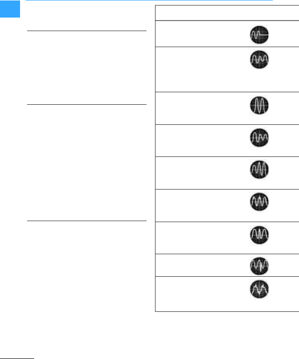
Powersupply problem
1Power supply failure
2Voltage dip
3Voltage surges
4Undervoltage
(voltage drop)
5Overvoltage
6Electrical disturbance
signals
7Frequency deviations
8Spikes due to switching
operations
9Harmonicdistortion
(harmonic waves)

Eaton power supply quality
Eaton Wiring Manual 06/11
00
to develop next-generation solutions.
Theproducts andservices listed below
represent examples from our extensive
solutions range.To view theentire range
or request aproductcatalog, please visit
www.eaton.com/powerquality.
Defi nition Cause Solution
Totalfailureof supply
network
Canoccurfrom anumber of events: lightning
strike,breaking of transmissionlines, network
congestion,accidents andnaturaldisasters
Temporaryunder-
voltage
Triggered by majorpowerconsumersbeing
switchedon,switchingin thesupplynetwork,
failureof grid facilities,lightningstrike andpower
supplysystems unable to meet requirements.
In addition to possible device failure, hardware can
alsobe damaged.
Temporaryvoltage
surge of more than
110 percentof the
nominalvalue
Canbe caused by lightningstrike andtemporarily
increase mainsvoltage to over6,000 volts.
Avoltage peakalmost always causes data losses
or hardwaredamage.
Reduced mainsvoltage
for a periodof between
afewminutes to a
fewdays
Canoccurif themainsvoltage is intentionally
reduced to reducepowerduringpeakconsumption
periodsor if theconnectedconsumer load exceeds
thesupplycapacity.
Increased mains
voltage for a periodof
between a fewminutes
andafewdays
Triggered by strong load reduction,majorpower
consumersbeingswitchedoffandotherswitching
operations in thenetwork. Hardware canbe
destroyedas aresult.
Disturbance signals
with higher
frequencies
These canbe triggered by electromagnetic
interference (EMI)or radio frequency interference
(RFI)from weldingequipment,transmitting
equipment,printers, thunderstorms etc.
Instability of mains
frequency
These occuras aresult of load variations,in partic-
ular in smallergeneratorinstallations.Frequency
deviations cancauseprocesses to fail, data losses,
system breakdownsanddamage to equipment.
Temporaryvoltage
dips
Spikes of this kind last avery shorttime,within the
nanosecond range.
Distortion of sinusoi-
dalwaveform, usually
causedby non-linear
loads
Switchingmode powersupplies, steppermotors,
copiersandfaxmachines areexamples of non-linear
consumer loads. They cancausecommunication
errors,overheating andhardware damage.
Single-phase UPS series 3
Single-phase UPS series 5
Single-phase andthree-phaseUPS series 9
Eaton Wiring Manual 06/11
00
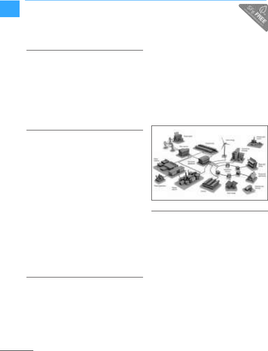
Eaton Medium Voltage Systems
Mediumvoltagesystems
Thequalityof Eaton’smedium voltage
systemsis foundedon over 100yearsof
experience.
Vacuum Technology
Vacuumtechnology is at theheartof
Eaton’sswitchingsystems. Eatonhas
over 30 yearsof experience in applying
vacuum technologyin circuit-breakers
andload-break switches.Theuseof this
technology results in amaximallyenviron-
mentally-friendlyswitchgearsolution.
Primaryswitchgear
As its namesays,primaryswitchgearis
thefirst stagein transmittingelectrical
currentfrom thesupply networkto the
endcustomer.Theimportance of the
strategicposition of thesubstation and
itsswitchgearwithin thesystem re-
flectsthefact that layout,construction
andoperation mustbe designedfor
maximum availability andreliability.For
this reason,Eaton’sportfolioincludes
theMMS–acompactstationary
switchgearunitwith singleor double
busbar – andPowerXpert®UX, a
switchgearunitwith removable circuit-
breakers,switches andcontactors.
Secondaryswitchgear
Eatonhasdeveloped universal, modular
secondaryswitchgearundertheSVS
andXiriaproductseries.It is suitablefor
usein supply networks,businessprem-
ises,infrastructure projects,industrial
applications andforstructures relating
to renewables such as wind farmsand
combined heat andpowerplants.The
design of theSVSandXiriais basedon a
combination of vacuum andepoxyresin
technology.Thereareamultitude of
differenttypesof switchgearsuitable
foreverykind of application.With its
compact dimensions andSF6-freede-
sign,SVSandXiriaarealso theideal
solution forunderground applications on
infrastructure projects.
Ring main units
Electrical energy hasbecome an indis-
pensable elementof modernsociety.
Areliable andconstant energy supply is
increasingin importance everyday. From
thestandpointof energy companiesand
theindustry, this meansthat thepower
distribution networkmustcope with
ever increasingdemand.It goeswithout
saying that safety andoperational
reliability play asignificantrole.
www.eaton.com
www.eaton.com/electrical
Eaton Wiring Manual 06/11
00
What's new in this edition?
The target markets of machine and system
builders are international. Eaton knows
these markets and is a competentpartner
worldwide in allissues relating to the
export of switchgear and switchgear
systems. The special requirements on the
export of products to North America (USA
and Canada) are taking on increasing
importance,see chapter 9.
Theuse of regenerative energy is
becoming increasingly important. Eaton is
a competent PV supplier and this
publication describes the technical
background information and range of
components required, see 7page 0-14.
easySafety–Fulfills the highest safety
demands.
The safety of people and machines must be
taken into account for the total lifecycle of
a machine/system.For personnel
protection safetycomponents such as
position switches, light curtains, two-hand
control switches or emergency switching
off pushbuttons come into use. The safety
information is monitored and evaluated by
the new easySafety control relay which
complies with the highest safety
requirements, 7Section ”The way to the
safe machine”, page1-29.
We make every effort to adapt and update
every new edition of theWiring Manual
according to the ever increasing
requirements of the markets.
The manyexample circuits in particular are
continually being updated by our
specialists to the best of their knowledge
and carefullytested. They serve as
practical examples. Eaton Industries GmbH
does not accept any liability for any errors.

Eaton Wiring Manual 06/11
00
Competence andExperience from aSingle Source
TheWiring Manual has been classic for
over 50 years and is probably the most
popular publication of the company.
Worldwide distribution has given it new
impetus in recent years. The 2005 edition
was translated forthe first time into nine
languages:
•English,
•French,
•Italian,
•Spanish,
•Dutch,
•Russian,
•Czech,
•Romanian,
•Swedish
Its contents are also available online at
www.wiringmanual.com.
The online version combines the proven
expertise with the latest Internet
technology. Forexample, full text searches
are also possible.
A special page with links to all the different
language versions available is provided as
a service to users from all over the world.
www.eaton.com/moeller/support
(Wiring Manual)
Edition 1958 Edition 1986

Competence andExperience from aSingle Source
Eaton Wiring Manual 06/11
00
Eaton offers you a range of products and
services that can be optimally combined
with one another. Visit our website on the
Internet. You will find there everything
about Eaton,such as:
•Up-to-date information about Eaton
products,
•Theaddresses of the Eaton sales offices
and representatives worldwide,
•Information about the European
activities of Eaton,
•Publicationsin the press, specialist
press,
•References,
•Exhibition dates and events,
•Technical support in the Eaton Support
Portal.
You can receive technical support for all
Eaton products just by a mouse click. And
tips und tricks, Frequently Asked Questions
(FAQs), updates, software modules, PDF
downloads, demo programs and much
more.
Youcan also put your name down to
receive the Eaton Newsletters.
Uncomplicated and quick way of finding
the information you need:
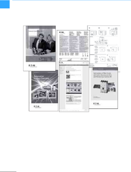
•PDF downloads, Internet-supported
browser catalogs, smartphone apps
–Catalogs
–Manuals and instructional leaflets
–Product information, such as
brochures, selection aids, technical
essays, declarations of conformity and
of course
–EatonWiring Manual
•Software Downloads
–Demo versions
–Updates
–Software modules and user modules
•Selection aids
–Motor starters 7Section ”Selection
aids”,page 8-3
Eaton Wiring Manual 06/11
00
Support Portal
You can also find a link to the Eaton After
Sales Service via the Support Portal
(7Section ”After Sales Service”,
page0-12).
You can sendyourqueries directly to the
TechnicalSupport/pre-sales service by
e-mail. Simply selectthe e-mail form that
meets your requirements to the +Eaton
experts.

Eaton Wiring Manual 06/11
00
Eaton Online Catalog
From detailed product information right up
to the enquiry for your products by email or
fax from yourEaton product supplier. All
this and more you can find in the Eaton
Online Catalog.
This gives youfast access to new
innovations as well as extensive
information on the current Eatonranges.
•Industrial switchgear,
•Drives,
•Automation systems, drives,
•Power distribution systems.
Create acomprehensive data sheet fora
product and save it as aPDF document or
print it out.
Several search options are available to
enable the right access for any product
search.
•The productgroup treestructure enables
simple searching in just a few clicks of
the mouse
•Selection tools provide logicalfilters in
product groups containing several
products
•A powerful search function with a
proposal list ensures above-average
search results
A number of links to additionalproduct
information and all aspects of it enable you
to ensure optimum use of the product:
•Application examples and project design
notes,
•Approvals
•Instructional leaflets,
•Manuals,
•Software etc.
Choose “Your”Online Catalog on the
Internet.
http://ecat.moeller.net/?locale=en_EN
The Online Catalog on the Internet is
updated regularly.

Eaton Wiring Manual 06/11
00
After SalesService
As close as you wish
Gain the benefit of our Service personnel.
Comprehensive expertise linked with long
term experience and modern equipment
help you find the solution to your tasks.
Components, cards and spare parts of our
product range are available for your use.
Personnel and material are furnished
according to your requirements,
professionally and on time.
You will receive competent and quick
telephone assistance round the clock in
the eventof unscheduled machine stops
and plant down-times, system faultsand
device break-downs.
During business hours, you will receive
support for commissioning,application
queries right through to fault analysis,
whichcan also be carriedoutusingremote
diagnostics.
Specialists are availablein the areas of
automation, drives, low-voltage power
distribution or switchgear.
Qualified technicians and specialists can
visit you in order to rectify faultsquickly
andreliably.
Contactus if you require fast and
competent support in installing and
commissioningtasks.
Whether with controllers, circuit-breakers
or other components, we can bring your
machines and plants up to the latest
state-of-the-art.
The legal requirements and regulations
demand the regulartesting of electrical
equipment in order to ensure itsproper
condition.Further information is available
from our website.
www.eaton.com/moeller/aftersales
The After Sales Service therefore offers
appropriate services for circuit-breakers
and low-voltage distribution boards.
We support you in the inspection and
maintenance of the circuit-breakers and
low-voltagedistribution boards supplied by
us, determine the condition of your
systems and carry outthenecessary work.
If required, thermography or network
analysis are also carried out with this work.

After SalesService
Eaton Wiring Manual 06/11
00
Tailored service seminars that meetyour
individual requirements to train up your
personnel.
Thermography gives us an efficient way of
analysing your electrical systems and
controls during operation.
Network analysis provides clear
information about the specific state of your
networks without the need for lengthy and
expensive fault retrieval.
Please enquirewhether we can inspect
the communication networks of your
systems with the latest technical
equipment.
In theevent of a fault,the directexchange
service for selective products
considerably reduces the downtime of
your production plant.
The repair of products in our Service
Center is an inexpensive alternative for
fault rectification.
We reduce maintenance costs with
selected spare partsand devices for
current/discontinued product lines.
We can provide special assistance if you
wish to analyse and rectifyfaultson
products. You can carry out interactive
troubleshooting via the Internet with direct
access to our Service-database.
There are some questions about our
products that ourcustomers very often
ask. You can benefit from the answers. You
can read the FAQ with the corresponding
answers on all aspects of automation.
You're at the right place here if you require
updates, software, documentation and
declarationsof conformity. Visit the Eaton
Download Center to obtain all the
information you require.
In the event of afault contact your local
representative
www.eaton.com/moeller/aftersales
or the After Sales Service directly
+49 (0) 180 522 3822, 24/7 (round the clock)
Tel.: +49 (0) 228 602 3640
(Mon.–Fri. 08:00 –16:00 CET).
AfterSalesEGBonn@eaton.com
www.eaton.com/moeller/aftersales
Eaton Wiring Manual 06/11
00
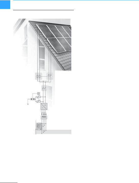
Photovoltaics in residential buildings
Photovoltaic systems use solar cells to
convert solarenergy into electrical energy.
If the system is connected to the grid, the
generated electricityis fed directly into it.
Unlike grid independent systems the
complicated temporary storage of
electricity is not required, however, the
generated DC current hasto be converted
to AC.
Apart from the PV panels, agrid-connected
system consists of one or several inverters
and switching devices, for operation,
maintenance and protection in the event of
afault –such as:
•a DC string protective device,
•DC switch-disconnector
•DC surge protection
•PV inverter
•Residual current device (RCD),
•AC surge protection
•and xComfort system (optional).
The PV panels are connected in series (as
a string)in order to provide the required
input DC voltage for the inverter.
Two or several strings are connected in
parallel to increase the powerof the
system. Forsafety reasons, all electrical
equipment must be isolated, protected and
securedwith switching devices which
must likewise be protected with
enclosures. All these important protective
devices can be sourced directly from
Eaton.
In order to feed the generated electricity
into the public grid or even to use it,
inverters are required to convert the DC
current of the solar cells in the AC current.
The frequency and voltage values are
adjusted to the grid parameters at hand.
Also here, Eaton offers reliable protective
and gridisolation devicessuchas inverters
from 1500 to 4000 W for indoor use and from
4000 to 4600 W for outdoor applications.
DC string
protective device
DC fuse switch
disconnector
DC switch
disconnector
DC surge
protection
PV inverter
Residual current
device
Meter reading
PV incomer panel

Photovoltaics in residential buildings
Eaton Wiring Manual 06/11
00
Each photovoltaic installation is as
individual as the requirements of its user.
Eatontherefore offers a complete line of
single-phase power inverters from 1500 to
4600 W:
•Suitable formoncrystalline and
polycrystalline PV generators.
•Maintenance free, highly reliable and
very easy to install.
•Integrated LCD display simplifies
operation.
•Optimum efficiency with maximum
power point tracking (MPPT).
•Fan-free thanks to natural convection
cooling.
•High performance compared to size.
•Particularly quiet and low pollution
operation.
•Standard RS232 ENS interface in
accordance with VDE0126-1-1/DK5940.
•Compact elegant modern design.
The ISG serieswith degree of protection
IP43 is designed for indoor installation.
The ISG series with degree of protection
IP65 is designed for bothindoor and
outdoorapplications.
All powerinverters are designed for
ambient temperatures from -20 to +55 °C.
Optimum operation is achieved at ambient
air temperatures between 0 and +40 °C.
The total output of a photovoltaic system
not only depends on the total area of the PV
panels, their alignment and the inclination
angle of the modules.
Components such as inverters playan
important part in the efficiency of the
system. Eaton inverters ensure you have
the maximum output.
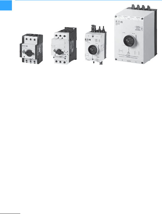
The IEC 60364-7-712 standard stipulates
the installation of a switch-disconnector
between the PV generator and the inverter.
Eaton offers enclosed and open
switch-disconnectors for DC voltages up to
1000V. In accordance with the regulations
of VDI6012 they can be used as separate
switching points, so that a faulty inverter
can be completely de-energized safely. All
switch-disconnectors switch two poles
and are therefore also suitable for
ungrounded systems. All switches are TÜV
certified.
Photovoltaics in residential buildings
Eaton Wiring Manual 06/11
00
Eaton offers both enclosed and open
switch-disconnectors in its range. The
open P-SOL switch disconnectors are
designed for mounting in customized
enclosures or inverters. They are mounted
on 35-mmtop-hat rails, and their terminals
enable a connection to all commonly used
cable types.
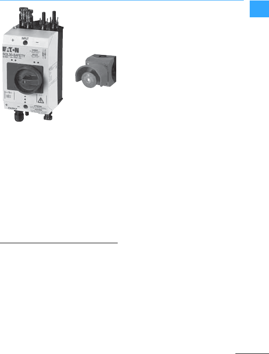
Eaton's enclosed SOL
switch-disconnectors are ready to fit and
are therefore very easy to install. Variants
for2, 3, 4 or 8 strings are available for the
most common connector types such as
MC4 or metric glands. The enclosure is
protected to IP65 and is suitable for
outdoorinstallation. The lockable
mechanism ensures safetyduring
maintenance work. A pressure-equalizing
element prevents the formation of
condensation, preventing malfunctions
caused by flashovers.
In the event of a house fire, the fire brigade
can often only rescue persons or animals
or preventthe fire spreading to
neighboring buildings. This is due to the
voltage of up to 1000 V generated by PV
systems, which is still present after the
inverter has been isolated. Rescue
services are thus exposed to fatal risks
when entering the building due to the
possibility of damaged DC cables. Eaton's
SOL30-SAFETY fireman's switch provides a
solution here, and de-energizes the line
from the solar modulesto the inverter, this
making safe any fire fighting activities.
Although VDE 0100-7-712 stipulates the use
of a DC isolator, it does not stipulate the
location. The isolator is frequently
integrated in the inverter so that the cable
between this and the house terminal is
safe, whilst a DC voltage of up to 1000V is
still present in the solar modulesand DC
cables up to that point, with up to ~8A for
each string.
Photovoltaics in residential buildings
Eaton Wiring Manual 06/11
00
Fireman's switches are installed in direct
proximity to the PV modules and inserted in
the DC cable directlyafterthe entry point
into the building between the panels and
the power inverter. The PV modules are
disconnected automatically using
undervoltage releases in the fireman's
switch, when theAC voltage of thebuilding
is isolated either by thefire brigade or the
localutility company or on site via a PV-OFF
switch.
If a PV installation has three or more
strings, a string protection device using DC
fuses or DC string circuit-breakers is
recommended. These protect the PV
panels from leakage and feedback
currents that can occur on faulty strings,
and prevent thefeedback of good panels to
panels with short-circuits. Compared to
fuses, string circuit-breakers have the
advantage that theyare immediately
operational again after the fault is rectified
as well as having the ability to send trip
indications via auxiliary contacts to thus
avoid any losses in yield. A further feature
of the DC string circuit-breaker is the
variable tripping range for short-circuit
currents: it reacts already from 1.05 …1.3
times the residual current. Eaton offers
both fuse switch-disconnectors as well as
string circuit-breakers that can be
combined easily with other components as
required.
The task of theFCFDC10DISOL fuse
switch-disconnector forthe ASFLC10-SOL
cylindrical fuse cartridges for fuse sizes 10
x 38 is to protect PV panels from
short-circuit currents. A flash function can
optionally be used to indicate a blown fuse.
The Eaton PKZ-SOL string circuit-breakers
are the fuseless alternative forprotection
against short-circuitcurrents. Its variable
tripping range enables optional settings to
the actual short-circuit current of a string.
Athermal release responds already at 1.05
... 1.3 times the current, whilst themagnetic
release responds at 6 times the current.
Non-enclosed string circuit-breakers are
designed forinstallation in customized
generatorterminal boxes.

Photovoltaics in residential buildings
Eaton Wiring Manual 06/11
00
The Eaton SPPT2PA surge arrester is
specially developed forphotovoltaic
applications and offers protection from
transient overvoltages that can occur
through the indirect effect of lightning.
Eaton offers types forboth grounded and
non-grounded systems in which the use of
a sparkgapensures galvanic isolation. The
unitscan be supplied pre-wired as ready to
use connection units.
AC switching devices forbuildings, such as
miniature circuit-breakers and residual
currentdevices offer maximum safety.
Eaton products of the xPole series combine
all functional, mounting and safety
benefits: intelligent design solutions
excludethe possibility of mounting faults.
They even offer optimum safety for the end
user:
Personnel protection in the form of residual
current devices and protection of the
electrical installation in the form of
overvoltage protection and MCBs. The
portfolio is rounded off with an extensive
rangeof intelligent switching devicessuch
as remote switches, restart devices and
others.
With the development of digitaltechnology
a new level of precision was achieved that
enables the avoidance of nuisance
tripping. This can occur for example with
permanent residual currents of electrical
devices or temporary faultscaused by
storms. Here too, Eaton is also one step
ahead:
Eaton is the firstcompany worldwide to
offer a digitalresidual current device. The
continuous status monitoring of the
installation allows unwanted and annoying
disconnections to be considerably
reduced, thus guaranteeing optimum
system availability. Three LEDs use the
"traffic light" principle to indicate when a
differential current has reached the 30%
warning threshold. In this way,
countermeasures can be taken in the
installation before the situation gets worse.
The installation user is thusprovided with
increased safety –with greater
convenience.
The benefits of MCBsand RCDs combined
in a single device–this is the Eaton
combination switch. It saves space, whilst
ensuring complete safety: reliable fire and
personnel protection (30 mA) with enough
spacefor flexible generous cabling.
The surge current proof design prevents
unwanted disconnection and selective
types enable the selective disconnection
of faulty system sections.

Photovoltaics in residential buildings
Eaton Wiring Manual 06/11
00
Regardless of whether plug terminal
connections or screw terminals are
required,Eaton has the right MCB for
residential buildings and for industrial
applications. Extensive accessories such
as auxiliary contacts, shunt releases,
restart devicesand intelligent busbar
solutions enable a host of applications and
automation solutions.
From the compact distribution board to the
meter cabinet and the data network
cabinet, Eaton offers a complete product
portfolio. All applications can thus be
coveredfor the infrastructure in residential
andnon-residential buildings as well as in
the industrial sector.
Lightning strikes andovervoltages not only
pose a risk for electrical installations but
also for their operators. Eaton offers an
extensive range of surge protective
devices. Attachable auxiliary contacts also
enable the monitoring of device functions.
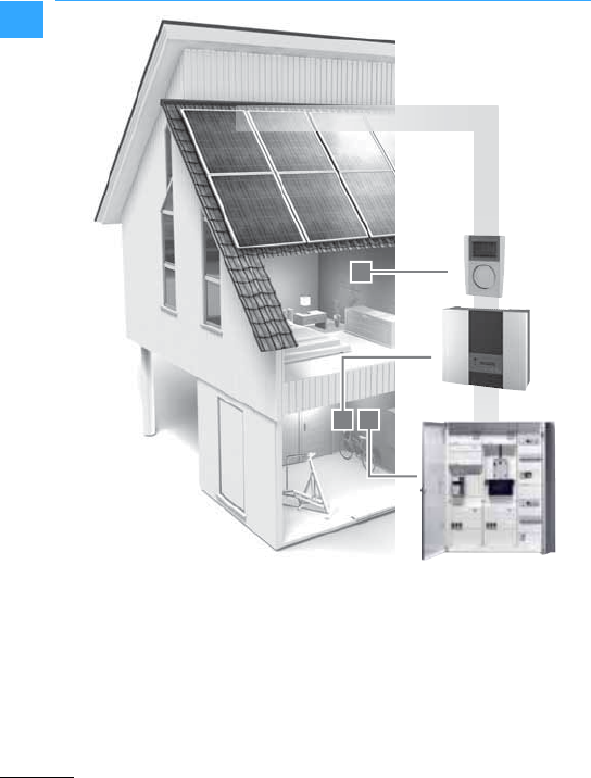
Convenient monitoring of electricity
generation from your living room –modern
home automation makes this possible.
With xComfort,Eaton is offering the Room
Manager with integrated energy
management software (Energy Manager)
fora powerful solution.
The connection of the Eaton energy sensor
with the inverterenables the electrical
energy currently fed into the grid to be
measured.
This data is then transferred wirelessly to
the Room-Manager which is installed in
one of the living areas. Here, the user of the
system can view values such as energy
(kWh), power (kW),voltage (V) and amps
(A) on a display.
Photovoltaics in residential buildings
Eaton Wiring Manual 06/11
00

Photovoltaics in residential buildings
Eaton Wiring Manual 06/11
00
Wireless home automation enables
lighting management, shade control,
monitoring and danger warnings, as well
as energysaving control concepts for
heating, cooling and ventilation.
Eaton's xComfort and Energy Manager
thus offertransparency, comfort and
safety combined:
•Consumption control
•Cost saving
•Reduction of CO2 emission
EU regulations stipulate that the actual
energy consumption must be clearly visible
to end consumers. The Eaton Room
Manager covers this requirementby
displaying and controlling the energy
consumption of specific electrical or gas
devices in the entire home.
Entering the price perunit of measure
makes it is possible to calculate the costs
fora consumption cycle quickly and
simply, for example for abath or a washing
machine cycle.
More consumption and cost control is
offered by a function that reads the history
of the previous 24 hours right through to the
last 12 monthsfrom the archive and shows
it as a value or a trend on the display. It is
also possible to output a warning message
as soon as a user-defined limit value is
exceeded. All this makes Eaton's energy
management software a useful toolfor
identifying possible savings and reducing
electricity costsfor private system users.
Eaton Wiring Manual 06/11
00
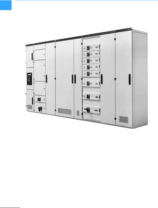
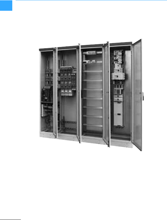
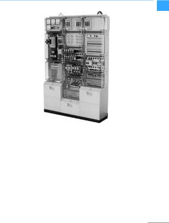
Eaton power distribution equipment
The modular system consists of perfectly
fitting function modules that are type
tested to IEC/EN 61439 with Form 1to Form
4internalpartitioning, and which take
European and local(DIN, VDE, CEI,NF,
UNE) installation practice into account.
xEnergy provides the panel builder with a
flexibly combinable product range for
power distribution systems up to 5000 A.
The operation of the system couldn't be
simpler, despite its complexity. The
modular design enables the creation of
intelligent combinations.
Switching and protective devices, as well
as the associated mounting technology
and extensive housing components are
perfectly matched and form both a
technical as well as an economic unit.
This practically oriented system platform
enables individual project design,
maximum flexibility and fast production in
the workshop. On the one hand, this saves
time,money and space, whilst type tested
mounting units offer a higherlevel of
safety. The modular system can
furthermore be extended with little effort to
meet future requirements.
Eaton power distribution equipment
Eaton Wiring Manual 06/11
00
The panel builder is provided with efficient
tools for tasks ranging from planning to
quotations, right through to ordering. The
entirerange is supplied in functional flat
packs or as pre-assembled switch
cabinets.
•Rated operational voltage 400 to 690 V AC
•Rated operational current 630 to 5000 A
•Rated short-time withstand current to
100kA (1 s)
•Main busbar currentto 5000 A
•Dropper bar current up to 2000 A
•Sheet steel housing forcombination and
separate mounting
•Degree of protection to IP31 and IP55
•Colour RAL 7035
•Internal separation up to Form 4
•Dimensions: Height 2000 mm
Width 425, 600, 800, 850, 1000, 1100, 1200,
1350 mm
Depth 400, 600, 800, 1000 mm
Fixed mounting
Removable compartments
Withdrawable compartments
•Incoming units/feeder units, outgoers
and couplingswith NZM or IZM
circuit-breakers up to 5000 A
•Circuit-breakers in fixed mounting or
withdrawable units
•3or 4 pole circuit-breakers
•Internal separation up to Form 4
•Cable connection fromtop or bottom
•Incomer system for drill-free cable
connection
Eaton power distribution equipment
Eaton Wiring Manual 06/11
00
•Outgoers with PKZ or NZM
circuit-breakers up to 630 A
•Circuit-breakers in fixed mounting or
withdrawable units
•3- or 4-pole circuit-breakers
•Outgoers with SL fuse-strip units up to
630A
•Individual outgoers, e.g. controllers,
motor starters, small energy outgoers, …
•Internal separation up to Form 3 or Form 4
•Cable connection fromtop or bottom
•Outgoers with PKZ and NZM
circuit-breakers up to 630 A
•Outgoers with strip-type switch-fuse
unitsup to 630 A
•Flexible surface mounting using plug-in
contacts
•Plug-in modules and switch-fuse units
exchangeable underconditions
•Straightforward maintenance, minimal
downtime
•Internal separation up to Form 4
•Cable connection fromtop or bottom
Eaton power distribution equipment
Eaton Wiring Manual 06/11
00
•Outgoers with PKZ and NZM
circuit-breakers up to 630 A
•Outgoers for motor starters up to 250 kW
•Emptydrawer-units forevery application
•Uniform, straightforward operation for all
drawer-unit sizes
•No special tool required
•Flexible assembly with plug-in contacts
(incoming and outgoing)
•Withdrawable modules exchangeable
whilst live
•Unambiguous position indication for
Operation, Test,De-energized
•Straightforward maintenance, minimal
downtime
•Internal separation up to Form 4
•Cable connection fromtop or bottom
•Power factor correction
•Mounting system forsubdistribution
system with modular installation devices
•Control technology with Sasy60i and
xStart
•Individual fixed mounted components on
mounting plate
Eaton power distribution equipment
Eaton Wiring Manual 06/11
00
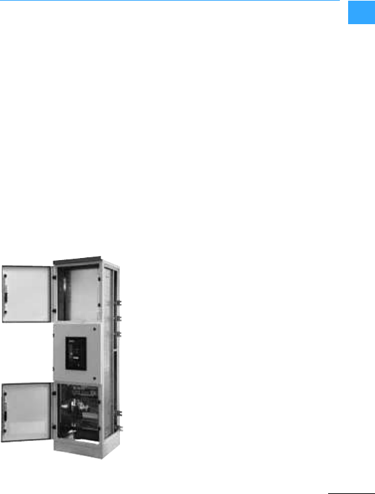
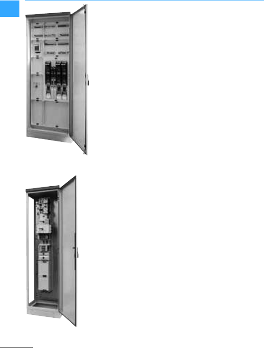
The xVtl side-by-side distribution system is
designed to take switchgear for
applications up to 2500 A.
Typicaluses are as power distribution
systems in utility buildings or as control
panel enclosures in industry. This is where
the xVtl can demonstrate the benefits of its
rugged design.
The xVtl is a stable, side-by-side mountable
distributor made of sheet steel thatis also
best suited forstand-alone installation.It
protects persons fromcoming into direct
contactwith conducting parts and even
from possible electric shock, and reliably
fends off damaging exterior influences. It
carries out these functions according to
the specific requirements, with protection
degrees of IP40 or IP55. Whilethe former is
suited to diverse uses in functional
buildingssuch as schools or hospitals, it is
also recommended for harsher conditions
such as wind energy systems, or in
industry, in a foam-type polyurethane
sealing design. Abrasion-proof protection
against corrosion is guaranteed thanks to
structured paint finish using a powder
coating RAL 7035.
Overall, the technical design of the xVtlL
complies with the IEC/EN62208 and
EN 60529 standards, as well as with

Eaton power distribution equipment
Eaton Wiring Manual 06/11
00
IEC60439-1, as long as it is used as a
low-voltage energy distribution system.
•Common platform with xEnergy: Several
design elements such as mounting
frames, bottom and topplates, as well as
side and rearpanels can be used for both
xVtl and xEnergy.
•Installation mounting systems : Profi+, EP
and IVS
•Rated operational voltage 415 V AC
•Rated operational current to 2500 A
•Rated short-time withstand current to
65 kA (1 s)
•Sheet steel housing forcombination and
separate mounting
•Degree of protection to IP40 and IP55
•Colour RAL 7035
•Internal separation up to Form 2
•Dimensions:
Height 1400, 1600, 1800, 2000 mm
Width 425, 600, 800, 850, 1000, 1100, 1200,
1350 mm
Depth 400, 600, 800 mm
•Incoming units /feeder units, outgoers
and couplingswith NZM and IZM
circuit-breakers up to 2500 A
•Outgoers with SL fuse-strip units up to
630A
•Internal separation up to Form 2
•Circuit-breakers in fixed mounting or
withdrawable units
•3- or 4-pole circuit-breakers
•Cable connection fromtop or bottom
•Incomer system for drill-free cable
connection
•Outgoers with NZM circuit-breakers
•Compensation sections
•Individual fixed mounted components on
mounting plate
Eaton power distribution equipment
Eaton Wiring Manual 06/11
00
•Installationmounting systems Profi+, EP
and IVS
•Mounting modules for
–for NZM
–NH switch-disconnectors
–Low-voltage h.b.c. fuse switch
disconnectors
–Busbar mounting fuses
–Modular installation devices
–Individual devices
•Control technology with Sasy60i and
xStart
•Individual fixed mounted components on
mounting plate
•Air conditioning and ventilation
•Automation engineering
Eaton power distribution equipment
Eaton Wiring Manual 06/11
00
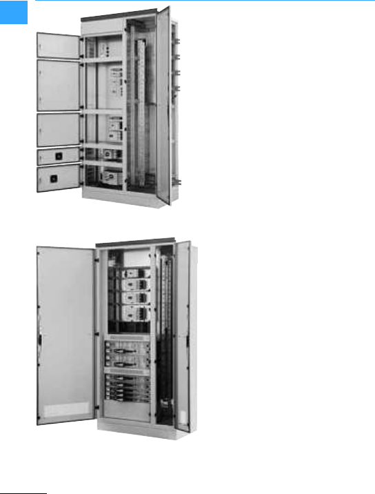
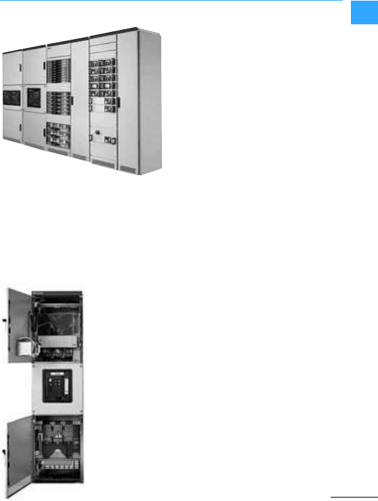
The MODAN is atype-tested modular
power distribution system in compliance
with IEC/EN 61439-1. It is used wherever
large amounts of energy have to be
distributed safelyand reliably or where
motor controllers have to be integrated into
processes.
MODAN combinesthe greatest possible
flexibility with safety and reliability, as well
as profitability for the long term.
Straightforward engineering, effective
commissioning and fault-free operation by
the modular construction using Eaton
products for switching, protection, control
and visualization.
Full and comprehensive integration of the
primary control is implemented on the basis
of networked functional groups.
For personnel and system protection, the
arc fault protection system ARCON®can be
integrated without problems.
•Operating voltage 400 to 690 VAC
•Rated operational current 630 to 6300 A
•Short-circuit strength to 100 kA (1 s)
•Connection from top and bottom for
cablesand busbars (LX, LD, BD)
•Internal partitioning up to Form 4b
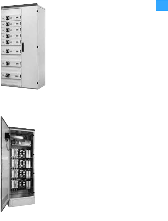
Eaton power distribution equipment
Eaton Wiring Manual 06/11
00
•Section for up to 15 removable
compartments forpower outgoers and
motor starters or
•Section for up to 27 fuse combination
+units
•Flexible surface mounting using plug-in
contacts
•Plug-in modules exchangeable whilst
live
•Straightforward maintenance and
reduced downtime
•Power outgoers up to 630 A
•Motor starters up to 90 kW
•Module is forplugging in, i. e. the
incoming unit is removable
Eaton power distribution equipment
Eaton Wiring Manual 06/11
00
•Section for up to 30 drawerunits for
poweroutgoers and motor starters
•High packing density
•Uniform, straightforward operation for all
drawer-unit sizes
•No special tool required
•Withdrawable modules exchangeable
whilst live
•Straightforward maintenance and
minimal downtime
•Internal partitioning up to Form 4b
•Power outgoers up to 630 A
•Motor starters up to 200 kW
•Drawer-unit is withdrawable,i. e. all
electrical connectionsare plug
connections
•Exchangeable whilst live
•All drawer unitspositions lockable
•Unambiguous and clearly visible
indication forallpossible drawer unit
positions(Operation, Test, De-energized)
Eaton power distribution equipment
Eaton Wiring Manual 06/11
00
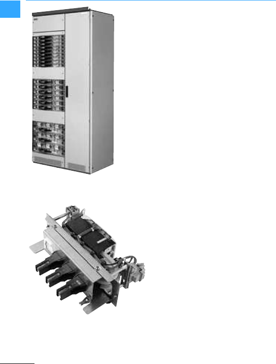
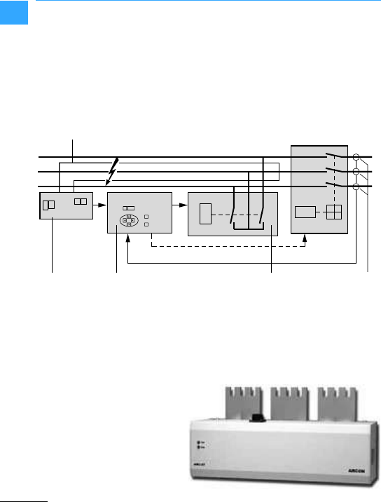
Maximum personnel and system safety,
especially during continuous production
processes, made possible using the
ARCON arc-fault protection system. The
system offers protection from 6 to 100 kArms
arc fault current.
Detection of the arc faults is by light and
current sensors. The evaluation unit
responds when light and currentsignals
are present. A tripping signal is applied to
the quenching device and to the feeder
circuit-breakers. The fault arc is quenched
in less than 2 ms. The system can be put
back into operation as soon as the fault is
eliminated and the quenching device is
renewed.
aCurrent transformer
bARC-SL... linear light sensor
cElectronic evaluation unit (slave)
ARC-EL3
dElectronic evaluation unit (master)
ARC-EM
eARC-AT quenching device
b
c d ea
ARC-EL3 IZM
IZM
ARC-EM
ARC-AT

Eaton power distribution equipment
Eaton Wiring Manual 06/11
00
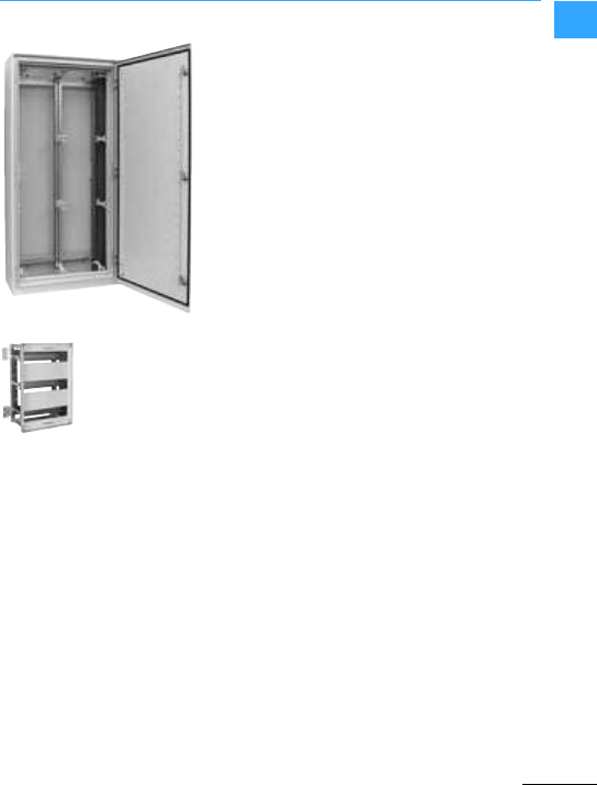
Therobust CS enclosure series with solid
sheetsteel is used wherever a particularly
effective protectionagainst direct contact
withlive partsor the protection of all
installed equipment from harmful external
influences is required. Thanks to itshigh
degreeofprotection to IP 66 (UL/CSA
Types 1, 12) with a continuous foam
polyurethane gasket, water, oil or dirt is
preventedfrom penetrating inside the
enclosure. This makes the CS enclosure
particularly suitable forsubdistribution
boards in control panels in industrial and
utility buildings, as well as for machine
building applications.
The stable sheet steel enclosure meets the
requirements of impact resistance
category IK09 to EN 62262. Impact resistant
metal locks provide additional safety. The
hinge pins with quickchange technology
enable the door hinge to be replaced
quickly since each metalpin can be
removed without any tools.Wall fixing
bracketsenable the switch cabinet to be
mounted on a wall.
The PHZ-A comfort rotary handle with
locked position indication clearly shows on
the outsidewhether the cylinder is in the
opened or closed position. The comfort
rotary handle can be retrofitted quickly,
without the need to remove the standard
lock -thuseliminating the need for the use
of rotary levers.
The galvanized sheet steel mounting plate
with a maximum thickness of 3 mm ensures
the safe installation of the switchgearand
basic EMC protection.
The CS enclosure can be turned through
180°, so that the cables can be fed in either
via the top or bottom. The largeflange plate
openings allow the fitter more flexible
handling.
Eaton power distribution equipment
Eaton Wiring Manual 06/11
00 The foam gasketof the flange plate saves
users the time required forgluing in foam
rubberseals. Both flange and mounting
plates areincorporated in the grounding
concept, thus eliminating the need for an
additional protective ground connection.
Their powder coated surface provides an
abrasion and corrosion resistant
protection. As a special service, Eaton also
offers individual solutions tailored to
customer specifications.
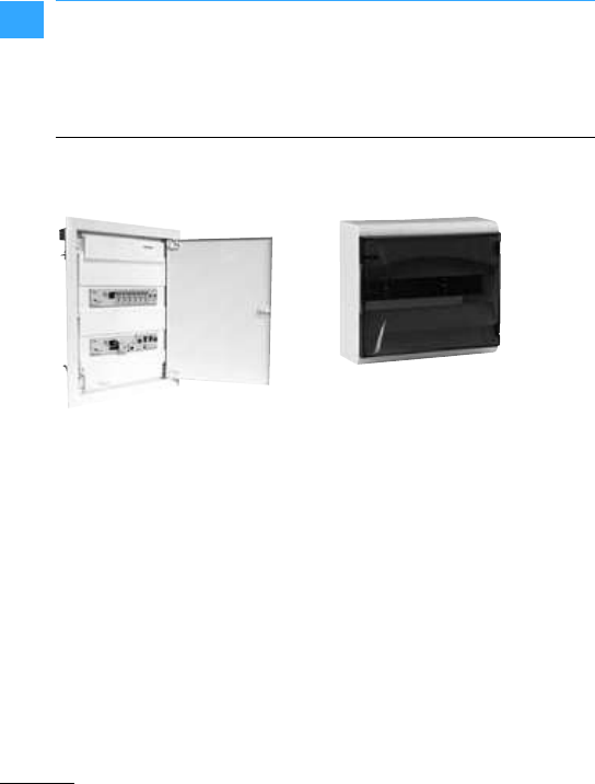
The plastic enclosure suitable for cavity
walls offers an outstanding level of stability
whilst the flat design of the sheet steel door
makes it inconspicuous in any room. An
adjustment tolerance of up to 18 mm for
compensating any unevenness in walls
andplaster significantly simplifies flush
mounting in wall openings.
The zero and protective ground terminals
are alreadyprefitted. The KVL-U
distribution board enclosure with
protection class II and degree of protection
IP30 are available in 1 to 4-row versions
each with 12 +2module widths.
The following door variants are available:
Sheet steel doorflat and super flat, plastic
design door white and transparent.
Wherever it is not possible to install in
cavity walls, the rugged BC-A surface
mountedcompact distribution board
protects the inside from mechanical
damage and harmful environmental
influences. In addition to degree of
protection IP30, the unit meets the
requirements of protection class II when
used in conjunction with the back plate and
the cover plate.
In spite of its compact dimensions, up to 4
rows of 13 space unitsare available for
each distribution board enclosure. The
BC-A surface mounted compact
distribution board comes standard with
white and transparent doors.
Eaton power distribution equipment
Eaton Wiring Manual 06/11
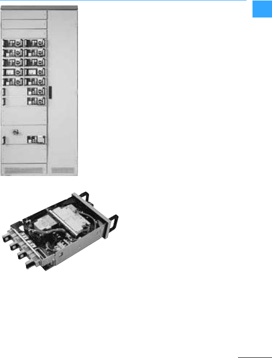
00
The IVS service distribution board up to
630 A is primarily used for the safe and
economical power supply in industrial,
building and commercial applications.
The range therefore includes wall and
standard enclosures, each with protection
to IP30 and IP54.
The mounting space with an even division
into standard 250 x 375 mm sections
ensures a particularly clear design.
Planning, ordering and mounting are thus
simplified accordingly.
•The link between the enclosure and the
mounting units is the mounting system
with insulated support brackets. The
mounting systemcan be lifted out of the
enclosure after the plates have been
removed and the screws released.
•A number of mounting unitsthat are
tailored to original Eaton switching and
protective devices allow fortime saving
and simple mounting.
•Insulated covers are used for protecting
the mounting units from directcontact.
Applicable standard formanufacturing is
IEC EN 60439-1 "Type-tested low-voltage
switchgear assemblies”.

Eaton power distribution equipment
Eaton Wiring Manual 06/11
00
The connection terminal consistsof a
combination of several very stable terminal
blocks. It is used forconnecting two or
several conductors.
A very wide range is available as standard
with 6 sizes and terminalcapacities from 16
to 3x240 mm²(160 to 1000 A).
Copper conductors can be inserted quickly
into the boxterminals from above without
bending.
The Eaton terminals are designed for
copper strips or busbars as well as copper
conductors. Each terminal pair is moulded
in a plastic Duroplast shell. Each of the 6
sizes is available from stock as a 1-pole,
3-pole, 4-pole or 5-pole terminal
combination.
Accessories such as the transparent
plastic cover, auxiliary conductor
terminals or conversion kitsalso enable
the creation of yourown terminal variants.
Eaton power distribution equipment
Eaton Wiring Manual 06/11
00
The assemblyof the CI system
demonstrates its flexibility. Whether as an
individual enclosure, wall-mounted or floor
standing distribution board of any size, the
modular CI insulated distribution board up
to 1600 A always offers theright solution in
harsh ambient conditions.
Themodularsystem makes it easy to adapt
to awide range of conditions.
•IP65 protection ensures protection from
dust, humidity and water jets,
•Pressure relief by meansof liftable
covers with spring-loaded enclosure
bolts,
•"Total insulation" providesmaximum
personnel protection and operational
safety.
•Transparent neutral cover allows
unrestricted view,
•Lock mechanism actuated with cylinder
lock or tool,
•Floorstanding distribution boards with
base covers for routing, fixing or
covering large cable cross-sections.
Enclosed distribution boards are
type-tested switchgear assemblies (TTA)
in accordance with VDE 0660 part 500 or
Type Tested Assemblies (TTA) to IEC 60439.
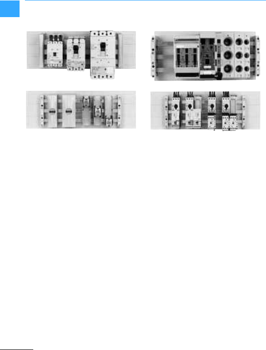
Eaton power distribution equipment
Eaton Wiring Manual 06/11
00
The SASY60i modularbusbar system from
Eaton is designed for effectivepower
distribution in the controlpanel.
Thanks to the innovative mounting
technology feeder and outgoing
circuit-breakers can be mounted quickly
and compactly. SASY60i is safe and
reliable.
In conjunction with the latest generation of
Eaton motor protective circuit-breakers
and othercircuit-breakers, the SASY 60i
provides a universal, UL certified solution
forswitching, controlling, protecting and
distributing energy. Together with the
appropriate switching and protective
devices, the busbar system is designed for
worldwide use.
The larger clearances and creepage
distances required in compliance with the
UL 508A in America have been considered
in the construction of the busbar
components.
When used in North America, the insulated
bottom plate must be mounted under the
system. Components approved for IEC
such as NH fuse switch-disconnectors or
D busbarmounting fuses can also suitable
forperfectly matched fitting.
As SASY60i requires few system
components the new Eaton busbar system
also reduces the stock-keeping and
ordering required.
These benefits naturally also apply to
Eaton's SASY185i and SASY Compact
busbarsystems.

Eaton Wiring Manual 06/11
1

Eaton Wiring Manual 06/11
1
SmartWire-DT communication system
The main part of a control system for a
machine is these days carried out by a PLC.
Typically the PLC is mounted in a control
panel at a central position in the system.
The control of the switchgear is carried out
via special cables from the input and
output terminals of the PLC forthe control
and return signals. With a decentralized
configuration the switchgear and the
remote input/output system are connected
in the same way.
The SmartWire-DT communication system
replaces the control wiring previously
required between the PLC inputs/outputs
andthe switching devices. In this way, the
inputs/outputs of the PLC are relocated to
the switching devices. Pluggable
communication modules are used forthis
task. The communication is implemented
via an 8-pole ribbon cable. Specialdevice
plugs are used for connecting the
communication modules to the cable.The
switchgear is supplied on the control
circuit side by the connection cable.
The SmartWire-DT system
•reduces the time required for the control
wiring and wiring test,
•saves space in the control cabinet
because cable ducts are unnecessary
and
•reduces the number of inputs/outputs
required at the PLC.
The length of a SmartWire-DT network can
be extended up to 600 meters. Up to 99
stations can be connected.
You can use the SmartWire-DT technology
flexibly. The connection via standard
fieldbus systems(e.g. PROFIBUS,
CANopen) enables SWD gateways to be
used on the controller platforms of many
manufacturers. Another option is the use of
Eaton automation components (e.g. XV100
visualization system) with an integrated
SmartWire-DT interface.
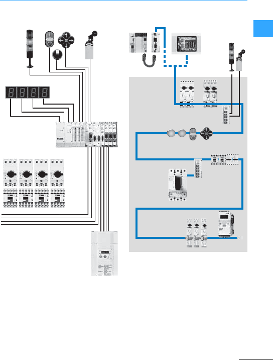
SmartWire-DT communication system
Eaton Wiring Manual 06/11
1
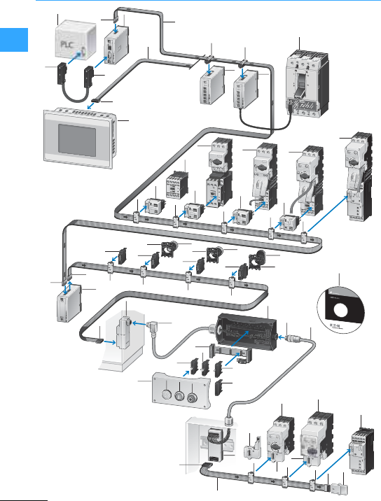
SmartWire-DT communication system
Eaton Wiring Manual 06/11
1
2
1
6
35
34
31
32
31
29
20
19
26
27
57
7
77
5
5
22 23
21
24
22 25
25
22
28
27 39
40
24
30
25
25
23
28
36
38
37
5
7
7
34
7
33
5
34
6
18
17
15
14
13
11
77
7
77
12
13
9
8
7
10
7
3
5
3
4
5
6
16

SmartWire-DT communication system
Eaton Wiring Manual 06/11
1
1Programmable logic controller PLC
2SmartWire-DT gateway
3Data plugs Sub-D 9 pole
4SmartWire-DT HMI-PLC
5SmartWire-DT blade terminal8 pole
6SmartWire-DT ribbon cable 8 pole
7SmartWire-DT device plug 8 pole
8SmartWire-DT I/O modules
9SmartWire-DT connection for NZM
10 NZM circuit-breaker
11 SmartWire-DT contactor module
12 DILM contactor
13 SmartWire-DT contactor modules with
Manual-0-Automatic switch
14 PKZM0 motor-protective
circuit-breaker
15 SC motor-starter combination
16 SmartWire-DT PKE module (motor
starter)
17 Motor-startercombination with PKE
electronic motor-protective
circuit-breaker
18 DS7 Softstarter with PKE electronic
motor-protective circuit-breaker
19 SmartWire-DT powerfeed module
20 SmartWire-DT universal station, front
fixing
21 SmartWire-DT LED elements, front
fixing
22 RMQ-Titan fixing adapters forfront
mounting
23 RMQ-Titan indicator light
24 SmartWire-DT function elements for
frontfixing
25 SmartWire-DT operating elements
26 SmartWire-DT control panel cable
entry for ribbon to round cable
27 SmartWire-DT plug connector
28 RMQ-Titan surface mounting enclosure
29 SmartWire-DT card for function
elements, base-fixing
30 SmartWire-DT LED elements forbase
fixing
31 SmartWire-DT function elements for
base fixing
32 SmartWire-DT universal station for
base fixing
33 SmartWire-DT adapter for
ribbon/round cable for top-hat rail
mounting
34 SmartWire-DT PKE module
(motor-protective circuit-breaker)
35 PKZ12, PKE32 motor-protective
circuit-breaker
36 PKE 65 motor-protective
circuit-breaker
37 Network termination for 8 pole ribbon
cable
38 DS7 softstarter
39 SmartWire-DT round cable,8-pole
40 SmartWire-DT planning and ordering
aid, SWD-Assist

SmartWire-DT communication system
Eaton Wiring Manual 06/11
1
Motor-starter combinations fitted with PKE
can transferthe following information via
SmartWire-DT:
I_max Maximum motorcurrent (relative): shows the single-phase
current (single-phase load) or the maximum current in the
appropriate phase (three-phase load).
Thermal image of the
motor
Shows thetemperature curve of the motor; stated in %,
“Overload warning”function possible
Type of trip block display Shows thetype of trip block currently in use.
Display of set Overload
value
Shows the currently set value for the overload release.
Display of time-lag class
value
Shows the currently set time-lag class (Class 5…20).
PKE switching state
display
Shows the currently set ON/OFF switching state.
DILM contactor
switching state
Shows the currently set ON/OFF switching state.
Trip indication overload Shows adifferentiated “Overload”fault indication.
Trip indication
short-circuit
Shows adifferentiated “Short-circuit”fault indication.
Trip indication Phase
failure
Shows adifferentiated “Phase failure”fault indication.
Trip indication Test Shows adifferentiated “Tripping via test function”fault
indication.
ZMR functionOverload relay function: When the ZMR function is set, the
contactordisconnects in the event of an overload.The PKE
motor-protective circuit-breaker remains switched on
(ON setting).
The contact is reset with the MANUAL/AUTO function via
PKE-SWD-32.

SmartWire-DT communication system
Eaton Wiring Manual 06/11
1
The ZMR function enables the motor to be
switched off by the connected contactor in
the event of an overload. To do this the PKE
sends the switch off command forthe
contactor to the PKE-SWD-32 via the data
cable of the PKE32-COM.
The trip in response to amotor overload
occurs if the thermal motor image of the
PKE reaches 110 %.
This value remains set until the thermal
motorimage has gone belowthe 100 %
level and the operational readiness of the
contactor is restored.
The reclosing readiness of the contactor
can be selected by the two manual and
automatic operating modes of the ZMR
function.
The ZMR function can only be used in
position "A" of the 1-0-A switch.
In the event of a phase unbalance and
activated ZMRfunction, the value of the
thermal motorimage is raised from 100%
to 110 %after a trip.
Theswitched offcontactor's readiness to
reclose is restored when the value falls
below 100 %.
The ZMR function must not be activated
with reversing starters since this operation
does not ensure the disconnection of the
second contactor in the event of an
overload.
In "manual" ZMR operating mode,the
retriggering of the contactor must be
acknowledged beforehand.
In "automatic" ZMR mode, the contactor is
ready to reclose immediately after the
thermal image dropsbelow 100 %.
If the switch on command for the contactor
is sent in "automatic" ZMR mode, the motor
starts up automatically after the thermal
motor image falls below 100 %.
Never disconnect the communication link
between the PKE-SWD-32 and the PKE trip
block after an overload with the ZMR
function activated, as this can cause the
contactor to switch on if a switch
command is present.
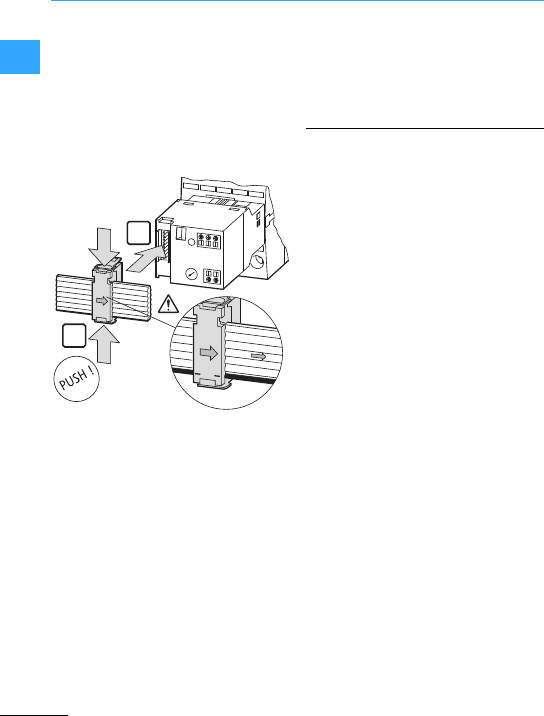
SmartWire-DT communication system
Eaton Wiring Manual 06/11
1
The DOL starters are assembled from a
PKZM0 and a DILM7 to DILM32 contactor.
The connection to SmartWire-DT is
implemented with the DIL-SWD-32-..
module. This is fitted directlyon the
contactor and connected via the SWD
device plug with the SWD communication
cable.
In addition to contactor control, two
feedback signals can be sent to the
SmartWire-DT system on each
SmartWire-DT module for DILM.
The SmartWire-DT module for DILM drives
the contactor so thatterminals A1-A2 must
no longer be wired.
The auxiliarycontact X3-X4is factory fitted
with a link. If electricalinterlocks are
envisaged in the application, the link can
be removed and a potential-free contact
can be connected.
Twofeedback inputs to the programmable
logic controller are provided at the
three-pole terminal X0-X1-X2. If required,
potential-free auxiliary contacts of the PKZ
motor protective circuit-breakercan be
connected to these two feedback inputs
(e.g. NHI-E-…-PKZ0 standard auxiliary
contact, AGM2-…-PKZ0differential
trip-indicating auxiliary contact).
7Figure, page 1-10
The reversing starters are made up of a
PKZM0 motor-protective circuit-breaker
and two DILM7 to DILM32 contactors. A
DIL-SWD-32-…SmartWire-DT module is
fitted to each contactor and connected to
the SWD communication cable viathe
SWD external device plug.
In addition to contactor control, two
feedback signals can be sent to the
SmartWire-DT system on each
SmartWire-DT module for DILM.
The SmartWire-DT modules forDILM drive
the contactors so that the connection
terminals A1-A2 of the contactors need no
further wiring, with the exception of the
DILM12-XEV link. The auxiliary contact
X3-X4 is factory fitted with a link. For the
electrical interlocking of the two
contactors this bridge is removed and the
auxiliary breaker (contacts 21-22) of the
other contactoris linked in as a
potential-free contact.
Two feedback inputs to the programmable
logic controller are provided at the
three-pole terminal X0-X1-X2. If required,
potential-free auxiliary contacts of the PKZ
motor protective circuit-breakercan be
connected to these two feedback inputs
(e.g. NHI-E-…-PKZ0 standard auxiliary
contact, AGM2-…-PKZ0differential
trip-indicating auxiliary contact).
SWD4-8SF2-5
+15V
SWD4-8SF2SWD4-8SF2
SWD4-8SF2-5
+15V

SmartWire-DT communication system
Eaton Wiring Manual 06/11
1
The wiring setsDILM12-XRL and
PKZM0-XRM12 must only be used to create
a reversing starter when the reversing
linksDOL starters with PKZ are replaced
withDILM12-XR. The A2 connections of the
contactors must not be bridged.
7Figure, page 1-11
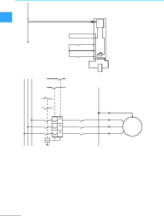
SmartWire-DT communication system
Eaton Wiring Manual 06/11
1
8
SmartWire-DT
L1
L2
L3
-Q11
X1
531
531
642
WVU
642
PE
WVU PE
PE
M
-M1
3 ~
III
-Q1
1.211.13
1.22
1.14 4.43
4.13
4.44
4.14
-Q1 -Q1
4.43
4.44
1.13
1.14
-Q11
X1X0 X2 X3 X4
8
A1
A2
“+” “I >”
24 V
0 V
DC
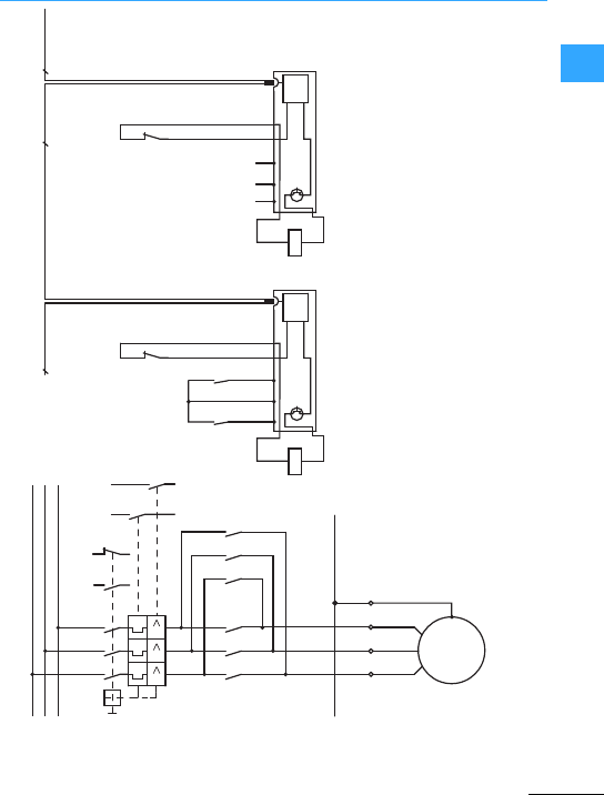
SmartWire-DT communication system
Eaton Wiring Manual 06/11
1
L1
L2
L3
-Q11
-Q12 -Q11
X1
531
531
642
WVU
642
-Q12 531
642
PE
WVUPE
PE
M
-M1
3 ~
III
-Q1
1.211.13
1.22
21
22
1.14 4.43
4.13
4.44
4.14
-Q1 -Q1
4.43
4.44
1.13
1.14
-Q11
X1X0 X2 X3 X4
8
21
22
8
SmartWire-DT
A1
A2
-Q12
X1X0 X2 X3 X4
8
SmartWire-DTSmartWire-DT
A1
A2
“+” “I >”
24 V
0 V
DC
24 V
0 V
DC
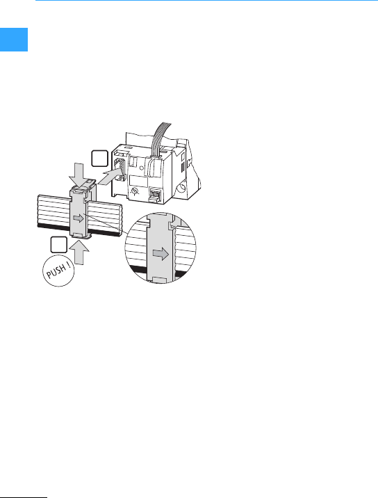
SmartWire-DT communication system
Eaton Wiring Manual 06/11
1
The DOL starters are assembled from a
PKE12/ PKE32 with thePKE-XTUA-…trip
block and a DILM7 to DILM32 contactor.
The connectionto SmartWire-DT is
implemented with the PKE-SWD-32
module. This is fittedto the contactorand
connected to the SWD communication
cable via the SWD device plug.
The PKE32-COM is used as a
communication link between the
PKE-SWD-32 and the PKE trip block. The
PKE-SWD-32 receives the data of the PKE
trip block via the PKE32-COM and makes
this available as input data on the
SmartWire-DT network.
The PKE32-COM is fitted on the PKE basic
device (PKE12 or PKE32) and is connected
withthe appropriate interface of the
PKE-SWD-32.
The auxiliary contactfor the electrical
enable X3-X4 is connected at the factory
with a link. If electrical locks are envisaged
in the application, the link can be removed
and a potential-free contact can be
connected.
The auxiliary contactfor the electrical
enable canbe used on the PKE-SWD-32 for
safety-related control sections (e.g. safety
shutdown of the drive).
7Figure, page 1-14
+15V
+15V

SmartWire-DT communication system
Eaton Wiring Manual 06/11
1
The reversing starters are made up from a
PKE12/PKE32 with a PKE-XTUA-…trip
block and two contactors DILM7 to
DILM32. The PKE-SWD-32 is fitted on one
of thetwo contactors of the reversing
starter. Unlike DOL starters, the control of
the second contactor for reversing starters
must be implementedwith a SmartWire-DT
contactor module (DIL-SWD-32-…). Both
SWD modules are then connected to the
SWD communication cable via the SWD
device plug.
The "Enable" X3-X4 auxiliary contact is
factory fitted with a link. For the electrical
interlocking of the two contactors this link
is removed and the auxiliary breaker
(contacts 21-22) of the other contactor is
linked in as a potential-free contact.
The auxiliary contactfor the electrical
enable X3-X4 can be used on the
PKE_SWD-32 for safety-related control
sections. The wiring sets DILM12-XRL and
PKZM0-XRM12 mustnot be used forthe
assembly of the reversing starters.
The A2 connections of the contactors must
not be bridged.
7Figure, page 1-15
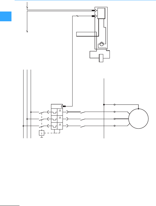
SmartWire-DT communication system
Eaton Wiring Manual 06/11
1
8
SmartWire-DT
L1
L2
L3
-Q11
X1
531
642
WVU
642
PE
WVU PE
PE
M
-M1
3 ~
-Q11
X3 X4
8
A1
A2
24 V
0 V
DC
10
-Q1
531
III
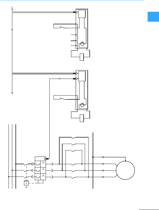
SmartWire-DT communication system
Eaton Wiring Manual 06/11
1
L1
L2
L3
-Q11
-Q12 -Q11
X1
531
642
WVU
-Q12 531
642
PE
WVU PE
PE
M
-M1
3 ~
21
22
-Q11
8
21
22
8
SmartWire-DT
A1
A2
-Q12
X1X0 X2 X3 X4
8
A1
A2
24 V
0 V
DC
24 V
0 V
DC
PKE-SWD-32
X3 X4
642
DIL-SWD-32-...
10
SmartWire-DT
-Q1
531
III

SmartWire-DT communication system
Eaton Wiring Manual 06/11
1
They control the contactors so that the
terminals A1-A2 of the contactors do not
have to be wired. A return signal is also
given back to the SmartWire-DT system via
the SWD contactor modules for DILM.
The terminals X3-X4 are supplied with a
bridging connection. For the electrical
interlocking of the two contactors this
bridge is removed and theauxiliary breaker
(contacts 21-22) of the other contactor is
linked in as a potential-free contact.
7Figure, page 1-18
TheSmartWire-DT I/O module actuates the
contactor Q11 via the digital relay output
Q0. The further procedure is the same as
that of a conventionalstar-delta starter.
The inputs of the SmartWire-DT I/O module
are used to implement return signals to the
SmartWire-DTsystem.
7Figure, page 1-19
The SWD contactor module for DILM
controls the mains contactorQ11 so that
the terminals A1-A2 do not have to be
wired. Areturn signal is also given back to
the SmartWire-DT system via the SWD
protective module forDILM.
The control and the changeover between
star contactor and delta contactor have
the same wiring and function as the
conventional star-delta starter assembly.
7Figure, page 1-20

SmartWire-DT communication system
Eaton Wiring Manual 06/11
1
The star-delta starters are made up from a
PKE12/PKE32 with a PKE-XTUA-…trip
block and three contactors DILM7 to
DILM32. The PKE-SWD-32 is fitted to the
mains contactor of the star-delta starter.
The star and delta contactor is actuated
with SmartWire-DT contactor modules
(DIL-SWD-32-…).
All SWD modules are then connected to
the SWD communication cable via the
SWD device plug.
The "Enable" X3-X4 auxiliary contact is
factory fitted with a link. For the electrical
interlocking of the star and delta contactor
this link is removed and the auxiliaryNC
contact(contacts 21-22) of the other
contactor is linked in as a potential-free
contact.
The auxiliary contactfor the electrical
enable X3-X4 can be used on the
PKE_SWD-32 for safety-related control
sections.
The wiring setsDILM12-XRL and
PKZM0-XRM12 must not be used forthe
assembly of a star-delta starter.
The A2 terminals of star and delta
connections must not be bridged.
7Figure, page 1-21
The star-delta starters are made up from a
PKE12/PKE32 with a PKE-XTUA-…trip
block and three contactors DILM7 to
DILM32. The PKE-SWD-32 is fitted to the
mains contactor of the star-delta starter.
The star-delta contactoris actuated in a
conventional circuit. The PKE-SWD-32
module is connected to the SWD
communication cable viathe SWD device
plug.The wiring sets DILM12-XRL and
PKZM0-XRM12 can be used for the
assembly of a star-delta starter.
7Figure, page 1-22
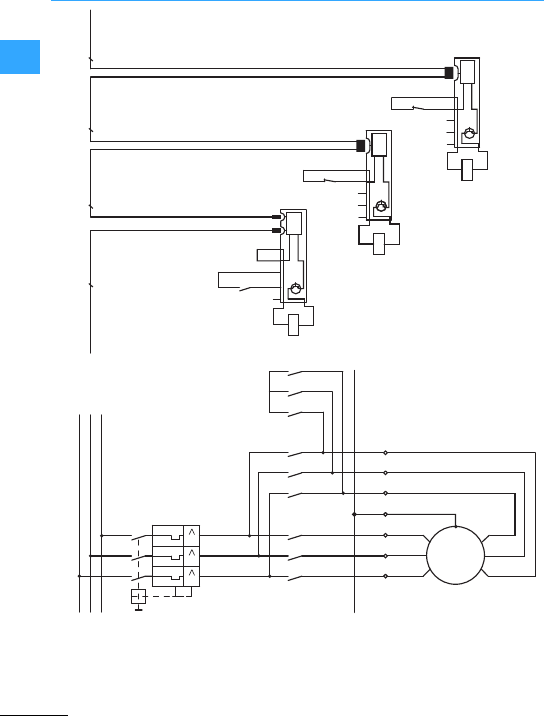
SmartWire-DT communication system
Eaton Wiring Manual 06/11
1
-Q12
X1 X2 X3 X4
24V
0V
DC
-Q13
22
21
8888
SmartWire-DT SmartWire-DT SmartWire-DT SmartWire-DT
-Q11
X1X0 X2 X3 X4
24V
0V
DC
X0
-Q12
22
21
-Q13
X1 X2 X3 X4
24V
0V
DC
X0
-Q1
1.54
1.53
DIL-SWD-32
DIL-SWD-32-...
DIL-SWD-32-...
L1
L2
L3
-Q11
X1
531
531
642
W1V1U1
W1V1U1
-Q12 531
642 -Q13 531
642
PE
U2W2V2
U2W2V2
PE
PE
M
-M1 3 ~
III
-Q1
642
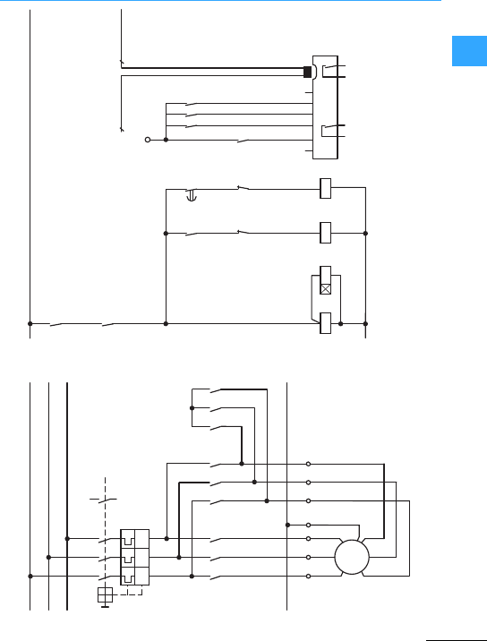
SmartWire-DT communication system
Eaton Wiring Manual 06/11
1
L01
-K2
V+ I0 I3 V+
14
13
①
①
②②
③
③
8
SmartWire-DT
8
SmartWire-DT
-Q1
-Q11
-Q12
-Q13
+24 V DC
1.54
1.53
68
67
-Q13
21
22
-Q12
-K1
58
57
-Q12
21
22
A2
A1
A2
A1
A2
A1
-Q13
-Q1
1.54
1.53
-K2
14
13
-Q11 -K1
L02
I2
I1
14
13
14
13
24
23
Q1
14
13
Q0
-K1
-M1
-Q12-Q11
3~
M
135
246
-Q13 135
246
135
246
U1 V1 W1 PE
U1 V1 W1
V2 W2 U2
PE
-Q1
1351.53
1.54
I> I> I>
246
V2 W2 U2
PE
L1
L2
L3
X1
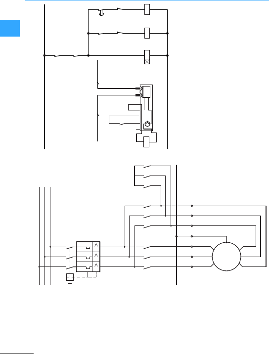
SmartWire-DT communication system
Eaton Wiring Manual 06/11
1
L01
28
17
-Q13
21
22
-Q12-Q13
-K1 -K1
18
17
-Q12
21
22
A2
A1
A2
A1
A2
A1
-Q1
1.54
1.53
-Q11
14
13
L02
88
SmartWire-DT SmartWire-DT
-K1
L1
L2
L3
-Q11
X1
531
531
642
W1V1U1
W1V1U1
-Q12 531
642 -Q13 531
642
PE
U2W2V2
U2W2V2
PE
PE
M
-M1 3 ~
III
-Q1
642
-Q11
X1X0 X2 X3 X4
24V
0V
DC
-Q1
1.54
1.53
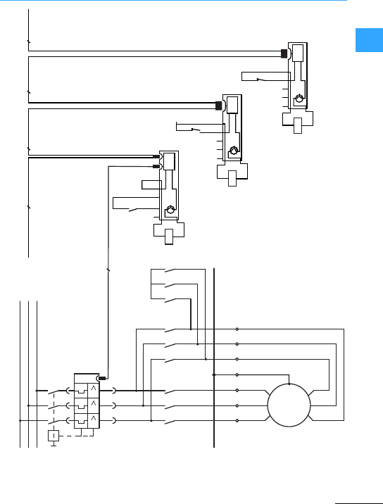
SmartWire-DT communication system
Eaton Wiring Manual 06/11
1
-Q12
X1 X2 X3 X4
24V
0V
DC
-Q13
22
21
8888
SmartWire-DT
10
SmartWire-DT
SmartWire-DT SmartWire-DT SmartWire-DT
-Q11
X1X0 X2 X3 X4
24V
0V
DC
X0
-Q12
22
21
-Q13
X1 X2 X3 X4
24V
0V
DC
X0
-Q1
1.54
1.53
PKE-SWD-32
DIL-SWD-32-...
DIL-SWD-32-...
L1
L2
L3
-Q11
X1
531
642
W1V1U1
W1V1U1
-Q12 531
642 -Q13 531
642
PE
U2W2V2
U2W2V2
PE
PE
M
-M1 3 ~
-Q1
642
531
III
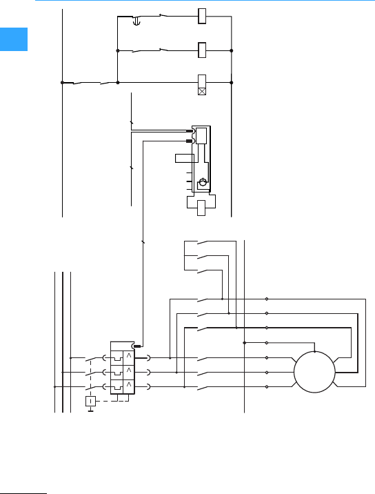
SmartWire-DT communication system
Eaton Wiring Manual 06/11
1
L01
28
17
-Q13
21
22
-Q12-Q13
-K1 -K1
18
17
-Q12
21
22
A2
A1
A2
A1
A2
A1
-Q1
1.54
1.53
-Q11
14
13
L02
88
SmartWire-DT SmartWire-DT
-K1
10
-Q11
X1X0 X2 X3 X4
24V
0V
DC
PKE-SWD-32
L1
L2
L3
-Q11
X1
531
642
W1V1U1
W1V1U1
-Q12 531
642 -Q13 531
642
PE
U2W2V2
U2W2V2
PE
PE
M
-M1 3 ~
642
531
III
-Q1
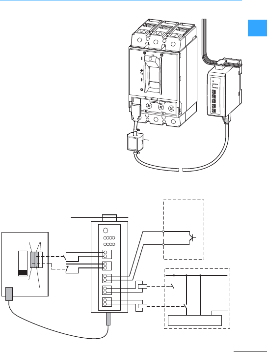
SmartWire-DT communication system
Eaton Wiring Manual 06/11
1
The NZM-XSWD-704 SmartWire-DT
module is used for querying a
circuit-breaker with an electronic release
(NZM2, 3, 4) via a PLC, i.e. the On/Off/Trip
position of the switch and the actual
currents.An optionally installed remote
operator can also be actuated viathe
module. The NZM-XSWD-704 is fitted on a
top-hat rail and is connected to the NZM
via a 2.0 m data cable. The auxiliary
contacts and the remote operator are
wired separately. The connection to the
SmartWire-DT ribbon cable is
implemented via the SWD device plug.
aSmartWire-DT connection
bData cable NZM with NZM-XSWD-704
cAuxiliary contactsin NZM
dXMC energy metering device (external)
eRemote operator
②
①
LT306.230.3
Trip
OFF
ON
70 71 72 74
0V, N
+, P
GND
24 V
I0
24 V
I1
S0+
S0-
Q0
0 V
Q1
0 V
③
①④
②
⑤
≦ 200 mA
≦ 200 mA
NZM-XRD
NZM
HIA HIN
M22-K01
M22-K10
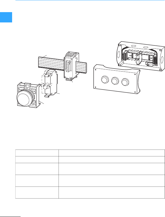
SmartWire-DT communication system
Eaton Wiring Manual 06/11
1
Simple pilot devicescan be integrated
directly in the SmartWire-DT
communication system without any time
consuming wiring. The function elements
are snap fitted in the M22-A fixing adapter
and thenconnected to the SWD
communication cable via the SWD device
plug.
The switch position indications of the
control elements and activation of the
indicator are implemented with the
SmartWire-DTcommunication system. The
function elements stated in the table are
available.
These function elements are each
available in two versionsfor front or base
fixing. Base fixing elements can be
combined to form remote operating and
display devices using the M22-SWD-I
cards and the M22-I.. surface mounting
enclosures to IP65.
M22-SWD-K…
M22-SWD-LED…
M22-SWD-NOP
SWD-8SF2-5
M22…
SWD4-…LF…
1
3
21
3
21
3
2
IN
OUT
OFF
ON
M22-SWD-K(C)11 Function element with one changeovercontact
M22-SWD-K(C)22 Function element with two changeovercontacts
M22-SWD-LED…LED function elements in white (W), red (R),green (G) or
blue (B)
M22-SWD-K11LED…Function element with one changeover contact and one LED
in white (W), red (R), green (G) or blue (B)
M22-SWD-K22LED…Function element with two changeover contacts and one LED
in white (W), red (R), green (G) or blue (B)
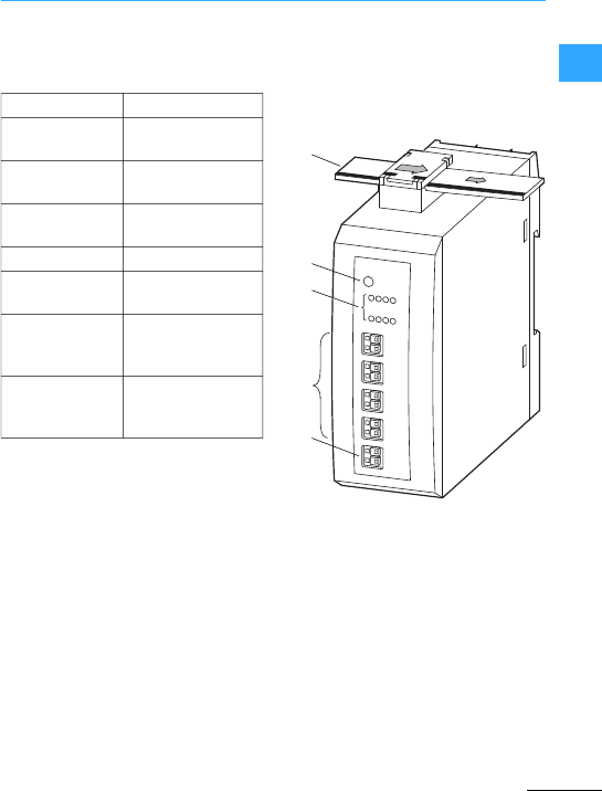
SmartWire-DT communication system
Eaton Wiring Manual 06/11
1
The following SWD modules are available
forprocessing digital or analog
input/output signals:
The modules are fitted directly on the
top-hat rail and then connected with the
SWD communication cable via the SWD
device plug.
The modules can be fitteddirectly in the
proximity of the sensors/actuators to be
connected. This also reduces the
remaining wiring required.
The following applications are possible:
•Connection of AC contactors or high
rated contactors > DILM32 that do not
have a connection option forthe
DIL-SWD-…module. For this use the
EU5E-SWD-4D2R module.
•Connection of auxiliary contacts to
modules with digital inputs
•Connection of digital actuators without
integrated SWD functionality (signal
lights, timing relays ..)
•Connection of any analog inputs/outputs
aSmartWire-DT cable with external
device plug
bSmartWire-DT diagnostics LED
cStatus display of inputs and outputs
(optional)
dInput/output terminals
eExternal supply (optional)
EU5E-SWD-8DX8digital inputs
EU5E-SWD-4DX4digital inputs with
transmitter supply
EU5E-SWD-4D4D 4digital inputs and
4digital outputs
EU5E-SWD-4D2R 4digital inputs and
2relay outputs 3A
EU5E-SWD-X8D 8 digital outputs
EU5E-SWD-4AX4analog inputs
0–10 V, 0 –20 mA
EU5E-SWD-2A2A 2analog inputs and
2analog outputs
0–10 V, 0 –20 mA
EU5E-SWD-4PT 4 temperatureinputs
PT100, PT1000,
Ni1000
①
②
③
④
⑤

SmartWire-DT communication system
Eaton Wiring Manual 06/11
1
For most applications, disconnection in the
event of an emergency or the
disconnection by the opening of the
protective doors is also required in addition
to normal operational switching.
The SmartWire-DT system is not designed
forthe transfer of safety relevant signals.
Using the configuration described below,
the SmartWire-DT system can however be
used for safety relevant switch offs.
In an emergency the control voltage for the
contactor coils can be switched off via the
enabling paths of the safetyrelay. By using
additionalSmartWire-DT Power modules,
contactor groups are made that can be
switched off togetherin an emergency.
This type of circuit can be used to create
control systems up to PL cin accordance
with EN ISO13849-1 (PL = Performance
Level). Thesafety relay in this example
must be PL c or higher (e.g.
ESR5-NO-41-24VAC-DC).
7Figure, page 1-27
The auxiliary contactintegratedin the
contactor is a mirror contact according to
IEC/EC 60947-4-1. Using this contact the
state of the main contacts can be reliably
signalled. The mirrorcontact can be
included into the feedback circuit of the
safety relay so that thesafety relay only
gives a new enable signal when the
contactor is open.
In many applications control systems with
a performance level of PL d or PL e
(PL=Performance Level) to
EN ISO13849-1 are required. Control
systems with PL d can be set up using an
additional group contactor which is
connected in series upstream of the motor
feeders. The control voltage for the motor
contactors as well as forthe group
contactor is switched off in an emergency
via thesafety relay. This redundant
disconnection circuit enables the
implementation of PL d control systems.
The safety relay used must comply with PL
d or higher to achieve this safety category
(e.g. ESR5-NO-31-24VAC-DC).
Furtherinformation on safety engineering
formachines and plants is provided in the
Eaton Safety Manual: www.eaton.eu/shb
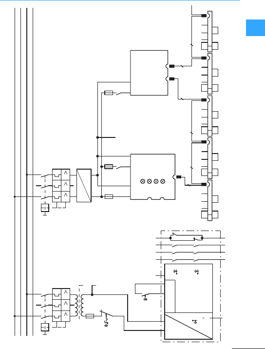
SmartWire-DT communication system
Eaton Wiring Manual 06/11
1
L1
L2
L3
PE
III
-Q1
-K01
-K02
-K01
-T01
-F01
K1
-S02
III
-Q1
4000
e
e
e
e
e
-F02
24 V0V24 V 0 V
24 0
-K03
SmartWire-DT
-F03
21
22
21
22
A1 A2 Y1 Y2 Y3 13
14
K1
23
24
33
34
41
42
2~ H
-K01
24 V 0 V
-F04
13
14
23
24
-Q11
A1 X0 X1 X2
A2 X3 X4 -Q12
A1 X0 X1 X2
A2 X3 X4 -Q13
A1 X0 X1 X2
A2 X3 X4 -Q14
A1 X0 X1 X2
A2 X3 X4 -Q15
A1 X0 X1 X2
A2 X3 X4
88
8 8 8
RESET
RESET
POWER
CONTROL-LOGIC
Gateway Power-Feeder
OutIn
AUX
8
SWD
In
NET
Out
Out
Config
Bus
Power
POW AUX
-S01 f
EMERGENCY-STOP
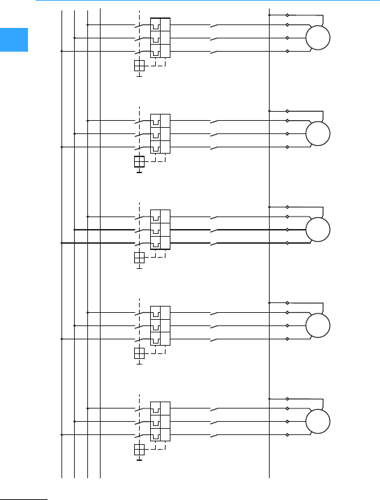
Switching, control, visualization
SmartWire-DT communication system
Eaton Wiring Manual 06/11
1-28
11
Mains circuit for safety relevant application
PE
L1
L2
PE
L3
-M1
3~
M
UVWPE
UVWPE
-Q1
135
I> I> I>
246
-M1
-Q11 135
246
-M1
3~
M
UVWPE
UVWPE
-Q2
135
I> I> I>
246
-M2
-Q12 135
246
-M1
3~
M
UVWPE
UVWPE
-Q3
135
I> I> I>
246
-M3
-Q13 135
246
-M1
3~
M
UVWPE
UVWPE
-Q4
135
I> I> I>
246
-M4
-Q14 135
246
-M1
3~
M
UVWPE
UVWPE
-Q5
135
I> I> I>
246
-M5
-Q15 135
246

Eaton Wiring Manual 06/11
1
The way to the safe machine
The international standard EN ISO 12100-1
“Safety of machinery - Basic concepts,
general principlesfor design”provides the
design engineerwith detailed assistance
in the identification of hazards and the
resulting risks to be assessed.
This therefore lays down the technical
measuresfor the reduction of hazards.
The parts of machine control systems that
handle safetytasks are defined as the
“safety-related partsof control systems”
(SRP/CS). Safety-related control systems
comprise the entiresafetyfunction
consisting of the input level(sensor), the
logic (safety signal processing) and the
output level(actuator).
For reducing risks by means of SRP/CS,
Eaton offers the right components with
safety technology in accordance with the
most stringent requirements stipulatedin
the safetystandards EN 954-1, EN ISO
13849-1 and EN IEC62061. The appropriate
safety functions areused accordingto the
application area and in compliance with
the required risk reduction.
Further information on the previous andthe
new international safety standards as well
as circuit examples for a wide range of
applications are provided in thelatest
version of the Eaton Safety Applications
Technical Guide PU05907001Z-EN.
The safetymanual helpsyou by means of
practical safety circuit examplesand the
associated calculations to determine
safety performance in accordance with
EN ISO 13849-1 and IEC62061.
The SafetyManualis available online or in
print:
•Register at www.eaton.eu/shb and work
online withthe Safety Manual or
download the PDF version free of charge.
•Order the current printed version from
yourwholesalers or your Eaton customer
service: PU05907001Z-EN,
Article no. 119906
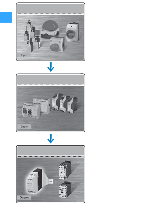
The way to the safe machine
Eaton Wiring Manual 06/11
1
Detectinghazards quicklywithRMQ-Titan
and FAK emergency-stop buttons.
Motion safety under controlwith
LS-Titan®position switches.
Safe switching, disconnection and control
with T rotary switches and P
switch-disconnectors.
Safe monitoring and processing with ESR
safety relays and easySafety control relay.
Reliable disconnection with DILM
contactors and CMD contactormonitoring
device.
Further technical information on the
individual safetyproducts is provided at
www.eaton.com/moeller
Fast and secure detection
Safe monitoring and processing
Reliable shut down

The way to the safe machine
Eaton Wiring Manual 06/11
1
Safetylogic unitsenable the hardware
required to be considerably reduced and
primarily restricted to the sensor/actuator
level. Eaton offers two logic series:
•ESR5 Electronic safety relays
•easySafety control relay suitable for
safety circuits.
Safetyrelays of the ESR5 series offer the
optimum solution for each application with
tailored safety functions. The internal logic
of the safety relay monitors the wired
safety circuits and activates the enable
contacts in fault-free condition.
The easySafety control relay offers a host
of integrated safety relays in the form of
safety function blocks in a single device,
thus offering maximum flexibility in a
considerable space saving design.
easySafety is used for monitoring all
typicalsafety devices and also
implementing the control tasks required on
the machine.
The ESR safety relays or the easySafety
control relay enable applications to be
implemented that meet the most stringent
safety requirements in accordance with
international standards:
•Category 4 to EN 954-1
•Performance level PL e acc.to
EN ISO13849-1
•Safety Integrity LevelSIL CL 3 according
to IEC62061
•Safety Integrity Level SIL 3 according to
IEC61508
Eaton ensuresthe required levelof
personal or process protection using the
safety products approved by TÜV
Rheinland –for both simple and complex
machines.
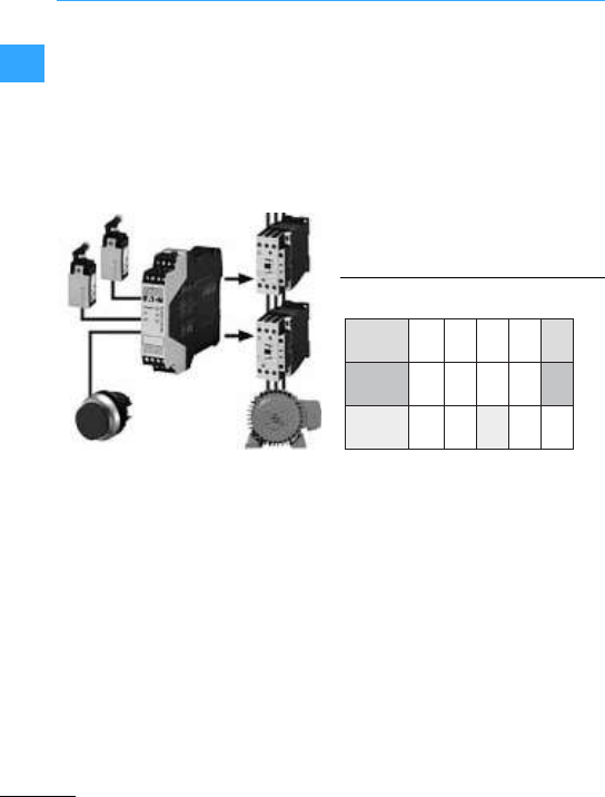
The way to the safe machine
Eaton Wiring Manual 06/11
1
Moving guards such as safety doors, gates
andflaps can be used to provide protection
from accessible hazardous areas. The
position of moving guardsis detected with
position switches or non-contacting
contactsensors that are monitored and
evaluated with a safetylogic unit. A risk
analysis supplies the necessary degree of
risk reduction by the guard.
The safetylogic unit provides two separate
input circuits for two-channel applications,
which monitorthe sensor (such as the
position switch of an interlock device).
After the input circuits are closed, the
safety relaycan be started by means of a
reset button. This activates the enable and
signal current paths and switches on the
connected actuators. Positively driven
auxiliary contacts of the actuators are
used by the safetyrelay to diagnose
possible safety states.
Cat. according to EN 954-1
PL according to EN ISO 13849-1
SIL according to IEC 62061
B 1 2 3 4
PL a b c d e
SIL 1 2 3
Cat
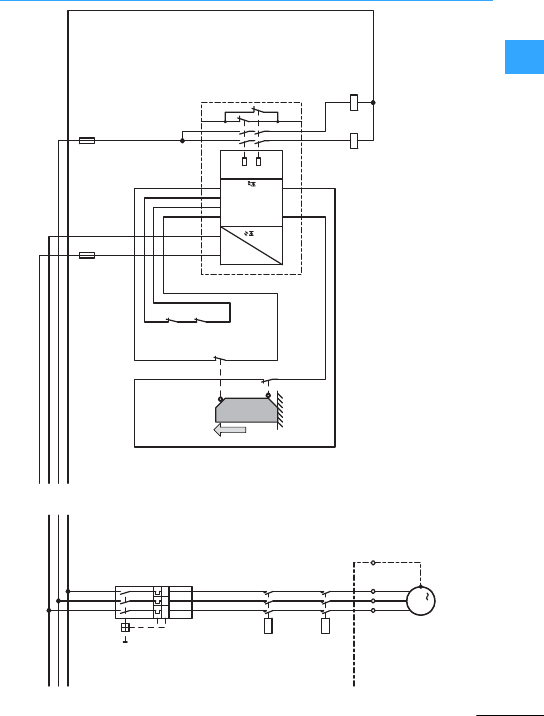
Switching, control, visualization
The way to the safe machine
Eaton Wiring Manual 06/11
1-33
1
1
Circuit example: Two-channel guard door monitoring with ESR5
0V1
24V1
0 V
24 V
-B2
1314
-B1
2122
-Q2
2122
-Q1
2122
A1
A2
S22 S12
S33
S21
S34
S11
3334
K2
ESR5-NO-21-24VAC-DC
-K11
K1
1314
2324
-F1
12
-Q1
A1A2
-F2
12
-Q2
A1A2
24 V DC
Power
24 V AC/AC
PE
L3
L2
L1
U1
-X1
-Q2
12
34
56
-Q1
12
34
56
L1
L2
L3
T1
T2
T3
I >I >I >
-Q3
M
3
U
V
W
PE
V1
W1
PE
L3
L2
L1
N/O
actuated
Logic
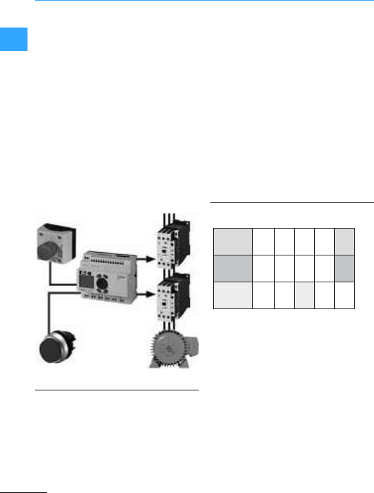
The way to the safe machine
Eaton Wiring Manual 06/11
1
The Emergency-stop function is an
additionalprotective measure and is not
permissible as the sole means of
protection. Machinery Directive
2006/42/EC stipulates however that every
machine must be provided with adevice
forstopping in an emergency (Emergency
stop). The degree of risk reduction by the
Emergency stop device must be
determined by means of arisk assessment.
If the immediate disconnection of the
power supply does not cause hazardous
states, you can use an uncontrolled Stop
function in accordance with Stop category
0to EN ISO 13850.
TheEmergency-stop actuator S4 must be
in the enable position (NC contacts closed)
so that the enable signal canbe issued via
the RESET pushbutton S3. Pressing the
START pushbutton S1 startsthe hazardous
movement. The self-latching function and
its interruption are implemented in the
program. Thetwo contactors drop out, and
a restart is possible by pressing the START
actuator. If the hazardous movement is
stopped by pressing the Emergency-stop
actuator S4, the enable for outputs QS1 and
QS2 is removed and the contactors drop
out. A restart is only possible afterthe
Emergency-stop actuator is reset and
enabled by pressing the RESET
pushbutton. The drive can be braked
actively by using output QS4. However, this
option is not included in the safety
consideration since the frequency inverter
does not support the safe braking
operation.
Cat. according to EN 954-1
PL according to EN ISO 13849-1
SIL according to IEC 62061
B 1 2 3 4
PL a b c d e
SIL 1 2 3
Cat
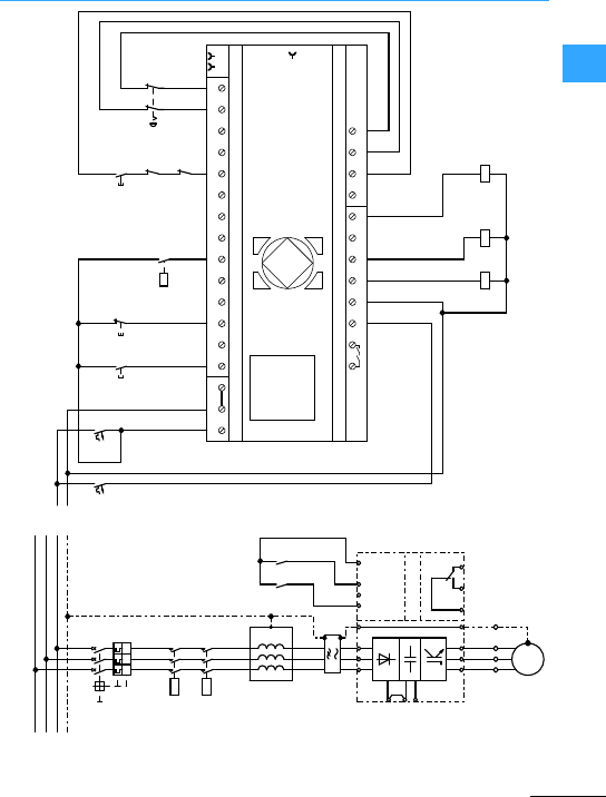
The way to the safe machine
Eaton Wiring Manual 06/11
1
0 V
+24 V
21
-F2
0V+24V QS1 QS2 QS3 QS4 T1 T2 T3 T4
Output 1x Relay / 6A 4x Test Signal
ES4P-221-DMXD1
4x Transistor / 0,5A
DC 24 VInput 14 x DC
NET
ALT
OK
-K1
DEL
ESC
IS1 IS2 IS3 IS4 IS5 IS6 IS7 IS8 IS9 IS10 IS11 IS12 IS13 IS14
1
QR1
2
+24V 0V 0V
P1
P2
P3
P4
21
-F1
-S1
3
1
41
-S2
1222
-Q1
1A2A
41K
-T1
11K
-Q2
1A2A
-Q3
1A2A
-Q2
1222
-Q1
12223141
-S3
-S4
1222
1
1
2
1
PE
L3
L2
L1
1
U
-X1
3L
EP
U1L
W
EP
V2L
L+
DC-
DC+
2
1K
41K
1
1K 4
2P
-T1
1
2
5
1
L
2
2
L
4
3L6
E
P
8
-R2
2V
1W
PE
2U
1V
1U
2W
-R1
-Q2
12
34
56
-Q1
12
34
56
1L1T
2L2T
3L3T
I >
-Q4
I >I >
M
3 ∼
1U
1V
1W
PE
1
V
1W
EP
1
2
-QR1
3141
-Q3
PE
L3
L2
L1
Start Stop Reset
EMERGENCY
STOP

Eaton Wiring Manual 06/11
1
Timing relays
Electronic timing relays are used in
contactor control systems which require
short reset times, high repetition accuracy,
high operating frequency, and along
component lifespan. Times between 0.05 s
and 100 h can be easily selected and set.
The switching capacity of electronic timing
relays complies with the utilization
categories AC-15 and DC-13.
In terms of theactuating voltages there are
with timing relays the following
differences:
• (DILET…and ETR4)
Universal devices:
DC 24 to 240V
AC 24 to 240 V, 50/60 Hz
• (DILET…and ETR4)
AC devices:
AC 346 to 440 V, 50/60 Hz
•(as modular installation device to
DIN43880)
Universal devices:
DC 24 to 48 V
AC 24 to 240 V, 50/60 Hz
(ETR2-69-D: 12 to 240 V, 50/60 Hz)
The functions of each of the timing relays
are as follows:
•DILET11, ETR4-11,ETR2-11
(on-delayed)
•ETR2-12
(off-delayed)
•ETR2-21
(fleeting contacton
energization)
•ETR2-42
(flashing, pulse initiating)
•ETR2-44
(flashing, two speeds; can be
setto either pulse initiating or pause
initiating)
•Multifunction relays DILET70,
ETR 4-69/70
(on-delayed)
(off-delayed)
(on- and off-delayed)
(fleeting contact on
energization)
(fleeting contact on
de-energization)
(flashing,pulseinitiating)
• (pulse generating)
(pulse shaping)
•Multifunction relay ETR2-69(-D)
(on-delayed)
(off-delayed)
(fleeting contact on
energization)
(fleeting contact on
de-energization)
(flashing,pulseinitiating)
(flashing,pause initiating)
(pulse initiating)
•Star-delta timing relays ETR4-51
(on-delayed)
With both DILET70 and ETR4-70 an external
potentiometercan be connected. Upon
connection, both timing relays
automatically recognize thata
potentiometer is fitted.
The ETR4-70 has a special feature.
Equipped with two changeover contacts
which can be converted to two timing
contacts 15-18 and 25-28 (A2-X1 linked) or
one timing contact 15-18 and a
non-delayed contact 21-24 (A2-X1 not
linked). If the link A2-X1 is removed, only
the timed contact 15-18 carries outthe
functions described below.
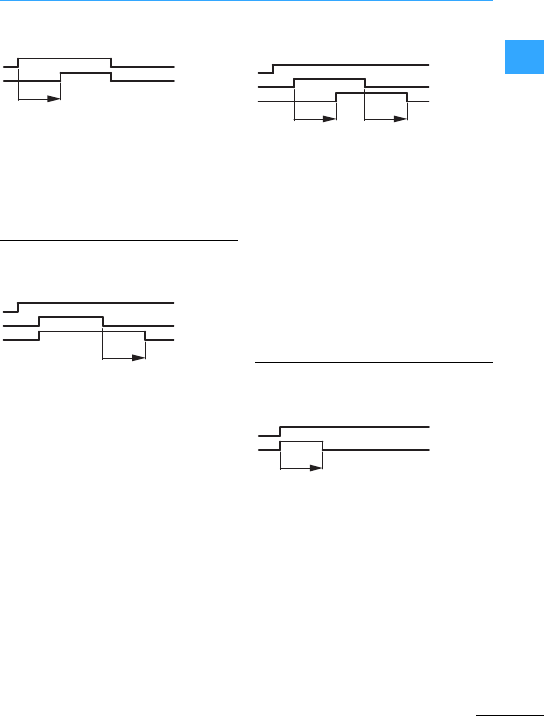
Timing relays
Eaton Wiring Manual 06/11
1
On-delayed
The actuating voltage Usis applied via an
actuating contact to the terminals A1 and
A2.
After the set delay time the changeover
contactof the output relaygoes to the
position15-18 (25-28).
Off-delayed
After the supply voltage has been applied
to the terminals A1 and A2, the changeover
contactof the output relay remains in the
original position 15-16 (25-26).If the
terminals Y1 and Y2 in the DILET70 are
linked by a potential-free N/O contact or, in
the case of the ETR4-69/70 or ETR2-69, a
potential is applied to B1, the changeover
contactchanges without delayto the
position15-18 (25-28).
If the connection between the terminals
Y1–Y2 is now interrupted, or B1 is
separatedfrom the potential, once the set
time haselapsed, the changeover contact
returns to it´s original position 15-16
(25-26).
On- and Off-delayed
The supply voltage Usis applied directly to
the terminals A1 and A2. If the terminals Y1
and Y2 in the DILET70 are linked by a
potential-free N/O contact, or in the case of
of the ETR4-69/70 a potential is applied to
B1, after a set time tthe changeover
contact goes to the position 15-18 (25-28).
If the connection Y1-Y2 is now interrupted,
or B1 is separated from the potential, the
changeover contact goes back to it´s
original position 15-16 (25-26) after the
same time t.
Fleeting contact on energization
After the voltage Ushas been applied to A1
and A2, the changeovercontact of the
outputrelay goes to position 15-18 (25-28)
and remains actuated for as long as the set
fleeting contact time.
Afleeting pulse (terminals 1-2,15-18) of
defined duration is therefore produced
fromatwo-wire control process (voltage
on A25/A28) by this function.
t
A1-A2
15-18
A1-A2
B1
15-18
(25-28)
Y1-Y2
t
A1-A2
B1
15-18
(25-28)
Y1-Y2
tt
A1-A2
15-18
(25-28)
t
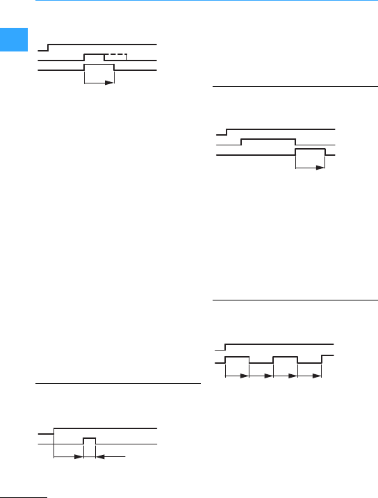
Timing relays
Eaton Wiring Manual 06/11
1
Pulse shaping
After the supply voltage has been applied
to A1 and A2, the changeovercontact of
the outputrelay remains in therest position
15-16 (25-26). If the terminals Y1 and Y2 in
the DILET70 are linked by a potential-free
N/O contact, or in the case of the
ETR4-69/70 or ETR2-69, a potentialis
applied to B1, the changeover contact
changes without delayto theposition 15-18
(25-28).
If Y1–Y2 is now opened again,or B1 is is
kept with the potential, the changeover
contactremains actuated until the set time
has elapsed. If, instead, Y1–Y2 remain
closed or B1 is separated from the
potential for longer, the output relay
likewise changes back to its rest position
after the set time. An outputpulse of
precisely defined duration is thus
produced in the pulse shaping function,
irrespective of whether the input pulse via
Y1–Y2 or B1 is shorter or longer than the set
time.
Pulse generating with fixed pulse
The actuating voltage is applied to the
terminals A1 and A2 via an actuating
contact. After the set delay time has
elapsed the changeover contact of the
output relay goes to position 15-18 (25-28)
and returns to it´s original position 15-16
(25-26) after 0.5 s. This function is therefore
afleeting pulse with a time delay.
Fleeting contact on de-energization
The supply voltage Usis present directly at
A1 andA2.If the terminals Y1 and Y2 of the
DILET70 that have been shorted (DILET-70
potential-free)at any time beforehand are
opened again, or with ETR4-69/70 or
ETR2-69 the contact B1 becomes
potential-free again, the contact 15-18
(25-28) closes forthe duration of the set
time.
Flashing, pulse initiating
After the voltage Ushas been applied to A1
and A2, the changeovercontact of the
output relay changes to position 15-18
(25-28) and remainsactuatedfor as long as
the set flashing time. The subsequent
pause duration corresponds to the flashing
time.
A1-A2
B1
15-18
(25-28)
Y1-Y2
t
A1-A2
15-18
(25-28)
0.5 s
t
B1
A1-A2
15-18
(25-28)
Y1-Y2
t
tttt
A1-A2
15-18
(25-28)
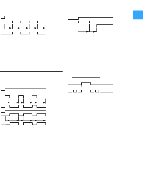
Switching, control, visualization
Timing relays
Eaton Wiring Manual 06/11
1-39
1
1
Function 43
Flashing, pause initiated
After the voltage Us has been applied to A1
and A2 the changeover contact of the
output relay stays in position 15-16 for the
set flashing time and after the duration of
this time goes to position 15-18 (the cycle
begins with a pause phase).
Function 44
Flashing, two speeds
After the voltage Us has been applied to A1
and A2 the changeover contact of the
output relay goes to position 15-18 (pulse
initiating). By bridging the contacts A1 and
Y1 the relay can be switched to pause
initiating. The times t1 and t2 can be set to
different times.
Function 51 Star-delta
On-delayed
If the actuating voltage Us is applied to A1
and A2, the instantaneous contact
switches to position 17-18. After the set
time duration the instantaneous contact
opens; the timing contact 17-28 closes
after a changeover time tu of 50 ms.
On-Off Function
The On-Off function allows the operation of
a control system to be tested and is an aid
for example for commissioning. The Off
function allows the output relay to be
de-energized and it no longer reacts to the
function sequence. The On function
energizes the output relay. This function is
dependent on the supply voltage being
applied to the terminals A1/A2. The LED
indicates the operating state.
Further information sources
• Instructional leaflets
→ www.eaton.com/moeller/support
(AWA / IL Installation Instructions)
Search terms: DILET, ETR4, ETR2
• Main Catalogue Industrial Control
Systems (HPL) Section "Timing relays"
LED
ttt t
A1-A2
15-18
(25-28)
t
A1-B1
A1-A2
Rel LED
A1-B1
Rel LED
tttt
15-18
tt
121212
15-18
ttt t tt
121212
tu
A1-A2
17-18
17-28
t
A1-A2
15-18
(25-28)
LED
OFF OFF
ON
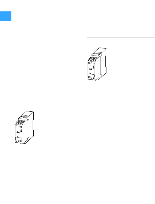
Eaton Wiring Manual 06/11
1
EMR measuringand monitoring relays
Measurement and monitoring relays are
required for a wide range of applications.
With the new EMR range Eaton covers a
large number of requirements:
•general use, EMR...-Icurrent monitoring
relay
•space saving monitoring of the rotation
field, EMR...-F phase sequence relay
•Protection against destruction or
damage of single system parts,
EMR…-(A)W(N) phase monitoring relay
•safe recognition of phase failure,
EMR...-A phase imbalance monitoring
relay
•enhanced safety by open-circuit
principle, EMR...-N liquid level
monitoring relay
•increase of the operational safety,
EMR...-R insulation monitoring relay
The EMR-Icurrent monitoring relay is
suitable for the monitoring of AC as well as
DC current. Pumps and drill machines can
be monitored for underload or overload.
This is possible due to the selectable lower
or upper threshold limit.
There are two versions each with three
measuring ranges (30/100/1000 mA,
1.5/5/15A). The multi-voltage coil allows
universal use of the relay. The twoauxiliary
changeover contacts allow fora direct
feedback.
By using the selectable response delay of
between 0.05 and 30 s short currentpeaks
can be bridged.
TheEMR...-W phase monitoring relay
monitors the voltage as well as the rotation
field rotation. This provides protection from
the destruction or damage of individual
system parts. The minimum undervoltage
and also the maximum overvoltage can be
set here easily, within adefined range to
the required voltage.
An on-delayed or off-delayed function can
also be set. In the on-delayed position
short voltage drops can be bridged. The
off-delayed position allows forafault
storage for the set time.
The delay time can be set between 0.1 und
10 s.
The relayactivates with the correct
rotation field and voltage. After a drop-out
the device does not reactive until the
voltage exceeds a5%hysteresis.
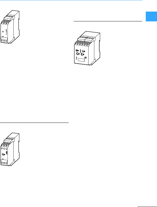
EMR measuringand monitoring relays
EatonWiring Manual 06/11
1
With the only 22.5 mm wide phase
sequence relay, portable motors, with
which the rotation direction is important
(e.g.pumps, saws, drills), can be
monitored forcorrectrotation.This
provides spacein the switchboard thanks
to the narrow width and protection against
damage due to the monitoring of the
rotating field.
With correct rotating field the changeover
contactreleases the control voltage of the
motor switching device. The EMR...-F500-2
covers the total voltage range from 200 to
500VAC.
The 22.5 mm wide EMR...-A phase
imbalance relay is the correct protection
device against phase failure. The motoris
then protected against destruction.
As the phase failure is monitored on the
basis of phase displacement, this can be
detected even with a higher motor
feedback and an overload of the motor can
be prevented.
The EMR...-N liquid level monitoring relay
is used mostly as dry running protection for
pumps or forthe level regulation of liquids.
It operates with sensors thatmeasure
conductivity.One sensor is required for the
maximum level and one sensor forthe
minimum level. A thirdsensor is used for
earth potential.
The 22.5 mm wide EMR...-N100 device is
suitable for conductive liquids. It can be
switched from level regulation to dry
running protection.Safety is increased as
in both cases the open-circuit principle is
used.
The EMR...-N500 liquid level monitoring
relay has an increased sensitivity and is
suitable for less conductive liquids. Due to
an integrated pickup and drop-out delay of
between 0.1 and 10 s moving liquidscan
also be monitored.
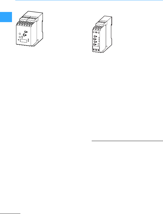
Switching, control, visualization
EMR measuring and monitoring relays
Eaton Wiring Manual 06/11
1-42
11
EMR...-R Insulation monitoring relay
EN 60204 “Safety of machines” provides
increased operational safety by the
monitoring of the auxiliary circuit for
earth-fault using an insulation monitoring
relay. This is the main application for the
EMR...-R. There are similar requirements in
medically used areas.
An earth-fault is signalled via a
changeover contact so that a fault can be
cleared without expensive down time.
The device has a selectable fault memory
so that the fault must be acknowledged
after it´s removal. The use of a Test button
enables the device to be checked for
correct operation at any time.
AC or DC control voltage
There is a device for AC and also DC.
Therefore the total control voltage range is
covered. Both devices have a multi-voltage
source. This means that both AC and DC
supplies are possible.
EMR...-AW(N) multifunctional
three-phase monitors
The multifunctional three-phase monitors
provide the space saving monitoring of the
rotation field with different functions..
These measure the phase parameters of
phase sequence, phase failure, phase
imbalance as well as undervoltage and
overvoltage.
Depending on device type, the threshold
value for phase imbalance can be set
between 2 to 15 %. The threshold values for
undervoltage and overvoltage are
adjustable or permanently set.
The different options and set values are
explained in the relevant instructional
leaflet.
Further information sources
• Instructional leaflets
→ www.eaton.com/moeller/support
(AWA / IL Installation Instructions)
Search terms: EMR4, EMR5
• Main catalog industrial switchgear
(HPL),
→ chapter “EMR measuring relays,
EMR monitoring relays”
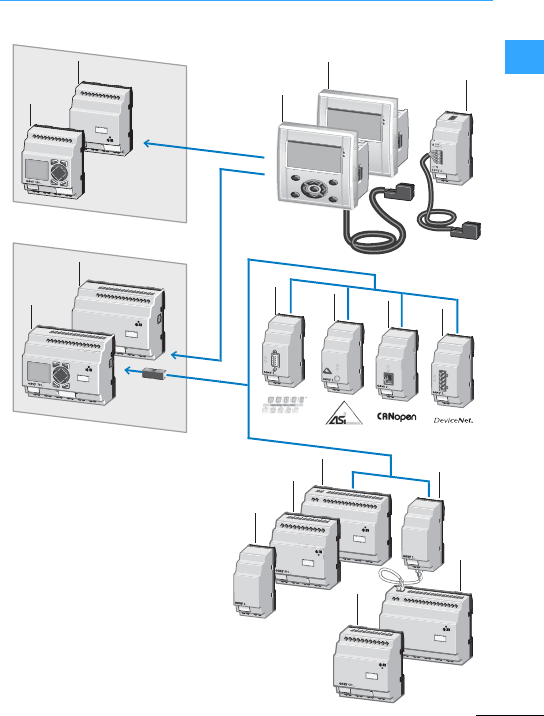
Eaton Wiring Manual 06/11
1
System overview &Relay, MFD-Titan
POW
BUS
POWER
COM-ERR
ADR
ERRMS
NS
4
3
3
2
2
1
1
5678
12
11
11
9
10
10
1Basic devices easy500, stand alone
2Basic devices easy700, expandable:
digitalinputs/outputs
Bus systems
3Remote text display
4Ethernet-Gateway
5PROFIBUS-DP Busmodule
6AS-Interface busmodule
7CANopen bus module
8DeviceNet busmodule
9Output expansion
10, 11 I/O expansions
12 Coupling module forthe remote
connectionofadigital
input/output expansion
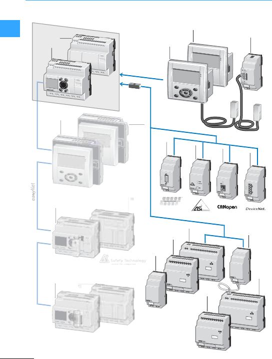
System overview &Relay, MFD-Titan
Eaton Wiring Manual 06/11
1
POW
BUS
MS
NS
DEL
OK
ALT
ESC
3
2
2
15
1
1
4
15
567
11
10
10
8
14
13
9, 12
12

System overview &Relay, MFD-Titan
Eaton Wiring Manual 06/11
1
1easy800 basicdevices, expandable:
Digital inputs/outputs and
Bus systems, easyNet onboard
2Remote text display
3Ethernet gateway
4PROFIBUS-DP bus module
5AS-Interface bus module
6CANopen bus module
7DeviceNet bus module
8Output expansion
9, 10 I/O expansions
11 Coupling module for the remote
connection of a digital
input/output expansion
12 I/O expansion
13 easyControl compact PLC
14 easySafetycontrol relay
15 MFD-Titan multi-function display
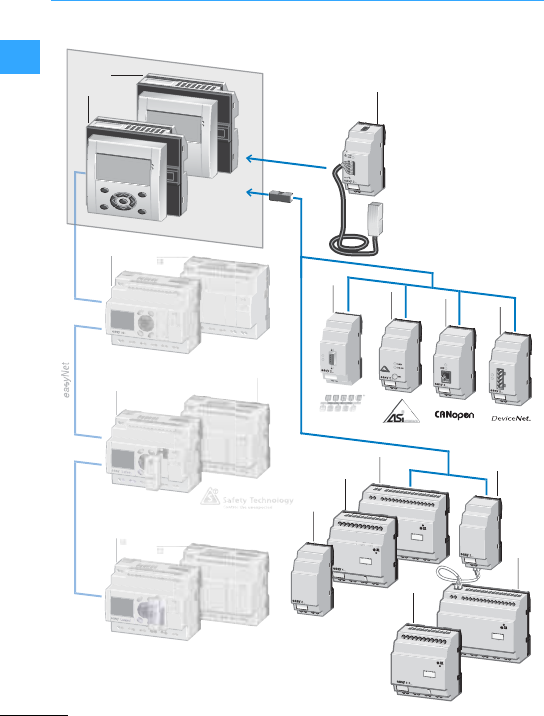
System overview &Relay, MFD-Titan
Eaton Wiring Manual 06/11
1
POW
BUS
MS
NS
2
1
3
1
456
11
9
9
7
8, 10
10
13
13
14

System overview &Relay, MFD-Titan
Eaton Wiring Manual 06/11
1
1MFD-Titan,consisting of:
Display/operating unit
Power supply unit/CPU module,
I/O module
2Ethernet gateway
3PROFIBUS-DP busmodule
4AS-Interface bus module
5CANopen busmodule
6DeviceNet bus module
7Output expansion
8, 9, 10 I/O expansions
11 Coupling module for the remote
connection of adigital
input/output expansion
12 Compact PLC &Control
13 easySafety
easycontrol relays
14 easy 800 control relays
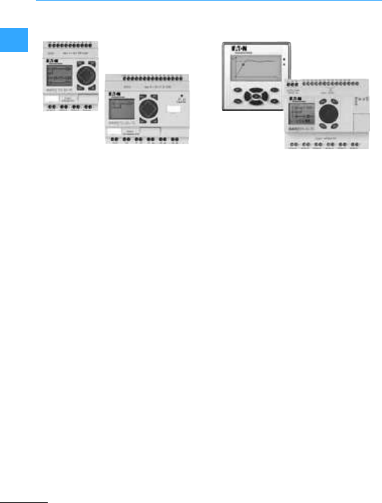
System overview &Relay, MFD-Titan
Eaton Wiring Manual 06/11
1
easy500 and easy700 have the same
functions. easy700 offers more inputs and
outputs, is expandable and can be
connected to a standard bus system.The
contacts and coils are connected in series
and in parallel in up to 128 current paths:
max. three contacts and a coil in series.
The display of 16 operating and message
texts isimplementedvia an internal or
external display.
The main functions are:
•Multi-function timing relays
•Currentimpulse relays,
•Counters
–up and down,
–high-speed counter,
–frequency counters,
–operating hours counter,
•Analog value comparators
•Week and year time switches,
•Automatic DST switch
•Retentive actual values of markers,
counters and timing relays.
Customized inscription of easy500 and
easy700 is possible.
MFD(-AC)-CP8…and easy800 have the
same functions. With IP65 MFD-80 can be
used in harsh environments. Eight easy800
or MFD-Titan devices can also be
networked via easyNetfor expansionsor
connection to standard bus systems.
Contacts and coils are linked in series or in
parallel up to 256 rungs consisting of four
contacts and a coil in series. The display of
32 operating and report message is
implemented viaan internalor external
display.
The easy800 and MFD-Titan offer the
following functionsin addition to those of
the easy700:
•PID controllers,
•Arithmetic modules,
•Value scaling,
•and much more.
Customized inscription on the MFD-80 and
the easy800 is possible.

System overview &Relay, MFD-Titan
Eaton Wiring Manual 06/11
1
The plug &work functionality allows you to
connectthe MFD-80.. display to the
easyRelays via the MFD-CP4.. power
supply and communication module. The
MFD-CP4...comes with a 5 m connection
cable thatcan be cut to the required
length. Another advantage is that no
software or drivers are required for
connection. The MFD-CP4.. offers genuine
plug &work capabilities. The input and
output wiring is connected to the
easyRelay. The processing of the circuit
diagramis also run in the easyRelay. The
MFD-80.. is mounted using two 22.5 mm
fixing holes. The IP65 display is backlit and
offers an easy to read display. The display
can be labeled to individualrequirements.
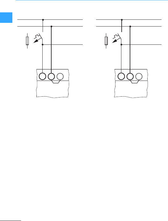
Eaton Wiring Manual 06/11
1
Engineering &Relay, MFD-Titan
EASY512-AB-…
EASY719-AB-…
EASY512-AC-…
EASY719-AC-…
EASY819-AC-…
24 VAC
24 VAC
100 –240 VAC
100 –240 VAC
100 –240 VAC
EASY512-DA-…
EASY719-DA-…
EASY512-DC-…
EASY7…-DC-…
EASY819-DC-…
EASY82.-DC-…
12 VDC
12 VDC
24 VDC
24 VDC
24 VDC
24 VDC
MFD-AC-CP8-…100 –240 VACMFD-CP8-…
MFD-CP10…
24 VDC
24 VDC
EASY618-AC…100 –240 VACEASY410-DC…
EASY618-DC…
EASY620-DC…
EASY406-DC-ME
EASY411-DC-ME
24 VDC
24 VDC
24 VDC
24 VDC
24 VDC
L
L.1
N
LNN
>1A
+
+.1
–
+...V 00
>1A
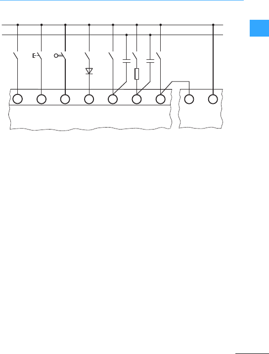
Engineering &Relay, MFD-Titan
Eaton Wiring Manual 06/11
1
aInput signal via relay contact e.g. DILER
bInput signal via RMQ-Titan pushbutton
cInput signal via position switch e.g.
LS-Titan
dAdditional circuit with diode
(7Notes)
eIncreased input current
fLimiting the input current
gIncreasing the input current with
EASY256-HCI
hEASY256-HCI upstream device with
internal additionalcircuit (7Notes)
•Due to the additional circuit thedrop out
delay of the input is increased.
•Length of input conductor without
additional circuit #40 m, with additional
circuit #100 m.
•Inputs I7, I8 already have an internal
additional circuit.
1 kΩ
N
L1
1N
1N4007
100 nF
/275 V ∼
100 nF
/275 V ∼
①②③④⑤⑦⑧⑥
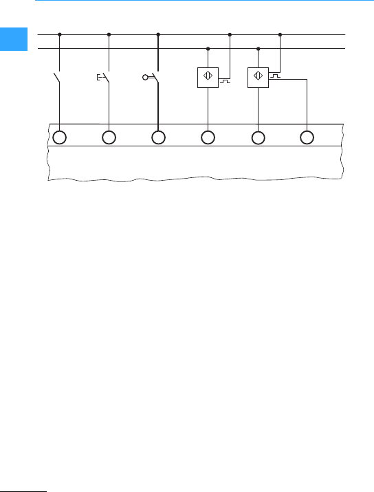
Engineering &Relay, MFD-Titan
Eaton Wiring Manual 06/11
1
aInput signal via relay contact e.g. DILER
bInput signal via RMQ-Titan pushbutton
cInput signal via position switch
e.g. LS-Titan
dProximity switch, three wire
eProximity switch, four wire
•With conductor length consider also the
voltage drop.
•Due to the high residual current do not
usetwo-wire proximity switches.
–
+
①②③④⑤

Engineering &Relay, MFD-Titan
Eaton Wiring Manual 06/11
1
Depending upon the device two or four 0 to
10 V analog inputs are available.
The resolution is 10-bit = 0 to 1023.
The following applies:
Incorrect connection may lead to
unwanted switching states. Analog signals
are more sensitive to interference than
digital signals, therefore the signalcables
should be carefully routed and connected.
•Use shielded twisted pair cablesto
prevent interference with the analog
signals.
•For short cable lengths, ground the
shielding at both ends using a large
contact area. If the cable length is more
than around 30 m, grounding at both ends
can result in equalization currents
between the two grounding points and
thus in the interference of analog signals.
In this case, only ground the cable at one
end.
•Do not lay signal lines parallel to power
cables.
•Supplyingloads such as motors, solenoid
valves or contactors and easy from the
same supply voltage may cause
interference of the analog input signals
when switching. Connect therefore
inductive loads to be switched via the
easy outputs to a separate supply
voltage, or use a suppressor circuit for
motors and valves.
I7 = IA01
I8 = IA02
I11 =IA03
EASY512-AB/DA/DC…
EASY719-AB/DA/DC…
EASY721-DC…
EASY819/820/821/822-DC…
MFD-R16, MFD-R17,
MFD-T16, MFD-TA17
I12 =IA04
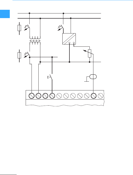
Engineering &Relay, MFD-Titan
Eaton Wiring Manual 06/11
1
With easy.... AB devices that process
analog signals, the device must be fed via a
transformer so that the device is
galvanically isolated from the mains
supply. The neutral conductor and the
reference potential of the DC powerfeed
foranalog sensors must be electrically
connected.
Ensure that the common reference
potential is earthed or monitored by a
ground fault monitoring device. Observe
the applicable standards.
I7L NI1N
L
N
~
0 V +12 V
L01h
N01 h
I8
F1
EASY200-POW
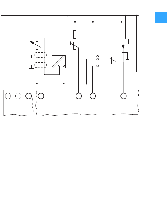
Engineering &Relay, MFD-Titan
Eaton Wiring Manual 06/11
1
aSetpoint potentiometer via separate
power supply and potentiometer #1k?,
e.g. 1k?,0.25 W
bSetpoint potentiometer with upstream
resistor 1.3k?, 0.25 W, potentiometer
1k?,0.25 W (values for24 VDC)
cTemperature monitoring via
temperature sensor and transducer
dSensor 4 to 20 mA with resistor500 ?
•Pay attention to thediffering number and
designation of the analog inputs of each
device type.
•Connect the 0Vof the or the MFD-Titan
with the 0Vof the power supply of the
analog transmitter.
•A 4(0) to 20 mA sensor and a resistor of
500 ?give the following approx. values:
–4mA 61.9 V,
–10 mA 64.8V,
–20 mA 69.5V.
•Analog input 0 to 10 V,
resolution 10 bit, 0to1023.
+
–
①②③④
+...V 0 V
+12 V0V
4...20 mA
(0...20 mA)
0 V
∼
+..V
-0 V
Out
0...10 V -35...55 °C 500 Ω
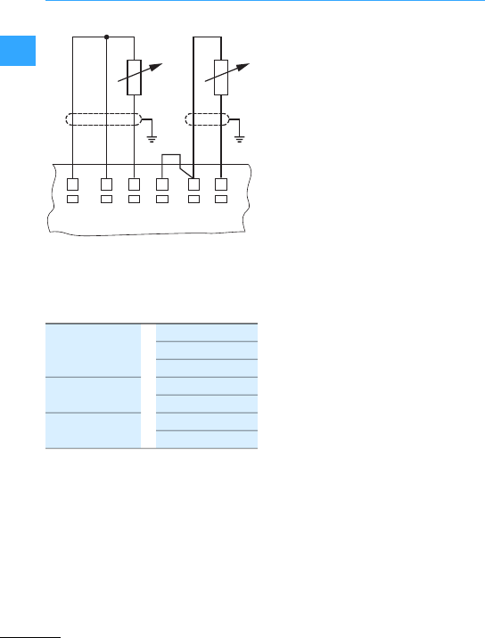
Engineering &Relay, MFD-Titan
Eaton Wiring Manual 06/11
1
Cable length, shielded <10m.
ab
aThree wire connection bTwo wireconnection
MFD-TAP13-PT-A
MFD-TP12-PT-A
-40 °C ... +90 °C
0°C ... +250 °C
0°C ... +400 °C
MFD-TAP13-NI-A
MFD-TP12-NI-A
0°C ... +250 °C
-40 °C ... +90 °C
MFD-TAP13-PT-B
MFD-TP12-PT-B
0°C ... +850 °C
-200 °C ... +200 °C
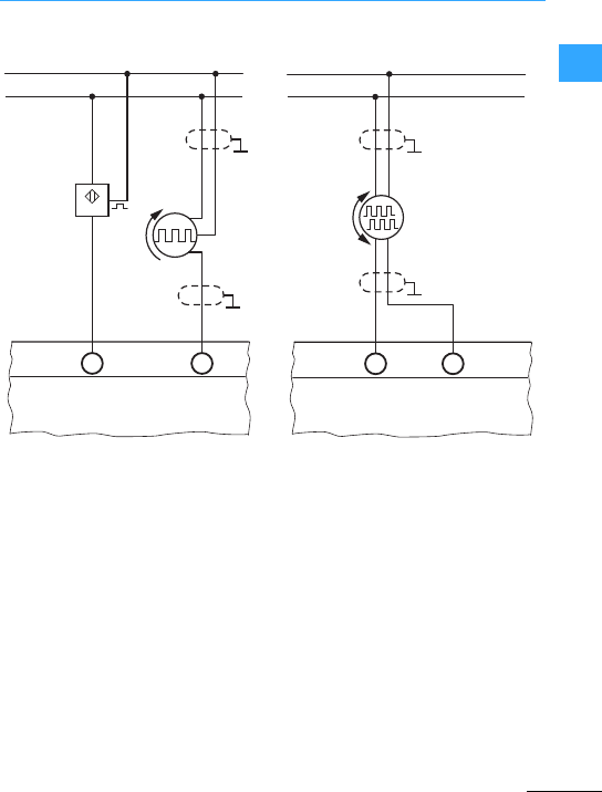
Engineering &Relay, MFD-Titan
Eaton Wiring Manual 06/11
1
aHigh-speed counter, square wave
signal via proximity switch,
mark-to-space ratio should be 1:1
easy500/700 max. 1kHz
easy800 max.5kHz
MFD-R/T…max. 3kHz
bSquare wave signal viafrequency
generator, pulse pause relationship
should be 1:1
easy500/700 max. 1kHz
easy800 max.5kHz
MFD-R/T…max. 3kHz
cSquare wave signals via 24 VDC
incremental encoder
easy800-DC…max. 5 kHz and
MFD-R/T…max. 3kHz
Pay attention to the different numberand
designation of the inputs of the
“high-speed counter”,“frequency
generator”and“incrementalencoder”for
each device type.
+
–
①②
+
–
AB
③
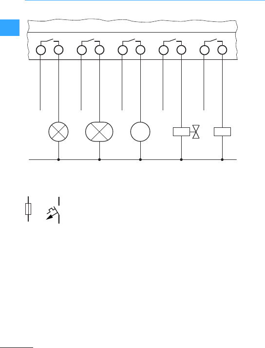
Engineering &Relay, MFD-Titan
Eaton Wiring Manual 06/11
1
#8A/B16
24 to 250V,50/60 Hz
e.g. L1, L2, L3 phase to zero conductor
12 to 300VDC
aFilamentlamp, max. 1000 Wat
230/240VAC
bFluorescent tube, max. 10 x 28 W with
electronic upstream device,
1x58Wwith conventionalupstream
device at 230/240VAC
cAC motor
dValve
eCoil
1
M
2
L… L… L… L… L…
abcde
12 12 12 12
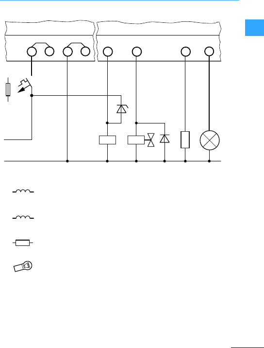
Engineering &Relay, MFD-Titan
Eaton Wiring Manual 06/11
1
Please note the following when switching
off inductive loads: Suppressed
inductances cause less interference in the
entire electrical system. It is generally
recommended thatto the suppressor is
connected as close as possible to the
inductance.
If inductances are not suppressed,the
following applies:
Several inductances should not be
switched off simultaneously to avoid
overheating the driver blocks in the worst
possible case. If in the event of an
emergency stop the +24 V DC power supply
is to be switched off by means of a contact,
and if this would mean switching off more
than one controlled output with an
inductance, these inductances must be
provided with a suppressor circuit.
ab cd
f2.5 A
F10.0 A
24 V DC
+ 24 V0V
aContactor coil with zener diode
as suppressor circuit,
0.5A at 24 V DC
bValve with diode as suppressor
circuit,
0.5 A at 24 VDC
cResistor,
0.5 A at 24 VDC
dIndicatorlight 3 or 5Wat 24 VDC,
Output dependent on device
types and outputs
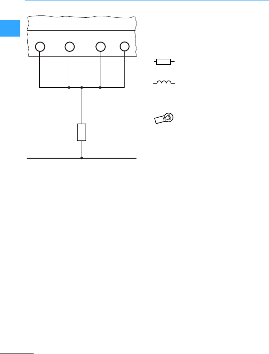
Engineering &Relay, MFD-Titan
Eaton Wiring Manual 06/11
1
aResistor
The outputs may only be connected in
parallel within a group (Q1 to Q4 or Q5 to
Q8, S1 to S4 or S5 to S8); Q1 and Q3 or Q5,
Q7 and Q8. Parallel outputs must be
activated simultaneously.
a
0 V
if 4 outputs in parallel,
max. 2Aat 24 VDC
if 4 outputs in parallel,
max. 2Aat 24 VDC
Inductances without suppression
circuit max.16mH
12 or 20 W at 24 VDC
Output dependent on device types
and outputs
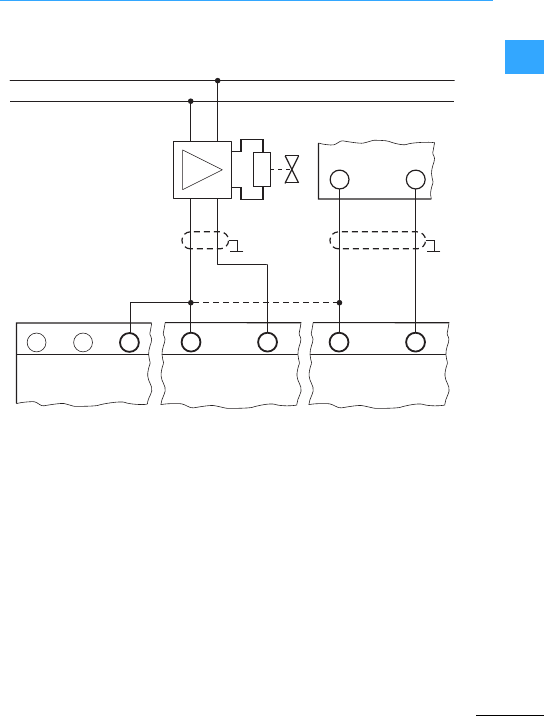
Engineering &Relay, MFD-Titan
Eaton Wiring Manual 06/11
1
aSolenoid valve control
bSet value selection for drive control
•Analog signals are more sensitive to
interference than digital signals,
therefore the signal conductors should
becarefullyrouted. Incorrectconnection
may lead to unwanted switching states.
•Analog output0to 10 V, resolution10bit,
0-1023.
+
–
①②
+...V 0 V0V0VQA1 0 VQA1
0VIA

Engineering &Relay, MFD-Titan
Eaton Wiring Manual 06/11
1
easy700, easy800, MFD(-AC)-CP8…can be
expanded via easy202, easy410, easy618 or
easy620. Up to 24 inputs and 16 outputs are
provided.An expansion is possible with
each basic unit, 7Section ”easy central
and remote expansion module”, page 1-63.
easy700, easy800 and MFD-Titan can be
expanded via the coupling module
easy200-EASY with easy410, easy618 or
easy620. The expansion unit can be
operated up to 30 m from the basic device.
There are a maximum of 24 inputs and 16
outputs available.One expansion unit per
basic device is possible, 7Section”easy
central and remote expansion module”,
page1-63.
Up to eight stations can be interconnected
by expanding the inputs and outputs via
easyNet. An expansion device can be
added to each easy800 or MFD(-AC)-CP8…
A network length of up to 1000 m is
possible. There are two types of operation:
•A master (position 1, user address 1) and
up to 7 other modules. The program is
contained in the master.
•A master (position 1, user address 1) and
up to 7 other “intelligent”or “dumb”
modules. Each “intelligent”module hasa
program.
7Section ”easyNet, “loop through the
device”network connection”,page 1-64
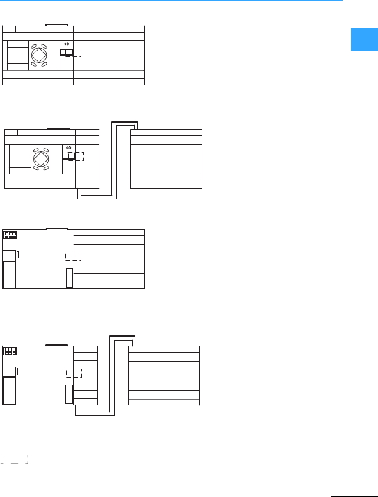
Engineering &Relay, MFD-Titan
Eaton Wiring Manual 06/11
1
easy700
easy800
easy202…
easy410…
easy618…, easy620…
easy700
easy800
easy200easy410…
easy618…, easy620…
MFD-AC-CP8…
MFD-CP8…
MFD-CP10…
easy202…
easy410…
easy618…, easy620…
MFD-AC-CP8…
MFD-CP8…
MFD-CP10…
easy200easy410…
easy618…
easy620…
I 1 - I... 12
Q 1 - Q...
R 1 - R...
S 1 - S...
12
I 1 - I...
Q 1 - Q...
R 1 - R...
E+ E-
E+ E- S 1 - S...
≦ 30 m
R 1 - R...
S 1 - S...
MFD
R 1 - R...
E+ E-
E+ E- S 1 - S...
≦ 30 m
MFD
EASY-LINK-DS
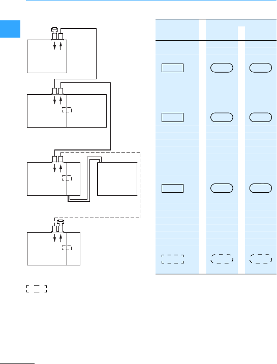
Engineering &Relay, MFD-Titan
Eaton Wiring Manual 06/11
1
1)
1) The geographic location/position 1 has
the station address 1.
•Addressing the stations:
–Automatic addressing from station 1or via
easySoft…from the PC,
,
–Single addressing on the corresponding
station or via easySoft…on each station,
.
•The maximum length of easyNet is 1000 m.
•Should easyNet be interrupted or a station is not
operational, thenetwork is no longer active
from the interrupted point.
•4core cable unshielded, each two cores
twisted. Characteristic impedance of the cable
must be 120 ?.
easyNet
EASY-NT-R
(124 Ω
PIN1+2)
easy800
easy800 easy800
easy618
easy620
easy800
easy618
easy620
easy200
MFD-AC-CP8…
MFD-CP8…
MFD-CP10…
easy202easy800
11 1
22 3
33 8
88 2
EASY-LINK-DS
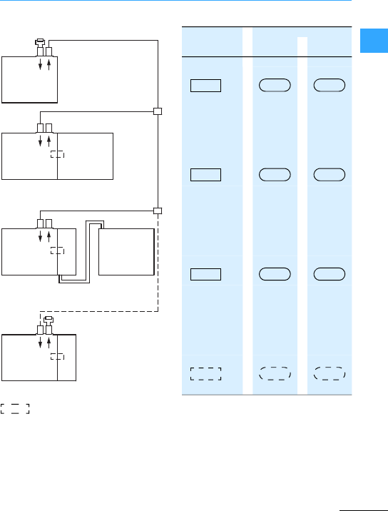
Engineering &Relay, MFD-Titan
Eaton Wiring Manual 06/11
1
1)
1) The geographic location/position 1 has
the station address 1.
•Addressing the stations:
–Single addressing on corresponding station
or via easySoft…on every station.
•The max. total length, including stub lines, with
easyNet is 1000 m.
•The max. stub line's length of the T connector to
easy800or to MFD-Titan is 0.30 m.
•If easyNet is interrupted between the T
connector and the station, or a station is not
operational, thenetwork is still active for the
remaining stations.
•4core cable unshielded, each two cores
twisted. Three cores are required.
Characteristic impedance of the cable must be
120 ?.
easyNet
EASY-NT-R
(124 Ω
PIN1+2)
≦ 0.3 m
≦ 0.3 m
easy800
easy800 easy800
easy618
easy620
easy800
easy618
easy620
easy200
MFD-AC-CP8…
MFD-CP8…
MFD-CP10…
easy202easy800
11 1
22 3
33 8
88 2
EASY-LINK-DS
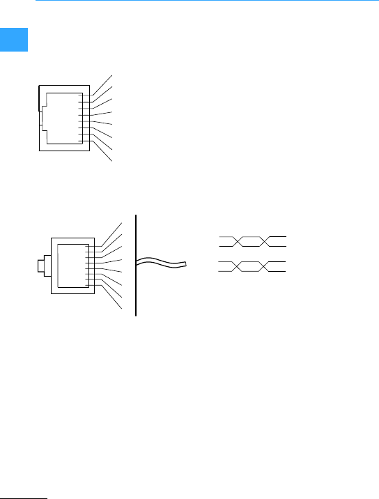
Engineering &Relay, MFD-Titan
Eaton Wiring Manual 06/11
1
Pin assignment of RJ45 socket on easy and
MFD.
Pin assignment of the RJ45 plug on the
easy, MFD(-AC)-CP8/CP10....
aCable entry side
8-pole RJ45, EASY-NT-RJ45
PIN 1: ECAN_H; Data cable;
conductor pair A
PIN 2: ECAN_L; Data cable;
conductor pair A
PIN 3: GND; ground conductor;
conductor pair B
PIN 4: SEL_IN; Select conductor;
conductor pair B
The characteristic impedance of the cable
must be 120 ?.
The network cable does not require any
shielding braid.
However,if ashielding braid is used,it
should be connected to PE.
Cable lengths and cross-sections
7Table, page1-68.
The minimum operation with &Net
functions with cablesECAN_H,ECAN_L,
GND. The SEL_INcable is only used for
automatic addressing.
Abus terminal resisting must be connected
to the geographicalfirst and last station in
the network:
•Value of the bus terminal resisting 124 ?,
•Connect to PIN 1and PIN 2of the RJ45
plug,
•Terminating connector :EASY-NT-R.
1
2
3
4
5
6
7
8
1
2
3
4
5
6
7
8
a
A1 ECAN_H
A2 ECAN_L
B3GND (Ground)
B4SEL_IN

Engineering &Relay, MFD-Titan
Eaton Wiring Manual 06/11
1
100m, 4 x 0.14 mm2; twisted pair:
EASY-NT-CAB
RJ45 plug:
EASY-NT-RJ45
Crimping tool for RJ45 plug:
EASY-RJ45-TOOL.
Theminimum cross-section is determined
forthe known maximum expansion of the
network.
If the result of the calculation does not
yield a standard cross-section, the next
larger cross-section is used.
For a known conductor cross section the
maximum conductor length is calculated.
30 EASY-NT-30
80 EASY-NT-80
150 EASY-NT-150
l=Length of cable in m
Smin =Minimum cross-section in mm2
;cu =Resistivity of copper, if not
otherwise stated 0.018 ?mm2/m
Smin =l×;cu
12.4
lmax =Length of cable in m
S=Cable cross-section in mm2
;cu =Resistivity of copper, if not
otherwise stated 0.018 ?mm2/m
lmax =S×12.4
;cu

Engineering &Relay, MFD-Titan
Eaton Wiring Manual 06/11
1
22
#6#1000 0.14 26 0.10
#25 #500 0.14 26 0.10
#40 #250 0.14 26 0.10
#125 #1251) 0.25 24 0.18
#175 #50 0.25 23 0.25
#250 #50 0.38 21 0.36
#300 #50 0.50 20 0.44
#400 #20 0.75 19 0.58
#600 #20 1.0 17 0.87
#700 #20 1.5 17 1.02
#1000 = 10 1.5 15 1.45
1) Default setting
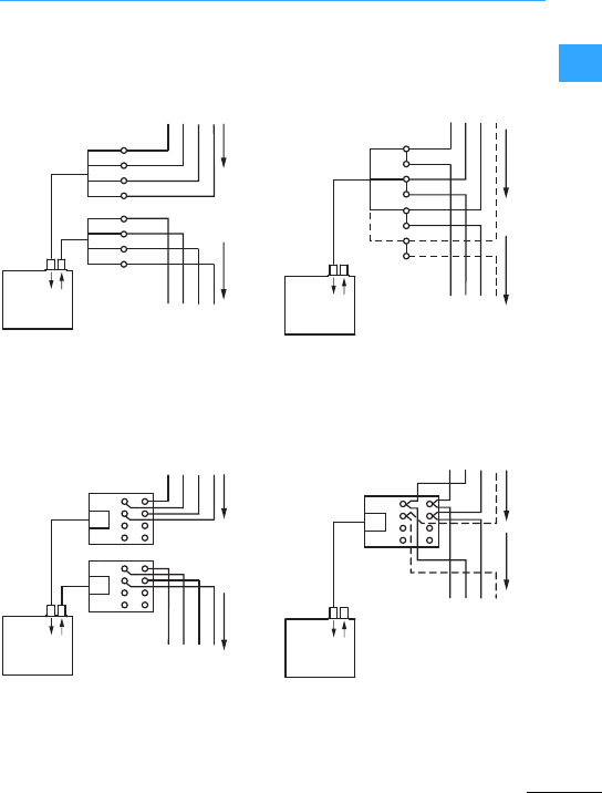
Engineering &Relay, MFD-Titan
Eaton Wiring Manual 06/11
1
2
Example A, with terminals
aRecommendation #0.3m
Example B, with interface element
bRecommendation #0.3 m (EASY-NT-30)
Example A, with terminals
c#0.3 m (3-core)
Example B, with interface element
d#0.3 m (EASY-NT-30)
RJ45
1
2
3
4
1
2
3
4
RJ45
①
IN
OUT
easy800
MFD-CP8
IN
OUT
RJ45
RJ45
RJ45
RJ45
②
1357
2468
1357
2468
easy800
MFD-CP8
1
2
3
4
RJ45
③
IN
OUT
easy800
MFD-CP8
IN
OUT
RJ45
RJ45
④
1357
2468
easy800
MFD-CP8
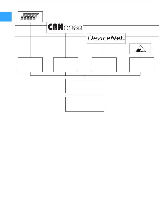
Engineering &Relay, MFD-Titan
Eaton Wiring Manual 06/11
1
An expansion unit for networking can be
connected with easy700, easy800 or
MFD(-AC)-CP8-…The expansion unit for
networking is integrated as slave in the
configuration.
The inputs and output points can be
expanded via easyNet
(7Section”easyNet, network
connection “Tconnector with stub line””,
page1-65 and 7Section ”easyNet,
network connection “T connector with
stub line””, page 1-65).
Furtherinformation can be found in the
manuals:
•MN05013003Z-EN
easy500, easy700, control relays
•MN04902001Z-EN
easy800, control relays
•MN05002001Z-EN
MFD-Titan multi-function display
•MN05013005Z-EN
EASY204-DP
•MN05013008Z-EN
EASY221-CO
•MN05013007Z-EN
EASY222-DN
EASY204-DP EASY221-C0 EASY222-DN EASY205-AS-
Interface
easy700, easy800
MFD…CP8…
MFD…CP10…
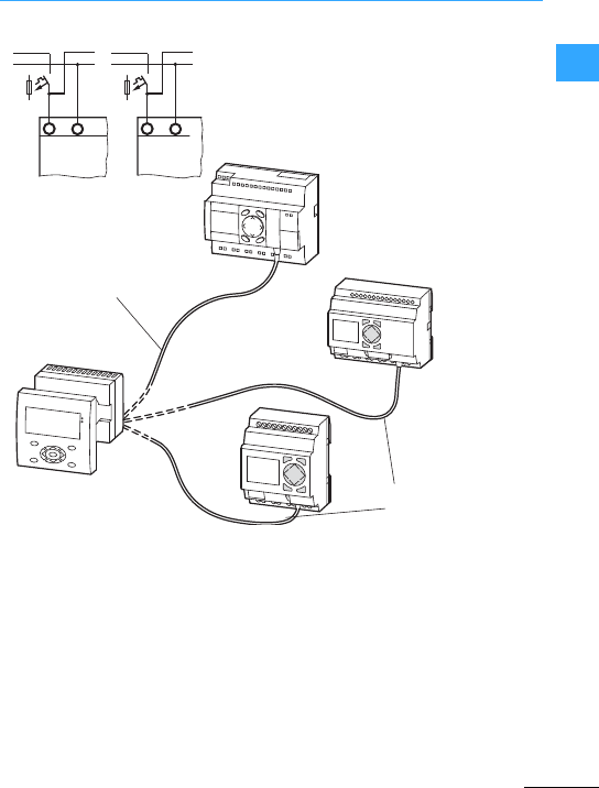
Engineering &Relay, MFD-Titan
Eaton Wiring Manual 06/11
1
The displayof the easyRelay is shown on
the MFD-80... “remote display“.
The easyRelaycan also be operated with
the MFD-80-B.
No extra software or programming is
necessaryto operate the“remote display”.
The connection cable MFD-CP4-…-CAB5
can be shortened.
LL.1
N
LN
115/230 V
50/60 Hz
>1A
+L.1
–
+ 24 V0V
> 1 A
MFD-CP4-500-CAB5
≦ 5 m
MFD-CP4-800-CAB5
easy800
easy700
ESC OK
DEL ALT
easy500
ESC OK
DEL ALT
≦5m
MFD...CP4...
MFD-80...
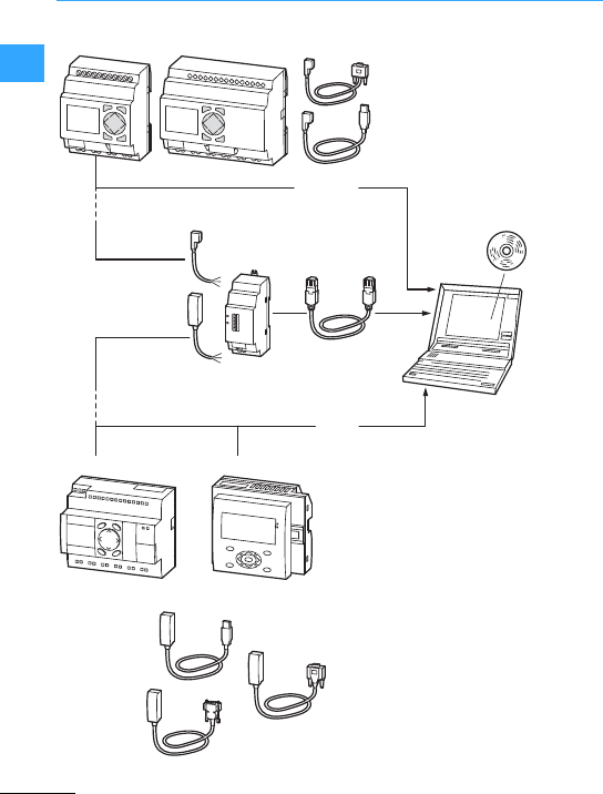
Engineering &Relay, MFD-Titan
Eaton Wiring Manual 06/11
1
easy800 MFD...CP8/CP10...
easy700
ESC OK
DEL ALT
easy500
ESC OK
DEL ALT
①EASY-SOFT-BASIC
②EASY-SOFT-PRO
③OPC
EASY-PC-CAB
EASY209-SE
EASY-USB-CAB
EASY800-MO-CAB
EASY800-PC-CAB
EASY800-USB-CAB
XT-CAT5-X...
MFD-CP4-500-CAB5
MFD-CP4-800-CAB5
② ③
①②③
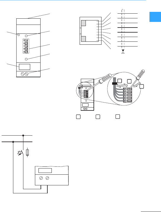
Engineering &Relay, MFD-Titan
Eaton Wiring Manual 06/11
1
aEthernet connection (RJ45 socket)
bStatus LED (POW/RUN)
cCOM connection, spring-cage terminal
5-pole
dRESET pushbutton
ePowersupplydevice 24 VDC V
fDevice label
gStrain relief
press –insert –remove
1 = grey
2 = brown
3 = yellow
4 = white
5 = green
g
fe
c
d
a
b
+24 V
> 1 A
0 V
+24 V0V
2
1
1
2
3
4
5
TX+
TX–
RX+
RX–
6
7
8
2
3
1
1
2
3
4
5
1 2 3
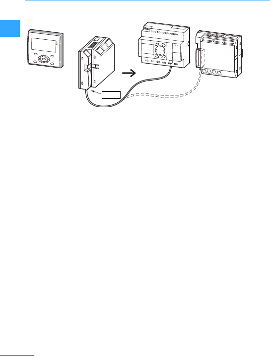
Engineering &Relay, MFD-Titan
Eaton Wiring Manual 06/11
1
The COM-LINKis a point-to-point
connection using the serial interface. Via
this interface the status of the inputs and
outputs are read as well as marker ranges
read and written Twenty markerdouble
words read or written are possible. Read
and write operations can be defined as
required.This data can be used for setpoint
entry or fordisplay functions.
The stationsof the COM-LINK have
different functions. The active station is
always a MFD…CP8/CP10…and controls
the complete interface.
Remote stations can be an easy800 or an
MFD…CP8/CP10…. The remote station
responds to the requests of the active
station. It does not recognize the
difference whether COM-LINK is active or
a PC with easySoft-PRO is using the
interface.
The stationsof the COM-LINK can be
expanded locally or remotely with easy
expansion units.
The remote station canalso be astation in
the easyNet.
POW-Side
MFD-80… easy800 MFD…CP8/CP10…
MFD..T../R..
MFD…CP8/CP10…
MFD..T../R..
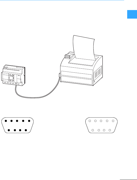
Engineering &Relay, MFD-Titan
Eaton Wiring Manual 06/11
1
An SP (SP =serial protocol) module can be
used to directly send data to the log printer
via the serial PC interface on the front of
the device. More information on this is
provided in the easySoft-PRO help.
Pin assignment of EASY800-MO-CAB:
Serially
controlled
printer
EASY800-MO-CAB
easy800
2 white T x D
3 brown R x D
5 green GND
Information on EASY800-MO-CAB, see alsoIL05013021Z instructional leaflet.
1
6789
23 45 1
6789
23 45
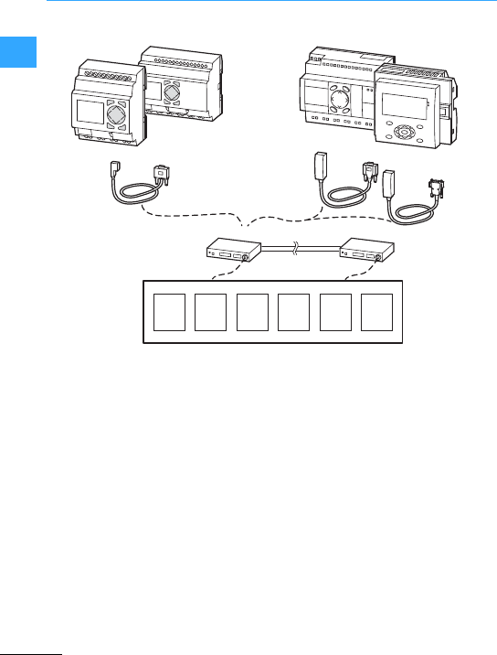
Engineering &Relay, MFD-Titan
Eaton Wiring Manual 06/11
1
Information on EASY800-MO-CAB, see also
IL05013021Z instructional leaflet.
easy800
MFD...CP8...
easy700
ESC OK
DEL ALT
OPC
easy500
ESC OK
DEL ALT
EASY-PC-CAB EASY800-MO-CAB
EASY800-PC-CAB
SMS
Modem 1Modem 2
PC Faxe-mail Pager
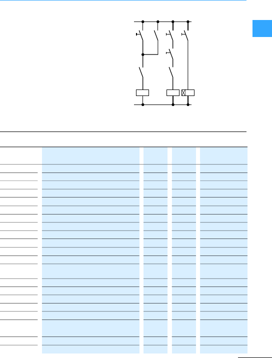
Eaton Wiring Manual 06/11
1
Programming &Relay,MFD-Titan
Circuit diagrams are the basis of all
electrotechnicalapplications. In practice
this involves the wiring together of
electrical switchgear. With the easy
control relay this can be carried out simply
at the push of a button or by using the
convenient easySoftprogramming
software on a PC. Simple menu navigation
in many languages simplify theinput. This
saves time and therefore costs. easy and
MFD-Titan are the professionals for the
world market.
S1 K1
K1 K2 K3
S4
K3 K3
S5
S6
IBitinput, basic device x x x
nIBitinput, basic device via easyNet –x x
IA Analog input x x x
RBitinput, expansion device1) x x x
nRBitinput, expansion unit via easyNet –x x
QBitoutput, basic device x x x
nQBitoutput, basic device via easyNet –x x
QA Analog output –×x
SBitoutput, expansion unit x x x
nSBitoutput, expansion unitvia easyNet –x x
ID Diagnostic alarm –x x
ID 1 COM-Link diagnostic alarm – – x
LE Bitoutput display backlight + Front plate
LEDs
– – x
MMarker x x x
1M MarkerCOM-Link – – x
MB Marker byte –x x
MD Marker double word –x x
MW Marker word –x x
1MB/1MW
/1MD
Marker operand COM-Link – – x
NMarker x – –
PP pushbuttons x x x

Programming &Relay,MFD-Titan
Eaton Wiring Manual 06/11
1:Jump x x x
nRN Bitinput via easyNet –x x
nSN Bitoutput via easyNET easyNet –x x
AAnalog value comparator x x x
AR Arithmetic functions –x x
BC Block comparison –x x
BT Block transfer –x x
BV Boolean sequence –x x
CCounter relay ×x x
CF Frequency counter x2) x x
CH High-speed counter x2) x x
CI Incremental counter –x x
CP Comparator –x x
DText display x x –
DB Data function block –x x
DC PID controller –x x
FT PT1 signal smoothing filter –x x
GT Get value from easyNet –x x
ÖH/HW (Hour)/7-day time switch x x x
Y/HY Year time switch x x x
JC Conditional jump –x x
LB Jump label –x x
LS Value scaling –x x
Z/MR Master reset x x x
MX Data multiplexer –x–
NC Numerical converter –x x
O/OT Operating hours counter x x x
PO Pulse output –x–
PW Pulse width modulation –x x
SC Synchronize clock via network –x x
ST Set cycle time –x x
SP Serial protocol –x–
SR Shift register –x x
TTiming relays x x x
TB Table function –x x
VC Value limitation –x x
1) Witheasy700, easy800 and MFD…CP8/CP10...
2) With easy500 and easy700 parameterizable as
operating mode
n = NET station 1…8
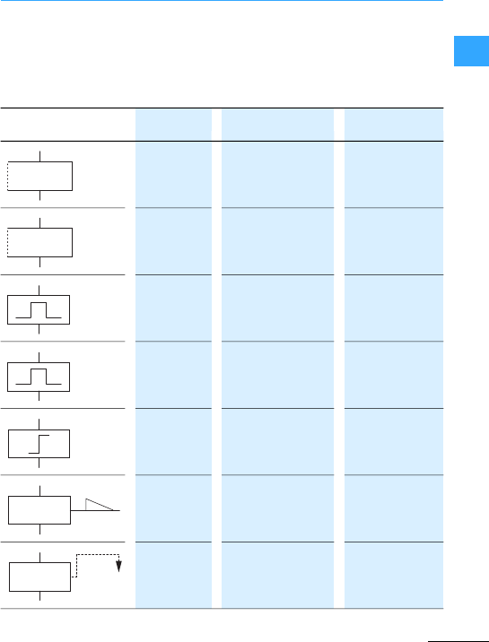
Programming &Relay,MFD-Titan
Eaton Wiring Manual 06/11
1
The switching behaviour of the relay coil is
determined by the selected coil function.
The specified function should for each
relay coil only be used once in the wiring
diagram.
Unused outputs Q and S can also be used
as markers like M and N.
ÄContactor function ÄQ1,ÄD2,
ÄS4,Ä:1,
ÄM7
ÅContactor function with
negated result ÅQ1,ÅD2,
ÅS4
èCycle pulse on falling
edge èQ3,èM4,
èD8,èS7
ÈCycle pulse with rising
edge ÈQ4,ÈM5,
ÈD7,ÈS3
äSurgefunction äQ3,äM4,
äD8,äS7
SLatch (set) SQ8,SM2,
SD3,SS4
RReset (unlatching) RQ4,RM5,
RD7,RS3

Programming &Relay,MFD-Titan
Eaton Wiring Manual 06/11
1
Possible coil functions:
•Trigger = TT..
•Reset = RT..
•Halt = HT..
Depending up on the program the following
parameters can be set:
•Switch function,
•Time range,
•Parameter display,
•Time 1and
•Time 2.
T1 Relay no.
I1 Time setpoint 1
I2 Time setpoint 2
#Outputswitch status:
#N/O contact open,
âN/C contact closed
üSwitch function
STimerange
+Parameter display
30,000 constant as value, e.g. 30 s
I7 Variable, e.g.analog value I7
T:00.00 actual time
XOn-delayed switching
?X On-delayed switching with random time range
âOff-delayed switching
?âOff-delayed switching with random time range
XâSwitching with on- and off-delayed
?XâSwitching with on- and off-delayed with random time
üPulse shaping switching
ÜSwitching with flashing
T1 üS+
I1 30,000
I2 I7
#T:00.00

Programming &Relay,MFD-Titan
Eaton Wiring Manual 06/11
1
Theeasy circuit diagram is entered in
ladderdiagram. This chapter includes a
few circuit examples which are intended to
demonstrate the possibilities foryour own
circuit diagrams.
Thevalues in the logic table have the
following meanings for switching contacts
0 = N/O contact open,
N/C contact closed
1 = N/O contact closed,
N/C contact open
For relay coils Qx
0 = Coil not energized
1 = Coil energized
The examples shown are based on easy500
and easy700. easy800 and
MFD…CP8/CP10…provide four contacts
and one coil perrung.
Negation means that the contact opens
rather than closes when it is actuated (NOT
connection).
In the easy
circuitdiagram,
press the
button to toggle
betweenN/Cand
N/O contact.
S00.00 Seconds: 0.000 to 99,999 easy500, easy700 10 ms
easy800, MFD…CP8/CP10…5ms
M:S 00:00 Minutes:Seconds 00:00 to 99:59 1s
H:M 00:00 Hours:Minutes 00:00 to 99:59 1min
+Call enabled
-Access disabled
10
01
I1-------ÄQ1

Programming &Relay,MFD-Titan
Eaton Wiring Manual 06/11
1
Q1 is controlled
by a series
connection
consisting of
three N/O
contacts (AND
connection).
Q2”is actuated viathree N/C contacts
connected in series (NAND connection).
In the easy circuit diagram, you can
connectup to three N/O or N/C contacts for
easy500 and easy700 in series within a
rung. Use M marker relays if you need to
connect more than three N/O contacts in
series.
Q1 is actuated
via a parallel
connection of
several N/O
contacts
(ORconnection).
A parallel
connection of
closed N/Cs Q2
(NOR circuit).
00001
10000
01000
11000
00100
10100
01100
11110
I1-I2-I3-ÄQ1
I1-I2-I3-ÄQ2
00001
10011
01011
11011
00111
10111
01111
11110
I1u------ÄQ1
I2s
I3k
I1u------ÄQ2
I2s
I3k

Programming &Relay,MFD-Titan
Eaton Wiring Manual 06/11
1
A twoway
switch is made in
easy using two
series
connections that
are combined to
form a parallel
circuit (XOR).
XOR is the abbreviation of eclusive
circuit.The coil is energized if only one
contactis activated.
A combination of
a series and
parallel
connection is
used to wirea
latching circuit.
Latching is
established by
contactQ1
which is connected in parallel to I1. When
I1 is actuated and reopened, the current
flows via contact Q1 until I2 is actuated.
The latching (self-maintaining) circuit is
used to switch machines on and off. The
machine is switched on at the input
terminals via N/O contact S1 and is
switched off via N/C contact S2.
S2 breaks the connection to the control
voltage in orderto switch off the machine.
This ensures that the machine can be
switched off, even in the event of a wire
breakage. I2 is always closed when not
actuated.
Aself-
maintaining
circuit with
open-circuit
monitoring can
alternatively be
wired using the
Setand Reset
coil functions.
000
101
011
110
I1-I2u---ÄQ1
I1-I2k
S1 N/O contacton I1
S2 N/C contact on I2
I1uI2----ÄQ1
Q1k
000 0
100 0
010 0
110 1
101 0
011 1
111 1
S1 N/O contact on I1
S2 N/C contact on I2
I1-------SQ1
I2-------RQ1

Programming &Relay,MFD-Titan
Eaton Wiring Manual 06/11
1
Coil Q1 latches if I1 is activated. I2 inverts
the break contact signal of S2 and only
switches if S2 is activated in order to
disconnect the machine or in the event of a
wire breakage.
Make sure that both coils are wired up in
the correctorderin the easy circuit
diagram: first wire the S coil andthen the R
coil. This will ensure thatthe machine will
be switched offwhen I2 is actuated, even if
I1 is switched on.
An impulse relay
is often used for
controlling
lighting such as
forstairwell
lighting.
The on-delay
can be used to
override short
pulses or with a
machine,tostart
afurther
operation after a
time delay.
To energize a
relay coil
continuously,
make a
connection of all
contact fields
from the coil to
the leftmost position.
00 0
10 1
01 1
11 0
S1 N/O contact at I1
I1-------äQ1
11
S1 N/Ocontact at I1
I1-------TT1
T1-------ÄM1
---------ÄQ1
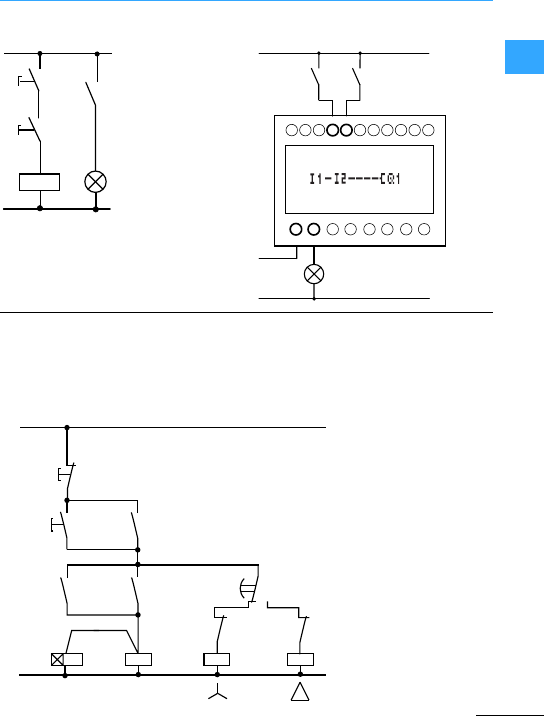
Programming &Relay,MFD-Titan
Eaton Wiring Manual 06/11
1
You can implement two star-delta circuits
with easy. The advantage of easy is that it
is possible to select the changeover time
between star and delta contactors, and
also the time delaybetween switching off
the star contactor and switching on the
delta contactor.
HardwiredWiring with easy
P1
S1
S2
K1
K1
P1
S1 S2
K1
NQ11
Q11
Q11
K1
K1
Q12
Q12
Q13
Q13
L
S1
S2
Q12
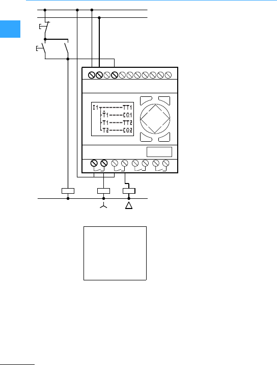
Programming &Relay,MFD-Titan
Eaton Wiring Manual 06/11
1
.
Start/Stop the
connection with
the external
pushbuttons S1
and S2. The
mains contactor
starts the timing
relay in easy.
I1: Mainscontactor switched on
Q1:Star contactor ON
Q2: Delta contactor ON
T1: Changeover time star-delta (10 to 30 s)
T2: Wait time between staroff, delta on
(30, 40, 50, 60 ms)
If your easy hasan integral time switch,
you can combine star-delta starting with
the time switch function. In this case, use
easy to also switch the mains contactor.
11
22
Q1
I1
LN
Q2
Q12 Q13Q11
N
Q11
L
N
S1
S2
K1
I1u------TT1
dT1----ÄQ1
dT1----TT2
hT2----ÄQ2
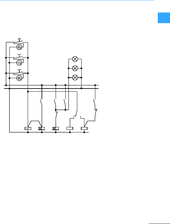
Programming &Relay,MFD-Titan
Eaton Wiring Manual 06/11
1
For a conventionalconnection aminimum
of five space unitsare required in the
distribution board, i.e. one impulse relay,
two timing relays,two auxiliary relays.
easy requires only fourspace units. With
five connections and the easy circuit the
stairway lighting is operational.
Four such stairway circuitscan be
implemented with one easy device.
N
L
S1
S2
S3
K3K1 K2
Q11
Q11
Q12
Q12
K3 K1
K2
Q12
5 s 6 min
E1
E2
E3
K3
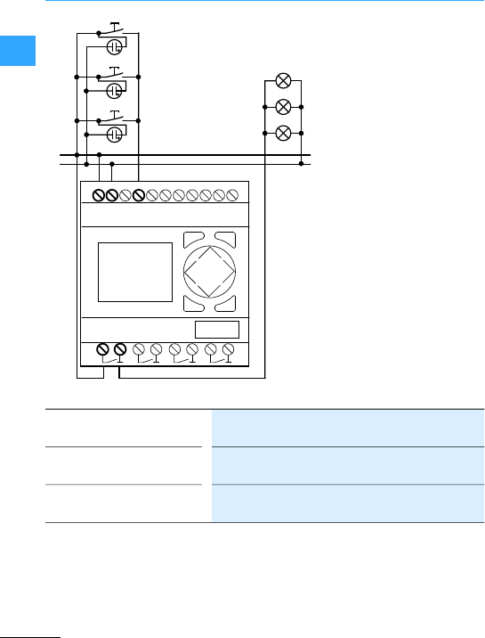
Programming &Relay,MFD-Titan
Eaton Wiring Manual 06/11
1
N
L
S1
S2
S3
E1
E2
E3
12
Q1
I1
LN
K1
Pushbutton pressed briefly Light ON or OFF. The impulse relay function will even
switch off with continuous lighting.
Lightoff after6 min Switched off automatically. With continuous light this
function is not active.
Pushbutton pressed for more
than 5 s
Continuous light

Programming &Relay,MFD-Titan
Eaton Wiring Manual 06/11
1
The easy circuit configuration for the
described function below looks like this:
The expanded easy circuit diagram: after
four hours, the continuous lighting is also
switched off.
I1: ON/OFF pushbutton
Q1: Output relay for light ON/OFF
M1:Markerrelay.This is used to block the
“switch off automatically after 6
minutes”function for continuous
lighting.
T1:Cyclical impulse for switching Q1
ON/OFF, (,pulse shaping with value
00.00 s)
T2: Scan to determine how long the
pushbutton waspressed.When
pressed for longerthan 5 s, it changes
to continuous light. (,on-delayed,
value 5s)
T3: Switch off after the light has been on for
von 6 min. (,on-delayed, value 6:00
min.)
T4: Switch off after 4 hours continuously
on.(,on-delayed, value 4:00 h)
I1-------TT2
T2-------SM1
I1u------äQ1
T3k
Q1-M1----TT3
Q1-------RM1
I1------uTT1
hTT2
T2-------SM1
T1u------äQ1
T3s
T4k
Q1uM1----TT3
h------TT4
Q1-------RM1
ü
X
X
X
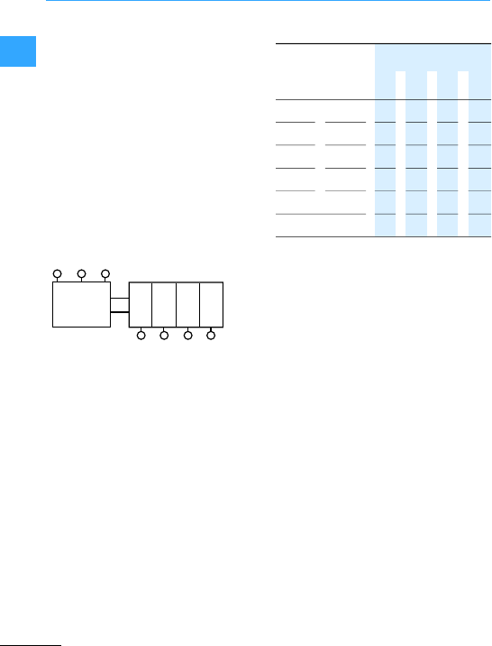
Programming &Relay,MFD-Titan
Eaton Wiring Manual 06/11
1
A shift register can be used for storing an
item of information –e.g. sorting of items
into“good”or “bad” – two,three or four
transport steps further on.
A shift pulse and the value (0 or 1) to be
shifted are required for the shift register.
Values which are no longerrequired are
deleted via the reset input of the shift
register. Thevalues in the shift register
pass through the register in the following
order:
1st, 2nd, 3rd, 4th storage position.
Block diagram of the 4-way shift register
aPulse
bValue
cRESET
dStorage position
Allocate the value 0 with the information
content bad.Should the shift register be
accidently deleted,no bad partswill be
reused.
I1:Shiftpulse (PULSE)
I2: Information (good/bad) to be shifted
(VALUE)
I3: Delete contents of the shift register
(RESET)
M1: 1st storage location
M2: 2nd storage location
M3: 3rd storage location
M4: 4th storage location
M7: Marker relay for cycle pulse
M8: Cyclical pulsefor shift pulse
1234
abc
d
111000
200100
300010
411001
500100
Reset = 1 0 0 0 0

Programming &Relay,MFD-Titan
Eaton Wiring Manual 06/11
1
Generateshift pulse
4th storage location, set
4th storage location, delete
3rdstorage location, set
3rdstorage location, delete
2nd storage location, set
2nd storage location, delete
1st storage location,set
1st storage location,delete
Delete all storage locations
I1uM7----ÄM8
h------ÄM7
M8uM3----SM4
dM3----RM4
dM2----SM3
dM2----RM3
dM1----SM2
dM1----RM2
dI2----SM1
hI2----RM1
I3------uRM1
dRM2
dRM3
hRM4

Programming &Relay,MFD-Titan
Eaton Wiring Manual 06/11
1
easy500 and easy700 can display 16 freely
editable texts,easy800 can display 32.
These texts can be triggeredby the actual
values of function relays such as timing
relays,counters, operating hours counters,
analog value comparators, date, time or
scaled analog values. Setpoint valuesof
timing relays, counters, opertaing hours
counters and analog value comparators
can be altered on the device during the
display of the texts.
Example of a text display:
The text display can display the following:
The setpoint values can be edited:
•easy500 and easy700, two values
•easy800, four values
The text output function block D (D =
Display, text display) functions in the
circuit diagram like a normal marker M.
Should atext be attached to a marker this
would be shown at condition in the easy
display whenthe coil is set to 1. For this
easy must be in RUN mode and before the
texts are displayed the Status displaymust
be active.
D1 is defined as an alarm text and has
therefore priority over text displays.
D2 to D16/D32 are displayed when
activated. When several displays are
activated they are shown in succession
every 4 secs. When a setpoint value is
edited the corresponding display stays
active until the value is transferred.
SWITCHING;
CONTROL;
DISPLAY;
ALL EASY!
Line 1, 12 characters
Line 2, 12 characters, a setpoint value or an actual value
Line 3, 12 characters, a setpoint value or actual value
Line 4, 12 characters
RUNTIME M:S
T1 :012:46
C1 :0355 ST
PRODUCED
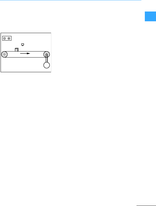
Programming &Relay,MFD-Titan
Eaton Wiring Manual 06/11
1
The visualization with MFD-Titan is
implemented with screen, on which the
display is shown.
Example of a screen:
The following screen elements can be
combined.
•Graphic elements
–Bit display
–Bitmap
–Bargraph
–Message bitmap
•Button elements
–Latching pushbutton
–Buttonfield
•Text elements
–Static text
–Message text
–Screen menu
–Running text
–Rolling text
•Valuedisplay elements
–Date and time display
–Numerical value
–Timing relayvalue display
•Value entry elements
–Value entry
–Timing relayvalue entry
–Date and time entry
–7-day time switch entry
–Year time switch entry
M
3h
S1 S2
S3
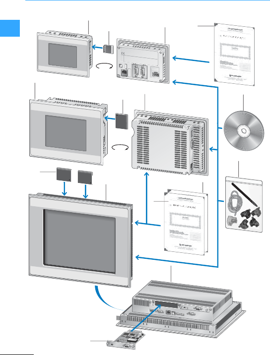
Eaton Wiring Manual 06/11
1
HMI-PLC - Systematic visualization and control
4
4
6
10
8
11
6
1
2
5
1
7
5
9
3
180
180

HMI-PLC - Systematic visualization and control
Eaton Wiring Manual 06/11
1
1XV100 HMI/PLC with touch display:
Fully graphical 3.5", 5.7" or 7" wide
screen devices
2SD memory card
3XV license product certificates:
Expansion of device functionality
through assignment of license points.
4XV200 HMI/PLC with touch display;
Fully graphical 5.7" devices
5CompactFlash memory card
6XV400 HMI/PLC with touch display:
5.7", 8.4", 10.4", 12.1", 15" devices with
infra-red or resistive touch
7XV license product certificates:
Expansion of device functionality
through assignment of license points
8OS Upgrade license
9Communication module for XV400
10 Fixing kit
11 Software

HMI-PLC - Systematic visualization and control
Eaton Wiring Manual 06/11
1
Whether in machine or system building or
in individual applications, an HMI (Human
Machine Interface) or HMI-PLC (HMI with
PLC functionality) simplifies operation and
reduces the workload for the operator.
Touch panels provide a clear, flexible
menu navigation in any required language
and enables the manufacturer to sell
machinery worldwide with only one
hardware and software solution.
Touch panels with resistive and infra-red
technology are primarily used. Eatonoffers
devices with both technologies.
On the resistive touch panel, a conductive
foil is stretched over the conductive screen
surface. The foil is separated from the
screen using several insulating pads. Only
when a slight pressure is applied, does the
foil touch the screen surface at this point
and a current flows. A different current or
resistance value is produced, based on the
voltage divider principle according to
where on the screen contact with the foil
was made. The contactpoint is thus
located unambiguously.
The infra-red touch panels uses alight
matrix in the infra-red range.
Each transmitter is assigned a receiver on
the other side.The beams are directed
slightly over the front panel. The
simultaneous interruption of several
infra-red channels on the X and Y axis is
used to indicate where the panel was
touched in orderto trigger the appropriate
switchfunction.
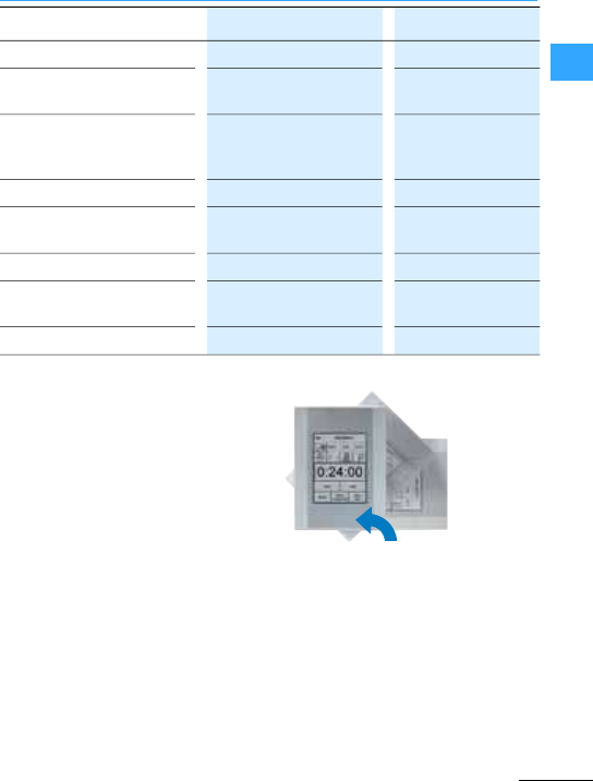
HMI-PLC - Systematic visualization and control
Eaton Wiring Manual 06/11
1
Devices with display sizes from 3.5”to 19”
are used in automation applications. Eaton
offers device versionsin plastic and metal.
Thefront on the metal devices is eitherin
aluminium or stainless steel.
Front degree of protection: IP65
Most touch panels can also be used in
portraitformat(upright).
Light permeability 100 % 70 –85 %
Operable with Fingers, gloves Fingers, gloves,
touch pen
Triggering of the function Without pressure
(interruption of the light
matrix)
With slight pressure
Display front Glass Plastic film
Device front Level determined by the
infra-red frame
Fully flat
Sensitivity to scratches No Yes
Resistance to cleaning agent
and chemicals
High Average
Use in humid atmospheres Yes Yes
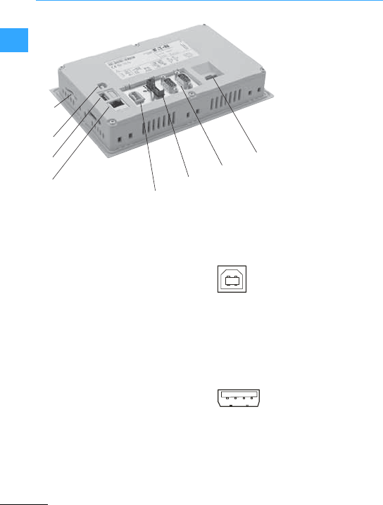
HMI-PLC - Systematic visualization and control
Eaton Wiring Manual 06/11
1
aSD memory card (Secure Digital
memory card)
bUSB device, page 1-98
cUSB host,page 1-98
dEthernet interface,page 1-99
e24 V DC power supply POW and AUX
(for SmartWire-DT slaves, page1-99
fSmartWire-DT interface (only specific
devices) page 1-100
gOnboard interfaces, depending upon
the device:
–RS232, page 1-100
–RS485, page 1-101
–CAN,page 1-102
–PROFIBUS-DP, page 1-104
h24 VDC device supply, page 1-106
The USB device interface supports
USB 2.0.
•Cable
–Only use standard USB cables with a
shield.
–Maximum cable length: 5 m
The USB Host interface supports USB 2.0.
•Cable
–Only use standard USB cables with a
shield.
–Maximum cable length: 5 m
Rear view of a 7”
resistive panelof the
XV102 series with plastic
housing
①
②
③
④⑤
⑥⑦⑧
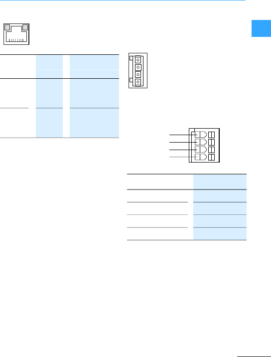
HMI-PLC - Systematic visualization and control
Eaton Wiring Manual 06/11
1
•Cable
–Use shielded twisted pair (STP)cable
fornetworking
For device to device connection:
cross overcable
For connection to hub/switch: 1:1
patch cord
–Maximal cable length: 100 m
Ethernet interface according to EIA/TIA
568 TSB-36.
The POW/AUX interface is not galvanically
isolated. The following powersupplies are
required for a SmartWire-DT network:
Supply voltage POW:
The device supply voltage for the
electronics of all SWDslaves (15 VDC) is
generated from the 24 VDC supply voltage
that you apply to the POW terminal
connection.
Supply voltage AUX:
If there are any contactors or motor
starters in the SWD topology, a 24 V DC
voltage AUX must be additionally supplied
as a control voltage for the contactor coils.
•Wiring
WAGO plug connector, Art no.734-104 is
supplied with the device.
Observe the following when preparing the
wiring of the plug connector:
ACT
(yellow)
flashes Ethernet is
active (data
traffic)
LINK
(green)
On Active network
is connected
and detected
ACT
LINK
+24VDC POW UPow +24 VDC
0VPOW UPow 0V
+24VDC AUX UAux +24 VDC
0VAUX UAux 0V
Terminal type: Spring-loaded
terminals
Connectable
conductor, solid:
0.2 - 1.5mm
2
(AWG24 -16)
Stripping length: 6 -7mm
0 V AUX
+24 VDC AUX
0 V POW
+24 VDC POW
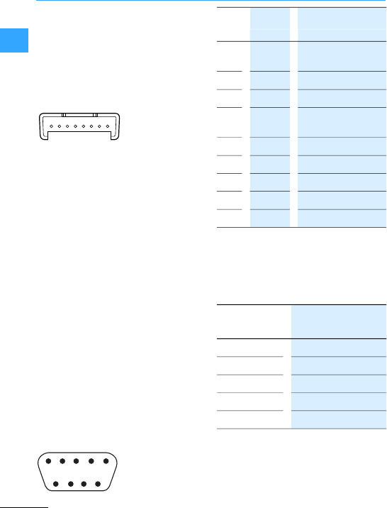
HMI-PLC - Systematic visualization and control
Eaton Wiring Manual 06/11
1
External protection using a24 VDC
miniature circuit-breakeris required for
UAux.
The SWD interface is not galvanically
isolated.
•Cabling
Only use the following cables to connect
the SmartWire-DT network:
–SWD-4-100LF8-24 with the
SWD-4-8MF2 blade terminals or
–SWD-4-(3/5/10)F8-24-25
(prefabricatedcable)
Detailed instructions for fitting the
SWD-4-8MF2 blade terminal is provided in
the manual MN05006002Z-EN, chapter
“Fitting the SWD4-8MF2 blade terminal”.
The project configuration (SmartWire-DT
configuration in XSoft-CoDeSys-2 project)
is described in the manual
MN04802091Z-EN, XSoft-CoDeSys-2: PLC
programming XV100, chapter
“SmartWire-DT Configuration”.
The RS232 interface is not galvanically
isolated. The device maybe damaged by
potential differences. The GND terminals of
all bus stations must therefore be
connected.
•Wiring
–Shielded cables must be used.
–The maximum baud rate depends on
the cable length:
12345678
1
6789
23 45
1DCD Data Carrier
Detected
2RxD Receive Data
3TxD Transmit Data
4DTR Data Terminal
Ready
5GND Ground
6DSR Data Set Ready
7RTS Request to Send
8CTS ClearTo Send
9RI Ring Indicator
2.5 m 115200 bit/s
5m 57600 bit/s
10 m 38400 bit/s
15 m 19200 bit/s
30 m 9600 bit/s

HMI-PLC - Systematic visualization and control
Eaton Wiring Manual 06/11
1
The RS485 interface is not galvanically
isolated. The device maybe damaged by
potential differences. The GND terminals of
all bus stations must therefore be
connected.
•Wiring
Screened twisted-pair cables must be
used.
When preparing connections, ensure that
the cable shield has a low impedance
connection withthe connector housing.
•RS485-topology
–A bus segment can interconnect up to
32 slaves.
–Several bus segments can be
connected via repeaters (bidirectional
amplifiers).Referto the documentation
of the repeater manufacturer formore
specific details.
–The use of repeaters enables the
maximum cable length to be increased.
Refer to the documentation of the
repeater manufacturer formore
specific details.
–A bus segment must be provided with
cable termination (120 ?)at both ends.
These terminals must be connected in
the connectordirectly between pin 3
and 7.
–The bus segment must be terminated
at both ends.
–No more than two terminations must
be provided for each bus segment.
–Operation without correct cable
termination can cause transfererrors.
1 - nc
2- nc
3B Line B
4- nc
5GND Ground
6- nc
7A Line A
8- nc
9- nc
nc: Pin 1, 2, 4, 6, 8 and 9 must not be
connected.
Rated cable impedance 120 ?
Permissibleimpedance 108-132 ?
1
6789
23 45
Max. cable length1200 m
Possible baud rates 9600 bit/s
19200 bit/s
38400 bit/s
57600 bit/s
115200 bit/s
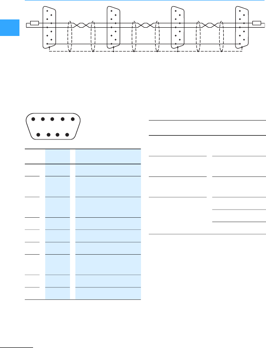
HMI-PLC - Systematic visualization and control
Eaton Wiring Manual 06/11
1
The CAN interface is not galvanically
isolated. The device maybe damaged by
potential differences. The GND terminals of
all bus stations must therefore be
connected.
The power supply of the CAN bus drivers is
implementedinternally.
A power supply for third party devices is
not provided on the CAN connector.
•Wiring
Shielded twisted pair cables must be used.
1
2
3
6
7
5
48
9
120
1
2
3
6
7
5
48
9
120
1
2
3
6
7
5
48
9
1
2
3
6
7
5
48
9
GND
A
B
GND
A
B
GND
A
B
GND
A
B
GND
A
B
GND
A
B
1- nc
2CAN-L Bus line
(dominant low)
3CAN-
GND
CANground
4- nc
5- nc
6GND Optional CAN ground
7CAN-H Bus line
(dominant high)
8- nc
9- nc
Pin 3 (CAN-GND) and 6 (GND) are
internally interconnected
nc: Pin 1, 4, 5, 8 and 9must not be
connected.
1
6789
23 45
Rated cable
impedance
120 ?
Permissible
impedance
108-132 ?
Capacitance per
unit length
<60 pF/m
Conductor
cross-section
Max. cable length
*0.25 mm2/100 m
*0.34 mm2/250 m
*0.75 mm2/500 m
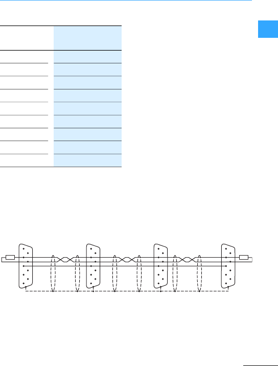
HMI-PLC - Systematic visualization and control
Eaton Wiring Manual 06/11
1
The maximal baud rate depends on the
cable length
–The use of repeaters is recommended
forcable lengths over 1000 m.
Repeaters can also be used for
galvanic isolation. Refer to the
documentation of the repeater
manufacturer formore specific details.
–Observe the recommendations of CiA
(CAN in Automation).
–When preparing connections, ensure
that the cable shield has a low
impedance connection with the
connector housing.
•CAN-Bus-topology
–A bus segment can interconnect up to
32 slaves.
–Several bus segments can be
connected via repeaters (bidirectional
amplifiers).Referto the documentation
of the repeater manufacturer formore
specific details.
–A bus segment must be provided with
cable termination (120 ?) at both ends.
These terminals must be connected in
the connectordirectly between pin 2
and 7.
–The bus segment must be terminated
at both ends.
–No more than two terminations must
be provided for each bus segment.
–Operation without correct cable
termination can cause transfererrors.
25 m 1000 kbit/s
50 m 800 kbit/s
100 m 500 kbit/s
250 m 250 kbit/s
500 m 125 kbit/s
500 m 100 kbit/s
1000m 50 kbit/s
2500m 20 kbit/s
5000m 10 kbit/s
1
2
3
6
7
5
48
9
120
1
2
3
6
7
5
48
9
120
1
2
3
6
7
5
48
9
1
2
3
6
7
5
48
9
GND
CAN-L
CAN-H
CAN-CND
CAN-L
CAN-H
CAN-CND

HMI-PLC - Systematic visualization and control
Eaton Wiring Manual 06/11
1
The PROFIBUS interface is not galvanically
isolated. The device maybe damaged by
potential differences. The GND terminals of
all bus stations must therefore be
connected.
•Wiring
Screened twisted-pair cables, cable type A
(acc. to the PROFIBUS standard EN 50170)
must be used.
The maximal baud rate depends on the
cable length
When preparing connections, ensure that
the cable shield has a low impedance
connection withthe connector housing.
1 - nc
2- nc
3BEIA RS485 cable B
4RTSAS Output for controlling
a repeater
5M5EXT Output 0 V for
external termination
6P5EXT Output 5 V for
external termination
7-nc
8AEIA RS485 cable A
9-nc
Pin6(5 V) must not be used as a power
supply forexternal devices.
34125
8967
Rated cable impedance 150 ?
Permissible impedance 135-165 ?
Capacitance perunit
length
< 30 pF/m
Loop resistance < 110 ?/km
Core cross section *0.34 mm2
(AWG22)
200 m 1500 kbit/s
400 m 500kbit/s
1000m 187.5 kbit/s
1200m 493.75 kbit/s
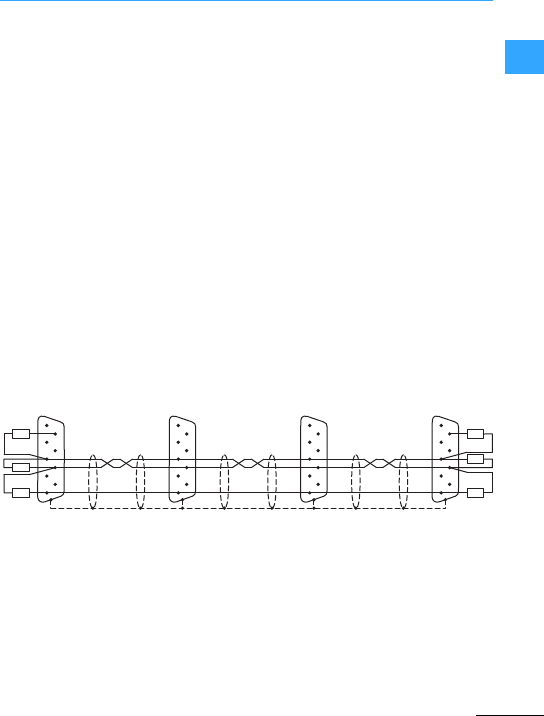
HMI-PLC - Systematic visualization and control
Eaton Wiring Manual 06/11
1
•PROFIBUS-topology
Shielded twisted-pair cablesmust be
used.opology
–Abus segment can interconnect up to
32 slaves.
–Several bus segments can be
connected via repeaters (bidirectional
amplifiers).Referto the documentation
of the repeater manufacturer formore
specific details.
The use of repeaters enables the maximum
cable length to be increased. Referto the
documentation of the repeater
manufacturer formore specific details.
–Only use bus connector plugs thatare
specified for use in the PROFIBUS
network. These combine both bus
cables on abus station and ensure that
the cable shield is a low impedance
connection and fed through to the
shield reference potential of the bus
station. The busconnector plug
contains the PROFIBUS-specific cable
termination that can be activated if
required.
–A bus segment must be provided with
cable termination at both ends. The
termination is passive but is fed from
the bus station. It ensures a defined
quiescent signalon the bus if no bus
station is sending. These bus terminals
are primarilyimplemented externally in
the connector housing in accordance
with the PROFIBUS standard.
–The bus segment must be terminated
at both ends.
–No more than two terminations must
be provided for each bus segment.
–At leastone of the two terminations
must be fed by the bus station.
–Operation without correct termination
of the PROFIBUS network can cause
transfer errors.
1
2
3
6
7
5
4
8
9390
390 1
2
3
6
7
5
4
8
9
1
2
3
6
7
5
4
8
9
1
2
3
6
7
5
4
8
9
M5EXT
(GND)
A
B
M5EXT
(GND)
A
B
M5EXT
(GND)
A
B
M5EXT
(GND)
A
B
M5EXT
(GND)
A
B
M5EXT
(GND)
A
B220
220
390
390
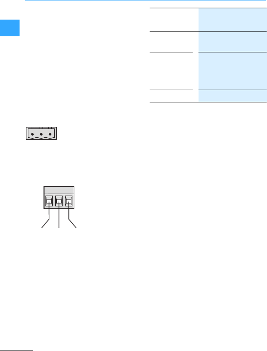
HMI-PLC - Systematic visualization and control
Eaton Wiring Manual 06/11
1
The device has an internal fuse and
protection against polarity reversal. The
functional earth must only be connected
with the connector panel not the0V. The
housing is plasticand is potential free. The
power supply of the device is not
galvanically isolated.
The device requires apower supply of 24 V
DC from an AC/DC transformer with safe
isolation (SELV).
–SELV (safety extra low voltage); circuit
in which no dangerous voltage occurs
even in the event of a single fault.
•Wiring
Plug connector Phoenix Contact
MSTB 2.5/3-ST-5.08, Phoenix Art no.
1757022 is supplied with the device.
Observe the following when preparing the
wiring of the plug connector:
⏚0V+24 VDC
+24VDC Supply voltage
+24 VDC
EFunctionalearth with
connector panel. Does
not have to be
connected.
0V Supply voltage 0V
Terminal type: Screw terminal
plug-in
Cross-section: min. 0.75mm
2/
max. 2.5mm
2
(lead or wire)
min. AWG18 /
max. AWG12
Stripping
length:
7mm
Max.tightening
torque:
0.6-0.8 Nm /
5-7 lb in
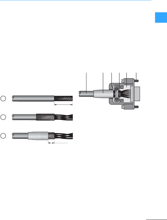
HMI-PLC - Systematic visualization and control
Eaton Wiring Manual 06/11
1
The design of the bus cabling is an
essentialfactor for reliable operation and
electromagnetic compatibility (EMC).
•The cables must be shielded.
•The cable shield must consist of a copper
braid.
•The cable shield must have alarge area
and low-impedance connection to the
connectorhousing. This is achieved by:
–Using metal or metallized connector
housings with a strap forstrain relief.
–The strap must be screw fastened with
the connector.
aInsulate the cable end so that approx. 3
cm of shield braid is exposed.
bFold back theshield braid over the
cable sheath.
cAttach heat-shrink tubing approx.
3 cm in length over the folded shield
braid or use a rubber grommet.
–5 - 8mm shield braid must be exposed
at the cable end.
–The folded shield braid end must be
coveredby the heat-shrink tubing or
rubber grommet.
dFit the SUB-D connector to the cable
end:
–Theexposed screen braid must be
connectedto the connector housing
with the cable clip.
ACable with cable sheath
BHeat-shrink tubing or rubber grommet
CGland plate
DShield braid
ESUB-D plug
FFixing screw UNC
30 mm
5…8mm
1
2
3
ABCDE F
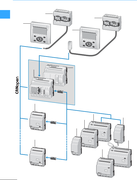
Eaton Wiring Manual 06/11
1
Compact PLC –universal compact controllers
ESC
DEL
OK
ESC
ALT
ALT
OK
3
2
4
2
1
1
9
9
8
7
7
5
6
6
1EC4P Compact PLC
2MFD-80 -B display/operating unit
3MFD-CP4-CO CANopen connection
4Power supply unit/communication
module, including connection cable for
EC4P
5EASY202-RE output expansion
6EASY410... I/O expansion, digital
7EASY6... I/O expansion,digital
8EASY200-EASY Coupling module
9EC4E-221-... CANopen expansion
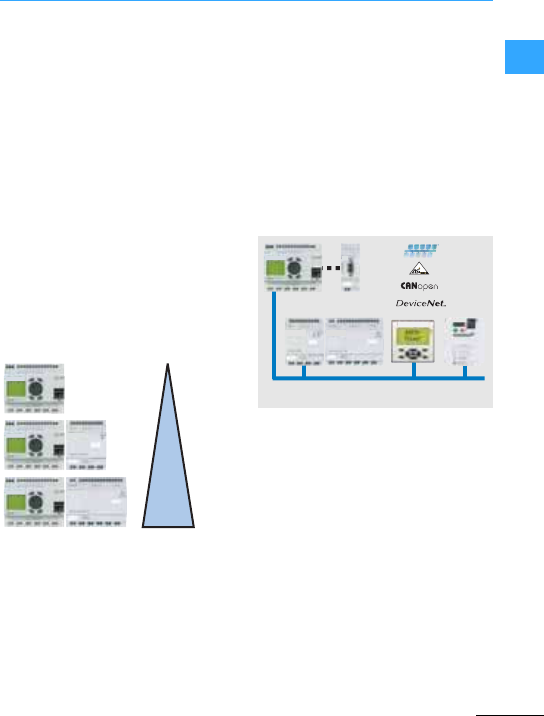
Compact PLC –universal compact controllers
EatonWiring Manual 06/11
1
Compact controllers offer in asingle
device several functions that cover the
automation of small and medium-sized
applications.
For this sector Eaton offers the EC4P
series.The controllers provide the
functionality of a PLC in the housing of an
easy800 control relay. Programming is
carried out using CoDeSys software.
The controllers vary according to the
number and type of inputs/outputs.
Moreover, there are variants with and
without display, as well as with and without
an Ethernet interface.Ethernet allows
remote programming viathe network and
communication via UDP and MODBUS.
All EC4P controllers are provided with a
CAN/easyNet interface.
Flexible networking options:
•Remotely expandable via CANopen or
easyNet
•Locally expandable via easyLink
interface
•Remote programming via network
•Connection of one or several MFD-80-B
via CANopen
•Connection of an MFD-80-B viaRS232
•Pluggable memory modules for data
archiving
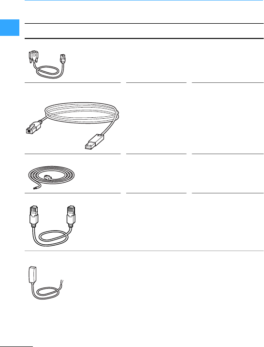
Compact PLC –universal compact controllers
EatonWiring Manual 06/11
1
EU4A-RJ45-CAB1PC, terminal/
printer
Programming via serial
interface COM1,
transparent mode
EU4A-RJ45-USB-CAB1PCProgramming via USB
interface
EU4A-RJ45-CAB2MFD-CP4-CO +
MFD-80-B
EC4E
CAN connection
XT-CAT5-X-2PCProgramming via
Ethernet
MFD-CP4-800-CAB5 MFD-CP4 Display extension, serial
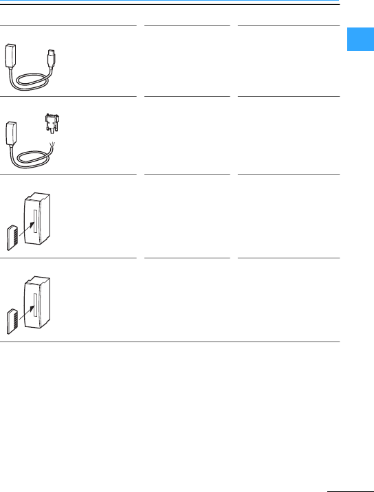
Compact PLC –universal compact controllers
EatonWiring Manual 06/11
1
easy800-USB-CAB PC For programming via the
USB interface
easy800-MO-CAB PC,terminal/
printer
Programming via serial
interface COM1,
transparent mode
EU4A-MEM-CARD1 EC4P Memory card
EU4A-MEM-CARD2 EC4P Memory card with
battery for backing up
the time
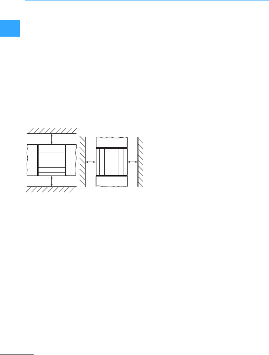
Compact PLC –universal compact controllers
EatonWiring Manual 06/11
1
Install the PLC in a controlcabinet, a
service distribution board or in an
enclosure so that the supply voltage
terminals and the terminal capacitiesare
protected against direct contact during
operation.
ThePLC can be installed vertically or
horizontally on a top-hat rail in compliance
with IEC/EN 60715 or on a mounting plate
using fixing brackets. Ensure thatthe
terminal side hasaclearance of at least
3cm from the wall and from neighbouring
devices in orderto simplify wiring.
The connection examples listed here from
the chapter “Engineering easyRelay,
MFD-Titan”are also relevant forthe EC4P
compact controller.
•Connecting the powersupply,
7page 1-50
•Connecting the digitalinputs,
7page 1-51
•Connecting analog inputs,
7page 1-55
•Connecting the incremental encoder,
7page1-57
•Connecting relay outputs,
7page1-58
•Connecting transistoroutputs,
7page1-59
•Connecting analog outputs,
7page1-61
Furtherinformation7Manual
MN05003003Z-EN
(1.18“)
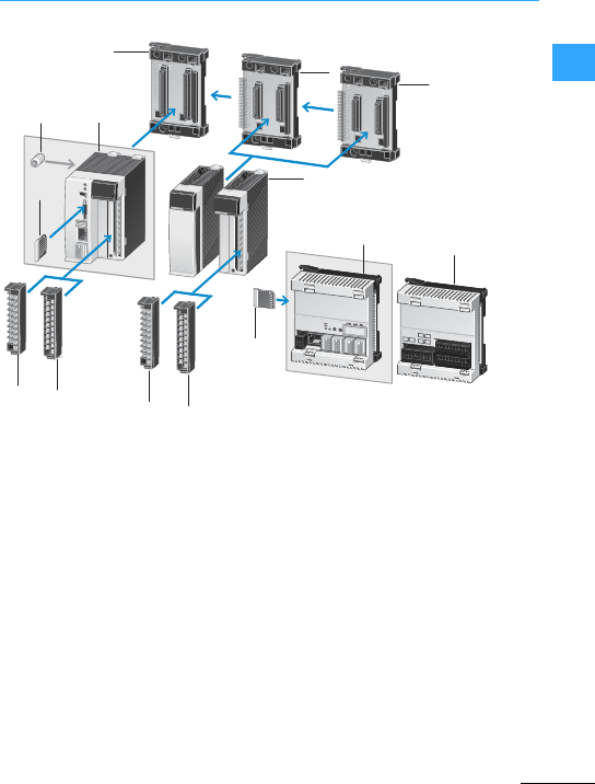
Eaton Wiring Manual 06/11
1
ModularPLC
1Racks
2Battery
3XC100/XC200 controllers
4XI/OC I/O-modules, Communication
modules
5Memorycard
6XI/OC terminal block (screw or
spring-cage terminal)
7XC121 controller
8XIO-EXT121-1 I/O-expansion for XC121
controller
DC INPUT EH-XD16
0
4
8
12
1
5
9
13
2
6
10
14
3
7
11
15
DC INPUT EH-XD16
0
4
8
12
1
5
9
13
2
6
10
14
3
7
11
15
XC-CPU201
0
4
0
4
1
5
1
5
2
6
2
14
3
7
3
15
3
8
2
5
11
1
6666
5
7
4
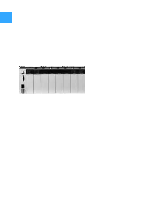
ModularPLC
Eaton Wiring Manual 06/11
1
Modular PLCs offer an outstanding level of
scalability. This ensures a high level of
flexibility for designing individual
automation systems. Different CPU
performanceclasses and a wide range of
expansion modules are available.
The data exchange via an Ethernet
interface to OPC clients or integrated WEB
servers enables the creation of innovative
solutions.
In this class Eaton offers the two XC100 and
XC200 series.
The controllers of the XC100 series are
universal automation devices for small and
medium-sized applications. They differ
according to the size of the available
program memory. One variant is provided
with an optical CAN interface.
•Expandable by up to 15 XI/OC modules
•Data storage on SD card
•CAN interface for communication
•RS232 interface
Furtherinformation 7Manual
MN05003004Z-EN
The controllers of the XC200 series offer a
high CPU performance and a wide range of
communication options. These devices
differ according to the size of the program
memory, the cycle time and the integrated
WEBserver.
•Expandable by up to 15 XIOC modules
•Data storage on SD card or USB stick
•Ethernet interface for programming and
communication
•CANinterface for communication
•RS232 interface
•Integrated web server
Furtherinformation7Manual
MN05003001Z-EN
The XIOC signal modules can be
connected to XC100 as well as to XC200
controllers (exception: XIOC-TC1
telecontrol module only to XC200). A wide
range of different modules are available:
•Digital input/output modules
•Analog input/output modules
•Temperature measuring modules
•Countermodules
•Serial interface module (RS232, RS485,
RS422; operating modes: Transparent
mode, Modbus master/slave, Sucom-A,
Suconet K slave)
•Telecontrol module
•Communication modules PROFIBUS-DP
master, PROFIBUS-DP slave, Suconet-K
master)
Furtherinformation7Manual
MN05002002Z-EN
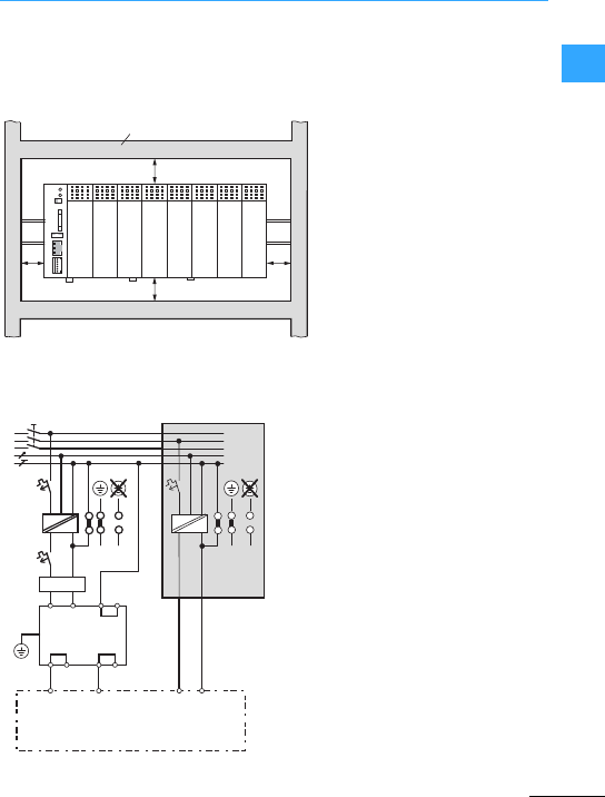
ModularPLC
Eaton Wiring Manual 06/11
1
Build the module racks and the controls
into the switchgearcabinet in ahorizontal
position.
aMain switches
bCircuitprotection device
c24 VDC supply voltage
dEarthed operation
eIn floating(i.e. unearthed) operation, an
isolation monitor must be used
(IEC 204-1, EN 60204-1, DIN EN 60204-1)
f24 V DC line filter; ensures that a
current of up to 2.2 A (maximum) is
available at a rated operating voltage of
24 V DC. Use of thefilter ensures that
the EMC stipulations for devices.
1*) Internally bridged
2*)Additional PE connection via contact
spring on rear
aClearance > 50 mm
bClearance > 75 mm to active
elements
cCable duct
c
ba
ba
b
a
b
a
~=~=
①
⑤④
⑥
⑤④
③
②
L1
L2
L3
N
PE
24 V 0 V DC 24 VQ0 VQDC
XC-CPU200
1*)
1*)1*)
XT-FIL-1
2*)
(CPU power supply) (power supply of
local digital I/O)
Ferrite ring
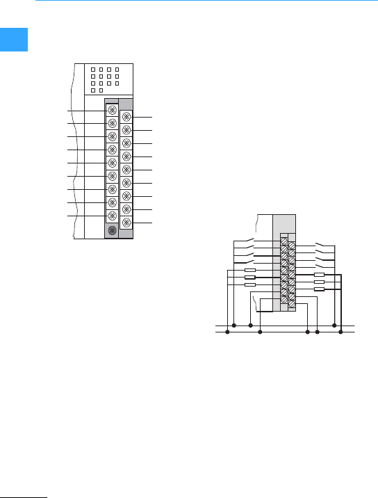
ModularPLC
Eaton Wiring Manual 06/11
1
The connections for the power supply and
the local inputs/outputs have the following
assignment:
The 0VQ/24VQ voltage terminal is intended
exclusively for the power supply to the
local inputs (8) and outputs (6),and is
electrically isolated from the bus.
At aduty factor (DF) of 100 %and a
utilization factor of 1, outputs 0 to 3can
each carry aload of 500 mA, and outputs
4and 5 a load of 1A.
The example shows the wiring with a
separate power supply for controller and
I/O terminals. If only one power supplyis
used, the following terminals must be
connected:
24 V to 24VQ and 0 V to 0VQ.
%IX 0.0 %IX 0.1
%IX 0.2 %IX 0.3
%IX 0.4 %IX 0.5
%IX 0.6 %IX 0.7
%QX 0.0 %QX 0.1
%QX 0.2 %QX 0.3
%QX 0.4 %QX 0.5
24 VQ0 VQ
0 V
24 V
+ 24 V ⎓
0 V ⎓
0
2
4
6
0
2
4
24 VQ
24 V
1
3
5
7
1
3
5
0 VQ
0 V
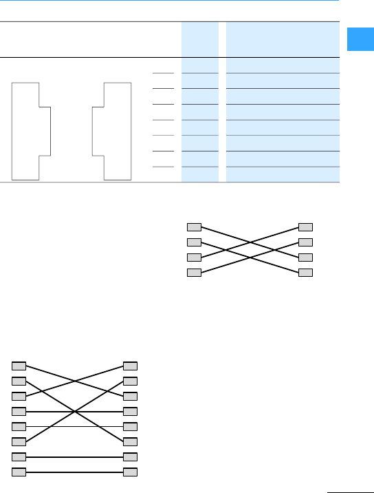
ModularPLC
Eaton Wiring Manual 06/11
1
From a purely physical/mechanicalpoint of
view the programing devices interfaceis
an RJ45 interface (socket). This means that
normal commercial RJ45 connectors or
Ethernet patch cables can be used.
•Direct connection PC –XC200:
TheXC200 can be connected directly to the
(programming) PC via acrossoverEthernet
cable.
Crossover cables have the following
design features:
–Connection set-up of 8-pole crossover
cable
–Connection set-up of a 4-pole
crossover cable
The following cross-over cables are
available:
XT-CAT5-X-2 (2 mlong)
XT-CAT5-X-5 (5 mlong)
•PC –XC200 via Hub/Switch connection:
If you use a Hub or a Switch between the
PC –XC200 connection, you must usea
standard Ethernet cable which is
connected 1:1 for the connection between
PC –Hub/Switch and Hub/Switch –XC200.
The cable EU4A-RJ45-USB-CAB1is
provided for programming via the USB
interfaceof a PC.
(XC-CPU101,
XC-CPU201)(XC-CPU202)
(XC-CPU201, XC-CPU202)
8RxD –
7GND –
6–Rx–
5TxD –
4GND –
3–Rx+
2–Tx–
1–Tx+
1
2
3
4
5
6
7
8
8
7
6
5
4
3
2
1
55
66
77
88
11
22
33
44
11
22
33
66
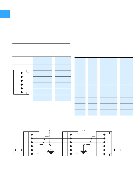
ModularPLC
Eaton Wiring Manual 06/11
1
Please note thatwhen there is a double
assignmentof the RJ45 interface with the
RS232 and Ethernet, the connections4 and
7 are connected to “GND potential”
because of the RS232 interface. For this
reason, we recommend theuse of 4-core
cables for the connection of the XC200 to
the Ethernet.
Configuration of the 6-pole Combicon plug:
Connectortype: 6-pole,pluggable
spring-loaded terminalblock
Connectorterminals: up to 0.5 mm2
Terminals 1 and 4 , 2 and 5 as well as 3 and
6 are internallyconnected.
The CAN interface is electrically isolated.
Bus termination resistors must be installed
at the first or last station on the line (->Fig.
below).
The bus terminating resistor on the
XC-CPU202 can be switched. The switch is
located above the battery.
Only use a cable thatis permissible for
CANopen with the following properties:
•Characteristic impedance 100 to 120 ?
•Capacitance perunit length < 60 pF/m
6GND
5CAN_L
4 CAN_H
3GND
2CAN_L
1 CAN_H
6
5
4
3
2
1
2
20 1000 0.75–0.80 16
125 500 0.50–0.60 40
250 250 0.50–0.60 40
500 100 0.34–0.60 60
1000 40 0.25–0.34 70
6
5
4
3
2
1
6
5
4
3
2
1
6
5
4
3
2
1
CAN_L
CAN_H
120 O120 O

ModularPLC
Eaton Wiring Manual 06/11
1
Terminal blocks with eitherscrew
terminals or spring-loaded terminals can
be optionallyused for the wiring.
•Cable lugs must not exceed 6 mm in
diameter.
•Do not attach more than 2 cable lugs to
one terminal.
•Use a cable with a maximum conductor
cross-section of 0.75 mm2,or 0.5 mm2if
two cable lugs are going to be fixed to the
same terminal.
Solid 0.5-2.5 mm20.14-1.0 mm2
Flexible with ferrule 0.5-1.5 mm2The cables are to be inserted into the
terminals with out the useof ferrules
or cable lugs.
Flexible –0.34-1.0 mm2
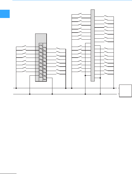
ModularPLC
Eaton Wiring Manual 06/11
1
0
1
2
3
4
5
6
7
0 V
8
9
10
11
12
13
14
15
0 V
XIOC-16DIXIOC-8DI
XIOC-16DI
8
9
10
11
12
13
14
15
0 V
24
25
26
27
28
29
30
31
0 V
0
1
2
3
4
5
6
7
0 V
16
17
18
19
20
21
22
23
0 V
+24 V ⎓
0 V
XIOC-32DI
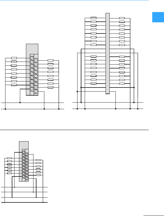
ModularPLC
Eaton Wiring Manual 06/11
1
When using inductive loads, connect a
free-wheel diode in parallel.
24 V ⎓
0 V ⎓
8
9
10
11
12
13
14
15
C
S
24
25
26
27
28
29
30
31
C
S
0
1
2
3
4
5
6
7
C
S
16
17
18
19
20
21
22
23
C
S
XIOC-32DO
0
1
2
3
4
5
6
7
24 V
8
9
10
11
12
13
14
15
0 V
XIOC-16DOXIOC-8DO
XIOC-16DO
24 V ⎓
0 V ⎓
+24 V ⎓
0 V ⎓
+24 V ⎓, 100/240 V ∼
0 V, N
0
1
2
3
4
5
C
24 V ⎓
6
7
8
9
10
11
C
0 V
XIOC-12DO-R
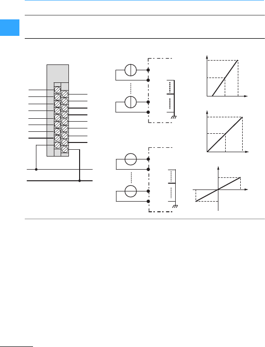
ModularPLC
Eaton Wiring Manual 06/11
1
+24 V ⎓
0 V ⎓
I/V
0+
1+
2+
3+
4+
5+
6+
7+
I/V
0–
1–
2–
3–
4–
5–
6–
7–
0 V
24 V ⎓
XIOC-8AI-I2
XIOC-8AI-U1/-U2
I0 +
I0 –
I7 +
I7 –
V7 +
V0 +
V0 –
V7 –
XIOC-8AI-I2
XIOC-8AI-U1
XIOC-8AI-U2
0000
hex
07FF
hex
0FFF
hex
41220
I
0
[mA]
0510
0FFF
hex
07FF
hex
0000
hex
U
0
[V]
0
0800
hex
10
–10 0000
hex
07FF
hex
U
0
[V]
XIOC-8AI-I2
XIOC-8AI-U1
XIOC-8AI-U2
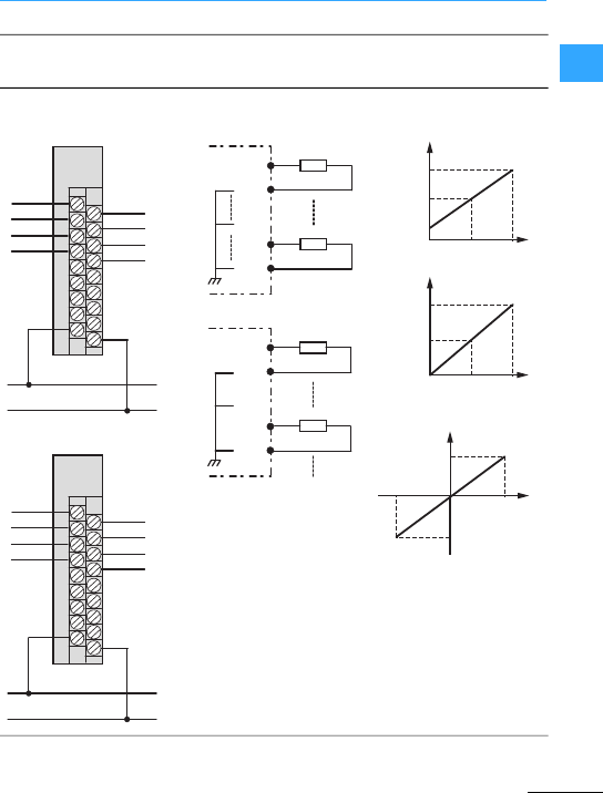
ModularPLC
Eaton Wiring Manual 06/11
1
+24 V ⎓
0 V ⎓
V0+
V1+
*V2+
*V3+
V0–
V1–
V2–*
V3–*
24 V ⎓ 0 V
+24 V ⎓
0 V ⎓
V0+
V1+
I2+
I3+
V0–
V1–
I2–
I3–
24 V ⎓
XIOC-2AO-U2
XIOC-4AO-U1/U2
XIOC-2AO-U1-2AO-I1
V0 +
V0 –
V3 +
V3 – *
V0 +
V0 –
I2 +
I2 –
XIOC-2AO-U2
XIOC-4AO-U1/U2
XIOC-2AO-U1-2AO-I1
4
12
20
0FFF
hex
07FF
hex
0000
hex
I
1
[mA]
0
5
10
0FFF
hex
07FF
hex
0000
hex
U
1
[V]
0
–10
07FF
hex
0800
hex
0FFF
hex
10
U
1
[V]
XIOC-2AO-U2
XIOC-4AO-U1/U2
XIOC-2AO-U2
XIOC-4AO-U1
XIOC-2AO-U1-2AO-I1
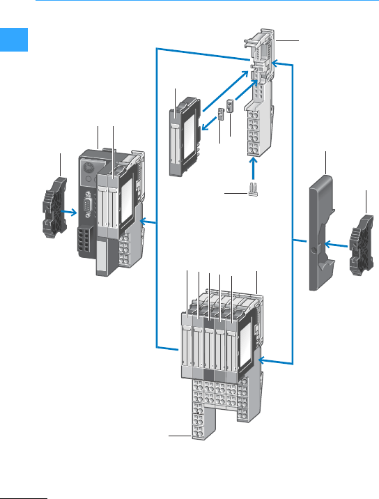
Eaton Wiring Manual 06/11
1
Modular I/O system
I/ONX
5
6
14
12
5
9
10
11
12
13
3
44
7
8
8
1Gateways
2 Digital input modules
3 Relais modules
4 Coding element
5 Base modules
6Relay jumpers
7 Cover plate
8 End bracket
9 Supply modules
10 Analog input modules
11 Digital output modules
12 Analog output modules
13 Technology modules
14 Marker
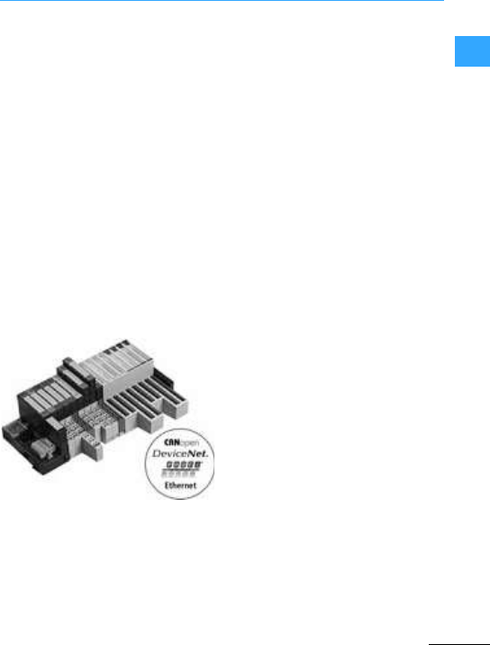
Modular I/O system
EatonWiring Manual 06/11
1
Whether controlling movements,
measuring temperature or speeds, logging
currents and voltages –the application
ranges forremote I/Os are varied. Remote
I/Os can be found wherever remote signal
processing is the key element of the
automation concept.
The XI/ON I/O system hasthe following
essentialfeatures:
•High modularity
•Field busses: CANopen, PROFIBUS-DP,
DeviceNet and Ethernet
•Bus-independent, plug-in modules
•Lowwiring requirement
•Effective diagnostics
•Space and cost savings with ECO
modules
•Programmable CANopen coupling unit
•Standard and ECO modules can be mixed
TheXI/ON I/O system providesan
extensive range of digital and analog I/Os
as well as technology modules:
•XI/ONECO gateways and ECO modules
XI/ON ECO adds cost andspace-optimized
I/O modules and gateways to the XI/ON I/O
system. The ECO gateways support the
CANopen,PROFIBUS-DP and Ethernet bus
systems.
–ECO gateways with built-in bus
termination resistors
–Full compatibility with the standard
XI/ON system
–No base modules required
–High channel density: (up to 16 DI/DO
over 12.5 mm width)
–Push-in spring-cage terminals
–Multi-functional slices
–Mini USB diagnostics interface
•XI/ONDefault gateways and standard
modules
The standard gateways support the
CANopen,PROFIBUS-DP, DeviceNet and
Ethernet bus systems.
–Use of the pluggable I/O modules is
possible regardless of the fieldbus
used
–Wiring implemented on base modules,
fixed wiring
–Hot-swapping of modules
–Generationof diagnostics information
forthe higher-level controller
–Up to 74 slice modules can be
connected pergateway
–Modules mechanical coding
•Programmable CANopen coupling unit
With the programmable CANopen
gateway, PLC performanceis now brought
directly to thefieldbus terminal. The device
is ideal for managing remote automation
tasks and thusrelieving the work load of a
higher-level PLC. The serial onboard
interface is used for programming onsite
and as an interface for the I/Oassistant
configuration and diagnostics tool.
Alternatively this interface can also be
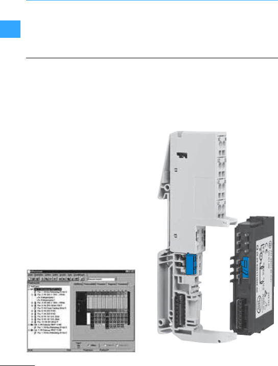
Modular I/O system
EatonWiring Manual 06/11
1
used as a free user interface. The gateway
is programmed with XSOFT-CODESYS-2.
•Base modulesforevery requirement
The base modules are used forconnecting
the fieldbus wiring for the standard XI/ON
modules. They are available for 2-, 3- and
4-cable connections, as block or slice
modules, either with spring-cage or screw
terminals.
The I/Oassistant is integrated in the
XSOFT-CODESYS-2 software and offers
interactive support in the entire planning
and implementation of an XI/ON system.
You choose the gateways, electronics and
basic modules, as well as the appropriate
accessories. The individual stations are
then either configured online or offline.
When everything is set to your
requirements, you put the system into
operation. I/Oassistant automatically
generatesafull parts list for your order.
TheI/Oassistant checks the station, reads
process data, outputs values and
visualizes the diagnosticsdata of the
channels. In this way, you can also
commission your station withoutthe need
forahigher-level controller and ensure
that one section of the installation is
functioning correctly.
The pluggable modules also allow hot
swapping for the fast and toolless
exchange of modules. The mechanical
coding of the modules prevents incorrect
fitting.
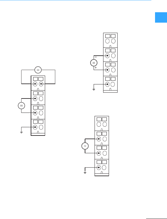
Modular I/O system
EatonWiring Manual 06/11
1
•Module forfeeding the 24 V DC system
power supply and the 24 V DC field
voltage supply
XN-P4…-SBBC with gateway supply
XN-P4…-SBBC-B without gateway
supply
•Field power supply module 24 V
XN-P4…-SBBCforXN-PF-24VDC-D
•Field power supply module 120/230 V AC
XN-P4...-SBB for XN-PF-120/230VAC-D
24 V ⎓
24 V ⎓
–
+
PE
–
+
11 21
12 22
13 23
14 24
Module bus supply
Fieldbus
supply
11 21
12 22
13 23
14 24
24 V ⎓
PE
11 21
12 22
13 23
14 24
N
L
PE
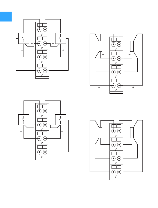
Modular I/O system
EatonWiring Manual 06/11
1
•Positive switching
XN-S4…-SBBCfor XN-2DI-24VDC-P
•Negative switching
XN-S4…-SBBCfor XN-2DI-24VDC-N
•Positive switching
XN-S4…-SBCS for
XN-2DO-24VDC-0.5A-P
XN-2DO-24VDC-2A-P
•Negative switching
XN-S4…-SBCS for
XN-2DO-24VDC-0.5A-N
11 21
12 22
13 23
14 24
SS
PE PE
11 21
12 22
13 23
14 24
SS
PEPE
11 21
12 22
13 23
14 24
PE PE
SS
11
++
21
12 22
13 23
14 24
SS
PE PE
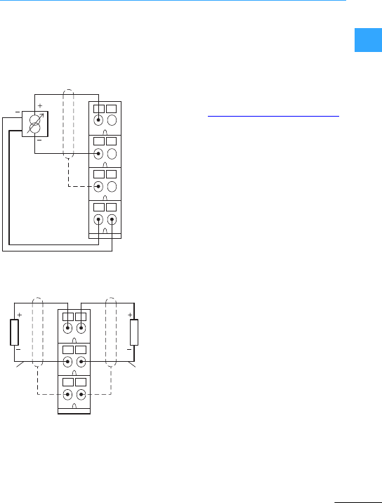
Switching, control, visualization
Modular I/O system
Eaton Wiring Manual 06/11
1-129
1
1
Analog input modules
XN-S4…-SBBS for XN-1AI-I(0/4...20MA)
XN-S4…-SBBS for
XN-1AI-U(-10/0...+10VDC)
Analog transmitter with non-isolated
transmitter supply
Analog output module
XN-S3...-SBB for XN-2AO-I(0/4...20MA)
Further connection examples can be found
in the manuals:
XI/ON digital I/O modules, power supply
modules, MN05002010Z-EN
(previously: M001735-02)
XI/ON analog I/O modules,
MN05002011Z-EN (previously: M001756-04)
These manuals can be downloaded as PDF
files at www.eaton.com/moellerproducts
in the “Products & Solutions” area.
11 21
12 22
13 23
14 24
Sh
Uh
Uh+
11 21
12 22
13 23
ShSh
Channel 1 Channel 2

Eaton Wiring Manual 06/11
1
Software
Users of automation components such as
machine and system builders are
increasingly no longer satisfied with single
solutions. This is why standardssuch as
IEC 61131-3 have become established as
manufacturer-independent standards for
PLC programming. CoDeSys supportsall
programming languages described in the
IEC-61131 standard.
CoDeSys is based on a standard of 3S.
Proven technical features, simple handling
and a wide distribution of this software for
programming automation components of
different manufacturers guarantee its
success.
All Eaton controllers are programmed with
the CoDeSys software. Programming can
be carried out in different programming
languages. These are divided into
text-based or graphic-based languages.
An instruction list (IL) consists of a
sequence of instructions. Each instruction
startson anew line and contains an
operator and one or several comma
separated operands –depending on the
type of operation.
An identifier label followed by a colon (:)
may be placed in front of an instruction.
This is used for labelling the instruction
whichcan then be used as a jump target.
A comment must always be the last
element of a line.
Example:
LD 17
ST lint (* comment *)
GE 5
JMPC next
LD idword
EQ istruct.sdword
STN test
next:
Structured Text (ST) consistsof aseries of
instructions thatare arranged as in high
level languages (IF...THEN...ELSE) or in
loops(WHILE…DO).
Example:
IF value < 7 THEN
WHILE value < 8 DO
value := value +1;
END_WHILE;
END_IF
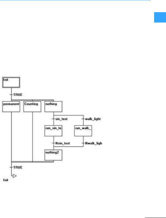
Software
Eaton Wiring Manual 06/11
1
Sequential function chart (SFC) is a
graphical language.It enablesthe timing of
different actions within a programto be
defined. Different step elements are used
forthis which are assigned to specific
actions and which are controlled by
so-called transition elements.
Example of a network in a sequential
function chart:
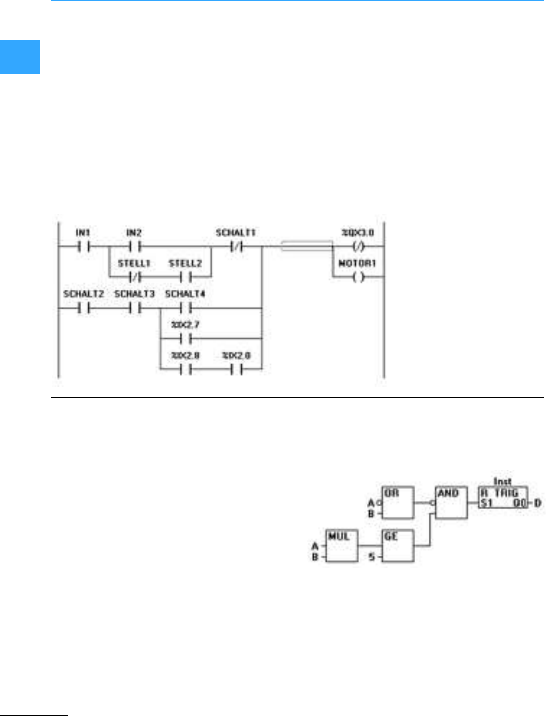
Software
Eaton Wiring Manual 06/11
1
Ladderdiagram is a graphical
programming language which closely
followsthe principle of an electrical
circuit.
On the one hand, ladder diagram is suitable
fordesigning logical switch systems, on
the other hand, it is also possible to create
networks as in FBD. LD is therefore very
good for controlling the calling of other
blocks. Ladder diagram consists of a
sequence of networks. A network is
bordered on the left and right by aleft and
rightvertical current path. A circuit
diagram consisting of contacts, coils and
connection lines is located in between.
Example of a network in ladder diagram
consisting of contacts and coils:
Function block diagram is a graphical
programming language. It operates with a
list of networks, in which each network
contains a structure that may represent a
logic andarithmetic expression, the calling
of afunction block, a jump or a return
instruction.
Example of a network in a function block
diagram:
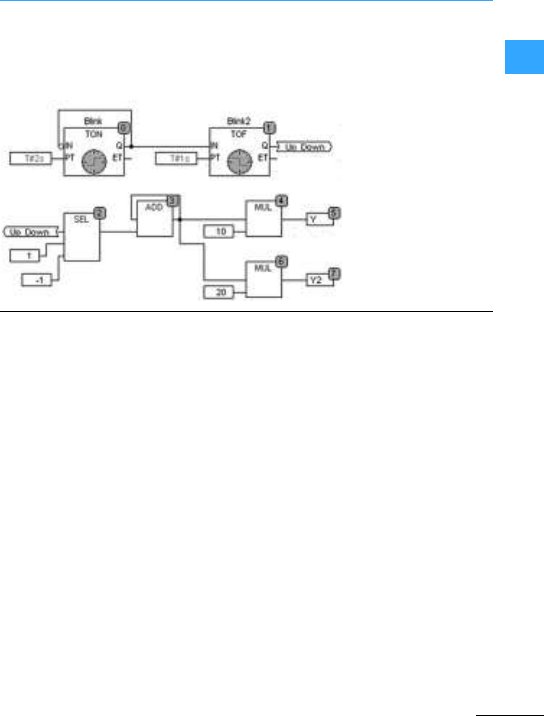
Software
Eaton Wiring Manual 06/11
1
The freely graphical function chart is
based on function block diagram (FBD) but
does not work like this with networks but
with freely placable elements. This enables
forexample the implementation of
feedback paths.
Implementation example in freely
graphical function block diagram editor:
The CoDeSys programming systemalso
contains a visualization editoras well as
the programming tool. This offers a clear
advantage:
Only one additional software package is
required to visualize (i.e. for monitoring and
operation) the data of a controller
programmed in CoDeSys. Whilst the
application is being developed, the user
can already create visualization screens in
the same user interface. The visualization
integrated in CoDeSys can access the
variables from the controller directly.
If the controller has a display (HMI-PLC),
this visualization can be displayed directly
on the panel (target visualization).
Many controllers are now equipped with a
web server. If required CoDeSys
generatesfrom the visualization data an
XML description which is stored on the
controller togetherwith a Java applet and
which can be shown onabrowserusing
TCP/IP (WEB visualization).
For itsHMI and HMI-PLCs Eaton offers an
easy to learn project design environment
that is nevertheless powerful and
comprehensive –ideal for use in all
machine and process-relevant
applicationsin system and machine
building. Galileo has a sector neutral
design and offers seamless project design
forall of Eaton's graphical HMI devices.

EatonWiring Manual 06/11
1


Eaton Wiring Manual 06/11
22
Drives engineering basic information
Each drive task requires a drive motor. The
speed,torque and controllability of each
motor must fulfill the requirements of the
task. As ageneral rule, the application
determines the drive.
The drive motor most frequently used
worldwide in industrial plants and large
buildingsis the three-phase asynchronous
motor. Its robust and simple construction
as well as itshigh degrees of protection
and standard types are the main features
of this inexpensive electricmotor.
• "
In the simplest case the motoris
connected directly with a contactor. The
combination of motorprotection and
cable protection (fuse) is called a motor
starter (MSC = Motor Starter
Combination).
By applying the full mains voltage to the
motor windings, DOL starting may
produce large starting currents which
may result in troublesome voltage
changes. Direct-on-line starting
three-phase motors must not cause
interference voltage changes in the
public utility grid. This requirement is
generally fulfilled if the apparent power
of a three-phase asynchronous motor
does not exceed 5.2 kVA or its startup
current does not exceed 60 A.
With a mains voltage of 400 Vand 8 times
the starting current, this corresponds to
a rated motor current of around 7.5 A and
thus a motor rating of 4kW.
The motor rating denotes the mechanical
output of the motor at the shaft.
• !
This is the most popular and commonly
used starting method for motor ratings
>4kW (400 V).
•
G
These enable the soft and low-noise
starting of the motor. This eliminates
interference producing current peaks
and jerks during switching.The startup
and deceleration phase of themotor can
also be time-controlled depending on the
load.
• E
This enables time-controlled motor
starting, motor braking and operation
with infinitely variable motor speeds.
Depending on the application, different
types of frequency inverters are used:
–with the voltage/frequency control
(U/f) or vector control for
frequency-controlled motor operation,
–with vector control or servo controlfor
highspeed accuracy and additional
torque adjustment.
Associated circuit diagrams 7page2-3
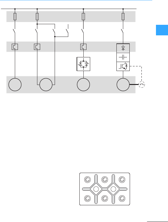
Drives engineering basic information
Eaton Wiring Manual 06/11
22
B1: Speed measuring (pulse generator)
F1: Fuse protection
(short-circuit and cable protection)
F2: Motor protection
(protection from thermal overload,
overload relay)
M1: Three-phase asynchronous motor
Q1: Switching
(contactor, motorcontactor)
Q2: Soft starter, electronic motorstarter
T1: Frequency inverter
When connecting a three-phase motor to
the mains supply, the data on the rating
plate of the motor must correspond to the
mains voltage and frequency.
The standard connection is implemented
via six screw terminals in the terminal box
of the motor and with two types of circuit,
the star connection and the delta
connection, depending on the mains
voltage.
M
①
F1
3 / N / PE / AC 50/60 Hz
Q1
F2
M1 3~MB1
T1
Q2
3~
M
④
3~
M
②③
3~
∆
U1 V1 W1
W2 U2 V2
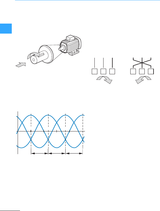
Drives engineering basic information
Eaton Wiring Manual 06/11
22
The rotation direction of amotor is always
determined by directly looking at the drive
shaft of the motor (from the drive end). On
motors with two shaft ends, the driving end
is denoted with D (= Drive), thenon-driving
end with N (= No drive).
Regardless of the circuit type and the type
of three-phase asynchronous motor, the
connections must be labeled, so thattheir
alphabetical sequence (e.g.U1, V1, W1)
corresponds with the order of the mains
voltage sequence (L1, L2, L3) and causes
the motorto rotate clockwise.
On the three-phase asynchronous motor,
three windings are arranged offset from
each other by 120°/p (p =number of pole
pairs). When a three-phase AC voltage
with a 120° phase sequence is applied,this
produces a rotation field in the motor.
The effect of inductance causes the
rotation field andtorque to be formed in the
rotorwinding. The speed of the motor thus
depends on the number of pole pairs and
the frequency of the supply voltage. The
rotation direction can be reversed by
swapping over two of the supply phases.
The electrical and mechanicalrating data
of the motor must be stated on its rating
plate (IEC 34-1, VDE 0530). The data on the
rating plate describes the stationary
operation of the motorin the area of its
operating point (MN, e.g. at 400 V and
50 Hz). The operating data is unstable in the
motor start phase.
The following examples show the rating
plates for two motors with a motor shaft
output of 4kWand the respective
connection circuitson a three-phase AC
network with 400 Vand 50 Hz.
90°
0
L1L2L3
360°
L1
120° 120° 120°
180°
270°
Clockwise (FWD) Anticlockwise
operation (REV)
FWD =forward run (clockwise rotation
field)
REV =reverse run (anticlockwise rotation
field active)
L1 L2 L3
U1 V2
W3
L1 L2 L3
U1 V2
W3
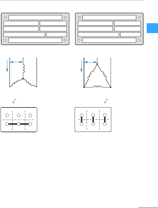
Drives engineering basic information
Eaton Wiring Manual 06/11
22
, ,
•With the specified 230/400 V voltage,
this motor must be connected to the
three-phase supply (ULN =400 V) in a
star configuration.
•With the specified 400/690 V voltage,
this motormust be connected to the
three-phase supply (ULN = 400 V) in a
delta configuration.
•The voltage of each motor winding is
designed for 230 V. The windings must
therefore be connected in sequence to
the phase voltage (400 V).
•Each motor winding is designed here for
the maximum phase voltage of 400 V
and can be connected directly.
•The three winding phases (W2-U2-V2)
are configured in the terminal boxto the
so-called star point. The voltage of the
individual phases to the star point is
230 V (= UW).
•The three winding phases (U1 –W2,
V1 –U2, W1 –V2)are combined in the
terminal box and connected directly to
the individual phases.
1410 min-1
230 / 400 V14.5 / 8.5 A
50 Hz
IP 54 Iso. KI F
4.0 KWS1 cos ϕ0.82
△ /
1410 min-1
400 / 690 V8.5 / 4.9 A
50 Hz
IP 54 Iso. KI F
4.0 KWS1 cos ϕ0.82
△ /
L1 L3L2
V1
V2
U1 W1
W2
U2
ULN
ILN
L1 L3L2
U1
W1
V1
V2
W2
U2
ULN
ILN
ULN 3U
W
(=I
LN IW
=
ULN UW
=
ILN 3I
W
(=
U1 V1 W1
W2 U2 V2
U1 V1 W1
W2 U2 V2
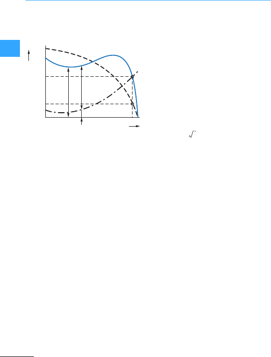
Drives engineering basic information
Eaton Wiring Manual 06/11
22
The following figure shows the
characteristic startup curves of a
three-phase asynchronous motor.
IA: Starting current
IN: Rated operational current at the
operating point
MA: Starting torque
MB:Accelerating torque (MM> ML)
MK: Breakdown torque
ML: Load torque
MM:Motor torque
MN:Ratedload torque,(stable operating
point,intersection point of the three-
phase speed torque characteristic
with the load characteristic)
MS:Pull-up torque
n: Speed (actual value)
nN: Rated speed at the operating point
nS:Synchronous speed
(nS- nN= slip speed s)
Synchronous speed:
Slip speed in %:
Three-phase asynchronous motor speed:
fFrequency of voltage in Hz (= s-1)
n Speed in r.p.m.
pNumber of pole pairs
s: Slip speed in r.p.m.
Electric power:
P1:Electricalpower in W
U: Rated operating voltage in V
I: Rated operational current in A
cos ':Power factor
Motor output (power equation):
P2:Mechanical shaft output power in kW
MN:Rated torque in Nm
n: Speed in r.p.m.
Efficiency:
The features of the startup variants "to
Edescribed on page 2-2 are shown on
the following pages 2-6 and 2-7.
The graphs show the typical
characteristics.
MN
nN
n
nS
MA
MM
MB
MK
ML
MS
IA
IN
M, I
0
nsf
p
---=
snsn–
ns
-------------- 100%#=
nf
p
--- 1s–'&#=
P
1
UI 3 -cos(((=
P2
MNn(
9550
-----------------=
!P2
P1
-----=
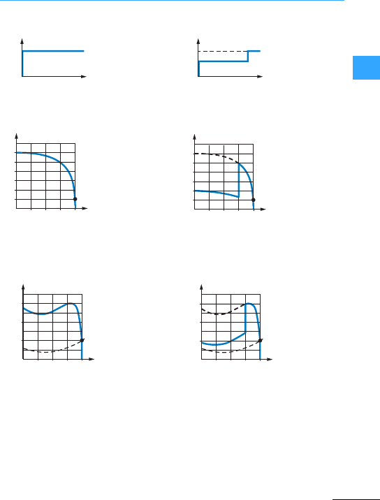
Drives engineering basic information
Eaton Wiring Manual 06/11
22
•Mains load high
•Relative startup current
4to 8x Ie(depending on motor)
•Relative startup torque
1.5 to 3x MN(depending on the motor)
•Features:
–Strong acceleration with large starting
current
–High mechanical load
•Scope of application:
Drives on powerful supply networks that
allow high starting currents (torques)
•Medium mains load
•Relative starting current
1.3to 3x Ie(~ .compared to DOL start)
•Relative starting torque
0.5to 1 x MN(~ .compared to DOL start)
•Features:
–Startup with reduced current and
torque
–Current, torque peak on switching
•Application range:
Drives thatare only subject to loads after
the startup
100 %
t
U
2
4
6
I/Ie
n/nN
IN
0.25 0.5 0.75 1
2
3
n/nN
MN
1
0.25 0.5 0.75 1
ML
M/MN
100 %
58 %
t
U
Δ
2
4
6
I/Ie
n/nN
IN
0.25 0.5 0.75 1
2
3
M/MN
n/nN
MN
ML
1
0.25 0.5 0.75 1
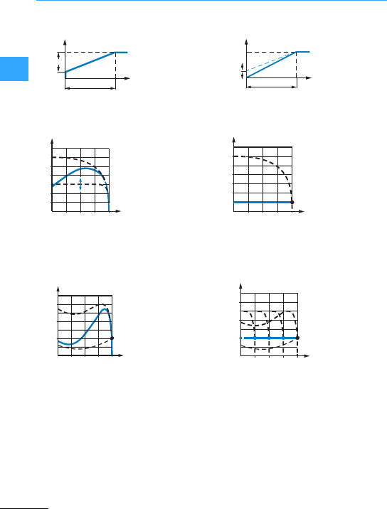
Drives engineering basic information
Eaton Wiring Manual 06/11
22
•Lowto medium mains load
•Relative starting current
2to 6x Ie(reduced by voltage control)
•Relative starting torque
0.1 to 1x MN(M ~ U
2
, quadratically
adjustable by voltage control)
•Features:
–adjustable starting characteristics
–controlled deceleration possible
•Application range
Drives with starting behavior adjusted to
working machine.
•Low mains load
•Relative starting current
#1to 2x Ie(adjustable)
•Relative starting torque
~0.1to 2 x MN(M ~U/f, adjustable
torque)
•Features:
–high torque at low current
–adjustable starting characteristics
•Application range:
Drives requiring a controlled and
infinitely variable speed adjustment.
t
100 %
30 %
U
U
Start
t
Start
2
4
6
I/Ie
n/nN
IN
0.250.5 0.75 1
2
3
n/nN
MN
M/MN
1
0.25 0.5 0.75 1
ML
t
100 %
U
UBoost
t-acc
2
3
4
5
6
I/Ie
n/nN
IN
1
0.25 0.5 0.75 1
2
3
n/nN
MN
M/MN
1
0.25 0.5 0.75 1
ML
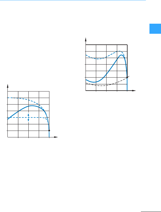
Eaton Wiring Manual 06/11
22
Soft starter basic information
Soft starters are electronic devices for the
softstarting of three-phase motors. Soft
starters must comply with the product
standard IEC/EN 60947-4-2.
During the startup phase of a motor, a soft
startercontrols the power supply smoothly
and continuously up to the rated value
(ULN)by controlling the phase angle. This
voltage control limitsthe starting current
since the motor current behaves
proportionally to the motor voltage. The
resulting smooth torque increase enables
the motorto be adapted to the load
behavior of the motor.
The mechanical components of this type of
drive unit are therefore accelerated very
smoothly. This has a positiveeffect on the
lifespan, operating behavior and operating
processes, and prevents any adverse
effects such as:
•Impacting of cog edges in the gearbox
•Reduction of the water hammers in pipe
systems
•Slipping of V belts
•Jitterwith conveyor systems
After a time controlled voltage change has
elapsed (TOR = Top-of-Ramp), so-called
bypass contacts can be used to bridge the
phase angle control for the static
continuous operation. The considerably
lower transition resistance of the
mechanical switch contacts compared to
power semiconductors enables heat
dissipation in the soft starter to be reduced
and the lifespan of the power
semiconductors to be extended.
2
3
4
5
6
I/Ie
n/nN
IN
1
0.25 0.50.75 1
2
3
n/nN
MN
M/MN
1
0.25 0.5 0.75 1
ML

Soft starter basic information
EatonWiring Manual 06/11
22
The acceleration time of a drive with a soft
starteralways depends on the load andthe
breakaway torques. When commissioning
this type of drive system,the required
breakaway torque should be set first of all
by means of the start voltage (U-Start) and
then the shortest possible ramp time
(t-Start) should be determined forthe linear
voltage change.
As well as thetime-controlled startup of a
motor, the soft starter also enables a
time-controlled reduction of the motor
voltage and thus a controlled stopping of
the motor. This type of stop function is
primarily used for pumpsin order to
preventpressure waves (water hammer).
Jerky movements and therefore the wear
on drive chains and drive belts as well as
bearingsand gears can be reduced.
The set ramp time for the deceleration
(t-Stop) must be greater than the
load-dependent uncontrolled deceleration
time of the machine.
TOR
U
LN
t
U-Start
t-Start
ULN =Mains voltage
U-Start =Start voltage
t-Start =Ramp time of the
voltage change
TOR =Top-of-Ramp (end point
of the voltage control: U = ULN)
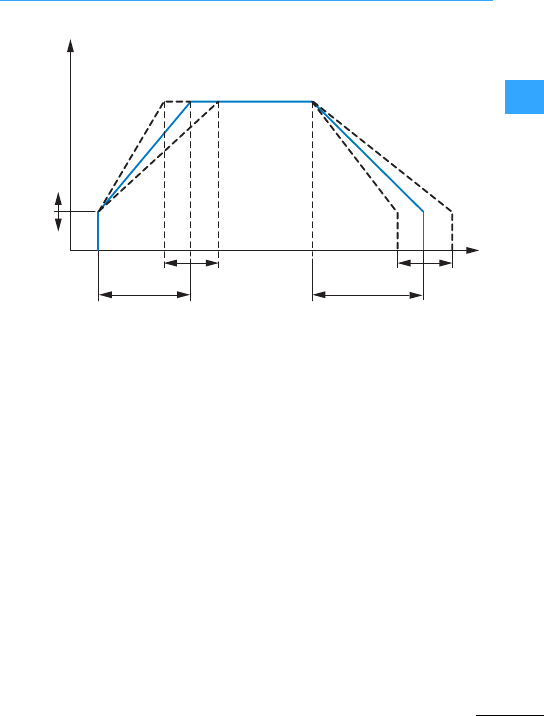
Soft starter basic information
EatonWiring Manual 06/11
22
The ratio of the overload current to the
rated operational current, the total of the
times for the controlled overload current,
as well as the duty factor and start cycle
form the overload current profile of a soft
starter; this data is stated on the rating
plate in accordance with IEC/EN 60947-4-2.
55A: AC-53a: 3-5 : 75-10
55A =Rated operational current of the
soft starter
AC-53a = Load cycle in accordance with
IEC/EN 60947-4-2
3 = 3-fold overcurrent at start
(3 ×55 A= 165 A)
5 = Overcurrent duration in seconds
75 = Duty factor within the load cycle in %
10 = Number of permissible starts per hour
Other overload cycles and operating
frequencies can be calculated.
Furtherinformation on this is provided in
the relevant softstartermanual.
The controlled deceleration presents a
similar load on the powersemiconductors
in the soft starter as the start phase. If
therefore the deceleration ramp is
activated on asoft starterwith amaximum
of 10 permissible starts per hour, the
number of permissible starts is reduced to
5 per hour (plus 5 stops within the same
hour).
U-Start
U
t-Start t-Stop
t
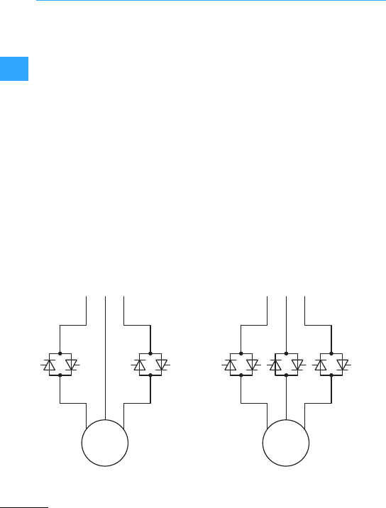
Soft starter basic information
EatonWiring Manual 06/11
22
Softstarters are usually divided into two
types:
•Two-phase controlled,electronic soft
startersfor simple tasks:
–Use is limited to small and medium
rated motor (< 250kW).
–Simple handling with limited setting
options and time controlled voltage
ramps.
–For simple applications where
importance is placed on jerk-free
operation in the starting phase.
–They are an inexpensive alternative to
the star-delta starter.
–They can only be used in so-called
In-Line configurations.
•Three-phase controlled, electronic soft
startersforcomplex tasks:
–For medium to high motor ratings up to
800 kW as compact devices
–The devices are provided with an
adjustable current limitation and
integrated motor protection functions.
–They have preset application
characteristicsand can be
parameterized for optimizing the
machine start functions.
–Control inputs, signal contacts and
optional fieldbus interfaces enable a
wide range of communication options
to be implemented.
–They can be used in both In-Line and
In-Delta configurations.
Example: see DM4 7page2-57
L1 L2 L3
M
3 ~
L1 L2 L3
M
3 ~
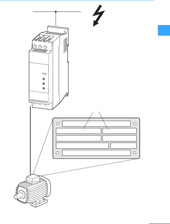
Soft starter basic information
EatonWiring Manual 06/11
22
230 / 400 V ∆ / 4.0 / 2.3
0,75 0.67
kW
min-1
1410 50 Hz
A
②
③
①
U, I, f
cos ϕ
The soft starterGis selected on the
basis of the supply voltage ULN of the
supply network "and the rated
operational current of the assigned
motor !.The circuit type (-/8) of
the motor must be selected according
to the supply voltage ". The rated
outputcurrent Ieof the soft starter
must be greater than/equal to the
rated motor current.
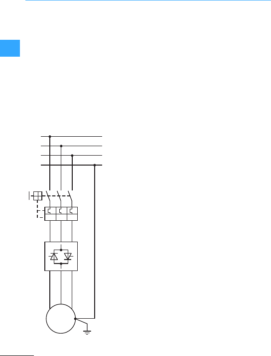
Soft starter basic information
EatonWiring Manual 06/11
22
When selecting the drive,the following
criteria must be known:
•Type of motor
(three-phase asynchronous motor)
•Mains voltage = rated operating voltage
of the motor(e.g. 3AC ~ 400 V)
•Rated motor current (recommended
value, dependent on thecircuit type and
the power supply)
•Load torque (quadratic,linear)
•Starting torque
•Ambient temperature
(rated value +40 °C).
The switching and protective devices
(electromechanical components) in the
main circuit of the motor feeder are
designed on the basis of the rated
operational current (Ie) of the motor andthe
utilization category AC-3 (standard
IEC60947-4-1).
The utilization category here is AC-53a
(IEC/EN60947-4-2 standard).
•AC-3 = squirrel-cage motors: startup,
switch off during operation.
•AC-53a = control of a squirrel-cage
motor: eight-hour duty with starting
currents forstart processes, settings,
operation
L1
L2
L3
V1 W1
U1
PE
I >I >I >
M
3 ~
Motor feeder with DS7
soft starter combined
withPKZM0 in In-Line
circuit
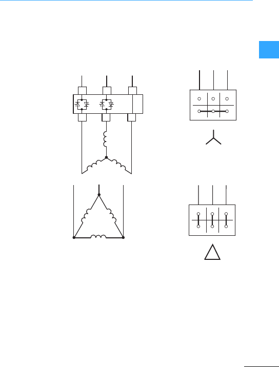
Soft starter basic information
EatonWiring Manual 06/11
22
Three-phase asynchronous motors can be
connected to a soft starter, depending on
the mains voltage in a star or delta
connection.
2 phase controlled soft starter(DS7)
L1 L3
L1 L3
L2
L2
T1 T2 T3
U1 V1 W1
W2 U2 V2
U1 V1 W1
W2 U2 V2

Soft starter basic information
EatonWiring Manual 06/11
22
Three-phase motors with a neutral point
(starcircuit) must not be connected to a
two-phase controlled softstarteras one
phase is connected here directly to the
mains voltage and causes impermissible
overheating in the motor.
The power section of soft
starters is formed with semi-conductors
(thyristors). When a supply voltage (ULN) is
present, there is also a dangerous voltage
presentat the output to the motorin the
OFF/STOP state.
This warning applies to all soft starter
types.
2 phase controlled soft starter
Not permissible
L1 L3
L1 L3
L2
L2
T1 T2 T3
M
3 ~
1L1 3L2 5L3 PE
PE2T1 4T2 6T3
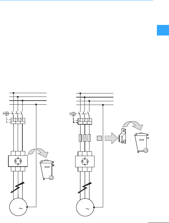
Soft starter basic information
EatonWiring Manual 06/11
22
The following coordination types are
defined in IEC/EN 60947-4-3, 8.2.5.1:
In type 1 coordination,the device must not
endanger persons or the installation in the
eventof a short-circuit and does not have
to be capable of continued operation
without repairs or partsreplacements.
In type 2 coordination, the device must not
endanger persons or the installation in the
event of a short-circuit and must be capable
of continued use withoutrepairs or parts
replacements. For hybrid control devices
and contactors, there is arisk of contact
welding, for which the manufacturer must
give maintenance instructions.
The assigned short-circuit protective
device (SCPD) must trip in the event of a
short-circuit.If afuse is used, this has to be
replaced. This is part of the normal
operation of the fuse, also for type 2
coordination.
Superfast semiconductor fuses must
always be arranged directly in front of the
power semiconductors (short cable
lengths).
M
3
L1
L2
L3
PE
Q1
L1 L2 L3
T1 T2 T3
M1
Q21
I>I>I>
Type 1 coordination
M
M1 3
L1
L2
L3
PE
Q1
F3
Q21
L1 L2 L3
T1 T2 T3
I>I>I>
F3: Superfast
semi-conductorfuses,
in addition to the
short-circuitand cable
protection Q1
Hybrid control devices =
Soft starter with bypass
contacts
Hybrid contactors =
Electronicmotorstarters
(EMS)
Type 2 coordination
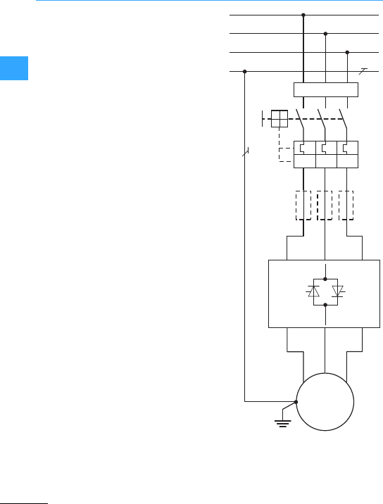
Soft starter basic information
EatonWiring Manual 06/11
22
Residual currentdevices (RCDs) protect
persons and animals from the presence
(not the creation!) of impermissibly high
contactvoltages. They prevent dangerous
and fatal injuries caused by electrical
accidents and also serveas fire
prevention.
Standard residual currentdevices (RCD
typeA)with up to 30 mA and higher can be
used with a soft starter.
F1:Residualcurrent device (RCD)
F3: Optional semiconductorfuses
for type 2 coordination
M1: Motor
Q1: Cable protection + motorprotection
Q21:Soft starter M
3 ~
1L1
2L3
3
L5
1T2
2T4
3T6
L1
L2
L3
PE
Q1
RCD
Q21
F1
F3
M1
I>I>I>
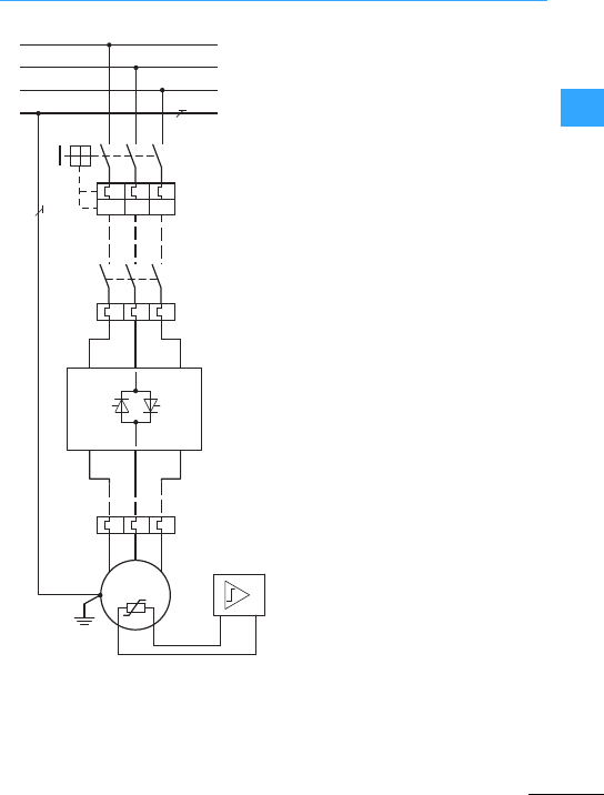
Soft starter basic information
EatonWiring Manual 06/11
22
The motor protection protects the
three-phase asynchronous motorfrom
thermal overload caused by amechanical
overload or the failure of one or two
connection cables.
Thereare two basic ways of protecting the
three-phase motor from overload during
operation:
•Monitoring of currentconsumption
(motorprotection, overload relay or
bimetal relay)
•Direct temperature monitoring in the
motor winding(PTC, thermistor)
aMotor-protective circuit-breaker(PKZ,
PKE, NZM), disconnection with manual
release
bOverload relay(ZB, ZEB) –here in
combination with a contactor
cOverload relay(ZB, ZEB) for indication
of the thermal overload
dThermistor, PTC or positive temperature
coefficient protection in the motor
winding with external indication relay
(EMT)
The combination of the current monitoring
motor protection variants ",!or Gwith
thetemperature monitoring variants Eis
also called full motor protection.
After a motor protective device has tripped,
the softstarter and the protective device
cannot be switched on again until it has
cooled down.The reset depends on the
temperature.
M
3 ~
1L1
2L3
3L5
1T2
2T4
3
T
6
L1
L2
L3
PE
M1
I>I>I>
①
②
③
④

Soft starter basic information
EatonWiring Manual 06/11
22
You can also use soft starters to start
several motors connected in parallel. This
does not, however, allow the startup
behavior of the individual motors to be
controlled.
•The current consumption of all
connected motors must not exceed the
rated operational current Ieof the soft
starter.
•Each motor must be protected from
thermal overload individually, e.g.with
thermistors and/or overload relays (F11,
F12) . Alternatively, motor-protective
circuit-breakers (Q11, Q12) can also be
used.
•It is advisable to use this circuit type only
with motors of a similar rating (maximum
deviation: one ratingsize). Problems may
arise during starting if motors with
significant rating differences (for
example 1.5 kW and 11 kW) are
connected to the output of a soft starter.
The lower-rated motors may notbe able
to reach the required torque due to the
relatively high ohmic resistance of their
stators. During the startup these require
ahigher voltage.
•The last motor must not be switched off
in operation since the resulting voltage
peaks maycause damage to the
electronic components in the soft starter
and thus to its failure.
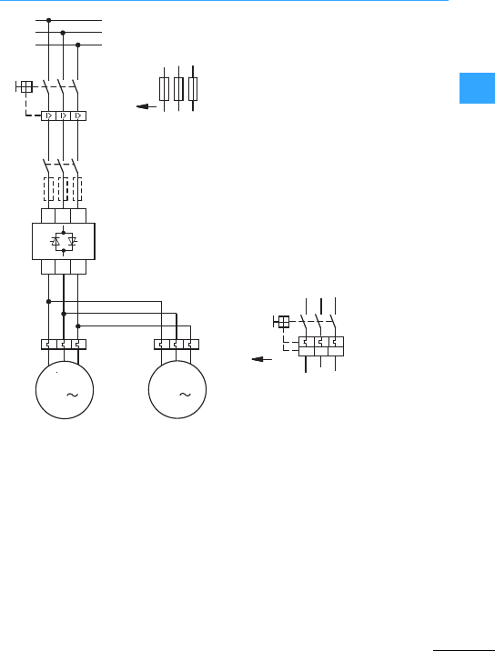
Soft starter basic information
EatonWiring Manual 06/11
22
F11, F12: Motor protection (overload
relay) or motor-protective
circuit-breaker (Q11, Q12)
F3: Superfast semi-conductor
fuses (optional, additionally to
Q1 and F1)
Q1 or F1: Short-circuit and cable
protection
F1
F3
M
M1 M2
3
Q11
Q21
L1
L2
L3
Q1
L1 L2 L3
T1 T2 T3
F12
F11
M
3
Q11
Q12
I > I>I>

Soft starter basic information
EatonWiring Manual 06/11
22
When upgrading or modernizing older
installations, contactors and rotor resistors
of multistage three-phase stator automatic
starters can be replaced with soft starters.
This is done by removing the rotor resistors
and assigned contactors and
short-circuiting the slip rings of the motor’s
rotor. The soft starter is then connected
into the feeder. The smooth starting of the
motor can then be implemented.
7Figure, page 2-23
•Slip ring motors develop a high starting
torque with low starting current.They
canthus be started at the rated load and
this must be taken into account when
selecting asoftstarter. The soft starter
cannot replace the rotor resistors in
every application.
•Depending on the type of motor, it may be
necessary to keep the last resistor group
permanently connected to the slipring
rotor terminal(K-L-M).
Q1: Cable and motor overload protection
or
F1: Cable protection and
F2: Overload protection required
(thermistor, bimetal relay) if the soft
starter (Q21) does not include this
function. Example:overloadrelay F2 in
combination with contactor Q11.
M1:Slip-ring motor
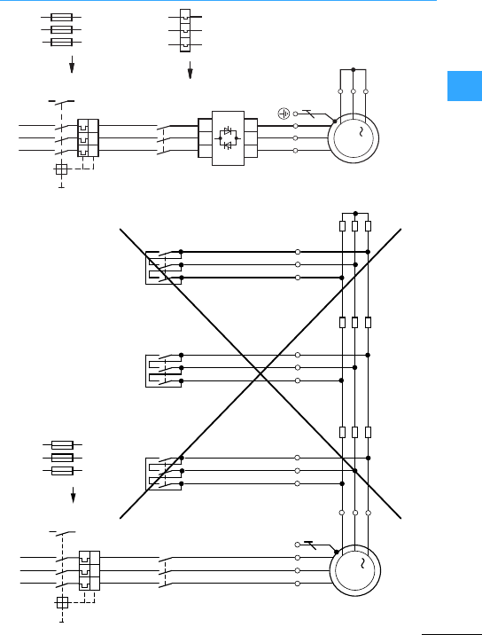
Soft starter basic information
EatonWiring Manual 06/11
22
L1 L2 L3
Q1
13513
14
F1
26
4
246
PE
UVW
M
3
M1
135
Q11 Q43 Q42 Q41
246
13515
3
246
246
135
K
L
M
U3
V3
W3
U2
V2
W2
R3 R2
U1
V1
W2
R1
I>I>I>
L1 L2 L3
4
15
3
246
UVW
K
L
M
M
3
I > I > I >
F1
26
15
3
Q1
13
14
F2
Q11
Q21
M1
L1 L2 L3
T1 T2 T3

Soft starter basic information
EatonWiring Manual 06/11
22
As resistive-inductive loads, three-phase
motors draw reactive power from the
network. This reactive powercan be
compensated by means of capacitors (Cx)
"(improved power factor cos ').
The output of a soft starter must not be
connected to any capacitive loads
(capacitors) !.This would damage the
soft starter.
If capacitors are to be used for reactive
power compensation and thusto improve
the powerfactor, they must be connected
to the mains side of the softstarterG.
If the softstarteris used together with an
isolating or main contactor (Q11), the
capacitors must be disconnected from the
softstarter (Q12) when the contactor
contacts are open.
The following figure Gshows a safe
arrangement. The compensation
capacitors are switched via a capacitor
contactor (Q12). The capacitor contactor is
controlled via the TOR (Top-of-Ramp)
signal of the softstarter. The capacitors
are disconnected from the mains during
the critical start and stop times.
In networks with electronically controlled
loads (e.g. softstarters), the compensation
devices must always be connected with a
series inductance.
Cx:Capacitors forreactive power
compensation
Q1:Motor-protective circuit-breaker
Q11:Mains contactor
Q12: Contactor forcapacitors
Q21: Soft starter
M1: Three-phase asynchronous motor
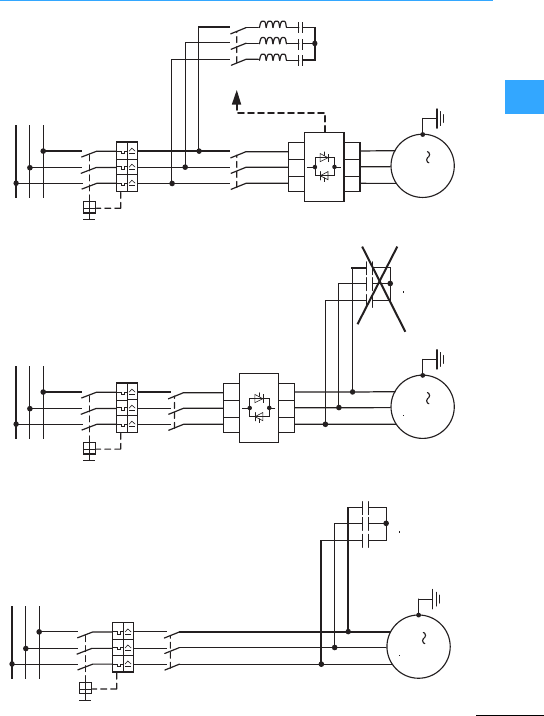
Soft starter basic information
EatonWiring Manual 06/11
22
M
3
L1
L2
L3
Q1
M1
①
Q11
Cx
M
M1 3
Q11
Q21
L1
L2
L3
Q1
L1 L2 L3
T1 T2 T3
Cx
②
Not permissible
M
M1 3
Q11
Q21
L1
L2
L3
Q12
TOR
Q1
L1 L2 L3
T1 T2 T3
③
Cx
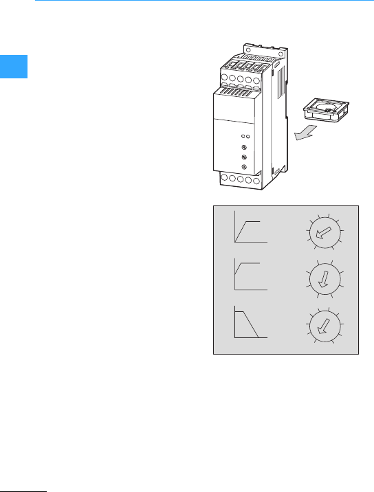
Eaton Wiring Manual 06/11
22
Connection example DS7
•Two-phase controlled soft starter, meets
the requirements of the IEC/EN 60947-4-2
product standard
•Power section and control section are
galvanically isolated
•Power section:
–Rated operational voltage: 200 –480 V,
-15 % /+10 %
–Mains frequency: 50/60 Hz ±10 %
–Overload cycle:AC53a: 3 –5: 75 –10
•Control voltage/regulator supply voltage:
–DS7-340…:24 VAC/DC, -15%/+10 %
–DS7-342…:120 - 230 VAC,
-15%/+10 %
–AC: 50/60Hz±10 %
–Control voltage and controller power
supply always have the same potential
and voltage level.
•Relaycontacts (potential-free)
–TOR (Top-of-Ramp): 230 VAC, 1A,
AC-11
In size 1 (to 12 A) with potential
connection to the control section
–RUN (operationalsignal): 230 VAC,
1A,AC-11
In size 1(to 12 A) this relay contact is
not present.
•Ambient temperature during operation:
-5 to +40°C, max. +60 °C with derating
and device fan
•Load cycle: 10 startsperhour, max. 40
starts per hour, with derating and
integrated device fan (optional)
•Status display (LEDs)
–RUN =Operating signal (green)
–Error = Error message (red)
•Parameterization/setting via three
parameters accessible on the front
DS7 with device fan DS7-FAN-032
t-Start = Ramp time (1 - 30 s) for the voltage
increase from the valueU-Start up to mains
voltage (ULN)
U-Start =The start voltage (30 - 100 %),
determines the torque of the motor
t-Stop=Ramp time (0/1 - 30 s) for the
voltage reduction from the mains voltage
(ULN)to the value U-Start
30
1
30
0
t-Start (s)
U-Start (%)
t-Stop (s)
2010
2010
100
30
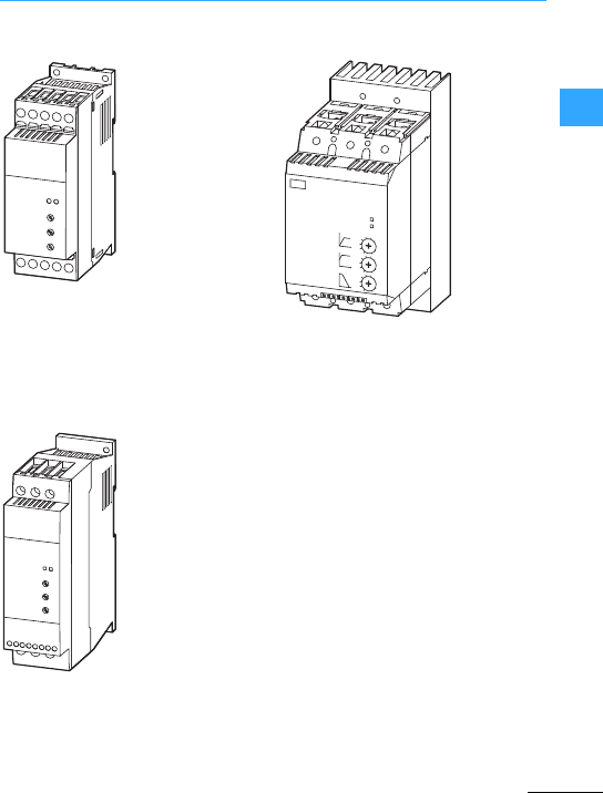
Connection example DS7
EatonWiring Manual 06/11
22
DS7-34…SX004…
DS7-34…SX007…
DS7-34…SX009…
DS7-34…SX012…
DS7-34…SX016…
DS7-34…SX024…
DS7-34…SX032…
DS7-34…SX041…
DS7-34…SX055…
DS7-34…SX070…
DS7-34…SX081…
DS7-34…SX100…
DS7-34…SX135…
DS7-34…SX160…
DS7-34…SX200…
Manual: MN03901001Z-EN
Instructional leaflet:
IL03902003Z (for size 1)
IL03902004Z (for size 2)
IL03902005Z (for size 3und 4)
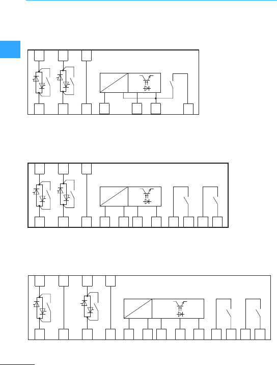
Connection example DS7
EatonWiring Manual 06/11
22
The numberand arrangement of the
control terminals, as well as the structure
in the power section of the individualsizes
vary according to the powersection.
TOR
1L1
2T1 13
5L3
6T3
3L2
4T2
+A1
-A2
+US
TOR RUN
1L1
2T1
+A1
-A2 13 14 23 24
5L3
6T3
3L2
4T2 +US-US
TOR RUN
1L1 5L3
2T1 6T3
PE
PE +US-US
+A1
-A2 13 14 23 24EN
3L2
4T2
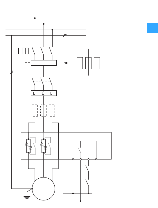
Connection example DS7
EatonWiring Manual 06/11
22
M
3 ~
1L1
3L2
5L3
+ Us
TOR
- A2 + A1
13
2T1
4T2
6T3
L1
L2
L3
PE
Q11
Q21
F3
F2
M1
Q11
Q1
I>I>I>
K3
F1
(+) Us24 V AC/DC, 120/230 V AC
(–) Us
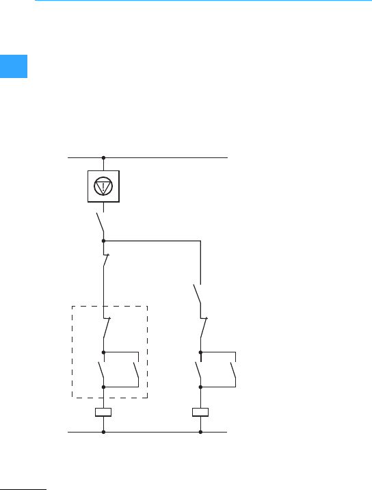
Connection example DS7
EatonWiring Manual 06/11
22
Q1, F1: Short-circuit- and cable protection
Q11: Mainscontactor
F2: Motor protection
F3:Optional semiconductor fuse for
type 2coordination, in addition to
Q1 and F1
K3: Start/Stop
"Optional –if astop is required without a
SoftStop
Setting: t-Stop >0
Q11
S2
L01/L+
L00/L-
Q1
F2
S1 Soft-Stop
Soft-Start
Q11
K3
Q11
K3
①
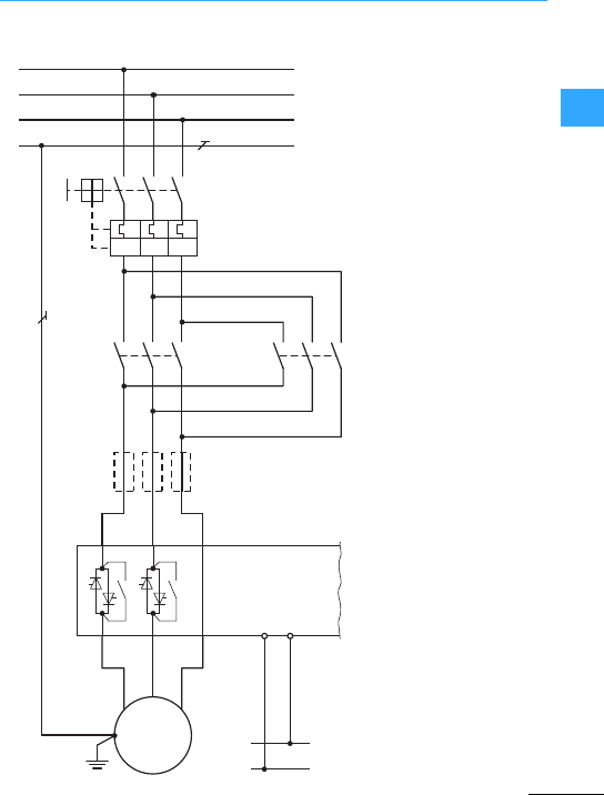
Connection example DS7
EatonWiring Manual 06/11
22
M
3 ~
1L1
3L2
5L3
2T1
4T2
6T3
L1
L2
L3
PE
Q1
Q21
M1
Q11
F3
Q12
I>I>I>
- A2 + Us
(+) Us24 V AC/DC,
120/230 V AC
(–) Us
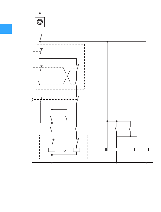
Connection example DS7
EatonWiring Manual 06/11
22
FWD = Clockwiserotation field
(Forward Run)
REV = Counterclockwise rotation field
(Reverse Run)
Q11 =Mains contactor FWD
Q12 =Mains contactor REV
aAssembled control station
bReversing starter
cStandard auxiliary contact
A2
A2
B1
A1
-A2
+US
53
15
1.53
1.54
16
25
13
22
21
14
26
53
54
63
64
63
64
54
②
①
③
+A1
Q11
Q12
N (-)
L (+)
Q12
Q11
K2T
K2T Q21
FWDI
REV II
0
Q12
Q11 Q12
Q11
t > t-Stop
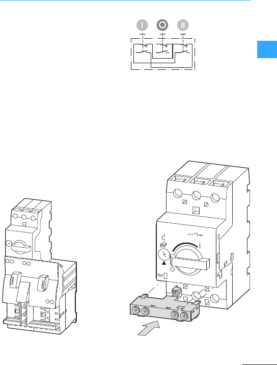
Connection example DS7
EatonWiring Manual 06/11
22
The control voltages (+US)of the DS7 soft
starterand the contactor control must
have the same potential:
24 VDC/AC or 120/230 VAC
Q1, Q11, Q12 = MSC-R motor-starter
combination!is a compactdevice with
electrical and mechanical interlocking.
The NHI-E-10-PKZ0 auxiliary contact Gis
added to Q1 for cable and motor protection.
M22-I3-M1
aContact sequence of assembled
controlstation
22
21
14
13
22
21
14
13
22
21
14
13
MSC-R-…
bReversing starter
NHI-E-10-PKZ0
cStandard auxiliary contact (grey)
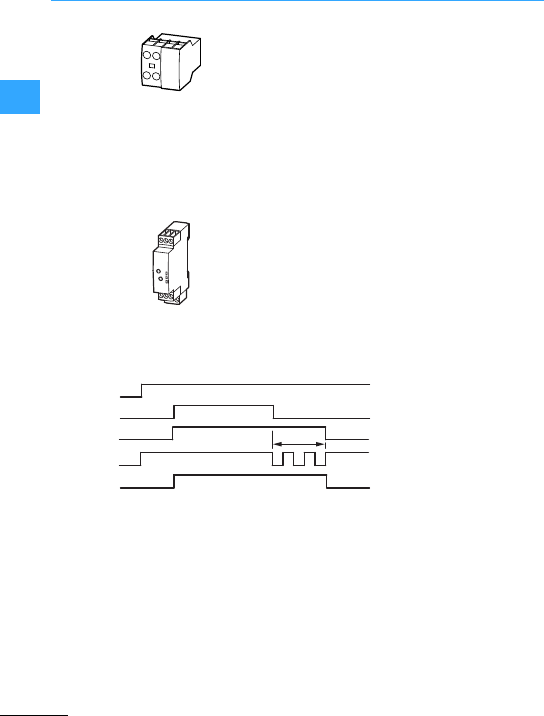
Connection example DS7
EatonWiring Manual 06/11
22
Two DILA-XHI20 auxiliary contact modules
are added to the two reversing contactors
Q11 and Q12.
The NO contact 53/54 is used for the
self-maintaining of reversing contactors
Q11 and Q12; NO contact 63/64 activates
the timing relay K2T and the softstarter
Q21.
The pushbutton actuators 0, I, II as a
complete device (M22-I3-M1) for surface
mounting "enable the rotation direction
change viathe stop button.
K2T is an off-delayed timing relay (type
ETR2) and simulates here the RUN signal.
The drop-out time must be greater than the
stop time (t-Stop)set on the DS7 soft
starter. Switching to the other direction is
only possible afterthe value set here has
elapsed.
DIL-XHI20
ETR2-11
Relais LED (yellow)
A1-A2
B1 t > t-Stop
15-16 / 25-26
t
Power LED (green)
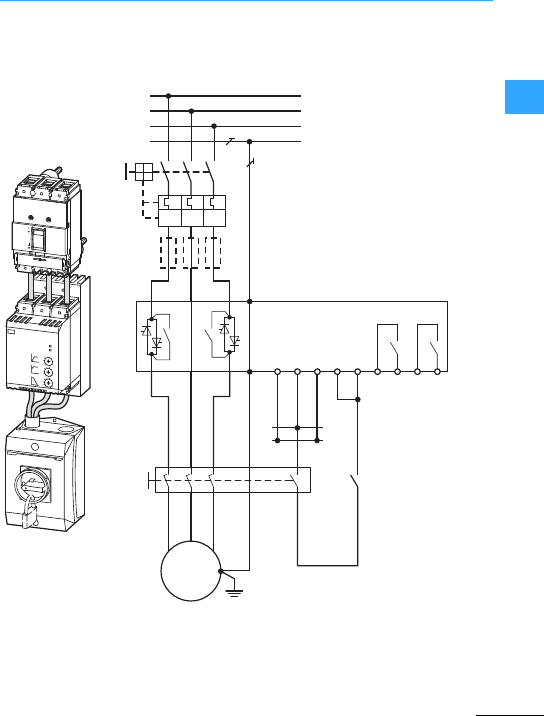
Connection example DS7
EatonWiring Manual 06/11
22
Soft starterDS7, circuit-breaker NZM1 and
maintenance switch P3,
size3 + 4(41 to 200 A)
F3: Superfast semiconductor fuse
(optional for type 2coordination,
additional to Q1)
Q1: Cable and motor protection
Q21: DS7 softstarters
Q32: Maintenance switch (local)
M1: Three-phase motor
M
3 ~
1L1
3L2
5L3
PE
PE
+24
RUN
EN
13 14 2423
2T1
4T2
6T3
L1
L2
L3
PE
Q1
NZM1
DS7
P3
Q21
F3
M1
I>I>I>
Q32
1357
246
UVW
8
Start/Stop
TOR
+ 24 V
0 V
0 V
-A2 +A1
Trip
ON
OFF
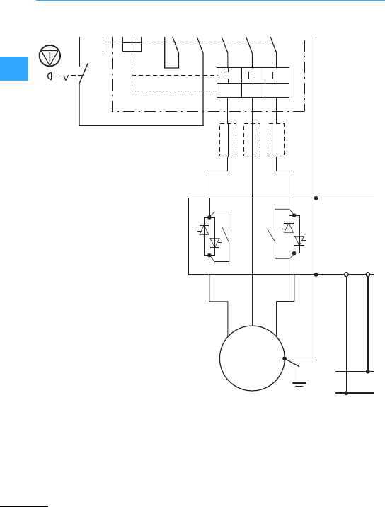
Connection example DS7
EatonWiring Manual 06/11
22
=Emergency switching off
F3: Superfast semiconductor fuse
(optional fortype 2 coordination,
additional to Q1)
Q1: Cable and motor protection
(NZM1, NZM2)
Q21: DS7 softstarters
M1: Motor
aControl circuit terminal
bUndervoltage release with early-make
auxiliary contact
M
3 ~
1L1
3L2
5L3
PE
PE
0 V
3.14
+24 -
2T1
4T2
6T3
Q1
Q21
F3
M1
I>I>I>

Connection example DS7
EatonWiring Manual 06/11
22
The devices of the DS7-34…series are
already provided with integrated bypass
contacts.An external bypass for
continuous operation with a DS7 soft
starteris therefore not required.
In pump applications the bypass contactor
is often required to provide emergency
operation capability. A service switch is
used to select between soft starter
operation and DOL starteroperation via a
bypass contactor (Q22). This is used to
fully isolate the softstarter. In this case, it
is importantthatthe output circuit is not
opened during operation. The interlocks
ensure that aswitchover is only possible
after a stop.An electricaland/or
mechanicalinterlocking of contactors Q22
and Q31 ensures a safeoperating state.
Unlike simple bypass operation,the bypass
contactor must be designed here in
accordance with utilization category AC-3.
F3: Superfast semiconductor fuse
(optional) for type 2 coordination
(additional to Q1)
Q1: Cable and motor protection
Q11: Mains contactor(optional) for
disconnection in emergency
operation
Q21: Soft starters
Q22: Bypass contactor
Q31: Motor contactor
M1:Motor
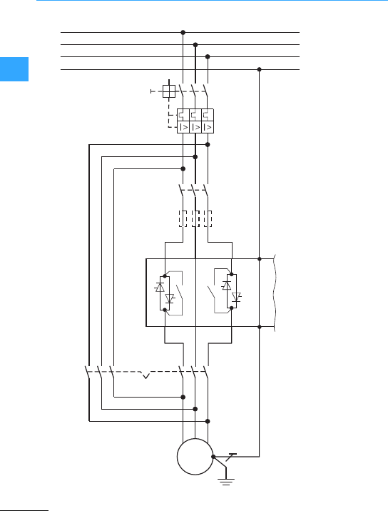
Connection example DS7
EatonWiring Manual 06/11
22
M
M1
F3
3 ~
L1
L2
L3
PE
3L2
Q1
Q11
Q22 Q31
1
L1
3L5
PE
PE
1T2
Q21
4T2
6T3
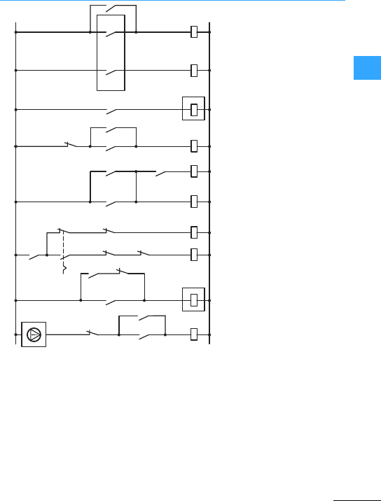
Connection example DS7
EatonWiring Manual 06/11
22
"Enable
!Automatic operation (soft starter)
GManual/bypass operation
ESoftstart/Softstop
DBypass contactor
S1: Operating mode switch
S2: Off
S3: On
S4: Stop (soft starter)
S5: Start (soft starter)
The control system shown here can also be used for the DS7 softstarterin size 2
(16to32A).
①
A1
A2
Q21K5
S5 K5 K5
S4
13
14
K4 Q22
TOR
K2
Q31
Q11
K3 K4
K3
EN
A2
K1
S3 K1
K1 K2
S2
K2
K1
K4
K3
S1
K2
Q22
②③ ④⑤
Q31
23
24
Q2 RUN
Q21

Connection example DS7
EatonWiring Manual 06/11
22
When starting several motors one afterthe
other using a soft starter, keep to the
following changeover sequence:
1. Start using softstarter
2. Switch on bypass contactor Qn2 via
TOR(Top-of-Ramp)
3. Block soft starter
4. Switch soft starter output with Qn1 to
the next motor
5. Restart
•When starting several motors with one
soft starter the thermal load of thesoft
starter(starting frequency, current load)
must be taken into account. If the starts
are to occurin close succession, the soft
startermust be dimensioned larger (i.e. the
soft starter must be designed with an
accordingly higherload cycle).
•Due to the thermal design of the DS7
softstarters, we recommend the use of an
(optional) fan when using aDS7 series
device for starting several motors.
F3: Superfast semiconductor fuse
(optional fortype 2coordination,
additional to Q1)
Q1: Cable protection
Q2: Soft starter DS7
Qn1:Contactor (1, 2, n)
Qn2: Mains bypass contactor for
motor (1, 2, n)
Qn3: Motor protection (motor-protective
circuit-breaker or bimetal relay
Mn: Motor (1, 2, n)
•The control system shown here can also
be used forthe DS7 soft starter in size 2
(16 to 32 A),however without an enable
signal".
•Bimetalrelays can also be used as an
alternative to the overload relays Q13,
Q23, …, Qn3 (see page 2-21).
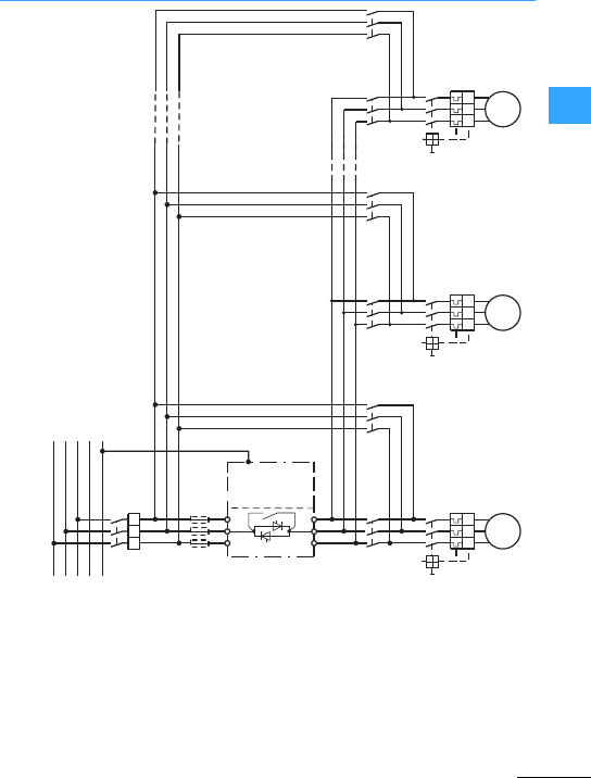
Connection example DS7
EatonWiring Manual 06/11
22
Q2
L1
L2
L3
1L1
2L2
3L3
2T1
4T2
6T3
N
PE
PE
Q1
Q11
F3
Q13
M1 M
3~
Q12 Q21
Q23
M2 M
3~
Q22 Qn1
Qn3
Mn M
3~
Qn2
I> I> I> I> I> I>
I> I> I>
I> I> I>
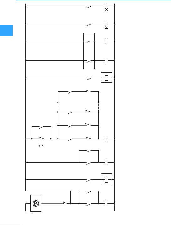
Connection example DS7
EatonWiring Manual 06/11
22
aEnable
bSoftstart/Soft stop
cStarting frequency monitoring. The timing relay must be setso that the soft starter does not have atemperature
overload. The correcttime is based on the permissible operating frequency of the selectedsoftstarter.
If necessary, use softstarters with a higher rating.
dSet thetiming relays to approx. 2 s off-delay. This ensures that the next motor branch can not be connected as long as
the soft starter is running.
N/C contact S1 switches all motors off at the same time.
①②③④
A1
A2
Q2
K2 23
24
K4
RUN
K1T K4T
K4
13
14
K3
Q2 TOR
EN
A2
Q2K1
S2 K1 K1
S1
Q11 Q21
K2
K1T K4
K1 K4
Q1
K12 K22
Q31
K32
Qn1
Kn2 K4
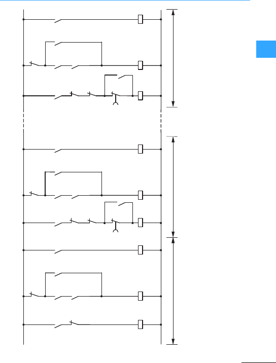
Connection example DS7
EatonWiring Manual 06/11
22
aMotor 1
bMotor 2
cMotor n
The N/C contact S3 is required if motors also have to be switched off individually.
Q11
Q12
Q12
K12
Q12
K3
Q1
Q11
①②
K12
Q21
Q22
Q22
K22
Q22
K3
K12
Q21
Q11
Q21
K22
K4T
③
Qn1
Qn2
Qn2
Kn2
Qn2
K3
K(n-1)2
Qn1
Q(n-1)1
Kn2
Qn1
K4T
S3 S3 S3

Eaton Wiring Manual 06/11
22
DM4 connection example
•Three-phase controlled soft starter;
meets the requirements of the IEC/EN
60947-4-2 product standard
•Configurable and
communication-enabled with pluggable
control signal terminals and interface for
options:
–Operator control andprogramming unit
–Serial interface
–Fieldbus connection
•Application selector switch with
user-programmable parametersets for
10 standard applications
•I2tcontroller
–Current limitation
–Overload protection
–Idle/undercurrent detection (e.g. belt
breakage)
•Kickstarting and heavy starting
•Automatic control voltage detection
•3relays, e.g. fault signal, TOR
(Top-of-Ramp)
•Power section:
Rated operational voltage 230 -480 V,
-15%/ + 10 %
Mains frequency: 50/60 Hz ±10 %
•Control voltage/regulator supply voltage:
–24 V DC
–120-240 VAC, -15%/ +10 %, 50/60Hz
•Ambient temperature during operation:
0to+40 °C
•Load cycle: 10 startsperhour with
3.5 xI
efor max. 35 s
Pre-programmed parameter sets for ten
typical applications can be simply called
up with aselector switch (see page 2-48).
Additionalplant-specific settings can be
defined with an optionalkeypad. This
includes, for example, the three-phase AC
power controllermode. In this mode
three-phase resistive and inductive loads
(heaters, lighting systems, transformers)
can be controlled with the DM4. Both
open-loop and –with measured value
feedback –closed-loop control are
possible.
Instead of the keypad, intelligent interfaces
can also be used:
•RS232/RS485 serial interface
(configuration with PC software)
•PROFIBUS-DP fieldbus connection
The DM4 softstarter providesthe most
convenient method of implementing soft
starting. In addition to phase failure and
motor current monitoring,the motor
winding temperature is evaluated through
the built-in thermistor input, so that the soft
starters do not require additional external
components, such as motorprotective
relays.
The optional superfast semiconductor
fuses (F3) for type 2 coordination can be
used from size 2 (from 85 A) in the housing
of the DM4 soft starter.
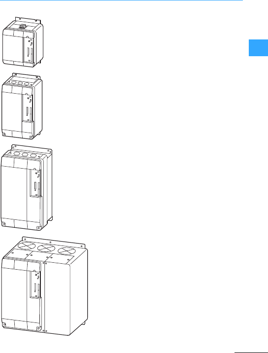
DM4 connection example
EatonWiring Manual 06/11
22
Size 1
16 - 72 A
Assigned motor powerat 400 V
7.5/11 -37 kW
Size 2
85 - 146A
Assigned motor powerat 400 V
45/75 - 75/132 kW
Size 3
174 - 370A
Assigned motor powerat 400 V
90/160 - 200/315kW
Size 4
500 - 900A
Assigned motor powerat 400 V
250/400 -500/900 kW

DM4 connection example
EatonWiring Manual 06/11
22
Manuals:
AWB8250-1346GB
(”Soft Starter Design”)
AWB8250-1341GB (DM4 ”Soft Starter”)
AWB8240-1398 (“DE8240-NET-DP2
interface module for PROFIBUS DP”)
AWB823-1279
(“DE4-COM-2X interface module”)
AWB8240-1344GB
(”DE4-KEY-2 Keypad”)
Installation instructions:
AWA8250-1704 (up to 37 kW)
AWA8250-1751 (45 to 75 kW)
AWA8250-1752 (90 to 200 kW)
AWA8250-1783 (250 to 500 kW)

EatonWiring Manual 06/11
22
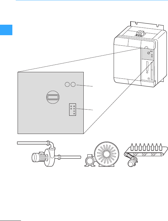
DM4 connection example
EatonWiring Manual 06/11
22
The application selector switch enables
direct assignment without parameter
entry.
0 - standard
1 - high torque
2 - pump
3 - pump kickstart
4 - light conveyor
5 - heavy conveyor
6 - low inertia fan
7 - high inertia fan
8 - recip compressor
9 - screw compressor
fault
c/l
run
supply
flash
on
0-standard
1-hightorque
2-pump
3-pumpkickstart
4-lightconveyor
5-heavyconveyor
6-lowinertia fan
7-highinertia fan
8-recipcompressor
9-screwcompressor
a
b

DM4 connection example
EatonWiring Manual 06/11
22
Standard Standard Standard •Default settings, suitable without
adaptation for mostapplications
High
torque1) High Torque High breakaway
torque
•Drives with higher breakaway torque
Pump Small pump Small pump •Pump drives up to 15 kW
Pump
Kickstart
Large pump Large pump •Pump drives over 15 kW
•Longer deceleration times
Light
conveyor
Light conveyor Light conveyor –
Heavy
conveyor
HeavyConvey Heavy-duty
conveyor
–
Low inertia
fan
LowInert.fan Low-inertia fan •Fan drive with relatively small mass
inertia moment of up to 15 times the
motor’sinertia moment
High inertia
fan
HighInertfan High-inertia fan •Fan drive with relatively large mass
inertia moment of over 15 times the
motor’sinertia moment.
•Longer ramp-up times
Recip
compressor
RecipCompres Reciprocal
compressor
•Higher start voltage
•p.f. optimization matched
Screw
compressor
ScrewCompres Screw compressor •Increased current consumption
•No current limitation
1) For the “High Torque”setting, the soft startermust be able to supply 1.5 times the motor’s rated
current.
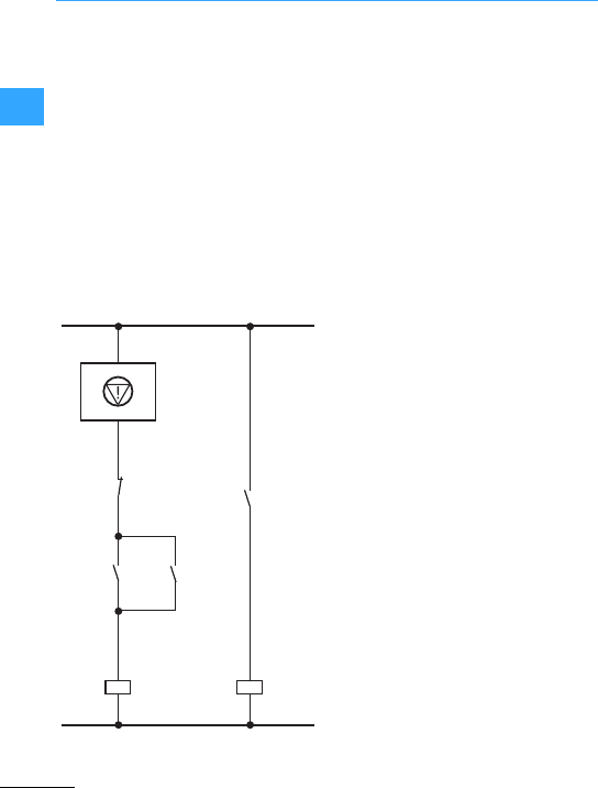
DM4 connection example
EatonWiring Manual 06/11
22
The digital input E2 is factory set to switch
the enable function. The soft starter is
enabled only when a High signal is present
at theterminal. The soft starter cannot be
operated without the enable signal.
In the event of wire breakage or
interruption of the signal by an
Emergency-Stop circuit, the regulatorin
the soft starter is immediately blocked and
the power circuit disconnected, and after
that the ”Run“relay drops out.
Normally the drive is always stopped via a
ramp function.
When the operating conditions requirean
immediate de-energization, this is effected
via the enabling signal.
You must in all operating conditions always
first stop the softstarter (”Run”relay
scanning), before you mechanically
interrupt the power conductors. Otherwise
aflowing current is interrupted –thus
resulting in voltage peaks, which in rare
cases may destroy the thyristorsof the soft
starter.
=Emergency switching off
E2: Digital input
Q21:Soft starter (E2 =1+enabled)
S1: Off
S2: On
S1
S2
K1 E2
39
K1
K1
Q21
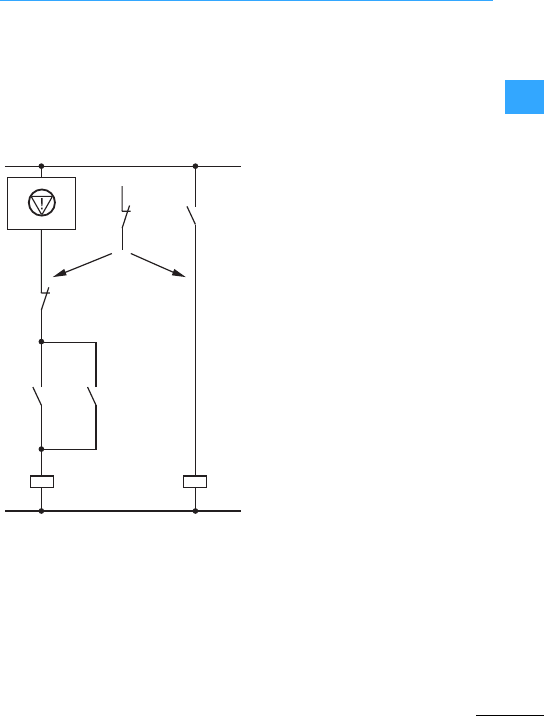
DM4 connection example
EatonWiring Manual 06/11
22
We recommend using an external overload
relay instead of a motor-protective
circuit-breaker with built-in overload relay.
This allows controlled ramping down of the
soft starter through the control section in
the event of an overload.
The direct opening of the power lines may
causeovervoltage and destruction of the
softstarter’s semi-conductors.
There are two ways of incorporating a
motor-protective relay in the control
system as shown in the diagram on theleft:
aThe signalling contacts of the overload
relay are incorporated in the on/off
circuit. In the event of a fault, the soft
starter decelerates according to the set
ramp time and stops.
bThe signalling contacts of the overload
relay are incorporated in the enable
circuit. In the event of a fault, the soft
starter’soutputis immediately
de-energized. The soft starter switches
off but the mains contactor remains on.
In order to switch off the mains
contactor, a second contactof the
overload relay must be incorporated in
the on/offcircuit.
=Emergency switching off
S1:Off
S2:On
Q21: Soft starter (E2 =17enabled)
E2
39
Q21K1
S2 K1
K1
F1
ab
S1
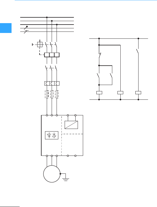
DM4 connection example
EatonWiring Manual 06/11
22
For isolation from the mains, either amains
contactor upstream of the soft starter or a
central switching device (contactoror
main switch) is necessary.
Q21
L
1L1
2L2
3L3
2T1
4T2
6T3
N
Q11
Q1
F2
F3
T1 T2
~=
M
3~
L2
N
L3
PE
L1
I> I> I>
M1
+ Thermistor
– Thermistor
F2:Overload relays
F3: Superfast semiconductor fuses
(optional)
M1: Motor
Q1:Cable protection
Q11: Mains contactor
Q21: Soft starter
S1: Soft-Start
S2: Soft-Stop
aEnable
bSoftstart/softstop
ba
E1
39
Q21
E2
39
Q21K1
S2
K1
K1
S1
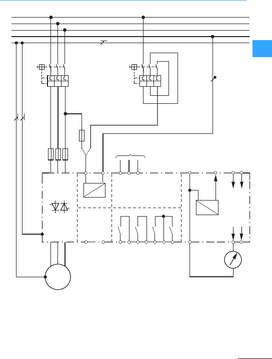
DM4 connection example
EatonWiring Manual 06/11
22
F3: Superfast semiconductor fuses
(optional)
Q1: Cable and motor protection
Q21:Soft starter
M1: Motor
aControl voltage through Q1 and F11 or
separately via Q2
bSee Actuation
cMotor currentindication
~=
~=
7
MM1
mot
Q21
F3
3~
L1
L2
L3
N
PE
LNE1 E2 39
13
K1;RUN K2;TOR K3 K4
14 23 24 33 34 43
1L1
3L2
5L3
2T1
4T2
6T3
+12 81
7
62 63
PE
0 V (E1;E2)
+12 V DC
REF 1: 0–10 V
REF 2: 4–20 mA
T1 T2
F1
Q1 Q2
①
③
②
I
I> I> I> I> I> I>
- Thermistor
+ Thermistor
0 V Analog
Analog Out 1
Analog Out 2
0 V Analog
Start/Stop
Enable
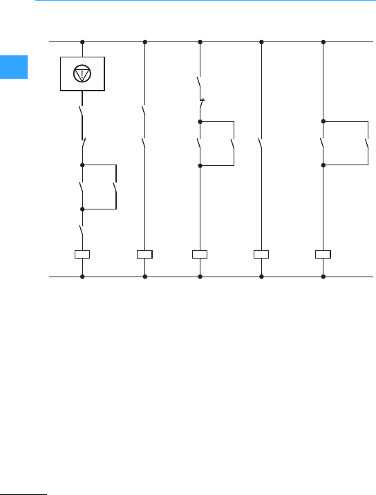
DM4 connection example
EatonWiring Manual 06/11
22
=Emergency switching off
M1: Motor with temperature sensor
(thermistor)
Q1: Cable and motor protection
Q21:Soft starter
S1: Off (uncontrolled deceleration)
S2: On
S3:Softstart
S4: Soft stop (deceleration ramp)
aEnable
bSoftstart/softstop
ab
S1
S2
K1 E1
39
E2
39
S4
S3
K1
K1
K2K1
Q11
K1 Q21 RUNK2
Q21 K2 Q21 Q11
13
14
33
34
Q1
Q21 OK
(no error)
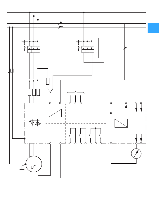
DM4 connection example
EatonWiring Manual 06/11
22
E1:Start/stop
E2: Enable
T1: + Thermistor
T2: –Thermistor
aSee Actuation
bControl voltage through Q1 and F11 or
through Q2
cMotor current indication
~=
~=
7
mot
Q21
F3
L1
L2
L3
N
PE
LNE1 E2 39
13
K1;RUN K2;TOR K3 K4
14 23 24 33 34 43
1L1
3L2
5L3
2T1
4T2
6T3
+12 81
7
62 63
PE
0 V (E1;E2)
+12 V DC
REF 1: 0–10 V
REF 2: 4–20 mA
T1 T2
F11
Q11
I >I > I >
Q1
I >I > I >
Q2
①
②
③
I
- Thermistor
+ Thermistor
0 V Analog
Analog Out 1
Analog Out 2
0 V Analog
Start/Stop
Enable
M
3 ~ M1

DM4 connection example
EatonWiring Manual 06/11
22
Softstarters are normally connected
directly in series with the motor (so-called
”in-line connection”). TheDM4 softstarter
also allows operation in an in-delta
connection.
The antiparallel thyristors are connected
directly in series to the individual motor
windings.
Advantages (compared with in-line
connection):
•Inexpensive since the soft starter only
has to be designed forapprox. 58 %
(1/53) of the rated current –particularly
with motor ratings >30kWand when
replacing star-delta starters.
•For the same motor rating the required
soft starter rating is reduced.
Disadvantages (compared with in-line
connection):
•As in astar-delta circuit, themotor must
be connected with six conductors.
•The DM4 softstarter overload protection
is active only in one line so that additional
motor protection must be fitted in the
parallel phase or in the supply cable. The
motor can be protected forexample via
thermistors.
•The voltage of the motor winding must
match the rated voltage. Fora400 V
mains voltage the motor must therefore
be marked with 400V/690 V.
•The soft starter canalso be bridged in the
in-delta connection for continuous
operation with a bypass contactor (see
page 2-60).This is actuated via TOR
(Top-of-Ramp).
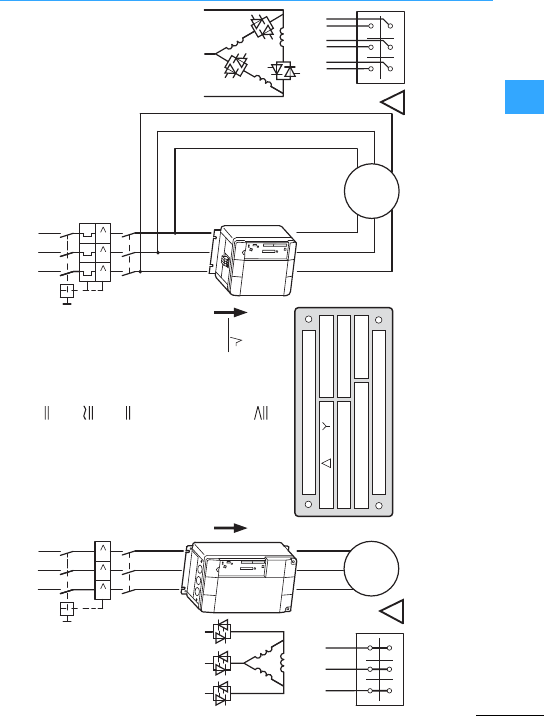
DM4 connection example
EatonWiring Manual 06/11
22
IIIIII
M
3 ~
55 kW
400 V
55 kW
400 V
M
3 ~
100 A
DM4-340-55K
(105 A)
DILM115
NZM7-125N-OBI
DILM115
NZM7-125N
U1 V1 W1
W2 U2 V2
/ 690 V400 100 / 59
55S1 0.86
j
cos
kW
rpm
1410 50 Hz
A
U1 V1 W1
W2 U2 V2
100 A
3
DM4-340-30K
(59 A)
ULN 400 V
In-Line In-Delta
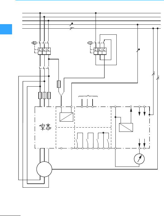
DM4 connection example
EatonWiring Manual 06/11
22
aControl voltage through Q1 and F11 or
through Q2
bSee Actuation (7page2-61)
cMotor currentindication
dThermistor connection
~=
~=
7
M
M1
mot
Q21
F3
3~
L1
L2
L3
N
PE
LNE1 E2 39
13
K1;RUN K2;TOR K3 K4
14 23 24 33 34 43
1L1
3L2
5L3
2T1
4T2
6T3
+12 8
PE
1
7
62 63
0 V (E1;E2)
+12 V DC
REF 1: 0–10 V
REF 2: 4–20 mA
T1 T2
F11
Q11
I>I>I>
Q1
I>I>I>
Q2
b
c
a
W1
V1
U1
W2
V2
U2
I
d
+
–
0 V Analog
Analog Out 1
Analog Out 2
0 V Analog
Start/Stop
Enable
Thermistor
Thermistor
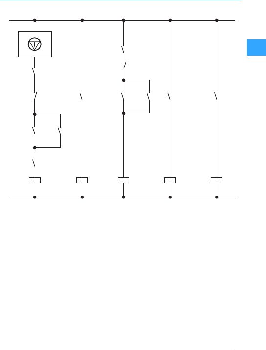
DM4 connection example
EatonWiring Manual 06/11
22
=Emergency switching off
E2:Enable
Q1: Cable and motor protection
S1: OFF; uncontrolled deceleration of the
motor
S2: ON/Start
S3:Soft stop
aEnable
bSoft start/softstop
ab
S1
S2
K1 E1
39
E2
39
S4
K1
K1
K2K1 K2
Q21 K2 Q21 Q11
Q21 RUN
13
14
33
34
Q1 S3
Q21 OK
(no error)
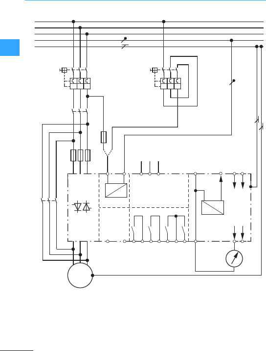
DM4 connection example
EatonWiring Manual 06/11
22
E1:Start/stop
E2: Enable
T1: + Thermistor
T2: –Thermistor
aSee Actuation (7page2-61)
bControl voltage through Q1 and F11 or
through Q2
cMotor current indication
~=
~=
7
M
M1
mot
Q21
F3
3~
L1
L2
L3
N
PE
LNE1 E2 39
13
K1;RUN K2;TOR K3 K4
14 23 24 33 34 43
1L1
3L2
5L3
2T1
4T2
6T3
+12 8
PE
1
7
62 63
0 V (E1;E2)
+12 V DC
REF 1: 0–10 V
REF 2: 4–20 mA
T1 T2
F11
Q11
⎧
⎪
⎨
⎪
⎩
Q1 Q1
a
b
c
Q22
I>I>I>I>I>I>
I
-Thermistor
+Thermistor
0 V Analog
Analog Out 1
Analog Out 2
0 V Analog
Start/Stop
Enable
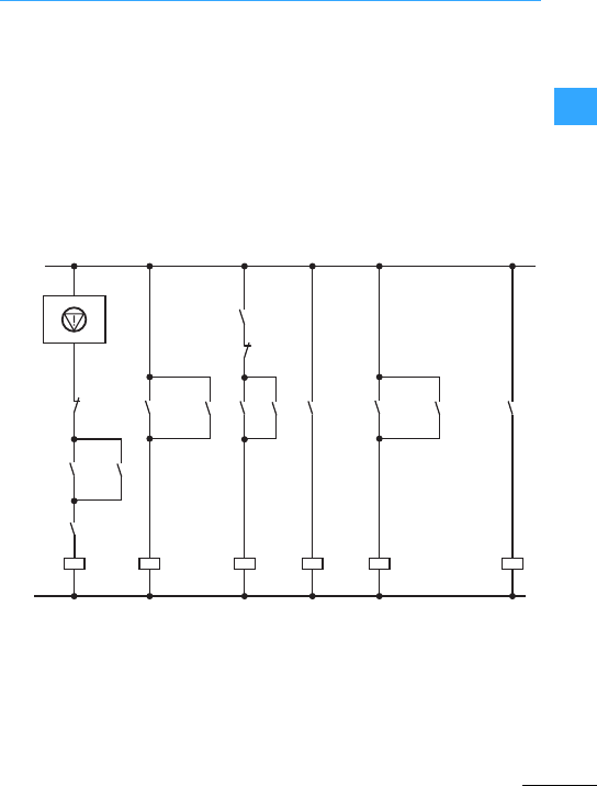
DM4 connection example
EatonWiring Manual 06/11
22
After completion of the acceleration phase
(full mains voltage reached), the soft
starterM4 actuates the bypass contactor.
Thus, the motor is directly connected with
the mains.
Advantage:
•The soft starter’sheat dissipation is
reduced to the no-load dissipation.
•The limit values of radio interference
class ”B“are adhered to.
The bypass contactor is now switched to a
de-energized state and can therefore be
designed to utilization category AC-1.
If an immediate voltage switch-off is
requiredin the event of an emergency stop,
the bypass contactor must also switch the
motor load. In this case a design to
utilization category AC-3 is required.
=Emergency switching off
S1: Off(uncontrolled deceleration)
S2:On
aEnable
bSoft start/softstop
cBypass contactor
①②③
S2
K1 E2
39
E1
39
S4
Q22
K1
K1 K1K2
K1
Q21 Q21
K2
K2
Q21 RUN
Q11
13
14
23
24
Q21 TOR
Q22
33
34
S1
S3
Q21 OK
(no error)

DM4 connection example
EatonWiring Manual 06/11
22
When using a softstarterto start several
motors in succession, keep to the following
changeoversequence:
1. Start using softstarter
2. Switch on bypass contactor
3. Block soft starter
4. Switch soft starter output to the next
motor
5. Restart
7Section ”Actuation part 1”,page 2-64
=Emergency switching off
F3: Superfast semiconductor fuse
(optional) for type 2 coordination
Q1: Main switch /
cable protection (NZM)
Q2/F11: Optional control voltage
supply
Qn3: Motor-protective circuit-breakers
Qn4: Motor protection Softstarter
Qn5: Motor contactors bypass
S1:Q11 Off
S2:Q11 On
aSoft start/softstop
bRUN
cOff-time monitoring
Setthe timing relay K1T so that the soft
starter is not thermally overloaded:
Calculate the time from the soft
starter’spermissible operating
frequency or selecta soft starter that
allows the required time to be reached.
dChangeovermonitoring
Set the timing relay to a return time of
about 2s. This ensures that the next
motor branch can not be connected as
long as the softstarteris running.
7Section ”Actuation,part 2”, page 2-65
"Motor 1
!Motor 2
GMotor n
BSwitching off individualmotors
The Off switch results in all motors being
switched offat the same time. To switch off
individual motors, you need to make use of
N/C contact B.
Observe the thermal load on the soft starter
(starting frequency, current load). If motors
are to be started at short intervals, you may
have to select asoftstarter with a higher
load cycle.
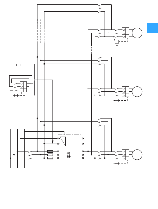
DM4 connection example
EatonWiring Manual 06/11
22
~
Q21
L1
L2
L3
L
1L1
2L2
3L3
2T1
4T2
6T3
N
N
PE
PE
Q1
Q14
F3
T1 T2
=
F11
Q2
Q13
M1 M
3~
Q15 Q24
Q23
M2 M
3~
Q25 Qn4
Qn3
Mn M
3~
Qn5
I>I>I>I>I>I>I>I>I>
I>I>I>
+Thermistor
–Thermistor

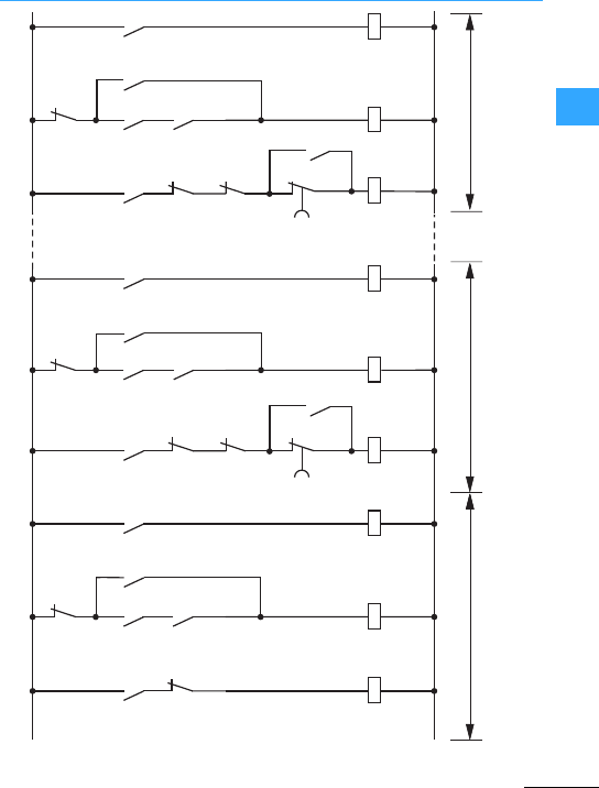
DM4 connection example
EatonWiring Manual 06/11
22
7Section ”Starting severalmotors sequentially with a soft starter (cascaded control)”, page 2-62
Q14
Q15
Q15
Q15
K12
K3
Q11
Q14
ab
K12
Q24
Q25
Q25
Q25
K22
K3
K12
Q24
Q41
Q14
K22
K4T
c
Qn
Qm
QmQm
Kn2
K3
K(n-1)2
Qn
Q(n-1)1
Kn2
Qn
K4T
ii
i
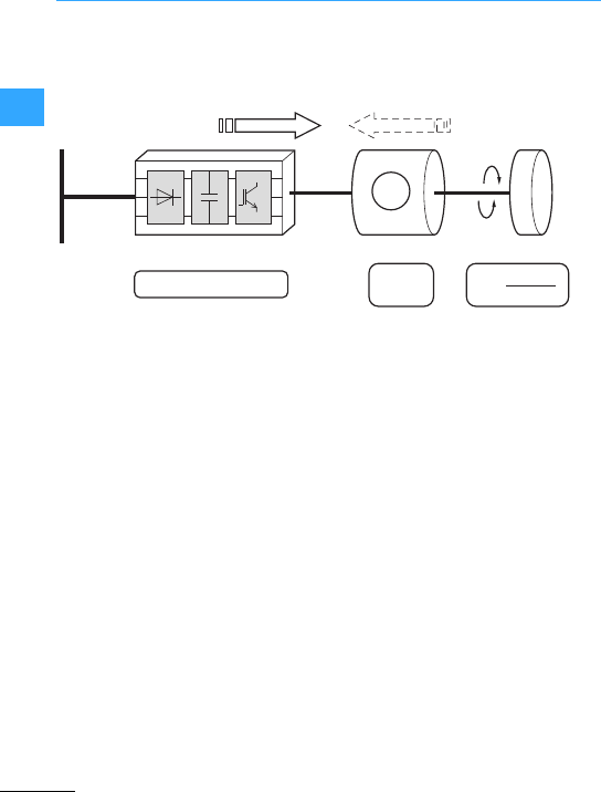
Eaton Wiring Manual 06/11
22
Frequency inverter basic information
Frequency inverters provide variable and
stepless speed control of three-phase
motors.
Frequency inverters convert the constant
mains voltage and frequency into a DC
voltage, from which they generate anew
three-phase supply with variable voltage
and frequency for the three-phase motor.
The frequency inverter draws almost only
active power (p.f. ~ 1) from the mains
supply.
The reactive power needed for motor
operation is supplied by the DC link. This
eliminates the need for p.f. correction on
the mains side.
Frequency inverters must comply with the
product standard IEC/EN 60947-4-2.
U=Rated operating voltage [V]
f=Frequency [Hz]
I=Rated operational current [A]
M=Torque [Nm]
n=Speed [r.p.m.]
F=Force [N]
v=Speed [m/s]
J=Moment of inertia [kg •m2]
Pel = Electricpower [kW]
PL= Mechanical shaft output power
[kW]
cos '= power factor(P/S)
with
P=Active power = Pel = P1[kW] and
S=Apparent power [kVA]
(= PL/Pel = P2/P1= Efficiency
M, n
U, f, I
U, f, (I)
F
v
m
J
M
3~
~IM
~fn
P
el = U x I x √3 x cos ϕ M x n
PL=9550
Energy flow
Variable
Constant
Mains Electronic actuator Motor Load
Driving Braking
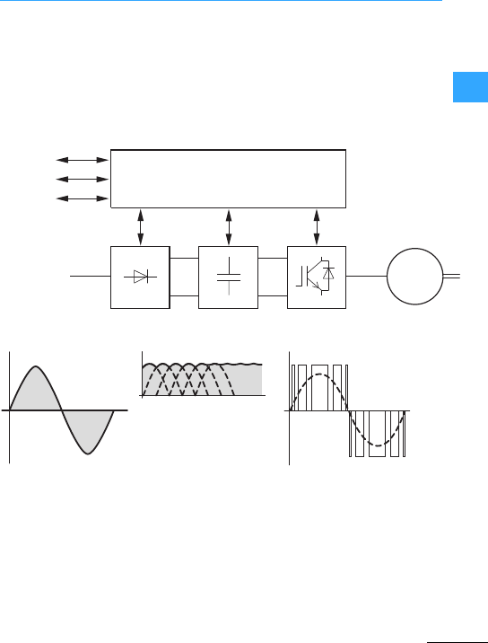
Frequency inverter basic information
EatonWiring Manual 06/11
22
Internal open and closed-loop control
circuits (centralprocessing unit) monitor
all variable values in thefrequency inverter
and automatically switch the process off if
a value reaches a dangerous level.
The power section of astatic compact
frequency inverterconsistsof three
subgroups:
•Rectifier(A)
•Internal DC link (B)
•Invertermodule (C)
ULN:Line supply
from mains
AC power supply
UDC: DC link circuit voltage
UDC =1.41 xU
LN
(single-phase line voltage)
UDC =1.35 xU
LN
(three-phase line voltage)
Output voltage =switched DC
link voltage with sinusoidal
pulse width modulation (PWM)
CPU
ABC
BUS
M
3 ∼
KEYPAD
I/O
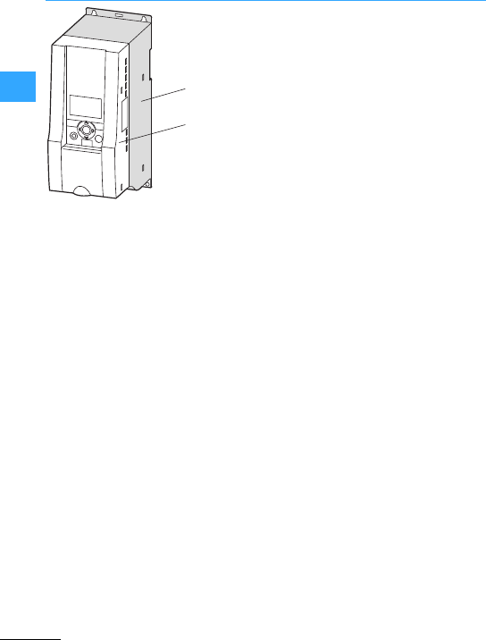
Frequency inverter basic information
EatonWiring Manual 06/11
22
aPower section:
A= Rectifier
B= DC link
C = Inverter module
bControl section with:
I/O = analog and binary inputs and
outputs
KEYPAD= keypad with display
BUS =serial interfaces
(RS485, fieldbus, PC interface)
I
OK
BACK
RESET
LOC
REM
a
b

Frequency inverter basic information
EatonWiring Manual 06/11
22
Electronic power converterwith
associated control which is connected
between the electrical power supply and a
motor. The module controls speed, torque,
force, position, current, frequency and
voltage individually or jointly or all
parameters together. The BDM can
transfer the power from the electrical
supply to the motor and also the power
from the motor to the electrical supply.
Drive module which consists of but is not
restricted to the BDM and additional
devices such as protective equipment,
transformers, and auxiliary devices.
This, however, does not include the motor
and the sensors thatare mechanically
connected to the motor shaft.
System control and sequence control
Closed and open-loop control unit
Converter
Protective device
Incoming section
Field supply
Resistance braking
Auxiliary equipment
other equipment
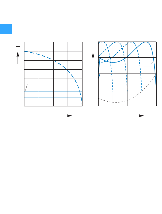
Frequency inverter basic information
EatonWiring Manual 06/11
22
The frequency-controlled three-phase
motor is a standard component for
infinitely variable speed and torque
regulation - providing efficient,
energy-saving power eitheras an
individual drive or as part of an automated
installation.
This not only refers to the frequency
inverter as a component but also considers
a complete drive system (PDS = Power
Drives System) with motor, cables, EMC
etc.(7page 2-69).
2
3
4
5
6
7
I
Ie
I/Ie: 0...1.8
n/nN
1
0.25 0.50.75 1
I
IN
1
2
ML
M
MN
M
MN
M/MN: 0.1...1.5
n/nN
0.25 0.5 0.75 1
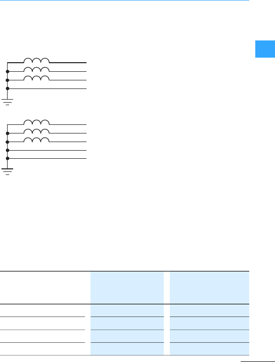
Frequency inverter basic information
EatonWiring Manual 06/11
22
Frequency inverters can be connected and
operated without restriction on
star-point-grounded AC mains (according
to IEC 60364).
Connection and operation on
asymmetrically grounded networks such
as phase grounded delta networks (USA)
or non-grounded or resistively grounded
(> 30 ))IT networks are only permissible
with restrictions and requireadditional
engineering measures.
The standardized ratedoperating voltages
of the utilitycompanies fulfil the following
conditions at the point of transferto the
consumer:
•Maximum deviation from the rated
voltage (ULN): ±10 %
•Maximum deviation in the voltage
symmetry: ±3 %
•Maximum deviation from the rated
frequency: ±4 %
A further voltage drop of 4 %in the
consumer networks is permissible in
relation to the lower voltage value (ULN
-10 %) of the supplying mains voltage. The
power supply voltage at the consumer can
therefore have a value of ULN-14 %.
In ring meshed networks (as used in the
EU) the consumer voltages (230 V / 400 V/
690 V) are identical to the power supply
voltages of the utility companies. In star
networks (for example in North
America/USA),the stated consumer
voltages take the voltage drop from the
utility company’sinfeed point to the last
consumer into account.
L2
PEN
L1
L3
L2
N
L1
L3
PE
120 V 110-120 V 115 V
240 V 220-240 V 230 V
480 V 440-480 V 460 V
600 V 550-600 V 575 V
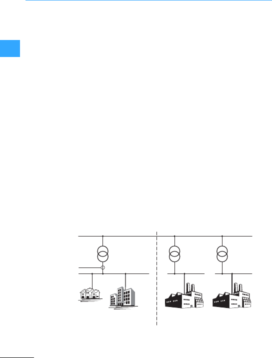
Frequency inverter basic information
EatonWiring Manual 06/11
22
The electricalcomponents of a system
(machine) are subjectto reciprocal
interference. Each device not only exerts
interference on other devices but is also
adversely affectedby it. This occurs as a
result of galvanic, capacitive and/or
inductive coupling or through
electromagnetic radiation. The border
between line-conducted interference and
radiated interference is around 30 MHz.
Above 30 MHz the linesand cables act like
antennas and radiate the electromagnetic
waves.
The electromagnetic compatibility (EMC)
forvariable speed drives is implemented in
accordance with product standard
IEC/EN 61800-3.
This covers the entire drive system (PDS =
Power DrivesSystem) from the mains end
supply to the motor, including all
components and cables. This type of drive
system can also consist of several
individual drives.
The generic standards of the individual
components in a PDS compliant with
IEC/EN 61800-3 do not apply. These
component manufacturers, however, must
offer solutions that ensure
standards-compliantuse.
In Europe, maintaining the EMC Directiveis
mandatory.
A declaration of conformity (CE) refers
always to a”typical”power drives system
(PDS). The responsibility to comply with the
legally stipulated limit values and thus the
provision of electromagnetic compatibility
is ultimately the responsibility of the end
user or system operator.
Measures must be taken to remove or
minimize emission in the associated
environment. It must also be ensured that
the immunity of the devicesor systems is
increased.
EMC environment and categories
Public medium-voltage supply grid
Public
low-voltage supply grid
Industry
grid 1
Industry
grid 2
Measuring
point
Category C1
Category C1/C2 Category C3/C4 Category C3/C4
1st enviroment 2nd enviroment

Frequency inverter basic information
EatonWiring Manual 06/11
22
Drive systems (PDS) are divided into the
followingfour categories.
•PDS foruse in the first environment
•Rated operating voltage <1000 V
•PDS foruse in the first environment
•Rated operating voltage <1000 V
•Not connected via plug-in devices
•No plug or movable equipment
•Connection and commissioning must be
carried out by persons with suitable
technical knowledge
•Hazard warning required
(“This product may cause malfunctions
in adomestic environment; in this case
additional measures may be
necessary.”)
•PDS foruse in the second environment
•Notintended for use in the first
environment
•Rated operating voltage <1000 V
•Hazard warning required
(“This PDS is not intended for connection
to the public utility grid.Connection to
these networks maycause
electromagnetic interference.”)
•PDS foruse in the second environment
which fulfills at least one of the following
criteria:
•Rated operating voltage >1000 V
•Rated operational current >400 A
•Connection to IT networks
•The required dynamic properties are not
achieved due to EMCfilter measures.
•EMC plan required
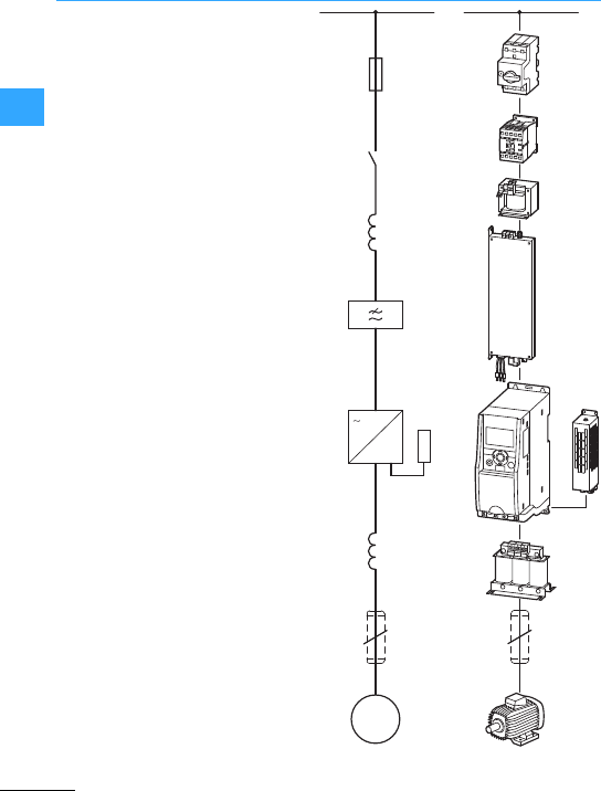
Frequency inverter basic information
EatonWiring Manual 06/11
22
Equipment code
F: Fuses and circuit-breakers
(cable protection)
Q: Controlled switching in powerflow
(contactor, circuit-breaker)
R: Limitation (choke, resistor)
K: Radio interference suppression filter
T: Frequency inverter
M: Motor
M
3~
3~
F
Q
R
R
K
T
M
3
I
OK
BACK
RESET
LOC
REM
R
3

Frequency inverter basic information
EatonWiring Manual 06/11
22
allow the protection of lines and electrical apparatus. For the
protection of persons, AC/DC-sensitive residual currentdevices (RCD Type B) are
required in addition.
are used for the on/off switching of the mains voltage.
suppress any currentharmonics and peaks and limit the inrush current
(link circuit capacitors).
attenuate high frequency electromagnetic emissionsfrom
devices. They ensure that the EMC limit values for conducted interference specified in the
applicable product standards are observed (frequency inverters).
enable the infinitely variable speed controlof three-phase motors.
A converts the frequency inverter’sregenerative braking energy into
heat.
The frequency inverter must be equipped with a brake chopper, which connects the
braking resistor parallel to the internal DC link.
•Compensate the capacitive capacitive currents,
•Reduce current ripple and the motor’s current change noise,
•Attenuate the retroaction on parallel connection of several motors.
•Smoothen the output voltage sinusoidally,
•Reduce motor noise through du/dt reduction, and thereby increase the motor
insulation’s lifespan,
•Reduce the leakage currents to allow better motor performance at improved EMC
values.
attenuate emitted and conducted high-frequency emissions within
the limit values specified in the applicable product standard (EMC).
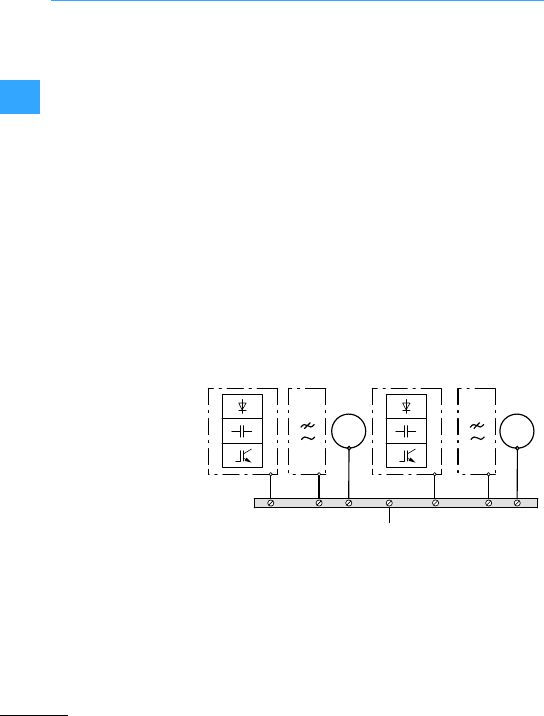
Frequency inverter basic information
EatonWiring Manual 06/11
22
For an EMC-compliantinstallation, observe
the following instructions. These enable
electrical and magnetic interference fields
to be limited to the required levels. The
necessary measureswork only in
combination and should be taken into
consideration at the engineering stage. To
subsequently modifyan installation to meet
EMC requirements is possible only at
considerable additionalcost.
Measures forEMC-compliant installation
are:
•Earthing measures,
•Shielding measures,
•Filtering measures,
•Chokes
They are described in more detail below.
Thesemust be implemented to comply with
the legal standards and are a prerequisite
forthe effective use of further measures
such as filters and shielding. All
conducting metallic enclosure sections
must be electrically connected to the earth
potential. For EMC compliance, the
important factor is not the cable’s
cross-section, but its surface, since this is
where high frequency current flows to
earth. All earth points must have alow
impedance, be highly conductive and
routed directlyto the central earth point
(potential equalization bar or star earth).
The contact points must be free from paint
and rust. Use galvanized mounting plates
and materials.
K1 =Radiointerference
suppression filter
T1 =Frequency
inverter e
PE
K1T1 Tn Kn
PE
PE
M1
PE PE
M
3h
Mn
M
3h
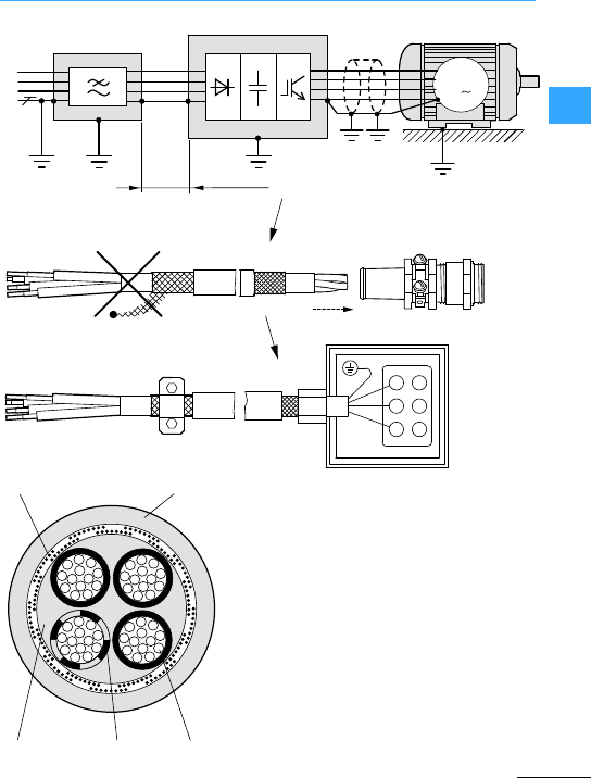
Frequency inverter basic information
EatonWiring Manual 06/11
22
L1
L2
L3
PE
b
a
edc
F300 mm
M
3
Four-core shielded motor supply cable:
aCoppershield braid, earth at both
ends with large-area connections
bPVC outer casing
cDrain wire (copper, U, V, W, PE)
dPVC coreinsulation,
3 x black, 1 x green–yellow
eTextile and PVC fillers
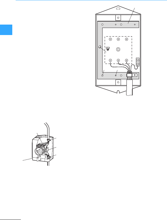
Frequency inverter basic information
EatonWiring Manual 06/11
22
Shielding reduces emitted interference
(noise immunity of neighboring systems
and devices against external influences).
Cables between frequency inverters and
motor must be shielded. However, the
shield must not be considered a
replacement for the PE cable. Four-wire
motor cables are recommended (three
phases plusPE).The shield must be
connected to earth (PES) at both ends with
a large-area connection. Do not connect
the shield with pigtails. Interruptionsin the
shield, such as terminals, contactors,
chokes, etc., must have a low impedance
and be bridgedwith a large contact area.
To do this, sever the shield near the module
and establish a large-area contact with
earth potential (PES, shield terminal). Free,
unshielded cables should not be longer
than about 100 mm.
Example: Shield attachment for
maintenance switch
aMetal plate (e.g. MSB-I2)
bEarthing terminal
cMaintenance switch
Maintenance switches at of frequency
inverter outputs must be operated only at
zero current.
Control and signal lines must be twisted
and may be double-shielded, the inner
shield being connected to the voltage
source at one end and the outer shield at
both ends.
①
②
PES
PES
③
4.2 x 8.2
⌀ 4.1
MBS-I2
⌀ 3.5
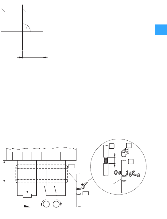
Frequency inverter basic information
EatonWiring Manual 06/11
22
aPowercables: network, motor, DC link
circuit, braking resistor
bSignal cables: analog and digital
control signals
The motorcable must be laid separately
from the control and signal lines(> 30 cm)
and must not run parallel to anypower
cables.
Inside control panels also cables should be
shielded if they are more than 30 cm long.
≧300 mm
(≧ 11.81”)
②①
Standard connection of a frequency inverter with setpoint potentiometer R11 (M22-4K7),
control signals for clockwise and anticlockwise rotation (FWD, REV) and ZB4-102-KS1
mounting accessory
REVFWD +24 V
+10 VAI 0 V
ZB4-102-KS1
15
M4
PE
2
Cu 2.5 mm
PES
PES
12
3
M
R11 REV FWD
4K7
M
≦ 20 m
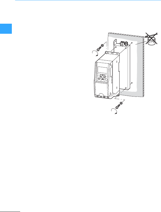
Frequency inverter basic information
EatonWiring Manual 06/11
22
Radio interference filters and line filters
(combinations of radio interference filter
and mains choke)protect against
conducted high-frequency interference
(noiseimmunity) and reduce the frequency
inverter’s high-frequency interference
which is transmitted through or emitted
from the mains cable, and which must be
limited to a prescribed and legallevel
(emitted interference).
Nowadays, filters are frequently integrated
in the frequency inverter or should be
installedin closeproximityof the
frequency inverter. When using externally
installed RFI filters, the connection cable
between the frequency inverter and filter
must be kept short (#30 cm).
The mounting surfaces of frequency
inverters andradio interference filters
must be free from paint and must have
good HF conductivity.
I
OK
BACK
RESET
LOC
REM
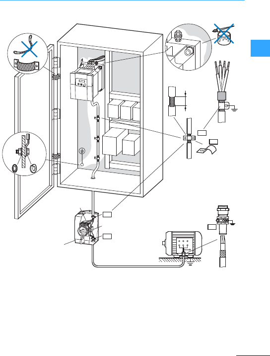
Frequency inverter basic information
EatonWiring Manual 06/11
22
aMetal plate with PE connection
bEarthing terminal (connection of PE
conductor and earthing of the plate ")
cMaintenance switch
PE
15
PES
PES
W2 U2 V2
U1 V1 W1
PE
①
②
③
PES
PES
PES
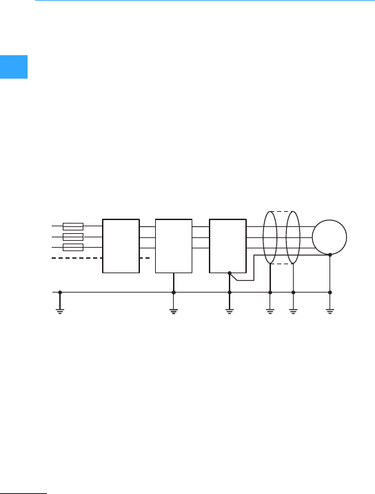
Frequency inverter basic information
EatonWiring Manual 06/11
22
Radio interference filters produce leakage
currents which, in the event of a fault
(phase failure, load unbalance), can be
considerably larger than the rated values.
To prevent dangerous voltages, all
components (frequency inverter, RFI filter,
motor, shielded motor cables) in the PDS
must be earthed. As the leakage currents
are high-frequency interference sources,
the earthing connections and cables must
have a low impedance and large contact
surfaces.
The residual current device on the
frequency invertermust be of type B
as sinusoidal AC and pulsed DC residual
currents may occur.
With leakage currents ,3.5 mA,EN 60335
states that one of the following conditions
must be fulfilled:
•The protective conductor must have a
cross-section ,10 mm2,
•The protectiveconductor must be
open-circuit monitored, or
•An additional protective conductor must
be fitted.
M
3∼
L1
L2
L3
U
V
W
R2
S2
T2
L1RCD
L2
L3
L1
KT M
FF
L2
L3
PE
N
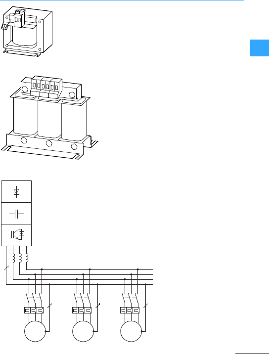
Frequency inverter basic information
EatonWiring Manual 06/11
22
Three-phase chokes
Fitted on the frequency inverter’s input
side, chokes reduce the
current-dependent mains feedback and
improve thepower factor. This reduces the
current harmonics and improves the mains
quality.The use of mains chokes is
especially recommended when several
frequency inverters are connected to a
single mains supply pointand when other
electronic devices are also connected on
the network.
A reduction of the mains current
interference is also achieved by installing
DC chokes in the frequency inverter’s DC
link. This eliminates the need for mains
chokes.
Single-phase
chokes
Q11
F1
M1
Q12
F2
M2
Q13
F3
M3
U1 V1 W1 U1 V1 W1 U1 V1 W1
M
3˜
M
3˜
M
3˜
①
With long motor cablesor the parallel
connection of several motors, motor
chokes "are used at the outputof the
frequency inverter.
They also enhance the protection of the
powersemiconductors in the event of an
earth fault or short-circuit, and protect the
motors from excessive rates of voltage rise
(> 500 V/>s) resulting from high pulse
frequencies.
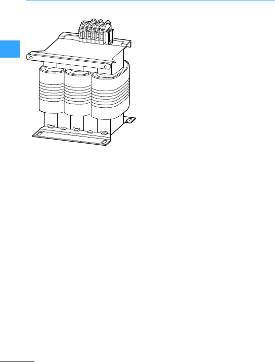
Frequency inverter basic information
EatonWiring Manual 06/11
22
SFB400/…
Sinusoidal filters are a combination of
choke and capacitor (low pass filter).
They improve the sinusoidal shape of the
frequency inverteroutputvoltage, thus
reducing the noise and thetemperature
rise of the motor.
Advantagesof the sinusoidal filter:
•Long shielded motor supply cables
possible
–max. 400mon supply voltages up to
240V+10 %
–max. 200 m on supply voltages up to
480V+10 %
•Extended lifespan –like that of a
mains-operated motor
•Lownoise generation of the motor
•Low motor temperature rise
•Reduced du/dtvalues (< 500 V/>s)
Disadvantages of a sinusoidal filter:
•Up to 30 V voltage drop
•Operation only with fixed pulse
frequency possible
"
!
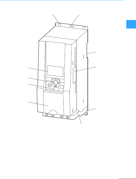
Eaton Wiring Manual 06/11
22
Connection example for M-Max™
Designations on M-Max™
aFixing holes
(screw fastening)
bRelease (dismantlingfrom mounting
rail)
cCutout for mounting on mounting rail
(DINEN 50022-35)
dInterface for fieldbus connection
modules (optional, MMX-NET-XA)
eEMC installation accessories
fPower section terminals
gCover flap of control signal terminals
and microswitches
hInterface for PC connection module
MMX-COM-PC (Option)
iKeypad with 9 control buttons
jDisplay unit(LCD)
①②
③
④
⑤
⑥
⑦
⑧
⑨
⑩
I
OK
BACK
RESET HOA

Connection example for M-Max™
EatonWiring Manual 06/11
22
A comprehensive range of protection
functions allow safe operation and the
protection of frequency inverter, motor and
application.They offer protection against:
•Overcurrent, earth fault
•Overload (electronic motor protection)
•Overtemperature
•Overvoltage, undervoltage
•Restart inhibit
•U/f control or sensorless vector control
•2-fold starting current and 1.5 fold
overcurrent
•PID controller
•Sequence control
•Braking control(DC braking)
•8fixed frequencies
•Electronic motorpotentiometer
•Logic function (AND,OR, XOR)
•Upper and lower frequency and current
limits
•Frequency hopping (frequency masking)
•DC braking before start and up to motor
standstill
•2parameter sets
Manual: MN04020001Z-EN
Instructional leaflet: IL04020001E
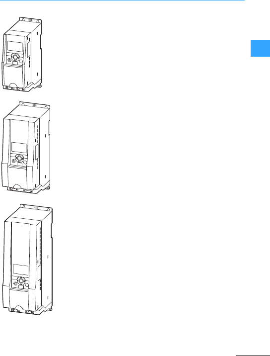
Connection example for M-Max™
EatonWiring Manual 06/11
22
Size1(FS1)
MMX12…: 1.7 -2.8 A
MMX32…: 1.7 -2.8 A
MMX34…: 1.4 -2.4 A
Size2(FS2)
MMX12…: 3.7 -7 A
MMX32…: 3.7 -7 A
MMX34…: 3.3 -5.6 A
Size3(FS3)
MMX12…: 9.6 A
MMX32…: 9.6 A
MMX34…: 7.6 -14 A
FS = Frame Size
MMX12…: Single-phase mains
connection, rated operating voltage
MMX230V
MMX32…:Three-phase power supply,
rated operating voltage 230 V
MMX34…:Three-phase power supply,
rated operating voltage 400 V
I
OK
I
OK
I
OK

Connection example for M-Max™
EatonWiring Manual 06/11
22
M-Max™frequency inverters allow the
continuouslyvariable speed control of
three-phase asynchronous motors. They
are especially suitable for applications
where simple operation and profitability
are important.
The characteristics-controlled
voltage/frequency (U/f) control already
allows a wide range of applications even
with the default settings: from simple pump
and fan drives, standard packaging
applications right through to the operation
of multiple motors in horizontal
transportation and conveying. With
sensorless vector control, an individual
drive can also be used in demanding
applications, in which a high torque and
concentricity in the lowerspeed range are
vital, for example in the plasticsand metal
industries, the textile, paper and printing
industries or in crane and elevator
systems.
Rated operating currents from 1.4 to 14 A
allow the operation of standard 4 pole
asynchronous motors in an assigned
performance range of :
•0.25 to 2.2 kW at 230 V (single-phase
mains connection),
•0.25 to 2.2 kW at 230 V (three-phase
mains connection),
•0.37 to 5.5 kW at 400 V (three-phase
mains connection).
•For UL®-compliant installation and
operation, the mains side switching
devices must allow fora1.25 times
higher input current.
•Mains contactors shown here take into
accountthe rated operating current ILN
of the frequency inverter at the input
without amains choke. Their selection is
based on thethermal current (AC-1).
•With frequency inverters, the inching
range is not permitted via the mains
contactor(pause time ,60 s between
switching off and on).
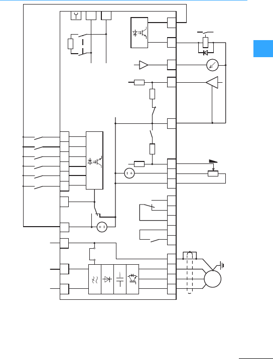
Connection example for M-Max™
EatonWiring Manual 06/11
22
Error
Run
Ready
L2/N
2322
PE
PE
WVU
M
3 ~
X1
A
B
e
24 2625 12354
AO
0 (4)...20 mA
0...+10 V < 10 mA
789
18
DI1
DI2
AI1
DI3
DI4
DI5
DI6
GND
DI_COM
< 10 mA
+10 V Out
14 15 1610
R13
R14
R21
R22
R24
S4
S3S2
S1
FWD
REV
FF1
FF2
24 V
6
< 50 mA
+24 V Out
GND
< 50 mA
DO-
DO+
13 20
+
0...+10 V
L1
200 kΩ
200 Ω
AI2
f-Out
PI-Ist
EMC
Reset
PI-O
f-Soll
3 AC 230 V
1AC 230 V
1AC 240 V
200 kΩ
200 Ω
120 Ω
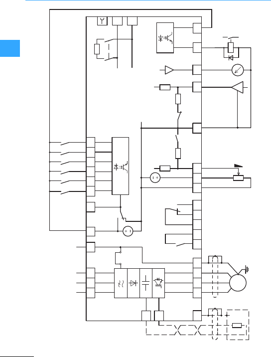
Connection example for M-Max™
EatonWiring Manual 06/11
22
PE
R+
R-
①
Error
Run
Ready
3 AC
3 AC
2322
PE
PE
WVU
M
3 ~
X1
A
B
24 2625 12354
AO
0 (4)...20 mA
0...+10 V < 10 mA
789
18
DI1
DI2
AI1
DI3
DI4
DI5
DI6
GND
DI_COM
< 10 mA
+10 V Out
14 15 1610
R13
R14
R21
R22
R24
S4
S3S2
S1
FWD
REV
FF1
FF2
24 V
6
< 50 mA
+24 V Out
GND
120 Ω
< 50 mA
DO-
DO+
13 20
+
0...+10 V
L1 L3
200 kΩ 200 kΩ
200 Ω
200 Ω
AI2
f-Out
PI -Ist
EMC
Reset
PI-Off
f-Soll
L2/N

Connection example for M-Max™
EatonWiring Manual 06/11
22
The control signal terminals are factory set
as follows:
2: AI1: f-Set = Frequency setpoint
(0 - +10V)
4: AI2: PI-Act = Actual value for PID
controller (process variable, 4 - 20 mA)
8: DI1: FWD = Clockwise rotation field
enable (Forward)
9: DI2: REV = Anticlockwise rotation field
enable (Reverse)
10: DI3: FF1 =Fixed frequency 1
13: DO-: Ready = Ready to start (transistor
outputwith the voltage of terminal 20)
14: DI4: FF2 =Fixed frequency 2
15: DI5: Reset = Acknowledge fault
message
16: DI6: PI-Off= PID controller deactivated
18: AO: f-Out = Outputfrequency to motor
(0 - +10 V)
20: DO+: Input voltage for transistor output
(+24 VDC)
22/23: R13/R14 (NO contact):
RUN = Operating signal(relay)
24/25/26: R21/R22/R24
(changeover contact):
Error =Fault signal (relay)
aConnection terminals R+ and R- for
external braking resistor (optional) –for
size 2 (FS2) and size 3 (FS3)
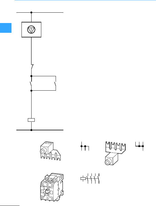
Connection example for M-Max™
EatonWiring Manual 06/11
22
Reference input through potentiometer
R11. Enable (START/STOP) and direction
control through terminals 1 and 2 with
internal control voltage
=Emergency switching off circuit
F1: Cable protection
PES: Cable shield PE connection
Q11: Mains contactor
M1: 230 V 3-phase motor
S1: OFF
S2: ON
•For EMC-compliant mains connection,
suitable radio interference
suppression measures must be
implemented according to product
standard IEC/EN 61800-3.
•With frequency inverters with a
single-phase mains connection,the
use of parallel links is recommended
forequalizing the load on the contacts.
DILM12-XP1
(4th pole can be broken off)
DILM
Q11
S2
S1
Q11
2
35
46
A1
A2
113
14
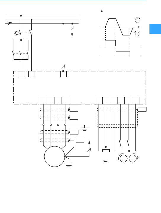
Connection example for M-Max™
EatonWiring Manual 06/11
22
–MMX12…Single-phase frequency
inverter
–Directional control through terminals
8 and 9
–External reference value input via R11
FWD: Clockwise rotation field enable
REV: Anticlockwise rotation field enable
T1 UVWPE 23
1986
PES
PES
PE
PES
PES
M
M1
X1
3 ~
R11
4K7
PE
L
N
PE
1 ∼ 230 V, 50/60 Hz
L1
Q11
PE
F1
M
REV
PES
M
FWD
REV
FWD
+10 V
AI
0 V
+24 V
L2/N
FWD
f
REV
M
M
t
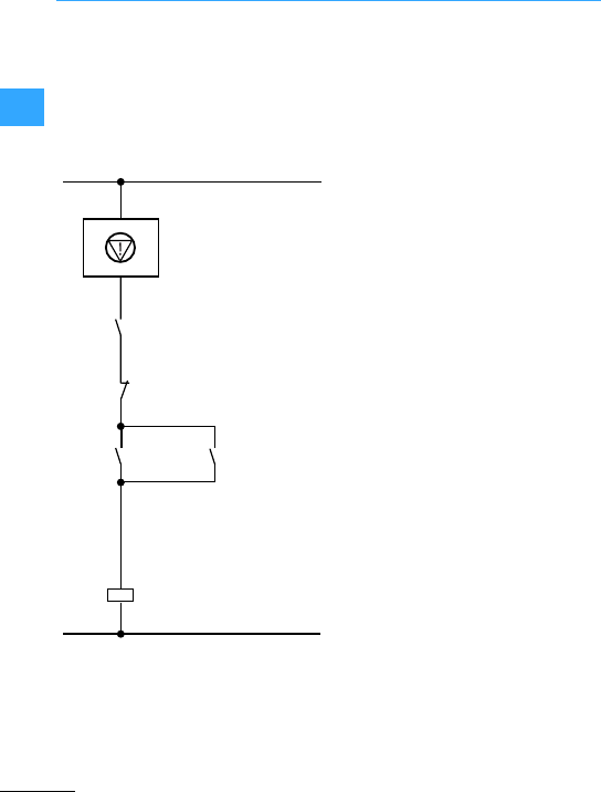
Connection example for M-Max™
EatonWiring Manual 06/11
22
Onlyfor MMX…N0-0(without internal RFI
filter)
Setpoint entry via potentiometer R11 (fs)
and fixed frequency (f1, f2, f3)viaterminal
10 and 14 with internalcontrol voltage
Enable (START/STOP) and rotation
direction selection viaterminal 8 (FWD)
=Emergency switching off circuit
FF1: Fixed frequency f1
FF2: Fixed frequency f2
FF1+ FF2: Fixed frequency f3
FWD: Enable clockwise rotation field,
analog setpoint value
frequency fS
K1: Radio interference suppression
filter MMX-LZ…
M1: 400 V3-phase motor
PES: Cable screen PE connection
Q1: Cable protection
Q11: Mains contactor
R1: Main choke
S1: OFF
S2: ON
Q11
S2
Q1
S1
Q11
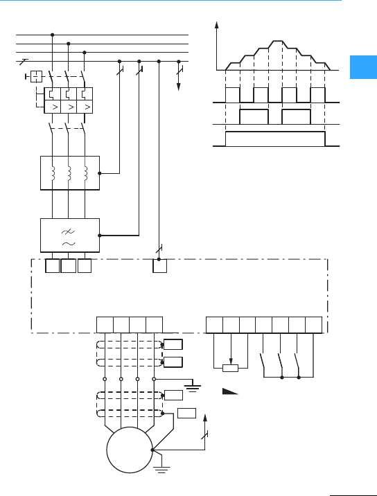
Connection example for M-Max™
EatonWiring Manual 06/11
22
3 ∼ 400 V, 50/60 Hz
T1
W2
L1
L2/N
L3 PE
L1
L2
L3
PE
Q11
Q1
V2U2
L1 L2 L3
W1V1U1
R1
K1
PE
PE
UVWPE 2 3
114 10 86
PES
PES
PE
PES
PES
M
M1
X1
3 ~
PE
III
FF2
FF1
FWD
R11
+10 V
AI
0 V
+24 V
K1: The external MMX-LZ…RFI
filter can only be used for
MMX…N0-0.
FF1
FF2
FWD
f1
f2
f3
fs= fmax
f
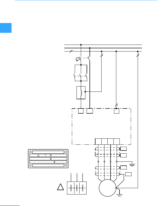
Connection example for M-Max™
EatonWiring Manual 06/11
22
The0.75 kW motor described below can be
delta-connected to asingle-phase 230 V
mains (version A) or star-connected to a
3-phase 400 V mains.
Motor: P = 0.75kW
Mains: 1/N/PE 230 V 50/60 Hz
PE
L
N
PE
2
1
R1 PE
1 ∼ 230 V, 50/60 Hz
L1
T1
Q11
UVWPE
PES
PES
PES
PES
M
M1
X1
3 ~
F1FAZ-B10/1N
DEX-LN1-009
MMX12AA3D7F0-0
230 V
3.2 A
0.75 kW
DILEM
+P1DILEM
U1 V1 W1
W2 U2 V2
L2/N
/ 400 V230 3,2 / 1,9 A
S1 0.97
ϕ
cos
rpm
141050 Hz
0,75 kW
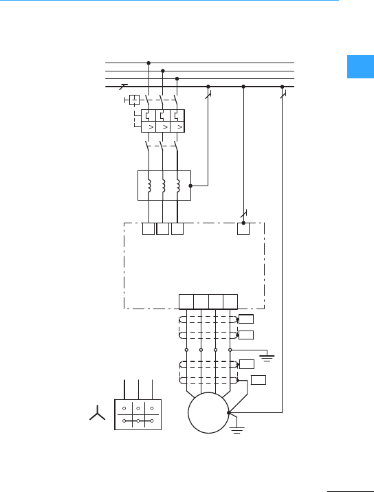
Connection example for M-Max™
EatonWiring Manual 06/11
22
Motor: P = 0.75kW
Mains: 3/PE 400 V 50/60 Hz
3 ∼ 400 V, 50/60 Hz
W2
L1 L2/N L3
L1
L2
L3
PE
Q11
Q1
V2U2
W1V1U1
R1 PE
PE
III
U1 V1 W1
W2 U2 V2
T1 UVWPE
PES
PES
PES
PES
M
M1
X1
3 ~
PKM0-6.3
DEX-LN3-004
400 V
1.9 A
0.75 kW
DILEM
MMX34AA2D4F0-0
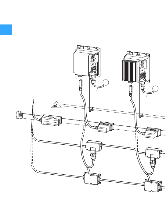
Eaton Wiring Manual 06/11
22
Rapid Link System 4.0
Rapid Link is a remote switching and
installation system.
Thanks to its compact design and its high
degree of protection to IP65 these motor
starters can be installed in the direct
vicinity of the motor.
Pluggable connection cables with
standard terminals reduce the wiring
requirement and provide the preferred
installation technology for conveying
system.
①
②
⑮
③
⑤
⑨
⑥
⑦
⑩
⑪
⑧
3 ∼ 400 V, N, PE
50/60 Hz ⑲
400 V
M
3∼
⑱
400 V
M
3∼
⑰
⑭
④
⑬
⑯
⑫

Rapid Link System 4.0
EatonWiring Manual 06/11
22
Function modules:
aRAMO motor starter(MotorControl
Unit) 4three-phase, electronic DOL
starter or reversing starter, with
electronic motor protection for the
assigned ratings of 90 W to 3kW
(at 400 V).
bRASP speed control unit 4
three-phase, frequency controlled
motor starter(fixed speeds, two
rotation directions, soft starting), in four
ratings (2.4 A/3.3A/4.3 A/ 5.6 A) with
electronic motor protection for
assigned ratings from 0.18kWto 2.2 kW
(at 400 V).
Power bus:
cIncoming supply (3 AC 400 V) via
circuit-breaker for overload and
short-circuit protection
dIncoming supply for ribbon cable
eRibbon cable für 400 VAC
fEnd-piece for flat cable
gFlexible busbarjunction
hPoweradapter cable to flexible busbar
junction
iRound cablefor 400 V AC
jPlug-in link for round cable
kPower adapter cable to round cable
junction
lLink for round cable
mPoweradapter cable (round cable) to
power box
nAS-Interface®–Supply via main cable
Data bus:
oAS-Interface®ribbon cable
pLink for M12 connector cables
qExtension M12
Motor connection:
rUnshielded motor cable
sShielded motor cable (EMC)
The system is installed with a powerbus
and data bus that are plugged into all
modules of the Rapid Link system.
Customerand sector-specific
requirements formaterial handling
applicationsare the main focus of system
design.
Rapid Link version 4.0 provides modules
with thefollowing features:
•Degree of protection IP65
•Ambienttemperature during operation
from -10 °C to +55 °C
•Max. cable length 10 m
•AS-Interface®Profi 7.4 for
communication and diagnostics
•Pluggable terminal design to ISO 23570
•Local operation/hand operation
•Maintenance and manual override
switches (optional)
•RAMO-D electronic DOL starter
•RAMO-W electronic reversing starter
•RASP frequency controlled speed
control
Manual: MN03406003Z-EN
Installation instructions:
IL003406019Z
IL003406020Z
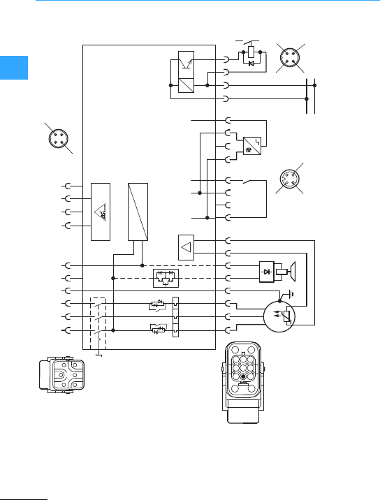
Rapid Link System 4.0
EatonWiring Manual 06/11
22
Optional variant:
aRepair switch
bActuation of externalbrake (230 V)
cActuator output
123PE
L1 L2 L3 PE
1234
ASi+ ASi-
54
N
1
UVW
T1T2
37PE
PE
12
+24 V
< 160 m A I3 I4
O3
0 V
0 V
+ 24 V
3
64
LN
58 1234 4
M 3 ∼
123
4
3
1
4
①
②
③
146
358
PE 7
1
3
1
2
34
+24 V
< 1 A
2
453
1
i
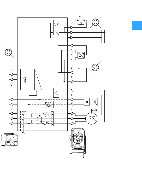
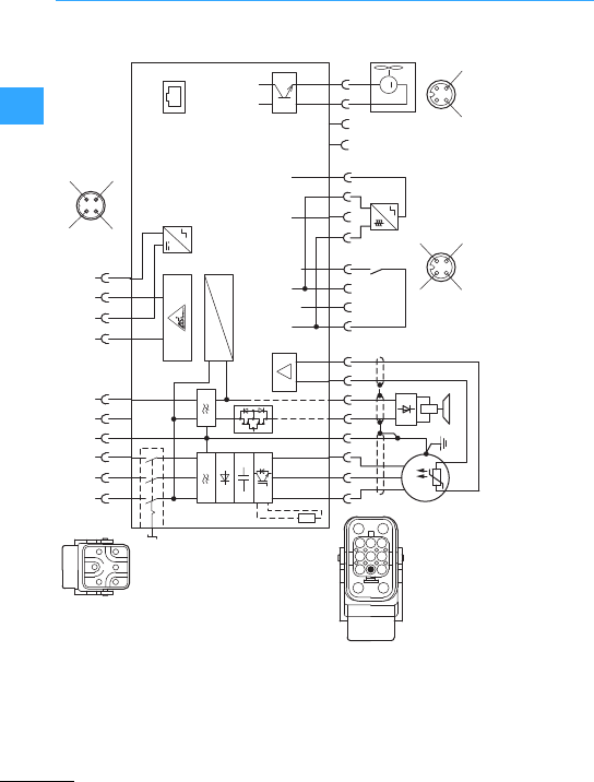
Rapid Link System 4.0
EatonWiring Manual 06/11
22
Optional variant:
aRepair switch
bActuation of externalbrake (230 V)
cDevice fans
dInternal braking resistor
+24 V
RJ 45
0 V
M
123PE
L1 L2 L3 PE
1234
ASi+ASi-
54
N
1
UVW
T1T2
37PE
PE
12
+24 V
< 160 m A
I3aI3(b) I4aI4(b)
F
0 V
3
64
LN
58 1234 4
M 3 h
i
1234
3
2
(b)
1
(4)
(2)
4
(a)
3
4
a
b
d
c
146
358
PE 7
1
3
+24 V
2
453
1
e

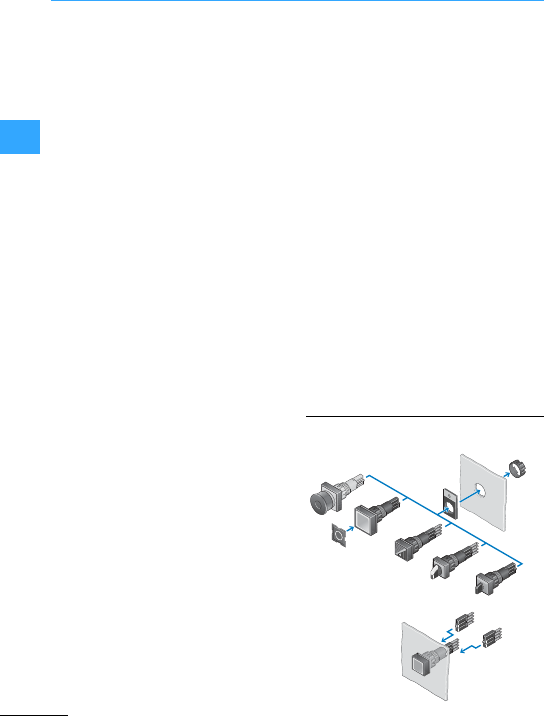
Eaton Wiring Manual 06/11
33
RMQ –System
Commands and signals are the
fundamentalfunctions for controlling
machines and processes. The required
control signals are produced either
manually by pilot devices or mechanically
by position switches. The respective
application governs the protection type,
the shape and color.
Advanced technology has been used
consistently in control circuit devices
„RMQ-Titan®“. The use of LED elements
and laserinscription throughout offer
maximum reliability, efficiency and
flexibility. In detail, this means:
•High-quality optics for a uniform
appearance,
•Highest degree of protection up to IP67
and IP69K (suitable for steam-jet
cleaning),
•Clearcontrast using LED element
lighting, even in daylight,
•Up to 100,000 h, i.e. machine lifespan,
•Impact and vibration resistant,
•LED operating voltage from 12 to 500 V,
•Lowpower consumption –only 1/6 of
filament lamps,
•Expanded operating temperature range
-25 to +70°C,
•Lighttesting circuit,
•Built-in safetycircuitsfor highest
operational reliability and accessibility,
•wear-resistant and clearly contrasting
laser inscription,
•Customer-specific symbols and
inscriptions from 1off,
•Text and symbols can be freely
combined,
•Terminal type using screwsand Cage
Clamp1) throughout,
•Spring-loaded Cage Clamp connections
for reliable and maintenance free
contact,
•Switching contacts suitable for use with
electronic devices to EN 61131-2:
5V/1 mA,
•user-programmable switching
performance on allselector switch
actuators: momentary/maintained
•All actuators in illuminated and
non-illuminated version,
•Emergency switching off pushbuttons
with pull and turn-to-release function,
•Emergency switching off pushbuttons
with lighting option for active safety,
•Contacts switch differing potentials,
•For use also in safety-related circuits
using positive operation and positive
opening contacts,
•Complying with industry Standard
IEC/EN60947.
1) Cage Clamp is aregistered trade mark of
Messrs. WAGO Kontakttechnik GmbH, Minden
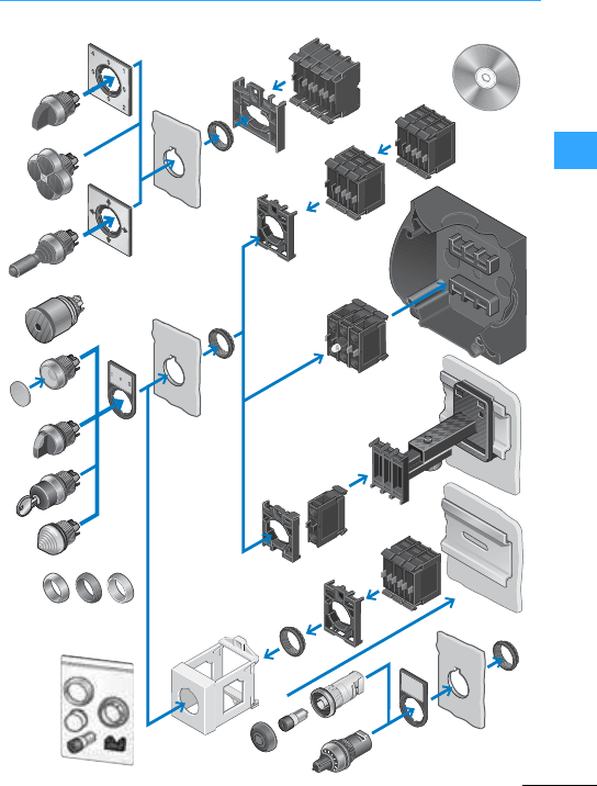
RMQ –System
EatonWiring Manual 06/11
33
®
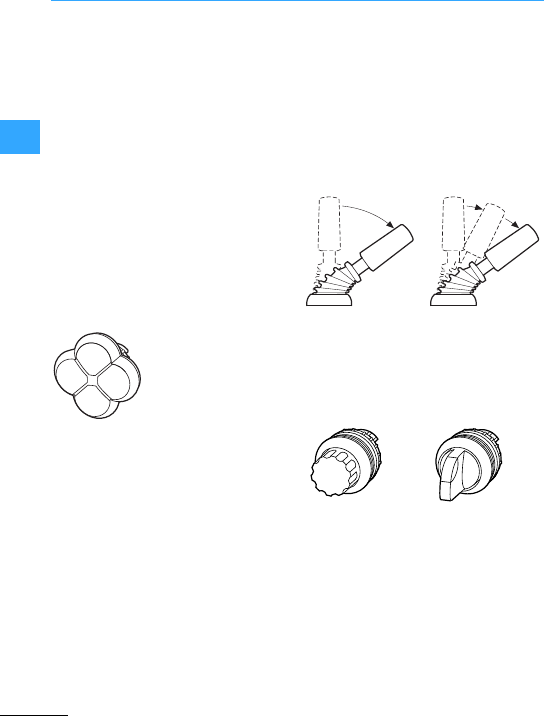
RMQ –System
EatonWiring Manual 06/11
33
Eaton has added more operator elements
to its highly successful range of pilot
devices RMQ-Titan. It has a modular
surface mounting. Contact elements from
the RMQ-Titan range are used. The bezels
andfront frames are of the familiar
RMQ-Titan format and color.
Thefour-way pushbuttons enable users to
control machines and systems in four
directions of movement. Each direction of
movement is being assigned one contact
element. The pushbutton has four
individual button plates. They can be
specifically selectedfor various
applications and can be laser-inscribed to
suit the customer's requirements.
The joystick allows the control of up to four
directions of movement on machines.
Differentvariants of the joystickhave 2/4
positions and other variants have 2 settings
foreach position. This allows for example
two speed settings for each direction. For
this a standard NO and an NO early-make
are fitted in series. Momentary contact and
latching contact versionsare possible.
The selectorswitch actuators have four
positions. The actuator is available either
as a rotary head or as athumb-grip. One
contact element is assigned to each On
and each Off position.
0
1
01
2
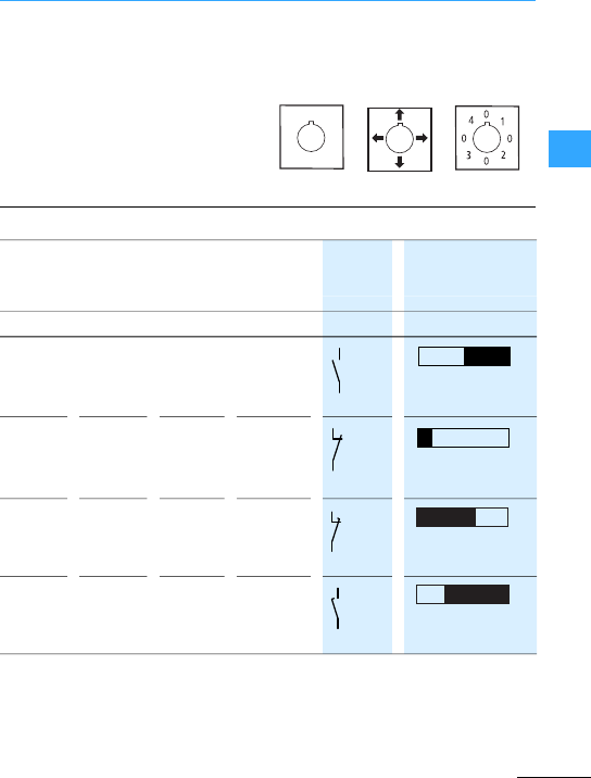
RMQ –System
EatonWiring Manual 06/11
33
Eaton offers varioustypes of labels forall
operating elements. Versionsavailable
are:
•Blank,
•With directionarrows,
•With inscription 0–1–0–2–0–3–0–4.
Customised inscriptions are also possible.
The software Labeleditor enables
customized inscriptions to be designed and
these can be subsequently applied to the
labels by laser, permanently and proof
against wiping off. 7Section
”Labeleditor”,page 3-13
1)
xxxx
M22-(C)K(C)10
xxx–
M22-(C)K(C)01
xxxx
M22-(C)K01D2)
x–x–
M22-K10P
1) Stroke in connection with front element.
2) N/C: Positive opening safety function according to IEC/EN 60947-5-1.
.3
.4
0 2.8 5.5
.1
.2
0 1.2 5.5
.5
.6
0 3.5 5.5
.7
.8
0 1.8 5.5
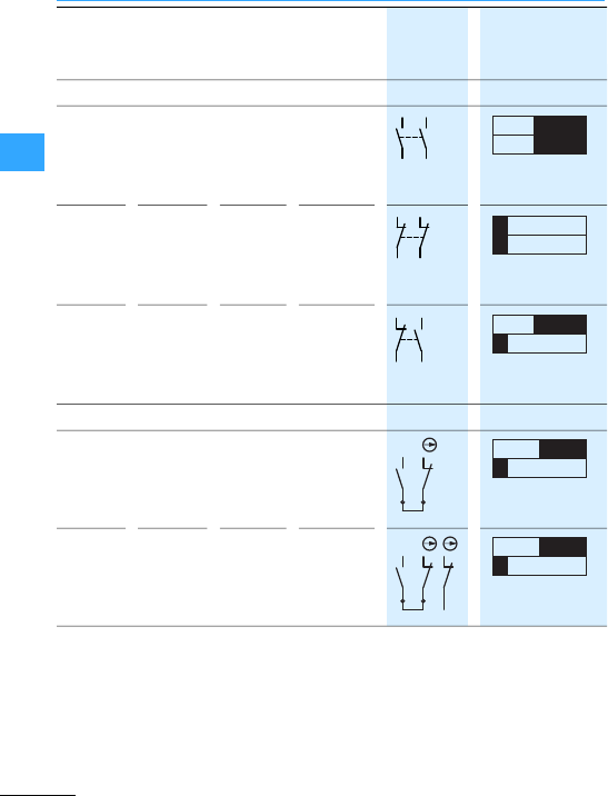
RMQ –System
EatonWiring Manual 06/11
33
1)
–xx–
M22-CK20
–xx–
M22-CK02
–xx–
M22-CK112)
x–xx
M22-K(C)01SMC10
x–xx
M22-K(C)02SMC10
1) Stroke in connection with front element.
2) N/C: Positive opening safety function according to IEC/EN 60947-5-1.
.3
.4
.3
.4
0 3.6 5.5
.1
.2
.1
.2
0 1.2 5.5
.3
.4
.1
.2
0 1.2 3.6 5.5
1
2
3
4
0 1.2 2.8 5.5
1
2
3
4
1
2
0 1.2 2.8 5.5
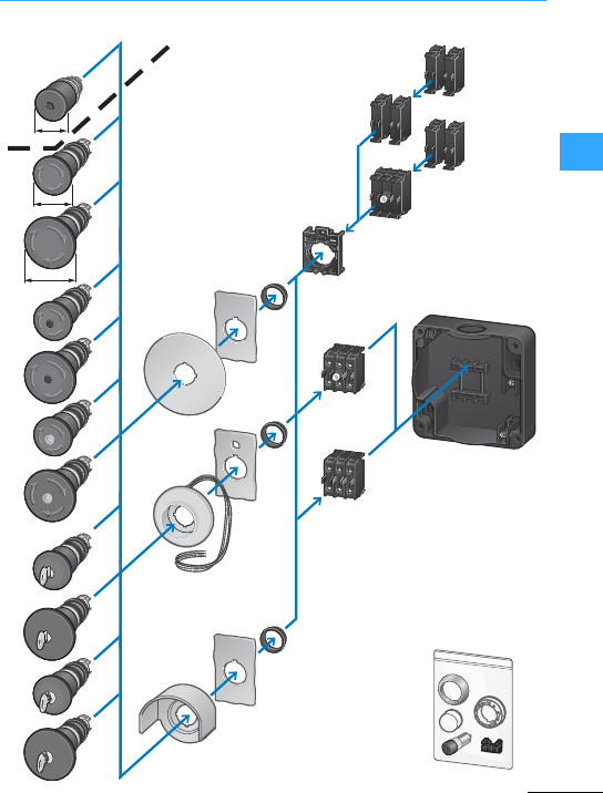
RMQ –System
EatonWiring Manual 06/11
33
38
45
60
Mushroom-shapedPalm-tree shape
E
M
E
R
G
E
N
C
Y
-
S
T
O
P

RMQ –System
EatonWiring Manual 06/11
33
The new emergency stop or emergency-off
pushbutton actuators for the RMQ-Titan
rangeof pilot devicesfor global use have a
palm shaped design with a 45 or 60 mm
diameter. They are available with or
without keys, turn-releasable,
non-illuminated, illuminated with standard
LEDs or with mechanicalswitch position
indication (green/red) in the center of the
actuator element. The self-monitoring
contactelements ensure extensive
operational safety; even with a faulty
installation or afterexcessive force is used
foractuation.As well as the emergency-off
NC contact, the modular contact elements
feature an integratedsecond contact for
querying the mechanical connection to the
emergency stop actuator element. The
contactelements are available forfront or
bottom fixing, for single or dual-channel
safetycircuits up to SIL 3 in accordance
with IEC 62061 or Performance Level PL e
to EN ISO13849-1.
An optional illuminatedring enables
emergency-stop/off pushbutton actuators
on amachine or a plant to be made more
conspicuous. Even in darkened
environments, the position of these
pushbutton actuators is clearly indicated.
The illuminated ring also clearly indicates
the operating state from a considerable
distance. When tripped, for example, it is
possible to activate three separately
controllable LED rows as a running light.
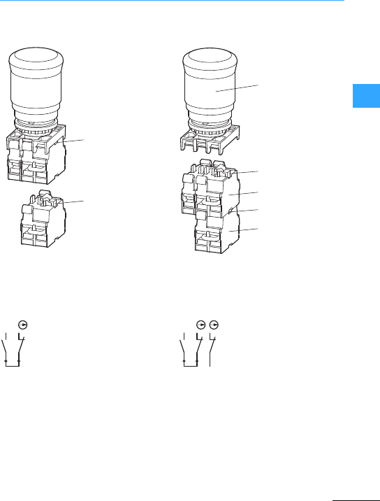
Eaton Wiring Manual 06/11
33
RMQ –Engineering
aThe self-monitoring contactmechanically monitors the connection on the M22-PV…
bThe self-monitoring contactmechanically monitors the interface on the
M22-K…SMC10 safetycontact above it; but NOTthe connection on the M22-PV…
When the self-monitoring contact is mounted correctly, the N/O contact is closed.
The emergency switching off/Stop circuit is activated via series connection of N/C and
N/Os if
•the emergency switching off/stop pushbutton is actuated or
•the self-monitoring contact is isolated mechanically from the pushbutton
b
a
a
b
M22-K... SMC10
M22-PV...
M22-K... SMC10
1
2
3
4
1
2
3
4
1
2
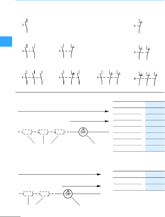
RMQ –Engineering
EatonWiring Manual 06/11
33
1) Ue#AC/DC
1x 60 V
2x 90 V
3x 120 V
... ...
x240 V
Ue#
1 x 220VDC
1) For increasing the voltage
AC/DC.
1) Ue#
1x 400V~
2x 500V~
1) AC–for increasing the voltage
50/60Hz.
13
14
13
14
23
24
13
14
23
24
33
34
30
20
10
13
14
13
14
33
34
21
11
21
22
21
22
13
14
12 21
22
31
32
21
22
03 11 21 31
12 22 32
21
22
01
02 11
12
12 – 30 V h/H
Ueh/H
X2X121
M22-XLED60/
M22-XLED220
M22-(C)LED(C)-...
2121
X2X1211
M22-XLED230-T M22-(C)LED(C)230-...
2
85 – 264 V h,
50 – 60 Hz
Ueh
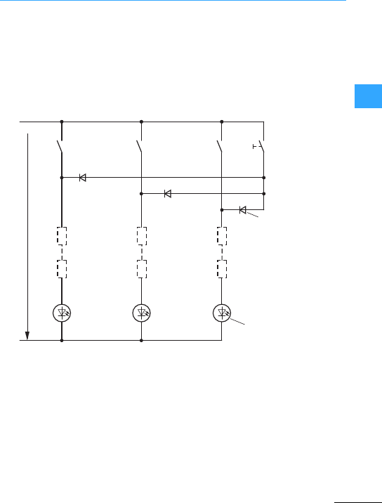
RMQ –Engineering
EatonWiring Manual 06/11
33
Thetest button is used to check operation
of theindicator lights independently of the
respective control state. Decoupling
elements prevent voltage feedback.
for Ue= 12 to 240 V AC/DC (also forlight test
with signal towers SL)
aTest button
1) Only for elements 12 to 30 V.
a
14
13
X2
X1
14
13
14
13
21
4
3
X2
X1
X2
X1
21
21
M22-XLED-T
M22-(C)LED(C)-...
1)
12 – 240 V h/H
2
1
M22-XLED60/
M22-XLED220
2
12
1
2
12
1
2
1
M22-XLED60/
M22-XLED220
M22-XLED60/
M22-XLED220
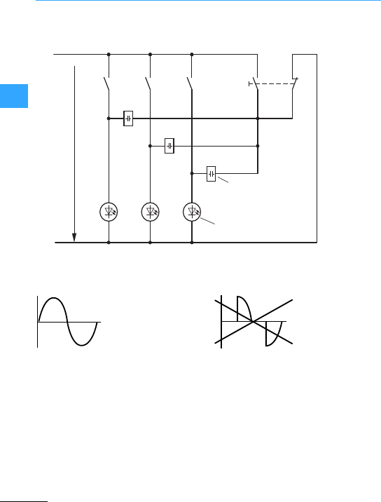
RMQ –Engineering
EatonWiring Manual 06/11
33
for Ue=85to 264 V AC/50 –60 Hz
aTest button
2) For elements 85 to 264V.
a
L1
N
14
13
X2
X1
14
13
14
13
4
3
2
1
X2
X1
X2
X1
M22-XLED230-T
M22-(C)LED(C)230-...
2)
85 – 264 V h/50 – 60 Hz
21
21
21

Eaton Wiring Manual 06/11
33
RMQ –Inscription
You can label your device to your individual
requirements in foursimple steps:
•Download the inscription software:
www.eaton.com/moeller/support
keyword: ”Labeleditor”
•Creation of label template (menu-guided
in the software)
•Send the label template to the factory by
email. The email address is automatically
setfor the selected product by the
program. When your template is sent, the
Labeleditorissues a file name such as
“RMQ_Silver_12345.zip”. This file name
is part of the article to be ordered (see
Ordering examples).
•Send order to the Eaton sales office or
the electrical engineering wholesaling.
•M22-XST insert label for M22S-ST-X
legend label mount with special
inscription
Basic type: M22-XST-*
* = File name generated by Labelditor
Please order:
1xM22-XST-RMQ_Titan_xxxxxx.zip
•Button plate in greenwith special
inscription
Basic type: M22-XDH-*
1. * = Colour (here „G“for green),
2.* = File name generated by Labeleditor
Please order:
1xM22-XDH-G-RMQ_Titan_xxxxx.zip
•Double actuator pushbutton with white
pushbutton platesand special symbols
Basic type: M22-DDL-*-*-*
1. * = Colour (here „W“for white),
2. and 3. * = File name assigned by
Labeleditor; must be stated here 2x
Please order:
1 x M22-DDL-W-RMQ_Titan_xx
xxx.zip-RMQ_Titan_xxxxx.zip
•Key-operated button, 2 positions,
individual lock mechanism no. MS1,
individual symbol
Basic type: M22-WRS*-MS*-*
WRS*: *= Numberof positions,
MS*: * = Number of individual lock
mechanism,
-*: * = File name assigned in Labeleditor
Please order:
1x
M22-WRS2-MS1-RMQ_Titan_xxxxxx.zip
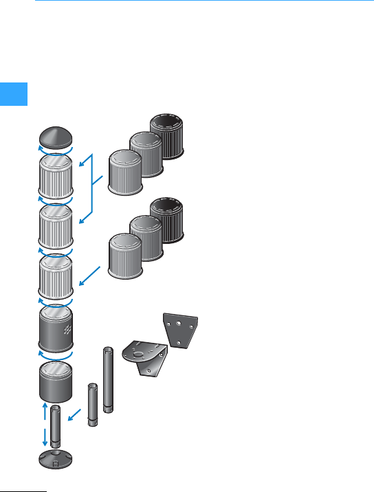
Eaton Wiring Manual 06/11
33
Signal Towers SL
Signal towersSL (IP65) indicate machine
states using visible and acoustic signals.
Mounted on control panels or on
machines, they can be reliably recognized
as continuous light, flashing light, strobe
light or acoustic device even from a
distance, and dealt with as necessary.
•Continuous light, flashing light, strobe
light and acoustic device can be
combined as required.
•Free programmability permits the
actuation of five addresses.
•Simple assembly without tools by
bayonet fitting.
•Automatic contacting by built-in contact
pins.
•Excellent illumination by specially
shaped lenses with Fresneleffect.
•Useof filament lampsor LEDs as
required.
•Alarge number of complete devices
simplifies selection, ordering and
stockkeeping for standard applications.
The various colors of the lightelements
indicate the operating state in each case to
IEC/EN 60204-1 an:
Dangerous state –Immediate action
necessary
Abnormal status–monitor or +action
Normal status –no action necessary
Discontinuity –action mandatory
Other status–can be used as required.
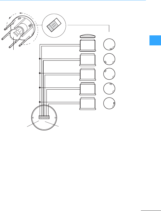
Signal Towers SL
EatonWiring Manual 06/11
33
Five signallines from aterminal strip in the
base module run through each module. The
module is addressed viaawire link
(jumper) on each card. Five different
addresses can also be allocated several
times.
Thus, for example, a red strobe lightand in
parallel with it an acoustic device can
indicate and announce the dangerous
status of a machine. Plug both jumpers into
the same position on the pcb –and it's
done!
(7Section ”Connection for light test”,
page 3-11.)
BA15d F7 W
N
1
2
3
4
0
5
054321
5
5
4
3
2
1
4
3
2
1
1...5 Ue= 24 – 230 Vh/H
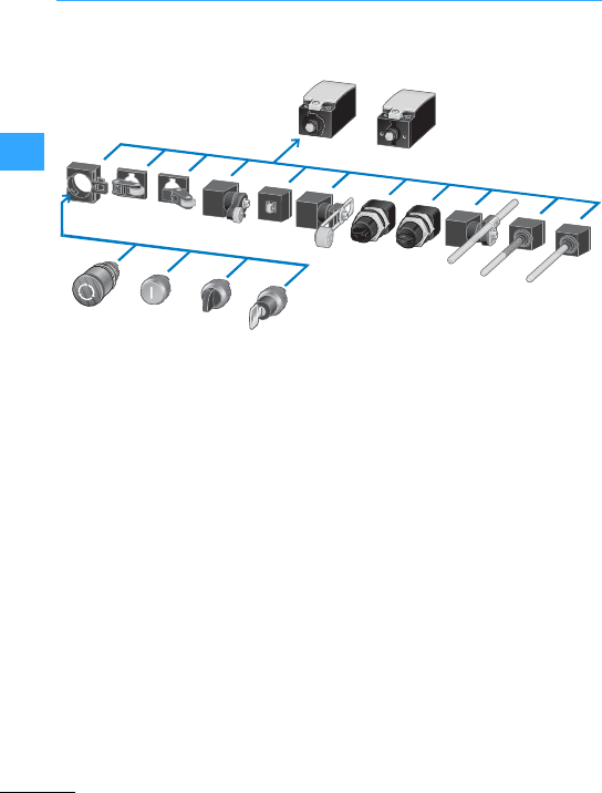
Eaton Wiring Manual 06/11
33
LS-Titan®position switches
Another unique feature is the possibility to
combine actuators from the RMQ-Titan
range with the position switches LS-Titan.
Pushbuttons, selector switches or
emergency switching off pushbuttonscan
all be directly snapped on to any position
switch as operating head. The complete
unit then has at least the high protection
type IP66 at front and rear.
In addition, all the operating heads and the
adapterfor accepting the RMQ-Titan
pushbuttons have a bayonet fitting that
enables quick and secure fitting. Using the
bayonet fitting, the heads can be attached
in any of the four directions (4 x 90°).
aOperating heads in fourpositions, each
turned by 90°, can be fitted
subsequently.
LS-Titan
RMQ-Titan
①
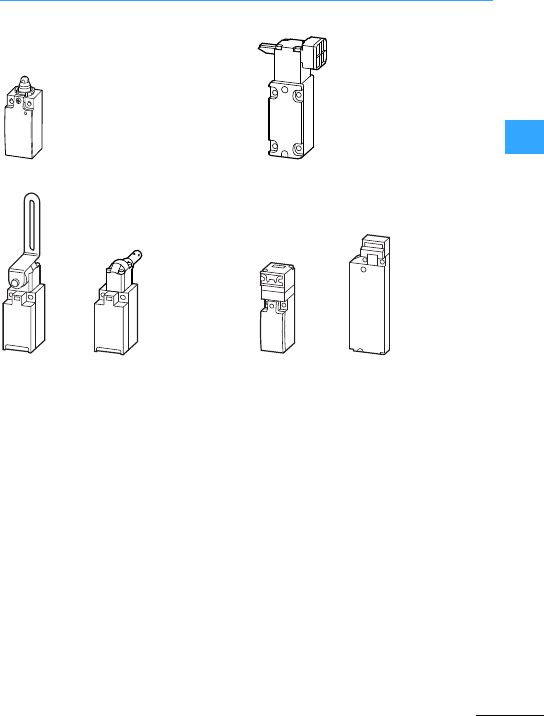
LS-Titan®position switches
Eaton Wiring Manual 06/11
33
LS, LSMLS4…ZB
LSR…LS…ZB LS…ZBZ
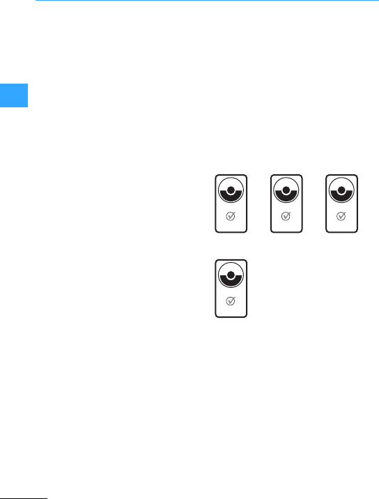
LS-Titan®position switches
Eaton Wiring Manual 06/11
33
Eaton safety position switches have been
specially designed for monitoring the
position of protectiveguards such as
doors, hinged flaps, shrouds and protective
guards. They meet the requirements of the
employers'liability insurance Association
forthe testing of positive opening position
switches for safetyfunctions (GS-ET-15).
These requirements include:
“Position switches for safety functions
must be designed so that the safety
function cannot be bypassed manually or
simple tools.”Simple tools are: pliers,
screwdrivers, pins, nails, wire,scissors,
penknives etc.
In addition to these requirements,LS...ZB
position switches offer additional
manipulation safetyby means of an
operating head which can rotate but
cannot be removed.
Mechanically operated position switches
in safety circuits must have positive
opening contacts (see
EN 60947-5-1
). Here,
the term positive opening is defined as
follows: “The execution of a contact
separation as the direct result of a
predetermined motion of the keypad of the
switch via non-spring operated parts
(e.g.not dependent on a spring )“.
Positive opening is an opening movement
by which it is ensured that the main
contacts of a switch have attained the
open position at the same time as the
keypad assumes the Off position. Eaton
position switches all meet these
requirements.
All Eaton safety position switches are
certified by the employers'liability
insurance Association or by the Technical
Monitoring Service (TÜV), Rheinland.
LS4…ZB LS…ZBZ LS…ZB
LSR-ZB…
B
G
P
R
Ü
F
Z
E
R
T
Sicherheit geprüft
tested safety
ET 06183
B
G
P
R
Ü
F
Z
E
R
T
Sicherheit geprüft
tested safety
BGIA 0603010
B
G
P
R
Ü
F
Z
E
R
T
Sicherheit geprüft
tested safety
ET 07014
B
G
P
R
Ü
F
Z
E
R
T
Sicherheit geprüft
tested safety
ET 06165
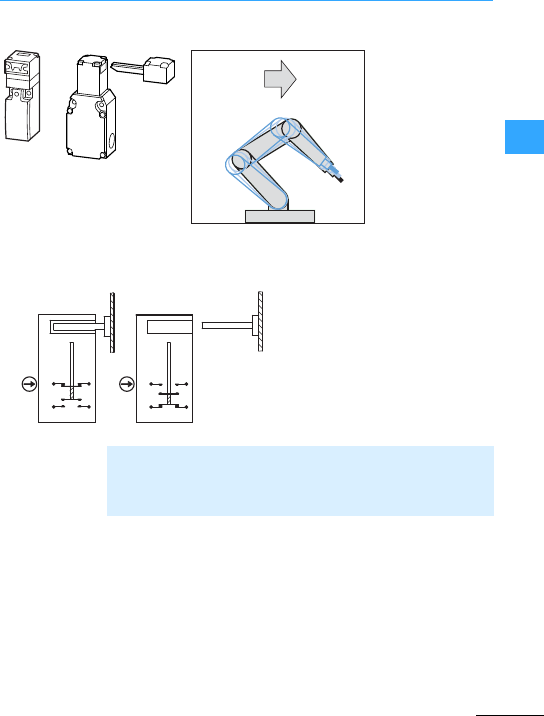
LS-Titan®position switches
Eaton Wiring Manual 06/11
33
LS…ZB LS4…ZB
•Door open
•LS...ZB
disconnects
power
•No danger
STOP
closed Open
aSafetycontact
bSignalling contact
21 22
13 14
21 22
13 14
a
b
Door closed 7Safety contact (21 - 22) closed
Signalling contact (13 - 14) open
Door open 7Safety contact (21 - 22) open
Signalling contact (13 - 14) closed
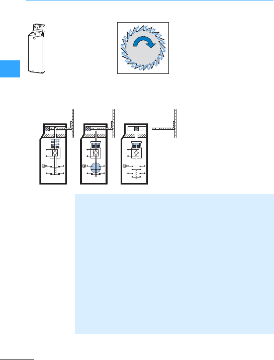
LS-Titan®position switches
Eaton Wiring Manual 06/11
33
LS…ZBZ
•Stop command
•Waiting time
•Machine is stopped
•Protective mechanism
open
•No danger
STOP
LS-S02-…FT-ZBZ
aSafety contact
bSignalling contact
cInterlocked
dReleased
eOpen
a
b
A1
A2
21 22
11 12
A1
A2
21 22
11 12
A1
A2
21 22
11 12
USUS
GED
Door closed and
interlocked 7Coil at (A1, A2) de-energized also with mains failure or wire breakage:
Door interlocked =safe state
Safety contact (21 - 22) closed
Signalling contact (11 - 12) closed
Releasing of door 7Apply voltage to coil (A1, A2)
e.g. via zero-speed monitor
Safety contact (21 - 22) opens
Signalling contact (11-12) remains closed
Door open 7Only possible once it is released
Signalling contact (11 - 12) opens.
Door open 7Both contacts in the open position
tamperproof against simple tools
Close door 7Signalling contact (11 - 12) closes
Lock door 7Switch off the voltage from coil (A1, A2)
1st actuator interlocked
2ndsafety contact (21 - 22) closes

LS-Titan®position switches
Eaton Wiring Manual 06/11
33
LS-S11-…FT-ZBZ
aSafety contact
bSignalling contact
cInterlocked
dReleased
eOpen
a
b
USUS
A1
A2
21 22
13 14
A1
A2
21 22
13 14
A1
A2
21 22
13 14
GED
Door closed and
interlocked 7Coil at (A1, A2) de-energized also with mains failure or wire breakage:
Door interlocked = safe state
Safety contact (21 - 22) closed
Signalling contact (13 - 14) open
Releasing of door 7Apply voltage to coil (A1, A2)
e.g. via zero-speed monitor
Safety contact (21 - 22) opens
Signalling contact (13 - 14) remains open
Door open 7Only possible once it is released
Signalling contact (13 - 14) closes.
Door open 7Safety contact (21 - 22) open
Signalling contact (13 - 14) closed
Close door 7Signalling contact (13 - 14) opens
Lock door 7Switch off the voltage from coil (A1, A2)
1stactuator interlocked
2nd safetycontact (21-22) closes
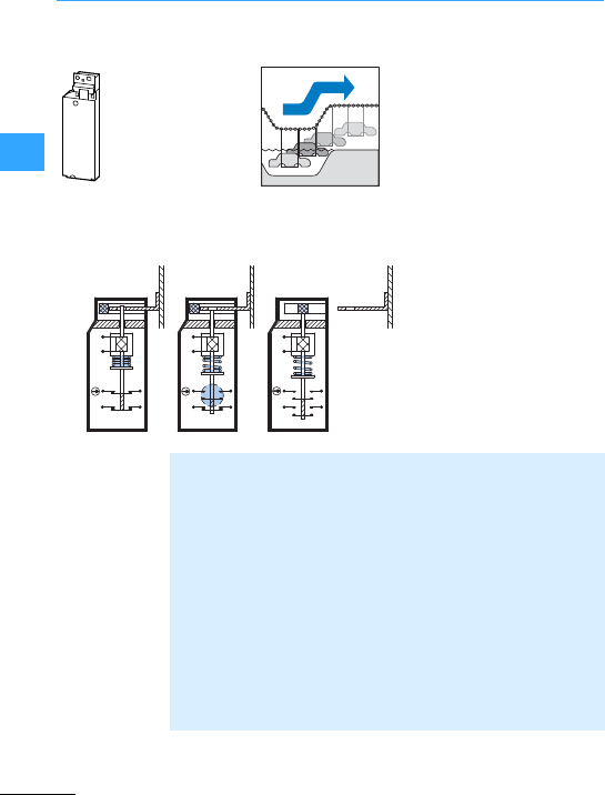
LS-Titan®position switches
Eaton Wiring Manual 06/11
33
LS…ZBZ
•Stop command
•Waiting time
•Process sequence halted
•Protective mechanism
open
•Product OK
STOP
LS-S02-…MT-ZBZ
aSafety contact
bSignalling contact
cInterlocked
dReleased
eOpen
A1
A2
21 22
11 12
A1
A2
21 22
11 12
A1
A2
21 22
11 12
a
b
US
GED
Door closed and
interlocked 7Voltage on coil (A1, A2)
Safety contact (21-22)closed
Signalling contact (11 - 12) closed
Releasing of door 7Coil de-energized (A1, A2)
e.g. viazero-speed monitor,
Safety contact (21-22)opens
Signalling contact (11 - 12) remains closed
Door open 7Onlypossible once it is released
Signalling contact (11 - 12) opens.
Door open 7both contacts in the open position, even with tampering with simple tools
Close door 7Signalling contact (11 - 12) closes
Lock door 7Apply voltage to coil (A1, A2)
1st actuator interlocked
2nd safety contact (21 - 22) closes

LS-Titan®position switches
Eaton Wiring Manual 06/11
33
LS-S11-…MT-ZBZ
aSafety contact
bSignalling contact
cInterlocked
dReleased
eOpen
a
b
A1
A2
US
A1
A2
A1
A2
21 22
13 14
21 22
13 14
21 22
13 14
GED
Door closed and
interlocked 7Voltage on coil (A1, A2)
Safety contact (21-22)closed
Signalling contact (13 - 14) open
Releasing of door 7Coil de-energized (A1, A2)
e.g. viazero-speed monitor,
Safety contact (21-22)opens
Door open 7Onlypossible once it is released
Signalling contact (13 - 14) closes.
Door open 7Safety contact (21-22)open
Signalling contact (13 - 14) closed
Close door 7Signalling contact (13 - 14) opens
Lock door 7Apply voltage to coil (A1, A2)
1st actuator interlocked
2nd safety contact (21 - 22) closes
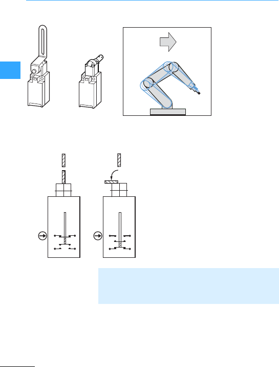
LS-Titan®position switches
Eaton Wiring Manual 06/11
33
LSR…I(A) /TKG LSR…I(A)/TS
•Hinged protective
cover open
•LSR... disconnects
power
•No danger
STOP
Closed Open
aSafety contact
bSignalling contact
21 22
13 14
21 22
13 14
a
b
Hinged protective cover
closed 7Safety contact (21 - 22) closed
Signalling contact (13-14)open
Protective flap open 7Safety contact (21 - 22) open
Signalling contact (13-14)closed

LS-Titan®position switches
Eaton Wiring Manual 06/11
33
Standards
•IEC60947-5-1
7EN 50047
•Dimensions
•Fixing
dimensions
•Operating points
•Minimum IP65
•IEC60947-5-1
7EN 50041
•Dimensions
•Fixing
dimensions
•Operating points
•IP65
•IEC60947-5-1
•IP65
•IEC60947-5-1
•IP65
Suitable applications
•Also for use in
safety circuits, by
positive
operation and
positive opening
contacts
•Safety position
switches for
protection of
personnel
•with separate
operating
element for
protective covers
•Positive
operation and
positive opening
contacts
•Approval of
employers'
liabilityinsurance
Association
•Safety position
switches for
protection of
personnel
•with separate
operating
element for
protective covers
•Positive
operation and
positive opening
contacts
•Approval of
employers'
liabilityinsurance
Association
•Safety position
switches for
protection of
personnel
•with separate
operating
element for
protective covers
•Positive
operation and
positive opening
contacts
•electromagnetic
interlock
•Approval of
employers'
liabilityinsurance
Association
Drive
•Rounded plunger
(centre fixing)
•Roller plunger
(centre fixing)
•Rotary lever
•Angled roller
lever
•Adjustable roller
lever
•Actuating rod
•Spring-rod
actuator
•Operating heads
adjustablein 90°
steps
•Coded actuating
element
•Operating head:
–Can be rotated
by 90°
–Can be
actuated from
both sides
•Actuating
element
–Convertible for
verticaland
horizontal
fixing
•With triple coding
•Coded actuating
element
•Operating head:
–Can be rotated
by 90°
–Can be
actuated from
four sides and
from above
•Coded actuating
element
•Operating head:
–Can be rotated
by 90°
–Can be
actuated from
four sides
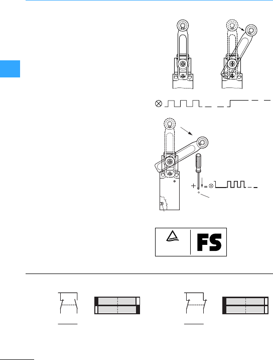
Eaton Wiring Manual 06/11
33
LSE-Titan®electronic position switches
The operating point on electronic position
switches LSE-Titan is adjustable and
variable. Two high-speed and bounce-free
PNP switching outputs enable high
switching frequencies.
The position switchis overload as well as
conditionallyshort-circuit proof and has
snap-action switching performance. This
ensures a defined and reproduceable
switching point. The operating point lies in
the range from 0.5 to 5.5 mm
(as supplied =3mm).
Adjustment to a new operating point is
carried out as follows:
Move the plunger from the original to the
new switch position.For this purpose,
press the setting pushbutton for1s.The
LED now flashes with a high pulse
frequency and the new operating point is
retentively set.
The LSE-11 and LSE-02 complete devices
can be used in safety-oriented
connections. They have the same function
as electromechanical position switches.
This means that allthe devices are also
suitable for safetyapplications designed
forpersonnel or process protection.
1 s
fmax F2 N
set
set
adjust
fix
LED
TÜV
Rheinland
Bauart geprüft
Type approved
Functional
Safety
electron.
+
U
e
Q1
0 V
Q2
Q1
Q2
0.5 5.5
default = 3.0
6.1
0
Q1
0 V
Q2
+
U
e
electron.
Q1
Q2
0.5 5.5
default = 3.0
6.1
0

Eaton Wiring Manual 06/11
33
Analog electronic position switches
Two part no. are available:
•LSE-AI with current output,
•LSE-AU with voltage output.
Analog position switches LSE-AI(4 to
20 mA) and LSE-AU (0 to 10 V) represent
another innovation in electronic position
switches. Using them,it is now possible for
the first time to monitor the actual position
of aflue gas valve or an actuator
continuously. The actual position is
converted in analog fashion into voltage
(0 to 10 V) or current (4 to 20 mA) and then
continuouslysignalled to the electronics.
Even objects of varying sizes or
thicknesses, such as brake shoes, can be
scanned and the results processed further.
Simple rotational-speed dependent control
systems of fan motors or smoke-venting
blowers signal the opening angle of the air
damper (e.g. 25, 50 or 75 %) and thus save
power and material wear. The analog
position switches also have a diagnosis
output for further processing of data. This
meansthat the safe statuscan be
monitored and analyzed at all times. The
position switch also has a self-test
function. The outputs Q1 and Q2 are
constantly scanned for overload,
short-circuitagainst 0Vand short-circuit
against +Ue.
LSE-AI
LSE-AU
1000
4
20
S [%]
I[mA]
1000
10
S [%]
U[V]
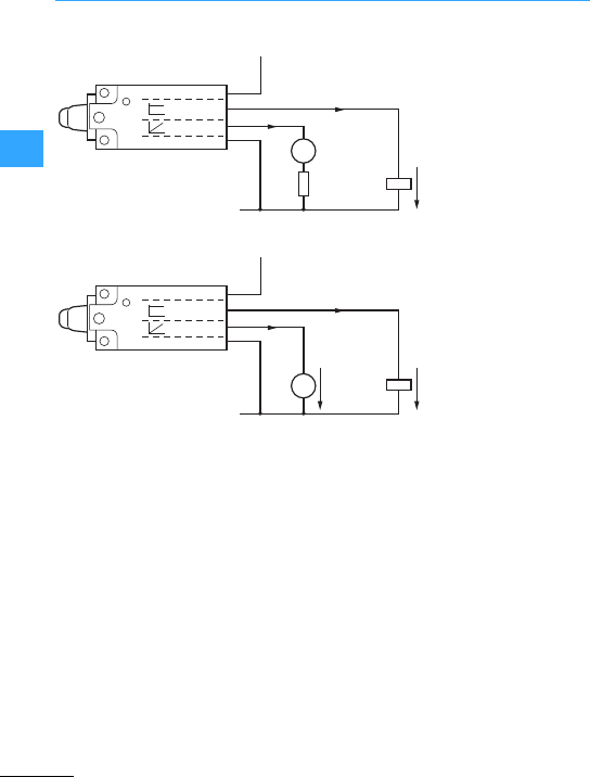
Analog electronic position switches
EatonWiring Manual 06/11
33
LSE-AI
F200 mA
4 – 20 mA
0 V
QUe
< 400 O
A
+24 V (–15 / +20 %)
+Ue
+Q2
+Q1
0 V
diagnosis
analog
LSE-AU
F200 mA
F10 mA
0 V
0 V – 10 V QUe
V
+24 V (–15 / +20 %)
+Ue
+Q2
+Q1
0 V
diagnosis
analog
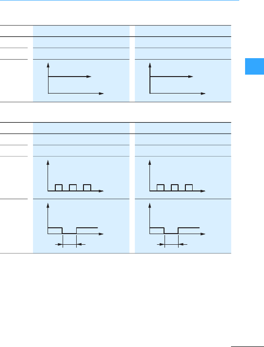
Analog electronic position switches
EatonWiring Manual 06/11
33
Normal scenario
Fault scenario
Q1 4–20 mA 0–10 V
Q2 6Ue6Ue
LED
t
LED
t
LED
Q1 0mA 0V
Q2 0V 0V
LED
Reset
t
LED
t
LED
+Ue
t
> 1 s
+Ue
t
> 1 s
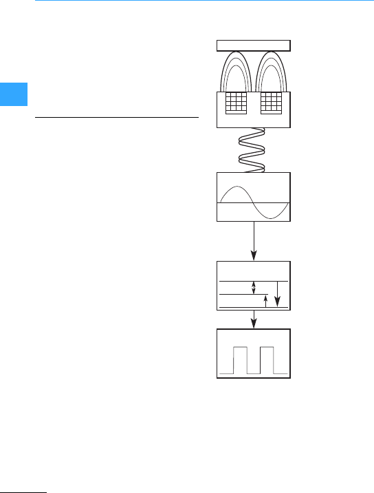
Eaton Wiring Manual 06/11
33
Sensors –Functionality
Inductive sensors are used to detect metal
objects. The objects are detected through
an electromagnetic field.
With the ability to detect at close range,
inductive proximity sensors are very useful
forprecision measurement and inspection
applications.
Inductive sensors create an invisible high
frequencyoscillation field. When metal
objects are brought into this field, this
oscillating field is affected. Each sensor
has a specific sensing range switch point
so thatmetal target detection is very
accurate and repeatable.
If a metal object is brought into the field
created by the sensor, this is interrupted
and causes a reduction in the current
flowing through the sensor coil (eddy
currentdamping). The detectorcircuit
senses this change and sends a signal via
the sensor output.
A metal object, or target, enters the
sensing field.
The sensor coil is a coil of wire typically
wound around a ferrite core. If you could
see the electromagnetic field created by it,
it would be cone shape.The targetwill
pass through this field.The ferrite core

Sensors –Functionality
EatonWiring Manual 06/11
33
shapes the field and the size of the coil
determines the sensing range.
The resonance circuit creates a high
frequencyoscillation of the
electromagnetic field (between 100 Hz and
1 MHz). If a metal object is located in the
field, this causes a change in the magnetic
field oscillation.
This change creates an eddy current
which dampens the signal fed back to the
sensor coil.
The detectorcircuit senses the change
and switches ON at a particular set point
(amplitude). This ON signal generates a
signal to the solid-state output.
The output circuit remains active until the
target leaves the sensing field. The
oscillator responds with an increase in
amplitude, and when it reaches the
setpoint value, the detector circuit
switches OFF. The outputreturns to its
normalstate.
The sensing ranges stated by the sensor
manufacturer are usually based upon
ferrite targets made of carbon-rolled steel
(IE FE 235) defined by ISO630.
Sensing ranges to targets made of other
materials have to have a correction factor
applied as listed in thetable below. To use
this table, multiply the sensing distance of
the device by the factor given below.
Multiply the sensing distance by the factor
given below.
1) Stainless steel 400 series to ASTM
A240, martensitic or ferritic,
magnetizable.
2) Stainless steel 300 series to ASTM
A240, austenitic, non-magnetizable.
The index of stainless steels is provided in
EN 10088-1.
Stainless
Steel 4001)
0.90 0.90 1.0 1.0
Stainless
Steel 3002)
0.65 0.70 0.70 0.75
Brass 0.35 0.45 0.45 0.45
Aluminium 0.35 0.40 0.45 0.40
Copper 0.30 0.25 0.35 0.30
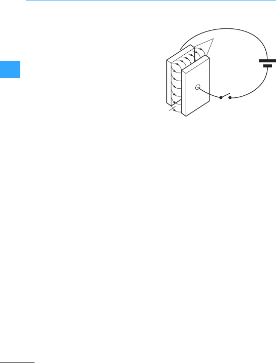
Sensors –Functionality
EatonWiring Manual 06/11
33
Capacitive sensors aredesigned to detect
both metallic and nonmetallic targets. They
are ideally suited for liquid level control
and for sensing powdered or granulated
material.
Capacitive sensors operate using a
capacitor. This consists of two metal plates
that are separated by an insulating
dielectric material. The function of this type
of sensor is based on dielectric
capacitance, which is the ability of a
dielectric to store an electrical charge.
Thedistance between the plates
determines theability of the capacitor to
store an electricalcharge.
If an object is put into the electricalfield.
the capacitance of the capacitor changes.
This change is used to implementthe on/off
switch function.
•Capacitor
aPlates
bSwitch
cDielectric
When this principle is applied to the
capacitive sensor, one capacitive plate is
part of the switch, the enclosure (the
sensor face) is the insulator. The target is
the other “plate”. Ground is the common
path.
Capacitive proximity sensors can detect
any target that hasa dielectricconstant
greater than air. Liquidshave high
dielectric constants. Metal also makes a
good target.
①
②
③
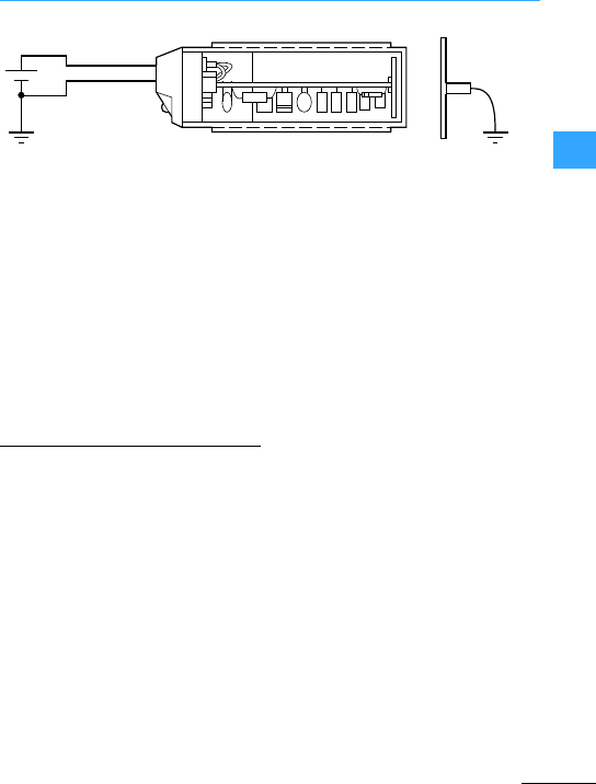
Sensors –Functionality
EatonWiring Manual 06/11
33
•Capacitive sensor
Capacitive sensors consist essentially of
four basic elements:
•Sensor (Dielectric)
•Resonance circuit
•Detector circuit
•Output circuit.
As an object approaches the sensor, the
dielectric constant of the capacitor
changes. The oscillator circuit’s vibration
begins when feedback capacitance is
detected. This is just the opposite in the
inductive proximity sensor, where the
vibrationis damped when the target is
present.
Capacitive sensors are activated both by
conductive as well as non-conductive
objects.
Metals achieve the greatest switching
distances due to their high conductivity.
Derating factors for various metals, such
as are necessary with inductive sensors,
need not be taken into account.
Actuation by objects made of
non-conductive materials (insulators):
When an insulator is brought between the
electrodes of a capacitor, the capacitance
rises relative to the dielectric constant e of
the insulator. The dielectric constant for all
solid and liquid materials is greater than
that forair.
Objects made of non-conductive materials
affectthe active surface of a capacitive
proximity switch in the same way. The
coupling capacitance is increased.
Materials with a high dielectric constant
achieve greatswitching distances.
When scanning organic materials (wood,
grain, etc.) it must be noted that the
attainable switching distance is greatly
dependent on their moisture content.
(FWater =80!)
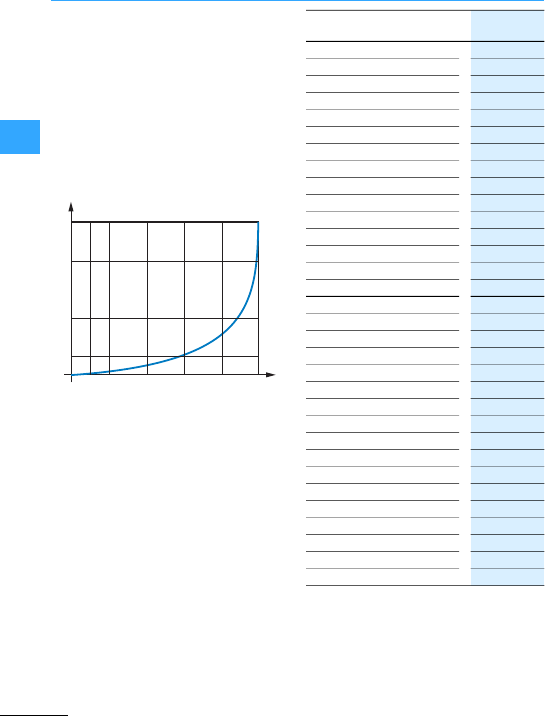
Sensors –Functionality
EatonWiring Manual 06/11
33
As can be seen from the following diagram,
the switching distance Sris dependent on
the dielectric constant Frof the object to
be monitored.
Metal objects produce the maximum
switching distance (100 %).
With other materials, it is reduced relative
to the dielectric constant of the object to be
monitored.
The followingtable lists the dielectric
constants Frof some important materials.
Dueto the high dielectric value of water,
the fluctuations with wood can be
significant. Damp wood therefore is
registered much more effectively by
capacitive sensors than dry wood.
60
80
30
10
10 20 40 60 80 100
1
er
sr[%]
r
Air, vacuum 1
Teflon 2
Wood 2 - 7
Paraffin 2.2
Kerosene 2.2
Oil of terpentine 2.2
Transformer oil 2.2
Paper 2.3
Polyethylene 2.3
Polypropylene 2.3
Cable insulation 2.5
Soft rubber 2.5
Silicone rubber 2.8
Polyvinyl chloride 2.9
Polystyrene 3
Celluloid 3
Perspex 3.2
Araldite 3.6
Bakelite 3.6
Silica glass 3.7
Hard rubber 4
Oil-impregnated paper 4
Chipboard 4
Porcelain 4.4
Laminated paper 4.5
Quartz sand 4.5
Glass 5
Polyamide 5
Mica 6
Marble 8
Alcohol 25.8
water 80
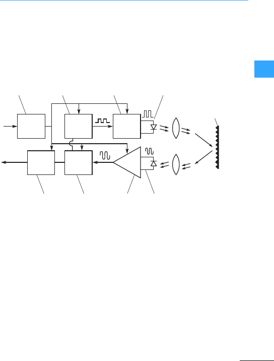
Sensors –Functionality
EatonWiring Manual 06/11
33
Optical sensorsuse light to detect the
presence or absence of an object. The
main advantages of optical sensors are
contactless sensing of objects and greatly
extended sensing ranges.
A LED sends a beam of light, which is
picked up by a photodetector. An object is
detected when it passes between the LED
and photodetector, interrupting the light
beam.
Let’s look at how an optical sensor works.
aPower supply:
Feeds the sensor circuit with a
regulated DC voltage.
bModulator:
generates pulsesto cycle amplifier and
LED at desired frequency.
cSource currentamplifier
dLED
eLens
fTarget object or reflector
gPhotodetector:
Either aphotodiode or aphototransistor
device,selected for a maximum
sensitivity at the source LED’s emitted
light wave-length. Both the source LED
and the detectorhave protective
lenses.When the sensor picks up the
light, it sends a small amount of current
to the detectoramplifier.
hDetector Amplifier:
Blocks current generated by the
background light. It also provides
amplification of the signal received to a
usable level, and sends it through to the
demodulator.
iDemodulator:
Sorts out thelight thrown out by the
sensor from all other lightin the area. If
the demodulator decides the signals it
receive are okay, it signals the output.
jOutput:
Performs switching routine when
directed to do so by the demodulator.
①② ③④
⑤
⑤
⑥
⑦⑧⑨⑩
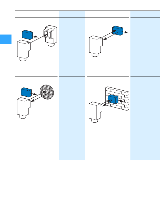
Sensors –Functionality
EatonWiring Manual 06/11
33
Light barriers A source unit in
one location
sends a light
beam to a
detector unit in
another
location. An
object is
detectedwhenit
passes between
the source unit
and the detector
unit,interrupting
the light beam.
Reflected-light beam Light source and
receiver are
located in the
same unit. If a
target moves in
front of the optical
sensor, it reflects
the light beam
directlyback to the
receiver.
Polarisation reflex sensor Lightsource and
receiver are
located in the
same unit. If a
target moves in
front of the
optical sensor, a
reflector
reflects the light
beam directly
back to the
receiver.
Background rejection
(Perfect Prox)
Thisis a special
type of diffuse
reflective sensor
that includes two
detectors. This
sensor offers
reliable detection
of target objects in
a defined sensing
range and at the
same time ignores
objects outside of
this range. Unlike a
standard diffuse
reflective optical
sensor, color or
reflectivity has
minimal effect on
the sensing range
of this sensor.
Detector
Source
Target
Target
Reflex
Sensor
Target
Reflex
Sensor
Retroreflector
Fixed Focus
Perfect Prox
Sensor
Target
Background
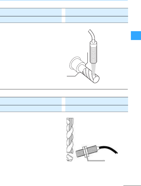
Eaton Wiring Manual 06/11
33
Sensors –Applications
This sensor is used to sense forthe
presence of the bit on a mill. The high
sensing power and background
suppression of the Perfect Prox allows
reliable detection through high levels of
cuttingfluids, whileignoring objects just
beyond the bit. The rugged harsh duty
sensor survives constant exposure to
lubricants, cutting fluidsand flying metal
chips.
A tubular sensor is used to detect the
presence of a drill bit –should the drill bit
be broken the sensor would signal a
controller.
E58 Perfect Prox Sensor E58-30DP or E58-18DP Sensor
Tubular inductive sensor E57 Product Family or iProx
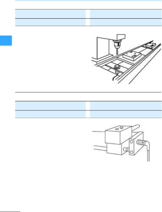
Sensors –Applications
EatonWiring Manual 06/11
33
A ferrous only sensor is used in a process
where aluminum is being machined. The
ferrous only sensor ignores the aluminum
(non-ferrous) chips from the machining
process and only detects the ferrous
target.
A tubular sensor is used to detect the
position of a tool chuck.
Tubular inductive sensor E57 Product Family or iProx
Tubular inductive sensor E57 Product Family or iProx
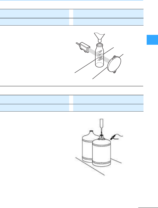
Sensors –Applications
EatonWiring Manual 06/11
33
A clearobject sensor is used to sense the
presence of bottlesat a filling operation.
Thesensor offers high reliability in sensing
clearbottlesof different colors and
thicknesses.
A capacitive sensor used to verify fill level
of bottled water on a filling process line.
E65 Clear Object Sensor E71-CON or E71-COP
Tubular capacitive Sensor E53 Product Family
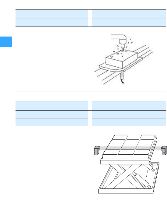
Sensors –Applications
EatonWiring Manual 06/11
33
Atubular inductive sensor is used to detect
the presence of metal carriers holding
partsto be machined.
A set of thru-beam sensors determines the
height of a scissor lift. For example, when
the control is set for“dark-to-light”
energize, the lift rises after a layer has
been removed and stops when the next
layer breaks the beam again.
Tubular inductive sensor E57 Product Family or iProx
Comet Series Thru-Beam - source 11100A
Comet Series Thru-beam - detector 12100A
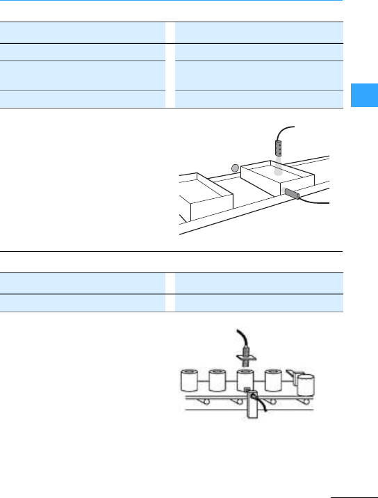
Sensors –Applications
EatonWiring Manual 06/11
33
Twosensors work togetherto inspect the
fill level in cartonson a conveyor. A reflex
sensor senses the position of the carton
and energizes the sensors located over the
contents.If the sensor does not“see”the
fill level, the carton does not pass
inspection.
Two sensors are used to detecta can on a
conveyorbelt and to check whether it has
a cover.
Comet visible reflexphotoelectric sensor 14102A
Comet reflected-light beam with
background suppression(PerfectProx)
13103A
Retro-reflector 6200A-6501
Tubular inductive sensor E57 Product Family or iProx
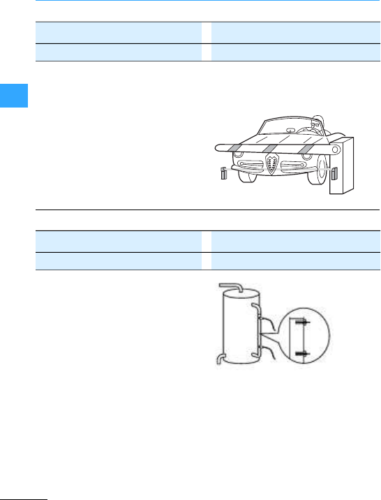
Sensors –Applications
EatonWiring Manual 06/11
33
The long range polarized reflex controls
are used for the time control of a toll
barrier. As soon as the carthat haspaid
passes, the barrier closes in order to
ensure that the next car stops. With the
initiator E67 Long Range Perfect Prox you
can mount the sensor on just one side
instead of both. It detects cars with
different colors and finishes whilst reliably
ignoring all other background objects.
The rugged design makes it also suitable
forcontinuous operation in extreme
weather conditions.
A pair of capacitive sensors are used to
sense high and low liquid levels in a tank
through a sight glass. This arrangement
starts a pump to fill thetank when the lower
sensor is energized and shuts the pump off
when the top sensor is energized.
E67 Perfect Prox long range sensor E67-LRDP
Tubular capacitive Sensor E53 Product Family
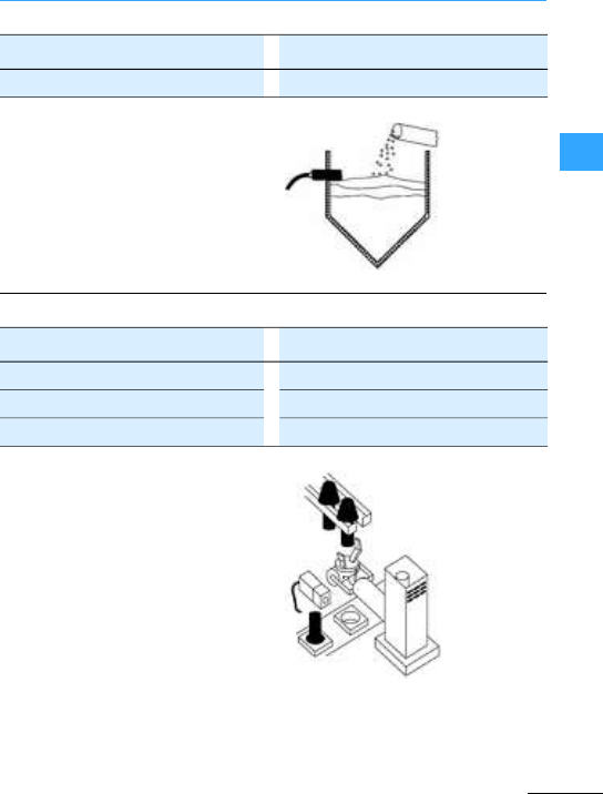
Sensors –Applications
EatonWiring Manual 06/11
33
A capacitive sensor is used to control fill
level of solids such as plastic pelletsin a
hopper or bin.
A sensor configured as a limit switch can
be used to detectwhether a component is
present in an automatic assembly
machine. The Comet detects all materials,
colors and services and masks out the
background. The iProx can be programmed
to detect a particular material and thus to
ignore allother materials.
Tubular capacitive Sensor E53 Product Family
Limit switch,inductive sensor E57 Product Family
Comet Perfect Prox 1310
Inductive sensor iProx E59-M
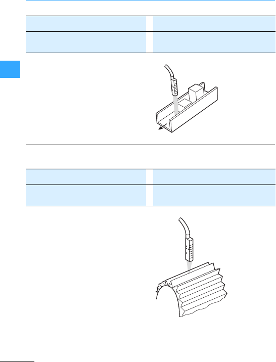
Sensors –Applications
EatonWiring Manual 06/11
33
The sensor detects components with
different heights from approx. 13 to 76 mm
in a channel and can mask out the channel.
Installation is simple and does not require
any drilling or cutting of the channel.
A focused diffuse reflective sensor
interfaces with aprogrammable controller
to measure a specific length of corrugated
automotive filter paper. The controller
detects the presence or absence of a
corrugation. When a predetermined
number of corrugationshasbeen detected,
the programmable controller directs a
shear to cut the paper.
Comet reflected-light beam
(Perfect Prox), 100 mm
13101A
Afocused diffuse Comet reflective
sensor
13102A
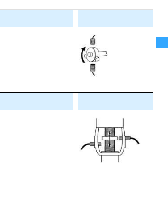
Sensors –Applications
EatonWiring Manual 06/11
33
A tubular sensor is used to detect the
presence of set screwson ashaft hub
providing a control device with signals for
speedregulation or detection of rotation.
A pair of tubular sensors is used to
determine full open and fully closed valve
position.
Tubular inductive sensor E57 Product Family or iProx
Tubular inductive sensor E57 Product Family or iProx

Sensors –Applications
EatonWiring Manual 06/11
33
The clear web is detected by an extremely
sensitive diffuse reflective sensor. Its short
detection range makes it immune to
reflective objects in the background. The
extremely high excess gain helps it ignore
reflection caused by fluttering of the web.
Right angle viewing and compact size
allow the sensor to be mounted in the tight
confines of paper handling systems. High
resolution and sharp opticalcut-off ensure
that background machinery will be ignored
while paper will be detected regardless of
colorand texture.
aComet sensors
bPaper
cRoller
Comet series 150 mm diffuse focus
reflective light sensor
13107A
Comet Perfect Prox, 50 mm series,
rightangled
13104R
c
a
b
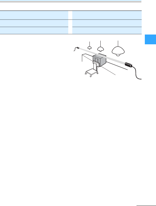
Sensors –Applications
EatonWiring Manual 06/11
33
Source and detector are mounted at
opposite ends of a long warehouse storage
shelf with the beam situated a safe
distance below overhead obstacles
(lighting, cable ducts, gas lines, etc.). If a
forklift operator interrupts the beam while
moving a load, a siren or flashing light will
warn him to stop before any damage
occurs.
Comet E58 series Thru-Beam, Source E58-30TS
Thru-beam sensor E58 series, detector E58-30TD

EatonWiring Manual 06/11
33

Eaton Wiring Manual 06/11
44

Eaton Wiring Manual 06/11
44
Overview
Eaton cam switches and
switch-disconnectors are used as:
aMain switches, main switches used as
Emergency-Stop devices,
bON-OFF switches,
cSafety switches,
dChangeover switches,
eReversing switches, star-delta
switches, multi-speed switches,
fStep switches, control switches,
coding switches, meter selector
switches.
The following designs are available:
gFlush mounting,
hCentre mounting,
iSurface mounting,
jService distribution board mounting,
kRearmounting.
Referto the latest issue of our main catalog
for“Industrial Switchgear”.
Other contact arrangements are listed in
the K115 special catalog in addition to the
switches listed in the main catalog.
(www.eaton.com/moeller/support
(Catalogs)).
u
TM 10 –x–x–x/ / –/–
T0 20 x x –x x x + / / / +
T3 32 x x –x x –+/ / / +
T5B 63 x x x x x –+–/–+
T5 100 x –x x – – +–/–+
T6 160 x – – x– – – – +–+
T8 3151) x– – x– – – – +–+
P1-25 25 x x x – – – +/+/+
P1-32 32 x x x – – – +/+/+
P3-63 63 x x x – – – +–+/+
P3-100 100 x x x – – – +–+/+
P5-125 125 x x – – – – +– – – +
P5-160 160 x x – – – – +– – – +
P5-250 250 x x – – – – +– – – +
P5-315 315 x x – – – – +– – – +
Iu=max. Rated uninterrupted current
1) In enclosed version (surface mounting), max. 275 A.
/Irrespective of the number of contact units, function and process.
+Irrespective of the number of contact units, function and contact sequence.
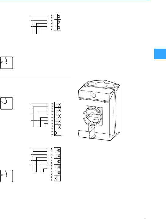
Eaton Wiring Manual 06/11
44
ON-OFF switches, main switches, maintenance switches
T0-2-1
P1-25
P1-32
P3-63
P3-100
P5-125
P5-160
P5-250
P5-315
These switches can also be used as
switch-disconnectors for lighting, heating or
combined loads.
Main switches to IEC/EN 60204; forrear
mounting switches with door interlock,
padlocking feature,finger proof incoming
terminals, Nand PE terminal, red thumb-grip
handle (black, if required), warning label.
If it is not clear which driveis associated
withwhich main switch, an additional
maintenance switch is required close to
each drive.
T0-3-15680
P1-25/.../
P1-32/.../
P3-63/.../
P3-100/.../
...N/NHI11
Maintenance switches are fitted to
electrical machines or installations to
provide safe working conditions in
accordance with the safety regulations.
By attaching his own padlock to the SVB
padlocking feature, the electrician can
protect himself against anyone switching on
without authorization
(7Section”Circuit diagram example for
maintenance switches with a load shedding
contact and(or) switch position indicator”,
page 4-4).
1) Load shedding contact
FS 908
ON
OFF
1
2
3
4
5
6
L1
L2
L3
01
FS 908
ON
OFF L1
L2
L3
1
2
3
4
5
6
7
8
9
10
11
12
N
N
01
1)
FS 908
ON
OFF
1
2
3
4
5
6
N
N
13
14
21
22
N
L1
L2
L3
N
1)
01
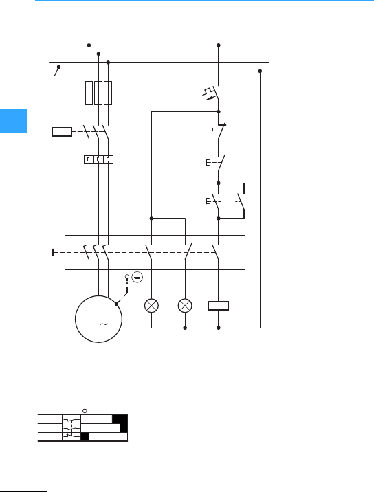
ON-OFF switches, main switches, maintenance switches
Eaton Wiring Manual 06/11
44
When
switching on, the main
current contacts close
first, then the contactor
is activated via the
late-make N/Ocontact.
When switching off,
the contactoris first
disconnected by
opening the
early-make contact,
then the main contacts
isolatethemotor
supply.
The
position of the switch
can be signalled to the
control panel or control
room via additional NO
and NC contacts.
P1:On
P2:Off
Q11: Load shedding
Q11
L2
N
L3
L1
F1
Q11
2
1
4
3
6
5
F2
135
246
M
3
7911
81012
Q1
UVW
A2
Q11
A1
A2
P1 P2
F0
95
96
21
22
F2
O
13
14
I
13
14
FAZ-
B4/1-HS
1-2,3-4,5-6
7-8,11-12
9-10
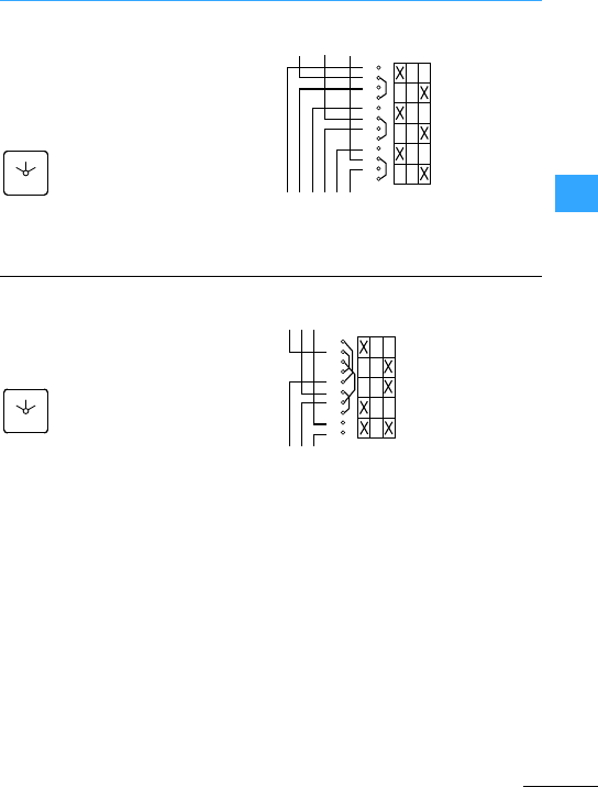
Eaton Wiring Manual 06/11
44
Changeover switches, reversing switches
T0-3-8212
T3-3-8212
T5B-3-8212
T5-3-8212
T6-3-8212
T8-3-8212
FS 684
0
12
1
2
3
4
5
6
7
8
9
10
11
12
01 2
L2L1 L3
T0-3-8401
T3-3-8401
T5B-3-8401
T5-3-8401
FS 684
0
12
210
1
2
3
4
5
6
7
8
9
10
L2L1 L3
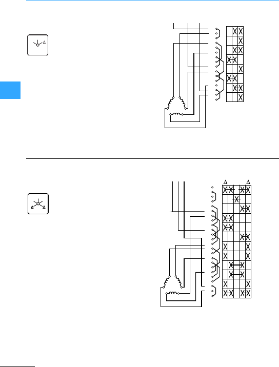
Eaton Wiring Manual 06/11
44
(Reversing) star-delta switches
T0-4-8410
T3-4-8410
T5B-4-8410
T5-4-8410
FS 635
Y
0
1
2
3
4
5
6
7
8
9
10
11
12
13
14
15
16
L1 L2 L3 0YΔ
U2
U1
V1V2
W1
W2
T0-6-15877
T3-6-15877
1) Standard contactor interlock
7Section”Interlock circuits”, page 4-11
FS 638
Y
0
Y
1
2
3
4
5
6
7
8
9
10
11
12
13
14
15
16
L1L2L3
U2
U1
V1V2
W1
W2
17
18
19
20
21
22
23
24
0
YY
SOND28)
1
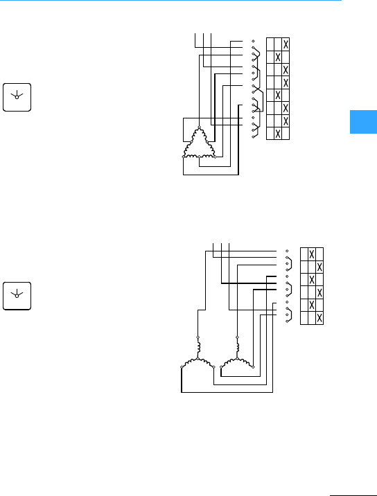
Eaton Wiring Manual 06/11
44
Multi-Speed Switches
T0-4-8440
T3-4-8440
T5B-4-8440
T5-4-8440
"without connections
FS 644
0
1
2
1
2
3
4
5
6
7
8
9
10
11
12
13
14
15
16
L1L2L3
1U
1W 1V
2W 2V
2U
12
0
T0-3-8451
T3-3-8451
T5B-3-8451
T5-3-8451
FS 644
0
1
2
1
2
3
4
5
6
7
8
9
10
11
12
L1L2 L3 12
1U
1W 1V
2U
2W 2V
0
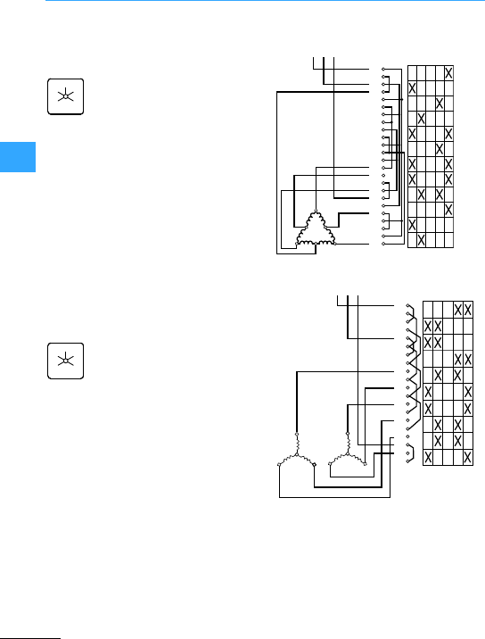
Multi-Speed Switches
Eaton Wiring Manual 06/11
44
T0-6-15866
T3-6-15866
T0-5-8453
T3-5-8453
FS 629
1
0
1
22
1
2
2
L1 L2 L3
10
3
4
5
6
7
8
9
10
11
12
13
14
1 2
15
16
17
18
19
20
21
22
23
24
1W
2W
1U
1V
2U
2V
FS 629
1
0
1
22
1
2
3
4
5
6
7
8
9
10
11
12
13
14
15
16
17
18
19
20
12012
1U
1W 1V
2U
2W 2V
L1L2L3
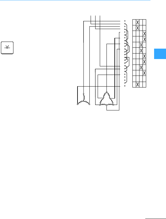
Multi-Speed Switches
Eaton Wiring Manual 06/11
44
T0-6-8455
T3-6-8455
T5B-6-8455
T5-6-8455
0-(A)8-(B)-= (B)8 8
FS 616
1
0
2
3
0123
1
2
3
4
5
6
7
8
9
10
11
12
13
14
15
16
17
18
19
20
21
22
23
24
L1 L2 L3
1U
1W 1V
AB
1U
1W 1V
2W 2V
2U
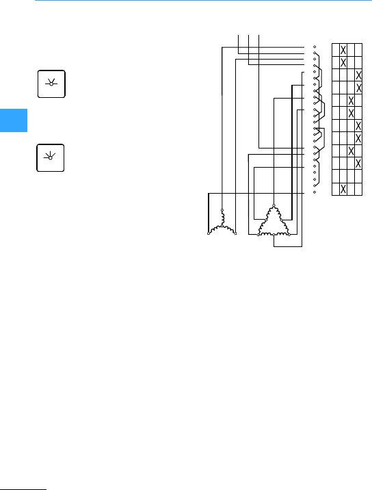
Multi-Speed Switches
Eaton Wiring Manual 06/11
44
T0-6-8459
T3-6-8459
T5B-6-8459
T5-6-8459
0-(B)--(B)8 8 -(A)8
FS 616
1
0
2
3
FS 420
2
1
0
3
0123
1
2
3
4
5
6
7
8
9
10
11
12
13
14
15
16
17
18
19
20
21
22
23
24
L1 L2 L3
1U
1W 1V
AB
1U
1W 1V
2W 2V
2U
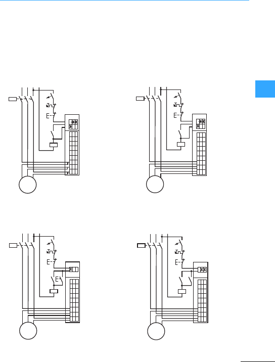
Eaton Wiring Manual 06/11
44
Interlock circuits
Interlock circuitsbetween cam switches
and contactors with overload relays
provide neat and economical solutions for
manyswitching drivetasks. The following
points are common to all interlockcircuits:
•Protection against automatic restarting
afteramotor overload or voltage failure
•The facility for remote disconnection
(e.g. emergency-stop) can be provided
by one or more Off pushbuttons.
Mains disconnection only by contactor
primarily for star-delta connection
Mains disconnection by contactor and
switch
Contactorcan be energized only when
switch is in an operating position
Contactor can be energized only when
switchis in an operating position
Q11
Q11
S0
F0
F2
021
M
3~
Q11
Q1
Circuit as required
Control section
SOND 27
Power section
without mains
disconnection
Q11
Q11
S0
F0
F2
021
M
3~
Q11
Q1
Circuit as required
Control section
SOND 28
Power section
without mains
disconnection
Q11
S1
S0
F0
F2
021
M
3~
Q11
Q1
Q11
Circuit as
required
Control section
SOND 29
Power section
Q11
S1
S0
F0
F2
021
M
3~
Q11
Q1
Q11
Circuit as
required
Control section
SOND 30
Power section
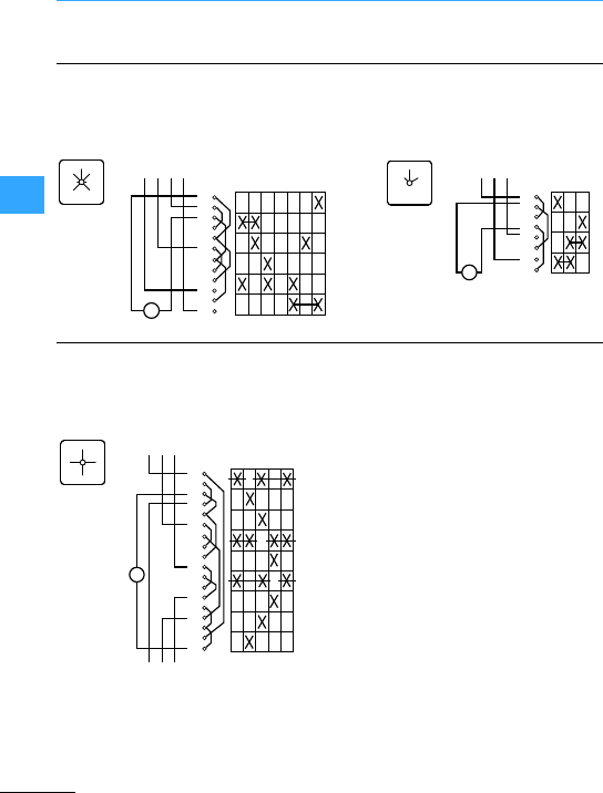
Eaton Wiring Manual 06/11
44
Single-phase approach circuits
Meter changeover switches enable you to
measure currents, voltages and powerin
three-phase systems with only one
measuring device.
T0-3-8007
3xphase to phase
3xphase to neutral with offposition
T0-2-15922
3xphase to neutral without off
position
T0-5-15925
T3-5-15925
For direct measurement
L1-L2
FS 1410759
0
L2-L3
L3-L1
L1-N
L2-N
L3-N
L3-L1
1
2
3
4
5
6
7
8
9
10
11
12
L2-L3
L1-L2
0
L1-N
L2-N
L3-N
V
L1L2 L3 N L1-L2
L2-L3
L3-L1
FS 164854
1
2
3
4
5
6
L3-L1
L2-L3
L1-L2
7
8
V
L1L2 L3
L1
L2
FS 9440
0
L3 L1L2L30
1
2
3
4
5
6
7
8
9
10
11
12
13
14
15
16
17
18
L1L2 L3
L1L2L3
A
0
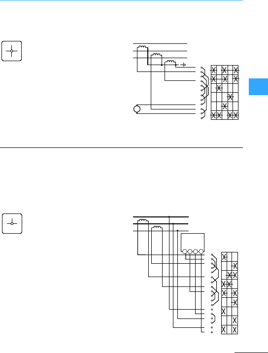
Eaton Wiring Manual 06/11
44
Meter changeover Switches
T0-3-8048
T3-3-8048
For measurement via transformers, complete rotation possible
L1
L2
FS 9440
0
L3
L1L2L3 00
L1
L2
L3
1
2
3
4
5
6
7
8
9
10
11
12
A
T0-5-8043
T3-5-8043
Two-phase method (Aron circuit) for
three-cable installations loaded as
required.The total wattage is calculated by
adding togetherthetwo wattages.
The Aron circuit will give a correct result
forfour-cable systems only when the sum
of the currents equals zero, i.e. only when
the four-cable systemis balanced.
FS 953
0
12
W120
L1
L2
L3
1
2
3
4
5
6
7
8
9
10
11
12
13
14
15
16
17
18
1 2 311
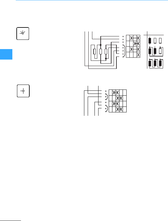
Eaton Wiring Manual 06/11
44
Heater switches
T0-2-8316
T3-2-8316
T5B-2-8316
T0-2-15114, complete rotation possible
Further heater switches, 2 and 3 pole, with
alternative circuitry, outputstages, and number
of steps are described in the main catalog,
”Industrial Switchgear”and in the special
catalog K115D/F/GB (Article no. 077643).
FS 420
2
1
0
3
1
2
3
4
5
6
7
8
L1 L2 L3
0123
1
III III
2
3
IIIII
I
FS 193840
1+2
1
0
2
1
2
3
4
5
6
7
8
011
+
22 0
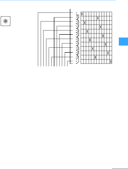
Eaton Wiring Manual 06/11
44
Step switches
T0-6-8239
T3-6-8239
FS 301
1
23456
7
8
9
10
11
12
1234
1
2
3
4
5
6
7
8
9
10
11
678951110 12
13
14
15
16
17
18
19
20
21
22
23
12
24
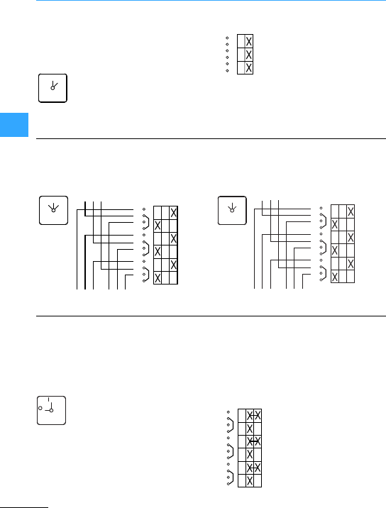
Step switches
Eaton Wiring Manual 06/11
44
1 pole: T0-1-15401
2 pole: T0-1-15402
3-pole: T0-2-15403
FS 415
01
1
0
1
2
3
4
5
6
1 pole: T0-1-15421
2 pole: T0-2-15422
3-pole: T0-3-15423
1 pole: T0-1-15431
2 pole: T0-2-15432
3-pole: T0-3-15433
FS 429
0
21
1
2
3
4
5
6
7
8
9
10
11
12
01
2
FS 1401
0
HAND AUTO 1
2
3
4
5
6
7
8
9
10
11
12
0AUTOHAND
1 pole: T0-1-15521
2 pole: T0-2-15522
3-pole: T0-3-15523
With pulsed contact in the intermediate
position
FS 908
ON
OFF 1
2
3
4
5
6
7
8
9
10
11
12
01

Eaton Wiring Manual 06/11
55

Eaton Wiring Manual 06/11
55
Contactor relays
Contactorrelays are often used in control
and regulating functions. They are used in
large quantities for the indirect control of
motors, valves, clutches and heating
equipment.
In addition to the simplicitywhich they
offer in project engineering, panel building,
commissioning and maintenance,the high
level of safety whichtheyafford is a major
factor in their favor.
The contactor relay contacts themselves
constitute a considerable safetyfeature.
By design and construction they ensure
potential isolation between the actuating
circuit and the operating circuit,in the
de-energized state, between the contact
input and output. All DIL contactor relays
have double-break contacts.
The Employers'liability insurance
association demands that, for control
systems of power-driven metalwork
presses, the contacts of contactors must
be interlocked and opposing. Interlocking
means that the contacts are mechanically
connected to one another such thatN/C
contacts and N/O contacts can never be
closed simultaneously. At the same time,it
is necessary to ensure that the contact
gaps are at least 0.5 mm over the lifespan,
even when defective (e.g. when a contact
is welded). The contactor relays DILER and
DILA fulfil this requirement.
Two contactor relay series are available as
a modular system:
•Contactor relays DILER,
•Contactor relays DILA.
The modular system has many advantages
forthe user. The system is formed around
basic units, which are equipped with
additionalfunctions by means of modules.
Basic unitsare intrinsically functional
units, consisting of an AC or DC drive and
four auxiliary contacts.
Auxiliarycontact modules having 2 or 4
contacts. The combination of N/O and N/C
contactsis according to EN 50011. The
auxiliary contact modules of the
contactors DILEM and DILM cannot be
snapped onto the basic device to prevent
duplication of terminal markings e.g.
contact 21/22 on the basic device and 21/22
on the add-on auxiliary contact module.
The DILA and DILM7 to DILM38 contactors
of the DILA-XHIR22 auxiliary contact are
availablespecially for switching the
smallest signals for electronic
applications.

Contactor relays
Eaton Wiring Manual 06/11
55
European Standard EN 50011 “Terminal
markings, distinctive numbers and
reference letters for certain contactor
relays”has a direct bearing on the use and
application of the modularsystem. There
are various types, which the Standard
differentiates between by means of
reference numbers and reference letters,
depending on the number and position of
the N/O and N/C contacts in the device,
and their terminal markings.
Ideally deviceswith the reference letter E
should be used. The basic devices DILA-40,
DILA-31, DILA-22 as well as DILER-40,
DILER-31 and DILER-22 comply with the E
version.
For 6 and 8 pole contactor relays, the “E”
version means that four N/Ocontacts must
be arranged in the lower/rear contact
level. If, for example, the available auxiliary
contactmodulesare used in the DILA-22
and DILA-31, they result in contact
configurations with reference letters X
andY.
Below are 3 examples of contactors with 4
N/O and 4 N/C contacts with different
reference letters. Version Eis to be
preferred.
DILA-XHI04 DILA-XHI13 DILA-XHI22
+
DILA-40
+
DILA-31
+
DILA-22
:44 E
DILA40/04
:44 X
DILA31/13
:44 Y
DILA22/22
51
52
61
62
71
72 82
81
53 61 71 81
82
72
62
54
54
53 61
62
71
72
83
84
14
13 33
34
43
44
A1
A2
23
24 14
13 21
22
33
34
43
44
A1
A2 14
13 21
22
31
32
43
44
A1
A2
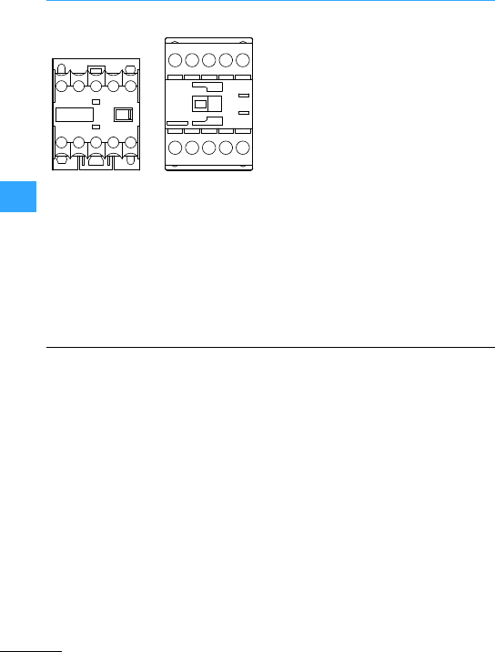
Contactor relays
Eaton Wiring Manual 06/11
55
On the top positioned terminals A1–A2 of
the contactor DILER the following
accessories are connected to limit the
relay coil switch off breaking voltage
peaks:
•RC suppressors
•Free-wheel diode suppressors
•Varistor suppressors
On the contactor relay DILA the coil
connection A1 is at the top and A2 at the
bottom. As suppressor circuits the
following are connected on the front:
•RC suppressors
•Varistorsuppressors
The DC operated contactors DILER and
DILA have an integrated suppressor
circuit.
Electronic equipment is nowadays being
increasingly used in combination with
conventional switching devices such as
contactors. This equipment includes
programmable logic controllers (PLCs)
timing relays and coupling modules, whose
operation can be adversely affected by
disturbances from interactions between all
the components.
One of the disturbance factors occurs
when inductive loads, such as coils of
electromagnetic switching devices, are
switched off.High cut-off induction
voltages can be produced when such
devices are switched off and, under some
circumstances, can destroy adjacent
electronic devices or, via capacitive
coupling mechanisms, can generate
interference voltage pulses and thus cause
function disturbances.
Since interference-free disconnection is
impossible without an accessory, the coils
may be connected to a suppressormodule,
depending on the application. The
advantagesand disadvantages of the
various suppressor circuits are explained
in the followingtable.
DILERDILA
A1
A2
A1
A2

EatonWiring Manual 06/11
55
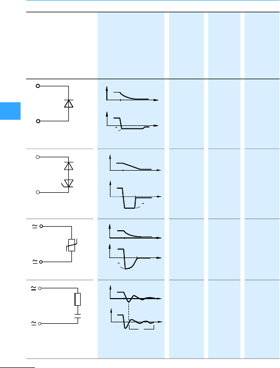
Contactor relays
Eaton Wiring Manual 06/11
55
–Very
long
1 V
–average UZD
Yes Short UVDR
Yes Short –
D
+
–
D
+
–
0
iI0
uU
0
0
U
t
1t2
t0t
t
D
+
–
ZD u
0
i
t
1t2
t0
I0
U
0
U
0
t
t
VDR u
0
i
0
U
t
1t2
I0
U
0
t
t
R
C
0
t
0
0
T
1
I
0
i
uU
0
t
t
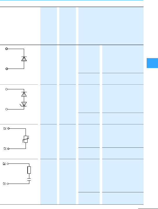
Contactor relays
Eaton Wiring Manual 06/11
55
– – Advan-
tages:
Dimensioning
uncritical, minimum
possible induction
voltage, very simple
and reliable
Disadvan-
tage:
Long drop-out delay
– – Advan-
tages:
Very short drop-out
delay. Dimensioning
uncritical. Simple
construction
Disadvan-
tage:
No damping below UZD
– – Advan-
tages:
Dimensioning
uncritical. High energy
absorption. Very simple
construction
Disadvan-
tage:
No damping below UVDR
Yes Yes Advan-
tages:
HF damping due to
stored energy,
immediate
de-energization, highly
suitable for AC.
Disadvan-
tage:
Precise dimensioning
required
D
+
–
D
+
–
D
+
–
ZD
VDR
R
C
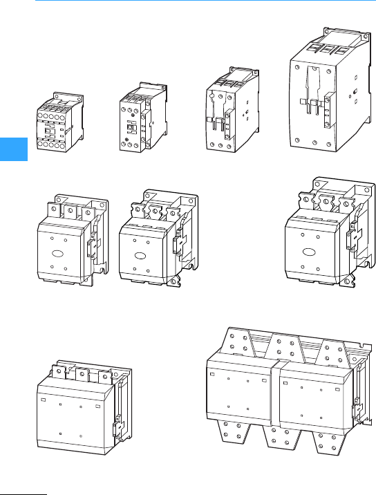
Eaton Wiring Manual 06/11
55
Contactors DIL, overload relays Z
DILM7 …DILM15 DILM17 …DILM38 DILM40 …DILM72 DILM80 …DILM170
DILM185A,
DILM225A
DILM250,
DILM300A
DILM400…DILM570
DILM580 …DILM1000
DILH1400
DILM1600
DILH2000, DILH2200, DILH2600
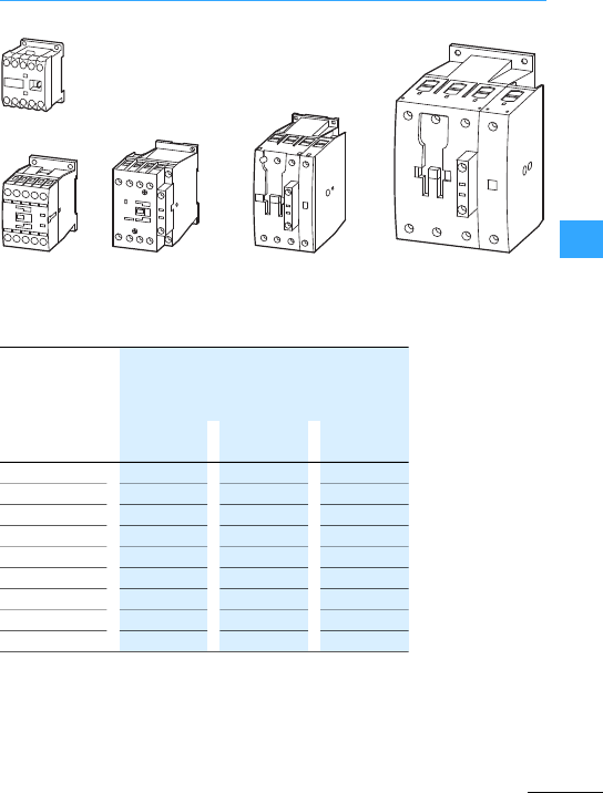
Contactors DIL, overload relays Z
Eaton Wiring Manual 06/11
55
DILEM4
DILMP20 DILMP32 …
DILMP45
DILMP63 …
DILMP80
DILMP125 …DILMP200
Rated operational current
50 –60 Hz open
Conventional thermal current
Ith = Ie, AC-1 open
40 °C 50 °C 60 °C
A A A
DILEM4 22 20 191)
DILMP20 22 21 20
DILMP32-10 32 30 28
DILMP45-10 45 41 39
DILMP63 63 60 54
DILMP80 80 76 69
DILMP125 125 116 108
DILMP160 160 150 138
DILMP200 200 188 172
1) At 55 °C

Contactors DIL, overload relays Z
Eaton Wiring Manual 06/11
55
Rated operating
current Ie[A]
AC-3 at 400 V
max.rating [kW] AC-3 Conventional
thermal
current Ith =I
e[A]
AC-1 at 40 °C
Type
220V,
230V
380V,
400V
660 V,
690 V
1000 V
6.61.5 33–22
92.2 44–22
12 3.55.5 4 –22
72.2 33.5 –22
92.5 44.5 –22
12 3.55.5 6.5 –22
15.5 47.5 7 –22
17 57.5 11 –40
25 7.51114–45
32 10 15 17 –45
38 11 18.5 17 –45
40 12.5 18.5 23 –60
50 15.5 22 30 –80
65 20 30 35 –98
72 25 37 35 –98
80 25 37 63 –110
95 30 45 75 –130
115375590–160
150487596–190
1705290140 –225
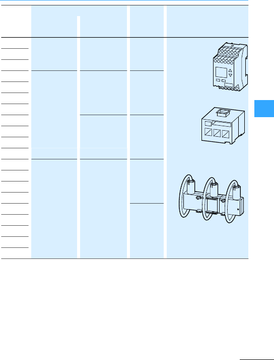
Contactors DIL, overload relays Z
Eaton Wiring Manual 06/11
55
For surface
mounting
For side
mounting
DILEEM 02DILEM
11DILEM
22DILEM
–ZE-0.16
up to
ZE-12
ZEV
+
ZEV-XSW-25
ZEV-XSW-65
ZEV-XSW-145
ZEV-XSW-820
DILEM
DILEM12
DILM7 DILA-XHI(V)…
DILM32-XHI…
–ZB12-0,16
up to
ZB12-16
ZEB12-1.65
up to
ZEB12-20
DILM9
DILM12
DILM15
DILM17 DILM32-XHI11-S ZB32-0,16
up to
ZB32-38
ZEB32-1.65
up to
ZEB32-45
DILM25
DILM32
DILM38
DILM40 DILM150+XHI(V)
…
DILM1000-XHI(V)
…
ZB65-10
up to
ZB65-75
ZEB65-45
up to
ZEB65-100
DILM50
DILM65
DILM72
DILM80 ZB150-35
up to
ZB150-175
ZEB150-100
DILM95
DILM115
DILM150
DILM170

Contactors DIL, overload relays Z
Eaton Wiring Manual 06/11
55
Rated operating
current Ie[A]
AC-3 at 400 V
max.rating [kW] AC-3 Conventional
thermal
current Ith =I
e[A]
AC-1 at 40 °C
Type
220V,
230V
380V,
400V
660 V,
690 V
1000 V
1855590140 108337
22570110 150 108356
25075132 195 108400
30090160 195 132430
400125 200344 132612
500155 250344 132857
580185 315560 600980
650205 355630 6001041
750240 400720 8001102
820260 450750 8001225
1000 315560 100011001225 DILM1000
1600 500900 160017702200 DILM1600
1400 ––––1714 DILH1400
2000 ––––2450 DILH2000
2200 ––––2700 DILH2200
2600 ––––3185 DILH2600
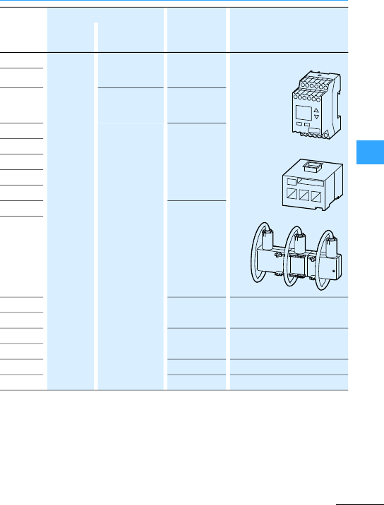
Contactors DIL, overload relays Z
Eaton Wiring Manual 06/11
55
Forsurface
mounting
Forside
mounting
DILM185A –DILM1000-XHI…Z5-70/FF225A
up to
Z5-250/FF225A
ZEV
+
ZEV-XSW-25
ZEV-XSW-65
ZEV-XSW-145
ZEV-XSW-820
DILM225A
DILM250 DILM820-XHI…Z5-70/FF250
up to
Z5-300/FF250
DILM300A ZW7-63
up to
ZW7-630
DILM400
DILM500
DILM580
DILM650
DILM750 –
DILM820
DILM1000 – –
DILM1600
DILH1400 – –
DILH2000
DILH2200 – –
DILH2600 – –

Eaton Wiring Manual 06/11
55
Contactors DIL
Suppressor circuit DC –$ $ $
RC suppressors $ $ – – –
Varistor
suppressors $ $ – – –
Motor suppressor
module
–to DILM15 to DILM15 – –
Star-point bridge $ $ $ $ –
Paralleling link $ $ $ to
DILM185A
–
Mechanical
interlock $ $ $ $ $
Sealable shroud $– – – –
Cable
terminals
– – – $to DILM820
Individual coils –from
DILM17
from
DILM17 $ $
Electronic modules – – – $ $
Electronic modules
including coils
– – – $ $
Terminal
shroud
– – – $ $ 1)
Timer module –to DILM38 to DILM38 – –
1) Terminal cover to DILM1000

Contactors DIL
Eaton Wiring Manual 06/11
55
These are designed and tested to
IEC/EN 60 947, VDE0660. For every motor
rating between 3kWand 900 kW (at 400 V)
there is a suitable contactor available.
•Magnet system
Due to the new electronic operation the
DC contactors from 17 to 72 A have a
sealing powerof only 0.5 W. Even for
170 Ais only 2.1Wnecessary.
•Accessible control voltage connections
The coil connections are on the front of
the contactor. They are not covered by
the main current wiring.
•Can be controlled directly from the PLC
The contactors DILA and DILM to 38 A
can be controlled directly from the PLC.
•Integrated suppressor DC
With all DC contactors DILM a
suppressor is integratedin the
electronics.
•Plug-in suppressor circuitsAC
With all AC contactors DILM up to 170 A
asuppressor can be simply plugged in on
thefront when required.
•Conventional controlof contactors
DILM185A to DILM2600 via coil terminals
A1-A2.
•Additional actuation of contactors
DILM250 to DILH2600:
–Directly from a PLC via terminals A3-A4
–By a low-powercontact via terminals
A10-A11.
•Conventional controlof contactors
DILM250-S to DILM500-S via coil
connectionsA1-A2. There are two coil
terminals (110 to 120 V50/60 Hz and
220 to 240V50/60Hz).
•All contactors up to DILM170 are finger
and back-of-hand proof to VDE 0160 Part
100. Additional terminal covers are
available from DILM185 onwards.
•Double-frame terminal for contactors
DILM7 to DILM170
With the new double frame-clamp the
cable connection area is not limited by
the screw. They give totalsecurity with
varying cross sectionsand have
protection against incorrect insertion to
ensure safe connection.
•Integrated auxiliary contact
The contactors up to DILM32 have an
integrated auxiliary contact as N/O or
N/C contact.
•Screw or spring-cage terminal
The contactors DILE(E)M and
DILA/DILM12, including the
corresponding auxiliary contacts, up to
2000 A, are available with screw or
spring terminals.
•Contactors with screwless terminals
They have spring-cage terminals in the
mains current circuit as well as for the
coil connections and auxiliary contacts.
The shake proof and maintenance free
spring-cage terminals can terminate two
conductors each of 0.75 to 2.5 mm2with
or without ferrules.
•Connection terminals
Up to DILM72 theconnection terminals
for all auxiliary contacts and coils as well
as for main conductors can be tightened
with a Pozidriv screwdriver size 2. For
contactors DILM80 to DILM170 Allen
screws are used.

Contactors DIL
Eaton Wiring Manual 06/11
55
•Mounting
All contactors can be fitted on to a
mounting plate with fixing screws.
DILE(E)M and DILM up to 72 A can also
be snapped on to a 35 mm top-hat rail to
IEC/EN 60715.
•Mechanical interlock
With two connectors and a mechanical
interlock an interlocked contactor
combination up to 170 A can be achieved
without extra space requirement. The
mechanical interlock ensuresthat both
connected contactors cannot be
simultaneously be operated. Even with a
mechanical shock the contacts of both
contactors cannot close simultaneously.
In addition to individualcontactors,
complete contactor combinationsare also
available:
•DIUL reversing contactors from 3 to
75 kW/400 V
•SDAINL star-delta starters from
5.5 to 132 kW/400 V
The marketfor DC operated contactors is
growing due to the increasing use of
electronics. Whilst AC operated
contactors were used 20 years ago with
additionalresistors and specially wound
DC coils with alot of copper were used till
recently, the next quantum leap has
started. Electronic components are now in
use forthe drives of DC operated
contactors.
The xStart contactor series DILM7 to
DILM225Ahasbeen particularly optimized
in the development of DC actuated
contactors. The DILM17 to DILM225A DC
operated contactors are no longer
switched on or off in the conventional way
using a coil but by means of an electronic
unit.
The integration of electronics in the
contactor drives makes different technical
features possible which enable the
contactors to offer outstanding
performance in their daily use.
The DILM17 to DILM225A DC operated
contactors cover the entire DC control
voltage range with only 4 control voltage
variants.
RDC24 24 - 27 VDC
RDC60 48 - 60 VDC
RDC130 110 - 130VDC
RDC240 200 - 240VDC

Contactors DIL
Eaton Wiring Manual 06/11
55
Contactors are built in compliance with the
IEC/EN 60947-4-1 standard. The
requirementforoperational safetyeven
with small mains supply fluctuations is
implemented with the reliable switchingof
contactors at between 85 to 110 %of the
rated control circuit voltage. The DC
operated DILM17 to DILM225A contactors
now cover an even widerrange in which
they switch reliably. They allow reliable
operation between 0.7 x Ucmin and
1.2 xU
cmax of the rated actuation voltage.
The greater voltage tolerance than
stipulated by the standard increases
operating safety even with less stable
mains conditions.
Conventionally operated contactors
generate voltage peaks at the coil to
current change dI/dt which can have a
negative effecton othercomponents in the
same actuating circuit. To prevent
damage, contactor coils are often
connected in parallel with additional
suppressor circuits (RC suppressors,
varistors or diodes).
Thanks to their electronics, the DC
actuated contactors DILM17 to DILM225A
switch without any effect on the network.
An additional suppressoris therefore
unnecessary since the coils do not
generate anyexternal overvoltages. The
other DILM7 to DILM15 DC operated
contactors have a built-in suppressor
circuit.
When using DC operated contactors from
Eaton in the project design, the issue of
transient voltage surge suppression in
control circuits is therefore unnecessary
since all DC operated contactors are free
of systemdisturbance or are provided with
a suppressor circuit.
The electronic circuit offers the coil a
higher inrush consumption and reduces
this after the closing operation to the
required sealing power. This enables the
AC and DC operated contactors to be
implemented with the same dimensions.
When designing AC and DC operated
contactors for a project, the additional
problem of different mounting depths is
eliminated so that the same accessories
can be used.

Contactors DIL
Eaton Wiring Manual 06/11
55
The electronic circuit on the DILM17 to
DILM225A DC operated contactors
controls their operation. A suitably high
power is provided forthe pickupto ensure
the reliable switching of the contactor.
Avery low sealing power is required for
holding the contactor. The electronics only
provides this power.
For project design, the reduced sealing
power also means a considerable
reduction in the heat dissipation in the
switch cabinet. This allows side by side
mounting of the contactors in the switch
cabinet.
7.5-
15 kW
DILM17
DILM25
DILM32
DILM38
12 W 0.5W
18.5-
37 kW
DILM40
DILM50
DILM65
DILM72
24 W 0.5W
37-
45 kW
DILM80
DILM95
90 W 1.3W
55-
90 kW
DILM115
DILM150
DILM170
149W 2.1W
90-
110 kW
DILM185A
DILM225A
180 W 2.1 W
1) AC-3 at 400V

Contactors DIL
Eaton Wiring Manual 06/11
55
The three-phase motor dominates the
electric motor sector. Apart from individual
low-power drives, which are often
switched directly by hand, most motors are
controlled using contactors and contactor
combinations. The powerrating in
kilowatts (kW) or the current rating in
amperes (A) is therefore the critical feature
forcorrect contactor selection.
Physical motor design results in that rated
currents for the same rating sometimes
differ widely. Furthermore it determines the
ratio of the transient peak current and the
starting current to the rated operational
current (Ie).
Switching electrical heating installations,
lighting fittings, transformers and power
factor correction installations, with their
typicalindividual characteristics,
increases the wide range of different uses
forcontactors.
The operating frequency can vary greatly
in every application. The difference can be,
forexample, from less than one operation
per day up to a thousand operations or
more perhour. Quite often, in the case of
motors, a high operating frequency
coincides with inching and plugging duty.
Contactors are actuated by hand or
automatically, using various types of
command devices, depending on the
travel, time, pressure or temperature. Any
interrelationships required between a
number of contactors can easily be
produced by means of interlocks via their
auxiliary contacts.
The auxiliary contactof the contactor
DILM can be used as mirror contact to
IEC/EN 60947-4-1 Appendix F to show the
condition of the main contacts.A mirror
contact is an N/C contact that cannot be
simultaneously closed with theN/O main
contacts.
•Contactors for capacitors forpower
factor correction DILK for 12.5 to 50
kvar/400 V.
•Lighting contactors for DILL lighting
systems for12 to 20 A/400 V(AC-5a) or 14
to 27 A/400 V (AC-5b).
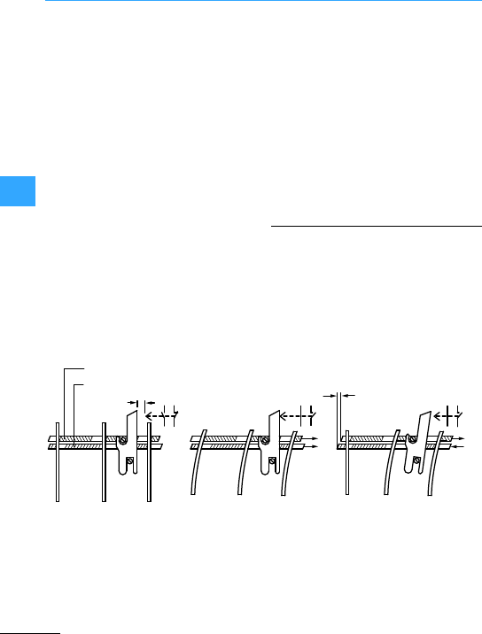
Eaton Wiring Manual 06/11
55
Overload relays Z
Overload relays are included in thegroup
of current-dependent protective devices.
They monitor the temperature of the motor
winding indirectly via the current flowing in
the supply cables, and offerproven and
cost-efficient protection from destruction
as a result of:
•Nonstarting,
•Overload,
•Phase failure.
Overload relays operate by using the
characteristic changes of shape and state
of the bimetal when subjected to heating.
When a specific temperature is reached,
they operate an auxiliary switch. The
heating is caused by resistances through
which the motor current flows. The
equilibrium between the reference and
actual value occurs at various
temperatures depending on the magnitude
of the current.
Tripping occurswhen the response
temperature is reached. The tripping time
depends on the magnitude of the current
and preloading of the relay. Whatever the
current, the relay must trip out before the
motor insulation is endangered, which is
why EN 60947-4-1 states maximum
response times. To prevent nuisance
tripping, minimum timesare also given for
the limitcurrent and locked-rotor current.
Overload relays Z offer, due to their design,
an effective protection against phase
failure. They have phase failure sensitivity
to IEC60947-4-1 and VDE 0660 part 102 and
therefore can also provide protection for
Ex e motors (7following diagrams).
Normal operation (no fault)three-phase overload One phase drops out
aTrip bridge
bDifferential bar
cDifferential travel
Trip bar
S97 95
98 96
97 95
98 96
97 95
98 96
Differential bar
Normal operation (no fault) Three-phase overload One phase drops out (2-phase load)
Differential travel
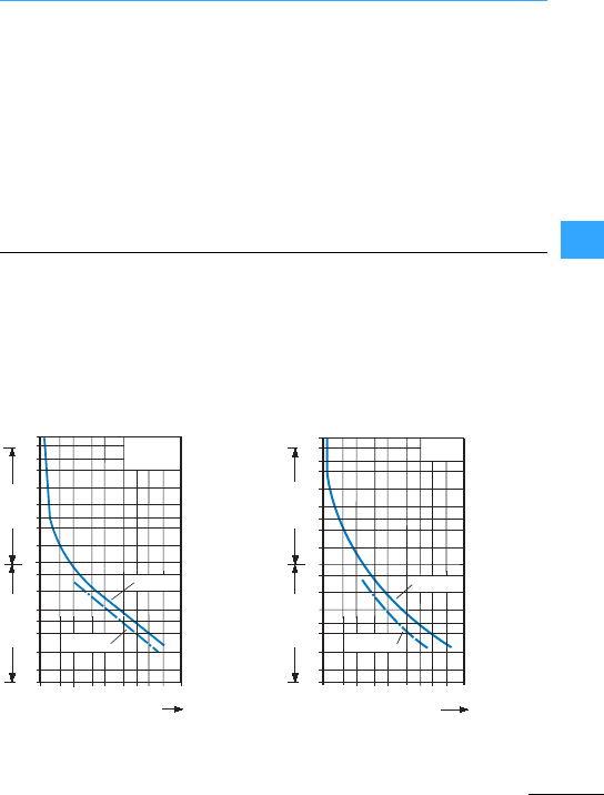
Overload relays Z
Eaton Wiring Manual 06/11
55
When the bimetallicstrips in the main
current section of the relay deflect as a
result of three-phase motor overloading,all
threeact on a trip barand a differential bar.
A shared trip lever switches over the
auxiliary contact when the limits are
reached. The trip and differential bars lie
againstthe bimetallic strips with uniform
pressure. If, in the event of phase failure for
instance, one bimetallic strip doesnot
deflect(or recover) as strongly as the other
two, then the trip and differential bars will
cover different distances. This differential
movement is converted in the device by a
step-up mechanism into a supplementary
tripping movement, and thus accelerates
the tripping action.
Design note 7Section ”Motor protection
in special applications”, page8-8
Furtherinformation to motor protection
7Section ”All about Motors”,page 8-1
The overload relays ZE, ZB12, ZB32, ZB65
andthe ZB150 up to 175 A are, due to the
German Physical/Technical Bureau (PTB),
suitable forprotection of Ex e-motors to the
ATEX-Guidelines 94/9 EG. In therelevant
manual all tripping characteristicsare
printed for all currents.
These characteristic curves are mean
values of the spreads at an ambient air
temperature of 20 °C from cold.The
tripping time is dependant upon the
current. When unitsare warm, the tripping
delay of theoverload relay drops to about a
quarter of the value shown.
2h
100
60
40
20
10
6
4
2
1
40
20
10
6
4
2
1
0.6
ZB12,ZB32,
ZB65, ZE
1 1.5 2346810 15 20
x Setting current
2-phase
Seconds Minutes
3-phase
2h
100
60
40
20
10
6
4
2
1
40
20
10
6
4
2
1
0.6
ZB150
68 1015 20
3 4
1 1.5 2
xSetting current
2-phase
Seconds Minutes
3-phase
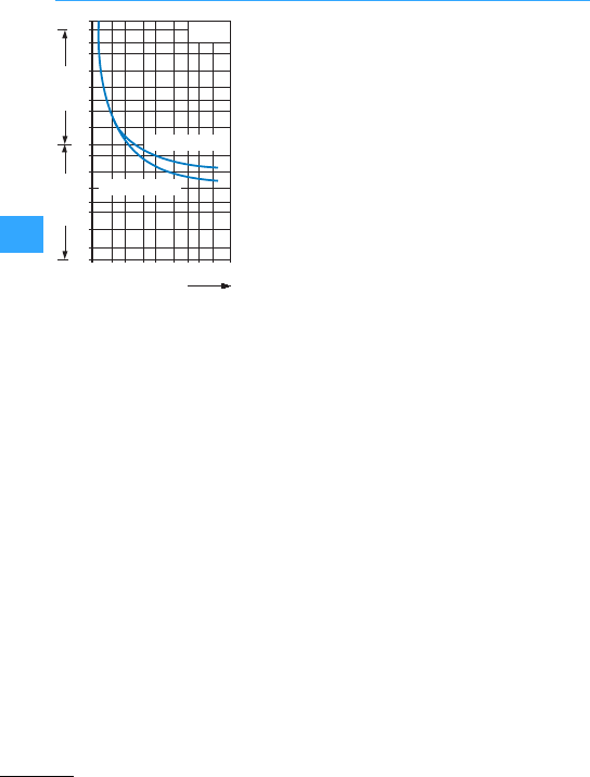
Overload relays Z
Eaton Wiring Manual 06/11
55
2 h
100
60
40
20
10
6
4
2
1
40
20
10
6
4
2
1
11.5 23468101520
0.6
ZW7
Minutes
Seconds
x
Setting current
Minimum
Maximum
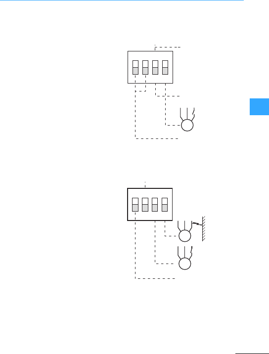
Eaton Wiring Manual 06/11
55
ZEB electronic overload relay
Like the thermaloverload relays operating
on the bimetallic operating principle,
electronic motor-protective relays are
current-dependent protective devices.
ZEB electronic motor-protective relays are
an alternative to a bimetal overload relay.
The measuring of the actual motor current
present in thethree phase conductors of a
motor feeder is implemented on the ZEB
overload relay with integrated current
transformers for the range from 0.3 to
100A.
Like the ZEB, overload relays with
electronic wide-range overloadprotection
operate with alarger current transfer ratio.
Compared to conventional bimetal relays,
this provides the device with awide
currentsetting range ratio of 1:5.
The ZEB…-GF overload relay provides
optional protection of the motor from earth
faults. It adds the currents of the phases
and evaluatesany imbalance.If the
imbalance is greaterthan 50 % of the set
rated motor current, the relay trips.
By selecting one of the 4 tripping classes
(CLASS 10A, 10, 20, 30)via DIP switches,
the protected motor can be adapted to
normal or heavy starting conditions. This
allows the thermal reserves of the motor to
be utilized safely. The overload relay does
not require any auxiliary voltage and is fed
internally via the current transformer.
The ZEBs come with the usualNC contacts
(95-96) andNO contacts (97-98) for
overload relays.
MARESET
CLASS (10, 10A, 20, 30)
M
A
M
ON OFF
M
ON
ON
A
OFF
OFF
RESET
CLASS (10, 20)
M
M
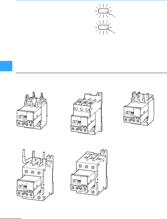
ZEB electronic overload relay
Eaton Wiring Manual 06/11
55
The current of the motor is set viaa setting
dial. It is also possible to switch off phase
failure sensitivity via the DIP switches
when protecting single phase motors.
The manual or automatic reset can also be
set on the DIP switch.
No externalpower supply is required
thanks to theindependently fed electronic
circuit.
A diagnostics LED gives a visual warningof
an overload.
ZEB electronic overload relays can be
fitted directly to DILM contactors up to
100A.
Separate mounting (rail mounting) is only
possible with ZEB…/KK.
I < 1.15 x Ir
0.5 Hz
If1.15 x Ir
1 Hz
ZEB12, ZEB32 ZEB32…/KKZEB65
Direct mounting Separate mounting Direct mounting
ZEB150 ZEB150…/KK
Direct mounting Separate mounting
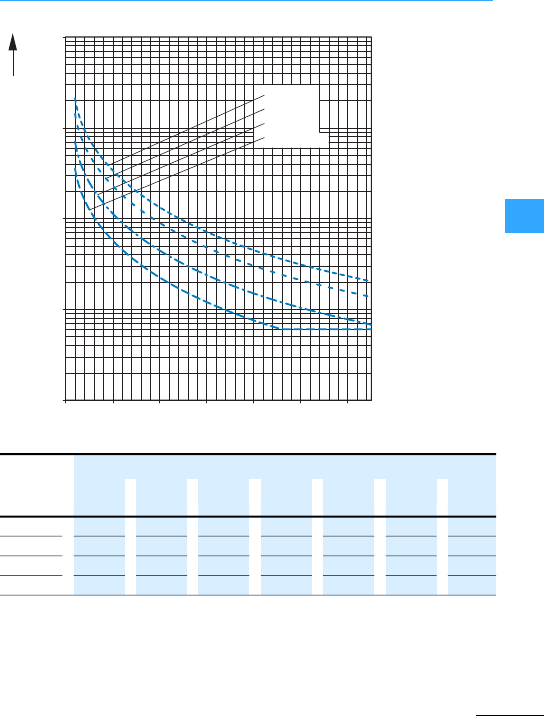
ZEB electronic overload relay
Eaton Wiring Manual 06/11
55
Class 30
Class 20
Class 10
Class 10A
10000
1000
100
10
11234567x Ir
t [s]
30 133.5 72.5 45.7 31.4 21.7 17.5 11.2
20 89.0 48.3 30.4 21.0 14.5 11.7 7.5
10 44.5 24.2 15.2 10.5 7.2 6.0 6.0
10A 22.3 12.1 7.6 6.0 6.0 6.0 6.0

Eaton Wiring Manual 06/11
55
ZEV electronic motor-protective system
Like electronic overload relays operating
on the bimetallic strip principle, electronic
motor-protective relays are
current-dependent protective devices.
The acquisition of the actual flowing motor
current in the three external conductors of
the motorconnections is with motor
protection systemZEV with separate
push-through sensors or a sensor belt.
These are combined with an evaluation
unit so that separate arrangement of the
current sensor and the evaluation unit is
possible.
The current sensor is based on the
Rogowski principle from the measurement
technology. The sensor belt hasno iron
core, unlike a current transformer,
thereforeit doesn´tbecome saturated and
canmeasure a very wide current range.
Dueto this inductive current detection, the
conductorcross-sections used in the load
circuit have no influence on the tripping
accuracy. With electronic overload relays,
it is possible to set higher current ranges
than is possible with electromechanical
thermal overload relays.In the ZEV System,
the entire protected range from 1 to 820 A
is covered using only an evaluation unit.
The ZEV electronic motor-protective
system carries out motor protection both
by means of indirect temperature
measurement via the current and also by
means of direct temperature measurement
in motors with thermistors.
Indirectly, themotor is monitored for
overload,phase failure and unbalanced
current consumption.
With directmeasurement, the temperature
in the motor winding is detected by means
of one or more PTC thermistors. In the
event of excessive temperature rise, the
signal is passed to the tripping unit and the
auxiliary contacts are actuated. A reset is
not possible untilthe thermistors cool to
less than the response temperature. The
built-in thermistor connection allows the
relay to be used as complete motor
protection.
In addition, the relay protects the motor
against earth faults. Small currents flow
out even in the event of minor damage to
the motor winding insulation. These fault
currents are registered on an external
core-balance transformerwhich adds
together the currents in the phases,
evaluates them and reportsfault currents
to the microprocessor in the relay.
By selecting one of the eight tripping
classes (CLASS) allows the motor to be
protected to be adapted from normal to
extended starting conditions. This allows
the thermal reserves of the motor to be
used safely.

ZEV electronic motor-protective system
Eaton Wiring Manual 06/11
55
The overload relay is supplied with an
auxiliary voltage. The evaluation unit hasa
multi-voltage version, which enables all
voltages between 24 V and 240 V AC or DC
to be applied as supply voltage. The
devices have monostable behavior; they
trip out as soon as the supply voltage fails.
In addition to the usualN/C contact (95-96)
and the N/O contact (97-98) for overload
relays the motor protection relay ZEV is
equipped with a programmable N/O
contact(07-08) and a programmable N/C
contact(05-06). The above mentioned,
usual contacts react directly via
thermistors or indirectly via the current,to
the detected temperature rise of the motor,
including phase failure sensitivity.
The programmable contacts can be
assigned to various signals, such as
•Earth-fault,
•Pre-warning at 105 %thermaloverload,
•Separate indication of thermistor
tripping,
•Internal device fault.
The function assignment is menu-guided
using a display. The motor currentis
entered without tools using the function
keys, and can be clearly verified on the
display.
In addition the display allows a differential
diagnostics of trip reasons, andtherefore a
faster error handling is possible.
Tripping in the event of athree-pole
balanced overload at x-times the set
current takes placewithin the time
specified by the tripping class. The tripping
delayin comparison with the cold state is
reduced as a function of the preloading of
the motor. Very good tripping accuracy is
achieved and thetripping delays are
constant over the entire setting range.
If the motor currentimbalance exceeds
50 %, the relay trips after 2.5s.
The accreditation existsforoverload
protection of explosion proof motors of the
explosion protection “enhanced safety”
Ex e to guideline 94/9/EG as well as the
report of the German Physical/Technical
Bureau (PTB report) (EG-Prototype test
certificate number PTB 10 ATEX 3007).
Furtherinformation can be found in the
manual MN03407008Z-DE/EN “Motor
protection system ZEV, overload
monitoring of motors in Ex e areas”.
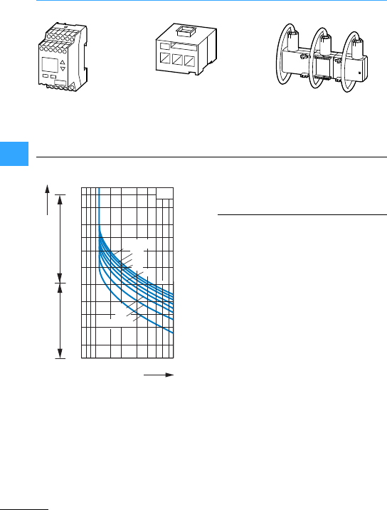
ZEV electronic motor-protective system
Eaton Wiring Manual 06/11
55
Tripping characteristics for 3-phase loads
These tripping characteristicsshow the
relationship between the tripping time from
cold to the current (multiples of set current
IE). After preloading with 100 %of the set
current and the temperature rise to the
operational warm state associated with it,
the stated tripping delays tAare reduced to
approx. 15 %.
Pick-up time:
< 30 min. at up to 115%of the set current,
>2hat up to 105 %of the set current from
cold.
Evaluation unit
1to 820 A
Current sensors
1to 25 A
3to 65 A
10 to 145 A
Sensor belt
40 to 820 A
20
CLASS 40
25
15
CLASS 5
10
tA100
50
20
10
5
2
1
20
10
5
2
10.7 1258
30
35
xIe
ZEV
Minutes
Seconds
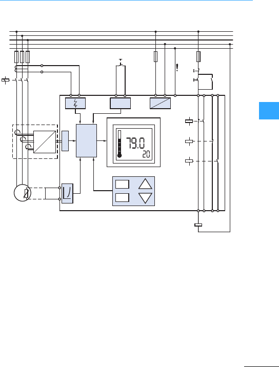
ZEV electronic motor-protective system
Eaton Wiring Manual 06/11
55
aFault
bParameterizable contact 1
cParameterizable contact 2
dCurrent sensor with A/D transducer
eSelf hold-in of the contactor prevents
an automatic re-start after the control
voltage has failed and then returned
(important forEx e applications,
7MN03407008Z-DE/EN)
fRemotereset
L1
L2
L3
N
96 06 08
98
95 05 07
A1 A2Y1 Y2 PEC1
Z1
Z2
C2
T2
T1
<
>
M
3~
Reset
S1
S2 Q11
Q11
~=
97
IμP
Mode
Class
Test
Reset
Up
Down
L1
A
D
L2L3
%
PE
Q11
①
⑥
④
⑤
②
③

ZEV electronic motor-protective system
Eaton Wiring Manual 06/11
55
With thermistormotor protection, to DIN
44081 and DIN 44082, up to six PTC
thermistor temperature sensors with a
thermistor resistance of RK#250 ?or nine
with a RK#100 ?can be connected to
terminals T1-T2.
TNF =Nominalresponse temperature
aTripping range IEC 60947-8
bRe-switch on range IEC 60947-8
cTrip block at 3200 ?±15 %
dRe-switch on at 1500 ?+10%
The ZEV switches off at R=3200 ?±15%
and switches on again at R=1500 ?+10%.
The contacts 95-96 and97-98 change over
in the event of a shutdown caused by a
signal at thethermistor input.
Additionally, the thermistor tripping can be
programmed to different trip messages on
contacts 05-06 or 07-08.
With temperature monitoring with
thermistors, no dangerous condition can
occur should a sensor fail as the device
would directly switch off.
TNF
–20°
TNF
TNF
–5°
750
4000
12000
1650
TNF
+5° TNF
+15°
a
b
c
d
R [ ]
i[°C]
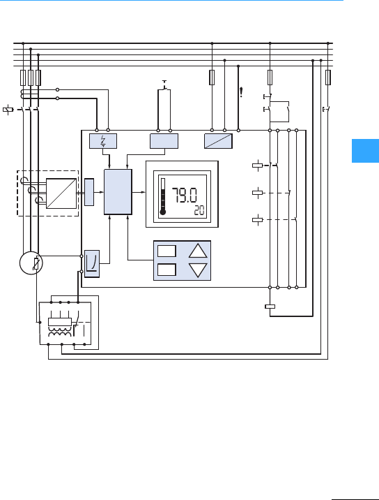
ZEV electronic motor-protective system
Eaton Wiring Manual 06/11
55
Short-circuits in the thermistor circuit can
be detectedif required by the additional
use of acurrent monitoring relay K1
(e.g.type EIL 230 V AC from Crouzet).
•Short-circuit current in the sensor circuit
#2.5mA,
•max. cable length to sensor 250 m
(unscreened),
•Totalcold resistance #1500 ),
•Programming ZEV: “Auto reset”,
•Setting current monitoring relay:
–Device to lowest current level,
–Overload tripping,
–Store the tripping,
•Confirmation of the short-circuit after
clearing with pushbutton S3.
①
L1
L2
L3
N
96 06 08
98
95 05 07
A1 A2Y1 Y2 PEC1
Z1
Z2
C2
T1
T2
<
>
M
3~
Reset
S1
S2 Q11
Q11
~=
97
IμP
Mode
Class
Test
Reset
Up
Down
L1
A
D
L2L3
%
PE
IN1
M
IN2IN3 11
A1 A2 12 14
S3
Q11
K1
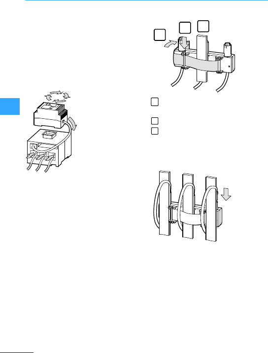
ZEV electronic motor-protective system
Eaton Wiring Manual 06/11
55
Themounting of the device is very simple
due to the clip-on and the push-through
cable entry.
Mounting details of every device can be
found in the instructional leaflet
IL03407080Z or the manual
MN03407008Z-DE/EN.
•Place the ZEV in the desired mounting
position.
•Click the ZEV on the current sensor.
•Position motorconductors through the
current sensor.
Due to the fixing band the Rogowski sensor
ZEV-XSW-820 is particularly easy to mount.
And this saves the user time and money.
Wrap the band around the current
conductors.
Engage the fixing pin.
Pull thefixing band tight and close with
the velcro fastener.
Attaching the sensor coils 7following
figure
11
2
3
1
2
3
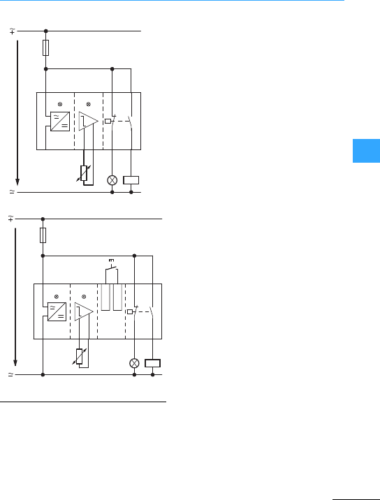
Eaton Wiring Manual 06/11
55
Thermistor overload relay for machine protection EMT6
The output relay is actuated when the
control voltage is switched on and the
resistance of the PTC thermistor
temperature sensor is low. The auxiliary
contacts operate. On reaching thenominal
response temperature (NAT), the sensor
resistancebecomes high and causes the
outputrelay to drop-out. The defectis
indicated by an LED. As soon as the
sensors have cooled enough so that the
respective smaller resistance is reached
the EMT6-(K) switches automaticallyon
again. With the EMT6-(K)DB(K) the
automatic re-switchon can be defeated by
switchingthe device to “Hand”. The unit is
reset using the reset button.
The EMT6-K(DB) and EMT6-DBK are fitted
with ashort-circuit recognition in sensor
circuit monitor. Should the resistance in
the sensor circuit fall below 20 )it trips.
The EMT6-DBK also has a zero voltage
safe reclosing lockout and stores the fault
by a voltage drop. Switching on again is
possible only after the fault has been
rectified and the control voltage is present
again.
Since all the units use the closed-circuit
principle,they also respond to a wire
breakage in thesensor circuit.
The thermistormachine protection relays
EMT6…are accredited for protection of
Ex e motors to ATEX-Guideline 94/9EG by
the German Physical/Technical Bureau.
For protection of Ex e motors the
ATEX-Guidelines require short-circuit
recognition in thesensor circuit. Because
of their integrated short-circuit recognition
the EMT6-K(DB) and EMT6-DBK are
especially suitable for this application.
US
A1
A2
PTC
N
T1 T2
21 13
22 14
L
Power Tripped
US
A1
A2
PTC
N
T1 T2
21Y2Y1 13
22 14
L
+24 V
Power Tripped
Reset
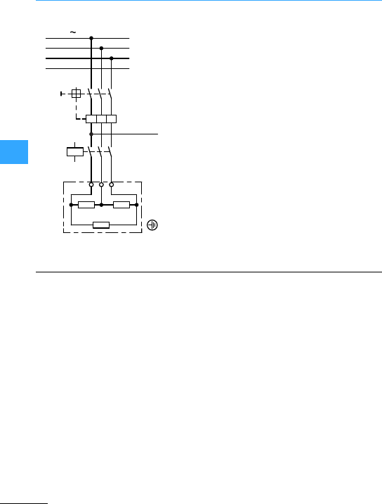
Thermistor overload relay for machine protection EMT6
EatonWiring Manual 06/11
55
Control of a storage tankheater
aActuating circuit
bHeater
Q11: Heaterprotection
For this see circuit page 5-35.
Theheater can be switched on provided
the main switch Q1 is switched on, the
safety thermostat F4 hasnottripped and
the condition T #Tmin is satisfied. When S1
is actuated, the control voltage is applied
to the contactor relay K1, which maintains
itself via a N/O contact. The changeover
contactof the contactthermometer has
the position I-II. The low resistance sensor
circuit of the EMT6 guaranteesthat Q11 is
actuated via K2 N/O contact 13-14; Q11
goes to self-maintain.
The heater protection Q11 stays in self
maintain until the main switch Q1 is
switched off, the pushbutton S0 is pressed,
the thermostat trips or T=T
max.
When T=T
max the changeover contact of
the contact thermometerhas the position
I-III. The sensor circuit of the EMT6(K3) is
low resistance, theN/C contact K3/21-22
open. The main protection Q11 drops out.
L1 3400 V 50 Hz
L2
L3
N
-Q1
L1
-Q11
A2
A1 135
246
UVW
I>I>I>
400 V 50 Hz
b
a
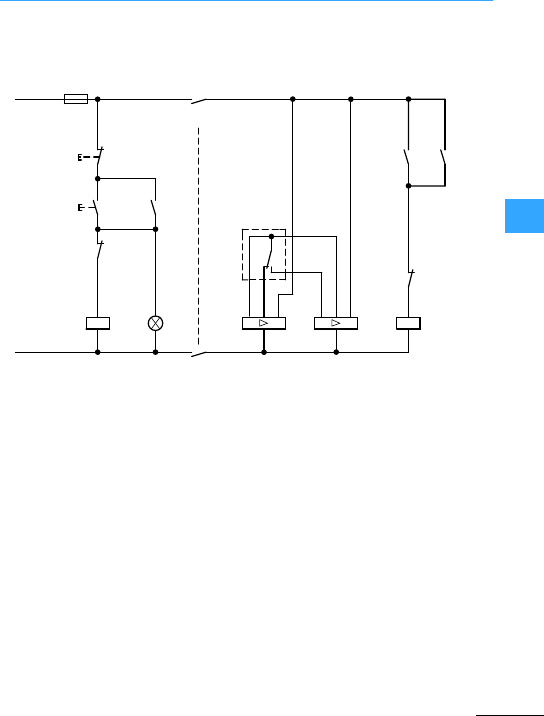
Thermistor overload relay for machine protection EMT6
EatonWiring Manual 06/11
55
Security against wire breakage in the
sensor circuit of K3 (e.g. non-recognition of
the limit value Tmax) is guaranteed by the
use of a safety thermostat thatwhen Tmax is
exceeded it's normally closed contact F4
switchesoff so that “switch off by
de-energization”is carried out.
aContact thermometerchangeover
contacts
I-II position at T #Tmin
I-III position at T #Tmax
K1: Control voltage ”On"”
K2: Switch on at T #Tmin
K3: Switchoff at Tmax
S0: Off
S1: Start
F4: Safetythermostat
230 V 50 Hz
-S0
-S1
-F4
-K1
-K2 -Q11
-Q11
-K2 1313
1414
-K3
-K3
EMT6 EMT6
A2
T1 T2 A1 T2 T1 A1
A2
A1
21
22
A2
-K1
N
A1 X1
X2
A2
- H1
II III
L1
-F1
4AF
-K1
14
24
13
23
a

Eaton Wiring Manual 06/11
55
CMD contactor monitoring device
The CMD (Contactor Monitoring Device)
monitors the main contacts of acontactor
forwelding. It compares the contactor
control voltage with the state of the main
contactors and indicates this reliably with
a mirror contact(IEC EN 60947-4-1 Ann. F).
If the contactorcoil is de-energized and
the contactor does not drop out, the CMD
trips the backup circuit-breaker,
motor-protective circuit-breakeror
switch-disconnector via an undervoltage
release.
The CMD also monitors the functioning of
the internalrelay using an additional
auxiliary make contact of the monitored
contactor. For this the auxiliary make and
break contact is positively driven. The
break contact is designed as a mirror
contact.
To ensure the functional reliability of the
entireunit, consisting of contactor,
circuit-breaker and CMD, the CMD is only
approved for use with specific contactors
as well as motor-protective
circuit-breakers/circuit-breakers/or
switch-disconnectors. CMD can be used
formonitoring the welding of all DILEM and
DILM7 to DILH2000 contactors. All auxiliary
break contacts of these contactors are
designed as mirror contacts and can be
used for monitoring tasks. The NZM1 to
NZM4 or N1 to N4 can be used as backup
motor-protective
circuit-breakers/circuit-breakers or
switch-disconnectors when fitted with a
NZM…-XUVL undervoltage releases.
These combinations are used in
safety-orientedapplications. Previously,
the series connection of two contactors
was recommended with circuitsof safety
category 3 and 4. Now one contactor and
the contactor monitoring device is
sufficient for safetycategory 3. The CMD
contactor monitoring relay is used for
emergency-stop applications in
compliance with EN 60204-1. It can also be
used in the American automotive industry.
In this sector there is a demand for
solutions thatreliably detect the welding of
the motor starters and disconnect the
motor feeder safely.
The CMDis approved as asafetymodule
by theGerman employers'liability
insurance association. It also has UL and
CSA approval fortheNorth American
market.
Furtherinformation can be found in the
manuals
•CMD(24VDC)
MN04913001Z-EN
•CMD(110-120VAC), CMD(220-240VAC)
MN04913002Z-EN
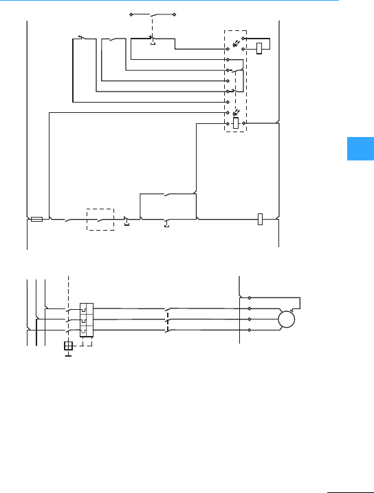
CMD contactor monitoring device
EatonWiring Manual 06/11
55
aSwitchingbysafety relay or safety PLC
bSignal contact to PLC evaluation
I>I>I>
U<
M
3˜
-Q1
-Q1
-K
-S1
-F1
-Q11
-X1
-M1
L1 L2 L3 1.13
21
22
1.14
-Q11
13
14
-Q11
33
34
-Q11
21
22
-F2
CMD
-Q1D1
D2
D2
A1
A2
LS21 S22 S13 S14 S31 S32
-Q11A1
A2
T1
135
246
T2 T3
L1 L01 L01
L02 L02
L2
PE UVWPE PE
L3
L1
L2
L3
-S2 13
14
-S3 21
22
13
14
a
b
TEST
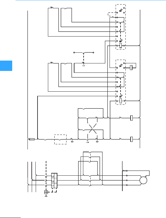
CMD contactor monitoring device
EatonWiring Manual 06/11
55
aSwitching by safety relay or safety PLC
bSignal contact to PLC evaluation
cCMD (24VDC)
L1
L2
L3
L1
L2
L3
-Q1
-Q1
-K
-S1
-F1
-Q11
-X1
-M1
-Q12
-Q11 -Q12
-Q11
-Q11
-Q12 -Q11
-F2
CMD
-Q12 -Q1-Q11
L01 L01
L02 L02
PE PE
-F3
CMD
-S2
-S3
-S4
TEST
-Q12
-Q12
I>I>I>
U <
M
3˜
L1 L2 L3 1.13
21
22
1.14
13
14 13
14
21
22
13
14
43
44
21
22
31
32
31
32
A1
A2
D1
D2
D2 D1 D2
A1 A1
A2
LLS21 S22 S13 S14 S31 S32
A1
A2
T1
135
246
135
246
T2 T3
UVWPE
A2
13
14
21
22
21
22
13
14
①
②
43
44
21
22
S21 S22 S13 S14 S31 S32
③

Eaton Wiring Manual 06/11
66

Eaton Wiring Manual 06/11
66
Overview
Motor-protective circuit-breakers are
circuit-breakers used for the switching,
protection and isolation of circuits
primarily associated with motorloads.At
the same time, they protect these motors
against destruction from locked-motor
starting, overload, short-circuit and
phase-failure in three-phase power
supplies. They have athermal trip block
(PKZ) or an electronic release (PKE) for
protecting of the motor winding (overload
protection) and an electromagnetic
release (short-circuit protective device).
The following accessories can be fitted to
motor-protective circuit-breakers:
•Undervoltage releases,
•Shunt release,
•Auxiliary contact,
•Trip-indicating auxiliary contact.
The PKZM01 motor-protective
circuit-breaker up to 25 A is supplied with
the pushbutton actuator. The fitted
mushroom button is available for
emergency-off actuation on simple
machines. The PKZM01 is primarily
installed in surface-mounted or
flush-mounted enclosures. Many
accessories of the PKZM0 can be used.
The PKZM4 motor-protective
circuit-breakers are amodular and
efficient systemfor switching and
protecting motorloads up to 63 A. It is the
“big brother”of the PKZM0 and can be
used with almost all PKZM0 accessory
parts.
The PKZM0 motor-protective
circuit-breaker is a modular and efficient
system for switching and protecting motor
loads up to 32 A and transformers up to
25 A.
Versions:
•Motor-protective circuit-breakers
•Transformer-protectivecircuit-breaker
Description 7Section ”The
motor-protective circuit-breakers
PKZM01, PKZM0 and PKZM4”, page 6-4
PKE for motor and distribution circuit
protection
The PKE is a modular and efficient system
forprotecting, switching and signalling of
motors and systems in low-voltage
switchgear systems up to 65 A, consisting
of:
•Motor-protective circuit-breaker basic
units
•Trip blocks
Description 7Section ”Motor and
system protection with PKE”, page6-5
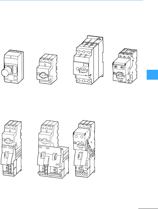
Overview
Eaton Wiring Manual 06/11
66
Circuit-breakers
in surface
mounting
enclosure
Circuit-breakersup
to 32 A
Circuit-breakers up
to 63 A
Circuit-breakers
with electronic
wide-range
overload
protection
DOL starters
Reversing starters
DOL starters
(for SmartWire-DT)

Eaton Wiring Manual 06/11
66
PKZM01, PKZM0 and PKZM4 –description
The PKZM01, PKZM0 and PKZM4 with their
bimetal releases with acurrent-dependent
delayoffer a proven technical solution for
motor protection. The releases offer phase
failure sensitivity and are temperature
compensated. The rated currents of the
PKZM0 up to 32 A are divided up into 15
ranges, 14 ranges on the PKZM01 and 7 on
the PKZM4 up to 63 A. The installation
(motor) and the supply cable are reliably
protected and motor startup is ensured by
the short-circuit releases, permanently set
to 14 x Iu. The phase failure sensitivity of the
PKZM0and PKZM4 enables them to be
used for the protection of Ex e motors. An
ATEXcertificate has been awarded. The
motor-protective circuit-breakers are set
to the rated motor current in order to
protect the motors.
The following accessories complementthe
motor-protective circuit-breakerforthe
various secondary functions:
•Undervoltage release U,
•Shunt release A,
•Standard auxiliary contact NHI,
•Trip-indicating auxiliary contactAGM.

Eaton Wiring Manual 06/11
66
PKE –description
The PKE achieves its modularity by
combining the motor or system-protective
circuit-breaker with various accessories.
Theexchangeable motor-protective trip
blocks with electronic wide range overload
protection (current range 1:4) are available
as a standard or enhanced version for
connection to SmartWire-DT. This results
in numerous application options and
adaptation to widely differing
requirements.
The PKE circuit-breaker consists of:
•Basicdevice, 3 types for 12 A, 32 A and
65 A and
•Pluggable trip block.
There is a choice of trip blocks:
•Motor protectivetrip blocks (5 variants
for therange 0.3 to 65 A)
•System protective tripblock (forthe
range 5 to 36 A)
All trip blocks are provided with adjustable
overload releases.
Overload from ... to...:
•Motor protectivetrip blocks:
also with adjustable tripping classes
(CLASS 5, 10, 15 and 20) forprotecting
heavy starting motors.
•System protective tripblock:
also with adjustable short-circuit release
5to8xI
e
.
The phase failure sensitivity of PKE allows
forthe use in the protection of Ex e motors.
An ATEX certificate has been awarded.
The motor-protectivecircuit-breakers are
set to the rated motor current in order to
protect the motors.
The following accessories of PKZM0
complementthe motor-protective
circuit-breaker PKE forthe various
secondary functions:
•Undervoltage release U,
•Shunt release A,
•Standard auxiliary contact NHI,
•Trip-indicating auxiliary contact AGM.
The PKE motor-protective circuit-breaker
is compliant with IEC/EN 60947 and
VDE 0660. The PKE also meets the
requirements for isolation and main switch
functions stipulated in EN 60204.

Eaton Wiring Manual 06/11
66
PKM0, PKZM0-…-T, PKZM0-…-…C–description
The PKM0 motor-protective
circuit-breaker is a protective switch for
startercombinations or for use as a basic
unit in ashort-circuit protectiveswitchin
the range 0.16 A to 32 A. The basicdevice
is without overload release, but equipped
with short-circuit release. This
circuit-breaker is used for protection of
resistive loads where no overloading is to
be expected.
Theseprotective switches are also used in
motor-starter combinations with and
without reclosing lockout,where an
overload relay or a thermistor overload
relay is used as well.
…-
The transformer-protective circuit-breaker
is designed for protecting transformer
primaries. The short-circuit releases in the
types from 0.16 Ato 25 A are permanently
set to 20 x Iu.The response ranges of the
short-circuitreleases are higher here than
with motor-protective circuit-breakers in
order to cope with the even higher
in
rush
currents of idling transformers without
tripping. The overload release in the
PKZM0-T is set to the rated current of the
transformer primary. All the PKZM0 system
accessories can be combined with the
PKZM0-T.
……
The PKZM0 features a version with
springloaded terminals. A version with
springloaded terminals on both sides, and
a combined version whichfeatures
springloaded terminals on the outgoer side
only can be chosen. The conductors can
be connected here without ferrules. The
connections are maintenance-free.

Eaton Wiring Manual 06/11
66
MSC Motor starters –description
The MSC motor-starter combinations are
available up to 32 A. Motor starters up to
16 A consist of a PKZM0 or PKE
motor-protective circuit-breakerand a
DILM contactor. Both are connected by a
tool-less mechanicalconnection element.
Furthermore,a plug-in electrical connector
is used to establish the connection with the
main circuitwiring. The PKZM0 or PKE
motor-protective circuit-breakerand the
DILM contactors up to 16 A are provided
withthe relevant interfaces for this
purpose.
The MSC motor-starter combinations from
16 A consist of a motor-protective
circuit-breaker PKZM0 or PKE and a
contactor DILM. Both are fitted to atop-hat
rail and mechanically and electrically
interconnected by a connectorelement.
The MSC is available as a MSC-D DOL
starter and as a MSC-R reversing starter.
The combinations of PKZM4 or PKE65 with
the proven DILM contactors are available
for motor ratings over 15 kW/400 V.
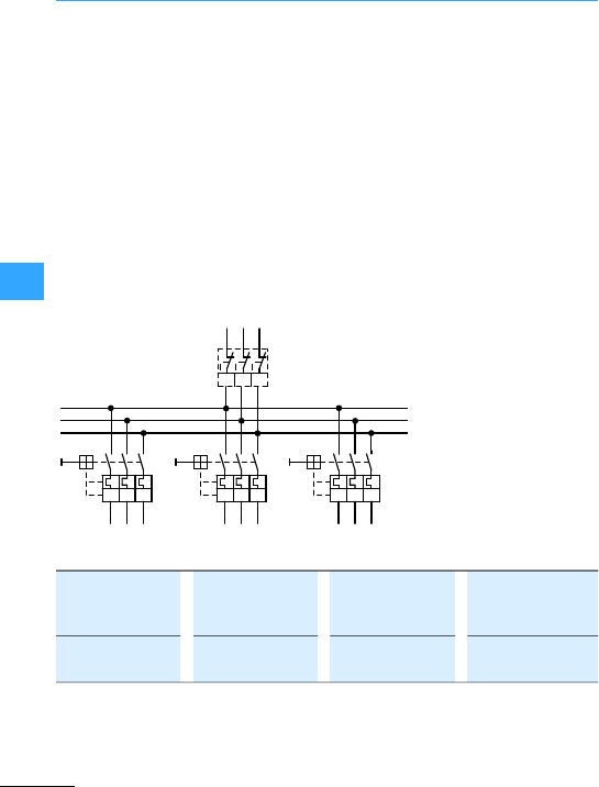
Eaton Wiring Manual 06/11
66
PKZM0 and PKZM4 –currentlimiters
The current limitermodule CL-PKZ0 is a
short-circuitprotective device specially
developed forthe PKZM0 and PKZM4 for
non-intrinsically-safe areas. The CL
module has the same base area and uses
the same terminations as the PKZM0.
When they are mounted on a top-hat rail
alongside one another, it is possible to
connect them using B3...-PKZ0
three-phase commoning links. The
switching capacity of the series connected
PKZM0 or PKZM4 + CL is 100 kA at 400V. In
the event of a short-circuit, the contacts of
the motor-protective circuit-breaker and
CL will open. While the current limiter
returnsfor the closed rest position, the
motor protective-circuit breakertrips via
the instantaneous release and produces a
permanent isolating gap. The system is
ready to operate again, once any defect
hasbeen rectified. The current limitercan
conduct an uninterrupted current of 63 A.
The module may be used forindividual or
group protection. Any direction of
incoming supply may be used.
Use theBK25/3-PKZ0 for
terminals > 6/4 mm2
Forgrouped connection
with three-phase
commoning link B3...PKZ0.
Observe load factors in
accordance with
VDE0660-600-2.
Iu= 63 A
l> l> l> l> l> l> l> l> l>
l> l> l>
PKZM0-16,
PKZM4-16
or
PKZM0-16/20,
PKZM4-16/20
or
PKZM0-20,
PKZM4-20
or
PKZM0-25,
PKZM4-25
4 x 16 A x0.8
= 51.2 A
2x(16A+20 A)
x0.8=57.6 A
3x20 Ax0.9
= 54 A
2x25 A x 0.9
=45 A
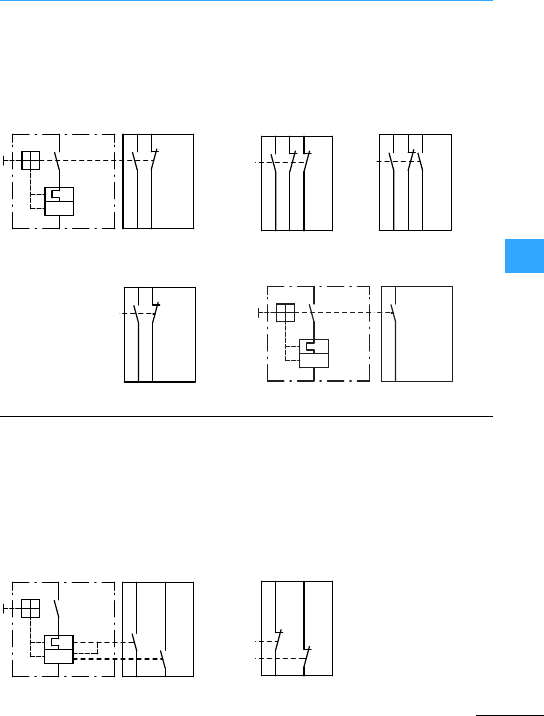
Eaton Wiring Manual 06/11
66
PKZM01, PKZM0, PKZM4 and PKE –auxiliary contacts
Theyswitch at the same time as the main
contacts.They are used forremote
indication of the operating state,and
interlocking of switches between one
another. They are available with screw
connections or springloaded terminals.
These provide information about the
reason for the circuit-breaker having
tripped. In the event of a voltage/overload
release (contact 4.43-4.44 or 4.31-4.32) or
short-circuit release (contact4.13-4.14 or
4.21-4.22) two potential-free contacts are
actuated independently of one another. It
is thus possible to indicate the difference
between short-circuit and overload.
Side mounted:
Integrated:
1.14 1.22
1.13 1.21
I>
1.13
1.14 1.22
1.21 1.31
1.32
1.13 1.21 1.33
1.14 1.22 1.34
1.53
1.54
1.61
1.62
I >
1.53
1.54
I>
"+"
4.43 4.13
"I>"
4.44 4.14
4.21
"I>"
"+"
4.31
4.32 4.22
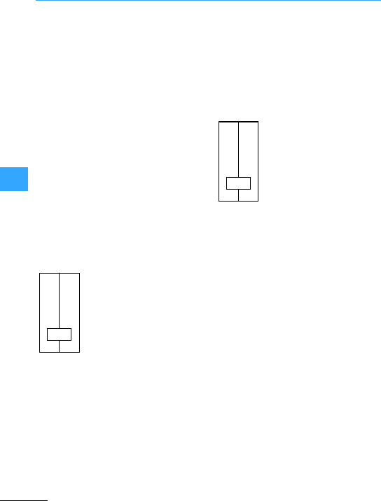
Eaton Wiring Manual 06/11
66
PKZM01, PKZM0, PKZM4 and PKE –trip blocks
These operate according to the
electromagnetic principle and act on the
switch mechanism of the circuit-breaker.
These switch the circuit-breaker off when
no voltage is present. They are used for
safety tasks. The U-PKZ20 undervoltage
release, which is connected to voltage via
theVHI20-PKZ0 or VHI20-PKZ01
early-make auxiliarycontacts, allows the
circuit-breaker to be switched on. In the
event of power failure the undervoltage
release switches the circuit-breakeroff via
the switch mechanism. Uncontrolled
restarting of machines is thus reliably
prevented. The safetycircuitsare proof
againstwirebreaks.
The VHI-PKZ0 cannot be used together
with the PKZM4!
These switch the circuit-breakeroff when
they are connected to voltage. Shunt
releases can be provided in interlock
circuits or for remote releases where
voltage dips or interruptions are notto lead
to unintentional switch off.
U<
D1
D2
C1
C2
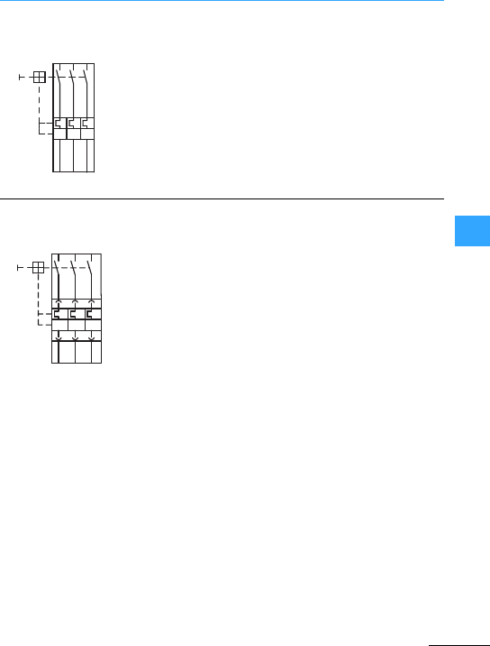
Eaton Wiring Manual 06/11
66
PKZM01, PKZM0, PKZM4 and PKE –block diagram
Manually operated motorstarter
Manually operated motorstarter
I > I > I >
L1 L2 L3
T1 T2 T3
-Q1
-Q1
L1 L2 L3
I>I>I>
T1 T2 T3
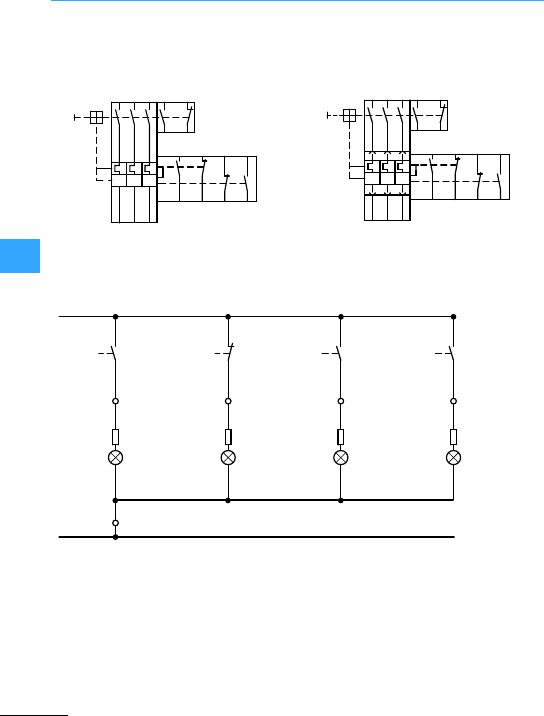
PKZM01, PKZM0, PKZM4 and PKE –block diagram
Eaton Wiring Manual 06/11
66
(Overload or short-circuit)
PKZM01(PKZM0-...)(PKZM4...) +
NHI11-PKZ0 + AGM2-10-PKZ0
PKE…+ NHI11-PKZ0 + AGM2-10-PKZ0
I>I>
I>
L1 L2 L3
-Q1
1.13 1.21
T1 T2 T3
4.44 4.32 4.22 4.14
4.43 4.31 4.21 4.13
1.14 1.22
I>I>I>
-Q1
L1 L2 L3 1.13 1.21
1.14 1.22
4.43 4.31 4.21 4.13
4.44 4.32 4.22 4.14
T1 T2 T3
E1: circuit-breaker ON
E2: circuit-breaker OFF
E3: generalfault,overload release
E4: short-circuit release
4.43
4.44
X2
L1
-Q1
1.13
1.14
-Q1
1.21
1.22
-Q1 -Q1
4.13
4.14
-X1 1
X1 X1 X1 X1
-X1 2-X1 3-X1 4
-E1 -E2 -E3 -E4
X2 X2 X2
-X1 5
N
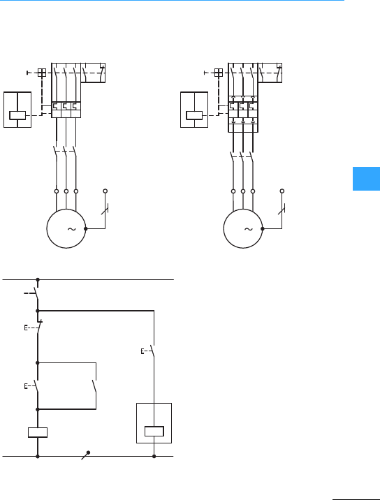
PKZM01, PKZM0, PKZM4 and PKE –block diagram
Eaton Wiring Manual 06/11
66
Motor starters with auxiliary contact and shunt release
PKZM0-... + DILM…+A-PKZ0 PKE…+ A-PKZ0
S1: OFF
S2: ON
S3: OFF circuit-breaker
I
>
I
>
I
>
L1 L2 L3
1
2
-Q11
-Q1
1.13 1.21
C2
C1 1.14 1.22
-X1 PE
T1 T2 T3
-M1
U1 V1 W1
M
3
123
3
4
5
6
I
>
I
>
I
>
L2 L3
1
2
-Q11
-Q1
1.13 1.21
C2
C1 1.14 1.22
-X1 PE
T1 T2 T3
-M1
U1 V1 W1
M
3
123
3
4
5
6
L1
L1
-Q1
-S1
1.13
1.14
21
22
13
14
-S2 Q11
13
14
A1
A2
-Q11
N
13
14
-S3
C1
C2
-Q1

EatonWiring Manual 06/11
66

Eaton Wiring Manual 06/11
77
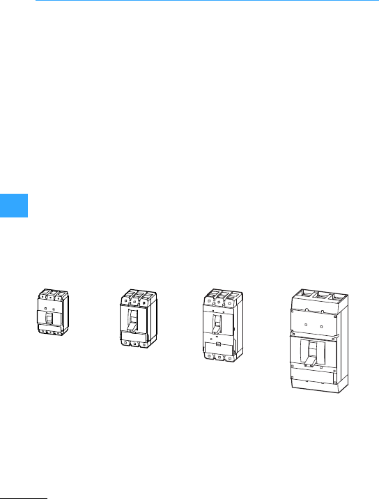
Eaton Wiring Manual 06/11
77
Overview
Circuit-breakers are mechanical switching
devices thatswitch currents in the circuit
on or off and control them under normal
operating conditions. These
circuit-breakers protectelectrical
equipment from thermal overloads and in
the event of a short-circuit.
The NZM circuit-breakers cover the rated
current range from 20 to 1600 A.
Depending on the version, they have
additional protective functions such as
residual currentdevice, earth-fault
protection or the capability forenergy
management by detecting load peaks, and
selective load shedding. NZM
circuit-breakers stand on account of their
compact shape and their current-limiting
characteristics.
Switch-disconnectors without overload or
tripping units are available in the same
sizes as the circuit-breakers and can be
fitted with additional shunt or undervoltage
release to suit the versions concerned.
NZM circuit-breakers and switch-
disconnectors are built and tested to the
specifications in standard IEC/EN 60947.
They feature isolating characteristics. In
conjunction witha locking facility, they are
suitable for use as main switches to
IEC/EN 60204/VDE 0113, part1.
The electronic release of frame sizes
NZM2, NZM3 and NZM4 feature
communication capabilities. The actual
states of the circuit-breakers can be
visualized locally via a Data Management
Interface (DMI) or converted to digital
output signals. Additionally, the
circuit-breakers can be connected to a
network, e.g. PROFIBUS-DP.
The NZM7, NZM10 and NZM14
circuit-breakers are no longer contained in
the Eaton range. They have been replaced
by a new generation of devices.
Information on the above devices is
provided in this chapter.
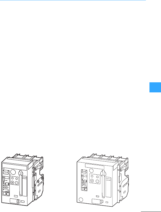
Overview
Eaton Wiring Manual 06/11
77
The IZMX circuit-breakers are designed
foruse in the high rated current range from
630 A.
IZMX circuit-breakers and INX
switch-disconnectors provide the main
switch isolation functions required by the
IEC/EN 60204-1 standard as they are
lockable in the OFF position. They can
therefore be used as mains switches. IZM
circuit-breakers are built and tested in
accordance with IEC/EN 60947.
Depending on the type of equipment
protected, the following main areas of
application are possible with different
settings to the release electronics:
•System protection,
•Motor protection,
•Transformer protection,
•Generator protection.
IZMX circuit-breakers offerdifferent
electronic unitsfrom simple system
protection with overload and short-circuit
release right through to the digital release
with graphical display and the possibility to
create time selective networks.
They can be adapted to awide range of
requirements with a comprehensive range
of mounted accessoriessuch as auxiliary
contacts, trip-indicating auxiliary contacts,
motor operators or voltage release,
fixed-mounted or withdrawable units.
With their communication capability, the
IZMX circuit-breakers open up new
possibilities in power distribution.
Importantinformation can be passed on,
collected and evaluated, also for
preventative maintenance. For example,
by enabling rapid intervention in
processes, system downtimes can be
reduced or even prevented.
Selection criteriaof an IZM circuit-breaker
are:
•Max. short-circuit current Ikmax,
•Rated operating current In,
•Ambienttemperature,
•3or 4-pole design,
•Fixed mounting or withdrawable units,
•Protectivefunction,
•Min. short-circuit current.
Detailed information on the circuit-breakers
is provided in chapter 18 of the Eaton
Industrial Switchgear Catalog 2010.
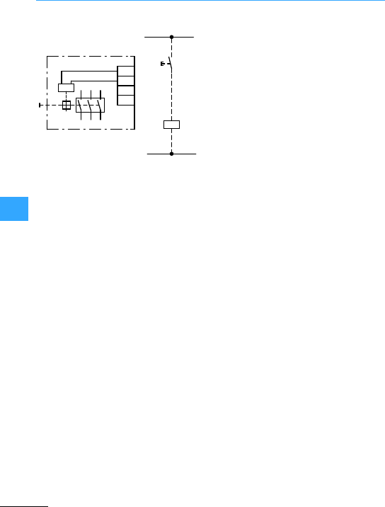
Eaton Wiring Manual 06/11
77
Shunt release
Module (Q1, solenoid) of acircuit-breaker
or motor-protective circuit-breakerthat
actuates a release mechanism when
voltage is applied. When de-energized,
the system is in the rest position.
Anormally open contact actuates the
system. If the shunt release is rated for
intermittent duty (overexcited shunt
release with 5%DF), the intermittent
operation must be ensured by connecting
an appropriate auxiliary contact of the
circuit-breaker upstream. This measure is
not required when using a shunt release
with 100 % DF.
Shunt releases are used forremote
tripping when an interruption in the
voltage is not intended to lead to
automatic disconnection. Tripping does
not occur in the event of wire breakage,
loose contacts or undervoltage.
L1
(L+)
-Q1
-S11
C1
C1
C2
Q1
E1 -Q1
0
C2
N
(L-,L2)
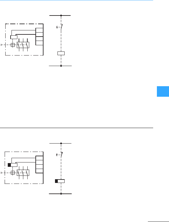
Eaton Wiring Manual 06/11
77
Undervoltage releases
A passive electromagnetic relay (Q1)
whichactuates a release mechanism
when the supply voltage drops or is
interrupted, in order, for example, to
preventthe automatic restarting of motors.
Undervoltage releases are also suitable for
very reliable interlocking and remote off
switching since disconnection always
occurs in the event of a fault (e.g. wire
breakage in the controlcircuit). The
circuit-breakers cannot be reclosed when
the undervoltage releases are
de-energized.
The system is in therest position when
energized. Actuation is produced by a
normally closed contact. Undervoltage
releases are always designed for
uninterrupted operation. These are the
ideal tripping elements fortotally reliable
interlocking tasks (e.g. emergency
offswitching ).
The off-delayed undervoltage release (Q1)
is acombination of a separate delay unit
(UVU) and the respective release. This
release is used to prevent brief
interruptions in power leading to
disconnection of the circuit-breaker. The
delaytime can be set between 0.06 and
16 s.
N
(L-, L2)
L1
(L+)
D1
D2
-Q1
-Q1
D1
D2
E1
Q1 U<
U<
0
-S11
L1
(L+)
-S11
0
N
(L-, L2)
-Q1
D2
D1
D2
D1
U<
Q1
-Q1
E1
U<
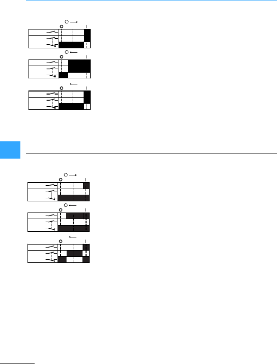
Eaton Wiring Manual 06/11
77
Contact diagrams of the auxiliary contacts
Auxiliary contacts are used to provide
command or signal outputs from
processes which are governed by the
position of the contacts. They can be
used for interlocking with other
switches, and for the remote
indication of the switching state.
Auxiliary contactshave thefollowing
properties:
•Standard auxiliary contacts behave
like main switch contacts
•Switch position indication
•Interlocking
•Disconnection of the shuntrelease
Usedto provide command and signal
outputrelating to electrical tripping of
the circuit-breaker (trip position +) as
is required, for example, for mesh
network circuit-breakers. No pulse is
produced when the switch is opened
or closed manually or by a motor
operator.
•Indication that the switch is in the
tripped position
•Switch position indication only if
tripping is caused by, for example,
overcurrent, short-circuit, test or
voltage release. No fleeting contact
when switched on or off manually or
switched off with the motor
(exception:manual switch off with
motoroperator NZM2, NZM3,
NZM4).
04I
Switch on
09I
Switch off
+9I
Trip
0Contact closed
1Contact open
L1L2L3
HIN
L1L2L3
HIN
L1L2L3
HIN
I
I
+I
+
+
+
L1L2L3
HIA
L1L2L3
HIA
L1L2L3
HIA
+
+
+I
I
+I
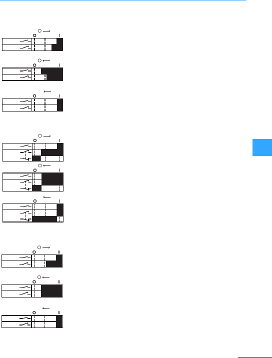
Contact diagrams of the auxiliary contacts
EatonWiring Manual 06/11
77
Early-make auxiliary contacts are used to
provide command or signal outputs for
processes which are initiated before the
closure or opening of the main contact
system.Because they close early, they can
be used for interlocks with other switches.
Furthermore, they allow a switch position
indication.
With the circuit-breaker in the Tripped
position,the HIV is in the same position as it is
at OFF. Because of its early-make
characteristics, it can be used to apply
voltageto the undervoltage release.
7Section ”Undervoltage releases”,
page7-5,
7Section ”Remote switch-off with voltage
release”,page 7-11,
7Section ”Applications of the undervoltage
release”,page 7-13.
04I
Switch on
09I
Switch off
+9I
Trip
0Contact closed
1Contact open
L1L2L3
HIV
I
I
++
+
+
I
L1L2L3
HIV
L1L2L3
HIV
NZM1, NZM2, NZM3, NZM7
L1L2L3
HIV
L1L2L3
HIV
L1L2L3
HIV
I
I
+I
+
+
+
NZM10
I
I
++
+
+
I
L1L2L3
HIV
L1L2L3
HIV
L1L2L3
HIV
NZM4
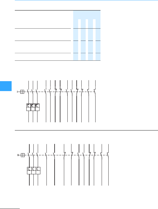
Eaton Wiring Manual 06/11
77
Internal circuit diagrams NZM
If a motor operator is used at
the same time, aconfiguration
with 2NO, 2NCor 1NO/1NC
(double auxiliary contact) is
restricted on the NZM3
circuit-breaker.
For this observethe latest
installation instructions.
HIN: 1NO, 1NC, 2NO, 2NCor
1NO/1NC
1 2 3 3
HIA: 1NO, 1 NC, 2NO, 2NC or
1NO/1NC
1 1 1 2
HIV: 2S 1 1 1 1
Contact elements M22-K10
(K01, K20, K02, K11) from the
RMQ-Titan range from Eaton are
usedfor the auxiliary contacts.
Two early-make auxiliary
contacts (2 NO) are also
available.
Information on the
auxiliary contacts
7Section ”Maximum
configuration”, page 7-8
1.11
L1
L2
L3
T1
T2
T3
1.13
4.11
3.13
3.23
1.14
4.134.14
1.12
4.12
3.14
3.24
HIN
-Q1
HIA HIV
I>I>I>
4.214.22
4.234.24
1.211.22
1.231.24
L1
L2
L3
T1
T2
T3
1.13
4.21
3.13
3.23
1.14
4.234.24
4.22
3.14
3.24
HIN
1.41
1.431.44
1.42
-Q1
HIA HIV
I>I>I>
1.111.12
......
4.114.12
4.134.14
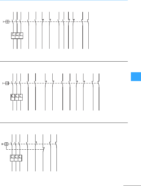
Internal circuit diagrams NZM
Eaton Wiring Manual 06/11
77
Details about the
auxiliarycontacts
7Section
”Maximum
configuration”,
page7-8
Details about
the auxiliary
contacts
7Section
”Maximum
configuration”,
page 7-8
In the NZM7 circuit-breakertwo auxiliary
contact modules can be fitted as NHI
(NC or NO) as well as a trip-indicating
auxiliary contact RHI (NC or NO).
Contact elements EK01/EK10 are used
from the Eaton RMQ range of pilot
devices. Early-make auxiliary contacts
(2 NO) are also available.
L1
L2
L3
T1
T2
T3
1.13
4.21
3.13
3.23
1.14
4.134.14
4.22
3.14
3.24
HIN
4.114.12
1.61
1.62
-Q1
HIA HIV
I>I>I>
1.111.12
4.234.24
1.631.64
...
...
L1
L2
L3
T1
T2
T3
1.13
4.41
3.13
3.23
1.14
4.134.14
4.434.44
4.42
4.114.12
3.14
3.24
HIN
1.611.62
-Q1
HIA HIV
I>I>I>
1.111.12
1.631.64
...
... ... ...
L1
L2
L3
1.13
1.11
4.11
3.13
3.33
1.14
1.12
4.12
3.14
3.34
NHI RHI VHI
I>I>I>
-Q1
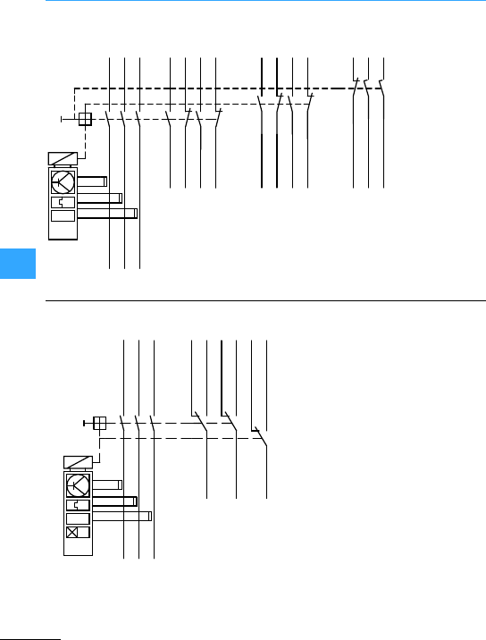
Internal circuit diagrams NZM
Eaton Wiring Manual 06/11
77
L1
L2
L3
1.13
1.21
1.43
1.31
4.13
4.21
4.43
4.31
3.21
3.13
3.33
1.14
1.22
1.44
NHI
I>
ZM(M)-
RHI VHI
1.32
4.14
4.22
4.44
4.32
3.22
3.14
3.34
-Q1
L1
L2
L3
1.12
1.11
1.21
4.11
1.14
1.22
1.24
4.12
4.14
NRHI
003
I>
I>
-Q1
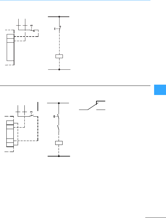
Eaton Wiring Manual 06/11
77
Remote switch-off with voltage release
Terminal marking for NZM14
When the switch is in the Off position, the
entire control circuit is live.
In order to de-energize theentire actuating
circuitwhen using ashunt release, the
control voltage must be connected
downstream of theswitch terminals.
N
(L-, L2)
L1
(L+)
L1
(L+)
N
(L-, L2)
-S.
-S.
D1
D2
D2
-Q1 U<
D1
-Q1
N
(L-, L2)
L1
(L+)
L1
(L+)
N
(L-, L2)
-S.
-S.
C1
C2
1.13
1.14 -Q1
C1
-Q1
HIN
1.13
1.14
C2
-Q1
-Q1
1.12
1.14
1.11
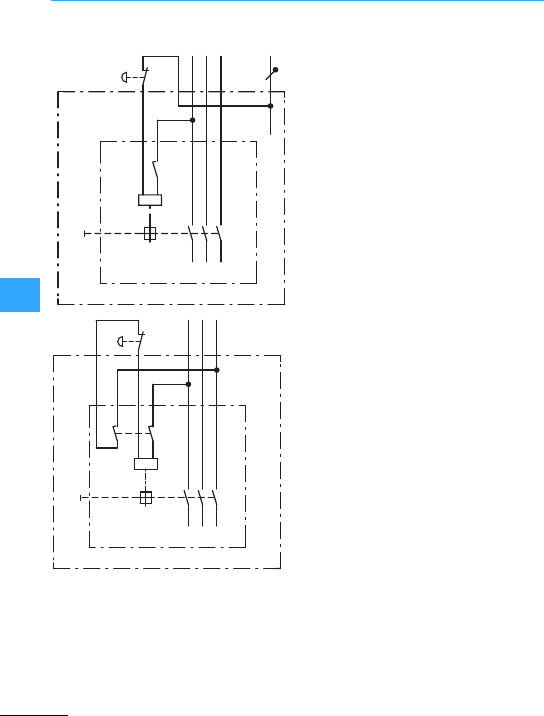
Remote switch-off with voltage release
Eaton Wiring Manual 06/11
77
In the OFF position of the main switch all
control elements and control cables
which exitthe control panel are
de-energized.The only live components
are the control-voltage tap-offs with the
control lines to the early-make auxiliary
contacts.
-S.
NZM
L1 L2 L3 N
-Q1
E1
-Q1 U<
HIV
-Q1
D1
D2
L1 L2 L3
HIV
-Q1
E1
-Q1U<
-Q1
NZM
D1
D2
-S.
3.14
3.13
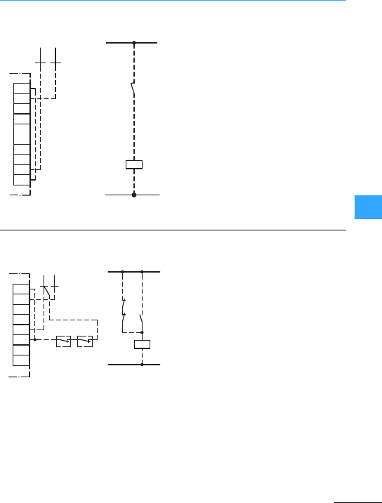
Eaton Wiring Manual 06/11
77
Applications of theundervoltage release
The early-make auxiliary contact HIV (Q1)
can –as shown above –disconnect the
undervoltage release from the control
voltage when the circuit-breaker is in the
Off position. If the undervoltage release is
to be disconnected in 2 poles, then a
further normally open contact of Q1 must
be connected between terminals D2 and
N. The early-make auxiliary contact HIV
(Q1) will always apply voltage to the
undervoltage release in time to permit
closure.
Circuit-breakers with an undervoltage
release produce a positive Off position in
conjunction with an interlocking auxiliary
contact on the starter(S5), ancillary
devices on the motor (e.g. brush lifting, S6)
or on all switches in multi-motordrives.
The circuit-breaker can only be closed if
the starteror switch is in the zero or OFF
position.
L1
(L+)
N
(L-, L2)
L1
(L+)
N
(L-, L2)
-Q1
-Q1
HIV
D1
D2
D1
D2
3.13
3.14
U<
3.13
3.14
-Q1
L1
(L+) L1
(L+)
N
(L-, L2)
-S5
-Q1 U<
-S6 -Q1
1.14
D1
D2
1.13
-S6 -S5
N
(L-, L2)
D1
D2
1.13
1.14
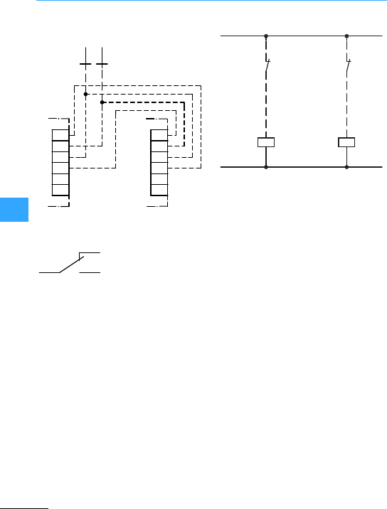
Eaton Wiring Manual 06/11
77
Switch off of the undervoltage release
When interlocking 3 or more
circuit-breakers, each circuit-breaker
must be interlockedwith the
series-connected normally closed
contacts of the auxiliary contacts on the
other circuit-breakers using one
contactor relay –for contact duplication –
perauxiliary contact. If one of the
circuit-breakers is closed, the others
cannot be closed.
Terminal marking for NZM14
D1
-Q1
D2
1.21
1.22
D1
-Q2
D2
1.21
1.22
L1
(L+)
N
(L-, L2)
-Q2
-Q1
D1
D2
U<
1.21
1.22
-Q1
-Q2
D1
D2
U<
1.21
1.22
L1
(L+)
N
(L-, L2)
-Q1/Q2
1.12
1.14
1.11
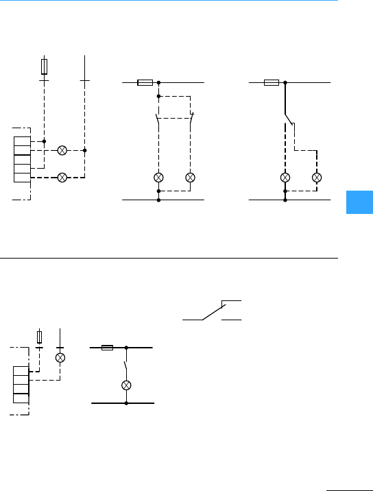
Eaton Wiring Manual 06/11
77
Indication of the contactor state
P1:On
P2:Off
Trip-indicating auxiliary contacts formesh
network circuit-breaker
P1:Tripped
Terminal marking forNZM14
L1
(L+)
L1
(L+)
N
(L-, L+)
N
(L-, L+)
-F0
1.13
1.14
X1
-P1 -P2
X2
X1
X2
-Q1
L1
(L+)
-F0
1.11
1.12
X1
-P1 -P2
X2
X1
X2
1.14
1.22
1.21
-F0
1.21 X1 X2
X1 X2
-P1
-P2
1.13
1.14
1.22
-Q1
N
(L-, L2)
N
(L-, L+)
L1
(L+)
-P1
X1
X2
-P1
X1
X2
L1
(L+)
N
(L-, L2)
-F0
-Q1
-F0
4.13
4.14
4.13
4.14
-Q1
4.11
4.12
4.14
-Q1
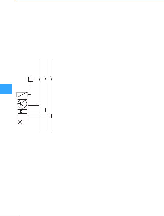
Eaton Wiring Manual 06/11
77
Short-time delayed circuit-breaker –internalcircuit diagrams
Short-timedelayed circuit-breakers
NZM2(3)(4)/VE, NZM10/ZMVandNZM14
enable a time-discriminating network
design with variable stagger times.
Where the prospective short-circuit
currents are extremely high, additional
installation protection is achieved by
instantaneous releases, which respond
without anydelay.
Trip block VE
Adjustable short-time delay:
0, 20, 60,100, 200, 300, 500, 750, 1000 ms
ZMV trip block only forcircuit-breaker
types:
NZM10-...N
NZM10…S
Adjustable short-time delay:
0, 10, 50, 100, 150, 200, 300, 500, 750, 1000 ms
Standard circuit-breakers
NZM14-...S
NZM14-...H
Adjustable short-time delay:
100, 150, 200, 250, 300 ms
I>
I>
L1
L2
L3
-Q1
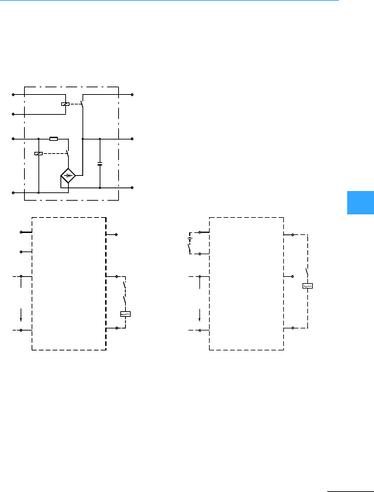
Eaton Wiring Manual 06/11
77
Mesh network circuit-breakers
Circuit with capacitor unit and shunt
release 230 V, 50 Hz.
The configurationof the capacitor unit
which provides the energy for the shunt
release of the mesh network
circuit-breaker can be undertaken
independently of the circuit-breaker.
Connect NZM-XCM to the supply side!
aMesh network relay bMesh networkrelay with low power
contacts
18
19
20
21 22
23
24
19
18
20
L1
N21
24
23
22
51 (C1)
a
HIN-NZM...
53 (C2)
230 V
50/60 Hz
NZM-XCM
②
19
USt
24 V ⎓
18
20
21
24
23
22
51 (C1)
HIN-NZM...
L1
N
53 (C2)
230 V
50/60 Hz
NZM-XCM
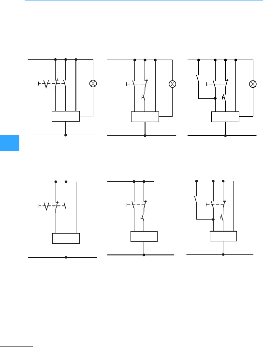
Eaton Wiring Manual 06/11
77
Remote operation with motor operator
L1
(L+)
N
(L-, L2)
0
P1
75
70 71
74
72
NZM-XR
I
L1
(L+)
N
(L-, L2)
P1
0
I
75
70 71
74
72
NZM-XR
L1
(L+)
N
(L-, L2)
P1
0
75
I
70 71
74
72
NZM-XR
HIA
L1
(L+)
N
(L-, L2)
0
70 71
74
72
R-NZM14
I
L1
(L+)
N
(L-, L2)
R-NZM14
70 71
74
72
0
I
L1
(L+)
N
(L-, L2)
RHI
R-NZM14
70 71
74
72
0
I
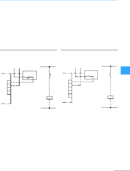
Eaton Wiring Manual 06/11
77
Circuit-breaker as transfomer switch
Faults upstream of the low-voltage
circuit-breaker, e.g. in the transformer
itself, are disconnected by suitable
protective devices (e.g. a Buchholz relay)
on the high-voltage side. The S7 auxiliary
contactof the high-voltage circuit-breaker
trips outthe NZM transformer switch on
the low-voltage side in orderto prevent
feedback to the high-voltage network.
S7 thus isolates the transformer from the
network on both sides. This interlocking
with the high-voltage circuit-breaker must
always be provided when transformers are
being operated in parallel.
If only one normallyopen contact is
available as the auxiliary contact, an
undervoltage release must be used instead
of the shunt release. At the same time, this
provides protection against undervoltage.
L1
(L+) L1
(L+)
N
(L-,L2)
C1
C2
Q1
N
(L-, L2)
-S7
-S7
C1
C2
-Q1
L1
(L+) L1
(L+)
N
(L-, L2)
D1
D2
Q1
N
(L-, L2)
-S7
-S7
D1
D2
U<
-Q1

Eaton Wiring Manual 06/11
77
Circuit-breaker with residual currentdevice
Residual currentreleases combined with
circuit-breakers are used for protection
against the effects of fault currents. These
device combinations fulfill the following
tasks:
•Overload protection,
•Short-circuit protection,
•Fault-current protection.
Depending on type the earth-fault releases
protect the following:
•Persons against direct contact
(basic protection),
•Persons against indirect contact
(fault protection),
•Dangers of an earth fault (fire etc.)
These kinds of earth-faultreleases can be
attached to the NZM1 and NZM2
circuit-breakers. No auxiliary voltage is
required. In the event of a fault, the
earth-fault release trips the
circuit-breaker, i.e. the main contacts are
opened. The circuit-breakerand the
earth-fault release must be reset to restore
the supply.
NZM1(-4)-XFI30(R)(U) 15 –125 200 –415 0.03 –Pulsating
current
NZM1(-4)-XFI300(R)(U) 15 –125 200 –415 0.3 –
NZM1(-4)-XFI(R)(U) 15 –125 200 –415 0.03; 0.1; 0.3
0.5; 1; 3
10;60; 150;
300; 450
NZM2-4-XFI301) 15 –250 280 –690 0.03 –
NZM2-4-XFI1) 15 –250 280 –690 0.1; 0.3; 1; 3 60;150;
300; 450
NZM2-4-XFI30A1) 15 –250 50 –400 0.03 –AC/DC
NZM2-4-XFIA1) 15 –250 50 –400 0.1; 0.3; 1 60;150;
300; 450
1) Devicesare not dependent on the supply voltage.
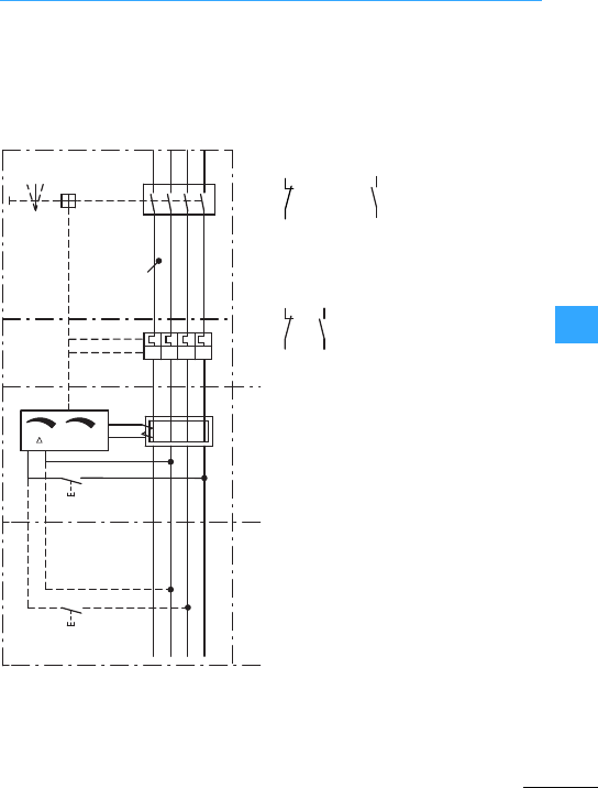
Circuit-breaker with residual currentdevice
Eaton Wiring Manual 06/11
77
Circuit-breakers can be used together
with residualcurrentreleases in
three-phase and single-phase systems.
With 2-pole operation it must be ensured
that voltage is applied to both terminals
required for test functions.
aTest button (T)
bNZM1-(4)…, NZM2-4…
c+NZM2-4-XFI
dNZM1-(4)-XFI
Trip indication is implementedvia auxiliary
contacts. Circuit-breaker NZM2-4 -XFI…
has fixed contacts. The NZM1(-4)-XFI…
allows two M22-K…contact elements
from the Eaton RMQ-Titan range to be
clipped in.
NZM1(-4)-XFI…
NZM2-4-XFI…
0 + I
NL1L2L3
Q1
nt
Iv
I> I> I> I>
①
①
②
③
④
M22-K10 M22-K02
6.13
6.14
6.21
6.22
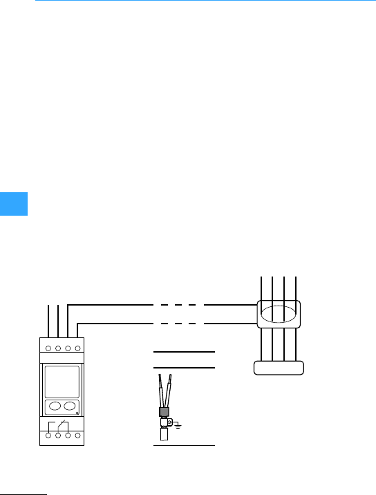
Circuit-breaker with residual currentdevice
Eaton Wiring Manual 06/11
77
The area of application forthe
relay/transformer combination ranges –
depending on the standards involved –
from personnel protection to fire
prevention to general protection of
systems for 1to 4-pole electrical power
networks.
There are three different relay types and
seven different transformer types
available. They cover operating currents
ranging from 1 to 1800 A.
Thethree relay types have thefollowing
features:
•Ratedfault current 30 mA, permanently
set,
•Rated fault current 300 mA,permanently
set,
•Rated fault current from 30 mA to 5Aand
a delay time from 20 ms to 5swhich is
variable in stages.
The residual current relay indicates when
afault current has exceeded the
predefined fault current by using a
changeovercontact. The contact signal
can be processed further as a signalin
programmable logic controllers or can
initiate a trip via the undervoltage release
of a circuit-breaker/switch-disconnector.
The compact ring-typetransformeris
placed without any particular space
requirement at a suitable position in the
power chain.
230 V AC g20 %
50/60 Hz
3 V A
50/60 Hz 250 V AC 6 A
LOAD
N
NO CNC
L
L1 L2 L3 N
1S2
1S1
5678
1234
> 3 m – 50 m
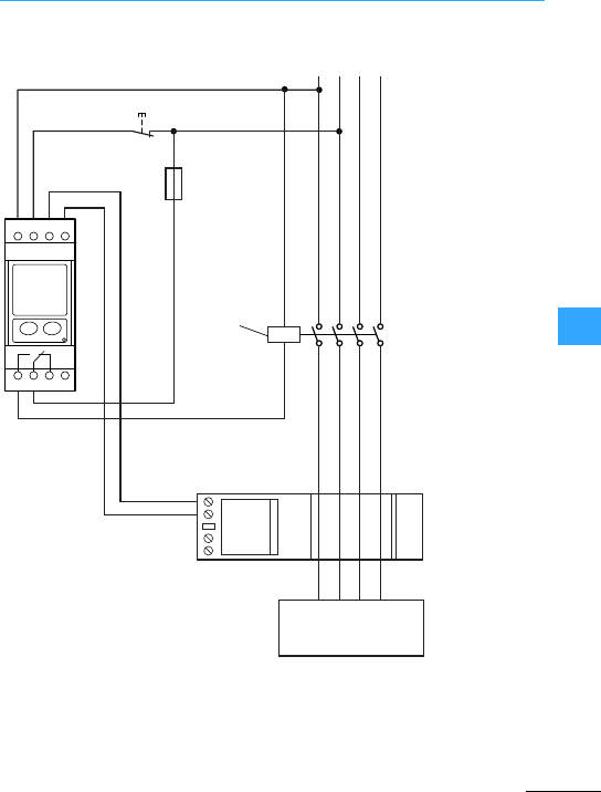
Circuit-breaker with residual currentdevice
Eaton Wiring Manual 06/11
77
5678
1234
L1
1S1
6 A
1S2
L2 L3N
PFR-W
LOAD
NZM.-XA... C2
C1
-S.
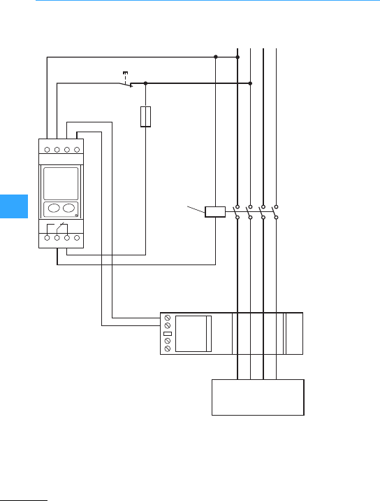
Circuit-breaker with residual currentdevice
Eaton Wiring Manual 06/11
77
5678
1234
L1
1S1
6 A
1S2
L2 L3N
PFR-W
LOAD
NZM.-XU... D2
D1
-S.
U <

Eaton Wiring Manual 06/11
77
Terminal assignments of IZMX circuit-breakers
(Front view from left to right)
Shuntrelease
Undervoltage release
(2ndShuntrelease)
Overload tripswitch1(OTS)
Overload tripswitch2(OTS)
Control unit Digitrip
Alarm
Current transformer, neutral conductor
Core-balance transformer, transformer star
point
Enable transformer star pointsignal
Communication
Wiring of ECAM,
MCAM, PCAM
Control voltage supply 24 VDC
Communication
Zone selectivity ZSI
Activation Maintenance mode (ARMS)
Closing releases
Motor operator
Indication “spring-operatedstored energy
mechanism tensioned“
Latch check switch
Auxiliary contacts ON/OFF
2 ST2
M
4UV2
(STS2)
6 OT1M
8 OT2B
10 OT2M
12 ALM1
14
16 N2
18 G2
20 SGF1
22 AGND
24 CMM2
26 CMM4
28 ZCOM
30
32
34 ARMS1
36 SR2
38 E02
40 LCB
42 LCM
44 A1
46 B2
48 A2
50 A3
52 B4
54 A4
1 ST1
3UV1
(STS1)
5 OT1C
7 OT1B
9 OT2C
11 ALMC
13 ALM2
15 N1
17 G1
19 SGF2
21 +24V
23 CMM1
25 CMM3
27 ZOUT
29 ZIN
31
33 ARMS2
35 SR1
37 E01
39 SC
41 LCC
43 C1
45 B1
47 C2
49 C3
51 B3
53 C4
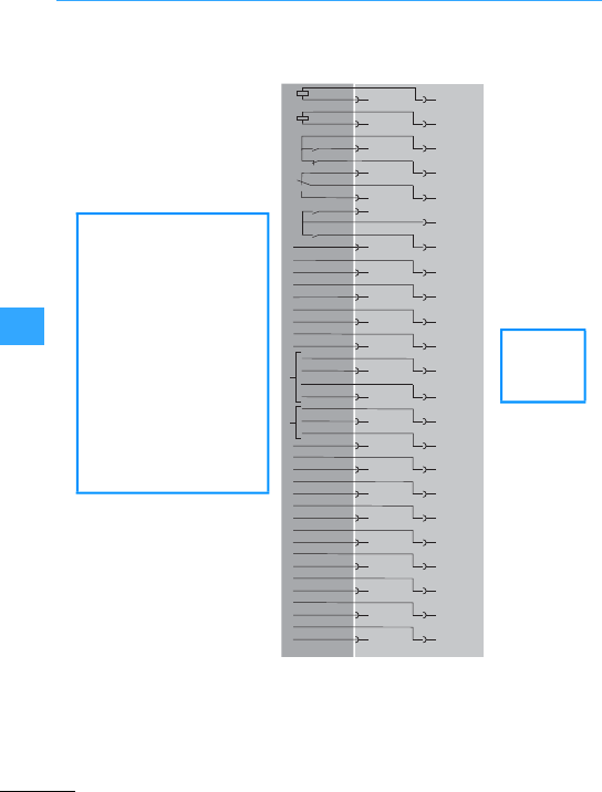
Terminal assignments of IZMX circuit-breakers
Eaton Wiring Manual 06/11
77
(Front view from left to right)
Shuntrelease
Undervoltage release
(2ndShuntrelease)
Overload tripswitch1(OTS)
Overload tripswitch2(OTS)
Control unit Digitrip
Alarm
Current transformer, neutral conductor
Core-balance transformer, transformer star
point
Enable transformer star pointsignal
Communication
Wiring of ECAM,
MCAM, PCAM
Control voltage supply 24 VDC
Communication
Zone selectivity ZSI
Activation Maintenance mode (ARMS)
2ST2
4UV2
(STS2)
6OT1M
8OT2B
10 OT2M
12 ALM1
16 N2
14 VN
18 G2
20 SGF1
22 AGND
24 CMM2
26 CMM4
28 ZCOM
30
32
34 ARMS1
1ST1
3UV1
(STS1)
5OT1C
7OT1B
9OT2C
11 ALMC
13 ALM2
15 N1
17 G1
19 SGF2
21 +24V
23 CMM1
25 CMM3
27 ZOUT
29 ZIN
31
33 ARMS2
RR2 RR1
36
38
35
37
44
46
43
45
40 ARCON1
42 ARCON3
39
41 ARCON2
VC
VA
VB
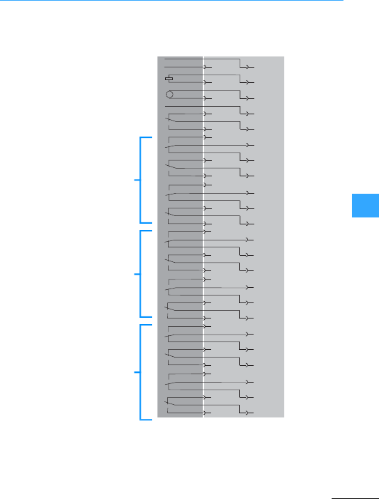
Terminal assignments of IZMX circuit-breakers
Eaton Wiring Manual 06/11
77
(Front view from left to right)
Closing releases
Motoroperator
Indication “spring-operated stored“
Latch check switch
Auxiliary contacts ON/OFF
Auxiliary contacts ON/OFF
Auxiliary contacts ON/OFF
48 47
M
50 SR2
52 E02
54 LCB
56 LCM
49 SR1
51 E01
53 SC
55 LCC
70 A5
72 B6
74 A6
76 A6
78 B8
80 A8
69 C5
71 B5
73 C6
75 C7
77 B7
79 C8
82 A9
84 B10
86 A10
88 A11
90 B12
92 A12
81 C9
83 B9
85 C10
87 C11
89 B11
91 C12
58 A1
60 B2
62 A2
64 A3
66 B4
68 A4
57 C1
59 B1
61 C2
63 C3
65 B3
67 C4
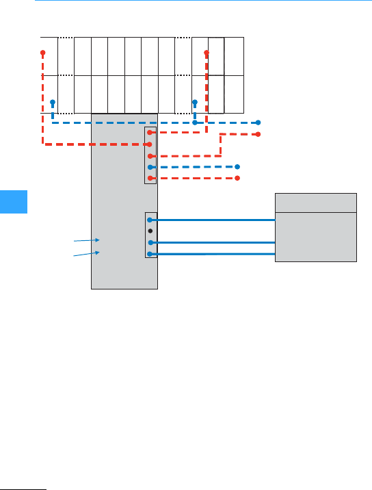
Terminal assignments of IZMX circuit-breakers
Eaton Wiring Manual 06/11
77
5
4
3
2
1
Close
Open
362826242220182
352725232119171
2220182
1
SR2
CMM4
CMM2
AGND
SGF1
ST2
SR1
ST1ST2
CMM3
CMM1
+24V
SGF2
ST1
54
53
COM -R
-24 V DC
+24 V DC
0V
+24 V DV
4
3
2
1
Shield
COM -C
A(Tx/Rx -)
B(Tx/Rx+)
MCAM
Tx /Rx+
Tx /Rx-
Modbus RTU
Master
GND**
RS485
Modbus
Integrated
Status (ON/OFF)
sensors in
breaker
CAM Supply
Remote Reset control voltage
non-
inverting
inverting
Wiring for remote control
(Shunt trip and spring release)
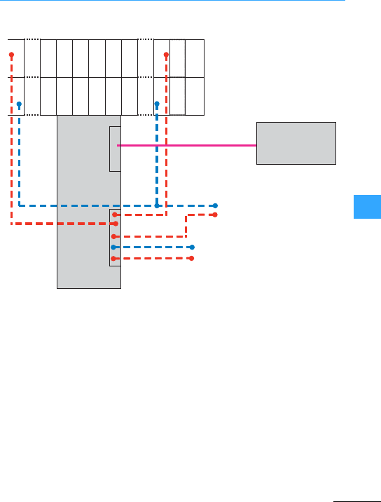
Terminal assignments of IZMX circuit-breakers
Eaton Wiring Manual 06/11
77
5
4
3
2
1
Close
Open
COM -R
36
2826242220182
352725232119171
SR2
CMM4
CMM2
AGND
SGF1
ST2
SR1
CMM3
CMM1
+24 V
SGF2
ST1
54
53
0V
PCAM
PROFIBUS-DP
Master
RS485
PROFIBUS-DP
-24 V DC
+24 V DC +24 V DV
Wiring for remote control
(Shunt trip and spring release)
CAM Supply
Remote Reset control voltage
Integrated
Status (ON/OFF)
sensors in
breaker
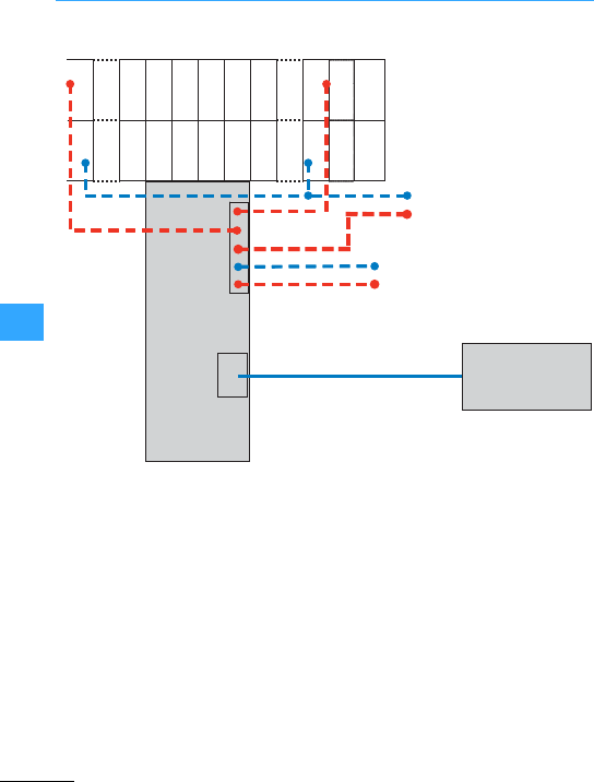
Terminal assignments of IZMX circuit-breakers
Eaton Wiring Manual 06/11
77
5
4
3
2
1
Close
Open
362826242220182
352725232119171
2220182
1
SR2
CMM4
CMM2
AGND
SGF1
ST2
SR1
ST1ST2
CMM3
CMM1
+24V
SGF2
ST1
54
53
ECAM
COM -R 0V
-24 V DC
+24 V DC +24 V DV
Integrated
Status (ON/OFF)
sensors in
breaker Ethernet Network,
Switch, or PC
Connection
CAM Supply
Remote Reset control voltage
Wiring for remote control
(Shunt trip and spring release)

Eaton Wiring Manual 06/11
8


Eaton Wiring Manual 06/11
8
Motor protection
The Eaton selectorslide enables you to
determine quickly and reliably which motor
starter is the most suitable for the
application concerned. For this only the
operating voltage, the motorrating, the
various short-circuit ratings and
coordination types are required.
The selectorslide can be used for
dimensioning deviceswith short-circuit
coordination types 1 and 2. Standard cable
cross-sections and permissible cable
lengths are stated forthe tripping of
protective devices in compliance with
standards. They can vary according to the
installation requirements. The selector
slide has several variants of the movable
section with numerical valuesfor DOL and
reversing starters or star-delta starters.
The selectorslide can be obtained free of
charge. If you prefer to use the selection
aid online, this is available at:
www.eaton.com/moeller/support
(Online Selection Tools)

Motor protection
EatonWiring Manual 06/11
8
They should always be used where
continuous contact devices (two-wire
control) are concerned (e.g. pressure and
position switches), to prevent automatic
restarting. The reset button can be fitted as
an external feature in orderto make it
accessible to all personnel. Overload
relays for example are always supplied
with manual reset. but can be converted to
automatic reset by the user.
They can be used only with pulsed contact
devices (three-wire control) such as
pushbuttons etc., because on these, the
cooling of the bimetal strips cannot lead to
automatic reconnection.
Specialcircuitry such as is found in
star-delta switches, individually
compensated motors, current
transformer-operated overloadrelays etc.
may requirethat therelaysettings deviates
from the motor rated operational current.
It makes motor protection difficult. The
relay should be set to higher than rated
motor current in view of its shorter time
constant. Motors which are rated forahigh
operating frequency will stand this setting
to acertain degree. Although this will not
ensure complete protection against
overload,it will nevertheless provide
adequate protection against non-starting.
They are needed to protect not only the
motor, but also the relay, against the
effects of short-circuits. Their maximum
rating is shown clearly on every relay and
must be adhered to without fail. Higher
ratings–chosen forinstance according to
the cable cross-section –would lead to the
destruction of the motorand relay.
The followingimportantquestions and
answers give a further guide to the
behaviour of an installation with motor
protection.
To the rated motor current –no higher, no
lower. A relay set to too low a figure will
prevent the full utilization of the motor; set
too high, it will not guarantee full overload
protection. If a correctly set relay trips too
frequently, then either the load on the
motor should be reduced or the motor
should be exchanged for a larger one.
Only when the current consumption of the
motorincreases due to mechanical
overloading of the motor, undervoltage or
phase failure when the motor is under full
load or thereabout, or when the motor fails
to start due to a stalled rotor.
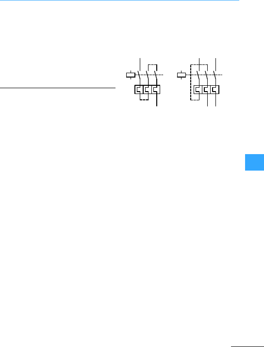
Motor protection
EatonWiring Manual 06/11
8
With changes in the motorwhich do not
cause an increase in current consumption:
Effects of humidity, reduced cooling due to
a reductionin speed or motor dirt,
temporary additional external heating of
the motoror bearing wear.
Destruction will take place only in the
eventof a short-circuit on the load side of
the relay when the back-up fuse is rated
too high. In most cases, this will also
endangerthe contactor and motor.
Therefore, always adhere to the maximum
fuse rating specified on every relay.
3-pole overload relays should be so
connected in the case of single-phase and
DC motors so that all three poles of the
overload relay carry the current, whether
in 1-pole or 2-pole circuits.
An important characteristic feature of
overload relays conforming to IEC/EN
60947-4-1 are the tripping classes (CLASS
10 A, 10, 20, 30). They determine different
tripping characteristics for the various
starting conditions of motors (normal
starting to heavy starting duty).

Motor protection
EatonWiring Manual 06/11
8
Response limits of time-delayed overload
relays at all-pole load.
In the case of thermal overload relays with
acurrent setting range, the response limits
must apply equally to the highest and the
lowest settingof the associated current.
A B C D
t > 2 h
starting
from
cold
state of
relay
t#2 h Tripping
classes
Tripping
time in
minutes
Tripping
class
Tripping
time in
seconds
10 A
10
20
30
#2
#4
#8
#12
10 A
10
20
30
2< T #10
4< T #10
6< T #20
9< T #30
Non-ambient
temperature
compensated
thermal
relays and
magnetic
relays
1.0 1.2 1.5 7.2 +40 °C
Ambient
temperature
compensated
thermal
relays
1.05 1.2 1.5 7.2 +20 °C

Motor protection
EatonWiring Manual 06/11
8
Response limits of 3-pole thermal overload
relays at 2-pole load
In the case of thermal overload relays with
acurrent setting range, the response limits
must apply equally to the highest and the
lowest settingof the associated current.
Overload relays and releases have heating
coils which can be thermally destroyed by
overheating. The making and breaking
currents of the motorflow in thermal
overload relays which are used for motor
protection. These currents are between 6
and 12 xI
e(rated operational current),
depending on the utilization category and
the size of the motor.
The point of destruction depends on the
frame size and design. It is usually
approximately 12 to 20 x Ie.
The point of destruction is the point of
intersection between the projected
tripping characteristic curves and the
multiple of the current.
With currents that exceed the breaking
capacity of the motor starterin relation to
the utilization category (EN60947-1, VDE
0660, Section 102, Table 7), it is permissible
forthe current flowing during the break
time of the protective device to damage the
motor starter.
The permissible behaviour of starters
under short-circuit conditions is defined in
the so-called types of coordination
(1 and2). It is common practice to state in
A
t > 2 h, starting
from cold state of
relay
B
t#2 h
Ambient temperature
compensated, without
phase failure sensitivity
3 poles 1.0 2 poles
1 pole
1.32
0
+20 °C
Non-ambient temperature
compensated, without
phase failure sensitivity
3 poles 1.0 2 poles
1 pole
1.25
0
+40 °C
Ambient temperature
compensated, with phase
failure sensitivity
2 poles
1 pole
1.0
0.9
2 poles
1 pole
1.15
0
+20 °C

Motor protection
EatonWiring Manual 06/11
8
the details of protective devices which
type of coordination is ensured by them.
In the event of ashort circuit the starter
must not endangerpersons and
installations. It does not have to be fit for
renewed operation without repair.
In the event of ashort-circuit the starter
must not endangerpersons and
installations. It must be fit for renewed
operation. There is a risk of contact weld.
forwhich the manufacturer must give
maintenance instructions.
The trippingtype of theoverload relay must
not differ from the given tripping
characteristic aftera short-circuit.
The manufacturer detailsthe required
overcurrent protective device.The
combination is subjected to three test
disconnection's at 1000 A prospective
current with a power factor between 0.5
and 0.7 at rated operational voltage.
Welding of the contacts may not occur
(EN60947-5-1, VDE0660 Part 200).
An adequate tripping time is essential in
order to allow a motor to start up smoothly.
In the majority of cases, overload relays
such as motor-protective circuit-breakers
PKZ(M)or circuit-breakers NZMcan be
used. The tripping time can be taken from
the tripping characteristics in the main
catalogue, Industrial Switchgear.
In the case of especially high-inertia
motors, whose run-up time exceeds the
tripping delay of the above devices, it
would be completely wrong to adjust an
overload relay which tripped out before the
run-up time expired, to a current level
higher than the rated motor current. This
would, it is true, solve the starting problem,
but the motor would no longerbe
adequately protected during run.However,
there are other solutions to the problem:
The ZW7 consists of three special
saturable core current transformers,
supplying an overload relay Z…It is used
principally formedium and large motors.
Up to two times rated operational current
Ie, the transformation ratio I1/I2of the
saturable core current transformers is
practically linear. Within this range it does
not differ from the normal overload relay,
i.e. it provides normal overload protection
during normal operation. However, within
the transformer characteristic range
(I > 2 x Ie) , the secondary current no longer
increases proportionally to the primary
current.
This non-linear increase in the secondary
current produces an extended tripping
delay if overcurrents greater than twice
rated operationalcurrent occur, and hence
permits longer start-up times.

Motor protection
EatonWiring Manual 06/11
8
Thesetting ranges quoted in the main
catalogue, Industrial Switchgear, apply
when the incoming cable is looped once
through the transformer relay.
If the current transformer-operated
overload relay ZW7 is required to provide
protection to a motor of below 42 A rating
(minimum value in the setting range of 42 A
to 63 A),the necessary range adjustment is
achieved by looping the incomer several
times through the aperture in the relay. The
change in the rated motorcurrent quoted
on the rating plate is inversely proportional
to the number of loops.
With the ZW7-63 relay, which has a setting
range from 42 A to 63 A, a rated motor
currentof 21 A to 31.5 A can be
accommodated by looping the leads twice
through the relay.
For small motors the bridgingof the motor
protection during starting is more
economical. Because of the additional
parallel contactor, the overload relay does
not carry the full current during starting.
Only when the motor has reached full
speed is the bridging contactor switched
off and the full motor current is then carried
by the overload relay. Provided it has been
set correctly to the rated motor current,
this will ensure full motor protection during
operation. Starting must be monitored.
The motor is a limiting factor with regard to
the tripping delay of the current
transformer-operated relay and the
bridging period. One must ensure that the
motor is able to tolerate the high
temperature generated by directstarting,
forthe prescribed starting time.Motor and
starting procedure have to be selected
carefully when dealing with machines
having avery large rotating mass, which
are practically the only ones subject to this
problem when directstarting is used.
Depending on the operating conditions
adequate protection of the motor winding
may no longer be given by an overload
relay. In that case it must be weighed up
whether an electronic overload relay ZEV,
ZEB or a thermistoroverload relay EMT 6 in
conjunction with an overload relay Z meets
the requirements.
Example circuits 7page 8-10
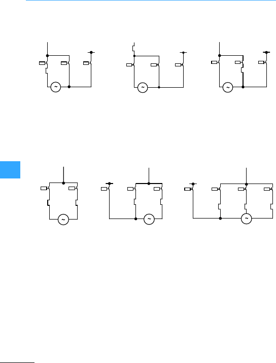
Motor protection
EatonWiring Manual 06/11
8
1 operating direction
Changeover time with overload relay in position
A: < 15 sB:> 15 < 40 sC: > 40 s
0.58 x Ie1 x Ie0.58 x Ie
Full motor protection in
8(star) position
Only partial motor protection
in 8position
Motornot protected in
8position
2 speeds
2separate
windings
One tapped winding3speeds
1 x tapped winding
+1 winding
Attention must be paid to short-circuit protectivedevice of the overload relays.
Separate supply input wiringsshould be provided if required.
-Q11
A
-Q15 -Q13
Ie
-Q11
B
-Q15 -Q13
Ie
-Q11 -Q15 -Q13
Ie
C
-Q17 -Q21
-Q17-Q23 -Q21 -Q17
-Q23 -Q21
-Q11

Motor protection
EatonWiring Manual 06/11
8
ZW7current
transformer-operated
overload relays
Bridging of motor protection
during starting
Bridging during starting
using bridging relay
For medium and large
motors
For small motors; no
protection during starting
Automatic cut out of the
bridging contactor
-Q11 -Q11 -Q12 -Q11 -Q12
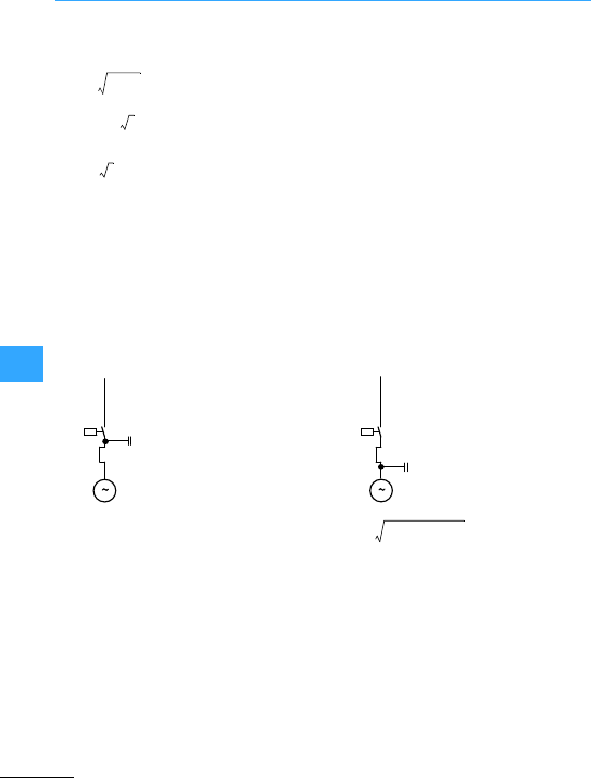
Motor protection
EatonWiring Manual 06/11
8
Iw=
Ib=
Ic=
Ic=
Ie= Rated motor operational current [A]
Iw= Active current
Ib= Reactive current
Ic= Capacitor-Rated operational current [A]
IEM = Setting current of overload relay [A]
cos '= Motor power factor
Ue= Rated operationalvoltage [V]
Pc= Rated capacitoroutput[kvar]
C=Capacitance of capacitor [>F]
Ie-[A]cos(
Ie
2Iw
2
–A$"
U
e320fC10 6–A$"((((
P
c103
(
3U
e
(
-------------------
}Proportion of motor rated operational current [A]
to protective conductorterminals to motor terminals
Setting IEM of overload relay
Capacitor does not relieve loading of cable
between contactorand motor.
Capacitor relieves loading of cable
between contactor and motor; normal
arrangement.
-Q11 PC
IEM
-Q11
P
C
IEM
IEM 1I
e
(=I
EM Iw
2Ib
'Ic&2
–+=

Motor protection
EatonWiring Manual 06/11
8
Thermistoroverload relays for machine
protection are used in conjunction with
temperature-dependent semi-conductor
resistors (thermistors) formonitoring the
temperature of motors, transformers,
heaters, gases, oils, bearings etc.
Depending on the application, thermistors
have positive (PTC thermistors) or negative
(NTC thermistors) temperature
coefficients. WithPTC thermistorsthe
resistance at low temperature is small.
From a certain temperature it rises steeply.
On the other hand, NTC thermistorshave a
falling resistance-temperature
characteristic, which does not exhibit the
pronounced change behaviour of the PTC
thermistor characteristic.
Thermistoroverload relays for machine
protection EMT6 comply with the
characteristics forthe combination of
protective devices and PTC sensors to
EN 60947-8. They are therefore suitable for
monitoring the temperature of series
motors.
When designing motor protection, it is
necessary to differentiate between
stator-critical and rotor-critical motors:
•
Motors whose stator winding reaches
the permissible temperature limit quicker
than the rotor. The PTC sensor fitted in
the stator winding ensures that the stator
winding and rotor are adequately
protected even with a stalled rotor.
•
Squirrel-cage motors whose rotor in the
event of stalling reaches the permissible
temperature limit earlier than the stator
winding. The delayedtemperature rise in
the stator can lead to a delayed tripping
of the thermistoroverload relay for
machineprotection. It is therefore
advisable to supplement the protection
of rotor-criticalmotors by aconventional
overload relay. Three-phase motors
above 15 kW are usually rotor-critical.
Overload protection for motors in
accordance with IEC 204 and IEC/EN 60204.
These standards specify that motors above
2 kW used forfrequent starting and
stopping should be adequately protected
forthis type of duty. This can be achieved
by fitting temperature sensors. If the
temperature sensor is not able to ensure
adequate protection with stalled rotors, an
overcurrentrelay must also be provided.
Generally, where there is frequent starting
and stopping of motors, intermittent
operation and excessive frequency of
operation,the use of overload relays in
conjunction with thermistor overload
relays is to be recommended.In order to
avoid premature tripping out of the
overload relay in these operating
conditions, it is set higherthan the
predefined operating current. The overload
relay then assumes stalling protection; the
thermistor protection monitors the motor
winding.

Motor protection
EatonWiring Manual 06/11
8
Thermistoroverload relays for machine
protection can be used in conjunction with
up to six PTC sensors to DIN 44081 for
direct monitoring of temperatures in Ex e
motors compliant with the ATEX directive
(94/9 EC). An EC type testing certificate can
be provided.
+ Full protection
(+)Partial protection
–No protection
Overload in continuous operation + + +
Extended starting and stopping (+) + +
Switching to stalled rotor
(stator-critical motor)
+ + +
Switching on stalled rotor
(rotor-critical motor)
(+) (+) (+)
Single-phasing + + +
Intermittent operation –+ +
Excessive operating frequency –+ +
Voltage and frequency
fluctuations
+ + +
Increased coolant temperature –+ +
Impaired cooling –+ +
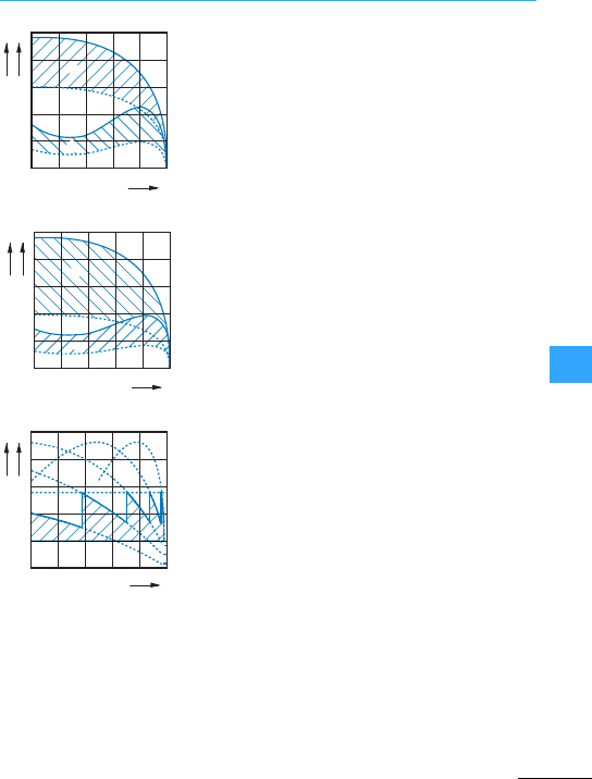
Eaton Wiring Manual 06/11
8
Notes on engineering
Single or multi-step resistors are connected upstream
of the three-phase squirrel-cage motors to reduce the
inrush current and the tightening torque.
With single-step starters,the inrush currentis
approximately three times the rated motor current. With
multi-stage starters, the resistors can be so designed
that the inrush current is only 1.5 to 2timesthe rated
motor current, with a very low level of tightening torque.
This type of starting is preferable where the same
tightening torque is to be obtained as with the primary
series resistors but the inrush current taken from the
mains is to be furtherreduced. A reduced voltage Ua
(approximately 70 %of the rated operating voltage) is
supplied to the motor when starting via the starting
transformer. Thus, the current taken from the mains is
reduced to approximately half the direct inrush current.
Resistors are connected in the rotorcircuit of the motor
to reduce the inrush current of motors with slipring
rotors. The current taken from the mains is thus
reduced. In contrast to stator resistance starters, the
torque of the motor is practically proportional to the
current taken from the mains. The number of steps of
the automaticstarter is determined by the maximum
permissible inrush current and by the type of the motor.
I: Line current
Md: Torque
n: Speed
aReduction of the line current
bReduction of the torque
①
②
20 40 60 80 n
100 %
I
I
I'
M
d
M
d
M'
d
①
20 40 60 80 100 %
②
n
I
I
I'
Md
Md
M'd
20 40 60 80 100 %
n
IMd

Notes on engineering
EatonWiring Manual 06/11
8
1) Type of starter Stator resistance starter (for squirrel-cage motors) Rotor starter
(for slipring rotors)
2) Part no. of
starter
Star-delta
switches
With starting
resistors
With start-up
transformers
Rotor resistance
starter
3) Number of
starting stages
1 only Normally 1 Normally 1 Selectable(no
longer selectable
when current or
torque have been
determined)
4) Voltage
reduction at the
motor
0.58 xrated
operational
voltage
Selectable:
axrated
operational
voltage
(a < 1) e.g. 0.58as
with 8A-switch
Selectable:
0.6/0.7/0.75 x Ua
(transformer
tappings)
None
5) Inrush current
taken from mains
0.33 xinrush
current at
rated
operational
voltage
a x inrush current
at rated
operational
voltage
Selectable (see 4)
0.36/0.49/0.56 x
inrush current at
rated operational
voltage
Selectable: from
0.5 to about 2.5 x
rated operational
current
5a) Inrush current
at the motor
Selectable (see 4)
0.6/0.7/0.75 xI
e
6) Starting torque 0.33 x
tightening
torque at
rated
operational
voltage
a2xtightening
torque at rated
operational
voltage
Selectable (see 4)
0.36/0.49/0.56 x
tightening torque
at rated
operational
voltage
Selectable(see 5)
from 0.5 to pull-out
torque
7) Current and
torque reduction
Proportional Currentreduction
lessthan torque
reduction
Proportional Current reduction
much greater than
torque reduction.
From pull-out
torque to rated
speed almost
proportional
8) Approximate
price (for similar
data)
DOL starting = 100
(with overload
relay, enclosed)
150 –300 350 –500 500 –1500 500 –1500
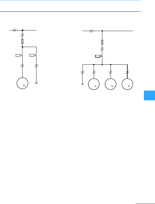
Notes on engineering
EatonWiring Manual 06/11
8
When capacitors are switched on,
contactors are heavily stressed by
transient current peaks. When a single
capacitoris switched on, currents up to
30 timesthe rated operationalcurrent can
occur; these can, however, be reliably
switched by Eaton DIL contactors.
When installing capacitors, the VDE
specification 0560 part 4 (Germany) andthe
standards which apply to each country
should be observed. According to these,
capacitors not directly connected to an
electrical device which forms a discharge
circuit,should be equipped with a rigidly
connected discharge device. Capacitors
connected in parallel to the motor do not
require a discharge device,since
discharging is performed via the motor
winding. No switch-disconnectors or fuses
must be installed between the discharge
circuit and the capacitor.
A discharge circuit or discharge device
must reduce the residual voltage of the
capacitor to less than 50 V within a minute
of the capacitor being switched off.
L1...3
-F1
-Q11 -Q31
-M1
-C1
M
3
L1...3
-F1
-Q11
-M1
-C1 M
3
M
3M
3
-M2-M3
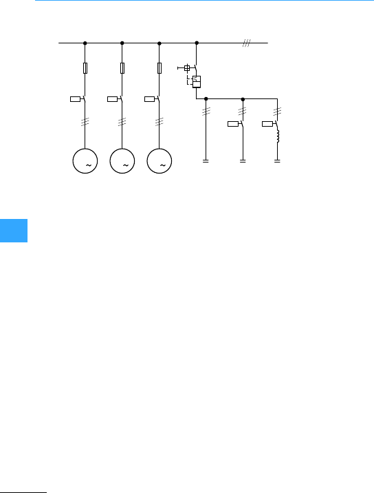
Notes on engineering
EatonWiring Manual 06/11
8
In the case of group compensation where
capacitors are connected in parallel,it
must be noted thatthe charging current is
taken not only from the mains but also from
the capacitors connected in parallel. This
produces inrush current peaks which can
exceed 150 times the rated operational
current. A further reason for these peak
currents is the use of low-loss capacitors
as well as the compact construction,with
short connecting elements between
contactor and capacitor.
Where standard contactors are used,
there is danger of welding. Special
contactors for capacitors such as those
available from Eaton in the DILK…range
which can control inrush current peaks of
up to 180 times the rated current, should be
used here.
If no special contactors are available, the
inrush currents can be damped by
additionalinductance's. This is achieved
either by longer inputwirings to the
capacitors or by inserting an air-cored coil
with a minimum induction of approximately
6>H (5 windings, diameter of the coil
approximately 14 cm) between contactor
and capacitor. The use of series resistors
is another way of reducing high inrush
currents.
Frequently the capacitors in group
compensation are providedwith reactors
to avoid harmonics. The reactors also act
to limit the inrush current and normal
contactor can be used.
aAdditional inductance with standard contactor
L1...3
-F1
-Q11
M
3
-F2 -F3
-Q12 -Q13
-Q1
M
3M
3
-Q31 -Q32 a
-C0 -C1 -C2
-M1 -M2 -M3
I>

Eaton Wiring Manual 06/11
8
Circuit documents
Circuit documents serve to explain the
function of circuitsor electrical
connections. They provide information for
the construction, installation and
maintenance of electrical installations.
The supplier and the operator must agree
on the form in whichthe circuit documents
are to be produced: paper, film, diskette,
etc. They must also agree on the language
or languages in which the documentation
is to be produced. In thecase of machines,
user information must be written in the
official language of the country of use to
comply with ISO 12100.
The circuit documents are divided into two
groups:
Explanation of the mode of operation, the
connections or the physical position of the
apparatus. This consists of:
•Explanatory circuit diagrams,
•Block diagrams,
•Equivalent circuit diagrams,
•Explanatory tables or diagrams,
•Flow diagrams, tables
•Time flow diagrams, tables
•Wiring diagrams,
•Device wiring diagrams,
•Interconnection diagrams,
•Terminal diagrams,
•Assignment diagrams.
Simplified or detailed :
•1-pole or multi-pole representation,
•Connected, semi-connected or separate
representation,
•Topographicalrepresentation.
In addition to this, there is the
process-orientated representation with
the function block diagram (see previous
pages).
Examplesfor drawing up circuit
documents are given in IEC/EN 61082-1.
Diagrams indicate the voltage-free or
current-free status of the electrical
installation. A distinction is drawn
between:
•Block diagram. Simplified representation
of a circuit with its main parts. It shows
how the electrical installation works and
how it is subdivided.
•Circuit diagram. Detailed representation
of a circuitwith its individual
components,which shows how the
electricalinstallation works.
•Equivalent circuit diagram. Special
version of an explanatory circuitdiagram
for theanalysis andcalculation of circuit
characteristics.
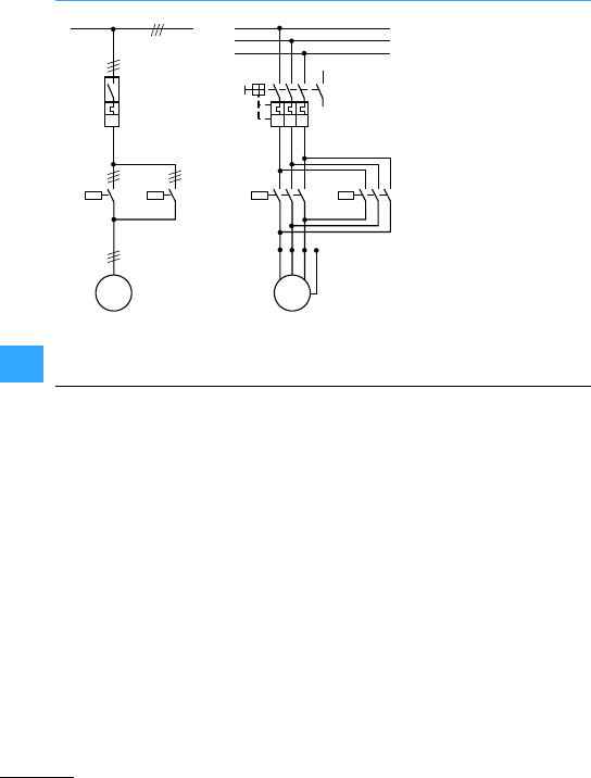
Circuit documents
EatonWiring Manual 06/11
8
Wiring diagrams show the conductive
connections between electricalapparatus.
They show the internal and/or external
connections but, in general, do not give any
information on the mode of operation.
Instead of wiring diagrams, wiring tables
can also be used.
•Unit wiring diagram. Representation of
allthe connections within the device or
combination of devices.
•Interconnection diagram.
Representation of the connections
between the device or combination of
devices within an installation.
•Terminal diagram. Representation of the
connection points of an electrical
installation and the internaland external
conductive connections connected to
them.
•Location diagram (location diagram).
Representation of the physicalposition
of the electrical apparatus, which does
not have to be to scale.
You will find notes on the marking of
electrical apparatusin the diagramas well
as further diagram details in the chapter
“Specifications, Formulae, Tables”.
Circuit diagram: 1-pole and 3-pole representation
M
3 ~
Q1
Q11 Q12
135
246
135
246
M
3 ~
UVW
PE
Q12
135
246
L1
L2
L3
13
14
Q
Q11
L1, L2, L3
I>I>I>
I>
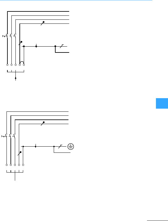
Eaton Wiring Manual 06/11
8
Power supply
aProtective earth conductor
Protective earth terminal in
enclosure (not totally insulated)
Overcurrent protective device is required in
the input wiringfor compliance to
IEC/EN 60204-1
aProtective earth conductor
Protective earth terminal in
enclosure (not totally insulated)
Overcurrent protective device is required in
the input wiringfor compliance to
IEC/EN 60204-1
L1 L2 L3 NPEN
PE
N
L31
L21
L11
N
L31
L21
L11
L1 L2 L3 NPE
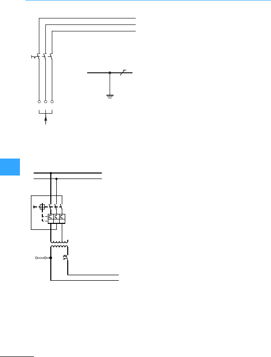
Power supply
EatonWiring Manual 06/11
8
Overcurrentprotective device is required in
the input wiringfor compliance to IEC/EN
60204-1
For all systems: use the N neutral conductor
Grounded circuit. In non-grounded circuit,
remove link and provide insulation
monitoring.
L31
L21
L11
L1 L2 L3
PE
1
L1
L3
5
2
3
6
4
I
L01
L02
0
II
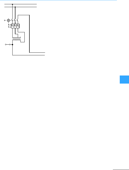
Power supply
EatonWiring Manual 06/11
8
Grounded circuit.In non-grounded circuit,
remove link and provide insulation
monitoring.
Maximum ratio of U1/U2 = 1/1.73
Circuit not to be used with STI/STZ (safety
or isolatingtransformers).
L1
L3
15
2
3
6
4
I>I>I>
L01
L02
0
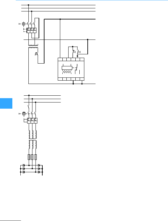
Eaton Wiring Manual 06/11
8
Control circuit supply
aClear button
bTest button
L1
L3
15
2
3
6
4
I. I. I.
L011
PE
0
L02
L01
A1
R <
A1
L15
A2
15 S1 S2 E
E
E
16
16 18
18 LA2
ab
L2
L1
L3
15
2
3
6
4
III
L2
Yy0
–+

Eaton Wiring Manual 06/11
8
Contactor markings
The contactors in contactor combinations
have, in accordance with EN 81346-2 for
apparatusand function,the code letter Q,
as well as numerical identification, which
shows the function of thedevice (e.g. Q22 =
mains contactor with anticlockwise
operation for high speed).
With contactor combinations which are
made up of several basic types, the basic
typeis always maintained. Thus, the circuit
diagram for a reversing star-delta starter,
forexample, is formed by combining the
basic circuit of the reversing contactor and
that of the standard star-delta starter.
Other marking of electrical apparatus:
•for the IEC world 7page10-2
•for North America 7page 9-14
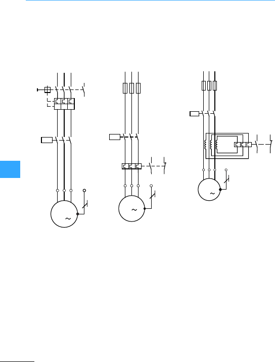
Eaton Wiring Manual 06/11
8
Direct-on-line start of three-phase motors
Short-circuit protection1) and overload
protection by means of PKZM
motor-protective circuit-breakeror NZM
circuit-breaker.
Short-circuit protection2) for contactorand
overload relay by meansof fuses F1.
Short-circuit protection3) for contactor by
means of fuses F1.
1) Protective device in the input wiring in accordance with the main catalogue,
Industrial Switchgearor IL installation instructions.
2) Fuse size in accordance with data on the rating plate of the overload relay.
3) Fuse size in accordance with the main catalogue, Industrial Switchgear
(Technical data forcontactors)
L1 L3
15
2
3
6
4
L2
13
14
15
3
26
4
-Q1
PE
UVW
-Q11
M
3
-M1
I>I>I>
L1 L3
L2
15
3
26
4
PE
UVW
-Q11
M
3
-M1
-F1
-F2
26
496
95
97
98
L1 L3
L2
15
3
26
4
PE
UVW
-Q11
M
3
-M1
-F1
-F2
96
95
97
98
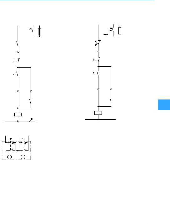
Direct-on-line start of three-phase motors
Eaton Wiring Manual 06/11
8
I: ON
0: OFF
7Section ”Three-wire control”,
page8-34
Actuation of
pushbutton I energizes the coil of
contactor Q11. The contactor switches on
the motorand maintains itself after the
button is enabled via its own auxiliary
contact Q11/14-13 and pushbutton 0
(three-wire control contact). Contactor Q11
is de-energized, in the normal course of
events, by actuation of pushbutton 0. In the
event of an overload, it is de-energized via
the normally closed contact 95-96 on the
overload relay F2. The coil current is
interrupted,and contactor Q11 switches
the motoroff.
The short-circuit strength capacity of thecontacts in the circuit
has to be considered when selecting F0.
Double pushbutton
L1
(Q11/1)
-Q1 13
14
21
22
0
-S11
13
14
13
14
-Q11
A1
A2
-Q11
N
-F0
I
L1
(Q11/1)
95
96
21
22
13
14
-F2
0
-S11
I
13
14
-Q11
A1
A2
-Q11
N
-F0
21
22
13
14
96
14
13
14
13 21
22
Q11 Q11
F2
0I
AB
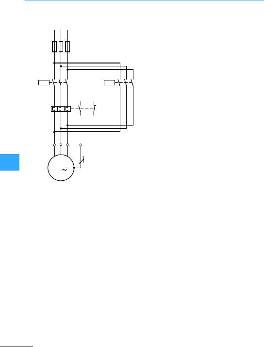
Direct-on-line start of three-phase motors
Eaton Wiring Manual 06/11
8
7Section ”Fuses with
overload relays”,page 8-30
L1 L3
26
4
L2
15
3
26
4
-F1
PE
UVW
-Q11
M
3
-M1
-F2
26
4
15
3
9698
97 95
-Q14
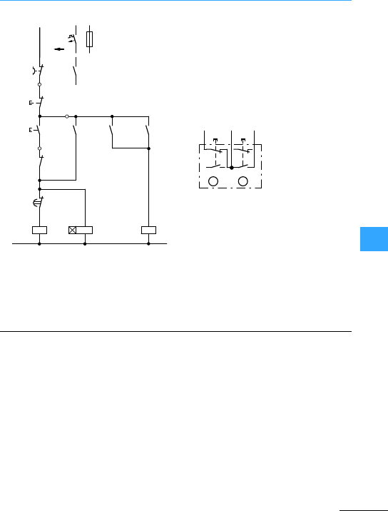
Direct-on-line start of three-phase motors
Eaton Wiring Manual 06/11
8
Actuationofpushbutton Ienergizes
bridging contactorQ14 which then
maintains itself via Q14/13-14. At thesame
time, voltage is applied to the timing relay
K1. The mains contactor Q11 is closed by
Q14/44-43 and maintains itself via
Q11/14-13. When the set time –which
corresponds to the start-up time of the
motor - has elapsed, the bridging contactor
Q14 is disconnectedby K1/16-15. K1 is
likewise disconnected and, exactly as Q14,
can only be energized again after the motor
has been switched off by pressing
pushbutton 0. TheN/C Q11/22-21 prevents
Q14 and K1 closing whilst the motor is
running. In the event of an overload,
normally closed contact 95-96 on the
overload relay F2 effects de-energization.
Q14:Bridging contactor
K1:Timing relays
Q11:Mains contactor
I: ON
0: OFF
7Section ”Three-wire control”,
page8-34
-Q11
-Q14 -Q14 -Q11
-K1
-K1
L1
(Q11/1)
-F2
95
96
21
22
0
-S11
16
15
13
14
-Q11
A1
A2
-Q14
N
-F0
13
14
-Q1
13
14
13
14 43
44
21
22
A1
A2
A1
A2
I
Q14 Q11
96 22
14
13
14
21
22
13
14
21
22
F2
0
-S11
I
AB
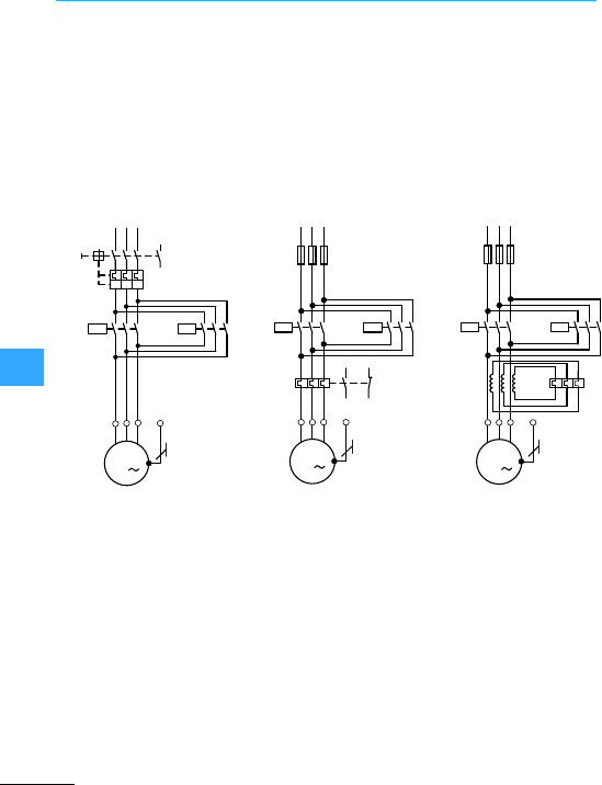
Direct-on-line start of three-phase motors
Eaton Wiring Manual 06/11
8
Short-circuitprotective device and
overload protection by means of
motor-protective circuit-breakerPKZM,
PKE or circuit-breaker NZM.
Fuse size in theinput wiring in accordance
with the main catalogue, Industrial
Switchgear or AWA installation
instructions.
Short-circuit protection1) for contactorand
overload relay by meansof fuses F1.
Short-circuit protection1) for contactor by
means of fuses F1.
1) Fuse size in accordance with data on the rating plate of the overload relay F2
L1 L3
L2
15
3
26
4
UVW
M
3
-M1
-Q1
15
3
26
4
15
3
26
4
-Q11 -Q12
13
14
PE
I>I>I>
L1 L3L2
15
3
UVW
M
3
-M1
26
4
-Q11 -Q12 15
3
26
4
26
4
-F1
-F2
PE
96
97 95
98
L1 L3
L2
UVW
M
3
-M1
26
4-Q12 15
3
26
4
-F1
PE
-F2
-Q11 15
3
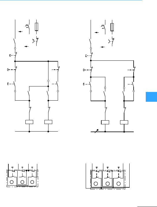
Direct-on-line start of three-phase motors
Eaton Wiring Manual 06/11
8
Changing direction of rotation actuation
of the 0 pushbutton
Changing direction of rotation
actuation of the 0 pushbutton
Q11: Mains contactor, clockwise
Q12: Mains contactor,
anticlockwise operation
(three-way
pushbutton)
I= Clockwise
0=Stop
II =anticlockwise
operation
-Q11 -Q12
-Q11
-Q11
-Q12
95
96
21
22
13
14
21
22
13
14
13
14
13
14
21
22
13
14
A1
A2
A1
A2
21
22
21
22
L1
(Q11/1)
0
-S11
-Q12
N
-F0
-Q1
I
I
II
-F2
II
-Q11 -Q12
-Q11
-Q11
-Q12
95
96
21
22
13
14
13
14
13
14
21
22
A1
A2
A1
A2
21
22
21
22
13
14
21
22
13
14
L1
(Q11/1)
0
-S11
-Q12
N
-F0
-Q1
I
I
II
-F2
II
Q12
0
-S11
I
Q12
21
22
13 14
Q11 96
F2
14
13
14
13
21
22
AB
14
13
C
21
22
13
II
Q12 Q12
Q11
13
14 Q11 96
F2 13 14
-S11
21
22
14
13
14
13
21
22
AB
14
13
C
21
22
0I II
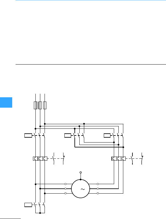
Direct-on-line start of three-phase motors
Eaton Wiring Manual 06/11
8
Actuation of
pushbutton I energizes the coil of
contactor Q11. It switches on the motor
running clockwise and maintains itself
after button Iis enables via its own
auxiliary contactQ11/14-13and pushbutton
0 (three-wire control). The normally closed
contact Q11/22-21 electrically inhibits the
closing ofcontactor Q12. When pushbutton
II is pressed, contactor Q12 closes (motor
running anticlockwise). Depending on the
circuit,direction can be changed from
clockwise to anticlockwise either after
pressing pushbutton 0, or by directly
pressing the pushbutton for the reverse
direction. In the event of an overload,
normally closed contact 95-96 of the
overload relay F2 or the normally open
contact 13-14 of the motor-protective
circuit-breaker or the circuit-breaker will
switch.
Specialcircuit (tapped winding) for feed
drives,etc.
FORWARD: feed or high-speed
RETRACT: high-speed only
STOP: tapped winding
15
3
L1 L3
L2
-F1
26
4
PE
M
3
-M1
97 95
98 96
15
3
26
4
15
3
26
4
26
426
4
26
4
15
3
-F2
97 95
98 96
-F21
-Q23
1U
1V
1W
2U
2V
2W
-Q17 -Q22 -Q21
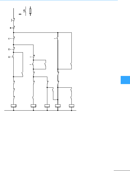
Direct-on-line start of three-phase motors
Eaton Wiring Manual 06/11
8
Forward travel is
initiated by pressing pushbutton I or II
according to the speed required.
Pushbutton I switches on thefeed motion
via Q17. Q17 maintainsitself via its N/O
13-14. If the feed movementis to occurat
high-speed star contactorQ23 is energized
via pushbutton II which energizes the high
speed contactorQ21 via its N/O Q23/13-14.
Both of the contactors are maintained via
Q21/13-14. Adirect switch over from feed
to high-speed during the process is
possible.
High-speed reverse is initiated by
pushbutton III. Contactor relay K1 picks up
and energizes starcontactorQ23 via
K1/14-13.High-speed contactor Q22 is
energized via normally open contacts
K1/43-44 and Q23/44-43, and is maintained
via Q22/14-13. The reverse motion can only
be stopped via pushbutton 0. Direct
changeover/reversalis not possible.
0: Stop
I:Low speed –FORWARD
(Q17)
II: High speed –
FORWARD (Q21 + Q23)
III:High speed –BACK
(Q22 + Q23)
Q17: Feed forward
Q21: High-speed forward
Q23: Starcontactor
K1: Contactor relay
Q22: Retract high-speed
L1
(Q17/1)
-F2/F21
95
96
21
22
0
-S11
13
14
A1
A2
N
-F0
13
14
44
21
22
III
21
22
13
14
22
21
I
13
I
II
14
21
-Q22
-Q21
-Q23
-Q17 -Q21
-Q23
31
32
-Q17 -Q17
-Q22
-Q23
A1
A2
22
21
A1
A2
13
14
-Q17
22
21
-K1 -Q21
-K1
-K1
13
14
A1
A2 -Q22
-Q23
-K1
A1
A2
43
43
44
31
32
31
32
21
22
-Q21
13
14 -Q22 13
14
21
22
III
22
II
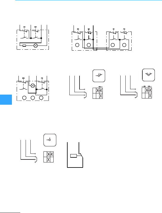
Eaton Wiring Manual 06/11
8
Control circuit devices for direct-on-line start
Illuminated pushbutton
actuators
Two double actuator pushbuttons
Double actuator
pushbutton with indicator
light
T0-1-15511 spring-return
switchwith automatic return
to position 1
T0-1-15366 spring-return
switchwithautomatic return
to position of rest
Changeover switch
T0-1-15521 with fleeting
contactin the intermediate
position
MCS pressure switches
0I
Q11
21
13
14 Q11
96
F2
13
14
Q11
A2
13
14
21
22
22
X1 X2
0I
Q11 13
14
Q11
96
F2
13
14
21
22
-S11
I0
-S11
13
14
21
22
21
22
21
22
13
14
13
14
ABB
A
0
Q11
13
14 Q11
96
F2
13
14
21
22
I
21
22
13
14
ABC
Q11
A2
0
Q11 13
14 Q11 96
F2
1
0
1
2
1
3
4
S11
Start
Start
Q11 13
14 Q11 96
F2 01
2
1
3
4
I
01
I
S11
Start
Q11 13
14 Q11 96
F2
2
1
3
4
I ON
0
OFF
01
S11
Q11
A1 F2
96
-S12
2
1
4
I
P>
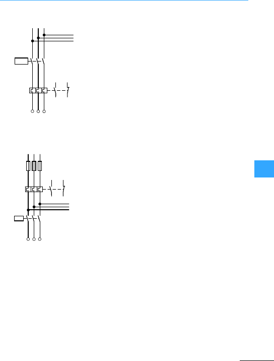
Eaton Wiring Manual 06/11
8
Star-delta switching of three-phase motors
In a standard circuit configuration, the
star-delta switch with overload relay, i.e. a
thermally delayed overcurrent relay, is
installed in the cables leading to the motor
terminals U1, V1, W1 or V2, W2,U2. The
overload relay can also be operated in a
star circuit as it is usually connected in
series with themotor winding and the relay
current flowing through it = rated motor
current x 0.58.
The complete circuit diagram 7Section
”Automatic star-delta switches SDAINL”,
page 8-37.
Instead of the arrangement in the motor
line, the overload relay can be placed in the
. The sectionshown here
indicates how the circuit diagram differs
from that on 7Section ”Automatic
star-delta switches SDAINL”,page 8-37.
For drives where the F2 relay trips out when
the motor is starting in the starconnection,
theF2 relay rated for the
.
The tripping delay is thus increased by
approximately fourto six times. In the star
connection, the currentalso flows through
the relay but here the relay does not offer
full protection since its limit current is
increased to 1.73 times the phase current.
It does, however, offer protection against
non-starting.
15
3
U1 V1 W1
26
4
-Q11
26
4
-F2 96
97 95
98
26
4
-Q11
-F2
96
97 95
98
-F1
26
4
15
3
U1 V1 W1
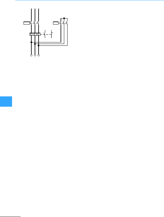
Star-delta switching of three-phase motors
EatonWiring Manual 06/11
8
Instead of the arrangement in the motor line
or mains supply line, the overload relay can
be placed in the delta connection. The
cutout shown here indicatesthe modified
circuitdiagram from 7Section
”Automatic star-delta switches SDAINL”,
page 8-37. When heavy, long-starting
procedures are involved (e.g.for
centrifuges) theF0.58 relay, ratedfor relay
current = rated motorcurrentx2, can also
be connected in the connecting cables
between the delta contactor Q15 and the
star contactor Q13. In the starconnection
no currentthen flows through the F2 relay.
The motoris therefore not protected when
starting. This connection is always used
when exceptionally heavy and long starting
procedures are involved andwhen
saturable core current transformer-
operated relays react too quickly.
26
4
-Q15
-F2 96
97 95
98
26
4
15
3
U2
W2
V2
-Q13 15
3
26
4
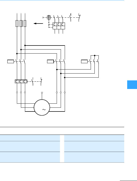
Star-delta switching of three-phase motors
EatonWiring Manual 06/11
8
Q11, Q15 =0.58x Ie
Q13 =0.33 x Ie
Position A Position B
F2 = 0.58 x Ie
with F1 in position B ta#15 s
Q1 = Ie
ta> 15 –40 s
Motor protection in 8- and
A-configuration
Only partial motorprotection in
8-configuration
M
3
-M1
U1
V1
W1
W2
U2
V2
L1 L3
L2
26
4
-Q15
-F2
96
97 95
98
26
4
15
3
-Q13
15
3
-F1
15
3
26
4
15
3
26
4
-Q11
B
-Q1
A
PE
26
4
13
14
21
22
I>I>I>
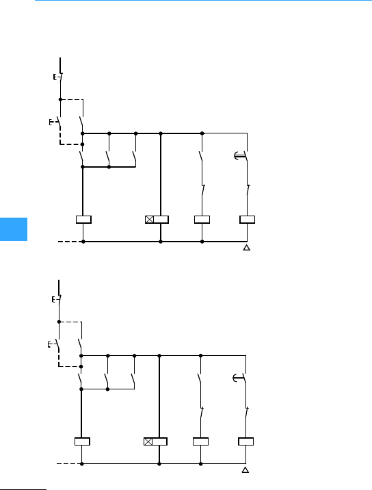
Star-delta switching of three-phase motors
EatonWiring Manual 06/11
8
Furthernotes on the configuration of the
overload relay 7Section ”Automatic
star-delta switches SDAINL”, page 8-37
K1:Timing relay
approx. 10 s
Q11: Mains contactor
Q13: Star contactor
Q15: Delta contactor
Double pushbutton
Pushbutton I energizes
timing relay K1. The
normally open contact
K1/17-18 (instantaneous
contact) which applies
voltage to starcontactor
Q13, which closes and
appliesvoltage to mains
contactor Q11 via normally
open contactQ13/14-13.
Q11 and Q13 maintain
themselvesvia the N/O
Q11/14-13 and Q11/44-43.
Q11 applies mains voltage
to motor M1 in star
connection.
S11
0
(–)N
Q11
Q13
Q13
Q15
K1
I
Q11
Q11
Q15
Q13
K1
Q15
NY
K1
21
22
13
14
A2
A1
A2
A1
53
54
22
21
28
17
17
18
14
13
53
54
53
54
A2
A1
A2
A1
22
21
S11
0
(–)N
Q11
Q13
Q13
Q15
K1
I
Q11
Q11
Q15
Q13
K1
Q15
NY
K1
21
22
13
14
A2
A1
A2
A1
13
14
22
21
28
17
17
18
14
13
13
14
43
44
A2
A1
A2
A1
22
21
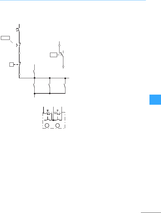
Star-delta switching of three-phase motors
EatonWiring Manual 06/11
8
Double pushbutton
I = ON
0 = OFF
7Section ”Control circuit
devices forstar-delta starting”, page8-45
When the set changeovertime has
elapsed, K1/17-18 opens the circuit of Q13
and after 50 ms closes the circuit of Q15 via
K1/17-28. Star contactor Q13 drops out.
Delta contactor Q15 closes and switches
motor M1 to full mainsvoltage. At the same
time,normally closed contact Q15/22-21
interrupts the circuit of Q13thus
interlocking against renewed switching on
while the motor is running.
The motorcannot start up again unless it
has previously been disconnected by
pushbutton 0, or in the event of an overload
by thenormally closed contact 95-96 of
overload relay F2,or via normally open
contact 13-14 of the motor-protective
circuit-breaker or standard
circuit-breaker.
44
2
43 13
14
L1
(Q11/1)
-F0
95
96
-F2
13
14
13
14
-S14
-Q11 -Q13 -Q15
-Q11
-S14
MCS
P>
2
4
1
SW
Q1
Q11
21
22
13
14 Q11
96
F2
0I
14
13
14
13 21
22
AB
-S11
HAND
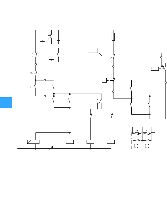
Star-delta switching of three-phase motors
EatonWiring Manual 06/11
8
Pushbutton actuators Maintained contact sensors
K1:Timing relay approx. 10 s
Q11: Mains contactor
Q13: Star contactor
Q15: Delta contactor
Double pushbutton
I= ON
0 = OFF
L1
(Q11/1)
-F2
95
96
0
-S11
13
14
A1
A2
N
-F0
44
21
22
2
13
14
I
-Q11
-Q15
-K1 A1
A2
A1
A2
A1
A2
-Q15
-Q13
43
44
43
-Q11 -Q13
-F0
95
96
-F2
13
14
-S14
13
14
13
14
-Q1
-Q11
14
13
22
21
-Q13
-Q11
-S14
MCS
24
1
SW
Q
-K1
22
21
16
15
18 -Q13
1
L1
(Q11/1)
Q11
21
22
44
14 Q11
96
F2
0I
14
13
14
13 21
22
AB
-S11
-Q11
P>
HAND

Star-delta switching of three-phase motors
EatonWiring Manual 06/11
8
7Section ”Control circuit
devices for star-delta starting”, page8-45
Pushbutton I energizes star contactor Q13,
the normally open contact Q13/14-13
applies voltage to mains contactorQ11.
Q11 closesand applies mains voltage to
motor M1 in star connection. Q11 and Q13
maintain themselves via normally open
contactQ11/14-13 and Q11 additionally via
Q11/44-43 and pushbutton 0. Timing relay
Q11 is energized at the same time as mains
contactor K1. When the set changeover
time haselapsed, K1 opens the circuit of
Q13 via the changeover contact 15-16 and
closes the circuit of Q15 via 15-18.
Delta contactor Q15 closes and switches
motor M1 to full mainsvoltage. At the same
time,normally closed contactQ15/22-21
interruptsthe circuit of Q13thus
interlocking against renewed switching on
while the motor is running.
The motorcannot be started up again
unless it has previouslybeen disconnected
by pushbutton 0, or in the event of an
overload,by the normally closed contact
95-96 of the overload relay F2, or viathe
normally open contact 13-14 of the
motor-protective circuit-breakeror
circuit-breaker.
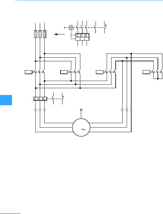
Star-delta switching of three-phase motors
EatonWiring Manual 06/11
8
2 operating directions
Q11, Q12: Ie
F2, Q15: 0.58 x Ie
Q13:0.33 x Ie
The maximum motoroutput is limited by the
upstream reversing contactor, and is lower
than with automaticstar-delta switches for
only one direction of operating direction.
Standard version: Relay current = motor
rated operational current x 0.58
For other arrangements of overload relay
7Section ”Star-delta switch with
overload relay”, page 8-35
M
3
-M1
U1
V1
W1
W2
U2
V2
L1 L3
L2
26
4
-Q12
-F2
96
97 95
98
26
4
-Q15
15
3
-F1
15
3
26
4
15
3
26
4
-Q11
-Q1
PE
26
4
13
1 3 5
14
21
22
-Q13
15
3
26
4
I>I>I>
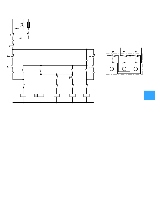
Star-delta switching of three-phase motors
EatonWiring Manual 06/11
8
Changing direction of rotation after actuation of the 0
pushbutton Three-way pushbutton
I = clockwise
0 = Stop
II = anticlockwise
operation
L1
(Q11/1)
-F2
0
-S11
A1
A2
N
-F0
44
13
14
II
-Q11 -K1
A1
A2 -Q15
-Q13
43
44
43
-Q11
-Q1
-Q11
-Q11
I
21
22
95
96
21
22
-Q12
13
14
13
14 -Q12
-K1-K1
-Q12 13
14
13
14
II
I21
22
21
22
A1
A2
-Q15 -Q13
21
22
-Q12
A1
A2
A1
A2
21
22
21
22
18
17
28
17
0
Q12
13 14
Q11 96
F2
13
14
21
22
I
13
14
ABC
13
Q12
II
13
14
21
22
21
22
-S11
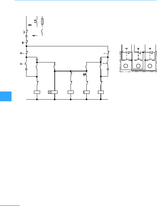
Star-delta switching of three-phase motors
EatonWiring Manual 06/11
8
7Section ”Control circuit devices for
star-delta starting”, page8-45
Pushbutton I energizes contactorQ11
(e.g.clockwise). Pushbutton II energizes
contactor Q12 (e.g. anticlockwise
operation). The contactor first energized
applies voltage to the motor winding and
maintains itself via its own auxiliary
contact14-13 and pushbutton 0. The
normally open contact 44-43 fittedto each
mains contactor energizes the star
contactor Q13. Q13 energizes and switches
on motor M1 in the star connection. At the
same time, timing relay K1 is triggered.
When the set changeovertime has
elapsed, K1/17-18 opens the circuit of Q13.
Q13 drops out. K1/17-28 closes the circuit
of Q15.
Delta contactor Q15 energizes and
switches motor M1 to the delta
configuration, i.e. full mains voltage.At the
same time,normally closed contact
Q15/22-21 interrupts thecircuit of Q13, thus
interlocking against renewed switching on
while the motor is running. Motordirection
can be changed,either after pressing
pushbutton 0, or by directactuation of the
reverse button, depending upon the circuit.
In the event of an overload, disconnection
is effected by the normally closed contact
95-96 of the overload relay F2.
Changing direction of rotation without actuation of the 0
Three-way pushbutton
I = clockwise
0=Stop
II =anticlockwise
operation
L1
(Q11/1)
-F2
0
-S11
A1
A2
N
-F0
44
13
14
II
-Q11 -K1
A1
A2 -Q15
-Q13
43
44
43
-Q11
18
17
-Q1
-Q11
-K1
-Q11
I
21
22
95
96
21
22
-Q12
13
14
13
14 -Q12 -Q12 13
14
13
14
II
I21
22
21
22
A1
A2
-K1
-Q15 -Q13
21
22
-Q12
A1
A2
A1
A2
21
22
21
22
28
17
21
22
13 14 96
14
13
14
13
Q11
Q11 F2
0
I
AB
13
Q12
14
Q12
II
-S11
21
22
21
22
14
13
C
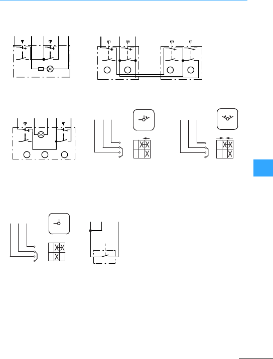
Eaton Wiring Manual 06/11
8
Control circuit devices for star-delta starting
Illuminated pushbutton
actuators
Two double actuatorpushbuttons
Double actuatorpushbutton
with indicatorlight
Spring-return switch
T0-1-15511 with automatic
return to position 1.
Spring-return switch
T0-1-15366 with automatic
return to position of rest.
Changeover switch
T0-1-15521 with fleeting
contactin the intermediate
position
e.g. selector switch
Cam switchT
LS position switches
MCS pressure switches
F2 Q11Q11 Q11 Q11
21
2213
14
13
14 21
22
96 13
X1 X2
14
-S11
44 A2
0I
F2
-S11 -S11
2113
14
13
14
13
14
13
14
22
21
22
21
22
21
22
0
ABAB
I0I
96
Q11
14
Q11
44
22
96 13
13 21
14
13
14
21
22
A2 14 44
F2
-S11
Q11 Q11 Q11 Q11
AB C
1
0
Q11 13
14 Q11 96
F2
1
0
1
2
1
3
4
S11
Start
Start
Q11 13
14 Q11 96
F2 01
2
1
3
4
I
01
I
S11
Start
Q11 13
14 Q11 96
F2
2
1
3
4
I ON
0
OFF
01
S11
Q11
14 Q11
44 F2
S14
96
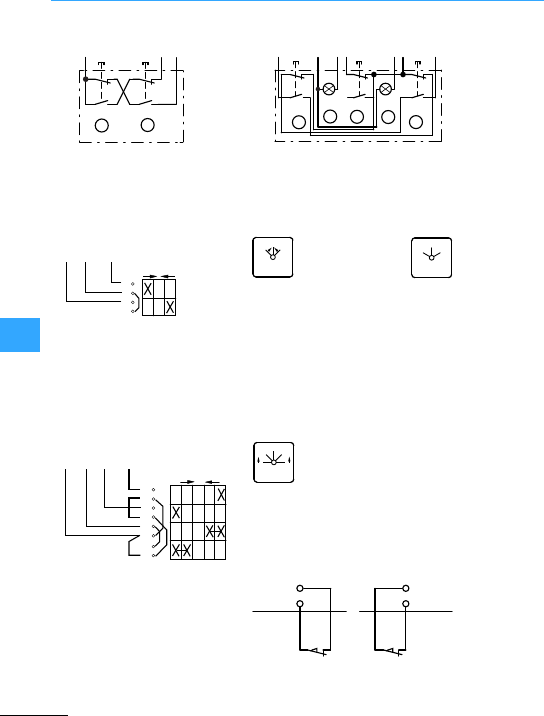
Control circuit devices for star-delta starting
EatonWiring Manual 06/11
8
Two-way pushbutton1) without
self-maintaining circuit (inching)
foruse only with reversing
contactors
Three-way pushbutton with indicator light. Reversing
afteractuation of pushbutton 0
Spring-return switch1)
T0-1-8214, without
self-maintaining circuit
(inching)
automatic return to off
position only for reversing
contactors
Changeoverswitch1)
Switch T0-1-8210
remains in position 1or 2
Spring-return switch
T0-2-8177 with automatic
return to position 1 or 2
Limit switch
Connectedby removingthe links
between the contactor terminals
Q11/13 and Q12/22 and between
Q12/13 and Q11/22 and
interposing the position switches.
1) Overload relays always with reclosing lockout
-S11
22
21
14
13
22
21
14
13
III
B
A
13
Q12 13
Q11
96
F2 13
-S11
22
21
14
13
22
21
14
13
22
21
14
13
I
A
BDE
C
Q11 A2 21 96
Q12 21 II
Q11 14
Q12 13
Q12F2 0
2
3
4
0
12
1
Q12
13
F2
96
Q11
13
FS 4011
0
12
FS 684
0
12
2
1
2
3
4
5
6
01 START
START
7
8
Q11F2
96 13
Q12
13
Q12
14
FS 140660
0
12
STARTSTART
Q11/13
Q12/22
Q12/13
Q11/22

Eaton Wiring Manual 06/11
8
Pole-changing motors
The speed is determined by the numberof
poleson three-phase asynchronous
motors. Several speeds can be obtained by
altering the numberof poles.
The usual types are:
The various tappedwinding configurations
give differential output ratiosfor the two
speeds.
The A/-connection comes nearest to
satisfying the most usualrequirement for
constant torque.It has the additional
advantage that, because nine terminals
are available, y/d starting can be used to
provide smooth starting or to reduce the
starting current for the low speed condition
(7Section ”Motor windings”,
page8-50).
The 8/8 8-connection preferred for
bettermatching of the motor to machines
in whichthe torque increases by a
quadratic factor (pumps, fans, rotary
compressors). All multi-speed switches
can be used for both types of connection.
In theory, motors with separate windings
allow any combination of speed and any
output ratio. Both windings are arranged in
y connection and are completely
independent of one another.
Preferredspeed combinations are:
The code numbers are prefixed to the main
notations to denote increasing speed.
Example: 1U, 1V, 1W, 2U, 2V, 2W
Comparable to EN 60034-8
two speeds 1:2 1 convertible tapped winding
2speeds as required 2 separate windings
three speeds 1 convertible tapped winding 1:2,
aseparate winding
four speeds 2 convertible tapped windings 1:2
two speeds Tapped winding
Type of connectionA/88 8/88
Output ratio 1/1.5–1.8 0.3/1
Motors with tapped
winding
1500/3000 –750/1500 500/1000
Motors with separate
windings
–1000/1500 – –
No. of poles 4/2 6/4 8/4 12/6
Code no. low/high 1/2 1/2 1/2 1/2
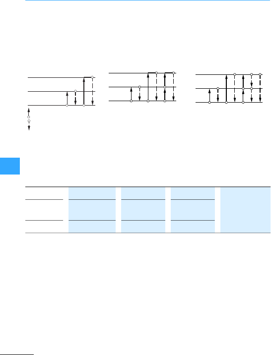
Pole-changing motors
Eaton Wiring Manual 06/11
8
The 1:2 -speeds tapped windings are
supplemented by the speed of the separate
winding. This speed can be below,
between or above the two tapped winding
speeds. The connection must consider it
(7Figure, page 8-78).
Preferred speed combinations are:
Selection of low and high
speed only from zero. No
return to low speed, only to
zero.
Selection of either speed
from zero. Switching from
low to high speed possible.
Return only to zero.
Selection of either speed
from zero. Switching back
and forward between low
andhighspeed (high braking
torque). Return also to zero.
High speed
Low speed
Off (zero)
Switch-on and further switching
Switch-off
Speeds 1000/1500/3000 750/1000/1500 750/1500/3000 = separate
winding (inthe
circuit
diagrams)
No. of
poles
6/4/2 8/6/4 8/4/2
Connection X Y Z
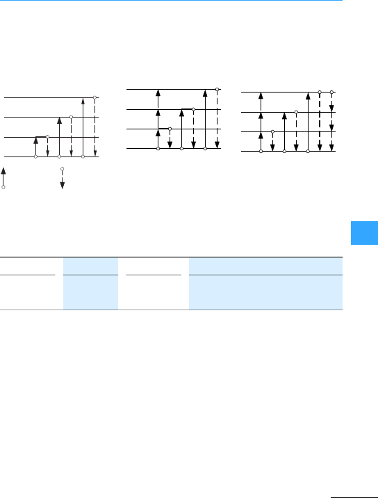
Pole-changing motors
Eaton Wiring Manual 06/11
8
The 1:2-speeds tapped windings can follow
in sequence or overlap, as the following
examples show:
For motorshaving 3 or 4 speeds the
non-connected winding hasto be opened
at certain pole ratios to avoid inductive
circulating currents. This is achievedvia
additionalmotorterminals. A series of cam
switches is equipped with this connection
(7Section ”Multi-Speed Switches”,
page4-7).
Selection of any speed only
from zero. Return only to zero.
Selection of any speed from
zero and from low speed.
Returnonly to zero.
Selection ofany speed from
zero and from low speed.
Return to low speed (high
braking torque) or to zero.
3rd speed
2nd speed
1st speed
Off (zero)
Switch-on and
further switching
Switch-off
1st winding
500/10002nd winding 1500/3000 = 500/1000/1500/3000
or
1st winding 500/10002nd winding 750/1500 = 500/750/1000/1500
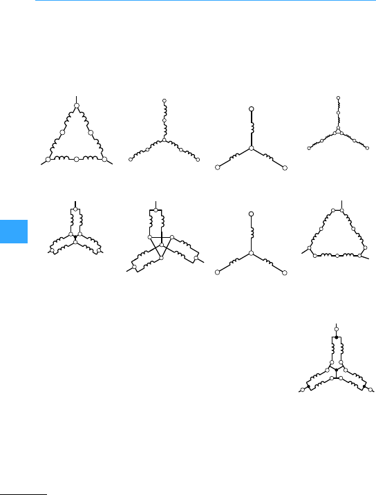
Eaton Wiring Manual 06/11
8
Motor windings
2 speeds
2 speeds
2 separate windings
with 8--starting at
low speed
Low speed-Low speed 8Low speed Low speed 8
High speed High speed High speed Low speed -
7Figure,
page 8-55
7Figure, page8-55 7Figure, page 8-59
High speed
7Figure, page8-68
1U
1W 1V
2W
2V
2U
1U
1W 1V
2W
2V
2U
1W 1V
1U
1U
1W 1V
2W1
2U2
2V1
2V2
2U12W2
1U
2U
1V
1W
2W 2V
1U
2U
1W
2V
1V
2W
2W 2V
2U
1V
1W
2W2
1U
2V1
2V2
2U2
2W1
2U1
1U 2V2
2U1
1V
1W
2W1 2V1
2W2
2U2
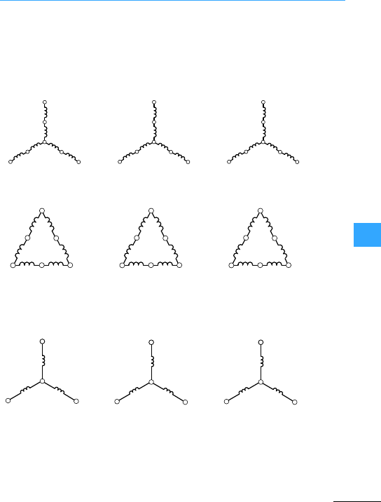
Motor windings
EatonWiring Manual 06/11
8
3 speeds
2 windings, medium and
high speed–tapped
winding
2 windings, low and high
speed –tapped winding
2 windings,low and
medium speed –tapped
winding
222
or 2or2or 2
Low speed
Separate winding
1
Medium speed
Separate winding
1
High speed
Separate winding
1
7Figure, page 8-77 7Figure, page 8-79 7Figure, page 8-81
2U
2W 2V
3W
3V
3U
1U
1W 1V
3W
3V
3U
1U
1W 1V
2W
2V
2U
2U
2W 2V
3W
3V
3U
1U
1W 1V
3W
3V
3U
1U
1W 1V
2W
2V
2U
1W 1V
1U
2W 2V
2U
3W 3V
3U

EatonWiring Manual 06/11
8
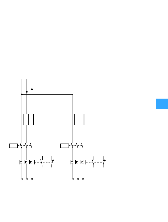
Eaton Wiring Manual 06/11
8
Multi-speed contactors
Certain operating sequences for
pole-changing motors may be necessary,
or undesirable,depending on the nature of
the drive.If, for example, the starting
temperature rise is to be reduced or high
inertia loads are to be accelerated, it is
advisable to switch to low speed first and
then to high speed.
It may be necessary to prevent switching
from high to low speed in order to avoid
oversynchronous braking.In other cases, it
should be possible to switch each speed
on and off directly. The operating
sequence and indexing facilities of cam
switches allow for these possibilities.
Multi-speed contactor switches can
achieve these connecting by interlocking
with suitable control circuitdevices.
When a common fuse is used in the input
wiring, it must not be largerthan the
back-up fuses specified on the nameplate
of either overload relay, otherwise each
relay must be protected by its own back-up
fuse,as shown in the diagram.
L1
-F11
-Q17 -Q21
-F21 -F2
135
246
24 6
135
246
246
97
98
95
96
L2 L3
97
98
95
96
-F1
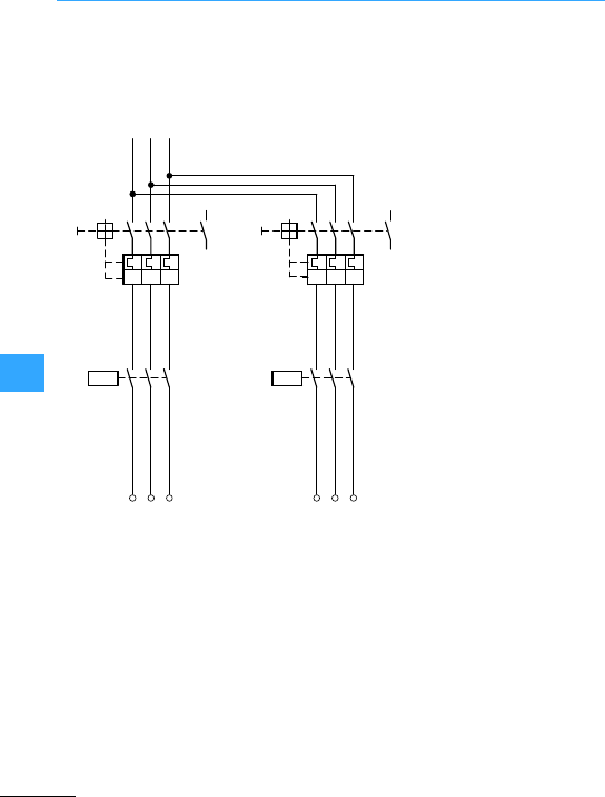
Multi-speed contactors
EatonWiring Manual 06/11
8
Pole-changing motors can be protected
againstshort-circuits and overloads by
motor-protectivecircuit-breakersPKZ/PKE
or circuit-breakers NZM. These provide all
the advantages of a fuseless circuit.
Normally, the fuse in input wiring protects
the switches fromwelding.
L1
-Q1
-Q17 -Q21
1
I>I>I>
35
13 5
24 6
13 5
24 6
24 6
13
14
L2 L3
-Q2
1
I>I>I>
35
24 6
13
14
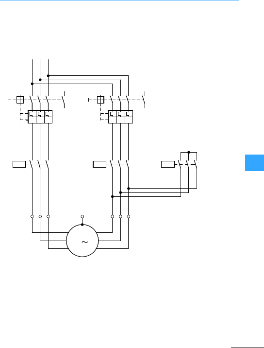
Eaton Wiring Manual 06/11
8
Multi-speed switch for three-phase motors
, without overload relay, with
motor-protective circuit-breakeror
circuit-breaker.
7Section ”Motorwindings”,page 8-50
Synchronous speeds
One multi-speed winding
L1
-Q1
-Q21 -Q17
PE
M
-M1
2U
2V
2W
1U
1V
1W
3
1
I>I>I>
35
13 5
24 6
13 5
24 6
-Q23
13 5
24 6
24 6
13
14
L2 L3
-Q2
1
I>I>I>
35 13
14

Multi-speed switch for three-phase motors
EatonWiring Manual 06/11
8
Rating of switchgear
Q2, Q17: I1(low speed)
Q1, Q21: I2(high speed)
Q23: 0.5 x I2
Motor terminals 1U, 1V, 1W 2U, 2V, 2W
Amount of poles 12 6
rpm 500 1000
Amount of poles 8 4
rpm 750 1500
Amount of poles 4 2
rpm 1500 3000
Contactors Q17 Q21, Q23
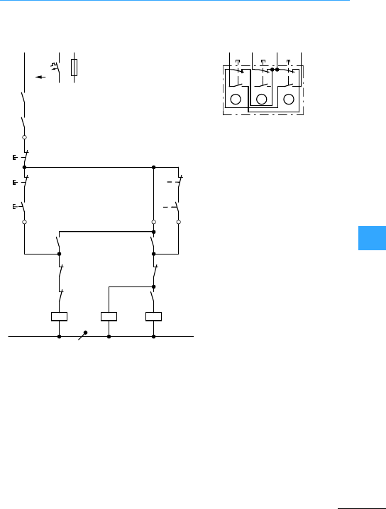
Multi-speed switch for three-phase motors
EatonWiring Manual 06/11
8
1 three-way pushbutton
7Figure, page 8-63, 7Figure,
page 8-64, 7Figure, page 8-65
Pushbutton I energizes mains contactor
Q17 (low speed). Q17 maintains itself viaits
N/O 13-14. Pushbutton II energizes star
contactor Q23 and viaitsN/O13-14 mains
contactor Q21. Q21 and Q23 maintain
themselves via N/O 13-14 of Q21.
Speed can be changed either after
pressing pushbutton 0 (connection A) or
directly by pressing the appropriate
pushbutton (connection C),depending
upon the circuit. The motor can be
switched off either by pressing pushbutton
0, or in the event of an overload, by N/O
13-14 of the circuit-breaker.
Three-way pushbutton
I: Low speed (Q17)
0: Stop
II: high speed (Q21 + Q23)
Q17: Mains contactor, low speed
Q23: Star contactor
Q21: Mains contactor, high speed
L1
(Q11/1)
-F0
-Q1
-Q2
0
II
-S11
-Q17
-Q17 -Q23
N
-Q23
-Q21
I
13
14
13
14
21
22
21
22
14
13
14
13
21
22
22
21
A1
A2
A1
A2
-Q21
-Q17
-Q23
-Q21
22
21
13
14
A1
14
II
I
22
14
13
21
13
A2
-S11
14 1313 III
0
A
BC
96
21
22
13
14
21
22
13
14
21
22
13
14
Q17 F21 Q21 Q21
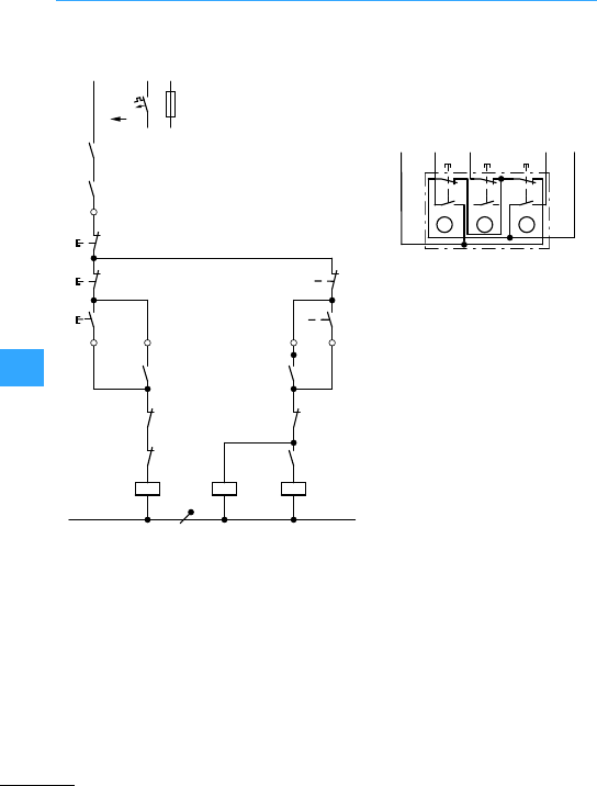
Multi-speed switch for three-phase motors
EatonWiring Manual 06/11
8
1 three-way pushbutton
7Figure, page 8-66
Three-way pushbutton
I: Low speed (Q17)
0: Stop
II: High speed (Q21 + Q23)
Q17:Mains contactor, low speed
Q23: Star contactor
Q21: Mains contactor, high speed
L1
(Q11/1)
-F0
-Q1
-Q2
0
II
-S11
-Q17
-Q17 -Q23
N
-Q23
-Q21
I
13
14
13
14
21
22
21
22
14
13
14
13
22
21
21
22
A1
A2
A1
A2
-Q21
-Q23
-Q17
-Q21
22
21
13
14
A1
14
II
I
22
14
13
21
13
A2
14
-S11
Q17
14
Q21
13
Q21
13 III
0
A
BC
Q17
96
F21
21
22
13
14
21
22
13
14
21
22
13
14
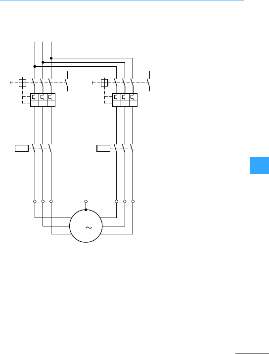
Multi-speed switch for three-phase motors
EatonWiring Manual 06/11
8
Multi-speed contactor ,fuseless without
overload relay
Rating of switchgear
Q1, Q17 = I1(low speed)
Q2, Q21 = I2(highspeed)
Motor windings 7Section ”Motor
windings”, page 8-50
L1
-Q1
-Q17 -Q21
PE
M
-M1
1U
1V
1W
2U
2V
2W
3
1
I>I>I>
35
13 5
24 6
13 5
24 6
24 6
13
14
L2 L3
-Q2
1
I>I>I>
35
24 6
13
14
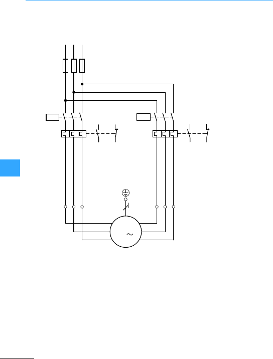
Multi-speed switch for three-phase motors
EatonWiring Manual 06/11
8
Multi-speed contactor with fuses and
overload relay
Fuse size in accordance with data on the
nameplate of the overload relays F2 and
F21. If overload relays F2 and F21 cannot be
protected by a common fuse, then use
connection 7Figure, page 8-53.
Motor windings 7Section ”Motor
windings”, page 8-50
L1
F1
F1
F21 F2
M1
1W
1V
1U
2W
2V
2U
Q17Q21
135
246
9698
9597
9698
9597
246
135
246
246
L2 L3
M
3
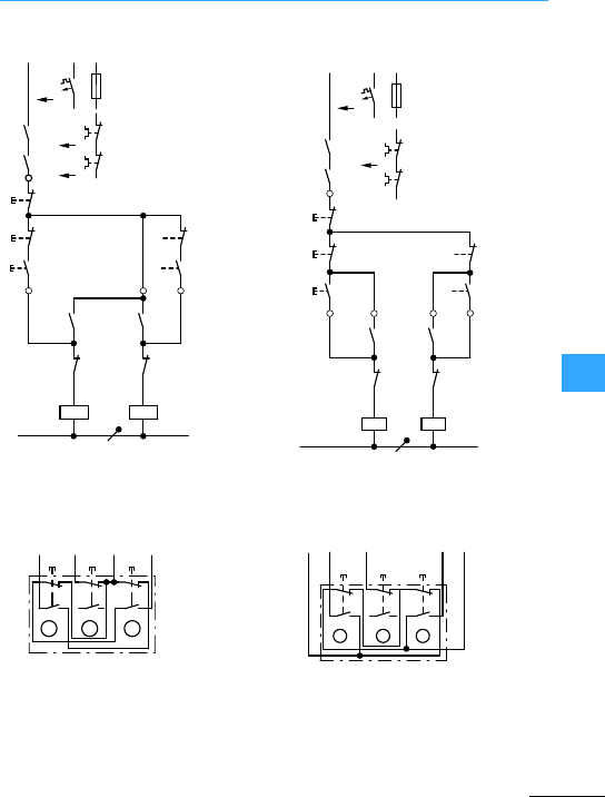
Multi-speed switch for three-phase motors
EatonWiring Manual 06/11
8
Connection A (7Figure, page 8-49)
1 three-way pushbutton
ConnectionC (7Figure, page 8-49)
1 three-way pushbutton
Q17: Mains contactor, low speed
Q21: Mains contactor, high speed
Three-way pushbutton
I: Low speed (Q17)
0: Stop
II:High speed (Q21 + Q23)
7Figure, page 8-67
L1
FO
F2
F21
Q1
13
14
13
21
22
21
22
14
13
14
13
22
21
A1
A2
A1
13
14
14
13
21
22
95
96
95
96
21
A2
14
Q2
0
S11
Q17
Q21 Q17
Q21
I
II
Q17 Q21
N
II
I
22
L1
(Q17/1)
-F0
0
-S11
A1
A2
A1
A2
II
III
22
21
-Q21
22
21
95
96
22
21
22
21
14
13
-Q21
-Q17
-Q21
-Q17
14
13
N
-F21
-F2
FL1
14
13
14
13
-Q1
-Q2
95
96
14
13
-Q17
22
21
14
13
I
-S11
14
Q21
13
Q21
13 III
0
A
BC
Q17
96
F21
21
22
13
14
21
22
13
14
21
22
13
14
13
14
21
22
-S11
A
Q21
13
Q21
14
Q17
14
I0II
F21
96
Q17
13
BC
21
22
13
14
21
22
13
14

Multi-speed switch for three-phase motors
EatonWiring Manual 06/11
8
Actuation of pushbutton Ienergizes the
coil of contactorQ17. Q17 switches on the
low speed of the motor and after
pushbutton I is released, maintains itself
via itsauxiliary contact 13-14 and
pushbutton 0.
Speed can be changed either after
pressing pushbutton 0, or directlyby
pressing the appropriate pushbutton,
depending upon the connection. The motor
is switched off either by pressing
pushbutton 0, or in the event of an
overload,by normallyclosed contact 95-96
of overload relays F2 and F21.
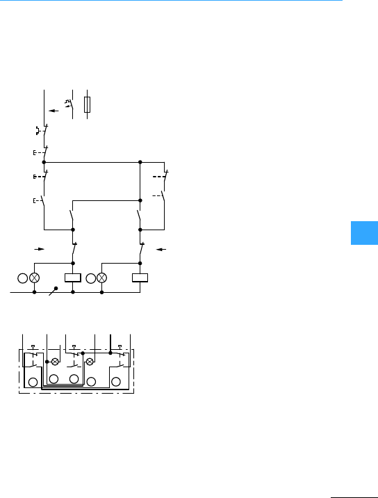
Eaton Wiring Manual 06/11
8
Control circuit devices for multi-speed contactors
(7Figure, page8-49)
One three-way pushbutton with indicator
lights
I:Low speed (Q17)
0: Stop
II :High speed (Q21)
-F0
L1
0
A1
A2
A1
A2
II
I
22
21
-Q21
22
21
22
21
14
13
-Q21
-Q17
-Q21
14
13
N
95
96
14
13
-Q17
14
13
I
-Q17
22
21
II
-F2/F21
22
21
A
BD
B
-S11
I021 II
13
ABCD E
21
21
13
22
22
22
14
13
21
13
14
14
Q17 A2
Q21 21
Q17 14
Q21 13
Q21
96
F21
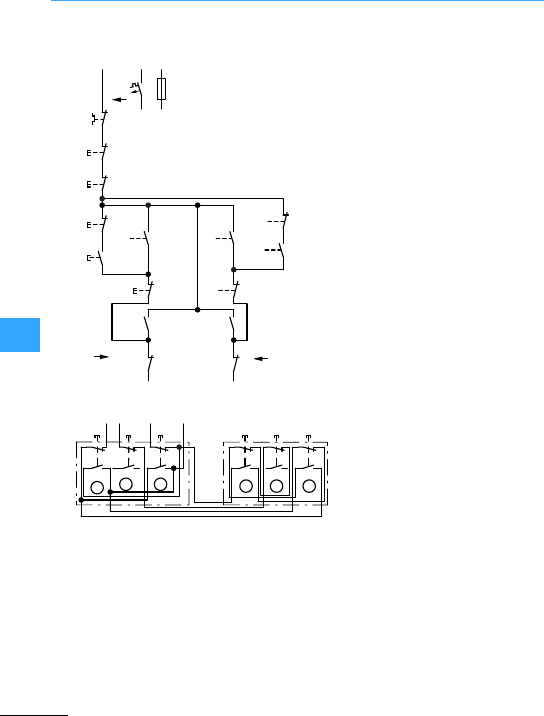
Control circuit devices for multi-speed contactors
EatonWiring Manual 06/11
8
(7Figure, page8-49)
2 three-way pushbuttons
I: Low speed(Q17)
0: Stop
II:High speed (Q21)
Remove existing linksand rewire
-F0
L1
95
21
22
21
22
21
22
22
21
22
21
21
14
13
14
13
22
21
13
14
13
14
22
22
21
13
14
13
14
96
-F2/F21
0a
0b
IIb
Ib
IIa
IIb
IIa
-Q17
-Q21
-Q21
-Q17
AB
Ia
Ib
Ia
13
A
96
BCBA C
-S11 -S11
Ia
21
22
14
13
14
13
14
13
21
22
21
22
21
22
14
13
14
13
14
13
21
22
21
22
IIa0a Ib IIb0b
Q21
13
Q17
14
Q21F21
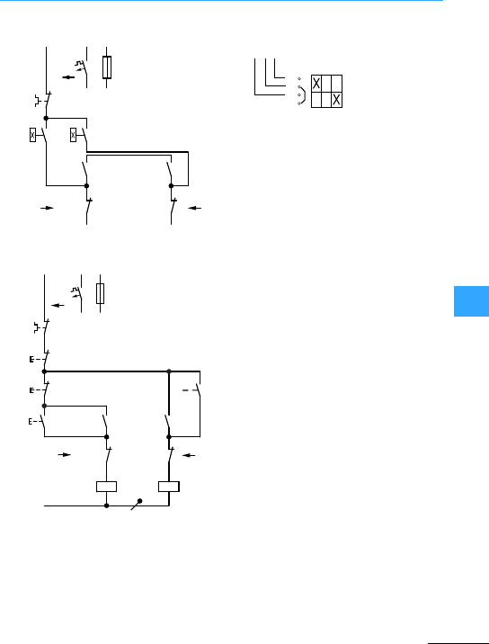
Control circuit devices for multi-speed contactors
EatonWiring Manual 06/11
8
(7Figure, page 8-49)T0-1-8210 changeoverswitch
Always set overload relay to manualreset
(7Figure, page 8-49)
1 three-way pushbutton
L1
95
96
-F2/F21
-S12
-Q17
-Q21 -Q17
-Q21
-S12
AB
1
2
13
14
13
22
14
13
21
22
21
24
-F0
S12
Q21
13
F2
96
Q17
13
102
1
2
3
4
L1
95
96
21
22
21
22
14
13
14
13
13
14
14
13
22
21
A1
A2
A1
A2
22
21
-F0
-F2/F21
0
II
I
AB
II
N
-Q21 -Q17
-Q17 -Q21
-Q17 -Q21
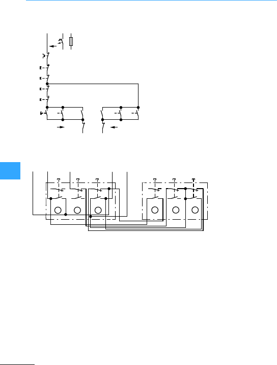
Control circuit devices for multi-speed contactors
EatonWiring Manual 06/11
8
(7Figure, page8-49)
2 three-way pushbuttons
Control circuit device forconnection B
-F0
L1
0a
-Q21
22
21
22
21
14
13
-Q21
14
13
95
96
-Q17
IIb
IIa
-F2(1)
22
21 B
0b
22
21
Ib
21
22
Ia IIa IIb 14
13
14
13
A
14
13
-Q17
22
21
14
13
A
Q21
13
F21
96
BC
Q17
14
Q17
13
Ia
S11S11
Q21
14
0a IIa Ib 0b IIb
21 22
13 14
21 22
13 14
21 22
13 14
21 22
13 14
21 22
13 14
21 22
13 14
ABC
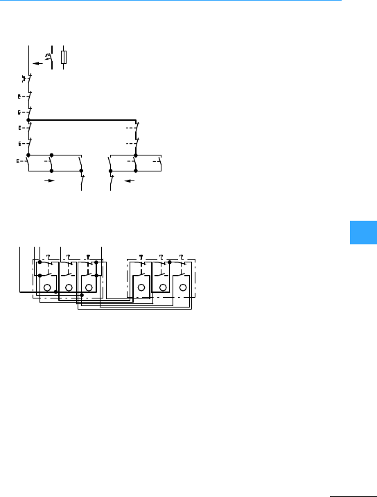
Control circuit devices for multi-speed contactors
EatonWiring Manual 06/11
8
(7Figure, page 8-49)
2 three-way pushbuttons
Control circuit device forconnection C
-F0
L1
0a
-Q21
22
21
22
21
14
13 -Q21
14
13
95
96
14
13
-Q17
IIb
-Q17
IIa
-F2(1)
22
21
AB
0b
22
21
Ib
22
21
Ia
22
21
14
13
IIa
Ib
Ia
IIb
14
13
14
13
22
21
22
21
-S11
A
Q21
13
F21
96
BC
Q17
14 13
Ia
-S11
Q21
14 0a IIa
21
22
13
14
21
22
13
14
21
22
13
14
Ib 0b IIb
ABC
21
22
13
14
21
22
13
14
21
22
13
14
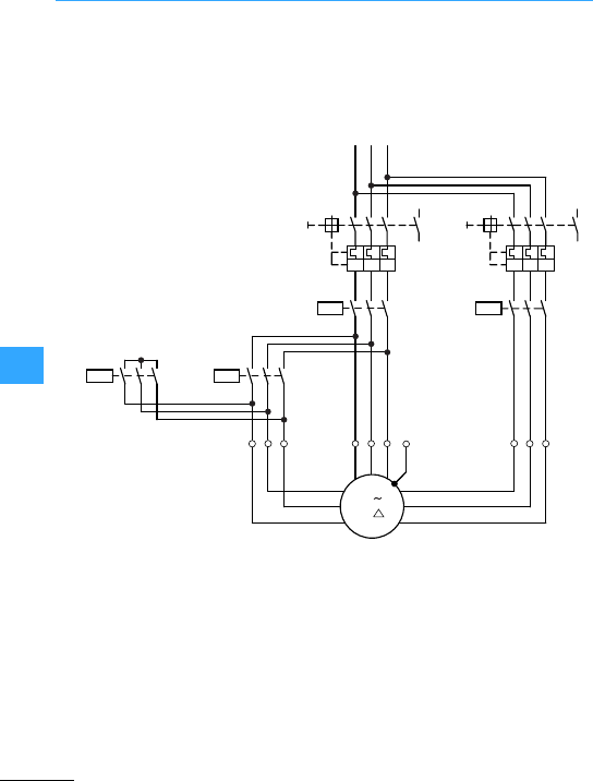
Eaton Wiring Manual 06/11
8
Multi-speed switch for three-phase motors
Star-delta startup at low speed
Without overload relay
Ratingof switchgear
Q1, Q17=I
1
(low speed)
Q2, Q21=I
2
(high speed)
Q19, Q23 =0.5 x I2
L1
PE
Y
-M1
3
2W1
2V1
2U1
1W
1V
1U
135
24
L2 L3
35
246
246
-Q17
-Q23
-Q21
6
2W2
2V2
2U2
135
1
135
246
35
246
1
13
14
-Q1
-Q19
246
-Q2
14
13
135
I>I>I>I>I>
I>
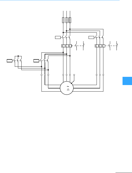
Multi-speed switch for three-phase motors
EatonWiring Manual 06/11
8
With and overload relays
Rating of switchgear
F2, Q17 = I1
(low speed)
F21, Q21 = I2
(high speed)
Q19, Q23 =0.5 x I2
F1 = I2
Overload relays F2 and F21 are not used on
multi-speed contactors without motor
protection. If F2 and F21 cannot be
protected by a common fuse, then use
connection on 7Figure,page 8-53.
Motor windings 7Section ”Motor
windings”, page8-50
L1
PE
Y
-M1
3
2W1
2V1
2U1
1W
1V
1U
L2 L3
5
246
-Q17
-Q23
-Q21
2W2
2V2
2U2
135
1
135
246
35
246
1
-F1
-Q19
246
-F21
-F2
246
97 95
98 96
3
97 95
98 96
246
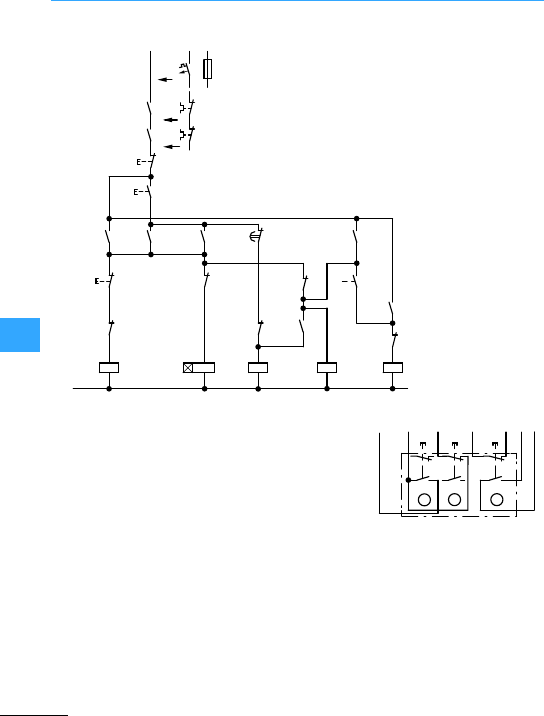
Multi-speed switch for three-phase motors
EatonWiring Manual 06/11
8
Actuation of pushbutton Ienergizes the
coil of star contactorQ23. Its N/O 13-14
energizes the coil of contactor Q17. The
motor runs in starat low speed.The
contactors are maintained via auxiliary
contactQ17/13-14. At the same time, timing
relay K3 is triggered. When the set time has
elapsed, K3/15-16 opens the circuit of Q23.
Q23 drops out, the coil of delta contactor
Q19 is energized and maintains itselfvia
Q19/13-14. The timing relay is de-energized
via N/C Q19/32-31.
The motorruns in delta at low speed.
Actuation of pushbutton II de-energizes
the coil of Q17and via Q17/22-21 energizes
the coil of Q21. This state is maintained by
Q21/43-44: The coil of star contactorQ23 is
re-energized by normally open contact
Q21/14-13. The motor runs at high speed.
Pushbutton 0 (= Stop) executes
disconnection.
Low speed selected
only from off position,
high speed only via
low speed without
actuation of the Stop
button.
Three-way
pushbutton
I: Low speed
(Q17, Q19)
0: Stop
II:High speed (Q21,
Q19, Q23)
Q17:Mainscontactor, low
speed
K3:Timing relays
Q23: Star contactor
Q19: Delta contactor
Q21: Mains contactor,
high speed
-F0
-F21
-Q1
-Q2
-S11
-Q17
-Q21
-Q17
-Q17
21
21
A1
A2
N
22
22
-Q21
-Q21
-Q21
-Q17
-Q23 -Q19
-Q19
-Q23
-Q19
-Q19
-K3
-K3
A1
A2
A1
A2
A1
A2
31
32 21
22
21
A1
A2
21
22
44
43
22
13 15
16
14
13
14
13
14
13
14
43
44
L1
(Q17/1)
0
II
I
-Q23
14
13
22
21
95
96
95
96
14
13
14
13
14
13
II
-S11
A
Q17
13 Q19
44 14
F21
96
BC
21
22
13
14
Q17
43 Q17
14
I0II
Q21
22
21
22
13
14
21
22
13
14
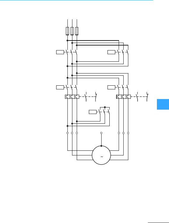
Multi-speed switch for three-phase motors
EatonWiring Manual 06/11
8
Overload relays F2 and
F21 are not used on
multi-speed contactors
without motor protection.
Rating of switchgear
Q11, Q12 = I2(low and
high speed)
F2, Q17 = I1(low speed)
F1, Q21 = I2
Q23 = 0.5 x I2(high speed)
L1
PE
-M1
2W
2V
2U
135
2
4
L2 L3
-F1
246
246
-Q11
97
-Q17
6
1W
1V
1U
135
-F21
98
95
96 246
97
98
95
96
-F2
246
135
246
135
246
135
M
3
-Q12
-Q21
-Q23
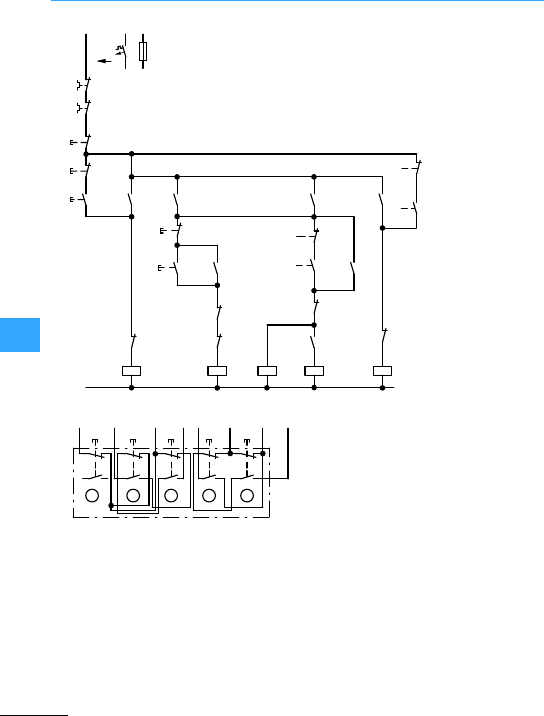
Multi-speed switch for three-phase motors
EatonWiring Manual 06/11
8
ContactorQ11 is energized by pressing
pushbutton I. Contactor Q11 selects the
operating direction, and maintains itself
after release of pushbutton I via its
auxiliarycontact 14-13 and pushbutton 0.
Speed-selection buttons III and IV are
madeoperative by Q11/44-43.
Pushbutton III energizes Q17, which
maintains itself via its contact 14-13.
Pushbutton IV energizes high speed
contactors Q23 and Q21. Auxiliary contact
Q21/21-22 makes low-speed pushbutton III
inoperative. Pushbutton 0 must be pressed
before any change in speed or direction.
Five-way
pushbutton
Change of direction
FORWARD–REVERS
E after actuation of
Stop button,
optionally followed
bySLOW–FASTwith
no return to low
speed.
0: Stop
I: Forward (Q11)
II:Back (Q12)
III: Slow (Q17)
IV:Fast (Q21 +Q23)
L1
(Q11/1)
-F0
0
-S11
A1
A2
A1
A2
-Q17
-Q17
A1
A2
A1
A2
N
-F21
-F2
II
I
II
14
13
22
21
-Q11
-Q17
-Q11 -Q21
14
13
22
21
95
96
22
22
21
14
13
44
43
-Q11
-Q21
95
96
21
A1
A2
22
21
I
22
21
-Q11
14
13
IV 22
21
14
13
III
22
21
-Q23
-Q12
-Q23
-Q23
21
22
14
13
-Q12
-Q21
14
13
IV
III 21
22
-Q12
44
43
-Q12 14
13
14
13
Q11
13
I
F21
96
13
14
21
22
-S11
AC
0
BD
Q12
13
Q12
14
Q17
13
Q11
43
Q17
14
Q17
21
II III IV
E
13
14
21
22
13
14
21
22
13
14
21
22
13
14
21
22
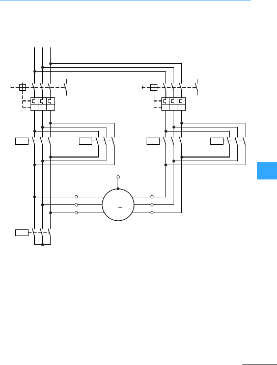
Multi-speed switch for three-phase motors
EatonWiring Manual 06/11
8
without overload relay
Rating of switchgear
Q1, Q17, Q18 = I1(low speed)
Q2, Q21, Q22 = I2
Q23 = 0.5x I2(high speed)
L1
PE
M
-M1
3
1W
1V
1U
2W
2V
2U
-Q23
135
246
L2 L3
-Q1
I> I> I>
-Q2
135
246
135
246
135 135 135
135
246
24
6246 246
-Q17
I> I> I>
13
14
-Q18 -Q21 -Q22
13
14
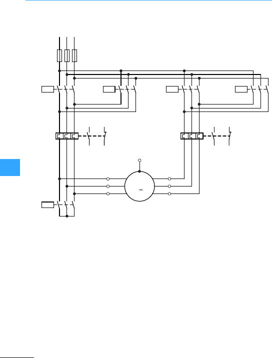
Multi-speed switch for three-phase motors
EatonWiring Manual 06/11
8
With and overload relays
Rating of switchgear
F2, Q17, Q18 = I1
(low speed)
F21, Q21, Q22 = I2
Q23 = 0.5x I2
(high speed)
Overload relays F2 and F21 are not used on
multi-speed contactors without motor
protection
L1
PE
M
-M1
3
1W
1V
1U
2W
2V
2U
135
246
L2 L3
-F2
135
246
135
246
-Q17
-F1
-Q18
97 95
98 96
-Q23
97 95
98 96
-F21
246
246
-Q21 -Q22
135
246
135
246
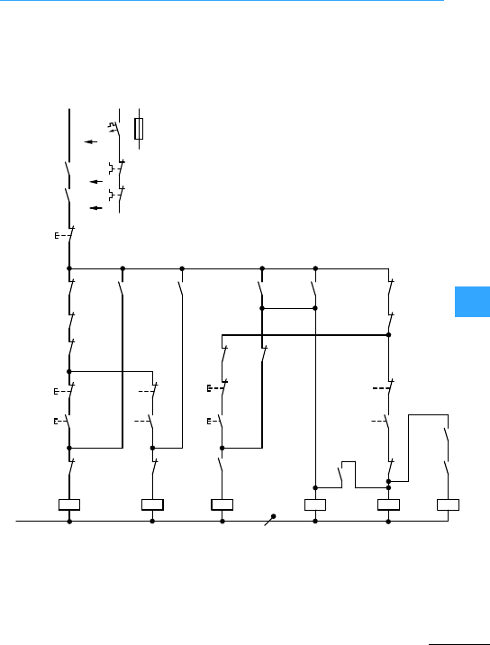
Multi-speed switch for three-phase motors
EatonWiring Manual 06/11
8
Simultaneous selection of direction and
speed via one pushbutton. Always operate
Stop button before changeover.
Q17: Slow forward
Q18:Slow back
Q21: Fast forward
Q23: Star contactor
K1:Contactor relay
Q22: Fast back
L1
(Q17/1)
N
-F0
0
-S11
I
-Q18
A1
A2
A1
A2
-Q21
21
22
-Q21
14
13
22
21
95
96
II
22
21
-Q17
21
II
21
22
22
-Q23
21
-Q17
-Q22
-Q23
-Q22
-Q21
-Q23
A1
A2
A1
A2
-Q23
-Q22
-Q18
-Q17
22
-Q22
14
14
13
III
95
96
-F2
-F21
14
13
-Q2
-Q1
-Q17
13
31
32
-Q21
22
21
22
21
-K1
I
14
13 14
13
IV
14
13
22 21 14
21 22 13
-Q18 -K1
-K1
A1
A2
14
13
44
43
A1
A2
-K1
43
44
14
13
32
31
III
IV
21
22
-Q18
31
32
31
32
14
13
14
13

Multi-speed switch for three-phase motors
EatonWiring Manual 06/11
8
Desired speed andoperating direction can
be selected by actuationof one of thefour
pushbutton. Contactors Q17, Q18, Q21 and
Q23 maintain themselves by their contact
14-13 and can be de-energized only by
actuation of pushbutton 0. Contactors Q21
and Q22 can maintain themselves only
when Q23 has picked up and contact
Q23/13-14 or 44-43 is closed.
Five-way pushbutton
0: Stop
I: Slow forward (Q17)
II: Slow back (Q18)
III:Fast forward (Q21 + Q23)
IV: Fast back (Q22 + Q23)
Q18
22
13
14
21
22
-S11
A
Q21
21
Q23
22 Q17
21
I
0II
F21
96
Q23
14 Q18
32 Q22
32
III IV
BCDE
13
14
21
22
21
22
13
14
21
22
13
14
21
22
13
14
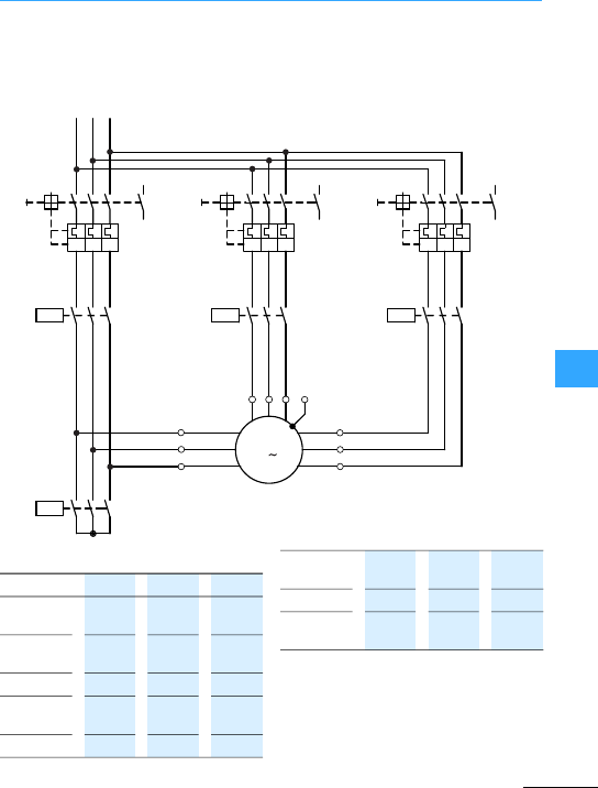
Multi-speed switch for three-phase motors
EatonWiring Manual 06/11
8
Multi-speed contactors overload
relay 7Figure, page 8-79
Motor circuit X7Section ”Motor circuit
X”,page 8-51
Synchronous Speed
Rating of switchgear
Q2, Q11 : I
1
(low speed)
Q1, Q17 : I
2
(medium speed)
Q3, Q21 : I
3
(high speed)
Q23 :0.5 x I3
L1
PE
M
-M1
33W
3V
3U
2W
2V
2U
135
24
L2 L3
-Q1
I> I> I>
-Q2
135
246
135
246
135 135
135
246
24
6246
-Q17
I> I> I>
13
14
-Q23
-Q11 -Q21
13
14
6
1W
1V
1U
13
14
246
I> I> I>
-Q3
135
Motor
terminals
1U, 1V,
1W
2U,2V,
2W
3U, 3V,
3W
Amount of
poles
12 8 4
RPM 500 750 1500
Amount of
poles
8 4 2
RPM 750 1500 3000
Amount of
poles
6 4 2
RPM 1000 1500 3000
Contactors Q11 Q17 Q21,
Q23
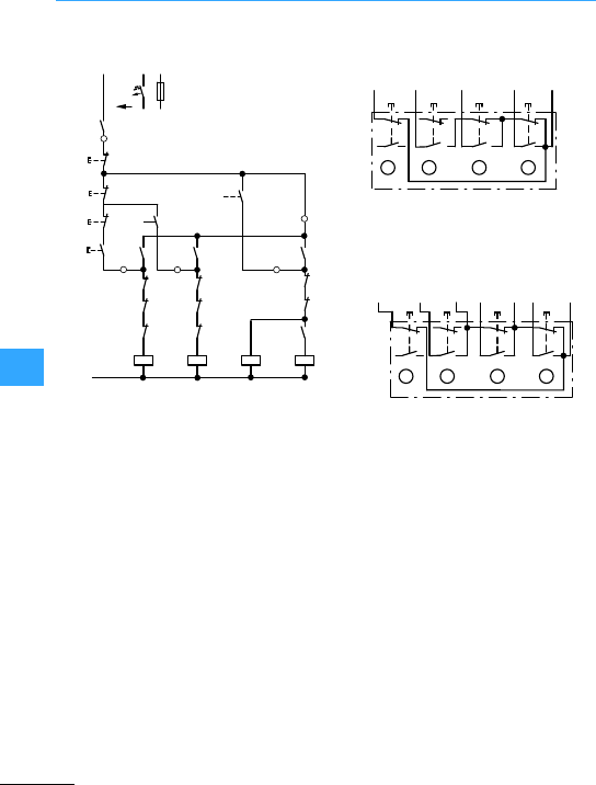
Multi-speed switch for three-phase motors
EatonWiring Manual 06/11
8
Pushbutton I energizes mains contactor
Q17 (low speed), pushbutton II mains
contactor Q11 (medium speed), pushbutton
III star contactor Q23 and viaitsN/O
Q23/14-13 mains contactor Q21 (high
speed). All contactors maintain themselves
by their auxiliary contact 13-14.
Speed sequence from low to high is
optional. Switching in steps from high to
medium or low speed is not possible. The
motor is always switched off by pressing
pushbutton 0. In the event of an overload,
normally open contact 13-14 of the
motor-protective circuit-breakeror
circuit-breaker can also switch off.
Connection of motor winding: X
Connection A
Selection of any speed only from zero.
No return to low speed, only to zero.
Selection of any speed from zero or
from low speed. Return only to zero.
Q11: Low speed winding 1
Q17: Medium speedwinding 2
Q23:High speed winding 2
Q21: High speed winding 2
Four-waypushbuttons
0: Stop
I: Low speed (Q11)
II: Mediumspeed (Q17)
III:High speed (Q21+ Q23)
L1
(Q17/1)
-F0
0
-S11
A1
A2
A1
A2
21
22
22
21
-Q17
21
-Q23
-Q17
-Q23 -Q21
A1
A2
A1
A2
-Q23
N
-Q17
14
13
III
14
13
-Q2
-Q1
31
32
-Q3
III
22
21
14
13
II
14
13
I
II
14
13
-Q11 14
13
13
14
22
21
22
21
-Q21 21
22
22
-Q11
-Q21
31
32
32
31
-Q11-Q17
-Q11
-Q21
-Q23
32
31
14
13
13
14
21
22
A
Q21
13
Q11
14
Q17
14
I
0II
F22
96
Q21
14
III
BCD
13
14
21
22
21
22
13
14
21
22
13
14
13
14
21
22
-S11
A
Q21
13
Q11
14
Q17
14
I
0II
F22
96
Q23
14III
BCD
13
14
21
22
21
22
13
14
Q11
13
Q17
13
21
22
13
14
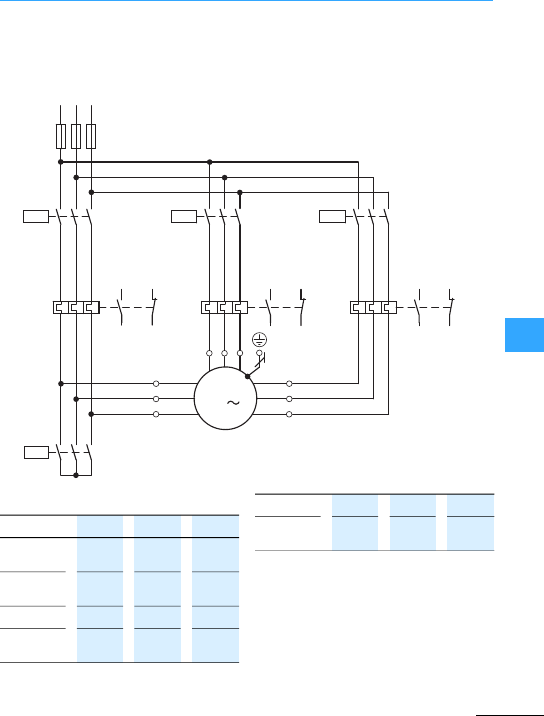
Multi-speed switch for three-phase motors
EatonWiring Manual 06/11
8
Multi-speed contactor overload
relay 7Figure, page 8-77
Motor circuit Y 7Section ”Motor circuit
Y”, page 8-51
Synchronous Speed
Rating of switchgear
F2, Q17: I1(low speed)
F3, Q11: I2(medium speed)
F4, Q21: I3(high speed)
Q23: 0.5 x I3
L1 L2 L3
135
M1
246
F1
97 95
98 96
Q17 Q11
135
246
F2
246
F3
97 95
98 96
246
Q21
135
246
F4
97 95
98 96
246
135
Q23
135
246
3U 3V 3W
2U
2V
2W
1U
1V
1W
M
3
135
135
Motor
terminals
1U, 1V,
1W
2U,2V,
2W
3U, 3V,
3W
Amount of
poles
12 8 6
RPM 500 750 1000
Amount of
poles
8 6 4
RPM 750 1000 1500
Contactors Q17 Q11 Q21,
Q23
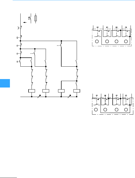
Multi-speed switch for three-phase motors
EatonWiring Manual 06/11
8
Pushbutton I energizes mains contactor
Q17 (low speed), pushbutton II mains
contactor Q11 (medium speed), pushbutton
III star contactor Q23 and viaitsN/O
Q23/14-13 mains contactor Q21 (high
speed). All contactors maintain themselves
by their auxiliary contact 13-14.
Speed sequence from low to high is
optional. Switching in steps from high to
medium or low speed is not possible. The
motor is always switched off by pressing
pushbutton 0. In the event of an overload,
normally closed contact 95-96 of overload
relays F2, F21 and F22 can also switch off.
Connection of motor winding: Y
Connection A
Selection of any speed only from
zero. No return to low speed, only
to zero.
Selection of any speed from zero or
from low speed. Return only to zero.
Four-way pushbuttons
0: Stop
I: Low speed (Q17)
II:Medium speed (Q11)
III: High speed (Q21 + Q22)
Q17: Low speed winding 1
Q11: Medium speed winding 1
Q23:High speed winding 2
Q21: High speed winding 2
L1
F0
0
S2
S1
S3
S0
A1
A2
A1
A2
Q17
21
Q17 Q21
A1
A2
A1
A2
Q23
N
III
14
13
F3
F2
F4
III
II
I
II
14
13
14
13
22
21
22
21
21
22
22
Q11
31
32
32
31
Q11 Q11
Q21
Q23
14
13
22
21
95
96
22
21
22
21
14
13
14
13
Q11
31
32
Q21
Q23 Q23
32
31
Q17 Q21
Q17
14
13
Q17
14
13
14
21
22
-S11
A
Q21
13
Q11
14
I
0II
F22
96
Q21
14 III
BCD
21
22
13
14
21
22
13
14
21
22
13
14
Q21
14
Q17
13 Q21
13
Q11
13
Q17
14
F22
96 0III
-S11
13
14
21
22
13
14
21
22
13
14
21
22
13
14
ABCD
Q11
14
21
22
III
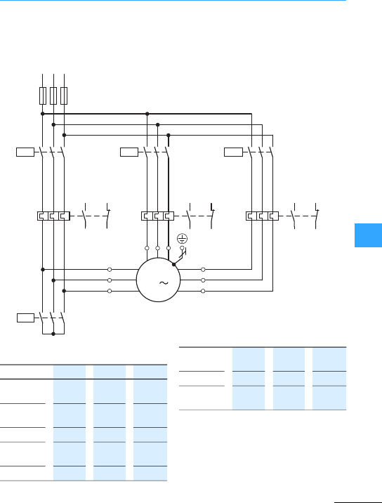
Multi-speed switch for three-phase motors
EatonWiring Manual 06/11
8
Multi-speed contactor overload
relay 7Figure, page 8-53
Motor circuit Z 7Section ”Motor circuit
Z”, page 8-51
Synchronous Speed
Rating of switchgear
F2, Q17: I1(low speed)
F4, Q21: I2(medium speed)
F3, Q11: I3(high speed)
Q23: 0.5 x I3
L1 L2 L3
135
M1
246
F1
97 95
98 96
Q17 Q11
135
246
F2
246
F3
97 95
98 96
246
Q21
135
246
F4
97 95
98 96
246
135
Q23
135
246
3U 3V 3W
2U
2V
2W
1U
1V
1W
M
3
135
135
Motor
terminals
1U,1V,
1W
2U, 2V,
2W
3U, 3V,
3W
Amount of
poles
12 6 4
RPM 500 1000 1500
Amount of
poles
12 6 2
RPM 500 1000 3000
Amount of
poles
8 4 2
RPM 750 1500 3000
Contactors Q17 Q21,
Q23
Q11
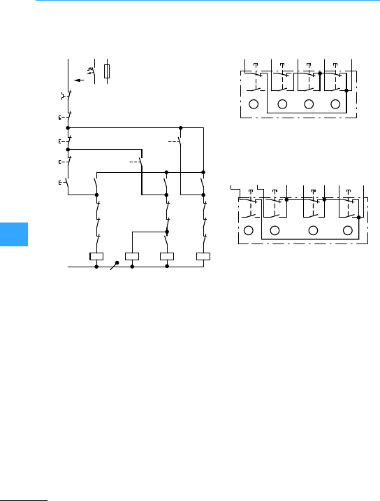
Multi-speed switch for three-phase motors
EatonWiring Manual 06/11
8
Pushbutton I energizes mains contactor
Q17 (low speed), pushbutton II mains
contactor Q23 (low speed) and via its N/O
Q23/14-13 mains contactor Q21 (high
speed), pushbutton III mains contactor
Q11. All contactors maintain themselves by
pushbutton I energizes m13n14co.
Speed sequence from low to high is
optional. Switching in steps from high to
medium or low speed is not possible. The
motor is always switched off by pressing
pushbutton 0. In the event of an overload,
normally closed contact 95-96 of overload
relays F2, F21 and F22 can also switch off.
Connection of motor winding: Z
Connection A
Selection of any speed from zero.
No return to low speed, only to zero.
Selection of any speed from zero or from
low speed. Return only to zero.
Q17: Low speed winding 1
Q23: Medium speed winding 2
Q21: Medium speed winding 2
Q11:High speed winding 1
Four-way pushbuttons
0: Stop
I: Low speed (Q17)
II: Medium speed (Q21 + Q23)
III:High speed (Q11)
L1
(Q17/1)
N
-F0
0
-S11
I
-Q11
A1
A2
A1
A2
-Q21
21
22
-Q21
14
13
22
21
-F2
-F21
-F22
95
96
III
II
22
21
-Q17
14
13
22
21
14
13
II
21
22
22
-Q23 21
-Q17 -Q23 -Q21
-Q11
-Q17
-Q23
A1
A2
A1
A2
-Q23
-Q11
-Q21
-Q17
14
13
32
31
32
31
22
21
32
31
32
31
-Q11
14
13
14
13
14
13
III
Q21
13
Q17
14
Q11
14
F22
96 0III III
13
14
21
22
ABCD
Q21
14
21
22
21
22
21
22
13
14
13
14
13
14
-S11
II III
0I
14
Q23
13
Q23
14
Q17
13
Q17
14
Q11
13
Q11
14
F22
96
-S11
13 21
22
13
14
21
22
13
14
21
22
13
14
ABCD
21
22
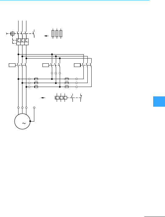
Eaton Wiring Manual 06/11
8
Three-phase autotransformer starter
Use F2 when using F1 instead of Q1.
L1 L2 L3
-Q1
123
I> I> I>
246
13
14 -F1
15
3
246
-Q11 -Q17
-R2
X
Y
Z
-F2
PE
UVW
M
3
-M1
15
3
246-Q16
246
135
-R1
U1 U2
V2
W2
V1
W1
4
26
97 95
98 96
Rating of switchgear:
Starting voltage:0.6 x Ue
Inrush current:0.6 xdirect switching system
Tightening torque:0.36 x direct switching system
Q1, Q11: Ie
Q16, Q17: 0.6 x Ie

Three-phase autotransformer starter
EatonWiring Manual 06/11
8
Q16: Step contactor
K1:Timing relay
Q17: Step contactor
K2: Timing relay
Q11: Mains contactor
Always set overload relay to
reclosing lockout
-Q1 -F2
L1
(-Q11)
N
-F0
13
14
95
96
0
21
22
-S11 I13
14
21
22
-Q11
-Q16 A1
A2
-K1 A1
A2
-Q17 A1
A2
-K1 15
18
-K2
-Q17
A1
A2 -Q11 A1
A2
-K2
13
14
13
14
-Q16
13
14
15
18
-Q11
32
31
-Q11
-F0
-Q1
13
14
-S12
-Q11
32
31
-Q11
L1
(Q11/1)
22
21

Three-phase autotransformer starter
EatonWiring Manual 06/11
8
Pushbutton I energizes step contactor Q16
and timing relay K1. Q16/14-13 –
self-maintaining through Q11, Q11/32-31
and pushbutton 0. The motoris connected
to the supply with upstream resistors
R1 +R2. When the set starting time has
elapsed,normally open contact K1/15-18
energizes Q17. Step contactorQ17
bypasses the starting stage R1. At the
same time, normally open contact
Q17/14-13 energizes K2. When the set
starting time has elapsed, K2/15-18
energizes mains contactor Q11. This
bypasses the second starting stage R2, and
the motorrunsat the rated speed. Q11
maintains itself via Q11/14-13. Q16, Q17, K1
and K2 are de-energized by normally
closed contacts Q11/22-21 and Q11/32-31.
The motoris switched off with
pushbutton 0. In the event of an overload,
normally closed contact 95-96 of the
overload relay F2 or normally open contact
13-14 of the motor-protective
circuit-breaker switch off the motor.
Step contactorQ17, resistorR2 and timing
relay K1 are omitted in single-stage
starting circuits. Timing relay K2 is
connected directlyto Q16/13 and resistor
R2 is connected by means of its terminals
U1, V1 and W1 to Q11/2, 4, 6.
Double pushbutton
I = ON
0 = OFF
-S11
Q11
32
22
21
Q11
21
F2
96
22
21
14
13
14
13
0I
AB
F2
96
Q11
22
Q11
32
-S12
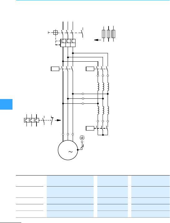
Three-phase autotransformer starter
EatonWiring Manual 06/11
8
Use F2 when using F1 instead of Q1. Rating of switchgear
L1 L2 L3
4
15
3
246
UVW
15
3
246
a
U2
V2
W2
1U1
2W1
2V1
2U1
1V1
1W1
M
3
M1
F1
26
15
3
Q1
13
14
Q11
15
3
246
K1
Q13
24697 95
98 96
I>I>I>
Starting voltage = 0.7x Ue(typical value) Tightening torque = 0.49 x Direct
switching
Inrush current =0.49 x direct switching
system
Q1, Q11 = Ie
IA/Ie= 6 Q16 = 0.6 x Ie
tA=10 s Q13 =0.25 x Ie
ops./h =30
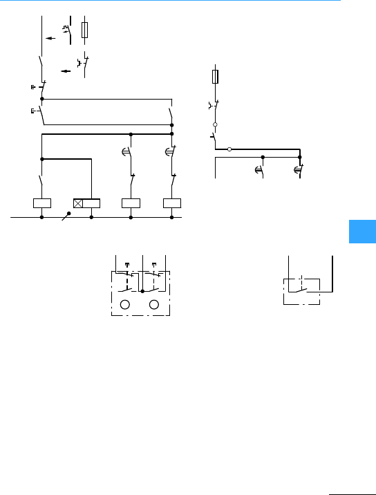
Three-phase autotransformer starter
EatonWiring Manual 06/11
8
Pressing pushbutton Isimultaneously
energizes star contactor Q13, timing relay
K1 and, via normally open contact
Q13/13-14, step contactor Q16, and are
maintained via K1/13-14. When K1 has
elapsed, normally closed contact K1/55-56
de-energizes starcontactorQ13, and Q16 –
via normally open contact Q13/13-14:
Thestarting transformer is disconnected,
and the motor runs at the rated speed.
The motorcannot start up again unless
previously switched off by actuation of
pushbutton 0, or in the event of an
overload,by N/C 95-96 of the overload relay
F2. With two-wire control, overload relay
F2 must always be set to reclosing lockout.
If themotor has been switched off by F2,
the motorcannot start up again unless the
reclosing lockout is released.
Always setoverload relay to reclosing
lockout (manual reset)
Q16: Step contactor
K1:Timing relay
Q11: Mains contactor
Q13: Star contactor
I: ON
0: OFF
L1
Q1
F0
13
14
95
96
F2
21
S11
0
I
13
14
K1
13
14
13
14
Q13
Q16
N
A1
A2
K1
Q13
A1
A2
Q11
K1
A1
A2
K1
Q11
Q13
22
21
A1
A2
22
21
67
68
55
56
22
L1
(Q11/1)
-F0
95
96
-F2
-S12
-K1 -K1
55
96
67
68
-S11
K1
13
22
21
F2
96
22
21
14
13
14
13
0I
AB
K1
14
-S12
F2
96 K1
55
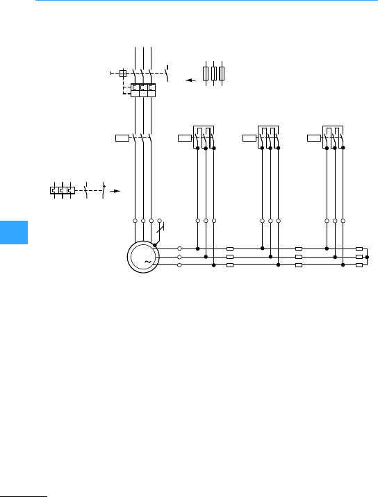
Eaton Wiring Manual 06/11
8
Three-phase automatic rotor starters
Use F2 when using F1 instead of Q1.
L1 L2 L3
-Q1
135
I>I>I>
13
14
-F1
26
4
246
PE
UVW
M
3
-M1
-Q12
246
97 95
98 96
135
-Q11
-F2
246
13515
3
246
-Q13 -Q14
246
135
K
L
M
U3
V3
W3
U2
V2
W2
-R3 -R2
U1
V1
W2
-R1
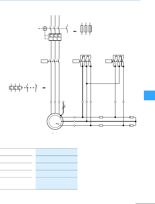
Three-phase automatic rotor starters
EatonWiring Manual 06/11
8
Use F2 when using F1 instead of Q1.
Rating of switchgear
L1 L2 L3
13513
14
I> I> I>
26
4
135
246
PE
UVW
M
3
-M1
-Q11
135
-F2
246
-R2
U1
V1
-R1
-Q1
-F1
97 95
98 96
K
L
M
-Q12 -Q14 246
135
U2
XY
V2
246
Inrush current = 0.5–2.5 x Ie
Tightening torque = 0.5 to pull-out torque
Q1, Q11 = Ie
Step contactors = 0.35 x Irotor
Final step
contactors
= 0.58 x Irotor
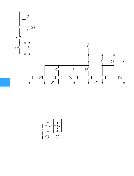
Three-phase automatic rotor starters
EatonWiring Manual 06/11
8
Q11: Mains contactor
K1:Timing relay
Q14: Step contactor
K2:Timing relay
Q12: Step contactor
Q13:Final step contactor
K3:Timing relay
Q1 F2
L1
N
F0
0
S11
I
Q11
A1
A2
A1
A2
K1
K2
Q14
A1
A2
13
14
13
14
95
96
21
22
13
14 Q11 13
14
K1 Q14
A1
A2
15
18
K2
Q12
14
13
A1
A2
15
18
A1
A2
Q13
Q13 Q13
32
31
14
13
U3
A1
A2
U3
15
18
Q12
Q11 44
43
Double
pushbutton
I: ON
0: OFF
7Section ”Control circuit devices for
star-delta starting”, page8-45
F2
96
Q11
14
Q11
13
0I
-S11
21
22
21
22
13
14
13
14
AB

Three-phase automatic rotor starters
EatonWiring Manual 06/11
8
Pushbutton I energizes mains contactor
Q11: N/O Q11/14-13 transfers the voltage,
Q11/44-43 energizes timing relay K1. The
motor is connected to the supply system
with rotor resistors R1 + R2 + R3 in series.
When the set starting time has elapsed,
normally open contact K1/15-18 energizes
Q14. Step contactor Q14 short-circuits
starting stage R1 and via Q14/14-13
energizes timing relay K2. When the set
starting time has elapsed, K2/15-18
energizes step contactor Q12, which
short-circuitsstarting stage R2 and via
Q12/14-13 energizes timing relay K3. When
the set starting time has elapsed, K3/15-18
energizes final step contactor Q13, which
is maintained viaQ13/14-13, Step
contactors Q14 and Q12 as well as timing
relays K1, K2 and K3 are de-energized via
Q13. Finalstep contactor Q13 short-circuits
the rotor slip rings: themotor operateswith
rated speed.
The motoris switched off either by
pushbutton 0, or in the event of an
overload,by N/C 95-96 of the overload relay
F2 or N/O 13-14of the motor-protective
circuit-breaker or circuit-breaker.
Stepcontactors Q13 and/or Q12 with their
resistors R3, R2 and timing relays K3, K2 are
omitted in single-stage or two-stage
starting circuits. Therotor is then
connectedto the resistance terminals U, V,
W2 or U, V, W1.The references forstep
contactors and timing relays in the wiring
diagrams are then changed from Q13, Q12
to Q12, Q11or to Q13, Q11 as appropriate.
When there are more than three stages,
the additional step contactors, timing
relays and resistors have appropriate
increasing designations.
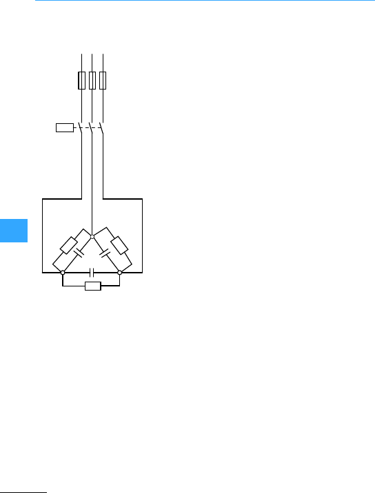
Eaton Wiring Manual 06/11
8
Switching of capacitors
Individual circuit without
quick-dischargeresistors
R1 discharge resistors fitted in
capacitor
L3
-F1
135
246
-Q11
-R1
-C1
-R1
-R1
L1 L2
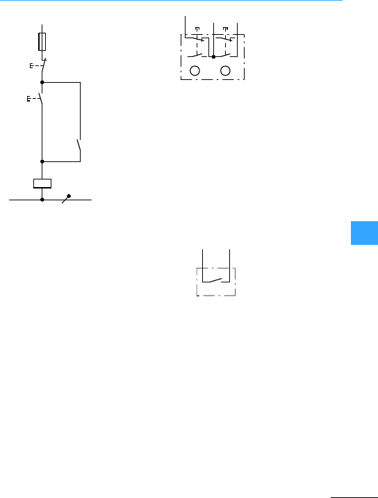
Switching of capacitors
EatonWiring Manual 06/11
8
Double pushbutton
7Section ”Control circuit devices for
star-delta starting”, page8-45
L1
(Q11/1)
-F0
21
22
-S11
0
I
13
14
13
14
-Q11
-Q11
A1
A2
N
22
L1
21
0I
Q11
14
AB
Q11
13
14
13
22
21
14
13
In the case of actuation by means of power
factor correction relay, check that this has
sufficient power to actuate the contactor
coil. Interpose a contactorrelay if
necessary.
Pushbutton I actuatescontactor Q11,
which picks up and maintains itself via its
own auxiliary contact 14-13 and
pushbutton 0 on voltage. Capacitor C1 is
thus energized. Discharge resistors R1 are
not active when contactor Q11 is
energized. Actuation of pushbutton 0
effects de-energization.Normally closed
contacts Q11/21-22 then switch discharge
resistors R1 to capacitor C1.
L1
-S12
Q11
A1
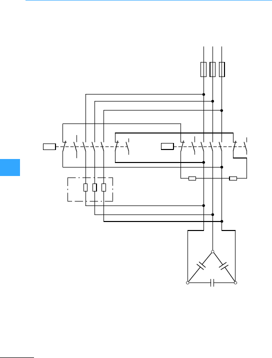
Switching of capacitors
EatonWiring Manual 06/11
8
Capacitors contactorwith pilot contactor
and series resistors. Individual and parallel
circuit with and without discharge
resistors and with series resistors.
On the version without discharge resistors,
resistors R1 and the connections to the
auxiliary contacts 21-22 and 31-32 are
omitted.
L3
L1 L2
-F1
135
246
-Q14
-R1
-C1
-R1
21
22
-Q11
31
32
43
44
13
14
21
22
A1
A2
31
32
43
44
135
246
A1
A2
13
14
-R2
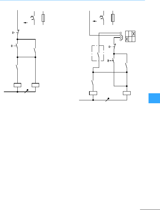
Switching of capacitors
EatonWiring Manual 06/11
8
Actuation by double pushbutton S11:
Pushbutton I energizes pilot contactor Q14.
Q14 switches capacitor C1 in with bridged
series resistors R2. N/O Q14/14-13
energizes mains contactor Q11. Capacitor
C1 is then switched in with bridged series
resistors R2. Q14 is maintained via
Q11/14-13 when Q11 has closed.
Dischargeresistors R1 are not operative
when Q11 and Q14 are energized.
Pushbutton 0 effects de-energization.N/C
Q11/21-22 and 31-32 then switch discharge
resistors R1 to capacitor C1
Q11: Mains contactor
Q14: Pilot contactor
Actuation by double pushbutton S11 Actuation by selector switch S13, two-wire
control S12 (power factor correction relay)
and double pushbutton S11
-F0
0
I
-S11
L1
(Q11/1)
-Q14
21
22
-Q11
A1
A2
13
14 -Q11
13
14
13
14
-Q14
A1
A2
N
-F0
0
I
-S12
L1
(Q11/1)
-Q14
21
22
13
14 -Q11 13
14
13
14
A1
A2
-S12
-Q14
A1
A2
-Q11
N
T0 (3)-1-15431
1
2
3
4
1
02
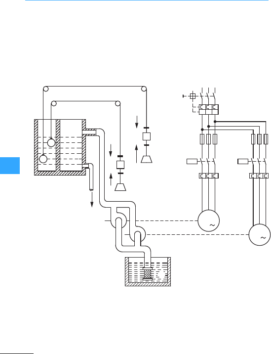
Eaton Wiring Manual 06/11
8
Duplexpump control
Starting sequence of pumps1 and 2 can be
selected by control switch S12.
Control circuit wiring with two float
switches for basic and peak loads
(operation is also possible with two
pressure switches)
P1 Auto =Pump 1 base load,
Pump 2peak load
P2 Auto =Pump 2 base load,
Pump 1peak load
P1 +P2 =Direct operation independent
of float switches (or pressure
switches)
aCable with float, counterweight,
pulleys and clamps
bStorage tank
cInlet
dPressure pipe
eOutlet
fCentrifugal or reciprocating pump
gPump 1
hPump 2
iSuction pipe with filter
jWell
L1 L2 L3
-Q1
-F22
-Q11
UVW
M
3
-M1
-M2 M
3
F7 -F11 -F21
-F12
-Q12
UVW
F8
b
d
F7 Q
Q
a
a
F8
c
e
f
f
i
h
g
0
0
I
I
F7: 0
F7: I
F8: 0
F8: I
j
I>I>I>
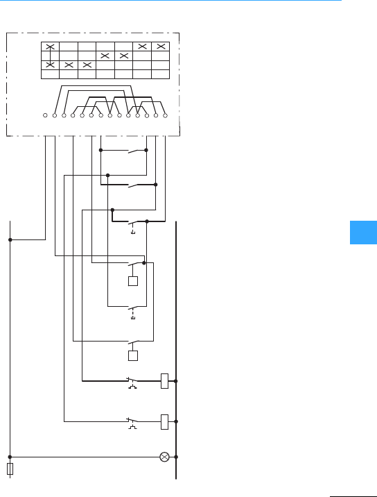
Duplexpump control
Eaton Wiring Manual 06/11
8
Float switch F7 closes before F8 Q11:Pump 1 mains contactor Q12: Pump 2mains contactor
The duplex pump control is designed for
operation of two pump motors M1 and M2.
Control is via float switches F7 and F8.
Operating mode selector switch S12 in position
P1 auto. The system operates as follows:
When the water level in the storage tank falls or
rises, F7 switchespump 1on or off (base load).
If the water level drops below
the range of F7 (discharge is greater than
intake), F8 starts pump 2(peak load). When the
water level rises again, F8 is deactivated. Pump
2 continues running until F7 stops both pumps.
The operating sequence of pumps 1and 2 can
be determined using operating mode selector
switchS12: Position P1 auto or P2 auto.
In position P1 + P2, both pumps are in operation,
independent of the float switches (Caution!
Tank may possibly overflow).
On the version of duplex pump control with
cyclic load sharing (T0(3)-4-15915), S12 has a
further state: the operating sequences are
automatically reversed after each cycle.
F11 F0
-F12 -F22
95
96
95
96 -F7 Q
2
1-S11
14
13 -F8 Q-S21
2
1
14
13 -Q12
14
13 -Q11
14
13
N
EO -Q11 A1
A2 -Q12 A1
A2
-S12
L
1
2
3
4
5
6
7
8
9
10
11
12
13
0
P 1, P 2
P 1 Auto
P 2 Auto
T0(3)-4-15833
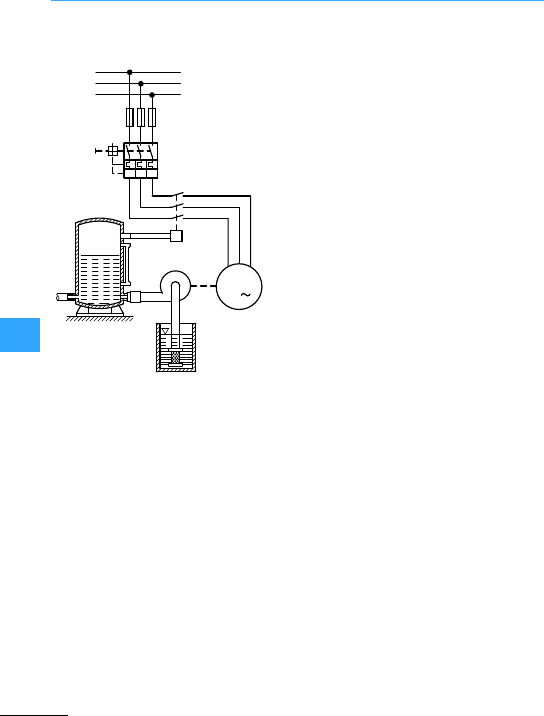
Eaton Wiring Manual 06/11
8
Fully automatic pump control
With pressure switch forair tank and
domestic water supply without water
failure (run dry) safety device
With 3-pole pressure switch MCSN (main
circuit)
F1: Fuses (if required)
Q1: Motor-protective circuit-breaker
switch, manual (e.g. PKZ)
F7:Pressure switch MCSN, 3-pole
M1:Pump motor
aAir or pressure tank
bNon-return valve
cPressure pipe
dCentrifugal (or reciprocating) pump
eSuction pipe with filter
fWell
L1
L2
L3
-F1
-Q1
a
b
d
ce
f
UVW
-M1
M
3
P
-F7
I>I>I>
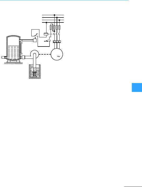
Fully automatic pump control
Eaton Wiring Manual 06/11
8
With 1pole pressure switch MCS (control
circuit)
F1: Fuses
Q11:Contactoror automatic star-delta
switch
F2: Overload relay with reclosing lockout
F7: Pressure switch MCS, 1 pole
M1: Pump motor
aAiror pressure tank
bNon-return valve
cCentrifugal (or reciprocating) pump
dPressure pipe
eSuction pipe with filter
fWell
35
246
95
96
-M1
M
3
UVW
L1
L2
L3
-F1
-F2
a
bc
de
f
P
N
-Q11 1
-F7
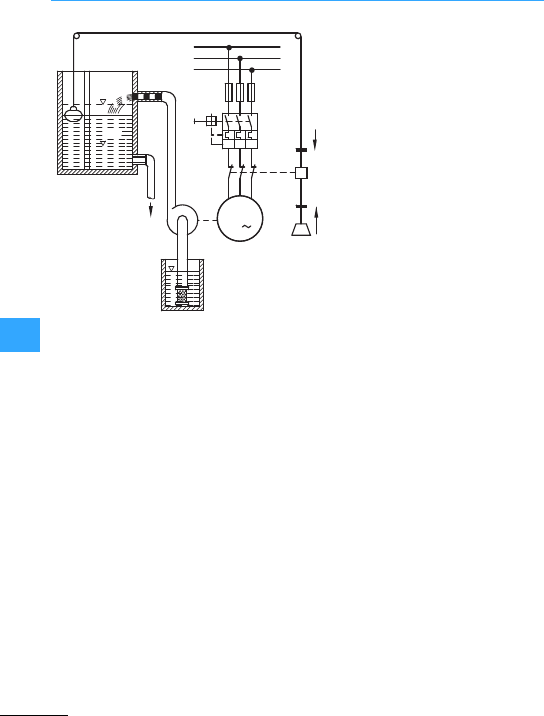
Fully automatic pump control
Eaton Wiring Manual 06/11
8
With 3-pole float switch SW (main circuit)
F1: Fuses (if required)
Q1:Motor-protective
circuit-breakers, manual
(e.g. PKZ)
F7:Float switch3-pole
(connection:pump full)
M1: Pump motor
HW:Highest level
NW:Lowest value
aCable with float,counterweight,
pulleys and clamps
bStorage tank
cPressure pipe
dCentrifugal (orreciprocating)
pump
eOutlet
fSuction pipe with filter
gWell
UVW
L1
L2
L3
-F1
-F7
I
0
HW
NW -Q1
-M1
Q
M
3
a
c
b
d
e
f
g
I>I>I>
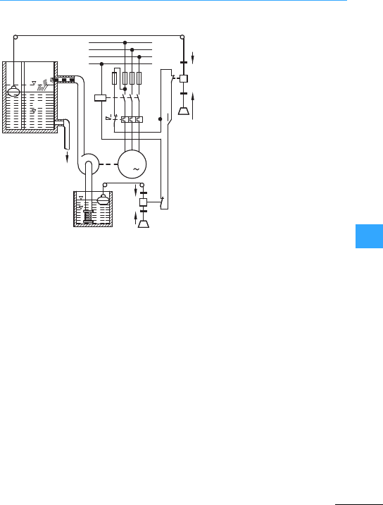
Fully automatic pump control
Eaton Wiring Manual 06/11
8
With 1pole float switch SW (control
circuit)
F1:Fuses
Q11:Contactor or automatic
star-delta switch
F2:Overload relay with reclosing
lockout
F8: Floatswitch 1 pole
(connection pump full)
S1:Changeover switch
MANUAL-OFF-AUTO
F9: Floatswitch 1 pole
(connection: pump full)
M1:Pump motor
aCable with float,
counterweight, pulleys and
clamps
bStorage tank
cPressure pipe
dCentrifugal (or reciprocating)
pump
eOutlet
fSuction pipe with filter
gWater-failure monitoring by
means of a float switch
hWell
L1
UVW
L2
L3
N
-F1
-F2
-Q11
135
246
95
96
-F8
0
HA
-M1
S1
HW
NW
M
3
-F9
I
0
Q
Q
a
b
c
d
e
h
f
g
0
I
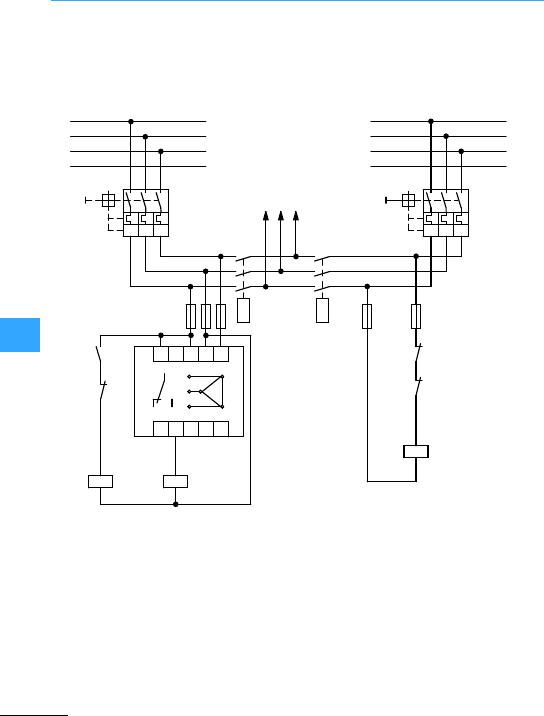
Eaton Wiring Manual 06/11
8
Fully automatic main transfer switch with automatic release
Pick-up voltage Uan =0.95x Un
Drop-out voltageU
b
=0.85x Uan
Main switch Q1 is closed first, followed by
main switch Q1.1(auxiliary supply).
Phase monitor K1 is energized via the main
supply and immediately energizes
contactor relay K2. N/C K2/21-22 blocks the
circuit contactor. Q12 (auxiliary supply)
and N/O K2/13-14 closes the circuit of
contactor Q11. Contactor Q11 energizes
and switches the mains supply on the
loads. Contactor Q12 is also interlocked
against main supply contactorQ11 via N/C
Q11/22-21.
aMain supply
bAuxiliary supply
cTo load
L1
L2
L3
N
-Q1
-F01
21
22
14
21
21
22
22
11
11
12 14
12 14
R
RS
S
T
T
-F02
5
6
3
4
1
2
5
6
3
4
1
2
-Q1.1
-Q11
-K2
-Q12
-Q12
-Q11
-K2
-Q12
-Q11 -K2
-K1
A1
A2
A1
A2
A1
A2
L2.1
L3.1
N
L1.1
13
ab
c
I>I>I>
I>I>I>

Eaton Wiring Manual 06/11

Eaton Wiring Manual 06/11
Approvals and certifications
Approval of electrical equipment is based
on the conformity and certification of
components and assemblies to regional
and country specific product and
installation standards that are geared
towards the proper application of these
products in those markets.
•Product testing conducted by nationally
recognized certification agencies is
often required, and product certification
is also subjectto periodic review and
auditing by the certification agency.
•In the majority of cases, product
certification is tied to the displayof
respective certification marks on the
product themselves.
•Product certification ratings may differ
from IEC based technical data and
ratings.
•Product certifications are sometimes
subject to additional and specific
conditions of acceptability.
•Design flexibility on the part of
manufacturers can sometimes be
impacted by the possible need to
re-certify each subsequent product
modification.
Refer to Chapter 23 of the Main Industrial
Switchgear catalogue for additional
information on approvals and product
certifications in general.
www.eaton.com/moeller/support
(Catalogs)
Successful exports are based on more
than just using certified equipment.
In addition to product certifications, a firm
understanding of the standards and market
conventions involved is necessary to
insure that electrical components and
assemblies are also properly applied.
A checklist is a useful tool to clarify
important issues and minimize costs during
the engineering phase.Special
requirements that are overlookedduring
the initial stages, and need to be remedied
after the fact, will not only be costly but
very time consuming as well.

Approvals and certifications
Eaton Wiring Manual 06/11
Technologies that have proven themselves
reliable the world over are not guaranteed
automatic acceptance in North America.
Exportsto North America must take into
consideration the following:
•NorthAmerican certificationofelectrical
equipment,
•North American product, application,
and installation standards,
•Particular and specialized market
conventions,
•Approval of electrical installations by
local inspectors
(AHJ =uthority avingurisdiction).
Particular aspects of theNorth American
market, which are not readily known in the
IEC world:
•Product groupings and fields of
application
•Product specific differences and ratings
based on certification
•Differentiation of power circuits (Feeder
and Branch Circuits)
•Equipment limitations based on
particularsupply network configurations
•Application related differences affecting
product selection

Approvals and certifications
Eaton Wiring Manual 06/11
There is a differentiation made in North
America between products used in Energy
Distribution, such as molded case circuit
breakers certified per the UL 489 product
standard, and those found in Industrial
Control,typically falling underUL 508.
Productstandards such as UL 489 and CSA
C22.2 No.5-09 require significantly larger
air and creepage clearances in component
construction than do the IEC standardsand
their harmonized European counterparts
(EN norms).
An example of its impact on component
construction would be the European motor
protective switch which, in North America,
needs to be equipped with a large spacings
terminal on its supply side whenever it is
applied as astand-alone protective device
in individual motor branch circuits.
•Molded Case Circuit Breakers
UL 489, CSA C22.2 No. 5-09
•Molded Case Switches
UL 489, CSA C22.2 No. 5-09
•Enclosed Switches
UL 98, CSA C 22.2 No. 4
•Fusible Disconnect Switches
UL 98, CSA C 22.2 No. 4
•Fuses
UL 248, CSA C22.2 No. 248
UL 508 and CSA C22.2 No. 14
•Contactors
•Control Relays
•Overload Relays
•Cam Switches
•Pilot devices and Limit switches
•Solid State relays and equipment
Programmable Controllers

Approvals and certifications
Eaton Wiring Manual 06/11
•Knowing the type of load and circuit is
especially important in selecting theright
equipment for the application.
Motor starters are usedexclusively for
the protection and switching of motor
loads.
•Motor starters mounted on busbar
adapters thatare supplied from a feeder
must have the larger electrical
clearances on their incoming supply
side.1)
•Motor starters mounted on busbar
adapters within a branch circuit are
permitted to have industrial control
electricalclearances on their field
terminations.1)
•Supplementary handles are necessary
for supply circuit disconnect switches
equipped with door mounted rotary
handlesin applications such as industrial
machinery.
1) Circuit examples: Referto diagrams on
page 9-35.
Comprehensive information and tips on
exporting electrical equipment and
controls to North America can be
downloaded free of charge from the
Internet.
www.eaton.com/moeller
(News/Press, Publications)

Eaton Wiring Manual 06/11
Fuse classifications in North America
Additional comments on Table 7page 9-8
Class
,
"Code"
Class,
No. 59
"Code"
UL 248-6/7,
C22.2 248-6/7
Fast-
Acting
10 kA, 250 V AC 0…600
10 kA, 600 V AC
Class
Class
UL 248-4,
C22.2248-4
Fast-
Acting
Time
Delay
200 kA,600 V AC 0.5…30
Class Class UL 248-5,
C22.2248-5
Fast-
Acting
Time
Delay
100 kA,480 V AC 21…60
100 kA, 600 V AC 0.5…20
Class Class
HRCI-J
UL 248-8,
C22.2248-8
Fast-
Acting
Time
Delay
200 kA,600 V AC 1…600
Class
K1, K5
Class
K1, K5
UL 248-9,
C22.2248-9
Fast-
Acting
Time
Delay
50 kA/100 kA/
200kA,
600 V AC
0…600
Class Class UL 248-10,
C22.2248-10
Fast-
Acting
Time
Delay
200 kA,600 V AC 601…6000
Class
RK1,
RK5
Class
HRCI-R
RK1,
RK5
UL 248-12,
C22.2248-12
Fast-
Acting
Time
Delay
50 kA/100 kA/
200kA,
600 V AC
0…600
Class Class UL 248-15,
C22.2248-15
Fast-
Acting
200 kA, 300 V AC
200 kA,600 V AC
0…1200

Fuse classifications in North America
EatonWiring Manual 06/11
Residential, Commercial,
Industrial
Class H, K andNo. 59 "Code" fuses are physically
interchangeable and fit in the same fuseholders.
Refer to comments below under Class K.
Protection of
resistive and
inductive
loads.
Appliances,
Heaters,
Lighting,
Mixed loads
in Feeders
and Branch
Circuits.
Protection of
inductiveand
highly
inductive
loads.
Electrical
Motors,
Transformers,
Lighting...
Extremely compact size!
per UL/CSAStandards!
Compact size!
per UL/CSAStandards!
Non-interchangeable with any other fuse class.
Compact size!
per UL/CSAStandards!
Non-interchangeable with any other fuse class.
per UL/CSA
Standards!
That's why Class K fuses are often substituted by
rejection -type Class RK...fuses.
per UL/CSAStandards!
Non-interchangeable with any other fuse class.
per UL/CSAStandards!
Types RK1, RK5 and HRCI-R fit in the same
rejection-type fuseholders, and are
non-interchangeable with any other fuse class.
RK1 fuses have lower let through values than RK5
fuses.
_Extremely compact size!
per UL/CSAStandards!
Non-interchangeable with any other fuse class.

Fuse classifications in North America
EatonWiring Manual 06/11
The table contains selection and
application information forfeeder and
branch circuit fuses commonly used in
North America.
The fuse characteristics and application
guidelines mentioned in the table provide a
general overview only.
Most North American power circuit fuses
also carry DC ratings per UL and CSA
product certification standards.

Eaton Wiring Manual 06/11
Global Codes and Standards Authorities
ABS merican ureau of hipping
Ship classification association
USA
AEI ssoziazione lettrotechnica ed Elettronica taliana
Italian electrotechnical industry organisation
Italy
AENOR sociacion spañola de malizacióny Certificación,
Spanish organisation for standards and certification
Spain
ALPHA Gesellschaft zurPrüfung und Zertifizierung von
Niederspannungsgeräten
German test laboratories association
Germany
ANSI merican ationaltandards nstitute USA
AS ustraliantandard Australia
ASA merican tandards ssociation
American association for standards
USA
ASTA ssociation of hort-Circuit esting uthorities
Association of the testing authorities
Great Britain
BS ritish tandard Great Britain
BV ureau eritas, Ship´s classification association France
CEBEC omitélectrotechnique lge, Belgian
electro-technical product quality mark
Belgium
CEC anadian lectrical ode Canada
CEI omitato lettrotecnico taliano
Italian standards organisation
Italy
CEI ommissionlectrotechnique nternationale
International electrotechnical commission
Switzerland
CEN omitéuropéen de ormalisation
European standards committee
Europe
CENELEC omitéuropéen de coordination de ormalisation
trotechnique, European committee for
electro-technical standards
Europe
CSA anadian tandards ssociation
Canadian standards association, Canadian standard
Canada

Global Codes and Standards Authorities
EatonWiring Manual 06/11
DEMKO anmarks lektriske aterielntrol
Danish material control for electrotechnical products
Denmark
DIN eutsches nstitut fürormung
German institute for standardisation
Germany
DNA eutscher ormenusschuss
German standards committee
Germany
DNV et orsk eritas
Ship classification association
Norway
EN European standard Europe
ECQAC lectronic omponents uality ssurance ommittee
Committee for components with a verified quality
Europe
EEMAC lectrical quipment anufacturers ssociation of
anada
Canada
ELOT Hellenic Organization for Standardization
Greek organization for standardization
Greece
EOTC uropean rganization foresting and ertification Europe
ETCI lectroechnical ouncil of reland
Irish organization for standardization
Ireland
GL ermanischer loyd
Ship classification association
Germany
HD Harmonization document Europe
IEC nternational lectrotechnical ommission –
IEEE nstitute of lectrical and lectronics ngineersUSA

Global Codes and Standards Authorities
EatonWiring Manual 06/11
IPQ nstituto ortoguêsda ualidade
Portuguese quality institute
Portugal
ISO nternational rganization for tandardization –
JEM apanese lectrical anufacturers Association
Electrical industry association
Japan
JIC oint ndustry onference
Gesamtverband der Industrie
USA
JIS apanese ndustrial tandard Japan
KEMA euring van lektrotechnische aterialen
Testing institute forelectrotechnical products
Netherlands
LOVAG ow oltage Agreement Group –
LRS loyd'segister of hipping
Ship classification association
Great Britain
MITI inistry of nternational rade and ndustry Japan
NBN orme elge, Belgian standard Belgium
NEC ational lectrical ode USA
NEMA ational lectrical anufacturers ssociation
Electrical industry association
USA
NEMKO orges lektrische ateriellntroll
Norwegian testing institute for electrotechnical
products
Norway
NEN derlands orm, Dutch standard Netherlands
NFPA ational ire rotection ssociation USA
NKK ippon aiji yakai
Japanese classification association
Japan
OSHA ccupational afety and ealthdministration USA

Global Codes and Standards Authorities
EatonWiring Manual 06/11
ÖVE sterreichischer erband fürlektrotechnik
Austrian electrotechnical association
Austria
PEHLA rüfstelle lektrischer ocheistungspparate der
Gesellschaft fürelektrische Hochleistungsprüfungen
Electrical high-performance apparatus test laboratory
of the association forelectrical high-performance
testing
Germany
PRS olski ejestr tatków
Ship classification association
Poland
PTB hysikalisch-echnische undesanstalt German
physical/technical federal agency
Germany
RINA egistro taliano vale
Italian ship classification association
Italy
SAA tandards ssociation of ustralia Australia
SABS outh frican ureau of tandards South Africa
SEE ervice de l'nergie de l'tat
Luxemburg authority for standardisation, testing and
certification
Luxemburg
SEMKO venska lektriska aterielntrollanstalten
Swedish test institute for electrotechnical products
Sweden
SEV chweizerischer lektrotechnischer erein
Swiss electro-technical association
Switzerland
SFS Suomen Standardisoimisliitlo r.y.
Finnish standardisation association, Finnish standard
Finland
SUVA chweizerische nfallersicherungs-nstalt
Swiss accident insurance federal agency
Switzerland
TÜV echnischer berwachungserein
Technicalinspection association
Germany
UL nderwriters'aboratories Inc. USA
UTE nionechnique de l'lectricité
Electrotechnical federation
France

Global Codes and Standards Authorities
EatonWiring Manual 06/11
VDE Verband der Elektrotechnik, Elektronik,
Informationstechnik (erband eutscher
lektrotechniker)
Association of electrical, electronics and information
technology
Germany
ZVEI entralerband lektrotechnik- und Elektronikndustrie
Central association of the electrical and electronic
industry
Germany

Eaton Wiring Manual 06/11
Testing Agenciesand Certification Marks
Nearly all of Eaton’selectrical components
in the Moeller line are compliant with
global standards, including those in the
USA and Canada.
Some components, like e.g.
circuit-breakers, meetall relevant
international standards in their base model
versions and can be universally applied,
except in the USA and Canada. A special
line of circuit breakers, certified to UL and
CSA standards, is available for export to
North America.
An up-to-date listing of all component
certifications and classifications can be
accessed via the Internet:
www.moeller.net/
eaton-approbationen/en
In somecases, certain country specific
installation and operational requirements,
wiring materials and practices, as well as
special circumstances such as unusual
environmental conditions, must be taken
into consideration.
As of January 1997, all electrical
equipment built in accordance with the
European Low Voltage
Directiveand destined forsale in the
European Union must bear a CE mark.
The CE mark verifies thatthe marked
component meets all the provisions of the
relevant standards and requirements
pertaining to thatproduct. The marking
obligation thus enables components to
gain unfettered access to the European
market place.
Because CE marked components are
constructed in accordance with
harmonized standards, certification in
individualcountries within the European
Union is no longer necessary.
An exception would be components that
could also be installed in non-industrial
environments. Accordingly, components
such as miniature circuit breakers and
residual current protective devices are
often expected to bear national
certification marks. The following table
provides a selection of the most commonly
encountered certification marks from
international testing authorities.
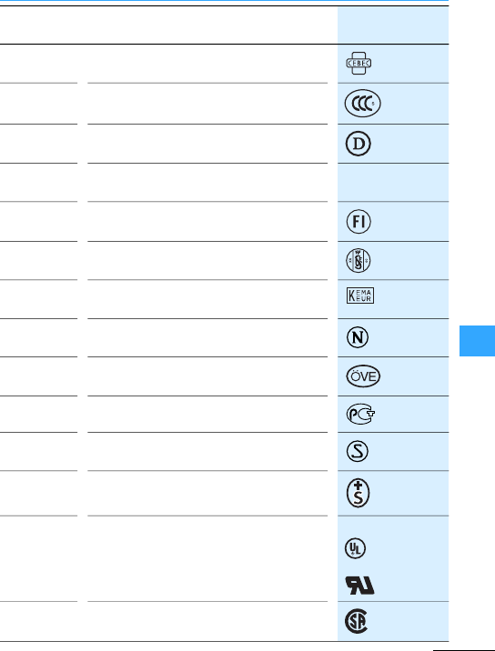
Testing Agenciesand Certification Marks
EatonWiring Manual 06/11
ComitéElectrotechnique Belge
Belgisch Elektrotechnisch Comité(CEBEC)
China Compulsory Certification (CCC)
Danmarks Elektriske Materielkontrol
(DEMKO)
Association of electical, electronics and
information technology
FIMKO
Union Technique de l’Electricité(UTE)
Naamloze Vennootschap tot Keuring van
Electrotechnische Materialien (KEMA)
NorgesElektriske Materiellkontrol (NEMKO)
Österreichischer Verband für Elektrotechnik
(ÖVE)
Goststandart(GOST-)R
Svenska ElektriskaMaterielkontrollanstalten
(SEMKO)
Schweizerischer Elektrotechnischer Verein
(SEV)
Underwriters Laboratories
Listing
Recognition
Canadian Standards Association (CSA)
v

Eaton Wiring Manual 06/11
Identification of electrical equipment in North America
Suitable prefix numbers and/or letters, and
suffix letters may be added to the basic
device designations to differentiate
between componentsperforming similar
functions.
Where two or more basic device
designations are combined,the function
designation is normally given first.
The first control relay initiating a jog
function is designated: "1JCR", where:
1= numberprefix
J = Jogging function of the component
CR =The type of component is aControl
Relay (Contactor Relay).

Identification of electrical equipment in North America
EatonWiring Manual 06/11
AAccelerating
AM Ammeter
BBraking
C or CAP Capacitor, capacitance
CB Circuit-breaker
CR Control relay
CT Current transformer
DM Demand meter
DDiode
DS or DISC Disconnect switch
DB Dynamic braking
FA Field accelerating
FC Field contactor
FD Field decelerating
FL Field-loss
F or FWD Forward
FM Frequency meter
FU Fuse
GP Ground protective
HHoist
JJog
LS Limit switch
LLower
MMain contactor
MCR Master control relay

Identification of electrical equipment in North America
EatonWiring Manual 06/11
MS Master switch
OC Overcurrent
OL Overload
PPlugging, potentiometer
PFM Power factor meter
PB Pushbutton
PS Pressure switch
REC Rectifier
R or RES Resistor, resistance
REV Reverse
RH Rheostat
SS Selector switch
SCR Silicon controlled rectifier
SV Solenoid valve
SC Squirrel cage
SStarting contactor
SU Suppressor
TACH Tachometergenerator
TB Terminal block, board
TR Time-delay relay
QTransistor
UV Undervoltage
VM Voltmeter
WHM Watthour meter
WM Wattmeter
XReactor, reactance

Identification of electrical equipment in North America
EatonWiring Manual 06/11
The use of class designationcode letters to
appropriate ANSI/IEEE standards is
permissible as an alternative to device
designations perNEMA ICS19-2002
(R 2007). Class designation code letters
should simplify harmonization with
international standards. The code letters
are, in part, similar to those of IEC 61346-1
(1996-03).
ASeparate Assembly
BInduction Machine, Squirrel Cage
Induction Motor
Synchro, General
•Control transformer
•Control transmitter
•Control Receiver
•Differential Receiver
•Differential Transmitter
•Receiver
•Torque Receiver
•Torque Transmitter
Synchronous Motor
Wound-Rotor Induction Motor or
Induction Frequency Convertor
BT Battery
CCapacitor
•Capacitor, General
•Polarized Capacitor
Shielded Capacitor
CB Circuit-Breaker (all)

Identification of electrical equipment in North America
EatonWiring Manual 06/11
D, CR Diode
•Bidirectional Breakdown Diode
•Full Wave Bridge Rectifier
•Metallic Rectifier
•Semiconductor Photosensitive
•Cell
•Semiconductor Rectifier
•TunnelDiode
•Unidirectional Breakdown
Diode
D, VR Zener Diode
DS Annunciator
Light Emitting Diode
Lamp
•Fluorescent Lamp
•Incandescent Lamp
•Indicating Lamp
EArmature (Commutor and
Brushes)
Lightning Arrester
Contact
•Electrical Contact
•Fixed Contact
•Momentary Contact
Core
•Magnetic Core
Horn Gap
Permanent Magnet
Terminal
Not Connected Conductor

Identification of electrical equipment in North America
EatonWiring Manual 06/11
FFuse
GRotary Amplifier(all)
A.C. Generator
Induction Machine, Squirrel Cage
Induction Generator
HR ThermalElement Actuating
Device
JFemale Disconnecting Device
Female Receptacle
KContactor, Relay
LCoil
•Blowout Coil
•Brake Coil
•Operating Coil
Field
•Commutating Field
•Compensating Field
•Generator or Motor Field
•Separately Excited Field
•Series Field
•Shunt Field
Inductor
Saturable Core Reactor
Winding, General
LS Audible Signal Device
•Bell
•Buzzer
•Horn
MMeter, Instrument

Identification of electrical equipment in North America
EatonWiring Manual 06/11
P•Male Disconnecting Device
•Male Receptable
QThyristor
•NPN Transistor
•PNP Transistor
RResistor
•Adjustable Resistor
•Heating Resistor
•Tapped Resistor
•Rheostat
Shunt
•Instrumental Shunt
•Relay Shunt
SContact
•Time Closing Contact
•Time Opening Contact
•Time Sequence Contact
•Transfer Contact
•BasicContact Assembly
•Flasher

Identification of electrical equipment in North America
EatonWiring Manual 06/11
SSwitch
•Combination Locking and
Nonlokking Switch
•Disconnect Switch
•Double Throw Switch
•Drum Switch
•Flow-Actuated Switch
•Foot Operated Switch
•Key-Type Switch
•Knife Switch
•Limit Switch
•Liquid-Level Actuated Switch
•Locking Switch
•Master Switch
•Mushroom Head
•Operated Switch
•Pressure or Vacuum
•Operated Switch
•Pushbutton Switch
•Pushbutton Illuminated Switch,
Rotary Switch
•Selector Switch
•Single-Throw Switch
•Speed Switch
Stepping Switch
•Temperature-Actuated Switch
•Time Delay Switch
•Toggle Switch
•Transfer Switch
•Wobble Stick Switch
Thermostat

Identification of electrical equipment in North America
EatonWiring Manual 06/11
TTransformer
•Current Transformer
•Transformer, General
•Polyphase Transformer
•PotentialTransformer
TB Terminal Board
TC Thermocouple
UInseparable Assembly
VPentode, Equipotential Cathode
Phototube, Single Unit,
Vacuum Type
Triode
Tube, Mercury Pool
WConductor
•Associated
•Multiconductor
•Shielded
Conductor, General
XTube Socket
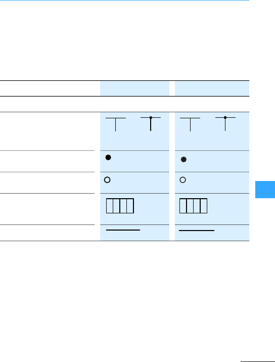
Eaton Wiring Manual 06/11
Electrical circuit symbols, Europe –North America
The following comparison of electrical
circuit symbols is based on the following
international/nationalspecifications:
•IEC60617 graphic symbol database
(DIN EN 60617-2 to DIN EN 60617-12)
•NEMA ICS 19-2002 (R 2007), ANSI Y32.2/
IEEE 315/315A, CSAZ99
Junction of conductors or or
Connection of conductors
(node)
Terminal
Terminal strip/block
Conductors
03-02-04 03-02-05
03-02-01
03-02-02
03-02-03
1234 1234
03-01-01
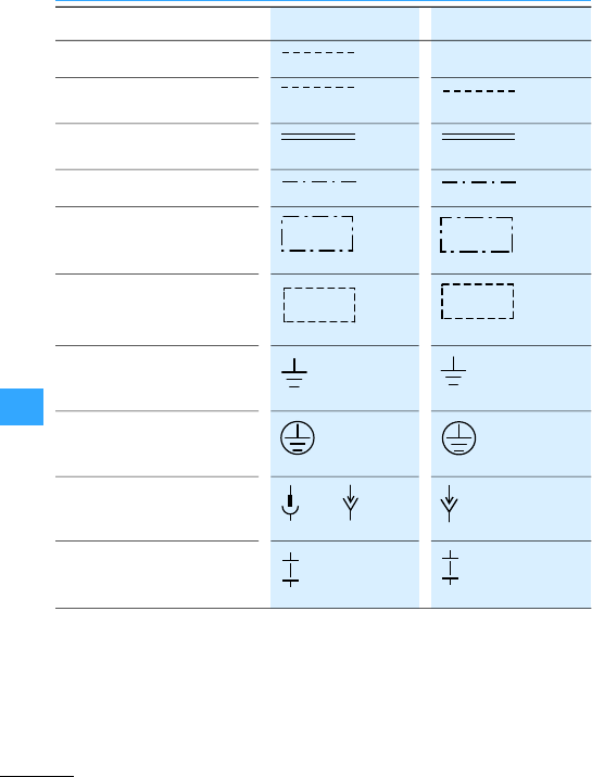
Electrical circuit symbols, Europe –North America
Eaton Wiring Manual 06/11
Conductor (for later expansion)
Line of application, general
symbol
Line of application, optional,
denoting small interval
Separation between two fields
Line of separation between
functional units
Shielding
Earth, general symbolGround,
general symbol
Protective earth Protective
ground
Connector with plug and socket or
Isolating point, lug, closed
103-01-01
02-12-01
02-12-04
02-01-06
02-01-06
02-01-07
02-15-01
GRD
02-15-03
03-03-05 03-03-06
03-03-18
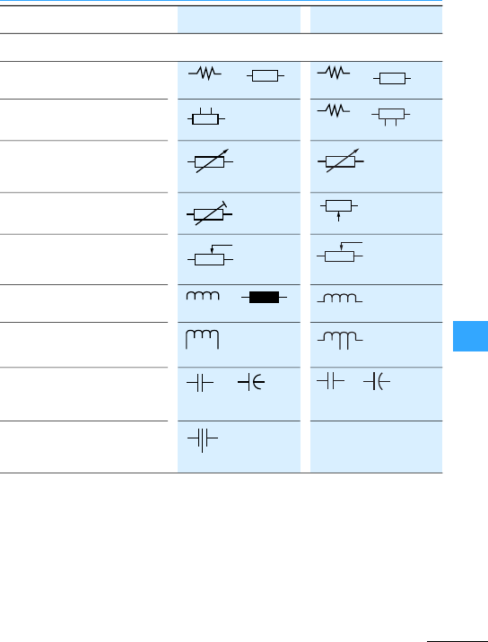
Electrical circuit symbols, Europe –North America
Eaton Wiring Manual 06/11
Resistor, general symbol or or
Resistor with fixed tappings or
Variable resistor, general
Adjustable resistor
Resistor with sliding contact,
potentiometer
Winding, inductance, general or
Winding with fixed tapping
Capacitor, general symbol or or
Variable capacitor
04-01-02 04-01-02
RES
04-01-09
RES
04-01-03 RES
RES
04-01-07
RES
04-03-01 04-03-02
04-03-06
04-02-01 04-02-02
104-02-01

Electrical circuit symbols, Europe –North America
Eaton Wiring Manual 06/11
Visual indicator, general
symbol
*with colour stated
Indicator light, general symbol or or
*with colour stated
Buzzers or
Horn,claxon
Manual operation, general use
Operated by pushing
Operated by pulling
Operated by turning
Operated by key
Operated by rollers, sensors
08-10-01
08-10-11 08-10-10
ABU
08-10-05
HN
02-13-01
02-13-05
02-13-03
02-13-04
02-13-13
02-13-15
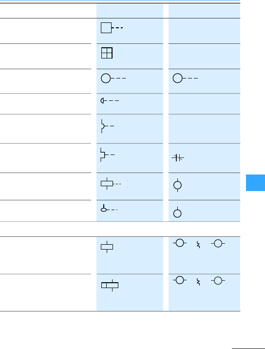
Electrical circuit symbols, Europe –North America
Eaton Wiring Manual 06/11
Stored energy mechanism,
general symbol
Switch mechanism with
mechanical release
Operated by motor
Emergency switch
Operated by electromagnetic
overcurrent protection
Operated by thermal
overcurrent protection
Electromagnetic operation
Control by fluid level
Electromechanical operating
device,general symbol, relay
coil, general symbol
or or
xdevice code letter
7table, page 9-17
Operating device with special
features, general symbol
or or
xdevice code letter
7table, page 9-17
02-13-20
102-05-04
M
02-13-26
MOT
02-13-08
02-13-24
02-13-25
OL
02-13-23
02-14-01
07-15-01
×
×
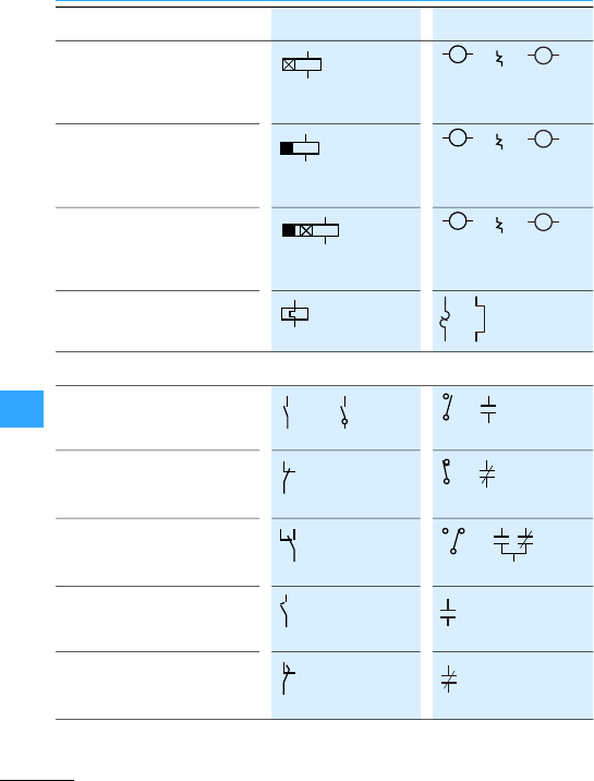
Electrical circuit symbols, Europe –North America
Eaton Wiring Manual 06/11
Electromechanical operating
device with On-delay
or or
xdevice code letter
7table, page 9-17
Electromechanical device with
Off-delay
or or
xdevice code letter
7table, page 9-17
Electromechanical device with
On-and Off-delay
or or
xdevice code letter
7table, page 9-17
Electromechanical device of a
thermal relay or
N/Ocontact or or
N/C contact or
Changeover contactwith
interruption
or
Early-make N/O contact of a
contact assembly
TC or TDC
Late-break N/C contact of a
contact assembly
T0 or TD0
07-15-08
×
07-15-07
×
07-15-09
×
07-15-21
07-02-01 07-02-02
07-02-03
07-02-04
07-04-01
07-04-03
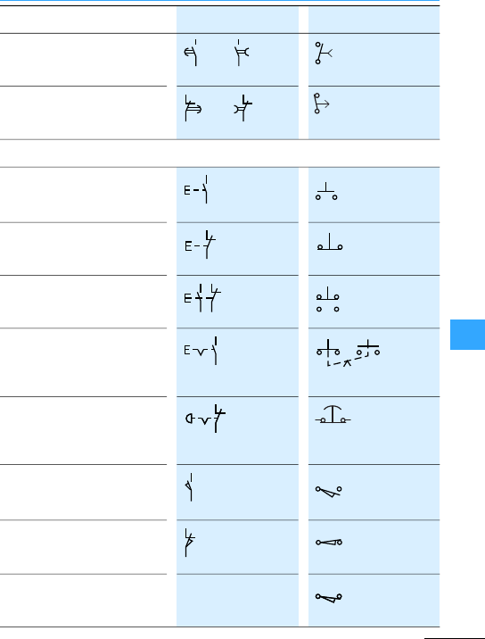
Electrical circuit symbols, Europe –North America
Eaton Wiring Manual 06/11
N/Ocontact, delayed when
closing
or
N/C contact, delayed when
reclosing
or
Push-button (notstay-put)
Spring-return switches with
N/C contact, manually operated
by pushing, e.g. push-button
Spring-return switches with
N/OandN/C contacts, manually
operated by pushing
Spring-return switches with
latching position and one N/O
contact, manually operated by
pushing
Spring-return switches with
latching position and one N/C
contact, manually operated by
striking (e.g.mushroom button)
Position switches (N/O
contacts)
Limit switches (N/O contacts)
Position switches (N/C
contacts)
Limit switches (N/C contacts)
Spring-return switches with
N/Ocontacts, mechanically
operated, N/O contacts closed
07-05-02 07-05-01 T.C.
07-05-03 07-05-04
T.C.
07-07-02
PB
PB
PB
PB
07-08-01
LS
07-08-02
LS
LS
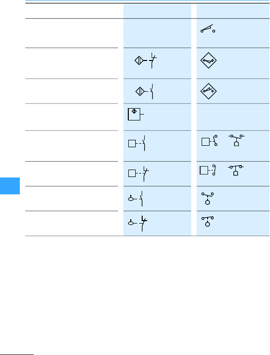
Electrical circuit symbols, Europe –North America
Eaton Wiring Manual 06/11
Spring-return switches with
N/C contacts, mechanically
operated, N/C contacts open
Proximity switches (N/C
contacts), actuated by the
proximity of iron
Proximity switches, inductive,
N/Ocontacts
Proximity switches, block
diagram
Under-pressure relays,N/O
contacts
or
Pressure switches, N/C contact or
Float switches, N/O contact
Float switches, N/C contact
LS
Fe
07-20-04
Fe
07-19-02
07-17-03
P<P
P>P
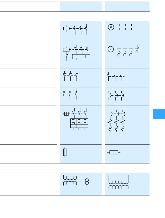
Electrical circuit symbols, Europe –North America
Eaton Wiring Manual 06/11
Contactors (N/O contacts)
xcode letter
Three-pole contactor with
bimetal relay (3 thermal
elements)
xcode letter
Three-pole
switch-disconnector
Three-pole circuit-breaker
Three-pole breaker with switch
mechanism with three
thermoelectric overcurrent
releases,three
electromagnetic overcurrent
releases, motor-protective
circuit-breaker
Fuse, general symbol
Transformers with two
windings or
07-13-02
OL
07-13-06
DISC
07-13-05
CB
107-05-01
l>l>l>
07-21-01
FU
06-09-02 06-09-01 X1 X2
H1 H2
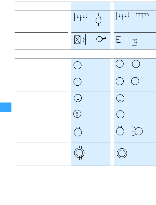
Electrical circuit symbols, Europe –North America
Eaton Wiring Manual 06/11
Autotransformer or or
Currenttransformer or or
Generator or
Motor, general symbol or
DC motor,general symbol
AC motor,general symbol
Three-phase asynchronous
motor with squirrel-cage rotor
or
Three-phase asynchronous
motor with slip-ringrotor
06-09-07
06-09-06
06-09-11 06-09-10
CT
(H1)
(X1)
G
06-04-01
GGEN
M
06-04-01
M
06-04-01
MOT
M
06-04-01
M
06-04-01
M
~
M
3
~
06-08-01
M
M
3
~
06-08-03
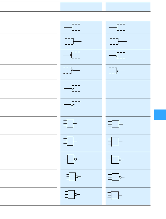
Electrical circuit symbols, Europe –North America
Eaton Wiring Manual 06/11
Static input
Static output
Static input with negation
Static output with negation
Dynamic input,change of
status from 0to 1(L/H)
Dynamic input with negation,
change of status from 1 to 0
(H/L)
AND gate, general symbol
OR gate, general symbol
NOT gate, inverter
AND with negated output,
NAND
OR with negated output, NOR
12-07-01
12-07-02
12-07-07
12-07-08
&
12-27-02
A
1
12-27-01
OR
1
12-27-11
OR
&
1
2
13
12-28-01
A
1
3
4
5
12-28-02
OR
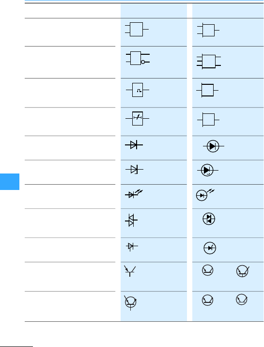
Electrical circuit symbols, Europe –North America
Eaton Wiring Manual 06/11
Exclusive OR gate, general
RS flip-flop
Monostable gate,cannot be
triggered during the output
pulse,general symbol
Delay, variable with indication
of delay values
Semiconductor diode, general
symbol
Limiting diode Zener diode
Light-emitting diode (LED),
general symbol
Bi-directional diode, diac
Thyristor, general symbol
PNP transistor or
NPNtransistor, in which the
collectoris connected to the
enclosure
or
= 1
12-27-09
OE
S
R
12-42-01
S FF 1
T
C 0
1
12-44-02
SS
02-08-05
TP
Adj.
m/ms
05-03-01
(A) (K)
05-03-06
05-03-02
05-03-09
(T) (T)
05-04-04
(A) (K)
05-05-01
(A) (K)
(E) (C)
(B)
05-05-02
(A)
(K) (E) (C)
(B)
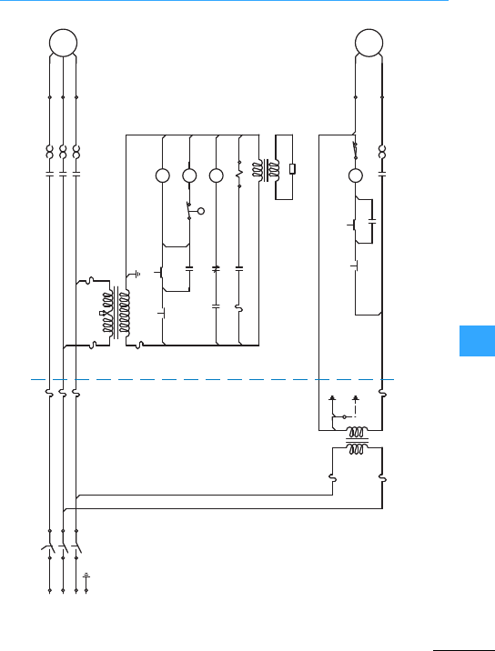
Eaton Wiring Manual 06/11
Circuit diagram examples using North American graphic symbols
aFeeder Circuit
bBranch Circuit 1
cBranch Circuit 2
dPowerTransformer
eControl Circuit Transformer
fClass 2 Transformer
gClass 2 Circuit
1 DISC
L 1 L 1 T 1 1 FU-1 1 M-110 L
2 M-1
2 M-1
2 M-1
2 PB-22 PB-1 2 PB-2 1 LS
20 L
MTR1
MTR2
a
1 FU-2
1 FU-3
4 FU-1
5 FU-1
5 FU-2
3 FU-2
3 T
2 FU-2
2 FU-1
4 FU-2
1 PB-1 1 PB-2
1 M-1
1 M-2 1 SOL
1 M-1 1 M-2
1 M-1
1 FS 1 CR-1
1 CR-1
L 2 L 2 T 2
L 3 L 3 T 3
1 T
2 T
d
b
f
g
c
e
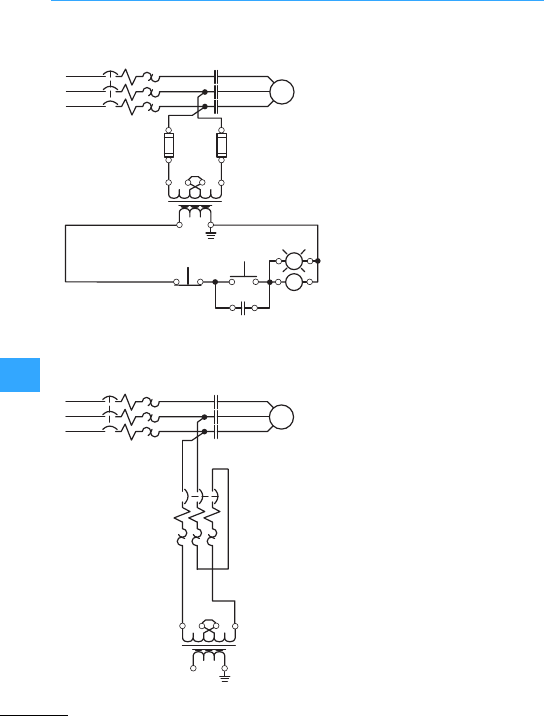
Circuit diagram examples using North American graphic symbols
Eaton Wiring Manual 06/11
with fuse
,fuseless
L1
L2
L3
CB L1
L2
L3
T1
T2
T3
H3
H1 H4
14
H2
X1 X2
1FU 2FU
M
M
X1 X2
A1 A2
W
2 PB
M
13
13
14
14
M
12
11
1 PB
STOP START
L1
L2
L3
CB L1
L2
L3
T1
T2
T3
H3
14
H2
X1 X2
M
M
H1 H4
H1 H4

EatonWiring Manual 06/11

Eaton Wiring Manual 06/11
North American classification for control circuit contact ratings
Classification Designation
At maximum rated voltage of
Thermal
uninterrupt
ed current
600 V 300 V 150 V A
Heavy Duty A600
A600
A600
A600
A300
A300
–
–
A150
–
–
–
10
10
10
10
Standard Duty B600
B600
B600
B600
B300
B300
–
–
B150
–
–
–
5
5
5
5
C600
C600
C600
C600
C300
C300
–
–
C150
–
–
–
2.5
2.5
2.5
2.5
–
–
D300
D300
D150
–
1
1
Heavy Duty N600
N600
N600
N300
N300
–
N150
–
–
10
10
10
Standard Duty P600
P600
P600
P300
P300
–
P150
–
–
5
5
5
Q600
Q600
Q600
Q300
Q300
–
Q150
–
–
2.5
2.5
2.5
–
–
–
R300
R300
–
R150
–
–
1.0
1.0
–
to UL 508, CSA C 22.2-14 and NEMA ICS 5

North American classification for control circuit contact ratings
EatonWiring Manual 06/11
Switching capacity
Ratedvoltage V Make A Break A Make VA Break VA
120
240
480
600
60
30
15
12
6
3
1.5
1.2
7200
7200
7200
7200
720
720
720
720
120
240
480
600
30
15
7.5
6
3
1.5
0.75
0.6
3600
3600
3600
3600
360
360
360
360
120
240
480
600
15
7.5
3.75
3
1.5
0.75
0.375
0.3
1800
1800
1800
1800
180
180
180
180
120
240
3.6
1.8
0.6
0.3
432
432
72
72
125
250
301–600
2.2
1.1
0.4
2.2
1.1
0.4
275
275
275
275
275
275
125
250
301–600
1.1
0.55
0.2
1.1
0.55
0.2
138
138
138
138
138
138
125
250
301–600
0.55
0.27
0.10
0.55
0.27
0.10
69
69
69
69
69
69
125
250
301–600
0.22
0.11
–
0.22
0.11
–
28
28
–
28
28
–

Eaton Wiring Manual 06/11
North American motor ratings
HP 115 V
120 V
230 V
240 V
460 V
480 V
575 V
600 V
1/2
3/4
1
4.4
6.4
8.4
2.2
3.2
4.2
1.1
1.6
2.1
0.9
1.3
1.7
11/2
2
3
12
13.6
6.0
6.8
9.6
3.0
3.4
4.8
2.4
2.7
3.9
5
71/2
10
15.2
22
28
7.6
11
14
6.1
9
11
15
20
25
42
54
68
21
27
34
17
22
27
30
40
50
80
104
130
40
52
65
32
41
52
60
75
100
154
192
248
77
96
124
62
77
99
125
150
200
312
360
480
156
180
240
125
144
192
250
300
350
302
361
414
242
289
336
400
450
500
477
515
590
382
412
472
1) Source: NEC Code, Table 430-250, with additional full load current values for208 V
and 200 V motors.
2) The full load current values provided in the tables are used as guidelines for
equipment selection. Also consult motormanufacturer data and actual motor
nameplate ratings.

Eaton Wiring Manual 06/11
North American environmental type ratings for electrical equipment
IP ratings per IEC/ENstandards cannot be
used as a substitute for North American
Type ratings.
A
precise conversion is not possible since
tests and evaluation criteriain the relevant
standards differ greatly from one another.
UL/CSA and NEMA type ratings are often
used interchangeably. The significant
difference between the two is that a
UL/CSA type rating represents third party
certification by an approved testing
agency, which is the preferred manner in
which ratings are verified in North
America.
North American environmental type
ratings are referenced in the following
standards:
•NFPA 70 (National Electrical Code),
•CEC (Canadian ElectricalCode),
•UL 50E, UL 508A,
•CSA-C22.2 No.94-M91 (2006),
•NEMA 250-2008 (National Electrical
Manufacturers Association).
Incidental contactwith enclosed
equipment; falling dirt
Indoor useIP20
Driptight
Indoor use IP22
Dusttight, raintight, degree of
protection against rain, snowand
sleet
Outdooruse IP55
Rainproof, degree of protection
against rain, snow and sleet
Outdooruse IP24
Dust-tight,rain-tight, protection
against sleet and ice
Outdooruse IP55

North American environmental type ratings for electrical equipment
EatonWiring Manual 06/11
same as 3, 3R and 3 S, but with
corrosion resistance
Outdooruse IP55
Watertight,raintight, dusttight
Indoor or
Outdooruse1)
IP66
Watertight,raintight, dusttight,
corrosion resistant
Indoor or
Outdooruse1)
IP66
Driptight, dusttight
Indoor use IP53
Raintight, watertight, temporarily
submersible
Indoor or
Outdooruse1)
IP67
Common industrial rating, driptight,
dusttight
Indoor use IP54
driptight, dusttight, oiltight
Indoor useIP54
1)Take note of manufacturer instructions!

North American environmental type ratings for electrical equipment
EatonWiring Manual 06/11
General purpose: general purpose
tropfdicht: drip-tight
staubdicht: dust-tight
regendicht: rain-tight
regensicher: rain-proof
wettersicher: weather-proof
wasserdicht: water-tight
eintauchbar: submersible
eisbeständig: ice resistant
hagelbeständig: sleet resistant
korrosionsbeständig: corrosion
resistant
öldicht: oil-tight

Eaton Wiring Manual 06/11
North American conductor cross-sections
22 0.324 0.4
20 0.519 0.5
18 0.823 0.75
16 1.31 1.5
14 2.08
12 3.31 4
10 5.261 6
88.367 10
613.30 16
421.15 25
326.67
233.62 35
142.41
1/0 (0) 53.49 50
2/0 (00) 67.43 70
3/0 (000) 85.01
4/0 (0000) 107.2 95

North American conductor cross-sections
EatonWiring Manual 06/11
250 127 120
300 152 150
350 177 185
400 203
450 228
500 253 240
550 279
600 304 300
650 329
700 355
750 380
800 405
900 456
1,000 507 500
In addition to “circularmills”, cable sizesare often given in “MCM”:
250 000 circular mills = 250 MCM

EatonWiring Manual 06/11

Eaton Wiring Manual 06/11
10

Eaton Wiring Manual 06/11
10
Marking of electrical equipment
Eaton uses the above standard.
Unlike the method of marking up to now,
the function of the electrical equipment in
the respective circuit primarly determines
the cose letter. This means that there is
some freedom in the selection of the code
letters.
Example of a resistor
•Normalcurrent limiter: R
•Heaterresistor: E
•Measurementresistor: B
In addition to that, Eaton specific decisions
have been made with regard to the
interpretation of the standard that
sometimes deviatefrom the standard.
•The marking of connection terminals are
readable from the right.
•Asecond code letter for the marking of
the use of the equipment is given,
e.g.: timing relay K1T becomes K1.
•Circuit-breakers with the main function
of protection are still marked with Q.
They are numbered from 1 to 10 from the
top left.
•Contactors are newly marked with Q and
numbered from 11 to nn.
e.g.: K91M becomes Q21.
•Contactor relays remain K and are
numbered from 1ton.
The marking appears in a suitable position
as close as possible to the circuit symbol.
The marking forms the link betweenthe
equipment in the installation and the
various circuit documents (wiring
diagrams, parts lists, circuit diagrams,
instructions). For simpler maintenance, the
complete marking or part of it, can be
affixed on or near to the equipment.
Selected equipment with a comparison of
the Eaton used code letters old –new
7Table, page10-3

Marking of electrical equipment
Eaton Wiring Manual 06/11
10
A(several purposes) (without main purpose)
BSignal generation Pressure switches; limit switches
CStorage Capacitors
D(reserved for later)
E Energy supply Heating resistor, lamps
FProtection Bimetalreleases, fuses
GPower supply Generator, UPS
H(reserved for later)
I(must not be used)
J(reserved for later)
KP Signal processing Contactor relay, timing relays
L(reserved for later)
M Drive energy Motor
N(reserved for later)
O(must not be used)
PInformation display Signalling and measuring devices
QSwitching energy /
signal flow
Soft starter, contactor,
motorstarter
REnergy flow limitation Reactorcoils, diodes
SManual signalgeneration Control circuit devices
TEnergy conversion Frequency inverters, transformer
UObject fixing
VMaterial processing Electro filter
WPower transmission
X Object connection Terminal, plug connector
Y, Z (reserved for later)

Eaton Wiring Manual 06/11
10
Protective measures
This is divided into basic protection
(previously protection against direct
contact), fault protection (previously
protection against indirect contact) and
protection against both direct and indirect
contact.
•
These are all the measures for the
protection of personneland working
animals from dangers which may arise
from contact with live parts of electrical
equipment.
•
This is the protection of personnel and
working animals from fault scenarios
which may arise from accidental contact
with components or extraneous
conductive parts.
•
If basic or fault protection fails or there is
agreaterpotential danger, residual
current protective devices with
I-n#30 mA offeradditional protection.
Protection must be ensured by eithera) the
equipment itself or b) the use of protective
measureswhen erecting the installation or
c) acombination of a) and b).
If basic, fault and additional protection is
combined in a suitable manner the
following protective measures result and
are covered in section 410 of DIN VDE0100:
•Automatic disconnection of the power
supply (0100-411)
•Double or reinforced insulation
(0100-412)
•Protective separation (0100-413)
•Safety extra low voltage SELV or PELV
(0100-414)
One of the key amendments to DINVDE
0100-410 of June 2007 was the additional
protection for final circuits for outdoor
areas and sockets (411.3.3). This stipulates
that an additional protection must be
provided by means of residual current
devices (RCDs) with I-n#30 mA for
sockets #20 A, as well as final current
circuits forportable equipment #32 A used
outdoors. The previous recommendation
has therefore been changed to a
mandatory requirement in order to
increase safety.
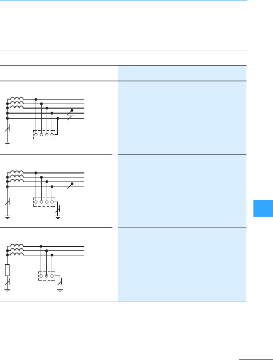
Protective measures
Eaton Wiring Manual 06/11
10
The conditions for disconnection are
determined by the type of systemin use
and the protective device selected.
RBEarthing on the current source
RAEarthing on chassis of electrical
equipment
T: Direct earthing of a point
N: Chassis (of electrical equipment)
directly connected with the power
supply system earth
T: Direct earthing of a point
T: Direct electricalconnection of chassis
to earth, independent of any existing
earthing of the power supply system
I: All live parts isolated from earth or one
point connected to earth via a high
impedance
T: Direct electricalconnection of chassis
to earth, independent of any existing
earthing of the power supply system
L2
N
L1
L3
PE
RB
L2
N
L1
L3
RBRA
L2
L1
L3
RA
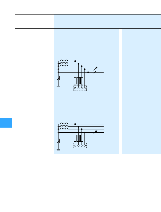
Protective measures
Eaton Wiring Manual 06/11
10
Protection with Circuit principle Conditionfor
disconnection
Overcurrent
protective device
TN-S system
separated neutral and protective
conductors throughout the system
ZsxI
a#U
0with
Zs=Impedance of the
faultcircuit
Ia= Current, which
causes switch off in
(0100-411.3.2):
•#5 s
•#0.2 s
U0= rated voltage
against earthed
conductor
Fuses,
miniature circuit-
breakers,
circuit-breakers
TN-C system
Neutral conductor and protection
functions are combined throughout
the system in a single PEN
conductor.
L2
N
L1
L3
PE
L2
PEN
L1
L3
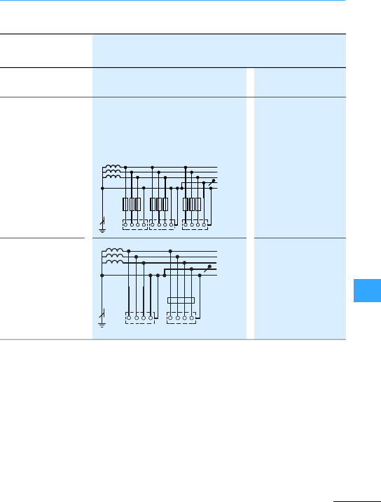
Protective measures
Eaton Wiring Manual 06/11
10
1) 7Table, page 10-11
Protection with Circuit principle Conditionfor
disconnection
Overcurrent
protective device
TN-C-S system
Neutral conductor and protective
conductorfunctions are in a part of
the system combined in asingle PEN
conductor.
Fault current
protective device
Zsx I-n#U0with
I-n= Rated fault
current
U0= Maximum
permissible touch
voltage1):
(#50 V AC,
#120VDC)
L2
L1
L3
N
PE(N)
L2
L1
L3
N
PE(N)
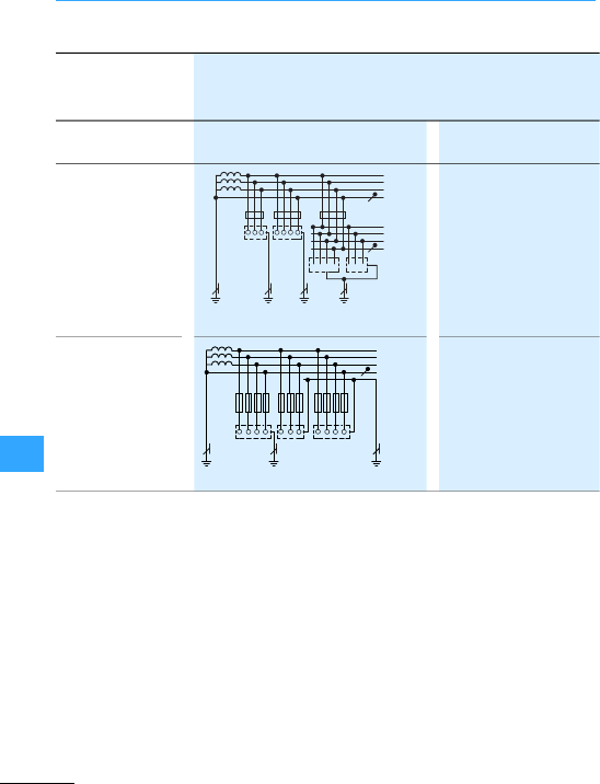
Protective measures
Eaton Wiring Manual 06/11
10
1) 7Table, page 10-11
Protection with Circuit principle Conditions for
indication/disconnection
Residual current
device
(General case)
RAx I-n#ULwith
RA=Earthing resistance
of conductive parts of
the chassis (total)
I-n= Rated fault current
UL= Maximum
permissible touch
voltage1):
(#50 V AC, #120VDC)
Overcurrent
protective device
Fuses,
miniature circuit-
breakers,
Circuit-breakers
(special case)
RAx Ia#ULwith
Ia=Current which
causes automatic
disconnection in #5 s
L2
PE
L1
L3
N
L2
L1
L3
N
PE PE
FI FI FI
L2
PE
L1
L3
N
PE
PE
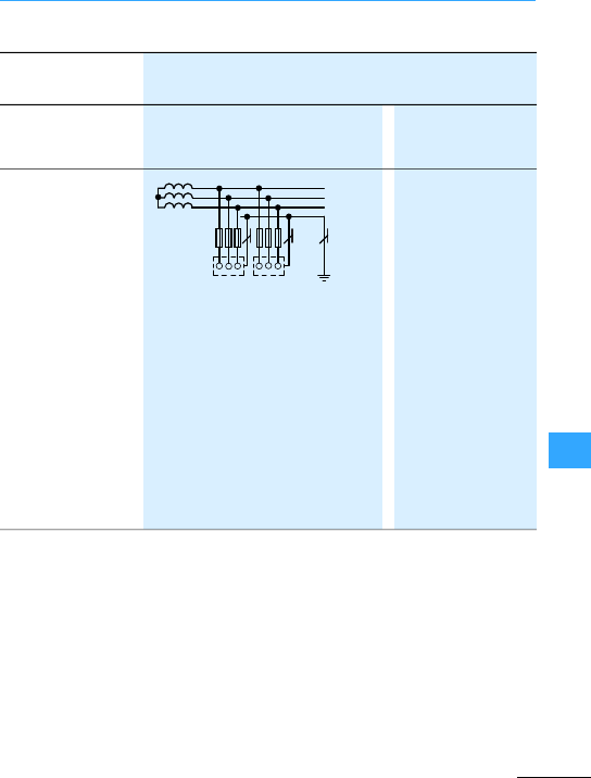
Protective measures
Eaton Wiring Manual 06/11
10
1) 7Table, page 10-11
Protection with Circuit principle Conditions for
indication/
disconnection
Overcurrent
protective device
(always with
additional
insulation
monitoring device,
see below)
RAx Id#UL(1)
ZSx Ia#Uo(2)
RA= Earthing
resistance of all
conductive parts
connected to an
earth
Id= Fault currentin
the event of thefirst
fault with a negligible
impedance between
a phase conductor
and the protective
conductororelement
connected to it
UL= Maximum
permissible touch
voltage1):
#50 V AC, #120 VDC
L2
PE
L1
L3
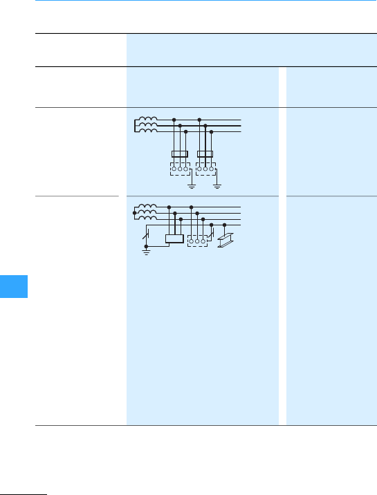
Protective measures
Eaton Wiring Manual 06/11
10
Protection with Circuit principle Conditions for
indication/
disconnection
Residualcurrent
device(RCD)
(alwayswith
additional
insulation
monitoring device,
see below)
RAx I-n#UL
I-n=Rated fault
current
Insulation
monitoring device
(IMD)
"additionalpotential equalization
The insulation
monitoring device is
used to displaythe
insulation state of all
live parts to earth. An
indication
(visual/acoustic) is
generated if the
resistance goes
below a specific
value (R). The system
is not disconnected
but remains
operational untila
second earth fault
occurs and the
automatic
disconnection takes
place.
L2
PE
L1
L3
PE
FI FI
L2
PE
L1
L3
R<
①

Protective measures
Eaton Wiring Manual 06/11
10
The protective device must automatically
disconnect thefaulty part of the
installation. At no part of the installation
may there be a touch voltage or an
effective duration greater than that
specified in thetable below.
U0is the rated operatingvoltage phase
conductor to earth.
A disconnection may be necessary for
different reasons than the protection from
electric shock.
Max. permissible
disconnection time [s]
Max. permissible
disconnection time [s]
50 V< U0#120 VAC0.8 0.3
DC (see note) (see note)
120V< U0#230VAC0.4 0.2
DC 5.0 0.4
230V< U0#400VAC0.2 0.07
DC 0.4 0.2
U0> 400 VAC
0.1 0.04
DC 0.1 0.1
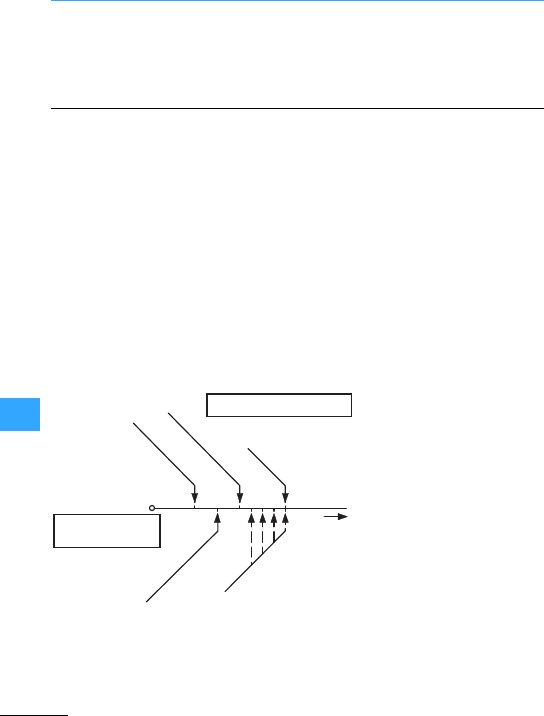
Eaton Wiring Manual 06/11
10
Overcurrent protection of cables and conductors
Cables and conductors must be protected
by means of overcurrent protective
devices against excessivetemperature
rises, which may result both from
operational overloading and from short-
circuit.
(in depth explanations on new DINVDE
0100-430 contained in volume 143, 3rd
edition, of the VDE publication series).
Overload protection involves the provision
of protective devices which will interrupt
overload currents in the conductors of a
circuit before they can cause temperature
rises which may damage the conductor
insulation, the terminals and connections
or the area around the conductors.
For the protection of conductors against
overload the following conditions must be
fulfilled (source: DIN VDE 0100-430)
IBAnticipated operating current of the
circuit
IZCurrent carrying capacityof conductor
or cable
InRated operational current of the
protective device
I2The currentwhich causes tripping of
the protectivedevice underthe
conditions specified in the equipment
regulations.
Protection devices foroverloadprotection
must be fitted at the start of every circuit
and at every point where the current
carrying capacity is reduced unless an
upstream protection device can ensure
protection.
IB#In#IZ
I2#1.45 IZ
IA
1.45 3Iz
Characteristic values
of the protective device
Reference values of the cable
Rated current or
setting current In
Tripping current I2
Current carrying capacity Iz
Operating current IB

Overcurrent protection of cables and conductors
Eaton Wiring Manual 06/11
10
Reasons forthe currentcarrying capacity
being reduced:
Reduction of the conductor cross-section,
a different installation method, different
conductor insulation, a different number of
conductors.
Protective devices foroverload protection
should not be fitted if interruption of the
circuitcould prove hazardous. The circuits
must be laid out in such a way thatno
possibility of overload currents occurring
need be considered.
Examples:
Timing relay =function relay with contacts
and coils
Time switch = function relay with contacts
•Energizing circuits for rotating machines
•Feeder circuits of solenoids
•Secondary circuitsof current
transformers
•Circuitsfor safety purposes
Short-circuit protection means providing
protective deviceswhich will interrupt
short-circuitcurrents in the conductors of
a circuitbefore they can cause a
temperature rise which may damage the
conductor insulation,the terminals and
connections, or the area around the cables
and conductors.
In general, the permissible disconnection
time t for short circuits of up to 5 s duration
can be specified approximately using the
following equation:
or
The meaning of the symbols is as follows:
t: Permissible disconnection time in the
event of short-circuit in s
S: Conductor cross-section in mm2
I: r.m.s. value of the current with a
maximum short-circuit in A
k: Constants with the values
–115 for PVC-insulated copper
conductors
–76 for PVC-insulated aluminum
conductors
–141 forrubber-insulated copper
conductors
–93 forrubber-insulated aluminum
conductors
–115 forsoft-solder connections in
copper conductors
–Other values for k are given in Table
43Aof DIN VDE 0100-430.
With very short permissible disconnection
times (< 0.1 s) the product from the
equation k2x S2must be greaterthan the
I2xtvalue of the current-limiting device
stated by manufacturer.
Protective devices for protection in the
eventof a short-circuit must be fitted at the
startof every circuit and at every point at
which the short-circuit current-carrying
capacity is reduced unless aprotective
device fitted upstream can ensure the
necessary protection in the event of a short
circuit.
tkx
S
I
---
+1
,3
2
=I
2xt=k
2
x S2

Overcurrent protection of cables and conductors
Eaton Wiring Manual 06/11
10
Reasons forthe reduction in the short-
circuitcurrent-carrying capacitycan be:
Reduction of the conductor cross-section,
other conductor insulation.
Short-circuit protection must not be
provided where an interruption of the
circuit could prove hazardous. In these
cases two requirements must be fulfilled:
•The cable must be laid so that the risk of
short-circuits is reduced to a minimum.
•The cable must not be laid in the vicinity
of flammable materials.
Overcurrentprotection devicesmust be
provided in every main pole: they must
disconnect the conductor in which the
overcurrent occurs, but not necessarily
also disconnect the other live conductors.
Where the disconnection of an individual
main pole could prove hazardous, as for
example,with three-phase motors,
suitable precautions must be taken. Motor-
protective circuit-breakers and circuit-
breakers disconnect in 3 poles as
standard.
1. In installations with a directly earthed
neutral point or
Where the cross-section of the neutral
conductor is less than that of the main
poles, an overcurrent monitoring device
appropriate to its cross-section is to be
provided in the neutral conductor; this
overcurrentmonitoring device must result
in the disconnection of the phase
conductors but not necessarily that of the
neutral conductor.
An overcurrent monitoring devicein the
neutral conductor is not necessary where:
•theneutral conductoris protected in the
event of a short-circuit by the protective
device forthe main poles
•the largest current which can flow
through the neutral conductor is, in
normal operation, considerably less than
the current carrying capacity of this
conductor.
This second conditionis met provided that
the powertransferred is divided as evenly
as possible among the main poles, for
example where the total power
consumption of the load connected
between phase and neutral conductors,
lamps and socket outlets is much less than
the total powertransferred via the circuit.

Overcurrent protection of cables and conductors
Eaton Wiring Manual 06/11
10
2.In installations without adirectly earthed
neutral point
Where it is necessary for the neutral
conductor to be included, an overcurrent
monitoring device must be provided in the
neutral conductor of each circuit,to cause
disconnection of all live conductors in the
relevant circuit (including the neutral
conductor).
Theovercurrent monitoring device may
howeverbe omitted where the neutral
conductor in question is protected against
short-circuit by an upstream protective
device, such as in the incoming unit of the
installation.
Where disconnection of the neutral
conductor is specified, the protective
device used must be designed in such a
way thatthe neutral conductorcannot
under any circumstances be disconnected
before the phase conductors and
reconnected again after them. 4-pole NZM
circuit-breakers always meet these
conditions.
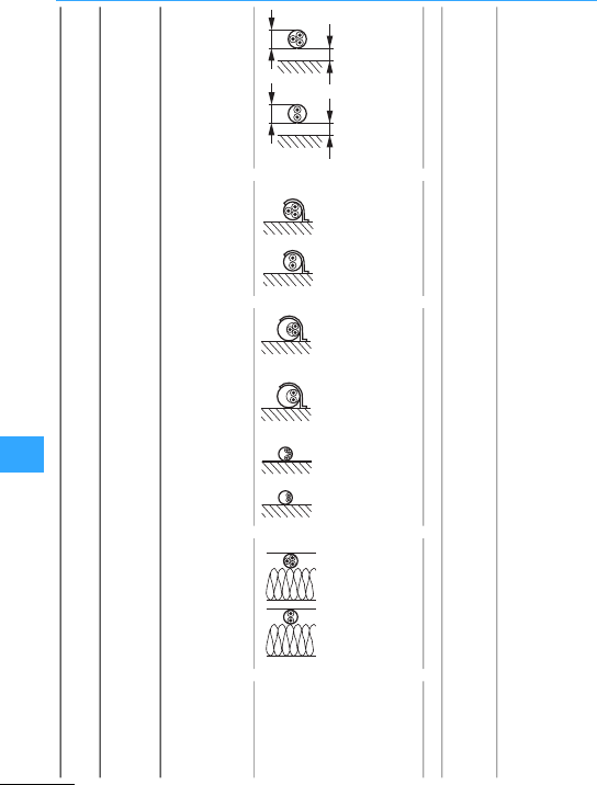
Overcurrent protection of cables and conductors
Eaton Wiring Manual 06/11
10
Type of cable or
conductor
NYM, NYBUY, NHYRUZY, NYIF,
H07V-U, H07V-R, H07V-K, NYIFY
NYY,NYCWY, NYKY, NYM,
NYMZ, NYMT, NYBUY,
NHYRUZY
Type of
installation
A1 b1 m2 CE
In heat-insulating
walls, in cable conduit
underthe surface
In cable conduits On a wall Exposed
Single-core
cables
Multi-core cable
Multi-core cable
underthe surface
Cable cores in
cable conduit
on the wall
Multi-core cable in
cable conduit on the
wall surface
Singleormulti-core
cables or insulated
cables
Multi-core cables or
insulated cables with a
minimum clearance of
0.3xdiameter d to wall
Number of 23 232323 23
Current-carrying capacity Izin A for 25°C
ambient air temperature and 70°C operating
temperature.
≧ 0.3 d≧ 0.3 d
dd

Overcurrent protection of cables and conductors
Eaton Wiring Manual 06/11
10
Type of
installation
A1 b1 m2 CE
Number of
cores
23232323 23
Copper
conductor
cross-
section in
mm2
IzInIzInIzInIzInIzInIzInIzInIzInIzInIzIn
1.516.51614.51318.51616.51617.5161613212018.516232019.516
2.5212019.51625252220242021202925252532322725
42825252534323025322529253835343242403635
63635333243403835403536354940434054504640
10 49 40 45 40 60 50 53 50 55 50 49 50 67 63 60 63 74 63 64 63
16 65 63 59 50 81 80 72 63 73 63 66 63 90 80 81 80 100100 85 80
25 85 80 77 63 107100 94 80 95 80 85 80 119100 102100 126125 107 100
35 105100 94 80 133125 117 100118 100105 100146 125 126125 157125 134 125
50 126125 114100 160160 142 125141 125125 125178 160 153125 191160 162 160
70 160160 144125 204200 181 160178 160158 125226 224 195160 246224 208 200
95 193160 174160 246224 219 200213 200190 160273 250 236224 299250 252 250
120223 200 199160 285250 253 250246 224218 200317 315 275250 348315 293 250
For overcurrent protective devices with a rated operational current Inthat does not conform to the values given in the table, select the next lower
available rated operational current value.

Overcurrent protection of cables and conductors
Eaton Wiring Manual 06/11
10
Main poles Insulated power
cables
0.6/1-kV cable
with
4 conductors
Protected Unprotected2)
mm2mm2mm2mm2
Cu Al
mm2
Cu
To 0.5 0.5 –2.5 4 4
0.75 0.75 –2.5 4 4
11–2.5 4 4
1.5 1.5 1.5 2.5 4 4
2.5 2.5 2.5 2.5 4 4
44 4 4 4 4
66 6 6 6 6
10 10 10 10 10 10
16 16 16 16 16 16
25 16 16 16 16 16
35 16 16 16 16 16
50 25 25 25 25 25
70 35 35 35 35 35
95 50 50 50 50 50
120 70 70 70 70 70
150 70 70 70 70 70
185 95 95 95 95 95
240 –120 120 120 120
300 –150 150 150 150
400 –185 185 185 185
1) PEN conductor ,10 mm2Cu or 18 mm2Al
2) It is not permissible to lay aluminum conductors without protection.
3) With main poles of ,95 mm2or more, it is advisable to use non-insulted conductors.

Overcurrent protection of cables and conductors
Eaton Wiring Manual 06/11
10
When the ambient temperature is not 30 °C;
to be usedfor the current carrying capacity
of wiring or cables in air to VDE 0298-4
Table 17.
1) Higher ambient air temperatures in
accordance with information given
by the manufacturer
Insulation material1) NR/SR PVC EPR
Permissible operating
temperature
60 °C 70 °C 80 °C
Ambient air temperature °C Conversion factors
10 1.29 1.22 1.18
15 1.22 1.17 1.14
20 1.15 1.12 1.10
25 1.08 1.06 1.05
30 1.00 1.00 1.00
35 0.91 0.94 0.95
40 0.82 0.87 0.89
45 0.71 0.79 0.84
50 0.58 0.71 0.77
55 0.41 0.61 0.71
60 –0.50 0.63
65 –0.35 0.55
70 – – 0.45
75 – – 0.32

Overcurrent protection of cables and conductors
Eaton Wiring Manual 06/11
10
Grouping of several circuits
Conversion factors for the grouping of
multi-core cables or cables on cable
troughs or trays as well as for other cases
are provided in DIN VDE 0298-4,tables 22 to
27.
1 2 3 4 6 9 12 16 20
1Embedded or
enclosed
1.00 0.80 0.70 0.65 0.57 0.50 0.45 0.41 0.38
2Fixed to walls or
floors
1.00 0.85 0.79 0.75 0.72 0.70 0.70 0.70 0.70
3Fixed under
ceilings
0.95 0.81 0.72 0.68 0.64 0.61 0.61 0.61 0.61

Eaton Wiring Manual 06/11
10
Electrical equipment of machines
This standard is used for the electrical
equipment of machines, unless there is a
product standard (Type C) for the type of
machine to be equipped.
Safety requirements regarding the
protection of personnel, machines and
material according to the European
Machinery Safety Directive are highlighted
under the heading “Safety of machines”.
The degree of possible danger is to be
estimated by risk assessment. The
standard also includes requirements for
equipment, engineering and construction,
as well as tests to ensure faultless function
andthe effectiveness of protective
measures. The following paragraphs are
an extractfrom the standard.
Every machinemust be equipped with a
manually-operated mains isolating device.
It must be possible to isolate the entire
electrical equipment of the machine from
the mains using the mains isolating device.
The breaking capacity must be sufficient to
simultaneously disconnect the stalled
current of the largest motor in the machine
and the total current drawn by all the other
loads in normal operation.
Its Off position must be lockable and must
not be indicated until the specified
clearances and creepage distances
betweenall contacts have been achieved.
It must have only one On and one Off
position with associated stops. Star-delta,
reversing and multi-speed switches are
not permissible for use as mains isolating
devices.
The tripped position of circuit-breakers is
not regarded as aswitch position,
therefore there is no restriction on their
use as mains isolating devices.
Where there are several incomers, each
one must have a mains isolating device.
Mutual interlocking must be provided
where ahazard may result from only one
mains isolating device being switched off.
Only circuit-breakers may be used as
remotely-operated switches. They must be
provided with an additional handle and be
lockable in the Off position.
The following measures must be taken to
protect personnel against electricshock.
This is understood as meaning protection
by means of an enclosure which can only
be opened by qualified personnel using a
key or special tool. Such personnel is not
obliged to disable the mains isolating
device before opening the enclosure. Live
parts must be protected against direct
contact in accordance with DIN EN 50274
or VDE 0660-514.
Where the mains isolating device is
interlocked with the door, the restrictions
mentioned in the previousparagraph
cease to apply because the doorcan only
be opened when themains isolating device
is switched off. It is permissible for an

Electrical equipment of machines
EatonWiring Manual 06/11
10
interlockto be removable by an electrician
using a tool, e.g. in order to search for a
fault. Where an interlockhas been
removed, it must still be possible to switch
off themains isolating device.
Where it is possible for an enclosure to be
opened without using a key and without
disconnection of the mains isolating
device, all live parts must at the very least
comply with IP2X or IPXXB degree of
protection in accordance with
DIN EN 60529; VDE 0470-1.
This involves prevention of a dangerous
touch voltage resulting from faulty
insulation. To meetthis requirement,
protective measures in accordance with
IEC60364-4-410; VDE 0100-410 must be
used.
When the power returns following afailure
in the supply, machines or partsof
machines must not start automatically
where this would result in a dangerous
situation or damage to property. With
contactor controls this requirement can
easily be met via self-maintaining circuits.
For circuits with two-wirecontrol, an
additional contactor relay with three-wire
control in the input wiring to the actuating
circuitcan carry out this function. Mains
isolating devices and motor-protective
circuit-breakers with undervoltage
releases also reliably prevent automatic
restarting on return of voltage.
No overcurrent protective device is
normally required for the mains supply
cable. Overcurrent protection is provided
by the protective device at the head of the
input wiring. All other circuitsmust be
protected by means of fuses or circuit-
breakers.
Thestipulation for fuses is that
replacementmust be freely obtainable in
the country in which the fuses are used.
This difficulty can be avoided by using
circuit-breakers, with the added benefits of
all-pole disconnection, rapid operational
readiness and prevention of single-
phasing.
Continuously operating motors above
0.5 kW must be protected against overload.
Overload protection is recommended for
all other motors. Motors which are
frequently starting and braking are difficult
to protect and often require a special
protectivedevice. Built-in thermal sensors
are particularly suitable for motors with
restricted cooling.In addition, the fitting of
overload relays is always recommended,
particularly as protection in the event of a
stalled rotor.

Electrical equipment of machines
EatonWiring Manual 06/11
10
A fault in the electrical equipment must not
result in a dangerous situation or in
damage. Suitable measures must be taken
to prevent danger from arising. The
expense of using appropriate measures
can be extremely high if applied generally.
To permit a better assessment of the
magnitude of the risk in conjunction with
the respective application, the standard
DIN EN ISO 13849-1 has been published:
“Safety-related partsof control systems
Part 1: General rules for design”.
The use of risk assessment to DIN EN ISO
13849-1 is dealt with in the Eaton safety
manual “Safety Technology for Machines
and Systems”(Order No. PU05907001Z).
Every machinewhich could potentially
cause dangermust be equipped with an
emergency switching off device which, in a
main circuit may be an emergency
switching off switch, and in a control
circuit an emergency switching off control
circuit device.
Actuationofthe Emergency-Stop device
must result in all current loads which could
directly result in danger, being
disconnected by de-energization via
anotherdevice or circuit, i.e.
electromechanicaldevices such as
contactors, contactorrelays or the
undervoltage release of the mains isolating
device.
For direct manual operation, emergency
switching off controlcircuit devices must
have a mushroom-head push-button and
positively opening contacts. Once the
emergency switching off control circuit
device hasbeen actuated, it must only be
possible to restart the machine after local
resetting. Resetting alone must not allow
restarting.
Furthermore, the following apply for both
emergency-stop switch and emergency
switching off control circuit device:
•The handle must be red with a yellow
background
•Emergency switching off devices must
be quickly and easily accessible in the
event of danger
•The emergency switching off function
must take precedence over all other
functions and operations
•It must be possible to determine
functional capability by means of tests,
especially in severe environmental
conditions.
•Where there is separation into several
Emergency-Stop areas, it must be clearly
discernible to which area an Emergency-
Stop device applies
It is not clear however from the term
emergency switching off which functions
are carried out with this. In order to be able
to give amore precise definition here,
DIN EN 60204-1 describes twospecific
functions:
1. Devices for emergency stop
This involves the possibility of stopping
hazardous motion as quickly as possible.
2. Devices for emergency switching off
Where there is a risk of an electric shock
by direct contact, e.g. with live parts in
electrical operating areas, then an
Emergency-Off device shall be provided.

Electrical equipment of machines
EatonWiring Manual 06/11
10
to DIN EN 60073; VDE0199
DIN EN 60204-1; VDE0113-1, Table 2
RED Emergency •Emergency switching off
•Fire fighting
YELLOW Abnormal condition Intervention, tosuppress abnormal
conditions or to avoid unwanted
changes
BLUE Enforced action Resetting function
GREEN Normal Start from safe condition
WHITE No specific meaning assigned •Start/ON (preferred)
•Stop/OFF
GREY •Start/ON
•Stop/OFF
BLACK •Start/ON
•Stop/Off (preferred)

Electrical equipment of machines
EatonWiring Manual 06/11
10
to DIN EN 60073; VDE0199
DIN EN 60204-1; VDE0113-1, Table 4
Both tables are valid for illuminated
pushbutton actuators, Table 1 relating to
the function of the actuators.
RED Emergency Warning of potential
dangeror a situation
which requires immediate
action
•Failure of pressure in the
lubricating system
•Temperature outside
specified (safe) limits
•Essential equipment stopped
by action of a protective
device
YELLOW Abnormal
condition
Impending critical
condition
•Temperature
(orpressure) different from
normal level
•Overload,which is
permissible fora limitedtime
BLUE Enforced
action
Operator action essential •Remove obstacle
•Switch over to Advance
GREEN Normal Indication of safe
operating conditions or
authorization to proceed,
clear way
•Cooling liquid circulating
•Automatic tankcontrol
switched on
•Machine ready to be started
WHITE Neutral Any meaning: may be used
whenever doubt exists
about the applicability of
thecolors RED, YELLOW or
GREEN; or as confirmation
•Motor running
•Indication of operating modes

Electrical equipment of machines
EatonWiring Manual 06/11
10
A safety-related system can consist of one
or several components. The assessment of
the safety-related parts of a control system
to EN ISO 13849-1 and IEC62061 require the
use of characteristic values provided by
the component manufacturer.
Eaton provides the characteristic valuesof
all safety-related components in the area
of safety technology.
Furtherdetails are provided in the
overview of the safety-related
characteristic valuesforcomponents:
http://www.moeller.net/binary/
bl_supplements/bl8896de.pdf
B10d Numberof operations until 10 % of the tested components fail
dangerously.
MTTFdMean Time To Dangerous Failure.
Average of the time expected up to a dangerous failure
PL Performance Level
B10 Numberof operations until 10 % of the tested components fail.
PFHd Probability of a Dangerous Failure per Hour
Probability of a dangerous failure perhour
SIL CL Safety Integrity Level Claim Limit.
SIL claim limit (for a subsystem).
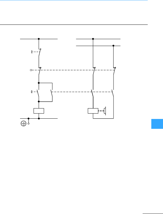
Eaton Wiring Manual 06/11
10
Measures for risk reduction
A fault in the electrical equipment must not
result in a dangerous situation or in
damage. Suitable measures must be taken
to prevent danger from arising.
aAll switching functions on the non-
earthed side
bUse of break devices with positively
opening contacts (not to be confused
with interlocked opposing contacts)
cShut-down by de-excitation (fail-safe in
the event of wire breakage)
dCircuit engineering measures which
make undesirable operating statesin
the fault scenario unlikely (in this
instance, simultaneous interruption via
contactorand position switch)
eSwitching of all live conductors to the
device to be controlled
fChassis earth connection of the
actuatingcircuit foroperational
purposes (notused as a protective
measure)
This means the existence of an additional
device or system which takes over the
function in the fault scenario.
L01
0
K1
K1
I
⎧
⎪
⎪
⎪
⎪
⎨
⎪
⎪
⎪
⎪
⎩
⎧
⎪
⎨
⎪
⎩
L1
L2
L02
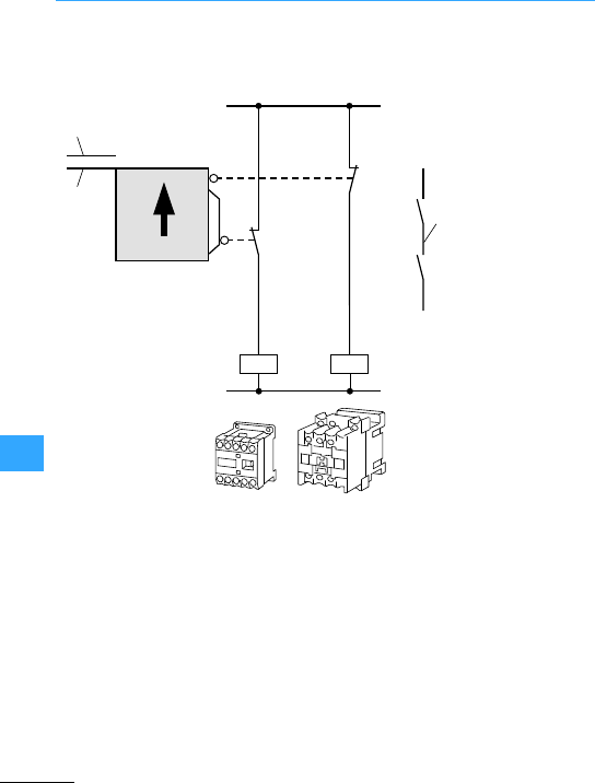
Measures for risk reduction
Eaton Wiring Manual 06/11
10
The construction of control circuits
according to a range of function principles
or using various types of device.
aFunctional diversity by combination of
N/O andN/C contacts
bDiversity of devices due to useof
various types of device (here, various
types of contactor relay)
cSafety barrier open
dFeedback circuit
eSafety barrier closed
The correct functioning of the equipment
can be tested either manually or
automatically.
c
ed
K1 K2
K1
K2
13
14
21
22
a
b

Eaton Wiring Manual 06/11
10
Protection types for electrical equipment
The designation to indicate degrees of
enclosure protection consistsof the
characteristic letters (Ingress
Protection) followed by twocharacteristic
numerals. The first numeralindicates the
degree of protection of persons against
contact with live parts and of equipment
against ingress of solid foreign bodiesand
dust,the second numeralthe degree of
protection against the ingress of water.
First
numeral
Description Explanation
0Not protected No special protection of persons against accidental
contact with live or moving parts.
No protection of the equipment against ingress of solid
foreign bodies.
1Protection
against solid
objects
,50 mm
Protection against contact with live parts with back of
hand.
The access probe, sphere 50 mm diameter, must have
enough distance from dangerous parts.
The probe, sphere 50 mm diameter, must not fully
penetrate.
2Protection
against solid
objects
,12.5 mm
Protection against contact with live parts with a finger.
The articulated test finger, 12 mm diameter and 80 mm
length, must have sufficient distance from dangerous
parts.
The probe, sphere 12.5 mm diameter, must not fully
penetrate.

Protection types for electrical equipment
EatonWiring Manual 06/11
10
First
numeral
Description Explanation
3Protection
against solid
objects
,2.5mm
Protection against contact with live partswith a tool.
The entry probe,2.5 mm diameter, must not penetrate.
The probe, 2.5 mm diameter, must not penetrate.
4Protection
against solid
objects ,1mm
Protection against contact with live partswith a
conductor.
The entry probe,1.0 mm diameter, must not penetrate.
The probe, 1.0 mm diameter, must not penetrate.
5Protection
against
accumulation
of dust
Protection against contact with live partswith a
conductor.
The entry probe,1.0 mm diameter, must not penetrate.
The ingress of dust is not totally prevented, but dust
does not enter in sufficient quantityto interfere with
satisfactory operation of the equipment or with safety.
6Protection
against the
ingress of dust
Dust-tight
Protection against contact with live partswith a
conductor.
The entry probe,1.0 mm diameter, must not penetrate.
No entry of dust.
Example forstating degree of protection: IP 44
Characteristic letter
First numeral
Second numeral

Protection types for electrical equipment
EatonWiring Manual 06/11
10
Second
numeral
Description Explanation
0Not protected No special protection
1Protected
against
vertically
dripping
water
Dripping water (vertically falling drops) shallhave no
harmful effect.
2Protected
against
dripping
water when
enclosure
tilted up to 15°
Dripping water shall have no harmful effect when the
enclosure is tilted at any angle up to 15° from the
vertical.
3Protected
against
sprayed
water
Waterfalling as a spray at any angle up to 60° from the
vertical shallhave no harmful effect.
4Protected
against
splashing
water
Watersplashed against the enclosure from any
direction shall have no harmfuleffect.
5Protected
againstwater
jets
Waterprojected by a nozzle against the equipment from
anydirection shall have no harmfuleffect.
6Protected
against
powerful
water jets
Waterprojected in powerful jetsagainst the enclosure
from any direction shall have no harmful effect.
7Protected
against the
effects of
occasional
submersion
Ingress of water in harmful quantities shall not be
possible when the enclosure is immersed in water
under defined conditions of pressure and time.

Protection types for electrical equipment
EatonWiring Manual 06/11
10
8Protected
against the
effects of
submersion
Ingress of water in harmful quantities must not be
possible when the equipment is continuously
submerged in water underconditions which are subject
to agreement between manufacturer and user.
These conditions must be more stringent than those for
characteristic numeral 7.
9K1) Protected
during
cleaning
using high-
pressure/
steam jets
Waterwhich is directed against the enclosure under
extremely high pressure from any direction must not
have any harmfuleffects.
Water pressure of 100 bar
Watertemperature of 80 °C
1) This characteristic numeral originates from DIN40050 9.
Second
numeral
Description Explanation

EatonWiring Manual 06/11
10

Eaton Wiring Manual 06/11
10
Utilization categories for switching elements
Type of
current
Utilization
category
Typicalapplications Normal
conditions of
use
I=Inrush current, Ic=Breaking current,
Ie=Rated operational current,
U=Voltage,
Ue= Rated operational voltage
Ur= Recovery voltage,
t0.95 =Time in ms, until 95 % of the steady-
state current has been reached.
P = Uex Ie= Rated power in Watts
Switch on
Alter-
nating
current
AC-12 Control of resistive and solid state loads
as in optocoupler input circuits
1 1
AC-13Control of solid state loads with
transformer isolation
2 1
AC-14 Control of small electromagnetic loads
(max. 72 VA)
6 1
AC-15 Control of electromagnetic loads
(above 72 VA)
10 1
DC
current
DC-12 Control of resistive and solid state loads
as in optocoupler input circuits
1 1
DC-13 Control of electromagnets 1 1
DC-14 Control of electromagnetic loads with
economy resistors in the circuit
10 1
I
Ie
U
Ue
I
Ie
U
Ue

Utilization categories for switching elements
Eaton Wiring Manual 06/11
10
Abnormal conditions of use
Switch off Switch on Switch off
cos 'cos 'cos 'cos '
0.9 1 1 0.9 – – – – – –
0.65 1 1 0.65 10 1.1 0.65 1.1 1.1 0.65
0.3 1 1 0.3 6 1.1 0.7 6 1.1 0.7
0.3 1 1 0.3 10 1.1 0.3 10 1.1 0.3
t0.95 T0.95 T0.95 T0.95
1 ms 1 1 1 ms – – – – – –
6 x P1) 1 1 6x P1) 1.1 1.1 6x P1) 1.1 1.1 6 x P1)
15 ms 1 1 15 ms 10 1.1 15 ms 10 1.1 15 ms
1) The value“6xP”results from an empirical relationship that represents most DC
magnetic loads to an upper limitof P = 50 W, i.e. 6[ms]/[W] = 300 [ms]. Loads having
a powerconsumption greater than 50 W are assumed to consist of smaller loads in
parallel. Therefore, 300 ms is to be an upper limit, irrespective of the power
consumption.
I
Ie
U
Ue
I
Ie
U
Ue
I
Ie
U
Ue
I
Ie
U
Ue
I
Ie
U
Ue
I
Ie
U
Ue

Eaton Wiring Manual 06/11
10
Utilization categories for contactors and motor starters
Type of
current
Utilization
category
Typical applications:
I = Inrushcurrent,
Ic= Breaking current,
Ie= Rated operational current,
U = Voltage,
Ue=Rated operational voltage
Ur= Recovery voltage
Verification of
electricallifespan
Switch on
Alter-
nating
current
AC-1 Non-inductive or slightly inductive
loads, resistance furnaces
All
values
1 1
AC-2 Slip-ring motors: starting, switch off All
values
2.5 1
AC-3 NormalAC induction motors:
starting, switch offduring running4)
Ie#17
Ie> 17
6
6
1
1
AC-4 NormalAC induction motors:
starting, plugging, reversing, inching
Ie#17
Ie> 17
6
6
1
1
AC-5a Switching of electric discharge lamp
controls
AC-5b Switching of filamentlamps
AC-6a3) Switching of transformers
AC-6b3) Switching of capacitor banks
AC-7a Slightly inductive loads in household
appliances and similar applications
Data as
suppliedbythe
manufacturer
AC-7b Motor load for domestic applications
AC-8a Switching of hermetically enclosed
refrigerant compressor motors with
manualreset of overload releases5)
AC-8b Switching of hermetically enclosed
refrigerant compressor motors with
automatic resetof overload
releases5)
Ie
[A]
I
Ie
U
Ue

Utilization categories for contactors and motor starters
Eaton Wiring Manual 06/11
10
Verification of switching capacity
Switch off Switch on Switch off
cos
'
cos
'
cos
'
cos
'
0.95 1 1 0.95 All
values
1.5 1.05 0.8 1.5 1.05 0.8
0.65 2.5 1 0.65 All
values
41.05 0.65 4 1.05 0.8
0.65
0.35
1
1
0.17
0.17
0.65
0.35
Ie#100
Ie> 100
8
8
1.05
1.05
0.45
0.35
8
8
1.05
1.05
0.45
0.35
0.65
0.35
6
6
1
1
0.65
0.35
Ie#100
Ie> 100
10
10
1.05
1.05
0.45
0.35
10
10
1.05
1.05
0.45
0.35
3.0 1.05 0.45 3.0 1.05 0.45
1.52) 1.05 2) 1.52) 1.05 2)
1.5 1.05 0.8 1.5 1.05 0.8
8.0 1.05 1) 8.0 1.05 1)
6.0 1.05 1) 6.0 1.05 1)
6.0 1.05 1) 6.0 1.05 1)
Ic
Ie
Ur
Ue
Ie
[A]
I
Ie
U
Ue
Ic
Ie
Ur
Ue

Utilization categories for contactors and motor starters
Eaton Wiring Manual 06/11
10
Type of
current
Utilization
category
Typical applications:
I = Inrush current,
Ic= Breaking current,
Ie= Rated operationalcurrent,
U = Voltage,
Ue= Rated operational voltage,
Ur= Recovery voltage
Verification of
electrical lifespan
Switch on
DC
current
DC-1 Non-inductive or slightly inductive
loads, resistance furnaces
All values 1 1
DC-3Shunt motors: starting,plugging,
reversing,inching, dynamic braking
All values 2.5 1
DC-5 Series motors: starting, plugging,
reversing,inching, dynamic braking
All values 2.5 1
DC-6 Switching of filament lamps
1) cos '= 0.45 for Ie#100 A; cos '= 0.35 for Ie>100 A
2) Tests must be carried out with an filament bulb load connected.
3) Here, the test data are to be derived from the AC-3 or AC-4 test values in accordance
with particular table.
Ie
[A]
I
Ie
U
Ue

Utilization categories for contactors and motor starters
Eaton Wiring Manual 06/11
10
Verification of switching capacity
Switch off Switch on Switch off
L/R
[ms]
L/R
[ms]
L/R
[ms]
L/R
[ms]
1 1 1 1 All
values
1.5 1.05 1 1.5 1.05 1
2 2.5 1 2 All
values
4 1.05 2.5 4 1.05 2.5
7.5 2.5 1 7.5 All
values
4 1.05 15 4 1.05 15
1.52) 1.05 2) 1.52) 1.05 2)
4) Devices for utilization category AC-3 may be used for occasional inching or plugging
during a limited period such as for setting up a machine; during this limited time
period, the numberof operations must not exceed a total of five per minute or more
than ten in aten minute period.
5) Hermetically enclosed refrigerant compressor motor means a combination of a
compressor and amotorboth of which are housed in the same enclosure with no
external shaft or shaft seals, the motor running in the coolant.
Ic
Ie
Ur
Ue
Ie
[A]
I
Ie
U
Ue
Ic
Ie
Ur
Ue

Eaton Wiring Manual 06/11
10
Utilization categories for switch-disconnectors
Type of
current
Utilization
category
Typicalapplications:
I=Inrush current,
Ic= Breaking current,
Ie=Rated operational current,
U = Voltage,
Ue= Rated operational voltage,
Ur= Recovery voltage
Alter-
nating
current
AC-20A(B)1) Making and breaking withoutload
AC-21A(B)1) Switching resistive loads including low overloads
AC-22A(B)1) Switching mixed resistive and inductive loads including
low overloads
AC-23A(B)1) Switching motors and other highly inductive loads
DC
current
DC-20A(B)1) Making and breaking withoutload
DC-21A(B)1) Switching resistive loads including low overloads
DC-22A(B)1) Switching mixed resistive and inductiveloads, including
low overloads(e.g. shunt motors)
DC-23A(B)1) Switching highly inductive loads (e.g. series motors)
1) A: Frequent actuation, B: Occasional actuation
Switch-disconnectors that are suitable for switchingmotors are also tested according
to the criteria stated in 7Section ”Utilization categories for contactors and motor
starters”, page10-36.

Utilization categories for switch-disconnectors
Eaton Wiring Manual 06/11
10
Verification of switching capacity
Switch on Switch off
cos 'cos '
All
values
1) 1) 1) 1)
All
values
1.5 1.05 0.95 1.5 1.05 0.95
All
values
31.05 0.65 3 1.05 0.65
Ie#100
Ie> 100
10
10
1.05
1.05
0.45
0.35
8
8
1.05
1.05
0.45
0.35
L/R
[ms]
L/R
[ms]
All
values
1) 1) 1) 1) 1) 1)
All
values
1.5 1.05 1 1.5 1.05 1
All
values
41.05 2.5 4 1.05 2.5
All
values
41.05 15 4 1.05 15
Ie
[A]
I
Ie
U
Ue
Ic
Ie
Ur
Ue
Ie
[A]
I
Ie
U
Ue
Ic
Ie
Ur
Ue

EatonWiring Manual 06/11
10

Eaton Wiring Manual 06/11
10
Rated motor currents
The maximum value is determined by the
switching device or overload relay.
The rated motor currents are for standard
1500 r.p.m. three-phase motors with normal
innerand outer surface cooling.
Rated fuse currents for 8/-starting also
apply to three-phase motors with slip-ring
rotors.
For higher rated currents, starting currents
and/or longer starting times, largerfuses
will be required.
This table applies to “slow”or “gL”fuses
(VDE 0636).
D.O.L. starting: Maximum starting
current: 6 x rated motor
current, maximum
starting time: 5sec.
8/-starting: Maximum starting
current: 2 x rated motor
current, maximum
starting time: 15 sec.
Motor overload relay in
phase current: set to
0.58 x rated motor
current.

Rated motor currents
EatonWiring Manual 06/11
10
Rated
motor
current
Fuse Rated
motor
current
Fuse
Direct
starting 8/-Direct
starting 8/-
kW cos '([%] A A A A A A
0.06
0.09
0.12
0.18
0.7
0.7
0.7
0.7
58
60
60
62
0.37
0.54
0.72
1.04
2
2
4
4
–
–
2
2
0.21
0.31
0.41
0.6
2
2
2
2
–
–
–
–
0.25
0.37
0.55
0.75
0.7
0.72
0.75
0.79
62
66
69
74
1.4
2
2.7
3.2
4
6
10
10
2
4
4
4
0.8
1.1
1.5
1.9
4
4
4
6
2
2
2
4
1.1
1.5
2.2
3
0.81
0.81
0.81
0.82
74
74
78
80
4.6
6.3
8.7
11.5
10
16
20
25
6
10
10
16
2.6
3.6
5
6.6
6
6
10
16
4
4
6
10
4
5.5
7.5
11
0.82
0.82
0.82
0.84
83
86
87
87
14.8
19.6
26.4
38
32
32
50
80
16
25
32
40
8.5
11.3
15.2
21.7
20
25
32
40
10
16
16
25
15
18.5
22
30
0.84
0.84
0.84
0.85
88
88
92
92
51
63
71
96
100
125
125
200
63
80
80
100
29.3
36
41
55
63
63
80
100
32
40
50
63
37
45
55
75
0.86
0.86
0.86
0.86
92
93
93
94
117
141
173
233
200
250
250
315
125
160
200
250
68
81
99
134
125
160
200
200
80
100
125
160
90
110
132
160
0.86
0.86
0.87
0.87
94
94
95
95
279
342
401
486
400
500
630
630
315
400
500
630
161
196
231
279
250
315
400
400
200
200
250
315
200
250
315
400
0.87
0.87
0.87
0.88
95
95
96
96
607
–
–
–
800
–
–
–
630
–
–
–
349
437
544
683
500
630
800
1000
400
500
630
800
450
500
560
630
0.88
0.88
0.88
0.88
96
97
97
97
–
–
–
–
–
–
–
–
–
–
–
–
769
–
–
–
1000
–
–
–
800
–
–
–

Rated motor currents
EatonWiring Manual 06/11
10
Rated
motor
current
Fuse Rated
motor
current
Fuse Rated
motor
current
Fuse
Direct
starting 8/-Direct
starting 8/-Direct
starting 8/-
A A A A A A A A A
0.19
0.28
0.37
0.54
2
2
2
2
–
–
–
–
0.17
0.25
0.33
0.48
2
2
2
2
–
–
–
–
0.12
0.18
0.24
0.35
2
2
2
2
–
–
–
–
0.76
1
1.4
1.7
2
4
4
4
–
2
2
2
0.7
0.9
1.2
1.5
2
2
4
4
–
2
2
2
0.5
0.7
0.9
1.1
2
2
4
4
–
–
2
2
2.4
3.3
4.6
6
4
6
10
16
2
4
6
10
2.1
2.9
4
5.3
6
6
10
16
4
4
4
6
1.5
2.1
2.9
3.8
4
6
10
10
2
4
4
4
7.7
10.2
13.8
19.8
16
20
25
32
10
10
16
25
6.8
9
12.1
17.4
16
20
25
32
10
16
16
20
4.9
6.5
8.8
12.6
16
16
20
25
6
10
10
16
26.6
32.8
37
50
50
63
80
100
32
32
40
63
23.4
28.9
33
44
50
50
63
80
25
32
32
50
17
20.9
23.8
32
32
32
50
63
20
25
25
32
61
74
90
122
125
125
125
160
80
100
100
125
54
65
79
107
100
125
160
200
63
80
80
125
39
47
58
78
80
80
100
160
50
63
63
100
146
179
210
254
200
250
250
315
160
200
250
250
129
157
184
224
200
250
250
315
160
160
200
250
93
114
134
162
160
200
250
250
100
125
160
200
318
397
495
621
400
630
630
800
315
400
630
800
279
349
436
547
400
500
630
800
315
400
500
630
202
253
316
396
315
400
500
630
250
315
400
400
699
–
–
–
800
–
–
–
800
–
–
–
615
–
–
–
800
–
–
–
630
–
–
–
446
491
550
618
630
630
800
800
630
630
630
630

Eaton Wiring Manual 06/11
10
Conductors
Cable entry intoclosed devices is
considerably simplified and improved by
using cable grommets.
For direct and quick cable entry into an
enclosure and as a plug.
Detailed information on material properties
7Table, page 10-48.
•IP66 with
built-in
push-
through
membrane
•PE and
thermo-
plastic
elastomer,
halogen
free
M16 16.5 1–9H03VV-F3 x 0.75
NYM 1 x 16/3 x1.5
KT-M16
M20 20.5 1–13 H03VV-F3 x 0.75
NYM 5 x 1.5/5 x2.5
KT-M20
M25 25.5 1–18 H03VV-F3 x 0.75
NYM 4x 10
KT-M25
M32 32.5 1–25 H03VV-F3 x 0.75
NYM 4 x 16/5 x10
KT-M32
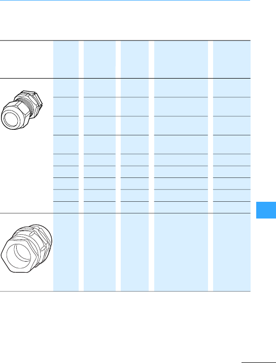
Conductors
Eaton Wiring Manual 06/11
10
Detailed information on material properties
7Table, page 10-48.
with9, 10, 12, 14 or 15 mm long thread.
•Withlocknutand
built-in strain
relief
•IP68 up to 5 bar,
polyamide,
halogen free
M12 12.5 3 –7 H03VV-F3 x 0.75
NYM 1 x 2.5
V-M12
M16 16.5 4.5 –10 H05VV-F3 x 1.5
NYM 1 x 16/3x1.5
V-M16
M20 20.5 6 –13 H05VV-F4 x2.5/3 x 4
NYM 5 x 1.5/5 x2.5
V-M20
M25 25.5 9 –17 H05VV-F5 x2.5/5 x 4
NYM 5 x 2.5/5 x 6
V-M25
M32 32.5 13 –21 NYM 5 x 10 V-M32
M32 32.5 18 –25 NYM 5 x 16 V-M32G1)
M40 40.5 16 –28 NYM 5 x 16 V-M40
M50 50.5 21 –35 NYM 4 x 35/5x25 V-M50
M63 63.5 34 –48 NYM 4 x 35 V-M63
Ventilation cable
glands IP69K
M20 20.5 6 –13 H05VV-F 4 x 2.5/3 x 4
NYM 5 x 1.5/5 x2.5
V-M20-VENT
1) Not in compliance with DIN EN 50262.

Conductors
Eaton Wiring Manual 06/11
10
Material Polyethylene and
thermoplastic elastomer,
halogen free
Polyamide, halogen free
Color grey, RAL 7035 grey, RAL7035
Protection type up to IP66 IP68 up to 5 bar (30min)
Chemical resistance Resistant to:
•Alcohol,
•Animal and plant-based oils,
•Weak alkalis,
•Weak acids,
•water
Resistant to:
•Acetone,
•Petrol,
•paraffin,
•Diesel oil,
•Greases,
•Oils,
•Solvents forpaints and
lacquers
Danger of stress fracture Relatively high low
Temperature resistance –40 °C…80 °C, short-time up to
approx. 100 °C
–20 °C…100 °C, short-time up
to approx. 120 °C
Flame retardant –Glow-wire test 750 °C to
DINEN60695-2-11;
VDE 0471-2-11
Flammability to UL94 –V2

Conductors
Eaton Wiring Manual 06/11
10
NYM: light plastic-sheated cable
NYY: plastic-sheathed cable
H05RR-F: light rubber-sheathed flexible
cable (NLH +NSH)
NYCY: cable with concentric conductor
and plastic sheath
NYCWY:cable with concentric wave-form
conductor and plastic sheath
Cross section mm mm mm mm mm
mm2max. max. max.
2x1.5 10 11 9 10 12
2x2.5 11 13 13 11 14
3x1.5 10 12 10 10 13
3x2.5 11 13 11 12 14
3x4 13 17 –14 15
3x6 15 18 –16 16
3x10 18 20 –23 18
3x16 20 22 –25 22
4x1.5 11 13 9 11 13
4x2.5 12 14 11 13 15
4x4 14 16 –15 16
4x6 16 17 –17 18
4x10 18 19 –23 21
4x16 22 23 –27 24
4x25 27 27 –32 30
4x35 30 28 –36 31
4x50 –30 –42 34
4x70 –34 –47 38
4x95 –39 –53 43
4x120 –42 – – 46
4x150 –47 – – 52
4x185 –55 – – 60
4x240 –62 – – 70
5x1.5 11 14 12 14 15
5x2.5 13 15 14 17 17
5x4 15 17 –19 18
5x6 17 19 –21 20
5x10 20 21 –26 –
5x16 25 23 –30 –
8x1.5 –15 – – –
10 x1.5 –18 – – –
16 x1.5 –20 – – –
24 x1.5 –25 – – –

Conductors
Eaton Wiring Manual 06/11
10
PVC-sheathed wire, 0.75 mm2flexible,
H05V-K 0.75 black
Heavy rubber-sheathed cable,3-core,
2.5 mm2without green/yellow protective
conductor A07RN-F3 x 2.5
Harmonized specificationH
Recognized national type A
300/300V03
300/500 V05
450/750V07
PVCV
Natural- and/or synthetic rubber R
Silicon rubber S
PVCV
Natural- and/or synthetic rubber R
Polychloroprene rubber N
Fibre-glass braid J
Textile braid T
Flat, separable conductor H
Flat, non-separable conductorH2
solid-U
stranded -R
Flexible with cables forfixed installation -K
Flexible with flexible cables-F
Highly flexible with flexible cables -H
Tinsel cord-Y
...
Without protective conductors X
With protective conductors G
...

EatonWiring Manual 06/11
10

Conductors
Eaton Wiring Manual 06/11
10
Rated operating voltage
Un
Short-circuit
voltage UK
4%6%
Rating Rated
operational
current
Short-circuit
current
Rated
operational
current
InIK
’’ In
kVA AA A A
50 72 1967 –55
63 91 24781652 69
100 144 39332622 110
125 180 49163278 137
160 231 62934195 176
200 289 78665244 220
250 361 98336555 275
315 455 12390 8260 346
400 577 15733 10489 440
500 722 19666 13111 550
630 909 24779 16519 693
800 1155 –20977 880
1000 1443 –26221 1100
1250 1804 –32777 1375
1600 2309 –41954 1760
2000 2887 –52443 2199
2500 3608 –65553 2749

Conductors
Eaton Wiring Manual 06/11
10
4%6% 4%6%
Short-circuit
current
Rated
operational
current
Short-circuit
current
IK
’’ InIK
’’
A A AA A
1498 –42 1140 –
1888 1259 53 1436958
2997 1998 84 22801520
3746 2497 105 28501900
4795 3197 134 36482432
5993 3996 167 45603040
7492 4995 209 57003800
9440 6293 264 71824788
11987 7991 335 91206080
14984 9989 418 11401 7600
18879 12586 527 14365 9576
–15983 669 –12161
–19978 837 –15201
–24973 1046 –19001
–31965 1339 –24321
–39956 1673 –30402
–49945 2092 –38002

Eaton Wiring Manual 06/11
10
Formulae
Copper:
l = Length of conductor [m]Aluminum:
3= Conductivity [m/?mm2]Iron:
A = Conductor cross section
[mm2]
Zinc:
Transformer
Capacitors
Impedance
L = Inductance [H]f=Frequency [Hz]
C = Capacitance [F] '= Phase angle
XL=Inductive impedance [?]
XC= Capacitive impedance [?]
With 2 parallel resistances: With 3 parallel resistances:
General calculation of resistances:
UIRV$"(=IU
R
--- A$"=RU
I
--- .$"=
Rl
%A(
------------- .$"=%57 m
.mm2
---------------
=
%33 m
.mm2
---------------=
%8,3 m
.mm2
---------------
=
%15,5 m
.mm2
---------------
=
XL20fL.$"(((=
X
C
1
20fC(((
----------------------------- .$"=
ZR
2
X
L
X
C
–'&
2
+= Z
R
cosv
------------ .$"=
R
g
R
1R
2
(
R
1R
2
+
----------------- .$"=R
g
R
1R
2
(R
3
(
R
1R
2R
2R
3R
1R
3
(+(+(
---------------------------------------------------------------- .$"=
1
R
--- 1
R1
----- 1
R2
----- 1
R3
----- ... 1 .2$"+++= 1
Z
--- 1
Z1
----- 1
Z2
----- 1
Z3
----- ... 1 .2$"+++=
1
X
--- 1
X1
----- 1
X2
----- 1
X3
----- ... 1 .2$"+++=

Formulae
Eaton Wiring Manual 06/11
10
Power Current consumption
DC current
Single-phase AC
Alternating current
2 conductors with currents I1and I2
= Distance between
supports [cm]
= Distance between
conductors [cm]
3 conductors with current I
PUI(W$"=IP
U
---A$"=
PUIcos-(( W$"=IP
Ucos-(
---------------------- A$"=
P3UIcos-((( W$"=IP
3Ucos-((
----------------------------------- A$"=
F
20.2 I1I2s(((
a
----------------------------------- N$"=I
1
I
2
s
a
F
30.808 F2N$"(=
F
30.865 F2N$"(=
F
30.865 F2N$"(=

Formulae
Eaton Wiring Manual 06/11
10
Known power Known current
DC current
Single-phase AC
Alternating current
DC currentSingle-phase AC Alternating current
Known power
Known current
DC currentSingle-phase AC
Alternating current
l = Single length of conductor[m];
A = Conductor cross section [mm2];
= Conductivity (copper: =57; aluminum: = 33; iron: =8.3 )
2U = Voltage drop
U)2l(P(
zA(U(
----------------------- V$"=U)2l(l(
zA(
----------------- V$"=
U)2l(P(
zA(U(
----------------------- V$"=U)2l(l(
zA(
----------------- cos(-V$"=
U)lP(
zA(U(
----------------------- V$"=U)3ll(
zA(
------------- cos(-V$"(=
A2l(P(
z)U(U(
--------------------------- mm2
$"=A2l(P(
z)U(U(
--------------------------- mm2
$"=AlP(
z)U(U(
--------------------------- mm2
$"=
A
2l(l(
z)U(
----------------- mm2
$"=A
2l(l(
z)U(
----------------- cos-mm2
$"(=A3
ll(
z)U(
-----------------
(cos(-mm2
$"=
P
loss
2l(P(P(
zA(U(U(
--------------------------------- W$"=P
loss
2l(P(P(
zA(U(U(cosv(cosv(
----------------------------------------------------------------------- W$"=
P
loss
lP(P(
zA(U(U(cosv(cosv(
----------------------------------------------------------------------- W$"=
zzzz
m
Omm2
---------------

Formulae
Eaton Wiring Manual 06/11
10
Output Current consumption
DC current
Single-
phase AC
Alternating
current
P1= Rated mechanicalpower at the motor shaft conform to rating plate
P2= Electrical power consumption
Efficiency
Amount of
poles
Synchronous speed Full load speed
23000 2800 –2950
41500 1400 –1470
61000 900–985
8750 690–735
10 600550 –585
Synchronous speed =approx. no-load speed
P1Ul(h(W$"=lP
1
Uh(
------------- A$"=
P
1Ul(cosv(h(W$"=lP
1
Ucosv(h(
-------------------------------- A$"=
P
11.73 U(l(cosv(h(W$"=lP
1
1.73 U(cosv(h(
------------------------------------------------ A$"=
hP
1
P
2
----- (100 %)(=P2
P1
h
----- W$"=

Eaton Wiring Manual 06/11
10
International Unit System
Basicparameters
Physical
parameters
Symbol SI basic unit Furtherrelated
SI units
Length l m (Metre) km, dm, cm, mm, >m,
nm, pm
Mass m kg (Kilogram) Mg, g, mg, >g
Time t s (Second) ks, ms, >s, ns
Electrical currentIA(Ampere) kA, mA, >A, nA, pA
Thermo-dynamic
temperature
T K (Kelvin) –
Amount of
substance
n mole (Mol) Gmol, Mmol, kmol,
mmol, >mol
Light intensity vcd (Candela) Mcd, kcd, mcd
Force 1kp
1 dyn
9.80665 N
1·10-5 N
10 N
1·10-5 N
Momentumof
force
1 mkp 9.80665 Nm 10 Nm
Pressure 1 at
1 Atm = 760 Torr
1 Torr
1 mWS
1 mmWS
1 mmWS
0.980665 bar
1.01325 bar
1.3332 mbar
0.0980665 bar
0.0980665 mbar
9.80665 Pa
1 bar
1.01 bar
1.33 bar
0.1 bar
0.1 mbar
10 Pa
Tension
Energy 1 mkp
1kcal
1 erg
9.80665 J
4.1868 kJ
1·10-7 J
10 J
4.2 kJ
1·10-7 J
1kp
mm2
---------- 9.80665 N
mm2
---------- 10 N
mm2
----------

International Unit System
Eaton Wiring Manual 06/11
10
Power
1.163 W 1.16 W
1PS 0.73549 kW 0.74kW
Heat transfer
coefficient
Dynamic viscosity
1Poise
1Poise 0.1
Kinetic viscosity 1 Stokes
Angle (flat) 1
1 gon
1
1 gon
57,296 1 rad
63,662 gon 1 rad
1kcal
h
---------- 4.1868kJ
h
----- 4.2 kJ
h
-----
1kcal
h
----------
1kcal
m2h°C
--------------- 4.1868 kJ
m2hK
------------- 4.2 kJ
m2hK
-------------
1kcal
m2h°C
--------------- 1.163 W
m2K
---------- 1.16 W
m2K
----------
110
6–kps
m2
---------
#0980665/10 5–Ns
m2
-------
#110
5–
Ns
m2
-------
#
0.1 Ns
m2
------ 0,1 Ns
m2
------
Pa s#
110
4–m
2
s
------
#110
4–m
2
s
------
#
1
360
-------- pla 278/10 3–pla#
1
400
-------- pla 25 10 3–pla#/
0
180
-------- rad 17 510
3–
rad#/
0
200
-------- rad 15 7/10 3–pla#

International Unit System
Eaton Wiring Manual 06/11
10
SizeSIunits
name
Symbol Basic
unit
Conversion of SI units
Force Newton N
Force
momentum
Newton+
metre
Nm
PressureBar bar
Pascal Pa
Energy, heat Joule J 1 J =1Ws = 1 Nm
Power Watt W
Tension
Angle (flat) Degree
Gon
1
gon
360° =1 pla = 2*rad
400gon = 360°
Radian rad
Full circlepla 1 pla=2*rad = 360°
VoltageVolts V
Resistance Ohm ?
Conductivity SiemensS
Electric
charge
CoulombC 1·A·s
1kg m#
s2
--------------
#
1kg m2
#
s2
----------------
#
105kg
ms
2
#
------------- 1 bar 105Pa 105N
m2
------
==
1
kg
ms
2
#
-------------
#1Pa 10 5–bar=
1kg m2
#
s2
----------------
#
1kg m2
#
s3
----------------
#W1=
J
s
--- 1Nm#
s
------------
=
N
mm2
---------- 106kg
ms
2
#
------------- 1N
mm2
---------- 102N
cm2
---------
=
1m
m
----
1kg m2
#
s3A#
----------------
#1V1=W
A
-----
#
1kg m2
#
s3A2
#
----------------
#1.1=V
A
--- 1W
A2
-----
#=#
1s3A2
#
kg m2
#
----------------
#1S1=A
V
--- 1=A2
W
-----
##

International Unit System
Eaton Wiring Manual 06/11
10
Capacity FaradF
Electrical
field
Flux Weber Wb
Flux densityTesla T
Reactor Henry H
Power Prefix Symbol Power Prefix Symbol
10–18 Atto a10
–1Deci d
10–15 Femto f10Deca da
10–12 Pico p10
2Hecto h
10–9Nano n10
3Kilo k
10–6Micro >106Mega M
10–3Milli m10
9Giga G
10–2Centi c10
12 Tera T
SizeSIunits
name
Symbol Basic
unit
Conversion of SI units
1s4A#
kg m2
#
----------------
#1F1=C
V
---
#1sA
2
#
W
------------
#=
V
m
---- 1kg m#
s3A#
--------------
#1V
m
---- 1W
Am#
------------
#=
1kg m2
#
s2A#
----------------
#1 Wb1=Vs 1Ws#
A
------------
#=##
1kg
s2A#
------------
#1 T Wb
m2
------- 1Vs#
m
2
----------
#1Ws#
m
2
A
------------
#== =
1
kg m2
#
s2A2
#
----------------
#1 H Wb
A
------- 1Vs#
A
----------
#1Ws#
A
2
------------
#== =

International Unit System
Eaton Wiring Manual 06/11
10
Obsolete units
SI unit: N(Newton)
J/m (Joule/m)
Previous unit: kp (kilopond)
dyn (Dyn)
1N=1J/m=1kg m/s2= 0.102 kp =105dyn
1 J/m =1N=1kg m/s2= 0.102 kp =105dyn
1 kg m/s2= 1 N=1 J/m = 0.102 kp =105dyn
1 kp = 9.81 N=9.81 J/m=9.81kg m/s2=0.981 106dyn
1 dyn=10–5N=10–5J/m=10–5kg m/s2=1.02 10–5kp
SI unit: Pa (Pascal) bar
(Bar)
Previous unit: at = kp/cm2= 10 m Ws
Torr = mm Hg
atm
1 Pa = 1 N/m2= 10–5bar
1 Pa = 10–5bar = 10.2 ·10–6at =9.87 ·10–6at = 7.5 ·10–3Torr
1 bar = 105Pa = 1.02 at = 0.987 at = 750 Torr
1 at = 98.1 ·103Pa = 0.981 bar = 0.968 at = 736 Torr
1 atm = 101.3 ·103Pa = 1.013 bar = 1.033 at = 760 Torr
1 Torr = 133.3 Pa = 1.333 ·10–3bar =1.359 ·10–3at = 1.316 ·10–3atm

International Unit System
Eaton Wiring Manual 06/11
10
SI unit: J (Joule)
Nm (Newtonmeter)
SI unit:
(asbefore)
Ws (Wattsecond)
kWh (Kilowatthour)
Previous unit: kcal (Kilocalorie) = cal ·10–3
1 Ws =1J=1 Nm 107erg
1 Ws =278 ·10–9kWh =1 Nm =1 J =0.102 kpm = 0.239 cal
1kWh =3.6 ·106Ws = 3.6 ·106Nm =3.6 ·106J=367 ·106kpm = 860 kcal
1Nm = 1 Ws = 278 ·10–9kWh=1 J = 0.102 kpm = 0.239 cal
1J=1Ws =278 ·10–9kWh=1Nm =0.102 kpm = 0.239 cal
1kpm = 9.81Ws = 272 ·10–6kWh=9.81 Nm =9.81 J = 2.34 cal
1kcal = 4.19 ·103Ws = 1.16 ·10–3kWh=4.19 ·103Nm = 4.19 ·103J = 427 kpm
SI unit: Nm/s (Newtonmeter/s)
J/s (Joule/s)
SI unit:
(as before)
W (Watt)
kW (Kilowatt)
Previous unit: kcal/s (Kilocalorie/sec.) = cal/s ·103
kcal/h (Kilocalorie/hour.) = cal/h ·106
kpm/s (Kilopondmeter/Sec.)
PS (metric horsepower)
1W=1J/s=1Nm/s
1W=10–3kW = 0.102 kpm/s = 1.36 ·10–3PS =860 cal/h = 0.239 cal/s
1kW = 103W = 102 kpm/s =1.36 PS =860 ·103cal/h = 239 cal/s
1kpm/s=9.81 W=9.81 ·10–3kW =13.3 ·10–3PS =8.43 ·103cal/h = 2.34 cal/s
1PS = 736W=0.736 kW =75 kpm/s = 632 ·103cal/h = 176 cal/s
1kcal/h = 1.16 W=1.16 ·10–3kW =119 ·10–3kpm/s = 1.58 ·10–3PS = 277.8 ·10–3cal/s
1cal/s=4.19 W=4.19 ·10–3kW =0.427 kpm/s = 5.69 ·10–3PS =3.6 kcal/h

International Unit System
Eaton Wiring Manual 06/11
10
SI unit:
Previous unit: Oe = (Oerstedt)
= 0.01256 Oe
= 12.56 Oe
1 Oe
1A
m
---- 0.001 kA
m
------
=
1kA
m
------ 1000=A
m
----
79.6 A
m
----
=0.0796 kA
m
------
=
SI unit: Wb (Weber)
>Wb (Microweber)
Previous unit: M = Maxwell
1Wb =1Tm2
1Wb =106>Wb = 108M
1>Wb =10–6Wb = 100 M
1M=10–8Wb = 0.01 >Wb
SI unit: T (Tesla)
mT (Millitesla)
Previous unit: G = Gauss
1T=1Wb/m2
1T=103mT = 104G
1 mT = 10–3T= 10 G
1G=0.1–3T=0.1 mT

International Unit System
Eaton Wiring Manual 06/11
10
Length 1in 1ft 1yd 1 mile
Land mile
1 mile
Sea mile
m25.4 ·10 –30.3048 0.9144 1.609 ·1031.852 ·103
Weight 1lb 1 ton (UK)
long ton
1 cwt (UK)
long cwt
1 ton (US)
short ton
1ounce 1grain
kg 0.4536 1016 50.80 907.2 28.35 ·10–364.80 ·10–6
Area 1sq.in 1sq.ft 1sq.yd 1 acre 1 sq.mile
m20.6452 ·10–392.90 ·10–30.8361 4.047 ·1032.590 ·103
Volume 1 cu.in 1 cu.ft 1cu.yd 1 gal (US) 1gal(UK)
m316.39 ·10–628.32 ·10–30.7646 3.785 ·10–34.546 ·10–3
Force 1 lb 1 ton (UK)
long ton
1 ton(US)
short ton
1 pdl
(poundal)
N4.448 9.964 ·1038.897 ·1030.1383
Speed 1knot
0.447 0.5144 0.3048 5.080 ·10–3
Pressure 1 in Hg 1 ft H2O1in H2O
bar 65.95 ·10-3 33.86 ·10-3 29.89 ·10-3 2.491 ·10-3
Energy,
Work
1 HPh 1 BTU 1PCU
J2.684 ·1061.055 ·1031.90 ·103
1mile
h
---------- 1ft
s
--- 1ft
min
--------
m
s
----

International Unit System
Eaton Wiring Manual 06/11
10
Length 1 cm 1 m 1 m 1km 1 km
0.3937 in 3.2808 ft 1.0936yd 0.6214 mile
(land mile)
0.5399 mile
(sea mile)
Weight 1g 1kg 1 kg 1 t 1 t
15.43 grain 35.27 ounce 2.2046lb. 0.9842 long
ton
1.1023 short
ton
Area 1cm21 m21 m21 m21 km2
0.155 sq.in 10.7639 sq.ft 1.196 sq.yd 0.2471 ·10–3
acre
0.3861
sq.mile
Volume 1cm31 l 1 m31 m31 m3
0.06102
cu.in
0.03531 cu.ft 1.308 cu.yd 264.2 gal
(US)
219.97 gal
(UK)
Force 1 N 1 N 1 N 1 N
0.2248 lb 0.1003 ·10–3long
ton (UK)
0.1123 ·10–3short
ton (US)
7.2306 pdl
(poundal)
Speed 1 m/s 1 m/s 1
m/s
1m/s
3.2808 ft/s 196.08
ft/min
1.944 knots 2.237 mph
Pressure 1 bar 1 bar 1 bar 1bar
14.50 psi 29.53 in Hg 33.45 ft H2O401.44in
H2O
Energy,
Work
1 J 1 J 1 J
0.3725 ·10–6HPh 0.9478 ·10–3BTU 0.5263 ·10–3PCU

Eaton Wiring Manual 06/11
AC/DC sensitive ............................................................ 7-20
Accelerating torque ....................................................... 2-6
Accessories contactors ............................................... 5-14
Add-on board ................................................................ 0-26
Analog inputs, easy ...........................................1-53…1-56
Analog output, easy ..................................................... 1-61
Anticlockwise rotation field ........................................... 2-4
Arc fault protective system ARCON ............................ 0-32
ARCON quenching device ............................................ 0-32
ATEX approval
EMT6 ........................................................................ 8-14
Motor protection system ZEV ................................. 5-27
Motor-protective circuit-breakers PKZM0, PKZM4 6-4
Overload relays ....................................................... 5-20
Motor-protectivecircuit-breakers PKE .......................... 6-5
Thermistor overload relay for machine
protection EMT6 ...................................................... 5-33
Automatic stator starters
Engineering starting resistor .................................. 8-15
Engineeringstart-up transformer ........................... 8-15
Example resistors .................................................... 8-83
Example start-up transformer ................................. 8-86
Auxiliary contact
Motor-protective circuit-breakers PKZ, PKE ........... 6-9
Normal ....................................................................... 7-6
Auxiliary contact module ............................................... 5-2
Auxiliary switches
Early make ................................................................. 7-7
Trip-indicating ........................................................... 7-6
Basic circuits
easy ...............................................................1-81…1-86
Bimetal
Motor protection ..................................................... 8-14
Motor-protective circuit-breakers ........................... 6-4
Overload relay ......................................................... 5-20
Braking,oversynchronous ........................................... 8-53
Breakdown Torque ......................................................... 2-6

Eaton Wiring Manual 06/11
Bridging during starting
Heavy starting duty ..................................................8-11
Motorcontactor .........................................................8-9
Overload relays ........................................................8-27
Busbar system ...............................................................0-38
Buzzer, general symbol .................................................9-28
Bypass circuit ...............................................................2-37
Bypass contactor ..........................................................2-61
Bypass contacts ..............................................................2-9
Cable entries ...............................................................10-46
Cables
external diameters .................................................10-49
type abbreviation ...................................................10-50
Cables, externaldiameters .........................................10-49
Cables, type abbreviation ...........................................10-50
Cage Clamp ...................................................................5-15
Cam switches
Changeover switches, reversing switches ...............4-5
Heater switches .......................................................4-14
Interlock circuits ......................................................4-11
Main switch, maintenance switch ............................4-3
Meterchangeover switches ...................................4-12
Multi-speedswitches ................................................4-7
Speed switching ......................................................8-53
Star-delta,reversing star-delta .................................4-6
Step switches ...........................................................4-15
Use, designs ...............................................................4-2
Capacitive sensors ........................................................3-32
Capacitor
General symbol ........................................................9-27
Group compensation, use of reactors ....................8-18
Single, group compensation ....................................8-17
Capacitor group compensation ....................................8-18
Cascadecontrol ............................................................2-40
Changeover switch .........................................................4-5
Ammeter ...................................................................4-12
Voltmeter ..................................................................4-12
Wattmeter ................................................................4-13
CI insulated distribution boards ...................................0-37

Eaton Wiring Manual 06/11
Circuit diagrams contactor relays ................................. 5-6
Circuit documents
general ..................................................................... 8-19
Wiring diagram ........................................................ 8-20
Circuit examples
Bridging during starting .......................................... 8-27
Contactors DIL ......................................................... 8-26
Circuit-breaker
as transformer switches ......................................... 7-19
Contactor state ........................................................ 7-15
Internal circuit diagrams ........................................... 7-8
IZMX .......................................................................... 7-3
Meshed network circuit-breakers .......................... 7-17
Meshed network circuit-breakers .......................... 7-17
Motor operated remote switch ............................... 7-18
NZM ........................................................................... 7-2
NZM internal circuit diagrams .................................. 7-8
Remote operation with motoroperator .................. 7-18
Residual current device ............................... 7-20…7-21
Selection criteria ....................................................... 7-3
short-time delayed .................................................. 7-16
Time-discriminating ................................................ 7-16
Transformer switches ............................................. 7-19
withresidual current device ................................... 7-22
Circuit-breakers
Clockwise rotation field ................................................. 2-4
CMD (Contactor Monitoring Device) ........................... 5-36
Coil Functions ............................................................... 1-79
Coils .............................................................................. 1-77
Colors
of indicator lights ................................................... 10-25
of pushbuttons ....................................................... 10-24
COM-LINK connection ................................................. 1-74
Compact distribution board forflush mounting and
surface mounting ......................................................... 0-34
Compact PLC .............................................................. 1-108
Compensated motor ..................................................... 8-12
Conductor
General symbol ...............................................9-25,9-26

Eaton Wiring Manual 06/11
Connection examples
DS4 ............................................................................2-65
Connection for overload relay 1 pole, 2 pole .................8-5
Contact protection relay ...............................................5-34
Contact, self-monitoring .................................................3-9
Contactorfor capacitor ................................................8-94
Contactorrelays circuit diagrams ..................................5-6
Contactorrelays reference letters .................................5-3
Contactors
DC operated .............................................................5-16
DILM .........................................................................5-15
General symbol ........................................................9-33
Marking ....................................................................8-25
Overview ..........................................................5-8…5-9
Contacts ........................................................................1-77
Control circuit devices ..................................................1-24
Fordirect-on-line start .............................................8-34
Formulti-speed contactors ......................... 8-63…8-67
For star-delta ............................................................8-45
RMQ ............................................................................3-2
Control circuit supply motor .........................................8-24
Control Relays ...............................................................1-30
Control relays aeasyRelays ............................ 1-43, 1-44
Core-balance transformer ............................................5-26
Current Limiter
aCurrent limiters PKZM0, PKZM4 .........................6-8
Current limiters PKZM0, PKZM4 .....................................6-8
Current monitoring relays .............................................1-40
Current peaks ................................................................1-40
Current sensors ZEV .....................................................5-28
Current transformer integrated ....................................5-23
DC motors ........................................................................8-5
Deceleration ramp ........................................................2-11
Decelerationtime ..........................................................1-38
Delta circuit ...........................................................2-5, 2-15
Delta circuit, motor .......................................................2-96
Dielectric constant ........................................................3-34

Eaton Wiring Manual 06/11
Digital inputs, easy
AC devices ............................................................... 1-51
DC devices ............................................................... 1-52
DILcontactors
Overload protection ................................................ 8-26
DirectMotor start ........................................................... 2-2
DOLstarters ................................................................ 2-100
Motor-protective circuit-breakers ........................... 6-3
with PKE ................................................................... 1-12
with PKZ ..................................................................... 1-8
Double-frame terminal ................................................. 5-15
Drive system ........................................................ 2-69,2-72
Early-make auxiliary contacts ....................................... 7-7
Early-make auxiliary switches ....................................... 7-7
Earth, general symbol Ground ..................................... 9-26
Earth-fault
ZEB ........................................................................... 5-23
ZEV ........................................................................... 5-26
Earth-fault release ........................................................ 7-20
Earth-fault release circuit-breaker .............................. 7-20
easy
Display ..................................................................... 1-92
Power supply ........................................................... 1-50
Programming ................................................1-77…1-93
Relay outputs ........................................................... 1-58
easy expansion ..................................................1-62…1-63
easy expansion units fornetworking .......................... 1-70
easy inputs .........................................................1-51…1-57
easy local expansion .................................................... 1-62
easy modem operation ................................................. 1-76
easy outputs ......................................................1-58…1-61
easy power supply ....................................................... 1-50
easy printer connection ............................................... 1-75
easy remote expansion ................................................ 1-62
easy system overview .......................................1-43…1-44
easyHMI ........................................................................ 1-46
easyNet ..............................................................1-64…1-68
easyRelay ............................................................ 1-43,1-44
Eaton selector slide formotor starter ........................... 8-3

Eaton Wiring Manual 06/11
Eaton Wiring Manual ......................................................0-8
EC4P .............................................................................1-108
Efficiency .........................................................................2-6
Electrical connector .......................................................6-7
Electrical equipment of machines ..............................10-21
Electronic Catalog .........................................................0-11
Electronic motor starter ..................................................2-2
Electronic overload relays ZEB ........................ 5-23…5-25
Electronic safety relays ................................................1-29
Electronic timing relays ................................................1-36
EMC compliance
in PDS .......................................................................2-72
Emergency stop function ..............................................1-34
Emergency stop pushbutton ...........................................3-8
Emergency switch, general symbol .............................9-29
Emergency-off pushbutton .............................................3-9
Employers'liability insurance Association ..................3-25
EN 50011 ..........................................................................5-3
Engineering
easy .............................................................. 1-50…1-76
Motor ............................................................ 8-15…8-18
Switching of capacitors ...........................................8-17
Three-phase-automatic starter ...............................8-15
Error message, differential ...........................................6-12
Ethernet module ............................................................1-73
Ex e motors
Overload relays ........................................................5-20
PKZM0, PKZM4 .................................................. 6-4, 6-5
External diameters, cables .........................................10-49
Fast counters .................................................................1-57
Fault current ..................................................................5-26
Feedback Circuit ...........................................................1-26
Firstenvironment ..........................................................2-73
Flashing .........................................................................1-38
Fleeting contact
on de-energization ...................................................1-38
on energization .........................................................1-37
Fleeting pulse ................................................................1-38
Float switch, generalsymbol ........................................9-32

Eaton Wiring Manual 06/11
Floor-standing
Distribution board .................................................... 0-37
Enclosure ................................................................. 0-35
Formulae ..................................................................... 10-54
Freely graphical function block diagram ................... 1-133
Free-wheel diode suppressor ........................................5-4
Frequency generators .................................................. 1-57
Frequency inverter ......................................................... 2-2
Control section ........................................................ 2-68
Design ...................................................................... 2-66
Earthing measures .................................................. 2-76
Electrical mains connection ................................... 2-71
EMC-compliant surface mounting .................2-76,2-81
Filtering measures ................................................... 2-80
Functions ................................................................. 2-86
Installation ............................................................... 2-76
M-Max™......................................................... 2-85,2-87
Operating principle .................................................. 2-66
Power section ......................................................... 2-68
Shielded measures .................................................. 2-78
Frequency-controlled three-phase motor ................... 2-70
Function Block Diagram ............................................. 1-132
Function blocks easy .................................................... 1-77
Functions easy .............................................................. 1-48
Fuseless, Reversing contactor DIUL ........................... 8-30
GALILEO Visualization tool ......................................... 1-133
Generator, general symbol .......................................... 9-34
Global Codes, Standards Authorities worldwide ..........9-9
Group compensation .................................................... 8-17
Group protection Motor-protective circuit-breakers ... 6-8
Guard ............................................................................ 1-32
Hazard reduction .......................................................... 1-29
Heaterswitches ........................................................... 4-14

Eaton Wiring Manual 06/11
Heavy starting duty
Bridging during starting ...........................................8-11
Example ....................................................................8-28
Motorprotection ........................................................8-8
Protection .................................................................5-23
HMI-PLC ........................................................................1-94
I/O modules ...................................................................1-25
I/Osystem ....................................................................1-124
I/Oassistant .................................................................1-126
IEC62061 ........................................................................1-29
IL ..................................................................................1-130
Impulserelays ...............................................................1-84
Incremental encoders ..................................................1-57
In-delta connection .......................................................2-56
Indicator light, general symbol .....................................9-28
Individual compensation ...............................................8-17
Inductive sensors ..........................................................3-30
Infra-red touch panel ....................................................1-96
In-line circuit .................................................................2-56
Input modules ................................................................1-25
Insulated enclosures ....................................................0-37
Insulation monitoring relays .........................................1-42
Interlock circuits, cam switches ..................................4-11
Internal DC link ..............................................................2-67
International Unit System (SI) ....................................10-58
Inverter module .............................................................2-67
Isolating point, general symbol ....................................9-26
Labeleditor .....................................................................3-13
Ladderdiagram ...........................................................1-132
Light barriers .................................................................3-36
Line filters ......................................................................2-80
Liquid level monitoring relay .........................................1-41
Load Torque ....................................................................2-6
Load-shedding contact ...................................................4-4

Eaton Wiring Manual 06/11
Mains
Chokes ..................................................................... 2-83
Switches .................................................................. 7-12
Voltage ..................................................................... 2-10
Voltages in North America ...................................... 2-71
Maintenance switch .................................................... 2-78
Maintenance switches
Circuit diagram .......................................................... 4-4
Maintenance switches, cam switches .........................4-4
Marking of electrical equipment ................................. 10-2
Markings, contactor ..................................................... 8-25
Measurement and monitoring relay EMR4 ................. 1-40
Mechanicalinterlock ................................................... 5-16
Minimum cross-sections for protective conductors 10-18
Mirror contact .............................................................. 5-19
MODAN ..............................................................0-29…0-31
Modular PLC ............................................................... 1-113
Modular switchgear system ........................................ 0-29
Monitoring relays ......................................................... 1-40
Motor
Anticlockwise operation ........................................... 2-4
Circuit documents ................................................... 8-19
Clockwise operation .................................................2-4
Control circuit devices fordirect-on-line start ...... 8-34
Controlcircuit supply .............................................. 8-24
Engineering ...................................................8-15…8-18
General symbol ........................................................ 9-34
Information on the rating plate ................................. 2-4
Motor windings ....................................................... 8-50
Multi-speed contactors .......................................... 8-53
Operating direction ................................................... 2-4
Overload .................................................................. 5-26
Pole changing ...............................................8-47…8-49
Power supply ........................................................... 8-21
Separate windings .................................................. 8-47
Star-delta of three-phase motors ................8-35…8-44
Switching of capacitors ...............................8-92…8-95
Switching on three-phase motors ...............8-26…8-33
Tapped winding ....................................................... 8-47

Eaton Wiring Manual 06/11
Motor overload relay, motor-protection ......................5-20
Motor Power ...................................................................2-6
Motor power supply ......................................................8-21
Motorprotection .................................................8-3…8-14
Bridging during starting .............................................8-9
Soft starter ...............................................................2-19
Variants ....................................................................2-19
Motorprotective circuit breakers ................................2-19
Motor rating ..................................................................5-15
Motor reactors ..............................................................2-83
Motor starter, RAMO ....................................................2-99
Motor torque ...................................................................2-6
Motor windings .............................................................8-50
Motor-protective circuit-breakers
For startercombinations ...........................................6-6
Operating principleschematics PKZ, PKE...... 6-11…6-13
Overview ....................................................................6-1
Motor-protective trip blocks ...........................................6-5
Motor-starter combination MSC ....................................6-7
Multi-function display ...................................................1-46
Multifunction relay ........................................................1-36
Multi-speed contactors
Control circuit devices .................................8-63…8-67
Star-delta ..................................................................8-68
Multi-speed switch Bridging during starting ...............8-10
Multi-speed switch of three-phase motors ..... 8-55…8-62
Star-delta ...................................................... 8-68…8-82
Multi-speed switches cam switches .............................4-7
Multi-speed switching,marking ...................................8-25
N/C contact,general symbol ........................................9-30
N/O contact, general symbol ........................................9-30
Networking easy ...................................................1-62…??
Normal AC induction motor ..........................................2-14
Number of pole pairs ......................................................2-4
NZM circuit-breakers ...................................................1-23
Off-delayed ....................................................................1-37
Off-delayed undervoltage release ..................................7-5

Eaton Wiring Manual 06/11
Ohm'sLaw .................................................................. 10-54
On-delayed ................................................................... 1-37
On-Off function ............................................................. 1-39
Operands ...................................................................... 1-77
Operating frequency ...................................................... 8-4
Optical sensors ............................................................. 3-35
Overcurrent protection of cables and conductors ... 10-12
Overload motor ............................................................. 5-26
Overload motor-protective circuit-breaker ................... 6-2
Overload protection
Contactor ................................................................. 8-26
Electronic ................................................................. 5-23
Overload relay
Function (ZMT) ..........................................................1-7
Motorprotection overload relay ............................. 5-20
Time-delayed ............................................................. 8-6
Tripping ...................................................................... 8-4
Overloadrelay aMotorprotection overload relay .. 5-20
Overload relay ZEB, tripping characteristics .............. 5-25
Overloadrelays ................................................... 2-19,2-51
In delta connection ................................................. 8-36
In motorcircuit, in mains line ................................. 8-35
ZEB, electronic .............................................5-23…5-25
Overloadrelays ZEB ..................................................... 5-24
Oversynchronous braking ............................................ 8-53
Overvoltage .................................................................. 2-51
Parallel connection ...................................................... 1-82
Parameterizable contacts ............................................ 5-27
PDS ............................................................................... 2-72
Permanentcontact ....................................................... 1-84
Personnel protection
Enhanced ................................................................. 3-20
LS ............................................................................. 3-19
LSR ........................................................................... 3-24
Phase cutting .................................................................. 2-9
Phase failure ................................................................. 5-26
Phase failure motor protective relay Z ........................ 5-20
Phase failure sensitive ................................................... 6-4
Phase imbalance relay ................................................. 1-41

Eaton Wiring Manual 06/11
Phase monitoring relays ...............................................1-40
Phase sequence relays ................................................1-41
Photovoltaics in residental buildings
Requirements,the DC isolation gap ........................0-15
Photovoltaics in residentialbuildings
Combination switch .................................................0-18
Comfort, safety and energy management ...............0-21
Compact isolator forinverter ...................................0-16
Converting solar energy efficiently .........................0-15
DC string protective device .....................................0-17
DC surge protection .................................................0-18
DC switch-disconnector ..........................................0-15
Digital residual current device ................................0-18
Distribution board ....................................................0-19
Energy measuring sensor ........................................0-19
Fireman’sswitch ......................................................0-16
Fuse switch-disconnectorwith integrated
short-circuit protective device ................................0-17
Grid-connected powerinverters .............................0-15
Increase building safety and comfort .....................0-18
Indoor use ................................................................0-15
Miniature circuit-breaker ........................................0-19
Outdoor use ..............................................................0-15
Overvoltage protection ............................................0-19
Perfect enclosure for outdoor mounting ................0-16
Safe isolation, switching and protecting ................0-14
Safe photovoltaic systems ......................................0-14
Simple mounting ......................................................0-17
Specifications ..........................................................0-15
String circuit-breaker ..............................................0-17
Wireless monitoring of PV system and
simple energy management ....................................0-19
Point-to-point connection .............................................1-74
Polarisation reflex sensor .............................................3-36
Pole-changing motors ...................................... 8-47…8-49
Position switchLS-Titan®............................................3-18
Drive .........................................................................3-25
Standards .................................................................3-25
Suitable applications ...............................................3-25
Positive opening ............................................................3-18
Potential isolation ...........................................................5-2

Eaton Wiring Manual 06/11
Powerdistribution systems ......................................... 0-22
Power Factor .................................................................. 2-6
Process protection ....................................................... 3-22
Programmingeasy ............................................1-77…1-93
Protection against earth fault ............................. 5-23,5-26
Protection types for electrical equipment ................. 10-29
Protective conductors, minimum cross-sections .....10-18
Protective doors ........................................................... 1-32
Protective earth, Protective ground ............................ 9-26
Protective measures .................................................... 10-4
Pt100/Ni1000 inputs, easy ............................................ 1-56
PTC thermistors
Motor protection ..................................................... 8-13
Thermistor overload relays for
machine protection ................................................. 5-33
Pull-up torque .................................................................2-6
Pulse generating .......................................................... 1-38
Pulse shaping ............................................................... 1-37
Pump control ................................................................ 2-37
Floatswitches ....................................................... 8-100
Pressure switches ................................................... 8-98
Twopumps .............................................................. 8-96
Pump operation ............................................................ 2-37
Pushbutton actuators ................................................... 8-63
Radio interference suppression filters ........................ 2-76
Ramp time ..................................................................... 2-10
Rapid Link ..................................................................... 2-98
Rated motor current ..................................................... 2-13
of three-phase motors .......................................... 10-43
Rated operationalcurrent .............................................. 2-6
Rated speed .................................................................... 2-6
Rated torque ................................................................... 2-6
RC suppressor ................................................................ 5-4
RCD ............................................................................... 2-18
Reclosinglockout ........................................................... 8-4
Rectifier ........................................................................ 2-67
Reference lettercontactorrelays ................................. 5-3
Reflected-light beam .................................................... 3-36
Relay outputs, easy ...................................................... 1-58

Eaton Wiring Manual 06/11
Reliability values .........................................................10-26
Remote display ..............................................................1-71
Remote operator circuit-breaker .................................7-18
Remote switch off .........................................................7-12
Remote switch off PKZ, PKE .........................................6-13
Remote switch-off circuit-breaker ...............................7-11
Remote tripping ...............................................................7-4
Residual current protection ..........................................7-20
Residual-currentprotection relays ..............................7-22
Residual-current relays ................................................7-22
Resistivetouch panel ....................................................1-96
Resistor, general symbol ..............................................9-27
Reversing combination aReversing contactor .........8-30
Reversing contactor .....................................................8-30
Reversing star-delta
Cam switches .............................................................4-6
Directionchange ......................................................8-43
Reversing star-delta switch
2operating directions ..............................................8-42
Reversing starter .........................................................2-101
Motor-protective circuit-breakers ............................6-3
Reversing starter with PKE ...................................1-8, 1-13
Reversing switch .............................................................4-5
Risk reduction ...............................................................1-29
in the fault scenario...................................................10-27
SRP/CS .....................................................................1-29
RMQ16 .............................................................................3-2
RMQ-Titan®....................................................................3-3
Rogowski principle ........................................................5-26
Rogowski sensor ...........................................................5-32
Root -3 circuit ................................................................2-56
Rotorautomatic starter
Engineering starting resistor ...................................8-15
Properties of slipring rotor ......................................8-16
Slipring rotor ............................................................8-88
Rotor-critical .................................................................8-13
RS flip-flop, general symbol ..........................................9-36

Eaton Wiring Manual 06/11
Safety of machinery
DIN EN 60204-1 ...................................................... 10-21
EN ISO 12100-1 ........................................................ 1-29
Safety position switches .............................................. 3-18
Safety product .............................................................. 1-30
Safety Relays ................................................................ 1-29
Safety standards .......................................................... 1-29
Safety technicaldata ................................................. 10-26
Safety Technology ........................................................ 1-29
Safety-related applications ......................................... 1-26
SASY60 .......................................................................... 0-38
Sealing power ............................................................... 5-15
Second environment .................................................... 2-73
Self maintaining ............................................................ 1-83
Sensor belt ZEV ............................................................ 5-28
Separate windings
Multi-speed switch ...................................... 8-59…8-62
Speeds ..................................................................... 8-47
Separation galvanic ....................................................... 5-2
Sequential Function Chart .......................................... 1-131
Series connection ........................................................ 1-82
Service distribution board ............................................ 0-35
Shaft output .................................................................... 2-6
Sheet steel housing
IVS ............................................................................ 0-35
MODAN .................................................................... 0-29
Wall-mounting housing CS ..................................... 0-33
xEnergy .................................................................... 0-22
xVtl ........................................................................... 0-26
Shielding, general symbol ............................................ 9-26
Shift register ................................................................. 1-90
short-circuit currents ................................................. 10-52
Short-circuit monitoring ............................................... 5-31
Short-circuit protective device .................................... 8-26
Short-circuit releases .................................................... 6-4
Short-circuit strength ..................................................... 8-7

Eaton Wiring Manual 06/11
Shunt releases
Circuit-breaker remote tripping .................................7-4
Circuit-breakers .......................................................7-19
PKZ, PKE....................................................................6-10
Remote switch-off ....................................................7-11
Signal modules ............................................................1-114
Signalling units ..............................................................1-24
Single-phase motors .......................................................8-5
Sinusoidal filter .............................................................2-84
SL signal towers ............................................................3-14
Slipspeed
....................................................................................2-6
Slipring rotoraRotorautomatic starter ....................8-88
SmartWire-DT .................................................................1-2
SmartWire-DT Communication System .........................1-2
Soft starter .......................................................................2-9
Bidirectional operation ............................................2-33
Classification types ..................................................2-17
Controlled deceleration ...........................................2-11
DM4 ..........................................................................2-44
DS7 ............................................................................2-27
Examples ..................................................................2-20
Overload current profile ..........................................2-11
Parallel connection of several motors ....................2-20
Selection criteria ......................................................2-13
three-phase controlled ............................................2-12
two-phase controlled ...............................................2-12
Soft stop ramp ...............................................................2-29
Special purpose relays .................................................1-36
Speed ...............................................................................2-6
Speeds, separate windings ..........................................8-47
Spring-cage terminal ....................................................5-15
Stairwell lighting ...........................................................1-87
Standard auxiliarycontact .............................................7-6
ON-OFF indication ....................................................7-15
Standard transformers,rated and
short-circuitcurrents ..................................................10-52
Star circuit
Motor ........................................................................2-97
Principle .....................................................................2-5

Eaton Wiring Manual 06/11
Star-delta ...................................................................... 1-39
Bridging during starting .......................................... 8-10
Cam switches ............................................................4-6
easy .......................................................................... 1-85
Marking .................................................................... 8-25
Multi-speed contactors .......................................... 8-68
SDAINL .........................................................8-37…8-41
Three-phase motors ..................................... 8-35…8-44
Star-delta starter ................................................... 1-16, 2-2
Star-deltastarters
with overload relays ................................................ 8-35
Start voltage ................................................................. 2-10
Starting current .............................................................. 2-6
Starting torque ....................................................... 2-6,2-14
Stator automatic starters
Propertiesof squirrel cage rotor ............................ 8-16
Stopping in the event of an emergency ...................... 1-34
Structured Text ........................................................... 1-130
Support Portal ................................................................. 0-9
Suppressor circuit .......................................................... 5-4
Suppressor circuit integrated, pluggable ................... 5-15
Switch position indication .............................................. 4-4
Switch position indication circuit-breaker .................. 7-15
Switch-disconnector, INX .............................................. 7-3
Switch-disconnectors Use, mounting forms ................. 4-2
Switching of capacitors ....................................8-92…8-95
Switching on three-phase motors ....................8-26…8-33
Synchronous speed ....................................................... 2-6
System MODAN ............................................................ 0-29
System-protective circuit-breakers .....................6-2…6-5
System-protective trip block .......................................... 6-5

Eaton Wiring Manual 06/11
Tapped winding .............................................................8-10
Camswitch ..................................................... 4-7…4-10
Feed drive .................................................................8-32
Four speeds ..............................................................8-49
Marking ....................................................................8-25
Multi-speed switch ...................................... 8-55…8-58
Multi-speedswitch star-delta .................................8-68
Pole-changing motors .............................................8-47
Three speeds ............................................................8-48
Temperature compensated ............................................6-4
Temperature monitoring ...............................................8-13
Temperature,conversion factors ...............................10-19
Terminal .........................................................................0-36
Terminal assignment
IZMX16 .....................................................................7-25
IZMX40 .....................................................................7-26
Terminal strip, general symbol .....................................9-25
TestingAgencies, Certification Marks .........................9-14
Text display, easy ..........................................................1-92
Thermal overload relays ...............................................5-20
Thermistor .....................................................................8-13
Thermistormotor protection ............................... 2-19, 5-30
Thermistoroverload relay for machine
protection EMT6 ............................................................5-33
Thermistor protection ...................................................5-30
Three-phase asynchronous motor .................................2-2
General symbol ........................................................9-34
Startupcharacteristics ..............................................2-6
Three-phase automatic rotor starter ...............8-88…8-91
Three-phase autotransformer starter .....8-15, 8-83…8-87
Three-phase current slip-ring motor ............................2-22
Three-phase current-automatic starter .......................8-15
Three-phase monitor ....................................................1-42
Three-phase motors
Connection .................................................................2-3
Multi-speed switch ...................................... 8-55…8-62
Rated motor currents .............................................10-43
Star-delta Multi speed switch ..................... 8-68…8-82
Time selectivity circuit-breaker ...................................7-16

Eaton Wiring Manual 06/11
Time-discriminating network topology ........................ 7-16
Timing relay, on-delayed .............................................. 1-84
Timing relays ................................................................ 1-36
Top of Ramp ........................................................... 2-9,2-10
Touch display ............................................................... 1-95
Touch panel .................................................................. 1-96
Transformer-protective circuit-breaker ........................ 6-6
Transistor, general symbol .......................................... 9-36
Trip blocks ...................................................................... 6-5
Trip-indicating auxiliary contact circuit-breaker .......... 7-6
Trip-indicating auxiliary contacts
formesh network circuit-breaker .......................... 7-15
formotor protective circuit-breakers PKZ, PKE ...... 6-9
Tripping characteristics motor protection system ..... 5-28
Tripping characteristics Overload relays ...........5-21,5-25
Tripping CLASS .................................................... 5-23,5-26
Tripping classes CLASS ................................................. 6-5
Two way switch ............................................................ 1-83
Type 1 coordination ...................................................... 2-17
Type 2 coordination ...................................................... 2-17
Type abbreviation, cables .......................................... 10-50
Typesof coordination motor protection ........................ 8-8
Typesof coordination of soft starter ........................... 2-17
U/f method .................................................................... 2-88
Unbalanced current consumption ...................... 5-23,5-26
Undervoltage releases
Circuit-breakers ...................................................... 7-19
Interlocking of multiple switches ........................... 7-14
Motor-protective circuit-breakers PKZ, PKE .........6-10
Off-delayed ................................................................ 7-5
Remote switch-off ................................................... 7-11
Starting interlock ..................................................... 7-13
Switch off ................................................................. 7-13
Useor reactor capacitor .............................................. 8-18
Utilization categories
contactors, motor starters .................................... 10-36
forswitch-disconnectors ...................................... 10-40
forswitching elements .......................................... 10-34
Utilization categories for switching elements ...........10-34

Eaton Wiring Manual 06/11
Varistor suppressor ........................................................5-4
Visual indicator, general symbol ..................................9-28
Visualization ..................................................................1-94
Visualization, easyHMI .................................................1-93
Voltage releases
Interlock with undervoltage releases .....................7-14
Motor-protective circuit-breakers PKZ, PKE ..........6-10
Starting interlock Undervoltage releases ...............7-13
Wall-mounting
Distribution system ..................................................0-37
Housing ........................................................... 0-33, 0-37
Wide-range overload protection ....................................6-5
Wide-range overload protection,electronic ...............5-23
Winding, general symbol ..............................................9-27
Wiringdiagrams ............................................................8-20
Interconnection diagram .........................................8-20
Location diagram .....................................................8-20
Terminal diagram .....................................................8-20
Unit wiring diagram ..................................................8-20
XC PLCs .......................................................................1-113
XI/ON ...........................................................................1-125
XIOC signal modules ...................................................1-114
ZEV motor protection system ...........................5-26…5-32
ZW7 current transformer-operated overload relays .....8-8

Eaton’s Electrical Sector is a global
leader in power distribution, power
quality, control and automation, and
monitoring products. When combined
with Eaton’s full-scale engineering
services, these products provide
customer-driven PowerChain™ solutions
to serve the power system needs of
the data center, industrial, institutional,
public sector, utility, commercial,
residential, IT, mission critical, alternative
energy and OEM markets worldwide.
PowerChain solutions help enterprises
achieve sustainable and competitive
advantages through proactive
management of the power system as a
strategic, integrated asset throughout its
life cycle, resulting in enhanced safety,
greater reliability and energy efficiency.
For more information, visit
www.eaton.com/electrical
Adresses worldwide:
www.eaton.com/moellerproducts
E-Mail: info-bonn@eaton.com
Internet:
www.eaton.com/moellerproducts
www.eaton.com
Issued by:
Eaton Corporation
Electrical Sector – EMEA
Eaton Industries GmbH
Hein-Moeller-Str. 7-11
D-53115 Bonn
© 2008 by Eaton Industries GmbH
Subject to alterations
PU08703001Z-EN (09/11) bb/Doku/DHW/CPI
Printed in Germany
(09/2011)
Article No.: 165291
For service issues please contact your Eaton representative
or the After Sales Service.
Hotline: +49 (0) 180 5 228322 (de, en) 24/7
Tel.: +49 (0) 228 602-3640
Fax: +49 (0) 228 602-61400
E-Mail: AfterSalesEGBonn@eaton.com
Internet:
www.eaton.com/moeller/aftersales
