R Contactor.indb Brochure
2016-10-27
: Pdf 1000449036-Brochure 1000449036-Brochure B6 unilog
Open the PDF directly: View PDF ![]() .
.
Page Count: 137 [warning: Documents this large are best viewed by clicking the View PDF Link!]
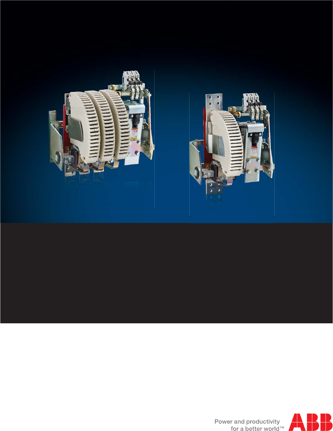
R contactors
Control of AC and DC power circuits
up to 5000 A
US catalog
2 1SXU10607C0201 | R contactor US catalog
Motor rated operational powers and currents
The currents given below concern standard three-phase four-pole cage motors (1500 r.p.m. at 50 Hz 1800 r.p.m. at 60 Hz).
These values are given for guidance and may vary according to the motor manufacturer and depending on the number of poles.
IEC Motor nominal current: standardized values in blue color
(according to IEC 60947-4-1 Annex G)
Motor
power
220 V 230 V 240 V 380 V 400 V 415 V 440 V 500 V 660 V 690 V
kW
AAAAAAAAAA
0.06 0.37 0.35 0.34 0.21 0.2 0.19 0.18 0.16 0.13 0.12
0.09 0.54 0.52 0.50 0.32 0.3 0.29 0.26 0.24 0.18 0.17
0.12 0.73 0.7 0.67 0.46 0.44 0.42 0.39 0.32 0.24 0.23
0.18 111 0.63 0.6 0.58 0.53 0.48 0.37 0.35
0.25 1.6 1.5 1.4 0.9 0.85 0.82 0.74 0.68 0.51 0.49
0.37 2.0 1.9 1.8 1.2 1.1 1.1 1 0.88 0.67 0.64
0.55 2.7 2.6 2.5 1.6 1.5 1.4 1.3 1.2 0.91 0.87
0.75 3.5 3.3 3.2 2.0 1.9 1.8 1.7 1.5 1.15 1.1
1.1 4.9 4.7 4.5 2.8 2.7 2.6 2.4 2.2 1.7 1.6
1.5 6.6 6.3 6 3.8 3.6 3.5 3.2 2.9 2.2 2.1
2.2 8.9 8.5 8.1 5.2 4.9 4.7 4.3 3.9 2.9 2.8
311.8 11.3 10.8 6.8 6.5 6.3 5.7 5.2 43.8
415.7 15 14.4 8.9 8.5 8.2 7.4 6.8 5.1 4.9
5.5 20.9 20 19.2 12.1 11.5 11.1 10.1 9.2 76.7
7.5 28.2 27 25.9 16.3 15.5 14.9 13.6 12.4 9.3 8.9
11 39.7 38 36.4 23.2 22 21.2 19.3 17.6 13.4 12.8
15 53.3 51 48.9 30.5 29 28 25.4 23 17.8 17
18.5 63.8 61 58.5 36.8 35 33.7 30.7 28 22 21
22 75.3 72 69 43.2 41 39.5 35.9 33 25.1 24
30 100 96 92 57.9 55 53 48.2 44 33.5 32
37 120 115 110 69 66 64 58 53 40.8 39
45 146 140 134 84 80 77 70 64 49.1 47
55 177 169 162 102 97 93 85 78 59.6 57
75 240 230 220 139 132 127 116 106 81 77
90 291 278 266 168 160 154 140 128 97 93
110 355 340 326 205 195 188 171 156 118 113
132 418 400 383 242 230 222 202 184 140 134
160 509 487 467 295 280 270 245 224 169 162
200 637 609 584 368 350 337 307 280 212 203
250 782 748 717 453 430 414 377 344 261 250
315 983 940 901 568 540 520 473 432 327 313
355 1109 1061 1017 642 610 588 535 488 370 354
400 1255 1200 1150 726 690 665 605 552 418 400
500 1545 1478 1416 895 850 819 745 680 515 493
560 1727 1652 1583 1000 950 916 832 760 576 551
630 1928 1844 1767 1116 1060 1022 929 848 643 615
710 2164 2070 1984 1253 1190 1147 1043 952 721 690
800 2446 2340 2243 1417 1346 1297 1179 1076 815 780
900 2760 2640 2530 1598 1518 1463 1330 1214 920 880
1000 3042 2910 2789 1761 1673 1613 1466 1339 1014 970
UL / CSA Motor nominal current: standardized values
(according to IEC 60947-4-1 Annex G and UL 508)
Motor
power
208 V 220-240 V 380-415 V 440-480 V 550-600 V
hp
AAAAA
1/2 2.4 2.2 1.3 1.1 0.9
3/4 3.5 3.2 1.8 1.6 1.3
14.6 4.2 2.3 2.1 1.7
1-1/2 6.6 6 3.3 3 2.4
27.5 6.8 4.3 3.4 2.7
310.6 9.6 6.1 4.8 3.9
516.7 15.2 9.7 7.6 6.1
7-1/2 24.2 22 14 11 9
10 30.8 28 18 14 11
15 46.2 42 27 21 17
20 59.4 54 34 27 22
25 74.8 68 44 34 27
30 88 80 51 40 32
40 114 104 66 52 41
50 143 130 83 65 52
60 169 154 103 77 62
75 211 192 128 96 77
100 273 248 165 124 99
125 343 312 208 156 125
150 396 360 240 180 144
200 528 480 320 240 192
250 – 604 403 302 242
300 – 722 482 361 289
350 – 828 560 414 336
400 – 954 636 477 382
450 – 1030 – 515 412
500 – 1180 786 590 472

R contactor US catalog | 1SXU106047C0201 3
R contactors
Control of AC and DC power circuits up to 5000 A
Overview
Construction characteristics
AC circuit switching
DC circuit switching
Advanced applications
General technical data
Accessories and spare parts
Terminal marking and wiring diagrams
Dimensions
Terms and definitions
Questionnaire
Index
4
8
12
2
6
10
1
5
9
3
7
11
4 1SXU10607C0201 | R contactor US catalog
R contactors
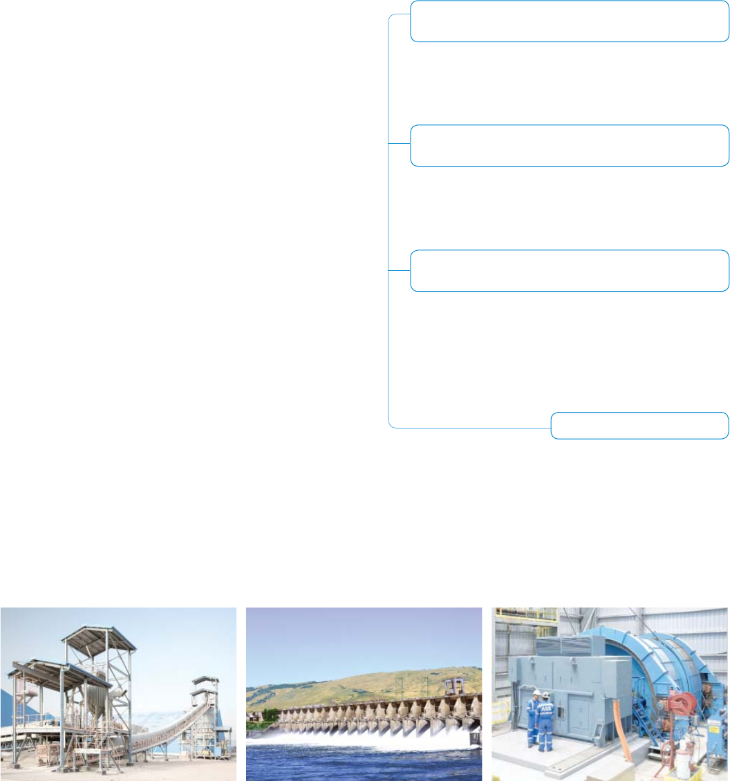
Engineered to perform in heavy duty applications
Engineered to perform in wide variety of applications
– Iron and steel industries
– Mining
– Cranes
– Induction furnaces
– Hydroelectric power stations
– Photovoltaic power plants
– Power distribution
– Energy storage
– Power panels
– Pump station
– Rail transportation
From standard to tailor-made solution
– Most commonly used confi gurations are presented in the R contactor catalog and well documented
– 120V 60Hz coil and 2 N.O. + 2 N.C. auxiliary contacts as standard
– Other configurations and ratings are available on request
With over 100 years of experience
in control, ABB meets AC and DC
requirements from 63 A up to 5000 A
with R contactor range.
Industries Power generation Infrastructure
We offer our application know-how through the R
contactor range to perfectly match your utilization
requirements, whatever the usage condition
and the required configuration. Robustness and
reliability bring R contactors technology beyond
the limits of other contactors.
¡ High making and breaking capacity
¡ Durability up to 5 million electrical operations
¡ Easy inspection access and availability of spare parts
¡ Experienced and proven for years
¡ Variable number of poles
¡ NO, NC or combined main poles configuration
¡ Main pole for On-load breaking or for coupling
¡ Magnetic or mechanical latch available
¡ Rated current up to 5000 A
¡ Rated voltage up to 1000 V AC or 1500 V DC
¡ IEC AC-1, AC-3, DC-1, DC-3 and DC-5
utilization categories.
¡ UL general use rated 800 - 2000A at 600VDC
¡ Mechanical switching frequency up to 1200
cycles per hour
... you can trust
Secure Operation
Reliability
Improved Installation
Effi ciency
Increased Application
Productivity
R contactor US catalog | 1SXU106047C0201 5
R contactors
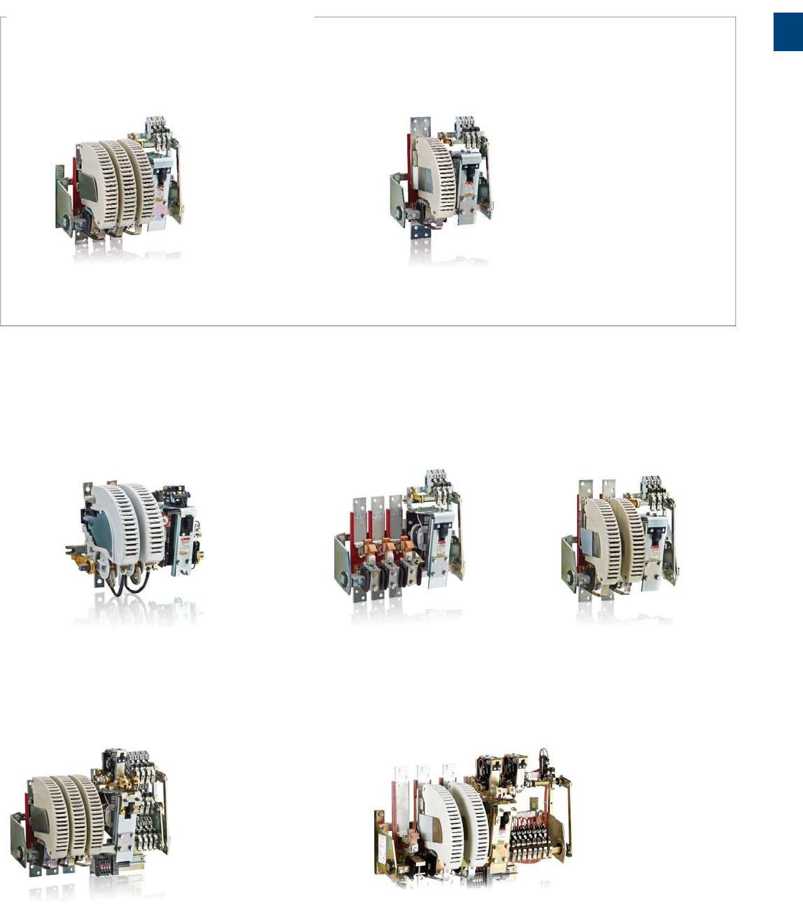
Get the right product
AC circuit switching DC circuit switching
Slip-ring motor control
Power circuit coupling
Alternator field discharge
Umax 2250 V DC
AM-CC-JORE contactors
Energy saving and safety requirements
Equipped with latching
..AMA, ..AME contactor types
N.O./N.C. main poles combination
AC circuit switching
NOR..MT contactors
DC circuit switching
NOR..CC contactors
Up to 500 V AC
IOR contactors
From 500 up to 1000 V AC
IOR..MT contactors
Up to 1500 V DC with poles in series
IOR..CC contactors
AC-1 Rated operational current up to 5000 A
AC-3 Rated power up to 1500 kW (1520 A - 440 V)
DC-1 Rated operational current up to 5000 A
DC-3 / DC-5 operational current up to 2000 A
Conventional applications
Advanced applications
Up to 1000 V AC / 1500 V DC
LOR couplers
Ue up to 5000 V AC
FOR contactors
1
6 1SXU10607C0201 | R contactor US catalog
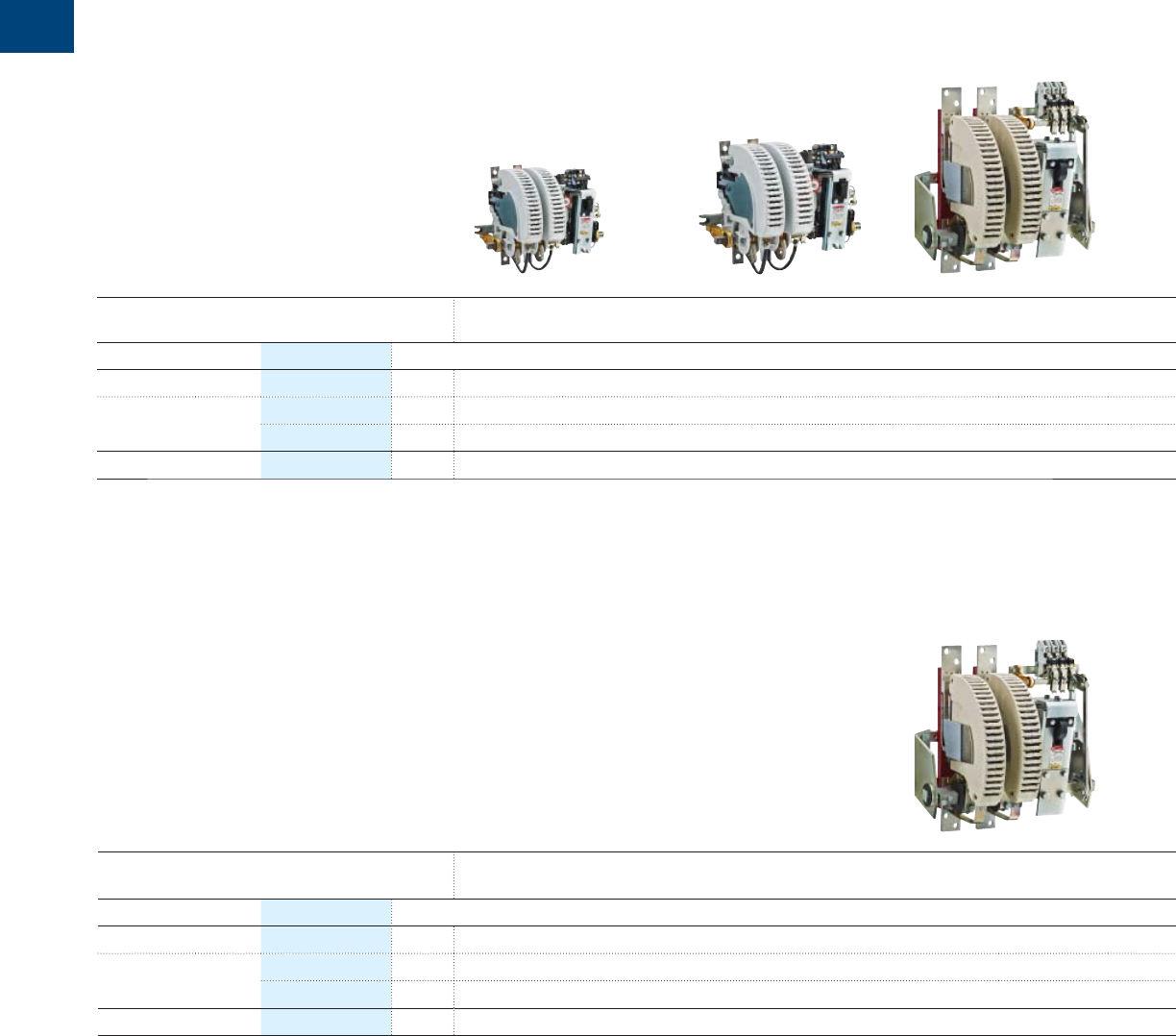
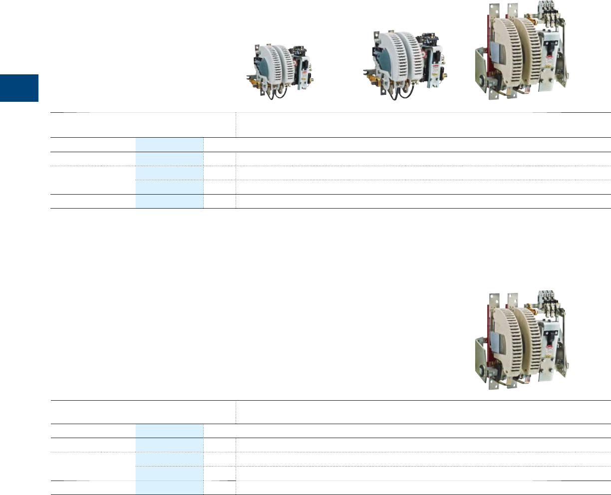
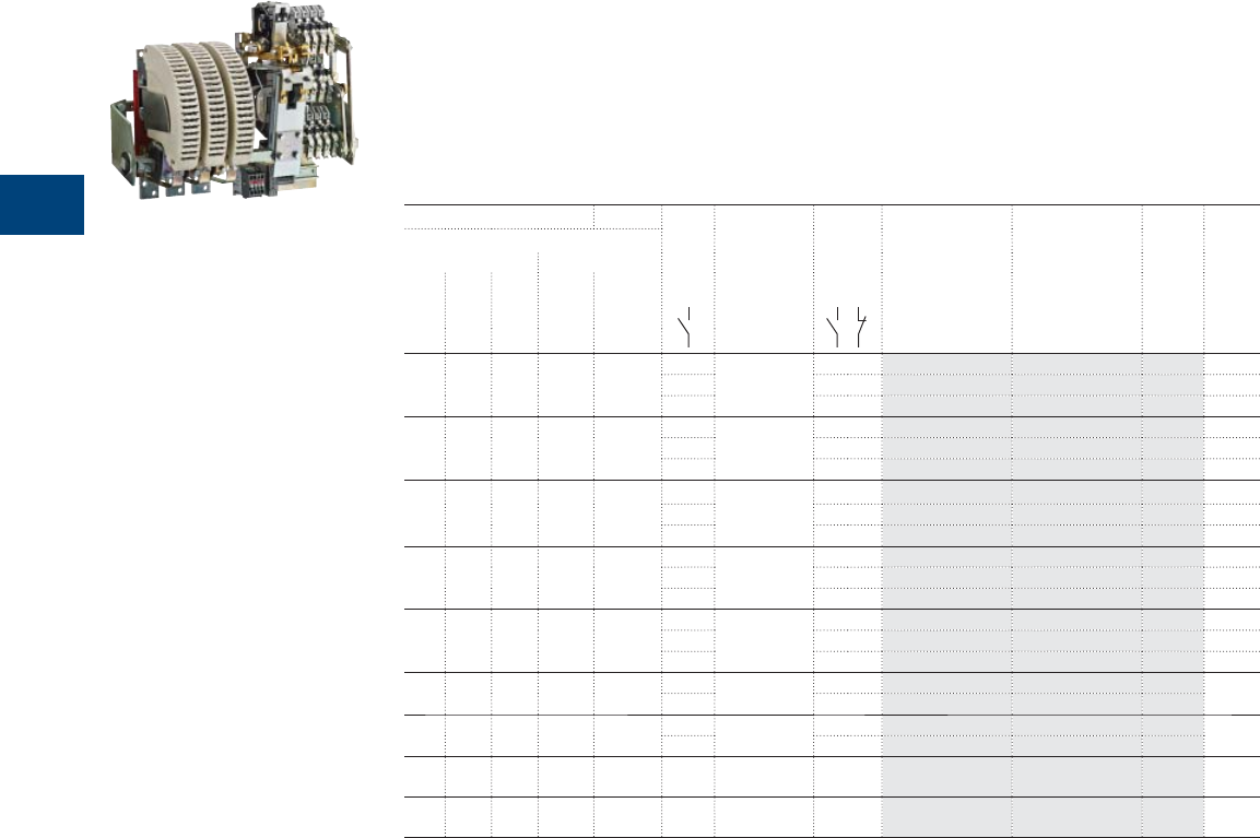
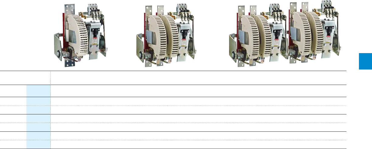
R contactors for AC circuit switching
Rated operational voltage
Ue up to 500 V AC
Contactor
type – IORR800
Categories Ue
AC-1 at 40 °C Ie From 85 A to 550 A, select above IOR..-MT 900 A
AC-3
380-415-440 V AC
Ie –800 A
500 V AC max. Ie –800 A
AC-3 400 V AC Power –450 kW
Rated operational voltage
Ue from 500 up to 1000 V AC
Contactor
type
IORR63..MT IORR125..MT IORR200..MT IORR400..MT IORR500..MT IORR800..MT
Categories Ue
AC-1 at 40 °C Ie 85 A 170 A 260 A 400 A 550 A 800 A
AC-3 690 V AC Ie 85 A 160 A 260 A 400 A 550 A 800 A
1000 V AC max. Ie 56 A 105 A 180 A 280 A 380 A 580 A
AC-3 690 V AC Power 80 kW 150 kW 240 kW 400 kW 540 kW 780 kW
1
*120 V 60Hz coil and 2 N.O. + 2 N.C. auxiliary contacts as standard
*120 V 60Hz coil and 2 N.O. + 2 N.C. auxiliary contacts as standard
R contactor US catalog | 1SXU106047C0201 7
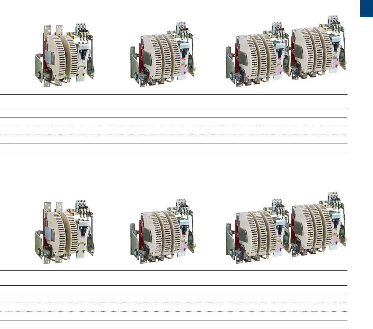
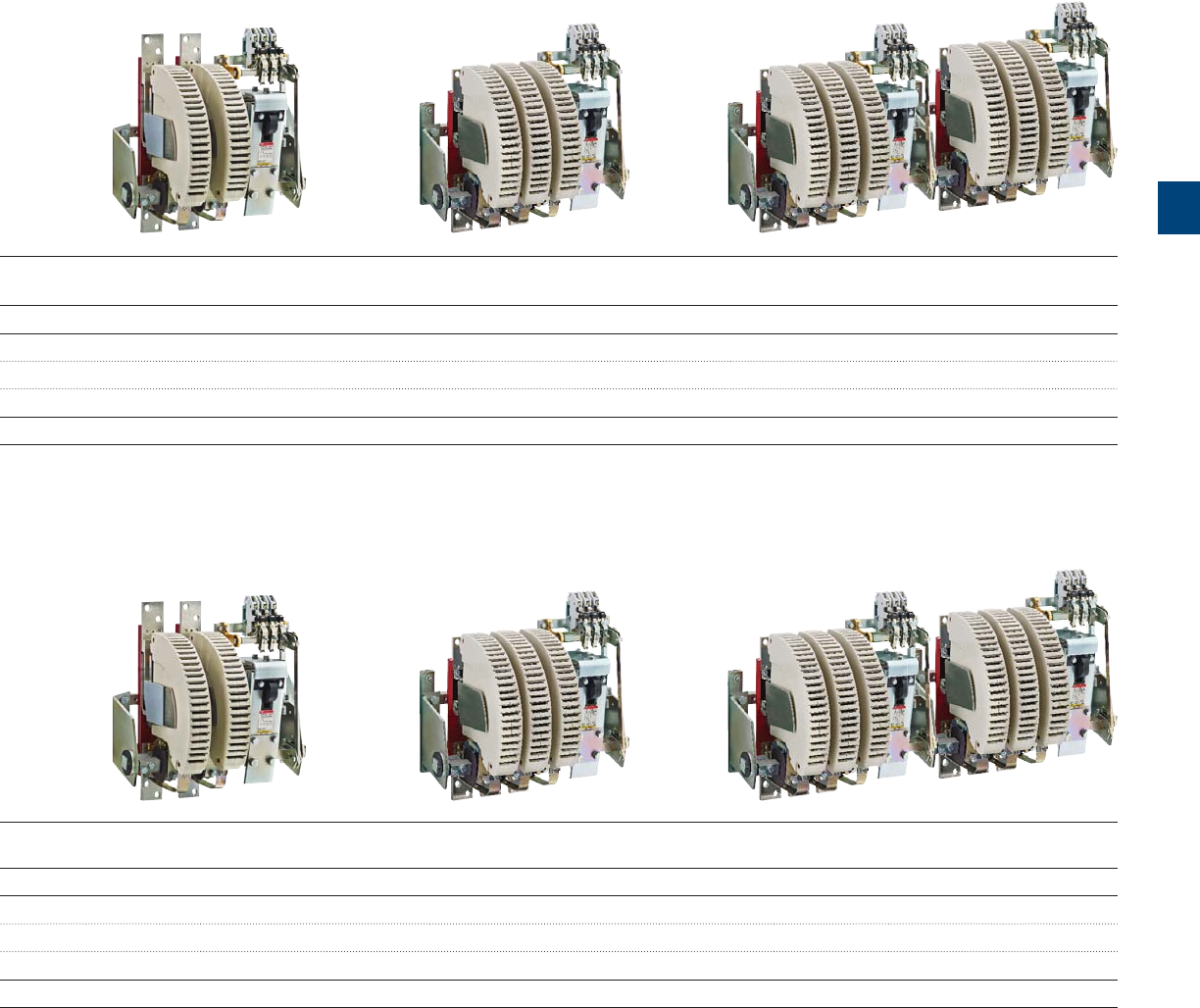
IORR1000 IORR1400 IORR1700 IORR2100 IORR2500 IORR3200 IORR3800 IORR4500 IORR5100
1000 A 1350 A 1650 A 2000 A 2400 A 3200 A 3800 A 4500 A 5000 A
800 A 1080 A 1260 A 1520 A –––––
800 A 1080 A 1220 A 1340 A – – – – –
450 kW 630 kW 750 kW 900 kW –––––
IORR1400..MT IORR1700..MT IORR2100..MT IORR2500..MT IORR3200..MT IORR3800..MT IORR4500..MT IORR5100..MT
1250 A 1650 A 1850 A 2200 A 3000 A 3500 A 4000 A 4500 A
970 A 1170 A 1270 A – – –––
610 A680 A810 A–––––
1000 kW 1200 kW 1300 kW –––––
1
8 1SXU10607C0201 | R contactor US catalog
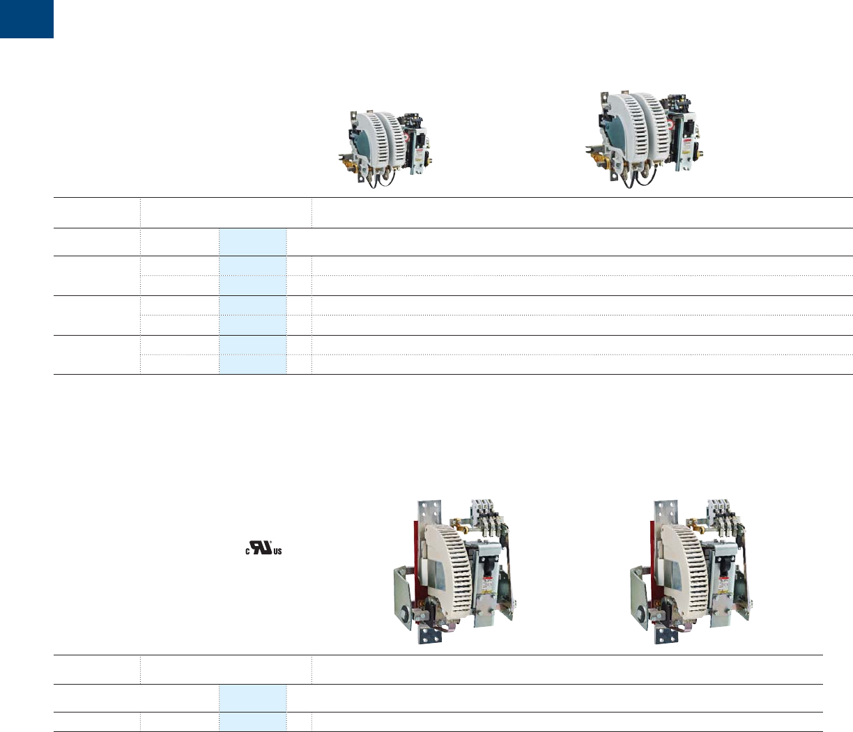
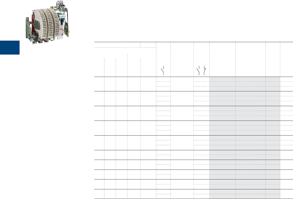
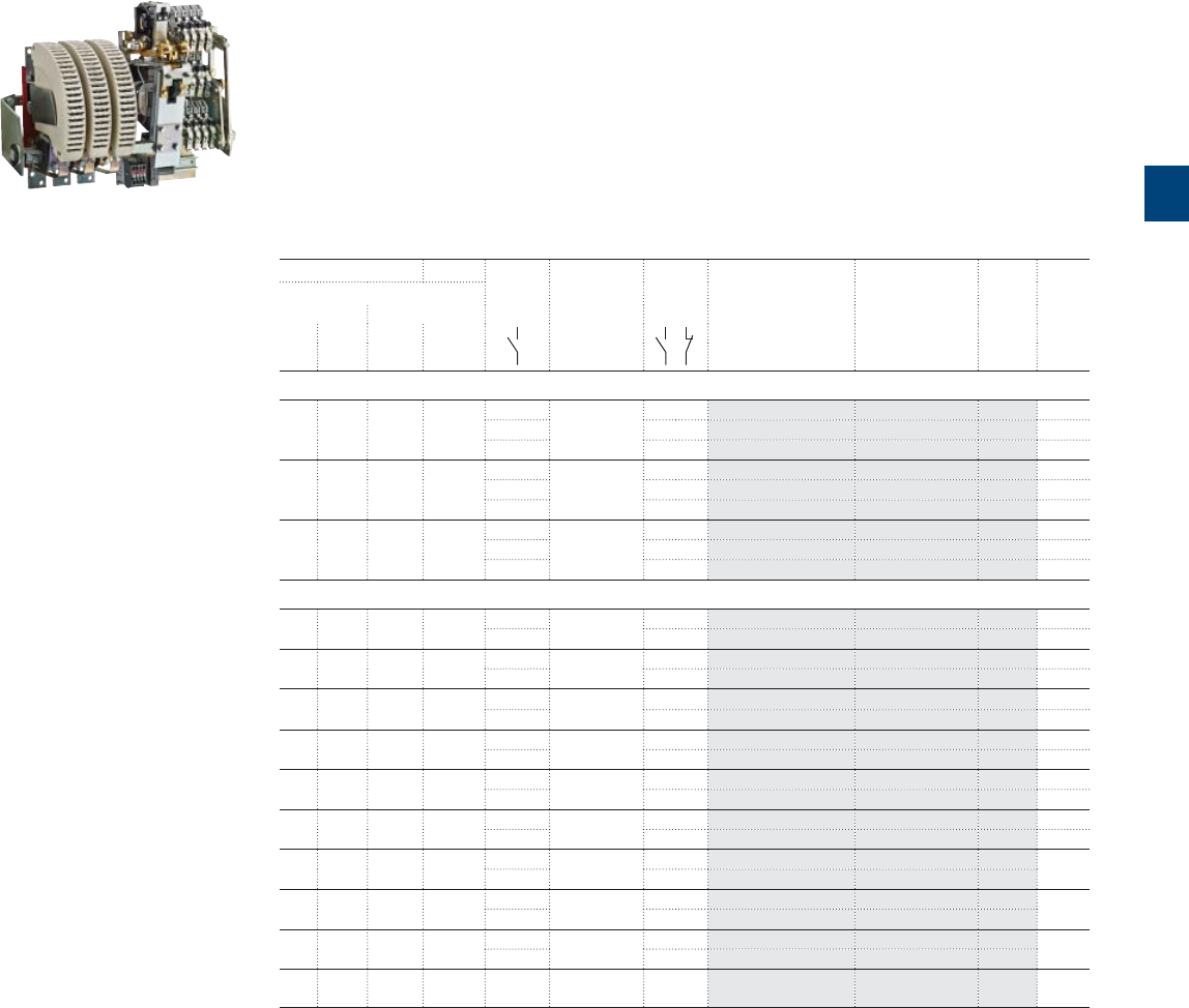
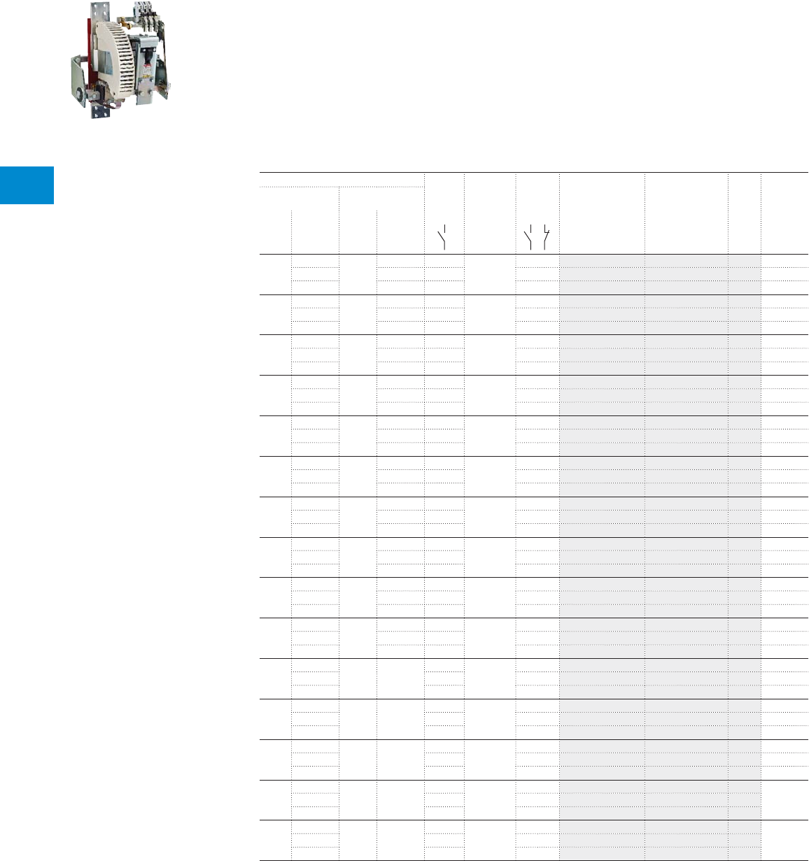
R contactors for DC circuit switching
Rated operational voltage
Ue up to 1500VDC
Contactor
type
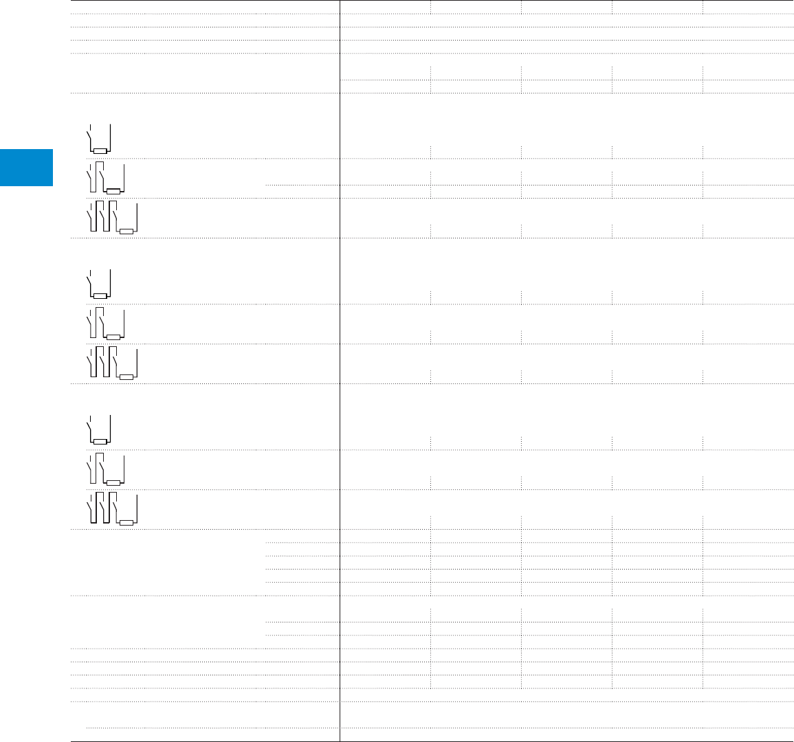
IORR63..CC IORR125..CC IORR200..CC IORR400..CC IORR500..CC
Number of poles
in series
Categories Ue max.
1 pole DC-1 500VDC Ie 85 A 170 A 275 A 400 A 550 A
DC-3 / DC-5 500VDC Ie 68 A 125 A 205 A 350 A 500 A
2 poles DC-1 1000VDC Ie 85 A 170 A 275 A 400 A* 550 A*
DC-3 / DC-5 1000VDC Ie 68 A 125 A 205 A 350 A 500 A
3 poles DC-1 1500VDC Ie 85 A* 170 A* 275 A* 400 A* 550 A*
DC-3 / DC-5 1500VDC Ie 68 A* 125 A* 205 A* 350 A* 500 A*
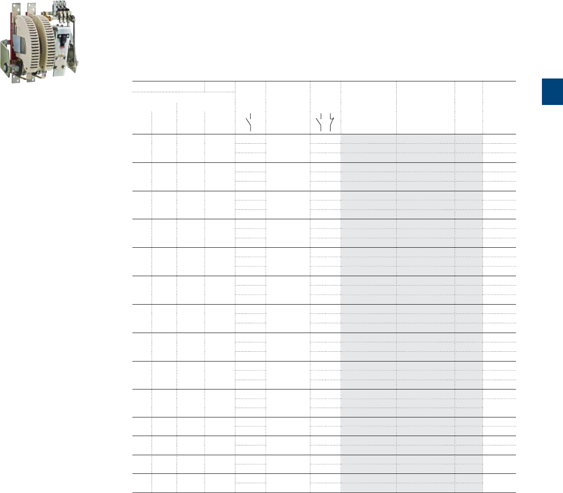
Contactor
type
IORR800-10-CC-U IORR1000-10-CC-U IORR1400-10-CC-U IORR1700-10-CC-U IORR2100-10-CC-U
U max.
1 pole General use 600VDC Ie 800 A 1000 A 1300 A 1700 A 2000 A
Rated operational voltage
Ue up to 600VDC
Contactors
UL / CSA approved
1
* Ue max. = 1500VDC, version with increased insulation for 1000VDC < Ue ≤ 1500VDC, please consult us.
*120 V 60Hz coil and 2 N.O. + 2 N.C. auxiliary contacts as standard
*120 V 60Hz coil and 2 N.O. + 2 N.C. auxiliary contacts as standard
R contactor US catalog | 1SXU106047C0201 9
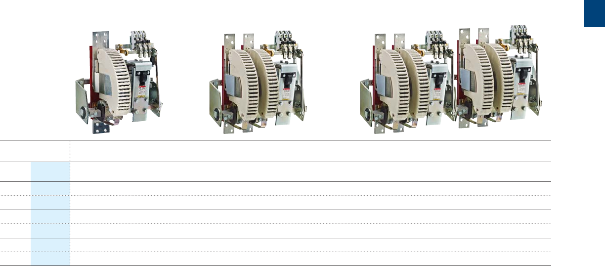
IORR800..CC IORR1000..CC IORR1400..CC IORR1700..CC IORR2100..CC IORR2500..CC IORR3200..CC IORR3800..CC IORR4500..CC IORR5100..CC
Ue max.
750VDC 800 A 1000 A 1250 A 1600 A 2000 A 2300 A 3200 A 3800 A 4500 A 5000 A
600VDC 720 A 1000 A 1250 A 1600 A 2000 A On request On request On request On request On request
1500VDC 800 A 1000 A 1250 A 1600 A 2000 A 2300 A 3200 A 3800 A 4500 A 5000 A
1000VDC 720 A 1000 A 1250 A 1600 A 2000 A On request On request On request On request On request
1500VDC 800 A 1000 A 1250 A 1600 A 2000 A 2300 A 3200 A 3800 A 4500 A 5000 A
1500VDC 720 A 1000 A 1250 A 1600 A 2000 A On request On request On request On request On request
1

10 1SXU10607C0201 | R contactor US catalog
2

R contactor US catalog | 1SXU106047C0201 11
2
Construction characteristics
Construction characteristics 12
Contactors with magnetic latching ..AMA type 14
Contactors with mechanical latching ..AME type 15
Type and order code for R contactors 16
Coil voltage and blowout type 17
Auxiliary contacts
Main characteristics 18
12 1SXU10607C0201 | R contactor US catalog
2
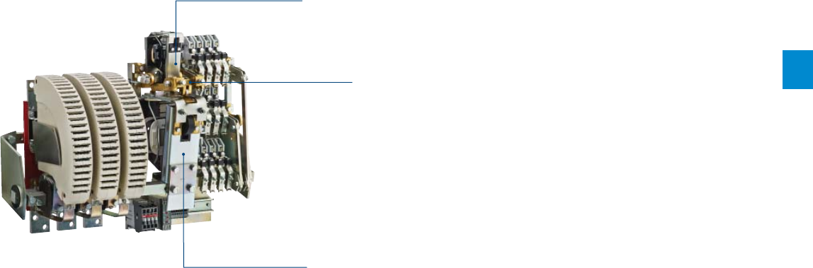
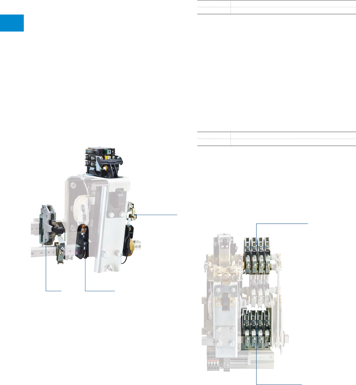
Construction characteristics
Flexible design
R contactors are built with a main frame supporting
main poles, electro-magnet, auxiliary contacts and
feature:
– Variable number of N.O. and N.C. poles, with or
without blowout coils
– Large number of N.O. and N.C. auxiliary contacts
– Control circuit for standard and specific voltages
– Mechanical or magnetic latching available.
All parts are easily accessible and removable from
the front.
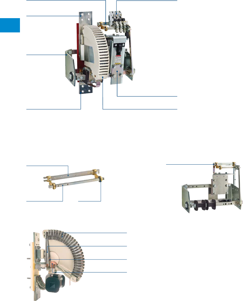
Main frame
The main frame is designed with a fixed bar and a rotating shaft linked by 2 bearings.
All parts (poles, electro-magnet, auxiliary contacts) are mounted on this frame.
Main frame
Upper connection
Electro-magnet
Auxiliary contacts
Main poles with arc chutes
Lower connection
Auxiliary frame
Large frame for R800 ... R5100 contactors
Auxiliary frame
Small frame for R63 ... R500 contactors
Fixed bar
Rotating shaft Bearings
This design offers a great
fl exibility with standard types as
well as special variants
Each pole is designed with:
Fixed and moving contacts
The fixed contacts are mounted on an insulated support
screwed onto the fixed bar.
Arcing horn
Arc chute
Fixed contacts
Moving contacts
Main poles
The moving contacts are similarly mounted and move directly
with the rotating shaft.
A blowout coil
The standard blowout coil is rated to carry the total current
flowing through the poles.
Arc chutes
Ensure a rapid extinction of the arcs. Quick and easy removal
of the arc chutes allows an easy inspection of the contacts
and their replacement if necessary.
Arcing horn
Assits the elongation and breaking of the electric arc (not
applicable to LOR couplers).
R contactor US catalog | 1SXU106047C0201 13
2
Construction characteristics
Low current breaking for DC circuits
R63 … R2100 contactors
If the breaking current is lower than 50 % of the contactor
rating, a permanent magnet must be added. Please consult
us. Refer to blowout code table in DC circuit switching
Control circuit
The electro-magnet is built with a magnetic circuit and a coil.
It is mounted on the right side or on the frame center, in
standard. It can be mounted on the left side on request.
AC control circuit supply:
RR electro-magnet
The coil is fed from an AC supply via a rectifier and an
economy resistor. The control supply frequency is 50/60Hz
in standard. For others frequencies, please consult us.
DC control circuit supply (on request):
RE electro-magnet
The coil is fed from a DC supply via an economy resistor.
Latching version
(see following pages)
Magnetic latching for R63 … R200
Mechanical latching for R500 … R5100
Rectifier
Economy resistor
A1 A2
A3
B2 =
Uc
B1 =
U
Pull-in
Holding
Varistor
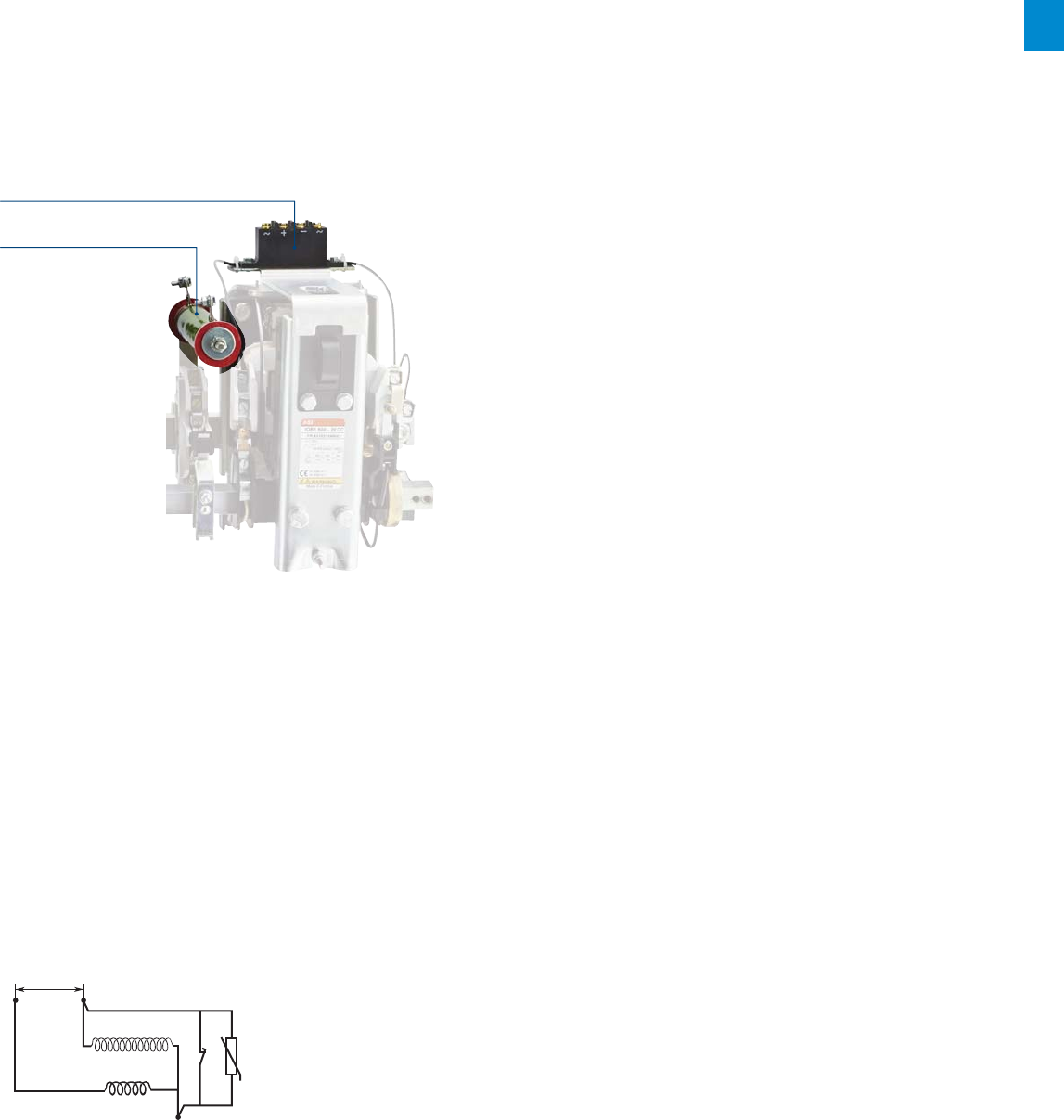
Low consumption coil for R63 … R500 contactors (on request)
– Up to 6 times less in control power consumption at holding
– Reduced width up to 15 % compared to standard R contactors
– Control voltage available:
- 24…440 V 50 / 60 Hz
- 24…250 V DC
– Example of type: IORE63..-LC.
Principle
A varistor and a lagging contact for holding winding
insertion are factory mounted.
Only a part of the winding (B1) is energized at closing.
After opening the NC contact, the complete coil (B1 +
B2) is used for contactor holding.
14 1SXU10607C0201 | R contactor US catalog
2
Contactors with magnetic latching ..AMA type
For R63 ... R200 contactors
Description
Contactors with magnetic latching are very similar to standard contactor
in construction and dimensions. Only the electro-magnet and the coil
have a specific design.
AC operated: ..RR..AMA
DC operated: ..R..AMA
A permanent magnet is mounted in the upper part of the fixed laminated
circuit. The double-winding coil is always fed from d.c. supply (from
rectifier for IORR..AMA type) and has:
– 1 terminal for "De-latching" + marked "A1" (red)
– 1 terminal for "Latching" + marked "A2" (red)
– 1 common terminal (blue).
Coil windings are only energized at the point of opening and closing of
the contactor. 2 NO + 2 NC auxiliary contacts is fitted as standard. For
additional auxiliary contact, refer to "Auxiliary contact fitting details".
Applications
– Contactors which remain permanently closed, that allows energy saving
– Installations where the control circuits are fed from batteries and
where it's needed to reduce the power consumption
– In case of accidental supply failure, the user knows the state (ON or
OFF) of the contactor when the failure occurred
– Contactors which must remain closed for safety reasons, even if the
control circuit current decreases
– Contactors in distribution circuits. The contactor is used as an
isolating switch
– Protection against accidental failure of the main supply.
Operation
Contactor closing (latching)
The electro-magnet being open, the coil winding (1) is fed via the contact B
with a current i1. The strength and direction of the magnetic fi eld produced
in this winding is the same as that produced by the permanent magnet.
Contactor opening (de-latching)
The electro-magnet being closed, the coil winding (2) is fed via the
contact A with a current i2. The direction of the field produced by current
i2, open the contactor.
Contactor opening and closing
On opening and closing of the contactor, the coil is immediately de-
energized by auxiliary contacts B and A mounted on the contactor.
Mechanical durability
0.2 millions of operating cycles.
12
i1 i2
BA
+
-
+
Block diagram
Electro-magnet of contactors ..AMA
Air-gap
Permanent magnet
R contactor US catalog | 1SXU106047C0201 15
2
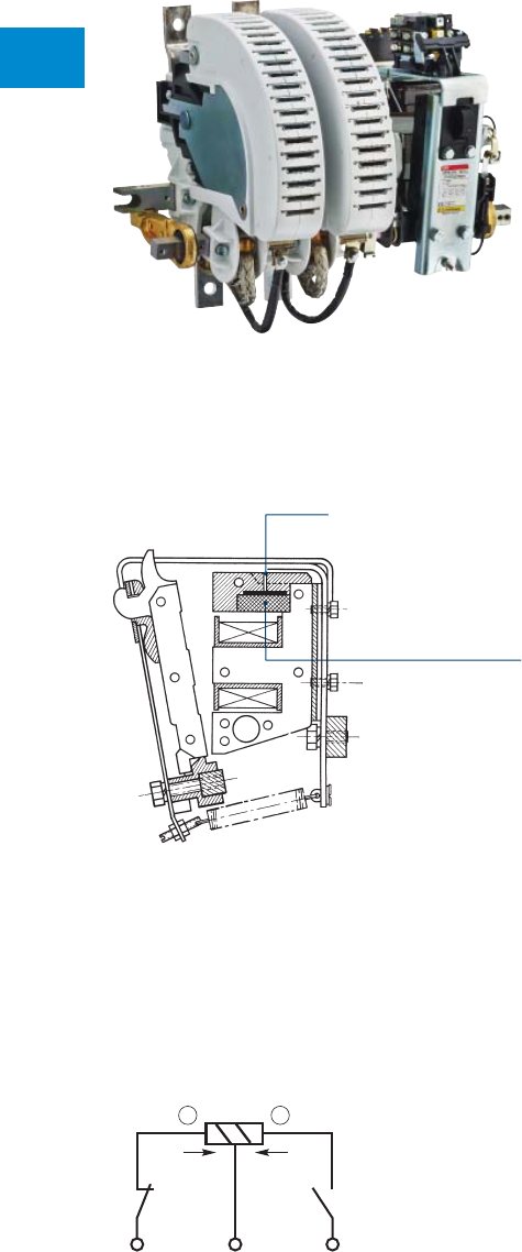
Contactors with mechanical latching ..AME type
For R500 ... R5100 contactors
Description
Contactors with mechanical latching differ from standard
contactor by a double electro-magnet (with closing and
tripping electro-magnet, electrically separated).
A mechanical latch is mounted above the closing electro-magnet.
The tripping electro-magnet releases the mechanical latch.
2 NO + 2 NC auxiiliary contacts are fitted as standard for
..AME types. For additional auxiliary contacts, refer to
"Auxiliary contact fitting details.
AC operated: ..RR..AME
Applications
– Contactors which remain permanently closed allows
energy saving
– Installations where the control circuits are fed from batteries
and where reduction of power consumption is needed
– In case of accidental supply failure, the user knows the state
(ON or OFF) of the contactor when the failure occurred
– Contactors which must remain closed for safety reasons,
even if the control circuit current decreases
– Contactors in distribution circuits where the contact serves
as an isolating switch
– Protection against accidental failure of the main supply.
Operation
Contactor closing (latching)
Once the closing coil is energized, the contactor closes. It
remains in this position by the mechanical latch action. The
closing coil is de-energized by an electrical interlocking contact.
Contactor opening (de-latching)
Once the tripping coil is energized, the mechanical latch is
released and the contactor opens.The tripping coil is de-
energized by an electrical interlocking contact.
Mechanical durability
0.2 millions of operating cycles.
Variant
AMF types with 2 tripping coils are available on request.
Closing electro-magnet
Tripping electro-magnet
Mechanical latch
16 1SXU10607C0201 | R contactor US catalog
2
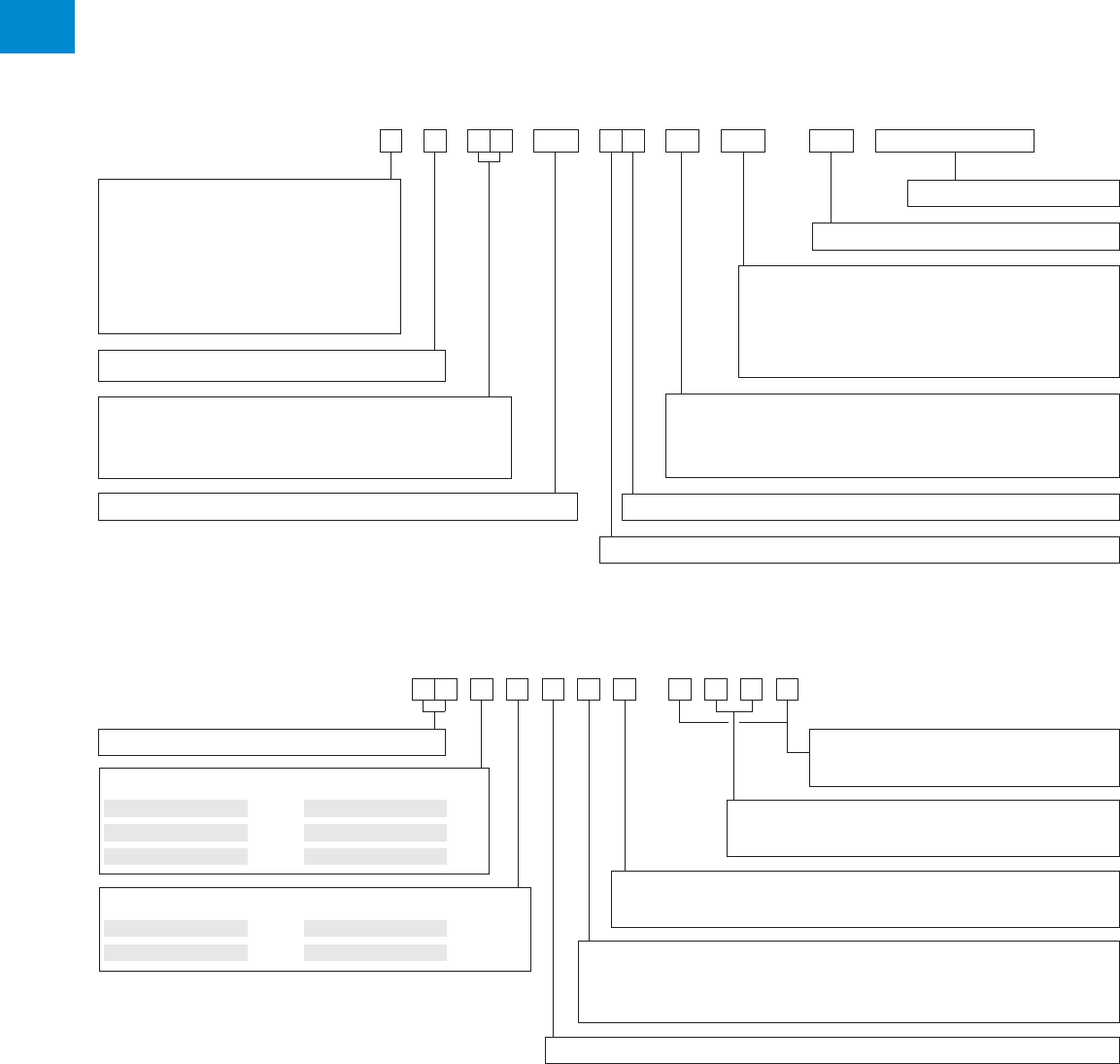
Type and order code for R contactors
Auxiliary contacts
Coil voltage (refer to following page)
empty AC switching, poles up to 500 V AC
MT AC switching, poles from 500…1000 V AC
CC DC switching, poles up to 1500 V DC
empty No option
AMA Magnetic latching (63…200 A)
AME Mechanical latching (400…5000 A)
LC Low consumption coil
Electro-magnet
AC operated coil + rectifi er + economy resistor R R
DC operated coil + economy resistor R E
Contactor type
N.O. poles I
N.C./N.O. poles, break before make N
N.C./N.O. poles, make before break J
Coupler L
Contactor for slip-ring motors F
Open bar mounted O
Contactor rating
Contactor rating
Number of poles
Number of N.C. poles
Number of N.O. poles
Type
Order code
Example:
IORE800-30-MT-AME, 220 V DC coil + 1 CA15-F + 1 CA15-O
R contactor with RE electro-magnet and circuit for DC operation via an economy resistor, 800 A rating, 3 N.O. main poles,
0 N.C. main pole, with mechanical latching, 220 V DC coil + 1 extra CA15-F (N.O.) auxiliary contact block + 1 extra CA15-O
(N.C.) auxiliary contact (total auxiliary contacts: 1 N.O. + 1 N.C.)
Equipment type
I 1
I..MT 2
L 3
Electro-magnet type
RR 5
RR..CC 6
N 4
N..MT 5
J 6
RE 9
RE..CC 0
Operating coil voltage
(see table on next page)
Extra auxiliary contacts
(see selection table)
Blowout type
(see table on next page)
Operation mode
1 Direct
2 Mechanical latching
Notes:
– Additional auxiliary contacts can be ordered separately and mounted by the user if the fi xed dimension F doesn't increase (see Auxiliary contact fi tting details table).
– Order code or contactor rating must be specifi ed when the CA15 auxiliary contact are ordered separately.
I O R E 800 -30-MT -AME 220 +1 CA15-F + 1CA15-O
FPL8629325R0116
R contactor US catalog | 1SXU106047C0201 17
2
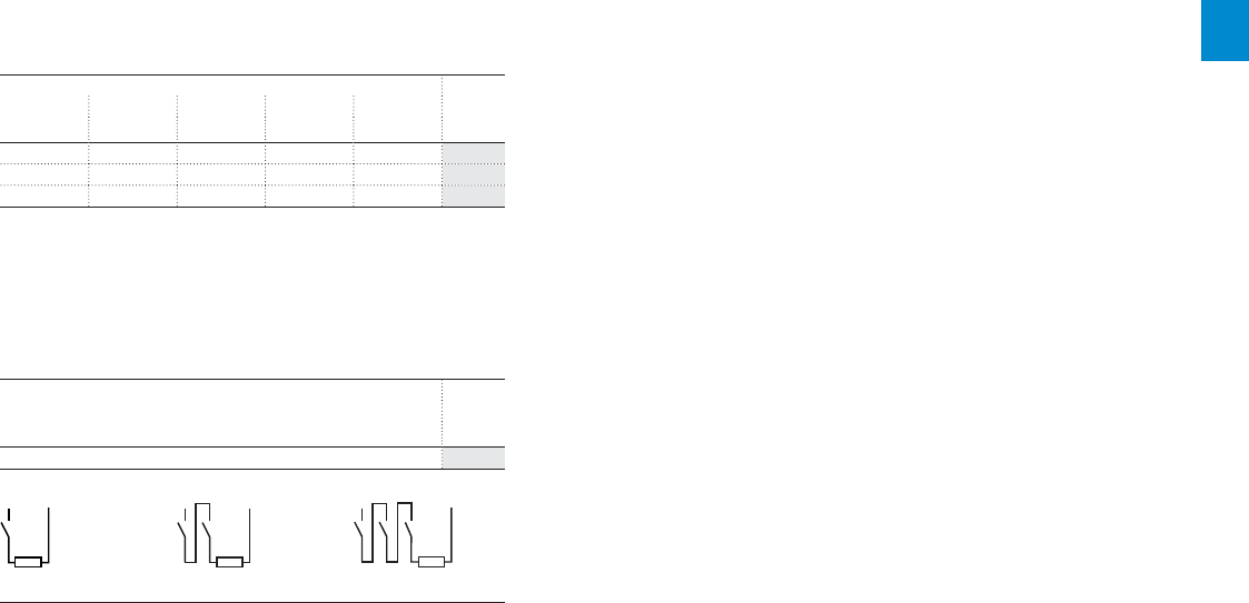
Coil voltage and blowout type
Selection table
Blowout code table in DC circuit switching
Standard electromagnetic blowout coil (bidirectional)
Used to stretch and break the electric arc from con-
tacts gap to the arc chute.
Blowout coil rating according to the operational current.
Rating Code
63 A 125 A 200 A 400 A 500 A
A AAAA£R
32––––4R
40 170 260 400 550 5R
85––––6R
Permanent magnets blowout (unidirectional)
If breaking current < 50% of contactor rating, the elec-
tromagnetic field remains too weak to blow the arc,
therefore permanent magnets must be added.
Rating Code
from 63 to 2100 A
£R
Permanent magnets blowout 7R
Pole polarization with permanent magnet
+
-
1-pole
+
-
2-pole
+
-
3-pole
18 1SXU10607C0201 | R contactor US catalog
2
Auxiliary contacts
Main characteristics
For R63 ... R500 contactors
CARB, 1-pole auxiliary contact
– 1 N.O. auxiliary contact, generally used for "hold-in"
– Ith = 6 A
– Fitted on the left side.
CAOVE, 1-pole auxiliary contact
– 1 N.C. auxiliary contact, generally used for electrical
interlocking (adjustable)
– Ith = 6 A
– Fitted on the right side.
CA12, 2-pole auxiliary contact blocks
CA12-1 1 N.O. + 1 N.C.
CA12-2 2 N.O.
– Ith = 12 A
– Fitted on the upper part of the electro-magnet.
CA15
CA15 on main frame
CA15 on auxiliary frame
CARB (N.O.)
CAOVE (N.C.)
CA12
CA15, 1-pole adjustable auxiliary contacts
CA15-F 1 N.O.
CA15-O 1 N.C.
– For R63 ... R500 contactors: auxiliary contact is mounted
between the main pole and the electro-magnet
– For R800 … R5100 contactors: auxiliary contact is
mounted on the auxiliary frame. If more CA15s are needed,
they are mounted on the main frame
– Ith = 15 A.
For R63 ... R5100 contactors
Small frame for R63 ... R500 contactors
Large frame for R800 ... R5100 contactors
R contactor US catalog | 1SXU106047C0201 19
2
Auxiliary contacts
Selection tables
Auxiliary contact fitting details
Contactor types Rating Auxiliary contacts
fi tted as standard
Additional auxiliary contacts
without increasing dimension F (1)
A
CA15 CA12
Single block
(incl. 2 contacts)
CA12
Double block
(incl. 4 contacts)
IORR 800…5100 1 CA15-F
+
1 CA15-O
+
2 max. -
IORE -
IORR..MT 63…500 1 CARB
+
1 CAOVE - -
+
1 max.
IORR..CC 800…5100 1 CA15-F
+
1 CA15-O
+
2 max. - -
IORE..MT 63…500 1 CARB
+
1 CAOVE -
+
1 max.
+
1 max.
800…5100 1 CA15-F
+
1 CA15-O
+
2 max. - -
IORE..CC 63…500 1 CARB
+
1 CAOVE -
+
1 max.
+
1 max.
800…5100 1 CA15-F
+
1 CA15-O
+
2 max. - -
IOR..AMA 63…200 1 CARB - -
+
1 max. -
IORR..AMA 63…200 1 CARB - - - -
IORR..AME 400...500 - - 1 max. - -
IORE..AME 800…5100 - - 5 max. - -
NORR..MT 63...200 1 CARB
+
1 CAOVE - -
+
1 max.
NORR..CC 800 1 CA15-F
+
1 CA15-O
+
2 max. - -
NORE..MT 63...200 1 CARB
+
1 CAOVE -
+
1 max.
+
1 max.
NORE..CC 800 1 CA15-F
+
1 CA15-O
+
2 max. - -
(1) More CA15 auxiliary contacts can be fi tted with increasing dimension F. See fi xing dimension F in "Dimensions" section.
Extra auxiliary contact code tables
F fixing dimension can change according to the number of CA15 auxiliary contacts. Refer to table below and
"Dimensions" section.
Type Code
RR, RE (63...500 A)
R..AMA (63...200 A)
CA12-1
N.O. + N.C.
CA12-2
2 x N.O.
CA15F
N.O.
CA15O
N.C. R_££_
– –––R_00_
1 –––R_11_
1––1R_12_
1––2R_13_
– 1––R_20_
1–1–R_21_
2 –––R_22_
–11–R_30_
1 1––R_31_
3 –––R_33_
– 2––R_40_
2 1––R_42_
1 2––R_51_
– 3––R_60_
1 –11R_61_
1 –22R_62_
– 111R_63_
–12–R_64_
– 122R_65_
–14–R_66_
– 131R_67_
The above tables indicate the main auxiliary contact combinations. For other combinations, please consult us.
Type Code
RR, RE, RR..AME, RE..AME (≥ 800 A)
RR..AMA (63...200 A)
CA15F
N.O.
CA15O
N.C. R
_
££
_
––R_00_
–1R_01_
–2R_02_
–3R_03_
–4R_04_
1–R_10_
11R_11_
12R_12_
2–R_20_
21R_21_
22R_22_
3–R_30_
31R_31_
32R_32_
33R_33_
4–R_40_
41R_41_
42R_42_
43R_43_
5–R_50_
51R_51_
6–R_60_

20 1SXU10607C0201 | R contactor US catalog
3

R contactor US catalog | 1SXU106047C0201 21
3
AC circuit switching
Overview 22
Ordering details
Power circuit up to 500 V AC
IORR AC operated 24
Power circuit up to 1000 V AC
IORR..MT AC operated 25
Power circuit up to 500 V AC, with mechanical latching
IORR..AME AC operated 26
Power circuit up to 1000 V AC, with latching
IORR..MT-AMA AC operated 27
IORR..MT-AME AC operated 27
Technical data 28
Type and order code for R contactors 18
22 1SXU10607C0201 | R contactor US catalog
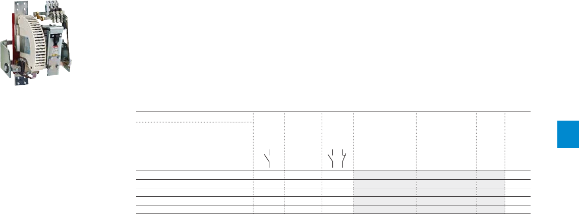
3
R contactors for AC circuit switching
Rated operational voltage
Ue up to 500 V AC
Contactor
type – IORR800
Categories Ue
AC-1 at 40 °C Ie From 85 A to 550 A, select above IOR..-MT 900 A
AC-3
380-415-440 V AC
Ie –800 A
500 V AC max. Ie –800 A
AC-3 400 V AC Power –450 kW
Rated operational voltage
Ue from 500 up to 1000 V AC
Contactor
type
IORR63..MT IORR125..MT IORR200..MT IORR400..MT IORR500..MT IORR800..MT
Categories Ue
AC-1 at 40 °C Ie 85 A 170 A 260 A 400 A 550 A 800 A
AC-3 690 V AC Ie 85 A 160 A 260 A 400 A 550 A 800 A
1000 V AC max. Ie 56 A 105 A 180 A 280 A 380 A 580 A
AC-3 690 V AC Power 80 kW 150 kW 240 kW 400 kW 540 kW 780 kW
*120 V 60Hz coil and 2 N.O. + 2 N.C. auxiliary contacts as standard
*120 V 60Hz coil and 2 N.O. + 2 N.C. auxiliary contacts as standard
R contactor US catalog | 1SXU106047C0201 23
3
IORR1000 IORR1400 IORR1700 IORR2100 IORR2500 IORR3200 IORR3800 IORR4500 IORR5100
1000 A 1350 A 1650 A 2000 A 2400 A 3200 A 3800 A 4500 A 5000 A
800 A 1080 A 1260 A 1520 A –––––
800 A 1080 A 1220 A 1340 A – – – – –
450 kW 630 kW 750 kW 900 kW –––––
IORR1400..MT IORR1700..MT IORR2100..MT IORR2500..MT IORR3200..MT IORR3800..MT IORR4500..MT IORR5100..MT
1250 A 1650 A 1850 A 2200 A 3000 A 3500 A 4000 A 4500 A
970 A 1170 A 1270 A – – –––
610 A680 A810 A–––––
1000 kW 1200 kW 1300 kW –––––
24 1SXU10607C0201 | R contactor US catalog
3
IORR contactors
Power circuit up to 500 V AC
Control circuit 120V 60Hz
Description
IORR contactors are used for controlling AC power circuits up to 500 V AC.
These contactors are designed with:
– variable number of poles according to the application
– control circuit: AC operated
– 2 NO + 2 NC auxiliary contacts available, as standard
Ordering details
AC-3 AC-1 Number
of poles
Rated control
circuit voltage
Uc
(1)
Auxiliary
contacts
fi tted (2)
Type Order code Weight
Pkg
(1 pce)
Rated operational
power current
380V
400V
415V
440V 500V ≤ 440 V θ ≤ 40°C
kW kW kW A A V 50/60Hz kg
450 500 560 800 900 2 120V 2 2 IORR800-20 FPL8615215R2113 38
3 2 2 IORR800-30 FPL8615315R2113 48
4 2 2 IORR800-40 FPL8615415R2113 58
---- 1000 2 120V 2 2 IORR1000-20 FPL8715215R2113 38
3 2 2 IORR1000-30 FPL8715315R2113 48
4 2 2 IORR1000-40 FPL8715415R2113 58
630 710 800 1080 1350 2 120V 2 2 IORR1400-20 FPL6115215R2113 40
3 2 2 IORR1400-30 FPL6115315R2113 50
4 2 2 IORR1400-40 FPL6115415R2113 63
750 800 900 1260 1650 2 120V 2 2 IORR1700-20 FPL6215215R2113 44
3 2 2 IORR1700-30 FPL6215315R2113 56
4 2 2 IORR1700-40 FPL6215415R2113 72
900 1000 1000 1520 2000 2 120V 2 2 IORR2100-20 FPL6315215R2113 48
3 2 2 IORR2100-30 FPL6315315R2113 62
4 2 2 IORR2100-40 FPL6315415R2113 78
---- 2400 2 120V 2 2 IORR2500-20 FPL6715215R2113 On
request
3 2 2 IORR2500-30 FPL6715315R2113
---- 3200 2 120V 2 2 IORR3200-20 FPL6515215R2113 On
request
3 2 2 IORR3200-30 FPL6515315R2113
---- 3800 2 120V 2 2 IORR3800-20 FPL6615215R2113 On
request
3 2 2 IORR3800-30 FPL6615001R2113
---- 4500 2 120V 2 2 IORR4500-20 FPL6815215R2113 On
request
3 2 2 IORR4500-30 FPL6815001R2113
---- 5000 2 120V 2 2 IORR5100-20 FPL6915001R2113 On
request
3 2 2 IORR5100-30 FPL6915002R2113
(1) Other control voltages, please contact us.
(2) Other auxiliary contact arrangements, please contact us.
IORR800-30
1SBC104038F0000
R contactor US catalog | 1SXU106047C0201 25
3
IORR..MT contactors
Power circuit up to 1000 V AC
Control circuit 120V 50/60 Hz
Description
IORR..MT contactors are used for controlling AC power circuits from 500 up to 1000 V AC.
These contactors are designed with:
– variable number of poles according to the application
– control circuit: AC operated
– 2 NO + 2 NC auxiliary contacts available, as standard
Ordering details
AC-3 AC-1 Number
of poles
Rated control
circuit voltage
Uc
(1)
Auxiliary
contacts
fi tted (2)
Type Order code Weight
Pkg
(1 pce)
Rated operational
power (3) current
690V 1000V ≤ 690 V θ ≤ 40°C
kW kW A A V 50/60Hz kg
80 80 85 85 2 120V 2 2 IORR63-20-MT FPL7125216R2113 4.2
3 2 2 IORR63-30-MT FPL7125386R2113 5.2
4 2 2 IORR63-40-MT FPL7125416R2113 6.2
150 150 160 170 2 120V 2 2 IORR125-20-MT FPL7425215R2113 6.2
3 2 2 IORR125-30-MT FPL7425315R2113 8.2
4 2 2 IORR125-40-MT FPL7425415R2113 10.2
240 250 260 260 2 120V 2 2 IORR200-20-MT FPL7625215R2113 9.6
3 2 2 IORR200-30-MT FPL7625315R2113 12.6
4 2 2 IORR200-40-MT FPL7625415R2113 15.6
400 400 400 400 2 120V 2 2 IORR400-20-MT FPL9425215R2113 19.2
3 2 2 IORR400-30-MT FPL9425315R2113 25
4 2 2 IORR400-40-MT FPL9425415R2113 30.8
540 550 550 550 2 120V 2 2 IORR500-20-MT FPL8325215R2113 19.7
3 2 2 IORR500-30-MT FPL8325315R2113 25.5
4 2 2 IORR500-40-MT FPL8325415R2113 31.3
780 850 800 800 2 120V 2 2 IORR800-20-MT FPL8625215R2113 40
3 2 2 IORR800-30-MT FPL8625315R2113 51
4 2 2 IORR800-40-MT FPL8625415R2113 62
1000 900 970 1250 2 120V 2 2 IORR1400-20-MT FPL6125215R2113 42
3 2 2 IORR1400-30-MT FPL6125315R2113 52
4 2 2 IORR1400-40-MT FPL6125415R2113 65
1200 1000 1170 1650 2 120V 2 2 IORR1700-20-MT FPL6225215R2113 47
3 2 2 IORR1700-30-MT FPL6225315R2113 61
4 2 2 IORR1700-40-MT FPL6225415R2113 74
1300 1200 1270 1850 2 120V 2 2 IORR2100-20-MT FPL6325215R2113 52
3 2 2 IORR2100-30-MT FPL6325315R2113 68
4 2 2 IORR2100-40-MT FPL6325415R2113 82
- - - 2200 2 120V 2 2 IORR2500-20-MT FPL6725215R2113 71
3 2 2 IORR2500-30-MT FPL6725315R2113 On request
4 2 2 IORR2500-40-MT FPL6725415R2113
- - - 3000 2 120V 2 2 IORR3200-20-MT FPL6525215R2113 83
3 2 2 IORR3200-30-MT FPL6525315R2113 On request
- - - 3500 2 120V 2 2 IORR3800-20-MT FPL6625215R2113 95
3 2 2 IORR3800-30-MT FPL6625001R2113 On request
- - - 4000 2 120V 2 2 IORR4500-20-MT FPL6825215R2113 On request
3 2 2 IORR4500-30-MT FPL6825002R2113
- - - 4500 2 120V 2 2 IORR5100-20-MT FPL6925001R2113 On request
3 2 2 IORR5100-30-MT FPL6925002R2113
(1) Other control voltages, please contact us.
(2) Other auxiliary contact arrangements, please contact us.
(3) Power circuit above 1000 V AC, please contact us.
1SBC104041F0000
IORR1400-20-MT
26 1SXU10607C0201 | R contactor US catalog
3
IORR..AME contactors
Power circuit up to 500 V AC, with mechanical latching
Control circuit 120V 50/60 Hz
Description
IORR..AME contactors are used for controlling AC power circuits up to 500 V AC.
These contactors are designed with:
– mechanical latching
– variable number of poles according to the application
– control circuit: AC operated
– 2 NO + 2 NC auxiliary contacts available
Ordering details
AC-3 AC-1 Nb of
poles
Rated control
circuit voltage
Uc
(1)
Auxiliary
contacts
fi tted (2)
Type Order code Weight
Pkg
(1 pce)
Rated operational
power current
380V
400V
415V
440V 500V ≤ 440 V θ ≤ 40°C
kW kW kW A A V 50/60Hz kg
450 500 560 800 900 2 120V 2 2 IORR800-20-AME FPL8615225R2223 48
3 2 2 IORR800-30-AME FPL8615325R2223 58
4 2 2 IORR800-40-AME FPL8615425R2223 68
---- 1000 2 120V 2 2 IORR1000-20-AME FPL8715225R2223 48
3 2 2 IORR1000-30-AME FPL8715325R2223 58
4 2 2 IORR1000-40-AME FPL8715425R2223 68
630 710 800 1080 1350 2 120V 2 2 IORR1400-20-AME FPL6115225R2223 50
3 2 2 IORR1400-30-AME FPL6115325R2223 60
4 2 2 IORR1400-40-AME FPL6115425R2223 73
750 800 900 1260 1650 2 120V 2 2 IORR1700-20-AME FPL6215225R2223 54
3 2 2 IORR1700-30-AME FPL6215325R2223 66
4 2 2 IORR1700-40-AME FPL6215425R2223 82
900 1000 1000 1520 2000 2 120V 2 2 IORR2100-20-AME FPL6315225R2223 58
3 2 2 IORR2100-30-AME FPL6315325R2223 72
4 2 2 IORR2100-40-AME FPL6315425R2223 88
---- 2400 2 120V 2 2 IORR2500-20-AME FPL6715225R2223 On
request
3 2 2 IORR2500-30-AME FPL6715325R2223
---- 3200 2 120V 2 2 IORR3200-20-AME FPL6515225R2223 On
request
3 2 2 IORR3200-30-AME FPL6515325R2223
---- 3800 2 120V 2 2 IORR3800-20-AME FPL6615225R2223 On
request
---- 4500 2 120V 2 2 IORR4500-20-AME FPL6815225R2223 On
request
(1) Other control voltages please consult us.
(2) Other auxiliary contact arrangements, please consult us.
1SBC104044F0000
IORR800-30-AME
R contactor US catalog | 1SXU106047C0201 27
3
IORR..MT-AMA and IORR..MT-AME contactors
Power circuit up to 1000 V AC, with latching
Control circuit 120V 50/60 Hz
Description
IORR..MT-AMA and IORR..MT-AME contactors are used for controlling AC power circuits from 500 up to
1000 V AC.
These contactors are designed with:
– magnetic latching, AMA types
– mechanical latching, AME types
– variable number of poles according to the application
– control circuit: AC operated
– 2 NO + 2 NC auxiliary contact available for AMA version, as standard
– 2 NO + 2 NC auxiliary contacts available for AME version
Ordering details
AC-3 AC-1 Number
of poles
Rated control
circuit voltage
Uc
(1)
Auxiliary
contacts
fi tted (2)
Type Order code Weight
Pkg
(1 pce)
Rated operational
power (3) current
690V 1000V ≤ 690 V θ ≤ 40°C
kW kW A A V 50/60Hz kg
Magnetic latching
80 80 85 85 2 120V 2 2 IORR63-20-MT-AMA FPL7125236R2123 3.9
3 2 2 IORR63-30-MT-AMA FPL7125336R2123 4.9
4 2 2 IORR63-40-MT-AMA FPL7125436R2123 5.9
150 150 160 170 2 120V 2 2 IORR125-20-MT-AMA FPL7425235R2123 5.9
3 2 2 IORR125-30-MT-AMA FPL7425335R2123 7.9
4 2 2 IORR125-40-MT-AMA FPL7425435R2123 9.9
240 250 260 260 2 120V 2 2 IORR200-20-MT-AMA FPL7625235R2123 9.2
3 2 2 IORR200-30-MT-AMA FPL7625335R2123 12.2
4 2 2 IORR200-40-MT-AMA FPL7625435R2123 15.2
Mechanical latching
400 400 400 400 2 120V 2 2 IORR400-20-MT-AME FPL9425225R2123 24.2
3 2 2 IORR400-30-MT-AME FPL9425325R2123 30
540 550 550 550 2 120V 2 2 IORR500-20-MT-AME FPL8325225R2123 24.2
3 2 2 IORR500-30-MT-AME FPL8325325R2123 30
780 850 800 800 2 120V 2 2 IORR800-20-MT-AME FPL8625225R2123 50
3 2 2 IORR800-30-MT-AME FPL8625325R2123 61
1000 900 970 1250 2 120V 2 2 IORR1400-20-MT-AME FPL6125225R2123 52
3 2 2 IORR1400-30-MT-AME FPL6125325R2123 62
1200 1000 1170 1650 2 120V 2 2 IORR1700-20-MT-AME FPL6225225R2123 57
3 2 2 IORR1700-30-MT-AME FPL6225325R2123 71
1300 1200 1270 1850 2 120V 2 2 IORR2100-20-MT-AME FPL6325225R2123 62
3 2 2 IORR2100-30-MT-AME FPL6325325R2123 78
- - - 2200 2 120V 2 2 IORR2500-20-MT-AME FPL6725225R2123 On
request
3 2 2 IORR2500-30-MT-AME FPL6725325R2123
- - - 3000 2 120V 2 2 IORR3200-20-MT-AME FPL6525225R2123 On
request
3 2 2 IORR3200-30-MT-AME FPL6525325R2123
- - - 3500 2 120V 2 2 IORR3800-20-MT-AME FPL6625225R2123 On
request
3 2 2 IORR3800-30-MT-AME FPL6625325R2123
- - - 4000 2 120V 2 2 IORR4500-20-MT-AME FPL6825225R2123 On
request
(1) Other control voltages, please consult us.
(2) Other auxiliary contact arrangements, please consult us.
(3) Power circuit above 1000 V AC, please consult us.
1SBC104044F0000
IORR800-30-MT-AME

28 1SXU10607C0201 | R contactor US catalog
3
IORR800 … IORR2100 contactors
Technical data
Main pole - Utilization characteristics according to IEC
Contactor types AC operated
IORR800 IORR1000 IORR1400 IORR1700 IORR2100
Standards IEC 60947-1 / 60947-4-1 and EN 60947-1 / 60947-4-1
Rated operational voltage Ue max. 500 V
Rated frequency (without derating) 25…60 Hz (for > 60...400 Hz please consult us)
Number of poles 2...4
Conventional free-air thermal current Ith
acc. to IEC 60947-4-1, open contactors, θ ≤ 40 °C 1000 A 1100 A 1400 A 1700 A 2100 A
With conductor cross-sectional area 600 mm² 600 mm² 1000 mm² 1500 mm² 2000 mm²
AC-1 Utilization category
For air temperature close to contactor
Ie / Rated operational current AC-1 θ ≤ 40 °C 900 A 1000 A 1350 A 1650 A 2000 A
Ue max. ≤ 500 V, 50/60 Hz θ ≤ 55 °C 840 A 930 A 1180 A 1450 A 1750 A
θ ≤ 70 °C 720 A 800 A 1000 A 1250 A 1500 A
With conductor cross-sectional area 600 mm² 600 mm² 1000 mm² 1500 mm² 2000 mm²
AC-3 Utilization category
For air temperature close to contactor θ ≤ 55 °C
Ie / Max. rated operational current AC-3
M
3
380-415-440 V 800 A - 1080 A 1260 A 1520 A
500 V 800 A - 1080 A 1220 A 1340 A
Rated operational power AC-3
M
3
380-415 V 450 kW - 630 kW 750 kW 900 kW
440 V 500 kW - 710 kW 800 kW 1000 kW
500 V 560 kW - 800 kW 900 kW 1000 kW
Rated making capacity AC-3 10 x Ie AC-3 acc. to IEC 60947-4-1
Rated breaking capacity AC-3 8 x Ie AC-3 acc. to IEC 60947-4-1
Short-circuit protection device for contactors
without thermal overload relay - Motor protection excluded
Circuit breaker 1250 A 1250 A 1600 A 2000 A 2500 A
Rated short-time withstand current Icw 1 s 9000 A 9000 A 11000 A 13000 A 15000 A
at 40 °C ambient temperature, 10 s 8000 A 8000 A 9000 A 11000 A 12200 A
in free air from a cold state 30 s 4000 A 4000 A 5000 A 6000 A 7000 A
1 min 3000 A 3000 A 3700 A 4400 A 5000 A
15 min 1600 A 1600 A 2000 A 2400 A 2800 A
Maximum breaking capacity
cos φ = 0.35 at 500 V 6400 A 6400 A 10000 A 13500 A
Maximum making capacity 14000 A 14000 A 19000 A 21000 A 24000 A
Dynamical withstand of pole 14000 A 14000 A 19000 A 21000 A 24000 A
Impedance per pole 0.18 mΩ 0.18 mΩ 0.10 mΩ 0.09 mΩ 0.08 mΩ
Maximum electrical switching frequency AC-1 300 cycles/h 150 cycles/h 120 cycles/h
AC-3 300 cycles/h - 150 cycles/h 120 cycles/h
AC-4 150 cycles/h - -
Mechanical durability
Number of operating cycles 5 millions cycles 2 millions cycles
Max. switching frequency 1200 cycles/h 600 cycles/h
Note: These characteristics are suitable for IOR..AME contactor versions (except for mechanical durability = 0.2 millions of operating cycles).
R contactor US catalog | 1SXU106047C0201 29
3
IORR2500 … IORR5100 contactors
Technical data
Main pole - Utilization characteristics according to IEC
Contactor types AC operated
IORR2500 IORR3200 IORR3800 IORR4500 IORR5100
Standards IEC 60947-1 / 60947-4-1 and EN 60947-1 / 60947-4-1
Rated operational voltage Ue max. 500 V
Rated frequency (without derating) 25…60 Hz (for > 60...400 Hz please consult us)
Number of poles 2...4
Conventional free-air thermal current Ith
acc. to IEC 60947-4-1, open contactors, θ ≤ 40 °C 2500 A 3200 A 3800 A 4500 A 5000 A
With conductor cross-sectional area 2000 mm² 3000 mm² 3000 mm² 4000 mm² 4000 mm²
AC-1 Utilization category
For air temperature close to contactor
Ie / Rated operational current AC-1 θ ≤ 40 °C 2400 A 3200 A 3800 A 4500 A 5000 A
Ue max. ≤ 500 V, 50/60 Hz θ ≤ 55 °C 2100 A 2810 A 3330 A 3950 A 4390 A
θ ≤ 70 °C 1760 A 2350 A 2790 A 3300 A 3670 A
With conductor cross-sectional area 2000 mm² 3000 mm² 3000 mm² 4000 mm² 4000 mm²
Rated making capacity AC-1 1.5 x Ie AC-1 acc. to IEC 60947-4-1
Rated breaking capacity AC-1 1.5 x Ie AC-1 acc. to IEC 60947-4-1
AC-3 Utilization category
For air temperature close to contactor θ ≤ 55 °C
Ie / Max. rated operational current AC-3
M
3
380-415-440 V Please consult us
500 V Please consult us
Short-circuit protection device for contactors
without thermal overload relay - Motor protection excluded
Circuit breaker - - - - -
Rated short-time withstand current Icw 1 s 20000 A 21000 A 24000 A 28000 A 30000 A
at 40 °C ambient temperature, 10 s 15000 A 18000 A 19000 A 21000 A 24000 A
in free air from a cold state 30 s 8000 A 10000 A 11000 A 12000 A 13000 A
1 min 6000 A 7000 A 7500 A 8000 A 9000 A
15 min 3000 A 4000 A 4500 A 5000 A 5500 A
Maximum making capacity 24000 A 26000 A 29000 A 32000 A 32000 A
Dynamical withstand of pole 24000 A 26000 A 29000 A 32000 A 32000 A
Impedance per pole 0.05 mΩ 0.045 mΩ 0.040 mΩ 0.030 mΩ 0.027 mΩ
Maximum electrical switching frequency AC-1 60 cycles/h 40 cycles/h
Mechanical durability
Number of operating cycles 2 millions cycles 1 million cycles
Max. switching frequency 600 cycles/h 300 cycles/h
Note: These characteristics are suitable for IOR..AME contactor versions (except for mechanical durability = 0.2 millions of operating cycles).

30 1SXU10607C0201 | R contactor US catalog
3
IORR63..MT … IORR500..MT contactors
Technical data
Main pole - Utilization characteristics according to IEC
Contactor types AC operated
IORR63..MT IORR125..MT IORR200..MT IORR400..MT IORR500..MT
Standards IEC 60947-1 / 60947-4-1 and EN 60947-1 / 60947-4-1
Rated operational voltage Ue max. 1000 V
Rated frequency (without de-rating) 25…60 Hz (for > 60...400 Hz please consult us)
Number of poles 2...4
Conventional free-air thermal current Ith
acc. to IEC 60947-4-1, open contactors, θ ≤ 40 °C 85 A 170 A 275 A 400 A 550 A
With conductor cross-sectional area 25 mm² 70 mm² 150 mm² 240 mm² 400 mm²
AC-1 Utilization category
For air temperature close to contactor
Ie / Rated operational current AC-1 θ ≤ 40 °C 85 A 170 A 260 A 400 A 550 A
Ue max. ≤ 1000 V, 50/60 Hz θ ≤ 55 °C 76 A 150 A 230 A 350 A 490 A
θ ≤ 70 °C 68 A 135 A 205 A 300 A 400 A
With conductor cross-sectional area 25 mm² 70 mm² 150 mm² 240 mm² 400 mm²
AC-3 Utilization category
For air temperature close to contactor θ ≤ 55 °C
Ie / Max. rated operational current AC-3
M
3
690 V 85 A 160 A 260 A 400 A 550 A
1000 V 56 A 105 A 180 A 280 A 380 A
Rated operational power AC-3
M
3
690 V 80 kW 150 kW 240 kW 400 kW 540 kW
1000 V 80 kW 150 kW 250 kW 400 kW 550 kW
Rated making capacity AC-3 10 x Ie AC-3 acc. to IEC 60947-4-1
Rated breaking capacity AC-3 8 x Ie AC-3 acc. to IEC 60947-4-1
Short-circuit protection device for contactors
without thermal overload relay - Motor protection excluded
Ue ≤ 1000 V AC - gG type fuse 100 A 200 A 315 A 500 A 630 A
Ue ≤ 1000 V AC - L type fuse - - - - -
Rated short-time withstand current Icw 1 s 1150 A 2250 A 3800 A 6000 A 8400 A
at 40 °C ambient temperature, 10 s 680 A 1280 A 2080 A 3200 A 4400 A
in free air from a cold state 30 s 310 A 680 A 1040 A 1600 A 2200 A
1 min 230 A 450 A 730 A 1200 A 1680 A
15 min 120 A 250 A 390 A 600 A 840 A
Maximum breaking capacity
cos φ = 0.45 at 690 V 680 A 1280 A 2100 A 4480 A 4480 A
(cos φ = 0.35 for Ie > 100 A) at 1000 V 450 A 850 A 1450 A 3050 A 3050 A
Maximum making capacity 1300 A 2400 A 4000 A 7000 A 9000 A
Dynamical withstand of pole 1400 A 2500 A 4500 A 8000 A 10000 A
Impedance per pole 1.8 mΩ 1.20 mΩ 0.60 mΩ 0.40 mΩ 0.35 mΩ
Maximum electrical switching frequency AC-1 300 cycles/h
AC-3 300 cycles/h
AC-4 150 cycles/h
Mechanical durability
Number of operating cycles 5 millions cycles
Max. switching frequency 1200 cycles/h
Note: These characteristics are suitable for IOR..MT-AMA and IOR..MT-AME contactors with latching versions (except for mechanical durability = 0.2 millions of operating cycles).

R contactor US catalog | 1SXU106047C0201 31
3
IORR800..MT … IORR2100..MT contactors
Technical data
Main pole - Utilization characteristics according to IEC
Contactor types AC operated
IORR800..MT IORR1400..MT IORR1700..MT IORR2100..MT
Standards IEC 60947-1 / 60947-4-1 and EN 60947-1 / 60947-4-1
Rated operational voltage Ue max. 1000 V
Rated frequency (without derating) 25…60 Hz (for > 60...400 Hz please consult us)
Number of poles 2...4
Conventional free-air thermal current Ith
acc. to IEC 60947-4-1, open contactors, θ ≤ 40 °C 800 A 1300 A 1700 A 1850 A
With conductor cross-sectional area 500 mm² 1000 mm² 1500 mm² 1500 mm²
AC-1 Utilization category
For air temperature close to contactor
Ie / Rated operational current AC-1 θ ≤ 40 °C 800 A 1250 A 1650 A 1850 A
Ue max. ≤ 690 V, 50/60 Hz θ ≤ 55 °C 740 A 1100 A 1450 A 1620 A
θ ≤ 70 °C 640 A 900 A 1250 A 1400 A
Ie / Rated operational current AC-1
Ue max. ≤ 1000 V, 50/60 Hz θ ≤ 40 °C 800 A 1220 A 1360 A 1620 A
With conductor cross-sectional area 500 mm² 1000 mm² 1500 mm² 1500 mm²
AC-3 Utilization category
For air temperature close to contactor θ ≤ 55 °C
Ie / Max. rated operational current AC-3
M
3
690 V 800 A 970 A 1170 A 1270 A
1000 V 580 A 610 A 680 A 810 A
Rated operational power AC-3
M
3
690 V 780 kW 1000 KW 1200 kW 1300 kW
1000 V 850 kW 900 kW 1000 kW 1200 kW
Rated making capacity AC-3 10 x Ie AC-3 acc. to IEC 60947-4-1
Rated breaking capacity AC-3 8 x Ie AC-3 acc. to IEC 60947-4-1
Short-circuit protection device for contactors
without thermal overload relay - Motor protection excluded
Circuit breaker 1250 A 1600 A 2000 A 2500 A
Rated short-time withstand current Icw 1 s 9000 A 11000 A 13000 A 15000 A
at 40 °C ambient temperature, 10 s 6400 A 9000 A 11000 A 12000 A
in free air from a cold state 30 s 3200 A 5000 A 6000 A 7000 A
1 min 2100 A 3600 A 4200 A 4600 A
15 min 1200 A 1900 A 2200 A 2600 A
Maximum breaking capacity
cos φ = 0.45 at 690 V 6400 A 8500 A 11000 A
(cos φ = 0.35 for Ie > 100 A) at 1000 V 4650 A 5000 A 8500 A
Maximum making capacity 14000 A 19000 A 21000 A 24000 A
Dynamical withstand of pole 14000 A 19000 A 21000 A 24000 A
Impedance per pole 0.28 mΩ 0.24 mΩ 0.18 mΩ 0.17 mΩ
Maximum electrical switching frequency AC-1 300 cycles/h 150 cycles/h 120 cycles/h
AC-3 300 cycles/h 150 cycles/h 120 cycles/h
Mechanical durability
Number of operating cycles 5 millions cycles 2 millions cycles
Max. switching frequency 1200 cycles/h 600 cycles/h
Note: These characteristics are suitable for IOR..MT-AME contactor versions (except for mechanical durability = 0.2 millions of operating cycles).

32 1SXU10607C0201 | R contactor US catalog
3
IORR2500..MT … IORR5100..MT contactors
Technical data
Main pole - Utilization characteristics according to IEC
Contactor types AC operated
IORR2500..MT IORR3200..MT IORR3800..MT IORR4500..MT IORR5100..MT
Standards IEC 60947-1 / 60947-4-1 and EN 60947-1 / 60947-4-1
Rated operational voltage Ue max. 690 V
Rated frequency (without derating) 25…60 Hz (for > 60...400 Hz please consult us)
Number of poles 2...4
Conventional free-air thermal current Ith
acc. to IEC 60947-4-1, open contactors, θ ≤ 40 °C 2200 A 3000 A 3500 A 4000 A 4500 A
With conductor cross-sectional area 2000 mm² 3000 mm² 3000 mm² 4000 mm² 4000 mm²
AC-1 Utilization category
For air temperature close to contactor
Ie / Rated operational current AC-1 θ ≤ 40 °C 2200 A 3000 A 3500 A 4000 A 4500 A
Ue max. ≤ 690 V, 50/60 Hz θ ≤ 55 °C 1930 A 2630 A 3070 A 3510 A 3950 A
θ ≤ 70 °C 1620 A 2200 A 2570 A 2940 A 3300 A
With conductor cross-sectional area 2000 mm² 3000 mm² 3000 mm² 4000 mm² 4000 mm²
Rated making capacity AC-1 1.5 x Ie AC-1 acc. to IEC 60947-4-1
Rated breaking capacity AC-1 1.5 x Ie AC-1 acc. to IEC 60947-4-1
AC-3 Utilization category
For air temperature close to contactor θ ≤ 55 °C
Ie / Max. rated operational current AC-3
M
3
690 V Please consult us
Short-circuit protection device for contactors
without thermal overload relay - Motor protection excluded
Circuit breaker - - - - -
Rated short-time withstand current Icw 1 s 20000 A 21000 A 24000 A 28000 A 30000 A
at 40 °C ambient temperature, 10 s 15000 A 18000 A 19000 A 21000 A 24000 A
in free air from a cold state 30 s 8000 A 10000 A 11000 A 12000 A 13000 A
1 min 6000 A 7000 A 7500 A 8000 A 9000 A
15 min 3000 A 4000 A 4500 A 5000 A 5500 A
Maximum making capacity 24000 A 26000 A 29000 A 32000 A 32000 A
Dynamical withstand of pole 24000 A 26000 A 29000 A 32000 A 32000 A
Impedance per pole 0.12 mΩ 0.09 mΩ 0.085 mΩ 0.06 mΩ 0.055 mΩ
Maximum electrical switching frequency AC-1 60 cycles/h 40 cycles/h
Mechanical durability
Number of operating cycles 2 millions cycles 1 million cycles
Max. switching frequency 600 cycles/h 300 cycles/h
Note: These characteristics are suitable for IOR..MT-AME contactor versions (except for mechanical durability = 0.2 millions of operating cycles).

Notes
R contactor US catalog | 1SXU106047C0201 33

34 1SXU10607C0201 | R contactor US catalog
4

R contactor US catalog | 1SXU106047C0201 35
4
DC circuit switching
Overview 36
Ordering details
Power circuit up to 1500 V DC
IORR..CC AC operated 38
Power circuit up to 600 V DC acc. to UL / CSA
IORR..CC-U AC operated 39
Power circuit up to 1500 V DC, with latching
IORR..CC-AMA AC operated 40
IORR..CC-AME AC operated 40
Technical data 42
Type and order code for R contactors 18
36 1SXU10607C0201 | R contactor US catalog
4
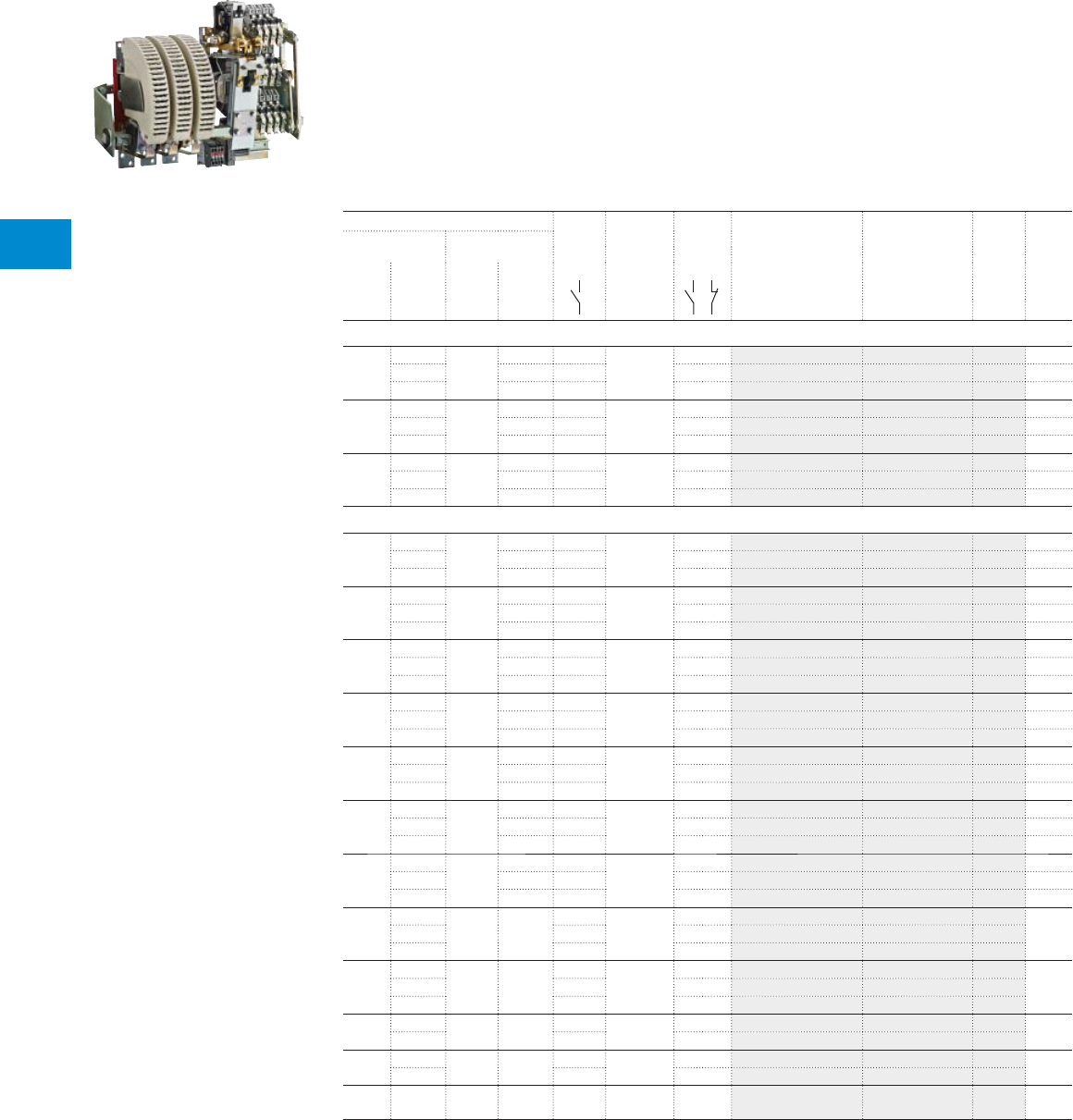
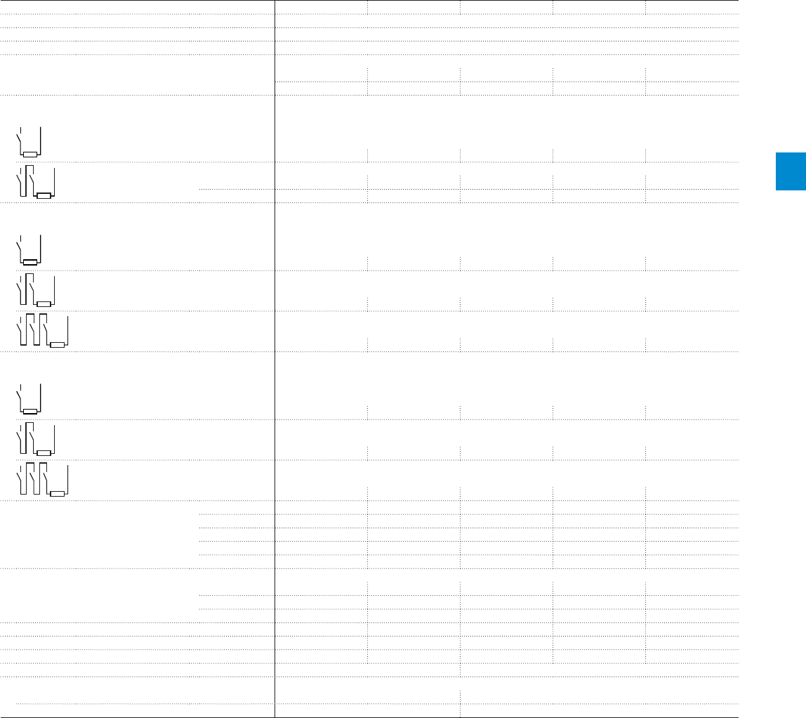
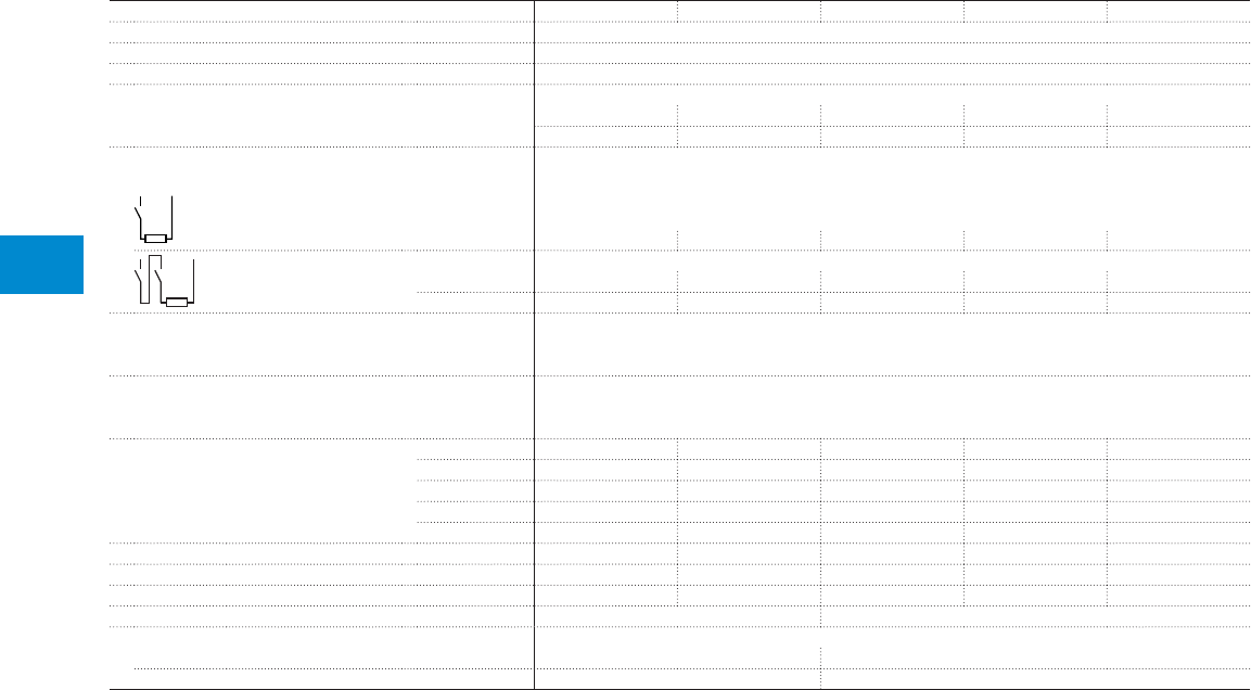
R contactors for DC circuit switching
Rated operational voltage
Ue up to 1500VDC
Contactor
type
IORR63..CC IORR125..CC IORR200..CC IORR400..CC IORR500..CC
Number of poles
in series
Categories Ue max.
1 pole DC-1 500VDC Ie 85 A 170 A 275 A 400 A 550 A
DC-3 / DC-5 500VDC Ie 68 A 125 A 205 A 350 A 500 A
2 poles DC-1 1000VDC Ie 85 A 170 A 275 A 400 A* 550 A*
DC-3 / DC-5 1000VDC Ie 68 A 125 A 205 A 350 A 500 A
3 poles DC-1 1500VDC Ie 85 A* 170 A* 275 A* 400 A* 550 A*
DC-3 / DC-5 1500VDC Ie 68 A* 125 A* 205 A* 350 A* 500 A*
Contactor
type
IORR800-10-CC IORR1000-10-CC IORR1400-10-CC IORR1700-10-CC IORR2100-10-CC
U max.
1 pole General use 600VDC Ie 800 A 1000 A 1300 A 1700 A 2000 A
Rated operational voltage
Ue up to 600VDC
Contactors
UL / CSA approved
* Ue max. = 1500VDC, version with increased insulation for 1000VDC < Ue ≤ 1500VDC, please consult us.
*120 V 60Hz coil and 2 N.O. + 2 N.C. auxiliary contacts as standard
*120 V 60Hz coil and 2 N.O. + 2 N.C. auxiliary contacts as standard
R contactor US catalog | 1SXU106047C0201 37
4
IORR800..CC IORR1000..CC IORR1400..CC IORR1700..CC IORR2100..CC IORR2500..CC IORR3200..CC IORR3800..CC IORR4500..CC IORR5100..CC
Ue max.
750VDC 800 A 1000 A 1250 A 1600 A 2000 A 2300 A 3200 A 3800 A 4500 A 5000 A
600VDC 720 A 1000 A 1250 A 1600 A 2000 A On request On request On request On request On request
1500VDC 800 A 1000 A 1250 A 1600 A 2000 A 2300 A 3200 A 3800 A 4500 A 5000 A
1000VDC 720 A 1000 A 1250 A 1600 A 2000 A On request On request On request On request On request
1500VDC 800 A 1000 A 1250 A 1600 A 2000 A 2300 A 3200 A 3800 A 4500 A 5000 A
1500VDC 720 A 1000 A 1250 A 1600 A 2000 A On request On request On request On request On request
38 1SXU10607C0201 | R contactor US catalog
4
IORR..CC contactors
Power circuit up to 1500 V DC
Control circuit 120V 50/60 Hz
Description
IORR..CC contactors are used for controlling DC power circuits up to 1500 V DC.
These contactors are designed with:
– variable number of poles according to the application
– control circuit: AC operated
– 2 NO + 2 NC auxiliary contacts available, as standard
Blowout in DC circuit switching
If the breaking current is lower than 50 % of the contactor rating, permanent magnet must be added, see
blowout code table.
Ordering details
IEC Number
of poles
Rated con-
trol circuit
voltage
Uc
(1)
Auxiliary
contacts
fi tted (2)
Type Order code Weight
pkg
(1 pce)
DC-1 DC-3 / DC-5
Rated operationnal Rated operationnal
current voltage (3) current voltage (3)
A V DC A V DC V 50/60Hz kg
85 500 68 500 1 120V 2 2 IORR63-10-CC FPL7116116R2113 3.2
1000 1000 2 2 2 IORR63-20-CC FPL7116216R2113 4.2
1500 1500 3 2 2 IORR63-30-CC On request 5.2
170 500 125 500 1 120V 2 2 IORR125-10-CC FPL7416115R2113 4.2
1000 1000 2 2 2 IORR125-20-CC FPL7416215R2113 6.2
1500 1500 3 2 2 IORR125-30-CC On request 8.2
275 500 205 500 1 120V 2 2 IORR200-10-CC FPL7616115R2113 6.6
1000 1000 2 2 2 IORR200-20-CC FPL7616215R2113 9.6
1500 1500 3 2 2 IORR200-30-CC On request 12.6
400 500 350 500 1 120V 2 2 IORR400-10-CC FPL9416115R2113 13.9
1000 1000 2 2 2 IORR400-20-CC FPL9416215R2113 19.7
1500 1500 3 2 2 IORR400-30-CC On request 25.5
550 500 500 500 1 120V 2 2 IORR500-10-CC FPL8316115R2113 13.9
1000 1000 2 2 2 IORR500-20-CC FPL8316215R2113 19.7
1500 1500 3 2 2 IORR500-30-CC On request 25.5
800 750 720 600 1 120V 2 2 IORR800-10-CC-U FPL8616195R2113 30
1500 1000 2 2 2 IORR800-20-CC FPL8616215R2113 40
- 1500 3 2 2 IORR800-30-CC FPL8616315R2113 51
1000 750 1000 600 1 120V 2 2 IORR1000-10-CC-U FPL8716195R2113 31
1500 1000 2 2 2 IORR1000-20-CC FPL8716215R2113 42
- 1500 3 2 2 IORR1000-30-CC FPL8716315R2113 50
1250 750 1250 600 1 120V 2 2 IORR1400-10-CC-U FPL6616195R2113 32
1500 1000 2 2 2 IORR1400-20-CC FPL6116215R2113 42
- 1500 3 2 2 IORR1400-30-CC FPL6116315R2113 52
1600 750 1600 600 1 120V 2 2 IORR1700-10-CC-U FPL6216195R2113 34
1500 1000 2 2 2 IORR1700-20-CC FPL6216215R2113 47
- 1500 3 2 2 IORR1700-30-CC FPL6216315R2113 61
2000 750 2000 600 1 120V 2 2 IORR2100-10-CC-U FPL6316195R2113 37
1500 1000 2 2 2 IORR2100-20-CC FPL6316215R2113 52
- 1500 3 2 2 IORR2100-30-CC FPL6316315R2113 68
2300 750 On
request
On
request
1 120V 2 2 IORR2500-10-CC FPL6716115R2113 45
1500 2 2 2 IORR2500-20-CC FPL6716215R2113 71
- 3 2 2 IORR2500-30-CC FPL6716315R2113 On request
3200 750 On
request
On
request
1 120V 2 2 IORR3200-10-CC FPL6516115R2113 52
1500 2 2 2 IORR3200-20-CC FPL6516215R2113 83
- 3 2 2 IORR3200-30-CC FPL6516315R2113 On request
3800 750 On
request
On
request
1 120V 2 2 IORR3800-10-CC FPL6616115R2113 58
1500 2 2 2 IORR3800-20-CC FPL6616215R2113 95
- 3 2 2 IORR3800-30-CC FPL6616001R2113 On request
4500 750 On
request
On
request
1 120V 2 2 IORR4500-10-CC FPL6816115R2113 On request
1500 2 2 2 IORR4500-20-CC FPL6816215R2113
- 3 2 2 IORR4500-30-CC FPL6816001R2113
5000 750 On
request
On
request
1 120V 2 2 IORR5100-10-CC FPL6916115R2113 On request
1500 2 2 2 IORR5100-20-CC FPL6916002R2113
- 3 2 2 IORR5100-30-CC FPL6916001R2113
(1) Other control voltages, please consult us.
(2) Other auxiliary contact arrangements, please consult us.
(3) Power circuit above 1500 V DC, please consult us.
1SBC104034F0000
IORR800-10-CC
R contactor US catalog | 1SXU106047C0201 39
4
IORR..CC-U contactors
Power circuit up to 600 V DC acc. to UL / CSA
Control circuit 120V 50/60 Hz
Description
IORR..CC-U contactors are used for controlling DC power circuits up to 600 V DC.
These contactors are designed with:
– One N.O. Pole
– control circuit: AC operated
– 2 NO + 2 NC auxiliary contacts available, as standard
For R800 … R2100 contactors, if the breaking current is lower than 50 % of the contactor rating, permanent
magnet must be added: see blowout code table.
Ordering details
UL / CSA Number
of poles
Rated con-
trol circuit
voltage
Uc
(1)
Auxiliary
contacts
fi tted (2)
Type Order code Weight
pkg
(1 pce)
General use rating
600 V DC
A V 50/60Hz kg
800 1 120V 2 2 IORR800-10-CC-U FPL8616195R2113 30
1000 1 120V 2 2 IORR1000-10-CC-U FPL8716195R2113 31
1300 1 120V 2 2 IORR1400-10-CC-U FPL6116195R2113 32
1700 1 120V 2 2 IORR1700-10-CC-U FPL6216195R2113 34
2000 1 120V 2 2 IORR2100-10-CC-U FPL6316195R2113 37
(1) Other control voltages, please consult us.
(2) Other auxiliary contact arrangements, please consult us.
1SBC104034F0000
IORR800-10-CC-U
40 1SXU10607C0201 | R contactor US catalog
4
IORR..CC-AMA and IORR..CC-AME contactors
Power circuit up to 1500 V DC, with latching
Control circuit 120V 50/60 Hz
Description
IORR..CC-AMA and IORR..CC-AME contactors are used for controlling DC power circuits up to 1500 V DC.
These contactors are designed with:
– magnetic latching, AMA types
– mechanical latching, AME types
– variable number of poles according to the application
– control circuit: AC operated
– 2 NO + 2 NC auxiliary contact available for AMA version, as standard
– 2 NO + 2 NC auxiliary contacts available for AME version
Ordering details
IEC Number
of poles
Rated con-
trol circuit
voltage
Uc
(1)
Auxiliary
contacts
fi tted (2)
Type Order code Weight
pkg
(1 pce)
DC-1 DC-3 / DC-5
Rated operational Rated operational
current voltage
(3)
current voltage
(3)
A V DC A V DC V 50/60Hz kg
Magnetical latching
85 500 68 500 1 120V 2 2 IORR63-10-CC-AMA FPL7116136R2123 2.9
1000 1000 2 2 2 IORR63-20-CC-AMA FPL7116236R2123 3.9
1500 1500 3 2 2 IORR63-30-CC-AMA On request 4.9
170 500 125 500 1 120V 2 2 IORR125-10-CC-AMA FPL7416135R2123 3.9
1000 1000 2 2 2 IORR125-20-CC-AMA FPL7416235R2123 5.9
1500 1500 3 2 2 IORR125-30-CC-AMA On request 7.9
275 500 205 500 1 120V 2 2 IORR200-10-CC-AMA FPL7616135R2123 6.2
1000 1000 2 2 2 IORR200-20-CC-AMA FPL7616235R2123 9.2
1500 1500 3 2 2 IORR200-30-CC-AMA On request 12.2
Mechanical latching
400 500 350 500 1 120V 2 2 IORR400-10-CC-AME FPL9416125R2223 18.4
1000 1000 2 2 2 IORR400-20-CC-AME FPL9416225R2223 24.2
1500 1500 3 2 2 IORR400-30-CC-AME FPL9416325R2223 30
550 500 500 500 1 120V 2 2 IORR500-10-CC-AME FPL8316125R2223 18.4
1000 1000 2 2 2 IORR500-20-CC-AME FPL8316225R2223 24.2
1500 1500 3 2 2 IORR500-30-CC-AME FPL8316325R2223 30
800 750 720 600 1 120V 2 2 IORR800-10-CC-AME FPL8616125R2223 40
1500 1000 2 2 2 IORR800-20-CC-AME FPL8616225R2223 50
- 1500 3 2 2 IORR800-30-CC-AME FPL8616325R2223 61
1000 750 720 600 1 120V 2 2 IORR1000-10-CC-AME FPL8716125R2223 40
1500 1000 2 2 2 IORR1000-20-CC-AME FPL8716225R2223 50
- 1500 3 2 2 IORR1000-30-CC-AME FPL8716325R2223 61
1250 750 720 600 1 120V 2 2 IORR1400-10-CC-AME FPL6116125R2223 42
1500 1000 2 2 2 IORR1400-20-CC-AME FPL6116225R2223 52
- 1500 3 2 2 IORR1400-30-CC-AME FPL6116325R2223 62
1600 750 720 600 1 120V 2 2 IORR1700-10-CC-AME FPL6216125R2223 43
1500 1000 2 2 2 IORR1700-20-CC-AME FPL6216225R2223 57
- 1500 3 2 2 IORR1700-30-CC-AME FPL6216325R2223 71
2000 750 720 600 1 120V 2 2 IORR2100-10-CC-AME FPL6316125R2223 46
1500 1000 2 2 2 IORR2100-20-CC-AME FPL6316225R2223 62
- 1500 3 2 2 IORR2100-30-CC-AME FPL6316325R2223 78
2300 750 On
request
On
request
1 120V 2 2 IORR2500-10-CC-AME FPL6716125R2223 On
request
1500 2 2 2 IORR2500-20-CC-AME FPL6716225R2223
- 3 2 2 IORR2500-30-CC-AME FPL6716325R2223
3200 750 On
request
On
request
1 120V 2 2 IORR3200-10-CC-AME FPL6516125R2223 On
request
1500 2 2 2 IORR3200-20-CC-AME FPL6516225R2223
- 3 2 2 IORR3200-30-CC-AME FPL6516325R2223
3800 750 On
request
On
request
1 120V 2 2 IORR3800-10-CC-AME FPL6616125R2223 On
request
1500 2 2 2 IORR3800-20-CC-AME FPL6616225R2223
4500 750 On
request
On
request
1 120V 2 2 IORR4500-10-CC-AME FPL6816125R2223 On
request
1500 2 2 2 IORR4500-20-CC-AME FPL6816225R2223
5000 750 On
request
On
request
1 120V 2 2 IORR5100-10-CC-AME FPL6916125R2223 On
request
(1) Other control voltages, please consult us.
(2) Other auxiliary contact arrangements, please consult us.
(3) Power circuit above 1500 V DC, please consult us.
1SBC104044F0000
IORR800-30-CC-AME

Notes
R contactor US catalog | 1SXU106047C0201 41
42 1SXU10607C0201 | R contactor US catalog
4
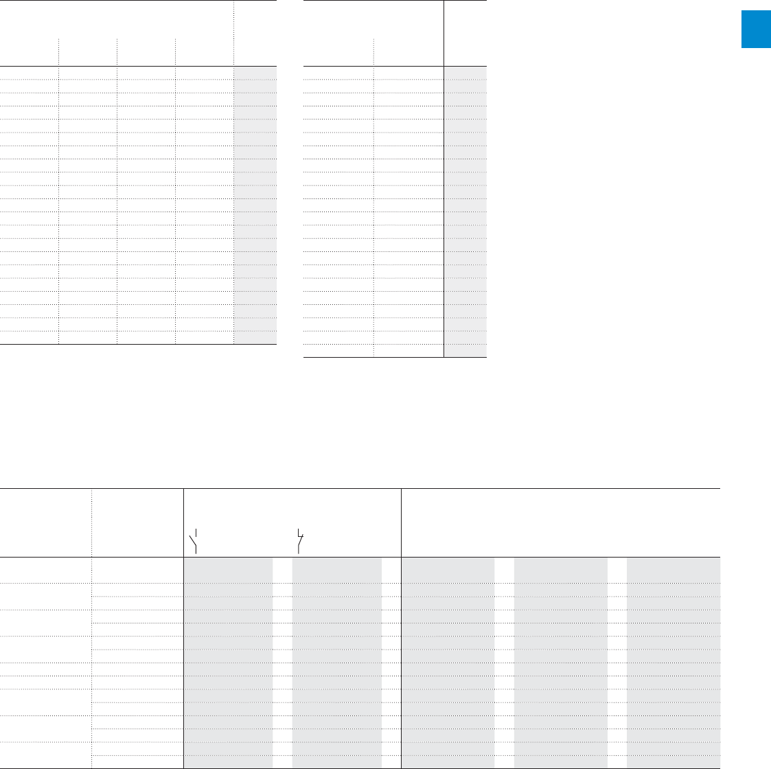
IORR63..CC … IORR500..CC contactors
Technical data
Main pole - Utilization characteristics according to IEC
Contactor types AC operated
IORR63..CC IORR125..CC IORR200..CC IORR400..CC IORR500..CC
Standards IEC 60947-1 / 60947-4-1 and EN 60947-1 / 60947-4-1
Rated operational voltage Ue max. 1000 V DC (1500 V DC with increased insulation (1))
Number of poles 1...4
Conventional free-air thermal current Ith
acc. to IEC 60947-4-1, open contactors, θ ≤ 40 °C 85 A 170 A 275 A 400 A 550 A
With conductor cross-sectional area 25 mm² 70 mm² 150 mm² 240 mm² 400 mm²
DC-1 Utilization category, L/R ≤ 1 ms
Ie / Rated operational current DC-1
1 pole
≤ 500 V 85 A 170 A 275 A 400 A 550 A
2 poles in series
≤ 1000 V 85 A 170 A 275 A 400 A 550 A
≤ 1500 V (1) - - - 400 A 550 A
3 poles in series
≤ 1500 V (1) 85 A 170 A 275 A 400 A 550 A
DC-3 Utilization category, L/R ≤ 2 ms
Ie / Rated operational current DC-3
1 pole
≤ 500 V 68 A 125 A 205 A 350 A 500 A
2 poles in series
≤ 1000 V 68 A 125 A 205 A 350 A 500 A
3 poles in series
≤ 1500 V (1) 68 A 125 A 205 A 350 A 500 A
DC-5 Utilization category, L/R ≤ 7.5 ms
Ie / Rated operational current DC-5
1 pole
≤ 500 V 68 A 125 A 205 A 350 A 500 A
2 poles in series
≤ 1000 V 68 A 125 A 205 A 350 A 500 A
3 poles in series
≤ 1500 V (1) 68 A 125 A 205 A 350 A 500 A
Rated short-time withstand current Icw 1 s 1150 A 2250 A 3800 A 6000 A 8400 A
at 40 °C ambient temperature, 10 s 680 A 1280 A 2080 A 3200 A 4400 A
in free air from a cold state 30 s 310 A 680 A 1040 A 1600 A 2200 A
1 min 230 A 450 A 730 A 1200 A 1680 A
15 min 120 A 250 A 390 A 600 A 840 A
Rated breaking capacity
(L/R ≤ 15 ms) 1 pole 500 V 272 A 500 A 820 A 1400 A 2000 A
2 poles 1000 V 272 A 500 A 820 A 1400 A 2000 A
3 poles 1500 V 272 A 500 A 820 A 1400 A 2000 A
Maximum making capacity 1300 A 2400 A 4000 A 7000 A 9000 A
Dynamical withstand of pole 1400 A 2500 A 4500 A 8000 A 10000 A
Impedance per pole 1.8 mΩ 1.20 mΩ 0.60 mΩ 0.40 mΩ 0.35 mΩ
Maximum electrical switching frequency 120 cycles/h
Mechanical durability
Number of operating cycles 5 millions cycles
Maximum switching frequency 1200 cycles/h
(1) Version with increased insulation for 1000 V < Ue < 1500 V, please consult us.
Notes: - The arc switching on DC is more diffi cult than on AC
- For information, typical time constant values are quoted hereafter: non inductive loads such as resistance furnaces: L/R < 1 ms; inductive loads such as shunt motor:
L/R < 2 ms; series motor: L/R < 7.5 ms
- The addition of a resistor in parallel with an inductive winding helps in the elimination of the arcs
- All the poles required for breaking must be connected, in series, between the load and the source polarity not linked to the earth
- Connection of the poles in series by the user, according to the above diagrams. The connection of the poles in series helps in the elimination of the arcs
- These characteristics are suitable for IOR..CC-AMA and IOR..CC-AME contactor latching versions (except for mechanical durability = 0.2 millions of operating cycles).
R contactor US catalog | 1SXU106047C0201 43
4
IORR800..CC … IORR2100..CC contactors
Technical data
Main pole - Utilization characteristics according to IEC
Contactor types AC operated
IORR800..CC IORR1000..CC IORR1400..CC IORR1700..CC IORR2100..CC
Standards IEC 60947-1 / 60947-4-1 and EN 60947-1 / 60947-4-1
Rated operational voltage Ue max. 1500 V DC
Number of poles 1...4
Conventional free-air thermal current Ith
acc. to IEC 60947-4-1, open contactors, θ ≤ 40 °C 800 A 1000 A 1300 A 1700 A 2000 A
With conductor cross-sectional area 500 mm² 600 mm² 1000 mm² 1500 mm² 1500 mm²
DC-1 Utilization category, L/R ≤ 1 ms
Ie / Rated operational current DC-1
1 pole
≤ 750 V 800 A 1000 A 1250 A 1600 A 2000 A
2 poles in series
≤ 1000 V 800 A 1000 A 1250 A 1600 A 2000 A
≤ 1500 V 800 A 1000 A 1250 A 1600 A 2000 A
DC-3 Utilization category, L/R ≤ 2 ms
Ie / Rated operational current DC-3
1 pole
≤ 600 V 720 A 1000 A 1250 A 1600 A 2000 A
2 poles in series
≤ 1000 V 720 A 1000 A 1250 A 1600 A 2000 A
3 poles in series
≤ 1500 V 720 A 1000 A 1250 A 1600 A 2000 A
DC-5 Utilization category, L/R ≤ 7.5 ms
Ie / Rated operational current DC-5
1 pole
≤ 600 V 720 A 1000 A 1250 A 1600 A 2000 A
2 poles in series
≤ 1000 V 720 A 1000 A 1250 A 1600 A 2000 A
3 poles in series
≤ 1500 V 720 A 1000 A 1250 A 1600 A 2000 A
Rated short-time withstand current Icw 1 s 9000 A 9000 A 11000 A 13000 A 15000 A
at 40 °C ambient temperature, 10 s 6400 A 6400 A 9000 A 11000 A 12000 A
in free air from a cold state 30 s 3200 A 3200 A 5000 A 6000 A 7000 A
1 min 2100 A 2100 A 3600 A 4200 A 4600 A
15 min 1200 A 1200 A 1900 A 2200 A 2600 A
Rated breaking capacity
(L/R ≤ 15 ms) 1 pole 600 V 2880 A 4000 A 5000 A 6400 A 8000 A
2 poles 1000 V 2880 A 4000 A 5000 A 6400 A 8000 A
3 poles 1500 V 2880 A 4000 A 5000 A 6400 A 8000 A
Maximum making capacity 14000 A 14000 A 19000 A 21000 A 24000 A
Dynamical withstand of pole 14000 A 14000 A 19000 A 21000 A 24000 A
Impedance per pole 0.28 mΩ 0.24 mΩ 0.18 mΩ 0.12 mΩ 0.10 mΩ
Maximum electrical switching frequency 120 cycles/h 60 cycles/h
Mechanical durability
Number of operating cycles 5 millions cycles 2 millions cycles
Maximum switching frequency 1200 cycles/h 600 cycles/h
Notes: - The arc switching on DC is more diffi cult than on AC
- For information, typical time constant values are quoted hereafter: non inductive loads such as resistance furnaces: L/R < 1 ms; inductive loads such as shunt motor:
L/R < 2 ms; series motor: L/R < 7.5 ms
- The addition of a resistor in parallel with an inductive winding helps in the elimination of the arcs
- All the poles required for breaking must be connected, in series, between the load and the source polarity not linked to the earth
- Connection of the poles in series by the user, according to the above diagrams. The connection of the poles in series helps in the elimination of the arcs
- These characteristics are suitable for IOR..CC-AME contactor latching versions (except for mechanical durability = 0.2 millions of operating cycles).
44 1SXU10607C0201 | R contactor US catalog
4
IORR2500..CC … IORR5100..CC contactors
Technical data
Main pole - Utilization characteristics according to IEC
Contactor types AC operated
IORR2500..CC IORR3200..CC IORR3800..CC IORR4500..CC IORR5100..CC
Standards IEC 60947-1 / 60947-4-1 and EN 60947-1 / 60947-4-1
Rated operational voltage Ue max. 1500 V DC
Number of poles 1...4
Conventional free-air thermal current Ith
acc. to IEC 60947-4-1, open contactors, θ ≤ 40 °C 2300 A 3200 A 3800 A 4500 A 5000 A
With conductor cross-sectional area 2000 mm² 3000 mm² 3000 mm² 4000 mm² 4000 mm²
DC-1 Utilization category, L/R ≤ 1 ms
Ie / Rated operational current DC-1
1 pole
≤ 750 V 2300 A 3200 A 3800 A 4500 A 5000 A
2 poles in series
≤ 1000 V 2300 A 3200 A 3800 A 4500 A 5000 A
≤ 1500 V 2300 A 3200 A 3800 A 4500 A 5000 A
DC-3 Utilization category, L/R ≤ 2 ms
Ie / Rated operational current DC-3
For voltage up to 1500 V Please consult us
DC-5 Utilization category, L/R ≤ 7.5 ms
Ie / Rated operational current DC-5
For voltage up to 1500 V Please consult us
Rated short-time withstand current Icw 1 s 20000 A 21000 A 24000 A 28000 A 30000 A
at 40 °C ambient temperature, 10 s 15000 A 18000 A 19000 A 21000 A 24000 A
in free air from a cold state 30 s 8000 A 10000 A 11000 A 12000 A 13000 A
1 min 6000 A 7000 A 7500 A 8000 A 9000 A
15 min 3000 A 4000 A 4500 A 5000 A 5500 A
Maximum making capacity 24000 A 26000 A 29000 A 32000 A 32000 A
Dynamical withstand of pole 24000 A 26000 A 29000 A 32000 A 32000 A
Impedance per pole 0.09 mΩ 0.06 mΩ 0.05 mΩ 0.04 mΩ 0.03 mΩ
Maximum electrical switching frequency 60 cycles/h 40 cycles/h
Mechanical durability
Number of operating cycles 2 millions cycles 1 million cycles
Maximum switching frequency 600 cycles/h 300 cycles/h
Notes: - The arc switching on DC is more diffi cult than on AC
- For information, typical time constant values are quoted hereafter: non inductive loads such as resistance furnaces: L/R < 1 ms; inductive loads such as shunt motor:
L/R < 2 ms; series motor: L/R < 7.5 ms
- The addition of a resistor in parallel with an inductive winding helps in the elimination of the arcs
- All the poles required for breaking must be connected, in series, between the load and the source polarity not linked to the earth
- Connection of the poles in series by the user, according to the above diagrams. The connection of the poles in series helps in the elimination of the arcs
- These characteristics are suitable for IOR..CC-AME contactor latching versions (except for mechanical durability = 0.2 millions of operating cycles).

Notes
R contactor US catalog | 1SXU106047C0201 45

5
46 1SXU10607C0201 | R contactor US catalog

5
R contactor US catalog | 1SXU106047C0201 47
Advanced applications
N.O. / N.C. main poles combination
Presentation 48
Power circuit up to 690 V AC
NORR, NORR..MT AC operated 49
Power circuit up to 1500 V DC
NORR, NORR..CC AC operated 50
Technical data 51
Power circuit coupling
Presentation 54
Power circuit up to 1000 V AC or 1500 V DC
LORR AC operated 55
Technical data 57
Slip-ring motor control 60
Rotor voltages up to 1500 V AC
FORR1000 … FORR3800 AC operated 62
Rotor voltages up to 2500 V AC
FORR1000S … FORR2100S AC operated 63
Rotor voltages up to 3500 V AC
FORR1000NSP … FORR2100NSP AC operated 64
Rotor voltages up to 4200 V AC
FORR1000SPE … FORR2100SPE AC operated 65
Closed transition star-delta starting of three-phase
asynchronous motors 66
Field discharge contactors AM-CC-JOR and AMF-CC-JOR 67
Autotransformer starters 68
Type and order code for R contactors 18
5
48 1SXU10607C0201 | R contactor US catalog
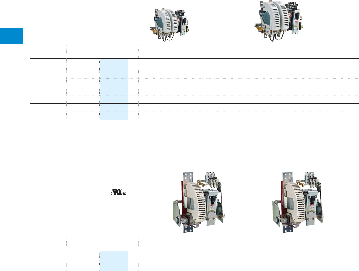
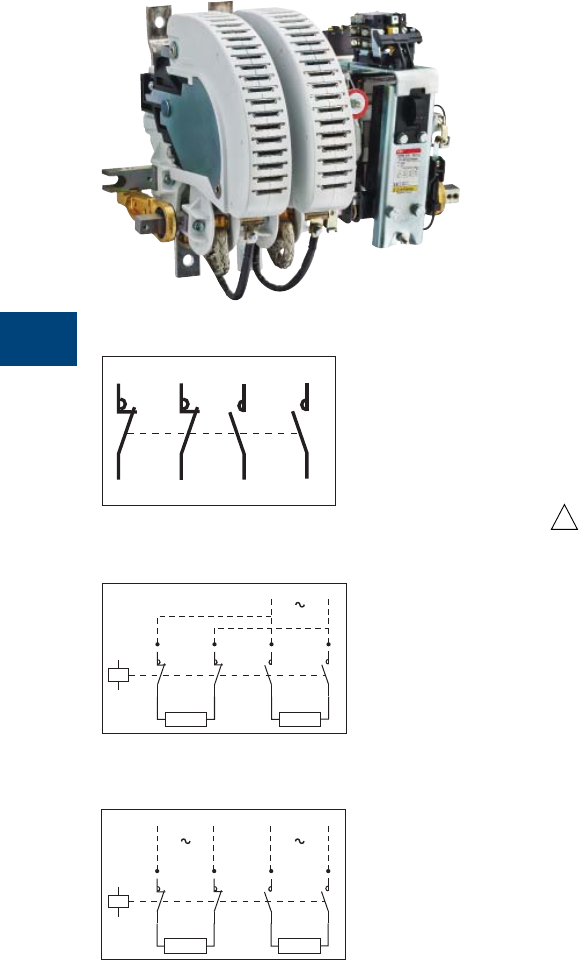
N.O. / N.C. main poles combination
NOR contactors
R0115DG
R1
R2
7
8
A1
A2
Supply
R3
R4
5
6
Load Load
R1
R2
7
8
A1
A2
Load Load
Back-up
supply
Main
supply
R3
R4
5
6
R0116DG
R1
R2
5
6
R3
R4
7
8
R0114D
2 N.C. poles + 2 N.O. poles
Single supply and 2 separate loads
2 separate supplies and 2 separate loads
Description
NOR contactors are built with a combination of N.O. and N.C. poles:
– AC switching: NOR..MT up to 690 V AC
– DC switching: NOR..CC up to 1500 V DC in standard.
– For low current breaking, permanent magnet must be added.
2 NO + 2 NC auxiliary contacts are fitted as standard. For additional
auxiliary contacts refer to “Auxiliary contact fitting details.”
Example of use :
Change-over contactor with 2 N.C. poles + 2 N.O. poles.
Block diagrams
These contactors are suitable for controlling 2 separate circuits, i.e.
2 loads with 2 separate supplies, or 1 circuit including 2 separate loads
with a single supply (diagrams on left column).
When the contactor operates there is no mechanical overlapping between
the N.O. poles and the N.C. poles: BREAK before MAKE operation.
These contactors are not suitable for a reversing starter or star-delta
starter, or for controlling a single load from 2 separate supplies.
Operation
The N.O. and N.C. poles are set-up without any mechanical overlap:
– as the electro-magnet closes, the N.C. pole(s) BREAK before the N.O.
pole(s) MAKE
– as the electro-magnet opens, the N.O. pole(s) BREAK before the N.C.
pole(s) MAKE.
The breaking and making capacities of the N.C. poles are identical to
those of the N.O. poles.
Other variants
Please consult us for :
– NOR..AMA and NOR..AME with latching
– JOR types: version with overlapping between N.O. and N.C. main poles.
!
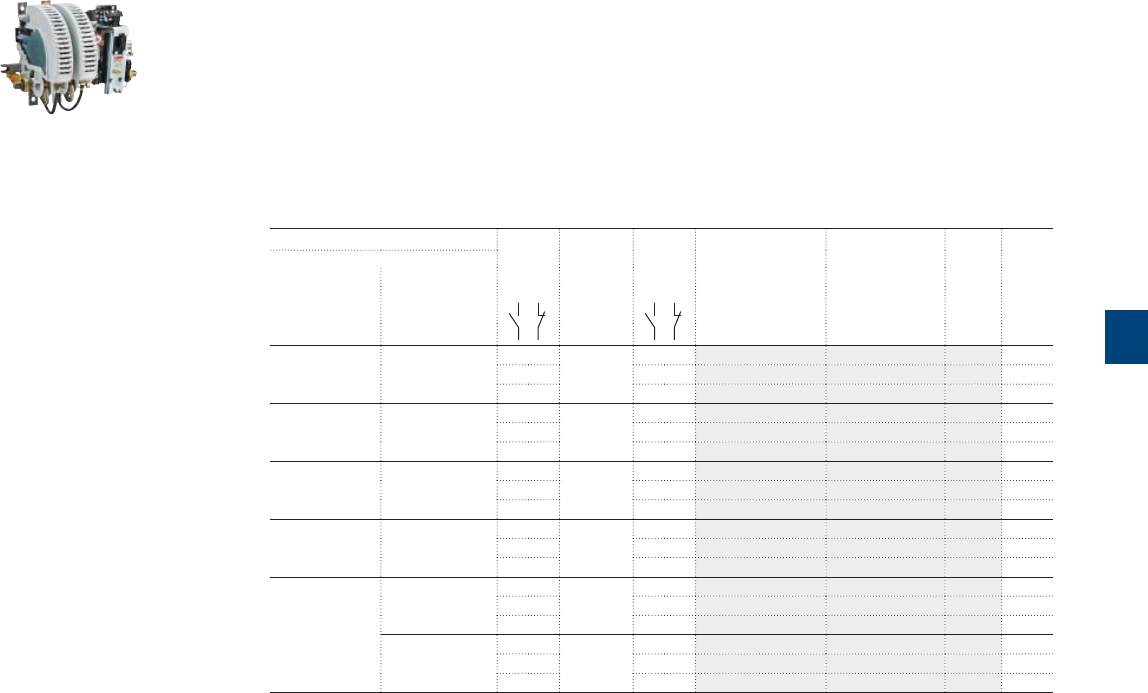
5
R contactor US catalog | 1SXU106047C0201 49
NORR, NORE, NORR..MT and NORE..MT contactors
Power circuit up to 690 V AC
Control circuit 120V 50/60 Hz
Description
NORR..MT and NORE..MT contactors with N.O. and N.C. main poles are used for controlling AC power
circuits up to 690 V AC.
NORR400 ... NORR800 and NORE400 ... NORE800 contactors with N.O. and N.C. main poles are used for
controlling AC power circuits up to 500 V AC.
These contactors are designed with:
– variable number of poles according to the application
– control circuit: AC or DC operated
– 2 NO + 2 NC auxiliary contacts available, as standard.
AC operated
IEC Number
of poles
(4)
Rated con-
trol circuit
voltage
Uc
(1)
Auxiliary
contacts
fi tted (2)
Type Order code Weight
pkg
(1 pce)
Rated operationnal
current voltage (3)
θ ≤ 40°C
AC-1
A V AC V 50/60Hz kg
63 690 0 2 120V 2 2 NORR63-02-MT FPL7155216R2113 4.2
2 1 2 2 NORR63-21-MT FPL7155516R2113 3.9
3 1 2 2 NORR63-31-MT FPL7155716R2113 4.9
125 690 0 2 120V 2 2 NORR125-02-MT FPL7455215R2113 6.2
2 1 2 2 NORR125-21-MT FPL7455515R2113 8.2
3 1 2 2 NORR125-31-MT FPL7455715R2113 9
200 690 0 2 120V 2 2 NORR200-02-MT FPL7655215R2113 9.6
2 1 2 2 NORR200-21-MT FPL7655515R2113 10
3 1 2 2 NORR200-31-MT FPL7655715R2113 12.2
315 500 0 2 120V 2 2 NORR400-02 FPL9445215R2113 12
2 1 2 2 NORR400-21 FPL9445515R2113 15
3 1 2 2 NORR400-31 FPL9445715R2113 18
800 500 0 2 120V 2 2 NORR800-02 FPL8645215R2113 38
2 1 2 2 NORR800-21 FPL8645515R2113 48
3 1 2 2 NORR800-31 FPL8645715R2113 58
690 0 2 120V 2 2 NORR800-02-MT FPL8655215R2113 40
2 1 2 2 NORR800-21-MT FPL8655515R2113 51
3 1 2 2 NORR800-31-MT FPL8655715R2113 62
(1) Other control voltages, please consult us.
(2) Other auxiliary contact arrangements, please consult us.
(3) Power circuit above 690 V AC, please consult us.
(4) Other main pole combinations, please consult us.
1SBC104042F0000
NORR125-02-MT
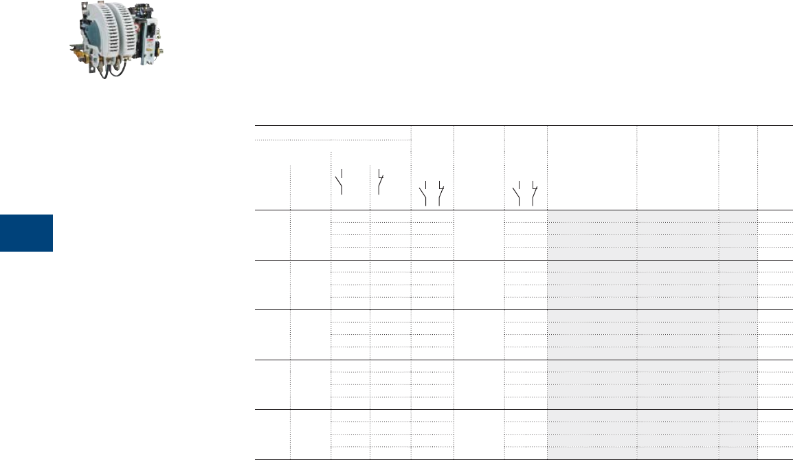
5
50 1SXU10607C0201 | R contactor US catalog
NORR, NORE, NORR..CC and NORE..CC contactors
Power circuit up to 1500 V DC
Control circuit 120V 50/60 Hz
Description
NORR..CC and NORE..CC contactors with N.O. and N.C. main poles are used for controlling DC power
circuits up to 1500 V DC. NORR and NORE400 up to 440 V DC.
These contactors are designed with:
– variable number of poles according to the application
– control circuit: AC or DC operated
– 2 NO + 2 NC auxiliary contacts available, as standard.
AC operated
IEC Number
of poles
(4)
Rated con-
trol circuit
voltage
Uc
(1)
Auxiliary
contacts
fi tted (2)
Type Order code Weight
pkg
(1 pce)
Rated operationnal
current voltage (3)
DC-1 DC-3
DC-5
A A V DC V DC V 50/60Hz kg
63 63 - 500 0 1 120V 2 2 NORR63-01-CC FPL7146116R2113 3.2
- 1000 0 2 2 2 NORR63-02-CC FPL7146216R2113 4.2
1000 500 2 1 2 2 NORR63-21-CC FPL7146516R2113 3.9
1000 500 3 1 2 2 NORR63-31-CC FPL7146716R2113 4.9
125 125 - 500 0 1 120V 2 2 NORR125-01-CC FPL7446115R2113 4.2
- 1000 0 2 2 2 NORR125-02-CC FPL7446215R2113 6.2
1000 500 2 1 2 2 NORR125-21-CC FPL7446515R2113 8.2
1000 500 3 1 2 2 NORR125-31-CC FPL7446715R2113 9
200 200 - 500 0 1 120V 2 2 NORR200-01-CC FPL7646115R2113 6.6
- 1000 0 2 2 2 NORR200-02-CC FPL7646215R2113 9.6
1000 500 2 1 2 2 NORR200-21-CC FPL7646515R2113 10
1000 500 3 1 2 2 NORR200-31-CC FPL7646715R2113 12.2
315 315 - 220 0 1 120V 2 2 NORR400-01 FPL9445115R2113 9
- 440 0 2 2 2 NORR400-02 FPL9445215R2113 12
440 220 2 1 2 2 NORR400-21 FPL9445515R2113 15
440 220 3 1 2 2 NORR400-31 FPL9445715R2113 18
800 720 - 500 0 1 120V 2 2 NORR800-01-CC FPL8646115R2113 28.6
- 1000 0 2 2 2 NORR800-02-CC FPL8646215R2113 40
1000 500 2 1 2 2 NORR800-21-CC FPL8646515R2113 51
1500 500 3 1 2 2 NORR800-31-CC FPL8646715R2113 62
(1) Other control voltages, please consult us.
(2) Other auxiliary contact arrangements, please consult us.
(3) Please consult us for power circuit above:
- 1000 V DC for ratings 63…500 A
- 1500 V DC for ratings 800 A.
(4) Other main pole combinations, please consult us.
1SBC104042F0000
NORR125-02-CC
5
R contactor US catalog | 1SXU106047C0201 51
NORR63..MT … NORR800..MT contactors
Technical data
Main pole - Utilization characteristics according to IEC
Contactor types AC operated
NORR63..MT NORR125..MT NORR200..MT NORR800..MT NORR400 NORR800
Standards IEC 60947-1 / 60947-4-1 and EN 60947-1 / 60947-4-1
Rated operational voltage Ue max. 690 V 500 V
Rated frequency (without de-rating) 25…60 Hz (for > 60...400 Hz please consult us)
Number of poles 2…4
Conventional free-air thermal current Ith
acc. to IEC 60947-4-1, open contactors, θ ≤ 40 °C 63 A 125 A 200 A 800 A 315 A 800 A
With conductor cross-sectional area 16 mm² 50 mm² 95 mm² 500 mm² 185 mm² 500 mm²
AC-1 Utilization category
For air temperature close to contactor
Ie / Rated operational current AC-1
Ue max. ≤ 690 V, 50/60 Hz
θ ≤ 40 °C 63 A 125 A 200 A 800 A 315 A 800 A
θ ≤ 55 °C 56 A 110 A 180 A 710 A 280 A 710 A
θ ≤ 70 °C 50 A 100 A 160 A 640 A 250 A 640 A
With conductor cross-sectional area 16 mm² 50 mm² 95 mm² 500 mm² 185 mm² 500 mm²
Rated making capacity AC-1 1.5 x Ie AC-1 acc. to IEC 60947-4-1
Rated breaking capacity AC-1 1.5 x Ie AC-1 acc. to IEC 60947-4-1
AC-3 Utilization category
For air temperature close to contactor θ ≤ 55 °C
Ie / Max. rated operational current AC-3
M
3
690 V Please consult us
Short-circuit protection device for contactors
without thermal overload relay - Motor protection excluded
Ue ≤ 1000 V AC - gG type fuse 80 A 160 A 250 A 1000 A 630 A 1000 A
Ue ≤ 1000 V AC - L type fuse - - - - - -
Rated short-time withstand current Icw 1 s 850 A 2250 A 3800 A 7500 A 5000 A 7500 A
at 40 °C ambient temperature, 10 s 500 A 1280 A 2080 A 6000 A 2500 A 6000 A
in free air from a cold state 30 s 250 A 680 A 1040 A 3000 A 1250 A 3000 A
1 min 230 A 450 A 730 A 2000 A 870 A 2000 A
15 min 120 A 250 A 390 A 1200 A 460 A 1200 A
Impedance per pole 1.8 mΩ 1.20 mΩ 0.60 mΩ 0.28 mΩ 0.40 mΩ 0.18 mΩ
Maximum electrical switching frequency AC-1 300 cycles/h 300 cycles/h
Mechanical durability
Number of operating cycles 3 millions cycles 1 million cycles 3 millions
cycles
1 million
cycles
Maximum switching frequency 1200 cycles/h 1200 cycles/h
Note: These characteristics are suitable for NOR..MT-AMA and NOR..MT-AME contactors with latching versions (except for mechanical durability = 0.2 millions of operating cycles).
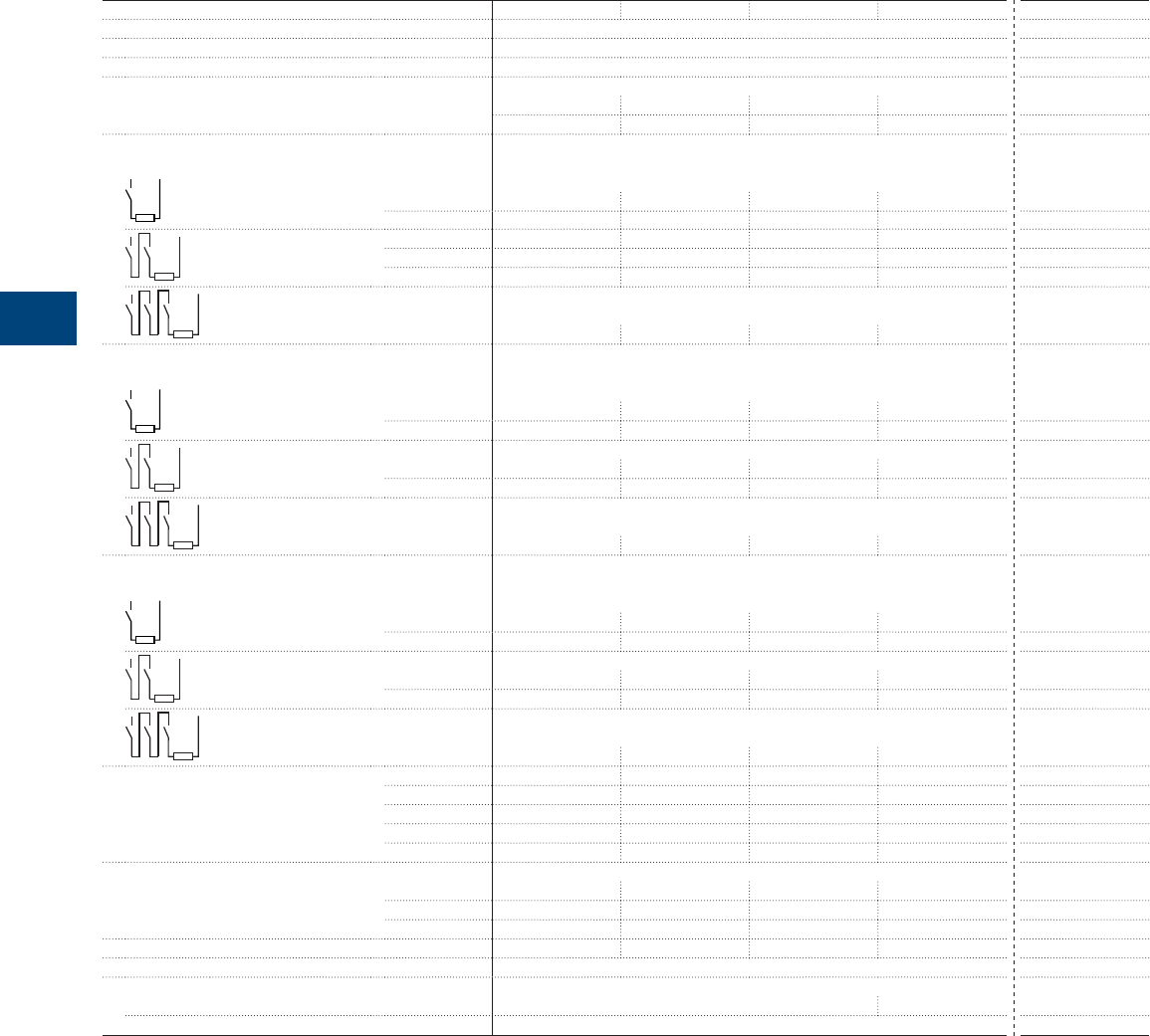
5
52 1SXU10607C0201 | R contactor US catalog
NORR63..CC … NORR800..CC contactors
Technical data
Main pole - Utilization characteristics according to IEC
Contactor types AC operated
NORR63..CC NORR125..CC NORR200..CC NORR800..CC NORR400
Standards IEC 60947-1 / 60947-4-1 and EN 60947-1 / 60947-4-1
Rated operational voltage Ue max. 1000 V DC (1500 V DC with increased insulation (1)) 440 V DC
Number of poles 1…4
Conventional free-air thermal current Ith
acc. to IEC 60947-4-1, open contactors, θ ≤ 40 °C 63 A 125 A 200 A 800 A 315 A
With conductor cross-sectional area 16 mm² 50 mm² 95 mm² 500 mm² 185 mm²
DC-1 Utilization category, L/R ≤ 1 ms
Ie / Rated operational current DC-1
1 pole
≤ 220 V ---- 315 A
≤ 500 V 63 A 125 A 200 A 800 A -
2 poles in series ≤ 440 V ---- 315 A
≤ 1000 V 63 A 125 A 200 A 800 A -
≤ 1500 V - - - 800 A -
3 poles in series
≤ 1500 V (1) 63 A 125 A 200 A 800 A -
DC-3 Utilization category, L/R ≤ 2 ms
Ie / Rated operational current DC-3
1 pole
≤ 220 V ---- 315 A
≤ 500 V 63 A 125 A 200 A 720 A -
2 poles in series
≤ 440 V ---- 315 A
≤ 1000 V 63 A 125 A 200 A 720 A -
3 poles in series
≤ 1500 V (1) 63 A 125 A 200 A 720 A -
DC-5 Utilization category, L/R ≤ 7.5 ms
Ie / Rated operational current DC-5
1 pole
≤ 220 V ---- 315 A
≤ 500 V 63 A 125 A 200 A 720 A -
2 poles in series
≤ 440 V ---- 315 A
≤ 1000 V 63 A 125 A 200 A 720 A -
3 poles in series
≤ 1500 V (1) 63 A 125 A 200 A 720 A -
Rated short-time withstand current Icw 1 s 850 A 1700 A 3100 A 9000 A 5000 A
at 40 °C ambient temperature, 10 s 500 A 900 A 1600 A 6400 A 2500 A
in free air from a cold state 30 s 250 A 450 A 800 A 3200 A 1250 A
1 min 170 A 310 A 560 A 2100 A 870 A
15 min 90 A 180 A 300 A 1200 A 460 A
Rated breaking capacity
(L/R ≤ 15 ms) 1 pole 500 V 252 A 500 A 800 A 2880 A 1260 A (220 V)
2 poles 1000 V 252 A 500 A 800 A 2880 A 1260 A (440 V)
3 poles 1500 V 252 A 500 A 800 A 2880 A -
Impedance per pole 1.8 mΩ 1.20 mΩ 0.60 mΩ 0.18 mΩ 0.40 mΩ
Maximum electrical switching frequency 120 cycles/h 120 cycles/h
Mechanical durability
Number of operating cycles 3 millions cycles 1 million cycles 3 million cycles
Maximum switching frequency 1200 cycles/h 1200 cycles/h
(1) NOR63 ... NOR200: version with increased insulation for 1000 V < Ue < 1500 V, please consult us.
Notes: - The arc switching on DC is more diffi cult than on AC
- For selecting a contactor, it is essential to determine the current, the voltage, an the L/R time constant of the controlled load
- For information, typical time constant values are quoted hereafter: non inductive loads such as resistance furnaces: L/R < 1 ms; inductive loads such as shunt motor:
L/R < 2 ms; series motor: L/R < 7.5 ms
- The addition of a resistor in parallel with an inductive winding helps in the elimination of the arcs
- All the poles required for breaking must be connected, in series, between the load and the source polarity not linked to the earth
- Connection of the poles in series by the user, according to the above diagrams. The connection of the poles in series helps in the elimination of the arcs
- These characteristics are suitable for NOR..CC-AMA and NOR..CC-AME contactor latching versions (except for mechanical durability = 0.2 millions of operating cycles).

Notes
R contactor US catalog | 1SXU106047C0201 53
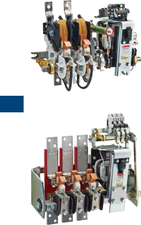
5
54 1SXU10607C0201 | R contactor US catalog
Power circuit coupling
LOR couplers
Description
LOR couplers are built without blowout coil and arc chutes. They are not
suitable for breaking on-load at voltages above 24 V AC or DC.
– AC switching up to 1000 V AC
– DC switching up to:
- 1000 V DC for R85 … R550
- 1500 V DC for R800 … R5100
For other voltages, please consult us.
2 NO + 2 NC auxiliary contacts are fitted as standard. For additional
auxiliary contact, refer to "Auxiliary contact fitting details".
Example of use
– Automatic short-circuiting of the starting resistances of a slip-ring or
DC motors without the possibility of opening on-load
– Electrolytic installations and electro-plating plants
– Induction furnaces (please consult us).
Other variants:
Please consult us for:
– LOR couplers with N.C. poles
– LOR..AMA and LOR..AME couplers with latching.
5
R contactor US catalog | 1SXU106047C0201 55
LORR couplers
Power circuit up to 1000 V AC or 1500 V DC
Control circuit 120V 50/60 Hz
Description
LORR are used for controlling:
– AC power circuits up to 1000 V AC
They are not suitable for breaking on-load at voltages above 24 V AC or DC.
These contactors are designed with:
– variable number of poles according to the application
– control circuit: AC operated
– 2 NO + 2 NC auxiliary contacts available, as standard.
Ordering details
Conventional
thermal current
lth (θ ≤ 40 °C)
Rated
operational voltage
Number
of poles
Rated control
circuit voltage
Uc
(1)
Auxiliary
contacts
fi tted (2)
Type Order code Weight
pkg
(1 pce)
A V AC V DC (3) V 50/60Hz kg
90 1000 1000 1 120V 2 2 LORR85-10 FPL7235110R2113 2.6
2 2 2 LORR85-20 FPL7235210R2113 3
3 2 2 LORR85-30 FPL7235310R2113 3.4
4 2 2 LORR85-40 FPL7235410R2113 3.8
185 1000 1000 1 120V 2 2 LORR170-10 FPL7535110R2113 3.2
2 2 2 LORR170-20 FPL7535210R2113 4.1
3 2 2 LORR170-30 FPL7535310R2113 5
4 2 2 LORR170-40 FPL7535410R2113 5.9
300 1000 1000 1 120V 2 2 LORR260-10 FPL7835110R2113 4.7
2 2 2 LORR260-20 FPL7835210R2113 5.9
3 2 2 LORR260-30 FPL7835310R2113 7.1
4 2 2 LORR260-40 FPL7835410R2113 8.3
420 1000 1000 1 120V 2 2 LORR400-10 FPL9435110R2113 11.4
2 2 2 LORR400-20 FPL9435210R2113 14.7
3 2 2 LORR400-30 FPL9435310R2113 18
4 2 2 LORR400-40 FPL9435410R2113 21.3
630 1000 1000 1 120V 2 2 LORR550-10 FPL8435110R2113 11.4
2 2 2 LORR550-20 FPL8435210R2113 14.7
3 2 2 LORR550-30 FPL8435310R2113 18
4 2 2 LORR550-40 FPL8435410R2113 21.3
1100 1000 1000 1 120V 2 2 LORR800-10 FPL8635110R2113 29
1500 2 2 2 LORR800-20 FPL8635210R2113 34
1500 3 2 2 LORR800-30 FPL8635310R2113 42
1500 4 2 2 LORR800-40 FPL8635410R2113 54
1400 1000 1000 1 120V 2 2 LORR1400-10 FPL6135110R2113 30
1500 2 2 2 LORR1400-20 FPL6135210R2113 36
1500 3 2 2 LORR1400-30 FPL6135310R2113 44
1500 4 2 2 LORR1400-40 FPL6135410R2113 56
1700 1000 1000 1 120V 2 2 LORR1700-10 FPL6235110R2113 34
1500 2 2 2 LORR1700-20 FPL6235210R2113 42
1500 3 2 2 LORR1700-30 FPL6235310R2113 50
1500 4 2 2 LORR1700-40 FPL6235410R2113 66
2100 1000 1000 1 120V 2 2 LORR2100-10 FPL6335110R2113 36
1500 2 2 2 LORR2100-20 FPL6335210R2113 44
1500 3 2 2 LORR2100-30 FPL6335310R2113 52
1500 4 2 2 LORR2100-40 FPL6335410R2113 68
2500 1000 1000 1 120V 2 2 LORR2500-10 FPL6735110R2113 On
request
1500 2 2 2 LORR2500-20 FPL6735210R2113
1500 3 2 2 LORR2500-30 FPL6735310R2113
1500 4 2 2 LORR2500-40 FPL6735410R2113
3200 1000 1000 1 120V 2 2 LORR3200-10 FPL6535110R2113 On
request
1500 2 2 2 LORR3200-20 FPL6535210R2113
1500 3 2 2 LORR3200-30 FPL6535310R2113
1500 4 2 2 LORR3200-40 FPL6535001R2113
3800 1000 1000 1 120V 2 2 LORR3800-10 FPL6635110R2113 On
request
1500 2 2 2 LORR3800-20 FPL6635210R2113
1500 3 2 2 LORR3800-30 FPL6635002R2113
1500 4 2 2 LORR3800-40 FPL6635003R2113
4500 1000 1000 1 120V 2 2 LORR4500-10 FPL6835110R2113 On
request
1500 2 2 2 LORR4500-20 FPL6835210R2113
1500 3 2 2 LORR4500-30 FPL6835001R2113
5100 1000 1000 1 120V 2 2 LORR5100-10 FPL6935110R2113 On
request
1500 2 2 2 LORR5100-20 FPL6935001R2113
(1) Other control voltages, please consult us.
(2) Other auxiliary contact arrangements, please consult us.
(3) Please consult us for power circuit above 1000 V AC or 1500 V DC.
1SBC104043F0000
LORR550-20
– DC power circuits up to:
- 1000 V DC for ratings 85…550 A
- 1500 V DC for ratings 800…5100 A

5
56 1SXU10607C0201 | R contactor US catalog
LORR85 ... LORR550 couplers
Technical data
Main pole - Utilization characteristics according to IEC
Couplers types AC operated
LORR85 LORR170 LORR260 LORR400 LORR550
Standards IEC 60947-1 / 60947-4-1 and EN 60947-1 / 60947-4-1
Rated operational voltage Ue max. 1000 V
Rated frequency (without derating) 25…60 Hz (for > 60…400 Hz please contact us)
Number of poles 1…4
Conventional free-air thermal current Ith
acc. to IEC 60947-4-1, open couplers, θ ≤ 40 °C 90 A 185 A 300 A 420 A 630 A
With conductor cross-sectional area 35 mm² 95 mm² 185 mm² 300 mm² 400 mm²
AC-1 / DC-1 Utilization category
For air temperature close to couplers
Ie / Rated operational current AC-1 / DC-1
θ ≤ 40 °C 90 A 185 A 300 A 420 A 630 A
Ue max. ≤ 690 V, 50/60 Hz θ ≤ 55 °C 82 A 170 A 270 A 370 A 570 A
θ ≤ 70 °C 72 A 150 A 240 A 330 A 500 A
With conductor cross-sectional area 35 mm² 95 mm² 185 mm² 300 mm² 400 mm²
Rated making capacity AC-1 / DC-1 1000 V max. 1.5 x Ie / AC-1 or DC-1 acc. to IEC 60947-4-1
Rated breaking capacity AC-1 / DC-1 24 V max. 1.5 x Ie / AC-1 or DC-1 acc. to IEC 60947-4-1
Short-circuit protection device for couplers
without thermal overload relay - Motor protection excluded
Ue ≤ 1000 V AC - gG type fuse 100 A 200 A 315 A 500 A 700 A
Ue ≤ 1000 V AC - L type fuse - - - - -
Rated short-time withstand current Icw 1 s 1150 A 2250 A 3800 A 6000 A 8400 A
at 40 °C ambient temperature, 10 s 680 A 1200 A 1920 A 2960 A 4400 A
in free air from a cold state 30 s 310 A 680 A 1040 A 1480 A 2200 A
1 min 230 A 450 A 730 A 1100 A 1680 A
15 min 120 A 250 A 390 A 600 A 840 A
Impedance per pole 1.80 mΩ 1.20 mΩ 0.60 mΩ 0.40 mΩ 0.35 mΩ
Maximum electrical switching frequency AC-1 300 cycles/h
Mechanical durability
Number of operating cycles 5 millions cycles
Maximum switching frequency 1200 cycles/h
Note: - Technical data applicable for N.O. main poles. For N.C. main poles, please consult us.
- These characteristics are suitable for LOR..AMA and LOR..AME contactor versions (except for mechanical durability = 0.2 millions of operating cycles).
5
R contactor US catalog | 1SXU106047C0201 57
LORR800 ... LORR5100 couplers
Technical data
Main pole - Utilization characteristics according to IEC
Couplers types AC operated
LORR800 LORR1400 LORR1700 LORR2100 LORR2500 LORR3200 LORR3800 LORR4500 LORR5100
Standards IEC 60947-1 / 60947-4-1 and EN 60947-1 / 60947-4-1
Rated operational voltage Ue max. 1000 V
Rated frequency (without de-rating) 25…60 Hz (for > 60…400 Hz please consult us)
Number of poles 1…4
Conventional free-air thermal current Ith
acc. to IEC 60947-4-1, open couplers, θ ≤ 40 °C 1100 A 1400 A 1700 A 2100 A 2500 A 3200 A 3800 A 4500 A 5100 A
With conductor cross-sectional area 800 mm² 1000 mm² 1500 mm² 1500 mm² 2000 mm² 3000 mm² 3000 mm² 4000 mm² 4000 mm²
AC-1 / DC-1 Utilization category
For air temperature close to couplers
Ie / Rated operational current AC-1 / DC-1
θ ≤ 40 °C 1100 A 1400 A 1700 A 2100 A 2500 A 3200 A 3800 A 4500 A 5100 A
Ue max. ≤ 690 V, 50/60 Hz θ ≤ 55 °C 1000 A 1230 A 1500 A 1840 A 2200 A 2800 A 3330 A 3950 A 4470 A
θ ≤ 70 °C 900 A 1030 A 1250 A 1540 A 1830 A 2350 A 2780 A 3300 A 3740 A
With conductor cross-sectional area 800 mm² 1000 mm² 1500 mm² 1500 mm² 2000 mm² 3000 mm² 3000 mm² 4000 mm² 4000 mm²
Rated making capacity AC-1 / DC-1 1000 V max. 1.5 x Ie / AC-1 or DC-1 acc. to IEC 60947-4-1
Rated breaking capacity AC-1 / DC-1 24 V max. 1.5 x Ie / AC-1 or DC-1 acc. to IEC 60947-4-1
Short-circuit protection device for couplers
without thermal overload relay - Motor protection excluded
Ue ≤ 1000 V AC - Circuit breaker 1250 A 1600 A 2000 A 2500 A -----
Rated short-time withstand current Icw 1 s 9000 A 11000 A 13000 A 15000 A 20000 A 21000 A 24000 A 28000 A 29000 A
at 40 °C ambient temperature, 10 s 8000 A 9000 A 11000 A 12200 A 15000 A 18000 A 19000 A 21000 A 22000 A
in free air from a cold state 30 s 4000 A 5000 A 6000 A 7000 A 8000 A 10000 A 11000 A 12000 A 13000 A
1 min 3000 A 3700 A 4400 A 5000 A 6000 A 7000 A 7500 A 8000 A 8500 A
15 min 1600 A 2000 A 2400 A 2800 A 3000 A 4000 A 4500 A 5000 A 5500 A
Impedance per pole 0.18 mΩ 0.10 mΩ 0.090 mΩ 0.080 mΩ 0.05 mΩ 0.045 mΩ 0.04 mΩ 0.03 mΩ 0.027 mΩ
Maximum electrical switching frequency AC-1
300 cycles/h 150 cycles/h
120 cycles/h 60 cycles/h 40 cycles/h
Mechanical durability
Number of operating cycles 5 millions cycles 2 millions cycles 1 million cycles
Maximum switching frequency 1200 cycles/h 600 cycles/h 300 cycles/h
Note: - Technical data applicable for N.O. main poles. For N.C. main poles, please consult us.
- These characteristics are suitable for LOR..AME contactor versions (except for mechanical durability = 0.2 millions of operating cycles).

Notes
58 1SXU10607C0201 | R contactor US catalog
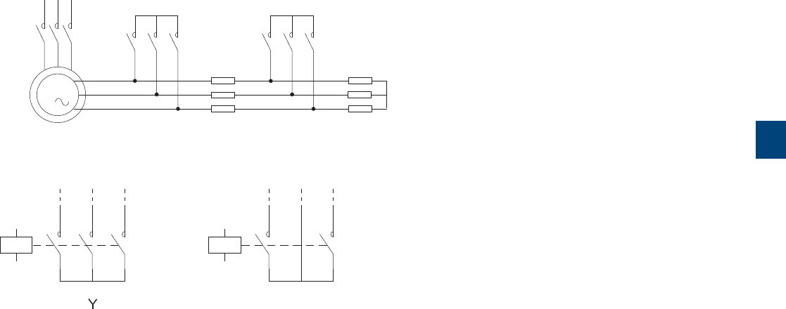
5
R contactor US catalog | 1SXU106047C0201 59
Application
Three kinds of contactors are used to control three-phase slip-ring motors: the stator contactor, the acceleration contactor(s),
and the rotor short-circuit contactor.
Example of a three-stroke starter (star (Y) connection diagram)
R2 R1
M
3
The starting resistances should be star (Y) or V connected acc. to the following wiring diagrams. Contactors have to be select-
ed accordingly.
Stator contactor
The standard R contactor selection is based on the motor rated current acc. to the AC-2 utilization category, as well as on the
rated operational voltage and the on-load factor.
Acceleration contactor and rotor short-circuit contactor
FOR contactor selection is based on the contactor rated operational current Ie acc. to the AC-1 utilization category.
At the time of slip-ring motor starting and as soon as the motor nominal speed is reached, these contactors are used for the
short-circuiting of the rotor current limitation starting resistances (e.g. vapor-liquid rheostats).
These contactors are derived from the standard R contactors and are available in 2, 3, 4 or 6-pole versions acc. to the applica-
ble connection diagram required (Y, V).
They can control rotor currents up to 3800A and rotor voltages up to 4200V (with increased insulation) acc. to the
IEC 60947-4-1 standard requirements. For rotor voltages ≥ 4200 V, please consult us.
Although the breaking of the rotor circuit is normally carried out in "off-load" conditions, the contactors are equipped with blow-
out devices and can occasionally break "on-load".
Ordering details, dimensions : please consult us.
The LOR couplers may be used for applications where equipment is breaking in "Off-load" conditions only.
Slip-ring motor control
With rheostats
Stator
contactor
Rotor short-circuit
contactor
Acceleration
contactor
V
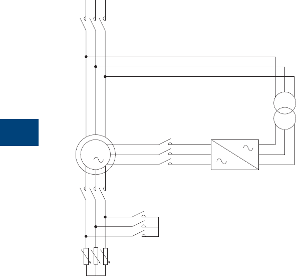
5
60 1SXU10607C0201 | R contactor US catalog
Application
This variant is used to start a slip-ring motor which will be then controlled by a variable frequency drive.
M
3
Description
A liquid rheostat is used to start and accelerate the motor after closing of the starter coupling contactor (2) and then the stator
contactor (1). When the nominal speed is reached, the rotor short-circuit contactor (3) closes.
Then the rotor inverter contactor closes (4) and the starter coupling contactor (2) opens.
The speed of the motor is controlled by the variable frequency drive.
FOR contactors are suitable for starter coupling (2), rotor short-circuiting (3) and rotor inverter (4) contactor.
IOR contactors must be used for stator contactor (1).
Slip-ring motor control
With variable frequency drive
(1) Stator contactor
(4) Rotor inverter contactor
(2) Starter coupling contactor
(3) Rotor short-circuit contactor
Rheostat

5
R contactor US catalog | 1SXU106047C0201 61
FORR1000 … FORR3800 contactors
Rotor voltages up to 1500 V AC
Main pole - Utilization characteristics according to IEC (Y and V connection diagram)
Contactor types AC operated
FORR1000 FORR1400 FORR1700 FORR2100 FORR2500 FORR3200 FORR3800
Rated rotor operational voltage Uer 1500 V
Rated frequency (without de-rating) 0.1...60 Hz (for > 60 Hz consult us)
Conventional free-air thermal current Ith
acc. to IEC 60947-4-1, θ ≤ 40 °C 1000 A 1400 A 1700 A 2100 A 2500 A 3200 A 3800 A
With conductor cross-sectional area 600 mm² 1000 mm² 1500 mm² 2000 mm² 2000 mm² 3000 mm² 3000 mm²
Rated rotor operational current Ier
For air temperature close to contactor
θ ≤ 40 °C 1000 A 1400 A 1700 A 2100 A 2500 A 3200 A 3800 A
θ ≤ 55 °C 930 A 1180 A 1450 A 1750 A 2200 A 2800 A 3200 A
θ ≤ 70 °C 800 A 1000 A 1250 A 1500 A 1830 A 2350 A 2780 A
With conductor cross-sectional area 600 mm² 1000 mm² 1500 mm² 2000 mm² 2000 mm² 3000 mm² 3000 mm²
Maximum making capacity 14000 A 19000 A 21000 A 24000 A 24000 A 26000 A 29000 A
Maximum breaking capacity at
cos φ = 0.80 and 1000 V 1500 A 2100 A 2600 A 3200 A 3800 A 4800 A 5700 A
Rated short-time withstand current Icw 1 s 9000 A 11000 A 13000 A 15000 A 20000 A 21000 A 24000 A
at 40 °C ambient temperature, 10 s 8000 A 9000 A 11000 A 12200 A 15000 A 18000 A 19000 A
in free air from a cold state 30 s 4000 A 5000 A 6000 A 7000 A 8000 A 10000 A 11000 A
1 min 3000 A 3700 A 4400 A 5000 A 6000 A 7000 A 7500 A
15 min 1600 A 2000 A 2400 A 2800 A 3000 A 4000 A 4500 A
Impedance per pole 0.18 mΩ 0.10 mΩ 0.09 mΩ 0.08 mΩ 0.05 mΩ 0.045 mΩ 0.04 mΩ
Maximum electrical switching frequency 120 cycles/h
Mechanical durability
Number of operating cycles 5 millions
cycles
2 millions cycles
Max. switching frequency 600 cycles/h
Note: Altitude ≥ 2000 m, dimension drawings: please consult us.
- Consult us for order codes.

5
62 1SXU10607C0201 | R contactor US catalog
FORR1000S … FORR2100S contactors
Rotor voltages up to 2500 V AC
Main pole - Utilization characteristics according to IEC (Y and V connection diagram)
Contactor types AC operated
FORR1000S FORR1400S FORR1700S FORR2100S FORR2500S FORR3200S FORR3800S
Rated rotor operational voltage Uer 2500 V
Rated frequency (without de-rating) 0.1...60 Hz (for > 60 Hz consult us)
Conventional free-air thermal current Ith
acc. to IEC 60947-4-1, θ ≤ 40 °C 1000 A 1400 A 1700 A 2100 A 2500 A 3200 A 3800 A
With conductor cross-sectional area 600 mm² 1000 mm² 1500 mm² 2000 mm² 2000 mm² 3000 mm² 3000 mm²
Rated rotor operational current Ier
For air temperature close to contactor
θ ≤ 40 °C 1000 A 1400 A 1700 A 2100 A 2500 A 3200 A 3800 A
θ ≤ 55 °C 930 A 1180 A 1450 A 1750 A 2200 A 2800 A 3200 A
θ ≤ 70 °C 800 A 1000 A 1250 A 1500 A 1830 A 2350 A 2780 A
With conductor cross-sectional area 600 mm² 1000 mm² 1500 mm² 2000 mm² 2000 mm² 3000 mm² 3000 mm²
Maximum making capacity 14000 A 19000 A 21000 A 24000 A 24000 A 26000 A 29000 A
Maximum breaking capacity at
cos φ = 0.80 and 1000 V 1500 A 2100 A 2600 A 3200 A 3800 A 4800 A 5700 A
Rated short-time withstand current Icw 1 s 9000 A 11000 A 13000 A 15000 A 20000 A 21000 A 24000 A
at 40 °C ambient temperature, 10 s 8000 A 9000 A 11000 A 12200 A 15000 A 18000 A 19000 A
in free air from a cold state 30 s 4000 A 5000 A 6000 A 7000 A 8000 A 10000 A 11000 A
1 min 3000 A 3700 A 4400 A 5000 A 6000 A 7000 A 7500 A
15 min 1600 A 2000 A 2400 A 2800 A 3000 A 4000 A 4500 A
Impedance per pole 0.18 mΩ 0.10 mΩ 0.09 mΩ 0.08 mΩ 0.05 mΩ 0.045 mΩ 0.04 mΩ
Maximum electrical switching frequency 120 cycles/h
Mechanical durability
Number of operating cycles 5 millions
cycles
2 millions cycles
Max. switching frequency 600 cycles/h
Note: Altitude ≥ 2000 m, dimension drawings: please consult us.
- Consult us for order codes.
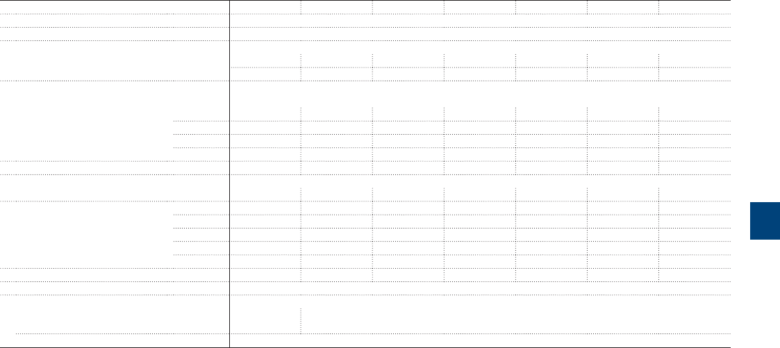
5
R contactor US catalog | 1SXU106047C0201 63
FORR1000NSP … FORR2100NSP contactors
Rotor voltages up to 3500 V AC
Main pole - Utilization characteristics according to IEC (Y and V connection diagram)
Contactor types AC operated
FORR1000NSP FORR1400NSP FORR1700NSP FORR2100NSP FORR2500NSP FORR3200NSP FORR3800NSP
Rated rotor operational voltage Uer 3500 V
Rated frequency (without de-rating) 0.1...60 Hz (for > 60 Hz consult us)
Conventional free-air thermal current Ith
acc. to IEC 60947-4-1, θ ≤ 40 °C 1000 A 1400 A 1700 A 2100 A 2500 A 3200 A 3800 A
With conductor cross-sectional area 600 mm² 1000 mm² 1500 mm² 2000 mm² 2000 mm² 3000 mm² 3000 mm²
Rated rotor operational current Ier
For air temperature close to contactor
θ ≤ 40 °C 1000 A 1400 A 1700 A 2100 A 2500 A 3200 A 3800 A
θ ≤ 55 °C 930 A 1180 A 1450 A 1750 A 2200 A 2800 A 3200 A
θ ≤ 70 °C 800 A 1000 A 1250 A 1500 A 1830 A 2350 A 2780 A
With conductor cross-sectional area 600 mm² 1000 mm² 1500 mm² 2000 mm² 2000 mm² 3000 mm² 3000 mm²
Maximum making capacity 14000 A 19000 A 21000 A 24000 A 24000 A 26000 A 29000 A
Maximum breaking capacity at
cos φ = 0.80 and 1000 V 1500 A 2100 A 2600 A 3200 A 3800 A 4800 A 5700 A
Rated short-time withstand current Icw 1 s 9000 A 11000 A 13000 A 15000 A 20000 A 21000 A 24000 A
at 40 °C ambient temperature, 10 s 8000 A 9000 A 11000 A 12200 A 15000 A 18000 A 19000 A
in free air from a cold state 30 s 4000 A 5000 A 6000 A 7000 A 8000 A 10000 A 11000 A
1 min 3000 A 3700 A 4400 A 5000 A 6000 A 7000 A 7500 A
15 min 1600 A 2000 A 2400 A 2800 A 3000 A 4000 A 4500 A
Impedance per pole 0.18 mΩ 0.10 mΩ 0.09 mΩ 0.08 mΩ 0.05 mΩ 0.045 mΩ 0.04 mΩ
Maximum electrical switching frequency 120 cycles/h
Mechanical durability
Number of operating cycles 5 millions
cycles
2 millions cycles
Max. switching frequency 600 cycles/h
Note: Altitude ≥ 2000 m, dimension drawings: please consult us.
- Consult us for order codes.

5
64 1SXU10607C0201 | R contactor US catalog
FORR1000SPE … FORR2100SPE contactors
Rotor voltages up to 4200 V AC
Main pole - Utilization characteristics according to IEC (Y only connection diagram)
Contactor types AC operated
FORR1000SPE FORR1400SPE FORR1700SPE FORR2100SPE FORR2500SPE FORR3200SPE FORR3800SPE
Rated rotor operational voltage Uer 4200 V
Rated frequency (without de-rating) 0.1...60 Hz (for > 60 Hz consult us)
Conventional free-air thermal current Ith
acc. to IEC 60947-4-1, θ ≤ 40 °C 1000 A 1400 A 1700 A 2100 A 2500 A 3200 A 3800 A
With conductor cross-sectional area 600 mm² 1000 mm² 1500 mm² 2000 mm² 2000 mm² 3000 mm² 3000 mm²
Rated rotor operational current Ier
For air temperature close to contactor
θ ≤ 40 °C 1000 A 1400 A 1700 A 2100 A 2500 A 3200 A 3800 A
θ ≤ 55 °C 930 A 1180 A 1450 A 1750 A 2200 A 2800 A 3200 A
θ ≤ 70 °C 800 A 1000 A 1250 A 1500 A 1830 A 2350 A 2780 A
With conductor cross-sectional area 600 mm² 1000 mm² 1500 mm² 2000 mm² 2000 mm² 3000 mm² 3000 mm²
Maximum making capacity 14000 A 19000 A 21000 A 24000 A 24000 A 26000 A 29000 A
Maximum breaking capacity at
cos φ = 0.80 and 1000 V 1500 A 2100 A 2600 A 3200 A 3800 A 4800 A 5700 A
Rated short-time withstand current Icw 1 s 9000 A 11000 A 13000 A 15000 A 20000 A 21000 A 24000 A
at 40 °C ambient temperature, 10 s 8000 A 9000 A 11000 A 12200 A 15000 A 18000 A 19000 A
in free air from a cold state 30 s 4000 A 5000 A 6000 A 7000 A 8000 A 10000 A 11000 A
1 min 3000 A 3700 A 4400 A 5000 A 6000 A 7000 A 7500 A
15 min 1600 A 2000 A 2400 A 2800 A 3000 A 4000 A 4500 A
Impedance per pole 0.18 mΩ 0.10 mΩ 0.09 mΩ 0.08 mΩ 0.05 mΩ 0.045 mΩ 0.04 mΩ
Maximum electrical switching frequency 120 cycles/h
Mechanical durability
Number of operating cycles 5 millions
cycles
2 millions cycles
Max. switching frequency 600 cycles/h
Note: - Uer > 4200 V AC, please consult us.
- Altitude ≥ 2000 m, dimension drawings: please consult us.
- Consult us for order codes.
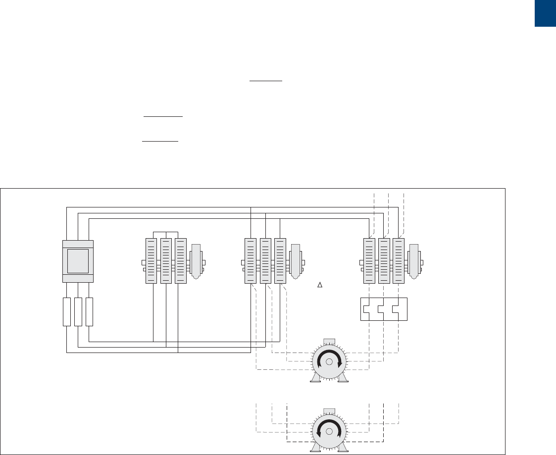
5
R contactor US catalog | 1SXU106047C0201 65
Closed transition star-delta starting of three-phase
asynchronous motors
R contactor selection
KM2 / (Y)
L1 L2 L3
W2
V2
U2
W1
V1
U1
W2
V2
U2
W1
V1
U1
135
246
13 5
24 6
KM4
135
246
135
246
R
KM1 / (L)
KM3 / ( )
135
246
Application
R contactors can be used for closed transition star-delta starting of three-phase asynchronous motors up to 1300 kW.
Description
This starting method, mainly used for large motor powers, prevents the speed drop during the "star-delta" transition time and maintains the
resulting current peak at a relatively low value.
For this purpose the extra KM4 transition contactor closes fi rst before the KM2 star contactor opens. When the KM4 contactor closes, the motor
windings are automatically delta connected, via resistances, to compensate the lack of current during the transition time. Thus the motor speed
remains basically the same. The fi nal delta connection step is then achieved by the KM3 delta contactor closing which switches-off the coil supply
to the KM4 transition contactor. As in the basic star-delta starting mode, the closed transition star-delta starting mode is restricted to low resistive
torque machines.
It is advisable, especially for big masses of inertia, to observe that the connection is made in acc. to the clockwise or anticlockwise rotation
direction, as indicated in the block diagram shown below, in order to prevent damages due to torque throbs.
Equipment sizing
– KM1 main contactor and KM3 delta contactor: rating = 0.58 x In for both contactors
– KM2 star contactor: compared with a star contactor that would be used for a basic open transition star-delta starter the present KM2 star
contactor has to be over-rated as it is intended to break the star current (0.34 x In) and the transition current too.
– KM4 transition contactor: the rating is based on the calculation of the short permissible current duration (Icw).
The value of the current fl ow is about 1.5 x In and the current fl ow duration < 100 ms.
A block type contactor in the AF series can be selected for this step.
– Transition resistances: empiric value, generally as follows, R (Ω) = 0.4 x Ue
In
Watt dissipation values for the transition resistances:
- for 12 cycles/h max. P (W) = Ue2
1200 x R
- for 30 cycles/h max. P (W) = Ue2
500 x R
Block Diagram
KM1: Line contactor
KM2: Star contactor
KM3: Delta contactor
KM4: Closed transition contactor
R: Transition resistances
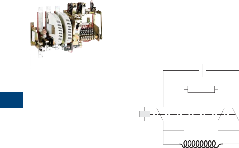
5
66 1SXU10607C0201 | R contactor US catalog
AM-CC-JOR and AMF-CC-JOR field discharge contactors
Power circuit up to 2250 V DC, R63 ... R4500
Application
Field discharge contactors (or field circuit breakers) are used to control the field winding of
synchronous machines or exciter machines. In case of disturbances, the contactors ensure
a definite disconnection from the supply source and the subsequent discharge of the energy
stored in the machine magnetic circuit via a discharge resistor.
Diagram
Supply
Discharge resistor
Field discharge
contactor
Field winding
Description
These contactors are designed with:
– 2 or 3 N.O. main poles with blowout devices, suitable for 2250V DC max. operational
voltage and circuit time constant L/R ≤ 15 ms
– 1 N.C. main pole, without blowout device, named "discharge pole" and set MAKE before
BREAK with regard to the N.O. main poles.
Electro-magnet
AM-CC-JOR and AMF-CC-JOR fi eld discharge contactors are equipped with a latching device:
– magnetic latch for R63 ... R200
– mechanical latch for R550 ... R4500.
AC or DC control circuit.
The AMF-CC-JOR type is equipped with 2 tripping coils (double de-latching control).
Auxiliary contacts
– AM-CC: 5 auxiliary contacts as standard (3 N.O. + 2 N.C.)
– AMF-CC: 4 auxiliary contacts as standard (2 N.O. + 2 N.C.)
– Up to 16 auxiliary contacts max. on request.
AMF-CC-JORE 800-21
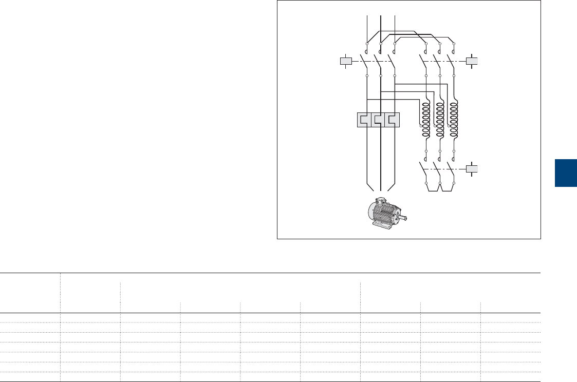
5
R contactor US catalog | 1SXU106047C0201 67
Autotransformer starters
General
An autotransformer starter allows to start a squirrel-cage
motor with a reduced starting current due to the reduced
voltage within the accelerating duration.
At the contrary of the star-delta wiring, this autotransformer
starting method needs three wires and three terminals on the
motor.
At the starting period, the motor is wired to the auto-
transformer taps: the "KM3" star contactor and the "KM2"
autotransformer contactor are closed, the motor is under
reduced voltage. Consequently, the torque is reduced as
the square of the applied voltage. The auto-transformers are
generally equipped of three taps at each phase in order to
adapt the starting parameters to the field requirements.
When the motor reaches 80...95% of its nominal speed,
the star contactor opens. Then, the "KM1" line contactor is
making and the autotransformer contactor is opening. This
starting process is done without any network interruption.
Selection table (Id starting current / In nominal current < 8 - Acceleration time < 20 s - 30 cycles / h max.)
Motor ratings Contactors
50/60 Hz KM1 KM2 KM3
440 V Line Autotransformer taps Autotransformer taps
kW 90 % 80 % 70 % 60 % 90 % 80 % 60-70 %
500 IOR..800 IOR..800 IOR..500..MT IOR..400..MT IOR..400..MT IOR..200..MT IOR..400..MT IOR..500..MT
560 IOR..1400 IOR..800 IOR..500..MT IOR..500..MT IOR..400..MT IOR..200..MT IOR..400..MT IOR..500..MT
630 IOR..1400 IOR..800 IOR..800 IOR..500..MT IOR..400..MT IOR..200..MT IOR..400..MT IOR..800
710 IOR..1400 IOR..1400 IOR..800 IOR..500..MT IOR..400..MT IOR..200..MT IOR..500..MT IOR..800
800 IOR..1700 IOR..1400 IOR..800 IOR..800 IOR..500..MT IOR..400..MT IOR..500..MT IOR..800
900 IOR..2100 IOR..1700 IOR..1400..MT IOR..800 IOR..500..MT IOR..400..MT IOR..800 IOR..1400
1000 IOR..2100 IOR..1700 IOR..1400..MT IOR..800 IOR..500..MT IOR..400..MT IOR..800 IOR..1400
KM1 KM2
T1
KM3
Electrical distribution
Autotransformer

68 1SXU10607C0201 | R contactor US catalog
6

R contactor US catalog | 1SXU106047C0201 69
6
Advanced applications
Technical data 70

70 1SXU10607C0201 | R contactor US catalog
6
R contactors
Technical data
Types
NORR63..MT
NORR63..CC
NORR125..MT
NORR125..CC
NORR200..MT
NORR200..CC
NORR400 NORR800..MT
NORR800..CC
NORR800
Magnet system characteristics
Coil operating limits
acc. to IEC 60947-4-1 At θ ≤ 55 °C 0.85…1.1 x Uc
AC control voltage 50/60 Hz
Rated control circuit voltage Uc 24…550 V AC
Coil consumption Average pull-in value 290 VA 460 VA 410 VA 540 VA 610 VA
Average holding value 25 VA 45 VA 45 VA 65 VA 55 VA
Drop-out voltage 20...75 % of Uc
Operating time (average values for Uc)
For N.O. poles of the NORR
Between coil energization and N.C. contact opening 30 ms 30 ms 40 ms 60 ms 100 ms
Between coil de-energization and N.C. contact closing 20 ms 20 ms 20 ms 50 ms 55 ms
For N.C. poles of the NORR
Between coil energization and N.O. contact closing 27 ms 27 ms 37 ms 55 ms 85 ms
Between coil de-energization and N.O. contact opening 23 ms 23 ms 23 ms 28 ms 60 ms
Types
NORR63..MT
NORR63..CC
NORR125..MT
NORR125..CC
NORR200..MT
NORR200..CC
NORR400 NORR800..MT
NORR800..CC
NORR800
Mounting characteristics
Fixing by screws (not supplied) 2 X M6 2 x M6 2 x M8 2 x M12 4 x M12
Connecting characteristics
Main terminals Terminal plates for lugs or bars
Connection capacity (min. ... max.)
Main conductors (poles)
Terminal plates width 16 mm 20 mm 25 mm 30 mm 48 mm
Terminal screw (not supplied) 2 x M6 2 x M6 2 x M8 - -
Drilling holes (without thread) - - - 1 x ø13 mm 2 x ø13 mm
Auxiliary conductors
(built-in auxiliary terminals + coil terminals)
Rigid solid 1 or 2 x 1...2.5 mm²
Flexible without ferrule 1 or 2 x 1...2.5 mm²
Tightening torque
Coil terminals 1.5 Nm
Built-in auxiliary terminals 1.5 Nm
Screw terminals
Main terminals Screws and bolts
Coil terminals M4 with cable clamps
Built-in auxiliary terminals M4 with cable clamps
R contactor US catalog | 1SXU106047C0201 71
6
R contactors
Technical data
General technical data
Contactor types
IOR, LOR, NOR contactors
Standards IEC 60947-1 / 60947-4-1 and EN 60947-1 / 60947-4-1
Rated insulation voltage Ui
acc. to IEC 60947-4-1 and EN 60947-4-1
R63 ... R500 1000 V AC or 1000 V DC (1500 V DC with increased insulation)
R800 ... R5100 1000 V AC or 1500 V DC
Rated impulse withstand voltage Uimp. 8 kV
Ambient air temperature close to contactor
Operation -20...+70 °C
Storage -20...+80 °C
Climatic withstand Standard version for industrial environment and atmospheres
Maximum operating altitude (without de-rating) 2000 m
Mounting characteristics and condition for use
Contactor types
IOR, LOR, NOR contactors
Mounting positions Position 1 (horizontal bar)
Maximum angle of inclination, in any direction : ±22° 30'
Mounting distances See "Dimensions"
72 1SXU10607C0201 | R contactor US catalog
6
R contactors
Technical data
Types
IORR63..MT
IORR63..CC
LORR85
IORR125..MT
IORR125..CC
LORR170
IORR200..MT
IORR200..CC
LORR260
IORR400..MT
IORR400..CC
LORR400
IORR500..MT
IORR500..CC
LORR550
Magnet system characteristics
Coil operating limits
acc. to IEC 60947-4-1 At θ ≤ 55 °C 0.85…1.1 x Uc
AC control voltage 50/60 Hz
Rated control circuit voltage Uc 24…550 V AC
Coil consumption Average pull-in value 290 VA 460 VA 410 VA 540 VA 540 VA
Average holding value 25 VA 45 VA 45 VA 65 VA 65 VA
Drop-out voltage 20...75 % of Uc
Operating time (average values for Uc)
Between coil energization and N.O. contact closing 30 ms 30 ms 40 ms 60 ms 60 ms
Between coil de-energization and N.O. contact opening 20 ms 20 ms 20 ms 50 ms 50 ms
Types
IORR63..MT
IORR63..CC
LORR85
IORR125..MT
IORR125..CC
LORR170
IORR200..MT
IORR200..CC
LORR260
IORR400..MT
IORR400..CC
LORR400
IORR500..MT
IORR500..CC
LORR550
Mounting characteristics
Fixing by screws (not supplied) 2 x M6 2 x M6 2 x M8 2 x M12 2 x M12
Connecting characteristics
Main terminals Terminal plates for lugs or bars
Connection capacity (min. ... max.)
Main conductors (poles)
Terminal plates width 16 mm 20 mm 25 mm 30 mm 30 mm
Terminal screw (not supplied) M6 x 20 M8 x 20 M10 x 25 - -
Drilling holes (without thread) - - - 1 x ø13 mm 1 x ø13 mm
Auxiliary conductors
(built-in auxiliary terminals + coil terminals)
Rigid solid 1 or 2 x 1...2.5 mm²
Flexible without ferrule 1 or 2 x 1...2.5 mm²
Tightening torque
Coil terminals 1.5 Nm
Built-in auxiliary terminals 1.5 Nm
Screw terminals
Main terminals Screws and bolts
Coil terminals M4 with cable clamps
Built-in auxiliary terminals M4 with cable clamps
R contactor US catalog | 1SXU106047C0201 73
6
R contactors
Technical data
Types
IORR800
LORR800
IORR800..MT
IORR800..CC
IORR1000
IORR1000..CC
FORR1000
IORR1400
LORR1400
IORR1400..MT
IORR1400..CC
FORR1400
IORR1700
LORR1700
IORR1700..MT
IORR1700..CC
FORR1700
IORR2100
LORR2100
IORR2100..MT
IORR2100..CC
FORR2100
Magnet system characteristics
Coil operating limits
acc. to IEC 60947-4-1 At θ ≤ 55 °C 0.85…1.1 x Uc
AC control voltage 50/60 Hz
Rated control circuit voltage Uc 24…550 V AC
Coil consumption Average pull-in value 610 VA 2 and 3 poles: 610 VA
4 poles: 925 VA
2...4 poles: 925 VA
Average holding value 55 VA 2 and 3 poles: 55 VA
4 poles: 130 VA
2...4 poles: 130 VA
Drop-out voltage 20...75 % of Uc
Operating time (average values for Uc)
Between coil energization and N.O. contact closing 100 ms 100 ms 100 ms 90 ms 90 ms
Between coil de-energization and N.O. contact opening 55 ms 55 ms 55 ms 40 ms 30 ms
Types
IORR800
LORR800
IORR800..MT
IORR800..CC
IORR1000
IORR1000..CC
FORR1000
IORR1400
LORR1400
IORR1400..MT
IORR1400..CC
FORR1400
IORR1700
LORR1700
IORR1700..MT
IORR1700..CC
FORR1700
IORR2100
LORR2100
IORR2100..MT
IORR2100..CC
FORR2100
Mounting characteristics
Fixing by screws (not supplied) 4 x M12
Connecting characteristics
Main terminals Terminal plates for lugs or bars
Connection capacity (min. ... max.)
Main conductors (poles)
Terminal plates width 48 mm 48 mm 60 mm 80 mm 100 mm
Drilling holes (without thread) 2 x ø13 mm 2 x ø13 mm 2 x ø13 mm 4 x ø11 mm 4 x ø11 mm
Auxiliary conductors
(built-in auxiliary terminals + coil terminals)
Rigid solid 1 or 2 x 1...2.5 mm²
Flexible without ferrule 1 or 2 x 1...2.5 mm²
Tightening torque
Coil terminals 1.5 Nm
Built-in auxiliary terminals 1.5 Nm
Screw terminals
Main terminals Screws and bolts
Coil terminals M4 with cable clamps
Built-in auxiliary terminals M4 with cable clamps
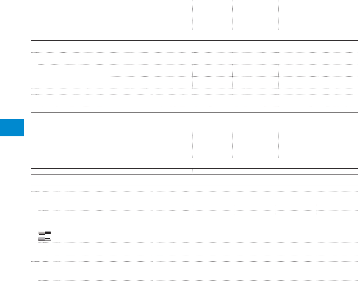
74 1SXU10607C0201 | R contactor US catalog
6
R contactors
Technical data
Types
IORR2500
LORR2500
IORR2500..MT
IORR2500..CC
FORR2500
IORR3200
LORR3200
IORR3200..MT
IORR3200..CC
FORR3200
IORR3800
LORR3800
IORR3800..MT
IORR3800..CC
FORR3800
IORR4500
LORR4500
IORR4500..MT
IORR4500..CC
IORR5100
LORR5100
IORR5100..MT
IORR5100..CC
Magnet system characteristics
Coil operating limits
acc. to IEC 60947-4-1 At θ ≤ 55 °C 0.85…1.1 x Uc
AC control voltage 50/60 Hz
Rated control circuit voltage Uc 48…550 V AC
Coil consumption Average pull-in value 1...4 poles:
925 VA
1...3 poles:
925 VA
1 and 2 poles:
925 VA
1 and 2 poles:
925 VA
1 pole:
925 VA
Average holding value 1...4 poles:
130 VA
1...3 poles:
130 VA
1 and 2 poles:
130 VA
1 and 2 poles:
130 VA
1 pole:
130 VA
Drop-out voltage 20...75 % of Uc
Operating time (average values for Uc)
Between coil energization and N.O. contact closing -
Between coil de-energization and N.O. contact opening -
Types
IORR2500
LORR2500
IORR2500..MT
IORR2500..CC
FORR2500
IORR3200
LORR3200
IORR3200..MT
IORR3200..CC
FORR3200
IORR3800
LORR3800
IORR3800..MT
IORR3800..CC
FORR3800
IORR4500
LORR4500
IORR4500..MT
IORR4500..CC
IORR5100
LORR5100
IORR5100..MT
IORR5100..CC
Mounting characteristics
Fixing by screws (not supplied) 4 x M12 4 or 6 x M12
Connecting characteristics
Main terminals Terminal plates for lugs or bars
Connection capacity (min. ... max.)
Main conductors (poles)
Terminal plates width 150 mm 180 mm 220 mm 280 mm 340 mm
Drilling holes (without thread) 8 x ø9 mm 8 x ø13 mm 8 x ø13 mm 12 x ø11 mm 14 x ø13 mm
Auxiliary conductors
(built-in auxiliary terminals + coil terminals)
Rigid solid 1 or 2 x 1...2.5 mm²
Flexible without ferrule 1 or 2 x 1...2.5 mm²
Tightening torque
Coil terminals 1.5 Nm
Built-in auxiliary terminals 1.5 Nm
Screw terminals
Main terminals Screws and bolts
Coil terminals M4 with cable clamps
Built-in auxiliary terminals M4 with cable clamps

Notes
R contactor US catalog | 1SXU106047C0201 75

7
76 1SXU10607C0201 | R contactor US catalog

7
R contactor US catalog | 1SXU106047C0201 77
Accessories and spare parts
Auxiliary contacts
Auxiliary contact blocks CA12 78
Auxiliary contacts CA15 78
Technical data 79
Main poles
Contact sets 80
Arcing horns 80
Equipotential connections 81
Arc chutes 81
Control circuits
Surge suppressors 82
Rectifiers 82
Magnet circuits 82
Mechanical interlock units 83
Mounting feet - Shaft extensions 84
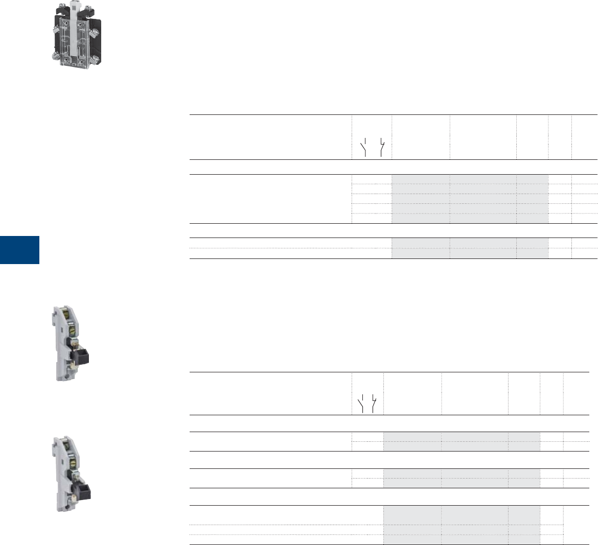
7
78 1SXU10607C0201 | R contactor US catalog
Auxiliary contacts
Auxiliary contact blocks type CA12
Description
CA12 auxiliary contact blocks 2 or 4-pole are mounted on a support bracket, above the electro-magnet.
The R contactors type R and RE can be equipped with:
– 1 or 2 x 2-pole blocks
– 1 x 2-pole block + 1 x 4-pole blocks.
The R contactors type RR can be equipped with 1 or 2 x 2-pole blocks.
Ordering details
For R contactors type
R, RE, RR
(RC excluded)
Auxiliary
contacts
Type Order code Pkg
qty
Weight
(1 pce)
kg
Auxiliary contact blocks
63 ... 550 1 1 CA12-1 FPTN410004R0001 1 0.050
2 0 CA12-2 FPTN410005R0001 1 0.050
2 2 CA12-11 FPTN410013R0001 1 0.090
3 1 CA12-12 FPTN410016R0001 1 0.090
4 0 CA12-22 FPTN410012R0001 1 0.090
Support bracket
63 … 260 Support bracket FPTN410056R0001 1 0.060
315 … 550 Support bracket FPTN410056R0002 1 0.060
Auxiliary contacts type CA15
Description
CA15 auxiliary contacts are mounted on a mounting kit, on the frame.
Ordering details
For R contactors type
R, RE, RR, RC
Auxiliary
contacts
Type Order code Pkg
qty
Weight
(1 pce)
kg
Auxiliary contact with screw terminals
63 ... 5100 1 0 CA15-F FPTN410008R0004 1 0.070
0 1 CA15-O FPTN410007R0006 1 0.070
Auxiliary contact for railway
63 ... 5100 1 0 CA15-F FPTN210382R0003 1 0.070
0 1 CA15-O FPTN210382R0004 1 0.070
Mounting kit
63 … 170, 315 … 550,
auxiliary frame ≥ 800
universal
mounting kit
FPTN410054R0016 1 On
request
200 … 260 Mounting kit FPTN410054R0017 1
Main frame ≥ 800 Mounting kit FPTN410213R0006 1
Special auxiliary contact blocks
Please contact your local sales organization (order code of R contactor needed).
1SBC373832F0301
CA12-1
1SBC104054F0014
CA15-F
1SBC104053F0014
CA15-O
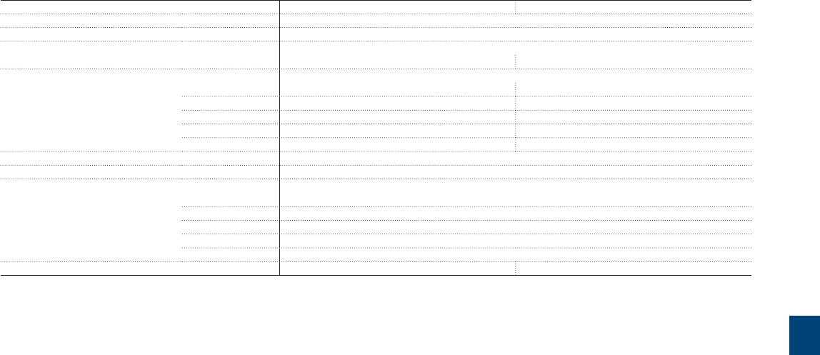
7
R contactor US catalog | 1SXU106047C0201 79
Auxiliary contact blocks
Technical data
CA auxiliary contact blocks
Types
CA12 CA15
Rated operational voltage Ue max. 690 V
Rated frequency (without de-rating) 25...400 Hz
Conventional free-air thermal current Ith
acc. to IEC 60947-4-1, open couplers, θ ≤ 40 °C 12 A 15 A
Ie / Rated operational current AC-15
acc. to IEC 60947-5-1 24-48 V 50/60 Hz 8 A 10 A
110-127 V 50/60 Hz 8 A 10 A
220-240 V 50/60 Hz 5 A 6 A
380-440 V 50/60 Hz 3 A 3.5 A
500-600 V 50/60 Hz 2 A 2.5 A
Making capacity acc. to IEC 60947-5-1 10 x Ie / AC-15
Breaking capacity acc. to IEC 60947-5-1 10 x Ie / AC-15
Ie / Rated operational current DC-13
acc. to IEC 60947-5-1 24 V DC 6 A
48 V DC 2.8 A
72 V DC 1 A
110-125 V DC 0.55 A
220-250 V DC 0.3 A
Short-circuit protection device gG type fuse 10 A 16 A
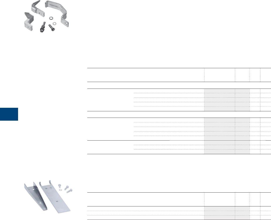
7
80 1SXU10607C0201 | R contactor US catalog
Main poles
Contacts sets for N.O. or N.C. main poles
Description
The contact sets include 1 fi xed contact, 1 moving contact, 1 arcing horn (according to table below) and
screws.
The quantities needed are defi ned per ratings as follow:
– 1 set per pole for R63….R800, R1000, R1400, R1700, R2100
– 2 sets per pole for R1250, R1500, R2500, R3200, R3800
– 3 sets per pole for R2000, R4500, R5100
– 4 sets per pole for R3150
– 5 sets per pole for R4000.
Ordering details
For R contactors type Order code Pkg
qty
Weight
(1 pce)
kg
Contact set with arcing horn
IOR, NOR, JOR, FOR 63, 85 FPTN410389R0001 1 set 0.050
125, 170 FPTN410389R0002 1 set 0.150
200, 260 FPTN410389R0003 1 set 0.250
315, 400 (1), 420 FPTN410389R0004 1 set 0.400
400 (2), 500, 550, 630 FPTN410389R0005 1 set 0.480
Contact set without arcing horn
LOR 85 FPTN410390R0001 1 set 0.040
170 FPTN410390R0002 1 set 0.090
260 FPTN410390R0003 1 set 0.180
420 FPTN410390R0004 1 set 0.250
400, 550 FPTN410390R0005 1 set 0.470
IOR, NOR, JOR, FOR, LOR 800, 1000, 1250, 1500, 2000, 3150, 4000 FPTN410391R0001 1 set 0.520
1400, 2500 FPTN410503R0001 1 set 0.520
1700, 2100, 3200, 3800, 4500, 5100 FPTN410506R0001 1 set 0.830
(1) For NOR and JOR types, NC poles
(2) For IOR, NOR and JOR types, NO poles
Arcing horns for N.O. or N.C. main poles
Ordering details
For R contactors type
IOR, NOR, JOR, FOR
Order code Pkg
qty
Weight
(1 pce)
kg
800, 1000, 1250, 1500, 2000, 3150, 4000 FPTN410446R0001 1 0.200
1400, 2500 FPTN410446R0001 1 0.200
1700, 2100, 3200, 3800, 4500, 5100 FPTN410508R0001 1 0.280
1SBC388134F0302NB
1SBC104033F0014
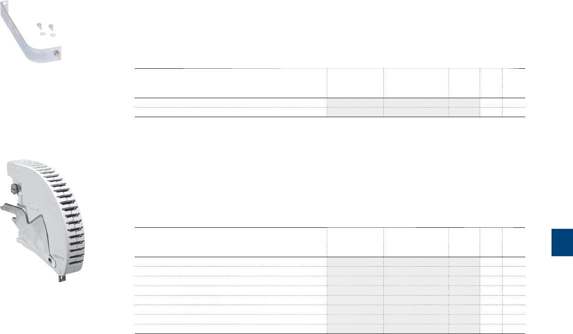
7
R contactor US catalog | 1SXU106047C0201 81
Main poles
Equipotential connections
Description
Equipotential connections must be ordered separately for ratings ≥ 800 A.
Ordering details
For R contactors type
IOR, NOR, JOR and FOR
Type Order code Pkg
qty
Weight
(1 pce)
kg
800 ... 5100 NO poles FPTN410176R0006 1 0.500
800 ... 4000 NC poles FPTN410176R0007 1 0.530
Arc chutes
Description
De-ion arc chutes replace basic arc chutes except for 315 and 420 A ratings.
Ordering details
For R contactors type
IOR, NOR, JOR and FOR
Type Order code Pkg
qty
Weight
(1 pce)
kg
63, 85 De-ion arc chute FPTN401938R0002 1 0.470
125, 170 De-ion arc chute FPTN401939R0002 1 0.930
200, 260 De-ion arc chute FPTN401940R0002 1 1.360
315, 400 (1),420 Basic arc chute FPTN401936R0002 1 1.300
400 (2), 500, 550 De-ion arc chute FPTN401941R0002 1 3.600
800, 1000, 1250, 1500, 2000, 3150, 4000 De-ion arc chute FPTN410067R0002 1 2.570
1400, 2500 De-ion arc chute FPTN410067R0002 1 2.570
1700, 2100, 3200, 3800, 4500, 5100 De-ion arc chute FPTN410507R0001 1 3.150
(1) For NOR and JOR types, NC poles
(2) For IOR, NOR and JOR types, NO poles
Pressure springs, insulated supports, complete poles and
other spare parts
Please contact your local sales organization (order code for R contactor needed).
1SBC104032F0014
1SBC387943F0302
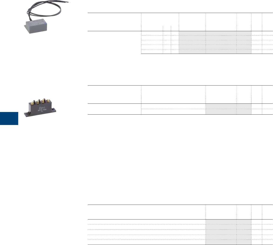
7
82 1SXU10607C0201 | R contactor US catalog
Control circuits
Surge suppressors for contactor coils
Ordering details
For R contactors type
IOR, NOR , JOR, LOR and FOR
Rated control circuit
voltage
Uc
Type Order code Pkg
qty
Weight
(1 pce)
VACDC kg
63 ... 5100 24...60
●
– RV-R1/60 FPTN410463R6001 1 0.050
60...133
●
– RV-R1/133 FPTN410463R6002 1 0.050
110...250
●
– RV-R1/250 FPTN410463R6003 1 0.050
250...440
●
– RV-R1/440 FPTN410463R6004 1 0.050
440...660
●
– RV-R1/660 FPTN410463R6005 1 0.050
Rectifi ers
Ordering details
For R contactors type
IORR, NORR, JORR,
LORR and FORR
Rated control circuit
voltage
Uc
Order code Pkg
qty
Weight
(1 pce)
kg
63 ... 5100 < 440 V AC TRE2614501 1 0.050
≥ 440 V AC TRE2720806 1 0.050
Complete control circuit kit
Including:
– 1 coil
– 1 economy resistor
– 1 surge suppressor
– 1 rectifi er
For complete kit, please contact your local sales organization (order code of R contactor needed).
Magnet circuits
Ordering details
For R contactors type
IORR, NORR, JORR, LORR, and FORR
IORE, NORE, JORE, LORE, and FORE
Order code Pkg
qty
Weight
(1 pce)
kg
63, 85 FPTN410437R0001 1 1.500
125, 170 FPTN410438R0001 1 1.500
200, 260 FPTN410439R0001 1 1.500
400 ... 630 FPTN410441R0001 1 2.500
≥ 800 FPTN410200R0006 1 8.000
For tripping electro-magnet circuit AME or AM(F)-CC > 800 A: use 63, 85 A electro-magnet circuit.
For IOR and IOR..AMA versions, please consult your local sales organization (order code of R contactor needed).
Coils, economy resistors and other specifi c parts
Please contact your local sales organization (order code of R contactor needed).
1SBC104030F0014
1SBC104029F0014
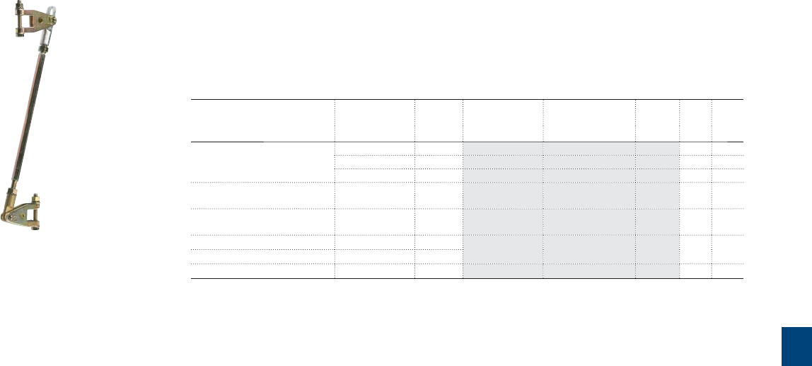
7
R contactor US catalog | 1SXU106047C0201 83
Mechanical interlock units
Description
The VM mechanical interlock units are designed for the interlocking of two R contactors of the same rating.
The mounting between 2 contactors of a same rating doesn't affect their fi xing centers or their overall
dimensions.
Ordering details
For R contactors type
IOR, NOR , JOR, LOR and FOR
Rating Fixing
center
Type Order code Pkg
qty
Weight
(1 pce)
mm kg
IOR..-CC, IOR..-MT, NOR..-CC,
NOR..-MT, LOR
63 220 VM21/24 FPL7101403R0001 1 0.140
125 260 VM25 FPL7401404R0001 1 0.180
200 320 VM27 FPL8001401R0001 1 0.260
IOR..-CC, IOR..-MT, NOR..400,
LOR
400 ... 500 520 VM15-SP FPL8301401R0002 1 0.500
IOR…, LOR…800, NOR…800,
FOR…1000
800 ... 1000 520 VM16 FPL8601401R0001 1 0.600
IOR…-CC, IOR…-MT 800 … 1000 640 VM17/18 FPL8801401R0001 1 0.700
IOR, LOR, FOR 1400, 1700, 2100 640
IOR…-CC, IOR…-MT 1400, 1700, 2100 680 VM19 FPL9001401R0001 1 0.800
Note: For special versions, please consult us:
- interlocking between contactors with N.O. + N.C. poles or with latching
- interlocking between 2 contactors of different ratings
- interlocking between 3 contactors.
1SBC388162F0302
VM
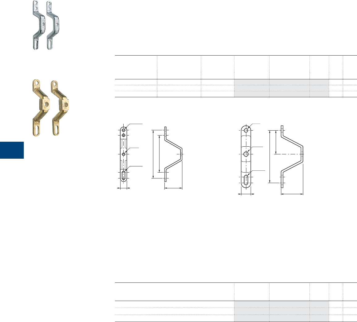
7
84 1SXU10607C0201 | R contactor US catalog
Mounting feet - Shaft extensions
Mounting feet
Description
When the contactors are to be fi tted on a back plate the mounting feet provide an increased clearance
behind the contactor for easier cabling.
Two pieces are required for one contactor.
Ordering details
For R contactors Drilling for bar fi xing Ø Fixing centres
for vertical wall
mounting
Type Order code Pkg
qty
Weight
(2 pce)
mm mm kg
63 ... 170 6.2 85 / 100...110 4NMW1009 FPL7108201P0001 2 0.060
200, 260 8.2 85 / 100...110 4NMW1039 FPL7608201P0001 2 0.060
400, 500, 550 12.5 110...120 4NMW1041 FPL8308201P0001 2 0.320
Main dimensions mm
40
85
100 ... 110
R0111D
* 4 NMW 1009 : ø = 6.2
* 4 NMW 1039 : ø = 8.2
2 x ø 6.5
ø 6.2*
ø 8.2*
20 x 6.5
15
50
54
110 ... 120
ø 8.5
ø 10.5*
ø 12.5*
22 x 8.5
22
* 4 NMW 1040 : ø = 10.5
* 4 NMW 1041 : ø = 12.5
R0112D
Shaft extensions
Description
For 3 or 4 pole reversing or changeover pairs built with two contactors of different ratings, vertically mounted
above one another. Fitting on the shaft of the contactor having the smaller frame size.
Ordering details
For R contactors Type Order code Pkg
qty
Weight
(1 pce)
kg
63 ... 170 - FPTN410111R0001 1 (1)
200 ... 420 - FPTN410111R0002 1 (1)
400, 500, 550 - FPTN410111R0003 1 (1)
(1) On request.
1SBC104030F0014
4NMW1009/1039
1SBC104029F0014
01041

Notes
R contactor US catalog | 1SXU106047C0201 85

8
86 1SXU10607C0201 | R contactor US catalog

8
R contactor US catalog | 1SXU106047C0201 87
Terminal marking and wiring diagrams
Terminal marking and positioning
R63 ... R500 88
R800 ... R5100 89
Wiring diagrams
R contactors and couplers
Control by 2 impulse pushbuttons and hold-in contact 90
Control by switch 90
R magnetically latched contactors - Contactors and couplers
Control by 2 impulse pushbuttons 91
Control by switch 92
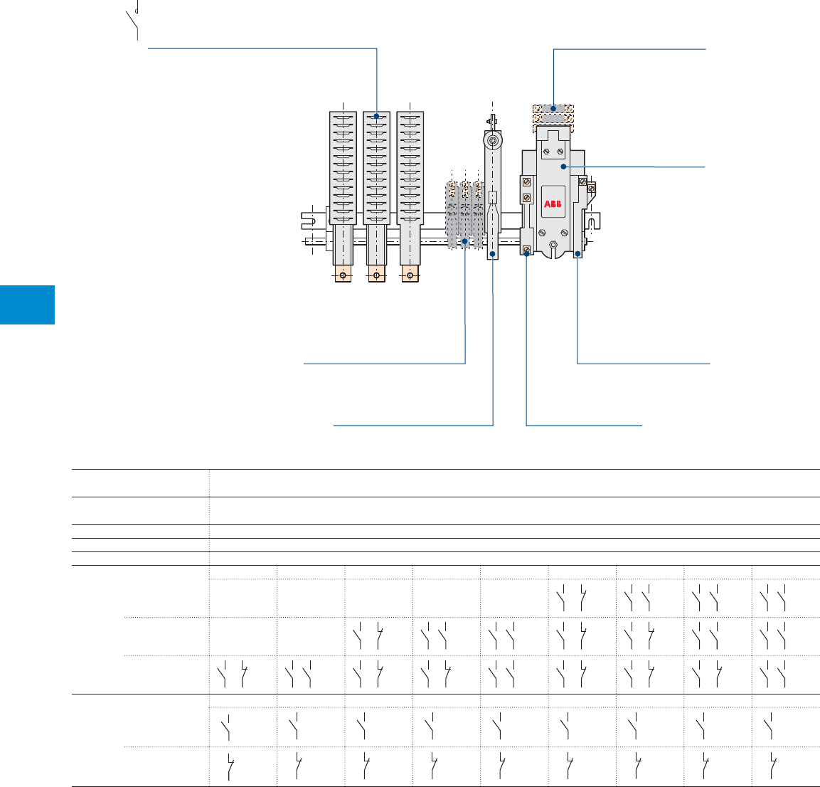
8
88 1SXU10607C0201 | R contactor US catalog
Main poles N.O. main poles are respectively marked 1-2, 3-4, 5-6, 7-8
For N.C. main poles the letter R precedes the figures
Coil AC coil: the terminals are marked A1 and A2
DC coil: the terminals are marked A1 (-) and A2 (+)
CAOVE contact N.C. contact, adjustable, intended for electrical interlocking. Terminal marking: 21-22
CARB contact N.O. contact, intended for "hold-in" function. Terminal marking: 13-14
CA15-OR contact N.C. contact, factory wired. It is intended for insertion of economy resistor. Terminal marking: 15-16
CA12 auxiliary contacts
1 NO + 1 NC 2 NO 2 NO + 2 NC 3 NO + 1 NC 4 NO 3 NO + 3 NC 4 NO + 2 NC 5 NO + 1 NC 6 NO
Block No 3
83
84
71
72
83
84
73
74
83
84
73
74
83
84
73
74
Block No 2
63
64
51
52
63
64
53
54
63
64
53
54
63
64
51
52
63
64
51
52
63
64
53
54
63
64
53
54
Block No 1
43
44
31
32
43
44
33
34
43
44
31
32
43
44
31
32
43
44
33
34
43
44
31
32
43
44
31
32
43
44
31
32
43
44
33
34
CA15 extra auxiliary contacts
No "n" No 8 No 7 No 6 No 5 No 4 No 3 No 2 No 1
CA15-F (N.O.)
..
3
..
4
173
174
163
164
153
154
143
144
133
134
123
124
113
114
103
104
or CA15-O (N.C.)
..
1
..
2
171
172
161
162
151
152
141
142
131
132
121
122
111
112
101
102
The CA15 auxiliary contacts are fi tted from the right on the contactor frame according to this marking.
R63 ... R500 (the main poles in variable number)
Main poles
The L.H.S. main pole is marked 1-2,
the following poles are marked 3-4, 5-6, etc CA12 auxiliary contact blocks
CA15 auxiliary contact blocks
CAOVE contact
for electrical interlocking
Coil
CA15-OR contact
for economy resistor insertion
CARB contacts
for "hold-in" function
123
R contactors
Terminal marking and positioning
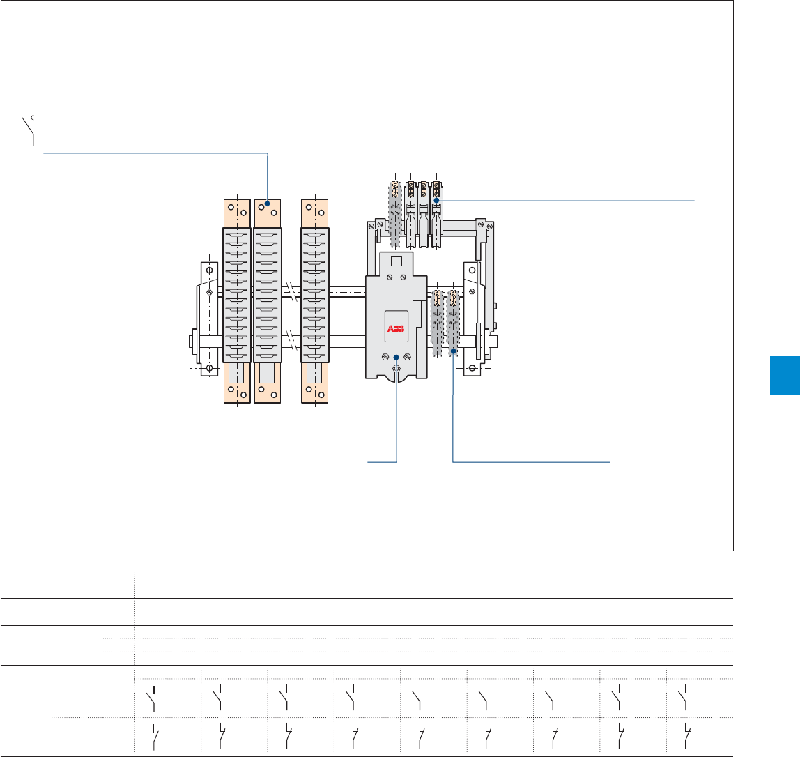
8
R contactor US catalog | 1SXU106047C0201 89
Main poles N.O. main poles are respectively marked 1-2, 3-4, 5-6, 7-8
For N.C. main poles the letter R precedes the figures
Coil AC coil: the terminals are marked A1 and A2
DC coil: the terminals are marked A1 (-) and A2 (+)
CA15 auxiliary contact No 1 CA15-O (N.C.) contact intended for electrical interlocking. Terminal marking: 21-22
No 2 CA15-F (N.O.) contact intended for "hold-in" function. Terminal marking: 13-14
No 3 CA15-OR (N.C.). This contact is factory wired. It is intended for insertion of economy resistor. Terminal marking: 15-16
CA15 extra auxiliary contacts
No "n" No 11 No 10 No 9 No 8 No 7 No 6 No 5 No 4
CA15-F (N.O.)
..
3
..
4
173
174
163
164
153
154
143
144
133
134
123
124
113
114
103
104
or CA15-O (N.C.)
..
1
..
2
171
172
161
162
151
152
141
142
131
132
121
122
111
112
101
102
The CA15 auxiliary contacts are fi tted from the right, fi rst on the auxiliary frame and next on the main frame of the contactor, according to this marking.
R800 ... R5100 (the main poles in variable number, can be distributed on both sides of the electro-magnet)
Coil
CA15 auxiliary contact blocks
mounted on main frame
CA15 auxiliary contact blocks
mounted on auxiliary frame
Position of the CA15 starting from the right
1234
Main poles
The L.H.S. main pole is marked 1-2,
the following poles are marked 3-4, 5-6, etc
R contactors
Terminal marking and positioning
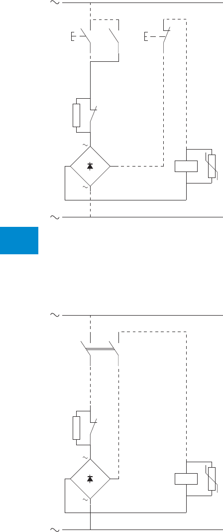
8
90 1SXU10607C0201 | R contactor US catalog
0
IKM
KM
A1
A2
13
14
16
15
Re
+– KM
I
A1
A2
16
15
Re
+–
KM
KM
R contactors and couplers
Wiring diagrams
AC operated
IORR, IORR-MT, IORR-CC, NORR-MT, NORR-CC, LORR
IORR, IORR-MT, IORR-CC, NORR-MT, NORR-CC, LORR
Note: remove the factory wired strap 14-16
AC operated
Control by 2 impulse pushbuttons and hold-in contact
Control by switch

8
R contactor US catalog | 1SXU106047C0201 91
KM KM
A1 A2
63
64
53
54
0
I
–
85
86
75
76
+–
KM
KM
A1 A2
63
64
53
54
0
I
Rad
–
+–
KM
KM
85
86
75
76
R magnetically latched contactors
Contactors and couplers
Wiring diagrams
AC operated
Control voltage Uc ≤ 110 V AC
AC operated
Control voltage Uc > 110 V AC
IORR-CC-AMA, IORR-MT-AMA, NORR-CC-AMA,
NORR-MT-AMA, LORR-AMA
IORR-CC-AMA, IORR-MT-AMA, NORR-CC-AMA,
NORR-MT-AMA, LORR-AMA
Control by 2 impulse pushbuttons
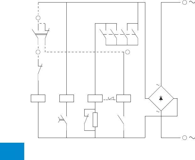
8
92 1SXU10607C0201 | R contactor US catalog
I
KA2 KA1 KM KL
A2
A1
A2
A1
A1
A2
A1
A2
3/L2
4/T2
KM
14
13
KM
12
11
58
57
15
16
KMKA2 Re
1/L1
2/T1
7/L4
8/T4
5/L3
6/T3
1
3 2
KA1
9
10
+–
R mechanically latched contactors
Contactors and couplers
Wiring diagrams
AC operated
Control by switch
KM = Closing coil
KL = Tripping coil
KA1 = Contactor relay
KA2 = Timed contactor relay
Re = Economy resistor
Supply between 9 and 10
Closing between 1 and 3
Tripping between 1 and 2
IORR-AME, IORR-MT-AME, IORR-CC-AME, NORR-CC-AME, NORR-MT-AME,
LORR-AME

Notes
R contactor US catalog | 1SXU106047C0201 93

9
94 1SXU10607C0201 | R contactor US catalog

9
R contactor US catalog | 1SXU106047C0201 95
Main dimensions
IORR and LORR types
R800 … R2100 96
R2500 … R5100 98
IORR..MT and IORR..CC types
R63 … R500 100
R800 … R2100 102
R2500 … R5100 104
IORR..AME and LORR..AME types
R800 … R2100 106
R2500 … R5100 108
IORR..MT-AMA … IOR..MT-AMA and
IORR..CC-AMA … IOR..CC-AMA types
R63 ... R200 110
IORR..MT-AME and IORR..CC-AME types
R400 ... R500 112
R800 … R2100 114
R2500 … R5100 116
NORR..MT and NORR..CC types
R63 … R200 118
LORR type
R85 … R550 120
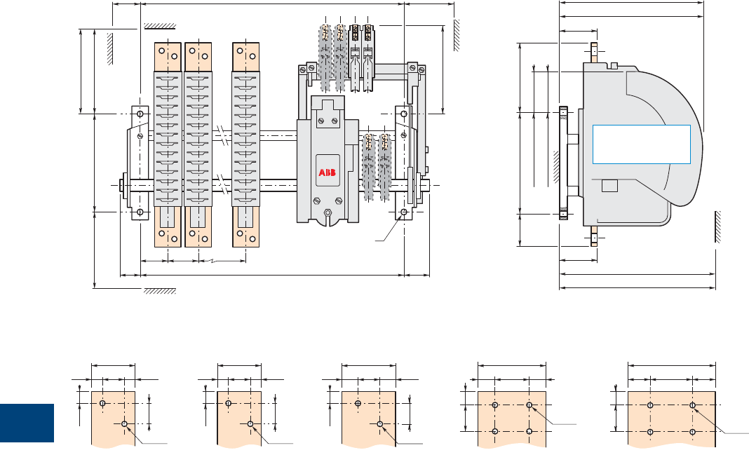
9
96 1SXU10607C0201 | R contactor US catalog
48
11.52511.5
25
12.5
2 x ø13
60
17.5 25 17.5
25
12.5
2 x ø13
80
4 x ø11
20 40 20
15 30
100
4 x ø11
25 50 25
15 30
48
11.52511.5
25
12.5
2 x ø13
IORR and LORR types
R800 … R2100
Main dimensions mm
Terminal plate details
R800 R1700 R2100R1400
200
IORR M
N
180
50 60F
40 F 50
CA15
CA15
AB B
ø
LORR M1
IORR D
D2
D3
LORR Y1
I1200
H
LORR D1
LORR I = 0
IORR I
IORR Y
R1000
LORR types poles
are not equipped
with arc chutes
Terminal plate thickness: top terminal plates = 10 mm, bottom terminal plates = 12 mm
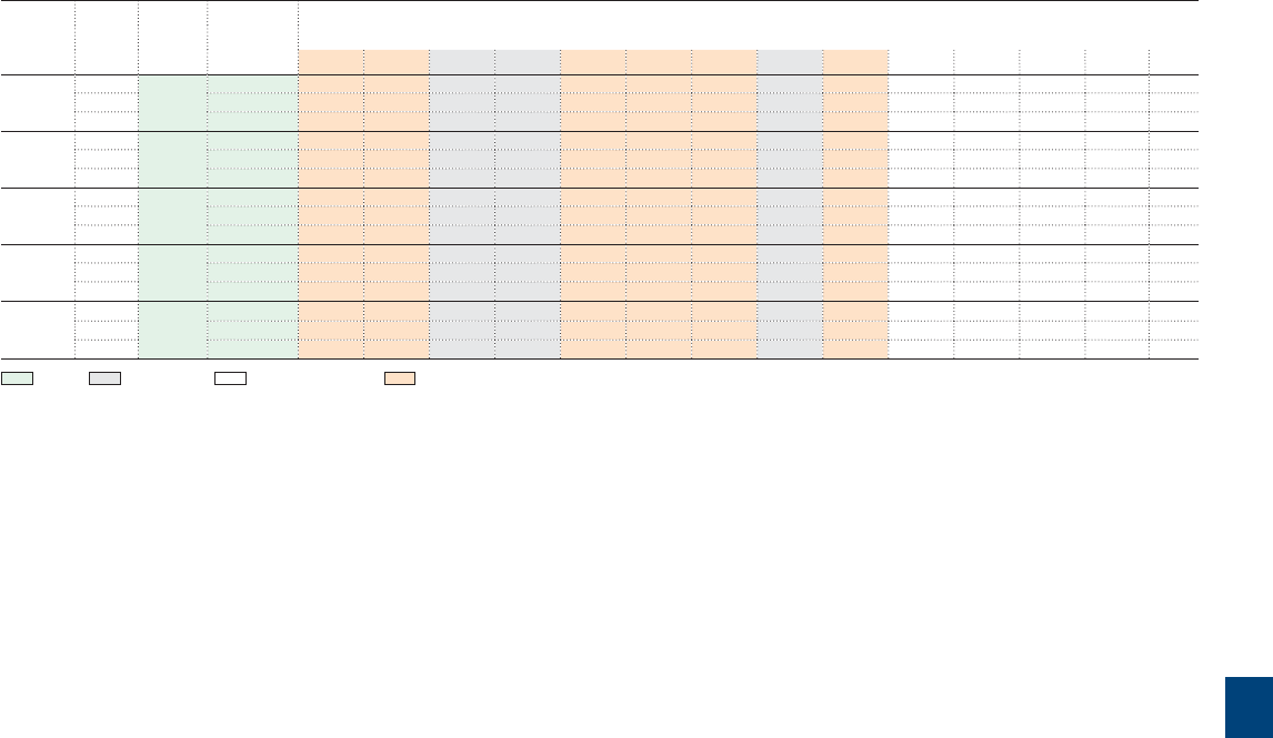
9
R contactor US catalog | 1SXU106047C0201 97
IORR and LORR types
R800 … R2100
Contactor
types
Number Fixing
holes
Fixing
dimensions
F
Dimensions
of poles
A B D D1D2D3H I I1 M M1N Y Y1
R800 1 4 x ø13 245 60 - 325 260 75 77 70 108 98 158 115 85 345 280
2 345 60 90 325 260 75 77 70 108 98 158 115 85 345 280
3 385 60 70 325 260 75 77 70 108 98 158 115 85 345 280
R1000 1 4 x ø13 245 60 - 325 260 75 77 70 108 98 158 115 85 345 280
2 345 60 90 325 260 75 77 70 108 98 158 115 85 345 280
3 385 60 70 325 260 75 77 70 108 98 158 115 85 345 280
R1400 1 4 x ø13 285 85 - 325 260 75 77 70 108 98 228 165 100 400 280
2 385 85 110 325 260 75 77 70 108 98 228 165 100 400 280
3 540 85 120 325 260 75 77 70 108 98 228 165 100 400 280
R1700 1 4 x ø13 300 85 - 325 260 75 77 84 108 112 258 165 125 425 280
2 445 85 140 325 260 75 77 84 108 112 258 165 125 425 280
3 540 85 120 325 260 75 77 84 108 112 258 165 125 425 280
R2100 1 4 x ø13 300 85 - 325 260 75 77 84 108 112 258 165 125 425 280
2 445 85 140 325 260 75 77 84 108 112 258 165 125 425 280
3 540 85 120 325 260 75 77 84 108 112 258 165 125 425 280
Fixing - Dimensions - Clearing distances - Connecting
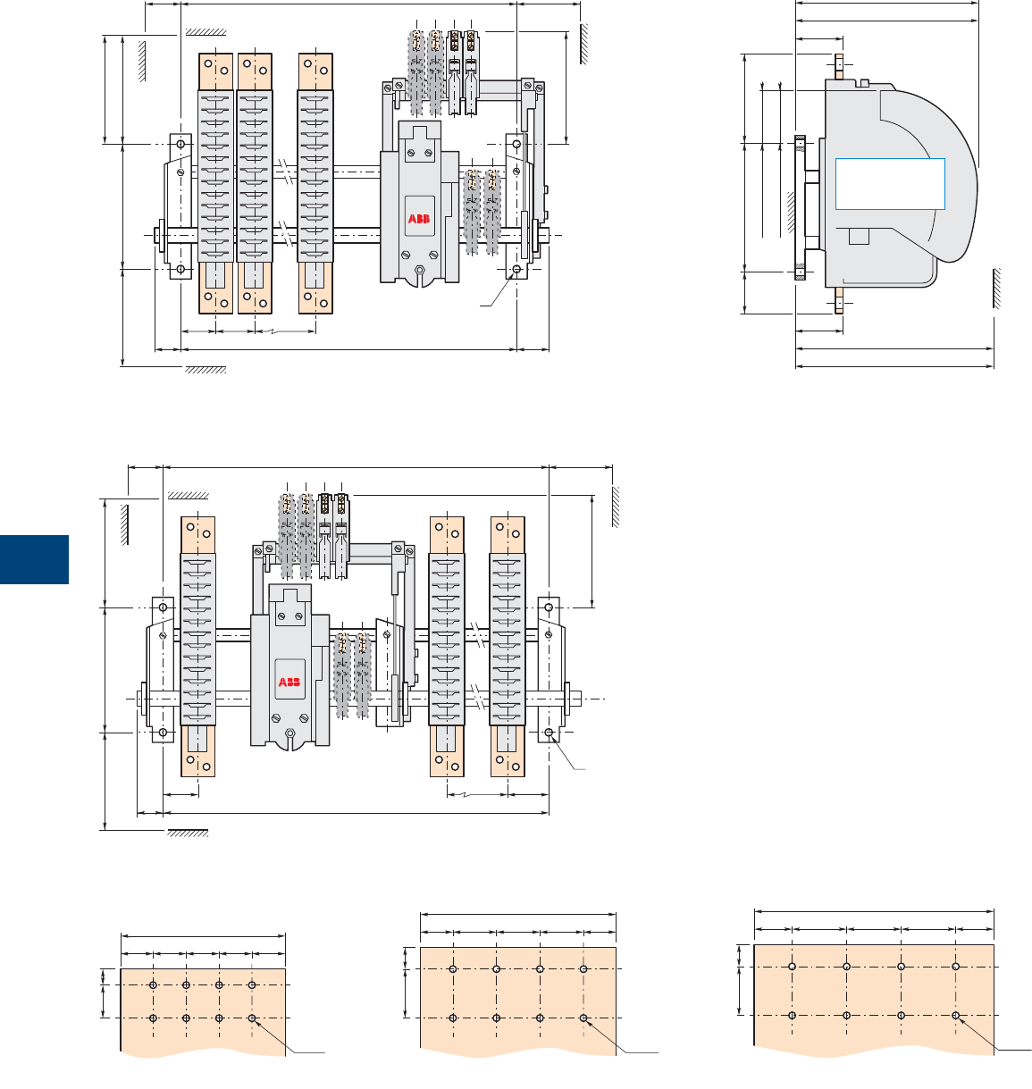
9
98 1SXU10607C0201 | R contactor US catalog
IORR and LORR types
R2500 … R5100
Main dimensions mm
200
IORR M
N
180
50 60F
40 F 50
CA15
CA15
AB B
ø
LORR M1
Terminal plate thickness for R2500 ... R5100: top and bottom terminal plates = 10 mm
Fig 1 = right electro-magnet (see table in the following page)
Fig 2 = central electro-magnet (see table in the following page)
IORR D
D2
D3
LORR Y1
I1200
H
LORR D1
LORR I = 0
IORR I
IORR Y
180
60
ø
200 MN
50 F
40 F
CA15
CA15
A A1B
150
30
30 15
30 30 30 30
8 x ø9
R2500
180
30
2045
40404030
8 x ø13
R3200
220
2045
50 50 5035 35
8 x ø13
R3800
LORR types poles
are not equipped
with arc chutes
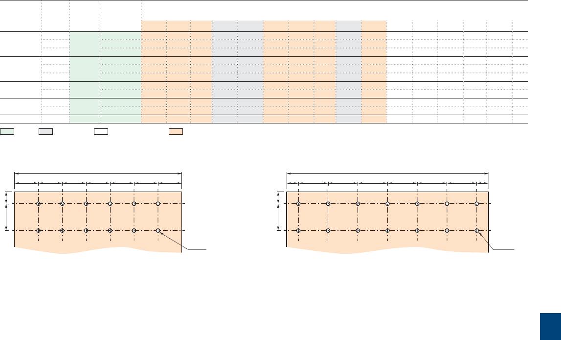
9
R contactor US catalog | 1SXU106047C0201 99
Terminal plate thickness for R2500 ... R5100: top and bottom terminal plates = 10 mm
IORR and LORR types
R2500 … R5100
Contactor
types
Number Fixing
holes
Fixing
dimension
F
Dimensions
of poles
A A1 B D D1 D2 D3 H I I1 M M1 N Y Y1 Fig
R2500 1 4 x ø13 385 130 - - 325 260 85 87 135 108 161 258 245 152 425 280 1
2 635 135 - 220 325 260 85 87 135 108 161 258 245 152 425 280 1
3 950 135 135 - 325 260 85 87 135 108 161 258 245 152 425 280 2
R3200 1 4 x ø13 445 150 - - 325 260 99 87 174 108 202 300 245 215 450 280 1
2 760 135 135 - 325 260 99 87 174 108 202 300 245 215 450 280 2
3 950 135 135 - 325 260 99 87 174 108 202 300 245 215 450 280 2
R3800 1 4 x ø13 445 160 - - 325 260 99 87 174 108 202 300 245 215 450 280 1
2 760 145 145 - 325 260 99 87 174 108 202 300 245 215 450 280 2
R4500 1 4 x ø13 540 185 - - 325 260 99 87 174 108 202 300 245 215 450 280 1
2 950 185 180 - 325 260 99 87 174 108 202 300 245 215 450 280 2
R5100 1 4 x ø13 540 210 - - 325 260 99 87 174 108 202 300 245 215 465 280 1
Fixing - Dimensions - Clearing distances - Connecting
280
2045
40 40 40 40 40 40 40
12 x ø13
R4500
340
2045
20 50 50 50 50 50 50 20
14 x ø13
R5100

9
100 1SXU10607C0201 | R contactor US catalog
RFQ
S
ø
CA12
CH CH
BBA
FO P
NM
CA15
C2222 22
IORR..MT and IORR..CC types
R63 … R500
Main dimensions mm
CH = Frame
I1H
I
DW
K
YE
V
Z
Terminal plate details
Lower
terminal plate
Upper
terminal plate
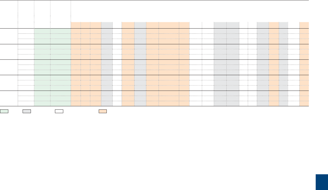
9
R contactor US catalog | 1SXU106047C0201 101
IORR..MT and IORR..CC types
R63 … R500
Contactor
types
Number Fixing
holes
Fixing
dimension
F
Dimensions
of poles
ABC D EH I I1 K ℓ M N O P QRS V WY Z
R63 1 2 x ø7 205 45 - 93 148 36 63 114 101 M6 x 20 16 164 83 12.5 10.5 53 23 15 8 16 178 8
2 245 45 50 93 148 36 63 114 101 M6 x 20 16 164 83 12.5 10.5 53 23 15 8 16 178 8
3 285 45 50 93 148 36 63 114 101 M6 x 20 16 164 83 12.5 10.5 53 23 15 8 16 178 8
R125 1 2 x ø7 205 57 - 93 153 40 76 138 130 M8 x 20 20 188 96 12.5 10.5 53 23 15 10 20 183 10
2 285 57 61 93 153 40 76 138 130 M8 x 20 20 188 96 12.5 10.5 53 23 15 10 20 183 10
3 345 57 61 93 153 40 76 138 130 M8 x 20 20 188 96 12.5 10.5 53 23 15 10 20 183 10
R200 1 2 x ø9 245 69 - 116 190 40 93 140 123 M10 x 25 25 190 116 9 10 53 20 25 13 20 220 12
2 345 69 68 116 190 40 93 140 123 M10 x 25 25 190 116 9 10 53 20 25 13 20 220 12
3 385 69 68 116 190 40 93 140 123 M10 x 25 25 190 116 9 10 53 20 25 13 20 220 12
R400 1 2 x ø13 345 79 - 160 260 100 118 230 195 ø13 30 253 150 15 14 53 20 20 20 46 290 20
2 445 79 80 160 260 100 118 230 195 ø13 30 253 150 15 14 53 20 20 20 46 290 20
3 540 79 80 160 260 100 118 230 195 ø13 30 253 150 15 14 53 20 20 20 46 290 20
R500 1 2 x ø13 345 79 - 160 260 100 118 230 195 ø13 30 253 150 15 14 53 20 20 20 46 290 20
2 445 79 80 160 260 100 118 230 195 ø13 30 253 150 15 14 53 20 20 20 46 290 20
3 540 79 80 160 260 100 118 230 195 ø13 30 253 150 15 14 53 20 20 20 46 290 20
Fixing - Dimensions - Clearing distances - Connecting
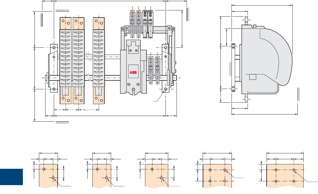
9
102 1SXU10607C0201 | R contactor US catalog
IORR..MT and IORR..CC types
R800 … R2100
Main dimensions mm
200 MN
180
50 60F
40 F 50
CA15
CA15
AB B
ø
D
D2
D3
Y
I
I1200
H
48
11.52511.5
25
12.5
2 x ø13
60
17.5 25 17.5
25
12.5
2 x ø13
80
4 x ø11
20 40 20
15 30
100
4 x ø11
25 50 25
15 30
48
11.52511.5
25
12.5
2 x ø13
Terminal plate details
R800 R1700 R2100R1400R1000
Terminal plate thickness: top terminal plates = 10 mm, bottom terminal plates = 12 mm
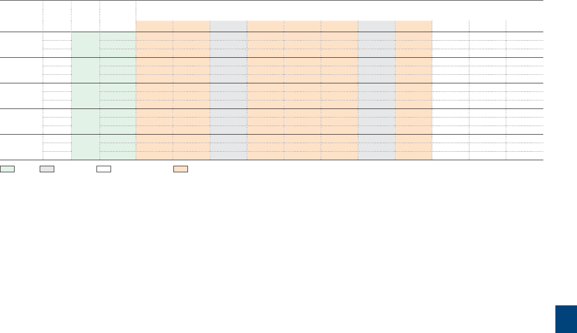
9
R contactor US catalog | 1SXU106047C0201 103
IORR..MT and IORR..CC types
R800 … R2100
Contactor
types
Number Fixing
holes
Fixing
dimension
F
Dimensions
of poles
ABDD2D3HI I1MNY
R800 1 4 x ø13 245 60 - 325 76 77 70 108 175 195 90 375
2 345 60 90 325 76 77 70 108 175 195 90 375
3 385 60 70 325 76 77 70 108 175 195 90 375
R1000 1 4 x ø13 285 60 - 325 76 77 70 108 175 195 90 375
2 345 60 90 325 76 77 70 108 175 195 90 375
3 445 60 80 325 76 77 70 108 175 195 90 375
R1400 1 4 x ø13 285 80 - 325 76 77 70 108 175 258 100 425
2 385 80 110 325 76 77 70 108 175 258 100 425
3 540 85 120 325 76 77 70 108 175 258 100 425
R1700 1 4 x ø13 300 85 - 325 89 77 84 108 189 288 125 450
2 445 85 140 325 89 77 84 108 189 288 125 450
3 540 85 120 325 89 77 84 108 189 288 125 450
R2100 1 4 x ø13 300 85 - 325 89 77 84 108 189 288 125 450
2 445 85 140 325 89 77 84 108 189 288 125 450
3 540 85 120 325 89 77 84 108 189 288 125 450
Fixing - Dimensions - Clearing distances - Connecting
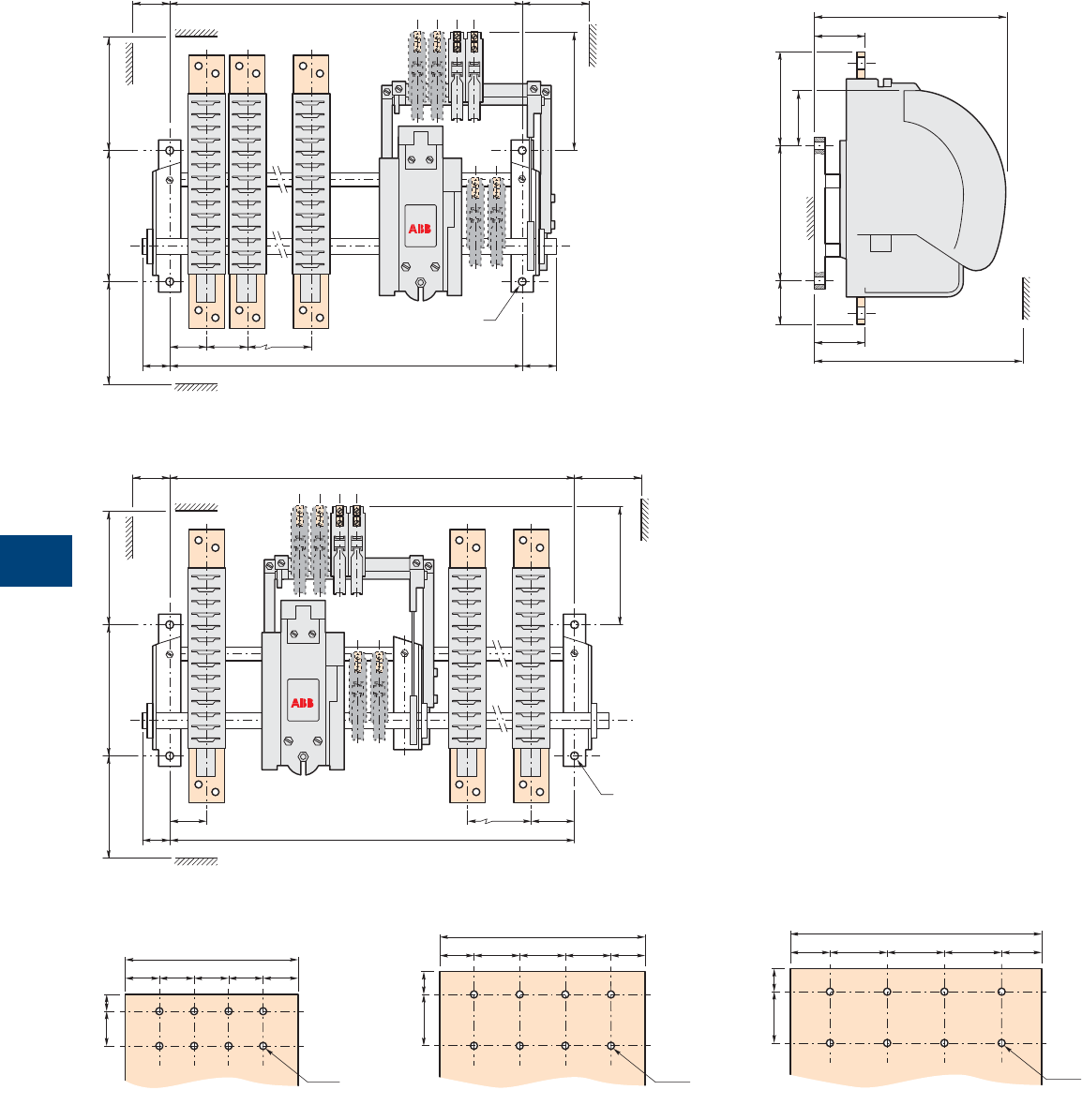
9
104 1SXU10607C0201 | R contactor US catalog
IORR..MT and IORR..CC types
R2500 … R5100
Main dimensions mm
200 MN
180
50 60F
40 F 50
CA15
CA15
AB B
ø
D
D2
D3
Y
I
I1200
H
Fig 1 = right electro-magnet (see table in the following page)
Fig 2 = central electro-magnet (see table in the following page)
180
60
ø
200 MN
50 F
40 F
CA15
CA15
A A1B
Terminal plate thickness for R2500 ... R5100: top and bottom terminal plates = 10 mm
150
30
30 15
30 30 30 30
8 x ø9
R2500
180
30
2045
40404030
8 x ø13
R3200
220
2045
50 50 5035 35
8 x ø13
R3800
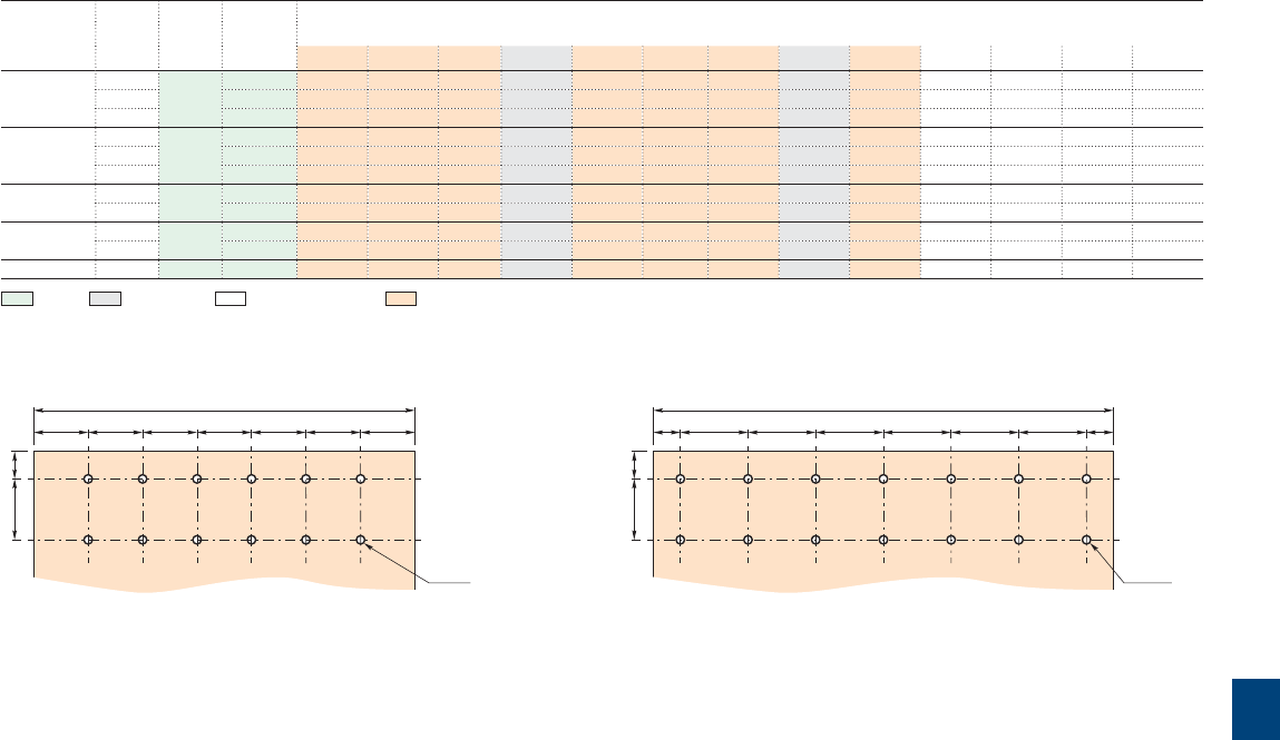
9
R contactor US catalog | 1SXU106047C0201 105
IORR..MT and IORR..CC types
R2500 … R5100
Contactor
types
Number Fixing
holes
Fixing
dimension
F
Dimensions
of poles
A A1 B D D2 D3 H I I1 M N Y Fig
R2500 1 4 x ø13 385 130 - - 325 85 87 135 108 238 258 152 425 1
2 635 135 - 220 325 85 87 135 108 238 258 152 425 1
3 950 135 135 - 325 85 87 135 108 238 258 152 425 2
R3200 1 4 x ø13 445 150 - - 325 99 87 174 108 279 300 215 450 1
2 760 135 135 - 325 99 87 174 108 279 300 215 450 2
3 950 135 135 - 325 99 87 174 108 279 300 215 450 2
R3800 1 4 x ø13 445 160 - - 325 99 87 174 108 279 300 215 450 1
2 760 145 145 - 325 99 87 174 108 279 300 215 450 2
R4500 1 4 x ø13 540 185 - - 325 99 87 174 108 279 300 215 450 1
2 950 185 180 - 325 99 87 174 108 279 300 215 450 2
R5100 1 4 x ø13 540 210 - - 325 99 87 174 108 279 300 215 465 1
Fixing - Dimensions - Clearing distances - Connecting
Terminal plate thickness for R2500 ... R5100: top and bottom terminal plates = 10 mm
280
2045
40 40 40 40 40 40 40
12 x ø13
R4500
340
2045
20 50 50 50 50 50 50 20
14 x ø13
R5100
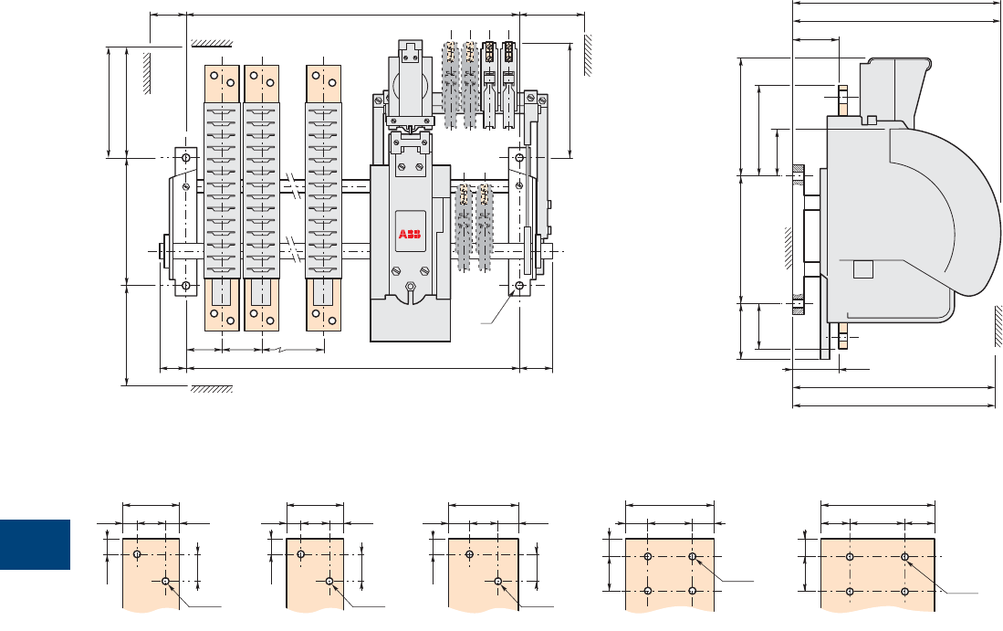
9
106 1SXU10607C0201 | R contactor US catalog
IORR..AME and LORR..AME types
R800 … R2100
Main dimensions mm
CA15
CA15
200
IORR M
N
180
50 60F
40 F 50
AB B
ø
LORR M1
IORR D
D2
D3
LORR Y1
I
I1
210200100
H
LORR D1
IORR Y
48
11.52511.5
25
12.5
2 x ø13
60
17.5 25 17.5
25
12.5
2 x ø13
80
4 x ø11
20 40 20
15 30
100
4 x ø11
25 50 25
15 30
48
11.52511.5
25
12.5
2 x ø13
Terminal plate details
R800 R1700 R2100R1400R1000
Terminal plate thickness: top terminal plates = 10 mm, bottom terminal plates = 12 mm
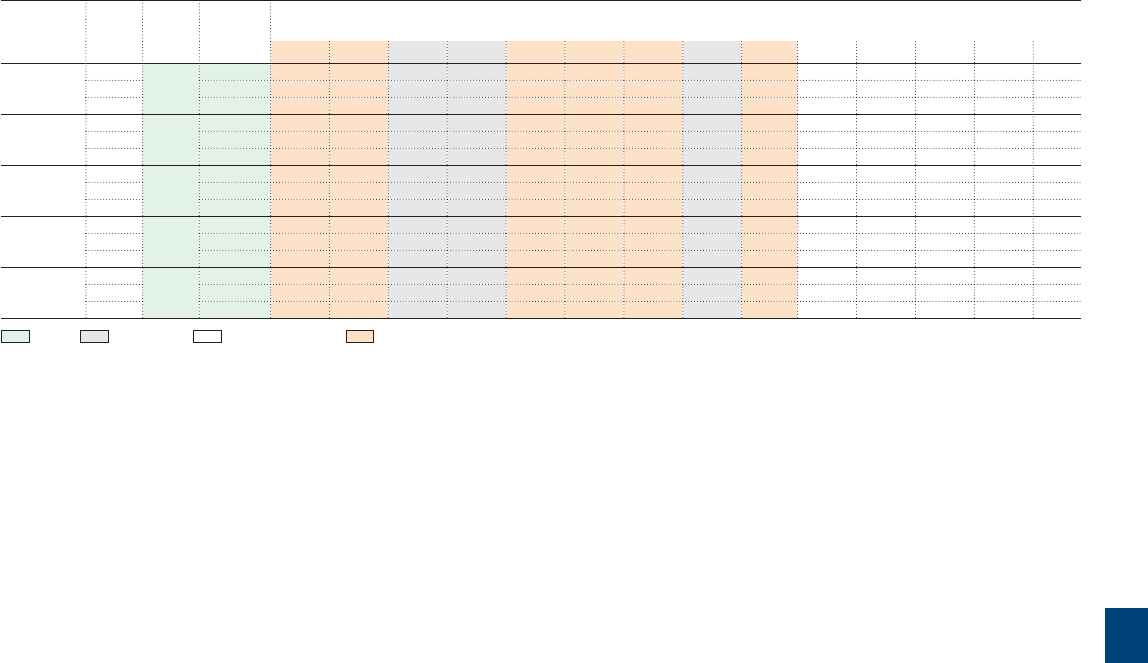
9
R contactor US catalog | 1SXU106047C0201 107
IORR..AME and LORR..AME types
R800 … R2100
Contactor
types
Number Fixing
holes
Fixing
dimension
F
Dimensions
of poles
A B D D1D2D3H I I1 M M1N Y Y1
R800 1 4 x ø13 345 60 - 325 260 75 77 70 108 98 245 245 90 345 280
2 445 60 90 325 260 75 77 70 108 98 245 245 90 345 280
3 540 60 70 325 260 75 77 70 108 98 245 245 90 345 280
R1000 1 4 x ø13 345 60 - 325 260 75 77 70 108 98 245 245 90 345 280
2 445 60 90 325 260 75 77 70 108 98 245 245 90 345 280
3 540 60 70 325 260 75 77 70 108 98 245 245 90 345 280
R1400 1 4 x ø13 385 80 - 325 260 76 77 70 108 98 258 245 100 400 280
2 540 80 110 325 260 76 77 70 108 98 258 245 100 400 280
3 635 85 120 325 260 76 77 70 108 98 258 245 100 400 280
R1700 1 4 x ø13 385 85 - 325 260 75 77 84 108 112 288 245 125 425 280
2 540 85 140 325 260 75 77 84 108 112 288 245 125 425 280
3 635 85 120 325 260 75 77 84 108 112 288 245 125 425 280
R2100 1 4 x ø13 385 85 - 325 260 75 77 84 108 112 288 245 125 425 280
2 540 85 140 325 260 75 77 84 108 112 288 245 125 425 280
3 635 85 120 325 260 75 77 84 108 112 288 245 125 425 280
Fixing - Dimensions - Clearing distances - Connecting
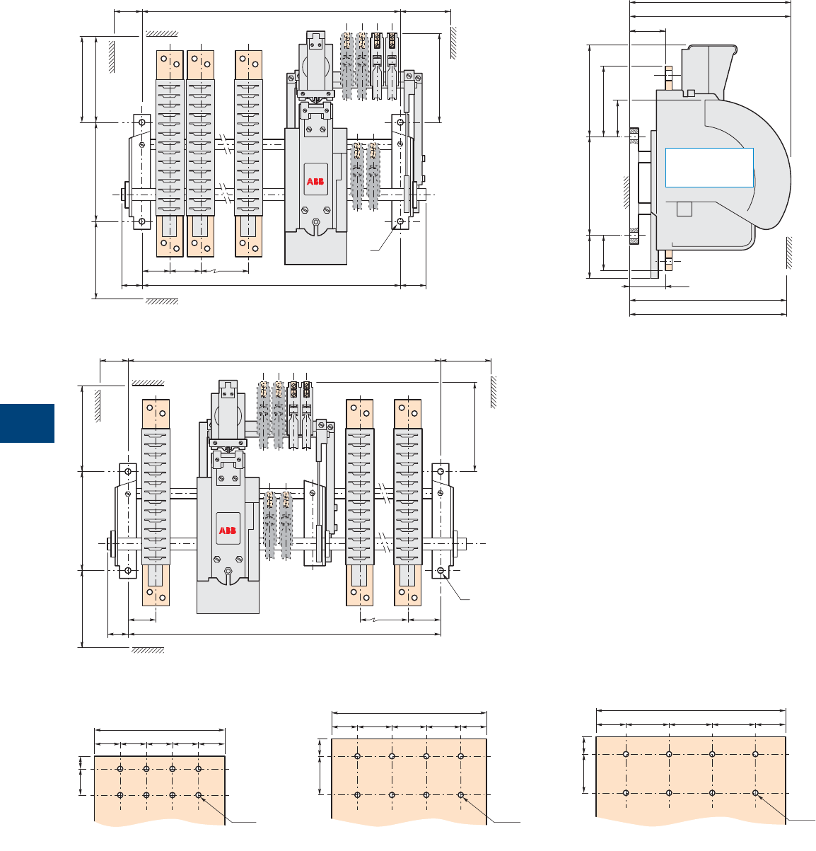
9
108 1SXU10607C0201 | R contactor US catalog
IORR..AME and LORR..AME types
R2500 … R5100
CA15
CA15
200
IORR M
N
180
50 60F
40 F 50
AB B
ø
LORR M1
IORR D
D2
D3
LORR Y1
I
I1
210200100
H
LORR D1
IORR Y
Main dimensions mm
Fig 1 = right electro-magnet (see table in the following page)
Fig 2 = central electro-magnet (see table in the following page)
180
60
ø
200 MN
50 F
40 F
CA15
CA15
A A1B
LORR types poles
are not equiped
with arc chutes
Terminal plate thickness for R2500 ... R5100: top and bottom terminal plates = 10 mm
150
30
30 15
30 30 30 30
8 x ø9
R2500
180
30
2045
40404030
8 x ø13
R3200
220
2045
50 50 5035 35
8 x ø13
R3800
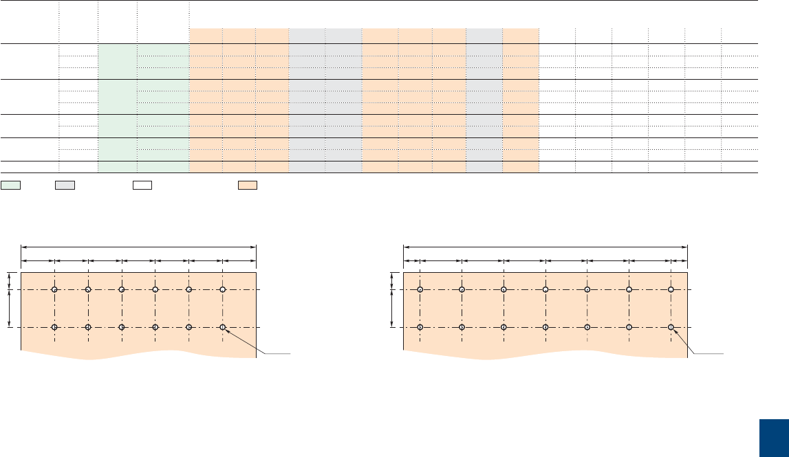
9
R contactor US catalog | 1SXU106047C0201 109
IORR..AME and LORR..AME types
R2500 … R5100
Contactor
types
Number Fixing
holes
Fixing
dimensions
F
Dimensions
of poles
A A1 B D D1 D2 D3 H I I1 M M1 N Y Y1 Fig
R2500 1 4 x ø13 540 130 - - 325 260 85 87 135 108 161 258 245 152 425 280 1
2 685 135 - 220 325 260 85 87 135 108 161 258 245 152 425 280 1
3 1050 135 135 - 325 260 85 87 135 108 161 258 245 152 425 280 2
R3200 1 4 x ø13 540 150 - - 325 260 99 87 174 108 202 300 245 215 450 280 1
2 885 135 135 - 325 260 99 87 174 108 202 300 245 215 450 280 2
3 1050 135 135 - 325 260 99 87 174 108 202 300 245 215 450 280 2
R3800 1 4 x ø13 540 160 - - 325 260 99 87 174 108 202 300 245 215 450 280 1
2 885 145 145 - 325 260 99 87 174 108 202 300 245 215 450 280 2
R4500 1 4 x ø13 635 185 - - 325 260 99 87 174 108 202 300 245 215 450 280 1
2 1050 185 180 - 325 260 99 87 174 108 202 300 245 215 450 280 2
R5100 1 4 x ø13 635 210 - - 325 260 99 87 174 108 202 300 245 215 465 280 1
Fixing - Dimensions - Clearing distances - Connecting
Terminal plate thickness for R2500 ... R5100: top and bottom terminal plates = 10 mm
280
2045
40 40 40 40 40 40 40
12 x ø13
R4500
340
2045
20 50 50 50 50 50 50 20
14 x ø13
R5100
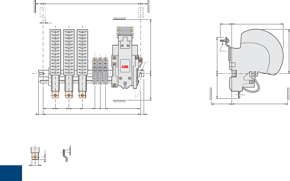
9
110 1SXU10607C0201 | R contactor US catalog
RFQ
S
ø
CA12
CH CH
BBA
FO P
NM
CA15
C2222
Main dimensions mm
V
Z
Terminal plate details
Lower
terminal plate
Upper
terminal plate
I1H
I
DW
K
YE
IORR..MT-AMA … IOR..MT-AMA and
IORR..CC-AMA … IOR..CC-AMA types
R63 … R200
CH = Frame

9
R contactor US catalog | 1SXU106047C0201 111
Contactor
types
Number Fixing
holes
Fixing
dimension
F
Dimensions
of poles
ABCD EHI I1 K ℓMN O P QRSVWYZ
R63 1 2 x ø7 245 45 - 93 148 36 63 114 101 M6 x 20 16 164 83 12.5 10.5 53 23 15 8 16 178 8
2 285 45 50 93 148 36 63 114 101 M6 x 20 16 164 83 12.5 10.5 53 23 15 8 16 178 8
3 345 45 50 93 148 36 63 114 101 M6 x 20 16 164 83 12.5 10.5 53 23 15 8 16 178 8
R125 1 2 x ø7 285 57 - 93 153 40 76 138 130 M8 x 20 20 188 96 12.5 10.5 53 23 15 10 20 183 10
2 345 57 61 93 153 40 76 138 130 M8 x 20 20 188 96 12.5 10.5 53 23 15 10 20 183 10
3 385 57 61 93 153 40 76 138 130 M8 x 20 20 188 96 12.5 10.5 53 23 15 10 20 183 10
R200 1 2 x ø9 345 69 - 116 190 40 93 140 123 M10 x 25 25 190 116 9 10 53 20 25 13 20 220 12
2 445 69 68 116 190 40 93 140 123 M10 x 25 25 190 116 9 10 53 20 25 13 20 220 12
3 540 69 68 116 190 40 93 140 123 M10 x 25 25 190 116 9 10 53 20 25 13 20 220 12
Fixing - Dimensions - Clearing distances - Connecting
IORR..MT-AMA … IOR..MT-AMA and
IORR..CC-AMA … IOR..CC-AMA types
R63 … R200
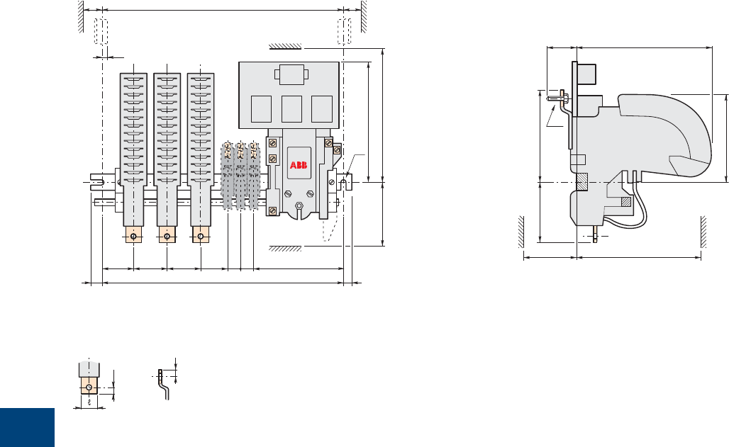
9
112 1SXU10607C0201 | R contactor US catalog
Main dimensions mm
IORR..MT-AME and IORR..CC-AME types
R400 … R500
I1H
I
DW
K
YE
V
Z
Terminal plate details
Lower
terminal plate
Upper
terminal plate
RFQ
S
ø
CH CH
BBA
FO P
300
NM
R0021D
CA 15
C2222
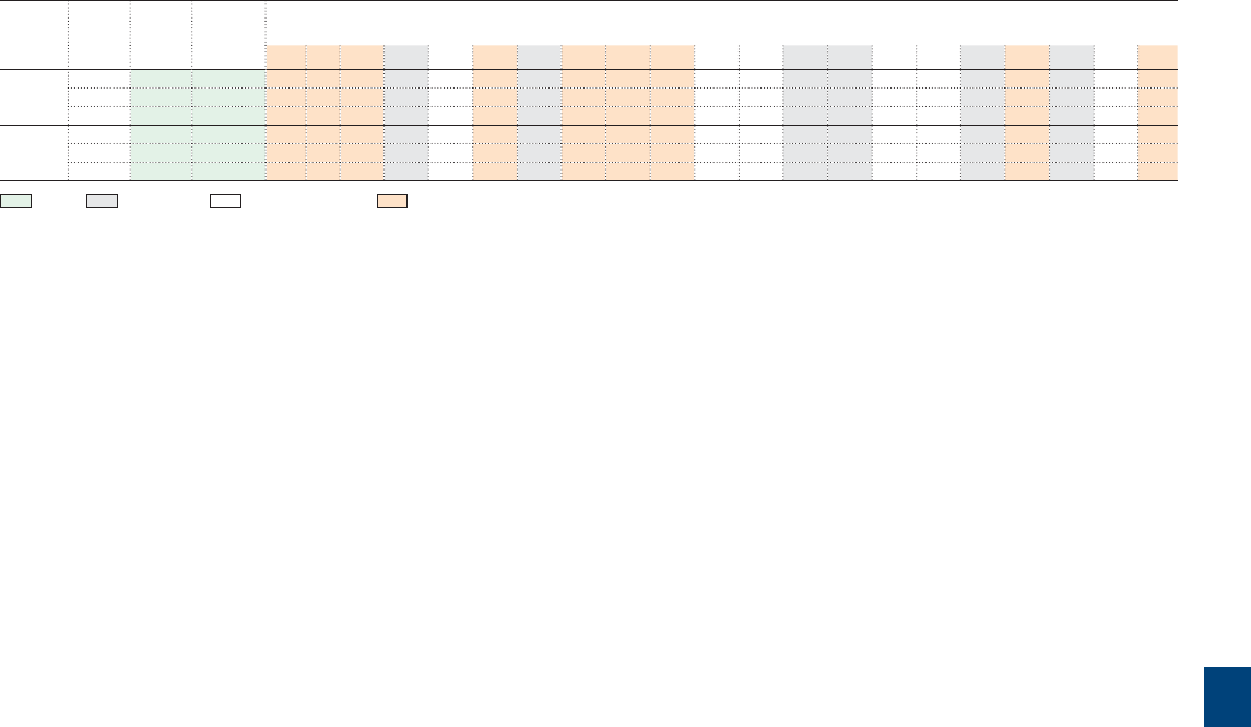
9
R contactor US catalog | 1SXU106047C0201 113
Contactor
types
Number Fixing
holes
Fixing
dimension
F
Dimensions
of poles
ABCDEHI I1Kℓ MNOPQRSV WYZ
R400 1 2 x ø13 445 79 - 160 260 100 118 230 195 ø13 30 313 150 15 14 53 20 20 20 46 335 20
2 540 79 80 160 260 100 118 230 195 ø13 30 313 150 15 14 53 20 20 20 46 335 20
3 635 79 80 160 260 100 118 230 195 ø13 30 313 150 15 14 53 20 20 20 46 335 20
R500 1 2 x ø13 445 79 - 160 260 100 118 230 195 ø13 30 313 150 15 14 53 20 20 20 46 335 20
2 540 79 80 160 260 100 118 230 195 ø13 30 313 150 15 14 53 20 20 20 46 335 20
3 635 79 80 160 260 100 118 230 195 ø13 30 313 150 15 14 53 20 20 20 46 335 20
Fixing - Dimensions - Clearing distances - Connecting
IORR..MT-AME and IORR..CC-AME types
R400 … R500
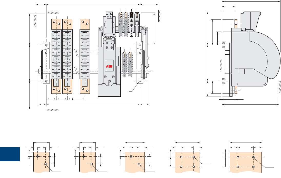
9
114 1SXU10607C0201 | R contactor US catalog
IORR..MT-AME and IORR..CC-AME types
R800 … R2100
Main dimensions mm
CA15
CA15
200 MN
180
50 60F
40 F 50
AB B
ø
D
D2
D3
Y
I
I1
210200100
H
48
11.52511.5
25
12.5
2 x ø13
60
17.5 25 17.5
25
12.5
2 x ø13
80
4 x ø11
20 40 20
15 30
100
4 x ø11
25 50 25
15 30
48
11.52511.5
25
12.5
2 x ø13
Terminal plate details
R800 R1700 R2100R1400R1000
Terminal plate thickness: top terminal plates = 10 mm, bottom terminal plates = 12 mm
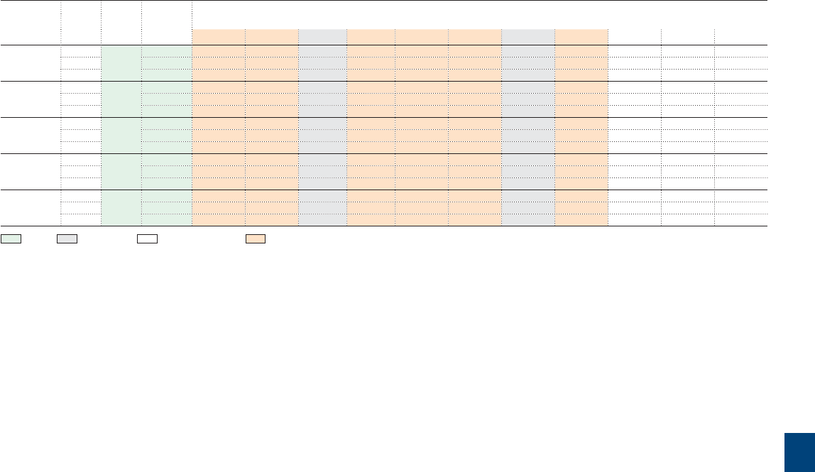
9
R contactor US catalog | 1SXU106047C0201 115
IORR..MT-AME and IORR..CC-AME types
R800 … R2100
Contactor
types
Number Fixing
holes
Fixing
dimension
F
Dimensions
of poles
ABDD2D3HI I1MNY
R800 1 4 x ø13 345 60 - 325 76 77 70 108 175 245 90 375
2 445 60 90 325 76 77 70 108 175 245 90 375
3 540 60 70 325 76 77 70 108 175 245 90 375
R1000 1 4 x ø13 345 60 - 325 76 77 70 108 175 245 90 375
2 445 60 90 325 76 77 70 108 175 245 90 375
3 540 60 80 325 76 77 70 108 175 245 90 375
R1400 1 4 x ø13 385 80 - 325 76 77 70 108 175 258 100 425
2 540 80 100 325 76 77 70 108 175 258 100 425
3 635 85 120 325 76 77 70 108 175 258 100 425
R1700 1 4 x ø13 385 85 - 325 89 77 84 108 189 288 125 450
2 540 85 140 325 89 77 84 108 189 288 125 450
3 635 85 120 325 89 77 84 108 189 288 125 450
R2100 1 4 x ø13 385 85 - 325 89 77 84 108 189 288 125 450
2 540 85 140 325 89 77 84 108 189 288 125 450
3 635 85 120 325 89 77 84 108 189 288 125 450
Fixing - Dimensions - Clearing distances - Connecting
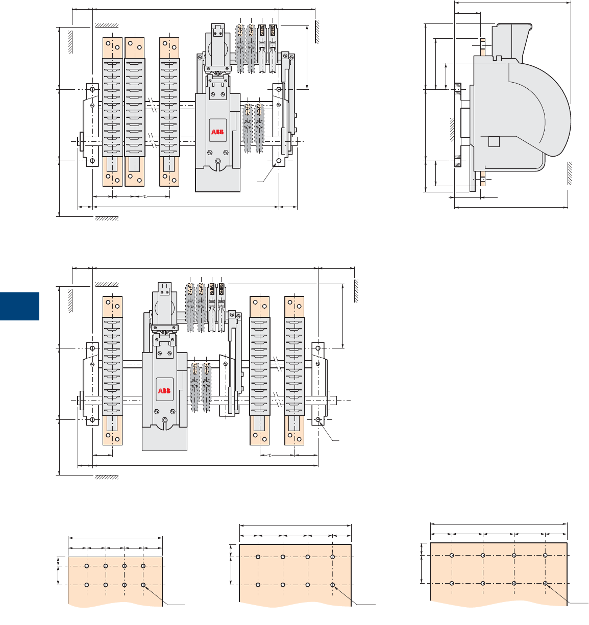
9
116 1SXU10607C0201 | R contactor US catalog
IORR..MT-AME and IORR..CC-AME types
R2500 … R5100
CA15
CA15
200 MN
180
50 60F
40 F 50
AB B
ø
D
D2
D3
Y
I
I1
210200100
H
Main dimensions mm
Fig 1 = right electro-magnet (see table in the following page)
Fig 2 = central electro-magnet (see table in the following page)
180
60
ø
200 MN
50 F
40 F
CA15
CA15
A A1B
Terminal plate thickness for R2500 ... R5100: top and bottom terminal plates = 10 mm
150
30
30 15
30 30 30 30
8 x ø9
R2500
180
30
2045
40404030
8 x ø13
R3200
220
2045
50 50 5035 35
8 x ø13
R3800
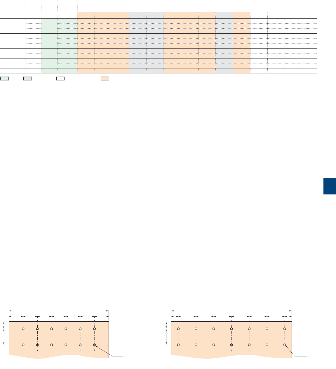
9
R contactor US catalog | 1SXU106047C0201 117
IORR..MT-AME and IORR..CC-AME types
R2500 … R5100
Contactor
types
Number Fixing
holes
Fixing
dimension
F
Dimensions
of poles
AA1BDB1D2D3HI I1MNYFig
R2500 1 4 x ø13 540 130 - - 325 - 85 87 135 108 238 258 152 425 1
2 685 135 - 220 325 - 85 87 135 108 238 258 152 425 1
3 1050 135 135 220 325 - 85 87 135 108 238 258 152 425 2
R3200 1 4 x ø13 540 150 - - 325 - 99 87 174 108 279 300 215 450 1
2 885 135 135 - 325 - 99 87 174 108 279 300 215 450 2
3 1050 135 - - 325 - 99 87 174 108 279 300 215 450 2
R3800 1 4 x ø13 540 160 - - 325 - 99 87 174 108 279 300 215 450 1
2 885 145 145 - 325 - 99 87 174 108 279 300 215 450 2
R4500 1 4 x ø13 635 185 - - 325 - 99 87 174 108 279 300 215 450 1
2 1050 185 180 - 325 - 99 87 174 108 279 300 215 450 2
R5100 1 4 x ø13 635 210 - - 325 - 99 87 174 108 279 300 215 465 1
Fixing - Dimensions - Clearing distances - Connecting
Terminal plate thickness for R2500 ... R5100: top and bottom terminal plates = 10 mm
280
2045
40 40 40 40 40 40 40
12 x ø13
R4500
340
2045
20 50 50 50 50 50 50 20
14 x ø13
R5100
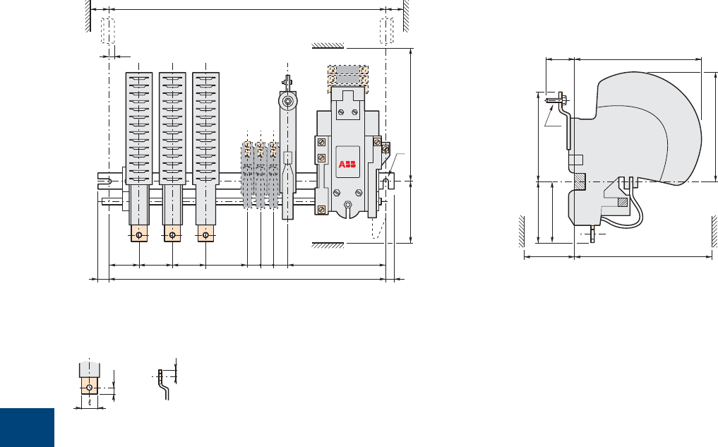
9
118 1SXU10607C0201 | R contactor US catalog
NORR..MT and NORR..CC types
R63 … R200
Main dimensions mm
RFQ
S
ø
CA12
CH CH
BBA
FO P
NM
CA15
C2222 22
I1
I
DW
K
YE
N.O. pole H
N.C. pole T
CH = Frame
V
Z
Terminal plate details
Lower
terminal plate
Upper
terminal plate
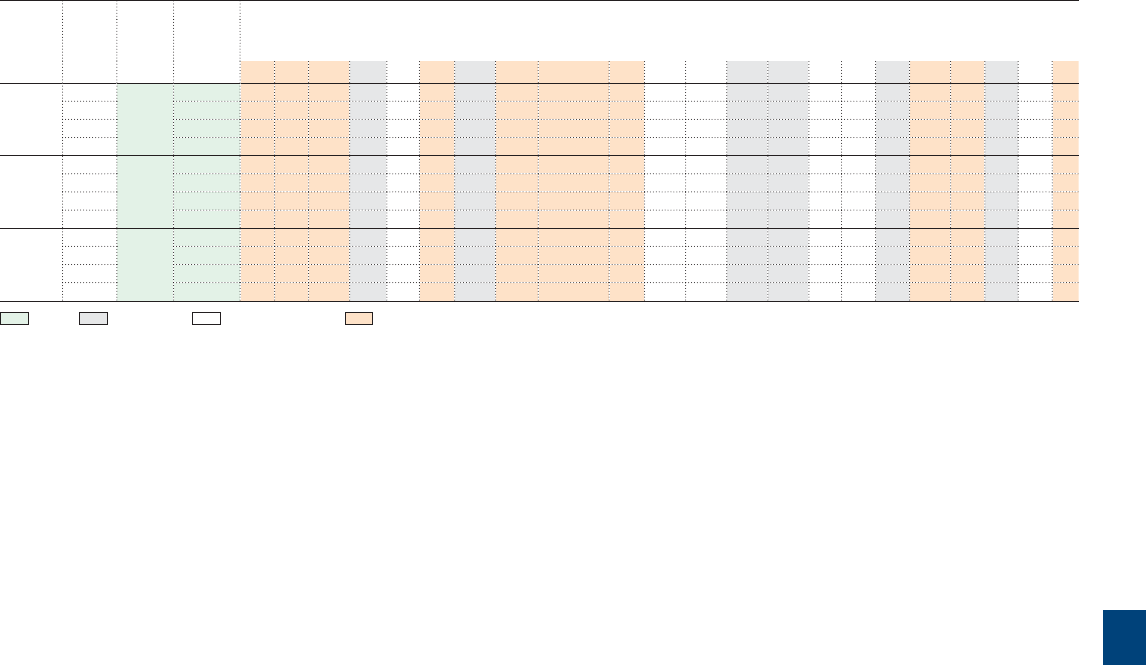
9
R contactor US catalog | 1SXU106047C0201 119
NORR..MT and NORR..CC types
R63 … R200
Contactor
types
Number fi xing
holes
Fixing
dimension
F
Dimensions
of poles
ABC D EHI I1 K ℓ M N O P QRST VWYZ
R63 1 2 x ø7 205 45 - 93 148 36 63 114 101 M6 x 20 16 164 111 12.5 10.5 53 23 15 96 8 16 178 8
2 245 45 50 93 148 36 63 114 101 M6 x 20 16 164 111 12.5 10.5 53 23 15 96 8 16 178 8
3 285 45 50 93 148 36 63 114 101 M6 x 20 16 164 111 12.5 10.5 53 23 15 96 8 16 178 8
4 345 45 50 93 148 36 63 114 101 M6 x 20 16 164 111 12.5 10.5 53 23 15 96 8 16 178 8
R125 1 2 x ø7 205 57 - 93 153 40 76 138 130 M8 x 20 20 188 126 12.5 10.5 53 23 15 111 10 20 183 10
2 285 57 61 93 153 40 76 138 130 M8 x 20 20 188 126 12.5 10.5 53 23 15 111 10 20 183 10
3 345 57 61 93 153 40 76 138 130 M8 x 20 20 188 126 12.5 10.5 53 23 15 111 10 20 183 10
4 385 57 61 93 153 40 76 138 130 M8 x 20 20 188 126 12.5 10.5 53 23 15 111 10 20 183 10
R200 1 2 x ø9 245 69 - 116 190 40 93 140 123 M10 x 25 25 190 143 9 10 53 20 25 125 13 20 220 12
2 345 69 68 116 190 40 93 140 123 M10 x 25 25 190 143 9 10 53 20 25 125 13 20 220 12
3 385 69 68 116 190 40 93 140 123 M10 x 25 25 190 143 9 10 53 20 25 125 13 20 220 12
4 445 69 68 116 190 40 93 140 123 M10 x 25 25 190 143 9 10 53 20 25 125 13 20 220 12
Fixing - Dimensions - Clearing distances - Connecting
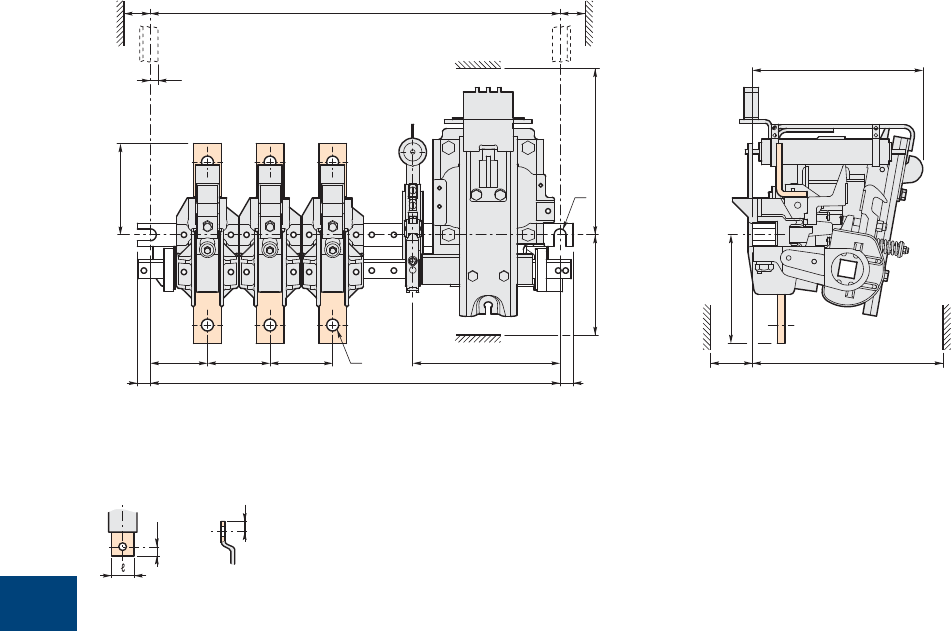
9
120 1SXU10607C0201 | R contactor US catalog
LORR type
R85 … R550
Main dimensions mm
V
Z
Terminal plate details
Lower
terminal plate
Upper
terminal plate
A
O
I1
B B
FP
C
RFQ
S
CH CH
NM
ø
K
D
H
YE
CH = Frame
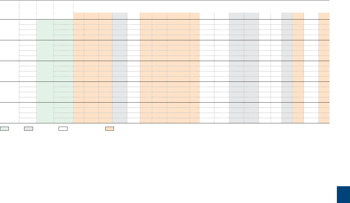
9
R contactor US catalog | 1SXU106047C0201 121
LORR type
R85 … R550
Contactor
types
Number Fixing
holes
Fixing
dimension
F
Dimensions
of poles
AB C D E H I1 K ℓM N O P Q RSV Y Z
R85 1 2 x ø7 175 35 - 93 110 36 63 101 M6 x 20 16 150 83 12.5 10.5 53 23 15 8 125 8
2 205 35 37 93 110 36 63 101 M6 x 20 16 150 83 12.5 10.5 53 23 15 8 125 8
3 245 35 37 93 110 36 63 101 M6 x 20 16 150 83 12.5 10.5 53 23 15 8 125 8
4 345 35 37 93 110 36 63 101 M6 x 20 16 150 83 12.5 10.5 53 23 15 8 125 8
R170 1 2 x ø7 175 41 - 93 110 40 76 130 M8 x 20 20 150 96 12.5 10.5 53 23 15 10 125 10
2 245 41 46 93 110 40 76 130 M8 x 20 20 150 96 12.5 10.5 53 23 15 10 125 10
3 285 41 46 93 110 40 76 130 M8 x 20 20 150 96 12.5 10.5 53 23 15 10 125 10
4 345 41 46 93 110 40 76 130 M8 x 20 20 150 96 12.5 10.5 53 23 15 10 125 10
R260 1 2 x ø9 205 48 - 116 130 40 93 123 M10 x 25 25 167 116 9 10 53 20 25 13 145 12
2 285 45 54.5 116 130 40 93 123 M10 x 25 25 167 116 9 10 53 20 25 13 145 12
3 345 48 54.5 116 130 40 93 123 M10 x 25 25 167 116 9 10 53 20 25 13 145 12
4 385 48 54.5 116 130 40 93 123 M10 x 25 25 167 116 9 10 53 20 25 13 145 12
R400 1 2 x ø13 345 62 - 160 178 100 118 195 ø13 30 142 150 15 14 53 20 20 20 193 20
2 385 62 68 160 178 100 118 195 ø13 30 142 150 15 14 53 20 20 20 193 20
3 445 62 68 160 178 100 118 195 ø13 30 142 150 15 14 53 20 20 20 193 20
4 540 62 68 160 178 100 118 195 ø13 30 142 150 15 14 53 20 20 20 193 20
R550 1 2 x ø13 345 62 - 160 178 100 118 195 ø13 30 142 150 15 14 53 20 20 20 193 20
2 385 62 68 160 178 100 118 195 ø13 30 142 150 15 14 53 20 20 20 193 20
3 445 62 68 160 178 100 118 195 ø13 30 142 150 15 14 53 20 20 20 193 20
4 540 62 68 160 178 100 118 195 ø13 30 142 150 15 14 53 20 20 20 193 20
Fixing - Dimensions - Clearing distances - Connecting

10
122 1SXU10607C0201 | R contactor US catalog

10
R contactor US catalog | 1SXU106047C0201 123
Terms and definition
Specifications, standards and certifying 124
Terms and technical definitions 125
Utilization categories 126
Climatic withstand of devices 128

10
124 1SXU10607C0201 | R contactor US catalog
Specifications, standards and certifying
Definitions
ABB low voltage devices are developed and manufactured according to the rules set out in IEC international publications and in EN European
specifi cations.
In most countries, low voltage apparatus is built according to such rules with checking being the responsibility of the manufacturer. The devices
are therefore not subject to any further obligation for approval. A test report from our laboratories can be remitted to our customers, on request,
for presentation to different qualifi ed local organizations.
Prescriptions and standards
International specifi cations
The International Electrotechnical Commission, IEC, which is part of the International Standards Organization, ISO, publishes IEC publications
which act as a basis for the world market.
European specifi cations and national specifi cations
The European Committee for Electrotechnical Standardization (CENELEC), which groups together 18 European countries, publishes EN standards.
These European standards differ very little from IEC international standards and have similar numbering.
The same applies for national standards which use, without exception, the same numbering and reproduce the texts of these unifi ed standards in
their entirety. Contradicting national standards are withdrawn.
European directives
The guarantee of the free movement of goods within the European Community means that any regulatory differences between member states
have been eliminated. The European directives set up common rules that are included in the legislation of each state while contradictory regula-
tions are canceled.
Three directives are essential:
– Low voltage directive 2006/95/EC concerns electrical equipment from 0 to 1000 V AC and from 75 to 1500 V DC
– This specifi es that compliance with the requirements that it sets out is acquired if the equipment conforms to the standards harmonized on a
European level: EN 60947-1 and EN 60947-4-1 for contactors
– Machines directive 2006/42/EC for safety specifi cations of machines and equipment on complete machines. Machines bearing the ce mark
comply with these specifi cations
– Electromagnetic compatibility directive 2004/108/EC which concerns all devices able to create electromagnetic disturbance
– Standard EN 60947-4-1 does not set out any requirement concerning the level of emission or immunity of contactors which do not have any
active electronic components. Owing to this fact, compliance with standard EN 60947-4-1 meets the requirements for ce marking, with respect
to this directive.
CE Marking :
– must not be confused with a quality label
– is proof of conformity with the European Directives concerning the product
– is part of an administrative procedure and guarantees free movement of the product within the European Community.
International standards
IEC 60947-1 Low-voltage switchgear and controlgear – Part 1: General rules.
IEC 60947-4-1 Low-voltage switchgear and controlgear – Part 4: Contactors and motor starters.
Section 1: Electromechanical contactors and motor starters.
IEC 60947-5-1 Low-voltage switchgear and controlgear – Part 5: Control circuit devices and switching elements.
Section 1: Electromechanical control circuit devices.
European standards
EN 60947-1 Low-voltage switchgear and controlgear – Part 1: General rules.
EN 60947-4-1 Low-voltage switchgear and controlgear – Part 4: Contactors and motor starters.
Section 1: Electromechanical contactors and motor starters.
EN 60947-5-1 Low-voltage switchgear and controlgear – Part 5: Control circuit devices and switching elements.
Section 1: Electromechanical control circuit devices.

10
R contactor US catalog | 1SXU106047C0201 125
Terms and technical definitions
Terminology
Altitude
Characterizes the place of use. It is expressed in meters above sea
level.
Circuits
– Auxiliary circuit:
All the conductive parts of a contactor designed to be inserted in
a different circuit from the main circuit and the contactor control
circuits.
– Control circuit:
All the conductive parts of a contactor (other than the main circuit
and the auxiliary circuit) used to control the contactor's closing oper-
ation or opening operation or both.
– Main circuit:
All the conductive parts of a contactor designed to be inserted in the
circuit that it controls.
Rated operational current Ie
Current rated by the manufacturer. It is mainly based on the rated
operational voltage Ue, the rated frequency, the utilization category, the
rated duty and the type of protective enclosure, if necessary.
Conventional free air thermal current Ith
Current that the contactor can withstand in free air for a duty time of
8 hours without the temperature rise of its various parts exceeding the
maximum values given by the standard.
Electrical durability
Number of on-load operating cycles that the contactor is able to carry
out. It depends on the utilization category.
Mechanical durability
Number of no-current operating cycles that a contactor is able to carry
out.
Switching frequency
Number of switching cycles per hour.
Coil operating limits
Expressed in multiples of the nominal control circuit voltage Uc for the
upper and lower limits.
Mounting position
Comply with the manufacturer's instructions.
Rated breaking or making capacity
Root mean square value (R.M.S.) Of the current that the contactor is
able to break or make at a given voltage according to the conditions
specifi ed by standards and for a given utilization category.
Ambient temperature
Air temperature close to the contactor.
Time
– Time constant :
Ratio of the inductance to the resistance (L/R = mh/ = ms).
– Short-time withstand current Icw:
Current that the contactor is able to withstand in closed position for
a short time interval and in specifi ed conditions.
– Minimum switching time:
This is the minimum closing or opening order time necessary for the
contactor to reach complete closing or opening.
– Closing time:
Time interval between the beginning of the closing operation and the
instant the contacts touch on all the poles.
– Opening time:
Time interval between the specifi ed starting instant of the opening
operation and the instant the arcing contacts separate on all the
poles.
Rated control voltage Uc
Control voltage value for which the control circuit is sized.
Rated operational voltage Ue
Voltage to which the contactor's utilization characteristics refer. In
three-phase it is the phase-to-phase voltage.
Rated insulation voltage Ui
Reference voltage for dielectric tests and creepage distances.
Rated impulse withstand voltage Uimp
Peak value of an impulse voltage, having a specifi ed form and polarity,
which does not cause breakdown in specifi c test conditions.
Shock withstand
Requirement for vehicles, crane drives, installations on board ships and
plug-in equipment. The contactors must not change position and the
overload relays must not trip.
Resistance to vibrations
Requirements for vehicles, boats and other means of transport. For
the specifi ed vibration amplitude and frequency values the device must
remain able to operate.

10
126 1SXU10607C0201 | R contactor US catalog
Utilization categories
Standards
IEC publications 60941-1, 60947-4-1 and 60947-5-1 should be re-
ferred to on an international level with respect to contactors.
A contactor's duty is characterised by the utilization category together
with the rated operational voltage and current indicated.
Utilization categories for contactors according to IEC 60947-4-1
Alternating current:
– AC-1 Non-inductive or slightly inductive loads, resistance furnaces
– AC-2 Slip-ring motors: starting, switching off
– AC-3 Cage motors: starting, switching off running motors
– AC-4 Cage motors: starting, plugging, inching
– AC-5a Discharge lamp switching
– AC-5b Incandescent lamp switching
– AC-6a Transformer switching
– AC-6b Capacitor bank switching
– AC-7a Slightly inductive loads for domestic devices and similar appli-
cations
– AC-7b Motors for domestic applications
– AC-8a Hermetic refrigeration compressor motor control with manual
resetting of overload releases
– AC-8b Hermetic refrigeration compressor motor control with auto-
matic resetting of overload releases.
Direct current:
– DC-1 Non inductive or slightly inductive loads, resistance furnaces
– DC-3 Shunt motors: starting, plugging, inching, dynamic breaking of
DC motors
– DC-5 Series motors: starting, plugging, inching, dynamic breaking of
DC motors
– DC-6 Incandescent lamp switching.
Utilization categories for the auxiliary contacts according to
IEC 60947-5-1
Alternating current:
– AC-12 Control of resistive loads and static loads with opto-coupler
isolation
– AC-13 Control of static loads with transformer isolation
– AC-14 Control of weak electromagnetic loads (≤ 72 VA)
– AC-15 Control of electromagnetic loads (> 72 VA).
Direct current:
– DC-12 Control of resistive loads and static loads with opto-coupler
isolation
– DC-13 Control of DC electromagnets
– DC-14 Control of DC electromagnets having economy resistors.
In fact some applications, and the specifi c criteria characterizing the
various loads controlled by contactors, may modify the utilization char-
acteristics of the contactors.
DC power circuit switching
Arc suppression is more diffi cult in direct current than in alternating
current and this is all the more true the higher the circuit time constant
which is why it is necessary to connect several poles in series in order
to improve breaking conditions.
AC high current circuit switching
Possibility of increasing performances by connecting poles in parallel
(please consult us).
Infl uence of the length of the conductors used in the contactor
control circuit
According to the operational voltages and the coil consumption, take
line resistances and capacitances into consideration, for the length and
the cross-sectional of the conductors.
10
R contactor US catalog | 1SXU106047C0201 127
Utilization categories
Making and breaking conditions for utilization categories
Utilization category Durability test conditions Occasional operation
Making conditions Breaking conditions Making conditions Breaking conditions
I/Ie U/Ue Cos. φ
or
L/R (ms)
I/Ie U/Ue Cos. φ
or
L/R (ms)
Ic/Ie Ur/Ue Cos. φ
or
L/R (ms)
Ic/Ie Ur/Ue Cos. φ
or
L/R (ms)
Contactors for AC circuit switching
AC-1 1 1 0.95 1 1 0.95 1.5 1.05 0.8 1.5 1.05 0.8
AC-2 2.5 1 0.65 2.5 1 0.65 4 1.05 0.65 4 1.05 0.65
AC-3 Ie ≤ 100 A 6 1 0.35 1 0.17 0.35 10 1.05 0.45 8 1.05 0.45
Ie > 100 A 6 1 0.35 1 0.17 0.35 10 1.05 0.35 8 1.05 0.35
AC-4 Ie ≤ 100 A 6 1 0.35 6 1 0.35 12 1.05 0.45 10 1.05 0.45
Ie > 100 A 6 1 0.35 6 1 0.35 12 1.05 0.35 10 1.05 0.35
Contactors for DC circuit switching
DC-1 1 1 1 1 1 1 1.5 1.05 1 1.5 1.05 1
DC-3 2.5 1 2 2.5 1 2 4 1.05 2.5 4 1.05 2.5
DC-5 2.5 1 7.5 2.5 1 7.5 4 1.05 15 4 1.05 15
Auxiliary contacts for AC circuit switching
AC-14 (≤ 72 VA) - - - - - - 6 1.1 0.7 6 1.1 0.7
AC-15 (> 72 VA) 10 1 0.7 1 1 0.4 10 1.1 0.3 10 1.1 0.3
Auxiliary contacts for DC circuit switching
Utilization category Standard operation Occasional operation
Making conditions Breaking conditions Making conditions Breaking conditions
I/Ie U/Ue T0.95 I/Ie U/Ue T0.95 I/Ie U/Ue T0.95 I/Ie U/Ue T0.95
DC-13 1 1 6 P (1) 1 1 6 P (1) 1.1 1.1 6 P (1) 1.1 1.1 6 P (1)
DC-14 - - - - - - 10 1.1 15 ms 10 1.1 15 ms
(1) The value "6 x P" is the result of an empirical relation which is estimated to represent most DC magnetic loads up to the highest limit of P = 50 W (6 x P = 300 ms). It is accepted
that loads having drawn energy above 50 W are made up of weaker loads in parallel. As a consequence, the 300 ms value must form the highest limit whatever the value of the
power drawn.
Key:
U (I) = applied voltage (current) Ic = making and breaking current expressed in DC or in AC like the
Ur = recovery voltage r.m.s. value of the symmetrical components
L/R = test circuit time constant T0.95 = time required to reach 95 % of the current in steady-state conditions,
Ue (Ie) = rated operational voltage (current) expressed in milliseconds
10
128 1SXU10607C0201 | R contactor US catalog
Climatic withstand of devices
General
The life time and dependability of devices are mainly infl uenced by a series of climatic factors which cause their corrosion.
In practice, besides climatic conditions, there are other factors which may damage equipment such as fungi, insects (termites), dust, work site dirt
and aggressive environment (salty or sulphurous atmosphere, etc.) which can often only be identifi ed at the place of installation.
The entrance of dust, insects, dirt, etc. in devices may be prevented if the appropriate degree of protection according to IEC 60529 is chosen.
ABB contactors have been used for many years in the most varied countries, with hot and humid climates for example: Brazil, Indonesia, India etc.
Experience has shown that ABB devices can be used in most countries throughout the world.
The climate of the country in which the device is installed is not the determining choice factor.
Account must be taken of:
– the immediate environment of the devices (sheltered, ventilated, temperature)
– the aggressiveness of the immediate atmosphere at the place of installation
– the length and frequency of non operating periods.
In the case of frequent condensation (Ie the formation of steam caused by rapid changes in temperature), heating resistors must be installed in
cubicles (100 to 250 W per m3 of enclosure).
The table below gives the cases where heating is necessary.
Environment Operating conditions Climate Internal heating of enclosure
Inside premises no running water,
no condensation
Continuous or not All climates Without
with running water Continuous All climates Without
Frequent or long stops Temperate Without
Tropical With
Outside, sheltered no running water,
no condensation
Continuous or not Temperate Without
Tropical With
Outside or by the seaside with running water Continuous All climates Without
Frequent or long stops Temperate Without
Tropical With
The standard R series contactors are suitable for industrial environment and tropical atmospheres.

Notes
R contactor US catalog | 1SXU106047C0201 129
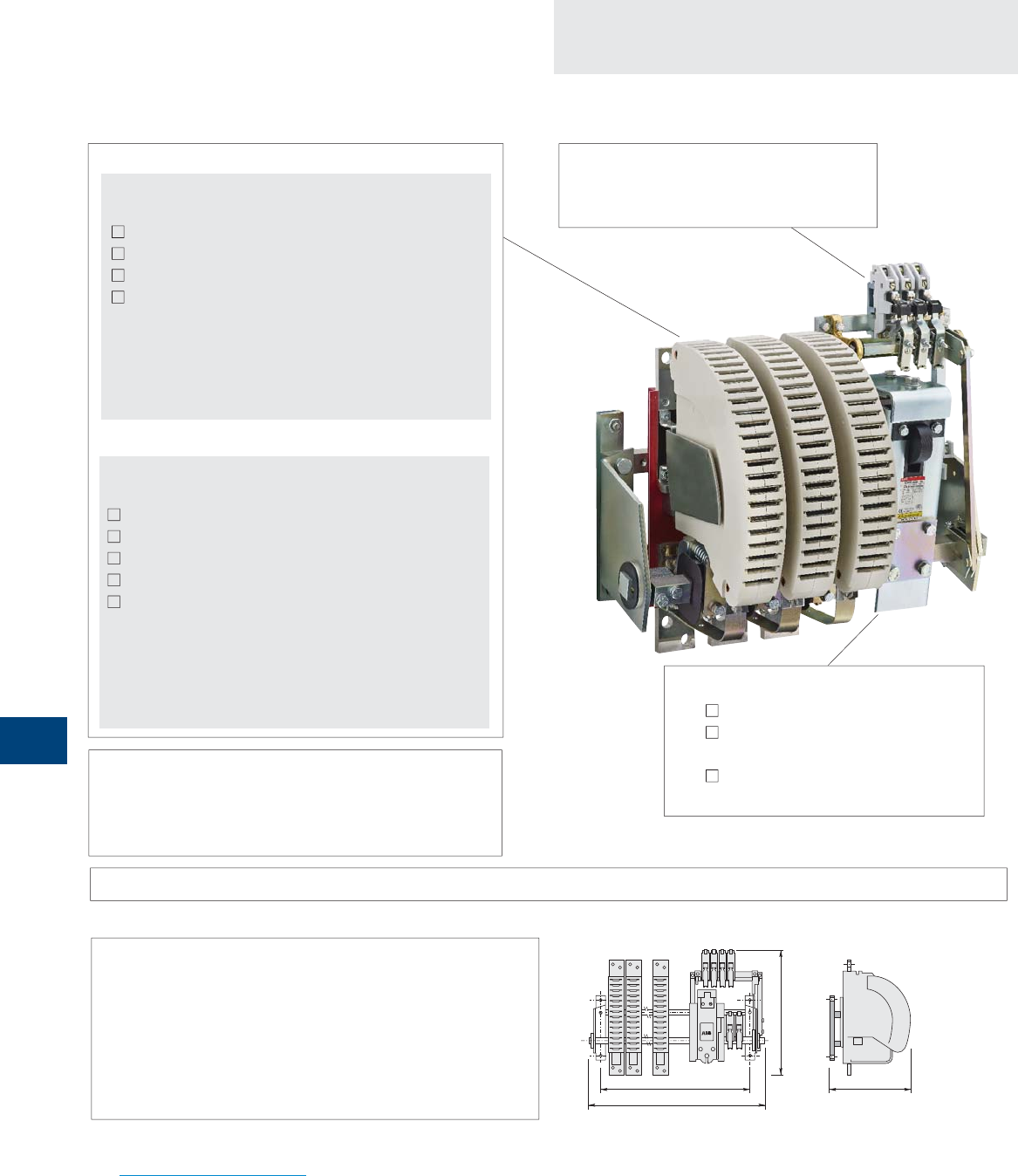
11
130 1SXU10607C0201 | R contactor US catalog
F
H
W
D
Questionnaire
Specification for R contactors
Control circuit (coil)
AC Voltage ..................... V ............... Hz
DC Voltage ..................... V DC
Options
Magnetic/Mechanical
latching option
Auxiliary contacts
Number of N.O. auxiliary contacts
............
Number of N.C. auxiliary contacts
.............
Replacement of an existing contactor
Brand ................................................................
Type ..................................................................
Fixing dimension F = ............... mm
Overall dimensions W = ............... mm
H = ............... mm
D = ............... mm
Customer .................................................................................................................
Contact person ...................................................... Date ..............................
Tel. .......................................................... e-mail ..................................................
ABB .............................................................................................................................
Contact person ....................................................................................................
Tel. ...............................................................................................................................
Operating conditions
Please add any other useful documents for further information e.g. technical specifi cation, drawing, wiring diagram, etc.
Accessories .............................................................................................................................................................................................................................................
AC switching
Application type
AC-1 (resistive load)
AC-3 (direct starting, switching off running motors)
No load breaking
Other ..............................................................................................
Number of poles: N.O. ..................... N.C. .....................
Rated operational current Ie .................. A
Max. making current ............................ A
Max. breaking current ......................... A
Rated operational voltage Ue ............... V ............... Hz
Quantity ................... Requested delivery date .....................................
Project / Application ...........................................................................................................................................................................................................................................
Please photocopy and forward. Questionnaire also available on the ABB Website:
www.abb.com/lowvoltage Section: Our offering Select: Control Products > Contactors > Bar mounted contactors
DC switching
Application type
DC-1 (resistive load)
DC-3 (shunt motors)
DC-5 (series motors)
No load breaking
Other ....................................... L/R .............. ms
Number of poles: N.O. ..................... N.C. .....................
Rated operational current Ie .................. A
Making current ........................................ A
Breaking current min. .......... A max. .......... A
Rated operational voltage Ue ............... V DC
Power circuit
or
Switching frequency ............................................. cycles/h
Mech. durability required (millions of operating cycles) ..............
Remarks ..........................................................................................

11
R contactor US catalog | 1SXU106047C0201 131
Questionnaire
Specification for R contactors
Please photocopy and forward. Questionnaire also available on the ABB Website:
www.abb.com/lowvoltage Section: Our offering Select: Control Products > Contactors > Bar mounted contactors
Other information / Application type
This document is used to define the contactor specification according to the complete information on the application

12
132 1SXU10607C0201 | R contactor US catalog
Index
Order code classifi cation
FPL6115215R2113 IORR1400-20 24
FPL6115225R2223 IORR1400-20-AME 26
FPL6115315R2113 IORR1400-30 24
FPL6115325R2223 IORR1400-30-AME 26
FPL6115415R2113 IORR1400-40 24
FPL6115425R2223 IORR1400-40-AME 26
FPL6116125R2223 IORR1400-10-CC-AME 40
FPL6116195R2113 IORR1400-10-CC-U 39
FPL6116215R2113 IORR1400-20-CC 38
FPL6116225R2223 IORR1400-20-CC-AME 40
FPL6116315R2113 IORR1400-30-CC 38
FPL6116325R2223 IORR1400-30-CC-AME 40
FPL6125215R2113 IORR1400-20-MT 25
FPL6125225R2123 IORR1400-20-MT-AME 27
FPL6125315R2113 IORR1400-30-MT 25
FPL6125325R2123 IORR1400-30-MT-AME 27
FPL6125415R2113 IORR1400-40-MT 25
FPL6135110R2113 LORR1400-10 55
FPL6135210R2113 LORR1400-20 55
FPL6135310R2113 LORR1400-30 55
FPL6135410R2113 LORR1400-40 55
FPL6215215R2113 IORR1700-20 24
FPL6215225R2223 IORR1700-20-AME 26
FPL6215315R2113 IORR1700-30 24
FPL6215325R2223 IORR1700-30-AME 26
FPL6215415R2113 IORR1700-40 24
FPL6215425R2223 IORR1700-40-AME 26
FPL6216125R2223 IORR1700-10-CC-AME 40
FPL6216195R2113 IORR1700-10-CC-U 38
FPL6216195R2113 IORR1700-10-CC-U 39
FPL6216215R2113 IORR1700-20-CC 38
FPL6216225R2223 IORR1700-20-CC-AME 40
FPL6216315R2113 IORR1700-30-CC 38
FPL6216325R2223 IORR1700-30-CC-AME 40
FPL6225215R2113 IORR1700-20-MT 25
FPL6225225R2123 IORR1700-20-MT-AME 27
FPL6225315R2113 IORR1700-30-MT 25
FPL6225325R2123 IORR1700-30-MT-AME 27
FPL6225415R2113 IORR1700-40-MT 25
FPL6235110R2113 LORR1700-10 55
FPL6235210R2113 LORR1700-20 55
FPL6235310R2113 LORR1700-30 55
FPL6235410R2113 LORR1700-40 55
FPL6315215R2113 IORR2100-20 24
FPL6315225R2223 IORR2100-20-AME 26
FPL6315315R2113 IORR2100-30 24
FPL6315325R2223 IORR2100-30-AME 26
FPL6315415R2113 IORR2100-40 24
FPL6315425R2223 IORR2100-40-AME 26
FPL6316125R2223 IORR2100-10-CC-AME 40
FPL6316195R2113 IORR2100-10-CC-U 38
FPL6316195R2113 IORR2100-10-CC-U 39
FPL6316215R2113 IORR2100-20-CC 38
FPL6316225R2223 IORR2100-20-CC-AME 40
FPL6316315R2113 IORR2100-30-CC 38
FPL6316325R2223 IORR2100-30-CC-AME 40
FPL6325215R2113 IORR2100-20-MT 25
FPL6325225R2123 IORR2100-20-MT-AME 27
FPL6325315R2113 IORR2100-30-MT 25
FPL6325325R2123 IORR2100-30-MT-AME 27
FPL6325415R2113 IORR2100-40-MT 25
FPL6335110R2113 LORR2100-10 55
FPL6335210R2113 LORR2100-20 55
FPL6335310R2113 LORR2100-30 55
FPL6335410R2113 LORR2100-40 55
FPL6515215R2113 IORR3200-20 24
FPL6515225R2223 IORR3200-20-AME 26
FPL6515315R2113 IORR3200-30 24
FPL6515325R2223 IORR3200-30-AME 26
FPL6516115R2113 IORR3200-10-CC 38
FPL6516125R2223 IORR3200-10-CC-AME 40
FPL6516215R2113 IORR3200-20-CC 38
FPL6516225R2223 IORR3200-20-CC-AME 40
FPL6516315R2113 IORR3200-30-CC 38
FPL6516325R2223 IORR3200-30-CC-AME 40
FPL6525215R2113 IORR3200-20-MT 25
FPL6525225R2123 IORR3200-20-MT-AME 27
FPL6525315R2113 IORR3200-30-MT 25
FPL6525325R2123 IORR3200-30-MT-AME 27
FPL6535001R2113 LORR3200-40 55
FPL6535110R2113 LORR3200-10 55
FPL6535210R2113 LORR3200-20 55
FPL6535310R2113 LORR3200-30 55
FPL6615001R2113 IORR3800-30 24
FPL6615215R2113 IORR3800-20 24
FPL6615225R2223 IORR3800-20-AME 26
FPL6616001R2113 IORR3800-30-CC 38
FPL6616115R2113 IORR3800-10-CC 38
FPL6616125R2223 IORR3800-10-CC-AME 40
FPL6616195R2113 IORR1400-10-CC-U 38
FPL6616215R2113 IORR3800-20-CC 38
FPL6616225R2223 IORR3800-20-CC-AME 40
FPL6625001R2113 IORR3800-30-MT 25
FPL6625215R2113 IORR3800-20-MT 25
FPL6625225R2123 IORR3800-20-MT-AME 27
FPL6625325R2123 IORR3800-30-MT-AME 27
FPL6635002R2113 LORR3800-30 55
FPL6635003R2113 LORR3800-40 55
FPL6635110R2113 LORR3800-10 55
FPL6635210R2113 LORR3800-20 55
FPL6715215R2113 IORR2500-20 24
FPL6715225R2223 IORR2500-20-AME 26
FPL6715315R2113 IORR2500-30 24
FPL6715325R2223 IORR2500-30-AME 26
FPL6716115R2113 IORR2500-10-CC 38
FPL6716125R2223 IORR2500-10-CC-AME 40
FPL6716215R2113 IORR2500-20-CC 38
FPL6716225R2223 IORR2500-20-CC-AME 40
FPL6716315R2113 IORR2500-30-CC 38
FPL6716325R2223 IORR2500-30-CC-AME 40
FPL6725215R2113 IORR2500-20-MT 25
FPL6725225R2123 IORR2500-20-MT-AME 27
FPL6725315R2113 IORR2500-30-MT 25
FPL6725325R2123 IORR2500-30-MT-AME 27
FPL6725415R2113 IORR2500-40-MT 25
FPL6735110R2113 LORR2500-10 55
FPL6735210R2113 LORR2500-20 55
FPL6735310R2113 LORR2500-30 55
FPL6735410R2113 LORR2500-40 55
FPL6815001R2113 IORR4500-30 24
FPL6815215R2113 IORR4500-20 24
FPL6815225R2223 IORR4500-20-AME 26
FPL6816001R2113 IORR4500-30-CC 38
FPL6816115R2113 IORR4500-10-CC 38
FPL6816125R2223 IORR4500-10-CC-AME 40
FPL6816215R2113 IORR4500-20-CC 38
FPL6816225R2223 IORR4500-20-CC-AME 40
FPL6825002R2113 IORR4500-30-MT 25
FPL6825215R2113 IORR4500-20-MT 25
FPL6825225R2123 IORR4500-20-MT-AME 27
FPL6835001R2113 LORR4500-30 55
FPL6835110R2113 LORR4500-10 55
FPL6835210R2113 LORR4500-20 55
FPL6915001R2113 IORR5100-20 24
FPL6915002R2113 IORR5100-30 24
FPL6916001R2113 IORR5100-30-CC 38
FPL6916002R2113 IORR5100-20-CC 38
FPL6916115R2113 IORR5100-10-CC 38
FPL6916125R2223 IORR5100-10-CC-AME 40
FPL6925001R2113 IORR5100-20-MT 25
FPL6925002R2113 IORR5100-30-MT 25
FPL6935001R2113 LORR5100-20 55
FPL6935110R2113 LORR5100-10 55
FPL7101403R0001 VM21/24 83
FPL7108201P0001 4NMW1009 84
FPL7116116R2113 IORR63-10-CC 38
FPL7116136R2123 IORR63-10-CC-AMA 40
FPL7116216R2113 IORR63-20-CC 38
FPL7116236R2123 IORR63-20-CC-AMA 40
FPL7125216R2113 IORR63-20-MT 25
FPL7125236R2123 IORR63-20-MT-AMA 27
FPL7125336R2123 IORR63-30-MT-AMA 27
FPL7125386R2113 IORR63-30-MT 25
FPL7125416R2113 IORR63-40-MT 25
FPL7125436R2123 IORR63-40-MT-AMA 27
FPL7146116R2113 NORR63-01-CC 50
FPL7146216R2113 NORR63-02-CC 50
FPL7146516R2113 NORR63-21-CC 50
FPL7146716R2113 NORR63-31-CC 50
FPL7155216R2113 NORR63-02-MT 49
FPL7155516R2113 NORR63-21-MT 49
FPL7155716R2113 NORR63-31-MT 49
FPL7235110R2113 LORR85-10 55
FPL7235210R2113 LORR85-20 55
FPL7235310R2113 LORR85-30 55
FPL7235410R2113 LORR85-40 55
FPL7401404R0001 VM25 83
FPL7416115R2113 IORR125-10-CC 38
FPL7416135R2123 IORR125-10-CC-AMA 40
FPL7416215R2113 IORR125-20-CC 38
FPL7416235R2123 IORR125-20-CC-AMA 40
FPL7425215R2113 IORR125-20-MT 25
FPL7425235R2123 IORR125-20-MT-AMA 27
FPL7425315R2113 IORR125-30-MT 25
FPL7425335R2123 IORR125-30-MT-AMA 27
FPL7425415R2113 IORR125-40-MT 25
FPL7425435R2123 IORR125-40-MT-AMA 27
FPL7446115R2113 NORR125-01-CC 50
FPL7446215R2113 NORR125-02-CC 50
FPL7446515R2113 NORR125-21-CC 50
FPL7446715R2113 NORR125-31-CC 50
FPL7455215R2113 NORR125-02-MT 49
FPL7455515R2113 NORR125-21-MT 49
FPL7455715R2113 NORR125-31-MT 49
FPL7535110R2113 LORR170-10 55
FPL7535210R2113 LORR170-20 55
FPL7535310R2113 LORR170-30 55
FPL7535410R2113 LORR170-40 55
FPL7608201P0001 4NMW1039 84
Order code Type Page Order code Type Page Order code Type Page

12
R contactor US catalog | 1SXU106047C0201 133
Order code Type Page Order code Type Page Order code Type Page
Index
Order code classifi cation
FPL7616115R2113 IORR200-10-CC 38
FPL7616135R2123 IORR200-10-CC-AMA 40
FPL7616215R2113 IORR200-20-CC 38
FPL7616235R2123 IORR200-20-CC-AMA 40
FPL7625215R2113 IORR200-20-MT 25
FPL7625235R2123 IORR200-20-MT-AMA 27
FPL7625315R2113 IORR200-30-MT 25
FPL7625335R2123 IORR200-30-MT-AMA 27
FPL7625415R2113 IORR200-40-MT 25
FPL7625435R2123 IORR200-40-MT-AMA 27
FPL7646115R2113 NORR200-01-CC 50
FPL7646215R2113 NORR200-02-CC 50
FPL7646515R2113 NORR200-21-CC 50
FPL7646715R2113 NORR200-31-CC 50
FPL7655215R2113 NORR200-02-MT 49
FPL7655515R2113 NORR200-21-MT 49
FPL7655715R2113 NORR200-31-MT 49
FPL7835110R2113 LORR260-10 55
FPL7835210R2113 LORR260-20 55
FPL7835310R2113 LORR260-30 55
FPL7835410R2113 LORR260-40 55
FPL8001401R0001 VM27 83
FPL8301401R0002 VM15-SP 83
FPL8308201P0001 4NMW1041 84
FPL8316115R2113 IORR500-10-CC 38
FPL8316125R2223 IORR500-10-CC-AME 40
FPL8316215R2113 IORR500-20-CC 38
FPL8316225R2223 IORR500-20-CC-AME 40
FPL8316325R2223 IORR500-30-CC-AME 40
FPL8325215R2113 IORR500-20-MT 25
FPL8325225R2123 IORR500-20-MT-AME 27
FPL8325315R2113 IORR500-30-MT 25
FPL8325325R2123 IORR500-30-MT-AME 27
FPL8325415R2113 IORR500-40-MT 25
FPL8435110R2113 LORR550-10 55
FPL8435210R2113 LORR550-20 55
FPL8435310R2113 LORR550-30 55
FPL8435410R2113 LORR550-40 55
FPL8601401R0001 VM16 83
FPL8615215R2113 IORR800-20 24
FPL8615225R2223 IORR800-20-AME 26
FPL8615315R2113 IORR800-30 24
FPL8615325R2223 IORR800-30-AME 26
FPL8615415R2113 IORR800-40 24
FPL8615425R2223 IORR800-40-AME 26
FPL8616125R2223 IORR800-10-CC-AME 40
FPL8616195R2113 IORR800-10-CC-U 38
FPL8616195R2113 IORR800-10-CC-U 39
FPL8616215R2113 IORR800-20-CC 38
FPL8616225R2223 IORR800-20-CC-AME 40
FPL8616315R2113 IORR800-30-CC 38
FPL8616325R2223 IORR800-30-CC-AME 40
FPL8625215R2113 IORR800-20-MT 25
FPL8625225R2123 IORR800-20-MT-AME 27
FPL8625315R2113 IORR800-30-MT 25
FPL8625325R2123 IORR800-30-MT-AME 27
FPL8625415R2113 IORR800-40-MT 25
FPL8635110R2113 LORR800-10 55
FPL8635210R2113 LORR800-20 55
FPL8635310R2113 LORR800-30 55
FPL8635410R2113 LORR800-40 55
FPL8645215R2113 NORR800-02 49
FPL8645515R2113 NORR800-21 49
FPL8645715R2113 NORR800-31 49
FPL8646115R2113 NORR800-01-CC 50
FPL8646215R2113 NORR800-02-CC 50
FPL8646515R2113 NORR800-21-CC 50
FPL8646715R2113 NORR800-31-CC 50
FPL8655215R2113 NORR800-02-MT 49
FPL8655515R2113 NORR800-21-MT 49
FPL8655715R2113 NORR800-31-MT 49
FPL8715215R2113 IORR1000-20 24
FPL8715225R2223 IORR1000-20-AME 26
FPL8715315R2113 IORR1000-30 24
FPL8715325R2223 IORR1000-30-AME 26
FPL8715415R2113 IORR1000-40 24
FPL8715425R2223 IORR1000-40-AME 26
FPL8716125R2223 IORR1000-10-CC-AME 40
FPL8716195R2113 IORR1000-10-CC-U 38
FPL8716195R2113 IORR1000-10-CC-U 39
FPL8716215R2113 IORR1000-20-CC 38
FPL8716225R2223 IORR1000-20-CC-AME 40
FPL8716315R2113 IORR1000-30-CC 38
FPL8716325R2223 IORR1000-30-CC-AME 40
FPL8801401R0001 VM17/18 83
FPL9001401R0001 VM19 83
FPL9416115R2113 IORR400-10-CC 38
FPL9416125R2223 IORR400-10-CC-AME 40
FPL9416215R2113 IORR400-20-CC 38
FPL9416225R2223 IORR400-20-CC-AME 40
FPL9416325R2223 IORR400-30-CC-AME 40
FPL9425215R2113 IORR400-20-MT 25
FPL9425225R2123 IORR400-20-MT-AME 27
FPL9425315R2113 IORR400-30-MT 25
FPL9425325R2123 IORR400-30-MT-AME 27
FPL9425415R2113 IORR400-40-MT 25
FPL9435110R2113 LORR400-10 55
FPL9435210R2113 LORR400-20 55
FPL9435310R2113 LORR400-30 55
FPL9435410R2113 LORR400-40 55
FPL9445115R2113 NORR400-01 50
FPL9445215R2113 NORR400-02 49
FPL9445215R2113 NORR400-02 50
FPL9445515R2113 NORR400-21 49
FPL9445515R2113 NORR400-21 50
FPL9445715R2113 NORR400-31 49
FPL9445715R2113 NORR400-31 50
FPTN210382R0003 CA15-F 77
FPTN210382R0004 CA15-O 77
FPTN401936R0002 ARC CHUTE 81
FPTN401938R0002 ARC CHUTE 81
FPTN401939R0002 ARC CHUTE 81
FPTN401940R0002 ARC CHUTE 81
FPTN401941R0002 ARC CHUTE 81
FPTN410004R0001 CA12-1 77
FPTN410005R0001 CA12-2 77
FPTN410007R0006 CA15-O 77
FPTN410008R0004 CA15-F 77
FPTN410012R0001 CA12-22 77
FPTN410013R0001 CA12-11 77
FPTN410016R0001 CA12-12 77
FPTN410054R0016 UNIVERSAL MOUNTING KIT 77
FPTN410054R0017 MOUNTING KIT 77
FPTN410056R0001 CA12-1 SUPPORT BRACKET 77
FPTN410056R0002 CA12 SUPPORT BRACKET 77
FPTN410067R0002 ARC CHUTE 81
FPTN410067R0002 ARC CHUTE 81
FPTN410111R0001 SHAFT EXTENSION
R63… R170 84
FPTN410111R0002 SHAFT EXTENSION
R200… R420 84
FPTN410111R0003 SHAFT EXTENSION
R400, 500 550 84
FPTN410176R0006 EQUIPOTENTIAL
CONNECTION 81
FPTN410176R0007 EQUIPOTENTIAL
CONNECTION 81
FPTN410200R0006 MAGNET SET FOR
MAIN COIL 82
FPTN410213R0006 MOUNTING KIT 77
FPTN410389R0001 CONTACT SET
WITH ARCING HORN 80
FPTN410389R0002 CONTACT SET
WITH ARCING HORN 80
FPTN410389R0003 CONTACT SET
WITH ARCING HORN 80
FPTN410389R0004 CONTACT SET
WITH ARCING HORN 80
FPTN410389R0005 CONTACT SET
WITH ARCING HORN 80
FPTN410390R0001 CONTACT SET
WITH ARCING HORN 80
FPTN410390R0002 CONTACT SET
WITH ARCING HORN 80
FPTN410390R0003 CONTACT SET
WITH ARCING HORN 80
FPTN410390R0004 CONTACT SET
WITH ARCING HORN 80
FPTN410390R0005 CONTACT SET
WITH ARCING HORN 80
FPTN410391R0001 CONTACT SET
WITH ARCING HORN 80
FPTN410437R0001 MAGNET SET FOR
MAIN COIL 82
FPTN410438R0001 MAGNET SET FOR
MAIN COIL 82
FPTN410439R0001 MAGNET SET FOR
MAIN COIL 82
FPTN410441R0001 MAGNET SET FOR
MAIN COIL 82
FPTN410446R0001 ARCING HORN 80
FPTN410446R0001 ARCING HORN 80
FPTN410463R6001 RV-R1/60 82
FPTN410463R6002 RV-R1/133 82
FPTN410463R6003 RV-R1/250 82
FPTN410463R6004 RV-R1/440 82
FPTN410463R6005 RV-R1/660 82
FPTN410503R0001 CONTACT SET
WITH ARCING HORN 80
FPTN410506R0001 CONTACT SET
WITH ARCING HORN 80
FPTN410507R0001 ARC CHUTE 81
FPTN410508R0001 ARCING HORN 80
TRE2614501 RECTIFIER BRIDGE 82
TRE2720806 RECTIFIER BRIDGE 82
On request IORR125-30-CC 38
On request IORR125-30-CC-AMA 40
On request IORR200-30-CC 38
On request IORR200-30-CC-AMA 40
On request IORR400-30-CC 38
On request IORR500-30-CC 38
On request IORR63-30-CC 38
On request IORR63-30-CC-AMA 40

12
134 1SXU10607C0201 | R contactor US catalog
4NMW1009 FPL7108201P0001 84
4NMW1039 FPL7608201P0001 84
4NMW1041 FPL8308201P0001 84
ARC CHUTE FPTN401938R0002 81
ARC CHUTE FPTN401939R0002 81
ARC CHUTE FPTN401940R0002 81
ARC CHUTE FPTN401936R0002 81
ARC CHUTE FPTN401941R0002 81
ARC CHUTE FPTN410067R0002 81
ARC CHUTE FPTN410067R0002 81
ARC CHUTE FPTN410507R0001 81
ARCING HORN FPTN410446R0001 80
ARCING HORN FPTN410446R0001 80
ARCING HORN FPTN410508R0001 80
CA12 SUPPORT
BRACKET FPTN410056R0002 77
CA12-1 FPTN410004R0001 77
CA12-1 SUPPORT
BRACKET FPTN410056R0001 77
CA12-11 FPTN410013R0001 77
CA12-12 FPTN410016R0001 77
CA12-2 FPTN410005R0001 77
CA12-22 FPTN410012R0001 77
CA15-F FPTN410008R0004 77
CA15-F FPTN210382R0003 77
CA15-O FPTN410007R0006 77
CA15-O FPTN210382R0004 77
CONTACT SET WITH
ARCING HORN FPTN410389R0001 80
CONTACT SET WITH
ARCING HORN FPTN410389R0002 80
CONTACT SET WITH
ARCING HORN FPTN410389R0003 80
CONTACT SET WITH
ARCING HORN FPTN410389R0004 80
CONTACT SET WITH
ARCING HORN FPTN410389R0005 80
CONTACT SET WITH
ARCING HORN FPTN410390R0001 80
CONTACT SET WITH
ARCING HORN FPTN410390R0002 80
CONTACT SET WITH
ARCING HORN FPTN410390R0003 80
CONTACT SET WITH
ARCING HORN FPTN410390R0004 80
CONTACT SET WITH
ARCING HORN FPTN410390R0005 80
CONTACT SET WITH
ARCING HORN FPTN410391R0001 80
CONTACT SET WITH
ARCING HORN FPTN410503R0001 80
CONTACT SET WITH
ARCING HORN FPTN410506R0001 80
EQUIPOTENTIAL
CONNECTION FPTN410176R0006 81
EQUIPOTENTIAL
CONNECTION FPTN410176R0007 81
IORR1000-10-CC-AME FPL8716125R2223 40
IORR1000-10-CC-U FPL8716195R2113 38
IORR1000-10-CC-U FPL8716195R2113 39
IORR1000-20 FPL8715215R2113 24
IORR1000-20-AME FPL8715225R2223 26
IORR1000-20-CC FPL8716215R2113 38
IORR1000-20-CC-AME FPL8716225R2223 40
IORR1000-30 FPL8715315R2113 24
IORR1000-30-AME FPL8715325R2223 26
IORR1000-30-CC FPL8716315R2113 38
IORR1000-30-CC-AME FPL8716325R2223 40
IORR1000-40 FPL8715415R2113 24
IORR1000-40-AME FPL8715425R2223 26
IORR125-10-CC FPL7416115R2113 38
IORR125-10-CC-AMA FPL7416135R2123 40
IORR125-20-CC FPL7416215R2113 38
IORR125-20-CC-AMA FPL7416235R2123 40
IORR125-20-MT FPL7425215R2113 25
IORR125-20-MT-AMA FPL7425235R2123 27
IORR125-30-CC On request 38
IORR125-30-CC-AMA On request 40
IORR125-30-MT FPL7425315R2113 25
IORR125-30-MT-AMA FPL7425335R2123 27
IORR125-40-MT FPL7425415R2113 25
IORR125-40-MT-AMA FPL7425435R2123 27
IORR1400-10-CC-AME FPL6116125R2223 40
IORR1400-10-CC-U FPL6616195R2113 38
IORR1400-10-CC-U FPL6116195R2113 39
IORR1400-20 FPL6115215R2113 24
IORR1400-20-AME FPL6115225R2223 26
IORR1400-20-CC FPL6116215R2113 38
IORR1400-20-CC-AME FPL6116225R2223 40
IORR1400-20-MT FPL6125215R2113 25
IORR1400-20-MT-AME FPL6125225R2123 27
IORR1400-30 FPL6115315R2113 24
IORR1400-30-AME FPL6115325R2223 26
IORR1400-30-CC FPL6116315R2113 38
IORR1400-30-CC-AME FPL6116325R2223 40
IORR1400-30-MT FPL6125315R2113 25
IORR1400-30-MT-AME FPL6125325R2123 27
IORR1400-40 FPL6115415R2113 24
IORR1400-40-AME FPL6115425R2223 26
IORR1400-40-MT FPL6125415R2113 25
IORR1700-10-CC-AME FPL6216125R2223 40
IORR1700-10-CC-U FPL6216195R2113 38
IORR1700-10-CC-U FPL6216195R2113 39
IORR1700-20 FPL6215215R2113 24
IORR1700-20-AME FPL6215225R2223 26
IORR1700-20-CC FPL6216215R2113 38
IORR1700-20-CC-AME FPL6216225R2223 40
IORR1700-20-MT FPL6225215R2113 25
IORR1700-20-MT-AME FPL6225225R2123 27
IORR1700-30 FPL6215315R2113 24
IORR1700-30-AME FPL6215325R2223 26
IORR1700-30-CC FPL6216315R2113 38
IORR1700-30-CC-AME FPL6216325R2223 40
IORR1700-30-MT FPL6225315R2113 25
IORR1700-30-MT-AME FPL6225325R2123 27
IORR1700-40 FPL6215415R2113 24
IORR1700-40-AME FPL6215425R2223 26
IORR1700-40-MT FPL6225415R2113 25
IORR200-10-CC FPL7616115R2113 38
IORR200-10-CC-AMA FPL7616135R2123 40
IORR200-20-CC FPL7616215R2113 38
IORR200-20-CC-AMA FPL7616235R2123 40
IORR200-20-MT FPL7625215R2113 25
IORR200-20-MT-AMA FPL7625235R2123 27
IORR200-30-CC On request 38
IORR200-30-CC-AMA On request 40
IORR200-30-MT FPL7625315R2113 25
IORR200-30-MT-AMA FPL7625335R2123 27
IORR200-40-MT FPL7625415R2113 25
IORR200-40-MT-AMA FPL7625435R2123 27
IORR2100-10-CC-AME FPL6316125R2223 40
IORR2100-10-CC-U FPL6316195R2113 38
IORR2100-10-CC-U FPL6316195R2113 39
IORR2100-20 FPL6315215R2113 24
IORR2100-20-AME FPL6315225R2223 26
IORR2100-20-CC FPL6316215R2113 38
IORR2100-20-CC-AME FPL6316225R2223 40
IORR2100-20-MT FPL6325215R2113 25
IORR2100-20-MT-AME FPL6325225R2123 27
IORR2100-30 FPL6315315R2113 24
IORR2100-30-AME FPL6315325R2223 26
IORR2100-30-CC FPL6316315R2113 38
IORR2100-30-CC-AME FPL6316325R2223 40
IORR2100-30-MT FPL6325315R2113 25
IORR2100-30-MT-AME FPL6325325R2123 27
IORR2100-40 FPL6315415R2113 24
IORR2100-40-AME FPL6315425R2223 26
IORR2100-40-MT FPL6325415R2113 25
IORR2500-10-CC FPL6716115R2113 38
IORR2500-10-CC-AME FPL6716125R2223 40
IORR2500-20 FPL6715215R2113 24
IORR2500-20-AME FPL6715225R2223 26
IORR2500-20-CC FPL6716215R2113 38
IORR2500-20-CC-AME FPL6716225R2223 40
IORR2500-20-MT FPL6725215R2113 25
IORR2500-20-MT-AME FPL6725225R2123 27
IORR2500-30 FPL6715315R2113 24
IORR2500-30-AME FPL6715325R2223 26
IORR2500-30-CC FPL6716315R2113 38
IORR2500-30-CC-AME FPL6716325R2223 40
IORR2500-30-MT FPL6725315R2113 25
IORR2500-30-MT-AME FPL6725325R2123 27
IORR2500-40-MT FPL6725415R2113 25
IORR3200-10-CC FPL6516115R2113 38
IORR3200-10-CC-AME FPL6516125R2223 40
IORR3200-20 FPL6515215R2113 24
IORR3200-20-AME FPL6515225R2223 26
IORR3200-20-CC FPL6516215R2113 38
IORR3200-20-CC-AME FPL6516225R2223 40
IORR3200-20-MT FPL6525215R2113 25
IORR3200-20-MT-AME FPL6525225R2123 27
IORR3200-30 FPL6515315R2113 24
IORR3200-30-AME FPL6515325R2223 26
IORR3200-30-CC FPL6516315R2113 38
IORR3200-30-CC-AME FPL6516325R2223 40
IORR3200-30-MT FPL6525315R2113 25
IORR3200-30-MT-AME FPL6525325R2123 27
IORR3800-10-CC FPL6616115R2113 38
IORR3800-10-CC-AME FPL6616125R2223 40
IORR3800-20 FPL6615215R2113 24
IORR3800-20-AME FPL6615225R2223 26
IORR3800-20-CC FPL6616215R2113 38
IORR3800-20-CC-AME FPL6616225R2223 40
IORR3800-20-MT FPL6625215R2113 25
IORR3800-20-MT-AME FPL6625225R2123 27
IORR3800-30 FPL6615001R2113 24
IORR3800-30-CC FPL6616001R2113 38
IORR3800-30-MT FPL6625001R2113 25
IORR3800-30-MT-AME FPL6625325R2123 27
IORR400-10-CC FPL9416115R2113 38
IORR400-10-CC-AME FPL9416125R2223 40
IORR400-20-CC FPL9416215R2113 38
IORR400-20-CC-AME FPL9416225R2223 40
IORR400-20-MT FPL9425215R2113 25
IORR400-20-MT-AME FPL9425225R2123 27
IORR400-30-CC On request 38
IORR400-30-CC-AME FPL9416325R2223 40
Index
Type classifi cation
Type Order code Page Type Order code Page Type Order code
Pag
e

12
R contactor US catalog | 1SXU106047C0201 135
IORR400-30-MT FPL9425315R2113 25
IORR400-30-MT-AME FPL9425325R2123 27
IORR400-40-MT FPL9425415R2113 25
IORR4500-10-CC FPL6816115R2113 38
IORR4500-10-CC-AME FPL6816125R2223 40
IORR4500-20 FPL6815215R2113 24
IORR4500-20-AME FPL6815225R2223 26
IORR4500-20-CC FPL6816215R2113 38
IORR4500-20-CC-AME FPL6816225R2223 40
IORR4500-20-MT FPL6825215R2113 25
IORR4500-20-MT-AME FPL6825225R2123 27
IORR4500-30 FPL6815001R2113 24
IORR4500-30-CC FPL6816001R2113 38
IORR4500-30-MT FPL6825002R2113 25
IORR500-10-CC FPL8316115R2113 38
IORR500-10-CC-AME FPL8316125R2223 40
IORR500-20-CC FPL8316215R2113 38
IORR500-20-CC-AME FPL8316225R2223 40
IORR500-20-MT FPL8325215R2113 25
IORR500-20-MT-AME FPL8325225R2123 27
IORR500-30-CC On request 38
IORR500-30-CC-AME FPL8316325R2223 40
IORR500-30-MT FPL8325315R2113 25
IORR500-30-MT-AME FPL8325325R2123 27
IORR500-40-MT FPL8325415R2113 25
IORR5100-10-CC FPL6916115R2113 38
IORR5100-10-CC-AME FPL6916125R2223 40
IORR5100-20 FPL6915001R2113 24
IORR5100-20-CC FPL6916002R2113 38
IORR5100-20-MT FPL6925001R2113 25
IORR5100-30 FPL6915002R2113 24
IORR5100-30-CC FPL6916001R2113 38
IORR5100-30-MT FPL6925002R2113 25
IORR63-10-CC FPL7116116R2113 38
IORR63-10-CC-AMA FPL7116136R2123 40
IORR63-20-CC FPL7116216R2113 38
IORR63-20-CC-AMA FPL7116236R2123 40
IORR63-20-MT FPL7125216R2113 25
IORR63-20-MT-AMA FPL7125236R2123 27
IORR63-30-CC On request 38
IORR63-30-CC-AMA On request 40
IORR63-30-MT FPL7125386R2113 25
IORR63-30-MT-AMA FPL7125336R2123 27
IORR63-40-MT FPL7125416R2113 25
IORR63-40-MT-AMA FPL7125436R2123 27
IORR800-10-CC-AME FPL8616125R2223 40
IORR800-10-CC-U FPL8616195R2113 38
IORR800-10-CC-U FPL8616195R2113 39
IORR800-20 FPL8615215R2113 24
IORR800-20-AME FPL8615225R2223 26
IORR800-20-CC FPL8616215R2113 38
IORR800-20-CC-AME FPL8616225R2223 40
IORR800-20-MT FPL8625215R2113 25
IORR800-20-MT-AME FPL8625225R2123 27
IORR800-30 FPL8615315R2113 24
IORR800-30-AME FPL8615325R2223 26
IORR800-30-CC FPL8616315R2113 38
IORR800-30-CC-AME FPL8616325R2223 40
IORR800-30-MT FPL8625315R2113 25
IORR800-30-MT-AME FPL8625325R2123 27
IORR800-40 FPL8615415R2113 24
IORR800-40-AME FPL8615425R2223 26
IORR800-40-MT FPL8625415R2113 25
LORR1400-10 FPL6135110R2113 55
LORR1400-20 FPL6135210R2113 55
LORR1400-30 FPL6135310R2113 55
LORR1400-40 FPL6135410R2113 55
LORR1700-10 FPL6235110R2113 55
LORR1700-20 FPL6235210R2113 55
LORR1700-30 FPL6235310R2113 55
LORR1700-40 FPL6235410R2113 55
LORR170-10 FPL7535110R2113 55
LORR170-20 FPL7535210R2113 55
LORR170-30 FPL7535310R2113 55
LORR170-40 FPL7535410R2113 55
LORR2100-10 FPL6335110R2113 55
LORR2100-20 FPL6335210R2113 55
LORR2100-30 FPL6335310R2113 55
LORR2100-40 FPL6335410R2113 55
LORR2500-10 FPL6735110R2113 55
LORR2500-20 FPL6735210R2113 55
LORR2500-30 FPL6735310R2113 55
LORR2500-40 FPL6735410R2113 55
LORR260-10 FPL7835110R2113 55
LORR260-20 FPL7835210R2113 55
LORR260-30 FPL7835310R2113 55
LORR260-40 FPL7835410R2113 55
LORR3200-10 FPL6535110R2113 55
LORR3200-20 FPL6535210R2113 55
LORR3200-30 FPL6535310R2113 55
LORR3200-40 FPL6535001R2113 55
LORR3800-10 FPL6635110R2113 55
LORR3800-20 FPL6635210R2113 55
LORR3800-30 FPL6635002R2113 55
LORR3800-40 FPL6635003R2113 55
LORR400-10 FPL9435110R2113 55
LORR400-20 FPL9435210R2113 55
LORR400-30 FPL9435310R2113 55
LORR400-40 FPL9435410R2113 55
LORR4500-10 FPL6835110R2113 55
LORR4500-20 FPL6835210R2113 55
LORR4500-30 FPL6835001R2113 55
LORR5100-10 FPL6935110R2113 55
LORR5100-20 FPL6935001R2113 55
LORR550-10 FPL8435110R2113 55
LORR550-20 FPL8435210R2113 55
LORR550-30 FPL8435310R2113 55
LORR550-40 FPL8435410R2113 55
LORR800-10 FPL8635110R2113 55
LORR800-20 FPL8635210R2113 55
LORR800-30 FPL8635310R2113 55
LORR800-40 FPL8635410R2113 55
LORR85-10 FPL7235110R2113 55
LORR85-20 FPL7235210R2113 55
LORR85-30 FPL7235310R2113 55
LORR85-40 FPL7235410R2113 55
MAGNET SET FOR
MAIN COIL FPTN410437R0001 82
MAGNET SET FOR
MAIN COIL FPTN410438R0001 82
MAGNET SET FOR
MAIN COIL FPTN410439R0001 82
MAGNET SET FOR
MAIN COIL FPTN410441R0001 82
MAGNET SET FOR
MAIN COIL FPTN410200R0006 82
MOUNTING KIT FPTN410054R0017 77
MOUNTING KIT FPTN410213R0006 77
NORR125-01-CC FPL7446115R2113 50
NORR125-02-CC FPL7446215R2113 50
NORR125-02-MT FPL7455215R2113 49
NORR125-21-CC FPL7446515R2113 50
NORR125-21-MT FPL7455515R2113 49
NORR125-31-CC FPL7446715R2113 50
NORR125-31-MT FPL7455715R2113 49
NORR200-01-CC FPL7646115R2113 50
NORR200-02-CC FPL7646215R2113 50
NORR200-02-MT FPL7655215R2113 49
NORR200-21-CC FPL7646515R2113 50
NORR200-21-MT FPL7655515R2113 49
NORR200-31-CC FPL7646715R2113 50
NORR200-31-MT FPL7655715R2113 49
NORR400-01 FPL9445115R2113 50
NORR400-02 FPL9445215R2113 49
NORR400-02 FPL9445215R2113 50
NORR400-21 FPL9445515R2113 49
NORR400-21 FPL9445515R2113 50
NORR400-31 FPL9445715R2113 49
NORR400-31 FPL9445715R2113 50
NORR63-01-CC FPL7146116R2113 50
NORR63-02-CC FPL7146216R2113 50
NORR63-02-MT FPL7155216R2113 49
NORR63-21-CC FPL7146516R2113 50
NORR63-21-MT FPL7155516R2113 49
NORR63-31-CC FPL7146716R2113 50
NORR63-31-MT FPL7155716R2113 49
NORR800-01-CC FPL8646115R2113 50
NORR800-02 FPL8645215R2113 49
NORR800-02-CC FPL8646215R2113 50
NORR800-02-MT FPL8655215R2113 49
NORR800-21 FPL8645515R2113 49
NORR800-21-CC FPL8646515R2113 50
NORR800-21-MT FPL8655515R2113 49
NORR800-31 FPL8645715R2113 49
NORR800-31-CC FPL8646715R2113 50
NORR800-31-MT FPL8655715R2113 49
RECTIFIER BRIDGE TRE2614501 82
RECTIFIER BRIDGE TRE2720806 82
RV-R1/133 FPTN410463R6002 82
RV-R1/250 FPTN410463R6003 82
RV-R1/440 FPTN410463R6004 82
RV-R1/60 FPTN410463R6001 82
RV-R1/660 FPTN410463R6005 82
SHAFT EXTENSION
R200… R420 FPTN410111R0002 84
SHAFT EXTENSION
R400, 500 550 FPTN410111R0003 84
SHAFT EXTENSION
R63… R170 FPTN410111R0001 84
UNIVERSAL
MOUNTING KIT FPTN410054R0016 77
VM15-SP FPL8301401R0002 83
VM16 FPL8601401R0001 83
VM17/18 FPL8801401R0001 83
VM19 FPL9001401R0001 83
VM21/24 FPL7101403R0001 83
VM25 FPL7401404R0001 83
VM27 FPL8001401R0001 83
Index
Type classifi cation
Type Order code
Pag
e Type Order code
Pag
e Type Order code
Pag
e

Notes
136 1SXU10607C0201 | R contactor US catalog
Contact us
Note
We reserve the right to make technical changes or
modify the contents of this document without prior
notice. ABB does not accept any responsibility
whatsoever for potential errors or possible lack of
information in this document.
We reserve all rights in this document and in the
subject matter and illustrations contained therein.
Any reproduction, disclosure to third parties or
utilization of its contents – in whole or in parts – is
forbidden without prior written consent of ABB.
Copyright © 2015 ABB - All rights reserved
ABB
Low Voltage Products
8155 T&B Boulevard
Memphis, TN 38125
www.abb.us/lowvoltage
www.abb.com/lowvoltage
R contactors
USA Technical Support: 888-385-1221
Customer Service: 888-862-3290
7:00 a.m.-5:30 p.m., CST, Monday-Friday
lvps.support@us.abb.com
1SXU106047C0201 - Printed in US July 2015
