Catalog IC 10 English 2011 Brochure
2016-10-27
: Pdf 1000470528-Brochure 1000470528-Brochure B6 unilog
Open the PDF directly: View PDF ![]() .
.
Page Count: 9

SIRIUS 3RN1 Thermistor Motor Protection
For PTC sensors
8/103
Siemens IC 10 · 2011
8
■
Overview
SIRIUS 3RN1 thermistor motor protection
Thermistor motor protection devices are used for direct monitor-
ing of the motor winding temperature. For this purpose, the mo-
tors are equipped with temperature-dependent resistors (PTC)
that are directly installed in the motor winding and abruptly
change their resistance at their limit temperature.
Order No. scheme
Note:
The Order No. scheme is presented here merely for information
purposes and for better understanding of the logic behind the
order numbers.
For your orders, please use the order numbers quote in the
catalog in the Selection and ordering data.
■
Benefits
• Thanks to direct motor protection, overdimensioning of the
motors is not necessary
• No settings on the device are necessary
• Solid-state compatible output thanks to versions with hard
gold-plated contacts
• Rapid error diagnosis thanks to versions that indicate open-
and short-circuit in the sensor circuit
• All versions with removable terminals
• All versions with screw terminals or alternatively with innova-
tive spring-type terminals
■
Application
Direct motor protection through temperature monitoring of the
motor winding offers 100 % motor protection even under the
most difficult ambient conditions, without the need to make ad-
justments on the device. Versions with hard gold-plated contacts
ensure, in addition, a high switching reliability that is even higher
than an electronic control.
Direct motor protection
• At increased ambient temperatures
• For high switching frequency
• For long start-up and braking procedures
• Used together with frequency converters (low speeds)
ATEX approval for operation in areas subject to explosion
hazard
The SIRIUS 3RN1 thermistor motor protection relay for PTC sen-
sors is certified according to ATEX Ex II (2) G and GD for gases
and dust see www.siemens.com/industrial-controls/atex
Digit of the Order No. 1st - 5th 6th 7th 8th 9th 10th 11th 12th
@@@@@ @ @ –@ @ @ @ @
Thermistor motor protection 3 R N 1 0
Number and version of the sensor circuits @
RESET response @
Connection type @
Type and number of outputs @
Control supply voltage @
Protective separation @
Behavior in the event of voltage failure @
Example 3 R N 1 0 0 0 – 1 A B 0 0
IC10_08.book Seite 103 Mittwoch, 15. Dezember 2010 3:21 15
© Siemens AG 2010
SIRIUS 3RN1 Thermistor Motor Protection
For PTC sensors
8/104 Siemens IC 10 · 2011
8
Motor protection using current- and temperature-dependent
protective devices
EN 60204 and IEC 60204 stipulate that motors must be pro-
tected from overheating at a rating of 0.5 kW and higher. The
protection can take the form of overload protection, overtemper-
ature protection or current limiting.
For motors with frequent starting and braking and in environ-
ments where cooling may be impaired (e.g. by dust), it is recom-
mended to use the overtemperature protection option in the form
of a protective device coordinated with this mode of operation.
A good choice in this case is the use of 3RN1 thermistor motor
protection devices.
On rotor-critical motors, overtemperature detection in the stator
windings can lead to delayed and hence inadequate protection.
In this case the standards stipulate additional protection, e.g. by
means of an overload relay.
This combination of thermistor motor protection and an overload
relay is recommended for full motor protection in case of fre-
quent starting and braking of motors, irregular intermittent duty
or excessive switching frequency. To prevent premature tripping
of the overload relay in such operating conditions, a higher set-
ting than that normally required for the operational current is cho-
sen. The overload relay then performs the stall protection, and
the 3RN1 thermistor motor protection device monitors the tem-
perature of the motor windings.
✓
Full protection
❍
Conditional protection
-- No protection
■
Technical specifications
The 3RN1 tripping units are suitable for use in any climate and
finger-safe according to EN 50274.
They comply with:
• EN 61000-6-2 and EN 61000-6-4
"Electromagnetic compatibility of I&C equipment in industrial
process engineering"
• EN 60947-8
The terminals of the auxiliary contacts are designated in accor-
dance with EN 50005.
The 3RN1 tripping units are suitable for snap-on mounting onto
TH 35 standard mounting rails according to EN 60715 or for
screw mounting using an adapter (Accessories).
Any mounting position is possible.
For devices with the "Manual RESET" function, the test function
can be activated and a trip simulated by pressing the blue
Test/RESET button for > 2 seconds.
If a Type A temperature sensor is connected to a Type A tripping
unit, compliance with the operating temperatures is assured (on
pick-up and reset) according to IEC 60034-11-2 (EN 60947-8).
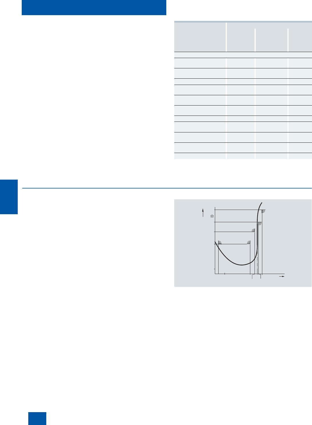
Characteristic curve of the 3RN1 release
The characteristic curves of the Type A temperature sensors are
described in EN 60947-8, DIN 44081 and DIN 44082.
Application Motor protection
Only current-
dependent,
e.g. with
overload relay
Only tempera-
ture-dependent,
e.g. with
thermistor motor
protection relay
Current-
and
temperature
-
dependent
Motor protection in case of
Overloading in
uninterrupted duty ✓ ✓ ✓
Long start-up and braking
operations ❍ ✓ ✓
Irregular intermittent duty ❍ ✓ ✓
Excessively high switching
frequency ❍ ✓ ✓
Single-phase operation and
current unbalance ✓ ✓ ✓
Voltage and frequency
fluctuations ✓ ✓ ✓
Stalling of the rotor ✓ ✓ ✓
Switching on a stalled rotor
of a stator-critical motor ✓ ✓ ✓
Switching on a stalled rotor
of a rotor-critical motor ✓ ❍ ✓
Elevated ambient
temperature -- ✓ ✓
Impeded cooling -- ✓ ✓
TNF+5
NSB0_00320
R
T
TNF+15
TNF
TNF-5
TNF-20
0
-20°C
20
250
550
1330
4000
IC10_08.book Seite 104 Mittwoch, 15. Dezember 2010 3:21 15
© Siemens AG 2010

SIRIUS 3RN1 Thermistor Motor Protection
For PTC sensors
8/105
Siemens IC 10 · 2011
8
Use in areas subject to explosion hazard for gases
All devices are approved for Equipment Group II, Category (2)
in Area "G" (areas that contain explosive gases, vapor, spray and
air mixtures).
With PTB 01 ATEX 3218 ex II (2) G, compliance with directive
94/9 EC Appendix II is confirmed. The safety devices must be
selected with suitable settings for the safe operation of motors of
the "Increased safety" (EEx e) and "Flameproof enclosure"
(EEx d) degrees of protection and are used outside the area sub-
ject to explosion hazard.
PTB 01 ATEX 3218 ex II (2) G
The increased danger in areas subject to explosion hazard de-
mands careful analysis of the operator's guide, the safety and
commissioning instructions and the standard (EN 60079-14 /
VDE 0165) for electronic equipment in areas subject to gas ex-
plosion hazards.
A risk analysis must be performed for the complete plant or ma-
chine. If this risk analysis results in a minimal potential for danger
(Safety Category 1), all 3RN1 TMS releases can be implemented
taking into account the safety notes. In the case of plants or ma-
chines with a high potential risk, versions with integrated short-
circuit detection in the sensor circuit are necessary.
Use in areas subject to explosion hazard for dust
PTB 01 ATEX 3218 ex II (2) GD
3RN10 11-.B/-.G, 3RN10 12-.B/-.G and 3RN10 13-...0 tripping
units can be used as protective devices for motors in areas sub-
ject to gas explosion hazard for protection against impermissible
overheating due to overload. If the ATEX marking has the exten-
sion "D:=Dust", these units can also be used as protective de-
vices for motors in areas subject to dust explosion hazard
(EN 50281-1-1).
Additional information is provided in the EC prototype test certif-
icate which can be obtained from the Internet. The units comply
with the requirements of the following classes:
The measuring circuit leads must be routed as separate control
cables. It is not permitted to use cores from the supply line of the
motor or any other main supply cables. If extreme inductive or
capacitive interference is expected as a result of power lines
routed in parallel, shielded control cables must be used.
Cable routing
Maximum cable length for sensor circuit cables
1)
A short-circuit in the sensor circuit will be detected up to this maximum
cable length.
Note:
Tripping of the thermistor motor protection relay even in combi-
nation with a converter must directly result in disconnection. This
must be implemented with circuitry.
Mounting and installation must only be performed by qualified
personnel who observe the applicable regulations! For mount-
ing, use the mounting instructions
Order No.: 3ZX1012-0RN10-1AA1.
The 3RN10 is not intended for installation in hazardous areas.
For installation in areas subject to explosion hazards, the 3RN10
must be enclosed in a flameproof casing.
For tripping units with a 24 V AC/DC control voltage, electrical
separation must be secured with a battery network or a safety
transformer to EN 61558.
When releases with Auto-RESET function are used, a reset is
performed automatically after the cooling time has expired. It
must be ensured by means of an external interlock (latching with
a separate ON and OFF button) that the machine to be moni-
tored does not start up again spontaneously.
Units with the "Auto-RESET" function must not be used in appli-
cations in which the unexpected restart can lead to personal in-
jury or property damage.
In the case of releases without short-circuit detection, during
commissioning or after modifications or maintenance work (as-
sembly, disassembly) on the equipment, the sensor resistance
must be measured using a suitable measuring device. For resis-
tances of < 50
Ω
the sensor circuit must be checked for a
short-circuit.
If 3RN10 00 units are used to protect EEx e motors, separate
monitoring of the control voltage is recommended because there
is no Ready LED to indicate connection to the supply voltage.
If 3RN10 13-.BW01 unit are used to protect EEx e motors,
separate monitoring of the control voltage is recommended be-
cause the switching state of the auxiliary contacts does not
change if the control voltage fails (use of a bistable relay is
recommended).
Before commissioning, the effectiveness of the protection func-
tion must be checked.
Device Class
3RN10 00, 3RN10 10, 3RN10 11-.C,
3RN10 12-.C, 3RN10 22, 3RN10 62 EN 954-1: Category 1
3RN10 11-.B, 3RN10 11-.G,
3RN10 12-.B, 3RN10 12-.G,
3RN10 13
EN 954-1: Category 2
Conductor
cross
section
Cable length for releases
Without short-circuit detection
3RN10 00, 3RN10 10,
3RN10 11-.C, 3RN10 12-.C,
3RN10 22, 3RN10 62
With short-circuit detection
1)
3RN10 11-.B/-.G,
3RN10 12-.B/-.G,
3RN10 13
mm
2
m m
2.5 2 x 2800 2 x 250
1.5 2 x 1500 2 x 150
0.5 2 x 500 2 x 50
IC10_08.book Seite 105 Mittwoch, 15. Dezember 2010 3:21 15
© Siemens AG 2010

SIRIUS 3RN1 Thermistor Motor Protection
For PTC sensors
8/106 Siemens IC 10 · 2011
8
Principle of operation
The 3RN1 releases operate in accordance with the closed-cir-
cuit principle and therefore monitor themselves for open circuit
(except: warning output in the case of 3RN10 22). A momentary
voltage failure of less than 50 ms does not change the status of
the auxiliary contacts. The 3RN10 11, 3RN10 12 and 3RN10 13
units with 2 changeover contacts are also equipped with short-
circuit detection in the sensor circuit. The unit will trip in the event
of a short-circuit in the sensor circuit (resistance in sensor circuit
< 20 Ω).
All tripping units (except for 24 V AC/DC) feature electrical sep-
aration between the control circuit and the sensor circuit.
3RN10 00 compact releases
The compact release is equipped with a red LED (TRIPPED) for
the tripped indicator and a changeover contact.
After the unit has tripped, it is automatically reset once the
thermistors have cooled down. The root of the changeover con-
tact is connected to the control voltage (95 is connected to
terminal A1).
This unit is particularly suitable in circuits in which the control cir-
cuit and signaling circuit have the same potential, e.g. in local
control cabinets.
3RN10 10, 3RN10 11, 3RN10 12, 3RN10 13 standard releases
The standard devices are equipped with two LEDs (READY and
TRIPPED) for an operating and tripped display and are available
with either 1 NO + 1 NC or with 2 CO contacts. They are available
depending on the version with Auto-RESET (3RN10 10), Man-
ual/Remote-RESET (3RN10 11) or Manual/Auto and Remote-
RESET (3RN10 12 and 3RN10 13). Remote-RESET can be
achieved by connecting an external pushbutton with a normally-
open function to terminals Y1 and Y2. If terminals Y1 and Y2 are
bridged, tripping will be followed by an Auto-RESET.
The 3RN10 11, 3RN10 12 and 3RN10 13 units with 2 COs also
have short-circuit monitoring in the sensor circuit.
The 3RN10 12 and the 3RN10 13 are non-volatile. This means
that even if the control supply voltage fails, a trip preceding it will
be latched.
In the case of the 3RN10 13 release, tripping due to a short-cir-
cuit in the sensor circuit will be indicated by a flashing red LED.
The monostable version also indicates open circuit in the sensor
circuit by flashing of the red LED.
3RN10 22 "Warning and disconnection" releases
Two sensor circuits can be connected to one 3RN10 22 release
that acts on one output relay with 1 NO contact for warning and
1 CO for disconnection. Temperature sensors with different rated
response temperatures TNF are used to implement the "Warn-
ing" and "Disconnection" functions. When the "Warning" sensor
circuit responds, a yellow LED is lit and when the "Disconnec-
tion" circuit responds, a red LED is lit.
The sensor circuits have a different reset response and operat-
ing behavior:
• "Warning" (terminals 2T1, T2) only features Auto-RESET and
uses the open-circuit principle.
• "Disconnection" (terminals 1T1, T2) can be changed from
Manual RESET to Auto-RESET by linking terminals Y1 and Y2.
Remote-RESET is implemented by connecting an external
pushbutton with a normally-open function.
3RN10 62 releases for multiple motor protection
Up to 6 sensor circuits can be connected to the 3RN10 62 re-
lease, all of which act on one output relay. The simultaneous pro-
tection of several motors (up to 6) is an advantage for multi-mo-
tor drives (e.g. if one motor is overloaded, all the other motors of
the drive will be shut down). Apart from the red LED "TRIPPED",
which signals the switching state of the release, a LED is as-
signed to each sensor circuit which indicates the sensor circuit
that has responded. Unused sensor circuits must be
short-circuited.
The reset response of the 3RN10 62 releases can be changed
from Manual RESET to Auto-RESET by linking terminals Y1 and
Y2. Remote-RESET is implemented by connecting an external
pushbutton with a normally-open function.
Response of the releases
in the event of control voltage failure
Protective separation
All circuits (outputs, control circuits, sensor and RESET circuits)
of the multifunction tripping units 3RN10 13-1BW10 and 3RN10
13-1GW10 (wide voltage range, monostable output relay and
screw connection) are safely isolated from each other up to a
rated voltage of 300 V according to DIN VDE 0100 Part 410
(IEC 60364-4-41 modified) and EN 60947-1.
Behavior Monostable Non-volatile,
monostable Bistable
3RN10 00,
3RN10 10,
3RN10 11
3RN10 12,
3RN10 13-....0,
3RN10 22,
3RN10 62
3RN10 13-...01
In case of failure
of the control
voltage
Device trips Device trips No change in
switching state of
the auxiliary
contacts
In case of return
of the control
voltage without a
preceding trip-
ping operation
Device resets Device resets No change in
switching state of
the auxiliary
contacts
In case of return
of the control
voltage after a
preceding trip-
ping operation
Device resets The device
remains tripped No change in
switching state of
the auxiliary
contacts
IC10_08.book Seite 106 Mittwoch, 15. Dezember 2010 3:21 15
© Siemens AG 2010
SIRIUS 3RN1 Thermistor Motor Protection
For PTC sensors
8/107
Siemens IC 10 · 2011
8
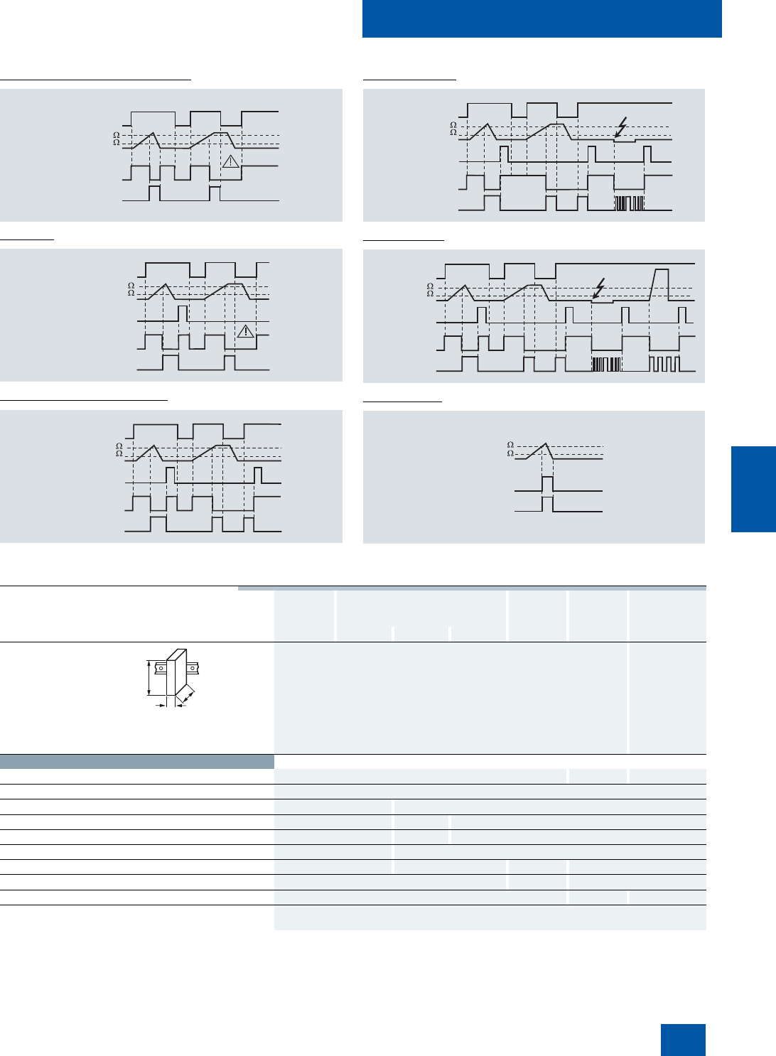
Function diagrams
3RN10 00, 3RN10 10 (Auto-RESET)
3RN10 11
1)
3RN10 12/3RN10 22/3RN10 62
1)
1)
For versions with 2 CO and short-circuit detection in the sensor circuit see
function diagram 3RN10 13.
3RN10 13-.BW01
3RN10 13-...00
3RN10 22 only
✓
Function is available
-- Function is not available
1)
Remote-RESET possible by disconnecting control voltage.
2)
Open circuits are only indicated by monostable versions
(3RN10 13-....0).
K
NSB0_00314b
1500
3800
T1/T2
A1/A2
LED Tripped
1500
3800
T1/T2
A1/A2
NSB0_00315c
(Y1/Y2)
K
LED Tripped
1500
3800
T1/T2
A1/A2
K, K2
NSB0_00317a
RESET
(Y1/Y2)
LED Tripped
1500
3800
T1/T2
A1/A2
K
RESET
(Y1/Y2)
NSB0_00316a
LED Tripped
1500
3800
T1/T2
A1/A2
K
RESET
(Y1/Y2)
NSB0_00318a
LED Tripped
NSB0_00319b
K1
1500
3800
2T1/T2
LED alarm
Type Compact
units Standard devices Multi-
function
units
Warning +
tripping Multiple motor
protection
3RN10 00 3RN10 10 3RN10 11 3RN10 12 3RN10 13 3RN10 22 3RN10 62
Dimensions (W x H x D)
• For 2 terminal blocks
- Screw terminals mm 22.5 x 83 x 91 45 x 83 x 91
- Spring-type terminals mm 22.5 x 84 x 91 45 x 84 x 91
• For 3 terminal blocks
- Screw terminals mm 22.5 x 92 x 91 --
- Spring-type terminals mm 22.5 x 94 x 91 --
• For 4 terminal blocks
- Screw terminals mm 22.5 x 102 x 91 45 x 106 x 91
- Spring-type terminals mm 22.5 x 103 x 91 45 x 108 x 91
General data
Number of connectable sensor circuits 1 2 6
Response in the event of control voltage failure See page 8/106
Manual RESET -- ✓
Auto-RESET ✓-- ✓
Remote-RESET -- ✓
1)
✓
TEST pushbutton -- ✓
Short-circuit detection for sensor circuit -- ✓ (for 2 CO units) ✓--
Short-circuit and open-circuit indication -- ✓
2)
--
Warning and disconnection in one unit -- ✓--
Permissible ambient temperature
• During operation °C -25 ... +60
W
H
D
IC10_08.book Seite 107 Mittwoch, 15. Dezember 2010 3:21 15
© Siemens AG 2010

SIRIUS 3RN1 Thermistor Motor Protection
For PTC sensors
8/108 Siemens IC 10 · 2011
8
1)
I
n
> 1 kA weld-free according to EN 60947-5-1.
Type Compact
units Standard devices Multi-
function
units
Warning +
tripping Multiple motor
protection
3RN10 00 3RN10 10 3RN10 11 3RN10 12 3RN10 13 3RN10 22 3RN10 62
Releases
Rated insulation voltage U
i
(pollution degree 3) V300
Connection type Screw terminals
• Terminal screw M3 (for standard screwdriver, size 2 and Pozidriv 2)
• Solid mm
2
1 x (0.5 ... 4)/2 x (0.5 ... 2.5)
• Finely stranded with end sleeve mm
2
1 x (0.5 ... 2.5)/2 x (0.5 ... 1.5)
• AWG cables, solid or stranded AWG 2 x (20 ... 14)
• Tightening torque Nm 0.8 … 1.2
Connection type Spring-type terminals
• Solid mm
2
2 x (0.25 ... 1.5)
• Finely stranded, with end sleeves according to
DIN 46228 mm
2
2 x (0.25 ... 1.5)
• Finely stranded mm
2
2 x (0.25 ... 1.5)
• AWG cables, solid or stranded AWG 2 x (24 ... 16)
Sensor circuit
Measuring circuit load at R
F
≤ 1.5 mW ≤5
Voltage in sensor circuit at R
F
≤ 1.5 mW V≤2
Response temperature (depends on sensor) °C 60 ... 180
Coupling time (depends on sensor) s About 5
Summation PTC resistance R
F
(per sensor loop) kΩ ≤ 1.5; response value 3.4 ... 3.8; return value 1.5 ... 1.65
Response tolerance °C ±6
Control circuit
Rated control supply voltage U
s
See page 8/110
Operating range
• 110/230 V AC
0,85 ... 1.1 x U
s
• 24 ... 240 V AC/DC 0,85 ... 1.1 x U
s
• 24 V AC/DC 0.85 ... 1.2 x U
s
for DC operation, 0.85 ... 1.1 x U
s
for AC operation
Rated power AC/DC W < 2
Auxiliary circuit
Conventional thermal current I
th
A 5
Rated operational current I
e
• AC-15/240 V A 3
• DC-13/24 V A 1
DIAZED fuse A6
1)
CSA and UL rated data, control circuit
Rated control voltage 50/60 Hz
•AC V 300
•DC V 300
Switching capacity R 300/B 300
Protective separation up to 300 V
according to DIN 60947-1
-- 3RN10 13-
1BW10,
3RN10 13-
1GW10
--
IC10_08.book Seite 108 Mittwoch, 15. Dezember 2010 3:21 15
© Siemens AG 2010
SIRIUS 3RN1 Thermistor Motor Protection
For PTC sensors
8/109
Siemens IC 10 · 2011
8
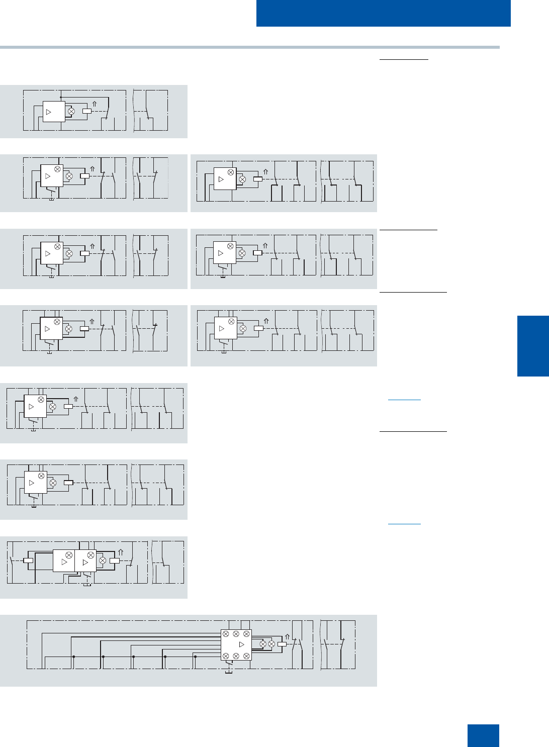
Circuit diagrams
1)
For units with combination voltages 230/110 V AC (3RN10 11-.CK00 and
3RN10 12-.CK00) A1 and A2 apply: 230 V AC, A3 and A2: 110 V AC.
Illustrated with
control voltage
applied
Illustrated with
control voltage
not applied
Illustrated with
control voltage
applied
Illustrated with
control voltage
not applied
3RN10 00, 1 CO
3RN10 10, 1 NO + 1 NC 3RN10 10, 2 COs
3RN10 11
1)
, 1 NO + 1 NC 3RN10 11, 2 COs
3RN10 12
1)
, 1 NO + 1 NC 3RN10 12, 2 COs
3RN10 13-...0 (monostable)
3RN10 13-...1 (bistable)
3RN10 22
3RN10 62
General legend
A1, A2 , A3
N
T/R
Y1, Y2
⇑
Terminals of the
control voltage
Amplifier
TEST/RESET button
Ter minals for
Remote-RESET
(jumpered =
Auto-RESET)
The double arrow
indicates an operating
state of the contact
according to
DIN 40900, Part 7 which
deviates from the norm
(here: Position of the
contacts when control
voltage is applied to
terminals A1 and A2)
Legend for 3RN10
H1
H2
K
T1, T2
LED "READY"
LED "TRIPPED"
Output relay
Terminals of
the sensor loop
Legend for 3RN10 22
H1
H2
H3
K1
K2
1T1 and T2
2T1 and T2
LED "READY"
LED "TRIPPED"
LED "ALARM"
Output relay
for warning threshold
(LED "ALARM")
Output relay for discon-
nect (LED "TRIPPED")
Terminals of the
sensor loop
. Important!
Close unconnected sensor circuits.
Legend for 3RN10 62
H1 to H6
H7
H8
K
1T1, 1T2
to
6T1, 6T2
LED of the tripped
sensor loop
LED "READY"
LED "TRIPPED"
Output relay
Terminals of the
1st sensor loop
Terminals of the
6th sensor loop
. Important!
Close unconnected sensor circuits.
A1(11)
NSB0_00322b
(12)(14)
K
H2
N
9896A2T2T1
A1/95
K
H2
N
H1
NSB0_00323b
(21)(13)
(22)(14)
A1 9795
A2T2T1 9896
T/R
N
H1
(22)(24)(12)
NSB0_01397
(21)(11)
(14)
K
H2
05
0806T2
95
A1
9896A2T1
K
H2
N
H1
NSB0_00323b
(21)(13)
(22)(14)
A1 9795
A2T2T1 9896
T/R
N
H1
(22)(24)(12)
NSB0_01398
(21)(11)
(14)
K
H2
05
0806T2
95A1
9896A2
T/R
T1
NSB0_00325a
(21)(13)
(22)(14)
T/R
A2T2T1
K
H2
N
H1
A1(A3)
Y2Y1 9795
9896
A1Y2Y1
N
H1
(22)(24)(12)
NSB0_01399a
(21)(11)
(14)
K
H2
05
0806T2
95
9896A2
T/R
T1
N
H1
(22)(24)(12)
NSB0_01400
(21)(11)
(14)
K
H2
05
0806T2
95A1Y2Y1
9896A2
T/R
T1
N
H1
(22)(24)(12)
NSB0_00327
(21)(11)
(14)
K
H2
05
0806T2
95A1Y2Y1
9896A2
T/R
T1
(11)
NSB0_00328c
(12)(14)
07(23)
T/R
K2
H1
N
H2
N
H3
K1
9896A2T21T12T1
08(24)
95A1Y2Y1
NSB0_00329a
(13) (21)
(14) (12)
96
3T12T2 3T2 4T24T1 5T2 6T1 6T25T1
65
3
2
H4
H1
H7H8
K
Y1 Y2 A1
A2
1T1 1T2 2T1
T/R
98
9795
N
IC10_08.book Seite 109 Mittwoch, 15. Dezember 2010 3:21 15
© Siemens AG 2010
SIRIUS 3RN1 Thermistor Motor Protection
For PTC sensors
8/110 Siemens IC 10 · 2011 * You can order this quantity or a multiple thereof.
Illustrations are approximate
8
■
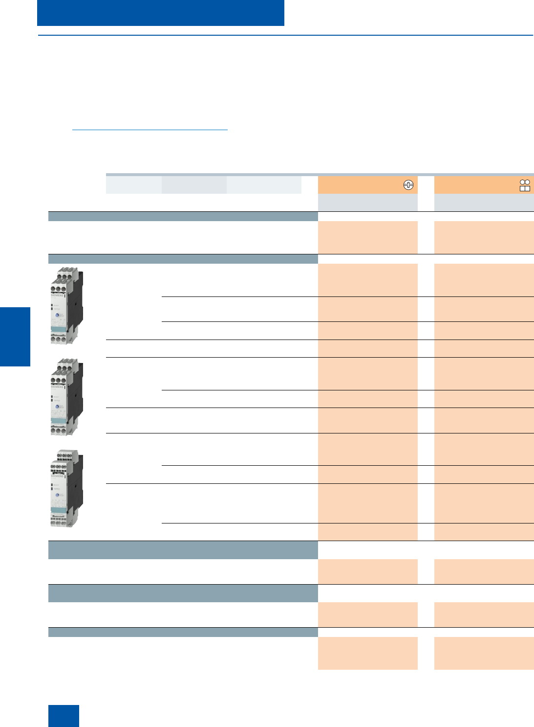
Selection and ordering data
• For monitoring the motor winding temperature using tempera-
ture-dependent resistors (PTCs, type A) that are directly in-
stalled in the motor winding by the manufacturer
• Monostable versions with closed-circuit principle, i.e. relays
respond in the event of control supply voltage failure
• 3RN10 13-.BW01: Bistable version, does not trigger in the
event of control supply voltage failure
• All devices with PTB01 ATEX approval for dust or gas
see www.siemens.com/industrial-controls/atex
• All devices except for 24 V AC/DC feature electrical
separation
• Versions with safe isolation up to 300 V according to EN 61140
• Non-volatile versions
• Versions with short-circuit and open-circuit detection in sensor
circuit
• Versions with solid-state compatible contacts with hard
gold-plating
• Versions for up to 6 sensor circuits
• Versions with Manual-RESET, Remote-RESET, Auto-RESET
and test button
• Terminal labeling according to DIN 50005
• All terminals are removable
• Width 22.5 mm (45 mm on version for several sensor circuits)
PU (UNIT, SET, M) = 1
PS* = 1 unit
PG = 101
1)
The unit can be reset with the RESET button or by disconnecting the con-
trol supply voltage.
2)
For protection against voltage failure see note on Technical Information on
page 8/1.
RESET Contacts Rated control supply
voltage U
s
50/60 Hz DT Screw terminals DT Spring-type
terminals
VOrder No. Price
per PU Order No. Price
per PU
Compact signal evaluation units, width 22.5 mm, 1 LED
Terminal A1 is jumpered with the root of the CO contact
Auto 1 CO 24 AC/DC }3RN10 00-1AB00 A3RN10 00-2AB00
110 AC A 3RN10 00-1AG00 B3RN10 00-2AG00
230 AC }3RN10 00-1AM00 B3RN10 00-2AM00
Standard evaluation units, width 22.5 mm, 2 LEDs
3RN10 11-1BB00
3RN10 13-1BB00
3RN10 12-2CK00
Auto 1 NO + 1 NC 24 AC/DC }3RN10 10-1CB00 }3RN10 10-2CB00
110 AC }3RN10 10-1CG00 A3RN10 10-2CG00
230 AC }3RN10 10-1CM00 A3RN10 10-2CM00
24 … 240 AC/DC }3RN10 10-1CW00 A3RN10 10-2CW00
2 CO 24 AC/DC A 3RN10 10-1BB00 A3RN10 10-2BB00
110 AC A 3RN10 10-1BG00 C3RN10 10-2BG00
230 AC A 3RN10 10-1BM00 A3RN10 10-2BM00
2 CO, hard
gold-plated 24 AC/DC A 3RN10 10-1GB00 C3RN10 10-2GB00
Manual/Remote
1)
1 NO + 1 NC 24 AC/DC }3RN10 11-1CB00 A3RN10 11-2CB00
110/230 AC }3RN10 11-1CK00 A3RN10 11-2CK00
Short-circuit detection for sensor circuit
Manual/Remote
1)
2 CO 24 AC/DC A 3RN10 11-1BB00 A3RN10 11-2BB00
110 AC A 3RN10 11-1BG00 C3RN10 11-2BG00
230 AC A 3RN10 11-1BM00 A3RN10 11-2BM00
2 CO, hard
gold-plated 24 AC/DC A 3RN10 11-1GB00 A3RN10 11-2GB00
Non-volatile
2)
Manual/Auto/
Remote 1 NO + 1 NC 24 AC/DC }3RN10 12-1CB00 A3RN10 12-2CB00
110/230 AC }3RN10 12-1CK00 A3RN10 12-2CK00
Non-volatile
2)
, short-circuit detection in sensor circuit
Manual/Auto/
Remote 2 CO 24 AC/DC A 3RN10 12-1BB00 C3RN10 12-2BB00
110 AC A 3RN10 12-1BG00 C3RN10 12-2BG00
230 AC A 3RN10 12-1BM00 C3RN10 12-2BM00
2 CO, hard
gold-plated 24 AC/DC A 3RN10 12-1GB00 C3RN10 12-2GB00
Non-volatile
2)
, short-circuit and open-circuit detection and indi-
cation in sensor circuit; wide-range voltage with screw terminal
with safe isolation
Manual/Auto/
Remote 2 CO 24 AC/DC }3RN10 13-1BB00 A3RN10 13-2BB00
24 … 240 AC/DC }3RN10 13-1BW10 A3RN10 13-2BW00
2 CO, hard
gold-plated 24 … 240 AC/DC A 3RN10 13-1GW10 C3RN10 13-2GW00
Evaluation units for 2 sensor circuits, warning and disconnection,
width 22.5 mm, 3 LEDs
Test/RESET button, non-volatile
2)
Manual/Auto/
Remote 1 NO + 1 CO 24 … 240 AC/DC }3RN10 22-1DW00 A3RN10 22-2DW00
Evaluation units for 6 sensor circuits, multiple motor protection,
width 45 mm, 8 LEDs
Test/RESET button, non-volatile
2)
Manual/Auto/
Remote 1 NO + 1 NC 24 … 240 AC/DC }3RN10 62-1CW00 A3RN10 62-2CW00
Bistable evaluation units, width 22.5 mm
Test / RESET button, non-volatile
2)
, short-circuit and open-cir-
cuit detection and indication in sensor circuit
Manual/Auto/
Remote 2 CO 24 … 240 AC/DC }3RN10 13-1BW01 A3RN10 13-2BW01
IC10_08.book Seite 110 Mittwoch, 15. Dezember 2010 3:21 15
© Siemens AG 2010
SIRIUS 3RN1 Thermistor Motor Protection
For PTC sensors
8/111
Siemens IC 10 · 2011
* You can order this quantity or a multiple thereof.
Illustrations are approximate
8
■
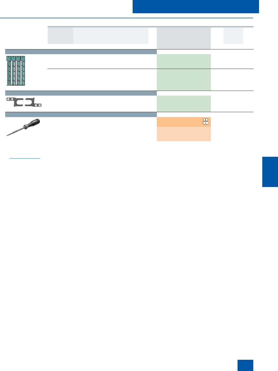
Accessories
1)
PC labeling system for individual inscription
of unit labeling plates available from:
murrplastik Systemtechnik GmbH
www.murrplastik.de
Use Version DT Order No. Price
per PU PU
(UNIT,
SET,
M)
PS* PG
Blank labels
3RT19 00-1SB20
For 3RN1 Unit labeling plates
For SIRIUS devices
20 mm x 7 mm, pastel turquoise
1)
D3RT19 00-1SB20 100 340 units 101
For 3RN1 Inscription labels for sticking
For SIRIUS devices
19 mm x 6 mm, pastel turquoise C 3RT19 00-1SB60 100 3060 units 101
19 mm x 6 mm, zinc yellow C 3RT19 00-1SD60 100 3060 units 101
Push-in lugs
3RP19 03
For 3RN1 Push-in lugs
For screw fixing,
2 units are required for each device
}3RP19 03 1 10 units 101
Tools for opening spring-type terminals by hand
3RA29 08-1A
For auxiliary
circuit
connections
Screwdrivers
For all SIRIUS devices with spring-type
terminals
3.0 mm x 0.5 mm, length approx. 200 mm,
titanium gray/black, partially insulated
Spring-type
terminals
A3RA29 08-1A 1 1 unit 101
NSB0_01429b
IC10_08.book Seite 111 Mittwoch, 15. Dezember 2010 3:21 15
© Siemens AG 2010
