P RDF Version A.1
2014-09-04
: Pdf 100190-Attachment 100190-Attachment 783166 Batch7 unilog
Open the PDF directly: View PDF ![]() .
.
Page Count: 36
Form P-RDF, Page 1
IMPORTANT
1. Always include complete heater model and serial number so
that any specification change can be considered for parts ship-
ment. It can save time and expense.
2. Specifications are subject to change without notice.
3. We reserve the right to substitute functional replacements.
4. Order either by Kit or Component Part No.
®
Replacement Parts Form RZ-NA P-RDF (Version A)
Obsoletes Form RGM 740 (Version A) and P-RDF
APPLIES TO: Model RDF
RDF Series
Direct-Fired
Makeup Air Heater
ADDITIONAL REFERENCES
Forms:
• Installation Form I-RDF, Model RDF
• Operation/Maintenance/Service Form O-ADF/DV/RDF
• Installation Form I-OPT-C, Roof Curb Installation Instructions
• Parts Form P-GC, Gas Conversion
• Parts Form P-VALVES, Serial No., Gas Valves, and Maxitrol Gas Controls
• Instruction Form CP-RDF-IGN, Conversion to Hot Surface Ignition
Website: www.RezSpec.com (Forms are available to download.)
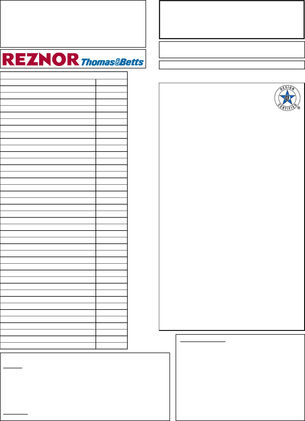
Rating Plate and Serial No.
Rating Plate Codes:
A = Model No.
B = Gas Type (Nat or LP)
C = Motor HP
D = Volt
E = Phase
F = Maximum Total Input
Amps for Unit
G = SCFM
H = ESP
I = CFM
J = Maximum Input
REZNOR
MERCER, PA. USA 16137
ANSI Z83.18A-2001 DIRECT-FIRED INDUSTRIAL AIR HEATER
FOR INDUSTRIAL/COMMERCIAL USE ONLY
FOR EITHER INDOOR OR OUTDOOR INSTALLATION
MODEL { A } SERIAL #
GAS TYPE { B } MOTOR HP { C }
VOLTAGE { D } PHASE { E } 60 HZ
MAX TOTAL INPUT AMPS FOR THE UNIT { F }
WIRING DIAGRAM NUMBER: { P }
UNIT IS EQUIPPED FOR { G } SCFM AGAINST { H } IN WC ESP
WITH A MAX DISCH TEMP OF { Q }
o
F AND A MAX TEMP RISE OF
{ Z }
o
F AND CANNOT BE USED BELOW -40
o
F
MAXIMUM INPUT RATING BTU/HR
MINIMUM INPUT RATING BTU/HR
NORMAL MANIFOLD PRESS. IN WC
MIN GAS INLET PRESS. FOR BURN. ADJ. IN WC
MAX PERMISSIBLE GAS SUPPLY PRESS. PSI
MIN PRESSURE DROP ACROSS BURNER IN WC
MAX PRESSURE DROP ACROSS BURNER IN WC
CLEARANCES TO COMBUSTIBLES:
TOP, BOTTOM, AND SIDE OPPOSITE CONTROLS - 1 INCH
FOR SERVICE ON CONTROL SIDE OF UNIT - WIDTH OF UNIT
INSTALL UNITS IN ACCORDANCE TO THE MOST RECENT
STAND. ANSI/NFPA 409 IF INSTALLED IN AIRCRAFT HANGERS
STAND. ANSI/NFPA 88A IF INSTALLED IN PARKING STRUCTURES
STAND. ANSI/NFPA 88B IF INSTALLED IN REPAIR GARAGES
0.25
0.75
{
Q
}
o
F. SEE INSTALLATION INSTRUCTIONS FOR OTHER
{ M }
{ N }
{ L }
{ K }
{ J }
THIS HEATER HAS BEEN DESIGNED TO OPERATE AT A MINIMUM
{ I } CFM OF VENTILATION AIR TO PROPERLY DILUTE ITS
COMBUSTION PRODUCTS BASED ON A MINIMUM ROOM AIR
TEMPERATURE OF 55
o
F, A MINIMUM OUTDOOR TEMPERATURE
OF -40
o
F, AND A MAXIMUM DISCHARGE TEMPERATURE OF
LIMITATIONS FOR RE-CIRCULATION APPLICATIONS.
K = Minimum Input
L = Manifold Presssure
M = Minimum Inlet
Pressure
N = Maximum Supply
Pressure
P = Wiring Diamgram No.
Q = Maximum Discharge
Temperature
Z = Maximum Temperature
Rise °F
Index by Page No.
Amplifier 13
Belts 23-32
Blowers 22
Burners 16-16
Cabinet Parts 33-36
Circuit Analyzer Board 4-5
Contactor 6
Dampers 17-18
Disconnect Switch 21
Drives 23-32
ECO Device 4-5
Electrical Compartment Illustration 3
Filter Sections 35
Filters 35
Firestat 4-5
Flame Sensor 14, 15
Freezestat 4-5
Fuseholder and Fuses 4-5
Gas Train Controls 11-12
Outside Air Inlet Hoods 35
Ignition System 14-15
Limit Controls 4-5
Maxitrol System Components 13
Mirror 16
Modulat ing Gas Cont rols 13-14
Motors (Blower) 6-8
Motors (Damper) 17-18
Potentiometer 4, 6, 20
Pressure Switches (Air) 4-5
Pressure Switches (Gas) 12
Rating Plate 1
Regulat ors 11
Relays 4
Remote Console 20
Roof Curbs 36
Ser ial No. 2
Sheaves 23-32
St ar t ers 6 - 1 0
Temperature Sensor 13
Transformer 4-5
Valves 11-12

Form P-RDF, Page 2
Serial No.
Example: ANH 61 K2 N 40297 CA MV7
1 234 56 7
Codes:
1 = Date of manufacture (see chart on page 2)
2 = Type of pilot
3 = Type of valve
4 = Type of gas (N= Natural;
L= Propane)
5 = Consecutive number
6 = Type of air control (CA=Constant Air Volume; VA=Variable Air Volume;
RA=Recirculation Air)
7 = Type of Maxitrol gas control (MV7=Maxitrol System 14; MV8=Maxitrol System 14A;
MV9=Maxitrol System 44; MVB=Maxitrol System 94; MVC=with Maxitrol A200
Conditioner; MVD=Maxitrol System 14E; MVE-Maxitrol System 44E-21; MVF-Maxitrol
System 44ER-21)
Rating Plate and
Serial No. (cont'd)
First Element of the Serial Number - Date of Manufacture
Year Jan Feb Mar Apr May June July Aug Sept Oct Nov Dec
1984 AJA AJB AJC AJD AJE AJF AJG AJH AJI AJJ AJK AJL
1985 AKA AKB AKC AKD AKE AKF AKG AKH AKI AKJ AKK AKL
1986 ALA ALB ALC ALD ALE ALF ALG ALH ALI ALJ ALK ALL
1987 AMA AMB AMC AMD AME AMF AMG AMH AMI AMJ AMK AML
1988 ANA ANB ANC AND ANE ANF ANG ANH ANI ANJ ANK ANL
1989 AOA AOB AOC AOD AOE AOE AOG AOH AOI AOJ AOK AOL
1990 APA APB APC APD APE APF APG APH API APJ APK APL
1991 AQA AQB AQC AQD AQE AQF AQG AQH AQI AQJ AQK AQL
1992 ARA ARB ARC ARD ARE ARF ARG ARH ARI ARJ ARK ARL
1993 ASA ASB ASC ASD ASE ASF ASG ASH ASI ASJ ASK ASL
1994 ATA ATB ATC ATD ATE ATF ATG ATH ATI ATJ ATK ATL
1995 AUA AUB AUC AUD AUE AUF AUG AUH AUI AUJ AUK AUL
1996 AVA AVB AVC AVD AVE AVF AVG AVH AVI AVJ AVK AVL
1997 AWA AWB AWC AWD AWE AWF AWG AWH AWI AWJ AWK AWL
1998 AXA AXB AXC AXD AXE AXF AXG AXH AXI AXJ AXK AXL
1999 AYA AYB AYC AYD AYE AYF AYG AYH AYI AYJ AYK AYL
2000 AZA AZB AZC AZD AZE AZF AZG AZH AZI AZJ AZK AZL
2001 BAA BAB BAC BAD BAE BAF BAG BAH BAI BAJ BAK BAL
2002 BBA BBB BBC BBD BBE BBF BBG BBH BBI BBJ BBK BBL
2003 BCA BCB BCC BCD BCE BCF BCG BCH BCI BCJ BCK BCL
2004 BDA BDB` BDC BDD BDE BDF BDG BDH BDI BDJ BDK BDL
2005 BEA BEB BEC BED BEE BEF BEG BEH BEI BEJ BEK BEL
2006 BFA BFB BFC BFD BFE BFF BFG BFH BFI BFJ BFK BFL
2007 BGA BGB BGC BGD BGE BGF BGG BGH BGI BGJ BGK BGL
2008 BHA BHB BHC BHD BHE BHF BHG BHH BHI BHJ BHK BHL
2009 BIA BIB BIC BID BIE BIF BIG BIH BII BIJ BIK BIL
2010 BJA BJB BJC BJD BJE BJF BJG BJH BJI BJJ BJK BJL
2011 BKA BKB BKC BKD BKE BKF BKG BKH BKI BKJ BKK BKL
2012 BLA BLB BLC BLD BLE BLF BLG BLH BLI BLJ BLK BLL
2013 BMA BMB BMC BMD BME BMF BMG BMH BMI BMJ BMK BML
2014 BNA BNB BNC BND BNE BNF BNG BNH BNI BNJ BNK BNL
2015 BOA BOB BOC BOD BOE BOF BOG BOH BOI BOJ BOK BOL
Form P-RDF, Page 3
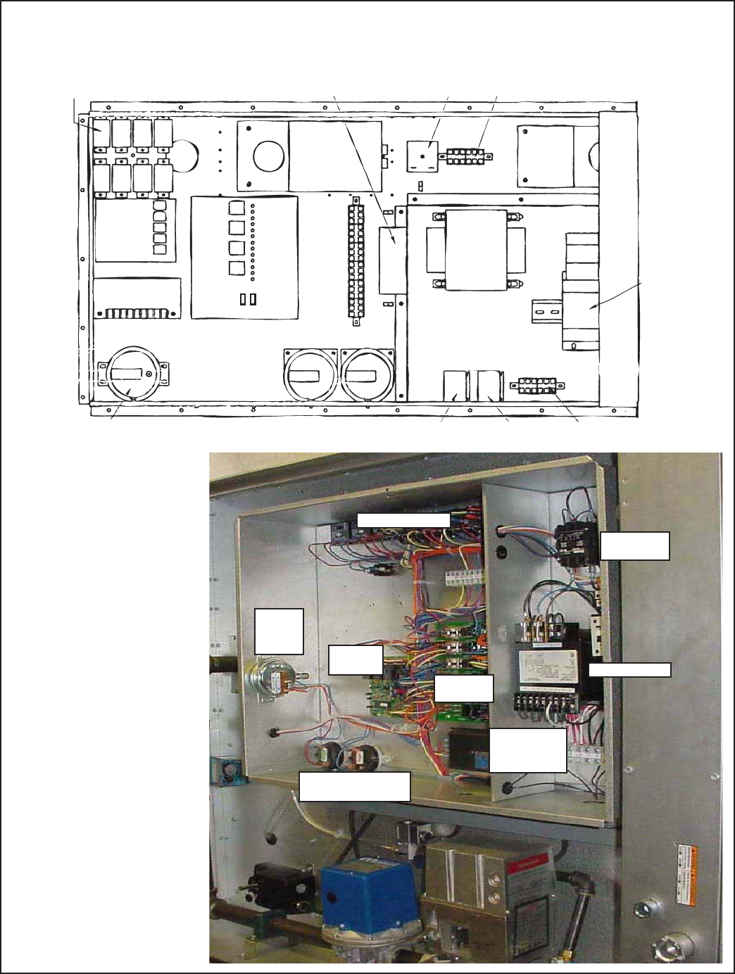
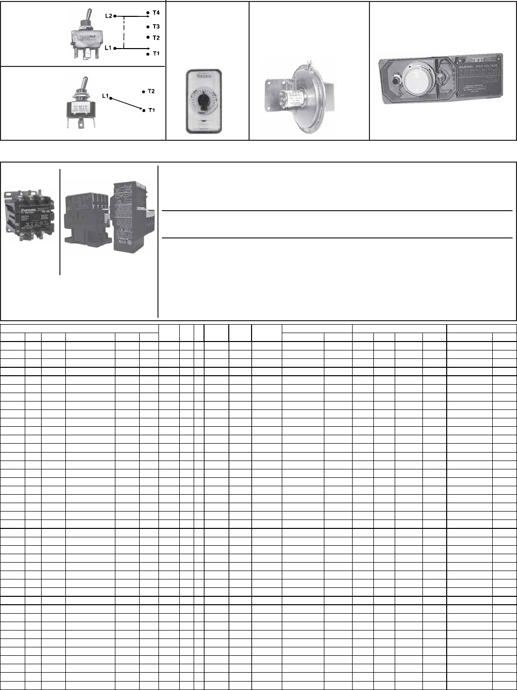
Electrical Control Compartment Typical Component Locations
See below and the following pages for P/N's and illustrations.
Control
Relays
Outside Air Cutoff
(high ambient limit control)
Time Delay
Relay 24-volt Terminals
Ignition
Module
Maxitrol Amplifier
or Signal Conditioner Service
Switches
Status Lights
Circuit
Board
24-Volt Terminals
Bypass
Damper
Motor
Return
Air
Damper
Motor
Motor
Starter
Transformer
Line Voltage
Terminals
Starter
Relay
Relay for
Optional 2-Speed
High Low
Standard Pressure
Switches
Optional Dirty Filter
Pressure Switch
NOTE: Illustration shows approximate locations of controls on RDF Series 3 systems. Manufacture of Series 3 system began
in 9/03. RDF systems manufactured prior to Series 3 have similar controls but control locations are different. Because this
product has experienced ongoing development, always provide complete model and serial number when inquiring about or
ordering replacement parts.
Model RDF Series 3 Control
Compartment
Electrical
Box
Gas Train/
Manifold
Transformer
Contactor
or Starter
Amplifier
or Signal
Conditioner
Circuit
Analyzer
Ignitor
Module
High and Low
Pressure Switches
Control Relays
Dirty
Filter
Switch
Form P-RDF, Page 4
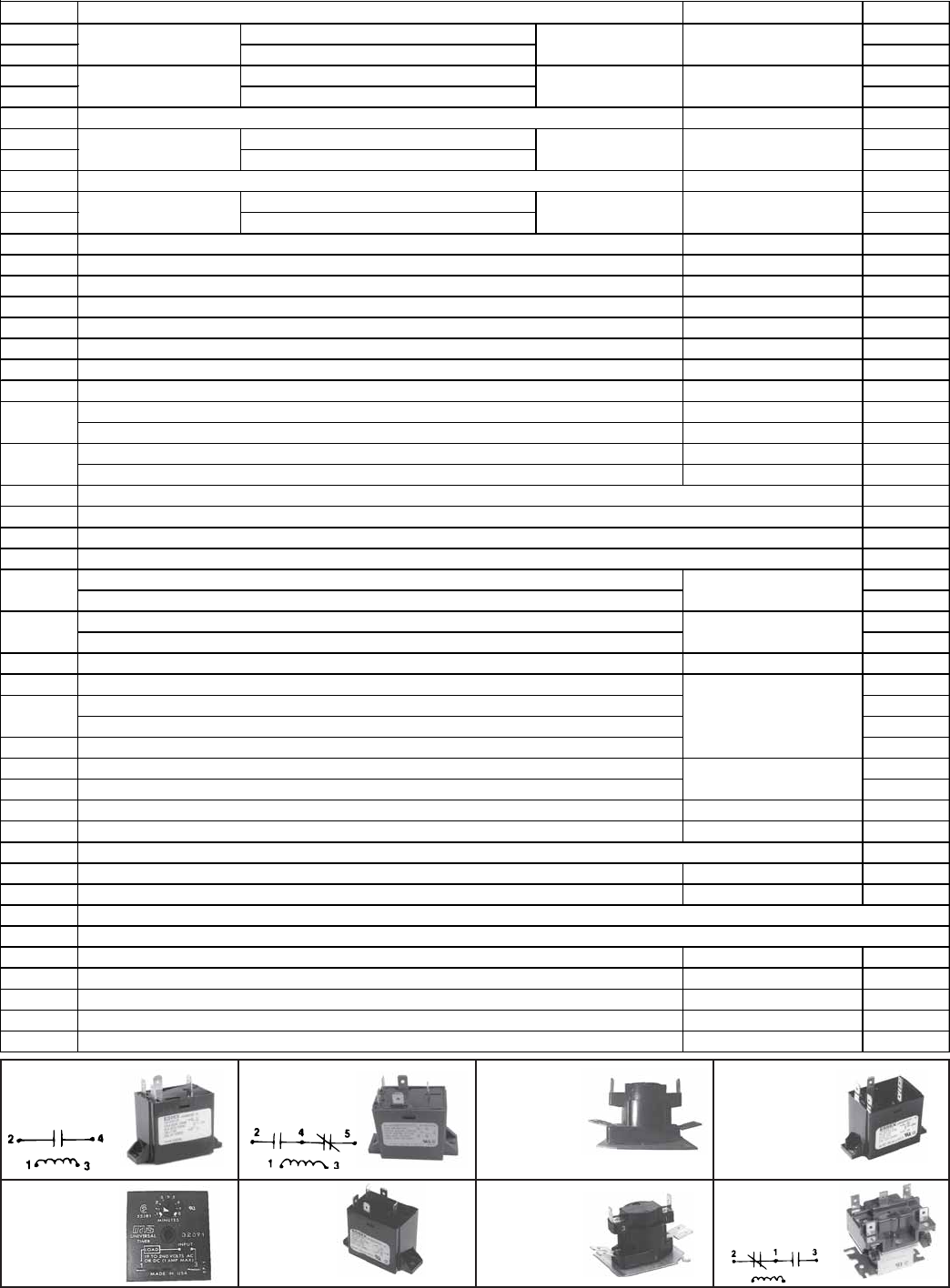
CODE 1B -
Relay,
P/N 98118
CODE 2B -
Relay,
P/N 103317
CODE 4B -
Relay,
P/N 103319
CODE 5 -
Time Delay
Relay
(Freezestat),
P/N 89661
CODE 6 -
Relay,
P/N
103318
CODE 7 -
Prepurge
Time Delay
Relay,
P/N 52887
CODE 8 -
Relay,
P/N 110656
CODE 3 -
Time Delay
Relay
(Low Fire),
P/N 89254
(On units mfgd prior to 3/96)
Electrical Components
CODE Location P/N
1A Hamilton Standard #84-20102-101 14747
1B Hamilton Standard #134-20102-101 98118
2A Hamilton Standard #84-20103-301 18549
2B Products Unltd 9400-04-Q180 103317
3Time Delay Relay (Low Fire), 24V Coil, Thermodisc #F12S20, Style 305005 Control Compartment 89254
4A Hamilton Standard #84-50202-101 86982
4B Hamilton Standard #134-50202-101 103319
5Time Delay Relay (for freezestat bypass), T&B Agastst #VTM1ULA Control Compartment 89661
6A Hamilton Standard #84-50203-301 90205
6B Hamilton Standard #134-50203-301 103318
7Prepurge Time Delay Relay, 24V Coil, Thermodisc #12S20 Control Compartment 52887
8Relay, 24V Coil, Essex #91-102006-1300 Control Compartment 110656
9Manual Reset Limit, Thermodisc 330545, L150 Blower Discharge 82610
10 Automatic Limit, L135, Thermodisc #60T11-312616 Blower Discharge 86979
11 Outside Air Cutoff (High Ambient Limit) & Freezestat, J/C #A19AAF-12C Control Compartment 126170
12 Flame Safety Limit (ECO), Opens 306°F, Thermodisc #G4AP0200152C Gas Train Compartment 82414
13 Firestat, Honeywell #L4029E1029, 200°F Blower Discharge 42782
14 Spark Generator, 120V, Honeywell #Q624A1014 Control Compartment 86974
Low Air Pressure Switch, IS2-0233-5275 for RDF Series 3 Control Compartment 207178
Low Air Pressure Switch Kit replaces P/N 86986, #FS4197-166 or PPS10175-3043 Control Compartment 193806
High Air Pressure Switch, IS2-0233-5273 for RDF Series 3 Control Compartment 207176
High Air Pressure Switch Kit replaces P/N 86987, #FS4197-164 or PPS10175-3041 Control Compartment 193807
17 Plastic Tee for Air Pressure Tubing, 3/16", 1/16" I.D. 87482
18A Yellow Plastic Tubing for air pressure switch, 3/16" O.D. x 14" 122855
18B Clear Plastic Tubing for Air Pressure Switch, 3/16" O.D. x 3 ft 102401
19 Bushing and Insect Screen for Sensing Probes (not illustrated) 96794
Air Pressure Switch, IS2-0233-5274 for RDF Series 3 207177
Air Pressure Switch Kit replaces P/N 87250, #FS4197-165 or PPS10175-3042 193809
Air Pressure Switch, IS2-0233-5276 for RDF Series 3 207179
Air Pressure Switch Kit replaces P/N 87249, #FS4197-171 or PPS10175-3044 193808
21 Contactor, Furnace 42AF15AJ, 24V (used with Option BM80 and BM81 manifold) Control Com
p
artment 203935
22 Diagnostic Circuit Analyzer Board 151263
Replacement Bulb for Circuit Analyzer Board, RDF Series 3 125189
Replacement Light for Circuit Analyzer Board (Option BS2 prior to RDF Series 3) 101889
22B Replacement Relay for Code 22, SKMP-2C-24AC 151271
23 Terminal Block, #KT3 144972
24 Terminal Block Adapter 144973
25 Convenience Outlet Receptacle, Hubbell #GF5362 (separate electrical supply) Control Compartment 96912
26A Dirty Filter Pressure Switch, Tri-Delta #AP4434, set at .3" w.c. Control Compartment 105507
26B Clear Plastic Tubing for Dirty Filter Pressure Switch, 3/16" O.D. x 112" 179302
27A Fuseholder, 24V, Wesco #S257A57G01 Control Compartment 38635
27B Fuseholder, Buss Model HTB-481 Control Compartment 60241
28 Fuses - See descriptions and list of P/N's on page 5.
29 Transformer - See descriptions and list of P/N's on page 5.
30 DPDT System Switch, Winter/Off/Summer, Cutler Hammer 7561K6 Space (Console) 101900
31 SPDT Switch (service switch), Cutler Hammer 7505K6 Control Compartment 101901
32 Null Pressure Switch, .01" - .20" w.c., Dwyer #1640-0 Heated Space 88052
33 Potentiometer, Honeywell 112894FA Space / Remote Console 16110
34 Photohelic Pressure Sensor in Options AR36 & AR37, 3000-00-N24 Vac Remote 158893
RBM Relay, SP-DT,
120V Coil
Description Codes 1A&B are
interchan
g
eable.
Codes 2A&B are
interchan
g
eable.
Codes 4A&B are
interchan
g
eable.
RBM Relay, SP-ST,
24V Coil
RBM Relay, SP-DT,
24V Coil
RBM Relay, SP-ST,
120V Coil
Codes 6A&B are
interchan
g
eable.
Control Compartment
Control Compartment
Control Compartment
Control Compartment
15
16
20A
20B
Control Compartment &
Remote Console
Control Compartment
Control Compartment
22A Control Compartment
Form P-RDF, Page 5
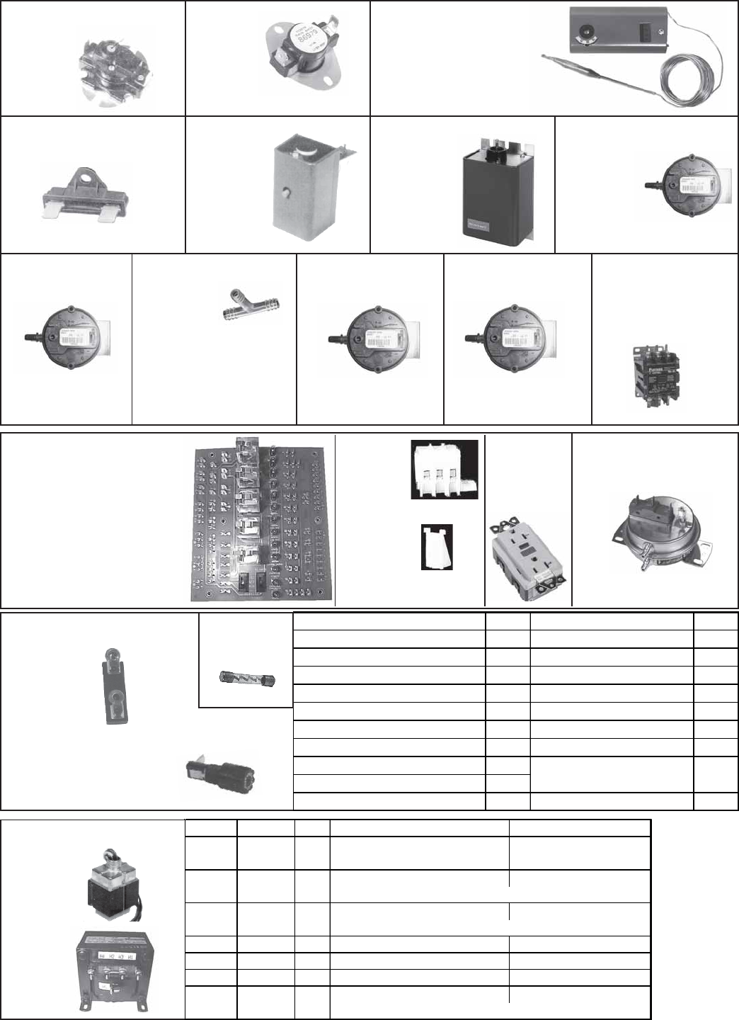
CODE 26A - Dirty Filter
Pressure Switch, P/N
105507 (replaces P/N
102773)
CODE 22A, Replacement
Lights for Circuit Analyzer
Board - P/N 125189 Series 3;
prior to Series 3, P/N 101889
CODE 22B, Replacement
Relay for Board, P/N 151271
CODE 23 -
Terminal
Block,
P/N
144972
CODE 24 -
Terminal
Block
Adapter,
P/N 144973
CODE 20A - Air
Pressure Switch,
P/N 207177
CODE 20B - Air
Pressure Switch,
P/N 207179
CODE 25 -
Convenience
Outlet
Receptacle,
P/N 96912
CODE 14 -
Spark
Generator,
P/N 86974
(On units
mfgd
prior to
3/96)
CODE 15 - Low Air
Pressure Switch,
P/N 207178
CODE 16 - High Air
Pressure Switch,
P/N 207176
CODE 13 -
Firestat,
P/N 42782
CODE 17 - Tee
for Air
Pressure
Tubing,
P/N 87482
CODE 18A - Clear Plastic
Tubing, P/N 102401 (3')
CODE 27A -
Fuseholder,
P/N 38635
Fuseholders and Fuses
CODE 27B - Fuseholder,
P/N 60241
(used with spark ignition)
CODE 28 -
Fuses
CODE 12 - ECO Limit,
P/N 82414
CODE 11, - Adjustable
Outside Air Cutoff Control
and Freezestat,
P/N 126170
CODE 9 -
Limit Switch,
P/N 82610
Reset
Button
CODE 10
- Limit,
P/N
86979
(Automatic Reset)
(Replaces
P/N 16108) Grommet
Clamp, P/N 131993;
Cable Clamp, P/N 132065
Replace pressure
switch P/N 86987
with Kit P/N 193807.
Replace pressure switch
P/N 87250 with Kit P/N
193809.
Replace pressure switch
P/N 87249 with Kit P/N
193808.
CODE 22 - Circuit Analyzer
Board, P/N 151263 (Std
beginning with RDF Series 3.
Option BS2 prior to Series 3.)
Description P/N Description P/N
2.5 Amp, #3210 (spark ignition) 61542 Bussman FRN-R175 91595
Bussman FRN-R15, 230/1 14667 Bussman FRS-R3.5, 460/3 89266
Bussman FRN-R30, 208/230/3 31892 Bussman FRS-R8, 460/3 89268
Bussman FRN-R10, 208/3 89265 Bussman FRS-R5, 460/3 89267
Bussman FRN-R7, 230/3 16207 Bussman FRS-R15, 460/3 87638
Bussman FRN-R25, 208/3 45054 Bussman FRS25 31891
Bussman FRN-R60 31895 Bus sman FRS-R40 89936
Bussman FRN-R50 87957
Bussman FRN-R90 89931
Bussman FRN-R150 91077 5 Amp, Fusetron MDL 3AG 90335
8 Amp, Fusetron 3AG-8
(hot surface ignition)
38636
CODE 29 - Transformers
40VA
200-500
VA
Replace pressure
switch P/N 86986
with Kit P/N 193806.
CODE 18B - Yellow Plastic
Tubing, P/N 122855 (14")
CODE 26B - Clear Plastic
Tubing, 3/16", P/N 179302
Volts In Volts Out VA Manufacturer's No. Reznor P/N
Hevi-Duty #2223018T00 38634
(used with hot surface ignition)
Basler #BE141650-WAA 103055
(Used with spark igntion) (2 required to replace P/N 61806)
Basler #BE21539001 103497
208 110 500 Hevi-Duty #2227003T00 86998
230/460 24 200 Siemens MT0200JX24 39095
230/460 110 500 Hevi-Duty #2227001T00 86997
Basler #BE23975001 103498
115 24 200
115 24 40
(2 required to replace P/N 61807)
(2 required to replace P/N 61808)
208/230 24 40
460 24 40
CODE 21 - Contactor,
Furnas 42AF15AJ,
24V, (used with Option
BM80 and BM81
manifold, P/N 203935
Form P-RDF, Page 6
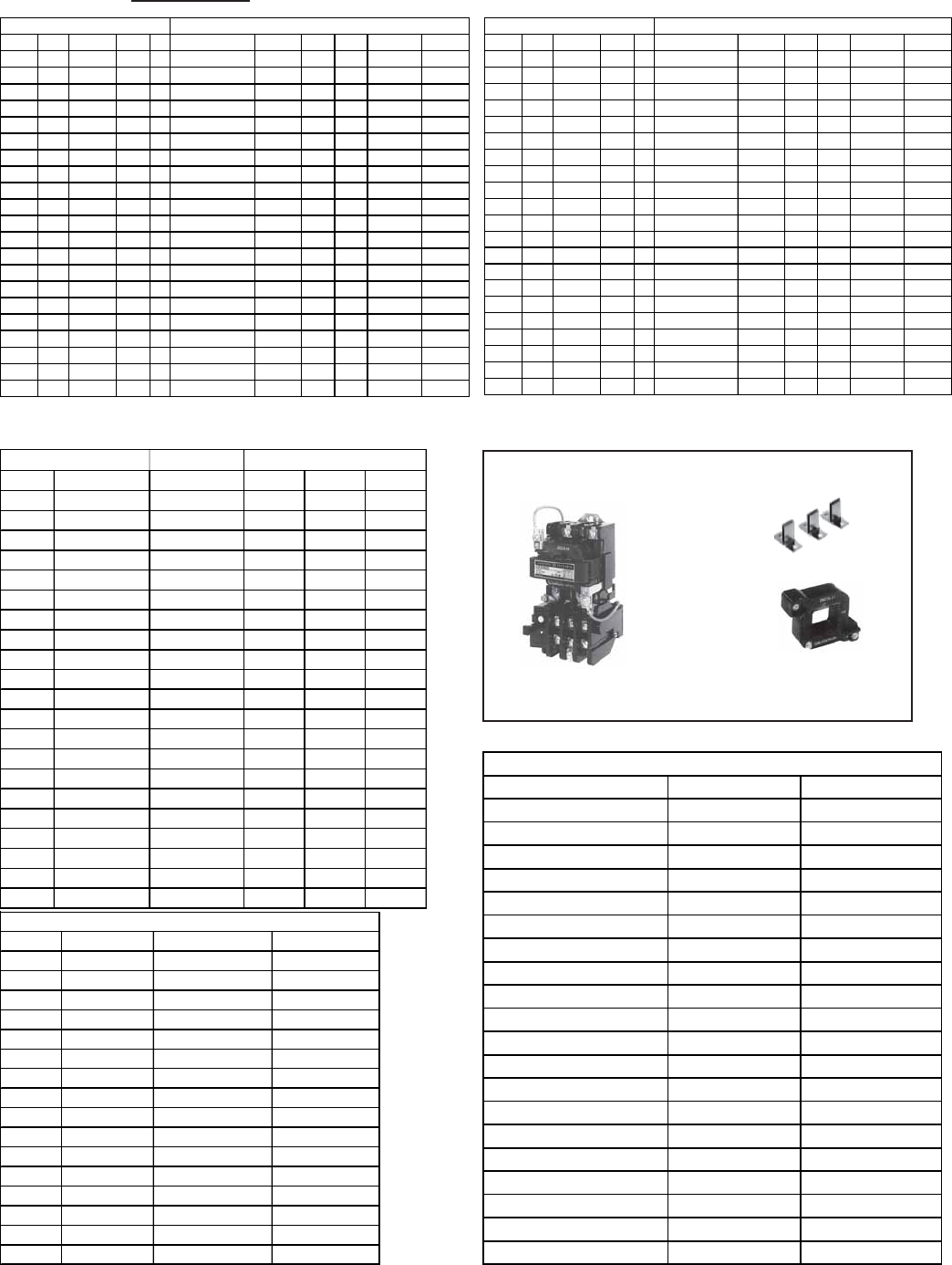
Blower Motors, Contactor, and Starters
CODE 35 - BLOWER MOTOR
Motors in the table below that do not have a CODE 36 contactor listed do not have internal
overload protection and MUST be used with the CODE 37 motor starter and starter overload.
If a contactor is listed, motor may be used with either the contactor or the optional starter.
CODE 36 - Replacement Contactor (Option AN2)
Motor contactor, P/N 119625, Mfr #42AF35AJ-24V coil
CODE 37 - Replacement Starter (24V) & Overload (Option AN10)
When ordering a replacement IEC starter or overload, check the manufacturer's number on both
parts. If the number is different than that listed, both components must be replaced. IEC Starter
(contactor) and overload are mounted on rail, P/N 111387.
If Model RDF was manufactured prior to 1996, check to see if the IEC starter is line
voltage or 24 volt. If line voltage, select replacement starter on pages 9-10. If the motor
has a NEMA starter (units mfgd before 1991), see the replacement parts on page 10.
CODE 36 CODE 37
Starter
(24V) Overload
Contactor
Electrical Components (cont'd)
CODE 30 - DPDT
System Switch,
P/N 101900
(winter/off/
summer)
CODE 31 -
DPDT System
Switch,
P/N 101901
(service
switch)
CODE 32 - Null Pressure
Switch, P/N 88052
(remote damper motor
control in Air Control
Options AR 20 and 23)
CODE 32 -
Potentiometer,
P/N 16011 (remote
damper motor
control in Options
AR 19 and 22)
CODE 34 - Photohelic Pressure
Sensor, P/N 158893 (remote
damper motor control in Air
Control Options AR 36 and 37)
CODE 35 - Sampling Tube
only, P/N 159714
(Located in the electrical compartment;
see location on page 3.)
Service Power
Type HP P/N Model No. Frame fla Factor Factor Mfr No. P/N min max GE # P/N Mfr No. P/N
OPEN 1/2 102627 BF2054 56Z 8.8 5/8" 120 1 1.15 CL00A310T-1 151275 8.00 12.00 RTA1-N 151193 42AF35AJ-24V 119625
OPEN 1/2 102627 BF2054 56Z 5.1 5/8" 208 1 1.15 CL00A310T-1 151275 4.00 6.30 RTA1-L 151191 42AF35AJ-24V 119625
OPEN 1/2 102627 BF2054 56Z 4.4 5/8" 240 1 1.15 CL00A310T-1 151275 4.00 6.30 RTA1-L 151191 42AF35AJ-24V 119625
OPEN 1/2 159183 H880 LA56 2.5 5/8" 208 3 1.25 CL00A310T-1 151275 1.80 2.70 RTA1-J 151189 42AF35AJ-24V 119625
OPEN 1/2 159183 H880 LA56 3.0 5/8" 240 3 1.25 CL00A310T-1 151275 2.50 4.10 RTA1-K 151190 42AF35AJ-24V 119625
OPEN 1/2 159183 H880 LA56 1.5 5/8" 480 3 1.25 CL00A310T-1 151275 1.30 1.90 RTA1-H 151188 42AF35AJ-24V 119625
OPEN 1/2 202089 H991 H56 0.9 5/8" 575 3 1.25 CL00A310T-1 151275 0.65 1.10 RTA1-F 151186 ============ ===
OPEN 3/4 93548 312P629 B56 11.0 5/8" 120 1 1.25 CL01A310T-1 151276 10.00 16.00 RTA1-P 151194 42AF35AJ-24V 119625
OPEN 3/4 93548 312P629 B56 6.3 5/8" 208 1 1.25 CL00A310T-1 151275 5.50 8.50 RTA1-M 151192 42AF35AJ-24V 119625
OPEN 3/4 93548 312P629 B56 5.5 5/8" 240 1 1.25 CL00A310T-1 151275 4.00 6.30 RTA1-L 151191 42AF35AJ-24V 119625
OPEN 3/4 36951 312P696 D56 2.9 5/8" 208 3 1.25 CL00A310T-1 151275 2.50 4.10 RTA1-K 151190 42AF35AJ-24V 119625
OPEN 3/4 36951 312P696 D56 2.6 5/8" 240 3 1.25 CL00A310T-1 151275 2.50 4.10 RTA1-K 151190 42AF35AJ-24V 119625
OPEN 3/4 36951 312P696 D56 1.3 5/8" 480 3 1.25 CL00A310T-1 151275 1.00 1.50 RTA1-G 151187 42AF35AJ-24V 119625
OPEN 3/4 202090 H992 H56 1.0 5/8" 575 3 1.25 CL00A310T-1 151275 0.65 1.10 RTA1-F 151186 ============ ===
OPEN 1 13685 C523 H56 13.0 5/8" 120 1 1.25 CL01A310T-1 151276 10.00 16.00 RTA1-P 151194 42AF35AJ-24V 119625
OPEN 1 13685 C523 H56 7.5 5/8" 208 1 1.25 CL00A310T-1 151275 5.50 8.50 RTA1-M 151192 42AF35AJ-24V 119625
OPEN 1 13685 C523 H56 6.5 5/8" 240 1 1.25 CL00A310T-1 151275 5.50 8.50 RTA1-M 151192 42AF35AJ-24V 119625
OPEN 1 36580 H882 F56 3.7 5/8" 208 3 1.15 79% CL00A310T-1 151275 2.50 4.10 RTA1-K 151190 42AF35AJ-24V 119625
OPEN 1 36580 H882 F56 3.2 5/8" 240 3 1.15 79% CL00A310T-1 151275 2.50 4.10 RTA1-K 151190 42AF35AJ-24V 119625
OPEN 1 36580 H882 F56 1.6 5/8" 480 3 1.15 79% CL00A310T-1 151275 1.30 1.90 RTA1-H 151188 42AF35AJ-24V 119625
OPEN 1 158175 E1006 N143T 1.1 7/8" 575 3 1.15 82.50% CL00A310T-1 151275 1.00 1.50 RTA1-G 151187 ============ ===
OPEN 1.5 194202 C621 56 15.0 5/8" 120 1 1.2 86.4 77.20% CL01A310T-1 151276 10.00 16.00 RTA1-P 151194 42AF35AJ-24V 119625
OPEN 1.5 194202 C621 56 7.8 5/8" 208 1 1.2 86.4 77.20% CL00A310T-1 151275 5.50 8.50 RTA1-M 151192 42AF35AJ-24V 119625
OPEN 1.5 194202 C621 56 7.5 5/8" 240 1 1.2 86.4 77.20% CL00A310T-1 151275 5.50 8.50 RTA1-M 151192 42AF35AJ-24V 119625
OPEN 1.5 115859 H884 UA56 5.6 5/8" 208 3 1.15 66.4 78.60% CL00A310T-1 151275 4.00 6.30 RTA1-L 151191 42AF35AJ-24V 119625
OPEN 1.5 115859 H884 UA56 5.0 5/8" 240 3 1.15 66.4 78.60% CL00A310T-1 151275 4.00 6.30 RTA1-L 151191 42AF35AJ-24V 119625
OPEN 1.5 115859 H884 UA56 2.8 5/8" 480 3 1.15 66.4 78.60% CL00A310T-1 151275 2.50 4.10 RTA1-K 151190 42AF35AJ-24V 119625
OPEN 1.5 158162 E1007 R145T 1.6 7/8" 575 3 1.15 85.3 84.00% CL00A310T-1 151275 1.30 1.90 RTA1-H 151188 ============ ===
OPEN 2 202581 RB1204A 56 24.6 7/8" 120 1 CL04A310M-1 151279 21.00 26.00 RTA1-U 151198 42AF35AJ-24V 119625
OPEN 2 202581 RB1204A 56 12.3 7/8" 208 1 CL01A310T-1 151276 10.00 16.00 RTA1-P 151194 42AF35AJ-24V 119625
OPEN 2 202581 RB1204A 56 12.3 7/8" 240 1 CL01A310T-1 151276 10.00 16.00 RTA1-P 151194 42AF35AJ-24V 119625
OPEN 2 159327 H886 56HZ 7.0 7/8" 208 3 1.15 67 79% CL00A310T-1 151275 5.50 8.50 RTA1-M 151192 42AF35AJ-24V 119625
OPEN 2 159327 H886 56HZ 6.6 7/8" 240 3 1.15 67 79% CL00A310T-1 151275 5.50 8.50 RTA1-M 151192 42AF35AJ-24V 119625
OPEN 2 159327 H886 56HZ 3.5 7/8" 480 3 1.15 67 79% CL00A310T-1 151275 2.50 4.10 RTA1-K 151190 42AF35AJ-24V 119625
OPEN 2 158176 E1008 P145T 2.1 7/8" 575 3 1.15 86 84.00% CL00A310T-1 151275 1.80 2.70 RTA1-J 151189 ============ ===
OPEN 3 111560 B735 L56 13.7 5/8" 208 1 1.15 CL01A310T-1 151276 10.00 16.00 RTA1-P 151194 ============ ===
OPEN 3 111560 B735 L56 12.4 5/8" 230 1 1.15 CL01A310T-1 151276 10.00 16.00 RTA1-P 151194 ============ ===
OPEN 3 159185 H845 P56HZ 9.0 7/8" 208 3 1.15 CL00A310T-1 151275 8.00 12.00 RTA1-N 151193 42AF35AJ-24V 119625
OPEN 3 159185 H845 P56HZ 8.6 7/8" 240 3 1.15 CL00A310T-1 151275 8.00 12.00 RTA1-N 151193 42AF35AJ-24V 119625
OPEN 3 159185 H845 P56HZ 4.3 7/8" 480 3 1.15 CL00A310T-1 151275 4.00 6.30 RTA1-L 151191 42AF35AJ-24V 119625
OPEN 3 120019 H954 N56HZ 3.6 7/8" 575 3 1.15 80.3 83.80% CL00A310T-1 151275 2.50 4.10 RTA1-K 151190 ============ ===
Shaft Volt Starter OverloadCODE 37 - Starter (24V) CODE 36 - ContactorCODE 35 -Motor ph Efficiency
%

Form P-RDF, Page 7
(continued)
Blower Motors, Contactor, and Starters (cont'd)
TEFC 1/2 159184 C613 J56 7.2 5/8" 120 1 CL00A310T-1 151275 5.50 8.50 RTA1-M 151192 42AF35AJ-24V 119625
TEFC 1/2 159184 C613 J56 3.5 5/8" 208 1 CL00A310T-1 151275 2.50 4.10 RTA1-K 151190 42AF35AJ-24V 119625
TEFC 1/2 159184 C613 J56 3.6 5/8" 240 1 CL00A310T-1 151275 2.50 4.10 RTA1-K 151190 42AF35AJ-24V 119625
TEFC 1/2 16077 H274 H56 2.3 5/8" 208 3 1 59.5 74.80% CL00A310T-1 151275 1.80 2.70 RTA1-J 151189 42AF35AJ-24V 119625
TEFC 1/2 16077 H274 H56 2.0 5/8" 240 3 1 59.5 74.80% CL00A310T-1 151275 1.80 2.70 RTA1-J 151189 42AF35AJ-24V 119625
TEFC 1/2 16077 H274 H56 1.0 5/8" 480 3 1 59.5 74.80% CL00A310T-1 151275 0.65 1.10 RTA1-F 151186 42AF35AJ-24V 119625
TEFC 1/2 105568 H276 J56 0.7 5/8" 575 3 1.15 76.4 77% CL00A310T-1 151275 0.65 1.10 RTA1-F 151186 ============ ===
TEFC 3/4 115860 F353 F56 11.0 5/8" 120 1 CL01A310T-1 151276 10.00 16.00 RTA1-P 151194 42AF35AJ-24V 119625
TEFC 3/4 115860 F353 F56 5.4 5/8" 208 1 CL00A310T-1 151275 4.00 6.30 RTA1-L 151191 42AF35AJ-24V 119625
TEFC 3/4 159184 F353 F56 5.5 5/8" 240 1 CL00A310T-1 151275 4.00 6.30 RTA1-L 151191 42AF35AJ-24V 119625
TEFC 3/4 20371 H580 KA56 2.0 5/8" 208 3 1 73.5 81.10% CL00A310T-1 151275 1.80 2.70 RTA1-J 151189 42AF35AJ-24V 119625
TEFC 3/4 20371 H580 KA56 2.2 5/8" 240 3 1 73.5 81.10% CL00A310T-1 151275 1.80 2.70 RTA1-J 151189 42AF35AJ-24V 119625
TEFC 3/4 20371 H580 KA56 1.1 5/8" 480 3 1 73.5 81.10% CL00A310T-1 151275 1.00 1.50 RTA1-G 151187 42AF35AJ-24V 119625
TEFC 3/4 105569 H461 L56 0.8 5/8" 575 3 1.15 78.3 82% CL00A310T-1 151275 0.65 1.10 RTA1-F 151186 ============ ===
TEFC 1 174993 159105 L56 12.0 5/8" 120 1 CL01A310T-1 151276 10.00 16.00 RTA1-P 151194 42AF35AJ-24V 119625
TEFC 1 174993 159105 L56 6.2 5/8" 208 1 CL00A310T-1 151275 4.00 6.30 RTA1-L 151191 42AF35AJ-24V 119625
TEFC 1 174993 159105 L56 6.0 5/8" 240 1 CL00A310T-1 151275 4.00 6.30 RTA1-L 151191 42AF35AJ-24V 119625
TEFC 1 16080 H524 J56 3.3 5/8" 208 3 1 74.4 80.20% CL00A310T-1 151275 2.50 4.10 RTA1-K 151190 42AF35AJ-24V 119625
TEFC 1 16080 H524 J56 3.4 5/8" 240 3 1 74.4 80.20% CL00A310T-1 151275 2.50 4.10 RTA1-K 151190 42AF35AJ-24V 119625
TEFC 1 16080 H524 J56 1.7 5/8" 480 3 1 74.4 80.20% CL00A310T-1 151275 1.30 1.90 RTA1-H 151188 42AF35AJ-24V 119625
TEFC 1 105570 H525 H56 1.4 5/8" 575 3 1.15 71.6 80.40% CL00A310T-1 151275 1.00 1.50 RTA1-G 151187 ============ ===
TEFC 1.5 94347 311P402 TK56H 16.4 5/8" 120 1 CL02A310T-1 151277 14.50 18.00 RTA1-S 151196 42AF35AJ-24V 119625
TEFC 1.5 94347 311P402 TK56H 9.5 5/8" 208 1 CL00A310T-1 151275 8.00 12.00 RTA1-N 151193 42AF35AJ-24V 119625
TEFC 1.5 94347 311P402 TK56H 8.2 5/8" 240 1 CL00A310T-1 151275 8.00 12.00 RTA1-N 151193 42AF35AJ-24V 119625
TEFC 1.5 101286 H535 L56H 4.3 5/8" 208 3 1 80.9 82.40% CL00A310T-1 151275 4.00 6.30 RTA1-L 151191 42AF35AJ-24V 119625
TEFC 1.5 101286 H535 L56H 4.4 5/8" 240 3 1 80.9 82.40% CL00A310T-1 151275 4.00 6.30 RTA1-L 151191 42AF35AJ-24V 119625
TEFC 1.5 101286 H535 L56H 2.2 5/8" 480 3 1 80.9 82.40% CL00A310T-1 151275 1.80 2.70 RTA1-J 151189 42AF35AJ-24V 119625
TEFC 1.5 105665 E127 M145T 1.6 7/8" 575 3 1.15 85.7 84% CL00A310T-1 151275 1.30 1.90 RTA1-H 151188 ============ ===
TEFC 2 105572 K200 F182T 24 1-1/8" 120 1 CL04A310M-1 151279 21.00 26.00 RTA1-U 151198 ============ ===
TEFC 2 205881 L3516TM F182T 8.3 7/8" 240 1 1.15 99 78% CL00A310T-1 151275 5.50 8.50 RTA1-M 151192 42AF35AJ-24V 119625
TEFC 2 158165 E166 145T 7.0 7/8" 208 3 CL00A310T-1 151275 5.50 8.50 RTA1-M 151192 ============ ===
TEFC 2 158165 E166 145T 5.8 7/8" 240 3 CL00A310T-1 151275 4.00 6.30 RTA1-L 151191 ============ ===
TEFC 2 158165 E166 145T 2.9 7/8" 480 3 CL00A310T-1 151275 2.50 4.10 RTA1-K 151190 ============ ===
TEFC 2 158166 E169 145T 2.3 7/8" 575 3 CL00A310T-1 151275 1.90 2.70 RTA1-J 151189 ============ ===
TEFC 3 111564 K222 F184T 30.0 1-1/8" 120 1 CL04A310M-1 151279 25.00 32.00 RTA1-V 151199 ============ ===
TEFC 3 111564 K222 F184T 15.0 1-1/8" 240 1 CL02A310T-1 151277 14.50 18.00 RTA1-S 151196 ============ ===
TEFC 3 159330 B - M3559T 145T 7.9 7/8" 208 3 CL00A310T-1 151275 5.50 8.50 RTA1-N 151192 ============ ===
TEFC 3 159330 B - M3559T 145T 7.2 7/8" 240 3 CL00A310T-1 151275 5.50 8.50 RTA1-N 151192 ============ ===
TEFC 3 159330 B - M3559T 145T 3.6 7/8" 480 3 CL00A310T-1 151275 2.50 4.10 RTA1-K 151190 ============ ===
TEFC 3 111571 B-M3559T-5 145T 3 7/8" 575 3 CL00A310T-1 151275 2.50 4.10 RTA1-K 151190 ============ ===
TEFC 5 111567 K223 F184T 20.2 1-1/8" 240 1 CL25A310T-1 151278 17.50 22.00 RTA1-T 151197 ============ ===
TEFC 5 155048 E241 184T 16 1-1/8" 208 3 CL02A310T-1 151277 14.50 18.00 RTA1-S 151196 ============ ===
TEFC 5 155048 E241 184T 12 1-1/8" 240 3 CL01A310T-1 151276 10.00 16.00 RTA1-P 151194 ============ ===
TEFC 5 155048 E241 184T 6 1-1/8" 480 3 CL00A310T-1 151275 4.00 6.30 RTA1-L 151191 ============ ===
TEFC 5 158170 E273 184T 4.8 1-1/8" 575 3 CL00A310T-1 151275 4.00 6.30 RTA1-L 151191 ============ ===
Service Power
Type HP P/N Model No. Frame fla Factor Factor Mfr No. P/N min max GE # P/N Mfr No. P/N
OPEN 5 111562 V211 L184T 28.3 1-1/8" 208 1 CL04A310M-1 151279 25.00 32.00 RTA1-V 151199 ============ ===
OPEN 5 111562 V211 L184T 25.6 1-1/8" 240 1 CL04A310M-1 151279 25.00 32.00 RTA1-V 151199 ============ ===
OPEN 5 113371 196033 Y56HZ 13.4 7/8" 208 3 1.15 87.2 85% CL01A310T-1 151276 10.00 16.00 RTA1-P 151194 ============ ===
OPEN 5 113371 196033 Y56HZ 13.2 7/8" 240 3 1.15 87.2 85% CL01A310T-1 151276 10.00 16.00 RTA1-P 151194 ============ ===
OPEN 5 113371 196033 Y56HZ 6.6 7/8" 480 3 1.15 87.2 85% CL00A310T-1 151275 5.50 8.50 RTA1-M 151192 ============ ===
OPEN 5 120020 H956 Y56HZ 5.4 7/8" 575 3 1.15 85.9 85.30% CL00A310T-1 151275 4.00 6.30 RTA1-L 151191 ============ ===
OPEN 7.5 105828 V305 S215T 35.4 1-3/8" 208 1 CL06A311M-1 203687 30.00 43.00 RTA2-E 151206 ============ ===
OPEN 7.5 105828 V305 S215T 32.0 1-3/8" 230 1 CL06A311M-1 203687 30.00 43.00 RTA2-E 151206 ============ ===
OPEN 7.5 105854 E302 F213T 22.5 1-3/8" 208 3 CL04A310M-1 151279 21.00 26.00 RTA1-U 151198 ============ ===
OPEN 7.5 105855 E300 213T 19.4 1-3/8" 240 3 CL25A310T-1 151278 17.50 22.00 RTA1-T 151197 ============ ===
OPEN 7.5 105855 E300 213T 9.7 1-3/8" 480 3 CL00A310T-1 151275 8.00 12.00 RTA1-N 151193 ============ ===
OPEN 7.5 158164 E324 S213T 7.8 1-3/8" 575 3 CL00A310T-1 151275 5.50 8.50 RTA1-M 151192 ============ ===
OPEN 10 105830 V303 S215T 42.0 1-3/8" 208 1 CL06A311M-1 203687 30.00 43.00 RTA2-E 151206 ============ ===
OPEN 10 105830 V303 S215T 38.0 1-3/8" 230 1 CL06A311M-1 203687 30.00 43.00 RTA2-E 151206 ============ ===
OPEN 10 105857 E303 F215T 31.0 1-3/8" 208 3 CL04A310M-1 151279 25.00 32.00 RTA1-V 151199 ============ ===
OPEN 10 105858 E301 215T 26.0 1-3/8" 240 3 CL04A310M-1 151279 25.00 32.00 RTA1-V 151199 ============ ===
OPEN 10 105858 E301 215T 13.0 1-3/8" 480 3 CL01A310T-1 151276 10.00 16.00 RTA1-P 151194 ============ ===
OPEN 10 158163 E325 S215T 10.4 1-3/8" 575 3 CL01A310T-1 151276 10.00 16.00 RTA1-P 151194 ============ ===
OPEN 15 142287 B-FM2513T-8 254T 43.1 1-5/8" 208 3 CL06A311M-1 203687 42.00 55.00 RTA2-G 151202 ============ ===
OPEN 15 142288 BALD-FM2513T 254T 39.0 1-5/8" 240 3 CL06A311M-1 203687 30.00 43.00 RTA2-E 151206 ============ ===
OPEN 15 142288 BALD-FM2513T 254T 19.5 1-5/8" 480 3 CL25A310T-1 151278 17.50 22.00 RTA1-T 151197 ============ ===
OPEN 15 142289 B-EFM2513T-5 254T 16.0 1-5/8" 575 3 CL02A310T-1 151277 14.50 18.00 RTA1-S 151196 ============ ===
OPEN 20 142295 B-FM2515T-8 256T 58.7 1-5/8" 208 3 1.15 80 88.50% CL07A311M-1 203793 54.00 65.00 RTA2-H 151203 ============ ===
OPEN 20 142296 BAL-FM2515T 256T 53.0 1-5/8" 240 3 1.15 81 88.50% CL07A311M-1 203793 42.00 55.00 RTA2-G 151202 ============ ===
OPEN 20 142296 BAL-FM2515T 256T 26.5 1-5/8" 480 3 1.15 81 88.50% CL04A310M-1 151279 25.00 32.00 RTA1-V 151199 ============ ===
OPEN 20 142297 B-FM2515T-5 256T 21.2 1-5/8" 575 3 1.15 80 88.50% CL25A310T-1 151278 17.50 22.00 RTA1-T 151197 ============ ===
OPEN 25 159021 E545-F2 S284T 69.8 1-7/8" 208 3 1.15 84.1 91.70% CL09A311M-1 203794 64.00 82.00 RTA2-J 151204 ============ ===
OPEN 25 159022 E546-F2 S284T 60.6 1-7/8" 240 3 1.15 84.1 91.70% CL07A311M-1 203793 54.00 65.00 RTA2-H 151203 ============ ===
OPEN 25 159022 E546-F2 S284T 30.3 1-7/8" 480 3 1.15 84.1 91.70% CL04A310M-1 151279 25.00 32.00 RTA1-V 151199 ============ ===
OPEN 25 159023 E594-F2 S284T 24.3 1-7/8" 575 3 1.15 84.1 91.70% CL04A310M-1 151279 21.00 26.00 RTA1-U 151198 ============ ===
OPEN 30 159024 E547-F2 S286T 78.0 1-7/8" 208 3 1.15 81 92.40% CL09A311M-1 203794 64.00 82.00 RT2-J 151204 ============ ===
OPEN 30 159025 E548-F2 S286T 75.0 1-7/8" 240 3 1.15 81 92.40% CL09A311M-1 203794 64.00 82.00 RT2-J 151204 ============ ===
OPEN 30 159025 E548-F2 S286T 37.5 1-7/8" 480 3 1.15 81 92.40% CL06A311M-1 203687 30.00 43.00 RTA2-E 151206 ============ ===
OPEN 30 159026 E595-F2 S286T 30.0 1-7/8" 575 3 1.15 81 92.40% CL04A310M-1 151279 25.00 32.00 RTA1-V 151199 ============ ===
CODE 37 - Starter (24V) Starter Overload CODE 36 - Contactor
Efficiency
%
CODE 35 - Motor Shaft Volt ph

Form P-RDF, Page 8
Blower Motors, Contactor, and Starters (cont'd)
CODE 38 - Replacement Holding Coils for IEC Starters
Service Power
Type HP P/N Model No. Frame fla Factor Factor Mfr No. P/N min max GE # P/N Mfr No. P/N
TEFC 7.5 105842 K305 F215T 34 1-3/8" 240 1 CL06A311M-1 203687 30.00 43.00 RTA2-E 151206 ============ ===
TEFC 7.5 158171 E356 213T 24 1-3/8" 208 3 CL04A310M-1 151279 21.00 26.00 RTA1-U 151198 ============ ===
TEFC 7.5 158171 E356 213T 19 1-3/8" 240 3 CL25A310T-1 151278 17.50 22.00 RTA1-T 151197 ============ ===
TEFC 7.5 158171 E356 213T 9.5 1-3/8" 480 3 CL00A310T-1 151275 8.00 12.00 RTA1-N 151193 ============ ===
TEFC 7.5 158172 E364 213T 7.6 1-3/8" 575 3 CL00A310T-1 151275 5.50 8.50 RTA1-N 151192 ============ ===
TEFC 10 105846 K313 215T 39 1-3/8" 240 1 CL06A311M-1 203687 30.00 43.00 RTA2-E 151206 ============ ===
TEFC 10 158173 E357 215T 30 1-3/8" 208 3 CL04A310M-1 151279 25.00 32.00 RTA1-V 151199 ============ ===
TEFC 10 158173 E357 215T 26 1-3/8" 240 3 CL04A310M-1 151279 21.00 26.00 RTA1-U 151198 ============ ===
TEFC 10 158173 E357 215T 13 1-3/8" 480 3 CL02A310T-1 151277 10.00 16.00 RTA1-P 151194 ============ ===
TEFC 10 158174 E365 215T 9.6 1-3/8" 575 3 CL00A310T-1 151275 8.00 12.00 RTA1-N 151193 ============ ===
TEFC 15 142443 BAL-FM2333T 254T 38 1-5/8" 240 3 1.15 82 90.20% CL06A311M-1 203687 30.00 43.00 RTA2-E 151206 ============ ===
TEFC 15 142443 BAL-FM2333T 254T 19 1-5/8" 480 3 1.15 82 90.20% CL25A310T-1 151278 17.50 22.00 RTA1-T 151197 ============ ===
TEFC 15 142444 B-FM2333-5 254T 15 1-5/8" 575 3 1.15 82 90.20% CL02A310T-1 151277 10.00 16.00 RTA1-P 151194 ============ ===
TEFC 20 142301 BAL-FM2334T 256T 52 1-5/8" 240 3 1.15 81 89.50% CL07A311M-1 203793 42.00 55.00 RTA2-G 151202 ============ ===
TEFC 20 142301 BAL-FM2334T 256T 26 1-5/8" 480 3 1.15 81 89.50% CL04A310M-1 151279 25.00 32.00 RTA1-V 151199 ============ ===
TEFC 20 142302 B-FM2334T-5 256T 20.6 1-5/8" 575 3 1.15 81 89.50% CL25A310T-1 151278 17.50 22.00 RTA1-T 151197 ============ ===
EE 1 105659 E103 N143T 3.1 7/8" 208 3 CL00A310T-1 151275 2.50 4.10 RTA1-K 151190 ============ ===
EE 1 159328 E1015 143T 2.7 7/8" 240 3 CL00A310T-1 151275 2.50 4.10 RTA1-K 151190 ============ ===
EE 1 159328 E1015 143T 1.4 7/8" 480 3 CL00A310T-1 151275 1.00 1.50 RTA1-G 151187 ============ ===
EE 1 158175 E1006 N143T 1.1 7/8" 575 3 CL00A310T-1 151275 1.00 1.50 RTA1-G 151187 ============ ===
EE 1 1/2 105662 E104 P145T 4.5 7/8" 208 3 CL00A310T-1 151275 4.00 6.30 RTA1-L 151191 ============ ===
EE 1 1/2 159329 E1016 145T 3.9 7/8" 240 3 CL00A310T-1 151275 2.50 4.10 RTA1-K 151190 ============ ===
EE 1 1/2 159329 E1016 145T 2.0 7/8" 480 3 CL00A310T-1 151275 1.90 2.70 RTA1-J 151189 ============ ===
EE 1 1/2 158162 E1007 R145T 1.6 7/8" 575 3 CL00A310T-1 151275 1.30 1.90 RTA1-H 151188 ============ ===
EE 2 105664 E105 P145T 6.0 7/8" 208 3 CL00A310T-1 151275 4.00 6.30 RTA1-L 151191 ============ ===
EE 2 159027 E1017 145T 5.8 7/8" 240 3 CL00A310T-1 151275 4.00 6.30 RTA1-L 151191 ============ ===
EE 2 159027 E1017 145T 2.9 7/8" 480 3 CL00A310T-1 151275 2.50 4.10 RTA1-K 151190 ============ ===
EE 2 158176 E1008 P145T 2.1 7/8" 575 3 CL00A310T-1 151275 1.90 2.70 RTA1-J 151189 ============ ===
EE 3 159186 B-35L405S489G3 145T 8.3 7/8" 208 3 CL00A310T-1 151275 8.00 12.00 RTA1-N 151193 ============ ===
EE 3 159028 B-EM3158T 145T 7.4 7/8" 240 3 CL00A310T-1 151275 5.50 8.50 RTA1-N 151192 ============ ===
EE 3 159028 B-EM3158T 145T 3.7 7/8" 480 3 CL00A310T-1 151275 2.50 4.10 RTA1-K 151190 ============ ===
EE 3 159030 B-35L405S709G1 145T 3.0 7/8" 575 3 CL00A310T-1 151275 2.50 4.10 RTA1-K 151190 ============ ===
EE 5 159029 E204 H182T 13.9 1-1/8" 208 3 CL02A310T-1 151277 10.00 16.00 RTA1-P 151194 ============ ===
EE 5 159029 E204 H182T 11.6 1-1/8" 240 3 CL01A310T-1 151276 10.00 16.00 RTA1-P 151194 ============ ===
EE 5 159029 E204 H182T 5.8 1-1/8" 480 3 CL00A310T-1 151275 5.50 8.50 RTA1-M 151192 ============ ===
EE 5 111602 BAL-M3613T-5 184T 4.8 1-1/8" 575 3 CL00A310T-1 151275 4.00 6.30 RTA1-L 151191 ============ ===
EE 7 1/2 159331 E316 D213T 22.3 1-3/8" 208 3 CL04A310M-1 151279 21.00 26.00 RTA1-U 151198 ============ ===
EE 7 1/2 159332 E317 D213T 19.4 1-3/8" 240 3 CL25A310T-1 151278 17.50 22.00 RTA1-T 151197 ============ ===
EE 7 1/2 159332 E317 D213T 9.7 1-3/8" 480 3 CL00A310T-1 151275 8.00 12.00 RTA1-N 151193 ============ ===
EE 7 1/2 158164 E324 S213T 7.8 1-3/8" 575 3 CL00A310T-1 151275 5.50 8.50 RTA1-N 151192 ============ ===
EE 10 159333 E318 H215T 27.8 1-3/8" 208 3 CL04A310M-1 151279 25.00 32.00 RTA1-V 151199 ============ ===
EE 10 159334 E397 H215T 24.2 1-3/8" 240 3 CL04A310M-1 151279 21.00 26.00 RTA1-U 151198 ============ ===
EE 10 159334 E397 H215T 12.1 1-3/8" 480 3 CL01A310T-1 151276 10.00 16.00 RTA1-P 151194 ============ ===
EE 10 158163 E325 S215T 10.4 1-3/8" 575 3 CL01A310T-1 151276 10.00 16.00 RTA1-P 151194 ============ ===
EE 15 142440 B-EFM2513T-8 254T 41.5 1-5/8" 208 3 1.15 84 92.40% CL06A311M-1 203687 30.00 43.00 RTA2-E 151206 ============ ===
EE 15 142441 B-EFM2513T 254T 36.0 1-5/8" 240 3 1.15 84 92.40% CL06A311M-1 203687 30.00 43.00 RTA2-E 151206 ============ ===
EE 15 142441 B-EFM2513T 254T 18.0 1-5/8" 480 3 1.15 84 92.40% CL25A310T-1 151278 17.50 22.00 RTA1-T 151197 ============ ===
EE 15 142289 B-EFM2513T-5 254T 16 1-5/8" 575 3 1.15 84 92.40% CL02A310T-1 151277 10.00 16.00 RTA1-P 151194 ============ ===
EE 20 159187 C-E452-F2 S256T 57.0 1-5/8" 208 3 1.15 84 93.60% CL07A311M-1 203793 54.00 65.00 RTA2-H 151203 ============ ===
EE 20 142299 B-EFM2515T 256T 48.0 1-5/8" 240 3 1.15 84 93.00% CL07A311M-1 203793 42.00 55.00 RTA2-G 151202 ============ ===
EE 20 142299 B-EFM2515T 256T 24.0 1-5/8" 480 3 1.15 84 93.00% CL04A310M-1 151279 21.00 26.00 RTA1-U 151198 ============ ===
EE 20 142300 B-EFM2515T-5 256T 19.2 1-5/8" 575 3 1.15 84 93.00% CL25A310T-1 151278 17.50 22.00 RTA1-T 151197 ============ ===
CODE 36 - ContactorCODE 35 - Motor Shaft Volt ph Efficiency
%
CODE 37 - Starter (24V) Starter Overload
Voltage
GE # Reznor
P/N
For Use with
Contactors
Beginning with
GE#
Voltage
GE # Reznor
P/N
For Use with
Contactors
Beginning with
GE#
Voltage
GE # Reznor
P/N
For Use with
Contactors
Beginning with
GE#
24 LB1A-C 151280 24 LB3A-C 151286 208 LB4A-L 151292
120 LB1A-J 151281 120 LB3A-J 151287 230 LB4A-S 151293
208 LB1A-L 151282 208 LB3A-L 151288 460 LB4A-U 151294
230 LB1A-S 151283 230 LB3A-S 151289
460 LB1A-U 151284 460 LB3A-U 151290
575 LB1A-Y 151285 575 LB3A-Y 151291
CL00; CL01;
CL02; CL25 CL04; CL45
CL06; CL07;
CL08; CL09

Form P-RDF, Page 9
Replacement Line Voltage IEC Starters for RDF units manufactured before 1996
Type HP P/N volt ph Mfg No. P/N min max GE # P/N
OPEN 1/2 102627 120 1 CL00A310T-J 151146 8.00 12.00 RTA1-N 151193
OPEN 1/2 102627 208 1 CL00A310T-L 151150 4.00 6.30 RTA1-L 151191
OPEN 1/2 102627 240 1 CL00A310T-S 151147 4.00 6.30 RTA1-L 151191
OPEN 1/2 159183 208 3 CL00A310T-L 151150 1.90 2.70 RTA1-J 151189
OPEN 1/2 159183 240 3 CL00A310T-S 151147 2.50 4.10 RTA1-K 151190
OPEN 1/2 159183 480 3 CL00A310T-U 151148 1.30 1.90 RTA1-H 151188
OPEN 3/4 93548 120 1 CL01A310T-J 151151 10.00 16.00 RTA1-P 151194
OPEN 3/4 93548 208 1 CL00A310T-L 151150 5.50 8.50 RTA1-M 151192
OPEN 3/4 93548 240 1 CL00A310T-S 151147 4.00 6.30 RTA1-L 151191
OPEN 3/4 36951 208 3 CL00A310T-L 151150 2.50 4.10 RTA1-K 151190
OPEN 3/4 36951 240 3 CL00A310T-S 151147 2.50 4.10 RTA1-K 151190
OPEN 3/4 36951 480 3 CL00A310T-U 151148 1.00 1.50 RTA1-G 151187
OPEN 1 13685 120 1 CL01A310T-J 151151 10.00 16.00 RTA1-P 151194
OPEN 1 13685 208 1 CL00A310T-L 151150 5.50 8.50 RTA1-M 151192
OPEN 1 13685 240 1 CL00A310T-S 151147 5.50 8.50 RTA1-M 151192
OPEN 1 36580 208 3 CL00A310T-L 151150 2.50 4.10 RTA1-K 151190
OPEN 1 36580 240 3 CL00A310T-S 151147 2.50 4.10 RTA1-K 151190
OPEN 1 36580 480 3 CL00A310T-U 151148 1.30 1.90 RTA1-H 151188
OPEN 1 158175 575 3 CL00A310T-Y 151149 1.00 1.50 RTA1-G 151187
OPEN 1.5 194202 120 1 CL02A310T-J 151156 10.00 16.00 RTA1-P 151194
OPEN 1.5 194202 208 1 CL00A310T-L 151150 5.50 8.50 RTA1-M 151192
OPEN 1.5 194202 240 1 CL00A310T-S 151147 5.50 8.50 RTA1-M 151192
OPEN 1.5 115859 208 3 CL00A310T-L 151150 4.00 6.30 RTA1-L 151191
OPEN 1.5 115859 240 3 CL00A310T-S 151147 4.00 6.30 RTA1-L 151191
OPEN 1.5 115859 480 3 CL00A310T-U 151148 2.50 4.10 RTA1-K 151190
OPEN 1.5 158162 575 3 CL00A310T-Y 151149 1.30 1.90 RTA1-H 151188
OPEN 2 202581 120 1 CL25A310T-J 151160 17.50 22.00 RTA1-T 151197
OPEN 2 202581 208 1 CL01A310T-L 151155 8.00 12.00 RTA1-N 151193
OPEN 2 202581 240 1 CL01A310T-S 151152 8.00 12.00 RTA1-N 151193
OPEN 2 159327 208 3 CL00A310T-L 151150 5.50 8.50 RTA1-M 151192
OPEN 2 159327 240 3 CL00A310T-S 151147 5.50 8.50 RTA1-M 151192
OPEN 2 159327 480 3 CL00A310T-U 151148 2.50 4.10 RTA1-K 151190
OPEN 2 158176 575 3 CL00A310T-Y 151149 1.90 2.70 RTA1-J 151189
OPEN 3 111560 208 1 CL02A310T-L 151159 10.00 16.00 RTA1-P 151194
OPEN 3 111560 240 1 CL01A310T-S 151152 10.00 16.00 RTA1-P 151194
OPEN 3 159185 208 3 CL00A310T-L 151150 8.00 12.00 RTA1-N 151193
OPEN 3 159185 240 3 CL00A310T-S 151147 8.00 12.00 RTA1-N 151193
OPEN 3 159185 480 3 CL00A310T-U 151148 4.00 6.30 RTA1-L 151191
OPEN 3 120019 575 3 CL00A310T-Y 151149 2.50 4.10 RTA1-K 151190
OPEN 3 152002 208 3 ====== ====== 8.00 12.00 RTA1-N 151193
OPEN 3 152002 240 3 ====== ====== 5.50 8.50 RTA1-M 151192
OPEN 3 152002 480 3 ====== ====== 2.50 4.10 RTA1-K 151190
OPEN 5 111562 208 1 CL04A310M-L 151169 25.00 32.00 RTA1-V 151199
OPEN 5 111562 240 1 CL04A310M-S 151166 25.00 32.00 RTA1-V 151199
OPEN 5 113371 208 3 CL01A310T-L 151155 10.00 16.00 RTA1-P 151194
OPEN 5 113371 240 3 CL01A310T-S 151152 10.00 16.00 RTA1-P 151194
OPEN 5 113371 480 3 CL00A310T-U 151148 5.50 8.50 RTA1-M 151192
OPEN 5 120020 575 3 CL00A310T-Y 151149 4.00 6.30 RTA1-L 151191
OPEN 7.5 105828 208 1 CL06A311M-L 151173 30.00 43.00 RTA2-E 151206
OPEN 7.5 105828 240 1 CL45A310M-S 151170 25.00 32.00 RTA1-V 151199
OPEN 7.5 105854 208 3 CL25A310T-L 151164 21.00 26.00 RTA1-U 151198
OPEN 7.5 105855 240 3 CL25A310T-S 151161 17.50 22.00 RTA1-T 151197
OPEN 7.5 105855 480 3 CL01A310T-U 151153 8.00 12.00 RTA1-N 151193
OPEN 7.5 158164 575 3 CL00A310T-Y 151149 5.50 8.50 RTA1-M 151192
OPEN 10 105830 208 1 CL06A311M-L 151173 30.00 43.00 RTA2-E 151206
OPEN 10 105830 240 1 CL06A311M-S 151172 30.00 43.00 RTA2-E 151206
OPEN 10 105857 208 3 CL04A310M-L 151169 25.00 32.00 RTA1-V 151199
OPEN 10 105858 240 3 CL04A310M-S 151166 25.00 32.00 RTA1-V 151199
OPEN 10 105858 480 3 CL01A310T-U 151153 10.00 16.00 RTA1-P 151194
Motor CODE 39 - Starter (line voltage) and Overloads Type HP P/N volt ph Mfg No. P/N min max GE # P/N
TEFC 1/2 159184 120 1 CL00A310T-J 151146 5.50 8.50 RTA1-M 151192
TEFC 1/2 159184 208 1 CL00A310T-L 151150 2.50 4.10 RTA1-K 151190
TEFC 1/2 159184 240 1 CL00A310T-S 151147 2.50 4.10 RTA1-K 151190
TEFC 1/2 16077 208 3 CL00A310T-L 151150 1.90 2.70 RTA1-J 151189
TEFC 1/2 16077 240 3 CL00A310T-S 151147 1.90 2.70 RTA1-J 151189
TEFC 1/2 16077 480 3 CL00A310T-U 151148 0.65 1.10 RTA1-F 151186
TEFC 1/2 105568 575 3 CL00A310T-Y 151149 0.65 0.90 RTA1-F 151186
TEFC 3/4 115860 120 1 CL01A310T-J 151151 10.00 16.00 RTA1-P 151194
TEFC 3/4 115860 208 1 CL00A310T-L 151150 4.00 6.30 RTA1-L 151191
TEFC 3/4 115860 240 1 CL00A310T-S 151147 4.00 6.30 RTA1-L 151191
TEFC 3/4 20371 208 3 CL00A310T-L 151150 1.90 2.70 RTA1-J 151189
TEFC 3/4 20371 240 3 CL00A310T-S 151147 1.90 2.70 RTA1-J 151189
TEFC 3/4 20371 480 3 CL00A310T-U 151148 1.00 1.50 RTA1-G 151187
TEFC 3/4 105569 575 3 CL00A310T-Y 151149 0.65 1.10 RTA1-F 151186
TEFC 1 174993 120 1 CL01A310T-J 151151 10.00 16.00 RTA1-P 151194
TEFC 1 174993 208 1 CL00A310T-S 151147 5.50 8.50 RTA1-M 151192
TEFC 1 174993 240 1 CL00A310T-S 151147 5.50 8.50 RTA1-M 151192
TEFC 1 16080 208 3 CL00A310T-L 151150 2.50 4.10 RTA1-K 151190
TEFC 1 16080 240 3 CL00A310T-S 151147 2.50 4.10 RTA1-K 151190
TEFC 1 16080 480 3 CL00A310T-U 151148 1.30 1.90 RTA1-H 151188
TEFC 1 105570 575 3 CL00A310T-Y 151149 1.00 1.50 RTA1-G 151187
TEFC 1.5 94347 120 1 CL02A310T-J 151156 14.50 18.00 RTA1-S 151196
TEFC 1.5 94347 208 1 CL00A310T-L 151150 8.00 12.00 RTA1-N 151193
TEFC 1.5 94347 240 1 CL00A310T-S 151147 8.00 12.00 RTA1-N 151193
TEFC 1.5 101286 208 3 CL00A310T-L 151150 4.00 6.30 RTA1-L 151191
TEFC 1.5 101286 240 3 CL00A310T-S 151147 4.00 6.30 RTA1-L 151191
TEFC 1.5 101286 480 3 CL00A310T-U 151148 1.90 2.70 RTA1-J 151189
TEFC 1.5 105665 575 3 CL00A310T-Y 151149 1.30 1.90 RTA1-H 151188
TEFC 2 105572 120 1 CL04A310M-J 151165 21.00 26.00 RTA1-U 151198
TEFC 2 105572 240 1 CL01A310T-S 151152 10.00 16.00 RTA1-P 151194
TEFC 2 158165 208 3 CL00A310T-L 151150 5.50 8.50 RTA1-M 151192
TEFC 2 158165 240 3 CL00A310T-S 151147 4.00 6.30 RTA1-L 151191
TEFC 2 158165 480 3 CL00A310T-U 151148 2.50 4.10 RTA1-K 151190
TEFC 2 158166 575 3 CL00A310T-Y 151149 1.90 2.70 RTA1-J 151189
TEFC 3 111564 120 1 CL04A310M-J 151165 25.00 32.00 RTA1-V 151199
TEFC 3 111564 240 1 CL02A310T-S 151157 10.00 16.00 RTA1-P 151194
TEFC 3 159330 208 3 CL00A310T-L 151150 5.50 8.50 RTA1-N 151192
TEFC 3 159330 240 3 CL00A310T-S 151147 5.50 8.50 RTA1-N 151192
TEFC 3 159330 480 3 CL00A310T-U 151148 2.50 4.10 RTA1-K 151190
TEFC 3 111571 575 3 CL00A310T-Y 151149 2.50 4.10 RTA1-K 151190
TEFC 5 111567 240 1 CL04A310M-S 151166 17.50 22.00 RTA1-T 151197
TEFC 5 155048 208 3 CL01A310T-L 151155 14.50 18.00 RTA1-S 151196
TEFC 5 155048 240 3 CL01A310T-S 151152 10.00 16.00 RTA1-P 151194
TEFC 5 155048 480 3 CL00A310T-U 151148 4.00 6.30 RTA1-L 151191
TEFC 5 158170 575 3 CL00A310T-Y 151149 4.00 6.30 RTA1-L 151191
TEFC 7.5 105842 240 1 CL45A310M-S 151170 30.00 40.00 RTA1-W 151200
TEFC 7.5 158171 208 3 CL04A310M-L 151169 21.00 26.00 RTA1-U 151198
TEFC 7.5 158171 240 3 CL25A310T-S 151161 17.50 22.00 RTA1-T 151197
TEFC 7.5 158171 480 3 CL01A310T-U 151153 8.00 12.00 RTA1-N 151193
TEFC 7.5 158172 575 3 CL00A310T-Y 151149 5.50 8.50 RTA1-N 151192
TEFC 10 105846 240 1 CL06A311M-S 151172 30.00 43.00 RTA2-E 151206
TEFC 10 158173 208 3 CL04A310M-L 151169 25.00 32.00 RTA1-V 151199
TEFC 10 158173 240 3 CL04A310M-S 151166 21.00 26.00 RTA1-U 151198
TEFC 10 158173 480 3 CL01A310T-U 151153 10.00 16.00 RTA1-P 151194
TEFC 10 158174 575 3 CL01A310T-Y 151154 8.00 12.00 RTA1-N 151193
TEFC 15 142443 240 3 CL06A311M-S 151172 30.00 43.00 RTA2-E 151206
TEFC 15 142443 480 3 CL25A310T-U 151162 17.50 22.00 RTA1-T 151197
TEFC 15 142444 575 3 CL02A310T-Y 151158 10.00 16.00 RTA1-P 151194
TEFC 20 142301 240 3 CL07A311M-S 151175 42.00 55.00 RTA2-G 151202
Motor CODE 39 - Starter (line voltage) and Overloads
OPEN 10 158163 575 3 CL01A310T-Y 151154 10.00 16.00 RTA1-P 151194
OPEN 15 142287 208 3 CL06A311M-L 151173 42.00 55.00 RTA2-G 151202
OPEN 15 142288 240 3 CL06A311M-S 151172 30.00 43.00 RTA2-E 151206
OPEN 15 142288 480 3 CL25A310T-U 151162 17.50 22.00 RTA1-T 151197
OPEN 15 142289 575 3 CL02A310T-Y 151158 14.50 18.00 RTA1-S 151196
OPEN 20 142295 208 3 CL07A311M-L 151176 54.00 65.00 RTA2-H 151203
OPEN 20 142296 240 3 CL07A311M-S 151175 42.00 55.00 RTA2-G 151202
OPEN 20 142296 480 3 CL04A310M-U 151167 25.00 32.00 RTA1-V 151199
OPEN 20 142297 575 3 CL25A310T-Y 151163 17.50 22.00 RTA1-T 151197
OPEN 25 159021 208 3 CL09A311M-L 151179 64.00 82.00 RTA2-J 151204
OPEN 25 159022 240 3 CL08A311M-S 151177 54.00 65.00 RTA2-H 151203
OPEN 25 159022 480 3 CL45A310M-U 151171 25.00 32.00 RTA1-V 151199
OPEN 25 159023 575 3 CL04A310M-Y 151168 21.00 26.00 RTA1-U 151198
OPEN 30 159024 208 3 CL09A311M-L 151179 64.00 82.00 RT2-J 151204
OPEN 30 159025 240 3 CL09A311M-S 151178 64.00 82.00 RT2-J 151204
OPEN 30 159025 480 3 CL06A311M-U 151174 30.00 43.00 RTA2-E 151206
OPEN 30 159026 575 3 CL04A310M-Y 119852 25.00 32.00 RTA1-V 151199
TEFC 20 142301 480 3 CL04A310M-U 151167 25.00 32.00 RTA1-V 151199
TEFC 20 142302 575 3 CL25A310T-Y 151163 17.50 22.00 RTA1-T 151197
TEFC 25 165321 208 3 CL09A311M-L 151179 64.00 82.00 RT2-J 151204
TEFC 25 165321 240 3 CL07A311M-S 151175 54.00 65.00 RT2-H 151203
TEFC 25 165321 480 3 CL04A310M-U 151167 25.00 32.00 RT1-V 151199
TEFC 25 165322 575 3 CL04A310M-Y 151168 21.00 26.00 RT1-U 151198
TEFC 30 165323 208 3 CL10A311M-L 166756 78.00 97.00 RT2-L 151205
TEFC 30 165323 240 3 CL09A311M-S 151178 64.00 82.00 RT2-J 151204
TEFC 30 165323 480 3 CL06A311M-U 151174 30.00 43.00 RT2-E 151206
TEFC 30 165324 575 3 CL04A310M-Y 151168 25.00 32.00 RT1-V 151199
(continued)
Form P-RDF, Page 10
CODE 40 - Replacement Parts for NEMA Starters - Apply to RDF Models MAnufactured prior to 10/92
NEMA Open Motor
Starters
NOTE: Effective 10/90, motor starter coils were changed
to line voltage (For relay, see CODE 8, page 4)
Starter
Heater
Holding
Coil
Heaters for NEMA Starters
HP/Voltage/Phase GE# Reznor P/N
5/208/3 CR123C18.0B 89941 or 110617
5/230/3 and 10/460/3 CR123C16.3B 16193 or 110626
5/460/3 CR123C8.67A 16192 or 110619
5/208/3 CR123C19.8B 91542
7.5/208/3 CR123C25.0B 16196
7.5/230/3 CR123C22.8B 89924 or 110622
7.5/460/3 CR123C12.5B 17257 or 110624
10/208/3 CR123C33.0B 89947 or 110625
10/230/3 CR123C30.3B 89949 or 110627
10/460/3 CR123C137B 110623
15/208/3 CR123F56.7B 91543
15/230/3 CR123FC40.0B 89933
15/460/3 CR123C21.4B 19556
20/208/3 and 25/230/3 CR123F77.28B 91544
20/230/3 CR123F65.8B 91545
25/208/3 and 30/230/3 CR123F91.4B 91546
25/460/3 CR123C36.6B 16195
30/208/3 CR123F10.4C 91547
30/460/3 FA30B 119851
30/575/3 F327B 121175
Blower Motors, Contactor, and Starters (cont'd)
Replacement Line Voltage Starters for RDF units manfuactured before 1996 (cont'd)
Type HP P/N volt ph Mfg No. P/N min max GE # P/N
EE 1 105659 208 3 CL00A310T-L 151150 2.50 4.10 RTA1-K 151190
EE 1 159328 240 3 CL00A310T-S 151147 2.50 4.10 RTA1-K 151190
EE 1 159328 480 3 CL00A310T-U 151148 1.00 1.50 RTA1-G 151187
EE 1 158175 575 3 CL00A310T-Y 151149 1.00 1.50 RTA1-G 151187
EE 1 1/2 105662 208 3 CL00A310T-L 151150 4.00 6.30 RTA1-L 151191
EE 1 1/2 159329 240 3 CL00A310T-S 151147 2.50 4.10 RTA1-K 151190
EE 1 1/2 159329 480 3 CL00A310T-U 151148 1.90 2.70 RTA1-J 151189
EE 1 1/2 158162 575 3 CL00A310T-Y 151149 1.30 1.90 RTA1-H 151188
EE 2 105664 208 3 CL00A310T-L 151150 4.00 6.30 RTA1-L 151191
EE 2 159027 240 3 CL00A310T-S 151147 4.00 6.30 RTA1-L 151191
EE 2 159027 480 3 CL00A310T-U 151148 2.50 4.10 RTA1-K 151190
EE 2 158176 575 3 CL00A310T-Y 151149 1.90 2.70 RTA1-J 151189
EE 3 159186 208 3 CL00A310T-L 151150 8.00 12.00 RTA1-N 151193
EE 3 159028 240 3 CL00A310T-S 151147 5.50 8.50 RTA1-N 151192
EE 3 159028 480 3 CL00A310T-U 151148 2.50 4.10 RTA1-K 151190
EE 3 159030 575 3 CL00A310T-Y 151149 2.50 4.10 RTA1-K 151190
EE 5 159029 208 3 CL02A310T-L 151159 10.00 16.00 RTA1-P 151194
EE 5 159029 240 3 CL02A310T-S 151157 10.00 16.00 RTA1-P 151194
EE 5 159029 480 3 CL00A310T-U 151148 5.50 8.50 RTA1-M 151192
EE 5 111602 575 3 CL00A310T-Y 151149 4.00 6.30 RTA1-L 151191
EE 7 1/2 159331 208 3 CL04A310M-L 151169 21.00 26.00 RTA1-U 151198
Motor CODE 39 - Starter (line voltage) and Overloads
Type HP P/N volt ph Mfg No. P/N min max GE # P/N
EE 7 1/2 159332 240 3 CL25A310T-S 151161 17.50 22.00 RTA1-T 151197
EE 7 1/2 159332 480 3 CL00A310T-U 151148 8.00 12.00 RTA1-N 151193
EE 7 1/2 158164 575 3 CL00A310T-Y 151149 5.50 8.50 RTA1-N 151192
EE 10 159333 208 3 CL04A310M-L 151169 25.00 32.00 RTA1-V 151199
EE 10 159334 240 3 CL04A310M-S 151166 21.00 26.00 RTA1-U 151198
EE 10 159334 480 3 CL01A310T-U 151153 10.00 16.00 RTA1-P 151194
EE 10 158163 575 3 CL00A310T-Y 151149 10.00 16.00 RTA1-P 151194
EE 15 142440 208 3 CL06A311M-L 151173 30.00 43.00 RTA2-E 151206
EE 15 142441 240 1 CL06A311M-S 151172 30.00 43.00 RTA2-E 151206
EE 15 142441 480 3 CL25A310T-U 151162 17.50 22.00 RTA1-T 151197
EE 15 142289 575 3 CL02A310T-Y 151158 10.00 16.00 RTA1-P 151194
EE 20 159187 208 3 CL07A311M-L 151176 54.00 65.00 RTA2-H 151203
EE 20 142299 240 3 CL06A311M-S 151172 42.00 55.00 RTA2-G 151202
EE 20 142299 480 3 CL04A310M-U 151167 21.00 26.00 RTA1-U 151198
EE 20 142300 575 3 CL25A310T-Y 151163 17.50 22.00 RTA1-T 151197
EE 25 159031 208 3 CL09A311M-L 151179 64.00 82.00 RT2-J 151204
EE 25 159033 240 3 CL08A311M-S 151177 54.00 65.00 RT2-H 151203
EE 25 159033 480 3 CL04A310M-U 151167 25.00 32.00 RT1-V 151199
EE 30 159032 208 3 CL10A311M-L 166756 78.00 97.00 RT2-L 151205
EE 30 159034 240 3 CL09A311M-S 151178 64.00 82.00 RT2-J 151204
EE 30 159034 480 3 CL06A311M-U 151174 30.00 43.00 RT2-E 151206
Motor CODE 39 - Starter (line voltage) and Overloads
NEMA Motor Starters
Size Coil Voltage GE# RDF-1 RDF-2 RDF-3
0 24 Volt CR306B024 39919 39919 39919
1 24 Volt CR306C024 39920 39920 39920
2 24 Volt CR306D024 — 39921 39921
3 24 Volt CR306E024 — 39922 39922
4 24 Volt CR306F024 — — 91519
0 115 Volt CR306B002 111523 — —
0 208 Volt CR306B023 111524 111524 —
0 230 Volt CR306B003 111525 111525 —
0 460 Volt CR306B004 111522 111522 111522
1 115 Volt CR306C002 111526 — —
1 208 Volt CR306C023 111499 111499 —
1 230 Volt CR306C003 111521 111521 —
1 460 Volt CR306C004 111527 111527 —
2 208 Volt CR306D023 — 111528 111528
2 230 Volt CR306D003 — 111529 111529
2 460 Volt CR306D004 — 111530 111530
3 208 Volt CR306E023 — 111531 111531
3 230 Volt CR306E003 — — 111533
3 460 Volt CR306E004 — — 111532
3 575 Volt CR306E004 — — 119852
4 208 Volt CR306F023 — — 111534
Reznor P/N for
Holding Coils for NEMA Starters
Size Coil Voltage GE# Reznor P/N
0/1 24 15D21G024 48531
0/1 115 15D21G002 48507
0/1 208 15D21G023 48509
0/1 230 15D21G003 73795
0/1 460 15D21G004 48512
0/1 575 15D21G005 73601
2 24 15D22G024 93957
2 208 15D22G023 111927
2 230 15D22G003 111928
2 460 15D22G004 111929
3 24 55-501336G024 95093
3 208 55-501336G023 111931
3 230 55-501336G003 111933
3 460 55-501336G004 111932
4 24 55-501463G024 102816
4 208 55-501463G023 111935
Form P-RDF, Page 11
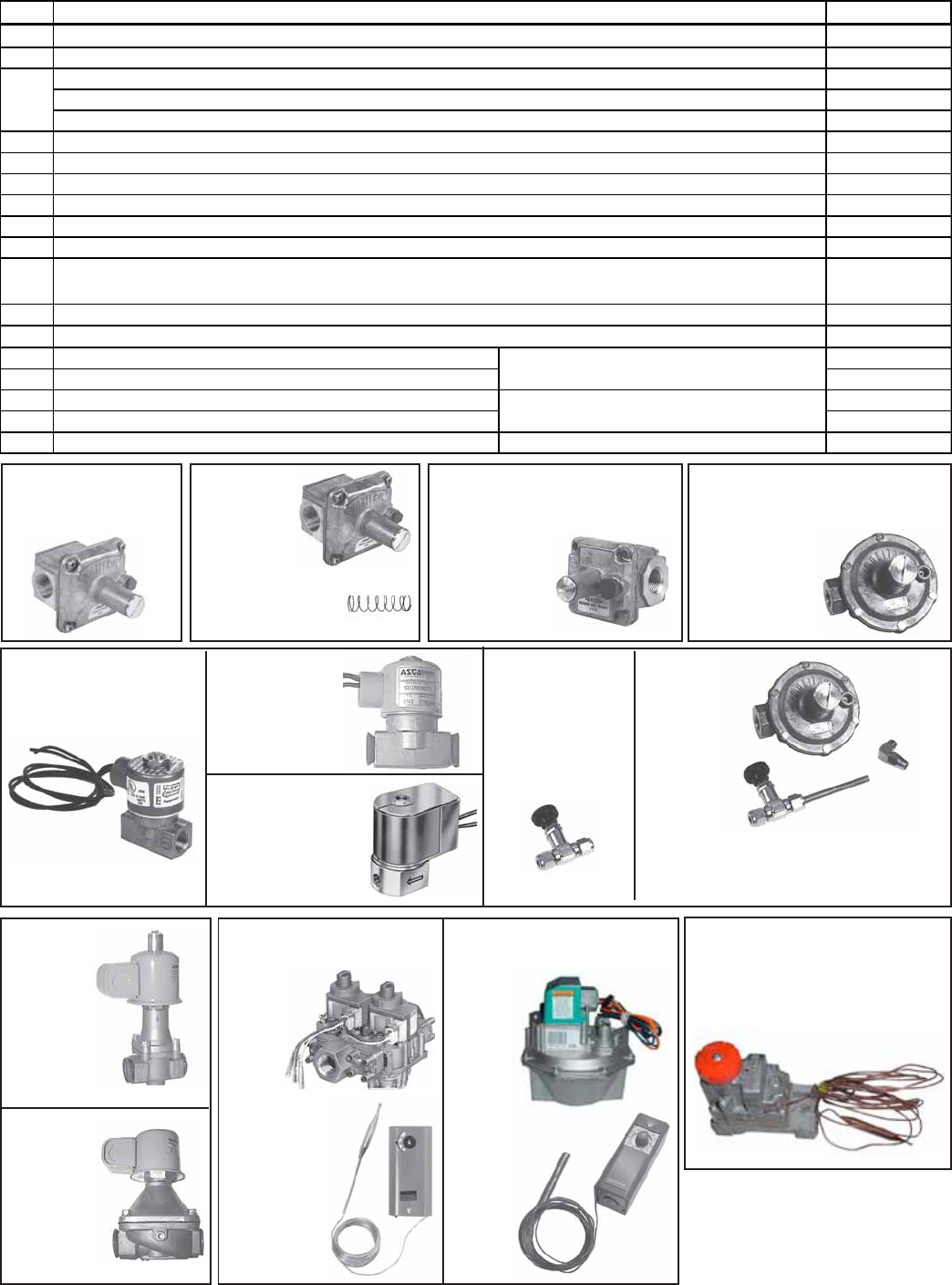
Gas Regulators, Valves, and Pressure Switches
CODE 42 -
Regulator,
P/N 86964,
Maxitrol
R600S
CODE 42A -
Regulator Spring
for CODE 42
CODE 43A - Pilot Regulator,
P/N 86965, Maxitrol R400S
(on units manufactured prior to
1/91; replaced
by CODE 43B)
CODE 44A - Pilot Valve,
P/N 86967, 110V, G/C
#S311AF02N6-CP5
CODE45A - Pilot
Needle Valve, P/N
112462, Nupro
#B-4JNR (on
units manufac-
tured between
1/91 and 3/96)
CODE 46A -
Solenoid
Valve,
P/N 86966,
G/C
#K3A562,
120V
CODE 43B - Pilot Regulator,
P/N 112644, Maxitrol 325-03
(on units manufactured
beginning 1/91) -
a functional
replacement
for CODE 42A
Regulator,
P/N 112644
Needle Valve and
Tubing, P/N 112710
Brass
Elbow,
P/N 93388
CODE 44B -
Pilot Valve,
P/N 145733,
24V, G/C
#S311AF02N6-
CF5
Components in Gas
Control Option AG1 Components in Gas
Control Option AG3
CODE
47 - P/N
159743,
1-Stage
Gas
Valve
CODE 48 -
P/N 126170,
Conroller
CODE 41 -Regulator,
P/N 123950, Maxitrol
RV53-88
CODE 46B -
Solenoid
Valve,
P/N 146472,
G/C
#K3A661T,
24V
CODE 49 -
P/N
203866,
2-Stage
Gas
Valve
CODE 50 -
P/N 41700,
2-Stage
Ductstat
CODE 51 - P/N 203868,
Mechanical Modulation Valve,
M/H V5115B-2548, in Gas
Control Option AG50
CODE Description P/N
41 1" Pressure Regulator, RV53-88 123950
42 Regulator, 1" manifold, 5 PSI to 6" w.c., Maxitrol R600S 86964
91787
97196
97351
43A 86965
43B 112644
44A 86967
44B 145733
44C Pilot Valve, 24V, 3/8", M/H V8046C1030 (on units manufactured beginning 9/03) 204769
45A 112462
45B 112645
46A 86966
46B Solenoid Valve, 1", 24V, G/C #K3A661T (on units mfgd prior to Series 3, 9/03) 146472
47 1-stage Gas Valve, M/H VR8404M5569, Natural or Propane, 1" 159743
48 Air Controller, 40-100°F (used as a ductstat) 126170
49 2-stage Gas Valve, M/H V8944B-1126, Natural, 1" 203866
50 2-stage Ductstat, T678A1015, 60-110°F 41700
51 Mechanical Modulation Gas Valve, V5155-2548, 1", 40-120°F Used in Gas Control O
p
tion AG5
0
203868
Pilot Valve, 110V, 3/8", G/C #S311AF02N6-CF5
(
chan
g
ed to 24V, CODE 44B, with units mf
g
d be
g
innin
g
3/96
)
Pilot Valve, 24V, 3/8", G/C #S3111AF02N6-CF5
(
used from 3/96 to 9/03
)
Pilot Needle Valve, Nu
p
ro B-4JNR
(
on units mf
g
d from 1/91 throu
g
h 1/96
)
Used in Gas Control Option AG3 available on
RDF Series 3
(
manufactured be
g
innin
g
9/03
)
Pilot Needle Valve Conversion Kit (includes all parts needed to add pilot needle valve and change regulator
on RDF Models manufactured prior to 1/91)
Solenoid Valve, 1", 120V, G/C #K3A562T
(
chan
g
ed to 24V, CODE 46B, with units mf
g
d be
g
innin
g
3/96
)
42A
Used in Gas Control Option AG1 available on
RDF Series 3
(
manufactured be
g
innin
g
9/03
)
Standard brown s
p
rin
g
for
p
ro
p
ane
g
as
(
in CODE 42
)
for lower
p
ressure ran
g
e 1 - 3.5" w.c.
Std cadmium s
p
rin
g
for natural
g
as
(
in CODE 42
)
for
p
ressure ran
g
e from 3.0 - 6.0" w.c., Maxitrol #R5310-36
O
p
tional oran
g
e s
p
rin
g
in CODE 42, for
p
ressure ran
g
e from 4.0 - 8.0" w.c., Maxitrol #R5310-48
Pilot Re
g
ulator, 3/8", Maxitrol #R400-S
(
re
p
laced b
y
CODE 43B
)
Pilot Re
g
ulator, 3/8", Maxitrol 325-3
(
functional re
p
lacement for 43A
)
CODE 45B
- Pilot
Needle
Valve
Conversion
Kit, P/N
112645, for
units
manufactured
before 1/91
CODE 44C - Pilot
Valve, P/N 204769,
M/H V8046C1030,
24V
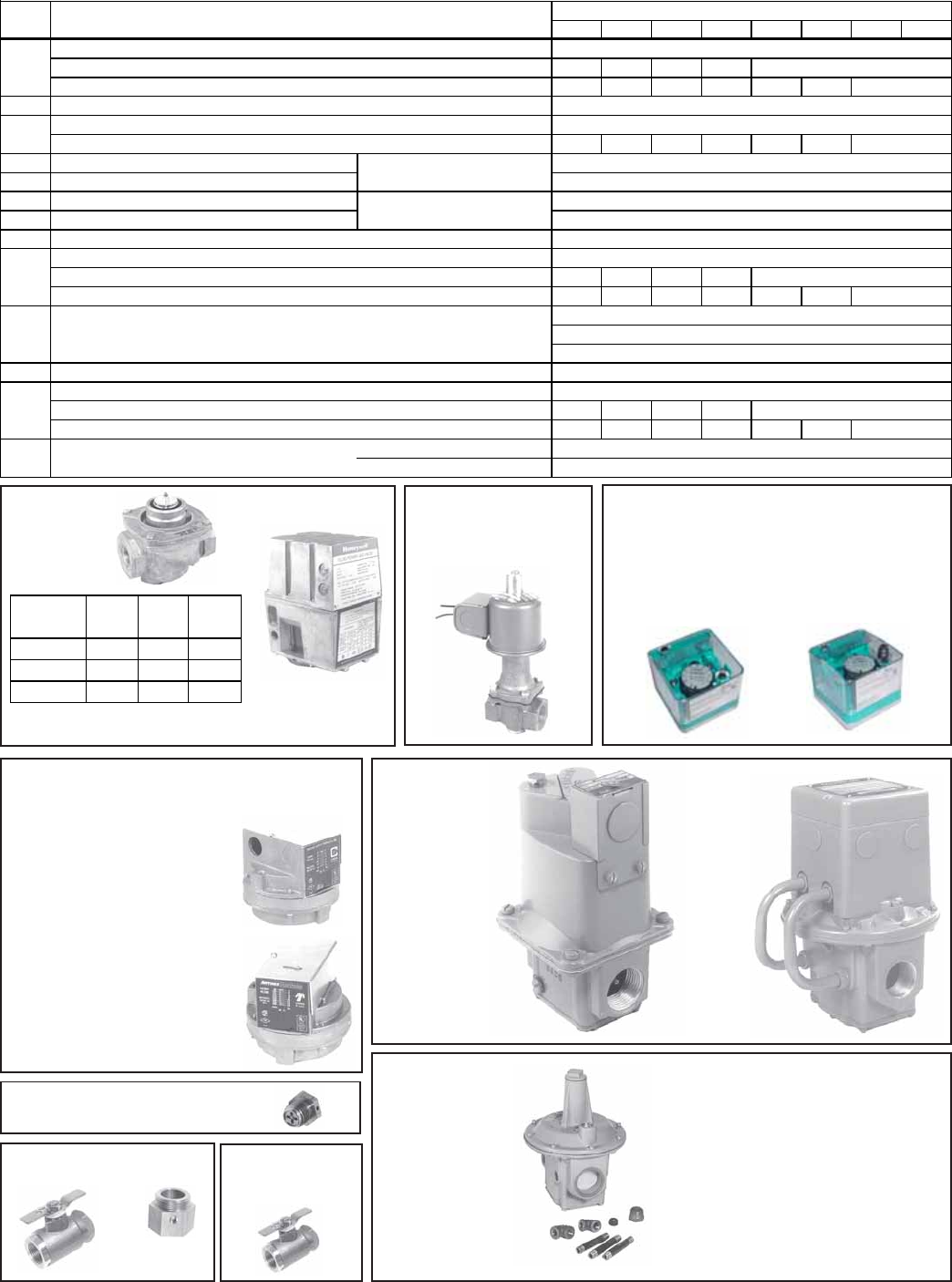
Form P-RDF, Page 12
CODE 52A
(used with
CODE 52B)
CODE 52B
Part of Serial No.
Valve codes J2,
J3, J4, K2 and K4
CODE 53 - Vent Valve
3/4", P/N 86996, G/C
#S262; 1", P/N 91084,
G/C S262A0N3FJ5
CODE 56 - Low Gas
Pressure Switch,
P/N 93849, Automatic Reset,
Settings - 50% of minimum
inlet gas pressure as stated
on the unit rating plate
CODE 57 - High Gas
Pressure Switch,
P/N 93850, Manual Reset,
Settings - 125% of normal
manifold gas pressure as
stated on the unit rating plate
CODE 58 - Vent Limiter used with
Pressure Switches, P/N 123481
CODE 59B - Valve and
Adapter with Test Port
Valve Adapter
CODE 60 -
Pilot Gas Valve,
P/N 159720
CODE 61 -
Gas Control
Regulators
P/N 87001,
1", Maxitrol
M611 R-88
P/N 89351,
1-1/4",
Maxitrol
MR212D
P/N 91071,
2", Maxitrol
MR212E
Gas Pressure Switehes - prior to Series 3
(9/03)
CODE 54 - Low Gas
Pressure Switch
(automatic),
#C6097A1053,
P/N 204375
Gas Pressure Switehes - on RDF Series 3
(manufactured beginning 9/03)
CODE 55 - High Gas
Pressure Switch
(manual reset),
#C6097B1028,
P/N 204297
Gas Regulators, Valves, and Pressure Switches (cont'd)
1-20 1-40 1-50 1-65 2-80 2-120 3-180 3-260
52A Valve only, 1" fluid power, Honeywell #V5055A1004
Valve only, 1-1/4" fluid power, Honeywell #V5055A1012 N/A N/A N/A N/A
Valve only, 2" fluid power, Honeywell #V5055A1038 N/A N/A N/A N/A N/A N/A
52B Actuator only, 120V, fluid operated, Honeywell #V4055A1007
53 Ven t Valv e, 3/ 4" G/ C # S262
Vent Valve, 1" G/C #S262A02N3FJ5 N/A N/A N/A N/A N/A N/A
54 Low Gas Pressure Switch, automatic
55 High Gas Pressure Switch, manual reset
56 Low Gas Pressure Switch, Antunes #RLGP-A
57 High Gas Pressure Switch, Antunes #HGP-AMI
58 Vent Limiter, Maxitrol #12A09
59A Manual Gas Valve, 1", Conbraco #50-4031
Manual Gas Valve, 1-1/4", Conbraco #50-503-02 N/A N/A N/A N/A
Manual Gas Valve, 2", Conbraco #50-703-02 N/A N/A N/A N/A N/A N/A
59B
60 Manual Pilot Gas Valve, 3/8"
61 Gas Control Regulator, 1", Maxitrol M611 R-88
Gas Control Regulator, 1-1/4", Maxitrol MR212D N/A N/A N/A N/A
Gas Control Regulator, 2", Maxitrol MR212E N/A N/A N/A N/A N/A N/A
62 Gas Su
pp
l
y
Re
g
ulator Kit, 5
p
si
x
1" NPT (Same as Option CZ1)
1-1/2" x 1-1/2" NPT (Same as Option CZ2) 124258
124259
91071
Gas Valve, Watts B-6000-UL-TH, with ball valve adapter, used on units mfgd
beginning 7/90 replacing CODE 59A valves
159720
87001 89351
159729, 1-1/4" Valve & 110759, 1-1/4" Ball Valve Adapter
159735, 2" Valve & 110760, 2" Ball Valve Adapter
123481
89350 91072
159725, 1" Valve & 110758, 1" Ball Valve Adapter
30257
91084
93849
93850
Used on RDF Series 3 (both
include built-in vent limiter
)
Used on RDF prior to Series 3
(
9/03
)
204375
204297
89356 91079
86993
86996
CODE RDF Model
Description
86992
Serial No.
Code Size Gas P/N
J2, J3, J4 1" N or P 86992
K2 1-1/4" N or P 89356
K4 2" N or P 91079
CODE 62 - Gas
Regulator Kit,
outlet pressure
range 1-12"
(maximum 5 psi)
P/N 124258 (Same as Option CZ1),
Kit includes Maxitrol 1"x1" NPT
regulator
P/N 124259 (Same as Option
CZ2), Kit includes Maxitrol
1-1/2"x1-1/2" NPT regulator
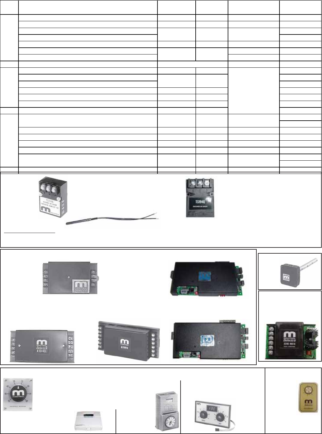
Form P-RDF, Page 13
CODE 70 -
Temperature
Sensor
P/N 90324, Maxitrol #TS114;
P/N 87106, Maxitrol #TS114A (illustrated);
P/N 119617, Maxitrol #TS44E;
P/N 194160, Maxitrol #TS44C;
P/N 133228, Maxirol TS194A;
CODE 71
- Mixing
Tube,
P/N
90323
Modulating Gas Controls
IMPORTANT NOTE: When replacing a temperature sensor on a Maxitrol MV-9 system (Option AG33), check the Model No. on the
sensor.. P/N 119617 or 194160 is used on units manufactured beginning 2/92; P/N 87041 is used on units manufactured prior to 2/92.
Sensors are not interchangeable; the sensor MUST match the amplifier.
P/N 204452, Maxitrol #TS394-2B-4;
P/N 204453, Maxitrol #TS194Q
(illustrated)
CODE 72 - Amplifier (Amplifiers are not interchangeable and must match the temperature sensor.)
P/N 148590,
Maxitrol
#A1014L
(replaces
P/N 86976)
P/N 194159, Maxitrol #A1044CL;
P/N 157915, Maxitrol #A1044EL
(replaces P/N 119616);
P/N 86989, Maxitrol #A1044 (on
systems mfgd prior to 2/91)
P/N
204454,
Maxitrol
#ADFM14
CODE 73 - Maxitrol
Signal Conditioner,
P/N 134170
(for computer control)
P/N 204450, Maxitrol
#ADFM44
P/N 86990,
Selectrastat
Maxitrol T-244
CODE 75 - P/N
24857, Maxitrol
#T115
CODE 74 - Temperature Selectors (see chart for option application)
P/N 86988, TD114 U.S. Models, Range 55-90°F
P/N 101165, TD114, Canadian Models, Range 50-75°F;
P/N 87107, TD114A, Range 80-130°F;
P/N 123943, TD114B, Range 120-170°F
P/N 204455, TD DFM14;
P/N 204451, TD DFM44
P/N 133230, Maxitrol #TD294E-
609-0818, Dual Temperature
Selector for Paint Booth
Application, Option AG36
CODE Description In Gas Control
Option
Serial No.
Suffix Location P/N
Temperature Sensor, Maxitrol Series 14, #TS114 AG30, AG31 MV-7 Discharge 90324
Temperature Sensor, Maxitrol Series 14A, #TS114A AG32 MV-8 Discharge 87106
Temperature Sensor, Maxitrol Series 44, #TS44E, 120°F max 119617
Temperature Sensor, Maxitrol Series 44, #TS44C, 140°F max 194160
Temperature Sensor, Maxitrol Series 94, #TS194A AG36 MV-B Discharge 133228
Temperature Sensor, Maxitrol Series 14E, #TS394-2B-4 Outside & Return Ai
r
204452
Temperature Sensor, Maxitrol Series 14E, #TS194Q Discharge 204453
71 Mixing Tube, Maxitrol MTI-12 Same as above 90323
Amplifier, Maxitrol Series 14 & 14A, #A1014L AG 30, 31, 32 MV-7, MV-8 148590
Amplifier, Maxitrol Series 44, #A1044EL, 120°F maximum 157915
Amplifier, Maxitrol Series 44, #A1044CL, 140°F maximum 194159
Amplifier, Maxitrol Series 94, A1494 AG36 MV-B 133229
Amplifier, Maxitrol Series 14E, ADFM14 AG47 MV-D 204454
Amplifier, Maxitrol Series 44E-21 & 44ER-21, ADFM44 AG48, AG51 MV-E, MV-F 204450
73 Signal Conditioner, Maxitrol AG37 MV-C 134170
86988 (U.S.A.)
101165 (Canada)
Temperature Selector, Maxitrol Series 14A, #TD114A AG32 MV-8 Remote 87107
Temperature Selector, Maxitrol Series 14E, #TDDFM14 AG47 MV-D Remote 204455
Selectrastat (temperature selector), Maxitrol Series 44, #T-244 AG33 MV-9 Space 86990
Temperature Selector, Maxitrol Series 44E, #TDDFM44 AG48, AG51 MV-E, MV-F Remote 204451
133230, 120°F
159287, 160°F
75 Overriding Thermostat, Series 14, #T115 AG 30, 31, 32 MV-7, MV-8 Space 24857
Electrical Control
Compartment (See
page 3.)
Remote
MV-9
MV-7
MV-B
Remote
MV-9 Discharge
MV-D, MV-E,
MV-F
All above
70
74
72
AG47, AG48,
AG51
AG33
AG33
Temperature Selector, Maxitrol Series 14, #TD114
Temperature Selector, Maxitrol Series 94, #TD294E-609-0818 AG36
AG30, AG31
Overriding
Thermostat,
Option AG33
P/N 133229,
Maxitrol A1494
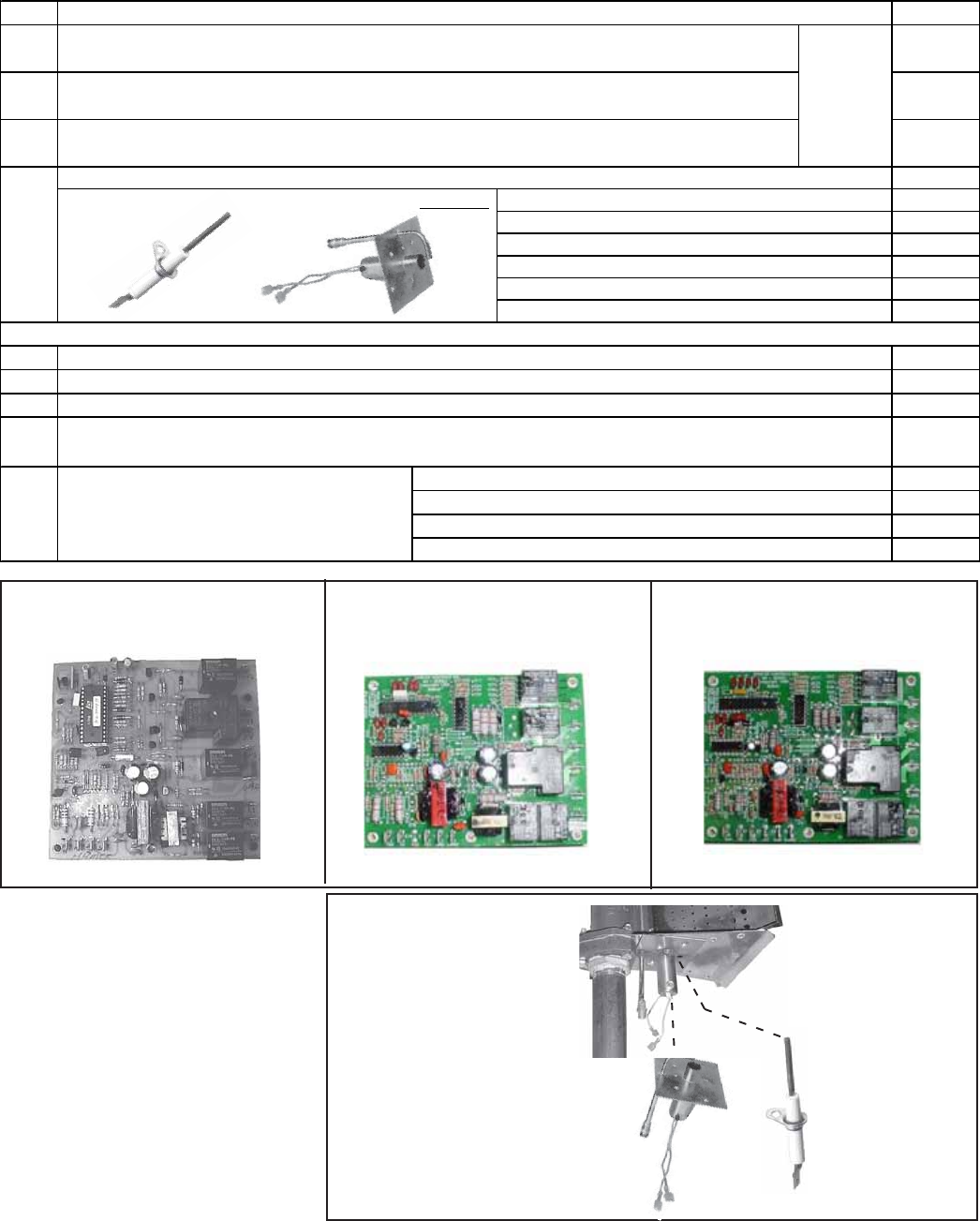
Form P-RDF, Page 14
Ignition System - Hot Surface Ignition
Ignition system changed from spark to hot surface beginning 3/96.
Pilot and
Ignitor
Flame
Sensor
CODE 80A, P/N 157953, Hot Surface
Ignition Module, RAM H4MC24-01 CODE 80B, P/N 204376, Hot Surface
Ignition Module, Synetek FC-IH1040B,
for burner with a single flame rod
CODE 80C, P/N 204166, Hot Surface
Ignition Module, synetek FC IH1040C,
for burner with a double flame rod
Pilot, Hot Surface Ignitor,
and Flame Sensor on RDF
Series 3 Burner
CODE P/N
80A 157953
80B 204376
80C 204166
Pilot Assembly for Hot Surface Ignition prior to RDF Series 3 (9/03) 120048
including: 122840
134706
38529
121730
90167
121865
Pilot, Sensor, and Ignitor for Model RDF Series 3
82A Pilot for RDF Series 3, 250-1500 MBH 127910
82B Pilot for RDF Series 3, 1750-3000 MBH 122840
83 Hot Surface Ignitor, Norton #401E 121865
84 134706
146268
146318
146319
146320
85
81
for unit with a 200VA transformer
for 115V unit with an 80VA transformer
for 208V unit with an 80VA transformer
Ignition Conversion Kit from Spark Pilot with
either a rectification type (CODE 94) or
ultraviolet flame (CODE 95) sensor to hot
surface ignition. for 240V, 480V, or 575V unit with an 80VA transformer
Hex head cap screw, #10-32x3/8" lg
Hot Surface Ignitor, Norton #401E
Hot Surface Ignition Module, RAM #H4MC24-01- applies to RDF systems manufactured from
3/96 to 9/03 (prior to RDF Series 3) - Serial No. Ignition System Code 72
Description of Parts of Hot Surface Ignition System and Conversion Kits
Located in
the
electrical
control
compart-
ment.
Flame Sensor, J/C #Y75MK-1D (Note: CODE 84 is for replacement of the flame sensor at the ignitor end of the
burner only. 1750-3000 MBH burners have a second flame sensor. For replacement, see CODE 99.)
Hot Surface Ignition Module, Synetek FC-IH1040B, single flame rod (Used on RDF Series 3 with
burner sizes from 250-1500 MBH, Options BL1-BL6) - Serial No. Ignition System Code 82
Hot Surface Ignition Module, Synetek FC-IH1040C, dual flame rod (Used on RDF Series 3 with
burner sizes from 1750-3000 MBH, Options BL7-BL13) - Serial No. Ignition System Code 81
Pilot
Flame Sensor, J/C #Y75MK-1D
Screw, #8-1/2" long
Pilot bushing
Location
(not
shown)
CODE
82
CODE
83
CODE
84
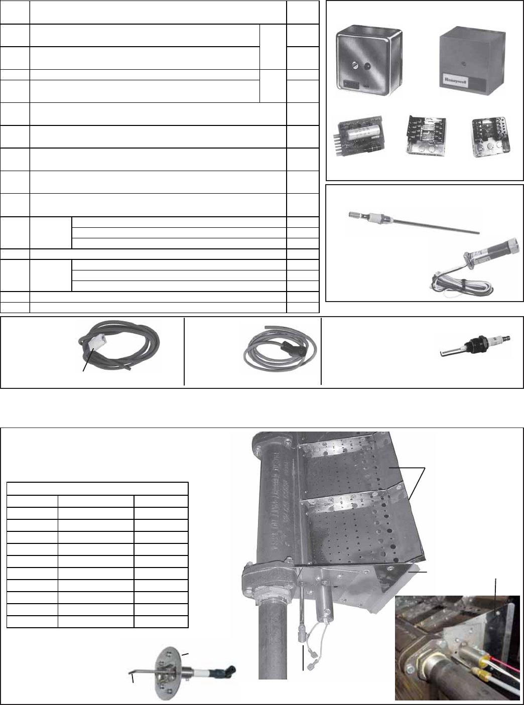
Form P-RDF, Page 15
Burners for RDF Series 3 (manufactured beginning 9/03)
Burner
Mixing Plates
CODE 83 -
Ignitor
Gas Supply CODE 82 - Pilot
Assembly
Burner End Plate
Flame Sensor Safety Relays and Subbases
for Spark Ignition System
Codes 86 and 88 Codes 87 and 89
CODE 90,
P/N 89408 CODE 91,
P/N 89410 CODE 92,
P/N 86973
CODE 93, P/N 87937, Flame Probe (std on
units with date codes from AJH to ANH)
CODE 94, P/N 89411,
Ultraviolet Detector
(std on units with date
codes from ANI to AVB;
optional on prior units)
CODE 95,
Flame Rod
Wire Assy for
Spark Ignition
System Housing only, P/N 19127
CODE 96,
Ignitor
Wire Assy
for Spark
Ignition
System
Spark Plug for Spark Ignition System
CODE 97A, P/N 87936
(illusrated)
CODE 97B, P/N 179342, #23539 Sapco
14mm (used prior to CODE 97A)
Ignition System - Spark Ignition System (discontinued 3/96)
RDF Series 3 systems use Midco HMA-700 Series
Burners. The Burner P/N listed below includes the burner,
the mixing plates, and the end plate. 1750-3000 MBH (42-
60") burners also include CODES 99 & 100.
Length MBH P/N
6" Burner 250 203312
12" Burner 500 203313
18" Burner 750 203314
24" Burner 1,000 203315
30" Burner 1,250 203316
36" Burner 1,500 203317
42" Burner 1,750 or 2,000 203318
48" Burner 2,250 203319
54" Burner 2,500 203320
60" Burner 2,750 or 3,000 203321
CODE 98 - Model RDF Series 3 BURNER
CODE 99 - Second Sensor (at the end of
the burner opposite the ignitor)
on 42-60" Burners, P/N 210766
CODE 100 - Holder
for CODE 99,
P/N 210767 99
100
CODE P/N
86 86972
87 89407
88 89409
89 89436
90 89408
91 89410
92 86973
93 87937
94 89411
87904
89614
113952
95A 19127
87906
89627
91362
97A 87936
97B 179342
Flame Sensor Safety Relay, Ultraviolet, Honeywell #R7795A-
1009 (less CODE 90)
S
p
ark Plu
g
, #23539 Sa
p
co 14mm
(
used
p
rior to CODE 97A
)
95
96
RDF 3-180, 26
0
Ultraviolet Minipeeper Detector, Honeywell #C7027A (std on units
from 9/88 -2/96; optional on prior units; used with CODE 88 or 89)
Ignitor
Wire
Assembl
y
S
p
ark Plu
g
, Auburn #27750 I-31, Maxon #18075
RDF 1-20, 40, 50, 65
RDF 2-80, 120
RDF 3-180, 26
0
Flame Rod
Wire
Assembl
y
Housin
g
onl
y
for Flame Rod Wire Ass
y
, AMP #1-48016-
0
RDF 1-20, 40, 50, 65
RDF 2-80, 120
Description of Components of Spark Ignition System (Discontinued
on units beginning 3/96. See conversion kits in CODE 85, page 13.)
Subbase only used with CODES 87 (P/N 89407) & 89 (P/N 89436) ,
Honeywell #Q795A-1004
Subbase only used with CODES 86 (P/N 86972) & 88 (P/N 89409),
Honeywell #Q270A-1024
Flame Probe, Auburn #AA67-7892-1 (std on units mfgd before 9/88;
used w/CODE 84 or 85)
With
Code
93
With
Code
94
Prepurge Timer Board (prepurge relay), M/H ST795A-1031 (used in
CODES 87 and 89)
Flame Sensor Safety Relay, Rectification, Honeywell
#RA890F1270
Flame Sensor Safety Relay, Rectification, Honeywell #R7795B-
1009 (less CODE 80)
Flame Sensor Safet
y
Rela
y
, Ultraviolet, Hone
y
well
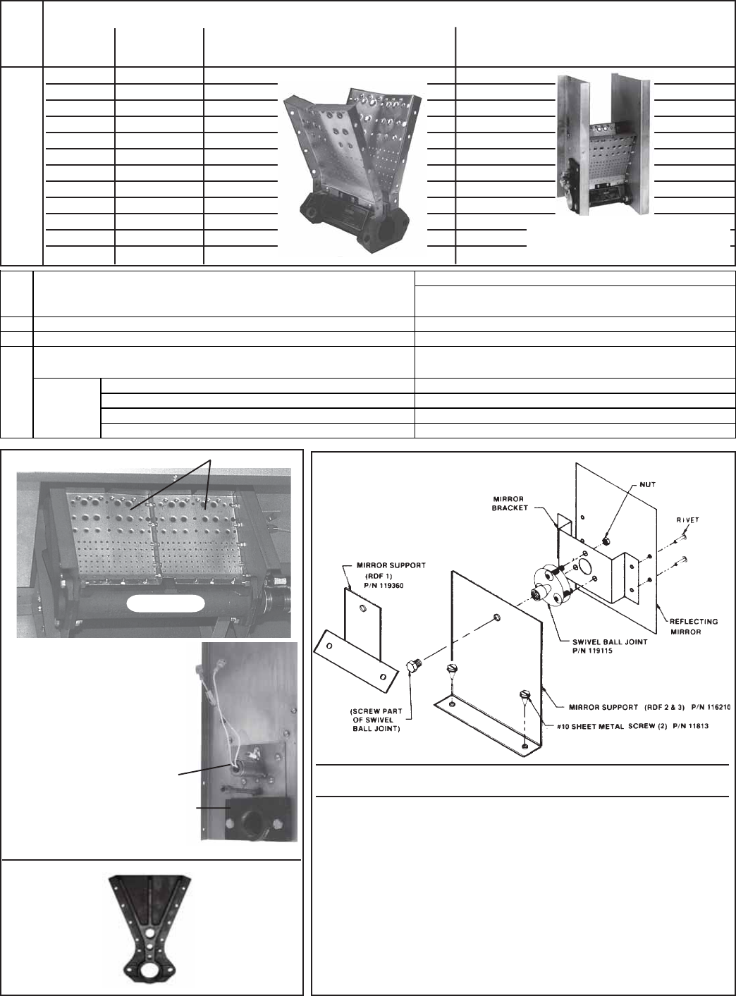
Form P-RDF, Page 16
Burners for RDF Systems manufactured prior to Series 3 (9/03)
CODE Replacement Burners (burners include cast iron burner and stainless steel mixing plates)
Size BTU Burner only by size Replacement burner assembly only
for all burner assemblies with inlet end for units with a spark ignition system
(does not include end plates, order CODE 102B)
101 6" Burner 250,000 123405 145757
12" Burner 500,000 123665 145758
18" Burner 750,000 123684 145759
24" Burner 1,000,000 123696 145760
30" Burner 1,250,000 123700 145761
36" Burner 1,500,000 145140 145762
42" Burner 1,750,000 145159 145763
48" Burner 2,000,000 145162 145764
54" Burner 2,250,000 145169 145765
60" Burner 2,500,000 145172 145766
66" Burner 2,750,000 145175 145767
72" Burner 3,000,000 145178 145768
Instructions to install pilot/burner mirror assembly on RDF units
manufactured prior to 3/92.
All Sizes (requires two #10 x 1/2" sheet metal screws) - (1) Turn off gas and power.
(2) Remove the burner door panel on the side of the unit opposite the controls. (3)
Remove the burner control door panel.
RDF 1 - (1) On the side of the unit opposite the controls, position the mirror on the
center post inner liner (refer to drawing on page 5, inner liner of CODE 12) so that
the bottom of the mirror is slightly higher than the top of the burner. (2) Mark and
drill two 1/8" holes.
RDF 2 and 3 - On the side of the unit opposite the controls, locate the two small
holes on the horizontal surface of the air deflector (aka return air damper support).
All Sizes - (1) Attach the mirror assembly with field-supplied sheet metal screws.
(2) On the back of the mirror support bracket, tighten the ball joint (swivel) bolt
head. (3) Adjust the mirror so that the burner and the pilot are visible when looking
through the viewport in the burner control panel. (4) Close the door panels.
CODE 103 - Pilot/Burner
Mirror Assembly
Installed Burner Assembly 101A
CODE 102A - Burner End
Plate showing the hot surface
ignition system
Burner Inlet Flange,
P/N 123449, (must be sealed
with key graphite paste,
P/N 146269)
Pilot and Ignitor Assembly,
See CODE 81, page 13
Hot surface ignition is standard
with units manufactured
beginning 3/96; for ignition
conversion kit see CODE 85,
page 13.
Inlet end enclosure for spark ignition is
different from currently manufactured
burner assemblies.
12" Burner
CODE 102B -
Burner End
Plate for burner
with spark
ignition,
P/N 102957
101A P/N 116104, Maxon P/N 20580
Total quantity of plates per burner size, 6"-2; 12"-4"; 18"-6; 24"-8;
30"-10; 36"-12; 42"-14; 48"-16; 54"-18; 60"-20; 66"-22; 72"-24
102A (2) P/N 95473 - For all sizes of heaters and burners
102B (2) P/N 102957 - For all sizes of heaters and burners
103 P/N 119480 - Sizes 1-20 - 1-65; P/N 119481 - Sizes 2-80 - 3-260
Components: Reflecting mirror only P/N 116212 - All Sizes
Bracket assy including swivel ball joint P/N 119483 - All Sizes
Swivel ball joint only P/N 119115 - All Sizes
Mirror support only (attaches to cabinet) P/N 119360 - Sizes 1-20-1-65; P/N 116210 - Sizes 2-80 - 3-260
Adjustable "mirror" to view burner and pilot flame through viewport on control
side of cabinet (on units manufactured beginning 3/92) - complete assembly
Replacement burner mixing plate only, 6" section, for all of the burners listed
above. Refer to Operation/ Maintenance/Service, Form O-ADF/DV/RDF, Burner
Cleaning, for instructions on burner service.
Burner End Plate only for HOT Surface Ignition
Burner End Plate only for Spark Ignition
Mixing Plates
Cast Iron
Burner
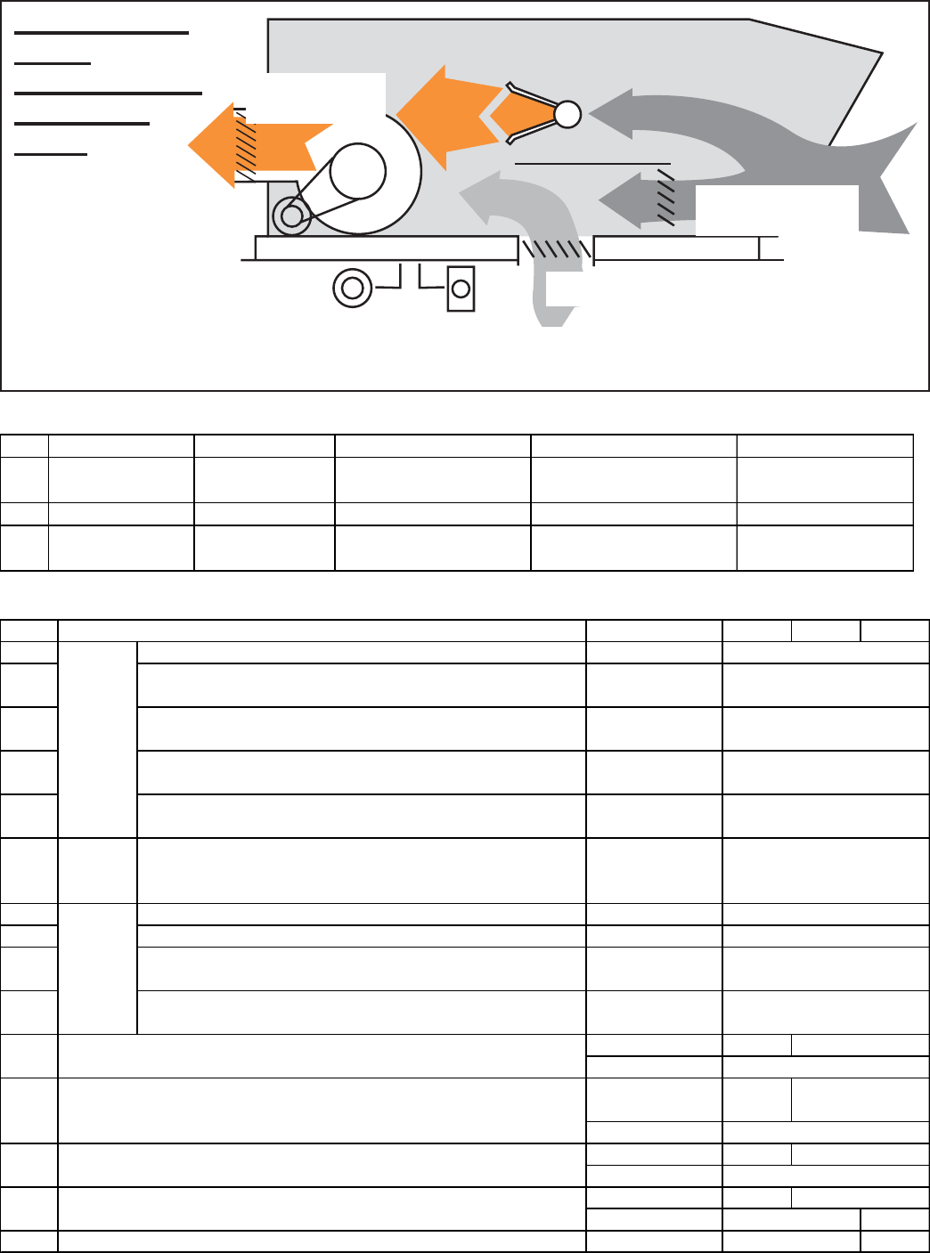
Form P-RDF, Page 17
Dampers and Controls
Code Description In Option RDF-1 RDF-2 RDF-3
110 Bypass Damper AR 19, 20, 22, 23,
33, 34, 36, 37 203602 - 26" x 12" 203604 - 53-1/2" x 17-3/4" 203603 - 65-3/4" x 20"
111 Return Air Damper AR 22, 23, 34, 37 203602 - 26" x 12" 203604 - 53-1/2" x 17-3/4" 203603 - 65-3/4" x 20"
112 Discharge Damper AQ 3, 4; AR19, 20,
33, 36 15869 - 21-1/8" x 18-1/2" 89355 - 27-1/4" x 27-1/4" 91073 - 37" x 37"
Dampers in RDF Series 3 (units manufacturered beginning 9/03)
Damper Motors and Linkages in RDF Series 3 (units manufacturered beginning 9/03)
AR22 AR23
Return Dampers
Options AR 22, 23, 34, 37
Bypass Dampers
Options AR 19, 20, 22,
23, 33, 34, 35, 36, 37
Discharge Dampers
Options AQ 3, 4;
AR 19, 20, 33, 36
AR 20 or 23
Remote Potentiometer, CODE 32, page 6.
AR 19
or 22
Remote Pressure Null
Switch, CODE 33, page 6.
Options AR 36 and 37 have a Remote Photohelic Pressure Sensor, CODE 34, page 6.
RDF Series 3
(units
manufactured
beginning
9/03)
CODE Description/Damper Arrangement In Option RDF-1 RDF-2 RDF-3
115 2-Position, 100% Makeup Air AQ3, AQ4
116 Variable Air Volume with Manual Potentiometer (CODE 32,
page 6) AR19
117 Variable Air Volume with Automatic Pressure Switch (CODE
33, page 6) AR20
118 Variable Air Volume with Computer Control through Signal
Conditioner (CODE 73, page 13) AR33
119 Variable Air Volume with Photohelic Pressure Sensor (CODE
34, page 6) AR36
120 Bypass
Damper
Motor
Variable Air Volume AR 19, 20, 22, 23,
33, 34, 36, 37
121 Return Air with Manual Potentiometer (CODE 32, page 6) AR22
122 Return Air with Automatic Pressure Switch (CODE 33, page 6) AR23
123 Variable Air Volume with Computer Control through Signal
Conditioner (CODE 73, page 13) AR34
124 Variable Air Volume with Photohelic Pressure Sensor (CODE
34, page 6) AR37
(1) AR 22, 23, 34 12635
(1) AQ 3, 4
(2) AR19, 20, 22,
23, 34, 37 12636
(2) AQ 3, 4
(1) AR 22, 23; 194200
(1) AQ 3
(1) AR 34, 37 66278
(1) AQ 3, 4 66278
129 Damper Crank Arm, W/R 135-0002 (1) AQ 4 66277
204269, J/C M9216-JGA-2
204268, J/C M9108-AGD-2
204271, J/C M9216-GGC-2
204270, J/C M9109-AGA-2
204270, J/C M9109-AGA-2
194200
128 Damper Crank Arm, W/R 135-0007
--
204270, J/C M9109-AGA-2
Discharge
Damper
Motor
Return Air
Damper
Motor
Damper Crank Arm, M/H #26026K --
12635
204269, J/C M9216-JGA-2
204270, J/C M9109-AGA-2
159892, J/C M9216-BGC-2
204271, J/C M9216-GGC-2
--
125
126 Ball Joint, M/H 27518
Damper Crank Arm Kit, J/C #9000-153
127
--
--
12636
--
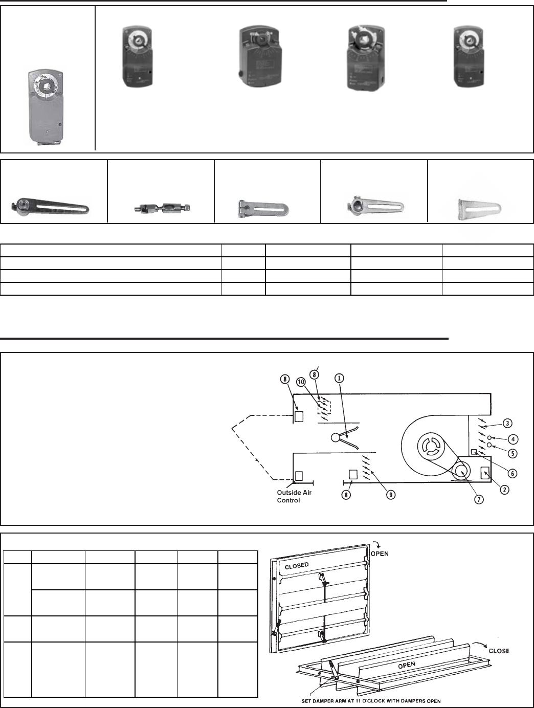
Form P-RDF, Page 18
Damper Arrangement Options RDF-1 RDF-2 RDF-3
Discharge, 2-Position, 100% Makeup Air (Vertical) AQ3 112555 - 1/4" x 16" 89640 - 1/4" x 7-1/2" 89640 - 1/4" x 7-1/2"
Discharge 2-Position, 100% Makeup Air (Horizontal) AQ4 112555 - 1/4" x 16" 89970 - 1/4" x 38" 91428 - 1/4" x 24"
Return Air Damper AR34, 37 5120, 1/4" X 7-7/8" -- --
CODE 130 - Damper Rods in RDF Series 3 (units manufactured beginning 9/03)
CODE 125, Damper
Crank Arm, P/N 12635,
M/H #26026K
CODE 126, Ball
Joint, P/N 12636,
M/H #27518
CODE 115 -
2-Position Damper
Motor, J/C M9216-
BGC-2,
P/N 159892
Modulating Damper Motors (See Chart on page 16 for application.)
CODES 116, 121 -
Discharge or Return
Air Damper Motor,
J/C M9216-JGA-2,
P/N 204269
CODES 117, 119, 122,
144, Discharge or
Return Air Damper
Motor, J/C M9109-
AGA-2, P/N 204270
CODE 120 - Bypass
Damper Motor, J/C
M9108-AGD-2,
P/N 204268
CODES 118, 123 -
Discharge or Return
Air Damper Motor,
J/C M9216-GGC-2,
P/N 204271
Dampers and Controls
RDF Systems prior to Series 3 (manufactured before 9/03)
KEY:
1 - Burner
2 - Discharge Damper Motor (Options AR19 & 20)
3 - Discharge Damper (Options AR19 & 20)
4 - Manual Reset Limit
5 - Automatic Limit
6 - Discharge Air Sensor
7 - Blower Motor
8 - Damper Motor (Optional)
9 - Return Air Damper (Options AR22 & 23)
10 - Bypass Damper (Options AR19, 20, 22 & 23)
Control and Damper Locations
Sizes 2-80, 2-120,
3-180, 3-260
In the Electrical Compartment --
Sizes 1-20, 1-40,
1-50, 1-65
Sizes 2-80, 2-120,
3-180, 3-260
Outside
Air
Hood
Dampers in RDF Systems prior to Series 3 (9/03)
Code Description In Option RDF-1 RDF-2 RDF-3
140
141 Discharge
Damper
AQ 3, 4;
AR19, 20
86999 -
22"x18"
89355 -
28"x28"
91073 -
37"x37"
142 Bypass
Damper
Adjustment
Arm
AR 22, 23 111309 111309 111309
Bypass
Damper
Return Air
Damper
AR 19, 20,
22, 23
87117 -
32"x10"
89354 -
22"x54"
91074 -
30"x68"
AR 22, 23 87117 -
32"x10"
89354 -
22"x54"
91074 -
30"x68"
CODE 127, Damper
Crank Arm Kit, P/N
194200, J/C #9000-153
CODE 128, Damper
Crank Arm Kit, P/N
66278, W/R 135-0007
CODE 129, Damper
Crank Arm Kit, P/N
66277, W/R 135-0002
Dampers and Controls (cont'd)
RDF Series 3 (units manufactured beginning 9/03) (cont'd)
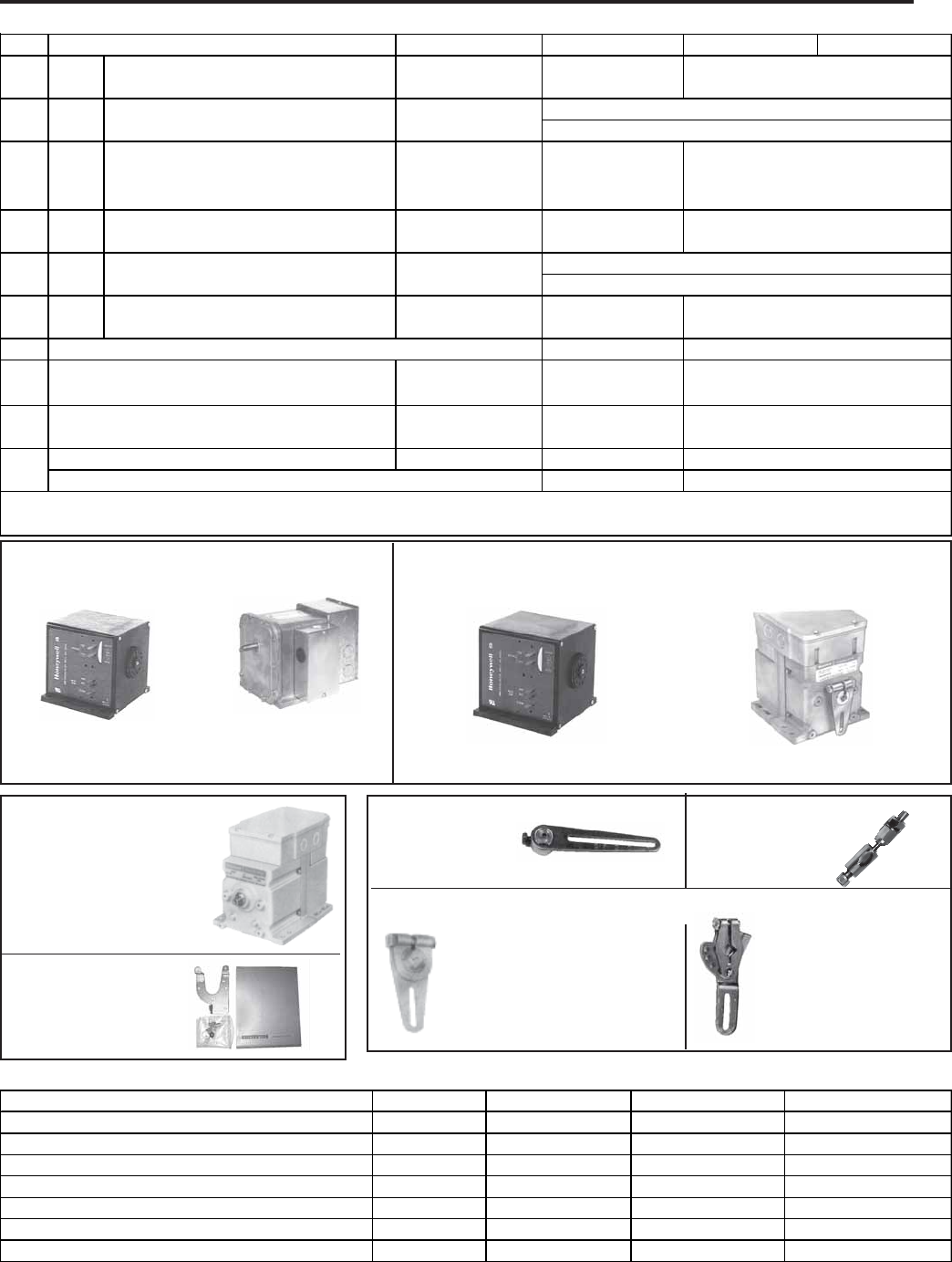
Form P-RDF, Page 19
CODE 153 - Damper Rods (Damper rods may require being cut to desired length.)
CODE 143 - Damper Motor for 2-Position
Discharge Damper, 100% Makeup Air
(Options AQ3 and AQ4)
P/N 87000, M/H
#M8415A1004, used on
RDF 1
P/N 97385, W/R
#3402-9, used on
RDF 2 & 3
Codes 144 and 147 -
Modulating Damper
Motor,
P/N 115681,
M/H M9175A1015, used
in Options AR19 and
AR22 on RDF 1, 2 & 3
Codes 145, 146 and 148 - Modulating Damper Motor used for the
discharge damper in Option AR20; for the bypass damper in Options
AR19, 20, 22, and 23; and for the return air damper in Option AR23
P/N 87116, M/H #M6414A1009,
used on RDF 1 P/N 115683, M/H #M6194B1011
used on RDF 2 & 3
CODE 149 - Auxiliary
End Switch, P/N
113963,
M/H Q607B1067
CODE 152 - Damper Motor Crank Arms
P/N 116209, M/H 221455A,
used in Options AR19, 20, 22,
and 23 (required when
replacing obsolete motors; see
note on page 16.)
P/N 20874, M/H
7616BR, motor crank
arm used with obsolete
motor P/N's 53928
and 87059
Damper Motor and Accessories by Damper Arrangement and Option
Dampers and Controls (cont'd)
RDF Systems prior to Series 3 (manufactured before 9/03) (cont'd)
CODE 150 -
Damper Crank
Arm, P/N 12635,
M/H #26026K
CODE 151 - Ball
Joint, P/N 12636,
M/H #27518
CODE Description/Damper Arrangement In Option RDF-1 RDF-2 RDF-3
143 Motor 87000
M/H M8415A1004
144 Motor
145 Motor 87116
M/H M6414A1009
146 Motor 87116
M/H M6414A1009
147 Motor
148 Motor 87116
M/H M6414A1009
149 113963
150 (2) AR19,20,22,23;
(1) AQ3,4 12635
151 (4) AR19,20,22,23;
(2) AQ3,4 12636
152 Damper Motor Crank Arm, M/H 221455A (2) AR19,20,22,23 116209*
Damper Motor Crank Arm & Clip, M/H 7616BR(used w/obsolete mtrs) 20874
97385
W/R 3402-9
115683*
115681*
M/H M9175A1015 (replaces 53928)
M/H M9175A1015 (replaces 53928)
115683*
113963
115683*
115681*
12635
12636
116209*
20874
Return Air with Manual Potentiometer
(CODE 33, page 6)
Return Air with Automatic Pressure
Switch (CODE 34, page 6)
AQ3, AQ4
AR19
AR20
Discharge, 2-Position, 100% Makeup Air
Discharge, Variable Air Volume with
Manual Potentiometer (CODE 33, page 6)
Discharge, Variable Air Volume with
Automatic Pressure Switch (CODE 34,
page 6)
Bypass, Variable Air Volume
*When installing motors P/N 115681 or 115683 to replace P/N 53928 or 87059, it is necessary to change the motor crank arm. Order P/N
116209.
Ball Joint, M/H 27518 -used in all damper
arrangements
M/H M6194B1011 (replaces 87059)
M/H M6194B1011 (replaces 87059)
M/H M6194B1011 (replaces 87059)
Damper Crank Arm, M/H #26026K -used in all
damper arrangements
AR19, AR20, AR22,
AR23
AR22
AR23
Auxiliary End Switch only for M/H damper motors, M/H Q607B1067
Damper Arrangement Options RDF-1 RDF-2 RDF-3
Discharge 2-Position, 100% Makeup Air (Horizontal) AQ4 11560 - 1/4" x 16" 89970 - 1/4" x 38" 91428 - 1/4" x 24"
Discharge, 2-Position, 100% Makeup Air (Vertical) AQ3 11560 - 1/4" x 16" 89640 - 1/4" x 7-1/2" 89640 - 1/4" x 7-1/2"
Discharge, Variable Air Volume with Potentiometer AR19 11560 - 1/4" x 16" 14226 - 1/4" x 11" 91428 - 1/4" x 24"
Discharge, Variable Air Volume with Pressure Sensor AR20 11560 - 1/4" x 16" 14226 - 1/4" x 11" 91428 - 1/4" x 24"
Bypass, Variable Air Volume and Return Air AR19,20,22,23 5120 - 1/4" x 7-7/8" 90056 - 1/4" x 5" 89640 - 1/4" x 7-1/2"
Return Air with Potentiometer AR22 11560 - 1/4" x 16" 14226 - 1/4" x 11 91422 -1/4" x 18-1/2"
Return Air with Pressure Sensor AR23 11560 - 1/4" x 16" 14226 - 1/4" x 11 91422 -1/4" x 18-1/2"
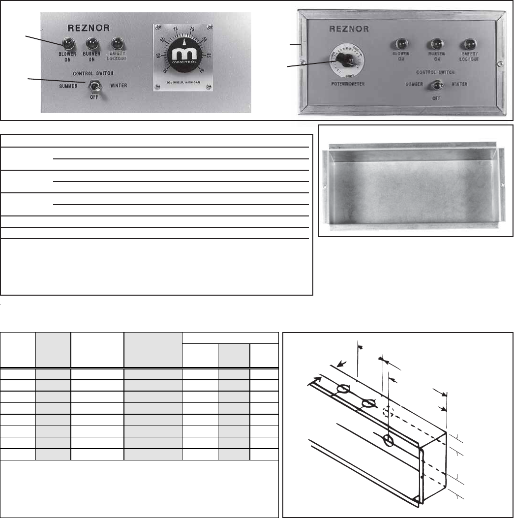
Form P-RDF, Page 20
Remote Console
Note: Console height changed 10/01. Console parts listed are currently manufactured size.
NOTE: A remote console was standard with RDF Models manufactured prior to 9/03. Beginning with RDF Series 3 (units
manufactured beginning 9/03), the remote console is an option.
Replacement Components
CODE Description P/N
160 Remote Console Box 10-9/16" x 7-1/4" x 2-5/8" 107010
Remote Console Box 15-9/16" x 7-1/4" x 2-5/8" 107011
161 Mounting Ring for 10-1/16" long box 107014
Mounting Ring for 15-1/16" long box 107015
162 Light with red lens, Solico #5TD1L-R-B5 101889
Bushing for installing light above on old-style console 106747
31, page 6 DPDT Switch, Cutler Hammer #7561K6 101900
32, page 6 Potentiometer, Honeywell 112894FA 16110
74, page 13 Temperature Selector, Option AG30, AG31 86988 or 101165
Temperature Selector, Option AG32 87101
Temperature Selector, Option AG33 86990
Temperature Selector, Option AG47 204455
Temperature Selector, Option AG48, AG51 204451
2-3/8
(60)
6 (152)
5-15/32 (139)
1-5/16 (33)
1-3/32 (28)
4-7/16
(113)
1-3/32 (28)
CODE 160 - Console Box
161
162
163 164
Temperature
Selector or
Sensor ** L**** H**** D
Yes 3 Yes No 10-13/16 7-3/8 2-5/8
Yes 3 No No 10-13/16 7-3/8 2-5/8
Yes 3 Yes Yes 15-13/16 7-3/8 2-5/8
Yes 3 No Yes 10-13/16 7-3/8 2-5/8
Yes 4 Yes No 15-13/16 7-3/8 2-5/8
Yes 4 No Yes 15-13/16 7-3/8 2-5/8
Yes 4 Yes Yes 15-13/16 7-3/8 2-5/8
Yes 4 No No 15-13/16 7-3/8 2-5/8
* 3 - Blower On, Burner On, and Safety Lockout;
4th light is Dirty Filter Indicator
** On the console with Gas Control Options AG 30, 31, 32, 33, 47, 48, 51
*** On the console with Air Control Options AR19 or AR22
**** Subtract 7/8" when recessing
Technical Data of the Remote Console (Variations depend on options selected; consult
custom wiring diagram for controls and to determine wiring required.)
Dimensions (inches)
Control
Switch
Qty of
Lights*
Potentiometer
***
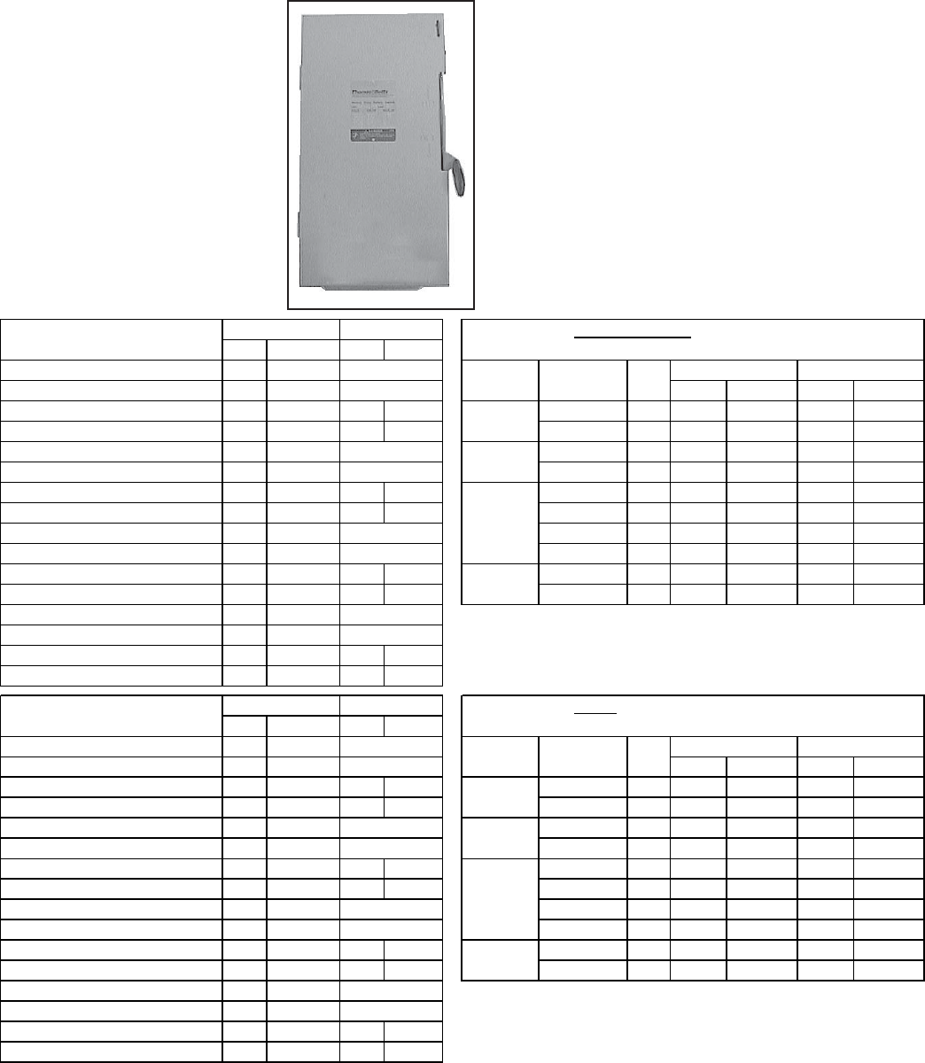
Form P-RDF, Page 21
Disconnect
Switch
Opt P/N Opt P/N
30 Amp, 240 Volt, Non-Fusible CP5 40269 Vo lt ag e / M o t o r
30 Amp, 240 Volt, Fusible CP6 87147 Phase HP Fusible Non-Fuse Fusible Non-Fuse
30 Amp, 600 Volt, Non-Fusible CP7 20367 CP59 208054 1/4 to 1-1/2 30 CP6 CP5 CP42 CP59
30 Amp, 600 Volt, Fusible CP8 20368 CP42 208046 2 to 3 60 CP17 CP30 CP44 CP61
60 Amp, 240-Volt, Non-Fusible CP30 161469 1/4 to 3 30 CP6 CP5 CP42 CP59
60 Amp, 240-Volt, Fusible CP17 89932 5 to 10 60 CP17 CP30 CP44 CP61
60 Amp, 600 Volt, Non-Fusible CP38 90973 CP61 208056 1/4 to 5 30 CP6 CP5 CP42 CP59
60 Amp, 600-Volt, Fusible CP20 90974 CP44 208048 7-1/2 to 15 60 CP17 CP30 CP44 CP61
100 Amp, 240-Volt, Non-Fusible CP31 162834 20 to 25 100 CP18 CP31 CP46 CP63
100 Amp, 240-Volt, Fusible CP18 90973 30 200 CP19 CP32 CP48 CP65
100 Amp, 600 Volt, Non-Fusible CP39 155013 CP63 208058 1/4 to 15 30 CP8 CP7 CP42 CP59
100 Amp, 600-Volt, Fusible CP36 155010 CP46 208050 20 to 30 60 CP20 CP38 CP44 CP61
200 Amp, 240-Volt, Non-Fusible CP32 155007
200 Amp, 240-Volt, Fusible CP19 91076
200 Amp, 600 Volt, Non-Fusible CP40 155014 CP65 208060
200 Amp, 600-Volt, Fusible CP37 155011 CP48 208052
Opt P/N Opt P/N
30 Amp, 240 Volt, Non-Fusible CP1 40267 Vo lt ag e / M o t o r
30 Amp, 240 Volt, Fusible CP2 40268 Phase HP Fusible Non-Fuse Fusible Non-Fuse
30 Amp, 600 Volt, Non-Fusible CP3 50365 CP58 208053 1/4 to 1-1/2 30 CP2 CP1 CP41 CP58
30 Amp, 600 Volt, Fusible CP4 50366 CP41 208045 2 to 3 60 CP27 CP21 CP43 CP60
60 Amp, 240-Volt, Non-Fusible CP21 161462 1/4 to 3 30 CP2 CP1 CP41 CP58
60 Amp, 240-Volt, Fusible CP17 89932* 5 to 10 60 CP27 CP21 CP43 CP60
60 Amp, 600 Volt, Non-Fusible CP23 161464 CP60 208055 1/4 to 5 30 CP2 CP1 CP41 CP58
60 Amp, 600-Volt, Fusible CP20 90974* CP43 208047 7-1/2 to 15 60 CP27 CP21 CP43 CP60
100 Amp, 240-Volt, Non-Fusible CP22 161463 20 to 25 100 CP28 CP22 CP45 CP62
100 Amp, 240-Volt, Fusible CP18 90973* 30 200 CP29 CP26 CP47 CP64
100 Amp, 600 Volt, Non-Fusible CP24 164330 CP62 208057 1/4 to 15 30 CP4 CP3 CP41 CP58
100 Amp, 600-Volt, Fusible CP36 155010* CP45 208049 20 to 30 60 CP33 CP23 CP43 CP60
200 Amp, 240-Volt, Non-Fusible CP26 155005
200 Amp, 240-Volt, Fusible CP19 91076* * Actually an outdoor switch.
200 Amp, 600 Volt, Non-Fusible CP35 155009 CP64 208059
200 Amp, 600-Volt, Fusible CP37 155011* CP47 208051
--
--
--
--
--
--
--
--
Canada Outdoor
Canada Indoor
General Guide to Indoor Disconnect Switches by Option Code
(unit motor/voltage availability varies by model/size)
General Guide to Outdoor/Raintight Switches by Option Code
(unit motor/voltage availability varies by model/size)
Amps
Amps USA Outdoor
USA Indoor
115/1
208/1 and
230/1
208/3 and
230/3
460/3 and
575/3
CODE 170 - OUTDOOR
Disconnect Switches
CODE 171 - INDOOR
Disconnect Switches
115/1
208/1 and
230/1
460/3 and
575/3
208/3 and
230/3
--
--
--
--
USA Only Canada Only
USA Only Canada Only
--
--
--
--
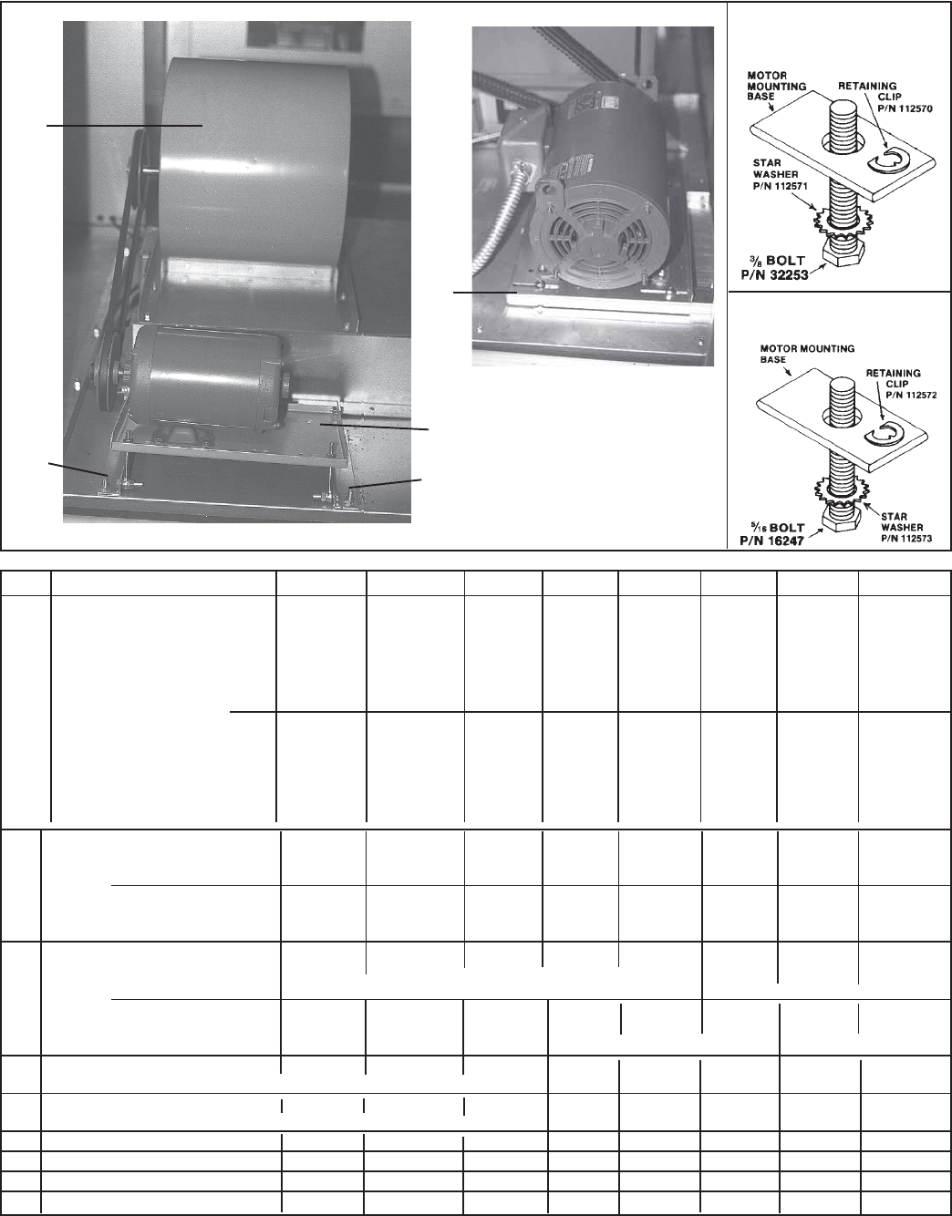
Form P-RDF, Page 22
Blowers
CODE Description 1-20 1-40 1-50 1-65 2-80 2-120 3-180 3-260
180 Blower with shaft 1357 1360 86983 86984 92343* 89345 91067 91069
and bearings Size 10" 12" 15" 18" 18" 20" 22" 30"
Mfg # A10-10AC A12-12AC A15-15A A18-18A 022920-03 027550-02 020350-01 029353-02
A20-20K A22-22K A30-22K
Class Class 1 Class 1 Class 1 Class 1 Class 1
Shaft 1" 1-7/16" 1-7/16" 1-7/16" 1-11/16"
————89658 —91068 91070
Size 18" 22" 30"
Mfg # 0217142-15 029353-01 029353-03
A18-18A A22-22K A30-22K
Class Class 2 Class 2 Class 2
Shaft 1-7/16" 2-3/16" 2-11/16"
180A Blower Class 1 Blowers 11302 11303 100747 100748 100748 100746 100751 100754
Shaft 3/4x22 1x22 1x23 1x28.8 2x28.8 1.44x 1.44x 1.69x
37.25 45.73 46.25
Class 2 Blowers — — — — 100749 —100752 101705
1.44x 2.19x 2.69x
38.5" 45.75" 46.25'
180B Blower Class 1 Blowers 7310 10437 10437 10437 10437 106942 106942 100755
Bearings Ball Bearings (2) 1.44" 1.44" 1.69"
Pillowblock (2)
Class 2 Blowers — — — — 106942 —100753 101710
1.44" 2.19" 2.69"
Pillowblock (2) Pillowblock (2)
181 External Shaft Support Bearing Plate 111389 111389 111389 111389 111389 111389 111389 111389
- for units with dampers (Options AQ3, AQ4 and/or AR19, AR20, AR22, AR23) 126588** 126588**
182 Bearing BF-1127-502-A - for units 111390 111390 111390 111390 111390 111390 111390 111390
with dampers, Options AQ3, AQ4, and/or AR19, AR20, AR22, AR23)
183 Blower Motor Mounting Plate 12578 12578 12578 12578 94371 94371 94371 94371
184 Mtr Mounting Plate Left Support 87015 87015 87015 87015 94369 94369 94369 94369
185 Mtr Mounting Plate Right Support 87016 87016 87016 87016 94369 94369 94369 94369
186 Blower Support (Horzntl Discharge) 207840 207840 207840 207840 (2)207461 (2)207461 (3)207462 (3)207462
*Effective 8/90, RDF 2-80 models are no longer manufactured with a Class 1 blower. P/N 92343 is no longer available. Replace with Class 2 blower,
P/N 89658 and Q1-1-7/16" Bushing, P/N 16177.
** Order P/N 126588 when heater has Option AR23, outside and return dampers controlled by a remote pressure sensor.
Hardware for 3/8" Motor
Mounting Bolts
Hardware for 5/16" Motor
Mounting Bolts
Blower and Motor - RDF 1
180
183
184 185
Blower Motor - RDF 2 and 3
183
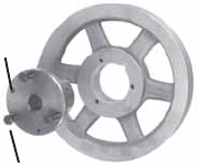
Form P-RDF, Page 23
Drives Belt Tension - Check belt tension. Proper belt tension is important to the long life of the belt
and motor. A loose belt will cause wear and slippage. Too much tension will cause excessive
motor and blower bearing wear. If adjustment is required, adjust belt tension by means of the
adjusting screw on the motor base until the belt can be depressed 1/2" to 3/4". Tighten the
lock nut on the adjusting screw. Be sure the belt is aligned in the pulleys.
Blower Speed Adjustment - Units are set at the factory for the RPM required to meet the CFM
and external static pressure specified on the order. If the estimated external static is incorrect,
or changes are made to the duct system, the blower RPM may have to be changed. Motors
are equipped with adjustable pitch pulleys which permit adjustment of blower speed.
To make adjustments on all RDF-1 units and on RDF-2 and RDF-3 units with less than 7-1/
2 HP motor (units with a Browning motor sheave Model VP), follow these instructions:
1) Loosen belt tension and remove belt.
2) Loosen the set screw on the side of the pulley away from the motor.
3) Turn adjustable half of the pulley inward to increase blower speed or outward
to decrease speed. One turn of the pulley will change speed 8 to 10%.
4) After setting the pulley, tighten the set screw on the flat portion of the pulley
shaft.
5) Replace belts and adjust belt tension.
6) Always check motor amps with an amp meter after RPM adjustment. The
maximum motor amp rating on the nameplate must not be exceeded.
In RDF-2 and RDF-3 models with 7-1/2 HP and larger motors (units with adjustable Brown-
ing motor sheave Model MV), follow these instructions for adjusting RPM:
1) Slack off all belt tension by moving the motor toward driven shaft until the
belts are free of grooves. For easiest adjustment, remove the belts from the
grooves.
2) On the outer locking ring, locate the two locking screws that are directly
across from each other. Loosen, but do not remove, those two screws. Do not
loosen any other screws.
3) Adjust sheave to desired pitch diameter by turning the outer locking ring.
One complete turn of the outer locking ring will result in .233" change in
pitch diameter. To increase blower speed, decrease diameter. CAUTION: Do
not adjust sheaves in either direction to the point where moveable and
stationary flanges are in contact.
4) After completing adjustment, tighten both locking screws in the outer
locking ring.
5) Replace belts and move motor away from the drive shaft to apply sufficient
belt tension to prevent slippage. Be sure that the belts are aligned in the
pulley grooves properly and are not angled from pulley to pulley.
6) Always check motor amps with an amp meter after RPM adjustment. The
maximum motor amp rating on the nameplate must not be exceeded.
Blower Pulley - Size 2-80, 2-120, 119 and 120 systems equipped with 3 and 5 HP motors with
a 15.4" diameter and larger blower pulley or a 7-1/2 HP and larger motor and all Size 3-180, 3-
260, 122, and 130 systems are equipped with a split taper bushing in the blower pulley. The
split taper bushings must be loosened in order to remove the pulley. Follow these instruc-
tions to loosen the bushing.
3 Cap Screws
Split Taper
Bushing
2 Push-Off
Holes
1) Notice that there are three cap screws in the
bushing and two holes without screws, called
push-off holes (see illustration).
2) Remove the three cap screws.
3) Put two of the cap screws into the two push-off
holes. Tighten these two screws evenly until
the pulley is loosened.
4) Pulley may now be removed from the shaft.
Replacement Drive Components
are Listed in Tables on pages 23-
31. Tables are by RDF Size, Type of
Motor, Motor HP, and RPM (Option
AM, see chart top of page 23),
CODE 200 - Motor Sheave
CODE 201 - Blower Sheave
CODE 202 - Belt
CODE 203 - Bushing
NOTE: Read each drive table
carefully. They are not all in the
same format.

Form P-RDF, Page 24
Drive Components (cont'd)
Notes and Key to Option Codes on Drive Tables, pages 24 - 32
Option ............... RPM
AM6 .................. 651-700
AM7 .................. 701-750
AM8 .................. 751-800
AM9 .................. 801-850
AM10 ................ 851-900
AM11 ................ 901-950
AM12 ................ 951-1000
Option ............... RPM
AM13 ................ 1001-1050
AM14 ................ 1051-1100
AM15 ................ 1101-1150
AM16 ................ 1151-1200
AM17 ................ 1201-1250
AM18 ................ 1251-1300
AM19 ................ 1301-1350
Option ............... RPM
AM20 ................ 1351-1400
AM21 ................ 1401-1450
AM22 ................ 1451-1500
AM23 ................ 1501-1550
AM24 ................ 1551-1600
AM25 ................ 1601-1650
AM26 ................ 1651-1700
Option ............... RPM
AMA3 ............... 301-350
AMA4 ............... 351-400
AM1 .................. 401-450
AM2 .................. 451-500
AM3 .................. 501-550
AM4 .................. 551-600
AM5 .................. 601-650
NOTE : Where 575V (AK8) is listed, the two corresponding AL option lines above apply to all other voltages with that HP.
HP Option P/N Mfr No. Bore P/N Mfr No. Bore P/N Mfr No.
AL4 V AM6-9 7962 111607 50513 A52 -
AL4 H AM6-9 7962 111607 50470 A43 -
AL4 V AM10-15 7962 105480 50475 A49 -
AL4 H AM10-15 7962 105480 105493 A39 -
AL5 V AM8-11 105476 111682 50513 A52 -
AL5 H AM8-11 105476 111682 50470 A43 -
AL5 V AM12-16 7962 1VL40 105479 AK49 65403 A48 -
AL5 H AM12-16 105476 1VL44 111684 AK59 50500 A41 -
AL5 V AM17-21 13013 105480 88558 A50 -
AL5 H AM17-21 13013 105480 50500 A41 -
AL6 V AM10-15 7962 105480 50475 A49 -
AL6 H AM10-15 7962 105480 105493 A39 -
AL6-AK8 V AM10-15 106748 105480 50475 A49 -
AL6-AK8 H AM10-15 106748 105480 105493 A39 -
AL6 V AM16-20 13013 111684 65404 A51 -
AL6 H AM16-20 13013 111684 105493 A39 -
AL6-AK8 V AM16-20 37451 111684 105493 A39 -
AL6-AK8 H AM16-20 37451 111684 65404 A51 -
AL7 V AM10-15 7962 105480 50475 A49 -
AL7 H AM10-15 7962 105480 105493 A39 -
AL7-AK8 V AM10-15 106748 105480 50475 A49 -
AL7-AK8 H AM10-15 106748 105480 105493 A39 -
AL7 V AM16-20 13013 111684 65404 A51 -
AL7 H AM16-20 13013 111684 105493 A39 -
AL7-AK8 V AM16-20 37451 111684 105493 A39 -
AL7-AK8 H AM16-20 37451 111684 65404 A51 -
AL7 V AM21-24 7962 1VL40 105478 AK41 50474 A47 -
AL7 H AM21-24 16151 1VP56 110807 AK56H 101412 A42 105487
AL7-AK8 V AM21-24 106748 105478 50474 A47 -
AL7-AK8 H AM21-24 106748 105478 101412 A42 -
AL8 V AM15-20 37451 111684 65404 A51 -
AL8 H AM15-20 37451 111684 105493 A39 -
AL8 V AM21-24 106748 105478 50474 A47 -
AL8 H AM21-24 106748 105478 101412 A42 -
AL8 V AM15-20 13013 111684 65404 A51 -
AL8 H AM15-20 13013 111684 105493 A39 -
AL8 V AM21-24 7962 1VL40 105478 50474 A47 -
AL8 H AM21-24 16151 1VP56 105478 101412 A42 -
1VM50
3/4
5/8
AK59
3/4
AK41
7/8
1VM50
1VL40
AK59
AK41
5/8
7/8 AK41
2 HP Drive Components for Model RDF 1-20 Series 3 only
3/4
5/8
7/8
AK54
AK59
3/4
1VL40
1VM50
5/8
7/8
5/8
7/8
AK54
AK59
3/4
5/8
AK71
AK54
1VL40
5/8
7/8
2 HP Drive Components for Model RDF 1-20 prior to Series 3
2
CODE 200 - Motor
Sheave
CODE 201- Blower
Sheave CODE 202 - Belt
1VL40 5/8 3/4
AK74
CODE
203 -
Bushin
g
Model RDF 1-20
1/2
Open Motor
AK54
Horz/Vert
Discharge
Drive Option
(See table
above.
)
3/4
1
1-1/2
1VL44
1VM50
1VM50
1VL40

Form P-RDF, Page 25
Drive Components (cont'd)
NOTE : Where 575V (AK8) is listed, the two corresponding AL option lines above apply to all other voltages with that HP.
HP Option P/N Mfr No. Bore P/N Mfr No. Bore P/N Mfr No.
AL5 V AM4-6 7962 19111 50513 A53
AL5 H AM4-6 7962 19111 50473 A46
AL5 V AM7-11 7962 18797 50475 A49
AL5 H AM7-11 7962 18797 101412 A42
AL5 V AM12-17 105476 105482 50475 A49
AL5 H AM12-17 105476 105482 101412 A42
AL6 V AM7-11 7962 18797 50475 A49
AL6 H AM7-11 7962 18797 101412 A42
AL6-AK8 V AM7-11 106748 18797 50475 A49
AL6-AK8 H AM7-11 106748 18797 101412 A42
AL6 V AM12-17 105476 105482 50475 A49
AL6 H AM12-17 105476 105482 101412 A42
AL6-AK8 V AM12-17 106758 105482 50475 A49
AL6-AK8 H AM12-17 106758 105482 101412 A42
AL7 V AM7-11 7962 18797 50475 A49
AL7 H AM7-11 7962 18797 101412 A42
AL7-AK8 V AM7-11 106748 18797 50475 A49
AL7-AK8 H AM7-11 106748 18797 101412 A42
AL7 V AM12-17 105476 105482 50475 A49
AL7 H AM12-17 105476 105482 101412 A42
AL7-AK8 V AM12-17 106758 105482 50475 A49
AL7-AK8 H AM12-17 106758 105482 101412 A42
AL7 V AM18-21 13013 105482 50475 A49
AL7 H AM18-21 13013 105482 50470 A43
AL7-AK8 V AM18-21 37451 105482 50475 A49
AL7-AK8 H AM18-21 37451 105482 50470 A43
AL8 V AM7-11 106748 18797 50475 A49
AL8 H AM7-11 106748 18797 101412 A42
AL8 V AM12-17 106758 105482 50475 A49
AL8 H AM12-17 106758 105482 101412 A42
AL8 V AM18-21 37451 105482 50475 A49
AL8 H AM18-21 37451 105482 50470 A43
AL8 V AM7-11 7962 18797 50475 A49
AL8 H AM7-11 7962 18797 101412 A42
AL8 V AM12-17 105476 105482 50475 A49
AL8 H AM12-17 105476 105482 101412 A42
AL8 V AM18-21 13013 105482 50475 A49
AL8 H AM18-21 13013 105482 50470 A43
AL9 V AM12-17 106748 111609 16132 A55
AL9 H AM12-17 106748 111609 65403 A48
AL9 V AM18-21 106748 19111 50513 A52
AL9 H AM18-21 106748 19111 50473 A46
AL10 V AM14-18 8973 30621 50477 A60
AL10 H AM14-18 8973 30621 16131 A54
AL10 V AM19-23 8973 7955 16134 A57
AL10 H AM19-23 8973 7955 88558 A50
5
7/8
5/8
1VL40
7/8
1VL40 7/8
2VP50 7/8
1VL40
1
1
AK99
AK84
2AK124
2AK104
1VL40
1VL44 5/8
AK64
AK56
AK64
AK56
1VL40
1VM50
2 HP Drive Components for Model RDF 1-40 prior to Series 3
3
1
AK64
AK56
1VM50
1
1
7/8
1
5/8
1VL44 5/8
2 HP Drive Components for Model RDF 1-40 Series 3 only
1VL44
1VM50
7/8
5/8
7/8
5/8
2
CODE 200 - Motor
Sheave
CODE 201 - Blower
Sheave CODE 202 - Belt
1VL40
1VL44
1
7/8
1
1-1/2
Model RDF 1-40
Open Motor
AK84
5/8
3/4 AK64
AK56
Horz/Vert
Discharge
Drive Option
(See page 23.)
7/8
AK64
AK56

Form P-RDF, Page 26
Drive Components (cont'd)
NOTE : Where 575V (AK8) is listed, the two corresponding AL option lines above apply to all other voltages with that HP.
HP Option P/N Mfr No. Bore P/N Mfr No. Bore P/N Mfr No.
AL6 V AM4-6 7962 19111 88558 A50
AL6 H AM4-6 7962 19111 50473 A46
AL6-AK8 V AM4-6 106748 19111 88558 A50
AL6-AK8 H AM4-6 106748 19111 50473 A46
AL6 V AM7-11 7962 18797 50474 A47
AL6 H AM7-11 7962 18797 101412 A42
AL6-AK8 V AM7-11 106748 18797 50474 A47
AL6-AK8 H AM7-11 106748 18797 101412 A42
AL7 V AM4-6 7962 19111 88558 A50
AL7 H AM4-6 7962 19111 50473 A46
AL7-AK8 V AM4-6 106748 19111 88558 A50
AL7-AK8 H AM4-6 106748 19111 50473 A46
AL7 V AM7-11 7962 18797 50474 A47
AL7 H AM7-11 7962 18797 101412 A42
AL7-AK8 V AM7-11 106748 18797 50474 A47
AL7-AK8 H AM7-11 106748 18797 101412 A42
AL8 V AM4-6 106748 19111 88558 A50
AL8 H AM4-6 106748 19111 50473 A46
AL8 V AM7-11 106748 18797 50474 A47
AL8 H AM7-11 106748 18797 101412 A42
AL8 V AM4-6 7962 19111 88558 A50
AL8 H AM4-6 7962 19111 50473 A46
AL8 V AM7-11 7962 18797 50474 A47
AL8 H AM7-11 7962 18797 101412 A42
AL9 V AM8-11 106758 113372 88560 A61
AL9 H AM8-11 106758 113372 50476 A58
AL9 V AM12-16 37451 50520 50477 A60
AL9 H AM12-16 37451 50520 16133 A56
AL10 V AM8-13 87500 7955 16130 A53
AL10 H AM8-13 87500 7955 50475 A49
AL10 V AM14-18 8973 30621 50476 A58
AL10 H AM14-18 8973 30621 16131 A54
1
AK84
AK64
5/8
7/8
5/8
7/8
Model RDF 1-50
Open Motor Horz/Vert
Discharge
Drive Option
(See page 23.)
CODE 200 - Motor
Sheave
CODE 201- Blower
Sheave CODE 202 - Belt
3
5
AK84
2VP36
2VP50
7/8
2
1VL40 7/8
1VL44
1VL40
1-1/2
1VL40
5/8
7/8
1
1VL40
1
2 HP Drive Components for Model RDF 1-50 Series 3 only
2 HP Drive Components for Model RDF 1-50 prior to Series 3
1VL40 5/8
7/8
AK84
AK64
1
AK84
AK64
1VL40 5/8 1
AK64
1VM50
7/8 1
1
AK144
AK134
2AK104
2AK124

Form P-RDF, Page 27
Drive Components (cont'd)
NOTE : Where 575V (AK8) is listed, the two corresponding AL option lines above apply to all other voltages with that HP.
HP Option P/N Mfr No. Bore P/N Mfr No. Bore P/N Mfr No.
AL7 V AM2-3 13013 113372 88560 A61 -
AL7 H AM2-3 13013 113372 92402 A59 -
AL7-AK8 V AM4-6 37451 113372 88560 A61 -
AL7-AK8 H AM4-6 37451 113372 92403 A59 -
AL7 V AM4-6 7962 19111 50475 A49 -
AL7 H AM4-6 7962 19111 50473 A46 -
AL7-AK8 V AM4-6 106748 19111 50475 A49 -
AL7-AK8 H AM4-6 106748 19111 50473 A46 -
AL7 V AM7-11 7962 18797 50472 A45 -
AL7 H AM7-11 7962 18797 50470 A43 -
AL7-AK8 V AM7-11 106748 18797 50472 A45 -
AL7-AK8 H AM7-11 106748 18797 50470 A43 -
AL8 V AM2-3 37451 113372 88560 A61 -
AL8 H AM2-3 37451 113372 92403 A59 -
AL8 V AM4-6 106748 19111 50475 A49 -
AL8 H AM4-6 106748 19111 50473 A46 -
AL8 V AM7-11 106748 18797 50472 A45 -
AL8 H AM7-11 106748 18797 50470 A43 -
AL8 V AM2-3 13013 113372 88560 A61 -
AL8 H AM2-3 13013 113372 92403 A59 -
AL8 V AM4-6 7962 19111 50475 A49 -
AL8 H AM4-6 7962 19111 50473 A46 -
AL8 V AM7-11 7962 18797 50472 A45 -
AL8 H AM7-11 7962 18797 50470 A43 -
AL9 V AM4-7 87500 113382 92402 A59 -
AL9 H AM4-7 87500 113382 50476 A58 -
AL9 V AM8-11 6599 30622 50476 A58 92203
AL9 H AM8-11 6599 30622 16133 A56 92203
AL10 V AM7-13 87500 7955 65404 A51 -
AL10 H AM7-13 87500 7955 88558 A50 -
CODE 201- Blower
Sheave CODE 202 - Belt Open Motor Horz/Vert
Discharge
Drive Option
(See page 23.)
CODE 200 - Motor
Sheave
3
5
Model RDF 1-65
1-1/2 AK84
AK64
1VM50
1VL40
7/8
AK144
1
CODE
203 -
Bushin
g
1VM50
1VL40
1VL40
5/8
7/8
5/8
7/8
5/8
7/8
2 HP Drive Components for Model RDF 1-65 Series 3 only
2 HP Drive Components for Model RDF 1-65 prior to Series 3
2
1VM50
1VL40
7/8
AK144
AK84
AK64
1
5/8
AK144
1
AK84
AK64
2VP36
2VP42
2VP36 2AK104
1
17/8
AK144
2AK134H

Form P-RDF, Page 28
Drive Components (cont'd)
Horz/Vert Drive Option
HP Option Discharge (See page 23.) P/N Mfr No. Bore P/N Mfr No. Bore P/N Qty Mfr No.
AL8 V AM3-5 106748 114026 112531 1B55 89659
AL8 H AM3-5 106748 114026 92222 1B53 89659
AL8 V AM3-5 7962 114026 112531 1B55 89659
AL8 H AM3-5 7962 114026 92222 1B53 89659
AL9 V AM3-4 87500 114027 16558 2A69 89659
AL9 H AM3-4 87500 114027 16139 2A67 89659
AL9 V AM5-9 110125 114028 92402 1A59 89659
AL9 H AM5-9 110125 114028 16134 1A57 89659
AL9 V AM10-13 106748 114030 92402 1A59 89659
AL9 H AM10-13 106748 114030 16132 1A55 89659
AL10 V AM3-4 87500 114027 16558 2A69 89659
AL10 H AM3-4 87500 114027 16139 2A67 89659
AL10 V AM5-6 87500 114032 2B5V160 92276 2BX65 114033
AL10 H AM5-6 6599 2VP42 114027 2AK184H 16139 2A67 89659
AL10 V AM7-11 87500 114034 50476 2A58 89659
AL1
0
HAM7-11
87500 114034 16132 2A55 89659
AL11 V AM6-7 113802 2VP68 89651 114104 2B66 89659
AL11 H AM6-7 114249 2VP71 89651 92414 2B64 89659
AL11 V AM8-9 106257 113811 92226 2B58 89659
AL11 H AM8-9 106257 113811 92224 2B56 89659
AL11 V AM10-11 16150 114045 92280 2BX59 114033
AL11 H AM10-11 16150 114045 92409 2BX55 114033
AL11 V AM12-15 106257 113804 92222 2B53 89659
AL11 H AM12-15 106257 113804 92220 2B51 89659
AL12 V AM6-7 113802 2VP68 89651 114104 2B66 89659
AL12 H AM6-7 114249 2VP71 89651 92414 2B64 89659
AL12 V AM8-9 106257 113811 92226 2B58 89659
AL12 H AM8-9 106257 113811 92224 2B56 89659
AL12 V AM10-11 16150 114045 92280 2BX59 114033
AL12 H AM10-11 16150 114045 92409 2BX55 114033
AL12 V AM12-15 106257 113804 92222 2B53 89659
AL12 H AM12-15 106257 113804 92220 2B51 89659
AL15 V AM7-9 91615 2MVP40B54 113811 2BK120H 92409 2BX55 89659
AL15 H AM7-9 113809 92204 2BK140H 16143 2B59 89659
AL15 V AM10-11 113809 89650 92226 2B58 89659
AL15 H AM10-11 113809 89650 92225 2B57 89659
AL15 V AM12-16 114047 114048 92236 2BX50 114033
AL15 H AM12-16 114047 114048 113805 2B49 114033
AL15 V AM17-20 113808 114048 114341 2BX53 114033
AL15 H AM17-20 113808 114048 92237 2BX51 114033
Horz/Vert Drive Option
HP Option Discharge (See page 23.) P/N Mfr No. Bore P/N Mfr No. Bore P/N Qty Mfr No.
5AL27 H AM7-9 111681 1VP50 1-1/8 113799 AK184H 1-7/16 16139 2A67 89659
CODE 202 - Belt CODE 203 -
Bushing
NOTE: If drive components are required for units with a TEFC or Premium Efficiency motor not listed here, contact your Distributor or the
Factory Service Department. Be prepared to provide complete Model and Serial No.
1-7/16
2MVP45B59
2VP71A
1-5/8
2BK130H
2B5V86
1-7/16
1-7/16
2VP75
TEFC Motor CODE 200 - Motor Sheave CODE 201 - Blower Sheave
2BK16 0H
2BK120H
2BV110
2BK90H
1-3/8
2VP60
2VP60
2VP62
2BK16 0H
2BK120H
2BV110
2BK90H
1-7/16
2VP36
2VP36
2AK184H
2AK124H
1-7/16
7/8
7/8
2VP36
1VL40
1VP34
2AK184H
AK134H
AK124H
1-7/16
2
1VL40 5/8
1VL40 7/8
CODE 200 - Motor Sheave CODE 201 - Blower Sheave CODE 202 - Belt CODE 203 -
Bushing
3
5
7-1/2
Model RDF 2-80 with a CLASS 2 BLOWE
R
Open Motor
2 HP Drive Components for Model RDF 2-80 Series 3 only
2 HP Drive Components for Model RDF 2-80 prior to Series 3
BK110H 1-7/16
BK110H
1-3/8
10
15
2VP60
2VP62
2VP60
(Effective 8/90 all RDF-2-80 Models are equipped with a Class 2 blower. For RDF-2-80 with a Class 1 blower, see page 28. A Class 2 blower was
available as a option prior to 8/90.)
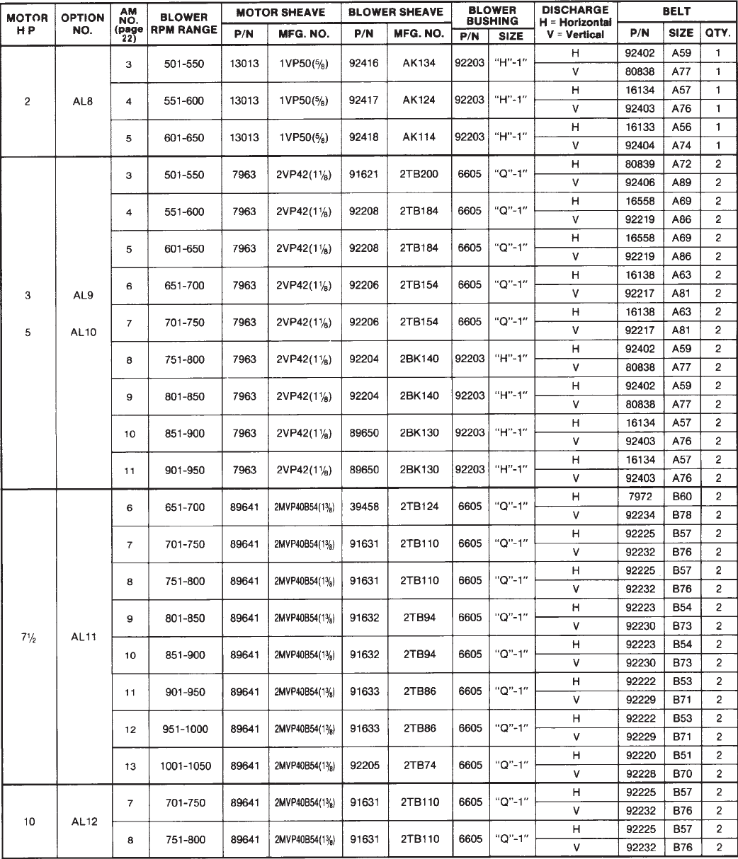
Form P-RDF, Page 29
Drive Components (cont'd)
Model RDF-2-80 with a Class 1 Blower
(Effective 8/90 all RDF-2-80 Models are equipped with a Class 2 blower. For RDF-2-890 with a Class 2 blower, see page 27. A Class 2 blower was
available as a option prior to 8/90.

Form P-RDF, Page 30
Drive Components (cont'd)
Horz/Vert Drive Option
HP Option Discharge (See page 23.) P/N Mfr No. Bore P/N Mfr No. Bore P/N Qty Mfr No.
AL8 V AM3-5 106758 1VL44 113798 AK104H 16130 1A53 89659
AL8 H AM3-5 106748 1VL40 114026 BK110H 92223 1B54 89659
AL8 V AM3-5 105476 1VL44 113798 AK104H 16130 1A53 89659
AL8 H AM3-5 7962 1VL4
0
114026 BK110H 92223 1B5
4
89659
AL9 V AM3-4 87500 89652 2BK10H 92241 2BX68 89659
AL9 H AM3-4 87500 114027 2AK184H 16558 2A69 89659
AL9 V AM5-7 106758 1VL44 113799 AK184H 16558 1A69 89659
AL9 H AM5-7 110125 1VP34 114028 AK134H 92402 1A59 89659
AL9 V AM8-11 106758 113800 AK144H 88560 1A61 89659
AL9 H AM8-11 106758 113800 AK144H 16138 1A63 89659
AL10 V AM3-4 87500 89652 2BK10H 92241 2BX68 89659
AL10 H AM3-4 87500 114027 2AK184H 16558 2A69 89659
AL10 V AM5-7 87500 89651 BK160H 92411 2BX62 89659
AL10 H AM5-7 6599 2VP42 114027 2AK184H 114257 2A70 89659
AL10 V AM8-11 87500 113801 2AK104H 16130 2A53 89659
AL1
0
HAM8-11
87500 114034 2AK124H 16134 2A57 89659
AL11 V AM4-5 110771 114032 2B5V160 114258 2BX64 114033
AL11 H AM4-5 110771 114032 2B5V160 80841 2BX67 114033
AL11 V AM6-7 113802 2VP68 89651 2BK160H 92278 2BX63 89659
AL11 H AM6-7 114249 2VP71 89651 2BK160H 114104 2B66 89659
AL11 V AM8-11 106257 113803 2BK110H 92223 2B54 89659
AL11 H AM8-11 106257 113803 2BK110H 92224 2B56 89659
AL11 V AM12-15 106257 113804 2BK90H 114010 2B50 89659
AL11 H AM12-15 106257 113804 2BK90H 92222 2B53 89659
AL12 V AM4-5 110771 114032 2B5V160 114258 2BX64 114033
AL12 H AM4-5 110771 114032 2B5V160 80841 2BX67 114033
AL12 V AM6-7 113802 2VP68 89651 2BK160H 92278 2BX63 89659
AL12 H AM6-7 114249 2VP71 89651 2BK160H 114104 2B66 89659
AL12 V AM8-11 106257 113803 2BK110H 92223 2B54 89659
AL12 H AM8-11 106257 113803 2BK110H 92224 2B56 89659
AL12 V AM12-15 106257 113804 2BK90H 114010 2B50 89659
AL12 H AM12-15 106257 113804 2BK90H 92222 2B53 89659
AL15 V AM6-7 113808 2VP75 114032 2B5V160 92411 2BX62 114033
AL15 H AM6-7 91615 2MVP40B54 113811 2BK120H 92409 2BX55 89659
AL15 V AM8-9 113809 2VP71A 92204 2BK140H 92226 2B58 89659
AL15 H AM8-9 91615 2MVP40B54 113811 2BK120H 92409 2BX55 89659
AL15 V AM10-11 113808 2VP75 89650 92224 2B56 89659
AL15 H AM10-11 113809 2VP71A 89650 16143 2B59 89659
AL15 V AM12-13 113808 113811 112531 2B55 89659
AL15 H AM12-13 113808 113811 92226 2B58 89659
2VP65
2VP60
1-3/8 1-7/16
1VL44
7/8 1-7/16
1-7/167/8
2VP36
2VP36
2 HP Drive Components for Model RDF 2-120 prior to Series 3
1-7/16
CODE 200 - Motor Sheave CODE 201 - Blower Sheave CODE 202 - Belt
2 HP Drive Components for Model RDF 2-120 Series 3 only
* Open Motor CODE 203
- Bushing
15
3
7-1/2
5
10
Model RDF 2-120
2VP36
2VP65
2VP60
1-3/8 1-7/16
27/8
5/8
1-7/16
1-5/8 1-7/16
2VP75 2BK120H
2BK130H
* If drive components are required for units with a 3-10HP TEFC or 3-10 HP Premium Efficiency motor, contact your Distributor or the Factory
Service Department. Be prepared to provide complete Model and Serial No.

Form P-RDF, Page 31
* If drive components are required for units with a 5-15HP TEFC or 5-15 HP Premium Efficiency motor, contact your Distributor or the
Factory Service Department. Be prepared to provide complete Model and Serial No.
Drive Components (cont'd)
Horz/Vert Drive Option
HP Option Discharge (See page 23.) P/N Mfr No. Bore P/N Mfr No. Bore P/N Qty Mfr No.
AL10 1 V AM2-3 6599 2VP42 115718 2B5V250 92319 2BX97114033
AL10 1 V AM4-5 87500 2VP36 89652 2BK190H 92312 2B86 89659
AL10 1 H AM2-3 6599 2VP42 115718 2B5V250 92308 2B92 114033
AL10 1 H AM4-5 87500 2VP36 89652 2BK190H 92341 2BX77 89659
AL11/12 1 V AM1 114249 2VP71 115718 2B5V250 115932 2BX99114033
AL11/12 1 V AM2 106257 2VP60 89652 115933 2B88 89659
AL11/12 1 V AM3 16150 2VP62 89652 115934 2B89 89659
AL11/12 1 V AM4-5 110771 2VP65 114032 92273 2B84 114033
AL11/12 1 V AM6-7 114249 2VP71 114032 92317 2BX85114033
AL11/12 1 V AM8-9 106257 2VP60 113811 2BK120H 92277 2BX75 89659
AL11/12 1 H AM1 114249 2VP71 115718 2B5V250 92313 2BX93114033
AL11/12 1 H AM2 106257 2VP60 89652 92332 2BX79 89659
AL11/12 1 H AM3 16150 2VP62 89652 92332 2BX79 89659
AL11/12 1 H AM4-5 110771 2VP65 114032 92277 2BX75114033
AL11/12 1 H AM6-7 114249 2VP71 89651 92277 2BX75 89659
AL11/12 1 H AM8-9 106257 2VP60 113811 2BK120H 92240 2BX66 89659
AL15/16 1 V AM4-5 89644 3MVP40B54 115720 3B5V136 92341 3BX77114033
AL15/16 1 V AM6-7 115719 3MVP50B64 115721 3B5V154 92274 3BX81114033
AL15/16 1 V AM8-10 89645 3MVP45B59 115722 3BK120H 92231 3B74 89659
AL15/16 1 V AM11-14 89644 3MVP40B54 115723 3BK90H 92241 3BX68 89659
AL15/16 2 V AM2-3 89645 3MVP45B59 115943 3B5V184 92310 3B87 116205
AL15/16 2 V AM4-6 89644 115720 3B5V136 92341 3BX77116205
AL15/16 2 V AM7-9 89644 115935 92230 3B73 116205
AL15/16 2 V AM10-12 115719 3MVP50B64 115935 92277 3BX75116205
AL15/16 2 V AM13-15 89645 3MVP45B59 115945 3B6V90 92243 3BX71116205
AL15/16 1 H AM4-5 89644 3MVP40B54 115720 3B5V136 92241 3BX68114033
AL15/16 1 H AM6-7 115719 3MVP50B64 115721 3B5V154 92230 3B73 114033
AL15/16 1 H AM8-10 89645 3MVP45B59 115722 3BK120H 6010 3B65 89659
AL15/16 1 H AM11-14 89644 3MVP40B54 115723 3BK90H 16143 3B59 89659
AL15/16 2 H AM2-3 89645 3MVP45B59 115943 3B5V184 92234 3B78 116205
AL15/16 2 H AM4-6 89644 115720 3B5V136 92241 3BX68116205
AL15/16 2 H AM7-9 89644 115935 114258 3BX64116205
AL15/16 2 H AM10-12 115719 3MVP50B64 115935 92276 3BX65116205
AL15/16 2 H AM13-15 89645 3MVP45B59 115945 3B6V90 92411 3BX62116205
AL17/18 2 V AM5-6 115931 4MVP50B64 116204 4MVB154R 92412 4BX80116206
AL17/18 2 V AM7-9 115946 4MVP45B59 116203 4MVB124R 92277 4BX72116206
AL17/18 2 V AM10-12 115931 4MVP50B64 116202 4MVB110R 92230 4B73 116206
AL17/18 2 V AM13-16 115931 4MVP50B64 116201 4MVB94Q 92242 4BX70116207
AL17/18 2 H AM5-6 115931 4MVP50B64 116204 4MVB154R 92243 4BX71116206
AL17/18 2 H AM7-9 115946 4MVP45B59 116203 4MVB124R 92276 4BX65116206
AL17/18 2 H AM10-12 115931 4MVP50B64 116202 4MVB110R 92278 4BX63116206
AL17/18 2 H AM13-16 115931 4MVP50B64 116201 4MVB94Q 92289 4BX61116207
25
and
30
15
and
20
7-1/2
and
10
CODE 200 - Motor Sheave
5
*Open Motor Blower
Class
7/8
CODE 203
- Bushing
Model RDF 3-180
1-7/16
1-5/8
3MVP40B54
3B5V110
3MVP40B54
3B5V110
CODE 201- Blower Sheave CODE 202 - Belt
1-7/16
1-3/8 1-7/16
2BK190H
2B5V160
2BK190H
2B5V160
2-3/16
1-7/16
2-3/16
1-7/8 2-3/16

Form P-RDF, Page 32
Horz/Vert Drive Option
HP Option Discharge (See page 23.) P/N Mfr No. Bore P/N Mfr No. Bore P/N Qty Mfr No.
AL11/12 1 H AMA3 115940 115941 92316 2 BX103 115949
AL11/12 1 V AMA3 115940 115941 115947 2 BX113 115949
AL11/12 1 H AMA4 106257 115941 92316 2 BX103 115949
AL11/12 1 V AMA4 106257 115941 115948 2 BX115 115949
AL11/12 1 H AM1-2 89641 115942 92313 2BX93 115949
AL11/12 1 V AM1-2 89641 115942 92314 2 BX105 115949
AL11/12 1 H AM3-4 106257 114032 92315 2BX90 115949
AL11/12 1 V AM3-4 106257 114032 92316 2 BX103 115949
AL15/16 1 H AMA4 89644 115944 92318 3 BX100 115949
AL15/16 1 V AMA4 89644 115944 115947 3 BX113 115949
AL15/16 1 H AM1 115719 115944 115865 3 B101 115949
AL15/16 1 V AM1 115719 115944 115947 3 BX113 115949
AL15/16 1 H AM2 89644 115943 92315 3BX90 115949
AL15/16 1 V AM2 89644 115943 92316 3 BX103 115949
AL15/16 1 H AM3-5 89644 115721 92273 3B84 115949
AL15/16 1 V AM3-5 89644 115721 92319 3BX97 115949
AL15/16 2 H AMA4 89645 116446 92316 3 BX103 116451
AL15/16 2 V AMA4 89645 116446 115948 3 BX115 116451
AL15/16 2 H AM1 89644 116447 92313 3BX93 116451
AL15/16 2 V AM1 89644 116447 92314 3 BX105 116451
AL15/16 2 H AM2-3 89645 116448 92315 3BX90 91609
AL15/16 2 V AM2-3 89645 116448 92316 3 BX103 91609
AL15/16 2 H AM4-6 89644 116449 92274 3BX81 91609
AL15/16 2 V AM4-6 89644 116449 119610 3B94 91609
AL17/18 2 H AM1 116460 116461 92316 4 BX103 116451
AL17/18 2 V AM1 116460 116461 115948 4 BX115 116451
AL17/18 2 H AM2-3 115946 116462 92315 4BX90 116451
AL17/18 2 V AM2-3 115946 116462 92316 4 BX103 116451
AL17/18 2 H AM4-5 115946 116204 92333 4BX83 116451
AL17/18 2 V AM4-5 115946 116204 92334 4BX96 116451
AL17/18 2 H AM6-8 116460 116204 92317 4BX85 116451
AL17/18 2 V AM6-8 116460 116204 92319 4BX97 116451
15 and
20
25 and
30
7-1/2
and 10
2VP60
2MVP40B54
2VP60
3MVP40B54
3MVP50B54
3MVP40B54
3MVP45B59
CODE 202 - Belt CODE 203 -
Bushing
Model RDF 3-260
2MVP35B49
2B5V234
*Open Motor Blower
Class
CODE 200 - Motor Sheave CODE 201- Blower Sheave
4MVP45B59
4MVP55B69
1-3/8
1-5/8
1-5/8
1-7/8
3MVP40B54
3MVP45B59
3MVP40B54
4MVP55B69
2B5V184
1-11/16
3B5V234
3MVB250R
3B5V184
2B5V160
3B5V154
1-11/16
3MVB200R
3MVB184Q
3MVB136Q
2-11/16
2-11/16
4MVB250R
4MVB184R
4MVB154R
Drive Components (cont'd)
* If drive components are required for units with a 7-1/2 - 20 HP TEFC or 7-1/2 - 20 HP Premium Efficiency motor, contact your Distributor or
the Factory Service Department. Be prepared to provide complete Model and Serial No.
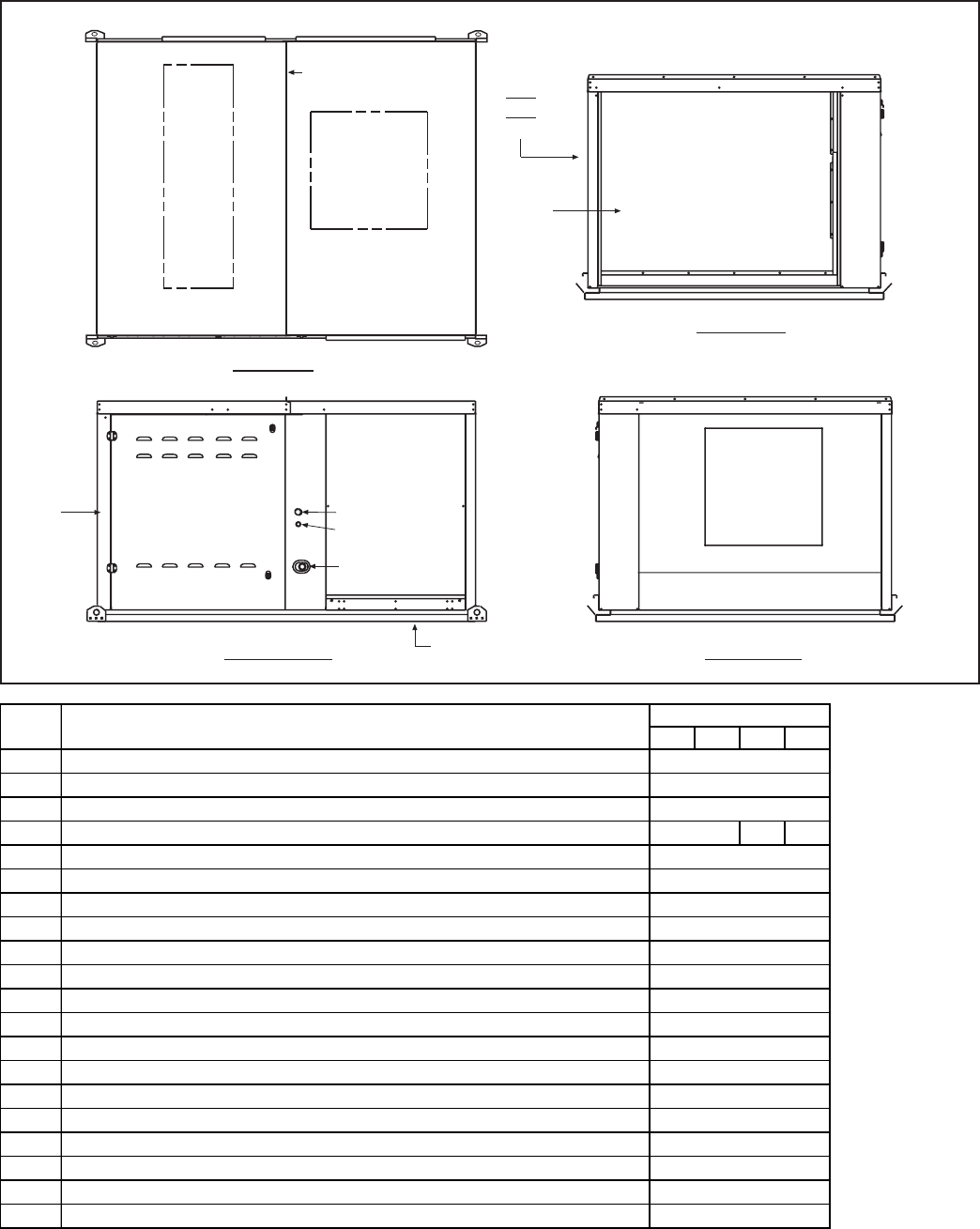
Form P-RDF, Page 33
Cabinet Parts for Models RDF-1 Series 3
Top View
Control Side Front View
Rear View
Control
Compartment
Blower
Compartment
Supply Wiring
24V Wiring
Horizontal
Discharge
Outside Air
Opening
Optional Return Air
Opening
Bottom
Discharge
Gas Supply
222
220
221
223
231
232
227
229
228
225
230
224
226
234
226
235
1-20 1-40 1-50 1-65
220 Top Front
221 Top Rear
222 Top Clamp
223 Inlet Screen (Standard unit without optional inlet air hood or filter cabinet) N/A N/A
224A Front Panel Assembly including Duct Assembly for Horizontal discharge
224B Front Panel Assembly for unit with bottom discharge (includes insulation)
225 Motor Access Panel Assembly - Horizontal Discharge Only
226 Side Panel Assembly (includes insulation)
227 Front Panel Assembly for unit with bottom discharge (includes insulation)
228 Burner/Control Door Assembly
228A Positioning Hinge (Part of CODE 228)
229 Blower Section Door Assembly
230 Center Pos t Outer Cover
231 Front Corner Post Outer Cover
232 Left Rear Corner Post Outer Cover
233 Right Rear Corner Post Outer Cover
234 Intermediate Post Cover
235 Vertical Discharge Cover (hoizontal discharge only)
236 Pilot Access Cover Assembly
237 Door Latch
86848
158800
203815
204474
CODE Description
86879
86880
87685
94360
90321
Model RDF Series 3
86882
124067
96817
86848
204476
203816
(2) 86865
86868
86848
203994
203817
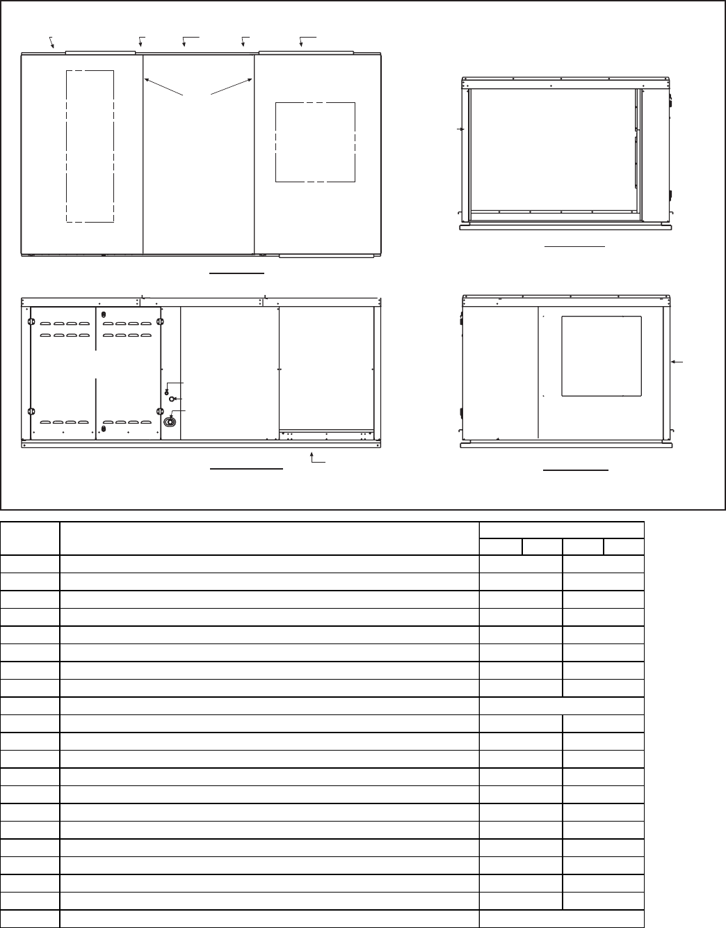
Form P-RDF, Page 34
Cabinet Parts for Models RDF-2 and RDF-3 Series 3
Top View
Control Side Front View
Rear View
Control
Compartment
Blower
Compartment
Supply Wiring
24V Wiring
Horizontal
Discharge
Outside Air
Opening
Optional Return Air
Opening (F x G)
Bottom
Discharge
Gas Supply
240241242
243
244 245
246247
248
249
250
251
254255
256
252
245
245 253
253
2-80 2-120 3-180 3-260
240 Top Front
241 Top Center
242 Top Rear
243 Top Clamp
244 Right Rear Side Door Assembly
245 Side Door Assembly
246 Front Burner/Control Door Assembly
247 Rear Burner/Control Door Assembly
247A Positioning Hinge (Part of CODE 247)
248A Front Panel Assembly including Duct Assembly for Horizontal Discharge
248B Front Panel Assembly - Bottom Discharge
249 Left Front Corner Post Outer Cover
250 Right Front Corner Post Outer Cover
251 Intermediate Post (Control)
252 Intermediate Post Outer Cover #1
253 Intermediate Post Outer Cover #2
254 Left Rear Corner Post Outer Cover
255 Right Rear Corner Pos t Outer Cover
256 Vertical Discharge Cover (horizontal discharge only)
257 Pilot Access Cover
258 Door Latch 124067
204536
89547 91157
203729
89547 91158
89552
(2) 91163
CODE Description Model RDF
204474 203876
204498 204559
158800204560204497
89558 91172
89559 91174
N/A 91173
(2) 9117989562
204538203982
89519 91125
89967 91212
203639
N/A
203745 204558
203646
203644
203728
203736
(3) 91116(2)89510
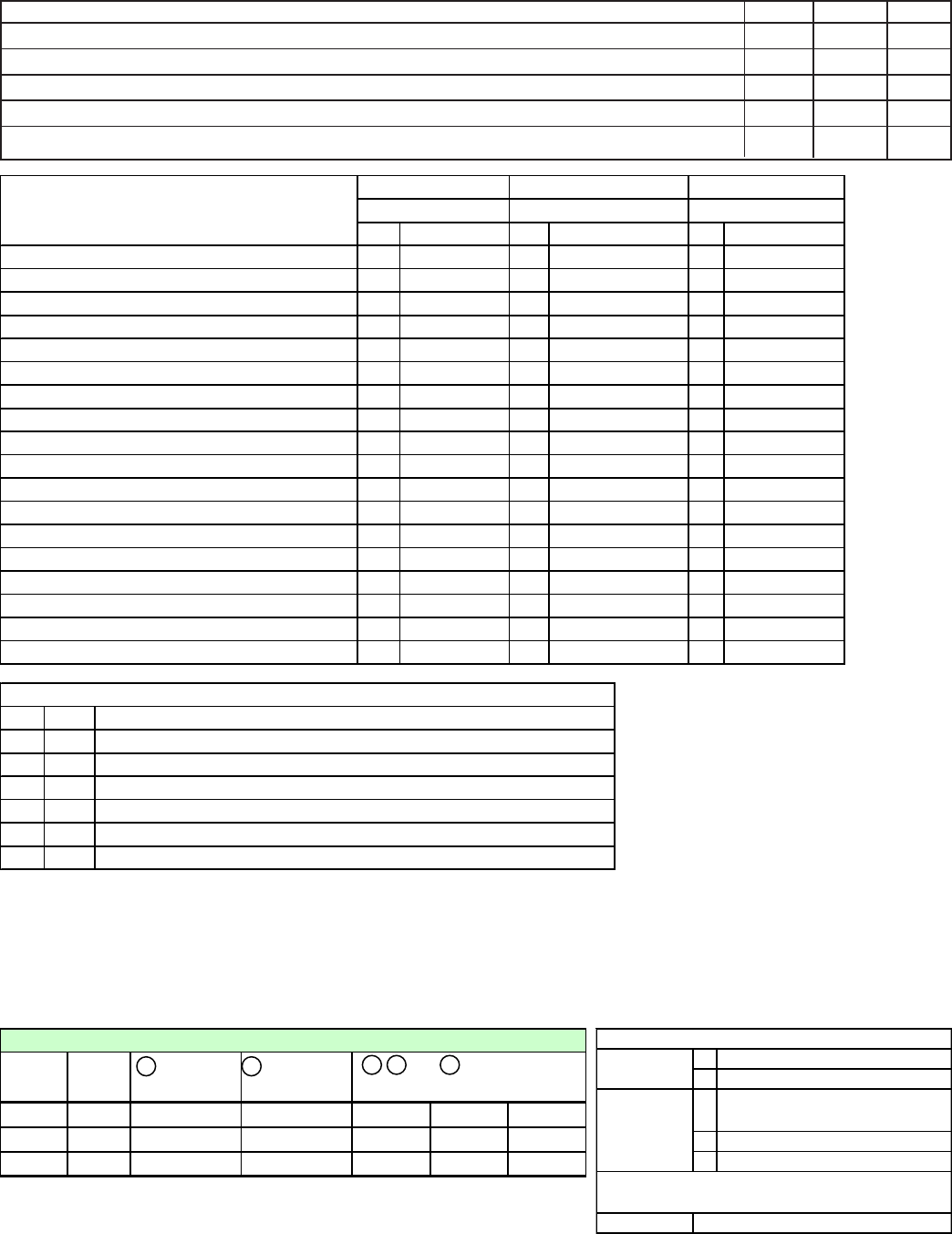
Form P-RDF, Page 35
CODE 270 - Screened Air Inlet Hoods for Outdoor Units and Filter
Sections for Indoor Units
Description RDF-1 RDF-2 RDF-3
100% Outside Air Inlet Hood (Same as Option AS2) 69594 68774 71150
100% Outside Air Inlet Hood with Integral Filter Rack & 1" Permanent Filters (Same as Option AS6) 69596 68739 71152
100% Outside Air Inlet Hood with Integral Filter Rack & 2" Permanent Filters (Same as Option AS7) 72623 72625 72627
Outside Air Filter Section for Indoor Units with 1" Filters (Same as Option AW3) 69597 68775 71153
Outside Air Filter Section for Indoor Units with 2" Filters (Same as Option AW6) 72624 72626 72628
Qty P/N Qty P/N Qty P/N
Top of Inlet Hood Cabinet Section 1 91575 191575 191575
Top of Inlet Hood 1 91576 191576 191576
Clamp for Top Seam (Hood to Cabinet) 1 91577 191577 191577
Bottom of Hood Cabinet Section 1 91567 191567 191567
Supports (2 pieces per leg) 6 91581 691581 691581
Left Side of Hood 1 91568 191568 191568
Right Side of Hood 1 91569 191569 191569
Intermediate Posts - Cabinet Section 2 91578 291578 291578
Right Corner Posts - Cabinet Section 1 91579 191579 191579
Left Corner Post - Cabinet Section 1 91579 191579 191579
Doors (Filter Access Section on AS6 and AS7) 2 91585 291585 291585
Center Louver Top/Bottom Supports 2 91582 291582 291582
Pre-assembled Louver Sections with Screens 2 113003 2113003 2113003
Top and Bottom Filter channels N/A 2 91580 294224
Filter Block Off Plates N/A 2 91584 N/A
Bottom Filter block Off Plate N/A N/A 198764
Filter Block off Sections N/A 6 95335 695335
Permanent Filters N/A 12 87251, 12x35x1 10 94383, 12x35x2
Pkg P/N 72627
Same as Option AS6 Same as Option AS7
Components - Outdoor Screened Air Inlet
Cabinets for Models RDF-3 only
Pkg P/N 71150
Same as Option AS2
Pkg P/N 71152
Hardware included in all of the above packages:
Qty P/N Description
100 11813 Sheetmetal Screws #10 x 1/2" long
15 10393 Screws 1/4-10 x 5/8" long (bolt type) - for legs and top clamp
15 7328 Hex Locking Nuts 1/4-20 - for legs and top clamp
3 41463 Sheetmetal Screws #14-10 x 3/4" long - for attaching legs
5 87900 Tinnerman Clips, Palnut #PW-1880-008-21 - for joining louver sections
4 37661 Screws, #10 x 1/2" long (self-drilling) - for attaching middle of doors)
CODE 280 - Roof Curb Packages and Components
Each roof curb package for a Model RDF system includes two curb sides, one front, one back, eight curb dividers for creating supply and return air
ductwork in the curb, and hardware for corner assembly and for installing ductwork dividers.
RDF
Series 3
Pkg
P/N
2 Curb Side
Assembly
1 Curb Front
and Back Ass
y
RDF-1 204368 (2)204365 (2)104655 (4)203803 (2)203804 (2)203806
RDF-2 203980 (2)204366 (2)111508 (4)203977 (2)203978 (2)203979
RDF-3 204370 (2)204369 (2)111512 (4)203662 (2)203663 (2)203664
3 , 4 , and 5 - Curb Dividers
for Ductwork
Roof Curb Option CJ3 for Model RDF Series 3 (See illustration, page 36) Roof Curb Corner Hardware
8 5/16" x 1" La
g
Screws, P/N 16243
8 5/16" Lockwasher, P/N 1333
8 5/16" x 3/4" Hex Head Cap Screw,
P/N 16247
8 5/16" Lockwasher, P/N 1333
8 5/16-18 Hex Nut, P/N 1035
64
For Top Two
"Holes"
For Bottom
Two "Holes"
#10 Sheetmetal Screws, P/N 11813
Hardware to Assemble and Attach Dividers to make
Ductwork O
p
enin
g
s
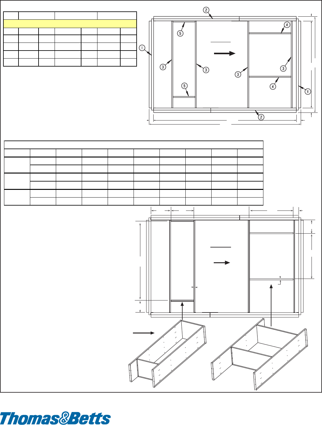
Form P-RDF, Page 36
(800) 695-1901; www.RezSpec.com
©2005 Thomas & Betts Corporation, All rights reserved. Printed in U.S.A.
MANUFACTURER OF GAS, OIL, ELECTRIC HEATING AND VENTILATING SYSTEMS
9/05 Form P-RDF (Version A.1)
B
A
C
D
1-7/8
(48)
1-7/8 (48)
1-7/8
(48)
Roof Curb
Ductwork for
Bottom Discharge
(Option AQ1
or AQ3)
Roof Curb
Ductwork for
Optional Return Air
Airflow
(See IMPORTANT
NOTE.)
Top View
Model RDF Series 3 - Reznor Roof Curb and Duct Opening Dimensions
Airflow
Assembled Dividers for Optional
Return Air Ductwork in the Roof Curb
Field-supplied ductwork may be either
dropped in from the top resting on
the top flange or be attached to the bottom
flange, using the dividers as ductwork.
Bottom
Discharge
Supply Air
Opening
(E x F)
Return
Air
Opening
(J x K)
E
G
FH
J
K
M
N
3/4 (19)
3/4 (19)
Top View
IMPORTANT NOTE: Area enclosed by roof curb must
comply with clearance to combustible materials. If the roof
is constructed of combustible materials, area within the
roof curb must be ventilated; left open, or
covered with non-combustible material which
has an "R" value of at least 5. If area within curb is
left open, higher radiated sound levels may result.
NOTES:
• Drawings are not proportional for all sizes.
• 3/4" (19mm) measurement is the width of the
flanges where the roof curb mates with the
heater. Surface of flanges must be sealed.
• When cutting duct openings in the roof, cut
opening 1” (25mm) larger than duct size
opening for installation clearance.
RDF
inches mm inches mm inches m
m
A84-5/8 2149 84-5/8 2149 131-3/4 3346
B43-5/8 1108 67-9/16 1716 82-1/16 2084
C** 80-7/8 2054 80-7/8 2054 128 3251
D** 39-7/8 1013 63-13/16 1621 78-5/16 1989
** C and D are roof opening dimensions if curb area
is full
y
o
p
en.
Dimensions of Roof Curb Option CJ3
-1 -2 -3
Roof Curb Packages and Components (cont'd)
Sizes EFGHJKMN
inches 23-11/32 20-1/8 5 10-1/4 25-1/2 11-1/2 11-15/32 11-1/32
mm 593 511 127 260 648 292 291 280
inches 28-13/32 28-11/32 13-15/32 7 54-11/16 17-23/32 8 11-3/32
mm 722 720 342 178 1389 432 203 282
inches 38 38 11-19/32 4-5/8 66-3/4 20-1/16 10-15/32 17-1/4
mm 965 965 294 117 1695 510 266 438
RDF-1
RDF-2
RDF-3
Roof Curb Duct Opening Dimensions
