100561 Catalog
100561-Catalog 100561-Catalog 100561-Catalog 782051 Batch7 unilog cesco-content
2014-09-05
: Pdf 100561-Catalog 100561-Catalog 781011 Batch7 unilog
Open the PDF directly: View PDF ![]() .
.
Page Count: 244 [warning: Documents this large are best viewed by clicking the View PDF Link!]
Other Cooper B-Line Product Lines
Cable Tray Systems
Electrical Enclosures
Electronic Enclosures
Pipe Hanger & Support Systems
Spring Steel Fasteners
Cable Runway & Relay Racks (CommData)
Meter Mounting & Distribution Equipment
Anchors
© 2008 Cooper B-Line, Inc. Printed in U.S.A. 10708
SYSTEMS THAT MAKE SENSE
“B
B-
-V
VO
OC
CA
AL
LS
SM
M
“B
B-
-V
VO
OC
CA
AL
LS
SM
M
Questions, Comments, Suggestions?
with Cooper B-Line ”
Voice Of the Customer...Actively Listening
bvocal@cooperindustries.com
618-654-2184 ext. 456
“B
B-
-V
VO
OC
CA
AL
LS
SM
M
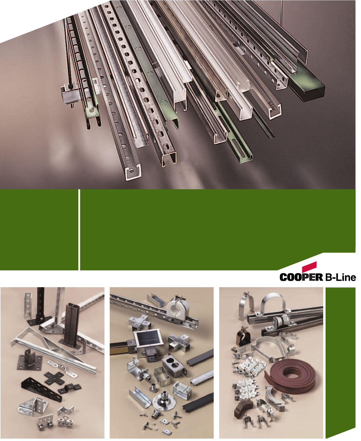
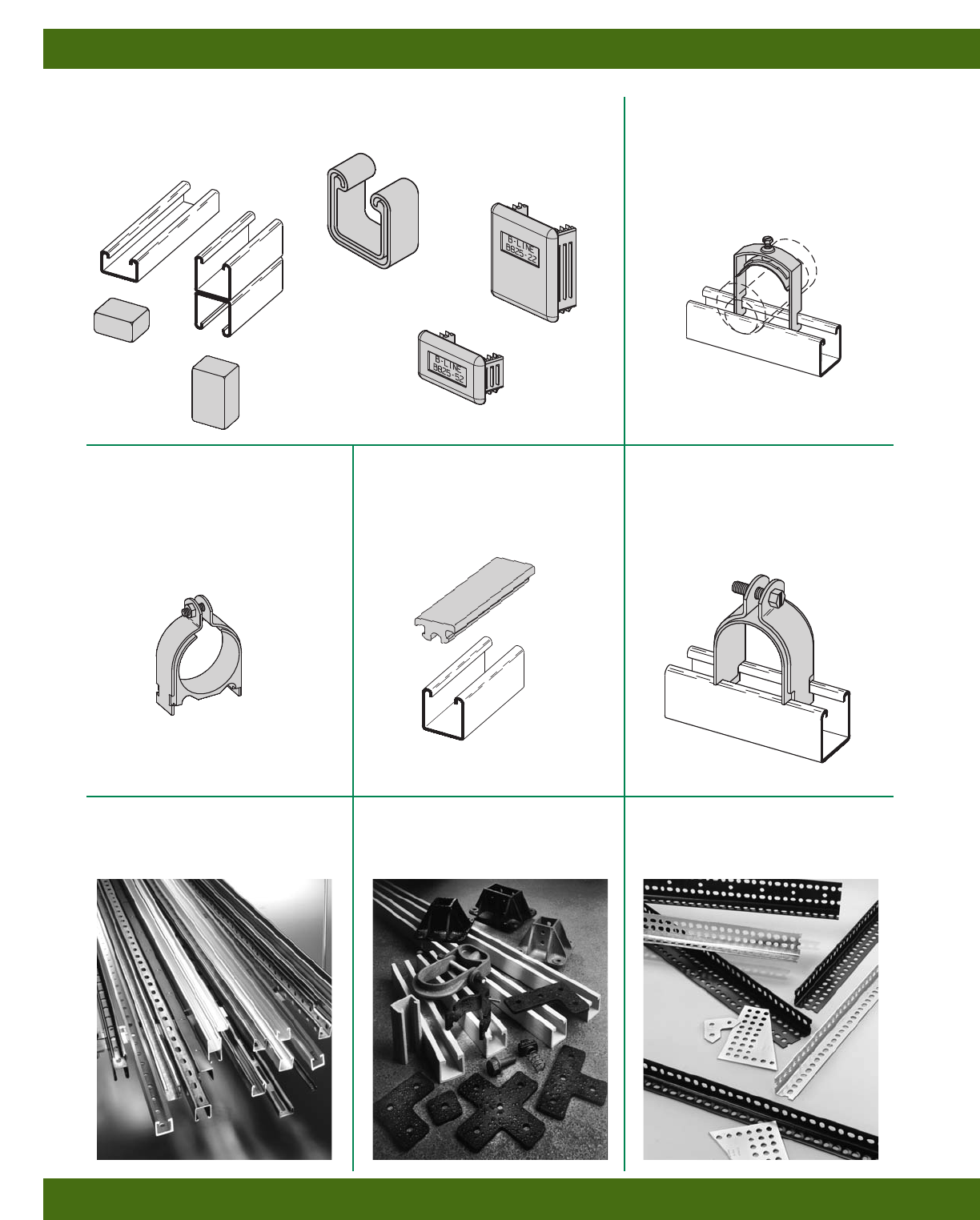
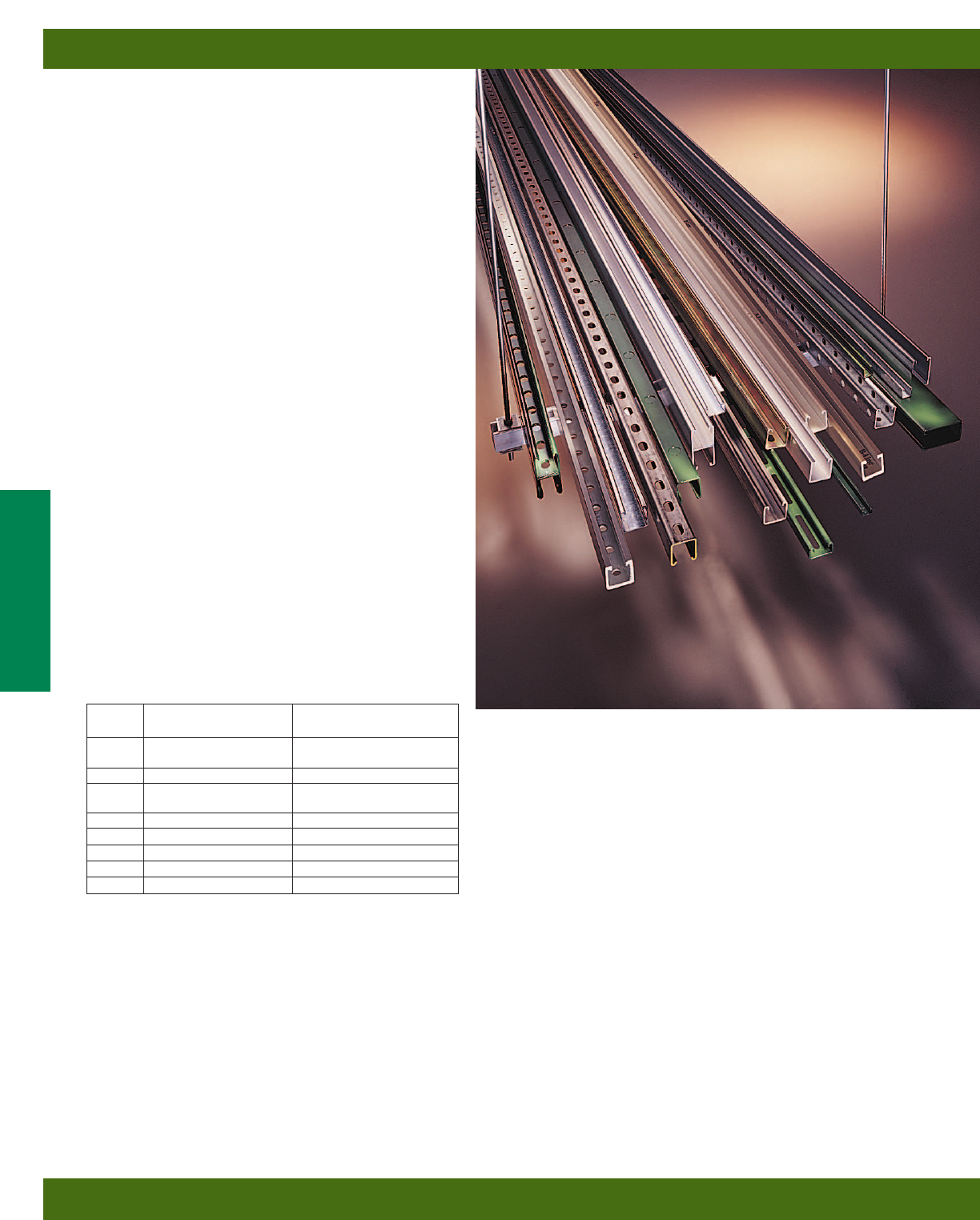
Strut Systems
Channels, Hardware, Fittings. Mechanical & Electrical Accessories,
Special Materials (Aluminum, Stainless Steel, Fiberglass),
Mini Channel, Concrete Inserts, Slotted Angle,
Kwik-Wire™, Roof-Top Supports
Cooper B-Line
509 West Monroe Street
Highland, IL 62249
Phone: 800-851-7415
Fax: 618-654-1917
www.cooperbline.com
Cooper Industries, Ltd.
600 Travis, Ste. 5800
Houston, TX 77002-1001
Phone: 713-209-8400
www.cooperindustries.com
Strut Systems SS-08R
SS-08R

INTRODUCTION
Cooper B-Line, Inc. is a leading manufacturer and fabricator of steel and
aluminum products which are used in support of equipment for industrial,
commercial, utility, and OEM installations. Cooper B-Line is proud of the
exacting standards of research, design, engineering, and manufacturing that
go into each and every product that comprise our metal framing product
line. Our customers have access to the most complete support systems
offered in the industry, including metal framing, cable tray, pipe hangers,
slotted angle, and fasteners.
Many of Cooper B-Lines products are listed by the Underwriters
Laboratories, Inc. All Cooper B-Line products are manufactured to meet
or exceed MFMA and other industry standards set for their design and
manufacture.
The majority of Cooper B-Line products are produced in four modern
plants consisting of approximately 900,000 square feet. These facilities
are located in Highland, Illinois; Troy, Illinois; Reno, Nevada; and
Sherman, Texas. Regional sales and distribution centers are located
throughout the United States stocking standard Cooper B-Line products
for quick service and delivery.
This catalog is designed to be helpful to engineers and contractors in
the application and selection of strut products for construction and
maintenance.
If a unique application requires a special product not included in this
catalog. Cooper B-Line engineering personnel are ready to furnish design
consultation and realistic cost estimates. In addition, sales representatives
with engineering know-how are located throughout the United States and
abroad for your convenience.
Cooper B-Line, Inc.
509 West Monroe Street
Highland, Illinois 62249-0326
Phone: 800-851-7415
www.cooperbline.com
©2008 Cooper B-Line
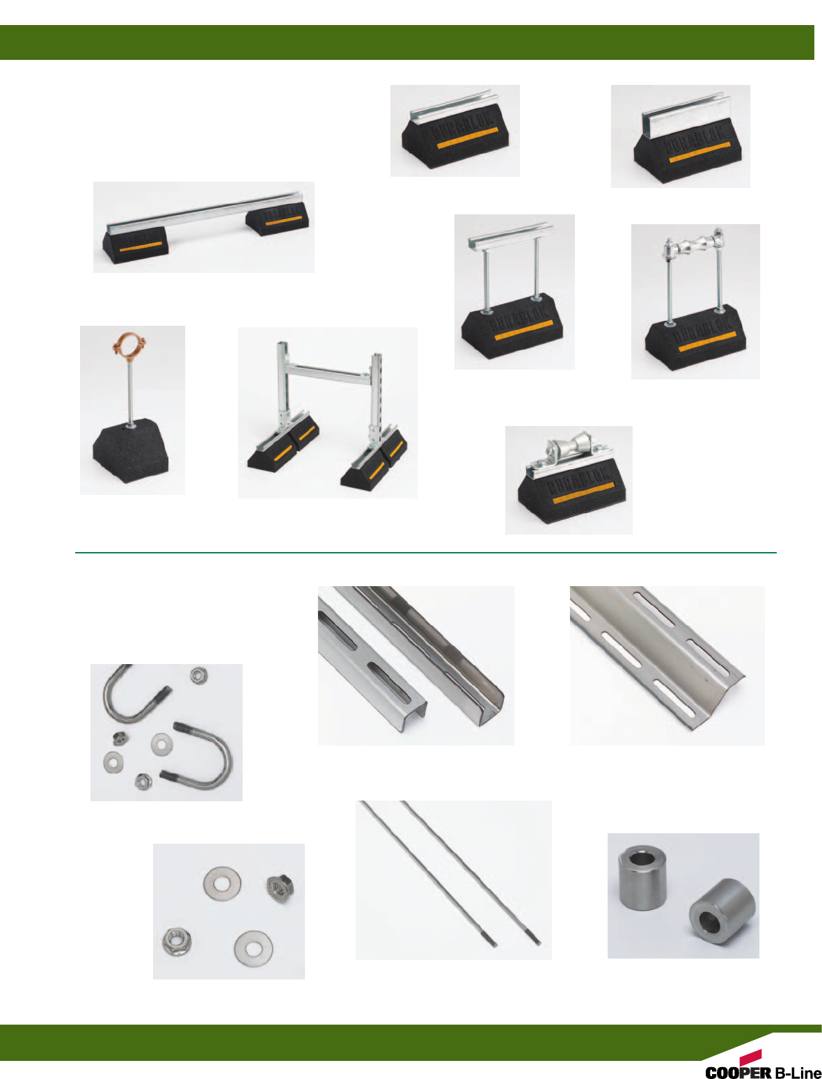
DURA-BLOK™
ROOFTOP SUPPORTS
Pgs. 136-143
DURA CLEAN™
WASHDOWN SUPPORTS
Pg. 144-149
U-Bolts
Hardware
Dura Clean™
Wall Mount Rails
Threaded Rod
Dura Clean™ Channel
DB6 Series
DB Series
DBE10 Series
DBR Series
DBR10-12
DB__DS Series
DBM Series
DB10 Series
Spacers
New Products
I
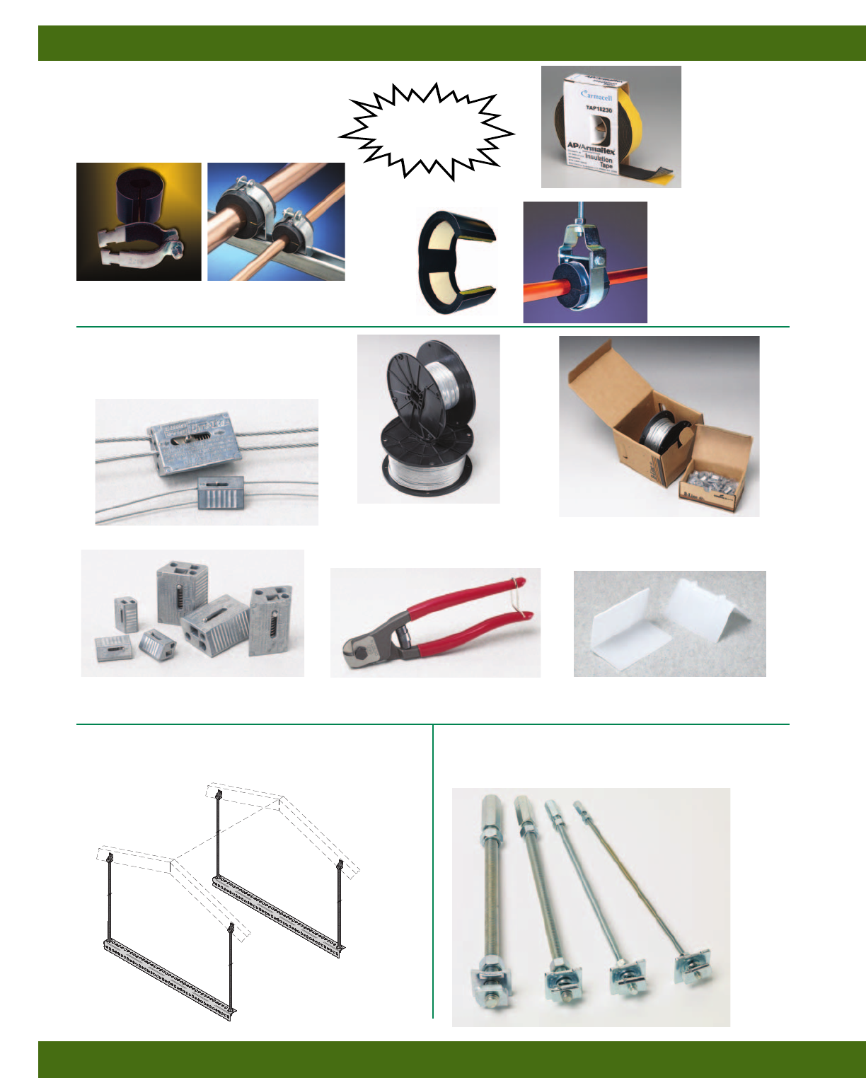
KwikPak™
(Includes clamps & wire rope)
KWIKWIRE™ & ACCESSORIES
Pg. 57
KwikWire™ Clamps
KwikWire™
Wire Rope
KwikWire™ Cutter Air Duct Corner Protector
AHHK-1/4& AHHK-3/8
AIR HANDLER HANGING KIT
Pg. 215
HOT RODS™
Pg. 56
New Products
II
ARMAFIX®CLAMPS
& ACCESSORIES
Pg. 120
Insert Only
Used with B-Line
Pipe Hangers
(Sold Separately)
Clamp & Insert Assembly
Includes: Insert, Clamp, and Hardware
Armaflex®
Insulation
Tape
Stop
Condensation
Leaks
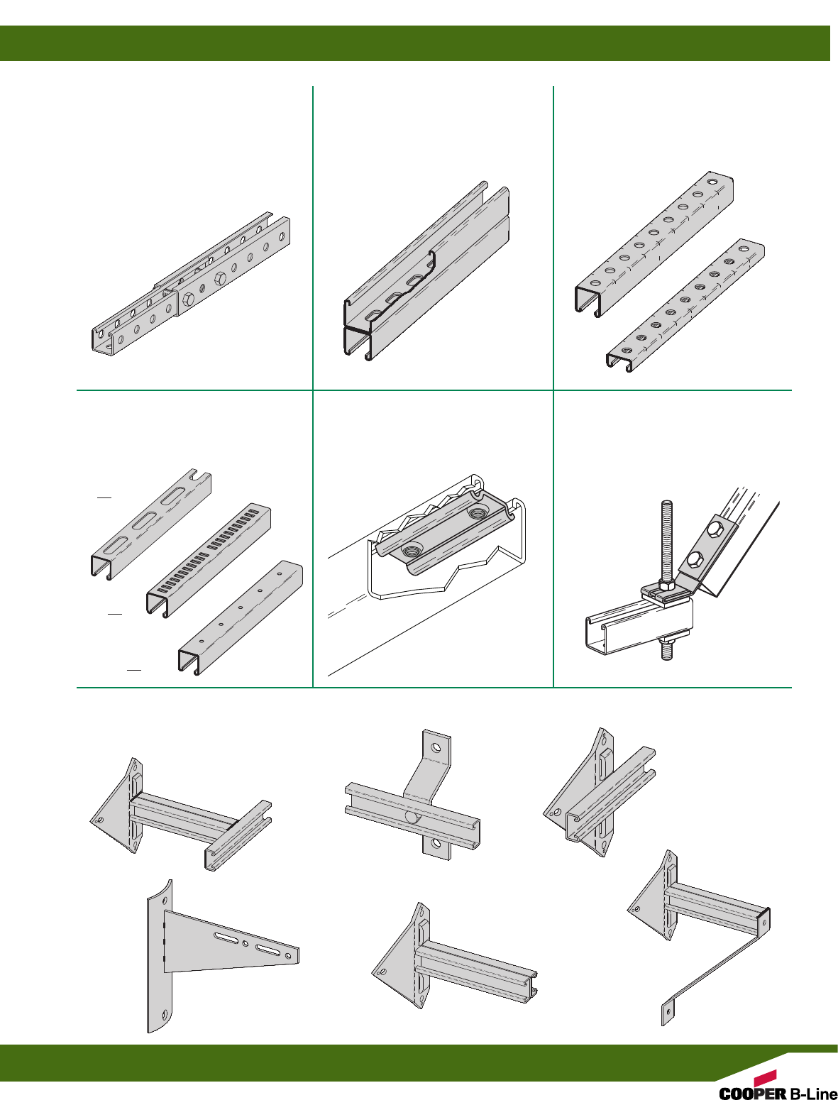
BK__H112
CHANNEL WITH 9/16” HOLES
ON 11/2” CENTERS & CUTTING
MARKS ON 11/2” CENTERS
Pg. 42
BTS22TH
TELESCOPING CHANNEL
Pg. 38 & 39
B22SHA
SLOTTED BACK-TO-BACK
CHANNEL
Pg. 41
B__S58, B__M, B__H25
CHANNELS
Pg. 42 & 43
BxxS58
BxxM
BxxH25
DCN3/8
CONVEYOR NUT
Pg. 52
B650
SEISMIC RETROFIT BRACKET
Pg. 70
UTILITY POLE BRACKET
Pgs. 90 & 91
B852S-W-D
B809B
B816
B810
B802D
B812
Product Showcase
III
Fiberglass
Pgs. 170 - 187
Slotted Angle
Pgs. 210 - 215
B2417 & B2417-CT
STRUT MOUNTED PIPE GUIDE
Pg. 123
Stainless Steel & Aluminum
Pgs. 164 - 169
VIBRACLAMP®
O.D. SIZE 1/4”-61/8”
PIPE SIZE 1/4”-6”
Pg. 118 & 119
BVS-12 & BVS-120
VIBRA STRIP FOR 15/8” WIDE
CHANNEL
Pg. 121
P CLAMPS
O.D. SIZE .250”-2.750”
Pg. 117
PLASTIC END CAPs
Pgs. 96 & 97
B822A
B825
Series
B852
B823
Series
Product Showcase
IV

Dura-Blok™ Rooftop Supports
Info. & Specifications . . . . . . . . . . . . . . . . 136
Base Support . . . . . . . . . . . . . . . . . . . . . . . . . 137
Base Support - Channel . . . . . . . . . . 137-138
Base Support - Pipe/Tubing Riser . . . . 138
Base Support Riser - Channel . . . . . . . . 139
Base Support Riser - Pipe Roller . . . . . 139
Base Support - ‘H’ Stand . . . . . . . . 140-141
Base Support - Pipe Roller . . . . . . . . . . . 142
Application Photos . . . . . . . . . . . . . . . . . . . 143
Dura-Clean™ Washdown Supports
Info. & Specifications . . . . . . . . . . . . . . . . 144
Channel . . . . . . . . . . . . . . . . . . . . . . . . . . . . . . 145
Wall Mount Rails . . . . . . . . . . . . . . . . . . . . 146
U-Bolts & Hardware . . . . . . . . . . . . . . . . . 147
Threaded Rod & Spacers . . . . . . . . . . . . . 148
Application Photos . . . . . . . . . . . . . . . . . . . 149
Electrical Accessories
Info. & Specifications . . . . . . . . . . . . . . . . 150
Selection Chart . . . . . . . . . . . . . . . . . . . . . . . 151
Fluorescent Fixture Hangers . . . . . 152-154
Electrical Accessories . . . . . . . . . . . 155-156
Junction Boxes . . . . . . . . . . . . . . . . . . . . . . . 157
Strut Joiners . . . . . . . . . . . . . . . . . . . . . 158-159
Electrical Hardware . . . . . . . . . . . . . . . . . . 160
Porcelain Clamps . . . . . . . . . . . . . . . . 161-162
Maple Clamps . . . . . . . . . . . . . . . . . . . 162-163
Aluminum & Stainless Steel Materials
Info. & Specifications . . . . . . . . . . . . . . . . 164
Aluminum . . . . . . . . . . . . . . . . . . . . . . . 165-167
Stainless Steel . . . . . . . . . . . . . . . . . . . 168-169
Fiberglass Materials
Info. & Specifications . . . . . . . . . . . 170-171
Channels . . . . . . . . . . . . . . . . . . . . . . . . 172-176
Hardware . . . . . . . . . . . . . . . . . . . . . . . . 176-178
Fittings . . . . . . . . . . . . . . . . . . . . . . . . . . 179-187
Mini Channel & Fittings
Info. & Specifications . . . . . . . . . . . . . . . . 188
Mini Channels . . . . . . . . . . . . . . . . . . . 189-190
Mini Channel Nuts . . . . . . . . . . . . . . . . . . . 191
Mini Fittings . . . . . . . . . . . . . . . . . . . . 191-199
Econo-Strut & Fittings . . . . . . . . . . . 200-201
Concrete Inserts
Info. & Specifications . . . . . . . . . . . . . . . . 202
Continuous Inserts . . . . . . . . . . . . . . . 203-206
Spot Inserts . . . . . . . . . . . . . . . . . . . . . . . . . . 207
Insert Accessories . . . . . . . . . . . . . . . . . . . . 208
Anchors . . . . . . . . . . . . . . . . . . . . . . . . . . . . . . 209
Slotted Angle
Info. & Specifications . . . . . . . . . . . . . . . . 210
Slotted Angle
Sizes . . . . . . . . . . . . . . . . . . . . . . . . . . . . . . . 211
Loading Charts . . . . . . . . . . . . . . . . 212-214
Slotted Angle Fittings . . . . . . . . . . . . . . . . 215
Reference Data . . . . . . . . . . . . . . . . . . . . . 216-225
Index . . . . . . . . . . . . . . . . . . . . . . . . . . . . . . . 226-233
Introduction . . . . . . . . . . . . . . . . . . . . . . . . . . . . . 2-3
Technical Data
Materials . . . . . . . . . . . . . . . . . . . . . . . . . . . . . . . 4
Finishes . . . . . . . . . . . . . . . . . . . . . . . . . . . . . . 5-6
Welding . . . . . . . . . . . . . . . . . . . . . . . . . . . . . . . . 7
Corrosion . . . . . . . . . . . . . . . . . . . . . . . . . . . . . 8-9
Design of Strut Systems . . . . . . . . . . . . 10-12
Recommended Specification . . . . . . . . . . . 13
Channel & Combinations
Info. & Specifications . . . . . . . . . . . . . . . . . 14
Selection Chart . . . . . . . . . . . . . . . . . . . . . . . . 15
B11 Channel . . . . . . . . . . . . . . . . . . . . . . . 16-17
B12 Channel . . . . . . . . . . . . . . . . . . . . . . . 18-19
B22 Channel . . . . . . . . . . . . . . . . . . . . . . . 20-23
B24 Channel . . . . . . . . . . . . . . . . . . . . . . . 24-25
B26 Channel . . . . . . . . . . . . . . . . . . . . . . . 26-27
B32 Channel . . . . . . . . . . . . . . . . . . . . . . . 28-29
B42 Channel . . . . . . . . . . . . . . . . . . . . . . . 30-31
B52 Channel . . . . . . . . . . . . . . . . . . . . . . . 32-33
B54 Channel . . . . . . . . . . . . . . . . . . . . . . . 34-35
B56 Channel . . . . . . . . . . . . . . . . . . . . . . . 36-37
Telescoping Channel . . . . . . . . . . . . . . . 38-39
Channel Hole Patterns . . . . . . . . . . . . . 40-43
Channel Hole Punch . . . . . . . . . . . . . . . . . . . 43
Channel Nuts & Hardware
Info. & Specifications . . . . . . . . . . . . . . . . . 44
Channel Nuts
Selection Charts . . . . . . . . . . . . . . . . . 45-49
Slip & Pull-out Load Charts . . . . . . 50-51
Other Hardware . . . . . . . . . . . . . . . . . . . . 52-56
KwikWire™ & Accessories . . . . . . . . . . . 57
Strut Fittings
Info. & Specifications . . . . . . . . . . . . . . . . . 58
Flat Plate Fittings . . . . . . . . . . . . . . . . . . 59-61
90° Angle Fittings . . . . . . . . . . . . . . . . . . 62-67
Angular Fittings . . . . . . . . . . . . . . . . . . . . 68-70
Braces . . . . . . . . . . . . . . . . . . . . . . . . . . . . . . . . . 71
Clevis Fittings . . . . . . . . . . . . . . . . . . . . . . . . . 72
U-Fittings . . . . . . . . . . . . . . . . . . . . . . . . . . 73-76
Z-Fittings . . . . . . . . . . . . . . . . . . . . . . . . . . 77-79
Wing Fittings . . . . . . . . . . . . . . . . . . . . . . 80-82
Post Bases . . . . . . . . . . . . . . . . . . . . . . . . . 83-84
Brackets . . . . . . . . . . . . . . . . . . . . . . . . . . . 85-91
Miscellaneous Fittings . . . . . . . . . . . . . 92-97
Beam Clamps & Accessories
Info. & Specifications . . . . . . . . . . . . . . . . . 98
Beam Clamps & Accessories . . . . . . 99-109
Pipe/Conduit Clamps & Hangers
Info. & Specifications . . . . . . . . . . . . . . . . 110
Pipe Clamps . . . . . . . . . . . . . . . . . . . . . 111-117
Vibra Clamps . . . . . . . . . . . . . . . . . . . . 118-119
Armafix®Clamps & Accessories . . . . . 120
Vibra Cushions . . . . . . . . . . . . . . . . . . . . . . . 121
Pipe Clamps . . . . . . . . . . . . . . . . . . . . . 122-126
Pipe Hangers . . . . . . . . . . . . . . . . . . . . 127-128
Pipe Brackets . . . . . . . . . . . . . . . . . . . . . . . . 129
Pipe Rollers . . . . . . . . . . . . . . . . . . . . . 130-135
Table of Contents
1
B-Line’s metal framing support system is designed with many time-saving features. They are fully adjustable and
reusable, with a complete line of channels, fittings and accessories for multi-purpose applications.
• No Welding
• No Drilling
• Use Your Imagination
B-Line metal framing installs quickly. There is no
need for special tools. All you need is a wrench
and hacksaw. Channels and parts can be taken
apart for reuse as quickly as they were assembled,
yet they provide the strength of welded construction.
Eliminating welding and drilling produces substantial
savings in time and labor.
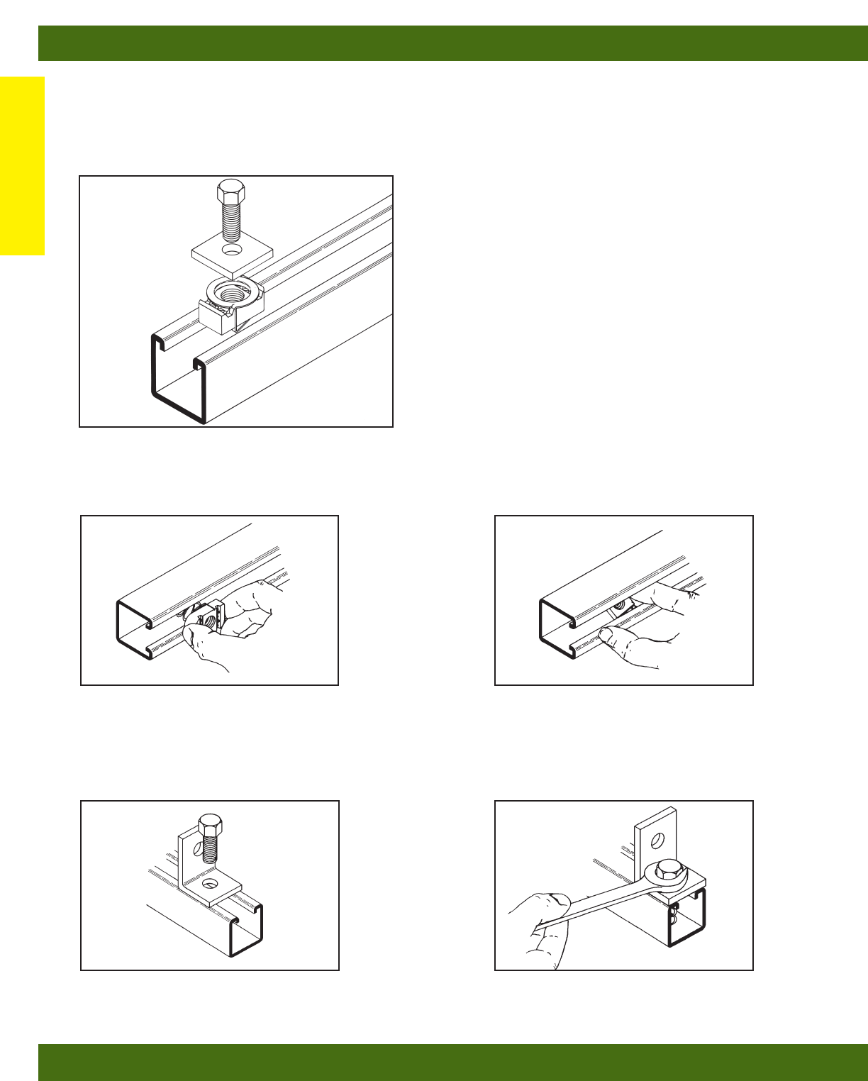
1. Tite-Grip channel nut may be
inserted anywhere along continuous
slot. Designed for easy insertion and
self-alignment.
2. A 90 degree turn aligns channel nut
grooves with inturned lips of the
channel.
3. Position fitting over channel nut and insert bolt to
start any connection.
4. With the twist of a wrench, channel
nut locks its teeth firmly against
inturned lips.
Introduction
Introduction
2
B-Line’s Metal Framing system provides an
economical solution for electrical, mechanical
and industrial supports with an unlimited
variety of applications in the construction
industry.
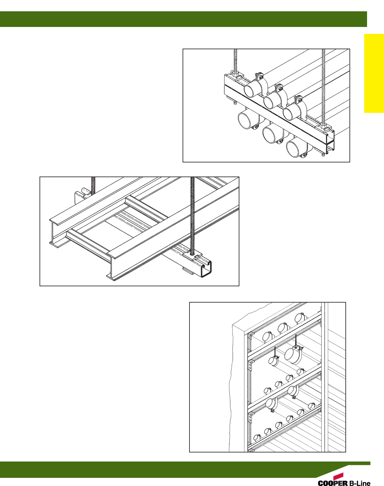
Metal Framing Electrical Applications
• Lighting Fixture Supports
• Raceway Systems
• Trapeze Hangers
• Pipe & Conduit Supports
• Cable Tray Supports
• Beam Adjustments
Metal Framing Mechanical Applications
• Piping Racks
• Tunnel Pipe Stanchions
• Concrete Inserts
• Beam Attachments
• Pipe Risers
Metal Framing Industrial Applications
• Racks and Shelving
• Partitions
• Production Line Supports
• Trolley Systems
• Wall Framing
Introduction
Introduction
3
MATERIALS
Carbon Steel
Channels made from high-quality carbon
steel are continuously roll formed to precise
dimensions. By cold working the steel
mechanical properties are increased,
allowing lightweight structures to carry the
required load. Corrosion resistance of
carbon steel varies widely with coating and
alloy. See “Finishes” for more detailed
information.
Stainless Steel
Stainless steel channel is available in AISI
Type 304 or 316 material. Both are
non-magnetic and belong to the austenitic
stainless steels group, based on alloy
content and crystallographic structure. Like
carbon steel, stainless steel exhibits
increased strength when cold worked by
roll-forming.
Several conditions make the use of
stainless steel ideal. These include reducing
long term maintenance costs, high ambient
temperatures, appearance, and stable
structural properties such as yield strength,
and high creep strength.
Type 304 resists most organic chemicals,
dyestuffs and a wide variety of inorganic
chemicals at elevated or cryogenic
temperatures. Type 316 contains slightly
more nickel and adds molybdenum to give
it better corrosion resistance in chloride and
sulfuric acid environments. More specific
\information concerning the differences
between types 304 and 316 is available
from B-Line.
Aluminum
B-Line’s standard aluminum channel is
extruded from aluminum alloy 6063-T6.
Strut fittings are made from aluminum
alloy 5052-H32.
The high strength to weight ratio of channel
made of aluminum greatly reduces the
overall cost of installation through ease of
handling and field cutting.
Aluminum owes its excellent corrosion
resistance to its ability to form an aluminum
oxide film that immediately reforms when
scratched or cut. In most outdoor
applications, aluminum has excellent
resistance to “weathering”. The resistance
to chemicals, indoor or outdoor, can best be
determined by tests conducted by the user
with exposure to the specific conditions for
which it is intended. The corrosion
resistance of aluminum to some commonly
known chemicals is shown in the Corrosion
Chart. For further information, contact
B-Line Systems, Inc. or the Aluminum
Association.
Fiberglass
B-Line offers two fire retardant (FR) resins
for strut systems, polyester and vinyl ester.
Both resins are ideal for corrosive
environments or nonconductive applications
with moderate strength requirements.
Some common types of environments
where Vinyl Ester Resins are recommended,
that Poly Esters are not, are paper mills,
most any metal plating operation and any
condition with concentrated levels of
Chlorine, [ Cl- ]. Please consult our
fiberglass corrosion resistance charts on
pg. 173 for specific chemical
recommendation data.
Unlike other base materials depicted in this
catalog, fiberglass exhibits unique physical
property changes when operating in
elevated temperature conditions, that are a
fraction of increase compared to steel or
aluminum. This being true, B-Line advises
against using fiberglass in temperatures
greater than 200° F.
Please refer to the "Corrosion Resistance
Guide" below for specific applications.
B-Line Fiberglass Strut systems are
manufactured from glass fiber-reinforced
plastic shapes that meet ASTM E-84, Class 1
Flame Rating and self-extinguishing
requirements of ASTM D-635. A surface veil
is applied during pultrusion to insure a
resin-rich surface and ultraviolet resistance.
While polyester is sufficient for most uses,
vinyl ester is suitable for a broader range of
environments.
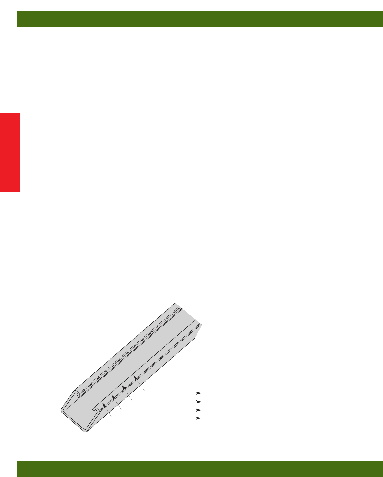
B-Line B22 SS6 87401A6
B-Line Steel Strut is stamped with:
Traceable to the steel’s origin
Material/Finish
B-Line part number designation
Company Name
Technical Data
Technical Data
4
FINISHES
Zinc Coatings
Zinc protects steel in two ways. First it
protects the steel as a coating and second as
a sacrificial anode to repair bare areas such
as cut edges, scratches, and gouges. The
corrosion protection of zinc is directly
related to its thickness and the environment.
This means a .2 mil coating will last twice
as long as a .1 mil coating in the same
environment.
Galvanizing also protects cut and drilled edges.
Electrogalvanized Zinc
Electrogalvanized Zinc (also known as zinc
plated or electroplated) is the process by
which a coating of zinc is deposited on the
steel by electrolysis from a bath of zinc
salts.
A rating of SC3, B-Line’s standard,
provides a minimum zinc coating thickness
of .5 mils (excluding hardware, which is
SC1 = .2 mils).
When exposed to air and moisture, zinc
forms a tough, adherent, protective film
consisting of a mixture of zinc oxides,
hydroxides, and carbonates. This film is in
itself a barrier coating which slows
subsequent corrosive attack on the zinc.
This coating is usually recommended for
indoor use in relatively dry areas, as it
provides ninety-six hours protection in salt
spray testing per ASTM B117.
Chromium/ Zinc
Chromium/ Zinc is a corrosion resistant
composition, which was developed to
protect fasteners and small bulk items for
automotive use. The coating applications
have since been extended to larger parts and
other markets.
Chromium/Zinc composition is an aqueous
coating dispersion containing chromium,
proprietary organics, and zinc flake.
This finish provides 500 hours protection in
salt spray testing per ASTM B117.
Pre-Galvanized Zinc
(Mill galvanized, hot dip mill galvanized or
continuous hot dip galvanized) Pre-
galvanized steel is produced by coating
coils of sheet steel with zinc by
continuously rolling the material through
molten zinc at the mills. This is also known
as mill galvanized or hot dip mill
galvanized. These coils are then slit to size
and fabricated by roll forming, shearing,
punching, or forming to produce B-Line
pre-galvanized strut products.
The G90 specification calls for a coating of
.90 ounces of zinc per square foot of steel.
This results in a coating of .45 ounces per
square foot on each side of the sheet. This
is important when comparing this finish to
hot dip galvanized after fabrication.
During fabrication, cut edges and welded
areas are not normally zinc coated;
however, the zinc near the uncoated metal
becomes a sacrificial anode to protect the
bare areas after a short period of time.
Hot Dip Galvanized After
Fabrication (Hot dip galvanized or
batch hot dip galvanized)
Hot dip galvanized strut products are
fabricated from steel and then completely
immersed in a bath of molten zinc. A
metallic bond occurs resulting in a zinc
coating that completely coats all surfaces,
including edges and welds.
Another advantage of this method is coating
thickness. Strut products that are hot dip
galvanized after fabrication have a
minimum thickness of 1.50 ounces per
square foot on each side, or a total 3.0
ounces per square foot of steel, according to
ASTM A123.
The zinc thickness is controlled by the
amount of time each part is immersed in the
molten zinc bath as well as the speed at
which it is removed. The term "double
dipping" refers to parts too large to fit into
the galvanizing kettle and, therefore, must
be dipped one end at a time. It does not
refer to extra coating thickness.
The layer of zinc which bonds to steel
provides a dual protection against corrosion.
It protects first as an overall barrier
coating. If this coating happens to be
scratched or gouged, zinc's secondary
defense is called upon to protect the steel by
galvanic action.
Hot-Dip Galvanized After Fabrication is
recommended for prolonged outdoor
exposure and will usually protect steel
for
20 years or more in most atmospheric
environments and in many industrial
environments. For best results, a zinc rich
paint (available from B-Line) should be
applied to field cuts. The zinc rich paint will
provide immediate protection for these
areas and eliminate the short time period for
galvanic action to “heal” the damaged
coating.
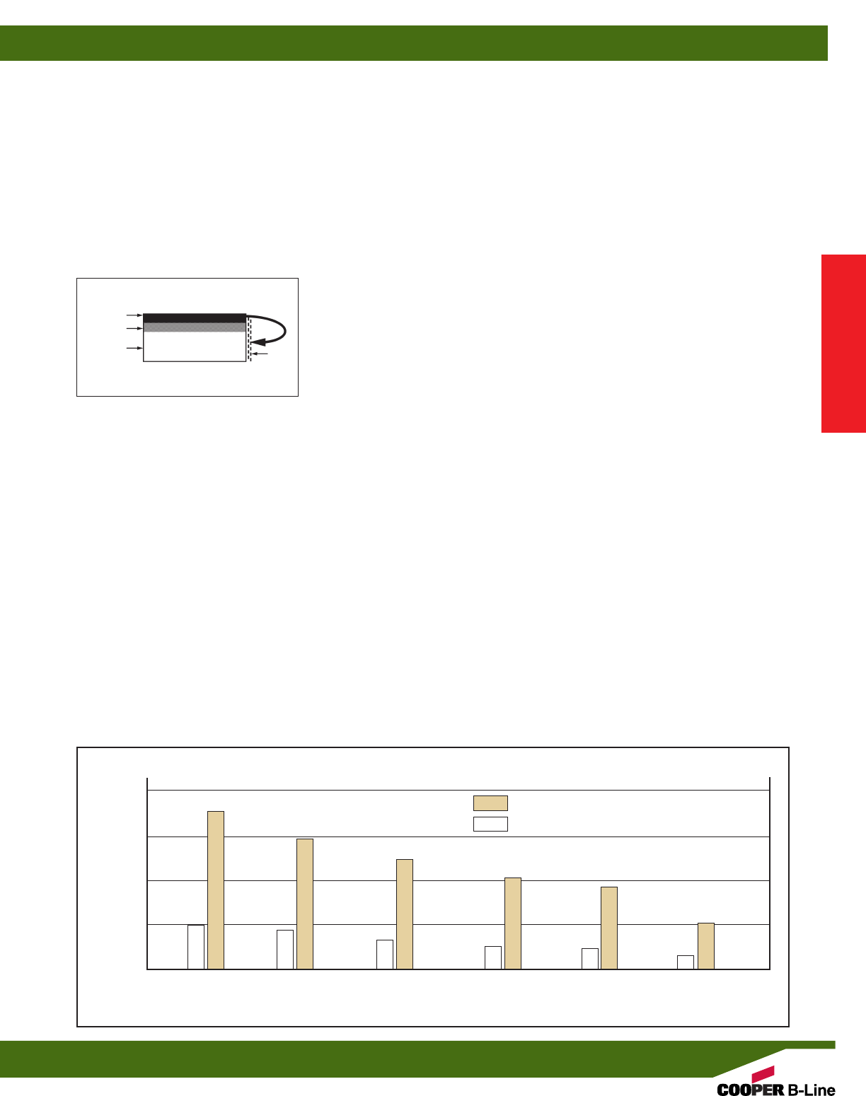
Anticipated Life of Zinc Coatings In Various Atmospheric Environments
Hot Dip Galvanized
Pre-Galvanized
= Zinc Coating 1.50 Oz./Ft.2(.0026” Thick)
= Zinc Coating 0.45 Oz./Ft.2(.00075” Thick)
Rural Tropical
Marine
Temperature
Marine
Highly
Industrial
Life
in
Years
Suburban
Environment
Urban
10
20
30
40
10
36
8
29
7
25
6
21
5
18
3
11
Zn
Fe
ZnFe
ZnO
Technical Data
Technical Data
5

Dura-Green®and Dura-Copper®
Epoxy Coatings
Dura-Green and Dura-Copper epoxy
coatings are water borne epoxy coatings
applied to B-Line products by a precisely
controlled cathodic electro-deposition
process. This process is accomplished using
a conveyor to transport channel and fittings
through several cleaning, phosphatizing and
application stages prior to being baked (See
diagram below).
This custom-designed paint system is used
for painting all channels, channel
combinations, slotted angle, and fittings.
Samples are selected on a routine basis for
Salt Spray (fog) testing to verify the quality
of the finish. These tests are performed in
accordance with ASTM B117 and evaluated
and related according to ASTM D1654
(Tables 1 & 2).
The Dura-Green and Dura-Copper Epoxy
coatings have been tested and listed by
Underwriters Laboratories in accordance
with “Standard for Surface Metal Raceway
and Fittings, UL5” and “Standard for Pipe
Hanger Equipment for Fire Protection
Service, UL203”.
Due to Dura-Green’s organically based
composition, it seats itself into porous
surfaces more completely and efficiently
than zinc coatings. As these porous caverns
are filled along the material profile, the
outer finished surface demonstrates an
increased smooth uniform plane which
produces considerably less off-gasing when
tested.
B-Line’s Dura-Green channel meets or
exceeds 100 level clean room standards.
This was confirmed by testing the channel
in accordance with Boeing (PCL)
Standards, which are more stringent and
complete than ASTM E595-93. Dura-Green
was found to be a superior finish, due in
part to its proven application process.
PVC Coating
Another of the corrosion resistant coatings
offered by B-Line is PVC (polyvinyl
chloride), applied over steel or aluminum
channel and fittings. The PVC coating
process begins by cleaning the product
thoroughly. A bonding coat is applied to the
part and then preheated to a temperature
above the melting point of the coating
powder. The product is then passed through
a fluidized bed of vinyl plastic powder
where the powder particles melt, adhere and
flow out to form a smooth continuous
coating. The thickness is controlled by the
base metal temperature and the immersion
time in the bed. It is then post-heated to
complete the fusion of the outer surfaces.
The standard coating thickness of B-Line’s
PVC coated products is 15 mils (.380 mm),
plus or minus 5 mils (.125 mm). Since the
chemistry, not the thickness of vinyl plastic
PVC determines longevity, a coating of 10
to 20 mils (.250 to .500 mm) is more than
adequate. If the corrosive conditions are
such that the plasticizers are leeched out, a
thicker coating will do little to extend the
life of a coated product.
For certain environments, a plastisol dipped
PVC coating is available on request.
PVC coating depends totally on the concept
of encapsulation attached to the base metal
by a bonding agent. If any hole or
discontinuity occurs, the corrosive action
can undercut the base metal to a point
where all that remains is the PVC.
In the event of field cuts or any other
damage to the coating, a liquid PVC patch,
available from B-Line, must be applied to
maintain the integrity of the coating. After
the installation is complete, a thorough
inspection should be performed to assure
the absence of voids, pinholes, or cuts.
˛Unscribed Scribed 1/8” (3.2) Creepage
Type of Finish 5% Failure (1) from Scribe (1)
B-Line Dura-Green Epoxy 1000 Hours 312 Hours
Mill Galv. (Pre-Galv.) G90 192 Hours 288 Hours
Perma-Green 438 Hours 231 Hours
Zinc Chromate 36 Hours 96 Hours
Industry Green (Range) 10 to 36 Hours 4 to 30 Hours
SALT SPRAY TEST RESULTS
DURA-GREEN®/DURA-COPPER®EPOXY COATING PROCESS
TANK 1 TANK 2 TANK 3 TANK 4 TANK 5 TANK 6 TANK 7 TANK 8 BAKE OVEN
The channel A rinse is A phosphatized The material A pre-deionized The electro- The first post The final rinse The curing
and parts are applied to sealer is applied moves through rinse prepares coating tank rinse removes insures a process takes 20
thoroughly remove insol- to insure corro- clear water rinse the metal for the applies a uni- any unelectri- smooth, non- minutes at a
cleaned and uble salts and sion resistance to remove excess cathodic electro- form coat of cally attracted blemish surface. baking temperature
phosphatized. unreacted and paint phosphates. coating. epoxy paint to solids. of 375° F (199° C).
phosphates. adhesion. the entire
surface.
(1) All salt spray (fog) tests conducted in accordance with ASTM B117 and evaluated and rated
according to ASTM D1654 Tables 1 & 2. Tests are performed and certified by an independent
testing laboratory.
Technical Data
Technical Data
6
WELDING
The welding procedures used in the
fabrication of B-Line steel products are
in accordance with American Welding
Society Standards. To achieve the highest
quality in our manufacturing processes, our
welders follow standards set by AWS Code.
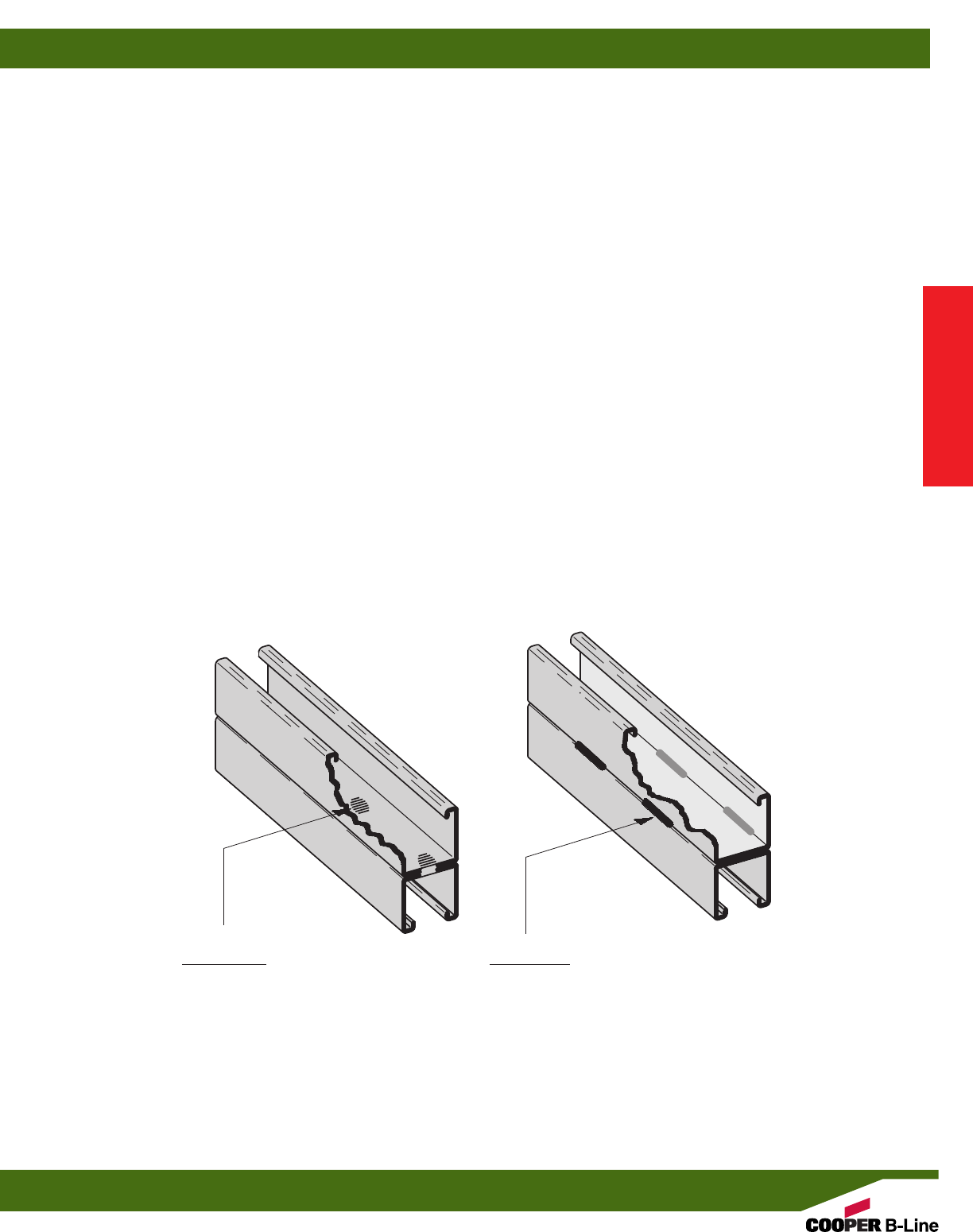
Spot Welding
Spot welded back-to-back channel is
manufactured using a modern DC powered
resistance welder controlled by a
microprocessor. This produces a series of
spot welds with speed and consistency.
Consistency is one of the
most important
advantages in specifying
B-Line back-to-
back channel. Variables such as weld
sequence, speed and duration are carefully
controlled and monitored by a sophisticated
electronic control system. A statistical
quality control program, combining
destructive and non-destructive testing, is
used by B-Line to ensure high quality
welds.
MIG Welding
MIG welded, more properly called gas
metal arc welded (GMAW) combination
channels and fittings, are produced when
physical dimensions or certain
combinations require a weld process other
than
automatic spot welding. The same
quality
control requirements are imposed on
MIG welded and spot-welded products.
Quality Assurance
B-Line System’s Quality Assurance
Program has been developed and
implemented for compliance to 10CFR50
appendix B and NQA-1. B-Line also
complies with various industry standards
and specifications. B-Line has extensive
experience in supplying metal framing
components for the nuclear power
generating industry and complies with
10 CFR21.
Mig WeldSpot Weld
Technical Data
Technical Data
7
CORROSION
All metal surfaces are affected by corrosion
Depending on the physical properties of
the metal and the environment to which it is
exposed, chemical or electromechanical
corrosion may occur.
Atmospheric Corrosion
Atmospheric corrosion occurs when metal
is exposed to airborne liquids, solids or
gases. Some sources of atmospheric
corrosion are moisture, salt, dirt and
sulphuric acid. This form of corrosion is
typically more severe outdoors, especially
near marine environments.
Chemical Corrosion
Chemical corrosion takes place when metal
comes in direct contact with a corrosive
solution. Some factors which affect the
severity of chemical corrosion include:
chemical concentration level, duration of
contact, frequency of washing, and
operating temperature.
Storage Corrosion
Wet storage stain (white rust) is caused by
the entrapment of moisture between
surfaces of closely packed and poorly
ventilated material for an extended period.
Wet storage stain is usually superficial,
having no affect on the properties of the
metal.
Light staining normally disappears with
weathering. Medium to heavy buildup
should be removed in order to allow the
formation of normal protective film. Proper
handling and storage will help to assure
stain-free material. If product arrives wet, it
should be unpacked and dried before
storage. Dry material should be stored in a
well ventilated “low moisture” environment
to avoid condensation formation. Outdoor
storage is undesirable, and should be
avoided whenever possible.
Galvanic Corrosion
Galvanic corrosion occurs when two or
more dissimilar metals are in contact in the
presence of an electrolyte (ie. moisture).
An electrolytic cell is created and the metals
form an anode or a cathode depending on
their relative position on the Galvanic
Series Table. The anodic material will be
the one to corrode. Anodic or cathodic
characteristics of two dissimilar metals will
depend on the type of each material. For
example: If zinc and steel are in contact, the
zinc acts as the anode and will corrode; the
steel acts as the cathode, and will be
protected. If steel and copper are in
contact, the steel is now the anode and will
corrode.
The rate at which galvanic corrosion occurs
depends on several factors:
1. The relative position on the Galvanic
Series Table - the further apart materials are
in the Galvanic Series Table, the greater the
potential for corrosion of the anodic
material.
2. The amount and concentration of
electrolyte present - an indoor, dry
environment will have little or no galvanic
corrosion compared to a wet atmosphere.
3. The relative size of the materials - a
small amount of anodic material in contact
GALVANIC SERIES IN SEA WATER
Metals in descending order of activity in the presence of an electrolyte.
with a large cathodic material will result in
greater corrosion. Likewise, a large anode
in contact with a small cathode will
decrease the rate of attack.
Magnesium
Magnesium Alloys
Zinc
Beryllium
Aluminum - Zinc Alloys (7000 series)
Aluminum - Magnesium Alloys (5000 series)
Aluminum (1000 series)
Aluminum - Magnesium Alloys (3000 series)
Aluminum - Magnesium - Silicon Alloys (6000 series)
Cadmium
Aluminum - Copper Alloys (2000 series)
Cast Iron, Wrought Iron, Mild Steel
Austenitic Nickel Cast Iron
Type 410 Stainless Steel (active)
Type 316 Stainless Steel (active)
Type 304 Stainless Steel (active)
Naval Brass, Yellow Brass, Red Brass
Tin
Copper
Lead-Tin Solders
Admiralty Brass, Aluminum Brass
Manganese Bronze
Silicon Bronze
Tin Bronze
Type 410 Stainless Steel (passive)
Nickel - Silver
Copper Nickel Alloys
Lead
Nickel - Aluminum Bronze
Silver Solder
Nickel 200
Silver
Type 316 Stainless Steel (passive)
Type 304 Stainless Steel (passive)
Incoloy 825
Hastelloy B
Titanium
Hastelloy C
Platinum
Graphite
More Anodic
Anodic End
Cathodic End
Technical Data
Technical Data
8

Type 304 Type 316 Zinc
Chemical Aluminum Dura-Green PVC Stainless Stainless Coated Steel
Acetic Acid 10% R NR R R R NR
Acetic Acid 2% R F R R R NR
Acetone R R NR R R R
Ammonium Hydroxide-Conc. R R R R R –
Ammonium Hydroxide 10% F R R R R –
Ammonium Hydroxide 2% R R R R R –
Benzene R R NR R R –
Bromine Water NR R R NR NR –
Butanol (Butyl Alcohol) R R R R R R
Carbon Disulfide R R NR R R –
Carbon Tetrachloride F R F R R –
Chlorine Water R R R NR F R
Cutting Oil – R – – – –
Diethanolamine R R NR – – NR
Ethanol R R R R R R
Ethyl Acetate R R NR – – R
Ethylene Dichloride F R NR – – R
Formaldehyde 20% R R R R R R
Gasoline R R R R R R
Glycerine R R R R R R
Household Detergent 10% F R R R R –
Hydrochloric Acid 40% NR NR R NR NR NR
Hydrochloric Acid 10% NR F – NR NR NR
Hydrochloric Acid 2% NR F – NR NR NR
Hydrogen Peroxide 30% R NR R R R –
Hydrogen Peroxide 3% R R – R R –
Hydrogen Sulfide (Gas) R R R F R –
JP-4 Jet Fuel R R R R R –
Lactic Acid 85% F R R NR – –
Latex R R – R R NR
Linseed Oil Fatty Acid R F R R R –
Methanol R R R R R R
Methyl Ethyl Ketone R R NR – – R
Methyl Isobutyl Ketone R R NR – – R
Mineral Spirits R R – – – –
Motor Oil-10W R R R R R R
Naphtha, VM&P R R R R R R
Nitric Acid 2% F NR R R R –
Perchloroethylene R R – – – NR
Petroleum Ether – R – R R R
Phenol 10% R R NR R R R
Phosphoric Acid 2% F NR R R R NR
Potassium Hydroxide 50% NR R R R R –
Potassium Hydroxide 10% NR R R R R –
Potassium Hydroxide 2% NR R R R R –
Sodium Chloride 25% F R R R R F
Sodium Hydroxide 50% NR R R R R NR
Sodium Hydroxide 10% NR R R R R F
Sodium Hydroxide 2% NR R R – – –
Sodium Hypochlorite-C1. 10% F R R – – –
Sodium Hypochlorite-C1. 6% F R R NR R –
Sulfuric Acid 2% F NR R NR R NR
Tall Oil Fatty Acid (Syfate 94) R R R – – –
Tannic Acid 50% F R R R R –
Water-Deionized R R R R R F
Water-Sea F F R R R F
Water-Tap R R R F F R
Xyol R R NR – – –
Fiberglass corrosion chart on page 171.
The corrosion data given in this table is for general comparison only.
The presence of contaminates and the effect of temperature in chemical environments can greatly affect the corrosion of any material.
B-Line strongly suggests that field service tests or simulated laboratory tests using actual environmental conditions be conducted in order
to determine the proper materials and finishes to be selected.
R=Recommended
F=May be used under some conditions
NR=Not Recommended
–Information not available
Technical Data
Technical Data
9
DESIGN OF
STRUT SYSTEMS
Beams
Beams are usually defined as horizontal
members which are subjected to vertical
loads such as shelves, platforms or supports
for pipes, conduits or cable trays. The
following is a brief overview of common
beam configurations:
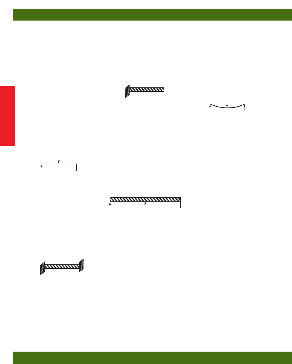
Simple Beam
An example of a simple beam is a length of
channel placed across two cylinders. When
a load is applied, the channel will support
the load because of its stiffness. The
cylinders serve to support the channel, but
do not interfere with its natural tendency to
flex or bend. Simple beam analysis is used
almost universally for beam comparisons,
even though it is seldom practical in field
installations.
A cable tray or conduit trapeze hanger
closely resembles a simple beam.
Fixed Beam
This type of fixed support restricts the
movement of the ends of the channel when
a load is applied. Because of this, the
stiffness of the channel at the ends and
center is employed to resist the load. The
result is a load capability which is greater
than that of an identical simple beam.
The fixed beam can be approximated by
bolting or welding a length of channel to
rigid supports.
Cantilever Beam
Cantilever beams are often viewed as
variations of a fixed beam, but they have
special characteristics of their own. One
end of the channel is firmly attached to a
rigid support while the other end remains
completely free.
A shelf bracket is an example of a
cantilever beam.
Continuous Beam
This beam configuration is
commonly used
in lighting installations. The continuous beam
possesses
traits of both the simple and fixed
beams. When equal loads are applied to all
spans simultaneously, the counter-balancing
effect of the loads on both sides of a
support restricts the movement of the
channel at the support, similar to that of
the fixed beam. The end spans behave
substantially like simple beams.
Continuous beam installations can typically
support 20% more load than a simple beam
of the same span with approximately half
the deflection.
Therefore, simple beam data should be used
for a general comparison
only. An example
of this configuration
is found in a long run
of channel
when installed across several
supports
to form a number of spans.
Deflection
Deflection, commonly referred to as “sag”,
is inherent in applying a load to a beam
and cannot be avoided. Any and all beams
will deflect when loaded. The amount of
deflection will vary depending upon the
material and the stiffness or moment of
inertia. The deflection equations in this
section show that increasing the stiffness
can be increased by a variety of methods.
Increasing the depth of the channel is the
most direct method.
The material used affects deflection in a
manner which is significantly different
from the way in which it affects load
capacity. The deflection under load is
inversely proportional to a material property
known as the “modulus of elasticity”
designated by “E”.
The modulus of elasticity is dependent
upon
the basic composition of the material and is
not necessarily related to the material’s
strength.
Point Load
Point Load
Technical Data
Technical Data
10

Safety Factor
The design loads given for strut beam loads
are based on a simple beam condition using
allowable stress of 25,000 psi. This
allowable stress results in a safety factor of
1.68. This is based upon a virgin steel
minimum yield strength of 33,000 psi cold
worked during rolling to an average yield
stress of 42,000 psi.
Aluminum typically has an elastic modulus
which is 1/3that of steel even though they
may have identical strength. As a result, the
deflection of aluminum channel will be
three times that of steel channel under equal
loading. In areas where structures will be
subject to general viewing, deflection can
produce a displeasing effect. To the
untrained eye, a sagging channel may
appear to be a result of poor design or
excessive loading. This is not usually the
case. Many properly designed channel
installations will show a noticeable
deflection at their designed loads. In areas
where cosmetics are not important,
deflection should not be a factor. Designing
an entire installation based on minimal
deflection could result in an over designed
structure. This translates into increased
material and installation cost. Where
cosmetics are important, it may be
necessary to limit the deflection to an
aesthetically pleasing amount. This
“acceptable deflection” amount is typically
given as a fraction of the span. 1/240 span
deflection is typically the limit where the
amount of deflection appears negligible. For
example, a beam span of 240” would be
allowed 1” (240/240) of deflection at the
mid point. A 120” span would only be
allowed 1/2” (120/240) of deflection. The
maximum load for the channel must be
limited in order to remain under these
deflection requirements. The allowable load
resulting in 1/240 span deflection is posted
in the beam load chart for each channel
size.
For even more stringent deflection
requirements, an allowable load is listed in
the beam load charts which results in 1/360
span deflection. This amount of deflection
is sometimes used for beams in finished
ceilings that are to be plastered.
Twisting & Lateral Bracing
Loading of strut on long spans can cause
torsional stress, resulting in the tendency of
the strut to twist or bend laterally. This
phenomenon reduces the allowable beam
loads as shown in the beam loading charts.
It is recommended that long spans be
supported in a manner to prevent twisting
(fixed ends), and that the channel have
adequate lateral bracing. Many typical strut
applications provide this support and
bracing inherently. Piping, tubing, cable
trays, or conduits mounted to the strut with
straps and clamps prevent twisting or lateral
movement. If no such lateral support exists,
contact the factory for loading
recommendations.
Columns
Columns are vertical members which carry
loads in compression. One common
example of a channel column is the vertical
members of a storage rack.
In theory, a column will carry a load equal
to its cross sectional area multiplied by the
ultimate compressive stress of the material
of which the column is made. In reality,
there are many factors affecting the load
capacity of a column, such as the tendency
to buckle or twist laterally (torsional-
flexural buckling), the type of connection
at the top or bottom, the eccentricity of the
load application, and material
imperfections. Several of these failure
modes have been considered in the
allowable column load tables shown in the
“Channel” section of this catalog.
B-Line strongly recommends that the
engineer perform a detailed study of the
many variable conditions before the
selection process begins.
Design Factors to be Considered
The loading capacity of channel depends
primarily on the material, its cross-sectional
design, and the beam or column loading
configuration. It should be noted that if two
lengths of channel have identical designs
and configurations, the one made of the
stronger base material will support a larger
load. Therefore, any comparison of channel
should begin by determining whether the
materials are approximately equal in
strength.
The column loading chart for each channel
lists the allowable load for each channel in
compression. This load varies depending
on the support condition or “K-factor”.
Several “K-factors” are listed, which
correspond to the following support
conditions:
K = .8 pinned top - fixed bottom
K = .65 fixed top - fixed bottom
K = 1.0 pinned top - pinned bottom
K = 1.2 free top - fixed bottom
There are a number of physical properties
which are important to the complete design
of a channel member; the “section
modulus” designated as “Sx” or “Sy”,
“moment of inertia” designated by “Ix” or
“Iy”, and the “radius of gyration” which is
given as “rx” or “ry”.
Every structural material has its own
maximum or ultimate stress, which is
usually expressed in “pounds per square
inch” (pascals). Any load which causes a
member to fail is referred to as its
“ultimate” load. In order to prevent channel
from being accidentally loaded up to or
beyond its ultimate load, a safety factor is
included into the design. The ultimate load
is divided by the safety factor to obtain the
“recommended” or “allowable” working
load.
When evaluating channel under various
beam conditions, it is often more convenient
to compare in
terms of the ultimate or
recommended
“bending moment”. Simple
equations
show the stress is directly
proportional
to the bending moment.
Therefore, comparing bending moments
can save time in repeated calculations. The
chart containing Formulas on Common
Beam Loadings (following page) shows
how to calculate the bending moment for
various configurations and load conditions.
It should be noted that the bending moment
is usually not constant, but varies along the
length of the span. However, the channel
must be designed for a single point, which
is the point of maximum bending moment.
For information regarding dynamic or
seismic design, contact B-Line’s Home
Office.
GENERAL
INFORMATION
Torque
The torque values given throughout the
catalog are to be used as a guide only. The
relationship between the applied torque or
torque wrench reading and the actual
tension created in the bolt may be
substantially different. For example, a dry
non-lubricated bolt with a heavy plating
may rate 50% as efficient as a bolt which is
lubricated with a mixture of heavy oil and
graphite. Other important factors affecting
torque-tension relationships include friction
under the bolt head or nut, hole tolerances,
and torque wrench tolerances. Accuracy of
many commercial torque wrenches may
vary as much as plus or minus 25%.
Charts and Tables
Charts and tables in this section are
compiled from information published by
nationally recognized organizations and are
intended for use as a guide only. B-Line
recommends that users of this information
determine the validity of such information
as applied to their own application.
Technical Data
Technical Data
11
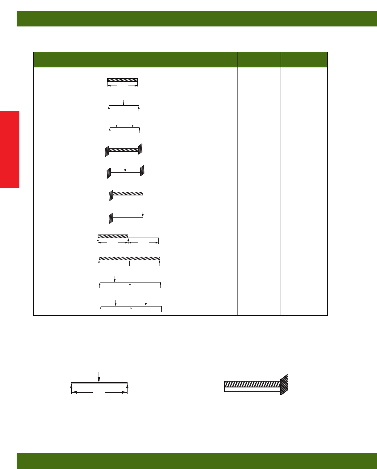
LOAD AND SUPPORT CONDITION Load Deflection
Factor Factor
Simple Beam - Uniform Load 1.00 1.00
Simple Beam - Concentrated Load at Center .50 .80
Simple Beam - Two Equal Concentrated Loads at 1/4Points 1.00 1.10
Beam Fixed at Both Ends - Uniform Load 1.50 .30
Beam Fixed at Both Ends - Concentrated Load at Center 1.00 .40
Cantilever Beam - Uniform Load .25 2.40
Cantilever Beam - Concentrated Load at End .12 3.20
Continuous Beam - Two Equal Spans - Uniform Load on One Span 1.30 .92
Continuous Beam - Two Equal Spans - Concentrated Load on Both Spans 1.00 .42
Continuous Beam - Two Equal Spans - Concentrated Load at Center of One Span .62 .71
Continuous Beam - Two Equal Spans - Concentrated Load at Center of Both Spans .67 .48
Span
Span
Span
The data shown in the beam load charts for appropriate channels on page(s) 17 thru 39 is for simply supported, single span beams with a
uniformly distributed load. For other loading and/or support conditions, use the appropriate factor from the chart below.
EXAMPLES:
PROBLEM: PROBLEM:
Calculate the maximum allowable load and corresponding Calculate the maximum allowable load and corresponding
deflection of a simply supported B22 beam with a concentrated deflection of a cantilever B52 beam with a uniformly distributed
load at midspan as shown. load.
SOLUTION: SOLUTION:
From beam load chart for B22 (page 22), maximum allowable From beam load chart for B52 (page 33), maximum allowable
Load is A and the corresponding deflection is B. load is A and the corresponding deflection is B.
Multiplying by the appropriate factors shown in the chart above. Multiplying by the appropriate factors shown in chart above.
LOAD = A x load factor = _______ LOAD = A x load factor = _______
DEFLECTION = B x deflection factor = DEFLECTION = B x deflection factor = _______
96”
Technical Data
Technical Data
12

Brackets [ ] indicate alternative
specifications which may be substituted by
the project engineer.
PART 1 - GENERAL
1.01 WORK INCLUDED
A. Continuous slot, bolted framing channels
and all associated fittings and hardware.
B. Trapeze type supports for cable tray,
conduit, pipe and other similar systems.
C. Use of bolted metal framing as a surface
metal raceway.
1.02 REFERENCES
A. ASTM A108 - Specification for Steel
Bars, Carbon, Cold Finished, Structural
Quality.
B. ASTM A123 - Specification for Zinc
(hot-dip galvanized) Coatings on Products
Fabricated from Rolled, Pressed, and
Forged Steel Shapes, Plates, Bars and
Strips.
C. ASTM A1011, 33,000 PSI min. yield -
Specification for Steel, Sheet and Strip,
Carbon, Hot-Rolled, Structural Quality.
D. ASTM B633 - Specification for
Electrodeposited Coatings of Zinc on Iron
and Steel.
E. ASTM A653 33,000 PSI min. yield G90
- Specification for Steel Sheet, Zinc Coated
(Galvanized) by the Hot-Dip Process.
F. ASTM A1018 - Standard Specification
for Steel, Sheet and Strip, Heavy-Thickness
Coils, Carbon, Hot-Rolled, Structural
Quality.
G. MFMA - Metal Framing Standards
Publication, MFMA-1.
1.03 QUALITY ASSURANCE
A. Manufacturers : Firms regularly engaged
in the manufacture of bolted metal framing
of the types required, whose products have
been in satisfactory use in similar service
for not less than 5 years.
B. A material heat code number shall be
stamped on all strut and fittings. This is
required to maintain traceability of the
product to the material test reports to the
ASTM standard.
C. For stainless steel items, the part number
shall contain a material designator
(EXAMPLE: B-Line B22SS6 for type 316
or B22SS4 for type 304), or a separate
stamp shall be included to reference the
type of material used.
D. MFMA Compliance: comply with the
latest revision of MFMA Standard
Publication Number MFMA-3, “Metal
Framing”.
E. NEC Compliance: Comply with the
latest revision NFPA 70 - Article 352
“Surface Metal Raceways and Surface
Nonmetallic Raceways”.
F. UL Compliance: Comply with UL
“Standard for Surface Metal Raceway and
Fittings”.
1.04 SUBMITTALS
A. Submit drawings of strut and accessories
including clamps, brackets, hanger rods and
fittings.
B. Submit manufacturer’s product data on
strut channels including, but not limited to,
types, materials, finishes, gauge thickness
and hole patterns. For each different strut
cross section, submit cross sectional
properties including Section Modulus (Sx)
and Moment of Inertia (Ix).
1.05 DELIVERY, STORAGE AND
HANDLING
A. Deliver strut systems and components
carefully to avoid breakage, denting, and
scoring finishes. Do not install damaged
equipment.
B. Store strut systems and components in
original cartons and in clean dry space;
protect from weather and construction
traffic.
PART 2 - PRODUCTS
2.01 ACCEPTABLE
MANUFACTURERS
A. Manufacturer: Subject to compliance
with these specifications, strut systems to
be installed shall be as manufactured by
B-Line Systems, Inc. [or engineer approved
equal.]
2.02 STRUT CHANNELS AND
COMPONENTS
A. General: Strut shall be 15/8” wide in
varying heights and welded combinations
as required to meet load capacities and
designs indicated on the drawings.
B. Material and Finish: Material and finish
specifications for each strut type are as
follows:
1. Aluminum: Strut shall be manufactured
of extruded aluminum alloy 6063-T6. All
fittings and hardware shall be zinc plated
according to ASTM B633. For outdoor use,
all fittings and hardware shall be stainless
steel Type 316 [Type 304] or chromium
zinc, ASTM F1136 Gr. 3.
2. Epoxy Painted: Strut shall be made from
steel meeting the minimum mechanical
properties of ASTM A1011 33,000 PSI min
yield, then painted with water born epoxy
applied by a cathodic electro-deposition
process. Fittings shall be manufactured from
steel meeting the minimum requirements of
ASTM A1018 33,000 PSI min. yield. The
fittings shall have the same epoxy finish as
the strut. Threaded hardware shall be zinc
plated in accordance with ASTM B633
Service Class 1 (SC1). Service Class 1 is
not an acceptable coating for fittings or
components other than threaded hardware.
3. Pre-Galvanized Steel: Strut shall be made
from steel meeting the minimum
mechanical properties of ASTM A653
33,000 PSI min. yield, mill galvanized
coating designation G90. Fittings shall be
manufactured from steel meeting the
minimum requirements of ASTM A1018
33,000 PSI min. yield and zinc plated in
accordance with ASTM B633 service class
3 (SC3). Threaded hardware shall be zinc
plated in accordance with ASTM B633
Service Class 1 (SC1). Service Class 1 is
not an acceptable coating for fittings or
components other than threaded hardware.
4. Hot-Dip Galvanized Steel: Strut shall be
made from steel meeting the minimum
mechanical properties of ASTM A1011
33,000 PSI min. yield and shall be hot-dip
galvanized after fabrication in accordance
with ASTM A123. Fittings shall be
manufactured from steel meeting the
minimum requirements of ASTM A1018
33,000 PSI min. yield, and hot-dip
galvanized after fabrication in accordance
with ASTM A123. All hardware shall be
stainless steel Type 316 [Type 304] or
chromium zinc ASTM F1136 Gr. 3. All hot-
dip galvanized after fabrication products
must be returned to point of manufacture
after coating for inspection and removal of
all sharp burrs.
5. Stainless Steel: All strut, fittings and
hardware shall be made of AISI Type 316
[Type 304] stainless steel as indicated.
Channels must be identified as required in
previous section 1.03 Quality Assurance.
PART 3 - EXECUTION
3.01 INSTALLATION
A. Install strut as indicated; in accordance
with equipment manufacturer’s
recommendations, and with recognized
industry practices.
B. All nuts and bolts shall be tightened to
the following values.
RECOMMENDED BOLTED METAL
FRAMING SPECIFICATION
Bolt Size Torque (ft-lbs)
1/4-20 6
5/16-18 11
3/8-16 19
1/2-13 50
Technical Data
Technical Data
13
Channel
B-Line’s metal framing channel is cold formed on our
modern rolling mills from 12 Ga. (2.6mm), 14 Ga.
(1.9mm), and 16 Ga. (1.5mm) low carbon steel strips. A
continuous slot with inturned lips provides the ability
to make attachments at any point.
Lengths
Standard lengths are 10’ (3.05m) and 20’ (6.09m) with
length tolerance of ±1/8” (+3.2mm). Custom lengths are
available upon request.
Slots
B-Line’s slotted series of channels offer full flexibility.
A variety of pre-punched slot patterns eliminate the
need for precise field measuring for hole locations.
Slots offer wide adjustments in the alignment and bolt
sizing.
Holes
A variety of pre-punched 9/16” (14.3 mm) diameter hole
patterns are available in B-Line channels. These hole
patterns provide an economical alternative to costly
field drilling required for many applications.
Knockouts
When used with series B217-20 Closure Strips,
B-Line’s knockout channels can be used to provide
an economical U.L. listed surface raceway. Channels
are furnished with 7/8” (22.2 mm) knockouts on
6” (152 mm) centers, allowing for perfect fixture
alignment on spans up to 20’ (6.09 m).
Materials & Finishes (Unless otherwise noted)
Steel: Plain
12 Ga. (2.6), 14 Ga. (1.9) and 16 Ga. (1.5)
Steel: Pre-galvanized
12 Ga. (2.6), 14 Ga. (1.9) and 16 Ga. (1.5)
Note: A minimum order may apply on special material and finishes.
Design Load
The design loads given for strut beam loads are based on a simple beam condition using an allowable stress of
25,000 psi. This allowable stress results in a safety factor of 1.68. This is based upon virgin steel minimum yield
strength of 33,000 psi cold worked during rolling to an average yield stress of 42,000 psi.
Welding
Weld spacing is maintained between 21/2inches (63.5 mm) and 4 inches (101.6 mm) on center. Through high quality
control testing of welded channels and continuous monitoring of welding equipment, B-Line provides the most
consistent combination channels available today.
Metric
Metric dimensions are shown in parentheses. Unless noted, all metric dimensions are in millimeters.
Finish
Code Finish Specification
PLN Plain ASTM A1011, 33,000 PSI
min. yield
GRN Dura-Green
GALV Pre-Galvanized ASTM A653 33,000 PSI
min. yield
HDG Hot-Dipped Galvanized ASTM A123
YZN Yellow Zinc Chromate ASTM B633 SC3 Type II
SS4 Stainless Steel Type 304 ASTM A240
SS6 Stainless Steel Type 316 ASTM A240
AL Aluminum Aluminum 6063-T6
Channel & Combinations
Metal Framing Channels
14
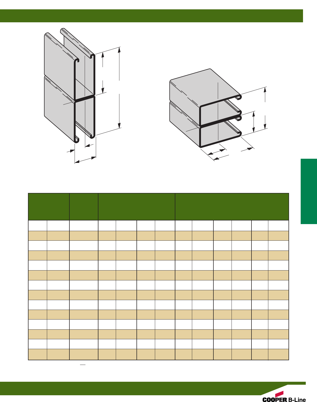
Material & Thickness * Channel Hole Pattern **
Channel
Dimensions Stainless SH S H17/8TH KO6
Steel
Channel Height Width
Type Steel Alum. Type Type
304 316
12 3 4
B11 31/4”(82.5) 15/8”(41.3) 12 Ga. – – – 1 1 1 –1
B12 27/16”(61.9) 15/8”(41.3) 12 Ga. .105 – – 1 2 1 1 2 –12
B22 15/8”(41.3) 15/8”(41.3) 12 Ga. .105 12 Ga. 12 Ga. 1 2 3 4 1 3 1 2 3 1 1 2
B24 15/8”(41.3) 15/8”(41.3) 14 Ga. .080 14 Ga. 14 Ga. 1 2 3 4 1 1 2 3 –12
B26 15/8”(41.3) 15/8”(41.3) 16 Ga. – – – 1 1 1 –1
B32 13/8”(34.9) 15/8”(41.3) 12 Ga. – 12 Ga. – 1 3 1 1 3 –1
B42 1” (25.4) 15/8”(41.3) 12 Ga. – 12 Ga. – 1 3 1 1 3 –1
B52 13/16”(20.6) 15/8”(41.3) 12 Ga. – 12 Ga. – 1 1 1 –1
B54 13/16”(20.6) 15/8”(41.3) 14 Ga. .080 14 Ga. 14 Ga. 1 2 3 4 1 1 2 3 4 –12
B56 13/16”(20.6) 15/8”(41.3) 16 Ga. – – – 1 1 1 –1
B62 13/16”(20.6) 13/16”(20.6) 18 Ga. – – – – – – – –
B72 13/32”(10.3) 13/16”(20.6) 18 Ga. – – – – – – – –
E7016 3/4”(19.0) 5/8”(15.9) 16 Ga. – – – – – – – –
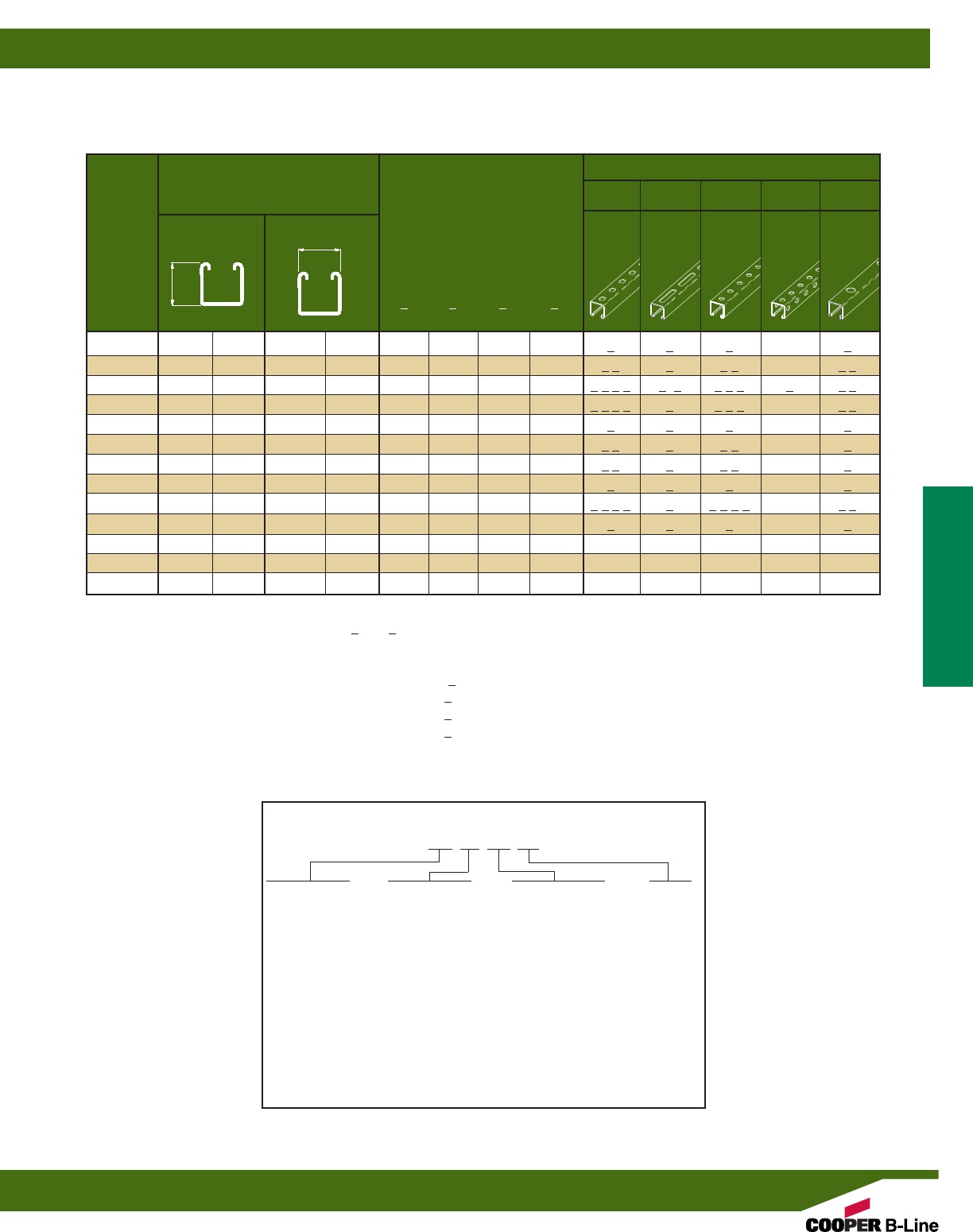
SELECTION CHART
for Channels, Materials and Hole Patterns
The selection has been prepared to provide a reference for available channel, materials and hole patterns. Material types available for
various hole patterns are defined by numbers 1 thru 4.
Some stainless steel channels with hole patterns are available on special order only.
*Metric equivalent for thicknesses shown in chart. **1 - Steel
12 Ga. = 2.6 mm 18 Ga. = 1.2 mm 2 - Aluminum
14 Ga. = 1.9 mm .105 = 2.6 mm 3 - Type 304 Stainless Steel
16 Ga. = 1.5 mm .080 = 2.0 mm 4 - Type 316 Stainless Steel
Properties may vary due to commercial tolerances of the material.
Channel Part Numbering
Example:
B22 SH SS4 120
Channel Type Hole Patterns Material/Finish Length
B11 SH (pg. 40) GRN 120
B12 S (pg. 40) GALV 240
B22 † H178 (pg. 40) HDG
B24 † TH (pg. 41) YZN
B26 K06 (pg. 41) SS4
B32 SHA (pg. 41) SS6
B42 S58 (pg. 42) AL
B52 † M (pg. 42)
B54 † H25 (pg. 43)
B56 H112 † (pg. 42)
B62 * Leave blank for no hole pattern
B72
E7016
9/16” x 11/8”
slots on
2” centers
13/32” x 3”
slots
9/16”
diameter
holes
9/16”
diameter
on 17/8”
centers
7/8”
diameter
knockouts
Reference page 14 for general fitting and standard finish specifications.
† BK style channel available in four (4) channel sizes and one (1) hole pattern only. (Example BK22H112)
Channel & Combinations
Channel
15
Areas of Moment of Section Radius of Moment of Section Radius of
Channel Weight Section Inertia (I) Modulus (S) Gyration (r) Inertia (I) Modulus (S) Gyration (r)
lbs./ft. kg/m sq. in. cm2in.4cm4in.3cm3in. cm in.4cm4in.3cm3in. cm
B11 3.059 (4.55) .900 (5.81) 1.1203 (46.63) .6472 (10.61) 1.116 (2.83) .4357 (18.14) .5362 (8.79) .696 (1.77)
B11A 6.119 (9.11) 1.800 (11.61) 6.3931 (266.10) 1.9671 (32.24) 1.885 (4.79) .8714 (36.27) 1.0725 (17.58) .696 (1.77)
X - X Axis Y - Y Axis
B11
•Thickness: 12 Gauge (2.6 mm)
•Standard lengths: 10’ (3.05 m) & 20’ (6.09 m)
•Standard finishes: Plain, Dura-Green, Pre-Galvanized,
Hot-Dipped Galvanized, Aluminum
•Weight: 3.05 Lbs./Ft. (4.54 kg/m)
Calculations of section properties are based on metal thicknesses as determined by the AISI Cold-Formed Steel Design Manual.
15/8”
(41.3)
31/4”
(82.5)
13/16”
(20.6)
1.5190
(38.6)
3/8”
(9.5)
3/8”
(9.5)
9/32”
(7.1)
7/8”
(22.2)
X
Y
Y
X
SECTION PROPERTIES
Reference page 14 for general fitting and standard finish specifications.
Channel & Combinations
B11 Channel, Combinations & Load Data
16
BEAM LOADING
Based on simple beam condition using an allowable design stress of 25,000 psi (172 MPa) in accordance with MFMA, with adequate lateral bracing (see
page 11 for further explanation). Actual yield point of cold rolled steel is 42,000 psi. To determine concentrated load capacity at mid span, multiply uniform
load by 0.5 and corresponding deflection by 0.8. *Failure determined by weld shear.
Uniform Load @ Deflection =
Beam Span Channel Uniform Load and Deflection 1/240 Span 1/360 Span
In. mm Style Lbs. N In. mm Lbs. N Lbs. N
24 (609) B11 5130 (22819) .029 (.73) 5130 (22819) 5130 (22819)
B11A 5130* (22819) .005 (.13) 5130* (22819) 5130* (22819)
36 (914) B11 3488 (15515) .065 (1.65) 3488 (15515) 3488 (15515)
B11A 5130* (22819) .017 (.43) 5130* (22819) 5130* (22819)
48 (1219) B11 2616 (11636) .117 (2.97) 2616 (11636) 2616 (11636)
B11A 5130* (22819) .040 (1.01) 5130* (22819) 5130* (22819)
60 (1524) B11 2093 (9310) .183 (4.65) 2093 (9310) 1908 (8487)
B11A 5130* (22819) .079 (2.00) 5130* (22819) 5130* (22819)
72 (1829) B11 1744 (7757) .263 (6.68) 1744 (7757) 1325 (5894)
B11A 5130* (22819) .136 (3.45) 5130* (22819) 5130* (22819)
84 (2133) B11 1495 (6650) .358 (9.09) 1460 (6494) 974 (4332)
B11A 4552 (20248) .191 (4.85) 4552 (20248) 4552 (20248)
96 (2438) B11 1308 (5818) .468 (11.89) 1118 (4973) 745 (3314)
B11A 3983 (17717) .250 (6.35) 3983 (17717) 3983 (17717)
108 (2743) B11 1163 (5173) .592 (15.03) 884 (3932) 589 (2620)
B11A 3541 (15751) .317 (8.05) 3541 (15751) 3353 (14915)
120 (3048) B11 1046 (4653) .731 (18.57) 716 (3185) 477 (2122)
B11A 3187 (14176) .391 (9.93) 3187 (14176) 2716 (12081)
144 (3657) B11 872 (3879) 1.053 (26.74) 497 (2211) 331 (1472)
B11A 2656 (11814) .563 (14.30) 2656 (11814) 1886 (8389)
168 (4267) B11 747 (3323) 1.433 (36.40) 365 (1623) 243 (1081)
B11A 2276 (10124) .766 (19.45) 2078 (9243) 1386 (6165)
192 (4877) B11 654 (2909) 1.871 (47.52) 280 (1245) 186 (827)
B11A 1992 (8861) 1.001 (25.42) 1591 (7077) 1061 (4719)
216 (5486) B11 581 (2584) 2.368 (60.15) 221 (983) 147 (654)
B11A 1770 (7873) 1.267 (32.18) 1257 (5591) 838 (3727)
240 (6096) B11 523 (2326) 2.924 (74.27) 179 (796) 119 (529)
B11A 1593 (7086) 1.564 (39.72) 1018 (4528) 679 (3020)
COLUMN LOADING
**Where the slenderness ratio KL exceeds 200, and K = end fixity factor, L = actual length and r = radius of gyration.
r
Reference page 14 for general fitting and standard finish specifications.
Max. Column Loading K = .80 Max. Column Loading (Loaded @ C.G.)
Unbraced Channel Loaded@ Loaded@
Height Style C.G. Slot Face K = .65 K = 1.0 K = 1.2
In. mm Lbs. N Lbs. N Lbs. N Lbs. N Lbs. N
24 (609) B11 8190 (36431) 4477 (19914) 8446 (37569) 7783 (34620) 7311 (32521)
B11A 17701 (78738) 8267 (36773) 17778 (79080) 17572 (78164) 17416 (77470)
36 (914) B11 7311 (32521) 4183 (18607) 7838 (34865) 6503 (28927) 5612 (24963)
B11A 17416 (77470) 8189 (36426) 17590 (78244) 17127 (76184) 16774 (74614)
48 (1219) B11 6214 (27641) 3783 (16827) 7053 (31373) 4988 (22188) 3816 (16974)
B11A 17016 (75691) 8079 (35937) 17327 (77074) 16503 (73409) 15876 (70620)
60 (1524) B11 4988 (22188) 3279 (14586) 6140 (27312) 3595 (15991) 2790 (12410)
B11A 16503 (73409) 7727 (34371) 16988 (75566) 15701 (69841) 14721 (65478)
72 (1829) B11 3816 (16974) 2444 (10871) 5146 (22890) 2790 (12410) 2213 (9844)
B11A 15876 (70620) 6160 (27401) 16574 (73724) 14721 (65482) 13310 (59206)
84 (2133) B11 3063 (13625) 1897 (8438) 4133 (18384) 2291 (10191) 1846 (8211)
B11A 15135 (67324) 4961 (22067) 16084 (71545) 13563 (60331) 11642 (51786)
96 (2438) B11 2564 (11405) 1532 (6814) 3398 (15115) 1953 (8687) 1591 (7077)
B11A 14279 (63516) 4045 (7993) 15520 (69036) 12226 (54384) 9717 (43223)
108 (2743) B11 2213 (9844) 1273 (5662) 2886 (12837) 1708 (7597) 1401 (6232)
B11A 13310 (59206) 3337 (14844) 14880 (66189) 10712 (47649) 7725 (34362)
120 (3048) B11 1953 (8687) 1081 (4808) 2514 (11183) 1522 (6770) 1251** (5565)
B11A 12226 (54384) 2784 (12384) 14164 (63004) 9019 (40118) 6257** (27832)
144 (3657) B11 1591 (7077) 816 (3630) 2011 (8945) 1251** (5565) 1026** (4564)
B11A 9717 (43223) 1990 (8852) 12508 (55638) 6257** (27832) 4345** (19327)
168 (4267) B11 1347 (5992) 642 (2856) 1687 (7504) 1058** (4706) 859** (3821)
B11A 7183 (31951) 1464 (6512) 10550 (46929) 4597** (20448) 3192** (14199)
192 (4877) B11 1167** (5191) 519 (2308) 1459 (6490) 910** (4048) ––
B11A 5499** (24461) 1121 (4986) 8330 (37053) 3520** (15658) ––
216 (5486) B11 1026** (4564) 429 (1908) 1285** (5716) ––––
B11A 4345** (19327) 885 (3936) 6582** (29278) ––––
240 (6096) B11 910** (4048) 360 (1601) 1148** (5106) ––––
B11A 3520** (15658) 717 (3189) 5331** (23713) ––––
Channel & Combinations
B11 Beam & Column Loading Data
17
31/4”
(82.5)
61/2”
(165.1)
31/4”
(82.5)
15/8”
(41.3)
31/4”
(82.5)
1.5190
(38.6)
15/8”
(41.3)
13/16”
(20.6)
X
X
Y
Y
Y
X
X
Y
B11A
Wt. 6.10 Lbs./Ft. (9.08 kg/m)
B11B
Wt. 6.10 Lbs./Ft. (9.08 kg/m)
Areas of Moment of Section Radius of Moment of Section Radius of
Channel Weight Section Inertia (I) Modulus (S) Gyration (r) Inertia (I) Modulus (S) Gyration (r)
lbs./ft. kg/m sq. in. cm2in.4cm4in.3cm3in. cm in.4cm4in.3cm3in. cm
B12 2.484 (3.70) .731 (4.71) .5349 (22.26) .4061 (6.65) .856 (2.17) .3377 (14.06) .4156 (6.81) .680 (1.73)
B12A 4.969 (7.40) 1.462 (9.43) 2.9036 (120.86) 1.1915 (19.52) 1.409 (3.58) .6756 (28.12) .8315 (13.63) .680 (1.73)
X - X Axis Y - Y Axis
B12
•Thickness: 12 Gauge (2.6 mm)
•Standard lengths: 10’ (3.05 m) & 20’ (6.09 m)
•Standard finishes: Plain, Dura-Green, Pre-Galvanized,
Hot-Dipped Galvanized, Aluminum
•Weight: 2.47 Lbs./Ft. (3.67 kg/m)
Calculations of section properties are based on metal thicknesses as determined by the AISI Cold-Formed Steel Design Manual.
15/8”
(41.3)
27/16”
(61.9)
27/16”
(61.9)
47/8”
(123.8)
31/4”
(82.5)
15/8”
(41.3)
27/16”
(61.9)
1.1199
(28.4)
15/8”
(41.3)
13/16”
(20.6)
13/16”
(20.6)
1.1197
(28.4)
3/8”
(9.5)
3/8”
(9.5)
9/32”
(7.1)
7/8”
(22.2)
X
Y
Y
X
X
X
Y
Y
Y
X
X
Y
SECTION PROPERTIES
B12A
Wt. 4.94 Lbs./Ft. (7.35 kg/m)
B12B
Wt. 4.94 Lbs./Ft. (7.35 kg/m)
Reference page 14 for general fitting and standard finish specifications.
Channel & Combinations
B12 Channel & Combinations
18

BEAM LOADING
COLUMN LOADING
Based on simple beam condition using an allowable design stress of 25,000 psi (172 MPa) in accordance with MFMA, with adequate lateral bracing (see
page 11 for further explanation). Actual yield point of cold rolled steel is 42,000 psi. To determine concentrated load capacity at mid span, multiply uniform
load by 0.5 and corresponding deflection by 0.8. *Failure determined by weld shear.
**Where the slenderness ratio KL exceeds 200, and K = end fixity factor, L = actual length and r = radius of gyration.
r
Uniform Load @ Deflection =
Beam Span Channel Uniform Load and Deflection 1/240 Span 1/360 Span
In. mm Style Lbs. N In. mm Lbs. N Lbs. N
12 (305) B12 3880 (17259) .009 (.23) 3880 (17259) 3880 (17259)
B12A 3880* (17259) .001 (.02) 3880* (17259) 3880* (17259)
24 (609) B12 3273 (14559) .038 (.96) 3273 (14559) 3273 (14559)
B12A 3880* (17259) .008 (.20) 3880* (17259) 3880* (17259)
36 (914) B12 2182 (9706) .086 (2.18) 2182 (9706) 2182 (9706)
B12A 3880* (17259) .028 (.71) 3880* (17259) 3880* (17259)
48 (1219) B12 1636 (7277) .153 (3.88) 1636 (7277) 1421 (6321)
B12A 3880* (17259) .067 (1.70) 3880* (17259) 3880* (17259)
60 (1524) B12 1309 (5823) .240 (6.09) 1309 (5823) 909 (4043)
B12A 3847* (17112) .130 (3.30) 3847* (17112) 3847* (17112)
72 (1829) B12 1091 (4853) .345 (8.76) 947 (4212) 632 (2811)
B12A 3206 (14261) .188 (4.77) 3206 (14261) 3206 (14261)
84 (2133) B12 935 (4159) .470 (11.94) 696 (3096) 464 (2064)
B12A 2748 (12224) .255 (6.48) 2748 (12224) 2509 (11160)
96 (2438) B12 818 (3638) .614 (15.59) 533 (2371) 355 (1579)
B12A 2404 (10693) .334 (8.48) 2404 (10693) 1921 (8545)
108 (2743) B12 727 (3234) .777 (19.73) 421 (1873) 281 (1250)
B12A 2137 (9506) .422 (10.72) 2137 (9506) 1518 (6752)
120 (3048) B12 655 (2913) .959 (24.36) 341 (1517) 227 (1010)
B12A 1924 (8558) .521 (13.23) 1844 (8202) 1229 (5467)
Max. Column Loading K = .80 Max. Column Loading (Loaded @ C.G.)
Unbraced Channel Loaded@ Loaded@
Height Style C.G. Slot Face K = .65 K = 1.0 K = 1.2
In. mm Lbs. N Lbs. N Lbs. N Lbs. N Lbs. N
12 (305) B12 10140 (45105) 4752 (21138) 10247 (45581) 9965 (44326) 9756 (43397)
B12A 20820 (92612) 8023 (35688) 20854 (92763) 20763 (92358) 20694 (92051)
24 (609) B12 9244 (41119) 4514 (20079) 9639 (42876) 8629 (38384) 7933 (35288)
B12A 20519 (91273) 7956 (35390) 20655 (91878) 20293 (90268) 20017 (89040)
36 (914) B12 7933 (35288) 4137 (18402) 8711 (35748) 6786 (30185) 5572 (24785)
B12A 20017 (89040) 7844 (34892) 20324 (90405) 19509 (86780) 18889 (84022)
48 (1219) B12 6386 (28406) 3638 (16182) 7562 (33637) 4785 (21285) 3717 (16534)
B12A 19315 (85917) 7688 (34198) 19861 (88346) 18412 (81900) 17309 (76994)
60 (1524) B12 4785 (21285) 2963 (13180) 6285 (27957) 3523 (15671) 2806 (12482)
B12A 18412 (81900) 6941 (30875) 19265 (85695) 17002 (75628) 15278 (67960)
72 (1829) B12 3717 (16534) 2197 (9773) 4964 (22081) 2806 (12482) 2271 (10102)
B12A 17309 (76994) 5334 (23727) 18536 (82452) 15278 (67960) 12795 (56915)
84 (2133) B12 3052 (13576) 1717 (7637) 3994 (17766) 2345 (10431) 1913 (8509)
B12A 16005 (71194) 4176 (18576) 17675 (78622) 13240 (58894) 9884 (43966)
96 (2438) B12 2600 (11565) 1391 (6187) 3350 (14901) 2019 (8981) 1650 (7339)
B12A 14500 (64499) 3328 (14803) 16682 (74205) 10889 (48436) 7567 (33659)
108 (2743) B12 2271 (10102) 1155 (5137) 2893 (12869) 1773 (7886) 1446 (6432)
B12A 12795 (56915) 2692 (11974) 15556 (69196) 8610 (38299) 5979 (26596)
120 (3048) B12 2019 (8981) 977 (4346) 2553 (11356) 1577 (7015) 1279** (5689)
B12A 10889 (48436) 2202 (9795) 14298 (63600) 6974 (31022) 4843** (21543)
Reference page 14 for general fitting and standard finish specifications.
Channel & Combinations
B12 Beam & Column Loading Data
19
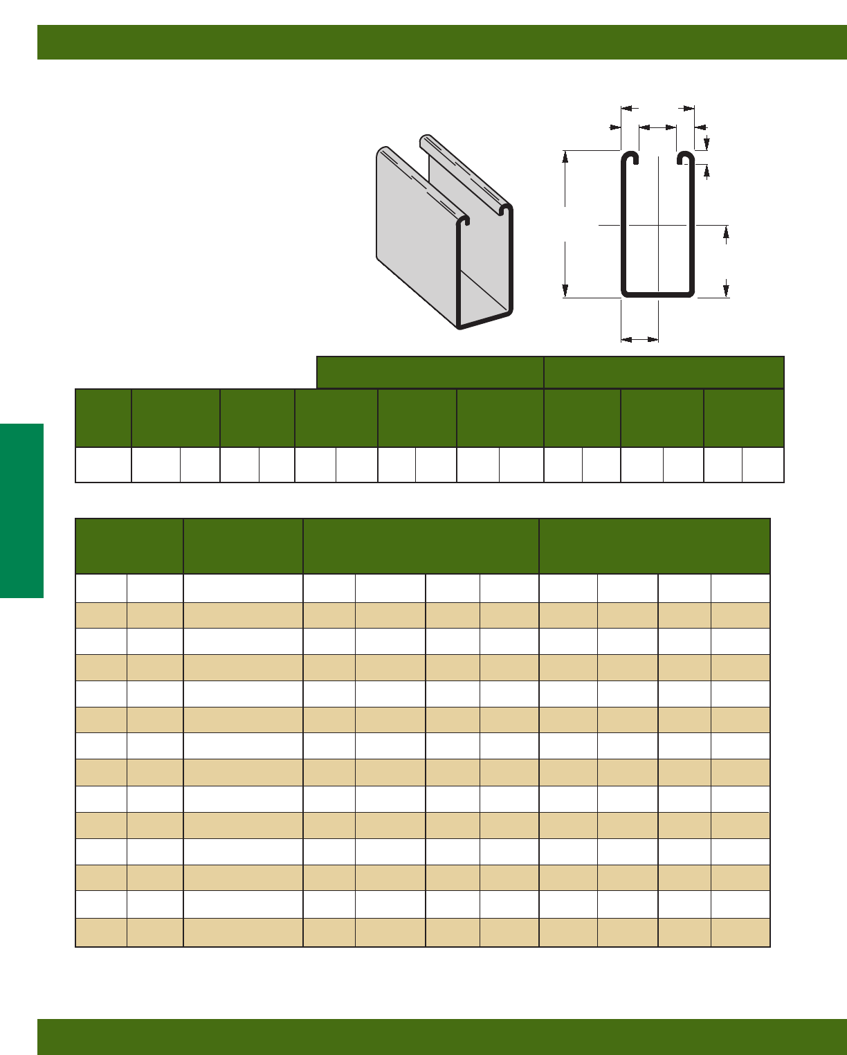
Areas of Moment of Section Radius of Moment of Section Radius of
Channel Weight Section Inertia (I) Modulus (S) Gyration (r) Inertia (I) Modulus (S) Gyration (r)
lbs./ft. kg/m sq. in. cm2in.4cm4in.3cm3in. cm in.4cm4in.3cm3in. cm
B22 1.910 (2.84) .562 (3.62) .1912 (7.96) .2125 (3.48) .583 (1.48) .2399 (9.99) .2953 (4.84) .653 (1.66)
B22A 3.820 (5.69) 1.124 (7.25) .9732 (40.51) .5989 (9.81) .931 (2.36) .4798 (19.97) .5905 (9.68) .653 (1.66)
B22X 6.649 (9.89) 1.956 (12.62) 4.1484 (172.67) 1.7019 (27.89) 1.456 (3.70) 1.1023 (45.88) 1.2027 (19.71) .751 (1.91)
X - X Axis Y - Y Axis
B22
•Thickness: 12 Gauge (2.6 mm)
•Standard lengths: 10’ (3.05 m) & 20’ (6.09 m)
•Standard finishes: Plain, Dura-Green, Pre-Galvanized,
Hot-Dipped Galvanized, Stainless Steel Type 304 or 316, Aluminum
•Weight: 1.90 Lbs./Ft. (2.83 kg/m)
Calculations of section properties are based on metal thicknesses as determined by the AISI Cold-Formed Steel Design Manual.
15/8”
(41.3)
15/8”
(41.3)
15/8”
(41.3)
31/4”
(82.5)
13/16”
(20.6)
13/16”
(20.6)
15/8”
(41.3)
.7252
(18.4)
3/8”
(9.5)
3/8”
(9.5)
9/32”
(7.1)
7/8”
(22.2)
X
Y
Y
X
X
Y
Y
X
SECTION PROPERTIES
B22A
Wt. 3.80 Lbs./Ft. (5.65 kg/m)
Reference page 14 for general fitting and standard finish specifications.
Channel & Combinations
B22 Channel
20
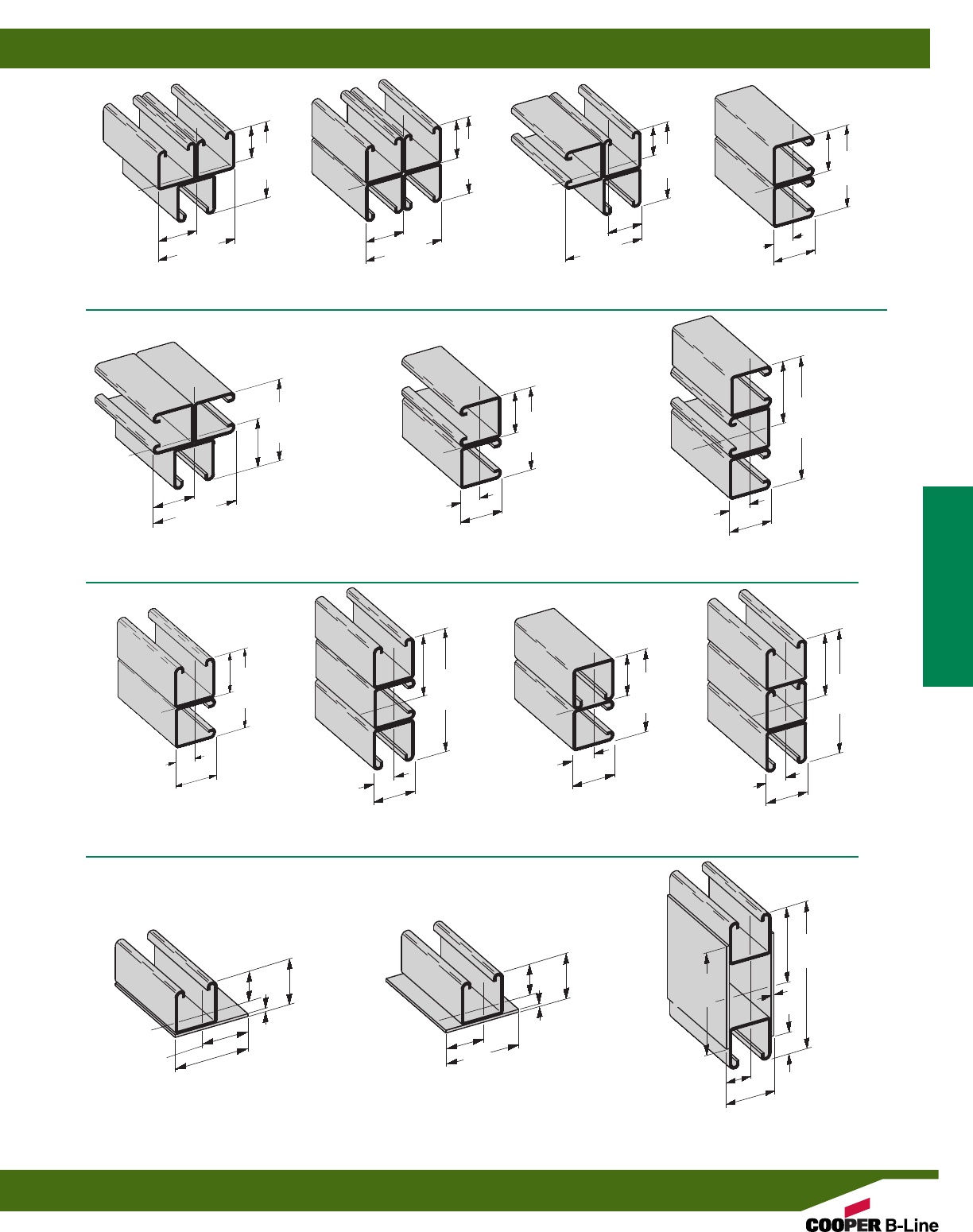
B22A3
Wt. 5.70 Lbs./Ft. (8.48 kg/m)
B22B3
Wt. 5.70 Lbs./Ft. (8.48 kg/m)
B22D
Wt. 3.80 Lbs./Ft. (5.65 kg/m)
B22LPL
Wt. 2.90 Lbs./Ft. (4.31 kg/m)
B22PL
Wt. 3.35 Lbs./Ft. (4.98 kg/m) B22X
Wt. 6.70 Lbs./Ft. (9.97 kg/m)
B22D3
Wt. 5.70 Lbs./Ft. (8.48 kg/m)
B22E
Wt. 3.80 Lbs./Ft. (5.65 kg/m)
B22E3
Wt. 5.70 Lbs./Ft. (8.48 kg/m)
B22C
Wt. 3.80 Lbs./Ft. (5.65 kg/m)
B22C3
Wt. 5.70 Lbs./Ft. (8.48 kg/m)
B22A4
Wt. 7.60 Lbs./Ft. (11.31 kg/m)
B22AD3
Wt. 5.70 Lbs./Ft. (8.48 kg/m)
B22B
Wt. 3.80 Lbs./Ft. (5.65 kg/m)
31/4”
(82.5)
31/4”
(82.5)
15/8”
(41.3)
213/16”
(71.4)
4”
(101.6)
1.835
(46.6)
15/8”
(41.3)
15/8”
(41.3) 15/8”
(41.3)
15/8”
(41.3) 15/8”
(41.3)
47/8”
(123.8)
31/4”
(82.5)
31/4”
(82.5)
47/8”
(123.8) 31/4”
(82.5)
47/8”
(123.8)
31/4”
(82.5)
31/4”
(82.5)
31/4”
(82.5)
15/8”
(41.3)
31/4”
(82.5) 31/4”
(82.5)
31/4”
(82.5)
31/4”
(82.5)
1.3833
(35.1)
1.3540
(34.4) 15/8”
(41.3)
.725
(18.4)
15/8”
(41.3)
15/8”
(41.3)
.769
(19.5)
1.795
(45.6)
.105
(2.6) 2”
(50.8)
.918
(23.3)
4”
(101.6)
7/16”
(11.1)
.105
(2.6)
1.730
(43.9)
1.730
(43.9)
47/8”
(123.8)
.104
(2.6)
1.168
(29.7)
1.231
(31.3)
27/16”
(61.9)
.842
(21.4)
.769
(19.5) 13/16”
(20.6)
1.9249
(48.9)
15/8”
(41.3)
27/16”
(61.9) 1.5813
(40.2)
2.467
(62.7)
15/8”
(41.3)
13/16”
(20.6) .8416
(21.4)
27/16”
(61.9)
15/8”
(41.3)
15/8”
(41.3)
1.3250
(33.7)
Y
Y
Y
Y
Y
YX
XX
XX
X
Y
Y
Y
Y
Y
YYYY
Y
Y
Y
YY
Y
Y
Y
X
X
X
X
X
X
X
X
X
X
X
X
X
XXX
X
X
X
X
X
X
YYY
Y
Y
Reference page 14 for general fitting and standard finish specifications.
Channel & Combinations
B22 Combinations
21
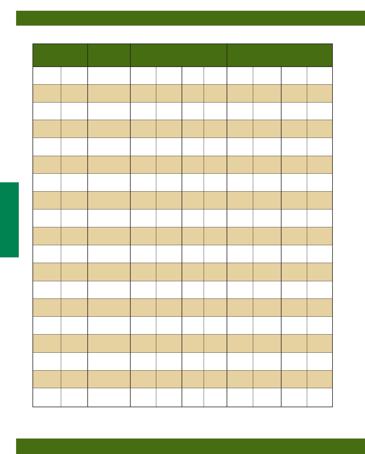
Uniform Load @ Deflection =
Beam Span Channel Uniform Load and Deflection 1/240 Span 1/360 Span
In. mm Style Lbs. N In. mm Lbs. N Lbs. N
12 (305)
B22 2610 (11610) .014 (.35) 2610 (11610) 2610 (11610)
B22A 2610* (11610) .002 (.05) 2610* (11610) 2610* (11610)
B22X 5790* (25755) .001 (.02) 5790* (25755) 5790* (25755)
18 (457)
B22 2269 (10093) .031 (.79) 2269 (10093) 2269 (10093)
B22A 2610* (11610) .007 (.18) 2610* (11610) 2610* (11610)
B22X 5790* (25755) .003 (.07) 5790* (25755) 5790* (25755)
24 (609)
B22 1702 (7571) .056 (1.42) 1702 (7571) 1702 (7571)
B22A 2610* (11610) .017 (.43) 2610* (11610) 2610* (11610)
B22X 5790* (25755) .008 (.20) 5790* (25755) 5790* (25755)
30 (762)
B22 1361 (6054) .087 (2.21) 1361 (6054) 1294 (5756)
B22A 2610* (11610) .033 (.84) 2610* (11610) 2610* (11610)
B22X 5790* (25755) .017 (.73) 5790* (25755) 5790* (25755)
36 (914)
B22 1135 (5049) .126 (3.20) 1135 (5049) 899 (3999)
B22A 2610* (11610) .057 (1.45) 2610* (11610) 2610* (11610)
B22X 5790* (25755) .029 (.73) 5790* (25755) 5790* (25755)
42 (1067)
B22 972 (4323) .172 (4.37) 972 (4323) 660 (2936)
B22A 2610* (11610) .091 (2.31) 2610* (11610) 2610* (11610)
B22X 5790* (25755) .046 (1.17) 5790* (25755) 5790* (25755)
48 (1219)
B22 851 (3785) .224 (5.69) 758 (3372) 505 (2246)
B22A 2405 (10698) .125 (3.17) 2405 (10698) 2405 (10698)
B22X 5790* (25755) .068 (1.73) 5790* (25755) 5790* (25755)
54 (1371)
B22 756 (3363) .284 (7.21) 599 (2664) 399 (1775)
B22A 2138 (9510) .158 (4.01) 2138 (9510) 2024 (9003)
B22X 5790* (25755) .097 (2.46) 5790* (25755) 5790* (25755)
60 (1524)
B22 681 (3029) .351 (8.91) 485 (2157) 323 (1437)
B22A 1924 (8558) .195 (4.95) 1924 (8558) 1640 (7295)
B22X 5645 (25110) .130 (3.30) 5645 (25110) 5645 (25110)
66 (1676)
B22 619 (2753) .424 (10.77) 401 (1784) 267 (1187)
B22A 1749 (7780) .236 (5.99) 1749 (7780) 1355 (6027)
B22X 5132 (22828) .158 (4.01) 5132 (22828) 5132 (22828)
72 (1829)
B22 567 (2522) .505 (12.83) 337 (1499) 225 (1001)
B22A 1603 (7130) .281 (7.14) 1603 (7130) 1139 (5066)
B22X 4704 (20924) .188 (4.77) 4704 (20924) 4704 (20924)
78 (1981)
B22 524 (2331) .593 (15.06) 287 (1276) 191 (849)
B22A 1480 (6583) .330 (8.38) 1455 (6472) 970 (4315)
B22X 4342 (19314) .220 (5.59) 4342 (19314) 4270 (18994)
84 (2133)
B22 486 (2162) .687 (17.45) 248 (1103) 165 (734)
B22A 1374 (6112) .383 (9.73) 1255 (5582) 837 (3723)
B22X 4032 (17935) .255 (6.48) 4032 (17935) 3682 (16378)
90 (2286)
B22 454 (2019) .789 (20.04) 216 (961) 144 (640)
B22A 1283 (5707) .440 (11.17) 1093 (4862) 729 (3243)
B22X 3763 (16738) .293 (7.44) 3763 (16738) 3207 (14265)
96 (2438)
B22 425 (1890) .898 (22.81) 190 (845) 126 (560)
B22A 1202 (5347) .500 (12.70) 961 (4275) 640 (2847)
B22X 3528 (15693) .334 (8.48) 3528 (15693) 2819 (12539)
102 (2591)
B22 400 (1779) 1.013 (25.73) 168 (747) 112 (498)
B22A 1132 (5035) .565 (14.35) 851 (3785) 567 (2522)
B22X 3320 (14768) .377 (9.57) 3320 (14768) 2497 (11107)
108 (2743)
B22 378 (1681) 1.136 (28.85) 150 (667) 100 (445)
B22A 1069 (4755) .633 (16.08) 759 (3376) 506 (2251)
B22X 3136 (13949) .422 (10.72) 3136 (13949) 2227 (9906)
114 (2895)
B22 358 (1592) 1.266 (32.15) 134 (596) 90 (400)
B22A 1013 (4506) .706 (17.93) 681 (3029) 454 (2019)
B22X 2971 (13215) .471 (11.96) 2971 (13215) 1999 (8892)
120 (3048)
B22 340 (1512) 1.403 (35.63) 121 (538) 81 (360)
B22A 962 (4279) .782 (19.86) 615 (2735) 410 (1824)
B22X 2822 (12553) .521 (13.23) 2706 (12037) 1804 (8024)
Based on simple beam condition using an allowable design stress of 25,000 psi (172 MPa) in accordance with MFMA, with adequate lateral bracing (see
page 11 for further explanation). Actual yield point of cold rolled steel is 42,000 psi. To determine concentrated load capacity at mid span, multiply uniform
load by 0.5 and corresponding deflection by 0.8. *Failure determined by weld shear.
Reference page 14 for general fitting and standard finish specifications.
Channel & Combinations
B22 Beam Loading Data
22
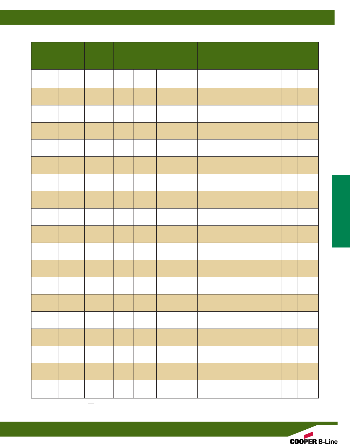
Max. Column Loading K = .80 Max. Column Loading (Loaded @ C.G.)
Unbraced Channel Loaded@ Loaded@
Height Style C.G. Slot Face K = .65 K = 1.0 K = 1.2
In. mm Lbs. N Lbs. N Lbs. N Lbs. N Lbs. N
12 (305)
B22 10454 (46502) 4276 (19120) 10598 (47142) 10222 (45470) 9950 (44260)
B22A 21625 (96193) 7002 (31146) 21677 (96424) 21539 (95810) 21433 (95339)
B22X 46948 (208835) 18975 (84405) 47061 (209338) 46761 (208003) 46531 (206980)
18 (457)
B22 9950 (44260) 4153 (18473) 10253 (45607) 9481 (42173) 8955 (39834)
B22A 21433 (95339) 6959 (30955) 21551 (95863) 21239 (94476) 21001 (93417)
B22X 46531 (206980) 18859 (83899) 46787 (208119) 46110 (205107) 45593 (202808)
24 (609)
B22 9311 (41417) 3993 (17762) 9801 (43597) 8582 (38174) 7801 (34700)
B22A 21164 (94142) 6898 (30684) 21373 (95072) 20819 (92607) 20397 (90730)
B22X 45947 (204382) 18693 (84440) 46401 (206402) 45198 (201051) 44282 (196976)
30 (762)
B22 8582 (38174) 3802 (16912) 9268 (41226) 7601 (33811) 6595 (29336)
B22A 20819 (92607) 6821 (30341) 21145 (94057) 20279 (90205) 19619 (87269)
B22X 45198 (201051) 18485 (82225) 45906 (204200) 44026 (195837) 42593 (189463)
36 (914)
B22 7801 (34700) 3589 (15964) 8676 (38593) 6595 (28336) 5392 (23985)
B22A 20397 (90730) 6728 (29927) 20866 (92816) 19619 (87269) 18669 (83044)
B22X 44282 (196976) 18233 (81104) 45300 (201504) 42593 (189463) 40530 (180286)
42 (1067)
B22 6998 (31128) 3360 (14946) 8048 (35799) 5595 (24888) 4444 (19768)
B22A 19898 (88511) 6620 (29447) 20537 (91353) 18840 (83804) 17546 (78048)
B22X 43198 (192154) 17940 (79801) 44586 (198328) 40901 (181937) 38092 (169441)
48 (1219)
B22 6193 (27548) 3118 (13869) 7401 (32921) 4718 (20987) 3791 (16863)
B22A 19322 (85948) 6496 (28895) 20157 (89663) 17940 (79801) 16251 (72288)
B22X 41948 (186594) 17604 (78306) 43761 (194568) 38948 (173254) 35281 (156938)
54 (1371)
B22 5392 (23985) 2864 (12740) 6746 (30008) 4090 (18193) 3310 (14723)
B22A 18669 (83044) 6263 (27859) 19276 (87745) 16920 (75264) 14782 (65753)
B22X 40530 (180286) 16973 (75499) 42825 (190495) 36733 (163396) 32092 (142752)
60 (1524)
B22 4718 (20987) 2631 (11703) 6093 (27103) 3616 (16085) 2936 (13060)
B22A 17940 (79801) 5340 (23753) 19244 (85601) 15781 (70197) 13141 (58454)
B22X 38948 (173249) 14471 (64370) 41779 (185842) 34260 (152396) 28529 (126903)
66 (1676)
B22 4202 (18691) 2434 (10827) 5441 (24203) 3242 (14421) 2634 (11716)
B22A 17134 (76216) 4587 (20404) 18712 (83235) 14521 (64592) 11328 (50389)
B22X 37198 (165465) 12431 (55296) 40624 (180704) 31525 (140230) 24593 (109395)
72 (1829)
B22 3791 (16863) 2264 (10071) 4869 (21658) 2936 (13060) 2381 (10591)
B22A 16251 (72288) 3968 (17650) 18129 (80642) 13141 (58454) 9524 (42365)
B22X 35281 (156938) 10753 (47832) 39358 (175073) 28529 (126903) 20676 (91971)
78 (1981)
B22 3456 (15373) 2116 (9412) 4412 (19625) 2680 (11921) 2166 (9635)
B22A 15291 (68018) 3456 (15373) 17496 (77826) 11642 (51786) 8115 (36097)
B22X 33197 (147667) 9366 (41662) 37984 (168961) 25275 (112429) 17617 (78364)
84 (2133)
B22 3176 (14127) 1984 (8825) 4037 (17957) 2461 (10947) 1980 (8807)
B22A 14255 (63409) 3028 (13469) 16812 (74783) 10076 (44820) 6998 (31128)
B22X 30947 (137659) 8206 (36502) 36499 (162355) 21875 (97305) 15192 (67577)
90 (2286)
B22 2936 (13060) 1867 (8305) 3724 (16565) 2270 (10097) 1816 (8078)
B22A 13141 (58454) 2667 (11863) 16077 (71514) 8778 (39046) 6096 (27116)
B22X 28529 (126903) 7227 (32147) 34903 (155256) 19057 (84770) 13234 (58868)
96 (2438)
B22 2728 (16583) 1761 (7833) 3456 (15373) 2101 (9346) 1671 (7433)
B22A 11951 (53160) 2359 (10493) 15291 (68018) 7715 (34318) 5357 (23829)
B22X 25945 (115409) 6393 (28437) 33197 (147667) 16749 (74503) 11630 (51733)
102 (2591)
B22 2545 (11321) 1664 (7402) 3225 (14345) 1951 (8678) 1542** (6343)
B22A 10678 (47498) 2093 (9310) 14455 (64299) 6834 (30399) 4746 (21111)
B22X 23182 (103118) 5672 (25230) 31382 (139594) 14836 (65994) 10303 (45830)
108 (2743)
B22 2381 (10591) 1575 (7006) 3022 (13442) 1816 (8078) 1426** (68599)
B22A 9524 (42365) 1867 (8305) 13568 (60353) 6096 (27116) 4233 (18829)
B22X 20676 (91971) 5059 (22503) 29456 (131027) 13234 (58868) 9190 (40879)
114 (2895)
B22 2234 (9937) 1494 (6645) 2842 (12642) 1694 (7535) 1322** (5880)
B22A 8548 (38023) 1675 (7451) 12630 (56181) 5471 (24336) 3799** (16899)
B22X 18558 (82550) 4539 (20190) 27420 (121970) 11877 (52831) 8247 (36684)
120 (3048)
B22 2101 (9346) 1418 (6307) 2680 (11921) 1583** (7041) 1228** (5462)
B22A 7715 (34318) 1512 (6726) 11642 (51786) 4937 (21961) 3429** (15253)
B22X 16749 (74503) 4097 (18224) 25275 (112429) 10718 (47676) 7444 (33112)
**Where the slenderness ratio KL exceeds 200, and K = end fixity factor, L = actual length and r = radius of gyration.
r
Reference page 14 for general fitting and standard finish specifications.
Channel & Combinations
B22 Column Loading Data
23
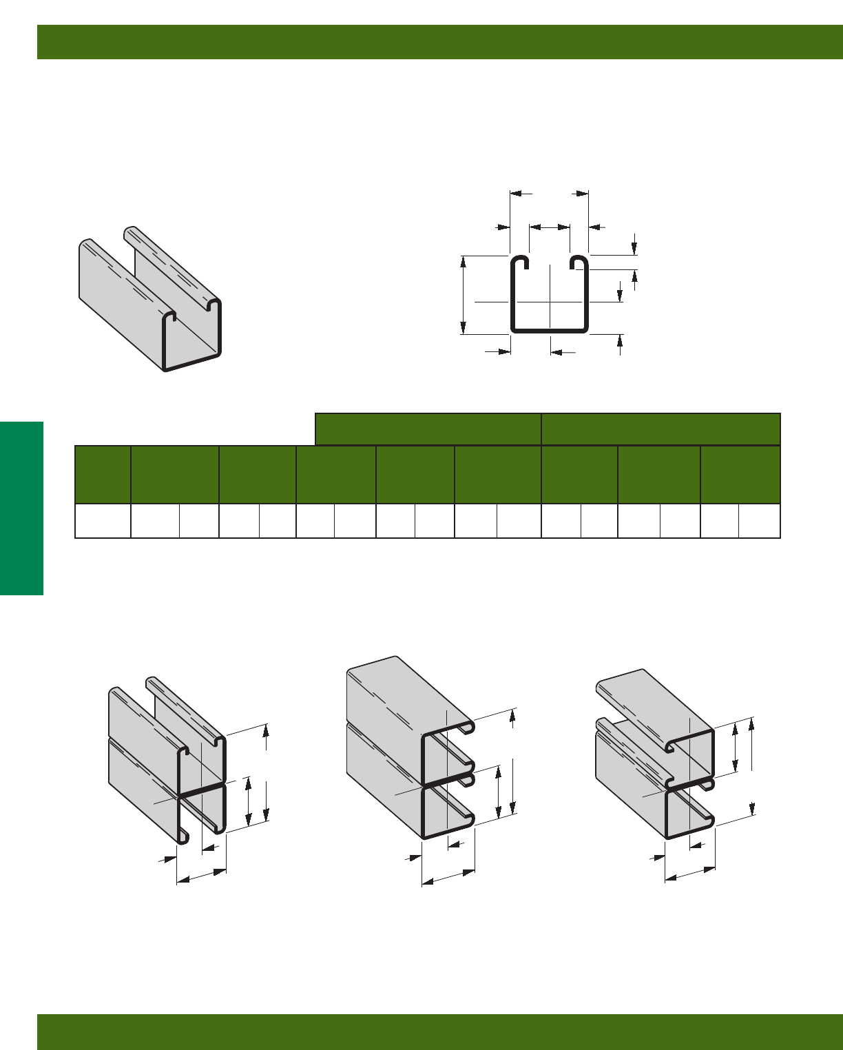
Areas of Moment of Section Radius of Moment of Section Radius of
Channel Weight Section Inertia (I) Modulus (S) Gyration (r) Inertia (I) Modulus (S) Gyration (r)
lbs./ft. kg/m sq. in. cm2in.4cm4in.3cm3in. cm in.4cm4in.3cm3in. cm
B24 1.442 (2.15) .424 (2.74) .1494 (6.22) .1670 (2.74) .594 (1.51) .1857 (7.73) .2286 (3.75) .662 (1.68)
B24A 2.884 (4.29) .848 (5.47) .7514 (31.28) .4624 (7.58) .941 (2.39) .3713 (15.45) .4570 (7.49) .662 (1.68)
X - X Axis Y - Y Axis
B24
•Thickness: 14 Gauge (1.9 mm)
•Standard lengths: 10’ (3.05 m) & 20’ (6.09 m)
•Standard finishes: Plain, Dura-Green, Pre-Galvanized,
Hot-Dipped Galvanized, Stainless Steel Type 304 or 316, Aluminum
•Weight: 1.40 Lbs./Ft. (2.08 kg/m)
Calculations of section properties are based on metal thicknesses as determined by the AISI Cold-Formed Steel Design Manual.
15/8”
(41.3)
15/8”
(41.3)
13/16”
(20.6)
.7304
(18.6)
3/8”
(9.5)
3/8”
(9.5)
9/32”
(7.1)
7/8”
(22.2)
X
Y
Y
X
SECTION PROPERTIES
B24A
Wt. 2.80 Lbs./Ft. (4.16 kg/m)
B24B
Wt. 2.80 Lbs./Ft. (4.16 kg/m)
B24C
Wt. 2.80 Lbs./Ft. (4.16 kg/m)
31/4”
(82.5)
31/4”
(82.5)
31/4”
(82.5)
15/8”
(41.3)
15/8”
(41.3)
15/8”
(41.3)
15/8”
(41.3)
15/8”
(41.3)
15/8”
(41.3)
13/16”
(20.6)
13/16”
(20.6)
.730
(18.6)
X
Y
Y
YY
Y
Y
XX
XX
X
Reference page 14 for general fitting and standard finish specifications.
Channel & Combinations
B24 Channel & Combinations
24

**Where the slenderness ratio KL exceeds 200, and K = end fixity factor, L = actual length and r = radius of gyration.
r
Uniform Load @ Deflection =
Beam Span Channel Uniform Load and Deflection 1/240 Span 1/360 Span
In. mm Style Lbs. N In. mm Lbs. N Lbs. N
12 (305) B24 1750 (7784) .014 (.35) 1750 (7784) 1750 (7784)
B24A 1750* (7784) .002 (.05) 1750* (7784) 1750* (7784)
24 (609) B24 1379 (6134) .057 (1.45) 1379 (6134) 1379 (6134)
B24A 1750* (7784) .014 (.35) 1750* (7784) 1750* (7784)
36 (914) B24 919 (4088) .128 (3.25) 919 (4088) 720 (3203)
B24A 1750* (7784) .048 (1.22) 1750* (7784) 1750* (7784)
48 (1219) B24 689 (3065) .227 (5.76) 607 (2700) 405 (1801)
B24A 1750* (7784) .115 (2.92) 1750* (7784) 1750* (7784)
60 (1524) B24 551 (2451) .355 (9.02) 389 (1730) 259 (1152)
B24A 1518 (6752) .195 (4.95) 1518 (6752) 1294 (5756)
72 (1829) B24 460 (2046) .511 (12.98) 270 (1201) 180 (800)
B24A 1265 (5627) .281 (7.14) 1265 (5627) 898 (3994)
84 (2133) B24 394 (1752) .695 (17.65) 198 (881) 132 (587)
B24A 1084 (4822) .383 (9.73) 990 (4404) 660 (2936)
96 (2438) B24 345 (1534) .908 (23.06) 152 (676) 101 (449)
B24A 949 (4221) .500 (12.70) 758 (3372) 505 (2246)
108 (2743) B24 306 (1361) 1.149 (29.18) 120 (534) 80 (356)
B24A 843 (3750) .633 (16.08) 599 (2664) 399 (1775)
120 (3048) B24 276 (1228) 1.419 (36.04) 97 (431) 65 (289)
B24A 759 (3376) .782 (19.86) 485 (2157) 323 (1437)
BEAM LOADING
Max. Column Loading K = .80 Max. Column Loading (Loaded @ C.G.)
Unbraced Channel Loaded@ Loaded@
Height Style C.G. Slot Face K = .65 K = 1.0 K = 1.2
In. mm Lbs. N Lbs. N Lbs. N Lbs. N Lbs. N
12 (305) B24 6441 (28651) 3077 (13687) 6509 (28953) 6330 (28157) 6198 (27570)
B24A 13212 (58770) 4988 (22188) 13237 (58881) 13171 (58587) 13121 (58365)
24 (609) B24 5874 (26129) 2896 (12882) 6124 (27241) 5483 (24389) 5038 (22410)
B24A 12993 (57796) 4924 (21903) 13092 (58236) 12828 (57062) 12627 (56167)
36 (914) B24 5038 (22410) 2619 (11650) 5535 (24621) 4302 (19136) 3516 (15640)
B24A 12627 (56167) 4819 (21436) 12851 (57164) 12256 (54517) 11804 (52507)
48 (1219) B24 4043 (17984) 2272 (10106) 4800 (21351) 3008 (13380) 2324 (10337)
B24A 12115 (53890) 4675 (20795) 12512 (55656) 11456 (50959) 10651 (47378)
60 (1524) B24 3008 (13380) 1873 (8331) 3978 (17695) 2200 (9786) 1740 (7740)
B24A 11456 (50959) 4020 (17882) 12078 (53725) 10427 (46381) 9169 (40786)
72 (1829) B24 2324 (10337) 1562 (6948) 3123 (13892) 1740 (7740) 1397 (6214)
B24A 10651 (47378) 3048 (13558) 11546 (51359) 9169 (40786) 7358 (32730)
84 (2133) B24 1898 (8443) 1340 (5960) 2502 (11129) 1444 (6423) 1168 (5195)
B24A 9700 (43148) 2362 (10506) 10918 (48565) 7683 (34175) 5464 (24305)
96 (2438) B24 1608 (7153) 1175 (5226) 2089 (9292) 1236 (5498) 1000 (4448)
B24A 8602 (38263) 1866 (8300) 10194 (45345) 6024 (26796) 4184 (18611)
108 (2743) B24 1397 (6214) 1046 (4653) 1796 (7989) 1078 (4795) 870** (3870)
B24A 7358 (32730) 1498 (6663) 9373 (41693) 4760 (21173) 3306 (14706)
120 (3048) B24 1236 (5498) 942 (4190) 1578 (7019) 953** (4239) 764** (3398)
B24A 6024 (26796) 1216 (5409) 8455 (37610) 3856 (17152) 2677** (11908)
COLUMN LOADING
Based on simple beam condition using an allowable design stress of 25,000 psi (172 MPa) in accordance with MFMA, with adequate lateral bracing (see
page 11 for further explanation). Actual yield point of cold rolled steel is 42,000 psi. To determine concentrated load capacity at mid span, multiply uniform
load by 0.5 and corresponding deflection by 0.8. *Failure determined by weld shear.
Reference page 14 for general fitting and standard finish specifications.
Channel & Combinations
B24 Beam & Column Loading Data
25
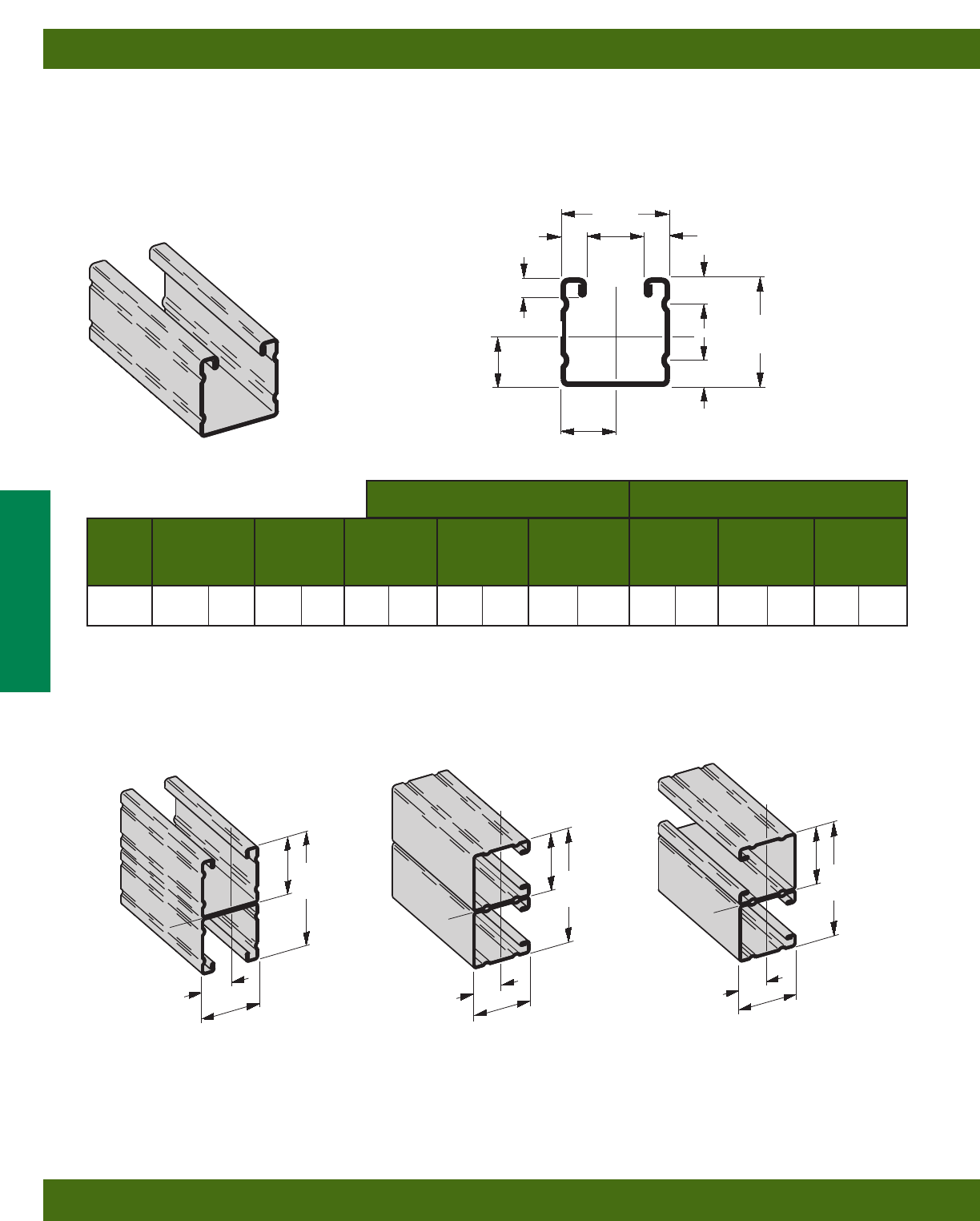
Areas of Moment of Section Radius of Moment of Section Radius of
Channel Weight Section Inertia (I) Modulus (S) Gyration (r) Inertia (I) Modulus (S) Gyration (r)
lbs./ft. kg/m sq. in. cm2in.4cm4in.3cm3in. cm in.4cm4in.3cm3in. cm
B26 1.234 (1.84) .363 (2.34) .1337 (5.57) .1581 (2.59) .607 (1.54) .1564 (6.51) .1925 (3.15) .656 (1.67)
B26A 2.467 (3.67) .726 (4.68) .7086 (29.49) .4361 (7.15) .988 (2.51) .3128 (13.02) .3850 (6.31) .656 (1.67)
X - X Axis Y - Y Axis
B26
•Thickness: 16 Gauge (1.5 mm)
•Standard lengths: 10’ (3.05 m) & 20’ (6.09 m)
•Standard finishes: Plain, Dura-Green, Pre-Galvanized
•Weight: 1.12 Lbs./Ft. (1.66 kg/m)
Calculations of section properties are based on metal thicknesses as determined by the AISI Cold-Formed Steel Design Manual.
15/8”
(41.3)
15/8”
(41.3)
.7745
(19.7)
13/16”
(20.6)
3/8”
(9.5)
27/64”
(10.7)
27/64”
(10.7)
3/8”
(9.5)
9/32”
(7.1)
7/8”
(22.2)
X
Y
Y
X
SECTION PROPERTIES
B26A
Wt. 2.24 Lbs./Ft. (3.33 kg/m)
B26B
Wt. 2.24 Lbs./Ft. (3.33 kg/m)
B26C
Wt. 2.24 Lbs./Ft. (3.33 kg/m)
31/4”
(82.5) 31/4”
(82.5)
31/4”
(82.5)
15/8”
(41.3)
15/8”
(41.3)
15/8”
(41.3)
15/8”
(41.3)
15/8”
(41.3)
15/8”
(41.3)
13/16”
(20.6)
13/16”
(20.6)
.774
(19.7)
X
YY
YY
Y
Y
XX
XX
X
Reference page 14 for general fitting and standard finish specifications.
Channel & Combinations
B26 Channel & Combinations
26

**Where the slenderness ratio KL exceeds 200, and K = end fixity factor, L = actual length and r = radius of gyration.
r
Uniform Load @ Deflection =
Beam Span Channel Uniform Load and Deflection 1/240 Span 1/360 Span
In. mm Style Lbs. N In. mm Lbs. N Lbs. N
12 (305) B26 1220 (5427) .014 (.35) 1220 (5427) 1220 (5427)
B26A 1220* (5427) .001 (.02) 1220* (5427) 1220* (5427)
24 (609) B26 1163 (5173) .057 (1.45) 1163 (5173) 1163 (5173)
B26A 1220* (5427) .012 (.30) 1220* (5427) 1220* (5427)
36 (914) B26 775 (3447) .128 (3.25) 775 (3447) 603 (2682)
B26A 1220* (5427) .040 (1.01) 1220* (5427) 1220* (5427)
48 (1219) B26 581 (2584) .228 (5.79) 509 (2264) 339 (1508)
B26A 1220* (5427) .096 (2.44) 1220* (5427) 1220* (5427)
60 (1524) B26 465 (2068) .357 (9.07) 326 (1450) 217 (965)
B26A 1220* (5427) .188 (4.77) 1220* (5427) 1076 (4786)
72 (1829) B26 388 (1726) .514 (13.05) 226 (1450) 151 (965)
B26A 1052 (4679) .281 (7.14) 1052 (4679) 747 (3323)
84 (2133) B26 332 (1477) .699 (17.75) 166 (738) 111 (494)
B26A 902 (4012) .383 (9.73) 824 (3665) 549 (2442)
96 (2438) B26 291 (1294) .913 (23.19) 127 (565) 85 (378)
B26A 789 (3509) .500 (12.70) 631 (2807) 420 (1868)
108 (2743) B26 258 (1147) 1.156 (29.36) 101 (449) 67 (298)
B26A 702 (3122) .633 (16.08) 498 (2215) 332 (1477)
120 (3048) B26 233 (1036) 1.427 (36.24) 81 (360) 54 (240)
B26A 631 (2807) .782 (19.86) 404 (1797) 269 (1196)
BEAM LOADING
Max. Column Loading K = .80 Max. Column Loading (Loaded @ C.G.)
Unbraced Channel Loaded@ Loaded@
Height Style C.G. Slot Face K = .65 K = 1.0 K = 1.2
In. mm Lbs. N Lbs. N Lbs. N Lbs. N Lbs. N
12 (305) B26 4002 (17802) 2216 (9857) 4032 (17935) 3952 (17579) 3891 (17308)
B26A 8151 (36257) 3630 (16147) 8163 (36311) 8133 (36177) 8109 (36070)
24 (609) B26 3740 (16636) 2109 (9381) 3857 (17157) 3554 (15809) 3336 (14838)
B26A 8051 (35812) 3591 (15973) 8096 (36013) 7975 (35474) 7883 (35065)
36 (914) B26 3336 (14839) 1941 (8634) 3579 (15920) 2962 (13175) 2546 (11325)
B26A 7883 (35065) 3528 (15693) 7986 (35523) 7713 (34309) 7505 (33384)
48 (1219) B26 2828 (12579) 1725 (7613) 3217 (14310) 2251 (10013) 1705 (7584)
B26A 7648 (34020) 3441 (15306) 7831 (34834) 7346 (32676) 6977 (31035)
60 (1524) B26 2251 (10013) 1469 (6534) 2793 (12424) 1603 (7130) 1233 (5484)
B26A 7346 (32676) 3066 (13638) 7631 (33944) 6874 (30577) 6298 (28015)
72 (1829) B26 1705 (7584) 1203 (5351) 2326 (10346) 1233 (5484) 967 (4301)
B26A 6977 (31035) 2385 (10609) 7388 (32863) 6298 (28015) 5467 (24318)
84 (2133) B26 1358 (6040) 1011 (4497) 1851 (8233) 1003 (4461) 797 (3545)
B26A 6541 (29096) 1884 (8380) 7100 (31582) 5616 (24981) 4486 (19955)
96 (2438) B26 1129 (5022) 871 (3874) 1513 (6730) 847 (3767) 680 (3025)
B26A 6038 (26858) 1512 (6726) 6767 (30101) 4830 (21485) 3463 (15404)
108 (2743) B26 967 (4301) 766 (3407) 1277 (5680) 734 (3265) 592** (2633)
B26A 5467 (24318) 1231 (5476) 6391 (28428) 3940 (17526) 2736 (12170)
120 (3048) B26 847 (3767) 684 (3042) 1105 (4915) 648 (2882) 523** (2326)
B26A 4830 (21485) 1015 (4515) 5970 (26556) 3192 (14199) 2216** (9857)
COLUMN LOADING
Based on simple beam condition using an allowable design stress of 25,000 psi (172 MPa) in accordance with MFMA, with adequate lateral bracing (see
page 11 for further explanation). Actual yield point of cold rolled steel is 42,000 psi. To determine concentrated load capacity at mid span, multiply uniform
load by 0.5 and corresponding deflection by 0.8. *Failure determined by weld shear.
Reference page 14 for general fitting and standard finish specifications.
Channel & Combinations
B26 Beam & Column Loading Data
27
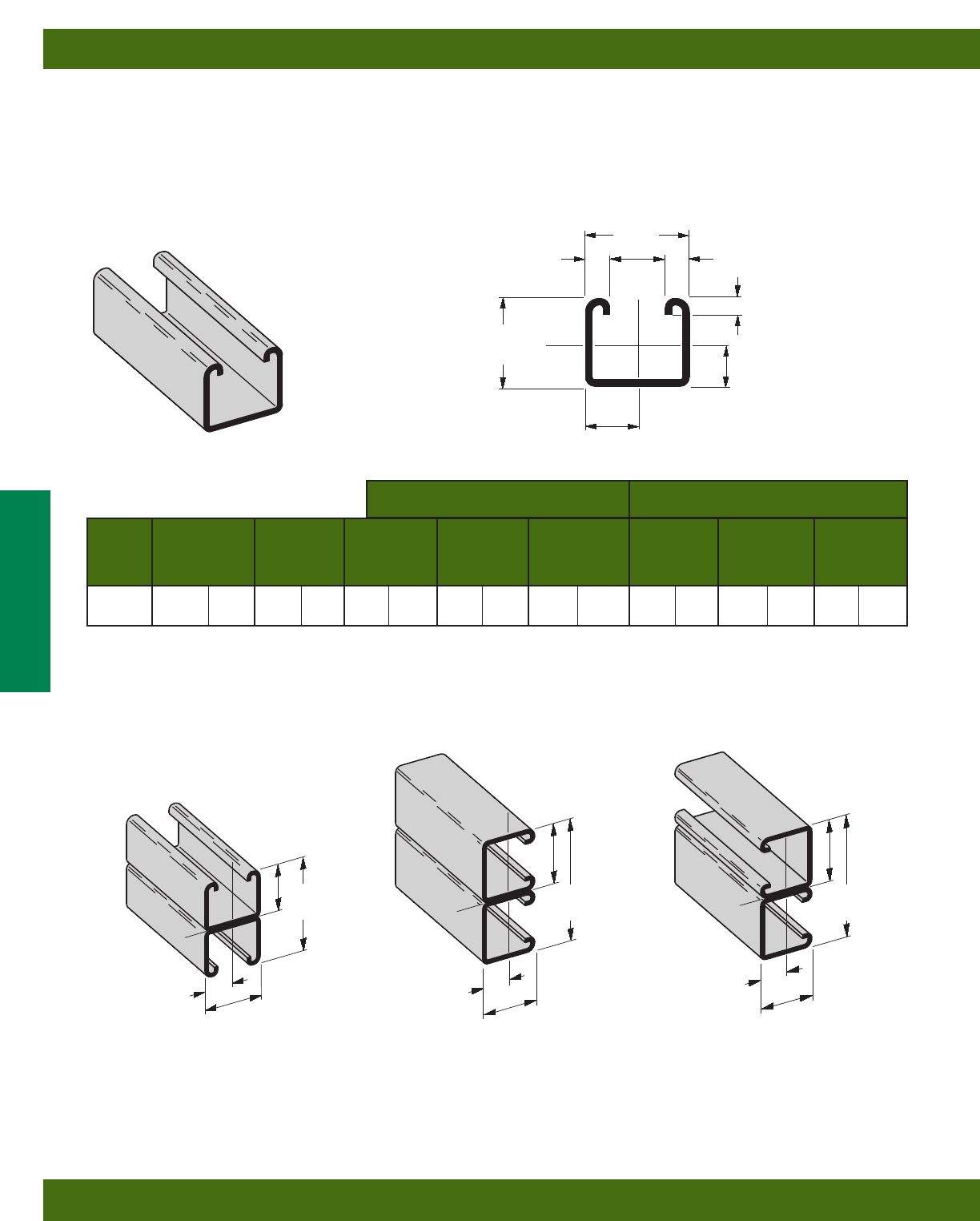
Areas of Moment of Section Radius of Moment of Section Radius of
Channel Weight Section Inertia (I) Modulus (S) Gyration (r) Inertia (I) Modulus (S) Gyration (r)
lbs./ft. kg/m sq. in. cm2in.4cm4in.3cm3in. cm in.4cm4in.3cm3in. cm
B32 1.733 (2.58) .510 (3.29) .1252 (5.21) .1626 (2.67) .496 (1.26) .2098 (8.73) .2582 (4.23) .642 (1.63)
B32A 3.467 (5.16) 1.020 (6.58) .6238 (25.96) .4537 (7.43) .782 (1.99) .4195 (17.46) .5163 (8.46) .642 (1.63)
X - X Axis Y - Y Axis
B32
•Thickness: 12 Gauge (2.6 mm)
•Standard lengths: 10’ (3.05 m) & 20’ (6.09 m)
•Standard finishes: Plain, Dura-Green, Pre-Galvanized,
Hot-Dipped Galvanized, Stainless Steel Type 304
•Weight: 1.70 Lbs./Ft. (2.53 kg/m)
Calculations of section properties are based on metal thicknesses as determined by the AISI Cold-Formed Steel Design Manual.
15/8”
(41.3)
13/8”
(34.9)
13/16”
(20.6)
3/8”
(9.5)
.6052
(15.4)
9/32”
(7.1)
3/8”
(9.5) 7/8”
(22.2)
X
Y
Y
X
SECTION PROPERTIES
B32A
Wt. 3.40 Lbs./Ft. (5.06 kg/m)
B32B
Wt. 3.40 Lbs./Ft. (5.06 kg/m)
B32C
Wt. 3.40 Lbs./Ft. (5.06 kg/m)
23/4”
(69.8)
31/4”
(82.5)
31/4”
(82.5)
13/8”
(34.9)
15/8”
(41.3)
15/8”
(41.3)
15/8”
(41.3) 13/8”
(34.9)
13/8”
(34.9)
13/16”
(20.6)
.687
(17.4)
.605
(15.4)
X
Y
Y
YY
Y
Y
X
X
XX
X
Reference page 14 for general fitting and standard finish specifications.
Channel & Combinations
B32 Channel & Combinations
28

**Where the slenderness ratio KL exceeds 200, and K = end fixity factor, L = actual length and r = radius of gyration.
r
Uniform Load @ Deflection =
Beam Span Channel Uniform Load and Deflection 1/240 Span 1/360 Span
In. mm Style Lbs. N In. mm Lbs. N Lbs. N
12 (305) B32 2210 (9830) .016 (.40) 2210 (9830) 2210 (9830)
B32A 2210* (9830) .003 (.07) 2210* (9830) 2210* (9830)
24 (609) B32 1299 (5778) .065 (1.65) 1299 (5778) 1299 (5778)
B32A 2210* (9830) .022 (.56) 2210* (9830) 2210* (9830)
36 (914) B32 866 (3852) .147 (3.73) 866 (3852) 587 (2611)
B32A 2210* (9830) .076 (1.93) 2210* (9830) 2210* (9830)
48 (1219) B32 649 (2887) .262 (6.65) 495 (2202) 330 (1468)
B32A 1817 (8082) .148 (3.76) 1817 (8082) 1638 (7286)
60 (1524) B32 520 (2313) .410 (10.41) 317 (1410) 211 (938)
B32A 1454 (6468) .231 (5.87) 1454 (6468) 1048 (4662)
72 (1829) B32 433 (1926) .590 (14.98) 220 (978) 147 (654)
B32A 1211 (5387) .333 (8.46) 1092 (4857) 728 (3238)
84 (2133) B32 371 (1650) .803 (20.39) 162 (720) 108 (480)
B32A 1038 (4617) .453 (11.50) 802 (3567) 535 (2380)
96 (2438) B32 325 (1445) 1.049 (26.64) 124 (551) 83 (369)
B32A 909 (4043) .591 (15.01) 614 (2731) 410 (1824)
108 (2743) B32 289 (1285) 1.327 (33.70) 98 (436) 65 (289)
B32A 808 (3594) .749 (19.02) 485 (2157) 324 (1441)
120 (3048) B32 260 (1156) 1.639 (41.63) 79 (351) 53 (236)
B32A 727 (3234) .924 (23.47) 393 (1748) 262 (1165)
BEAM LOADING
Max. Column Loading K = .80 Max. Column Loading (Loaded @ C.G.)
Unbraced Channel Loaded@ Loaded@
Height Style C.G. Slot Face K = .65 K = 1.0 K = 1.2
In. mm Lbs. N Lbs. N Lbs. N Lbs. N Lbs. N
12 (305) B32 10278 (45719) 4036 (17953) 10432 (46404) 10035 (44638) 9753 (43383)
B32A 21320 (94836) 6557 (29167) 21378 (95094) 21224 (94409) 21106 (93884)
24 (609) B32 9104 (40496) 3732 (16601) 9600 (42702) 8387 (37307) 7640 (33984)
B32A 20806 (92550) 6431 (28606) 21039 (93586) 20421 (90837) 19950 (88742)
36 (914) B32 7640 (33984) 3323 (14781) 8479 (37716) 6520 (29002) 5425 (24131)
B32A 19950 (88742) 6228 (27703) 20474 (91073) 19083 (84885) 18023 (80170)
48 (1219) B32 6151 (27361) 2877 (12797) 7265 (32316) 4778 (21253) 3870 (17214)
B32A 18751 (83408) 5954 (26485) 19682 (87550) 17210 (76554) 15326 (68173)
60 (1524) B32 4778 (21253) 2435 (10831) 6060 (26956) 3693 (16427) 2994 (13318)
B32A 17210 (76554) 4692 (20871) 18665 (83026) 14801 (65838) 11858 (52747)
72 (1829) B32 3870 (17214) 2089 (9292) 4923 (21898) 2994 (13318) 2403 (10689)
B32A 15326 (68173) 3448 (15337) 17421 (77492) 11858 (52747) 8316 (36991)
84 (2133) B32 3243 (14425) 1817 (8082) 4114 (18300) 2489 (11071) 1807** (8038)
B32A 13100 (58272) 2609 (11605) 15951 (70953) 8798 (39135) 6110 (27178)
96 (2438) B32 2774 (12339) 1594 (7090) 3531 (15706) 1993 (8865) 1384** (6156)
B32A 10525 (46817) 2014 (8959) 14256 (63414) 6736 (29963) 4678 (20809)
108 (2743) B32 2403 (10689) 1407 (6258) 3083 (13714) 1574** (7001) 1093** (4862)
B32A 8316 (36991) 1592 (7081) 12334 (54864) 5322 (23673) 3696** (16440)
120 (3048) B32 1993 (8865) 1221 (5431) 2723 (12112) 1275** (5671) 886** (3941)
B32A 6736 (29963) 1289 (5734) 10203 (45385) 4311 (19176) 2994** (13318)
COLUMN LOADING
Based on simple beam condition using an allowable design stress of 25,000 psi (172 MPa) in accordance with MFMA, with adequate lateral bracing (see
page 11 for further explanation). Actual yield point of cold rolled steel is 42,000 psi. To determine concentrated load capacity at mid span, multiply uniform
load by 0.5 and corresponding deflection by 0.8. *Failure determined by weld shear.
Reference page 14 for general fitting and standard finish specifications.
Channel & Combinations
B32 Beam & Column Loading Data
29
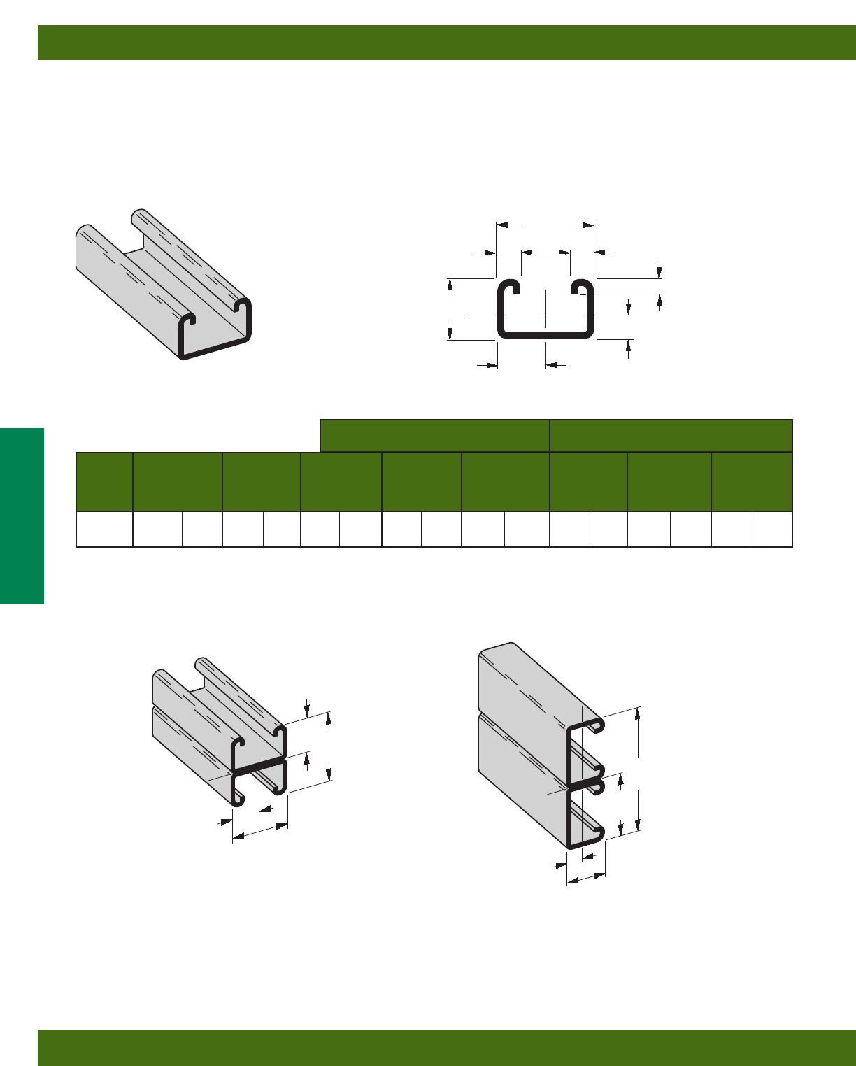
Areas of Moment of Section Radius of Moment of Section Radius of
Channel Weight Section Inertia (I) Modulus (S) Gyration (r) Inertia (I) Modulus (S) Gyration (r)
lbs./ft. kg/m sq. in. cm2in.4cm4in.3cm3in. cm in.4cm4in.3cm3in. cm
B42 1.468 (2.18) .432 (2.79) .0554 (2.31) .0968 (1.59) .358 (.91) .1645 (6.85) .2025 (3.32) .617 (1.57)
B42A 2.936 (4.37) .864 (5.57) .2689 (11.19) .2689 (4.41) .558 (1.42) .3292 (13.70) .4052 (6.64) .617 (1.57)
X - X Axis Y - Y Axis
B42
•Thickness: 12 Gauge (2.6 mm)
•Standard lengths: 10’ (3.05 m) & 20’ (6.09 m)
•Standard finishes: Plain, Dura-Green, Pre-Galvanized,
Hot-Dipped Galvanized, Stainless Steel Type 304
•Weight: 1.44 Lbs./Ft. (2.14 kg/m)
Note: Also available in 14 gauge (1.9mm) material as B44
Calculations of section properties are based on metal thicknesses as determined by the AISI Cold-Formed Steel Design Manual.
15/8”
(41.3)
1”
(25.4)
13/16”
(20.6)
3/8”
(9.5)
.4226
(10.7)
9/32”
(7.1)
3/8”
(9.5) 7/8”
(22.2)
X
Y
Y
X
SECTION PROPERTIES
B42A
Wt. 2.88 Lbs./Ft. (4.28 kg/m)
B42B
Wt. 2.88 Lbs./Ft. (4.28 kg/m)
2”
(50.8)
31/4”
(82.5)
1”
(25.4)
15/8”
(41.3)
1”
(25.4)
13/16”
(20.6)
.428
(10.9)
X
YY
Y
Y
XX
X
Reference page 14 for general fitting and standard finish specifications.
Channel & Combinations
15/8”
(41.3)
B42 Channel & Combinations
30

**Where the slenderness ratio KL exceeds 200, and K = end fixity factor, L = actual length and r = radius of gyration.
r
Uniform Load @ Deflection =
Beam Span Channel Uniform Load and Deflection 1/240 Span 1/360 Span
In. mm Style Lbs. N In. mm Lbs. N Lbs. N
12 (305) B42 1538 (6841) .022 (.56) 1538 (6841) 1538 (6841)
B42A 1590* (7072) .005 (.13) 1590* (7072) 1590* (7072)
24 (609) B42 769 (3420) .088 (2.23) 769 (3420) 582 (2589)
B42A 1590* (7072) .038 (.96) 1590* (7072) 1590* (7072)
36 (914) B42 513 (2282) .198 (5.03) 388 (1726) 259 (1152)
B42A 1428 (6352) .114 (2.89) 1428 (6352) 1248 (5551)
48 (1219) B42 384 (1708) .352 (8.94) 218 (970) 145 (645)
B42A 1071 (4764) .203 (5.15) 1053 (4684) 702 (3122)
60 (1524) B42 308 (1370) .550 (13.97) 140 (623) 93 (413)
B42A 857 (3812) .318 (8.08) 674 (2998) 449 (1997)
72 (1829) B42 256 (1139) .792 (20.11) 97 (431) 65 (289)
B42A 714 (3176) .457 (11.61) 468 (2082) 312 (1388)
84 (2133) B42 220 (978) 1.079 (27.40) 71 (316) 48 (213)
B42A 612 (2722) .623 (15.82) 344 (1530) 229 (1018)
96 (2438) B42 192 (854) 1.409 (35.79) 55 (244) 36 (160)
B42A 535 (2380) .813 (20.65) 263 (1170) 176 (783)
108 (2743) B42 171 (760) 1.783 (45.29) 43 (191) 29 (129)
B42A 476 (2117) 1.029 (26.13) 208 (925) 139 (618)
120 (3048) B42 154 (685) 2.202 (55.93) 35 (155) 23 (102)
B42A 428 (1904) 1.271 (32.28) 168 (747) 112 (498)
BEAM LOADING
Max. Column Loading K = .80 Max. Column Loading (Loaded @ C.G.)
Unbraced Channel Loaded@ Loaded@
Height Style C.G. Slot Face K = .65 K = 1.0 K = 1.2
In. mm Lbs. N Lbs. N Lbs. N Lbs. N Lbs. N
12 (305) B42 9138 (40648) 3493 (15537) 9283 (41293) 8916 (39660) 8670 (38566)
B42A 21094 (93831) 5834 (25951) 21304 (94765) 20793 (92492) 20469 (91050)
24 (609) B42 8137 (36195) 3145 (13989) 8540 (37988) 7589 (33757) 7050 (31360)
B42A 19757 (87883) 5585 (24843) 20299 (90294) 18964 (84356) 18094 (80486)
36 (914) B42 7050 (31360) 2722 (12108) 7657 (34060) 5925 (26356) 4335 (19283)
B42A 18094 (80486) 5237 (23295) 19067 (84814) 16654 (74080) 15057 (66977)
48 (1219) B42 5405 (24042) 2227 (9906) 6786 (30185) 3512 (15622) 2439 (10849)
B42A 16139 (71790) 4818 (21431) 17632 (78431) 13906 (61857) 11387 (50652)
60 (1524) B42 3512 (15622) 1718 (7642) 5272 (23451) 2247 (9995) 1561** (6943)
B42A 13906 (61857) 4352 (19358) 16008 (71207) 10710 (47640) 7531 (33499)
72 (1829) B42 2439 (10849) 1351 (6009) 3694 (16432) 1561** (6943) 1084** (4822)
B42A 11387 (50652) 3856 (17152) 14200 (64165) 7531 (33499) 5230 (23264)
84 (2133) B42 1792 (7971) 1087 (4835) 2714 (12072) 1147** (5102) 796** (3541)
B42A 8645 (38455) 3332 (14821) 12206 (54295) 5533 (24612) 3842 (17090)
96 (2438) B42 1372** (6103) 891 (3963) 2078 (9243) 878** (3905) ––
B42A 6619 (29443) 2873 (12780) 10012 (44535) 4236 (18842) 2942** (13086)
108 (2743) B42 1084** (4822) 743 (3305) 1642 (7304) ––––
B42A 5230 (23264) 2495 (11098) 7922 (35239) 3347 (14888) 2324** (10337)
120 (3048) B42 878** (3905) 628 (2793) 1330** (5916) ––––
B42A 4236 (18842) 2182 (9706) 6417 (28544) 2711** (12059) 1883** (8376)
COLUMN LOADING
Based on simple beam condition using an allowable design stress of 25,000 psi (172 MPa) in accordance with MFMA, with adequate lateral bracing (see
page 11 for further explanation). Actual yield point of cold rolled steel is 42,000 psi. To determine concentrated load capacity at mid span, multiply uniform
load by 0.5 and corresponding deflection by 0.8. *Failure determined by weld shear.
Reference page 14 for general fitting and standard finish specifications.
Channel & Combinations
B42 Beam & Column Loading Data
31
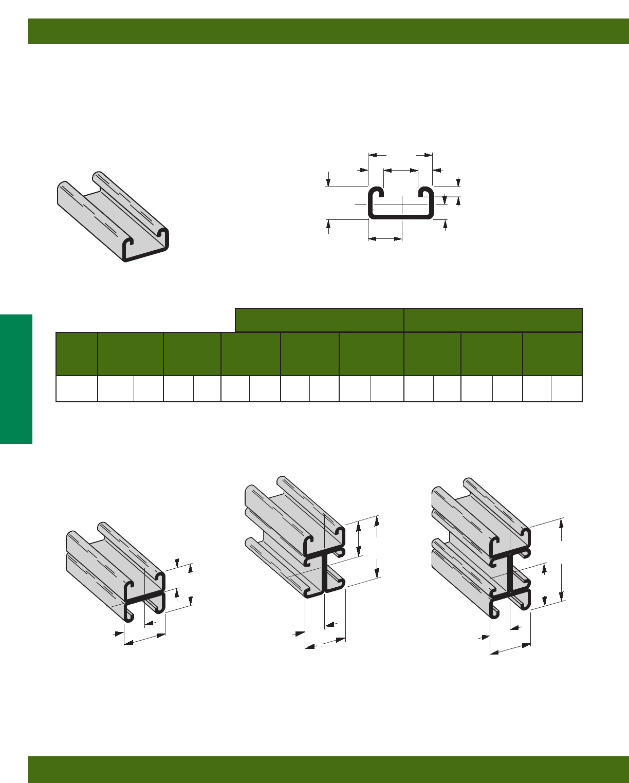
Areas of Moment of Section Radius of Moment of Section Radius of
Channel Weight Section Inertia (I) Modulus (S) Gyration (r) Inertia (I) Modulus (S) Gyration (r)
lbs./ft. kg/m sq. in. cm2in.4cm4in.3cm3in. cm in.4cm4in.3cm3in. cm
B52 1.313 (1.95) .386 (2.49) .0320 (1.33) .0673 (1.10) .288 (.73) .1404 (5.84) .1728 (2.83) .603 (1.53)
B52A 2.627 (3.91) .773 (4.99) .1517 (6.31) .1868 (3.06) .443 (1.13) .2809 (11.69) .3457 (5.67) .603 (1.53)
X - X Axis Y - Y Axis
B52
•Thickness: 12 Gauge (2.6 mm)
•Standard lengths: 10’ (3.05 m) & 20’ (6.09 m)
•Standard finishes: Plain, Dura-Green, Pre-Galvanized,
Hot-Dipped Galvanized
•Weight: 1.27 Lbs./Ft. (1.89 kg/m)
Calculations of section properties are based on metal thicknesses as determined by the AISI Cold-Formed Steel Design Manual.
15/8”
(41.3)
13/16”
(20.6)
13/16”
(20.6)
3/8”
(9.5)
.3366
(8.5)
9/32”
(7.1)
3/8”
(9.5) 7/8”
(22.2)
X
Y
Y
X
SECTION PROPERTIES
B52A
Wt. 2.54 Lbs./Ft. (3.78 kg/m)
B52B4
Wt. 5.08 Lbs./Ft. (7.56 kg/m)
B52B3
Wt. 3.81 Lbs./Ft. (5.67 kg/m)
31/4”
(82.5)
15/8”
(41.3)
15/8”
(41.3)
15/8”
(41.3)
15/8”
(41.3)
13/16”
(20.6)
13/16”
(20.6)
13/16”
(20.6)
X
Y
Y
Y
Y
X
X
X
15/8”
(41.3)
13/16”
(20.6)
27/16”
(41.3)
1.241
(31.5)
Y
Y
X
X
Reference page 14 for general fitting and standard finish specifications.
Channel & Combinations
B52 Channel & Combinations
32

**Where the slenderness ratio KL exceeds 200, and K = end fixity factor, L = actual length and r = radius of gyration.
r
Uniform Load @ Deflection =
Beam Span Channel Uniform Load and Deflection 1/240 Span 1/360 Span
In. mm Style Lbs. N In. mm Lbs. N Lbs. N
12 (305) B52 1079 (4799) .026 (.66) 1079 (4799) 1079 (4799)
B52A 1270* (5649) .006 (.15) 1270* (5649) 1270* (5649)
24 (609) B52 539 (2397) .106 (2.69) 506 (2251) 337 (1499)
B52A 1270* (5649) .052 (1.32) 1270* (5649) 1270* (5649)
36 (914) B52 360 (1601) .240 (6.09) 225 (1001) 150 (667)
B52A 1013 (4506) .141 (3.58) 1013 (4506) 719 (3198)
48 (1219) B52 270 (1201) .427 (10.84) 126 (560) 84 (373)
B52A 759 (3376) .250 (6.35) 607 (2700) 404 (1797)
60 (1524) B52 216 (961) .667 (16.94) 81 (360) 54 (240)
B52A 608 (2704) .391 (9.93) 388 (1726) 259 (1152)
72 (1829) B52 180 (800) .960 (24.38) 56 (249) 37 (164)
B52A 506 (2251) .563 (14.30) 270 (1201) 180 (800)
84 (2133) B52 154 (685) 1.307 (33.20) 41 (182) 28 (124)
B52A 434 (1930) .766 (19.45) 198 (881) 132 (587)
96 (2438) B52 135 (600) 1.707 (43.36) 32 (142) 21 (93)
B52A 380 (1690) 1.001 (25.42) 152 (676) 101 (449)
108 (2743) B52 120 (534) 2.160 (54.86) 25 (111) 17 (75)
B52A 338 (1503) 1.267 (32.18) 120 (534) 80 (356)
120 (3048) B52 108 (480) 2.667 (67.74) 20 (89) 13 (58)
B52A 304 (1352) 1.564 (39.72) 97 (431) 65 (289)
BEAM LOADING
Max. Column Loading K = .80 Max. Column Loading (Loaded @ C.G.)
Unbraced Channel Loaded@ Loaded@
Height Style C.G. Slot Face K = .65 K = 1.0 K = 1.2
In. mm Lbs. N Lbs. N Lbs. N Lbs. N Lbs. N
12 (305) B52 8407 (37396) 3162 (14065) 8543 (38001) 8205 (36497) 7989 (35537)
B52A 19160 (85228) 5290 (23531) 19425 (86407) 18777 (83524) 18363 (81682)
24 (609) B52 7519 (33446) 2755 (12255) 7879 (35047) 6521 (29007) 5397 (24007)
B52A 17444 (77595) 4955 (22041) 18144 (80708) 16412 (73004) 15275 (67946)
36 (914) B52 5397 (24007) 2152 (9572) 6653 (29594) 3616 (16085) 2511 (11169)
B52A 15275 (67946) 4496 (19999) 16547 (73605) 13376 (59499) 11243 (50011)
48 (1219) B52 3178 (14136) 1560 (6939) 4785 (21285) 2034 (9047) 1412** (6281)
B52A 12692 (56457) 3963 (17628) 14667 (65242) 9683 (43072) 6780 (30159)
60 (1524) B52 2034 (9047) 1159 (5155) 3081 (13705) 1302** (5791) 904** (4021)
B52A 9683 (43072) 3383 (15048) 12516 (55674) 6248 (27792) 4339 (19301)
72 (1829) B52 1412** (6281) 891 (3963) 2139 (9515) 904** (4021) ––
B52A 6780 (30159) 2799 (12450) 10084 (44856) 4339 (19301) 3013 (13402)
84 (2133) B52 1038** (4617) 704 (3131) 1572 (6992) 664** (2953) ––
B52A 4981 (22156) 2337 (10395) 7545 (33562) 3188 (14181) 2214** (9848)
96 (2438) B52 794** (3532) 570 (2535) 1203** (5351) ––––
B52A 3814 (16965) 1973 (8776) 5777 (25697) 2441** (10858) 1695** (7540)
108 (2743) B52 --470 (2090) 951** (4230) ––––
B52A 3013 (13402) 1684 (7491) 4564 (20301) 1928** (8576) 1339** (5956)
120 (3048) B52 --394 (1752) 770** (3425) ––––
B52A 2441** (10858) 1452 (6459) 3697 (16445) 1562** (6948) ––
COLUMN LOADING
Based on simple beam condition using an allowable design stress of 25,000 psi (172 MPa) in accordance with MFMA, with adequate lateral bracing (see
page 11 for further explanation). Actual yield point of cold rolled steel is 42,000 psi. To determine concentrated load capacity at mid span, multiply uniform
load by 0.5 and corresponding deflection by 0.8. *Failure determined by weld shear.
Reference page 14 for general fitting and standard finish specifications.
Channel & Combinations
B52 Beam & Column Loading Data
33
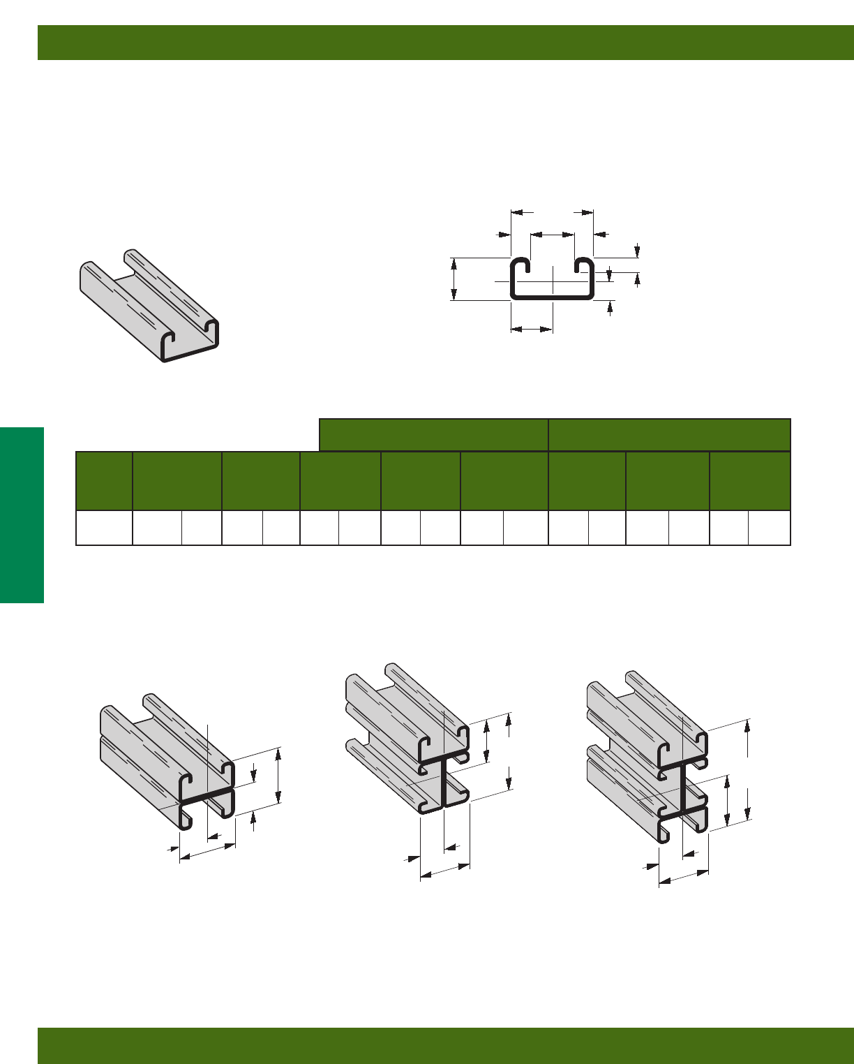
Areas of Moment of Section Radius of Moment of Section Radius of
Channel Weight Section Inertia (I) Modulus (S) Gyration (r) Inertia (I) Modulus (S) Gyration (r)
lbs./ft. kg/m sq. in. cm2in.4cm4in.3cm3in. cm in.4cm4in.3cm3in. cm
B54 1.016 (1.51) .299 (1.93) .0263 (1.09) .0560 (.92) .297 (.75) .1106 (4.60) .1361 (2.23) .608 (1.55)
B54A 2.032 (3.02) .598 (3.86) .1226 (5.10) .1510 (2.47) .453 (1.15) .2212 (9.12) .2722 (4.46) .608 (1.55)
X - X Axis Y - Y Axis
B54
•Thickness: 14 Gauge (1.9 mm)
•Standard lengths: 10’ (3.05 m) & 20’ (6.09 m)
•Standard finishes: Plain, Dura-Green, Pre-Galvanized,
Hot-Dipped Galvanized, Stainless Steel Type 304 or 316, Aluminum
•Weight: .97 Lbs./Ft. (1.44 kg/m)
Calculations of section properties are based on metal thicknesses as determined by the AISI Cold-Formed Steel Design Manual.
15/8”
(41.3)
13/16”
(20.6)
13/16”
(20.6)
3/8”
(9.5)
.3422
(8.7)
9/32”
(7.1)
3/8”
(9.5) 7/8”
(22.2)
X
Y
Y
X
SECTION PROPERTIES
B54A
Wt. 1.94 Lbs./Ft. (2.89 kg/m)
B54B4
Wt. 3.88 Lbs./Ft. (5.77 kg/m)
B54B3
Wt. 2.91 Lbs./Ft. (4.33 kg/m)
31/4”
(82.5)
15/8”
(41.3)
15/8”
(41.3)
15/8”
(41.3)
15/8”
(41.3)
13/16”
(20.6) 13/16”
(20.6)
13/16”
(20.6)
X
YY
Y
Y
XX
X
15/8”
(41.3)
13/16”
(20.6)
27/16”
(41.3)
1.241
(31.5)
X
X
Y
Y
Reference page 14 for general fitting and standard finish specifications.
Channel & Combinations
B54 Channel & Combinations
34
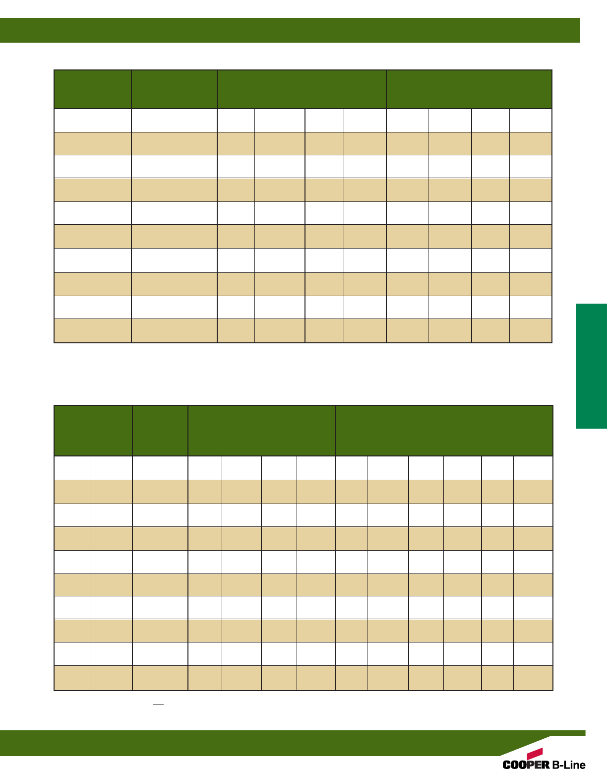
**Where the slenderness ratio KL exceeds 200, and K = end fixity factor, L = actual length and r = radius of gyration.
r
Uniform Load @ Deflection =
Beam Span Channel Uniform Load and Deflection 1/240 Span 1/360 Span
In. mm Style Lbs. N In. mm Lbs. N Lbs. N
12 (305) B54 870 (3870) .027 (.68) 870 (3870) 870 (3870)
B54A 870* (3870) .005 (.13) 870* (3870) 870* (3870)
24 (609) B54 465 (2068) .108 (2.74) 430 (1913) 287 (1276)
B54A 870* (3870) .043 (1.09) 870* (3870) 870* (3870)
36 (914) B54 310 (1379) .243 (6.17) 191 (849) 127 (565)
B54A 832 (3701) .141 (3.58) 832 (3701) 591 (2629)
48 (1219) B54 233 (1036) .432 (10.97) 108 (480) 72 (320)
B54A 624 (2775) .250 (6.35) 499 (2219) 332 (1477)
60 (1524) B54 186 (827) .676 (17.17) 69 (307) 46 (204)
B54A 499 (2219) .391 (9.93) 319 (1419) 213 (947)
72 (1829) B54 155 (689) .973 (24.71) 48 (213) 32 (142)
B54A 416 (1850) .563 (14.30) 222 (987) 148 (658)
84 (2133) B54 133 (591) 1.324 (33.63) 35 (155) 23 (102)
B54A 357 (1588) .766 (19.45) 163 (725) 109 (485)
96 (2438) B54 116 (516) 1.730 (43.94) 27 (120) 18 (80)
B54A 312 (1388) 1.001 (25.42) 125 (556) 83 (369)
108 (2743) B54 103 (458) 2.189 (55.60) 21 (93) 14 (62)
B54A 277 (1232) 1.267 (32.18) 98 (436) 66 (293)
120 (3048) B54 93 (413) 2.703 (68.65) 17 (75) 11 (49)
B54A 250 (1112) 1.564 (39.72) 80 (356) 53 (236)
BEAM LOADING
Max. Column Loading K = .80 Max. Column Loading (Loaded @ C.G.)
Unbraced Channel Loaded@ Loaded@
Height Style C.G. Slot Face K = .65 K = 1.0 K = 1.2
In. mm Lbs. N Lbs. N Lbs. N Lbs. N Lbs. N
12 (305) B54 6186 (27516) 2586 (11503) 6284 (27952) 6032 (26831) 5857 (26053)
B54A 12763 (56772) 4060 (18060) 12835 (57093) 12645 (56248) 12501 (55607)
24 (609) B54 5464 (24305) 2254 (10026) 5763 (25635) 4968 (22099) 4300 (19127)
B54A 12135 (53979) 3857 (17157) 12420 (55247) 11663 (51879) 11087 (49317)
36 (914) B54 4300 (19127) 1816 (8078) 5043 (22432) 3076 (13683) 2136 (9501)
B54A 11087 (49317) 3549 (15787) 11728 (52169) 10026 (44598) 8729 (38828)
48 (1219) B54 2703 (12023) 1341 (5965) 3920 (17437) 1730 (7695) 1201 (5342)
B54A 9620 (42792) 3169 (14096) 10759 (47858) 7734 (34402) 5571 (24781)
60 (1524) B54 1730 (7695) 995 (4426) 2621 (11659) 1107** (4924) 769** (3420)
B54A 7734 (34402) 2745 (12210) 9514 (42320) 5134 (22837) 3566 (15862)
72 (1829) B54 1201 (5342) 763 (3394) 1820 (8096) 769** (3420) 534** (2375)
B54A 5571 (24781) 2291 (10191) 7992 (35550) 3566 (15862) 2476 (11014)
84 (2133) B54 883** (3928) 603 (2682) 1337 (5947) 565** (2513) ––
B54A 4093 (18206) 1913 (8509) 6200 (27579) 2620 (11654) 1819** (8091)
96 (2438) B54 676** (3007) 487 (2166) 1024** (4555) ––––
B54A 3134 (13941) 1616 (7188) 4747 (21116) 2006** (8923) 1393** (6196)
108 (2743) B54 534** (2375) 401 (1784) 809** (3598) ––––
B54A 2476 (11014) 1380 (6138) 3751 (16685) 1585** (7050) 1100** (4893)
120 (3048) B54 ––336 (1494) 655** (2913) ––––
B54A 2006** (8923) 1190 (5293) 3038 (13513) 1284** (5711) ––
COLUMN LOADING
Based on simple beam condition using an allowable design stress of 25,000 psi (172 MPa) in accordance with MFMA, with adequate lateral bracing (see
page 11 for further explanation). Actual yield point of cold rolled steel is 42,000 psi. To determine concentrated load capacity at mid span, multiply uniform
load by 0.5 and corresponding deflection by 0.8. *Failure determined by weld shear.
Reference page 14 for general fitting and standard finish specifications.
Channel & Combinations
B54 Beam & Column Loading Data
35

Areas of Moment of Section Radius of Moment of Section Radius of
Channel Weight Section Inertia (I) Modulus (S) Gyration (r) Inertia (I) Modulus (S) Gyration (r)
lbs./ft. kg/m sq. in. cm2in.4cm4in.3cm3in. cm in.4cm4in.3cm3in. cm
B56 .894 (1.33) .263 (1.70) .0241 (1.00) .0546 (.89) .303 (.77) .0966 (4.02) .1189 (1.95) .606 (1.54)
B56A 1.789 (2.66) .526 (3.39) .1205 (5.02) .1484 (2.43) .479 (1.22) .1931 (8.04) .2377 (3.89) .606 (1.54)
X - X Axis Y - Y Axis
B56
•Thickness: 16 Gauge (1.5 mm)
•Standard lengths: 10’ (3.05 m) & 20’ (6.09 m)
•Standard finishes: Plain, Dura-Green, Pre-Galvanized,
Hot-Dipped Galvanized
•Weight: .85 Lbs./Ft. (1.26 kg/m)
Calculations of section properties are based on metal thicknesses as determined by the AISI Cold-Formed Steel Design Manual.
15/8”
(41.3)
13/16”
(20.6)
27/64”
(10.7) 13/16”
(20.6)
3/8”
(9.5)
.3706
(9.4)
9/32”
(7.1)
3/8”
(9.5)
7/8”
(22.2)
X
Y
Y
X
SECTION PROPERTIES
B56A
Wt. 1.70 Lbs./Ft. (2.53 kg/m)
B56B3
Wt. 2.55 Lbs./Ft. (3.79 kg/m)
B56B4
Wt. 3.40 Lbs./Ft. (5.06 kg/m)
15/8”
(41.3)
27/16”
(61.9)
31/4”
(82.5)
15/8”
(41.3)
15/8”
(41.3)
15/8”
(41.3) 15/8”
(41.3)
13/16”
(20.6)
13/16”
(20.6) 13/16”
(20.6) 13/16”
(20.6)
1.207
(30.7)
X
Y
Y
YY
Y
Y
X
X
XX
X
Reference page 14 for general fitting and standard finish specifications.
Channel & Combinations
B56 Channel & Combinations
36

**Where the slenderness ratio KL exceeds 200, and K = end fixity factor, L = actual length and r = radius of gyration.
r
Uniform Load @ Deflection =
Beam Span Channel Uniform Load and Deflection 1/240 Span 1/360 Span
In. mm Style Lbs. N In. mm Lbs. N Lbs. N
12 (305) B56 610 (2713) .027 (.68) 610 (2713) 610 (2713)
B56A 610* (2713) .004 (.10) 610* (2713) 610* (2713)
24 (609) B56 405 (1801) .109 (2.77) 372 (1655) 248 (1103)
B56A 610* (2713) .035 (.89) 610* (2713) 610* (2713)
36 (914) B56 270 (1201) .245 (6.22) 165 (734) 110 (489)
B56A 610* (2713) .121 (3.07) 610* (2713) 502 (2233)
48 (1219) B56 202 (898) .435 (11.05) 93 (413) 62 (276)
B56A 530 (2357) .250 (6.35) 423 (1881) 282 (1699)
60 (1524) B56 162 (720) .680 (17.27) 59 (262) 40 (178)
B56A 424 (1886) .391 (9.93) 271 (1205) 181 (805)
72 (1829) B56 135 (600) .980 (24.89) 41 (182) 28 (124)
B56A 353 (1570) .563 (14.30) 188 (836) 125 (556)
84 (2133) B56 116 (516) 1.334 (33.88) 30 (133) 20 (89)
B56A 303 (1348) .766 (19.45) 138 (614) 92 (409)
96 (2438) B56 101 (449) 1.742 (44.24) 23 (102) 15 (67)
B56A 265 (1179) 1.001 (25.42) 106 (471) 71 (316)
108 (2743) B56 90 (400) 2.205 (56.01) 18 (80) 12 (53)
B56A 236 (1050) 1.267 (32.18) 84 (373) 56 (249)
120 (3048) B56 81 (360) 2.722 (69.14) 15 (67) 10 (44)
B56A 212 (943) 1.564 (39.72) 68 (302) 45 (200)
BEAM LOADING
Max. Column Loading K = .80 Max. Column Loading (Loaded @ C.G.)
Unbraced Channel Loaded@ Loaded@
Height Style C.G. Slot Face K = .65 K = 1.0 K = 1.2
In. mm Lbs. N Lbs. N Lbs. N Lbs. N Lbs. N
12 (305) B56 4968 (22099) 2182 (9706) 5044 (22437) 4845 (21551) 4702 (20915)
B56A 10237 (45536) 3365 (14968) 10291 (45776) 10148 (45140) 10039 (44655)
24 (609) B56 4367 (19425) 1903 (8465) 4624 (20568) 3985 (17726) 3572 (15889)
B56A 9762 (43423) 3202 (14243) 9977 (44380) 9405 (41835) 8969 (39896)
36 (914) B56 3572 (15889) 1557 (6926) 4034 (17944) 2658 (11823) 1845 (8207)
B56A 8969 (39896) 2955 (13144) 9454 (42053) 8167 (36328) 7186 (31965)
48 (1219) B56 2335 (10386) 1164 (5178) 3290 (14634) 1495 (6650) 1038 (4617)
B56A 7860 (34963) 2649 (11783) 8722 (38797) 6434 (28620) 4731 (21044)
60 (1524) B56 1495 (6650) 862 (3834) 2264 (10071) 957 (4257) 664** (2953)
B56A 6434 (28620) 2307 (10262) 7780 (34607) 4360 (19394) 3028 (13469)
72 (1829) B56 1038 (4617) 661 (2940) 1572 (6992) 664** (2953) 461** (2050)
B56A 4731 (21044) 1937 (8616) 6629 (29487) 3028 (13469) 2103 (9354)
84 (2133) B56 763** (3394) 522 (2322) 1155 (5137) 488** (2171) ––
B56A 3476 (15462) 1619 (7201) 5269 (23437) 2224 (9893) 1545** (6872)
96 (2438) B56 584** (2598) 422 (1877) 884** (3932) ––––
B56A 2661 (11837) 1368 (6085) 4031 (17931) 1703** (7575) 1183** (5262)
108 (2743) B56 461** (2050) 348 (1548) 699** (3109) ––––
B56A 2103 (9354) 1169 (5200) 3185 (14167) 1346** (5987) 934** (4154)
120 (3048) B56 ––291 (1294) 566** (2417) ––––
B56A 1703** (7575) 1008 (4484) 2580 (11476) 1090** (4848) ––
COLUMN LOADING
Based on simple beam condition using an allowable design stress of 25,000 psi (172 MPa) in accordance with MFMA, with adequate lateral bracing (see
page 11 for further explanation). Actual yield point of cold rolled steel is 42,000 psi. To determine concentrated load capacity at mid span, multiply uniform
load by 0.5 and corresponding deflection by 0.8. *Failure determined by weld shear.
Reference page 14 for general fitting and standard finish specifications.
Channel & Combinations
B56 Beam & Column Loading Data
37
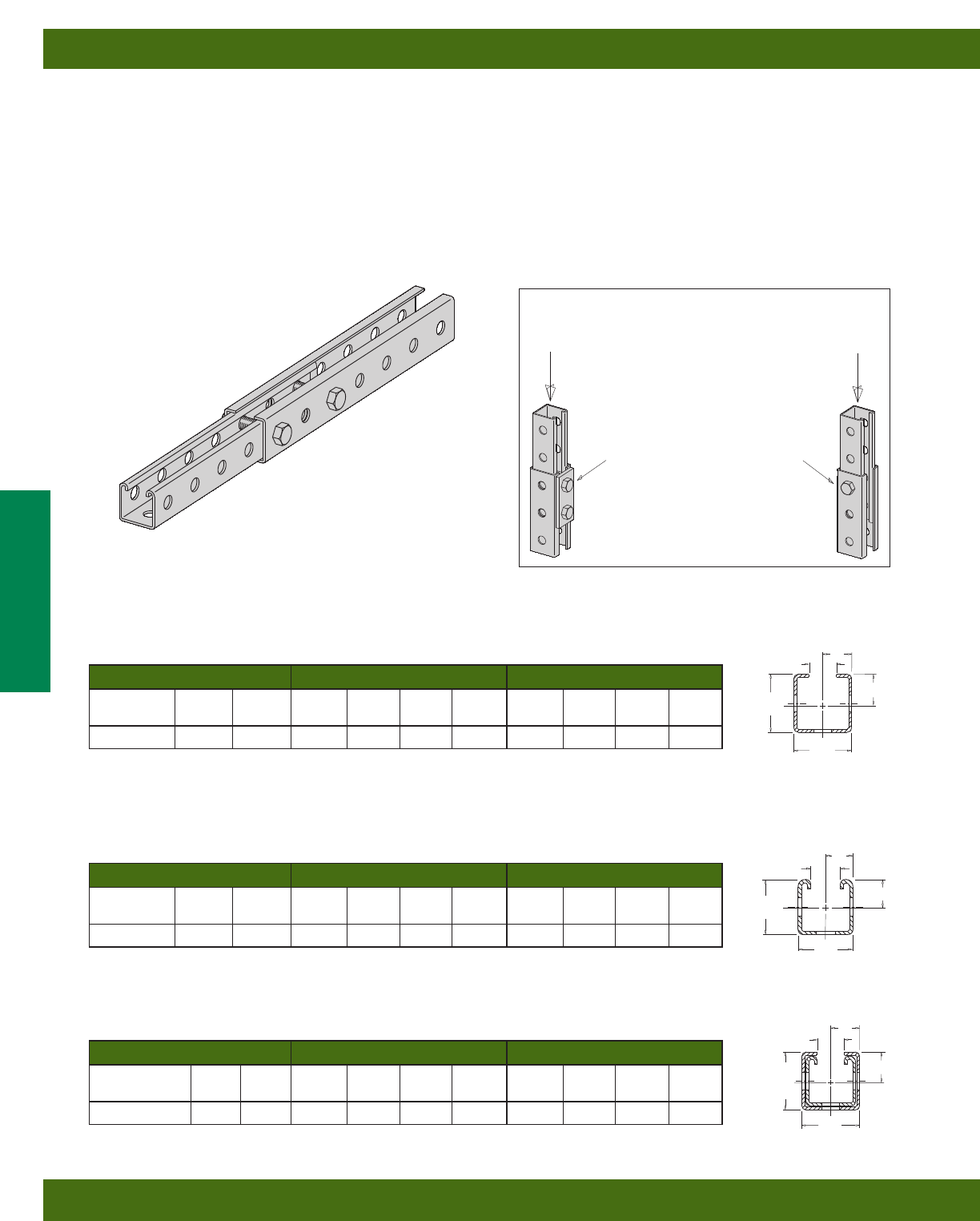
BTS22TH
TELESCOPING STRUT
Fits over all 15/8” x 15/8” channels 9/16” holes on 17/8” centers 12 gauge material thickness
Section Properties X-X Axis Y-Y Axis
Channel Weight Area CxIxSxrxCyIySyry
lbs./ft. In2In In4In3In In In4In3In
BTS22TH 1.934 0.4578 1.0009 0.2525 0.2523 0.7426 0.9375 0.2757 0.2941 0.7761
17/8”X
17/8”
Cy
Y
Y
X
Cx
C
L
7/8”
15/8”
15/8”
XX
Y
Y
Cx
Cy
C
L
Cy
Cx
Y
7/8”
17/8”XX
Y
17/8”
C
L
B22TH
THREE HOLE STRUT
9/16” holes on 17/8” centers 12 gauge material thickness
Section Properties X-X Axis Y-Y Axis
Channel Weight Area CxIxSxrxCyIySyry
lbs./ft. In2In In4In3In In In4In3In
B22TH 1.760 0.3863 0.8245 0.1596 0.1936 0.6400 0.8125 0.1719 0.2116 0.6642
COMBINATION OF BTS22TH & B22TH
Section Properties X-X Axis Y-Y Axis
Channel Weight Area CxIxSxrxCyIySyry
Combination lbs./ft. In2In In4In3In In In4In3In
BTS22TH/B22TH
3.597 0.8474 0.9773 0.4126 0.4222 0.6978 0.9375 0.4476 0.4774 0.7268
7/8”
Section properties are based on nominal metal thickness, and overall dimensions.
Section properties are based on nominal metal thickness, and overall dimensions.
Section properties are based on nominal metal thickness, and overall dimensions.
Resistance to slip*
3600 lbs.
1/2” bolt
& nut
Slip Load Data
*With a safety factor of 3
Resistance to slip*
700 lbs.
1/4” thick 2-hole
fitting with (2)
1/2” bolts &
channel nuts.
Typical of many
standard fittings.
BTS22TH
•Can be secured at any point of system
•Order BTS22TH & B22TH separately
•Thickness: 12 Gauge (1.5 mm)
•Standard lengths: 10’ (3.05 m)
•Standard finishes: Dura-Green, Yellow Zinc Dichromate,
Hot-Dipped Galvanized
Reference page 14 for general fitting and standard finish specifications.
Channel & Combinations
Telescoping Channel
38
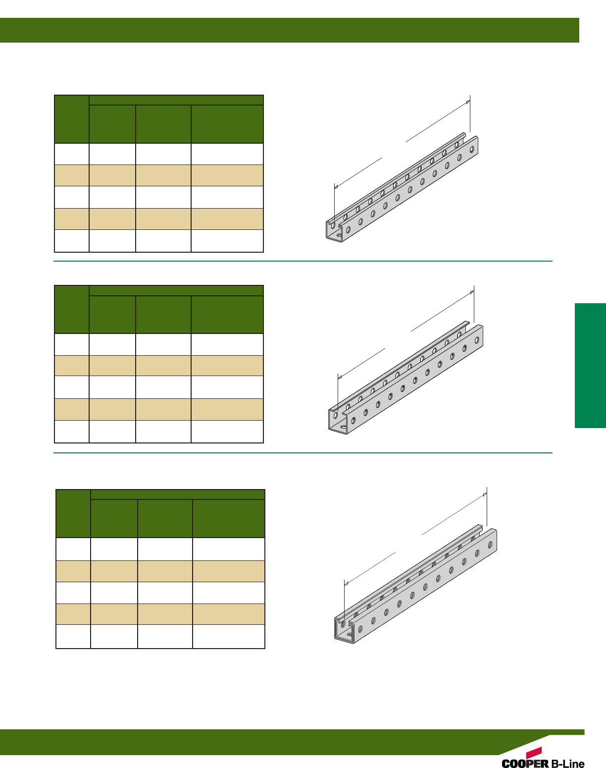
Beam Load Data x-x Axis
Beam Allowable Resulting Allowable Load
Span Load Deflection @ Deflection=
in lbs* in 1/240 Span
12 4203 0.012 4203
24 2099 0.050 2099
36 1396 0.112 1396
48 1044 0.200 1044
60 831 0.312 664
72 689 0.450 456
84 587 0.612 330
96 510 0.799 248
108 450 1.012 190
120 401 1.249 149
Beam Load Data x-x Axis
Beam Allowable Resulting Allowable Load
Span Load Deflection @ Deflection=
in lbs* in 1/240 Span
12 7033 0.013 7033
24 3511 0.051 3511
36 2335 0.115 2335
48 1745 0.205 1705
60 1389 0.320 1082
72 1151 0.460 742
84 980 0.627 536
96 851 0.819 401
108 749 1.036 307
120 668 1.279 239
BTS22TH
BTS22TH & B22TH
TELESCOPING MEMBERS OF EQUAL LENGTH
*Based on simple beam condition using an allowable design stress of 25,000 psi (172 MPa) with adequate lateral bracing (see page 11 for further
explanation). To determine concentrated load capacity at mid span, multiply uniform load by 0.5 and corresponding deflection by 0.8.
Beam Load Data x-x Axis
Beam Allowable Resulting Allowable Load
Span Load Deflection @ Deflection=
in lbs* in 1/240 Span
12 2225 0.015 3225
24 1610 0.061 1610
36 1071 0.136 1071
48 800 0.243 658
60 637 0.379 417
72 528 0.546 286
84 449 0.743 206
96 390 0.970 153
108 344 1.228 116
120 306 1.516 90
B22TH
Beam
Span
Beam
Span
Beam
Span
B22TH
BTS22TH
BTS22TH & B22TH
BEAM LOADING DATA
Reference page 14 for general fitting and standard finish specifications.
Channel & Combinations
Telescoping Channel
39
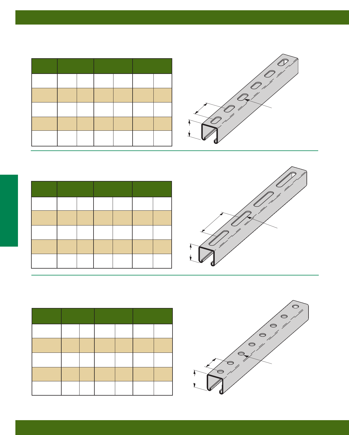
Reference page 14 for general fitting and standard finish specifications.
Height H Weight
Part No. Thickness In. mm Lbs./Ft. kg/m
B11SH 12 Ga. (2.6) 31/4”(82.5) 2.97 (4.42)
B12SH 12 Ga. (2.6) 27/16”(61.9) 2.39 (3.55)
B22SH 12 Ga. (2.6) 15/8”(41.3) 1.82 (2.71)
B24SH 14 Ga. (1.9) 15/8”(41.3) 1.34 (1.99)
B26SH 16 Ga. (1.5) 15/8”(41.3) 1.07 (1.59)
B32SH 12 Ga. (2.6) 13/8”(34.9) 1.62 (2.41)
B42SH 12 Ga. (2.6) 1” (25.4) 1.36 (2.02)
B52SH 12 Ga. (2.6) 13/16”(20.6) 1.19 (1.77)
B54SH 14 Ga. (1.9) 13/16”(20.6) .91 (1.35)
B56SH 16 Ga. (1.5) 13/16”(20.6) .80 (1.19)
B11SH THRU B56SH
SH TYPE CHANNEL
•For beam loads use 90% of Channel Loading Chart
2” (50.8)
TYP. 9/16” x 11/8” SLOTS
(14.3) (28.6)
H
Height H Weight
Part No. Thickness In. mm Lbs./Ft. kg/m
B11S 12 Ga. (2.6) 31/4”(82.5) 2.94 (4.37)
B12S 12 Ga. (2.6) 27/16”(61.9) 2.36 (3.51)
B22S 12 Ga. (2.6) 15/8”(41.3) 1.79 (2.66)
B24S 14 Ga. (1.9) 15/8”(41.3) 1.32 (1.96)
B26S 16 Ga. (1.5) 15/8”(41.3) 1.06 (1.58)
B32S 12 Ga. (2.6) 13/8”(34.9) 1.59 (2.36)
B42S 12 Ga. (2.6) 1” (25.4) 1.33 (1.98)
B52S 12 Ga. (2.6) 13/16”(20.6) 1.16 (1.72)
B54S 14 Ga. (1.9) 13/16”(20.6) .89 (1.32)
B56S 16 Ga. (1.5) 13/16”(20.6) .79 (1.17)
B11S THRU B56S
S TYPE CHANNEL
•For beam loads use 90% of Channel Loading Chart
4” (101.6)
TYP.
13/32”x 3” SLOTS
(10.3) (76.2)
H
Height H Weight
Part No. Thickness In. mm Lbs./Ft. kg/m
B11H17/8 12 Ga. (2.6) 31/4”(82.5) 3.00 (4.46)
B12H17/8 12 Ga. (2.6) 27/16”(61.9) 2.42 (3.60)
B22H17/8 12 Ga. (2.6) 15/8”(41.3) 1.85 (2.75)
B24H17/8 14 Ga. (1.9) 15/8”(41.3) 1.36 (2.02)
B26H17/8 16 Ga. (1.5) 15/8”(41.3) 1.09 (1.62)
B32H17/8 12 Ga. (2.6) 13/8”(34.9) 1.65 (2.45)
B42H17/8 12 Ga. (2.6) 1” (25.4) 1.39 (2.07)
B52H17/8 12 Ga. (2.6) 13/16”(20.6) 1.22 (1.81)
B54H17/8 14 Ga. (1.9) 13/16”(20.6) .93 (1.38)
B56H17/8 16 Ga. (1.5) 13/16”(20.6) .82 (1.22)
B11H17/8 THRU B56H17/8
H17/8 TYPE CHANNEL
•For beam loads use 90% of Channel Loading Chart
9/16”DIA. HOLES
(14.3)
17/8” (47.6)
TYP.
H
Channel & Combinations
Channel Hole Patterns
40
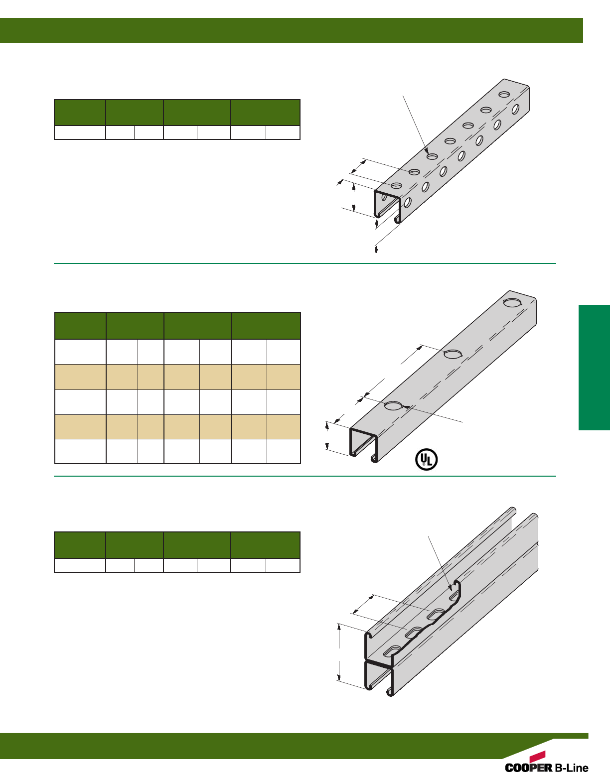
Reference page 14 for general fitting and standard finish specifications.
Height H Weight
Part No. Thickness In. mm Lbs./Ft. kg/m
B22TH 12 Ga. (2.6) 15/8”(41.3) 1.76 (2.62)
B22TH
(TH TYPE CHANNEL)
•For beam loads use 90% of Channel Loading Chart
Height H Weight
Part No. Thickness In. mm Lbs./Ft. kg/m
B11KO6 12 Ga. (2.6) 31/4”(82.5) 3.05 (4.54)
B12KO6 12 Ga. (2.6) 27/16”(61.9) 2.47 (3.67)
B22KO6 12 Ga. (2.6) 15/8”(41.3) 1.90 (2.83)
B24KO6 14 Ga. (1.9) 15/8”(41.3) 1.40 (2.08)
B26KO6 16 Ga. (1.5) 15/8”(41.3) 1.12 (1.66)
B32KO6 12 Ga. (2.6) 13/8”(34.9) 1.70 (2.53)
B42KO6 12 Ga. (2.6) 1” (25.4) 1.44 (2.14)
B52KO6 12 Ga. (2.6) 13/16”(20.6) 1.27 (1.89)
B54KO6 14 Ga. (1.9) 13/16”(20.6) .97 (1.44)
B56KO6 16 Ga. (1.5) 13/16”(20.6) .85 (1.26)
17/8” TYP.
(47.6)
13/16”
(20.6)
15/16”
(23.8)
9/16”DIA. HOLES
(14.3)
H
6” TYP.
(152.4)
3” TYP.
(76.2)
H
7/8”DIA. K.O.
(22.2)
B11KO6 THRU B56KO6
(KO6 TYPE KNOCKOUT CHANNEL)
•For beam loads use 90% of Channel Loading Chart
B22SHA
(BACK TO BACK SH TYPE CHANNEL)
•For beam loads use 90% of Channel Loading Chart
2” TYP.
(50.8)
Height H Weight
Part No. Thickness In. mm Lbs./Ft. kg/m
B22SHA 12 Ga. (2.6) 31/4”(82.5) 3.64 (5.42)
H
9/16” x 11/8” SLOTS
(14.3) (28.6)
Channel & Combinations
Channel Hole Patterns
41
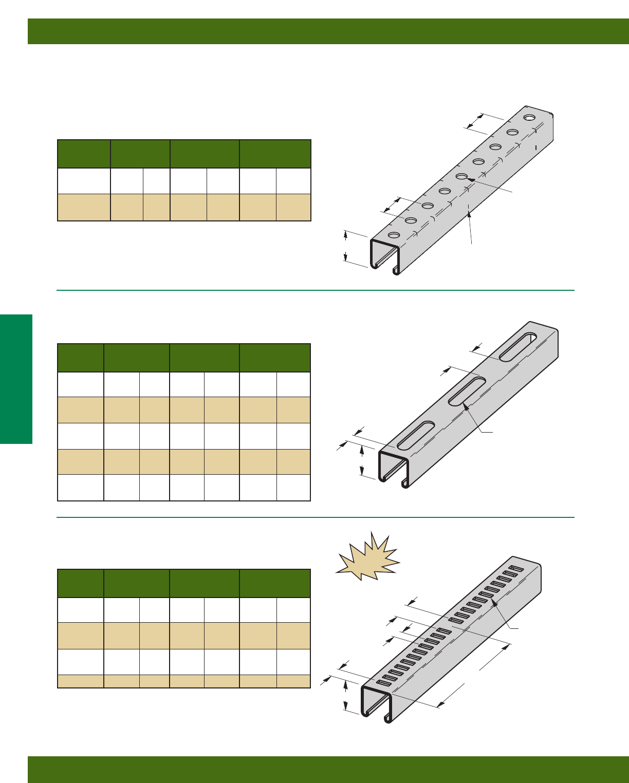
Reference page 14 for general fitting and standard finish specifications.
BK22H112 THRU BK54H112
H11/2 TYPE CHANNEL
•For beam loads use 90% of Channel Loading Chart
•Standard Finish: Yellow Zinc Chromate (YZN) Other finishes available.
9/16”(14.3)
DIA. HOLES
11/2” (38.1)
TYP.
TICK
MARKS
11/2” (38.1)
TYP.
6” (152.4)
ON CENTER
TICK MARKS
B22M THRU B54M
M (MARINE RUNG) TYPE CHANNEL
•For beam loads use 90% of Channel Loading Chart
1”
(25.4)
1/2”
(38.1)
6” (152.4)
NEW
Height H Weight
Part No. Thickness In. mm Lbs./Ft. kg/m
BK22H112 12 Ga. (2.6) 15/8”(41.3) 1.85 (2.75)
BK24H112 14 Ga. (1.9) 15/8”(41.3) 1.36 (2.02)
BK52H112 12 Ga. (2.6) 13/16”(20.6) 1.22 (1.81)
BK54H112 14 Ga. (1.9) 13/16”(20.6) .93 (1.38)
B11S58 THRU B56S58
S58 TYPE CHANNEL
•For beam loads use 90% of Channel Loading Chart
11/16” x 25/8”
(17.5) x (66.7)
SLOTS
1/4” x 11/16”
(6.3) x (17.5)
SLOTS
11/16”
(101.6)
13/8” (34.9)
TYP.
Height H Weight
Part No. Thickness In. mm Lbs./Ft. kg/m
B11S58 12 Ga. (2.6) 31/4”(82.5) 2.94 (4.37)
B12S58 12 Ga. (2.6) 27/16”(61.9) 2.36 (3.51)
B22S58 12 Ga. (2.6) 15/8”(41.3) 1.79 (2.66)
B24S58 14 Ga. (1.9) 15/8”(41.3) 1.32 (1.96)
B26S58 16 Ga. (1.5) 15/8”(41.3) 1.06 (1.58)
B32S58 12 Ga. (2.6) 13/8”(34.9) 1.59 (2.36)
B42S58 12 Ga. (2.6) 1” (25.4) 1.33 (1.98)
B52S58 12 Ga. (2.6) 13/16”(20.6) 1.16 (1.72)
B54S58 14 Ga. (1.9) 13/16”(20.6) .89 (1.32)
B56S58 16 Ga. (1.5) 13/16”(20.6) .79 (1.17)
H
H
H
1/2”
(38.1)
Height H Weight
Part No. Thickness In. mm Lbs./Ft. kg/m
B22M 12 Ga. (2.6) 15/8”(41.3) 1.79 (2.66)
B24M 14 Ga. (1.9) 15/8”(41.3) 1.32 (1.96)
B32M 12 Ga. (2.6) 13/8”(34.9) 1.59 (2.36)
B42M 12 Ga. (2.6) 1” (25.4) 1.33 (1.98)
B44M 14 Ga. (1.9) 1” (25.4) 0.98 (1.46)
B52M 12 Ga. (2.6) 13/16”(20.6) 1.16 (1.72)
B54M 14 Ga. (1.9) 13/16”(20.6) .89 (1.32)
Channel & Combinations
Channel Hole Patterns
42
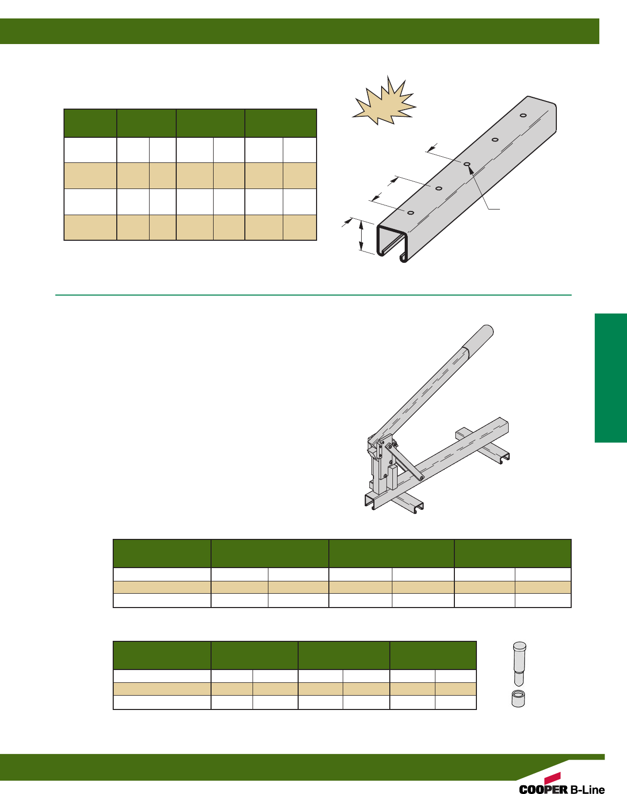
Weight Each
Part No. Hole Size Bolt Size Lbs. kg
B96HP-0.562D 9/16”(14.3) 1/2”(12.7) .50 (.2)
B96HP-0.438D 7/16”(11.1) 3/8”(9.5) .50 (.2)
B96HP-0.281D 9/32”(7.1) 1/4”(6.3) .50 (.2)
Weight Each
Part No. Hole Size Bolt Size Lbs. kg
B96HP-0.562 9/16”(14.3) 1/2”(12.7) 24.5 (11.1)
B96HP-0.438 7/16”(11.1) 3/8”(9.5) 24.5 (11.1)
B96HP-0.281 9/32”(7.1) 1/4”(6.3) 24.5 (11.1)
B96HP
CHANNEL PUNCH
•Field-punch holes exactly where you want
them in any type channel...Quick and easy!
•Any size holes...anywhere you need
them...with on-the-job convenience!
•Channel punch will work on any standard
single channels that have solid backs.
•Do not use this punch on combination,
stainless steel, or KO6 channels.
Die Blocks Only
Punch & Die Block Assembly
Height H Weight
Part No. Thickness In. mm Lbs./Ft. kg/m
B22H25 12 Ga. (2.6) 15/8”(41.3) 1.85 (2.75)
B24H25 14 Ga. (1.9) 15/8”(41.3) 1.36 (2.02)
B26H25 16 Ga. (1.5) 15/8”(41.3) 1.09 (1.62)
B32H25 12 Ga. (2.6) 13/8”(34.9) 1.65 (2.45)
B42H25 12 Ga. (2.6) 1” (25.4) 1.39 (2.07)
B52H25 12 Ga. (2.6) 13/16”(20.6) 1.22 (1.81)
B54H25 14 Ga. (1.9) 13/16”(20.6) .93 (1.38)
B56H25 16 Ga. (1.5) 13/16”(20.6) .82 (1.22)
B22H25 THRU B56H25
H25 TYPE CHANNEL
•For beam loads use 90% of Channel Loading Chart
9/32”DIA. HOLES
(7.1)
H
NEW
1”
(25.4)
2”
(50.8)
Channel & Combinations
Channel Hole Patterns & Hole Punch
43
Reference page 14 for general fitting and standard finish specifications.
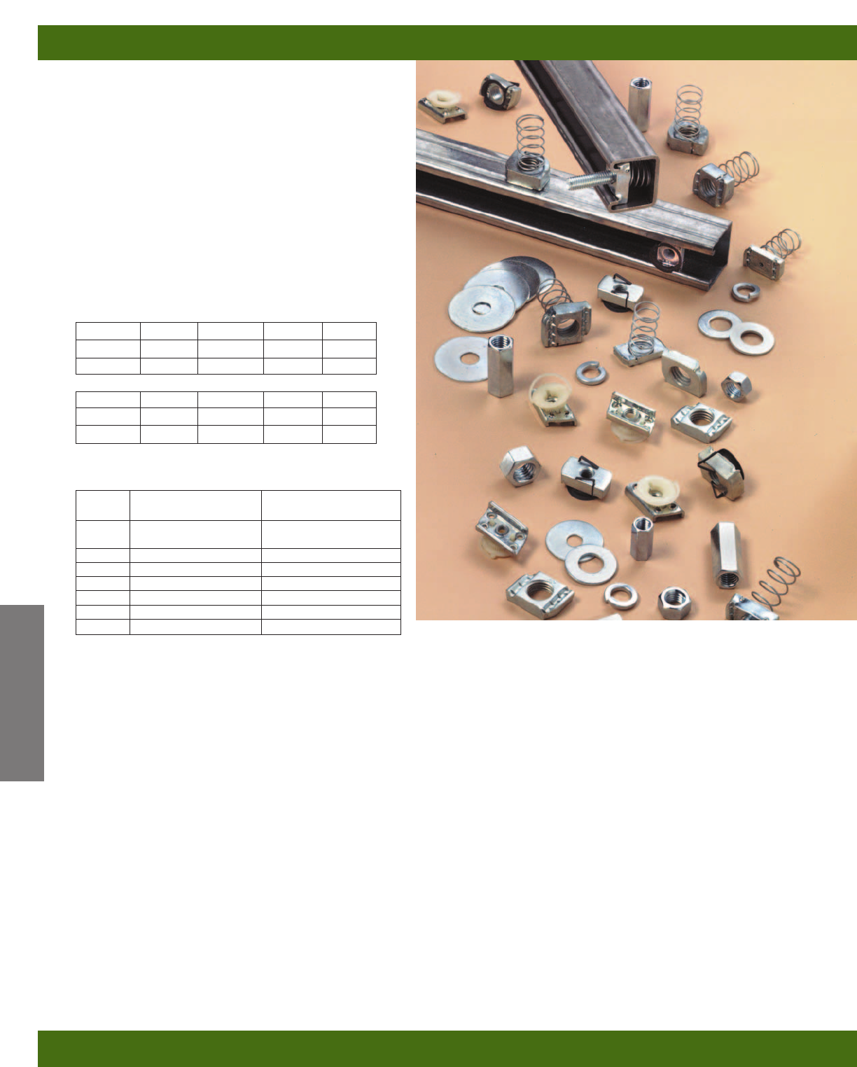
Channel Nuts
B-Line’s channel nut is one of the main components
of our metal framing system. It is designed to provide
essential gripping power and ease during installation.
Channel nuts are press formed, machined and
hardened from steel which meets the requirements
of ASTM A108 or ASTM A36 for our larger sizes.
Bolts, Screws, and Nuts
All bolts, screws and nuts meet the physical and
chemical requirements of ASTM A307, SAE J429 or
ASTM A563, and have unified inch screw threads
(coarse, UNC). ISO metric threads are also available
on special request.
Recommended Torque
Materials & Finishes*
*Unless otherwise noted.
Note: Channel nuts are not available in HDG or Aluminum
Metric
Metric dimensions are shown in parentheses. Unless noted, all metric dimensions are in millimeters.
Bolt Size 1/4”-20 5/16”-18 3/8”-16 1/2”-13
Foot/Lbs. 6 11 19 50
Nm 8 15 26 68
Bolt Size M6x1 M8 x1.25 M10 x 1.5 M12x1.75
NM 12 17 36 62
Foot/Lbs. 9 13 27 46
Finish
Code Finish Specification
PLN Plain ASTM A108/A307 Gr. A,
ASTM A563, SAE J429
ZN Electro-Plated Zinc ASTM B633 SC1 Type III
CZ Chromium Zinc ASTM F1136 Gr. 3
HDG Hot-Dipped Galvanized ASTM A153
SS4 Stainless Steel Type 304 ASTM F593
SS6 Stainless Steel Type 316 MPIF 35/ASTM A593
AL Aluminum ASTM F468 S4
Channel Nuts & Hardware
Channel Nuts & Hardware
44
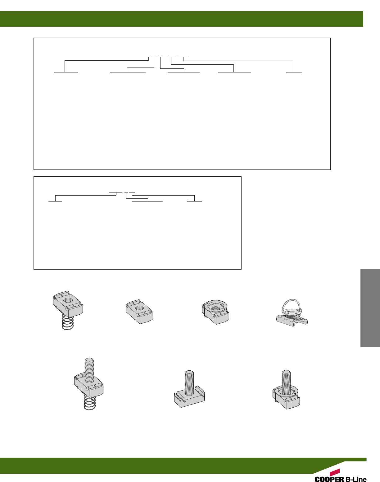
METRIC CHANNEL NUTS
Numbering Example: BMS 6 M
Nut Metric Suffix
Type Thread Size
BMS = Spring Nut 3 = M3.5 S = Short Spring
BMS-D = Spring Nut (1/2” thick) 4 = M4 M = Medium Spring
BMT = Twirl Nut 5 = M5 L = Long Spring
BMT-D = Twirl Nut (1/2” thick) 6 = M6 * = Twirl Nuts and nuts
BFN = FN Nut 8 = M8 without springs have
BMM = Spring Nut (Mini channel) 10 = M10 blank suffix
12 = M12
Reference page 44 for general fitting and standard finish specifications.
STANDARD CHANNEL NUTS
Numbering Example: N 7 25 (*) WO
Nut Type Channel Type Thread Size Stud Length Suffix
N = Standard Nut 7 = Tall Channels 21 = #8-32 * = Specify Length WO = Without Spring
TN = Twirl Nut B11 22 = #10-24 of stud below ** = Twirl Nuts or nuts
SN = Stud Nut B12 27 = #10-32 for Stud Nut or with springs have
STN = Stud Twirl Nut 2 = Medium Channels 24 = 1/4-20 Twirl Stud Nuts blank suffix
FN = FN Nut B22 23 = 5/16-18 3/4= 3/4”
NW = Combo Nut B24 28 = 3/8-16 1 = 1”
Washer B26 26 = 7/16-14 11/4= 11/4”
B32 25 = 1/2-13 11/2= 11/2”
5 = Short Channels 55 = 5/8-11
B42 75 = 5/8-11
B52 78 = 7/8-9
B54
B56
SPRING NUT TWIRL-NUT®FN NUT PatentedNUT WITHOUT SPRING
STUD NUT WITH SPRING STUD NUT WITHOUT SPRING TWIRL STUD NUT
Channel Nuts & Hardware
Channel Nuts & Hardware
45
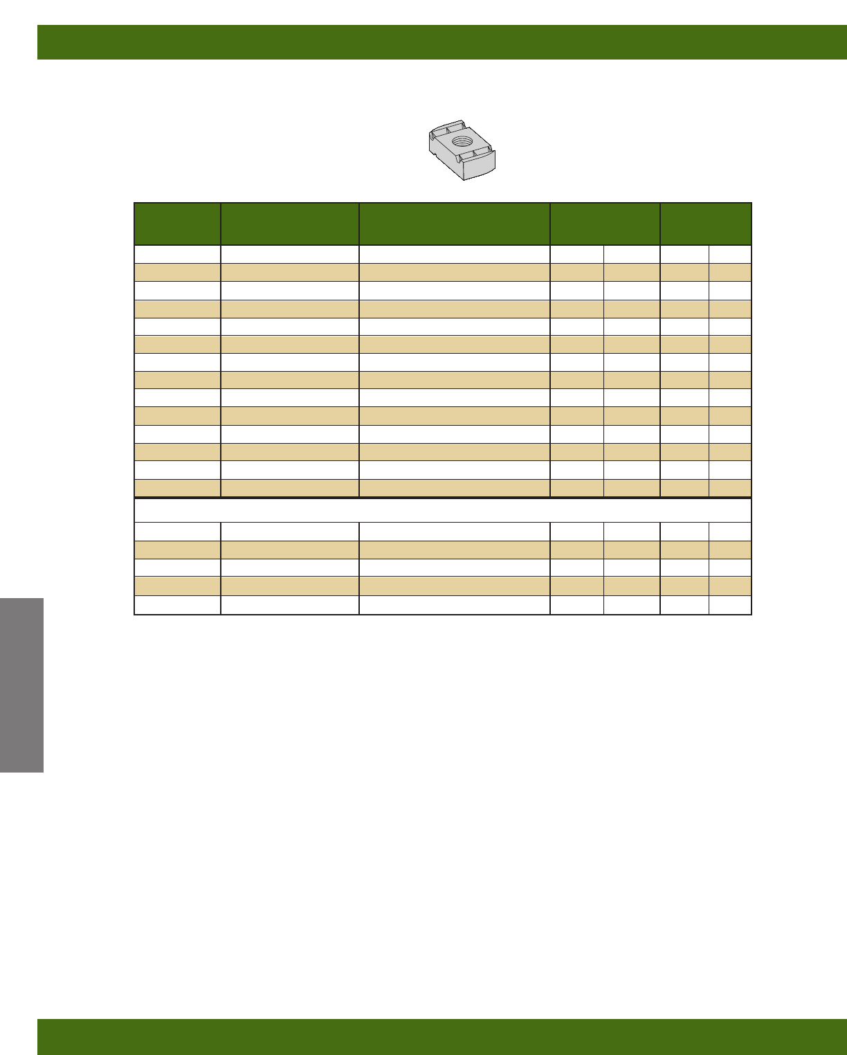
Reference page 44 for general fitting and standard finish specifications.
Note: See page 50 for resistance to slip
& page 51 for pull-out strength.
Part No. Thread Size Fits Channel Sizes Nut Thickness Wt./C
Lbs. kg
N221WO #8-32 All sizes except B62 & B72 1/4”(6.3) 7.0 (3.17)
N227WO #10-32 All sizes except B62 & B72 1/4”(6.3) 7.0 (3.17)
N222WO #10-24 All sizes except B62 & B72 1/4”(6.3) 7.0 (3.17)
N224WO 1/4-20 All sizes except B62 & B72 1/4”(6.3) 6.7 (3.04)
N223WO 5/16-18 All sizes except B62 & B72 1/4”(6.3) 6.7 (3.04)
N228WO 3/8-16 All sizes except B62 & B72 3/8”(9.5) 9.3 (4.22)
N226WO 7/16-14 All sizes except B62 & B72 3/8”(9.5) 8.8 (3.99)
N225WO 1/2-13 B11, B12, B22, B24, B26, B32 1/2”(12.7) 11.6 (5.26)
N525WO 1/2-13 B42, B52, B54, B56 3/8”(9.5) 8.8 (3.99)
N255WO 5/8-11 B11, B12, B22, B24, B26, B32 1/2”(12.7) 16.4 (7.44)
N555WO 5/8-11 B42, B52, B54, B56 3/8”(9.5) 10.2 (4.62)
N275WO 3/4-10 B11, B12, B22, B24, B26, B32 1/2”(12.7) 14.5 (6.58)
N575WO 3/4-10 B42, B52, B54, B56 3/8”(9.5) 8.8 (3.99)
N278WO 7/8-9 B11, B12, B22, B24, B26, B32 1/2”(12.7) 12.5 (5.67)
Metric Threads
BMS-6 M6 x 1 All sizes except B62 & B72 1/4”(6.3) 6.9 (3.13)
BMS-8 M8 x 1.25 All sizes except B62 & B72 1/4”(6.3) 6.7 (3.04)
BMS-10 M10 x 1.5 All sizes except B62 & B72 3/8”(9.5) 9.6 (4.35)
BMS-12 M12 x 1.75 All sizes except B62 & B72 3/8”(9.5) 9.2 (4.17)
BMS-D-12 M12 x 1.75 B11, B12, B22, B24, B26, B32 1/2”(12.7) 12.2 (5.53)
NUT WITHOUT SPRING
Channel Nuts & Hardware
Note: For mini channel nut information see page 191.
Channel Nuts
46
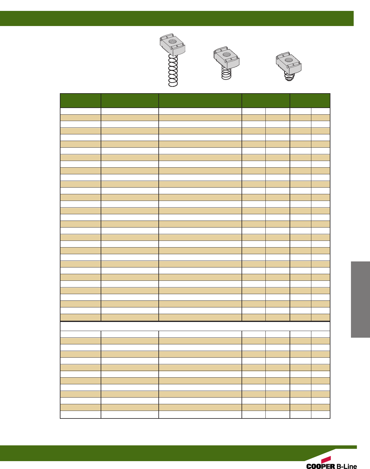
Reference page 44 for general fitting and standard finish specifications.
Part No. Thread Size Fits Channel Sizes Nut Thickness Wt./C
Lbs. kg
N721 #8-32 B11 & B12 1/4”(6.3) 7.0 (3.17)
N221 #8-32 B22, B24, B26, B32 1/4”(6.3) 7.0 (3.17)
N521 #8-32 B42, B52, B54, B56 1/4”(6.3) 7.0 (3.17)
N727 #10-32 B11 & B12 1/4”(6.3) 7.0 (3.17)
N227 #10-32 B22, B24, B26, B32 1/4”(6.3) 7.0 (3.17)
N527 #10-32 B42, B52, B54, B56 1/4”(6.3) 7.0 (3.17)
N722 #10-24 B11 & B12 1/4”(6.3) 7.0 (3.17)
N222 #10-24 B22, B24, B26, B32 1/4”(6.3) 7.0 (3.17)
N522 #10-24 B42, B52, B54, B56 1/4”(6.3) 7.0 (3.17)
N724 1/4-20 B11 & B12 1/4”(6.3) 6.7 (3.04)
N224 1/4-20 B22, B24, B26, B32 1/4”(6.3) 6.7 (3.04)
N524 1/4-20 B42, B52, B54, B56 1/4”(6.3) 6.7 (3.04)
N723 5/16-18 B11 & B12 1/4”(6.3) 6.7 (3.04)
N223 5/16-18 B22, B24, B26, B32 1/4”(6.3) 6.7 (3.04)
N523 5/16-18 B42, B52, B54, B56 1/4”(6.3) 6.7 (3.04)
N728 3/8-16 B11 & B12 3/8”(9.5) 9.3 (4.22)
N228 3/8-16 B22, B24, B26, B32 3/8”(9.5) 9.3 (4.22)
N528 3/8-16 B42, B52, B54, B56 3/8”(9.5) 9.3 (4.22)
N726 7/16-14 B11 & B12 3/8”(9.5) 8.8 (3.99)
N226 7/16-14 B22, B24, B26, B32 3/8”(9.5) 8.8 (3.99)
N526 7/16-14 B42, B52, B54, B56 3/8”(9.5) 8.8 (3.99)
N725 1/2-13 B11 & B12 1/2”(12.7) 11.6 (5.26)
N225 1/2-13 B22, B24, B26, B32 1/2”(12.7) 11.6 (5.26)
N525 1/2-13 B42, B52, B54, B56 3/8”(9.5) 8.8 (3.99)
N755 5/8-11 B11 & B12 1/2”(12.7) 16.4 (7.44)
N255 5/8-11 B22, B24, B26, B32 1/2”(12.7) 16.4 (7.44)
N555 5/8-11 B42, B52, B54, B56 3/8”(9.5) 10.2 (4.62)
N775 3/4-10 B11 & B12 1/2”(12.7) 14.5 (6.58)
N275 3/4-10 B22, B24, B26, B32 1/2”(12.7) 14.5 (6.58)
N575 3/4-10 B42, B52, B54, B56 3/8”(9.5) 8.8 (3.99)
N778 7/8-9 B11 & B12 1/2”(12.7) 12.5 (5.67)
N278 7/8-9 B22, B24, B26, B32 1/2”(12.7) 12.5 (5.67)
Metric Threads
BMS-6L M6 x 1 B11 & B12 1/4”(6.3) 6.9 (3.13)
BMS-6M M6 x 1 B22, B24, B26, B32 1/4”(6.3) 6.9 (3.13)
BMS-6S M6 x 1 B42, B52, B54, B56 1/4”(6.3) 6.9 (3.13)
BMS-8L M8 x 1.25 B11 & B12 1/4”(6.3) 6.7 (3.04)
BMS-8M M8 x 1.25 B22, B24, B26, B32 1/4”(6.3) 6.7 (3.04)
BMS-8S M8 x 1.25 B42, B52, B54, B56 1/4”(6.3) 6.7 (3.04)
BMS-10L M10 x 1.5 B11 & B12 3/8”(9.5) 9.6 (4.35)
BMS-10M M10 x 1.5 B22, B24, B26, B32 3/8”(9.5) 9.6 (4.35)
BMS-10S M10 x 1.5 B42, B52, B54, B56 3/8”(9.5) 9.6 (4.35)
BMS-12M M12 x 1.75 B22, B24, B26, B32 3/8”(9.5) 9.2 (4.17)
BMS-12S M12 x 1.75 B42, B52, B54, B56 3/8”(9.5) 9.2 (4.17)
BMS-D-12L M12 x 1.75 B11 & B12 1/2”(12.7) 12.2 (5.53)
BMS-D-12M M12 x 1.75 B22, B24, B26, B32 1/2”(12.7) 12.2 (5.53)
SPRING NUT
700
SERIES
200
SERIES
500
SERIES
Channel Nuts & Hardware
Note: See page 50 for resistance to slip
& page 51 for pull-out strength.
Note: For mini channel nut information see page 191.
Channel Nuts
47
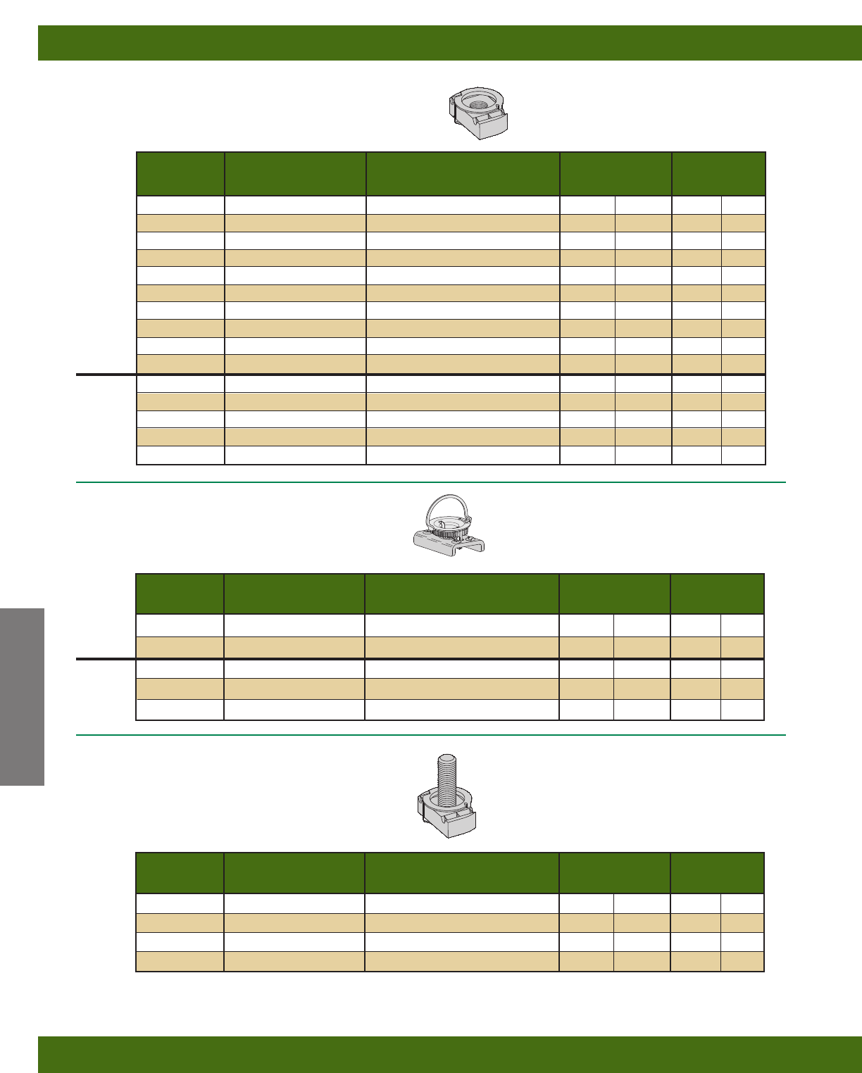
Reference page 44 for general fitting and standard finish specifications.
*Note: Add stud length in inches (3/4, 1, 11/4, 11/2)
Part No. Thread Size Fits Channel Sizes Nut Thickness Wt./C
Lbs. kg
FN224 1/4-20 All sizes except B62 & B72 .31 (7.9) 5.4 (2.45)
FN228 3/8-16 All sizes except B62 & B72 .31 (7.9) 5.4 (2.45)
BFN-6 M6 x 1 All sizes except B62 & B72 .31 (7.9) 5.4 (2.45)
BFN-8 M8 x 1.25 All sizes except B62 & B72 .31 (7.9) 5.4 (2.45)
BFN-10 M10 x 1.5 All sizes except B62 & B72 .31 (7.9) 5.4 (2.45)
Part No. Thread Size Fits Channel Sizes Nut Thickness Ave. Wt./C
Lbs. kg
STN224-* 1/4-20 All sizes except B62 & B72 1/4”(6.3) 8.1 (3.66)
STN228-* 3/8-16 All sizes except B62 & B72 3/8”(9.5) 12.9 (5.85)
STN225-* 1/2-13 B11, B12, B22, B24, B26, B32 1/2”(12.7) 18.2 (8.23)
STN525-* 1/2-13 B42, B52, B54, B56 3/8”(9.5) 15.4 (6.96)
FN NUT
STUD TWIRL NUT
Part No. Thread Size Fits Channel Sizes Nut Thickness Wt./C
Lbs. kg
TN221 #8-32 All sizes except B62 & B72 1/4”(6.3) 7.0 (3.17)
TN227 #10-32 All sizes except B62 & B72 1/4”(6.3) 7.0 (3.17)
TN222 #10-24 All sizes except B62 & B72 1/4”(6.3) 7.0 (3.17)
TN224 1/4-20 All sizes except B62 & B72 1/4”(6.3) 6.7 (3.04)
TN223 5/16-18 All sizes except B62 & B72 1/4”(6.3) 6.7 (3.04)
TN228 3/8-16 All sizes except B62 & B72 3/8”(9.5) 9.3 (4.22)
TN226 7/16-14 All sizes except B62 & B72 3/8”(9.5) 8.8 (3.99)
TN225 1/2-13 B11, B12, B22, B24, B26, B32 1/2”(12.7) 11.6 (5.26)
TN525 1/2-13 B42, B52, B54, B56 3/8”(9.5) 8.8 (3.99)
TN255 5/8-11 B11, B12, B22, B24, B26, B32 1/2”(12.7) 11.0 (4.99)
BMT-6 M6 x 1 All sizes except B62 & B72 1/4”(6.3) 6.9 (3.13)
BMT-8 M8 x 1.25 All sizes except B62 & B72 1/4”(6.3) 6.7 (3.04)
BMT-10 M10 x 1.5 All sizes except B62 & B72 3/8”(9.5) 9.6 (4.35)
BMT-12 M12 x 1.75 All sizes except B62 & B72 3/8”(9.5) 9.2 (4.17)
BMT-D-12 M12 x 1.75 B11, B12, B22, B24, B26, B32 1/2”(12.7) 12.2 (5.53)
Metric
Threads
Metric
Threads
TWIRL-NUT®Patented
Channel Nuts & Hardware
Note: See page 50 for resistance to slip
& page 51 for pull-out strength.
Note: See page 50 for resistance to slip
& page 51 for pull-out strength.
Note: See page 50 for resistance to slip
& page 51 for pull-out strength.
Channel Nuts
48
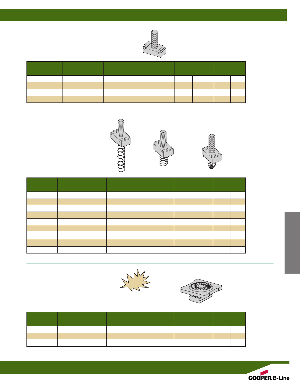
*Note: Add stud length in inches (3/4, 1, 11/4, 11/2)
Reference page 44 for general fitting and standard finish specifications.
Part No. Thread Size Fits Channel Sizes Nut Thickness Ave. Wt./C
Lbs. kg
SN724-* 1/4-20 B11 & B12 1/4”(6.3) 8.1 (3.66)
SN224-* 1/4-20 B22, B24, B26, B32 1/4”(6.3) 8.1 (3.66)
SN524-* 1/4-20 B42, B52, B54, B56 1/4”(6.3) 8.1 (3.66)
SN728-* 3/8-16 B11 & B12 3/8”(9.5) 12.9 (5.85)
SN228-* 3/8-16 B22, B24, B26, B32 3/8”(9.5) 12.9 (5.85)
SN528-* 3/8-16 B42, B52, B54, B56 3/8”(9.5) 12.9 (5.85)
SN725-* 1/2-13 B11 & B12 1/2”(12.7) 18.2 (8.23)
SN225-* 1/2-13 B22, B24, B26, B32 1/2”(12.7) 18.2 (8.23)
SN525-* 1/2-13 B42, B52, B54, B56 3/8”(9.5) 15.4 (6.96)
STUD NUT WITH SPRING
Part No. Thread Size Fits Channel Sizes Nut Thickness Ave. Wt./C
Lbs. kg
NW524 1/4-20 All Channel Sizes 1/4”(6.3) 11.9 (5.40)
NW528 3/8-16 All Channel Sizes 3/8”(9.5) 13.8 (6.26)
NW525 1/2-13 All Channel Sizes 3/8”(9.5) 13.1 (5.94)
COMBO NUT WASHER
700
SERIES
200
SERIES
500
SERIES
*Note: Add stud length in inches (3/4, 1, 11/4, 11/2)
Part No. Thread Size Fits Channel Sizes Nut Thickness Ave. Wt./C
Lbs. kg
SN224-*WO 1/4-20 All sizes except B62 & B72 1/4”(6.3) 8.1 (3.66)
SN228-*WO 3/8-16 All sizes except B62 & B72 3/8”(9.5) 12.9 (5.85)
SN225-*WO 1/2-13 B11, B12, B22, B24, B26, B32 1/2”(12.7) 18.2 (8.23)
SN525-*WO 1/2-13 B42, B52, B54, B56 3/8”(9.5) 15.4 (6.96)
STUD NUT WITHOUT SPRING
Channel Nuts & Hardware
Note: See page 50 for resistance to slip
& page 51 for pull-out strength.
Note: See page 50 for resistance to slip
& page 51 for pull-out strength.
•Finish: Electrodeposited zinc ASTM B633 SC1
•Available in 316 stainless steel - add SS6 to
part number
Note: See page 50 for resistance to slip
& page 51 for pull-out strength.
NEW
Channel Nuts
49
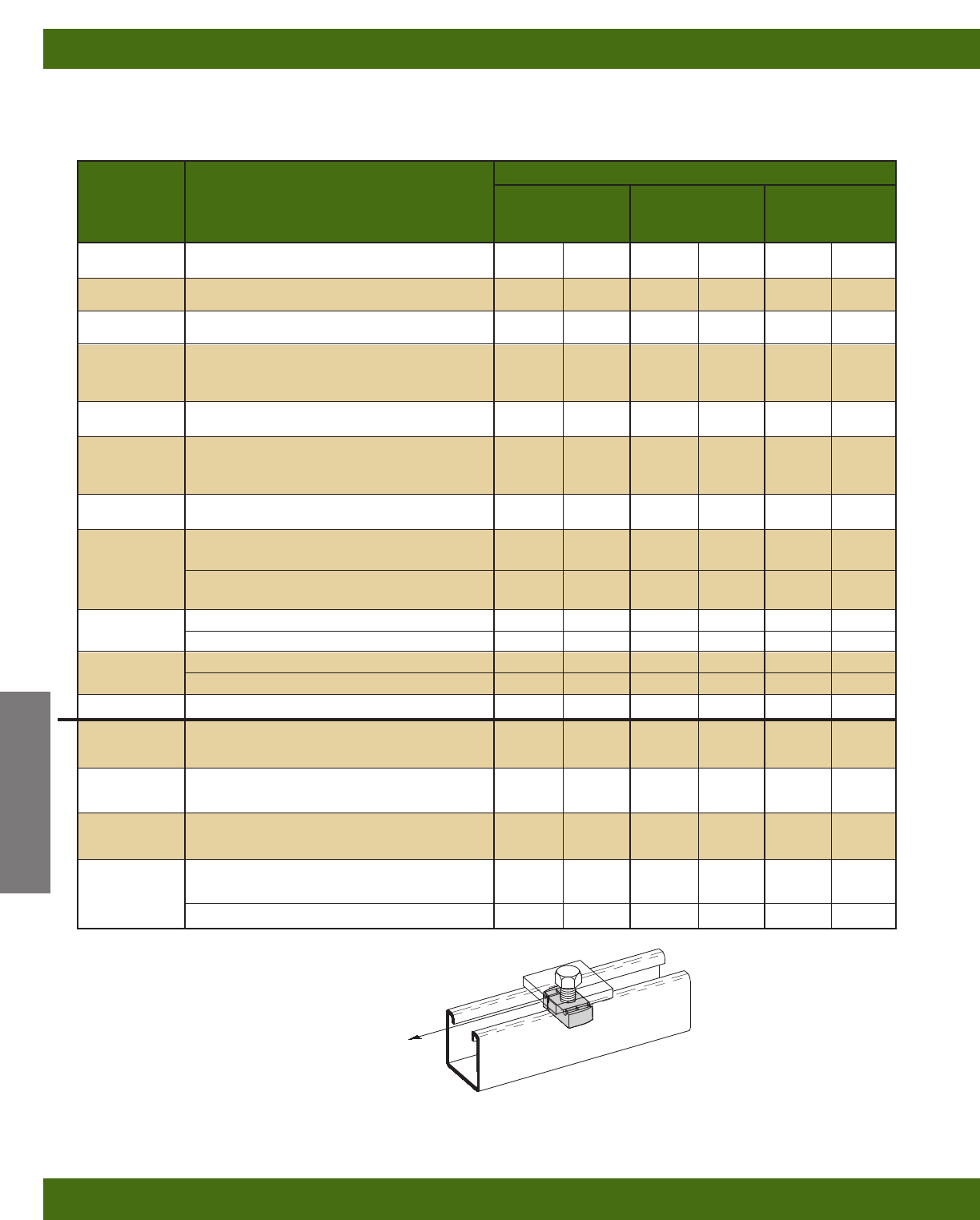
Resistance to Slip
Thread Nut Part
Size Numbers 12 ga. Channel 14 ga. Channel 16 ga. Channel
Lbs. N Lbs. N Lbs. N
#8-32 N221, N221WO,N521, N721, TN221 50 220 50 220 50 220
#10-24 N222, N222WO, N522, N722, TN222 100 440 100 440 100 440
#10-32 N227, N227WO, N527, N727, TN227 100 440 100 440 100 440
NW524*, FN224, N224,N224WO, N524, N724,
1/4”-20 TN224, STN224, SN224WO, SN224, 300 1330 300 1330 300 1330
SN524, SN724
5/16”-18 N223, N223WO, N523, N723, TN223 450 2000 450 2000 450 2000
NW528*, FN228, N228, N228WO, N528, N728
3/8”-16 TN228, STN228, SN228WO, SN228, 800 3560 600 2670 600 2670
SN528, SN728
7/16”-14 N226, N226WO, N526, N726, TN226 1000 4450 800 3560 800 3560
N225, N225WO, N725, TN225, 1500 6670 1000 4450 1000 4450
STN225, SN225WO, SN225, SN725
1/2”-13 NW525*, N525, N525WO, TN525, 1500 6670 1000 4450 1000 4450
STN525, SN525WO, SN525
5/8”-11 N255, N255WO, N755, TN255 1500 6670 1000 4450 1000 4450
N555, N555WO 1500 6670 1000 4450 1000 4450
3/4”-10 N275, N275WO, N775 1500 6670 1000 4450 1000 4450
N575, N575WO 1500 6670 1000 4450 1000 4450
7/8”-9 N278, N278WO, N778 1500 6670 1000 4450 1000 4450
M6 x 1 BMS-6, BMS-6L, BMS-6M, BMS-6S, 300 1330 300 1330 300 1330
BFN-6, BMT-6
M8 x 1.25 BMS-8, BMS-8L, BMS-8M, BMS-8S, 450 2000 450 2000 450 2000
BFN-8, BMT-8
M10 x 1.50 BMS-10, BMS-10L, BMS-10M, BMS-10S, 800 3560 600 2760 600 2760
BFN-10, BMT-20
BMS-D-12, BMS-D-12L, 1500 6670 1000 4450 1000 4450
M12 x 1.75 BMS-D-12M, BMT-D-12
BMS-12, BMS-12M, BMS-12S, BMT-12 1500 6670 1000 4450 1000 4450
RESISTANCE TO SLIP
•With Safety Factor of 3
Resistance to Slip
of Channel Nut
Reference page 44 for general fitting and standard finish specifications.
Channel Nuts & Hardware
Note: For mini channel nut information see page 191.
* Combo Nut Washer (see page 49)
Metric Threads
Channel Nuts
50
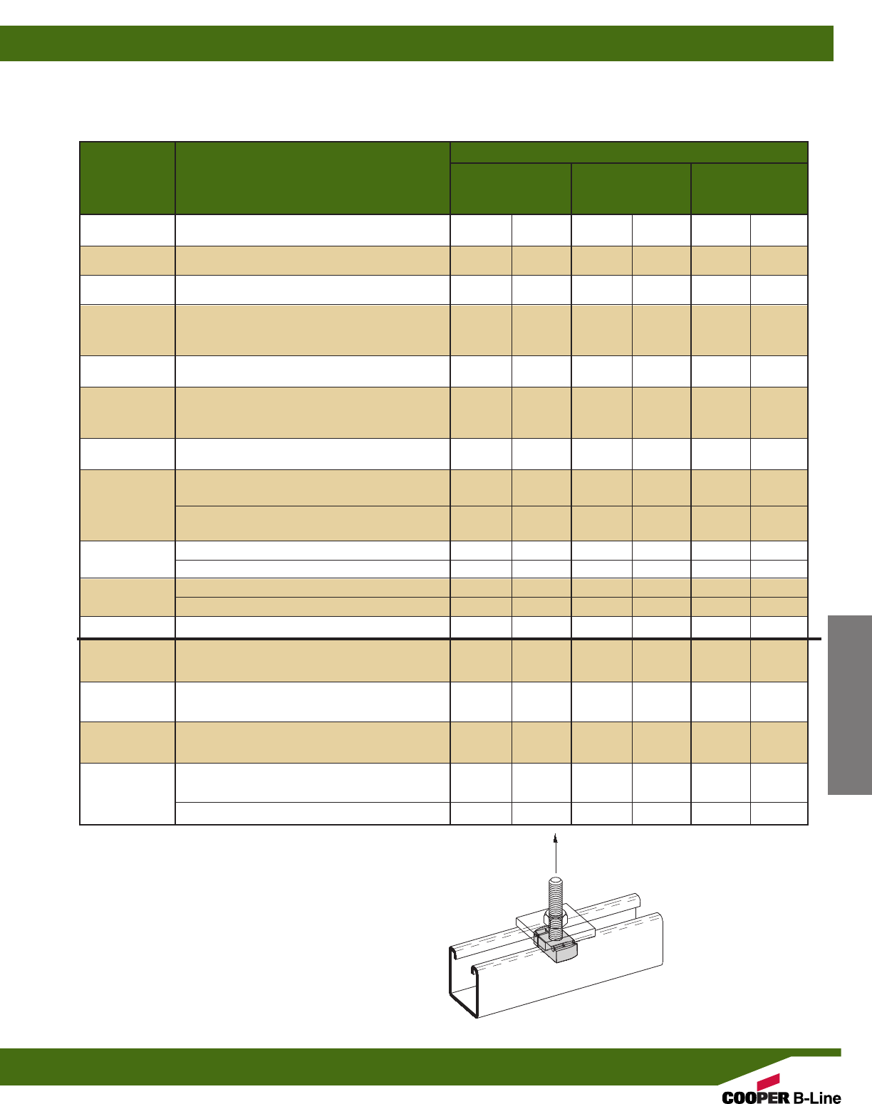
PULL-OUT STRENGTH
•With Safety Factor of 3
•Maximum pullout strength for B11 & B12 channels is limited to 1500 lbs. (6670 N).
Reference page 44 for general fitting and standard finish specifications.
Channel Nuts & Hardware
Note: For mini channel nut
information see page 191.
Pull-Out Strength
Thread Nut Part
Size Numbers 12 ga. Channel 14 ga. Channel 16 ga. Channel
Lbs. N Lbs. N Lbs. N
#8-32 N221, N221WO,N521, N721, TN221 200 890 200 890 200 890
#10-24 N222, N222WO, N522, N722, TN222 250 1110 250 1110 250 1110
#10-32 N227, N227WO, N527, N727, TN227 250 1110 250 1110 250 1110
NW524*, FN224, N224,N224WO, N524, N724,
1/4”-20 TN224, STN224, SN224WO, SN224, 450 2000 450 2000 450 2000
SN524, SN724
5/16”-18 N223, N223WO, N523, N723, TN223 750 3330 750 3330 750 3330
NW528*, FN228, N228, N228WO, N528, N728
3/8”-16 TN228, STN228, SN228WO, SN228, 1100 4890 1000 4450 1000 4450
SN528, SN728
7/16”-14 N226, N226WO, N526, N726, TN226 1500 6670 1200 5340 1000 4450
N225, N225WO, N725, TN225, 2000 8900 1400 6230 1000 4450
STN225, SN225WO, SN225, SN725
1/2”-13 NW525*, N525, N525WO, TN525, 1500 6670 1400 6230 1000 4450
STN525, SN525WO, SN525
5/8”-11 N255, N255WO, N755, TN255 2000 8900 1400 6230 1000 4450
N555, N555WO 1500 6670 1400 6230 1000 4450
3/4”-10 N275, N275WO, N775 2000 8900 1400 6230 1000 4450
N575, N575WO 1500 6670 1400 6230 1000 4450
7/8”-9 N278, N278WO, N778 1500 6670 1400 6230 1000 4450
M6 x 1 BMS-6, BMS-6L, BMS-6M, BMS-6S, 450 2000 450 2000 450 2000
BFN-6, BMT-6
M8 x 1.25 BMS-8, BMS-8L, BMS-8M, BMS-8S, 750 3330 750 3330 750 3330
BFN-8, BMT-8
M10 x 1.50 BMS-10, BMS-10L, BMS-10M, BMS-10S, 1100 4890 1000 4450 1000 4450
BFN-10, BMT-20
BMS-D-12, BMS-D-12L, 2000 8900 1400 6230 1000 4450
M12 x 1.75 BMS-D-12M, BMT-D-12
BMS-12, BMS-12M, BMS-12S, BMT-12 1500 6670 1400 6230 1000 4450
* Combo Nut Washer (see page 49)
Metric Threads
Pull-Out
Strength of
Channel Nut
Channel Nuts
51
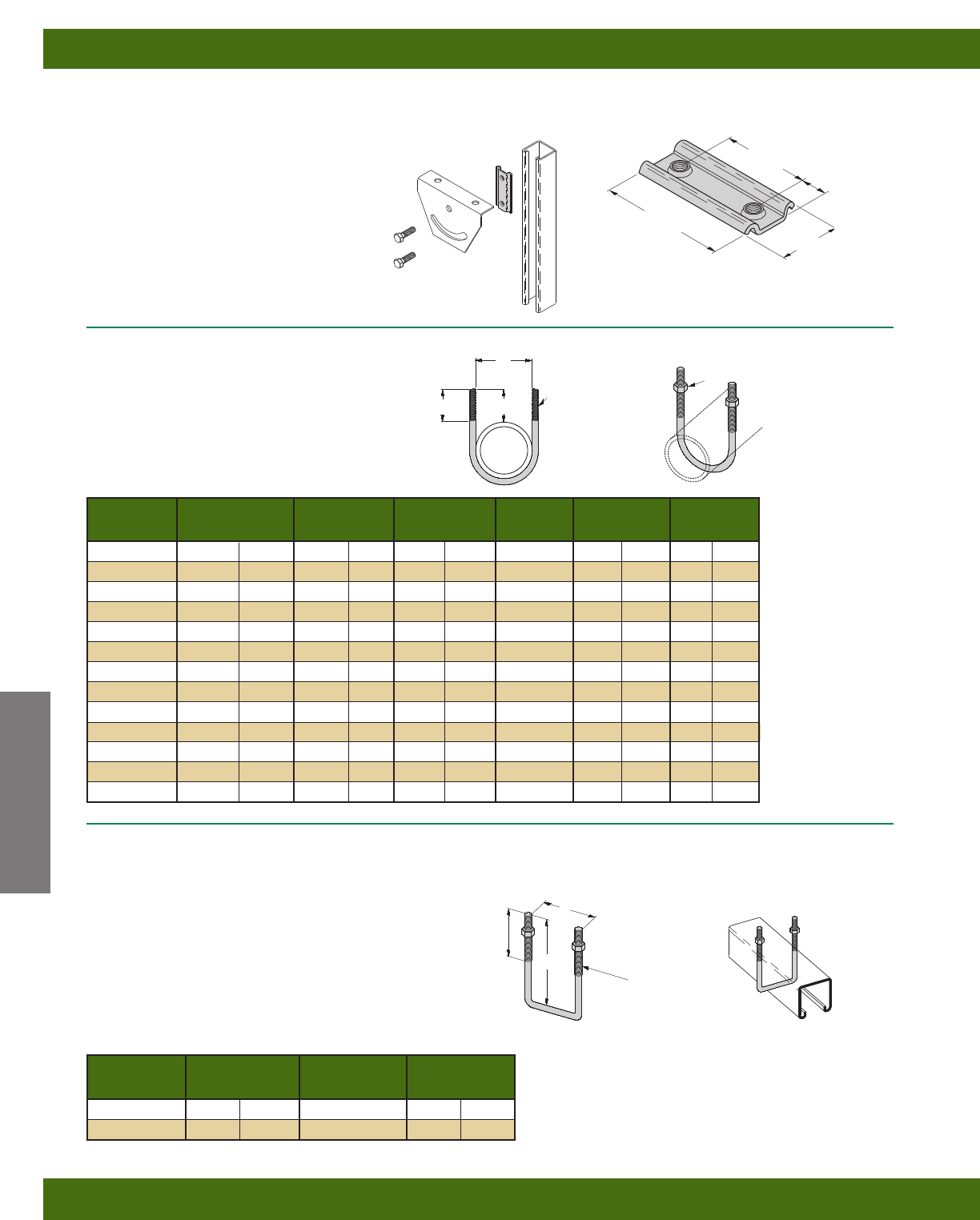
DCN 3/8
DOUBLE CONVEYOR NUT
•Recommended torque - 19 ft./Lbs.
•Allowable slip loading - 700 Lbs.(3.11kN)
•Safety Factor of 3
•Material: ASTM 1011SS Gr. 33
•Finish: Electrodeposited zinc ASTM B633 SC1
•Strut ordered separately
B501 SERIES
U-BOLT
•Designed for use with Rigid Conduit or Iron Pipe
•Dimension “C” is dependent on the type of pipe or
conduit supported and is a reference only
Design Load Wt./C
Part No. A B C D Lbs. kN Lbs. kg
B501-1/215/16”(23.8) 13/4”(44.4) 11/2”(38.1) 5/16”-18 600 (2.67) 12 (5.4)
B501-3/411/8”(28.6) 13/4”(44.4) 15/8”(41.3) 5/16”-18 600 (2.67) 13 (5.9)
B501-1 13/8”(29.9) 17/8”(47.6) 15/8”(41.3) 5/16”-18 900 (4.00) 14 (6.3)
B501-11/4123/32”(43.6) 13/4”(44.4) 115/32”(37.3) 5/16”-18 900 (4.00) 15 (6.8)
B501-11/22” (50.8) 13/4”(44.4) 17/16”(36.5) 5/16”-18 900 (4.00) 16 (7.2)
B501-2 27/16”(61.9) 21/16”(52.4) 17/8”(47.6) 3/8”-16 1200 (5.34) 27 (12.2)
B501-21/2215/16”(74.6) 21/16”(52.4) 113/16”(46.0) 3/8”-16 1200 (5.34) 32 (14.5)
B501-3 39/16”(90.5) 2” (50.8) 13/4”(44.4) 3/8”-16 1800 (8.00) 36 (16.3)
B501-31/243/32”(94.6) 2” (50.8) 123/32”(43.6) 3/8”-16 1800 (8.00) 38 (17.2)
B501-4 419/32”(116.7) 21/4”(57.1) 121/32”(50.0) 3/8”-16 1800 (8.00) 42 (19.0)
B501-5 521/32”(143.6) 21/4”(57.1) 2” (50.8) 1/2”-13 2400 (10.70) 92 (41.7)
B501-6 63/4”(171.4) 25/8”(66.7) 23/8”(60.3) 5/8”-11 2400 (10.70) 176 (79.8)
B501-8 83/4”(222.2) 25/8”(66.7) 23/8”(60.3) 5/8”-11 2400 (10.70) 191 (86.6)
D
THREAD
SIZE
HEX NUTS
INCLUDED
C
B
A
B500 SERIES
SQUARE U-BOLT
•Includes:
1 pc. U-Bolt only
2 pcs. 3/8”-16 Hex Nuts
•Additional sizes available
•Standard finish: ZN, SS4
Channel Wt./C
Part No. A Size Lbs. kg
B500-3-3/833/8”(85.7) 15/8” x 15/8”25(11.3)
B500-5 5” (127.0) 31/4” x 15/8”33(14.9)
21/2”
(63.5)
121/32”
(42.1)
3/8”-16
THREADS
A
Reference page 44 for general fitting and standard finish specifications.
13/8”
(34.9)
3”
(76.2)
2”
(50.8) 1/2”
(12.7)
Channel Nuts & Hardware
Hardware
52
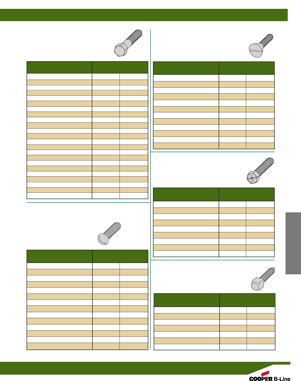
Wt./C
Part No. Lbs. kg
1/4” x 1/2” HHCS 1.3 (.59)
1/4” x 3/4” HHCS 1.4 (.63)
1/4” x 1” HHCS 1.7 (.77)
1/4” x 11/4” HHCS 2.1 (.95)
1/4” x 11/2” HHCS 2.4 (1.09)
5/16” x 1” HHCS 2.8 (1.27)
5/16” x 11/4” HHCS 3.2 (1.45)
5/16” x 11/2” HHCS 3.8 (1.72)
3/8” x 3/4” HHCS 3.4 (1.54)
3/8” x 1” HHCS 4.1 (1.86)
3/8” x 11/4” HHCS 4.7 (2.13)
3/8” x 11/2” HHCS 5.2 (2.36)
3/8” x 13/4” HHCS 5.9 (2.67)
3/8” x 2” HHCS 7.0 (3.17)
3/8” x 21/4” HHCS 7.8 (3.54)
3/8” x 21/2” HHCS 8.5 (3.85)
1/2” x 7/8” HHCS 8.0 (3.63)
1/2” x 1” HHCS 8.4 (3.81)
1/2” x 11/4” HHCS 9.2 (4.17)
1/2” x 11/2” HHCS 10.1 (4.58)
1/2” x 13/4” HHCS 12.0 (5.44)
1/2” x 2” HHCS 13.2 (5.99)
1/2” x 21/2” HHCS 16.0 (7.26)
Wt./C
Part No. Lbs. kg
1/4” x 3/4” SHHMS 1.2 (.54)
1/4” x 1” SHHMS 1.5 (.68)
1/4” x 11/4” SHHMS 1.8 (.80)
1/4” x 11/2” SHHMS 2.0 (.91)
5/16” x 1” SHHMS 2.6 (1.18)
5/16” x 11/4” SHHMS 3.1 (1.40)
5/16” x 11/2” SHHMS 3.4 (1.54)
3/8” x 11/4” SHHMS 4.6 (2.08)
3/8” x 11/2” SHHMS 5.3 (2.40)
Wt./C
Part No. Lbs. kg
1/4” x 1/2” SRHMS .9 (.41)
1/4” x 3/4” SRHMS 1.2 (.54)
1/4” x 1” SRHMS 1.5 (.68)
1/4” x 11/4” SRHMS 1.7 (.77)
1/4” x 11/2” SRHMS 1.9 (.86)
5/16” x 1” SRHMS 2.5 (1.13)
5/16” x 11/4” SRHMS 2.9 (1.31)
5/16” x 11/2” SRHMS 3.3 (1.49)
3/8” x 1” SRHMS 4.0 (1.81)
3/8” x 11/4” SRHMS 4.5 (2.04)
3/8” x 11/2” SRHMS 5.1 (2.31)
3/8” x 2” SRHMS 6.3 (2.86)
3/8” x 21/4” SRHMS 7.1 (3.22)
3/8” x 21/2” SRHMS 7.7 (3.49)
Wt./C
Part No. Lbs. kg
1/4” x 1/2” SFHMS 1.1 (.50)
1/4” x 5/8” SFHMS 1.2 (.54)
1/4” x 3/4” SFHMS 1.4 (.63)
5/16” x 1” SFHMS 2.8 (1.27)
3/8” x 11/2” SFHMS 5.6 (2.54)
3/8” x 2” SFHMS 6.7 (3.04)
3/8” x 21/4” SFHMS 7.3 (3.31)
3/8” x 21/2” SFHMS 7.9 (3.58)
1/2” x 1” SFHMS 5.9 (2.67)
1/2” x 11/4” SFHMS 7.0 (3.17)
1/2” x 11/2” SFHMS 8.3 (3.76)
1/2” x 21/2” SFHMS 13.8 (6.26)
HHCS
HEX HEAD CAP SCREWS
•Standard finish: Zinc-Plated, Stainless Steel
SFHMS
SLOTTED FLAT HEAD MACHINE SCREWS
•Standard finish: Zinc-Plated
SRHMS
SLOTTED ROUND HEAD MACHINE SCREWS
•Standard finish: Zinc-Plated
SHHMS
SLOTTED (COMBINATION RECESS)
HEX HEAD MACHINE SCREWS
•Standard finish: Zinc-Plated, Stainless Steel
Reference page 44 for general fitting and standard finish specifications.
CNPSS
SQUARE HEAD CONE POINT SET SCREWS
•Standard finish: ZN
Wt./C
Part No. Lbs. kg
3/8” x 11/2” CNPSS 4.7 (2.13)
3/8” x 2” CNPSS 6.0 (2.72)
1/2” x 11/2” CNPSS 9.2 (4.17)
1/2” x 2” CNPSS 11.4 (5.17)
1/2” x 21/2” CNPSS 13.7 (6.21)
5/8” x 2” CNPSS 19.0 (8.62)
5/8” x 21/2” CNPSS 22.6 (10.25)
Channel Nuts & Hardware
Hardware
53
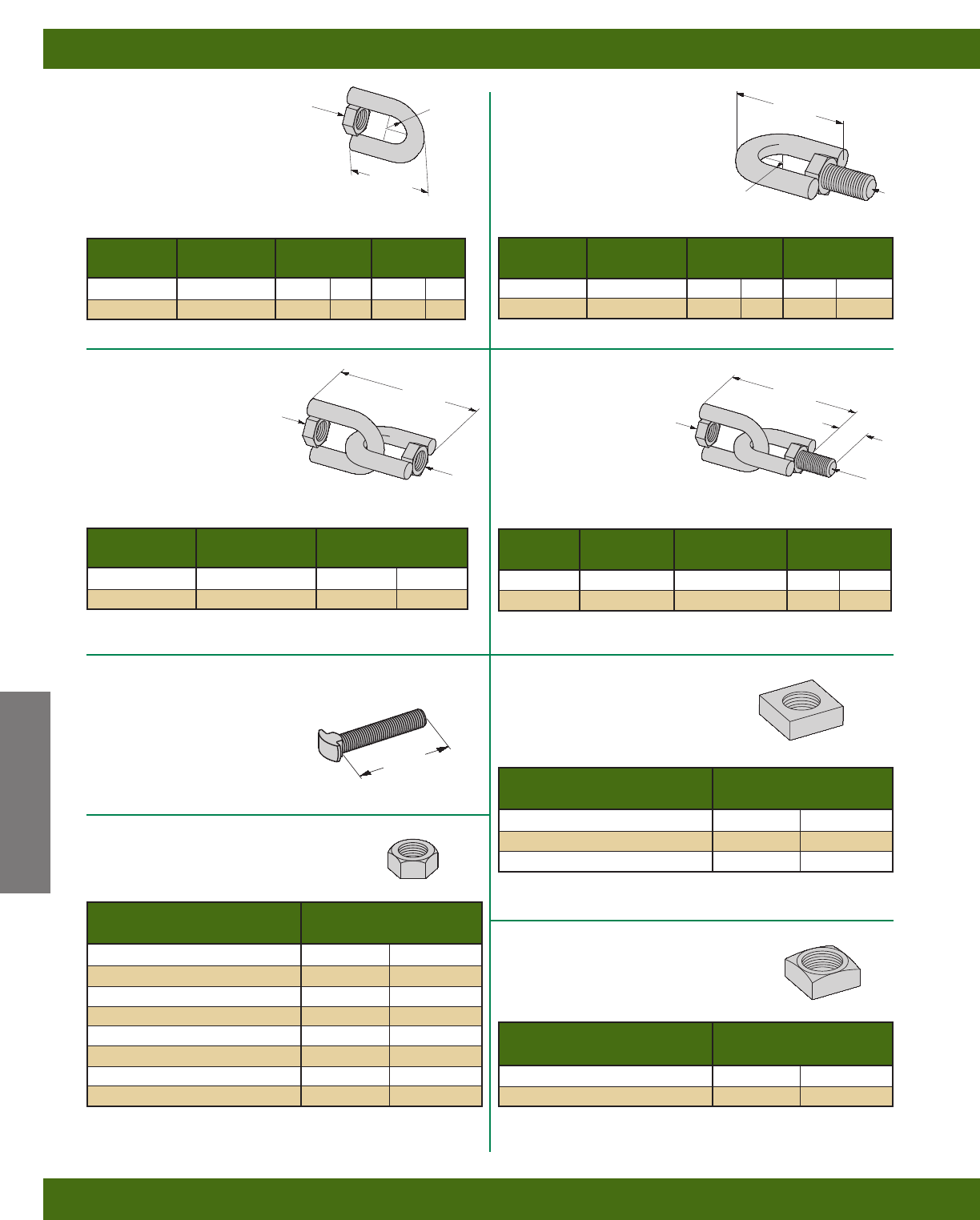
Reference page 44 for general fitting and standard finish specifications.
B446A
SWIVEL HANGER
(FEMALE ONLY)
•Design Load: (3/8)-610 Lbs. (2.71 kN)
(1/2)-1130 Lbs. (5.02 kN)
•Safety Factor of 3
•Standard finish: ZN
B446B
SWIVEL HANGER
(MALE ONLY)
•Design Load: (3/8)-610 Lbs. (2.71 kN)
(1/2)-1130 Lbs. (5.02 kN)
•Safety Factor of 3
•Standard finish: ZN
B446C
SWIVEL HANGER
(FEMALE-FEMALE)
•Design Load:
(3/8)-610 Lbs. (2.71 kN)
(1/2)-1130 Lbs. (5.02 kN)
•Safety Factor of 3
•Standard finish: ZN
B617
SHOULDER BOLT
•Standard finish: ZN
•Wt./C 6 Lbs. (2.7 kg)
Wt./C
Part No. A B Lbs. kg
B446-3/83/8”-16 HN 3/8”-16 HHCS 28 (12.7)
B446-1/21/2”-13 HN 1/2”-13 HHCS 36 (16.3)
B
23/4”
(69.8) 1”
(25.4)
Wt./C
Part No. A R Lbs. kg
B446A-3/83/8”-16 HN 9/32”(7.1) 13 (5.9)
B446A-1/21/2”-13 HN 3/8”(9.5) 15 (6.8)
13/4”
(44.4)
AR
Wt./C
Part No. B R Lbs. kg
B446B-3/83/8”-16 HHCS 9/32”(7.1) 16 (7.2)
B446B-1/21/2”-13 HHCS 3/8”(9.5) 20 (9.1)
13/4”
(44.4)
B
R
Wt./C
Part No. A Lbs. kg
B446C-3/83/8”-16 HN 26 (11.8)
B446C-1/21/2”-13 HN 31 (14.0)
23/4”
(69.8)
A
A
3/8”-16 THREAD SIZE
2”
(50.8)
HN
HEX NUTS
•Standard finish: Zinc-Plated, Stainless Steel
Wt./C
Part No. Lbs. kg
1/4” HN .7 (.32)
5/16” HN 1.0 (.45)
3/8” HN 1.5 (.68)
1/2” HN 3.6 (1.63)
5/8” HN 7.2 (3.26)
3/4” HN 11.1 (5.03)
7/8” HN 17.9 (8.12)
1” HN 27.2 (12.34)
Wt./C
Part No. Lbs. kg
MSQN 1/4”.6 (.27)
MSQN 5/16”1.2 (.54)
MSQN 3/8”1.8 (.81)
MSQN
MACHINE SQUARE NUT
•For use with B755 Beam Clamp
•Standard finish: Zinc-Plated
Wt./C
Part No. Lbs. kg
1/2” SQN 5.7 (2.58)
5/8” SQN 10.1 (4.58)
SQN
SQUARE NUTS
•Standard finish: Zinc-Plated
B446
SWIVEL HANGER
(FEMALE-MALE)
•Design Load:
(3/8)-610 Lbs. (2.71 kN)
(1/2)-1130 Lbs. (5.02 kN)
•Safety Factor of 3
•Standard finish: ZN
A
Channel Nuts & Hardware
Hardware
54
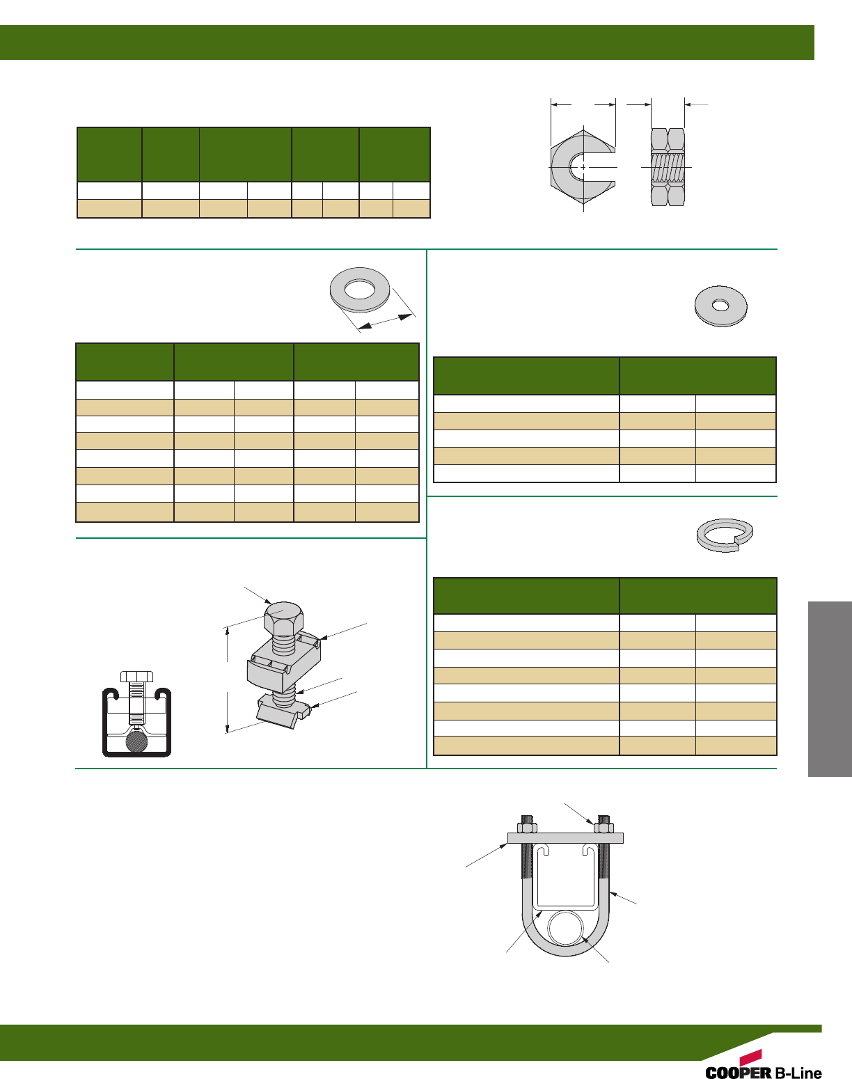
Wt./C
Part No. Lbs. kg
1/4” LW .3 (.13)
5/16” LW .4 (.18)
3/8” LW .6 (.27)
1/2” LW 1.3 (.59)
5/8” LW 2.4 (1.09)
3/4” LW 3.8 (1.72)
7/8” LW 5.9 (2.67)
1” LW 8.8 (3.99)
O.D. Outside Dia. Wt./C
Part No. in. mm Lbs. kg
1/4” FW 47/64”(18.7) .7 (.32)
5/16” FW 7/8”(22.2) 1.4 (.63)
3/8” FW 1” (25.4) 1.7 (.77)
1/2” FW 13/8”(34.9) 3.9 (1.77)
5/8” FW 115/32”(37.3) 6.4 (2.90)
3/4” FW 2” (50.8) 10.9 (4.94)
7/8” FW 21/4”(57.1) 13.4 (6.08)
1” FW 21/2”(63.5) 18.8 (8.53)
Wt./C
Part No. Lbs. kg
1/4” x 11/4” FFW 2.2 (1.00)
1/4” x 11/2” FFW 3.1 (1.40)
3/8” x 11/4” FFW 2.0 (.91)
3/8” x 11/2” FFW 3.0 (1.36)
1/2” x 2” FFW 5.4 (2.45)
LW
LOCK WASHERS
•Standard finish: Zinc-Plated, Stainless Steel
FW
FLAT WASHERS
•Standard finish: Zinc-Plated, Stainless Steel
FFW
FLAT FENDER WASHERS
•Standard finish: Zinc-Plated
O.D.
SC228
HANGER ROD
STIFFENER
•For 3/8” thru 5/8” ATR
•Strut ordered separately
•Standard finish: ZN
11/2”
(63.5)
3/8”-16
THREADS
SC228B
SC228BS
N228WO
SC-UB
HANGER ROD STIFFENER
•For 3/4” thru 7/8” ATR
•Strut ordered separately
•Includes: (1) B3188-11/2WO U-Bolt
(2) 3/8”-16 Hex Nuts
(1) 2-Hole Plate
•Standard finish: ZN
B3188-11/2”WO U-BOLT
3/8”-16 HEX NUTS
2-HOLE PLATE
1/2” (6mm) x 15/8” (41mm) x 31/2” (89mm)
STIFFENER CHANNEL ALL THREADED ROD (ATR)
Channel Nuts & Hardware
Hardware
55
Reference page 44 for general fitting and standard finish specifications.
SLN SLIP-ON LOCK NUT
•Material: ASTM A307 Gr. A.
•Standard finish: Zinc-Plated
Recommended
Part No. Size
Load
Length
Wt./C
Lbs. kg
SLN1/21/2”-13 11/8”(28.6) 5/8”(15.9) 6.0 (2.72)
SLN5/85/8”-11 15/16”(33.3) 5/8”(15.9) 7.0 (3.17)
BC
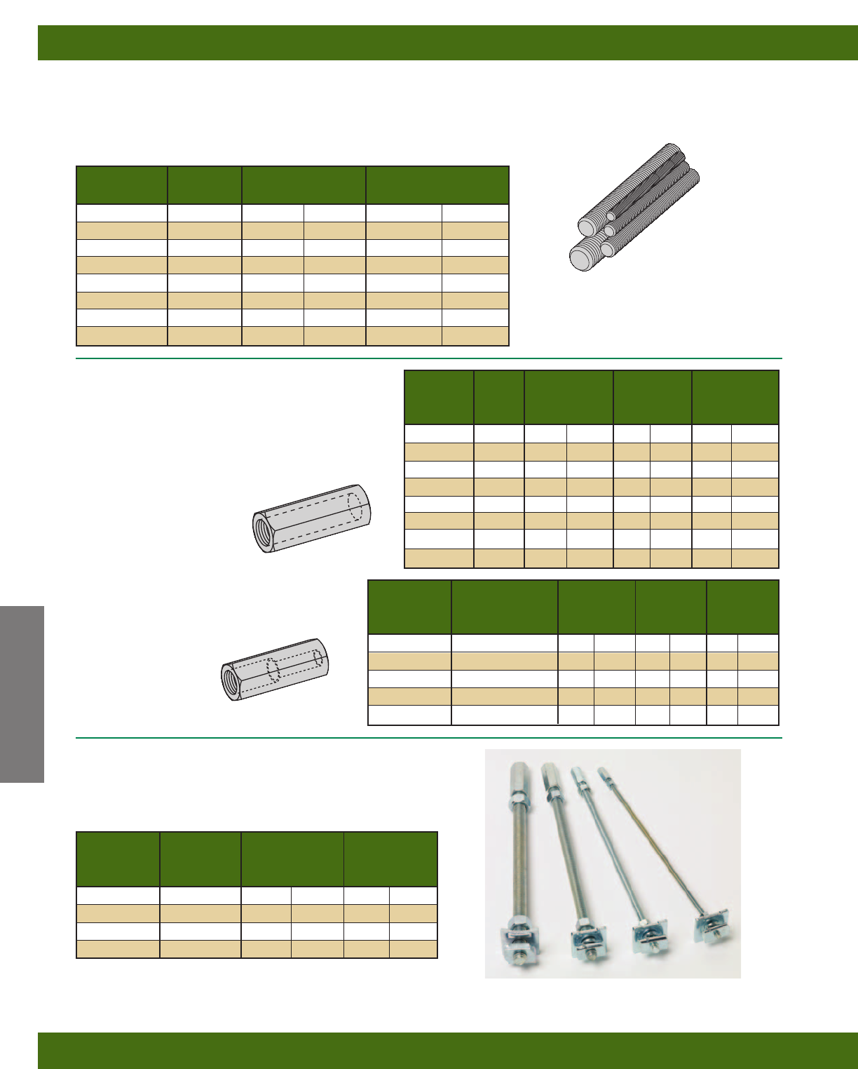
Reference page 44 for general fitting and standard finish specifications.
Part No. Threads Recommended Load Wt./C Ft. (3048.0 cm)
& Size Per Inch Lbs. kN Lbs. kg
ATR 1/4”20 240 (1.07) 12 (5.44)
ATR 5/16”18 400 (1.78) 19 (8.62)
ATR 3/8”16 730 (3.24) 29 (13.15)
ATR 1/2”13 1350 (6.00) 53 (24.04)
ATR 5/8”11 2160 (9.60) 89 (40.37)
ATR 3/4”10 3230 (14.37) 123 (55.79)
ATR 7/8”9 4480 (19.93) 170 (77.11)
ATR 1” 8 5900 (26.24) 225 (102.06)
ATR
ALL THREADED ROD
•Available in 36” (91.4 cm), 72” (182.9 cm), 120” (304.8 cm), 144” (365.7 cm) lengths
•Safety Factor of 5 on recommended load
•Standard finish: Zinc-Plated, Stainless Steel Type 304
B655 ROD COUPLING
B656 REDUCER ROD COUPLING
•Load rating for each coupler meets All Threaded Rod value
•Standard finish: Zinc-Plated, Stainless Steel Type 304
BHR SERIES
HOT RODS FOR TRAPEZE HANGERS
•12” length of threaded rod completely assembled with rod
coupling, locking hex nuts, square washer, and channel nut.
•Standard finish: Zinc-Plated
Recommended
Part No. Size Load Length Wt./C
Lbs. kN Lbs. kg
B655-1/41/4”-20 240 (1.07) 7/8”(22.2) 1.9 (.86)
B655-5/16 5/16”-18 380 (1.69) 7/8”(22.2) 1.8 (.81)
B655-3/83/8”-16 730 (3.24) 11/8”(28.6) 3.6 (1.63)
B655-1/21/2”-13 1350 (6.00) 13/4”(44.4) 11.3 (5.12)
B655-5/85/8”-11 1810 (8.05) 21/8”(54.0) 17.6 (7.98)
B655-3/43/4”-10 2710 (12.05) 21/4”(57.1) 28.1 (12.74)
B655-7/87/8”-9 3770 (16.77) 21/2”(63.5) 57.2 (25.94)
B655-1 1”-8 4960 (22.06) 23/4”(69.8) 73.7 (33.43)
Recommended
Part No. Size
Load
Length
Wt./C
Lbs. kN Lbs. kg
B656-3/8x 1/43/8”-16 & 1/4”-20 240 (1.07) 1” (25.4) 3.7 (1.68)
B656-1/2x 3/81/2”-13 & 3/8”-16 610 (2.71) 11/4”(31.7) 6.6 (2.99)
B656-5/8x 1/25/8”-11 & 1/2”-13 1130 (5.02) 11/4”(31.7) 11.6 (5.26)
B656-3/4x 5/83/4”-10 & 5/8”-11 1810 (8.05) 11/2”(38.1) 20.6 (9.34)
B656-7/8x 3/47/8”-9 & 3/4”-10 2710 (12.05) 13/4”(44.4) 39.4 (17.87)
Recommended
Part No.
Rod
Size
Load Wt./C
Lbs. kN Lbs. kg
BHR1225ZN 1/4”-20 240 (1.07) 41 (18.6)
BHR1238ZN 3/8”-16 730 (3.24) 63 (28.6)
BHR1250ZN 1/2”-13 1350 (6.00) 98 (44.4)
BHR1262ZN 5/8”-11 1500 (6.67) 148 (67.1)
Channel Nuts & Hardware
(BHR1225, BHR1238, and BHR1250 use combo nut washers instead of square washers and channel nuts)
Note: Based on use with 12 ga. channel.
Hardware
56
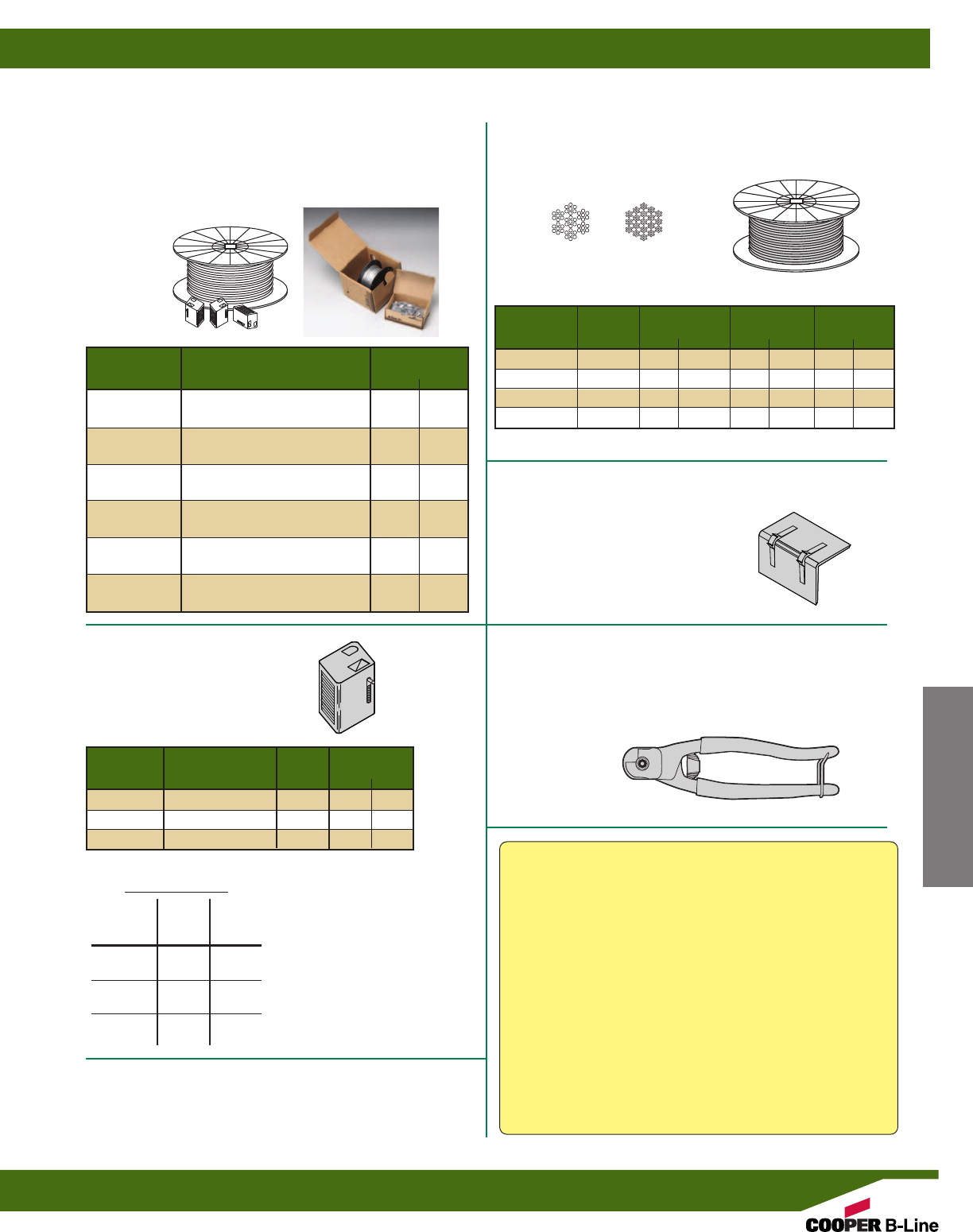
Reference page 44 for general fitting and standard finish specifications.
KWIKWIRE™ HANGING SYSTEM
KWIKPAK™
WIRE ROPE & CLAMPS
IN HANDY CARRYING CARTON
• Dispenser Box - Easy Jobsite Handling.
• 1 Kit per box
WIRE ROPE
•Uncoated Galvanized Wire
• 1 Spool per box
CLAMPS
• For use with Wire Rope
AIR DUCT CORNER POTECTORS
BKCP
• Material: Plastic
• 100 per box
• Weight per 100 pcs. 1.0 Lbs. (0.45 kg)
WIRE ROPE CUTTER
BKCC
• Never use cutter on energized circuits, wire, or cable.
• 1 per box
• Weight per each 1.0 Lbs. (0.45 kg)
Part No.
Kit Includes Wt./Kit
Lbs. kg
BKP10063 BKC100 (100 pcs.) 9.1 (4.1)
1/16ӯ Wire Rope (500 ft.)
BKP10094 BKC100 (100 pcs.) 18.1 (8.2)
3/32ӯ Wire Rope (500 ft.)
BKP15094 BKC150 (100 pcs.) -- (--)
3/32ӯ Wire Rope (500 ft.)
BKP15125 BKC150 (100 pcs.) -- (--)
1/8ӯ Wire Rope (500 ft.)
BKP20125 BKC200 (50 pcs.) 31.0 (14.1)
1/8ӯ Wire Rope (500 ft.)
BKP20188 BKC200 (50 pcs.) 33.0 (15.0)
3/16ӯ Wire Rope (250 ft.)
KwikWire™ Clamp
Working Loads**
Clamp Wire Lbs.
Part No. Rope Safety
Dia. Factor 5
BKL100 1/16” 0-75
BKL100 3/32” 25-150
BKL150 3/32” 25-150
BKL150 1/8” 25-250
BKL200 1/8” 25-250
BKL200 3/16” 50-640
**Working loads shown are for
hanging vertically.
For suspending at 15°, 30°, 45°
or 60° angles from vertical use
the following percentage of
the working loads from the
chart:
15° = 96%, 30° = 86%,
45° = 70%, 60° = 50%
Part No.
For Use With Wire Qty. Wt./Box
Rope Diameters Per Box Lbs. kg
BKC100 1/16” & 3/32” 100 4.1 (1.8)
BKC150 3/32” & 1/8” 100 -- (--)
BKC200 1/8” & 3/16” 50 15.0 (6.8)
7 x 7 7 x 19
Part No.
Diameter Working Load Spool Qty. Wt./Spool
Lbs. kg Ft. M Lbs. kg
BKW063 (1) 1/16”96(43.5) 500 (152.4) 5.0 (2.3)
BKW094 (1) 3/32” 184 (83.4) 500 (152.4) 14.0 (6.3)
BKW125 (1) 1/8” 340 (154.2) 500 (152.4) 16.0 (7.2)
BKW188 (2) 3/16” 840 (381.0) 250 (76.2) 18.0 (8.2)
(1) Wire rope construction Type 7 x 7 (2) Wire rope construction Type 7 x 19
KwikWire™ System Recommendations:
• Do not exceed the safe working load of the products shown in
their charts
• KwikWire™ Clamp load ratings are guaranteed only when used
in combination with B-Line/Cooper supplied wire rope
• Do not use for overhead lifting or hoisting
• Do not use if cable or components are visibly distorted or worn,
remove damaged cable end prior to inserting in KwikWire™
Clamp
• Do not paint cable near working area of KwikWire Clamp
connector
• Do not apply lubricant
• Keep product clean and free of dirt
• Do not use on coated wire rope
• Do not use in chlorinated or caustic atmospheres
• For use in dry locations
• Cooper’s BKCC tool is recommended for cutting wire rope to
prevent fraying
For additional information on KwikWire™ products
see the KwikWire brochure on the website at
www.cooperbline.com
Channel Nuts & Hardware
KwikWire™ Hardware
57
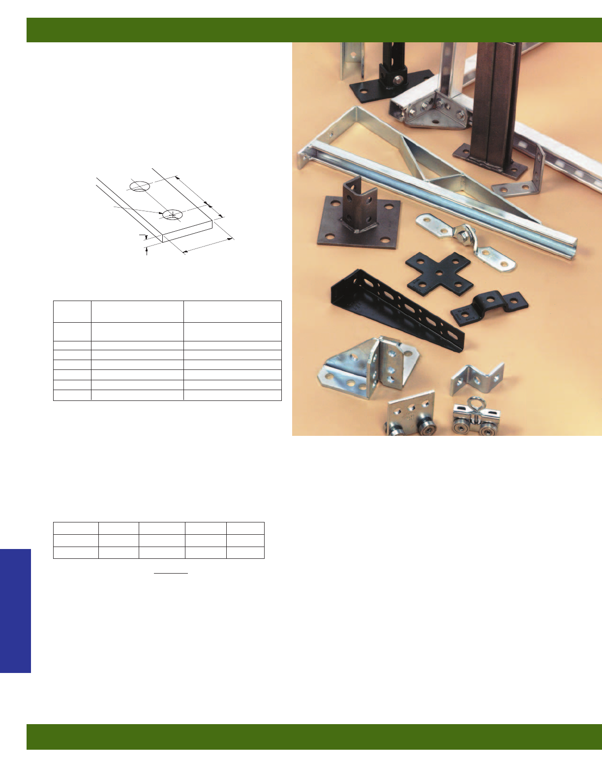
This section offers a full selection of fittings and
accessories to complete B-Line’s metal framing
system. Fittings are made from hot rolled, pickled and
oiled plate or strip steel in accordance with ASTM
A1018 33,000 PSI min. yield, unless noted.
Dimensions
The following dimensions apply to all fittings except
as noted:
Materials & Finishes (Unless otherwise noted)
Note: A minimum order may apply on special material
and finishes.
Load Data
The load data published includes safety factor of 2.5 when used with 12 ga. (2.6) channel (safety factor = ratio of
ultimate load to the design load).
Use 1/2” by 7/8” hex head cap screws and 1/2” (N225 or TN225) channel nuts for the rated results.
Recommended Bolt Torque
See chart on page 98 for setscrew torque.
Hardware
Nuts and bolts are not included with the fittings and must be ordered separately, unless noted.
Metric
Metric dimensions are shown in parentheses.
Unless noted, all metric dimensions are in millimeters.
Bolt Size 1/4”-20 5/16”-18 3/8”-16 1/2”-13
Foot/Lbs. 6 11 19 50
Nm 8 15 26 68
Finish
Code Finish Specification
PLN Plain ASTM A1018
33,000 PSI min. yield
ZN Electro-Plated Zinc ASTM B633 SC3 Type III
GRN Dura-Green
HDG Hot-Dipped Galvanized ASTM A123
SS4 Stainless Steel Type 304 ASTM A240
SS6 Stainless Steel Type 316 ASTM A240
AL Aluminum ASTM B209
Hole Size – 9/16”
(14.3 mm) diameter
Thickness – 1/4” (6.3 mm)
Width –
15/8” (41.3 mm)
Hole Spacing – 17/8”
(47.6 mm) on center
Hole Spacing –
13/16” (20.6 mm)
from end
Strut Fittings
Fittings
58
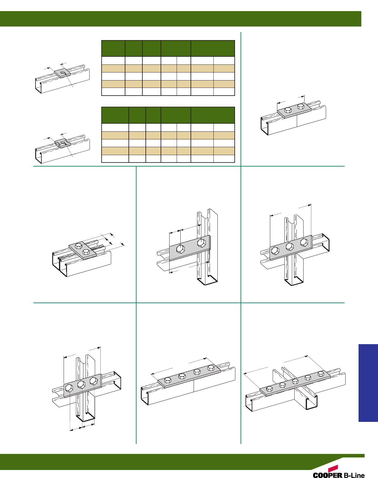
Part Wt./C
No. A (A) Bolt Size Lbs. kg
B200 3/8”(9.5) 5/16”(7.9) 18 (8.1)
B201 7/16”(11.1) 3/8”(9.5) 18 (8.1)
B202 9/16”(14.2) 1/2”(12.7) 17 (7.7)
B202-1 11/16”(17.4) 5/8”(15.9) 16 (7.2)
B202-2 13/16”(20.6) 3/4”(19.0) 15 (6.8)
Part Wt./C
No. A (A) Bolt Size Lbs. kg
B200D 3/8”(9.5) 5/16”(7.9) 18 (8.1)
B201D 7/16”(11.1) 3/8”(9.5) 18 (8.1)
B202D 9/16”(14.2) 1/2”(12.7) 17 (7.7)
B202-1D 11/16”(17.4) 5/8”(15.9) 16 (7.2)
B202-2D 13/16”(20.6) 3/4”(19.0) 15 (6.8)
15/8”
(41.3)
31/2”
(88.9)
31/4”
(82.5)
21/2”
(63.5)
53/8”
(136.5)
15/16”
(33.3)
45/8”
(117.5)
15/8”
(41.3)
47/8”
(123.8)
71/4”
(184.1)
91/8”
(231.8)
15/8”
(41.3)
15/8”
(41.3)
15/8”
(41.3)
HOLE SIZE A
HOLE SIZE A
B200D-B202-2D
•Standard finishes: ZN,
GRN, HDG, SS4, SS6, AL
B200-B202-2
•Standard finishes: ZN,
GRN, HDG, SS4, SS6, AL
B129
TWO HOLE SPLICE PLATE
•Standard finishes: ZN, GRN
•Wt./C 37 Lbs. (16.8 kg)
B340
TWO HOLE SPLICE PLATE
•Standard finishes: ZN, GRN
•Wt./C 34 Lbs. (15.4 kg)
B557
THREE HOLE SPLICE PLATE
•Standard finishes: ZN, GRN
•Wt./C 50 Lbs. (22.7 kg)
B341
FOUR HOLE SPLICE PLATE
•Standard finishes: ZN, GRN, HDG
•Wt./C 76 Lbs. (34.5 kg)
B342
FIVE HOLE SPLICE PLATE
•Standard finishes: ZN, GRN
•Wt./C 96 Lbs. (43.5 kg)
B528
TWO HOLE SPLICE PLATE
•Standard finishes: ZN, GRN
•Wt./C 50 Lbs. (22.7 kg)
B141
THREE HOLE SPLICE PLATE
•Standard finishes: ZN, GRN
•Wt./C 55 Lbs. (24.9 kg)
NO TWIST SQUARE WASHER
SQUARE WASHER
Strut Fittings
Reference page 58 for general fitting and standard finish specifications.
Flat Plate Fittings
59
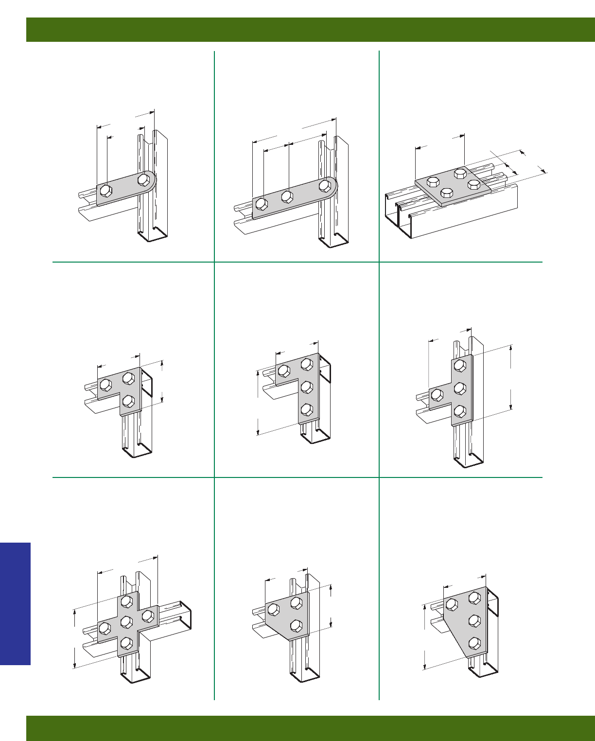
B504
FOUR HOLE SPLICE PLATE
•Standard finishes: ZN, GRN
•Wt./C 73 Lbs. (33.1 kg)
B139
THREE HOLE SWIVEL PLATE
•Standard finishes: ZN, GRN
•Wt./C 69 Lbs. (31.3 kg)
B138
TWO HOLE SWIVEL PLATE
•Standard finishes: ZN, GRN
•Wt./C 48 Lbs. (21.8 kg)
B140
THREE HOLE CORNER PLATE
•Standard finishes: ZN, GRN, HDG, SS4
•Wt./C 56 Lbs. (25.4 kg)
B143
FOUR HOLE CORNER PLATE
•Standard finishes: ZN, GRN, HDG, SS4
•Wt./C 75 Lbs. (34.0 kg)
B133
FOUR HOLE TEE PLATE
•Standard finishes: ZN, GRN, HDG, SS4, AL
•Wt./C 75 Lbs. (34.0 kg)
45/8”
(117.5)
31/2”
(88.9)
53/8”
(136.5)
53/8”
(136.5)
31/2”
(88.9)
31/2
(88.9)
31/2”
(88.9)
53/8”
(136.5)
31/2”
(88.9)
31/2”
(88.9)
53/8”
(136.5)
31/2”
(88.9)
53/8”
(136.5)
61/2”
(165.1) 31/2”
(88.9)
15/8”
(41.3) 31/4”
(82.5)
3”
(76.2)
17/8”
(47.6)
3”
(76.2)
B142
FOUR HOLE CORNER
GUSSET PLATE
•Standard finishes: ZN, GRN, HDG
•Wt./C 102 Lbs. (46.2 kg)
B135
THREE HOLE CORNER
GUSSET PLATE
•Standard finishes: ZN, GRN
•Wt./C 70 Lbs. (31.7 kg)
B132
FIVE HOLE CROSS PLATE
•Standard finishes: ZN, GRN, HDG
•Wt./C 100 Lbs. (45.3 kg)
Strut Fittings
Reference page 58 for general fitting and standard finish specifications.
Flat Plate Fittings
60
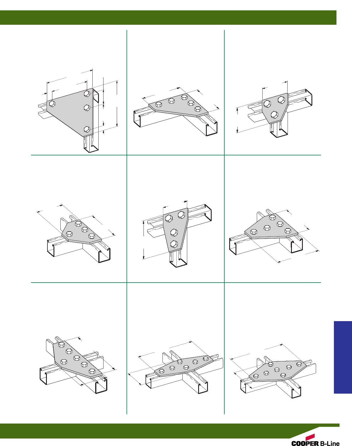
B337
THREE HOLE TEE
GUSSET PLATE
•Standard finishes: ZN, GRN
•Wt./C 70 Lbs. (31.7 kg)
B556
FIVE HOLE CORNER
GUSSET PLATE
•Standard finishes: ZN, GRN
•Wt./C 145 Lbs. (65.8 kg)
B137
FOUR HOLE CORNER
GUSSET PLATE
•Standard finishes: ZN, GRN
•Wt./C 273 Lbs. (123.8 kg)
B432
FOUR HOLE TEE GUSSET PLATE
•Standard finishes: ZN, GRN
•Wt./C 100 Lbs. (45.3 kg)
B136
FOUR HOLE TEE GUSSET PLATE
•Standard finishes: ZN, GRN, HDG
•Wt./C 100 Lbs. (45.3 kg)
B532
FIVE HOLE TEE GUSSET PLATE
•Standard finishes: ZN, GRN
•Wt./C 143 Lbs. (64.8 kg)
B339
SIX HOLE TEE GUSSET PLATE
•Standard finishes: ZN, GRN
•Wt./C 149 Lbs. (67.6 kg)
B568
SIX HOLE CROSS GUSSET PLATE
•Standard finishes: ZN, GRN
•Wt./C 166 Lbs. (75.3 kg)
B334
SEVEN HOLE CROSS
GUSSET PLATE
•Standard finishes: ZN, GRN
•Wt./C 232 Lbs. (105.2 kg)
75/8”
(193.7)
75/8”
(193.7)
53/8”
(136.5) 53/8”
(136.5)
31/2”
(88.9)
31/2”
(88.9)
31/2”
(88.9)
31/2”
(88.9)
31/2”
(88.9)
53/8”
(136.5)
91/8”
(231.8) 91/8”
(231.8) 91/8”
(231.8)
53/8”
(136.5)
31/2”
(88.9) 31/2”
(88.9)
53/8”
(136.5)
53/8”
(136.5)
53/8”
(136.5)
25/16”
(58.7)
513/16”
(147.6)
1”
(25.4)
1”
(25.4)
Strut Fittings
Reference page 58 for general fitting and standard finish specifications.
Flat Plate Fittings
61
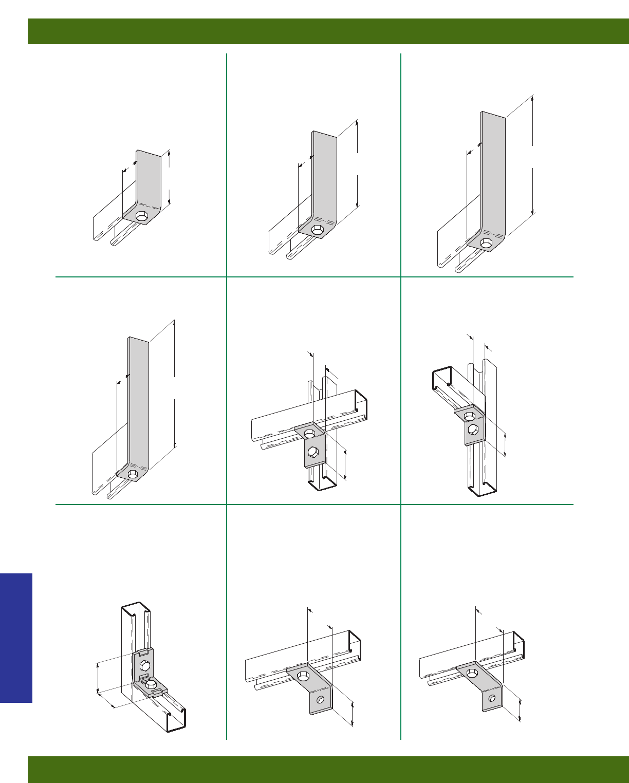
B420-778
ONE HOLE CORNER ANGLE
•Standard finishes: ZN, GRN
•Wt./C 107 Lbs. (48.5 kg)
B420-578
ONE HOLE CORNER ANGLE
•Standard finishes: ZN, GRN
•Wt./C 85 Lbs. (38.5 kg)
B420-378
ONE HOLE CORNER ANGLE
•Standard finishes: ZN, GRN
•Wt./C 60 Lbs. (27.2 kg)
B420-978
ONE HOLE CORNER ANGLE
•Standard finishes: ZN, GRN
•Wt./C 129 Lbs. (58.5 kg)
B101
TWO HOLE CORNER ANGLE
•
Standard finishes: ZN, GRN, HDG, SS4, AL
•Wt./C 37 Lbs. (16.8 kg)
B230
TWO HOLE CORNER ANGLE
•Standard finishes: ZN, GRN, HDG, SS4, AL
•Wt./C 37 Lbs. (16.8 kg)
B231
TWO HOLE “NO-TWIST”
CORNER ANGLE
•Standard finishes: ZN, GRN, HDG
•Wt./C 41 Lbs. (18.6 kg)
B359
TWO HOLE CORNER ANGLE
•Standard finishes: ZN, GRN
•Wt./C 48 Lbs. (21.8 kg)
B360
TWO HOLE CORNER ANGLE
•Standard finishes: ZN, GRN
•Wt./C 53 Lbs. (24.0 kg)
37/8”
(98.4)
57/8”
(149.2)
77/8”
(200.0)
17/8”
(47.6)
17/8”
(47.6) 97/8”
(250.8)
25/16”
(58.7)
21/4”
(57.1)
21/4”
(57.1) 17/8”
(47.6)
17/8”
(47.6)
31/2”
(88.9)
3”
(76.2)
15/8”
(41.3)
21/16”
(52.4)
17/8”
(47.6)
17/8”
(47.6)
17/8”
(47.6)
Strut Fittings
Reference page 58 for general fitting and standard finish specifications.
90° Angle Fittings
62
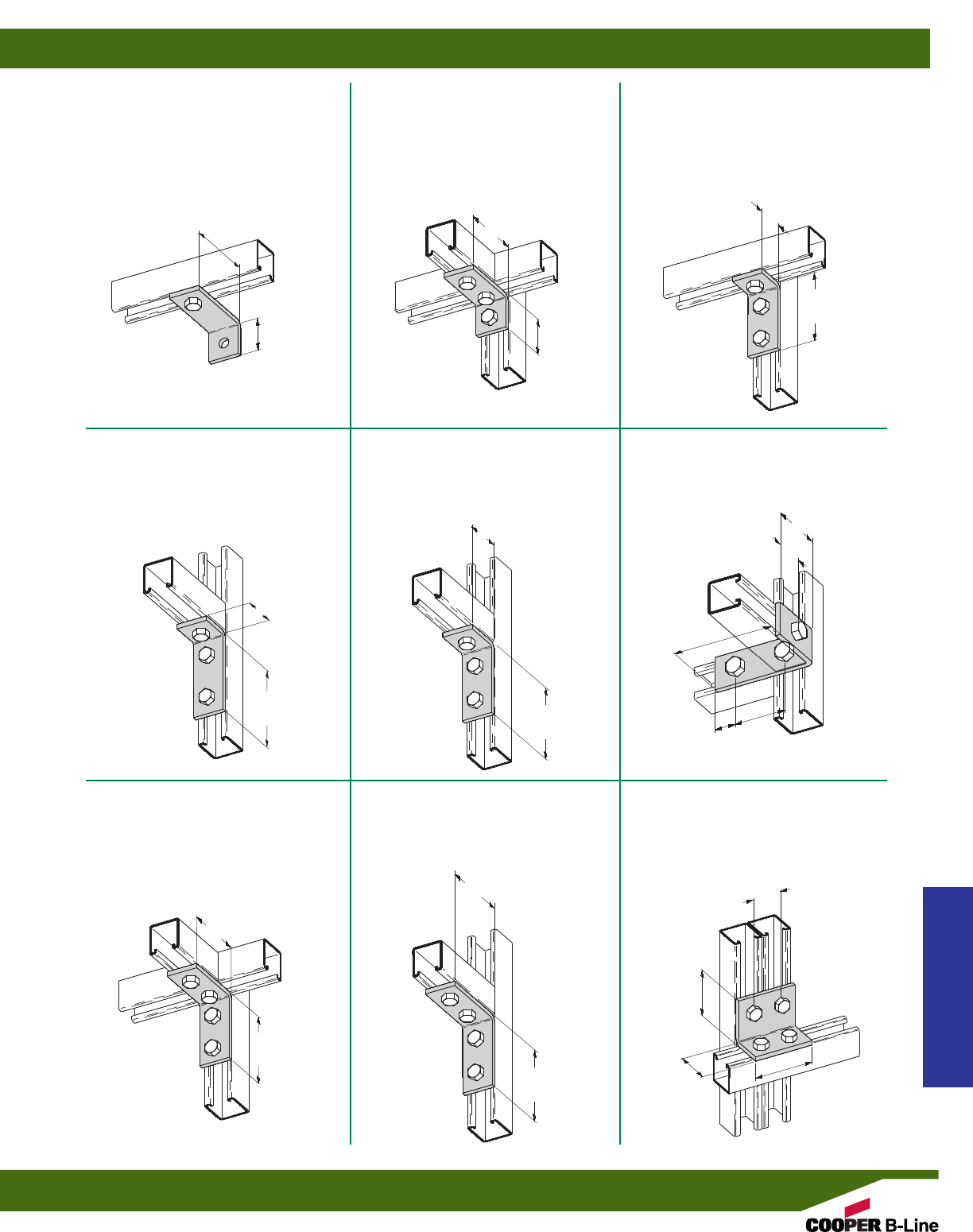
B103
THREE HOLE CORNER ANGLE
•Standard finishes: ZN, GRN, HDG, SS4
•Wt./C 56 Lbs. (25.4 kg)
B102
THREE HOLE CORNER ANGLE
•Standard finishes: ZN, GRN, HDG, SS4
•Wt./C 56 Lbs. (25.4 kg)
B361
TWO HOLE CORNER ANGLE
•Standard finishes: ZN, GRN
•Wt./C 60 Lbs. (27.2 kg)
B232
THREE HOLE CORNER ANGLE
•Standard finishes: ZN, GRN, HDG, SS4
•Wt./C 56 Lbs. (25.4 kg)
B374
THREE HOLE CORNER ANGLE
•Standard finishes: ZN, GRN, HDG
•Wt./C 56 Lbs. (25.4 kg)
B529
THREE HOLE CORNER ANGLE
•Standard finishes: ZN, GRN
•Wt./C 78 Lbs. (35.4 kg)
B104
FOUR HOLE CORNER ANGLE
•Standard finishes: ZN, GRN, HDG, SS4,
SS6, AL
•Wt./C 78 Lbs. (35.4 kg)
B115
FOUR HOLE CORNER ANGLE
•Standard finishes: ZN, GRN, HDG, SS4, AL
•Wt./C 76 Lbs. (34.5 kg)
B558
FOUR HOLE CORNER ANGLE
•Standard finishes: ZN, GRN
•Wt./C 73 Lbs. (33.1 kg)
17/8”
(47.6)
17/8”
(47.6)
21/16”
(52.4)
315/16”
(100.0)
31/2”
(88.9)
41/8”
(104.8)
315/16”
(100.0)
33/4”
(95.2)
15/8”
(41.3)
21/4”
(57.1)
31/4”
(82.5)
15/8”
(41.3)
33/4”
(95.2) 21/2”
(63.5)
15/16”
(33.3)
15/16”
(33.3)
47/8”
(123.8)
3”
(76.2)
21/4”
(57.1)
15/8”
(41.3)
31/2”
(88.9)
41/8”
(104.8)
4”
(101.6)
Strut Fittings
Reference page 58 for general fitting and standard finish specifications.
90° Angle Fittings
63
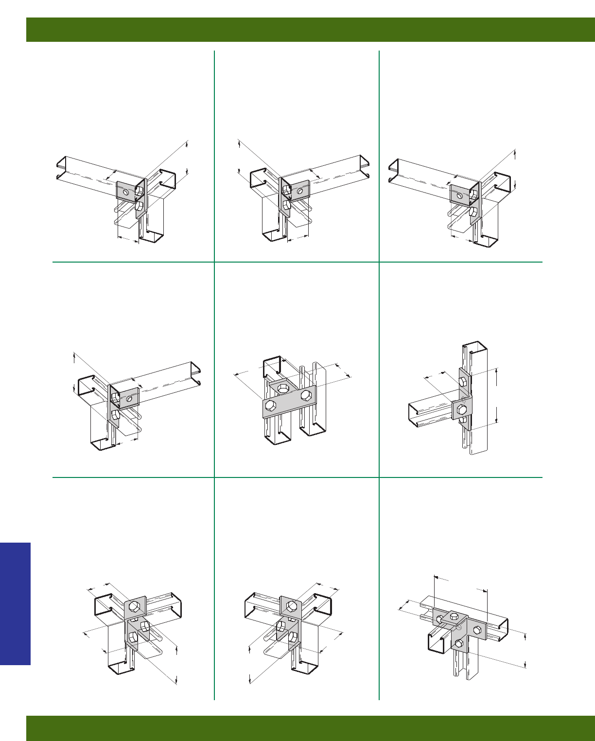
B236R
THREE HOLE (RIGHT HAND)
OFFSET BENT ANGLE
•Standard finishes: ZN, GRN
•Wt./C 65 Lbs. (29.5 kg)
B236L
THREE HOLE (LEFT HAND)
OFFSET BENT ANGLE
•Standard finishes: ZN, GRN
•Wt./C 65 Lbs. (29.5 kg)
B235R
THREE HOLE (RIGHT HAND)
OFFSET BENT ANGLE
•15/8” (41.3) from center to center of the
holes that are shown with bolt heads
•Standard finishes: ZN, GRN
•Wt./C 53 Lbs. (24.0 kg)
B235L
THREE HOLE (LEFT HAND)
OFFSET BENT ANGLE
•15/8” (41.3) from center to center of the
holes that are shown with bolt heads
•Standard finishes: ZN, GRN
•Wt./C 53 Lbs. (24.0 kg)
B237
THREE HOLE OFFSET BENT TEE
•Standard finishes: ZN, GRN
•Wt./C 71 Lbs. (32.2 kg)
B357
FOUR HOLE OFFSET BENT TEE
•Standard finishes: ZN, GRN
•Wt./C 77 Lbs. (34.9 kg)
B238L
FOUR HOLE (LEFT HAND)
OFFSET BENT TEE
•Standard finishes: ZN, GRN
•Wt./C 76 Lbs. (34.5 kg)
B238R
FOUR HOLE (RIGHT HAND)
OFFSET BENT TEE
•Standard finishes: ZN, GRN
•Wt./C 76 Lbs. (34.5 kg)
B239
FIVE HOLE OFFSET BENT TEE
•Standard finishes: ZN, GRN
•Wt./C 96 Lbs. (43.5 kg)
31/4”
(82.5)
31/4”
(82.5) 31/2”
(88.9)
21/16”
(52.4)
21/16”
(52.4)
21/16”
(52.4)
17/8”
(47.6)
17/8”
(47.6) 17/8”
(47.6)
31/2”
(88.9)
21/16”
(52.4)
21/16”
(52.4)
21/16”
(52.4) 21/16”
(52.4)
53/8”
(136.5)
33/4”
(95.2) 33/4”
(95.2)
17/8”
(47.6)
47/8”
(123.8)
53/8”
(136.5)
31/2”
(88.9)
31/2”
(88.9)
31/2”
(88.9)
21/16”
(52.4)
2”
(50.8)
Strut Fittings
Reference page 58 for general fitting and standard finish specifications.
90° Angle Fittings
64
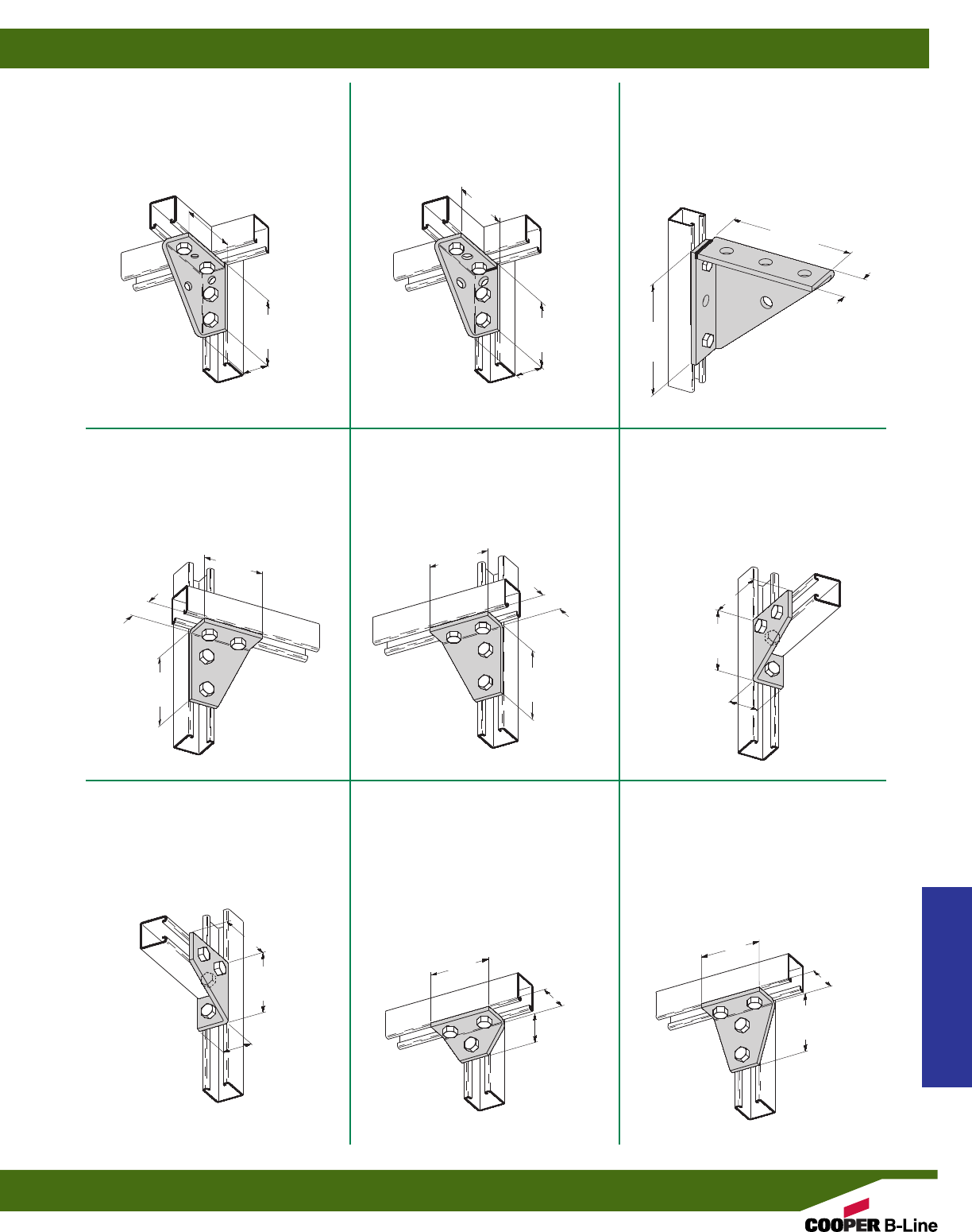
B234R
FOUR HOLE (RIGHT HAND)
CORNER GUSSET
•Standard finishes: ZN, GRN, HDG
•Wt./C 100 Lbs. (45.3 kg)
B234L
FOUR HOLE (LEFT HAND)
CORNER GUSSET
•Standard finishes: ZN, GRN, HDG
•Wt./C 100 Lbs. (45.3 kg)
B844W
UNIVERSAL SHELF BRACKET-
WELDED
•Standard finishes: ZN, GRN
•Wt./C 134 Lbs. (60.8 kg)
B888W
UNIVERSAL SHELF BRACKET-
WELDED
•Standard finishes: ZN, GRN
•Wt./C 197 Lbs. (89.4 kg)
B844
UNIVERSAL SHELF BRACKET
•Standard finishes: ZN, GRN, HDG, SS4
•Wt./C 132 Lbs. (59.9 kg)
B134R
FOUR HOLE (RIGHT HAND)
CORNER GUSSET
•Standard finishes: ZN, GRN
•Wt./C 100 Lbs. (45.3 kg)
B134L
FOUR HOLE (LEFT HAND)
CORNER GUSSET
•Standard finishes: ZN, GRN
•Wt./C 100 Lbs. (45.3 kg)
B125
THREE HOLE GUSSETTED
SHELF ANGLE
•Standard finishes: ZN, GRN
•Wt./C 67 Lbs. (30.4 kg)
B118
FOUR HOLE GUSSETTED
SHELF ANGLE
•Standard finishes: ZN, GRN, HDG
•Wt./C 102 Lbs. (46.2 kg)
4”
(101.6)
4”
(101.6)
4”
(101.6)
4”
(101.6)
17/8”
(47.6)
17/8”
(47.6)
15/8”
(41.3)
43/16”
(106.3)
31/2”
(88.9)
15/8”
(41.3)
17/8”
(47.6)
17/8”
(47.6)
31/2”
(88.9)
31/2”
(88.9)
315/16”
(100.0)
315/16”
(100.0)
43/16”
(106.3)
31/2”
(88.9)
31/2”
(88.9)
15/8”
(41.3)
15/8”
(41.3)
25/16”
(58.7)
41/8”
(104.8)
31/2”
(88.9)
Welded
Corner
513/16”
(147.6)
53/8”
(136.5)
17/8”
(47.6)
Strut Fittings
Reference page 58 for general fitting and standard finish specifications.
90° Angle Fittings
65
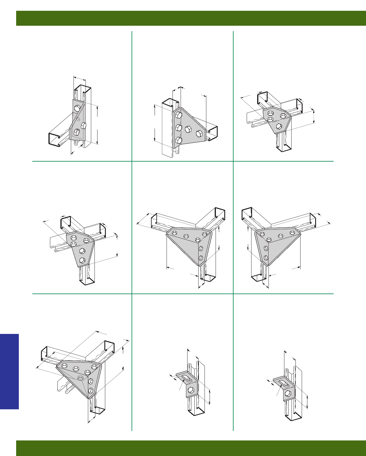
B127
FIVE HOLE GUSSETTED THREE
WAY SHELF ANGLE
•Standard finishes: ZN, GRN
•Wt./C 135 Lbs. (61.2 kg)
B126
FOUR HOLE GUSSETTED THREE
WAY SHELF ANGLE
•Standard finishes: ZN, GRN
•Wt./C 101 Lbs. (45.8 kg)
B533
FIVE HOLE GUSSETTED
SHELF ANGLE
•Standard finishes: ZN, GRN
•Wt./C 141 Lbs. (63.9 kg)
B503R
SIX HOLE (RIGHT HAND)
GUSSETTED CORNER
CONNECTION
•Standard finishes: ZN, GRN
•Wt./C 229 Lbs. (103.9 kg)
B503L
SIX HOLE (LEFT HAND)
GUSSETTED CORNER
CONNECTION
•Standard finishes: ZN, GRN
•Wt./C 229 Lbs. (103.9 kg)
B663
SEVEN HOLE GUSSETTED
CORNER CONNECTION
•Standard finishes: ZN, GRN
•Wt./C 289 Lbs. (131.1 kg)
B371
TWO HOLE ADJUSTABLE
CORNER ANGLE
•Standard finishes: ZN, GRN
•Wt./C 41 Lbs. (18.6 kg)
B372
TWO HOLE ADJUSTABLE
CORNER ANGLE
•Standard finishes: ZN, GRN
•Wt./C 38 Lbs. (17.2 kg)
41/8”
(104.8)
53/8”
(136.5)
15/8”
(41.3) 31/2”
(88.9)
31/2”
(88.9)
31/2”
(88.9)
31/2”
(88.9)
43/16”
(106.3)
21/4”
(57.1)
53/8”
(136.5)
53/8”
(136.5)
53/8”
(136.5)
43/16”
(106.3)
43/16”
(106.3)
15/8”
(41.3)
15/8”
(41.3)
53/8”
(136.5)
15/8”
(41.3)
25/8”
(66.7) 25/8”
(66.7)
15/8”
(41.3)
2”
(50.8)
9/16”
(14.3) 9/16”
(14.3)
43/16”
(106.3)
33/4”
(95.2)
33/4”
(95.2)
9/16” x 11/2” SLOT
(14.3) (38.1) 9/16” x 11/2” SLOT
(14.3) (38.1)
B485
FOUR HOLE GUSSETTED
SHELF ANGLE
•Standard finishes: ZN, GRN
•Wt./C 148 Lbs. (67.1 kg)
315/16”
(100.0)
53/8”
(136.5)
17/8”
(47.6)
Strut Fittings
Reference page 58 for general fitting and standard finish specifications.
90° Angle Fittings
66
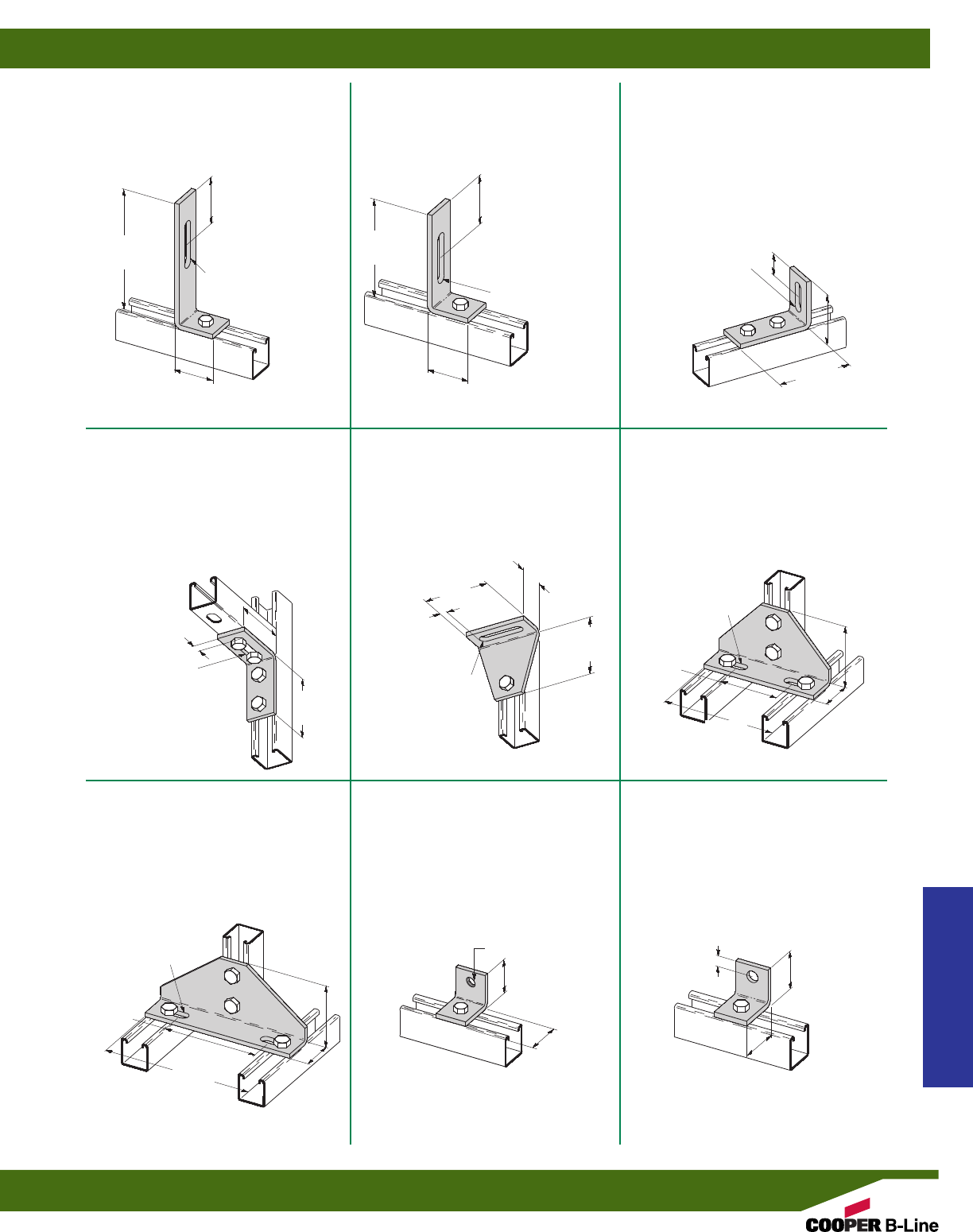
B104SH
THREE HOLE ADJUSTABLE
CORNER ANGLE
•Standard finishes: ZN, GRN
•Wt./C 68 Lbs. (30.8 kg)
B371-2
THREE HOLE ADJUSTABLE
CORNER ANGLE
•Standard finishes: ZN, GRN
•Wt./C 61 Lbs. (27.6 kg)
B496-1
TWO HOLE ADJUSTABLE
CORNER ANGLE
•Standard finishes: ZN, GRN, HDG
•Wt./C 58 Lbs. (26.3 kg)
B461
TWO HOLE ADJUSTABLE
CORNER ANGLE
•Standard finishes: ZN, GRN
•Wt./C 87 Lbs. (39.4 kg)
B112
FOUR HOLE ADJUSTABLE
CORNER ANGLE
•Standard finishes: ZN, GRN
•Wt./C 180 Lbs. (81.6 kg)
B113
FOUR HOLE ADJUSTABLE
CORNER ANGLE
•Standard finishes: ZN, GRN
•Wt./C 256 Lbs. (116.1 kg)
B109S
TWO HOLE TAPPED
CORNER ANGLE
•Standard finishes: ZN, GRN
•Wt./C 33 Lbs. (14.9 kg)
B521
TWO HOLE BUS DUCT ANGLE
•Standard finishes: ZN, GRN
•Wt./C 37 Lbs. (16.8 kg)
17/8”
(47.6)
31/2”
(88.9)
1/2”
(12.7)
21/4”
(57.1)
31/2”
(88.9)
33/4”
(95.2)
33/4”
(95.2)
17/8”
(47.6)
85/8”
(219.1)
6”
(152.4)
65/8”
(168.3)
4”
(101.6)
23/8”
(60.3)
15/16”
(33.3)
37/8”
(98.4)
25/8”
(66.7)
41/8”
(104.8)
31/2”
(88.9)
13/32”
(10.3)
47/8”
(123.8)
9/16” x 29/16” SLOT
(14.3) (65.1)
9/16” x 11/2” SLOT
(14.3) (38.1)
9/16” x 11/2” SLOT-(2)
(14.3) (38.1)
9/16” x 11/2” SLOT-(2)
(14.3) (38.1)
9/16” x 29/16” SLOT
(14.3) (65.1) 9/16” x 29/16” SLOT
(14.3) (65.1)
17/8”
(47.6)
15/8”
(41.3)
17/8”
(47.6)
2”
(50.8)
1/2”
(12.7)
5/16”-18 TAPPED
B496
TWO HOLE ADJUSTABLE
CORNER ANGLE
•Standard finishes: ZN, GRN
•Wt./C 85 Lbs. (38.5 kg)
67/8”
(174.6)
23/8”
(60.3)
9/16” x 29/16” SLOT
(14.3) (65.1)
17/8”
(47.6)
Strut Fittings
Reference page 58 for general fitting and standard finish specifications.
90° Angle Fittings
67
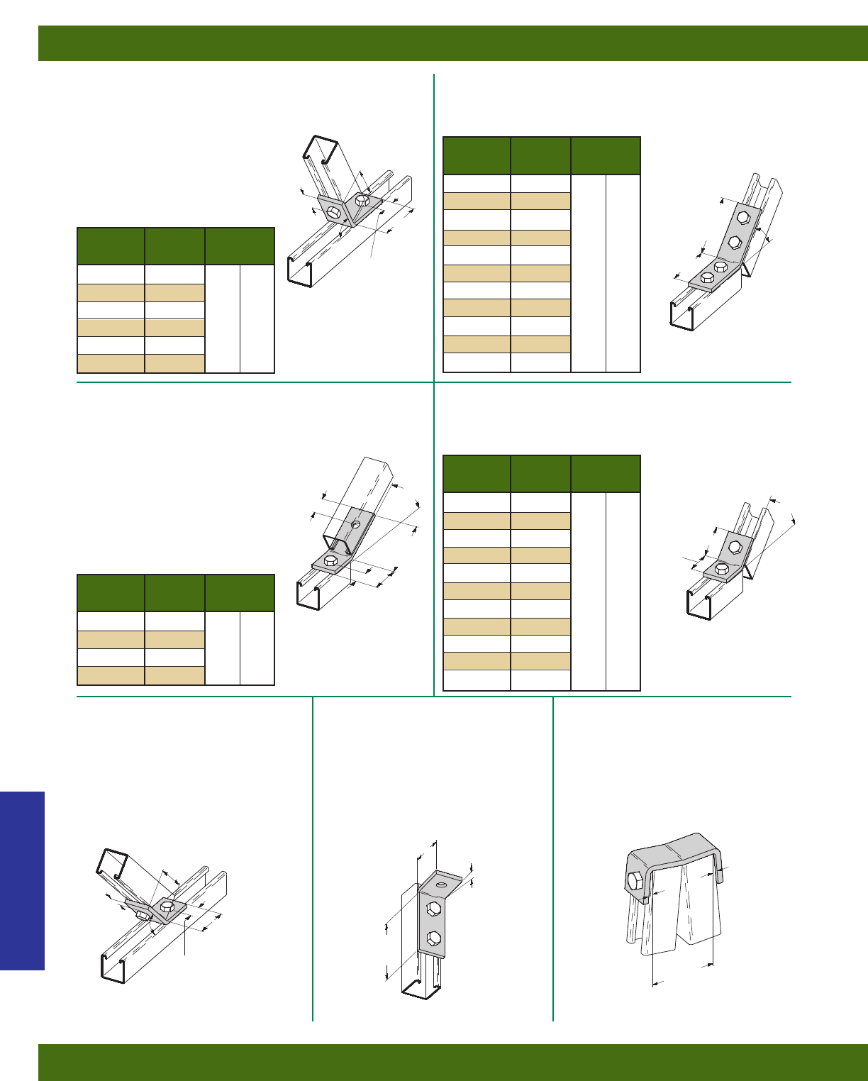
B154
TWO HOLE OPEN ANGLE
•Standard finishes: ZN, GRN, SS4
•Wt./C 58 Lbs. (26.3 kg)
B147-B152
TWO HOLE OPEN ANGLE
•Standard finishes: ZN, GRN
B162-B165
TWO HOLE OPEN ANGLE
•Standard finishes: ZN, GRN
B322-B332
TWO HOLE OPEN SHORT ANGLE
•Standard finishes: ZN, GRN
B243-B253
FOUR HOLE OPEN ANGLE
•Standard finishes: ZN, GRN
23/8”
(60.3)
31/4”
(82.5)
11/16”
(27.0)
3”
(76.2)
25/16”
(58.7)
11/16”
(27.0)
11/16”
(27.0)
13/4”
(44.4)
15/8”
(41.3)
11/16”
(27.0)
21/16”
(52.4)
311/16”
(93.6)
31/2”
(88.9)
11/16”
(27.0)
A
Part A Wt./C
No. Lbs. kg
B147 821/2°
B148 75°
B149 671/2°63 (28.6)
B150 60°
B151 521/2°
B152 371/2°
Part A Wt./C
No. Lbs. kg
B322 71/2°
B323 15°
B324 221/2°
B325 30°
B326 371/2°
B327 45° 35 (15.9)
B328 521/2°
B329 60°
B330 671/2°
B331 75°
B332 821/2°
Part A Wt./C
No. Lbs. kg
B243 71/2°
B244 15°
B245 221/2°
B246 30°
B247 371/2°
B248 45° 77 (34.9)
B249 521/2°
B250 60°
B251 671/2°
B252 75°
B253 821/2°
Part A Wt./C
No. Lbs. kg
B162 30°
B163 221/2°59 (26.7)
B164 15°
B165 71/2°
11/16”
(27.0)
A
A
A
35/16”
(84.1)
45°
B488
TWO HOLE LEG CONNECTION
•Standard finishes: ZN, GRN
•Wt./C 100 Lbs. (45.3 kg)
B522
THREE HOLE 95°
OPEN ANGLE FITTING
•Standard finishes: ZN, GRN
•Wt./C 54 Lbs. (24.5 kg)
35/8”
(92.1)
17/8”
(47.6)
31/4”
(82.5)
5°5°
5°
Strut Fittings
Reference page 58 for general fitting and standard finish specifications.
Angular Fittings
68
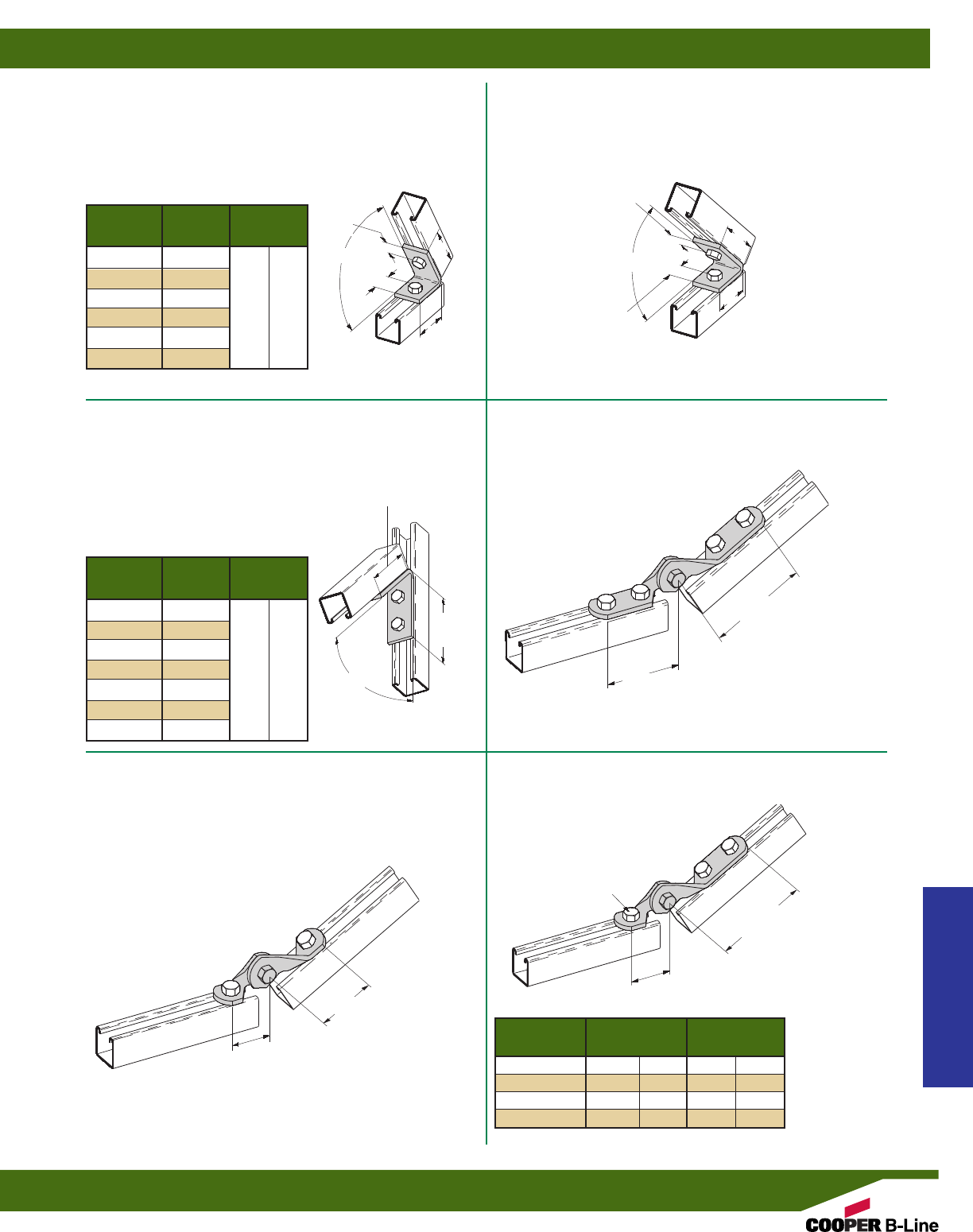
B155
TWO HOLE CLOSED ANGLE
•Standard finishes: ZN, GRN, HDG, SS4
•Wt./C 63 Lbs. (28.6 kg)
B156 - B161
TWO HOLE CLOSED ANGLE
•Standard finishes: ZN, GRN
B363 - B369
FOUR HOLE CLOSED ANGLE
•Standard finishes: ZN, GRN
B335
FOUR HOLE ADJUSTABLE HINGE
•Standard finishes: ZN, GRN
•Wt./C 110 Lbs. (49.9 kg)
B335-2 SERIES
THREE HOLE ADJUSTABLE HINGE
•OSHPD approved for Seismic Zone 4
•Standard finishes: ZN, GRN
33/16”
(80.9)
21/2”
(63.5)
31/2”
(88.9)
21/2”
(63.5)
43/8”
(111.1)
411/16”
(119.1)
411/16”
(119.1)
H
HOLE SIZE
THIS HOLE ONLY
213/16”
(71.4)
411/16”
(119.1)
5”
(127.0)
13/16”
(20.6)
13/16”
(20.6)
13/16”
(20.6)
13/16”
(20.6)
A
A
45°
213/16”
(71.4)
213/16”
(71.4)
Part No. Hole Size Wt./C
& Size H Lbs. kg
B335-2-3/87/16” (11.1) 96 (43.2)
B335-2-1/29/16”(14.3) 94 (42.3)
B335-2-5/811/16”(17.4) 92 (41.4)
B335-2-3/413/16”(20.6) 90 (40.5)
B335-1
TWO HOLE ADJUSTABLE HINGE
•Standard finishes: ZN, GRN
•Wt./C 78 Lbs. (35.4 kg)
Part A Wt./C
No. Lbs. kg
B156 821/2°
B157 75°
B158 671/2°56 (25.4)
B159 60°
B160 521/2°
B161 371/2°
Part A Wt./C
No. Lbs. kg
B363 821/2°
B364 75°
B365 671/2°
B366 60° 95 (43.1)
B367 521/2°
B368 45°
B369 371/2°
Strut Fittings
Reference page 58 for general fitting and standard finish specifications.
Angular Fittings
69
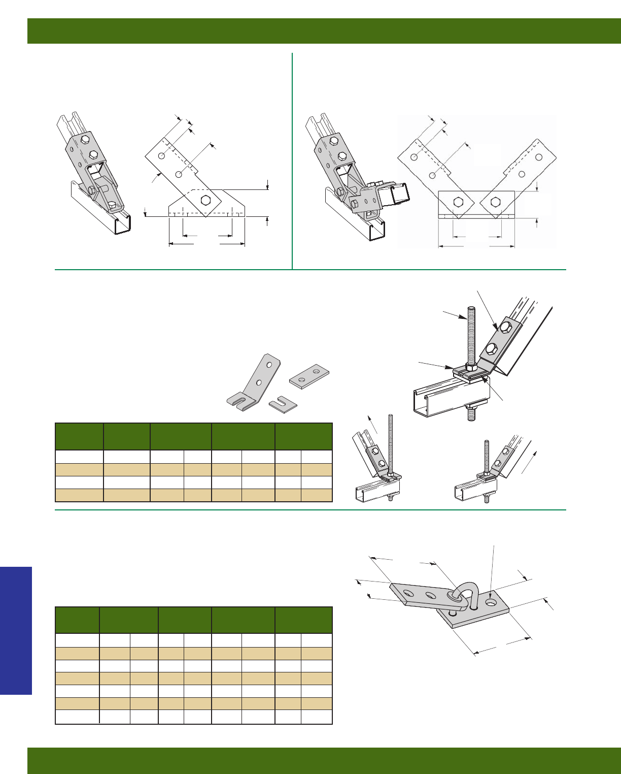
B634
SINGLE CHANNEL ADJUSTABLE BRACE
•Standard finishes: ZN, GRN
•Wt./C 306 Lbs. (138.8 kg)
B635
DOUBLE CHANNEL ADJUSTABLE BRACE
•Standard finishes: ZN, GRN
•Wt./C 518 Lbs. (234.9 kg)
B633
ADJUSTABLE SEISMIC HINGE FITTING
•B633-1/2thru B633-7/8- OSHPD approved for Seismic Zone 4.
•Use 1/2” Bolt & Channel Nut on two hole side of
Connector Fitting (Torque to 50 ft.-lbs.)
•Allows for swivel in two planes.
•Standard finish: ZN
Part No. Hole Size Wt./C
& Size AB H
Lbs. kg
B633-1/231/2”(82.5) 15/8”(41.3) 9/16”(14.3) 92 (41.4)
B633-5/831/2”(82.5) 15/8”(41.3) 11/16”(17.4) 97 (43.6)
B633-3/431/2”(82.5) 15/8”(41.3) 13/16”(20.6) 95 (42.7)
B633-7/839/16”(90.5) 2” (50.8) 15/16”(23.8) 107 (48.5)
B633-1 39/16”(90.5) 2” (50.8) 11/16”(27.0) 120 (54.0)
B633-11/839/16”(90.5) 2” (50.8) 13/16”(30.2) 104 (47.2)
B633-11/437/8”(98.4) 21/4”(57.1) 15/16”(33.3) 114 (51.7)
33/4”
(95.2)
15/8”
(41.3)
A
B
H
B129
ATR
Bracket
Transverse
Load (TL)
Longitudinal
Load (LL)
Key
13/16”
(20.6)
15/8”
(41.3)
17/8”
(47.6)
53/8”
(136.5)
33/4”
(95.2)
30°
MIN.
13/16”
(20.6)
15/8”
(41.3)
17/8”
(47.6)
53/8”
(136.5)
33/4”
(95.2)
B650 SERIES
SEISMIC RETROFIT BRACKET
•OSHPD approved for Seismic Zone 4.
•Available for 3/8”, 1/2”, 5/8”, and 3/4” threaded rods.
•Allows installer to easily brace existing trapeze supports.
•Includes: Bracket, B129 plate, & key. Hardware sold separately.
•Standard finish: ZN, GRN
Part No. For TL LL Wt./C
& Size Rod Size Lbs. kN Lbs. kN Lbs. kg
B650-3/83/8” 1100 (4.89) 1100 (4.89) 92 (41.4)
B650-1/21/2” 1500 (6.67) 1500 (6.67) 97 (43.6)
B650-5/85/8” 1500 (6.67) 1500 (6.67) 95 (42.7)
B650-3/43/4”1500 (6.67) 1500 (6.67) 107 (48.5)
Strut Fittings
Reference page 58 for general fitting and standard finish specifications.
Angular Fittings
70
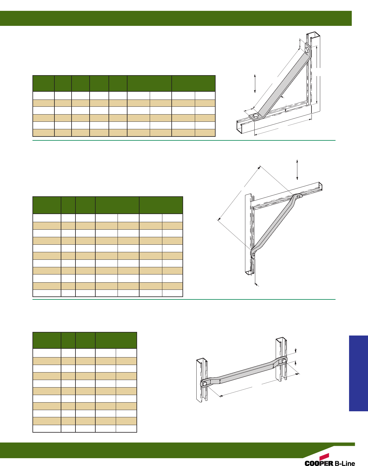
B631
TWO HOLE 45° TUBING KNEE BRACE
•1” (25.4) Square steel tubing
•Material: ASTM A513
•Standard finishes: ZN, GRN
•Design load determined by testing using a B335 hinged corner connection.
•Load ratings are for brace members only. Do not exceed allowable beam or
column loads for strut channels.
•Safety Factor of 3
B632
TWO HOLE STRAIGHT TUBING BRACE
•1” (25.4) Square steel tubing
•Material: ASTM A513
•Standard finishes: ZN, GRN
15/8”
(41.3)
13/4”
(44.4)
13/4”
(44.4)
Part
45°
A
A
A
B
B
15/8”
(41.3)
Part Design Load Wt./C
No. A (A) Lbs. kN Lbs. kg
B631-18 18” (457.2) 1500 (6.67) 145 (65.8)
B631-24 24” (609.6) 1500 (6.67) 186 (84.4)
B631-30 30” (762.0) 1500 (6.67) 225 (102.0)
B631-36 36” (914.4) 1500 (6.67) 266 (120.6)
B631-42 42” (1066.8) 1230 (5.47) 307 (139.2)
B631-48 48” (1219.2) 940 (4.18) 348 (157.8)
B631-54 54” (1371.6) 740 (3.29) 389 (176.4)
B631-60 60” (1524.0) 600 (2.67) 430 (195.0)
B631-72 72” (1828.8) 420 (1.87) 508 (230.4)
B631-84 84” (2133.6) 310 (1.38) 589 (267.2)
B631-96 96” (2438.4) 240 (1.07) 669 (303.5)
Part Wt./C
No. A (A) Lbs. kg
B632-18 18” (457.2) 133 (60.3)
B632-24 24” (609.6) 174 (78.9)
B632-30 30” (762.0) 215 (97.5)
B632-36 36” (914.4) 256 (116.1)
B632-42 42” (1066.8) 295 (133.8)
B632-48 48” (1219.2) 335 (151.9)
B632-54 54” (1371.6) 380 (172.3)
B632-60 60” (1524.0) 420 (190.5)
B632-72 72” (1828.8) 500 (226.8)
B632-84 84” (2133.6) 585 (265.3)
B632-96 96” (2438.4) 670 (303.9)
B261
TWO HOLE 45° KNEE BRACE
•Standard finishes: ZN, GRN
•Design load determined by testing using a B335 hinged corner connection.
•Load ratings are for brace members only. Do not exceed allowable beam or
column loads for strut channels.
•Safety Factor of 3
Design Load Wt./C
No. A (A) B (B) Lbs. kN Lbs. kg
B261-8 8” (203.2) 73/8”(187.3) 1500 (6.67) 119 (54.0)
B261-12 12” (304.8) 101/8”(257.2) 1020 (4.54) 165 (74.8)
B261-16 165/8”(422.3) 133/8”(339.7) 530 (2.36) 218 (98.9)
B261-18 18” (457.2) 147/16”(366.7) 450 (2.00) 234 (106.1)
B261-24 24” (609.6) 1811/16”(474.7) 250 (1.11) 303 (137.4)
B261-36 36” (914.4) 273/16”(690.6) 110 (.49) 441 (200.0)
Design Load
Design Load
Strut Fittings
Reference page 58 for general fitting and standard finish specifications.
Braces
71
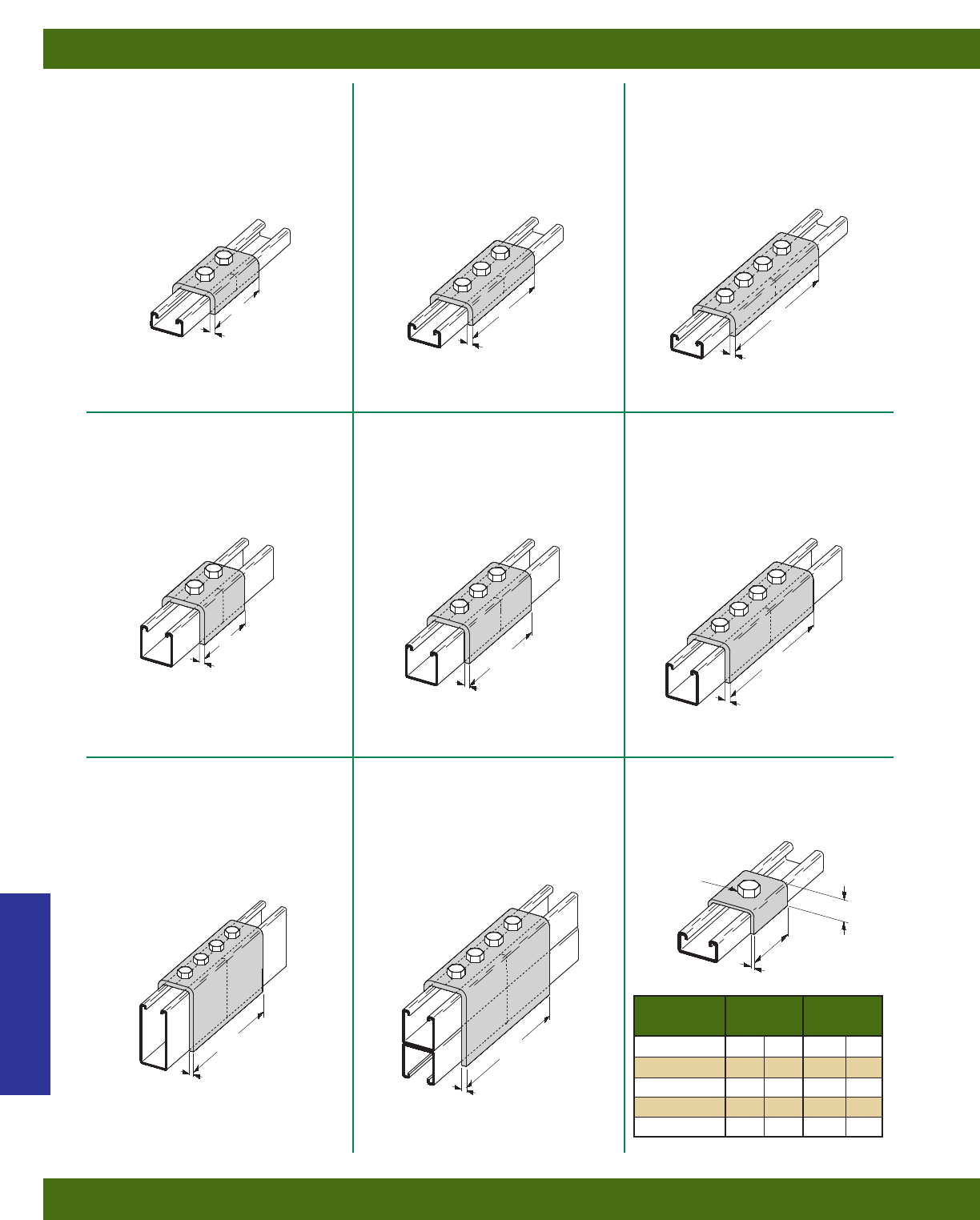
B167
FOUR HOLE SPLICE
CLEVIS FOR B52
•Standard finishes: ZN, GRN
•Wt./C 178 Lbs. (80.7 kg)
B168
THREE HOLE SPLICE
CLEVIS FOR B52
•Standard finishes: ZN, GRN
•Wt./C 126 Lbs. (57.1 kg)
B169
TWO HOLE SPLICE
CLEVIS FOR B52
•Standard finishes: ZN, GRN
•Wt./C 84 Lbs. (38.1 kg)
B170
TWO HOLE SPLICE
CLEVIS FOR B22 OR B52A
•Standard finishes: ZN, GRN
•Wt./C 123 Lbs. (55.8 kg)
B171
THREE HOLE SPLICE
CLEVIS FOR B22 OR B52A
•Standard finishes: ZN, GRN
•Wt./C 195 Lbs. (88.4 kg)
B172
FOUR HOLE SPLICE
CLEVIS FOR B22 OR B52A
•Standard finishes: ZN, GRN
•Wt./C 266 Lbs. (120.6 kg)
B172-12
FOUR HOLE SPLICE
CLEVIS FOR B12
•Standard finishes: ZN, GRN
•Wt./C 326 Lbs. (147.8 kg)
B172-22A
FOUR HOLE SPLICE
CLEVIS FOR B11 OR B22A
•Standard finishes: ZN, GRN
•Wt./C 406 Lbs. (184.1 kg)
B450
U-WASHER
•Material: ASTM A1011 HSLAS Gr. 50
•Standard finishes: ZN, GRN
31/2”
(88.9)
31/2”
(88.9)
1/4”
(6.3)
1/4”
(6.3)
1/4”
(6.3) 1/4”
(6.3)
1/4”
(6.3) 1/4”
(6.3)
1/4”
(6.3) 1/4”
(6.3)
53/8”
(136.5)
53/8”
(136.5)
Part No. Hole Size Wt./C
& Size H Lbs. kg
B450-1/45/16” (7.9) 14 (6.3)
B450-3/87/16”(11.1) 14 (6.3)
B450-1/29/16”(14.3) 13 (5.8)
B450-5/811/16”(17.4) 13 (5.8)
B450-3/413/16”(20.6) 13 (5.8)
71/4”
(184.1)
71/4”
(184.1)
71/4”
(184.1) 71/4”
(184.1)
15/8”
(41.3)
11 Gauge (3.1)
H
HOLE SIZE
15/32”
(11.9)
Strut Fittings
Reference page 58 for general fitting and standard finish specifications.
Clevis Fittings
72
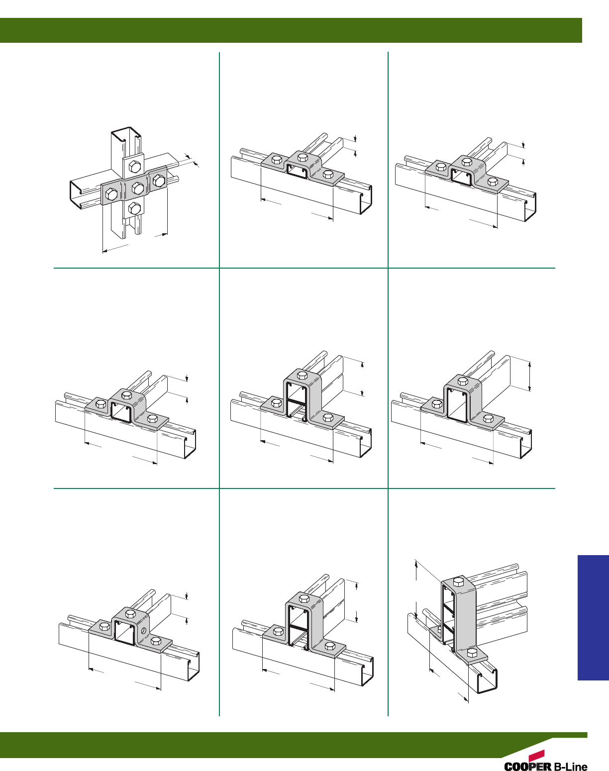
B116-42
THREE HOLE U-SUPPORT
•Standard finishes: ZN, GRN
•Wt./C 75 Lbs. (34.0 kg)
B116-52
THREE HOLE U-SUPPORT
•Standard finishes: ZN, GRN
•Wt./C 70 Lbs. (31.7 kg)
B527
THREE HOLE OFFSET PLATE
CONNECTION
•Standard finishes: ZN, GRN
•Wt./C 54 Lbs. (24.5 kg)
B116-32
THREE HOLE U-SUPPORT
•Standard finishes: ZN, GRN
•Wt./C 84 Lbs. (38.1 kg)
B116-32A
THREE HOLE U-SUPPORT
•Standard finishes: ZN, GRN
•Wt./C 116 Lbs. (52.6 kg)
B116-12
THREE HOLE U-SUPPORT
•Standard finishes: ZN, GRN
•Wt./C 108 Lbs. (49.0 kg)
B107
FIVE HOLE U-SUPPORT
•Standard finishes: ZN, GRN, HDG
•Wt./C 85 Lbs. (38.5 kg)
B107-22A
THREE HOLE U-SUPPORT
•Standard finishes: ZN, GRN
•Wt./C 126 Lbs. (57.1 kg)
B588
THREE HOLE U-SUPPORT
•Standard finishes: ZN, GRN
•Wt./C 157 Lbs. (71.2 kg)
1/2”
(12.7)
55/16”
(134.9)
57/16”
(138.1)
57/16”
(138.1) 57/16”
(138.1) 57/16”
(138.1)
57/16”
(138.1)
57/16”
(138.1) 57/16”
(138.1)
1”
(25.4)
13/16”
(20.6)
27/16”
(61.9)
13/8”
(34.9)
31/4”
(82.5)
47/8”
(123.8)
15/8”
(41.3)
23/4”
(69.8)
57/16”
(138.1)
Strut Fittings
Reference page 58 for general fitting and standard finish specifications.
‘U’ Fittings
73
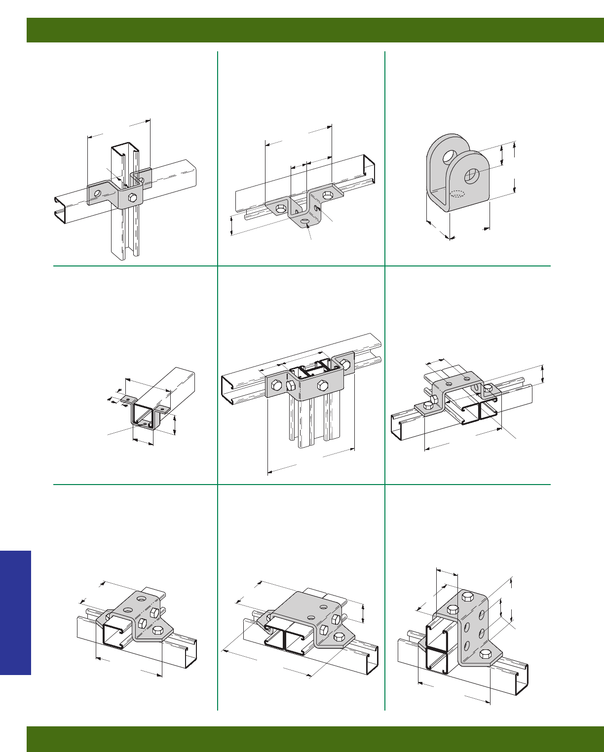
B596
THREE HOLE SWIVEL CLEVIS
•Standard finishes: ZN, GRN
•Wt./C 53 Lbs. (24.0 kg)
B107S
FIVE HOLE U-SUPPORT
•Material: 7 Gauge (4.5)
ASTM A1011 33,000 PSI min. yield
•Standard finishes: ZN, GRN
•Wt./C 51 Lbs. (23.1 kg)
B412
THREE HOLE
OFFSET U-SUPPORT
•Standard finishes: ZN, GRN
•Wt./C 89 Lbs. (40.3 kg)
B578
THREE HOLE LIGHT-WEIGHT
U-SUPPORT
•Material: 10 Gauge (3.4)
ASTM A1011 HSLAS Gr. 50
•Standard finishes: ZN, GRN
•Wt./C 18 Lbs. (8.1 kg)
B594
FIVE HOLE U-SUPPORT
•Standard finishes: ZN, GRN
•Wt./C 106 Lbs. (48.1 kg)
B266
SIX HOLE U-SUPPORT
•Standard finishes: ZN, GRN
•Wt./C 105 Lbs. (47.6 kg)
B425
SIX HOLE U-SUPPORT
•Standard finishes: ZN, GRN
•Wt./C 167 Lbs. (75.7 kg)
B581
EIGHT HOLE U-SUPPORT
•Standard finishes: ZN, GRN
•Wt./C 201 Lbs. (91.2 kg)
B519
EIGHT HOLE U-SUPPORT
•Standard finishes: ZN, GRN
•Wt./C 266 Lbs. (102.5 kg)
57/16”
(138.1)
17/8”
(47.6)
33/4”
(95.2)
13/16”
(20.6)
13/4”
(44.4)
13/8”
(34.9)
9/16” (14.3) DIA.
7/16” (11.1) DIA.
4 HOLES
9/32” (7.1)
DIA. 3 HOLES 35/16”
(84.1)
111/16”
(42.8)
311/16”
(93.6)
71/16”
(179.4)
17/8”
(47.6)
121/32”
(42.1)
15/8”
(41.3)
71/32”
(178.6)
15/8”
(41.3)
31/2”
(88.9)
31/2”
(88.9) 31/2”
(88.9) 31/2”
(88.9)
71/16”
(179.4)
57/16”
(138.1)
513/32”
(137.3)
111/16”
(42.9)
3/4”
(19.0)
13/32”
(10.3)
35/16”
(84.1)
1”
(25.4) 21/4”
(57.1)
15/8”
(41.3)
15/8”
(41.3)
15/8”
(41.3)
15/8”
(41.3)
Strut Fittings
Reference page 58 for general fitting and standard finish specifications.
‘U’ Fittings
74
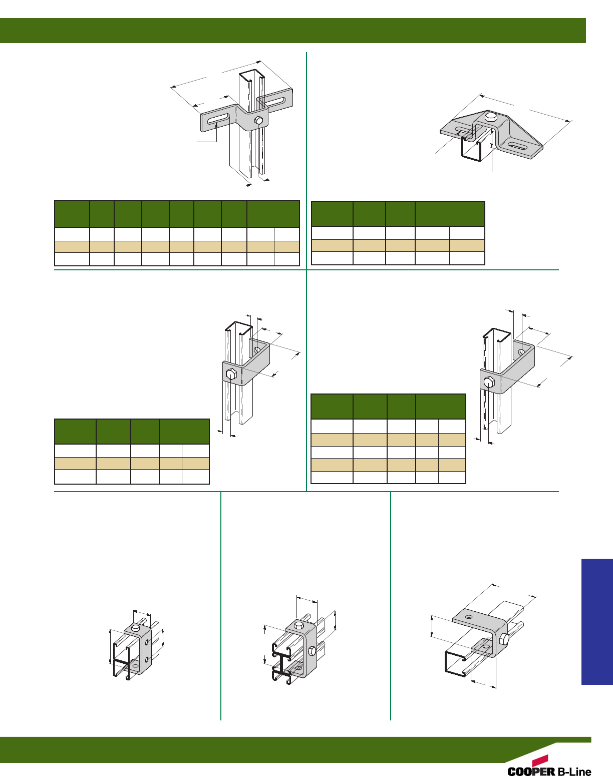
B451
SLOTTED THREE HOLE U-SUPPORT WITH
GUSSET FOR B22
•Consists of B333-1, 2, or 3 with
gusset plate welded on back.
•Material: ASTM A1011 HSLAS Gr. 50
•Standard finishes: ZN, GRN
B333
SLOTTED THREE HOLE
U-SUPPORT FOR B22
•Standard finishes: ZN, GRN
B408
TWO HOLE BUS DUCT CLEVIS
•Standard finishes: ZN, GRN
B358
TWO HOLE CLEVIS
•Standard finishes: ZN, GRN
B173
FOUR HOLE CLEVIS
•Standard finishes: ZN, GRN
•Wt./C 71 Lbs. (32.2 kg)
B595
THREE HOLE CLEVIS
•Standard finishes: ZN, GRN
•Wt./C 75 Lbs. (34.0 kg)
B405
THREE HOLE
SUSPENSION CLEVIS
•Standard finishes: ZN, GRN
•Wt./C 75 Lbs. (34.0 kg)
17/8”
(47.6)
17/8”
(47.6)
13/16”
(20.6) 13/16”
(20.6)
1/2”
(12.7)
13/16”
(20.6)
17/8”
(47.6)
17/8”
(47.6)
121/32”
(42.0)
121/32”
(42.0)
129/32”
(48.4)
35/16”
(84.1)
35/16”
(84.1)
37/16”
(87.3)
17/8”
(47.6)
Part
Wt./C
No.
A (A) B (B) C (C) Lbs. kg
B333-1 71/2”(190.5) 15/16”(33.3) 27/8”(73.0) 103 (46.7)
B333-2 81/2”(215.9) 115/16”(49.2) 33/8”(85.7) 115 (52.1)
B333-3 103/8”(263.5) 27/8”(73.0) 45/16”(109.5) 135 (61.2)
Part Wt./C
No. A (A) Lbs. kg
B451-1 71/2”(190.5) 137 (62.1)
B451-2 81/2”(215.9) 156 (70.7)
B451-3 103/8”(263.5) 172 (78.0)
Part Wt./C
No. A (A) Lbs. kg
B408-1 213/32”(61.1) 58 (26.3)
B408-2 325/32”(96.0) 76 (34.5)
B408-3 43/4”(762.0) 88 (39.9)
Part Wt./C
No. A (A) Lbs. kg
B358-4 4” (101.6) 89 (40.3)
B358-5 5” (127.0) 93 (42.2)
B358-6 6” (152.4) 106 (48.1)
B358-7 7” (177.8) 118 (53.5)
B358-8 8” (203.2) 132 (59.9)
A
A
C
B
AA
9/16” x 11/2” SLOTS-(2)
(14.3) (38.1)
9/16” x 11/2” SLOTS-(2)
(14.3) (38.1) 15/8”
(41.3)
9/16” (14.3) DIA.
2 HOLES
Strut Fittings
Reference page 58 for general fitting and standard finish specifications.
‘U’ Fittings
75
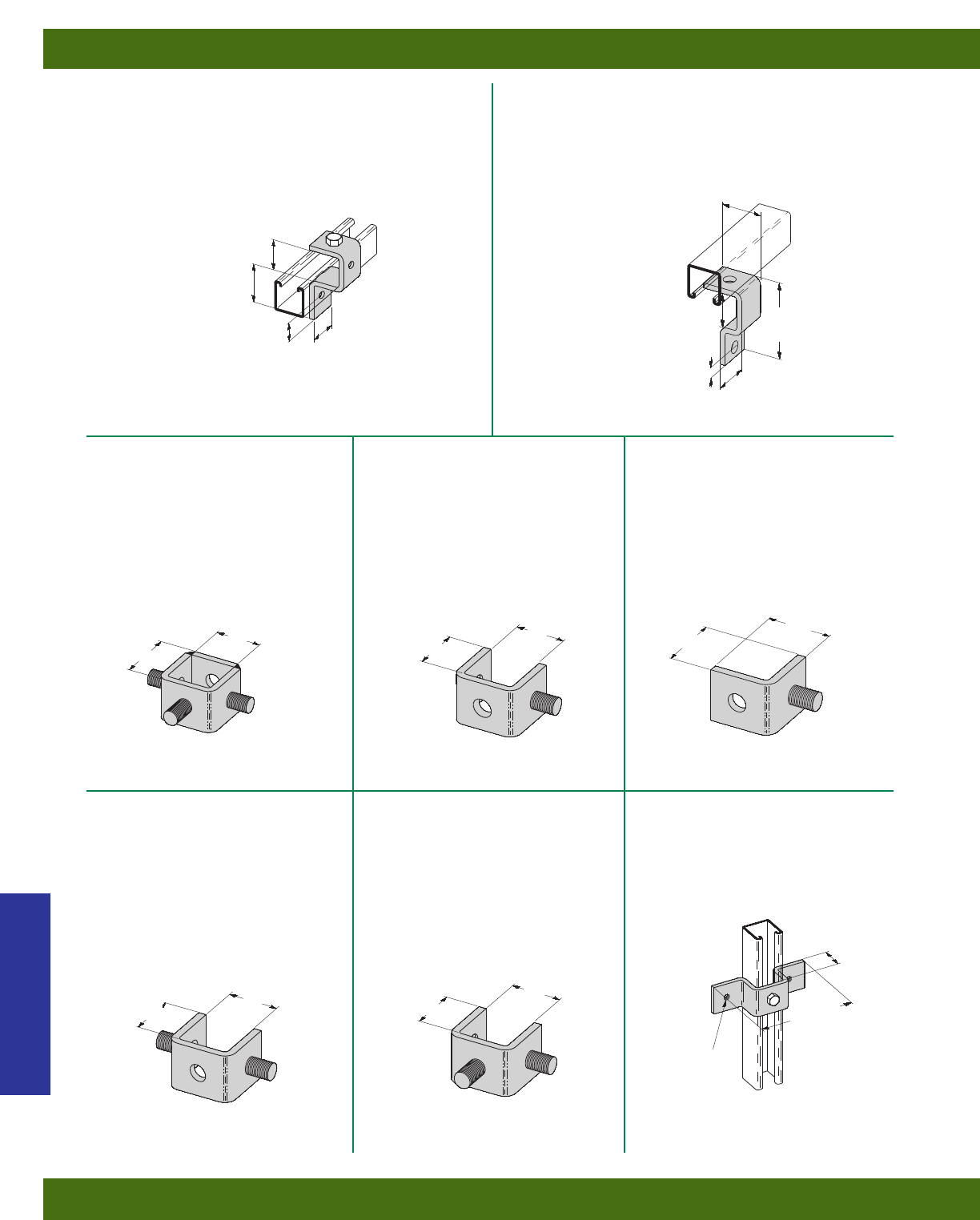
B415
TWO HOLE BUS DUCT
CONNECTION
•Standard finishes: ZN, GRN
•Wt./C 56 Lbs. (25.4 kg)
B398-1
THREE HOLE CUP SUPPORT
•Standard finishes: ZN, GRN
•Wt./C 73 Lbs. (33.1 kg)
B400
THREE STUD
RING CONNECTION
•1/2”-13 stud protrudes 1” (25.4mm)
•Standard finishes: ZN
•Wt./C 85 Lbs. (38.5 kg)
B400-1
ONE STUD
RING CONNECTION
•1/2”-13 stud protrudes 1” (25.4mm)
•Standard finishes: ZN
•Wt./C 53 Lbs. (24.0 kg)
B400-2
ONE STUD
RING CONNECTION
•1/2”-13 stud protrudes 1” (25.4mm)
•Standard finishes: ZN
•Wt./C 40 Lbs. (18.1 kg)
B400-3
TWO STUD
RING CONNECTION
•1/2”-13 stud protrudes 1” (25.4mm)
•Standard finishes: ZN
•Wt./C 59 Lbs. (26.7 kg)
B400-4
TWO STUD
RING CONNECTION
•1/2”-13 stud protrudes 1” (25.4mm)
•Standard finishes: ZN
•Wt./C 59 Lbs. (26.7 kg)
B536
TAPPED U-SUPPORT
•Standard finishes: ZN
•Wt./C 87 Lbs. (39.4 kg)
111/16”
(42.9)
111/16”
(42.9)
1/2”
(12.7)
23/32”
(53.2)
11/16”
(27.0)
15/8”
(41.3)
17/8”
(47.6)
17/8”
(47.6)
59/16”
(141.3)
325/32”
(96.0)
11/16”
(27.0)
17/8”
(47.6)
15/8”
(41.3)
111/16”
(42.9)
23/16”
(55.6)
111/16”
(42.9)
111/16”
(42.9)
111/16”
(42.9)
111/16”
(42.9)
111/16”
(42.9)
111/16”
(42.9)
TAPPED 5/16”-18
(2) HOLES
Strut Fittings
Reference page 58 for general fitting and standard finish specifications.
‘U’ Fittings
76
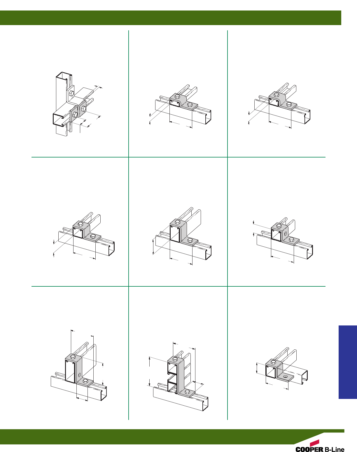
B106-42
TWO HOLE
Z-SUPPORT FOR B42
•Standard finishes: ZN, GRN
•Wt./C 44 Lbs. (20.0 kg)
B106-52
TWO HOLE
Z-SUPPORT FOR B52
•Standard finishes: ZN, GRN
•Wt./C 40 Lbs. (18.1 kg)
B526
TWO HOLE
OFFSET Z-SUPPORT
•Standard finishes: ZN, GRN
•Wt./C 38 Lbs. (17.2 kg)
B106-32
TWO HOLE
Z-SUPPORT FOR B32
•Standard finishes: ZN, GRN
•Wt./C 51 Lbs. (23.1 kg)
B106-12
TWO HOLE
Z-SUPPORT FOR B12
•Standard finishes: ZN, GRN
•Wt./C 63 Lbs. (28.6 kg)
B105
THREE HOLE
Z-SUPPORT FOR B22
•Standard finishes: ZN, GRN, HDG
•Wt./C 51 Lbs. (23.1 kg)
B110
THREE HOLE
Z-SUPPORT FOR B11
•Standard finishes: ZN, GRN
•Wt./C 70 Lbs. (31.7 kg)
B586
TWO HOLE
Z-SUPPORT
•Standard finishes: ZN, GRN
•Wt./C 90 Lbs. (40.8 kg)
B108
TWO HOLE
OFFSET Z-SUPPORT
•Standard finishes: ZN, GRN
•Wt./C 55 Lbs. (24.9 kg)
1/4”
(6.3)
15/8”
(41.3)
31/2”
(88.9)
31/2”
(88.9)
31/2”
(88.9)
31/2”
(88.9) 31/2”
(88.9)
31/2”
(88.9)
47/8”
(123.8)
31/2”
(88.9)
31/2”
(88.9)
13/16”
(20.6)
1”
(25.4)
15/8”
(41.3)
13/8”
(34.9)
21/8”
(54.0)
15/8”
(41.3)
15/8”
(41.3)
27/16”
(61.9)
315/32”
(88.1) 31/2”
(88.9)
Strut Fittings
Reference page 58 for general fitting and standard finish specifications.
‘Z’ Fittings
77
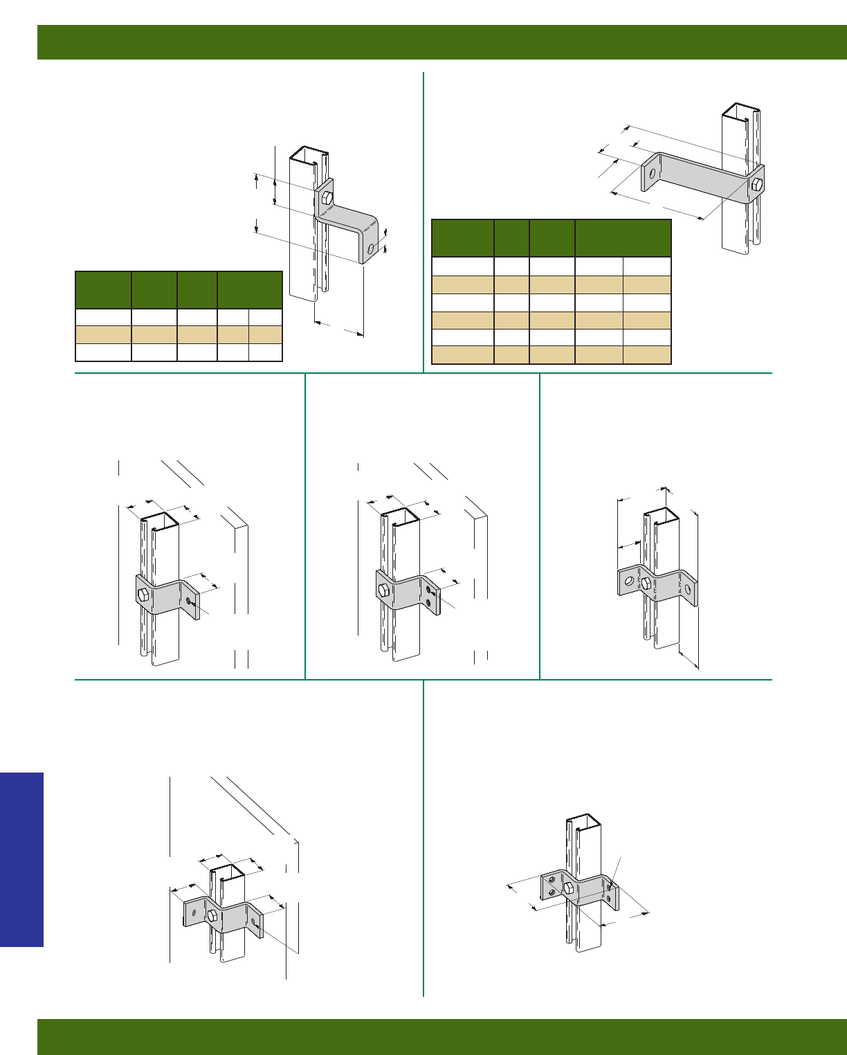
B407
TWO HOLE Z-SUPPORT
•Standard finishes: ZN, GRN
B387
TWO HOLE Z-BUS DUCT CONNECTION
•Standard finishes: ZN, GRN
B534
TAPPED Z-SUPPORT
•Standard finishes: ZN
•Wt./C 51 Lbs. (23.1 kg)
B535
TAPPED Z-SUPPORT
•Standard finishes: ZN
•Wt./C 50 Lbs. (22.7 kg)
B111
THREE HOLE SHEATH
CORNER CONNECTION
•Standard finishes: ZN, GRN
•Wt./C 68 Lbs. (30.8 kg)
B538
TAPPED CORNER CONNECTION
•Standard finishes: ZN
•Wt./C 71 Lbs. (32.2 kg)
B539
TAPPED CORNER CONNECTION
•Standard finishes: ZN
•Wt./C 68 Lbs. (30.8 kg)
15/8”
(41.3)
1/2”
(12.7)
31/2”
(88.9)
31/2”
(88.9)
31/2”
(88.9)
15/8”
(41.3)
15/8”
(41.3)
15/8”
(41.3) 15/8”
(41.3)
15/8”
(41.3)
15/8”
(41.3)
15/8”
(41.3)
17/8”
(47.6)
17/8”
(47.6)
15/8”
(41.3) 15/8”
(41.3)
15/8”
(41.3)
31/2”
(88.9)
31/2”
(88.9)
15/8”
(41.3)
A
A
Wt./C
Part No. A (A) Lbs. kg
B387 43/4”(120.6) 89 (40.3)
B387-1 325/32”(96.0) 78 (35.4)
B387-2 213/32”(61.1) 62 (28.1)
Wt./C
Part No. A (A) Lbs. kg
B407-4 4” (101.6) 77 (34.9)
B407-5 5” (127.0) 95 (43.1)
B407-6 6” (152.4) 98 (44.4)
B407-7 7” (177.8) 105 (47.6)
B407-8 8” (203.2) 120 (54.4)
B407-95/8”95/8”(244.5) 138 (62.6)
31/2”
(88.9)
5/16”-18
TAPPED HOLE
5/16”-18
TAPPED
HOLES (2)
5/16”-18 TAPPED
HOLES (4)
5/16”-18 TAPPED
HOLES (2)
Strut Fittings
Reference page 58 for general fitting and standard finish specifications.
‘Z’ Fittings
78
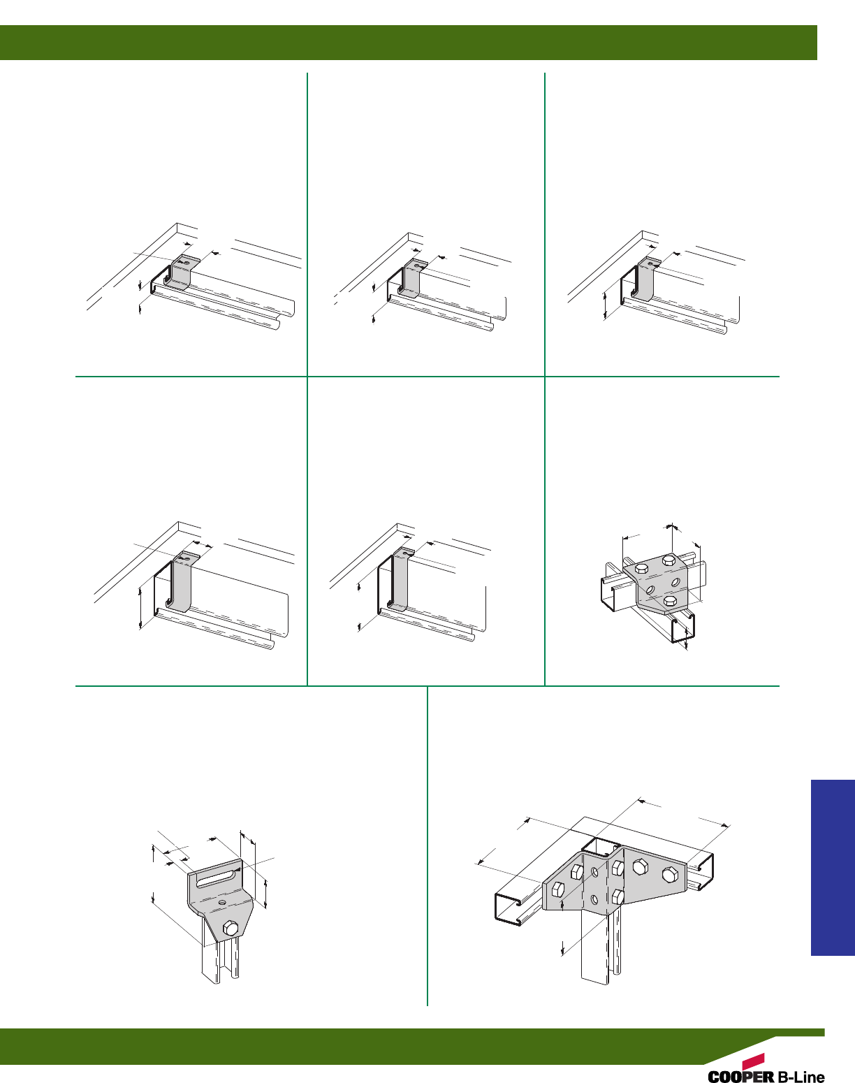
B410-22
CHANNEL HANGER
BRACKET FOR B22
•Material: 11 Gauge (3.0)
ASTM A1011 HSLAS Gr. 50
•Standard finishes: ZN, GRN
•Wt./C 9 Lbs. (4.1 kg)
B410-32
CHANNEL HANGER
BRACKET FOR B32
•Material: 11 Gauge (3.0)
ASTM A1011 HSLAS Gr. 50
•Standard finishes: ZN, GRN
•Wt./C 8.3 Lbs. (3.7 kg)
B410-52
CHANNEL HANGER
BRACKET FOR B52
•Material: 11 Gauge (3.0)
ASTM A1011 HSLAS Gr. 50
•Standard finishes: ZN, GRN
•Wt./C 6.7 Lbs. (3.0 kg)
B410-12
CHANNEL HANGER
BRACKET FOR B12
•Material: 11 Gauge (3.0)
ASTM A1011 HSLAS Gr. 50
•Standard finishes: ZN, GRN
•Wt./C 11.2 Lbs. (5.1 kg)
B410-11
CHANNEL HANGER
BRACKET FOR B11
•Material: 11 Gauge (3.0)
ASTM A1011 HSLAS Gr. 50
•Standard finishes: ZN, GRN
•Wt./C 13.4 Lbs. (6.1 kg)
B580
FIVE HOLE
GUSSETTED Z-SUPPORT
•Standard finishes: ZN, GRN
•Wt./C 100 Lbs. (45.3 kg)
B515
ADJUSTABLE OFFSET
GUSSETTED Z-SUPPORT
•Standard finishes: ZN, GRN
•Wt./C 93 Lbs. (42.2 kg)
B428
EIGHT HOLE GUSSETTED
CORNER CONNECTION
•Standard finishes: ZN, GRN
•Wt./C 203 Lbs. (92.1 kg)
13/8”
(34.9)
15/8”
(41.3)
15/8”
(41.3)
13/16”
(20.6) 13/16”
(20.6)
13/16”
(20.6)
13/16”
(20.6)
13/16”
(20.6)
27/16”
(61.9)
37/8”
(98.4)
15/32”
(11.9) 31/2”
(88.9)
17/8”
(47.6)
17/8”
(47.6)
31/4”
(82.5)
31/2”
(88.9) 31/2”
(88.9)
9/32” (7.1)
DIA. HOLE
9/32” (7.1)
DIA. HOLE
9/32” (7.1)
DIA. HOLE
9/32” (7.1)
DIA. HOLE
9/32” (7.1)
DIA. HOLE
13/16”
(20.6)
9/16” x 29/16” SLOTS
(14.3) (65.1)
31/2”
(88.9)
53/4”
(146.0)
53/4”
(146.0)
Strut Fittings
Reference page 58 for general fitting and standard finish specifications.
‘Z’ Fittings
79
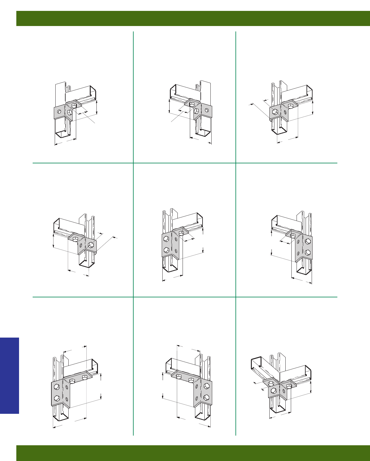
B270R
FOUR HOLE SINGLE CORNER
CONNECTION (RIGHT HAND)
•Standard finishes: ZN, GRN
•Wt./C 77 Lbs. (34.9 kg)
B267L
THREE HOLE SINGLE CORNER
CONNECTION (LEFT HAND)
•Standard finishes: ZN, GRN
•Wt./C 54 Lbs. (24.5 kg)
B267R
THREE HOLE SINGLE CORNER
CONNECTION (RIGHT HAND)
•Standard finishes: ZN, GRN
•Wt./C 54 Lbs. (24.5 kg)
B270L
FOUR HOLE SINGLE CORNER
CONNECTION (LEFT HAND)
•Standard finishes: ZN, GRN
•Wt./C 77 Lbs. (34.9 kg)
B268R
FIVE HOLE SINGLE CORNER
CONNECTION (RIGHT HAND)
•Standard finishes: ZN, GRN
•Wt./C 100 Lbs. (45.3 kg)
B268L
FIVE HOLE SINGLE CORNER
CONNECTION (LEFT HAND)
•Standard finishes: ZN, GRN
•Wt./C 100 Lbs. (45.3 kg)
B269R
SIX HOLE SINGLE CORNER
CONNECTION (RIGHT HAND)
•Standard finishes: ZN, GRN
•Wt./C 120 Lbs. (54.4 kg)
B269L
SIX HOLE SINGLE CORNER
CONNECTION (LEFT HAND)
•Standard finishes: ZN, GRN
•Wt./C 120 Lbs. (54.4 kg)
B119
FOUR HOLE DOUBLE
CORNER CONNECTION
•Standard finishes: ZN, GRN
•Wt./C 71 Lbs. (32.2 kg)
31/2”
(88.9)
31/2”
(88.9)
31/2”
(88.9) 31/2”
(88.9)
21/16”
(52.4)
21/16”
(52.4)
15/8”
(41.3)
15/8”
(41.3)
15/8”
(41.3) 15/8”
(41.3)
31/2”
(88.9)
31/2”
(88.9)
315/16”
(100.0)
315/16”
(100.0)
31/2”
(88.9)
21/16”
(52.4)
53/8”
(136.5)
53/8”
(136.5)
315/16”
(100.0) 315/16”
(100.0)
313/16”
(96.8)
21/16”
(52.4)
111/16”
(42.8)
15/8”
(41.3)
313/16”
(96.8)
21/16”
(52.4)
111/16”
(42.8)
Strut Fittings
Reference page 58 for general fitting and standard finish specifications.
Wing Fittings
80
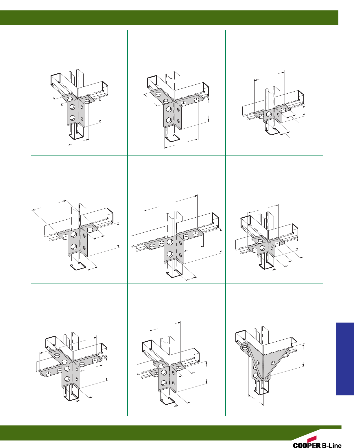
B271
FIVE HOLE DOUBLE
WING CONNECTION
•Standard finishes: ZN, GRN
•Wt./C 95 Lbs. (43.1 kg)
B121
EIGHT HOLE DOUBLE
CORNER CONNECTION
•Standard finishes: ZN, GRN
•Wt./C 152 Lbs. (68.9 kg)
B120
SIX HOLE DOUBLE
CORNER CONNECTION
•Standard finishes: ZN, GRN
•Wt./C 110 Lbs. (49.9 kg)
B272
EIGHT HOLE DOUBLE
WING CONNECTION
•Standard finishes: ZN, GRN
•Wt./C 156 Lbs. (70.7 kg)
B273
TEN HOLE DOUBLE
WING CONNECTION
•Standard finishes: ZN, GRN
•Wt./C 185 Lbs. (83.9 kg)
B122
SIX HOLE TRIPLE
WING CONNECTION
•Standard finishes: ZN, GRN
•Wt./C 110 Lbs. (49.9 kg)
B123
TWELVE HOLE TRIPLE
WING CONNECTION
•Standard finishes: ZN, GRN
•Wt./C 234 Lbs. (106.1 kg)
B276
FOURTEEN HOLE DOUBLE CORNER
GUSSETTED CONNECTION
•Standard finishes: ZN, GRN
•Wt./C 196 Lbs. (88.9 kg)
B124
NINE HOLE TRIPLE
WING CONNECTION
•Standard finishes: ZN, GRN
•Wt./C 177 Lbs. (80.3 kg)
15/8”
(41.3)
15/8”
(41.3)
15/8”
(41.3)
31/2”
(88.9)
31/2”
(88.9)
31/2”
(88.9)
93/16”
(233.4)
93/16”
(233.4)
31/2”
(88.9)
315/16”
(100.0)
315/16”
(100.0)
315/16”
(100.0)
315/16”
(100.0)
315/16”
(100.0)
53/8”
(136.5)
57/16”
(138.1)
21/16”
(52.4)
57/16”
(138.1)
57/16”
(138.1)
15/8”
(41.3)
21/16”
(52.4)
111/16”
(42.8)
111/16”
(42.8)
111/16”
(42.8)
111/16”
(42.8)
111/16”
(42.8)
315/16”
(100.0)
111/16”
(42.8)
15/8”
(41.3)
57/16”
(138.1)
4”
(101.6)
4”
(101.6)
Strut Fittings
Reference page 58 for general fitting and standard finish specifications.
Wing Fittings
81
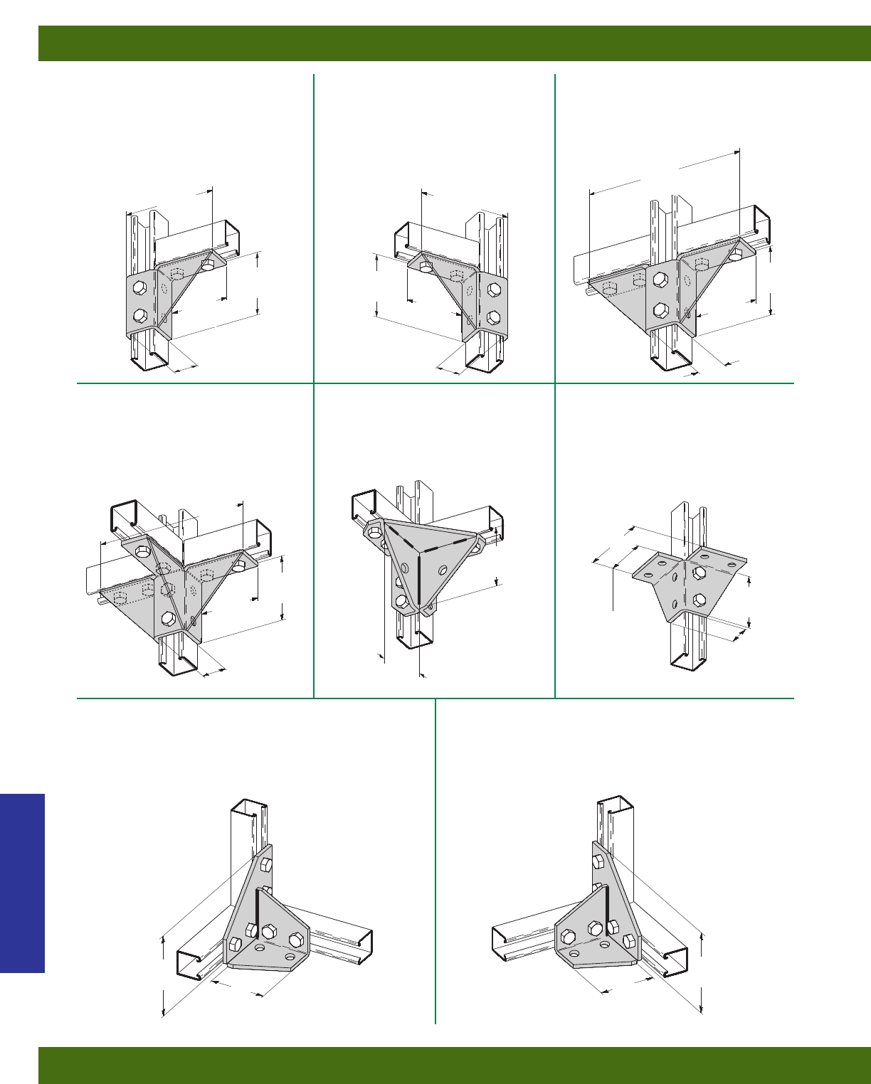
B495
TEN HOLE DOUBLE WING
GUSSETTED CONNECTION
•Standard finishes: ZN, GRN
•Wt./C 240 Lbs. (108.8 kg)
B274R
EIGHT HOLE SINGLE CORNER
GUSSETTED CONNECTION
(RIGHT HAND)
•Standard finishes: ZN, GRN
•Wt./C 176 Lbs. (79.8 kg)
B274L
EIGHT HOLE SINGLE CORNER
GUSSETTED CONNECTION
(LEFT HAND)
•Standard finishes: ZN, GRN
•Wt./C 176 Lbs. (79.8 kg)
B277
TWELVE HOLE TRIPLE WING
GUSSETTED CONNECTION
•Standard finishes: ZN, GRN
•Wt./C 285 Lbs. (129.3 kg)
B362
EIGHT HOLE DOUBLE CORNER
GUSSETTED CONNECTION
•Standard finishes: ZN, GRN
•Wt./C 226 Lbs. (102.5 kg)
B571
EIGHT HOLE WING
CONNECTION
•Standard finishes: ZN, GRN
•Wt./C 201 Lbs. (91.2 kg)
B346L
EIGHT HOLE DOUBLE CORNER GUSSETTED
CONNECTION (LEFT HAND)
•Standard finishes: ZN, GRN
•Wt./C 242 Lbs. (109.8 kg)
B346R
EIGHT HOLE DOUBLE CORNER GUSSETTED
CONNECTION (RIGHT HAND)
•Standard finishes: ZN, GRN
•Wt./C 242 Lbs. (109.8 kg)
31/2”
(88.9)
31/2”
(88.9)
31/2”
(88.9) 31/2”
(88.9)
511/16”
(144.5) 521/32”
(143.7)
315/16”
(100.0) 315/16”
(100.0)
111/16”
(42.8)
111/16”
(42.8)
15/8”
(41.3)
31/2”
(88.9)
53/8”
(136.5)
315/16”
(100.0)
53/8”
(136.5)
37/8”
(98.4)
93/16”
(233.4)
111/16”
(42.8)
315/16”
(100.0)
93/16”
(233.4)
111/16”
(42.8)
31/2”
(88.9)
53/8”
(136.5)
31/2”
(88.9)
4”
(101.6)
4”
(101.6)
Strut Fittings
Reference page 58 for general fitting and standard finish specifications.
Wing Fittings
82
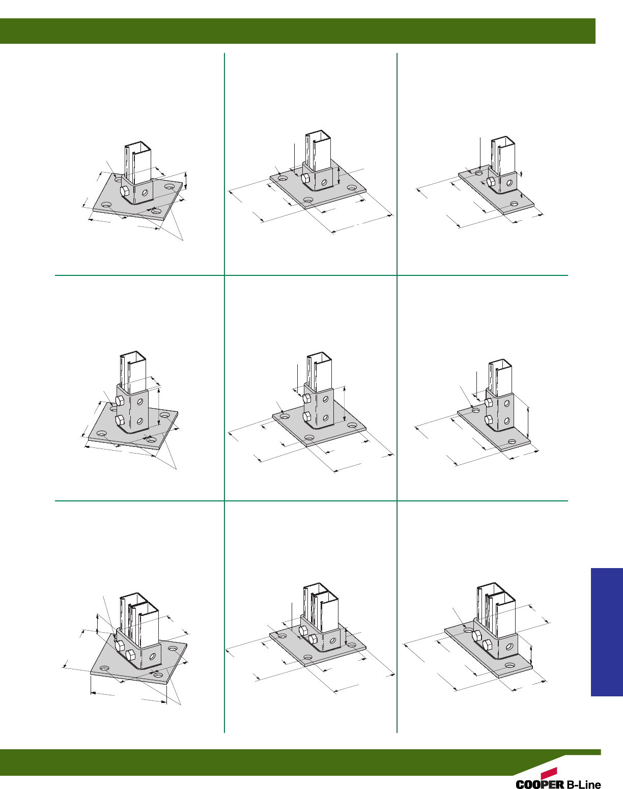
B279FL
POST BASE FOR B22
•Standard finishes: ZN, GRN
•Wt./C 230 Lbs. (104.3 kg)
B279SQ
POST BASE FOR B22
•Standard finishes: ZN, GRN
•Wt./C 314 Lbs. (142.4 kg)
B279
POST BASE FOR B22
•Standard finishes: ZN, GRN
•Wt./C 314 Lbs. (142.4 kg)
B280
POST BASE FOR B22
•Standard finishes: ZN, GRN, HDG, SS4, AL
•Wt./C 392 Lbs. (177.8 kg)
B280SQ
POST BASE FOR B22
•Standard finishes: ZN, GRN, HDG, SS4, AL
•Wt./C 392 Lbs. (177.8 kg)
B280FL
POST BASE FOR B22
•Standard finishes: ZN, GRN, HDG, SS4
•Wt./C 312 Lbs. (141.5 kg)
B281A
POST BASE FOR B22A, B,C, ETC.
•Standard finishes: ZN, GRN
•Wt./C 330 Lbs. (149.7 kg)
B281AFL
POST BASE FOR B22A, B, C, ETC.
•Standard finishes: ZN, GRN
•Wt./C 250 Lbs. (113.4 kg)
B281ASQ
POST BASE FOR B22A, B, C, ETC.
•Standard finishes: ZN, GRN
•Wt./C 330 Lbs. (149.7 kg)
15/8”
(41.3)
15/8”
(41.3)
15/8”
(41.3)
111/16”
(42.8)
111/16”
(42.8)
6”
(152.4)
6”
(152.4)
6”
(152.4)
6”
(152.4)
6”
(152.4)
6”
(152.4)
6”
(152.4)
6”
(152.4)
6”
(152.4)
41/4”
(107.9)
41/4”
(107.9)
41/4”
(107.9) 41/4”
(107.9)
6”
(152.4)
3”
(76.2)
31/2”
(88.9) 31/2”
(88.9)
31/2”
(88.9)
15/8”
(41.3)
111/16”
(42.8)
111/16”
(42.8)
111/16”
(42.8)
35/16”
(84.1) 15/8”
(41.3)
35/16”
(84.1)
3”
(76.2)
3”
(76.2)
3/4” (19.0)
DIA .4 HOLES 3/4” (19.0)
DIA. 4 HOLES
3/4” (19.0)
DIA. 2 HOLES
3/4” (19.0)
DIA. 4 HOLES 3/4” (19.0)
DIA. 4 HOLES
3/4” (19.0)
DIA. 2 HOLES
61/4”
(158.7)
31/8”
(79.4)
8”
(203.2)
8”
(203.2)
61/4”
(158.7)
61/4”
(158.7)
31/8”
(79.4)
31/8”
(79.4)
3/4” (19.0)
DIA. 4 HOLES
3/4” (19.0)
DIA. 4 HOLES
3/4” (19.0)
DIA. 2 HOLES
41/4”
(107.9) 41/4”
(107.9) 6”
(152.4)
6”
(152.4)
15/8”
(41.3)
35/16”
(84.1)
111/16”
(42.8)
8”
(203.2)
Strut Fittings
Reference page 58 for general fitting and standard finish specifications.
Post Bases
83
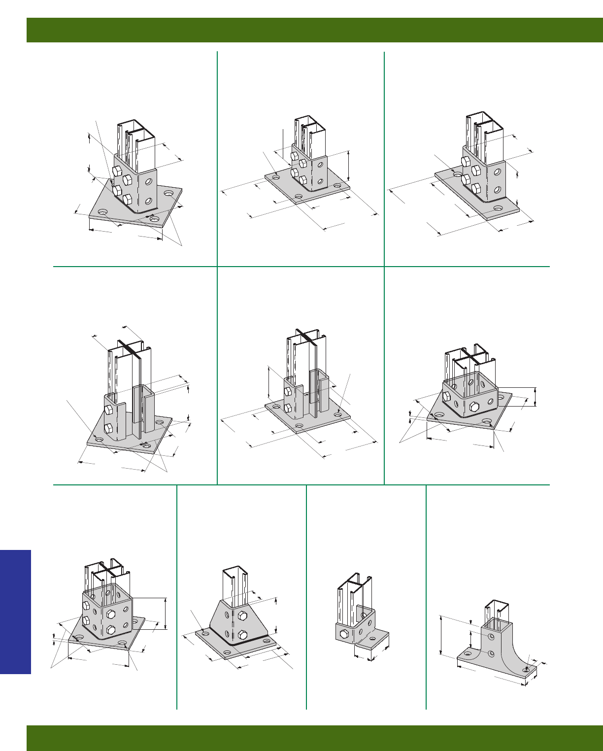
B281FL
POST BASE FOR B22A, B, C, ETC.
•Standard finishes: ZN, GRN
•Wt./C 320 Lbs. (145.1 kg)
B281SQ
POST BASE FOR B22A, B, C, ETC.
•Standard finishes: ZN, GRN, HDG, SS4
•Wt./C 400 Lbs. (181.4 kg)
B281
POST BASE FOR B22A, B, C, ETC.
•Standard finishes: ZN, GRN, HDG
•Wt./C 400 Lbs. (181.4 kg)
B281M
POST BASE FOR B22-2PL
•Standard finishes: ZN, GRN
•Wt./C 470 Lbs. (213.2 kg)
B281MSQ
POST BASE FOR B22-2PL
•Standard finishes: ZN, GRN
•Wt./C 470 Lbs. (213.2 kg)
B278
POST BASE FOR B22
•Standard finishes: ZN, GRN
•Wt./C 288 Lbs. (130.6 kg)
B570
POST BASE FOR FOUR
CHANNEL COMBINATIONS
•Standard finishes: ZN, GRN
•Wt./C 397 Lbs. (180.1 kg)
B570A
POST BASE FOR FOUR
CHANNEL COMBINATIONS
•Standard finishes: ZN, GRN
•Wt./C 550 Lbs. (249.5 kg)
B585
POST BASE FOR B22A
•Standard finishes: ZN, GRN
•Wt./C 97 Lbs. (44.0 kg)
B300
POST BASE
•Material: Malleable Iron
•Standard finishes: ZN, GRN
•Wt./C 259 Lbs. (117.5 kg)
31/2”
(88.9)
31/2”
(88.9)
31/2”
(88.9)
31/2”
(88.9)
5”
(127.0) 5”
(127.0)
315/32”
(87.9)
39/16”
(90.5)
31/2”
(88.9)
35/16”
(84.1)
35/16”
(84.1)
31/2”
(88.9)
111/16”
(42.8)
31/16”
(77.8)
3/4” (19.0)
DIA. 4 HOLES
3/4” (19.0)
DIA. 4 HOLES
3/4” (19.0)
DIA. 4 HOLES
3/4” (19.0)
DIA. 4 HOLES
3/4” (19.0)
DIA. 4 HOLES
3/4” (19.0)
DIA. 4 HOLES
7/16” (11.1)
DIA. 4
HOLES
3/4” (19.0)
DIA. 2 HOLES
3”
(76.2)
3”
(76.2)
3”
(76.2)
6”
(152.4)
6”
(152.4)
6”
(152.4)
6”
(152.4)
6”
(152.4)
6”
(152.4)
6”
(152.4)
6”
(152.4) 41/4”
(107.9) 41/4”
(107.9) 6”
(152.4)
6”
(152.4)
41/4”
(107.9) 41/4”
(107.9)
6”
(152.4)
6”
(152.4)
8”
(203.2)
61/4”
(158.7)
31/8”
(79.4)
31/2”
(88.9)
35/16”
(84.1)
111/16”
(42.8)
15/8”
(41.3)
3”
(76.2)
15/8”
(41.3)
1/4”
(6.3)
1/4”
(6.3)
31/2”
(88.9)
4”
(101.6)
7”
(177.8)
3/4”
(19.0)
9/16”
(14.4)
13/4”
(44.4)
21/16”
(52.4)
3/8” (9.5)
COUNTER-
SUNK TO
3/4” (19.0) DIA.
Strut Fittings
Reference page 58 for general fitting and standard finish specifications.
Post Bases
84
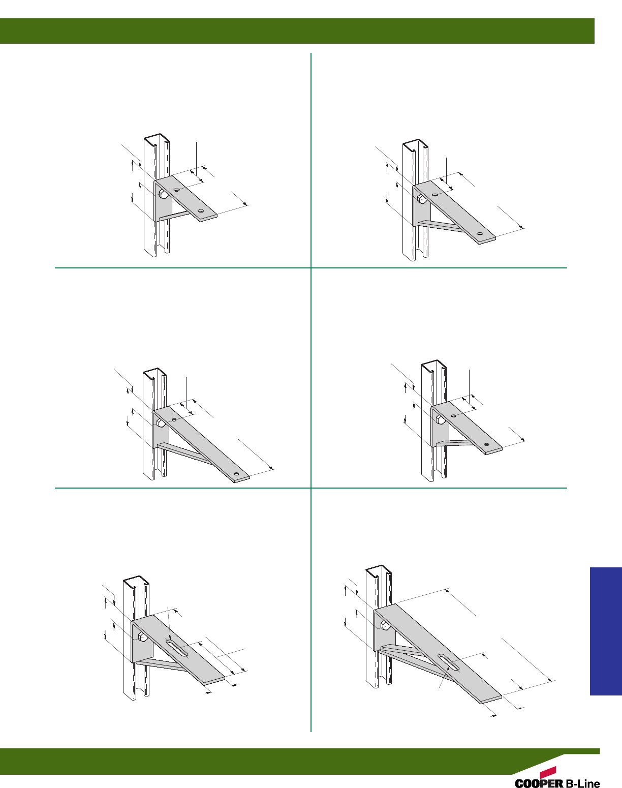
B188 BRACKET
•Uniform Loading 1080 Lbs. (4.80 kN)
•Safety Factor of 2.5
•Hole Spacing on Bracket Top 815/16”(227.0) Center to Center
•Standard finishes: ZN, GRN
•Wt./C 241 Lbs. (109.3 kg)
B187 BRACKET
•Uniform Loading 1450 Lbs. (6.45 kN)
•Safety Factor of 2.5
•Hole Spacing on Bracket Top 55/16” (150.8) Center to Center
•Standard finishes: ZN, GRN
•Wt./C 193 Lbs. (87.5 kg)
B189 BRACKET
•Uniform Loading 870 Lbs. (3.87 kN)
•Safety Factor of 2.5
•Hole Spacing on Bracket Top 1115/16” (303.2) Center to Center
•Standard finishes: ZN, GRN
•Wt./C 308 Lbs. (139.7 kg)
B541 BRACKET
•Uniform Loading 1240 Lbs. (5.51 kN)
•Safety Factor of 2.5
•Hole Spacing on Bracket Top 77/16” (188.9) Center to Center
•Standard finishes: ZN, GRN
•Wt./C 201 Lbs. (91.2 kg)
B190 12” (304.8) BRACKET
•Uniform Loading 900 Lbs. (4.00 kN)
•Safety Factor of 2.5
•Standard finishes: ZN, GRN
•Wt./C 260 Lbs. (117.9 kg)
B191-18 18” (457.2) BRACKET
•Uniform Loading 600 Lbs. (2.67 kN)
•Safety Factor of 2.5
•Standard finishes: ZN, GRN
•Wt./C 377 Lbs. (171.0 kg)
21/4”
(57.1)
11/16”
(27.0)
4”
(101.6)
4”
(101.6)
4”
(101.6)
2”
(50.8)
12”
(304.8)
4”
(101.6)
9”
(228.6)
15”
(381.0)
11/16”
(27.0)
11/16”
(27.0)
11/16”
(27.0)
21/4”
(57.1)
21/4”
(57.1)
101/2”
(266.7)
71/2”
(190.5)
71/2”
(190.5)
11/16”
(27.0)
11/16”
(27.0)
12”
(304.8)
4”
(101.6)
9/16” x 3” SLOT
(14.3) (76.2)
9/16” x 3” SLOT
(14.3) (76.2) 2”
(50.8)
4”
(101.6)
18”
(457.2)
21/4”
(57.1)
Strut Fittings
Reference page 58 for general fitting and standard finish specifications.
Brackets
85
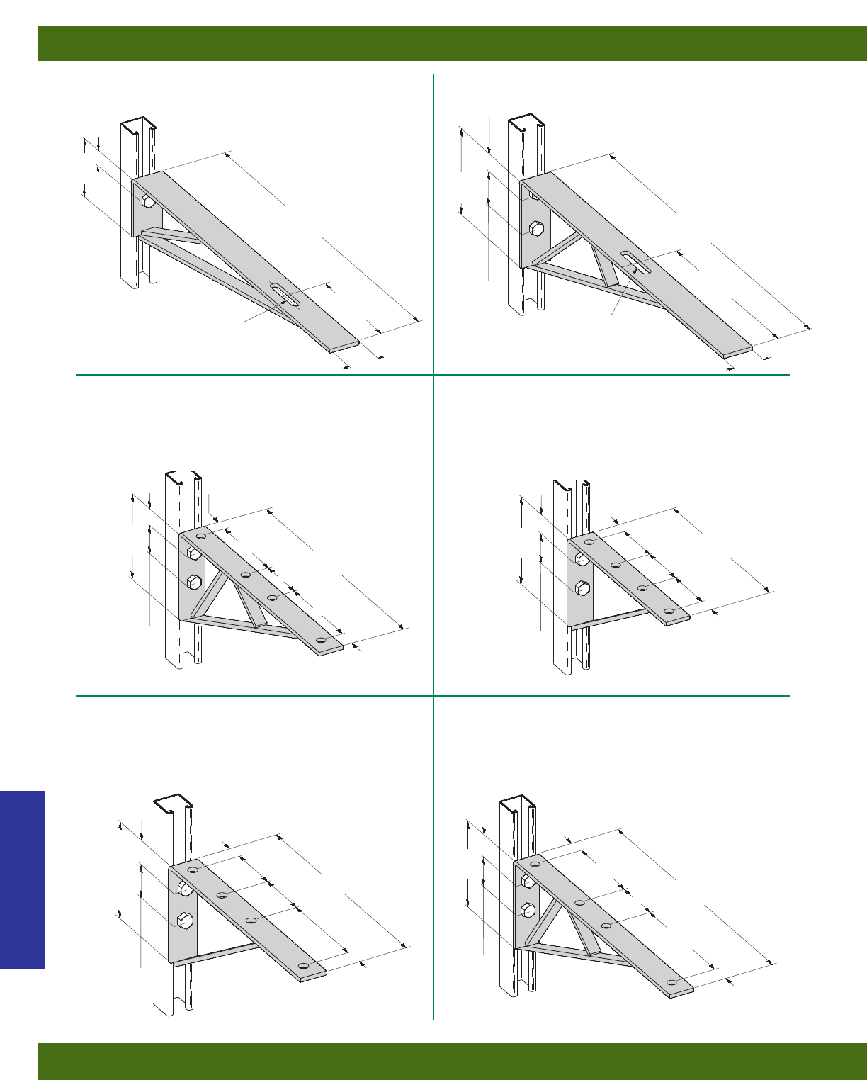
B192 24” (609.6) BRACKET
•Uniform Loading 820 Lbs. (3.65 kN)
•Safety Factor of 2.5
•Standard finishes: ZN, GRN
•Wt./C 576 Lbs. (261.3 kg)
B191-24 24” (609.6) BRACKET
•Uniform Loading 450 Lbs. (2.00 kN)
•Safety Factor of 2.5
•Standard finishes: ZN, GRN
•Wt./C 377 Lbs. (171.0 kg)
B290 161/2” (419.1) BRACKET
•Uniform Loading 1200 Lbs. (5.34 kN)
•Safety Factor of 2.5
•Standard finishes: ZN, GRN
•Wt./C 405 Lbs. (183.7 kg)
B289-12 121/2” (317.5) BRACKET
•Uniform Loading 1040 Lbs. (4.63 kN)
•Safety Factor of 2.5
•Standard finishes: ZN, GRN
•Wt./C 285 Lbs. (129.3 kg)
B289-14 141/2” (368.3) BRACKET
•Uniform Loading 900 Lbs. (4.00 kN)
•Safety Factor of 2.5
•Standard finishes: ZN, GRN
•Wt./C 295 Lbs. (133.8 kg)
B291 181/2” (469.9) BRACKET
•Uniform Loading 1070 Lbs. (4.76 kN)
•Safety Factor of 2.5
•Standard finishes: ZN, GRN
•Wt./C 468 Lbs. (212.3 kg)
71/2”
(190.5)
6”
(152.4)
6”
(152.4)
6”
(152.4)
24”
(609.6)
31/8”
(79.4)
33/4”
(95.2)
161/2”
(419.1)
31/4”
(82.5) 121/2”
(317.5)
12”
(304.8)
6”
(152.4)
181/2”
(469.9)
4”
(101.6)
2”
(50.8)
2”
(50.8)
9/16” x 3” SLOT
(14.3) (76.2)
9/16” x 3” SLOT
(14.3) (76.2)
24”
(609.6)
11/16”
(27.0)
11/16”
(27.0)
13/16”
(30.1)
51/4”
(133.3)
31/8”
(79.4)
53/4”
(146.0)
13/16”
(30.1)
13/16”
(30.1)
13/16”
(30.1)
141/2”
(368.3)
13/16”
(30.1)
13/16”
(30.1)
13/16”
(30.1)
31/4”
(82.5) 31/8”
(79.4)
51/4”
(133.3) 31/8”
(79.4)
73/4”
(196.8)
53/4”
(146.0)
13/16”
(30.1)
6”
(152.4)
27/16”
(61.9)
21/2”
(63.5)
21/2”
(63.5)
21/2”
(63.5)
21/2”
(63.5)
13/16”
(30.1)
13/16”
(30.1)
13/16”
(30.1)
13/16”
(30.1)
Strut Fittings
Reference page 58 for general fitting and standard finish specifications.
Brackets
86
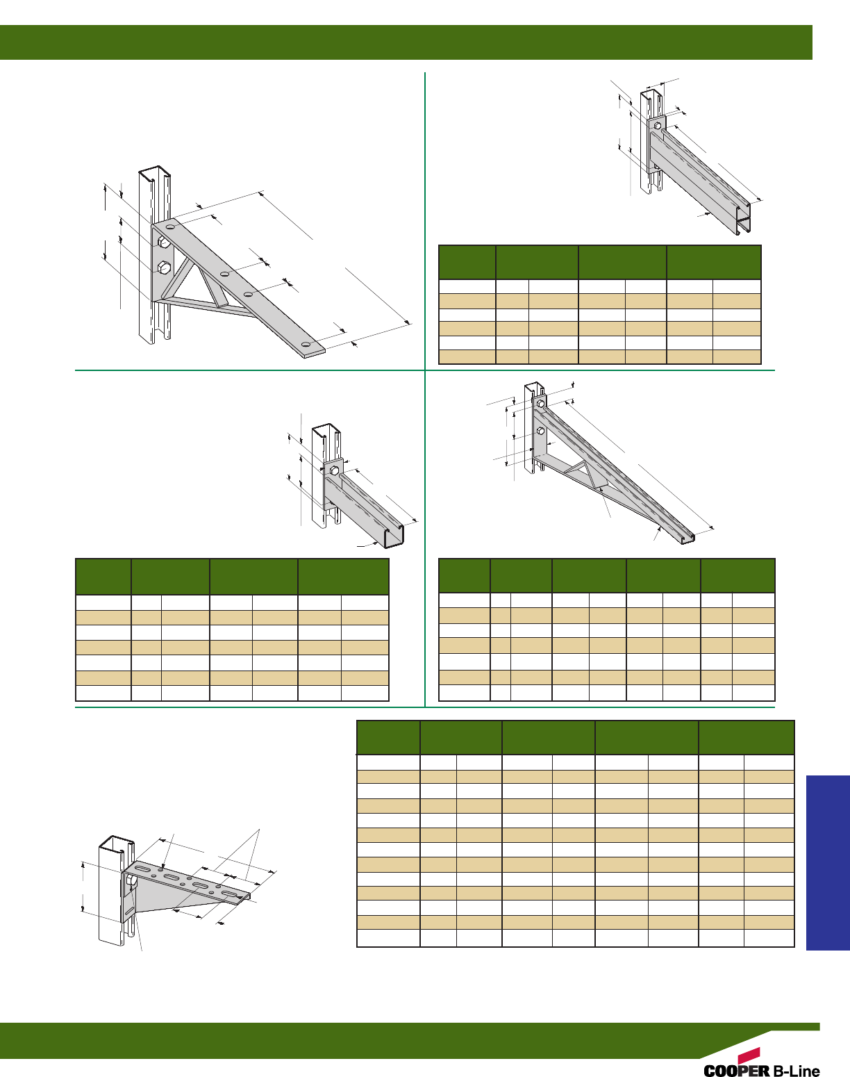
B297
DOUBLE CHANNEL
BRACKET
•Safety Factor of 2.5
•Standard finishes:
ZN, GRN, HDG
B292 201/2” (520.7) BRACKET
•Uniform Loading 600 Lbs. (2.67 kN)
•Safety Factor of 2.5
•Standard finishes: ZN, GRN, HDG, SS4
•Wt./C 490 Lbs. (222.2 kg)
B409
SINGLE CHANNEL BRACKET
•Safety Factor of 2.5
•Standard finishes: ZN, GRN, SS4
B494
BRACED
SINGLE BRACKET
•Safety Factor of 2.5
•Standard finishes:
ZN, GRN
B174SH-B186SH
L&R SLOTTED BRACKET
•Safety Factor of 2.5
•Specify L for left or R for right bracing
•Material: ASTM A1011 33,000 PSI min. yield
•Standard finishes: ZN, GRN
201/2”
(520.7)
45/8”
(117.5)
13/16”
(30.1)
13/16”
(30.1)
13/16”
(30.1)
13/16”
(20.6)
11/2”
(38.1)
4”
(101.6)
71/4”
(184.1)
31/8”
(79.4)
73/4”
(196.8)
6”
(152.4)
3/8”
(9.5)
13/16”
(20.6)
2”
(50.8)
2”
(50.8)
3”
(76.2)
2”
(50.8)
2”
(50.8)
1”
(25.4)
A
L
B
A
A
H
B42
B22
Part Uniform Load Wt./C
No. A Lbs. kN Lbs. kg
B297-12 12” (304.8) 1660 (7.37) 485 (220.0)
B297-18 18” (457.2) 1100 (4.88) 668 (303.0)
B297-24 24” (609.6) 835 (3.71) 857 (388.7)
B297-30 30” (762.0) 665 (2.95) 1040 (471.7)
B297-36 36” (914.4) 550 (2.44) 1240 (562.4)
B297-42 42” (1066.8) 465 (2.06) 1440 (653.2)
Part Uniform Load Wt./C
No. A Lbs. kN Lbs. kg
B409-6 6” (152.4) 1920 (8.54) 152 (68.9)
B409-9 9” (228.6) 1280 (5.69) 195 (88.4)
B409-12 12” (304.8) 960 (4.27) 232 (105.2)
B409-14 14” (355.6) 800 (3.56) 274 (124.3)
B409-16 16” (406.4) 730 (3.25) 314 (142.4)
B409-18 18” (457.2) 640 (2.84) 347 (157.4)
B409-24 24” (609.6) 480 (2.13) 450 (204.1)
Part
Uniform Load Wt. /C
No. L H Lbs. kN Lbs. kg
B494-12 12” (304.8) 83/4”(222.2) 1580 (7.02) 364 (165.1)
B494-18 18” (475.2) 83/4”(222.2) 1000 (4.45) 479 (217.3)
B494-24 24” (609.6) 83/4”(222.2) 996 (4.43) 716 (324.8)
B494-30 30” (762.0) 111/4”(285.7) 924 (4.11) 927 (420.5)
B494-36 36” (914.4) 111/4”(285.7) 864 (3.84) 1095 (496.7)
B494-42 42” (1066.8) 16” (406.4) 580 (2.58) 1400 (635.0)
B494-48 48” (1219.2) 16” (406.4) 500 (2.22) 1510 (684.9)
Part Uniform Load Wt./C
No. A B Lbs. kN Lbs. kg
B174SH 24” (609.6) 67/16”(163.5) 225 (1.00) 370 (167.8)
B175SH 26” (660.4) 615/16”(176.2) 225 (1.00) 425 (192.8)
B176SH 28” (711.2) 77/16”(188.9) 225 (1.00) 480 (217.7)
B177SH 30” (762.0) 715/16”(201.6) 225 (1.00) 520 (235.9)
B178SH 12” (304.8) 37/16”(87.3) 350 (1.55) 143 (64.8)
B179SH 14” (355.6) 315/16”(100.0) 350 (1.55) 162 (73.5)
B180SH 16” (406.4) 47/16”(112.7) 250 (1.11) 204 (92.5)
B181SH 18” (457.2) 415/16”(125.4) 250 (1.11) 232 (105.2)
B182SH 20” (508.0) 57/16”(138.1) 250 (1.11) 275 (124.7)
B183SH 22” (558.8) 515/16”(150.8) 250 (1.11) 317 (143.8)
B184SH 6” (152.4) 115/16”(49.2) 225 (1.00) 58 (26.3)
B185SH 8” (203.2) 27/16”(61.9) 225 (1.00) 82 (37.2)
B186SH 10” (254.0) 215/16”(74.6) 325 (1.44) 103 (46.7)
15/8”
(41.3)
Inside Brace on
B494-24 and Larger.
Right bracket shown, left bracket
gussett on opposite side.
MOUNTING HOLE
7/16” (11.1) DIA.
13/32” x 1” SLOT
(10.3) (25.4)
9/32” (7.1)
DIA. HOLES
B22A
61/4”
(158.7)
45/8”
(117.5)
21/2”
(63.5)
13/16”
(20.6)
Strut Fittings
Reference page 58 for general fitting and standard finish specifications.
Brackets
87
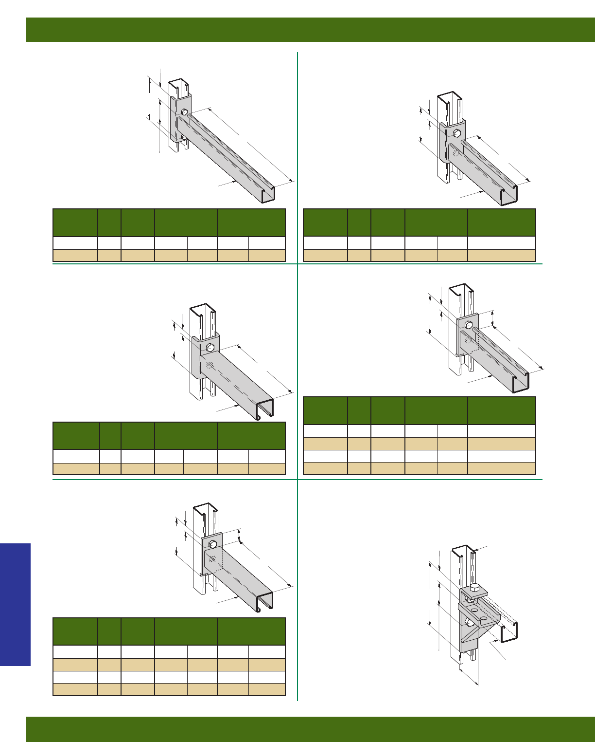
B198
CHANNEL CLEVIS BRACKET
•Safety Factor of 2.5
•Standard finishes: ZN, GRN
B196
CHANNEL
CLEVIS
BRACKET
•Safety Factor of 2.5
•Standard finishes:
ZN, GRN
B198A
CHANNEL CLEVIS BRACKET
•Safety Factor of 2.5
•Standard finishes: ZN, GRN
B293
CHANNEL BRACKET
•Safety Factor of 2.5
•Standard finishes: ZN, GRN
B293A
CHANNEL BRACKET
•Safety Factor of 2.5
•Standard finishes: ZN, GRN
B194 BRACKET FOR B22 & B24
•Safety Factor of 2.5
•6300 In.-Lbs (712 N•m) applies to fitting only,
not to strength of strut arm
•Refer to page 217 for strut
loading data
•Standard finishes: ZN, GRN
•Wt./C 210 Lbs. (95.2 kg)
53/8”
(136.5)
35/8”
(92.1)
A
A
A
A
A
Part Uniform Load Wt./C
No. A (A) Lbs. kN Lbs. kg
B198A-6 6” (152.4) 1600 (7.12) 185 (83.9)
B198A-12 12” (304.8) 800 (3.56) 284 (128.8)
31/2”
(88.9)
31/2”
(88.9)
31/2”
(88.9)
33/4”
(95.3)
31/2”
(88.9)
11/2”
(38.1)
11/2”
(38.1)
63/8”
(161.9)
23/16”
(55.6)
13/32”
(27.8)
Part Uniform Load Wt./C
No. A (A) Lbs. kN Lbs. kg
B198-6 6” (152.4) 1600 (7.12) 185 (83.9)
B198-12 12” (304.8) 800 (3.56) 284 (128.8)
Part Uniform Load Wt./C
No. A (A) Lbs. kN Lbs. kg
B196-18 18” (457.2) 600 (2.67) 430 (195.0)
B196-24 24” (609.6) 450 (2.00) 510 (231.3)
Part Uniform Load Wt./C
No. A (A) Lbs. kN Lbs. kg
B293-6 6” (152.4) 1200 (5.34) 144 (65.3)
B293-12 12” (304.8) 600 (2.67) 252 (114.3)
B293-18 18” (457.2) 400 (1.78) 340 (154.2)
B293-24 24” (609.6) 300 (1.33) 412 (186.9)
Part Uniform Load Wt./C
No. A (A) Lbs. kN Lbs. kg
B293A-6 6” (152.4) 1200 (5.34) 144 (65.3)
B293A-12 12” (304.8) 600 (2.67) 252 (114.3)
B293A-18 18” (457.2) 400 (1.78) 340 (154.2)
B293A-24 24” (609.6) 300 (1.33) 412 (186.9)
B22
B22
B22
B22
B22
B22
B22
13/16”
(20.6)
13/16”
(20.6)
13/16”
(20.6)
13/16”
(20.6)
13/16”
(20.6)
Strut Fittings
Reference page 58 for general fitting and standard finish specifications.
Brackets
88
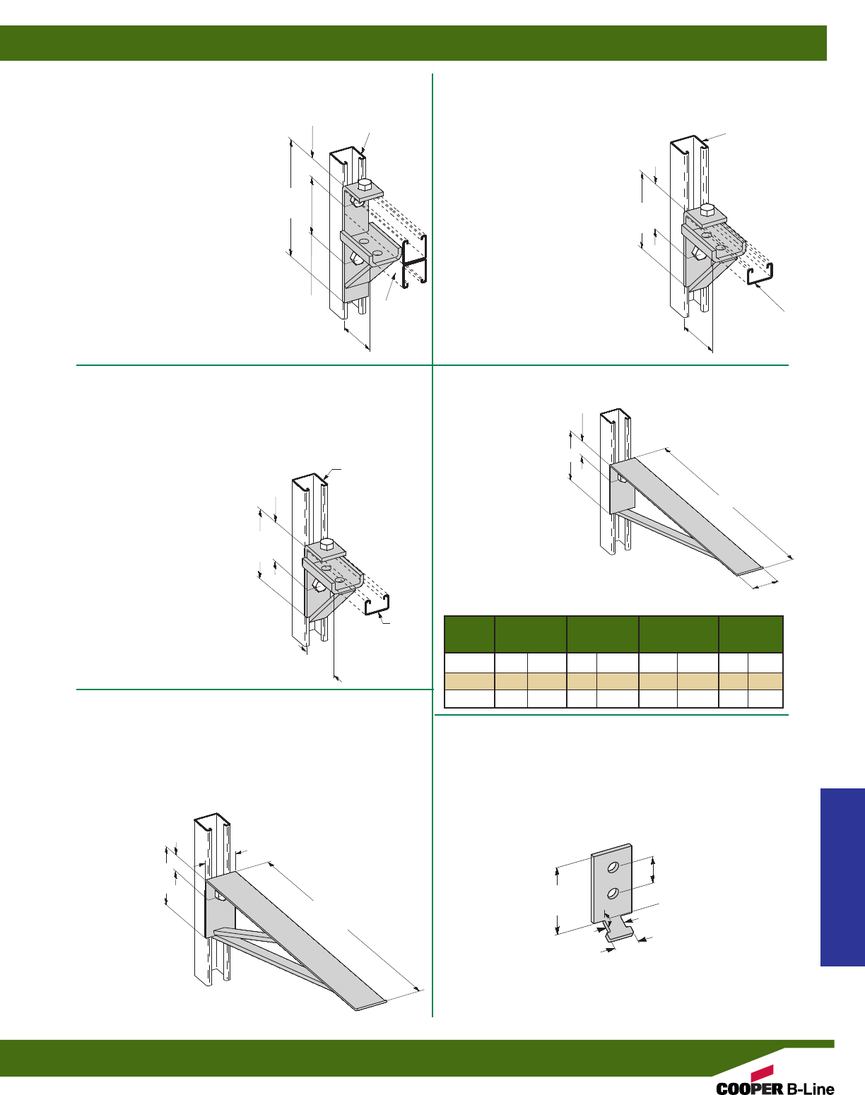
B195 BRACKET FOR B42
•Safety Factor of 2.5
•2500 In.-Lbs (282 N•m) applies to fitting only,
not to strength of strut arm
•Refer to page 217 for strut loading
data
•Standard finishes: ZN, GRN
•Wt./C 174 Lbs. (78.9 kg)
B370 BRACKET FOR B22A & B11
•Safety Factor of 2.5
•13000 In.-Lbs (1469 N•m) applies to
fitting only, not to strength of strut arm
•Refer to page 217 for strut loading
data
•Standard finishes: ZN, GRN
•Wt./C 266 Lbs. (120.6 kg)
B440
BRACKET FOR B52 & B54
•Safety Factor of 2.5
•2000 In.-Lbs (226 N•m) applies to fitting only,
not to strength of strut arm
•Refer to page 217 for strut loading data
•Standard finishes: ZN, GRN
•Wt./C 177 Lbs. (80.3 kg)
B449-4, 8 & 12
CABLE SADDLE
BRACKET
•Safety Factor of 2.5
•Material:
11 Gauge (3.0)
ASTM A1011
HSLAS Gr. 50
•Standard finishes:
ZN, GRN
B293PL
BRACKET PLATE ONLY
•Standard finishes: ZN, GRN
•Wt./C 46 Lbs. (20.8 kg)
B449-18
18” (457.2) CABLE SADDLE BRACKET
•Safety Factor of 2.5
•Uniform Load 960 Lbs. (4.17 kN)
•Material: 11 Gauge (3.0) ASTM A1011 HSLAS Gr. 50
•Standard finishes: ZN, GRN
•Wt./C 312 Lbs. (141.5 kg)
33/4”
(95.2)
315/16”
(100.0)
33/4”
(95.2)
33/4”
(95.2)
31/2”
(88.9)
2”
(50.8)
2”
(50.8)
37/8”
(98.4)
37/8”
(98.4)
8”
(203.2)
B22 B22
B42
B52
B22
B22A
Part
Uniform Load Wt./C
No. A B Lbs. kN Lbs. kg
B449-4 41/2”(114.3) 23/8”(60.3) 2400 (10.67) 74 (33.5)
B449-8 81/2”(215.9) 23/8”(60.3) 1270 (5.65) 124 (56.2)
B449-12 121/2”(317.5) 4” (101.6) 860 (3.82) 184 (83.4)
A
B
11/2”
(38.1)
11/4”
(31.7)
13/16”
(20.6)
4”
(101.6)
18”
(457.2)
120°
13/32”
(27.8)
21/8”
(54.0)
21/8”
(54.0)
13/16”
(20.6)
13/16”
(20.6)
Strut Fittings
Reference page 58 for general fitting and standard finish specifications.
Brackets
89
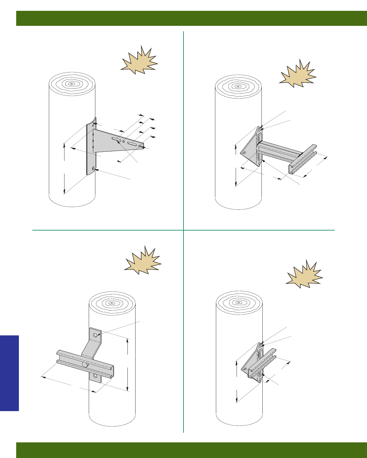
NEW
NEW
NEW
NEW
B810-W
•Specify W = 8, 12, 16
•13/16” (20.6mm) x 1” (25.6mm) banding slots for steel band
•Standard finishes: ZN, HDG
B802D-W
•Specify W = 8, 12, 16
•Standard finishes: ZN, HDG
B852S-W-D
•Specify W = 8, 12, 16
•Specify D = 6, 8, 10, 12, 16, 18, 24
•13/16” (20.6mm) x 1” (25.4mm) banding
slots for steel band
•Standard finishes: ZN, HDG
B816
•Standard finishes: ZN, HDG
14”
(355.6)
14”
(355.6)
13/16” (20.6) DIA.
11/16” x 1” SLOT
(17.4) (25.4)
9/16” x 29/16”SLOT
(14.3) (65.1)
13/16” x 1” SLOT
(20.6) (25.4)
13/16” x 1” SLOT
(20.6) (25.4)
13/32” (10.3) DIA.
13/16” (20.6) DIA.
13/16” (20.6) DIA. 13/32” (10.3) DIA.
W
W
W
D
725/32”
(197.6)
61/2”
(165.1) 23/8”
(60.3)
21/8”
(54.0)
9/16”
(14.3)
2”
(50.8)
95/8”
(244.5)
725/32”
(197.6)
Strut Fittings
Reference page 58 for general fitting and standard finish specifications.
Brackets
90
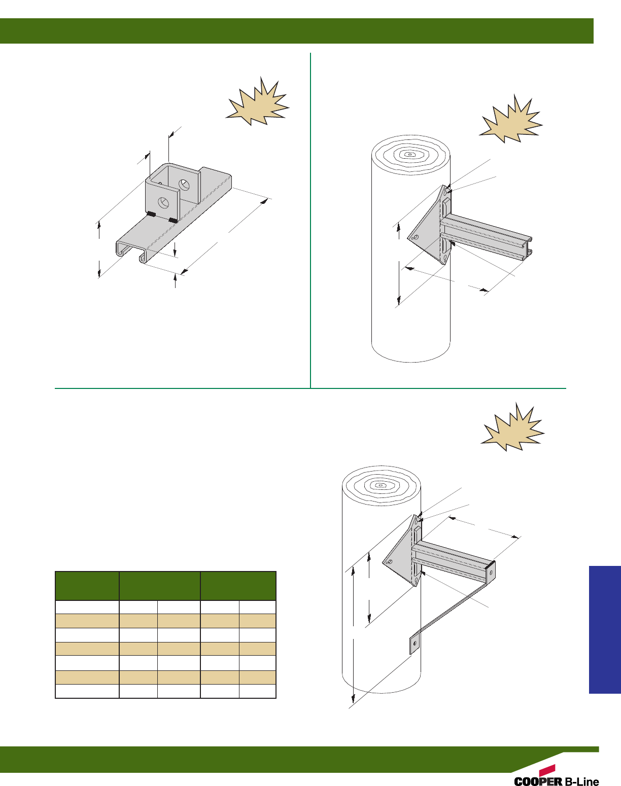
NEW
NEW
B811-W
•Can be attached directly to B809 & B812
•Specify W = 8, 12, 16
•Standard finishes: ZN, HDG
B812-*
•Specify D = 6, 8, 10, 12, 16, 18, 24
•13/16” (20.6mm) x 1” (25.4mm) banding slots for steel band
•Standard finishes: ZN, HDG
B809B-*
•Specify D = 6, 8, 10, 12, 16, 18, 24
•13/16” (20.6mm) x 1” (25.4mm) banding slots for steel band
•Standard finishes: ZN, HDG
W
D
D
27/16”
(61.9)
725/32”
(197.6)
121/32”
(42.1)
13/16”
(20.6)
13/16” (20.6) DIA.
13/32” (10.3) DIA.
725/32”
(197.6)
H
13/16” (20.6) DIA.
13/32” (10.3) DIA.
13/16” x 1” SLOT
(20.6) (25.4)
13/16” x 1” SLOT
(20.6) (25.4)
Part No. D H
In. mm In. mm
B809B-6 6” (152.4) 123/4”(323.9)
B809B-8 8” (203.2) 143/4”(374.7)
B809B-10 10” (254.0) 163/4”(425.5)
B809B-12 12” (304.8) 183/4”(476.2)
B809B-16 16” (406.4) 223/4”(577.8)
B809B-18 18” (457.2) 243/4”(628.6)
B809B-24 24” (609.6) 273/4”(704.8)
Strut Fittings
Reference page 58 for general fitting and standard finish specifications.
Brackets
91
NEW
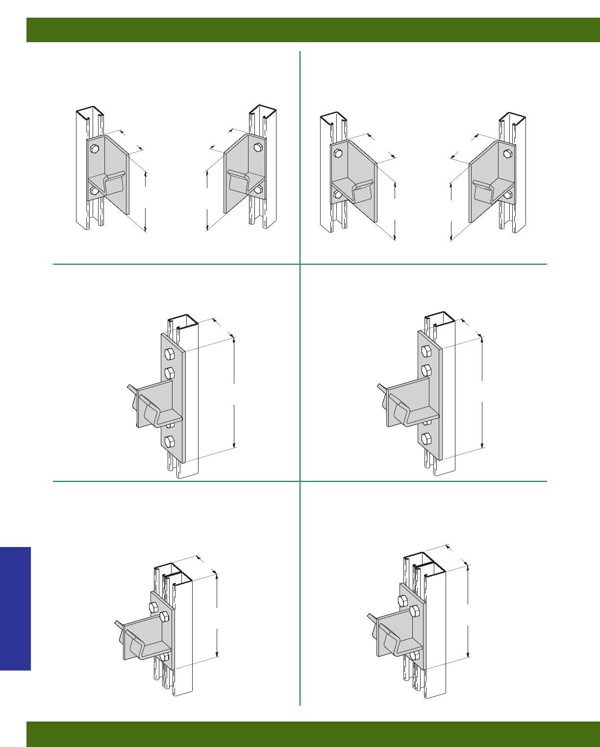
B514 R&L
REEL RACK SUPPORT FOR 2” (50) PIPE
•Standard finishes: ZN, GRN
•Wt./C 246 Lbs. (111.6 kg)
B214 R&L
REEL RACK SUPPORT FOR 11/4” (32) PIPE
•Standard finishes: ZN, GRN
•Wt./C 200 Lbs. (90.7 kg)
B475
DOUBLE REEL RACK SUPPORT ON
SINGLE CHANNEL FOR 11/4” (32) PIPE
•Standard finishes: ZN, GRN
•Wt./C 326 Lbs. (147.9 kg)
B473
DOUBLE REEL RACK SUPPORT ON
SINGLE CHANNEL FOR 2” (50) PIPE
•Standard finishes: ZN, GRN
•Wt./C 351 Lbs. (159.2 kg)
B474
DOUBLE REEL RACK
CHANNEL FOR 11/4” (32) PIPE
•Standard finishes: ZN, GRN
•Wt./C 257 Lbs. (116.6 kg)
B472
DOUBLE REEL RACK SUPPORT ON
DOUBLE CHANNEL FOR 2” (50) PIPE
•Standard finishes: ZN, GRN
•Wt./C 299 Lbs. (135.6 kg)
A
B214R
RIGHT HAND B514R
RIGHT HAND
B214L
LEFT HAND B514L
LEFT HAND
3”
(76.2)
3”
(76.2)
9”
(228.6)
9”
(228.6)
53/8”
(136.5) 53/8”
(136.5) 53/8”
(136.5)
35/8”
(92.1)
35/8”
(92.1)
53/8”
(136.5)
3”
(76.2)
3”
(76.2)
53/8”
(136.5)
53/8”
(136.5)
31/4”
(82.5)
31/4”
(82.5)
Strut Fittings
Reference page 58 for general fitting and standard finish specifications.
Miscellaneous Fittings
92
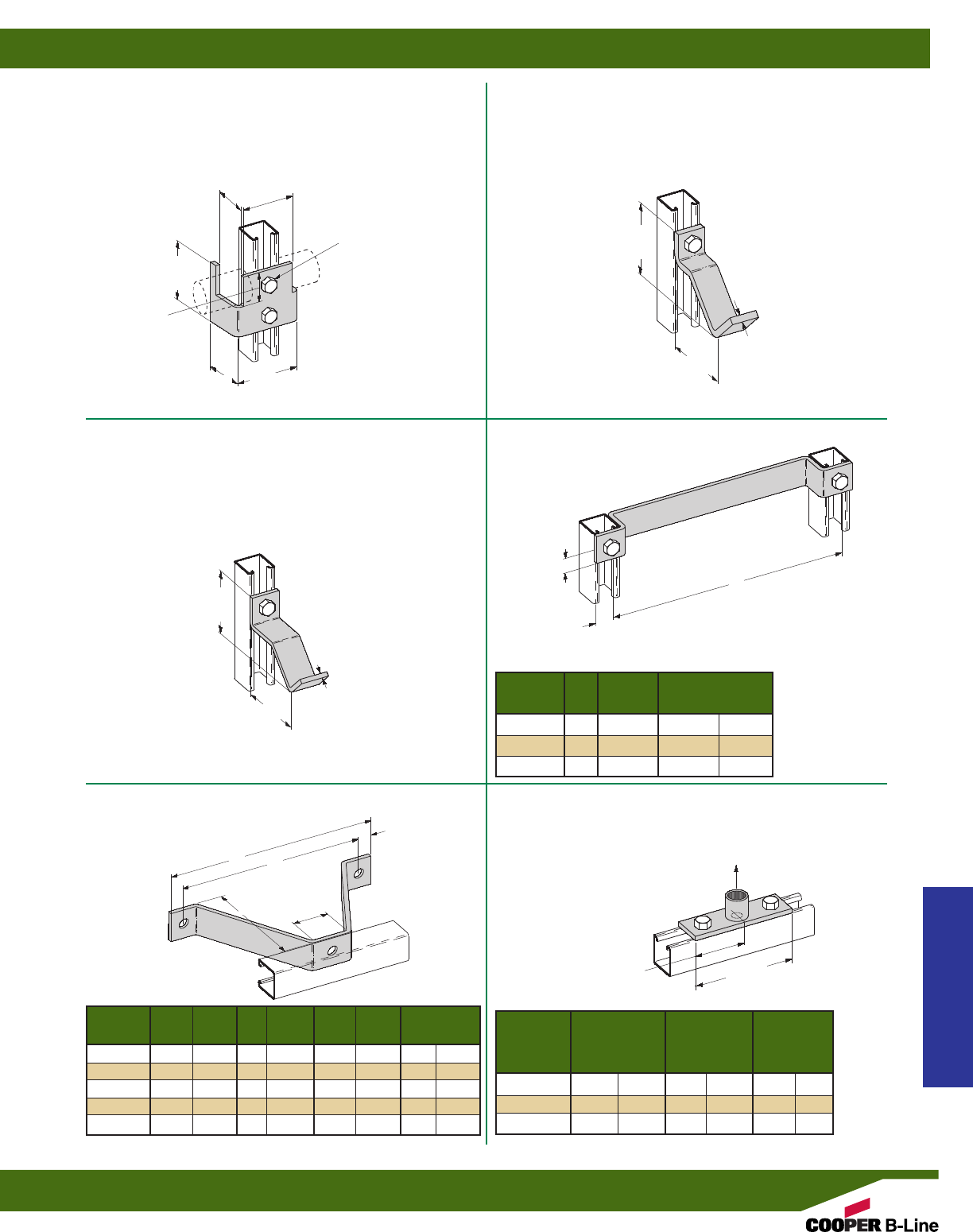
B438
PIPE SUPPORT BRACKET
•Standard finishes: ZN, GRN
•Material: ASTM A36
•Wt./C 132 Lbs. (59.9 kg)
B664
DOUBLE PIPE SUPPORT FOR 11/4” (32) PIPE
•Standard finishes: ZN, GRN
•Wt./C 154 Lbs. (69.8 kg)
B439
PIPE SUPPORT BRACKET
•Standard finishes: ZN, GRN
•Wt./C 88 Lbs. (39.9 kg)
B411 SERIES
LADDER RUNGS
•Standard finishes: ZN, GRN
B587-1/2, 3/4& 1
PIPE COUPLING FITTING
•Safety Factor of 2.5
•Standard finishes: ZN, GRN
B381-B385
WALL LADDER BRACKETS
•Standard finishes: ZN, GRN
41/4”
(107.9)
4”
(101.6)
3/8”
(9.5)
31/2”
(88.9)
13/4”
(44.4)
325/32”
(96.0)
35/16”
(84.1)
213/16”
(71.4)
31/2”
(88.9)
53/8”
(136.5)
1/4”
(6.3)
13/16”
(20.6)
13/16”
(20.6)
13/16”
(20.6)
4”
(101.6)
A
13/4”
(44.4)
HOLES 9/16”(14.3)
Wt./C
Part No. A (A) Lbs. kg
B411-12 12” (304.8) 176 (79.8)
B411-15 15” (381.0) 202 (91.6)
B411-18 18” (457.2) 234 (106.1)
Part Wt./C
No. A (A) B (B) C (C) Lbs. kg
B381 23/8”(60.3) 6” (152.4) 75/8”(193.7) 110 (49.9)
B382 43/8”(111.1) 8” (203.2) 95/8”(244.5) 164 (74.4)
B383 63/8”(161.9) 10” (254.0) 115/8”(295.3) 200 (90.7)
B384 63/8”(212.7) 12” (304.8) 135/8”(346.1) 253 (114.7)
B385 63/8”(263.5) 14” (355.6) 155/8”(396.9) 318 (144.2)
A
B
C
2” I.D.
(50.8)
Design
Part For Wt./C Load
No. Pipe Size Lbs. kg Lbs. kN
B587-1/21/2”(15) 77 (34.9) 1000 (4.45)
B587-3/43/4”(20) 84 (38.1) 1400 (6.23)
B587-1 1” (25) 105 (47.6) 1900 (8.45)
211/16”
(68.2)
Design Load
Strut Fittings
Reference page 58 for general fitting and standard finish specifications.
Miscellaneous Fittings
93
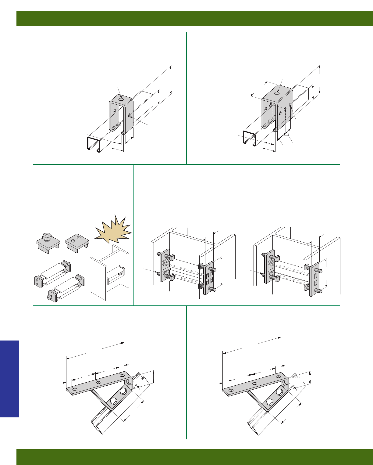
B350
TROLLEY BEAM JOINT SUPPORT
•Design Load 1200 Lbs. (5.34 kN)
•Use 3/8” x 3” bolts in side hole to clamp strut
together (not included)
•Standard finishes: ZN, GRN
•Wt./C 233 Lbs. (105.7 kg)
B349
TROLLEY BEAM SUPPORT
•Design Load 1200 Lbs. (5.34 kN)
•Safety Factor of 2.5
•Use 3/8” x 3” bolts in side hole to clamp strut
together (not included)
•Standard finishes: ZN, GRN
•Wt./C 107 Lbs. (48.5 kg)
B560
45° STAIR SUPPORT
•Standard finishes: ZN, GRN
•Wt./C 220 Lbs. (99.8 kg)
B562
37-1/2° STAIR SUPPORT
•Standard finishes: ZN, GRN
•Wt./C 206 Lbs. (93.4 kg)
315/16”
(100.0)
13/32”
(27.8)
21/32”
(16.7)
121/32”
(42.0)
315/16”
(100.0)
31/2”
(88.9)
31/2”
(88.9)
31/2”
(88.9) 31/2”
(88.9)
31/2”
(88.9)
33/4”
(95.2)
33/4”
(95.2)
45° 371/2°
7/16”(11.1) DIA.
2 HOLES
7/16”(11.1) DIA.
6 HOLES
9/16”(14.3) DIA.
1 HOLE
9/16”(14.3) DIA.
1 HOLE
21/8”
(54.0)
15/8”
(41.3)
17/8”
(47.6) 17/8”
(47.6)
121/32”
(42.0)
11/32”
(26.2)
21/8”
(54.0)
11/32”
(26.2)
87/8”
(225.4)
87/8”
(225.4)
11/16”
(27.0) 11/16”
(27.0)
13/16”
(20.6)
13/16”
(20.6)
B613
COLUMN SUPPORT FOR B22
•Design Load 800 Lbs. (3.56 kN) Slip
with Safety Factor of 3
•Use with B22 and B24 Channel
•Setscrews to be torqued to 19 ft./Lbs
•Sold in pairs
•Standard finishes: ZN, GRN, HDG
•Wt./C 100 Lbs. (45.3 kg)
B613A
COLUMN SUPPORT FOR B52
•Design Load 800 Lbs. (3.56 kN) Slip
with Safety Factor of 3
•Use with B52 and B54 Channel
•Setscrews to be torqued to 19 ft./Lbs
•Sold in pairs
•Standard finishes: ZN, GRN, HDG
•Wt./C 100 Lbs. (45.3 kg)
15/8”
(41.3) 15/8”
(41.3)
31/2”
(88.9)
31/2”
(88.9)
3/8” x 2” CONE
POINT
SETSCREWS
3/8” x 2” CONE
POINT
SETSCREWS
NEW
B614
COLUMN SUPPORT FOR B22
•Quick installation (one bolt to tighten)
•Design Load 800 Lbs. (3.56 kN) Slip
with Safety Factor of 3
•Use with B22 and B24 Channel
•Sold in pairs
•Standard finish: ZN
•Wt./C 50 Lbs. (22.6 kg)
Strut Fittings
Reference page 58 for general fitting and standard finish specifications.
Miscellaneous Fittings
94
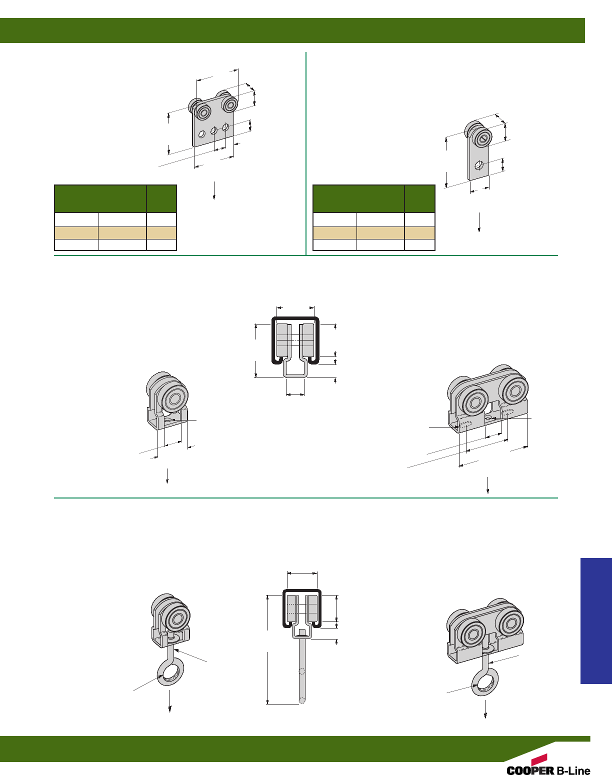
B376
FOUR BEARING TROLLEY
ASSEMBLY
•Safety Factor of 2.5
•Stainless steel ball bearings
•Not for continuous cycling
applications
•Standard finishes: ZN
•Wt./C 110 Lbs. (49.9 kg)
B377
TWO BEARING TROLLEY ASSEMBLY
•Safety Factor of 2.5
•Stainless steel ball bearings
•Not for continuous cycling
applications
•Standard finishes: ZN
•Wt./C 48 Lbs. (21.8 kg)
B477
TWO BEARING LIGHT DUTY
TROLLEY ASSEMBLY
•Design Load 50 Lbs. (.22 kN)
•Safety Factor of 2.5
•Stainless steel ball bearings
•Not for continuous cycling applications
•Material:12 Gauge (2.6) ASTM A1011
33,000 PSI min. yield
•Standard finishes: ZN
•Wt./C 30 Lbs. (13.6 kg)
B477P
WITH PLASTIC
BEARINGS
•Design Load
10 Lbs. (.045 kN)
B477H
TWO BEARING LIGHT DUTY
TROLLEY ASSEMBLY WITH EYE HOOK
•Design Load 50 Lbs. (.22 kN)
•Safety Factor of 2.5
•Stainless steel ball bearings
•Not for continuous cycling applications
•Material:12 Gauge (2.6) ASTM A1011
33,000 PSI min. yield
•Standard finishes: ZN
•Wt./C 36 Lbs. (16.3 kg)
B477HP
WITH PLASTIC
BEARINGS
•Design Load
10 Lbs. (.045 kN)
B478H
FOUR BEARING LIGHT DUTY
TROLLEY ASSEMBLY WITH EYE HOOK
•Design Load 100 Lbs. (.44 kN)
•Safety Factor of 2.5
•Stainless steel ball bearings
•Not for continuous cycling applications
•Material:12 Gauge (2.6) ASTM A1011
33,000 PSI min. yield
•Standard finishes: ZN
•Wt./C 72 Lbs. (32.6 kg)
B478HP
WITH PLASTIC
BEARINGS
•Design Load
20 Lbs. (.090 kN)
B478
FOUR BEARING LIGHT DUTY
TROLLEY ASSEMBLY
•Design Load 100 Lbs. (.44 kN)
•Safety Factor of 2.5
•Stainless steel ball bearings
•Not for continuous cycling applications
•Material:12 Gauge (2.6) ASTM A1011
33,000 PSI min. yield
•Standard finishes: ZN
•Wt./C 68 Lbs. (30.8 kg)
B478P
WITH PLASTIC
BEARINGS
•Design Load
20 Lbs. (.090 kN)
13/16”
(20.6)
13/16”
(20.6)
5/8”
(15.9)
33/8”
(85.7)
33/8”
(85.7)
35/16”
(84.1) 15/16”
(33.3)
15/16”
(33.3)
11/8” (28.6)
BEARING O.D.
9/32” (7.1)
DIA. HOLE
11/8” (28.6)
BEARING O.D.
31/8”
(79.4)
3”
(76.2)
2”
(50.8)
3/4”
(19.0)
3/4”
(19.0)
11/4”
(31.7)
3/4” I.D
(19.0)
3/4” I.D
(19.0)
1/4” (6.3)
EYE ROD
1/4” (6.3)
EYE ROD
Design Load in B22
Lbs. kN RPM
300 (1.33) @600
450 (2.00) @300
600 (2.67) @100
Design Load in B22
Lbs. kN RPM
150 (.67) @600
225 (1.00) @300
437 (1.94) @100
15/16”
(23.8)
11/32”
(8.7)
11/8”
(28.6)
11/4”
(31.7)
5/8”
(15.9)
11/32”
(8.7)
11/8”
(28.6)
11/4”
(31.7)
13/4”
(44.4)
315/16”
(100.0)
Design Load
Design Load
Design Load
Design Load
Design Load Design Load
11/4”
(31.7)
9/32” x 9/16”
SLOT-(2)
(7.1) (14.3)
9/32” (7.1)
DIA. HOLE
Strut Fittings
Reference page 58 for general fitting and standard finish specifications.
Miscellaneous Fittings
95
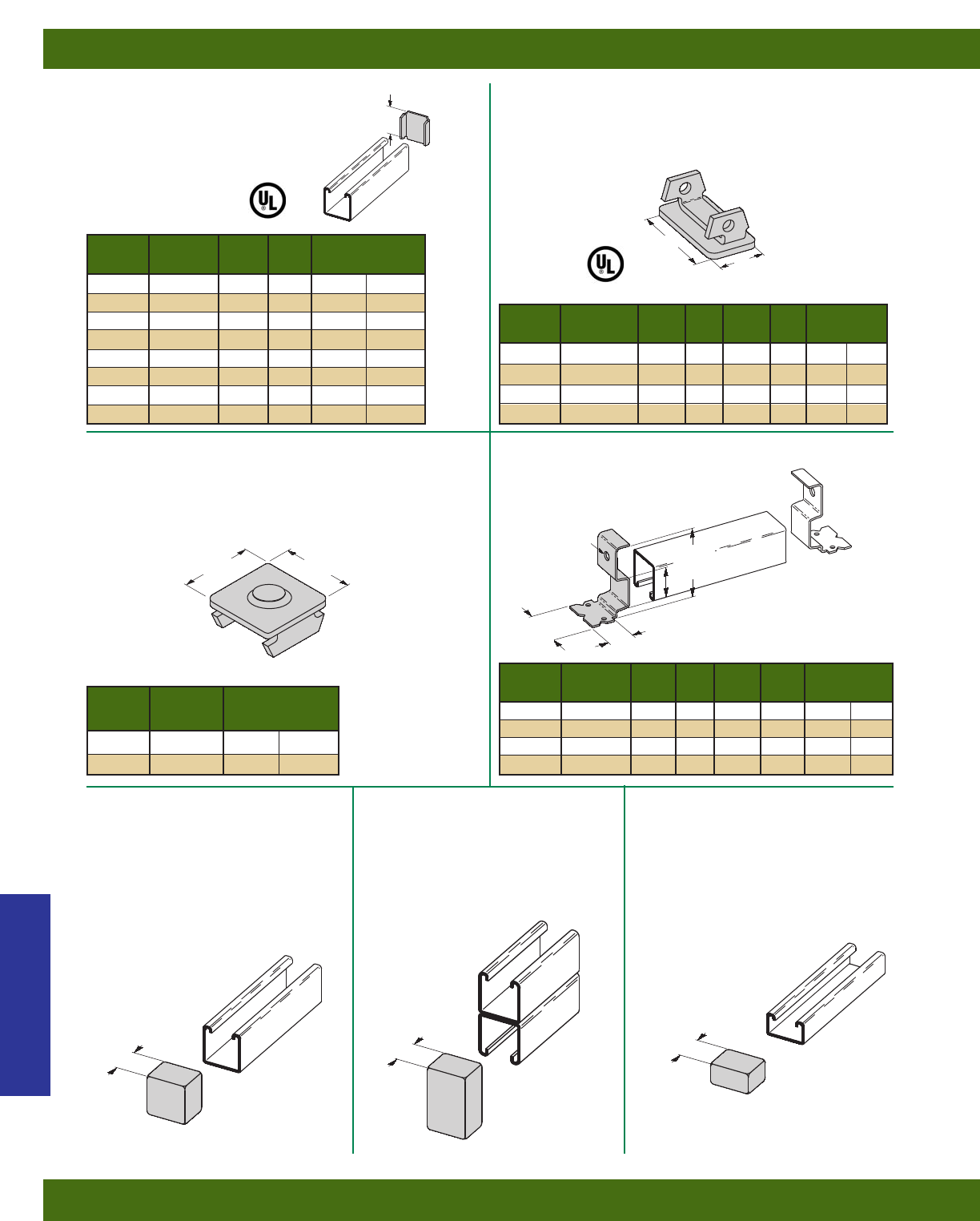
B203-B206 & B220-B223
CHANNEL END CAPS TYPE X
•Material: ASTM A1011 CS Type B
•Standard finishes: ZN, GRN, HDG, SS4, AL
B283-B286
CHANNEL END CAPS
•Material: ASTM A1011 33,000 PSI min. yield
•Standard finishes: ZN, GRN
B287 & B288
CHANNEL END CAPS
•Material: ASTM A1011 33,000 PSI min. yield
•Standard finishes: ZN, GRN
B3322, B3332, B3342, B3352
ANCHOR END CAPS TYPE Y
•Material: ASTM A1011 33,000 PSI min. yield
•Standard finishes: ZN
119/32”
(40.5)
119/32”
(40.5) 25/8”
(66.7)
113/16”
(46.0)
A
A
A
B
B
Part Wt./C
No. Use With A (A) Lbs. kg
B203 B42 1.015 (25.8) 6(2.7)
B204 B54 .827 (21.0) 5(2.2)
B205 B22 1.640 (41.6) 10 (4.5)
B206 B32 1.390 (35.3) 8(3.6)
B220 B52 .827 (21.0) 4(1.8)
B221 B12 2.452 (62.3) 15 (6.8)
B222 B11 3.265 (82.9) 20 (9.1)
B223 B24 1.640 (41.6) 10 (4.5)
Part Wt./C
No. Use With A (A) B (B) Lbs. kg
B283 B52 119/32”(40.5) 25/32”(19.8) 6(2.7)
B284 B54 & B56 119/32”(40.5) 25/32”(19.8) 6(2.7)
B285 B22 119/32”(40.5) 119/32”(40.5) 13 (5.9)
B286 B24 & B26 119/32”(40.5) 119/32”(40.5) 14 (6.3)
Part Wt./C
No. Use With A (A) B (B) Lbs. kg
B3322 B22I 1.270 (32.2) 13/16”(30.2) 15 (6.8)
B3332 B32I 1.000 (25.4) 13/16”(30.2) 15 (6.8)
B3342 B42I .645 (16.4) 11/4”(31.8) 15 (6.8)
B3352 B52I .460 (11.7) 15/16”(33.3) 15 (6.8)
Part Wt./C
No. Use With Lbs. kg
B287 B22 13 (5.9)
B288 B24 14 (6.3)
3/8” (9.5)
DIA. HOLE
B822
PLASTIC END CAP
FOR B22 & B24
•Material: Soft White PVC
•Wt./C 3 Lbs. (1.3 kg)
•Available in colors: White (W),
Yellow (Y), Black (BLK), Gray (GRY),
Green (GRN)
B822A
PLASTIC END CAP
FOR B22A & B11
•Material: Soft White PVC
•Wt./C 5 Lbs. (2.2 kg)
•Available in colors: White (W),
Yellow (Y), Black (BLK), Gray (GRY),
Green (GRN)
B852
PLASTIC END CAP
FOR B52
•Material: Soft White PVC
•Wt./C 2.5 Lbs. (1.1 kg)
•Available in colors: White (W),
Yellow (Y), Black (BLK), Gray (GRY),
Green (GRN)
11/4”
(31.7)
11/4”
(31.7)
11/4”
(31.7)
Strut Fittings
Reference page 58 for general fitting and standard finish specifications.
Miscellaneous Fittings
96
B823
PROFILE END CAPS
•Material: PVC
•Available in colors: White (W),
Yellow (Y), Black (BLK), Gray (GRY),
Green (GRN)
B825
PLASTIC END CAPS
•Material: Polyurethane
•Available in colors: Gray (GRY), Green (GRN)
Approx. 3/4” deep
(19.0)
Fits Wt./C
Part No. Channel Sizes Lbs. kg
B823-22A B22A, B24A, B26A 6.9 (3.1)
B823-22 B22, B24, B26 4.1 (1.8)
B823-42 B42 3.8 (1.7)
B823-52 B52, B54, B56 3.5 (1.6)
Fits Wt./C
Part No. Channel Sizes Lbs. kg
B825-22 B22 & B24 2.0 (0.9)
B825-52 B52 & B54 1.0 (0.4)
NEW
NEW
Strut Fittings
Reference page 58 for general fitting and standard finish specifications.
Miscellaneous Fittings
97
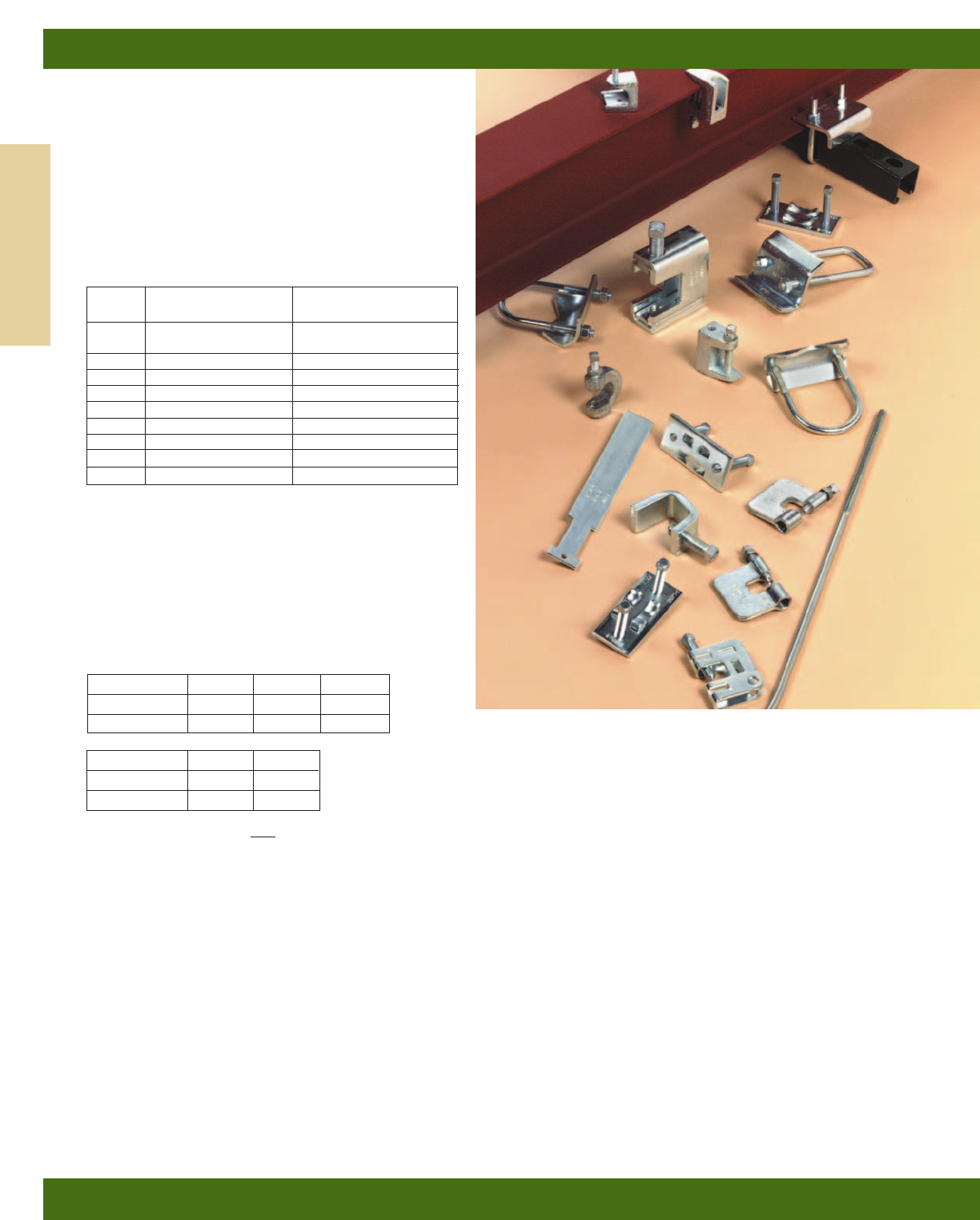
B-Line’s beam attachments and pipe supports offered
in this section are designed to provide supports without
drilling or welding . A complete selection of beam
clamps, pipe clamps, rollers, supports and accessories
are designed for use with B-Line channels and offer
many installation advantages.
Materials & Finishes (Unless otherwise noted)
Pipe clamps, pipe hangers, beam clamps, brackets, and
rollers are made from low carbon steel strips, plates or
rod unless noted.
Note: A minimum order may apply on special material
and finishes.
Load Data
The load data published includes a safety factor of 5.0
unless noted (safety factor = ratio of ultimate load to
the design load).
Recommended Torque For Setscrews
(unless noted)
See chart on page 58 for bolt torque.
Metric
Metric dimensions are shown in parentheses. Unless noted, all metric dimensions are in millimeters.
Setscrew Size 1/4”-20 3/8”-16 1/2”-13
Foot/Lbs. 4511
Nm 5715
Setscrew Size 5/8”-11 3/4”-10
Foot/Lbs. 21 34
Nm 28 46
Beam Clamps
Beam Clamps
98
Finish
Code Finish Specification
PLN Plain ASTM A1018 Gr. 33
ASTM A1011 SS Grade 33
ZN Electro-Plated Zinc ASTM B633 SC3 Type III
GRN Dura-Green
– Malleable Iron ASTM A47 Gr. 32510
HDG Hot-Dipped Galvanized ASTM A123
CZ Chromium Zinc ASTM F1136
SS4 Stainless Steel Type 304 ASTM A240
SS6 Stainless Steel Type 316 ASTM A240
AL Aluminum ASTM B209
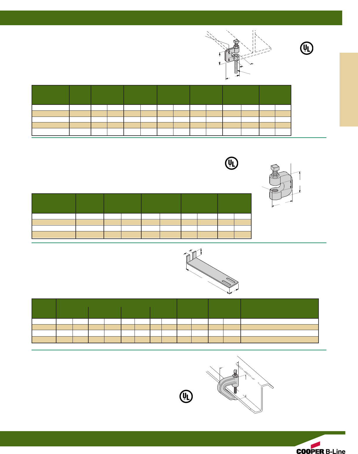
B3362 THRU B3365
RETAINING STRAP
•*When ordering specify L (Length) as a
suffix to the part number
•Material: 14 Gauge (1.9)
•Standard finishes: ZN, SS4, PLN
B3036L
C-CLAMP WITH LOCKNUT
•Safety Factor of 5
•When Retaining Strap is required, order B3363 or B3364 separately
•Setscrew and locknut included
•Material: Malleable iron
•Standard finishes: ZN, PLN
Part Number Rod
With Size B C D E Design Load Wt./C
Locknut A Lbs. kg Lbs. kg
B351L-3/8*3/8”-16 23/8”(60.3) 23/8”(60.3) 3/4”(19.0) 13/8”(34.9) 230 (1.03) 41 (18.6)
B351L-1/2*1/2”-13 23/8”(60.3) 23/8”(60.3) 3/4”(19.0) 13/8”(34.9) 380 (1.71) 41 (18.6)
B351L-5/8*5/8”11 23/8”(60.3) 21/4”(57.1) 3/4”(19.0) 13/8”(34.9) 550 (2.47) 60 (27.2)
B351L-3/4*3/4”-10 23/8”(60.3) 31/4”(82.5) 3/4”(19.0) 13/8”(34.9) 630 (2.83) 71 (32.2)
B351L-7/87/8”-9 3” (76.2) 31/4”(82.5) 1” (25.4) 17/8”(47.6) 1200 (5.34) 184 (83.4)
Wt./C for Length L of
Part No. 6” (152.4) 8” (203.2) 10” (254.0) 12” (304.8) A B For Use With
Lbs. kg Lbs. kg Lbs. kg Lbs. kg
B3362* 17 (7.7) 24 (10.9) 31 (14.0) 38 (17.2) 11/4”(31.7) 7/16”(11.1) B351-3/8& 1/2
B3363* 16 (7.2) 23 (10.4) 30 (13.6) 37 (16.8) 11/4”(31.7) 5/8”(15.9) B351-5/8& 3/4B3036-3/8& 1/2
B3364* 16 (7.2) 23 (10.4) 30 (13.6) 37 (16.8) 11/4”(31.7) 11/16”(17.4) B3036-5/8& 3/4
B3365* 21 (9.5) 29 (13.1) 37 (16.8) 46 (20.8) 11/2”(38.1) 3/4”(19.0) B351-7/8
Part Number Rod
With Size B C Design Load Wt./C
Locknut A Lbs. kg Lbs. kg
B3036L-3/83/8”-16 13/4”(44.4) 13/4”(44.4) 400 (1.78) 29 (13.1)
B3036L-1/21/2”-13 13/4”(44.4) 13/4”(44.4) 400 (1.78) 28 (12.7)
B3036L-5/85/8”-11 2” (50.8) 17/8”(47.6) 450 (2.00) 55 (24.9)
B3036L-3/43/4”-10 2” (50.8) 2” (50.8) 500 (2.22) 72 (32.6)
C
B
ROD SIZE
A
*
3/8THRU 3/4
SIZES ONLY
B351L
STEEL C-CLAMP WITH LOCKNUT
•Safety Factor of 5
•Setscrew and locknut included
•When Retaining Strap is required, order B3362, B3363
or B3365 separately
•Standard finishes: ZN, SS4, PLN
ROD SIZE
A
B
B
C
3/4”
(19.0)
L
A
B3037
Z-PURLIN C-CLAMP
•Design Load 500 Lbs. (2.22 kN)
•Safety Factor of 5
•Designed for attaching a 3/8”-16 hanger rod
to the bottom flange of a Z-purlin
•Setscrew and locknut included
•Material: Malleable iron
•Standard finishes: ZN, PLN
3”
(76.2)
313/32”
(86.5)
Bottom Hanger
Rod Threads
3/8”-16
3/4” (19.0)
MAX.
FLANGE
THICKNESS
*See note above.
D
MAX. FLANGE
THICKNESS
E
Beam Clamps
Reference page 98 for general fitting and standard finish specifications.
Beam Clamps
99
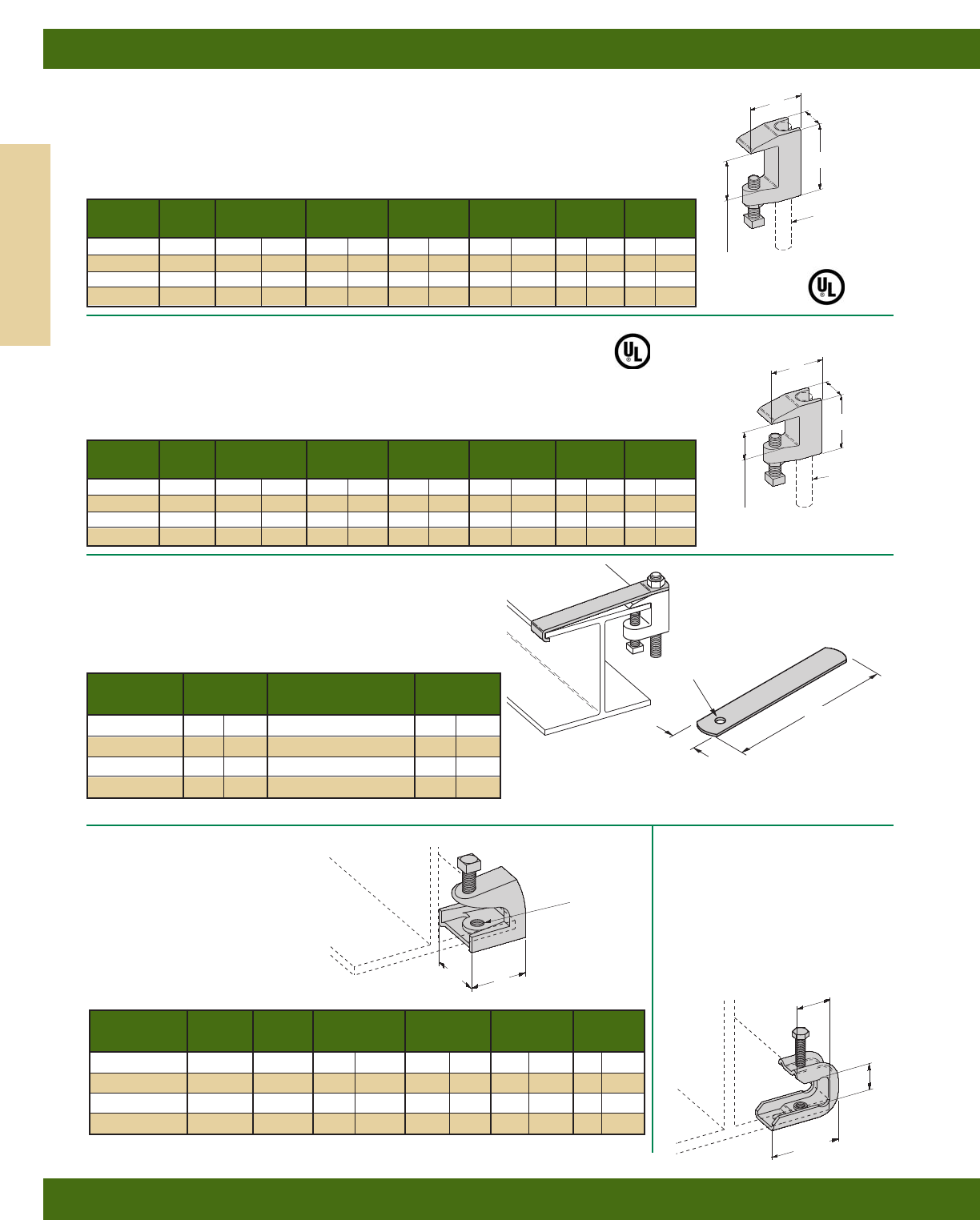
B3033
REVERSIBLE WIDE JAW WEDGE C-CLAMP
(MALLEABLE IRON)
•Safety Factor of 5
•Setscrew and locknut included
•Material: Malleable iron
•Standard finishes: ZN, PLN
B3034
WEDGE C-CLAMP
•Safety Factor of 5 NOTE:
•3/4” (19.0) Max. Flange Thickness 3/8”& 1/2” SIZES
•Setscrew and locknut included ARE REVERSIBLE
•Material: Malleable iron STYLE
•Standard finishes: ZN, PLN
B3367
RETAINING STRAP
•Available in ‘L’ lengths of 6” (152.4), 8” (203.2), 9” (228.6),
10” (254,0), 12” (304.8), 14” (355.6), 16” (406.4), 18” (457.2)
•Material: Steel
•Standard finishes: ZN, PLN
THOAT
OPENING
THROAT OPENINGS
11/4” (31.7) FOR
3/8& 1/2 SIZES
15/16” (33.3) FOR
5/8& 3/4 SIZES
3/4” (19.0) MAX.
FLANGE THICKNESS
C
C
B
B
D
D
ROD SIZE
A
ROD SIZE
A
Rod Design Load Wt./C UL Max.
Part No. Size AB C D Lbs. kN Lbs. kg Pipe Size
B3033-3/83/8”-16 21/4”(57.1) 2” (50.8) 11/8”(28.6) 500 (2.22) 46 (20.8) 4” (100)
B3033-1/21/2”-13 25/16”(58.7) 23/16”(55.5) 11/4”(31.7) 810 (3.60) 64 (29.0) 8” (200)
B3033-5/85/8”-11 25/8”(66.7) 21/2”(63.5) 13/8”(34.9) 1000 (4.48) 116 (52.6) 8” (200)
B3033-3/43/4”-10 211/16”(68.3) 21/2”(63.5) 17/16”(36.5) 1400 (6.22) 140 (63.5) 10” (250)
BC442
LIGHT DUTY BEAM CLAMP
•Design Load 75 Lbs. (.33 kN)
•Safety Factor of 5
•11/16” (17.5) Max. Flange Thickness
•Setscrew included
•Holes tapped 1/4”-20 (Bottom & Back)
•Material: 13 Gauge (2.3)
•Standard finish: ZN
•Wt./C 13 Lbs. (3.9 kg)
B444
SERIES ROD SUPPORT
•Safety Factor of 5
•Max. Flange Thickness
3/4” (19.0) for 1/4& 5/16 sizes
1” (25.4) for 3/8& 1/2sizes
•Setscrew included
•Material: Malleable iron
•Standard finish: ZN
Available in HDG with CZ Hardware
Thread Set Design Load Wt./C
Part No. Size A Screw C D Lbs. kN Lbs. kg
B444-1/41/4”-20 1/4”-20 13/8”(34.9) 13/16”(30.1) 150 (.66) 24 (10.9)
B444-5/16 5/16”-18 1/4”-20 13/8”(34.9) 13/16”(30.1) 150 (.66) 23 (10.4)
B444-3/83/8”-16 1/2”-13 17/8”(47.6) 2” (50.8) 350 (7.12) 65 (29.5)
B444-1/21/2”-13 5/8”-11 23/8”(60.3) 21/2”(63.5) 1000 (4.45) 132 (59.9)
Hole Dia. For Use Wt./C**
Part No. D With Lbs. kg
B3367-3/8-L 7/16”(30.1) B3033-3/8& B3034-3/823.9 (10.8)
B3367-1/2-L 9/16”(30.1) B3033-1/2& B3034-1/223.6 (10.7)
B3367-5/8-L 11/16”(50.8) B3033-5/823.2 (10.5)
B3367-3/4-L 13/16”(63.5) B3033-3/422.7 (10.3)
13/16”
(20.6)
11/16”
(17.5)
13/4”
(44.5)
DC
A
(BOTTOM &
BACK)
L
D
11/4”
(31.7)
** Wt./C based on 6” (152.4) length. For each additional inch in strap length add 4.2 Lbs (1.9 kg) to Wt./C.
*
3/8&1/2
SIZES ONLY
Rod Design Load Wt./C UL Max.
Part No. Size AB C D Lbs. kN Lbs. kg Pipe Size
B3034-3/8*3/8”-16 15/8”(41.3) 2” (50.8) 7/8”(22.2) 560 (2.49) 54 (24.5) 4” (100)
B3034-1/2*1/2”-13 113/16”(46.0) 23/16”(55.5) 13/16”(30.2) 810 (3.60) 51 (23.1) 8” (200)
B3034-5/85/8”-11 13/4”(44.5) 21/8”(54.0) 11/8”(28.6) 1000 (4.48) 70 (31.7) -- --
B3034-3/43/4”-10 2” (50.8) 21/4”(57.2 11/8”(28.6) 1500 (6.67) 98 (44.4) -- --
Beam Clamps
Reference page 98 for general fitting and standard finish specifications.
Beam Clamps
100
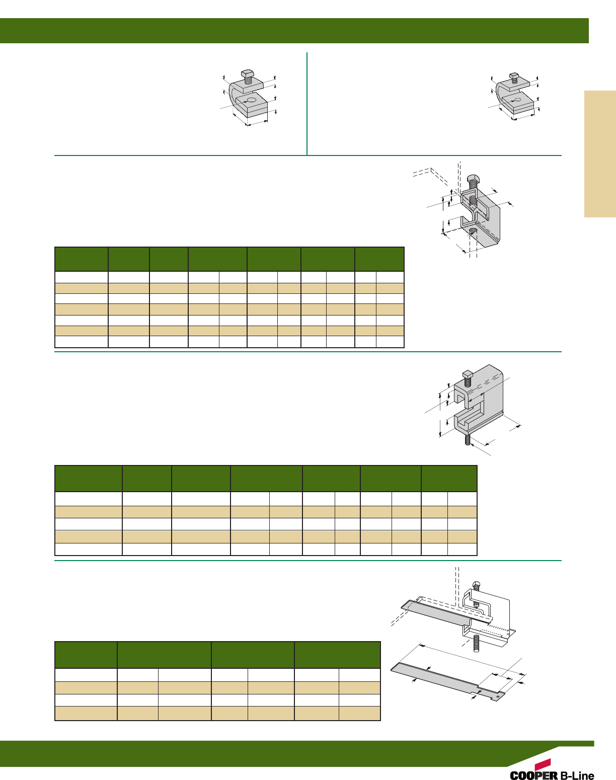
B312 SERIES
RETAINING STRAP FOR USE WITH
B303 THRU B309 AND B321 SERIES
•3/4” (19.0) Max. Flange Thickness
•For thicker beams, step up one flange width size
•Material: 14 Gauge (1.9)
•Standard finishes: ZN, HDG
B321 SERIES BEAM CLAMPS
•Safety Factor of 5
•111/16” (42.8) Max. Flange Thickness
•Setscrew included
•When Retaining Strap is required, order B312 separately
•Recommended Setscrew Torque: 1/2”-13 350 in-lbs. (39.5 N•m)
5/8”-11 700 in-lbs. (79.0 N•m)
•Minimum flange thickness: B321-1 thru B321-3 1/4” (6.3)
B321-4 and B321-5 3/8” (9.5)
•Standard finishes: ZN, HDG
B303 THRU B309 BEAM CLAMPS
•Safety Factor of 5
•Max. Flange Thickness 1/16” (1.6) thru 7/8” (22.2)
•Setscrew included
•When Retaining Strap is required, order B312 separately
•Recommended Setscrew Torque: 3/8”-16 150 in-lbs. (16.9 N•m)
1/2”-13 350 in-lbs. (39.5 N•m)
•Standard finishes: ZN, HDG
Rod Set Design Load Wt./C
Part No. Size A Screw C T Lbs. kN Lbs. kg
B303 1/4”-20 3/8”-16 25/16”(58.7) 11 Ga. (3.0) 400 (1.78) 72 (32.6)
B304 5/16”-18 3/8”-16 25/16”(58.7) 11 Ga. (3.0) 600 (2.67) 72 (32.6)
B305 3/8”-16 3/8”-16 25/16”(58.7) 11 Ga. (3.0) 600 (2.67) 72 (32.6)
B306 3/8”-16 1/2”-13 27/16”(61.9) 7 Ga. (4.5) 1100 (4.89) 97 (44.0)
B307 1/2”-13 1/2”-13 27/16”(61.9) 7 Ga. (4.5) 1100 (4.89) 97 (44.0)
B308 1/2”-13 1/2”-13 29/16”(65.1) 1/4”(6.3) 1500 (6.67) 133 (60.3)
B309 5/8”-11 1/2”-13 29/16”(65.1) 1/4”(6.3) 1500 (6.67) 133 (60.3)
11/8”
(28.6)
21/2”
(63.5)
C
A
T
Rod Design Load Wt./C
Part No. Size A Setscrew C T Lbs. kN Lbs. kg
B321-1 3/8”-16 1/2”-13 39/16”(92.1) 1/4”(6.3) 1300 (5.78) 187 (84.8)
B321-2 1/2”-13 1/2”-13 39/16”(92.1) 1/4”(6.3) 1400 (6.23) 186 (84.3)
B321-3 5/8”-11 1/2”-13 39/16”(92.1) 1/4”(6.3) 1600 (7.12) 185 (83.9)
B321-4 5/8”-11 5/8”-11 323/32”(94.4) 5/16”(7.9) 1800 (8.00) 239 (108.4)
B321-5 3/4”-10 5/8”-11 323/32”(94.4) 5/16”(7.9) 2000 (8.89) 238 (107.9)
For Flange Wt./C
Part No. Width A Lbs. kg
B312-6 6” (152.4) 9” (228.6) 22 (10.0)
B312-9 9” (228.6) 12” (304.8) 30 (13.6)
B312-12 12” (304.8) 15” (381.0) 40 (18.1)
B312-15 15” (381.0) 18” (457.2) 49 (22.2)
15/8”
(41.3)
31/4”
(82.5)
11/4”
(31.7)
13/4”
(44.4)
1/4”
(6.3)
1/2”
(12.7)
C
T
A
A
MAX FLANGE
THICKNESS
111/16” (42.8)
MAX FLANGE
THICKNESS
B210A
BEAM CLAMP
•Design Load
300 Lbs. (1.33 kN)
•Safety Factor of 5
•3/4” (19.0) Max. Flange Thickness
•3/8”-16 Setscrew included
•Standard finish: ZN
•Wt./C 60 Lbs. (27.2 kg)
B210
BEAM CLAMP
•Design Load
800 Lbs. (3.56 kN)
•Safety Factor of 5
•5/8” (15.9) Max. Flange Thickness
•1/2”-13 Setscrew included
•Standard finish: ZN
•Wt./C 100 Lbs. (45.3 kg)
11/2”
(38.1)
11/2”
(38.1)
1/2”
(12.7)
1/4”
(6.3)
3/8”
(9.5)
3/4”
(19.0)
5/8” (15.9)
MAX. FLANGE
THICKNESS
3/4” (19.0)
MAX. FLANGE
THICKNESS
2”
(50.8)
2”
(50.8)
3/8”-16
TAP
Bottom
Plate
Only
1/2”-13
TAP
Bottom
Plate
Only
Beam Clamps
Reference page 98 for general fitting and standard finish specifications.
Beam Clamps
101
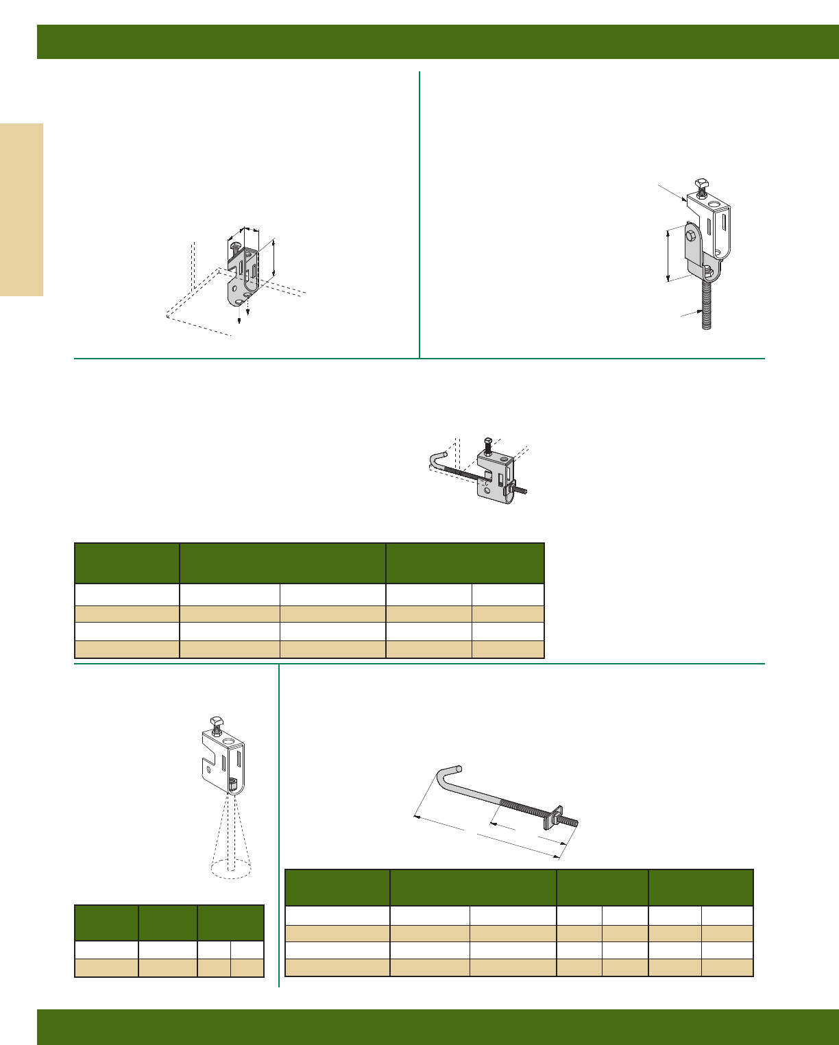
B751
BEAM CLAMP
•Safety Factor of 5
•3/4” (19.0) Max. Flange Thickness
•Setscrew and Locknut included
•Maximum ATR Size 1/2”
•Use B753 Swivel Nut (not included)
•Material: 12 Gauge (2.6)
•Standard finish: ZN, HDG
•Wt./C 42 Lbs. (19.0 kg)
B752
BEAM CLAMP SWIVEL
•Design Load 500 Lbs. (2.22 kN)
•Safety Factor of 5
•Material: 12 Gauge (2.6)
•Use B753 Swivel Nut (not included)
•Includes:
1 pc. B752 Swivel Body
1 pc. 5/16”-18 x 13/4” HHCS
1 pc. 5/16”-18 Hex Nut
•Standard finish: ZN
•Wt./C 30 Lbs. (13.6 kg)
B753
SWIVEL NUT
•Provides a full swivel
of 15° in any direction
Specify rod size
•Standard finish: ZN
B701 SERIES
J-HOOK
•1/4” (6.3) Diameter J-Hook available upon request
Part Number changes to B751-J_-1/4and a 1/4-20
Machine Square Nut (MSQN) is used
•Standard finish: ZN
B751-J_-3/8
BEAM CLAMP ASSEMBLY
•Includes:
1 pc. B751 Beam Clamp
1 pc. B701 Type J-Hook only
1 pc. SA203-158 Clip
1 pc. 3/8”-16 Hex Nut
•1/4” (6.3) Diameter J-Hook available upon request
Part Number changes to B751-J_-1/4and a 1/4-20
Machine Square Nut (MSQN) is used
•Use B753 Swivel Nut (not included)
•Standard finishes: ZN
Design Load 300 Lbs. (1.33 kN)
B751 CLAMP (NOT
INCLUDED)
Thread Length Wt./C
Part No. A TL Lbs. kg
B701-J4-3/883/4”(222.2) 51/2”(139.7) 26 (11.8)
B701-J6-3/8113/4”(298.4) 61/2”(165.1) 34 (15.4)
B701-J9-3/8143/4”(374.6) 61/2”(165.1) 41 (18.6)
B701-J12-3/8173/4”(450.8) 61/2”(165.1) 48 (21.8)
Wt./C
Part No. For Flange Width Lbs. kg
B751-J4-3/83”-6” (76.2-152.4) 70 (31.7)
B751-J6-3/85”-9” (127.0-228.6) 78 (35.4)
B751-J9-3/88”-12” (203.2-304.8) 83 (37.6)
B751-J12-3/811”-15” (279.4-381.0) 88 (39.9)
For Wt./C
Part No. Rod Size Lbs. kg
B753-3/83/8”-16 4.0 (1.8)
B753-1/21/2”-13 3.4 (1.5)
3”
(76.2)
2”
(50.8)
1”
(25.4)
OVERALL
HEIGHT
31/4”
(82.5)
B701-J_-3/8J-HOOK
B751 CLAMP
ATL
B701-J_-3/8J-HOOK ONLY
SA203-158 CLIP
3/8”-16 HEX NUT
FOR ROD SIZES 1/4”
(6.3) to 1/2” (12.7)
Design Load 500 Lbs. (2.22 kN)
Beam Clamps
Reference page 98 for general fitting and standard finish specifications.
Beam Clamps
102
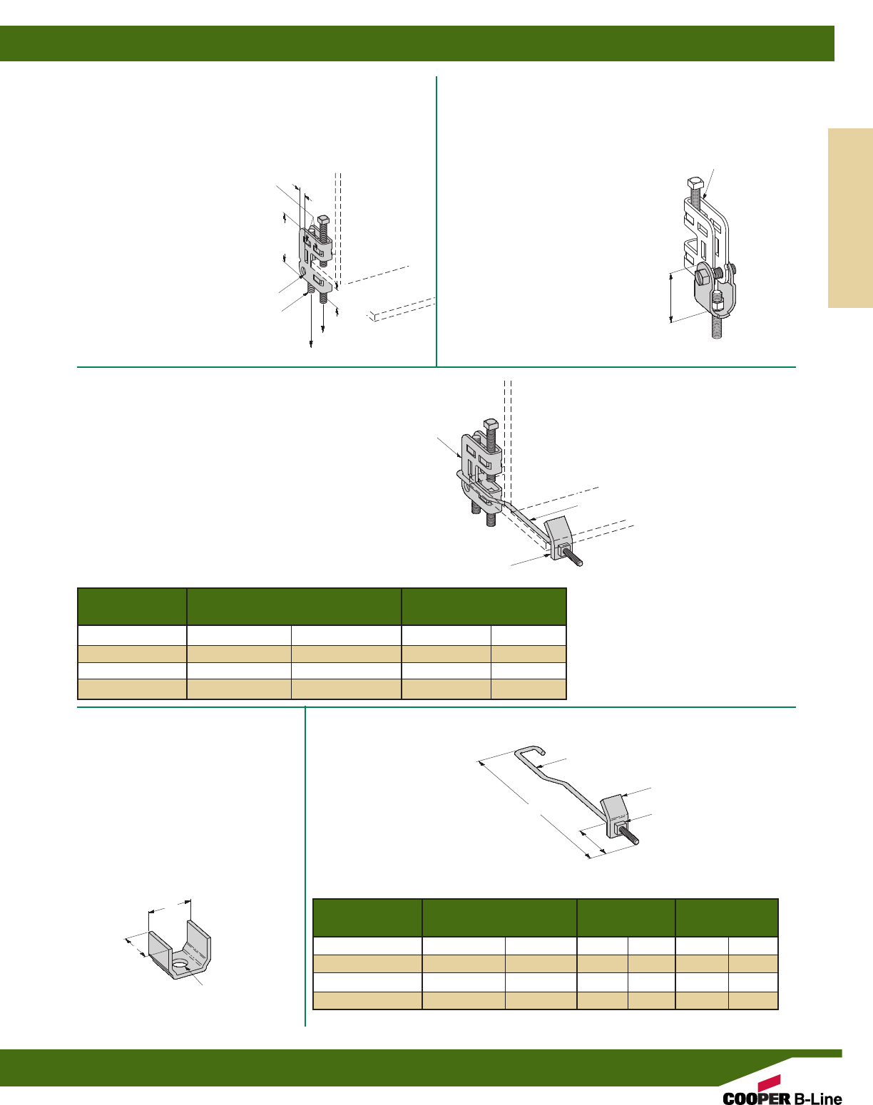
B755-3/8-J_
BEAM CLAMP ASSEMBLY
•Includes:
1 pc. B755-3/8Beam Clamp
1 pc. B705 Type J-Hook only
1 pc. B705 Clip
1 pc. 1/4”-20 Square Nut
•Standard finish: ZN
B702
CLEAT
•To eliminate the swiveling of the rod
when required, use the B702 Cleat and a
locking nut. This can be used with the
B751 Beam Clamp, B752 Swivel or
B756 Swing Connector.
•Material: 12 Gauge (2.6)
•Standard finish: ZN
•Wt./C 6 Lbs. (2.7 kg)
B705 SERIES
J-HOOK
•Use with B755-3/8
•Standard finish: ZN
B756-3/8
SWING CONNECTOR
•Design Load 150 Lbs. (0.66 kN)
•Safety Factor of 5
•Material: 12 Gauge (2.6)
•Includes:
1 pc. B756-3/8Swing Connector Body
1 pc. 5/16”-18 x 11/4” SHHMS
1 pc. 5/16”-18 Square Nut
•Use B753 Swivel Nut (not included)
•Standard finish: ZN
•Wt./C 15 Lbs. (6.8 kg)
Wt./C
Part No. For Flange Width Lbs. kg
B755-3/8-J4 4”-6” (101.6-152.4) 47 (21.3)
B755-3/8-J6 6”-10” (152.4-254.0) 51 (23.1)
B755-3/8-J10 10”-12” (254.0-304.8) 53 (24.0)
B755-3/8-J12 12”-14” (304.8-355.6) 55 (24.9)
Thread Length Wt./C
Part No. A TL Lbs. kg
B705-J4 73/8”(187.3) 3” (76.2) 17 (7.7)
B705-J6 113/8”(288.9) 41/2”(114.3) 21 (9.5)
B705-J10 133/8”(339.7) 41/2”(114.3) 23 (10.4)
B705-J12 153/8”(390.5) 41/2”(114.3) 25 (11.3)
Design Load
300 Lbs. (1.33 kN)
Design Load
150 Lbs. (0.66 kN)
3/8” (9.5) HOLE
FOR SWING
CONNECTOR
3/8”-16 ROD
21/2”
(60.3)
1”
(25.4)
7/8”
(22.2)
B755 CLAMP (NOT
INCLUDED)
OVERALL
HEIGHT
17/8”
(47.6)
B705 CLIP
B705 CLIP
B755 CLAMP
B705-J_
J-HOOK ONLY
B705-J_
J-HOOK ONLY
A
TL
17/32”
(30.9)
1”
(25.4)
13/32” (10.3)
DIA. HOLE
1/4”-20
MACHINE NUT
B755
3/8BEAM CLAMP
•Safety Factor of 5
•5/8” (15.9) Max. Flange Thickness
•For 3/8”-16 Hanger Rod only.
•Material: 12 Gauge (2.6)
•Includes:
1 pc. B755 Beam Clamp
1 pc. 3/8” x 2” Square Head
Set Screw
2 pcs. 3/8” Square Nut
•Standard finish: ZN
•Wt./C 30 Lbs. (13.6 kg)
3/8”-16 SQUARE
MACHINE NUTS
Beam Clamps
Reference page 98 for general fitting and standard finish specifications.
Beam Clamps
103
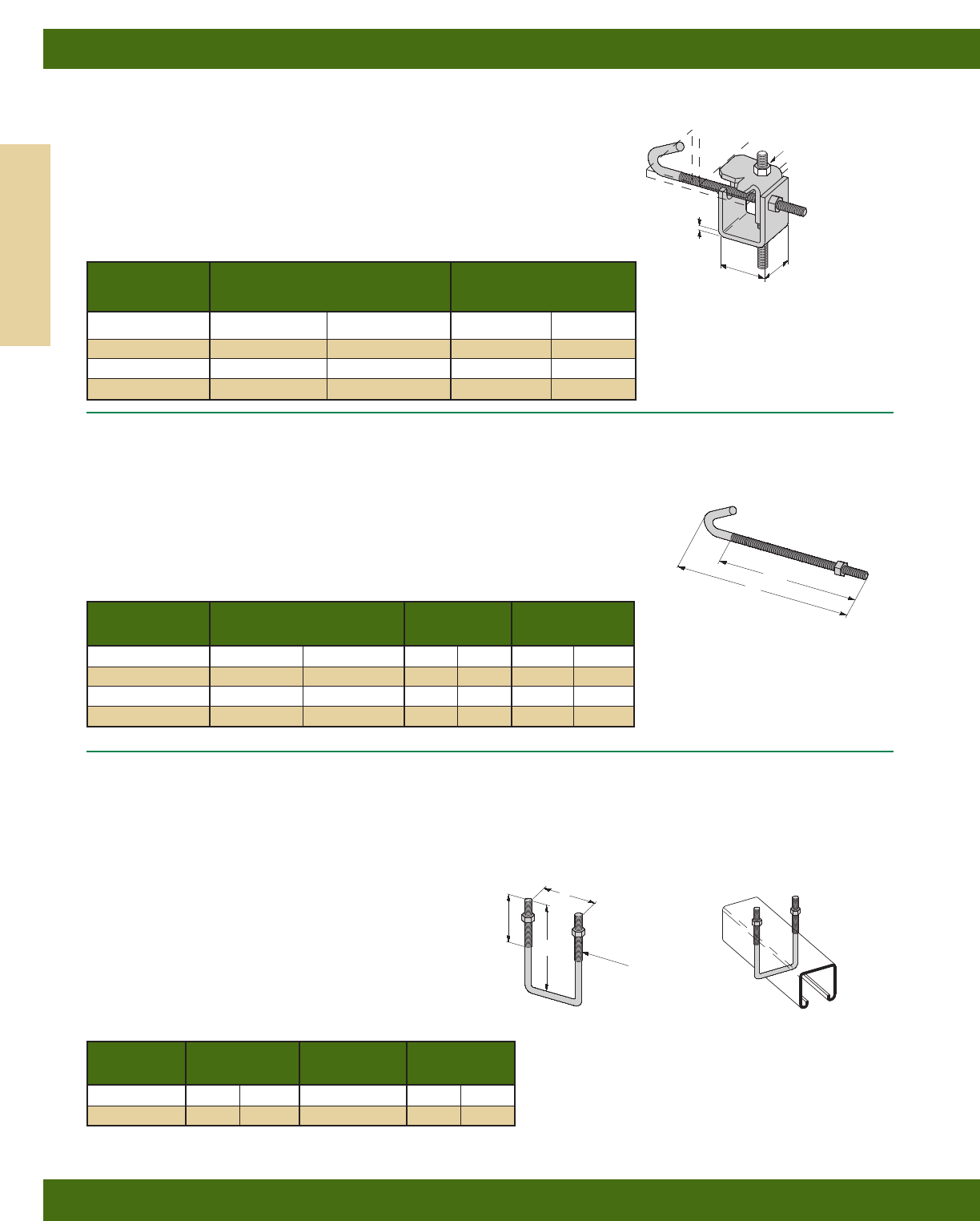
Wt./C
Part No. For Flange Width Lbs. kg
B750-J4 3”-6” (76.2-152.4) 109 (49.4)
B750-J6 5”-9” (127.0-228.6) 124 (56.2)
B750-J9 8”-12” (203.2-304.8) 135 (61.2)
B750-J12 11”-15” (279.4-381.0) 147 (66.7)
Thread Length Wt./C
Part No. A TL Lbs. kg
B700-J4 81/2”(215.9) 63/4”(171.4) 44 (19.9)
B700-J6 111/2”(292.1) 93/4”(247.6) 53 (24.0)
B700-J9 141/2”(368.3) 123/4”(323.8) 63 (28.6)
B700-J12 171/2”(444.5) 153/4”(400.0) 78 (35.4)
B750 SERIES
BEAM CLAMP
•Safety Factor of 5
•Design Load 500 Lbs. (2.22 kN)
•Recommended Torque:
J-Hook Nut 125 in-lbs. (14.1 N•m)
•Maximum Flange Thickness 5/8” (15.9)
•Standard finish: ZN
B700 SERIES
J-HOOK
•Includes:
1 pc. J-Bolt
1 pc. Hex Nut
•Maximum Flange Thickness 5/8” (15.9)
•Standard finish: ZN
15/8”
(41.3)
127/32”
(46.8)
1/2”-13 ROD
& HEX
NUT SOLD
SEPARATELY
ATL
1/2”-13
THREADS
B500 SERIES
SQUARE U-BOLT
•Includes:
1 pc. U-Bolt only
2 pcs. 3/8”-16 Hex Nuts
•Additional sizes available
•Standard finish: ZN, SS4
21/2”
(63.5)
121/32”
(42.1)
3/8”-16
THREADS
A
Channel Wt./C
Part No. A Size Lbs. kg
B500-3-3/833/8”(85.7) 15/8” x 15/8”25(11.3)
B500-5 5” (127.0) 31/4” x 15/8”33(14.9)
7 Ga
(4.6)
Beam Clamps
Reference page 98 for general fitting and standard finish specifications.
Beam Clamps
104
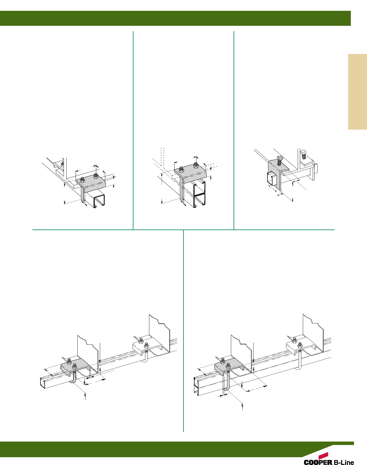
B441-22
BEAM CLAMP
•Design Load 1200 Lbs. (5.34 kN)
when used in pairs
•Safety Factor of 5
•3/4” (19.0) Max. Flange Thickness
•For use with 13/16” (20.6) to 15/8” (41.3)
high channel
•Recommended Torque:
150 in-lbs. (16.9 N•m)
•Sold in pieces
•Other flange thickness variations
are available, contact B-Line
Engineering for sizes
•Standard finishes: ZN, HDG, SS4
•Wt./C 87 Lbs. (39.4 kg)
B441-22A
BEAM CLAMP
•Design Load 1200 Lbs. (5.34 kN)
when used in pairs
•Safety Factor of 5
•3/4” (19.0) Max. Flange Thickness
•For use with 15/8” (41.3) to 31/4” (82.5)
high channel
•Recommended Torque:
150 in-lbs. (16.9 N•m)
•Sold in pieces
•Other flange thickness variations
are available, contact B-Line
Engineering for sizes
•Standard finishes: ZN, HDG, SS4
•Wt./C 93 Lbs. (42.2 kg)
B441Z-22
BEAM CLAMP
•Design Load 1200 Lbs. (5.34 kN)
when used in series
•Safety Factor of 5
•Sold in pieces
•For use with 13/16” (20.6) to 15/8” (41.3)
high channel
•Recommended Torque:
150 in-lbs. (16.9 N•m)
•Standard finishes: ZN
•Wt./C 95 Lbs. (43.1 kg)
23/8”
(60.3)
23/8”
(60.3)
1”
(25.4)
1”
(25.4)
31/8”
(79.4)
31/8”
(79.4)
33/8”
(85.7)
5”
(127.0)
1/4”
(6.3)
1/4”
(6.3)
1”
(25.4)
45/8”
(117.5)
23/4”
(69.9)
1/4”
(6.3)
31/8”
(79.4)
B441Z-22A
BEAM CLAMP
•Design Load 1200 Lbs. (5.34 kN)
when used in series
•Safety Factor of 5
•Sold in pieces
•For use with 15/8” (41.3) to 31/4” (82.5)
high channel
•Recommended Torque:
150 in-lbs. (16.9 N•m)
•Standard finishes: ZN
•Wt./C 101 Lbs. (45.8 kg)
1”
(25.4)
45/8”
(117.5)
43/8”
(111.1)
1/4”
(6.3)
31/8”
(79.4)
B314
BEAM CLAMP
•Design Load 900 Lbs. (4.00 kN)
when used in pairs
•Safety Factor of 5
•5/8” (15.9) Max. Flange Thickness
•For use with channel 15/8” (41.3)
in height
•Setscrew included
•Sold in pieces.
•Standard finishes: ZN, GRN, HDG, SS4
•Wt./C 105 Lbs. (47.6 kg)
13/4”
(44.4)
13/4”
(44.4)
1/4”
(6.3)
37/16”
(87.3)
Beam Clamps
Reference page 98 for general fitting and standard finish specifications.
Beam Clamps
105
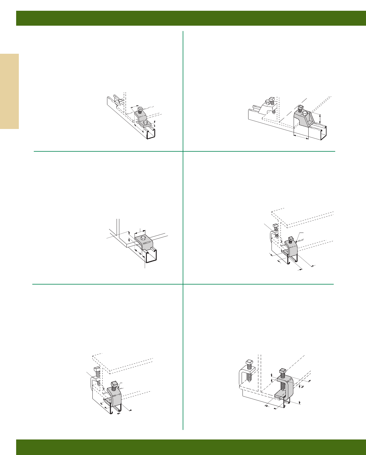
B212-1/4
I-BEAM CLAMP
•Design Load 600 Lbs. (2.67 kN)
when used in pairs
•Safety Factor of 5
•7/8” (22.2) Max. Flange Thickness
•3/8”-16 Setscrew included
•Sold in pieces
•Standard finish: ZN
•Wt./C 41 Lbs. (18.6 kg)
B212-3/8
I-BEAM CLAMP
•Design Load 1000 Lbs. (4.45 kN)
when used in pairs
•Safety Factor of 5
•11/8” (28.6) Max. Flange Thickness
•1/2”-13 Setscrew included
•Sold in pieces
•Standard finishes: ZN, HDG
•Wt./C 62 Lbs. (28.1 kg)
B355
BEAM CLAMP
•Design Load 1200 Lbs. (5.34 kN)
when used in pairs
•Safety Factor of 5
•5/8” (15.9) Max. Flange Thickness
•Sold in pieces
•Order 1/2”-13 x 11/2” HHCS and
Channel Nut separately
•Standard finishes: ZN, GRN, HDG, SS4
•Wt./C 30 Lbs. (13.6 kg)
B211
ZEE BEAM CLAMP
•Design Load 600 Lbs. (2.67 kN)
when used in pairs
•Safety Factor of 5
•1” (25.4) Max. Flange Thickness
•1/2”-13 Setscrew included
•Sold in pieces
•Order 1/2”-13 HHCS and Channel
Nut separately
•Standard finishes: ZN, HDG
•Wt./C 66 Lbs. (29.9 kg)
11/4”
(31.7)
11/4”
(31.7)
127/32”
(46.8)
15/8”
(41.3)
5/8”
(15.9)
2”
(50.8)
2”
(50.8)
31/4”
(82.5)
3/8”
(9.5)
11/4” (31.7)
I.D. 3/8” THICK
(9.5)
1/4” THICK
(6.3)
7/8” (22.2)
I.D.
1/4”
(6.3)
11/2”
(38.1)
B213
I-BEAM CLAMP
•Design Load 900 Lbs. (4.00 kN)
when used in pairs
•Safety Factor of 5
•7/8” (22.2) Max. Flange Thickness
•1/2”-13 Setscrew included
•Sold in pieces
•Order 1/2”-13 x 21/4” HHCS and
Channel Nut separately
•Material: Malleable iron
•Standard finishes: ZN, GRN
•Wt./C 95 Lbs. (43.1 kg)
21/2”
(63.5)
11/2”
(38.1)
B435
BEAM CLAMP
•Design Load 900 Lbs. (4.00 kN)
when used in pairs
•Safety Factor of 5
•21/8” (54.0) Max. Flange Thickness
•1/2”-13 x 2” Setscrew included
•Sold in pieces
•Standard finish: ZN
•Wt./C 82 Lbs. (37.2 kg)
11/4”
(31.7)
3/8”
(9.5)
27/8”
(73.0)
2”
(50.8)
Beam Clamps
Reference page 98 for general fitting and standard finish specifications.
Beam Clamps
106
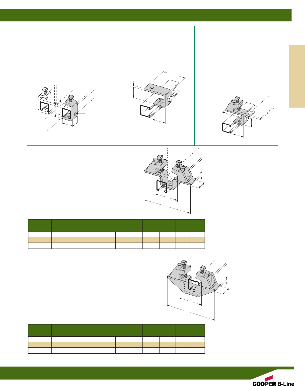
B602A THRU B602C
BEAM CLAMP WITH GUSSET ASSEMBLY
•Safety Factor of 5
•7/8” (22.2) Max. Flange Thickness
•Includes:
1 pc. B451 Slotted Three Hole U Support with Gusset
2 pcs. B213 I-Beam Clamp
2 pcs. 1/2”-13 x 21/2” HHCS
2 pcs. 1/2”-13 Hex Nuts
•Material: Malleable iron
•Standard finishes: ZN, GRN
B318 THRU B320
BEAM CLAMP ASSEMBLY
•Safety Factor of 5
•7/8” (22.2) Max. Flange Thickness
•Includes:
1 pc. B333 Slotted U-Support
2 pcs. B213 I-Beam Clamp
2 pcs. 1/2”-13 x 21/2” HHCS
2 pcs. 1/2”-13 Hex Nuts
•Material: Malleable iron
•Standard finishes: ZN, GRN
Design Load Wt./C
Part No. A For Flange Width B Lbs. kN Lbs. kg
B318 71/4”(184.1) 23/8”-41/2”(60.3-114.3) 1200 (5.34) 325 (147.4)
B319 81/2”(215.9) 33/4”-53/4”(95.2-146.0) 800 (3.56) 340 (154.2)
B320 103/8”(263.5) 55/8”-75/8”(142.9-193.7) 560 (2.49) 357 (161.9)
Design Load Wt./C
Part No. A For Flange Width B Lbs. kN Lbs. kg
B602A 71/4”(184.1) 23/8”-41/2”(60.3-114.3) 1200 (5.34) 365 (165.1)
B602B 81/2”(215.9) 33/4”-53/4”(95.2-146.0) 1200 (5.34) 383 (173.7)
B602C 103/8”(263.5) 55/8”-75/8”(142.9-193.7) 1200 (5.34) 408 (185.0)
15/8”
(41.3)
13/4”
(44.4)
1/4”
(6.3)
1/4”
(6.3)
A
A
B
B
B427
BEAM CLAMP
•Design Load 1100 Lbs. (4.89 kN)
when used in pairs
•Safety Factor of 5
•21/2” (63.5) Max. Flange Thickness
without channel
•1/2”-13 x 11/2” Setscrew included
•Sold in pieces
•Standard finish: ZN
•Wt./C 92 Lbs. (41.7 kg)
2 HOLES
9/16” (14.3)
DIA.
11/2”
(38.1)
3/8”
(9.5)
27/8”
(73.0)
2”
(50.8)
10°
B405
SUSPENSION MEMBER
•Standard finishes: ZN, GRN
•Wt./C 75 Lbs. (34.0 kg)
B405A
SUSPENSION MEMBER
WITH BEAM CLAMP
•7/8” (22.2) Max. Flange Thickness
•Includes:
1 pc. B405 Suspension Member
1 pc. B213 I-Beam Clamp
1 pc. 1/2”-13 x 21/2” HHCS
1 pc. 1/2”-13 Hex Nut
•Material: Malleable iron
•Standard finishes: ZN, GRN
•Wt./C 183 Lbs. (83.0 kg)
37/8”
(87.3) O.D.
37/16”
(87.3)
17/8”
(47.6)
O.D. 17/8”
(47.6)
111/16”
(42.9)
I.D.
111/16”
(42.9)
1/4”
(6.3)
Beam Clamps
Reference page 98 for general fitting and standard finish specifications.
Beam Clamps
107
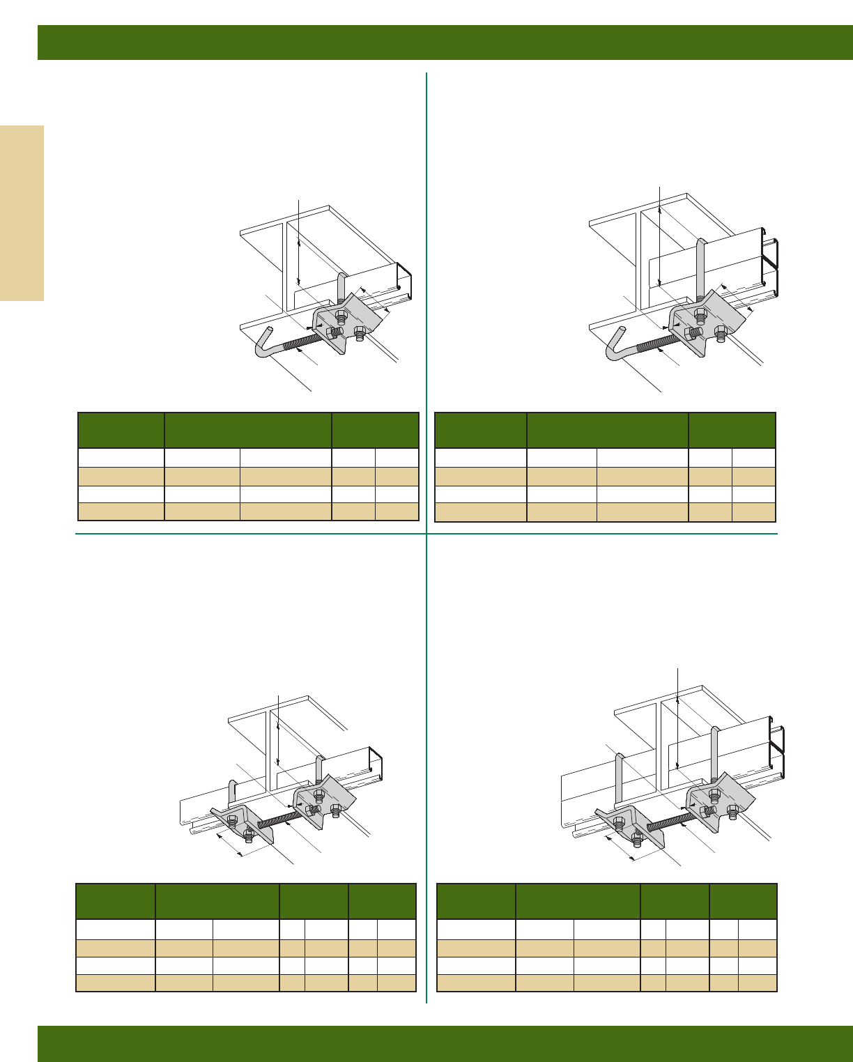
B760-22 SERIES
BEAM CLAMP
•1” (25.4) Max. Flange Thickness
•For use with 13/16” (20.6) to 15/8” (41.3)
high channel
•Recommended Torques:
U-Bolt Nuts 150 in-lbs. (16.9 N•m)
J-Hook Nut 60 in-lbs. (6.8 N•m)
•Includes:
1 pc. B760 Plate
1 pc. B701 Type J-Hook only
1 pc. B500-33/8” U-Bolt only
3 pcs. 3/8”-16 Hex Nuts
•Standard finish: ZN
B761-22 SERIES
BEAM CLAMP
•1” (25.4) Max. Flange Thickness
•For use with 13/16” (20.6) to 15/8” (41.3)
high channel
•Recommended Torques:
U-Bolt Nuts 150 in-lbs. (16.9 N•m)
ATR Nuts 60 in-lbs. (6.8 N•m)
•Includes:
2 pcs. B700 Plates
2 pcs. B500-33/8” U-Bolts only
1 pc. 3/8”-16 ATR (Length)
6 pcs. 3/8”-16 Hex Nuts
•Standard finish: ZN
B761-22A SERIES
BEAM CLAMP
•1” (25.4) Max. Flange Thickness
•For use with 15/8” (41.3) to 31/4” (82.5)
high channel
•Recommended Torques:
U-Bolt Nuts 150 in-lbs. (16.9 N•m)
ATR Nuts 60 in-lbs. (6.8 N•m)
•Includes:
2 pcs. B700 Plates
2 pcs. B500-5” U-Bolts only
1 pc. 3/8”-16 ATR (Length)
6 pcs. 3/8”-16 Hex Nuts
•Standard finish: ZN
B760-22A SERIES
BEAM CLAMP
•1” (25.4) Max. Flange Thickness
•For use with 15/8” (41.3) to 31/4” (82.5)
high channel
•Recommended Torques:
U-Bolt Nuts 150 in-lbs. (16.9 N•m)
J-Hook Nut 60 in-lbs. (6.8 N•m)
•Includes:
1 pc. B760 Plate
1 pc. B701 Type J-Hook only
1 pc. B500-5” U-Bolt only
3 pcs. 3/8”-16 Hex Nuts
•Standard finish: ZN
Wt./C
Part No. For Flange Width Lbs. kg
B760-22-J4 4”-57/8”(101.6-149.2) 122 (55.3)
B760-22-J6 6”-87/8”(152.4-225.4) 129 (58.5)
B760-22-J9 9”-117/8”(228.6-301.6) 135 (61.2)
B760-22-J12 12”-147/8”(304.8-377.8) 141 (63.9)
Wt./C
Part No. For Flange Width Lbs. kg
B760-22A-J4 4”-57/8”(101.6-149.2) 129 (58.5)
B760-22A-J6 6”-87/8”(152.4-225.4) 136 (61.7)
B760-22A-J9 9”-117/8”(228.6-301.6) 142 (64.4)
B760-22A-J12 12”-147/8”(304.8-377.8) 148 (67.1)
33/8”
(85.7)
31/8”
(79.4)
31/8”
(79.4)
5”
(127.0)
3/8” (9.5) DIA.
J-HOOK AND
HEX NUT
3/8” (9.5) DIA.
J-HOOK AND
HEX NUT
1/4”
(6.3)
1/4”
(6.3)
ATR W
t./C
Part No. For Flange Width Length Lbs. kg
B761-22-4 4”-57/8”(101.6-149.2) 4” (101.6) 202 (91.6)
B761-22-6 6”-87/8”(152.4-225.4) 6” (152.4) 206 (93.4)
B761-22-9 9”-117/8”(228.6-301.6) 9” (228.6) 214 (97.0)
B761-22-12 12”-147/8”(304.8-377.8) 12” (304.8) 221 (100.2)
ATR
Wt./C
Part No. For Flange Width Length Lbs. kg
B761-22A-4 4”-57/8”(101.6-149.2) 4” (101.6) 216 (98.0)
B761-22A-6 6”-87/8”(152.4-225.4) 6” (152.4) 220 (99.8)
B761-22A-9 9”-117/8”(228.6-301.6) 9” (228.6) 228 (103.4)
B761-22A-12 12”-147/8”(304.8-377.8) 12” (304.8) 235 (106.6)
33/8”
(85.7)
31/8”
(79.4) 3/8”-16 (9.5) ATR
AND HEX NUTS
3/8”-16 (9.5) ATR
AND HEX NUTS
1/4”
(6.3)
1/4”
(6.3)
31/8”
(79.4)
5”
(127.0)
Beam Clamps
Reference page 98 for general fitting and standard finish specifications.
Beam Clamps
108
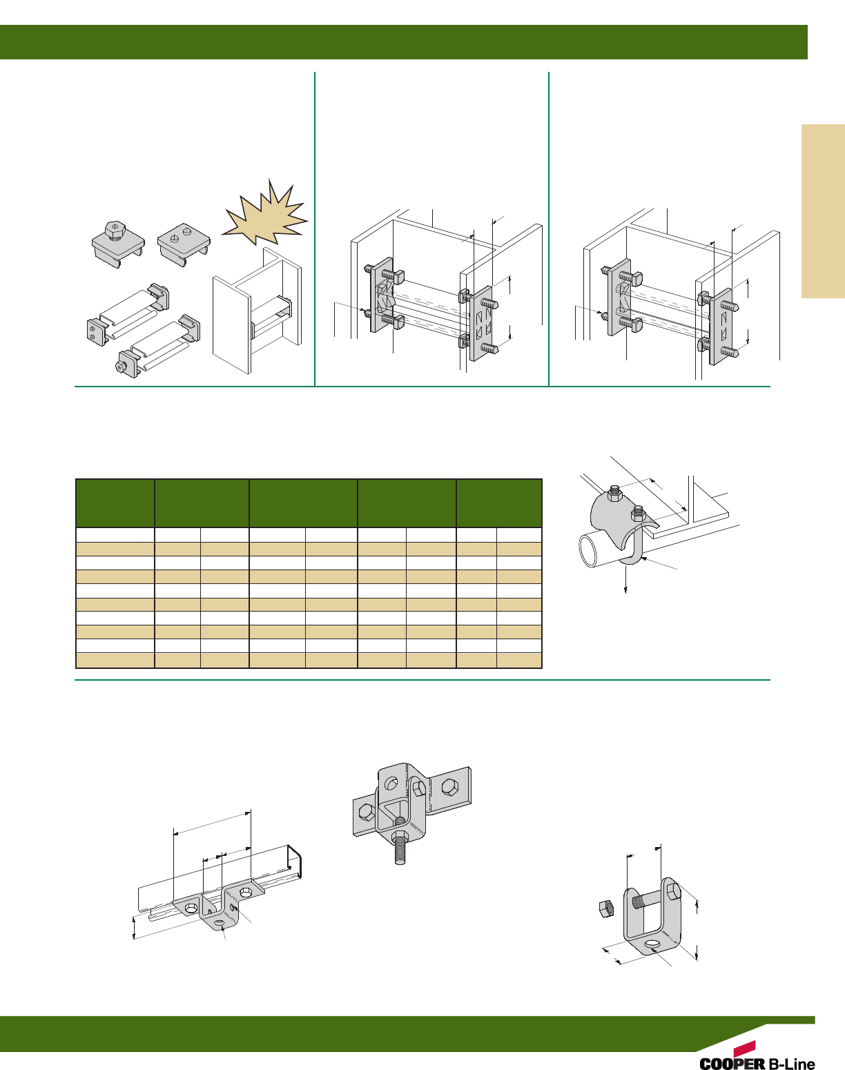
B613
COLUMN SUPPORT FOR B22
•Design Load 800 Lbs. (3.56 kN) Slip
with Safety Factor of 3
•Use with B22 and B24 Channel
•Setscrews to be torqued to 19 ft./Lbs
•Sold in pairs
•Standard finishes: ZN, GRN, HDG
•Wt./C 100 Lbs. (45.3 kg)
B613A
COLUMN SUPPORT FOR B52
•Design Load 800 Lbs. (3.56 kN) Slip
with Safety Factor of 3
•Use with B52 and B54 Channel
•Setscrews to be torqued to 19 ft./Lbs
•Sold in pairs
•Standard finishes: ZN, GRN, HDG
•Wt./C 100 Lbs. (45.3 kg)
15/8”
(41.3) 15/8”
(41.3)
31/2”
(88.9)
31/2”
(88.9)
3/8” x 2” CONE
POINT
SETSCREWS
3/8” x 2” CONE
POINT
SETSCREWS
NEW
B614
COLUMN SUPPORT FOR B22
•Quick installation (one bolt to tighten)
•Design Load 800 Lbs. (3.56 kN) Slip
with Safety Factor of 3
•Use with B22 and B24 Channel
•Sold in pairs
•Standard finish: ZN
•Wt./C 50 Lbs. (22.6 kg)
B422 SERIES
RIGHT ANGLE CLAMP
•Safety Factor of 5
•Material: 7 Gauge (4.5)
•Standard finishes: ZN, SS4
Design Load
Conduit Vertical Pull Wt./C
Part No. Size A Lbs. kg Lbs. kg
B422-1/21/2”(15) 23/8”(60.3) 250 (1.11) 38 (17.2)
B422-3/43/4”(20) 23/8”(60.3) 300 (1.33) 39 (17.7)
B422-1 1” (25) 27/8”(73.0) 400 (1.78) 48 (21.8)
B422-11/411/4”(32) 27/8”(73.0) 400 (1.78) 50 (22.7)
B422-11/211/2”(40) 31/4”(82.5) 500 (2.22) 59 (26.7)
B422-2 2(50) 311/16”(93.7) 600 (2.67) 75 (34.0)
B422-21/221/2”(65) 41/4”(107.9) 700 (3.11) 98 (44.4)
B422-3 3” (80) 47/8”(123.8) 800 (3.56) 111 (50.3)
B422-31/231/2”(90) 57/16”(138.1) 900 (4.00) 123 (55.8)
B422-4 4” (100) 6” (152.4) 1000 (4.45) 135 (61.2)
Design Load
Vertical Pull
U-BOLT AND
HEX NUTS
A
B107S
U-SUPPORT
•Material: 7 Gauge (4.5)
•Standard finishes: ZN, GRN
•Wt./C 51 Lbs. (23.1 kg)
B593
CLEVIS SWIVEL
•Includes:
1 pc. 3/8”-16 x 2” HHCS
1 pc. 3/8”-16 Hex Nut
•Material: 11 Gauge (3.0)
•Standard finishes: ZN, GRN
•Wt./C 31 Lbs. (14.0 kg)
•Illustration shows B107S and
B593 used together
•Design Load 900 Lbs.,
strength of assembly only
•Verify anchorage
7/16” (11.1)
DIA. 4 HOLES
9/16” (14.3) DIA.
9/16” (14.3) DIA.
13/4” O.D.
(44.4)
33/4”
(95.2)
13/8”
(34.9)
1”
(25.4)
17/16”
(36.5)
21/2”
(63.5)
11/4”
(31.7)
Beam Clamps
Reference page 98 for general fitting and standard finish specifications.
Beam Clamps
109
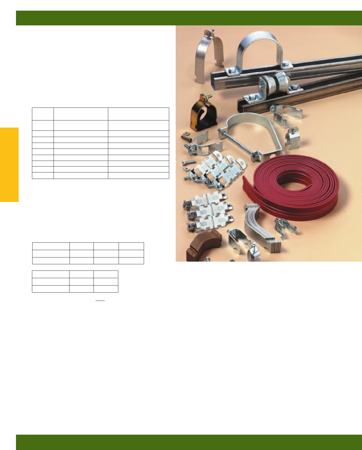
B-Line’s beam attachments and pipe supports offered
in this section are designed to provide supports without
drilling or welding. A complete selection of beam
clamps, pipe clamps, rollers, supports and accessories
are designed for use with B-Line channels and offer
many installation advantages.
Materials & Finishes*
Pipe clamps, pipe hangers, beam clamps, brackets, and
rollers are made from low carbon steel strips, plates or
rod unless noted.
*Unless otherwise noted.
Load Data
The load data published includes a safety factor of 5.0
unless noted (safety factor = ratio of ultimate load to
the design load).
Recommended Torque For Setscrews
(unless noted)
*See chart on page 58 for bolt torque.
Metric
Metric dimensions are shown in parentheses. Unless noted, all metric dimensions are in millimeters.
Setscrew Size 1/4”-20 3/8”-16 1/2”-13
Foot/Lbs. 4511
Nm 5715
Setscrew Size 5/8”-11 3/4”-10
Foot/Lbs. 21 34
Nm 28 46
Pipe/Conduit Clamps & Hangers
Pipe/Conduit Clamps & Hangers
110
Finish
Code Finish Specification
PLN Plain ASTM A1011
33,000 PSI min. yield
ZN Electro-Plated Zinc ASTM B633 SC3 Type III
GRN Dura-Green
DCU Dura-Copper
HDG Hot-Dipped Galvanized ASTM A123
YZN Yellow Zinc Chromate ASTM B633 SC3 Type II
SS4 Stainless Steel Type 304 ASTM A240
SS6 Stainless Steel Type 316 ASTM A240
AL Aluminum ASTM B209
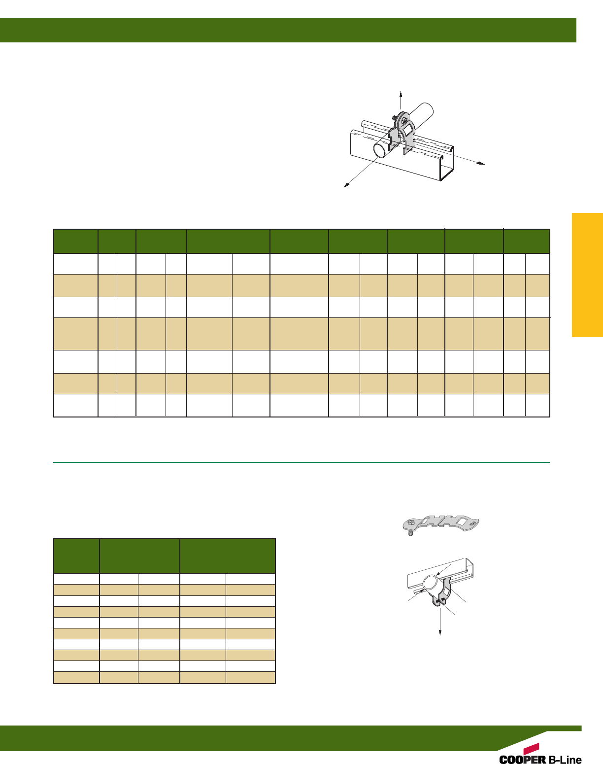
B2207 THRU B2213
MULTI-GRIP PIPE CLAMPS FOR THINWALL
(EMT), I.M.C., RIGID CONDUIT OR PIPE
•Safety Factor of 5
•Add PA to suffix for pre-assembled pipe clamps
•Includes Combination Recess Hex Head Machine Screw and Square Nut
•Material: ASTM A1011 33,000 PSI min. yield
•Standard finish: ZN
Nominal Material O.D. Size Alternate For Design Load 1 Design Load 2 Design Load 3 Wt./C
Part No. Size Thickness Range Clamp No.’s Lbs. kN
Lbs. kg Lbs. kg Lbs. kg
B2207 3/8”(10) 16 Ga. (1.5) .557-.706 (14.2-17.9) B2000, B2007, 400 (1.78) 50 (.22) 50 (.22) 9 (4.1)
B2026
B2208 1/2”(15) 16 Ga. (1.5) .701-.875 (17.8-22.2) B2001, B2008, 400 (1.78) 50 (.22) 50 (.22) 11 (5.0)
B2027, B2028
B2209 3/4”(20) 14 Ga. (1.9) .917-1.081 (23.2-27.4) B2002, B2009, 400 (1.78) 50 (.22) 50 (.22) 12 (5.4)
B2029
B2210 1” (25) 14 Ga. (1.9) 1.125-1.375 (28.6-34.9) B2003, B2010, 400 (1.78) 50 (.22) 50 (.22) 13 (5.9)
B2030, B2031,
B2032
B2211 11/4”(32) 14 Ga. (1.9) 1.500-1.691 (38.1-42.9) B2004, B2011, 400 (1.78) 50 (.22) 50 (.22) 15 (6.8)
B2033, B2034
B2212 11/2”(40) 12 Ga. (2.6) 1.735-1.931 (44.0-49.0) B2005, B2012, 600 (2.67) 75 (.33) 75 (.33) 23 (10.4)
B2035, B2036
B2213 2” (50) 12 Ga. (2.6) 2.192-2.400 (55.7-60.9) B2006, B2013 600 (2.67) 75 (.33) 75 (.33) 26 (11.8)
B2039
Design Load 1
Design Load 2
Design Load 3
BPC-8 THRU BPC-64
BREAK-APART CONDUIT CLAMP
•Design Load 200 Lbs. (.896 kN)
•Includes Combination Recess Hex Head Machine Screw
•Material: ASTM A1011 33,000 PSI min. yield
•Standard finish: ZN
A
Part No. Rigid or EMT Wt./C
Conduit Size Lbs. kg
BPC-8 1/2”(21.3) 11.2 (5.1)
BPC-12 3/4”(26.7) 12.7 (5.8)
BPC-16 1” (33.4) 14.5 (6.6)
BPC-20 11/4”(42.2) 16.5 (7.5)
BPC-24 11/2”(48.3) 18.5 (8.4)
BPC-32 2” (60.3) 21.5 (9.8)
BPC-40 21/2”(73.0) 21.5 (9.8)
BPC-48 3” (88.9) 22.0 (10.0)
BPC-56 31/2”(101.6) 23.0 (10.4)
BPC-64 4” (114.3) 27.5 (12.5)
A
Design Load
Pipe/Conduit Clamps & Hangers
Reference page 110 for general fitting and standard finish specifications.
Pipe Clamps
111
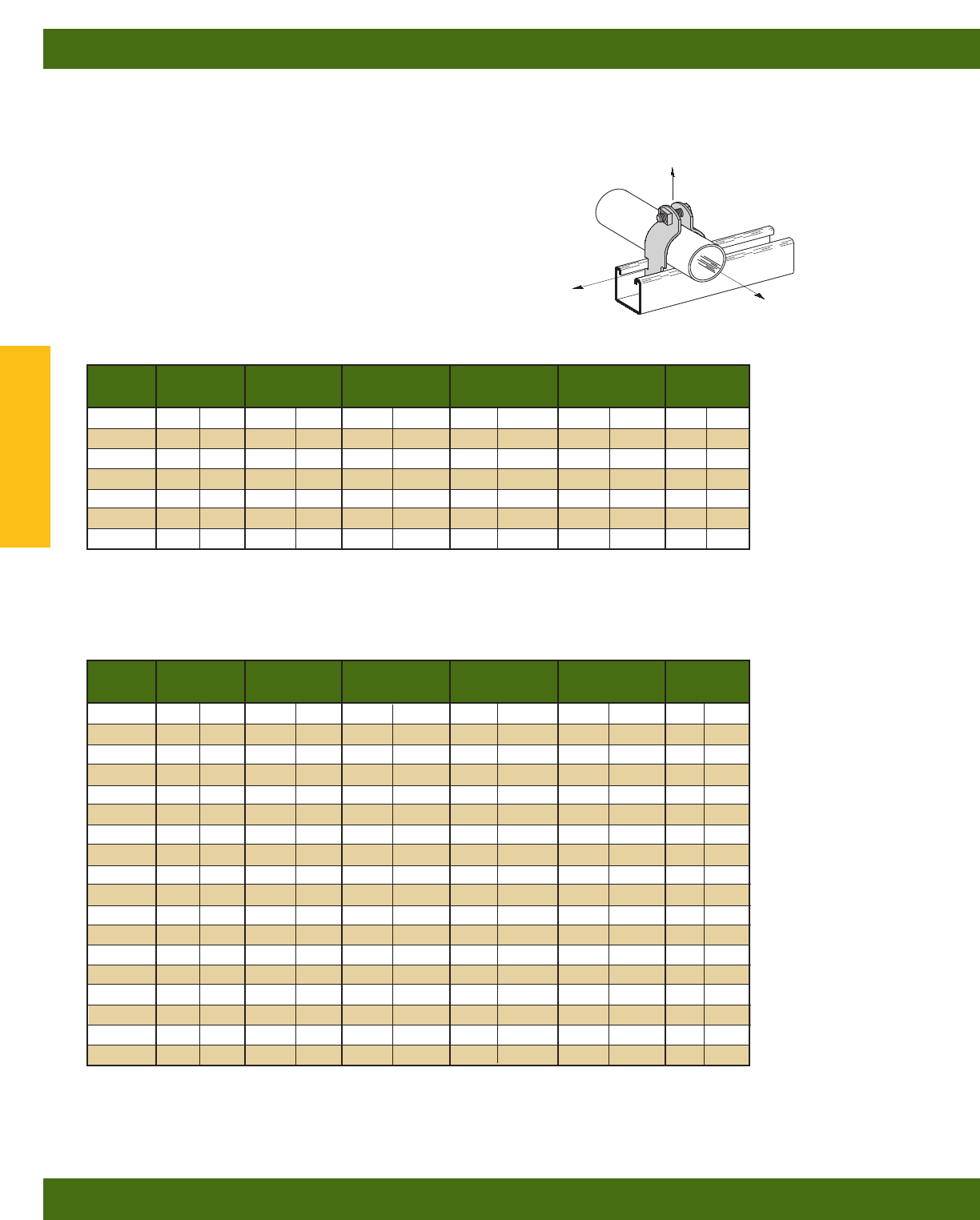
B2000 SERIES
PIPE AND CONDUIT CLAMPS
•Safety Factor of 5
•Add PA to suffix for pre-assembled pipe clamps
•Includes Combination Recess Hex Head Machine Screw and Square Nut
•Material: 16 Ga. (1.5), 14 Ga. (1.9), 12 Ga. (2.6) ASTM A1011 33,000 PSI min. yield
and 11 Ga. (3.0) ASTM A1011HSLA Gr. 50
•Standard finishes: ZN, HDG, SS4, SS6, AL
Note: For EMT sizes 21/2” and larger use rigid conduit sizes.
Conduit Material Design Load 1 Design Load 2 Design Load 3 Wt./C
Part No. Size Thickness Lbs. kN Lbs. kg Lbs. kg Lbs. kg
B2000 3/8”(10) 16 Ga. (1.5) 400 (1.78) 50 (.22) 50 (.22) 10 (4.5)
B2001 1/2”(15) 16 Ga. (1.5) 400 (1.78) 50 (.22) 50 (.22) 10 (4.5)
B2002 3/4”(20) 16 Ga. (1.9) 400 (1.78) 50 (.22) 50 (.22) 11 (5.0)
B2003 1” (25) 14 Ga. (1.9) 600 (2.67) 75 (.33) 75 (.33) 16 (7.2)
B2004 11/4”(32) 14 Ga. (1.9) 600 (2.67) 75 (.33) 75 (.33) 19 (8.6)
B2005 11/2”(40) 12 Ga. (2.6) 800 (3.56) 125 (.56) 125 (.56) 28 (12.7)
B2006 2” (50) 12 Ga. (2.6) 800 (3.56) 125 (.56) 125 (.56) 33 (14.9)
Conduit Material Design Load 1 Design Load 2 Design Load 3 Wt./C
Part No. Size Thickness Lbs. kN Lbs. kg Lbs. kg Lbs. kg
B2001 3/8”(10) 16 Ga. (1.5) 400 (1.78) 50 (.22) 50 (.22) 10 (4.5)
B2008 1/2”(15) 16 Ga. (1.5) 400 (1.78) 50 (.22) 50 (.22) 11 (5.0)
B2009 3/4”(20) 14 Ga. (1.9) 600 (2.67) 75 (.33) 75 (.33) 15 (6.8)
B2010 1” (25) 14 Ga. (1.9) 600 (2.67) 75 (.33) 75 (.33) 16 (7.2)
B2011 11/4”(32) 14 Ga. (1.9) 600 (2.67) 75 (.33) 75 (.33) 20 (9.1)
B2012 11/2”(40) 12 Ga. (2.6) 800 (3.56) 125 (.56) 125 (.56) 30 (13.6)
B2013 2” (50) 12 Ga. (2.6) 800 (3.56) 125 (.56) 125 (.56) 34 (15.4)
B2014 21/2”(65) 12 Ga. (2.6) 800 (3.56) 125 (.56) 125 (.56) 38 (17.2)
B2015 3” (80) 12 Ga. (2.6) 800 (3.56) 125 (.56) 125 (.56) 44 (19.9)
B2016 31/2”(90) 11 Ga. (3.0) 1000 (4.45) 200 (.89) 150 (.67) 61 (27.6)
B2017 4” (100) 11 Ga. (3.0) 1000 (4.45) 200 (.89) 150 (.67) 66 (29.9)
B2018 41/2”(115) 11 Ga. (3.0) 1000 (4.45) 200 (.89) 150 (.67) 70 (31.7)
B2019 5” (125) 11 Ga. (3.0) 1000 (4.45) 200 (.89) 150 (.67) 77 (34.9)
B2020 6” (150) 11 Ga. (3.0) 1000 (4.45) 200 (.89) 150 (.67) 100 (45.3)
B2021 7” (175) 11 Ga. (3.0) 1000 (4.45) 250 (1.11) 200 (.89) 115 (52.1)
B2022 8” (200) 11 Ga. (3.0) 1000 (4.45) 250 (1.11) 200 (.89) 128 (58.0)
B2130 10 (254) 11 Ga. (3.0) 1000 (4.45) 250 (1.11) 200 (.89) 160 (72.6)
B2132 12” (305) 11 Ga. (3.0) 1000 (4.45) 250 (1.11) 200 (.89) 185 (83.9)
THINWALL CONDUIT (EMT) CLAMPS
RIGID CONDUIT OR PIPE CLAMPS
Design Load 1
Design Load 3
Design Load 2
Pipe/Conduit Clamps & Hangers
Reference page 110 for general fitting and standard finish specifications.
Pipe Clamps
112
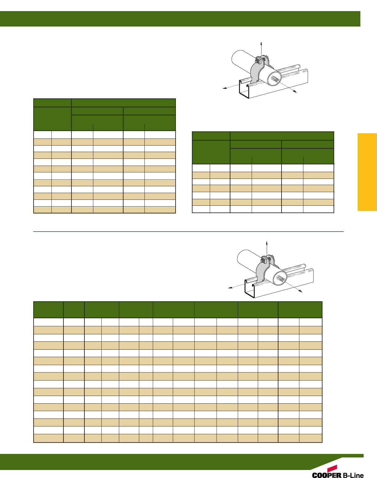
B2000 SERIES
PVC CLAMPS
•Safety Factor of 5
•Add PA to suffix for pre-assembled pipe clamps
•Includes Combination Recess Hex Head Machine Screw and Square Nut
•Material: 16 Ga. (1.5), 14 Ga. (1.9), 12 Ga. (2.6) ASTM A1011 33,000 PSI
min. yield and 11 Ga. (3.0) ASTM A1011HSLA Gr. 50
•Standard finishes: PVC
CLAMP SIZING CHART FOR PVC COATED
RIGID CONDUIT AND CLAMPS
Conduit Coating
Nominal .020 (.51mm) .040 (1.01mm)
Conduit Clamp Coating Clamp Coating
Size 0
.020 (.51mm)
0
.020 (.51mm)
1/2”(15) B2008 B2002 B2002 B2029
3/4”(20) B2030 B2030 B2030 B2004
1” (25) B2032 B2032 B2032 B2004
11/4”(32) B2005 B2005 B2005 B2005
11/2”(40) B2012 B2037 B2037 B2037
2” (50) B2013 B2041 B2041 B2041
21/2”(65) B2014 B2045 B2045 B2045
3” (80) B2015 B2050 B2050 B2050
31/2”(90) B2016 B2054 B2054 B2054
4” (100) B2017 B2058 B2058 B2058
5” (125) B2019 B2066 B2066 B2066
6” (150) B2020 B2115 B2115 B2115
Conduit Coating
Nominal .020 (.51mm) .040 (1.01mm)
Conduit Clamp Coating Clamp Coating
Size 0
.020 (.51mm)
0
.020 (.51mm)
3/8”(10) B2026 B2026 B2026 B2001
1/2”(15) B2027 B2027 B2027 B2008
3/4”(20) B2029 B2029 B2029 B2009
1” (25) B2003 B2031 B2031 B2031
11/4”(32) B2004 B2011 B2011 B2011
11/2”(40) B2005 B2005 B2005 B2036
2” (50) B2039 B2039 B2039 B2013
CLAMP SIZING CHART FOR PVC COATED
THINWALL (EMT) CONDUIT AND CLAMPS
Design Load 1
Design Load 3
Design Load 2
*See B2000 O.D. pipe and conduit clamp chart on pgs. 112-113
for corresponding clamp load data.
*See B2000 O.D. pipe and conduit clamp chart on pgs. 112-113
for corresponding clamp load data.
Part Tubing O.D. Size Material Design Load 1 Design Load 2 Design Load 3 Wt./C
No. Size In. (mm) Thickness Lbs. kN Lbs. kg Lbs. kg Lbs. kg
B2024DCU 1/4” .375 (9.5) 16 Ga. (1.5) 400 (1.78) 50 (.22) 50 (.22) 8(3.6)
B2025DCU 3/8” .500 (12.7) 16 Ga. (1.5) 400 (1.78) 50 (.22) 50 (.22) 9(4.1)
B2026DCU 1/2” .625 (15.9) 16 Ga. (1.5) 400 (1.78) 50 (.22) 50 (.22) 10 (4.5)
B2027DCU 5/8” .750 (19.0) 16 Ga. (1.5) 400 (1.78) 50 (.22) 50 (.22) 10 (4.5)
B2008DCU 3/4” .875 (22.2) 16 Ga. (1.5) 400 (1.78) 50 (.22) 50 (.22) 11 (5.0)
B2030DCU 1” 1.125 (28.6) 14 Ga. (1.9) 600 (2.67) 75 (.33) 75 (.33) 15 (6.8)
B2032DCU 11/4” 1.375 (34.9) 14 Ga. (1.9) 600 (2.67) 75 (.33) 75 (.33) 17 (7.7)
B2011DCU 11/2” 1.625 (41.3) 14 Ga. (1.9) 600 (2.67) 75 (.33) 75 (.33) 19 (8.6)
B2038DCU 2 2.125 (54.0) 12 Ga. (2.6) 800 (3.56) 125 (.56) 125 (.56) 32 (14.5)
B2042DCU 21/2” 2.625 (66.7) 12 Ga. (2.6) 800 (3.56) 125 (.56) 125 (.56) 35 (15.9)
B2046DCU 3 3.125 (79.4) 12 Ga. (2.6) 800 (3.56) 125 (.56) 125 (.56) 39 (17.7)
B2050DCU 31/2” 3.625 (92.1) 11 Ga. (3.0) 1000 (4.45) 200 (.89) 150 (.67) 54 (24.5)
B2054DCU 4 4.125 (104.8) 11 Ga. (3.0) 1000 (4.45) 200 (.89) 150 (.67) 61 (27.6)
B2062DCU 5 5.125 (130.2) 11 Ga. (3.0) 1000 (4.45) 200 (.89) 150 (.67) 70 (31.7)
B2110DCU 6 6.125 (155.6) 11 Ga. (3.0) 1000 (4.45) 250 (1.11) 200 (.89) 94 (42.6)
B2126DCU 8 8.125 (206.4) 11 Ga. (3.0) 1000 (4.45) 250 (1.11) 200 (.89) 123 (55.8)
COPPER TUBING CLAMPS
B2000 SERIES
COPPER TUBING CLAMPS
•Safety Factor of 5
•Add PA to suffix for pre-assembled pipe clamps
•Includes Combination Recess Hex Head Machine Screw and Square Nut
•Material: 16 Ga. (1.5), 14 Ga. (1.9), 12 Ga. (2.6) ASTM A1011 33,000 PSI
min. yield and 11 Ga. (3.0) ASTM A1011HSLA Gr. 50
•Standard finish: Exclusive Dura-Copper®Finish (DCU)
Design Load 1
Design Load 3
Design Load 2
Pipe/Conduit Clamps & Hangers
Reference page 110 for general fitting and standard finish specifications.
Pipe Clamps
113
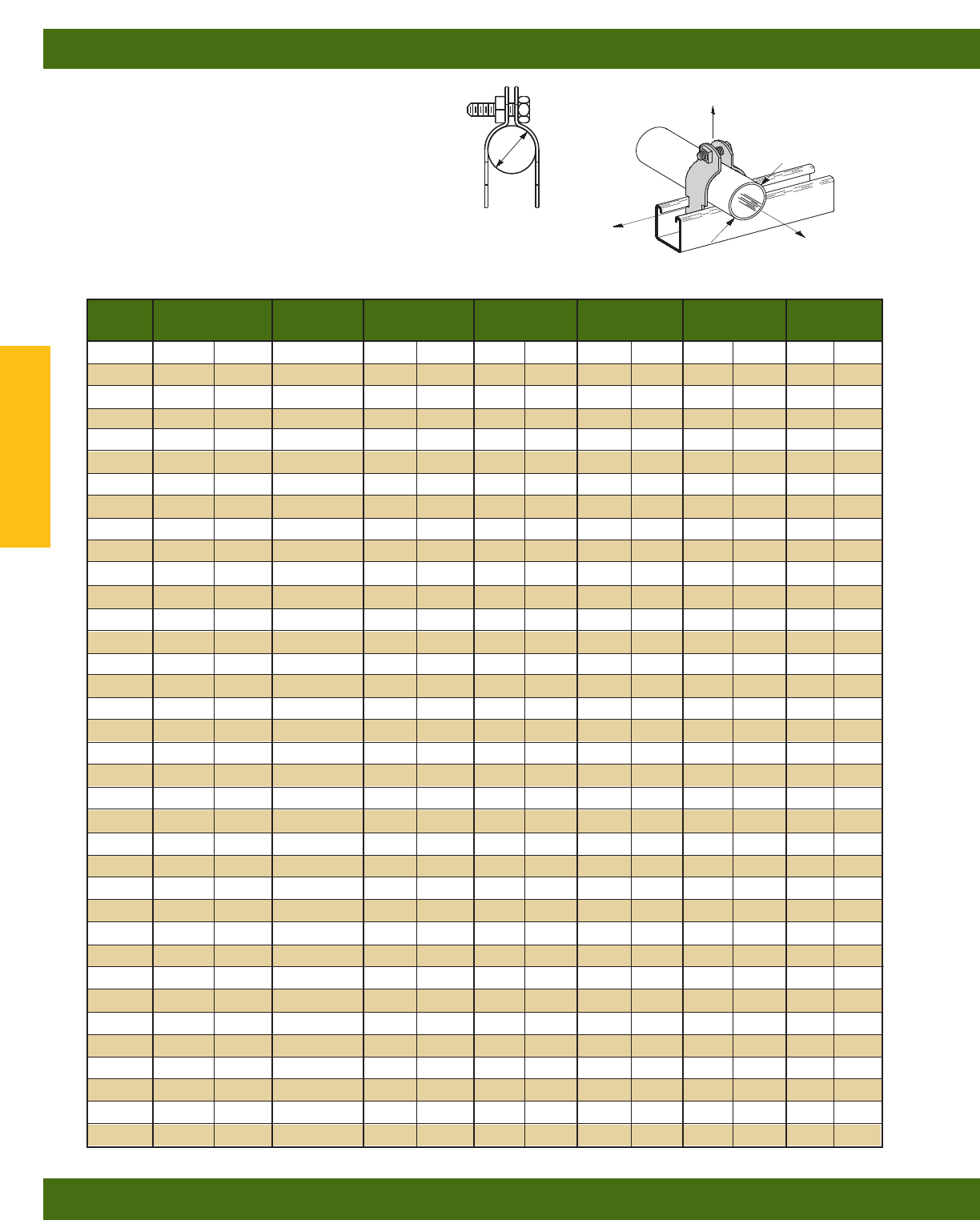
B2000 SERIES
O.D. PIPE AND CONDUIT CLAMPS
•Safety Factor of 5
•Add PA to suffix for pre-assembled pipe clamps
•Other sizes available upon request
•Includes Combination Recess Hex Head Machine Screw
and Square Nut.
•Material: 16 Ga. (1.5), 14 Ga. (1.9), 12 Ga. (2.6)
ASTM A1011 33,000 PSI min. yield and 11 Ga. (3.0)
ASTM A1011HSLA Gr. 50
•Standard finishes: ZN, HDG, SS4
Part O.D. Hardware Material Design Load 1 Design Load 2 Design Load 3 Wt./C
No. Size (in.) Size Gauge Thickness Lbs. kN Lbs. kN Lbs. kN Lbs. kg
B2023 1/4”(6.3) 1/4”-20 16 (1.5) 120 (.54) 30 (.13) 30 (.13) 8(3.6)
B2024 3/8”(9.5) 1/4”-20 16 (1.5) 300 (1.33) 40 (.18) 40 (.18) 8(3.6)
B2025 1/2”(12.7) 1/4”-20 16 (1.5) 400 (1.78) 50 (.22) 50 (.22) 9(4.1)
B2026 5/8”(15.9) 1/4”-20 16 (1.5) 400 (1.78) 50 (.22) 50 (.22) 10 (4.5)
B2027 3/4”(19.0) 1/4”-20 16 (1.5) 400 (1.78) 50 (.22) 50 (.22) 10 (4.5)
B2028 7/8”(22.2) 1/4”-20 16 (1.5) 400 (1.78) 50 (.22) 50 (.22) 11 (5.0)
B2029 1” (25.4) 1/4”-20 14 (1.9) 500 (2.22) 75 (.33) 75 (.33) 15 (6.8)
B2030 11/8”(28.6) 1/4”-20 14 (1.9) 600 (2.67) 75 (.33) 75 (.33) 15 (6.8)
B2031 11/4”(31.7) 1/4”-20 14 (1.9) 600 (2.67) 75 (.33) 75 (.33) 16 (7.3)
B2032 13/8”(34.9) 1/4”-20 14 (1.9) 600 (2.67) 75 (.33) 75 (.33) 17 (7.7)
B2004 11/2”(38.1) 1/4”-20 14 (1.9) 600 (2.67) 75 (.33) 75 (.33) 18 (8.2)
B2011 15/8”(41.3) 1/4”-20 14 (1.9) 600 (2.67) 75 (.33) 75 (.33) 19 (8.6)
B2005 13/4”(44.4) 5/16”-18 12 (2.6) 800 (3.56) 125 (.56) 125 (.56) 29 (13.1)
B2036 17/8”(47.6) 5/16”-18 12 (2.6) 800 (3.56) 125 (.56) 125 (.56) 30 (13.6)
B2037 2(50.8) 5/16”-18 12 (2.6) 800 (3.56) 125 (.56) 125 (.56) 30 (13.6)
B2038 21/8”(54.0) 5/16”-18 12 (2.6) 800 (3.56) 125 (.56) 125 (.56) 32 (14.5)
B2039 21/4”(57.1) 5/16”-18 12 (2.6) 800 (3.56) 125 (.56) 125 (.56) 32 (14.5)
B2013 23/8”(60.3) 5/16”-18 12 (2.6) 800 (3.56) 125 (.56) 125 (.56) 34 (15.4)
B2041 21/2”(63.5) 5/16”-18 12 (2.6) 800 (3.56) 125 (.56) 125 (.56) 35 (15.9)
B2042 25/8”(66.7) 5/16”-18 12 (2.6) 800 (3.56) 125 (.56) 125 (.56) 35 (15.9)
B2043 23/4”(69.8) 5/16”-18 12 (2.6) 800 (3.56) 125 (.56) 125 (.56) 38 (17.2)
B2014 27/8”(73.0) 5/16”-18 12 (2.6) 800 (3.56) 125 (.56) 125 (.56) 38 (17.2)
B2045 3(76.2) 5/16”-18 12 (2.6) 800 (3.56) 125 (.56) 125 (.56) 38 (17.2)
B2046 31/8”(79.4) 5/16”-18 12 (2.6) 800 (3.56) 125 (.56) 125 (.56) 39 (17.7)
B2047 31/4”(82.5) 5/16”-18 12 (2.6) 800 (3.56) 125 (.56) 125 (.56) 41 (18.6)
B2048 33/8”(85.7) 5/16”-18 12 (2.6) 800 (3.56) 125 (.56) 125 (.56) 43 (19.5)
B2015 31/2”(88.9) 5/16”-18 12 (2.6) 800 (3.56) 125 (.56) 125 (.56) 44 (20.0)
B2050 35/8”(92.1) 5/16”-18 11 (3.0) 1000 (4.45) 200 (.89) 150 (.67) 54 (24.5)
B2051 33/4”(95.2) 5/16”-18 11 (3.0) 1000 (4.45) 200 (.89) 150 (.67) 57 (25.8)
B2052 37/8”(41.3) 5/16”-18 11 (3.0) 1000 (4.45 200 (.89) 150 (.67) 55 (25.0)
B2016 4(101.6) 5/16”-18 11 (3.0) 1000 (4.45) 200 (.89) 150 (.67) 57 (25.8)
B2054 41/8”(104.8) 5/16”-18 11 (3.0) 1000 (4.45) 200 (.89) 150 (.67) 61 (27.7)
B2055 41/4”(107.9) 5/16”-18 11 (3.0) 1000 (4.45) 200 (.89) 150 (.67) 62 (28.1)
B2056 43/8”(111.1) 5/16”-18 11 (3.0) 1000 (4.45) 200 (.89) 150 (.67) 64 (29.0)
B2017 41/2”(114.3) 5/16”-18 11 (3.0) 1000 (4.45) 200 (.89) 150 (.67) 66 (29.9)
B2058 45/8”(117.5) 5/16”-18 11 (3.0) 1000 (4.45) 200 (.89) 150 (.67) 66 (29.9)
O.D. CLAMPS
Design Load 1
Design Load 3
Design Load 2
O.D.
O.D.
Pipe/Conduit Clamps & Hangers
Reference page 110 for general fitting and standard finish specifications.
Pipe Clamps
114
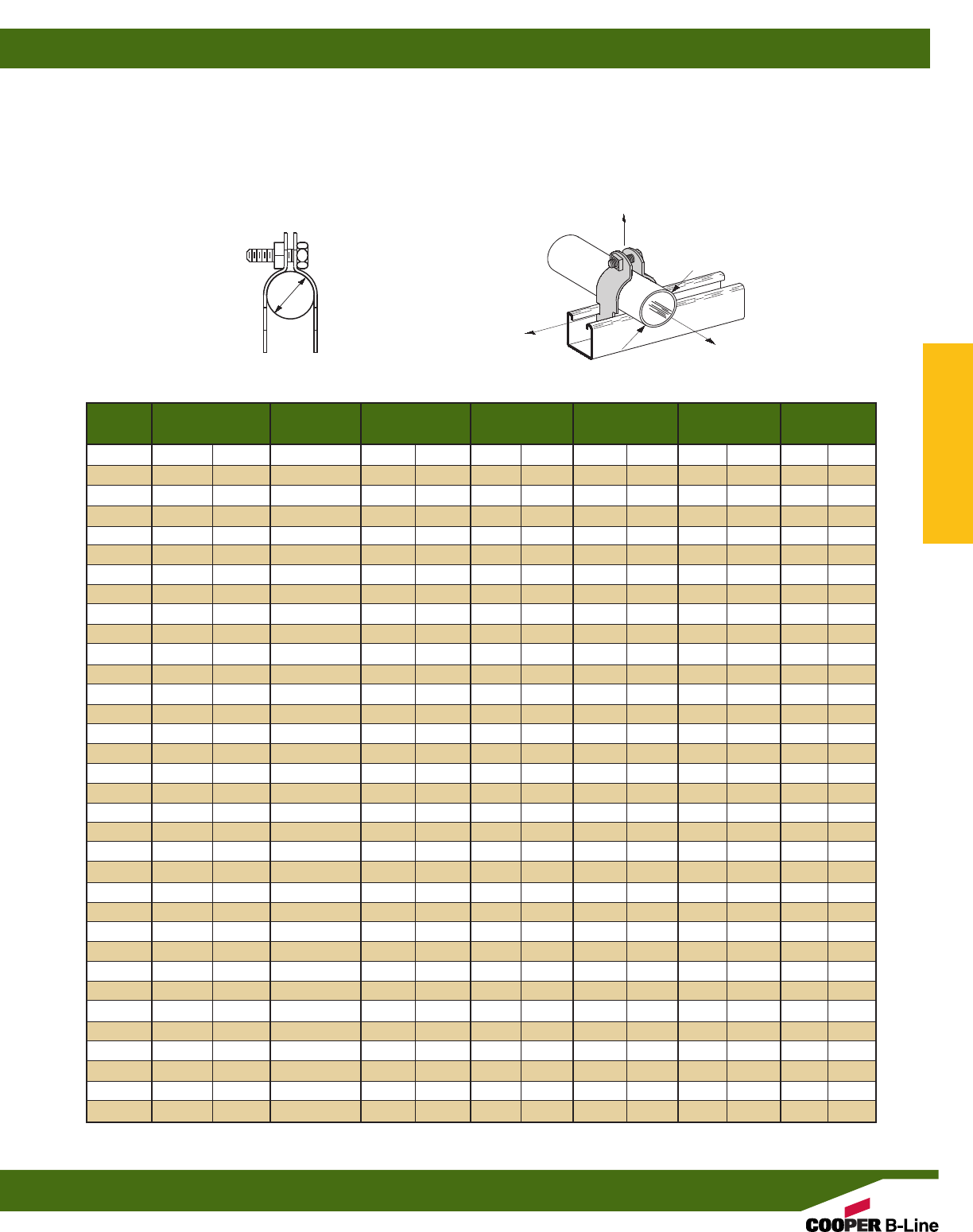
Part O.D. Hardware Material Design Load 1 Design Load 2 Design Load 3 Wt./C
No. Size (in.) Size Gauge Thickness Lbs. kN Lbs. kN Lbs. kN Lbs. kg
B2059 43/4”(120.6) 5/16”-18 11 (3.0) 1000 (4.45) 200 (.89) 150 (.67) 68 (30.8)
B2060 47/8”(123.8) 5/16”-18 11 (3.0) 1000 (4.45) 200 (.89) 150 (.67) 69 (31.3)
B2018 5(127.0) 5/16”-18 11 (3.0) 1000 (4.45) 200 (.89) 150 (.67) 70 (31.8)
B2062 51/8”(130.2) 5/16”-18 11 (3.0) 1000 (4.45) 200 (.89) 150 (.67) 70 (31.8)
B2063 51/4”(133.3) 5/16”-18 11 (3.0) 1000 (4.45) 200 (.89) 150 (.67) 70 (31.8)
B2064 53/8”(136.5) 5/16”-18 11 (3.0) 1000 (4.45) 200 (.89) 150 (.67) 77 (34.9)
B2019 51/2”(139.7) 5/16”-18 11 (3.0) 1000 (4.45) 200 (.89) 150 (.67) 78 (35.4)
B2066 55/8”(142.9) 5/16”-18 11 (3.0) 1000 (4.45) 200 (.89) 150 (.67) 83 (37.6)
B2067 53/4”(146.0) 5/16”-18 11 (3.0) 1000 (4.45) 200 (.89) 150 (.67) 84 (38.1)
B2068 57/8”(149.2) 5/16”-18 11 (3.0) 1000 (4.45) 200 (.89) 150 (.67) 85 (38.6)
B2069 6” (152.4) 5/16”-18 11 (3.0) 1000 (4.45) 200 (.89) 150 (.67) 87 (39.5)
B2110 61/8”(155.6) 3/8”-16 11 (3.0) 1000 (4.45) 250 (1.11) 200 (.89) 94 (42.6)
B2111 61/4”(158.7) 3/8”-16 11 (3.0) 1000 (4.45) 250 (1.11) 200 (.89) 96 (43.5)
B2112 63/8”(161.9) 3/8”-16 11 (3.0) 1000 (4.45) 250 (1.11) 200 (.89) 98 (44.4)
B2113 61/2”(165.1) 3/8”-16 11 (3.0) 1000 (4.45) 250 (1.11) 200 (.89) 99 (44.9)
B2020 65/8”(168.3) 3/8”-16 11 (3.0) 1000 (4.45) 250 (1.11) 200 (.89) 100 (45.4)
B2115 63/4”(171.4) 3/8”-16 11 (3.0) 1000 (4.45) 250 (1.11) 200 (.89) 102 (46.3)
B2116 67/8”(174.6) 3/8”-16 11 (3.0) 1000 (4.45) 250 (1.11) 200 (.89) 104 (47.2)
B2117 7” (177.8) 3/8”-16 11 (3.0) 1000 (4.45) 250 (1.11) 200 (.89) 106 (48.1)
B2118 71/8”(181.0) 3/8”-16 11 (3.0) 1000 (4.45) 250 (1.11) 200 (.89) 108 (49.0)
B2119 71/4”(184.1) 3/8”-16 11 (3.0) 1000 (4.45) 250 (1.11) 200 (.89) 110 (49.9)
B2120 73/8”(187.3) 3/8”-16 11 (3.0) 1000 (4.45) 250 (1.11) 200 (.89) 112 (50.8)
B2121 71/2”(190.5) 3/8”-16 11 (3.0) 1000 (4.45) 250 (1.11) 200 (.89) 114 (51.7)
B2021 75/8”(193.7) 3/8”-16 11 (3.0) 1000 (4.45) 250 (1.11) 200 (.89) 115 (52.2)
B2123 73/4”(196.8) 3/8”-16 11 (3.0) 1000 (4.45) 250 (1.11) 200 (.89) 117 (53.1)
B2124 77/8”(200.0) 3/8”-16 11 (3.0) 1000 (4.45) 250 (1.11) 200 (.89) 119 (54.0)
B2125 8” (203.2) 3/8”-16 11 (3.0) 1000 (4.45) 250 (1.11) 200 (.89) 121 (54.9)
B2126 81/8”(206.4) 3/8”-16 11 (3.0) 1000 (4.45) 250 (1.11) 200 (.89) 123 (55.8)
B2127 81/4”(209.5) 3/8”-16 11 (3.0) 1000 (4.45) 250 (1.11) 200 (.89) 125 (56.7)
B2128 83/8”(212.7) 3/8”-16 11 (3.0) 1000 (4.45) 250 (1.11) 200 (.89) 126 (57.2)
B2129 81/2”(215.9) 3/8”-16 11 (3.0) 1000 (4.45) 250 (1.11) 200 (.89) 128 (58.1)
B2022 85/8”(219.1) 3/8”-16 11 (3.0) 1000 (4.45) 250 (1.11) 200 (.89) 128 (58.1)
B2130 103/4”(273.0) 3/8”-16 11 (3.0) 1000 (4.45) 250 (1.11) 200 (.89) 160 (72.6)
B2132 123/4”(323.8) 3/8”-16 11 (3.0) 1000 (4.45) 250 (1.11) 200 (.89) 185 (83.9)
O.D. CLAMPS
B2000 SERIES
O.D. PIPE AND CONDUIT CLAMPS
•Safety Factor of 5
•Add PA to suffix for pre-assembled pipe clamps
•Other sizes available upon request
•Includes Combination Recess Hex Head Machine Screw and Square Nut.
•Material: 16 Ga. (1.5), 14 Ga. (1.9), 12 Ga. (2.6) ASTM A1011 33,000 PSI min. yield
and 11 Ga. (3.0) ASTM A1011HSLA Gr. 50
•Standard finishes: ZN, HDG, SS4
Design Load 1
Design Load 3
Design Load 2
O.D.
O.D.
Pipe/Conduit Clamps & Hangers
Reference page 110 for general fitting and standard finish specifications.
Pipe Clamps
115
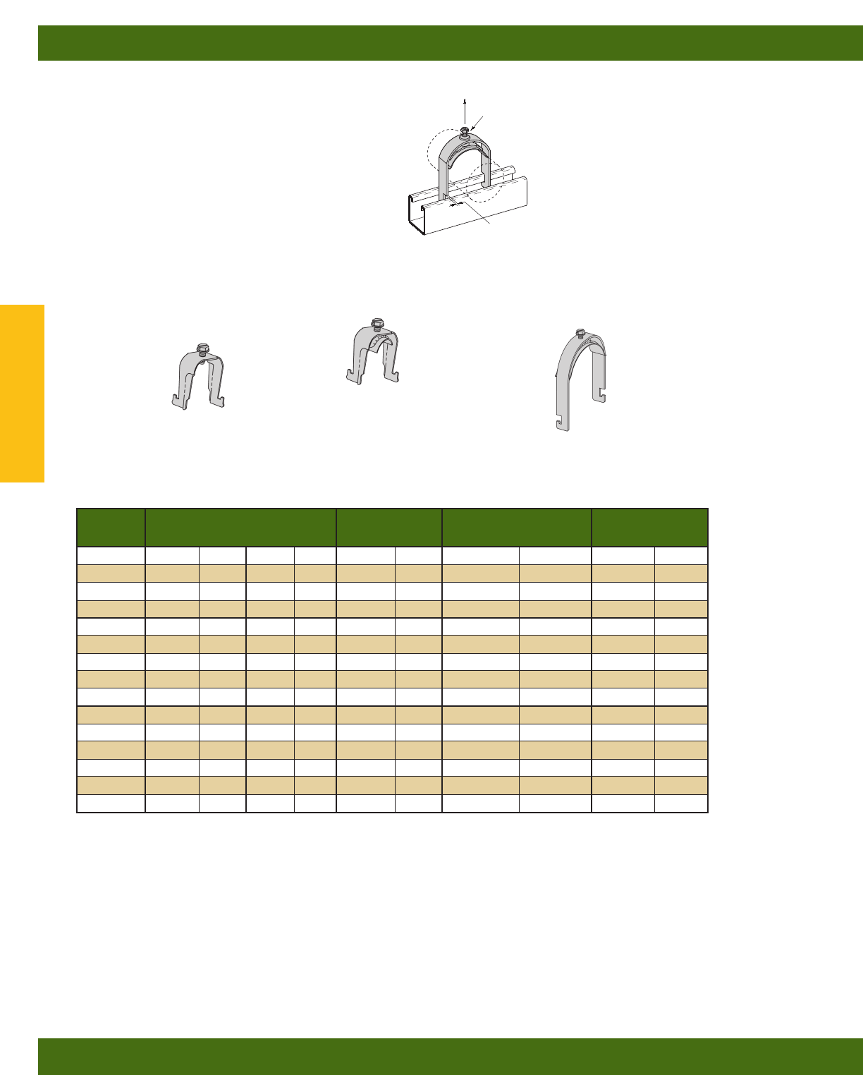
B1508 THRU B1564S
CONDUIT/STRUT CLAMPS
•Safety Factor of 3
•Clamps without saddles are not recommended
for flexible conduit or cable
•All Sizes Include:
1/4”-20 Slotted Hex Head Machine Screw
•Standard finish: ZN
B1508S THRU B1524S
B1508 THRU B1520
B1532S THRU B1564S
Use With Design Load Wt./C
Part No. EMT Rigid Conduit Thickness Lbs. kN Lbs. kg
B1508 1/2” (15) – – 16 Ga. (1.5) 200 (.89) 7.4 (3.4)
B1512 3/4” (20) 1/2”(15) 16 Ga. (1.5) 200 (.89) 8.0 (3.6)
B1516 1” (25) 3/4”(20) 14 Ga. (1.9) 300 (1.33) 11.0 (5.0)
B1520 11/4” (32) 1” (25) 14 Ga. (1.9) 300 (1.33) 12.5 (5.7)
B1508S 1/2” (15) – – 16 Ga. (1.5) 200 (.89) 8.6 (3.9)
B1512S 3/4” (20) 1/2”(15) 16 Ga. (1.5) 200 (.89) 9.2 (4.2)
B1516S 1” (25) 3/4”(20) 14 Ga. (1.9) 300 (1.33) 12.7 (5.8)
B1520S 11/4” (32) 1” (25) 14 Ga. (1.9) 300 (1.33) 14.6 (6.6)
B1524S 11/2” (40) 11/4”(32) 12 Ga. (2.6) 400 (1.78) 20.5 (9.3)
B1532S 2” (50) 11/2”(40) 12 Ga. (2.6) 400 (1.78) 21.5 (9.8)
B1534S ––2”(50) 12 Ga. (2.6) 400 (1.78) 22.7 (10.3)
B1540S 21/2” (65) 21/2”(65) 12 Ga. (2.6) 400 (1.78) 26.0 (11.9)
B1548S 3” (80) 3” (80) 12 Ga. (2.6) 400 (1.78) 30.2 (13.7)
B1556S 31/2” (90) 31/2”(90) 12 Ga. (2.6) 400 (1.78) 33.3 (15.1)
B1564S 4” (100) 4” (100) 12 Ga. (2.6) 400 (1.78) 36.6 (16.6)
Design Load
SETSCREW
THICKNESS
Pipe/Conduit Clamps & Hangers
Reference page 110 for general fitting and standard finish specifications.
Pipe Clamps
116
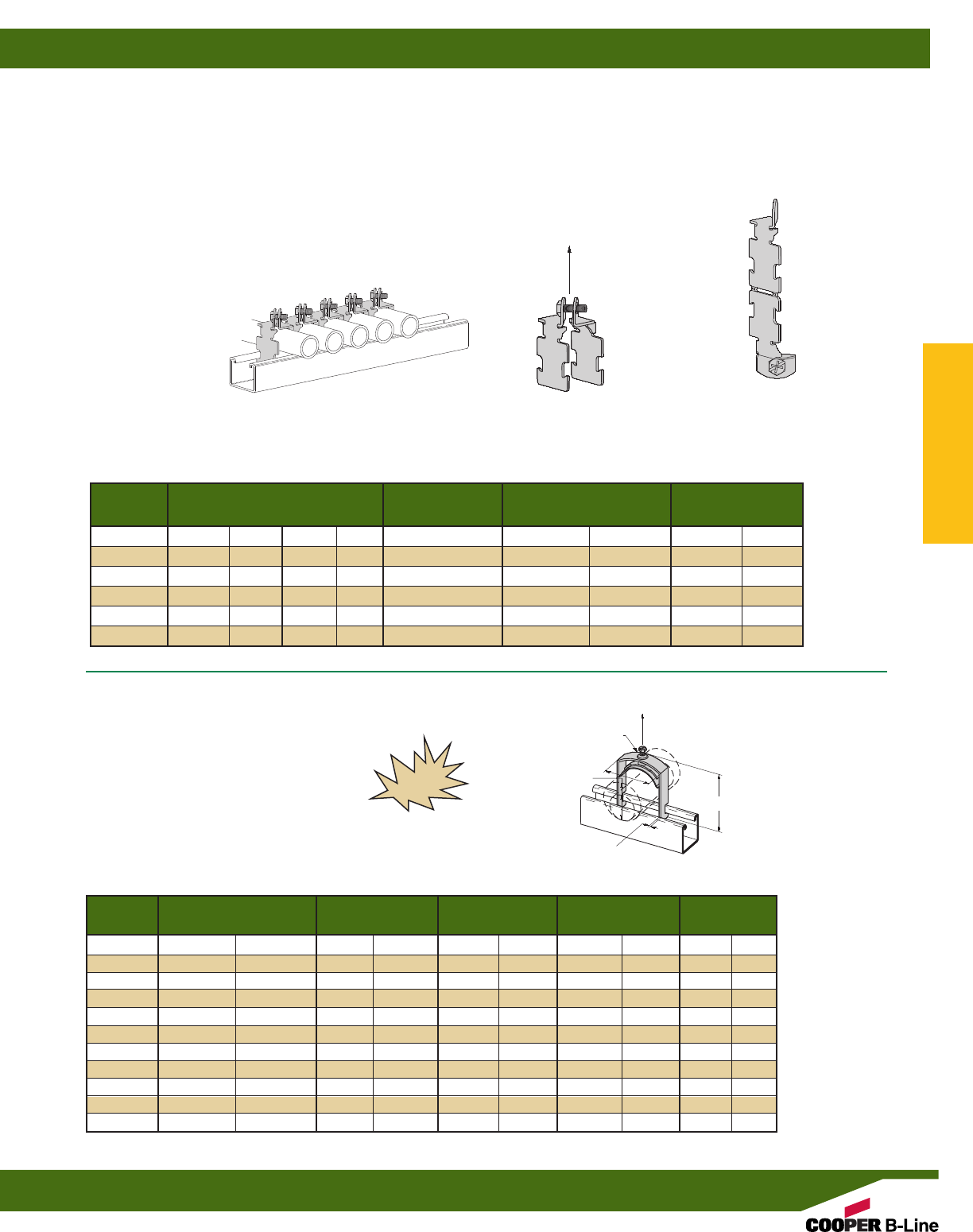
B2601 THRU B2610
TWIST EAR®PIPE CLAMP
•One piece break apart, screw retainer, thread impressions
•Tighter alignment, no need to leave additional space between
clamps in order to access nut and bolt
•Easier access bolt can be tightened directly from front
•Available in 1/2”, 3/4”, 1” rigid and EMT Conduit
•Recommended Torque 30 in. - lbs.
•Safety Factor of 3
•Standard finish: ZN
No loose pieces. One piece
break apart with screw
retainer and thread impressions.
Break-apart - break in the middle,
bolt the ends together.
Allows for multiple clamps to be used in succession,
with easier access than other pipe clamps.
B-Line
B2609-3/4
3/4" STD
B-Line
B2609-3/4
3/4" STD
B-Line
B2609-3/4
3/4" STD
B-Line
B2609-3/4
3/4" STD
Use With Design Load Wt./C
Part No. EMT Rigid Conduit Thickness Lbs. kN Lbs. kg
B2601 1/2”(17.9) – – 16 Ga. 300 (1.34) 8.2 (3.7)
B2602 3/4”(23.4) – – 14 Ga. 500 (2.24) 13.5 (6.1)
B2603 1” (29.5) – – 14 Ga. 500 (2.24) 15.6 (7.1)
B2608 ––
1/2”(21.3) 16 Ga. 300 (1.34) 8.2 (3.7)
B2609 ––
3/4”(26.7) 14 Ga. 500 (2.24) 13.5 (6.1)
B2610 ––1”(33.4) 14 Ga. 500 (2.24) 15.6 (7.1)
O.D. Size Height H Width W Design Load Wt/C.
Part No. In. mm In. mm In. mm Lbs. kN Lbs. kg
BP081SS .250-.840 (6.4-21.3) 1.86 (47.2) 0.87 (22.1) 300 (1.33) 9.0 (4.1)
BP110SS .810-1.100 (20.6-28.0) 2.18 (55.4) 1.19 (30.2) 300 (1.33) 12.0 (5.4)
BP135SS .850-1.350 (21.6-34.8) 2.25 (57.2) 1.38 (35.1) 300 (1.33) 14.0 (6.3)
BP175SS 1.250-1.750 (31.8-44.4) 2.78 (70.6) 1.78 (45.2) 300 (1.33) 21.0 (9.5)
BP205SS 1.550-2.050 (39.4-52.1) 3.00 (76.2) 2.28 (57.9) 300 (1.33) 30.0 (13.6)
BP250SS 2.00-2.50 (50.8-63.5) 3.43 (87.1) 2.83 (71.9) 300 (1.33) 35.0 (15.9)
BP300SS 2.55-3.00 (64.7-76.2) 3.87 (97.8) 3.15 (80.0) 300 (1.33) 39.0 (17.7)
BP325SS 2.75-3.25 (69.9-82.8) 4.06 (103.1) 3.28 (83.3) 300 (1.33) 41.0 (18.6)
BP375SS 3.25-3.75 (82.6-95.3) 4.60 (116.8) 3.83 (97.3) 300 (1.33) 47.0 (21.3)
BP425SS 3.75-4.25 (95.3-108.0) 5.13 (130.3) 4.50 (114.3) 300 (1.33) 54.0 (24.4)
BP475SS 4.25-4.75 (108.0-120.7) 5.70 (5.70) 4.85 (123.2) 300 (1.33) 58.0 (26.3)
BP081SS THRU BP475SS
P CLAMPS
•Minimizes induction heating
•Material: Stainless Steel Type 304
NEW
SETSCREW
O.D. SIZE
H
W
Design Load
Design Load
14 GAUGE
Pipe/Conduit Clamps & Hangers
Reference page 110 for general fitting and standard finish specifications.
Pipe Clamps
117
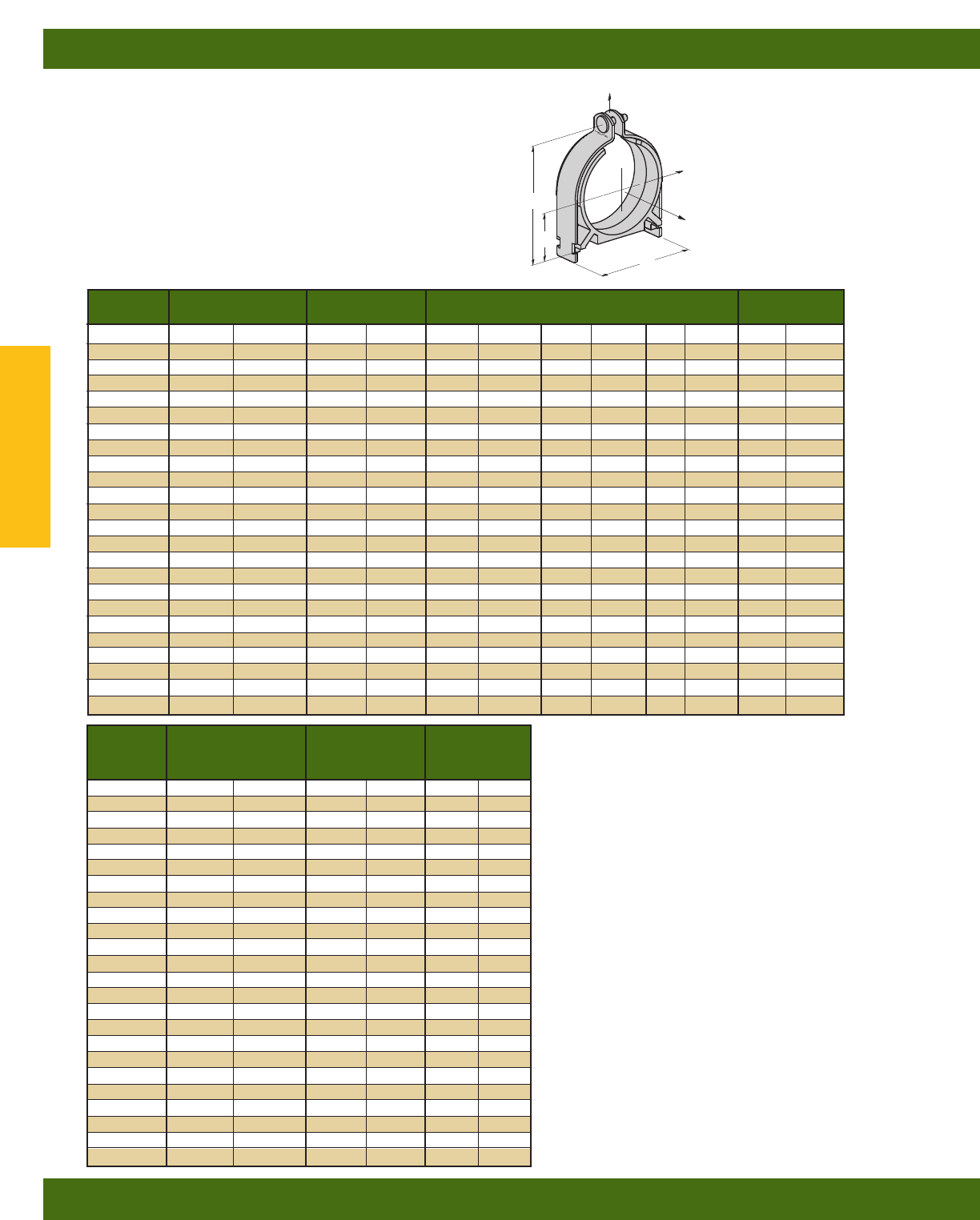
Catalog Tubing Copper Dimensions Wt./C
Number O.D. Size Tubing Size A B C Lbs. kg
BVT025 1/4”(6.3) 1/8”(3) 1.22 (30.9) 0.19 (4.8) 0.49 (12.4) 11 (5.0)
BVT037 3/8”(9.5) 1/4”(6) 1.36 (34.5) 0.25 (6.3) 0.61 (15.5) 12 (5.4)
BVT050 1/2”(12.7) 3/8”(10) 1.49 (37.8) 0.31 (7.8) 0.74 (18.8) 14 (6.3)
BVT062 5/8”(15.9) 1/2”(15) 1.62 (41.1) 0.38 (9.6) 0.86 (21.8) 15 (6.8)
BVT075 3/4”(19.0) 5/8”(17) 1.87 (47.4) 0.50 (12.7) 1.15 (29.2) 19 (8.6)
BVT087 7/8”(22.2) 3/4”(20) 2.00 (50.8) 0.56 (14.2) 1.27 (32.2) 21 (9.5)
BVT100 1” (25.4) – – 2.25 (57.1) 0.69 (17.5) 1.52 (38.6) 22 (10.0)
BVT112 11/8”(28.6) 1” (25) 2.25 (57.1) 0.69 (17.5) 1.52 (38.6) 26 (11.8)
BVT125 11/4”(31.7) – – 2.51 (63.7) 0.81 (20.6) 1.78 (45.2) 36 (16.3)
BVT137 13/8”(34.9) 11/4”(32) 2.51 (63.7) 0.81 (20.6) 1.78 (45.2) 38 (17.2)
BVT150 11/2”(38.1) – – 2.74 (69.6) 0.88 (22.4) 1.96 (49.8) 35 (15.9)
BVT162 15/8”(41.3) 11/2”(40) 3.00 (76.2) 1.00 (25.4) 2.20 (55.9) 40 (18.1)
BVT175 13/4”(44.4) – – 3.13 (79.5) 1.06 (26.9) 2.33 (59.1) 44 (19.9)
BVT187 17/8”(47.6) – – 3.28 (83.3) 1.13 (28.7) 2.46 (62.5) 40 (18.1)
BVT200 2” (50.8) – – 3.52 (89.4) 1.25 (31.7) 2.70 (68.6) 55 (25.0)
BVT212 21/8”(54.0) 2” (50) 3.52 (89.4) 1.25 (31.7) 2.70 (68.6) 55 (25.0)
BVT225 21/4”(57.1) – – 3.64 (92.4) 1.31 (33.2) 2.83 (71.8) 54 (24.5)
BVT250 21/2”(63.5) – – 3.91 (99.3) 1.43 (36.3) 3.11 (79.0) 56 (25.4)
BVT262 25/8”(66.6) 21/2”(65) 4.02 (102.1) 1.50 (38.1) 3.20 (81.3) 55 (25.0)
BVT300 3” (76.2) – – 4.42 (112.2) 1.68 (42.6) 3.61 (91.6) 67 (30.4)
BVT312 31/8”(79.4) 3” (80) 4.53 (115.0) 1.75 (44.4) 3.70 (93.9) 64 (29.0)
BVT362 35/8”(92.1) 31/2”(90) 5.05 (128.2) 2.00 (50.8) 4.23 (107.4) 76 (34.5)
BVT412 41/8”(104.8) 4” (100) 5.55 (140.9) 2.25 (57.1) 4.73 (120.1) 93 (42.2)
BVT612 61/8”(155.5) 6” (150) 7.62 (193.5) 3.25 (82.5) 6.74 (171.1) 136 (61.6)
Catalog Design Load Design Load Design Load
Number 1 2 3
Lbs. kN Lbs. kN Lbs. kN
BVT025 400 (1.78) 50 (0.22) 50 (0.22)
BVT037 400 (1.78) 50 (0.22) 50 (0.22)
BVT050 400 (1.78) 50 (0.22) 50 (0.22)
BVT062 400 (1.78) 50 (0.22) 50 (0.22)
BVT075 600 (2.67) 75 (0.33) 75 (0.33)
BVT087 600 (2.67) 75 (0.33) 75 (0.33)
BVT100 600 (2.67) 75 (0.33) 75 (0.33)
BVT112 600 (2.67) 75 (0.33) 75 (0.33)
BVT125 600 (2.67) 75 (0.33) 75 (0.33)
BVT137 600 (2.67) 75 (0.33) 75 (0.33)
BVT150 600 (2.67) 75 (0.33) 75 (0.33)
BVT162 800 (3.56) 125 (0.56) 125 (0.56)
BVT175 800 (3.56) 125 (0.56) 125 (0.56)
BVT187 800 (3.56) 125 (0.56) 125 (0.56)
BVT200 800 (3.56) 125 (0.56) 125 (0.56)
BVT212 800 (3.56) 125 (0.56) 125 (0.56)
BVT225 800 (3.56) 125 (0.56) 125 (0.56)
BVT250 800 (3.56) 125 (0.56) 125 (0.56)
BVT262 800 (3.56) 125 (0.56) 125 (0.56)
BVT300 800 (3.56) 125 (0.56) 125 (0.56)
BVT312 800 (3.56) 125 (0.56) 125 (0.56)
BVT362 1000 (4.45) 200 (0.89) 150 (0.67)
BVT412 1000 (4.45) 200 (0.89) 150 (0.67)
BVT612 1000 (4.45) 200 (0.89) 150 (0.67)
BVT SERIES VIBRACLAMPS-COPPER & O.D.
•Safety Factor of 3
•Accesses tubing sizes 1/8” (3) to 6” (150)
•Allows easy one tool installation
•Endures both high (+300°F) and low (-40°F) temperatures
•Dampens vibration and noise
•Eliminates galvanic metal to metal contact
•Resists most industrial oils and solvents
•Reduces thermal loss and gain
•Secures tubing firmly to channel (strut)
•Dielectric strength of 400 volts/mil
•Includes cushion, clamp, screw and nut
•Standard finishes: YZN, SS4
A
Design Load 1
Design
Load 2
Design
Load 3
B
C
Pipe/Conduit Clamps & Hangers
Reference page 110 for general fitting and
standard finish specifications.
VibraClamp®Pipe Clamps
118
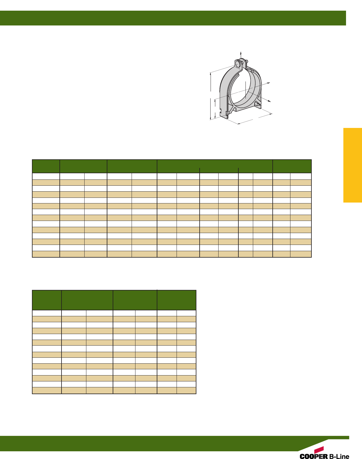
Catalog Nominal Steel Dimensions Wt./C
Number Pipe Size O.D. Size A B C Lbs. kg
BVP025 1/4”(6.3) 0.540 (13.7) 1.61 (39.9) 0.37 (9.4) 0.87 (22.1) 15 (6.8)
BVP037 3/8”(9.5) 0.675 (17.1) 1.86 (47.2) 0.50 (12.7) 1.15 (29.2) 18 (8.2)
BVP050 1/2”(12.7) 0.875 (22.2) 1.99 (50.5) 0.56 (14.2) 1.27 (32.3) 20 (9.1)
BVP075 3/4”(19.0) 1.050 (26.7) 2.25 (57.1) 0.69 (17.5) 1.52 (38.6) 21 (9.5)
BVP100 1” (25.4) 1.312 (33.3) 2.51 (63.8) 0.81 (20.6) 1.77 (45.0) 20 (9.1)
BVP125 11/4”(31.7) 1.660 (42.2) 3.00 (76.2) 1.00 (25.4) 2.21 (56.1) 36 (16.3)
BVP150 11/2”(38.1) 1.900 (48.3) 3.21 (83.1) 1.12 (28.4) 2.41 (62.3) 40 (18.1)
BVP200 2” (50.8) 2.375 (60.3) 3.77 (95.8) 1.37 (34.8) 2.96 (75.2) 45 (20.4)
BVP250 21/2”(63.5) 2.875 (73.0) 4.28 (108.7) 1.62 (41.1) 3.46 (87.9) 54 (24.5)
BVP300 3” (76.2) 3.500 (88.9) 5.05 (128.3) 2.00 (50.8) 4.24 (107.7) 81 (36.7)
BVP350 31/2”(88.9) 4.000 (101.6) 5.55 (140.9) 2.25 (57.1) 4.74 (120.3) 87 (39.4)
BVP400 4” (101.6) 4.500 (114.3) 6.05 (153.7) 2.50 (63.5) 5.24 (133.1) 109 (49.4)
BVP500 5” (127.0) 5.563 (141.3) 6.84 (173.7) 3.00 (76.2) 6.24 (158.4) 136 (61.6)
BVP600 6” (152.4) 6.625 (168.3) 8.24 (209.3) 3.56 (90.4) 7.36 (186.9) 163 (73.8)
BVP SERIES
VIBRACLAMPS-IRON PIPE & RIGID CONDUIT
•Safety Factor of 3
•Accesses pipe sizes 1/4” (6) to 6” (150)
•Allows easy one tool installation
•Endures both high (+300°F) and low (-40°F) temperatures
•Dampens vibration and noise
•Eliminates galvanic metal to metal contact
•Resists most industrial oils and solvents
•Reduces thermal loss and gain
•Secures pipe firmly to channel (strut)
•Dielectric strength of 400 volts/mil
•Includes cushion, clamp, screw and nut
•Standard finishes: YZN, SS4
Catalog Design Load Design Load Design Load
Number 1 2 3
Lbs. kN Lbs. kN Lbs. kN
BVP025 400 (1.78) 50 (0.22) 50 (0.22)
BVP037 600 (2.67) 75 (0.33) 75 (0.33)
BVP050 600 (2.67) 75 (0.33) 75 (0.33)
BVP075 600 (2.67) 75 (0.33) 75 (0.33)
BVP100 600 (2.67) 75 (0.33) 75 (0.33)
BVP125 800 (3.56) 125 (0.56) 125 (0.56)
BVP150 800 (3.56) 125 (0.56) 125 (0.56)
BVP200 800 (3.56) 125 (0.56) 125 (0.56)
BVP250 800 (3.56) 125 (0.56) 125 (0.56)
BVP300 1000 (4.45) 200 (0.89) 150 (0.67)
BVP350 1000 (4.45) 200 (0.89) 150 (0.67)
BVP400 1000 (4.45) 200 (0.89) 150 (0.67)
BVP500 1000 (4.45) 200 (0.89) 150 (0.67)
BVP600 1000 (4.45) 200 (0.89) 150 (0.67)
A
Design Load 1
Design
Load 2
Design
Load 3
B
C
Pipe/Conduit Clamps & Hangers
Reference page 110 for general fitting and standard finish specifications.
VibraClamp®Pipe Clamps
119
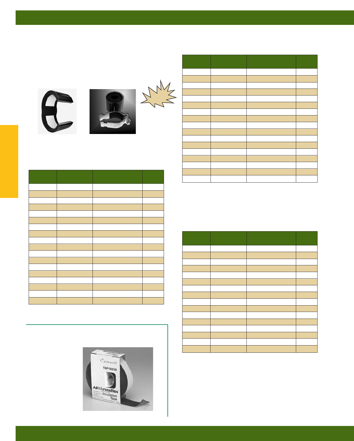
IPH SERIES
INSERTS - INSERTS WITH CLAMPS
• Engineered load-bearing inserts prevents insulation compression
• Innovative insulated pipe support
• Desirable “Foam-to-Foam” Bond
• Slip Data: 45 lbs. (0.20 kN) max
• Recommended Clamp Torque: 12-15 in-lbs. (1.3-1.7 Nm)
• Service Temperature Range
-58°F (-50°C) to +220°F (+105°C)
Assembly Insert Only Pipe/Copper/OD Hanger
Part No. Part No. Size Size*
IPH03812 IPH03812WO 3/8” O.D. 11/4”
IPH01212 IPH01212WO 1/2” O.D. 11/4”
IPH05812 IPH05812WO 5/8” O.D. 11/2”
IPH03412 IPH03412WO 3/4” O.D. 11/2”
IPH07812 IPH07812WO 7/8” O.D. 2”
IPH11812 IPH11812WO 3/4” IPS & 11/8” O.D. 2”
IPH13812 IPH13812WO 13/8” O.D. 21/2”
IPH15812 IPH15812WO 15/8” O.D. 21/2”
IPH11012 IPH11012WO 11/2” IPS & 17/8” O.D. 3”
IPH21812 IPH21812WO 21/8” O.D. 3”
IPH25812 IPH25812WO 25/8” O.D. 31/2”
IPH31812 IPH31812WO 31/8” O.D. 4”
IPH35812 IPH35812WO 35/8” O.D. 5”
IPH41812 IPH41812WO 41/8” O.D. 6”
IPH40012 IPH40012WO 4” IPS 6”
IPH50012 IPH50012WO 5” IPS 8”
IPH60012 IPH60012WO 6” IPS 8”
1/2” Wall Insulation Thickness
Insert Only Assembly
Insert & Clamp
IPH18230
ARMACELL®INSUALTION TAPE
• 30 ft. (9.14 M) roll
* Recommended pipe hanger size for insulation thickness shown.
(Order hanger separately)
Assembly Insert Only Pipe/Copper/OD Hanger
Part No. Part No. Size Size*
IPH03834 IPH03834WO 3/8” O.D. 2”
IPH01234 IPH01234WO 1/2” O.D. 2”
IPH05834 IPH05834WO 5/8” O.D. 2”
IPH03434 IPH03434WO 3/4” O.D. 2”
IPH07834 IPH07834WO 7/8” O.D. 21/2”
IPH11834 IPH11834WO 3/4” IPS & 11/8” O.D. 21/2”
IPH13834 IPH13834WO 13/8” O.D. 3”
IPH15834 IPH15834WO 15/8” O.D. 31/2”
IPH11034 IPH11034WO 11/2” IPS & 17/8” O.D. 31/2”
IPH21834 IPH21834WO 21/8” O.D. 4”
IPH25834 IPH25834WO 25/8” O.D. 5”
IPH31834 IPH31834WO 31/8” O.D. 5”
IPH35834 IPH35834WO 35/8” O.D. 6”
IPH41834 IPH41834WO 41/8” O.D. 6”
IPH40034 IPH40034WO 4” IPS 6”
IPH50034 IPH50034WO 5” IPS 8”
IPH60034 IPH60034WO 6” IPS 10”
IPH80034 IPH80034WO 8” IPS 12”
3/4” Wall Insulation Thickness
* Recommended pipe hanger size for insulation thickness shown.
(Order hanger separately)
Assembly Insert Only Pipe/Copper/OD Hanger
Part No. Part No. Size Size*
IPH05810 IPH05810WO 5/8” O.D. 21/2”
IPH03410 IPH03410WO 3/4” O.D. 21/2”
IPH07810 IPH07810WO 7/8” O.D. 3”
IPH11810 IPH11810WO 3/4” IPS & 11/8” O.D. 3”
IPH13810 IPH13810WO 13/8” O.D. 31/2”
IPH15810 IPH15810WO 15/8” O.D. 31/2”
IPH11010 IPH11010WO 11/2” IPS & 17/8” O.D. 4”
IPH21810 IPH21810WO 21/8” O.D. 4”
IPH25810 IPH25810WO 25/8” O.D. 5”
IPH31810 IPH31810WO 31/8” O.D. 5”
IPH35810 IPH35810WO 35/8” O.D. 6”
IPH41810 IPH41810WO 41/8” O.D. 6”
IPH40010 IPH40010WO 4” IPS 8”
IPH50010 IPH50010WO 5” IPS 8”
IPH60010 IPH60010WO 6” IPS 10”
IPH80010 IPH80010WO 8” IPS 12”
1” Wall Insulation Thickness
* Recommended pipe hanger size for insulation thickness shown.
(Order hanger separately)
NEW
Pipe/Conduit Clamps & Hangers
Reference page 110 for general fitting and standard finish specifications.
Armifix Clamps & Accessories
120
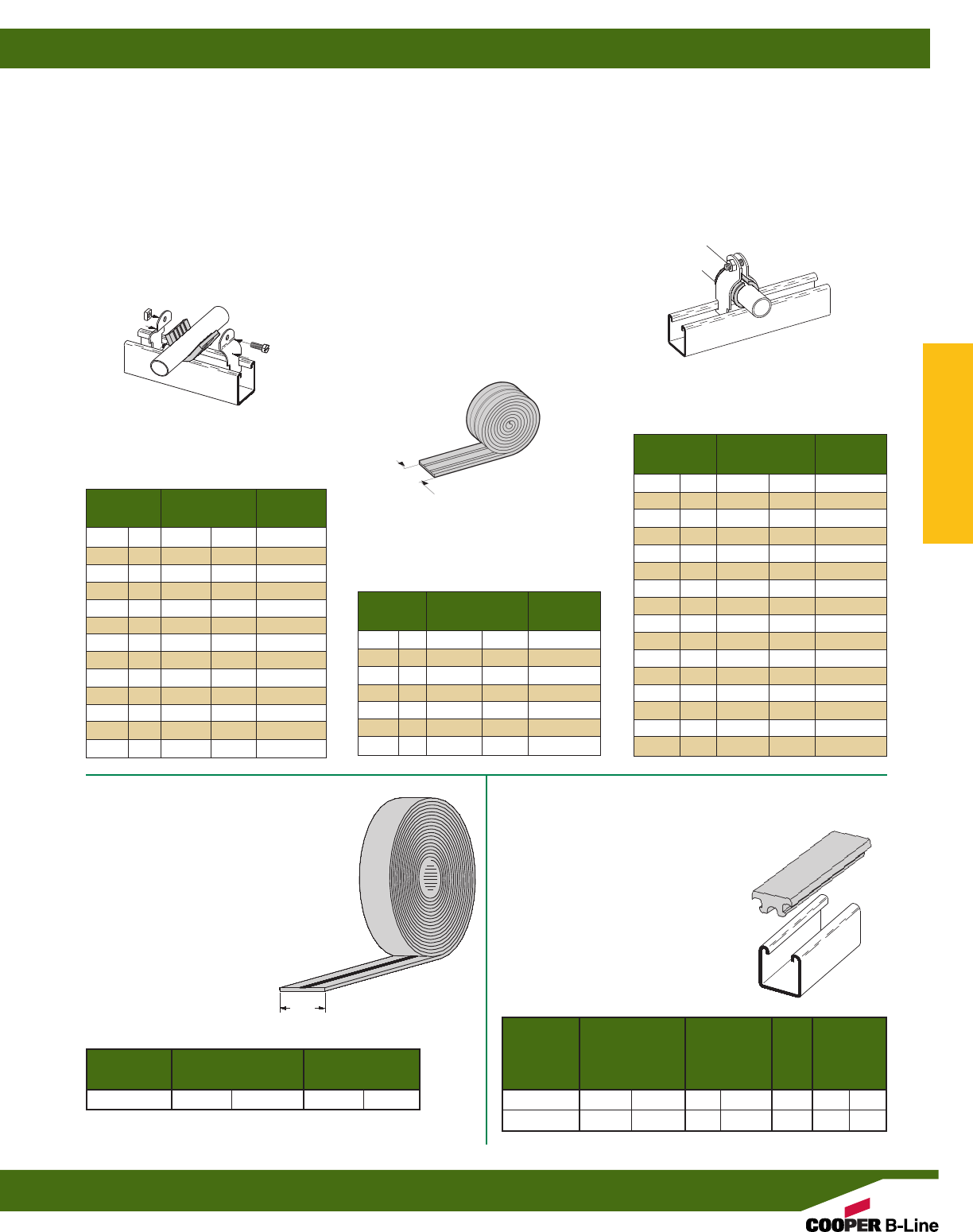
B1999
VIBRA CUSHION®
•Packaged 20 Ft. (6.09 m) per carton
•Ideal Isolation Material
•Inhibits Galvanic Corrosion
•Dampens Sound and Vibrations
•Service Temperature Range
-75°F (-60°C) to +375°F (+199°C)
•Wt./Carton 3.8 Lbs. (1.7 kg)
ISO PIPE
•Non-adhesive rubber tape
•Fuses to itself
•Water resistant
•Ideal Isolation Material
•Prevents galvanic reaction caused by
dissimilar metal contact
•Temperature Range
-140°F (-60°C) to +395°F (+200°C)
Nominal Length of Use
Size Vibra-Cushion Clamp No.
3/8”(10) 21/8”(54.0) B2002
1/2”(15) 25/8”(66.7) B2009
3/4”(20) 31/4”(82.5) B2031
1” (25) 41/8”(104.8) B2004
11/4”(32) 53/16”(131.8) B2012
11/2”(40) 515/16”(150.8) B2038
2” (50) 71/2”(190.5) B2042
21/2”(65) 9” (228.6) B2046
3” (80) 11” (279.4) B2051
31/2”(90) 121/2”(317.5) B2055
4” (100) 141/2”(368.3) B2059
5” (125) 177/16”(442.9) B2067
6” (150) 203/4”(527.0) B2116
FOR RIGID CONDUIT
OR IRON PIPE
Nominal Length of Use
Size Vibra-Cushion Clamp No.
3/8”(10) 113/16”(46.0) B2027
1/2”(15) 213/16”(58.7) B2002
3/4”(20) 27/8”(73.0) B2003
1” (25) 35/8”(92.1) B2032
11/4”(32) 43/8”(120.6) B2036
11/2”(40) 57/16”(138.1) B2012
2” (50) 67/8”(174.6) B2013
Nominal Length of Use
Size Vibra-Cushion Clamp No.
1/4”(6) 13/16”(30.2) B2026
3/8”(10) 19/16”(39.7) B2027
1/2”(15) 17/8”(47.6) B2028
5/8”(17) 25/16”(58.7) B2029
3/4”(20) 23/4”(69.8) B2030
1” (25) 31/2”(88.9) B2032
11/4”(32) 45/16”(109.5) B2011
11/2”(40) 51/8”(130.2) B2036
2” (50) 611/16”(169.9) B2013
21/2”(65) 81/4”(209.5) B2014
3” (80) 913/16”(249.2) B2048
31/2”(90) 113/8”(288.9) B2052
4” (100) 1215/16”(328.6) B2056
5” (125) 161/8”(409.6) B2064
6” (150) 191/4”(488.9) B2112
8” (200) 251/2”(647.7) B2128
FOR THINWALL (EMT)
CONDUIT
FOR COPPER TUBING
TYPE L & K
FEATURES
Vibra Cushion®is designed for use
with refrigeration lines, HVAC, copper
tubing, glass pipe and hydraulic lines.
It provides an energy-absorption barrier
between the lines and the mounting
material and remains flexible thru its
entire service range of -75°F (-60°C) to
+375°F (+199°C).
This elastomer allows for expansion
and contraction within the mounting
system and prevents galvanic reaction
between dissimilar metals.
Part No. Thickness Ft./Roll
In. mm Ft. m
ISO .020 (0.5) 36 (11)
15/8”
(41.3)
1”
(25.4)
BVS Type - Vibra Strip™ for 15/8"(41.3) wide
B-Line channel
•Fits securely in 15/8” wide channel
•Temperature range: -20°F to 212°F
•Ideal Isolation & Vibration Dampening
Qualities
•45 durometer hardness
•Material: Neoprene
Max. Load
Lbs. per Wt.
Lineal In. Std. Each
Part No. Lbs.
kg/25.4 mm
Length Pkg. Lbs. kg
BVS-12 40 (18.1) 12” (304.8) 25 .46 (.21)
BVS-120 40 (18.1) 120” (3048.0) 25 .46 (.21)
Pipe/Conduit Clamps & Hangers
Reference page 110 for general fitting and standard finish specifications.
Vibra Cushion®Accessories
121
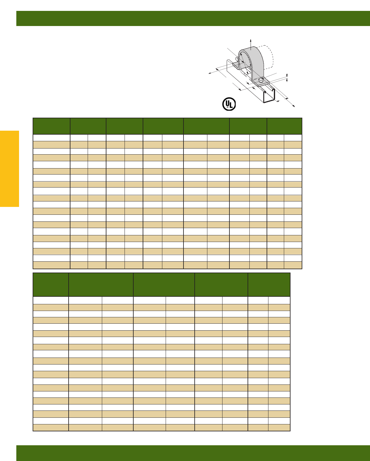
B2400 SERIES
STANDARD PIPE STRAP
•Safety Factor of 5
•B2400-3/4thru B2400-8 are UL listed
•Order hardware separately
•Other sizes available upon request
•Material: Sizes - 1/2” - 11/2”, ASTM A1011 33,000 PSI min. yield;
2” - 10”, ASTM A1018 33,000 PSI min. yield;
12” ASTM A1011 CS Type B;
14”-Larger, ASTM A36
•Standard finish: ZN
•Ductile Iron Sizes Available
•Meets requirements of MSS SP-58 & SP-69 Type 26
Part No. Pipe Size A B C T W
B2400-1/21/2”(15) 5/16”(7.9) 7/16”(11.1) 213/16”(71.4) 10 Ga. (3.4) 15/8”(41.3)
B2400-3/43/4”(20) 5/16”(7.9) 7/16”(11.1) 3” (76.2) 10 Ga. (3.4) 15/8”(41.3)
B2400-1 1” (25) 5/16”(7.9) 7/16”(11.1) 317/32”(89.7) 10 Ga. (3.4) 15/8”(41.3)
B2400-11/411/4”(32) 5/16”(7.9) 7/16”(11.1) 33/4”(95.2) 10 Ga. (3.4) 15/8”(41.3)
B2400-11/211/2”(40) 5/16”(7.9) 7/16”(11.1) 41/16”(103.2) 10 Ga. (3.4) 15/8”(41.3)
B2400-2 2” (50) 7/16”(11.1) 11/16”(17.4) 521/32”(143.6) 1/4”(6.3) 15/8”(41.3)
B2400-21/221/2”(65) 7/16”(11.1) 11/16”(17.4) 65/32”(156.3) 1/4”(6.3) 15/8”(41.3)
B2400-3 3” (80) 7/16”(11.1) 11/16”(17.4) 625/32”(172.2) 1/4”(6.3) 15/8”(41.3)
B2400-31/231/2”(90) 7/16”(11.1) 11/16”(17.4) 79/32”(184.9) 1/4”(6.3) 15/8”(41.3)
B2400-4 4” (100) 9/16”(14.3) 11/16”(17.4) 725/32”(197.6) 1/4”(6.3) 15/8”(41.3)
B2400-5 5” (125) 9/16”(14.3) 11/16”(17.4) 87/8”(225.4) 1/4”(6.3) 15/8”(41.3)
B2400-6 6” (150) 9/16”(14.3) 11/16”(17.4) 915/16”(252.4) 1/4”(6.3) 15/8”(41.3)
B2400-8 8” (200) 9/16”(14.3) 11/16”(17.4) 1131/32”(304.0) 1/4”(6.3) 15/8”(41.3)
B2400-10 10” (250) 9/16”(14.3) 15/16”(33.3) 14” (355.6) 1/4”(6.3) 15/8”(41.3)
B2400-12 12” (300) 9/16”(14.3) 15/16”(33.3) 16” (406.4) 1/4”(6.3) 15/8”(41.3)
B2400-14 14” (350) 15/16”(23.8) 11/2”(38.1) 203/4”(527.0) 3/8”(9.5) 13/4”(44.4)
B2400-16 16” (400) 15/16”(23.8) 11/2”(38.1) 223/4”(577.8) 3/8”(9.5) 13/4”(44.4)
B2400-18 18” (460) 15/16”(23.8) 13/4”(44.4) 27” (685.8) 1/2”(12.7) 13/4”(44.4)
B2400-20 20” (510) 15/16”(23.8) 13/4”(44.4) 29” (736.6) 1/2”(12.7) 13/4”(44.4)
B2400-24 24” (610) 15/16”(23.8) 13/4”(44.4) 33” (838.2) 1/2”(12.7) 13/4”(44.4)
Design Load
1
Design Load
3
Design Load
2
PIPE SIZE
HOLE SIZE
A
T
C
B
Part No. Design Load Design Load Design Load Wt./C
123
Lbs. kN Lbs. kN Lbs. kN Lbs. kg
B2400-1/2600 (2.67) 150 (.67) 105 (.47) 23 (10.4)
B2400-3/4600 (2.67) 150 (.67) 105 (.47) 26 (11.8)
B2400-1 600 (2.67) 150 (.67) 120 (.53) 31 (14.0)
B2400-11/4600 (2.67) 150 (.67) 120 (.53) 36 (16.3)
B2400-11/2600 (2.67) 150 (.67) 120 (.53) 39 (17.7)
B2400-2 1200 (5.34) 480 (2.14) 180 (.80) 93 (42.2)
B2400-21/21200 (5.34) 480 (2.14) 180 (.80) 106 (48.1)
B2400-3 1200 (5.34) 480 (2.14) 300 (1.33) 132 (59.9)
B2400-31/21200 (5.34) 480 (2.14) 300 (1.33) 151 (68.5)
B2400-4 1500 (6.67) 600 (2.67) 450 (2.00) 160 (72.6)
B2400-5 1500 (6.67) 600 (2.67) 450 (2.00) 192 (87.1)
B2400-6 1500 (6.67) 600 (2.67) 450 (2.00) 219 (99.3)
B2400-8 2000 (8.90) 800 (3.56) 600 (2.67) 297 (134.7)
B2400-10 2000 (8.90) 800 (3.56) 600 (2.67) 465 (210.9)
B2400-12 2000 (8.90) 800 (3.56) 600 (2.67) 560 (254.0)
B2400-14 2000 (8.90) 800 (3.56) 600 (2.67) 761 (345.2)
B2400-16 2000 (8.90) 800 (3.56) 600 (2.67) 861 (390.5)
B2400-18 2000 (8.90) 800 (3.56) 600 (2.67) 1297 (588.3)
B2400-20 2000 (8.90) 800 (3.56) 600 (2.67) 1426 (646.8)
B2400-24 2000 (8.90) 800 (3.56) 600 (2.67) 1682 (762.9)
W
Pipe/Conduit Clamps & Hangers
Reference page 110 for general fitting and standard finish specifications.
Pipe Clamps
122
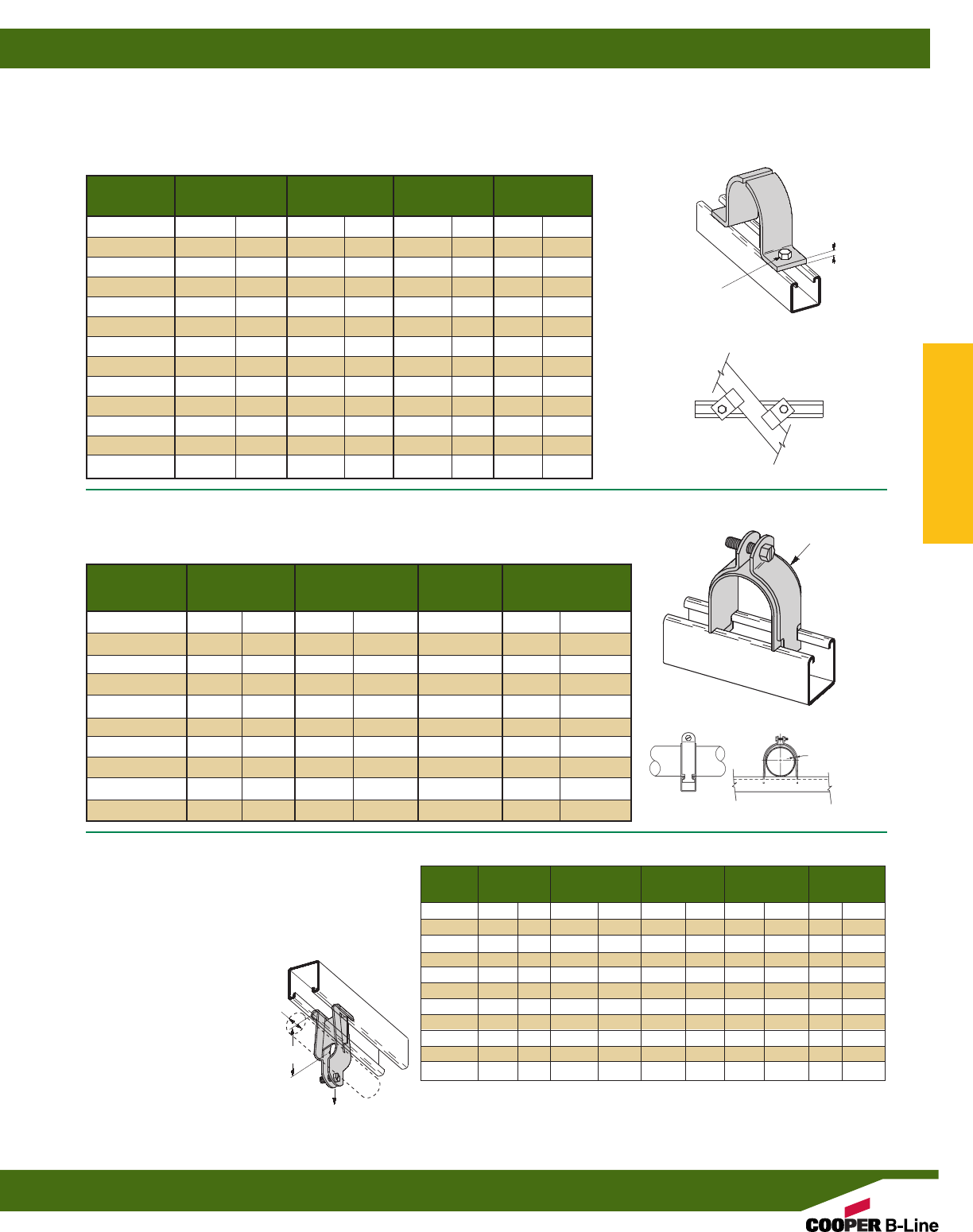
B437 SERIES TWO PIECE PIPE STRAP
•Clamp halves can turn allowing pipe to
be fastened to channel at any direction
•Order hardware separately
•Standard finish: ZN
B2417 STRUT MOUNTED PIPE GUIDE
•Copper tubing sizes available - B2417CT Series
•Standard finish: ZN
HOLE SIZE
A
Wt./C
Part No. Pipe Size A T Lbs. kg
B437-1/21/2”(15) 5/16”(7.9) 10 Ga. (3.4) 22 (10.0)
B437-3/43/4”(20) 5/16”(7.9) 10 Ga. (3.4) 26 (11.8)
B437-1 1” (25) 5/16”(7.9) 10 Ga. (3.4) 30 (13.6)
B437-11/411/4”(32) 5/16”(7.9) 10 Ga. (3.4) 35 (15.9)
B437-11/211/2”(40) 5/16”(7.9) 10 Ga. (3.4) 38 (17.2)
B437-2 2” (50) 7/16”(11.1) 1/4”(6.3) 91 (41.3)
B437-21/221/2”(65) 7/16”(11.1) 1/4”(6.3) 104 (47.2)
B437-3 3” (80) 7/16”(11.1) 1/4”(6.3) 130 (58.9)
B437-31/231/2”(90) 7/16”(11.1) 1/4”(6.3) 149 (67.6)
B437-4 4” (100) 9/16”(11.1) 1/4”(6.3) 158 (71.6)
B437-5 5” (125) 9/16”(11.1) 1/4”(6.3) 190 (86.2)
B437-6 6” (150) 9/16”(11.1) 1/4”(6.3) 217 (98.4)
B437-8 8” (200) 9/16”(11.1) 1/4”(6.3) 295 (133.8)
T
Clearance
Minimum Includes Wt./C
Part No. Pipe Size Radial Clearance Clamp No. Lbs. kg
B2417-1/21/2"(15) 1/16"(1.6) B2009 22 (10.0)
B2417-3/43/4"(20) 1/16"(1.6) B2010 25 (11.3)
B2417-1 1" (25) 3/32"(2.3) B2034 30 (13.6)
B2417-11/411/4"(32) 3/32"(2.3) B2037 47 (21.8)
B2417-11/211/2"(40) 3/32"(2.3) B2039 51 (23.1)
B2417-2 2" (50) 1/8"(3.2) B2043 62 (28.1)
B2417-21/221/2"(65) 1/8"(3.2) B2047 69 (31.3)
B2417-3 3" (80) 5/32"(3.9) B2016 108 (49.0)
B2417-31/231/2"(90) 5/32"(3.9) B2017 118 (53.5)
B2417-4 4" (100) 5/32"(3.9) B2018 128 (58.0)
14 GAUGE
(1.9)
Material Design Load Wt./C
Part No. Pipe Size A Thickness Lbs. kN Lbs. kg
B2070 3/8”(10) 111/16”(42.9) 16 Ga. (1.5) 300 (1.33) 24 (10.9)
B2071 1/2”(15) 13/4”(44.4) 16 Ga. (1.5) 300 (1.33) 26 (11.8)
B2072 3/4”(20) 17/8”(47.6) 14 Ga. (1.9) 300 (1.33) 30 (13.6)
B2073 1” (25) 2” (50.8) 14 Ga. (1.9) 400 (1.78) 33 (14.9)
B2074 11/4”(32) 23/16”(55.6) 14 Ga. (1.9) 400 (1.78) 36 (16.3)
B2075 11/2”(40) 25/16”(58.7) 12 Ga. (2.6) 500 (2.22) 50 (22.7)
B2076 2” (50) 29/16”(65.1) 12 Ga. (2.6) 500 (2.22) 55 (24.9)
B2077 21/2”(65) 27/8”(73.0) 12 Ga. (2.6) 500 (2.22) 60 (27.2)
B2078 3” (80) 33/16”(80.9) 12 Ga. (2.6) 500 (2.22) 66 (29.9)
B2079 31/2”(90) 37/16”(87.3) 11 Ga. (3.0) 500 (2.22) 85 (38.5)
B2080 4” (100) 35/8”(92.1) 11 Ga. (3.0) 500 (2.22) 95 (43.1)
B2070 THRU B2080
PARALLEL PIPE CLAMP
•Safety Factor of 2
•Designed to support pipe or rigid conduit
•Includes:
1 pr. Pipe Clamps
1 pc. Stand Off Plate
1 pc. Slotted Hex Head
Machine Screws
1 pc. Square Nut
•Standard finish: ZN
A dimension, from bottom
of channel to center of pipe.
Design Load
PIPE
SIZE
A
Pipe/Conduit Clamps & Hangers
Reference page 110 for general fitting and standard finish specifications.
Pipe Clamps
123
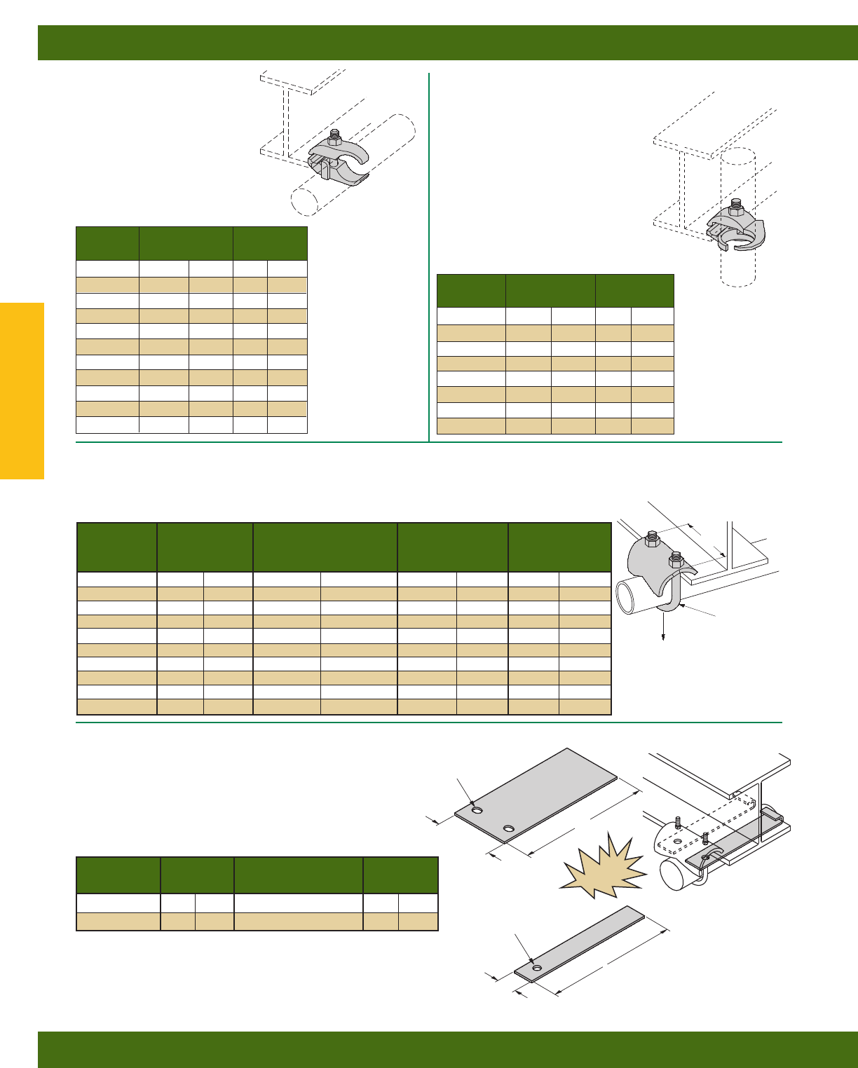
Part Pipe or Conduit Wt./C
Number Size Lbs. kg
B670-3/83/8”(10) 32 (14.5)
B670-1/21/2”(15) 58 (26.3)
B670-3/43/4”(20) 64 (29.0)
B670-1 1” (25) 70 (31.7)
B670-11/411/4”(32) 77 (34.9)
B670-11/211/2”(40) 93 (42.2)
B670-2 2” (50) 105 (47.6)
B670-21/221/2”(65) 143 (64.8)
B670-3 3” (80) 164 (74.4)
B670-31/231/2”(90) 190 (86.2)
B670-4 4” (100) 205 (93.0)
Part Pipe or Conduit Wt./C
Number Size Lbs. kg
B671-1/21/2”(15) 67 (30.4)
B671-3/43/4”(20) 71 (32.2)
B671-1 1” (25) 85 (38.5)
B671-11/411/4”(32) 91 (41.3)
B671-11/211/2”(40) 115 (52.1)
B671-2 2” (50) 135 (61.2)
B671-21/221/2”(65) 183 (83.0)
B671-3 3” (80) 230 (104.3)
B671 SERIES
EDGE PIPE CLAMP
•Designed to support pipe or rigid
conduit perpendicular to the edge of a
beam or angle iron
•Hardware included
•Material: Malleable Iron
•Standard finish: HDG
B670 SERIES
PARALLEL PIPE CLAMP
•Designed to support pipe or rigid
conduit parallel to the edge of a
beam or angle iron
•Hardware included
•Material: Malleable Iron
•Standard finish: HDG
B422 SERIES RIGHT ANGLE CLAMP
•Safety Factor of 5
•Material: 7 Gauge (4.5)
•Standard finishes: ZN, SS4
Design Load
Conduit Vertical Pull Wt./C
Part No. Size A Lbs. kg Lbs. kg
B422-1/21/2”(15) 23/8”(60.3) 250 (1.11) 38 (17.2)
B422-3/43/4”(20) 23/8”(60.3) 300 (1.33) 39 (17.7)
B422-1 1” (25) 27/8”(73.0) 400 (1.78) 48 (21.8)
B422-11/411/4”(32) 27/8”(73.0) 400 (1.78) 50 (22.7)
B422-11/211/2”(40) 31/4”(82.5) 500 (2.22) 59 (26.7)
B422-2 2(50) 311/16”(93.7) 600 (2.67) 75 (34.0)
B422-21/221/2”(65) 41/4”(107.9) 700 (3.11) 98 (44.4)
B422-3 3” (80) 47/8”(123.8) 800 (3.56) 111 (50.3)
B422-31/231/2”(90) 57/16”(138.1) 900 (4.00) 123 (55.8)
B422-4 4” (100) 6” (152.4) 1000 (4.45) 135 (61.2)
Design Load
Vertical Pull
U-BOLT AND
HEX NUTS
A
B3367S
RETAINING STRAP
•Available in ‘L’ lengths of 6” (152.4), 8” (203.2), 9” (228.6),
10” (254,0), 12” (304.8), 14” (355.6), 16” (406.4), 18” (457.2)
•Material: Steel
•Standard finishes: ZN, PLN
Hole Dia. For Use Wt./C**
Part No. D With Lbs. kg
B3367S-1-L 7/16”(30.1) B422-1/2& 3/433.4 (5.8)
B3367S-2-L 9/16”(30.1) B422-1, 11/4& 11/212.8 (15.1)
** Wt./C based on 6” (152.4) length. For each additional inch
in strap length add the following to the Wt./C.
For B3367S-1 add 5.7 Lbs (2.6 kg)
For B3367S-2 add 2.2 Lbs (1.0 kg)
Note: Use B3367-3/8retaining strap (page 100) for B422-2 thru 4
L
L
B3367S-1
B3367S-2
21/4”
(57.1)
12 GAUGE
(2.6)
13 GAUGE
(2.3)
3/4”
(19.0)
3/8” Dia.
(19.0)
3/8” x 1/2”
(9.5) (12.7)
Slots
NEW
Pipe/Conduit Clamps & Hangers
Reference page 110 for general fitting and standard finish specifications.
Pipe Clamps
124
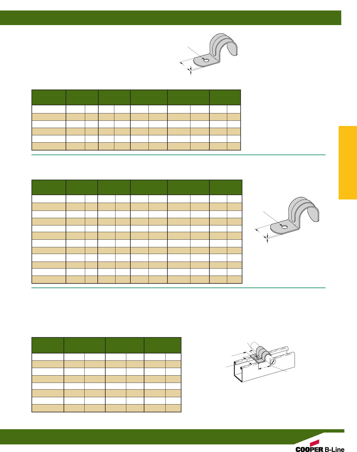
B2084 THRU B2091
ONE HOLE O.D. TUBING CLAMP
•Material: 14 Gauge (1.9) ASTM A1011 33,000 PSI min. yield
•Standard finish: ZN
B2301 SERIES
ONE HOLE EMT STRAP
•Standard finish: ZN
B2302 SERIES
ONE HOLE RIGID CONDUIT/PIPE STRAP
•Standard finish: ZN
Part Conduit Hole Wt./C
No. Size T W Dia. Lbs. kg
B2301-1/21/2”(15) .050 (1.3) 3/4”(19.0) 9/32”(7.1) 2.4 (1.1)
B2301-3/43/4”(20) .050 (1.3) 7/8”(22.2) 9/32”(7.1) 4.2 (1.9)
B2301-1 1” (25) .050 (1.3) 1” (25.4) 9/32”(7.1) 8.3 (3.7)
B2301-11/411/4”(32) .065 (1.6) 11/4”(31.7) 9/32”(7.1) 11.0 (5.0)
B2301-11/211/2”(40) .090 (2.3) 1” (25.4) 11/32”(8.7) 14.8 (6.7)
B2301-2 2” (50) .090 (2.3) 11/4”(31.7) 13/32”(10.3) 21.6 (9.8)
Part Conduit/Pipe Hole Wt./C
No. Size T W Dia. Lbs. kg
B2302-1/41/4”(6) .045 (1.1) 5/8”(15.9) 13/64”(5.1) 1.4 (.6)
B2302-3/83/8”(10) .050 (1.3) 3/4”(19.0) 9/32”(7.1) 2.4 (1.1)
B2302-1/21/2”(15) .050 (1.3) 7/8”(22.2) 9/32”(7.1) 3.3 (1.5)
B2302-3/43/4”(20) .050 (1.3) 7/8”(22.2) 9/32”(7.1) 3.8 (1.7)
B2302-1 1” (25) .065 (1.6) 1” (25.4) 9/32”(7.1) 7.2 (3.2)
B2302-11/411/4”(32) .065 (1.6) 11/4”(31.7) 21/64”(8.3) 11.0 (5.0)
B2302-11/211/2”(40) 11 Ga. (3.0) 1” (25.4) .380 (9.6) 19.2 (8.7)
B2302-2 2” (50) 11 Ga. (3.0) 11/4”(31.7) .389 (9.9) 28.8 (13.0)
B2302-21/221/2”(65) 7 Ga. (4.5) 11/4”(31.7) .665 (16.9) 55.2 (25.0)
B2302-3 3” (80) 7 Ga. (4.5) 11/4”(31.7) .650 (16.5) 68.0 (30.8)
B2302-31/231/2”(90) 1/4” (6.3) 11/4”(31.7) .622 (15.8) 96.0 (43.5)
B2302-4 4” (100) 1/4” (6.3) 11/4”(31.7) .630 (16.0) 108.0 (49.0)
Wt./C
Part No. O.D. Size A Lbs. kg
B2084 1/4”(6.3) 7/8”(22.2) 4.0 (1.8)
B2085 5/16”(7.9) 29/32”(23.0) 4.2 (1.9)
B2086 3/8”(9.5) 31/32”(24.6) 5.2 (2.3)
B2087 1/2”(12.7) 11/16”(25.9) 5.8 (2.6)
B2088 5/8”(15.9) 13/32”(27.8) 7.1 (3.2)
B2089 3/4”(19.0) 15/32”(29.1) 7.7 (3.5)
B2090 7/8”(22.2) 17/32”(30.7) 8.7 (3.9)
B2091 1” (25.4) 19/32”(32.2) 10.0 (4.5)
HOLE DIA.
T
W
HOLE DIA.
O.D.
SIZE
T
A
W
15/8”
(41.3)
3/8”
(9.5)
9/32” (7.1)
DIA.
Pipe/Conduit Clamps & Hangers
Reference page 110 for general fitting and standard finish specifications.
Pipe Clamps
125
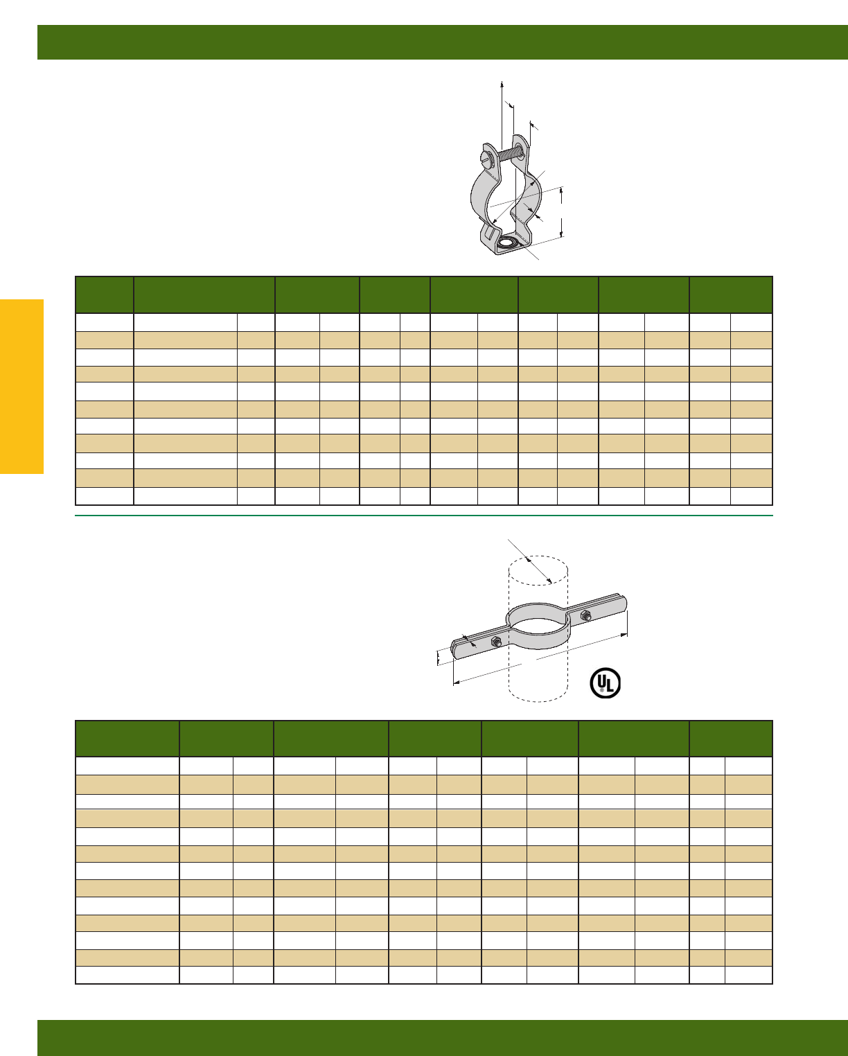
B3373 SERIES
RISER CLAMP
•Safety Factor of 4
•B3373-3/4thru B3373-8 are UL listed
•Includes Hex Head Cap Screws and Hex Nuts
•Standard finishes: ZN, PLN
BL1400 SERIES
CONDUIT HANGER
•Safety Factor of 3
•Unless noted all sizes fit both rigid (R) and thinwall (EMT) conduit
•Hardware included
•Standard finishes: ZN, SS4
Conduit Design Load Wt./C
Part No Size A B T W Lbs. kN Lbs. kg
BL1400 1/2”(15) 29/32”(23.0) 9/32”(7.1) 16 Ga. (1.5) 3/4”(19.0) 590 (2.62) 6(2.7)
BL1410 3/4”(20) 31/32”(24.6) 9/32”(7.1) 16 Ga. (1.5) 3/4”(19.0) 590 (2.62) 7(3.2)
BL1420 1” (25) 11/4”(31.7) 9/32”(7.1) 16 Ga. (1.5) 3/4”(19.0) 590 (2.62) 8(3.6)
BL1425 11/4” EMT (32) 11/4”(31.7) 9/32”(7.1) 18 Ga. (1.2) 7/8”(22.2) 590 (2.62) 10 (4.5)
BL1430 11/4” R,11/2” EMT (32) 113/32”(35.7) 9/32”(8.7) 18 Ga. (1.2) 7/8”(22.2) 590 (2.62) 10 (4.5)
BL1440 11/2” R (40) 15/8”(41.3) 11/32”(8.7) 16 Ga. (1.5) 1” (25.4) 755 (3.36) 17 (7.7)
BL1450 2” (50) 21/16”(47.6) 11/32”(8.7) 16 Ga. (1.5) 11/4”(31.7) 755 (3.36) 25 (11.3)
BL1460 21/2”(65) 21/16”(52.4) 11/32”(8.7) 16 Ga. (1.5) 11/4”(31.7) 755 (3.36) 26 (11.8)
BL1470 3” (80) 21/2”(63.5) 11/32”(8.7) 16 Ga. (1.5) 11/4”(31.7) 820 (3.65) 33 (14.9)
BL1480 31/2”(90) 23/4”(69.8) 11/32”(8.7) 16 Ga. (1.5) 11/4”(31.7) 850 (3.78) 36 (16.3)
BL1490 4” (100) 31/2”(88.9) 11/32”(8.7) 16 Ga. (1.5) 11/4”(31.7) 1410 (6.27) 40 (18.1)
Pipe Design Load Wt./C
Part No. Size A T W Lbs. kN Lbs. kg
B3373-1/21/2”(15) 9” (228.6) 3/16”(4.7) 1” (25.4) 255 (1.13) 103 (46.3)
B3373-3/43/4”(20) 91/4”(234.9) 3/16”(4.7) 1” (25.4) 255 (1.13) 106 (47.7)
B3373-1 1” (25) 99/16”(242.9) 3/16”(4.7) 1” (25.4) 255 (1.13) 111 (49.9)
B3373-11/411/4”(32) 10” (254.0) 3/16”(4.7) 1” (25.4) 255 (1.13) 114 (51.3)
B3373-11/211/2”(32) 101/4”(260.3) 3/16”(4.7) 1” (25.4) 255 (1.13) 120 (54.0)
B3373-2 2” (40) 103/4”(273.0) 1/4”(6.3) 1” (25.4) 255 (1.13) 167 (75.1)
B3373-21/221/2”(50) 111/4”(285.7) 1/4”(6.3) 1” (25.4) 390 (1.73) 177 (79.6)
B3373-3 3” (65) 1115/16”(303.2) 1/4”(6.3) 1” (25.4) 530 (2.36) 191 (85.9)
B3373-31/231/2”(80) 123/8”(314.3) 1/4”(6.3) 1” (25.4) 670 (2.98) 216 (97.2)
B3373-4 4” (90) 127/8”(327.0) 1/4”(6.3) 1” (25.4) 810 (3.60) 227 (102.1)
B3373-5 5” (100) 14” (355.6) 1/4”(6.3) 11/2”(38.1) 1160 (5.16) 471 (213.6)
B3373-6 6” (100) 153/16”(385.8) 1/4”(6.3) 11/2”(38.1) 1570 (6.98) 518 (234.9)
B3373-8 8” (100) 173/4”(450.8) 3/8”(9.5) 11/2”(38.1) 2500 (11.12) 950 (430.9)
CONDUIT SIZE
Design Load
HOLE SIZE B
A
W
T
PIPE SIZE
A
T
W
Pipe/Conduit Clamps & Hangers
Reference page 110 for general fitting and standard finish specifications.
Pipe Clamps
126
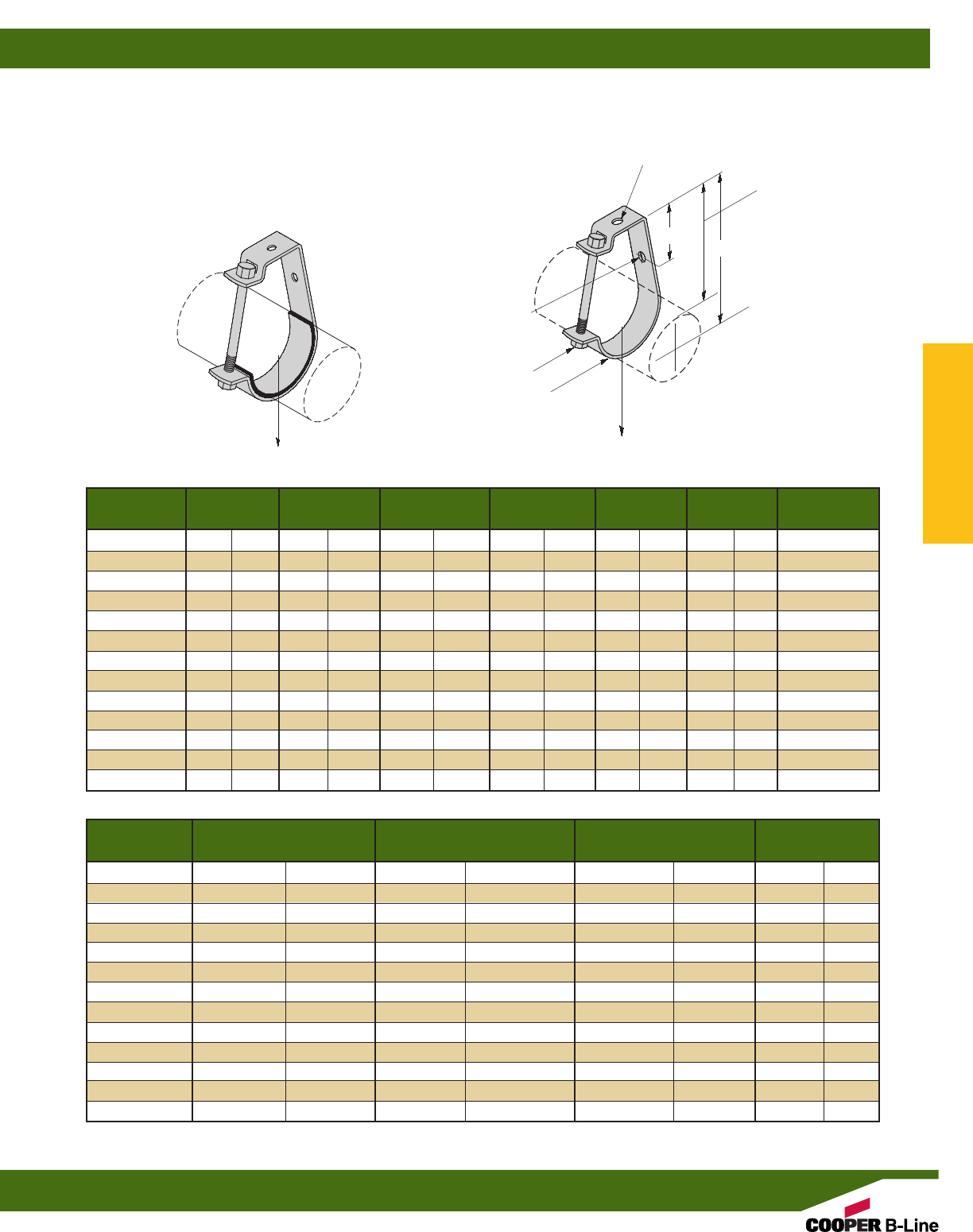
B3690 SERIES
ADJUSTABLE J HANGER
•Safety Factor of 5
•Material:
12 Ga. (2.6) ASTM A1011 33,000 PSI min. yield
11 Ga. (3.0) ASTM A1011 HSLA Gr. 50 Class 1
7 Ga. (4.5) ASTM A1011 33,000 PSI min. yield and
1/4” (6.3) ASTM A1018 33,000 PSI min. yield
•Standard finish: ZN
Pipe or
Part No. Conduit Size A B C D E F
B3690-1/21/2”(15) 13/32”(10.3) 23/32”(53.2) 1” (25.4) 111/16”(42.5) 13/32”(10.3) 1/4”-20 x 21/4”
B3690-3/43/4”(20) 13/32”(10.3) 211/32”(59.5) 1” (25.4) 113/16”(46.2) 13/32”(10.3) 1/4”-20 x 21/2”
B3690-1 1” (25) 13/32”(10.3) 219/32”(65.9) 1” (25.4) 115/16”(49.2) 13/32”(10.3) 1/4”-20 x 23/4”
B3690-11/411/4”(32) 13/32”(10.3) 213/16”(71.4) 1” (25.4) 2” (50.4) 13/32”(10.3) 1/4”-20 x 3”
B3690-11/211/2”(40) 13/32”(10.3) 31/16”(77.8) 1” (25.4) 21/8”(53.7) 13/32”(10.3) 1/4”-20 x 31/4”
B3690-2 2” (50) 13/32”(10.3) 31/2”(88.9) 1” (25.4) 25/16”(58.7) 13/32”(10.3) 1/4”-20 x 31/2”
B3690-21/221/2”(65) 9/16”(14.3) 47/16”(112.7) 1” (25.4) 3” (76.2) 9/16”(14.3) 3/8”-16 x 41/2”
B3690-3 3” (80) 9/16”(14.3) 47/8”(123.8) 1” (25.4) 31/8”(79.4) 9/16”(14.3) 3/8”-16 x 5”
B3690-31/231/2”(90) 9/16”(14.3) 53/16”(131.8) 1” (25.4) 33/16”(81.0) 9/16”(14.3) 3/8”-16 x 51/2”
B3690-4 4” (100) 11/16”(17.5) 61/8”(155.6) 11/4”(31.8) 37/8”(98.4) 9/16”(14.3) 3/8”-16 x 61/2”
B3690-5 5” (125) 11/16”(17.5) 63/4”(171.4) 11/2”(38.1) 4” (100.8) 9/16”(14.3) 3/8”-16 x 71/2”
B3690-6 6” (150) 13/16”(20.6) 73/4”(196.8) 13/16”(30.2) 47/16”(112.7) 9/16”(14.3) 3/8”-16 x 81/2”
B3690-8 8” (200) 13/16”(20.6) 91/4”(235.0) 1” (25.4) 415/16”(125.4) 9/16”(14.3) 3/8”-16 x 101/2”
Design Load Wt./C
Part No. T W Lbs. kN Lbs. kg
B3690-1/212 Ga. (2.6) 3/4”(19.0) 400 (1.78) 20 (9.1)
B3690-3/412 Ga. (2.6) 3/4”(19.0) 400 (1.78) 23 (10.4)
B3690-1 12 Ga. (2.6) 3/4”(19.0) 400 (1.78) 24 (10.9)
B3690-11/412 Ga. (2.6) 3/4”(19.0) 400 (1.78) 27 (12.2)
B3690-11/212 Ga. (2.6) 3/4”(19.0) 400 (1.78) 29 (13.1)
B3690-2 12 Ga. (2.6) 3/4”(19.0) 400 (1.78) 32 (14.5)
B3690-21/211 Ga. (3.0) 11/4”(31.7) 800 (3.56) 71 (32.2)
B3690-3 11 Ga. (3.0) 11/4”(31.7) 800 (3.56) 77 (34.9)
B3690-31/211 Ga. (3.0) 11/4”(31.7) 800 (3.56) 84 (38.1)
B3690-4 7 Ga. (4.5) 11/4”(31.7) 800 (3.56) 139 (63.0)
B3690-5 7 Ga. (4.5) 11/4”(31.7) 800 (3.56) 166 (75.3)
B3690-6 1/4”(6.3) 11/4”(31.7) 1000 (4.45) 226 (102.5)
B3690-8 1/4”(6.3) 11/2”(38.1) 1200 (5.34) 332 (150.6)
FELT LINE
B3690F-SIZE
B
C
‘D’ ROD TAKE-OUT
BOLT SIZE ‘F’ AND
HEX NUT INCLUDED
Tx W
‘E’ DIAMETER. IS
FOR WALL MOUNTING
A
DIA.
Design Load Design Load
Pipe/Conduit Clamps & Hangers
Reference page 110 for general fitting and standard finish specifications.
Pipe Hangers
127
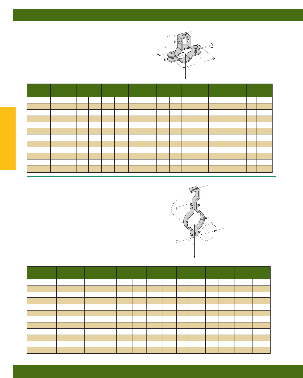
B394 SERIES
PIPE STRAP
•Safety Factor of 3
•Includes:
1 Pair Pipe Clamps with Hex Head Cap Screws and Hex Nuts
1 Hanger Strap
•Standard finishes: ZN
B386 SERIES
SUSPENSION ROD PIPE STRAP
•Safety Factor of 3
•Includes Hex Head Cap Screws and Hex Nuts
•Standard finishes: ZN, GRN
Design Load Wt./C
Part No. Pipe Size A B C T W Lbs. kN Lbs. kg
B386-3/43/4”(20) 7/16”(11.1) 35/16”(84.1) 23/16”(55.6) 1/8”(3.2) 1” (25.4) 730 (3.25) 46 (20.8)
B386-1 1” (25) 7/16”(11.1) 33/4”(95.2) 25/16”(58.7) 1/8”(3.2) 1” (25.4) 730 (3.25) 51 (23.1)
B386-11/411/4”(32) 7/16”(11.1) 4” (101.6) 217/32”(64.3) 1/8”(3.2) 1” (25.4) 730 (3.25) 52 (23.6)
B386-11/211/2”(40) 7/16”(11.1) 45/16”(109.5) 211/16”(68.3) 1/8”(3.2) 1” (25.4) 730 (3.25) 54 (24.5)
B386-2 2” (50) 7/16”(11.1) 51/2”(139.7) 35/16”(84.1) 1/4”(6.3) 1” (25.4) 730 (3.25) 134 (60.8)
B386-21/221/2”(65) 9/16”(14.3) 63/8”(161.9) 31/2”(88.9) 1/4”(6.3) 1” (25.4) 1350 (6.00) 157 (71.2)
B386-3 3” (80) 9/16”(14.3) 7” (177.8) 37/8”(98.4) 1/4”(6.3) 1” (25.4) 1350 (6.00) 168 (76.2)
B386-31/231/2”(90) 9/16”(14.3) 79/16”(192.1) 41/8”(104.8) 1/4”(6.3) 1” (25.4) 1350 (6.00) 197 (89.3)
B386-4 4” (100) 9/16”(14.3) 85/8”(219.1) 43/8”(111.1) 1/4”(6.3) 11/4”(31.7) 1350 (6.00) 270 (122.4)
B386-5 5” (125) 11/16”(17.4) 93/4”(247.6) 53/16”(131.8) 1/4”(6.3) 11/4”(31.7) 2160 (9.61) 308 (139.7)
B386-6 6” (150) 11/16”(17.4) 115/8”(295.3) 61/16”(154.0) 3/8”(9.5) 11/2”(38.1) 2160 (9.61) 609 (276.4)
B386-8 8” (200) 13/16”(20.6) 137/8”(352.4) 71/8”(181.0) 3/8”(9.5) 11/2”(38.1) 3230 (14.37) 713 (323.4)
Design Load Wt./C
Part No. Pipe Size A B T W Lbs. kN Lbs. kg
B394-3/43/4”(20) 35/16”(84.1) 7/16”(11.1) 1/8”(3.2) 1” (25.4) 500 (2.22) 71 (32.2)
B394-1 1” (25) 33/4”(95.2) 7/16”(11.1) 1/8”(3.2) 1” (25.4) 500 (2.22) 76 (34.5)
B394-11/411/4”(32) 4” (101.6) 7/16”(11.1) 1/8”(3.2) 1” (25.4) 500 (2.22) 77 (34.9)
B394-11/211/2”(40) 45/16”(109.5) 7/16”(11.1) 1/8”(3.2) 1” (25.4) 800 (3.56) 79 (35.8)
B394-2 2” (50) 51/2”(139.7) 7/16”(11.1) 1/4”(6.3) 1” (25.4) 1040 (4.62) 166 (75.3)
B394-21/221/2”(65) 63/8”(161.9) 9/16”(14.3) 1/4”(6.3) 1” (25.4) 1040 (4.62) 179 (81.2)
B394-3 3” (80) 7” (177.8) 9/16”(14.3) 1/4”(6.3) 1” (25.4) 1040 (4.62) 190 (86.2)
B394-31/231/2”(90) 79/16”(192.1) 9/16”(14.3) 1/4”(6.3) 1” (25.4) 1040 (4.62) 203 (92.1)
B394-4 4” (100) 85/8”(219.1) 11/16”(17.4) 1/4”(6.3) 11/4”(31.7) 1040 (4.62) 320 (145.1)
B394-5 5” (125) 93/4”(247.6) 11/16”(17.4) 1/4”(6.3) 11/4”(31.7) 1040 (4.62) 353 (160.1)
B394-6 6” (150) 115/8”(295.3) 13/16”(20.6) 3/8”(9.5) 11/2”(38.1) 1615 (7.18) 637 (288.9)
B394-8 8” (200) 137/8”(352.4) 13/16”(20.6) 3/8”(9.5) 11/2”(38.1) 1615 (7.18) 837 (379.6)
A DIA.
B
W
C
T
A
W
CLAMP
ONLY
T
CLAMP
ONLY
B DIA.
PIPE SIZE
Design Load
Design Load
Pipe/Conduit Clamps & Hangers
Reference page 110 for general fitting and standard finish specifications.
Pipe Hangers
128
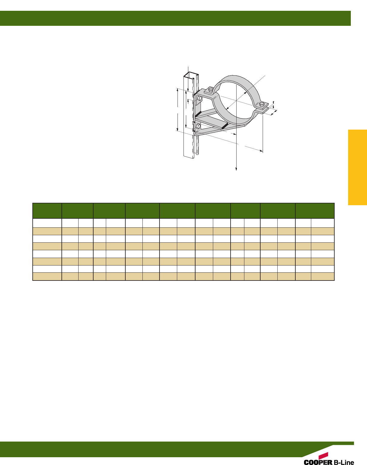
Design Load Wt./C
Part No. Pipe Size A B C D W Lbs. kN Lbs. kg
B591-2 2” (50) 41/2”(114.3) 41/2”(114.3) 73/16”(182.6) 31/16”(77.8) 15/8”(41.3) 1235 (5.53) 290 (131.5)
B591-21/221/2”(65) 5” (127.0) 5” (127.0) 715/16”(201.6) 39/16”(90.5) 15/8”(41.3) 1180 (5.29) 330 (149.7)
B591-3 3” (80) 51/2”(139.7) 53/4”(146.0) 83/4”(222.2) 313/16”(96.8) 15/8”(41.3) 1125 (5.04) 439 (199.1)
B591-31/231/2”(90) 6” (152.4) 63/4”(171.4) 91/2”(241.3) 49/16”(115.9) 15/8”(41.3) 1070 (4.79) 490 (222.2)
B591-4 4” (100) 61/2”(165.1) 63/4”(171.4) 101/4”(260.3) 61/16”(128.6) 15/8”(41.3) 1015 (4.55) 545 (247.2)
B591-5 5” (125) 71/2”(190.5) 8” (203.2) 121/8”(308.0) 61/16”(154.0) 15/8”(41.3) 960 (4.30) 666 (302.1)
B591-6 6” (150) 8” (203.2) 83/4”(222.2) 133/16”(335.0) 613/16”(173.0) 15/8”(41.3) 905 (4.05) 724 (328.4)
B591-8 8” (200) 9” (228.6) 101/2”(266.7) 159/16”(395.3) 89/16”(217.5) 2” (50.8) 850 (3.81) 1087 (493.0)
B591 SERIES
PIPE BRACKET SADDLE AND CLAMP
•Safety Factor of 3
•Inside brace not required on B591-2 and B591-21/2
•Includes:
1 pc. Saddle bottom
1 pc. Saddle top (clamp)
2 pcs. Hex Head Cap Screws
2 pcs. Hex Nuts
•Standard finish: ZN
A
C
BD
W
113/16”
(30.1)
1/4”
(6.3)
PIPE SIZE
Design Load
Pipe/Conduit Clamps & Hangers
Reference page 110 for general fitting and standard finish specifications.
Pipe Brackets
129
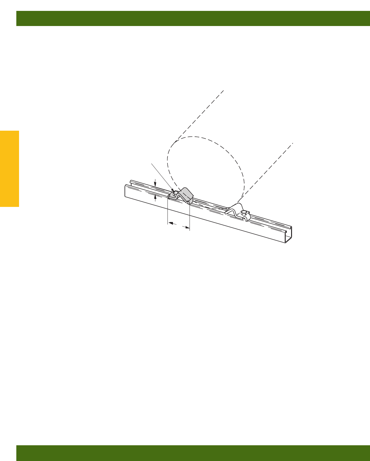
B356
PIPE BLOCK-2” (50) TO 8” (200) PIPE
•Required hardware not included:
1 pc. 3/8”-16 x 1” Hex Head Cap Screw
1 pc. 3/8”-16 Channel Nut
•Material: 1/4” (6.3) thick 15/8” (41.3) wide
ASTM A1018 33,000 PSI min. yield
•Standard finish: ZN
•Wt./C 42 Lbs. (19.0 kg) Per Pair
31/16”
(77.8)
1”
(25.4)
HOLE FOR 3/8”-16 HHCS
Pipe/Conduit Clamps & Hangers
Reference page 110 for general fitting and standard finish specifications.
Pipe Block
130
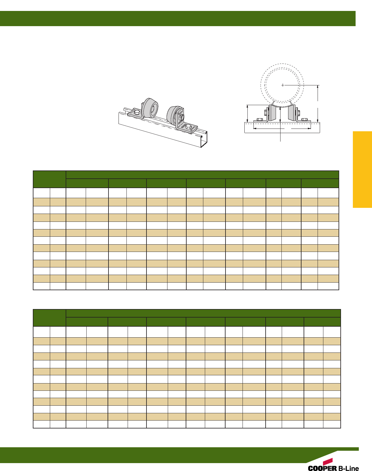
B218
PIPE ROLLERS-1/2” (15) TO 8” (200) PIPE
•Design Load 500 Lbs. (2.22 kN)
•Safety Factor of 5
•When used with B3160 thru B3165 Saddles
(See Pipe Hanger Catalog)
•Malleable Iron Rollers
•Sold in pairs
•Required hardware not included:
2 pcs. 1/2”-13 x 11/4” Hex Head Cap Screws
2 pcs. 1/2”-13 Channel Nuts
•Standard finish: ZN
•Wt./C 256 Lbs. (116.1 kg) Per Pair
Insulation Thickness
Pipe Size 0” (0.0) 1” (25.4) 11/2” (38.1) 2” (50.8) 21/2” (63.5) 3” (76.2) 4” (101.6)
1/2”(15) 71/4”(184.1) –– ––– – – – –– ––
3/4”(20) 71/4”(184.1) 71/4”(184.1) 75/8”(193.7) 8” (203.2) ––––––
1” (25) 71/4”(184.1) 71/4”(184.1) 75/8”(193.7) 81/4”(209.5) ––––––
11/4”(32) 71/4”(184.1) 71/4”(184.1) 8” (203.2) 81/4”(209.5) ––––––
11/2”(40) 71/4”(184.1) 75/8”(193.7) 8” (203.2) 81/2”(215.9) 9” (228.6) –– ––
2” (50) 71/4”(184.1) 75/8”(193.7) 81/2”(215.9) 81/2”(215.9) 9” (228.6) –– ––
21/2”(65) 71/4”(184.1) 8” (203.2) 81/2”(215.9) 9” (228.6) 10” (254.0) –– ––
3” (80) 71/4”(184.1) 81/2”(215.9) 9” (228.6) 9” (228.6) 10” (254.0) 10” (254.0) ––
31/2”(90) 71/4”(184.1) 81/2”(215.9) 9” (228.6) 10” (254.0) 10” (254.0) 10” (254.0) ––
4” (100) 75/8”(193.7) 9” (228.6) 9” (228.6) 10” (254.0) 10” (254.0) 11” (279.4) ––
5” (125) 81/2”(215.9) 9” (228.6) 10” (254.0) 10” (254.0) 11” (279.4) 11” (279.4) 12” (304.8)
6” (150) 9” (228.6) 10” (254.0) 10” (254.0) 11” (279.4) 11” (279.4) 11” (279.4) 12” (304.8)
8” (200) 10” (254.0) 11” (279.4) 11” (279.4) 11” (279.4) 12” (304.8) –– ––
Insulation Thickness
Pipe Size 0” (0.0) 1” (25.4) 11/2” (38.1) 2” (50.8) 21/2” (63.5) 3” (76.2) 4” (101.6)
1/2”(15) 211/16”(68.3) ––––––– ––– ––
3/4”(20) 213/16”(71.4) 37/8”(98.4) 43/8”(111.1) 47/8”(123.8) ––––––
1” (25) 215/16”(74.6) 43/16”(106.4) 411/16”(119.1) 51/16”(128.6) ––––––
11/4”(32) 31/8”(79.4) 43/16”(106.4) 45/8”(117.5) 51/8”(130.2) ––––––
11/2”(40) 31/4”(82.5) 43/8”(111.1) 47/8”(123.8) 55/16”(134.9) 53/4”(146.0) –– ––
2” (50) 39/16”(90.5) 411/16”(119.1) 51/16”(128.6) 55/8”(142.9) 61/16”(154.0) –– ––
21/2”(65) 313/16”(96.8) 47/8”(123.8) 55/16”(134.9) 6” (152.4) 63/8”(161.9) –– ––
3” (80) 41/8”(104.8) 51/16”(128.6) 59/16”(141.3) 61/8”(155.6) 67/16”(163.5) 7” (177.8) ––
31/2”(90) 43/8”(111.1) 55/16”(134.9) 513/16”(147.6) 61/4”(158.7) 611/16”(169.9) 71/4”(184.1) ––
4” (100) 45/8”(117.5) 59/16”(141.3) 61/16”(154.0) 67/16”(163.5) 615/16”(176.2) 73/8”(187.3) ––
5” (125) 5” (127.0) 61/16”(154.0) 67/16”(163.5) 7” (177.8) 73/8”(187.3) 77/8”(200.0) 813/16”(223.8)
6” (150) 51/2”(139.7) 67/16”(163.5) 615/16”(176.2) 73/8”(187.3) 715/16”(201.6) 81/2”(215.9) 91/2”(241.3)
8” (200) 615/16”(160.3) 73/8”(187.3) 715/16”(201.6) 87/16”(214.3) 815/16”(227.0) –– ––
B
A
25/8”
(66.7)
23/8”
(60.3)
REFERENCE CHART - A DIMENSION
REFERENCE CHART - B DIMENSION
Pipe/Conduit Clamps & Hangers
Reference page 110 for general fitting and standard finish specifications.
Pipe Rollers
131
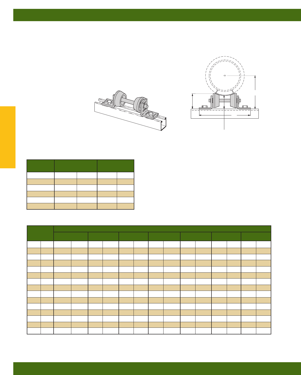
B219
PIPE ROLLER SERIES - 3/4” (20) TO 12” (300) PIPE
•Design Load 750 Lbs. (3.33 kN)
•Safety Factor of 5
•Requires field assembly
•When used with B3160 thru B3165 Saddles
(See Pipe Hanger Catalog)
•Malleable Iron Rollers
•Sold in pairs
•Required hardware not included:
2 pcs. 1/2”-13 x 11/4” Hex Head Cap Screws
2 pcs. 1/2”-13 Channel Nuts
•Reference sizing chart on page 133
•Standard finish: ZN
Wt./C PR
Part No. A Lbs. kg
B219 71/4”(184.1) 253 (114.7)
B219-1 8” (203.2) 258 (117.0)
B219-2 9” (228.6) 263 (119.3)
B219-3 10” (254.0) 269 (122.0)
B219-4 107/8”(276.2) 274 (124.8)
B219-5 115/8”(295.3) 279 (126.5)
Insulation Thickness
Pipe Size 0” (0.0) 1” (25.4) 11/2” (38.1) 2” (50.8) 21/2” (63.5) 3” (76.2) 4” (101.6)
1/2”(15) 211/16”(68.3) ––––– – – –––––
3/4”(20) 213/16”(71.4) 37/8”(98.4) 41/2”(114.3) 47/8”(123.8) ––––––
1” (25) 215/16”(74.6) 43/16”(106.4) 45/8”(117.5) 51/16”(128.6) ––––––
11/4”(32) 31/8”(79.4) 43/16”(106.4) 45/8”(117.5) 51/8”(130.2) ––––––
11/2”(40) 31/4”(82.5) 47/16”(112.7) 47/8”(123.8) 51/4”(133.3) 53/4”(146.0) ––––
2” (50) 39/16”(90.5) 45/8”(117.5) 53/16”(131.8) 51/2”(139.7) 61/16”(154.0) ––––
21/2”(65) 33/4”(95.2) 47/8”(123.8) 51/4”(133.3) 6” (152.4) 63/8”(161.9) ––––
3” (80) 41/8”(104.8) 51/8”(130.2) 59/16”(141.3) 61/16”(154.0) 67/16”(163.5) 615/16”(176.2) ––
31/2”(90) 41/4”(107.9) 51/4”(133.3) 513/16”(147.6) 61/4”(158.7) 611/16”(169.9) 71/16”(179.4) ––
4” (100) 49/16”(115.9) 51/2”(139.7) 61/16”(154.0) 67/16”(163.5) 615/16”(176.2) 73/8”(187.3) ––
5” (125) 51/16”(128.6) 61/16”(154.0) 67/16”(163.5) 7” (177.8) 73/8”(187.3) 77/8”(200.0) 815/16”(227.0)
6” (150) 57/16”(138.1) 67/16”(163.5) 615/16”(176.2) 73/8”(187.3) 77/8”(200.0) 815/16”(211.1) 99/16”(242.9)
8” (200) 63/8”(161.9) 77/16”(188.9) 715/16”(201.6) 83/8”(212.7) 9” (228.6) ––––
10” (250) 75/16”(185.7) 83/16”(208.0) ––– – – –––––
12” (300) 81/4”(209.5) ––––– – – –––––
B
A
25/8”
(66.7)
23/8”
(60.3)
REFERENCE CHART - A DIMENSION
REFERENCE CHART - B DIMENSION
Reference B219 sizing chart on page 133
Pipe/Conduit Clamps & Hangers
Reference page 110 for general fitting and standard finish specifications.
Pipe Rollers
132
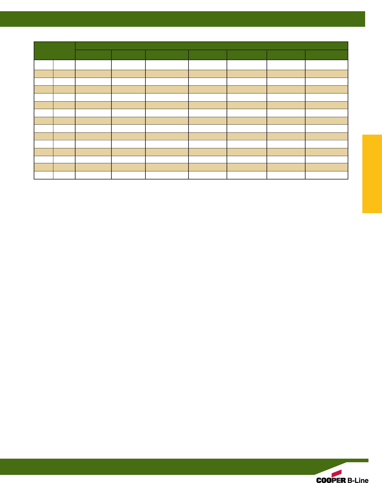
Insulation Thickness
Pipe Size 0” (0.0) 1” (25.4) 11/2” (38.1) 2” (50.8) 21/2” (63.5) 3” (76.2) 4” (101.6)
1/2” (15) B219 – – – – – –
3/4” (20) B219 B219 B219 B219-1 – – –
1” (25) B219 B219 B219-1 B219-1 – – –
11/4” (32) B219 B219 B219-1 B219-1 – – –
11/2” (40) B219 B219 B219-1 B219-2 B219-2 – –
2” (50) B219 B219-1 B219-1 B219-2 B219-2 – –
21/2” (65) B219 B219-1 B219-2 B219-2 B219-3 – –
3” (80) B219 B219-1 B219-2 B219-2 B219-3 B219-3 –
31/2” (90) B219-1 B219-2 B219-2 B219-3 B219-3 B219-4 –
4” (100) B219-1 B219-2 B219-2 B219-3 B219-3 B219-4 –
5” (125) B219-1 B219-2 B219-3 B219-3 B219-4 B219-4 B219-5
6” (150) B219-2 B219-3 B219-3 B219-4 B219-4 B219-5 B219-5
8” (200) B219-3 B219-4 B219-4 B219-5 B219-5 – –
10” (250) B219-4 B219-5 – – – – –
12” (300) B219-5 – – – – – –
B219 SIZING CHART
Pipe/Conduit Clamps & Hangers
Reference page 110 for general fitting and standard finish specifications.
Pipe Rollers
133
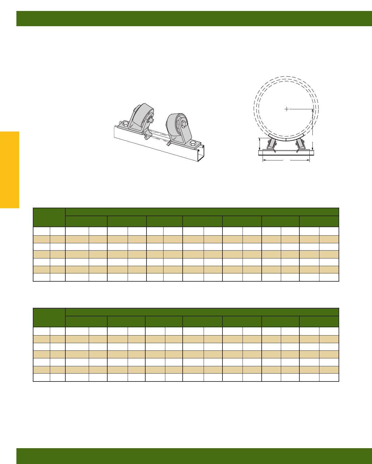
B379
PIPE ROLLERS-6” (150) TO 18” (450) PIPE
•Design Load 1500 Lbs. (6.67 kN)
•Safety Factor of 5
•Requires field assembly
•When used with B3160 thru B3165 Saddles
(See Pipe Hanger Catalog)
•Malleable Iron Rollers
•Sold in pairs
•Required hardware not included:
2 pcs. 1/2”-13 x 11/4” Hex Head Cap Screws
2 pcs. 1/2”-13 Channel Nuts
•Standard finish: ZN
•Wt./C 889 Lbs. (403.2 kg)
B
A
4”
(101.6)
Insulation Thickness
Pipe Size 0” (0.0) 1” (25.4) 11/2” (38.1) 2” (50.8) 21/2” (63.5) 3” (76.2) 4” (101.6)
6” (150) 99/16”(242.9) 103/16”(258.8) 105/8”(269.9) 11” (279.4) 113/8”(288.9) 113/4”(298.4) 121/2”(317.5)
8” (200) 101/4”(260.3) 111/16”(281.0) 113/8”(288.9) 113/4”(298.4) 123/16”(309.6) 121/2”(317.5) 131/4”(336.5)
10” (250) 11” (279.4) 113/4”(298.4) 121/8”(308.0) 121/2”(317.5) 1213/16”(325.4) 131/8”(333.4) 137/8”(352.4)
12” (300) 1111/16”(296.9) 129/16”(319.1) 127/8”(327.0) 131/4”(336.5) 139/16”(344.5) 137/8”(352.4) 145/8”(371.5)
14” (350) 121/16”(306.4) 127/8”(327.0) 133/16”(335.0) 139/16”(344.5) 137/8”(352.4) 141/4”(361.9) 147/8”(377.8)
16” (400) 123/4”(323.8) 131/2”(342.9) 137/8”(352.4) 1413/16”(360.4) 141/2”(368.3) 147/8”(377.8) 151/2”(393.7)
18” (450) 131/2”(342.9) 141/4”(361.9) 145/8”(371.5) 15” (381.0) 155/16”(388.9) 155/8”(396.9) 165/16”(414.3)
Insulation Thickness
Pipe Size 0” (0.0) 1” (25.4) 11/2” (38.1) 2” (50.8) 21/2” (63.5) 3” (76.2) 4” (101.6)
6” (150) 67/8”(174.6) 77/8”(200.0) 83/8”(212.7) 87/8”(225.4) 93/8”(238.1) 97/8”(250.8) 1015/16”(277.8)
8” (200) 713/16”(198.4) 87/8”(225.4) 93/8”(238.1) 97/8”(250.8) 107/16”(265.1) 1015/16”(277.8) 117/8”(301.6)
10” (250) 813/16”(223.8) 97/8”(250.8) 107/16”(265.1) 1015/16”(277.8) 113/8”(228.9) 117/8”(301.6) 1213/16”(325.4)
12” (300) 93/4”(247.6) 1015/16”(277.8) 113/8”(288.9) 117/8”(301.6) 125/16”(312.7) 1213/16”(325.4) 133/4”(349.2)
14” (350) 105/16”(261.9) 113/8”(288.9) 117/8”(301.6) 125/16”(312.7) 1213/16”(325.4) 131/4”(336.5) 141/4”(361.9)
16” (400) 115/16”(287.3) 125/16”(312.7) 1213/16”(325.4) 131/4”(336.5) 133/4”(349.2) 141/4”(361.9) 151/8”(384.2)
18” (450) 121/4”(311.1) 131/4”(336.5) 133/4”(349.2) 143/16”(360.4) 1411/16”(373.1) 151/8”(384.2) 161/16”(408.0)
REFERENCE CHART - A DIMENSION
REFERENCE CHART - B DIMENSION
Pipe/Conduit Clamps & Hangers
Reference page 110 for general fitting and standard finish specifications.
Pipe Rollers
134
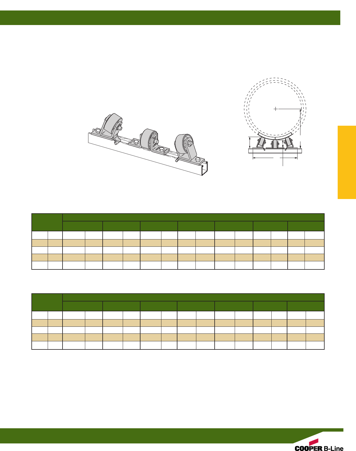
B479
PIPE ROLLERS-16” (400) TO 30” (750) PIPE
•Design Load 2000 Lbs. (8.89 kN)
•Safety Factor of 5
•Requires field assembly
•When used with B3160 thru B3165 Saddles
(See Pipe Hanger Catalog)
•Malleable Iron Rollers
•Sold in pieces
•Required hardware not included:
4 pcs. 1/2”-13 x 11/4” Hex Head Cap Screws
4 pcs. 1/2”-13 Channel Nuts
•Standard finish: ZN
•Wt./C 889 Lbs. (403.2 kg)
B
A
4”
(101.6)
Insulation Thickness
Pipe Size 0” (0.0) 1” (25.4) 11/2” (38.1) 2” (50.8) 21/2” (63.5) 3” (76.2) 4” (101.6)
16” (400) 153/16”(385.8) 155/8”(396.9) 157/8”(403.2) 16” (406.4) 161/4”(412.7) 161/2”(419.1) 17” (431.8)
18” (450) 151/2”(393.7) 16” (406.4) 163/16”(411.2) 163/8”(415.9) 169/16”(420.7) 163/4”(425.4) 173/16”(436.6)
20” (500) 16” (406.4) 163/8”(415.9) 169/16”(420.7) 167/8”(428.6) 1615/16”(430.2) 173/16”(436.6) 171/2”(444.5)
24” (600) 1613/16”(427.0) 175/16”(439.7) 171/2”(444.5) 171/2”(444.5) 1711/16”(449.3) 177/8”(454.0) 181/8”(460.4)
30” (750) 1713/16”(452.4) 181/4”(463.5) 183/8”(466.7) 189/16”(471.5) 187/8”(476.2) 187/8”(479.4) 191/4”(488.9)
Insulation Thickness
Pipe Size 0” (0.0) 1” (25.4) 11/2” (38.1) 2” (50.8) 21/2” (63.5) 3” (76.2) 4” (101.6)
16” (400) 1013/16”(274.6) 1115/16”(303.2) 123/8”(314.3) 1215/16”(328.6) 133/8”(339.7) 1315/16”(354.0) 1415/16”(379.4)
18” (450) 117/8”(301.6) 1215/16”(328.6) 137/16”(341.3) 1315/16”(354.0) 147/16”(366.7) 1415/16”(379.4) 1515/16”(404.8)
20” (500) 123/16”(325.4) 1315/16”(354.0) 147/16”(366.7) 147/8”(377.8) 157/16”(392.1) 157/8”(403.2) 1615/16”(430.2)
24” (600) 1413/16”(376.2) 157/8”(403.2) 163/8”(415.9) 167/8”(428.6) 173/8”(441.3) 177/8”(454.0) 187/8”(479.4)
30” (750) 1713/16”(452.4) 187/8”(479.4) 193/8”(492.1) 197/8”(504.8) 203/8”(517.5) 205/16”(531.8) 2115/16”(557.2)
REFERENCE CHART - A DIMENSION
REFERENCE CHART - B DIMENSION
213/16”
(71.4)
Pipe/Conduit Clamps & Hangers
Reference page 110 for general fitting and standard finish specifications.
Pipe Rollers
135
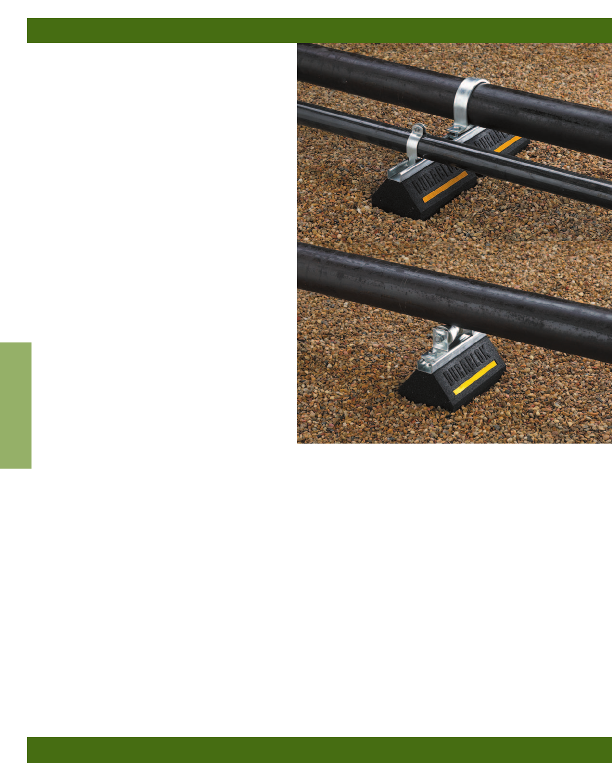
Cooper B-Line’s new line of Dura-Blok™ products
gives you a versatile and long-term solution for all
your roof top support needs. Designed with flexibility
in mind, Dura-Bloks are ideal for such roof top
support applications as pipe, HVAC, duct, conduit,
cable tray, and roof walkways.
Manufactured to provide years of service in harsh,
roof top environments, Dura-Bloks are made from
100% recycled rubber, require no supplemental
rubber pads, and will not float or blow away. 1” gaps
between blocks allow water to flow freely around
longer assemblies. For added strength, the Dura-Blok
support channel is through bolted on all sizes. For
added visibility, a reflective strip is incorporated on
both sides of each Dura-Blok.
Beyond product durability, Dura-Bloks help to
dampen vibration, are not sharp or abrasive and
require no roof penetration to maximize existing roof
life - and roof structural and environmental integrity.
Recommended Torque (In channels)
See page 44 Channel Nuts & Hardware section
Materials & Finishes
See appropriate fitting’s pages
Metric
Metric dimensions are shown in parentheses.
Unless noted, all metric dimensions are in millimeters.
Dura-Blok™Supports
Dura-Blok™ Rooftop Supports
136
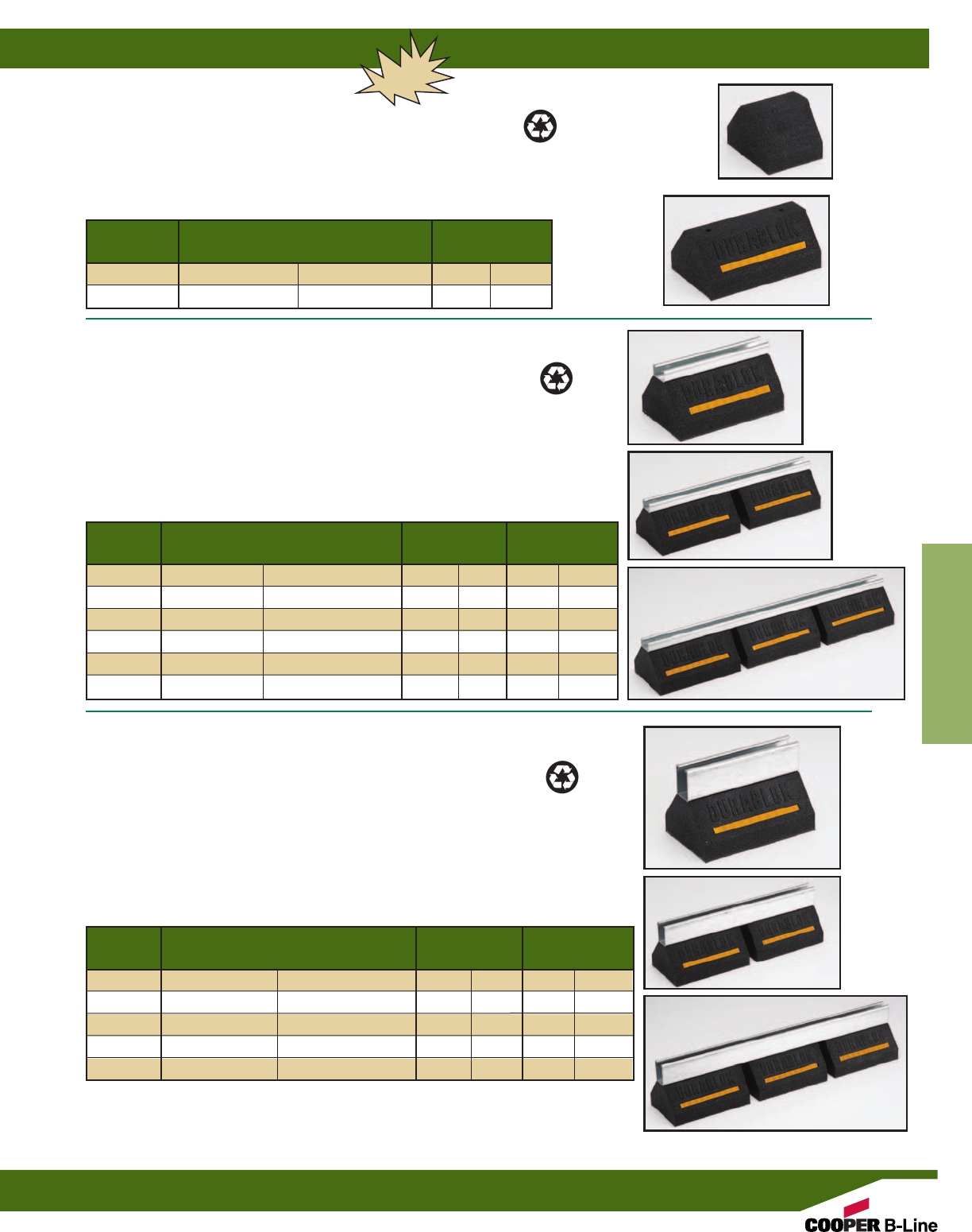
Reference page 136 for general fitting and standard finish specifications.
Dura-Blok™ Rooftop Supports
137
Dura-Blok™Supports
SUPPORT BASES ONLY
• Base only - see chart for height, width and length.
• 100% recycled rubber, UV resistant.
• Load Rating” 500 lbs. (2.22KN) (Uniform Load)*
• Dura-Blok™ channel support is designed as an economical support for piping systems,
cable tray, HVAC equipment and many other applications. The Dura-Blok is UV
resistant and suitable for any type of roofing material or other flat surfaces. Material
effectively accepts screw fasteners for securing accessories.
* General Note: Consult roofing manufacturer or engineer for roof load capacity.
The weakest point may be the insulation board beneath the rubber membrane.
DB SERIES SUPPORT BASE WITH B44 CHANNEL
• Base with 14 ga. (1.9mm) galvanized channel 1” high (25.4mm) -
see chart for height, width and length.
• 100% recycled rubber, UV resistant.
• Load Rating - Ultimate Uniform Load (See Chart Below)*
• Dura-Blok™ DB-Series channel support is designed for superior support of piping
systems, cable tray, HVAC equipment, walkway systems and many other applications.
The Dura-Blok is UV resistant and suitable for installation on any type of roofing
material or other flat surfaces. (For pipe straps/clamps, rollers and roller supports that can
be used with these Dura-Blok supports, see page 142)
• For sloped roofs use B634 adjustable hinge fittings (see Strut Systems catalog).
Height x Width x Length Wt./Each Load Rating
Part No. In. (mm) Lbs. (kg) Lbs. (kN)
DB5 5” x 6” x 4.8” (127.0 x 152.4 x 121.9) 2.75 (125) 500 (2.22)
DB10 5” x 6” x 9.6” (127.0 x 152.4 x 243.8) 5.28 (2.39) 500 (2.22)
DB20 5” x 6” x 20.2” (127.0 x 152.4 x 513.1) 10.63 (4.82) 1000 (4.45)
DB30 5” x 6” x 30.8” (127.0 x 152.4 x 782.3) 15.99 (7.25) 1500 (6.67)
DB40 5” x 6” x 41.4” (127.0 x 152.4 x 1051.5) 21.34 (9.68) 2000 (8.89)
DB48 5” x 6” x 52.0” (127.0 x 152.4 x 1320.8) 26.70 (12.40) 2500 (11.12)
Height x Width x Length Wt./Each
Part No. In. (mm) Lbs. (kg)
DBM 4” x 6” x 4.8” (101.6 x 152.4 x 121.9) 2.35 (1.07)
DBP 4” x 6” x 9.6” (101.6 x 152.4 x 243.8) 4.48 (2.03)
Height x Width x Length Wt./Each Load Rating
Part No. In. (mm) Lbs. (kg) Lbs. (kN)
DB610 67/16” x 6” x 9.6” (163.5 x 152.4 x 243.8) 6.36 (2.88) 500 (2.22)
DB620 67/16” x 6” x 20.2” (163.5 x 152.4 x 513.1) 12.90 (5.85) 1000 (4.45)
DB630 67/16” x 6” x 30.8” (163.5 x 152.4 x 782.3) 19.45 (8.82) 1500 (6.67)
DB640 67/16” x 6” x 41.4” (163.5 x 152.4 x 1051.5) 26.00 (11.79) 2000 (8.89)
DB648 67/16” x 6” x 52.0” (163.5 x 152.4 x 1320.8) 32.55 (14.76) 2500 (11.12)
DB6 SERIES SUPPORT BASE WITH B12 CHANNEL
• Base with 12 ga. (2.6mm) galvanized channel 27/16” high (61.9mm) -
see chart for height, width and length.
• 100% recycled rubber, UV resistant.
• Load Rating - Ultimate Uniform Load (See Chart Below)*
• Dura-Blok™ DB-Series channel support is designed for superior support of piping
systems, cable tray, HVAC equipment, walkway systems and many other applications.
The Dura-Blok is UV resistant and suitable for installation on any type of roofing
material or other flat surfaces. (For pipe straps/clamps, rollers and roller supports that can
be used with these Dura-Blok supports, see page 142)
• For sloped roofs use B634 adjustable hinge fittings (see Strut Systems catalog).
DB20
DB10
DBP
DBM
DB40
DB610
DB620
DB630
NEW
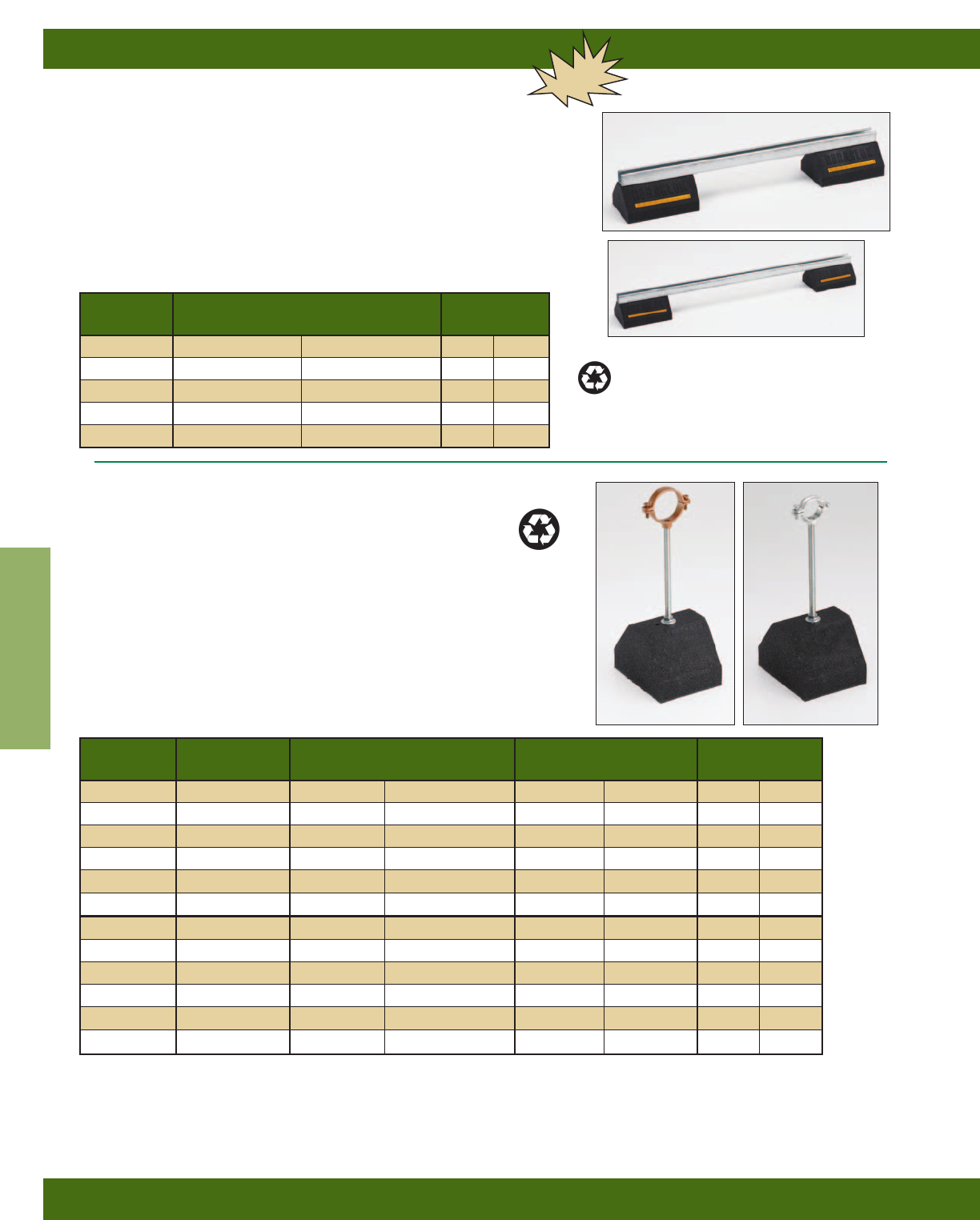
Dura-Blok™ Rooftop Supports
138
Reference page 136 for general fitting and standard finish specifications.
Dura-Blok™Supports
DB10 SERIES
SUPPORT BASES WITH B22 CHANNEL
• Two (2) bases bridged with 12 ga. (2.6mm) galvanized channel 15/8” high (41.3mm) -
see chart for height, width and length.
• 100% recycled rubber, UV resistant.
• Load Rating: 1000 lbs. (4.45kN) (Uniform Load)*
• Dura-Blok™ DB10-Series channel support is designed for superior support of
piping systems, cable tray, HVAC equipment, walkway systems and many
other applications. The Dura-Blok is UV resistant and suitable for installation
on any type of roofing material or other flat surfaces. (For pipe straps/clamps,
rollers and roller supports that can be used with these Dura-Blok supports,
see page 142)
Height x Width x Length Wt./Each
Part No. In. (mm) Lbs. (kg)
DB10-28 55/8” x 6” x 28” (142.9 x 152.4 x 711.2) 13.16 (5.97)
DB10-36 55/8” x 6” x 36” (142.9 x 152.4 x 914.4) 14.36 (6.51)
DB10-42 55/8” x 6” x 42” (142.9 x 152.4 x 1066.8) 15.52 (7.04)
DB10-50 55/8” x 6” x 50” (142.9 x 152.4 x 1270.0) 16.45 (7.46)
DB10-60 55/8” x 6” x 60” (142.9 x 152.4 x 1524.0) 17.94 (8.14)
DBM SERIES
SUPPORT BASE WITH RISER ROD & CLAMP
• Base with 3/8”-16 threaded rod and B3198H clamp -
see chart for height, width and length
• 100% recycled rubber, UV resistant.
• Load Rating” 50 lbs. (0.22kN) (Ultimate Load)*
• Dura-Blok™ DBM-Series pipe/tubing support is designed for support of single
piping systems where elevation adjustment is needed. The Dura-Blok is UV
resistant and suitable for installation on any type of roofing material or other
flat surfaces.
Clamp Block -Height x Width x Length Height** Min.-Max. Wt./Each
Part No. Part No.† In. (mm) In. (mm) Lbs. (kg)
DBM-1/2CT B3198HCT-1/24” x 6” x 4.8” (101.6 x 152.4 x 121.9) 9.69”-11.19” (246.1-284.2) 2.75 (1.25)
DBM-3/4CT B3198HCT-3/44” x 6” x 4.8” (101.6 x 152.4 x 121.9) 9.84”-11.34” (249.9-2288.0) 2.76 (1.25)
DBM-1CT B3198HCT-1 4” x 6” x 4.8” (101.6 x 152.4 x 121.9) 9.95”-11.45” (252.7-290.8) 2.84 (1.29)
DBM-11/4CT B3198HCT-11/44” x 6” x 4.8” (101.6 x 152.4 x 121.9) 10.13”-11.63” (257.3-295.4) 2.95 (1.34)
DBM-11/2CT B3198HCT-11/24” x 6” x 4.8” (101.6 x 152.4 x 121.9) 10.28”-11.78” (261.1-299.2) 2.96 (1.34)
DBM-2CT B3198HCT-2 4” x 6” x 4.8” (101.6 x 152.4 x 121.9) 10.53”-12.03” (267.4-305.5) 3.03 (1.37)
DBM-1/2B3198H-1/2 4” x 6” x 4.8” (101.6 x 152.4 x 121.9) 9.86”-11.36” (250.4-288.5) 2.78 (1.26)
DBM-3/4B3198H-3/44” x 6” x 4.8” (101.6 x 152.4 x 121.9) 10.06”-11.56” (255.5-293.6) 2.84 (1.29)
DBM-1 B3198H-1 4” x 6” x 4.8” (101.6 x 152.4 x 121.9) 10.14”-11.64” (257.5-295.6) 2.86 (1.30)
DBM-11/4B3198H-11/44” x 6” x 4.8” (101.6 x 152.4 x 121.9) 10.25”-11.75” (260.3-298.4) 2.93 (1.33)
DBM-11/2B3198H-11/24” x 6” x 4.8” (101.6 x 152.4 x 121.9) 10.42”-11.92” (264.6-302.7) 2.99 (1.36)
DBM-2 B3198H-2 4” x 6” x 4.8” (101.6 x 152.4 x 121.9) 10.66”-12.16” (270.7-308.8) 3.10 (1.41)
* General Note: Consult roofing manufacturer or engineer for roof load capacity.
The weakest point may be the insulation board beneath the rubber membrane.
NEW
DB10-36
DB10-50
DBM-2CT DBM-1
† See Pipe Hanger Catalog for dimensions and specifications. ** From bottom of rubber block to center of pipe/tubing.
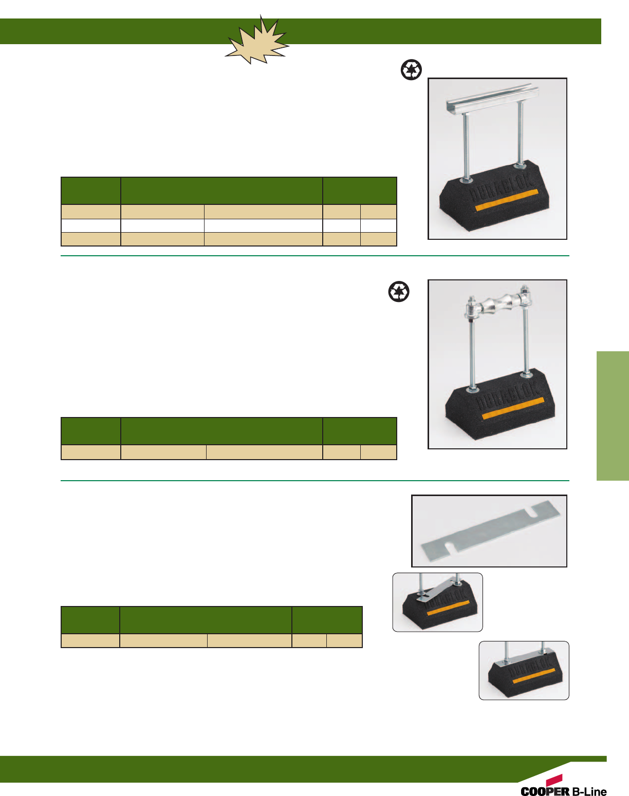
Reference page 136 for general fitting and standard finish specifications.
Dura-Blok™ Rooftop Supports
139
Dura-Blok™Supports
Loosen hex nuts and
slide plate under the
flat washers
Retighten the hex nuts
with plate in place
DBE SERIES
SUPPORT BASE WITH ROD RISERS & CHANNEL
• Base with (2) 1/2” electro zinc all threaded rod risers - Top channel is 1” (25.4mm) tall.
see chart for adjustable height x wide x length.
• 100% recycled rubber, UV resistant.
• Load Rating” 200 lbs. (0.89kN) (To increase load capacity use load distribution plate CLDP10)
• Dura-Blok™ DBE-Series channel support is designed as a superior support of piping
systems, cable tray, HVAC equipment and many other applications where elevation
adjustment is critical. The Dura-Blok is UV resistant and suitable for installation on any
type of roofing material or other flat surfaces. (For pipe straps/clamps, rollers and roller
supports that can be used with these Dura-Blok supports, see page 142)
* General Note: Consult roofing manufacturer or engineer for roof load capacity.
The weakest point may be the insulation board beneath the rubber membrane.
DBR SERIES
SUPPORT BASE WITH ROD RISERS & PIPE ROLL
• Base with (2) 1/2” electro zinc all threaded rod risers and a
B3114-31/2pipe roll with sockets - base is 4” (101.6mm) high x 6” (152.4mm)
wide x 9.6” (243.8mm) long. Overall height is 12” (304.8mm) from bottom of
base to contact point on roller.
• Pipe roll & sockets for up to 31/2” (90) pipe sizes.
• 100% recycled rubber, UV resistant.
• Load Rating” 200 lbs. (0.89kN) (To increase load capacity use load distribution plate CLDP10)
• Dura-Blok™ DBR-Series support is designed to support pipe up to 31/2” (90) nominal size
where difference in elevation is required and longitudinal movement is expected. The
Dura-Blok is UV resistant and approved for installation on any type of roofing material or
other flat surfaces.
Thickness x Width x Length Wt./Each
Part No. In. (mm) Lbs. (kg)
CLDP10 11 Ga. x 15/8” x 91/2”(3.0 x 41.3 x 241.3) 0.53 (0.24)
Adjustable Height x Width x Length Wt./Each
Part No. In. (mm) Lbs. (kg)
DBE10-8 51/2-8” x 6” x 9.6” (139.7-152.4 x 152.4 x 243.8) 5.68 (2.58)
DBE10-12 51/2-12” x 6” x 9.6” (139.7-304.8 x 152.4 x 243.8) 5.72 (2.59)
DBE10-16 51/2-16” x 6” x 9.6” (139.7-406.4 x 152.4 x 243.8) 5.76 (2.61)
CLDP10
LOAD DISTRIBUTION PLATE
• 11 ga. (3.0mm) steel plate with slots.
• Dimensions: 15/8” (41.3mm) wide x 91/2” (241.3mm) long.
• Dura-Blok™ CLDP10 load bearing stabilizer plate increases load ratings for
DBE Series and DBR Series by allowing the load from the threaded rods to be
distributed over the length of the base instead of the point load where the rods
attach to the base.
Adjustable Height x Width x Length Wt./Each
Part No. In. (mm) Lbs. (kg)
DBR10-12 up to 12” x 6” x 9.6” (up to 304.8 x 152.4 x 243.8) 8.20 (3.72)
NEW
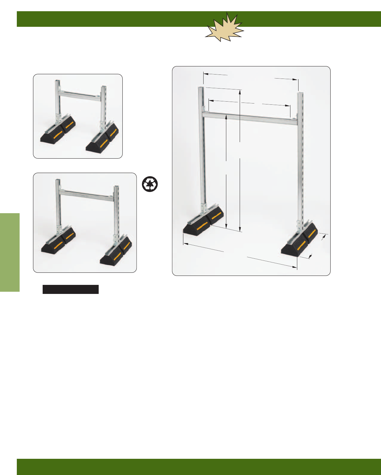
Dura-Blok™ Rooftop Supports
140
Reference page 136 for general fitting and standard finish specifications.
Dura-Blok™Supports
Reference page 136 for general fitting and standard finish specifications.
DB__DS SERIES
SUPPORT BASES WITH B22SH
VERTICAL & HORIZONTAL CHANNEL MEMBERS
• Product is shipped unassembled.
* General Note: Consult roofing manufacturer or engineer for roof load capacity.
The weakest point may be the insulation board beneath the rubber membrane.
NEW
DB2318DS
DB2924DS DB5336DS
Length
(overall)
Width
(overall)
Height
(overall)
B
B + 4.5” (114mm)
A
Features
• Two (2) DB20 bases with 14 ga. (1.9mm) galvanized channel 1” high (25.4mm) -
Bases are 5” (127.0mm) high x 6” (152.4mm) wide x 20.2” (513.1mm) long.
Vertical & Horizontal Riser Channels (SH Style) - 15/8” (41.3mm) x 15/8” (41.3mm) x 12 ga. (2.6mm)
Fittings & Hardware - Electro-Plated Steel
• 100% recycled rubber, UV resistant.
• Ultimate Load Rating: 1000 lbs. (4.45kN) (Uniform Load)*
• Dura-Blok™ DB__DS-Series channel support with risers is designed for superior support of piping
systems, cable tray, HVAC equipment, walkway systems and many other applications. The Dura-Blok
is UV resistant and suitable for installation on any type of roofing material or other flat surfaces.
(For pipe straps/clamps, rollers and roller supports that can be used with these Dura-Blok supports,
see page 142)
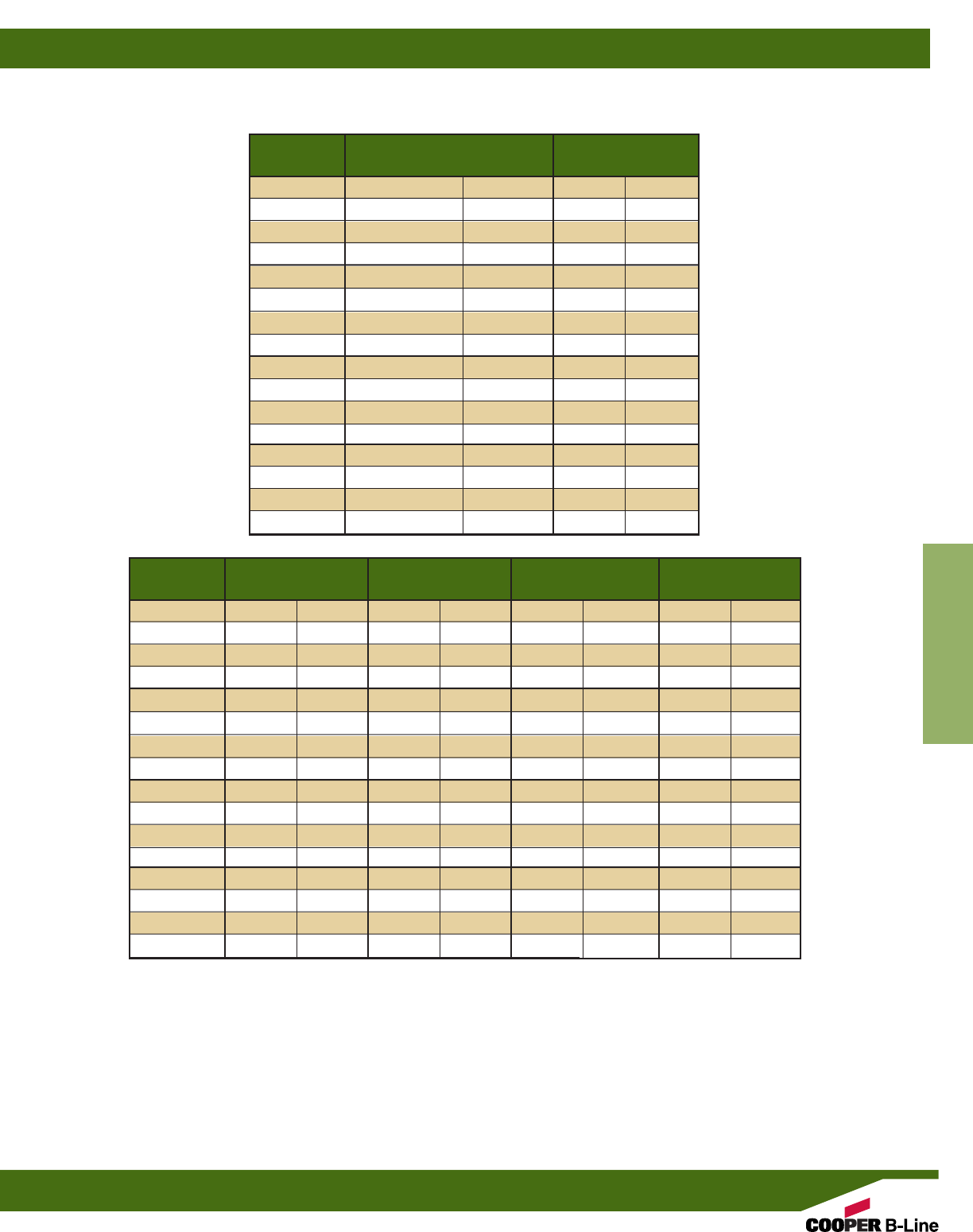
Reference page 136 for general fitting and standard finish specifications.
Dura-Blok™ Rooftop Supports
141
Dura-Blok™Supports
A = Adjustable height from bottom of Dura-Blok to top of horizontal channel.
B = Space between fittings that support horizontal channel.
Height (overall) = Distance from bottom of Dura-Blok to top of upright channel.
Width (overall) = Distance from outside-to-outside of Dura-Blok supports.
Length (overall) = Distance from end-to-end of Dura-Blok supports.
A Min. to Max. B
Part No. In. (mm) In. (mm)
DB2318DS 10.56” to 20.75” (268 to 527) 131/2”(343)
DB2918DS 10.56” to 26.75” (268 to 679) 131/2”(343)
DB4118DS 10.56” to 38.75” (268 to 984) 131/2”(343)
DB5318DS 10.56” to 50.75” (268 to 1289) 131/2”(343)
DB2324DS 10.56” to 20.75” (268 to 527) 191/2”(495)
DB2924DS 10.56” to 26.75” (268 to 679) 191/2”(495)
DB4124DS 10.56” to 38.75” (268 to 984) 191/2”(495)
DB5324DS 10.56” to 50.75” (268 to 1289) 191/2”(495)
DB2336DS 10.56” to 20.75” (268 to 527) 311/2”(800)
DB2936DS 10.56” to 26.75” (268 to 679) 311/2”(800)
DB4136DS 10.56” to 38.75” (268 to 984) 311/2”(800)
DB5336DS 10.56” to 50.75” (268 to 1289) 311/2”(800)
DB2348DS 10.56” to 20.75” (268 to 527) 431/2”(1105)
DB2948DS 10.56” to 26.75” (268 to 679) 431/2”(1105)
DB4148DS 10.56” to 38.75” (268 to 984) 431/2”(1105)
DB5348DS 10.56” to 50.75” (268 to 1289) 431/2”(1105)
Height (overall) Width (overall) Length (overall) Wt./Each
Part No. In. (mm) In. (mm) In. (mm) lbs. (kg)
DB2318DS 23” (584) 255/8”(651) 20.2” (513) 33.31 (15.11)
DB2918DS 29” (736) 255/8”(651) 20.2” (513) 35.00 (15.88)
DB4118DS 41” (1041) 255/8”(651) 20.2” (513) 38.40 (17.42)
DB5318DS 53” (1346) 255/8”(651) 20.2” (513) 41.80 (18.96)
DB2324DS 23” (584) 315/8”(803) 20.2” (513) 34.15 (15.49)
DB2924DS 29” (736) 315/8”(803) 20.2” (513) 35.84 (16.26)
DB4124DS 41” (1041) 315/8”(803) 20.2” (513) 39.25 (17.80)
DB5324DS 53” (1346) 315/8”(803) 20.2” (513) 42.65 (19.34)
DB2336DS 23” (584) 435/8”(1108) 20.2” (513) 35.84 (16.26)
DB2936DS 29” (736) 435/8”(1108) 20.2” (513) 37.56 (17.03)
DB4136DS 41” (1041) 435/8”(1108) 20.2” (513) 40.95 (18.57)
DB5336DS 53” (1346) 435/8”(1108) 20.2” (513) 44.34 (20.11)
DB2348DS 23” (584) 555/8”(1415) 20.2” (513) 37.55 (17.03)
DB2948DS 29” (736) 555/8”(1415) 20.2” (513) 39.25 (17.80)
DB4148DS 41” (1041) 555/8”(1415) 20.2” (513) 42.65 (19.34)
DB5348DS 53” (1346) 555/8”(1415) 20.2” (513) 46.03 (20.88)
DB__DS SERIES cont.
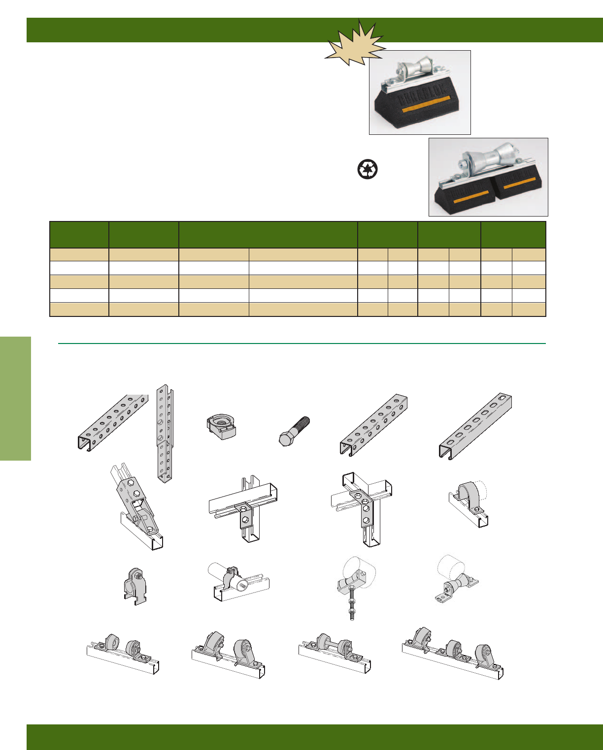
Dura-Blok™ Rooftop Supports
142
Reference page 136 for general fitting and standard finish specifications.
Dura-Blok™Supports
Above rollers can be mounted on C-Series and CB-Series units 19” (482mm) or longer.
B3126 Series
B-LINEB-LINE
BVP150BVP150
1 1/2” I.P1 1/2” I.P.
BVT Series
B2400
Series
B218
B101
BTS
B22SH
B634
B22TH
TN Nuts HHCS
B104
B219 Series
B379 B479
B2000 Series
Compatible Components Available to make Dura-Blok bases more versatile
(See Strut Systems Catalog for other products)
B3124
Series
DBR SERIES
SUPPORT BASES WITH B42 CHANNEL & PIPE ROLLER
• Base with 14 ga. (1.9mm) galvanized channel 1” high (25.4mm) tall -
see chart for height, width and length.
• 100% recycled rubber, UV resistant.
• Load Rating: (See Chart Below)*
• Dura-Blok™ DBR-Series support is designed to support pipe where longitudinal
movement is expected. The Dura-Blok is UV resistant and approved for
installation on any type of roofing material or other flat surfaces.
NEW
DB$4-6
DBR16-20
Roller Block & Channel -Height x Width x Length Height** Wt./Each Load Rating
Part No. Part No.† In. (mm) In. (mm) Lbs. (kg) Lbs. (kN)
DBR2-31/2B3126-2 to 31/25” x 6” x 4.8” (127.0 x 152.4 x 121.9) 7.09” (180) 5.28 (2.39) 500 (2.22)
DBR4-6 B3126-4 to 6 5” x 6” x 4.8” (127.0 x 152.4 x 121.9) 7.09” (180) 10.63 (4.82) 500 (2.22)
DBR8-10 B3126-8-10 5” x 6” x 4.8” (127.0 x 152.4 x 121.9) 8.34” (212) 15.99 (7.25) 1000 (4.45)
DBR12-14 B3126-12-14 5” x 6” x 4.8” (127.0 x 152.4 x 121.9) 9.38” (238) 21.34 (9.68) 1000 (4.45)
DBR16-20 B3126-16-20 5” x 6” x 4.8” (127.0 x 152.4 x 121.9) 9.78” (248) 26.70 (12.11) 1000 (4.45)
† See Pipe Hanger Catalog for dimensions and specifications. ** From bottom of rubber block to bottom of pipe/tubing.
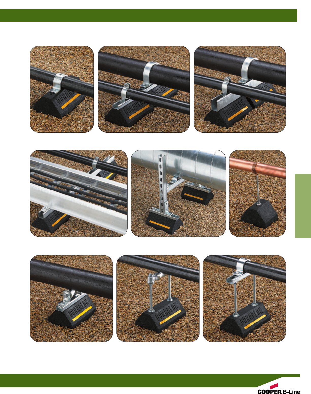
Dura-Blok™ Rooftop Supports
143
Dura-Blok™Supports
ROOFTOP APPLICATIONS
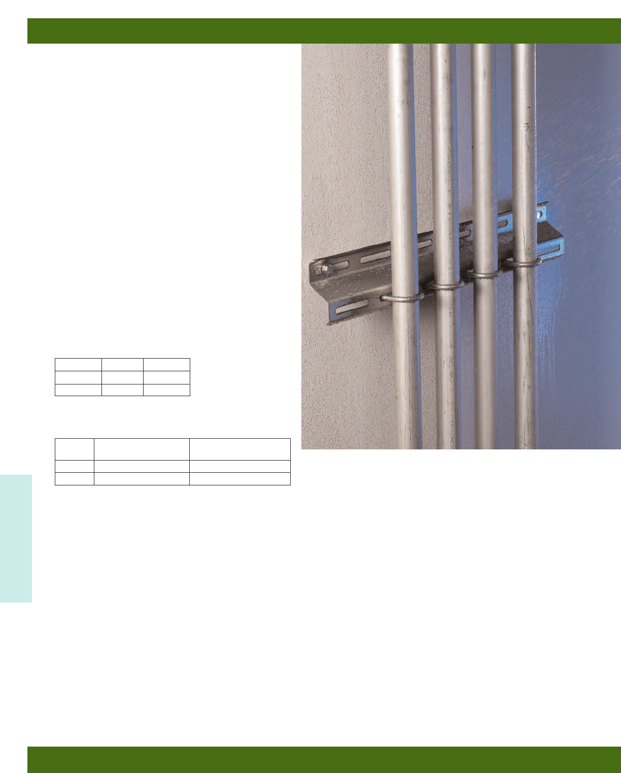
Cooper B-Line’s new line of Dura-Clean™ electrical
and mechanical support products are specifically
designed for the critical and rigorous wash-down
requirements of the Food & Beverage and
Pharmaceutical industries.
Manufactured from high quality stainless steel with
all angles minimized to prevent water pooling and
collection, Dura-Clean™ strut and hanger components
are designed with the durability and flexibility needed
for applications where pipe, conduit and enclosures
are subjected to regular, high pressure, high moisture
wash-down environments.
Dura-Clean™ products can be installed in trapeze
configurations for hanging piping, conduit or virtually
any type of roof supported racking system - or
wall-mount configurations for vertical or horizontal
pipe support runs and enclosure support.
The new Dura-Clean™ Washdown Support System
products from Cooper B-Line.
Highest quality.
Lasting durability.
Immediate availability.
Recommended Torque
Materials
Metric
Metric dimensions are shown in parentheses. Unless noted, all metric dimensions are in millimeters.
Bolt Size 3/8”-16 1/2”-13
Foot/Lbs. 19 50
Nm 26 68
Finish
Code Finish Specification
SS4 Stainless Steel Type 304 ASTM A240
SS6 Stainless Steel Type 316 ASTM A240
Dura Clean™
Dura Clean™ Washdown Support System
144
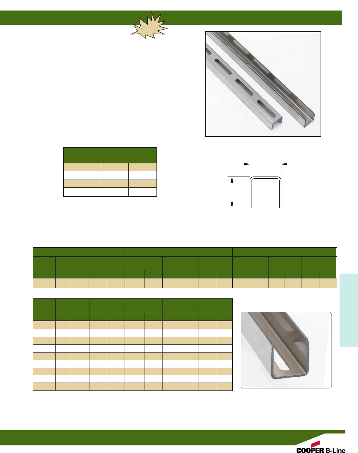
Reference page 144 for general fitting and standard finish specifications.
Dura Clean™ Channels
145
Dura Clean™
DURA CLEAN™ CHANNEL
• Thickness: 12 Gauge (2.6mm)
• Standard Lengths:12” (.30m), 24” (.61m), 48” (1.22m), 120” (3.06m)
• Standard Finish: #4 Polished 304 Stainless Steel w/cellophane cover
(other materials available upon request)
• Weight: 1.68 lbs/ft (2.50kg/m)
• 15/8” (41mm) x 15/8” (41mm) profile with 13/32” (10mm) x 3” (76mm) slot
on 4” (101mm) centers
• Straight leg design does not harbor water or dust, eliminating areas
known to harbor bacteria
• Profile allows product to be used with standard strut accessories
Length
Part No. In. (mm)
DC22S-12 12” (305)
DC22S-24 24” (610)
DC22S-48 48” (1219)
DC22S-120 120” (3048)
NEW
Section Properties X - X Axis Y - Y Axis
Channel Weight Areas of Moment of Section Radius of Moment of Section Radius of
Section Inertia (I) Modulus (S) Gyration (R) Inertia (I) Modulus (S) Gyration (R)
lbs./ft. kg/m in.2cm2in.4cm4in.3cm3in. cm in.4cm4in.3cm3in. cm
DC22S 1.68 0.7628 0.4829 3.1155 0.1328 5.5276 0.1283 2.1025 0.5244 1.332 0.2178 9.0655 0.2681 4.3934 0.6717 1.7061
Channel Beam Span Uniform Load Deflection Uniform Load @ Deflection =
1/240 Span 1/360 Span
in. mm lbs. N in. mm lbs. N lbs. N
DC22S 12 305 2500 562 0.0146 0.37 2500 562 2500 562
DC22S 18 457 1667 375 0.0329 0.83 1667 375 1667 375
DC22S 24 610 1250 281 0.0584 1.48 1250 281 1250 281
DC22S 30 762 1000 225 0.0913 2.32 1000 225 913 205
DC22S 36 914 833 187 0.1314 3.34 833 187 634 143
DC22S 42 1067 714 161 0.1788 4.54 699 157 466 105
DC22S 48 1219 625 141 0.2337 5.94 535 120 357 80
DC22S 54 1372 556 125 0.2960 7.52 423 95 282 63
DC22S 60 1524 500 112 0.3651 9.27 342 77 228 51
15/8”
(41mm)
15/8”
(41mm)
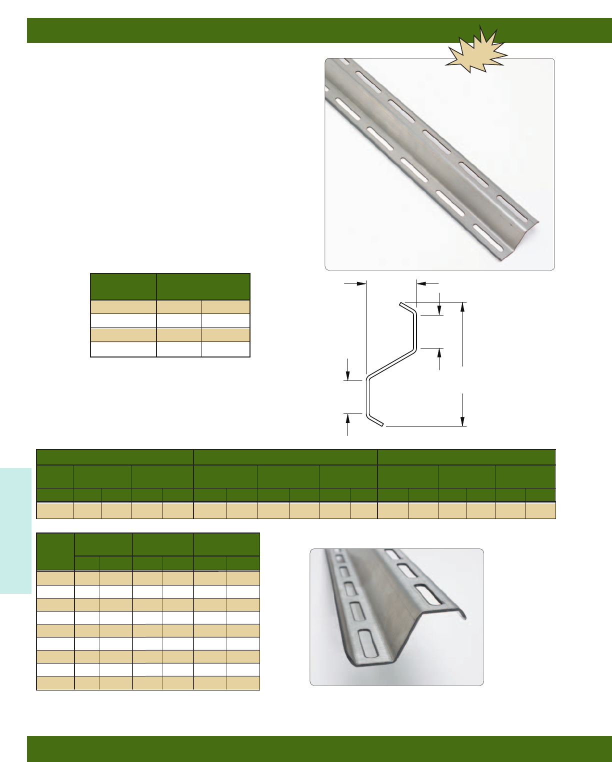
Dura Clean™ Wall Rails
146
Reference page 144 for general fitting and standard finish specifications.
Dura Clean™
DURA CLEAN™ WALL MOUNT RAILS
• Thickness: 12 Gauge (2.6mm)
• Standard Lengths:12” (.30m), 24” (.61m), 48” (1.22m), 120” (3.06m)
• Standard Finish: #4 Polished 304 Stainless Steel w/cellophane cover
(other materials available upon request)
• Weight: 1.90 lbs/ft (2.83kg/m)
• Z-Profile with 13/32” (10mm) x 3” (76mm) slot on 4” (101mm) centers
• DCSP spacers are used to offset profile 1” (25.4mm) from mounting
surface to eliminate any area that may harbor bacteria
Section Properties X - X Axis Y - Y Axis
Channel Weight Areas of Moment of Section Radius of Moment of Section Radius of
Section Inertia (I) Modulus (S) Gyration (R) Inertia (I) Modulus (S) Gyration (R)
lbs./ft. kg/m in.2cm2in.4cm4in.3cm3in. cm in.4cm4in.3cm3in. cm
DCWM 1.8999 0.8618 0.5456 3.5200 0.7305 30.406 0.3564 5.8403 1.1571 2.939 0.2345 9.7606 0.2646 4.336 0.6556 1.6652
Channel Beam Span Uniform Load Deflection
in. mm lbs. N in. mm
DCWM 12 305 1350 303 0.0014 0.04
DCWM 18 457 900 202 0.0032 0.08
DCWM 24 610 675 152 0.0057 0.15
DCWM 30 762 540 121 0.0090 0.23
DCWM 36 914 450 101 0.0129 0.33
DCWM 42 1067 386 87 0.0176 0.45
DCWM 48 1219 338 76 0.0230 0.58
DCWM 54 1372 300 67 0.0290 0.74
DCWM 60 1524 270 61 0.0358 0.91
1.13”
(29mm)
1.72”
(44mm)
4.23”
(107mm)
1.13”
(29mm)
NEW
Length
Part No. In. (mm)
DCWM-12 12” (305)
DCWM-24 24” (610)
DCWM-48 48” (1219)
DCWM-120 120” (3048)
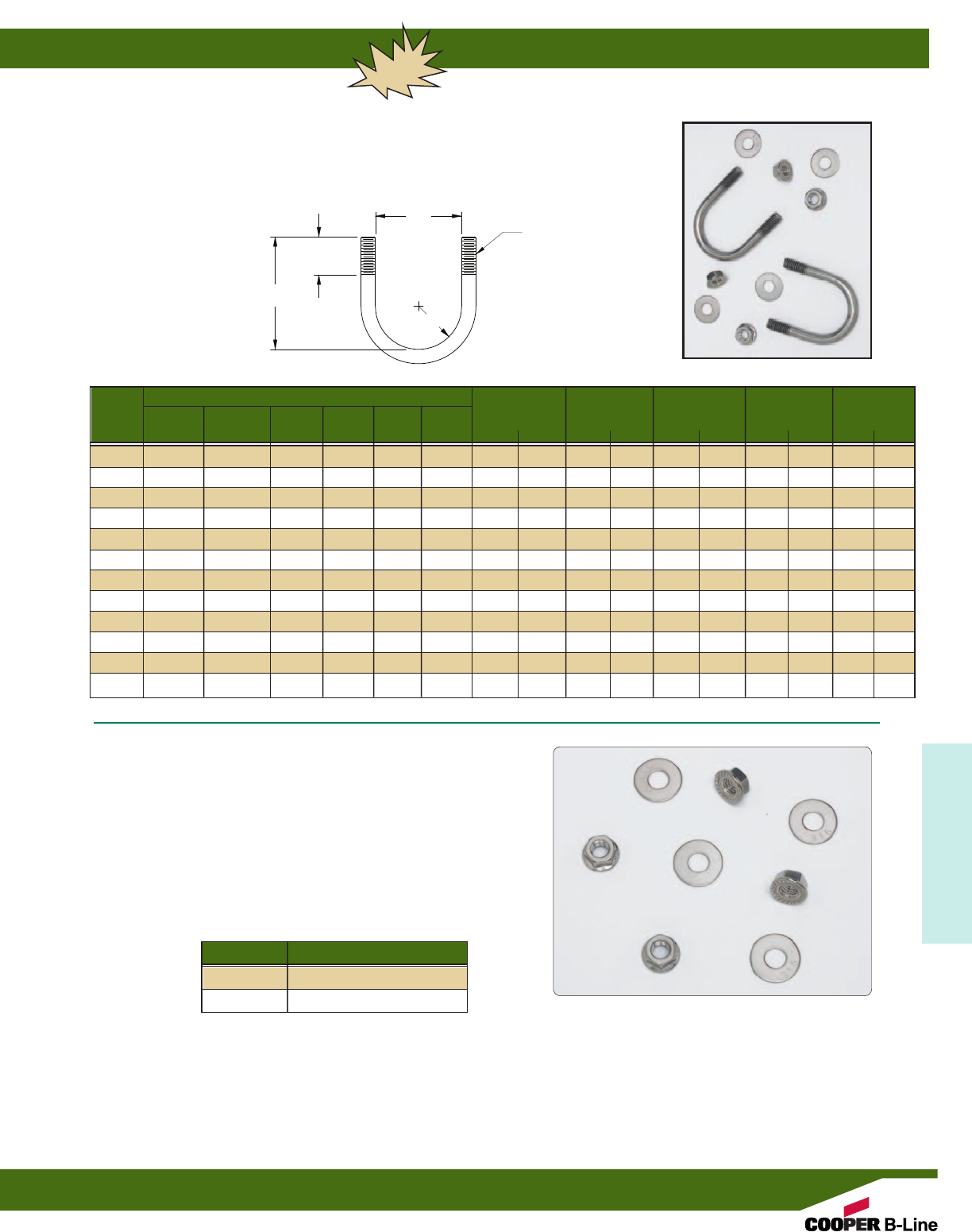
Reference page 144 for general fitting and standard finish specifications.
Dura Clean™ Accessories
147
Dura Clean™
U-BOLTS
• Material: Stream cleaned 304 Stainless Steel
• Includes serrated flange hex nuts and flat washers
• Designed for use with rigid/emt conduit, OD tubing and copper, schedule 40/80
and Ocal pipe sizes
HARDWARE
• Material: 316 Stainless Steel
• Flat washer for 3/8” threaded rod
• Serrated hex nut for 3/8”-16 threaded rod
• Weight/C: Flat Washers 1.7 Lbs. (0.77kg)
Serrated Hex Nuts 3.0 Lbs. (1.36kg)
NEW
Pipe - Conduit - Tubing Sizes
Part OD Sch. Rigid EMT Copper Ocal “A” “B” “C” Design Load Wt./C
Number Tubing 40/80 Pipe Conduit Conduit Pipe Pipe in. mm in. mm in. mm lbs. kN lbs. kg
DC-1 1/2”, 3/4”- - 1/2”1/2” - 0.81 20.6 0.88 22.2 1.50 38.1 600 2.67 27.0 12.2
DC-2 -1/2”1/2”3/4”3/4”1/2” 0.98 25.0 0.88 22.2 1.67 42.5 600 2.67 28.4 12.9
DC-3 1” 3/4”3/4” 1” 1” 3/4” 1.23 31.1 1.00 25.4 1.91 48.6 600 2.67 30.4 13.8
DC-4 11/4” 1” 1” - 11/4” 1” 1.46 37.0 1.00 25.4 2.15 54.5 900 4.00 32.3 14.6
DC-5 11/2”1
1/4”1
1/4”1
1/4”1
1/2” - 1.72 43.7 1.00 25.4 2.41 61.2 900 4.00 33.3 15.1
DC-6 -1
1/2”1
1/2”1
1/2”-1
1/4” 1.96 49.8 1.00 25.4 2.65 67.3 900 4.00 36.4 16.5
DC-7 2” - - 2” 2” 11/2” 2.26 57.4 1.00 25.4 2.95 74.9 1200 5.34 38.9 17.6
DC-8 21/2” 2” 2” - 21/2” 2” 2.69 68.2 1.00 25.4 3.38 85.7 1200 5.34 42.4 19.2
DC-9 3” 21/2”2
1/2”2
1/2”3”2
1/2” 3.19 80.9 1.00 25.4 3.88 98.4 1200 5.34 46.5 21.1
DC-10 31/2” 3” 3” 3” 31/2” 3” 3.69 93.6 1.00 25.4 4.38 111.1 1800 8.00 53.0 24.0
DC-11 4” 31/2”3
1/2”3
1/2”4”3
1/2” 4.25 108.0 1.00 25.4 4.88 123.8 1800 8.00 54.9 24.9
DC-12 - 4” 4” 4” - 4” 4.71 119.5 1.00 25.4 5.33 135.4 1800 8.00 58.6 26.6
Part Number Description
3/8FWSS6 3/8” Flat Washer
SFHN3/8SS6 3/8”-16 Serrated Hex Nut
“C”
3/8”-16
Cut Threads
“A”
“B”
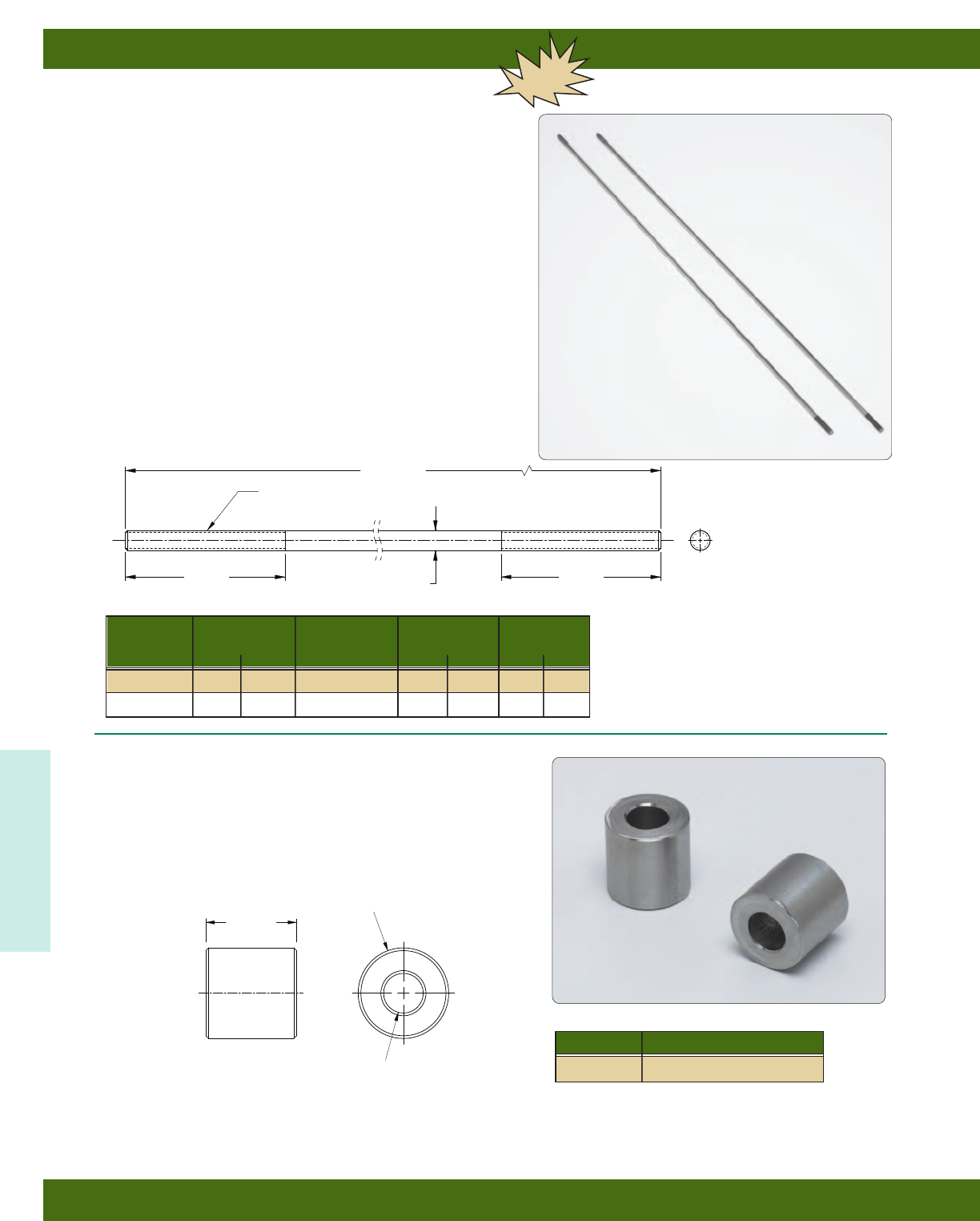
3”
(76mm) 3/8” (9.5mm)
3”
(76mm)
3/8”-16 Cut Thread
(both ends)
Length
Dura Clean™ Accessories
148
Reference page 144 for general fitting and standard finish specifications.
Dura Clean™
TREADED ROD
• Material: Steam cleaned 304 Stainless Steel
• Standard Lengths: 36” (.92m) & 72” (1.83m)
(other length available upon request)
• 3/8”-16 cut threads standard
• Cut threads allow the customer to cut rods to length and then field
cut threads where required
SPACERS
• Material: 304 Stainless Steel
• Spacers are used to provide 1” (25mm) of separation from wall to channel,
eliminating any area that may harbor bacteria.
• Weight/C: 16.9 Lbs. (7.6kg)
NEW
Channel Length Threads Per Recommended Wt./100 pcs
Inch Load
in. mm lbs. N lbs. kg
DCR38-36 36” 914 16 730 324 186.2 84.4
DCR38-72 72” 1829 16 730 324 372.4 168.9
1.000” OD
(25mm)
1”
(25mm)
.440” ID
(11mm)
Part Number Description
DCSP SS4 Stand-off Spacer
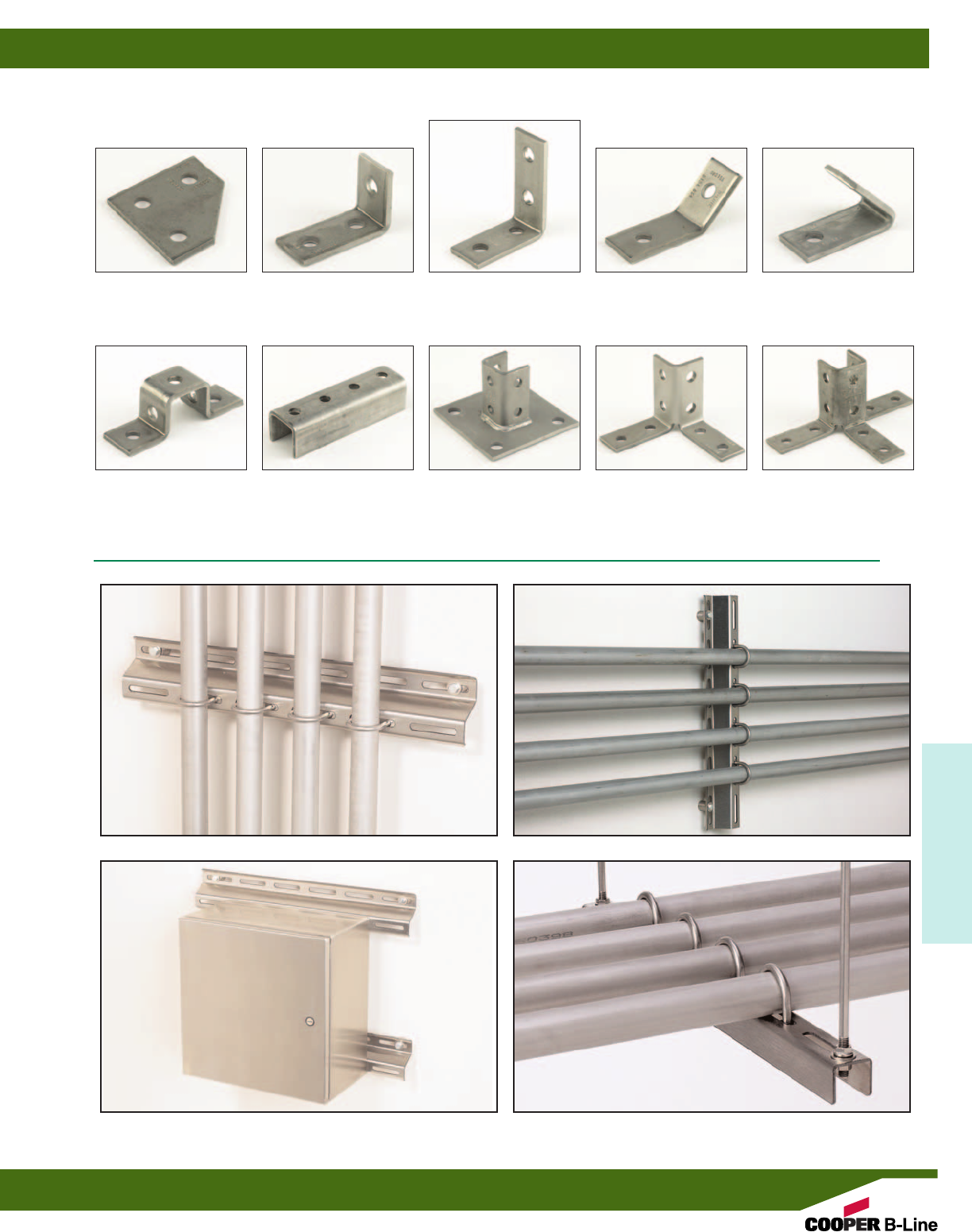
Dura Clean™ Accessories
149
Dura Clean™
B135
Flat Corner Plate
B102
3-Hole Corner Angle
B104
4-Hole Corner Angle
B154
2-Hole 45° Open Angle
B155
2-Hole ‘U’ Support
B107
5-Hole 45° Closed Angle
B172
4-Hole Splice Clevis
B280SQ
Post Base
B121
8-Hole Double Corner
Connection
B123
12-Hole Triple Wing
Connection
Other Stainless Steel Products
Consult Customer Service for other products that can be made in Stainless Steel material
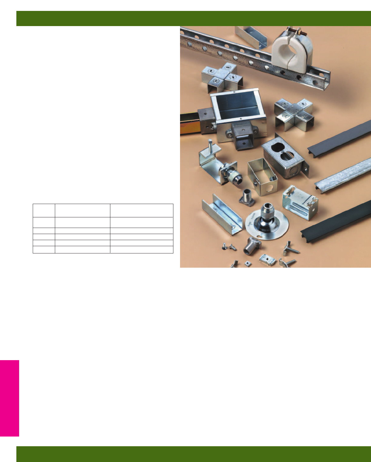
A complete system of top quality, time saving products,
designed for surface metal raceways, lighting and cable
supports. Innovative designs offer many installation
advantages. B-Line’s surface raceways are U.L. listed
and meet the requirements of the National Electrical
Code, Article 352.
Surface Raceways
B-Line’s channel provides structural support in
addition to a raceway system.
For U.L. wire fill see chart on page 218-219.
Cable Supports
A full range of clamps and saddles are offered in
porcelain, thermoplastic elastomer and maple. B-Line’s
maple clamps, Insulclamp®cable clamps and porcelain
saddles are furnished complete with steel clamps
(electro-plated) and Everdur hardware where required.
Materials & Finishes*
Steel products are made from low carbon steel strips
or plates. Porcelain saddles and clamps are made by
dry process and white glazed (porcelain dielectric
strength is 50 volts per mil). Maple clamps are made
from kiln-dried maple wood, paraffin impregnated.
*Unless otherwise noted.
Design Load
Design load data published includes a Safety Factor of 3.0 (Safety Factor = Ratio of ultimate load to the
design load).
U.L. listed raceway channels:
B11, B11KO6 B32, B32KO6
B12, B12KO6 B42, B42KO6
B22, B22KO6 B52, B52KO6
B24, B24KO6 B54, B54KO6
B26, B26KO6 B56, B56KO6
U.L. File No. E29637
In all cases, the snap-in closure strip is required to complete raceway enclosure.
Metric
Metric dimensions are shown in parentheses. Unless noted, all metric dimensions are in millimeters.
Electrical Accessories
Electrical Accessories
150
Finish
Code Finish Specification
PLN Plain ASTM A1011
33,000 PSI min. yield
ZN Electro-Plated Zinc ASTM B633 SC3 Type III
GRN Dura-Green
GALV Pre-Galvanized ASTM B653
YZN Yellow Zinc Chromate ASTM B633 SC3 Type II
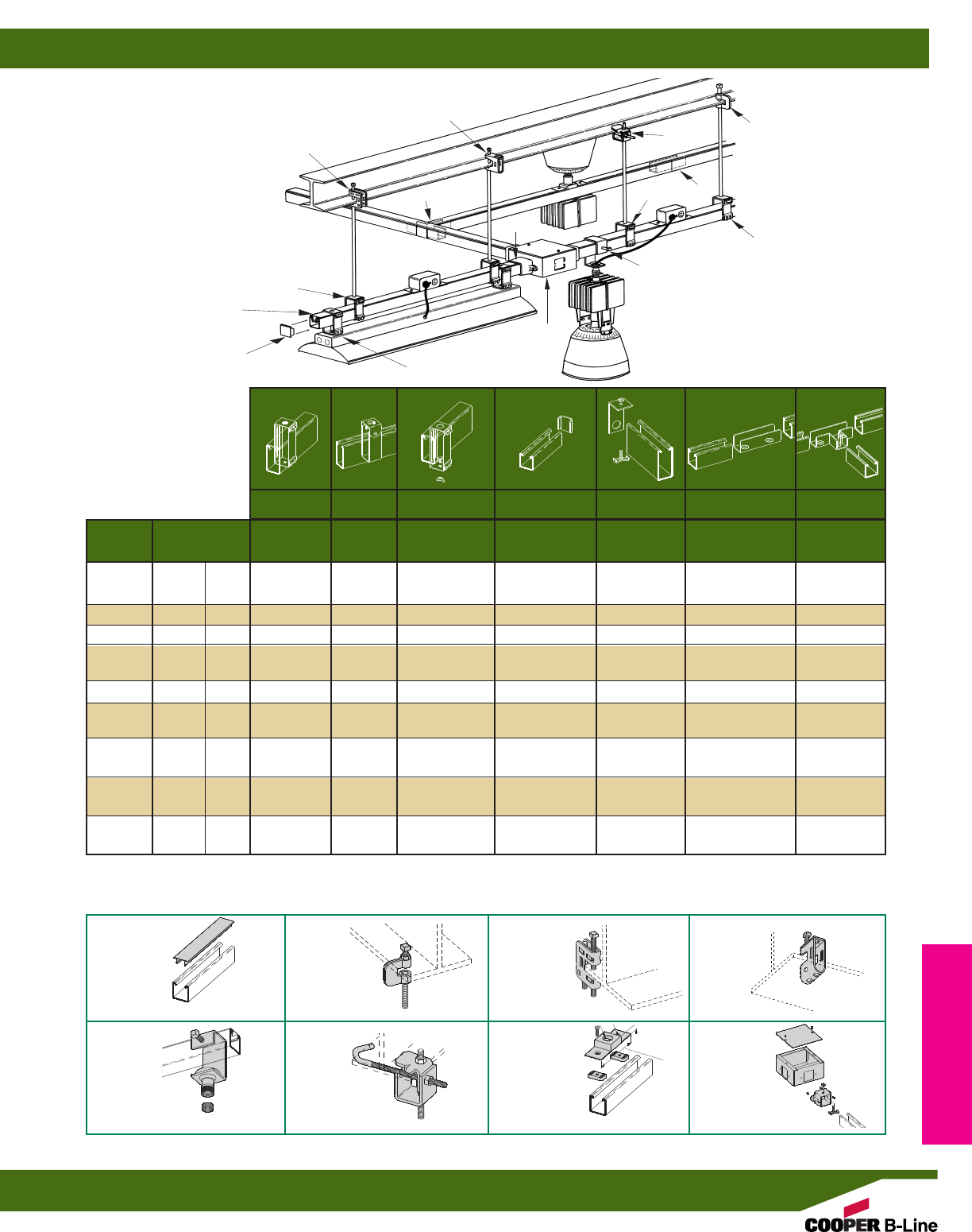
Channel Channel Channel Fixture Connection Internal Internal
Number Depth Hanger Hanger Hanger End Cap End Cap Straight Splice Tee Splice
B22A 31/4”(82.5) B616-22A* B241S* B616S-22A* B205 or B285 B392-22** B766-22 (2) B768-22 (2)
B285
B11 31/4”(82.5) B616-22A* B241S* B616S-22A* B222 B392-11** B766-11 B768-11
B12 27/16”(61.9) B616-22A* B241S* B616S-22A* B221 B392-12** B766-12 B768-12
B22 15/8”(41.3) B616* B216S* B616S* B205 or B285 B392-22** B766-22 B768-22
B24 B616TG* B223 or B286
B26 15/8”(41.3) B616* – – – B392-22** – –
B32 13/8”(34.9) B616* B216S* B616S* B206 B392-32** B766-32 B768-32
B616TG*
B42 1” (25.4) B616* B215S* B616S* B203 – B766-42 B768-42
B616TG*
B52 13/16”(20.6) B616* B215S* B616S* B220 or B283 – B766-52 B768-52
B54 B616TG* B204 or B284
B56 13/16”(20.6) B616* B215S* B616S* – – B766-56 –
B616TG*
1 1A 2 3 3A 4 5
*Specify Hanger Rod or Conduit Size.
**Specify Conduit Size
OTHER ITEMS SHOWN ON ILLUSTRATION
SELECTION CHART
Snap-in Closure Strip
H.I.D. Fixture Hanger Beam Clamp Conduit Connection Plate B718 Series Junction Box
Beam Clamp Beam Clamp Beam Clamp
B217-20 (6) (7) (8) (9)
(10) (11) (12) (13)
B465
B351L B755 B751
B719B447
B447A
B750
(8)
(9)
(5)
(2)
(13)
(13)
(10)
(1)
(1) (4)
(7)
(11)
(1) or
(1A) (Not Shown)
(3) or
(3A) (Not Shown)
(6)
Electrical Accessories
Reference page 150 for general fitting and standard finish specifications. U.L. Wire Fill Chart on pages 218 - 219.
Electrical Accessories
151
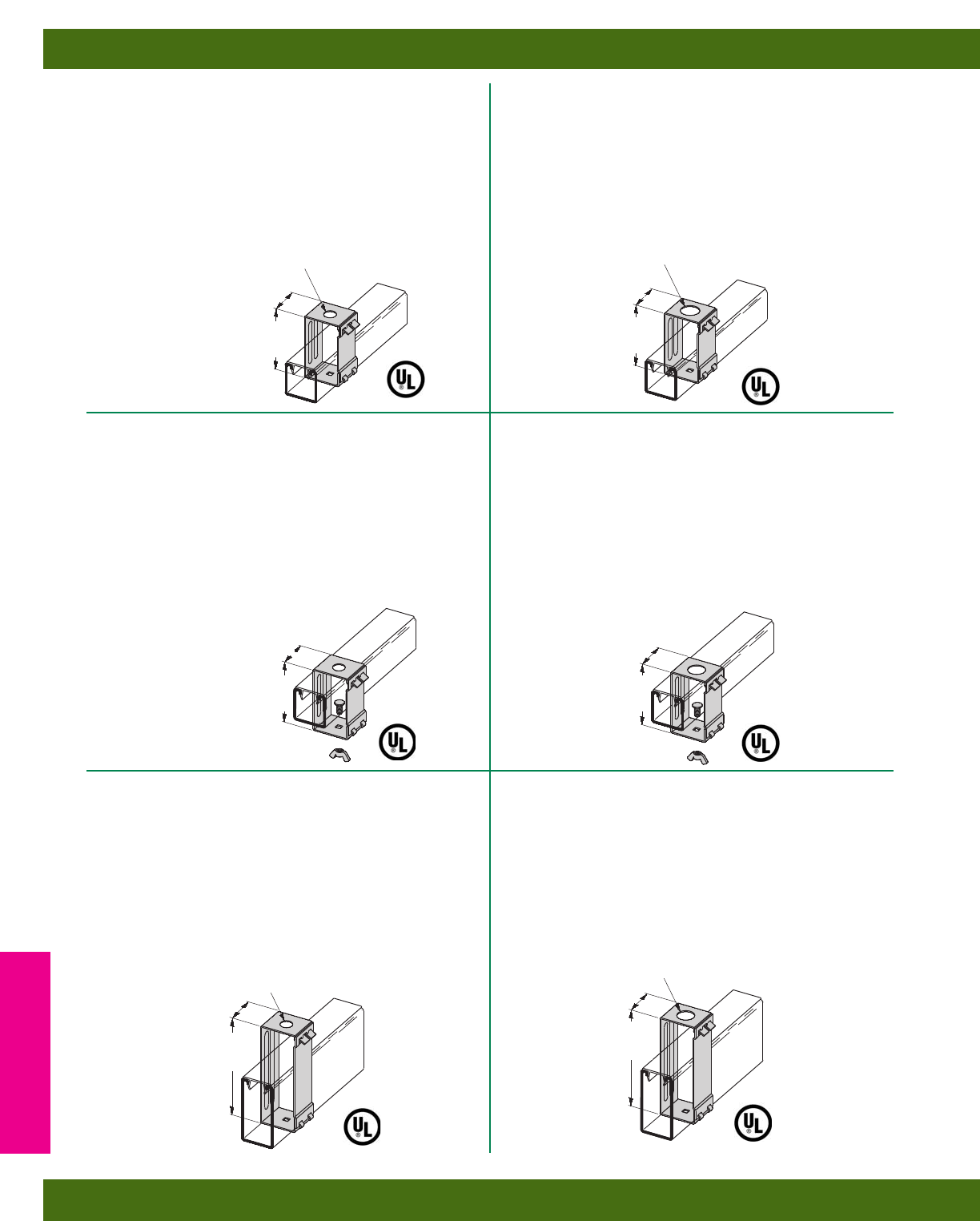
B616-7/8
CHANNEL HANGER
•Design Load 250 Lbs. (1.11 kN)
•Safety Factor of 3
•Maximum design load 50 Lbs. (.22 kN)
when used as a fixture support
•Material: 16 Gauge (1.5)
•Standard finish: ZN
•Wt./C 25 Lbs. (11.3 kg)
B616-9/16
CHANNEL HANGER
•Design Load 250 Lbs. (1.11 kN)
•Safety Factor of 3
•Maximum design load 50 Lbs. (.22 kN)
when used as a fixture support
•Includes:
2 pcs. 3/8” Flat Washers for use
with 3/8” ATR
•Material: 16 Gauge (1.5)
•Standard finish: ZN
•Wt./C 25 Lbs. (11.3 kg)
B616S-9/16
FLUORESCENT FIXTURE
HANGER WITH STUD
•Design Load 150 Lbs. (.67 kN)
•Safety Factor of 3
•Maximum design load 50 Lbs. (.22 kN)
when used as a fixture support
•Allows more than 1/2” (12.7) space
between channel and fixture
•Includes:
2 pcs. 3/8” Flat Washers for use with 3/8” ATR
•Material:16 Gauge (1.5)
•Standard finish: ZN
•Wt./C 30 Lbs. (13.6 kg)
B616S-7/8
FLUORESCENT FIXTURE
HANGER WITH STUD
•Design Load 150 Lbs. (.67 kN)
•Safety Factor of 3
•Maximum design load 50 Lbs. (.22 kN)
when used as a fixture support
•Allows more than 1/2” (12.7) space
between channel and fixture
•Standard finish: ZN
•Wt./C 30 Lbs. (13.6 kg)
B616-22A-9/16
CHANNEL HANGER
•Design Load 250 Lbs. (1.11 kN)
•Safety Factor of 3
•Maximum design load 50 Lbs. (.22 kN) when
used as a fixture support
•Includes:
2 pcs. 3/8” Flat Washers for use with 3/8” ATR
•Material: 14 Gauge (1.9)
•Standard finish: ZN
•Wt./C 44 Lbs. (19.9 kg)
B616-22A-7/8
CHANNEL HANGER
•Design Load 250 Lbs. (1.11 kN)
•Safety Factor of 3
•Maximum design load 50 Lbs. (.22 kN)
when used as a fixture support
•Material: 14 Gauge (1.9)
•Standard finish: ZN
•Wt./C 44 Lbs. (19.9 kg)
31/8”
(79.4)
11/2”
(38.1)
9/16” (14.3) DIA. FOR
1/2” ATR
7/8” (22.2) DIA. FOR
1/2” (15) CONDUIT
31/8”
(79.4)
11/2”
(38.1)
31/8”
(79.4)
11/2”
(38.1)
31/8”
(79.4)
11/2”
(38.1)
51/8”
(130.2)
11/2”
(38.1)
9/16” (14.3) DIA. FOR
1/2” ATR
7/8” (22.2) DIA. FOR
1/2” (15) CONDUIT
11/2”
(38.1)
51/8”
(130.2)
Electrical Accessories
Reference page 150 for general fitting and standard finish specifications. U.L. Wire Fill Chart on pages 218 - 219.
Fluorescent Fixture Hangers
152
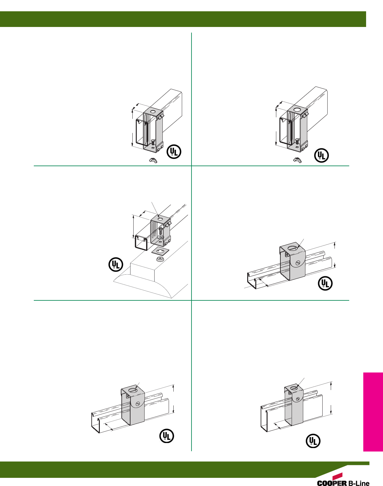
B616S-22A-7/8
FLUORESCENT FIXTURE
HANGER WITH STUD
•Design Load 150 Lbs. (.67 kN)
•Safety Factor of 3
•Maximum design load 50 Lbs. (.22 kN)
when used as a fixture support
•Allows more than 1/2” (12.7) space
between channel and fixture
•Material: 14 Gauge (1.9)
•Standard finish: ZN
•Wt./C 49 Lbs. (22.2 kg)
B616S-22A-9/16
FLUORESCENT FIXTURE
HANGER WITH STUD
•Design Load 150 Lbs. (.67 kN)
•Safety Factor of 3
•Maximum design load 50 Lbs. (.22 kN)
when used as a fixture support
•Includes:
2 pcs. 3/8” Flat Washers for use with 3/8” ATR
•Allows more than 1/2” (12.7) space
between channel and fixture
•Material: 14 Gauge (1.9)
•Standard finish: ZN
•Wt./C 49 Lbs. (22.2 kg)
B616TG-9/16
FLUORESCENT FIXTURE
HANGER FOR 1/2” (15) KNOCKOUT
•Design Load 150 Lbs. (.67 kN)
•Safety Factor of 3
•Maximum design load
50 Lbs. (.22 kN) when used as a
fixture support
•Includes:
2 pcs. 3/8” Flat Washers for
use with 3/8” ATR
•Design Load 150 Lbs. (.67 kN)
•Allows more than 1/2” (12.7) space
between channel and fixture
•Material: 16 Gauge (1.5)
•Standard finish: ZN
•Wt./C 32 Lbs. (14.5 kg)
B215S
CHANNEL HANGER
•Can be used with 3/8” & 1/2” threaded rod or 3/8” & 1/2” conduit
•Design Load 250 Lbs. (1.11 kN)
•Safety Factor of 3
•For use with B42, B52, B54 & B56 Channels
•Hardware included:
One (1) 3/8” x 11/2” FFW for use with 3/8”-16 ATR
One (1) 1/2” FW for use with 1/2”-13 ATR
One (1) 5/8” FW for use with 3/8” conduit
•Material: 16 Gauge (1.5)
•Standard finish: ZN
•Wt./C 31 Lbs. (14.0 kg)
B216S
CHANNEL HANGER
•Can be used with 3/8” & 1/2” threaded rod or 3/8” & 1/2” conduit
•Design Load 250 Lbs. (1.11 kN)
•Safety Factor of 3
•For use with B22, B24, B26 & B32 Channels
•Hardware included:
One (1) 3/8” x 11/2” FFW for use with 3/8”-16 ATR
One (1) 1/2” FW for use with 1/2”-13 ATR
One (1) 5/8” FW for use with 3/8” conduit
•Material: 16 Gauge (1.5)
•Standard finish: ZN
•Wt./C 38 Lbs. (17.2 kg)
B241S
CHANNEL HANGER
•Can be used with 3/8” & 1/2” threaded rod or 3/8” & 1/2” conduit
•Design Load 250 Lbs. (1.11 kN)
•Safety Factor of 3
•For use with B11 & B12 Channels.
•Hardware included:
One (1) 3/8” x 11/2” FFW for use with 3/8”-16 ATR
One (1) 1/2” FW for use with 1/2”-13 ATR
One (1) 5/8” FW for use with 3/8” conduit
•Material: 16 Gauge (1.5)
•Standard finish: ZN
•Wt./C 47 Lbs. (21.3 kg)
51/8”
(130.2)
11/2”
(38.1)
51/8”
(130.2)
11/2”
(38.1)
31/8”
(79.4)
11/2”
(38.1)
9/16” (14.3) DIA.
FOR 1/2” ATR
7/8” (22.2) DIA.
23/16”
(55.6)
31/2”
(88.9)
121/32”
(42.0)
7/8” (22.2) DIA.
7/8” (22.2) DIA.
121/32”
(42.0)
51/16”
(128.6)
121/32”
(42.0)
Electrical Accessories
Reference page 150 for general fitting and standard finish specifications. U.L. Wire Fill Chart on pages 218 - 219.
Fluorescent Fixture Hangers
153
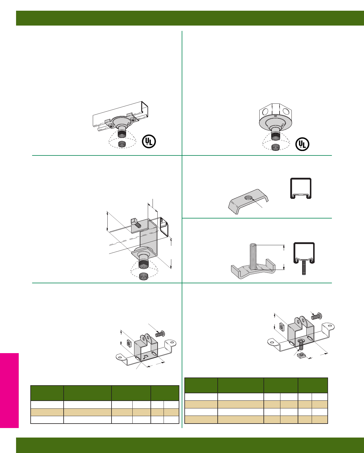
B390BX
360° SWIVEL BOX CONNECTOR
•Design Load 250 Lbs. (1.11 kN) for Connector
Fitting only
•Safety Factor of 3
•Design Load 50 Lbs. (.22 kN) when used as
illustrated or for use as a fixture support
•Swings 15° in 360° plane
•Includes:
1 pc. 3/4” (20) to 1/2” (15) Conduit Reducer
•Fits on 4” box
•Standard finish: ZN
•Wt./C 55 Lbs. (24.9 kg)
B390S
360° SWIVEL CHANNEL CONNECTOR
•Design Load 250 Lbs. (1.11 kN)
•Safety Factor of 3
•Maximum design load 50 Lbs. (.22 kN)
when used as a fixture support
•Swings 15° in 360° plane
•Includes:
2 pcs. SN224-3/4”WO Stud Nut
2 pcs. 1/4”-20 Square Nut
1 pc. 3/4” (20) to 1/2” (15) Conduit Reducer
•Standard finish: ZN
•Wt./C 71 Lbs. (32.2 kg)
B465
H.I.D. FIXTURE HANGER
•Design Load 250 Lbs. (1.11 kN)
•Safety Factor of 3
•Swings 15° in 360° plane
•Includes:
1 pc. 3/4” (20) to 1/2” (15)
Conduit Reducer
•Standard finish: ZN
•Wt./C 95 Lbs. (43.1 kg)
B436S
FLUORESCENT FIXTURE STUD NUT
•Bolt size: 1/4” x 11/4”
•Standard finish: ZN
•Wt./C 4 Lbs. (1.8 kg)
•Design Load
250 Lbs. (1.11 kN)
Safety Factor of 3
B436
FLUORESCENT FIXTURE NUT
•Standard finish: ZN
•Wt./C 2 Lbs. (.9 kg)
B460
FLUORESCENT FIXTURE
HANGER
•Hanger is shipped flat and requires
field bending as shown
•Allows more than 1/2” (12.7)
space between channel and fixture
•Material: 18 Gauge (1.2)
•Standard finish: ZN
B464
FLUORESCENT
FIXTURE HANGER
•Hanger is shipped flat and
requires field bending as shown
•Allows more than 1/8” (3.2) space
between channel and fixture
•Material: 18 Gauge (1.2)
•Standard finish: ZN
33/4”
(95.2)
21/16”
(52.4)
15/8”
(41.3)
9/32” (7.1)
SQUARE HOLE
Part No. For Channel Size A Wt./C
Lbs. kg
B460-22 B22, B24, B26, B32 21/8”(57.5) 17 (7.7)
B460-12 B12 215/16”(79.5) 20 (9.1)
B460-11 B11 33/4”(101.6) 23 (10.4)
A
TAPPED FOR 1/4”-20 SCREW
11/4”
(31.7)
Part No. For Channel Size A Wt./C
Lbs. kg
B464-32 B32 11/2”(40.6) 17 (7.7)
B464-22 B22, B24, B26 13/4”(47.4) 18 (8.1)
B464-12 B12 29/16”(66.0) 21 (9.5)
B464-11 B11 33/8”(91.4) 24 (10.9)
A
1/4” x 1” ROUND HEAD
MACHINE SCREW AND
SQUARE NUT INCLUDED
1/4” x 1” ROUND HEAD
MACHINE SCREW AND
SQUARE NUT INCLUDED
1/4” x 3/4” CARRIAGE BOLT
AND SQUARE NUT INCLUDED 15/8”
(41.3)
21/8”
(54.0)
Electrical Accessories
Reference page 150 for general fitting and standard finish specifications. U.L. Wire Fill Chart on pages 218 - 219.
Fluorescent Fixture Hangers
154
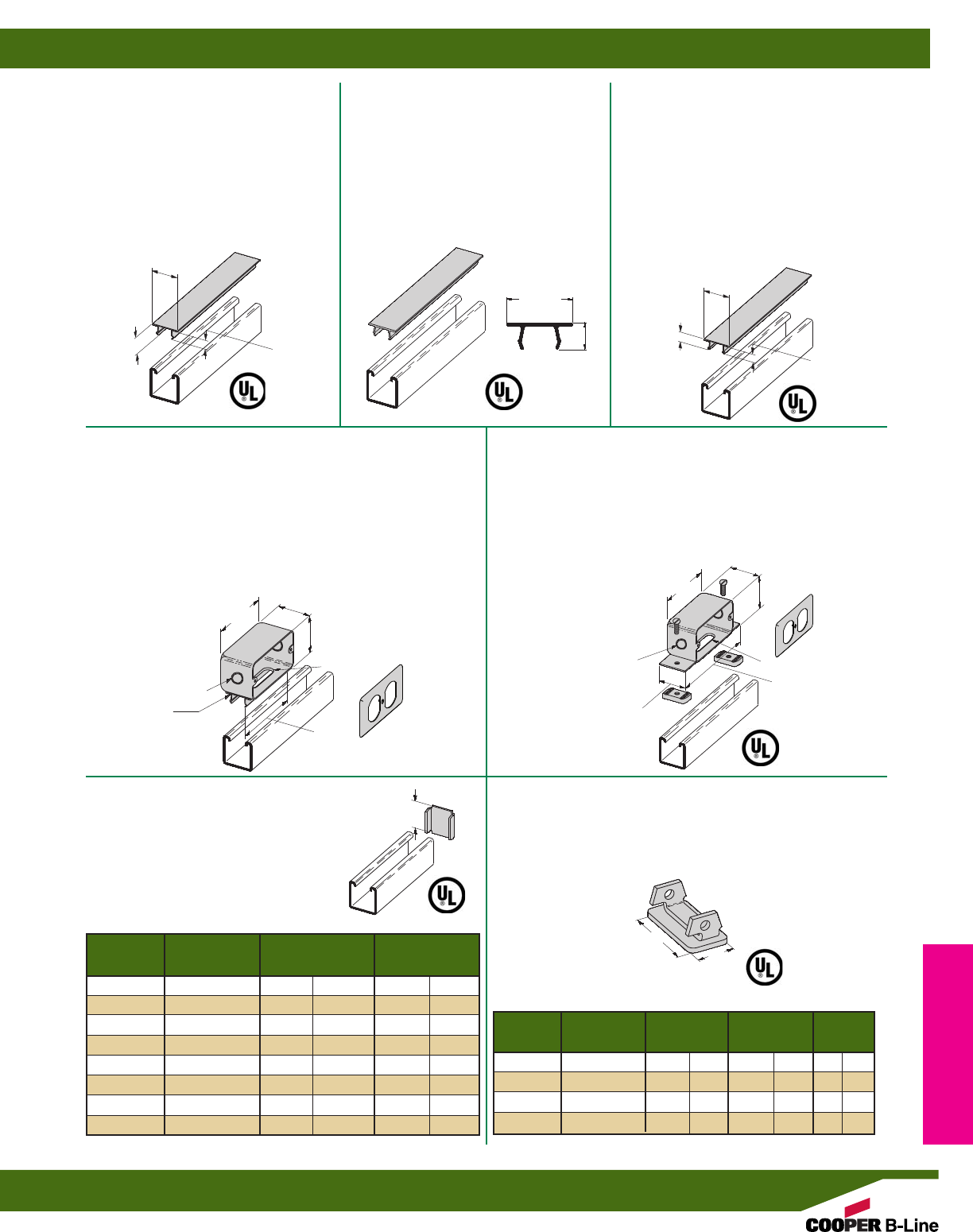
B516S
OUTLET BOX
•Duplex cover plate included
•Receptacle not furnished
•Includes:
2 pcs. 1/4”-20 Flat Head Machine Screws
2 pcs. N224WO Channel Nuts
•Standard finish: ZN
•Wt./C 98 Lbs. (44.4 kg)
B516
SNAP-IN OUTLET BOX
•Provided with #10-32 tapped hole for grounding strap
•Duplex cover plate included
•Receptacle not furnished
•Requires ground wire installation for
use with UL listed channel raceway system
•Standard finish: GALV
•Wt./C 72 Lbs. (32.6 kg)
B203 THRU B206
B220 THRU B223
X TYPE END CAPS
•Material: 12 Gauge (2.6)
•Standard finishes: ZN, GRN, HDG, SS4
B283 THRU B286
END CAPS
•Material: 12 Gauge (2.6)
•Standard finishes: ZN, GRN
B217-20
SNAP CLOSURE STRIP FOR
ALL 15/8” (41.3) WIDE
CHANNELS
•Refer to Raceway Fill Chart Pg. 214-215
•Material: 20 Gauge (.9)
•Standard finishes: GRN, GALV, YZN
•Standard length: 120” (3.05m)
•Wt./CFT 36 Lbs. (16.3 kg)
B217P
PLASTIC SNAP CLOSURE
STRIP FOR ALL 15/8” (41.3)
WIDE CHANNELS
•Refer to Raceway Fill Chart Pg. 214-215
•Standard finishes: Green (GRN) or
Gray (GRY) Plastic
•Standard length: 120” (3.05m)
•Wt./CFT 9.2 Lbs. (4.2 kg)
B217-24
SNAP CLOSURE STRIP FOR ALL
15/8” (41.3) WIDE CHANNELS
•Refer to Raceway Fill Chart Pg. 214-215
•For use with 7 or fewer conductors no
larger than #12 AWG
•Material: 24 Gauge (.6)
•Standard finishes: GRN, GALV, YZN
•Standard length: 120” (3.05m)
•Wt./CFT 28 Lbs. (12.7 kg)
17/8”
(47.6)
21/8”
(54.0)
41/16”
(103.2)
4”
(101.6)
1/2” (12.7) x 2” (25.4) SLOT
B217-20
CLOSURE STRIP
1/2” (15) & 3/4” (20)
CONCENTRIC KO’S
AWt./C
Part No. Use With Lbs. kg
B203 B42 1.015” (25.8) 6(2.7)
B204 B54 .827” (21.0) 5(2.2)
B205 B22 1.640” (41.6) 10 (4.5)
B206 B32 1.390” (35.3) 8(3.6)
B220 B52 .827” (21.0) 4(1.8)
B221 B12 2.452” (62.3) 15 (6.8)
B222 B11 3.265” (82.9) 20 (9.1)
B223 B24 1.640” (41.6) 10 (4.5)
A
AB
Wt./C
Part No. Use With Lbs. kg
B283 B52 119/32”(40.5) 25/32”(19.8) 6(2.7)
B284 B54 & B56 119/32”(40.5) 25/32”(19.8) 6(2.7)
B285 B22 119/32”(40.5) 119/32”(40.5) 13 (5.9)
B286 B24 & B26 119/32”(40.5) 119/32”(40.5) 14 (6.3)
1/2” (12.7) x 2” (25.4) SLOT
1/2” (15) & 3/4” (20)
CONCENTRIC KO’S
17/8”
(47.6)
15/8”
(41.3)
21/8”
(54.0)
41/16”
(103.2)
6”
(152.4)
A
B
17/16”
(36.5)
19/32”
(15.1)
1/2”
(12.7)
113/32”
(35.7)
15/32”
(11.9)
9/32”
(7.1)
17/16”
(36.5)
5/8”
(15.9)
Electrical Accessories
Reference page 150 for general fitting and standard finish specifications. U.L. Wire Fill Chart on pages 218 - 219.
Electrical Accessories
155
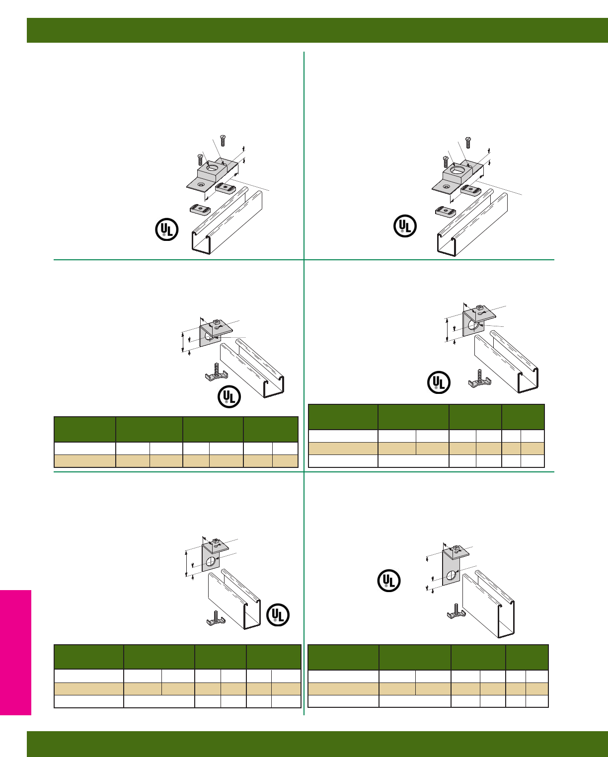
B447A
CONDUIT CONNECTION
PLATE FOR 3/4” (20) CONDUIT
•Includes:
2 pcs. 1/4”-20 Flat Head Machine Screws
2 pcs. N224WO Channel Nuts
•Material: 16 Gauge (1.5)
•Standard finish: ZN
•Wt./C 35 Lbs. (15.9 kg)
B447
CONDUIT CONNECTION
PLATE FOR 1/2” (15) CONDUIT
•Includes:
2 pcs. 1/4”-20 Flat Head Machine Screws
2 pcs. N224WO Channel Nuts
•Material: 16 Gauge (1.5)
•Standard finish: ZN
•Wt./C 35 Lbs. (15.9 kg)
B392-32 SERIES
CONNECTION END CAP
•Includes:
1 pc. 1/4”-20 Square Nut
1 pc. B436S Fixture Stud Nut
•Material: 11 Gauge (3.0)
•Standard finish: ZN
B392-22 SERIES
CONNECTION END CAP
•Includes:
1 pc. 1/4”-20 Square Nut
1 pc. B436S Fixture Stud Nut
•Material: 11 Gauge (3.0)
•Standard finish: ZN
B392-12 SERIES
CONNECTION END CAP
•Includes:
1 pc. 1/4”-20 Square Nut
1 pc. B436S Fixture Stud Nut
•Material: 11 Gauge (3.0)
•Standard finish: ZN
B392-11 SERIES
CONNECTION END CAP
•Includes:
1 pc. 1/4”-20 Square Nut
1 pc. B436S Fixture Stud Nut
•Material: 11 Gauge (3.0)
•Standard finish: ZN
7/8” (22.2) DIA.
2 HOLES
9/32” (7.1) DIA. 2 HOLES
9/32” (7.1) DIA.
5/8”
(15.9)
Wt./C
Part No. A Conduit Size Lbs. kg
B392-32-1/27/8”(22.2) 1/2”(15) 20 (9.1)
B392-32-3/411/16”(27.0) 3/4”(20) 19 (8.6)
15/8”
(41.3)
13/8”
(34.9)
3/4”
(19.0)
A DIA.
9/32” (7.1) DIA.
Wt./C
Part No. A Conduit Size Lbs. kg
B392-12-1/27/8”(22.2) 1/2”(15) 27 (12.2)
B392-12-3/411/16”(22.7) 3/4”(20) 26 (11.8)
B392-12-1 1” PIPE THREAD 1” (25) 23 (10.4)
15/8”
(41.3)
27/16”
(61.9)
3/4”
(19.0)
A DIA.
9/32” (7.1) DIA.
13/32” (27.8) DIA. 5/8”
(15.9)
51/8”
(130.2)
Wt./C
Part No. A Conduit Size Lbs. kg
B392-22-1/27/8”(22.2) 1/2”(15) 21 (9.5)
B392-22-3/411/16”(27.0) 3/4”(20) 20 (9.1)
B392-22-1 1” PIPE THREAD 1” (25) 17 (7.7)
15/8”
(41.3)
15/8”
(41.3)
3/4”
(19.0)
A DIA.
9/32” (7.1) DIA.
Wt./C
Part No. A Conduit Size Lbs. kg
B392-11-1/27/8”(22.2) 1/2”(15) 36 (16.3)
B392-11-3/411/16”(27.0) 3/4”(20) 33 (14.9)
B392-11-1 1” PIPE THREAD 1” (25) 32 (14.5)
15/8”
(41.3)
31/4”
(82.5)
3/4”
(19.0)
A DIA.
9/32” (7.1) DIA.
51/8”
(130.2)
Electrical Accessories
Reference page 150 for general fitting and standard finish specifications. U.L. Wire Fill Chart on pages 218 - 219.
Electrical Accessories
156
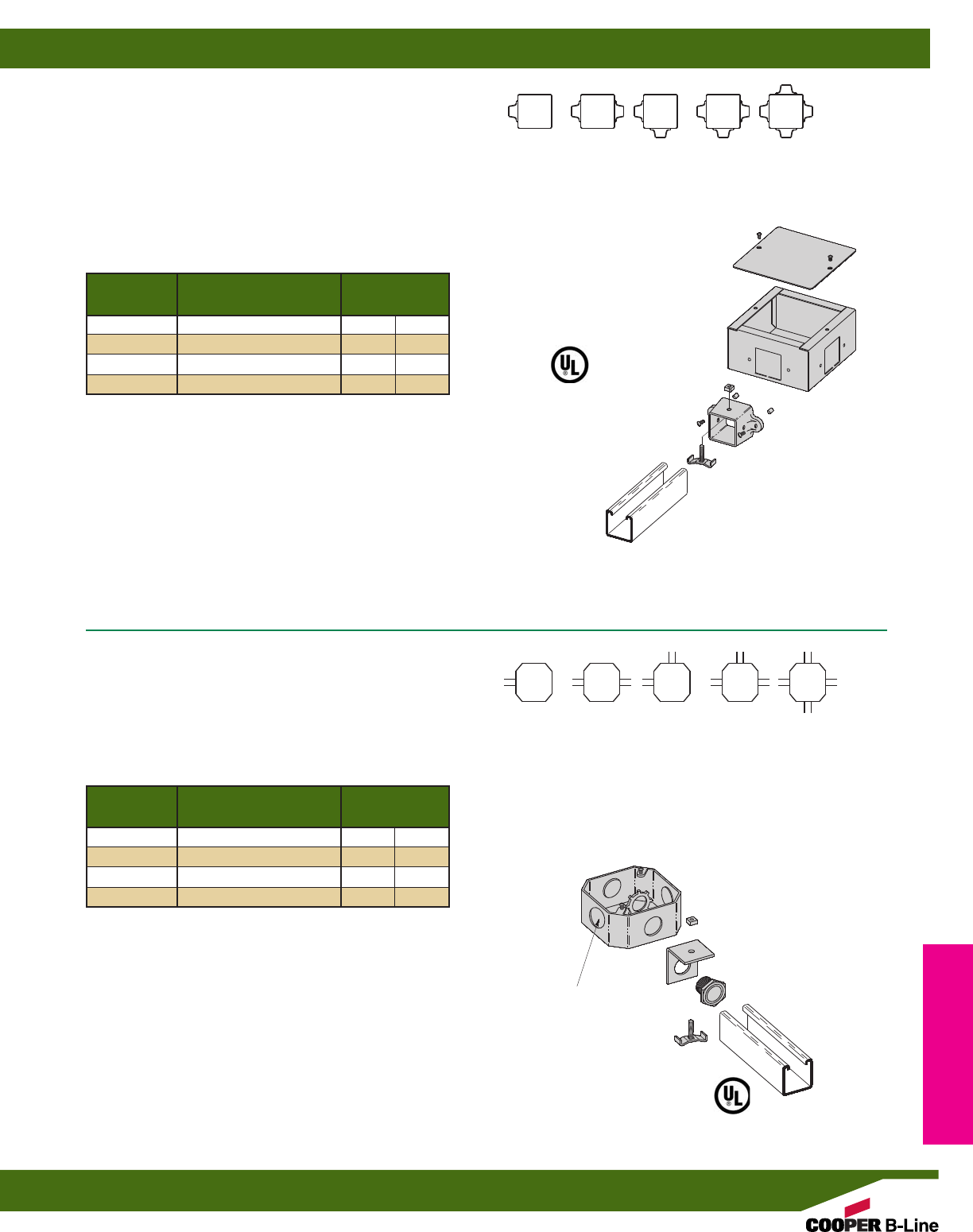
Wt./C
Part No. Includes Lbs. kg
B718-1 1 B718 & 1 B719 205 (93.0)
B718-2 1 B718 & 2 B719 230 (104.3)
B718-3 1 B718 & 3 B719 255 (115.6)
B718-4 1 B718 & 4 B719 280 (127.0)
CHANNEL CONNECTION KIT
•For use with B22, B24 & B26 Channels.
•Box Dimension: Standard 4” Octagon Box
•Includes:
1 pc. B392-22-3/4End Connection (See page 156)
1 pc. 3/4” (20) Insulated Chase Nipple
1 pc. 3/4” (20) Lock Nut
•Standard finish: ZN
Box Dimension:
21/2” Deep x 51/8” Square
B718
UNIVERSAL JUNCTION BOX
•Assemble B719 Hubs into B718 square knockouts
•Designed for use with B22, B24 & B26 Channel
•B718 Includes:
1 pc. Junction Box only
1 pc. Cover only
2 pcs. #10-20 Round Head Machine Screws
•Standard finish: ZN
•Wt./C 180 Lbs. (81.6 kg)
B719AL
UNIVERSAL JUNCTION BOX HUB
•B719AL Includes:
1 pc. B719AL Hub only
1 pc. B436S Fixture Stud Nut
1 pc. 1/4”-20 Square Nut
2 pcs. #10-24 Self Tapping Screws
2 pcs. Rubber Caps
•Material: Aluminum
•Wt./C 25 Lbs. (11.3 kg)
B518-1 THRU B518-4
UNIVERSAL JUNCTION BOX AND HUBS
•Channel Connection Kits as shown in the chart above
•Includes:
1 pc. Junction Box with Screws
1 pc. Box Cover
•Standard finish: ZN
B718-1 B718-2 B718-2 B718-3 B718-4
B718-1
END
B718-2
90°
B718-3
TEE
B718-4
CROSS
B718-2
THRU BOX
Channel Connection Wt./C
Part No. Kits Included Lbs. kg
B518-1 1 106 (48.1)
B518-2 2 137 (62.1)
B518-3 3 162 (78.5)
B518-4 4 192 (87.1)
SELECTION GUIDE
SELECTION GUIDE
B518-1
END
B518-2
90°
B518-3
TEE
B518-4
CROSS
B518-2
THRU BOX
3/4” (19.1) CONDUIT
KNOCKOUTS
Electrical Accessories
Reference page 150 for general fitting and standard finish specifications. U.L. Wire Fill Chart on pages 218 - 219.
Junction Boxes
157
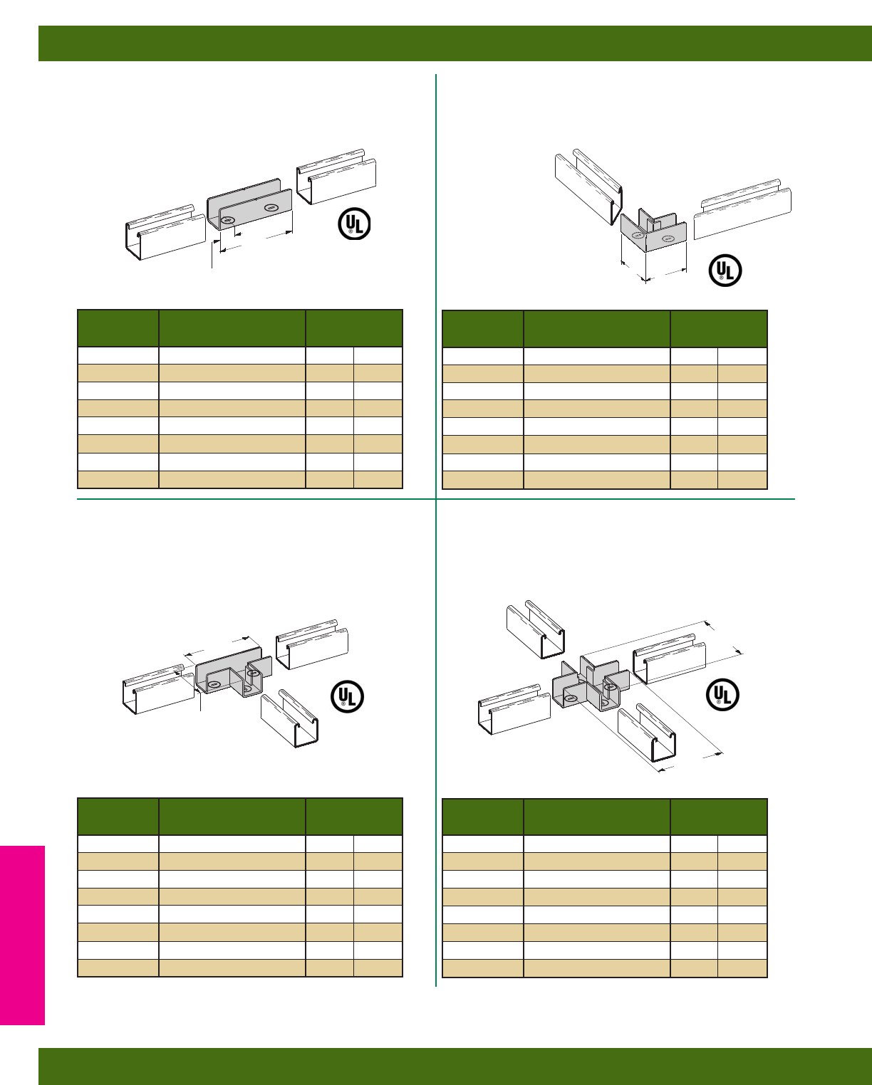
B766 SERIES
STRAIGHT STRUT JOINER
•Includes: 2 Cam Screws
•Material: 12 Gauge (2.6)
•Standard finish: ZN
B768 SERIES
TEE STRUT JOINER
•Includes: 3 Cam Screws
•Patented
•Material: 12 Gauge (2.6)
•Standard finish: ZN
B769 SERIES
CROSS STRUT JOINER
•Includes: 4 Cam Screws
•Patented
•Material: 12 Gauge (2.6)
•Standard finish: ZN
B767 SERIES
90° ELBOW STRUT JOINER
•Includes: 2 Cam Screws
•Material: 12 Gauge (2.6)
•Standard finish: ZN
41/2”
(114.3)
7/8”
(22.2)
41/2”
(114.3)
31/16”
(77.8)
25/16”
(58.7)
25/16”
(58.7)
Wt./C
Part No. For Channel Size Lbs. kg
B767-11 B11 74 (33.5)
B767-12 B12 56 (25.4)
B767-22 * B22 & B24 39 (17.7)
B767-26 B26 41 (18.6)
B767-32 B32 34 (15.4)
B767-42 B42 27 (12.2)
B767-52 B52 & B54 23 (10.4)
B767-56 B56 25 (11.3)
Wt./C
Part No. For Channel Size Lbs. kg
B766-11 B11 94 (42.6)
B766-12 B12 72 (32.6)
B766-22 * B22 & B24 50 (22.7)
B766-26 B26 53 (24.0)
B766-32 B32 44 (19.9)
B766-42 B42 34 (15.4)
B766-52 B52 & B54 28 (12.7)
B766-56 B56 31 (14.0)
Wt./C
Part No. For Channel Size Lbs. kg
B768-11 B11 142 (64.4)
B768-12 B12 112 (50.8)
B768-22 * B22 & B24 79 (35.8)
B768-26 B26 79 (35.8)
B768-32 B32 72 (32.6)
B768-42 B42 62 (28.1)
B768-52 B52 & B54 57 (25.8)
B768-56 B56 60 (27.2)
Wt./C
Part No. For Channel Size Lbs. kg
B769-11 B11 148 (67.1)
B769-12 B12 120 (54.4)
B769-22 * B22 & B24 87 (39.4)
B769-26 B26 93 (42.2)
B769-32 B32 78 (35.4)
B769-42 B42 65 (29.5)
B769-52 B52 & B54 58 (26.3)
B769-56 B56 62 (28.1)
41/2”
(114.3)
41/2”
(114.3)
* Cast Aluminum parts
Note: Strut joiners are not for structural support. A channel support is recommended within 24” (609 mm) of each joint.
Note: B767-22
(Cast Aluminum Fitting)
does not require miter
cutting of channel as
shown in drawing.
Electrical Accessories
Reference page 150 for general fitting and standard finish specifications. U.L. Wire Fill Chart on pages 218 - 219.
Strut Joiners
158
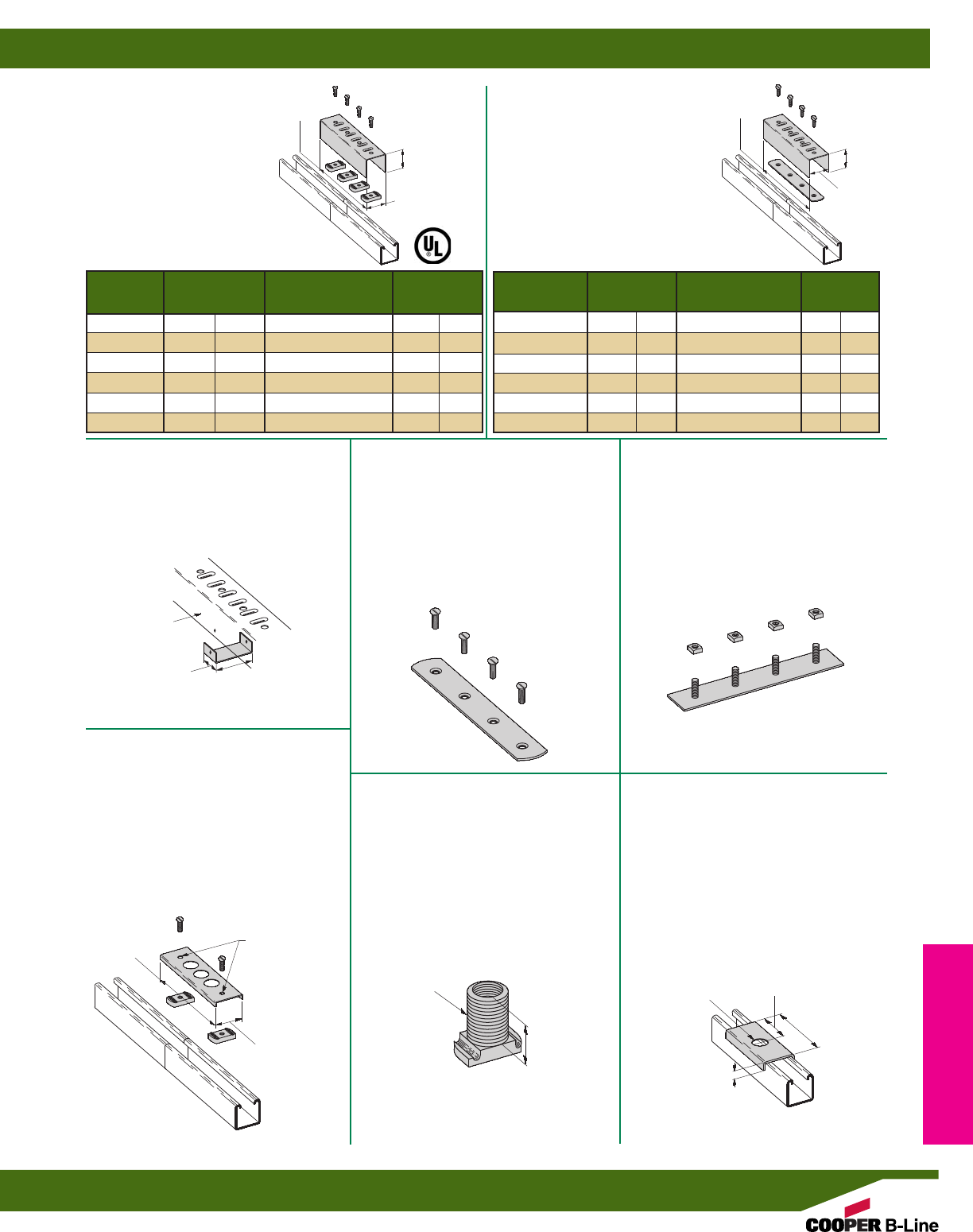
B166-46
FOUR HOLE
SPLICE CLEVIS ASSEMBLY
•Requires ground wire for use with UL
listed channel raceway system
•Includes:
1 Splice Clevis
1 pc. B466W tapped plate
4 pcs. 1/4”-20 Flat Head Machine
Screws
•Material: 16 Gauge (1.5)
•Standard finishes: ZN, GRN
B166
FOUR HOLE
SPLICE CLEVIS
•Includes:
1 Splice Clevis
4 pcs. 1/4”-20 Flat Head
Machine Screws
4 pcs. N224WO Channel Nuts
•Material: 16 Gauge
Wt./C
Part No. A For Channel Size Lbs. kg
B166-11 31/4”(82.5) B11 128 (58.0)
B166-12 27/16”(61.9) B12 108 (49.0)
B166-22 15/8”(41.3) B22, B24, B26 91 (40.3)
B166-32 13/8”(34.9) B32 83 (37.6)
B166-42 1” (25.4) B42 75 (34.0)
B166-52 13/16”(20.6) B52, B54, B56 71 (32.2)
A
111/16”
(42.9)
71/4”
(184.1)
Wt./C
Part No. A For Channel Size Lbs. kg
B166-46-11 31/4”(82.5) B11 118 (53.5)
B166-46-12 27/16”(61.9) B12 98 (44.4)
B166-46-22 15/8”(41.3) B22, B24, B26 79 (35.8)
B166-46-32 13/8”(34.9) B32 73 (33.1)
B166-46-42 1” (25.4) B42 65 (29.5)
B166-46-52 13/16”(20.6) B52, B54, B56 61 (27.6)
A
71/4”
(184.1)
111/16”
(42.9)
B166CL
SPLICE CLEVIS CLIP
•Use to cover gap between strut
•Material: 18 Gauge (1.2)
•Standard finish: ZN
•Wt./C 4 Lbs. (1.8 kg)
B619
KNOCK-OUT PLATE
•Requires ground wire for use with UL
listed channel raceway system
•Includes:
2 pcs. 1/4”-20 Flat Head Machine Screws
2 pcs. N224WO Channel Nuts
•Material: 16 Gauge (1.5)
1/2” (15) Conduit Knockouts
•Standard finish: ZN
•Wt./C 40 Lbs. (18.1 kg)
B393-1
WIRING STUD
•Requires ground wire for use with UL
listed channel raceway system
•1/2” (15) pipe threads
•Material: Cast Aluminum
•Wt./C 6 Lbs. (2.7 kg)
B589
SPACER CLEVIS
•Can be used with B393-1 wiring stud
•Material: 12 Gauge (2.6)
•Standard finish: ZN
•Wt./C 29 Lbs. (13.1 kg)
B466W
TAPPED SPLICE PLATE
•Includes:
4 pcs. 1/4”-20 Flat Head Machine Screws
•Material: 14 Gauge (1.9)
•Standard finish: ZN
•Wt./C 27 Lbs. (12.2 kg)
•Holes 13/16” (20.6) from ends and
17/8” (47.6) on centers
B466S
STUD SPLICE PLATE
•Includes:
4 pcs. 1/4”-20 Square Nuts
•Material: 14 Gauge (1.9)
•Standard finish: ZN
•Wt./C 34 Lbs. (15.4 kg)
•Studs 13/16” (20.6) from ends and
17/8” (47.6) on centers
125/32”
(45.2)
1”
(25.4)
B166
9/32” (7.1) DIA.
HOLES
121/32”
(42.0)
61/4”
(158.7)
11/8”
(28.6)
1/2” (15) PIPE
THREADS 7/8” (22.2) DIA.
1/2”
(12.7)
4”
(101.6)
2”
(50.8)
Electrical Accessories
Reference page 150 for general fitting and standard finish specifications. U.L. Wire Fill Chart on pages 218 - 219.
Strut Joiners
159
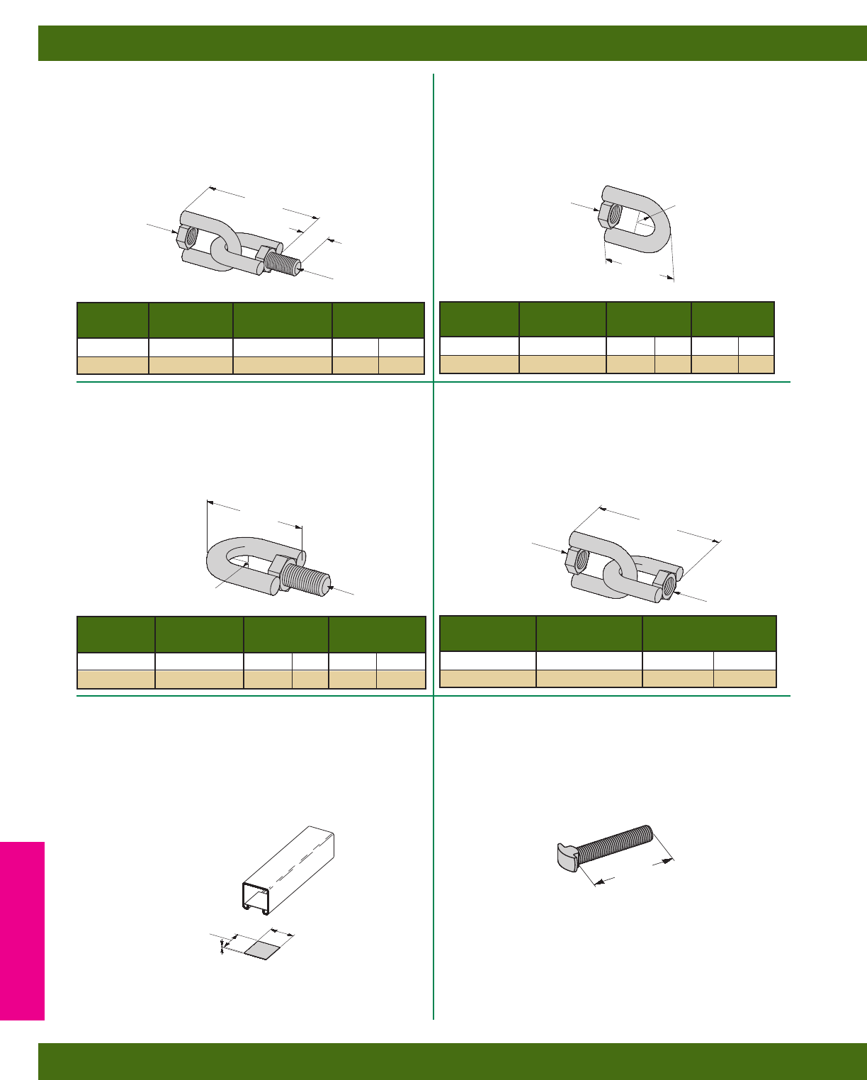
B446A
SWIVEL HANGER
(FEMALE ONLY)
•Design Load:
(3/8)-730 Lbs. (3.24 kN)
(1/2)-1350 Lbs. (6.00 kN)
•Safety Factor of 3
•Standard finish: ZN
B446
SWIVEL HANGER
(FEMALE-MALE)
•Design Load:
(3/8)-730 Lbs. (3.24 kN)
(1/2)-1350 Lbs. (6.00 kN)
•Safety Factor of 3
•Standard finish: ZN
B446B
SWIVEL HANGER
(MALE ONLY)
•Design Load:
(3/8)-730 Lbs. (3.24 kN)
(1/2)-1350 Lbs. (6.00 kN)
•Safety Factor of 3
•Standard finish: ZN
B446C
SWIVEL HANGER
(FEMALE-FEMALE)
•Design Load:
(3/8)-730 Lbs. (3.24 kN)
(1/2)-1350 Lbs. (6.00 kN)
•Safety Factor of 3
•Standard finish: ZN
B590
FIBER WIRE RETAINER
•Installation aid for retaining wires before
installing snap closure strip
•Wt./C 1 Lb. (.4 kg)
B617
SHOULDER BOLT
•Standard finish: ZN
•Wt./C 6 Lbs. (2.7 kg)
Wt./C
Part No. A B Lbs. kg
B446-3/83/8”-16 HN 3/8”-16 HHCS 28 (12.7)
B446-1/21/2”-13 HN 1/2”-13 HHCS 36 (16.3)
A
B
23/4”
(69.8) 1”
(25.4)
Wt./C
Part No. A R Lbs. kg
B446A-3/83/8”-16 HN 9/32”(7.1) 13 (5.9)
B446A-1/21/2”-13 HN 3/8”(9.5) 15 (6.8)
13/4”
(44.4)
AR
Wt./C
Part No. B R Lbs. kg
B446B-3/83/8”-16 HHCS 9/32”(7.1) 16 (7.2)
B446B-1/21/2”-13 HHCS 3/8”(9.5) 20 (9.1)
13/4”
(44.4)
B
R
Wt./C
Part No. A Lbs. kg
B446C-3/83/8”-16 HN 26 (11.8)
B446C-1/21/2”-13 HN 31 (14.0)
23/4”
(69.8)
A
A
13/8”
(34.9)
11/2”
(38.1)
1/32”
(.8)
3/8”-16 THREAD SIZE
2”
(50.8)
Electrical Accessories
Reference page 150 for general fitting and standard finish specifications. U.L. Wire Fill Chart on pages 218 - 219.
Electrical Hardware
160
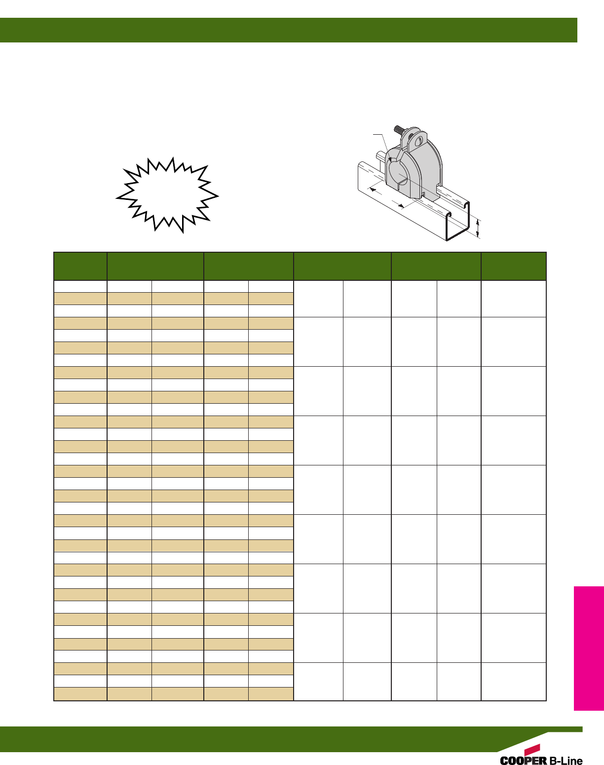
Wt./C Clamp No.
Part No. Hole Dia. Lbs. kg A B (included)
B4060 3/8”(9.5) 25 (11.3)
B4061 1/2”(12.7) 25 (11.3) 1.36” (34.5) .56” (14.2) B2030
B4062 5/8”(15.9) 25 (11.3)
B4063 3/4”(19.0) 37 (16.8)
B4064 7/8”(22.2) 37 (16.8) 1.86” (47.2) .81” (20.8) B2034
B4065 1” (25.4) 37 (16.8)
B4066 11/8”(28.6) 37 (16.8)
B4067 11/4”(31.7) 58 (26.3)
B4068 13/8”(34.9) 58 (26.3) 2.36” (59.9) 1.06” (26.9) B2038
B4069 11/2”(38.1) 58 (26.3)
B4070 15/8”(41.3) 58 (26.3)
B4071 13/4”(44.4) 76 (34.5)
B4072 17/8”(47.6) 76 (34.5) 2.86” (72.6) 1.31” (33.3) B2042
B4073 2” (50.8) 76 (34.5)
B4074 21/8”(54.0) 76 (34.5)
B4075 21/4”(57.1) 90 (40.8)
B4076 23/8”(60.3) 90 (40.8) 3.36” (85.3) 1.56” (39.6) B2046
B4077 21/2”(63.5) 90 (40.8)
B4078 25/8”(66.7) 90 (40.8)
B4079 23/4”(69.8) 109 (49.4)
B4080 27/8”(73.0) 109 (49.4) 3.86” (98.0) 1.81” (46.0) B2050
B4081 3” (76.2) 109 (49.4)
B4082 31/8”(79.4) 109 (49.4)
B4083 31/4”(82.5) 130 (58.9)
B4084 33/8”(85.7) 130 (58.9) 4.36” (110.7) 2.06” (52.3) B2054
B4085 31/2”(88.9) 130 (58.9)
B4086 35/8”(92.1) 130 (58.9)
B4087 33/4”(95.2) 160 (72.6)
B4088 37/8”(98.4) 160 (72.6) 4.86” (123.4) 2.31” (58.7) B2058
B4089 4” (101.6) 160 (72.6)
B4090 41/8”(104.8) 160 (72.6)
B4091 41/4”(107.9) 160 (72.6)
B4092 43/8”(111.1) 160 (72.6) 5.24” (133.1) 2.50” (63.5) B2018
B4093 41/2”(114.3) 160 (72.6)
B4060 THRU B4093
INSULCLAMP®CABLE CLAMPS (Replaces porcelain clamps)
• Assembly includes:
1 Insulclamp®& 1 pr. zinc plated Pipe Straps with Everdur (Silicon Bronze) Hardware
• The thermoplastic elastomer Insulclamp has a dielectric strength of 640 volts/mil
• The flame retardant one piece design allows for trouble free assembly
• Everdur hardware is non-ferrous and prevents magnetic induction
B
A
HOLE DIA.
New &
Improved
Electrical Accessories
Reference page 150 for general fitting and standard finish specifications. U.L. Wire Fill Chart on pages 218 - 219.
Insulclamp®Clamps
161
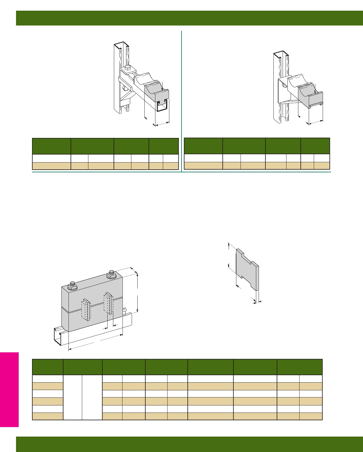
B4094 & B4095
PORCELAIN CABLE
RACK SADDLE
• Electrical porcelain has an
dielectric strength of 50 volts/mil
• Designed for use with B449 Brackets
B4050 & B4051
PORCELAIN CABLE
CHANNEL SADDLE
• Electrical porcelain has an
dielectric strength of 50 volts/mil
B4035A THRU B4035F
4” (101.6) BUS BAR
MAPLE CLAMPS
• Assembly Includes:
1 pr. Maple Clamps (Paraffin Impregnated)
3 pcs. 1/2” Flat Washers
3 pcs. N225WO
3 pcs. SQN-1/2”
3 pcs. ATR-1/2x L (Length)
• Required number of Separators
• 1/4” (6.3) x 2” (50.8) and 1/4” (6.3) x 6” (152.4)
Bus Bar Maple Clamps available
B4037B 1/4” (6.3) x 4” (101.6)
BUS BAR SEPARATOR
• Wt./C 9 Lbs. (4.1 kg)
Wt./C
Part No. A R Lbs. kg
B4050 3” (76.2) 13/8”(34.9) 72 (32.6)
B4051 4” (101.6) 21/8”(54.0) 100 (45.3)
Wt./C
Part No. A R Lbs. kg
B4094 27/8”(73.0) 13/8”(34.9) 67 (30.4)
B4095 37/8”(98.4) 21/8”(54.0) 106 (48.1)
No. of Bus No. of Bars Wt./C
Part No. A B C Separators Per Leg Lbs. kg
B4035A 81/2”(215.9) 1/4”(6.3) – 1 416 (188.7)
B4035B 91/2”(241.3) 3/4”(19.0) 2 2 447 (202.7)
B4035C 73/8”(187.3) 101/2”(266.7) 11/4”(31.7) 4 3 479 (217.3)
B4035D 111/2”(292.1) 13/4”(44.4) 64511(231.8)
B4035E 121/2”(317.5) 21/4”(57.1) 8 5 542 (245.8)
B4035F 131/2”(342.9) 23/4”(69.8) 10 6 574 (260.3)
x
A
R
21/4”
(57.1)
x
A
R
3”
(76.2)
A
B
C
15/8”
(41.3)
47/16”
(112.7)
31/2”
(88.9)
1/4”
(6.3)
Electrical Accessories
Reference page 150 for general fitting and standard finish specifications. U.L. Wire Fill Chart on pages 218 - 219.
Porcelain & Maple Clamps
162
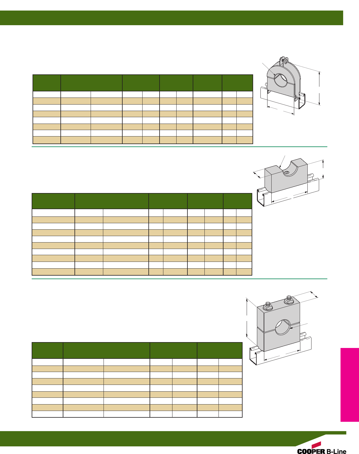
B4000 THRU B4007
MAPLE CABLE CLAMPS
• Assembly Includes:
1 pr. Maple Clamps (Paraffin Impregnated)
1 pr. zinc plated Steel Pipe Straps with Everdur Hardware (Silicon Bronze)
• Everdur hardware is non-ferrous and prevents magnetic induction
Note: Maple cable clamps may be replaced with Insulclamps®see page 161 for sizes
B4008 THRU B4017
SQUARE MAPLE CABLE SADDLE
• Assembly Includes:
1 Maple Saddle (Paraffin Impregnated)
1 pc. 3/8”-16 Flat Head Machine Screw
1 pc. N228 Channel Nut
• Other sizes available
B4033A THRU B4033I
MAPLE CABLE CLAMPS
• Assembly Includes:
1 pr. Maple Clamps (Paraffin Impregnated)
2 pcs. 3/8”-16 Stud Bolts
2 pcs. 3/8”-16 Flat Washers
2 pcs. 3/8”-16 Square Nuts
2 pcs. N228 Channel Nuts
• Other sizes available
Clamp No. Wt./C
Part No. Specify Hole Dia. A B (included) Lbs. kg
B4000 0” to 5/8”(0.0 to 15.9) 111/32”(34.1) 2” (50.8) B2010 24 (10.9)
B4001 1/2” to 1” (12.7 to 25.4) 129/32”(48.4) 225/32”(70.6) B2012 44 (19.9)
B4002 3/4” to 11/2”(19.0 to 38.1) 23/8”(60.3) 39/32”(83.3) B2013 58 (26.3)
B4003 11/4” to 13/4”(31.7 to 44.4) 27/8”(73.0) 33/4”(95.2) B2014 66 (29.9)
B4004 11/2” to 21/4”(38.1 to 57.1) 31/2”(88.9) 43/8”(111.1) B2015 86 (39.0)
B4005 2” to 21/2”(50.8 to 63.5) 4” (101.6) 47/8”(123.8) B2016 110 (49.9)
B4006 21/4” to 3” (38.1 to 76.2) 41/2”(114.3) 53/8”(136.5) B2017 125 (56.7)
B4007 3” to 4” (76.2 to 101.6) 59/16”(141.3) 67/16”(163.5) B2019 165 (74.8)
B
A
Specify Wt./C
Part No. Hole Dia. A B Lbs. kg
B4008 0” to 1” (0.0 to 25.4) 3” (76.2) 13/4”(44.4) 35 (15.9)
B4009 1” to 11/2”(25.4 to 38.1) 31/2”(88.9) 2” (50.8) 42 (19.0)
B4010 11/2” to 2” (38.1 to 50.8) 4” (101.6) 21/4”(57.1) 53 (24.0)
B4011 2” to 21/2”(50.8 to 63.5) 41/2”(114.3) 21/2”(63.5) 62 (28.1)
B4012 21/2” to 3” (63.5 to 76.2) 5” (127.0) 23/4”(69.8) 76 (34.5)
B4013 3” to 31/2”(76.2 to 88.9) 51/2”(139.7) 3” (76.2) 85 (38.5)
B4014 31/2” to 4” (88.9 to 101.6) 6” (152.4) 31/4”(82.5) 95 (43.1)
B4015 4” to 41/2”(101.6 to 114.3) 7” (177.8) 33/4”(95.2) 105 (47.8)
B4016 41/2” to 5” (114.3 to 127.0) 71/2”(190.5) 4” (101.6) 115 (52.4)
B4017 5” to 6” (127.0 to 152.4) 9” (228.6) 5” (127.0) 126 (57.1)
A
B
15/8”
(41.3)
15/8”
(41.3)
SPECIFY HOLE DIA.
SPECIFY HOLE DIA.
Specify Wt./C
Part No. Hole Dia. A Lbs. kg
B4033A 0” to 1” (0.0 to 25.4) 31/2”(88.9) 85 (38.5)
B4033B 1” to 11/2”(25.4 to 38.1) 4” (101.6) 95 (43.1)
B4033C 11/2to 2” (38.1 to 50.8) 41/2”(114.3) 118 (53.5)
B4033D 2” to 21/2”(50.8 to 63.5) 51/2”(127.0) 162 (73.5)
B4033E 21/2” to 3” (63.5 to 76.2) 6” (152.4) 187 (84.8)
B4033F 3” to 31/2”(76.2 to 88.9) 61/2”(165.1) 209 (94.8)
B4033G 31/2” to 4” (88.9 to 101.6) 7” (177.8) 248 (112.5)
B4033H 4” to 41/2”(101.6 to 114.3) 71/2”(190.5) 270 (122.5)
B4033I 41/2” to 5” (114.3 to 127.0) 8” (203.2) 298 (135.2)
A
A
SPECIFY
HOLE DIA.
Electrical Accessories
Reference page 150 for general fitting and standard finish specifications. U.L. Wire Fill Chart on pages 218 - 219.
Maple Clamps
163
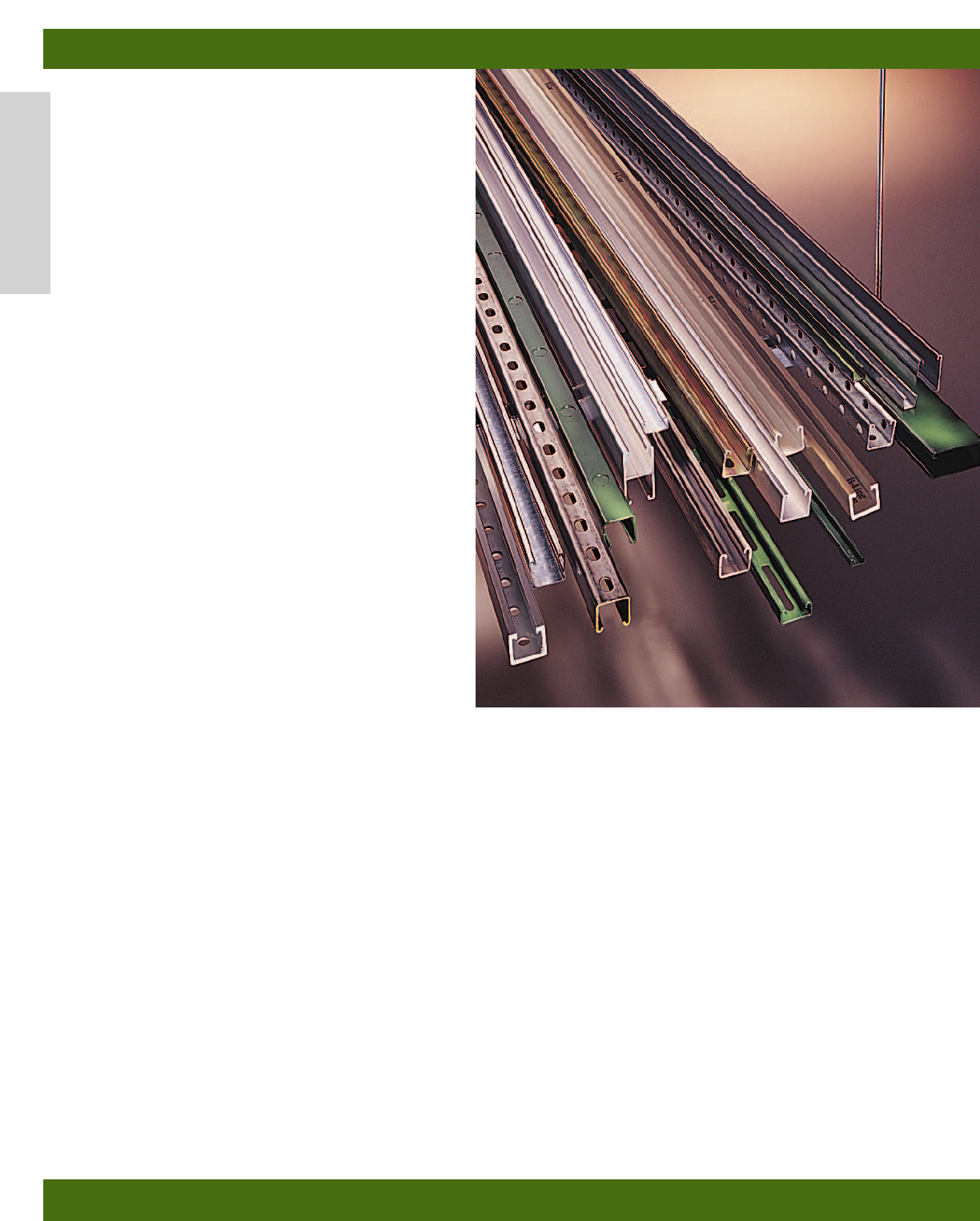
Aluminum
Aluminum channels, fittings and accessories offer
excellent corrosion resistance and are suitable for
many indoor and outdoor applications. Aluminum’s
high strength to weight ratio greatly reduces overall
cost of installation through ease of handling and
cutting. B-Line’s channels are extruded from aluminum
alloy 6063-T6. Closure strips are extruded from
aluminum alloy 6063-T5. Fittings and accessories are
made from aluminum alloy 5052-H32.
Stainless Steel
Where corrosion problems persist and other material
and fittings are ineffective, we recommend use of
B-Line’s corrosion resistant stainless steel channels
and accessories. Channels and fittings are available in
two types of stainless steel:
SS4-AISI Type 304
SS6-AISI Type 316
Fittings
Most fittings, as shown in this catalog, can be supplied
in aluminum or stainless steel.
Consult factory for possible minimum production
quantities and set-up charges.
Load Data
Aluminum
Channel’s approximate load data can be determined
by multiplying load data in the steel channel
section of this catalog by a factor of 0.38.
Stainless Steel
Channel load data is the same as the data in the
steel channel section of this catalog.
Metric
Metric dimensions are shown in parentheses. Unless noted, all metric dimensions are in millimeters.
Alum. & Stainless Steel Materials
Aluminum & Stainless Steel
164
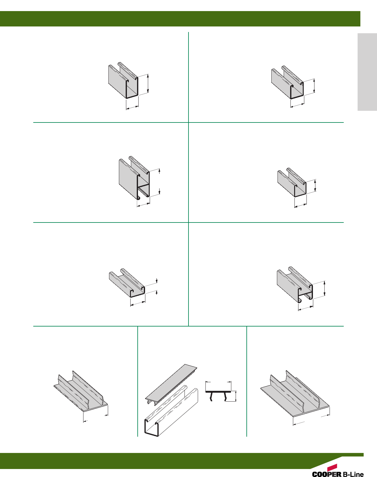
B12AL
•Thickness: .105 (2.6 mm)
•Standard Length: 10’ (3.05 m) and 20’ (6.09 m)
•Material: Aluminum
•Weight: .86 Lbs./Ft. (1.28 kg/m)
27/16”
(61.9)
15/8”
(41.3)
B22AAL
•Thickness: .105 (2.6 mm)
•Standard Length: 10’ (3.05 m) and 20’ (6.09 m)
•Material: Aluminum
•Weight: 1.18 Lbs./Ft. (1.75 kg/m)
15/8”
(41.3)
31/4”
(82.5)
B54AL
•Thickness: .080 (2.0 mm)
•Standard Length: 10’ (3.05 m) and 20’ (6.09 m)
•Material: Aluminum
•Weight: .37 Lbs./Ft. (0.55 kg/m)
15/8”
(41.3)
13/16”
(20.6)
B22AL
•Thickness: .105 (2.6 mm)
•Standard Length: 10’ (3.05 m) and 20’ (6.09 m)
•Material: Aluminum
•Weight: .66 Lbs./Ft. (0.98 kg/m)
15/8”
(41.3)
15/8”
(41.3)
B24AL
•Thickness: .080 (2.0 mm)
•Standard Length: 10’ (3.05 m) and 20’ (6.09 m)
•Material: Aluminum
•Weight: .52 Lbs./Ft. (0.77 kg/m)
15/8”
(41.3)
15/8”
(41.3)
B54AAL
•Thickness: .080 (2.0 mm)
•Standard Length: 10’ (3.05 m) and 20’ (6.09 m)
•Material: Aluminum
•Weight: .57 Lbs./Ft. (0.84 kg/m)
15/8”
(41.3)
15/8”
(41.3)
B217AL
CLOSURE STRIP
•Standard Length: 10’ (304.8 cm)
•Material: Aluminum
•Weight: .15 Lbs./Ft. (0.23 kg/m)
B217P
PLASTIC CLOSURE STRIP
•Standard Length: 10’ (304.8 cm)
•Material: PVC
•Weight: .09 Lbs./Ft. (0.14 kg/m)
B217FFAL
CLOSURE STRIP
•Standard Length: 10’ (304.8 cm)
•Material: Aluminum
•Weight: .16 Lbs./Ft. (0.24 kg/m)
17/16”
(36.5) 21/2”
(63.5)
17/16”
(36.5)
5/8”
(15.9)
Alum. & Stainless Steel Materials
Reference page 164 for general fitting specifications.Other channel combinations available-see steel section for styles.
Aluminum Channel & Closure Strips
165
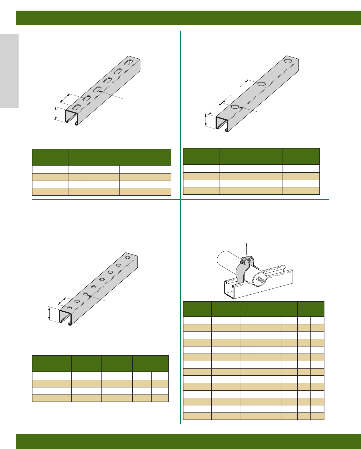
SH TYPE CHANNEL
•Material: Aluminum
H-17/8 TYPE CHANNEL
•Material: Aluminum
B2000 SERIES
RIGID CONDUIT CLAMPS
•Safety Factor of 5
•Machine Screw and Square Nut included
•Pipe clamp material 5052-H32
KO6 TYPE KNOCKOUT CHANNEL
•Material: Aluminum
Wt./C
Part No. Thickness H Lbs./Ft. kg/m
B12SH AL .105 (2.6) 27/16”(61.9) .83 (1.23)
B22SH AL .105 (2.6) 15/8”(41.3) .63 (.93)
B24SH AL .080 (2.0) 15/8”(41.3) .49 (.73)
B54SH AL .080 (2.0) 13/16”(20.6) .34 (.50)
Wt./C
Part No. Thickness H Lbs./Ft. kg/m
B12KO6 AL .105 (2.6) 27/16”(61.9) .86 (1.28)
B22KO6 AL .105 (2.6) 15/8”(41.3) .66 (.98)
B24KO6 AL .080 (2.0) 15/8”(41.3) .52 (.77)
B54KO6 AL .080 (2.0) 13/16”(20.6) .37 (.55)
Wt./C
Part No. Thickness H Lbs./Ft. kg/m
B12H17/8 AL .105 (2.6) 27/16”(61.9) .86 (1.28)
B22H17/8 AL .105 (2.6) 15/8”(41.3) .66 (.98)
B24H17/8 AL .080 (2.0) 15/8”(41.3) .52 (.77)
B54H17/8 AL .080 (2.0) 13/16”(20.6) .37 (.55)
Conduit or Material Design Load Wt./C
Part No. Pipe Size Thickness Lbs. kN Lbs. kg
B2007 AL 3/8”(10) .063 (1.6) 180 (.80) 4(1.8)
B2008 AL 1/2”(15) .063 (1.6) 180 (.80) 4(1.8)
B2009 AL 3/4”(20) .080 (2.0) 270 (1.20) 6(2.7)
B2010 AL 1” (25) .080 (2.0) 270 (1.20) 7(3.2)
B2011 AL 11/4”(32) .080 (2.0) 270 (1.20) 8(3.6)
B2012 AL 11/2”(40) .100 (2.5) 360 (1.60) 11 (5.0)
B2013 AL 2” (50) .100 (2.5) 360 (1.60) 12 (5.4)
B2014 AL 21/2”(65) .100 (2.5) 360 (1.60) 13 (5.9)
B2015 AL 3” (80) .100 (2.5) 360 (1.60) 16 (7.2)
B2016 AL 31/2”(90) .125 (3.2) 450 (2.00) 22 (10.0)
B2017 AL 4” (100) .125 (3.2) 450 (2.00) 24 (10.9)
B2018 AL 41/2”(115) .125 (3.2) 450 (2.00) 26 (11.8)
B2019 AL 5” (125) .125 (3.2) 450 (2.00) 27 (12.2)
B2020 AL 6” (150) .125 (3.2) 450 (2.00) 33 (14.9)
2” TYP.
(50.8)
H
9/16” x 11/8” SLOTS
(14.2) (28.6)
H
9/16” (14.2) DIA. HOLES
6”
(152.4)
3”
(76.2)
H
7/8” (22.2) DIA. KO
17/8” TYP.
(47.6)
Design Load
Alum. & Stainless Steel Materials
Reference page 164 for general fitting specifications.Other channel combinations available-see steel section for styles.
Aluminum
166
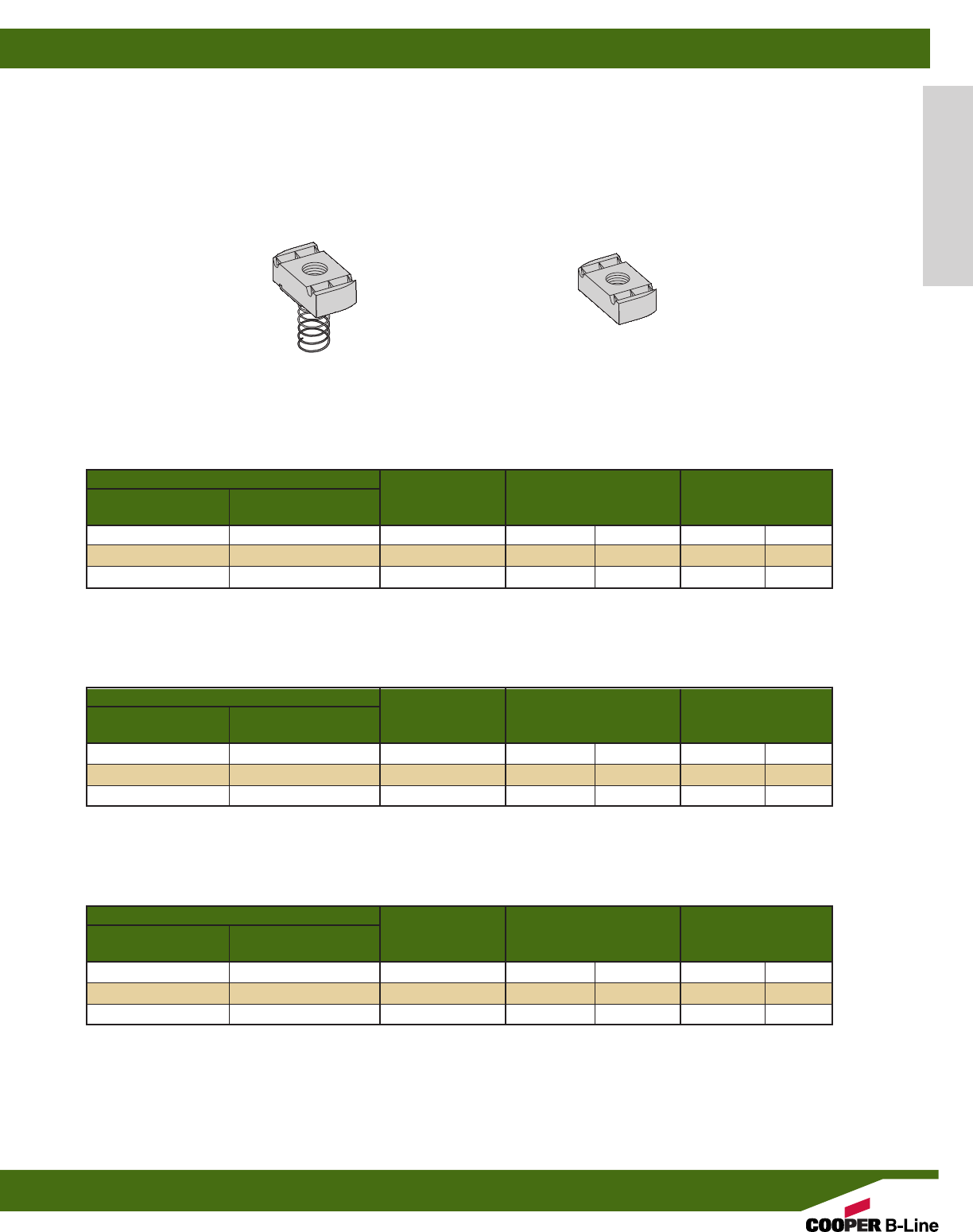
Part Number
With Without Thread Wt./C
Spring Spring Size Thickness Lbs. kg
N724SS6 N224WOSS6 1/4”-20 1/4”(6.3) 6.6 (3.0)
N728SS6 N228WOSS6 3/8”-16 3/8”(9.5) 10.6 (4.8)
N725SS6 N225WOSS6 1/2”-13 3/8”(9.5) 9.7 (4.4)
Part Number
With Without Thread Wt./C
Spring Spring Size Thickness Lbs. kg
N224SS6 N224WOSS6 1/4”-20 1/4”(6.3) 6.6 (3.0)
N228SS6 N228WOSS6 3/8”-16 3/8”(9.5) 10.6 (4.8)
N225SS6 N225WOSS6 1/2”-13 3/8”(9.5) 9.7 (4.4)
Part Number
With Without Thread Wt./C
Spring Spring Size Thickness Lbs. kg
N524SS6 N224WOSS6 1/4”-20 1/4”(6.3) 6.6 (3.0)
N528SS6 N228WOSS6 3/8”-16 3/8”(9.5) 10.6 (4.8)
N525SS6 N525WOSS6 1/2”-13 3/8”(9.5) 9.7 (4.4)
NUTS FOR B12 CHANNEL
NUTS FOR B22, B24 CHANNELS
NUTS FOR B54 CHANNEL
B-Line recommends the use of Stainless Steel channel nuts with Aluminum channel. For channel nut pull-out strength and slip
resistance, use the channel nut information provided on pg. 50 & 51. A (.70) multiplier is to be applied to obtain the appropriate
derated values for aluminum channel.
ALUMINUM FITTINGS
Most fittings, as shown in this catalog, can be supplied in aluminum. See “Fittings” section of this catalog.
Consult factory for possible minimum production quantities and set-up charges.
SPRING NUT NUT WITHOUT SPRING
Alum. & Stainless Steel Materials
Reference page 164 for general fitting specifications.Other channel combinations available-see steel section for styles.
Aluminum
167
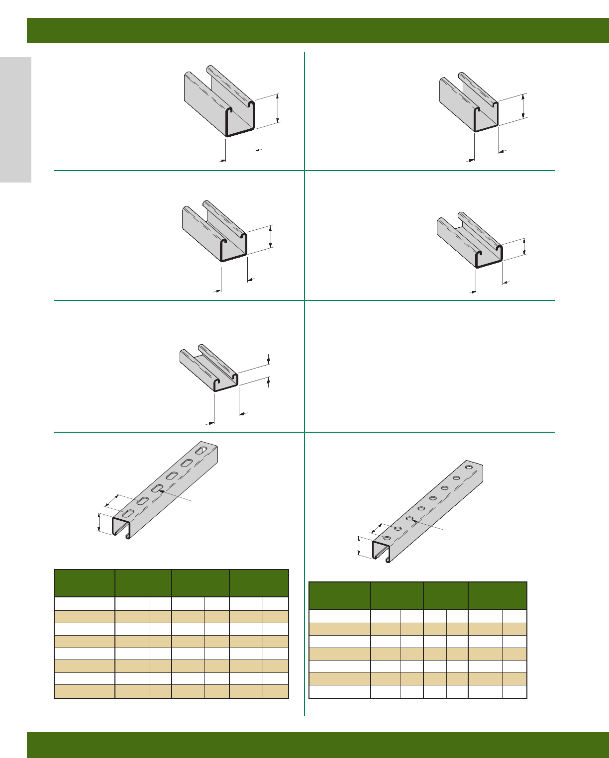
SH TYPE CHANNEL H-17/8 TYPE CHANNEL
B22SS*
•*Substitute 4 for Stainless Steel
Type 304 or 6 for Stainless Steel
Type 316
•Thickness: 12 Ga. (2.6 mm)
•Standard Length: 10’ (3.05 m)
and 20’ (6.09 m)
•Material: SS4, SS6
•Weight: 1.90 Lbs./Ft. (2.83 kg/m)
B32SS4
•Thickness: 12 Ga. (2.6 mm)
•Standard Length: 10’ (3.05 m)
and 20’ (6.09 m)
•Material: SS4
•Weight: 1.70 Lbs./Ft. (2.53 kg/m)
B42SS4
•Thickness: 12 Ga. (2.6 mm)
•Standard Length: 10’ (3.05 m)
and 20’ (6.09 m)
•Material: SS4
•Weight: 1.44 Lbs./Ft. (2.14 kg/m)
B24SS*
•*Substitute 4 for Stainless Steel
Type 304 or 6 for Stainless Steel
Type 316
•Thickness: 14 Ga. (1.9 mm)
•Standard Length: 10’ (3.05 m)
and 20’ (6.09 m)
•Material: SS4, SS6
•Weight: 1.40 Lbs./Ft. (2.08 kg/m)
B54SS*
•*Substitute 4 for Stainless Steel
Type 304 or 6 for Stainless Steel
Type 316
•Thickness: 14 Ga. (1.9 mm)
•Standard Length: 10’ (3.05 m)
and 20’ (6.09 m)
•Material: SS4, SS6
•Weight: .97 Lbs./Ft. (1.44 kg/m)
Wt./C
Part No. Thickness H Lbs./Ft. kg/m
B22SH SS4 12 Ga. (2.6) 15/8”(41.3) 1.82 (2.70)
B22SH SS6 12 Ga. (2.6) 15/8” (41.3) 1.82 (2.70)
B24SH SS4 14 Ga. (1.9) 15/8”(41.3) 1.34 (1.99)
B24SH SS6 14 Ga. (1.9) 15/8”(41.3) 1.34 (1.99)
B32SH SS4 12 Ga. (2.6) 13/8”(34.9) 1.62 (2.41)
B42SH SS4 12 Ga. (2.6) 1” (25.4) 1.36 (2.02)
B54SH SS4 14 Ga. (1.9) 13/16”(20.6) .91 (1.35)
B54SH SS6 14 Ga. (1.9) 13/16”(20.6) .91 (1.35)
Wt./C
Part No. Thickness H Lbs./Ft. kg/m
B22H17/8 SS4 12 Ga. (2.6) 15/8”(41.3) 1.85 (2.75)
B24H17/8 SS4 14 Ga. (1.9) 15/8”(41.3) 1.36 (2.02)
B24H17/8 SS6 14 Ga. (1.9) 15/8”(41.3) 1.36 (2.02)
B32H17/8 SS4 12 Ga. (2.6) 13/8”(34.9) 1.65 (2.45)
B42H17/8 SS4 12 Ga. (2.6) 1” (25.4) 1.39 (2.07)
B54H17/8 SS4 14 Ga. (1.9) 13/16”(20.6) .93 (1.38)
B54H17/8 SS6 14 Ga. (1.9) 13/16”(20.6) .93 (1.38)
9/16” x 7/8” SLOTS
(14.2) (22.2)
2” TYP.
(50.8)
H
H9/16” (14.2) DIA. HOLES
17/8” TYP.
(47.6)
15/8”
(41.3)
15/8”
(41.3)
15/8”
(41.3)
13/8”
(34.9) 1”
(25.4)
13/16”
(20.6)
15/8”
(41.3)
15/8”
(41.3)
15/8”
(41.3)
15/8”
(41.3)
Alum. & Stainless Steel Materials
Reference page 164 for general fitting specifications.Other channel combinations available-see steel section for styles.
Stainless Steel
168
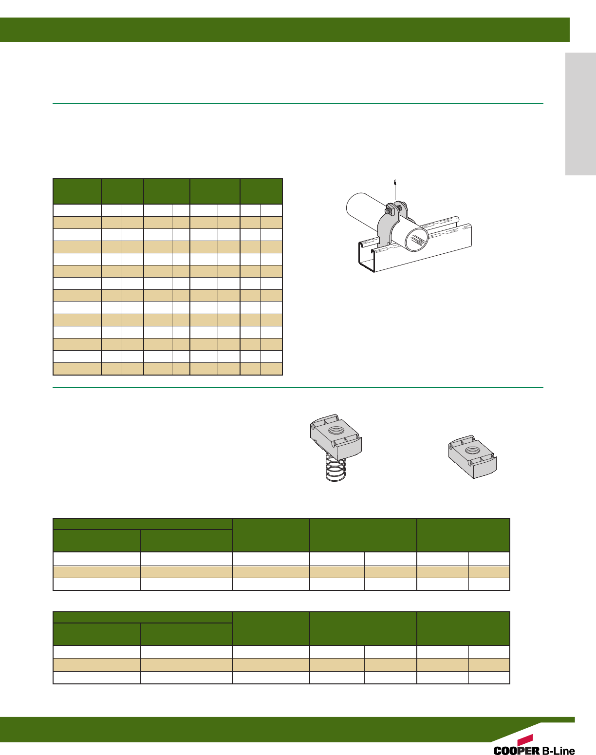
Part Number
With Without Thread Wt./C
Spring Spring Size Thickness Lbs. kg
N224SS6 N224WOSS6 1/4”-20 1/4”(6.3) 6.6 (3.0)
N228SS6 N228WOSS6 3/8”-16 3/8”(9.5) 10.6 (4.8)
N225SS6 N225WOSS6 1/2”-13 3/8”(9.5) 9.7 (4.4)
Part Number
With Without Thread Wt./C
Spring Spring Size Thickness Lbs. kg
N524SS6 N224WOSS6 1/4”-20 1/4”(6.3) 6.6 (3.0)
N528SS6 N228WOSS6 3/8”-16 3/8”(9.5) 10.6 (4.8)
N525SS6 N225WOSS6 1/2”-13 3/8”(9.5) 9.7 (4.4)
NUTS FOR B22, B24, B32 CHANNELS
CHANNEL NUTS
•For Channel Nuts pull-out strength and slip resistance, use the data
shown in “Channel Nuts & Hardware” section of this catalog.
Note: Reduce slip load by 50% due to hardness of material.
NUTS FOR B42, B52, B54 CHANNELS
Conduit Material Design Load Wt./C
Part No. Pipe Size Thickness Lbs. kN Lbs. kg
B2007 SS4 3/8”(10) 16 Ga. (1.5) 400 (1.78) 10 (4.5)
B2008 SS4 1/2”(15) 16 Ga. (1.5) 400 (1.78) 11 (5.0)
B2009 SS4 3/4”(20) 14 Ga. (1.9) 600 (2.67) 15 (6.8)
B2010 SS4 1” (25) 14 Ga. (1.9) 600 (2.67) 16 (7.2)
B2011 SS4 11/4”(32) 14 Ga. (1.9) 600 (2.67) 20 (9.1)
B2012 SS4 11/2”(40) 12 Ga. (2.6) 800 (3.56) 30 (13.6)
B2013 SS4 2” (50) 12 Ga. (2.6) 800 (3.56) 34 (15.4)
B2014 SS4 21/2”(65) 12 Ga. (2.6) 800 (3.56) 38 (17.2)
B2015 SS4 3” (80) 12 Ga. (2.6) 800 (3.56) 44 (19.9)
B2016 SS4 31/2”(90) 12 Ga. (2.6) 1000 (4.45) 51 (23.1)
B2017 SS4 4” (100) 12 Ga. (2.6) 1000 (4.45) 55 (24.9)
B2018 SS4 41/2”(115) 12 Ga. (2.6) 1000 (4.45) 59 (26.7)
B2019 SS4 5” (125) 12 Ga. (2.6) 1000 (4.45) 64 (29.0)
B2020 SS4 6” (150) 12 Ga. (2.6) 1000 (4.45) 80 (36.3)
STAINLESS STEEL FITTINGS
Most fittings, as shown in this catalog, can be supplied in Type 304 or Type 316 stainless steel. See “Fittings” section of this catalog.
Consult factory for possible minimum production quantities and set-up charges.
B2000 SERIES
PIPE AND TUBING CLAMPS
•Safety Factor of 5
•Combination Recess Hex Head Machine Screw and Square Nut included
•Material: Stainless Steel Type 304 & 316
SPRING NUT NUT WITHOUT SPRING
Design Load
Alum. & Stainless Steel Materials
Reference page 164 for general fitting specifications.Other channel combinations available-see steel section for styles.
Stainless Steel
169

B-Line offers two fire retardant (FR) resins for strut
systems, polyester and vinyl ester. Both resins are ideal
for corrosive environments.
While polyester is sufficient for most uses, vinyl ester
is suitable for a broader range of environments.
Please refer to the "Corrosion Resistance Guide" for
specific applications, page 171.
Materials & Finishes
B-Line Fiberglass Strut systems are manufactured from
glass fiber-reinforced plastic shapes that meet ASTM E-
84, Class 1 Flame Rating and self-extinguishing require-
ments of ASTM D-635. A surface veil is applied during
pultrusion to insure a resin-rich surface and ultraviolet
resistance.
Fittings
The following dimensions apply to all fittings except as
noted on the drawings:
Hole Size–13/32” (10.3 mm) Dia.
Hole Spacing–13/16” (20.6 mm) from end and
17/8” (47.6 mm) on center.
Width–15/8” (41.3 mm)
Thickness–1/4” (6.3 mm)
Metric
Metric dimensions are shown in parentheses. Unless
noted, all metric dimensions are in millimeters.
Fiberglass Materials
Fiberglass
170
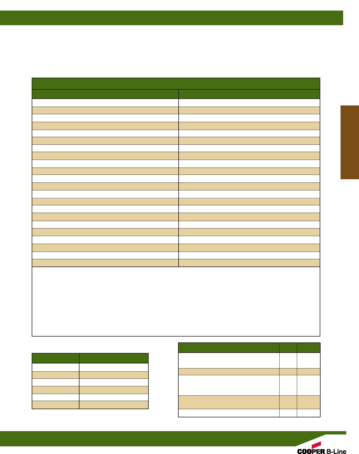
CHANNEL RESIN INFORMATION
B-Line offers two fire retardant (FR) resins for strut systems, polyester and vinyl ester. Both resins are ideal for corrosive
environments.
While polyester is sufficient for most uses, vinyl ester is suitable for a broader range of environments.
Please refer to the "Corrosion Resistance Guide" below for specific applications.
Corrosion Resistance Guide
Chemicals 70°F (21°C) 160°F (71°C) Chemicals 70°F (21°C) 160°F (71°C)
Acetic acid 5% BFP/BFV BFP/BFV Methyl alcohol 10% BFP/BFV BFV-150° **
Acetic acid 52% BFP/BFV BFV-210° ** Naphtha BFP/BFV BFP/BFV
Aluminum potassium sulfate 5% BFP/BFV BFP/BFV Nitric acid 5% BFP/BFV BFP/BFV
Ammonium hydroxide 10% BFP/BFV BFV-150° ** Nitric acid 20% BFV BFV-120° **
Ammonium nitrate BFP/BFV BFP/BFV Phosphoric acid 10% BFP/BFV BFP/BFV
Benzene sulfonic acid 5% BFP/BFV BFP/BFV Phosphoric acid 30% BFP/BFV BFP/BFV
Calcium chloride BFP/BFV BFP/BFV Phosphoric acid 85% BFP/BFV BFP/BFV
Carbon tetrachloride BFV BFV-100° ** Sodium bicarbonate 10% BFP/BFV BFP/BFV
Chlorine dioxide 15% BFP/BFV BFV-150° ** Sodium bisulfate BFP/BFV BFP/BFV
Chromic acid 5% BFV BFV-150° ** Sodium carbonate BFP/BFV BFV
Copper sulfate BFP/BFV BFP/BFV Sodium chloride BFP/BFV BFP/BFV
Diesel fuel BFP/BFV BFV Sodium hydroxide 1-50% BFV BFV-120° **
Ethylene glycol BFP/BFV BFP/BFV Sodium hypochlorite 5% BFP/BFV BFV-120° **
Fatty acids 100% BFP/BFV BFP/BFV Sodium nitrate BFP/BFV BFP/BFV
Ferrous sulfate BFP/BFV BFP/BFV Sodium silicate BFP/BFV BFV-210° **
Fluosilicic acid 0-20% BFV BFV Sodium sulfate BFP/BFV BFP/BFV
Gasoline BFP/BFV BFV Sulfuric acid 0-30% BFP/BFV BFP/BFV
Hydrochloric acid 1% BFP/BFV BFP/BFV Sulfuric acid 30-50% BFV BFV
Hydrochloric acid 15% BFP/BFV BFV-180° ** Sulfuric acid 50-70% BFV BFV-180° **
Hydrochloric acid 37% BFP/BFV BFV-150° ** Trisodium phosphate 25% BFP/BFV BFV-210° **
Kerosene BFP/BFV BFP/BFV Trisodium phosphate-All BFV BFV-210° **
Magnesium chloride BFP/BFV BFP/BFV Water, Distilled BFP/BFV BFP/BFV
BFP - BFP parts recommended BFV - BFV parts recommended ** - Not recommended to exceed this temperature
Information contained in this chart is based on data from raw material suppliers.
Temperatures are not the minimum nor the maximum (except where specifically stated) but represent standard test
conditions. The products may be suitable at higher temperatures but individual test data should be required to establish
suitability.
The recommendations or suggestions contained in this chart are made without guarantee or representation as to results.
We suggest that you evaluate the recommendations and suggestions in your own laboratory or actual field trial prior to use.
Flame Retardant Properties BFP BFV
Flame Resistance (FTMS 406-2023)
ign/burn, seconds 75/75 75/75
Intermittent Flame Test (HLT-15), rating 100 100
Flammability Test (ASTM D635)
Ignition none none
Burning Time 0 sec. 0 sec.
Surface Burning Characteristics (ASTM E84),
Flame spread index 25 25
UL 94 Flame Class V-0 V-0
Recommended Guideline:
Temperature Design Load Multiplier
75°F (24°C) 100%
100°F (38°C) 90%
125°F (52°C) 78%
150°F (66°C) 68%
175°F (79°C) 60%
200°F (93°C) 52%
Fiberglass Materials
Reference page 170 for general fitting specifications.
Fiberglass
171
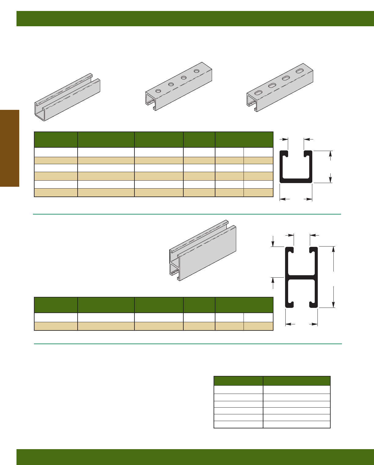
15/8”
(41.3)
Part No. Material Description Color Weight
Lbs./ft. kg/m
BFP22* Polyester Resin Solid Back Gray .63 (.94)
BFV22* Vinyl Ester Resin Solid Back Beige .63 (.94)
BFP22H17/8*Polyester Resin Holes in Back Gray .60 (.89)
BFV22H17/8*Vinyl Ester Resin Holes in Back Beige .60 (.89)
BFP22SH* Polyester Resin Slots in Back Gray .61 (.91)
BFV22SH* Vinyl Ester Resin Slots in Back Beige .61 (.91)
BFP22H17/8
BFV22H17/8
9/16” (14.3) holes
17/8” (47.6) on centers
BFP22
BFV22
Solid Back
BFP22 THRU BFV22SH
• Channel lengths: 10 Ft. (3.05 m) and 20 Ft. (6.09 m)
• Fiberglass strut meets specification of
ASTM D-4385 Levels III and IV.
BFP22A
BFV22A
• Channel Lengths: 10 Ft. (3.05 m) and 20 Ft. (6.09 m)
• Fiberglass strut meets specification of
ASTM D-4385 Levels III and IV.
BFP22SH
BFV22SH
9/16” (14.3) x 7/8” (22.2) slots
2” (50.8) on centers
13/16”
(20.6)
15/8”
(41.3)
31/4”
(82.5)
Part No. Material Description Color Weight
Lbs./ft. kg/m
BFP22A* Polyester Resin Back To Back Gray 1.15 (1.71)
BFV22A* Vinyl Ester Resin Back To Back Beige 1.15 (1.71)
15/8”
(41.3)
* Insert -10 for 10’-0” (3.05 m) length or -20 for 20’-0” (6.09 m) length
* Insert -10 for 10’-0” (3.05 m) length or -20 for 20’-0” (6.09 m) length
Temperature Design Load Multiplier
75°F (24°C) 100%
100°F (38°C) 90%
125°F (52°C) 78%
150°F (66°C) 68%
175°F (79°C) 60%
200°F (93°C) 52%
Published design loads on page 172 are based on usage at
70°F (21°C) and must be reduced for continuous exposure to
higher temperatures. Refer to the chart below for high tem-
perature applications.
Field Cutting Sealant Kits
• Seals exposed fibers after field cutting. •
• UV resistant •
RSK010 . . . . Pint Sealing Kit (473 cm3)
includes sealant and brush applicator
WARNING: Appropriate protective clothing and respiratory
protection device should be worn when field
cutting or grinding fiberglass.
15/8”
(41.3)
BFP22A
BFV22A
Solid Back to Back
13/16”
(20.6)
Fiberglass Materials
Reference page 170 for general fitting specifications.
Fiberglass
172
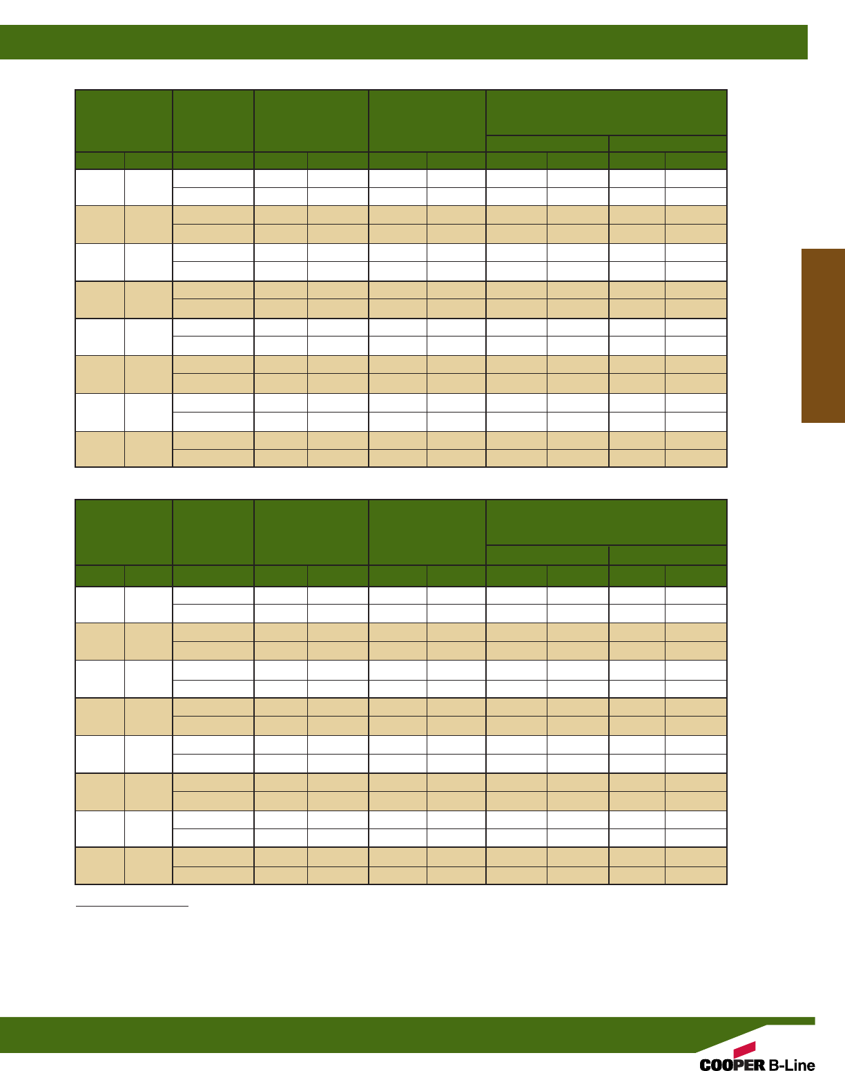
Maximum Deflection
Beam Allowable @ Maximum Allowable Load @ Deflection =
Span Part Beam Load Allowable
No. Load Beam Load 1/240 Span 1/360 Span
in. mm Lbs. kN in. mm Lbs. kN Lbs. kN
12” (305) BFP22 1781 (7.92) 0.064 (1.62) 1392 (6.19) 928 (4.13)
BFP22A 2259 (10.05) 0.037 (.94) 2259 (10.05) 2051 (9.12)
24” (609) BFP22 890 (3.96) 0.256 (6.50) 347 (1.54) 231 (1.03)
BFP22A 1127 (5.01) 0.147 (3.73) 767 (3.41) 511 (2.27)
36” (914) BFP22 592 (2.63) 0.576 (14.63) 153 (0.68) 101 (0.45)
BFP22A 750 (3.33) 0.330 (8.38) 338 (1.50) 224 (0.99)
48” (1219) BFP22 443 (1.97) 1.024 (26.01) 85 (0.38) 55 (0.24)
BFP22A 560 (2.49) 0.587 (14.91) 188 (0.83) 123 (0.55)
60” (1524) BFP22 353 (1.57) 1.600 (40.64) 53 (0.23) 34 (0.15)
BFP22A 446 (1.98) 0.918 (23.32) 117 (0.52) 76 (0.34)
72” (1829) BFP22 293 (1.30) 2.303 (58.49) 35 (0.15) 22 (0.10)
BFP22A 370 (1.64) 1.322 (33.58) 78 (0.34) 50 (0.22)
96” (2438) BFP22 218 (0.97) 4.095 (104.01) 17 (0.07) 9(0.04)
BFP22A 273 (1.21) 2.350 (59.69) 39 (0.17) 23 (0.10)
120” (3048) BFP22 172 (0.76) 6.398 (162.51) 8(0.03) 3(0.01)
BFP22A 214 (0.95) 3.671 (93.24) 19 (0.08) 9(0.04)
BEAM LOADING DATA FOR GLASS REINFORCED POLYESTER RESIN
Maximum Deflection
Beam Allowable @ Maximum Allowable Load @ Deflection =
Span Part Beam Load Allowable
No. Load Beam Load 1/240 Span 1/360 Span
in. mm Lbs. kN in. mm Lbs. kN Lbs. kN
12” (305) BFV22 2220 (9.87) 0.071 (1.80) 1568 (6.97) 1045 (4.65)
BFV22A 6442 (28.65) 0.039 (0.99) 6442 (29.65) 5549 (24.68)
24” (609) BFV22 1109 (4.93) 0.283 (7.19) 391 (1.74) 260 (1.15)
BFV22A 3219 (14.32) 0.155 (3.94) 2079 (9.25) 1385 (6.16)
36” (914) BFV22 738 (3.28) 0.637 (16.18) 172 (0.76) 114 (0.51)
BFV22A 2144 (9.53) 0.348 (8.84) 922 (4.10) 613 (2.72)
48” (1219) BFV22 553 (2.46) 1.133 (28.78) 96 (0.43) 63 (0.28)
BFV22A 1606 (7.14) 0.619 (15.72) 516 (2.29) 342 (1.52)
60” (1524) BFV22 441 (1.96) 1.770 (44.96) 60 (0.26) 39 (0.17)
BFV22A 1283 (5.70) 0.967 (24.56) 327 (1.45) 216 (0.96)
72” (1829) BFV22 366 (1.63) 2.549 (64.74) 40 (0.18) 25 (0.11)
BFV22A 1067 (4.74) 1.393 (35.38) 224 (0.99) 147 (0.65)
96” (2438) BFV22 273 (1.21) 4.531 (115.09) 19 (0.08) 11 (0.05)
BFV22A 796 (3.54) 2.477 (62.91) 121 (0.54) 78 (0.34)
120” (3048) BFV22 216 (0.96) 7.079 (179.80) 9(0.04) 7(0.02)
BFV22A 633 (2.81) 3.870 (98.30) 72 (0.32) 44 (0.19)
BEAM LOADING DATA FOR GLASS REINFORCED VINYL ESTER RESIN
Loading Information
Beam Loads:
The above charts list the total allowable uniform load for various simple spans based on a minimum safety factor of 2. If the load is concentrated at
center span, multiply the load from the above charts by 0.5 and the corresponding deflection by 0.8.
All beams should be supported in a manner to prevent rotation at supports. Long, deep beams should be tied between supports to prevent twist.
For channels with holes or slots use 90% of recommended load shown in channel loading chart.
Fiberglass Materials
Reference page 170 for general fitting specifications.
Fiberglass
173
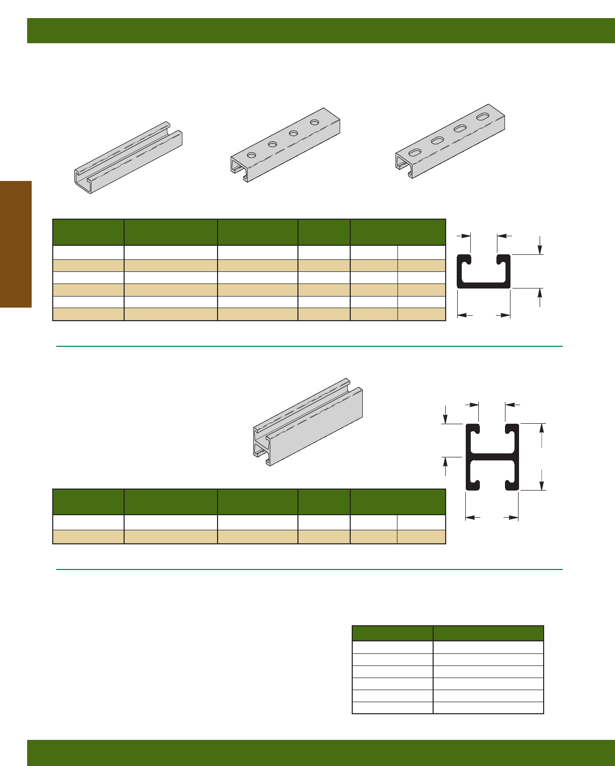
13/16”
(20.6)
1”
(25.4)
Part No. Material Description Color Weight
Lbs./ft. kg/m
BFP42* Polyester Resin Solid Back Gray .48 (.71)
BFV42* Vinyl Ester Resin Solid Back Beige .48 (.71)
BFP42H17/8*Polyester Resin Holes in Back Gray .46 (.68)
BFV42H17/8*Vinyl Ester Resin Holes in Back Beige .46 (.68)
BFP42SH* Polyester Resin Slots in Back Gray .47 (.70)
BFV42SH* Vinyl Ester Resin Slots in Back Beige .47 (.70)
BFP42H17/8
BFV42H17/8
9/16” (14.3) holes
17/8” (47.6) on centers
BFP42
BFV42
Solid Back
BFP42 THRU BFV42SH
• Channel lengths: 10 Ft. (3.05 m) and 20 Ft. (6.09 m)
• Fiberglass strut meets specification of
ASTM D-4385 Levels III and IV.
BFP42A
BFV42A
Solid Back to Back
BFP42A
BFV42A
• Channel lengths: 10 Ft. (3.05 m) and
20 Ft. (6.09 m)
• Fiberglass strut meets specification of
ASTM D-4385 Levels III and IV.
BFP42SH
BFV42SH
9/16” (14.3) x 7/8” (22.2) slots
2” (50.8) on centers
15/8”
(41.3)
* Insert -10 for 10’-0” (3.05 m) length or -20 for 20’-0” (6.09 m) length
* Insert -10 for 10’-0” (3.05 m) length or -20 for 20’-0” (6.09 m) length
Temperature Design Load Multiplier
75°F (24°C) 100%
100°F (38°C) 90%
125°F (52°C) 78%
150°F (66°C) 68%
175°F (79°C) 60%
200°F (93°C) 52%
Published design loads on page 174 are based on usage at
70°F (21°C) and must be reduced for continuous exposure to
higher temperatures. Refer to the chart below for high tem-
perature applications.
Field Cutting Sealant Kits
• Seals exposed fibers after field cutting. •
• UV resistant •
RSK010 . . . . Pint Sealing Kit (473 cm3)
includes sealant and brush applicator
WARNING: Appropriate protective clothing and respiratory
protection device should be worn when field
cutting or grinding fiberglass.
2”
(50.8)
1”
(25.4)
Part No. Material Description Color Weight
Lbs./ft. kg/m
BFP42A* Polyester Resin Back To Back Gray .85 (1.26)
BFV42A* Vinyl Ester Resin Back To Back Beige .85 (1.26)
13/16”
(20.6)
15/8”
(41.3)
Fiberglass Materials
Reference page 170 for general fitting specifications.
Fiberglass
174
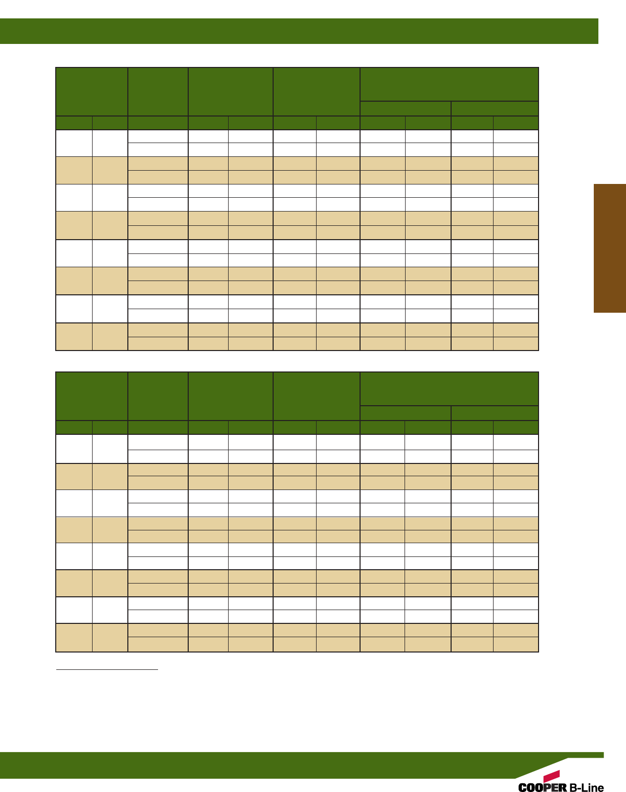
Maximum Deflection
Beam Allowable @ Maximum Allowable Load @ Deflection =
Span Part Beam Load Allowable
No. Load Beam Load 1/240 Span 1/360 Span
in. mm Lbs. kN in. mm Lbs. kN Lbs. kN
12” (305) BFP42 841 (3.74) 0.104 (2.64) 403 (1.79) 269 (1.19)
BFP42A 2325 (10.34) 0.060 (1.52) 1948 (8.66) 1299 (5.78)
24” (609) BFP42 420 (1.87) 0.417 (10.59) 100 (0.44) 66 (0.29)
BFP42A 1161 (5.16) 0.239 (6.07) 486 (2.16) 323 (1.43)
36” (914) BFP42 279 (1.24) 0.938 (23.82) 43 (0.19) 29 (0.13)
BFP42A 773 (3.44) 0.537 (13.64) 214 (0.95) 142 (0.63)
48” (1219) BFP42 208 (0.92) 1.667 (42.34) 23 (0.10) 15 (0.06)
BFP42A 578 (2.57) 0.955 (24.26) 119 (0.53) 78 (0.34)
60” (1524) BFP42 166 (0.74) 2.604 (66.14) 14 (0.06) 8(0.03)
BFP42A 461 (2.05) 1.491 (37.87) 74 (0.33) 48 (0.21)
72” (1829) BFP42 137 (0.61) 3.750 (95.25) 8(0.03) 5(0.02)
BFP42A 383 (1.70) 2.148 (54.56) 49 (0.22) 31 (0.14)
96” (2438) BFP42 101 (0.45) 6.667 (169.34) 3(0.01) ––
BFP42A 284 (1.26) 3.818 (96.98) 24 (0.10) 14 (0.04)
120” (3048) BFP42 79 (0.35) 10.417 (264.59) ––– –
BFP42A 224 (0.99) 5.966 (151.53) 11 (0.05) 5(0.02)
BEAM LOADING DATA FOR GLASS REINFORCED POLYESTER RESIN
Maximum Deflection
Beam Allowable @ Maximum Allowable Load @ Deflection =
Span Part Beam Load Allowable
No. Load Beam Load 1/240 Span 1/360 Span
in. mm Lbs. kN in. mm Lbs. kN Lbs. kN
12” (305) BFV42 988 (4.39) 0.112 (2.84) 440 (1.96) 293 (1.30)
BFV42A 2865 (12.74) 0.063 (1.60) 2278 (10.13) 1518 (6.75)
24” (609) BFV42 493 (2.19) 0.448 (11.38) 109 (0.48) 73 (0.32)
BFV42A 1431 (6.36) 0.252 (6.40) 568 (2.52) 378 (1.68)
36” (914) BFV42 328 (1.46) 1.009 (25.63) 48 (0.21) 31 (0.14)
BFV42A 953 (4.24) 0.566 (14.37) 251 (1.11) 166 (0.74)
48” (1219) BFV42 245 (1.09) 1.793 (45.54) 26 (0.11) 16 (0.07)
BFV42A 713 (3.17) 1.006 (25.55) 139 (0.62) 92 (0.41)
60” (1524) BFV42 195 (0.87) 2.802 (71.17) 15 (0.06) 9(0.04)
BFV42A 569 (2.53) 1.572 (39.93) 87 (0.38) 57 (0.25)
72” (1829) BFV42 162 (0.72) 4.035 (102.49) 9(0.04) 5(0.02)
BFV42A 473 (2.10) 2.264 (57.50) 58 (0.26) 37 (0.16)
96” (2438) BFV42 120 (0.53) 7.173 (182.19) 3(0.01) 1(0.004)
BFV42A 351 (1.56) 4.025 (102.23) 29 (0.13) 17 (0.07)
120” (3048) BFV42 94 (0.42) 11.207 (284.66) –– ––
BFV42A 278 (1.23) 6.288 (159.71) 14 (0.06) 7(0.03)
BEAM LOADING DATA FOR GLASS REINFORCED VINYL ESTER RESIN
Loading Information
Beam Loads:
The above charts list the total allowable uniform load for various simple spans based on a minimum safety factor of 2. If the load is concen-
trated at center span, multiply the load from the above charts by 0.5 and the corresponding deflection by 0.8.
All beams should be supported in a manner to prevent rotation at supports. Long, deep beams should be tied between supports to prevent twist.
For channels with holes or slots use 90% of recommended load shown in channel loading chart.
Fiberglass Materials
Reference page 170 for general fitting specifications.
Fiberglass
175
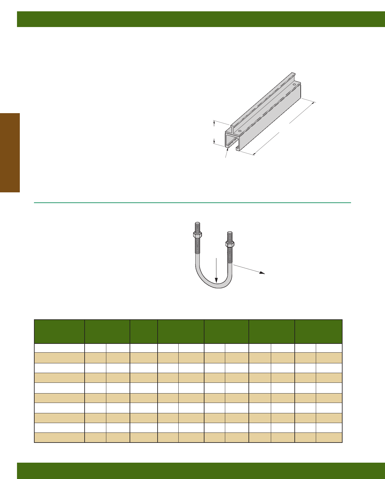
Nominal Thread Design Load Design Load Maximum
Part No. Pipe Size Size A B Torque Wt./C
in. mm Lbs. kN Lbs. kN in.-Lbs. N•m Lbs. kg
BFV501-1/21/2(15) 3/8”-16 300 (1.33) 150 (.67) 30 (3.4) 3.5 (1.59)
BFV501-3/43/4(20) 3/8”-16 300 (1.33) 150 (.67) 30 (3.4) 3.9 (1.77)
BFV501-1 1(25) 3/8”-16 300 (1.33) 150 (.67) 30 (3.4) 4.4 (1.99)
BFV501-11/411/4(32) 3/8”-16 300 (1.33) 150 (.67) 30 (3.4) 4.8 (2.18)
BFV501-11/211/2(40) 3/8”-16 300 (1.33) 150 (.67) 30 (3.4) 5.2 (2.36)
BFV501-2 2(50) 1/2”-13 600 (2.67) 200 (.89) 60 (6.8) 7.7 (3.49)
BFV501-21/221/2(65) 1/2”-13 600 (2.67) 200 (.89) 60 (6.8) 10.2 (4.63)
BFV501-3 3(80) 1/2”-13 600 (2.67) 200 (.89) 60 (6.8) 12.6 (5.71)
BFV501-31/231/2(90) 1/2”-13 600 (2.67) 200 (.89) 60 (6.8) 15.1 (6.85)
BFV501-4 4(100) 1/2”-13 600 (2.67) 200 (.89) 60 (6.8) 17.6 (7.98)
LOAD
A
LOAD
B
BFV501 SERIES
U-BOLTS WITH HEX NUTS
• Design Load Safety Factor of 3
• Load A: Straight down loading
• Load B: Side loading
• Inner surface of U-Bolt is flat to
provide additional contact surface area
• Material: Glass Reinforced Polyurethane
BF*22I
CONCRETE INSERTS
•Design Load 300 Lbs (1.47 kN)
•Safety Factor of 3
•Standard lengths: 6” (152),12” (305), 24” (609),
36” (914), 48” (1219), 60” (1524), 72” (1829),
84” (2133), 96” (2438), 108” (2743) and 120” (3048)
•Available Material:
*Insert P for BFP - Polyester Resin channel and tee
*Insert V for BFV - Vinyl Ester Resin channel with Polyester Resin tee
•Shipped with removable styrofoam insert
25/8”
(66.7)
Length
15/8” (41.3) x 15/8” (41.3)
Channel Size
Field Cutting Sealant Kits
• Seals exposed fibers after field cutting. •
• UV resistant •
RSK010 . . . . Pint Sealing Kit (473 cm3)
includes sealant and brush applicator
Fiberglass Materials
Reference page 170 for general fitting specifications.
Fiberglass
176
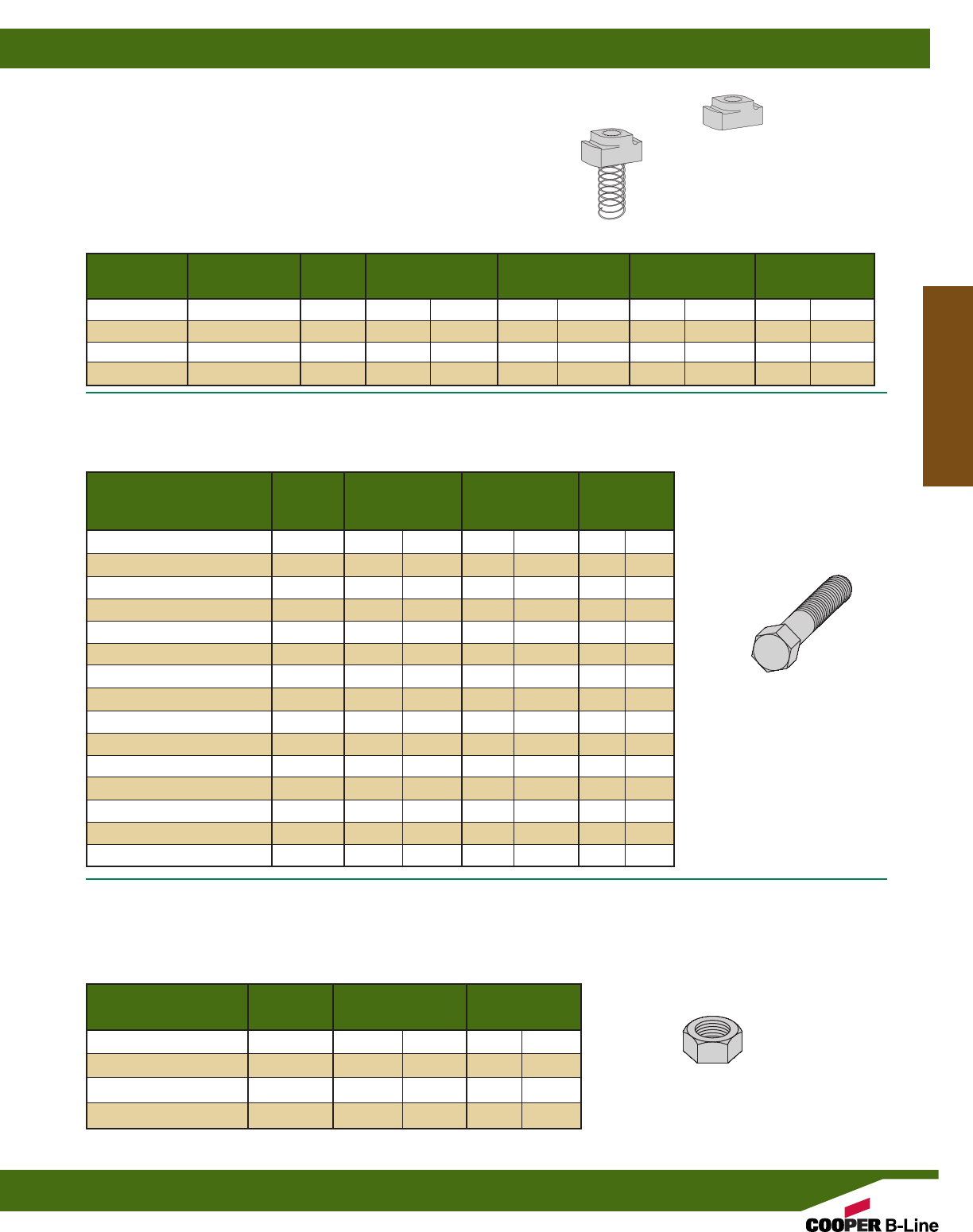
BFVHHCS
HEX HEAD CAP SCREWS
• Design Load Safety Factor of 3
• Material: Glass Reinforced Polyurethane
Design Load
Part Thread (in tension) Max. Torque Wt./C
No. Size Lbs. kN in.-Lbs. N•m Lbs. kg
BFVHHCS 5/16 x 1 5/16”-18 190 (.84) 30 (3.4) .4 (.18)
BFVHHCS 5/16 x 11/45/16”-18 190 (.84) 30 (3.4) .5 (.23)
BFVHHCS 5/16 x 11/25/16”-18 190 (.84) 30 (3.4) .6 (.27)
BFVHHCS 5/16 x 2 5/16”-18 190 (.84) 30 (3.4) .8 (.36)
BFVHHCS 3/8x 1 3/8”-16 300 (1.33) 45 (5.1) .9 (.41)
BFVHHCS 3/8x 11/43/8”-16 300 (1.33) 45 (5.1) 1.1 (.50)
BFVHHCS 3/8x 11/23/8”-16 300 (1.33) 45 (5.1) 1.3 (.59)
BFVHHCS 3/8x 2 3/8”-16 300 (1.33) 45 (5.1) 1.3 (.59)
BFVHHCS 3/8x 21/23/8”-16 300 (1.33) 45 (5.1) 1.5 (.68)
BFVHHCS 1/2x 1 1/2”-13 490 (2.18) 110 (12.4) 1.4 (.63)
BFVHHCS 1/2x 11/41/2”-13 490 (2.18) 110 (12.4) 1.8 (.81)
BFVHHCS 1/2x 11/21/2”-13 490 (2.18) 110 (12.4) 2.2 (1.00)
BFVHHCS 1/2x 2 1/2”-13 490 (2.18) 110 (12.4) 3.0 (1.36)
BFVHHCS 1/2x 21/21/2”-13 490 (2.18) 110 (12.4) 3.7 (1.68)
BFVHHCS 1/2x 3 1/2”-13 490 (2.18) 110 (12.4) 4.5 (2.04)
BFVHN
HEX NUTS
• 3/4” & 1” sizes are available. Contact inside
sales for details
• Material: Glass Reinforced Polyurethane
Part Thread Nut Thickness Wt./C
No. Size in. mm Lbs. kg
BFVHN 5/16 5/16”-18 17/64 (6.7) .2 (.09)
BFVHN 3/83/8”-16 21/64 (8.3) .3 (.13)
BFVHN 1/21/2”-13 7/16 (11.1) .7 (.32)
BFVHN 5/85/8”-11 35/64 (13.9) 1.4 (.63)
Part No. Part No. Thread Pull-Out Slip Resistance Max. Torque Wt./C
With Spring W/O Spring Size Lbs kN Lbs. N in.-Lbs. N•m Lbs. kg
BFV-224 BFV-224WO 1/4”-20 300 (1.33) 150 (.67) 200 (22.6) 2.4 (1.09)
BFV-223 BFV-223WO 5/16”-18 300 (1.33) 150 (.67) 200 (22.6) 2.5 (1.13)
BFV-228 BFV-228WO 3/8”-16 300 (1.33) 150 (.67) 200 (22.6) 2.3 (1.04)
BFV-225 BFV-225WO 1/2”-13 300 (1.33) 150 (.67) 200 (22.6) 2.1 (0.95)
WITH
SPRING
W/O
(WITHOUT)
SPRING
CHANNEL NUTS
• Design Load Safety Factor of 3
• Overall Nut Height 5/8” (15.9)
• Maximum torque and slip resistance loads shown are
when using stainless steel bolts. When using fiberglass
hardware use Max. Torque for fiberglass bolts, and
multiply slip resistance loads by .14 for 3/8” and .60 for
1/2” thread size.
• Material: Glass Reinforced Polyurethane
• Spring Material: Zinc Plated Steel
Fiberglass Materials
Reference page 170 for general fitting specifications.
Fiberglass
177
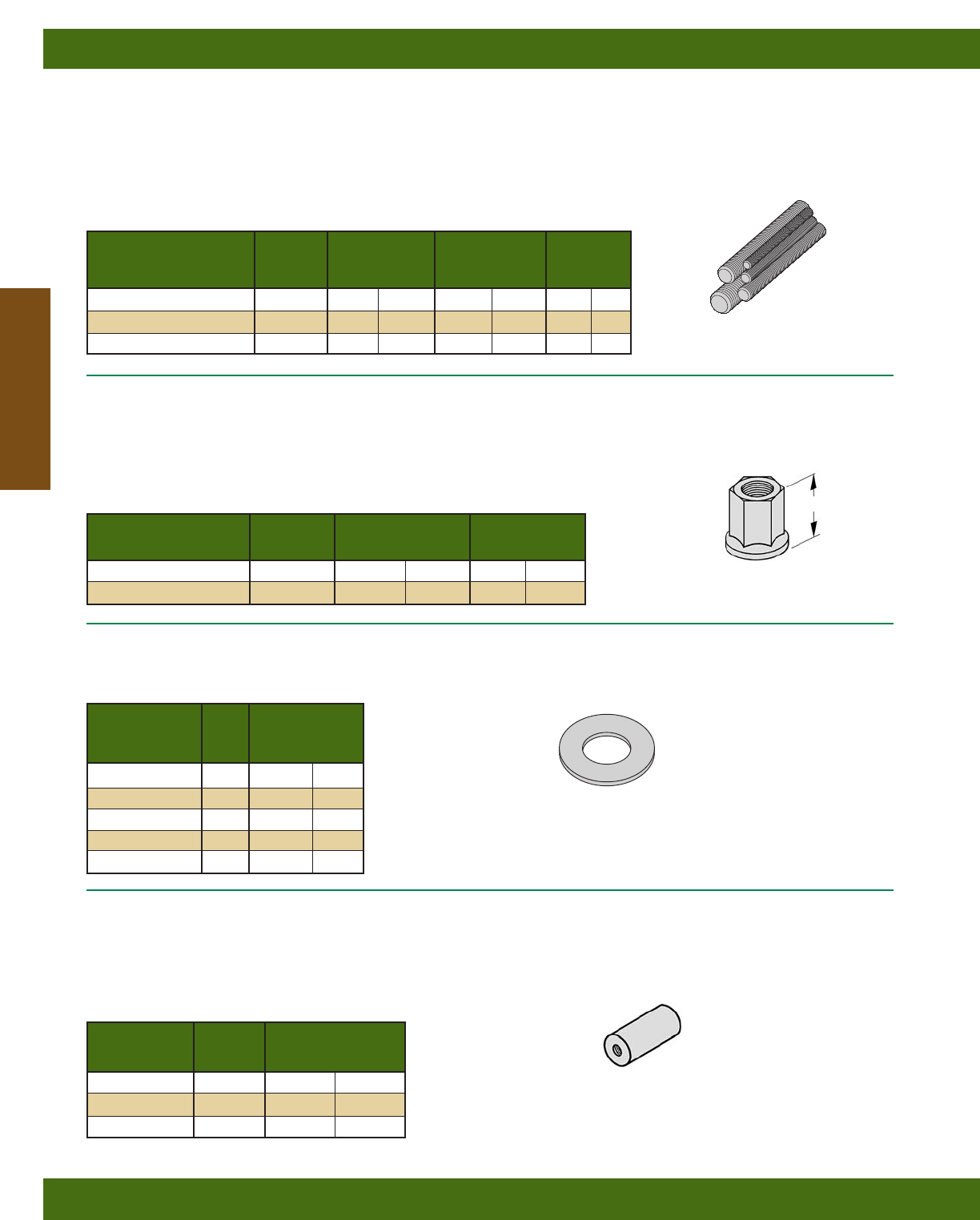
BFVATRHN
THREADED ROD NUTS
• ATR Nut is required with 3/8”-16 and 1/2”-13
ATR to provide additional thread engagement
which is critical to ATR load carrying capacity.
• Material: Glass Reinforced Polyurethane
BFV655 SERIES
ROD COUPLINGS
• Material: Glass Reinforced Polyurethane
Part Thread Wt./C
No. Size Lbs. kg
BFV655-3/83/8”-16 7.4 (3.35)
BFV655-1/21/2”-13 11.3 (5.12)
BFV655-5/85/8”-11 16.7 (7.57)
Part Thread H Wt./C
No. Size in. mm Lbs. kg
BFVATRHN 3/8 3/8”-16 3/4(19) .8 (.36)
BFVATRHN 1/21/2”-13 7/8(22) 1.7 (.77)
BFVATR
ALL THREADED ROD
• Design Load Safety Factor of 3
• Use ATR nuts in place of hex nuts with 3/8”-16
and 1/2”-13 threaded rod in order to obtain
minimum required thread engagement of
17/32” (13.5) to obtain design load shown below.
• Material: Glass Reinforced Vinyl Ester
Design Load Max. Torque Wt./Ft.
Part Thread (in tension)
No. Size Lbs. kN in.-Lbs. N•m Lbs. kg
BFVATR 3/8x 48” 3/8”-16 425 (1.89) 45 (5.1) .08 (.04)
BFVATR 1/2x 48” 1/2”-13 750 (3.33) 110 (12.4) .13 (.06)
BFVATR 5/8x 48” 5/8”-11 950 (4.22) 230 (26.0) .21 (.09)
BFVFW
FLAT WASHERS
• Material: PVC
Part Hole
No. Size Wt./C
in. Lbs. kg
BFVFW 3/83/8.5 (.22)
BFVFW 1/21/2.5 (.22)
BFVFW 5/85/8.5 (.22)
BFVFW 3/43/4.5 (.22)
BFVFW 1 1.5(.22)
H
Fiberglass Materials
Reference page 170 for general fitting specifications.
Fiberglass
178
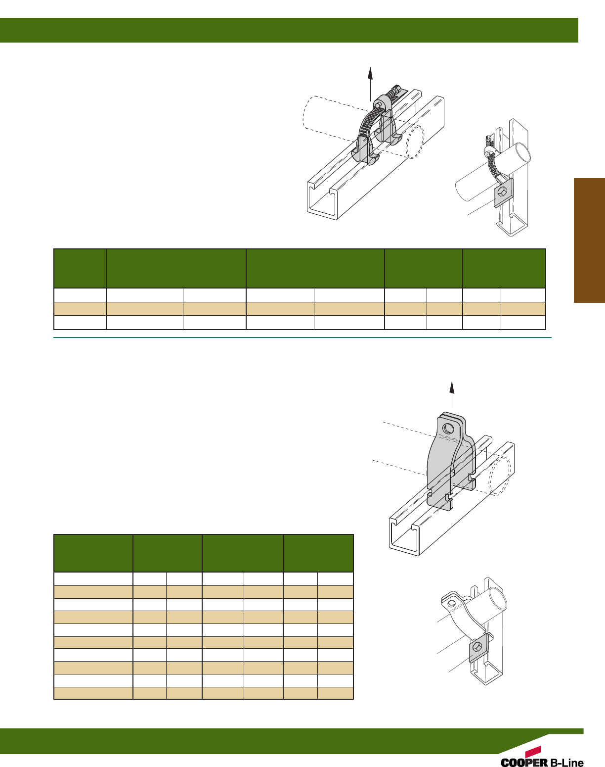
Nominal Design Load Maximum
Part No. Pipe Size Torque
in. mm Lbs. kN in.-Lbs. N•m
BFV2008 1/2(15) 300 (1.33) 10 (1.13)
BFV2009 3/4(20) 300 (1.33) 10 (1.13)
BFV2010 1(25) 300 (1.33) 10 (1.13)
BFV2011 11/4(32) 300 (1.33) 10 (1.13)
BFV2012 11/2(40) 300 (1.33) 10 (1.13)
BFV2013 2(50) 300 (1.33) 10 (1.13)
BFV2014 21/2(65) 300 (1.33) 10 (1.13)
BFV2015 3(80) 300 (1.33) 10 (1.13)
BFV2016 31/2(90) 300 (1.33) 10 (1.13)
BFV2017 4(100) 300 (1.33) 10 (1.13)
BFV2000 SERIES
NON-METALLIC PIPE CLAMPS
• For rigid and PVC conduit.
• Standard hardware includes slotted round head machine
screw and square nut in 316 stainless steel
• Design Load Safety Factor of 3
• Material: Glass Reinforced PPO
• Not recommended for vertical installation without additional Stop-Lock
Kit. Kit includes one square washer, channel nut and hex head cap
screw. Order (Stop-Lock Kit) BFVSL-3/8for 3/8”-16 hardware or
BFVSL-1/2for 1/2”-13 hardware. Mount kit below clamp when used
in vertical strut to prevent clamp slipping.
• If non-metallic hardware is required, add N
to the part number. Example: BFV2008N
BFV100 thru BFV300
ADJUSTABLE PIPE CLAMPS
•Completely Non-Metallic
•Adjustable to U.S. & Metric Pipe Diameters
•Fits OD Sizes 3/4” (19.0) to 31/2” (88.9)
•Easy To Install
•No Special Tools Required
•Design Load Safety Factor of 3
•Material: Glass Reinforced Polyurethane
•Not recommended for vertical installation without additional
Stop-Lock Kit. Kit includes one square washer, channel nut
and hex head cap screw. Order (Stop-Lock Kit) BFVSL-3/8
for 3/8”-16 hardware or BFVSL-1/2for 1/2”-13 hardware.
Mount kit below clamp when used in vertical strut to prevent
clamp slipping.
Nominal Pipe O.D. Design Max.
Part Pipe Sizes Range Load Torque
No. in. mm in. mm Lbs. kN in.-Lbs. N•m
BFV100 1/2 - 11/2(15- 40) .75 - 1.90 (21.3 - 48.3) 135 (.60) 10 (1.13)
BFV200 11/2- 2 (40 - 51) 1.90 - 2.37 (48.3 - 60.3) 135 (.60) 36 (4.07)
BFV300 21/2 - 3(63 - 76) 2.87 - 3.50 (73.0 - 88.9) 145 (.64) 36 (4.07)
DESIGN LOAD
DESIGN LOAD
Stop-Lock Kit
for vertical
installation
Stop-Lock Kit
for vertical
installation
Fiberglass Materials
Reference page 170 for general fitting specifications.
Fiberglass
179
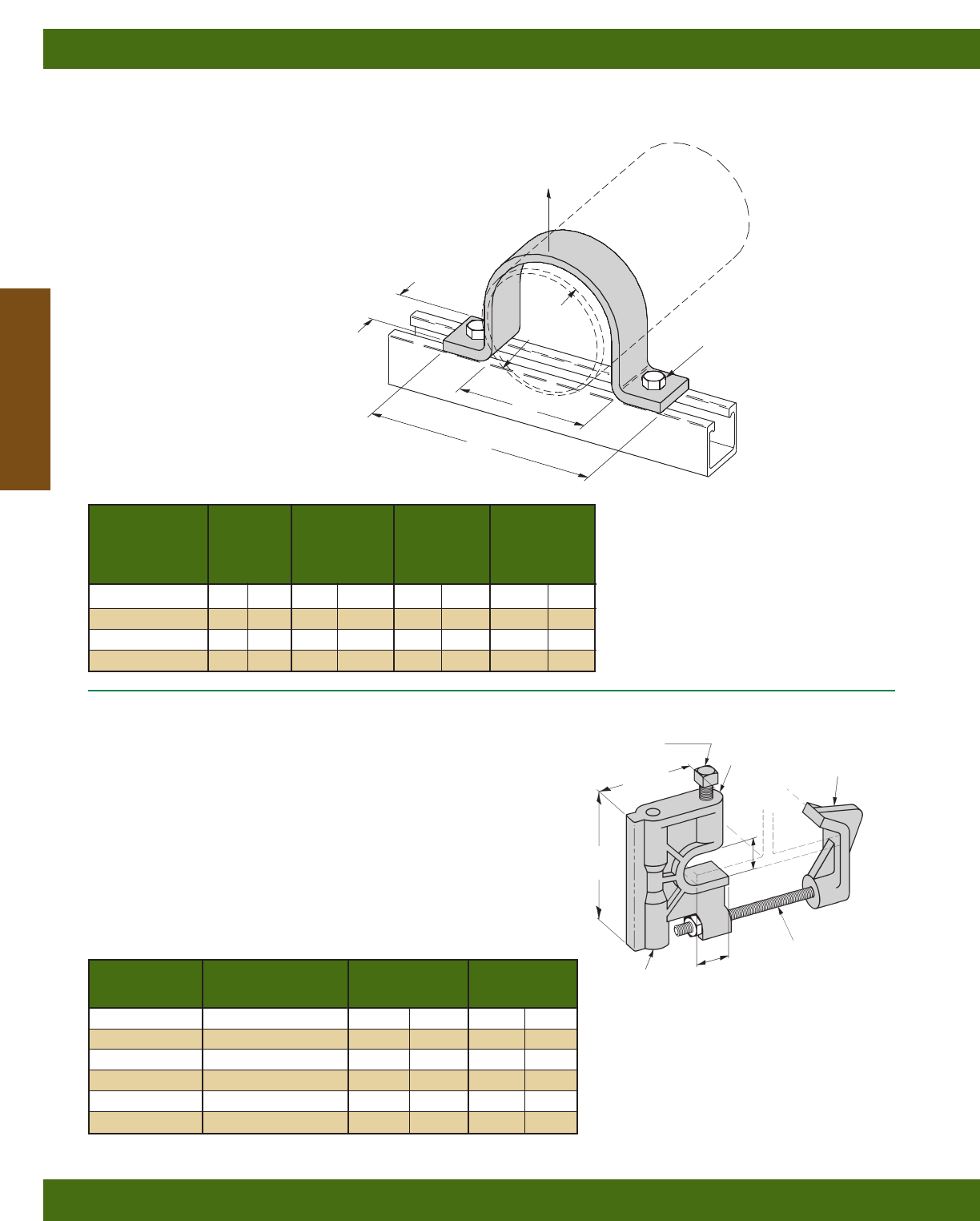
BFP2400 SERIES
2-HOLE PIPE CLAMPS
• Design Load Safety Factor of 3
• Material: Glass Reinforced Polyester
BFV751 & BFV751J
BEAM CLAMP
• Design Load Safety Factor of 3
• BFV751J (clip included) must be used
when installed on tapered flange beams.
• Material: Glass Reinforced Polyurethane
• Setscrew material: Stainless Steel 316
ASTM F593 Group 2, S4
Part No. For Hanger Rod Design Load Torque
Size A Lbs. kN ft.-Lbs. N•m
BFV751-3/83/8”-16 500 (2.22) 10 (13)
BFV751J-3/83/8”-16 500 (2.22) 10 (13)
BFV751-1/21/2”-13 500 (2.22) 10 (13)
BFV751J-1/21/2”-13 500 (2.22) 10 (13)
BFV751-5/85/8”-11 500 (2.22) 10 (13)
BFV751J-5/85/8”-11 500 (2.22) 10 (13)
41/4”
(108.0)
11/8”
(28.6)
1”
(25.4)
1/2”-13 x 2” (50.8)
Screw
TAPPED FOR
HANGER ROD
SIZE A
BFV751
(Clamp
Only)
BFV751J
(Clamp and
Retainer Clip)
BFVATR3/8”
&BFPUATRHN
(Order Separately)
3”
(76.2)
Nominal Design
Part Pipe A B Load
No. Size
in. mm in. mm in. mm Lbs. kN
BFP2400-2 2(50) 23/8(60) 51/2(140) 115 (0.51)
BFP2400-3 3(80) 31/2(89) 63/4(171) 130 (0.58)
BFP2400-4 4(100) 41/2(114) 73/4(197) 150 (0.66)
BFP2400-6 6(150) 65/8(168) 10 (254) 150 (0.66)
15/8”
(41.3) 13/32” (10.3)
HOLE DIA.
B
PIPE
SIZE
DESIGN LOAD
A
Fiberglass Materials
Reference page 170 for general fitting specifications.
Fiberglass
180
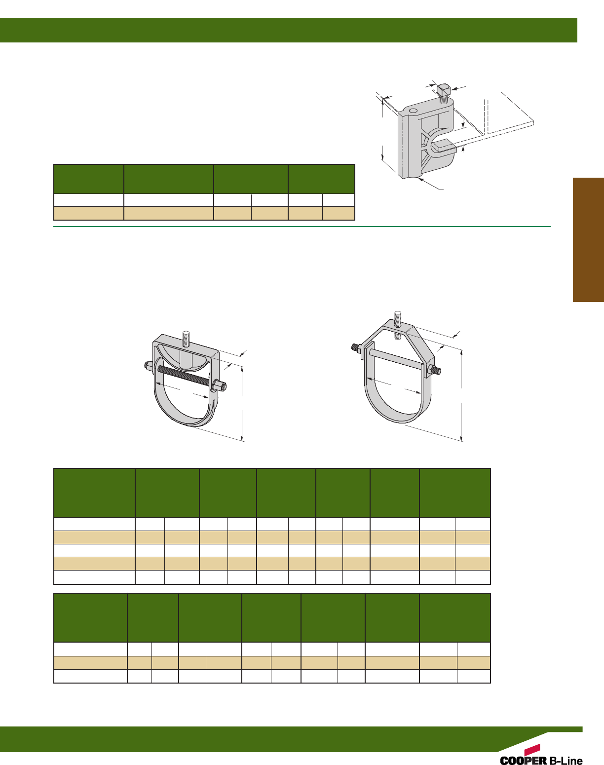
BFV3104 SERIES
CLEVIS HANGERS
• Design Load Safety Factor of 3
at 120°F (49°C).
• Insulation may be required at higher temperatures.
• Order hanger rod and nuts separately.
• Material: Glass Reinforced Polyurethane
For BFV3104-1 thru BFV3104-6
• Material: Glass Reinforced Polyester & Vinyl Ester
For BFV3104-8 thru BFV3104-12
Nominal Hanger Design
Part Pipe A B C Rod Load
No. Size Size
in. mm in. mm in. mm in. mm Lbs. kN
BFV3104-1 1(50) 11/2(38) 41/4(108) 11/4(32) 1/2”-13 670 (2.98)
BFV3104-11/211/2(65) 2(51) 51/8(130) 11/4(32) 1/2”-13 670 (2.98)
BFV3104-2 2(50) 21/2(63) 61/2(165) 11/4(32) 1/2”-13 730 (3.25)
BFV3104-21/2, 3, 4 21/2-4 (65-100) 51/8(130) 10 (254) 11/2(38) 1/2”-13 1150 (5.11)
BFV3104-6 6(150) 63/4(171) 125/16 (313) 2(51) 1/2”-13 1170 (5.20)
Nominal Hanger Design
Part Pipe A B C Rod Load
No. Size Size
in. mm in. mm in. mm in. mm Lbs. kN
BF*3104-8 8(200) 91/4(235) 165/8(422) 3(76) 5/8”-11 350 (1.55)
BF*3104-10 10 (250) 113/8(289) 197/8(505) 4(101) 5/8”-11 450 (2.01)
BF*3104-12 12 (300) 131/2(343) 223/8(568) 5(127) 5/8”-11 600 (2.69)
BFV3104-1 thru BFV3104-6 BFV3104-8 thru BFV3104-12
AA
BB
C
C
BFV755
BEAM CLAMP
• Design Load Safety Factor of 3
• Material: Glass Reinforced Polyurethane
• Setscrew material: Stainless Steel 316
ASTM F593 Group 2, S4
Part No. For Hanger Rod Design Load Torque
Size A Lbs. kN ft.-Lbs. N•m
BFV755-3/83/8”-16 400 (1.78) 10 (13)
BFV755-1/21/2”-13 400 (1.78) 10 (13)
3”
(76.2)
3/4”
(19.0)
TAPPED FOR
HANGER ROD
SIZE A
25/8”
(66.7)
1/2”-13 x 2” (50.8)
Screw
*Specify P for polyester or V for Vinyl ester.
Fiberglass Materials
Reference page 170 for general fitting specifications.
Fiberglass
181
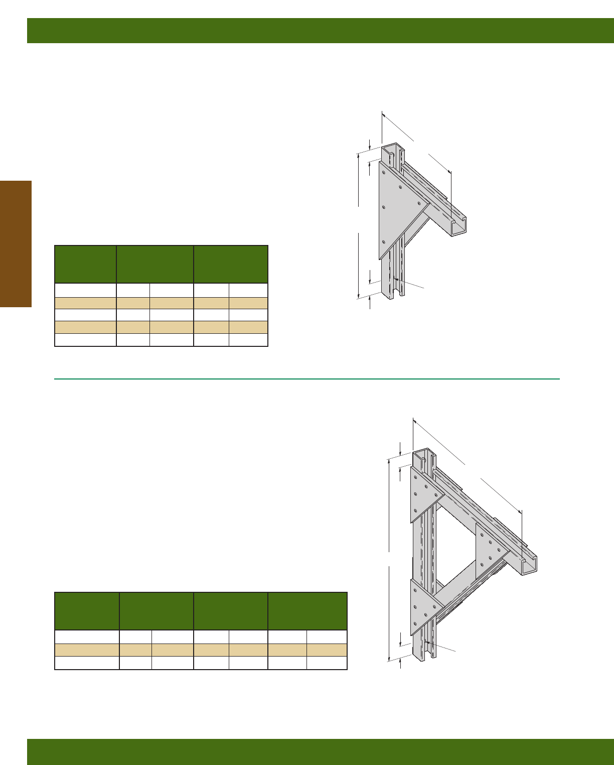
BF*494 SERIES
BRACKETS 24” (609) TO 36” (914) LONG
• Design Load Safety Factor of 3 based on uniform loading
• MH1 - From Top of Bracket to center of Mounting Hole
• MH2 - From Bottom of Bracket to center of Mounting Hole
• Material: Glass Reinforced Vinyl Ester or Polyester
Design
Part No. AB
Load
in. mm in. mm Lbs. kN
BF*494-24 28 (711) 23 (584) 750 (3.33)
BF*494-30 34 (863) 26 (660) 750 (3.33)
BF*494-36 40 (1016) 29 (736) 750 (3.33)
*Insert P for Glass Reinforced Polyester Resin or V
for Glass Reinforced Vinyl Ester Resin
BF*409 SERIES
BRACKETS 6” (152) TO 24” (609) LONG
• Design Load Safety Factor of 3 based on uniform loading
• MH1 - From Top of Bracket to center of Mounting Hole
• MH2 - From Bottom of Bracket to center of Mounting Hole
Design
Part No. ALoad
in. mm Lbs. kN
BF*409-6 10 (250) 1400 (6.22)
BF*409-9 13 (330) 1000 (4.45)
BF*409-12 16 (406) 800 (3.56)
BF*409-18 22 (559) 675 (3.00)
BF*409-24 28 (711) 450 (2.00)
*Insert P for Glass Reinforced Polyester Resin or V
for Glass Reinforced Vinyl Ester Resin
A
A
B
13/32" (10.3) DIA.
MOUNTING HOLES
13/32” (10.3) DIA.
MOUNTING HOLES
11/4”
(31.7)
11/4”
(31.7)
11/4”
(31.7)
MH1
MH2
11/4”
(31.7)
MH1
MH2
12"
(304.8)
Fiberglass Materials
Reference page 170 for general fitting specifications.
Fiberglass
182
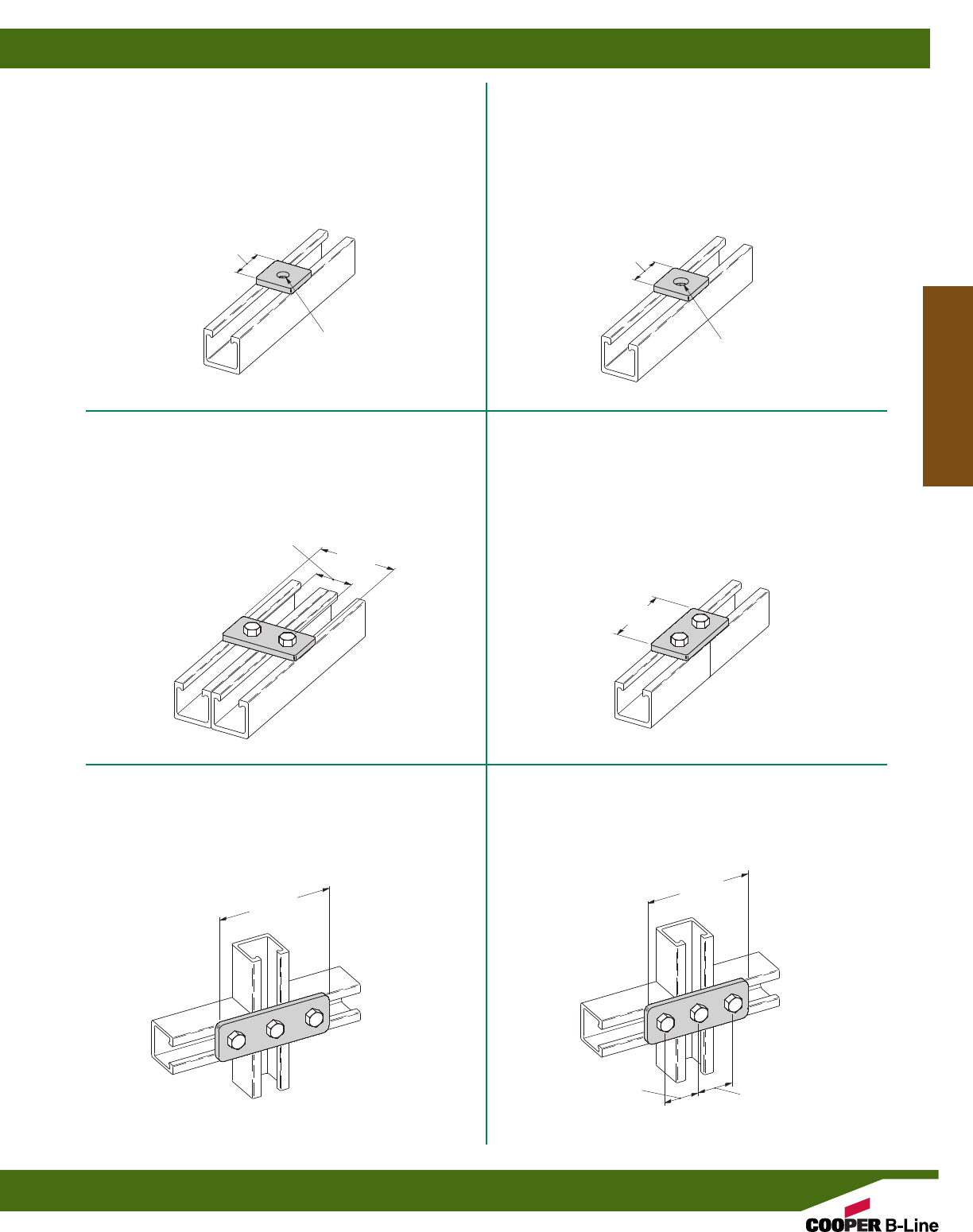
BFV201
SQUARE WASHER FOR 3/8” BOLT
•Material: Injection Molded Glass Reinforced
Polyurethane
BFV202
SQUARE WASHER FOR 1/2” BOLT
•Material: Injection Molded Glass Reinforced
Polyurethane
BFV141
THREE HOLE FLAT PLATE
•Material: Injection Molded Glass Reinforced
Polyurethane
BFV340
TWO HOLE FLAT PLATE
•Material: Injection Molded Glass Reinforced
Polyurethane
BFV129
TWO HOLE SPLICE PLATE
•Material: Injection Molded Glass Reinforced
Polyurethane
BFV557
THREE HOLE FLAT PLATE
•Material: Injection Molded Glass Reinforced
Polyurethane
15/8”
(41.3)
15/8”
(41.3)
15/8”
(41.3)
15/8”
(41.3)
15/8”
(41.3)
13/32” (10.3)
DIAMETER
HOLE
9/16” (14.3)
DIAMETER
HOLE
31/2”
(88.9)
31/4”
(82.5)
53/8”
(136.5)
47/8”
(123.8)
Fiberglass Materials
Reference page 170 for general fitting specifications.
Fiberglass
183
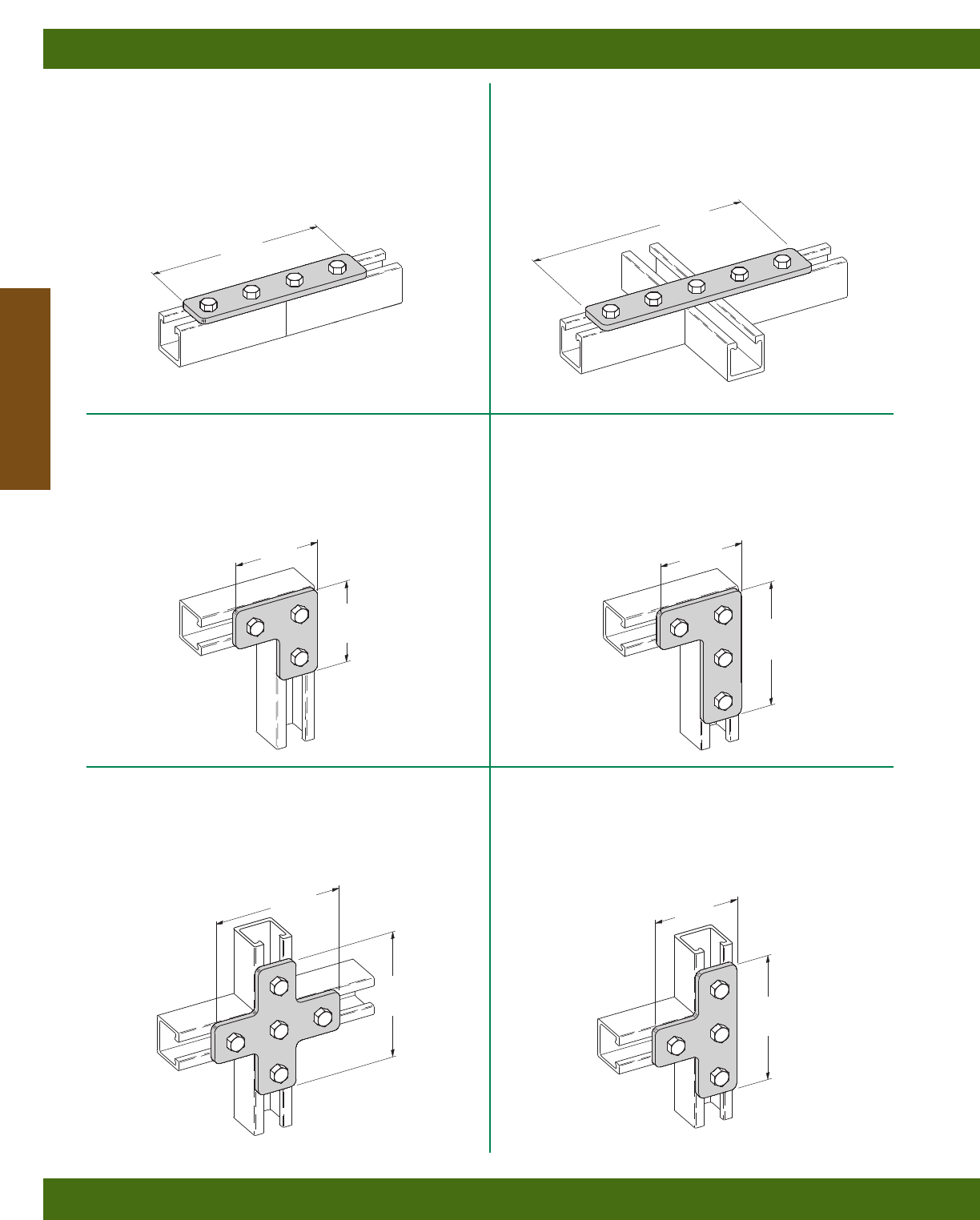
BFV341
FOUR HOLE SPLICE PLATE
•Material: Injection Molded Glass Reinforced
Polyurethane
BFV342
FIVE HOLE FLAT PLATE
•Material: Injection Molded Glass Reinforced
Polyurethane
BFV132
FIVE HOLE FLAT CROSS PLATE
•Material: Injection Molded Glass Reinforced
Polyurethane
BFV140
THREE HOLE FLAT CORNER PLATE
•Material: Injection Molded Glass Reinforced
Polyurethane
BFV143
FOUR HOLE FLAT CORNER PLATE
•Material: Injection Molded Glass Reinforced
Polyurethane
BFV133
FOUR HOLE FLAT TEE PLATE
•Material: Injection Molded Glass Reinforced
Polyurethane
31/2”
(88.9)
31/2”
(88.9)
53/8”
(136.5)
53/8”
(136.5)
53/8”
(136.5) 53/8”
(136.5)
71/4”
(184.1)
91/8”
(231.8)
31/2”
(88.9)
31/2”
(88.9)
Fiberglass Materials
Reference page 170 for general fitting specifications.
Fiberglass
184
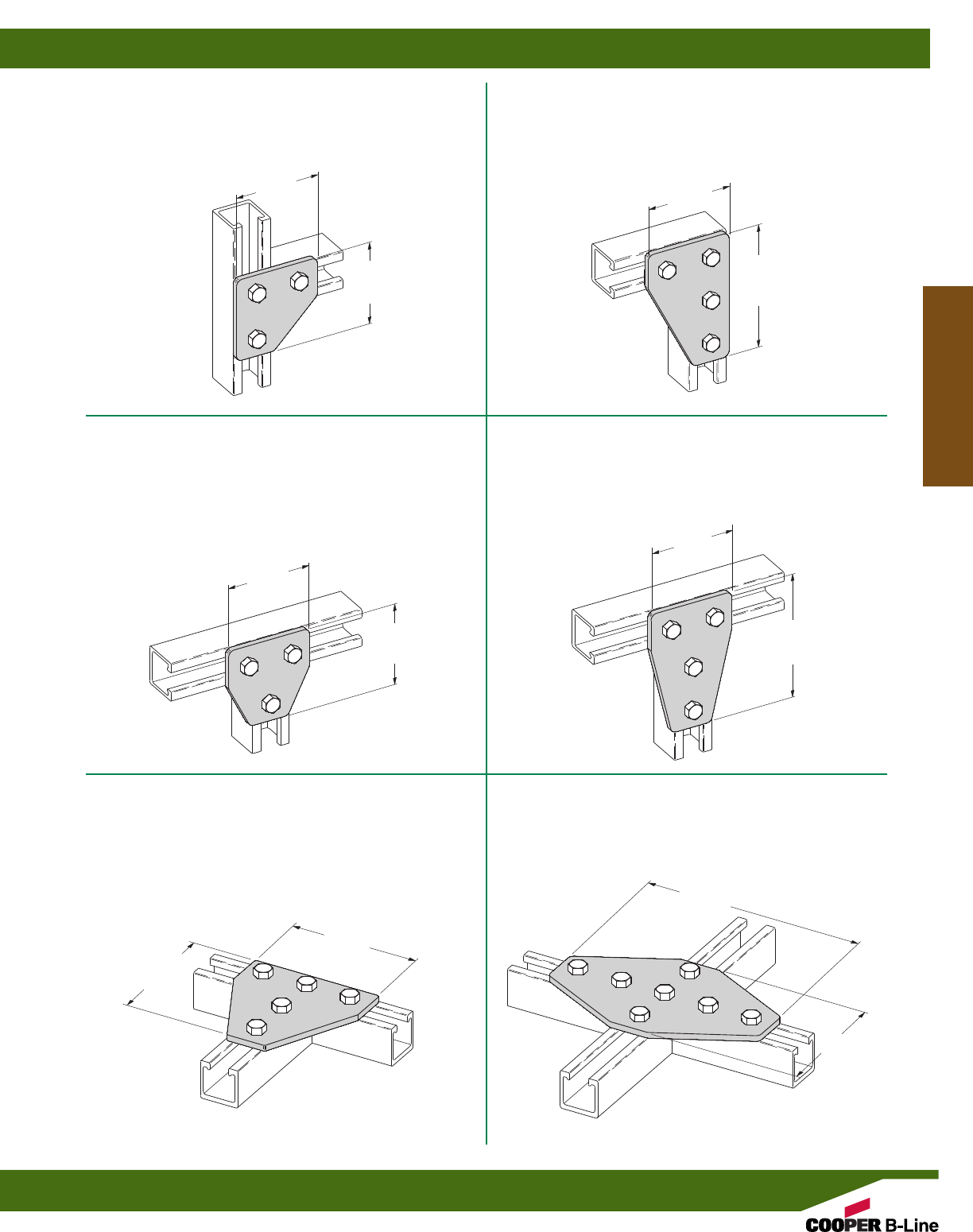
BFV135
THREE HOLE FLAT GUSSET CORNER PLATE
•Material: Injection Molded Glass Reinforced
Polyurethane
BFV142
FOUR HOLE FLAT GUSSET CORNER PLATE
•Material: Injection Molded Glass Reinforced
Polyurethane
BFV532
FIVE HOLE FLAT GUSSET TEE PLATE
•Material: Injection Molded Glass Reinforced
Polyurethane
BFV337
THREE HOLE FLAT GUSSET TEE PLATE
•Material: Injection Molded Glass Reinforced
Polyurethane
BFV136
FOUR HOLE FLAT GUSSET TEE PLATE
•Material: Injection Molded Glass Reinforced
Polyurethane
BFV334
SEVEN HOLE FLAT GUSSET CROSS PLATE
•Material: Injection Molded Glass Reinforced
Polyurethane
31/2”
(88.9)
31/2”
(88.9)
31/2”
(88.9)
31/2”
(88.9)
31/2”
(88.9)
31/2”
(88.9)
53/8”
(136.5)
53/8"
(136.5)
53/8”
(136.5)
53/8”
(136.5)
91/8”
(231.8)
53/8”
(136.5)
Fiberglass Materials
Reference page 170 for general fitting specifications.
Fiberglass
185
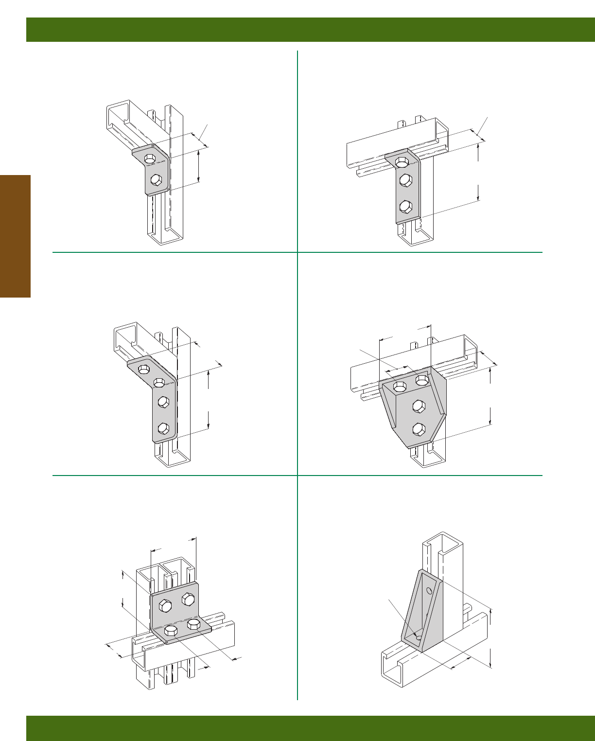
31/2”
(88.9)
31/2”
(88.9)
41/8”
(104.8)
41/8”
(104.8)
BFV101
TWO HOLE 90° CORNER ANGLE
•Material: Injection Molded Glass Reinforced
Polyurethane
BFV103
THREE HOLE 90° CORNER ANGLE
•Material: Injection Molded Glass Reinforced
Polyurethane
BFV558
FOUR HOLE 90° CORNER ANGLE
•Material: Injection Molded Glass Reinforced
Polyurethane
BFV104
FOUR HOLE 90° CORNER ANGLE
•Material: Injection Molded Glass Reinforced
Polyurethane
BFV118
FOUR HOLE 90° GUSSETTED SHELF ANGLE
•Material: Injection Molded Glass Reinforced
Polyurethane
BFV371-2G
THREE HOLE 90° GUSSETTED CORNER ANGLE
•Material: Injection Molded Glass Reinforced
Polyurethane
31/4”
(82.5)
15/8”
(41.3) 15/8”
(41.3)
4”
(101.6)
THREE HOLES
.400” Dia. (10.1)
21/4”
(57.1)
15/8”
(41.3)
15/8”
(41.3)
41/8”
(104.8)
25/16”
(58.7)
15/8”
(41.3)
15/8”
(41.3)
Fiberglass Materials
Reference page 170 for general fitting specifications.
Fiberglass
186
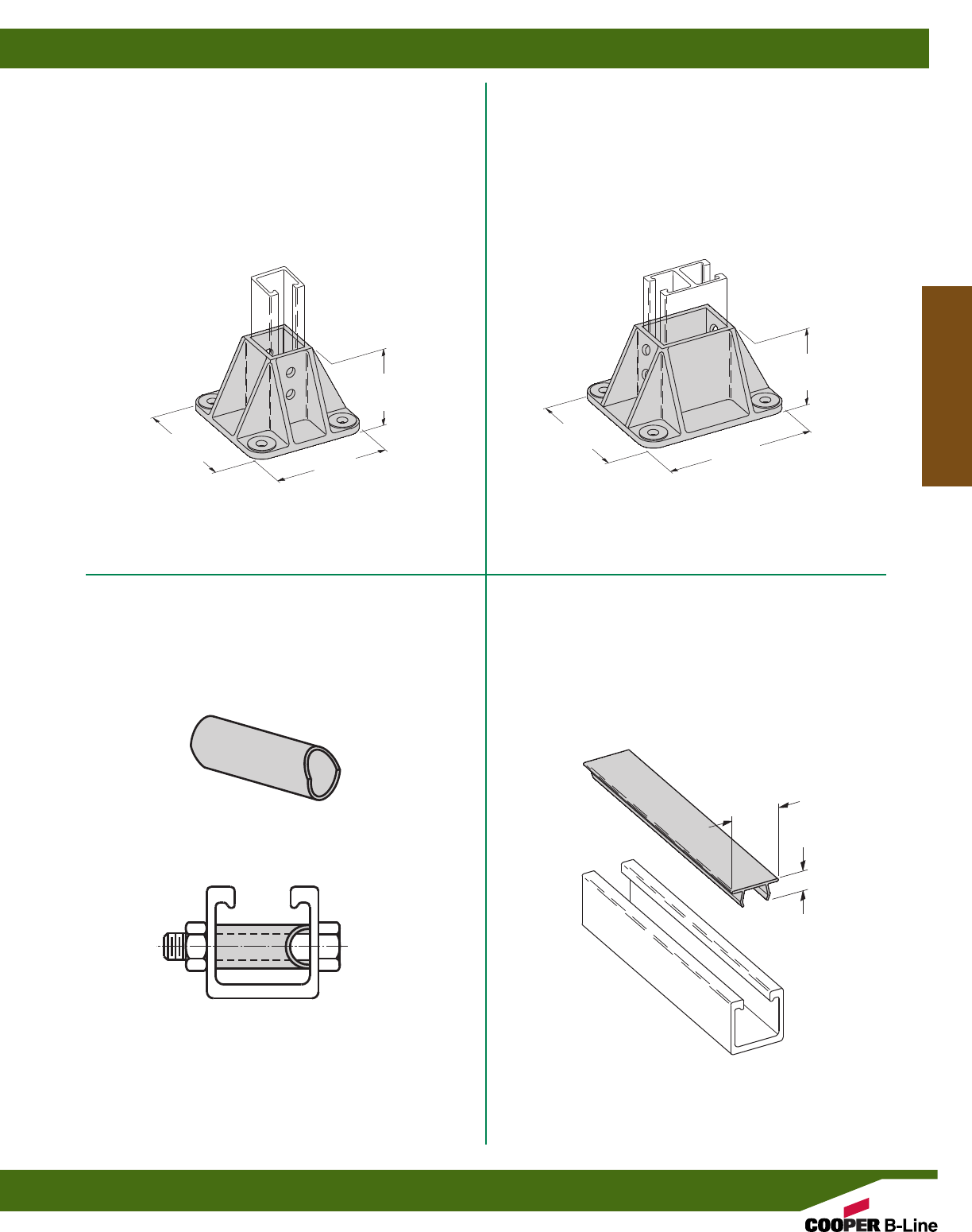
BFV280SQ
POST BASE FOR BF*22
•Material: Glass Reinforced Polyurethane
BFV281SQ
POST BASE FOR BF*22A
•Material: Glass Reinforced Polyurethane
BFV650
CHANNEL SPACER
•Spacer I.D. accommodates 3/8" rod or bolts.
•Material: Polyurethane
B217P
PLASTIC CLOSURE STRIP
•Available in 10 Ft. (3.05 m) lengths.
•Material: PVC
17/16”
(36.5)
5”
(127.0)
5”
(127.0)
5”
(127.0)
3”
(76.2)
3”
(76.2)
Used when attaching fittings to side walls of channel.
This channel spacer prevents wall compression in
heavy load conditions.
65/8”
(168.3)
5/8”
(15.9)
Fiberglass Materials
Reference page 170 for general fitting specifications.
Fiberglass
187
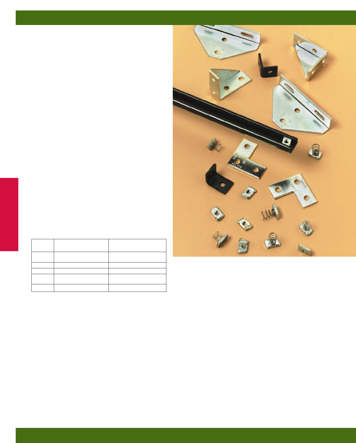
B-Line’s mini channels and fittings provide for an
economical method of supporting light load
requirements on a metal framing system.
Channel
Channels are cold formed on our modern rolling mills
from 18 Ga. (1.2 mm) low carbon steel strips plain steel
(ASTM A1008 33,000 PSI min. yield) and pre-
galvanized steel strips, (ASTM A653 33,000 PSI min.
yield). A continuous slot with inturned lips provides the
ability to make attachments at any point. Channel
combinations are made with new state of the art,
high-tech welding equipment.
Lengths
Standard lengths are 10’ (3.05 m) and 20’ (6.09 m) for B62
series, and 10’ (3.05 m) for B72 series. Custom lengths
are available.
Fittings
Mini fittings are formed from hot rolled pickled and
oiled strip or sheet steel (ASTM A1011, HSLAS,
Grade 50, Class1). The following dimensions apply to
all fittings except as noted on the drawings:
Hole Size–9/32” (7.14 mm) Dia.
Hole Spacing–13/32” (10.3 mm) from end and
11/16” (27.0 mm) on center.
Width–13/16” (20.6 mm)
Thickness–1/8” (3.2 mm)
Materials & Finishes*
*Unless otherwise noted.
Metric
Metric dimensions are shown in parentheses. Unless noted, all metric dimensions are in millimeters.
Mini Channel & Fittings
Finish
Code Finish Specification
PLN Plain ASTM A1011, HSLAS,
Grade 50, Class 1
ZN Electro-Plated Zinc ASTM B633 SC3 Type II
GRN Dura-Green
GALV Pre-Galvanized ASTM A653
33,000 PSI min. yield
HDG Hot-Dipped Galvanized ASTM A123
Mini Channel & Fittings
188
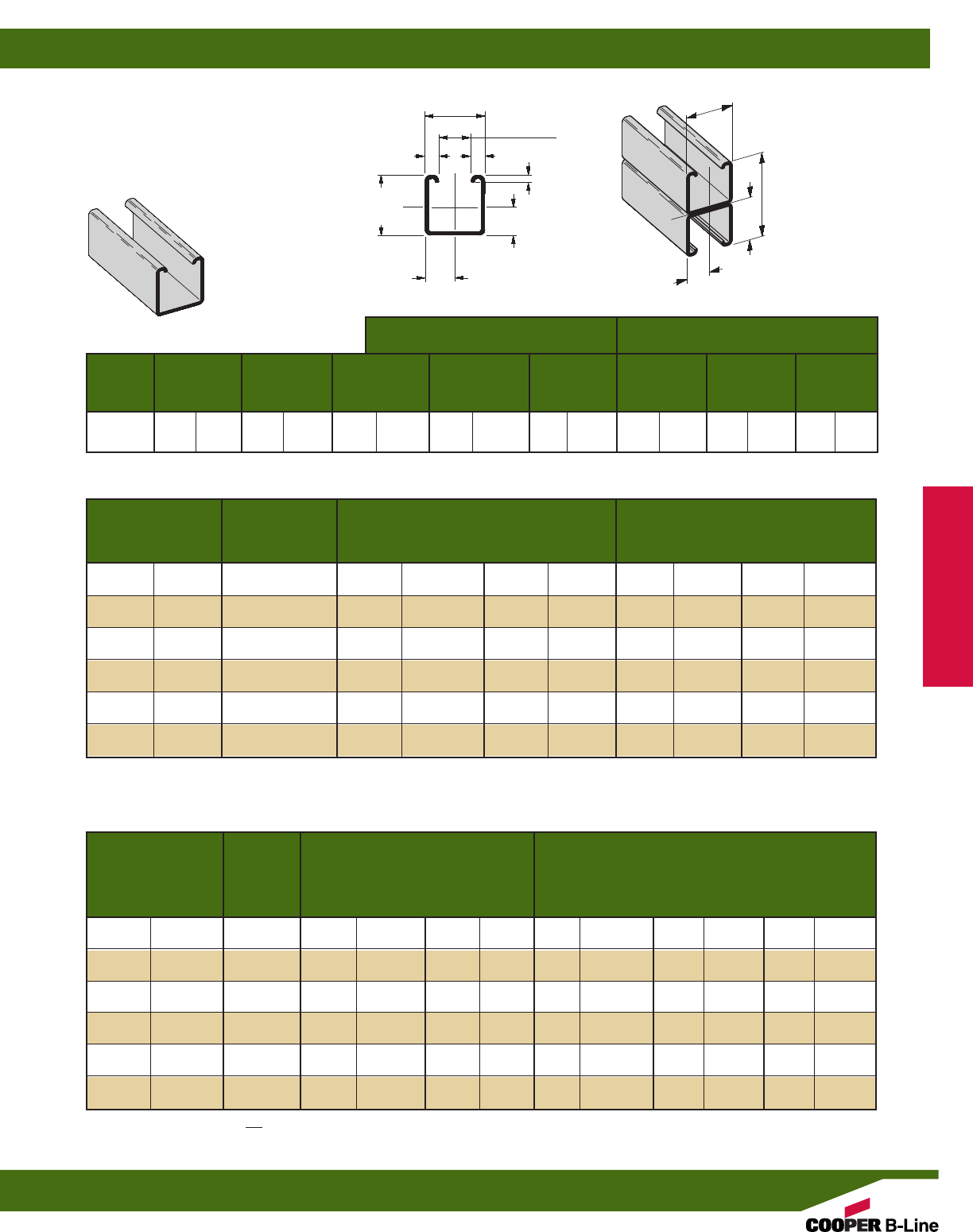
Areas of Moment of Section Radius of Moment of Section Radius of
Channel Weight Section Inertia (I) Modulus (S) Gyration (r) Inertia (I) Modulus (S) Gyration (r)
lbs./ft. kg/m sq. in. cm2in.4cm4in.3cm3in. cm in.4cm4in.3cm3in. cm
B62 .420 (.62) .123 (.80) .0103 (.43) .0221 (.36) .289 (.73) .0134 (.56) .0330 (.54) .330 (.84)
B62A .839 (1.25) .247 (1.59) .0500 (2.08) .0616 (1.01) .450 (1.14) .0269 (1.12) .0663 (1.09) .330 (.84)
X - X Axis Y - Y Axis
Uniform Load @ Deflection =
Beam Span Channel Uniform Load and Deflection 1/240 Span 1/360 Span
In. mm Style Lbs. N In. mm Lbs. N Lbs. N
12 (305) B62 364 (1619.1) .027 (.68) 364 (1619.1) 364 (1619.1)
B62A 420* (1868.2) .006 (.15) 420* (1868.2) 420* (1868.2)
24 (609) B62 182 (809.6) .109 (2.77) 167 (742.8) 111 (493.7)
B62A 420* (1868.2) .051 (1.29) 420* (1868.2) 420* (1868.2)
36 (914) B62 121 (538.2) .245 (6.22) 74 (329.1) 50 (222.4)
B62A 341 (1516.8) .141 (3.58) 341 (1516.8) 242 (1076.4)
48 (1219) B62 91 (404.8) .436 (11.07) 42 (186.8) 28 (124.5)
B62A 256 (1138.7) .250 (6.35) 204 (907.4) 136 (604.9)
60 (1524) B62 73 (324.7) .681 (17.30) 27 (120.1) 18 (80.0)
B62A 205 (911.9) .391 (9.93) 131 (582.7) 87 (387.0)
72 (1829) B62 61 (271.3) .981 (24.92) 19 (84.5) 12 (53.4)
B62A 170 (756.2) .563 (14.30) 91 (404.8) 61 (271.3)
Max. Column Loading K = .80 Max. Column Loading (Loaded @ C.G.)
Unbraced Channel Loaded@ Loaded@
Height Style C.G. Slot Face K = .65 K = 1.0 K = 1.2
In. mm Lbs. N Lbs. N Lbs. N Lbs. N Lbs. N
12 (305) B62 2052 (9127.7) 820 (3647) 2161 (9612.6) 1890 (8407.1) 1715 (7628.7)
B62A 4666 (20755.4) 1449 (6445) 4710 (20951.1) 4593 (20430.7) 4503 (20030.3)
24 (609) B62 1350 (6005.1) 645 (2869) 1624 (7223.9) 1020 (4537.2) 818 (3638.6)
B62A 4275 (19016.1) 1367 (6081) 4453 (19807.9) 3982 (17712.8) 3624 (16120.3)
36 (914) B62 818 (3638.6) 471 (2095) 1053 (4684.0) 633 (2815.7) 515 (2290.8)
B62A 3624 (16120.3) 847 (3767) 4023 (17895.2) 2965 (13189.0) 2179 (9692.7)
48 (1219) B62 589 (2620.0) 369 (1641) 745 (3313.9) 456 (2028.4) 365** (1623.6)
B62A 2713 (12068.0) 504 (2242) 3421 (15217.3) 1765 (7851.1) 1225 (5449.1)
60 (1524) B62 456 (2028.4) 300 (1334) 579 (2575.5) 347** (1543.5) 271** (1205.4)
B62A 1765 (7851.1) 323 (1437) 2647 (11774.4) 1129 (5022.0) 784** (3487.4)
72 (1829) B62 365** (1623.6) 248 (1103) 470 (2090.6) 271** (1205.4) ––
B62A 1225 (5449.1) 224 (996) 1856 (8255.9) 784** (3487.4) 545** (2424.3)
•Thickness: 18 Ga. (1.2 mm)
•Standard lengths: 10’ (3.05 m)
& 20’ (6.09 m)
•Standard finishes: Plain, Dura-Green,
Pre-Galvanized
•Weight: .42 Lbs./Ft. (.62 kg/m)
SECTION PROPERTIES
BEAM LOADING
COLUMN LOADING
Calculations of section properties are based on metal thicknesses as determined by the AISI Cold-Formed Steel Design Manual.
Based on simple beam condition using an allowable design stress of 25,000 psi (172 MPa) in accordance with MFMA, with adequate lateral
bracing (see page 11 for further explanation). Actual yield point of cold rolled steel is 42,000 psi. To determine concentrated load capacity at
mid span, multiply uniform load by 0.5 and corresponding deflection by 0.8. *Failure determined by weld shear.
**Where the slenderness ratio KL exceeds 200, and K = end fixity factor, L = actual length and r = radius of gyration.
r
13/16”
(20.6)
13/16”
(20.6)
13/16”
(20.6)
7/16”
(11.1)
13/16”
(20.6)
.406
(10.3)
.406
(10.3)
.346
(8.8)
3/16”
(4.7) 3/32”
(2.4)
3/16”
(4.7)
15/8”
(41.3)
Y
X
X
Y
B62A
Wt. .84 Lbs./Ft. (1.25 kg/m)
Mini Channel & Fittings
Reference page 188 for general fitting specifications.
B62 Channel
189
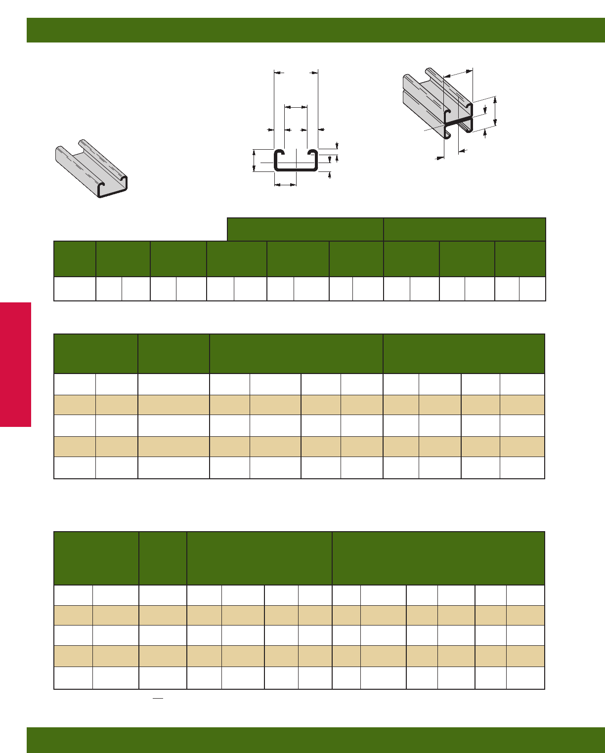
•Thickness: 18 Ga. (1.2 mm)
•Standard lengths: 10’ (3.05 m)
•Standard finishes: Plain, Dura-Green,
Pre-Galvanized
•Weight: .29 Lbs./Ft. (.43 kg/m)
SECTION PROPERTIES
BEAM LOADING
B72A
Wt. .58 Lbs./Ft. (.87 kg/m)
Areas of Moment of Section Radius of Moment of Section Radius of
Channel Weight Section Inertia (I) Modulus (S) Gyration (r) Inertia (I) Modulus (S) Gyration (r)
lbs./ft. kg/m sq. in. cm2in.4cm4in.3cm3in. cm in.4cm4in.3cm3in. cm
B72 .287 (.43) .084 (.54) .0018 (.07) .0073 (.12) .146 (.37) .0077 (.32) .0190 (.31) .302 (.77)
B72A .574 (.85) .169 (1.09) .0078 (.32) .0192 (.31) .215 (.55) .0155 (.65) .0382 (.63) .303 (.77)
X - X Axis Y - Y Axis
Uniform Load @ Deflection =
Beam Span Channel Uniform Load and Deflection 1/240 Span 1/360 Span
In. mm Style Lbs. N In. mm Lbs. N Lbs. N
12 (305) B72 116 (516.0) .051 (1.29) 113 (502.6) 75 (324.7)
B72A 210* (934.1) .020 (.51) 210* (934.1) 210* (934.1)
24 (609) B72 58 (258.0) .206 (5.23) 28 (124.5) 19 (84.5)
B72A 159 (707.2) .125 (3.17) 127 (564.9) 85 (378.1)
36 (914) B72 39 (173.5) .465 (11.81) 13 (57.8) 8(35.6)
B72A 106 (471.5) .281 (7.14) 57 (253.5) 38 (169.0)
48 (1219) B72 29 (129.0) .827 (21.00) 7(31.1) 5(22.2)
B72A 80 (355.8) .500 (12.70) 32 (142.3) 21 (93.4)
60 (1524) B72 23 (102.3) 1.292 (32.81) 5(22.2) 3(13.3)
B72A 64 (284.7) .782 (19.86) 20 (88.9) 14 (62.3)
Max. Column Loading K = .80 Max. Column Loading (Loaded @ C.G.)
Unbraced Channel Loaded@ Loaded@
Height Style C.G. Slot Face K = .65 K = 1.0 K = 1.2
In. mm Lbs. N Lbs. N Lbs. N Lbs. N Lbs. N
12 (305) B72 1598 (7108) 539 (2397) 1712 (7615) 1410 (6272) 1181 (5253)
B72A 3600 (16013) 986 (4386) 3700 (16458) 3433 (15271) 3229 (14363)
24 (609) B72 701 (3118) 320 (1423) 1050 (4670) 450 (2001) 313** (1392)
B72A 2710 (12054) 802 (3567) 3113 (13847) 2043 (9088) 1421 (6321)
36 (914) B72 313** (1392) 188 (836) 473 (2104) 201** (894) ––
B72A 1421 (6321) 569 (2531) 2135 (9497) 909 (4043) 631** (2807)
48 (1219) B72 177** (787) 122 (542) 267** (1187) –– – –
B72A 799 (3554) 404 (1797) 1211 (5387) 512** (2277) 355** (1579)
60 (1524) B72 113** (502) 85 (378) 171** (760) –– – –
B72A 512** (2277) 298 (1325) 775 (3447) 327** (1454) ––
COLUMN LOADING
Calculations of section properties are based on metal thicknesses as determined by the AISI Cold-Formed Steel Design Manual.
Based on simple beam condition using an allowable design stress of 25,000 psi (172 MPa) in accordance with MFMA, with adequate lateral
bracing (see page 11 for further explanation). Actual yield point of cold rolled steel is 42,000 psi. To determine concentrated load capacity at
mid span, multiply uniform load by 0.5 and corresponding deflection by 0.8. *Failure determined by weld shear.
**Where the slenderness ratio KL exceeds 200, and K = end fixity factor, L = actual length and r = radius of gyration.
r
13/16”
(20.6)
7/16”
(11.1)
.406
(10.3)
.160
(4.0)
3/32”
(2.4)
3/16”
(4.7)
3/16”
(4.7)
13/32”
(10.3)
13/16”
(20.6)
13/16”
(20.6)
.406
(10.3)
.406
(10.3)
Y
Y
X
X
Mini Channel & Fittings
Reference page 188 for general fitting specifications.
B72 Channel
190
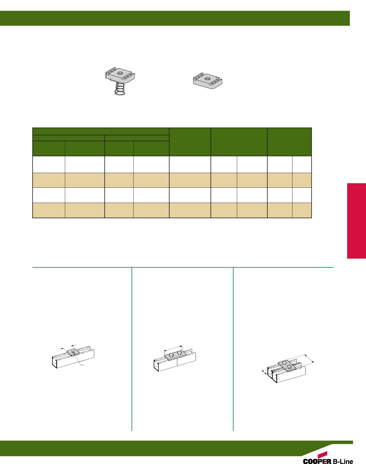
Part Number
B62 B72
With Without With Without Thread Wt./C
Spring Spring Spring Spring Size Thickness Lbs. kg
N621 N621WO N7221 N621WO #8-32 .150 (3.81) 1.0 (.45)
N622 N622WO N7222 N622WO #10-24 .150 (3.81) 1.0 (.45)
N627 N627WO N7227 N627WO #10-32 .150 (3.81) 1.0 (.45)
N624 N624WO N7224 N624WO 1/4-20 .150 (3.81) 1.0 (.45)
BMM-3L BMM-3 BMM-3S BMM-3 M3.5 x 0.6 .150 (3.81) 1.0 (.45)
BMM-4L BMM-4 BMM-4S BMM-4 M4 x 0.7 .150 (3.81) 1.0 (.45)
BMM-5L BMM-5 BMM-5S BMM-5 M5 x 0.8 .150 (3.81) 1.0 (.45)
BMM-6L BMM-6 BMM-6S BMM-6 M6 x 1 .150 (3.81) 1.0 (.45)
NUTS FOR B62, B72 CHANNEL
MINI FITTINGS
SPRING NUT NUT WITHOUT SPRING
B6202
SQUARE WASHER
•Standard finishes: ZN, GRN
•Wt./C 2 Lbs. (.9 kg)
B6129
TWO HOLE SPLICE PLATE
•Standard finishes: ZN, GRN
•Wt./C 5 Lbs. (2.2 kg)
B6340
TWO HOLE SPLICE PLATE
•Standard finishes: ZN, GRN
•Wt./C 5 Lbs. (2.2 kg)
13/16”
(20.6)
13/16”
(20.6)
17/8”
(47.6)
15/8”
(41.3)
9/32” (7.1)
DIA.
Mini Channel & Fittings
Reference page 188 for general fitting specifications.
Mini Channel Nuts & Fittings
191
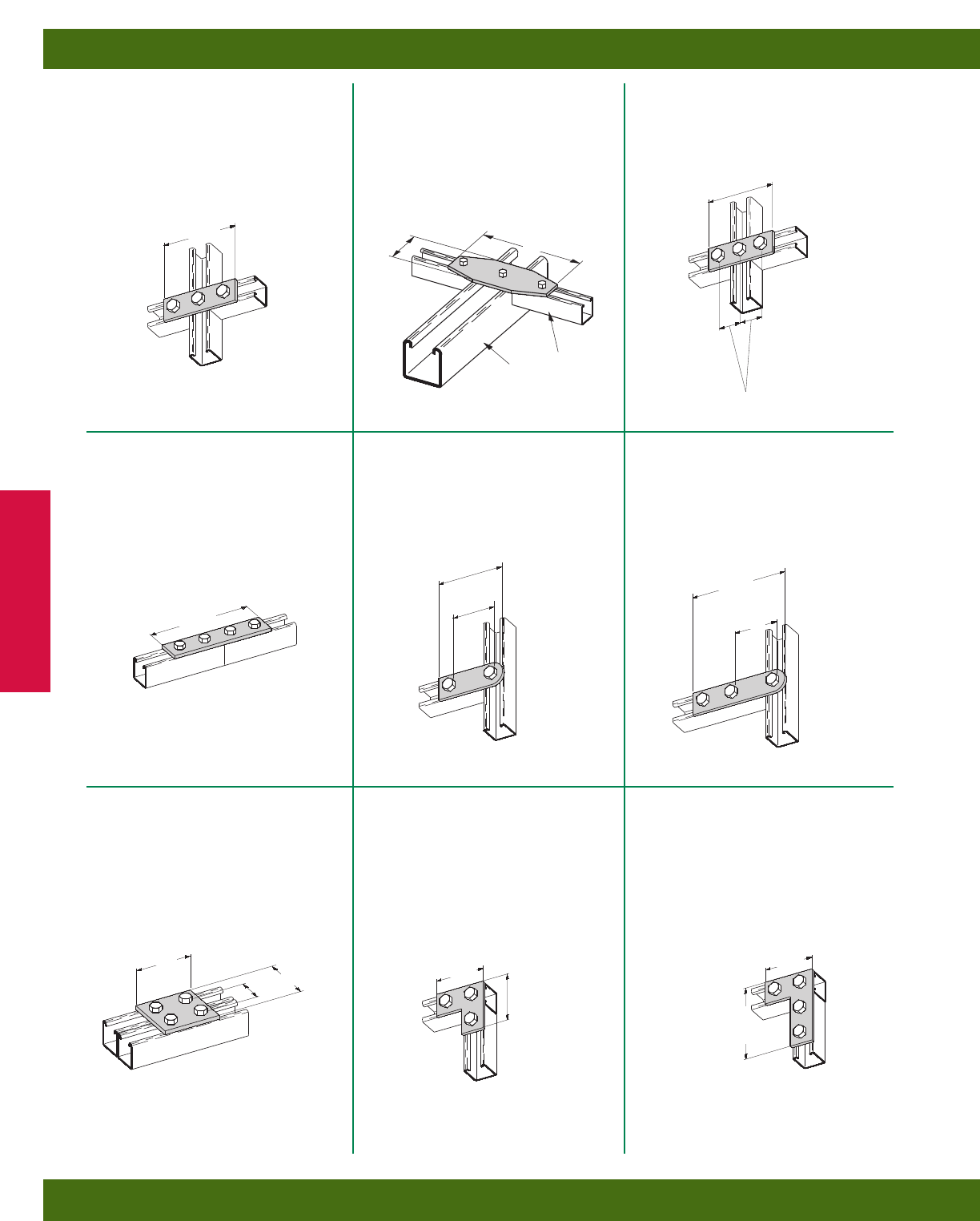
B6557
THREE HOLE SPLICE PLATE
•Standard finishes: ZN, GRN
•Wt./C 7 Lbs. (3.2 kg)
B600-62
THREE HOLE FLAT
ADAPTER PLATE
•Standard finishes: ZN, GRN
•Wt./C 19 Lbs. (8.6 kg)
B6141
THREE HOLE SPLICE PLATE
•Standard finishes: ZN, GRN
•Wt./C 7 Lbs. (3.2 kg)
B6341
FOUR HOLE
SPLICE PLATE
•Standard finishes: ZN, GRN
•Wt./C 11 Lbs. (5.0 kg)
B6138
TWO HOLE SWIVEL PLATE
•Standard finishes: ZN, GRN
•Wt./C 7 Lbs. (3.2 kg)
B6139
THREE HOLE
SWIVEL PLATE
•Standard finishes: ZN, GRN
•Wt./C 10 Lbs. (4.5 kg)
B6504
FOUR HOLE SPLICE PLATE
•Standard finishes: ZN, GRN
•Wt./C 10 Lbs. (4.5 kg)
B6140
THREE HOLE CORNER PLATE
•Standard finishes: ZN, GRN
•Wt./C 8 Lbs. (3.6 kg)
B6143
FOUR HOLE CORNER PLATE
•Standard finishes: ZN, GRN
•Wt./C 11 Lbs. (5.0 kg)
215/16”
(74.6) 15/8”
(41.3)
4”
(101.6)
13/16”
(20.6)
41/8”
(104.8)
211/16”
(68.2)
17/8”
(47.6)
27/16”
(61.9)
33/4”
(95.2)
B62
B22
13/16”
(20.6)
17/8”
(47.6)
17/8”
(47.6)
17/8”
(47.6)
17/8”
(47.6)
15/8”
(41.3)
17/8”
(47.6)
215/16”
(74.6)
Mini Channel & Fittings
Reference page 188 for general fitting specifications.
Mini Fittings
192
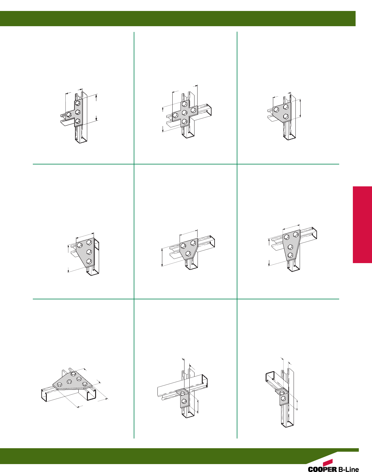
B6135
THREE HOLE CORNER
GUSSET PLATE
•Standard finishes: ZN, GRN
•Wt./C 9 Lbs. (4.1 kg)
B6132
FIVE HOLE CROSS PLATE
•Standard finishes: ZN, GRN
•Wt./C 13 Lbs. (5.9 kg)
B6133
FOUR HOLE TEE PLATE
•Standard finishes: ZN, GRN
•Wt./C 11 Lbs. (5.0 kg)
B6142
FOUR HOLE
CORNER GUSSET PLATE
•Standard finishes: ZN, GRN
•Wt./C 15 Lbs. (6.8 kg)
B6337
THREE HOLE
TEE GUSSET PLATE
•Standard finishes: ZN, GRN
•Wt./C 10 Lbs. (4.5 kg)
B6136
FOUR HOLE
TEE GUSSET PLATE
•Standard finishes: ZN, GRN
•Wt./C 15 Lbs. (6.8 kg)
B6532
FIVE HOLE
TEE GUSSET PLATE
•Standard finishes: ZN, GRN
•Wt./C 22 Lbs. (10.0 kg)
B6101
TWO HOLE CORNER ANGLE
•Standard finishes: ZN, GRN
•Wt./C 5 Lbs. (2.2 kg)
B6230
TWO HOLE CORNER ANGLE
•Standard finishes: ZN, GRN
•Wt./C 5 Lbs. (2.2 kg)
11/4”
(31.7)
11/8”
(28.6)
215/16”
(74.6) 215/16”
(74.6)
215/16”
(74.6)
17/8”
(47.6)
215/16”
(74.6)
17/8”
(47.6)
215/16”
(74.6)
215/16”
(74.6)
215/16”
(74.6)
17/8”
(47.6)
17/8”
(47.6)
17/8”
(47.6)
17/8”
(47.6)
17/8”
(47.6)
13/16”
(20.6)
15/16”
(23.8)
Mini Channel & Fittings
Reference page 188 for general fitting specifications.
Mini Fittings
193
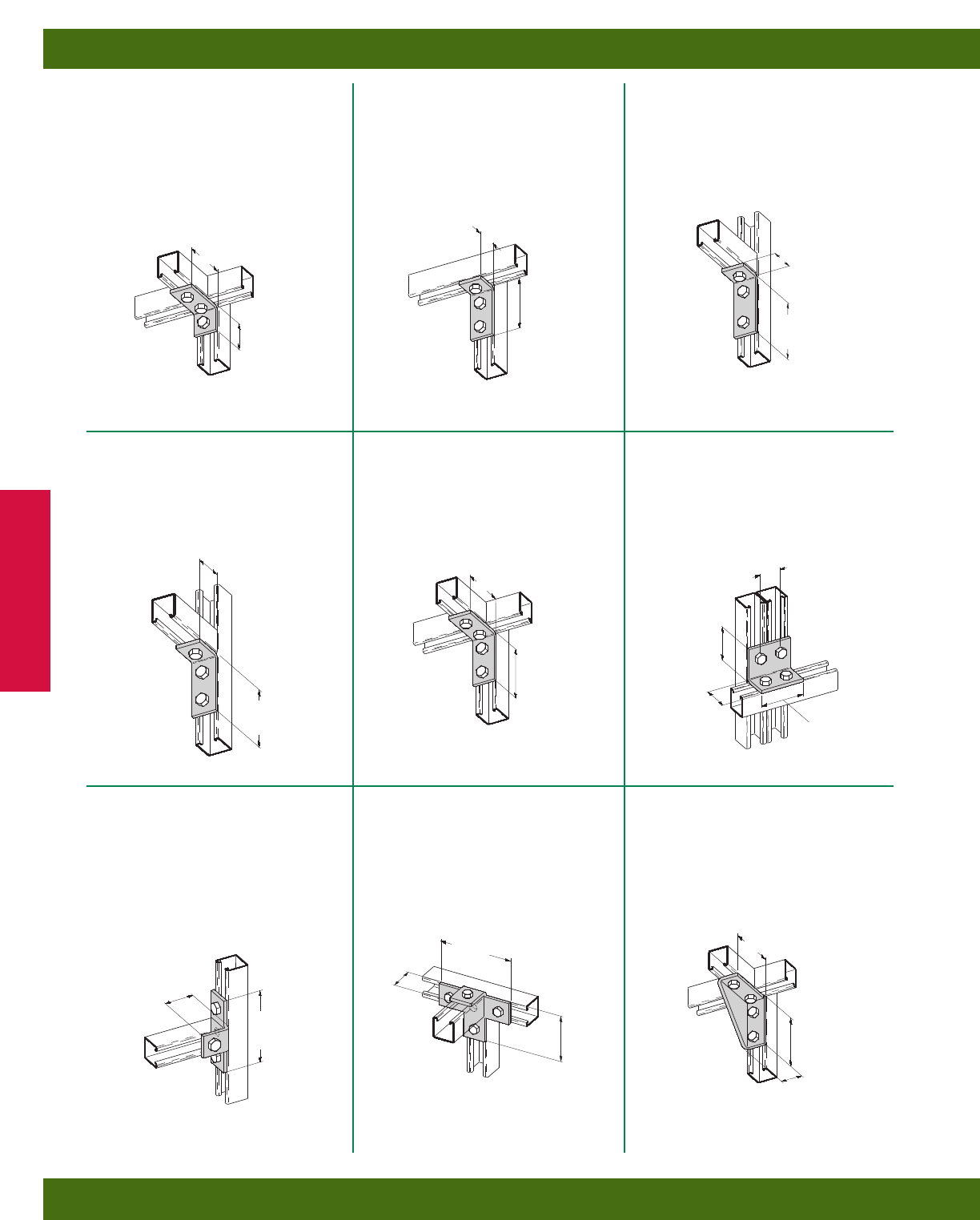
B6232
THREE HOLE
CORNER ANGLE
•Standard finishes: ZN, GRN
•Wt./C 7 Lbs. (3.2 kg)
B6103
THREE HOLE CORNER ANGLE
•Standard finishes: ZN, GRN
•Wt./C 8 Lbs. (3.6 kg)
B6102
THREE HOLE CORNER ANGLE
•Standard finishes: ZN, GRN
•Wt./C 8 Lbs. (3.6 kg)
B6374
THREE HOLE CORNER ANGLE
•Standard finishes: ZN, GRN
•Wt./C 7 Lbs. (3.2 kg)
B6104
FOUR HOLE CORNER ANGLE
•Standard finishes: ZN, GRN
•Wt./C 10 Lbs. (4.5 kg)
B6558
FOUR HOLE CORNER ANGLE
•Standard finishes: ZN, GRN
•Wt./C 10 Lbs. (4.5 kg)
B6357
FOUR HOLE
OFFSET BENT TEE
•Standard finishes: ZN, GRN
•Wt./C 11 Lbs. (5.0 kg)
B6239
FIVE HOLE
OFFSET BENT TEE
•Standard finishes: ZN, GRN
•Wt./C 14 Lbs. (6.3 kg)
B6144R&L
FOUR HOLE SHELF BRACKET
•Standard finishes: ZN, GRN
•Wt./C 19 Lbs. (8.6 kg)
2”
(50.8)
13/16”
(20.6)
13/16”
(20.6)
23/16”
(55.5)
15/16”
(23.8)
13/16”
(20.6)
17/8”
(47.6)
17/8”
(47.6)
17/8”
(47.6)
17/8”
(47.6)
25/16”
(58.7)
25/16”
(58.7)
25/16”
(58.7)
11/4”
(31.7)
11/4”
(31.7)
11/8”
(28.6)
15/8”
(41.3)
11/8”
(28.6)
11/8”
(28.6)
215/16”
(74.6)
215/16”
(74.6)
15/16”
(23.8)
(Right shown)
Mini Channel & Fittings
Reference page 188 for general fitting specifications.
Mini Fittings
194
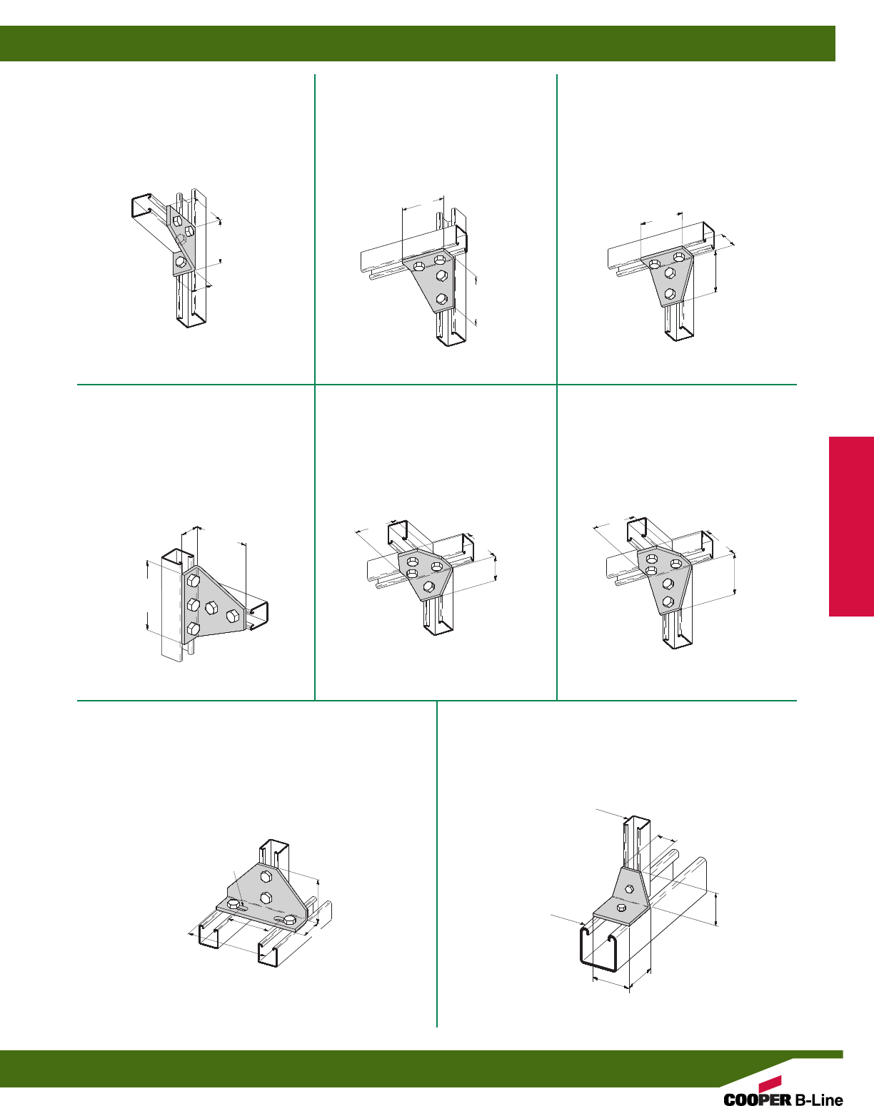
B6118
FOUR HOLE
GUSSETTED SHELF ANGLE
•Standard finishes: ZN, GRN
•Wt./C 15 Lbs. (6.8 kg)
B6234 R&L
FOUR HOLE CORNER GUSSET
•Standard finishes: ZN, GRN
•Wt./C 15 Lbs. (6.8 kg)
B6134R&L
FOUR HOLE CORNER GUSSET
•Standard finishes: ZN, GRN
•Wt./C 15 Lbs. (6.8 kg)
B6533
FIVE HOLE
GUSSETTED SHELF ANGLE
•Standard finishes: ZN, GRN
•Wt./C 22 Lbs. (10.0 kg)
B6126
FOUR HOLE GUSSETTED
THREE WAY SHELF ANGLE
•Standard finishes: ZN, GRN
•Wt./C 15 Lbs. (6.8 kg)
B6127
FIVE HOLE GUSSETTED THREE
WAY SHELF ANGLE
•Standard finishes: ZN, GRN
•Wt./C 18 Lbs. (8.1 kg)
B6112
FOUR HOLE ADJUSTABLE
CORNER ANGLE
•Standard finishes: ZN, GRN
•Wt./C 32Lbs. (14.5 kg)
23/16”
(55.5)
25/16”
(58.7)
25/16”
(58.7)
17/8”
(47.6)
17/8”
(47.6)
215/16”
(74.6)
25/16”
(58.7)
25/16”
(58.7)
23/16”
(55.6)
27/16”
(61.9)
4”
(101.6)
15/16”
(23.8)
17/8”
(47.6)
17/8”
(47.6)
17/8”
(47.6) 17/8”
(47.6)
17/8”
(47.6)
15/16”
(23.8)
15/16”
(23.8)
13/16”
(20.6)
11/4”
(31.7)
9/32”(7.1) x 3/4”(19.0)
SLOTS
(Left shown)
(Left shown)
B589-62
TWO HOLE 90°
ADAPTER ANGLE
•Standard finishes: ZN, GRN
•Wt./C 11 Lbs. (5.0 kg)
117/32”
(38.9)
13/16”
(20.6)
15/8”
(41.3)
15/8”
(41.3)
B62
B22
Mini Channel & Fittings
Reference page 188 for general fitting specifications.
Mini Fittings
195
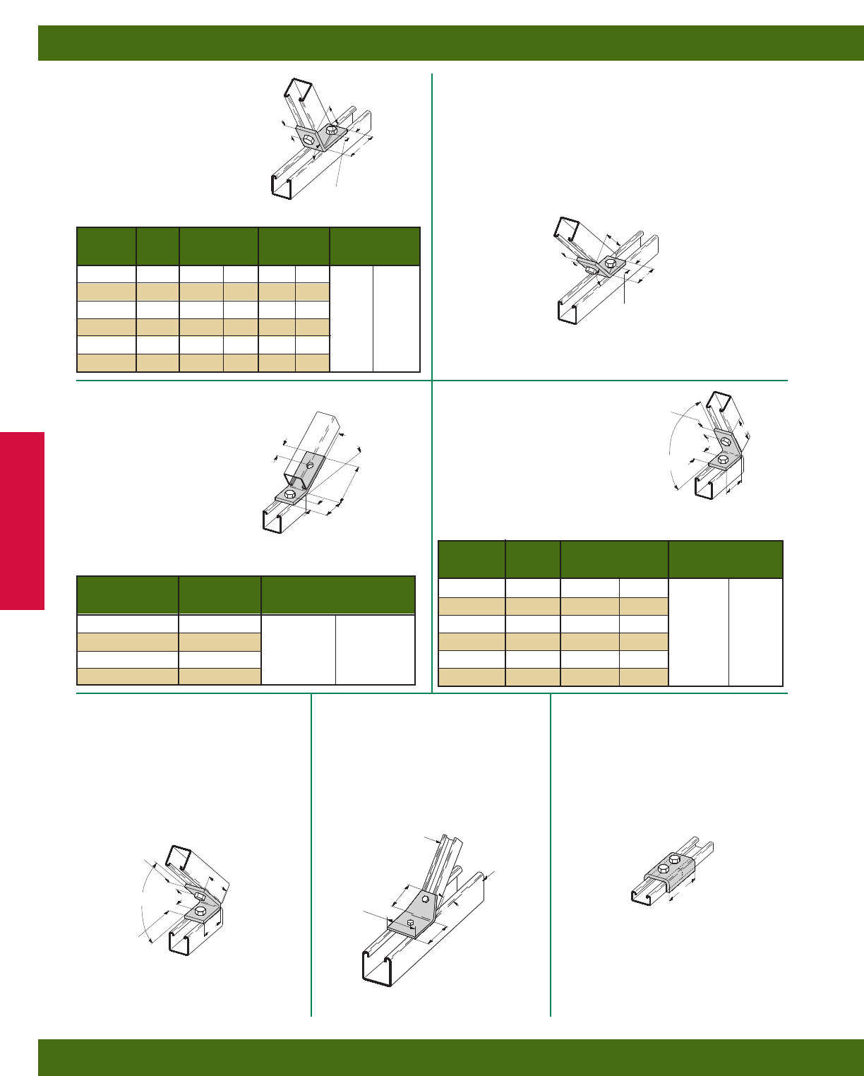
B6154
TWO HOLE OPEN ANGLE
•Standard finishes: ZN, GRN
•Wt./C 8 Lbs. (3.6 kg)
B6147-B6152
TWO HOLE OPEN ANGLE
•Standard finishes: ZN, GRN
B6162-B6165
TWO HOLE OPEN ANGLE
•Standard finishes: ZN, GRN
B6156-B6161
TWO HOLE CLOSED ANGLE
•Standard finishes: ZN, GRN
B6155
TWO HOLE
CLOSED ANGLE
•Standard finishes: ZN, GRN
•Wt./C 8 Lbs. (3.6 kg)
B601-62
TWO HOLE 45°
ADAPTER ANGLE
•Standard finishes: ZN, GRN
•Wt./C 14 Lbs. (6.3 kg)
B6169
TWO HOLE SPLICE
CLEVIS FOR B72
•Standard finishes: ZN, GRN
•Wt./C 11 Lbs. (5.0 kg)
13/32”
(10.3)
13/32”
(10.3)
13/16”
(30.1)
123/32”
(43.6)
13/32”
(10.3)
13/32”
(10.3)
13/32”
(10.3)
13/32”
(10.3)
15/8”
(41.3)
15/8”
(41.3)
17/8”
(47.6)
11/32”
(26.2)
17/8”
(47.6)
17/8”
(47.6)
113/64”
(30.5)
B
C
Wt./C
Part No. A B C Lbs. kg
B6147 821/2°2
1/32”(51.6) 27/32”(21.4)
B6148 75° 21/32”(51.6) 27/32”(21.4)
B6149 671/2°2”
(50.8) 7/8”(22.2) 8.0 (3.6)
B6150 60° 131/32”(50.0) 15/16”(23.8)
B6151 521/2°1
7/8”(47.6) 11/16”(27.0)
B6152 371/2°2”
(50.8) 29/32”(23.0)
45°
13/32”
(10.3)
13/32”
(10.3)
Wt./C
Part No. A Lbs. kg
B6162 30°
B6163 221/2° 8.0 (3.6)
B6164 15°
B6165 71/2°
Wt./C
Part No. A B Lbs. kg
B6156 821/2°1
9/32”(32.5)
B6157 75° 15/16”(33.3)
B6158 671/2°1
3/8”(34.9) 8.0 (3.6)
B6159 60° 113/32”(35.7)
B6160 521/2°1
15/32”(37.3)
B6161 371/2°1
21/32”(42.0)
B
A
A
13/32”
(10.3)
13/32”
(10.3)
17/8”
(47.6)
19/16”
(39.7)
45°
45°
B62
B22
B72
Mini Channel & Fittings
Reference page 188 for general fitting specifications.
Mini Fittings
196
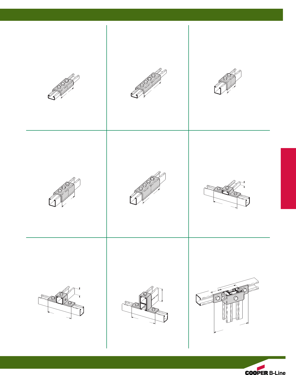
B6170
TWO HOLE SPLICE
CLEVIS FOR B62
•Standard finishes: ZN, GRN
•Wt./C 17 Lbs. (7.7 kg)
B6167
FOUR HOLE SPLICE
CLEVIS FOR B72
•Standard finishes: ZN, GRN
•Wt./C 24 Lbs. (10.9 kg)
B6168
THREE HOLE SPLICE
CLEVIS FOR B72
•Standard finishes: ZN, GRN
•Wt./C 16 Lbs. (7.2 kg)
B6171
THREE HOLE SPLICE
CLEVIS FOR B62
•Standard finishes: ZN, GRN
•Wt./C 26 Lbs. (11.8 kg)
B6172
FOUR HOLE SPLICE
CLEVIS FOR B62
•Standard finishes: ZN, GRN
•Wt./C 36 Lbs. (16.3 kg)
B7116
THREE HOLE U-SUPPORT
•Standard finishes: ZN, GRN
•Wt./C 10 Lbs. (4.5 kg)
B6107
THREE HOLE U-SUPPORT
•Standard finishes: ZN, GRN
•Wt./C 12 Lbs. (5.4 kg)
B6107-62A
THREE HOLE U-SUPPORT
•Standard finishes: ZN, GRN
•Wt./C 16 Lbs. (7.2 kg)
B6594
FIVE HOLE U-SUPPORT
•Standard finishes: ZN, GRN
•Wt./C 13 Lbs. (5.9 kg)
15/8”
(41.3)
317/32”
(89.7)
215/16”
(74.6)
4”
(101.6)
4”
(101.6)
215/16”
(74.6) 231/32”
(75.4)
231/32”
(75.4)
17/8”
(47.6)
15/16”
(23.8)
B72 B72 B62
B62 B62
13/32”
(10.3)
231/32”
(75.4)
13/16”
(20.6)
121/32”
(42.0)
Mini Channel & Fittings
Reference page 188 for general fitting specifications.
Mini Fittings
197
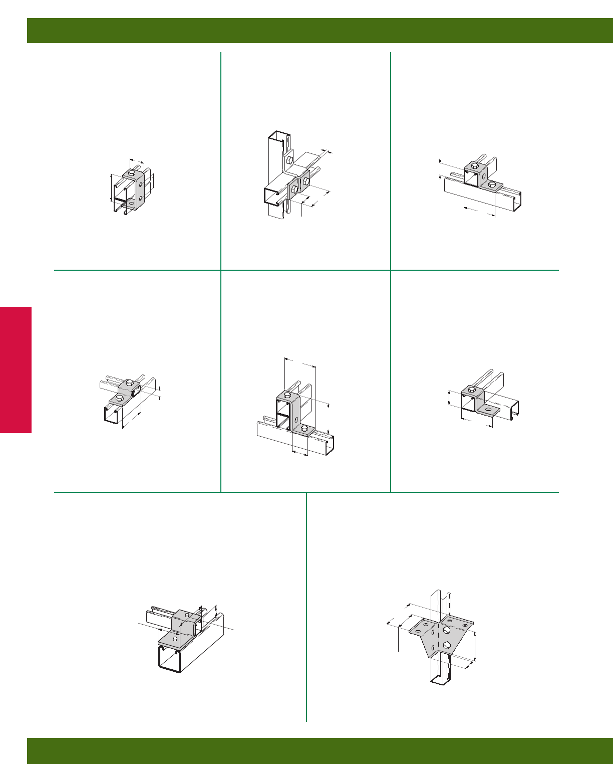
B6105
TWO HOLE
Z-SUPPORT FOR B62
•Standard finishes: ZN, GRN
•Wt./C 7 Lbs. (3.2 kg)
B6526
TWO HOLE
OFFSET Z-SUPPORT
•Standard finishes: ZN, GRN
•Wt./C 5 Lbs. (2.2 kg)
B6173
FOUR HOLE CLEVIS
•Standard finishes: ZN, GRN
•Wt./C 9 Lbs. (4.1 kg)
B7105
TWO HOLE
Z-SUPPORT FOR B72
•Standard finishes: ZN, GRN
•Wt./C 7 Lbs. (3.2 kg)
B6110
TWO HOLE
Z-SUPPORT FOR B62A
•Standard finishes: ZN, GRN
•Wt./C 9 Lbs. (4.1 kg)
B6108
TWO HOLE
OFFSET Z-SUPPORT
•Standard finishes: ZN, GRN
•Wt./C 7 Lbs. (3.2 kg)
B6571
EIGHT HOLE WING CONNECTION
•Standard finishes: ZN, GRN
•Wt./C 28 Lbs. (12.7 kg)
15/16”
(23.8)
13/16”
(20.6)
17/8”
(47.6)
13/16”
(20.6)
1/8”
(3.2)
13/16”
(20.6)
13/16”
(20.6)
17/8”
(47.6)
17/8”
(47.6)
17/8”
(47.6)
13/4”
(44.4)
13/4”
(44.4)
13/4”
(44.4)
13/4”
(44.4)
229/32”
(73.8)
15/16”
(23.8)
121/32”
(42.0)
13/32”
(10.3)
13/16”
(20.6)
B598-62
TWO HOLE Z-ADAPTER PLATE
•Standard finishes: ZN, GRN
•Wt./C 28 Lbs. (12.7 kg)
13/16”
(20.6)
23/4”
(69.8)
15/8”
(41.3)
B62
B22
Mini Channel & Fittings
Reference page 188 for general fitting specifications.
Mini Fittings
198
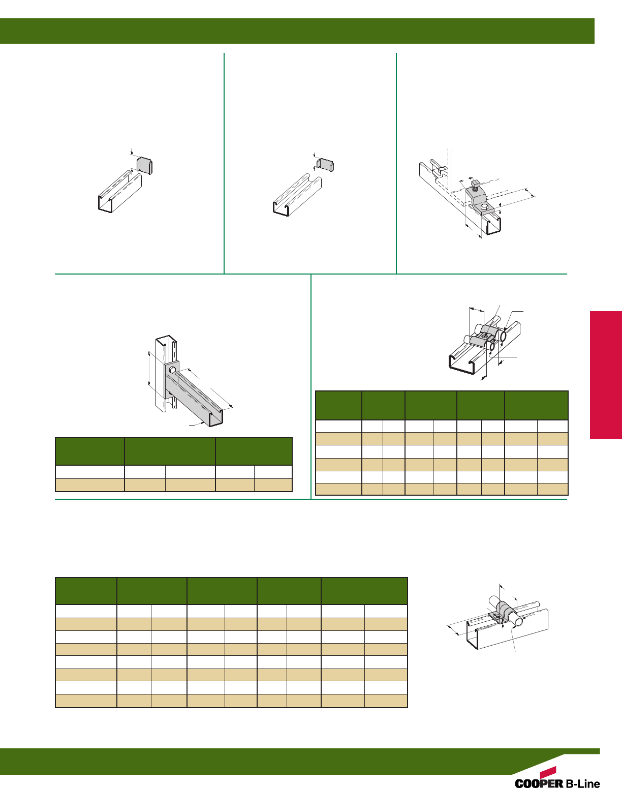
B6211
Z-BEAM CLAMP
•5/16”-18 Setscrew included
•13/16” (20.6) Max. Flange Thickness
•Material: ASTM A36
•Standard finishes: ZN, GRN
•Wt./C 13 Lbs. (5.9 kg)
B7205
END CAP FOR B72
•Material: ASTM A1008 SS Gr. 33 Type 1
•Standard finishes: ZN, GRN
•Wt./C 1 Lb. (.4 kg)
B6205
END CAP FOR B62
•Material: ASTM A1008 SS Gr. 33 Type 1
•Standard finishes: ZN, GRN
•Wt./C 3 Lbs. (1.3 kg)
B6409-6, 9
BRACKET
•Safety Factor of 2
•Uniform Design Load 40 Lbs. (.18 kN)
•Standard finishes: ZN, GRN
B2350-B2355
ONE HOLE DOUBLE
TUBING STRAP
•Material: ASTM A1008 SS
Gr. 33 Type 1
•Standard finishes: ZN, GRN
B2308-B2315
ONE HOLE TUBING STRAP
•Material: Sizes 1/4” - 1/2”, ASTM A611 Gr. C
5/8” - 1”, ASTM A1008 SS Gr. 33 Type 1
•Standard finishes: ZN, GRN
25/16”
(58.7)
17/8”
(47.6)
1/4”
(6.3)
13/16”
(20.6)
13/16”
(20.6)
13/32”
(10.3) 3/4”
(19.0)
B62
A
13/16”
(20.6)
13/16”
(20.6)
Wt./C
Part No. A Lbs. kg
B6409-6 6” (152.4) 28.0 (12.7)
B6409-9 9” (228.6) 35.0 (15.8)
A
C
B
B
A
C
9/32” (7.1) DIA.
9/32” (7.1) DIA.
O.D. Size O.D.Size Wt./C
Part No. A B C Lbs. kg
B2350 1/4”(6.3) 1/4”(6.3) 3/4”(19.0) 1.2 (.5)
B2351 3/8”(9.5) 3/8”(9.5) 1” (25.4) 2.0 (.9)
B2352 1/2”(12.7) 1/2”(12.7) 11/4”(31.7) 2.9 (1.3)
B2353 1/4”(6.3) 3/8”(9.5) 7/8”(22.2) 1.6 (.7)
B2354 1/4”(6.3) 1/2”(12.7) 1” (25.4) 2.1 (.9)
B2355 3/8”(9.5) 1/2”(12.7) 11/8”(28.6) 2.5 (1.1)
O.D. Size Wt./C
Part No. A B C Lbs. kg
B2308 1/4”(6.3) 11/32”(26.2) .048 (1.2) 1.2 (.5)
B2309 5/16”(7.9) 13/32”(27.8) .048 (1.2) 1.4 (.6)
B2310 3/8”(9.5) 13/16”(30.1) .048 (1.2) 1.6 (.7)
B2311 1/2”(12.7) 121/64”(33.7) .048 (1.2) 1.9 (.8)
B2312 5/8”(15.9) 125/64”(35.3) .062 (1.6) 2.7 (1.2)
B2313 3/4”(19.0) 139/64”(40.9) .075 (1.9) 4.3 (1.9)
B2314 7/8”(22.2) 151/64”(45.6) .075 (1.9) 4.9 (2.2)
B2315 1” (25.4) 21/32”(51.6) .075 (1.9) 5.2 (2.3)
Mini Channel & Fittings
Reference page 188 for general fitting specifications.
Mini Fittings
199
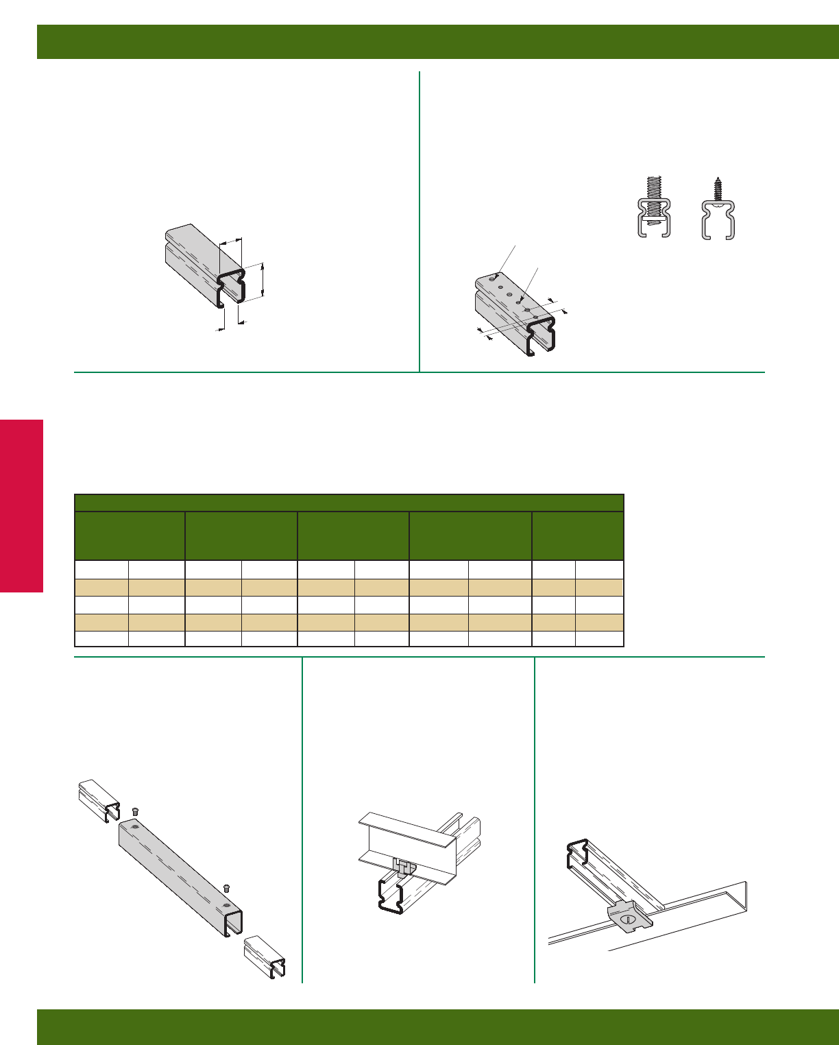
LOAD CHART
Uniform Load Deflection
Beam Span Uniform Load Deflection 1/240 Span 1/240 Span
In. mm Lbs. N In. mm Lbs. N In. mm
12 (305) 347 1543 .030 (.76) 347 1543 .05 (1.27)
24 (609) 173 769 .121 (3.07) 143 636 .10 (2.54)
36 (914) 115 511 .272 (6.91) 63 280 .15 (3.81)
48 (1219) 86 382 .484 (12.29) 35 155 .20 (5.08)
60 (1524) 69 307 .756 (19.20) 23 102 .25 (6.35)
E7016
•Light duty support for electrical fixtures,
conduits and boxes
•Standard 1/4”-20 square nut slips into the slot for
ease of attachment
•Thickness: 16 Ga. (1.5 mm)
•Standard lengths: 120” (3.05 m)
•Standard finish: Pre-Galvanized
•Weight: .45 Lbs./Ft. (.52 kg/m)
E7016H3/4
•Pre-punched holes provide for installation
on 11/2” (38.1) centers for 1/4”-20 ATR
or for #8 screws or toggle bolts
•Thickness: 16 Ga. (1.5 mm)
•Standard lengths: 120” (3.05 m)
•Standard finish: Pre-Galvanized
•Weight: .44 Lbs./Ft. (.50 kg/m)
Design Stress = 25,000 PSI (172 MPa)
Section Modulus (S) = .021 in.3(.34 cm3)
Moment of Inertia (I) = .009 in.4(.37 cm4)
Radius of Gyration (r) = .275 in. (.70 cm)
To determine concentrated load capacity at
mid span, multiply uniform load by 0.5 and corresponding
deflection by 0.8.
E7166
JOINER PLATE
•Joins Econo-Strut channels together to
provide continuous runs
•Includes:
1 pc. Joiner Plate
2 pcs. 1/4”-20 x 1/2” SRHMS
•Wt./C 42 Lbs. (19.0 kg)
E7212
FASTENER CLIP
•Used to attach Econo-Strut to lathers
channel or other light gauge carrying
beams
•Wt./C 1 Lb. (.4 kg)
E7355
BEAM CLAMP
•Secures Econo-Strut to bar joists, angle
iron, or I-Beams with a maximum flange
thickness of 1/4” (6.3)
•Includes:
1 Beam Clamp
1 pc. 1/4”-20 x 1” SHHMS
1 pc. 1/4”-20 Square Nut
•Wt./C 8 Lbs. (3.6 kg)
5/16”
(7.9)
3/4”
(19.0) 3/4” (19.0) CENTER TO
CENTER HOLE SPACING
3/8”
(9.5)
1/2”
(12.7)
INSIDE
DIMENSION 9/32” (7.1) DIA.
3/16” (4.7) DIA.
Mini Channel & Fittings
Reference page 188 for general fitting specifications.
Econo-Strut
200
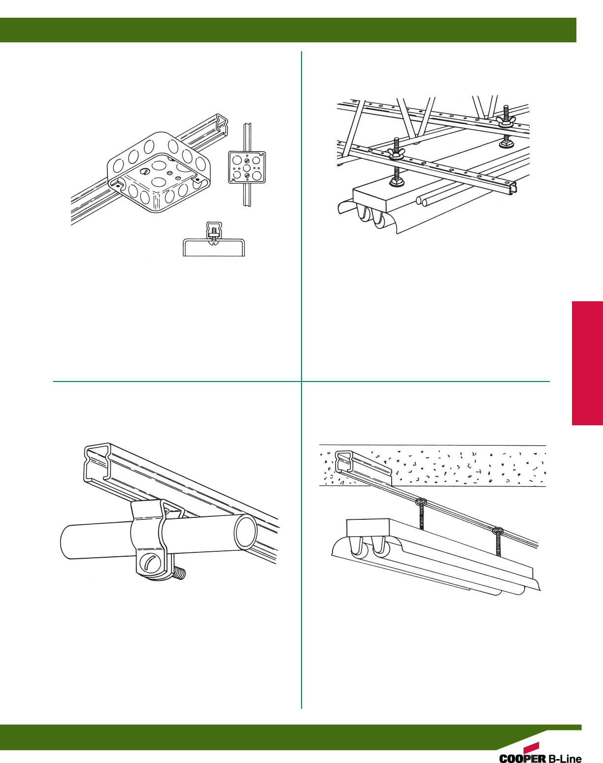
Econo-Strut supports electrical box with screws and
square nuts.
Econo-Strut pipe or conduit support. Econo-Strut used as a continuous concrete insert.
Econo-Strut fixture support secured to the bar joists.
Mini Channel & Fittings
Typical Econo-Strut Applications
201
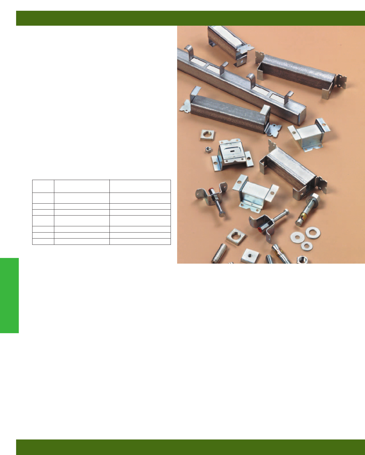
Continuous slot Concrete Inserts are designed to
provide a pre-set support system cast in concrete
ceilings, walls, and floors to allow flexibility of
attachment at any point along the channel. This
provides an excellent support system for pipe, conduit,
and cable trays.
Continuous Concrete Inserts, manufactured from
B-Line’s standard channels, have formed anchors
spaced on 4 inch (101.6 mm) centers. 3/16” (4.8 mm)
nail-holes are provided for securing the inserts to the
forms.
Available in lengths from 3 inches (7.62 cm) to 240
inches (609.6 cm), Concrete Inserts are shipped
complete with end caps and styrofoam filler strips
which prevent seepage of concrete into the insert.
Styrofoam is easily removed by pulling the convenient
pull-tab.
Materials & Finishes*
*Unless otherwise noted.
Spot Inserts
B-Line’s Spot Inserts provide for economical single attachment points with full flexibility of fastener
sizing, but with limited adjustment. These products are made from steel strips in accordance with
ASTM A1011, 33,000 PSI min. yield. Standard finish is electro-plated zinc (ASTM B633).
Special Concrete Inserts
Pre-stressed inserts, inserts with studs welded to the back of the channel, and other types of special
inserts are available from B-Line.
Test Data
Independent Testing Laboratory test data available upon request.
Metric
Metric dimensions are shown in parentheses. Unless noted, all metric dimensions are in millimeters.
Concrete Inserts
Continuous Concrete Inserts
202
Finish
Code Finish Specification
PLN Plain ASTM A1011
33,000 PSI min. yield
GRN Dura-Green
ZN Electro-Plated Zinc ASTM B633 SC1 Type III
GALV Pre-Galvanized ASTM A653
33,000 PSI min. yield
HDG Hot-Dipped Galvanized ASTM A123
SS4 Stainless Steel Type 304 ASTM A240
SS6 Stainless Steel Type 316 ASTM A240
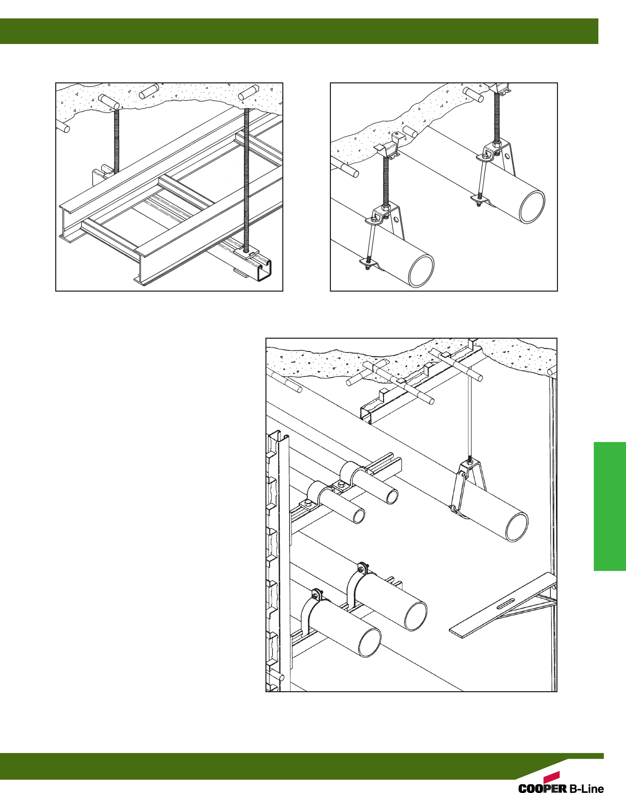
Continuous concrete inserts, installed in the ceiling,
can be used to support trapeze hangers, suspended
pipe racks, cable trays and single or multiple pipe
hangers.
When installed in walls, continuous concrete inserts
can be used as a support for tunnel stanchions,
equipment braces, brackets and pipe racks.
Use spot inserts for single pipe-support or trapeze
type hangers. Spot Inserts offer full flexibility of rod
and fastener sizings.
B-Line Channel can be attached to continuous
concrete inserts in walls or ceilings. Channel can also
be attached to concrete walls and floors with expan-
sion anchors.
Concrete Inserts
Reference page 202 for general fitting and standard finish specifications.
Concrete Inserts
203
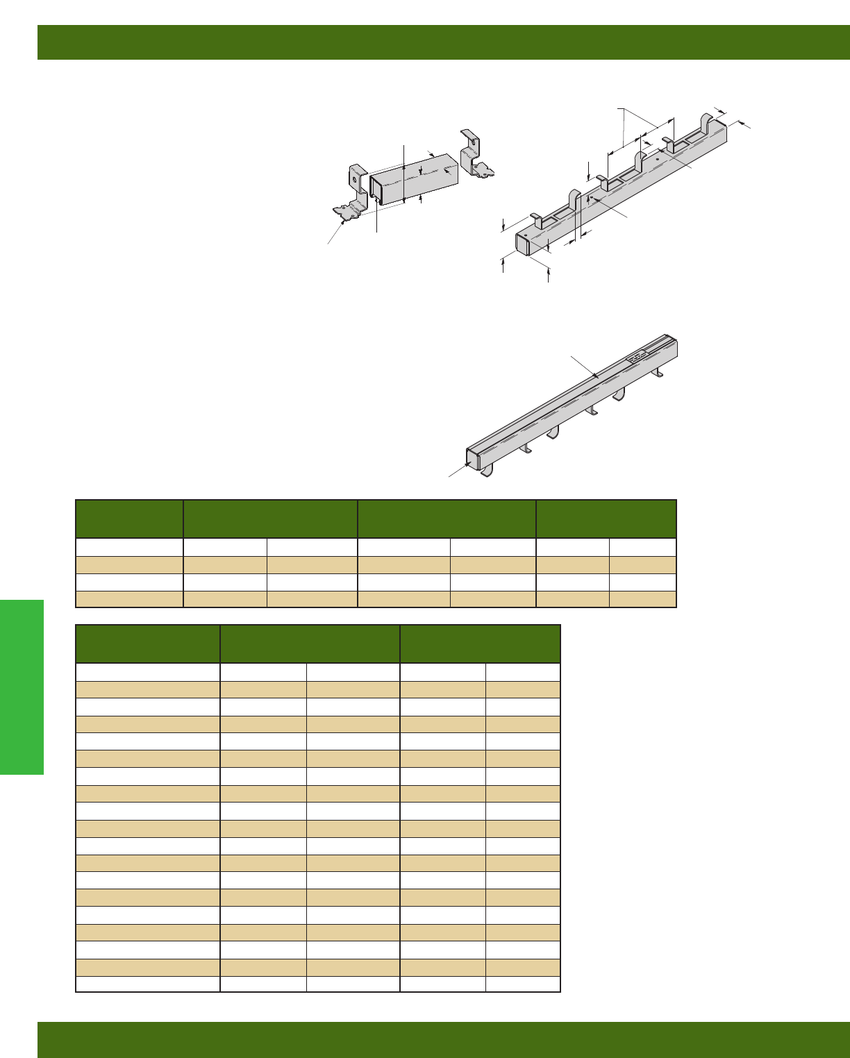
Length Wt./C Design Load
Part No. in. mm Lbs. kg Lbs. kN
B22-I-3 3” (76) 72 (32.6) 500 (2.22)
B22-I-4 4” (101) 88 (39.9) 800 (3.56)
B22-I-6 6” (152) 120 (54.4) 1000 (4.45)
B22-I-8 8” (203) 152 (68.9) 1200 (5.34)
Length Wt./C
Part No. in. mm Lbs. kg
B22-I-12 12” (305) 224 (101.6)
B22-I-16 16” (406) 289 (131.1)
B22-I-20 20” (508) 353 (160.1)
B22-I-24 24” (609) 420 (190.5)
B22-I-32 32” (813) 553 (250.8)
B22-I-36 36” (914) 620 (281.2)
B22-I-40 40” (1016) 686 (311.1)
B22-I-48 48” (1219) 820 (371.9)
B22-I-60 60” (1524) 1018 (461.7)
B22-I-72 72” (1829) 1218 (552.5)
B22-I-84 84” (2133) 1417 (642.7)
B22-I-96 96” (2438) 1616 (733.0)
B22-I-108 108” (2743) 1816 (823.7)
B22-I-120 120” (3048) 2016 (914.4)
B22-I-144 144” (3657) 2416 (1095.9)
B22-I-168 168” (4267) 2816 (1277.3)
B22-I-192 192” (4877) 3216 (1458.7)
B22-I-216 216” (5486) 3616 (1640.2)
B22-I-240 240” (6096) 4016 (1821.6)
B22I
CONTINUOUS CONCRETE
INSERT
•Design Load for B22-I-12 thru B22-I-
240 is 2,000 lbs. (8.89 kN) per foot of
concrete insert length with safety factor
of 3 in 3000 psi concrete.
•Loads concentrated within the last 2
inches (50.8 mm) of concrete inserts 8”
(203.2 mm) and longer should not
exceed 1,000 lbs. (4.45kN).
•Concrete insert should be secured to the
forms on 16” (406.4 mm) to 24”
(609.6 mm) intervals.
•B22-I continuous concrete inserts are
made from B22 channel. Use channel
nuts designed for use in B22 channel.
•B22-I concrete inserts are supplied with
styrofoam fillers. B3322 end caps
are furnished with inserts through 8”
(203.2 mm) long, and B205 end caps
are furnished with inserts 12”
(304.8 mm) and longer.
•Material: Plain Steel ASTM A1011
33,000 PSI min. yield or
Pre-Galvanized Steel ASTM
A653SS 33,000 PSI min. yield.
•Finish: Plain, Dura-Green, Pre-Galv,
HDG
B22-I-3 THRU B22-I-8
15/8”
(41.3)
15/8”
(41.3)
25/8”
(66.7)
B3322
END CAP
STYROFOAM
FILLER
MATERIAL: 12 Gauge (2.6)
.188 KNOCKOUTS
FOR NAILING
INSERTS TO FORMS
3/4”
(19.0)
15/8”
(41.3)
11/16”
(17.4)
4”
(101.6)
15/8”
(41.3)
11/2”
(38.1)
31/8”
(79.4)
B22-I-12 THRU B22-I-240
B205 END CAP
STYROFOAM
FILLER
Concrete Inserts
Reference page 202 for general fitting and standard finish specifications.
Continuous Concrete Inserts
204
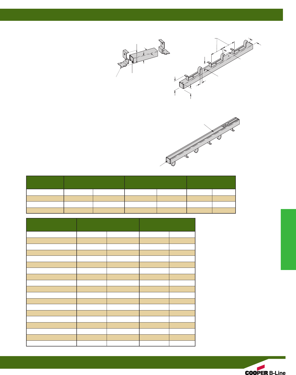
Length Wt./C Design Load
Part No. in. mm Lbs. kg Lbs. kN
B32-I-3 3” (76) 65 (29.5) 500 (2.22)
B32-I-4 4” (101) 80 (36.3) 800 (3.56)
B32-I-6 6” (152) 108 (49.0) 1000 (4.45)
B32-I-8 8” (203) 137 (62.1) 1200 (5.34)
Length Wt./C
Part No. in. mm Lbs. kg
B32-I-12 12” (305) 202 (91.6)
B32-I-16 16” (406) 262 (118.8)
B32-I-20 20” (508) 316 (143.3)
B32-I-24 24” (609) 376 (170.5)
B32-I-32 32” (813) 496 (225.0)
B32-I-36 36” (914) 556 (252.2)
B32-I-40 40” (1016) 616 (279.4)
B32-I-48 48” (1219) 736 (333.8)
B32-I-60 60” (1524) 915 (415.0)
B32-I-72 72” (1829) 1095 (496.7)
B32-I-84 84” (2133) 1274 (577.9)
B32-I-96 96” (2438) 1453 (659.0)
B32-I-108 108” (2743) 1633 (740.7)
B32-I-120 120” (3048) 1813 (822.3)
B32-I-144 144” (3657) 2173 (985.6)
B32-I-168 168” (4267) 2533 (1148.9)
B32-I-192 192” (4877) 2893 (1312.2)
B32-I-216 216” (5486) 3253 (1475.5)
B32-I-240 240” (6096) 3613 (1638.8)
B32I
CONTINUOUS CONCRETE
INSERT
•Design Load for B32-I-12 thru B32-I-
240 is 2,000 lbs. (8.89 kN) per foot of
concrete insert length with safety
factor of 3 in 3000 psi concrete.
•Loads concentrated within the last 2
inches (50.8 mm) of concrete inserts
8” (203.2 mm) and longer should not
exceed 1,000 lbs. (4.45kN).
•Concrete insert should be secured to
the forms on 16” (406.4 mm) to 24”
(609.6 mm) intervals.
•B32-I continuous concrete inserts are
made from B32 channel. Use channel
nuts designed for use in B32 channel.
•B32-I concrete inserts are supplied with
styrofoam fillers. B3332 end caps
are furnished with inserts through 8”
(203.2 mm) long, and B206 end caps
are furnished with inserts 12”
(304.8 mm) and longer.
•Material: Plain Steel ASTM A1011
33,000 PSI min. yield or
Pre-Galvanized Steel ASTM
A653SS 33,000 PSI min. yield.
•Finish: Plain, Dura-Green, Pre-Galv,
HDG
15/8”
(41.3)
25/8”
(66.7)
13/8”
(34.9)
B3332
END CAP
STYROFOAM
FILLER
B32-I-3 THRU B32-I-8
MATERIAL: 12 Gauge (2.6)
.188 KNOCKOUTS
FOR NAILING
INSERTS TO FORMS
3/4”
(19.0)
15/8”
(41.3)
11/16”
(17.4)
4”
(101.6)
13/8”
(34.9)
11/2”
(38.1)
27/8”
(73.0)
B206 END CAP
STYROFOAM
FILLER
B32-I-12 THRU B32-I-240
Concrete Inserts
Reference page 202 for general fitting and standard finish specifications.
Continuous Concrete Inserts
205
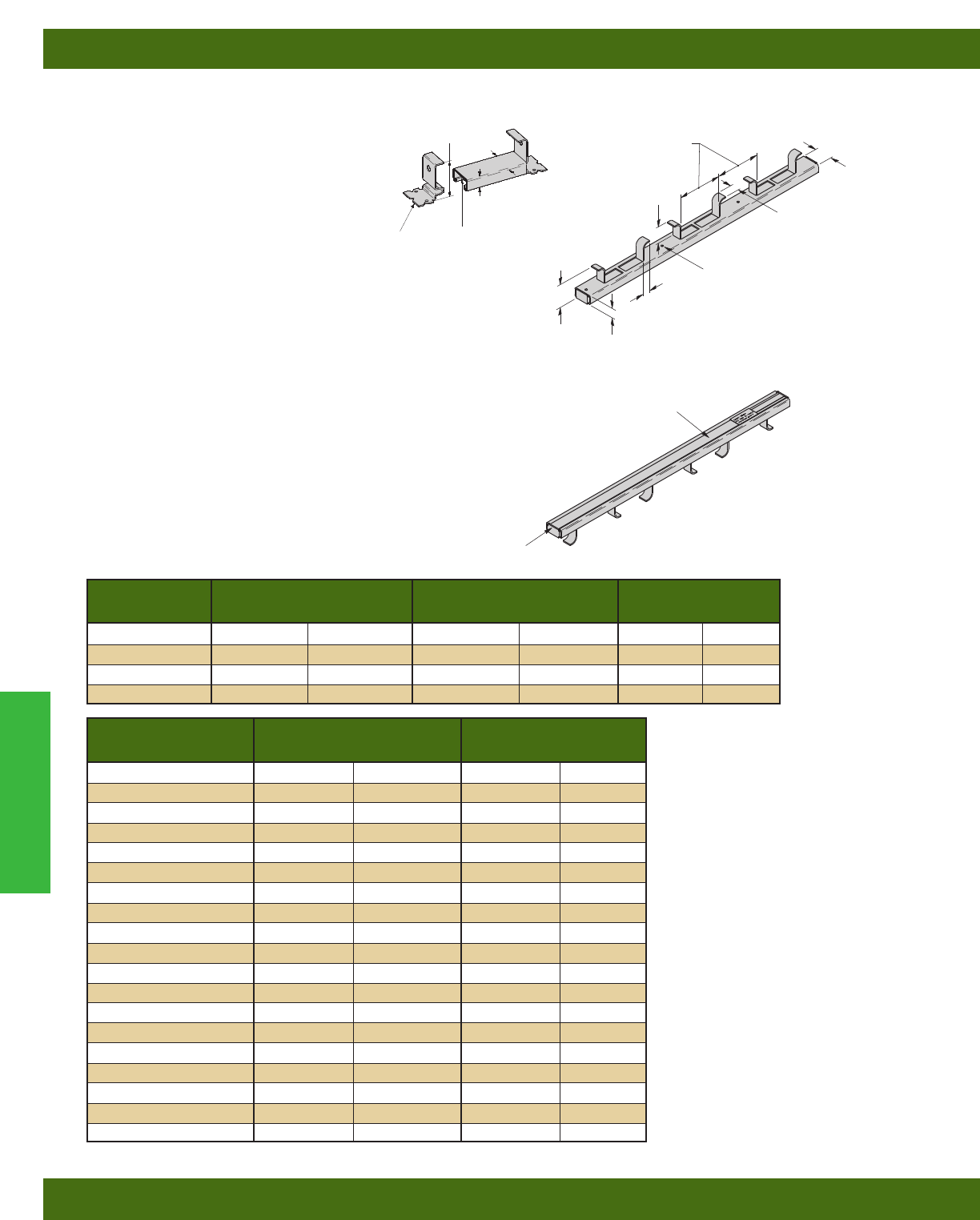
B52I
CONTINUOUS CONCRETE
INSERT
•Design Load for B52-I-12 thru B52-I-
240 is 1,500 lbs. (6.67 kN) per foot of
concrete insert length with safety
factor of 3 in 3000 psi concrete.
•Loads concentrated within the last 2
inches (50.8 mm) of concrete inserts
8” (203.2 mm) and longer should not
exceed 750 lbs. (3.33 kN).
•Concrete insert should be secured to
the forms on 16” (406.4 mm) to 24”
(609.6 mm) intervals.
•B52-I continuous concrete inserts are
made from B52 channel. Use channel
nuts designed for use in B52 channel.
•B52-I concrete inserts are supplied with
styrofoam fillers. B3352 end caps
are furnished with inserts through 8”
(203.2 mm) long, and B220 end caps
are furnished with inserts 12”
(304.8 mm) and longer.
•Material: Plain Steel ASTM A1011
33,000 PSI min. yield or
Pre-Galvanized Steel ASTM
A653SS 33,000 PSI min. yield.
•Finish: Plain, Dura-Green, Pre-Galv,
HDG
Length Wt./C
Part No. in. mm Lbs. kg
B52-I-12 12” (305) 157 (71.2)
B52-I-16 16” (406) 202 (91.6)
B52-I-20 20” (508) 237 (107.5)
B52-I-24 24” (609) 282 (127.9)
B52-I-32 32” (813) 373 (169.2)
B52-I-36 36” (914) 419 (190.0)
B52-I-40 40” (1016) 464 (210.4)
B52-I-48 48” (1219) 556 (252.2)
B52-I-60 60” (1524) 692 (313.9)
B52-I-72 72” (1829) 829 (376.0
B52-I-84 84” (2133) 965 (437.7)
B52-I-96 96” (2438) 1107 (502.1)
B52-I-108 108” (2743) 1237 (561.1)
B52-I-120 120” (3048) 1374 (623.2)
B52-I-144 144” (3657) 1648 (747.5)
B52-I-168 168” (4267) 1922 (871.8)
B52-I-192 192” (4877) 2196 (996.1)
B52-I-216 216” (5486) 2470 (1120.4)
B52-I-240 240” (6096) 2744 (1244.6)
Length Wt./C Design Load
Part No. in. mm Lbs. kg Lbs. kN
B52-I-3 3” (76) 53 (24.0) 400 (1.78)
B52-I-4 4” (101) 63 (28.6) 500 (2.22)
B52-I-6 6” (152) 85 (38.5) 750 (3.33)
B52-I-8 8” (203) 106 (48.1) 1000 (4.45)
15/8”
(41.3)
13/16”
(20.6)
29/16”
(65.1)
B3352
END CAP
STYROFOAM
FILLER
.188 KNOCKOUTS
FOR NAILING
INSERTS TO FORMS
3/4”
(19.0)
15/8”
(41.3)
11/16”
(17.4)
4”
(101.6)
13/16”
(20.6)
11/2”
(38.1)
25/16”
(58.7)
B220 END CAP
STYROFOAM
FILLER
B52-I-12 THRU B52-I-240
B52-I-3 THRU B52-I-8
MATERIAL: 12 Gauge (2.6)
Concrete Inserts
Reference page 202 for general fitting and standard finish specifications.
Continuous Concrete Inserts
206
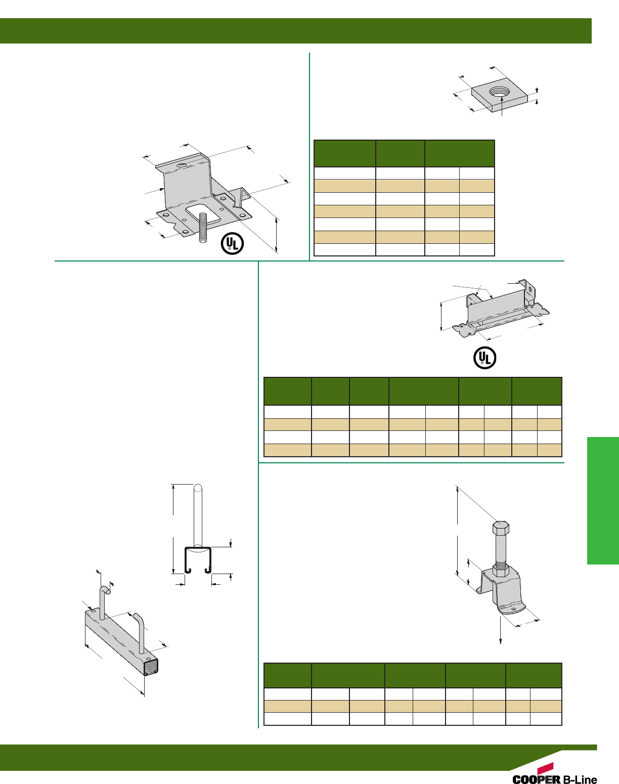
Thread Wt./C
Part No. Size Lbs. kg
N2500-1/41/4”-20 13 (5.9)
N2500-5/16 5/16”-18 13 (5.9)
N2500-3/83/8”-16 12 (5.4)
N2500-1/21/2-13 12 (5.4)
N2500-5/85/8”-11 11 (5.0)
N2500-3/43/4”-10 10 (4.5)
N2500-7/87/8”-9 9 (4.1)
Channel End Cap Design Load Maximum Wt./C
Part No. Style Part No. Lbs. kN Pipe Size Lbs. kg
B2505 B22 B3322 1200 (5.34) 10” (250) 96 (43.5)
B2506 B32 B3332 1000 (4.45) 8” (200) 88 (39.9)
B2507 B42 B3342 1000 (4.45) 8” (200) 77 (34.9)
B2508 B52 B3352 1000 (4.45) 8” (200) 69 (31.3)
Part No. Height Height Design Load Wt./C
& Size A H Lbs. kN Lbs. kN
B2501-1/427/16”(61.9) 7/8”(22.2) 250 (1.11) 16 (7.2)
B2501-3/831/16”(77.8) 17/8”(47.6) 610 (2.71) 22 (9.9)
B2501-1/241/8”(104.8) 17/8”(47.6) 880 (3.91) 26 (11.7)
N2500
INSERT SQUARE NUT
•For use in B2500 Spot Insert
•Material: Steel ASTM A36
•Standard finish: ZN
B2500
SPOT INSERT
•Design Load 600 Lbs. (2.67 kN)
•Safety Factor of 5
•Order N2500 Nuts Separately
•Material: Steel ASTM A1011
33,000 PSI min. yield
•Standard finish: ZN
•Wt./C 46 Lbs. (20.8 kg)
B2505 THRU B2508
SPOT INSERT
•Safety Factor of 5
•To support 10” (250) pipe use B2505
insert with 5/8”-11 Channel Nuts.
•To support up to and including 8”
(200) pipes use B2506, B2507 and
B2508 inserts with the desired
Channel Nuts.
•Standard finish: ZN
B2501
LIGHT DUTY SPOT INSERT
•Safety Factor of 2
•The concrete attachment problem solver for
light duty applications.
•Fast and easy applications.
•No concrete leakage problems.
•One piece unitized construction.
•Color coded cap on thread for rod size
identification and to prevent concrete seepage.
(1/4”-Yellow, 3/8”-Red, 1/2”-Blue)
B2503
HEAVY DUTY SPOT INSERT
•Designed for use where heavy loads are
required in curtain wall applications
•Design Load is 5000 Lbs. (22.2 kN) with a
Safety Factor of 3
•Loading based on two N225 channel nuts
spaced 3” (76.2 mm) on center and a
minimum of 2” (50.8 mm) from the end
of the insert
•Styrofoam end caps prevent concrete
seepage into the channel
•12” (304.8 mm) long insert is anchored
into the concrete at a depth of
51/2” (139.7 mm)
•Material: 12 Gauge (2.6 mm) thick steel
•Standard finish: ZN
•Wt./C 42 Lbs. (19.0 kg)
19/16”
(65.0)
31/4”
(82.5)
11/2”
(38.1)
11/4”
(31.7)
11/4”
(31.7)
11/4”
(31.7)
5/16”
(7.9)
2”
(50.8)
THREAD
SIZE
A
H
25/8”
(66.7)
51/2”
(139.7)
15/8”
(41.3)
15/8”
(41.3)
2”
(50.8)
12”
(304.8)
8”
(203.2)
51/16”
(128.6)
END CAPS
CHANNEL
SIZE
STYROFOAM
END CAPS
MATERIAL:
12 Gauge (2.6)
5/32” (4.0)
DIA. NAIL
HOLES
Design Load
Concrete Inserts
Reference page 202 for general fitting and standard finish specifications.
Spot Inserts
207
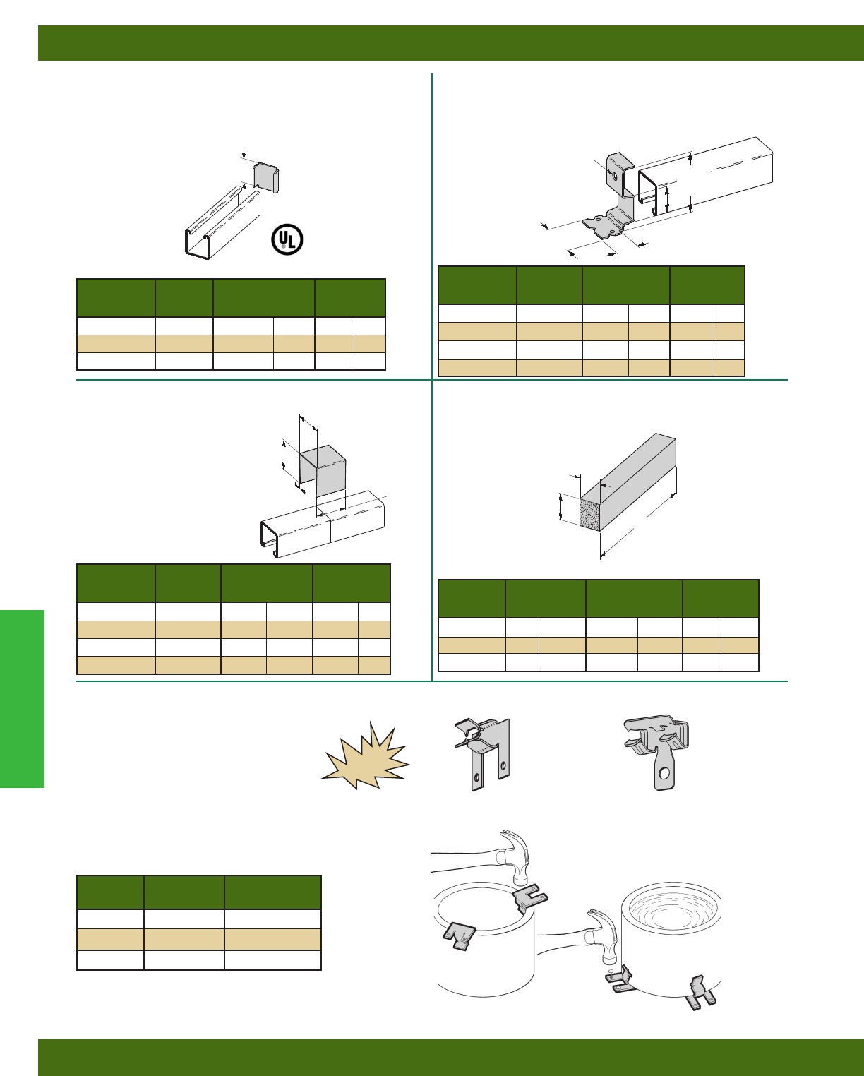
B205, B206, B220
X TYPE END CAPS
•UL listed for raceway use only
•Material: 12 Gauge (2.6)
•Standard finish: ZN
B3322, B3332, B3342, B3352
Y TYPE END CAPS
•UL listed for raceway use only
•Material: 14 Gauge (1.9)
•Standard finish: ZN
B22IFS-B52IFS
STYROFOAM FILLER STRIP
B380
JOINT SPLICE PLATE
•Used at splice points to prevent
concrete seepage in long
continuous runs of concrete inserts.
•Material: 18 Gauge (1.2)
•Standard finish: GALV
Use Wt./C
Part No. With A Lbs. kg
B205 B22 121/32”(42.0) 10 (4.5)
B206 B32 113/32”(35.7) 8(3.6)
B220 B52 27/32”(21.4) 4(1.8)
Use Wt./C
Part No. With A Lbs. kg
B3322 B22 1.270 (32.2) 15 (6.8)
B3332 B32 1.000 (25.4) 15 (6.8)
B3342 B42 .645 (16.4) 15 (6.8)
B3352 B52 .460 (11.7) 15 (6.8)
Use Wt./C
Part No. With A Lbs. kg
B380-22 B22 15/8”(41.3) 11 (5.0)
B380-32 B32 13/8”(34.9) 10 (4.5)
B380-42 B42 1” (25.4) 9(4.1)
B380-52 B52 13/16”(20.6) 7(3.2)
A Wt./C
Part No. Ft. mm B Lbs. kg
B22-IFS 4’ (1219) 17/32”(309) 10 (4.5)
B32-IFS 4’ (1219) 1” (254) 9(4.1)
B52-IFS 4’ (1219) 21/32”(167) 7(3.2)
Sleeve Wall
Part No. Diameter Thickness
BD40 All Dia. 5/16” & under
BE-5-8 6” Schedule 80 pipe
BE-9-12 9” - 14” Schedule 80 pipe
15/8”
(41.3)
113/16”
(46.0)
13/4”
(44.1)
25/8”
(66.7)
3/8” (9.5)
DIA.
1”
(25.4)
29/32”
(23.0)
1/16”
(1.6)
A
A
A
A
B
PIPE SLEEVE FASTENERS
•Allows for rigid attachment
of pipe sleeves to wall and floor
forms for concrete pouring.
•Accommodates Schedule 40,
Schedule 80, or 5/16" (8) and
smaller wall thickness.
•Simply installed with a hammer. BD40 BE-5-8 & BE-9-12
NEW
Concrete Inserts
Reference page 202 for general fitting and standard finish specifications.
Insert Accessories
208
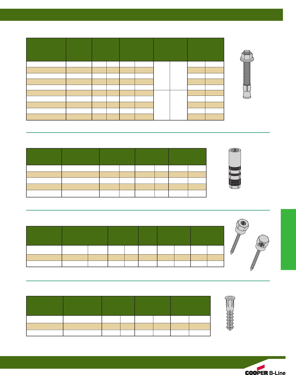
Catalog Thread Overall Max. Mat'l. Minimum
Number Size Length Thickness to Embedment Drill Hole
be Anchored Depth Diameter
in. mm in. mm in. mm in. mm
AWA-37-225 3/8"-16 21/4"(57) 3/8"(9) 3/8”(10)
AWA-37-275 3/8"-16 23/4"(70) 7/8"(22) 3/8”(10)
AWA-37-300 3/8"-16 3" (76) 11/8"(28) 11/2"(38) 3/8”(10)
AWA-37-375 3/8"-16 33/4"(95) 17/8"(47) 3/8”(10)
AWA-37-500 3/8"-16 5" (127) 31/8"(79) 3/8”(10)
AWA-50-275 1/2"-13 23/4"(70) 1/8"(3) 1/2”(13)
AWA-50-375 1/2"-13 33/4"(95) 1" (25) 1/2”(13)
AWA-50-425 1/2"-13 41/4"(108) 11/2"(38) 21/4"(57) 1/2”(13)
AWA-50-550 1/2"-13 51/2"(140) 23/4"(70) 1/2”(13)
AWA-50-700 1/2"-13 7" (178) 41/4"(108) 1/2”(13)
Catalog Thread Length Thread Drill/Hole
Number Size Depth Diameter
in. mm in. mm in. mm
ADI-25 1/4”-20 1” (25) 7/16”(11) 3/8”(10)
ADI-37 3/8”-16 19/16”(40) 5/8”(16) 1/2”(13)
ADI-50 1/2”-13 2” (51) 13/16”(21) 5/8”(16)
ADI-62 5/8”-11 21/2”(64) 13/16”(30) 7/8”(22)
ADI-75 3/4”-10 31/8”(79) 13/16”(30) 1” (25)
Catalog Size Drill/Hole Rod Allowable Allowable
Number Diameter Size Pull-Out Load Shear Load
in. mm in. mm Lbs. kN Lbs. kN
ARC-1-RH25 5/16” x 11/2”(8 x 38) 1/4”(6) 1/4”-20 702 (3.1) -- --
ARC-1-RH37 5/16” x 11/2”(8 x 38) 1/4”(6) 3/8”-16 702 (3.1) -- --
ARC-1-SW37 5/16” x 11/2”(8 x 38) 1/4”(6) 3/8”-16 -- -- 512 (2.3)
RH
SW
WEDGE ANCHOR
•Safety Factor of 4
DROP-IN
•Safety Factor of 4
RAPID ROD™HANGERS FOR CONCRETE
•Safety Factor of 4
PLASTIC SCREW ANCHORS
•Safety Factor of 4
Catalog Screw Anchor Drill/Hole Allowable Pull
Number Size Length Diameter Out Load
in. mm in. mm Lbs. kN
APS-4-87 #4, #6, & #8 7/8”(22) 3/16”(5) 50 (0.2)
APS-8-125 #8, #10, & #12 11/4”(32) 1/4”(6) 100 (0.4)
APS-12-150 #12, #14, & #16 11/2”(38) 5/16”(8) 150 (0.6)
Note: For Information on wedge anchors refer to Cooper B-Line Anchor catalog.
Note: For Information on drop-in anchors refer to Cooper B-Line Anchor catalog.
Note: For Information on Rapid Rod hangers refer to Cooper B-Line Anchor catalog.
Note: For Information on plastic screw anchors refer to Cooper B-Line Anchor catalog.
Concrete Inserts
Reference page 202 for general fitting and standard finish specifications.
Anchors
209
B-Line Slotted Angle is an all-purpose framing system,
roll formed from high strength steel strips. It is
designed to be used as economical shelving, racks or
electrical and mechanical supports. The unique pattern
of horizontal and vertical slots permits full flexibility.
Three basic sizes are available for light, medium, and
heavy duty applications.
Materials & Finishes*
*Unless otherwise noted.
Lengths
Standard lengths are 10’ (3.05 m) and 12’ (3.66 m).
Slotted Angle is shipped in ten piece bundles complete
with 75 pieces of 3/8” x 3/4” (19mm) hex head cap
screws and 3/8” hex nuts.
Metric
Metric dimensions are shown in parentheses. Unless
noted, all metric dimensions are in millimeters.
Finish
Code Finish Specification
PLN Plain ASTM A1011
33,000 PSI min. yield
ZN Electro-Plated Zinc ASTM B633 SC3
GRN Dura-Green
GALV Pre-Galvanized ASTM A653
33,000 PSI min. yield
Slotted Angle
Slotted Angle
210
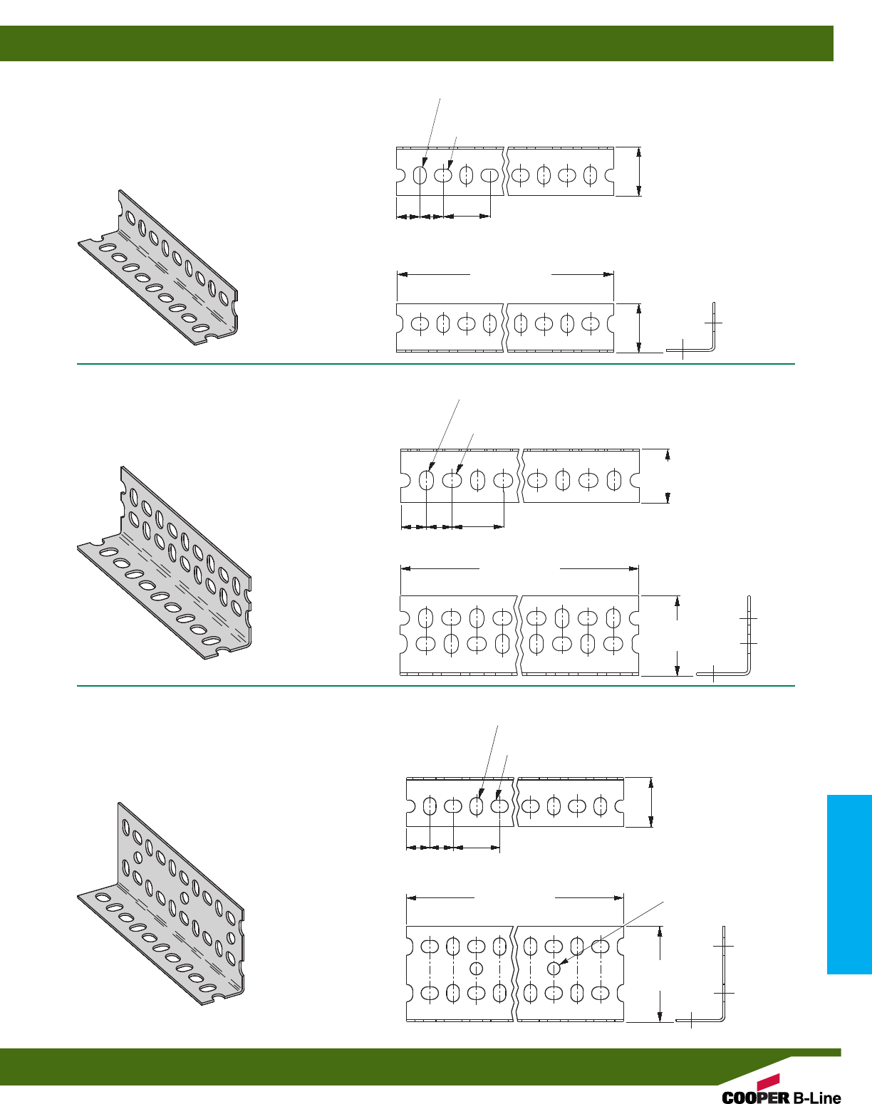
SA158
•14 Gauge (1.9)
•15/8” x 15/8”
•Standard finishes: ZN, GRN
•Wt./Ft. .66 Lbs. (.98 kg/m)
SA276
•14 Gauge (1.9)
•15/8” x 23/8”
•Standard finishes: ZN, GRN
•Wt./Ft. .78 Lbs. (1.17 kg/m)
SA318
•12 Gauge (2.6)
•15/8” x 31/8”
•Standard finishes: ZN, GRN
•Wt./Ft. 1.32 Lbs. (1.96 kg/m)
137/64”
(40.1)
11/2”
(38.1)
11/2”
(38.1)
11/2”
(38.1)
10’ (3.05 m)
12’ (3.66 m)
13/32” (10.3) x 9/16” (14.3)
TRANSVERSE SLOTS
13/32” (10.3) x 9/16” (14.3)
LONGITUDINAL SLOTS
10’ (3.05 m)
12’ (3.66 m)
137/64”
(40.1)
137/64”
(40.1)
137/64”
(40.1)
25/16”
(58.7)
3/4”
(19.0)
3/4”
(19.0)
3/4”
(19.0) 3/4”
(19.0)
3/4”
(19.0)
3/4”
(19.0)
13/32” (10.3) x 9/16” (14.3)
TRANSVERSE SLOTS
13/32” (10.3) x 9/16” (14.3)
LONGITUDINAL SLOTS
13/32” (10.3) x 9/16” (14.3)
TRANSVERSE SLOTS
10’ (3.05 m)
12’ (3.66 m)
33/32”
(78.6)
13/32” (10.3) HOLES ON
3” (76.2) CENTERS
13/32” (10.3) x 9/16” (14.3)
LONGITUDINAL SLOTS
Slotted Angle
Reference page 210 for general fitting and standard finish specifications.
Slotted Angle Sizes
211
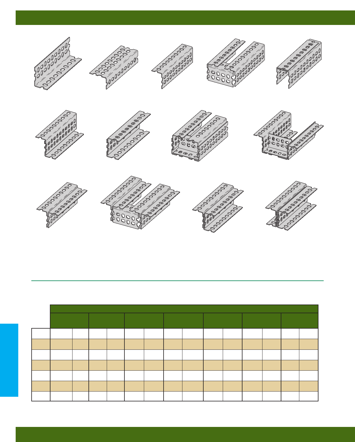
BEAM SECTIONS
A
F
Single Piece (Up)
Z-Section
Single Piece (Level)
Broad Channel Broad Channel with
Stiffener
Z-Section with
Stiffener
B
Single Piece (Down) Narrow ChannelSingle Piece with
Stiffener
C D E
G H H
I
T-Section T-Section with
Stiffener
J-Section I-Section
J K L
Beam Span
24” (609 mm) 36” (914 mm) 48” (1219 mm) 60” (1524 mm) 72” (1829 mm) 84” (2133 mm) 96” (2438 mm)
Lbs. N Lbs. N Lbs. N Lbs. N Lbs. N Lbs. N Lbs. N
825 (3670) 525 (2335) 340 (1512) 230 (1023) 180 (800) –– – –
1100 (4893) 800 (3558) 540 (2402) 370 (1646) 250 (1112) –– – –
1100 (4893) 800 (3558) 540 (2402) 370 (1646) 250 (1112) –– – –
1300 (5782) 900 (4003) 625 (2780) 450 (2001) 330 (1468) 275 (1223) 200 (889)
1900 (8451) 1360 (6049) 1050 (4670) 825 (3670) 660 (2936) 530 (2357) 400 (1779)
2300 (10231) 1850 (8229) 1450 (6450) 1100 (4893) 950 (4226) 800 (3558) 700 (3114)
2200 (9786) 1650 (7339) 1225 (5449) 930 (4137) 700 (3114) 550 (2446) 450 (2001)
A
B
C
D
G
H
I
BEAM LOADING
SA158-15/8” (41.3) x 15/8” (41.3) x 14 Gauge (1.9)
Based on simple beam condition with uniform loads on parallel beams. To determine concentrated load capacity at mid-span, multiply
uniform load by 0.5.
For greater strength required in some applications, Slotted Angle may be fastened together to create combination shapes. A number of
these combinations are illustrated above. Refer to the following table for load capacities of these combinations.
Beam Sections illustrated are single sections, except J, N, and P.
Slotted Angle
Reference page 210 for general fitting and standard finish specifications.
Slotted Angle Beam Loading & Combinations
212
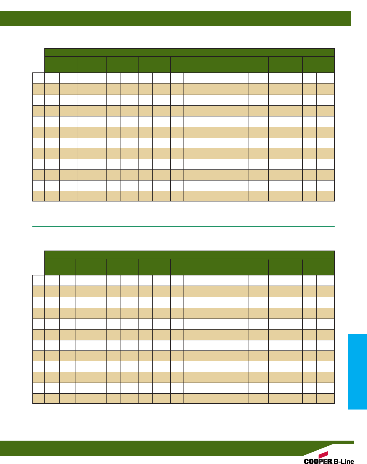
BEAM LOADING
SA318-15/8” (41.3) x 31/8” (79.4) x 12 Gauge (2.6)
Beam Span
24” (609 mm) 36” (914 mm) 48” (1219 mm) 60” (1524 mm) 72” (1829 mm) 84” (2133 mm) 96” (2438 mm) 108” (2743 mm) 120” (3048 mm)
Lbs. N Lbs. N Lbs. N Lbs. N Lbs. N Lbs. N Lbs. N Lbs. N Lbs. N
– – 680 (3025) 450 (2001) 340 (1512) –– –– –– – – ––
– – 830 (3692) 550 (2446) 360 (1601) 210 (934) 150 (667) –– – – ––
– – 1540 (6850) 1060 (4715) 800 (3558) 610 (2713) 480 (2135) 340 1512 250 (1112) ––
– – 1880 (8362) 1280 (5694) 970 (4315) 820 (3647) 650 (2891) 550 (2446) 420 (1868) 340 (1512)
– – 2110 (9386) 1730 (7695) 1460 (5775) 1250 (5560) 1090 (4848) 920 (4092) 820 (3647) 680 (3025)
4290 (19083) 2510 (11165) 1790 (7962) 1330 (5916) 980 (4359) 710 (3158) 550 (2446) 420 (1868) 320 (1423)
4320 (19216) 3000 (13344) 2140 (9519) 1600 (7117) 1290 (5738) 1040 (4626) 820 (3647) 640 (2847) 490 (2179)
– – 3480 (15480) 2430 (10809) 1890 (8407) 1620 (7206) 1430 (6361) 1270 (5649) 1160 (5160) 1030 (4581)
5780 (25711) 3640 (16191) 2820 (12544) 2200 (9786) 1700 (7562) 1350 (6005) 1060 (4715) 850 (3781) 680 (3025)
– – 3660 (16280) 2840 (12633) 2230 (9919) 1720 (7651) 1360 (6049) 1090 (4848) 874 (3888) 700 (3114)
– – 4910 (21841) 3830 (17036) 3000 (13344) 2550 (11343) 2190 (9741) 1880 (8362) 1640 (7295) 1430 (6361)
– – 6360 (28290) 4590 (20417) 3470 (15435) 2910 (12944) 2550 (11343) 2240 (9964) 2010 (8941) 1840 (8185)
A
B
C
D
E
F
G
H
I
J
K
L
Beam Span
24” (609 mm) 36” (914 mm) 48” (1219 mm) 60” (1524 mm) 72” (1829 mm) 84” (2133 mm) 96” (2438 mm) 108” (2743 mm) 120” (3048 mm)
Lbs. N Lbs. N Lbs. N Lbs. N Lbs. N Lbs. N Lbs. N Lbs. N Lbs. N
– – 1140 (5071) 850 (3781) 690 (3069) ––––––––––
– – 1250 (5560) 850 (3781) 600 (2669) 400 (1779) ––––––––
4800 (21351) 2750 (12232) 1800 (8007) 1280 (5694) 1000 (4448) 790 (3514) 610 (2713) –– ––
– – 3900 (17348) 2690 (11966) 2050 (9119) 1700 (7562) 1480 (6583) 1280 (5694) 1100 (4893) 960 (4270)
– – 4160 (18504) 3560 (15835) 3130 (13923) 2750 (12232) 2400 (10676) 2170 (9652) 1950 (8674) 1780 (7918)
8180 (36386) 5000 (22241) 3650 (16236) 2750 (12232) 2200 (9786) 1750 (7784) 1350 (6005) 1020 (4537) 700 (3114)
10600 (47151) 6050 (26912) 4440 (19750) 3330 (14812) 2670 (11877) 2120 (9430) 1660 (7384) 1210 (5382) 1000 (4448)
– – 6100 (27134) 4620 (20551) 3670 (16325) 3110 (13834) 2680 (11921) 2380 (10587) 2100 (9341) 1950 (8674)
13700 (60940) 7800 (34696) 5900 (26244) 4600 (20462) 3800 (16903) 3190 (14190) 2630 (11699) 2170 (9652) 1810 (8051)
– – 7900 (35141) 6300 (28024) 5050 (22463) 4070 (18104) 3240 (14412) 2630 (11699) 2170 (9652) 1810 (8051)
– – 10050 (44704) 8000 (35586) 6320 (28113) 5350 (23798) 4650 (20684) 4040 (17971) 3520 (15658) 3120 (13878)
– – 12700 (56492) 9550 (42480) 7540 (33539) 6540 (29091) 5730 (25488) 5030 (22374) 4520 (20106) 4000 (17793)
A
B
C
D
E
F
G
H
I
J
K
L
BEAM LOADING
SA276-15/8” (41.3) x 23/8” (60.3) x 14 Gauge (1.9)
Based on simple beam condition with uniform loads on parallel beams. To determine concentrated load capacity at mid-span, multiply
uniform load by 0.5.
Based on simple beam condition with uniform loads on parallel beams. To determine concentrated load capacity at mid-span, multiply
uniform load by 0.5.
Slotted Angle
Reference page 210 for general fitting and standard finish specifications.
Slotted Angle Beam Loading
213
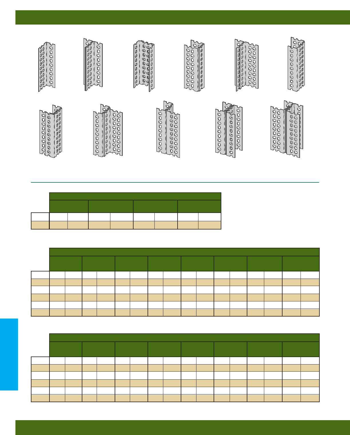
COLUMN SECTIONS
M
Single Piece
Dual Channel
Section
T-Section
T-Channel
Section
T-Channel
Section
N
Broad Channel
Section
Uneven T-Section
I-Section Uneven I-Section
Uneven Channel
Section
Narrow Channel
Section
N N O O
COLUMN LOADING - SA158-15/8” (41.3) x 15/8” (41.3) x 14 Gauge (1.9)
Column Loads assume no lateral support.
Column Loads assume no lateral support.
For greater strength required in some applications, Slotted Angle may be fastened together to create combination shapes. A number of
these combinations are illustrated above. Refer to the following table for load capacities of these combinations.
PP P Q R
M
N
Column Height
36
”
(914 mm) 48
”
(1219 mm) 60
”
(1524 mm) 72
”
(1829 mm)
Lbs. N Lbs. N Lbs. N Lbs. N
1450 (6450) 1150 (5115) 950 (4226) 750 (3336)
3850 (17125) 3500 (15569) 3000 (13344) 2500 (11120)
Column Height
36”(914 mm) 48”(1219 mm) 60”(1524 mm) 72”(1829 mm) 84”(2133 mm) 96”(2438 mm) 108”(2743 mm) 120”(3048 mm)
Lbs. N Lbs. N Lbs. N Lbs. N Lbs. N Lbs. N Lbs. N Lbs. N
2280 (10142) 1970 (8763) 1520 (6761) 1070 (4759) 660 (2936) –– – –– –
4760 (21173) 4490 (19972) 3995 (17770) 3140 (13967) 2340 (10409) 1750 (7784) ––––
4940 (21974) 4680 (20817) 4310 (19172) 3870 (17214) 3665 (16303) 2700 (12010) 2060 (9163) 1610 (7161)
7270 (32338) 6920 (30781) 6370 (28335) 5840 (25977) 4930 (21930) 3850 (17125) 2870 (12766) 2060 (9163)
9520 (42347) 8970 (39900) 7990 (35541) 6280 (27935) 4660 (20729) 3500 (15569) ––– –
9865 (43881) 9330 (41502) 8620 (38343) 7715 (34318) 6740 (29981) 5365 (23865) 4115 (18304) 3210 (14279)
M
N
O
P
Q
R
COLUMN LOADING - SA276-15/8” (41.3) x 23/8” (60.3) x 14 Gauge (1.9)
Column Loads assume no lateral support.
Column Height
36”(914 mm) 48”(1219 mm) 60”(1524 mm) 72”(1829 mm) 84”(2133 mm) 96”(2438 mm) 108”(2743 mm) 120”(3048 mm)
Lbs. N Lbs. N Lbs. N Lbs. N Lbs. N Lbs. N Lbs. N Lbs. N
3470 (15435) 2870 (12766) 1970 (8763) 1280 (5694) ––– – – – – –
7970 (35452) 7360 (32739) 6570 (29225) 5270 (23442) 3670 (16325) 2580 (11476) ––––
8770 (39011) 8580 (38166) 8180 (36386) 7690 (34207) 6970 (31004) 6260 (27846) 5460 (24287) 4460 (19839)
12560 (55869) 11970 (53245) 11360 (50532) 10480 (46617) 9470 (42124) 8370 (37231) 6880 (30604) 5370 (23887)
15940 (70904) 14750 (65611) 13160 (58538) 10560 (46973) 7370 (32783) 5170 (22997) ––––
17550 (78066) 17150 (76287) 16360 (72773) 15360 (68324) 13970 (62141) 12570 (55914) 10970 (48797) 8960 (39856)
M
N
O
P
Q
R
COLUMN LOADING - SA318-15/8” (41.3) x 31/8” (79.4) x 12 Gauge (2.6)
Slotted Angle
Reference page 202 for general fitting and standard finish specifications.
Slotted Angle Column Loading & Combinations
214
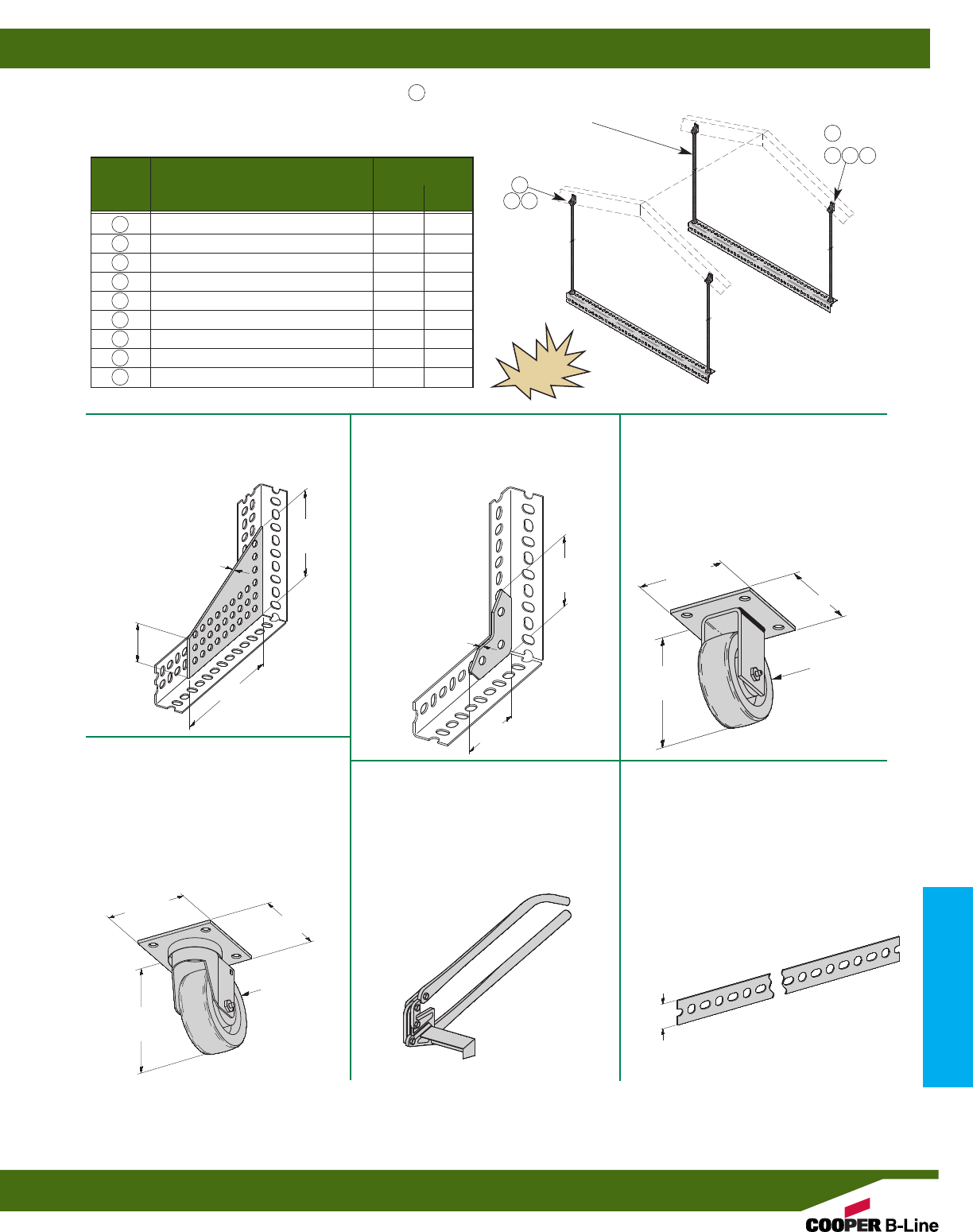
SA101
CONNECTION PLATE
•Standard finishes: ZN, GRN
•Wt./C 67 Lbs. (30.4 kg)
AHHK-1/4& AHHK-3/8
AIR HANDLER HANGING KIT
•Standard finishes: ZN
•Load CapacityPer Kit: 400 Lbs. (181.4 kg)
SA102
ANGLE BRACE
•Standard finishes: ZN, GRN
•Wt./C 15 Lbs. (6.8 kg)
SA110
SLOTTED ANGLE CUTTER
•Standard finishes:
•Wt./Ea. 16 Lbs. (7.26 kg)
SA131
SLOTTED STRAP
•Hole pattern is identical to the hole
pattern in slotted angles
•Standard length: 10’ (3.05 m)
•Standard finishes: Pre-Galv. (GALV)
•Material thickness: 14 gauge (1.9)
73/8”
(187.3)
53/32”
(129.4)
29/32”
(57.9)
12 GAUGE
14 GAUGE
33/16”
(80.9)
33/16”
(80.9)
CLEATS: To reinforce load-bearing joints, cleats can be field made by cutting 21/4” (57.1) long segments from the widest slotted angle available.
Use SA276 for light duty cleats and SA318 for heavy duty cleats.
SPLICE PLATES: To assemble two pieces of slotted angle using a butt joint requires a 6” (152.4) splice plate for reinforcement.
4”
(101.6)
51/4”
(133.4)
51/4”
(133.4)
41/2”
(114.3)
4”
(101.6)
41/2”
(114.3)
4” (101.6)
DIA. WHEELS
4” (101.6)
DIA. WHEELS
SA154
RIGID CASTER
•Safety Factor of 1.5
•300 Lbs. (136.1 kg) maximum load
capacity
•Caster material: Phenolic
•Standard finishes: ZN, GRN
•Wt./Ea. 2.0 Lbs. (.91 kg)
SA155
SWIVEL CASTER
•Safety Factor of 1.5
•300 Lbs. (136.1 kg) maximum load
capacity
•Caster material: Phenolic
•Standard finishes: ZN, GRN
•Wt./Ea. 2.2 Lbs. (1.0 kg)
15/16”
(33.3)
Hanging rods come in 72” lengths.
Rods can be field cut for proper
height requirement.
Note 1: Flat washers are required for 1/4”-20 hanging rods only.
Item # Description Quantity
AHHK AHHK
1/43/8
1 Rod Hanger Fitting 4 4
2 Lag Screw 4 4
3 Hex Head Cap Screw 4 4
4 Flat Washer (For HHCS) 44
5 Hex Nuts (For HHCS) 44
6 Hex Nuts (For Hanging Rods) 16 16
7 Flat Washer (See Note 1) 16 -
8 Hanging Rods (72” Long) 44
9 SA158 (36” Long) 22
1
6 7
2
345
8
or
NEW
Slotted Angle
Reference page 210 for general fitting and standard finish specifications.
Slotted Angle Kits & Fittings
215

To Convert From To Multiply By To Convert From To Multiply By
Angle Length
degree radian (rad) 0.01745329 foot (ft) meter (m) 0.3048
radian (rad) degree 57.29578 inch (in) meter (m) 0.0254
mil meter (m) 0.0000254
Area inch (in) micrometer (µm) 25400.00
foot2square meter (m2) 0.09290304 meter (m) foot (ft) 3.280840
inch2square meter (m2) 0.00064516 meter (m) inch (in) 39.37008
circular mil square meter (m2) 0.0000000005067075 meter (m) mil 39370.08
sq. centimeter (cm2) square inch (in2) 0.1550003 micrometer (µm) inch (in) 0.00003937008
square meter (m2) foot210.76391
square meter (m2) inch21550.003 Volume
square meter (m2) circular mil 1973523000.0 foot3cubic meter (m3) 0.02831685
inch3cubic meter (m3) 0.00001638706
Temperature cubic centimeter (cm2) cubic inch (in3) 0.06102374
degree Fahrenheit degree Celsius t°C=(t°F-32)/1.8 cubic meter (m3) foot335.31466
degree Celsius degree Fahrenheit t°F=1.8t°C+32 cubic meter (m3) inch361023.76
gallon (U.S. liquid) cubic meter (m3) 0.003785412
Force
pounds-force (lbf) newtons (N) 4.448222 Section Properties
section modulus S (in3) S (m3) 0.00001638706
moment of inertia I (in4) I (m4) 0.0000004162314
modulus of elasticity E (psi) E (Pa) 6894.757
section modulus S (m3) S (in3) 61023.74
moment of inertia I (m4) I (in4) 2402510.0
modulus of elasticity E (Pa) E (psi) 0.0001450377
METRIC CONVERSION CHART
To Convert From To Multiply By
Bending Moment or Torque
lbf • ft newton meter (N•m) 1.355818
lbf • in newton meter (N•m) 0.1129848
N•m lbf • ft 0.7375621
N•m lbf • in 8.850748
Mass
ounce (avoirdupois) kilogram (kg) 0.02834952
pound (avoirdupois) kilogram (kg) 0.4535924
ton (short, 2000 lb) kilogram (kg) 907.1847
ton (long, 2240 lb) kilogram (kg) 1016.047
kilogram (kg) ounce (avoirdupois) 35.27396
kilogram (kg) pound (avoirdupois) 2.204622
kilogram (kg) ton (short, 2000 lb) 0.001102311
kilogram (kg) ton (long, 2240 lb) 0.0009842064
Mass Per Unit Length
lb/ft kilogram per meter (kg/m) 1.488164
lb/in kilogram per meter (kg/m) 17.85797
kg/m lb/ft 0.6719689
kg/m lb/in 0.5599741
Mass Per Unit Volume
lb/ft3kilogram per cubic meter (kg/m3) 16.01846
lb/in3kilogram per cubic meter (kg/m3) 27679.9
kg/m3lb/ft30.06242797
kg/m3lb/in30.0000361273
lbs/ft3lbs/in31728.0
Mass Per Unit Area
lb/ft2kilogram per square meter (kg/m2) 4.882428
kg/m2pound per square foot (lb/ft2) 0.2048161
Pressure or Stress
lbf/in2(psi) pascal (Pa) 6894.757
kip/in2(ksi) pascal (Pa) 6894757.0
lbf/in2(psi) megapascals (MPa) 0.006894757
pascal (Pa) pound-force per square inch (psi) 0.0001450377
pascal (Pa) kip per square inch (ksi) 0.0000001450377
megapascals (MPa) lbf/in2(psi) 145.0377
Abbreviations
Defl. = Deflection
S.F. = Safety Factor
Ft. = Feet
Pre-galv. = Pre-galvanized Steel
K Factor = Deflection Divided
by load in Lbs./Ft.
o.c. = On Center
PVC = Poly Vinyl Chloride
In. = Inch
psi = Pounds per Square
Inch
wt./c = Weight pre 100 pieces
Metric Symbols
m = meter
cm = centimeter
mm = millimeter
µm = micrometer
kg = kilogram
N = newton
kN = kilonewton
Pa = pascal
MPa = megapascal
Reference Data
Reference Data
216
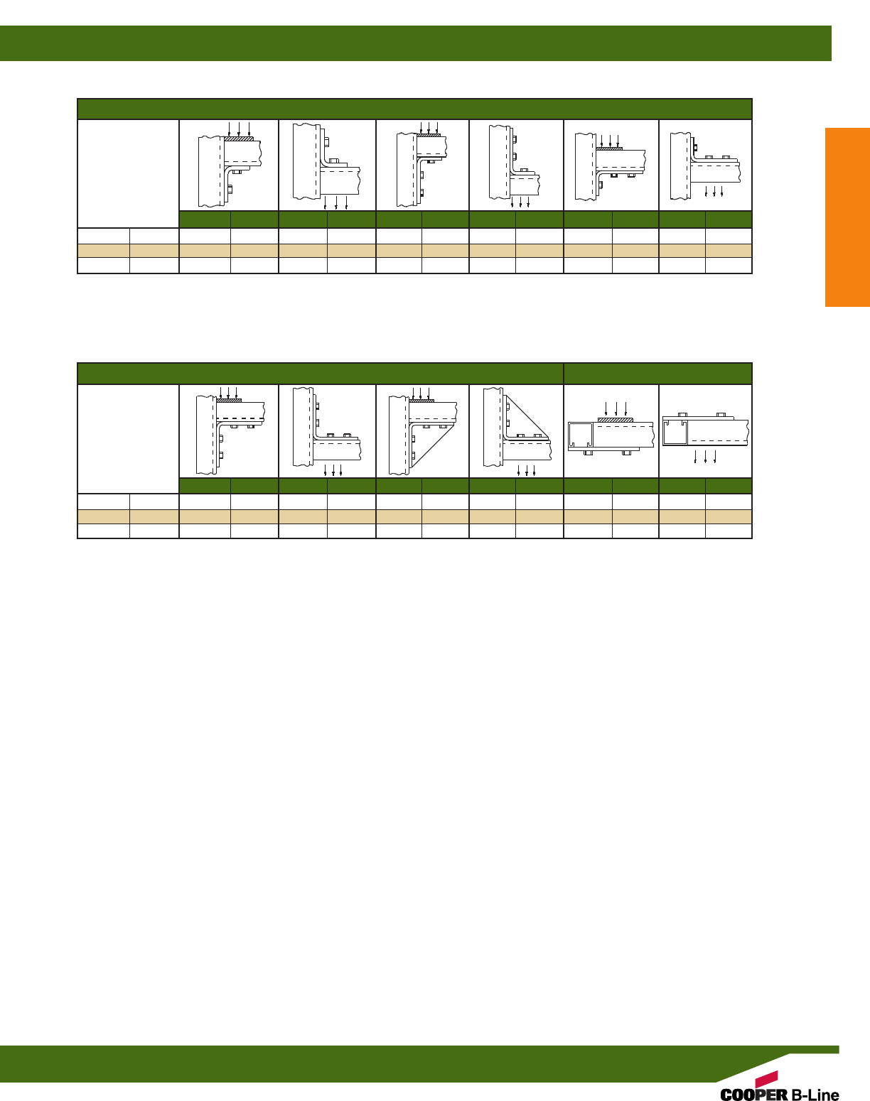
90° Fittings
Channel
Thickness Lbs. kN Lbs. kN Lbs. kN Lbs. kN Lbs. kN Lbs. kN
12 ga. (2.6) 1500 (6.67) 1000 (4.45) 2000 (8.90) 1500 (6.67) 1500 (6.67) 1000 (4.45)
14 ga. (1.9) 1000 (4.45) 650 (2.89) 1500 (6.67) 1150 (5.12) 1000 (4.45) 650 (2.89)
16 ga. (1.5) 750 (3.34) 500 (2.22) 900 (4.00) 650 (2.89) 1000 (4.45) 500 (2.22)
90° Fittings Flat Fittings
Channel
Thickness Lbs. kN Lbs. kN Lbs. kN Lbs. kN Lbs. kN Lbs. kN
12 ga. (2.6) 2500 (11.12) 2000 (8.90) 3000 (13.34) 2500 (11.12) 1000 (4.45) 1000 (4.45)
14 ga. (1.9) 2000 (8.90) 1650 (7.34) 2000 (8.90) 1650 (7.34) 500 (3.56) 800 (3.56)
16 ga. (1.5) 1500 (6.67) 1250 (5.56) 1500 (6.67) 1250 (5.56) 600 (2.67) 600 (2.67)
DESIGN LOAD DATA (For typical channel-fitting connections when USED IN PAIRS).
Design load data includes a safety factor of 2.5 (safety factor = ratio of ultimate load to design load).
Reference Data
Reference Data
217
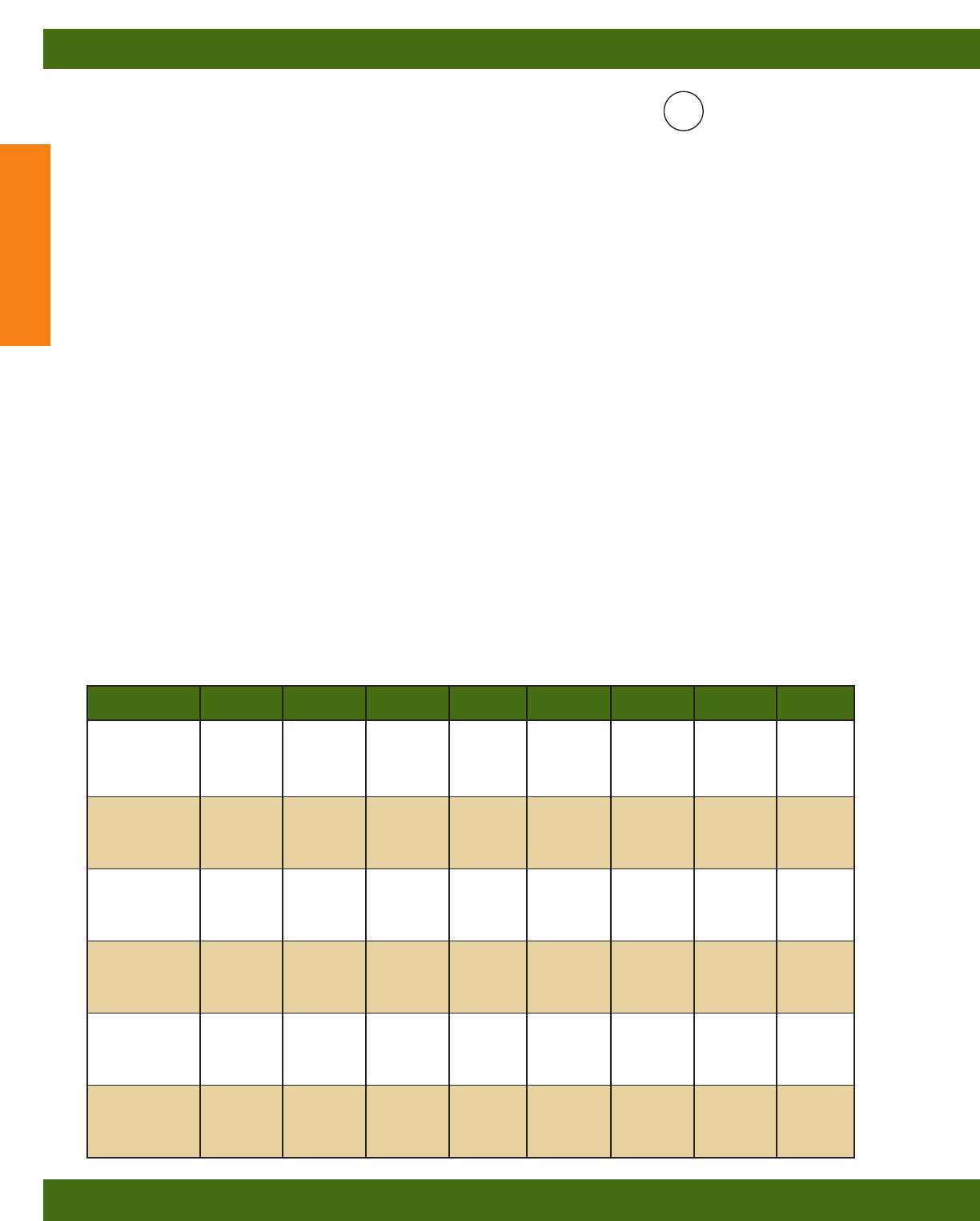
Insulation Wire Size B11 B12 B22 B24 B26 B32 B56
Type AWG. B11K06 B12K06 B22K06 B24K06 B26K06 B32K06 B56K06
14 172 127 81 81 81 67 36
FEP, 12 126 92 59 59 59 49 26
FEPB 10 90 66 42 42 42 35 19
8 51 38 24 24 24 20 11
6 24 17 11 12 12 9 5
14 52 38 24 26 27 20 12
12 45 33 21 22 23 17 10
RH, RHH, 10 37 27 17 18 19 14 8
RHW 8 20 14 9 10 10 7 4
6 14 10 6 7 7 5 3
14 124 91 58 58 58 48 26
12 95 70 45 45 45 37 20
T, TW 10 69 51 33 33 33 27 14
8 36 26 17 18 19 14 8
6 21 15 9 10 11 8 5
14 178 131 84 84 84 69 37
12 130 95 61 61 61 50 27
THHN, 10 82 60 38 38 38 32 17
THWN 8 46 34 21 22 22 17 10
6 33 24 15 16 16 12 7
14 82 61 39 39 39 32 17
12 66 49 31 31 31 26 14
THW 10 52 38 24 24 24 20 11
8 29 21 13 14 15 11 6
6 21 15 10 10 11 8 5
14 124 91 58 58 58 48 26
12 95 70 45 45 45 37 20
XHHW 10 71 52 33 33 33 28 15
8 37 27 17 19 19 14 8
6 27 20 13 14 14 10 6
General Notes for Strut-Type Channel Raceway
Guide RIUU - Cooper B-Line, Inc., Highland, IL 62249 December 11, 1998 (C) File No. E29637
FLUORESCENT AND INCANDESCENT LIGHTING
Suitable for not more than the number of wires of the sizes and types indicated in the following tables. Intended to enclose circuits
operating at potentials not exceeding 600 volts between conductors. In all cases, the B217-20 or B217P snap-in cover is required to
complete raceway closure. When using B217-24 snap-in cover, the number of wires is limited to 7 or fewer conductors no larger than
#12 AWG.
TABLE 1: MAXIMUM NUMBER OF WIRES (Adjusted per NEC Table 384.22 for 40% fill)
Use this table to determine the type and number of conductors for use with B-Line’s strut-type channel raceway using external
joiners. This table applies for all installations except for the support and supply of electric discharge type lighting fixtures. See
table 2 and 3 for further information.
®
UL
B-Line’s strut-type channel raceways and fittings are manufactured and tested to comply with the UL Standard for Safety
for Strut-Type Channel Raceways and Fittings (UL 5B) in accordance with Article 384 of the 2002 National Electrical
Code, NFPA 70.
1. Support spans for strut-type channel raceway shall not exceed 10 foot intervals.
2. No conductor larger than that for which the raceway is listed shall be installed in strut-type channel raceways. No
wires under 14AWG or over 6AWG are allowed in any of B-Line’s strut-type channel raceway. See tables 1, 2 and 3
below for a listing of the approved conductors for B-Line’s strut-type channel raceways.
3. The number of conductors permitted in strut-type channel raceway shall not exceed the percentage fill using
Table 384-22 and the applicable outside diameter of specific types and sizes of wire given in the tables in chapter 9
of the National Electrical Code. Table 384-22 lists two different percent fill areas depending on the use of internal or
external joiners. Use 40% area fill with external joiners and 25% area fill for internal joiners.
4. Items in the electrical section of the B-Line Strut Systems Catalog identified by the UL symbol provide for electrical
continuity. Other items require the use of a separate grounding wire.
5. If strut-type channel raceway is connected to another wiring system, the raceway must be field-tapped adjacent to the
wire entry point to accept a #10-32 or larger grounding screw. A plated or stainless steel screw may be used. A sheet
metal screw is not acceptable. Drill and tap the grounding wire hole before installing wires in raceway or move
installed wires out of the way to avoid damage. After drilling and tapping, remove metal chips and burrs before
installing screw.
Reference Data
Reference Data
218
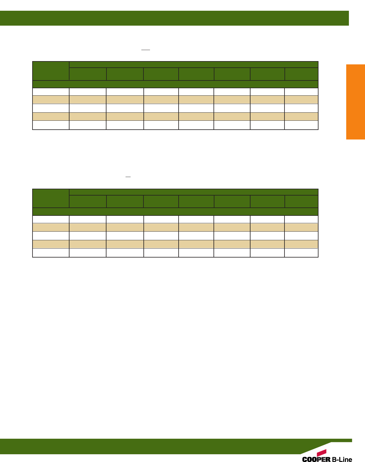
TABLE 2: MAXIMUM NUMBER OF WIRES
Also suitable for the number of wires in table below when installed to support and supply electric discharge type lighting fixtures
when raceway wiring is suitable for at least 70°C and clearance between fixture and raceway is at least 1/8”. In all cases, a
snap-in cover is required to complete the raceway enclosure.
TABLE 3: MAXIMUM NUMBER OF WIRES
Also suitable for the number of wires in table below when installed to support and supply electric discharge type lighting fixtures
when raceway wiring is suitable for 75°C, or wiring suitable for 60°C if a minimum clearance between fixture and raceway is
at least 1/2”. In all cases, a snap-in cover is required to complete the raceway enclosure.
When using B217-24 snap-in cover, the number of wires is limited to 7 or fewer conductors no larger than #12 AWG.
When using B217-24 snap-in cover, the number of wires is limited to 7 or fewer conductors no larger than #12 AWG.
Raceway Catalog Wires
Wire Size B11 B12 B22 B24 B26 B32 B56
B11K06 B12K06 B22K06 B24K06 B26K06 B32K06 B56K06
Type Insulation: FEP, FEPB, RH, RHH, RHW, RUH, THHN, THWN, THW, XHHW
14 13 10 10 10 10 10 6
12 13 10 10 10 10 10 6
10 13 10 8 8 8 6 –
8108 6664–
6 8 6 4443–
Raceway Catalog Wires
Wire Size B11 B12 B22 B24 B26 B32 B56
B11K06 B12K06 B22K06 B24K06 B26K06 B32K06 B56K06
Type Insulation: FEP, FEPB, RH, RHH, RHW, RUH, THHN, THWN, THW, XHHW
14 10 10 10 10 10 10 4
12 10 10 10 10 10 10 3
108 5 5555–
8 6 4 4444–
6 4 4 4444–
Reference Data
Reference Data
219
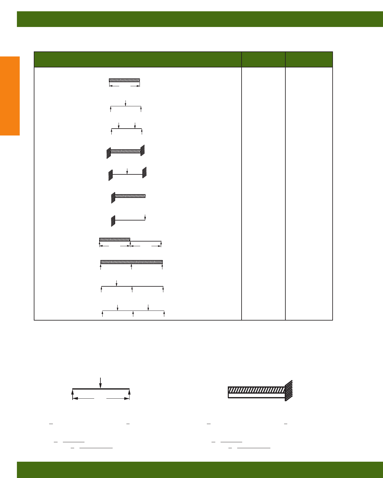
LOAD AND SUPPORT CONDITION Load Deflection
Factor Factor
Simple Beam - Uniform Load 1.00 1.00
Simple Beam - Concentrated Load at Center .50 .80
Simple Beam - Two Equal Concentrated Loads at 1/4Points 1.00 1.10
Beam Fixed at Both Ends - Uniform Load 1.50 .30
Beam Fixed at Both Ends - Concentrated Load at Center 1.00 .40
Cantilever Beam - Uniform Load .25 2.40
Cantilever Beam - Concentrated Load at End .12 3.20
Continuous Beam - Two Equal Spans - Uniform Load on One Span 1.30 .92
Continuous Beam - Two Equal Spans - Concentrated Load on Both Spans 1.00 .42
Continuous Beam - Two Equal Spans - Concentrated Load at Center of One Span .62 .71
Continuous Beam - Two Equal Spans - Concentrated Load at Center of Both Spans .67 .48
Span
Span
Span
The data shown in the beam load charts for appropriate channels on page(s) 17 thru 39 is for simply supported, single span beams
with a uniformly distributed load. For other loading and/or support conditions, use the appropriate factor from the chart below.
EXAMPLES:
PROBLEM: PROBLEM:
Calculate the maximum allowable load and corresponding Calculate the maximum allowable load and corresponding
deflection of a simply supported B22 beam with a concentrated deflection of a cantilever B52 beam with a uniformly distributed
load at midspan as shown. load.
SOLUTION: SOLUTION:
From beam load chart for B22 (page 22), maximum allowable From beam load chart for B52 (page 33), maximum allowable
load is A and the corresponding deflection is B. load is A and the corresponding deflection is B.
Multiplying by the appropriate factors shown in the chart above. Multiplying by the appropriate factors shown in chart above.
LOAD = A x load factor = _______ LOAD = A x load factor = _______
DEFLECTION = B x deflection factor = DEFLECTION = B x deflection factor = _______
96”
Reference Data
Reference Data
220
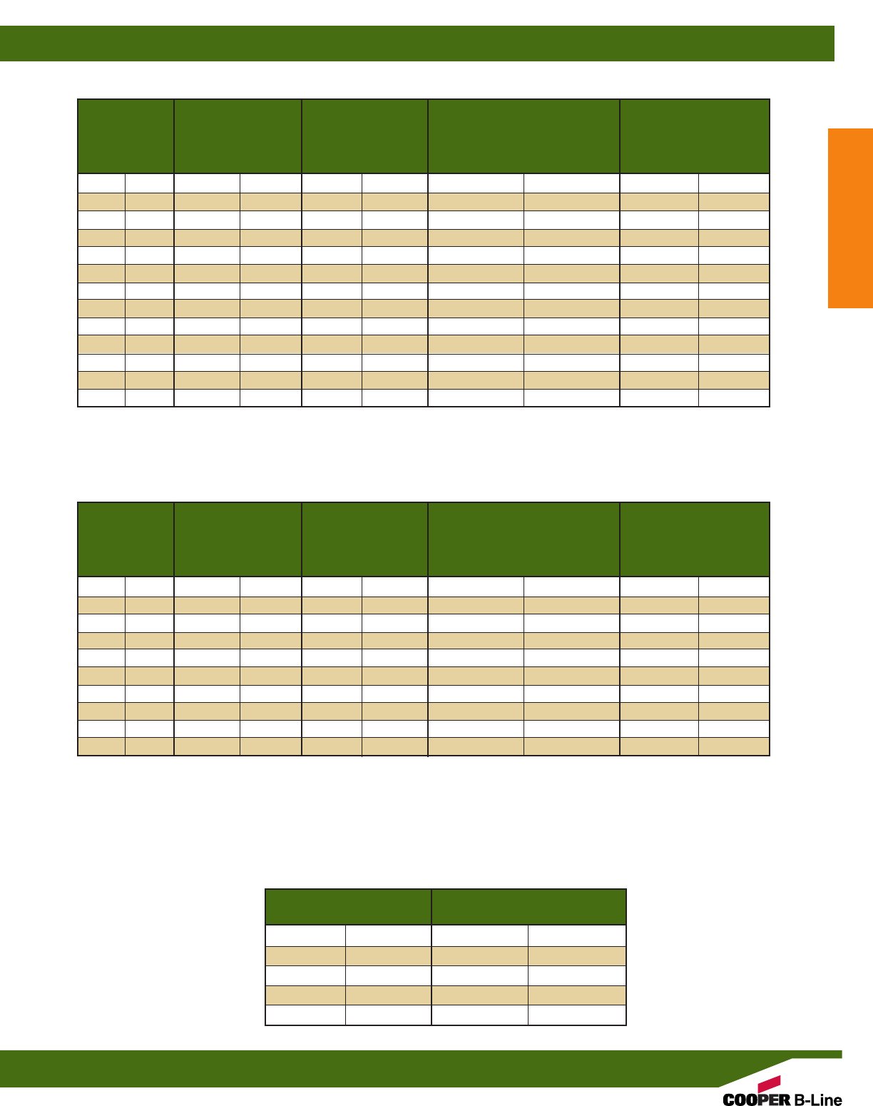
Nominal Minimum Weight Weight of Conduit
Nominal Outside Inside Per 100 Ft. (30.5m) with and Conductors
Conduit Size Diameter Diameter Couplings Attached Per 100 Ft. (30.5m)*
In. mm In. mm In. mm Lbs. kg Lbs. kg
3/8”(10) 0.675 (17.1) 0.493 (12.5) 51.5 (23.4) 65.1 (29.5)
1/2”(15) 0.840 (21.3) 0.632 (16.0) 79.0 (35.8) 101.1 (45.9)
3/4”(20) 1.050 (26.7) 0.836 (21.3) 105.0 (47.6) 145.8 (66.1)
1” (25) 1.315 (33.4) 1.063 (27.0) 153.0 (69.4) 219.3 (99.5)
11/4”(32) 1.660 (42.2) 1.394 (35.4) 201.0 (91.2) 318.3 (144.4)
11/2”(40) 1.900 (48.3) 1.624 (41.3) 249.0 (113.0) 408.8 (185.4)
2” (50) 2.375 (60.3) 2.083 (52.9) 332.0 (150.6) 593.8 (269.3)
21/2”(65) 2.875 (73.0) 2.489 (63.2) 527.0 (239.1) 901.0 (408.7)
3” (80) 3.500 (88.9) 3.090 (78.5) 682.6 (309.6) 1259.0 (571.1)
31/2”(90) 4.000 (101.6) 3.570 (90.7) 831.0 (376.9) 1604.0 (727.6)
4” (100) 4.500 (114.3) 4.050 (102.9) 972.3 (441.0) 1967.0 (892.2)
5” (125) 5.563 (141.3) 5.073 (128.9) 1313.6 (595.9) 2876.0 (1304.5)
6” (150) 6.625 (168.3) 6.093 (154.8) 1745.3 (791.7) 4003.0 (1815.7)
RIGID STEEL CONDUIT (HEAVY WALL CONDUIT)
INTERMEDIATE METAL CONDUIT (IMC)
NEC TABLE 346-12
Nominal Minimum Weight Weight of Conduit
Nominal Outside Inside Per 100 Ft. (30.5m) with and Conductors
Conduit Size Diameter Diameter Couplings Attached Per 100 Ft. (30.5m)*
In. mm In. mm In. mm Lbs. kg Lbs. kg
1/2”(15) 0.815 (20.7) .675 (17.1) 60.0 (27.2) 82.1 (37.2)
3/4”(20) 1.029 (26.1) .879 (22.3) 82.0 (37.2) 122.8 (55.7)
1” (25) 1.290 (32.7) 1.120 (28.4) 116.0 (52.6) 182.3 (82.7)
11/4”(32) 1.638 (41.6) 1.468 (37.3) 150.0 (68.0) 267.3 (121.2)
11/2”(40) 1.883 (47.7) 1.703 (43.3) 182.0 (82.5) 341.8 (155.0)
2” (50) 2.360 (59.9) 2.170 (55.1) 242.0 (109.7) 503.8 (228.5)
21/2”(65) 2.857 (72.5) 2.597 (66.0) 428.0 (194.1) 775.0 (351.5)
3” (80) 3.476 (88.3) 3.216 (81.7) 526.0 (238.6) 1069.0 (485.0)
31/2”(90) 3.971 (100.8) 3.711 (94.3) 612.0 (277.6) 1346.0 (610.8)
4” (100) 4.466 (113.4) 4.206 (106.8) 682.0 (309.4) 1632.0 (740.5)
*Conduit plus weight of heaviest conductor combination as specified by the National Electrical Code.
Rigid and Intermediate Metal Conduit shall be supported at least every 10 feet (3.05 m) and within 3 feet (914 mm) of each outlet box,
junction box, cabinet, or fitting, except for straight runs of conduit connected with couplings which may be supported in accordance with
NEC Article 345 and 346, provided such supports prevent transmission of stresses to termination where conduit is deflected between
supports.
Dimensions taken from ANSI C80.1-1977.
*Conduit plus weight of heaviest conductor combination as specified by the National Electrical Code.
Conduit Size Maximum Support Span
In. mm Feet Meters
1/2-3/4(15-20) 10 (3.05)
1(25) 12 (3.66)
11/4-11/2(32-40) 14 (4.27)
2-21/2(50-65) 16 (4.88)
3-6 (80-150) 20 (6.10)
Reference Data
Reference Data
221
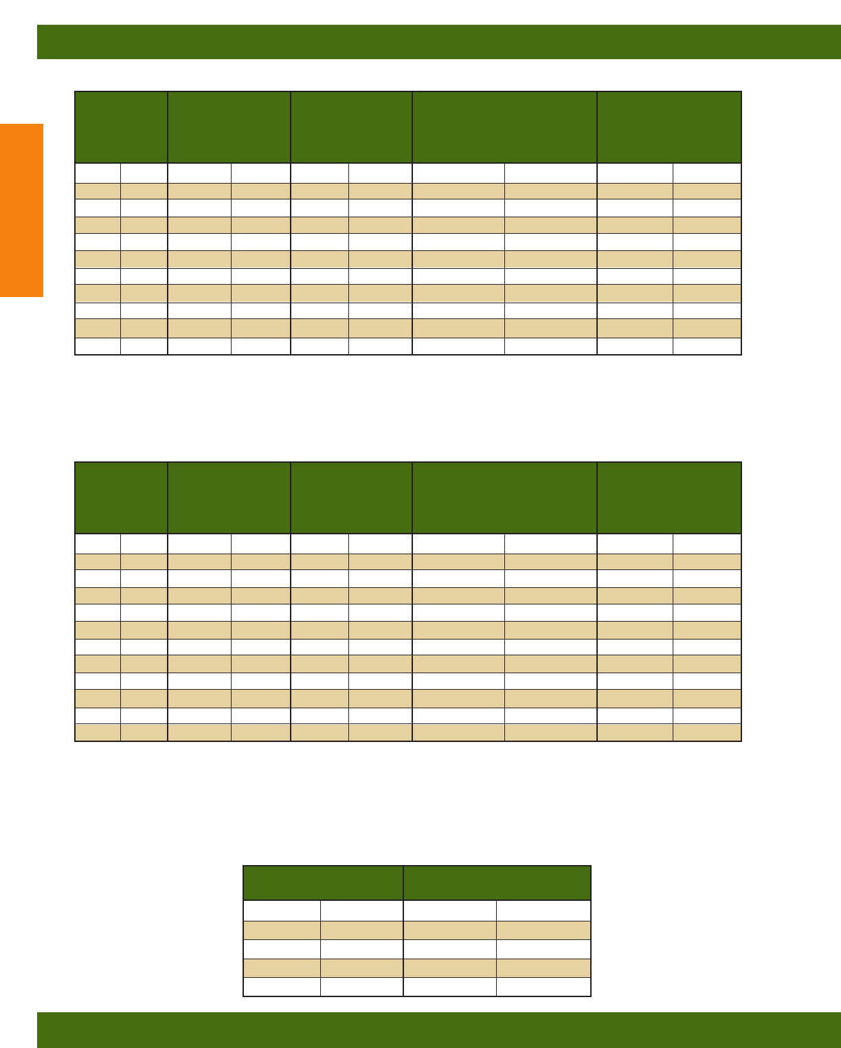
Nominal Minimum Weight Weight of Conduit
Nominal Outside Inside Per 100 Ft. (30.5m) with and Conductors
Conduit Size Diameter Diameter Couplings Attached Per 100 Ft. (30.5m)*
In. mm In. mm In. mm Lbs. kg Lbs. kg
1/2”(15) 0.840 (21.3) 0.632 (16.1) 27.4 (12.4) 49.5 (22.5)
3/4”(20) 1.050 (26.7) 0.836 (21.2) 36.4 (16.5) 77.2 (35.0)
1” (25) 1.315 (33.4) 1.063 (27.0) 53.0 (24.0) 119.3 (54.1)
11/4”(32) 1.660 (42.2) 1.394 (35.4) 69.6 (31.6) 186.9 (84.8)
11/2”(40) 1.900 (48.3) 1.624 (41.2) 82.2 (37.3) 242.0 (109.8)
2” (50) 2.375 (60.3) 2.083 (52.9) 115.7 (52.5) 377.5 (171.2)
21/2”(65) 2.875 (73.0) 2.489 (63.2) 182.5 (82.8) 556.5 (252.4)
3” (80) 3.500 (88.9) 3.090 (78.5) 238.9 (108.4) 815.2 (369.8)
31/2”(90) 4.000 (101.6) 3.570 (90.7) 287.7 (130.5) 1061.0 (481.3)
4” (100) 4.500 (114.3) 4.050 (102.9) 340.0 (154.2) 1334.0 (605.1)
5” (125) 5.563 (141.3) 5.073 (128.9) 465.4 (211.1) 2028.0 (919.9)
6” (150) 6.625 (168.3) 6.093 (154.8) 612.5 (277.8) 2870.0 (1301.8)
Weight of Conduit
Nominal Outside Inside Weight and Conductors
Conduit Size Diameter Diameter Per 100 Ft. (30.5m) Per 100 Ft. (30.5m)*
In. mm In. mm In. mm Lbs. kg Lbs. kg
3/8”(10) 0.577 (14.7) 0.493 (12.5) 23.0 (10.4) 36.6 (16.6)
1/2”(15) 0.706 (17.9) 0.622 (15.8) 28.5 (12.9) 50.6 (23.0)
3/4”(20) 0.922 (23.4) 0.824 (20.9) 43.5 (19.7) 84.3 (38.2)
1” (25) 1.163 (29.5) 1.049 (26.6) 64.0 (29.0) 130.3 (59.1)
11/4”(32) 1.510 (38.3) 1.380 (35.1) 95.0 (43.1) 212.3 (96.3)
11/2”(40) 1.740 (44.2) 1.610 (40.9) 110.0 (49.9) 269.8 (122.4)
2” (50) 2.197 (55.8) 2.067 (52.5) 140.0 (63.5) 401.8 (182.3)
21/2”(65) 2.875 (73.0) 2.731 (69.4) 205.0 (93.0) 579.0 (262.6)
3” (80) 3.500 (88.9) 3.356 (85.2) 250.0 (113.4) 826.3 (374.8)
31/2”(90) 4.000 (101.6) 3.834 (97.4) 325.0 (147.4) 1098.0 (498.0)
4” (100) 4.500 (114.3) 4.334 (110.1) 370.0 (167.8) 1364.0 (618.7)
ELECTRICAL METALLIC TUBING (EMT) — THINWALL CONDUIT
RIGID ALUMINUM CONDUIT
Dimensions taken from ANSI C80.5-1977.
*Conduit plus weight of heaviest conductor combination as specified by the National Electrical Code.
Aluminum Rigid Conduit shall be supported at least every 10 feet (3.05 m) and within 3 feet (914 mm) of each outlet box, junction box,
cabinet, or fitting, except for straight runs of conduit connected with couplings which may be supported in accordance with NEC Table
344.30 (B)(2), provided such supports prevent transmission of stresses to termination where conduit is deflected between supports.
Dimensions taken from ANSI C80.3-1977.
*Conduit plus weight of heaviest conductor combination as specified by the National Electrical Code.
Electrical Metallic tubing shall be supported at least every 10 feet (3.05 m) and within 3 feet (914 mm) of each outlet box, junction box,
cabinet or fitting. See NEC Article 348.
NEC TABLE 344.30 (B)(2)
Conduit Size Maximum Support Span
In. mm Feet Meters
1/2-3/4(15-20) 10 (3.05)
1(25) 12 (3.66)
11/4-11/2(32-40) 14 (4.27)
2-21/2(50-65) 16 (4.88)
3-6 (80-150) 20 (6.10)
Reference Data
Reference Data
222
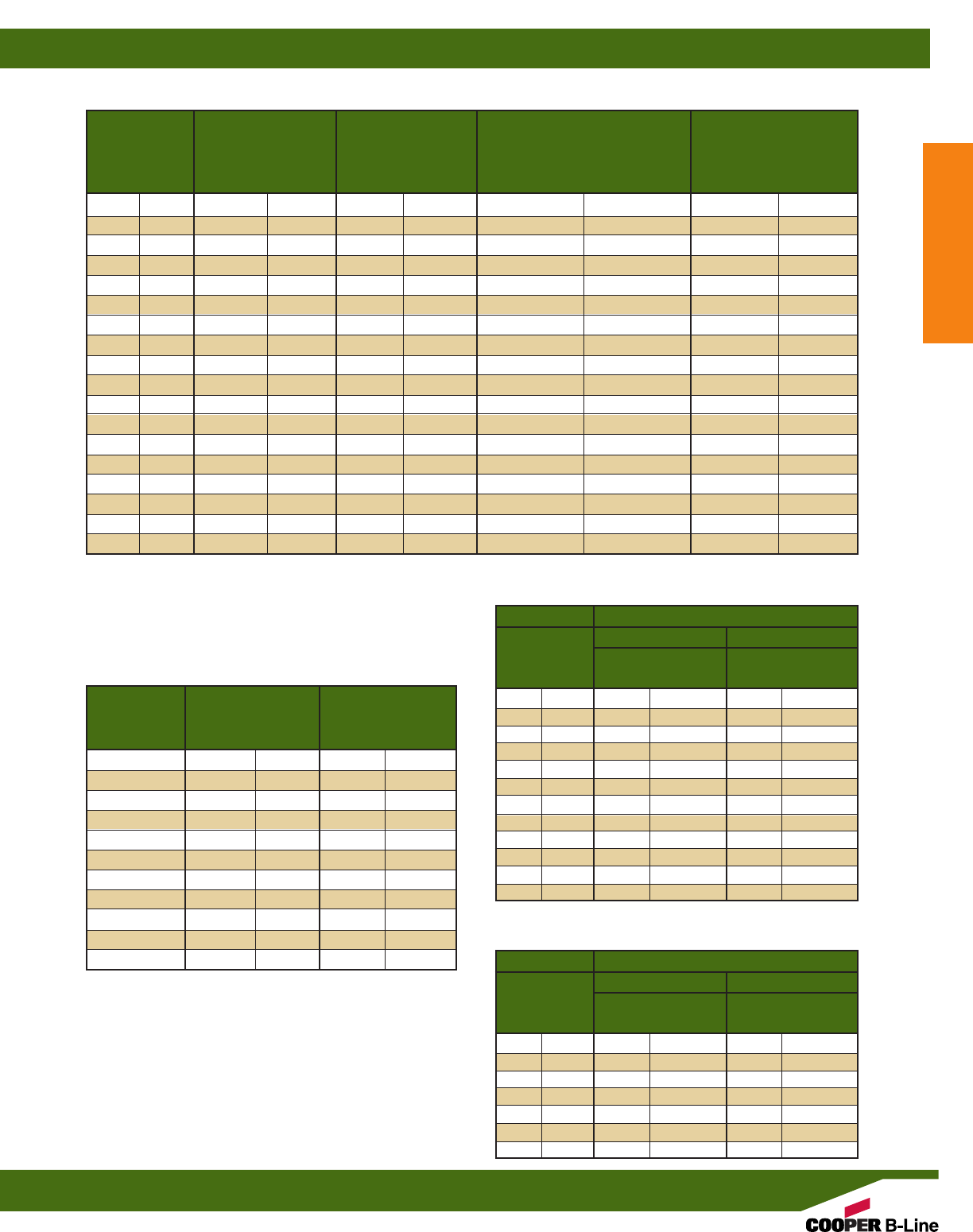
Weight of Pipe
Nominal Outside Inside Weight of Pipe Filled With Water
Pipe Size Diameter Diameter Per 100 Ft. (30.5m) Per 100 Ft. (30.5m)
In. mm In. mm In. mm Lbs. kg Lbs. kg
1/8”(3) .405 (10.3) .269 (6.8) 4.7 (2.1) 7.2 (3.2)
1/4”(6) .540 (13.7) .364 (9.2) 8.2 (3.7) 12.7 (5.8)
3/8”(10) .675 (17.1) .493 (12.5) 10.9 (4.9) 19.2 (8.7)
1/2”(15) .840 (21.3) .622 (15.8) 16.4 (7.4) 29.6 (13.4)
3/4”(20) 1.050 (26.7) .824 (20.9) 21.8 (9.9) 44.9 (20.4)
1” (25) 1.315 (33.4) 1.049 (26.6) 32.1 (14.6) 69.6 (31.6)
11/4”(32) 1.660 (42.2) 1.380 (35.1) 43.4 (19.7) 108.2 (49.1)
11/2”(40) 1.900 (48.3) 1.610 (40.9) 51.8 (23.5) 140.0 (63.5)
2” (50) 2.375 (60.3) 2.067 (52.5) 69.5 (31.5) 214.9 (97.5)
21/2”(65) 2.875 (73.0) 2.469 (62.7) 109.6 (49.7) 317.1 (143.8)
3” (80) 3.500 (88.9) 3.068 (77.9) 143.5 (65.1) 463.9 (210.4)
31/2”(90) 4.000 (101.6) 3.548 (90.1) 175.6 (79.7) 604.1 (274.0)
4” (100) 4.500 (114.3) 4.026 (102.3) 204.3 (92.7) 756.0 (342.9)
5” (125) 5.563 (141.3) 5.047 (128.2) 281.7 (127.8) 1148.8 (521.1)
6” (150) 6.625 (168.3) 6.065 (154.1) 360.9 (163.7) 1613.0 (731.7)
8” (200) 8.625 (219.1) 7.981 (202.7) 545.3 (247.3) 2713.5 (1230.8)
10” (250) 10.750 (273.1) 10.020 (254.5) 791.3 (358.9) 4208.9 (1909.1)
12” (300) 12.750 (323.9) 11.938 (303.2) 1035.2 (469.6) 5886.4 (2670.0)
SCHEDULE 40 PVC PLASTIC PIPE
ALL THREADED ROD (ATR)
CLAMP SIZING CHART FOR PVC COATED
RIGID CONDUIT AND CLAMPS
CLAMP SIZING CHART FOR PVC COATED
THINWALL (EMT) CONDUIT AND CLAMPS
Nominal
Size (In) Root Area Design Load (SF=5)
and Thread In.2cm2Lbs. kN
1/4-20” 0.027 (0.174) 240 (1.07)
5/16-18” 0.045 (0.290) 400 (1.78)
3/8-16” 0.068 (0.438) 730 (3.24)
1/2-13” 0.126 (0.812) 1350 (6.00)
5/8-11” 0.202 (1.303) 2160 (9.60)
3/4-10” 0.302 (1.948) 3230 (14.37)
7/8-9” 0.419 (2.703) 4480 (19.93)
1-8” 0.551 (3.561) 5900 (26.24)
11/8-7” 0.693 (4.471) 7450 (33.14)
11/4-7” 0.889 (5.735) 9500 (42.25)
11/2-6” 1.293 (8.342) 13800 (61.38)
Conduit Coating
Nominal .020 (.51mm) .040 (1.01mm)
Conduit Clamp Coating Clamp Coating
Size 0
.020 (.51mm)
0
.020 (.51mm)
1/2”(15) B2028 B2002 B2002 B2029
3/4”(20) B2030 B2030 B2030 B2003
1” (25) B2032 B2032 B2032 B2033
11/4”(32) B2005 B2005 B2005 B2005
11/2”(40) B2012 B2037 B2037 B2037
2” (50) B2013 B2041 B2041 B2041
21/2”(65) B2014 B2045 B2045 B2045
3” (80) B2015 B2050 B2050 B2050
31/2”(90) B2016 B2054 B2054 B2054
4” (100) B2017 B2058 B2058 B2058
5” (125) B2019 B2066 B2066 B2066
6” (150) B2020 B2115 B2115 B2115
Conduit Coating
Nominal .020 (.51mm) .040 (1.01mm)
Conduit Clamp Coating Clamp Coating
Size 0
.020 (.51mm)
0
.020 (.51mm)
3/8”(10) B2026 B2026 B2026 B2007
1/2”(15) B2027 B2027 B2027 B2008
3/4”(20) B2029 B2029 B2029 B2009
1” (25) B2003 B2031 B2031 B2031
11/4”(32) B2004 B2034 B2034 B2034
11/2”(40) B2035 B2035 B2035 B2036
2” (50) B2039 B2039 B2039 B2013
1 cubic ft. of water weighs 62.41 Lbs.
1 cubic meter of water weighs 999.972 kg.
1 gallon (U.S.) weighs 8.335 Lbs.
1 liter weighs .999 kg.
Dimensions taken from ANSI B1.1-1982 Unified Inch Screw
Threads. All threads are UNCR series.
Tabulated loads are based on an allowable tensile stress of 12000 psi
(82.7 MPa) reduced by 25% resulting in 9000 psi (62 MPa). From
ANSI/MSS SP-58, Table 3.
Reference Data
Reference Data
223
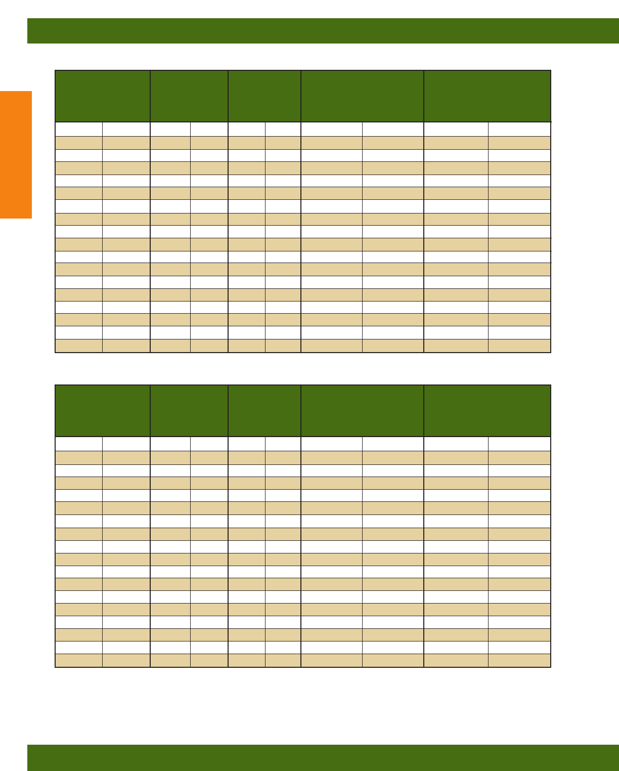
COPPER TUBING, TYPE L
Weight of Tubing
Nominal Outside Inside Weight of Tubing Filled With Water
Tubing Size Diameter Diameter Per 100 Ft. (30.5m) Per 100 Ft. (30.5m)
In. mm In. mm In. mm Lbs. kg Lbs. kg
1/4”(6) .375 (9.5) .315 (8.0) 12.6 (5.7) 16.0 (7.2)
3/8”(10) .500 (12.7) .430 (10.9) 19.8 (9.0) 26.1 (11.8)
1/2”(15) .625 (15.9) .545 (13.8) 28.5 (12.9) 38.6 (17.5)
5/8”(17) .750 (19.1) .666 (16.9) 36.2 (16.4) 51.3 (23.3)
3/4”(20) .875 (22.2) .785 (19.9) 45.5 (20.6) 66.5 (30.2)
1” (25) 1.125 (28.6) 1.025 (26.0) 65.5 (29.7) 101.3 (45.9)
11/4”(32) 1.375 (34.9) 1.265 (32.1) 88.4 (40.1) 142.9 (64.8)
11/2”(40) 1.625 (41.3) 1.505 (38.2) 114.0 (51.7) 191.1 (86.7)
2” (50) 2.125 (54.0) 1.985 (50.4) 175.0 (79.4) 309.1 (140.2)
21/2”(65) 2.625 (66.7) 2.465 (62.6) 248.0 (112.5) 454.8 (206.3)
3” (80) 3.125 (79.4) 2.945 (74.8) 333.0 (151.0) 628.2 (285.0)
31/2”(90) 3.625 (92.1) 3.425 (87.0) 429.0 (194.6) 828.3 (375.7)
4” (100) 4.125 (104.8) 3.905 (99.2) 538.0 (244.0) 1057.1 (479.5)
5” (125) 5.125 (130.2) 4.875 (123.8) 761.0 (345.2) 1570.0 (712.1)
6” (150) 6.125 (155.6) 5.845 (148.5) 1020.0 (462.7) 2182.9 (990.2)
8” (200) 8.125 (206.4) 7.725 (196.2) 1930.0 (875.4) 3961.3 (1796.8)
10” (250) 10.125 (257.2) 9.625 (244.5) 3010.0 (1365.3) 6163.4 (2795.7)
12” (300) 12.125 (308.0) 11.565 (293.8) 4040.0 (1832.5) 8592.8 (3897.6)
Weight of Tubing
Nominal Outside Inside Weight of Tubing Filled With Water
Tubing Size Diameter Diameter Per 100 Ft. (30.5m) Per 100 Ft. (30.5m)
In. mm In. mm In. mm Lbs. kg Lbs. kg
1/4”(6) .375 (9.5) .305 (7.7) 14.5 (6.6) 17.7 (8.0)
3/8”(10) .500 (12.7) .402 (10.2) 26.9 (12.2) 32.4 (14.7)
1/2”(15) .625 (15.9) .527 (13.4) 34.4 (15.6) 43.9 (19.9)
5/8”(17) .750 (19.1) .652 (16.6) 41.8 (19.0) 56.3 (25.5)
3/4”(20) .875 (22.2) .745 (18.9) 64.1 (29.1) 83.0 (37.6)
1” (25) 1.125 (28.6) .995 (25.3) 83.9 (38.1) 117.6 (53.3)
11/4”(32) 1.375 (34.9) 1.245 (31.6) 104.0 (47.2) 156.8 (71.1)
11/2”(40) 1.625 (41.3) 1.481 (37.6) 136.0 (61.7) 210.7 (95.6)
2” (50) 2.125 (54.0) 1.959 (49.8) 206.0 (93.4) 336.6 (152.7)
21/2”(65) 2.625 (66.7) 2.435 (61.8) 293.0 (132.9) 494.8 (224.5)
3” (80) 3.125 (79.4) 2.907 (73.8) 400.0 (181.4) 687.7 (311.9)
31/2”(90) 3.625 (92.1) 3.385 (86.0) 512.0 (232.2) 902.0 (409.2)
4” (100) 4.125 (104.8) 3.857 (98.0) 651.0 (295.3) 1157.4 (525.0)
5” (125) 5.125 (130.2) 4.805 (122.0) 967.0 (438.6) 1752.9 (795.1)
6” (150) 6.125 (155.6) 5.741 (145.8) 1390.0 (630.5) 2511.9 (1139.4)
8” (200) 8.125 (206.4) 7.583 (192.6) 2590.0 (1174.8) 4547.3 (2062.6)
10” (250) 10.125 (257.2) 9.449 (240.0) 4030.0 (1828.0) 7069.2 (3206.5)
12” (300) 12.125 (308.0) 11.315 (287.4) 5780.0 (2621.8) 10138.0 (4598.5)
COPPER TUBING, TYPE K
Dimensions taken from ASTM B 88-83.
1 cubic ft. of water weighs 62.41 Lbs.
1 cubic meter of water weighs 999.972 kg.
1 gallon (U.S.) weighs 8.335 Lbs.
1 liter weighs .999 kg.
Reference Data
Reference Data
224
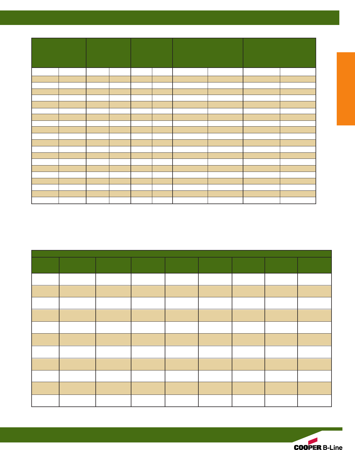
STANDARD WEIGHT SCHEDULE 40 STEEL PIPE
Nominal Weight Weight of Pipe
Nominal Outside Inside Per 100 Ft. (30.5mm) Filled With Water
Pipe Size Diameter Diameter Plain End Per 100 Ft. (30.5mm)
In. mm In. mm In. mm Lbs. kg Lbs. kg
3/8”(10) .675 (17.1) .493 (12.5) 57.0 (25.9) 65.3 (29.6)
1/2”(15) .840 (21.3) .622 (15.8) 85.0 (38.6) 98.2 (44.5)
3/4”(20) 1.050 (26.7) .824 (20.9) 113.0 (51.3) 136.1 (61.7)
1” (25) 1.315 (33.4) 1.049 (26.6) 168.0 (76.2) 205.5 (93.2)
11/4”(32) 1.660 (42.2) 1.380 (35.1) 227.0 (103.0) 291.8 (132.4)
11/2”(40) 1.900 (48.3) 1.610 (40.9) 272.0 (123.4) 360.2 (163.4)
2” (50) 2.375 (60.3) 2.067 (52.5) 365.0 (165.6) 510.4 (231.5)
21/2”(65) 2.875 (73.0) 2.469 (62.7) 579.0 (262.6) 786.5 (356.8)
3” (80) 3.500 (88.9) 3.068 (77.9) 758.0 (343.8) 1078.4 (489.2)
31/2”(90) 4.000 (101.9) 3.548 (90.1) 911.0 (413.2) 1339.5 (607.6)
4” (100) 4.500 (114.3) 4.026 (102.3) 1079.0 (489.4) 1630.7 (739.7)
5” (125) 5.563 (141.3) 5.047 (128.2) 1462.0 (663.2) 2329.1 (1056.4)
6” (150) 6.625 (168.3) 6.065 (154.1) 1897.0 (860.5) 3149.1 (1428.4)
8” (200) 8.625 (219.1) 7.981 (202.7) 2855.0 (1295.0) 5023.2 (2278.5)
10” (250) 10.750 (273.1) 10.020 (254.5) 4048.0 (1836.1) 7465.6 (3386.3)
12” (300) 12.750 (323.9) 12.000 (304.8) 4956.0 (2248.0) 9857.7 (4471.4)
14” (350) 14.000 (355.6) 13.250 (336.6) 5457.0 (2475.3) 11433.1 (5185.9)
16” (400) 16.000 (406.4) 15.250 (387.4) 6258.0 (2838.6) 14174.3 (6429.4)
18” (450) 18.000 (457.2) 17.250 (438.2) 7059.0 (3201.9) 17187.9 (7796.3)
20” (500) 20.000 (508.0) 19.250 (489.0) 7860.0 (3565.2) 20473.7 (9286.7)
24” (600) 24.000 (609.6) 23.250 (590.6) 9462.0 (4291.9) 27862.5 (12638.2)
NOMINAL PIPE SIZES
Length of 21/2” (65mm)
Trapeze Bar or less 3” (80mm) 31/2” (90mm) 4” (100mm) 5” (125mm) 6” (150mm) 8” (200mm) 10” (250mm)
1’-6” 11/2” x 11/2” x 3/16”1
1/2” x 11/2” x 3/16”1
1/2” x 11/2” x 3/16” 2” x 11/2” x 3/16” 2” x 11/2” x 3/16”2
1/2” x 11/2” x 3/16” 3” x 2” x 3/16” 3” x 2” x 1/4”
(0.46m) B24SH B24SH B24SH B22SH B22SH B12SH B11SH B11SH
2’-0” 11/2” x 11/2” x 3/16” 2” x 11/2” x 3/16” 2” x 11/2” x 3/16” 2” x 11/2” x 3/16”2
1/2” x 11/2” x 3/16”2
1/2” x 11/2” x 3/16” 3” x 2” x 3/16” 3” x 2” x 1/4”
(0.61m) B24SH B22SH B22SH B22SH B12SH B12SH B11SH B11SH
2’-6” 2” x 11/2” x 3/16” 2” x 11/2” x 3/16” 2” x 11/2” x 3/16”2
1/2” x 11/2” x 3/16”2
1/2” x 11/2” x 3/16” 3” x 2” x 3/16” 3” x 2” x 1/4” 3” x 2” x 1/4”
(0.76m) B22SH B22SH B22SH B12SH B12SH B11SH B11SH B11SH
3’-0” 2” x 11/2” x 3/16” 2” x 11/2” x 3/16”2
1/2” x 11/2” x 3/16”2
1/2” x 11/2” x 3/16” 3” x 2” x 3/16” 3” x 2” x 3/16”3
1/2” x 21/2” x 1/4”3
1/2” x 21/2” x 5/16”
(0.91m) B22SH B22SH B12SH B12SH B11SH B11SH B12SHA B12SHA
4’-0” 21/2” x 11/2” x 3/16”2
1/2” x 11/2” x 3/16”2
1/2” x 11/2” x 3/16” 3” x 2” x 3/16” 3” x 2” x 3/16” 3” x 2” x 1/4”3
1/2” x 21/2” x 5/16” 4” x 3” x 5/16”
(1.22m) B12SH B12SH B12SH B11SH B11SH B11SH B12SHA B12SHA
5’-0” 21/2” x 11/2” x 3/16”2
1/2” x 11/2” x 3/16” 3” x 2” x 3/16”3” x 2” x 3/16” 3” x 2” x 1/4”3
1/2” x 21/2” x 5/16” 4” x 3” x 5/16” 5” x 31/2” x 5/16”
(1.52m) B12SH B12SH B11SH B11SH B11SH B12SHA B12SHA B11SHA
6’-0” 21/2” x 11/2” x 3/16” 3” x 2” x 3/16” 3” x 2” x 3/16” 3” x 2” x 1/4”3
1/2” x 21/2” x 5/16” 4” x 3” x 5/16” 4” x 3” x 5/16” 5” x 31/2” x 5/16”
(1.83m) B12SH B11SH B11SH B11SH B12SHA B12SHA B12SHA B11SHA
7’-0” 3” x 2” x 3/16” 3” x 2” x 3/16” 3” x 2” x 1/4” 3” x 2” x 1/4”3
1/2” x 21/2” x 5/16” 4” x 3” x 5/16” 5” x 31/2” x 5/16” 6” x 4” x 1/4”
(2.13m) B11SH B11SH B11SH B11SH B12SHA B12SHA B11SHA 2-B12SHA
8’-0” 3” x 2” x 3/16” 3” x 2” x 1/4” 3” x 2” x 1/4”3
1/2” x 21/2” x 5/16”3
1/2” x 21/2” x 5/16” 4” x 3” x 5/16” 5” x 31/2” x 5/16” 6” x 4” x 1/4”
(2.44m) B11SH B11SH B11SH B12SHA B12SHA B12SHA B11SHA 2-B12SHA
9’-0” 3” x 2” x 3/16” 3” x 2” x 1/4”3
1/2” x 21/2” x 5/16”3
1/2” x 21/2” x 5/16”3
1/2” x 21/2” x 5/16” 4” x 3” x 5/16” 5” x 31/2” x 5/16” 6” x 4” x 3/8”
(2.74m) B11SH B11SH B12SHA B12SHA B12SHA B12SHA B11SHA 2-B11SHA
10’-0” 3” x 2” x 1/4” 3” x 2” x 1/4”3
1/2” x 21/2” x 5/16”3
1/2” x 21/2” x 5/16” 4” x 3” x 5/16” 5” x 31/2” x 5/16” 6” x 4” x 1/4” 6” x 4” x 3/8”
(3.05m) B11SH B11SH B12SHA B12SHA B12SHA B11SHA 2-B12SHA 2-B11SHA
Dimensions taken from ASTM A 53-82.
1 cubic ft. of water weighs 62.41 Lbs.
1 cubic meter of water weighs 999.972 kg.
1 gallon (U.S.) weighs 8.335 Lbs.
1 liter weighs .999 kg.
REFERENCE: Table 3-14.1.6 standard for the installation of Sprinkler Systems, NFPA
No. 13-1985, published by National Fire Protection Association.
TRAPEZE HANGERS USING B-LINE STRUT OR ANGLE IRON
Reference Data
Reference Data
225

ADI Series . . . . . . . . . . 209
AHHK-1/4 . . . . . . . . . 215
AHHK-3/8 . . . . . . . . . 215
APS Series . . . . . . . . . . 209
ARC Series . . . . . . . . . 209
ATR . . . . . . . . . . . . . . . . . . 56
AWA Series . . . . . . . . . 209
B11 . . . . . . . . . . . . . . . 16,17
B11A . . . . . . . . . . . . . . 16,17
B11B . . . . . . . . . . . . . . . . . 17
B11H17/8 . . . . . . . . . . . . . 40
B11KO6 . . . . . . . . . . . . . 41
B11S . . . . . . . . . . . . . . . . . 40
B11S58 . . . . . . . . . . . . . . 42
B11SH . . . . . . . . . . . . . . . 40
B12 . . . . . . . . . . . . . . . 18,19
B12A . . . . . . . . . . . . . 18,19
B12AL . . . . . . . . . . . . . . 165
B12B . . . . . . . . . . . . . . . . . 18
B12H17/8 . . . . . . . . . . . . . 40
B12H17/8AL . . . . . . . . 166
B12KO6 . . . . . . . . . . . . . 41
B12KO6AL . . . . . . . . . 166
B12S . . . . . . . . . . . . . . . . . 40
B12S58 . . . . . . . . . . . . . . 42
B12SH . . . . . . . . . . . . . . . 40
B12SHAL . . . . . . . . . . . 166
B22 . . . . . . . . . . . . . . . 20-23
B22A . . . . . . . . . . 20,22,23
B22A3 . . . . . . . . . . . . . . . 21
B22A4 . . . . . . . . . . . . . . . 21
B22AAL . . . . . . . . . . . . 165
B22AD3 . . . . . . . . . . . . . 21
B22AL . . . . . . . . . . . . . . 165
B22B . . . . . . . . . . . . . . . . . 21
B22B3 . . . . . . . . . . . . . . . 21
B22C . . . . . . . . . . . . . . . . . 21
B22C3 . . . . . . . . . . . . . . . 21
B22D . . . . . . . . . . . . . . . . 21
B22D3 . . . . . . . . . . . . . . . 21
B22E . . . . . . . . . . . . . . . . . 21
B22E3 . . . . . . . . . . . . . . . 21
B22H17/8 . . . . . . . . . . . . . 40
B22H17/8AL . . . . . . . . 166
B22H17/8SS4 . . . . . . . 168
B22H25 . . . . . . . . . . . . . . 43
B22-I Series . . . . . . . . . 204
B22-IFS . . . . . . . . . . . . . 208
B22KO6 . . . . . . . . . . . . . 41
B22KO6AL . . . . . . . . . 166
B22LPL . . . . . . . . . . . . . . 21
B22M . . . . . . . . . . . . . . . . 42
B22PL . . . . . . . . . . . . . . . 21
B22S . . . . . . . . . . . . . . . . . 40
B22S58 . . . . . . . . . . . . . . 42
B22SH . . . . . . . . . . . . . . . 40
B22SHA . . . . . . . . . . . . . 41
B22SHAL . . . . . . . . . . . 166
B22SHSS4 . . . . . . . . . . 168
B22SHSS6 . . . . . . . . . . 168
B22SS4 . . . . . . . . . . . . . 168
B22SS6 . . . . . . . . . . . . . 168
B22TH . . . . . . . . . 38,39,41
B22X . . . . . . . . . . . . . 20-23
B24 . . . . . . . . . . . . . . . 24,25
B24A . . . . . . . . . . . . . 24,25
B24AL . . . . . . . . . . . . . . 165
B24B . . . . . . . . . . . . . . . . . 24
B24C . . . . . . . . . . . . . . . . . 24
B24H17/8 . . . . . . . . . . . . . 40
B24H17/8AL . . . . . . . . 166
B24H17/8SS4 . . . . . . . 168
B24H17/8SS6 . . . . . . . 168
B24H25 . . . . . . . . . . . . . . 43
B24KO6 . . . . . . . . . . . . . 41
B24KO6AL . . . . . . . . . 166
B24M . . . . . . . . . . . . . . . . 42
B24S . . . . . . . . . . . . . . . . . 40
B24S58 . . . . . . . . . . . . . . 42
B24SH . . . . . . . . . . . . . . . 40
B24SHAL . . . . . . . . . . . 166
B24SHSS4 . . . . . . . . . . 168
B24SHSS6 . . . . . . . . . . 168
B24SS4 . . . . . . . . . . . . . 168
B24SS6 . . . . . . . . . . . . . 168
B26 . . . . . . . . . . . . . . . 26,27
B26A . . . . . . . . . . . . . 26,27
B26B . . . . . . . . . . . . . . . . . 26
B26C . . . . . . . . . . . . . . . . . 26
B26H17/8 . . . . . . . . . . . . . 40
B26H25 . . . . . . . . . . . . . . 43
B26KO6 . . . . . . . . . . . . . 41
B26S . . . . . . . . . . . . . . . . . 40
B26S58 . . . . . . . . . . . . . . 42
B26SH . . . . . . . . . . . . . . . 40
B32 . . . . . . . . . . . . . . . 28,29
B32A . . . . . . . . . . . . . 28,29
B32B . . . . . . . . . . . . . . . . . 28
B32C . . . . . . . . . . . . . . . . . 28
B32H17/8 . . . . . . . . . . . . . 40
B32H17/8SS4 . . . . . . . 168
B32H25 . . . . . . . . . . . . . . 43
B32-I Series . . . . . . . . . 205
B32-IFS . . . . . . . . . . . . . 208
B32KO6 . . . . . . . . . . . . . 41
B32M . . . . . . . . . . . . . . . . 42
B32S . . . . . . . . . . . . . . . . . 40
B32S58 . . . . . . . . . . . . . . 42
B32SH . . . . . . . . . . . . . . . 40
B32SHSS4 . . . . . . . . . . 168
B32SS4 . . . . . . . . . . . . . 168
B42 . . . . . . . . . . . . . . . 30,31
B42A . . . . . . . . . . . . . 30,31
B42B . . . . . . . . . . . . . . . . . 30
B42H17/8 . . . . . . . . . . . . . 40
B42H17/8SS4 . . . . . . . 168
B42H25 . . . . . . . . . . . . . . 43
B42KO6 . . . . . . . . . . . . . 41
B42M . . . . . . . . . . . . . . . . 42
B42S . . . . . . . . . . . . . . . . . 40
B42S58 . . . . . . . . . . . . . . 42
B42SH . . . . . . . . . . . . . . . 40
B42SHSS4 . . . . . . . . . . 168
B42SS4 . . . . . . . . . . . . . 168
B44M . . . . . . . . . . . . . . . . 42
B52 . . . . . . . . . . . . . . . 32,33
B52A . . . . . . . . . . . . . 32,33
B52B3 . . . . . . . . . . . . . . . 32
B52B4 . . . . . . . . . . . . . . . 32
B52H17/8 . . . . . . . . . . . . . 40
B52H25 . . . . . . . . . . . . . . 43
B52-I Series . . . . . . . . . 206
B52-IFS . . . . . . . . . . . . . 208
B52KO6 . . . . . . . . . . . . . 41
B52M . . . . . . . . . . . . . . . . 42
B52S . . . . . . . . . . . . . . . . . 40
B52S58 . . . . . . . . . . . . . . 42
B52SH . . . . . . . . . . . . . . . 40
B54 . . . . . . . . . . . . . . . 34,35
B54A . . . . . . . . . . . . . 34,35
B54AAL . . . . . . . . . . . . 165
B54AL . . . . . . . . . . . . . . 165
B54B3 . . . . . . . . . . . . . . . 34
B54B4 . . . . . . . . . . . . . . . 34
B54H17/8 . . . . . . . . . . . . . 40
B54H17/8AL . . . . . . . . 166
B54H17/8SS4 . . . . . . . 168
B54H17/8SS6 . . . . . . . 168
B54H25 . . . . . . . . . . . . . . 43
B54KO6 . . . . . . . . . . . . . 41
B54KO6AL . . . . . . . . . 166
B54M . . . . . . . . . . . . . . . . 42
B54S . . . . . . . . . . . . . . . . . 40
B54S58 . . . . . . . . . . . . . . 42
B54SH . . . . . . . . . . . . . . . 40
B54SHAL . . . . . . . . . . . 166
B54SHSS4 . . . . . . . . . . 168
B54SHSS6 . . . . . . . . . . 168
B54SS4 . . . . . . . . . . . . . 168
B54SS6 . . . . . . . . . . . . . 168
B56 . . . . . . . . . . . . . . . 36,37
B56A . . . . . . . . . . . . . 36,37
B56B3 . . . . . . . . . . . . . . . 36
B56B4 . . . . . . . . . . . . . . . 36
B56H17/8 . . . . . . . . . . . . . 40
B56H25 . . . . . . . . . . . . . . 43
B56KO6 . . . . . . . . . . . . . 41
B56S . . . . . . . . . . . . . . . . . 40
B56S58 . . . . . . . . . . . . . . 42
B56SH . . . . . . . . . . . . . . . 40
B62 . . . . . . . . . . . . . . . . . 189
B62A . . . . . . . . . . . . . . . 189
B72 . . . . . . . . . . . . . . . . . 190
B72A . . . . . . . . . . . . . . . 190
B96HP Series . . . . . . . . 43
B101 . . . . . . . . . . . . . . . . . 62
B102 . . . . . . . . . . . . . . . . . 63
B103 . . . . . . . . . . . . . . . . . 63
B104 . . . . . . . . . . . . . . . . . 63
B104SH . . . . . . . . . . . . . . 67
Index
Index
226

B105 . . . . . . . . . . . . . . . . . 77
B106-12 . . . . . . . . . . . . . . 77
B106-32 . . . . . . . . . . . . . . 77
B106-42 . . . . . . . . . . . . . . 77
B106-52 . . . . . . . . . . . . . . 77
B107 . . . . . . . . . . . . . . . . . 73
B107-22A . . . . . . . . . . . . 73
B107S . . . . . . . . . . . 74,109
B108 . . . . . . . . . . . . . . . . . 77
B109S . . . . . . . . . . . . . . . . 67
B110 . . . . . . . . . . . . . . . . . 77
B111 . . . . . . . . . . . . . . . . . 78
B112 . . . . . . . . . . . . . . . . . 67
B113 . . . . . . . . . . . . . . . . . 67
B115 . . . . . . . . . . . . . . . . . 63
B116-12 . . . . . . . . . . . . . . 73
B116-32 . . . . . . . . . . . . . . 73
B116-32A . . . . . . . . . . . . 73
B116-42 . . . . . . . . . . . . . . 73
B116-52 . . . . . . . . . . . . . . 73
B118 . . . . . . . . . . . . . . . . . 65
B119 . . . . . . . . . . . . . . . . . 80
B120 . . . . . . . . . . . . . . . . . 81
B121 . . . . . . . . . . . . . . . . . 81
B122 . . . . . . . . . . . . . . . . . 81
B123 . . . . . . . . . . . . . . . . . 81
B124 . . . . . . . . . . . . . . . . . 81
B125 . . . . . . . . . . . . . . . . . 65
B126 . . . . . . . . . . . . . . . . . 66
B127 . . . . . . . . . . . . . . . . . 66
B129 . . . . . . . . . . . . . . . . . 59
B132 . . . . . . . . . . . . . . . . . 60
B133 . . . . . . . . . . . . . . . . . 60
B134L . . . . . . . . . . . . . . . . 65
B134R . . . . . . . . . . . . . . . 65
B135 . . . . . . . . . . . . . . . . . 60
B136 . . . . . . . . . . . . . . . . . 61
B137 . . . . . . . . . . . . . . . . . 61
B138 . . . . . . . . . . . . . . . . . 60
B139 . . . . . . . . . . . . . . . . . 60
B140 . . . . . . . . . . . . . . . . . 60
B141 . . . . . . . . . . . . . . . . . 59
B142 . . . . . . . . . . . . . . . . . 60
B143 . . . . . . . . . . . . . . . . . 60
B147 . . . . . . . . . . . . . . . . . 68
B148 . . . . . . . . . . . . . . . . . 68
B149 . . . . . . . . . . . . . . . . . 68
B150 . . . . . . . . . . . . . . . . . 68
B151 . . . . . . . . . . . . . . . . . 68
B152 . . . . . . . . . . . . . . . . . 68
B154 . . . . . . . . . . . . . . . . . 68
B155 . . . . . . . . . . . . . . . . . 69
B156 . . . . . . . . . . . . . . . . . 69
B157 . . . . . . . . . . . . . . . . . 69
B158 . . . . . . . . . . . . . . . . . 69
B159 . . . . . . . . . . . . . . . . . 69
B160 . . . . . . . . . . . . . . . . . 69
B161 . . . . . . . . . . . . . . . . . 69
B162 . . . . . . . . . . . . . . . . . 68
B163 . . . . . . . . . . . . . . . . . 68
B164 . . . . . . . . . . . . . . . . . 68
B165 . . . . . . . . . . . . . . . . . 68
B166 Series . . . . . . . . . 159
B166-46 Series . . . . . . 159
B166CL . . . . . . . . . . . . . 159
B167 . . . . . . . . . . . . . . . . . 72
B168 . . . . . . . . . . . . . . . . . 72
B169 . . . . . . . . . . . . . . . . . 72
B170 . . . . . . . . . . . . . . . . . 72
B171 . . . . . . . . . . . . . . . . . 72
B172 . . . . . . . . . . . . . . . . . 72
B172-12 . . . . . . . . . . . . . . 72
B172-22A . . . . . . . . . . . . 72
B173 . . . . . . . . . . . . . . . . . 75
B174SHL . . . . . . . . . . . . 87
B174SHR . . . . . . . . . . . . 87
B175SHL . . . . . . . . . . . . 87
B175SHR . . . . . . . . . . . . 87
B176SHL . . . . . . . . . . . . 87
B176SHR . . . . . . . . . . . . 87
B177SHL . . . . . . . . . . . . 87
B177SHR . . . . . . . . . . . . 87
B178SHL . . . . . . . . . . . . 87
B178SHR . . . . . . . . . . . . 87
B179SHL . . . . . . . . . . . . 87
B179SHR . . . . . . . . . . . . 87
B180SHL . . . . . . . . . . . . 87
B180SHR . . . . . . . . . . . . 87
B181SHL . . . . . . . . . . . . 87
B181SHR . . . . . . . . . . . . 87
B182SHL . . . . . . . . . . . . 87
B182SHR . . . . . . . . . . . . 87
B183SHL . . . . . . . . . . . . 87
B183SHR . . . . . . . . . . . . 87
B184SHL . . . . . . . . . . . . 87
B184SHR . . . . . . . . . . . . 87
B185SHL . . . . . . . . . . . . 87
B185SHR . . . . . . . . . . . . 87
B186SHL . . . . . . . . . . . . 87
B186SHR . . . . . . . . . . . . 87
B187 . . . . . . . . . . . . . . . . . 85
B188 . . . . . . . . . . . . . . . . . 85
B189 . . . . . . . . . . . . . . . . . 85
B190 . . . . . . . . . . . . . . . . . 85
B191-18 . . . . . . . . . . . . . . 85
B191-24 . . . . . . . . . . . . . . 86
B192 . . . . . . . . . . . . . . . . . 86
B194 . . . . . . . . . . . . . . . . . 88
B195 . . . . . . . . . . . . . . . . . 89
B196-18 . . . . . . . . . . . . . . 88
B196-24 . . . . . . . . . . . . . . 88
B198-6 . . . . . . . . . . . . . . . 88
B198-12 . . . . . . . . . . . . . . 88
B198A-6 . . . . . . . . . . . . . 88
B198A-12 . . . . . . . . . . . . 88
B200 . . . . . . . . . . . . . . . . . 59
B200D . . . . . . . . . . . . . . . 59
B201 . . . . . . . . . . . . . . . . . 59
B201D . . . . . . . . . . . . . . . 59
B202 . . . . . . . . . . . . . . . . . 59
B202-1 . . . . . . . . . . . . . . . 59
B202-1D . . . . . . . . . . . . . 59
B202-2 . . . . . . . . . . . . . . . 59
B202-2D . . . . . . . . . . . . . 59
B202D . . . . . . . . . . . . . . . 59
B203 . . . . . . . . . . . . . 96,155
B204 . . . . . . . . . . . . . 96,155
B205 . . . . . . . . 96,155,208
B206 . . . . . . . . 96,155,208
B210 . . . . . . . . . . . . . . . . 101
B210A . . . . . . . . . . . . . . 101
B211 . . . . . . . . . . . . . . . . 106
B212-1/4 . . . . . . . . . . . . 106
B212-3/8 . . . . . . . . . . . . 106
B213 . . . . . . . . . . . . . . . . 106
B214L . . . . . . . . . . . . . . . . 92
B214R . . . . . . . . . . . . . . . 92
B215S . . . . . . . . . . . . . . 153
B216S . . . . . . . . . . . . . . 153
B217-20 . . . . . . . . . . . . 155
B217-24 . . . . . . . . . . . . 155
B217AL . . . . . . . . . . . . 165
B217FFAL . . . . . . . . . . 165
B217P . . . . . . 155,165,187
B218 . . . . . . . . . . . . . . . . 131
B219 Series . . . . . 132,133
B220 . . . . . . . . 96,155,208
B221 . . . . . . . . . . . . . 96,155
B222 . . . . . . . . . . . . . 96,155
B223 . . . . . . . . . . . . . 96,155
B230 . . . . . . . . . . . . . . . . . 62
B231 . . . . . . . . . . . . . . . . . 62
B232 . . . . . . . . . . . . . . . . . 63
B234L . . . . . . . . . . . . . . . . 65
B234R . . . . . . . . . . . . . . . 65
B235L . . . . . . . . . . . . . . . . 64
B235R . . . . . . . . . . . . . . . 64
B236L . . . . . . . . . . . . . . . . 64
B236R . . . . . . . . . . . . . . . 64
B237 . . . . . . . . . . . . . . . . . 64
B238L . . . . . . . . . . . . . . . . 64
B238R . . . . . . . . . . . . . . . 64
B239 . . . . . . . . . . . . . . . . . 64
B241S . . . . . . . . . . . . . . 153
B243 . . . . . . . . . . . . . . . . . 68
B244 . . . . . . . . . . . . . . . . . 68
B245 . . . . . . . . . . . . . . . . . 68
B246 . . . . . . . . . . . . . . . . . 68
B247 . . . . . . . . . . . . . . . . . 68
B248 . . . . . . . . . . . . . . . . . 68
B249 . . . . . . . . . . . . . . . . . 68
B250 . . . . . . . . . . . . . . . . . 68
B251 . . . . . . . . . . . . . . . . . 68
B252 . . . . . . . . . . . . . . . . . 68
B253 . . . . . . . . . . . . . . . . . 68
B261 Series . . . . . . . . . . 71
B266 . . . . . . . . . . . . . . . . . 74
B267L . . . . . . . . . . . . . . . . 80
B267R . . . . . . . . . . . . . . . 80
B268L . . . . . . . . . . . . . . . . 80
Index
Index
227

B268R . . . . . . . . . . . . . . . 80
B269L . . . . . . . . . . . . . . . . 80
B269R . . . . . . . . . . . . . . . 80
B270L . . . . . . . . . . . . . . . . 80
B270R . . . . . . . . . . . . . . . 80
B271 . . . . . . . . . . . . . . . . . 81
B272 . . . . . . . . . . . . . . . . . 81
B273 . . . . . . . . . . . . . . . . . 81
B274L . . . . . . . . . . . . . . . . 82
B274R . . . . . . . . . . . . . . . 82
B276 . . . . . . . . . . . . . . . . . 81
B277 . . . . . . . . . . . . . . . . . 82
B278 . . . . . . . . . . . . . . . . . 84
B279 . . . . . . . . . . . . . . . . . 83
B279FL . . . . . . . . . . . . . . 83
B279SQ . . . . . . . . . . . . . . 83
B280 . . . . . . . . . . . . . . . . . 83
B280FL . . . . . . . . . . . . . . 83
B280SQ . . . . . . . . . . . . . . 83
B281 . . . . . . . . . . . . . . . . . 84
B281A . . . . . . . . . . . . . . . 83
B281AFL . . . . . . . . . . . . 83
B281ASQ . . . . . . . . . . . . 83
B281FL . . . . . . . . . . . . . . 84
B281M . . . . . . . . . . . . . . . 84
B281MSQ . . . . . . . . . . . . 84
B281SQ . . . . . . . . . . . . . . 84
B283 . . . . . . . . . . . . . 96,155
B284 . . . . . . . . . . . . . 96,155
B285 . . . . . . . . . . . . . 96,155
B286 . . . . . . . . . . . . . 96,155
B287 . . . . . . . . . . . . . . . . . 96
B288 . . . . . . . . . . . . . . . . . 96
B289-12 . . . . . . . . . . . . . . 86
B289-14 . . . . . . . . . . . . . . 86
B290 . . . . . . . . . . . . . . . . . 86
B291 . . . . . . . . . . . . . . . . . 86
B292 . . . . . . . . . . . . . . . . . 87
B293 Series . . . . . . . . . . 88
B293A Series . . . . . . . . . 88
B293PL . . . . . . . . . . . . . . 89
B297 Series . . . . . . . . . . 87
B300 . . . . . . . . . . . . . . . . . 84
B303 . . . . . . . . . . . . . . . . 101
B304 . . . . . . . . . . . . . . . . 101
B305 . . . . . . . . . . . . . . . . 101
B306 . . . . . . . . . . . . . . . . 101
B307 . . . . . . . . . . . . . . . . 101
B308 . . . . . . . . . . . . . . . . 101
B309 . . . . . . . . . . . . . . . . 101
B312 Series . . . . . . . . . 101
B314 . . . . . . . . . . . . . . . . 105
B318 . . . . . . . . . . . . . . . . 107
B319 . . . . . . . . . . . . . . . . 107
B320 . . . . . . . . . . . . . . . . 107
B321 Series . . . . . . . . . 101
B322 . . . . . . . . . . . . . . . . . 68
B323 . . . . . . . . . . . . . . . . . 68
B324 . . . . . . . . . . . . . . . . . 68
B325 . . . . . . . . . . . . . . . . . 68
B326 . . . . . . . . . . . . . . . . . 68
B327 . . . . . . . . . . . . . . . . . 68
B328 . . . . . . . . . . . . . . . . . 68
B329 . . . . . . . . . . . . . . . . . 68
B330 . . . . . . . . . . . . . . . . . 68
B331 . . . . . . . . . . . . . . . . . 68
B332 . . . . . . . . . . . . . . . . . 68
B333-1 . . . . . . . . . . . . . . . 75
B333-2 . . . . . . . . . . . . . . . 75
B333-3 . . . . . . . . . . . . . . . 75
B334 . . . . . . . . . . . . . . . . . 61
B335 . . . . . . . . . . . . . . . . . 69
B335-1 . . . . . . . . . . . . . . . 69
B335-2 Series . . . . . . . . 69
B337 . . . . . . . . . . . . . . . . . 61
B339 . . . . . . . . . . . . . . . . . 61
B340 . . . . . . . . . . . . . . . . . 59
B341 . . . . . . . . . . . . . . . . . 59
B342 . . . . . . . . . . . . . . . . . 59
B346L . . . . . . . . . . . . . . . . 82
B346R . . . . . . . . . . . . . . . 82
B349 . . . . . . . . . . . . . . . . . 94
B350 . . . . . . . . . . . . . . . . . 94
B351L Series . . . . . . . . . 99
B355 . . . . . . . . . . . . . . . . 106
B356 . . . . . . . . . . . . . . . . 130
B357 . . . . . . . . . . . . . . . . . 64
B358 Series . . . . . . . . . . 75
B359 . . . . . . . . . . . . . . . . . 62
B360 . . . . . . . . . . . . . . . . . 62
B361 . . . . . . . . . . . . . . . . . 63
B362 . . . . . . . . . . . . . . . . . 82
B363 . . . . . . . . . . . . . . . . . 69
B364 . . . . . . . . . . . . . . . . . 69
B365 . . . . . . . . . . . . . . . . . 69
B366 . . . . . . . . . . . . . . . . . 69
B367 . . . . . . . . . . . . . . . . . 69
B368 . . . . . . . . . . . . . . . . . 69
B369 . . . . . . . . . . . . . . . . . 69
B370 . . . . . . . . . . . . . . . . . 89
B371 . . . . . . . . . . . . . . . . . 66
B371-2 . . . . . . . . . . . . . . . 67
B372 . . . . . . . . . . . . . . . . . 66
B374 . . . . . . . . . . . . . . . . . 63
B376 . . . . . . . . . . . . . . . . . 95
B377 . . . . . . . . . . . . . . . . . 95
B379 . . . . . . . . . . . . . . . . 134
B380 Series . . . . . . . . . 208
B381 . . . . . . . . . . . . . . . . . 93
B382 . . . . . . . . . . . . . . . . . 93
B383 . . . . . . . . . . . . . . . . . 93
B384 . . . . . . . . . . . . . . . . . 93
B385 . . . . . . . . . . . . . . . . . 93
B386 Series . . . . . . . . . 128
B387 Series . . . . . . . . . . 78
B390BX . . . . . . . . . . . . 154
B390S . . . . . . . . . . . . . . 154
B392-11 Series . . . . . . 156
B392-12 Series . . . . . . 156
B392-22 Series . . . . . . 156
B392-32 Series . . . . . . 156
B393-1 . . . . . . . . . . . . . . 159
B394 Series . . . . . . . . . 128
B398-1 . . . . . . . . . . . . . . . 76
B400 . . . . . . . . . . . . . . . . . 76
B400-1 . . . . . . . . . . . . . . . 76
B400-2 . . . . . . . . . . . . . . . 76
B400-3 . . . . . . . . . . . . . . . 76
B400-4 . . . . . . . . . . . . . . . 76
B405 . . . . . . . . . . . . . 75,107
B405A . . . . . . . . . . . . . . 107
B407 Series . . . . . . . . . . 78
B408 Series . . . . . . . . . . 75
B409 Series . . . . . . . . . . 87
B410-11 . . . . . . . . . . . . . . 79
B410-12 . . . . . . . . . . . . . . 79
B410-22 . . . . . . . . . . . . . . 79
B410-32 . . . . . . . . . . . . . . 79
B410-52 . . . . . . . . . . . . . . 79
B411 Series . . . . . . . . . . 93
B412 . . . . . . . . . . . . . . . . . 74
B415 . . . . . . . . . . . . . . . . . 76
B420-378 . . . . . . . . . . . . 62
B420-578 . . . . . . . . . . . . 62
B420-778 . . . . . . . . . . . . 62
B420-978 . . . . . . . . . . . . 62
B422 Series . . . . . 109,124
B425 . . . . . . . . . . . . . . . . . 74
B427 . . . . . . . . . . . . . . . . 107
B428 . . . . . . . . . . . . . . . . . 79
B432 . . . . . . . . . . . . . . . . . 61
B435 . . . . . . . . . . . . . . . . 106
B436 . . . . . . . . . . . . . . . . 154
B436S . . . . . . . . . . . . . . 154
B437 Series . . . . . . . . . 123
B438 . . . . . . . . . . . . . . . . . 93
B439 . . . . . . . . . . . . . . . . . 93
B440 . . . . . . . . . . . . . . . . . 89
B441-22 Series . . . . . . 105
B441-22A Series . . . . 105
B441Z-22 . . . . . . . . . . . 105
B441Z-22A . . . . . . . . . 105
B444 Series . . . . . . . . . 100
B446 Series . . . . . . 54,160
B446A Series . . . . 54,160
B446B Series . . . . 54,160
B446C Series . . . . 54,160
B447 . . . . . . . . . . . . . . . . 156
B447A . . . . . . . . . . . . . . 156
B449-4 . . . . . . . . . . . . . . . 89
B449-8 . . . . . . . . . . . . . . . 89
B449-12 . . . . . . . . . . . . . . 89
B449-18 . . . . . . . . . . . . . . 89
B450 Series . . . . . . . . . . 72
B451-1 . . . . . . . . . . . . . . . 75
B451-2 . . . . . . . . . . . . . . . 75
B451-3 . . . . . . . . . . . . . . . 75
B460 Series . . . . . . . . . 154
B461 . . . . . . . . . . . . . . . . . 67
B464 Series . . . . . . . . . 154
Index
Index
228

B465 . . . . . . . . . . . . . . . . 154
B466S . . . . . . . . . . . . . . 159
B466W . . . . . . . . . . . . . 159
B472 . . . . . . . . . . . . . . . . . 92
B473 . . . . . . . . . . . . . . . . . 92
B474 . . . . . . . . . . . . . . . . . 92
B475 . . . . . . . . . . . . . . . . . 92
B477 . . . . . . . . . . . . . . . . . 95
B477H . . . . . . . . . . . . . . . 95
B477HP . . . . . . . . . . . . . . 95
B477P . . . . . . . . . . . . . . . . 95
B478 . . . . . . . . . . . . . . . . . 95
B478H . . . . . . . . . . . . . . . 95
B478HP . . . . . . . . . . . . . . 95
B478P . . . . . . . . . . . . . . . . 95
B479 . . . . . . . . . . . . . . . . 135
B485 . . . . . . . . . . . . . . . . . 66
B488 . . . . . . . . . . . . . . . . . 68
B494 Series . . . . . . . . . . 87
B495 . . . . . . . . . . . . . . . . . 82
B496 . . . . . . . . . . . . . . . . . 67
B496-1 . . . . . . . . . . . . . . . 67
B500 Series . . . . . . 52,104
B501 Series . . . . . . . . . . 52
B503L . . . . . . . . . . . . . . . . 66
B503R . . . . . . . . . . . . . . . 66
B504 . . . . . . . . . . . . . . . . . 60
B514L . . . . . . . . . . . . . . . . 92
B514R . . . . . . . . . . . . . . . 92
B515 . . . . . . . . . . . . . . . . . 79
B516 . . . . . . . . . . . . . . . . 155
B516S . . . . . . . . . . . . . . 155
B518 Series . . . . . . . . . 157
B519 . . . . . . . . . . . . . . . . . 74
B521 . . . . . . . . . . . . . . . . . 67
B522 . . . . . . . . . . . . . . . . . 68
B526 . . . . . . . . . . . . . . . . . 77
B527 . . . . . . . . . . . . . . . . . 73
B528 . . . . . . . . . . . . . . . . . 59
B529 . . . . . . . . . . . . . . . . . 63
B532 . . . . . . . . . . . . . . . . . 61
B533 . . . . . . . . . . . . . . . . . 66
B534 . . . . . . . . . . . . . . . . . 78
B535 . . . . . . . . . . . . . . . . . 78
B536 . . . . . . . . . . . . . . . . . 76
B538 . . . . . . . . . . . . . . . . . 78
B539 . . . . . . . . . . . . . . . . . 78
B541 . . . . . . . . . . . . . . . . . 85
B556 . . . . . . . . . . . . . . . . . 61
B557 . . . . . . . . . . . . . . . . . 59
B558 . . . . . . . . . . . . . . . . . 63
B560 . . . . . . . . . . . . . . . . . 94
B562 . . . . . . . . . . . . . . . . . 94
B568 . . . . . . . . . . . . . . . . . 61
B570 . . . . . . . . . . . . . . . . . 84
B570A . . . . . . . . . . . . . . . 84
B571 . . . . . . . . . . . . . . . . . 82
B578 . . . . . . . . . . . . . . . . . 74
B580 . . . . . . . . . . . . . . . . . 79
B581 . . . . . . . . . . . . . . . . . 74
B585 . . . . . . . . . . . . . . . . . 84
B586 . . . . . . . . . . . . . . . . . 77
B587 Series . . . . . . . . . . 93
B588 . . . . . . . . . . . . . . . . . 73
B589 . . . . . . . . . . . . . . . . 159
B589-62 . . . . . . . . . . . . 195
B590 . . . . . . . . . . . . . . . . 160
B591 Series . . . . . . . . . 129
B593 . . . . . . . . . . . . . . . . 109
B594 . . . . . . . . . . . . . . . . . 74
B595 . . . . . . . . . . . . . . . . . 75
B596 . . . . . . . . . . . . . . . . . 74
B598-62 . . . . . . . . . . . . 198
B600-62 . . . . . . . . . . . . 192
B601-62 . . . . . . . . . . . . 196
B602-A . . . . . . . . . . . . . 107
B602-B . . . . . . . . . . . . . 107
B602-C . . . . . . . . . . . . . 107
B613 . . . . . . . . . . . . . 94,109
B613A . . . . . . . . . . . 94,109
B614 . . . . . . . . . . . . . 94,109
B616 Series . . . . . . . . . 152
B616-22A Series . . . . 152
B616S Series . . . . . . . . 152
B616S-22A Series . . . 153
B616TG-9/16 . . . . . . . . 153
B617 . . . . . . . . . . . . . 54,160
B619 . . . . . . . . . . . . . . . . 159
B631 Series . . . . . . . . . . 71
B632 Series . . . . . . . . . . 71
B633 Series . . . . . . . . . . 70
B634 . . . . . . . . . . . . . . . . . 70
B635 . . . . . . . . . . . . . . . . . 70
B650 Series . . . . . . . . . . 70
B655 Series . . . . . . . . . . 56
B656 Series . . . . . . . . . . 56
B663 . . . . . . . . . . . . . . . . . 66
B664 . . . . . . . . . . . . . . . . . 93
B670 Series . . . . . . . . . 124
B671 Series . . . . . . . . . 124
B700 Series . . . . . . . . . 104
B701 Series . . . . . . . . . 102
B702 . . . . . . . . . . . . . . . . 103
B705 Series . . . . . . . . . 103
B718 Series . . . . . . . . . 157
B719AL . . . . . . . . . . . . 157
B750 Series . . . . . . . . . 104
B751 . . . . . . . . . . . . . . . . 102
B751-J Series . . . . . . . 102
B752 . . . . . . . . . . . . . . . . 102
B753 Series . . . . . . . . . 102
B755 . . . . . . . . . . . . . . . . 103
B755-3/8-J Series . . . . 103
B756-3/8 . . . . . . . . . . . . 103
B760-22 Series . . . . . . 108
B760-22A Series . . . . 108
B761-22 Series . . . . . . 108
B761-22A Series . . . . 108
B766 Series . . . . . . . . . 158
B767 Series . . . . . . . . . 158
B768 Series . . . . . . . . . 158
B769 Series . . . . . . . . . 158
B802D Series . . . . . . . . 90
B809B Series . . . . . . . . . 91
B810 Series . . . . . . . . . . 90
B811 Series . . . . . . . . . . 91
B812 Series . . . . . . . . . . 91
B816 . . . . . . . . . . . . . . . . . 90
B822 . . . . . . . . . . . . . . . . . 96
B822A . . . . . . . . . . . . . . . 96
B823-22 . . . . . . . . . . . . . . 97
B823-22A . . . . . . . . . . . . 97
B823-42 . . . . . . . . . . . . . . 97
B823-52 . . . . . . . . . . . . . . 97
B825-22 . . . . . . . . . . . . . . 97
B825-52 . . . . . . . . . . . . . . 97
B844 . . . . . . . . . . . . . . . . . 65
B844W . . . . . . . . . . . . . . . 65
B852 . . . . . . . . . . . . . . . . . 96
B852S Series . . . . . . . . . 90
B888W . . . . . . . . . . . . . . . 65
B1508 . . . . . . . . . . . . . . . 116
B1508S . . . . . . . . . . . . . 116
B1512 . . . . . . . . . . . . . . . 116
B1512S . . . . . . . . . . . . . 116
B1516 . . . . . . . . . . . . . . . 116
B1516S . . . . . . . . . . . . . 116
B1520 . . . . . . . . . . . . . . . 116
B1520S . . . . . . . . . . . . . 116
B1524S . . . . . . . . . . . . . 116
B1532S . . . . . . . . . . . . . 116
B1534S . . . . . . . . . . . . . 116
B1540S . . . . . . . . . . . . . 116
B1548S . . . . . . . . . . . . . 116
B1556S . . . . . . . . . . . . . 116
B1564S . . . . . . . . . . . . . 116
B1999 . . . . . . . . . . . . . . 121
B2000 . . . . . . . . . . . . . . . 112
B2001 . . . . . . . . . . . . . . . 112
B2002 . . . . . . . . . . . . . . . 112
B2003 . . . . . . . . . . . . . . . 112
B2004 . . . . . . . . . . 112,114
B2005 . . . . . . . . . . 112,114
B2006 . . . . . . . . . . . . . . . 112
B2007AL . . . . . . . . . . . 166
B2007SS4 . . . . . . . . . . 169
B2008 . . . . . . . . . . . . . . . 112
B2008AL . . . . . . . . . . . 166
B2008DCU . . . . . . . . . 113
B2008SS4 . . . . . . . . . . 169
B2009 . . . . . . . . . . . . . . . 112
B2009AL . . . . . . . . . . . 166
B2009SS4 . . . . . . . . . . 169
B2010 . . . . . . . . . . . . . . . 112
B2010AL . . . . . . . . . . . 166
B2010SS4 . . . . . . . . . . 169
B2011 . . . . . . . . . . 112,114
B2011AL . . . . . . . . . . . 166
B2011DCU . . . . . . . . . 113
B2011SS4 . . . . . . . . . . . 169
Index
Index
229

B2012 . . . . . . . . . . . . . . . 112
B2012AL . . . . . . . . . . . 166
B2012SS4 . . . . . . . . . . 169
B2013 . . . . . . . . . . 112,114
B2013AL . . . . . . . . . . . 166
B2013SS4 . . . . . . . . . . 169
B2014 . . . . . . . . . . 112,114
B2014AL . . . . . . . . . . . 166
B2014SS4 . . . . . . . . . . 169
B2015 . . . . . . . . . . 112,114
B2015AL . . . . . . . . . . . 166
B2015SS4 . . . . . . . . . . 169
B2016 . . . . . . . . . . 112,114
B2016AL . . . . . . . . . . . 166
B2016SS4 . . . . . . . . . . 169
B2017 . . . . . . . . . . 112,114
B2017AL . . . . . . . . . . . 166
B2017SS4 . . . . . . . . . . 169
B2018 . . . . . . . . . . 112,115
B2018AL . . . . . . . . . . . 166
B2018SS4 . . . . . . . . . . 169
B2019 . . . . . . . . . . 112,115
B2019AL . . . . . . . . . . . 166
B2019SS4 . . . . . . . . . . 169
B2020 . . . . . . . . . . 112,115
B2020AL . . . . . . . . . . . 166
B2020SS4 . . . . . . . . . . 169
B2021 . . . . . . . . . . 112,115
B2022 . . . . . . . . . . 112,115
B2023 . . . . . . . . . . . . . . . 114
B2024 . . . . . . . . . . . . . . . 114
B2024DCU . . . . . . . . . 113
B2025 . . . . . . . . . . . . . . . 114
B2025DCU . . . . . . . . . 113
B2026 . . . . . . . . . . . . . . . 114
B2026DCU . . . . . . . . . 113
B2027 . . . . . . . . . . . . . . . 114
B2027DCU . . . . . . . . . 113
B2028 . . . . . . . . . . . . . . . 114
B2029 . . . . . . . . . . . . . . . 114
B2030 . . . . . . . . . . . . . . . 114
B2030DCU . . . . . . . . . 113
B2031 . . . . . . . . . . . . . . . 114
B2032 . . . . . . . . . . . . . . . 114
B2032DCU . . . . . . . . . 113
B2036 . . . . . . . . . . . . . . . 114
B2037 . . . . . . . . . . . . . . . 114
B2038 . . . . . . . . . . . . . . . 114
B2038DCU . . . . . . . . . 113
B2039 . . . . . . . . . . . . . . . 114
B2041 . . . . . . . . . . . . . . . 114
B2042 . . . . . . . . . . . . . . . 114
B2042DCU . . . . . . . . . 113
B2043 . . . . . . . . . . . . . . . 114
B2045 . . . . . . . . . . . . . . . 114
B2046 . . . . . . . . . . . . . . . 114
B2046DCU . . . . . . . . . 113
B2047 . . . . . . . . . . . . . . . 114
B2048 . . . . . . . . . . . . . . . 114
B2050 . . . . . . . . . . . . . . . 114
B2050DCU . . . . . . . . . 113
B2051 . . . . . . . . . . . . . . . 114
B2052 . . . . . . . . . . . . . . . 114
B2054 . . . . . . . . . . . . . . . 114
B2054DCU . . . . . . . . . 113
B2055 . . . . . . . . . . . . . . . 114
B2056 . . . . . . . . . . . . . . . 114
B2058 . . . . . . . . . . . . . . . 114
B2059 . . . . . . . . . . . . . . . 115
B2060 . . . . . . . . . . . . . . . 115
B2062 . . . . . . . . . . . . . . . 115
B2062DCU . . . . . . . . . 113
B2063 . . . . . . . . . . . . . . . 115
B2064 . . . . . . . . . . . . . . . 115
B2066 . . . . . . . . . . . . . . . 115
B2067 . . . . . . . . . . . . . . . 115
B2068 . . . . . . . . . . . . . . . 115
B2069 . . . . . . . . . . . . . . . 115
B2070 . . . . . . . . . . . . . . 123
B2071 . . . . . . . . . . . . . . 123
B2072 . . . . . . . . . . . . . . 123
B2073 . . . . . . . . . . . . . . 123
B2074 . . . . . . . . . . . . . . 123
B2075 . . . . . . . . . . . . . . 123
B2076 . . . . . . . . . . . . . . 123
B2077 . . . . . . . . . . . . . . 123
B2078 . . . . . . . . . . . . . . 123
B2079 . . . . . . . . . . . . . . 123
B2080 . . . . . . . . . . . . . . 123
B2084 . . . . . . . . . . . . . . 125
B2085 . . . . . . . . . . . . . . 125
B2086 . . . . . . . . . . . . . . 125
B2087 . . . . . . . . . . . . . . 125
B2088 . . . . . . . . . . . . . . 125
B2089 . . . . . . . . . . . . . . 125
B2090 . . . . . . . . . . . . . . 125
B2091 . . . . . . . . . . . . . . 125
B2110 . . . . . . . . . . . . . . . 115
B2110DCU . . . . . . . . . 113
B2111 . . . . . . . . . . . . . . . 115
B2112 . . . . . . . . . . . . . . . 115
B2113 . . . . . . . . . . . . . . . 115
B2115 . . . . . . . . . . . . . . . 115
B2116 . . . . . . . . . . . . . . . 115
B2117 . . . . . . . . . . . . . . . 115
B2118 . . . . . . . . . . . . . . . 115
B2119 . . . . . . . . . . . . . . . 115
B2120 . . . . . . . . . . . . . . . 115
B2121 . . . . . . . . . . . . . . . 115
B2123 . . . . . . . . . . . . . . . 115
B2124 . . . . . . . . . . . . . . . 115
B2125 . . . . . . . . . . . . . . . 115
B2126 . . . . . . . . . . . . . . . 115
B2126DCU . . . . . . . . . 113
B2127 . . . . . . . . . . . . . . . 115
B2128 . . . . . . . . . . . . . . . 115
B2129 . . . . . . . . . . . . . . . 115
B2130 . . . . . . . . . . 112,115
B2132 . . . . . . . . . . 112,115
B2207 . . . . . . . . . . . . . . . 111
B2208 . . . . . . . . . . . . . . . 111
B2209 . . . . . . . . . . . . . . . 111
B2210 . . . . . . . . . . . . . . . 111
B2211 . . . . . . . . . . . . . . . 111
B2212 . . . . . . . . . . . . . . . 111
B2213 . . . . . . . . . . . . . . . 111
B2301 Series . . . . . . . . 125
B2302 Series . . . . . . . . 125
B2308 . . . . . . . . . . . . . . 199
B2309 . . . . . . . . . . . . . . 199
B2310 . . . . . . . . . . . . . . 199
B2311 . . . . . . . . . . . . . . . 199
B2312 . . . . . . . . . . . . . . 199
B2313 . . . . . . . . . . . . . . 169
B2314 . . . . . . . . . . . . . . 169
B2315 . . . . . . . . . . . . . . 169
B2350 . . . . . . . . . . . . . . 169
B2351 . . . . . . . . . . . . . . 169
B2352 . . . . . . . . . . . . . . 169
B2353 . . . . . . . . . . . . . . 169
B2354 . . . . . . . . . . . . . . 169
B2355 . . . . . . . . . . . . . . 169
B2400 Series . . . . . . . . 122
B2417 Series . . . . . . . . 123
B2500 . . . . . . . . . . . . . . 207
B2501 Series . . . . . . . . 207
B2503 . . . . . . . . . . . . . . 207
B2505 . . . . . . . . . . . . . . 207
B2506 . . . . . . . . . . . . . . 207
B2507 . . . . . . . . . . . . . . 207
B2508 . . . . . . . . . . . . . . 207
B2601 . . . . . . . . . . . . . . . 117
B2602 . . . . . . . . . . . . . . . 117
B2603 . . . . . . . . . . . . . . . 117
B2608 . . . . . . . . . . . . . . . 117
B2609 . . . . . . . . . . . . . . . 117
B2610 . . . . . . . . . . . . . . . 117
B3033 Series . . . . . . . . 100
B3034 Series . . . . . . . . 100
B3036L Series . . . . . . . . 99
B3037 . . . . . . . . . . . . . . . . 99
B3322 . . . . . . . . . . . 96,208
B3332 . . . . . . . . . . . 96,208
B3342 . . . . . . . . . . . 96,208
B3352 . . . . . . . . . . . 96,208
B3362 Series . . . . . . . . . 99
B3363 Series . . . . . . . . . 99
B3364 Series . . . . . . . . . 99
B3365 Series . . . . . . . . . 99
B3367 Series . . . . . . . . 100
B3367S-1 Series . . . . 124
B3367S-2 Series . . . . 124
B3373 Series . . . . . . . . 126
B3690 Series . . . . . . . . 127
B3690F Series . . . . . . 127
B4000 . . . . . . . . . . . . . . 163
B4001 . . . . . . . . . . . . . . 163
B4002 . . . . . . . . . . . . . . 163
B4003 . . . . . . . . . . . . . . 163
B4004 . . . . . . . . . . . . . . 163
Index
Index
230

B4005 . . . . . . . . . . . . . . 163
B4006 . . . . . . . . . . . . . . 163
B4007 . . . . . . . . . . . . . . 163
B4008 . . . . . . . . . . . . . . 163
B4009 . . . . . . . . . . . . . . 163
B4010 . . . . . . . . . . . . . . 163
B4011 . . . . . . . . . . . . . . . 163
B4012 . . . . . . . . . . . . . . 163
B4013 . . . . . . . . . . . . . . 163
B4014 . . . . . . . . . . . . . . 163
B4015 . . . . . . . . . . . . . . 163
B4016 . . . . . . . . . . . . . . 163
B4017 . . . . . . . . . . . . . . 163
B4033A . . . . . . . . . . . . . 163
B4033B . . . . . . . . . . . . . 163
B4033C . . . . . . . . . . . . . 163
B4033D . . . . . . . . . . . . . 163
B4033E . . . . . . . . . . . . . 163
B4033F . . . . . . . . . . . . . 163
B4033G . . . . . . . . . . . . . 163
B4033H . . . . . . . . . . . . . 163
B4033I . . . . . . . . . . . . . . 163
B4035A . . . . . . . . . . . . . 162
B4035B . . . . . . . . . . . . . 162
B4035C . . . . . . . . . . . . . 162
B4035D . . . . . . . . . . . . . 162
B4035E . . . . . . . . . . . . . 162
B4035F . . . . . . . . . . . . . 162
B4037B . . . . . . . . . . . . . 162
B4050 . . . . . . . . . . . . . . 162
B4051 . . . . . . . . . . . . . . 162
B4060 . . . . . . . . . . . . . . 161
B4061 . . . . . . . . . . . . . . 161
B4062 . . . . . . . . . . . . . . 161
B4063 . . . . . . . . . . . . . . 161
B4064 . . . . . . . . . . . . . . 161
B4065 . . . . . . . . . . . . . . 161
B4066 . . . . . . . . . . . . . . 161
B4067 . . . . . . . . . . . . . . 161
B4068 . . . . . . . . . . . . . . 161
B4069 . . . . . . . . . . . . . . 161
B4070 . . . . . . . . . . . . . . 161
B4071 . . . . . . . . . . . . . . 161
B4072 . . . . . . . . . . . . . . 161
B4073 . . . . . . . . . . . . . . 161
B4074 . . . . . . . . . . . . . . 161
B4075 . . . . . . . . . . . . . . 161
B4076 . . . . . . . . . . . . . . 161
B4077 . . . . . . . . . . . . . . 161
B4078 . . . . . . . . . . . . . . 161
B4079 . . . . . . . . . . . . . . 161
B4080 . . . . . . . . . . . . . . 161
B4081 . . . . . . . . . . . . . . 161
B4082 . . . . . . . . . . . . . . 161
B4083 . . . . . . . . . . . . . . 161
B4084 . . . . . . . . . . . . . . 161
B4085 . . . . . . . . . . . . . . 161
B4086 . . . . . . . . . . . . . . 161
B4087 . . . . . . . . . . . . . . 161
B4088 . . . . . . . . . . . . . . 161
B4089 . . . . . . . . . . . . . . 161
B4090 . . . . . . . . . . . . . . 161
B4091 . . . . . . . . . . . . . . 161
B4092 . . . . . . . . . . . . . . 161
B4093 . . . . . . . . . . . . . . 161
B4094 . . . . . . . . . . . . . . 162
B4095 . . . . . . . . . . . . . . 162
B6101 . . . . . . . . . . . . . . 193
B6102 . . . . . . . . . . . . . . 194
B6103 . . . . . . . . . . . . . . 194
B6104 . . . . . . . . . . . . . . 194
B6105 . . . . . . . . . . . . . . 198
B6107 . . . . . . . . . . . . . . 197
B6107-62A . . . . . . . . . 197
B6108 . . . . . . . . . . . . . . 198
B6110 . . . . . . . . . . . . . . . 198
B6112 . . . . . . . . . . . . . . . 195
B6118 . . . . . . . . . . . . . . . 195
B6126 . . . . . . . . . . . . . . 195
B6127 . . . . . . . . . . . . . . 195
B6129 . . . . . . . . . . . . . . 191
B6132 . . . . . . . . . . . . . . 193
B6133 . . . . . . . . . . . . . . 193
B6134L . . . . . . . . . . . . . 195
B6134R . . . . . . . . . . . . . 195
B6135 . . . . . . . . . . . . . . 193
B6136 . . . . . . . . . . . . . . 193
B6138 . . . . . . . . . . . . . . 192
B6139 . . . . . . . . . . . . . . 192
B6140 . . . . . . . . . . . . . . 192
B6141 . . . . . . . . . . . . . . 192
B6142 . . . . . . . . . . . . . . 193
B6143 . . . . . . . . . . . . . . 192
B6144L . . . . . . . . . . . . . 194
B6144R . . . . . . . . . . . . . 194
B6147 . . . . . . . . . . . . . . 196
B6148 . . . . . . . . . . . . . . 196
B6149 . . . . . . . . . . . . . . 196
B6150 . . . . . . . . . . . . . . 196
B6151 . . . . . . . . . . . . . . 196
B6152 . . . . . . . . . . . . . . 196
B6154 . . . . . . . . . . . . . . 196
B6155 . . . . . . . . . . . . . . 196
B6156 . . . . . . . . . . . . . . 196
B6157 . . . . . . . . . . . . . . 196
B6158 . . . . . . . . . . . . . . 196
B6159 . . . . . . . . . . . . . . 196
B6160 . . . . . . . . . . . . . . 196
B6161 . . . . . . . . . . . . . . 196
B6162 . . . . . . . . . . . . . . 196
B6163 . . . . . . . . . . . . . . 196
B6164 . . . . . . . . . . . . . . 196
B6165 . . . . . . . . . . . . . . 196
B6167 . . . . . . . . . . . . . . 197
B6168 . . . . . . . . . . . . . . 197
B6169 . . . . . . . . . . . . . . 196
B6170 . . . . . . . . . . . . . . 197
B6171 . . . . . . . . . . . . . . 197
B6172 . . . . . . . . . . . . . . 197
B6173 . . . . . . . . . . . . . . 198
B6202 . . . . . . . . . . . . . . 191
B6205 . . . . . . . . . . . . . . 199
B6211 . . . . . . . . . . . . . . . 199
B6230 . . . . . . . . . . . . . . 193
B6232 . . . . . . . . . . . . . . 194
B6234L . . . . . . . . . . . . . 195
B6234R . . . . . . . . . . . . . 195
B6239 . . . . . . . . . . . . . . 194
B6337 . . . . . . . . . . . . . . 193
B6340 . . . . . . . . . . . . . . 191
B6341 . . . . . . . . . . . . . . 192
B6357 . . . . . . . . . . . . . . 194
B6374 . . . . . . . . . . . . . . 194
B6409 Series . . . . . . . . 199
B6504 . . . . . . . . . . . . . . 192
B6526 . . . . . . . . . . . . . . 198
B6532 . . . . . . . . . . . . . . 193
B6533 . . . . . . . . . . . . . . 195
B6557 . . . . . . . . . . . . . . 192
B6558 . . . . . . . . . . . . . . 194
B6571 . . . . . . . . . . . . . . 198
B6594 . . . . . . . . . . . . . . 197
B7105 . . . . . . . . . . . . . . 198
B7116 . . . . . . . . . . . . . . . 197
B7205 . . . . . . . . . . . . . . 199
BC442 . . . . . . . . . . . . . . 100
BD40 . . . . . . . . . . . . . . . 208
BE-5-8 . . . . . . . . . . . . . .208
BE-9-12 . . . . . . . . . . . . . 208
BFN-10 . . . . . . . . . . . . . . 48
BFN-6 . . . . . . . . . . . . . . . 48
BFN-8 . . . . . . . . . . . . . . . 48
BFP22 . . . . . . . . . . 172,173
BFP22A . . . . . . . . 172,173
BFP22H17/8 . . . . . . . . . 172
BFP22I . . . . . . . . . . . . . 176
BFP22SH . . . . . . . . . . . 172
BFP42 . . . . . . . . . . 174,175
BFP42A . . . . . . . . 174,175
BFP42H17/8 . . . . . . . . . 174
BFP42SH . . . . . . . . . . . 174
BFP409 Series . . . . . . 182
BFP494 Series . . . . . . 182
BFP2400-2 . . . . . . . . . . 180
BFP2400-3 . . . . . . . . . . 180
BFP2400-4 . . . . . . . . . . 180
BFP2400-6 . . . . . . . . . . 180
BFP3104-8 . . . . . . . . . . 181
BFP3104-10 . . . . . . . . 181
BFP3104-12 . . . . . . . . 181
BFV22 . . . . . . . . . 172,173
BFV22A . . . . . . . . 172,173
BFV22H17/8 . . . . . . . . 172
BFV22I . . . . . . . . . . . . . 176
BFV22SH . . . . . . . . . . . 172
BFV42 . . . . . . . . . 174,175
BFV42A . . . . . . . . 174,175
BFV42H17/8 . . . . . . . . 174
BFV42SH . . . . . . . . . . . 174
BFV100 . . . . . . . . . . . . . 179
Index
Index
231

BFV101 . . . . . . . . . . . . . 186
BFV103 . . . . . . . . . . . . . 186
BFV104 . . . . . . . . . . . . . 186
BFV118 . . . . . . . . . . . . . 186
BFV129 . . . . . . . . . . . . . 183
BFV132 . . . . . . . . . . . . . 184
BFV133 . . . . . . . . . . . . . 184
BFV135 . . . . . . . . . . . . . 185
BFV136 . . . . . . . . . . . . . 185
BFV140 . . . . . . . . . . . . . 184
BFV141 . . . . . . . . . . . . . 183
BFV142 . . . . . . . . . . . . . 185
BFV143 . . . . . . . . . . . . . 184
BFV200 . . . . . . . . . . . . . 179
BFV201 . . . . . . . . . . . . . 183
BFV202 . . . . . . . . . . . . . 183
BFV-223 . . . . . . . . . . . . 177
BFV-223WO . . . . . . . . 177
BFV-224 . . . . . . . . . . . . 177
BFV-224WO . . . . . . . . 177
BFV-225 . . . . . . . . . . . . 177
BFV-225WO . . . . . . . . 177
BFV-228 . . . . . . . . . . . . 177
BFV-228WO . . . . . . . . 177
BFV280SQ . . . . . . . . . 187
BFV281SQ . . . . . . . . . 187
BFV300 . . . . . . . . . . . . . 179
BFV334 . . . . . . . . . . . . . 185
BFV337 . . . . . . . . . . . . . 185
BFV340 . . . . . . . . . . . . . 183
BFV341 . . . . . . . . . . . . . 184
BFV342 . . . . . . . . . . . . . 184
BFV371-2G . . . . . . . . . 186
BFV409 Series . . . . . . 182
BFV494 Series . . . . . . 182
BFV501 Series . . . . . . 176
BFV532 . . . . . . . . . . . . . 185
BFV557 . . . . . . . . . . . . . 183
BFV558 . . . . . . . . . . . . . 186
BFV650 . . . . . . . . . . . . . 187
BFV655 Series . . . . . . 178
BFV751-1/2 . . . . . . . . . 180
BFV751-3/8 . . . . . . . . . 180
BFV751-5/8 . . . . . . . . . 180
BFV751J-1/2 . . . . . . . . 180
BFV751J-3/8 . . . . . . . . 180
BFV751J-5/8 . . . . . . . . 180
BFV755-1/2 . . . . . . . . . 181
BFV755-3/8 . . . . . . . . . 181
BFV2008 . . . . . . . . . . . 179
BFV2009 . . . . . . . . . . . 179
BFV2010 . . . . . . . . . . . 179
BFV2011 . . . . . . . . . . . 179
BFV2012 . . . . . . . . . . . 179
BFV2013 . . . . . . . . . . . 179
BFV2014 . . . . . . . . . . . 179
BFV2015 . . . . . . . . . . . 179
BFV2016 . . . . . . . . . . . 179
BFV2017 . . . . . . . . . . . 179
BFV3104 -1 thru 6 . . 181
BFV3104-8 . . . . . . . . . 181
BFV3104-10 . . . . . . . . 181
BFV3104-12 . . . . . . . . 181
BFVATR Series . . . . . 178
BFVATRHN Series . 178
BFVFW Series . . . . . . 178
BFVHHCS Series . . . 177
BFVHN Series . . . . . . 177
BHR1225ZN . . . . . . . . . 56
BHR1238ZN . . . . . . . . . 56
BHR1250ZN . . . . . . . . . 56
BHR1262ZN . . . . . . . . . 56
BK22H112 . . . . . . . . . . . 42
BK24H112 . . . . . . . . . . . 42
BK52H112 . . . . . . . . . . . 42
BK54H112 . . . . . . . . . . . 42
BKC100 . . . . . . . . . . . . . . 57
BKC150 . . . . . . . . . . . . . . 57
BKC200 . . . . . . . . . . . . . . 57
BKCC . . . . . . . . . . . . . . . . 57
BKCP . . . . . . . . . . . . . . . . 57
BKP10063 . . . . . . . . . . . 57
BKP10094 . . . . . . . . . . . 57
BKP15094 . . . . . . . . . . . 57
BKP15125 . . . . . . . . . . . 57
BKP20125 . . . . . . . . . . . 57
BKP20188 . . . . . . . . . . . 57
BKW063 . . . . . . . . . . . . . 57
BKW094 . . . . . . . . . . . . . 57
BKW125 . . . . . . . . . . . . . 57
BKW188 . . . . . . . . . . . . . 57
BL1400 Series . . . . . . 126
BMM-3 . . . . . . . . . . . . . 191
BMM-3L . . . . . . . . . . . . 191
BMM-3S . . . . . . . . . . . . 191
BMM-4 . . . . . . . . . . . . . 191
BMM-4L . . . . . . . . . . . . 191
BMM-4S . . . . . . . . . . . . 191
BMM-5 . . . . . . . . . . . . . 191
BMM-5L . . . . . . . . . . . . 191
BMM-5S . . . . . . . . . . . . 191
BMM-6 . . . . . . . . . . . . . 191
BMM-6L . . . . . . . . . . . . 191
BMM-6S . . . . . . . . . . . . 191
BMS-6 . . . . . . . . . . . . . . . 46
BMS-6L . . . . . . . . . . . . . . 47
BMS-6M . . . . . . . . . . . . . 47
BMS-6S . . . . . . . . . . . . . . 47
BMS-8 . . . . . . . . . . . . . . . 46
BMS-8L . . . . . . . . . . . . . . 47
BMS-8M . . . . . . . . . . . . . 47
BMS-8S . . . . . . . . . . . . . . 47
BMS-10 . . . . . . . . . . . . . . 46
BMS-10L . . . . . . . . . . . . 47
BMS-10M . . . . . . . . . . . . 47
BMS-10S . . . . . . . . . . . . 47
BMS-12 . . . . . . . . . . . . . . 46
BMS-12M . . . . . . . . . . . . 47
BMS-12S . . . . . . . . . . . . 47
BMS-D-12 . . . . . . . . . . . 46
BMS-D-12L . . . . . . . . . . 47
BMS-D-12M . . . . . . . . . 47
BMT-6 . . . . . . . . . . . . . . . 48
BMT-8 . . . . . . . . . . . . . . . 48
BMT-10 . . . . . . . . . . . . . . 48
BMT-12 . . . . . . . . . . . . . . 48
BMT-D-12 . . . . . . . . . . . 48
BP081SS . . . . . . . . . . . . 117
BP110SS . . . . . . . . . . . . 117
BP135SS . . . . . . . . . . . . 117
BP175SS . . . . . . . . . . . . 117
BP205SS . . . . . . . . . . . . 117
BP250SS . . . . . . . . . . . . 117
BP300SS . . . . . . . . . . . . 117
BP325SS . . . . . . . . . . . . 117
BP375SS . . . . . . . . . . . . 117
BP425SS . . . . . . . . . . . . 117
BP475SS . . . . . . . . . . . . 117
BPC Series . . . . . . . . . . 111
BTS22TH . . . . . . . . . 38,39
BVP Series . . . . . . . . . . 119
BVS-12 . . . . . . . . . . . . . 121
BVS-120 . . . . . . . . . . . . 121
BVT Series . . . . . . . . . 118
CLDP10 . . . . . . . . . . . . 139
CNPSS Series . . . . . . . . 53
DB__DS Series . 140-141
DB5 . . . . . . . . . . . . . . . . 137
DB10 . . . . . . . . . . . . . . . 137
DB10-28 . . . . . . . . . . . . 138
DB10-36 . . . . . . . . . . . . 138
DB10-42 . . . . . . . . . . . . 138
DB10-50 . . . . . . . . . . . . 138
DB10-60 . . . . . . . . . . . . 138
DB20 . . . . . . . . . . . . . . . 137
DB30 . . . . . . . . . . . . . . . 137
DB40 . . . . . . . . . . . . . . . 137
DB48 . . . . . . . . . . . . . . . 137
DB610 . . . . . . . . . . . . . . 137
DB620 . . . . . . . . . . . . . . 137
DB630 . . . . . . . . . . . . . . 137
DB640 . . . . . . . . . . . . . . 137
DB648 . . . . . . . . . . . . . . 137
DBE10-8 . . . . . . . . . . . . 139
DBE10-12 . . . . . . . . . . 139
DBE10-16 . . . . . . . . . . 139
DBM . . . . . . . . . . . . . . . 137
DBM-__ Series . . . . . 138
DBM-__CT Series . . 138
DBP . . . . . . . . . . . . . . . . 137
DBR10-12 . . . . . . . . . . 139
DBR2-31/2 . . . . . . . . . 142
DBR4-6 . . . . . . . . . . . . . 142
DBR8-10 . . . . . . . . . . . 142
DBR12-14 . . . . . . . . . . 142
DBR16-20 . . . . . . . . . . 142
DC-1 . . . . . . . . . . . . . . . . 147
DC-2 . . . . . . . . . . . . . . . . 147
DC-3 . . . . . . . . . . . . . . . . 147
DC-4 . . . . . . . . . . . . . . . . 147
Index
Index
232

DC-5 . . . . . . . . . . . . . . . . 147
DC-6 . . . . . . . . . . . . . . . . 147
DC-7 . . . . . . . . . . . . . . . . 147
DC-8 . . . . . . . . . . . . . . . . 147
DC-9 . . . . . . . . . . . . . . . . 147
DC-10 . . . . . . . . . . . . . . 147
DC-11 . . . . . . . . . . . . . . 147
DC-12 . . . . . . . . . . . . . . 147
DC22S-12 . . . . . . . . . . 145
DC22S-24 . . . . . . . . . . 145
DC22S-48 . . . . . . . . . . 145
DC22S-120 . . . . . . . . . 145
DCN 3/8 . . . . . . . . . . . . . . 52
DCR38-36 . . . . . . . . . . 148
DCR38-72 . . . . . . . . . . 148
DCSPSS4 . . . . . . . . . . . 148
DCWM-12 . . . . . . . . . . 146
DCWM-24 . . . . . . . . . . 146
DCWM-48 . . . . . . . . . . 146
DCWM-120 . . . . . . . . . 146
E7016 . . . . . . . . . . . . . . . 200
E7016H3/4 . . . . . . . . . . 200
E7166 . . . . . . . . . . . . . . . 200
E7212 . . . . . . . . . . . . . . . 200
E7355 . . . . . . . . . . . . . . . 200
FFW Series . . . . . . . . . . . 55
FN224 . . . . . . . . . . . . . . . 48
FN228 . . . . . . . . . . . . . . . 48
FW Series . . . . . . . 55, 147
HHCS Series . . . . . . . . . 53
HN Series . . . . . . . . . . . . 54
IPH Series . . . . . . . . . . 120
IPH18230 . . . . . . . . . . . 120
ISO . . . . . . . . . . . . . . . . . 121
LW Series . . . . . . . . . . . . 55
MSQN Series . . . . . . . . 54
N221 . . . . . . . . . . . . . . . . . 47
N221WO . . . . . . . . . . . . . 46
N222 . . . . . . . . . . . . . . . . . 47
N222WO . . . . . . . . . . . . . 46
N223 . . . . . . . . . . . . . . . . . 47
N223WO . . . . . . . . . . . . . 46
N224 . . . . . . . . . . . . . . . . . 47
N224SS6 . . . . . . . 167,169
N224WO . . . . . . . . . . . . . 46
N224WOSS6 . . . 167,169
N225 . . . . . . . . . . . . . . . . . 47
N225SS6 . . . . . . . 167,169
N225WO . . . . . . . . . . . . . 46
N225WOSS6 . . . 167,169
N226 . . . . . . . . . . . . . . . . . 47
N226WO . . . . . . . . . . . . . 46
N227 . . . . . . . . . . . . . . . . . 47
N227WO . . . . . . . . . . . . . 46
N228 . . . . . . . . . . . . . . . . . 47
N228SS6 . . . . . . . 167,169
N228WO . . . . . . . . . . . . . 46
N228WOSS6 . . . 167,169
N255 . . . . . . . . . . . . . . . . . 47
N255WO . . . . . . . . . . . . . 46
N275 . . . . . . . . . . . . . . . . . 47
N275WO . . . . . . . . . . . . . 46
N278 . . . . . . . . . . . . . . . . . 47
N278WO . . . . . . . . . . . . . 46
N521 . . . . . . . . . . . . . . . . . 47
N522 . . . . . . . . . . . . . . . . . 47
N523 . . . . . . . . . . . . . . . . . 47
N524 . . . . . . . . . . . . . . . . . 47
N524SS6 . . . . . . . 167,169
N525 . . . . . . . . . . . . . . . . . 47
N525SS6 . . . . . . . 167,169
N525WO . . . . . . . . . . . . . 46
N525WOSS6 . . . . . . . 167
N526 . . . . . . . . . . . . . . . . . 47
N527 . . . . . . . . . . . . . . . . . 47
N528 . . . . . . . . . . . . . . . . . 47
N528SS6 . . . . . . . 167,169
N555 . . . . . . . . . . . . . . . . . 47
N555WO . . . . . . . . . . . . . 46
N575 . . . . . . . . . . . . . . . . . 47
N575WO . . . . . . . . . . . . . 46
N621 . . . . . . . . . . . . . . . . 191
N621WO . . . . . . . . . . . 191
N622 . . . . . . . . . . . . . . . . 191
N622WO . . . . . . . . . . . 191
N624 . . . . . . . . . . . . . . . . 191
N624WO . . . . . . . . . . . 191
N627 . . . . . . . . . . . . . . . . 191
N627WO . . . . . . . . . . . 191
N721 . . . . . . . . . . . . . . . . . 47
N722 . . . . . . . . . . . . . . . . . 47
N723 . . . . . . . . . . . . . . . . . 47
N724 . . . . . . . . . . . . . . . . . 47
N724SS6 . . . . . . . . . . . . 167
N725 . . . . . . . . . . . . . . . . . 47
N725SS6 . . . . . . . . . . . . 167
N726 . . . . . . . . . . . . . . . . . 47
N727 . . . . . . . . . . . . . . . . . 47
N728 . . . . . . . . . . . . . . . . . 47
N728SS6 . . . . . . . . . . . . 167
N755 . . . . . . . . . . . . . . . . . 47
N775 . . . . . . . . . . . . . . . . . 47
N778 . . . . . . . . . . . . . . . . . 47
N2500 Series . . . . . . . . 207
N7221 . . . . . . . . . . . . . . 191
N7222 . . . . . . . . . . . . . . 191
N7224 . . . . . . . . . . . . . . 191
N7227 . . . . . . . . . . . . . . 191
NW524 . . . . . . . . . . . . . . 49
NW525 . . . . . . . . . . . . . . 49
NW528 . . . . . . . . . . . . . . 49
SA101 . . . . . . . . . . . . . . 215
SA102 . . . . . . . . . . . . . . 215
SA110 . . . . . . . . . . . . . . 215
SA131 . . . . . . . . . . . . . . 215
SA154 . . . . . . . . . . . . . . 215
SA155 . . . . . . . . . . . . . . 215
SA158 . . . . . . . . . . 211-214
SA276 . . . . . . . . . . 211-214
SA318 . . . . . . . . . . 211-214
SC228 . . . . . . . . . . . . . . . . 55
SC-UB . . . . . . . . . . . . . . . 55
SFHMS Series . . . . . . . 53
SFN38SS6 . . . . . . . . . . 147
SHHMS Series . . . . . . . 53
SLN Series . . . . . . . . . . . 55
SN224 Series . . . . . . . . . 49
SN224WO Series . . . . 49
SN225 Series . . . . . . . . . 49
SN225WO Series . . . . 49
SN228 Series . . . . . . . . . 49
SN228WO Series . . . . 49
SN524 Series . . . . . . . . . 49
SN525 Series . . . . . . . . . 49
SN525WO Series . . . . 49
SN528 Series . . . . . . . . . 49
SN724 Series . . . . . . . . . 49
SN725 Series . . . . . . . . . 49
SN728 Series . . . . . . . . . 49
SQN Series . . . . . . . . . . . 54
SRHMS Series . . . . . . . 53
STN224 Series . . . . . . . 48
STN225 Series . . . . . . . 48
STN228 Series . . . . . . . 48
STN525 Series . . . . . . . 48
TN221 . . . . . . . . . . . . . . . 48
TN222 . . . . . . . . . . . . . . . 48
TN223 . . . . . . . . . . . . . . . 48
TN224 . . . . . . . . . . . . . . . 48
TN225 . . . . . . . . . . . . . . . 48
TN226 . . . . . . . . . . . . . . . 48
TN227 . . . . . . . . . . . . . . . 48
TN228 . . . . . . . . . . . . . . . 48
TN255 . . . . . . . . . . . . . . . 48
TN525 . . . . . . . . . . . . . . . 48
Index
Index
233

Notes
234

Notes
235

Notes
236

INTRODUCTION
Cooper B-Line, Inc. is a leading manufacturer and fabricator of steel and
aluminum products which are used in support of equipment for industrial,
commercial, utility, and OEM installations. Cooper B-Line is proud of the
exacting standards of research, design, engineering, and manufacturing that
go into each and every product that comprise our metal framing product
line. Our customers have access to the most complete support systems
offered in the industry, including metal framing, cable tray, pipe hangers,
slotted angle, and fasteners.
Many of Cooper B-Lines products are listed by the Underwriters
Laboratories, Inc. All Cooper B-Line products are manufactured to meet
or exceed MFMA and other industry standards set for their design and
manufacture.
The majority of Cooper B-Line products are produced in four modern
plants consisting of approximately 900,000 square feet. These facilities
are located in Highland, Illinois; Troy, Illinois; Reno, Nevada; and
Sherman, Texas. Regional sales and distribution centers are located
throughout the United States stocking standard Cooper B-Line products
for quick service and delivery.
This catalog is designed to be helpful to engineers and contractors in
the application and selection of strut products for construction and
maintenance.
If a unique application requires a special product not included in this
catalog. Cooper B-Line engineering personnel are ready to furnish design
consultation and realistic cost estimates. In addition, sales representatives
with engineering know-how are located throughout the United States and
abroad for your convenience.
Cooper B-Line, Inc.
509 West Monroe Street
Highland, Illinois 62249-0326
Phone: 800-851-7415
www.cooperbline.com
©2008 Cooper B-Line

Other Cooper B-Line Product Lines
Cable Tray Systems
Electrical Enclosures
Electronic Enclosures
Pipe Hanger & Support Systems
Spring Steel Fasteners
Cable Runway & Relay Racks (CommData)
Meter Mounting & Distribution Equipment
Anchors
© 2008 Cooper B-Line, Inc. Printed in U.S.A. 35708
SYSTEMS THAT MAKE SENSE
“B
B-
-V
VO
OC
CA
AL
LS
SM
M
“B
B-
-V
VO
OC
CA
AL
LS
SM
M
Questions, Comments, Suggestions?
with Cooper B-Line ”
Voice Of the Customer...Actively Listening
bvocal@cooperindustries.com
618-654-2184 ext. 456
“B
B-
-V
VO
OC
CA
AL
LS
SM
M
Strut Systems
Channels, Hardware, Fittings. Mechanical & Electrical Accessories,
Special Materials (Aluminum, Stainless Steel, Fiberglass),
Mini Channel, Concrete Inserts, Slotted Angle,
Kwik-Wire™, Roof-Top Supports
Cooper B-Line
509 West Monroe Street
Highland, IL 62249
Phone: 800-851-7415
Fax: 618-654-1917
www.cooperbline.com
Cooper Industries, Ltd.
600 Travis, Ste. 5800
Houston, TX 77002-1001
Phone: 713-209-8400
www.cooperindustries.com
Strut Systems SS-08R
SS-08R
