9999CT9701 101048 Catalog
2014-09-05
: Pdf 101048-Catalog 101048-Catalog 785901 Batch7 unilog
Open the PDF directly: View PDF ![]() .
.
Page Count: 20
Class 9991/9998/9999
Separate Enclosures
Replacement Parts Kits,
Coils Modification Kits, and
Accessories
CONTENTS
Description . . . . . . . . . . . . . . . . . . . . . . . . . . . . . . . . . . . . . . . . . . . . . .Page
Separate Enclosures . . . . . . . . . . . . . . . . . . . . . . . . . . . . . . . . . . . . . . . . . 2
Approximate Dimensions . . . . . . . . . . . . . . . . . . . . . . . . . . . . . . . . . . . . 5
Magnetic Coils . . . . . . . . . . . . . . . . . . . . . . . . . . . . . . . . . . . . . . . . . . . . . . 9
Replacement Parts Kits . . . . . . . . . . . . . . . . . . . . . . . . . . . . . . . . . . . . . . 11
Accessories . . . . . . . . . . . . . . . . . . . . . . . . . . . . . . . . . . . . . . . . . . . . . . . 13
Catalog
9999CT9701R10/07
07

2
© 2007 Schneider Electric All Rights Reserved 12/2007
Separate Enclosures
Class 9991—NEMA Type 3R, 4, 4x, and 12
Separate enclosures can be used with open style devices for field assembly of enclosed controls.
These enclosures, plus the open style components, are equivalent to a factory-assembled device.
Separate enclosures are to be used only with the equipment listed below:
•NEMA Types 4 and 12, Class 9991, Separate Enclosures for Type S devices are supplied as
standard with closing plates. See the selection chart below for the specific number of closing plates
on various enclosures. For applications requiring enclosures without closing plates, consult your
local Schneider Electric representative.
•NEMA Type 3R Enclosures for field assembly of equipment for outdoor applications are provided
with three closing plates, a reset mechanism, and a predrilled panel as standard. For conduit
connection to the top of these enclosures, select watertight hubs from the listing on Digest 174
page 3–9 in accordance with applicable code requirements. Square D® brand NEMA Type 12
enclosures can also be modified for outdoor use. For details, refer to NEMA Type 12 enclosure
modification information on page 4.
NOTE: Not for use in high-corrosive outdoor locations and/or sea coast environments.
•NEMA Type 4X Enclosures for Type S devices, Sizes 0–2 and 30–60 A, are provided as
standard without closing plates. Cover-mounted control units for NEMA Type 4X separate
enclosures are available as a factory modification only.
When closing plates are removed from NEMA Types 4, 12, and 3R enclosure covers, the openings
can be used for easy installation of Class 9001 Type K or Type SK cover-mounted control units.
Refer to page 13.
Table 1: Equipment Used with Separate Enclosures
For Use With
Enclosure Classification
NEMA
Size
or
A
Rating
NEMA Type 4X NEMA Type 4 1
1The standard cabinet has a brushed finish.
NEMA Type 12/3R NEMA Type 3R
Class
Types
(All Pole
Arrangements)
Type Type
Number of
Closing
Plates
Type
Number
of Closing
Plates
Type
Manual Starters
2510 MBO, MCO
MO
M1
M1P
MW1 2
2Type MBO, Size MO only.
MW11 — MA1 — —
Magnetic Contactors
8502 3
3For contactors, replace reset assembly with proper closing plate; for NEMA Type 4 use Class 9001 Type K52, for NEMA Types 3R and 12 use
Class 9001 Type K51. Class 9991 Types SCW20 and SDW20 are designed for contactors only, reset closing plates not required.
SAO, SBO, SCO 00, 0, 1 SCW20 SCW11 2 SCA11 2 SCH2
SDO 2 SDW20 SDW11 2 SDA11 2 SDH1
SEO 3 SEW11 — 3 SEA11 3 SEH1
SFO 4 — SFW11 3 SFA11 3 SFH1
Magnetic Starters
8536
SAO, SBO, SCO 00, 0, 1 SCW21 SCW11 2 SCA11 2 SCH2
SDO 2 SDW21 SDW11 2 SDA11 2 SDH1
SEO 3 SEW11 4
4Enclosure suitable for starter with melting alloy overload and solid state overload relays only.
— 3 SEA11 4 3SEH1
SFO 4 — SFW11 43SFA11
43SFH1
Lighting Contactors Non-Combination Electrically and Mechanically-held
8903 3
LO, LXO 20 A SDW20 SDW11 2 SDA11 2 SDH1
SMO 30 A SCW20 5
5For electrically-held devices only.
SCW11 2 SCA11 2 SCH2
SPO 60 A SCW20 5SDW11 2 SDA11 2 SDH1
SQO 100 A SEW11 4— 3 SEA11 43SEH1
SVO 200 A — — — — — SFH1
Reversing and Two-Speed Horizontally Arranged Contactors and Starters
8702 3
8736
SBO, SCO
SDO
0, 1
2—SCW12
SDW12 3SCA12
SDA12 3—
—
8810 SBO & SCO 0, 1 — SCW13 3 SCA13 3 —
Table 2: How to Order
To Order Specify: Catalog Number
•Class Number
•Type Number
Class Type
9991 SCA11
Type SCW21
NEMA Type 4x Enclosure
Type SCA11
NEMA Type 12 Enclosure
Type SCW11
NEMA Type 4 Enclosure
Type SCH2
NEMA Type 3R Enclosure
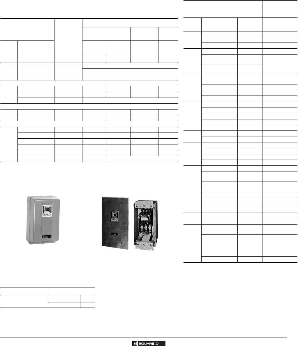
Separate Enclosures
NEMA Type 1 and Flush Mounting—Class 9991
3
12/2007 © 2007 Schneider Electric All Rights Reserved
Flush Mounting General Purpose separate enclosures for Type S
Sizes 0–2, 30–60 A, are provided with knock-outs in the cover for
field assembly of one Class 9999 push button or selector switch kit and
one Class 9999 pilot light kit. (Refer to page 5.) For Type S Size 3,
100 A, three closing plates are provided for installation of
Class 9001 Type K oiltight control units. For enclosure dimensions,
refer to page 13.
Table 3: Flush Mounting Selection
For Use With
NEMA Size
or
A Rating
Flush Mounting General Purpose (Components)
Flush Plates Mounting
Strap Pullbox
Class
Types
(All Pole
Arrangements)
Standard Stainless
Steel1
1The standard cabinet has a brushed finish.
Type Type
Type Type
2510 MBO & MCO
MO MF1 (with pullbox and plaster adjustment)
M1 MF2 (without pullbox but with mounting strap)
M1P
Magnetic Contactors
85022
2For contactors, replace reset assembly with proper closing plate. For flush mounting use Class 9999
Type SG2 except for Class 9991 Type SDF11 which requires a Class 9001 Type K51 or K11 closing plate. Class
9991 Type SEF11 is designed for contactors only, reset closing plates not required.
SBO & SCO 0, 1 SCF11 SCF12 SCF2 SCF1
SDO 2 SDF11 SDF12 SDF2 SDF1
SEO 3 SEF11 (enclosure complete)
Magnetic Starters
8536 SBO & SCO 0, 1 SCF11 SCF12 SCF2 SCF1
SDO 2 SDF11 SDF12 SDF2 SDF1
Lighting Contactors Non-Combination Electrically and Mechanically-held
89032
LO, LXO 20 A SDF13 — SDF2 SDF1
SMO 1–4 30 A SCF11 — SCF2 SCF1
SMO 10–13 30 A SCF13 — SCF2 SCF1
SPO 1–4 60 A SDF11 — SDF2 SDF1
SPO 10–13 60 A SDF13 — SDF2 SDF1
SQO 1–13 100 A SEF11 (enclosure eomplete)
Type SCG8, NEMA Type 1 Enclosure Flush Mounting Starter Pullbox and
Mounting Strap with
Plaster Adjustment Feature
Table 4: How to Order
To Order Specify: Catalog Number
Class Type
9991 DPG1
The NEMA Type 1 General Purpose separate
enclosures listed below, when used with open
style components, are equivalent to a standard
factory assembled control device.
Table 5: NEMA Type 1 Selection
For Use With
NEMA Type 1
Class 9991
Class Type Number
of Poles Type
2510
F and K All EN1
M-Sizes M0 and M1 All MG1
M-Size M1P All MG2
8501
CO All UE1
XO 2–12, 2–4 w/
Attachments UE7
XDO 2–8 w/o
Attachments
8502
SAO, SBO,
SCO 2–4 SCG7
SDO 2–4 SDG7
SEO 2–4 SEG7
SFO 2–4 SFG8
8536
SAO, SBO, SCO 2–4 SCG8
SDO 2–4 SDG8
SEO 2–4 SEG8 1
1Enclosure suitable for starter with melting alloy or solid state overload
relays only.
SFO 2–4 SFG8
SGO 3 SGG8 12
2Series B starter enclosure.
8702,
8736
SAO,SBO, SCO All SCG9 3
3For horizontally-arranged Class 8702 contactors and Class 8922
breakers replace reset assembly with a Class 9001 Type K51 closing
plate.
SDO All SDG9 3
8903
LO, LXO All LXG1 4
4If cover mounted control units are required, select oversized enclosure
listed on page 4.
SMO All SCG7 5
5For electrically-held contactors only.
SPO All SDG7 5
SQO All SFG8
8910
DP 1–2 DPG1
DPA12, 13, 22, 23,
32, 33, 42, 43 2–3 DPG1
DPA14, 24, 34, 44,
52, 53 2–4 DPG2
DPA62, 63 2–3 DPG3
DPA72, 73, 92, 93,
122, 123 2–3 DPG4
H, J, K, L & M All UE6
9050 AO (Single Head) All UE6
HO All UE6
9070
EO51, EO61, EO71,
K750, K1000 —SDG4
EO2, EO3, EO4,
EO15, EO16, EO18,
EO19, T75, T100,
T150, T200, T250,
T300, T350, T500
—LG1
EO1, EO17, T50 — UE7
4
© 2007 Schneider Electric All Rights Reserved 12/2007
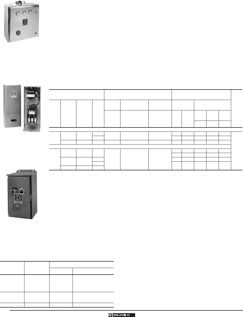
Separate Enclosures
Class 9991—NEMA Type 1, 4, and Oversize
Type SCW4
NEMA Type 4 Enclosure
Type SCG1
with Starter, Transformer,
and Fuse Block Installed
Type SCA4
NEMA Type 12 Enclosure
Table 7: Control Unit Selection Table Class 9001 Type K oiltight/watertight control units can be
easily installed in NEMA Types 4, 12, and oversized NEMA
Type 1 separate enclosures provided with closing plates.
When installing control units, simply remove the closing plates
and install the proper Class 9001 Type K components.
Convenient control unit kits complete with assembled and
pre-wired operators for quick installation are available as Class
9999 user modification kits. See Table 7 for contents of each
control unit kit. Class 9001 Type SK NEMA Type 4X corrosion
resistant control units may be used as an alternate.
Class 9999 Type Control Function
Kit Contents
Class & Type Description
SA3 Start-Stop
Pushbutton
1–9001 KR1B
1–9001 KR1R
1–9001 KN201
1–9001 KN202
2–9001 KA1
Start Operator
Stop Operator
“Start” Legend Plate
“Stop” Legend Plate
Contact Block
SC8 Hand-Off-Auto
Selector Switch
1–9001 KS43B
1–9001 KN260
1–9001 KA1
Selector Operator Switch
“Hand-Off-Auto” Legend Plate
Contact Block
SP28R Pilot Light (120 V) 1–9001 KP1R31 Red Pilot Light
NEMA Types 1, 4, and Oversized
For Addition of Control Circuit Transformer
The Class 9991 enclosures listed in Table 6 accept an open type Class 8502 or 8536, Type S, NEMA
Size 0, 1, 1P, or 2 contactor or starter along with a fused-control circuit transformer (Form F4T) to allow
field assembly of enclosed controllers. In the cover of the Class 9991 Type SCG1 enclosure,
knock-outs are provided for field addition of Class 9999 cover-mounted control units. All other Class
8502 and 8536 enclosures include a panel with space and drilling for an open-type device and a fused-
control circuit transformer. In addition, three closing plates are included in each cover for easy
installation of Class 9001 Type K or SK control units.
Oversized enclosures for open type Class 8903 Type L and LX 20 A, and Type S 30 and 60 A
electrically and mechanically held lighting contactors include a panel with space and drilling for an
open-type contactor and fused-control circuit transformer (Form F4T) and/or an auxiliary relay for use
with single pole pilot devices (Form R6). When an auxiliary relay is required, use a Class 8501 Type
XO11 relay. Three closing plates are provided as standard for easy installation of Class 9001 Type K
or SK control units. Note: A Class 9991 Type SCG1 NEMA Type 1 separate enclosure can also be
used for Class 8903 Type SMO30 A electrically-held lighting contactor if Form F4T (control
transformer) with or without cover control units is required.
Table 6: Enclosure and Transformer Selection
NEMA Type 12 Enclosures Modified for Outdoor Applications
(Do not use in salt air or corrosive environments)
Field Modifications for NEMA Type 3 dusttight, raintight, and sleet resistant outdoor applications
include: Use watertight conduit hubs or equivalent provision for watertight connection at the conduit
entrance.
Field Modifications for NEMA Type 3R dusttight, rainproof, and sleet resistant outdoor applications
include:
1. Use watertight conduit hubs or an equivalent provision for watertight connection at the conduit
entrance, when the conduit enters at a level higher than the lowest live part.
2. Add drain holes of 1/8 inch diameter to the bottom of the enclosure.
For Use With Class 9991 Enclosure Recommended Class 9070 1
Transformer Selection
1For price list and complete description, see the Class 9070 section. NOTE: Class 9991 Type SCG1 enclosure is provided with a Class 9999
Type SF4 fuse block as standard.
Fuse
Block
Class Type
NEMA
Size or
A Rating
No.
of
Poles
NEMA
Type 1 NEMA Type 4 2
2The standard cabinet has a brushed finish. For electropolished finish, specify Form G16.
NEMA
Type12 3
3NEMA Type 12 modified for outdoor use (see below).
Standard Extra Capacity
Type Type Type Type VA
100
VA
150
VA
300
VA
Type Type Type
Magnetic Contactors and Starters
8502 &
8536 4
4For contactors (Class 8502), a separate closing plate is provided with each enclosure to replace the reset mechanism with the exception of
Class 9991 Type SCG1 which requires a separate reset closing plate Class 9999 Type SG2.
SAO,SBO
& SCO 001, 0, & 1 1–3 SCG1 SCW4 SCA4 T50 50 VA T100 5
5For mounting in SCG1 enclosure a Class 9991 Type S1 adapter bracket is also required.
T150 5—
Class
9999
Type
SFR4
4–5 T10 5100 VA — T150 5—
SDO 2 2–5 SDG4 SDW4 SDA4 T100 100 VA — T150 T300
Lighting Contactors Non-Combination
8903
LO,
LXO 20A All
SDG3 SDW3 SDA3
T5050 VA———
T50 50 VA T100 5T150 5—
SMO 6
6Mechanically held.
30A 1–3 T10 5100 VA — T150 5—
4–5 T100 100 VA — T150 T300
SPO 660A 2–5
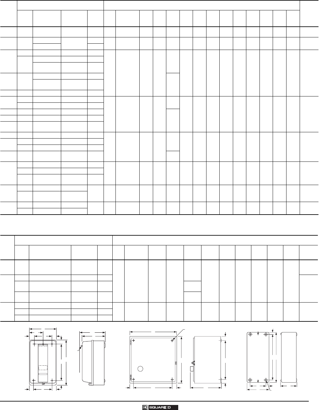
Separate Enclosures
Approximate Dimensions—Class 9991
5
12/2007 © 2007 Schneider Electric All Rights Reserved
Table 8: NEMA Type 1 – General Purpose Enclosures (Standard)
Class
9991
Type
For Use With Dimensions (inches/millimeters)
Weight
(lb)
Class Type NEMA Size
or A Rating
No. of
Poles
Fig.
No.
Mounting
Screws ABCDEF GHI J KL
LXG1 8903 LO, LXO 20 A 2–12 1 — 7.81
198
12.69
322
6.03
153 —1.09
28
10.50
267
1.09
28
1.09
28
5.63
143
5.75
146
1.09
28
5.63
143 8
DPG1 8910 DP 20–40 A 1–21 (4) #10 4.85
123
8.5
216
4.03
102
2.42
62
0.109
3
5.75
146
0.531
13
0.92
23
3.00
76
3.75
95 —— 2
DPA 1–3
SCG7
8903 SMO (E.H.) 30 A All
1 (3) #10 6.00
152
10.00
254
5.28
134
3.00
76
0.88
22
8.13
206
1.00
25
0.94
24
4.13
105
5.00
127 —— 4
8502
SAO 00 2–3
SBO
SCO
0
1All
SCG8 8536
SAO 00 2–3
5.56
141
SBO
SCO
0
1All
DPG2 8910 DP — —
SDG7 8903 SPO (E.H.) 60 A 2–12
1(4)
1/4 "7.81
198
12.69
322
6.03
153
—1.09
28
10.50
267
1.09
28
1.09
28
5.63
143
5.75
146
1.09
28
5.63
143 8
8502 SDO 2 All
SDG8 8536 SDO 2 All
6.31
160
DPG3 8910 DPA — —
DPSG2 8911 DPS ——
SEG7 8502 SEO 3 All
1(4)
3/8 "11.44
286
21.81
554
8.00
203 —1.53
39
18.75
476
1.53
39
1.53
39
8.38
213
7.75
197
1.53
39
8.38
213 23
SEG8 8536 SEO 3 All
8911 DPSG63 to 93 — All
DPG4 8910 DPA — — 8.38
213
SFG8
8502 SFO 4 All
2(4)
7/16 "11.25
286
25.15
639
8.99
228
8.60
218
1.25
32
1.25
32
22.31
567
1.42
36
0.44
11 ——— 34
8536 SFO 4 All
8903 SQO
(E.H. & M.H.) 100 A All
SCG9
8702 1
1Standard enclosure has space for a fused control transformer, Form F4T, on Sizes 0–2.
SBO, SCO 2
All 2 (4)5/16 "11.88
302
11.88
302
7.41
188
9.75
248
1.06
27
1.06
27
9.75
248
1.06
27
0.31
8——— 16
8922 ETBC20,
ETBC36 —
SDG9 8702 1SCO 2 All 2 (4)5/16 "14.88
378
14.13
359
7.56
192
12.75
324
1.06
27
1.06
27
12.00
305
1.06
27
0.31
8——— 24
8922 ETBC60 —
Table 9: NEMA Type 1 – General Purpose Enclosures (Oversize)
Class
9991
Type
For Use With Dimensions (inches/millimeters) (See Figure 2)
Class Type NEMA Size
or A Rating
No. of
Poles
Fig.
No.
Mounting
Screws ABCDEFGHIWeight
(lb)
SDG3 8903
LO, LXO
SMO (M.H.)
SPO (Form F4T)
20 A
30 A
60 A
All
2(4)
5/16 "14.88
378
14.13
359
7.56
192
12.75
324
1.06
27
1.06
27
12.00
305
1.06
27
0.31
8
15
SDG4
8502 SDO (Form F4T) 2 All
21
8536 SDO (Form F4T) 2 All 7.66
194
9070 EO51, EO61, EO71,
T750, T1000 —— 7.56
192
SCG1
8502 SBO, SCO (Form F4T) 0, 1 All
3(4)
9/32" 6.34
161
15.88
403
5.19
132
4.66
118
0.84
21
14.38
365
0.75
19
0.28
7
0.35
9SCG18536 SBO, SCO (Form F4T) 0, 1 All
8903 SMO (E.H.) (Form F4T) 30 A All
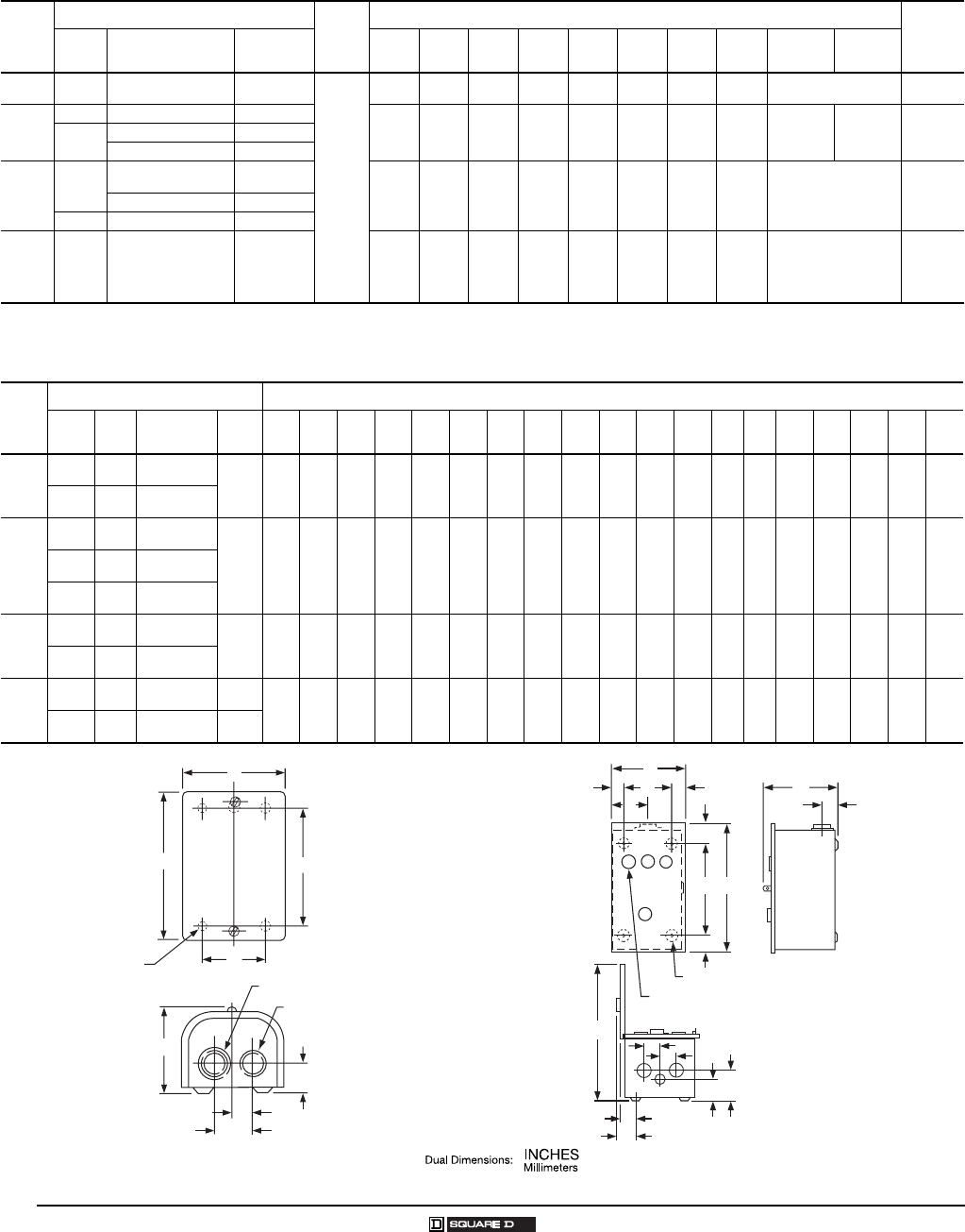
Figure 1 Figure 2 Figure 3
A
D
KL
K
E
B
F
HIH
G
RESET
C
J
Pilot
Light
A
B
EDF
Reset
C
H
G
H
(4) I Dia.
Mounting Holes
H
B
G
C
D
A(4) I Dia. Mtg. Holes
E
6
© 2007 Schneider Electric All Rights Reserved 12/2007
Separate Enclosures
Class 9991—Approximate Dimensions
Table 10: NEMA Type 1 – General Purpose Enclosures
Class
9991
Type
For Use With
Figure
Dimensions (inches/millimeters) (see Figure 4)
Weight
(lb)
Class Type No. of
Poles ABCDEF GHJ L
UE1 18501 CO All
4
3.63
92
5.28
134
3.31
84
1.88
48
3.63
92
1.06
27
1.50
38
1/4 ” 11
/2 ” – 3/4 ”2
UE6
8910 H, J, K, L & M All
4.91
125
5.75
146
5.53
140
3.50
89
4.38
111
1.56
40
2.00
51
9/32 ”
1/2 ” – 3/4 ”
1 ” – 11/4 ”
1/2 ” – 3/4 ”2
9050 AO (Single Head) All
HO All
UE7 8501 XO 2–12, 2–4 w/
Attachments 4.87
125
7.79
196
7.53
191
3.50
89
6.38
162
1.31
33
1.88
48 #10 1/2 ” – 3/4 ”4
XDO 2–8
9070 EO1, EO17, T25, & T50 —
LG1 29070
EO2, EO3, EO4, EO15,
EO16, EO18, EO19,
K75, K100, K150,
K200, K250, K300,
K350, & K500
—7.53
191
9.78
248
5.91
150
6.13
155
8.38
213
1.31
33
1.88
48
9/32 ”1/2 ” – 3/4 ” – 1 ” 210
1Class 9991 UE1 has only three mounting holes; 2 in the bottom as shown in Figure 4 and 1 centered at the top.
2Class 9999 LG1 has three knockouts, top and bottom.
Table 11: NEMA Type 3R – Rainproof and Sleet–Resistant Enclosures
Class
9991
Type
For Use With Dimensions (inches/millimeters) (see Figure 5)
Class Type NEMA Size
or A Rating
No. of
Poles A B C D1D2E F G1G2H1H2J K L M N P K.O.
X
K.O.
Y
SCH2
8502
8536
SBO,
SCO 0, 1
All 8.83
224
12.30
312
7.12
181
1.39
35
1.44
37
6.00
152
7.50
191
2.61
66
2.19
56
2.08
53
2.62
66
14.28
363
1.37
35
1.37
35
1.88
48
4.38
111
1.83
46
1/2
3/4
1
1/2
3/4
1
8903 SMO 30
A
SDH1
8502
8536 SDO 2
All 9.83
250
16.30
414
6.62
219
1.39
35
1.44
37
7.00
178
11.50
192
2.61
66
2.19
56
2.08
53
2.62
66
16.78
426
1.31
33
1.75
44
2.13
54
4.88
124
1.83
46
1
11/4
11/2
1/2
3/4
8903 LO
LXO
20
A
8903 SPO 60
A
SEH1
8502
8536 SEO 3
All 12.63
326
25.30
643
8.62
219
1.39
35
1.44
37
10.00
254
20.60
521
2.61
66
2.19
56
2.08
53
2.62
66
19.78
502
1.31
33
2.31
59
2.69
68
6.38
162
1.83
46
1
11/4
2
21/2
1/2
3/4
8903 SQO 100
A
SFH1
8502
8536 SFO 4 All 12.63
326
40.30
1024
9.12
232
1.39
35
1.44
37
10.00
254
35.50
902
2.61
66
2.19
56
2.08
53
2.62
66
20.28
515
1.31
33
2.31
59
2.69
68
6.38
162
1.83
46
1
11/4
2
21/2
1/2
3/4
8903 SVO 200
A2–3
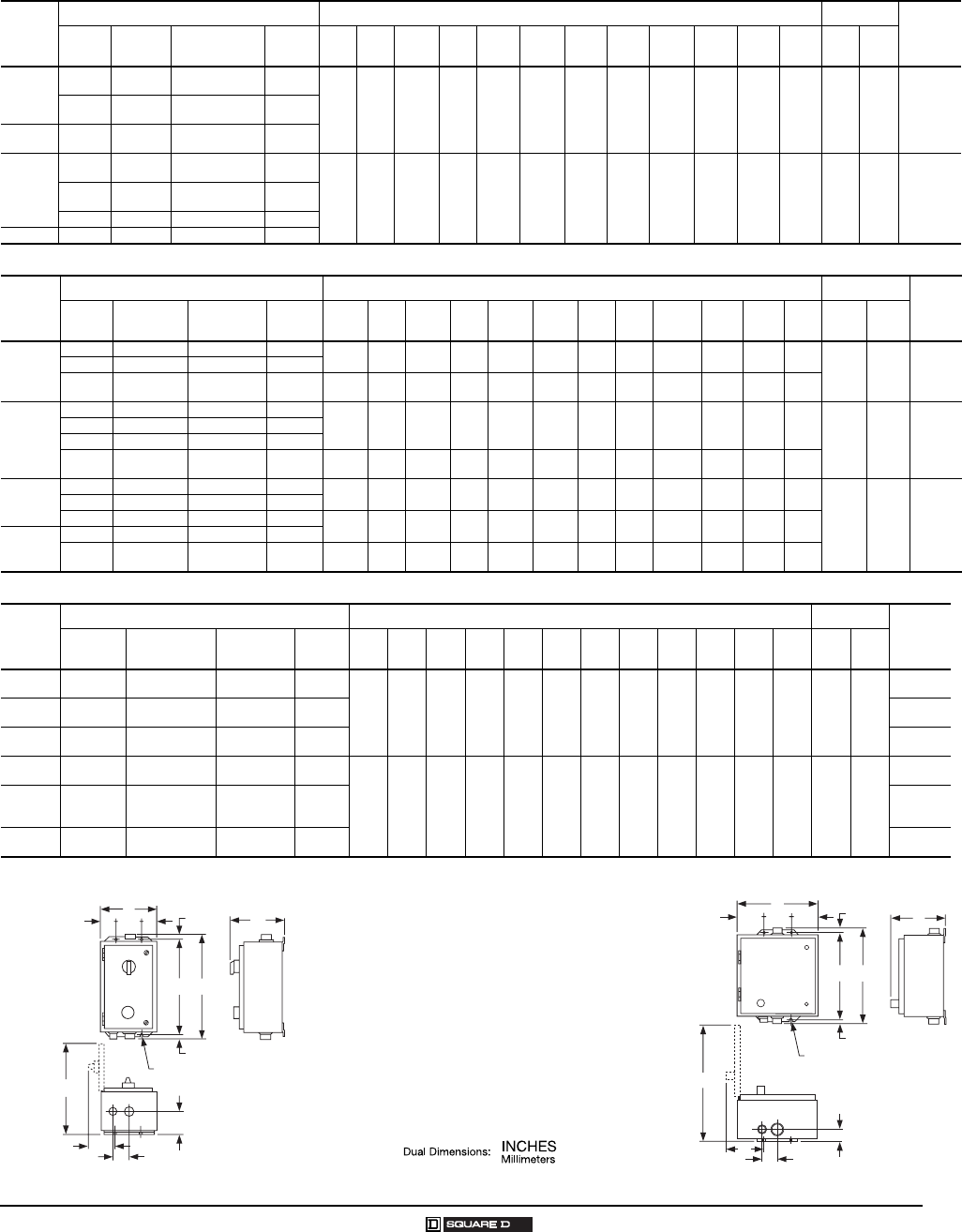
Figure 4 Figure 5
A
E
B
D
C
G2
G
F
(4) H Dia.
Mounting Holes “J” KO Top and Bottom
“L” KO Top and Bottom
A
E
D1 D2
N
G1
G2
FB
C
P
J
L
K
H1
H2
MM
XX
Y
(4) .36 Dia. Mounting Holes
(3) Closing Plates
Separate Enclosures
Approximate Dimensions—Class 9991
7
12/2007 © 2007 Schneider Electric All Rights Reserved
Table 12: NEMA Type 4X – Watertight and Corrosion Resistant Enclosures
Class
9991
Type
For Use With Dimensions (inches/millimeters) (see Figure 6) Hub Dia.
Weight
(lb)
Class Type NEMA Size
or A Rating # PolesABC DE F G H I J K L W 1X 2
SCW20
8903 SMO
(E.H.) 30A All
6.50
165
6.44
164
12.13
308
0.75
19
5.00
127
8.25
210
1.69
43
3.34
85
10.06
256
1.31
33
2.13
54
0.31
8
3/4 ”1 ”78502 SBO,
SCO 0, 1 All
SCW21 8536 SBO,
SCO 0, 1 All
SDW20
8903 LO,
LXO 20A All
8.50
216
7.06
179
13.88
352
0.75
19
7.00
178
10.50
267
1.69
43
3.91
99
11.94
303
1.63
41
2.38
60
0.31
8
3/4 ”11/2 ”13
8903 SPO
(E.H.) 60A All
8502 SDO 2 All
SDW21 8536 SDO 2 All
Table 13: NEMA Type 4 – Watertight Enclosures (Standard)
Class
9991
Type
For Use With Dimensions (inches/millimeters) (see Figure 6) Hub Dia.
Weight
(lb)
Class Type NEMA Size
or A Rating
No. of
Poles ABCDEFGHI JKLW
1X 2
SCW11
8903 SMO 30 A All 6.38
162
7.13
181
13.19
335
1.56
40
3.25
83
12.00
305
0.59
15
1.88
48
11.78
299
1.63
41
2.31
59
0.31
83/4 ”1 ”12
8502 SBO, SCO 0, 1 All
8536 SBO, SCO 0, 1 All 6.38
162
7.81
198
13.19
335
1.56
40
3.25
83
12.00
305
0.59
15
1.88
48
11.78
299
1.63
41
2.31
59
0.31
8
SDW11
8903 LO, LXO 20 A All 8.13
206
7.88
200
16.19
411
1.56
40
5.00
127
15.00
381
1.09
28
1.94
49
14.75
375
2.00
51
2.63
67
0.31
83/4 ”11/2 ”18
8903 SPO 60 A All
8502 SDO 2 All
8536 SDO 2 All 8.13
206
8.56
217
16.19
411
1.56
40
5.00
127
15.00
381
1.09
28
2.88
73
14.75
375
2.00
51
2.63
67
0.31
8
SEW11
8903 SQO 100 A All 18.15
461
8.77
223
32.21
818
3.08
78
12.00
305
30.50
775
0.86
22
3.67
93
26.71
678
2.58
66
3.19
81
0.44
11
3/4 ”21/2 ”51
8502 SEO 3 All
8536 SEO 3 All 18.15
461
9.58
243
32.21
818
3.08
78
12.00
305
30.50
775
0.86
22
4.48
114
26.71
678
2.58
66
3.19
81
0.44
11
SFW11
8536 SFO 4 All
8502 SFO 4 All 18.15
461
8.77
223
32.21
818
3.08
78
12.00
305
30.50
775
0.86
22
3.67
93
26.71
678
2.58
66
3.19
81
0.44
11
Table 14: NEMA Type 4 – Watertight Enclosures (Oversize)
Class
9991
Type
For Use With Dimensions (inches/millimeters) (see Figure 7) Hub Dia.
Weight
(lb)
Class Type NEMA Size
or A Rating
No. of
Poles ABCDEFGHI J KLW
1X 2
SCW2 8702
8736 SCO 1 All
12.63
321
7.81
198
14.69
373
2.56
65
7.50
191
13.50
343
0.59
15
3.88
98
18.41
468
1.66
42
2.31
59
0.31
8
3/4 ”1 ”
23
SCW3 8810 SBO
SCO
0
1All 19
SCW4 8502
8536
SBO, SCO
(Form F4T) 0, 1 All 24
SDW2 8702
8736 SDO 2 All
14.88
378
7.25
184
16.19
411
2.56
65
9.75
248
15.00
381
0.38
10
3.88
98
20.88
530
1.72
44
2.63
67
0.31
8
3/4 ”11/2 ”
25
SDW3 8903
LO, LXO
SMO, SPO
(Form F4T)
20 A
30 A
60 A
All 29
SDW4 8502
8536
SDO
(Form F4T) 2All 28
1 Bottom Only. 2 Top and Bottom.
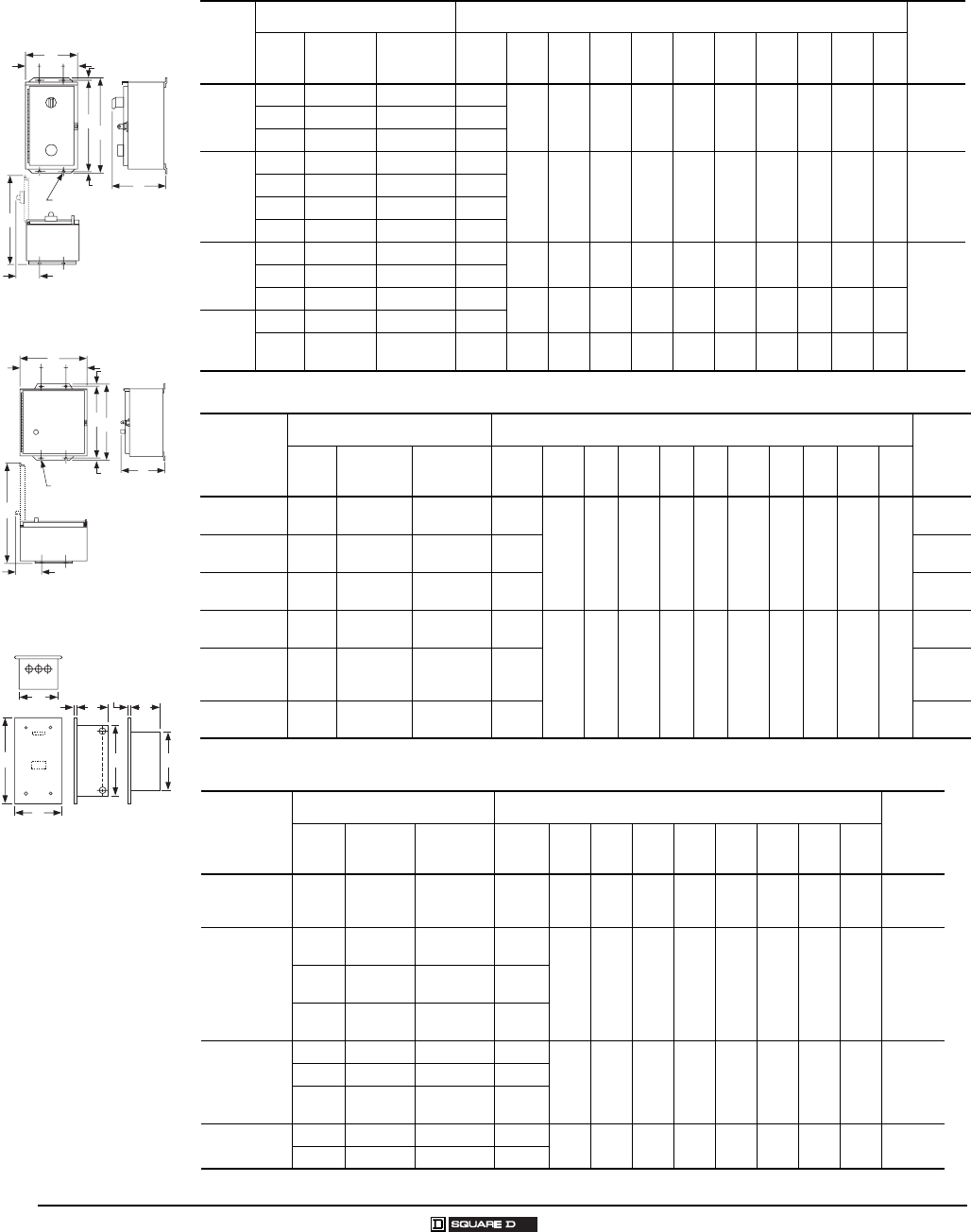
Figure 6 Figure 7
A
DEDG
G
B
G
F
I
WX
J
H
K
(4) L Mounting Holes
A
DEDG
FC
J
K
H
I
WX
B
G
(4) L Mounting Holes
8
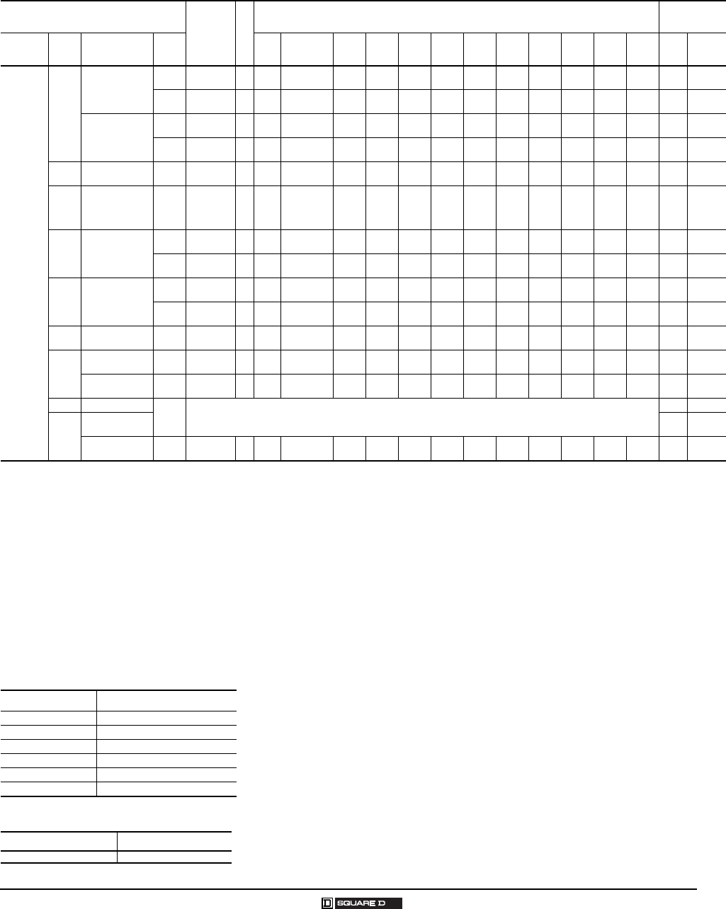
© 2007 Schneider Electric All Rights Reserved 12/2007
Separate Enclosures
Class 9991—Approximate Dimensions
A
DED G
F
C
GB
H
I
(4) J Dia. Mounting Holes
A
DED G
FC
B
I
H
G
(4) J Dia. Mounting Holes
C
A
B
HE G
DF
H
Figure 10
Figure 9
Figure 8
Table 15: NEMA Type 12 – Dusttight and Driptight Enclosures (Standard)
Class
9991
Type
For Use With Dimensions (inches/millimeters) (see Figure 8)
Weight
(lb)
Class Type NEMA Size
or A Rating
No. of
Poles ABCDEF GHI J
SCA11
8502 SBO, SCO 0, 1 All
6.38
162
8.53
217
12.75
324
1.56
40
3.25
83
12.00
305
0.38
10
3.56
90
12.50
318
0.31
8108536 SBO, SCO 0, 1 All
8903 SMO 30 A All
SDA11
8502 SDO 2 All
8.13
206
9.28
236
16.00
406
1.56
40
5.00
127
15.00
381
0.50
13
3.56
90
15.38
391
0.31
815
8536 SDO 2 All
8903 LO, LXO 20 A All
8903 SPO 60 A All
SEA11
8903 SQO 100 A All 18.15
461
9.24
235
31.50
800
3.08
78
12.0
305
30.50
775
0.50
13
3.67
93
26.71
678
0.44
11
51
8502 SEO 3 All
8536 SEO 3 All 18.15
461
9.58
243
31.50
800
3.08
78
12.0
305
30.50
775
0.50
13
4.48
114
26.71
678
0.44
11
SFA11
8536 SFO 4 All
8502 SFO 4 All 18.15
461
9.24
235
31.50
800
3.08
78
12.0
305
30.50
775
0.50
13
3.67
93
26.71
678
0.44
11
Table 16: NEMA Type 12 – Dusttight and Driptight Enclosures (Oversized)
Class 9991
Type
For Use With Dimensions (inches/millimeters) (see Figure 9)
Weight
(lb)
Class Type NEMA Size
or A Rating
No. of
Poles ABCDEFGHI J
SCA2 8702
8736 SCO 1 All
11.88
302
7.75
197
13.5
343
2.56
65
6.75
171
12.75
324
0.38
10
3.66
93
18.13
460
0.31
8
17
SCA3 8810 SBO
SCO
0
1All 18
SCA4 8502
8536
SBO, SCO
(Form F4T) 0, 1 All 19
SDA2 8702
8736 SDO 2 All
14.88
378
7.88
200
16.00
406
2.56
65
9.75
248
15.00
381
0.50
13
3.66
93
21.25
540
0.31
8
24
SDA3 8903
LO, LXO
SMO, SPO
(Form F4T)
20 A
30 A
60 A
All 27
SDA4 8502
8536
SDO
(Form F4T) 2All 27
Table 17: Flush Mounting General Purpose Enclosures
Class 9991
Type
For Use With Dimensions (inches/millimeters) (see Figure 10)
Weight
(lb)
Class Type NEMA Size
or A Rating
No. of
Poles ABCDEFGH
SDF13
(w/SDF1
& SDF2)
8903 LO, LXO 20 A All 15.19
386
8.94
227
7.63
194
12.88
327
5.44
138
10.94
278
5.13
130
0.38
10 17
SCF11
(w/SDF1
& SDF2)
8502 SBO,
SCO 0, 1 All
13.44
341
7.19
183
5.88
149
11.13
283
4.75
121
9.19
233
4.50
114
0.38
10 108536 SBO,
SCO 0, 1 All
8903 SMO
(E.H.) 30 A All
SDF11
(w/SDF1
& SDF2)
8502 SDO 2 All
15.19
386
8.94
227
7.63
194
12.88
327
5.44
138
10.94
278
5.13
130
0.38
10 17
8536 SDO 2 All
8903 SPO
(E.H.) 60 A All
SEF11 8502 SEO 3 All 31.00
787
16.75
425
14.25
362
26.25
667
8.00
203 ——
0.18
548
8903 SQO 100 A All
Magnetic Coils
Class 9998
9
12/2007 © 2007 Schneider Electric All Rights Reserved
NEMA Size 5 E-Coil Modification Kit
Classes 8502, 8536, 8538, 8539, 8606, 8630, 8640, 8647, 8650, 8651, 8702, 8736, 8738, 8739, 8810, 8811, 8812, 8910
and 8903
Consisting of:
•E-Coil
•Armature
•Bottom Magnet
•15 A, 600 V Fuse and Holder (Class 9999SFR)
•Instruction Manual
Table 18: Replacement AC Magnet Coils for Magnetic Contactors and Starters
(Refer to Table 21 on page 10 for listing of mechanically held unlatch coils)
Equipment To Be Serviced Coil
Prefix or
Class
and Type
Hz
Suffix Number (Complete Coil Number Consists of Prefix or Class
and Type Followed by Suffix Number.) Coil VA
Device Size Type Poles 24 V 110-115 V 120 V 208 V 220 V 240 V 277 V 380 V 440 V 480 V 550 V 600 V In-
rush Sealed
Coils
for
Present
Design
Magnetic
Contactors
and
Starters
Classes
8502,
8536,
8538,
8539,
8606,
8630,
8640,
8647,
8650,
8651,
8702,
8736,
8738,
8739,
8810,
8811,
8812,
8903,
8910
and
8940
(except
NP)
8911
8965
30 A
L
2–6 9998L 60
50
23
24
—
44
44
45
50
52
—
53
53
54
55
—
—
60
—
62
62
63
—
65
65
66
150
140
30
30
8–12 9998LH 60
50
23
24
—
44
44
45
50
—
—
53
53
54
55
—
—
60
—
62
62
—
—
65
65
—
180
170
35
35
LX
(Latch)
2–4 9998L 60
50
23
24
—
44
44
45
50
52
—
53
53
54
55
—
—
60
—
62
62
63
—
65
65
66
150
140
—
—
6–12 9998LH 60
50
23
24
—
44
44
45
50
—
—
53
53
54
55
—
—
60
—
62
62
—
—
65
65
—
180
170
—
—
00 SA
(Series B) All 9998SAC 60
50
23
—
—
45
45
—
52
—
—
54
54
—
55
—
59
—
—
62
62
—
—
65
65
—
165
—
33
—
00
0, 1,
1–P &
30 A
SA (Series A)
SB, SC & SM All 31041-400 60
50
20
22
—
42
42
43
48
—
—
51
51
53
52
—
56
57
58
60
—
60
61
62
62
64
245
232
27
26
2 &
60 A SD & SP
2 & 3 31063-409 60
50
16
17
—
38
38
39
44
—
—
47
47
48
49
—
53
54
—
57
57
—
—
60
60
61
311
296
37
36
4 & 5 31063-400 60
50
16
17
—
38
38
39
44
—
—
47
47
48
49
—
53
54
—
57
57
—
—
60
60
61
438
429
38
37
3 &
100 A
DPA12_,
SE, SQ &
SYD138
2 & 3 31074-400 60
50
16
17
—
38
38
39
44
—
—
47
47
48
49
—
53
54
—
57
57
—
—
60
60
61
700
678
46
47
4 & 5 31091-400 60
50
—
—
—
38
38
39
44
—
—
47
47
48
49
—
53
54
—
57
57
58
—
60
60
61
1185
1260
85
89
4 &
200 A
SF, SV &
SYD230 All 31091-400 60
50
—
—
—
38
38
39
44
—
—
47
47
48
49
—
53
54
—
57
57
58
—
60
60
61
1185
1260
85
89
5 &
300 A
SG, SX &
SYD368 Series A All 31096-400 60
50
—
—
—
09
09
10
15
—
—
18
18
—
19
—
21
22
—
24
24
—
—
29
29
30
2970
2970
212
250
SG, SX &
SYD368 Series B All 31096-320 60
50
—
—
50
50
50
50
51
—
52
52
52
52
53
—
54
54
55
55
55
55
—
—
—
—
1300
—
14
—
6 & 7 SH & SJ
2–3 Coil Part Number 3110440050 (All System Voltages)
1780 48
400,
600 &
800 A
SY, SZ, SJ
(Elect. Held) 1960 59
SY, SZ, SJ
(Mech. Held) 2–3 31104-418 60
50
—
—
—
09
09
—
15
—
—
18
18
—
19
—
—
—
—
24
24
—
—
29
29
—
1530
1250
—
—
Table 19: Coil Modification Kits
Catalog Number Description
9998SG120 Coil Modification Kit 120 V
9998SG480 Coil Modification Kit 480 V
9998SG277 Coil Modification Kit 277 V
9998SG208 Coil Modification Kit 208 V
9998SG240 Coil Modification Kit 240 V
9998SG380 Coil Modification Kit 380 V
Table 20: How to Order
To Order Specify: Catalog Number
31041-409-38
Magnetic Coils
Class 9998
10
© 2007 Schneider Electric All Rights Reserved 12/2007
Table 21: Replacement AC Magnet Coils for Relays, Timers and Contactors
Equipment
To Be Serviced Coil
Prefix
or Class
and Type
Hz
Suffix Number
(Complete Coil Number Consists of Prefix or Class and Type Followed by Suffix Number.) Coil VA
Device Type Poles 24 V 110–
115 V 120 V 208 V 220 V 240 V 277 V 380 V 440 V 480 V 550 V 600 V In-
rush Sealed
Classes 8501 and 9050
8501
(Relays) X All 9998-X 1
1To order an unlatch coil, add the letter “L” to the type number and the letter “B” to the suffix number.
Example: For a 120 V 60 Hz unlatch coil, order a Class 9998 Type XL44B.
60
50
23
24
—
44
44
—
51
52
52
53
53
—
55
—
—
—
—
62
62
—
—
65
65
—
148
143
23
25
9050
(Timer)
A All 2959-S49- 60
50
W25A
W25B
W31B
W32A
W32A
W32B
W34A
W34B
W34B
W35A
W35A
W35B
W35B
W36A
—
—
W37B
W38A
W38A
W38B
W38B
W39A
W39A
W39B
74
68
17
17
B 2
2Series C (Double Pole) and Series E (Single Pole).
All 31017-400- 60
50
33
34
—
—
54
55
61
—
61
63
63
64
65
—
—
—
70
72
72
73
73
75
75
76
165
155
27
27
Mechanically Held Unlatch Coils—Classes 8508 and 8903
A latch coil is also used with mechanically held devices. For selection of latch coils for mechanically held relays, refer to page 16-118.
8903
(Lighting
Contactors)
LX All 9998LX 60
50
23
—
—
44
44
—
51
—
—
53
53
—
55
—
—
—
—
62
62
—
—
65
65
—
25
—
—
—
SM, SP All 2959-S13 60
50
W23B
W24B
—
W30B
W30B
W31B
W33A
—
—
W33B
W33B
W34B
W34A
—
—
W36A
—
W36B
W36B
—
—
W37B
W37B
—
80
—
—
—
SQ, SV, SX,
SY, SZ All 31096-416 60
50
03
—
—
09
09
—
15
—
—
18
18
—
20
—
—
22
—
24
24
—
—
28
28
—
550
—
—
—
SJ All 31123-403 60
50
03
——
09
09
—
15
——
18
18
—
20
—
—
22
—
24
24
—
—
28
28
—
2100
—
—
—
Table 22: Replacement DC Magnet Coils for Magnetic Relays and Timers
Equipment To Be Serviced Coil Prefix
or Class
and Type
Suffix Number
(Complete Coil Number Consists of Prefix or Class and Type Followed by Suffix Number.) Coil
Burden
Watts
Class Type Poles 6 V 12 V 18 V 24 V 32 V 48 V 64 V 72 V 90 V 110 V 115/
125 V 220 V 230/
250 V
8501
(Relays)
XD All 9998 XD 19 28 34 37 40 46 49 52 55 — 58 — 67 18
XDL — 9998 XDL 19 28 34B 37B 40B 46B 49B 52B 55B — 58B — 67B 50
XUD All 9998 XUD 19 28 — 37 — 46 — — — — 58 1—67
1
1Not dual voltage rated; 250 Vdc only.
16
9050
(Timers)
C 31018-400- 22 31 — 40 — 49 — — — — 61 — 70 14
H 4491S1 W21 W24 — W27 — W30 — — — — W34 — W37 14
Table 23: Replacement Coil for 8903 Panel Board Lighting Contactors
Class Type Replacement Solenoid Catalog Number
8903 PB
120 V 9998PBV02
208 V 9998PBV08
240/277 V 9998PBV39
480 V 9998PBV28
Table 24: How to Order
To Order Specify: Catalog Number
•Class Number
•Type Number
Class Type
9998 PBV02
Replacement Parts Kits
Class 9998
11
12/2007 © 2007 Schneider Electric All Rights Reserved
Class 9998 replacement parts kits are
available for servicing Square D®
relays, contactors, and starters as well
as pressure, vacuum, and float
switches. Each kit contains the
necessary movable and stationary
contacts, contact springs (when required—NEMA Size 3 and
above do not include contact springs, and springs are not
available), and additional hardware required to service the
devices listed below. When servicing devices having more
poles than contained in the corresponding kit, it may be
necessary to order an additional kit.
Table 25: Magnetic Contactor and Starter Contact Kits
for Present Designs
Equipment To Be Serviced No. of
Poles
in Kit
Class
9998
Parts Kit
Type No.
Class Type NEMA Size
or A Rating
8502
8536
8538
8539
8547
8549
8606
8630
8640
8647
8702
8736
8738
8739
8810
8811
8812
8940
SA-, (Series B) 00 3 SJ1
SB- 0 3
4
SL2
SL12
SB-, SC-(Power Pole Adder) 0 & 1 1 SL22
SC- 1 & 1P
1
3
4
SL3
SL13
SD- 2 3
4
SL4
SL14
SD-(Power Pole Adder) 2 1 SL24
SE- 3 2
3
SL6
SL7
SF- 4 2
3
SL8
SL9
SG- 5 2
3
SL10
SL11
SH- 6 2
3
SL25
SL26
SJ- 7 2
3
SL30
SL31
8903
L (Series C) & LX (Series B) 30 A 4 RA5B
SM- 30 A 3
4
SL3
SL13
SP- 60 A 3
4
SL4
SL14
SQ- 100 A 2
3
SL6
SL7
SV- 200 A 2
3
SL8
SL9
SX- 300 A 2
3
SL10
SL11
SY- 400 A 2
3
SL25
SL26
SZ- 600 A 2
3
SL32
SL33
SJ- 800 A 2
3
SL30
SL31
PBM, PBP 30, 60 A 2 PB2
PBN, PBQ 75, 100 A
PBM, PBP 30, 60 A 3 PB3
PBN, PBQ 75, 100 A
PBR, PBV, PBW 150, 200, 225 A 2 PB14
PBR, PBV, PBW 150, 200, 225 A 3 PB15
Table 26: Magnetic Contactor and Starter Contact Kits
for Obsolete Designs
Equipment To Be Serviced No. of
Poles in
Kit
Class 9998
Parts Kit Type
No.
Class Type NEMA Size
8502 &
8536 1
1Includes reversing, two speed and similar devices. Select coil based on NEMA size of basic
starter or contactor
SA-, (Series A) 00 3
4
SL2
SL12
8903 LL, L (Series A, B) & LX (Series A) 20 A 4 RA5
Table 27: Class 8965 Replacement Contact Kits
Device
Type
Device
Series
Class 9998
Kit Type
Device
Series
Class 9998
Kit Type
DPR53
DPR63
A
A
DRC5 1
DRC6 1
1Single pole kits.
——
RO10 A & B RA10 C RA14
RO11 A & B RA11 C RA15
RO12 A & B RA12 C RA16
RO13 A & B RA13 C RA17
Table 28: Manual Starter Contact Kits
Equipment To Be Serviced No. of Poles
in Kit
Class 9998 Parts Kit
Type No.
Class Type NEMA Size
2510
Manual Starters M-, T- M-0 3 ML1
M-1 & M-1P 3 ML2
Table 29: Replacement Control Transformers (150 VA)
Class 8502, 8536 Type S Size 6
Voltage
Part Number
60 Hz 50 Hz
240/480–120 220/440–110 3110451250
208–120 — 3110451252
277–120 — 3110451253
— 380–110 3110451254
600–120 550–110 3110451251
120–120 110–110 3110451255
240–120 220–110 3110451256
Table 30: Replacement Control Transformers (200 VA)
Class 8502, 8536 Type S Size 7
Voltage
Part Number
60 Hz 50 Hz
240/480–120 220/440–110 3112350150
208–120 — 3112350152
277–120 — 3112350153
— 380–110 3112350154
600–120 550–110 3112350151
120–120 110–110 3112350155
240–120 220–110 3112350156
Table 31: Class 8910, 8911 and 8965 Replacement
Contact Kits
Device To Be Serviced Class 9998
1-Pole
Type
3-Pole
Type
Class 8910
Type
Class 8911
Type
Class 8965
Type Series
SYD138
SYD230
SYD368
—
—
—
—
—
—
—
—
—
—
—
—
SL27
SL28
SL29
DPA_20A
DPA_25A
DPA_30A
DPA_40A
DPSO1_
DPSO2_
DPSO3_
DPSO4_
DPR1_
DPR2_
DPR3_
DPR4_
B
B
B
B
DRC1
DRC2
DRC3
DRC4
—
—
—
—
DPA_50A
DPA_60 1
DPA_75A
DPA_90A
DPA_120A
1For class 8911, 60 A starter, use the 9998DRC7 contact kit.
DPSO5_
DPSO6_
DPSO7_
DPSO9_
—
DPR5_
DPR6_
—
—
—
A, B
A, B
A
A
A
DRC5
DRC6
DRC7
DRC9
DRC12
—
—
—
—
—
Table 32: How to Order
To Order Specify: Catalog Number
•Class Number
•Type Number
Class Type
9998 SL6

12
© 2007 Schneider Electric All Rights Reserved 12/2007
Replacement Parts Kits
Class 9998
Table 33: Contact Units for Melting Alloy Type Overload Relays
One normally-closed contact, Class 9998 Type SO1, is provided in each overload relay block on Type
S starters Sizes 00–4 and Size 6. On the Type S Size 5, a normally-closed contact is provided with
each of the three overload relay blocks. The Class 9998 Type SO1 contact unit listed below is provided
as standard in each Class 9065 Type M melting alloy overload relay. Contact modules can be easily
replaced and are identified in Table 33. Isolated overload relay alarm circuit contacts are available as
an optional feature. A pilot light or alarm bell can be wired in series with this contact to indicate that the
overload relay has tripped. For further information on isolated alarm contacts, refer to Class 9999
Types SO4 and SO5.
Table 34: Class 9998 Type UB Universal Baseplate
A universal baseplate may be used to retrofit a Square D® Type S NEMA starter into an application
which is currently using a competitor’s NEMA starter. The universal baseplate is a metal plate which
attaches to the panel in the location of the starter to be replaced. The Type S starter then mounts to the
baseplate. It is available for NEMA Sizes 00 through 4, and mounting screws are provided with each
plate.
The universal baseplate adapter allows the Type S starter to replace the following competitor’s
starters:
Table 35: Melting Alloy Overload Relay Jumper Strap Kits
Jumper strap kits are for use on three-phase manual or magnetic starters with melting alloy overload
relays only, where a three-phase starter is used to control a single-phase motor. These kits will include
two jumper straps, a wiring diagram showing how to wire a three-phase starter to control a single-
phase motor, and single-phase (one thermal unit) selection tables.
Magnetic Starter
Description Parts Kit Number
NEMA Size Type Series
00–4 & 6 SA–SF, SH A & B Standard N.C. contact unit Class 9998 Type SO1 1
1The Type SO1 is also the replacement contact unit for Class 9065 Type M melting alloy overload relays.
5SGA
Standard N.C. contact unit 31102–514–50
N.C. and N.O. alarm (three point) contact unit 31102–514–51
Competitor Starter
Type UB01 Type UB02 Type UB03 Type UB04
NEMA Size
Allen-Bradley 509 0, 1 2 3 4
Allen-Bradley 709 1 2 3 4
Cutler Hammer Freedom Series 00, 0, 1 2 3 4
Furnas ESP100 0, 1 2 3 4
Furnas INNOVA 0, 1 2 3 4
General Electric CR306 00, 0, 1 2 3 4
Class
For Starter Class 9998
Kit Type Number
Size Type
ALL
00, 0, 1, 2, 5 series B, and M0 & M1 SA, SB, SC, SD, SG, and M & T (Manual) SO31
3,4 SE, SF SO32
5 series A SG None Available
Table 36: How to Order
To Order Specify: Catalog Number
•Class Number
•Type Number
Class Type
9998 UB02
Class 9998 Type SO1
Overload Contact Unit
Part No. 31102–514–50
Melting Alloy Overload
L1 L2
1L1 L2 L3
T1
T1
T2
T2
T3
Motor
Three Phase Starter
Wired to Control a
Single Phase Motor
Disconnecting Means, Provided
by User, or with Controller
Accessories—Cover-Mounted Control Units
Class 9999
13
12/2007 © 2007 Schneider Electric All Rights Reserved
Cover-Mounted Control Units
Class 9999 push button, selector switch, and pilot light cover-mounted control unit kits can be easily field installed in a NEMA 1,
3R, 4, or 12 Type S contactor or starter enclosure cover. Knockouts or removable closing plates are furnished with many
enclosure covers for convenient field installation of control units. Kits are supplied with leads and clearly illustrated instructions.
The Class 9999 cover mounted control unit kits are identical to the units which are factory installed.
NOTE: There are no field modification kits available for the polyester enclosures.
Table 37: Control Mounted Control Unit Kits
For Use With NEMA 1 Kit Description NEMA 3R and 12 Kit
Description 1
1User made openings are required in order to field install these modification kits on standard 8502, 8536 Type S Sizes 0–2, and 8903 Sizes 30–60 A NEMA 4 and 12 enclosures.
NEMA 4/4X Kit (Stainless)
Description1
Class
Type
NEMA Size
or Ampere Rating
No. of Poles
Voltage
Red or Green
Pilot Light2
2Each pilot light kit contains 1 red and 1 green lens cap.
Push
Button
Selector
Switch
Red or Green
Pilot Light 2Push
Button
Selector
Switch
Red or Green
Pilot Light 2Push
Button
Selector
Switch
With Control
Transformer
(Form F4T)
Standard Start-
Stop
On-
Off
Hand-
Off-
Auto
On-
Off
120 V
60 Hz
Start-
Stop or
On-Off
Hand-
Off-
Auto
120 V
60 Hz
Start-
Stop
or
On-Off
Hand-
Off-
Auto
Type Type Type Type Type Type Type Type Type Type Type Type
8502
&
8536
SA, SB & SC 00, 0, 1 & 1P All
6–600
V
50–60
Hz
SP28R 3
3The coil voltage must be the same as the pilot light rating. Kit contains one Class 9001 Type KP1R31120V, 60 Hz red pilot light control unit. For other voltages, refer to Class 9001 Type KP.
SP2R
SA2 SA10 SC2 SC22
SP28R 3SA3 4
4Also requires N.O. auxiliary contact for holding circuit contact when used on Class 8903 electrically held lighting contactors.
SC8 SP29R SA13 SC9
SD 2 All SP28R 3SP3R
SE 3 2–3 SP28R 3SP4R
4–5 SP28R 3SP5R
SF 4 All SP28R 3SP28R SA3 SA3 SC8 —
SG–SJ 5–7 All SP28R 3SP28R
8538
8539
8702
8736
SB & SC 0 & 1 All SP12R SP12R
SA2 SA10 SC2 SC22
SD 2 All SP13R SP13R
SE 3 All SP14R SP14R
SF 4 All SP15R SP15R
SG–SJ 5–7 All SP28R 3SP28R 3SA3 SA3 SC8 —
8903
(Elec-
trically
Held)
L 20 A All SP28R 3——SA10
5
5To mount control unit in a NEMA 1 enclosure, a Class 9999 Type BLX bracket is also required.
— SC22 5
SM 30 A All SP28R 3SP2R SA2 4SA10 4SC2 SC22
SP 60 A All SP28R 3SP3R
SQ 100 A All SP28R 3SP28R 3SA3 4SA3 4SC8 —
SJ, SV, SX
SY, SZ
200–800
AAll SP28R 3SP28R 3SA3 4SA3 4SC8 —
Table 38: NEMA 1 Enclosure Closing Plates
For Use With
Description Type
Class Type NEMA Size or Ampere Rating
8502, 8536, 8903 SA–SE or SM–SP 00–3 or 30–60 A For Pilot Light or Reset—Slip-on Cover NEMA 1 Enclosure SG2
For Push Button or Selector Switch—Slip-on Cover NEMA 1 Enclosure SG3
8538 & 8539
Pre-series “J” SB–SF 0–4 For Push Button or Selector Switch—Hinged Cover NEMA 1 Enclosure SG1
For Pilot Light—Hinged Cover NEMA 1 Enclosure SG2
Table 39: How to Order
To Order Specify: Catalog Number
•Class Number
•Type Number
Class Type
9999 SP29R
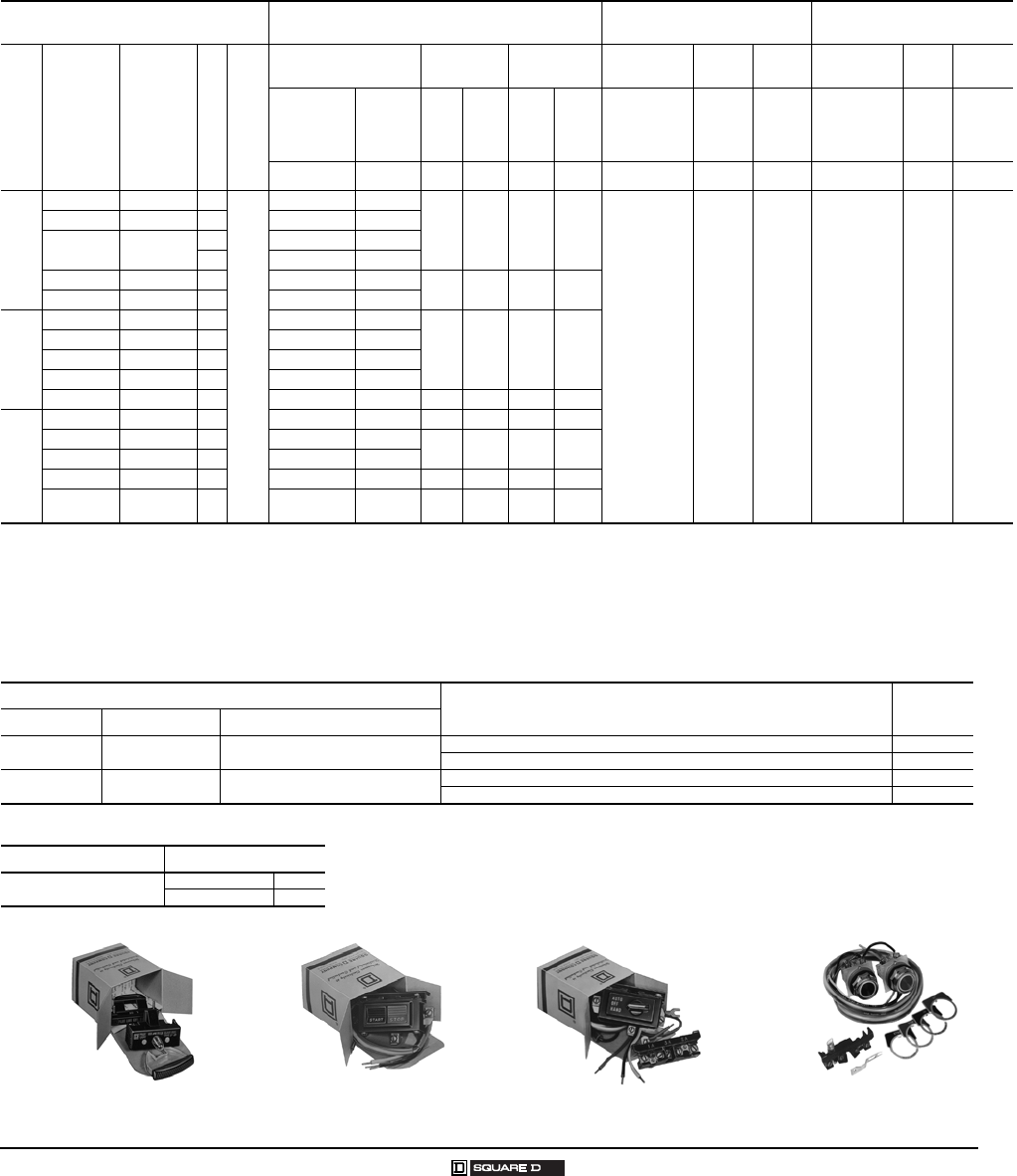
Class 9999 Type SP2R Pilot Light Kit Class 9999 Type SA2 Push Button Kit Class 9999 Type SC2 Selector Switch Kit Class 9999 Type SA3 Push Button Kit
14
© 2007 Schneider Electric All Rights Reserved 12/2007
Accessories—Auxiliary Contacts
Class 9999
Auxiliary Contacts for Manual and Magnetic Contactors and Starters
Internal Contacts
The Class 9999 Type SX11 internal contact kit is a replacement unit for the N.O. holding circuit contact
supplied as standard on Type S Sizes 00–2 three-phase starters and contactors. The Class 9999
Type SX12 is a replacement unit for the N.C. electrical contact which is furnished as standard on
Type S, Sizes 00–2 mechanically-interlocked devices (for example: Class 8736 reversing starters).
Internal contacts are also used on Class 2510 Types M and T manual starters. The internal contacts
can be used for other applications as long as the electrical rating is not exceeded.
See Table 40 for electrical ratings.
External Contacts
The Class 9999 Type SX6 external auxiliary contact is supplied as standard for the N.O. holding circuit
contact on Type S Sizes 3–7 starters and contactors. Additional auxiliary contacts can be added to
Type S contactors, starters, and lighting contactors. These contacts mount on either side of the basic
contactor, and are available with convertible or non-convertible contacts. The contacts of the
convertible version can be changed from N.O. to N.C. or vice versa in the field. The non-convertible
version has fixed contacts, either N.O. or N.C.
To determine the number of auxiliary contacts which can be added to each Type S contactor or starter,
refer to the Class 8536 or Class 8736 section.
See Table 40 for electrical ratings.
Table 40: Maximum Ratings for Type S Auxiliary Contacts and Timers
Class 9999
Type
Contact Ratings
Class 9999
Type
Contact Ratings
Volts AC
AC Only (35% Power Factor)
Continuous Volts AC
AC Only (35% Power Factor)
Continuous
Make Break Make Break
SX11, SX12
SK3, SK4
≤120 30 A 3 A 3 A SX6–SX10 ≤120 60 A 6 A 10 A
120–600 3600 VA 360 VA 3 A SX13–SX17 120–600 7200 VA 720 VA 10 A
Internal Auxiliary Contact
External Single-Circuit
Auxiliary Contact
Table 41: Class 8910 and 8911 Definite Purpose
Contactors and Starters – Auxiliary Contacts
Device To Be Serviced Auxiliary Contact Kit
Class 8910 or 8911 Type Contact Arrangement Class 9999 Type
DPA 1
DPS
1Type DPA122 and DPA123 use same auxiliary contacts as Type SA–SJ above.
(Example: Class 9999 Type SX6).
1 N.O. D10
1 N.C. D01
1 N.O./1 N.C. D11
2 N.O. D20
Table 42: Type S Contactors and Starters
For Use With
Kit Description Class 9999
Type
Type NEMA
Size
SA–SJ 00–7
External—Field Convertible
1–N.O. Contact
1–N.C. Contact
1–N.O. and 1–N.C. Isolated Contacts
1–N.O. Overlapping Contact
1–N.C. Overlapping Contact
SX6
SX7
SX8
SX9 1
SX10 1
1Types SX9 and SX10 or Types SX16 and SX17 must be used together and mounted on the
same side of the contactor. They are suitable for applications where it is necessary for a
normally open contact to overlap a normally closed contact.
SA–SJ 00–7
External—Non-Convertible
1–N.O. Contact
1–N.C. Contact
1–N.O. & 1 N.C. Isolated Contacts
1–N.O. Overlapping Contact
1–N.C. Overlapping Contact
SX13
SX14
SX15
SX16 1
SX17 1
SA–SD 00–2
Internal—Non-Convertible
1–N.O. Contact
1–N.C. Contact
SX11 2
SX12 2
2Types SX11 and SX12 are not applicable on NEMA Sizes 3 or larger. Internal contacts can
also be used on Class 2510 Types M and T manual starters.
Table 43: Class 8965 Reversing/Hoist Contactors –
Auxiliary Contacts
Device To Be Serviced Auxiliary Contact Kit
Class 8965 Type Contact
Arrangement
Type of
Connector
Class 9999
Type
DPR
1 N.O.
Screw/Quick
Connect
D10
1 N.C. D01
1 N.O./1 N.C. D11
2 N.O. D20
RO2 & RG2
RO10 Form X1
RO11 Form X1
1 N.O.
each side
Slip-on
R10
RO3 & RG3
RO10 Form X2
RO11 Form X2
1 N.C.
each side R11
RO5 & RG5
RO12 Form X1
RO13 Form X1
1 N.O.
each side
Screw
R12
RO6 & RG6
RO12 Form X2
RO13 Form X2
1 N.C.
each side R13
Table 44: How to Order
To Order Specify: Catalog Number
•Class Number
•Type Number
Class Type
9999 R11
Accessories—Solid State Overload Relay, Motor Logic®
Class 9999
15
12/2007 © 2007 Schneider Electric All Rights Reserved
Motor Logic—Class 9999
Table 45: Isolated Auxiliary Contacts for Motor Logic
Overload Relays
Overload relay auxiliary contacts are available factory installed
or in kit form for field installation on Motor Logic overload
relays. These contacts may be used for isolated alarm contact
applications.
Table 46: DIN Adapter
The DIN adapter provides a method to mount the Motor Logic
overload relay to a 35 mm DIN rail.
Table 47: Lug-Lug and Lug-Extender Kits
A Class 9999 LL0 Lug-Lug Kit can be field installed on
separately mounted overload relays. The standard Size 00B,
00C, 0, and 1 Class 9065 Type SS and SF overload relays are
supplied without lugs. A Class 9999 LB0 Lug-Extender Kit is
designed for Size 00B, 00C, 0, and 1 Retrofit Starter
Applications. This kit allows the lugs to be in the same location
as the Class 9065 melting alloy overload relay, eliminating the
need for additional wire length.
Table 48: Remote Reset Module
The Remote Reset Module can be easily field installed on solid
state overload relays. This module will allow the overload relay
to be reset from a remote location.
Motor Logic Plus—Class 9065
Table 49: Lug-Lug Kit
This kit can be field installed on separately mounted
Motor Logic Plus overload relays.
Table 50: Software Kit
Solutions software program allows an IBM PC compatible
computer (with Windows® 95 or greater) to communicate with
a Motor Logic Plus overload relay connected to an RS-485
network using Modbus protocol.
Table 51: Communication Module
This module allows the Motor Logic Plus overload relay to
support RS-485 electrical communications standards. Up to 99
Motor Logic Plus overload relays can be controlled and
monitored from one remote personal computer.
For Use With
Parts Kit Description Class 9999
Type
Class and Type NEMA Size 1
8536 SA-SJ 00B through 7 N.O. or N.C. Auxiliary
Contact (Field Convertible) AC04
9065 SS, SR, SF, ST 00B through 7
For Use With
Parts Kit Description Class 9999
Type
Class and Type NEMA Size 1
9065 SS or SF 00B, 00C, 0, and 1 DIN Adapter DA01
For Use With
Parts Kit Description Class 9999
Type
Class and Type NEMA Size 1
9065 SS or SF 00B, 00C, 0, and 1 Lug-Lug Kit for separate
mounting LL0
9065 SS or SF 00B, 00C, 0, and 1
Lug-Extender Kit for
retrofitting existing NEMA S
starters
LB0
For Use With
Parts Kit Description Class 9999
Type
Class and Type NEMA Size 1
1NEMA Size 00B and 00C are not actual NEMA sizes. These designations are used to
differentiate the lower FLA of these devices from the NEMA size 00 Motor Logic Solid State
Overload Relay.
8536 SA-SJ 00B through 7 Remote Reset Module RR04 2
2120 Vac power required.
9065 SS, SR, SF, ST 00B through 7
8536 SE-SF 3 and 4 Top Mounting Bracket RB34 2 3
3To be used to mount the remote reset module on the top of the overload relay.
9065 SS, SR, SF, ST 3 and 4
For Use With
Parts Kit Description Class 9999
Type
Class and Type NEMA Size 1
1NEMA Size 00B and 00C are not actual NEMA sizes. These designations are used to
differentiate the lower FLA of these devices from the NEMA size 00 Motor Logic Solid State
Overload Relay.
8536 SA-SH 1–6 Lug-Lug Kit MLPL
9065 SP 1–6
For Use With
Parts Kit Description Class 9999
Type
Class and Type NEMA Size
8536 SA-SH 1–6 Software Kit MLPS
9065 SP 1–6
For Use With
Parts Kit Description Class 9999
Type
Class and Type NEMA Size
8536 SA-SH 1–6 Modbus®
Communication Module MB22
9065 SP 1–6
Table 52: How to Order
To Order Specify: Catalog Number
•Class Number
•Type Number
Class Type
9999 AC04
Accessories
Class 9999
16
© 2007 Schneider Electric All Rights Reserved 12/2007
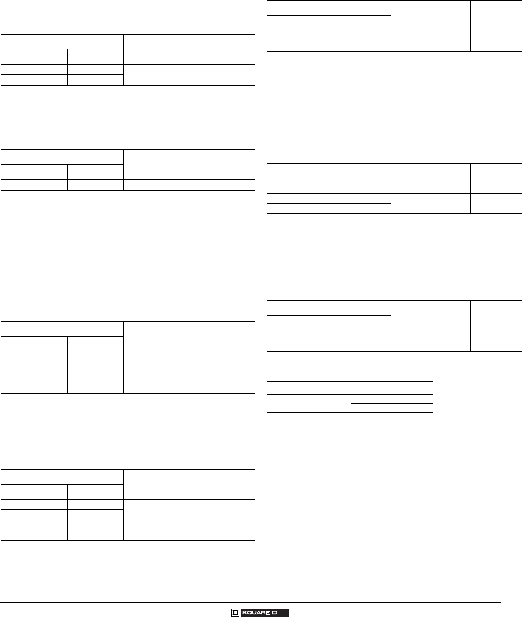
Table 53: Power Pole Adders
One single- or double-circuit power pole kit may be field added to a Size 0,
1, or 2, basic 2- or 3-Pole Type S contactor or starter or 30–60 A lighting
contactors. See Table 53 for selection. The ratings for these power pole
adders correspond to the NEMA contact ratings found on page 16-21 in
Digest 174. A two- or three-pole contactor or starter will accept only one
single- or double-circuit unit. A power pole cannot be used on four- or five-
pole devices or devices which are mechanically-interlocked.
For adding a power pole to a Size 2 or 60 A device, a coil change is
required. Select a 4 and 5 pole coil from the coil selection tables on page 10
or specify Form Y118 as noted in the footnote below. When adding Sizes
0–2 power pole kits to a Size 3–7 or 100–800 A device, an adapter bracket
(9999 SBT1) is required.
The Class 9999 Types SB6 thru SB15 power pole kits are suitable for
copper wire only. Types SB21 through 25 are supplied with lugs suitable for
copper and aluminum wire.
For Use With Power Pole Adder Kit
Type Size Description Class 9999 Type
SB, SC & SM 0, 1 & 30 A
One normally-open power pole adder
SB6
SD 2 SB11 1
1To order a Size 2 or 60 A power pole kit complete with a new starter coil, specify Form Y118, voltage and
frequency (e.g. Class 9999 Type SB11 Form Y118, 120 volts, 60 cycles.)
SP 60 A SB21 1
SB, SC & SM 0, 1 & 30 A
One normally-closed power pole adder
SB7
SD 2 SB12 1
SP 60 A SB22 1
SB, SC & SM 0, 1 & 30 A One normally-open
and
one normally-closed power pole adder
SB8
SD 2 SB13 1
SP 60 A SB23 1
SB, SC & SM 0, 1 & 30 A
Two normally-open power pole adders
SB9
SD 2 SB14 1
SP 60 A SB24 1
SB, SC & SM 0, 1 & 30
Two normally-closed power pole adders
SB10
SD 2 SB15 1
SP 60 A SB25 1
SE–SJ &
SQ–SZ & SJ
3–7 &
100–800 A Adapter Bracket SBT1
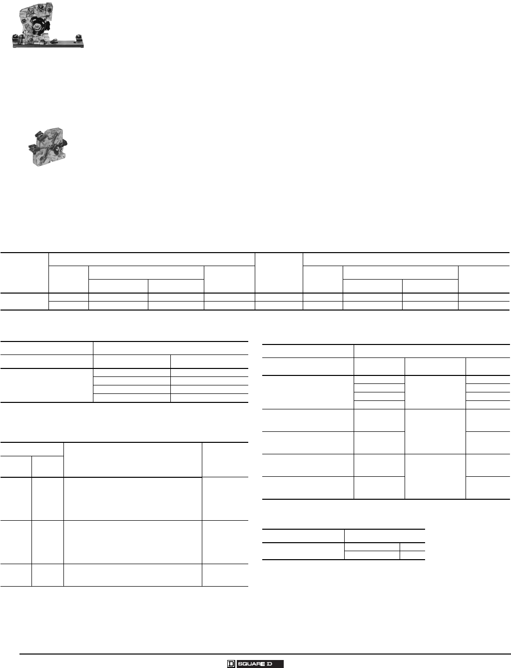
Class 9999 Type SB9
Double Power Pole Adder
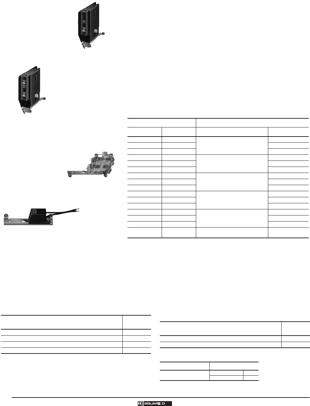
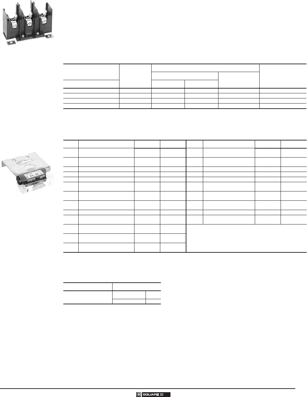
Class 9999 Type SF4 Fuse Kit
Class 9999 Type ST1
Transient Suppression Module
Table 54: Control Circuit Fuse Holder
The control circuit fuse holder is designed to be used on
Type S contactors and starters, Sizes 00–7, when one or two
control circuit fuses ≤ 600 volts are required. The Type SF3
and SF4 fuse holders will accept standard 600 V Bussmann®
Type KTK or equivalent fuses (13/32" x 11/2"); 6 A maximum.
The SFR3 and SFR4 will accept Class CC 600 V Bussmann
Type KTK–R or equivalent fuses only.
Table 55: Transient Suppression Module
The transient suppression module is designed to be used
where the transient voltage, generated when opening the coil
circuit, interferes with the proper operation of nearby integrated
or solid state control circuits. The module consists of an RC
circuit and is designed to suppress the coil voltage transients
to approximately 200% of peak coil supply voltage. The
module is wired across the coil for Type S, Sizes 00–5, and is
designed for coil voltages of 120 volts only.
Description1
1Fuses not included.
Class 9999
Type
Single-fuse Unit SF3
Single-fuse Unit for Class CC Fuse SFR3
Two-fuse Unit SF4
Two-fuse Unit for Class CC Fuses SFR4
Description Class 9999
Type
For Sizes 00–2 ST1
For Sizes 3–5 ST2
Table 56: How to Order
To Order Specify: Catalog Number
•Class Number
•Type Number
Class Type
9999 ST2
Class 9999 Type SB6 Single
Power Pole Adder
Accessories
Class 9999
17
12/2007 © 2007 Schneider Electric All Rights Reserved
Table 57: Isolated Alarm Contacts for Melting Alloy Overload Relays
Isolated overload relay alarm contacts are available factory installed or in kit form for field installation
in Type S, NEMA Size 00–61, starters and Class 9065 Types M and S melting alloy overload relays.
Type S, NEMA Size 7, uses a solid state overload relay which has isolated alarm contacts as a
standard feature. The alarm contacts will allow the starter to be used in applications which require
isolated contacts, such as inputs to a computer.
Class 9999 Types SO4 and SO5 modules are interchangeable with the standard module (Class 9998
Type SO1) and may be installed on starters already in service. The case is made of clear plastic
(polycarbonate) to allow for visual inspection of contacts.
Table 58: Compression Lugs
A Class 9999 Type AL hardware kit is required to install Versa-Crimp® compression lugs on
Class 8903 Type S, 100–800 A, lighting contactors. The lugs are suitable for both copper and
aluminum wire.
One VCEL lug is required for each line or load terminal. Each Class 9999 Type AL hardware kit
includes mounting hardware for 3 terminals, line or load side.
Example: To install compression lugs on a 300 A 3 pole device, line and load sides, order six (6)
VCEL–060–12H1 lugs and two (2) Class 9999 Type AL11 hardware kits.
Magnetic Starter
Description Class 9999
Parts Kit Type No.
NEMA Size Type
00–61
1Isolated alarm contacts cannot be added in the field to the Type SG, Size 5 series A starter. Current transformers and a Size 1 overload block must be
used. For factory installation specify Form Y342.
SA–SH
N.O. Isolated Alarm Contact Plus
Standard N.C. Overload Contact SO4
N.C. Isolated Alarm Contact Plus
Standard N.C. Overload Contact SO5
For Use With Versa-Crimp®
Catalog Number
Wire Range
Min.–Max.
Hardware Kit
Class 9999 Type
Rating Class 8903 Type
100 A SQ VCEL–021–14S1 8–1/0 Al/Cu None Required
200 A SV
VCEL–022–516H1 1–2/0 Al/Cu 2-Pole AL13
3-Pole AL14
4-Pole AL15
VCEL–024–516H1 2/0–4/0 Al/Cu
VCEL–030–516H1 4–300 MCM Al/Cu
300 A SX
VCEL–050–12H1 2/0–500 MCM Al/Cu
AL11
VCEL–060–12H1 400–600
400–500
MCM Al
MCM Cu
VCEL–075–12H1 500–750
500
MCM Al
MCM Cu
400 A
or
600 A
SY
or
SZ
VCEL–060–12H2 1
1One or two lugs may be mounted on each terminal.
400–600
400–500
MCM Al
MCM Cu AL12
VCEL–075–12H2 1500–750
500
MCM Al
MCM Cu
800 A SJ Available only as a factory modification. Order: Form Y1574. Specify wire size up to 750 MCM Al
or 500 MCM Cu and number of terminals.
Tie Point Terminal Block
Class 8903 with
Compression Lugs
installed
Type SO4
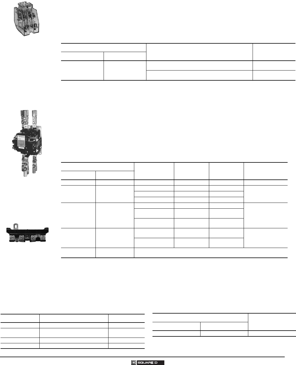
Table 59: Solid Neutral
The Class 9999 Type SN kit can be used on Class 8903 Type S
lighting contactors and other controllers where field addition of
a solid neutral is required. Each kit has lugs suitable for both
copper and aluminum wire, and mounts with two screws.
Table 60: Tie Point Terminal Block
The tie point terminal block provides easy wiring of a H–O–A
selector switch or Start-Stop push buttons with separate
control. The T7 terminal block requires no panel space. It
simply snaps on Type S Sizes 00–4 contactors and starters by
two tabs, and is secured to the left hand coil terminal.
Number of Lugs Wire Capacity Per Lug (Cu/Al) Class 9999 Type
4 #14–2/0 SN1
3(1) #4–600 MCM or
(2) #1/0–250 MCM SN2
3 (Dual) (2) #2–600 MCM SN3
2 (Dual) (2) #6–350 MCM SN4
Magnetic Contactor or Starter Class 9999
Type Number
NEMA Size Type
00–4 SA–SF T7
18
© 2007 Schneider Electric All Rights Reserved 12/2007
Accessories—Mechanical Interlocks
Class 9999
Mechanical Interlock
General – Type S contactors or starters can be mechanically-interlocked so that only one device will
be energized at a time. The mechanical interlock is an interference (non-jamming) type, locking at the
beginning of the stroke of any starter or contactor.
Type S Sizes 00, 0, 1 and 2 – The mechanical interlock is mounted on the underside of the reversing
baseplate. Two pins extend from the mechanical interlock through openings in the baseplate and
engage the contact carrier of each contactor. Two styles of mechanical interlocks are used: one
version for three-pole contactors, a different version for four- or five-pole contactors. When adding a
power pole to the left-hand side of an existing Size 0, 1, or 2 three-pole reversing contactor, a
new mechanical interlock must also be installed. When added to the right-hand side only, the
power pole will not be mechanically-interlocked with the left-hand contactor.
Type S Sizes 3 and 4 – The mechanical interlock is separate from the mounting pan on Sizes 3 and 4.
Cams on the mechanical interlocks are operated by the contact carrier of each contactor. The
mechanical interlock is attached to the underside of the two contactor baseplates on Sizes 3 and 4.
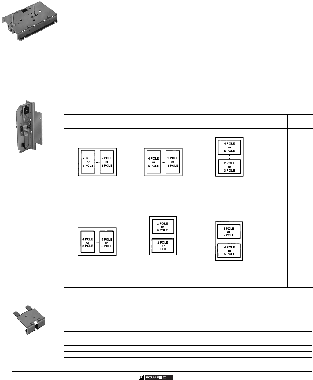
Table 61: Mechanical Interlock for Two Contactors
The following mechanical interlock kits can be used to interlock 2–5 pole contactors. Mechanical
interlocks for horizontal and vertical arrangement are listed in various pole arrangements.
Table 62: Overload Relay Mounting Bracket
Mechanical interlock Types SM1 through SM10 for Sizes 00–2 devices use overload relay mounting
brackets to support the overload relay portion of the starter.
Contactor
NEMA Size
Class 9999
Type
Horizontal
Type SM1 for Size 00–1
Type SM6 for Size 2
Type SM12 for Sizes 3 & 4
Horizontal
Type SM2 1 for Size 0 or 1
Type SM7 for Size 2
Type SM12 for Sizes 3 & 4
1The Type SM2 interlock is factory assembled for horizontal mounting but can easily be converted to vertical mounting. Conversion instructions are
included.
Vertical
Type SM2 1 for Size 0 or 1
Type SM10 for Size 2
Type SM11 for Size 3
Type SM13 for Size 4
00, 0, 1
0, 1
0, 1
0, 1
0, 1
SM1
SM2
SM3
SM4
SM5
Horizontal
Type SM3 for Size 0 or 1
Type SM8 for Size 2
Type SM12 for Sizes 3 & 4
Vertical
Type SM4 for Size 0 or 1
Type SM9 for Size 2
Type SM11 for Size 3
Type SM13 for Size 4
Vertical
Type SM5 for Size 0 or 1
Type SM11 for Size 3
Type SM13 for Size 4
2
2
2
2
2
3
3, 4
4
SM6
SM7
SM8
SM9
SM10
SM11
SM12
SM13
Kit Description Class 9999
Type
Bracket for one overload relay used with horizontal mechanical interlocks, Types SM1 through SM10 SO11
Bracket for two overload relays used with vertical mechanical interlocks, Types SM2, SM4, SM5, SM9 and SM10 SO12
Type SM12
Type SM1
Overload Relay
Mounting Bracket
Accessories —Fuse Block Replacement Parts Kits
Class 9422/9999
19
12/2007 © 2007 Schneider Electric All Rights Reserved
Class 9422 Replacement Fuse Clip Kits
Class 8538 (Series D and newer), Class 8738 (Series E and newer), and Class 8903 (Series C and
newer) Type S non-fusible combination starters and lighting contactors (sizes 0 – 2, 30 to 60 A) can be
converted to the fusible type by installing a Class 9422 Fuse Clip Kit. Both fusible and non-fusible
combination devices have the same size enclosure in NEMA Types 1, 4, and 12 construction, which
permits this conversion. The 9422 Fuse Clip Kits contain line and load fuse clips, load base, and fuse
pullers.
Table 63: Class 9422 Replacement Fuse Clip Kits
Device Used On Disconnect
A Rating
NEMA Class H, K, J, R Fuses
Class R Fuse Clip KitsFuse Clip Ratings–A
Class and Type
Size or Aere Rating 250 V Max. 600 V Max.
0, 1 & 30 A 30 0 – 30 — 9422TC301
1When using with a 9422 FTCN or FTCF disconnect switch in 8538 or 8738 combination starters, remove and discard metal base plate.
RFK032
2No Class Number required.
0, 1 & 30 A 30 31 – 60 0 – 30 9422TC331RFK062
2 & 60 A 60 31 – 60 0 – 30 9422TC33 RFK062
2 & 60 A 60 — 31 – 60 9422TD63 RFK06H2
Table 64: Class 9999 Auxiliary Contact Kits for Disconnect Switches and Circuit Breakers
Class Type SPDT Type DPDT Type Class Type SPDT Type DPDT Type
8538,
8738 SB, SC (Series C) R45 R46 9422 BTCF, BTCN, BTDF, BTDN,
BTEF, BTEN TC11 TC21
8539,
8739 SB, SC, SD, SE, SF, SG1
1No external auxiliary contacts are available for GJL circuit breaker. Must use internal auxiliary contacts, Catalog No. AAC.
R26 R27 9422 CSF R50 R51
8538 SBA, SCA, SBG, SCG (Series D) TC11 TC21 9422 FN, FP, FR, FT R18 R19
8738 SBA, SCA, SBG, SCG (Series E) TC10 TC20 9422 LF, LK, LL, LM, LN, LP, LR, LT R47 R48
8538 SB2, SC2, SD2 (Series B)
2Class 8538 type numbers ending in suffix “S8”.
R6 R7 9422 RN, RP, RR, RT R26 R27
8538 SBAS8, SCAS8, SBGS8,
SCGS8, (Series D) TC10 TC20 9422 TC R45 R46
8538,
8738 SD (Series C) R43 R44 9422 TCF, TCN, TDF, TDN, TEF,
TEN TC10 TC20
8538 SDA, SDA2, SDG, SDG2
(Series D) TC10 TC20 9422 TD R43 R44
8738 SDA, SDG (Series E) TC10 TC20 9422 TE R41 R42
8538,
8738 SE (Series B & C) R41 R42 9422 TF R8 R9
8538,
8738 SE, SF (Series A) R8 R9
8538,
8738 SF (Series B & C) R39 R40
8538,
8738 SG R35 R36
Table 65: How to Order
To Order Specify: Catalog Number
• Class Number
• Type Number
Class Type
9999 R6
Class 9422 TC33
Fuse Block
Class 9999 Type TC10

9999CT9701R10/07 © 2007 Schneider Electric All Rights Reserved
Replaces: 9999CT9701 May 1998
8001 Knightdale Blvd.
Knightdale, North Carolina 27545
USA
1-888-SquareD
1-888-778-2733
www.us.SquareD.com
12/2007
Schneider Electric USA
