Class 8502 Type S 101301 Catalog
2014-09-05
: Pdf 101301-Catalog 101301-Catalog 785901 Batch7 unilog
Open the PDF directly: View PDF ![]() .
.
Page Count: 54
- AC Magnetic Contactors Class 8502
- AC Magnetic Starters Class 8536
- Class 8502 and 8536 Application Data
- Power Contact Ratings
- Short Circuit Protection
- Capacitor Switching
- Maintenance of Equipment
- Auxiliary Units
- Factory Installed Auxiliary Contacts
- Form Number of Additional Auxiliary Contacts
- Control Circuit Transformers
- Power Poles
- Size 6 Type SH and Size 7 Type SJ Contactors and Starters
- Operation Rates
- Auxiliary Contacts
- Class 8502 Open Type Class 8536 Open Type
- NEMA Type 1 — General Purpose Enclosure
- NEMA Type 1 — General Purpose Enclosure with Form F4T
- NEMA Type 7 & 9 Enclosures for Hazardous Locations Sizes 0-2, Bolted Cover, Cast Iron, Sizes 0-5,...
- NEMA 7 & 9 Bolted Cover, Cast Aluminum
- General Information
- Altitude
- Termination Means
- Auxiliary Contacts
- Auxiliary Contact Units
- section 2 – reversing magnetic starters and contactors
- AC Magnetic Reversing Contactors Class 8702
- AC magnetic reversing starters class 8736
- General Information
- Overload Relays
- MOTOR LOGIC™ Solid State Overload Relay (SSOLR)
- Enclosures
- Holding Circuit Contact
- Coil Voltages
- Mechanical Interlocks
- Auxiliary Contacts
- Type S Accessories
- Power Contact Ratings
- Maintenance of Equipment
- Control Transformer Selection
- Auxiliary Units
- Factory Installed Auxiliary Contacts
- Open Type — 2 or 3-Pole Only
- Auxiliary Contact Units
- General Information
- section 3 – motor starters multi-speed
- Additional Features
- Special Relays for Non-Reversing and Reversing Multispeed Starters
- Thermal Units
- Typical Elementray Diagrams
- Thermal Units
- Vertically Arranged, Open Type, Two Speed Starters
- Thermal Units
- Special Arrangements with Three Devices
- Ordering Information Required
- Thermal Units
- Thermal Units
- Application Data for Types SB-SH
- Control Transformer Selection
- Mechanical Interlock
- Section 1 – magnetic contactors and starters
Type S Contactors and Starters
Class 8536/8502/8736/8702/8810/8811/8812
CONTENTS
Description Page
Magnetic Contactors and Starters . . . . . . . . . . . . . . . . . . . . . . . . . . . . . . . . . . . . . . .1
Reversing Magnetic Starters and Contactors . . . . . . . . . . . . . . . . . . . . . . . . . . . . . .25
Motor Starters Multi-Speed. . . . . . . . . . . . . . . . . . . . . . . . . . . . . . . . . . . . . . . . . . . .39

1
5/98 © 1998 Square D All Rights Reserved
SECTION 1 – MAGNETIC CONTACTORS AND STARTERS
Application Data – Class 8502, 8536. . . . . . . . . . . . . . . . . . . . . . . . . . . . 2-3
Selection – Class 8502 . . . . . . . . . . . . . . . . . . . . . . . . . . . . . . . . . . . . . . 4-7
Selection – Class 8536 . . . . . . . . . . . . . . . . . . . . . . . . . . . . . . . . . . . . . 8-12
Application Data – Class 8502, 8536. . . . . . . . . . . . . . . . . . . . . . . . . . 13-16
Approximate Dimensions, Shipping Weights – Class 8502, 8536 . . . . 17-22
Application Data – Class 8502 Vacuum Contactors. . . . . . . . . . . . . . . . . . 23
Selection and Pricing – Class 8502 . . . . . . . . . . . . . . . . . . . . . . . . . . . . . . 24
Contents
© 1998 Square D All Rights Reserved
2
5/98
AC MAGNETIC CONTACTORS
CLASS 8502
General Information
Class 8502 Type S magnetic contactors are used
to switch heating loads, capacitors, transformers,
and electric motors where overload protection is
separately provided. Class 8502 contactors are
available in NEMA Sizes 00-7. Type S contactors
are designed for operation at 600 Volts, AC 50-60
Hertz.
Holding Circuit Contact
A normally open holding circuit contact for three
wire control is provided on all contactors as
standard. Sizes 00-2 contactors use a Class 9999
SX11 auxiliary contact as the holding circuit
contact. Sizes 3-7 contactors use a Class 9999
SX6 auxiliary contact as the holding circuit
contact. See Class 9999 for the holding circuit
contact electrical ratings. On Size 00-1 single
phase contactors, a power pole is used as the
holding circuit contact and therefore has the same
rating as the power contacts.
Enclosures
Class 8502 magnetic contactors are available in
the following enclosures:
• NEMA Type 1 General Purpose
• NEMA Type 4 & 4X Watertight and Dusttight
Stainless Steel
• NEMA Type 4X Watertight, Dusttight, and
Corrosion Resistant Glass — Polyester
• NEMA Type 7 & 9 Bolted and Spin-Top for
Hazardous Locations
• NEMA Type 12 Dusttight and Driptight for
Industrial Use
The NEMA Type 4 & 4X stainless steel enclosure
(Sizes 0-5) has a brushed finish. For an
electropolished finish, specify Form G16 and add
15% to the price of the standard device.
Also, NEMA Type 12 devices are available UL
Listed for use in Class II, Division 2, Group G and
Class III, Divisions 1 and 2 locations. Request
Form G21, no additional charge.
Separate enclosures are available, see Class
9991.
AC MAGNETIC STARTERS
CLASS 8536
General Information
Class 8536 Type S magnetic starters are used for
full voltage starting and stopping AC squirrel cage
motors. Motor overload protection is provided by
melting alloy type thermal overload relays. Class
8536 starters are available in NEMA Sizes 00-7.
Type S starters are designed for operation at 600
Volts AC, 50-60 Hertz.
Holding Circuit Contact
A normally open holding circuit contact for three
wire control is provided on all contactors as
standard. Sizes 00-2 contactors use a Class 9999
SX11 auxiliary contact as the holding circuit
contact. Sizes 3-7 contactors use a Class 9999
SX6 auxiliary contact as the holding circuit
contact. See Class 9999 for the holding circuit
contact electrical ratings.
Overload Relays with Melting Alloys
Class 8536 Type S Sizes 00-6 starters are
provided with a melting alloy thermal overload
relay as standard. Interchangeable thermal units
are available in standard trip (Class 20) Sizes
00-6, quick trip (Class 10) Sizes 00-4, and slow
trip (Class 30) Sizes 00-3. Single-phase starters
use one thermal unit, 3-phase starters use three
thermal units.
Class 8536 Size 7 starters are provided with solid
state Motor Logic which has selectable trip
Class10/20, Ground fault detection, and
Communication capabilities for future
enhancement. The solid state overload relay is
ambient insensitive and features phase loss,
phase unbalance and over-current protection.
MOTOR LOGIC™ Solid State Overload Relay
(SSOLR)
Solid state overload relays are available for Sizes
00 – 7 starters. These ambient insensitive
overload relays provide phase loss protection,
phase unbalance protection and a LED power
indicator. For additional information, see the Class
9065 catalog section. To order Type S starters
with solid state overload relays, see Factory
Modification (FORMS).
Bimetallic overload relays are also available for
Sizes 0-6. Ambient Compensated and Non-
compensated versions are supplied with manual
Full Voltage Contactors and Starters — NEMA
Application Data – Class 8502, 8536
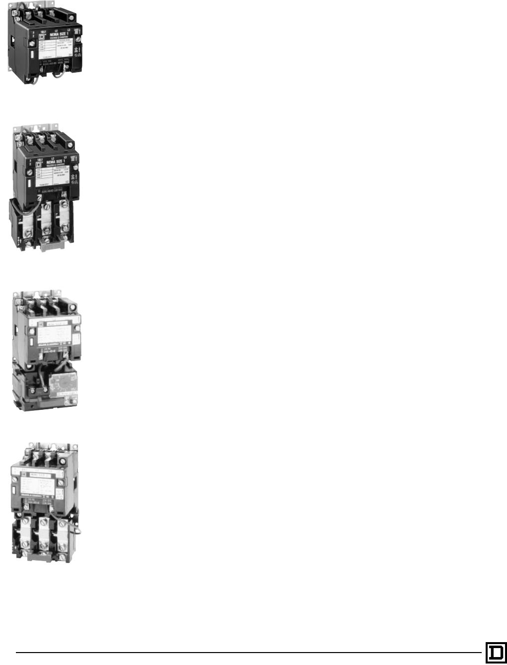
Type SCO3
Size 1, 3-Pole Starter
Starter with Melting Alloy
Starter with MOTOR LOGIC
Type SCO2
Size 1, 3-Pole Contactor

3
5/98 © 1998 Square D All Rights Reserved
and automatic reset, trip current adjustment, and
an alarm contact on Sizes 0-2. For additional
information, see the Class 9065 catalog section.
To order Type S starters with bimetallic overload
relays, see Factory Modifications (FORMS).
Enclosures
Class 8536 magnetic starters are available in the
following enclosures.
• NEMA Type 1 General Purpose Enclosure
• NEMA Type 3R Rainproof, Sleet Resistant for
Outdoor Use
• NEMA Type 4 & 4X Watertight and Dusttight
• NEMA Type 4X Watertight, Dusttight, and
Corrosion Resistant Glass – Polyester
• NEMA Type 7 & 9 Bolted and Spin-Top for
Hazardous Locations
• NEMA Type 9 Bolted for Hazardous Locations
• NEMA Type 12 Dusttight and Driptight for
Industrial Use
The NEMA Type 4 & 4X stainless steel enclosure
(Sizes 0-5) has a brushed finish. For an
electropolished finish, specify Form G16 and add
15% to the price of the standard device. Sizes 6 &
7 are painted sheet steel and are rated NEMA 4
ONLY.
Also NEMA Type 12 devices are available UL
Listed for use in Class II, Division 2, Group G and
Class III, Divisions 1 and 2 locations. Specify
Form G21, no additional charge.
Separate enclosures are available, see Class
9991.
Coil Voltages
AC coils are available for application on 50-60
Hertz. NEMA Sizes 00-5 are supplied with coils
that are designed to operate satisfactorily on line
voltages of 85% – 110% of rated voltage. NEMA
Size 6 and 7 contactors are supplied with a DC
coil operated by a solid state rectifier circuit that is
powered by an AC source.
Please note that
Voltage Codes
have been
added to the Type designations in order to
improve customer service. It is necessary to
include the Voltage Code when ordering
contactors and starters. Also, 120 Volt Polyphase
contactors and starters will be wired for separate
control.
Auxiliary Contacts
Additional auxiliary contacts may be added to
Type S contactors. See Page 15 for maximum
number of auxiliary units and Form designations
for factory installed auxiliary contacts.
Type S Accessories
Additional accessories such as power poles,
pneumatic timer attachments, and cover mounted
control stations are available as factory or field
modifications.
Full Voltage Contactors and Starters — NEMA
Application Data – Class 8502, 8536
© 1998 Square D All Rights Reserved
4
5/98
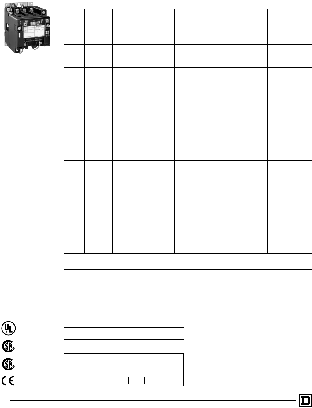
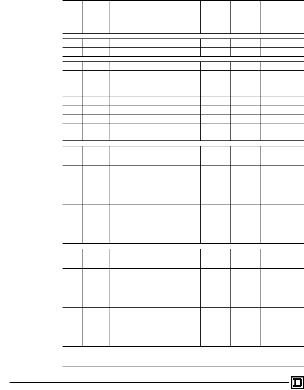
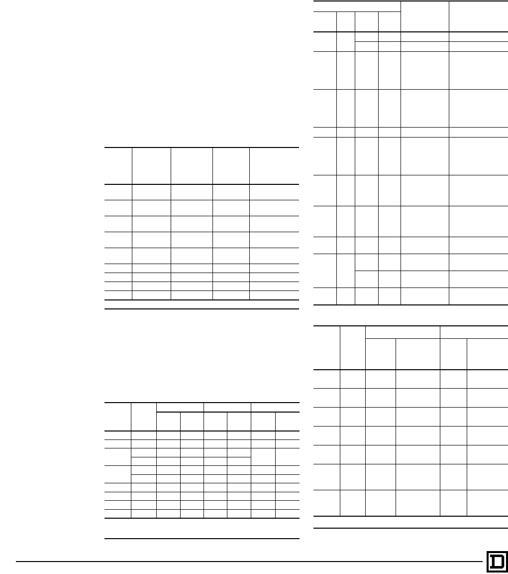
3-Pole Polyphase — 600 Volts AC Maximum — 50-60 Hertz
NEMA
Size
Continuous
Current
Ratings Motor Volts Max. HP
t
Coil Voltage
Open Type
NEMA Type 1
General
Purpose
Enclosure
NEMA Type 4 & 4X
Watertight, Dusttight
Brushed Stainless
Steel Enclosure
(Size 0-5)
f
Type Type Type
00 9
Separate Control
j
120 SAO12V02S SAG12V02S
USE Size 0
200 1
1
⁄
2
208 SAO12V08 SAG12V08
230 1
1
⁄
2
240 SAO12V03 SAG12V03
460 2 480 SAO12V06 SAG12V06
575 2 600 SAO12V07 SAG12V07
018
Separate Control
j
120 SBO2V02S SBG2V02S SBW12V02S
200 3 208 SBO2V08 SBG2V08 SBW12V08
230 3 240 SBO2V03 SBG2V03 SBW12V03
460 5 480 SBO2V06 SBG2V06 SBW12V06
575 5 600 SBO2V07 SBG2V07 SBW12V07
127
Separate Control
j
120 SCO2V02S SCG2V02S SCW12V02S
200 7
1
⁄
2
208 SCO2V08 SCG2V08 SCW12V08
230 7
1
⁄
2
240 SCO2V03 SCG2V03 SCW12V03
460 10 480 SCO2V06 SCG2V06 SCW12V06
575 10 600 SCO2V07 SCG2V07 SCW12V07
245
Separate Control
j
120 SDO2V02S SDG2V02S SDW12V02S
200 10 208 SDO2V08 SDG2V08 SDW12V08
230 15 240 SDO2V03 SDG2V03 SDW12V03
460 25 480 SDO2V06 SDG2V06 SDW12V06
575 25 600 SDO2V07 SDG2V07 SDW12V07
390
Separate Control
j
120 SEO2V02S SEG2V02S SEW12V02S
200 25 208 SEO2V08 SEG2V08 SEW12V08
230 30 240 SEO2V03 SEG2V03 SEW12V03
460 50 480 SEO2V06 SEG2V06 SEW12V06
575 50 600 SEO2V07 SEG2V07 SEW12V07
4 135
Separate Control
j
120 SFO2V02S SFG2V02S SFW12V02S
200 40 208 SFO2V08 SFG2V08 SFW12V08
230 50 240 SFO2V03 SFG2V03 SFW12V03
460 100 480 SFO2V06 SFG2V06 SFW12V06
575 100 600 SFO2V07 SFG2V07 SFW12V07
5 270
Separate Control
j
120 SGO2V02S SGG2V02S SGW12V02S
200 75 208 SGO2V08 SGG2V08 SGW12V08
230 100 240 SGO2V03 SGG2V03 SGW12V03
460 200 480 SGO2V06 SGG2V06 SGW12V06
575 200 600 SGO2V07 SGG2V07 SGW12V07
6 540
Separate Control
j
120 SHO2V02S SHG2V02S SHW12V02S
200 150 208 SHO2V08 SHG2V08 SHW12V08
230 200 240 SHO2V03 SHG2V03 SHW12V03
460 400 480 SHO2V06 SHG2V06 SHW12V06
575 400 600 SHO2V07 SHG2V07 SHW12V07
7 810
Separate Control
j
120 SJO2V02S SJG2V02S SJW12V02S
200 . . . 208 SJO2V08 SJG2V08 SJW12V08
230 300 240 SJO2V03 SJG2V03 SJW12V03
460 600 480 SJO2V06 SJG2V06 SJW12V06
575 600 600 SJO2V07 SJG2V07 SJW12V07
f
Size 6 and 7 are painted sheet steel rated NEMA Type 4 only.
j
120 Volt Polyphase contactors are wired for separate control.
t
Coil voltage code must be specified to order this product. Refer to standard voltage codes listed below and insert as shown in How to Order.
Coil Voltage Codes
Voltage Code
60 Hz 50 Hz
24
q
. . . VO1
120 110 VO2
208 . . . VO8
240 220 VO3
480 440 VO6
600 550 VO7
Specify Specify V99
q
24 V coils are not available on Sizes 4-7. On Sizes 00-3, where 24 V
coils are available, Form S (separate control) must be specified.
Full Voltage Contactors — NEMA
Selection – Class 8502
Factory Modifications (FORMS)
...............Refer to Catalog 9999CT9701
Application Data
................................................................... Pages 13-16
Dimensions
........................................................................... Pages 17-20
Separate Enclosures (Class 9991)
...........Refer to Catalog 9999CT9701
Replacement Parts (Class 9998)
..............Refer to Catalog 9999CT9701
Type S Accessories (Class 9999)
.............Refer to Catalog 9999CT9701
How to Order:
To Order Specify: Catalog Number
• Class Number
• Type Number
• Coil Voltage Code
• Form(s)
Class Type Coil
Voltage
Code
Form(s)
8502 SBG2 VO2 P1S
Type SC02
Size 1, 3-Pole Contactor
File LR12751
Class 3211-04
File E78351
CCN NLDX
File 60905
Class 3211-04
IEC 947-4-1
Sizes 00-5 only
5
5/98 © 1998 Square D All Rights Reserved
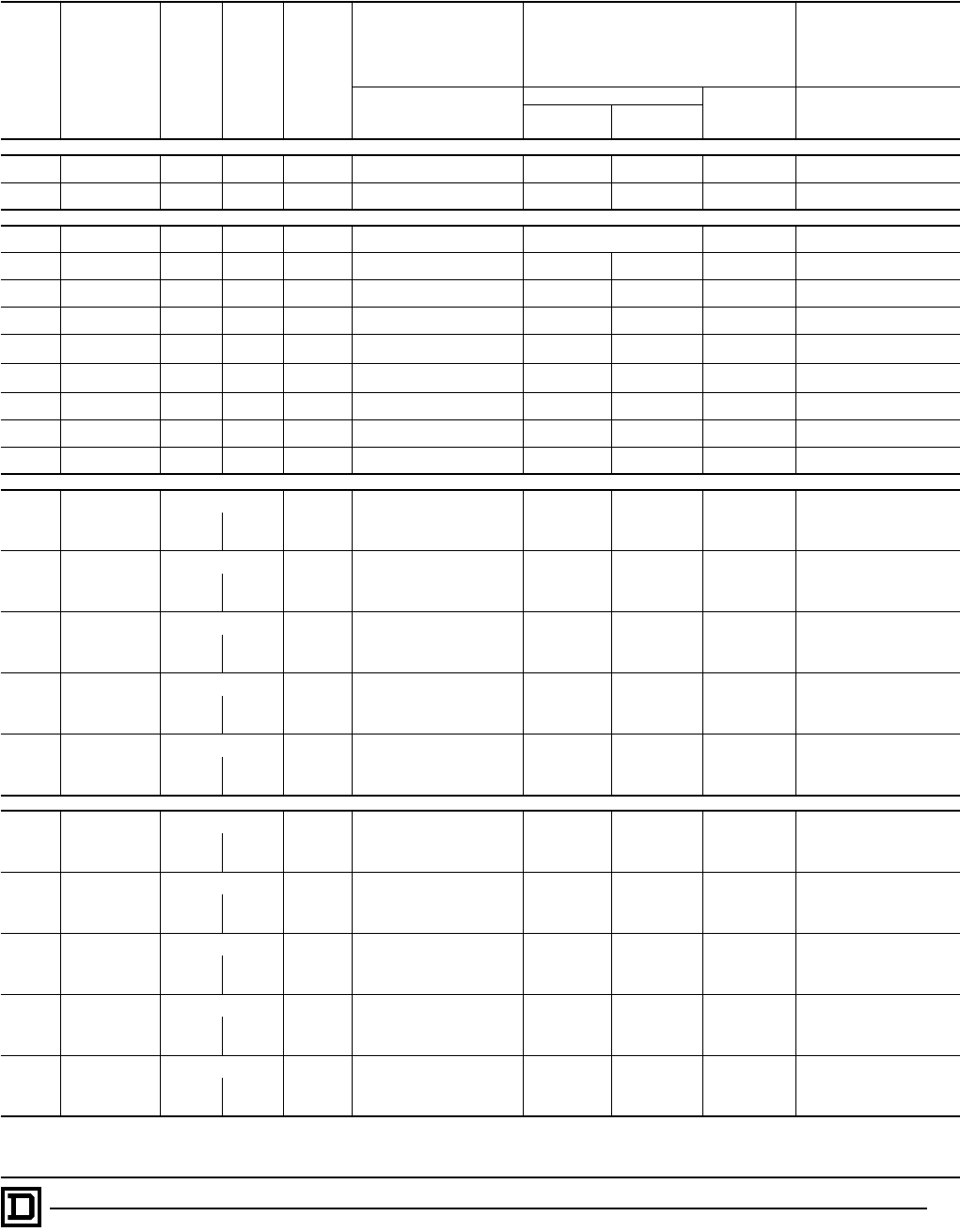
3-Pole Polyphase — 600 Volts AC Maximum — 50-60 Hertz
NEMA
Size
Continuous
Current
Ratings
Motor
Volts Max.
HP
t
Coil
Voltage
NEMA Type 4X
Watertight, Dusttight,
Corrosion-Resistant
Glass-Polyester
Enclosure
NEMA Type 7 & 9
Hazardous Locations
Class I, Groups C & D
Class II, Groups E, F, & G
NEMA Type 12
Dusttight & Driptight
Industrial Use Enclosure
Type
Bolted Type SPIN TOP
®
Type Type
Cast Iron
c
Cast
Aluminum
00 9
Separate Control
j
120
Use Size 0 Use Size 0 Use Size 0 Use Size 0
200 1
1
⁄
2
208
230 1
1
⁄
2
240
460 2 480
575 2 600
018
Separate Control
j
120 SBW22V02S SBT2V02S SBT42V02S SBR2V02S SBA2V02S
200 3 208 SBW22V08 SBT2V08 SBT42V08 SBR2V08 SBA2V08
230 3 240 SBW22V03 SBT2V03 SBT42V03 SBR2V03 SBA2V03
460 5 480 SBW22V06 SBT2V06 SBT42V06 SBR2V06 SBA2V06
575 5 600 SBW22V07 SBT2V07 SBT42V07 SBR2V07 SBA2V07
127
Separate Control
j
120 SCW22V02S SCT2V02S SCT42V02S SCR2V02S SCA2V02S
200 7
1
⁄
2
208 SCW22V08 SCT2V08 SCT42V08 SCR2V08 SCA2V08
230 7
1
⁄
2
240 SCW22V03 SCT2V03 SCT42V03 SCR2V03 SCA2V03
460 10 480 SCW22V06 SCT2V06 SCT42V06 SCR2V06 SCA2V06
575 10 600 SCW22V07 SCT2V07 SCT42V07 SCR2V07 SCA2V07
245
Separate Control
j
120 SDW22V02S SDT2V02S SDT42V02S SDR2V02S SDA2V02S
200 10 208 SDW22V08 SDT2V08 SDT42V08 SDR2V08 SDA2V08
230 15 240 SDW22V03 SDT2V03 SDT42V03 SDR2V03 SDA2V03
460 25 480 SDW22V06 SDT2V06 SDT42V06 SDR2V06 SDA2V06
575 25 600 SDW22V07 SDT2V07 SDT42V07 SDR2V07 SDA2V07
390
Separate Control
j
120 SEW22V02S
. . .
SET42V02S SER2V02S SEA2V02S
200 25 208 SEW22V08 SET42V08 SER2V08 SEA2V08
230 30 240 SEW22V03 SET42V03 SER2V03 SEA2V03
460 50 480 SEW22V06 SET42V06 SER2V06 SEA2V06
575 50 600 SEW22V07 SET42V07 SER2V07 SEA2V07
4 135
Separate Control
j
120 SFW22V02S
. . .
SFT42V02S SFR2V02S SFA2V02S
200 40 208 SFW22V08 SFT42V08 SFR2V08 SFA2V08
230 50 240 SFW22V03 SFT42V03 SFR2V03 SFA2V03
460 100 480 SFW22V06 SFT42V06 SFR2V06 SFA2V06
575 100 600 SFW22V07 SFT42V07 SFR2V07 SFA2V07
5 270
Separate Control
j
120
. . . . . . . . .
SGR2V02S SGA2V02S
200 75 208 SGR2V08 SGA2V08
230 100 240 SGR2V03 SGA2V03
460 200 480 SGR2V06 SGA2V06
575 200 600 SGR2V07 SGA2V07
6 540
Separate Control
j
120
. . . . . . . . . . . .
SHA2V02S
200 150 208 SHA2V08
230 200 240 SHA2V03
460 400 480 SHA2V06
575 400 600 SHA2V07
7 810
Separate Control
j
. . . . . . . . . . . .
SJA2V02S
200 — 208 SJA2V08
230 300 240 SJA2V03
460 600 480 SJA2V06
575 600 600 SJA2V07
j
120 Volt Polyphase contactors are wired for separate control.
c
Limited to one Pilot Light and a Selector Switch or Start-Stop Push Button.
t
Coil voltage code must be specified to order this product. Refer to standard coil voltage codes listed in selection table above or additional standard voltage codes below and insert as shown
in the HOW TO ORDER block.
Coil Voltage Codes
Voltage Code
60 Hz 50 Hz
24
q
. . . VO1
120 110 VO2
208 . . . VO8
240 220 VO3
480 440 VO6
600 550 VO7
Specify Specify V99
q
24 V coils are not available on Sizes 4-7. On Sizes 00-3, where 24 V
coils are available, Form S (separate control) must be specified.
Full Voltage Contactors — NEMA
Selection – Class 8502
Factory Modifications (FORMS)
............... Refer to Catalog 9999CT9701
Application Data
....................................................................Pages 13-16
Dimensions
............................................................................Pages 17-20
Separate Enclosures (Class 9991)
........... Refer to Catalog 9999CT9701
Replacement Parts (Class 9998)
.............. Refer to Catalog 9999CT9701
Type S Accessories (Class 9999)
............ Refer to Catalog 9999CT9701
How to Order:
To Order Specify: Catalog Number
• Class Number
• Type Number
• Coil Voltage Code
• Form(s)
Class Type Coil
Voltage
Code
Form(s)
8502 SBA2 VO2 P1S
File LR60905
Class 3218-03
File E78503
CCN NPKR
Explosion Proof Units
© 1998 Square D All Rights Reserved
6
5/98
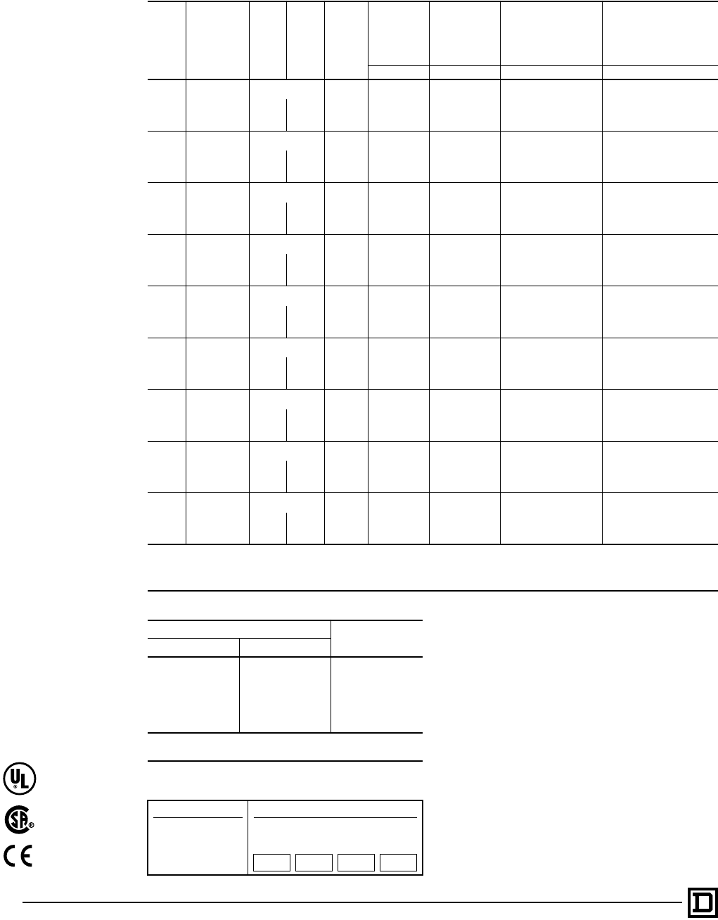
600 Volts AC Maximum — 50-60 Hertz
NEMA
Size
Continuous
Current
Ratings Motor Volts Max. HP
t
Coil Voltage
Open Type
NEMA Type 1
General
Purpose
Enclosure
NEMA Type 4 & 4X
Watertight, Dusttight
Brushed Stainless
Steel Enclosure
(Size 0-5)
f
Type Type Type
1-Pole Single Phase
018 115 1 120 SBO5V02 SBG5V02 SBW15V02
230 2 240 SBO5V03 SBG5V03 SBW15V03
127 115 2 120 SCO5V02 SCG5V02 SCW15V02
230 3 240 SCO5V03 SCG5V03 SCW15V03
2-Pole Single Phase
00 9 115
1
⁄
3
120 SAO11V02 SAG11V02 Use Size 0
230 1 240 SAO11V03 SAG11V03
018 115 1 120 SBO1V02 SBG1V02 SBW11V02
230 2 240 SBO1V03 SBG1V03 SBW11V03
127 115 2 120 SCO1V02 SCG1V02 SCW11V02
230 3 240 SCO1V03 SCG1V03 SCW11V03
245 115 3 120 SDO1V02 SDG1V02 SDW11V02
230 7
1
⁄
2
240 SDO1V03 SDG1V03 SDW11V03
3 90 . . . . . . 120 SEO1V02 SEG1V02 SEW11V02
240 SEO1V03 SEG1V03 SEW11V03
4 135 . . . . . . 120 SFO1V02 SFG1V02 SFW11V02
240 SFO1V03 SFG1V03 SFW11V03
5 270 . . . . . . 120 SGO1V02 SGG1V02 SGW11V02
240 SGO1V03 SGG1V03 SGW11V03
6 540 . . . . . . 120 SHO1V02 SHG1V02 SHW1V02
240 SHO1V03 SHG1V03 SHW1V03
7 810 . . . . . . 120 SJO1V02 SJG1V02 SJW1V02
240 SJO1V03 SJG1V03 SJW1V03
4-Pole Polyphase
018
Separate Control
j
120 SBO3V02S SBG3V02S SBW13V02S
200 3 208 SBO3V08 SBG3V08 SBW13V08
230 3 240 SBO3V03 SBG3V03 SBW13V03
460 5 480 SBO3V06 SBG3V06 SBW13V06
575 5 600 SBO3V07 SBG3V07 SBW13V07
127
Separate Control
j
120 SCO3V02S SCG3V02S SCW13V02S
200 7
1
⁄
2
208 SCO3V08 SCG3V08 SCW13V08
230 7
1
⁄
2
240 SCO3V03 SCG3V03 SCW13V03
460 10 480 SCO3V06 SCG3V06 SCW13V06
575 10 600 SCO3V07 SCG3V07 SCW13V07
245
Separate Control
j
120 SDO3V02S SDG3V02S SDW13V02S
200 10 208 SDO3V08 SDG3V08 SDW13V08
230 15 240 SDO3V03 SDG3V03 SDW13V03
460 25 480 SDO3V06 SDG3V06 SDW13V06
575 25 600 SDO3V07 SDG3V07 SDW13V07
390
Separate Control
j
120 SEO3V02S SEG3V02S SEW13V02S
200 25 208 SEO3V08 SEG3V08 SEW13V08
230 30 240 SEO3V03 SEG3V03 SEW13V03
460 50 480 SEO3V06 SEG3V06 SEW13V06
575 50 600 SEO3V07 SEG3V07 SEW13V07
4 135
Separate Control
j
120 SFO3V02S SFG3V02S SFW13V02S
200 40 208 SFO3V08 SFG3V08 SFW13V08
230 50 240 SFO3V03 SFG3V03 SFW13V03
460 100 480 SFO3V06 SFG3V06 SFW13V06
575 100 600 SFO3V07 SFG3V07 SFW13V07
5-Pole Polyphase
018
Separate Control
j
120 SBO4V02S SBG4V02S SBW14V02S
200 3 208 SBO4V08 SBG4V08 SBW14V08
230 3 240 SBO4V03 SBG4V03 SBW14V03
460 5 480 SBO4V06 SBG4V06 SBW14V06
575 5 600 SBO4V07 SBG4V07 SBW14V07
127
Separate Control
j
120 SCO4V02S SCG4V02S SCW14V02S
200 7
1
⁄
2
208 SCO4V08 SCG4V08 SCW14V08
230 7
1
⁄
2
240 SCO4V03 SCG4V03 SCW14V03
460 10 480 SCO4V06 SCG4V06 SCW14V06
575 10 600 SCO4V07 SCG4V07 SCW14V07
245
Separate Control
j
120 SDO4V02S SDG4V02S SDW14V02S
200 10 208 SDO4V08 SDG4V08 SDW14V08
230 15 240 SDO4V03 SDG4V03 SDW14V03
460 25 480 SDO4V06 SDG4V06 SDW14V06
575 25 600 SDO4V07 SDG4V07 SDW14V07
390
Separate Control
j
120 SEO4V02S SEG4V02S SEW14V02S
200 25 208 SEO4V08 SEG4V08 SEW14V08
230 30 240 SEO4V03 SEG4V03 SEW14V03
460 50 480 SEO4V06 SEG4V06 SEW14V06
575 50 600 SEO4V07 SEG4V07 SEW14V07
4 135
Separate Control
j
120 SFO4V02S SFG4V02S SFW14V02S
200 40 208 SFO4V08 SFG4V08 SFW14V08
230 50 240 SFO4V03 SFG4V03 SFW14V03
460 100 480 SFO4V06 SFG4V06 SFW14V06
575 100 600 SFO4V07 SFG4V07 SFW14V07
f
Size 6 and 7 are painted sheet steel rated NEMA Type 4 only.
j
120 Volt Polyphase contactors are wired for separate control.
t
Coil voltage code must be specified to order this product. Refer to standard voltage codes listed in selection table above or additional standard
voltage codes and insert as shown in the HOW TO ORDER block on Page 5.
Full Voltage Contactors — NEMA
Selection – Class 8502
7
5/98 © 1998 Square D All Rights Reserved
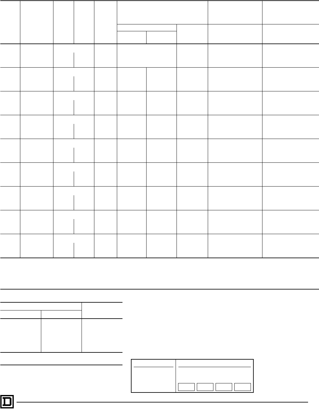
600 Volts AC Maximum — 50-60 Hertz
NEMA
Size
Continuous
Current
Ratings
Motor
Volts Max.
HP
t
Coil
Voltage
NEMA Type 4X
Watertight, Dusttight,
Corrosion-Resistant
Glass-Polyester
Enclosure
NEMA Type 7 & 9
Hazardous Locations
Class I, Groups C & D
Class II, Groups E, F, & G
NEMA Type 12
Dusttight & Driptight
Industrial Use Enclosure
Type
Bolted Type SPIN TOP
®
Type Type
Cast Iron
c
Cast
Aluminum
1-Pole Single Phase
018 115 1 120 . . . SBT5V02 SBT45V02 SBR5V02 SBA5V02
230 2 240 SBT5V03 SBT45V03 SBR5V03 SBA5V03
127 115 2 120 . . . SCT5V02 SCT5V02 SCR5V02 SCA5V02
230 3 240 SCT5V03 SCT5V03 SCR5V03 SCA5V03
2-Pole Single Phase
00 9 115 1/3 120 Use Size 0 Use Size 0 Use Size 0 Use Size 0
230 1 240
018 115 1 120 SBW21V02 SBT1V02 SBT41V02 SBR1V02 SBA1V02
230 2 240 SBW21V03 SBT1V03 SBT41V03 SBR1V03 SBA1V03
127 115 2 120 SCW21V02 SCT1V02 SCT41V02 SCR1V02 SCA1V02
230 3 240 SCW21V03 SCT1V03 SCT41V03 SCR1V03 SCA1V03
245 115 3 120 SDW21V02 SDT1V02 SDT41V02 SDR1V02 SDA1V02
230 7
1
⁄
2
240 SDW21V03 SDT1V03 SDT41V03 SDR1V03 SDA1V03
3 90 . . . . . . 120 Consult Local Square D
Field Office . . . SET41V02 SER1V02 SEA1V02
240 SET41V03 SER1V03 SEA1V03
4 135 . . . . . . 120 Consult Local Square D
Field Office . . . SFT41V02 SFR1V02 SFA1V02
240 SFT41V03 SFR1V03 SFA1V03
5 270 . . . . . . 120 . . . . . . . . . SGR1V02 SGA1V02
240 SGR1V03 SGA1V03
6 540 . . . . . . 120 . . . . . . . . . . . . SHA1V02
240 SHA1V03
7 810 . . . . . . 120 . . . . . . . . . . . . SJA1V02
240 SJA1V03
4-Pole Polyphase
018
Separate Control
j
120 SBW33V02S SBT3V02S Consult
Local Square D
Field Office
SBR3V02S SBA3V02S
200 3 208 SBW33V08 SBT3V08 SBR3V08 SBA3V08
230 3 240 SBW33V03 SBT3V03 SBR3V03 SBA3V03
460 5 480 SBW33V06 SBT3V06 SBR3V06 SBA3V06
575 5 600 SBW33V07 SBT3V07 SBR3V07 SBA3V07
127
Separate Control
j
120 SCW23V02S SCT3V02S Consult
Local Square D
Field Office
SCR3V02S SCA3V02S
200 7
1
⁄
2
208 SCW23V08 SCT3V08 SCR3V08 SCA3V08
230 7
1
⁄
2
240 SCW23V03 SCT3V03 SCR3V03 SCA3V03
460 10 480 SCW23V06 SCT3V06 SCR3V06 SCA3V06
575 19 600 SCW23V07 SCT3V07 SCR3V07 SCA3V07
245
Separate Control
j
120 SDW23V02S SDT3V02S Consult
Local Square D
Field Office
SDR3V02S SDA3V02S
200 10 208 SDW23V08 SDT3V08 SDR3V08 SDA3V08
230 15 240 SDW23V03 SDT3V03 SDR3V03 SDA3V03
460 25 480 SDW23V06 SDT3V06 SDR3V06 SDA3V06
575 25 600 SDW23V07 SDT3V07 SDR3V07 SDA3V07
390
Separate Control
j
120
Consult Local Square D
Field Office
Consult
Local Square D
Field Office
Consult
Local Square D
Field Office
SER3V02S SEA3V02S
200 25 208 SER3V08 SEA3V08
230 30 240 SER3V03 SEA3V03
460 50 480 SER3V06 SEA3V06
575 50 600 SER3V07 SEA3V07
4 135
Separate Control
j
120
Consult Local Square D
Field Office
Consult
Local Square D
Field Office
Consult
Local Square D
Field Office
SFR3V02S SFA3V02S
200 40 208 SFR3V08 SFA3V08
230 50 240 SFR3V03 SFA3V03
460 100 480 SFR3V06 SFA3V06
575 100 600 SFR3V07 SFA3V07
5-Pole Polyphase
018
Separate Control
j
120
Consult Local Square D
Field Office . . . . . . . . .
SBA4V02S
200 3 208 SBA4V08
230 3 240 SBA4V03
460 5 480 SBA4V06
575 5 600 SBA4V07
127
Separate Control
j
120
Consult Local Square D
Field Office . . . . . . . . .
SCA4V02S
200 7
1
⁄
2
208 SCA4V08
230 7
1
⁄
2
240 SCA4V03
460 10 480 SCA4V06
575 10 600 SCA4V07
245
Separate Control
j
120
Consult Local Square D
Field Office . . . . . . . . .
SDA4V02S
200 10 208 SDA4V08
230 15 240 SDA4V03
460 25 480 SDA4V06
575 25 600 SDA4V07
390
Separate Control
j
120
Consult Local Square D
Field Office . . . . . . . . .
SEA4V02S
200 25 208 SEA4V08
230 30 240 SEA4V03
460 50 480 SEA4V06
575 50 600 SEA4V07
4 135
Separate Control
j
120
Consult Local Square D
Field Office . . . . . . . . .
SFA4V02S
200 40 208 SFA4V08
230 50 240 SFA4V03
460 100 480 SFA4V06
575 100 600 SFA4V07
j
120 Volt Polyphase contactors are wired for separate control.
c
Limited to one Pilot Light and a Selector Switch or Start-Stop Push Button.
t
Coil voltage code must be specified to order this product. Refer to standard coil voltage codes listed in selection table above or additional standard voltage codes and insert as shown in
the HOW TO ORDER block on Page 5.
Full Voltage Contactors — NEMA
Selection – Class 8502
© 1998 Square D All Rights Reserved
8
5/98
3-Pole Polyphase—600 Volt AC Max. 50/60 Hz—Three Thermal Units Required
NEMA
Size
Continuous
Current
Ratings
Motor
Volts Max.
HP
t
Coil
Voltage
Open
Type
NEMA Type 1
General
Purpose
Enclosure
NEMA Type 4 & 4X
Watertight, Dusttight
Brushed Stainless
Steel Enclosure
(Size 0-5)
f
NEMA Type 4X
Watertight, Dusttight,
Corrosion-Resistant
Glass-Polyester
Enclosure
Type Type Type Type
00 9
Separate Control
j
120 SAO12V02S SAG12V02S
Use Size 0 Use Size 0
200 1
1
⁄
2
208 SAO12V08 SAG12V08
230 1
1
⁄
2
240 SAO12V03 SAG12V03
460 2 480 SAO12V06 SAG12V06
575 2 600 SAO12V07 SAG12V07
018
Separate Control
j
120 SBO2V02S SBG2V02S SBW12V02S SBW22V02S
200 3 208 SBO2V08 SBG2V08 SBW12V08 SBW22V08
230 3 240 SBO2V03 SBG2V03 SBW12V03 SBW22V03
460 5 480 SBO2V06 SBG2V06 SBW12V06 SBW22V06
575 5 600 SBO2V07 SBG2V07 SBW12V07 SBW22V07
127
Separate Control
j
120 SCO3V02S SCG3V02S SCW13V02S SCW23V02S
200 7
1
⁄
2
208 SCO3V08 SCG3V08 SCW13V08 SCW23V08
230 7
1
⁄
2
240 SCO3V03 SCG3V03 SCW13V03 SCW23V03
460 10 480 SCO3V06 SCG3V06 SCW13V06 SCW23V06
575 10 600 SCO3V07 SCG3V07 SCW13V07 SCW23V07
245
Separate Control
j
120 SDO1V02S SDG1V02S SDW11V02S SDW21V02S
200 10 208 SDO1V08 SDG1V08 SDW11V08 SDW21V08
230 15 240 SDO1V03 SDG1V03 SDW11V03 SDW21V03
460 25 480 SDO1V06 SDG1V06 SDW11V06 SDW21V06
575 25 600 SDO1V07 SDG1V07 SDW11V07 SDW21V07
390
Separate Control
j
120 SEO1V02S SEG1V02S SEW11V02S SEW21V02S
200 25 208 SEO1V08 SEG1V08 SEW11V08 SEW21V08
230 30 240 SEO1V03 SEG1V03 SEW11V03 SEW21V03
460 50 480 SEO1V06 SEG1V06 SEW11V06 SEW21V06
575 50 600 SEO1V07 SEG1V07 SEW11V07 SEW21V07
4 135
Separate Control
j
120 SFO1V02S SFG1V02S SFW11V02S SFW21V02S
200 40 208 SFO1V08 SFG1V08 SFW11V08 SFW21V08
230 50 240 SFO1V03 SFG1V03 SFW11V03 SFW21V03
460 100 480 SFO1V06 SFG1V06 SFW11V06 SFW21V06
575 100 600 SFO1V07 SFG1V07 SFW11V07 SFW21V07
5 270
Separate Control
j
120 SGO1V02S SGG1V02S SGW11V02S
. . .
200 75 208 SGO1V08 SGG1V08 SGW11V08
230 100 240 SGO1V03 SGG1V03 SGW11V03
460 200 480 SGO1V06 SGG1V06 SGW11V06
575 200 600 SGO1V07 SGG1V07 SGW11V07
6 540
Separate Control
j
120 SHO2V02S SHG2V02S SHW2V02S
. . .
200 150 208 SHO2V08 SHG2V08 SHW2V08
230 200 240 SHO2V03 SHG2V03 SHW2V03
460 400 480 SHO2V06 SHG2V06 SHW2V06
575 400 600 SHO2V07 SHG2V07 SHW2V07
7 810
Separate Control
j
120 SJO2V02S SJG2V02S SJW2V02S
. . .
200 — 208 SJO2V08 SJG2V08 SJW2V08
230 300 240 SJO2V03 SJG2V03 SJW2V03
460 600 480 SJO2V06 SJG2V06 SJW2V06
575 600 600 SJO2V07 SJG2V07 SJW2V07
f
Size 6 and 7 are rated NEMA Type 4 only.
j
120 Volt Polyphase starters are wired for separate control.
t
Coil voltage code must be specified to order this product. Refer to standard coil voltage codes listed in selection table above or additional standard
voltage codes below and insert as shown in the HOW TO ORDER block.
Coil Voltage Codes
Voltage Code
60 Hz 50 Hz
24
q
. . . VO1
120 110 VO2
208 . . . VO8
240 220 VO3
480 440 VO6
600 550 VO7
Specify Specify V99
q
24 V coils are not available on Sizes 4-7. On Sizes 00-3, where 24 V
coils are available, Form S (separate control) must be specified.
Full Voltage Starters — NEMA
Selection – Class 8536
Factory Modifications (FORMS)
...............Refer to Catalog 9999CT9701
Application Data
................................................................... Pages 13-16
Dimensions
........................................................................... Pages 17-20
Separate Enclosures (Class 9991)
...........Refer to Catalog 9999CT9701
Replacement Parts (Class 9998)
..............Refer to Catalog 9999CT9701
Type S Accessories (Class 9999)
.............Refer to Catalog 9999CT9701
How to Order:
To Order Specify: Catalog Number
• Class Number
• Type Number
• Coil Voltage Code
• Form(s)
Class Type Coil
Voltage
Code
Form(s)
8536 SBA2 VO2 P1S
File LR60905
Class 3211-04
File E78351
CCN NLDX
IEC 947-4-1
Sizes 00-5 only
9
5/98 © 1998 Square D All Rights Reserved
3-Pole Polyphase — 600 Volts AC Maximum — 50-60 Hertz—Three Thermal Units Required
NEMA
Size
Continuous
Current
Ratings
Motor
Volts Max.
HP
t
Coil
Voltage
NEMA Type 7 & 9
Hazardous Locations
Class I, Groups C & D
Class II, Class E, F, & G
NEMA Type 9
Hazardous Locations
Class II, Groups E, F, & G
NEMA Type 12/3R
k
Dusttight & Driptight
Industrial Use
Enclosure
Bolted Type SPIN TOP
®
Type Type Type
Cast Iron
c
Cast
Aluminum
00 9
Separate Control
j
120
USE Size 0 USE Size 0 USE Size 0 Use Size 0
200 1
1
⁄
2
208
230 1
1
⁄
2
240
460 2 480
575 2 600
018
Separate Control
j120 SBT2V02S SBT42V02S SBR2V02S SBE2V02S SBA2V02S
200 3 208 SBT2V08 SBT42V08 SBR2V08 SBE2V08 SBA2V08
230 3 240 SBT2V03 SBT42V03 SBR2V03 SBE2V03 SBA2V03
460 5 480 SBT2V06 SBT42V06 SBR2V06 SBE2V06 SBA2V06
575 5 600 SBT2V07 SBT42V07 SBR2V07 SBE2V07 SBA2V07
127
Separate Controlj120 SCT3V02S SCT43V02S SCR3V02S SCE3V02S SCA3V02S
200 71⁄2208 SCT3V08 SCT43V08 SCR3V08 SCE3V08 SCA3V08
230 71⁄2240 SCT3V03 SCT43V03 SCR3V03 SCE3V03 SCA3V03
460 10 480 SCT3V06 SCT43V06 SCR3V06 SCE3V06 SCA3V06
575 10 600 SCT3V07 SCT43V07 SCR3V07 SCE3V07 SCA3V07
245
Separate Controlj120 SDT1V02S SDT41V02S SDR1V02S SDE1V02S SDA1V02S
200 10 208 SDT1V08 SDT41V08 SDR1V08 SDE1V08 SDA1V08
230 15 240 SDT1V03 SDT41V03 SDR1V03 SDE1V03 SDA1V03
460 25 480 SDT1V06 SDT41V06 SDR1V06 SDE1V06 SDA1V06
575 25 600 SDT1V07 SDT41V07 SDR1V07 SDE1V07 SDA1V07
390
Separate Controlj120
. . .
SET43V02S SER3V02S SEE1V02S SEA1V02S
200 25 208 SET43V08 SER3V08 SEE1V08 SEA1V08
230 30 240 SET43V03 SER3V03 SEE1V03 SEA1V03
460 50 480 SET43V06 SER3V06 SEE1V06 SEA1V06
575 50 600 SET43V07 SER3V07 SEE1V07 SEA1V07
4 135
Separate Controlj120
. . .
SFT41V02S SFR1V02S SFE1V02S SFA1V02S
200 40 208 SFT41V08 SFR1V08 SFE1V08 SFA1V08
230 50 240 SFT41V03 SFR1V03 SFE1V03 SFA1V03
460 100 480 SFT41V06 SFR1V06 SFE1V06 SFA1V06
575 100 600 SFT41V07 SFR1V07 SFE1V07 SFA1V07
5 270
Separate Controlj120
. . .
SGT41V02S SGR1V02S SGE1V02S SGA1V02S
200 75 208 SGT41V08 SGR1V08 SGE1V08 SGA1V08
230 100 240 SGT41V03 SGR1V03 SGE1V03 SGA1V03
460 200 480 SGT41V06 SGR1V06 SGE1V06 SGA1V06
575 200 600 SGT41V07 SGR1V07 SGE1V07 SGA1V07
6 540
Separate Controlj120
. . . . . . . . . . . .
SHA2V02S
200 150 208 SHA2V08
230 200 240 SHA2V03
460 400 480 SHA2V06
575 400 600 SHA2V07
7 810
Separate Controlj120
. . . . . . . . . . . .
SJA2V02S
200 — 208 SJA2V08
230 300 240 SJA2V03
460 600 480 SJA2V06
575 600 600 SJA2V07
kFor NEMA Type 3R enclosed devices (Sizes 0-4 only), change “A” in Type designation to “H”, no additional charge. Consult Factory for restrictions on available Forms in NEMA Type 3R
enclosures.
j120 Volt Polyphase starters are wired for separate control.
cLimited to one Pilot Light and a Selector Switch or Start-Stop Push Button.
tCoil voltage code must be specified to order this product. Refer to standard coil voltage codes listed in selection table above or additional standard voltage codes in table below and insert
as shown in the HOW TO ORDER block.
Coil Voltage Codes
Voltage Code
60 Hz 50 Hz
24q. . . VO1
120 110 VO2
208 . . . VO8
240 220 VO3
480 440 VO6
600 550 VO7
Specify Specify V99
q24 V coils are not available on Sizes 4-7. On Sizes 00-3, where 24 V
coils are available, Form S (separate control) must be specified.
Full Voltage Starters — NEMA
Selection – Class 8536
Factory Modifications (FORMS)............... Refer to Catalog 9999CT9701
Application Data....................................................................Pages 13-16
Dimensions............................................................................Pages 17-20
Separate Enclosures (Class 9991)........... Refer to Catalog 9999CT9701
Replacement Parts (Class 9998).............. Refer to Catalog 9999CT9701
Type S Accessories (Class 9999) ............ Refer to Catalog 9999CT9701
How to Order:
To Order Specify: Catalog Number
• Class Number
• Type Number
• Coil Voltage Code
• Form(s)
Class Type Coil
Voltage
Code
Form(s)
8536 SBA2 VO2 H3O
© 1998 Square D All Rights Reserved
10 5/98
2-Pole Single Phase — 600 Volts AC Maximum — 50-60 Hertz Thermal Units —
One Thermal Unit Required
NEMA
Size
Continuous
Current
Ratings
Motor
Volts Max.
HP
t
Coil
Voltage
Open
Type
NEMA Type 1
General
Purpose
Enclosure
NEMA Type 4 & 4X
Watertight, Dusttight
Brushed Stainless
Steel Enclosure
NEMA Type 4X
Watertight, Dusttight,
Corrosion-Resistant
Glass-Polyester
Enclosure
Type Type Type Type
00 9 115 1⁄3120 SAO11V02 SAG11V02 Use Size 0 Use Size 0
230 1 240 SAO11V03 SAG11V03
018 115 1 120 SBO1V02 SBG1V02 SBW11V02 SBW21V02
230 2 240 SBO1V03 SBG1V03 SBW11V03 SBW21V03
127 115 2 120 SCO1V02 SCG1V02 SCW11V02 SCW21V02
230 3 240 SCO1V03 SCG1V03 SCW11V03 SCW21V03
1P 36 115 3 120 SCO2V02 SCG2V02 SCW12V02 SCW22V02
230 5 240 SCO2V03 SCG2V03 SCW12V03 SCW22V03
245 115 3 120 SDO6V02 SDG6V02 SDW16V02 SDW26V02
230 71⁄2240 SDO6V03 SDG6V03 SDW16V03 SDW26V03
4-Pole, 2-Phase — 600 Volts AC Maximum — 50-60 Hertz — Two Thermal Units Required
NEMA
Size
Continuous
Current
Ratings
Motor
Volts Max.
HP
t
Coil
Voltage
Open
Type
NEMA Type 1
General
Purpose
Enclosure
NEMA Type 4 & 4X
Watertight, Dusttight
Brushed Stainless
Steel Enclosure
NEMA Type 4X
Watertight, Dusttight,
Corrosion-Resistant
Glass-Polyester
Enclosure
Type Type Type Type
018
Separate Controlj120 SBO3V02S SBG3V02S SBW13V02S SBW23V02S
200 3 208 SBO3V08 SBG3V08 SBW13V08 SBW23V08
230 3 240 SBO3V03 SBG3V03 SBW13V03 SBW23V03
460 10 480 SBO3V06 SBG3V06 SBW13V06 SBW23V06
575 10 600 SBO3V07 SBG3V07 SBW13V07 SBW23V07
127
Separate Controlj120 SCO4V02S SCG4V02S SCW14V02S SCW24V02S
200 71⁄2208 SCO4V08 SCG4V08 SCW14V08 SCW24V08
230 71⁄2240 SCO4V03 SCG4V03 SCW14V03 SCW24V03
460 10 480 SCO4V06 SCG4V06 SCW14V06 SCW24V06
575 10 600 SCO4V07 SCG4V07 SCW14V07 SCW24V07
245
Separate Controlj120 SDO2V02S SDG2V02S SDW12V02S SDW22V02S
200 10 208 SDO2V08 SDG2V08 SDW12V08 SDW22V08
230 15 240 SDO2V03 SDG2V03 SDW12V03 SDW22V03
460 25 480 SDO2V06 SDG2V06 SDW12V06 SDW22V06
575 25 600 SDO2V07 SDG2V07 SDW12V07 SDW22V07
390
Separate Controlj120 SEO2V02S SEG2V02S SEW12V02S
Consult Local Square D
Field Office
200 15 208 SEO2V08 SEG2V08 SEW12V08
230 30 240 SEO2V03 SEG2V03 SEW12V03
460 50 480 SEO2V06 SEG2V06 SEW12V06
575 50 600 SEO2V07 SEG2V07 SEW12V07
4 135
Separate Controlj120 SFO2V02S SFG2V02S SFW12V02S
200 40 208 SFO2V08 SFG2V08 SFW12V08
230 50 240 SFO2V03 SFG2V03 SFW12V03
460 100 480 SFO2V06 SFG2V06 SFW12V06
575 100 600 SFO2V07 SFG2V07 SFW12V07
j120 Volt Polyphase starters are wired for separate control.
tCoil voltage code must be specified to order this product. Refer to standard coil voltage codes listed in selection table above or additional standard
voltage codes below and insert as shown in the HOW TO ORDER block.
Coil Voltage Codes
Voltage Code
60 Hz 50 Hz
24q. . . VO1
120 110 VO2
208 . . . VO8
240 220 VO3
480 440 VO6
600 550 VO7
Specify Specify V99
q24 V coils are not available on Sizes 4-7. On Sizes 00-3, where 24 V
coils are available, Form S (separate control) must be specified.
Full Voltage Starters — NEMA
Selection – Class 8536
Factory Modifications (FORMS) ...............Refer to Catalog 9999CT9701
Application Data ................................................................... Pages 13-16
Dimensions ........................................................................... Pages 17-20
Separate Enclosures (Class 9991) ...........Refer to Catalog 9999CT9701
Replacement Parts (Class 9998) ..............Refer to Catalog 9999CT9701
Type S Accessories (Class 9999) .............Refer to Catalog 9999CT9701
How to Order:
To Order Specify: Catalog Number
• Class Number
• Type Number
• Coil Voltage Code
• Form(s)
Class Type Coil
Voltage
Code
Form(s)
8536 SCG1 VO2 P1
File LR60905
Class 3211-04
File E78351
CCN NLDX
IEC 947-4-1
11
5/98 © 1998 Square D All Rights Reserved
2-Pole Single Phase — 600 Volts AC Maximum — 50-60 Hertz — One Thermal Unit Required
Devices require 1 thermal unit
NEMA
Size
Continuous
Current
Ratings
Motor
Volts Max.
HP
t
Coil
Voltage
NEMA Type 7 & 9
Hazardous Locations
Class I, Groups C & D
Class II, Groups E, F, & G
NEMA Type 9
Hazardous Locations
Class II, Groups E, F, & G
NEMA Type 12/3Rf
Dusttight & Driptight
Industrial Use
Enclosure
Bolted Type SPIN TOP®
Type Type Type
Cast IroncCast
Aluminum
00 9 115 1⁄3120 USE Size 0 USE Size 0 USE Size 0 Use Size 0
230 1 240
018 115 1 120 SBT1V02 SBT1V02 SBR1V02 SBE1V02 SBA1V02
230 2 240 SBT1V03 SBT1V03 SBR1V03 SBE1V03 SBA1V03
127 115 2 120 SCT1V02 SCT1V02 SCR1V02 SCE1V02 SCA1V02
230 3 240 SCT1V03 SCT1V03 SCR1V03 SCE1V03 SCA1V03
1P 36 115 3 120 SCT2V02 SCT2V02 SCR2V02 SCE2V02 SCA2V02
230 5 240 SCT2V03 SCT2V03 SCR2V03 SCE2V03 SCA2V03
245 115 3 120 SDT6V02 SDT6V02 SDR6V02 SDE6V02 SDA6V02
230 71⁄2240 SDT6V03 SDT6V03 SDR6V03 SDE6V03 SDA6V03
4-Pole 2-Phase — 600 Volts AC Maximum — 50-60 Hertz —Two Thermal Units Required
NEMA
Size
Continuous
Current
Ratings
Motor
Volts Max.
HP
t
Coil
Voltage
NEMA Type 7 & 9
Hazardous Locations
Class I, Groups C & D
Class II, Groups E, F, & G
NEMA Type 9
Hazardous Locations
Class II, Groups E, F, & G
NEMA Type 12
Dusttight & Driptight
Industrial Use
Enclosure
Bolted Type SPIN TOP®
Type Type Type
Cast IroncCast
Aluminum
018
Separate Controlj120 SBT3V02S Consult Local
Square D
Field Office
SBR3V02S
. . .
SBA3V02S
200 3 208 SBT3V08 SBR3V08 SBA3V08
230 3 240 SBT3V03 SBR3V03 SBA3V03
460 5 480 SBT3V06 SBR3V06 SBA3V06
575 5 600 SBT3V07 SBR3V07 SBA3V07
127
Separate Controlj120 SCT4V02S Consult Local
Square D
Field Office
SCR4V02S
. . .
SCA4V02S
200 71⁄2208 SCT4V08 SCR4V08 SCA4V08
230 71⁄2240 SCT4V03 SCR4V03 SCA4V03
460 10 480 SCT4V06 SCR4V06 SCA4V06
575 10 600 SCT4V07 SCR4V07 SCA4V07
245
Separate Controlj120 SDT2V02S Consult Local
Square D
Field Office
SDR2V02S
. . .
SDA2V02S
200 10 208 SDT2V08 SDR2V08 SDA2V08
230 15 240 SDT2V03 SDR2V03 SDA2V03
460 25 480 SDT2V06 SDR2V06 SDA2V06
575 25 600 SDT2V07 SDR2V07 SDA2V07
390
Separate Controlj120 Consult Local
Square D
Field Office
Consult Local
Square D
Field Office
SER2V02S
. . .
SEA2V02S
200 25 208 SER2V08 SEA2V08
230 30 240 SER2V03 SEA2V03
460 50 480 SER2V06 SEA2V06
575 50 600 SER2V07 SEA2V07
4 135
Separate Controlj120 Consult Local
Square D
Field Office
Consult Local
Square D
Field Office . . . . . .
SFA2V02S
200 40 208 SFA2V08
230 50 240 SFA2V03
460 100 480 SFA2V06
575 100 600 SFA2V07
j120 Volt Polyphase contactors are wired for separate control.
fFor NEMA Type 3R enclosed devices (2-Pole only), change ‘A’ in Type designation to ‘H’, no additional charge.
cLimited to one Pilot Light and Selector Switch or Start-Stop Push Button.
tCoil voltage code must be specified to order this product. Refer to standard coil voltage codes listed in selection table above or additional standard voltage codes below and insert as shown
in the HOW TO ORDER block.
Coil Voltage Codes
Voltage Code
60 Hz 50 Hz
24q. . . VO1
120 110 VO2
208 . . . VO8
240 220 VO3
480 440 VO6
600 550 VO7
Specify Specify V99
q24 V coils are not available on Sizes 4-7. On Sizes 00-3, where 24 V
coils are available, Form S (separate control) must be specified.
Full Voltage Starters — NEMA
Selection – Class 8536
Factory Modifications (FORMS)............... Refer to Catalog 9999CT9701
Application Data....................................................................Pages 13-16
Dimensions............................................................................Pages 17-20
Separate Enclosures (Class 9991)........... Refer to Catalog 9999CT9701
Replacement Parts (Class 9998).............. Refer to Catalog 9999CT9701
Type S Accessories (Class 9999) ............ Refer to Catalog 9999CT9701
How to Order:
To Order Specify: Catalog Number
• Class Number
• Type Number
• Coil Voltage Code
• Form(s)
Class Type Coil
Voltage
Code
Form(s)
8536 SCA1 VO3 P1
© 1998 Square D All Rights Reserved
12 5/98
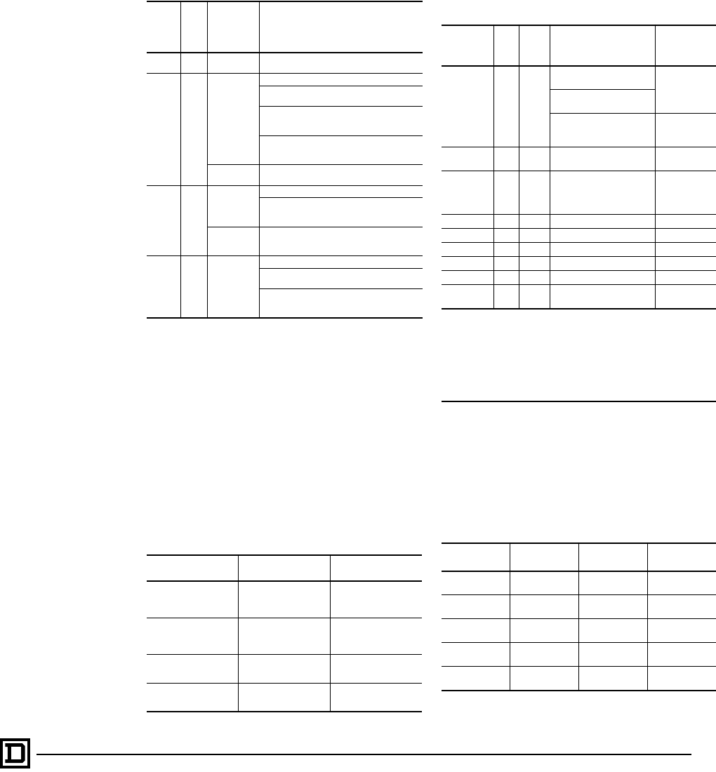
Types SB-SD with Auxiliary Load Terminals – Class 8536
3-Pole Polyphase — Three Thermal Units Required
It is sometimes desirable to use the capacitors in motor branch circuits to improve power factor. The Size
0-2 Type SB-SD starters listed included three auxiliary terminals to allow easy connection of power
factor correction capacitors. When capacitors are connected using these terminals, no adjustment on
the selection of thermal units is necessary.
These terminals are also available as a kit Class 9999 Type PFL for Type S NEMA Size 0, 1 and 2
Starters with Motor Logic overload relays. These terminals are available for connection of power factor
(PF) correction capacitors. These kits are sold separately and are not factory installed.
NEMA Size Motor Volts Maximum HP Coil Voltage Open Type
0
Separate Controlj120 SBTO2V02S
200 3 208 SBTO2V08
230 3 240 SBTO2V03
460 5 480 SBTO2V06
575 5 600 SBTO2V07
1
Separate Controlj120 SBTO3V02S
200 71⁄2208 SBTO3V08
230 71⁄2240 SBTO3V03
460 10 480 SBTO3V06
575 10 600 SBTO3V07
2
Separate Controlj120 SDTO1V02S
200 10 208 SDTO1V08
230 15 240 SDTO1V03
460 25 480 SDTO1V06
575 25 600 SDTO1V07
j120 Volt polyphase starters are wired for separate control.
Extra Capacity Single Phase Starters
2-Pole Single Phase — 250 Volts AC Maximum — 50-60 Hertz
Thermal Units — Devices require 1 thermal unit. Standard trip.
Motor
Volts Max.
HP
t
Coil
Voltage
Open
Type
NEMA Type 1
General Purpose
Enclosure
NEMA Type 3R
Rainproof, Sleet
Resistant, Outdoor
Use Enclosure
NEMA Type 4 & 4X
Watertight, Dusttight
Brushed Stainless Steel
Enclosure
(Sizes 0-5)
NEMA Type 4X
Watertight
Corrosion Resistant
Class-Polyester
Enclosure
NEMA Type 12
Dusttight & Driptight
Industrial Use
Enclosure
Type Type Type Type Type
115 5 120 SDO8V02 . . . SDH8V02 . . . . . . . . .
230 10 240 SDO8V03 SDH8V03
115 71⁄2120 SEO6V02 SEG6V02 SEH6V02 SEW16V02 SEW26V02 SEA6V02
230 15 240 SEO6V03 SEG6V03 SEH6V03 SEW16V03 SEW26V03 SEA6V03
tCoil voltage code must be specified to order this product. Refer to standard coil voltage codes listed in selection tables above or additional standard voltage codes below and insert as
shown in the HOW TO ORDER bolck.
Coil Voltage Codes
Voltage Code
60 Hz 50 Hz
24 . . . VO1
120 110 VO2
208 . . . VO8
240 220 VO3
480 440 VO6
600 550 VO7
Specify Specify V99
Full Voltage Starters
Selection – Class 8536
Factory Modifications (FORMS) ...............Refer to Catalog 9999CT9701
Application Data ................................................................... Pages 13-16
Dimensions ........................................................................... Pages 17-20
Separate Enclosures (Class 9991) ...........Refer to Catalog 9999CT9701
Replacement Parts (Class 9998) ..............Refer to Catalog 9999CT9701
Type S Accessories (Class 9999).............Refer to Catalog 9999CT9701
How to Order:
To Order Specify: Catalog Number
• Class Number
• Type Number
• Coil Voltage Code
• Form(s)
Class Type Coil
Voltage
Code
Form(s)
8536 SEG6 VO3 P1
13
5/98 © 1998 Square D All Rights Reserved
NEMA
Size Load
Volts
Maximum
Horsepower
Rating –
Nonplugging
and
Nonjogging
Duty
Maximum
Horsepower
Rating –
Plugging and
Jogging Duty j
Continuous
Current
Rating,
Amperes –
600 Volt
Max.
Service –
Limit
Current
Rating,
Amperes
t
Tungsten
and
Infrared
Lamp
Load,
Amperes –
250 Volts
Max.
a
Resistance
Heating Loads,
KW – Other
Than Infrared
Lamp Loads
u
KVA Rating for Switching
Transformer Primaries at 50 or 60
Cycles
3 Phase
Rating for
Switching
Capacitors
k
Transformers
Having Inrush
Currents (Worst
Case Peak) of
Not More Than
20 Times Peak of
Continuous
Current Rating
Transformers
Having Inrush
Currents (Worst
Case Peak) of
Over 20 Through
40 Times Peak of
Continuous
Current Rating
Single
Phase Poly-
Phase Single
Phase Poly-
Phase Single
Phase Poly-
Phase Single
Phase Poly-
Phase Single
Phase Poly-
Phase KVAR
00
115 1⁄2. . . . . . . . . 9 11 5 . . . . . . . . . . . . . . . . . . . . .
200 . . . 11⁄2. . . . . . 9 11 5 . . . . . . . . . . . . . . . . . . . . .
230 1 11⁄2. . . . . . 9 11 5 . . . . . . . . . . . . . . . . . . . . .
380 . . . 11⁄2. . . . . . 9 11 . . . . . . . . . . . . . . . . . . . . . . . .
460 . . . 2 . . . . . . 9 11 . . . . . . . . . . . . . . . . . . . . . . . .
575 . . . 2 . . . . . . 9 11 . . . . . . . . . . . . . . . . . . . . . . . .
0
115 1 . . . 1⁄2. . . 18 21 10 . . . . . . 0.6 . . . 0.3 . . . . . .
200 . . . 3 . . . 11⁄218 21 10 . . . . . . . . . 1.8 . . . 0.9 . . .
230 2 3 1 11⁄218 21 10 . . . . . . 1.2 2.1 0.6 1.0 . . .
380 . . . 5 . . . 11⁄218 21 . . . . . . . . . . . . . . . . . . . . . . . .
460 . . . 5 . . . 2 18 21 . . . . . . . . . 2.4 4.2 1.2 2.1 . . .
575 . . . 5 . . . 2 18 21 . . . . . . . . . 3.0 5.2 1.5 2.6 . . .
1
115 2 . . . 1 . . . 27 32 15 3 5 1.2 . . . 0.6 . . . . . .
200 . . . 71⁄2. . . 3 27 32 15 . . . 9.1 . . . 3.6 . . . 1.8 . . .
230 3 71⁄22 3 27 32 15 6 10 2.4 4.3 1.2 2.1 . . .
380 . . . 10 . . . 5 27 32 . . . . . . 16.5 . . . . . . . . . . . . . . .
460 . . . 10 . . . 5 27 32 . . . 12 20 4.9 8.5 2.5 4.3 . . .
575 . . . 10 . . . 5 27 32 . . . 15 25 6.2 11.0 3.1 5.3 . . .
1P 115 3 . . . 11⁄2. . . 36 42 24 . . . . . . . . . . . . . . . . . . . . .
230 5 . . . 3 . . . 36 42 24 . . . . . . . . . . . . . . . . . . . . .
2
115 3 . . . 2 . . . 45 52 30 5 8.5 2.1 . . . 1.0 . . . . . .
200 . . . 10 . . . 71⁄245 52 30 . . . 15.4 . . . 6.3 . . . 3.1 . . .
230 71⁄215 5 10 45 52 30 10 17 4.1 7.2 2.1 3.6 8
380 . . . 25 . . . 15 45 52 . . . . . . 28 . . . . . . . . . . . . . . .
460 . . . 25 . . . 15 45 52 . . . 20 34 8.3 14 4.2 7.2 16
575 . . . 25 . . . 15 45 52 . . . 25 43 10.0 18 5.2 8.9 20
3
115 . . . . . . . . . . . . 90 104 60 10 17 4.1 . . . 2.0 . . . . . .
200 . . . 25 . . . 15 90 104 60 . . . 31 . . . 12 . . . 6.1 . . .
230 . . . 30 . . . 20 90 104 60 20 34 8.1 14 4.1 7.0 27
380 . . . 50 . . . 30 90 104 . . . . . . 56 . . . . . . . . . . . . . . .
460 . . . 50 . . . 30 90 104 . . . 40 68 16 28 8.1 14 53
575 . . . 50 . . . 30 90 104 . . . 50 86 20 35 10 18 67
4
200 . . . 40 . . . 25 135 156 120 . . . 45 . . . 20 . . . 10 . . .
230 . . . 50 . . . 30 135 156 120 30 52 14 23 6.8 12 40
380 . . . 75 . . . 50 135 156 . . . . . . 86.7 . . . . . . . . . . . . . . .
460 . . . 100 . . . 60 135 156 . . . 60 105 27 47 14 23 80
575 . . . 100 . . . 60 135 156 . . . 75 130 34 59 17 29 100
5
200 . . . 75 . . . 60 270 311 240 . . . 91 . . . 41 . . . 20 . . .
230 . . . 100 . . . 75 270 311 240 60 105 27 47 14 24 80
380 . . . 150 . . . 125 270 311 . . . . . . 173 . . . . . . . . . . . . . . .
460 . . . 200 . . . 150 270 311 . . . 120 210 54 94 27 47 160
575 . . . 200 . . . 150 270 311 . . . 150 260 68 117 34 59 200
6f
200 . . . 150 . . . 125 540 621 480 . . . 182 . . . 81 . . . 41 . . .
230 . . . 200 . . . 150 540 621 480 120 210 54 94 27 47 160
380 . . . 300 . . . 250 540 621 . . . . . . 342 . . . . . . . . . . . . . . .
460 . . . 400 . . . 300 540 621 . . . 240 415 108 188 54 94 320
575 . . . 400 . . . 300 540 621 . . . 300 515 135 234 68 117 400
7f230 . . . 300 . . . . . . 810 932 . . . 180 315 . . . . . . . . . . . . 240
460 . . . 600 . . . . . . 810 932 . . . 360 625 . . . . . . . . . . . . 480
575 . . . 600 . . . . . . 810 932 . . . 450 775 . . . . . . . . . . . . 600
Tables and footnotes are taken from NEMA Standards.
jRatings shown are for applications requiring repeated interruptions of stalled motor current or repeated closing of high transient currents encountered in rapid motor reversal, involving more
than five openings or closings per minute and more than ten in a ten-minute period, such as plug-stop, plug-reverse or jogging duty. Ratings apply to single speed and multi-speed
controllers.
tPer NEMA Standards paragraph ICS 2-321.20, the service-limit current represents the maximum ms current, in amperes, which the controller may be expected to carry for protracted periods
in normal service. At service-limit current ratings, temperature rises may exceed those obtained by testing the controller at its continuous current rating. The ultimate trip current of over-
current (overload) relays or other motor protective devices shall not exceed the service-limit current ratings of the controller.
aFLUORESCENT LAMP LOADS – 300 VOLTS AND LESS – The characteristics of fluorescent lamps are such that it is not necessary to derate Class 8502 contactors below their normal
continuous current rating. Class 8903 contactors may also be used with fluorescent lamp loads. For controlling tungsten and infrared lamp loads, and resistance heating loads, Class 8903
ac lighting contactors are recommended. These contactors are specifically designed for such loads and are applied at their full rating as listed in the Class 8903 Section.
uRatings apply to contactors which are employed to switch the load at the utilization voltage of the heat producing element with a duty which requires continuous operation of not more than
five openings per minute. Class 8903 Types L and S lighting contactors are rated for resistance heating loads.
kWhen discharged, a capacitor has essentially zero impedance. For repetitive switching by contactor, sufficient impedance should be connected in series to limit inrush current to not more
than 6 times the contactor rated continuous current. In many installations, the impedance of connecting conductors may be sufficient for this purpose. When switching to connect additional
banks, the banks already on the line may be charged and can supply additional available short-circuit current which should be considered when selecting the impedance to limit the current.
The ratings for capacitor switching above assume the following maximum available fault currents: NEMA Size 2-3: 5,000 A RMS Sym.; NEMA Size 4-5: 10,000 A RMS Sym.; NEMA Size
6-7: 18,000 A RMS Sym. If available fault current is greater than these values, connect sufficient impedance in series as noted in the previous paragraph.
fSee Page 16 regarding operation rates for Size 6 & 7.
The motor ratings in the above table are NEMA standard ratings and apply only when the code letter of the motor is the same as or occurs earlier in the alphabet than is shown in
the table below. Motors having code letters occurring later in the alphabet may require a larger controller. Consult local Square D field office.
Motor HP Rating Maximum Allowable Motor
Code Letter
11⁄2-2 L
3-5 K
71⁄2 & above H
Full Voltage Contactors and Starters — NEMA
Application Data – Class 8502, 8536
© 1998 Square D All Rights Reserved
14 5/98
CLASS 8502 AND 8536 APPLICATION
DATA
Power Contact Ratings
All contactors and starters are rated in
accordance with NEMA standards. The ratings
shown in the price tables are for normal service.
For complete data on power contact ratings, refer
to Page 13.
Short Circuit Protection
According to the National Electrical Code branch
circuit overcurrent protection must be provided for
each contactor or starter. For starters refer to
instructions furnished with the thermal unit
selection table. For contactors (Class 8502 or
8702) provide branch circuit overcurrent
protection in accordance with the National
Electrical Code, except do not exceed the
maximum protective device ratings in table below.
Capacitor Switching
The kilovar ratings of enclosed, three phase contactors
used as switches for capacitor loads, when only one
load appears on the secondary of a distribution system
are shown in the table on Page 13.
Maintenance of Equipment
Class 9998 Repair Parts Kits are available for all
Class 8502 contactors and Class 8536 starters.
Service bulletins with a complete list of replaceable
parts are supplied with all enclosed devices.
Separate bulletins can be ordered and are listed
along with the appropriate contact parts kit.
NEMA
Size Maximum
Voltage
Class
K5, RK5 or
RK1 Fuse
(Ampere)
Class
J or T
Fuse
(Ampere)
Inverse-Time
Circuit
Breaker
(Ampere)
00 600 10 15 15
250 12
0600 20 30 20
250 25 35
1600 30 60 40
250 40 60
2600 60 100 80
250 90
3600 100 200 125
250 125 150
4 600 200 400 225
5 600 400 600 400
6 600 600 1200t800
7 600 600 1600t1200
tClass L Fuse only.
Coil Burdenq
NEMA
Size No. of
Poles
Inrush VA Sealed VA Sealed Watts
50
Hertz 60
Hertz 50
Hertz 60
Hertz 50
Hertz 60
Hertz
00 2-3 . . . 165 . . . 33 . . . 6
0 & 1 1-5 232 245 26 27 7.7 7.8
22 & 3 296 311 36 37 12 14
4 & 5 429 438 37 38
32-3 676 700 47 46 15 14
4-5 1260 1185 89 85 23.4 22
4 2-5 . . . 973 . . . 81 . . . 25
5 2-3 2970 2970 250 212 42 39
6a2-3 1495 1780 56 48 27 32
7a2-3 . . . 1960 . . . 59 . . . 36
qMean values.
aSize 6 and 7 have a DC coil. The values shown are for the AC input
to the DC power supply that provides power to the coil.
Device Service
Bulletin
Replacement
Contacts
Class 9998 Type
NEMA
Type Type Series No. of
Poles
00 SA A 2-3 362AS SL2
B 2-3 556AS SJ1
0 SB A & B 1-3
4
5
277AS
277AS & 250AS
277AS & 250AS
SL2
SL12
(1)SL12 & (1)SL22
or
(1)SL2 & (2)SL22
1 SC A & B 1-3
4
5
278AS
278AS & 250AS
278AS & 250AS
SL3
SL13
(1)SL13 & (1)SL22
or
(1)SL3 & (2)SL22
1P SC A 2 278AS SL3
2SDA2-3
4
5
279AS
279AS & 293AS
279AS & 293AS
SL4
SL14
(1)SL14 & (1)SL24
or
(1)SL4 & (2)SL24
3SEA
2 305AS SL6
3 305AS SL7
4 326AS (2)SL6
5 326AS (1)SL6 & (1)SL7
4SFA
2 306AS SL8
3 306AS SL9
4 326AS (2)SL8
5 326AS (1)SL8 & (1)SL9
5SGA2 328AS SL10
3 328AS SL11
6SH
A2 342AS SL25
3 342AS SL26
B2 370AS SL25
3 370AS SL26
7SJA2397AS SL30
3 SL31
Terminals
NEMA
Size Type
Power Terminals Control Terminals
Type
of Lug
Wire
Sizest
Min.-Max.
Type
of Lug
Wire
Sizest
Min.-Max.
00,
0 & 1 SA, SB
& SC Pressure
Wire #14-#8 Pressure
Wire #16-#12
2 SD Box Lug #14-#4 Pressure
Wire #16-#12
3 SE Box Lug #14-1/0 Pressure
Wire #16-#12
4 SF Box Lug #8-250 kcmil Pressure
Wire #16-#12
5 SG Box Lug #4-500 kcmil Pressure
Wire #16-#12
6SH
Parallel
Groove
One or two
250-500 kcmil
per phase
Pressure
Wire #16-#12
7SJ
Parallel
Groove
One to four
250-500 kcmil
per phase
Pressure
Wire #16-#12
tSolid or stranded copper wire.
Full Voltage Contactors and Starters — NEMA
Application Data – Class 8502, 8536
15
5/98 © 1998 Square D All Rights Reserved
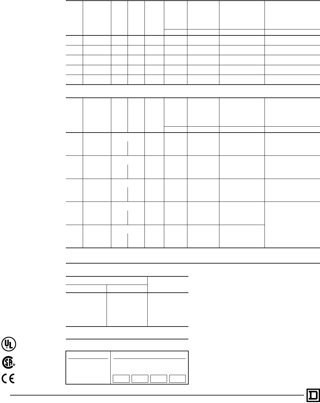
Auxiliary Units
Auxiliary contacts, power poles, and timer
attachments can be added by the factory or in the
field on all Type S starters and contactors. The
table below shows the maximum number of
auxiliary units (in addition to the holding circuit
contact) that can be added to a given size starter
or contactor. In addition, it is possible to add a
second internal contact on NEMA Size 0, 1, and 2
contactors and starters.
Factory Installed Auxiliary Contacts
Additional auxiliary contacts may be factory or
field added to any Type S contactor or starter. See
table above for maximum number of auxiliary
units. The table below lists the Form designations
for factory installed electrical contacts.
See Class 9999 for field modification kits.
Form Number of Additional Auxiliary
Contacts
When ordering factory installed auxiliary contacts,
the Form designations listed should be used.
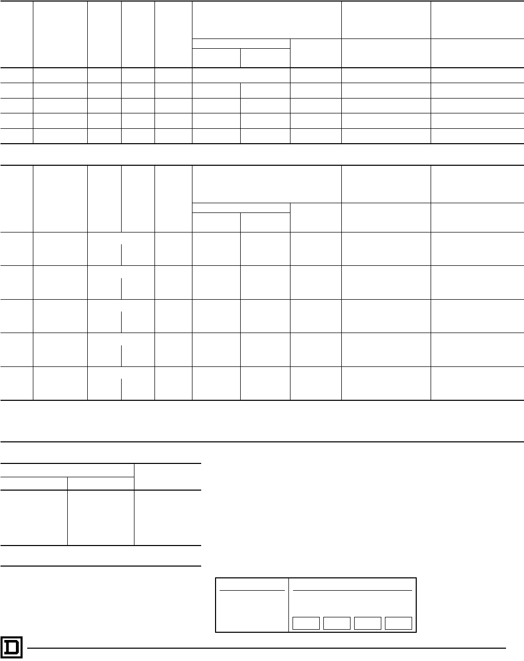
Control Circuit Transformers
Class 9070 Type T machine tool control
transformers are normally used when it is
necessary to provide a lower voltage to the control
circuit. This transformer with fused protection may
be ordered from the factory by specifying Form
F4T. The addition of a transformer often requires
the use of a larger enclosure. The table below
shows the transformer selection for given sized
starters and contactors with or without auxiliary
units.
Power Poles
Single or double circuit power pole adders may be
factory or field installed on 2 and 3 pole Type S
contactors and starters. The table below lists the
Form designation for factory installed power pole
adders. Only one power pole adder may be
installed per contactor.
NEMA
Size Type
No. of
Poles of
Basic
Contactor
Maximum Number of External
Auxiliary Units (In addition to
holding circuit contact)
00 SA 2-3 4 single circuit auxiliary contacts (N.O. or N.C.)
if second internal auxiliary contact is not used.
0, 1 & 2 SB
SC
SD
1, 2 or 3
4 single circuit auxiliary contacts (N.O. or N.C.)
3 single circuit auxiliary contacts (N.O. or N.C.)
plus 1 attached timer (ON or OFF delay).
2 single circuit auxiliary contacts (N.O. or N.C.)
plus 1 power pole adder (1 or 2 poles, N.O. or
N.C.).
1 attached timer (ON or OFF delay) plus 1
power pole adder (1 or 2 poles, N.O. or N.C.)
plus 1 auxiliary contact.
4 or 5 2 single circuit auxiliary contacts (N.O. or N.C.)
1 timer attachment plus 1 auxiliary contact.
3, 4 & 5 SE
SF
SG
2-5
(Size 3 & 4)
4 single circuit auxiliary contacts (N.O. or N.C.)
2 single circuit (Sizes 3 & 4) or 3 single circuit
(Size 5) auxiliary contacts plus 1 attached timer
(ON or OFF delay).
2-3
(Size 5)
2 single circuit auxiliary contacts (N.O. or N.C.)
plus 1 NEMA Size 0-1 or Size 2 power pole
adder (1 or 2 poles, N.O. or N.C.)
6 & 7 SH
SJ 2-3
4 single circuit auxiliary contacts (N.O. or N.C.)
3 single circuit auxiliary contacts (N.O. or N.C.)
plus 1 attached timer (ON or OFF delay).
2 single circuit auxiliary contacts (N.O. or N.C.)
plus 1 NEMA Size 0-1 or Size 2 power pole
adder (1 or 2 poles, N.O. or N.C.)
Number of N.O.
Contacts Number of N.C.
Contacts Form Number
0
1 X01
2 X02
3 X03
4 X04
1
0 X10
1 X11
2 X12
3 X13
20 X20
1 X21
2 X22
3 0 X30
3 1 X31
4 0 X40
NEMA
Size Type No.
of
Poles Auxiliary Units Transformer
Class 9070
Type
0 & 1 SB
SC 1-3
With max. of 2 auxiliary
contacts T50
With timer and maximum of
1 auxiliary contact
With 3 or 4 auxiliary
contacts with timer and 2 or
3 auxiliary contacts T100
0 & 1 SB
SC 4 & 5 With or without auxiliary
contacts or timer T100
0 & 1
Mechanically
Interlocked
Devices
SB
SC 1-5 With or without attachments T100
2 SD 2-5 With or without attachments T100
3 SE 2-3 With or without attachments GO3j
3 SE 4 & 5 With or without attachments T300
4 SF 2-5 With or without attachments T300
5 SG 2-3 Any T500
6, 7 SH,
SJ 2-3 Any u
jClass 8502 & 8536 Type S, Size 3 standard NEMA Type 1, 4 and 12
enclosures have space for field mounting a fused control circuit
transformer. A Class 9070 Type GFT3 transformer and fuse block kit
is available for Form F4T requirements in a NEMA Type 1 enclosure.
NEMA Type 4 and 12 enclosures utilize a Class 9070 T150
transformer and a Class 9999 SF4 fuse block.
uA Class 9070 transformer is an integral part of the Size 6 and Size 7
control circuit providing 120 volt control circuit voltage as standard.
Type NEMA Size Class 9999
Type Form
Designation
1 N.O. 0, 1 SB6 Y428
2 SB11 Y436
1 N.C. 0, 1 SB7 Y429
2 SB12 Y437
1 N.O., 1 N.C. 0, 1 SB8 Y435
2 SB13 Y440
2 N.O. 0, 1 SB9 Y430
2 SB14 Y438
2 N.C. 0, 1 SB10 Y434
2 SB15 Y439
Full Voltage Contactors and Starters — NEMA
Application Data – Class 8502, 8536
© 1998 Square D All Rights Reserved
16 5/98
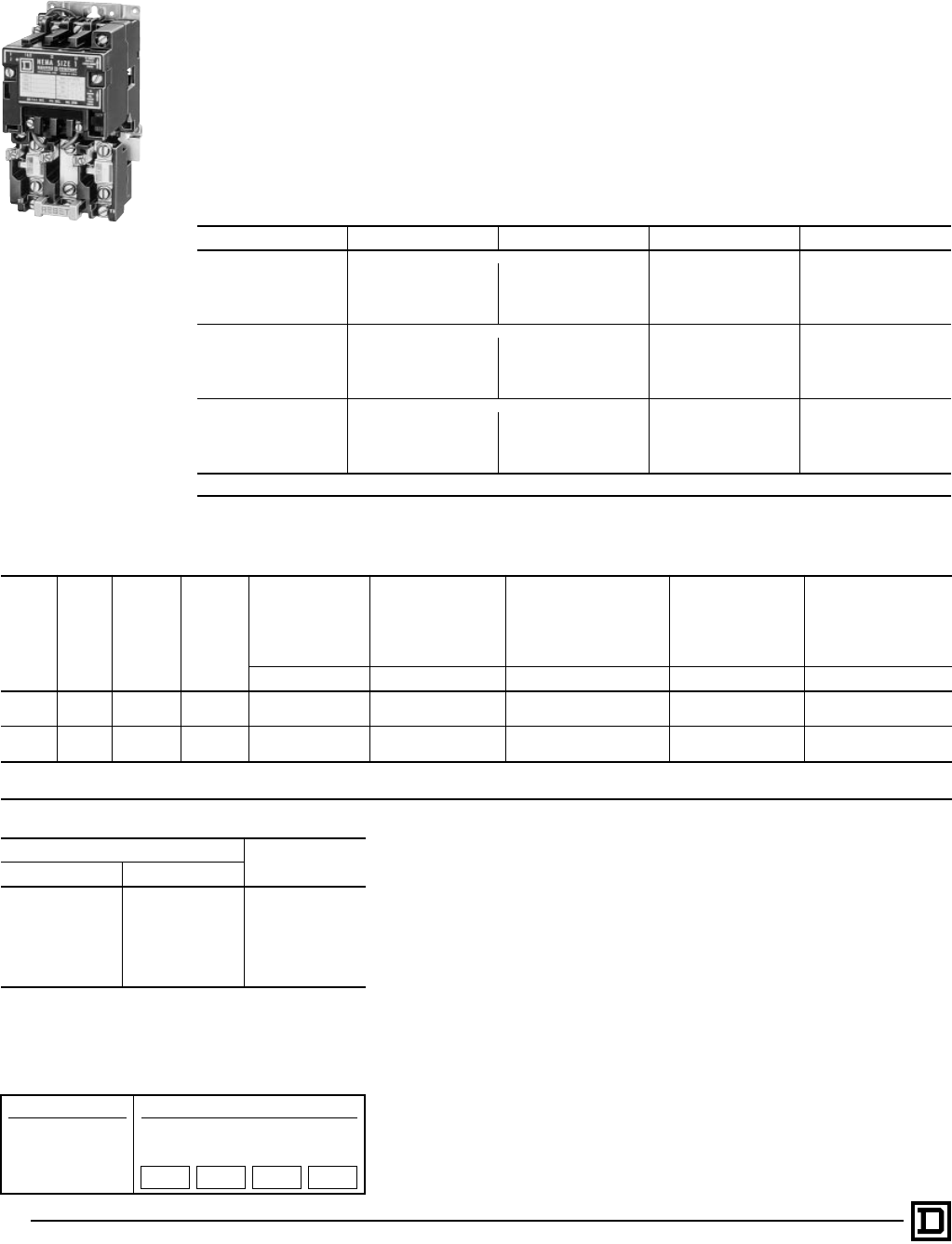
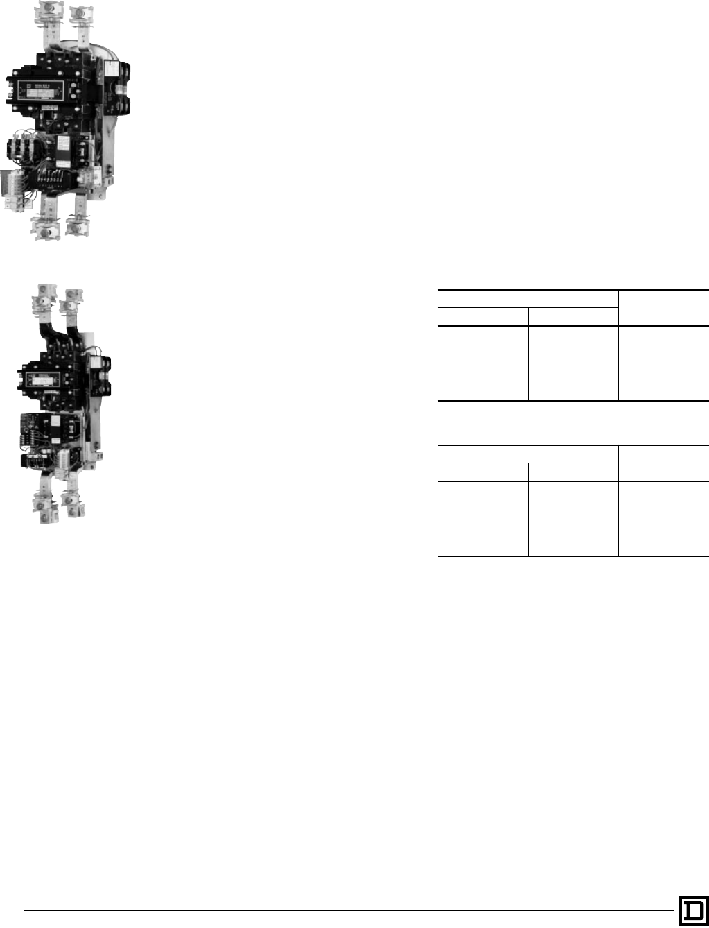
Size 6 Type SH and Size 7 Type SJ Contactors
and Starters
Size 6 Type SH and Size 7 Type SJ contactors and
starters have a DC coil operated by a solid state
rectifier circuit mounted on the device and
powered from an ac source. The Size 6 and 7 are
equipped as standard with a fused control circuit
transformer (Form F4T) rated 240/480-120 volts
60 hertz, 220/440-110 volts 50 hertz. The purpose
of this transformer is to provide an isolated 120
volts 60 hertz, 110 volts 50 hertz, supply for the
control circuit. Size 6 and 7 devices may be
ordered for other system voltages by specifying
the voltage and frequency desired.
Operation Rates
Continuous operation rate: 3 operations/minute
maximum. Jogging or Plugging Duty: 15
operations/minute – 3 minutes maximum.
Field conversion for other system voltages is
accomplished by one of the following methods,
NOT BY THE USUAL PRACTICE OF CHANGING
THE COIL:
1. If the factory wiring is indicated as being for
480 volts 60 hertz, 440 volts 50 hertz,
conversion to 240 volts 60 hertz, 220 volts 50
hertz, can be accomplished by reconnecting
the control transformer as illustrated on
instruction sheet supplied with the controller.
This is the same method that would be used
on Class 9070 control circuit transformers.
Conversion to any other voltage requires
replacement of the control transformer. For
other system voltages: i.e. 208, 277, 380, 600
volts, a new transformer with single voltage
primary must be selected from table at right.
Control transformer connections are
illustrated on the instruction sheet supplied
with the controller.
2. If the factory wiring is indicated as being for
any voltage other than 480 volts 60 hertz, 440
volts 50 hertz, conversion to any other voltage
requires replacement of the control
transformer. Refer to table at right.
3. The standard transformer supplied may be
used to power a maximum of five Class 9001
Type K illuminated operators powered with
transformer type light modules. When extra
capacity to power control relays or other
inductive loads is required, a second
transformer must be added. Extra capacity
can be purchased as Form F4T with additions
in 100 VA increments.
4. Standard controllers are wired for common
control and are not convertible for operation of
the control circuit from a separate source of
supply voltage. Controllers designated Form S
have special wiring designed for separate
control. They are furnished with an isolating
transformer, usually having a 120 volt primary
and 120 volt secondary, that must not be
bypassed. Form S controllers are not
convertible for operation on common control.
The tables below give the replacement
transformers for Type S Sizes 6 and 7 contactors
and starters. To change voltages on these
devices, coils are not changed, instead
transformers with the desired voltage are
changed.
Auxiliary Contacts
A N.O. holding circuit contact and a N.C. auxiliary
contact are provided as standard. The holding
circuit contact may or may not be required for
either 3-wire or 2-wire control. Size 6 and 7
devices have an additional N.C. auxiliary contact
which is wired in the coil control circuit. DO NOT
USE THIS N.C. CONTACT FOR ANY OTHER
PURPOSE.
Replacement Control Transformers for Type S
Size 6
Voltage Class 9070 Type
60 Hertz 50 Hertz
240/480-120 220/440-110 EO3S2A
208-120 . . . EO3S2B
277-120 . . . EO3S2C
. . . 380-110 EO3S2D
600-120 550-110 EO3S2E
120-120 110-110 EO3S2F
240-120 220-110 EO3S2G
Replacement Control Transformers for Type S
Size 7
Voltage Class 9070 Type
60 Hertz 50 Hertz
240/480-120 220/440-110 EO19S2A
208-120 . . . EO19S2B
277-120 . . . EO19S2C
. . . 380-110 EO19S2D
600-120 550-110 EO19S2E
120-120 110-110 EO19S2F
240-120 220-110 EO19S2G
Full Voltage Contactors and Starters — NEMA
Application Data – Class 8502, 8536
Size 6 Starter 8536 SH
Size 7 Starter 8536 SJ
17
5/98 © 1998 Square D All Rights Reserved
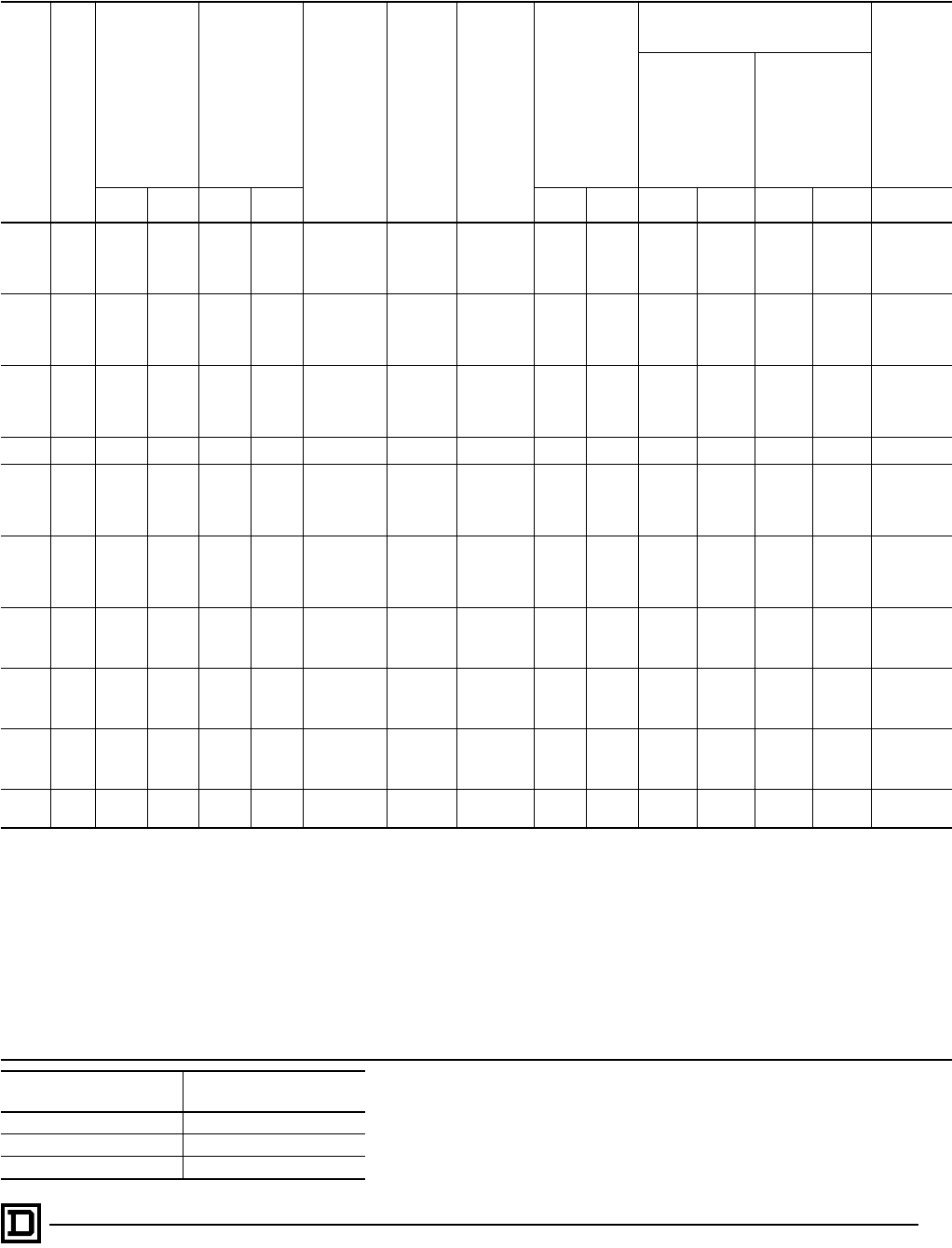
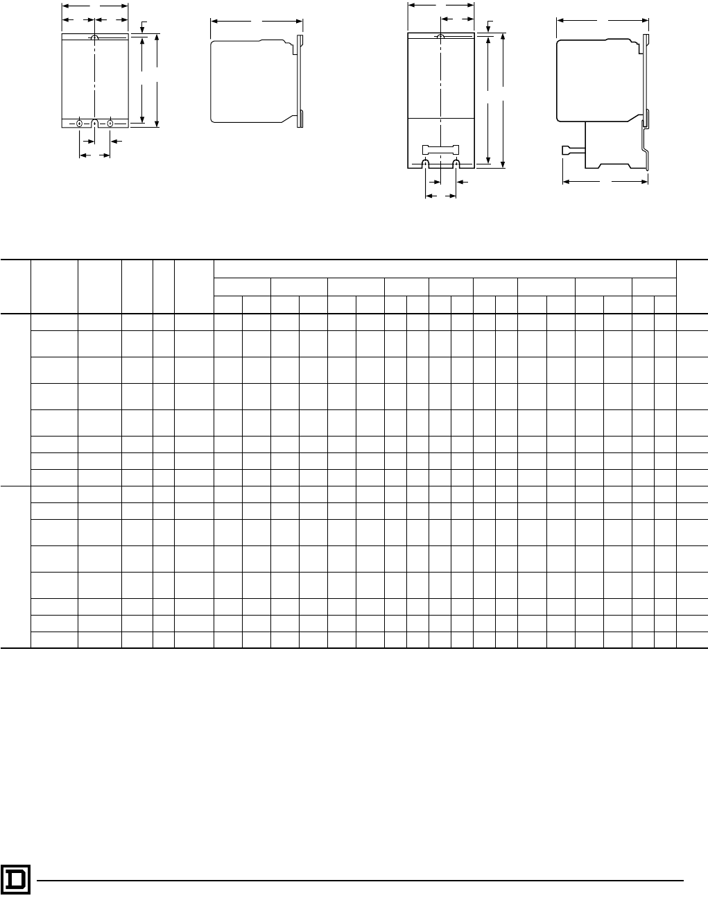
Class 8502 Open Type Class 8536 Open Type
Class NEMA
Size Type No.
of
Poles
Fig.
No. Mtg.
Screws
Dimensions – Inches/mm (Refer to Appropriate Figure) Wt
(Lbs)
ABCDEFGHI
IN mm IN mm IN mm IN mm IN mm IN mm IN mm IN mm IN mm
8502
00 SAO 2-3 1 (2) #10 3.22 82 4.34 110 4.22 107 1.63 41 1.63 41 .22 6 3.94 100 . . . . . . . . . . . . 4
0 SBO 1-3 1 (2) #10 3.22 82 4.34 110 4.22 107 1.63 41 1.63 41 .22 6 3.94 100 . . . . . . . . . . . . 4
1 SCO 4-5 4.25 108 4.34 110 4.22 107 1.63 41 2.63 67 .22 6 3.94 100 . . . . . . . . . . . . 41⁄2
2 SDO 2-3 1 (3) #10 4.94 125 5.13 130 4.94 125 2.16 55 2.16 55 .22 6 4.59 117 .53 13 1.06 27 63⁄4
4-5 5.63 143 5.13 130 4.94 125 2.16 55 3.47 88 .22 6 4.59 117 .53 13 1.06 27 81⁄4
3 SEO 2-3 1(3) 1⁄4" 5.47 139 7.09 180 6.50 165 1.88 48 3.59 91 .31 8 6.03 153 3.25 83 4.75 121 14
4-5 (3) 5⁄16" 9.75 248 7.88 200 6.50 165 3.94 100 5.81 148 .31 8 7.00 178 4.53 115 9.06 230 22
4 SFO 2-3 1(3) 5⁄16" 6.00 152 8.19 208 6.50 165 2.06 52 3.94 100 .31 8 7.00 178 3.59 91 5.31 135 18
4-5 (3) 5⁄16" 9.75 248 8.19 208 6.50 165 3.94 100 5.81 148 .31 8 7.00 178 4.53 115 9.06 230 22
5 SGO 2-3 1 (3) 1⁄2" 8.66 220 12.31 313 8.75 222 3.25 83 5.81 148 .63 16 11.13 283 4.75 121 7.25 184 45
6 SHO 2-3 1 (3) 1⁄2" 12.34 313 28.06 713 9.00 229 3.53 90 5.78 147 5.06 129 18.56 471 4.75 121 7.25 184 80
7 SJO 2-3 1 (3) 1⁄2" 12.34 313 37.25 946 10.88 276 3.53 90 5.78 147 7.22 183 22.38 568 4.75 121 7.25 184 135
8536
00, 0, 1, 1P SAO-SCO 2-3 2 (3) #10 3.50 89 6.77 172 4.22 107 .50 13 1.00 25 1.61 41 .20 5 6.25 159 3.97 101 5
0, 1 SBO-SCO 4 2 (3) #10 4.53 115 6.77 172 4.22 107 .50 13 1.00 25 2.66 68 .20 5 6.25 159 3.97 101 51⁄2
2 SDO 2-3 2 (3) #10 4.31 109 7.81 198 4.94 125 .50 13 1.00 25 2.16 55 .20 5 7.34 186 4.06 103 73⁄4
4 5.63 143 7.81 198 4.94 125 .50 13 1.00 25 3.47 88 .20 5 7.34 186 4.06 103 91⁄4
3 SEO 2-3 2(3) 1⁄4" 5.47 139 11.09 282 6.50 165 .88 22 1.75 44 3.59 91 .31 8 10.19 259 5.75 146 17
4 (3) 5⁄16" 9.75 248 12.13 308 6.50 165 1.81 46 1.75 44 5.81 148 .31 8 11.19 284 5.75 146 25
4 SFO 32(3) 5⁄16" 6.00 152 12.88 327 6.50 165 1.81 46 1.75 44 3.94 100 .31 8 11.19 284 5.75 146 22
4 (3) 5⁄16" 9.75 248 12.88 327 6.50 165 1.81 46 1.75 44 5.91 150 .31 8 11.19 284 5.75 146 25
5 SGO 3 2 (3) 1⁄2" 8.56 217 17.56 446 8.75 222 4.75 121 7.25 184 5.38 137 .63 16 16.38 416 6.00 152 62
6 SHO 3 2 (3) 1⁄2" 12.34 313 28.06 713 9.00 229 4.75 121 7.25 184 5.78 147 5.06 129 18.56 471 8.69 221 85
7 SJO 3 2 (3) 1⁄2" 12.34 313 37.25 946 10.88 276 4.75 121 7.25 184 5.78 147 7.22 183 22.38 568 9.00 229 140
A
B
C
I
H
EF
G
D
A
B
C
E
D
FG
H
I
RESET
Figure 1
Figure 2
Full Voltage Contactors and Starters — NEMA
Approximate Dimensions, Shipping Weights – Class 8502, 8536
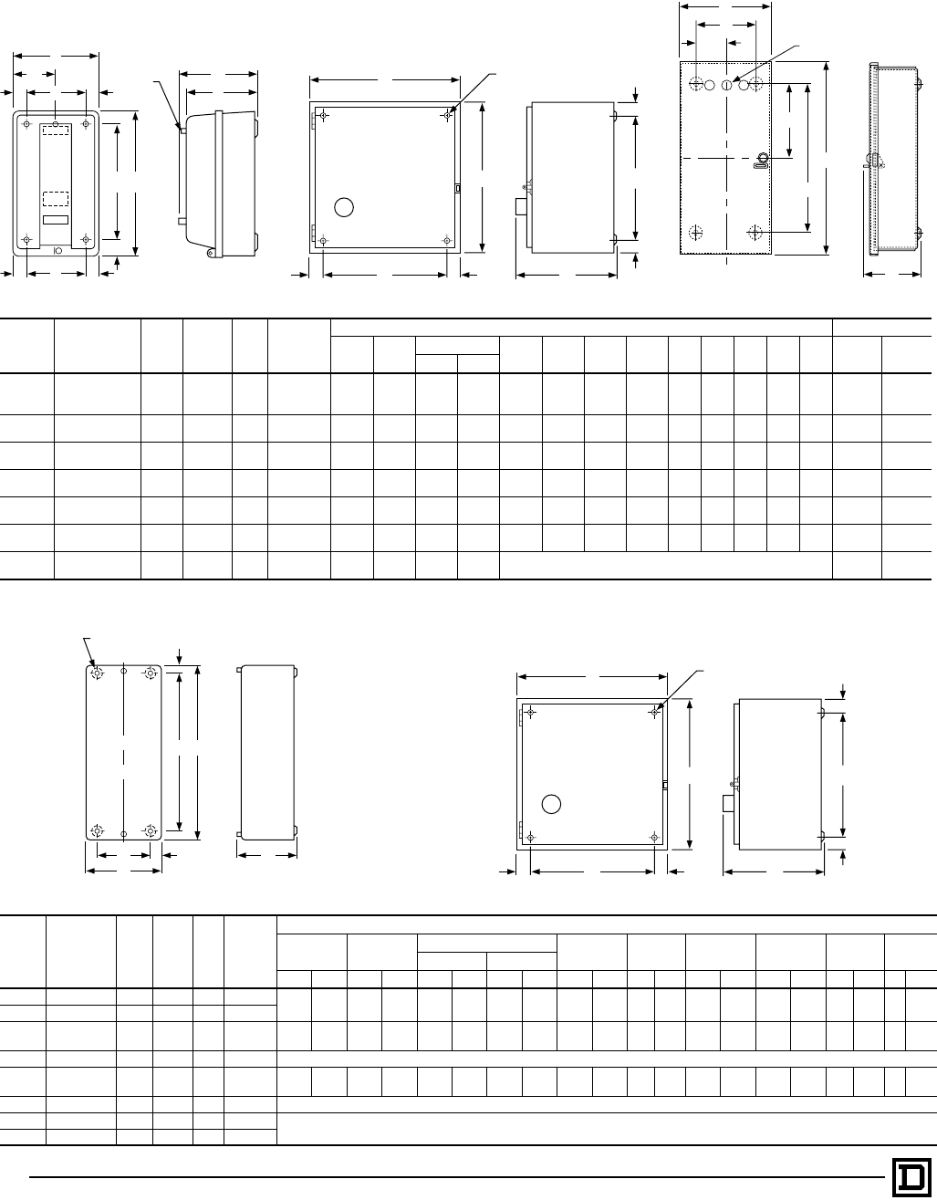
© 1998 Square D All Rights Reserved
18 5/98
NEMA Type 1 — General Purpose Enclosure
NEMA Type 1 — General Purpose Enclosure with Form F4T
NEMA
Size Class Type No.
of
Poles
Fig.
No. Mtg.
Screws
Dimensions – Inches/mm (Refer to Appropriate Figure) Wt (Lbs)
ABCDEFGHIJKL
Class
8502 Class
8536
8502 8536
00 8502 & 8536 SAG All 3 (3) #10 6.00
152 10.00
254 5.28
134 5.56
141 3.00
76 .88
22 8.13
207 1.00
25 .94
24 4.13
105 5.00
127 . . . . . . 71⁄280 SBG
1 SCG
2 8502 & 8536 SDG All 3 (4) 1⁄4"7.81
198 12.69
322 6.03
153 6.31
160 . . . 1.09
28 10.50
267 1.09
28 1.09
28 5.63
143 5.75
146 1.09
28 5.63
143 141⁄2151⁄2
3 8502 & 8536 SEG All 3 (4) 3⁄8"11.44
291 21.81
554 8.00
203 8.38
213 . . . 1.53
39 18.75
476 1.53
39 1.53
39 8.38
213 7.75
197 1.53
39 8.38
213 34 37
4 8502 & 8536 SFG All 4 (4) 7⁄16"11.25
286 25.16
639 9.00
229 9.00
229 8.59
218 1.25
32 1.25
32 22.31
567 1.44
37 .44
11 . . . . . . . . . 52 56
5 8502 & 8536 SGG All 4 (4) 9⁄16"17.22
437 44.22
1123 12.81
325 12.94
329 13.00
330 2.13
54 2.13
54 40.00
1016 2.13
54 .56
14 . . . . . . . . . 143 160
6 8502 & 8536 SHG All 5 (4) 11⁄16"65.75
1670 20.22
514 13.13
334 13.13
334 . . . 11.00
279 64.50
1638 2.31
59 5.50
140 . . . . . . . . . . . . 226 231
7 8502 & 8536 SJG All 5 . . . 93.00
2362 34.50
876 23.50
597 23.50
597 Floor Mounting . . . . . .
NEMA
Size Class Type No.
of
Poles
Fig.
No. Mtg.
Screws
Dimensions – Inches/mm (Refer to Appropriate Figure)
ABCDEFGHI
8502 8536
IN mm IN mm IN mm IN mm IN mm IN mm IN mm IN mm IN mm IN mm
0 8502 & 8536 SBG All 6 (4) 9⁄32 6.34 161 15.88 403 5.00 127 5.19 132 4.66 118 .84 21 14.38 365 .75 19 .28 7 . . . . . .
1 8502 & 8536 SCG All 6 (4) 9⁄32
2 8502 & 8536 SDG All 7 (4) 5⁄16 14.88 378 14.13 359 7.56 192 7.66 195 12.75 324 1.0
627 1.06 27 12.00 305 1.0
627 .3
18
3 8502 & 8536 SEG 2–3 3 (4) 3⁄8Same as Standard NEMA 1 Dimensions, see above.
4 8502 & 8536 SFG 2–3 7 (4) 3⁄818.16 461 29.16 741 9.25 235 9.25 235 15.50 394 1.3
334 1.33 34 26.50 673 1.3
334 .4
411
5 8502 & 8536 SGG All 7 (4) 9⁄16 Same as Standard NEMA 1 Dimensions, see above.
6 8502 & 8536 SHG All 5 (4) 11⁄16 Form F4T is supplied as standard. Refer to Page 16.
7 8502 & 8536 SJG All 5 . . .
RESET
H
F
G
E
K
D
KL
I
H
B
C
J
A
Pilot
Light
RESET
A(4) I Dia.
Mounting Holes
B
H
H
C
F
D
E
G
H
B
E
(3) Closing Plates
G
A
F
C
Figure 3 Figure 4 Figure 5
F
G
B
E
DC
A
(4) H Dia.
Mounting Holes
RESET
A(4) I Dia.
Mounting Holes
B
H
H
C
F
D
E
G
Figure 3 Figure 3
Full Voltage Contactors and Starters — NEMA
Approximate Dimensions, Shipping Weights – Class 8502, 8536
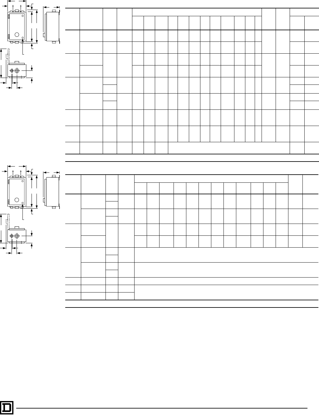
19
5/98 © 1998 Square D All Rights Reserved
NEMA Type 4 & 4X — Stainless Steel Watertight Enclosuresq
NEMA
Size Class Type No.
of
Poles
Dimensions – Inches/mm (Figure 8) W.
Bot.
Only
X Top
& Bot.
Weight (Lbs)
ABC DEFGHI JKL Class
8502 Class
8536
0
&
1
8502 SBW All 6.38
162 7.13
181 13.19
335 1.56
40 3.25
83 12.00
305 .59
15 1.19
30 11.78
299 1.63
41 2.31
59 .31
83⁄4"
Dia.
Hub
1"
Dia.
Hub
17 . . .
SCW
8536 SBW All 6.38
162 7.81
198 13.19
335 1.56
40 3.25
83 12.00
305 .59
15 1.88
48 11.78
299 1.63
41 2.31
59 .31
8. . . 18
SCW
2
8502
SDW All
8.13
207 7.88
200 16.19
411 1.56
40 5.00
127 15.00
381 1.09
28 1.94
49 14.75
375 2.00
51 2.63
67 .31
83⁄4"
Dia.
Hub
11⁄2"
Dia.
Hub
24 . . .
8536 8.13
207 8.56
217 16.19
411 1.56
40 5.00
127 15.00
381 1.09
28 2.88
73 14.75
375 2.00
51 2.63
67 .31
8. . . 25
3
&
4
8502 SEW All 18.16
461 8.75
222 32.22
818 3.08
78 12.00
305 30.50
775 .88
22 3.69
94 26.72
679 2.56
65 3.19
81 .44
11
3⁄4"
Dia.
Hub
21⁄2"
Dia.
Hub
65 . . .
SFW 69 . . .
8536 SEW All 18.16
461 9.56
243 32.22
818 3.08
78 12.00
305 30.50
775 .88
22 4.50
114 26.72
679 2.56
65 3.19
81 .44
11
3⁄4"
Dia.
Hub
21⁄2"
Dia.
Hub
. . . 68
SFW . . . 73
5 8502 & 8536 SGW All 17.22
437 12.63
321 47.22
1199 4.13
105 9.00
229 46.00
1168 .63
16 4.59
117 28.31
719 3.13
80 5.75
146 .56
14
3⁄4"
Dia.
Hub
31⁄2"
Dia.
Hub 159 176
6q8502 & 8536 SHW All 20.22
514 12.13
308 65.22
1657 4.13
105 12.00
305 64.00
1626 .63
16 4.59
117 30.81
783 2.69
68 4.50
114 .56
14
3⁄4"
Dia.
Hub
(2) 3"
Dia.
Hub 227 232
7q8502 & 8536 SJW All 34.50
876 23.50
597 101.00
2565 Floor Mounting . . . . . .
qSize 6 and 7 are sheet steel enclosures and are rated NEMA Type 4 only.
NEMA Type 4 & 4X — Stainless Steel Watertight Enclosures with Form F4Tq
NEMA
Size Class Type No.
of
Poles
Dimensions – Inches/mm (Figure 9) W
Bot.
Only
X Top
&
Bot.
ABC DEF GHI J KL
0
&
1
8502 SBW All 12.63
321 7.13
181 4.69
119 2.56
65 7.50
191 13.50
343 .59
15 3.19
81 18.41
468 1.66
42 2.31
59 .31
83⁄41
SCW
8536 SBW All 12.63
321 7.81
198 14.69
373 2.56
65 7.50
191 13.50
343 .59
15 3.88
99 18.41
468 1.66
42 2.31
59 .31
83⁄41
SCW
2
8502
SDW All
14.88
378 7.56
192 16.31
414 2.56
65 9.75
248 15.00
381 .66
17 3.19
81 20.88
530 2.00
51 2.63
67 .31
83⁄411⁄2
8536 14.88
378 8.25
210 16.31
414 2.56
65 9.75
248 15.00
381 .66
17 3.88
99 20.88
530 2.00
51 2.63
67 .31
83⁄411⁄2
3
&
4
8502 SEW 2-3 Same as Standard NEMA Type 4 dimensions, see above.
SFW
8536 SEW 2-3 See as Standard NEMA Type 4 dimensions, see above.
SFW
5 8502 & 8536 SGW All Same as Standard NEMA Type 4 dimensions, see above.
6q8502 & 8536 SHW All Form F4T is supplied as standard. Refer to Page 16.
7q8502 & 8536 SJW All
qSize 6 and 7 are sheet steel enclosures and are rated NEMA Type 4 only.
Full Voltage Contactors and Starters — NEMA
Approximate Dimensions, Shipping Weights – Class 8502, 8536
Figure 8
NEMA Type 4 & 4X
Watertight Enclosure
Figure 9
NEMA Type 4 & 4X
Watertight Enclosure
F
G
G
DDE
J
C
B
A
W
I
H
K
X
(4) L Dia.
Mounting Holes
F
G
G
DDE
J
C
B
A
W
I
H
K
X
(4) L Dia.
Mounting Holes
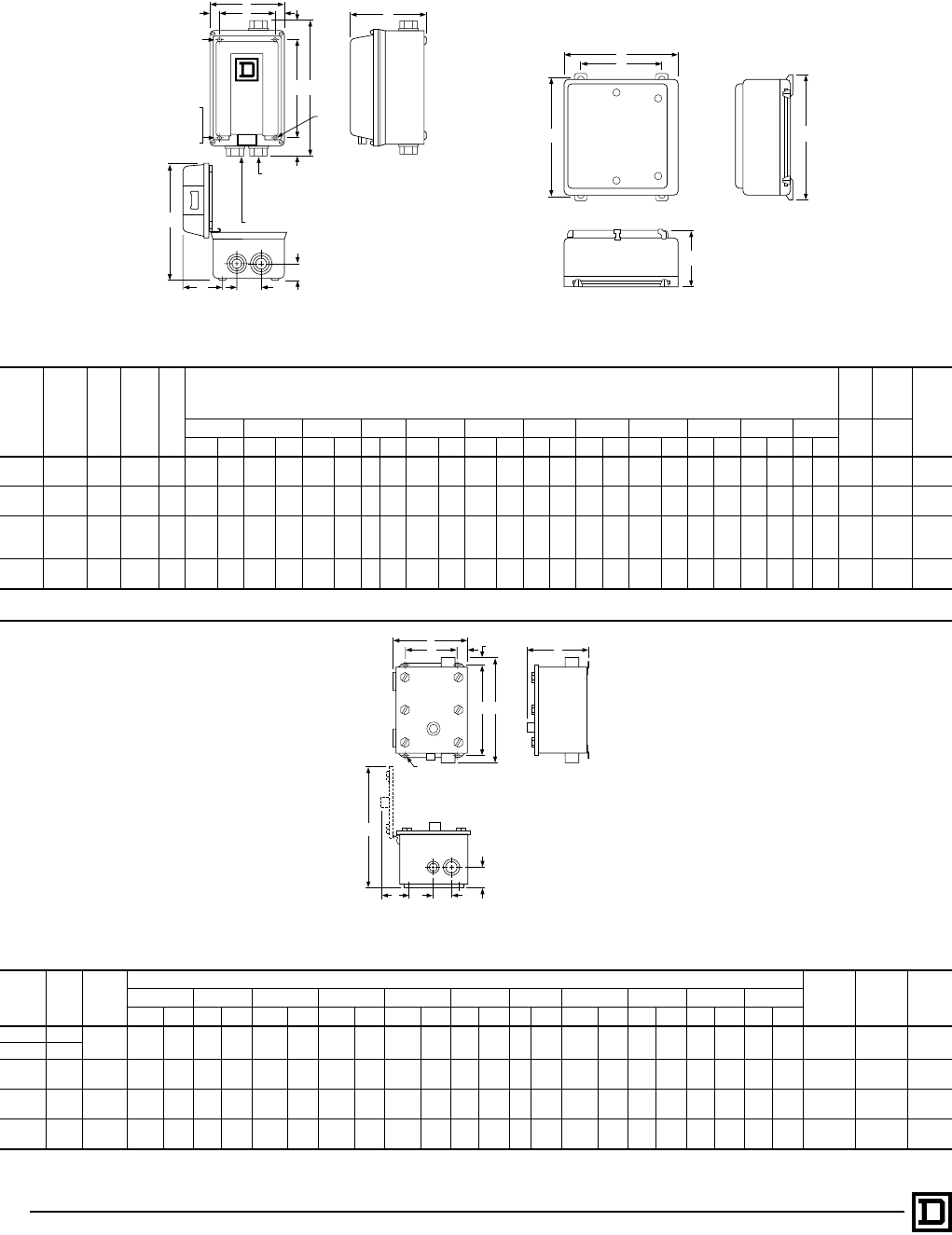
© 1998 Square D All Rights Reserved
20 5/98
NOTE: Devices with Form F4T may use larger enclosure. Consult local Square D Field Office for dimensions.
NEMA Type 4X — Watertight and Corrosion Resistant Glass Polyester Enclosures
NEMA
Size Class Type No.
of
Poles Fig.
Dimensions — Inches/mm (Figure 11) Bot.
Hub
Only
Top &
Bot.
Hub Wt
(Lbs)
ABCDEFGHI JKL
WX
IN mm IN mm IN mm IN mm IN mm IN mm IN mm IN mm IN mm IN mm IN mm IN mm
0, 1 8502 &
8536 SBW All 10A 6.50 165 6.44 164 12.13 308 .75 19 5.00 127 8.75 222 1.69 43 3.34 85 10.06 256 1.31 33 2.13 54 .31 8 3⁄4117
SCW
28502 &
8536 SDW All 10B 8.50 216 7.06 179 13.88 353 .75 19 7.00 179 10.50 267 1.69 43 3.91 99 11.94 303 1.63 41 2.38 60 .31 8 3⁄411⁄222
0-2t8502 &
8536
SBW All 10B 16.88 429 9.78 248 22.75 578 . . . . . . 10.13 257 21.50 546 . . . . . . . . . . . . . . . . . . . . . . . . . . . . . . . . . . . . . . . . . . . . .SCW
SDW
3-4j8502 &
8536 SEW All 10B 25.81 656 11.94 303 33.50 851 . . . . . . 18.50 470 32.25 819 . . . . . . . . . . . . . . . . . . . . . . . . . . . . . . . . . . . . . . . . . . . . .
SFW
tWith control power transformer (Form F4T).
jDimensions also for Form F4T.
NEMA Type 9 Enclosures for Hazardous Locations — Sheet Steel
NEMA
Size Type No. of
Poles
Dimensions — Inches/mm (Figure 11) X Bot.
Only W Top
& Bot. Wt
(Lbs)
ABCDEFGHIJK
IN mm IN mm IN mm IN mm IN mm IN mm IN mm IN mm IN mm IN mm IN mm
0 SBE 2-4 8.84 225 8.22 209 13.00 330 12.00 305 6.00 152 1.38 35 .50 13 14.69 373 3.91 99 2.13 54 2.00 51 3⁄4"
Dia. Hub 1"
Dia. Hub 241⁄2
1 SCE
2 SDE 2-4 10.34 263 8.97 228 16.13 410 15.00 381 7.50 191 1.38 35 .56 14 16.94 430 3.91 99 2.75 70 2.38 60 3⁄4"
Dia. Hub 11⁄2"
Dia. Hub 311⁄4
3 SEE 2-4 12.84 326 9.72 247 24.16 614 22.25 565 9.00 229 1.88 48 .97 25 20.56 522 4.41 112 3.25 83 2.88 73 3⁄4"
Dia. Hub 2"
Dia. Hub 54
4 SFE 2-4 15.84 402 9.72 247 34.16 868 32.25 819 12.00 305 1.88 48 .97 25 23.56 598 4.41 112 3.25 83 2.88 73 3⁄4"
Dia. Hub 21⁄2"
Dia. Hub 74
E
F
A
C
B
RESET
F
G
G
DDE
C
B
A
(2) L Dia.
Mounting Holes
(Size 1)
(4) L Dia.
Mounting Holes
(Size 2)
Size 2 Only
Size 2
Only
1.00 Conduit Hub
25 Top and Bottom
Size 1
1.50 Conduit Hub
38 Top and Bottom
Size 2
.75 Conduit Hub in
19 Bottom Size 1 and Size 2
I
J
KH
Figure 10A Figure 10B
D
GB
E
L
F
K
C
A
W
H
IJ
X
Figure 11
Full Voltage Contactors and Starters — NEMA
Approximate Dimensions, Shipping Weights – Class 8502, 8536
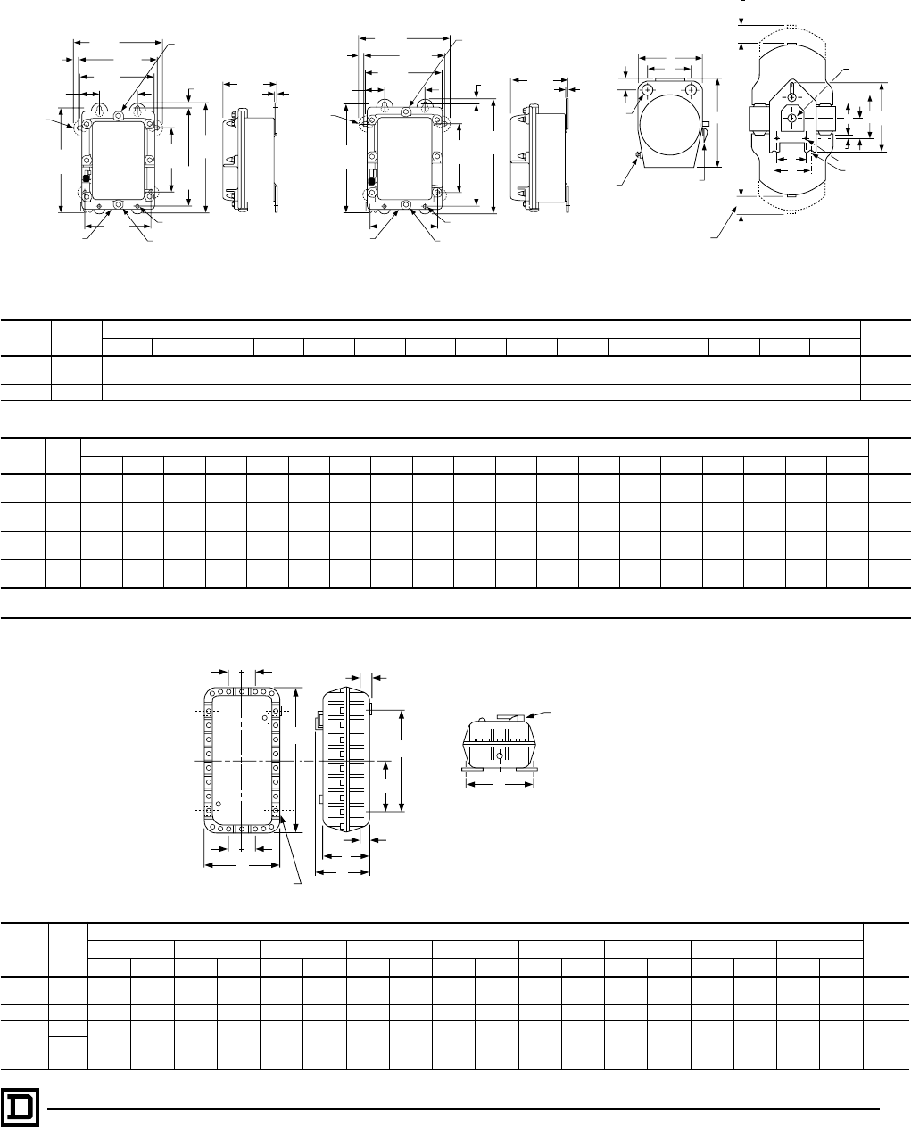
21
5/98 © 1998 Square D All Rights Reserved
NEMA Type 7 & 9 Enclosures for Hazardous Locations
Sizes 0-2, Bolted Cover, Cast Iron, Sizes 0-5, Bolted Cover, Cast Aluminum, Sizes 0-5, SPIN TOP®, Cast Aluminum
NEMA 7 & 9 Bolted Cover, Cast Aluminum
NEMA 7 & 9 Bolted Cover, Cast Iron
NEMA
Size Type Dimensions — Inches/mm Wt
(Lbs)
ABCDEFGHJ KLMNPR
0, 1 SBT See Figure 12 59
SCT
2 SDT See Figure 13 75
NEMA 7 & 9 SPIN TOP® Enclosure – Figure 14
NEMA
Size Type Dimensions — Inches/mm Wt
(Lbs)
ABtBjCtCjDEtEjFGHtHjJKLMNPR
0-1 SBR 10.63
270 25.06
637 30.06
764 34.69
881 47.69
1211 14.69
373 6.25
159 11.25
286 7.69
195 11.13
283 2.00
51 9.00
229 7.63
194 7.38
187 2.06
52 9.38
238 5.25
133 1.25
32 .38
10 70
SCR
2 SDR 12.00
305 29.31
744 34.31
871 42.81
1087 54.81
1392 16.75
425 6.75
171 11.75
298 7.69
195 14.75
375 3.00
76 9.00
229 11.50
292 8.50
216 2.06
52 9.38
238 5.25
133 1.50
38 .38
10 100
3-4 SER 16.13
410 37.50
953 40.50
1029 60.00
1524 66.50
1689 20.25
514 8.63
219 11.63
295 8.63
219 20.25
514 4.50
114 8.00
203 18.00
457 12.00
305 2.63
67 11.00
279 5.50
140 2.50
64 .50
13 165
SFR 195
5 SGR 20.75
527 62.13
1578 62.13
1578 103.63
2632 103.63
2632 25.75
654 24.13
613 24.13
613 13.88
353 24.13
613 20.00
508 20.00
508 21.50
546 14.38
365 4.75
121 17.00
432 8.00
203 4.00
102 .63
16 375
tWithout control transformer.
jWith control transformer (Form F4T)
NEMA
Size Type
Dimensions — Inches/mm Wt
(Lbs)
G H J K L N P Q, R S, T, U, V
IN mm IN mm IN mm IN mm IN mm IN mm IN mm IN mm IN mm
0-1 SBT 14.25 362 17.25 438 9.50 241 12.25 311 8.88 226 4.50 114 11.00 279 2.38 60 3.13 80 75
SCT
2 SDT 13.63 346 27.63 702 9.50 241 12.25 311 19.25 489 9.63 245 11.00 279 2.38 60 3.13 80 115
3-4 SET 18.13 461 13.63 346 10.00 254 16.25 413 19.25 489 9.63 245 12.63 321 2.38 60 3.75 95 180
SFT
5 SGT 24.50 622 45.63 1159 13.75 349 22.50 572 27.50 699 13.75 349 15.38 391 3.44 87 4.00 102 500
(4) .42 Dia. Mounting Holes
10
Optional
Mounting
(1) 1-11 1/2 Pipe Tap
at Top Std.
(1) 1 - 11 1/2 Pipe Tap
at Bottom Std.
(1) 3/4 - 14 Pipe Tap
at Bottom Std.
11.00
279 9.75
248
.63
16
2.40
61
9.25
235
4.90
125
.63
16
7.00
178 .25
6
7.90
201
12.00
305
13.25
337
12.70
323
8.25
210 (4) .42 Dia. Mounting Holes
10
Optional
Mounting
(1) 1-11 1/2 Pipe Tap
at Top Std.
(1) 1 1/2 - 11 1/2 Pipe Tap
at Bottom Std.
(1) 3/4 - 14 Pipe Tap
at Bottom Std.
12.00
305 10.75
273
.63
16
2.40
61
10.25
260
5.88
149
.63
16
7.50
191 .25
6
9.63
245
13.75
349
15.00
381
14.44
367
9.25
235
Figure 12 Size 0 and 1 Figure 13 Size 2 Figure 14 Size 0-5
N
A
BD
C
J
P
F
M
KH
Mtg. Holes
and/or Slots (3)
Space Required
To Remove
Top Cover
Rear View
Space Required To
Remove Bottom Cover
Circuit Breaker
Operational Handle –
Combination Form Only
(Add 1.00 Inch To
Overall Width)
Overload
Reset
Threaded
Cover
Enclosure
E
Q
R
G
Top View
T
L
Rear Seal
S
(2) "L" Pipe
Tap Top and
Bottom
R
O
VU
H
L
N
ST
GP
Mounting for 4 Bolts
Circuit Breaker Handle not supplied
on Class 8502 or 8536
1/2" NPT for Breather and Drain
K
J
Figure 15
Full Voltage Contactors and Starters — NEMA
Approximate Dimensions, Shipping Weights – Class 8502, 8536
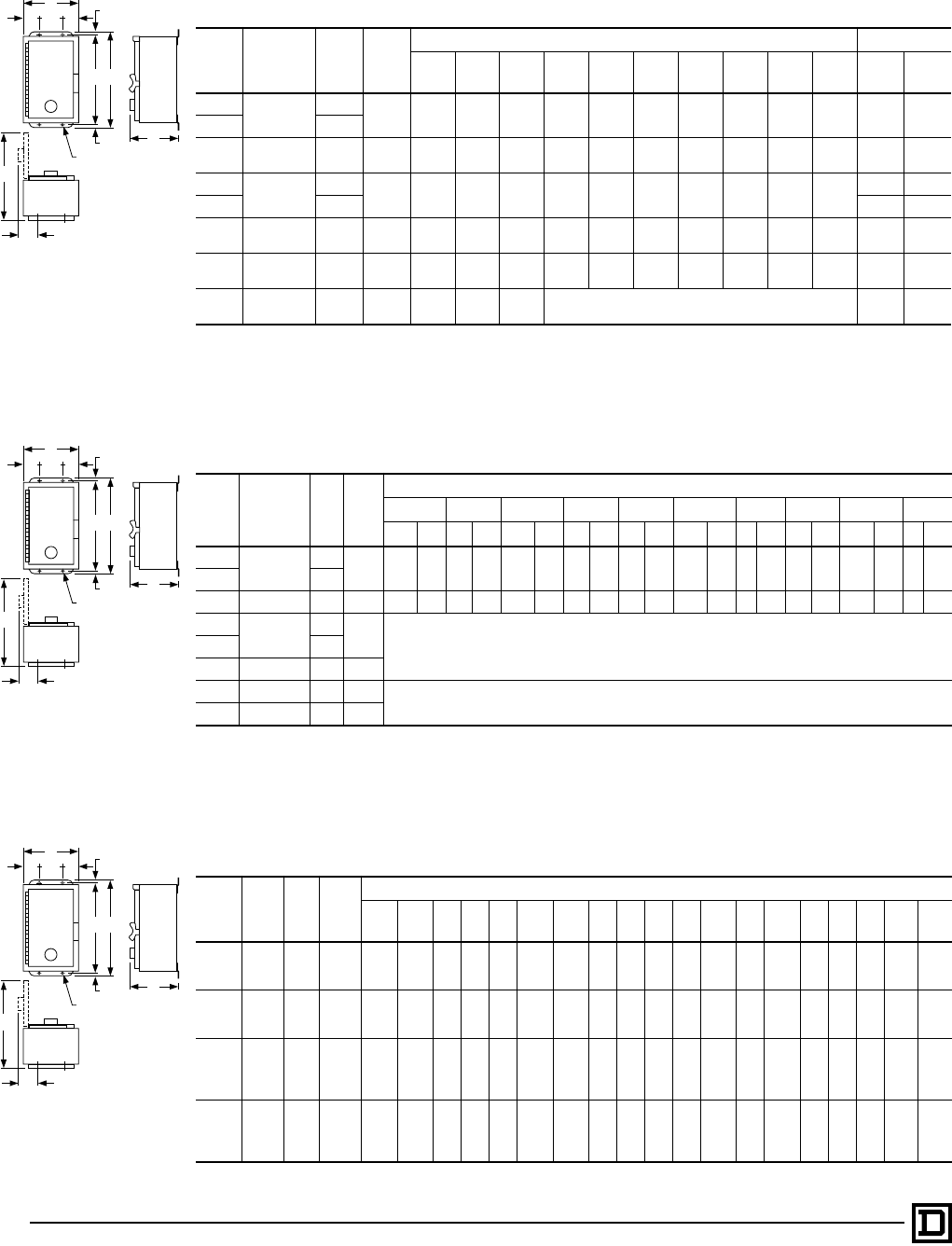
© 1998 Square D All Rights Reserved
22 5/98
NEMA Type 12 — Dusttight Enclosure
NEMA
Size Class Type No.
of
Poles
Dimensions – Inches/mm (Figure 16) Weight (Lbs)
ABCDEFGHI JClass
8502 Class
8536
08502 & 8536 SBA All 6.38
162 8.53
217 12.75
324 1.56
40 3.25
83 12.00
305 .38
10 3.56
90 12.25
311 .31
815 16
1 SCA
2 8502 & 8536 SDA All 8.13
207 9.28
236 16.00
406 1.56
40 5.00
127 15.00
381 .50
13 3.56
90 15.38
391 .31
822 23
38502 & 8536 SEA All 18.16
461 9.56
243 31.50
800 3.08
78 12.00
305 30.50
775 .50
13 4.50
114 26.72
679 .44
11
65 68
4SFA 69 73
5 8502 & 8536 SGA All 17.22
437 13.44
341 47.00
1194 4.13
105 9.00
229 46.00
1168 .50
13 5.41
137 28.31
719 .56
14 160 177
6 8502 & 8536 SHA All 20.22
514 13.00
330 65.00
1651 4.13
105 12.00
305 64.00
1626 .50
13 6.44
164 30.88
784 .69
18 228 233
7 8502 & 8536 SJA All 34.50
876 23.50
597 93.00
2362 Floor Mounting . . . . . .
NEMA Type 12 — Dusttight Enclosure with Form F4T
NEMA
Size Class Type No.
of
Poles
Dimensions – Inches/mm (Figure 17)
ABCDEFGHI J
IN mm IN mm IN mm IN mm IN mm IN mm IN mm IN mm IN mm IN mm
08502 & 8536 SBA All 11.88 302 8.00 203 13.50 343 2.81 71 6.75 171 12.75 324 .38 10 3.91 99 18.38 467 .31 8
1 SCA
2 8502 & 8536 SDA All 14.88 378 8.13 207 16.00 406 2.56 65 9.75 248 15.00 381 .38 10 3.66 93 21.50 546 .31 8
38502 & 8536 SEA 2–3 Same as Standard NEMA Type 12 dimensions, see above.4SFA
5 8502 & 8536 SGA All
6 8502 & 8536 SHA All Form F4T is supplied as standard. Refer to Page 16.
7 8502 & 8536 SJA All
NEMA Type 3R — Rainproof and Sleet Resistant Enclosures
NEMA
Size Class Type No.
of
Poles
Dimensions — Inches/mm (Figure 17)
A B C D1 D2 E F G1 G2 H1 H2 J K L M N P K.O.
XK.O.
Y
0 & 1 8502 &
8536 SBH,
SCH All 8.84
225 12.28
312 7.13
181 1.38
35 1.44
37 6.00
152 7.50
191 2.59
66 2.19
56 2.06
52 2.63
67 14.28
363 1.38
35 1.38
35 1.88
48 4.38
111 1.84
47
1⁄2
3⁄4
1
1⁄2
3⁄4
1
28502 &
8536 SDH All 9.84
250 16.28
414 8.63
219 1.38
35 1.44
37 7.00
178 11.50
292 2.59
66 2.19
56 2.06
52 2.63
67 16.78
426 1.31
33 1.75
44 2.13
54 4.88
124 1.84
47
1
11⁄4
11⁄2
1⁄2
3⁄4
38502 &
8536 SEH All 12.84
326 25.28
642 8.63
219 1.38
35 1.44
37 10.00
254 20.50
521 2.59
66 2.19
56 2.06
52 2.63
67 19.78
502 1.31
33 1.94
49 2.44
62 6.38
162 1.84
47
1
11⁄4
2
21⁄2
1⁄2
3⁄4
48502 &
8536 SFH All 12.84
326 40.28
1023 9.13
232 1.38
35 1.44
37 10.00
254 35.50
902 2.59
66 2.19
56 2.06
52 2.63
67 20.28
515 1.31
33 2.31
59 2.69
68 6.38
162 1.84
47
1
11⁄4
2
21⁄2
1⁄2
3⁄4
Full Voltage Contactors and Starters — NEMA
Approximate Dimensions, Shipping Weights – Class 8502, 8536
Figure 16
NEMA Type 12
Industrial Use
Enclosure
Figure 17
NEMA Type 12
Industrial Use
Enclosure
Figure 18
NEMA Type 3R
Outdoor Use
Enclosure
F
G
G
DDE
C
B
A
I
H
(4) J Dia.
Mounting Holes
F
G
G
DDE
C
B
A
I
H
(4) J Dia.
Mounting Holes
F
G
G
DDE
C
B
A
I
H
(4) J Dia.
Mounting Holes
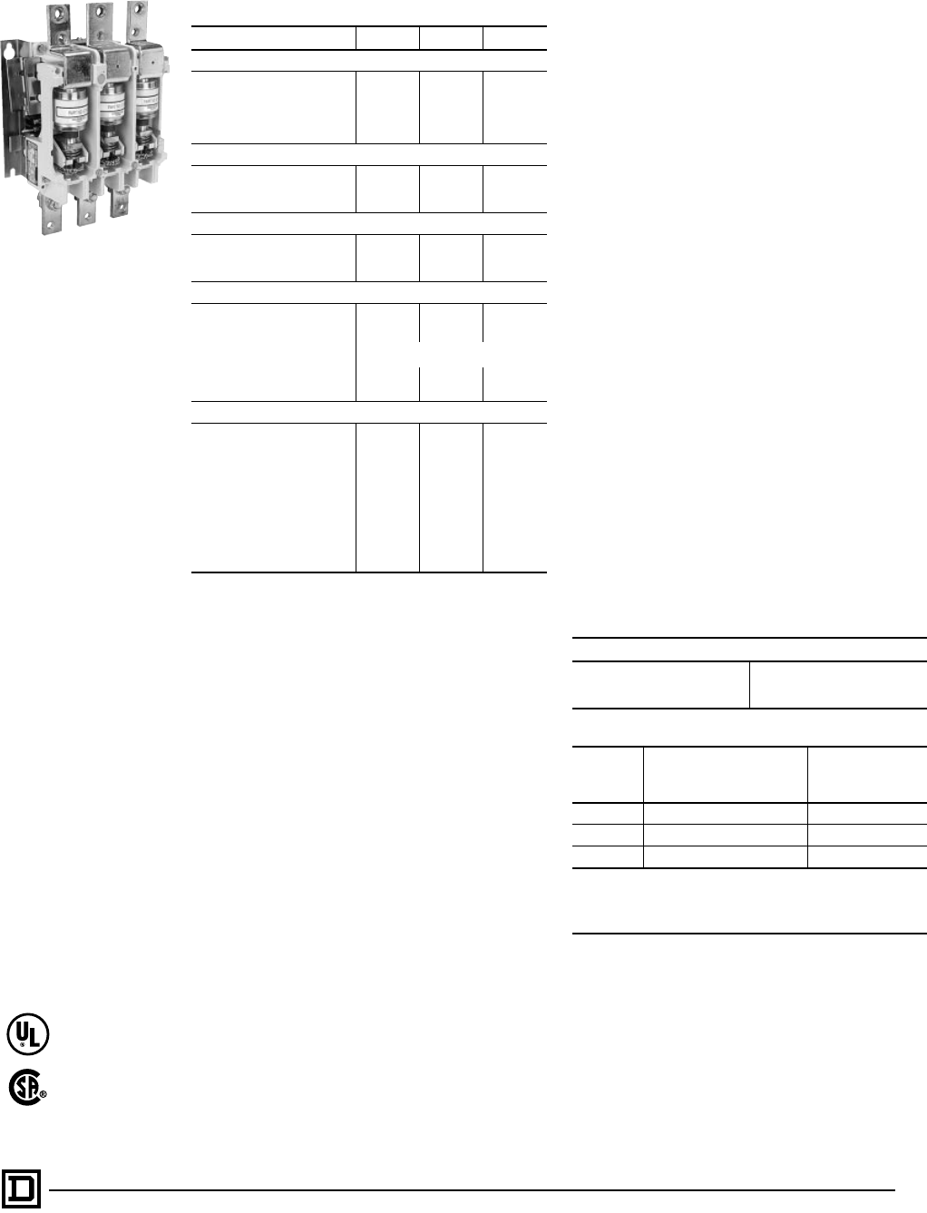
23
5/98 © 1998 Square D All Rights Reserved
General Information
Class 8502 Type W non-reversing vacuum
contactors are a new addition to the Square D line
of contactors. These contactors are used to switch
capacitors, transformers and electric motors
where overload protection is separately provided.
Type W vacuum contactors are designed for
operation at 600 Volts, 50/60 Hertz.
By design, these contactors are well suited to
heavy-duty applications in harsh environments.
The power contacts are sealed in ceramic tubes,
called vacuum interrupters or vacuum bottles,
where the air has been evacuated. Arc quenchers
are not required because any arc formed between
opening contacts is not sustained due to the
presence of the vacuum. The arc is extinguished
when the current crosses zero after the contacts
are opened, therefore the arc typically does not
survive more than one half cycle. There is one
vacuum interrupter or bottle per pole, therefore a
three pole contactor has three vacuum
interrupters or bottles. The power contacts are not
affected by ambient conditions or contamination.
This provides for long life and reliable operation in
harsh applications.
Altitude
The vacuum contactor is designed to tolerate
normal barometric pressure variances up to 6600
feet above sea level. If the contactor is to be used
above 6600 feet above sea level, please consult
the factory.
Termination Means
The Size 4 vacuum contactor is supplied with line
and load side lugst. The Size 5 and 6 vacuum
contactors are supplied without line and load side
lugs. Class 9999 Type LUW5 and LUW6 lug kits
are available for the Size 5 and 6 contactors.
These kits include six lugs and the necessary
mounting hardware.
Auxiliary Contacts
An auxiliary contact block, Class 9999 Type
WX11, with one normally-open contact and
normally-closed contact is used with the Size 4, 5
and 6 vacuum contactors.
Auxiliary Contact Units
Auxiliary contact units may be added in the field.
the table below shows the maximum number of
units that may be added to a given size contactor
(in addition to the coil auxiliary contact).
Electrical Ratings
Characteristic Size 4 Size 5 Size 6
Maximum Motor HP at:
200 V 40 75 150
230 V 50 100 200
380 V 75 150 300
460 V 100 200 400
575 V 100 200 400
3 Phase Capacitor Switching – KVAR
230 V 40 80 160
460 V 80 160 320
575 V 100 200 400
Transformer Switching – KVA 3 Phase, 3-Pole
240 V 23 47 94
480 V 47 94 188
600 V 59 117 234
Coil Data
Inrush VA 300 600 1450
Sealed VA 30 20 32
Sealed Watts 6 20 30
Pick-up Volts 70% of rated coil voltage
Drop-out Volts 50% of rated coil voltage
Pick-up Time (ms) 18-22 24-32 24-32
Drop-out Time (ms) 90-120 96-100 96-100
Additional Electrical Characteristics
Number of Poles 3 3 3
Max. Voltage Rating 600 600 600
Enclosed Ampere Rating 135 270 540
Max. Closing Current 1600 3000 6000
Max. Interrupting Current 1600 3000 6000
Short Time Current (RMS):
1 second 2400 4500 9000
2 seconds 1600 3000 6000
Dielectric Strength, volts 5375 5375 5375
Max. Allowable Interrupting 1200/hr 1200/hr 1200/hr
Impulse Voltage, VA (1 x 40ms) 15000 15000 15000
Class 8502
Size 4 3
Size 5 4
Size 6 4
Terminals
Size Power Terminals
Wire Sizeq
Min. – Max.
Control Terminals
Wire Sizeq
Min. – Max.
4 #12-4/0 #16-12
5cOne #0-500 kcmil per phase #16-12
6cTwo #0-500 kcmil per phase #16-12
cPower terminal lugs are not supplied on Size 5 and 6 contactors.
Values in table reflect those for the Size 5 and 6 lug kits, Class 9999
Type LUW5 and LUW6 respectively.
qSolid or stranded copper wire.
Full Voltage Contactors — NEMA
Application Data
Class 8502 Type WF
Vacuum Contactor
LR75167, 75168
Class 3211-04
File E78351
CCN NLDX2

© 1998 Square D All Rights Reserved
24 5/98
Class 8502 – Full Voltage Vacuum Contactors
NEMA
Size
Enclosed
Ampere
Rating
Locked
Rotor
Current
(Amps)
Motor
Volts Max.
HP
t
Coil
Voltage
Open Type NEMA Type 1
General Purpose
Enclosure
NEMA Type 4 & 4X
Watertight, Dusttight
Brushed Stainless
Steel Enclosure
(Size 4 & 5 only)
NEMA Type 12
Dusttight & Driptight
Industrial Use
Enclosure
Type Type Type Type
4 135 1080
200 40 120 WFO3V02S WFG3V02S WFW3V02S WFA3V02S
230 50 240 WFO3V03 WFG3V03 WFW3V03 WFA3V03
380 75 120 WFO3V02S WFG3V002S WFW3V02S WFA3V02S
460 100 480 WFO3V06 WFG3V06 WFW3V06 WFA3V06
575 100 600 WFO3V07 WFG3V07 WFW3V07 WFA3V07
5 270 2160
200 75 120 WGO3V02S WGG3V02S WGW3V02S WGA3V02S
230 100 240 WGO3V03 WGG3V03 WGW3V03 WGA3V03
380 150 120 WGO3V02S WGG3V002S WGW3V02S WGA3V02S
460 200 480 WGO3V06 WGG3V06 WGW3V06 WGA3V06
575 200 600 WGO3V07 WGG3V07 WGW3V07 WGA3V07
6 540 4320
200 150 120 WHO3V02S WHG3V02S WHW3V02S WHA3V02S
230 200 240 WHO3V03 WHG3V03 WHW3V03 WHA3V03
380 300 120 WHO3V02S WHG3V002S WHW3V02S WHA3V02S
460 400 480 WHO3V06 WHG3V06 WHW3V06 WHA3V06
575 400 600 WHO3V07 WHG3V07 WHW3V07 WHA3V07
tConsult factory for availability of enclosed devices.
Class 8502 Type WF Class 8502 Type WG
Class 8502 Type WH
4.63
118
6.63
168
6.00
152
3.60
91
1.44
37 1.44
37
1.88
48
1.88
48
.94
24
.94
24
.38
10
5.87
149
Front View
Shown Without
Overtravel
Gauge
Recess for
Auxiliary
Contact
Overtravel
Gauge
Front ViewRear View
Drilling Plan
Side View
.28 Dia.
7
(3) Mtg. Holes
6.13
156
5.22
133
Line Term.
5.93
151
5.09
129
Load Term. 1.45
37
7.28
185 8.94
227
7.90
201
2.50
64
2.50
64
12.50
318
Side View Front View
3.72
94
7.00
178
5.00
127
7.90
201
2.67
68
2.67
68
2.67
68 2.67
68
12.90
328
Term.
Holes
13.99
355
1.28
33
6.75
171
.38
10
8.00
203
.58
15
8.75
222
Coil
Interlock
1
2
1
2
Two Dual Circuit Interlocks.
Located on both sides of
contactor when used.
Coil Terminals located on both
sides of contactor.
.33 x .75
8 19
Key Holes
.33 Slot
8 (2 Places)
Rear View
Drilling Plan
Side View
Front View
Full Voltage Contactors — NEMA
Selection – Class 8502

25
5/98 © 1998 Square D All Rights Reserved
SECTION 2 – REVERSING MAGNETIC STARTERS AND
CONTACTORS
Application Data – Class 8702, 8736. . . . . . . . . . . . . . . . . . . . . . . . . . 27-28
Selection – Class 8702 . . . . . . . . . . . . . . . . . . . . . . . . . . . . . . . . . . . . 29-30
Selection – Class 8736 . . . . . . . . . . . . . . . . . . . . . . . . . . . . . . . . . . . . 31-32
Application Data – Class 8702, 8736. . . . . . . . . . . . . . . . . . . . . . . . . . . . . 33
Approximate Dimensions – Class 8702, 8736 . . . . . . . . . . . . . . . . . . . 34-36
Application Data, Selection – Class 8702 Vacuum Contactor . . . . . . . . . . 37
Selection – Class 8702 . . . . . . . . . . . . . . . . . . . . . . . . . . . . . . . . . . . . . . . 38
Contents

© 1998 Square D All Rights Reserved
26 5/98
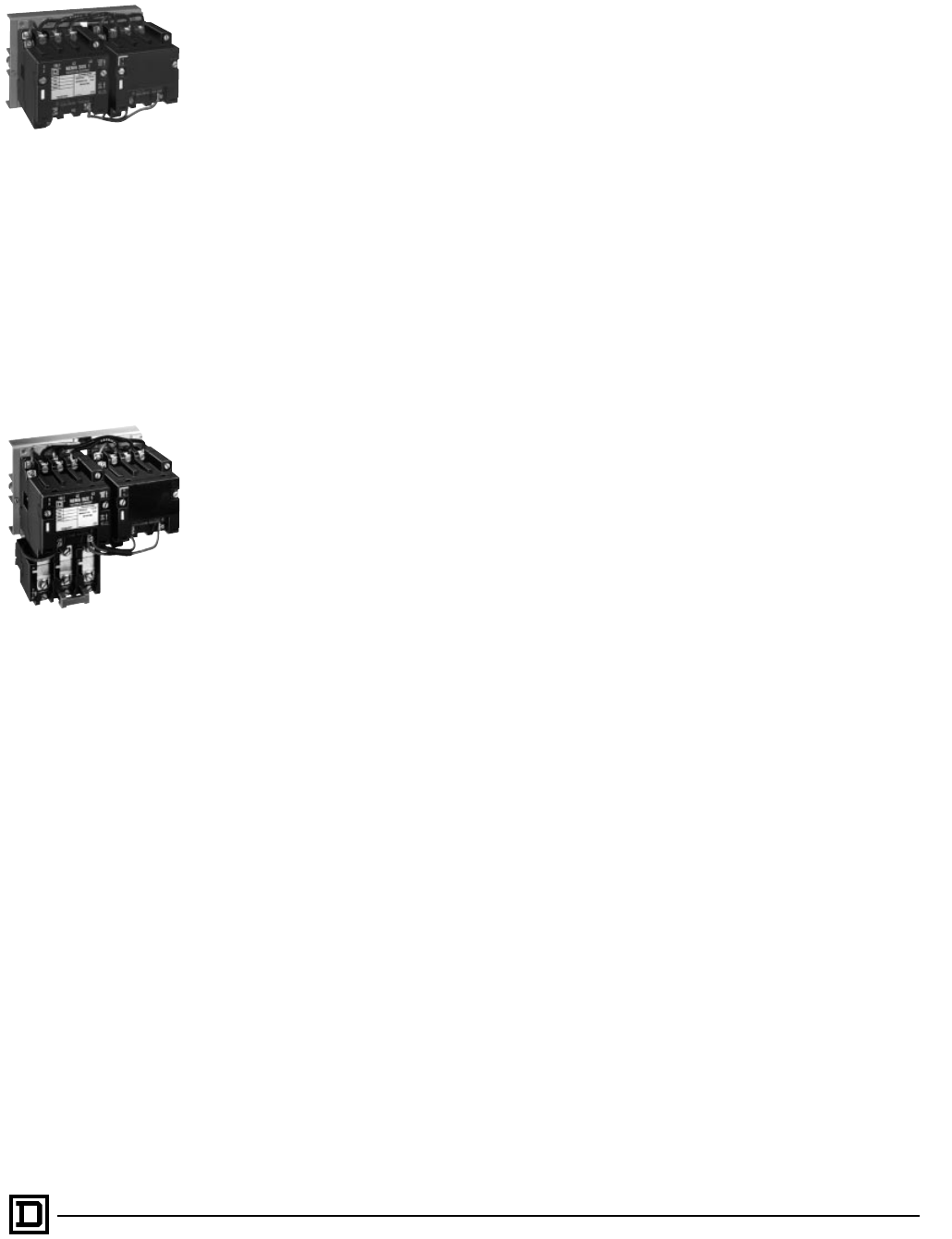
27
5/98 © 1998 Square D All Rights Reserved
AC MAGNETIC REVERSING
CONTACTORS CLASS 8702
General Information
Class 8702 Type S reversing magnetic contactors
are used for starting, stopping, and reversing AC
motors where overload protection is separately
provided. Class 8702 reversing contactors are
available in NEMA Sizes 00-7. Class 8702
reversing contactors consist of two Class 8502
contactors mechanically and electrically
interlocked. Open type devices, Sizes 0-5 are
available in either horizontal or vertical
arrangements. Sizes 00, 6, and 7 are available as
horizontal only. Enclosed devices, Size 00-7 use
horizontally arranged components. Type S
reversing contactors are designed for operation at
600 Volts AC, 50-60 Hertz.
AC MAGNETIC REVERSING STARTERS
CLASS 8736
General Information
Class 8736 Type S reversing magnetic starters
are used for full voltage starting, stopping, and
reversing AC squirrel cage motors. Class 8736
reversing starters are available in NEMA Sizes
00-7. Class 8736 reversing starters consist of one
Class 8502 contactor and one Class 8536 starter
mechanically and electrically interlocked. Open
type devices, Sizes 0-5 are available in either
horizontal or vertical arrangements. Sizes 00, 6,
and 7 are available as horizontal only. Enclosed
devices use horizontally arranged components.
Motor overload protection is provided by melting
alloy type thermal overload relays. Type S starters
are designed for operation at 600 Volts AC, 50-60
Hertz.
Overload Relays
Class 8736 Type S Size 00-6 reversing starters
are provided with melting alloy thermal overload
relay as standard. Interchangeable thermal units
are available in standard trip Sizes 00-6, quick trip
Sizes 00-4, and slow trip Sizes 00-3. Single phase
starters use one thermal unit, three phase
starters use three thermal units.
Class 8736 Size 7 starters are provided with solid
state overload Motor Logic, which has selectable
trip Class 10/20, Ground Fault Detection, and
Communication capabilities for future
enhancements. The solid state overload relay is
ambient insensitive and features phase loss,
phase unbalance and over-current protection.
MOTOR LOGIC™ Solid State Overload Relay
(SSOLR)
Solid state overload relays are available for Sizes
00-7 starters. These ambient insensitive overload
relays provide phase loss protection, phase
unbalance protection and LED power indicator.
For additional information see the Class 9065
catalog section. To order Type S starters with solid
state overload relays, see Factory Modification
(FORMS).
Bimetallic overload relays are also available for
Sizes 0-6. Ambient Compensated and Non-
compensated versions are supplied with manual
and automatic reset, trip current adjustment, and
an alarm contact on Sizes 0-2. For additional
information, see the Class 9065 catalog section.
To order Type S starters with bimetallic overload
relays, see Factory Modifications (FORMS).
Enclosures
Class 8702 and 8736 reversing magnetic
contactors and starters are available in the
following enclosures:
• NEMA Type 1 General Purpose Enclosure
• NEMA Type 4 & 4X Watertight and Dusttight
• NEMA Type 7 & 9 Bolted and Spin-Top for
Hazardous Locations
• NEMA Type 12 Dusttight and Driptight for
Industrial Use
The NEMA Type 4 and 4X stainless steel
enclosure (Sizes 0-5) has a brushed finish. For an
electropolished finish, specify Form G16 and add
15% to the price of the standard device. Sizes 6
and 7 are painted sheet steel and are rated NEMA
Type 4 only.
Also, NEMA Type 12 devices are available UL
Listed for use in Class II, Division 2, Group G and
Class III, Divisions 1 and 2 locations. Request
Form G21, no additional charge.
Separate enclosures are available, see
Class 9991.
Full Voltage Reversing Contactors and Starters — NEMA
Application Data – Class 8702, 8736
Size 00, 0, 1
Reversing Contactor
Size 00, 0, 1
Reversing Starter
© 1998 Square D All Rights Reserved
28 5/98
Holding Circuit Contact
Two normally open holding circuit contacts are
provided on all reversing contactors and starters
as standard. Sizes 00-2 contactors use a Class
9999 SX11 auxiliary contact as the holding circuit
contact. Sizes 3-7 contactors use a Class 9999
SX6 auxiliary contact as the holding circuit
contact. Additionally, two normally closed
auxiliary contacts are provided as standard and
wired to prevent energization of both coils at the
same time. Sizes 00-2 use a Class 9999 SX12
auxiliary contact while Sizes 3-7 use a Class 9999
SX7 auxiliary contact for this purpose. See Class
9999, for the holding circuit contact electrical
ratings.
Coil Voltages
AC coils are available for application on 50-60
Hertz. NEMA Sizes 00-5 are supplied with coils
that are designed to operate satisfactorily on line
voltages of 85%-110% of rated voltage. NEMA
Size 6 and 7 contactors are supplied with a DC
coil operated by a solid state rectifier circuit that is
powered by an AC source.
Please note that Voltage Codes have been
added to the Type designations in order to
improve customer service. It is necessary to
include the Voltage Code when ordering
contactors and starters. Also, 120 Volt Polyphase
reversing contactors and starters will be wired for
separate control.
Mechanical Interlocks
Mechanical interlocks are available for
replacement or field assembly of Type S reversing
contactors and starters (Sizes 00-4 ONLY). See
Class 9999 for additional information.
Auxiliary Contacts
Additional auxiliary contacts may be added to
Type S reversing contactors and starters. See
Page 33 for maximum number of auxiliary units
and Form designations for factory installed
auxiliary contacts. See Class 9999 for auxiliary
contact kits for field installation.
Type S Accessories
Additional accessories such as power poles,
pneumatic timer attachments, and cover mounted
control stations are available as factory or field
modifications.
Full Voltage Reversing Contactors and Starters — NEMA
Application Data – Class 8702, 8736
File LR60905
Class 3211-04
File E78351
CCN NLDX
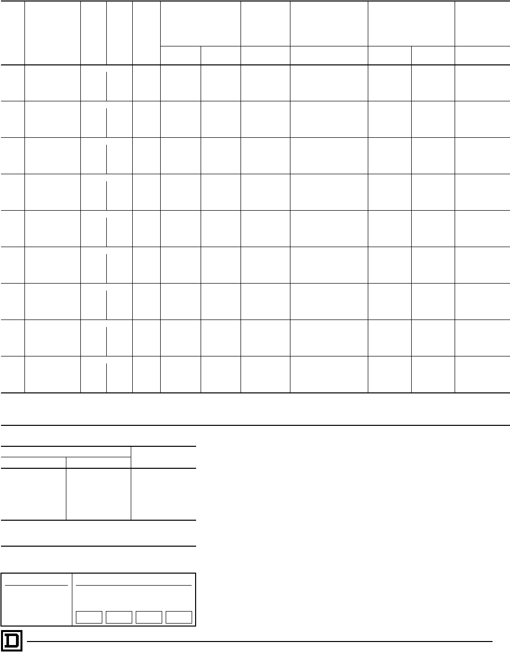
29
5/98 © 1998 Square D All Rights Reserved
3-Pole Polyphase — 600 Volts AC Maximum — 50-60 Hertz
NEMA
Size Continuous
Current Ratings Motor
Volts Max.
HP
t
Coil
Voltage
Open Type
NEMA Type 1
General
Purpose
Enclosure
NEMA Type 4 & 4X
Watertight, Dusttight
Brushed Stainless
Steel Enclosure
(Sizes 0-5)f
NEMA Type 7 & 9
Hazardous Locations
Class I, Groups C & D
Class II, Groups E, F & G
NEMA Type 12
Dusttight &
Driptight
Industrial Use
Enclosure
Vertical
Type Horizontal
Type Type Type Bolted Type
Aluminum SPIN TOP®
Type Type
00 9
Separate Controlj120 . . . SAO4V02S SAG4V02S
Use Size 0 Use Size 0 Use Size 0 Use Size 0
200 11⁄2208 . . . SAO4V08 SAG4V08
230 11⁄2240 . . . SAO4V03 SAG4V03
460 2 480 . . . SAO4V06 SAG4V06
575 2 600 . . . SAO4V07 SAG4V07
018
Separate Controlj120 SBO12V02S SBO4V02S SBG4V02S SBW14V02S SBT49V02S SBR9V02S SBA4V02S
200 3 208 SBO12V08 SBO4V08 SBG4V08 SBW14V08 SBT49V08 SBR9V08 SBA4V08
230 3 240 SBO12V03 SBO4V03 SBG4V03 SBW14V03 SBT49V03 SBR9V03 SBA4V03
460 5 480 SBO12V06 SBO4V06 SBG4V06 SBW14V06 SBT49V06 SBR9V06 SBA4V06
575 5 600 SBO12V07 SBO4V07 SBG4V07 SBW14V07 SBT49V07 SBR9V07 SBA4V07
127
Separate Controlj120 SCO7V02S SCO8V02S SCG8V02S SCW14V02S SCT49V02S SCR9V02S SCA4V02S
200 71⁄2208 SCO7V08 SCO8V08 SCG8V08 SCW14V08 SCT49V08 SCR9V08 SCA4V08
230 71⁄2240 SCO7V03 SCO8V03 SCG8V03 SCW14V03 SCT49V03 SCR9V03 SCA4V03
460 10 480 SCO7V06 SCO8V06 SCG8V06 SCW14V06 SCT49V06 SCR9V06 SCA4V06
575 10 600 SCO7V07 SCO8V07 SCG8V07 SCW14V07 SCT49V07 SCR9V07 SCA4V07
245
Separate Controlj120 SDO1V02S SDO2V02S SDG2V02S SDW11V02S SDT43V02S SDR3V02S SDA1V02S
200 10 208 SDO1V08 SDO2V08 SDG2V08 SDW11V08 SDT43V08 SDR3V08 SDA1V08
230 15 240 SDO1V03 SDO2V03 SDG2V03 SDW11V03 SDT43V03 SDR3V03 SDA1V03
460 25 480 SDO1V06 SDO2V06 SDG2V06 SDW11V06 SDT43V06 SDR3V06 SDA1V06
575 25 600 SDO1V07 SDO2V07 SDG2V07 SDW11V07 SDT43V07 SDR3V07 SDA1V07
390
Separate Controlj120 SEO1V02S SEO2V02S SEG2V02S SEW11V02S SET43V02S SER3V02S SEA1V02S
200 25 208 SEO1V08 SEO2V08 SEG2V08 SEW11V08 SET43V08 SER3V08 SEA1V08
230 30 240 SEO1V03 SEO2V03 SEG2V03 SEW11V03 SET43V03 SER3V03 SEA1V03
460 50 480 SEO1V06 SEO2V06 SEG2V06 SEW11V06 SET43V06 SER3V06 SEA1V06
575 540 600 SEO1V07 SEO2V07 SEG2V07 SEW11V07 SET43V07 SER3V07 SEA1V07
4 135
Separate Controlj120 SFO1V02S SFO3V02S SFG3V02S SFW11V02S
. . . . . .
SFA1V02S
200 40 208 SFO1V08 SFO3V08 SFG3V08 SFW11V08 SFA1V08
230 50 240 SFO1V03 SFO3V03 SFG3V03 SFW11V03 SFA1V03
460 100 480 SFO1V06 SFO3V06 SFG3V06 SFW11V06 SFA1V06
575 100 600 SFO1V07 SFO3V07 SFG3V07 SFW11V07 SFA1V07
5 270
Separate Controlj120 SGO1V02S SGO3V02S SGG3V02S SGW11V02S
. . . . . .
SGA1V02S
200 75 208 SGO1V08 SGO3V08 SGG3V08 SGW11V08 SGA1V08
230 100 240 SGO1V03 SGO3V03 SGG3V03 SGW11V03 SGA1V03
460 200 480 SGO1V06 SGO3V06 SGG3V06 SGW11V06 SGA1V06
575 200 600 SGO1V07 SGO3V07 SGG3V07 SGW11V07 SGA1V07
6 540
Separate Controlj120
. . .
SHO1V02S SHG1V02S SHW1V02S
. . . . . .
SHA1V02S
200 150 208 SHO1V08 SHG1V08 SHW1V08 SHA1V08
230 200 240 SHO1V03 SHG1V03 SHW1V03 SHA1V03
460 400 480 SHO1V06 SHG1V06 SHW1V06 SHA1V06
575 400 600 SHO1V07 SHG1V07 SHW1V07 SHA1V07
7 810
Separate Controlj120
. . .
SJO1V02S SJG1V02S SJW1V02S
. . . . . .
SJA1V02S
200 — 208 SJO1V08 SJG1V08 SJW1V08 SJA1V08
230 300 240 SJO1V03 SJG1V03 SJW1V03 SJA1V03
460 600 480 SJO1V06 SJG1V06 SJW1V06 SJA1V06
575 600 600 SJO1V07 SJG1V07 SJW1V07 SJA1V07
fSize 6 and 7 are rated NEMA Type 4 only.
j120 Volt Polyphase contactors are wired for separate control.
tCoil voltage code must be specified to order this product. Refer to standard coil voltage codes listed in selection table above or additional standard voltage codes below and insert as shown
in the HOW TO ORDER block.
Coil Voltage Codes
Voltage Code
60 Hz 50 Hz
24q. . . V01jq
120 110 V02j
208 . . . V08
240 220 V03
480 440 V06
600 550 V07
Specify Specify V99
q24 V coils are not available on Sizes 4-7. On Sizes 00-3, where 24 V
coils are available, Form S (separate control) must be specified.
jThese voltage codes must include Form S (supplied at N.C.).
Full Voltage Reversing Contactors — NEMA
Selection – Class 8702
Factory Modifications (FORMS)............... Refer to Catalog 9999CT9701
Application Data.....................................................................Page 33, 37
Dimensions............................................................................Pages 34-36
Separate Enclosures (Class 9991)........... Refer to Catalog 9999CT9701
Replacement Parts (Class 9998).............. Refer to Catalog 9999CT9701
Type S Accessories (Class 9999).............Refer to Catalog 9999CT9701
How to Order:
To Order Specify: Catalog Number
• Class Number
• Type Number
• Coil Voltage Code
• Form(s)
Class Type Coil
Voltage
Code
Form(s)
8702 SCG8 VO2 P1S
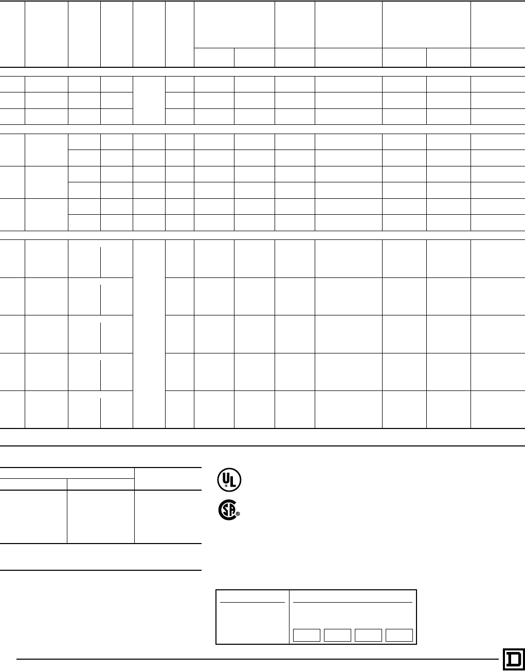
© 1998 Square D All Rights Reserved
30 5/98
600 Volts AC Maximum — 50-60 Hertz
NEMA
Size
Continuous
Current
Ratings
Motor
Volts Max.
HP Type of
Motor
t
Coil
Voltage
Open Type
NEMA
Type 1
General
Purpose
Enclosure
NEMA Type 4 & 4X
Watertight,
Dusttight
Brushed Stainless
Steel Enclosure
NEMA Type 7 & 9
Hazardous Locations
Class I, Groups C & D
Class II, Groups E, F & G
NEMA Type 12
Dusttight &
Driptight
Industrial Use
Enclosure
Vertical
Type Horizontal
Type Type Type Bolted Type SPIN TOP®
Type Type
2-Pole Single Phase
00 9 115 1⁄3
Single
Phase
3-Wire
120 . . . SAO1V02 SAG1V02 Use Size 0 Use Size 0 Use Size 0 Use Size 0
230 1 240 . . . SAO1V03 SAG1V03
018 115 1 120 SBO9V02 SBO1V02 SBG1V02 SBW11V02 SBT46V02 SBR6V02 SBA1V02
230 2 240 SBO9V03 SBO1V03 SBG1V03 SBW11V03 SBT46V03 SBR6V03 SBA1V03
127 115 2 120 SCO1V02 SCO2V02 SCG2V02 SCW11V02 SCT46V02 SCR6V02 SCA1V02
230 3 240 SCO1V03 SCO2V03 SCG2V03 SCW11V03 SCT46V03 SCR6V03 SCA1V03
3-Pole Single Phase
00 9
115 1⁄34-Wire
Rep.-Ind. 120 . . . SAO2V02 SAG2V02 Use Size 0 Use Size 0 Use Size 0 Use Size 0
230 1 240 . . . SAO2V03 SAG2V03
115 1⁄34-Wire
Split Ph. 120 . . . SAO3V02 SAG3V02 Use Size 0 Use Size 0 Use Size 0 Use Size 0
230 1 240 . . . SAO3V03 SAG3V03
018
115 1 4-Wire
Rep.-Ind. 120 SBO10V02 SBO2V02 SBG2V02 SBW12V02 SBT47V02 SBR7V02 SBA2V02
230 2 240 SBO10V03 SBO2V03 SBG2V03 SBW12V03 SBT47V03 SBR7V03 SBA2V03
115 1 4-Wire
Split Ph. 120 SBO11V02 SBO3V02 SBG3V02 SBW13V02 SBT48V02 SBR8V02 SBA3V02
230 2 240 SBO11V03 SBO3V03 SBG3V03 SBW13V03 SBT48V03 SBR8V03 SBA3V03
127
115 2 4-Wire
Rep.-Ind. 120 SCO3V02 SCO4V02 SCG4V02 SCW12V02 SCT47V02 SCR7V02 SCA2V02
230 3 240 SCO3V03 SCO4V03 SCG4V03 SCW12V03 SCT47V03 SCR7V03 SCA2V03
115 2 4-Wire
Split Ph. 120 SCO5V02 SCO6V02 SCG6V02 SCW13V02 SCT48V02 SCR8V02 SCA3V02
230 3 240 SCO5V03 SCO6V03 SCG6V03 SCW13V03 SCT48V03 SCR8V03 SCA3V03
4-Pole Polyphase
018
Separate Control
2 Phase
2 Wire
120 SBO13V02S SBO5V02S SBG5V02S SBW15V02S Consult Local
Square D
Field Office
SBR10V02S SBA5V02S
200 3 208 SBO13V08 SBO5V08 SBG5V08 SBW15V08 SBR10V08 SBA5V08
230 3 240 SBO13V03 SBO5V03 SBG5V03 SBW15V03 SBR10V03 SBA5V03
460 5 480 SBO13V06 SBO5V06 SBG5V06 SBW15V06 SBR10V06 SBA5V06
575 5 600 SBO13V07 SBO5V07 SBG5V07 SBW15V07 SBR10V07 SBA5V07
127
Separate Control 120 SCO9V02S SCO10V02S SCG10V02S SCW15V02S Consult Local
Square D
Field Office
SCR10V02S SCA5V02S
200 71⁄2208 SCO9V08 SCO10V08 SCG10V08 SCW15V08 SCR10V08 SCA5V08
230 71⁄2240 SCO9V03 SCO10V03 SCG10V03 SCW15V03 SCR10V03 SCA5V03
460 10 480 SCO9V06 SCO10V06 SCG10V06 SCW15V06 SCR10V06 SCA5V06
575 10 600 SCO9V07 SCO10V07 SCG10V07 SCW15V07 SCR10V07 SCA5V07
245
Separate Control 120
. . .
SDO4V02S SDG4V02S SDW12V02S Consult Local
Square D
Field Office
SDR4V02S SDA2V02S
200 10 208 SDO4V08 SDG4V08 SDW12V08 SDR4V08 SDA2V08
230 15 240 SDO4V03 SDG4V03 SDW12V03 SDR4V03 SDA2V03
460 25 480 SDO4V06 SDG4V06 SDW12V06 SDR4V06 SDA2V06
575 25 600 SDO4V07 SDG4V07 SDW12V07 SDR4V07 SDA2V07
390
Separate Control 120
. . .
SEO4V02S SEG4V02S SEW12V02S
. . . . . .
SEA2V02S
200 25 208 SEO4V08 SEG4V08 SEW12V08 SEA2V08
230 30 240 SEO4V03 SEG4V03 SEW12V03 SEA2V03
460 50 480 SEO4V06 SEG4V06 SEW12V06 SEA2V06
575 50 600 SEO4V07 SEG4V07 SEW12V07 SEA2V07
4 135
Separate Control 120
. . .
SFO4V02S SFG4V02S SFW12V02S
. . . . . .
SFA2V02S
200 40 208 SFO4V08 SFG4V08 SFW12V08 SFA2V08
230 50 240 SFO4V03 SFG4V03 SFW12V03 SFA2V03
460 100 480 SFO4V06 SFG4V06 SFW12V06 SFA2V06
575 100 600 SFO4V07 SFG4V07 SFW12V07 SFA2V07
tCoil voltage code must be specified to order this product. Refer to standard coil voltage codes listed in selection table above or additional standard voltage codes below and insert as shown
in the HOW TO ORDER block.
Coil Voltage Codes
Voltage Code
60 Hz 50 Hz
24q. . . V01j
120 110 V02j
208 . . . V08
240 220 V03
480 440 V06
600 550 V07
Specify Specify V99
q24 V coils are not available on Sizes 4-7. On Sizes 00-3, where 24 V
coils are available, Form S (separate control) must be specified.
jThese voltage codes must include Form S (supplied at N.C.).
Full Voltage Reversing Contactors — NEMA
Selection – Class 8702
Factory Modifications (FORMS)...............Refer to Catalog 9999CT9701
Application Data .................................................................... Page 33, 37
Dimensions ........................................................................... Pages 34-36
Separate Enclosures (Class 9991)...........Refer to Catalog 9999CT9701
Replacement Parts (Class 9998) ..............Refer to Catalog 9999CT9701
Type S Accessories (Class 9999).............Refer to Catalog 9999CT9701
How to Order:
To Order Specify: Catalog Number
• Class Number
• Type Number
• Coil Voltage Code
• Form(s)
Class Type Coil
Voltage
Code
Form(s)
8702 SCG2 VO2 P1S
File LR60905
Class 3211-04
File E78351
CCN NLDX

31
5/98 © 1998 Square D All Rights Reserved
3-Pole Polyphase—Three Thermal Units Required
NEMA
Size
Continuous
Current
Ratings
Motor
Volts Max.
HP
t
Coil
Voltage
Open Type
NEMA
Type 1
General
Purpose
Enclosure
NEMA Type 4 & 4X
Watertight, Dusttight
Brushed Stainless
Steel Enclosure
(Size 0-5)f
NEMA Type 7 & 9
Hazardous Locations
Class I, Groups C & D
Class II, Groups E, F & G
NEMA Type 12
Dusttight & Driptight
Industrial Use
Enclosure
Vertical
Type Horizontal
Type Type Type Bolted Type SPIN TOP®
Type Type
00 9
Separate Controlj120
. . .
SAO16V02S SAG16V02S
Use Size 0 Use Size 0 Use Size 0 Use Size 0
200 11⁄2208 SAO16V08 SAG16V08
230 11⁄2240 SAO16V03 SAG16V03
460 2 480 SAO16V06 SAG16V06
575 2 600 SAO16V07 SAG16V07
018
Separate Controlj120 SBO10V02S SBO4V02S SBG4V02S SBW14V02S SBT49V02S SBR9V02S SBA4V02S
200 3 208 SBO10V08 SBO4V08 SBG4V08 SBW14V08 SBT49V08 SBR9V08 SBA4V08
230 3 240 SBO10V03 SBO4V03 SBG4V03 SBW14V03 SBT49V03 SBR9V03 SBA4V03
460 5 480 SBO10V06 SBO4V06 SBG4V06 SBW14V06 SBT49V06 SBR9V06 SBA4V06
575 5 600 SBO10V07 SBO4V07 SBG4V07 SBW14V07 SBT49V07 SBR9V07 SBA4V07
127
Separate Controlj120 SCO7V02S SCO8V02S SCG8V02S SCW14V02S SCT49V02S SCR9V02S SCA4V02S
200 71⁄2208 SCO7V08 SCO8V08 SCG8V08 SCW14V08 SCT49V08 SCR9V08 SCA4V08
230 71⁄2240 SCO7V03 SCO8V03 SCG8V03 SCW14V03 SCT49V03 SCR9V03 SCA4V03
460 10 480 SCO7V06 SCO8V06 SCG8V06 SCW14V06 SCT49V06 SCR9V06 SCA4V06
575 10 600 SCO7V07 SCO8V07 SCG8V07 SCW14V07 SCT49V07 SCR9V07 SCA4V07
245
Separate Controlj120 SDO1V02S SDO2V02S SDG2V02S SDW11V02S SDT43V02S SDR3V02S SDA1V02S
200 10 208 SDO1V08 SDO2V08 SDG2V08 SDW11V08 SDT43V08 SDR3V08 SDA1V08
230 15 240 SDO1V03 SDO2V03 SDG2V03 SDW11V03 SDT43V03 SDR3V03 SDA1V03
460 25 480 SDO1V06 SDO2V06 SDG2V06 SDW11V06 SDT43V06 SDR3V06 SDA1V06
575 25 600 SDO1V07 SDO2V07 SDG2V07 SDW11V07 SDT43V07 SDR3V07 SDA1V07
390
Separate Controlj120 SEO1V02S SEO2V02S SEG2V02S SEW11V02S SET43V02S SER3V02S SEA1V02S
200 25 208 SEO1V08 SEO2V08 SEG2V08 SEW11V08 SET43V08 SER3V08 SEA1V08
230 30 240 SEO1V03 SEO2V03 SEG2V03 SEW11V03 SET43V03 SER3V03 SEA1V03
460 50 480 SEO1V06 SEO2V06 SEG2V06 SEW11V06 SET43V06 SER3V06 SEA1V06
575 50 600 SEO1V07 SEO2V07 SEG2V07 SEW11V07 SET43V07 SER3V07 SEA1V07
4 135
Separate Controlj120 SFO1V02S SFO3V02S SFG3V02S SFW11V02S
. . . . . .
SFA1V02S
200 40 208 SFO1V08 SFO3V08 SFG3V08 SFW11V08 SFA1V08
230 50 240 SFO1V03 SFO3V03 SFG3V03 SFW11V03 SFA1V03
460 100 480 SFO1V06 SFO3V06 SFG3V06 SFW11V06 SFA1V06
575 100 600 SFO1V07 SFO3V07 SFG3V07 SFW11V07 SFA1V07
5 270
Separate Controlj120 SGO1V02S SGO3V02S SGG3V02S SGW11V02S
. . . . . .
SGA1V02S
200 75 208 SGO1V08 SGO3V08 SGG3V08 SGW11V08 SGA1V08
230 100 240 SGO1V03 SGO3V03 SGG3V03 SGW11V03 SGA1V03
460 200 480 SGO1V06 SGO3V06 SGG3V06 SGW11V06 SGA1V06
575 200 600 SGO1V07 SGO3V07 SGG3V07 SGW11V07 SGA1V07
6 540
Separate Controlj120
. . .
SHO1V02S SHG1V02S SHW1V02S
. . . . . .
SHA1V02S
200 150 208 SHO1V08 SHG1V08 SHW1V08 SHA1V08
230 200 240 SHO1V03 SHG1V03 SHW1V03 SHA1V03
460 400 480 SHO1V06 SHG1V06 SHW1V06 SHA1V06
575 400 600 SHO1V07 SHG1V07 SHW1V07 SHA1V07
7 810
Separate Controlj120
. . .
SJO1V02S SJG1V02S SJW1V02S
. . . . . .
SJA1V02S
200 — 208 SJO1V08 SJG1V08 SJW1V08 SJA1V08
230 300 240 SJO1V03 SJG1V03 SJW1V03 SJA1V03
460 600 480 SJO1V06 SJG1V06 SJW1V06 SJA1V06
575 600 600 SJO1V07 SJG1V07 SJW1V07 SJA1V07
fSize 6 and 7 are sheet steel rated NEMA Type 4 only.
j120 Volt Polyphase starters are wired for separate control.
tCoil voltage code must be specified to order this product. Refer to standard coil voltage codes listed in selection table above or additional standard voltage codes below and insert as shown
in the HOW TO ORDER block.
Coil Voltage Codes
Voltage Code
60 Hz 50 Hz
24q. . . V01
120 110 V02
208 . . . V08
240 220 V03
480 440 V06
600 550 V07
Specify Specify V99
q24 V coils are not available on Sizes 4-7. On Sizes 00-3, where 24 V
coils are available, Form S (separate control) must be specified.
Full Voltage Reversing Starters — NEMA
Selection – Class 8736
Factory Modifications (FORMS)............... Refer to Catalog 9999CT9701
Application Data.....................................................................Page 33, 37
Dimensions............................................................................Pages 34-36
Separate Enclosures (Class 9991)........... Refer to Catalog 9999CT9701
Replacement Parts (Class 9998).............. Refer to Catalog 9999CT9701
Type S Accessories (Class 9999).............Refer to Catalog 9999CT9701
How to Order:
To Order Specify: Catalog Number
• Class Number
• Type Number
• Coil Voltage Code
• Form(s)
Class Type Coil
Voltage
Code
Form(s)
8736 SCG8 VO2 P1S
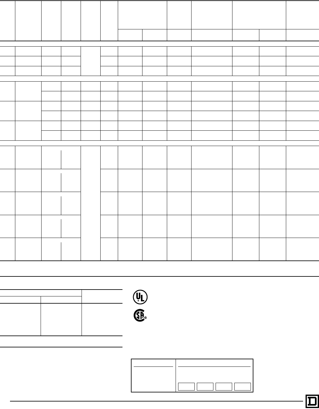
© 1998 Square D All Rights Reserved
32 5/98
600 Volts AC Maximum — 50-60 Hertz
NEMA
Size
Continuous
Current
Ratings
Motor
Volts Max.
HP Type of
Motor
t
Coil
Voltage
Open Type
NEMA
Type 1
General
Purpose
Enclosure
NEMA Type 4 & 4X
Watertight,
Dusttight
Brushed Stainless
Steel Enclosure
NEMA Type 7 & 9
Hazardous Locations
Class I, Groups C & D
Class II, Groups E, F & G
NEMA Type 12
Dusttight &
Driptight
Industrial Use
Enclosure
Vertical
Type Horizontal
Type Type Type Bolted Type SPIN TOP®
Type Type
2-Pole Single Phase — 1 Thermal Unit Required
00 9 115 1⁄3
Single
Phase
3-Wire
120 . . . SAO13V02 SAG13V02 Use Size 0 Use Size 0 Use Size 0 Use Size 0
230 1 240 . . . SAO13V08 SAG13V08
018 115 1 120 SBO7V02 SBO1V02 SBG1V02 SBW11V02 SBT46V02 SBR6V02 SBA1V02
230 2 240 SBO7V08 SBO1V08 SBG1V08 SBW11V08 SBT46V08 SBR6V08 SBA1V08
127 115 2 120 SCO1V02 SCO2V02 SCG2V02 SCW11V02 SCT46V02 SCR6V02 SCA1V02
230 3 240 SCO1V08 SCO2V08 SCG2V08 SCW11V08 SCT46V08 SCR6V08 SCA1V08
3-Pole Single Phase — 1 Thermal Unit Required
00 9
115 1⁄34-Wire
Rep.-Ind. 120 . . . SAO14V02 SAG14V02 Use Size 0 Use Size 0 Use Size 0 Use Size 0
230 1 240 . . . SAO14V08 SAG14V08
115 1⁄34-Wire
Split Ph. 120 . . . SAO15V02 SAG15V02 Use Size 0 Use Size 0 Use Size 0 Use Size 0
230 1 240 . . . SAO15V08 SAG15V08
018
115 1 4-Wire
Rep.-Ind. 120 SBO80V02 SBO2V02 SBG2V02 SBW12V02 SBT47V02 SBR7V02 SBA2V02
230 2 240 SBO8V08 SBO2V08 SBG2V08 SBW12V08 SBT47V08 SBR7V08 SBA2V08
115 1 4-Wire
Split Ph. 120 SBO9V02 SBO3V02 SBG3V02 SBW13V02 SBT48V02 SBR8V02 SBA3V02
230 2 240 SBO9V08 SBO3V08 SBG3V08 SBW13V08 SBT48V08 SBR8V08 SBA3V08
127
115 2 4-Wire
Rep.-Ind. 120 SCO3V02 SCO4V02 SCG4V02 SCW12V02 SCT47V02 SCR7V02 SCA2V02
230 3 240 SCO3V08 SCO4V08 SCG4V08 SCW12V08 SCT47V08 SCR7V08 SCA2V08
115 2 4-Wire
Split Ph. 120 SCO5V02 SCO6V02 SCG6V02 SCW13V02 SCT48V02 SCR8V02 SCA3V02
230 3 240 SCO5V08 SCO6V08 SCG6V08 SCW13V08 SCT48V08 SCR8V08 SCA3V08
4-Pole Polyphase — 2 Thermal Units Required
018
Separate Controlj
2 Phase
2 Wire
120 SBO11V02S SBO5V02S SBG5V02S SBW15V02S Consult Local
Square D
Field Office
SBR10V02S SBA5V02S
200 3 208 SBO11V08 SBO5V08 SBG5V08 SBW15V08 SBR10V08 SBA5V08
230 3 240 SBO11V03 SBO5V03 SBG5V03 SBW15V03 SBR10V03 SBA5V03
460 5 480 SBO11V06 SBO5V06 SBG5V06 SBW15V06 SBR10V06 SBA5V06
575 5 600 SBO11V07 SBO5V07 SBG5V07 SBW15V07 SBR10V07 SBA5V07
127
Separate Controlj120 SCO9V02S SCO10V02S SCG10V02S SCW15V02S Consult Local
Square D
Field Office
SCR10V02S SCA5V02S
200 71⁄2208 SCO9V08 SCO10V08 SCG10V08 SCW15V08 SCR10V08 SCA5V08
230 71⁄2240 SCO9V03 SCO10V03 SCG10V03 SCW15V03 SCR10V03 SCA5V03
460 10 480 SCO9V06 SCO10V06 SCG10V06 SCW15V06 SCR10V06 SCA5V06
575 10 600 SCO9V07 SCO10V07 SCG10V07 SCW15V07 SCR10V07 SCA5V07
245
Separate Controlj120
. . .
SDO4V02S SDG4V02S SDW12V02S Consult Local
Square D
Field Office
SDR4V02S SDA2V02S
200 10 208 SDO4V08 SDG4V08 SDW12V08 SDR4V08 SDA2V08
230 15 240 SDO4V03 SDG4V03 SDW12V03 SDR4V03 SDA2V03
460 25 480 SDO4V06 SDG4V06 SDW12V06 SDR4V06 SDA2V06
575 25 600 SDO4V07 SDG4V07 SDW12V07 SDR4V07 SDA2V07
390
Separate Controlj120
. . .
SEO4V02S SEG4V02S SEW12V02S
. . . . . .
SEA2V02S
200 25 208 SEO4V08 SEG4V08 SEW12V08 SEA2V08
230 30 240 SEO4V03 SEG4V03 SEW12V03 SEA2V03
460 50 480 SEO4V06 SEG4V06 SEW12V06 SEA2V06
575 50 600 SEO4V07 SEG4V07 SEW12V07 SEA2V07
4 135
Separate Controlj120
. . .
SFO4V02S SFG4V02S SFW12V02S
. . . . . .
SFA2V02S
200 40 208 SFO4V08 SFG4V08 SFW12V08 SFA2V08
230 50 240 SFO4V03 SFG4V03 SFW12V03 SFA2V03
460 100 480 SFO4V06 SFG4V06 SFW12V06 SFA2V06
575 100 600 SFO4V07 SFG4V07 SFW12V07 SFA2V07
j120 Volt starters are wired for separate control.
tCoil voltage code must be specified to order this product. Refer to standard coil voltage codes listed in selection table above or additional standard voltage codes below and insert as shown
in the HOW TO ORDER block.
Coil Voltage Codes
Voltage Code
60 Hz 50 Hz
24q. . . V01
120 110 V02
208 . . . V08
240 220 V03
480 440 V06
600 550 V07
Specify Specify V99
q24 V coils are not available on Sizes 4-7. On Sizes 00-3, where 24 V
coils are available, Form S (separate control) must be specified.
Full Voltage Reversing Starters — NEMA
Selection – Class 8736
Factory Modifications (FORMS)...............Refer to Catalog 9999CT9701
Application Data .................................................................... Page 33, 37
Dimensions ........................................................................... Pages 34-36
Separate Enclosures (Class 9991)...........Refer to Catalog 9999CT9701
Replacement Parts (Class 9998) ..............Refer to Catalog 9999CT9701
Type S Accessories (Class 9999).............Refer to Catalog 9999CT9701
How to Order:
To Order Specify: Catalog Number
• Class Number
• Type Number
• Coil Voltage Code
• Form(s)
Class Type Coil
Voltage
Code
Form(s)
8736 SCG8 VO2 P1S
File LR60905
Class 3211-04
File E78351
CCN NLDX
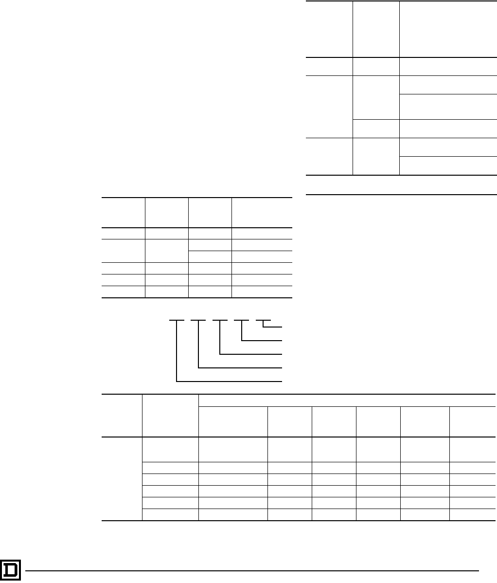
33
5/98 © 1998 Square D All Rights Reserved
Power Contact Ratings
All contactors are rated in accordance with NEMA
standards. The ratings shown in the tables on
Pages 29-32 are for normal service. For complete
data on power contact ratings, refer to Class 8536
Section.
Maintenance of Equipment
Class 9998 repair parts kits are available for all
Class 8702 contactors and Class 8736 starters.
Service bulletins with a complete list of
replaceable parts are supplied with all devices.
See Page 15.
Control Transformer Selection
The following table gives the proper size control
transformer to be used with a given reversing
device, with or without additional auxiliary
contacts or timer. For factory addition of control
transformers, see Factory Modifications (Forms)
section.
Auxiliary Units
The table below shows the maximum number of
auxiliary units (in addition to the holding circuit
and interlocking contacts) that can be added to
either the forward or reverse contactor or starter.
Factory Installed Auxiliary Contacts
Additional auxiliary contacts may be factory or
field added to any Type 3 contactor or starter. See
table above for maximum number of auxiliary
units. The table below lists the Form designations
for factory installed auxiliary contacts. See Class
9999 for field modification kits.
NEMA Size Type No. of
Poles
Transformers
Class 9070
Type
0, 1 & 2 SB, SC & SD Any T100 or GO2
3SE
3 T1500 or GO3
4 & 5 T300
4 SF Any T300
5 SG Any T500
6 & 7 SH & SJ Any See Page 16
NEMA Size
(Type)
No. of Poles
of Basic
Contactor
Maximum number of
auxiliary units on each
contactor, forward or
reverse, (in addition to
internal holding circuit and
interlocking contacts).
00
(SA) 2 or 3 2 single circuit auxiliary contacts
(N.O. or N.C.)
0, 1 & 2
(SB, SC
& SD)
2 or 3
4 single circuit auxiliary contactsq
(N.O. or N.C.)
1 single circuit auxiliary contact
(N.O. or N.C.) plus 1 attached timer
(ON or OFF delay).
42 single circuit auxiliary contacts
(N.O. or N.C.)
3, 4, 5, 6, & 7
(SE, SF, SG,
SH, & SJ) Any
2 single circuit auxiliary contacts
(N.O. or N.C.)
1 single circuit auxiliary contact plus
1 attached timer (ON or OFF delay).
qWhen adding 4 external auxiliary contacts to one Size 0 or 1
contactor, remove one of the return springs.
Example: X 1O1O
Number of N.C. auxiliary contacts on right hand (Reverse) contactor.
Number of N.O. auxiliary contacts on right hand (Reverse) contactor.
Number of N.C. auxiliary contacts on left hand (Forward) contactor.
Number of N.O. auxiliary contacts on left hand (Forward) contactor.
Basic Form Designation.
Additional Auxiliary Contacts on R.H. Contactor (Reverse Contactor)
Standard
(No Additional
Auxiliary Contacts) 1 N.O. 1 N.C. 2 N.O. 1 N.O.-1 N.C. 2 N.C.
Additional
Auxiliary
Contacts on
L.H.
Contactor
(Forward
Contactor)
Standard
(No Additional
Auxiliary Contacts) X0010 X0001 X0020 X0011 X0002
1 N.O. X1000 X1010 X1001 X1020 X1011 X1002
1 N.C. X0100 X0110 X0101 X0120 X0111 X0102
2 N.O. X2000 X2010 X2001 X2020 X2011 X2002
1 N.O.-1 N.C. X1100 X1110 X1101 X1120 X1111 X1102
2 N.C. X0200 X0210 X0201 X0220 X0211 X0202
Full Voltage Reversing Contactors and Starters — NEMA
Application Data – Class 8702, 8736
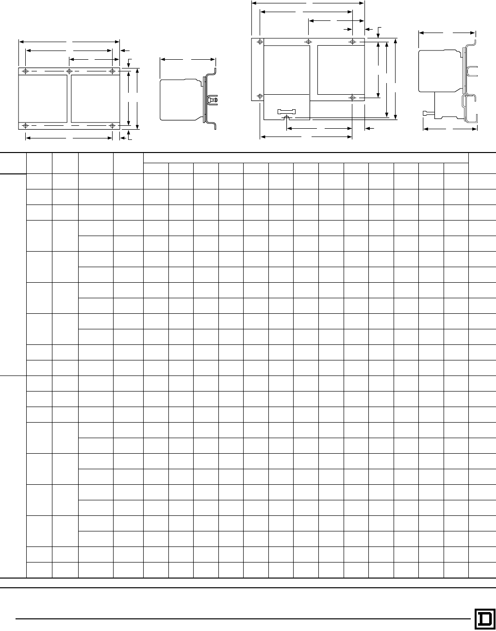
© 1998 Square D All Rights Reserved
34 5/98
Open Type — 2 or 3-Pole Only
Class NEMA
Size Type Mounting Figure
Number
Dimensions — Inches/mm Weight
(Lbs)
ABCDEFGHI J KLM
8702
00 SAO Horizontal 1 7.13
181 5.00
127 5.31
135 . . . . . . 3.41
87 .47
12 4.34
110 .19
55.50
140 .91
23 . . . . . . 12
0 SBO Horizontal 1 7.13
181 5.00
127 5.31
135 . . . . . . 3.41
87 .47
12 4.34
110 .19
55.50
140 .91
23 . . . . . . 12
1 SCO Vertical 1t5.41
137 9.22
234 5.31
135 5.03
128 .22
6. . . .61
15 8.00
203 .61
15 5.03
128 .22
6. . . . . . 12
2 SDO
Horizontal 1 9.00
229 6.88
175 6.03
153 . . . . . . 4.50
114 .38
10 5.63
143 .25
66.00
152 1.50
38 . . . . . . 16
Vertical 1t6.75
171 11.38
289 6.03
153 6.25
159 .25
6. . . .50
13 10.38
264 .50
13 6.25
159 .25
6. . . . . . 16
3 SEO
Horizontal 1 12.72
323 7.97
202 7.00
178 11.75
298 .48
12 . . . .48
12 7.00
178 .48
12 11.75
298 .48
12 . . . . . . 35
Vertical 1t7.20
183 19.00
483 7.00
178 6.25
159 .48
12 . . . 1.02
26 17.00
432 .98
25 6.25
159 .48
12 . . . . . . 35
4 SFO
Horizontal 1 14.25
362 11.69
297 7.00
178 13.25
337 .50
13 . . . .50
13 8.00
203 1.84
47 13.25
337 .50
13 . . . . . . 45
Vertical 1t7.97
202 23.91
607 7.00
178 7.00
178 .48
12 . . . 1.81
46 20.25
514 1.19
30 7.00
178 .48
12 . . . . . . 45
5 SGO
Horizontal 1 19.31
490 16.19
411 9.38
238 18.00
457 .66
17 . . . 1.03
26 14.00
356 1.16
29 18.00
457 .66
17 . . . . . . 98
Vertical 1t10.75
273 34.41
874 9.38
238 9.50
241 .63
16 . . . 1.25
32 32.00
813 1.16
29 9.50
241 .63
16 . . . . . . 98
6 SHO Horizontal 1 22.38
568 28.05
712 9.52
242 18.00
457 .77
20 . . . 3.83
97 21.19
538 3.03
77 18.00
457 .77
20 . . . . . . 195
7 SJO Horizontal 1 24.25
616 37.25
946 13.81
351 19.75
502 1.52
39 . . . . . . 30.00
762 . . . . . . . . . . . . . . . 310
8736
00 SAO Horizontal 2 7.13
181 6.91
176 5.31
135 . . . . . . 3.41
87 .47
12 4.34
110 6.22
158 4.53
115 5.06
129 .66
17 . . . 13
0 SBO Horizontal 2 7.13
181 6.91
176 5.31
135 . . . . . . 3.41
87 .47
12 4.34
110 6.22
158 4.53
115 5.06
129 .66
17 . . . 13
1 SCO Vertical 2t5.41
137 11.52
293 5.31
135 5.03
128 .22
6. . . .61
15 8.00
203 10.70
272 2.52
64 5.06
129 .22
65.03
128 13
2 SDO
Horizontal 2 9.00
229 8.50
216 6.03
153 . . . . . . 4.50
114 .38
10 5.63
143 7.50
191 5.00
127 5.16
131 1.50
38 . . . 18
Vertical 2t6.75
171 13.48
342 6.03
153 6.25
159 .25
6. . . .78
20 10.38
264 12.97
329 3.13
80 5.16
131 .25
66.00
152 18
3 SEO
Horizontal 2 12.72
323 11.72
298 7.00
178 11.75
298 .48
12 . . . .48
12 10.75
273 10.75
273 11.75
298 6.25
159 .48
12 11.75
298 38
Vertical 2t7.31
186 22.25
565 7.00
178 6.25
159 .48
12 . . . 1.02
26 20.75
527 . . . 6.25
159 6.25
159 .48
12 6.25
159 38
4 SFO
Horizontal 2 14.25
362 14.59
371 7.00
178 13.25
337 .50
13 . . . 1.84
47 12.25
311 12.25
311 13.25
337 6.25
159 .50
13 13.25
337 48
Vertical 2t7.97
202 26.81
681 7.00
178 7.00
178 .48
12 . . . 1.84
47 24.50
622 . . . 4.05
103 6.25
159 .48
12 7.00
178 48
5 SGO
Horizontal 2 19.31
490 20.91
531 9.38
238 18.00
457 .66
17 . . . 1.28
33 19.00
483 19.00
483 18.00
457 6.63
168 .63
16 18.00
457 115
Vertical 2t10.75
273 39.16
995 9.38
238 9.50
241 .66
17 . . . 1.28
33 37.25
946 37.25
946 9.50
241 6.63
168 .63
16 9.50
241 115
6 SHO Horizontal 2 22.38
568 28.05
712 9.52
242 18.00
457 .77
20 . . . 3.83
97 21.19
538 3.03
77 18.00
457 .77
20 . . . . . . 200
7 SJO Horizontal 1 24.25
616 37.25
946 13.81
351 19.75
502 1.52
39 . . . . . . 30.00
762 . . . . . . . . . . . . . . . 315
tVertical type design differs from that shown on the corresponding NEMA size horizontal figure, but dimensions listed apply to that figure.
A
G
I
HB
JK
DE
F C
A
H
F
C
LK
M
J
D
EG
RESET
I
B
Full Voltage Reversing Contactors and Starters — NEMA
Approximate Dimensions – Class 8702, 8736
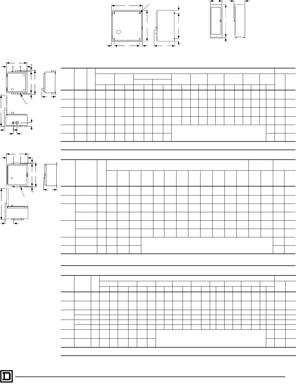
35
5/98 © 1998 Square D All Rights Reserved
NEMA Type 1
NEMA
Size Class
No. Fig.
No.
Dimensions — Inches/mm Wt (Lbs)
ABCDEFGHI
8702 87368702 8736
IN mm IN mm IN mm IN mm IN mm IN mm IN mm IN mm IN mm IN mm
00, 0 j
1j
8702 &
8736 4 11.88 302 11.88 302 7.41 188 7.53 191 9.75 248 1.06 27 1.06 27 9.75 248 1.06 27 .31 8 16 17
2j8702 &
8736 4 14.88 378 14.13 359 7.56 192 7.66 195 12.75 324 1.06 27 1.06 27 12.00 305 1.06 27 .31 8 24 25
3t
4t
8702 &
8736 4 18.16 461 29.16 741 9.25 235 9.25 235 15.50 394 1.33 34 1.33 34 26.50 673 1.33 34 .44 11 95 98
58702 &
8736 4 35.22 895 46.22 1174 12.81 325 12.93 328 31.00 787 2.11 54 2.11 54 42.00 1067 2.11 54 .56 14 298 315
68702 &
8736 5 36.22 920 62.22 1580 19.47 495 19.47 495 Floor Mounting 400 405
78702 &
8736 5 34.50 876 93.00 2362 23.50 597 23.50 597 . . . . . .
jStandard enclosure has space for a fused control transformer, Form F4T, on Sizes 0-2, except for Size 0 & 1 4-Pole.
t3-Pole only.
NEMA Type 4 & 4X – Stainless Steelq
NEMA
Size Class
Number Fig.
No.
Dimensions — Inches/mm Hub Dia. Weight
(Lbs)
AB C D EF G H I J K L W
Bot.
Only
X
Top &
Bot. 8702 8736
0j
1j8702 & 8736 6 12.63
321 7.81
198 14.69
373 2.56
65 7.50
191 13.50
343 .59
15 3.88
99 18.41
468 1.66
42 2.31
59 .31
83⁄412526
2j8702 & 8736 6 14.88
378 8.25
210 15.75
400 12.56
319 9.75
248 15.00
381 .38
10 3.88
99 20.88
530 1.72
44 2.63
67 .31
83⁄411⁄233 35
3t
4t
8702 6 18.16
461 8.75
222 32.22
818 3.08
78 12.00
305 30.50
775 .88
22 3.69
94 26.72
679 2.56
65 3.19
81 .44
11 3⁄421⁄296 . . .
8736 6 18.16
461 9.56
243 32.22
818 3.08
78 12.00
305 30.50
775 .88
22 4.50
114 26.72
679 2.56
65 3.19
81 .44
11 3⁄421⁄2. . . 99
58702 6 35.22
895 12.13
308 49.22
1250 4.11
104 27.00
686 48.00
1219 .63
16 4.59
117 45.81
1164 2.97
75 3.50
89 .56
14 3⁄431⁄2300 . . .
8736 6 35.22
895 12.94
329 49.22
1250 4.11
104 27.00
686 48.00
1219 .63
16 5.41
137 45.81
1164 2.97
75 3.50
89 .56
14 3⁄431⁄2. . . 317
6 8702 & 8736 5 36.22
920 70.13
1781 19.47
495 Floor Mounting 500 505
7 8702 & 8736 5 34.50
876 101.00
2565 23.50
597 . . . . . .
jStandard enclosure has space for a fused control transformer, Form F4T, on Sizes 0-2, except for Size 0 & 1 4-Pole devices.
t3-Pole only.
qSize 6 & 7 are sheet steel enclosures and are rated NEMA Type 4 only.
NEMA Type 12
NEMA
Size Class
Number Fig.
No.
Dimensions — Inches/mm Wt (Lbs)
ABCDEFGHI J
8702 8736
IN mm IN mm IN mm IN mm IN mm IN mm IN mm IN mm IN mm IN mm
0j
1j
8702 &
8736 7 11.88 302 7.75 197 13.75 349 2.56 65 6.75 171 12.75 324 .50 13 3.66 93 18.13 461 .31 8 23 24
2j8702 &
8736 7 14.88 378 7.88 200 16.00 406 2.56 65 9.75 248 15.00 381 .50 13 3.66 93 21.25 540 .31 8 31 32
3t
4t
8702 7 18.16 461 9.25 235 31.50 800 3.08 78 12.00 305 30.50 775 .50 13 3.69 93 26.72 679 .44 11 96 . . .
8736 7 18.16 461 9.56 243 31.50 800 3.08 78 12.00 305 30.50 775 .50 13 4.50 114 26.72 679 .44 11 . . . 99
58702 7 35.22 895 13.13 334 49.00 1245 4.13 105 27.00 686 48.00 1219 .50 13 5.31 135 45.88 1165 .56 14 302 . . .
8736 7 35.22 895 13.94 354 49.00 1245 4.13 105 27.00 686 48.00 1219 .50 13 6.13 156 45.88 1165 .56 14 . . . 319
68702 &
8736 5 36.22 920 62.22 1580 19.47 495
Floor Mounting
490 495
78702 &
8736 5 34.50 876 93.00 2362 23.50 597 . . . . . .
jStandard enclosure has space for a fused control transformer, Form F4T, on Sizes 0-2, except for Size 0 & 1 4-Pole devices.
t3-Pole only.
B
1.50
38
AC
Figure 5
RESET
A(4) I Dia.
Mounting Holes
B
H
H
C
F
D
E
G
Figure 4
Full Voltage Reversing Contacators and Starters — NEMA
Approximate Dimensions – Class 8702, 8736
Figure 6
Figure 7
F
G
G
DDE
J
C
B
A
W
I
HK
X
(4) L Dia.
Mounting Holes
F
G
G
DDE
C
B
A
I
H
(4) J Dia.
Mounting Holes
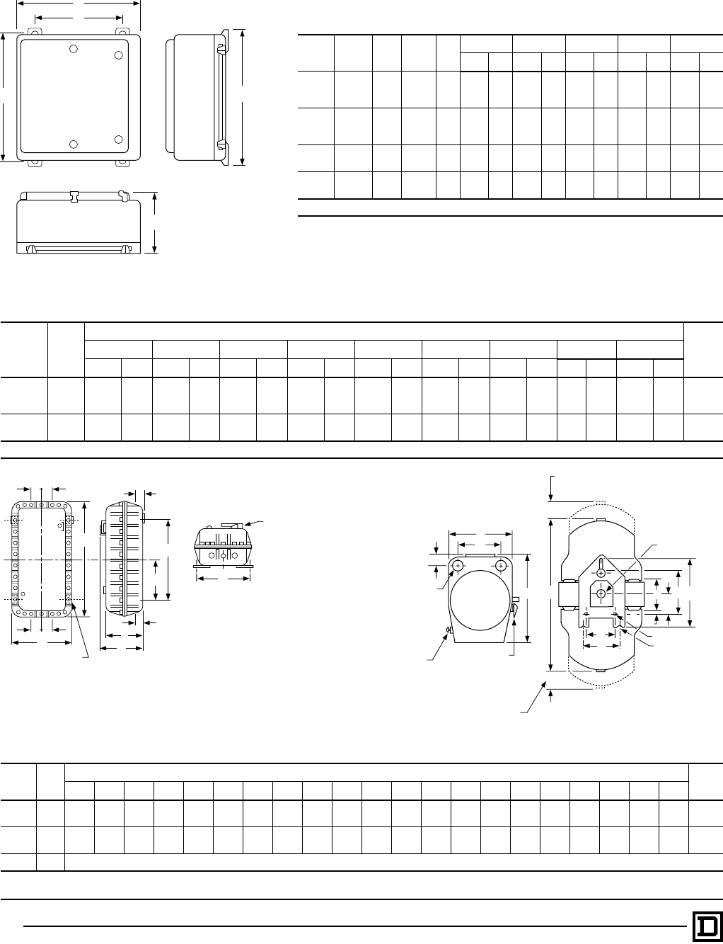
© 1998 Square D All Rights Reserved
36 5/98
NEMA Type 4X — Watertight and Corrosion Resistant
Glass Polyester Enclosure
NEMA
Size Class Type No. of
Poles Fig. ABCEF
IN mm IN mm IN mm IN mm IN mm
0-2 8702/36 SBW All 16.88 429 9.78 248 22.75 578 10.13 257 21.50 546SCW
SDW
0-2t8702/36 SBW All 24.63 626 11.94 303 27.00 686 17.88 454 25.75 654SCW
SDW
3-4 8702/36 SEW All 25.81 656 11.94 303 33.50 851 18.50 470 32.25 819
SPW
3-4t8702/36 SEW All 32.00 813 12.13 308 39.31 998 23.88 607 38.13 969
SPW
tWith control power transformer (Form F4T)
NEMA Type 7 & 9 Bolted Enclosure — Figure 8
NEMA
Size Type
Dimensions — Inches/mmc
Wt
(Lbs)
G H J K L N P Q, R S, T, U, V
IN mm IN mm IN mm IN mm IN mm IN mm IN mm IN mm IN mm
0-2 SBT 14.25 362 27.63 702 9.50 241 12.25 311 19.25 489 9.63 245 11.50 292 2.38 60 3.13 80 115SCT
SDT
3-4tSET 24.50 622 45.63 1159 13.75 349 22.50 572 27.50 699 13.75 349 15.38 391 3.44 87 4.00 102 180
SFT
cDimensions shown for 2 or 3-Pole devices only.
NEMA 7 & 9 SPIN TOP® Enclosure — Figure 9
NEMA
Size Type Dimensions — Inches/mm Wt
(Lbs)
ABtBjCtCjDEtEjFGtGjHtHjJtJjKLMNPR
0-1 SBR 12.00
305 41.06
1043 46.13
1172 68.06
1729 79.13
2010 16.75
425 7.25
184 12.25
311 7.69
195 26.13
664 26.13
664 3.00
76 9.00
229 24.00
610 24.00
610 8.50
216 2.06
52 9.38
238 5.25
133 1.50
38 .38
10 70
SCR
2 SDR 16.13
410 48.50
1232 50.50
1283 81.50
2070 85.00
2159 20.25
514 12.13
308 9.13
232 8.63
219 27.75
705 32.75
832 8.00
203 4.50
114 25.00
635 30.00
762 12.00
305 12.63
321 11.00
279 5.50
140 2.50
64 .38
10 100
3 SER Consult Local Square D Field Office
tWithout control transformer.
jWith control transformer (Form F4T).
N
A
BD
C
J
P
F
M
KH
Mtg. Holes
and/or Slots (3)
Space Required
To Remove
Top Cover
Space Required To
Remove Bottom Cover
Circuit Breaker
Operational Handle –
Combination Form Only
(Add 1.00 Inch To
Overall Width)
Overload
Reset
Threaded
Cover
Enclosure
E
Q
R
G
T
L
Rear Seal
S
(2) "L" Pipe
Tap Top and
Bottom
Figure 8
R
O
VU
H
L
N
ST
GP
Mounting for 4 Bolts
Circuit Breaker Handle not supplied
on Class 8502 or 8536
1/2" NPT for Breather and Drain
K
J
Figure 9
Full Voltage Reversing Contactors and Starters — NEMA
Approximate Dimensions – Class 8702, 8736
Figure 7
E
F
A
C
B
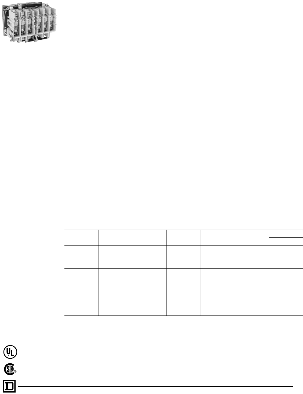
37
5/98 © 1998 Square D All Rights Reserved
Auxiliary Contact Units
Additional auxiliary contact units may be added to
the Size 4 and 5 reversing contactors in the field.
A maximum of 2 units may be added to the Size 4;
a maximum of 1 unit may be added to the Size 5.
No additional units may be added to the Size 6,
however, 1 N.O. and 1 N.C. circuit are available on
each forward and reverse contactor for customer
use.
GENERAL INFORMATION
Class 8702 Type W reversing vacuum contactors
are a new addition to the Square D line of
contactors. These reversing contactors are used
to switch capacitors, transformers and electric
motors where overload protection is separately
provided. Type W reversing vacuum contactors
are designed for operation at 600 Volts, 50/60
Hertz.
By design, these contactors are well suited to
heavy-duty applications in harsh environments.
The power contacts are sealed in ceramic tubes,
called vacuum interrupters or vacuum bottles,
where the air has been evacuated. Arc quenchers
are not required because any arc formed between
opening contacts is not sustained due to the
presence of the vacuum. The arc is extinguished
when the current crosses zero after the contacts
are opened, therefore the arc typically does not
survive more than one half cycle. There is one
vacuum interrupter or bottle per pole, therefore a
three pole contactor has three vacuum
interrupters or bottles. The power contacts are not
affected by ambient conditions or contamination.
This provides for long life and reliable operation in
harsh applications.
Altitude
The reversing vacuum contactor is designed to
tolerate normal barometric pressure variances up
to 6600 feet above sea level. If the contactor is to
be used above 6600 feet above sea level, please
consult the factory.
Termination Means
The Size 4 reversing vacuum contactor is
supplied with line and load side lugs. The Size 5
and 6 reversing vacuum contactors are supplied
without line and load side lugs. Class 9999 Type
LUW5 and LUW6 lug kits are available for the Size
5 and 6 contactors. These kits include six lugs and
the necessary mounting hardware.
Auxiliary Contacts
An auxiliary contact block, Class 9999 Type
WX11, with one normally-open contact and
normally-closed contact is used with Size 4, 5 and
6 vacuum contactors.
Class 8702 – Full Voltage Reversing Vacuum Contactors (Horizontal Only)
3-Pole Polyphase – 600 Volts AC Maximum (50-60 Hertz)
NEMA Size Enclosed
Ampere Rating Locked Rotor
Current (Amps) Motor Volts Max. HP t Coil Voltage Open Type
Type
4 135 1080
200 40 120 WFO3V02S
230 50 240 WFO3V03
380 75 120 WFO3V02S
460 100 480 WFO3V06
575 100 600 WFO3V07
5 270 2160
200 75 120 WGO3V02S
230 100 240 WGO3V03
380 150 120 WGO3V02S
460 200 480 WGO3V06
575 200 600 WGO3V07
6 540 4320
200 150 120 WHO3V02S
230 200 240 WHO3V03
380 300 120 WHO3V02S
460 400 480 WHO3V06
575 400 600 WHO3V07
Full Voltage Contactors — NEMA
Application Data, Selection – Class 8702
Class 8702 Type WF
Reversing Vacuum
Contactor
File LR60905
Class 3211-04
File E78351
CCN NLDX2
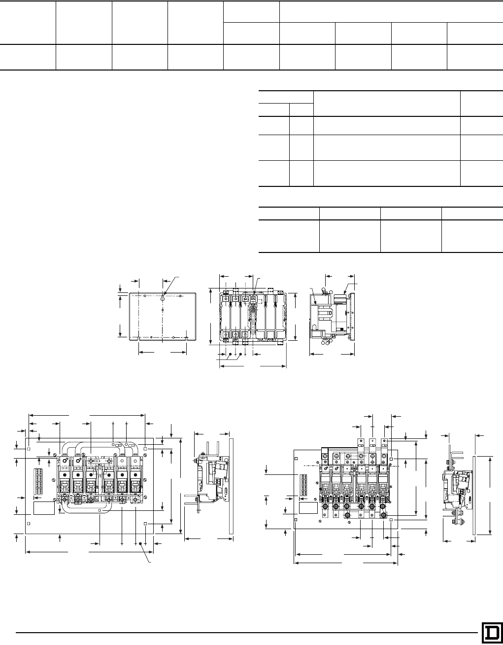
© 1998 Square D All Rights Reserved
38 5/98
Class 9998 – Replacement Coils for Class 8502 and 8702 Vacuum Contactors
Size Type Poles Class & Type
Hertz Suffix Number (Complete Coil Number Consists of Class and Type
Followed by Suffix Number)
50
60 120 Volts
110 Volts 240 Volts
220 Volts 480 Volts
440 Volts 600 Volts
550 Volts
4WF
All 9998WF 120 240 480 6005 WG 9998WG
6 WH 9998WH
Class 9999 – Vacuum Contactor Kits
For Use With Kit Description Class 9999
Type
Type Size
WF-WH 4-6 Auxiliary Contacts, Non-Convertible
1-N.O. & 1-N.C. Isolated Contacts 9999WX11
Coil Circuit Auxiliary Contacts
WF 4 1-N.O. & 1-N.C. Isolated Contacts, Delayed Break 9999WCX11
WG-WH 5-6 1-N.C. Isolated Contact 9999WLX01
Lug Kits
WG 5 (6) lugs included 9999LUW5
WH 6 (6) lugs included 9999LUW6
Auxiliary Contact Ratings — NEMA A600, R300
Description Voltage Make Break
Class 9999
Type WX11 and
WXO1
120-600 Vac 7200 VA 720 VA
72-120 Vac 60 A 720 VA
28-72 Vac 60 A 10 A
28-300 Vac 28 A 28 VA
Class 8702 WF
9.75
248
6.00
152
7.00
178
3.50
89
4.20
107
1.44
37
1.13
29
6.88
175
8.80
224
Max.
.44
11
6.45
164
Mechanical
Interlock Recess for
Auxiliary
Contact
4.88
124
Front View
Rear View
Drilling Plan Side View
.28 Dia.
7
(3) Mtg. Holes Overtravel
Gauge
Name
Plate
Size 5 Reversing Contactor Outline without Lugs
1
2
3
4
5
6
0
1
2
7
8
9
3.75
95
9.56
243
6.90
175
.86
22
2.48
63
3.98
101
24.00
610
4.26
108
2.75
70
.38
10
1.76
45
1.50
38
2.00
51
14.00
356
22.00
559 2.50
64
2.50
64 .40
10
1.89
48
4.00
102 3.65
93
5.81
148
.60
15
18.00
457
Class 8702 WG Class 8702 WH
Size 6 Reversing Contactor Outline without Lugs
Name
Plate
24.00
610
22.00
559
2.70
69 2.70
69
3.40
86
16.40
417
14.00
356
2.00
51
3.90
99
6.50
165
7.75
197
18.00
457
3.75
95
4.40
112
4.40
112
1.40
36
2.70
69 2.70
69
1.50
38
5.00
127
7.75
197
Full Voltage Contactors — NEMA
Selection – Class 8702

39
5/98 © 1998 Square D All Rights Reserved
SECTION 3 – MOTOR STARTERS MULTI-SPEED
Application Data – Class 8810, 8811, 8812. . . . . . . . . . . . . . . . . . . . . 40-41
Line Voltage — with Melting Alloy Overload Relays – Class 8810. . . . . . . 42
Reversing Line Voltage Type — with Melting Alloy Overload Relays –
Class 8810 . . . . . . . . . . . . . . . . . . . . . . . . . . . . . . . . . . . . . . . . . . . . . .43
Line Voltage — with Melting Alloy Overload Relays or
Solid State Overload Relays – Class 8810. . . . . . . . . . . . . . . . . . . 44-45
Line Voltage — with Melting Alloy Overload Relays – Class 8811, 8812. . 48
Application Data – Class 8810, 8811, 8812. . . . . . . . . . . . . . . . . . . . . . . . 47
Application Data for Types SB-SJ – Class 8810, 8811, 8812 . . . . . . . . . .48
Dimensions – Class 8810, 8811, 8812 . . . . . . . . . . . . . . . . . . . . . . . . . . . 49
Application Data – Class 8810, 8811, 8812. . . . . . . . . . . . . . . . . . . . . 50-51
Disconnect Switch or Circuit Breaker Type – Class 8810, 8811, 8812 . . .52
Contents
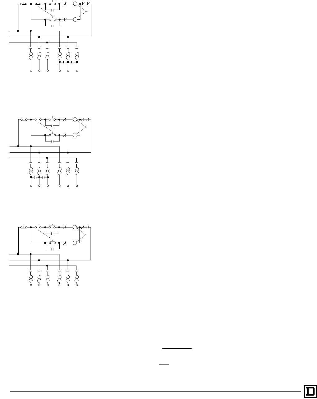
© 1998 Square D All Rights Reserved
40 5/98
Multispeed motors are available in two basic versions:
• Consequent pole
• Separate winding
A separate winding motor has a winding for each speed while a consequent
pole motor has a winding for every two speeds (three speed motors have two
windings). The motor connections (and thus the types of controllers) for two
speed starters are exemplified by the schematic diagrams shown to the left.
Note that consequent pole two speed controllers involve a 5-pole and a
3-pole starter while separate winding controllers have two 3-pole starters.
Separate winding motors are usually chosen when flexibility is important,
since the speeds of a consequent pole motor are usually limited to a 2/1 ratio;
a broad range of speeds can be obtained on a separate winding motor.
Both consequent pole and separate winding motors are available in three types:
• Constant horsepower
• Constant torque
• Variable torque
Typical applications for these different types of motors are shown below.
NOTE: For detailed information involving the technical aspects of flexibility of
the starters used in the multispeed controllers, see Classes 8702, 8736 and
8810 application data.
Typical Applications
Constant H.P.
• Spindles
• Cutting Tools
— Lathes
—Saws
Constant Torque
• Conveyors
• Mills
• Dough Mixers
• Reciprocating Pumps
Variable Torque
• Fans
• Centrifugal Pumps
Speed Selection
The speed of a squirrel cage motor is directly proportional to the power
supply frequency and inversely proportional to the number of poles in the
stator winding. With the frequency constant, motor speed is determined by
the number of poles.
(RPM) Speed = (120) (Frequency)
No. of Poles
Horsepower = T x S Where:
T = Torque in Lb Ft
S = Speed in RPM
5250
Typical Schematic Diagrams
AC Multispeed Magnetic Starters
Application Data – Class 8810, 8811, 8812
2-Speed Consequent Pole Constant Horsepower
NEMA Size 0-4
Sizes 5, 6 & 7 Use Special Circuitry
2-Speed Consequent Pole Constant or Variable Torque
NEMA Size 0-4
Sizes 5, 6 & 7 Use Special Circuitry
2-Speed Separate Winding Constant HP, Constant Torque
and Variable Torque NEMA Size 0-4
Sizes 5, 6 & 7 Use Special Circuitry
Stop High 4Low 5H
High
L
2
H
3L
LL
LLL
L1
L2
L3
LOL OL
H
H
HH
OL OL OL OL OL OL
T1 T2 T3 T6 T4 T5
1
A30064-446
Stop High 4Low 5H
High
L
2
H
3L
LLL
L1
L2
L3
LOL OL
H
H
HH
HH
OL OL OL OL OL OL
T1 T2 T3 T6 T4 T5
1
Stop High 4Low 5H
High
L
2
H
3L
LLL
L1
L2
L3
LOL OL
H
H
HH
OL OL OL OL OL OL
T1 T2 T3 T11 T12 T13
A30064-442
1
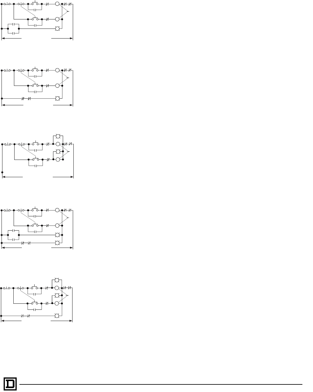
41
5/98 © 1998 Square D All Rights Reserved
ADDITIONAL FEATURES
Special Relays for Non-Reversing and Reversing Multispeed Starters
General
Standard starters are not equipped with any special relays to require starting
at lowest speed, progressive acceleration or deceleration through each
speed, etc. However, when the type of motor or characteristics of the load
involved make certain starting or control sequences necessary, four types of
relays/timers are available to accomplish the required function.
Form R1 Compelling Relay
This relay makes it necessary for the motor to be started at low speed before
any higher speed can be selected. Pressing any push button except the low
speed will not start the motor. This arrangement insures that the motor will
always start the load at low speed. The stop button must be pressed before
it is possible to change from a higher to a lower speed.
Form R2 Accelerating Relay/Timer
When the starter is equipped with Form R2 accelerating relays, the ultimate
speed is determined by the button which is pressed, but the starter will start
the motor at low speed and then automatically accelerate it through
successive steps until the selected speed is reached. Definite time intervals
must elapse between each speed change. Individual timing relays are
provided for each interval, and all are adjustable. The stop button must be
pressed before it is possible to change from a higher to a lower speed.
Form R3 Decelerating Relay/Timer
This is similar in action to Form R2 accelerating relays, except that they
function to prevent immediate transfer from a higher to a lower speed. A
definite time interval, preset on the timer, must elapse between each speed
change.
Form R10 Antiplugging Relays/Timers
If it is necessary to have an imposed time delay when transferring from the
forward to the reverse direction or reverse to forward, then Form R10 should
be included in the form designation of the reversing multispeed starters.
This provides up to a 60 second delay in the transfer of the direction of the
motor, and can help prevent damage which could result from plugging.
Special Pilot Lighting
AC Multispeed Magnetic Starters
Application Data – Class 8810, 8811, 8812
One pilot light “ON”
One pilot light “OFF”
Two pilot lights “L” and “H”
Three pilot lights “L”, “H” and “OFF”
Two pilot lights “ON” and “OFF”
Stop High 4Low 5H
High
L
2
H
L
H
3L
LOL OL
H
On
To Power Circuit
A30080-017
1
Stop High 4Low 5H
High
L
2
H
LH
3L
LOLOL
H
Off
To Power Circuit
A30080-018
1
Stop High 4Low 5H
High
L
2
H
3L
L
L
OLOL
H
H
To Power Circuit
A30080-015
1
Stop High 4Low 5H
High
L
2
H
L
H
3L
LH
LOLOL
H
On
To Power Circuit
A30080-016
Off
1
Stop High 4Low 5H
High
L
2
H
3L
LH
L
L
OLOL
H
H
To Power Circuit
A30080-019
Off
1
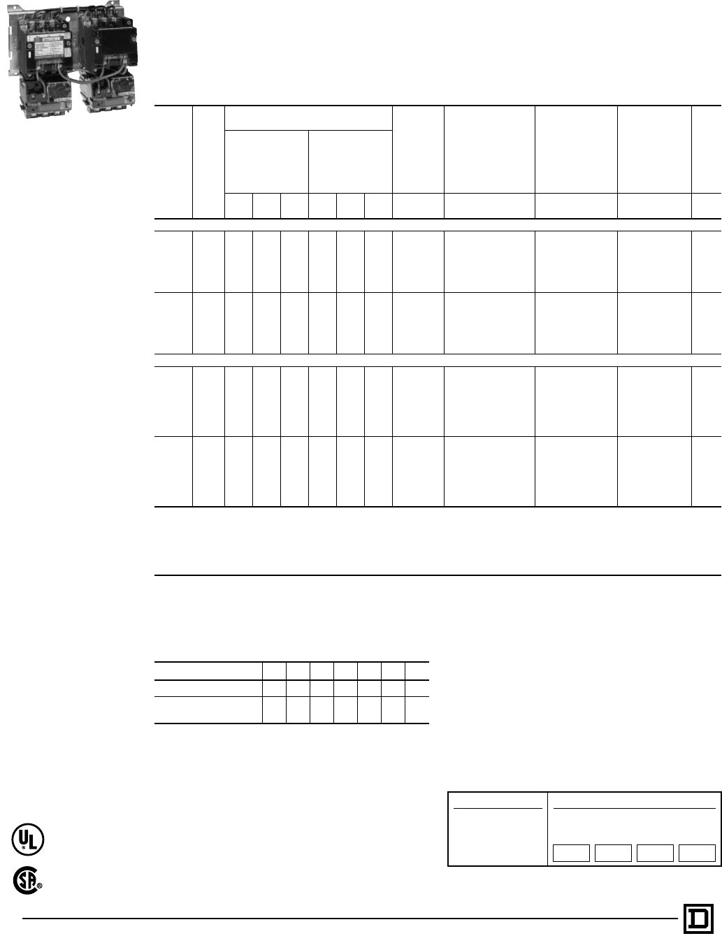
© 1998 Square D All Rights Reserved
42 5/98
Line voltage type, ac two speed starters are designed to control reconnectable squirrel cage motors to
operate at two different constant speeds, depending upon their construction. The use of an automatic
starter and proper control station permits greater operating efficiency and offers protection to both motor
and machine against improper sequencing or too rapid speed change. Protection against motor
overload in each speed is provided by an overload relay block which accepts three (3) thermal units.
380 Volts, 50 Hertz – above type numbers will
apply to starters for 380 volt, 50 hertz but the
selection by NEMA size must be based on the
horsepower ratings in the following table:
Thermal Units
Thermal units should be ordered separately. See
Thermal Unit Selection Index. Do not use
horsepower rating(s) for thermal unit
selection. All three phase two speed magnetic
starters require six (6) thermal units, three per
speed. Use nameplate FLC’s (Full Load
Currents) from motor nameplate.
Special Features — See Factory Modifications
and Forms, Catalog 9999CT9701.
Dimensions — See Pages 49-52.
Field Modification Kits — See Catalog
9999CT9701 Section.
Class 8810, 8811 and 8812 multispeed starters,
both non-reversing and reversing versions, are
available with either circuit breaker or disconnect
switch. Refer to Factory Modifications and Forms
for Form numbers and price additions.
Class 8810 Non-reversing – Two Speed – 50-60 Hertz – 600 Volts Maximum
Type
of
Motor
NEMA
Size
Maximum Polyphase Horsepower
Ratings General
Purpose
Enclosure
NEMA
Type 1
Watertight and
Dusttight
Enclosure
(Stainless Steel)
(Sizes 0-5 only)
Size 6 Sheet Steelc
NEMA Type 4
For Hazardous
Locations Class I
Groups C & D
Class II
Groups E, F & G
NEMA Types
7 and 9k
Dusttight and
Driptight
Industrial Use
Enclosure
NEMA Type 12j
Open
Type
Constant
Horsepower
Motors
Constant Torque
or Variable
Torque Motors
200 V 230 V 460-
575 V 200 V 230 V 460-
575 V Type Type Type Type Type
Single Winding (Consequent Pole) 5-Pole – 3-Pole
Constant
HP
0 223. . .. . .. . .SBG-1 SBW-1q. . . SBA-1qSBO-1
1 557
1⁄2. . . . . . . . . SCG-1 SCW-1qSCR-1kSCA-1qSCO-1
27
1⁄210 20 . . . . . . . . . SDG-1 SDW-1 SDR-1kSDA-1 SDO-1
3 20 25 40 . . . . . . . . . SEG-1 SEW-1 SER-1kSEA-1 SEO-1
4 30 40 75 . . . . . . . . . SFG-1 SFW-1 . . . SFA-1 SFO-1
5 60 75 150 . . . . . . . . . SGG-1 SGW-1 . . . SGA-1 SGO-1
6 100 150 300 . . . . . . . . . SHG-1 SHW-1 . . . SHA-1 SHO-1
Constant
Torque
or
Variable
Torque
0 . . . . . . . . . 3 3 5 SBG-2 SBW-2q. . . SBA-2qSBO-2
1 . . . . . . . . . 71⁄271⁄210 SCG-2 SCW-2qSCR-2kSCA-2qSCO-2
2 . . . . . . . . . 10 15 25 SDG-2 SDW-2 SDR-2kSDA-2 SDO-2
3 . . . . . . . . . 25 30 50 SEG-2 SEW-2 SER-2kSEA-2 SEO-2
4 . . . . . . . . . 40 50 100 SFG-2 SFW-2 . . . SFA-2 SFO-2
5 . . . . . . . . . 75 100 200 SGG-2 SGW-2 . . . SGA-2 SGO-2
6 . . . . . . . . . 150 200 400 SHG-2 SHW-2 . . . SHA-2 SHO-2
Two Winding (Separate WInding) 3-Pole – 3-Pole f
Constant
HPf
0 223. . .. . .. . .SBG-3 SBW-3q. . . SBA-3qSBO-3
1 557
1⁄2. . . . . . . . . SCG-3 SCW-3qSCR-3kSCA-3qSCO-3
27
1⁄210 20 . . . . . . . . . SDG-3 SDW-3 SDR-3kSDA-3 SDO-3
3 20 25 40 . . . . . . . . . SEG-3 SEW-3 SER-3kSEA-3 SEO-3
4 30 40 75 . . . . . . . . . SFG-3 SFW-3 . . . SFA-3 SFO-3
5 60 75 150 . . . . . . . . . SGG-3 SGW-3 . . . SGA-3 SGO-3
6 100 150 300 . . . . . . . . . SHG-3 SHW-3 . . . SHA-3 SHO-3
7 . . . 225 450 . . . . . . . . . SJG-3 . . . . . . SJA-3 SJO-3
Constant
Torque
or
Variable
Torquef
0 . . . . . . . . . 3 3 5 SBG-4 SBW-4q. . . SBA-4qSBO-4
1 . . . . . . . . . 71⁄271⁄210 SCG-4 SCW-4qSCR-4kSCA-4qSCO-4
2 . . . . . . . . . 10 15 25 SDG-4 SDW-4 SDR-4kSDA-4 SDO-4
3 . . . . . . . . . 25 30 50 SEG-4 SEW-4 SER-4kSEA-4 SEO-4
4 . . . . . . . . . 40 50 100 SFG-4 SFW-4 . . . SFA-4 SFO-4
5 . . . . . . . . . 75 100 200 SGG-4 SGW-4 . . . SGA-4 SGO-4
6 . . . . . . . . . 150 200 400 SHG-4 SHW-4 . . . SHA-4 SHO-4
7 . . . . . . . . . . . . 300 600 SJG-4 . . . . . . SJA-4 SJO-4
fType numbers shown for three phase separate winding motor starters apply only when motor windings are wye connected. When motor windings are
connected open delta use three phase consequent pole motor starters.
qSeparate NEMA Type 4 and 12 enclosures available.
jNEMA Type 12 enclosures may be field modified for outdoor applications.
cNEMA Type 4X enclosures available; consult local Square D field office.
kAddition of forms to standard NEMA Type 7 and 9 enclosed devices is limited. Consult local Square D field office.
NEMA Size 0123456
Constant Horsepower 3 71⁄220 40 60 100 200
Constant or Variable
Torque Horsepower 5 10255075150300
How to Order:
To Order Specify: Catalog Number
• Class Number
• Type Number
• Coil Voltage Code
• Form(s)
Class Type Coil
Voltage
Code
Form(s)
8810 SCO8 VO6 P1S
AC Two Speed Magnetic Starters
Line Voltage — with Melting Alloy Overload Relays – Class 8810
Class 8810, Type S
in NEMA Type 1 Enclosure
File LR60905
Class 3211-04
File E78351
CCN NLDX
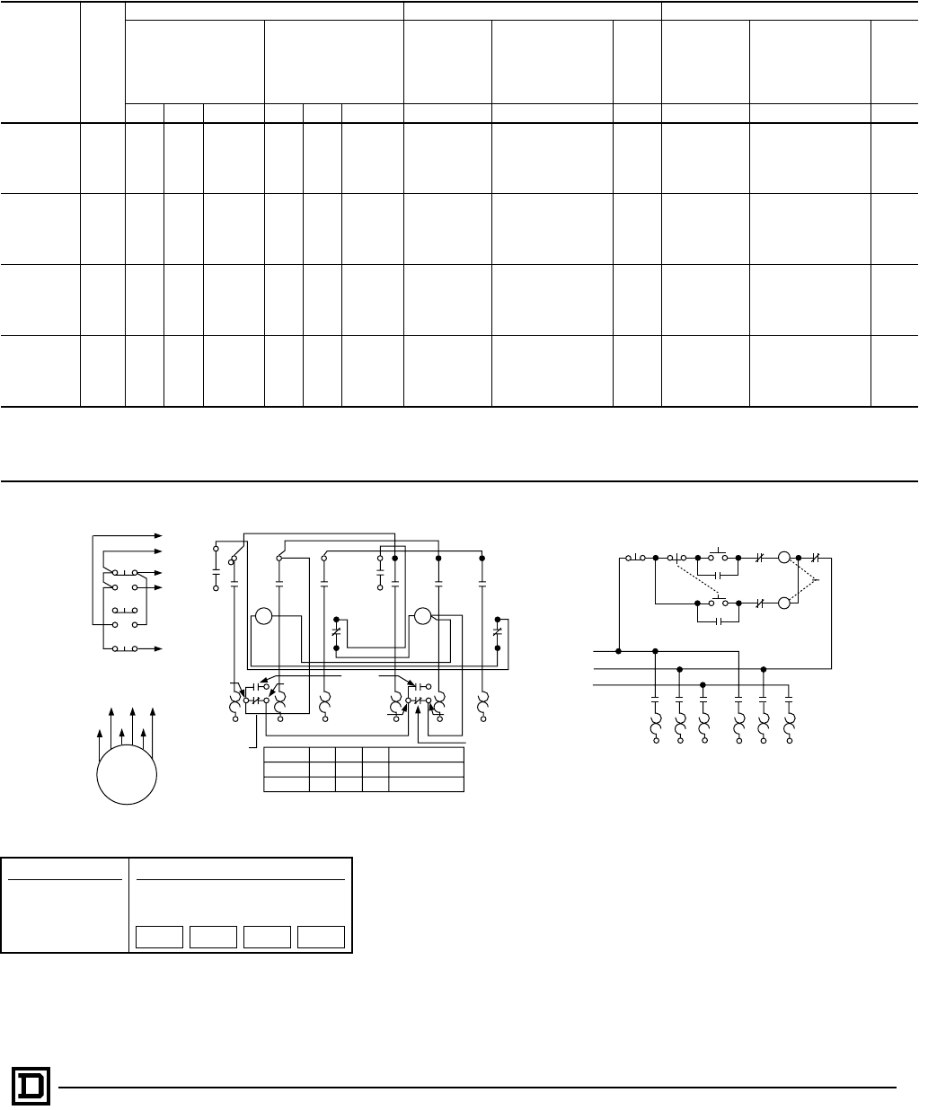
43
5/98 © 1998 Square D All Rights Reserved
Class 8810 AC reversing two speed starters combine the functions of reversing and speed selection in one controller. The units
are electrically and mechanically interlocked, and include motor running overcurrent protection. Typical applications include
conveyors, drilling and tapping machines, and cooling tower fans. Many of these applications also require the special relay features.
Typical Elementray Diagrams
Thermal Units
Thermal units should be ordered separately. See Thermal Unit
Selection Index. Do not use horsepower rating(s) for
thermal unit selection. All three phase two speed magnetic
starters require six (6) thermal units, three per speed. Use
nameplate FLC’s (Full Load Currents) from motor nameplate.
Class 8810 – Reversing – 50-60 Hertz – 600 Volts Maximum
Type
of Motor NEMA
Size
Maximum Polyphase Ratings Reversing In One Speed Only Reversing In Both Speeds
Constant
Horsepower
Motors
Constant Torque
or Variable
Torque Motors
General
Purpose
Enclosure
NEMA Type 1
Dusttight and
Driptight Industrial
Use Enclosure
NEMA Type 12
(Type 3 and 3R)f
Open
Type
General
Purpose
Enclosure
NEMA Type 1
Dusttight and
Driptight Industrial
Use Enclosure
NEMA Type 12
(Type 3 and 3R)f
Open
Type
200 V 230 V 460-575 V 200 V 230 V 460-575 V TypeaTypeaTypeaType Type Type
Single Winding
Constant
Horsepower
0 2 2 3 . . . . . . . . . SBG-21 SBA-21 SBO-21 SBG-31 SBA-31 SBO-31
1 557
1⁄2. . . . . . . . . SCG-21 SCA-21 SCO-21 SCG-31 SCA-31 SCO-31
27
1⁄210 20 . . . . . . . . . SDG-21 SDA-21 SDO-21 SDG-31 SDA-31 SDO-31
3 20 25 40 . . . . . . . . . SEG-21 SEA-21 SEO-21 SEG-31 SEA-31 SEO-31
4 30 40 75 . . . . . . . . . SFG-21 SFA-21 SFO-21 SFG-31 SFA-31 SFO-31
5 60 75 150 . . . . . . . . . SGG-21 SGA-21 SGO-21 SGG-31 SGA-31 SGO-31
Single
Winding
Constant
Torque or
Variable Torque
0 . . . . . . . . . 3 3 5 SBG-22 SBA-22 SBO-22 SBG-32 SBA-32 SBO-32
1 . . . . . . . . . 71⁄271⁄210 SCG-22 SCA-22 SCO-22 SCG-32 SCA-32 SCO-32
2 . . . . . . . . . 10 15 25 SDG-22 SDA-22 SDO-22 SDG-32 SDA-32 SDO-32
3 . . . . . . . . . 25 30 50 SEG-22 SEA-22 SEO-22 SEG-32 SEA-32 SEO-32
4 . . . . . . . . . 40 50 100 SFG-22 SFA-22 SFO-22 SFG-32 SFA-32 SFO-32
5 . . . . . . . . . 75 100 200 SGG-22 SGA-22 SGO-22 SGG-32 SGA-32 SGO-32
Constantj
Horsepower
0 2 2 3 . . . . . . . . . SBG-23 SBA-23 SBO-23 SBG-33 SBA-33 SBO-33
1 557
1⁄2. . . . . . . . . SCG-23 SCA-23 SCO-23 SCG-33 SCA-33 SCO-33
27
1⁄210 20 . . . . . . . . . SDG-23 SDA-23 SDO-23 SDG-33 SDA-33 SDO-33
3 20 25 40 . . . . . . . . . SEG-23 SEA-23 SEO-23 SEG-33 SEA-33 SEO-33
4 30 40 75 . . . . . . . . . SFG-23 SFA-23 SFO-23 SFG-33 SFA-33 SFO-33
5 60 75 150 . . . . . . . . . SGG-23 SGA-23 SGO-23 SGG-33 SGA-33 SGO-33
Constantj
Torque or
Variable Torque
0 . . . . . . . . . 3 3 5 SBG-24 SBA-24 SBO-24 SBG-34 SBA-34 SBO-34
1 . . . . . . . . . 71⁄271⁄210 SCG-24 SCA-24 SCO-24 SCG-34 SCA-34 SCO-34
2 . . . . . . . . . 10 15 25 SDG-24 SDA-24 SDO-24 SDG-34 SDA-34 SDO-34
3 . . . . . . . . . 25 30 50 SEG-24 SEA-24 SEO-24 SEG-34 SEA-34 SEO-34
4 . . . . . . . . . 40 50 100 SFG-24 SFA-24 SFO-24 SFG-34 SFA-34 SFO-34
5 . . . . . . . . . 75 100 200 SGG-24 SGA-24 SGO-24 SGG-34 SGA-34 SGO-34
jPrices and Type numbers shown for three phase, separate winding motor starters apply only when motor windings are wye connected. When motor windings are connected open delta use
the prices shown for consequent pole motor starters.
qSpecify the speed which requires reversing by adding an L (low) or an H (high) after the type number, e.g. A Class 8810 Type SBG-21 with reversing in low only would be ordered as a Class
8810 Type SBG-21L.
fNEMA Type 12 enclosures may be field modified for outdoor applications. For details refer to Class 9991.
Stop High 4
4
T3T2T1
COM
COM
Motor
1.2 or 3 OLR
Contacts
1.2 or 3 OLR
Contacts
L2
L1
1
3
2
L3
T13
High
High
Low
Low
Stop
3 Wire
Control Alarm
(If supplied)
T12
T11 T13 T2
T12 T1 T3
OL
Speed
Low
High
L1
T1
T11
L2
T2
T12
L3
T3
T13
Open
T11, T12, T13
T1, T2, T3
5
5
2
4
3
1
Low 5H
High
L
2
H
3L
LLL
L1
L2
L3
LOL
H
H
HH
OL OL OL OL OL OL
T1
T11
T2 T3 T11 T12 T13
1
OL
How to Order:
To Order Specify: Catalog Number
• Class Number
• Type Number
• Coil Voltage Code
• Form(s)
Class Type Coil
Voltage
Code
Form(s)
8810 SCO8 VO6 P1S
AC Reversing Two Speed Magnetic Starters
Line Voltage Type — with Melting Alloy Overload Relays – Class 8810
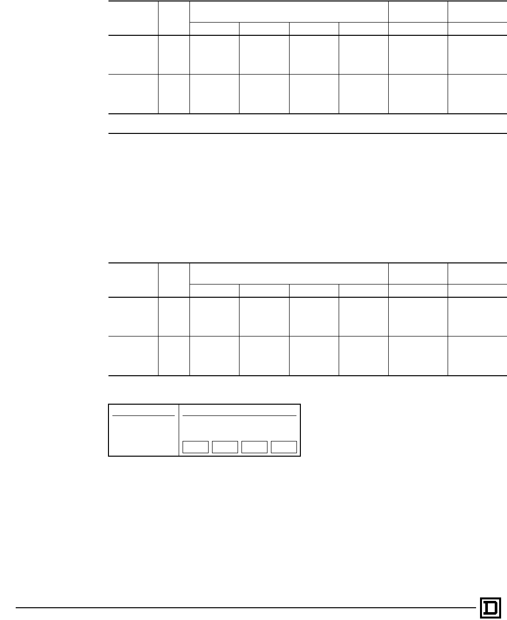
© 1998 Square D All Rights Reserved
44 5/98
Vertically Arranged, Open Type, Two Speed Starters
Vertically arranged starters are used where width limitations prevent the use of the conventional
horizontally arranged device. Such starters may be used to advantage in threaded NEMA Type 7
explosion-proof enclosures, and in multi-motor panels in which other equipment within the enclosure
used limits the available width.
These starters have all the features of the standard horizontally arranged devices, but the two
contactors are in a vertical arrangement. These starters are offered in open type construction only.
Thermal Units
Thermal units should be ordered separately. For selection of thermal units, refer to the Catalog Thermal
Unit Selection Index, Digest or Bulletin SM-416, entitled “Application and Selection of Overload Relays.”
Do not use horsepower rating(s) for thermal unit selection. All three phase two speed magnetic starters
require six (6) thermal units, three per speed. Use nameplate FLC’s (Full Load Currents) from motor
nameplate.
Class 8810 — Non-Reversing — Horizontally Arranged Starters
qjGlass Polyester Watertight, Dusttight and Corrosion Resistant Enclosure
50-60 Hertz – 600 Volts Maximum
Type of
Motor NEMA
Size
Maximum Horsepower Ratings For Consequent
Pole Motors For Separate
Winding Motors
200 V 230 V 380 V 460-575 V Type Type
Constant
Horsepower
02233SBW-51SBW-53
1557
1⁄271⁄2SCW-51 SCW-53
27
1⁄210 20 20 SDW-51 SDW-53
3 20 25 40 40 SEW-51 SEW-53
430406075. . . SFW-53
Constant
Torque or
Variable
Torque
03355SBW-52SBW-54
17
1⁄271⁄210 10 SCW-52 SCW-54
210152525SDW-52SDW-54
3 25 30 50 50 SEW-52 SEW-54
4 40 50 75 100 . . . SFW-54
qNEMA Type 4X hubs are included with each starter at no additional cost.
jCombination features available – consult factory.
Class 8810 — Non-Reversing — Vertically Arranged Starters – 50 or 60 Hertz – 600 Volts Maximum
Type of
Motor NEMA
Size
Maximum Horsepower Ratings For Consequent
Pole Motors For Separate
Winding Motors
200 V 230 V 380 V 460-575 V Type Type
Constant
Horsepower
02233SBO-11 SBO-13
1557
1⁄271⁄2SCO-11 SCO-13
27
1⁄210 20 20 SDO-11 SDO-13
3 20 25 40 40 SEO-11 SEO-13
4 30 40 60 75 SFO-11 SFO-13
Constant
Torque or
Variable
Torque
03355SBO-12 SBO-14
17
1⁄271⁄210 10 SCO-12 SCO-14
2 10 15 25 25 SDO-12 SDO-14
3 25 30 50 50 SEO-12 SEO-14
4 40 50 75 100 SFO-12 SFO-14
How to Order:
To Order Specify: Catalog Number
• Class Number
• Type Number
• Coil Voltage Code
• Form(s)
Class Type Coil
Voltage
Code
Form(s)
8810 SCO8 VO6 P1S
AC Two Speed Magnetic Starters
Line Voltage — with Melting Alloy Overload Relays or Solid State Overload Relays – Class 8810
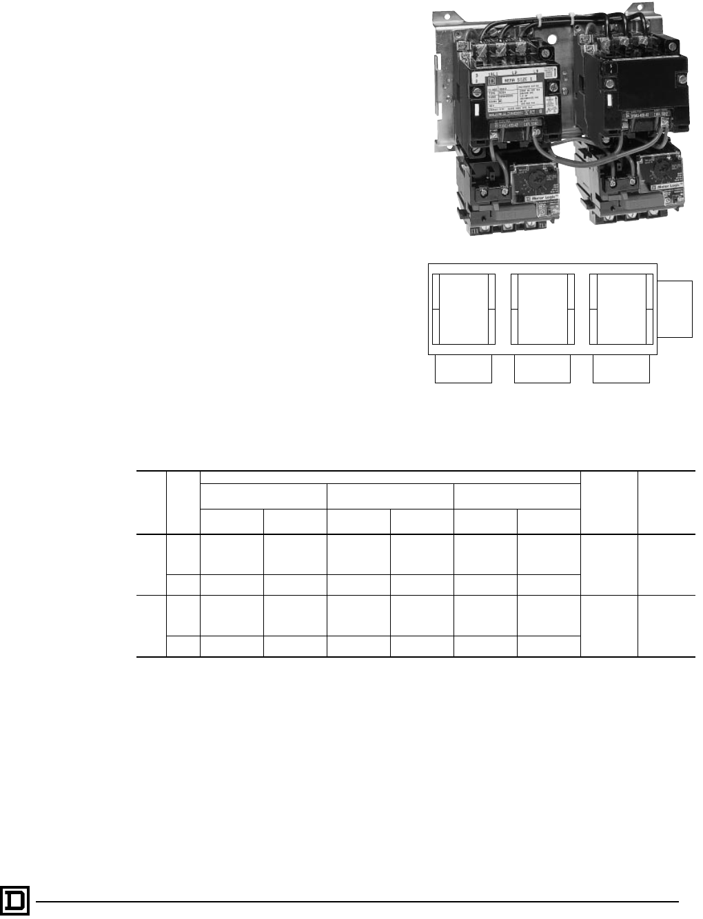
45
5/98 © 1998 Square D All Rights Reserved
Special Arrangements with Three Devices
Three Type S Contactors can be mechanically
interlocked so that only one contactor can be
energized at any one time. The mechanical
interlock, pictured in Figure 2, is an interference
(non-jamming) type locking at the beginning of the
stroke of any contactor.
Factory assembled units are listed in the table
below. Figures 1 and 2 show factory assembled
and wired devices. All contactors are both
electrically and mechanically interlocked. The
class and type numbers listed only cover the
contactor and/or starter mounting arrangement,
NEMA size of the devices, and the number of
poles. A power and control wiring diagram must
accompany each order. Additional electrical
interlocks are available factory (or field) installed
in the locations shown in Figure No. 2 and Table
No. 2, Page 52. 8810 starters are supplied with
melting alloy type thermal overload relays.
For customer assembled units, the basic
mechanical interlock and base assembly can be
purchased separately. Standard Class 8502
contactors and Class 8536 starters are used in
the locations and pole arrangement shown. If
Class 8536 starters are used, it is necessary to
mount a Class 9999 Type SO bracket below the
overload block to give the block support.
For electrically interlocking customer assembled
units a Class 9999 Type SX-12, normally closed
internal interlock and/or a Class 9999 Type SX-7,
normally closed external interlock can be used.
Ordering Information Required
1. Order complete factory assembled devices by
class and type number from table above.
2. Supply wiring diagram for power and control
connections as catalog number only covers
general contactor and starter mounting
arrangement.
3. Voltage and frequency of contactor coils.
4. Select additional factory assembled electrical
interlocks from table on Page 47 specifying
interlock position letter and whether interlock
is N.O. or N.C.
5. Example of ordering information required on
factory assembled devices:
(a) Class 8810 Type SCO-45
(b) Wired per diagram
(which must accompany order)
(c) All coils — 120 volts, 60 hertz
(d) Additional electrical interlocks:
C — N.O., E — N.C., and J — N.O.
6. For customer assembly of three mechanically
interlocked devices, order the mechanical
interlock and overload relay mounting
brackets by class and type numbers.
Thermal Units
Thermal units should be ordered separately. For
selection of thermal units, refer to the Catalog
Thermal Unit Selection Index R Digest. Use the
motor nameplate FLC’s (Full Load Currents) to
select thermal units.
A
B
C
D
No.
1
Cont.
E
F
G
H
No.
2
Cont.
J
K
L
M
No.
3
Cont.
OL-35
OL-1 OL-2 OL-3
Figure 2
Contactor, overload and external electrical
interlock positions
Three Mechanically Interlocked Contactors and Starters — Factory Assembled
Class Type
Contactor Position — See Figure 2 Overload
Relay
Position
See Fig. 3
Number of
Thermal
Units
Required
No. 1 Contactor
Size and Poles No. 2 Contactor
Size and Poles No. 3 Contactor
Size and Poles
NEMA Size 1
No. of Poles NEMA Size 2
No. of Poles NEMA Size 1
No. of Poles NEMA Size 2
No. of Poles NEMA Size 1
No. of Poles NEMA Size 2
No. of Poles
8810
SCO-41 3 . . . 3 . . . 3 . . .
OL-2 & -3 6
SCO-42 4 . . . 3 . . . 3 . . .
SCO-43 . . . 3 3 . . . 3 . . .
SCO-44 . . . 4 3 . . . 3 . . .
SDO-41 . . . 3 . . . 3 . . . 3
SDO-42 . . . 4 . . . 3 . . . 3
8810
SCO-45 3 . . . 3 . . . 5 . . .
OL-2 & -3 6
SCO-46 4 . . . 3 . . . 5 . . .
SCO-47 . . . 3 3 . . . 5 . . .
SCO-48 . . . 4 3 . . . 5 . . .
SDO-43 . . . 3 . . . 3 . . . 5
SDO-44 . . . 4 . . . 3 . . . 5
AC Two Speed Magnetic Starters
Line Voltage — with Melting Alloy Overload Relays or Solid State Overload Relays – Class 8810
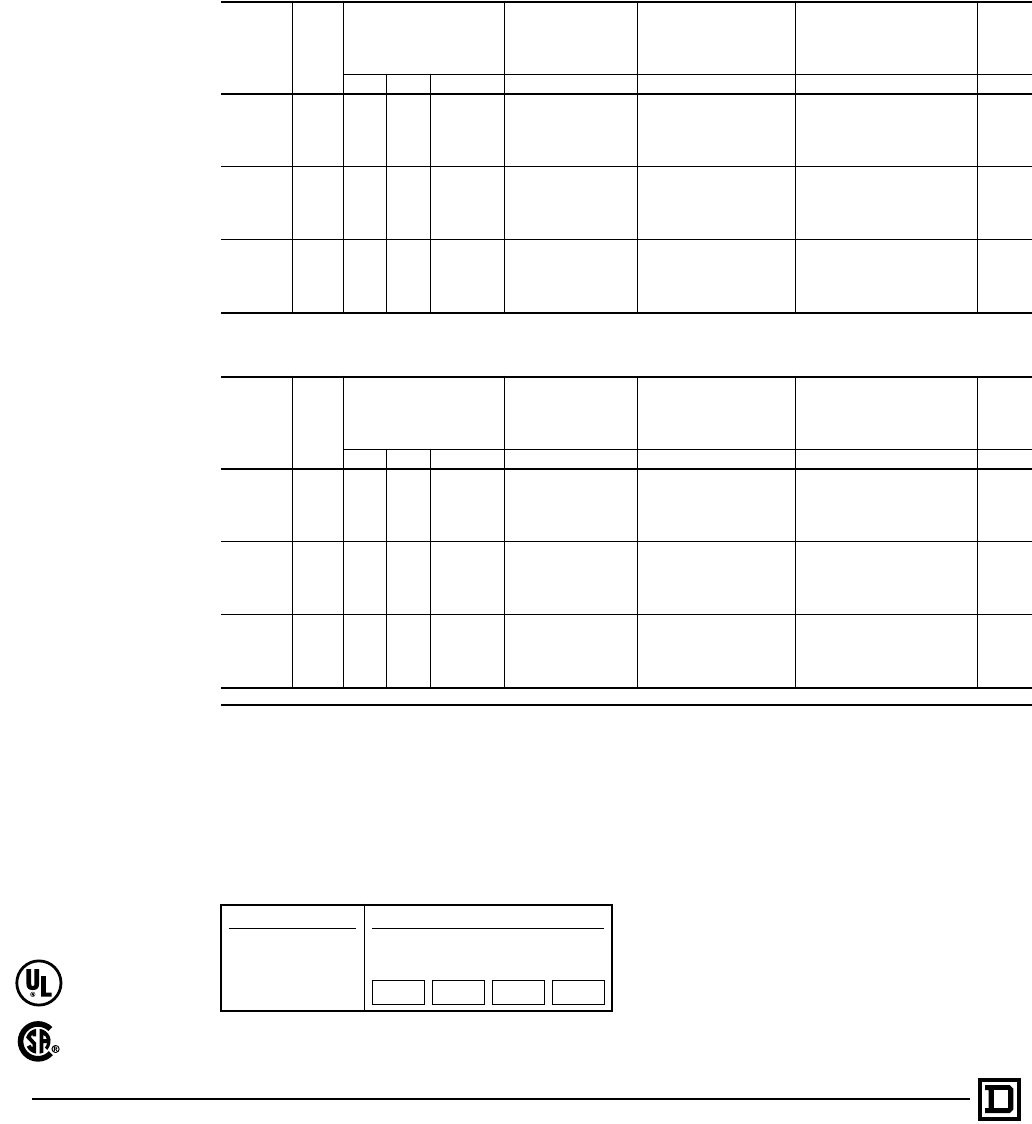
© 1998 Square D All Rights Reserved
46 5/98
Class 881 and 8812 line voltage starters are designed to control 3 and 4 speed motors, respectively.
The use of an automatic starter and proper control station permits greater efficiency. The addition of
compelling relays to a starter gives protection to both the motor and the machine against an improper
sequence or a too rapid change in speed. The motor is protected against excessive operating currents
by overload relay blocks (one for each motor speed) each of which accepts three (3) thermal units. While
the starters listed are for use with consequent pole motors only, separate winding motor starters are
also available upon request.
Thermal Units
Thermal units should be ordered separately. For selection of thermal units, refer to the Catalog Thermal
Unit Selection Index R Digest. All starters require the use of three (3) thermal units for each speed of
the motor. Do not use the horsepower rating(s) for selection. Use nameplate FLC’s (Full Load Currents)
from motor nameplate.
Class 8811 — Three Speed AC Magnetic Starters — Consequent Pole, 2 Winding
600 Volts Maximum — 50-60 Hertz
Type of
Motor NEMA
Size
Maximum Horsepower General Purpose
Enclosure
NEMA Type 1
Watertight and
Dusttight Enclosure
(Stainless Steel)
NEMA Type 4
Dusttight and Driptight
Industrial Use Enclosure
NEMA Type 12
(Type 3 and 3R)j
Open
Type
200 V 230 V 460-575 V Type Type Type Type
Constant
Horsepower
0 2 2 3 SBG-1 SBW-1 SBA-1 SBO-1
1 557
1⁄2SCG-1 SCW-1 SCA-1 SCO-1
27
1⁄210 20 SDG-1 SDW-1 SDA-1 SDO-1
3 20 25 40 SEG-1 SEW-1 SEA-1 SEO-1
4 30 40 75 SFG-1 SFW-1 SFA-1 SFO-1
Constant
Torque
0 3 3 5 SBG-2 SBW-2 SBA-2 SBO-2
17
1⁄271⁄210 SCG-2 SCW-2 SCA-2 SCO-2
2 10 15 25 SDG-2 SDW-2 SDA-2 SDO-2
3 25 30 50 SEG-2 SEW-2 SEA-2 SEO-2
4 40 50 100 SFG-2 SFW-2 SFA-2 SFO-2
Variable
Torque
0 3 3 5 SBG-3 SBW-3 SBA-3 SBO-3
17
1⁄271⁄210 SCG-3 SCW-3 SCA-3 SCO-3
2 10 15 25 SDG-3 SDW-3 SDA-3 SDO-3
3 25 30 50 SEG-3 SEW-3 SEA-3 SEO-3
4 40 50 100 SFG-3 SFW-3 SFA-3 SFO-3
Class 8812 — Four Speed AC Magnetic Starters — Consequent Pole, 2 Winding
600 Volts Maximum — 50-60 Hertz
Type of
Motor NEMA
Size
Maximum Horsepower General Purpose
Enclosure
NEMA Type 1
Watertight and
Dusttight Enclosure
(Stainless Steel)
NEMA Type 4
Dusttight and Driptight
Industrial Use Enclosure
NEMA Type 12
(Type 3 and 3R)j
Open
Type
200 V 230 V 460-575 V Type Type Type Type
Constant
Horsepower
0 2 2 3 SBG-1 SBW-1 SBA-1 SBO-1
1 557
1⁄2SCG-1 SCW-1 SCA-1 SCO-1
27
1⁄210 20 SDG-1 SDW-1 SDA-1 SDO-1
3 20 25 40 SEG-1 SEW-1 SEA-1 SEO-1
4 30 40 75 SFG-1 SFW-1 SFA-1 SFO-1
Constant
Torque
0 3 3 5 SBG-2 SBW-2 SBA-2 SBO-2
17
1⁄271⁄210 SCG-2 SCW-2 SCA-2 SCO-2
2 10 15 25 SDG-2 SDW-2 SDA-2 SDO-2
3 25 30 50 SEG-2 SEW-2 SEA-2 SEO-2
4 40 50 100 SFG-2 SFW-2 SFA-2 SFO-2
Variable
Torque
0 3 3 5 SBG-3 SBW-3 SBA-3 SBO-3
17
1⁄271⁄210 SCG-3 SCW-3 SCA-3 SCO-3
2 10 15 25 SDG-3 SDW-3 SDA-3 SDO-3
3 25 30 50 SEG-3 SEW-3 SEA-3 SEO-3
4 40 50 100 SFG-3 SFW-3 SFA-3 SFO-3
jNEMA Type 12 enclosures may be field modified for outdoor applications.
How to Order:
To Order Specify: Catalog Number
• Class Number
• Type Number
• Coil Voltage Code
• Form(s)
Class Type Coil
Voltage
Code
Form(s)
8810 SCO8 VO6 P1S
Three and Four Speed AC Magnetic Starters
Line Voltage — with Melting Alloy Overload Relays – Class 8811, 8812
File LR60905
Class 3211-04
File E78351
CCN NLDX
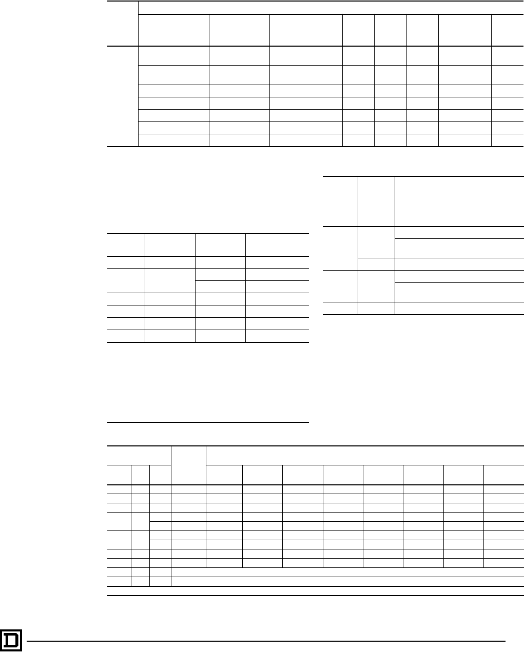
47
5/98 © 1998 Square D All Rights Reserved
Application Data for Types SB-SH
Control Transformer Selection
The following table gives the proper size control
transformer to be used with a given reversing
device, with or without additional electrical
interlocks or timer.
Form Designations for Factory Installation of Electrical Interlocks
Additional Electrical Interlocks on High Starter
Standard
(No Additional
Interlocks)
Change N.O.
Holding Circuit
Interlock to N.C. 1 N.O. 1 N.C. 2 N.O. 1 N.O.-1 N.C. 2 N.C.
Additional Electrical Interlocks
on Low Starter
Standard (No Additional
Interlocks) X01 X02 X03 X05 X06 X07
Change N.O. Holding
Circuit Interlock to N.C. X10 X11 X12 X13 X15 X16 X17
1 N.O. X20 X21 X22 X23 X25 X26 X27
1 N.C. X30 X31 X32 X33 X35 X36 X37
2 N.O. X50 X51 X52 X53 X55 X56 X57
1 N.O.-1 N.C. X60 X61 X62 X63 X65 X66 X67
2 N.C. X70 X71 X72 X73 X75 X76 X77
NEMA
Size Type No. of Poles Transformert
Class 9070 Type
0, 1 & 2 SB, SC & SD Any EO-2 or GO-2
3SE 3 EO-3 or GO-3
4 & 5 EO-4
4 SF Any EO-4
5SG Any q
6SH Any u
7SJ Any j
tIf a different manufacturer’s transformer is to be used, check its
suitability for use with coil loads. See inrush and sealed VA ratings
of the contactor coil.
qStandard engineering practice for Size 5 contactors is to use a
Class 9070 Type EO-1 transformer and Class 8501 Type DO-20
control relay.
uA Class 9070 Type EO-3S2 transformer is an integral part of the
Size 6 control circuit providing 120 volt control circuit voltage as
standard on devices wired for common control.
jA Class 9070 Type EO-19-S2 transformer is an integral part of the
size 7 control circuit providing 120 volt control circuit voltage as
standard on devices wired for common control.
Maximum Number of Auxiliary Units
NEMA
Size
(Type)
No. of
Poles of
Basic
Contactor
Maximum number of auxiliary units
on each contactor, forward or
reverse, (in addition to internal
holding circuit and electrical
interlocks).
00, 0, 1
and 2
(SA, SB, SC
and SD)
2 or 3
4 single circuit external interlocks (N.O. or N.C.)
1 single circuit external interlock (N.O. or N.C.)
plus 1 attached timer (ON or OFF delay).
4 2 single circuit external interlocks (N.O. or N.C.)
3, 4, 5 and 6
(SE, SF, SG
and SH) Any
2 single circuit external interlocks (N.O. or N.C.)
1 single circuit external interlock plus 1
attached timer (ON or OFF delay).
7 (SJ) Any Consult local Square D field office
AC Magnet Coils for AC Contactors and Starters
Devices Using
Coil Coil
Speci-
fication
Number
Suffix Numbers (Complete coil part number consists of specification number followed by
suffix number as 31041-400-51.)
NEMA
Size Type Poles 24 V/60 Hz 120 V/60 Hz
110 V/50 Hz 208 V/60 Hz 220 V/60 Hz 240 V/60 Hz
220 V/50 Hz 277 V/60 Hz 480 V/60 Hz
440 V/50 Hz 600 V/60 Hz
550 V/50 Hz
00 SA All 31041-400- 20 42 48 u51 52 60 62
0 SB All 31041-400- 20 42 48 u51 52 60 62
1 SC All 31041-400- 20 42 48 u51 52 60 62
2SD
3 31063-409- 16 38 44 u47 49 57 60
4-5 31063-400- 16 38 44 u47 49 57 60
3SE
3 31074-400- 16 38 44 u47 49 57 60
4-5 31091-400- 16 38 44 u47 49 57 60
4 SF All 31091-400- 16 38 44 u47 49 57 60
5 SG 3 31096-400- . . . 09 15 u18 19 24 29
6 SH 3 31104-400-50 (all voltages)
7 SJ 3 31104-400-50 (all voltages)
uFor 220 volt and 230 volt, 60 hertz applications, use 240 volt coil.
AC Multispeed Magnetic Starters
Application Data – Class 8810, 8811, 8812
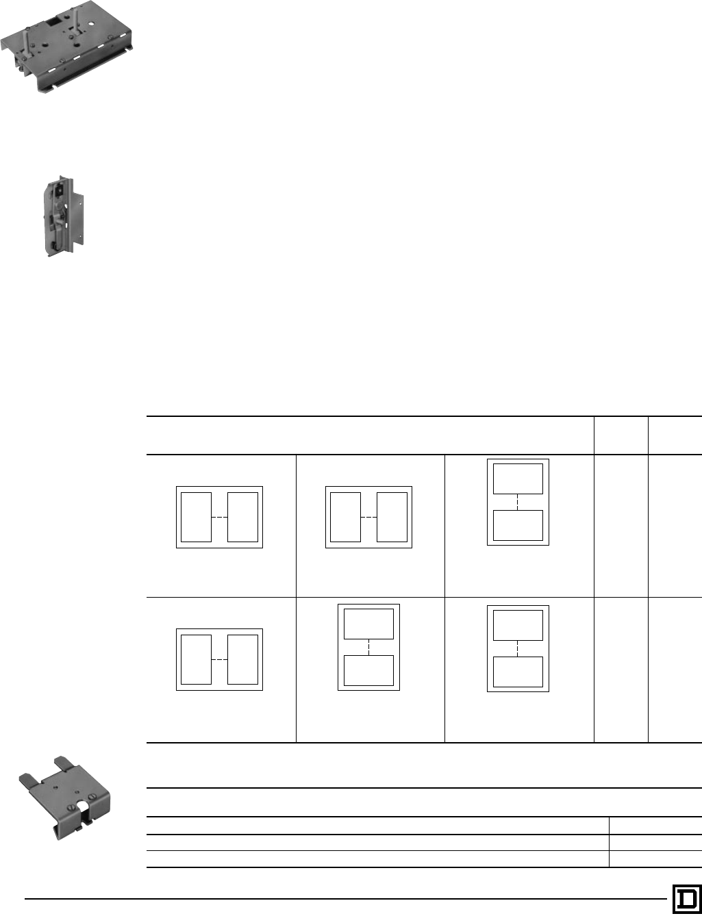
© 1998 Square D All Rights Reserved
48 5/98
MECHANICAL INTERLOCK
General
Type S contactors or starters can be mechanically
interlocked so that only one device will be
energized at a time. The mechanical interlock is
an interference (non-jamming) type, locking at the
beginning of the stroke of any starter or contactor.
Overload Relay Mounting Bracket
Mechanical interlock Types SM-1 through SM-10
for Sizes 00-2 devices use overload relay
mounting brackets to support the overload relay
portion of the starter.
Type S Sizes 00, 0, 1 and 2
The mechanical interlock is mounted on the
underside of the reversing baseplate. Two pins
extend from the mechanical interlock through
openings in the baseplate and engage the contact
carrier of each contactor. Two styles of
mechanical interlocks are used: one version for
three pole contactors, a different version for four
or five pole contactors. When adding a power
pole to an existing three pole reversing
contactor, a new mechanical interlock must
also be installed.
Three unit mechanically interlocked contactors
and/or starters are also available for various
combinations of Sizes 0, 1 and 2.
Type S Sizes 3, 4, 5 and 6
The mechanical interlock is separate from the
mounting pan on Sizes 3-6. Cams on the
mechanical interlocks are operated by the contact
carrier of each contactor. The mechanical
interlock is attached to the underside of the two
contactors on Sizes 3 and 4; directly to the
mounting pan on sizes 5 and 6. Size 5 and 6
mechanical interlocks are sold only as a factory
assembly with the 8810 starter.
The mechanical interlock utilizes a special
baseplate and bracket that connects between the
armatures. This is sold only as a factory assembly
with the 8810 starter.
Mechanical Interlock for Two Contactors
Kit Description – The following kits consist of the mechanical interlock and base assembly for
interlocking 2-5 pole contactors. Mechanical interlocks for horizontal and vertical mounting are
listed for various pole arrangements.
Contactor
NEMA
Size
Class
9999
Type
Horizontal
Type SM-1 for Size 00j, 0, or 1
Type SM-6 for Size 2
Type SM-12 for Sizes 3 & 4
Horizontalt
Type SM-2 for Size 0 or 1
Type SM-7 for Size 2
Type SM-12 for Sizes 3 & 4
Verticalt
Type SM-2 for Size 0 or 1
Type SM-10 for Size 2
Type SM-11 for Size 3
Type SM-13 for Size 4
00j, 0, 1 SM-1
0, 1 SM-2t
0, 1 SM-3
0, 1 SM-4
0, 1 SM-5
Horizontal
Type SM-3 for Size 0 or 1
Type SM-8 for Size 2
Type SM-12 for Sizes 3 & 4
Vertical
Type SM-4 for Size 0 or 1
Type SM-9 for Size 2
Type SM-11 for Size 3
Type SM-13 for Size 4
Horizontal
Type SM-5 for Size 0 or 1
Type SM-11 for Size 3
Type SM-13 for Size 4
2 SM-6
2 SM-7
2 SM-8
2 SM-9
2 SM-10
3 SM-11q
3, 4 SM-12q
4 SM-13q
tThe type SM-2 interlock is factory assembled for horizontal mounting but can easily be converted to vertical mounting. Conversion instructions are
included.
jFor replacement only on the NEMA Size 00, reversing starters and contactors.
qInterlocks do not include mounting pan.
Overload Relay Mounting Bracket
Kit Description Class 9999 Type
Bracket for one overload relay used with horizontal mechanical interlocks, Types SM-1, SM-2, SM-3, SM-6, SM-7 and SM-8 SO-11
Bracket for two overload relays used with vertical mechanical interlocks, Types SM-2, SM-4, SM-5, SM-9 and SM-10 SO-12
2 Pole
or
3 Pole
2 Pole
or
3 Pole
4 Pole
or
5 Pole
2 Pole
or
3 Pole
4 Pole
or
5 Pole
2 Pole
or
3 Pole
4 Pole
or
5 Pole
4 Pole
or
5 Pole
2 Pole
or
3 Pole
2 Pole
or
3 Pole
4 Pole
or
5 Pole
4 Pole
or
5 Pole
AC Multispeed Magnetic Starters
Application Data for Types SB-SJ – Class 8810, 8811, 8812
Class 9999 Type SM-1
Mechanical Interlock For
Two Contactors
Horizontally Mounted
Class 9999 Type SM-12
For Sizes 3 and 4
Horizontally Mounted
Type SO-11 Overload Relay
Mounting Bracket
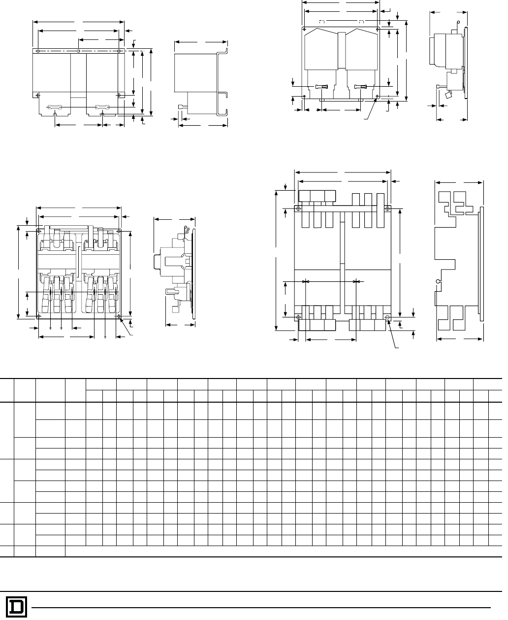
49
5/98 © 1998 Square D All Rights Reserved
Non-Reversing — Open Type
Approximate Dimensions
Fig.
No. NEMA
Size Type Mtg.
Holes
ABCDEFGHI JKLMN
IN mm IN mm IN mm IN mm IN mm IN mm IN mm IN mm IN mm IN mm IN mm IN mm IN mm IN mm
1
0 and 1
SBO-1, 2 4 9.63 245 7.34 186 5.31 135 8.00 203 .63 16 . . . . . . .22 6 6.91 176 . . . . . . .22 6 4.75 121 2.25 57 5.06 129 .59 15
SCO-1, 2
SBO-3, 4 3 7.13 181 6.91 176 5.31 135 . . . . . . . . . . . . 3.41 87 .47 12 6.22 158 . . . . . . .22 6 3.56 90 1.63 41 5.06 129 .59 15
SCO-3, 4
2SDO-1, 2 6 12.03 306 8.53 217 6.03 153 10.38 264 .50 13 . . . . . . .25 6 8.13 207 6.25 159 .16 4 5.75 146 2.81 71 5.16 131 .78 20
SDO-3, 4 3 9.00 229 8.06 205 6.03 153 . . . . . . . . . . . . 4.50 114 .38 10 7.50 191 . . . . . . .19 5 4.34 110 2.16 55 5.16 131 .78 20
2
3SEO-1, 2 4 18.00 457 14.44 367 17.00 432 12.25 311 1.50 38 .69 18 .50 13 6.44 164 7.38 187 1.66 42 2.16 55 . . . . . . . . . . . . . . . . . .
SEO-3, 4 4 12.75 324 12.28 312 11.75 298 10.75 273 1.03 26 .50 13 .50 13 2.50 64 6.75 171 1.16 29 1.16 29 . . . . . . . . . . . . . . . . . .
4SFO-1, 2 4 18.63 473 15.59 396 17.00 432 12.25 311 1.84 47 1.50 38 1.13 29 6.44 164 7.66 195 1.66 42 1.66 42 . . . . . . . . . . . . . . . . . .
SFO-3, 4 4 14.25 362 14.59 371 13.25 337 12.25 311 1.84 47 .50 13 .50 13 2.94 75 7.38 187 1.66 42 1.66 42 . . . . . . . . . . . . . . . . . .
35 SGO-1, 2t4 29.28 744 20.28 515 9.38 238 5.41 137 1.28 33 28.00 711 .63 16 12.56 319 19.00 483 .63 15 22.53 572 .50 13 2.41 61 6.63 168
SGO-3, 4 4 19.28 490 20.28 515 9.38 238 5.14 137 1.28 33 18.00 457 .63 16 2.63 67 19.00 483 .63 15 12.53 318 .50 13 2.41 61 6.63 168
46qSHO-1, 2t4 29.53 750 22.44 570 9.53 242 6.97 177 3.81 97 28.00 711 .75 19 11.63 295 21.19 538 .63 15 9.88 251 .56 14 3.03 77 9.31 236
SHO-3, 4 4 19.53 496 22.44 570 9.53 242 6.97 177 3.81 97 18.00 457 .75 19 1.69 43 21.19 538 .63 15 9.88 251 .56 14 3.03 77 9.31 236
—7fSJO-3, 4 Consult Square D
tConsequent pole, type starters consist of two 3-pole starters as pictured in Figure 3 and an additional 2-pole shorting contactor (not shown), all on a common base-plate, horizontally
mounted.
qCurrent transformers used with Size 1 overload relay blocks.
fSolid state overloads and special current transformers.
RESETRESET
J
GH I
DB
K
F
Provision for
(4) .31 Dia. Mounting Screws
8
.50
13
.50
13
.50
13
C
A
E
.56
14 6.25
159
Reset
Travel
7.00
178
A
B
K
(4) L Dia. Mounting Holes
J
H
FG
D
I
M
E
N
C
Figure 1
Class 8810, Sizes 0, 1 & 2 Types SBO, SCO & SDO Figure 2
Class 8810, Sizes 3 & 4 Types SEO and SFO
Figure 3
Class 8810, Size 5 Type SGO Figure 4
Class 8810, Size 6 Type SHO
RESET RESET
A
D
F
E
G
I
HB
N
J
L
K
C
PM
Travel
G
F
A
E
B
D
MM
M
HM
K
J
(4) L Dia.
Mounting Holes
C
I
N
AC Two Speed Magnetic Starters
Dimensions – Class 8810, 8811, 8812
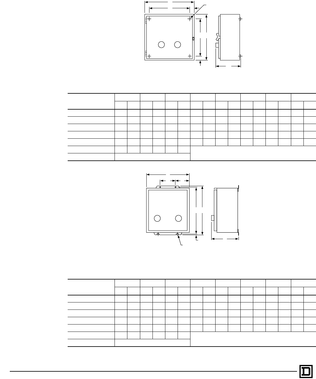
© 1998 Square D All Rights Reserved
50 5/98
Non-Reversing — Non-Combination — Enclosed
Approximate Dimensions
NEMA Type 1 Enclosure – Figure 1
Type ABCDEFGH
IN mm IN mm IN mm IN mm IN mm IN mm IN mm IN mm
SBG and SCG 11.88 302 11.88 302 7.53 191 9.75 248 1.06 27 1.06 27 9.75 248 .31 8
SDG 14.88 378 14.13 359 7.66 195 12.75 324 1.06 27 1.06 27 12.00 305 .31 8
SEG-3 & -4 and SFG-3 & -4 18.16 461 29.16 741 9.23 234 15.50 394 1.34 34 1.34 34 26.50 673 .44 11
SEG-1 & -2 and SFG-1 & -2 22.16 563 39.16 995 10.23 260 19.50 495 1.34 34 1.34 34 36.50 927 .44 11
SGG-1, 2, 3, 4 20.22 514 65.75 1670 6.45 164 31.00 787 2.13 54 2.13 54 42.00 1067 .56 14
SHG-1, 2, 3, 4 36.22 920 62.22 1580 19.47 495 Floor Mount
SJG-3 & 4 Consult Square D
NEMA Type 1 Enclosure – Figure 2
Type ABCDEFGH
IN mm IN mm IN mm IN mm IN mm IN mm IN mm IN mm
SBA and SCA 11.88 302 13.50 343 7.75 197 4.25 108 3.81 97 .38 10 12.75 324 .31 8
SDA 14.88 378 15.75 400 7.88 200 4.25 108 5.31 135 .38 10 15.00 381 .31 8
SEA-3 & -4 and SFA-3 & -4 18.16 461 31.50 800 9.59 244 16.00 406 3.09 78 .50 13 30.50 775 .44 11
SEA-1 & -2 and SFA-1 & -2 22.16 563 41.50 1054 10.59 269 16.00 406 3.09 78 .50 13 40.50 1029 .44 11
SGA-1, 2, 3, 4 35.22 895 49.00 1245 13.11 333 27.00 686 4.11 104 .50 13 48.00 1219 .56 14
SHA-1, 2, 3, 4 36.22 920 62.22 1580 19.47 495 Floor Mount
SJA-3 & 4 Consult Square D
RESET RESET
A(4) H Dia.
Mounting Holes
G
C
F
B
DE
Figure 1
G
F
ED
B
C
A
(4) H Dia. Mounting Holes
RESET RESET
Figure 2
AC Magnetic Starters
Application Data – Class 8810, 8811, 8812
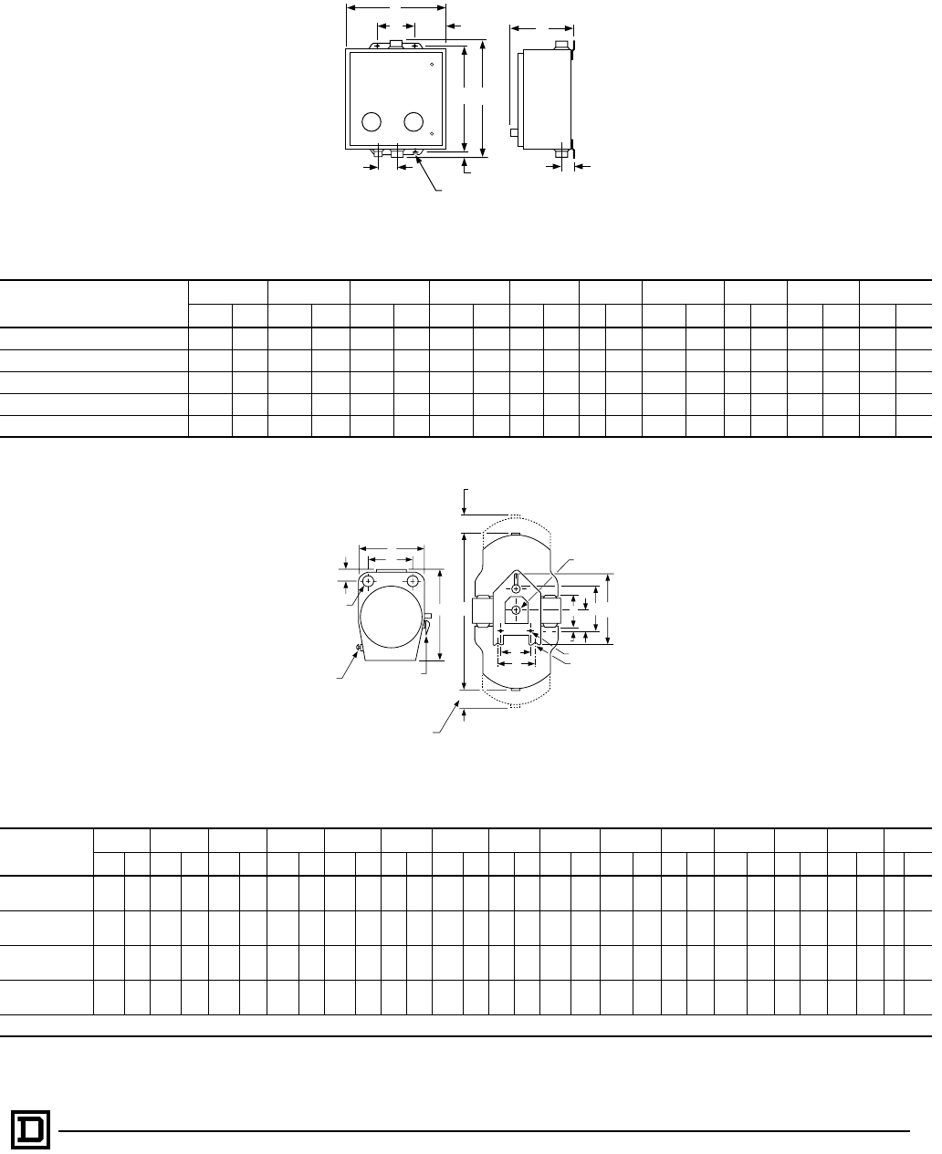
51
5/98 © 1998 Square D All Rights Reserved
Non-Reversing — Non-Combination — Enclosed
Approximate Dimensions
NEMA Type 4 Enclosure – Figure 3
Type AB CDEFGHIJ
IN mm IN mm IN mm IN mm IN mm IN mm IN mm IN mm IN mm IN mm
SBW and SCW 12.63 321 14.69 373 7.81 198 4.25 108 4.19 106 .59 15 13.50 343 .31 8 1.66 42 2.31 59
SDW 14.88 378 15.75 400 8.25 210 4.25 108 5.31 135 .38 10 15.00 381 .31 8 2.03 52 2.63 67
SEW-3 & -4 and SFW-3 & -4 18.16 461 32.22 818 8.77 223 12.00 305 3.08 78 .86 22 30.50 775 .44 11 2.58 66 3.19 81
SEW-1 & -2 and SFW-1 & -2 22.16 563 42.22 1072 9.77 248 16.00 406 3.08 78 .86 22 40.50 1029 .44 11 2.33 59 2.89 73
SGW-1, 2, 3, 4 35.22 895 49.22 1250 12.13 308 27.00 686 4.09 104 .61 15 48.00 1219 .56 14 2.98 76 3.50 89
NEMA Type 7 & 9 Enclosure – Figure 4
Type ABCDEFGHJ K LMNPR
IN mm IN mm IN mm IN mm IN mm IN mm IN mm IN mm IN mm IN mm IN mm IN mm IN mm IN mm IN mm
SCR-1, 2, 3 & 4
Std. & Form Y79-1 12.00 305 41.06 1043 68.06 1729 16.75 425 7.25 184 7.69 195 26.13 664 3.00 76 24.00 610 8.50 216 2.06 52 9.38 238 5.25 133 1.50 38 .38 10
SCR-1, 2, 3 & 4
Forms T & TY79-1 12.00 305 46.13 1172 79.13 2010 16.75 425 12.25 311 7.69 195 26.13 664 9.00 229 24.00 610 8.50 216 2.06 52 9.38 238 5.25 133 1.50 38 .38 10
SDR-1, 2, 3 & 4
Std. & Form Y79-1 16.13 410 48.50 1232 81.50 2070 20.25 514 12.50 318 8.63 219 27.75 705 8.00 203 25.00 635 12.00 305 2.63 67 11.00 279 5.50 140 2.50 64 .38 10
SCR-1, 2, 3 & 4
Forms T & Y79-1 16.13 410 50.50 1283 85.00 2159 20.25 514 9.13 232 8.63 219 32.75 832 4.50 114 30.00 762 12.00 305 2.63 67 11.00 279 5.50 140 2.50 64 .38 10
For Sizes 3, 4 and 5 consult Square D field office.
(4) H Dia. Mounting Holes
GB
F
C
JI
RESET RESET
ED
A
Figure 3
N
A
BD
C
J
P
F
M
KH
Mtg. Holes
and/or Slots (3)
Space Required
To Remove
Top Cover
Rear View
Space Required To
Remove Bottom Cover
Circuit Breaker
Operational Handle –
Combination Form Only
(Add 1.00 Inch To
Overall Width)
Overload
Reset
Threaded
Cover
Enclosure
E
Q
R
G
Top View
T
L
Rear Seal
S
(2) "L" Pipe
Tap Top and
Bottom
Figure 4
AC Magnetic Starters
Application Data – Class 8810, 8811, 8812
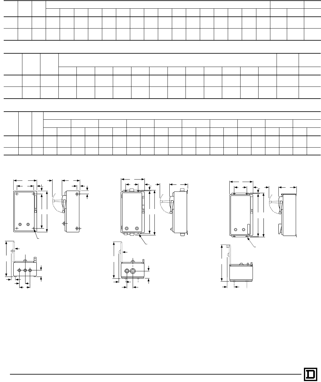
© 1998 Square D All Rights Reserved
52 5/98
“Quick Ship Only”
Approximate Dimensions
NEMA Type 1 Enclosure – Figure 1
NEMA
Size Class Type Dimensions — Inches/mm Top & Bottom Sides
ABCDEFGHI J KLMNOPW X Y
0-1 8810 SBG 13.88
353 23.13
588 8.25
210 10.63
270 21.00
533 19.28
490 1.88
48 1.88
48 3.75
95 2.31
59 1.06
27 3.30
84 2.19
56 1.25
32 .88
22 . . . 1⁄2-3⁄4-1 1⁄2-3⁄4-1 1⁄2
SCG
2 8810 SDG 15.16
385 28.91
734 9.56
243 11.63
295 26.25
667 21.81
554 2.19
56 2.00
51 4.00
102 2.63
67 1.33
34 3.30
84 2.22
56 1.27
32 .91
23 . . . 1-11⁄41⁄2-3⁄41⁄2
NEMA Type 4 Enclosure – Figure 2
NEMA
Size Class Type Dimensions — Inches/mm Bottom Top &
Bottom
ABCDEFGHI J KLW X
0-1 8810 SBW 13.88
353 8.33
212 25.19
640 3.30
84 2.56
65 8.75
222 24.00
610 .59
15 3.95
100 1.63
41 2.31
59 18.53
471 3⁄4 Hub 1 Hub
SCW
2 8810 SDW 15.13
389 9.58
243 30.94
786 3.30
84 2.56
65 10.00
254 29.75
756 .59
15 3.95
100 2.00
51 2.63
67 21.03
534 3⁄4 Hub 11⁄2 Hub
NEMA Type 12 Enclosure – Figure 3
NEMA
Size Class Type
Dimensions — Inches/mm
ABCDEFGHI J
IN mm IN mm IN mm IN mm IN mm IN mm IN mm IN mm IN mm IN mm
0-1 8810 SBA 13.88 353 10.09 256 24.75 629 3.30 84 2.56 65 8.75 222 24.00 610 .38 10 3.95 100 20.28 515
SCA
2 8810 SDA 15.16 385 10.97 279 31.25 794 3.30 84 3.08 78 9.00 229 30.25 768 .50 13 4.83 123 23.44 595
O
N
C
Handle
Swing
EB
K
M
D
A
Y
(4) .31 Dia. Mtg. Holes
(For Size 0, 1, & 2)
8
F
WXW
G
JHI
Cover Open 90°
L
Y
B
Handle
Swing
C
F
A
(4) .31 Dia. Mtg. Holes
(For Size 0, 1, & 2)
8
L
WX
I
Cover Open 90°
D
E
K
J
G
HB
Handle
Swing
C
F
A
(4) .31 Dia. Mtg. Holes
(For Size 0, 1, & 2)
8
J
I
D
E
G
H
Figure 1
NEMA Type 1 Enclosure Figure 2
NEMA Type 4 Enclosure Figure 3
NEMA Type 12 Enclosure
AC Two Speed Combination Starters
Disconnect Switch or Circuit Breaker Type – Class 8810, 8811, 8812

Catalog No. 8502CT9701 May 1998 © 1998 Square D All Rights Reserved.
UL is a registered trademark of Underwriters Laboratories, Inc.
CSA is a registered trademark of Canadian Standards Association.
MOTOR LOGIC is a trademark of Square D Company.
Spin Top, Square D and are registered trademarks of Square D Company.
Square D Company
8001 Highway 64 East
Knightdale, NC 27545-9023
(919) 266-3671
