Schneider Electric DIGEST 175 Terminal Blocks 101713 Catalog
2014-06-03
: Pdf 101713-Catalog 101713-Catalog 785901 Batch4 unilog
Open the PDF directly: View PDF ![]() .
.
Page Count: 22
- Terminal_Blocks.pdf
- Table of Contents
- Terminal Blocks
- Selection Guide
- IEC Style Terminal Blocks
- IEC Terminal Blocks
- NEMA Style Terminal Blocks
- Thermal-Magnetic Circuit Protectors
- Power Distribution Blocks
- Fuseholders
- Cable Ends
- Advantys TELEFAST® 2 Prewired Connection System
24-1
© 2009 Schneider Electric
All Rights Reserved
24 TERMINAL BLOCKS
Table of Contents
Section 24
Terminal Blocks
AB1RRN, p. 24-3 AB1AA, p. 24-10
AB1VV, p. 24-5 9080GR6, p. 24-13
GB2, p. 24-17 9080GCB, p. 24-17
9080LB, p. 24-18 9080LBF, p. 24-18
9080FB, p. 24-19 9080GF6, p. 24-14
DZ5, p. 24-20
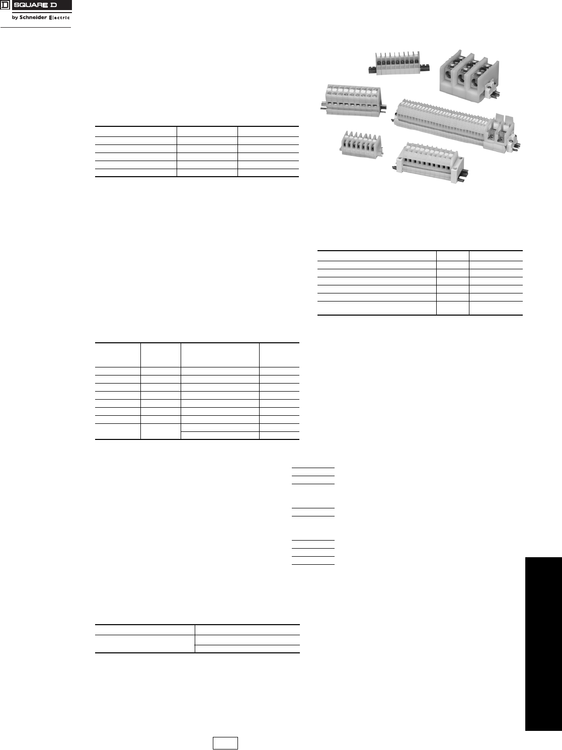
Track-Mounting Terminal Blocks & Prewired Connectors
Advantys TELEFAST® 2 ABE7 Connection
Systems
24-22
NEMA Style Class 9080 Type G 24-13
IEC Style AB1 24-3
Direct-Mounting Terminal Blocks
NEMA Style Class 9080 Type GK 24-13
Circuit Protectors
Class 9080 Type GCB 24-17
GB2 24-17
Power Distribution Blocks (Splitter Blocks)
Class 9080 Type LB 24-18
Fuseholders
Panel Mounting Class 9080 Type FB 24-19
NEMA Style Class 9080 Type GF6 24-14
IEC Style AB1FU, AB1SF 24-8
AB1AASF 24-10
AB1RRNSF 24-4
DF 24-8
Cable Ends (Ferrules, Wire Markers)
DZ5 24-20
AZ5 24-20
AR1 24-21
AT1 24-21
Mounting Track
9080GH (Square D) 24-16
9080MH (DIN) 24-12
Courtesy of Steven Engineering, Inc.-230 Ryan Way, South San Francisco, CA 94080-6370-Main Office: (650) 588-9200-Outside Local Area: (800) 258-9200-www.stevenengineering.com
www.schneider-electric.us
24 TERMINAL BLOCKS
24-2 © 2009 Schneider Electric
All Rights Reserved
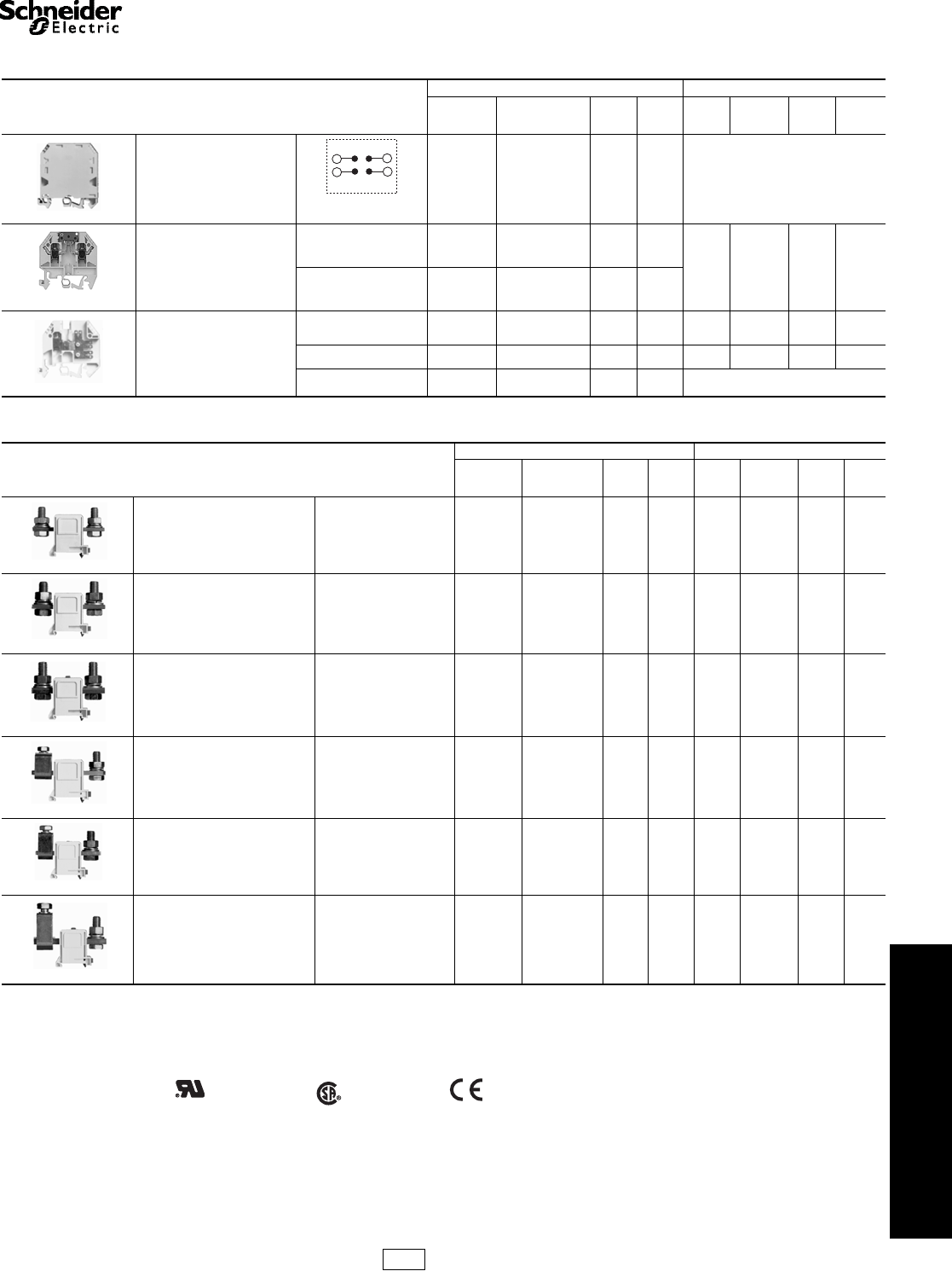
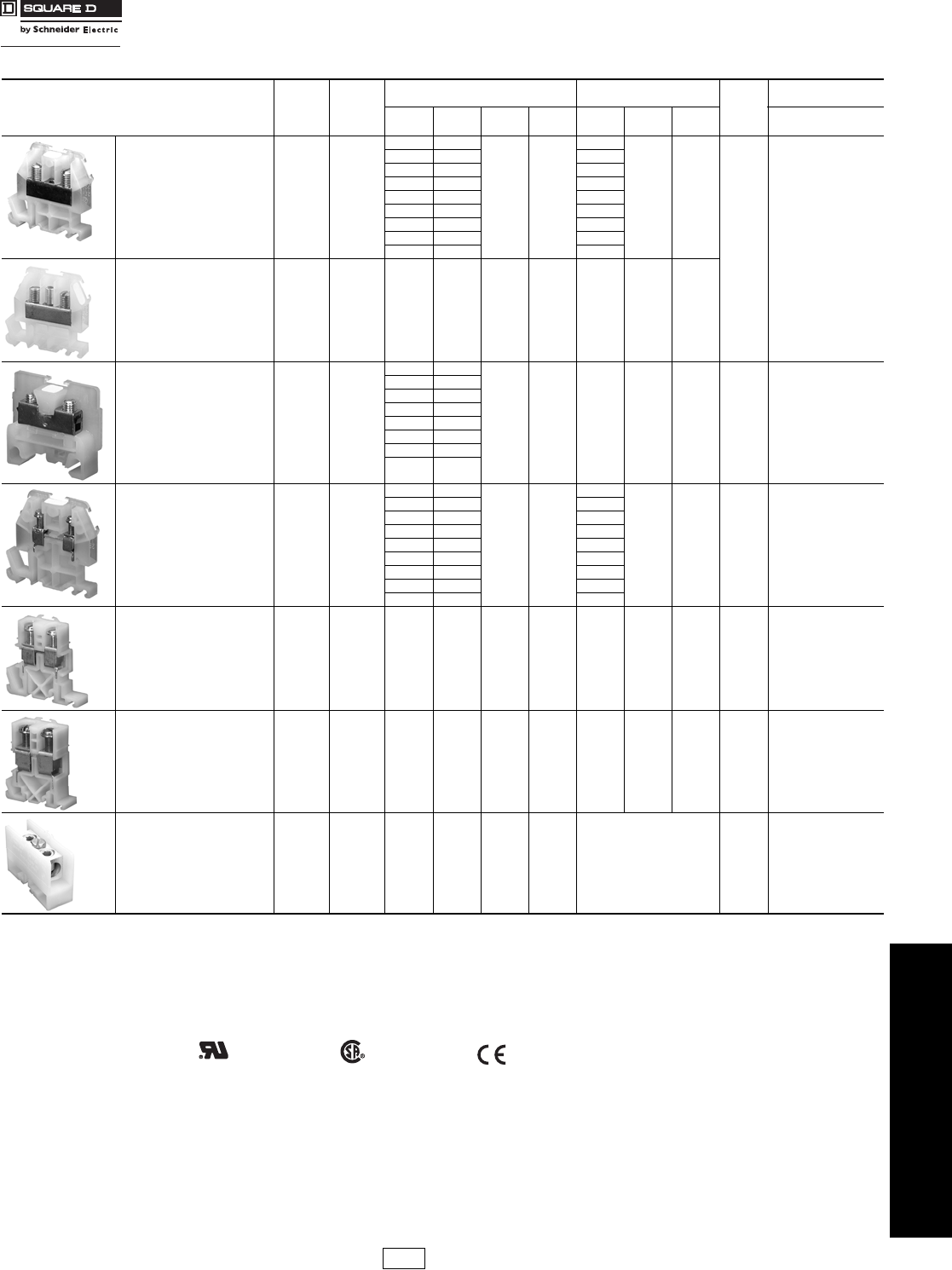
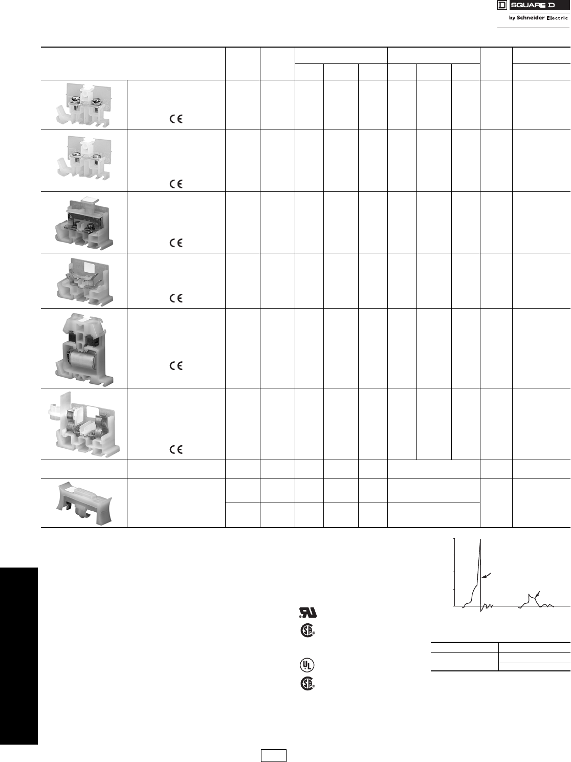
Selection Guide Terminal Blocks
Refer to Catalog 9080CT9901R7/07 and 9080CT9601
Table 24.1:
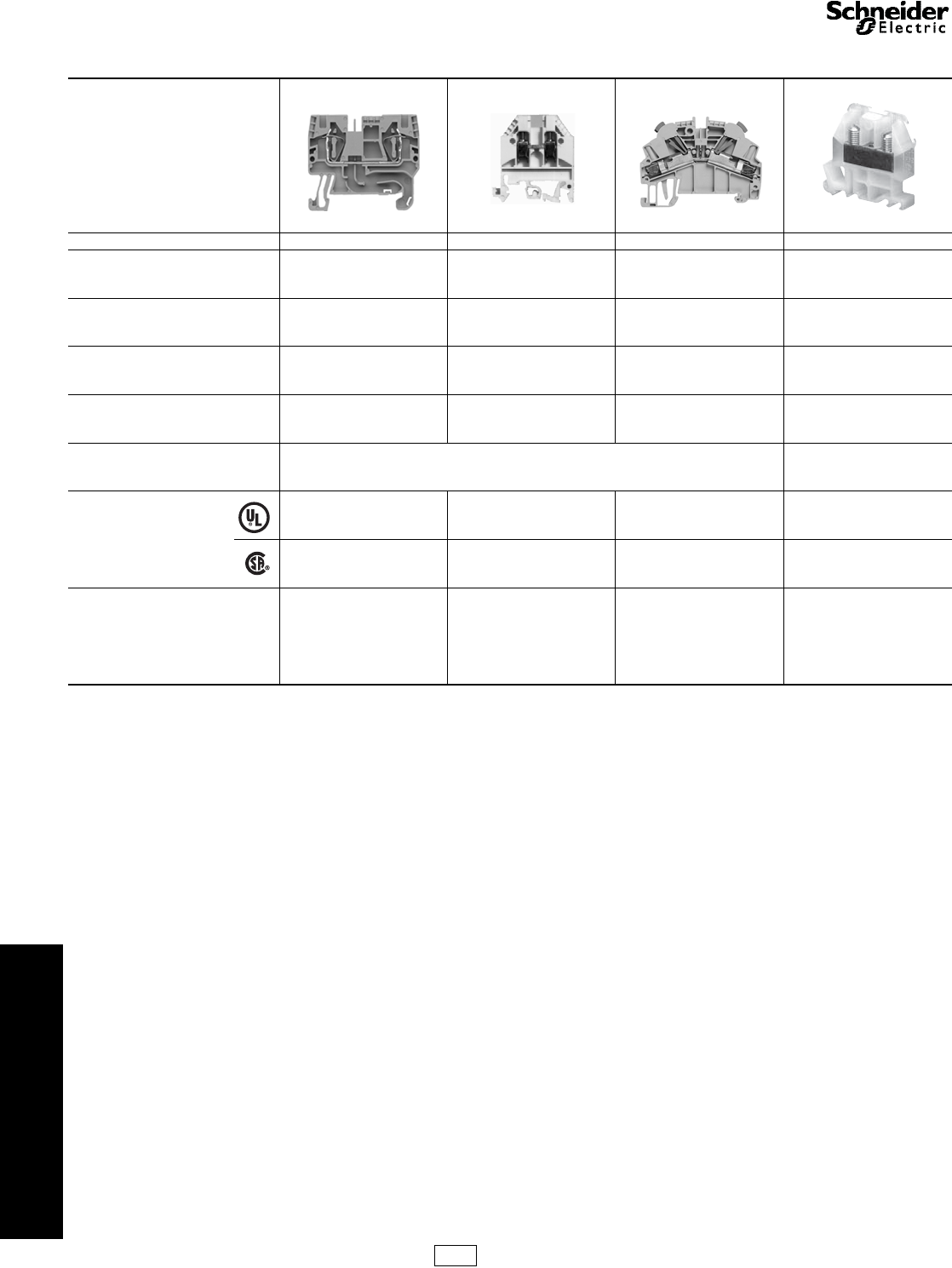
Product Family AB1RRN AB1VV AB1AA 9080G
Type of product IEC spring technology IEC screw technology IEC insulation displacement
technology NEMA screw technology
Mounting DIN 3 DIN 1 and DIN 3 DIN 3 DIN 3 and Square D track a
Maximum rated voltage (V) 600 600 600 600 b
Maximum rated current per UL (A) 115 375 22 255
Ambient air temperature -40 to +266 °F (-40 to 130 °C) -40 to +257 °F (-40 to 125 °C)
Approvals c
UL File 164359
CCN XCFR2 UL File 164359
CCN XCFR2 UL File 164359
CCN XCFR2 UL File E60616
CCN XCFR2
CSA File 702070
Class 6228 01 CSA File 702070
Class 6228 01 CSA File 702070
Class 6228 01 CSA File 025490
Class 3211 07
Color
Gray
Blue
Green/Yellow
Black
Gray
Blue
Green/Yellow
Orange
Red
Green
White
Black
Gray
Blue
Green/Yellow
Orange
Red
Natural (White)
Black
Blue
Green
Gray
Orange
Red
Yellow
Brown
a9080GK6 can be mounted directly to a panel or on Square D track.
b9080GT6 is 120 V.
cRefer to catalogs 9080CT9901 and 9080CT9601 for a complete list of certifications.
CP5 Discount
Schedule
Courtesy of Steven Engineering, Inc.-230 Ryan Way, South San Francisco, CA 94080-6370-Main Office: (650) 588-9200-Outside Local Area: (800) 258-9200-www.stevenengineering.com
www.schneider-electric.us
24 TERMINAL BLOCKS
© 2009 Schneider Electric
All Rights Reserved 24-3
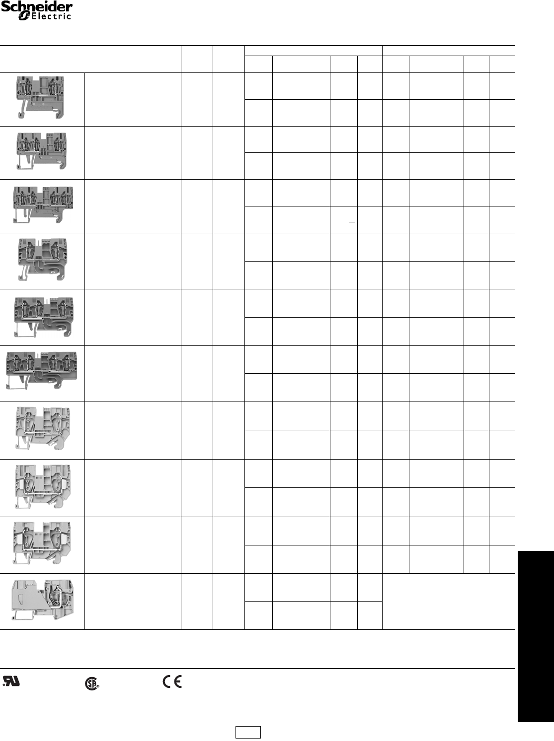
IEC Style Terminal Blocks AB1RRN Spring Clip Blocks
Refer to Catalog 9080CT9901R7/07
For track and accessories, see pages 24-11 and 24-12.
Table 24.2: Spring-Clip, AB1RRN
Description Maximum
Voltage
Maximum
Current
b
Block End Barrierc
Color Catalog Number $ Price
ea. Std.
PackaColor Catalog Number $ Price
ea. Std.
Packa
5 mm (0.20 in.) wide
Spring-Clip Style Block
Two Terminals
Solid or Stranded Copper Wire
22–12 AWG
600 V 20 A
Gray AB1RRN235U2GR 1.40 100 Gray AB1RRNAC242GR 0.60 10
Blue AB1RRN235U2BL 1.40 100 Blue AB1RRNAC242BL 0.60 10
5 mm (0.20 in.) wide
Spring-Clip Style Block
Three Terminals
Solid or Stranded Copper Wire
22–12 AWG
600 V 20 A
Gray AB1RRN235U3GR 1.80 100 Gray AB1RRNAC243GR 0.68 10
Blue AB1RRN235U3BL 1.80 100 Blue AB1RRNAC243BL 0.68 10
5 mm (0.20 in.) wide
Spring-Clip Style Block
Four Terminals
Solid or Stranded Copper Wire
22–12 AWG
600 V 20 A
Gray AB1RRN235U4GR 2.30 100 Gray AB1RRNAC244GR 0.75 10
Blue AB1RRN235U4BL 2.30 100 Blue AB1RRNAC244BL 0.75 10
6 mm (0.24 in.) wide
Spring-Clip Style Block
Two Terminals
Solid or Stranded Copper Wire
24–10 AWG
600 V 30 A
Gray AB1RRN435U2GR 1.50 100 Gray AB1RRNAC442GR 0.60 10
Blue AB1RRN435U2BL 1.50 100 Blue AB1RRNAC442BL 0.60 10
6 mm (0.24 in.) wide
Spring-Clip Style Block
Three Terminals
Solid or Stranded Copper Wire
24–10 AWG
600 V 30 A
Gray AB1RRN435U3GR 2.30 100 Gray AB1RRNAC443GR 0.60 10
Blue AB1RRN435U3BL 2.30 100 Blue AB1RRNAC443BL 0.60 10
6 mm (0.24 in.) wide
Spring-Clip Style Block
Four Terminals
Solid or Stranded Copper Wire
24–10 AWG
600 V 30 A
Gray AB1RRN435U4GR 2.90 100 Gray AB1RRNAC444GR 0.90 10
Blue AB1RRN435U4BL 2.90 100 Blue AB1RRNAC444BL 0.90 10
8 mm (0.31 in.) wide
Spring Clip Style Block
Two Terminals
Solid or Stranded Copper Wire
24–8 AWG
600 V 50 A
Gray AB1RRN635U2GR 2.10 50 Gray AB1RRNAC642GR 0.83 10
Blue AB1RRN635U2BL 2.10 50 Blue AB1RRNAC642BL 0.83 10
10 mm (0.39 in.) wide
Spring Clip Style Block
Two Terminals
Solid or Stranded Copper Wire
16–6 AWG
600 V 60 A
Gray AB1RRN1035U2GR 2.70 50 Gray AB1RRNAC1042GR 0.90 10
Blue AB1RRN1035U2BL 2.70 50 Blue AB1RRNAC1042BL 0.90 10
12 mm (0.47 in.) wide
Spring Clip Style Block
Two Terminals
Solid or Stranded Copper Wire
16–4 AWG
600 V 85 A
Gray AB1RRN1635U2GR 4.40 50 Gray AB1RRNAC1642GR 1.20 10
Blue AB1RRN1635U2BL 4.40 50 Blue AB1RRNAC1642BL 1.20 10
16 mm (0.63 in.) wide
Spring Clip Style Block
Two Terminals
Solid or Stranded Copper Wire
14–2 AWG
600 V 115 A
Gray AB1RRN3535U2GR 22.50 10
None Required
Blue AB1RRN3535U2BL 22.50 10
aOrders must specify the standard package quantity (Std. Pack) or multiples of that quantity.
bThese maximum current values assume the use of insulated copper conductors with 75oC temperature rating and are calculated based on NEC Article 310, Table 310-16. In most cases this
value is the maximum ampacity of the wire which has the greatest current carrying capacity. The actual allowable current for a particular application depends on the size, insulation class, and
other characteristics of the wire used. The UL ratings are shown. The CSA rating may be higher or lower. Refer to the catalog for CSA ratings.
cOne end-barrier is required for each assembly of like blocks.
File
CCN E164359
XCFR2 File
Class 702070
6228 01 RoHS
Compliant
CP5 Discount
Schedule
Courtesy of Steven Engineering, Inc.-230 Ryan Way, South San Francisco, CA 94080-6370-Main Office: (650) 588-9200-Outside Local Area: (800) 258-9200-www.stevenengineering.com
www.schneider-electric.us
24 TERMINAL BLOCKS
24-4 © 2009 Schneider Electric
All Rights Reserved
IEC Style
Terminal Blocks
AB1RRN Spring Clip Terminals, AB1VV and AB1TP Miniature
Blocks
Refer to Catalog 9080CT9901R7/07
Table 24.3: Spring-Clip, AB1RRN (continued)
Description Maximum
Voltage
Maximum
Current
b
Block End Barrier c
Color Catalog
Number $ Price
ea. Std. Pack
aColor Catalog
Number $ Price
ea. Std. Pack
a
5 mm (0.20 in.) wide
Spring-Clip Style
Grounding Block
Two Ter mina ls
Solid or Stranded Copper Wire
22–12 AWG
600 V 20 A Green /
Yellow AB1RRNTP235U2 5.10 100 Green AB1RRNTPAC242 0.60 10
5 mm (0.20 in.) wide
Spring-Clip Style
Grounding Block
Four Terminals
Solid or Stranded Copper Wire
22–12 AWG
600 V 20 A Green /
Yellow AB1RRNTP235U4 7.50 100 Green AB1RRNTPAC244 0.75 10
6 mm (0.24 in.) wide
Spring-Clip Style
Grounding Block
Two Ter mina ls
Solid or Stranded Copper Wire
22–10 AWG
600 V 30 A Green /
Yellow AB1RRNTP435U2 6.20 100 Green AB1RRNTPAC242 0.60 10
8mm (0.31 in.) wide
Spring-Clip Style
Grounding Block
Two Ter mina ls
Solid or Stranded Copper Wire
24–8 AWG
600 V 50 A Green /
Yellow AB1RRNTP635U2 6.90 50 Green AB1RRNTPAC642 0.83 10
10 mm (0.39 in.) wide
Spring-Clip Style
Grounding Block
Two Ter mina ls
Solid or Stranded Copper Wire
16–6 AWG
600 V 60 A Green /
Yellow AB1RRNTP1035U2 7.80 50 Green AB1RRNTPAC1042 0.90 10
12 mm (0.47 in.) wide
Spring-Clip Style
Grounding Block
Two Ter mina ls
Solid or Stranded Copper Wire
22–10 AWG
600 V 85 A Green /
Yellow AB1RRNTP1635U2 9.30 50 Green AB1RRNTPAC1642 1.20 10
6 mm (0.24 in.) wide
Spring-Clip Style
Diode/Fuseholder Block
Solid or Stranded Copper Wire
22–10 AWG
300 V 10 A Gray AB1RRNSF435UGR 4.10 100 Gray AB1RRNAC442GR 0.60 10
Fuseholder 5x20 (Fuse not included)
Depends on fuse or
diode used Gray
AB1SF520 6.50 100
Not applicable
Fuseholder 5x20 + 24 V LED AB1SF520B 20.30 100
Fuseholder 5x20 + 220 V LED AB1SF520M 20.30 100
Holder for Diode (Diode not included) AB1SV1 6.20 100
Holder with1N4007-1 Diode AB1SV2 15.60 100
Table 24.4: Miniature, AB1VV and AB1TP
5 mm (0.20 in.) wide
Miniature Block
with Box Lug
Solid or Stranded Copper Wire
22–14 AWG
Mounts on 15 mm
DIN 2 track
150 V 10 A
Gray AB1VV215 1.50 100 Gray
AB1AC2 0.62 10
Blue AB1VV215BL 1.50 100 Blue
5 mm (0.20 in.) wide
Miniature Block with Box Lug
Solid or Stranded Copper Wire
22–10 AWG
Mounts on 15 mm DIN 2 track
150 V 10 A Gray AB1VV415 1.70 100 Gray AB1AC2 0.62 10
6 mm (0.24 in.) wide
Miniature Grounding Block
with Box Lug
Solid or Stranded Copper Wire
22–14 AWG
Mounts on 15 mm DIN 2 track
150 V 10 A Green /
Yellow AB1TP215 4.40 100 Gray AB1CT215 0.62 50
aOrders must specify the standard package quantity (Std. Pack) or multiples of that quantity.
bThese maximum current values assume the use of insulated copper conductors with 75oC temperature rating and are calculated based on NEC article 310, Table 310-16. In most cases this
value is the maximum ampacity of the wire which has the greatest current carrying capacity. The actual allowable current for a particular application depends on the size, insulation, class and
other characteristics of the wire used. The UL ratings are shown. The CSA rating may be higher or lower. Refer to the catalog for CSA ratings.
cOne end-barrier is required for each assembly of like blocks.
File
CCN E164359
XCFR2 File
Class 702070
6228 01 RoHS
Compliant
For track and accessories, see pages 24-11 and 24-12.
CP5 Discount
Schedule
Courtesy of Steven Engineering, Inc.-230 Ryan Way, South San Francisco, CA 94080-6370-Main Office: (650) 588-9200-Outside Local Area: (800) 258-9200-www.stevenengineering.com
www.schneider-electric.us
24 TERMINAL BLOCKS
© 2009 Schneider Electric
All Rights Reserved 24-5
IEC Style
Terminal Blocks
AB1VV Box Lug Blocks
Refer to Catalog 9080CT9901R7/07
For track and accessories, see pages 24-11 and 24-12.
Table 24.5: Box Lug, AB1VV
Description Maximum
Voltage
Maximum
Current
b
Block End Barrier c
Color Catalog Number $ Price
ea. Std.
Pack aColor Catalog Number $ Price
ea. Std.
Pack a
5 mm (0.20 in.) wide
Box-Lug Style Block
Solid or Stranded Copper Wire
22–12 AWG
600 V 20 A
Gray AB1VV235U 1.40 100 Gray AB1AC24 0.62 50
Blue AB1VV235UBL 1.40 100 Blue AB1AC24BL 0.62 50
Orange AB1VV235UGE 1.40 100 Orange AB1AC24GE 0.62 50
6 mm (0.24 in.) wide
Box-Lug Style Block
Solid or Stranded Copper Wire
22–10 AWG
600 V 30 A
Gray AB1VV435U 1.50 100 Gray AB1AC24 0.62 50
Blue AB1VV435UBL 1.50 100 Blue AB1AC24BL 0.62 50
Orange AB1VV435UGE 1.50 100 Orange AB1AC24GE 0.62 50
Black AB1VV435UNO 1.50 100 Gray AB1AC24 0.62 50
Red AB1VV435URO 1.50 100 Gray AB1AC24 0.62 50
Green AB1VV435UVE 1.50 100 Gray AB1AC24 0.62 50
White AB1VV435UBLA 1.50 100 Gray AB1AC24 0.62 50
8 mm (0.31 in.) wide
Box-Lug Style Block
Solid or Stranded Copper Wire
22–8 AWG
600 V 50 A
Gray AB1VV635U 2.10 100 Gray AB1AC6 0.62 50
Blue AB1VV635UBL 2.10 100 Blue AB1AC6BL 0.62 50
Orange AB1VV635UGE 2.10 100 Orange AB1AC6GE 0.62 50
10 mm (0.39 in.) wide
Box-Lug Style Block
Solid or Stranded Copper Wire
16–6 AWG
600 V 65 A
Gray AB1VVN1035U 2.70 50 Gray AB1ACN10 0.78 10
Blue AB1VVN1035UBL 2.70 50 Blue AB1ACN10BL 0.78 10
12 mm (0.47 in.) wide
Box-Lug Style Block
Solid or Stranded Copper Wire
12–4 AWG
600 V 85 A
Gray AB1VVN1635U 5.40 50 Gray AB1ACN16 0.93 10
Blue AB1VVN1635UBL 5.40 50 Blue AB1ACN16BL 0.93 10
16 mm (0.63 in.) wide
Box-Lug Style Block
Solid or Stranded Copper Wire
10–2 AWG
600 V 95 A
Gray AB1VVN3535U 7.70 20
Not required for these blocks.
Blue AB1VVN3535UBL 7.70 20
24 mm (0.94 in.) wide
Box-Lug Style Block
Solid or Stranded Copper Wire
6–2/0 AWG
600 V 175 A
Gray AB1VVN7035U 27.90 20
Not required for these blocks.
Blue AB1VVN7035UBL 27.90 20
28 mm (1.10 in.) wide
Box-Lug Style Block
Solid or Stranded Copper Wire
2/0–350 kcmil
600 V 335 A
Gray AB1VVN15035U 65.00 10
Not required for these blocks.
Blue AB1VVN15035UBL 65.00 10
aOrders must specify the standard package quantity (Std. Pack) or multiples of that quantity.
bThese maximum current values assume the use of insulated copper conductors with 75oC temperature rating and are calculated based on NEC Article 310, Table 310-16. In most cases this
value is the maximum ampacity of the wire which has the greatest current carrying capacity. The actual allowable current for a particular application depends on the size, insulation class, and
other characteristics of the wire used. The UL rating are shown. The CSA rating may be higher or lower. Refer to the catalog for CSA ratings.
cOne end-barrier is required for each assembly of like blocks.
File
CCN E164359
XCFR2 File
Class 702070
6228 01 RoHS
Compliant
CP5 Discount
Schedule
Courtesy of Steven Engineering, Inc.-230 Ryan Way, South San Francisco, CA 94080-6370-Main Office: (650) 588-9200-Outside Local Area: (800) 258-9200-www.stevenengineering.com
www.schneider-electric.us
24 TERMINAL BLOCKS
24-6 © 2009 Schneider Electric
All Rights Reserved
IEC Style
Terminal Blocks
AB1TP Grounding and AB1ET Two Tier Blocks
Refer to Catalog 9080CT9901R7/07
For track and accessories, see pages 24-11 and 24-12
Table 24.6: Grounding, AB1TP
Description Maximum
Voltage
Block End Barrier c
Color Catalog Number $ Price
ea. Std. Pack
aColor Catalog
Number $ Price
ea. Std. Pack
a
5.1 mm (0.20 in.) wide
Grounding Block
Solid or Stranded
Copper Wire
22–10 AWG
600 V Green/Yellow AB1TP235U 5.30 100 Green AB1AC25 0.83 10
6 mm (0.24 in.) wide
Grounding Block
Solid or Stranded
Copper Wire
22–10 AWG
600 V Green/Yellow AB1TP435U 6.20 100 Not required for this block.
8 mm (0.31 in.) wide
Grounding Block
Solid or Stranded
Copper Wire
22–8 AWG
600 V Green/Yellow AB1TP635U 6.90 100 Not required for this block.
10 mm (0.39 in.) wide
Grounding Block
Solid or Stranded
Copper Wire
16–6 AWG
600 V Green/Yellow AB1TP1035U 7.80 50 Not required for this block.
12 mm (0.47 in.) wide
Grounding Block
Solid or Stranded
Copper Wire
12–4 AWG
600 V Green/Yellow AB1TP1635U 9.30 50 Not required for this block.
16 mm (0.63 in.) wide
Grounding Block
Solid or Stranded
Copper Wire
10–2 AWG
600 V Green/Yellow AB1TP3535U 13.20 20 Not required for this block.
Table 24.7: Two Tier, AB1ET
Description
Block End Barrier c
Color Catalog Number $ Price
ea. Std. Pack
aColor Catalog
Number $ Price
ea. Std. Pack
a
6 mm (0.24 in.) wide
Two Tier Blocks
Solid or Stranded
Copper Wire
22–10 AWG
300 V 20 A b
Standard two tier block Gray AB1ET435U 4.10 100
Gray AB1TE 1.10 50
Standard two tier block
+ upper-lower link Black AB1ET435U2 6.20 100
Standard two tier block
+ grounding Green/Yellow AB1ET435UTP 18.60 100
Standard two tier block
+ red 24 V LED Red AB1ET435UBRO 17.10 100
Standard two tier block
+ green 24 V LED Red AB1ET435UBVE 17.10 100
Standard two tier block
+ head to tail diodes (red) Orange AB1ET435UBGE 17.10 100
Standard two tier block
+ diode upper-lower Red AB1ET435UHBRO 10.80 100
Standard two tier block
+ diode lower-upper Orange AB1ET435UBHGE 10.80 100
Standard two tier block
+ 2 diodes Red AB1ET435U2DRO 19.20 100
aOrders must specify the standard package quantity (Std. Pack) or multiples of that quantity.
bThese maximum current values assume the use of insulated copper conductors with 75oC temperature rating and are calculated based on NEC Article 310, Table 310-16. In most cases this
value is the maximum ampacity of the wire which has the greatest current carrying capacity. The actual allowable current for a particular application depends on the size, insulation class, and
other characteristics of the wire used. The UL ratings are shown. The CSA rating may be higher or lower. Refer to the catalog for CSA ratings.
cOne end-barrier is required for each assembly of like blocks.
File
CCN E164359
XCFR2 File
Class 702070
6228 01 RoHS
Compliant
CP5 Discount
Schedule
Courtesy of Steven Engineering, Inc.-230 Ryan Way, South San Francisco, CA 94080-6370-Main Office: (650) 588-9200-Outside Local Area: (800) 258-9200-www.stevenengineering.com
www.schneider-electric.us
24 TERMINAL BLOCKS
© 2009 Schneider Electric
All Rights Reserved 24-7
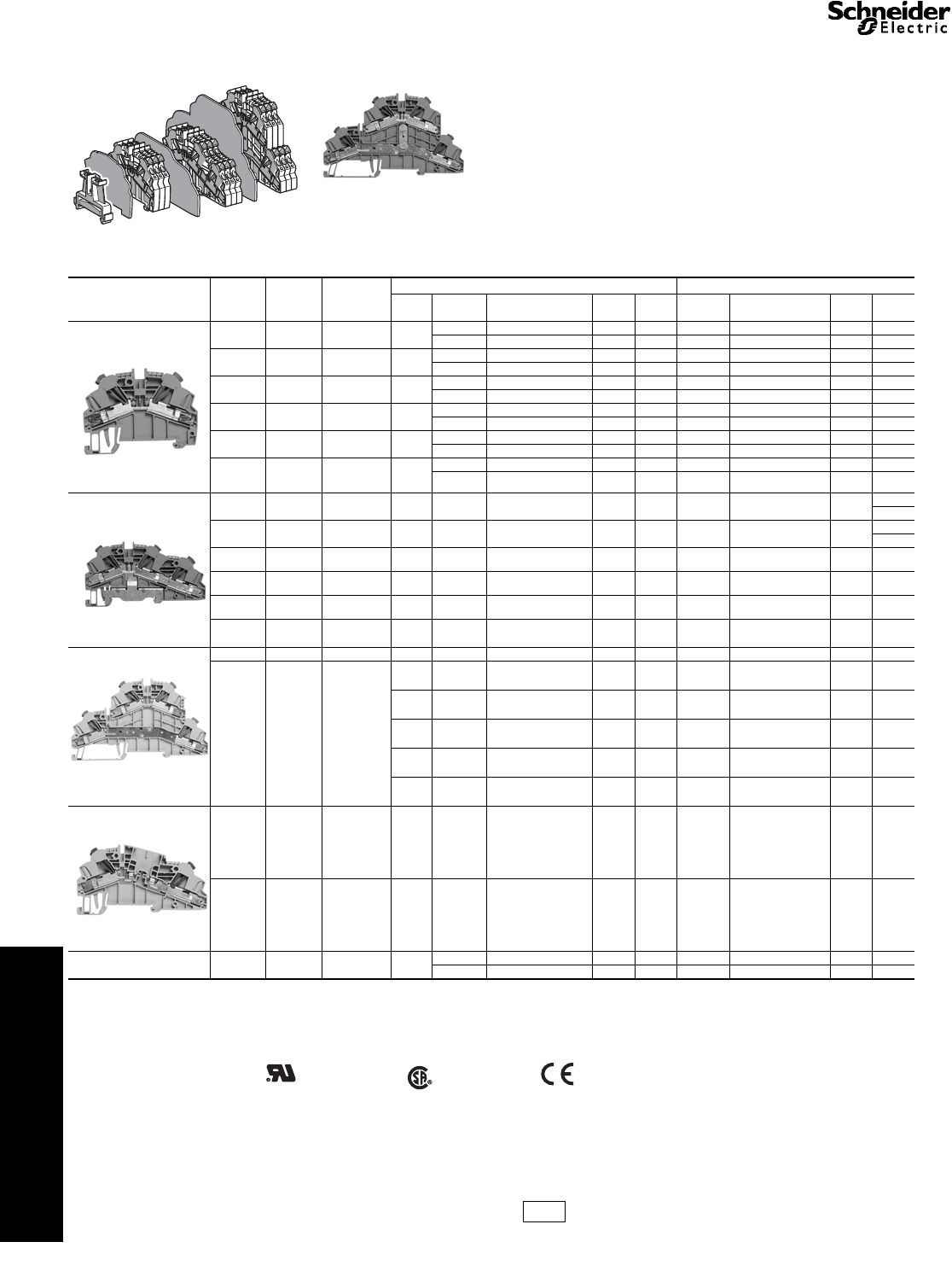
IEC Style
Terminal Blocks
AB1DD, AB1ET Three Tier and AB1ETN Two Tier Blocks
Refer to Catalog 9080CT9901R7/07
aOrders must specify the standard package quantity (Std. Pack) or multiples of that quantity.
bThese maximum current values assume the use of insulated copper conductors with 75oC temperature rating and are calculated based on NEC Article
310, Table 310-16. In most cases this value is the maximum ampacity of the wire which has the greatest current carrying capacity. The actual allowable
current for a particular application depends on the size, insulation class, and other characteristics of the wire used. The UL ratings are shown. The CSA
rating may be higher or lower. Refer to the catalog for CSA ratings.
cOne end-barrier is required for each assembly of like blocks.
For track and accessories, see pages 24-11 and 24-12.
Table 24.8: Three Tier, AB1DD and AB1ET
Description Maximum
Voltage Maximum
Currentb
Block End Barrier c
Color Catalog Number $ Price
ea. Std. Pack
aColor Catalog
Number $ Price
ea. Std. Pack
a
6 mm (0.24 in.) wide
Three Tier Block
Solid or Stranded Copper Wire
22–12 AWG
300 V 25 A
Gray
AB1DDP235U 5.40 100
Not required for these blocks.
Three Tier Block
with 24 V LED (+)
Solid or Stranded Copper Wire
22–12 AWG
AB1DDP235ULP 10.10 100
Three Tier Block
with 24 V LED (-)
Solid or Stranded Copper Wire
22–12 AWG
AB1DDP235ULM 10.10 100
6 mm (0.24 in.) wide
Three Tier Block
with ground
Solid or Stranded Copper Wire
22–12 AWG
Gray with
Green/Yellow
AB1DDP235T 8.60 100
Three Tier Block
with 24 V LED (+) and ground
Solid or Stranded Copper Wire
22–12 AWG
AB1DDP235TLP 13.20 100
Three Tier Block
with 24 V LED (-) and ground
Solid or Stranded Copper Wire
22–12 AWG
AB1DDP235TLM 13.20 100
6 mm (0.24 in.) wide
Three Tier Block
Solid or Stranded Copper Wire
22–12 AWG
Gray AB1ET3235U 8.60 100
Three Tier Block
with 24 V LED (+) and ground
Solid or Stranded Copper Wire
22–12 AWG
Gray with
Green/Yellow
AB1ET3235UTLP 27.80 100
Three Tier Block
with 24 V LED (-) and ground
Solid or Stranded Copper Wire
22–12 AWG
AB1ET3235UTLM 27.80 100
Three Tier Block
with ground
Solid or Stranded Copper Wire
22–12 AWG
AB1ET3235UT 12.60 100
Table 24.9: Two Tier, AB1ETN
Description Maximum
Voltage Maximum
Current b
Block End Barrier c
Color Catalog
Number $ Price
ea. Std. Pack
aColor Catalog
Number $ Price
ea. Std. Pack
a
6 mm (0.24 in.) wide
AB1ETN335U
Two Tier Block
(one terminal in and two out)
Solid or Stranded Copper Wire
22–10 AWG
300 V 30 A
Gray AB1ETN335U 3.60 100 Gray AB1TEN3 1.10 10
Two Tier Block
(two terminals in and two out)
Solid or Stranded Copper Wire
22–10 AWG
Gray AB1ETN435U 5.10 100 Gray AB1TEN4 1.20 10
Grounding Block
(two terminals in and two out)
Solid or Stranded Copper Wire
22–10 AWG
Green/
Yellow AB1ETNTP435U 12.20 100 Not required for this block.
File
CCN E164359
XCFR2 File
Class 702070
6228 01 RoHS
Compliant
CP5 Discount
Schedule
Courtesy of Steven Engineering, Inc.-230 Ryan Way, South San Francisco, CA 94080-6370-Main Office: (650) 588-9200-Outside Local Area: (800) 258-9200-www.stevenengineering.com
www.schneider-electric.us
24 TERMINAL BLOCKS
24-8 © 2009 Schneider Electric
All Rights Reserved
IEC Style
Terminal Blocks
DF, AB1FU and AB1SF/SV Fuseholders
Refer to Catalogs 9080CT9901R7/07 and 9080CT0801
aOrders must specify the standard package quantity (Std. Pack) or multiples of that quantity.
bThese maximum current values assume the use of insulated copper conductors with 75oC temperature rating and are calculated based on NEC Article
310, Table 310-16. In most cases this value is the maximum ampacity of the wire which has the greatest current carrying capacity. The actual allowable
current for a particular application depends on the size, insulation class, and other characteristics of the wire used. The UL ratings are shown. The CSA
rating may be higher or lower. Refer to the catalog for CSA ratings.
cOne end-barrier is required for each assembly of like blocks.
dFor additional information, refer to Catalog 9080CT9901
eFor additional blocks and information, refer to Catalog 9080CT0801.
fWith blown-fuse indicator.
Table 24.10: Fuse Block, AB1d
Description
Block End Barrier c
Color Catalog
Number $ Price
ea. Std.
Pack aColor Catalog
Number $ Price
ea. Std.
Pack a
8 mm (0.31 in.) wide
Fuse Block
For 5x20 or 5x25 mm fuse
Solid or Stranded Copper Wire
22–10 AWG
Maximum Voltage—600 V
Maximum Current—15 A b
Without indicator lamp Gray AB1FUSE435U5X 7.80 100
Not required for these blocks.
With 5–12 V LED indicator Gray AB1FUSE435U5XJ 16.10 50
With 12–24 V LED indicator Gray AB1FUSE435U5XB 16.10 50
With 110–250 V neon indicator Gray AB1FUSE435U5XM 16.10 50
10 mm (0.39 in.) wide
Fuse Block
For 1/4 x 1-1/4 in. fuse
Solid or Stranded Copper Wire
22–10 AWG
Maximum Voltage—600 V
Maximum Current—15 A b
Without indicator lamp Gray AB1FUSE435U6X 14.40 100
Not required for these blocks.
With 5–12 V LED indicator Gray AB1FUSE435U6XJ 18.60 50
With 12–24 V LED indicator Gray AB1FUSE435U6XB 18.60 50
With 110–250 V neon indicator Gray AB1FUSE435U6XM 18.60 50
12 mm (0.47 in.) wide
Fuse Block
For 5 x 20 mm fuse
Solid or Stranded Copper Wire
22–6 AWG
Maximum Voltage—600 V
Maximum Current—15 A b
Without indicator lamp Gray AB1FU10135U 10.80 50
Gray AB1TF 1.40 50With 28 V yellow LED indicator Gray AB1FU10135UB 26.40 50
With 250 V yellow LED indicator Gray AB1FU10135UU 26.40 50
Fuse Block
For 5 x 25 mm fuse
Solid or Stranded Copper Wire
22–6 AWG
Maximum Voltage—600 V
Maximum Current—15 A b
Without indicator lamp Gray AB1FU10235U 14.00 50 Gray AB1TF 1.40 50
Fuse Block
For 5 x 30 mm fuse
Solid or Stranded Copper Wire
22–6 AWG
Maximum Voltage—600 V
Maximum Current—15 A b
Without indicator lamp Gray AB1FU10335U 15.60 50 Gray AB1TF 1.40 50
Fuse Block
For 1/4 x 1-1/4 in. fuse
Solid or Stranded Copper Wire
22–6 AWG
Maximum Voltage—600 V
Maximum Current—15 A b
Without indicator lamp Gray AB1FU10435U 15.60 50
Gray AB1TF 1.40 50With 28 V yellow LED indicator Gray AB1FU10435UB 26.40 50
With 110–500 V red neon indicator Gray AB1FU10435UFS 26.40 50
6 mm (0.24 in.) wide
Fuse / Diode Block
Solid or Stranded Copper Wire
22–10 AWG
Maximum Voltage—300 V
Maximum Current—10 A b
Fuse / Diode block Gray AB1SF435U 3.90 100 Gray AB1PS4 0.86 10
Removable fuse holder
for 5x20 mm fuse Gray AB1SF520 6.50 100
N/A
Removable fuse holder
for 5x20 mm fuse
with 24 V red LED indicator Gray AB1SF520B 20.30 100
Removable fuse holder
for 5x20 mm fuse
with 220 V red LED indicator Gray AB1SF520M 20.30 100
Removable diode
or resistor holder Gray AB1SV1 6.20 100
Removable holder
With 1N4007.1 diode Gray AB1SV2 15.60 100
Table 24.11: Modular Fuse Holders, DFe
Rated Thermal
Current Type of Fuse Composition Standard Pack
Quantity Catalog
Number $ Price
ea.
DFCC1V DFCC3V
30 A Class CC
1 Pole 12 DFCC1 18.00
2 Poles 6 DFCC2 36.00
3 Poles 4 DFCC3 54.00
1 Pole f12 DFCC1V 22.50
2 Poles f6DFCC2V 45.00
3 Poles f 4DFCC3V 68.00
CP5 Discount
Schedule
File
CCN E164359
XCFR2
File
Class 702070
6228 01
RoHS
Compliant
File E310269
CNN IZLT
Courtesy of Steven Engineering, Inc.-230 Ryan Way, South San Francisco, CA 94080-6370-Main Office: (650) 588-9200-Outside Local Area: (800) 258-9200-www.stevenengineering.com
www.schneider-electric.us
24 TERMINAL BLOCKS
© 2009 Schneider Electric
All Rights Reserved 24-9
IEC Style
Terminal Blocks
AB1 Other Blocks
Refer to Catalog 9080CT9901R7/07
aOrders must specify the standard package quantity (Std. Pack) or multiples of that quantity.
bThese maximum current values assume the use of insulated copper conductors with 75oC temperature rating and are calculated based on NEC Article
310, Table 310-16. In most cases this value is the maximum ampacity of the wire which has the greatest current carrying capacity. The actual allowable
current for a particular application depends on the size, insulation class, and other characteristics of the wire used. The UL ratings are shown. The CSA
rating may be higher or lower. Refer to the catalog for CSA ratings.
cOne end-barrier is required for each assembly of like blocks.
For track and accessories, see pages 24-11 and 24-12.
Table 24.12: Other Blocks, AB1
Description
Block End Barrierc
Color Catalog Number $ Price
ea.
Std.
Pack
aColor Catalog
Number $ Price
ea.
Std.
Pack
a
12 mm (0.47 in.) wide
Block for Diodes
(Diodes not included)
Solid or Stranded Copper Wire
22–14 AWG
Gray AB1D11435U 12.50 50 Not required for this block.
6 mm (0.24 in.) wide
Circuit Isolation Block
Solid or Stranded Copper Wire
22–10 AWG
Maximum Voltage—600 V
Maximum Current—20 Ab
With no test sockets Gray AB1SC435U 7.10 50
Gray AB1PS4 0.86 10
With two test sockets Gray AB1SC435U2PT 7.10 50
6 mm (0.24 in.) wide
Box Lug / Slip-on Block
Solid or Stranded Copper Wire
22–12 AWG
Maximum Voltage—300 V
Maximum Current—10 Ab
Box lug on one side.
Slip-on access from top
and side Gray AB1FV135U 3.00 100 Gray AB1TC01 1.40 50
Box lug on one side.
Slip-on access from top Gray AB1FC335U 3.90 100 Gray AB1TC3 1.40 50
Slip-on connectors
on both sides Gray AB1FF235U 2.10 100 Not required for this block.
Table 24.13: Lug/Lug and Lug/Clamp, AB1
Description
Block Partition
Color Catalog
Number $ Price
ea.
Std.
Pack
aColor Catalog
Number $ Price
ea.
Std.
Pack
a
32 mm (1.26 in.) wide
Lug/Lug Block
Solid or Stranded Copper Wire
0 AWG–350 kcmil
M10 bolt
Maximum Voltage—600 V
Maximum Current—230 Ab
Gray AB1BB9535 21.30 10 Gray AB1CT1 2.40 50
42 mm (1.65 in.) wide
Lug/Lug Block
Solid or Stranded Copper Wire
0 AWG– 400 kcmil
M12 bolt
Maximum Voltage—600 V
Maximum Current—375 Ab
Gray AB1BB18535 27.30 10 Gray AB1CT2 2.70 50
42 mm (1.65 in.) wide
Lug/Lug Block
Solid or Stranded Copper Wire
0 AWG–500 kcmil
M12 bolt
Maximum Voltage—600 V
Maximum Current—375 Ab
Gray AB1BB24035 45.00 10 Gray AB1CT2 2.70 50
32 mm (1.26 in.) wide
Lug/Clamp Block
Solid or Stranded Copper Wire
0 AWG–350 kcmil
M10 bolt
Maximum Voltage—600 V
Maximum Current—230 Ab
Gray AB1BC9535 31.10 10 Gray AB1CT1 2.40 50
42 mm (1.65 in.) wide
Lug/Clamp Block
Solid or Stranded Copper Wire
0 AWG–400 kcmil
M12 bolt
Maximum Voltage—600 V
Maximum Current—325 Ab
Gray AB1BC15035 62.00 10 Gray AB1CT2 2.70 50
42 mm (1.65 in.) wide
Lug/Clamp Block
Solid or Stranded Copper Wire
0 AWG–500 kcmil
M12 bolt
Maximum Voltage—600 V
Maximum Current—375 Ab
Gray AB1BC24035 86.00 10 Gray AB1CT2 2.70 50
File
CCN E164359
XCFR2 File
Class 702070
6228 01 RoHS
Compliant
CP5 Discount
Schedule
Courtesy of Steven Engineering, Inc.-230 Ryan Way, South San Francisco, CA 94080-6370-Main Office: (650) 588-9200-Outside Local Area: (800) 258-9200-www.stevenengineering.com
www.schneider-electric.us
24 TERMINAL BLOCKS
24-10 © 2009 Schneider Electric
All Rights Reserved
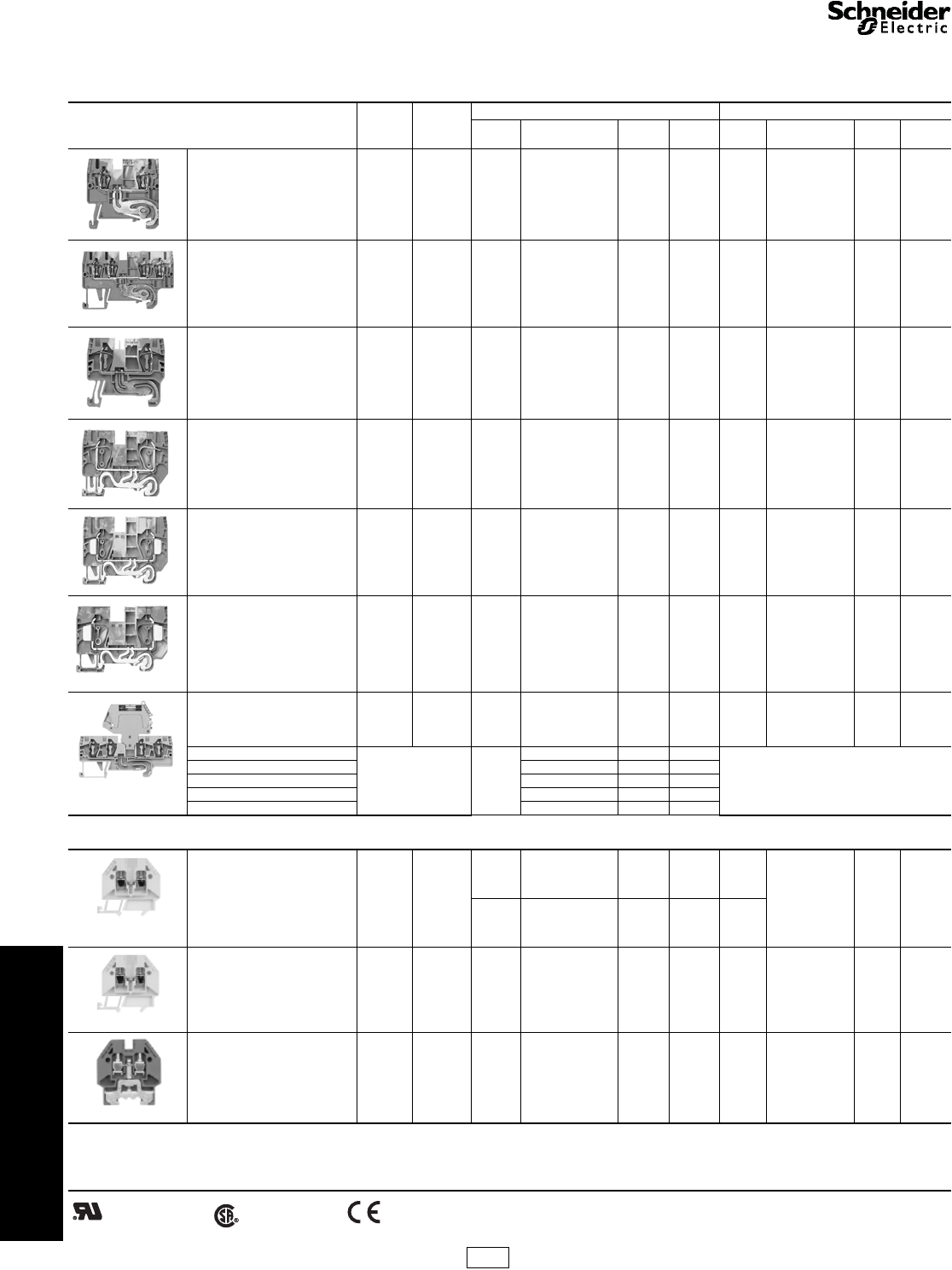
IEC Terminal Blocks AB1AA Insulation Displacement Blocks
Refer to Catalog 9080CT9901R7/07
Insulation Displacement Style Terminal Blocks and Accessories
aOrders must specify the standard package quantity (Std. Pack) or multiples of that quantity.
bThese maximum current values assume the use of insulated copper conductors with 75oC temperature rating and are calculated based on NEC Article
310, Table 310-16. In most cases this value is the maximum ampacity of the wire which has the greatest current carrying capacity. The actual allowable
current for a particular application depends on the size, insulation class, and other characteristics of the wire used.
cOne end-barrier is required for each assembly of like blocks.
For track and accessories, see pages 24-11 and 24-12.
5 mm (0.20 in.) wide
AB1AA135U4••
•Insert wires without stripping
•Available for wire sizes 30-14 AWG
•DIN 3 rail mounting
•Finger safe connections
Table 24.14: Insulation Displacement, AB1AA
Description Maximum
Voltage Maximum
CurrentbWire Size
Block End Barrierc
No. of
Poles Color Catalog Number $ Price
ea. Std.
PackaColor Catalog Number $ Price
ea. Std.
Packa
Insulation Displacement
Connector: Passthrough Block
Solid or Stranded Copper Wire
AB1AA135U2••
600 V 13 A 30–18 AWG 2 Gray AB1AA135U2GR 1.80 100 Gray AB1AAAC122GR .62 10
Blue AB1AA135U2BL 1.80 100 Blue AB1AAAC122BL .62 10
600 V 13 A 18–14 AWG 2 Gray AB1AA235U2GR 2.00 100 Gray AB1AAAC122GR .62 10
Blue AB1AA235U2BL 2.00 100 Blue AB1AAAC122BL .62 10
600 V 10 A 30–18 AWG 3 Gray AB1AA135U3GR 2.90 50 Gray AB1AAAC123GR .78 10
Blue AB1AA135U3BL 2.90 50 Blue AB1AAAC123BL .78 10
600 V 10 A 18–14 AWG 3 Gray AB1AA235U3GR 3.00 50 Gray AB1AAAC123GR .78 10
Blue AB1AA235U3BL 3.00 50 Blue AB1AAAC123BL .78 10
600 V 10 A 30–18 AWG 4 Gray AB1AA135U4GR 5.90 50 Gray AB1AAAC124GR .93 10
Blue AB1AA135U4BL 5.90 50 Blue AB1AAAC124BL .93 10
600 V 10 A 18–14 AWG 4 Gray AB1AA235U4GR 6.00 100 Gray AB1AAAC124GR .93 10
Blue AB1AA235U4BL 6.00 100 Blue AB1AAAC124BL .93 10
Insulation Displacement
Connector: Grounding Block
AB1AATP135U3
600 V 13 A 30–18 AWG 2 Green/
Yellow AB1AATP135U2 5.90 100 Green/
Ye l l ow AB1AAAC122VE .62 10
10
600 V 13 A 18–14 AWG 2 Green/
Yellow AB1AATP235U2 6.20 100 Green/
Ye l l ow AB1AAAC122VE .62 10
10
600 V 13 A 30–18 AWG 2 Green/
Yellow AB1AATP135U3 8.10 100 Green/
Ye l l ow AB1AAAC123VE .78 10
600 V 10 A 18–14 AWG 3 Green/
Yellow AB1AATP235U3 8.10 50 Green/
Ye l l ow AB1AAAC123VE .78 10
600 V 10 A 30–18 AWG 4 Green/
Yellow AB1AATP135U4 13.70 50 Green/
Ye l l ow AB1AAAC124VE .93 10
600 V 10 A 18–14 AWG 4 Green/
Yellow AB1AATP235U4 14.00 50 Green/
Ye l l ow AB1AAAC124VE .93 10
Two Tier Block 600 V 13 A 30–18 AWG 2 Gray AB1AAET135UGR 4.80 50 Gray AB1AAAC124GR .93 10
AB1AAET235••
600 V 22 A 18–14 AWG
2/2 Gray AB1AAET235UGR 5.10 50 Gray AB1AAAC124GR .93 10
2/2 Red AB1AAET235URO 5.10 50 Red AB1AAAC124GR .93 10
2/2 Orange AB1AAET235UGE 5.10 50 Orange AB1AAAC124GR .93 10
4RedAB1AAET235UBRO 15.60 50 Red AB1AAAC124GR .93 10
4OrangeAB1AAET235UBGE 15.60 50 Orange AB1AAAC124GR .93 10
Fuse Block
AB1AASF135U••
600 V 6.3 A 30–18 AWG 2 Gray AB1AASF135UGR 5.00 50 Gray AB1AAAC123GR .78 10
600 V 6.3 A 18–14 AWG 2 Gray AB1AASF235UGR 5.30 50 Gray AB1AAAC123GR .78 10
Disconnect Block 600 V 10 A 18–14 AWG 2 Gray AB1AASC235UGR 6.00 50 Gray AB1AAAC123GR .78 10
Blue AB1AASC235UBL 6.00 50 Blue AB1AAAC123BL .78 10
5 mm (0.20 in.) wide
5 mm (0.20 in.) wide
6 mm (0.24 in.) wide
6 mm (0.24 in.) wide
File
CCN E164359
XCFR2 File
Class 702070
6228 01 RoHS
Compliant
CP5 Discount
Schedule
Courtesy of Steven Engineering, Inc.-230 Ryan Way, South San Francisco, CA 94080-6370-Main Office: (650) 588-9200-Outside Local Area: (800) 258-9200-www.stevenengineering.com
www.schneider-electric.us
24 TERMINAL BLOCKS
© 2009 Schneider Electric
All Rights Reserved 24-11
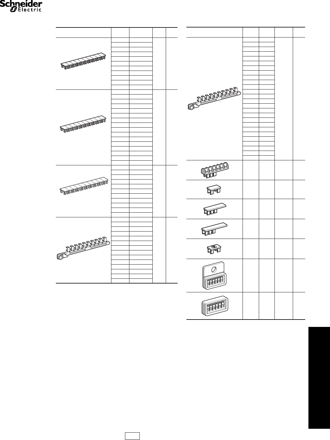
IEC Style Terminal Blocks AB1 Markers
Refer to Catalog 9080CT9901R7/07
aOrders must specify the standard package quantity (Std. Pack) or
multiples of that quantity.
RoHS
Compliant
Table 24.15: Markers, AB1
Marking Catalog
Number $ Price
ea. Std.
Pack a
Black number on
white background
5 mm (0.20 in.) wide
Blank AB1BV5
0.78 25
1–10 AB1B510
11–20 AB1B520
21–30 AB1B530
31–40 AB1B540
41–50 AB1B550
51–60 AB1B560
61–70 AB1B570
71–80 AB1B580
81–90 AB1B590
91–100 AB1B5100
Black number on
white background
6 mm (0.24 in.) wide
Blank AB1BV6
0.78 25
1–10 AB1B610
11–20 AB1B620
21–30 AB1B630
31–40 AB1B640
41–50 AB1B650
51–60 AB1B660
61–70 AB1B670
71–80 AB1B680
81–90 AB1B690
91–100 AB1B6100
L1 AB1B6L1
L2 AB1B6L2
L3 AB1B6L3
+ (Red) AB1BV6RP
– (Blue) AB1BV6BM
Black number on
white background
8 mm (0.31 in.) wide
Blank AB1BV8
0.78 25
1–10 AB1B810
11–20 AB1B820
21–30 AB1B830
31–40 AB1B840
41–50 AB1B850
51–60 AB1B860
61–70 AB1B870
71–80 AB1B880
81–90 AB1B890
91–100 AB1B8100
Black number or symbol
on white background
Blank AB1RV
0.78 25
1AB1R1
2AB1R2
3AB1R3
4AB1R4
5AB1R5
6AB1R6
7AB1R7
8AB1R8
9AB1R9
0AB1R0
0–9 AB1R11
+AB1R12
–AB1R13
1
2
3
4
5
6
7
8
9
10
AB1B510
1
2
3
4
5
6
7
8
9
10
AB1B610
1
2
3
4
5
6
7
8
9
10
AB1B810
2222222222
AB1R2
Marking Catalog
Number $ Price
ea. Std.
Pack a
Black capital letters on
white background
AAB1GA
0.78 25
BAB1GB
CAB1GC
DAB1GD
EAB1GE
FAB1GF
GAB1GG
HAB1GH
IAB1GI
JAB1GJ
KAB1GK
LAB1GL
MAB1GM
NAB1GN
OAB1GO
PAB1GP
QAB1GQ
RAB1GR
SAB1GS
TAB1GT
UAB1GU
VAB1GV
WAB1GW
XAB1GX
YAB1GY
ZAB1GZ
AB1SR6 0.78 200
AB1SA1 0.18 500
AB1SA2 0.39 500
AB1SA3 0.78 500
AB1RT 0.78 500
AR1SB2 1.50 100
AR1SB3 1.35 50
AAAAAAAAAA
AB1GA
CP5 Discount
Schedule
Courtesy of Steven Engineering, Inc.-230 Ryan Way, South San Francisco, CA 94080-6370-Main Office: (650) 588-9200-Outside Local Area: (800) 258-9200-www.stevenengineering.com
www.schneider-electric.us
24 TERMINAL BLOCKS
24-12 © 2009 Schneider Electric
All Rights Reserved
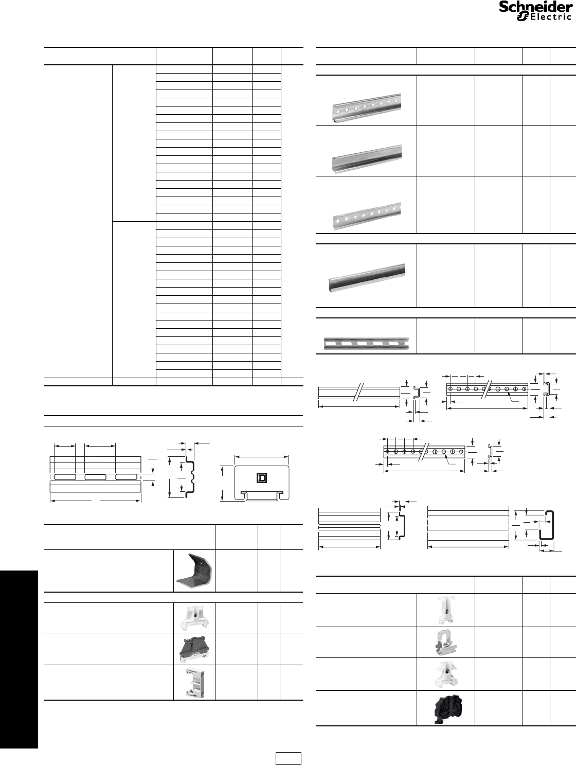
IEC Style Terminal
Blocks
Mounting Track and End Clamps
Refer to Catalog 9080CT9901
aOrders must specify the standard package quantity (Std. Pack) or multiples of that
quantity.
bNot RoHS Compliant
RoHS Compliant
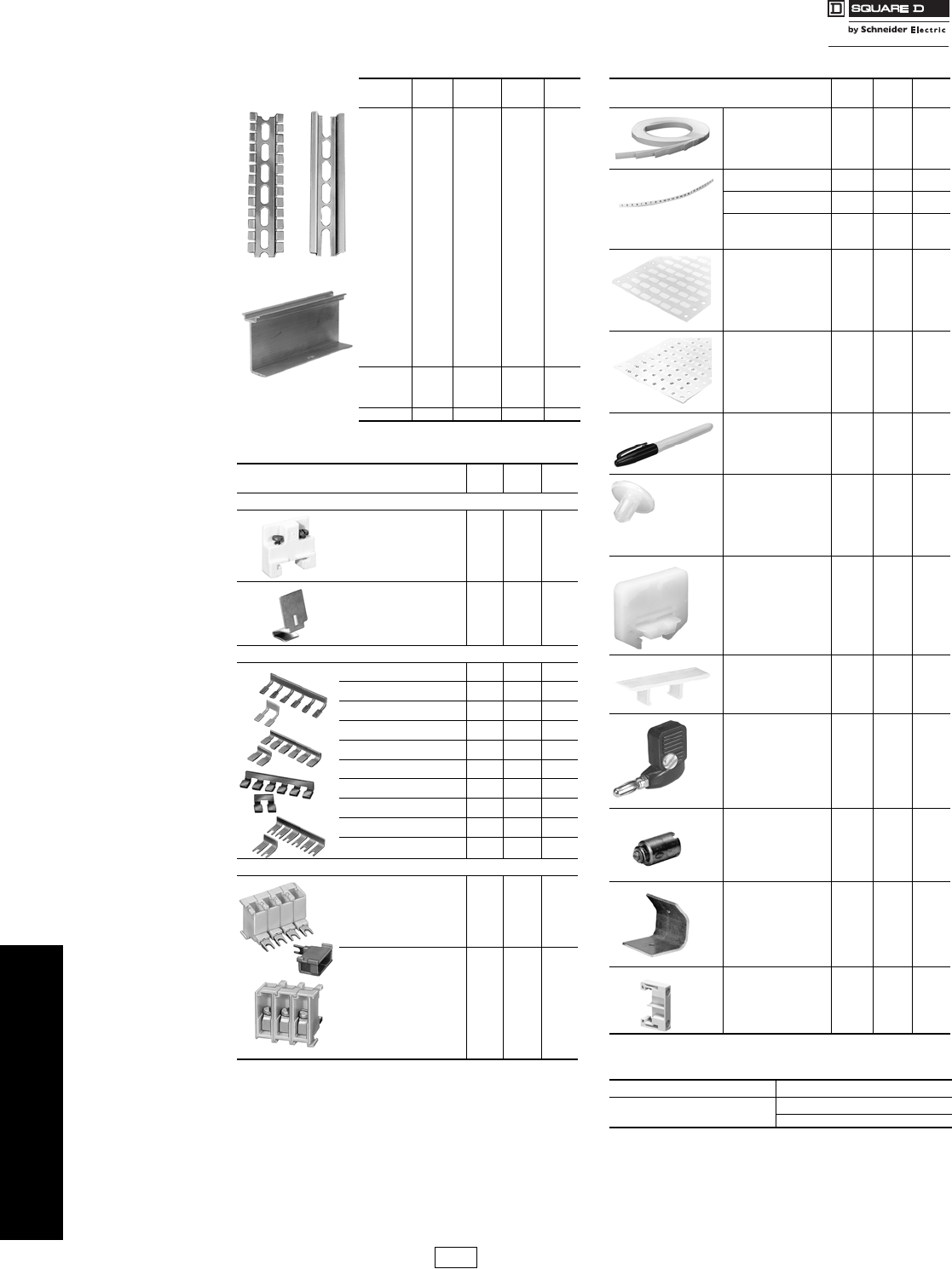
Table 24.16: DIN 3 Track – Various Lengths
Description Length
m (in.) Class 9080
Type $ Price
ea. Std.a
Pack
Symmetrical rail
35 x 7.5 mm
(1.38 in. x 0.295 in.)
in compliance with
EN 50022 standard
(DIN 46277-3).
Galvanized
steel,
no mounting
holes
0.08 (3) MH203 3.20
10
0.10 (4) MH204 3.60
0.13 (5) MH205 4.10
0.15 (6) MH206 4.70
0.18 (7) MH207 5.10
0.20 (8) MH208 5.60
0.23 (9) MH209 6.20
0.25 (10) MH210 6.80
0.28 (11) MH211 7.20
0.30 (12) MH212 7.80
0.33 (13) MH213 8.30
0.36 (14) MH214 8.70
0.38 (15) MH215 9.30
0.41 (16) MH216 9.80
0.42 (17) MH217 10.20
0.46 (18) MH218 10.80
0.50 (19.68) MH220 11.60
1 (39.37) MH239 19.70
2 (78.74) MH279 29.60
Galvanized
steel,
prepunched
0.08 (3) MH303 3.50
0.10 (4) MH304 3.90
0.13 (5 in. MH305 4.70
0.15 (6) MH306 5.10
0.18 (7) MH307 5.70
0.20 (8) MH308 6.20
0.23 (9) MH309 6.90
0.25 (10) MH310 7.40
0.28 (11) MH311 8.10
0.30 (12) MH312 8.60
0.33 (13) MH313 9.20
0.36 (14) MH314 9.60
0.38 (15) MH315 10.20
0.41 (16) MH316 10.80
0.42 (17) MH317 11.60
0.46 (18) MH318 12.00
0.50 (19.68) MH320 13.10
1 (39.37) MH339 23.00
2 (78.74) MH379 32.70
High rise track Aluminum 1 (39.37) MH439 27.90 2
Dimensions
Angle bracket kit Catalog
Number
$
Price
ea.
Std.a
Pack
For mounting 9080GH or MH track to a panel
at 45o angle. Includes 2 brackets and
hardware for mounting the track to the
brackets.
9080MH82c7.20 1
End Clamps
Plastic end clamp for 35 mm DIN 3 track,
8 mm (0.31 in.) wide AB1AB8P35 1.50 100
Metal end clamp for 35 mm DIN 3 track,
8 mm (0.31 in.) wide AB1AB8M35 2.40 100
Polycarbonate end clamp for 35 mm
DIN 3 track, 8 mm (0.31 in.) wide 9080MHA10 2.40 50
.25
6
A
.30
8
.04
1
.98
25
1.38
35
9080MH3**
.71
18 .98
25
1.80
46
1.17
30
9080MHA10
Table 24.17: Mounting Track 1 or 2 meter length
Description Length
m (in.) Catalog Number $ Price
ea. Std. a
Pack
DIN 3
15 mm depth, 1 mm steel,
zinc chromated
2 (78.74) AM1ED200 14.70 10
15 mm depth, 1.5 mm steel,
zinc chromated
2 (78.74) AM1DE200 21.80 10
7.5 mm depth, 1 mm steel,
zinc chromated
EN 50022 & NF C63-015
2 (78.74) AM1DP200 7.80 10
DIN 1
Asymmetrical 32 mm track
EN 50035 & NF C63-018
2 (78.74) DZ5MB201 23.20 10
15 mm steel,
zinc chromated
DIN 2
Symmetrical 15 mm track
EN 50045
1 (39.37) AB1PC15 7.50 10
Dimensions
End Clamps Catalog
Number $ Price
ea. Std.a
Pack
Plastic end clamp for 32 mm DIN 1
track, 7.5 mm (0.30 in.) wide AB1AB7P32 2.60 100
Metal end clamp for 32 mm DIN 1
track, 7.5 mm (0.30 in.) wide AB1AB10M32 2.60 100
Plastic end clamp for 15 mm DIN 2
track, 7.5 mm (0.30 in.) wide AB1AB715 1.50 100
Plastic end clamp for 35 mm DIN 3
track, 8 mm (0.31 in.) wide AB1AB8R35 1.50 100
AM1DE200
.06
2
1.38
35
78.74
2000
.59
15
1.06
27
AM1ED200
1.38
35
1.06
27
.28
7
78.74
2000
.59
15
.04
1
.49
12
.98
25
.98
25
.98
25
.30
8
AM1DP200
1.06
27
1.38
35
.28
7
78.74
2000
.49
12
.98
25
.98
25
.98
25
.30
8
.04
1
.04
1
AB1PC15
39.37
1000
.20
5
.34
9
.59
15
DZ5MB201
.24
6
.65
17
.06
2.59
15
1.26
32
78.74
2000
CP5 Discount
Schedule
Courtesy of Steven Engineering, Inc.-230 Ryan Way, South San Francisco, CA 94080-6370-Main Office: (650) 588-9200-Outside Local Area: (800) 258-9200-www.stevenengineering.com
www.schneider-electric.us
24 TERMINAL BLOCKS
© 2009 Schneider Electric
All Rights Reserved 24-13
NEMA Style
Terminal Blocks
Type G
Class 9080 / Refer to Catalog 9080CT9601
aOrders must specify standard package quantity or multiples of that quantity.
bThese maximum current values assume the use of insulated copper conductors with 75oC temperature rating, and are calculated based on NEC Article
310, Table 310-16. In most cases this value is the maximum ampacity of that wire or combination of wires (as listed in the above table) which has the
greatest current carrying capacity. The actual allowable current for a particular application depends on the number, size, insulation class, and other
characteristics of the wires used. The lower of the UL and CSA ratings are shown.
cOne end-barrier is required for each assembly of like blocks.
dTerminals are tin plated, making them suitable for use with either copper or aluminum wire.
For Standard or Custom Assemblies . . . . . . . . . . . . . . . . . . . . . . page 24-15
For Mounting Track and Accessories . . . . . . . . . . . . . . . . . . . . . . page 24-16
For DIN 3 track and end clamps . . . . . . . . . . . . . . . . . . . . . . . . . . page 24-12
Table 24.18: Selection Guide
Description Maximum
Voltage Maximum
Currentb
Blocks End BarrierscBlocks
per ft
Max. Wire
Combinations
Color Type $ Price
ea. Std.
PackaType $ Price
ea. Std.
PackaCopper Wire
(stranded or solid)
Solderless Box Lug
for #22 to #8 AWG wire.
Mounts on standard 9080GH
track or 35 mm DIN 3 track.
Fingersafe per DIN 57470.
600 V 60 A
Natural GR6
2.40 50
GM6B
0.78 10
34
1#8
1#10
1–3 #12
1–4 #14
1–4 #16
1–5 #18
1–8 #20
1–10 #22
Black GRB6 GMB6B
Blue GRL6 GML6B
Green GRG6 GMG6B
Gray GRE6 GME6B
Orange GRS6 GMS6B
Red GRR6 GMR6B
Ye l l ow GRY6 GMY6B
Brown GRN6 GMN6B
Similar to a 9080GR6 except with
a 9080GH91 banana test plug
adapter installed.
Fingersafe per DIN 57470.
600 V 60 A Natural GR6T 2.90 50 GM6B 0.78 10
Solderless Box Lug
for #22 to #10 AWG wire.
Can be mounted directly
to a panel or can be
mounted on 9080GH track.
600 V 40 A
Natural GK6
2.40 50 GK6B 0.93 50 34
1–4 #16
1#10
1–2 #12
1–2 #14
1–4 #16
1–5 #18
1–8 #20
1–10 #22
Black GKB6
Blue GKL6
Green GKG6
Gray GKE6
Orange GKS6
Red GKR6
Ye l l ow GKY6
High Density
Solderless Box Lug
for #22 to #10 AWG wire.
Mounts on standard
9080GH track or
35 mm DIN 3 track.
Fingersafe per DIN 57470.
600 V 30 A
Natural GM6
1.80 50
GM6B
0.78 10 51
1#10
1#12
1#14
1–2 #16
1–2 #18
1–5 #20
1–8 #22
1–2 #16
Black GMB6 GMB6B
Blue GML6 GML6B
Green GMG6 GMG6B
Gray GME6 GME6B
Orange GMS6 GMS6B
Red GMR6 GMR6B
Ye l l ow GMY6 GMY6B
Brown GMN6 GMN6B
Solderless Box Lug
for #18 to #4 AWG wire.
Mounts on standard 9080GH
track or 35 mm DIN 3 track.
600 V 85 A Natural GC6 5.00 50 GC6B 1.30 10 28
1#4
1#6
1–2 #8
1–4 #10
1–5 #12
1–6 #14
1–6 #16
1–8 #18
Solderless Box Lug
for #12 to #1/0 AWG wire.
Mounts on standard 9080GH
track or 35 mm DIN 3 track.
600 V 170 A Natural GD6 10.10 10 GD6B 1.70 10 17
11/0
1#1
1#2
1–2 #4
1–3 #6
1–5 #8
1–6 #10
1–7 #12
Solderless Box Lug
for #6 AWG to 250 kcmil wire. d
Mounts on standard 9080GH
track or 35 mm DIN 3 track.
600 V 255 A Natural GE6 27.00 10 None Required 10
1250 kcmild
14/0
13/0
12/0
11/0
1#1
1#2
1#4
1#6
File
CCN E60616
XCFR2 File
Class 025490
3211 07
CP5 Discount
Schedule
Courtesy of Steven Engineering, Inc.-230 Ryan Way, South San Francisco, CA 94080-6370-Main Office: (650) 588-9200-Outside Local Area: (800) 258-9200-www.stevenengineering.com
www.schneider-electric.us
24 TERMINAL BLOCKS
24-14 © 2009 Schneider Electric
All Rights Reserved
NEMA Style
Terminal Block
Type G
Class 9080 / Refer to Catalog 9080CT9601
aOrders must specify the standard package
quantity or multiples of that quantity.
bThese maximum current values assume the
use of insulated copper conductors with
75oC temperature rating, and are calculated
based on NEC Article 310, Table 310-16. In
most cases this value is the maximum
ampacity of that wire or combination of wires
(as listed in the above table) which has the
greatest current carrying capacity. The
actual allowable current for a particular
application depends on the number, size,
insulation class, and other characteristics of
the wires used. The lower of the UL and CSA
ratings are shown below.
cOne end-barrier is required for each
assembly of like sections.
dNot intended to make or break a live circuit.
Power must be disconnected from the circuit
before operation of the switch.
eFuse puller is supplied as standard with
Class 9080 Type GF6 fuse block. The
9080GH63 is a replacement fuse puller.
fModules have RC circuitry for suppressing
transient voltage, generated when opening a
coil circuit, to approximately 200% of the
peak line voltage, when used with 120 V
coils. Type GT6 is suitable for use with
Square D Class 8501 Type X, K, R and C
relays or Square D Type S starters and
contactors, Sizes 00-2.
For Standard or Custom Assemblies page 24-15
For Mounting Track and Accessories page 24-16
For DIN 3 track and end clamps page 24-12
Table 24.19: Selection Guide
Description Maximum
Voltage Maximum
Currentb
Blocks End BarrierscBlocks
per ft
Max. Wire
Combinations
Type $ Price ea. Std.
PackaType $ Price ea. Std.
PackaCopper Wire
(stranded or solid)
Self-Lifting Pressure Wire Connector
for #18 to #12 AWG wire. Mounts
on standard 9080GH track or
35 mm DIN 3 track. 600 V 40 A GP6 2.60 50 GP6B 1.00 10 32
1 or 2
1 or 2
1 or 2
1 or 2
#12
#14
#16
#18
Flat Terminal Connector for
#22 to #12 AWG wire. Screws are
#6-32 x 5/16 in. for ring or spade
lugs, 5/16 in. wide maximum.
Mounts on standard 9080GH
track or 35 mm DIN 3 track.
Fingersafe per DIN 57470.
600 V 40 A GA6 1.80 50 GP6B 1.00 10 32 1 or 2 Conductors
Per Screw
#12–22
Circuit Isolating Switchd
with self-lifting pressure
connectors
for #18 to #10 AWG wire.
Mounts on standard 9080GH
track or 35 mm DIN 3 track. 600 V 30 A GG6 18.00 10 GF6B 4.80 10 16
1
1
1
1–4
1–4
#10
#12
#14
#16
#18
Slip-on Connectors for #22 to
#12 AWG wire. Tabs accept
0.250 x 0.032 in. slip-on connectors
Mounts on standard 9080GH
track or 35 mm DIN 3 track. 600 V 20 A GS6 4.80 10 GF6B 4.80 10 16
1–2
1–2
1–2
1–2
1–2
1–2
#12
#14
#16
#18
#20
#22
Transient Voltage Suppressorsf
with box lug connectors
for #18 to #10 AWG wire.
Mounts on standard 9080GH
track or 35 mm DIN 3 track. 120 V — GT6 20.70 5GT6B 1.70 10 24
1
1
1
1–2
1–4
#10
#12
#14
#16
#18
Fuse Block for 13/32 in. Dia. x 1-1⁄2
in. ferrule fuse with self-lifting
pressure connectors. Fuse
puller is included as standard.
Fuses are not included.
Mounts on standard 9080GH
track or 35 mm DIN 3 track.
Fingersafe per DIN 57470.
600 V 30 A GF6 11.70 10 GF6B 4.80 10 16
1
1
1
1–4
1–4
#10
#12
#14
#16
#18
Fuse Pullere——GH63 2.40 50 N/A N/A N/A
Blown Fuse Indicator/
Pullers are neon pilot
lights which plug on to the
fuse in a standard Type
GF6 fuse block.
120–240 V — GLP3 11.90 10 N/A
N/A N/A
277–600 V — GLP6 11.90 10 N/A
Terminal Blocks
File
CCN E60616
XCFR2
File
Class 025490
3211 07
Blown Fuse Indicator
File
CCN E63698
JDV5
File
Class 025490
3211 07
Table 24.20: How to Order
To Order Specify Catalog Number
•Class Number
•Type Number
Class Type
9080 GP6
With Built-in
Transient
Suppression
Without
Transient
Suppression
TIME
VOLTS
0
300
600
900
1200
CP5 Discount
Schedule
Courtesy of Steven Engineering, Inc.-230 Ryan Way, South San Francisco, CA 94080-6370-Main Office: (650) 588-9200-Outside Local Area: (800) 258-9200-www.stevenengineering.com
www.schneider-electric.us
24 TERMINAL BLOCKS
© 2009 Schneider Electric
All Rights Reserved 24-15
NEMA Style
Terminal Blocks
Type G
Class 9080 / Refer to Catalog 9080CT9601
Standard Terminal Block Assemblies
The assemblies listed in the table below consist of 6 ft
(two 3 ft lengths packaged together) of terminal blocks.
The terminal blocks are mounted on snap-off mounting
track, which can be easily broken every 5/16 in. Every
tenth terminal block is marked to aid in counting off the
proper number of terminal blocks. After adding the proper
end barrier and a slip-in end clamp to the blocks that were
broken off, the custom assembly is ready for installation.
Custom Terminal Block Assemblies
Order an assembly built as required for the application.
As standard, custom assemblies use 9080GH mounting
track with screw on end clamps. Other options are
available from the table below.
One terminal block type: The number of blocks in the
assembly is added to the end of the catalog number of
the desired block. Example: an assembly of 25 9080GR6
blocks would be 9080GR625.
More than one terminal block type in an assembly: A
detailed drawing or sketch of the desired assembly must
accompany the order. aThe 9080GH10 screw-on end clamp is not recommended for use with
snap-off channel. It is recommended that the 9080GH11 slip-in end
clamp be used. Therefore, when the suffix B is used, it should be
followed by the suffix C.
Table 24.21: Standard Terminal Block Assemblies
Description Type $ Price
Assembly of 188 Type GA6 GA6188BC 530.00
Assembly of 204 Type GR6 GR6204BC 674.00
Assembly of 94 Type GF6 GF694BC 1311.00
Assembly of 296 Type GM6 GM6296BC 830.00
Assembly of 188 Type GP6 GP6188BC 653.00
Table 24.22: Custom Assembly Pricing
Block Type $ Price Per
Block/
Terminal Block Type $ Price Per
Block/
Terminal
GA6 2.80 GK6 channel mounted 3.30
GC6 6.10 GK6 direct mounted 2.70
GCB01–15 68.00 GM6 2.90
GCB20–150 84.00 GP6 3.50
GD6 12.20 GR6 3.30
GE6 31.80 GR6T 3.80
GF6 14.00 GS6 3.80
GG6 14.60 Blank vinyl marking strip 0.05
Pre-numbered (1-25 only) 0.24
Table 24.23: Custom Terminal Block Assemblies
Option Suffix Example
Substitute slip-in end clamps C9080GR625C
Substitute snap-off channel B9080GR625BC a
For direct mount assembly of 9080GK6 blocks D9080GK67D
Add a blank vinyl marking strip M9080GR625M
Add pre-marked (1–25 only) marking strip MPO 9080GR625MPO
Mount on 35 mm DIN 3 track instead of
9080GH track T9080GR625T
$ Price per block from Table 24.22
Number of blocks in the assembly x
Subtotal (multiply # of blocks by price of blocks)
Initial Charge for factory assemblies
All except 9080GK6 direct mount ($7.00)
OR for 9080GK6 direct mount ($3.60)
Vinyl Marking Strips
Adder for Suffix M—$0.05 per block
OR adder for Suffix MPO—$0.24 per block
Deduct for Suffix C—$2.40
Total everything from Subtotal down
Apply the following rounding rules to the total obtained:
$1.00 through $50.00 Round to the nearest dime
over $50.00 Round to the nearest dollar
Table 24.24: How to Order
To Order Specify Catalog Number
•Class Number
•Type Number
Class Type
9080 GA612
CP5 Discount
Schedule
Courtesy of Steven Engineering, Inc.-230 Ryan Way, South San Francisco, CA 94080-6370-Main Office: (650) 588-9200-Outside Local Area: (800) 258-9200-www.stevenengineering.com
www.schneider-electric.us
24 TERMINAL BLOCKS
24-16 © 2009 Schneider Electric
All Rights Reserved
NEMA Style
Terminal Blocks
Type G
Class 9080 / Refer to Catalog 9080CT9601
Note: For additional track and appropriate end clamps, see page 24-12.
aOrders must specify the standard package quantity or multiples of
that quantity.
Table 24.25: 3/4 in. Mounting Track
Style Length
(in.) Type $ Price
ea. Std.
Packa
Standard
Track
3GH103 2.40 5
4GH104 2.40 5
5GH105 2.60 5
6GH106 2.60 5
7GH107 2.60 5
8GH108 3.00 5
9GH109 3.00 5
10 GH110 3.30 5
11 GH111 3.30 5
12 GH112 3.50 5
13 GH113 3.50 5
14 GH114 3.80 5
15 GH115 3.90 5
16 GH116 4.20 5
17 GH117 4.40 5
18 GH118 4.80 5
36 GH136 11.70 5
48 GH148 15.20 5
72 GH172 22.70 5
Snap-Off
Track
36 GH236 11.70 20
48 GH248 15.20 20
72 GH272 22.70 20
High Rise 36 GH336 29.00 2
Table 24.26: Accessories
Description Type $ Price
ea. Std.
Packa
End Clamps
Screw-on End Clamp
(Not recommended for use
on snap-off mounting track) GH10 2.40 50
Slip-in End Clamp
(Not for use with 9080
GE6, GK6 blocks) GH11 .63 50
Jumpers
2-pole jumper for GM6 GH700 .59 20
6-pole jumper for GM6 GH710 1.20 10
2-pole jumper for GK6, GR6 GH72 .62 20
6-pole jumper for GK6, GR6 GH73 1.80 10
2-pole jumper for GC6 GH74 2.30 10
6-pole jumper for GC6 GH75 4.30 10
2-pole jumper for GD6 GH76 3.20 10
6-pole jumper for GD6 GH77 8.70 10
2-pole jumper for GA6, GP6 GH78 1.20 10
6-pole jumper for GA6, GP6 GH79 2.00 10
Fanning Strip
Snap-together fanning
strip section for GA6 blocks GH51 3.00 10
Snap-together fanning strip
section for GK6, GR6 blocks GH52 3.30 10
Standard
Track
Snap-Off
Track
High Rise
Table 24.27: Marking and Additional Accessories
Description Type $ Price
ea. Std.
Packa
25 ft blank vinyl marking
strip GH220 11.90 1
For GK6, GR6 GH21 4.40 5
For GA6, GP6 GH22 4.40 5
For GM6 GH230 4.40 5
Blank pin-feed marking
tabs—6 x 20
(total 120) marking tabs
for GD6, GR6,
and GT6 blocks
GH200 1.70 20
Pre-marked 01 to 50
(2 sets) plus 20
Various marking tabs
(total 120 marking tabs)
for GD6, GR6, and
GT6 blocks
GH210 13.10 5
Marking pen with
permanent, fine line
black ink GH40 8.00 12
Marking strip end plug
for GK6, GR6, GM6,
GA6, GP6, GC6, GD6,
GE6, and GT6 blocks
GH60 .39 50
Transition barrier
between GK6 and
all other G or K blocks GH61 .98 50
Cover for GR6 or GR6T
blocks GH62 .98 50
Banana test plug for
GR6T block GH90 7.40 10
Test plug adapter for
GR6T block
(included as standard
with GR6T)
GH91 1.20 50
Angle bracket kit—for
mounting
9080GH or MH track
to panel at 45° angle.
Includes 2 brackets
and hardware for
mounting the track to
the brackets
MH82 7.20 1
Polycarbonate end
clamp for 35 mm
DIN 3 track, 8 mm
(0.31 in.) wide
MHA10 2.40 50
Table 24.28: How to Order
To Order Specify Catalog Number
•Class Number Class Type
•Type Number 9080 GH10
Vinyl marking strip
numbered 1-25
CP5 Discount
Schedule
Courtesy of Steven Engineering, Inc.-230 Ryan Way, South San Francisco, CA 94080-6370-Main Office: (650) 588-9200-Outside Local Area: (800) 258-9200-www.stevenengineering.com
www.schneider-electric.us
24 TERMINAL BLOCKS
© 2009 Schneider Electric
All Rights Reserved 24-17
Thermal-Magnetic Circuit
Protectors
Type GCB
Class 9080 / Refer to Catalog 9080CT9901
aThese maximum current values assume the use of insulated copper conductors with 75oC temperature rating, and are calculated based on NEC Article
310, Table 310-16. In most cases this value is the maximum ampacity of that wire or combination of wires (as listed in the above table) which has the
greatest current carrying capacity. The actual allowable current for a particular application depends on the number, size, insulation class, and other
characteristics of the wires used.
bDiscount schedule CP5.
Thermal-Magnetic Circuit Protectors
Type GB2
www.schneider-electric.us
GCB100
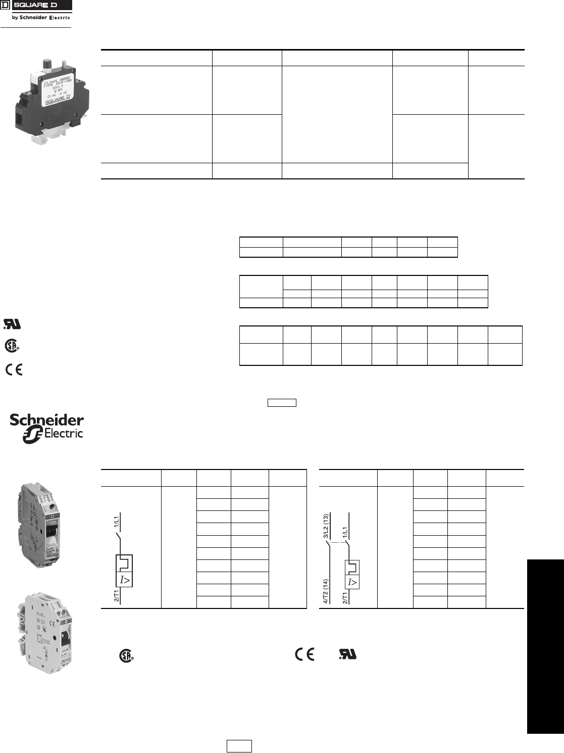
Table 24.29: 9080GCB Thermal-Magnetic Circuit Protectorsb
Maximum Current (A) Internal Resistance
¾Maximum Voltage Catalog Numbera$ Price
0.1 133
250 Vac
65 Vdc
GCB01
66.00
0.5 6.6 GCB05
0.8 2.55 GCB08
1.0 1.97 GCB10
1.2 1.22 GCB12
1.5 0.86 GCB15
2.0 0.49 GCB20
72.00
2.5 0.31 GCB25
3.0 0.20 GCB30
4.0 0.10 GCB40
5.0 0.08 GCB50
7.0 0.03 GCB70
10.0 <0.02 125 Vac
65 Vdc
GCB100
15.0 <0.02 GCB150
Selection
To properly select a Class 9080 Type GCB circuit protector, follow these steps:
1. Determine the inrush correction factor from Table 24.30.
2. Determine the temperature correction factor from Table 24.31.
3. Determine the sealed current of the load that is being protected.
4. Multiply the sealed current by the two correction factors and choose
the closest circuit protector.
Note: Choosing a circuit protector with a value lower than the calculated value might
cause nuisance tripping, while choosing the larger might provide a protector
that will not properly protect the load.
Table 24.30: Table A—Inrush Ratio Correction Table
Note: For resistive loads, use inrush correction factor of 1.0.
Inrush Ratio 1:1 to 1:4 1:5 1:6 1:7 1:8
Factor 1.3 1.4 1.5 1.6 1.7
Table 24.31: Table B—Ambient Temperature Correction Table
Ambient
Temperature
70oF 100oF 120oF140
oF160
oF180
oF200oF
(21.1oC) (37.8oC) (48.9oC) (60oC) (71.1oC) (82.2oC) (93.3oC)
Factor 1.0 1.1 1.2 1.3 1.4 1.5 1.6
File
CCN E152841
QVNU2 Example: Solenoid with sealed current of 0.75 A, an
inrush ratio of 1:6, and in an ambient temperature of
85oF: 0.75 x 1.5 x 1.05 = 1.18 Choose the 1.2 A
protector
Tripping Time: Tripping time of the circuit protector
is determined from Table 24.32. Divide the circuit
protector value by the temperature correction factor
from Table 24.31 to determine actual rated current
referenced in Table 24.32.
Table 24.32: Table C—Tripping Times in Seconds at 70oF (21.1oC)
Percent rated
current 100% 200% 300% 400% 500% 600% 1000% 2000% and
greater
File
Class 025490
3211 07 Tripping
Time (s) no trip 10–40 38 1.5–9 0.8–6 0.003–4 0.003–2 Max. 0.02
Note: When several protectors are channel mounted adjacent to each other, the “no trip” current will be
80% of rated current at 70oF.
CP5 Discount Schedule
Table 24.33: GB2 Thermal-Magnetic Circuit Protectorsc
Description Maximum
Voltage Thermal
Rating Catalog
Number $ Price ea.dDescription Maximum
Voltage Thermal
Rating Catalog
Number $ Price ea.d
One pole Thermal
Magnetic Circuit
Protector
300 Vac
0.5 A GB2CB05
43.60
Two pole Thermal
Magnetic Circuit
Protector
300 Vac
0.5 A GB2CD05
52.00
1 A GB2CB06 1 A GB2CD06
2 A GB2CB07 2 A GB2CD07
3 A GB2CB08 3 A GB2CD08
4 A GB2CB09 4 A GB2CD09
5 A GB2CB10 5 A GB2CD10
6 A GB2CB12 6 A GB2CD12
8 A GB2CB14 8 A GB2CD14
10 A GB2CB16 10 A GB2CD16
12 A GB2CB20 12 A GB2CD20
cDiscount schedule I.
dMust order in multiples of 6
Note: For markers, use AB1( )R and AB1( )G markers from page 24-16
File
Class 081630
3215 30 IEC 157-1
VDE 0660 File
CCN E113720
QVNU2
GB2CB06
GB2CD
IDiscount
Schedule
Courtesy of Steven Engineering, Inc.-230 Ryan Way, South San Francisco, CA 94080-6370-Main Office: (650) 588-9200-Outside Local Area: (800) 258-9200-www.stevenengineering.com
www.schneider-electric.us
24 TERMINAL BLOCKS
24-18 © 2009 Schneider Electric
All Rights Reserved
These Power Distribution Blocks are listed to UL1953 and meet the feeder spacing requirements of UL508A.
They carry a short circuit current rating (SCCR) according to the requirements of the 2005 National Electric
Code (NEC and UL580A. For SCCRs, refer to the catalog, 9080CT9603R9/08.
Table 24.34: Wire Range and Current Ratings
Catalog Wire Range AWG/kcmil Current Amps $ Price
Line Load CU AL
LBFA368104 2/0–14 (4) 4 -14 175 135 98.00
LBFA368101 2/0–14 2/0 -14 175 135 83.00
LBFA368101S 2/0–14 1/4 - 20 stud 175 135 90.00
LBFA368106 2/0–14 (6) 4 -14 175 135 105.00
LBFA369106 400–6 (6) 2 -14 335 270 180.00
LBFA369136 600–2 (3) 1/0 -14 335 335 263.00
(6) 2 -14
LBFA369112 600–2 (12) 4 -14 335 335 270.00
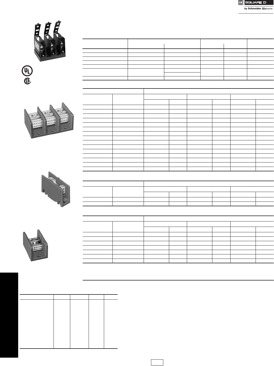
Table 24.35: Standard Power Distribution Blocks
Lug Wire RangeaAluminumb
Main Branch One Pole Two Pole Three Pole
Type d$ Price Type d$ Price Type d$ Price
(1) #14–2/0 (1) #14–2/0 LBA162101 10.40 LBA262101 22.10 LBA362101 25.70
(1) #6–350 kcmil (1) #6–350 kcmil LBA163101 53.00 LBA263101 81.00 LBA363101 107.00
(1) #4–600 kcmil (1) #4–600 kcmil LBA164101 95.00 N/A — LBA364101 183.00
(2) #4–350 kcmil (2) #4–350 kcmil LBA165202 98.00 LBA265202 147.00 LBA365202 189.00
(2) #6–500 kcmil (2) #4–500 kcmil LBA1652021 135.00 LBA2652021 206.00 LBA3652021 243.00
(1) #14–2/0 (4) #14–4 LBA162104 30.50 LBA262104 45.80 LBA362104 68.00
(1) #14–2/0 (6) #14–4 N/A — N/A — LBA362106 131.00
(1) #6–400 kcmil (4) #14–2 LBA163104 56.00 LBA263104 84.00 LBA363104 113.00
(1) #6–400 kcmil (6) #14–2 LBA163106 59.00 LBA263106 89.00 LBA363106 122.00
(1) #6–400 kcmil (8) #14–2 LBA164108 77.00 LBA264108 116.00 LBA364108 161.00
(1) #4–500 kcmil (6) #14–2/0 LBA165106 126.00 LBA265106 189.00 LBA365106 233.00
(1) #4–500 kcmil (12) #14–2 LBA165112 134.00 LBA265112 201.00 LBA365112 261.00
(2) #14–2/0 (6) #14–4 LBA163206 60.00 LBA263206 90.00 LBA363206 122.00
(2) #6–500 kcmil (8) #14–2/0 LBA165208 126.00 LBA265208 189.00 LBA365208 251.00
(2) #6–500 kcmil (12) #14–4 LBA165212 135.00 LBA265212 206.00 LBA365212 261.00
Table 24.36: Miniature Power Distribution Blocks
Lug Wire RangeaAluminumb
Main Branch One Pole Two Pole Three Pole
Type d$ Price Type d$ Price Type d$ Price
(1) #14–2 (1) #14–2 LBA161101 13.40 N/A — LBA361101 23.40
(1) #14–2 (4) #18–10 LBA161104 26.40 LBA261104 30.60 LBA361104 58.00
Table 24.37: Copper Power Distribution Blocks
Lug Wire RangeaCopperc
Main Branch One Pole Two Pole Three Pole
Type d$ Price Type d$ Price Type d$ Price
(1) #18–1/0 (1) #18–1/0 LBC162101 99.00 N/A — LBC362101 201.00
(1) #6–250 kcmil (1) #6–250 kcmil LBC163101 125.00 N/A — LBC363101 233.00
(1) #14–2/0 (4) #14–4 LBC162104 99.00 LBC262104 147.00 LBC362104 248.00
(1) #4–500 kcmil (6) #14–2 LBC163106 153.00 LBC263106 228.00 LBC363106 354.00
(2) #14–2/0 (6) #14–4 LBC163206 134.00 LBC263206 201.00 LBC363206 269.00
(2) #4–500 kcmil (8) #14–2/0 LBC165208 297.00 N/A — LBC365208 593.00
(2) #6–500 kcmil (12) #14–2 LBC165212 284.00 N/A — LBC365212 567.00
aLugs suitable for use with 75oC conductors. (#) indicates number of conductors.
bAluminum blocks will accept either Al or Cu conductors.
cCu blocks will accept copper conductors only.
dCE Marked.
eRefer to catalog for dimensions.
fUL component recognized (File
E60616 CCN XCFR2). CSA certified
(File LR70361, Class 070361).
Table 24.38: Clear Plastic Covers (0.045 in. thick) Application Data
Voltage Rating—Class B & C—600 V
Blocks are rated based on NEC Table 310-16 using 75oC wire.
Aluminum blocks are tin plated high conductive aluminum.
Copper blocks are tin plated high conductive copper.
Housing material:
•Miniature Blocks are made from high impact thermoplastic rated at 125oC. max. & -40oC. min.
•Full Size Blocks are made from general purpose phenolic rated at 150oC. max. & -40oC. min.
All blocks have a flammability rating of UL 94V-0.
Most blocks have a short circuit current rating for UL508A up to 200 kA for branch
circuit applications. For the actual ratings, see catalog 9080CT9603R9/08.
RoHS Compliant
Note: There are no covers for miniature blocks.
For LBA Type Type $ Price ea. gDim. A Dim. B
LBA162…, LBC162 LB21 11.30 1.062 2.750
LBA262…, LBC262 LB22 13.50 1.875 2.750
LBA362…, LBC362 hLB23 15.80 2.688 2.750
LBA163…, LBC163 LB31 12.50 1.782 3.813
LBA263…, LBC263 LB32 14.70 3.313 3.813
LBA363.… LBC363 LB33 17.00 4.844 3.813
LBA164… LB41 13.50 2.125 4.563
LBA264… LB42 15.80 4.000 4.563
LBA364… LB43 18.00 5.875 4.563
LBA165…, LBC165 LB51 14.70 2.719 5.313
LBA265…, LBC265 LB52 17.00 5.656 5.313
LBA365…, LBC365 LB53 19.20 8.375 5.313
gThese covers must be ordered in multiples of 5. Each cover comes with two self-tapping screws.
hWill not work on a 9080LBA362106 block.
Power Distribution Blocks Type LB
Class 9080 / Refer to Catalog 9080CT9603
CP1 Discount
Schedule
LBA365212
LBA161104
LBC165212
File 244651
Class 6228-01
File E323110 CCN QPQS
Courtesy of Steven Engineering, Inc.-230 Ryan Way, South San Francisco, CA 94080-6370-Main Office: (650) 588-9200-Outside Local Area: (800) 258-9200-www.stevenengineering.com
www.schneider-electric.us
24 TERMINAL BLOCKS
© 2009 Schneider Electric
All Rights Reserved 24-19
Fuseholders Type FB
Class 9080 / Refer to Catalog 9080CT9603
Application Information:
Base material:
aBase is high impact thermoplastic—
maximum operating temperature 125oC
bBase is general purpose phenolic—
maximum operating temperature 150oC
cBase is high impact polyester—
maximum operating temperature 130oC
Clip material:
•All 30 and 60 A fuse clips are copper alloy tin plated.
•All 100 and 200 A fuse clips are one piece aluminum with
copper spring tin plated.
•All Class H, R and J fuses are standard with reinforced fuse
clips.
Lug termination:
•All 30 A blocks have pressure wire connectors.
•All 60, 100 and 200 A blocks have box lug connectors.
Approvals:
•The Type M fuseholders are UL component recognized
(File E40747 CCN IZLT2).
•The Type H, R, J and CC are UL Listed (File E40747 CCN
IZLT).
•All fuseholders are CSA certified
(File 70360 Class 6225-01).
Flammability rating of all FB fuse blocks is UL 94V-0.
RoHS Compliant
dClass R and CC fuseholders accept current limiting Class R & CC
fuses only.
eNot in stock. Order point—Raleigh, NC.
fSpecified wire ranges are based on 75oC wire. Wires with
temperature ratings other than 75oC are approved while observing
NEC Article 310 wire tables for allowable ampacities of insulated
conductors.
Class R, J and CC fuse blocks are tested and approved for 200,000
AIC in accordance with UL 512.
gCan be mounted directly to a panel or on 35 mm DIN 3 track.
hOrders must specify the standard package quantity or multiples of that
quantity.
Sold in standard pack quanties.
Table 24.39: 250 V—Classes H and R
Rating
(A) f
No. of
Poles
Class H Class Rd Lug
Wire Range
Type $ Price Type $ Price
30a
1FB1211 12.90 FB1211R 19.20 #14–10
Cu
2FB2211 21.90 FB2211R 28.40
3FB3211 31.10 FB3211R 37.20
60a
1FB1221 21.90 FB1221R 28.40 #14–2
Cu or Al
2FB2221 39.20 FB2221R 45.80
3FB3221 55.00 FB3221R 61.00
100b
1
——
FB1231Re59.00 #6–2/0
Cu or Al
2FB2231Re98.00
3FB3231Re138.00
Table 24.40: 600 V—Classes H and R
Rating
(A) f
No. of
Poles
Class H Class Rd Lug
Wire Range
Type $ Price Type $ Price
30b
1FB1611 24.30 FB1611R 30.60 #14–10
Cu
2FB2611 42.60 FB2611R 48.50
3FB3611 54.00 FB3611R 60.00
60b
1FB1621 31.10 FB1621Re37.20 #14–2
Cu or Al
2FB2621 51.00
3FB3621 54.00 FB3621R 78.00
100b3FB3631 147.00 FB3631R 158.00 #6–2/0
Cu or Al
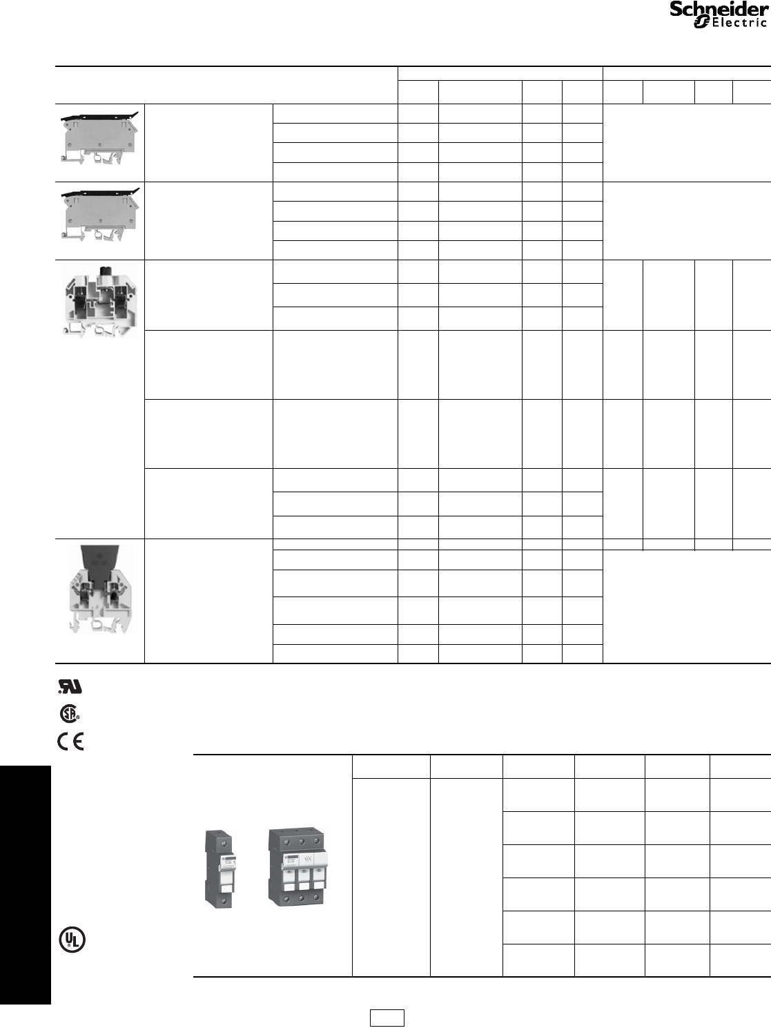
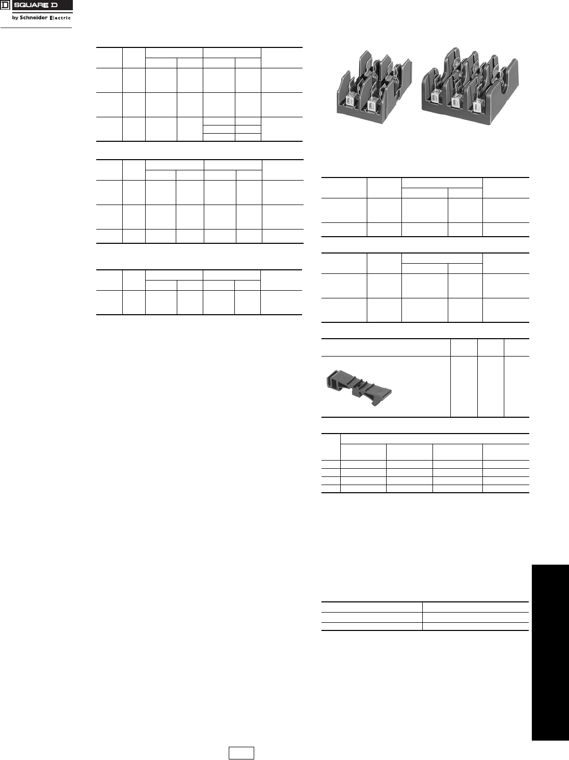
Table 24.41: 600 V Series—Miniature Fuse
Dimension (13/32 x 1-1/2 in.)
Rating
(A) f
No. of
Poles
Type M Class CCd Lug
Wire Range
Type $ Price Type $ Price
30a
1FB1611M 13.50 FB1611CC 13.50 #14–10
Cu
2FB2611M 19.80 FB2611CC 22.10
3FB3611M 24.30 FB3611CC 24.80
FB2221 FB3221R
Table 24.42: 600 V—Class H Only (Copper Only)
Rating
(A) f
No. of
Poles
Class H Lug
Wire Range
Type $ Price
30b
1FB1611 24.30 #14–10
Cu
2FB2611 42.60
3FB3611 54.00
100b3FB3631C 158.00 #6–2/0
Cu
Table 24.43: 600 V—Class J
Rating
(A) f
No. of
Poles
Class J Lug
Wire Range
Type $ Price
30bg
1FB1611J 26.00 #2–14 AWG
Cu—Al
2FB2611J 45.50
3FB3611J 63.00
60b
1FB1621Je32.00 #2–14
Cu—Al
2FB2621Je54.00
3FB3621Je75.00
Table 24.44: Track Adapter
Description Type $ Price
ea. Std.
Pack h
35 mm DIN 3 Track
Adapter
For 9080 FB*211,
FB*211R,
FB*611M, and
FB*611CC
Fuseholders
FBDIN3
e4.10 100
Table 24.45: Fuse Sizes—(Diameter x Length)
A
Class of Fuse
Class H/R—
300 V Class H/R—
600 V Class M/CC—
600 V Class J—600 V
30 9/16 x 2 in. 13/16 x 5 in. 13/32 x 1-1/2 in. 13/16 x 2-1/4 in.
60 13/16 x 3 in. 1-1/16 x 5-1/2 in. N/A 1-1/16 x 2-3/8 in.
100 1 x 7-7/8 in. 1 x 7-7/8 in. N/A N/A
200 1-1/2 x 7-1/8 in. 1-3/4 x 9-5/8 in. N/A N/A
Table 24.46: How to Order
To Order Specify Catalog Number
•Class Number Class Type
•Type Number 9080 FB1211
CP1 Discount
Schedule
Courtesy of Steven Engineering, Inc.-230 Ryan Way, South San Francisco, CA 94080-6370-Main Office: (650) 588-9200-Outside Local Area: (800) 258-9200-www.stevenengineering.com
www.schneider-electric.us
24 TERMINAL BLOCKS
24-20 © 2009 Schneider Electric
All Rights Reserved
Cable Ends DZ5 and AZ5
Refer to Catalog 9080CT9701
aBold faced catalog numbers are stocked in the United States.
bThese catalog numbers are UL Component Recognized (File E164872 CCN ZMMT2) provided the AT1PA crimping
tool is used to crimp the cable end.
cCE Marked.
dOrder must specify the standard pack quantities or multiples of that quantity.
eWill accept an AR1SC03 cable marker from page 24-22.
RoHS
Compliant
Conform to NF C 63-023 Standard
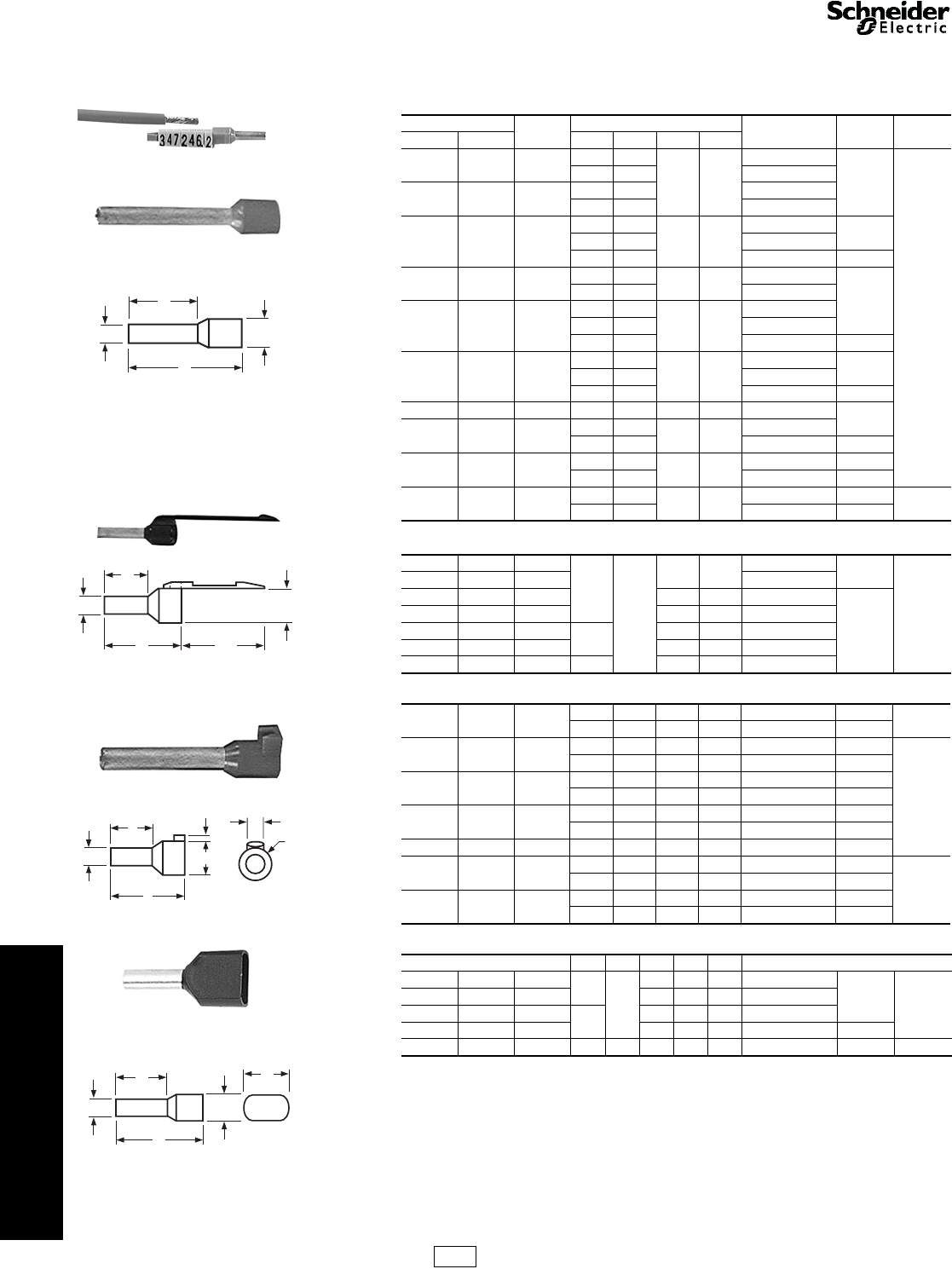
Mark and terminate wires simultaneously Strip the wire, insert it into the cable end and crimp it.
Up to 7 markers can be used.
Table 24.47: Without Marking Flag
Wire Size Sleeve
color
Dimensions (mm) Catalog Number
ac $ Price ea. Std. Pack
d
AWG mm2ABCD
26 0.25 Yellow 11 6.2
1.2 2.2
DZ5CE002L6
0.16
1000
13 8.2 DZ5CE002
24 0.34 Green 11 6.2 DZ5CE003L6
13 8.2 DZ5CE003
22 0.50 White
11 6.2
1.4 3
DZ5CE005L6b0.18
13 8.2 DZ5CE005b
16.8 12 DZ5CE005L12 0.26
20 0.75 Blue 11 6.2 1.6 3.1 DZ5CE007L6b
0.18
13 8.2 DZ5CE007b
18 1.00 Red
11.5 6.2
1.8 3.4
DZ5CE010L6b
13.5 8.2 DZ5CE010b
16.8 12 DZ5CE010L12 0.28
16 1.50 Black
11.5 6.2
2.1 4
DZ5CE015L6b0.22
13.5 8.2 DZ5CE015b
22.8 17.7 DZ5CE0153b0.42
14 2.00 Yellow 14.5 8.2 2.35 4.2 DZ5CE020 0.24
14 2.50 Gray 14.5 8.2 2.7 4.6 DZ5CE025b
24 17.7 DZ5CE0253b0.44
12 4.00 Orange 17.3 9.8 3.3 5.5 DZ5CE042b0.42
25.5 17.5 DZ5CE043b0.62
10 6.00 Green 20 11.5 3.95 7 DZ5CE062 0.48 100
26 17.5 DZ5CE063 0.66
Table 24.48: With Marking Flag
26 0.25 Yellow
13
8.2
1.2 2.2 DZ5CA002 0.26
1000
24 0.34 Green DZ5CA003
22 0.50 White 1.4 3 DZ5CA005b
0.32
20 0.75 Blue 1.6 3.1 DZ5CA007b
18 1.00 Red 13.5 1.8 3.4 DZ5CA010b
16 1.50 Black 2.1 4 DZ5CA015b
14 2.50 Gray 14.5 2.7 4.6 DZ5CA025b
Table 24.49: Marking Flag Optional e
12 4.00 Orange 19.5 11.5 3.3 5.5 DZ5CA042b0.38 1000
25.5 17.5 3.3 5.5 DZ5CA043b0.46
10 6.00 Green 20 11.5 3.95 7 DZ5CA062 0.62
100
26 17.5 3.95 7 DZ5CA063 0.64
8 10.00 Brown 21.5 12 4.95 8.4 DZ5CA102 0.72
27 17.5 4.95 8.4 DZ5CA103 0.78
616.00White
23.5 12 6.35 9.8 DZ5CA162 0.86
29 17.5 6.35 9.8 DZ5CA163 0.96
4 25.00 Black 30 17.5 8.15 12 DZ5CA253 1.10
235.00Red
30 16 9 13.5 DZ5CA352 1.30
20
39 25 9 13.5 DZ5CA353 1.50
0 50.00 Blue 36 20 11 15.7 DZ5CA502 1.50
41 25 11 15.7 DZ5CA503 1.70
Table 24.50: Dual Wire Cable Ends
ABCDE
22 0.50 White 13
8
1.4 2.5 4.7 AZ5DE005
0.24 500
20 0.75 Blue 1.6 2.8 5.0 AZ5DE007
18 1.00 Red 13.5 1.8 3.4 5.4 AZ5DE010
16 1.50 Black 2.1 3.6 6.6 AZ5DE015 0.26
14 2.50 Gray 24 10 2.7 4.2 7.8 AZ5DE025 0.32 250
B
A
CD
DZ5CE005
22
B
A
CD
DZ5CA007
C
A
D
D
4.5
B
2
DZ5CA042
BE
A
CD
AZ5DE010
IDiscount
Schedule
Courtesy of Steven Engineering, Inc.-230 Ryan Way, South San Francisco, CA 94080-6370-Main Office: (650) 588-9200-Outside Local Area: (800) 258-9200-www.stevenengineering.com
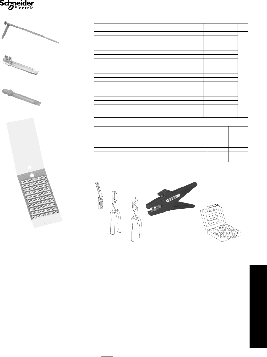
www.schneider-electric.us
24 TERMINAL BLOCKS
© 2009 Schneider Electric
All Rights Reserved 24-21
Cable Ends AR1 and AT1
Refer to Catalog 9080CT9701
Table 24.51: Cable End Markers & Accessories
Style Catalog
Number $ Price
ea. Std.
Packa
Adjustable collar type marker holder for #14 to #2 wire AR1SC01 0.42
100Clip-on marker holder for #18 to #16 wire (7 markers max.) AR1SC02 0.42
Cable end marker tags for DZ5CA042 to DZ5CA253 AR1SC03 0.12
Card of 200 yellow markers with black numeral 0 thru 9 AR1MA01b136.00
1
Card of 200 yellow markers with black letters A thru Z AR1MB01b300.00
Card of 200 black markers with a white 0 marked on them AR1MC010 13.60
Card of 200 brown markers with a white 1 marked on them AR1MC011 13.60
Card of 200 red markers with a black 2 marked on them AR1MC012 13.60
Card of 200 orange markers with a black 3 marked on them AR1MC013 13.60
Card of 200 yellow markers with a black 4 marked on them AR1MC014 13.60
Card of 200 green markers with a black 5 marked on them AR1MC015 13.60
Card of 200 blue markers with a black 6 marked on them AR1MC016 13.60
Card of 200 violet markers with a black 7 marked on them AR1MC017 13.60
Card of 200 gray markers with a black 8 marked on them AR1MC018 13.60
Card of 200 white markers with a black 9 marked on them AR1MC019 13.60
Card of 200 blank yellow markers AR1MA0196 12.20
Card of 200 blank green markers AR1MA0197 12.20
Card of 200 yellow markers with a black + marked on them AR1MA0198 12.20
Card of 200 yellow markers with a black—marked on them AR1MA0199 12.20
Complete set of numeral markers 0 thru 9, plus one card each of the “+” “-”, yellow blanks,
and green blanks/one AT1PA1 positioning tool. Each kit has 200 of each item. AR1MA01 136.00
Complete set of letter markers A thru Z, plus one card each of the “+” “-”, yellow blanks,
and green blanks/one AT1PA1 positioning tool. Each kit has 200 of each item. AR1MB01 300.00
Table 24.52: Cable End Tools
Description Catalog
Number $ Price
Cable end marker positioning tool AT1PA 1 30.20
Automatic stripping and cutting tool
for 0.8 mm to 4 mm cable,
adjustable stripping length AT1PA 7 506.00
Crimping tool for cable ends 0.5 mm2 to 16 mm2AT1PA2 246.00
Crimping tool for cable ends 10 mm2 to 35 mm2AT1PA 4 268.00
Organizing case for cable ends—holds
stripping tool and cable ends (not supplied) AT1HB2 116.00
aOrder must specify the standard pack quantities or multiples of that quantity.
bComplete the catalog number by adding the number or letter desired.
Examples: AR1 MA015 is a card of 200 yellow markers with a black 5 marked on them.
R1 MB01T is a card of 200 yellow markers with a black T marked on them.
AR1SC01
AR1SC02
AR1SC03
AR1MA019
AT1PA1
AT1PA4
AT1PA2
AT1HB2
AT1PA7
IDiscount
Schedule
Courtesy of Steven Engineering, Inc.-230 Ryan Way, South San Francisco, CA 94080-6370-Main Office: (650) 588-9200-Outside Local Area: (800) 258-9200-www.stevenengineering.com
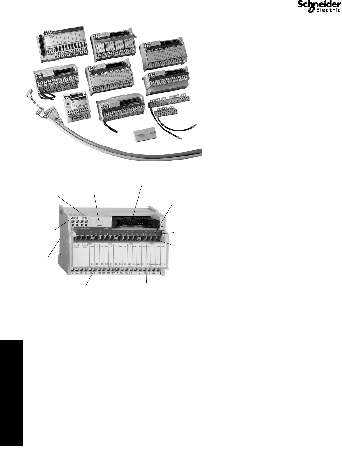
www.schneider-electric.us
24 TERMINAL BLOCKS
24-22 © 2009 Schneider Electric
All Rights Reserved
Advantys TELEFAST® 2 Prewired Connection System
Refer to Catalog 8501CT9801
The TELEFAST 2 system is a set of products for the rapid
connection of I/O modules (24 Vdc discrete, analog and
counters) to Various control circuit components. These
components act as a substitute for screw terminal blocks,
remotely locating and partly eliminating the single wire
connections. The system connects only to channels with
HE10 and SUB-D connectors, or to standard terminal blocks
with a cabled connector.
Variations within the listing of modules include those with
and without relays (electromechanical and solid state),
analog and counter modules, and special function modules.
Pre-wired cables available allow you to connect directly to:
•Schneider Electric (Modicon® family)
— TSX Premium™
— TSX Micro
— TSX Series 7
—Twido
— Quantum™
— Compact
— April S5000/7000
— NUM1020/1060
•Siemens
— S7 – 200/300/400
— S5 – 95U to 155U
•Allen-Bradley
— SLC500
In addition, other accessories include:
•I/O simulators
•Continuity blocks
•Label marking software
•Splitter bases (16, 23, and 32 channels)
•Mounting kits
•Detachable terminal strips
•Wiring pass-through connectors
•Fuses
Advantys TELEFAST 2 Product Features
NOTE: Not all features available on all modules.
LEDs Indicating
I/O State and
Blown Fuse
Custom Labeling of Channels (cover face)
and Wiring Diagram (under cover)
Blade Isolation
Switches per
Channel
Test Point for 2.3 mm PlugFuse Protection for
the Cable and
Power Supply
Power Supply
LED
Detachable
Terminal Blocks
(Screw Terminations)
35 mm
DIN-rail
Mounting
Fusing per
Channel
Blade Isolation Switch
on the 0 V terminal of
the Power Supply
Courtesy of Steven Engineering, Inc.-230 Ryan Way, South San Francisco, CA 94080-6370-Main Office: (650) 588-9200-Outside Local Area: (800) 258-9200-www.stevenengineering.com
