2006 TOC_copy 101848 Catalog
107990-Catalog 107990-Catalog 107990-Catalog 781810 Batch7 unilog cesco-content
2014-07-30
: Pdf 101848-Catalog 101848-Catalog 781810 Batch6 unilog
Open the PDF directly: View PDF ![]() .
.
Page Count: 723 [warning: Documents this large are best viewed by clicking the View PDF Link!]
- Table of Contents
- Section A—Mechanical Connectors
- Lightning Protection Info
- SERVIT®
- OKLIP™
- VERSITAP™
- SCRULUG™
- KA-LUG™ Type KA
- VERSILUG™ Type EA
- Lay-In QIKLUG™
- QIKLUG™
- QIKLINK™ Type QR
- VARITAP™ T-Connector
- Transformer Tap Adapter Type E-C-G
- VARILUG™ Types VA, VVA
- Bar Clamp Assembly Components Type HFB-P1
- Bar Clamp Tap Pad Adapter Type HFB-N
- Universal Terminals
- Transformer Lug Kit Type KAU-KIT
- Splices
- Taps
- SPEC-BLOK™
- Bus Assemblies
- VERSI-POLE™
- UNITAP™
- Section B—Small Compression Connectors
- Performance Tables
- Equivalent Tables (Military Specs)
- HYLUG™ Types T, YAD
- VINYLUG™
- INSULUG™
- Nylon Insulated Ring-Tongue Types TN, YAES
- Nylon Insulated Ring-Tongue Multi-finger Insulation Grip Type YAE-G BOX
- Types YAE-N BOX, YAE
- Nuclear Terminals and Splices Type YAES-K
- Types YAEV, YAEV-L
- Type YAEV-H
- Right-Angle Terminals, Nylon Insulated Type YAEV-RS
- Right-Angle Terminals, Nylon Insulated, Type YAEV-RH
- Nylon Insulated, Fork Tongue, Types TN-F, YAES-F
- Nylon Insulated, Fork Tongue, Types YAE-N-F BOX, YAE-N-F
- Nylon Insulated Flanged Fork, Types YAE-Z BOX, YAE-Z
- HYLUG™
- Seamless Uninsulated Types YAV BOX, YAV
- Seamless Uninsulated Types YAV-L BOX, YAV-L
- Seamless Uninsulated Types YAV-H BOX, YAV-H
- Flag-Type Ring-Tongue Terminals Type YBM
- Heavy Duty Right-Angle Terminals Types YAV-R, YAV-RS
- Uninsulated, Fork Tongue Types T-F, YAD-F
- Uninsulated, Fork Tongue Types YAV-T-F BOX, YAV-T-F
- Uninsulated, Fork Tongue with Shroud, Types YAV-H-F BOX, YAV-H-F, YAV-Z
- FINGRIP™
- Non-Insulated Female Quick Disconnects Type Q-F
- Vinyl Insulated Female Quick Disconnects Type QP-F
- Vinyl Insulated Male Quick Disconnects Type QP-M
- Nylon Insulated Male Quick Disconnects Type QN-M
- Male/Female Combination Quick Disconnects Types PGP, PGN
- Nylon Fully Insulated Female and Male Quick Disconnects Types FQN-F, FQN-M
- Non-Insulated Flag-Style Female Quick Disconnect Type FL
- Uninsulated Splices
- Insulated Splices
- Section C—Medium and Large Compression Connectors
- Introduction
- Die Sets
- HYLUG™ Conductors
- HYSTACK™ Terminals
- HYLINK™ Splices
- HYSPLICE™ In-Line Splice Kits, Type YS-TC
- HYREDUCER™ Splices
- Copper Taps
- "T" Connectors
- HYPLUG™ Connectors
- Aluminum HYLUG™ Terminals
- Transformer Lug Kits, Type YA-A-KIT
- H-CRIMPIT™
- Section D—Grounding
- Introduction
- HYGROUND™ Grounding Connectors
- HYGRID Cross Connector, Type YGL-C
- GRIDLOK, Type YGLR-C
- HYTAP™ Connectors
- Copper CRIMPIT™, Type YGC
- Double H-Tap Connector, Type YSHG
- HYTAIL™, Type YGHR-C
- HYTAIL™, Type YGHR-C
- HYLUG™ Heavy Duty Compression Terminals, Type YGHA
- HYLINK™ Heavy Duty Compression Terminals, Type YGHS
- HYLUG™, Type YGA
- HYLINK™, Compression Splices, Type YGS
- Grounding Plate, Type YGF
- GROUNDLINK™ Connector, Type YGIB
- VERSITAIL™ Structural Steel Grounding Connector, Type GSTUD-HY
- Static Grounding Receptacles, Types YGT, YTTAG
- Bus Bar Connector, Type YG-B
- Mechanical Grounding Connectors
- SERVIT™ Post, Types KC, K2C
- Transformer Ground Connectors, Types KC22J12T13, EQC632C
- SERVIT™ for Copper, Type KS-DB
- For Copper, Types GKA, KPB
- Copper Lay-In QIKLUG™, Type CL50-1
- Fence Post Grounding Connector, Type GAR
- Ground Connectors, Types GAR-BU, GAR3902, GAR-RB
- Water Pipe Ground Connector, Type GAR-TC
- Cable to Rod/Tube, Type GD
- Copper Cables to Rod or Pipe, Types GP, GK
- For Copper and Aluminum Cable, Type GC-A
- For Copper Bar, Strap, Braid or Cable to Rod or Tube, Type GG
- For Copper Cable to Tube, Type GQ
- For Copper Cables, Type GX
- High Strength Ground Rod Clamp, For Copper Cable to Rod, Type GRC
- Flexible Copper Braid, Type B
- For Copper Cable to Bar, Types GB, GBM, GC, GCM
- For Copper Cable to Bar, Types GL, GZ
- Cable Tray Ground Clamp, Type GC-CT
- For Vehicle Grounding, Heavy Duty Construction, Type GIE-G
- Rail Connector
- BARTAP™, for Copper Cable to Flat Bar or Pad, Type QGFL
- For Copper Cable to "H" Beam, Type GA-H
- Raised Floor Grounding
- Water Pipe Grounding Clamps
- BURNDYWeld™
- Introduction
- Weld Metal
- BURNDYWeld™ Molds
- Horizontal End to End, Type BCC-1
- Horizontal Cable Tap to Horizontal Cable Run, Type BCC-2
- Horizontal to Horizontal Cable Cross, Type BCC-4
- Horizontal to Horizontal Cable Cross, Type BCC-11
- Horizontal Parallel Tap, Type BCC-6
- Horizontal Parallel through Cables, Type BCC-14
- Horizontal Parallel through Cables, Type BCC-7
- Horizontal Cable Terminal to Ground Rod, Type BCR-1
- Horizontal Cable to Ground Rod, Type BCR-2
- Horizontal through Cable to Ground Rod, Type BCR-3
- Horizontal Run and Tap Cables to Ground Rod, Type BCR-17
- Horizontal Parallel Run Cables to Ground Rod, Type BCR-24
- Single Shot Molds
- Horizontal Cable to Horizontal Steel Surface, Types BCS-1, BCS-8
- Horizontal through Cable to Horizontal Steel Surface, Types BCS-2, BCS-9
- Angular Cable Drop to Vertical Steel Surface, Type BCS-3
- Vertical Cable Drop to Vertical Steel Surface, Type BCS-23
- Vertical through Cable to Verticle Steel Surface, Type BCS-4
- Horizontal through Cable to Vertical Steel Surface, Type BCS-6
- Overhead Vertical Tap Cable to Vertical Steel Surface, Type BCS-7
- Horizontal Tap Cable to Vertical Steel Surface, Type BCS-18
- Horizontal Cable Tap to Horizontal Cast Iron Surface, Type BCS-5
- Horizontal Parallel Tap to Rebar, Type BCRE-1
- Horizontal Cable Tap to Horizontal Rebar Run, Type BCRE-2
- Horizontal through Cable to Vertical Rebar, Type BCRE-3
- Horizontal through Cable to Horizontal Rebar, Type BCRE-4
- Horzontal Cable Tap to Vertical Rebar, Type BCRE-§
- BURNDYWeld™ FILL
- BURNDYWeld™ SET
- Prefabricated Wire Mesh
- B-106, B-107 Handle Clamps
- B40-0106-75 Handle Attachment
- Mold Support Clamp
- Vertical & Horizontal Clamps
- Accessories
- Trouble Shooting Tips
- Section E—Overhead
- Table of Contents
- Mechanical (Bolted) Tap Connectors
- SERVIT® Types KS, KS-3
- SERVIT® Cover, Type SC
- Universal SERVIT®, Type KSU
- OKLIP™, Type KVS
- OKLIP™, Type KVSW
- Universal OKLIP™, Types KVSU, KVS
- Aluminum OKLIP™, Type KVS-A
- Universal Parallel Clamps, Types UC-L, UC-K
- Parallel Clamp, Type CP-A
- Parallel Clamp, Type VP
- CLIPIT™, Type UW-R
- Parallel Clamps, Types UC, CP
- VERSITAP™ Parallel Clamp, Type QPX
- T-Connector,Type VT
- TAPIT™ Parallel Clamps, Types UCG-R, UCG-RS, UC-R, UC-RS
- Catcher, Type LSC
- Compression Tap Connectors
- Compression Splices
- Deadend Fitting and Accessories
- Compression Terminals and Accessories
- Section F—WEJTAP™
- Table of Contents
- Introduction
- WEJTAP™ Connection System
- WEJTAP™ and Test Data
- Aluminum Connectors
- WEJTAP™ POWERLUG™
- Ordering Information
- Copper Connectors
- Connector Selection Charts
- Stirrup Selection
- Large Conductor Connectors
- WEJTAP™ Cover
- Installation Tools
- Installation Tool Accessories
- Hotstick Tool and Accessories
- Hotstick Accessories
- Hotstick Accessories
- WEJTAP™ Kits
- Section G—Substation
- Table of Contents
- Copper Substation Connectors
- Introduction
- T-Connectors
- Couplers
- Type B, Flexible Copper Braid Jumper
- Type B, Expansion Coupler Assembly Components
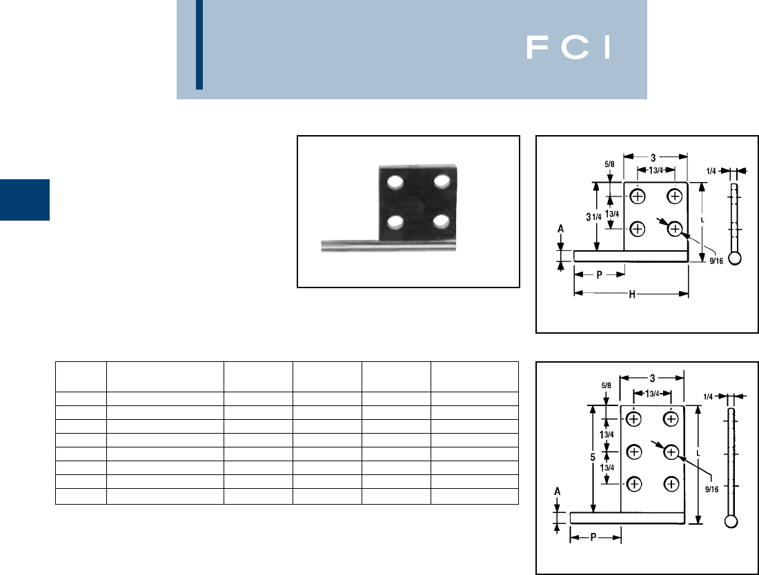
- Type HFBW Bar Clamp
- Type HFB-P1 Bar Clamp Assembly Components
- Type HFB-N Bar Clamp Tap Pad Adapter
- Terminals
- Bus Supports
- Stud Connectors
- BARTAP™, Type QGFL, for Copper Cable to Flat
- Transformer Tap Adapters
- Type FN, Contact Nut, Flat to Stud
- Aluminum Substation Connectors
- Section H—Aluminum Weldments
- Section I—Network Underground
- Section J—URD Underground
- Stud MOLE™, Types RDMD-28G, RDMD-2858D
- Rubber Insulating Boot, Type RDMD-28CR
- URD MOLE™, Type RDM-28
- URD MOLE™, Type RDM-28T
- MOLE™ Tap Kits, Types RYA-UC, RYA-AC, RYA-UCR, RYA-ACR
- URD Street Light Tap Kits, Types RA6UC-SL, RA6UCR-SL
- URD Insulated Splice Kit, Type YS-CG
- Y-LOK for Locking Enclosures
- HYREDUCER™ Splice, Type YRB-U
- HYREDUCER™ Splice, Type YRB-T
- URD Service Tap, Type K-P-C
- Compression Service Taps and Transformer Terminals
- Types BPD, BPD2, Power Distribution Blocks
- Section K—Cable Ties
- Cable Tie Features and Specs
- Military Spec Cable Ties
- Standard Cable Ties
- Releasable Cable Ties
- Identification Cable Ties
- Mounting Hole Cable Ties
- HALAR® Cable Ties
- TEFZEL® Cable Ties
- Stainless Steel Ties
- Hook and Loop Straps, Type TFV-V
- Mounting Bases (4-Way and 2-Way)
- Cable Hangers
- Cable Tie Tools
- Stainless Steel Strap and Accessories
- Stainless Steel Strap Installation Tools
- Section L—Hardware
- Section M—Accessories
- Section N—Tooling
- Section O—References
- Introduction—Basic Electrical Connection Principles
- Hardware Data
- Cable Data
- Charts
- AWG vs. Metric Wire Sizes
- Inches & Millimeters Conversion Chart
- Terminal Stud Size Chart
- Die Set Conversion Chart (For Obsolete Dies and Tools)
- BURNDY Conductor Numbering System
- Present Installation Tool Index
- Catalog Numbers Requiring MSDS
- Color Coding for Overhead Connectors
- Color Coding for AL/CU Connectors
- Color Coding for Copper Lugs and Splices
- Alpha-Numeric Index
- Product/Trade Name Index
MASTER INDEX
A
B
C
D
E
F
G
H
I
J
K
L
M
N
O
MECHANICAL
Connectors secured by nuts, bolts or allen head devices
SMALL COMPRESSION
Connectors secured by indent or circumferential crimps
MEDIUM AND LARGE COMPRESSION
Connectors secured by indent or circumferential crimps
GROUNDING
Irreversable Compression Grounding System and Mechanical Grounding
OVERHEAD
Power distribution connectors both Mechanical and Compression used on pole applications
WEJTAP™
Power actuated connection systems
SUBSTATION
Power distribution connectors for tube cable and bus applications
ALUMINUM WELDMENTS
Extra High Voltage devices
NETWORK UNDERGROUND
Power distribution connectors for underground applications
URD UNDERGROUND
Power distribution connectors for underground applications
CABLE TIES
UNIRAP™ cable ties
REFERENCES
Dies, Connectors Charts and General Information
TOOLING
Hand-Held, Mechanical Hydraulic and Pneumatic
ACCESSORIES
Oxide Inhibitors Markers and Terminal Blocks
HARDWARE
Nuts, Bolts and Washers of various metals
....... ............ .......
............. ...................
................
.... ......... ....
..................
.......... ............. ...
... ... ...
............................................... ..............
... ...........................
........ ......................
.................................................
............ .................. ...........
...........................
........ ............ ...
................................................
........
.........................
MASTER INDEX
A
B
C
D
E
F
G
H
I
J
K
L
M
N
O
............................................... ...........................
........................................................
.....................................................................................
.......
................... ............. ....................
.... .......... .... ................. .......
.....................................................................................
.....................................................................................
.....................................................................................
....... ...................................................................
.....................................................................................
.....................................................................................
...............................................
.............................................
................................
...............................
.....................................................................................
......... ...................... .........................
BURNDY
Mechanical
Types KS, KS-3 & SC. . . A-4
Type KSU. . . . . . . . . . . . A-5
Type KSA. . . . . . . . . . . . A-6
Types KVS, KVSU . . . . . A-7
Types KVSW, KVS-A . . . A-8
Type QPX. . . . . . . . . . . . A-9
Type QPX-Y . . . . . . . . . A-10
Type KPA . . . . . . . . . . . A-11
Type KPA-UP . . . . . . . . A-12
Type KLU . . . . . . . . . . . A-13
Types KA, EA. . . . . . . . A-14
Types BGBL, CL50-1 . . A-15
Types QA, QQA . . . . . . A-16
Types Q2A, Q3A. . . . . . A-17
Types QB, Q2B . . . . . . A-18
Types QDA & QR . . . . . A-19
Types VT, E-C-G. . . . . . A-20
Types VA, VVA . . . . . . . A-21
Type HFB-P1 . . . . . . . . A-22
Type HFB-N . . . . . . . . . A-23
Types KA-U, KKA-U . . . A-24
Type K2A-U . . . . . . . . . A-25
Types K3A-U, KK3A-U
. . . . . . . . . . . . . . A-26, A-27
Types K4A-U, KK4A,
K11A-U, K21A, K22A . A-28
Type KAU-KIT . . . . . . . A-29
Type AMS. . . . . . . . . . . A-30
Type AGSKIT . . . . . . . . A-31
Type UGSKIT . . . . . . . . A-31
Type UGSKIT8 . . . . . . . A-32
Type UGS350ULDB . . . A-32
Type QGFL. . . . . . . . . . A-33
Type FCB . . . . . . . . . . . A-34
Types KPU-AC,
UCU-AC . . . . . . . . . . . A-35
Type BIPC . . . . . . . . . . A-36
SPEC-BLOK. . . . A-37, A-38
SPEC-BLOK
PLATFORMS . . . . . . . A-39
Types 1300A, 1350A,
1500A . . . A-41, A-42, A-43
Types BDA, BDB,
BDC. . . . . . . . . A-44, A-45,
A-46, A-47, A-48
Types BIT, BISR . . . . . . A-49
Type BIBS . . . . . . . . . . A-50
Type BIBD . . . . . . . . . . A-51
Types BIBS-MT,
BIBD-MT . . . . . . . . . . A-52
Type BISR-DB . . . . . . . A-53
Type 1PL . . . . . . . . . . . A-54
Complies with NFPA 78-86 Ordinary Structures.
Complies with NFPA 78-86 Heavy Duty Stacks
(order: LD for Lead Plating for Heavy Duty Stacks
applications).
A-1
TABLE OF CONTENTS

BURNDY
Mechanical
LIGHTNING PROTECTION INFO.
Basic rules for selection are:
1Must be like material to the conductor
(Flexitap out due to steel bolts!).
2. Two bolts to ground rod — minimum.
3Cable to cable connections can be
anything — one bolt, two bolt, compres-
sion, etc.
4Cable to steel structure must have 8
square inch contact with steel.
5. Heavy duty stacks — mechanical only.
6. On all connectors with heavy duty stack
rating, we must offer 1/16" thick lead plat-
ing as an option. Reason is closest 25 ft.
to stack opening must use lead coated
product.
Complies with NFPA 78-86 Ordinary
Structures.
Complies with NFPA 78-86 Heavy
Duty Stacks
(order: LD for Lead Plating for Heavy
Duty Stack applications)
A-2
ALL OTHERS
REFER TO FACTORY
1-800-346-4175
Other features are also available for products
listed in price book such as undrilled or
special drilling, 45° or 90° pad angles, belling
for extra flexible cable, smooth or special
SPECIAL FEATURES
threaded studs, special labeling or packag-
ing, extra long braid, and nuclear certifica-
tion. REFER TO FACTORY.
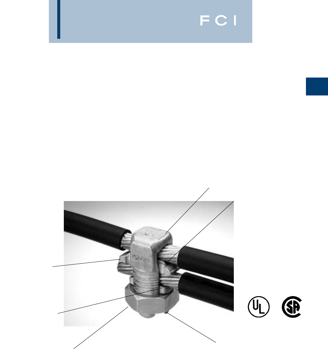
BURNDY
Mechanical
REVOLUTIONARY
BURNDY DESIGN
MEETS STRICT UL
486B STANDARDS
...and puts the bite on
aluminum connections
forever!
For use on all combinations
• Aluminum to aluminum
• Aluminum to copper
• Copper to copper
Patented
A-3
Special heat-treated hard,
aluminum alloy.
Tin-plated contact
surface inhibits oxide
formation.
Available in sizes from #10 through 500 kcmil.
†When used in NEC applications of insulated cables only.
Spacer provides built-in
separation to retard
galvanic corrosion.
Anti-galling, high efficiency
threaded components result in high
contact force. Easily installed using
standard, everyday wrenches.
Triangular edges bite
into cable to break
through surface oxides
...provide low contact resistance.
...produces gas tight seal.
Unique ‘‘bite and grip’’ TRITAP™
SERVIT®contact delivers safe,
long-term reliability—even
without scratch brushing . . .
without oxide inhibiting
compounds.†
BURNDY
Mechanical
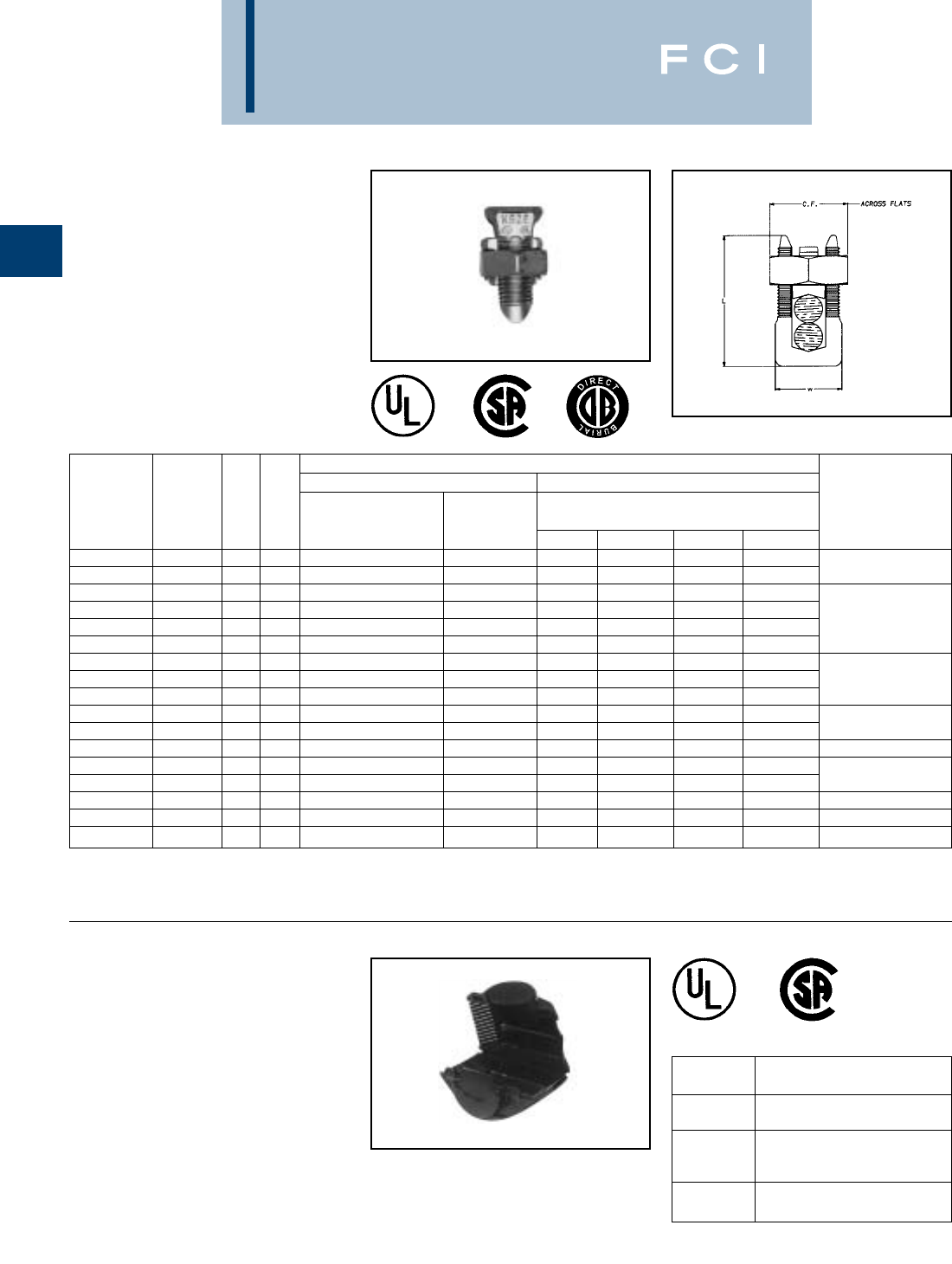
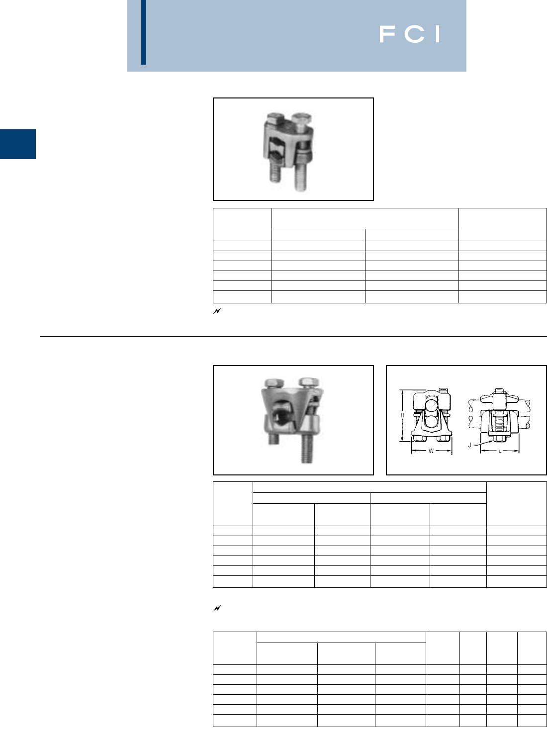
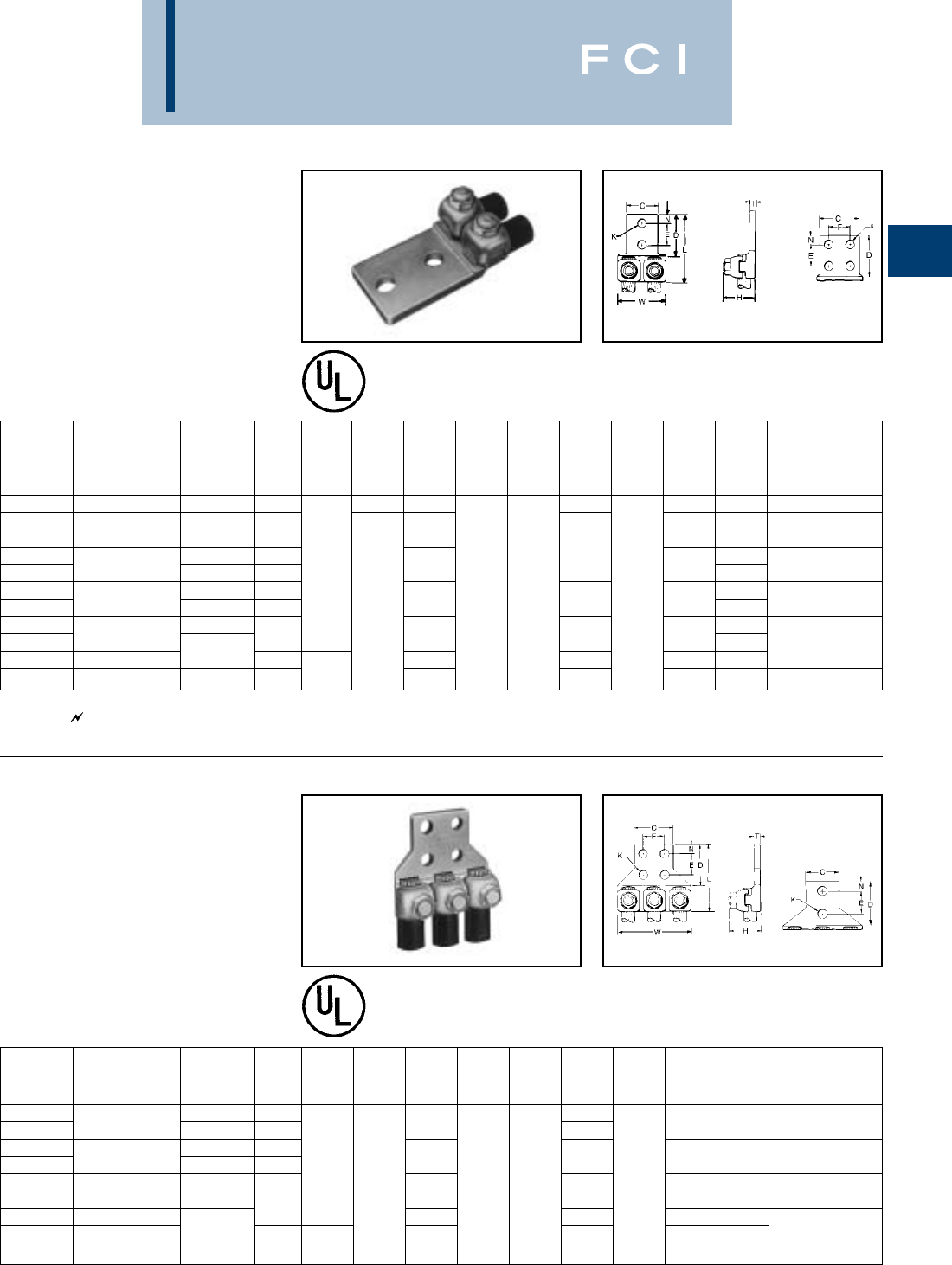
TYPES KS & KS-3
SERVIT®
For Copper, Copperweld
Compact, high strength, high copper alloy
SERVIT®split-bolt has free-running threads
and easy to grip wrench flats. Highly resistant
to season cracking and corrosion, the
SERVIT®provides maximum pressure and
assures a secure connection on all combina-
tions of run and tap conductors. Type KS-3
accommodates 3 maximum size conductors.
TYPE SC
SERVIT®COVER
HUG-A-BUG
Used indoors or outdoors, this compact, one-
piece plastic SERVIT®cover saves time and
material, eliminates costly taping of split-
bolts.Positive latch snaps easily and quickly
over connector, ideal for tight quarters. Self-
positioning plastic fingers wrap around wires
fully insulating joint. UL Listed for 600 volt
indoor application with type KS.Three Covers
accommodate a range of 6 SERVIT®sizes
through 2/0 Str.
A-4
▲Listed torque values are for maximum conductor combi-
nations accommodated. Consult UL486 Tables 7-4, 7-5,
7-6 for smaller conductor combinations.
SERVIT®and cover combination
can be ordered as follows:
CKS4 KS20 with cover
CKS2/0 KS26 with cover
For other combinations, please
contact factory.
See note page A-2
*Not UL or CSA Listed
** UL Rated for direct burial.
CONDUCTOR
COPPER COPPERWELD ▲
MIN. TAP RECOMMENDED
CATALOG CROSS RANGE FOR EQUAL WITH MAXIMUM RUN AND TAP TIGHTENING
NUMBER FLATS L W RUN AND TAP MAX. RUN SOL. STR. TYPE A TYPE D TORQUE in-lb
KS90 .50 .85 .38 12 STR. - 10 STR. 16 STR. #10 — — —
**KS15 .50 .85 .38 10 STR. - 8 STR. 14 STR. #8 — — — 80
**KS17 .63 1.14 .45 8 STR. - 6 SOL. 14 STR. #6 3 #12 8A 9-1/2D
* KS17-3 8 STR. - 6 SOL. 16 STR. #6 3 #12 8A 9-1/2D
**KS20 .69 1.20 .51 8 STR. - 4 SOL. 14 STR. #4 3 #10 6A 8D 165
* KS20-3 8 STR. - 4 SOL. 14 STR. #4 3 #10 6A 8D
**KS22 .75 1.50 .60 6 STR. - 2 SOL. 14 STR. #2 3 #8 4A 6D
* KS22-3 6 STR. - 2 SOL. 14 STR. #2 3 #8 4A 6D 275
**KS23 .82 1.54 .62 6 STR. - 2 STR. 14 STR. #1 3 #7 3A 5D
**KS25 .94 1.77 .73 4 STR. - 1/0 STR. 14 STR. 2/0 3 #5 2A 4D
**KS26 1.05 1.94 .82 2 STR. - 2/0 STR. 14 STR. 3/0 7 #7 — — 385
**KS27 1.36 1.86 1.17 1 STR. - 3/0 STR. 8 SOL. — — — — 500
**KS29 1.36 2.07 1.17 1 STR. - 250 8 STR. 4/0 7 #5 — —
**KS31 1.70 2.51 1.41 1/0 STR. - 350 1/0 STR. — 19 #8 — — 650
**KS34 1.82 2.79 1.48 2/0 STR. - 500 2/0 STR. — 19 #6 — — 825
KS39 2.31 3.29 1.94 4/0 STR. - 750 4/0 STR. — 19 #5 — — 1000
KS44 2.56 3.73 2.19 300 - 1000 4/0 STR. — — — — 1100
CATALOG
NUMBER FOR USE WITH
KS17, KS17-3, KS20
SC4 KSU17, KSU20
KS22, KS20-3, KS23,
SC2 KS22-3, KSA6, KSA4,
KSU22, KSU23
KS25, KS26, KSA2, KSA 1/0
SC2/0 KSU25, KSU26
BURNDY
Mechanical
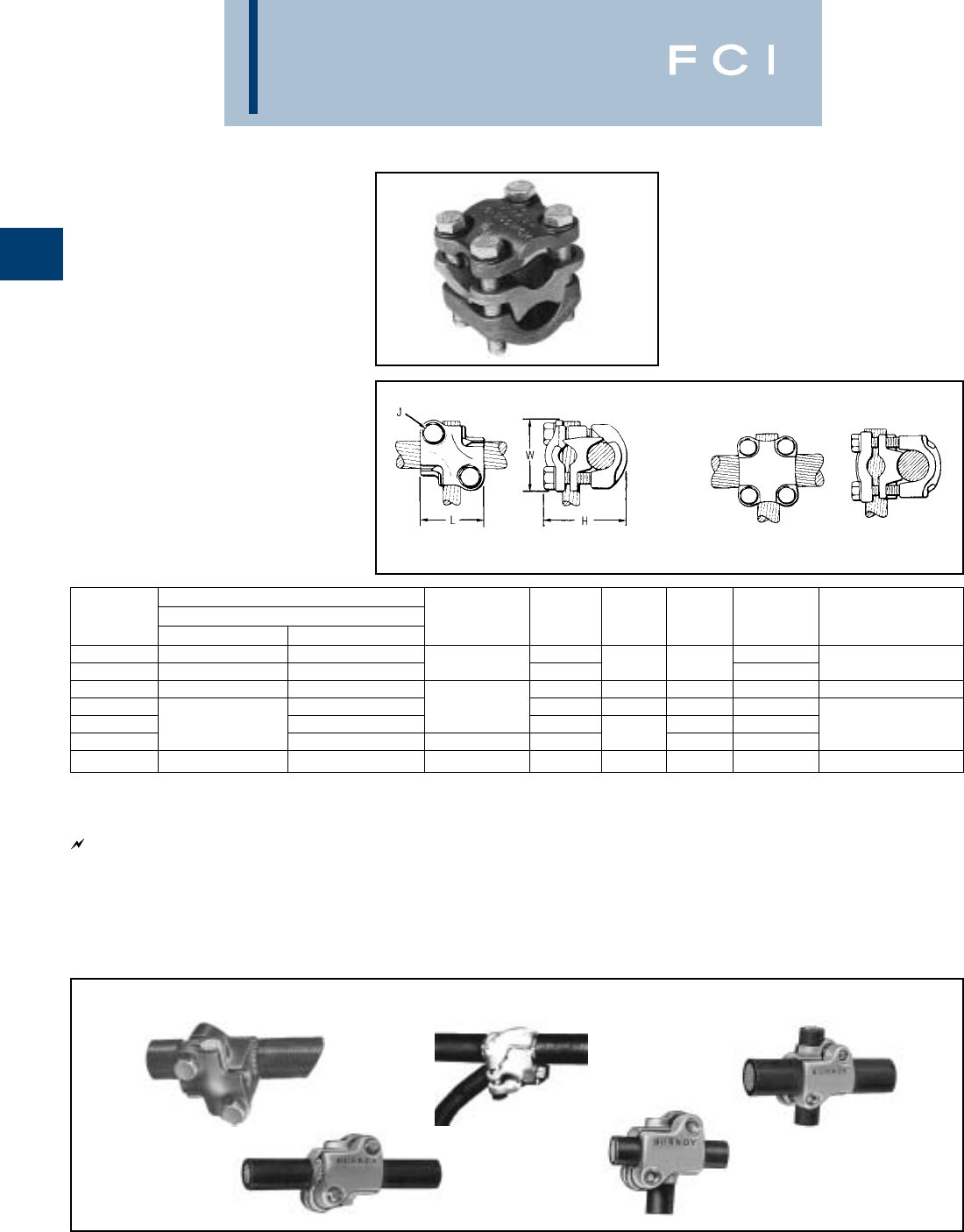
TYPE KSU
UNIVERSAL SERVIT®
For All Combinations of
Copper, Alum.,
ACSR, AAAC, 5005, and Steel
Tin-plated, high strength copper alloy
SERVIT®with spacer. Spacer separates dis-
similar conductors and provides long contact
length that prevents high pressure point
contacts between run and tap conductors.
Use of PENETROX™ joint compound recom-
mended with Aluminum and ACSR.
A-5
Accommodates compressed conductors within conductor
ranges.
See note page A-2
486A
Copper Only
CONDUCTOR
MAXIMUM
CONDUCTOR
RUNTAP STEEL RECOMMENDED
CATALOG CROSS COPPER & ACSR AAAC COPPER & ACSR † AAAC SOL. 3 STR. NOM TIGHTENING
NUMBER FIG. FLAT L W ALUMINUM 5005 ALUMINUM 5005 BWG BWG DIA. TORQUE in-lb.
KSU17 2.62 .92 .42 12 SOL. - 6 SOL. 8 (6-1) 12 SOL. - 6 SOL. 8 (6-1) 8 — 5/32
KSU20 2.69 1.05 .48 10 SOL. - 4 SOL. 6 (6-1) 10 SOL. - 4 SOL. 6 (6-1) 6 8 7/32 165
KSU22 2.74 1.25 .57 10 SOL. - 2 SOL. 6 (6-1) - 4 (7-1) 10 SOL. - 2 SOL. 6 (6-1) - 4 (7-1) 4 6 1/4 275
KSU23 2.81 1.48 .59 8 STR. - 2 STR. 3 (6-1) - 2 (6-1) 8 SOL. - 2 STR. 6 (6-1) - 2 (6-1) — 4 5/16 275
KSU25 2.93 1.77 .70 2 STR. - 1/0 STR. 3 (6-1) - 1 (6-1) 10 STR. - 1/0 STR. 6 (6-1) - 1 (6-1) — — 3/8 385
KSU26 21.04 1.93 .79 1/0 STR. - 2/0 STR. 1 (6-1) - 1/0 (6-1) 8 STR. - 2/0 STR. 6 (6-1) - 1/0 (6-1) — — 7/16 385
KSU27 11.38 2.34 1.12 1 STR. - 3/0 STR. 1 (6-1) - 2/0 (6-1) 8 SOL. - 3/0 STR. 8 (6-1) - 2/0 (6-1) — — 1/2 500
KSU29 11.38 2.50 1.14 1 STR. - 250 2/0 (6-1) - 4/0 (6-1) 8 STR. - 250 6 (6-1) - 4/0 (6-1) — — 1/2 650
KSU31 11.69 2.88 1.36 4/0 STR. - 350 3/0 (6-1) - 4/0 (6-1) 4 STR. - 350 4 (6-1) - 4/0 (6-1) — — 5/8 650
336 (30-7) - 477
KSU34 12.00 3.12 1.47 400 - 500 (18-1) 2 STR. - 500 2 (6-1) - 477 (18-1) — — — 825
BURNDY
Mechanical
A-6
▲Listed torque values are for maximum conductor
combinations accommodated. Consult UL486 Tables 7-4,
7-5, 7-6 for smaller conductor combinations.
*Not CSA listed.
** No scratch brushing or oxide inhibiting compounds
required for insulated 90° C max. rated conductor for
N.E.C. applications.
TYPE KSA
TRITAP SERVIT®
For All Combinations of
Aluminum to Aluminum,
Aluminum to Copper and
Copper to Copper, Aluminum
Alloy Tin Plated
PATENTED TRIANGULAR
PENETRATION TECHNOLOGY
CONTACT
Features and Benefits
•No scratch brushing required.
•No oxide inhibitor required.
•Orients the conductor.
•Provides maximum pressure and assures
a secure connection of run and tap
conductors.
•Facilitates piercing the aluminum
conductor surface oxides.
•UL 486B listed, 90°C rated.
•Provides a low contact resistance.
•Provides equal coefficient of expansion
•Inhibits the reformation of oxides by
producing a gas-tight seal.
•Provides improved retention of minimum
to maximum conductor combinations.
RECOMMENDED
CATALOG CROSS ALUM. TO ALUM., ALUM. TO COPPER, COPPER TO COPPER CONDUCTORS ▲TIGHTENING
NUMBER FLATS L W MAX. RUN TO MAX. TAP MIN. RUN TO MIN. TAP MAX. RUN TO MIN. TAP TORQUE in-lb
KSA6 .75 1.28 .56 #6 STR. (.184) #6 STR. (.184) #10 SOL. (.102) #10 SOL. (.102) #6 STR. (.184) #10 SOL. (.102) 165
KSA4 .81 1.38 .62 #4 STR. (.232) #4 STR. (.232) #8 SOL. (.129) #10 SOL. (.102) #4 STR. (.232) #10 SOL. (.102) 165
KSA2 .94 1.58 .69 #2 STR. (.292) #2 STR. (.292) #6 SOL. (.169) #8 STR. (.146) #2 STR. (.292) #8 SOL. (.146) 275
#2 STR. COMPACT
KSA 1/0 1.00 1.92 .75 #1/0 STR. (.373) #1/0 STR. (.373) (.268) #8 SOL. (.129) #1/0 STR. (.373) #8 SOL. (.129) 385
#2 STR. COMPACT
KSA 2/0 1.12 1.92 .88 #2/0 STR. (.418) #2/0 STR. (.418) (.268) #8 STR. (.146) #2/0 STR. (.418) #8 STR. (.146) 385
#2 STR. COMPACT
KSA 4/0 1.49 2.54 1.13 #4/0 STR. (.528) #4/0 STR. (.528) (.268) #6 STR. (.184) #4/0 STR. (.528) #6 STR. (.184) 500
#1/0 STR. COMPACT
*KSA 350 1.69 3.24 1.50 350 KCMIL (.681) 350 KCMIL (.681) (.336) #4 STR. (.232) #350 KCMIL (.681) #4 STR. (.232) 650
400 KCMIL #2 STR. COMPACT #2 STR. COMPACT
*KSA 500 2.00 3.62 1.73 500 KCMIL (.813) 500 KCMIL (.813) COMPACT (.659) (.268) #500 KCMIL (.813) (.268) 825
BURNDY
Mechanical
A-7
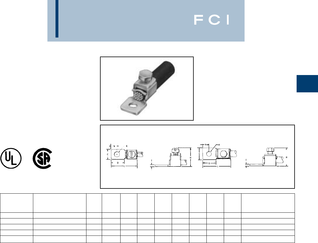
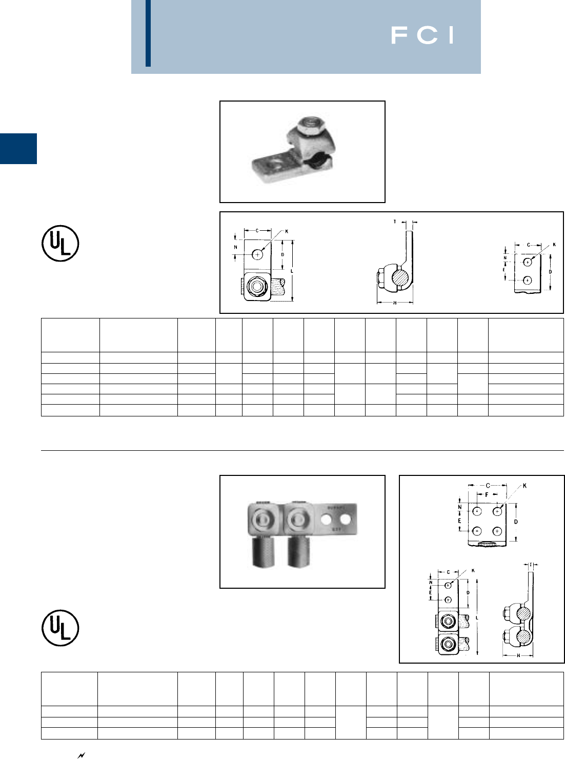
TYPE KVS
OKLIP™
Mechanical Connector
For Copper & Copperweld
Compact, two-piece, high strength, high
copper alloy BURNDY®OKLIP™recommend-
ed for heavy duty connections. Neoprene
rings hold DURIUM™ bolts in place during
installation. Installed with ordinary wrench.
TYPE KVSU
UNIVERSAL OKLIP™
Mechanical Connector
For All Combinations
of Copper, Aluminum,
ACSR, AAAC & 5005
Compact, high strength, tin plated copper
alloy two-piece connector with spacer and tin-
plated silicon bronze DURIUM™ hardware.
Recommended for heavy duty connections.
Spacer separates dissimilar conductors and
▲Listed torque values are for maximum conductor combi-
nations accommodated. Consult UL486 Tables 7-4, 7-5,
7-6 for smaller conductor combinations.
Accomodations compressed conductors within diameter
range.
See note page A-2
provides long contact length. Neoprene ring
prevents loss of shorter bolt during installa-
tion. Longer peened bolt permits swivel action
for easier installation.
Use of PENETROX™ joint compound recom-
mended with aluminum and ACSR.
See note page A-2
CONDUCTOR
COPPER COPPERWELD RECOMMENDED ▲
CATALOG MAX. RUN AND TAP TIGHTENING
NUMBER RUN TAP SOL. STR. TYPE V TORQUE in-lb
KVS26 2 STR. - 2/0 STR. 6 SOL. - 2/0 STR. 3/0 7 #8 — 180
KVS28 1/0 STR. - 4/0 STR. 10 STR. - 4/0 STR. 4/0 7 #6 V3/0 250
KVS31 250 - 350 10 STR. - 350 — 19 #8 V250 325
KVS34 400 - 500 10 STR. - 500 — 19 #6 V350 375
KVS40 400 - 800 3/0 STR - 800 — 19 #5 — 500
KVS44 500 - 1000 3/0 STR. - 1000 — — — 500
CONDUCTOR
RUN TAP RUN TAP
COPPER COPPER
ACSR, ACSR, SOL., SOL., RECOMMENDED
CATALOG AAAC, AAAC,
COPPERWELD
STEEL
COPPERWELD
STEEL TIGHTENING
NUMBER COPPER & ALUM. & 5005 COPPER & ALUM. & 5005 SOL., NOM. DIA. SOL., NOM. DIA. H J L W TORQUE in-lb
KVSU26 2 STR. - 2/0 STR. 3 - 2/0 6 STR. - 2/0 STR. 6 - 2/0 1 - 3/0 5/16 - 7/16 #6 - 3/0 3/16 - 7/16 2 5/16 1 1-1/2 180
KVSU28 1/0 STR. - 4/0 STR. 1/0 - 4/0 6 STR. - 4/0 STR. 6 - 4/0 2/0 - 4/0 3/8 - 1/2 #6 - 4/0 5/32 - 1/2 2-3/8 3/8 1-1/8 1-3/4 250
KVSU31 250 - 350 4/0 - 300 6 - 350 6 - 300 — 9/16 - 5/8 #6 - 4/0 3/16 - 5/8 2-5/8 1/2 1-3/8 2-1/8 325
KVSU34 400 - 500 336.4 - 397.5 4 - 500 5 - 397.5 — 3/4 - 3/4 #4 - 4/0 7/32 - 3/4 3 1/2 1-1/2 2-1/4 375
KVSU40 400 - 800 4/0 - 800 4/0 - 800 3/0 - 715.5 — 3/4 - 1 — 1/2 - 1 3-1/2 1/2 1-5/8 2-1/2
KVSU44 500 - 1000 4/0 - 1000 4/0 - 1000 4/0 - 900 — 7/8 - 1-1/8 — 1/2 - 1-1/8 4 3/8 2 3 500
BURNDY
Mechanical
A-8
TYPE KVSW
OKLIP™
Mechanical Connector
For Copper and Copperweld.
Similiar to OKLIP™ Type KVS except for a
high copper alloy spacer that separates run
and tap conductors. Provides high contact
pressure, confines conductor strands, and
assures vibration-proof connection. Longer
peened bolt, permits swivel action for easier
installation. Silicon bronze DURIUM™ hard-
ware.
TYPE KVS-A
ALUMINUM OKLIP™
Mechanical Connector
For All Combinations of
Copper, Aluminum†, ACSR†,
AAAC and 5005
Three-piece, high-conductivity, non-copper
bearing aluminum alloy connector with thick
spacer and aluminum hardware. Hardware in
KVS26A and KVS28A is stainless steel.
Recommended for heavy duty dissimilar
metal applications. Spacer separates conduc-
tors and provides long contact length. Belled
entrances prevent chafing, permit easier
assembly of conductors. Longer peened bolt
permits swivel action for easier installation.
Neoprene ring prevents loss of shorter bolt.
PENETROX™ joint compound recommend-
ed with aluminum and ACSR.
THESE CONNECTORS
CAN ACCOMMODATE
ACSR CONDUCTORS
OVER ARMOR ROD WITHIN
THE DIAMETER RANGE
INDICATED.
APPLICATION OVER
ARMOR ROD
See note page A-2
†Accommodates compressed conductors within diameter
range.
See note page A-2
RECOMMENDED
CATALOG CONDUCTOR TIGHTENING
NUMBER RUN TAP TORQUE in-lb
KVSW26 2 STR. - 2/0 STR. 6 SOL. - 2/0 STR. 180
KVSW28 1/0 STR. - 4/0 STR. 6 SOL. - 4/0 STR. 250
KVSW31 250 - 350 4 SOL. - 350 325
KVSW34 400 - 500 4 STR. - 500 375
KVSW40 400 - 800 4/0 - 800 500
KVSW44 500 - 1000 250 - 1000 500
CONDUCTOR
RUNTAP RECOMMENDED
CATALOG COPPER, ACSR†, COPPER, ACSR†, TIGHTENING
NUMBER & ALUM.† AAAC, & 5005 & ALUM.† AAAC & 5005 TORQUE in-lb
KVS26A 2 STR. - 2/0 STR. 4 - 2/0 10 STR. - 2/0 STR. 6 - 2/0 180
KVS28A 1/0 STR. - 4/0 STR. 1/0 - 4/0 10 STR. - 4/0 STR. 6 - 4/0 240
KVS31A 250 - 350 4/0 - 336.4 6 STR. - 350 6 - 336.4 300
KVS34A 400 - 500 336.4 - 397.5 4 STR. - 500 5 - 397.5 300
KVS40A 400 - 800 336.4 - 715.5 3/0 STR. - 800 3/0 - 715.5 300
KVS44A 500 - 1000 397.5 - 900 3/0 STR. - 1000 3/0 - 900 480
CONDUCTOR RANGE BY DIAMETER
CATALOG MAX. RUN &
NUMBER MIN. RUN DIA. MIN. TAP DIA. TAP DIA. H J L W
KVS26A .281 .116 .447 2-1/4 5/16 1-1/4 1-5/8
KVS28A .360 .116 .564 3 3/8 1-5/8 2-1/16
KVS31A .565 .184 .681 3-1/16 1/2 1-15/16 2-7/16
KVS34A .728 .216 .814 3-9/16 1/2 2-5/16 2-5/8
KVS40A .728 .470 1.036 4-1/16 1/2 2-7/16 2-7/8
KVS44A .806 .470 1.162 4-7/8 5/8 2-1/2 3-1/8

BURNDY
Mechanical
A-9
TYPE QPX
VERSITAP™
Parallel Clamp For Copper,
Copperweld, Copperweld-
Copper
The VERSITAP™ Type QPX is recommended
for Tee, Cross, Parallel, Butt and Tap connec-
tions. Range-taking, only 10 connectors
required to accommodate conductor sizes
from #6 Str. to 1000 kcmil. Edges are round-
ed for easy taping. Made of high strength,
high-conductivity copper alloy and silicon
bronze DURIUM™ hardware.
* For various configurations, see page
A-10.
▲Listed torque values are for maximum conductor combina-
tions accommodated. Consult UL486 Tables 7-4, 7-5, 7-6
for smaller conductor combinations.
See note page A-2.
Fig. 1 Fig. 2
RECOMMENDED
CATALOG COPPER CONDUCTOR TIGHTENING
NUMBER RUN TAP FIG. NO. H J L W TORQUE in-lb ▲
QPX2C2C 6 STR. - 2 STR. 6 STR. - 2 STR. 1-1/2 1-3/8 150
QPX282C 6 STR. - 2 STR. 2-1/16 5/16 1-5/16 1-9/16
QPX2828 1 STR. - 4/0 STR. 1 STR. - 4/0 STR. 1 3/8 1-13/16 1-13/16 250
QPX342C 6 STR. - 2 STR. 2-3/8 5/16 1-3/8 1-7/8
QPX3428 250 - 500 1 STR. - 4/0 STR. 2-3/4 1-3/4 2-1/16 375
QPX3434 250 - 500 2 3 3/8 2-1/16 2-3/16
QPX442C 6 STR. - 2 STR. 2-11/16 5/16 1-3/8 2-1/4
QPX4428 1 STR. - 4/0 STR. 12-7/8 1-13/16
QPX4434 500 - 1000 250 - 500 3-1/16 3/8 2-1/16 2-7/16 500
QPX4444 500 - 1000 23-7/16 2-5/8 2-9/16
CONDUCTOR
RUN TAP
CATALOG COPPERWELD COPPERWELD
NUMBER COPPERWELD – COPPER COPPERWELD – COPPER
QPX2C2C 5 SOL. - 3 #7 8A - 4A 5 SOL. - 3 #7 8A - 4A
QPX282C 7#9 - 7 #5 3A - 3/0 V 5 SOL. - 3 #7 8A - 4A
QPX2828 7#9 - 7 #5 3A - 3/0 V 7 #9 - 7 #5 3A - 3/0 V
QPX342C 5 SOL. - 3 #7 8A - 4A
QPX3428 19 #9 - 19 #6 4/0 EK 7 #9 - 7 #5 3A - 3/0 V
QPX3434 19 #9 - 19 #6 4/0 EK
QPX442C 5 SOL. - 3 #7 8A - 4A
QPX4428 7#9 - 7 #5 3A - 3/0 V
QPX4434 19 #6 — 19 #9 - 19 #6 4/0 EK
QPX4444 19 #6
BURNDY
Mechanical
A-10
TYPE QPX-Y
UNIVERSAL VERSITAP™
Universal Parallel Clamp
For Copper and Aluminum
High copper alloy cast connector, tin-plated for
use with copper or aluminum cable. Makes
parallel, tap, tee, cross or end-to-end connec-
tions. Edges rounded for easy taping.
PENETROX™ joint compound recommended.
APPLICATION
VARIATIONS
▲Listed torque values are for maximum conductor
combinations accommodated. Consult UL486
Tables 7 4, 7-5 7-6 for smaller conductor
combinations.
See note page A-2.
PARALLEL TAP CROSS
SPLICE
TEE
Fig. 1 Fig. 2
CONDUCTOR RECOMMENDED
CATALOG ALUMINUM OR COPPER TIGHTENING
NUMBER RUN TAP FIG. NO. H J L W TORQUE in-lb ▲
QPX2C2C-Y 6 STR. - 2 STR. 6 STR. - 2 STR. 1-5/8 1-5/8
QPX282C-Y 1/0 STR. - 4/0 STR. 6 STR. - 2 STR. 11-7/8 5/16 1-1/2 1-7/8 150
QPX2828-Y 1/0 STR. - 4/0 STR. 1/0 STR. - 4/0 STR. 2 3/8 2 2-1/8 250
QPX342C-Y 6 STR. - 2 STR. 1 2-1/4 5/16 1-1/2 2-1/8
QPX3428-Y 250 - 500 1/0 STR. - 4/0 STR. 2-1/2 2 2-1/2 375
QPX3434-Y 200 - 500 2 2-7/8 3/8 2-1/2 2-5/8
QPX4444-Y 750 - 1000 750 - 1000 2 3-7/8 1/2 3-1/2 3-1/2 500
BURNDY
Mechanical
A-11
TYPE KPA
SCRULUG™
For Copper Cable
High copper alloy tin-plated terminal for join-
ing a wide range of cable to equipment pads
or terminal blocks. Especially good in light
industrial applications. The tongue and body
are a one-piece design. The pressure bar
equalizes pressure over the conductor and
prevents the screw from cutting into the cable.
NOTE: For unplated version add “UNPL” suffix.
Fig. 1 Fig. 2
STUD RECOMMENDED
CATALOG FIG. HOLE TIGHTENING
NUMBER WIRE RANGE NO. CDHKSIZE L N T TORQUE in-lb
KPA8C 8 STR. - 14 SOL. 1 .38 .47 .72 .21 .10 .95 .22 .06 12
KPA4C 14 SOL. - 4 STR. 1 .50 .59 .94 .27 1/4 1.20 .30 .06 45
KPA25 4 STR. - 1/0 STR. 2 .75 .81 1.25 .33 5/16 1.70 .41 .10 180
KPA28 1/0 STR. - 4/0 STR. 2 .97 1.12 1.66 .40 3/8 2.29 .53 .13 250
KPA34 4/0 STR. - 500 kcmil 2 1.38 1.38 2.44 .54 1/2 3.14 .75 .20 375
BURNDY
Mechanical
A-12
TYPE KPA-UP
SCRULUG™
FOR COPPER CABLE
High copper alloy terminal for joining a wide
range of cable to equipment pads or terminal
blocks. Plain copper finish.
NOTE: For tin plating drop “-UP” suffix and add “-TP” suffix
(example: KPA4CTP).
For use in grounding applications with a green screw - con-
tact factory. Listed for grounding per UL467.
Features and Benefits
•One piece design.
◊Superior torque and pull
out performance.
•Convenient range taking design.
◊Reduces catalog numbers.
One catalog number accommodates
several conductor sizes.
•High conductivity copper alloy.
◊Long lasting, reliable contact.
•Compact design.
◊Easy to use.
•Slot Robertson screw, hex head,
hex socket bolt.
◊No special installation tools required.
Eliminates over-torquing/potential
conductor damage.
Fig. 1 Fig. 2 Fig. 3
STUD RECOMMENDED
CATALOG WIRE FIG. HOLE TIGHTENING
NUMBER RANGE NO. C D H K SIZE L N T HARDWARE TORQUE in-lb
14 SOL. 1/4 Dia. Slot
KPA8CUP 6 STR. 0.38 0.51 0.81 0.20 #10 1.01 0.24 0.07 Robertson 35
14 SOL. 15/16 Dia. Slot
KPA4CUP 4 STR. 0.50 0.71 1.00 0.28 1/4 1.28 0.33 0.07 Robertson 45
BURNDY
Mechanical
A-13
TYPE KLU
SCRULUG™
FOR COPPER CABLE -
OFFSET TONGUE -
NON-PLATED
High copper alloy terminal with offset tongue
for joining a wide range of cable to equipment
pads or bar. Easy to install with screwdriver or
wrench. Connector is reusable. Plain copper
finish.
Features and Benefits
•Convenient range-taking design.
◊Reduces catalog numbers.
One conductor accommodates
several conductor sizes.
•High conductivity copper alloy.
◊Long lasting reliable contact.
•Compact design.
◊Easy to use. Reduces labor time.
NOTES:
➀Suffix “-TP” on catalog number denotes tin plate (example:
KLU400TP).
2Material: Copper alloy.
•Slot Robertson screw, hex head/hex
socket bolt.
◊No special installation tools required.
Eliminates over-torquing/potential
conductor damage.
Fig. 1 Fig. 2 Fig. 3
➀RECOMMENDED STUD STRIP
CATALOG FIG. B C K L N T TIGHTENING HOLE QUANTITY/ LENGTH
NUMBER CONDUCTOR NO. (MM/IN) (MM/IN) (MM/IN) (MM/IN) (MM/IN) (MM/IN) TORQUE IN LBS. HARDWARE SIZE PACKAGE (IN.)
KLU25 14 Sol. 1.63 (0.64) Dia. to 6.4 8.0 3.6 26.0 6.3 1.9 No. 8 - 32 Slotted Round
KLU25TP 10 Sol. 2.60 (1.02) Dia. CU 3.26 .31 .14 1.02 .21 .07 20 Machine Screw #6 100 7/16
KLU35 14 Sol. 1.63 (.0641) Dia. to 8.4 10.0 6.0 31.6 5.6 1.8 1/4 UNF Slotted Set
KLU35TP 6 Str. 4.67 (.184) Dia. CU .33 .39 .20 1.24 .22 .07 45 Screw #10 100 5/8
KLU70 8 Sol. 3.28 (.129) Dia. to 11.8 12.0 6.7 39.6 6.4 2.1 5/16 UNF Slotted Set
KLU70TP 2 Str. 7.42 (.292) Dia. CU 2.46 .47 .26 1.56 .25 .08 50 Screw 1/4 100 3/4
KLU125 2 Str. 7.42 (.292) Dia. to 16.9 16.9 6.5 50.5 10.8 2.7 3/8 UNF Slotted Set
KLU125TP 1/0 Str. 9.44 (.372) Dia. CU .63 .63 .26 1.99 .43 .11 50 Screw 1/4 25 15/16
KLU175 4 Str. 5.89 (.232) Dia. to 18.0 19.0 10.0 66.0 11.0 4.0 3/8 UNF Socket Set
KLU175TP 3/0 Str. 11.94 (.470) Dia. CU .71 .75 .39 2.20 .43 .16 124 Screw 3/8 12 1
KLU225 2 Str. 7.42 (.292) Dia. to 119.6 26.2 8.5 65.0 13.0 3.1 7/16 UNF Socket Set
KLU225TP 4/0 Str. 13.4 (.528) Dia. CU .77 .99 .33 2.56 .51 .12 204 Screw 5/16 12 1-5/16
KLU300 1/0 Str. 9.44 (.372) Dia. to 25.2 26.2 10.0 72.0 13.1 3.1 5/8 UNF Slotted Set
KLU300TP 350 MCM 17.30 (.681) Dia. CU 1.0 .99 .39 2.83 .52 .12 325 Screw 3/8 6 1-5/8
KLU400 1/0 Str. 9.44 (.372) Dia. to 229.6 38.0 10.0 104.0 23.0 4.5 5/8 UNF Slotted Set
KLU400TP 500 MCM 207 (.813) Dia CU 1.16 1.60 .39 4.09 .91 .18 375 Screw 3/8 3 1-5/32
BURNDY
Mechanical
A-14
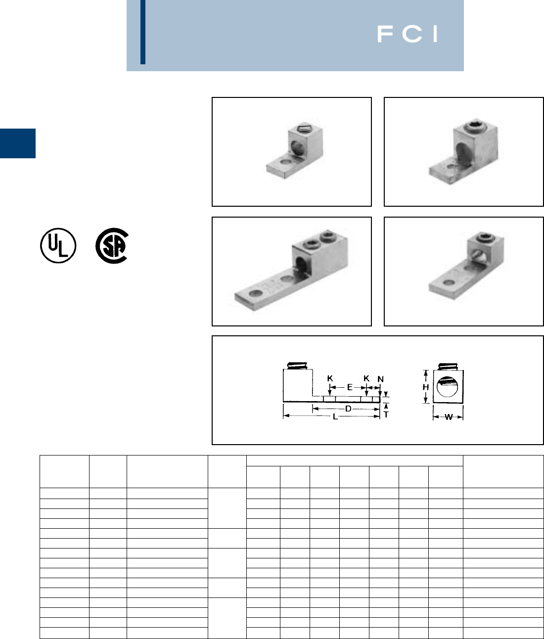
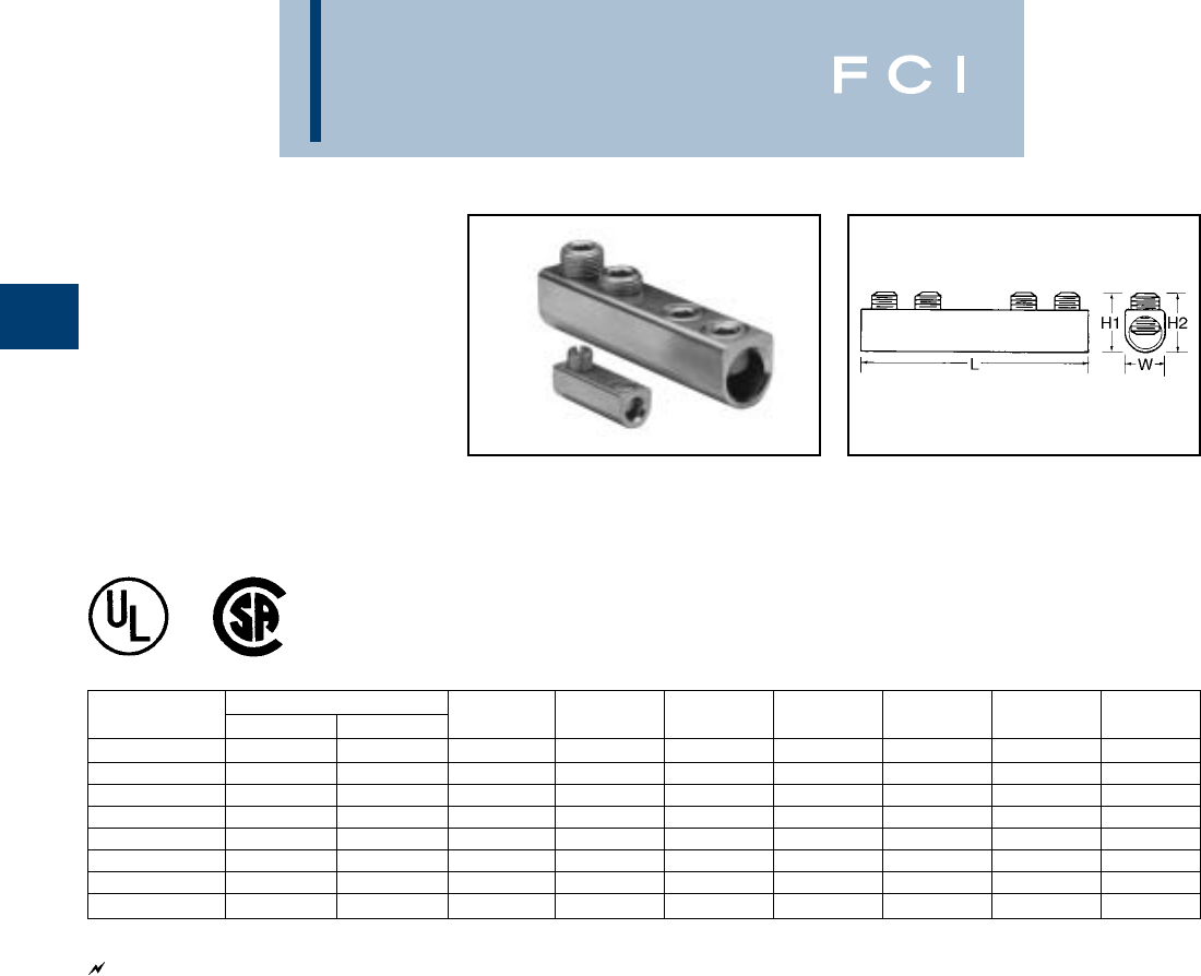
TYPE KA
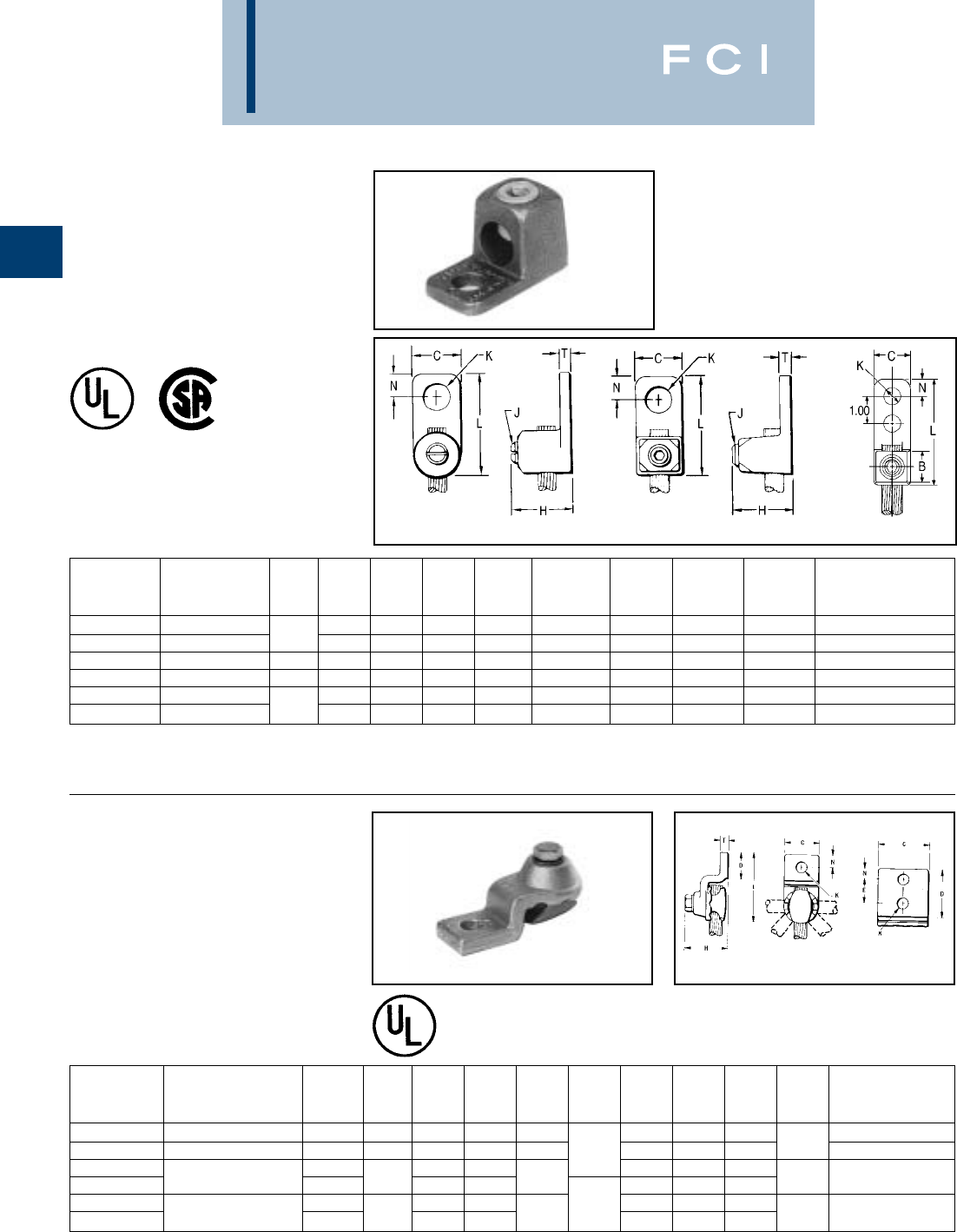
KA-LUG™
For Copper Cable
Compact, economical, high copper alloy
terminal for joining a wide range of cable to
equipment pads or terminal blocks.
TYPE EA
VERSILUG™
For Copper Cable
Compact, high copper alloy terminal for join-
ing a wide range of cable to equipment pads
or bar. Clamping element adjustable to
several angles. One-wrench installation.
▲Listed torque values are for maximum conductor sizes
accommodated.
Consult UL486 Tables 7-4, 7-5, 7-6 for smaller conductor
sizes.
* “N” indicates NEMA standard stud holes.
▲Listed torque values are for maximum conductor
sizes accommodated.
Consult UL486 Tables 7-4, 7-5, 7-6 for smaller
conductor sizes.
Fig. 1 Fig. 2
STUD RECOMMENDED
CATALOG FIG. HOLE TIGHTENING
NUMBER CONDUCTOR NO. C H J K SIZE L N T TORQUE in-lb
KA8C 14 SOL. - 8 STR. 3/8 5/8 #12 7/32 #10 13/16 3/16 3/32 25
KA4C 14 SOL. - 4 STR. 19/16 3/4 5/16 9/32 1/4 1-1/8 1/4 7/64 45
KA25 4 STR. - 1/0 STR. 2 3/4 15/16 1/2 27/64 3/8 1-11/16 3/8 1/8 200
KA25-2TC 38 4 STR. - 1/0 STR. 3 3/4 15/16 1/2 27/64 3/8 2-13/16 3/8 1/8 200
KA28 1 STR. - 4/0 STR. 15/16 1-1/4 5/8 27/64 3/8 1-15/16 7/16 3/16 275
KA34 4/0 STR. - 500 21-3/8 2-3/32 13/16 9/16 1/2 2-9/16 9/16 9/32 375
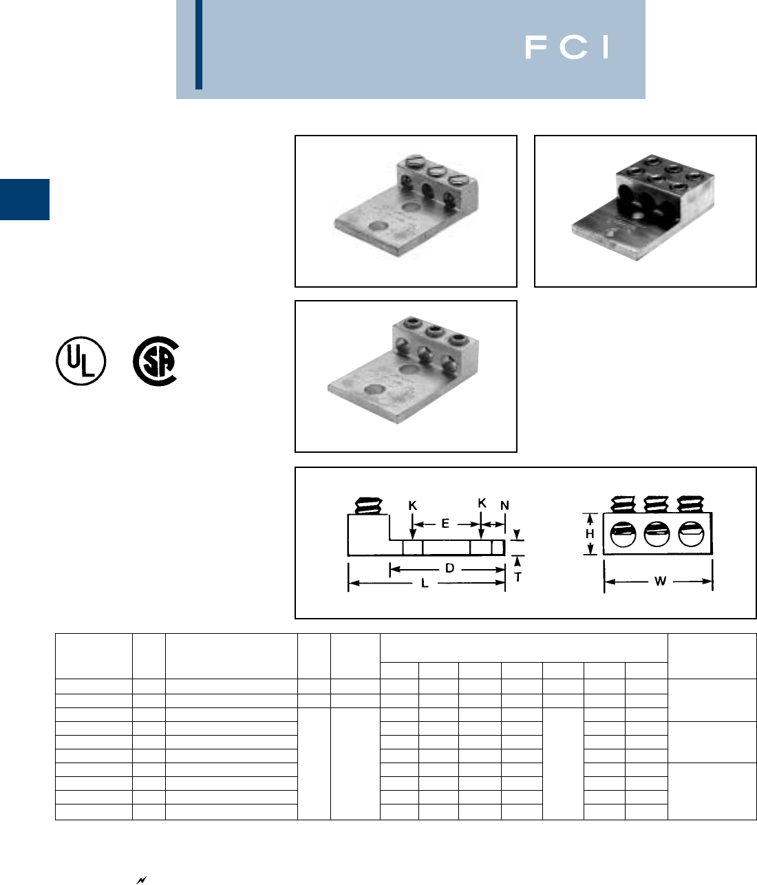
NO. OF STUD RECOMMENDED
CATALOG HOLES HOLE TIGHTENING
NUMBER CONDUCTOR IN PAD C D E H K SIZE L N T TORQUE in-lb
EA2C 8 SOL. - 2 STR. 1 13/16 1-1/16 — 1-3/8 3/8 2-1/2 13/32 150
EA25 2 STR. - 1/0 STR. 1 7/8 1-1/8 — 1-7/16 7/16 3/8 2-11/16 7/16 1/4 180
EA28 11-3/8 — 3/8 3-3/16 17/32
EA28-2N 1/0 STR. - 4/0 STR. 2 NEMA 1-1/16 3-5/8 1-3/4 1-3/4 1/2 5-1/8 5/8 5/16 250
EA34 11-5/8 — 9/16 1/2 4 13/16
EA34-2N 250 - 500 2 NEMA 1-3/8 3-5/8 1-3/4 2-1/4 1/2 5-5/8 5/8 3/8 375
Fig. 3
BURNDY
Mechanical
A-15
TYPE BGBL
LAY-IN QIKLUG™
*UL LISTED 90° C, 600 V
The Lay-In QIKLUG™, Type BGBL is manu-
factured from high strength 6061-T6
aluminum, and is ideally suited for grounding
and bonding applications accommodating
both copper and aluminum conductor sizes
#14 AWG to 250 kcmil. Features and Benefits
•* UL 486B listed, AL9CU rated.
◊For copper and aluminum conductor
combinations up to 90° C, 600 Volt
applications.
•UL Recognized for grounding and bonding.
◊Ensures reliability.
•Electro-tin plated.
◊Provides low contact resistance.
•Lay-in feature.
◊Eases installation.
NOTE: PEN-A PENETROX®inhibitor is recommended for all
aluminum terminations.
Fig. 1
Fig. 2
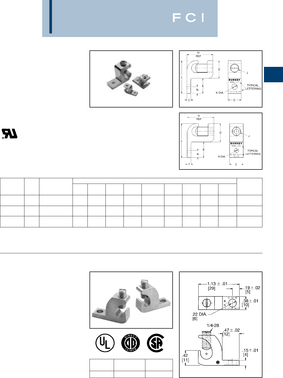
TYPE CL50-1
COPPER LAY-IN QIKLUG™
FOR COPPER
The Lay-In QIKLUG™ is manufactured from
high strength pure electrolytic copper to
ensure maximum strength and conductivity.
UL467 Listed for direct burial in earth or con-
crete. The open-faced design allows for fast
lay-in of the conductor without the need for
cutting or breaking.
CATALOG WIRE RANGE
NUMBER COPPER STUD HOLE
CL50-1 #14 - #4 CU #10
DIMENSIONS
CATALOG FIG CONDUCTOR H K HEX
NUMBER NO. RANGE C D E REF J DIA. L N T SIZE
.39 .62 .48 .79 .22 1.10 .20 .13
*BGBL-4 14 - 14 AWG [10] [16] [12] [20] 1/4 - 28 [6] [28] [5] [3] SLOT
.63 .80 .83 1.16 .28 1.63 .44 .19
BGBL-1/0 11/0 - 14 AWG [16] [20] [21] [29] 3/8 - 24 [7] [41] [11] [5] SLOT
.88 1.18 1.00 1.72 .28 2.18 .45 .25
BGBL-250 2250 kcmil - 6 [22] [30] [30] [44] 7/16 - 18 [7] [55] [11] [6] 7/32
BURNDY
Mechanical
A-16
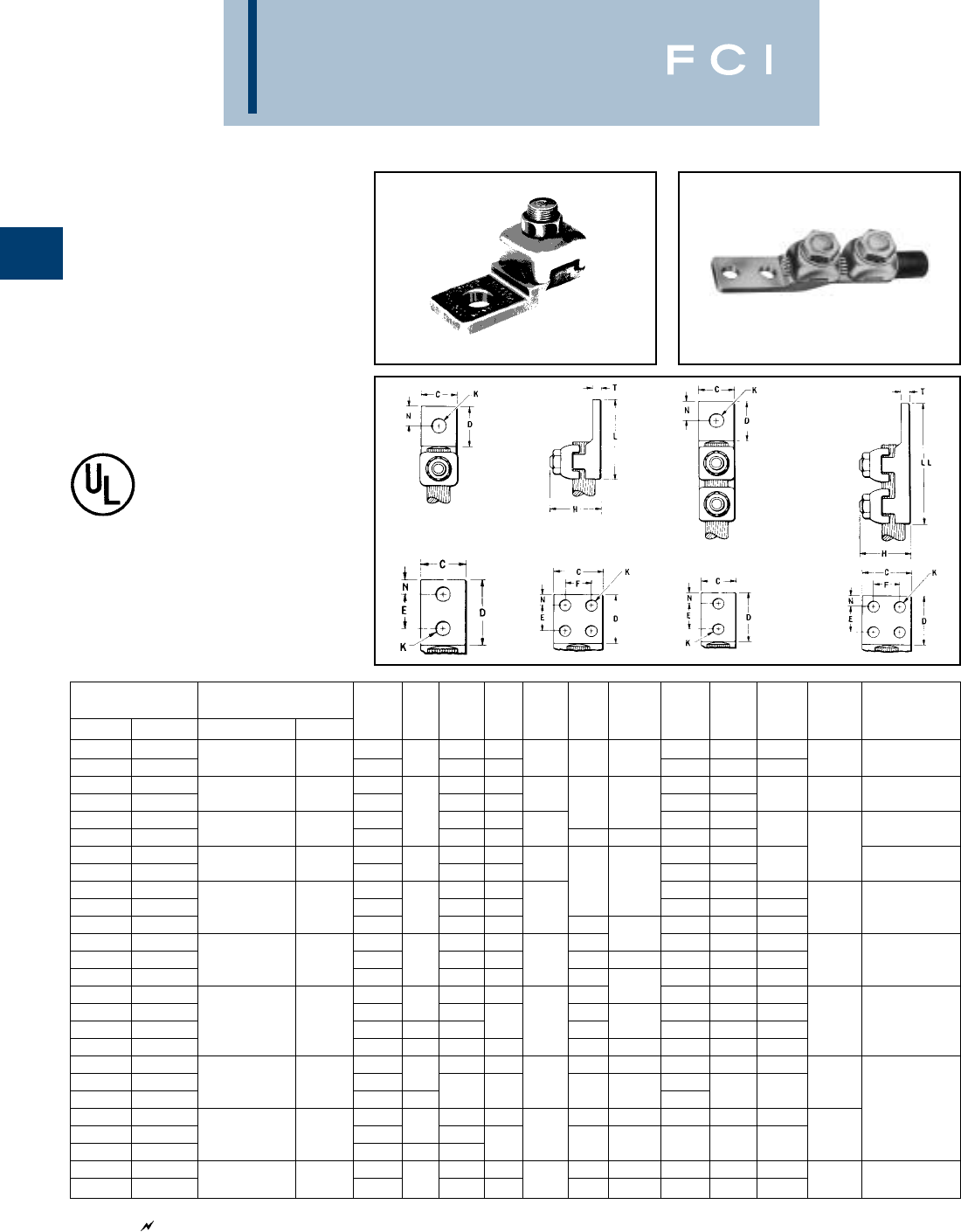
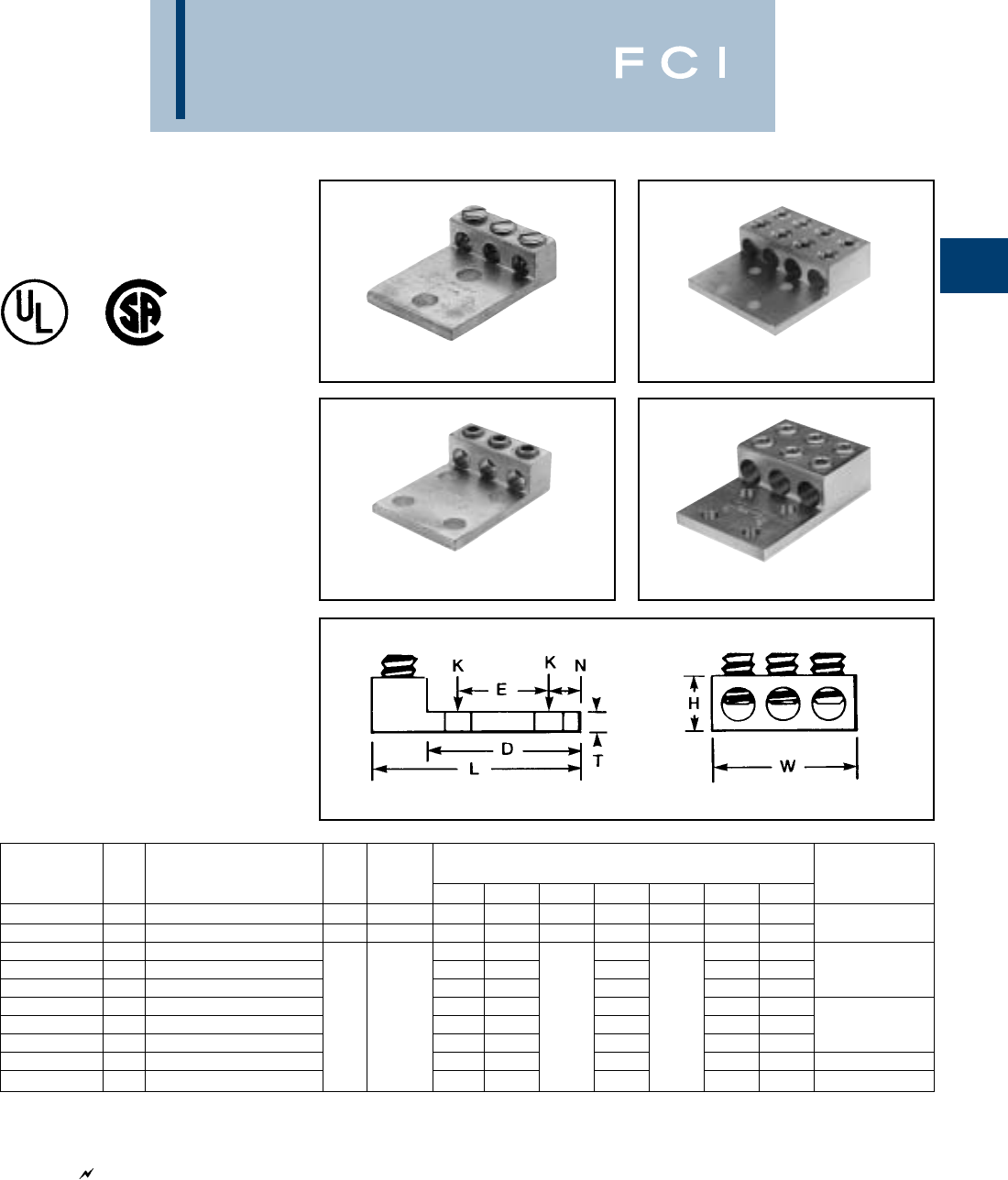
TYPES QA, QQA
QIKLUG™
For Copper Cable
Type QA heavy duty, compact, high copper
alloy terminal for joining a wide range of cable
to equipment pads or bar. Fast one-wrench
installation. Type QQA heavy duty, high
copper alloy terminal for joining cable to
equipment pads or bar. Twin clamping
elements secure joint vibration and flexing.
One-wrench installation.
Type QA Type QQA
*‘‘N’’ indicates NEMA standard stud holes.
All 4N items See note page A-2
NO. OF STUD RECOMMENDED
CATALOG NUMBER* CONDUCTOR HOLES HOLE TIGHTENING
TYPE QA TYPE QQA COMMERCIAL NAVY IN PAD C D E & F H K SIZE L LL N T TORQUE in-lb
QA8C-B QQA8C 19/16 — 1-3/8 2-5/16 9/32
QA8C-2B QQA8C-2 14 SOL. - 8 STR. 4 - 14 29/16 1-1/4 5/8 11/16 7/32 #10 235/16 5/32 75
QA4C-B QQA4C 15/8 — 1-7/16 2-3/8
QA4C-2B QQA4C-2 8 STR. - 4 STR. 23 - 40 21-3/16 5/8 3/4 9/32 1/4 2 2-15/16 5/16 3/16 110
QA1C-B QQA1C 15/8 3/4 — 1-3/4 2-13/16
QA1C-2B QQA1C-2 4 STR. - 1 STR. 50 - 75 21-9/16 7/8 111/32 5/16 2-9/16 3-5/8 11/32 150
QA26-B QQA26 11—23-3/16 7/32
QA26-2B QQA26-2 1/0 STR - 2/0 STR. 100 - 125 213/16 1-15/16 1 1-3/16 34-3/16 7/16 180
QA28-B QQA28 11-1/16 — 13/32 3/8 2-1/4 3-9/16 17/32
QA28-2B 3/0 STR. - 4/0 STR. 150 - 200 2 1 2 1 1-5/16 3-9/16 — 7/16 1/4 250
QA28-2N* QQA28-2N* 2 NEMA 3-1/8 1-3/4 9/16 4-5/16 5-5/8 5/8
QA31-B QQA31 11-3/8 — 17/32 1/2 2-11/36 4-1/8 11/16
QA31-2B 250 - 350 250 - 350 2 1-3/16 1-31/32 1 1-11/16 7/16 3/8 3-3/8 — 7/16 5/16 325
QA31-2N* QQA31-2N* 2 NEMA 3 1-3/4 9/16 4-7/16 5-7/8 5/8
QA34-B QQA34 11-5/8 — 17/32 1/2 3-3/16 4-7/8 13/16
QA34-2B 21-3/8 213/32 3-9/16 — 7/16
QA34-4B 400 - 500 400 - 500 41-7/8 1-15/16 12
7/16 3/8 3-1/2 — 7/16 5/16 375
QA34-2N* QQA34-2N* 2 NEMA 1-3/8 3-3/32 1-3/4 9/16 1/2 4-11/16 6-9/32 5/8
QA40-B 11-7/8 — 11/16 5/8 3-11/16 — 27/32
QA40-2N* QQA40-2N* 600 - 800 650 - 800 2 NEMA 1-5/8 2-7/16 4-14/16 3/8
QQA40-4N 4 NEMA 3 31-3/4 9/16 1/2 —7-3/32 5/8
QA44-B 12—11/16 5/8 3-15/16 — 1 500
QA44-2N* QQA44-2N 850 - 1000 1000 2 NEMA 1-7/8 32-3/4 1/2
QA44-4N* QQA44-4N* 4 NEMA 3 3-1/16 1-3/4 9/16 1/2 5 7-1/8 5/8
QA46-B 12-1/8 — 13/16 3/4 4-3/8 — 1-1/16
QA46-2N* 1100 - 1500 1300 2 NEMA 2-1/8 31-3/4 3-1/8 9/16 1/2 5-1/4 — 5/8 9/16 600
BURNDY
Mechanical
A-17
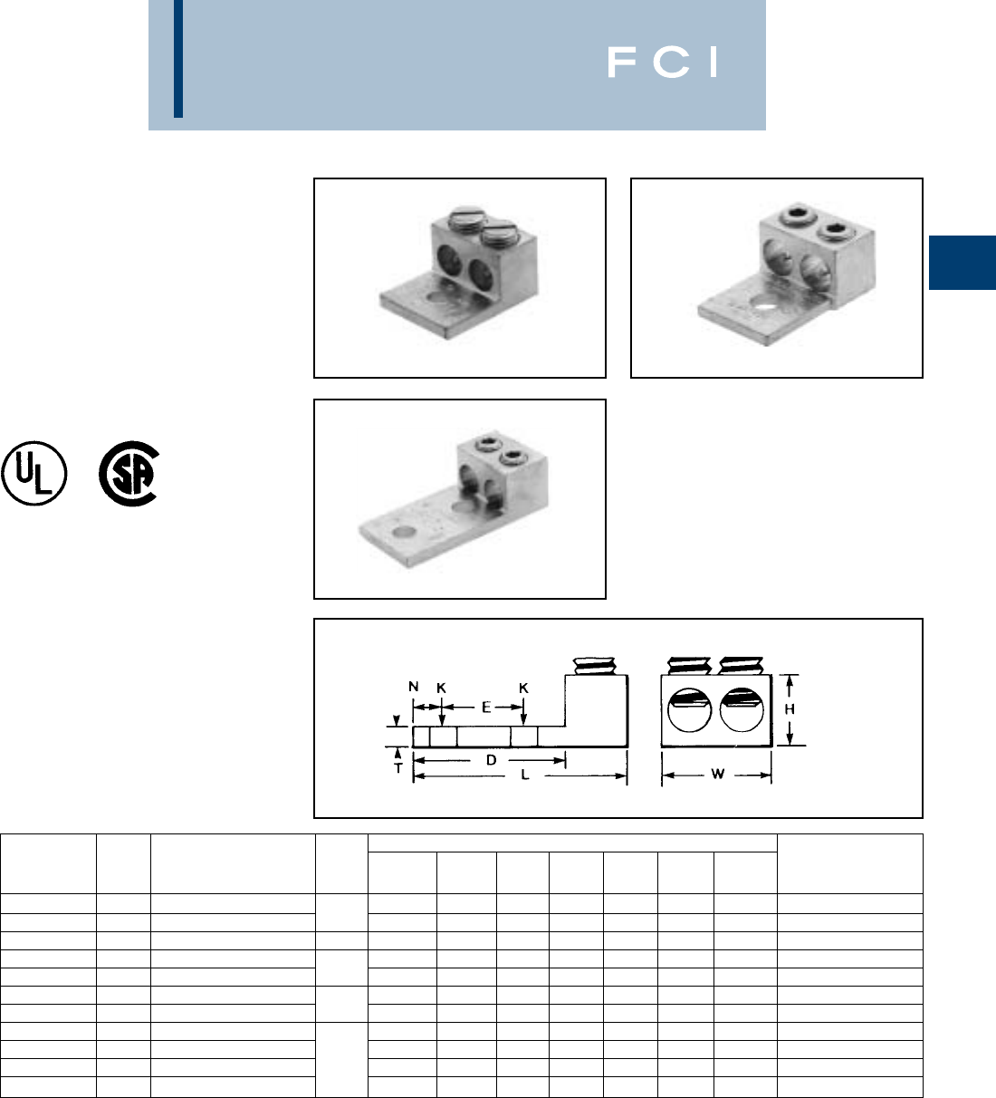
TYPE Q2A
QIKLUG™
For Copper Cable
Compact, high copper alloy terminal for join-
ing two cables to equipment pads or bars.
Each element accommodates a wide range
of cable. One-wrench installation.
TYPE Q3A
QIKLUG™
For Copper Cable
Compact, high copper alloy terminal for join-
ing three cables to equipment pads or bar.
Each element accommodates a wide range
of cable. One-wrench installation.
*‘‘N’’ indicates NEMA standard stud holes.
All 4N items See note page A-2
*‘‘N’’ indicates NEMA standard stud holes.
NO. OF STUD RECOMMENDED
CATALOG HOLES IN HOLE TIGHTENING
NUMBER* CONDUCTOR PAD C D E & F H K SIZE L N T W TORQUE in-lb ▲
Q2A1C-2 4 STR. - 1 STR. 2 1-1/2 1-7/8 1 1-1/16 7/16 3/8 2-7/8 7/16 7/32 1-13/16 150
Q2A26-2N 1/0 STR. - 2/0 STR. 2 NEMA 1-5/8 3/4 1-3/16 4-3/16 7/32 1-15/16 180
Q2A28-2N 2 NEMA 1-7/8 4-3/8 1-15/16
Q2A28-4N 3/0 STR. - 4/0 STR. 4 NEMA 3 1-3/8 1/4 2-1/8 250
Q2A31-2N 2 NEMA 2-3/8 4-1/2 2-1/8
Q2A31-4N 250 - 350 4 NEMA 3 3-1/8 1-11/16 5/16 3325
Q2A34-2N 2 NEMA 2-1/2 1-3/4 9/16 1/2 5/8 3
Q2A34-4N 400 - 500 4 NEMA 3 24-11/16 3/8 3-3/4 375
Q2A40-2N 2 NEMA 3-3/4
Q2A40-4N 600 - 800 3 2-7/16 5 7/16 4-11/32 500
Q2A44-4N 850 - 1000 4 NEMA 3-1/4 2-3/4 5-1/4 1/2 4-11/32
Q2A46-4N 1100 - 1500 4 NEMA 3-1/2 3-1/4 3-1/8 5-1/2 11/16 5 600
NO. OF STUD RECOMMENDED
CATALOG HOLES IN HOLE TIGHTENING
NUMBER* CONDUCTOR PAD C D E & F H K SIZE L N T W TORQUE in-lb
Q3A28-2N 2 NEMA 1-7/8 4-5/16
Q3A28-4N 3/0 STR. - 4/0 STR. 4 NEMA 3 1-3/8 4-3/8 1/4 3-3/16 250
Q3A31-2N 2 NEMA 2-3/8
Q3A31-4N 250 - 350 4 NEMA 3 3-1/8 1-11/16 4-7/16 5/16 4-1/16 325
Q3A34-2N 2 NEMA 2-1/2 1-3/4 9/16 1/2 5/8
Q3A34-4N 400 - 500 4 NEMA 1-15/16 4-3/4 3/8 4-9/16 375
Q3A40-4N 600 - 800 32-7/16 5 7/16 5-13/16
Q3A44-4N 850 - 1000 4 NEMA 3-1/4 2-3/4 5-1/4 1/2 6-5/8 500
Q3A46-4N 1100 - 1500 4 NEMA 3-1/2 3-1/4 3-1/8 5-1/2 11/16 7-7/8 600
BURNDY
Mechanical
A-18
TYPE QB
QIKLUG™
For Copper Cable
Compact, high copper alloy side entrance
terminal for joining a range of cable at right
angles to terminal blocks. One-wrench
installation.
“N” indicates NEMA standard stud holes.
“N” indicates NEMA standard stud holes.
All 4N items See note page A-2
TYPE Q2B
QIKLUG™
For Copper Cable
Compact, high copper alloy terminal for join-
ing two cables at right angles to a single
terminal block. Each element accommodates
a range of cable. One-wrench installation.
NO. OF STUD RECOMMENDED
CATALOG HOLES HOLE TIGHTENING
NUMBER* CONDUCTOR IN PAD C D E H K SIZE L N T TORQUE in-lb ▲
QB8C 14 SOL. - 8 STR. 1 9/16 9/16 — 7/8 7/32 #10 1-1/8 9/32 5/32 75
QB4C 8 STR. - 4 STR. 1 27/32 — 13/16 1-3/8 1/4 110
QB1C 4 STR. - 1 STR. 1 11/16 13/16 — 1 9/32 1/4 1-1/2 11/32 150
QB26 1/0 STR. - 2/0 STR. 1 13/16 1 — 1-1/32 1-13/16 7/16 7/32 180
QB28 3/0 STR. - 4/0 STR. 1 1 1-1/16 — 1-5/16 13/32 3/8 2-1/16 17/32 1/4 250
QB31-2N 250 - 350 2 NEMA 13/16 3-1/4 1-3/4 1-11/16 9/16 1/2 4-1/2 5/8 5/16 325
NO. OF STUD RECOMMENDED
CATALOG HOLES HOLE TIGHTENING
NUMBER* CONDUCTOR IN PAD C D E & F H K SIZE L N T TORQUE in-lb
Q2B28-2N 3/0 STR. - 4/0 STR. 2 NEMA 1-7/8 3-1/8 1-3/4 1-3/8 3/8 5-3/16 1/4 250
Q2B31-2N 250 - 350 2 NEMA 2-3/8 3-3/16 1-11/16 1-3/8 9/16 1/2 5-7/8 5/8 5/16 325
Q2B40-4N 600 - 800 4 NEMA 3 3-1/16 1-3/8 2-5/16 1 6-11/16 7/16 500
BURNDY
Mechanical
A-19
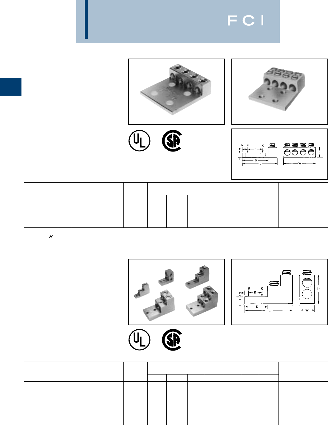
TYPE QDA
QIKLUG™
For Copper Cable
Compact, high copper alloy terminal for join-
ing a wide range of cable to equipment studs.
Provides low contact resistance when
gripped between two contact nuts. One-
wrench installation.
TYPE QR QIKLINK®
SPLICE OR REDUCER
For Copper Cable to Cable
High copper alloy splicer/reducer for joining a
range of cable end to end. Neat, compact
easy to tape installation. One-wrench
installation.
See note page A-2.
STUD RECOMMENDED
CATALOG CONDUCTOR HOLE TIGHTENING
NUMBER COMMERCIAL NAVY C H K SIZE L T TORQUE in-lb
QDA8C 14 SOL. - 8 STR. 3 - 14 11/16 3/16 75
QDA4C 8 STR. - 4 STR. 23 - 40 1 3/4 7/16 3/8 1-7/8 7/32 110
QDA1C 4 STR. - 1 STR. 50 - 75 1 2-3/16 9/32 150
QDA26 1/0 STR. - 2/0 STR. 100 - 125 1-3/16 2-1/2 180
QDA28 3/0 STR. - 4/0 STR. 150 - 200 1-1/4 1-5/16 9/16 1/2 2-5/8 250
QDA31 250 - 350 250 - 350 1-1/2 1-11/16 11/16 5/8 3 5/16 325
QDA34 400 - 500 400 - 500 1-7/8 2 13/16 3/4 3-5/8 375
QDA40 600 - 800 650 - 800 2-1/8 2-5/16 1-1/16 1 4-3/16 3/8 500
RECOMMENDED
CATALOG CONDUCTOR TIGHTENING
NUMBER EITHER SIZE H L W TORQUE in-lb
QR4C 8 STR. - 4 STR. 3/4 1-11/16 5/8 110
QR1C 4 STR. - 1 STR. 1-1/16 1-15/16 11/16 150
QR26 1/0 STR. - 2/0 STR. 1-3/16 2-1/8 13/16 180
QR28 3/0 STR. - 4/0 STR. 1-3/8 2-3/8 1 250
QR31 250 - 350 1-11/16 2-5/8 1-1/4 325
QR34 400 - 500 1-15/16 3-1/16 1-7/16 375
QR40 600 - 800 2-7/16 3-5/8 1-7/8 500
BURNDY
Mechanical
A-20
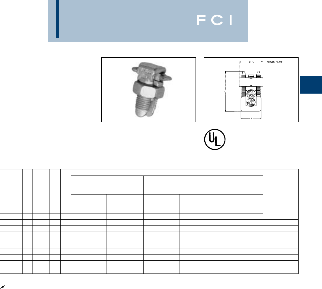
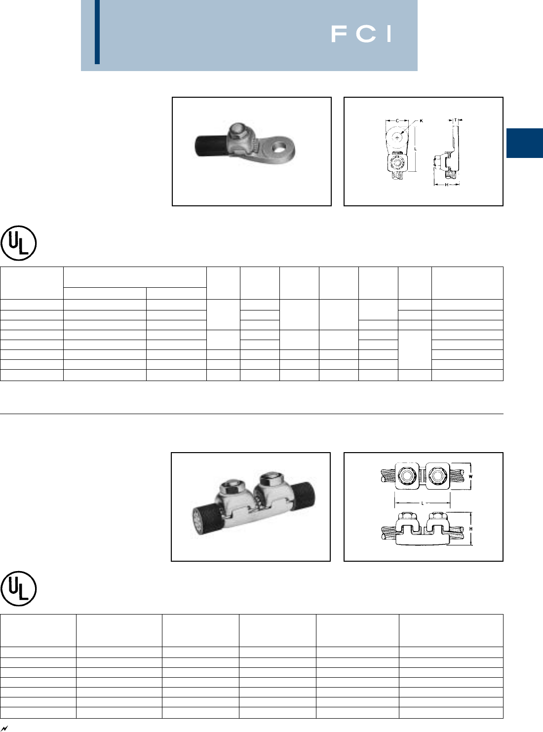
TYPE VT
VARITAP™ T-CONNECTOR
For Copper Cable to Cable
High copper alloy T-connector for cable run,
cable tap. V-bolt clamping elements accom-
modate large range of cable and are
particularly suited for extra flexible cable.
One-wrench installation.
See note page A-2
TYPE E-C-G
TRANSFORMER
TAP ADAPTER
For Copper
Multi-tap, range-taking cast copper alloy con-
nector designed to take 2, 3 or 4 conductors
from a single secondary transformer outlet.
RECOMMENDED
CATALOG CONDUCTOR TIGHTENING TORQUE in-lb
NUMBER RUN TAP H L W RUN TAP
VT2C2C 8 SOL. - 2 STR. 8 SOL. - 2 STR. 1-5/16 2-5/16 1-5/16 275 275
VT2525 6 SOL. - 1/0 STR. 6 SOL. - 1/0 STR. 2-5/8 1-7/16 385 385
VT2825 6 SOL. - 1/0 STR. 1-5/8 3-1/8 1-1/4 250 385
VT2828 1/0 STR. - 4/0 STR. 1/0 STR. - 4/0 STR. 3-1/16 1-11/16 250 250
VT3025 6 SOL. - 1/0 STR. 3-3/8 1-3/8 325 385
VT3030 1/0 STR. - 300 1/0 STR. - 300 1-7/8 3-5/16 1-15/16 325 325
VT3425 6 SOL. - 1/0 STR. 3-11/16 1-1/2 375 385
VT3428 1/0 STR. - 4/0 STR. 3-1/2 1-11/16 375 250
VT3430 300 - 500 1/0 STR. - 300 2-5/16 3-5/8 1-15/16 375 325
VT3434 300 - 500 3-3/4 2-1/4 375 375
VT4040 500 - 800 500 - 800 2-9/16 4-1/2 2-5/8 500 500
VT4425 6 SOL. - 1/0 STR. 4-5/16 2 500 385
VT4428 750 - 1000 1/0 STR. - 4/0 STR. 2-7/8 4-1/8 2 500 250
VT4834 300 - 500 5-1/4 5 600 375
VT4844 1500 - 2000 750 - 1000 4-1/4 5-3/4 5 600 500
VT4848 1500 - 2000 6-1/4 5 600 600
RECOMMENDED
CATALOG NO. OF CONDUCTOR A TIGHTENING
NUMBER CONDUCTORS SIZE DIA. D H J L W TORQUE in-lb
E2C34G1 23-1/2
E3C34G1 31/0 SOL. - 500 .78 3-3/4 2-7/8 1/2-13 6-1/4 5-1/4 480
E4C34G1 46-7/8

BURNDY
Mechanical
A-21
TYPE VA, VVA
VARILUG™
For Copper Cable
High copper alloy terminal for joining a wide
range of cable to equipment pads or bar.
Particularly suitable for use on extra flexible
cable. One-wrench installation. Type VVA,
twin elements secure joint against vibration
and flexing. Particularly recommended for
use on extra flexible cables. One-wrench
installation.
“N” indicates NEMA standard stud holes.
All 4N items See note page A-2
Type VA Type VVA
NO. OF STUD RECOMMENDED
CATALOG NUMBER* HOLES HOLE TIGHTENING
TYPE VA TYPE VVA CONDUCTOR IN PAD C D E & F H K SIZE L LL N T TORQUE in-lb
VA2C VVA2 8 SOL. - 2 STR. 13/16 1-1/4 — 1-1/2 2-3/4 4-1/16 13/32 275
VA25 VVA25 6 SOL. - 1/0 STR. 17/8 1-5/16 — 1-7/8 7/16 3/8 2-7/8 4-5/16 7/16 1/4 385
VA28 VVA28 11-1/2 — 7/16 2-7/8 4-1/8 17/32
VA28-2N VVA28-2N 1/0 STR. - 4/0 STR. 2 NEMA 1-1/16 3-1/2 1-3/4 2-1/4 9/16 1/2 4-15/16 6-3/6 5/8 250
VA30 VVA30 11-5/8 — 7/16 3/8 3-1/4 4-5/8 5/8 5/16
VA30-2N VVA30-2N 1/0 STR. - 300 2 NEMA 1-1/8 3-9/16 1-3/4 2-3/16 5-3/16 6-9/16 5/8 325
VA34 VVA34 12—3-13/16 5-5/16 13/16
VA34-2N VVA34-2N 300 - 500 2 NEMA 1-3/8 3-5/8 1-3/4 3-11/32 9/16 1/2 5-3/8 6-7/8 5/8 375
VA34-4N VVA34-4N 4 NEMA 3 3-5/8 1-3/4 5-3/8 6-7/8 5/8
VA40 VVA40 12-5/16 — 11/16 5/8 4-1/2 6-3/8 15/16 3/8
VA40-2N VVA40-2N 500 - 800 2 NEMA 1-5/8 3-5/8 1-3/4 2-7/8 9/16 5-13/16 7-11/16 5/8 500
VA40-4N VVA40-4N 4 NEMA 3 2-5/8 1-3/4 9/16 1/2 5-13/16 7-11/16 5/8
BURNDY
Mechanical
A-22
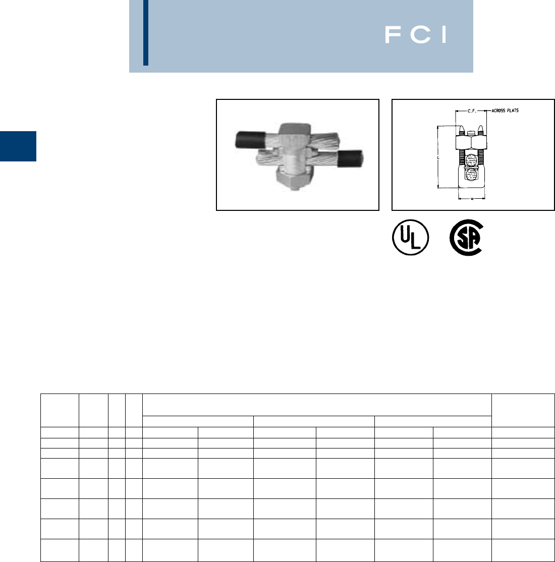
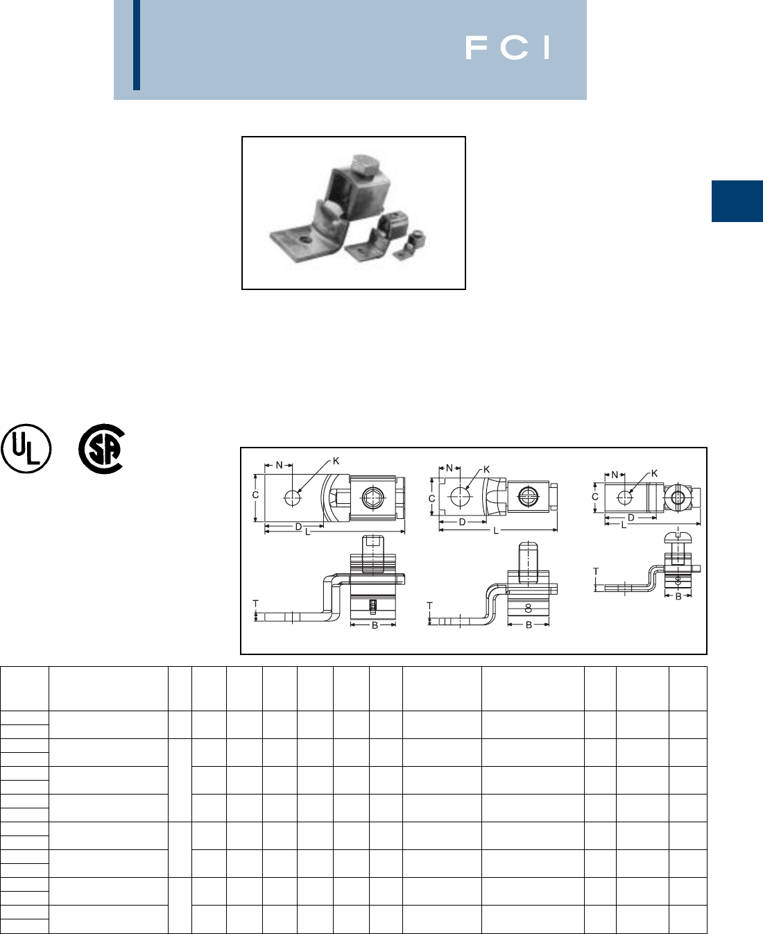
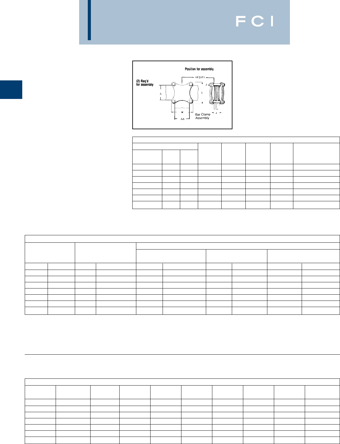
TYPE HFB-P1
BAR CLAMP ASSEMBLY
COMPONENTS
For Copper Bar
To build your own high strength clamp assem-
bly for multiple flat bar using type HFB-P1 bar
clamps and clamping hardware, the following
tables have been provided. The clamp
assembly eliminates the need for drilling the
flat bar and is used in indoor and outdoor
applications.
*Z=Space between the bar clamp contact surfaces
†Ordered separately from BURNDY®.
*See table below when ordering assembly clamp-
ing bolts to specify correct bolt length in Cat. #.
NOTE: When ordering assembly bolts specify
correct bolt length in catalog number as
indicated in table.
ONE CLAMP HALF
BAR CLAMP BAR “J” RECOMMENDED
CATALOG RUN TAP BOLT TIGHTENING
NUMBER ‘A’ ‘AA’ DIA. L W Z TORQUE in-lb
HFB22P1 2.00 2.00 3/8 4.38 4.38 * 240
HFB33P1 3.00 3.00 3/8 4.38 4.38 * 240
HFB42P1 4.00 2.00 3/8 5.75 5.75 * 240
HFB44P1 4.00 4.00 1/2 5.75 5.75 * 480
HFB63P1 6.00 3.00 1/2 7.75 4.75 * 480
HFB66P1 6.00 6.00 5/8 8.12 8.12 * 660
HFB88P1 8.00 8.00 3/4 10.50 10.50 * 1990
BAR CLAMP ASSEMBLY COMPONENTS †
COPPER SILICON BRONZE CLAMPING HARDWARE
BUS BAR SPLIT LOCK
WIDTH (INCHES) BAR CLAMP BOLTS NUTS WASHERS
RUN-A TAP-AA QTY. CAT. NO. QTY. CAT. NO. QTY. CAT. NO. QTY. CAT. NO.
222HFB22P1 438 X (*) HEB 438CHEN 438SW
332HFB33P1 438 X (*) HEB 438CHEN 438SW
422HFB42P1 438 X (*) HEB 438CHEN 438SW
442HFB44P1 450 X (*) HEB 450CHEN 450SW
632HFB63P1 450 X (*) HEB 450CHEN 450SW
662HFB66P1 462 X (*) HEB 462CHEN 462SW
882HFB88P1 475 X (*) HEB 475CHEN 475SW
BOLT LENGTH
CLAMP “J” WHEN WHEN WHEN WHEN WHEN WHEN WHEN WHEN
NUMBER BOLT DIA. Z = 1.25 Z = 1.50 Z = 1.75 Z = 2.00 Z = 2.25 Z = 2.50 Z = 2.75 Z = 3.00
HFB22P1 3/8 (-16) 3.00 3.25 3.50 4.00 4.00 4.50 4.50 5.00
HFB33P1 3/8 (-16) 3.00 3.25 3.50 4.00 4.00 4.50 4.50 5.00
HFB42P1 3/8 (-16) 3.00 3.25 3.50 4.00 4.00 4.50 4.50 5.00
HFB44P1 1/2 (-13) 3.25 3.50 3.75 4.00 4.50 4.50 5.00 5.00
HFB63P1 1/2 (-13) 3.25 3.50 3.75 4.00 4.50 4.50 5.00 5.00
HFB66P1 5/8 (-11) 3.50 4.00 4.00 4.50 4.50 5.00 5.00 5.50
HFB88P1 3/4 (-10) 3.75 4.00 4.50 4.50 5.00 5.00 5.50 5.50
BURNDY
Mechanical
A-23
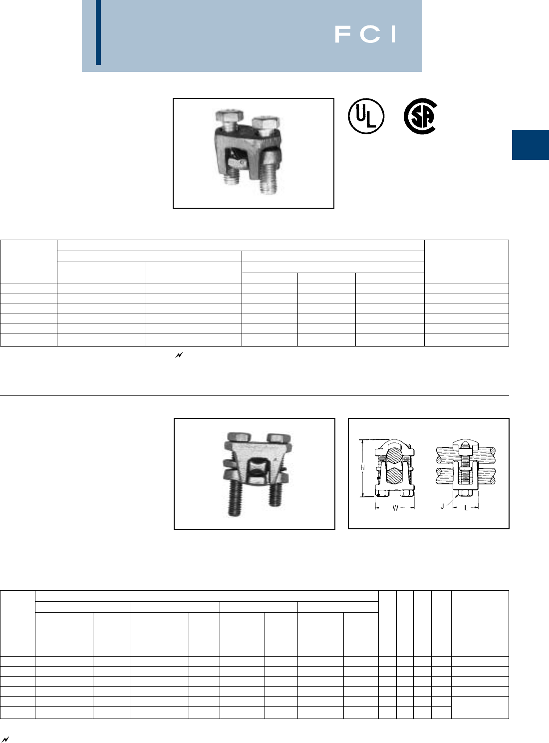
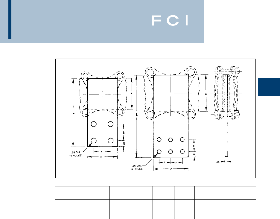
TYPE HFB-N
BAR CLAMP TAP
PAD ADAPTER
For Copper Bar
High conductivity copper, tap pad adapter
provides a NEMA drilled contact pad when
assembled to the HFB-P1 clamps. Tap
connections can be made from copper bus
bar(s) without drilling, by bolting standard
mechanical or compression terminal pads
directly to the pre-drilled tap pad
①‘H’ Clamp (two required per assembly) and hardware (as
shown) not included with bar clamp tap pad, order
separately.
Fig. 1 Fig. 2
CATALOG FIG. USE WITH ‘H’ CLAMP
NUMBER NO. A-C E & F L N CATALOG NUMBER ①
HFB33-4N 13.00 1.75 7.00 .62 HFB33P1
HFB44-4N 14.00 1.75 9.12 1.12 HFB44P1
HFB66-6N 26.00 1.75 11.31 1.12 HFB66P1
BURNDY
Mechanical
A-24
TYPES KA-U, KKA-U
UNIVERSAL TERMINAL
(One Conductor) For Aluminum
and Copper Conductors
These dual-rated one-conductor lugs are
constructed from high strength aluminum
alloy and electro tin-plated to provide low
contact resistance.
*"N" indicates NEMA standard stud holes.
▲Listed torque values are for maximum conductor sizes
accommodated. Consult UL486 Tables 7-4, 7-5, 7-6 for
smaller conductor sizes.
** Maximum dimension.
AL9CU
Fig. 1 Fig. 2
Fig. 3 Fig. 4
WIRE RANGE STUD DIMENSIONS RECOMMENDED
CATALOG FIG. ALUMINUM OR HOLE ** ** TIGHTENING ▲
NUMBER* NO. COPPER SIZE D L N W E T H TORQUE in-lb
KA6U 114 STR. - 6 STR. .63 1.06 .25 .50 — .09 .50 45
KA2U 114 STR. - 2 STR. .63 1.16 .31 .50 — .10 .55 50
KA25U 114 STR. - 1/0 STR. 1/4 .81 1.50 .44 .63 — .19 .80 50
KA26U 26 STR. - 2/0 STR. .81 1.47 .47 .63 — .19 .80 120
KA29U 26 STR. - 250 .94 2.00 .50 1.00 — .25 1.13 275
KA30U 26 STR. - 300 5/16 .94 2.00 .50 1.00 — .25 1.12 275
KA31U 26 STR. - 350 1.03 2.25 .88 1.13 — .25 1.25 375
KA34U 24 STR. - 500 3/8 1.50 2.81 .88 1.51 — .31 1.58 500
KA36U 22 STR. - 600 1.72 3.19 .78 1.50 — .44 1.56 500
KA40U 2300 - 800 1.69 3.38 .88 1.75 — .50 1.94 500
KA44U 2500 - 1000 1/2 1.69 3.38 .88 1.75 — .50 1.94 600
KKA31U-2N 36 STR. - 350 3.16 5.50 .63 1.25 1.75 .38 1.50 375
KA36U-2N 42 STR. - 600 3.22 4.69 .63 1.50 1.75 .44 1.57 500
KA40U-2N 4300 - 800 1/2 3.03 4.75 .63 1.75 1.75 .50 1.94 500
KA44U-2N 4500 - 1000 3.03 4.75 .63 1.75 1.75 .50 1.94 600
BURNDY
Mechanical
A-25
TYPE K2A-U
UNIVERSAL TERMINAL
(Two Conductor)
For Aluminum and
Copper Conductors
These dual-rated two-conductor lugs are con-
structed from high strength aluminum alloy
and electro tin-plated to provide low contact
resistance.
Fig. 1 Fig. 2
Fig. 3
*"N" indicates NEMA standard stud holes.
▲Listed torque values are for maximum conductor sizes
accommodated. Consult UL486 Tables 7-4, 7-5, 7-6 for
smaller conductor sizes.
** Maximum dimension.
WIRE RANGE STUD DIMENSIONS RECOMMENDED
CATALOG FIG. ALUMINUM OR HOLE ** ** TIGHTENING ▲
NUMBER* NO. COPPER SIZE D L N W E T H TORQUE in-lb
K2A25U 1Two: 14 STR. - 1/0 STR. .81 1.47 .44 1.13 — .19 .79 50
K2A26U 2Two: 14 STR. - 2/0 STR. 1/4 .81 1.47 .44 1.25 — .19 .79 50
K2A29U 2Two:6 STR. - 250 3/8 1.50 2.56 .50 1.66 — .25 1.20 275
K2A31U 2Two:4 STR. - 350 1.69 2.88 .88 1.94 — .25 1.25 275
K2A36U 2Two:2 STR. - 600 1/2 1.75 3.20 .63 2.41 — .44 1.58 375
K2A40U 2Two: 300 - 800 1.66 3.38 .88 3.19 — .50 1.94 375
K2A44U 2Two: 500 - 1000 5/8 1.66 3.50 .88 3.52 — .50 1.94 375
K2A31U-2N 3Two:6 STR. - 350 3.00 4.50 .63 2.31 1.75 .31 1.38 275
K2A36U-2N 3Two:2 STR. - 600 3.22 4.69 .63 2.41 1.75 .44 1.56 375
K2A40U-2N 3Two: 300 - 800 1/2 3.03 4.75 .63 3.19 1.75 .50 1.94 375
K2A44U-2N 3Two: 500 - 1000 3.03 4.75 .63 3.19 1.75 .50 1.94 375
BURNDY
Mechanical
A-26
TYPES K3A-U, KK3A-U
UNIVERSAL TERMINAL
(Three Conductor)
For Aluminum and
Copper Conductors
Dual-rated three-conductor lugs are con-
structed from high strength aluminum alloy
and electro tin-plated to provide low contact
resistance.
AL9CU
Fig. 1 Fig. 2
Fig. 3
*Slotted screw.
** ‘‘N” indicates NEMA standard stud holes.
▲Listed torque values are for maximum conductor sizes
accommodated.
Consult UL486 Tables 7-4, 7-5, 7-6 for smaller conductor
sizes. All 4N items See note page A-2
WIRE RANGE STUD RECOMMENDED
CATALOG FIG. ALUMINUM OR HOLE DIMENSIONS TIGHTENING ▲
NUMBER* NO. COPPER K SIZE D L N W E T H TORQUE in-lb
K3A2U-2* 1Three: 14 STR. - 2 STR. 11/32 5/16 1.63 2.19 .34 1.59 .88 .19 .62
K3A25U-2* 1Three: 14 STR. - 1/0 STR. 7/16 3/8 2.09 2.91 .34 1.94 1.00 .25 .88 50
K3A26U-2N 3Three: 14 STR. - 2/0 STR. 3.06 3.75 .63 1.95 .19 1.79
K3A27U-2N 3Three: 6 STR. - 3/0 STR. 3.00 3.88 .63 2.81 .31 1.12
K3A29U-2N 3Three: 6 STR. - 250 3.00 4.00 .63 2.81 .31 1.19 275
K3A31U-2N 3Three: 6 STR. - 350 3.00 4.31 .63 3.00 .31 1.38
K3A36U-2N 3Three: 2 STR. - 600 9/16 1/2 3.22 4.69 .63 3.63 1.75 .44 1.56
KK3A36U-2N 2Three: 2 STR. - 600 3.00 5.63 .56 4.22 .44 1.69
KK3A40U-2N 2Three: 300 - 800 3.03 5.69 .63 4.81 .50 1.94 375
KK3A44U-2N 2Three: 500 - 1000 3.34 6.19 .63 4.75 .56 1.88
BURNDY
Mechanical
A-27
TYPES K3A-U, KK3A-U
(Continued)
*Slotted screw
** ‘‘N” indicates NEMA standard stud holes.
▲Listed torque values are for maximum conductor sizes
accommodated. Consult UL486 Tables 7-4, 7-5, 7-6 for
smaller conductor sizes.
All 4N items See note page A-2
Fig. 1 Fig. 2
Fig. 3 Fig. 4
AL9CU
WIRE RANGE STUD RECOMMENDED
CATALOG FIG. ALUMINUM OR HOLE DIMENSIONS TIGHTENING ▲
NUMBER** NO. COPPER K SIZE D L N W E T H TORQUE in-lb
K3A2U-4* 3Three: 14 STR. - 2 STR. 11/32 5/16 1.63 2.19 .34 1.59 .88 .19 .62
K3A25U-4* 3Three: 14 STR. - 1/0 STR. 7/16 3/8 2.09 2.91 .34 1.94 1.00 .25 .88 50
K3A27U-4N 3Three: 6 STR. - 3/0 STR. 3.00 3.88 2.81 .31 1.12
K3A29U-4N 3Three: 6 STR. - 250 3.00 4.00 2.81 .31 1.19 275
K3A31U-4N 3Three: 6 STR. - 350 3.00 4.31 3.00 .31 1.38
K3A36U-4N 3Three: 2 STR. - 600 3.22 4.69 3.63 .44 1.56
K3A40U-4N 3Three: 300 - 800 9/16 1/2 3.03 4.75 .63 4.81 1.75 .50 1.94 375
KK3A36U-4N 4Three: 2 STR. - 600 3.00 5.63 4.22 .44 1.69
KK3A40U-4N 4Three: 350 - 800 3.34 6.19 5.34 .56 1.88 275
KK3A44U-4N 4Three: 500 - 1000 3.34 6.19 4.75 .56 1.88 375
BURNDY
Mechanical
A-28
TYPES K4A-U, KK4A-U
UNIVERSAL TERMINAL
(Four Conductor)
For Aluminum and
Copper Conductors
These dual-rated four conductor lugs are
constructed from high strength aluminum
alloy and electro tin-plated to provide low
contact resistance.
AL9CU
*”N” indicates NEMA standard stud holes.
All 4N items See note page A-2
*Not CSA Listed.
▲Listed torque values are for maximum conductor sizes
accommodated. Consult UL486 Tables 7-4, 7-5, 7-6 for
smaller conductor sizes.
TYPES K11A-U,
K21A-U,
K22A-U
UNIVERSAL TERMINAL
For Aluminum and
Copper Conductors
Dual-rated panelboard lugs are constructed
from high strength extruded aluminum alloy
and electro tin-plated to provide low contact
resistance.
Fig. 1
Fig. 2 Fig. 3
Fig. 4 Fig. 5
Fig. 1 Fig. 2
AL9CU
WIRE RANGE STUD RECOMMENDED
CATALOG FIG. ALUMINUM OR HOLE DIMENSIONS TIGHTENING ▲
NUMBER* NO. COPPER SIZE D L N W E T H TORQUE in-lb
K4A29U-4N 1Four: 6 STR. - 250 3 4 3.69 .31 1.19
K4A31U-4N 1Four: 6 STR. - 350 3 4.31 5.04 .31 1.38 275
KK4A36U-4N 2Four: 2 STR. - 600 1/2 3.34 5.63 .63 51.75 .44 1.69
KK4A40U-4N 2Four: 300 - 800 3 6.19 6 .56 1.88 375
WIRE RANGE STUD RECOMMENDED
CATALOG FIG. ALUMINUM OR HOLE DIMENSIONS TIGHTENING ▲
NUMBER* NO. COPPER SIZE D L N W E T H TORQUE in-lb
K11A30U* 1Two:6 STR. - 300 5/16 .94 3.00 .47 1.00 — .31 2.00 275
K11A34U-2 2Two: 4/0 STR. - 500 1/4 2.91 .25 1.44 .69 .63 2.38
K11A36U-2 3Two:2 STR. - 600 1.50
K21A36U-2 4Three: 2 STR. - 600 2.50
K22A36U-2 5Four: 2 STR. - 600 3/8 2.31 4.91 .38 2.50 1.38 .75 3.00 375
K11A39U-2 3Two: 1/0 STR. - 750 1.69
K22A39U-2 5Four: 1/0 STR. - 750 3.06
BURNDY
Mechanical
A-29
TYPE KAU-KIT
TRANSFORMER LUG KIT
These dual-rated lugs are constructed from
high strength aluminum alloy and electro tin-
plated to provide low contact resistance.
Lugs and mounting hardware packaged
together in these kits.
Features and Benefits
•UL listed AL9CU dual rated set screw
terminals and CSA certified.
◊Ensure the transformer feeders and
taps are terminated properly.
•Plated steel cap screws and hex nuts
with captive conical washers or individual
Belleville washers.
◊Terminal to bus connections are made
using proper hardware resulting in true
torque to pressure performance.
Compensates for dissimilar metal
expansion and contraction.
•Hardware packed in plastic bag.
◊No lost hardware prior to installation.
•Larger 800 kcmil lugs in KIT3 and KIT4.
◊Accommodates common 750 kcmil tap
conductors in larger transformers.
TERMINALS WIRE RANGE
CATALOG TRANSFORMER CATALOG ALUMINUM HARDWARE
NUMBER KVA RATING QTY. NUMBER OR COPPER QTY. BOLT SIZE QTY. NUT QTY. WASHER
15 - 37.5 1Ø 8 KA2U #14 - 2
KAU-KIT1 15 - 45 3Ø 4 KA29U #6 - 250 81/4-20 3/4 HH 8 1/4 20 HN — Captive to Nut
50 - 75 1Ø 8 1/4-20 3/4 HH
KAU-KIT2 75 - 112.5 3Ø 12 KA29U #6 - 250 81/4-20 2 HH 16 1/4 20 HN — Captive to Nut
100 - 167 1Ø 6 K2A31U #6 - 350 5 1/2-13 3 HH 22 1/2 FW
KAU-KIT3 150 - 300 3Ø 7 K2A40U 300 - 800 6 1/2-13 2-1/2 HH 11 1/2-13 HN 11 1/2 Belleville
71/2-13 2221/2 FW
KAU-KIT4 400 - 500 3Ø 15 K2A40U 300 - 800 41/2-13 2-1/2 11 1/2-13 HN 11 1/2 Belleville
BURNDY
Mechanical
A-30
TYPE AMS
DUAL RATED
SPLICER/REDUCER
For Copper and
Aluminum Cable
All splicer/reducers are dual rated for use with
aluminum and copper conductors and are
constructed from high strength, tin plated
aluminum. PENTROX™ oxide inhibiting joint
compounds are recommended for all
aluminum applications.
Features and Benefits
•All connectors are tin-plated.
◊Provide low contact resistance and
prevents galvanic corrosion.
•Connectors feature rounded bottoms.
◊Facilitates taping.
•Solid center barrier.
◊Prevents contact of dissimilar metals.
*Slotted Screws. H2 measured with maximum conductors,
reference only.
Complies with NFPA 78-86.
•Large screw diameters.
◊Ensures greater surface contact with
wires for maximum pullout force.
•Large cable ranges.
◊Each splice is also an effective
reducing connector.
CATALOG WIRE RANGE NO. OF SCREW HEX
NUMBER MAX. MIN. L W H1 H2 MAX. SCREWS DIA. SIZE
AMS-2* 2141-19/32 9/16 9/16 .79 2 3/8 S
AMS-0* 1/0 8 1-29/32 3/4 3/4 .86 2 7/16 S
AMS-4/0 4/0 6 2-5/16 1 1-3/32 1.28 2 9/16 5/16
AMS-250 250 6 4-3/32 1 1-3/32 1.29 4 5/8 5/16
AMS-350 350 6 4-11/32 1 1-3/32 1.30 4 11/16 5/16
AMS-500 500 3/0 4-25/32 1-1/4 1-3/8 1.48 4 13/16 3/8
AMS-750 750 250 6-1/16 1-7/16 1-5/8 1.98 4 15/16 1/2
AMS-1000 1000 500 8-11/16 1-21/32 1-7/8 2.34 6 1-1/8 9/16
BURNDY
Mechanical
A-31
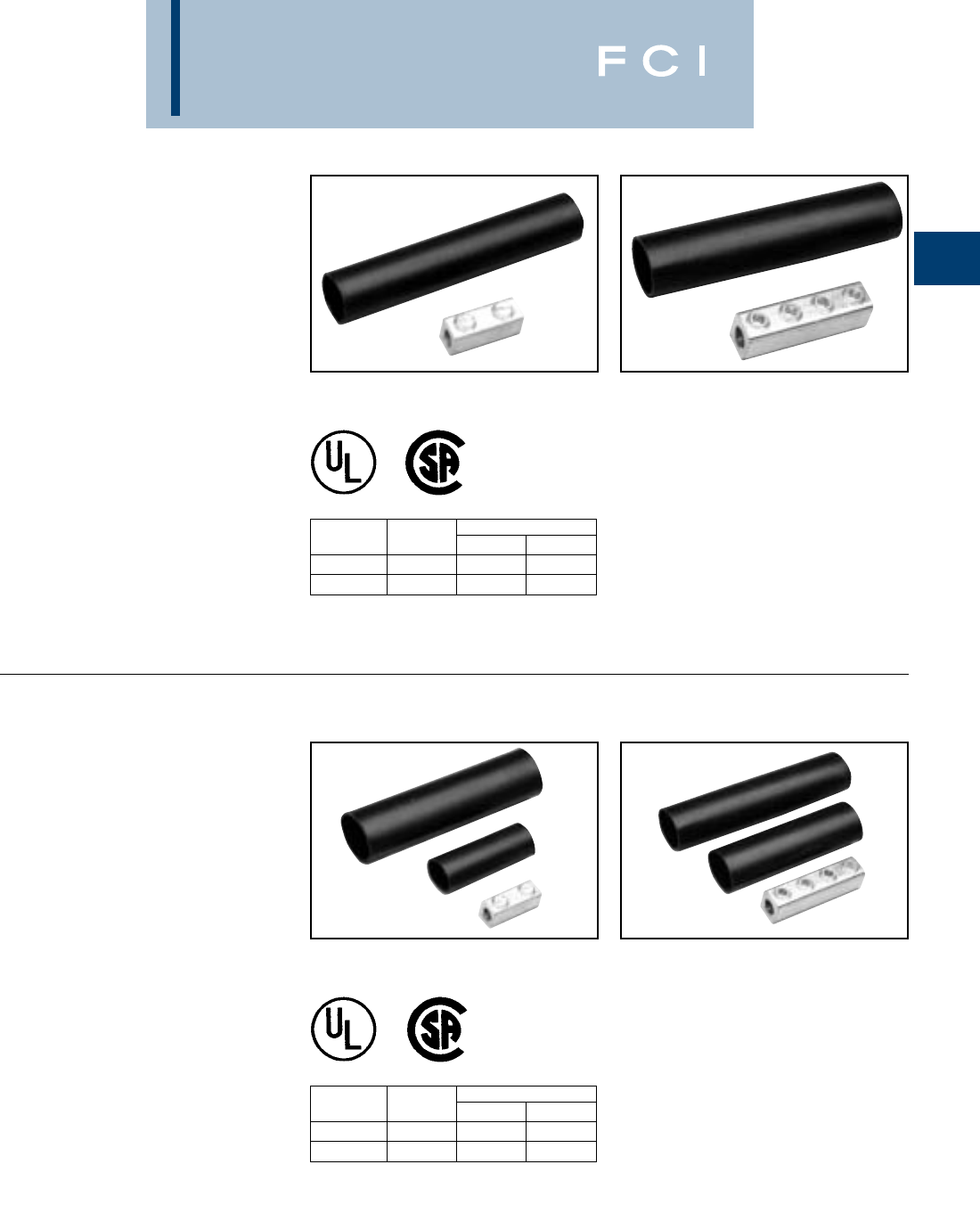
TYPE AGSKIT
ABOVE GRADE SPLICE KITS
For all Aluminum or
Copper/Aluminum
Combinations
Type AGS Above Grade Splice Kit consists of
a standard AMS splice/reducer and a heavy
wall heat-shrink sleeve. The AMS Splice is
dual rated for use with aluminum and copper
conductors and are constructed from high
strength, tin plated aluminum that provides
low contact resistance and reduces the
effects of galvanic corrosion. Connector is
installed with common installation tools. The
heavy wall heat shrink sleeve is lined with
adhesive material, providing a positive seal
against moisture egress. Heat shrink sleeve
is installed with standard propane torch, or
electric heat gun.
Catalog Figure Wire Range
Number Number Maximum Minimum
AGSKIT2 128
AGSKIT250 2250 1
Fig. 1 Fig. 2
TYPE UGSKIT
WATERTIGHT/UNDERGROUND
SPLICE KITS
For all Aluminum or
Copper/Aluminum
Combinations
Type UGS Watertight Underground Splice Kit
consists of a standard AMS splice/reducer
and two heavy wall heat-shrink sleeves. The
AMS Splice is dual rated for use with
aluminum and copper conductors and are
constructed from high strength, tin plated
aluminum that provides low contact resis-
tance and reduces the effects of galvanic
corrosion. Connector installed with common
installation tools. Both heavy wall heat shrink
sleeves are lined with adhesive material,
providing a watertight splice that can with-
stand abrasions that may occur during direct
burial applications. Heat shrink sleeve
installed with standard propane torch, or elec-
tric heat gun.
Catalog Figure Wire Range
Number Number Maximum Minimum
UGSKIT2* 128
UGSKIT250* 2250 1
Fig. 1 Fig. 2
*UL486D Listed for Direct Burial
BURNDY
Mechanical
A-32
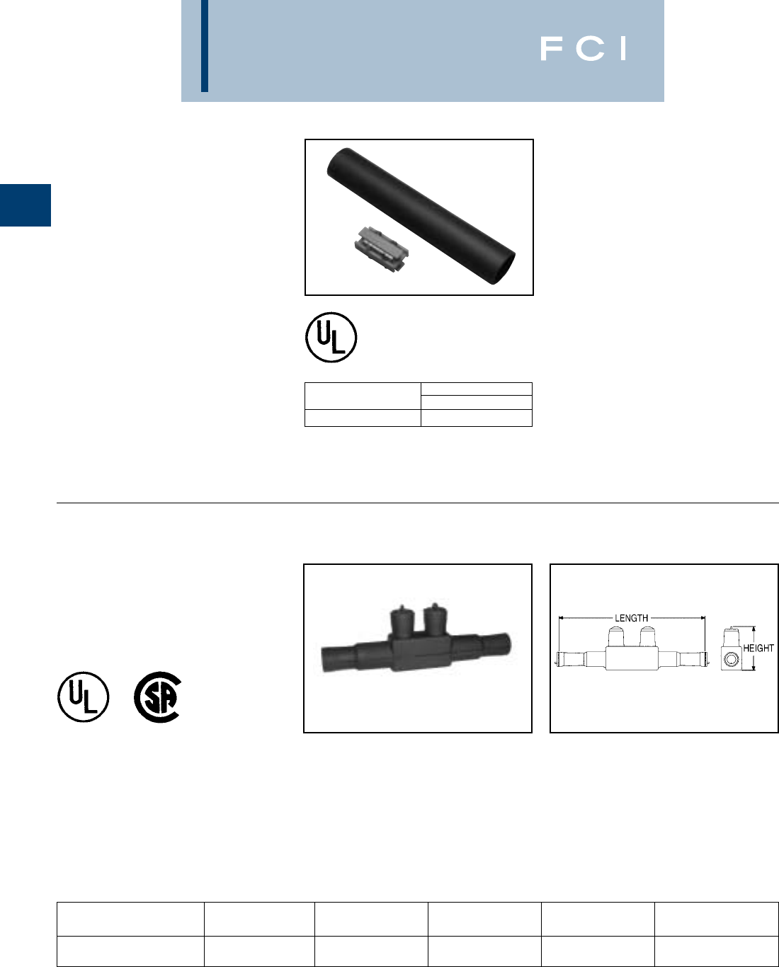
TYPE UGSKIT8
UF DIRECT BURIAL
SPLICE KIT
Type UGS UF Splice Kit consists of a UF
splice connector and a heavy wall heat-shrink
sleeve. The UF splice connector can accom-
modate up to four UF conductors and is
installed with common installation tools. The
heavy wall heat shrink sleeve is lined with an
adhesive material, providing a watertight
splice that can withstand abrasions that may
occur during direct burial applications. Heat
shrink sleeve installed with standard propane
torch, or electric heat gun. Catalog Wire Range
Number Copper
UGSKIT8* 8 AWG –14 AWG
*UL486D Listed for Direct Burial
TYPE UGS350ULDB
IN-LINE SPLICE/REDUCER
For Direct Burial
Features and Benefits
•EPDM rubber covered 6061-T6 aluminum
connector.
•Dual rated AL9CU for copper or aluminum
conductor.
•ULListed and CSA Certified for Direct
Burial.
•Broad range taking capability.
•Low installation cost.
CATALOG LENGTH HEIGHT TORQUE
NUMBER WIRE RANGE In. [mm] In. [mm] HEX SIZE (In. Lbs.)
8.50 2.81
UGS350ULDB 12 AWG - 350 kcmil [216] [71.4] 5/16350
Dimensions in brackets [ ] are in millimeters.
BURNDY
Mechanical
A-33
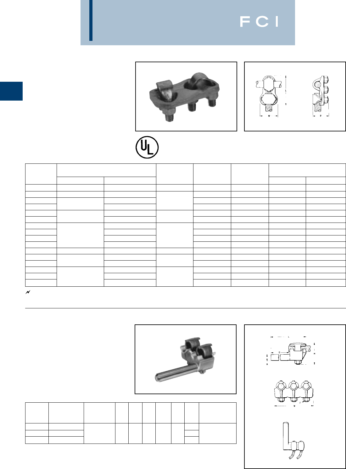
TYPE QGFL
BARTAP™
For Copper Cable To Flat
High copper alloy BARTAP™ for joining a
range of cable to bar or pad. One-wrench
installation.
*Can be installed side by side or in-line on NEMA drilled bar.
CATALOG COPPER T
NUMBER CONDUCTOR B H J (MAX.) W
QGFL1CB1 1-7/8 1/4
QGFL1CB1T6 10 SOL. - 1 STR. 1-1/8 2-3/8 3/4 1
QGFL26B1 2-1/8 3/8 1/4
QGFL26B1T6 1-1/4 2-5/8 3/4
QGFL26B2* 8 SOL. - 2/0 STR. 2-1/2 1/4 1-1/8
QGFL26B2T6* 2-1/8 3/4
QGFL29B1* 1-1/2 2-5/8 1/4
QGFL29B1T6* 6 STR. - 250 3-1/8 3/4 1-3/8
QGFL31B1* 1-5/8 2-7/8 1/4
QGFL31B1T6* 2 SOL. - 350 3-1/4 3/4 1-5/8
QGFL34B1 1-3/4 3-1/8 1/4
QGFL34B1T6 1/0 SOL. - 500 3-5/8 3/4
QGFL39B1 23-1/4 1/2 1/4 1-3/4
QGFL39B1T6 350 - 750 3-5/8 3/4
QGFL44B1 3-3/8 1/4
QGFL44B1T6 750 - 1000 4-1/8 3/4 2-1/8
QGFL46B1 2-1/4 4 1/4
QGFL46B1T6 1000 - 1500 4-1/2 3/4 2-1/2
QGFL48B1 5-1/4 1/4
QGFL48B1T6 1500 - 2000 5-1/4 3/4 3
BURNDY
Mechanical
A-34
NOTE: All pads are NEMA drilled.
TYPE FCB
TRANSFORMER
TAP ADAPTER
For Copper and Aluminum
Silver brazed 101% conductivity copper
transformer tap adapter designed to accom-
modate from 1 to 6 NEMA drilled copper or
aluminum terminal taps from a single
secondary transformer outlet. Tin-plated.
Order mounting hardware & tap terminals
separately.
Fig. 2
Fig. 1
FIG. CATALOG A H
NO. NUMBER DIA. REF. L P
1FCB63-4N .50 5.25 3.75 2.25
2FCB63-6N .50 5.25 5.50 2.25
1FCB64-4N .75 5.75 4.00 2.75
2FCB64-6N .75 5.75 5.75 2.75
1FCB65-4N 1.00 7.00 4.25 4.00
2FCB65-6N 1.00 7.00 6.00 4.00
FCB63-2NP300 .50 5.00 3.50 3.00
4FCB64-44NP50 .75 9.00 5.00 5.00

BURNDY
Mechanical
A-35
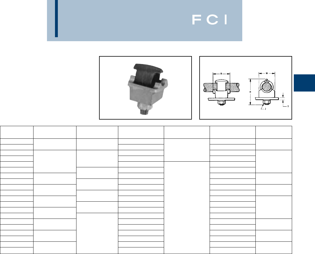
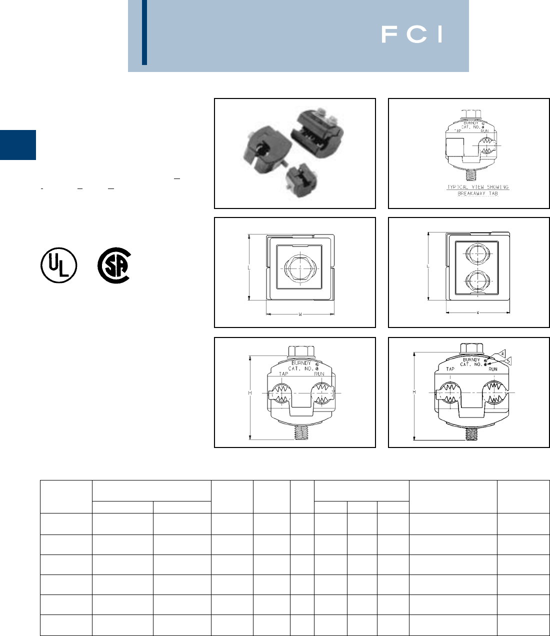
TYPE KPU-AC
POLYTAP™
Insulated Gutter Tap for All
Copper and Aluminum
Combinations
Wide range-taking tin-plated aluminum paral-
lel clamp and insulating cover assembly for
industrial and multiple story structure applica-
tions. Only six connectors cover the entire 14
Sol.-750 kcmil range. Covers having flexible
fingers that conform to conductor, fully insu-
lating the connection. UL486B listed for 600
volts maximum 90° C service. Cover and
connector are packaged together. No taping
required.
600 Volt Max. 90° C
▲Listed torque values are for maximum conductor combina-
tions accommodated. Consult UL486 Tables 7-4, 7-5, 7-6
for smaller combinations.
See note page A-2.
▲Listed torque values are for maximum conductor
combinations accommodated. Consult UL486 Tables 7-4,
7-5, 7-6 for smaller combinations.
TYPE UCU-AC
RISER TAP
Parallel-groove riser tap and insulation cover
for copper and aluminum. Wide range-taking
assembly for apartment house and light
industrial applications. Cover and connector
are packaged together. Covers having insu-
lating fingers that conform to conductors, fully
insulating the connection. UL486B Listed for
600 volts max. 90° C service. 600 VOLT MAX. 90° C MAX.
CONDUCTOR RECOMMENDED
CATALOG COPPER OR ALUMINUM TIGHTENING
NUMBER RUN TAP W H L TORQUE in-lb
KPU29A26AC 1/0 STR. - 250 14 SOL. - 2/0 STR.
KPU29A29AC 1/0 STR. - 250 6 STR. - 250 42-11/16 3-1/8 375
KPU34A26AC 4/0 STR. - 500 14 SOL. - 2/0 STR.
KPU34A34AC 4/0 STR. - 500 6 STR. - 500 4-11/32 1-7/8 3-1/2 450
KPU39A26AC 500 - 750 14 SOL. - 2/0 STR.
KPU39A39AC 500 - 750 1/0 STR. - 750 4-13/16 3-1/4 600
RECOMMENDED
CATALOG CONDUCTOR TIGHTENING ▲
NUMBER RUN TAP W H L TORQUE in-lb
UCU28AC 2 STR. - 4/0 STR. 10 SOL. - 2 STR. 2-1/4 1-13/16 2-5/8 120
BURNDY
Mechanical
A-36
TYPE BIPC
INSUL-TAP™
UL Listed 90° C, *600 Volt
The INSUL-TAP™, TYPE BIPC, Burndy
Insulation Piercing Connector is ideally suited
for splicing and tapping aluminum and copper
conductor wire sizes: #10 AWG to 500 kcmil.
The BIPC's unique insulation piercing design
allows for use on hot-line applications, elimi-
nating the need for taping.
Features and Benefits
•Insulation piercing capability.
◊Eliminates the need for conductor
insulation stripping.
•UL486B listed, AL9CU rated.
◊For copper and aluminum conductor
combinations up to 90° *600 Volt
applications.
•Insulation piercing design.
◊For use on hot-line applications.
Eliminates the need for taping.
•Easy snap-out tabs.
◊Eases installation, protects connection
from dirt and debris.
•Simple bolt-on connection.
◊Eases installation. Fig. 1 Fig. 2
MAX.
CATALOG CONDUCTOR RANGE BOLT SOCKET FIG. DIMENSIONS RECOMMENDED VOLTAGE
NUMBER RUN TAP SIZE SIZE NO. H L W TORQUE (N,m) RATING
1/0 - 8 AWG 2 - 8 AWG 2.00 1.53 2.56 180 in. lbs.
BIPC1/0-2 [50 - 6 mm2][35 - 6 mm2]5/16-18 1/2 1 [51] [39] [65] [20.3 N.m] 600V
4/0 - 1/0 AWG 1/0 - 6 AWG 2.50 2.12 2.00 250 in. lbs.
BIPC4/0-6 [95 - 50 mm2][50 - 16 mm2]5/16-18 1/2 2 [64] [54] [51] [28.3 N.m] 300V
4/0 - 1/0 AWG 4/0 - 1/0 AWG 2.50 2.12 2.06 250 in. lbs.
BIPC4/0-1/0 [95 - 50 mm2][95 - 50 mm2]5/16-18 1/2 2 [64] [2.12] [52] [28.3 N.m] 300V
350 - 4/0 AWG 4/0 - 10 AWG 3.00 1.59 2.50 375 in. lbs.
BIPC350-4/0 [185 - 95 mm2][95 - 6 mm2]3/8-16 9/16 1 [76] [40] [64] [42.4 N.m] 300V
350 - 4/0 AWG 350 - 4/0 AWG 3.00 2.62 2.75 300 in. lbs.
BIPC350-350 [185 - 95 mm2][185 - 95 mm2]3/8-16 9/16 2 [76] [67] [70] [33.9 N.m] 300V
500 - 350 kcmil 4/0 - 4 AWG 3.25 1.59 2.62 400 in. lbs.
BIPC500-4/0 [240 - 185 mm2][95 - 25 mm2]3/8-16 9/16 1 [83] [40] [67] [45.2 N.m] 600V
A-37
BURNDY
Mechanical
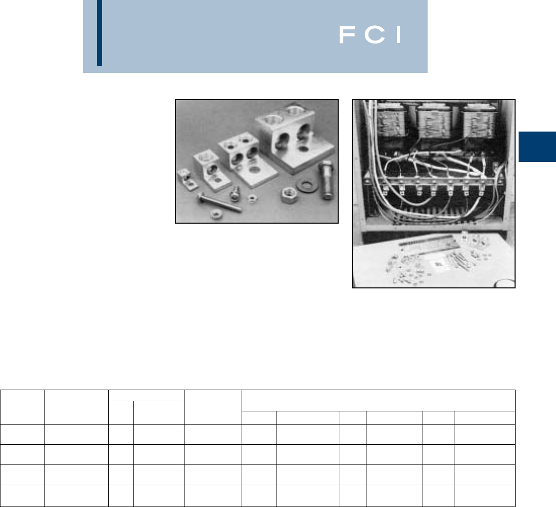
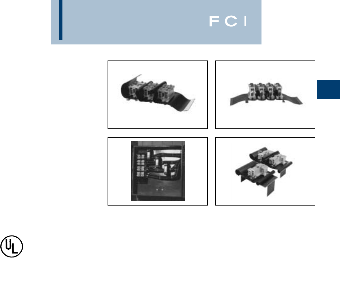
SPEC-BLOK™
POWER
DISTRIBUTION
CONNECTORS
Unique, modular, made-to-order, power-
distribution assemblies accommodate any
number of supply and load conductors in any
number of poles. Capacity matches the con-
ductors accommodated and SPEC-BLOK™
assures uniform loading.
Burndy will “design”, quote, assemble and
ship SPEC-BLOK™ especially constructed to
suit your particular requirements within
48 hours upon request.
Adjacent poles are separated by easy-to-
handle, wrap-around insulating covers which
eliminate taping and reduce heat build-up by
allowing air to flow freely around connectors.
SPEC-BLOK™ is UL Listed for copper or
aluminum conductors for 600 volts. (AL9CU)
Assemblies are mounted on platforms suit-
able for easy installation in wireway or
junction box.
Features and Benefits
•Accommodate unlimited conductors.
◊Fits wide range of applications.
Eliminates need for non-UL-listed
improvisation.
•Connector elements tin-plated.
◊Provides high reliability, low-resistance
connections.
•User friendly, space-saving design.
◊Easy to install. Saves labor.
•94-VO rated insulation folds into place
insulating the components.
◊Saves time and material. Allows
easy installation.
Contact Burndy or Technical Services, 1-800-451-4956
or Burndy Customer Service, 1-800-346-4175
•Connector caps removable for easy
cable lay-in.
◊Saves labor. Makes installation easier.
Allows installation or straight-through
conductors. Eases retrofit.
•Belleville washers built-in on pressure
screw assemblies, except in assemblies
installed with a 5/32" Allen wrench.
◊Provides high-integrity connections.
•Conductors can be cut or fed straight
through.
◊Straight through installation ideal for
riser applications.
BURNDY
Mechanical
A-38
SPEC-BLOK™ Features and Benefits
•The SPEC-BLOK™ system includes
12 connector elements
◊A wide variety of conductor sizes can
be accommodated
•Each element can be bolted together
in parallel
◊Provides an efficient flow of current from
one element to another
•AL9CU rated for Copper or Aluminum
conductors
◊Dual-rated system, with UL486B’s
highest temperature rating
SPEC-BLOK™ CONNECTORS
E
NOITANGISEDGOLATAC MUMIXAM( )ROTCUDNOC
FOREBMUN SROTCUDNOC DETADOMMOCCA
UCroLA REDNUEGNARERIW PACHCAESNOISNEMID NELLA HCNERW EZIS
4rotcudnoC 2rotcudnoC 4rotcudnoC 2rotcudnoC
tsriF srotcudnoC eBTSUM
dnoceS rotcudnoC fi( )deriuqer eByaM
nOthgieH xaM srotcudnoC
htdiW rotalusnItuohtiWhtgneL
4rotcudnoC 2rotcudnoC
AQ
1,0(4ot1 2ro )pacrep
2ro1 pacrep
0/2-0/10/2-21#
61/9-22/1-18/.1-28/7"23/5
)0/2(
BR 052-0/3052-6#
8/1-361/11-14/1-48/3-1
"4/1
)052(
CS 053-052053-6#
61/5-361/31-18/5-42/1-1
)053(
DT 005-004005-6#
61/1-428/5-54/3-1
"8/3
)005(
EW 057-006057-0/3
8/7-44/1-24/1-78/5-2
)057(
Catalog Designation
(Maximum Conductor) Number of Conductors
Accommodated Large
Groove Small
Grooves**
Height On
Maximum
Conductors Width
Length
Without
Insulator
Allen
Wrench
Size
P (1/0) 1 to 8 (0, 1 or 2 under
each screw) __ 6-1/0 3 1/2 2
1 3/4 5/32"
U (1/0 & 500) 2 to 9 (0, 1 or 2 under
each screw plus one
large conductor) 3/0-500 6-1/0 4 1/8 2
** This range may be expanded to include #8 provided two
conductors are being installed in that particular element.
W D T
C S B R A Q U P
•2 Wire (series), 4 (parallel), and Multi-Tap
versions available
◊Nearly any conductor combination can
be terminated
•Tin-plated Aluminum Alloy Construction
◊High-strength, corrosion-resistant
connector elements
•All SPEC-BLOKs™ are custom made for
nearly any Power Distribution system
requirement
◊Time savings — pre-assembled in our
factory for immediate installation!
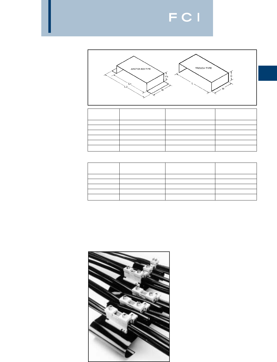
BURNDY
Mechanical
A-39
SPEC-BLOK™
MOUNTING PLATFORMS
SPEC-BLOK™ Mounting Platforms are rigid
steel construction with a black finish. They
can be supplied for junction box mounting or
wireway construction allowing trough conduc-
tors to pass underneath the assemblies. (CPB-) (CPT-)
5DR-NDST-GQP-12
(assembly pictured)
5 Total number of poles in the
completed assembly
DR One 'D' unit and one 'R' unit, bolted
in parallel, forming each phase pole
(3 phase poles)
NDenotes the beginning of the neutral
pole (where required)
DST One 'D' unit, one 'S' unit, and on 'T'
unit, bolted in parallel, forming the
neutral pole
GDenotes the beginning of the ground
pole description (where required)
QP One 'Q' unit and on 'P' unit, bolted in
parallel, forming the ground pole.
12 Size (inches) of the wireway or trough
that is needed to enclose the assem-
bly. If a junction box enclosure is used,
no number is used to denote the size
of the enclosure.
SPEC-BLOK™ catalog numbers describe exactly how the distribution block is assembled:
SPEC-BLOK™ IS A SYSTEM THAT CAN SOLVE MOST POWER DISTRIBUTION APPLICATIONS!
CATALOG L L W
NUMBER (Nominal) (Overall) (Overall)
CPB6 67-3/42-1/2
CPB8 89-3/42-1/2
CPB10 1011-3/42-1/2
CPB12 1213-3/43-1/2
CPB16-5/8 16-5/818-3/83-1/2
CPB21-1/4 21-1/4233-1/2
CATALOG
NUMBER L W H
CPT6 5-7/82-1/22-1/4
CPT8 7-7/83-1/23
CPT10 9-7/83-1/23-1/2
CPT12 11-7/83-1/24
CPT16 15-7/83-1/24

BURNDY
Mechanical
A-40
QUESTIONNAIRE
FOR SPEC-BLOK™
OR ELECTRO-RAIL™
APPLICATIONS
What is the total capacity of the system?_____________amps
How many poles in the system
(3-wire, 4-wire, single phase, etc.)?_____________poles
Are neutral conductors (when required) different sizes (AWG/KCMil)
than the phase conductors?
_________the same size __________different size
Is a ground connection required? ■■Yes ■■No
What are the quantities, sizes (AWG/kcmil) and material (Al/Cu)
of the incoming line conductors and outgoing load conductors?
CONDUCTOR
TYPE
QUANTITY SIZE (Cu/Al)
LINE
PER
PHASE LOAD
LINE
PER
NEUTRAL LOAD
LINE
PER
GROUND
LOAD
Are any conductors continuous? ■■Yes ■■No
If yes, which ones?____________________________________
___________________________________________________
What kind of enclosure is connection assembly being mounted into
and what are inside space dimensions?
Trough size _________________________________________
Box, panel, cabinet, other size___________________________
When is a quotation required? Date:______________________
When is the material required? Date:_____________________
Is there a preference for a particular
Burndy distributor? ■■Yes ■■No
If yes, give name, location & telephone Number:
Name:______________________________________________
Address:____________________________________________
__________________________________________________
Phone #:____________________________________________
BURNDY
Mechanical
A-41
3 WIRE BUS
ASSEMBLY
FOR TROUGH
(INSULATING COVERS AND
MOUNTING BASE INCLUDED)
Bus Assemblies consist of tin plated alu-
minum bus mounted to an insulating platform.
Each phase is separated with 94VO 600 volt
wrap-around adhesive insulations. The entire
assembly is mounted on a trough type base.
DIMENSIONS
CATALOG AMP RATING LENGTH
NUMBER PER BUS BUS INSULATION WIDTH HEIGHT WEIGHT PCS. PER CTN.
1300A-8-3-10 1300 812104.758 lbs. 1
1300A-12-3-10 1300 1216104.7511 lbs. 1
1300A18-3-10 1300 1822104.7515 lbs. 1
1300A-24-3-10 1300 2428104.7522 lbs. 1
1300A-30-3-10 1300 3034104.7526 lbs. 1
1350A-8-3-12 1350 812125.259 lbs. 1
1350A-12-3-12 1350 1216125.2512 lbs. 1
1350A-18-3-12 1350 1822125.2516 lbs. 1
1350A-24-3-12 1350 2428125.2523 lbs. 1
1350A-30-3-12 1350 3034125.2527 lbs. 1
1500A-12-3-10 1500 1216104.7515 lbs. 1
1500A-18-3-10 1500 1822104.7518 lbs. 1
1500A-24-3-10 1500 2428104.7527 lbs. 1
1500A-30-3-10 1500 3034104.7530 lbs. 1
1500A-12-3-12 1500 1216125.2516 lbs. 1
1500A-18-3-12 1500 1822125.2519 lbs. 1
1500A-24-3-12 1500 2428125.2528 lbs. 1
1500A-30-3-12 1500 3034125.2531 lbs. 1
BURNDY
Mechanical
A-42
4 WIRE BUS
ASSEMBLY
FOR TROUGH
(INSULATING COVERS AND
MOUNTING BASE INCLUDED)
DIMENSIONS
CATALOG AMP RATING LENGTH
NUMBER PER BUS BUS INSULATION WIDTH HEIGHT WEIGHT PCS. PER CTN.
1350A-8-4-12 1350 812125.2510 lbs. 1
1350A-12-4-10 1350 1216125.2513 lbs. 1
1350A-18-4-12 1350 1822125.2517 lbs. 1
1350A-24-4-12 1350 2428125.2526 lbs. 1
1350A-30-4-12 1350 3034125.2530 lbs. 1
1500A-12-4-12 1500 1216125.2518 lbs. 1
1500A-18-4-12 1500 1822125.2521 lbs. 1
1500A-24-4-12 1500 2428125.2530 lbs. 1
1500A-30-4-12 1500 3034125.2534 lbs. 1
BURNDY
Mechanical
A-43
WIRE BUS
ASSEMBLY FOR
JUNCTION BOXES
(INSULATING COVERS AND
MOUNTING BASE INCLUDED)
3 WIRE BUS ASSEMBLY
FOR JUNCTION BOXES
(INSULATING COVERS AND
MOUNTING BASE INCLUDED)
4 WIRE BUS ASSEMBLY
FOR JUNCTION BOXES
(INSULATING COVERS AND
MOUNTING BASE INCLUDED)
DIMENSIONS
CATALOG AMP RATING LENGTH
NUMBER PER BUS BUS INSULATION WIDTH HEIGHT WEIGHT PCS. PER CTN.
1350A-8-3-B 1350 812122.759 lbs. 1
1350A-12-3-B 1350 1216122.7512 lbs. 1
1350A-18-3-B 1350 1822122.7516 lbs. 1
1350A-24-3-B 1350 2428122.7523 lbs. 1
1350A-30-3-B 1350 3034122.7527 lbs. 1
1500A-12-3-B 1500 1216122.7515 lbs. 1
1500A-18-3-B 1500 1822122.7518 lbs. 1
1500A-24-3-B 1500 2428122.7527 lbs. 1
1500A-30-3-B 1500 3034122.7530 lbs. 1
DIMENSIONS
CATALOG AMP RATING LENGTH
NUMBER PER BUS BUS INSULATION WIDTH HEIGHT WEIGHT PCS. PER CTN.
1350A-8-4-B 1350 812162.7510 lbs. 1
1350A-12-4-B 1350 1216162.7513 lbs. 1
1350A-18-4-B 1350 1822162.7517 lbs. 1
1350A-24-4-B 1350 2428162.7526 lbs. 1
1350A-30-4-B 1350 3034162.7530 lbs. 1
1500A-12-4-B 1500 1216162.7518 lbs. 1
1500A-18-4-B 1500 1822162.7521 lbs. 1
1500A-24-4-B 1500 2428162.7530 lbs. 1
1500A-30-4-B 1500 3034162.7534 lbs. 1
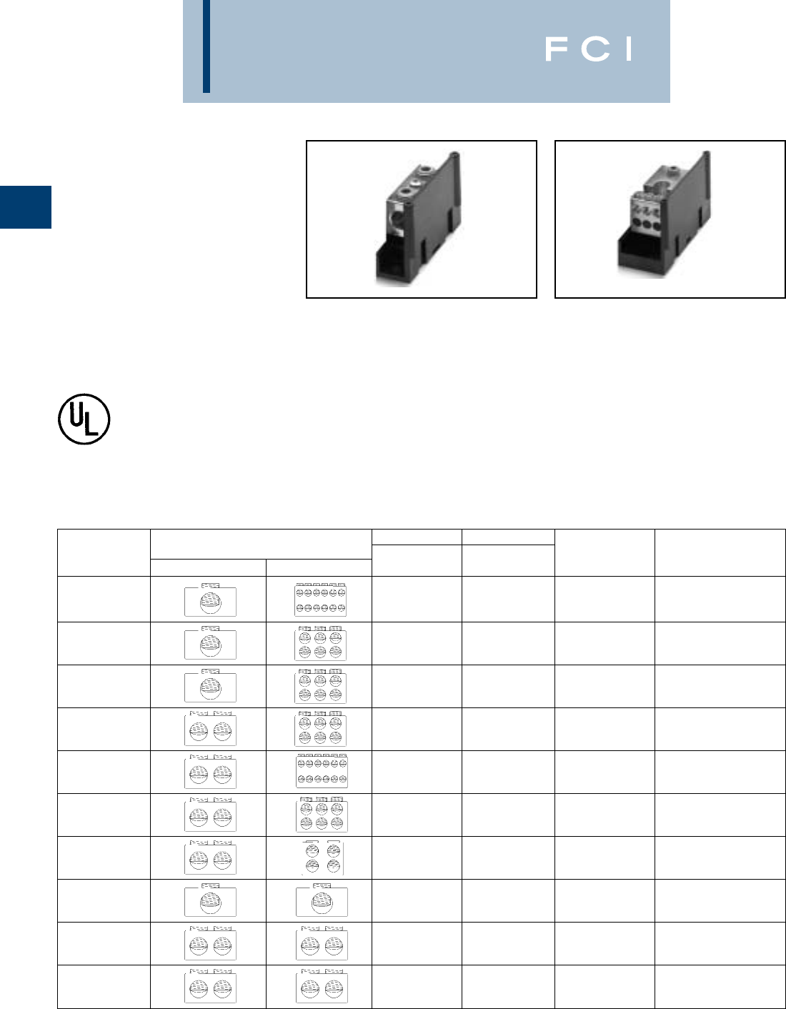
BURNDY
Mechanical
A-44
VERSI-POLE™
POWER DISTRIBUTION
BLOCKS
VERSI-POLE™ Power Distribution Blocks
are designed to provide modular solutions to
power distribution applications. Each connec-
tor element is made from a high conductivity
aluminum alloy which is insulated with a high
strength polymer housing. One, two, and
three pole versions available. "Add" a pole
(snap-together) blocks are also available for
wire sizes up to 500 kcmil. For use with Cu or
Al. 600 V, AL9CU rated.
Features and Benefits
•"Add" a pole feature available.
◊Provides capability to create as many
poles as required.
•Up to 30 tap conductors accommodated.
◊Ideal for current distribution to multiple
locations.
•Single or dual run connections.
◊Allows user to minimize the number
of connectors needed to do the job.
*BDB-430-500-1 not UL recognized or CSA certified
NOTES:
1. Order Optional BDB COVER1 per pole if desired.
2. Snap-together blocks can also be assembled to 1, 2, 3
pole blocks to create multi-pole distribution blocks.
VERSI-POLE™ SNAP-
TOGETHER BLOCKS
•Suitable for use with aluminum or
copper conductors.
◊Provides maximum versatility.
•600 V, AL9CU rated.*
◊Meets or exceeds industry standard
requirements.
•Dead-front covers available
◊Provides user protection – one cover
per pole.
RUNTAP AMPERE
CATALOG CONNECTOR WIRE RANGE WIRE RANGE RATING PER NUMBER OF
NUMBER RUN TAP AL9CU AL9CU POLE POLES
BDA-112-350 350 kcmil - 6 4 - 14 350 ADDER
BDA-16-350 350 kcmil - 6 2/0 - 14 350 ADDER
BDA-16-500 500 kcmil - 4 2/0 - 4 430 ADDER
BDA-26-350 350 kcmil - 6 2/0 - 14 700 ADDER
BDA-212-500 500 kcmil - 4 4 - 14 860 ADDER
BDA-26-500 500 kcmil - 4 2/0 - 14 860 ADDER
BDA-24-500 500 kcmil - 4 4/0 - 6 860 ADDER
BDA-11-500 500 kcmil - 4 500 kcmil - 4 430 ADDER
BDA-22-350 350 kcmil - 6 350 kcmil - 6 700 ADDER
BDA-22-500 500 kcmil - 4 500 kcmil - 4 860 ADDER
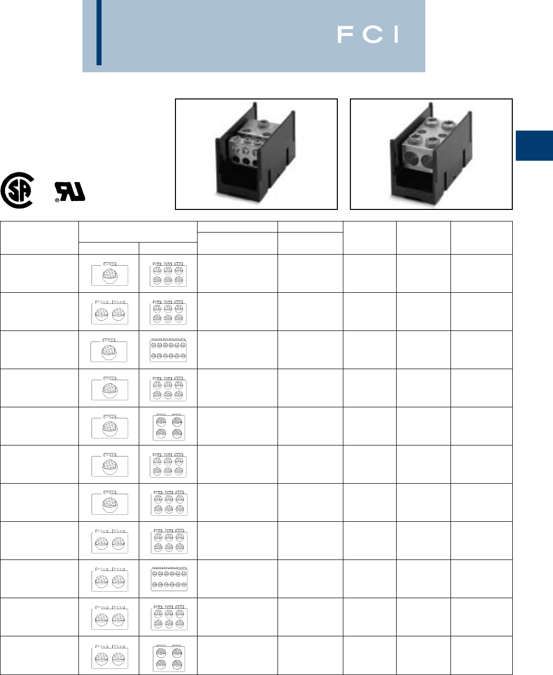
BURNDY
Mechanical
A-45
VERSI-POLE™
VERSI-POLE™ 1, 2, 3 POLE
DISTRIBUTION BLOCKS
RUNTAP AMPERE OPTIONAL
CATALOG CONNECTOR WIRE RANGE WIRE RANGE RATING PER NUMBER OF COVER ORDER
NUMBER RUN TAP AL9CU AL9CU POLE POLES 1 PER POLE
BDB-16-2/0-1 1
BDB-16-2/0-2 2/0 - 12 4 - 14 195 2 BDBCOVER2
BDB-16-2/0-3 3
BDB-26-2/0-1 1
BDB-26-2/0-2 2/0 - 14 2 - 14 390 2 BDBCOVER2
BDB-26-2/0-3 3
BDB-112-350-1 1
BDB-112-350-2 350 kcmil - 6 4 - 14 350 2 BDBCOVER1
BDB-112-350-3 3
BDB-16-350-1 1
BDB-16-350-2 350 kcmil - 6 2/0 - 14 350 2 BDBCOVER1
BDB-16-350-3 3
BDB-14-500-1 1
BDB-14-500-2 500 kcmil - 4 2/0 - 14 430 2 BDBCOVER2
BDB-14-500-3 3
BDB-16-500-1 1
BDB-16-500-2 500 kcmil - 4 2/0 - 14 430 2 BDBCOVER1
BDB-16-500-3 3
BDB-162-500-1 1
BDB-162-500-2 500 kcmil - 4 2 - 14 430 2 BDBCOVER2
BDB-162-500-3 3
BDB-26-350-1 1
BDB-26-350-2 350 kcmil - 6 2/0 - 14 700 2 BDBCOVER1
BDB-26-350-3 3
BDB-212-500-1 1
BDB-212-500-2 500 kcmil - 4 4 - 14 860 2 BDBCOVER1
BDB-212-500-3 3
BDB-26-500-1 1
BDB-26-500-2 500 kcmil - 4 2/0 - 14 860 2 BDBCOVER1
BDB-26-500-3 3
BDB-24-500-1 1
BDB-24-500-2 500 kcmil - 4 4/0 - 6 860 2 BDBCOVER1
BDB-24-500-3 3
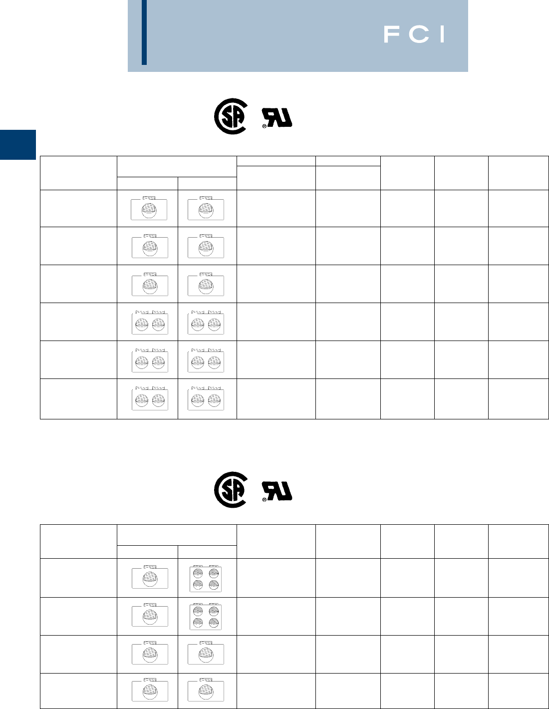
BURNDY
Mechanical
A-46
VERSI-POLE™
VERSI-POLE™ 1, 2, 3
SPLICE/REDUCER BLOCKS
SNAP TOGETHER
SPLICER/REDUCER
BLOCKS
RUNTAP AMPERE OPTIONAL
CATALOG CONNECTOR WIRE RANGE WIRE RANGE RATING PER NUMBER OF COVER ORDER
NUMBER RUN TAP AL9CU AL9CU POLE POLES 1 PER POLE
BDB-11-2/0-1 1
BDB-11-2/0-2 2/0 - 14 2/0 - 14 195 2 BDBCOVER2
BDB-11-2/0-3 3
BDB-11-350-1 1
BDB-11-350-2 350 kcmil - 6 350 kcmil - 6 350 2 BDBCOVER2
BDB-11-350-3 3
BDB-11-500-1 1
BDB-11-500-2 500 kcmil - 6 500 kcmil - 6 430 2 BDBCOVER1
BDB-11-500-3 3
BDB-22-2/0-1 1
BDB-22-2/0-2 2/0 - 14 2/0 - 14 390 2 BDBCOVER2
BDB-22-2/0-3 3
BDB-22-350-1 1
BDB-22-350-2 350 kcmil - 6 350 kcmil - 6 700 2 BDBCOVER1
BDB-22-350-3 3
BDB-22-500-1 1
BDB-22-500-2 500 kcmil - 4 500 kcmil - 4 860 2 BDBCOVER1
BDB-22-500-3 3
RUNTAP AMPERE OPTIONAL
CATALOG CONNECTOR WIRE RANGE WIRE RANGE RATING PER NUMBER OF COVER ORDER
NUMBER RUN TAP AL9CU AL9CU POLE POLES 1 PER POLE
BDC-14-2/0-1 2/0 - 14 4 - 14 195 1 BDBCOVER3
BDA-14-2/0-1 2/0 - 14 4 - 14 195 ADDER BDBCOVER3
BDC-11-2/0-1 2/0 - 14 2/0 - 14 195 1 BDBCOVER3
BDA-11-2/0-1 2/0 - 14 2/0 - 14 195 ADDER BDBCOVER3

BURNDY
Mechanical
A-47
VERSI-POLE™
(Continued)
VERSI-POLE™ 1, 2, 3
SPLICE/REDUCER BLOCKS
THE FIGURE TO THE LOWER RIGHT IS APPLICABLE TO THE FOLLOWING:
Catalog Number Number of Poles Catalog Number Number of Poles
BDA-11-500 1 (adder) BDB-16-500-3 3
BDA-112-350 1 (adder) BDB-212-500-1 1
BDA-16-350 1 (adder) BDB-212-500-2 2
BDA-16-500 1 (adder) BDB-212-500-3 3
BDA-212-500 1 (adder) BDB-22-350-1 1
BDA-22-350 1 (adder) BDB-22-350-2 2
BDA-22-500 1 (adder) BDB-22-350-3 3
BDA-24-500 1 (adder) BDB-22-500-1 1
BDA-26-350 1 (adder) BDB-22-500-2 2
BDA-26-500 1 (adder) BDB-22-500-3 3
BDB-11-500-1 1BDB-24-500-1 1
BDB-11-500-2 2BDB-24-500-2 2
BDB-11-500-3 3BDB-24-500-3 3
BDB-112-350-1 1BDB-26-350-1 1
BDB-112-350-2 2BDB-26-350-2 2
BDB-112-350-3 3BDB-26-350-3 3
BDB-16-350-1 1BDB-26-500-1 1
BDB-16-350-2 2BDB-26-500-2 2
BDB-16-350-3 3BDB-26-500-3 3
BDB-16-500-1 1BDB-430-500-1 1
BDB-16-500-2 2
NO. OF DIMENSIONS A
POLES INCHES
Adder 2.50
12.81
25.31
37.81
N(2.50 X N) + .31
Example for 10 poles:
A = (2.50 X 10) + .31 = 25
These tables and illustrations refer to VERSI-
POLE™ Power Distribution Blocks listed on
pages A-48 through A-50.
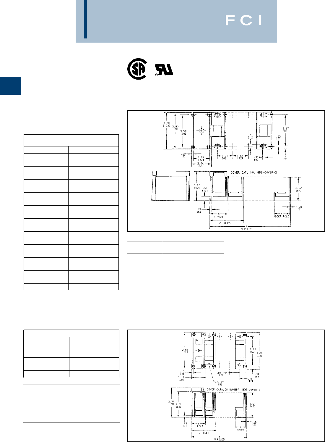
BURNDY
Mechanical
A-48
VERSI-POLE™
(Continued)
VERSI-POLE™ 1, 2, 3
SPLICE/REDUCER BLOCKS
THE FIGURE TO THE RIGHT IS
APPLICABLE TO THE FOLLOWING:
Catalog Number Number of Poles
BDB-11-2/0-1 1
BDB-11-2/0-2 2
BDB-11-2/0-3 3
BDB-11-350-1 1
BDB-11-350-2 2
BDB-11-350-3 3
BDB-14-500-1 1
BDB-14-500-2 2
BDB-14-500-3 3
BDB-16-2/0-1 1
BDB-16-2/0-2 2
BDB-16-2/0-3 3
BDB-162-500-1 1
BDB-162-500-2 2
BDB-162-500-3 3
BDB-22-2/0-1 1
BDB-22-2/0-2 2
BDB-22-2/0-3 3
BDB-26-2/0-1 1
BDB-26-2/0-2 2
BDB-26-2/0-3 3
NO. OF DIMENSIONS A
POLES INCHES
Adder 1.64
11.94
23.57
35.20
N(1.64 X N) + .30
Example for 10 poles:
A = (1.64 X 10) + .30 = 16.20
APPLICABLE VERSI-POLETM ITEMS
Catalog Number Number of Poles
BDA-14-2/0-1 1 (adder)
BDC-14-2/0-1 1
BDA-11-2/0-1 1 (adder)
BDC-11-2/0-1 1
NO. OF DIMENSIONS A
POLES INCHES
Adder .81
11.08
21.89
32.70
N(.81 X N) + .27
Example for 10 poles:
A = (.81 X 10) + .27 = 8.37
These tables and illustrations refer to VERSI-
POLE™ Power Distribution Blocks listed on
pages A-48 through A-50.
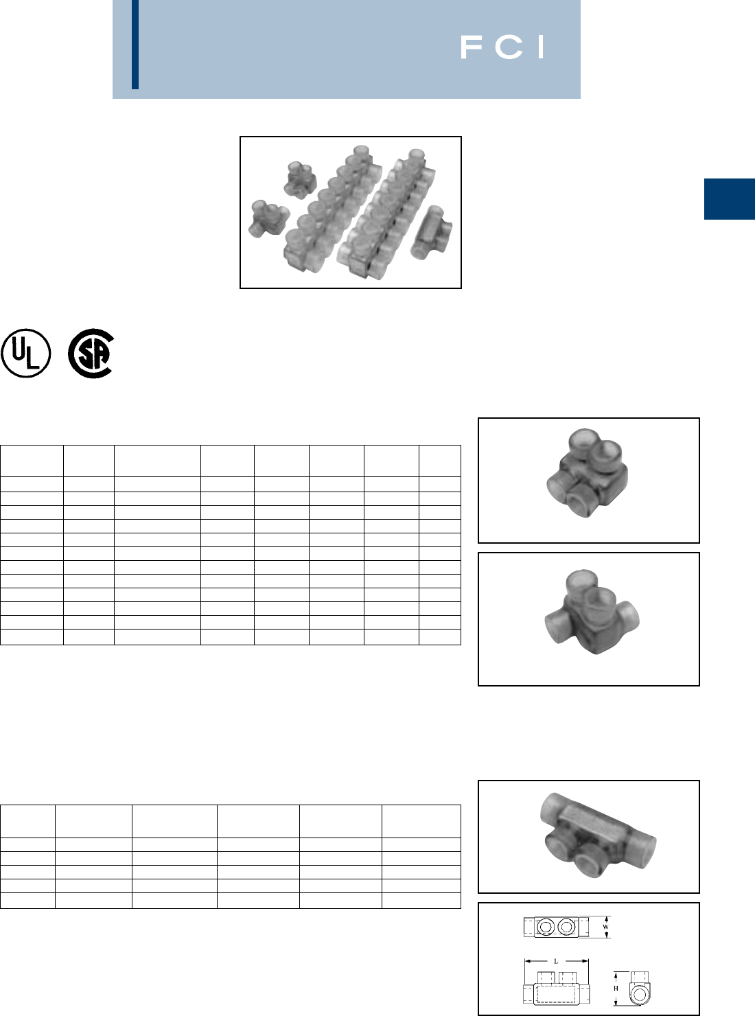
BURNDY
Mechanical
A-49
BURNDY UNITAP™
CLEAR INSULATED
MULTIPLE TAP CONNECTORS
Tap connections and in-line splice/reductions
are made quickly and easily with the
UNITAP™ line of connectors. UL486B Listed.
Dual-rated AL9CU for any stranded copper or
stranded aluminum applications. 600 Volt,
90° C. Features and Benefits
•Clear Plastisol covered AL6061-T6
aluminum body.
◊Saves time, lowers installation costs,
eliminates taping.
•Clear Plastisol.
◊Allows visual confirmation that
conductor is properly inserted.
2 PORT 1 or 2 Sided Entry
IN-LINE SPLICER/REDUCER
Fig. 1
Fig. 2
•Oxide inhibitor pre-installed.
◊Inhibits moisture and contaminants
from entering the contact area.
•Range-taking.
◊Reduces number of connectors carried
in inventory.
*Not UL Listed
Catalog # of Wire Range Fig.
Number Ports (AWG/kcmil) L W H Hex Key No.
BIT4 2#14 - #4 1.16 1.16 1.25 1/8 1
BITO4 2#14 - #4 1.16 1.50 1.25 1/8 2
BIT2/0 2#14 - 2/0 1.52 1.40 1.38 3/16 1
BITO2/0 2#14 - 2/0 1.52 1.56 1.38 3/16 2
BIT250 2#10 - 250 2.03 2.07 2.13 5/16 1
BITO250 2#10 - 250 2.03 2.64 2.13 5/16 2
BIT350 2#10 - 350 2.22 2.32 2.50 5/16 1
BITO350 2#10 - 350 2.22 3.00 2.50 5/16 2
BIT600 2#4 - 600 2.72 2.38 2.75 3/8 1
BITO600 2#4 - 600 2.72 3.00 2.75 3/8 2
BIT750* 2#2 - 750 2.87 2.70 3.00 3/8 1
BITO750* 2#2 - 750 2.87 3.38 3.00 3/8 2
Catalog Wire Range
Number (AWG/kcmil) L W H Hex Key
BISR2 #14 - 2 2.38 0.75 1.22 5/32
BISR1/0 #14 - 1/0 2.91 0.91 1.38 3/16
BISR250 #10 - 250 4.01 1.19 2.10 5/16
BISR350 #10 - 350 4.63 1.34 2.35 5/16
BISR500 #6 - 500 5.00 1.62 2.62 3/8
BURNDY
Mechanical
A-50
BURNDY UNITAP™
MULTI-PORT
Single-Sided Entry
*Not UL Listed
Catalog # of Wire Range Hex
Number Ports (AWG/kcmil) L W H Key
BIBS4-3 3#14 - 4 1.59 1.25 1.25 1/8
BIBS4-4 4#14 - 4 2.03 1.25 1.25 1/8
BIBS4-5 5#14 - 4 2.47 1.25 1.25 1/8
BIBS4-6 6#14 - 4 2.91 1.25 1.25 1/8
BIBS4-8 8#14 - 4 3.78 1.25 1.25 1/8
BIBS2/0-3 3#14 - 2/0 2.19 1.31 1.38 3/16
BIBS2/0-4 4#14 - 2/0 2.86 1.31 1.38 3/16
BIBS2/0-5 5#14 - 2/0 3.53 1.31 1.38 3/16
BIBS2/0-6 6#14 - 2/0 4.20 1.31 1.38 3/16
BIBS2/0-8 8#14 - 2/0 5.55 1.31 1.38 3/16
BIBS2/0-10 10 #14 - 2/0 6.89 1.31 1.38 3/16
BIBS2/0-12 12 #14 - 2/0 8.24 1.31 1.38 3/16
BIBS2/0-14 14 #14 - 2/0 9.58 1.31 1.38 3/16
BIBS250-3 3#10 - 250 2.97 2.07 2.13 5/16
BIBS250-4 4#10 - 250 3.91 2.07 2.13 5/16
BIBS250-5 5#10 - 250 4.84 2.07 2.13 5/16
BIBS250-6 6#10 - 250 5.78 2..07 2.13 5/16
BIBS250-8 8#10 - 250 7.66 2.07 2.13 5/16
BIBS250-10 10 #10 - 250 9.53 2.07 2.13 5/16
BIBS250-12 12 #10 - 250 11.41 2.07 2.13 5/16
BIBS250-14 14 #10 - 250 13.29 2.07 2.13 5/16
BIBS350-3 3#10 - 350 3.13 2.32 2.50 5/16
Catalog # of Wire Range Hex
Number Ports (AWG/kcmil) L W H Key
BIBS350-4 4#10 - 350 4.04 2.32 2.50 5/16
BIBS350-5 5#10 - 350 4.95 2.32 2.50 5/16
BIBS350-6 6#10 - 350 5.86 2.32 2.50 5/16
BIBS350-8 8#10 - 350 7.68 2.32 2.50 5/16
BIBS350-10 10 #10 - 350 9.50 2.32 2.50 5/16
BIBS350-12 12 #10 - 350 11.32 2.32 2.50 5/16
BIBS350-14 14 #10 - 350 13.14 2.32 2.50 5/16
BIBS600-3 3#4 - 600 4.00 2.38 2.75 3/8
BIBS600-4 4#4 - 600 5.28 2.38 2.75 3/8
BIBS600-5 5#4 - 600 6.56 2.38 2.75 3/8
BIBS600-6 6#4 - 600 7.84 2.38 2.75 3/8
BIBS600-8 8#4 - 600 10.41 2.38 2.75 3/8
BIBS600-10 10 #4 - 600 12.97 2.38 2.75 3/8
BIBS600-12 12 #4 - 600 15.53 2.38 2.75 3/8
BIBS600-14 14 #4 - 600 18.09 2.38 2.75 3/8
BIBS750-3* 3#2 - 750 4.25 2.70 3.00 3/8
BIBS750-4* 4#2 - 750 5.63 2.70 3.00 3/8
BIBS750-6* 6#2 - 750 8.37 2.70 3.00 3/8
BIBS750-8* 8#2 - 750 11.13 2.70 3.00 3/8
BIBS750-10* 10 #2 - 750 13.87 2.70 3.00 3/8
BIBS750-12* 12 #2 - 750 16.63 2.70 3.00 3/8
BIBS750-14* 14 #2 - 750 19.37 2.70 3.00 3/8
BURNDY
Mechanical
A-51
BURNDY UNITAP™
MULTI-PORT
Double-Sided Entry
NOTE: Only 1 conductor per port allowed.
*Not UL Listed
Catalog # of Wire Range Hex
Number Ports (AWG/kcmil) L W H Key
BIBD4-2 2#14 - #4 1.16 1.50 1.25 1/8
BIBD4-3 3#14 - #4 1.59 1.50 1.25 1/8
BIBD4-4 4#14 - #4 2.03 1.50 1.25 1/8
BIBD4-5 5#14 - #4 2.47 1.50 1.25 1/8
BIBD4-6 6#14 - #4 2.91 1.50 1.25 1/8
BIBD4-8 8#14 - #4 3.78 1.50 1.25 1/8
BIBD2/0-2 2#14 - 2/0 1.52 1.56 1.25 3/16
BIBD2/0-3 3#14 - 2/0 2.19 1.56 1.25 3/16
BIBD2/0-4 4#14 - 2/0 2.86 1.56 1.25 3/16
BIBD2/0-5 5#14 - 2/0 3.53 1.56 1.25 3/16
BIBD2/0-6 6#14 - 2/0 4.20 1.56 1.25 3/16
BIBD2/0-8 8#14 - 2/0 5.55 1.56 1.25 3/16
BIBD2/0-10 10 #14 - 2/0 6.89 1.56 1.25 3/16
BIBD2/0-12 12 #14 - 2/0 8.24 1.56 1.25 3/16
BIBD2/0-14 14 #14 - 2/0 9.58 1.56 1.25 3/16
BIBD250-2 2#10 - 250 2.03 2.64 2.13 5/16
BIBD250-3 3#10 - 250 2.97 2.64 2.13 5/16
BIBD250-4 4#10 - 250 3.91 2.64 2.13 5/16
BIBD250-5 5#10 - 250 4.84 2.64 2.13 5/16
BIBD250-6 6#10 - 250 5.78 2.64 2.13 5/16
BIBD250-8 8#10 - 250 7.66 2.64 2.13 5/16
BIBD250-10 10 #10 - 250 9.53 2.64 2.13 5/16
BIBD250-12 12 #10 - 250 11.41 2.64 2.13 5/16
BIBD250-14 14 #10 - 250 13.29 2.64 2.13 5/16
BIBD350-2 2#10 - 350 2.22 3.00 2.50 5/16
Catalog # of Wire Range Hex
Number Ports (AWG/kcmil) L W H Key
BIBD350-3 3#10 - 350 3.13 3.00 2.50 5/16
BIBD350-4 4#10 - 350 4.04 3.00 2.50 5/16
BIBD350-5 5#10 - 350 4.95 3.00 2.50 5/16
BIBD350-6 6#10 - 350 5.86 3.00 2.50 5/16
BIBD350-8 8#10 - 350 7.68 3.00 2.50 5/16
BIBD350-10 10 #10 - 350 9.50 3.00 2.50 5/16
BIBD350-12 12 #10 - 350 11.32 3.00 2.50 5/16
BIBD350-14 14 #10 - 350 13.14 3.00 2.50 5/16
BIBD600-2 2#4 - 600 2.56 3.00 2.75 3/8
BIBD600-3 3#4 - 600 3.77 3.00 2.75 3/8
BIBD600-4 4#4 - 600 4.97 3.00 2.75 3/8
BIBD600-5 5#4 - 600 6.17 3.00 2.75 3/8
BIBD600-6 6#4 - 600 7.37 3.00 2.75 3/8
BIBD600-8 8#4 - 600 9.78 3.00 2.75 3/8
BIBD600-10 10 #4 - 600 12.97 3.00 2.75 3/8
BIBD600-12 12 #4 - 600 15.53 3.00 2.75 3/8
BIBD600-14 14 #4 - 600 18.09 3.00 2.75 3/8
BIBD750-2* 2#2 - 750 2.87 3.38 3.00 3/8
BIBD750-3* 3#2 - 750 4.25 3.38 3.00 3/8
BIBD750-4* 4#2 - 750 5.63 3.38 3.00 3/8
BIBD750-6* 6#2 - 750 8.37 3.38 3.00 3/8
BIBD750-8* 8#2 - 750 11.13 3.38 3.00 3/8
BIBD750-10* 10 #2 - 750 13.87 3.38 3.00 3/8
BIBD750-12* 12 #2 - 750 16.63 3.38 3.00 3/8
BIBD750-14* 14 #2 - 750 19.37 3.38 3.00 3/8
BURNDY
Mechanical
A-52
BURNDY UNITAP™
CLEAR INSULATED
MULTIPLE TAP CONNECTORS
MOUNTING VERSION
TYPE BIBS-MT, BIBD-MT
The BIBS-MT and BIBD-MT series UNITAP™
offer the same multi-port capabilities as the
standard UNITAP™ connectors except these
-MT types are provided with two isolated
mounting holes at both ends of the connector
for direct mounting to a trough, gutter or
wireway. They will accommodate up to
standard 1/4hardware.
MULTI-PORT
Double-Sided Entry
Fig. 1 Fig. 2
Catalog # of Wire Range Hex
Number Fig # Ports (AWG/Kcmil) L W H Key
BIBS2/04MT 14 #14-2/0 3.95 1.31 1.38 3/16
BIBS2/06MT 16 #14-2/0 5.29 1.31 1.38 3/16
BIBS2/08MT 18 #14-2/0 6.64 1.31 1.38 3/16
BIBS2/010MT 110 #14-2/0 7.98 1.31 1.38 3/16
BIBS2/012MT 112 #14-2/0 9.33 1.31 1.38 3/16
BIBS2504MT 14 #10-250 5.53 2.07 2.13 5/16
BIBS2506MT 16 #10-250 7.40 2.07 2.13 5/16
BIBS2508MT 18 #10-250 9.28 2.07 2.13 5/16
BIBS25010MT 110 #10-250 11.16 2.07 2.13 5/16
BIBS25012MT 112 #10-250 13.03 2.07 2.13 5/16
BIBS3504MT 14 #10-350 5.61 2.32 2.50 5/16
BIBS3506MT 16 #10-350 7.43 2.32 2.50 5/16
BIBS3508MT 18 #10-350 9.25 2.32 2.50 5/16
BIBS35010MT 110 #10-350 11.07 2.32 2.50 5/16
BIBS35012MT 112 #10-350 12.89 2.32 2.50 5/16
BIBS6004MT 14 #4-600 7.59 2.38 2.75 3/8
BIBS6006MT 16 #4-600 10.16 2.38 2.75 3/8
BIBS6008MT 18 #4-600 12.72 2.38 2.75 3/8
BIBS60010MT 110 #4-600 15.28 2.38 2.75 3/8
BIBS60012MT 112 #4-600 17.84 2.38 2.75 3/8
Catalog # of Wire Range Hex
Number Fig # Ports (AWG/Kcmil) L W H Key
BIBD2/04MT 24 #14-2/0 3.95 1.56 1.38 3/16
BIBD2/06MT 26 #14-2/0 5.29 1.56 1.38 3/16
BIBD2/08MT 28 #14-2/0 6.64 1.56 1.38 3/16
BIBD2/010MT 210 #14-2/0 7.98 1.56 1.38 3/16
BIBD2/012MT 212 #14-2/0 9.33 1.56 1.38 3/16
BIBD2504MT 24 #10-250 5.53 2.64 2.13 5/16
BIBD2506MT 26 #10-250 7.40 2.64 2.13 5/16
BIBD2508MT 28 #10-250 9.28 2.64 2.13 5/16
BIBD25010MT 210 #10-250 11.16 2.64 2.13 5/16
BIBD25012MT 212 #10-250 13.03 2.64 2.13 5/16
BIBD3504MT 24 #10-350 5.61 3.00 2.50 5/16
BIBD3506MT 26 #10-350 7.43 3.00 2.50 5/16
BIBD3508MT 28 #10-350 9.25 3.00 2.50 5/16
BIBD35010MT 210 #10-350 11.07 3.00 2.50 5/16
BIBD35012MT 212 #10-350 12.89 3.00 2.50 5/16
BIBD6004MT 24 #4-600 7.59 3.00 2.75 3/8
BIBD6006MT 26 #4-600 10.16 3.00 2.75 3/8
BIBD6008MT 28 #4-600 12.72 3.00 2.75 3/8
BIBD60010MT 210 #4-600 15.28 3.00 2.75 3/8
BIBD60012MT 212 #4-600 17.84 3.00 2.75 3/8
MULTI-PORT
Single-Sided Entry
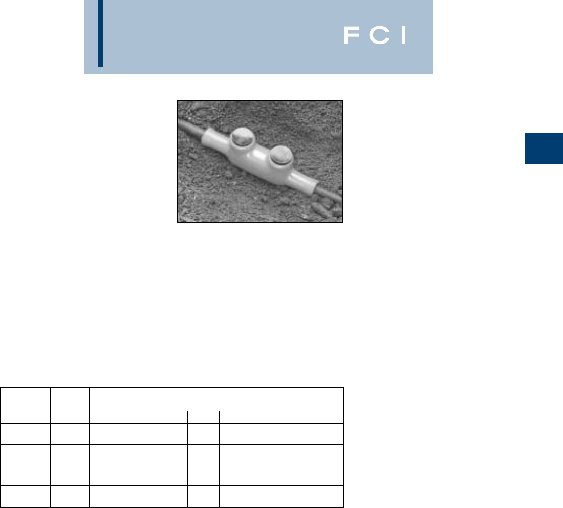
BURNDY
Mechanical
A-53
BURNDY UNITAP™
THE MOLE™
For Direct Burial
600V, 90°C
Designed specifically for direct burial applica-
tions, the MOLE™ inline splice/reducer is
made with a specialized plastisol material
that forms a rugged weathertight connection.
Features and Benefits
•UL486D Listed for direct burial.
•AL9CU Dual-rated for copper and
aluminum applications. 600V 90°C.
•Plastisol covered AL6061-T6 aluminum
body saves time by eliminating the need
for heat shrink.
•Oxide inhibitor pre-installed preventing
moisture and contaminants from entering
contact area.
•Range-taking capability reduces the
number of connectors carried in inventory.
Number Wire Hex Key Wire
Catalog of Range Dimensions (Inches) (Torque) Strip
Number Ports (AWG/kcmil) L W H (In.-lbs.) Length
1/8
BISR4-DB 2#6 - 4 AWG 4.30 0.80 1.28 (50) 7/8
5/32
BISR1-DB 2#2 - 1 AWG 6.30 0.93 1.59 (130) 1-3/32
3/16
BISR3/0-DB 21/0 - 3/0 AWG 6.25 0.99 1.84 (220) 1-3/32
5/16
BISR250-DB 24/0 - 250 kcmil 6.70 1.18 2.03 (360) 1-5/16
BISR-DB = BURNDY Inline Splice/Reducer Direct Burial
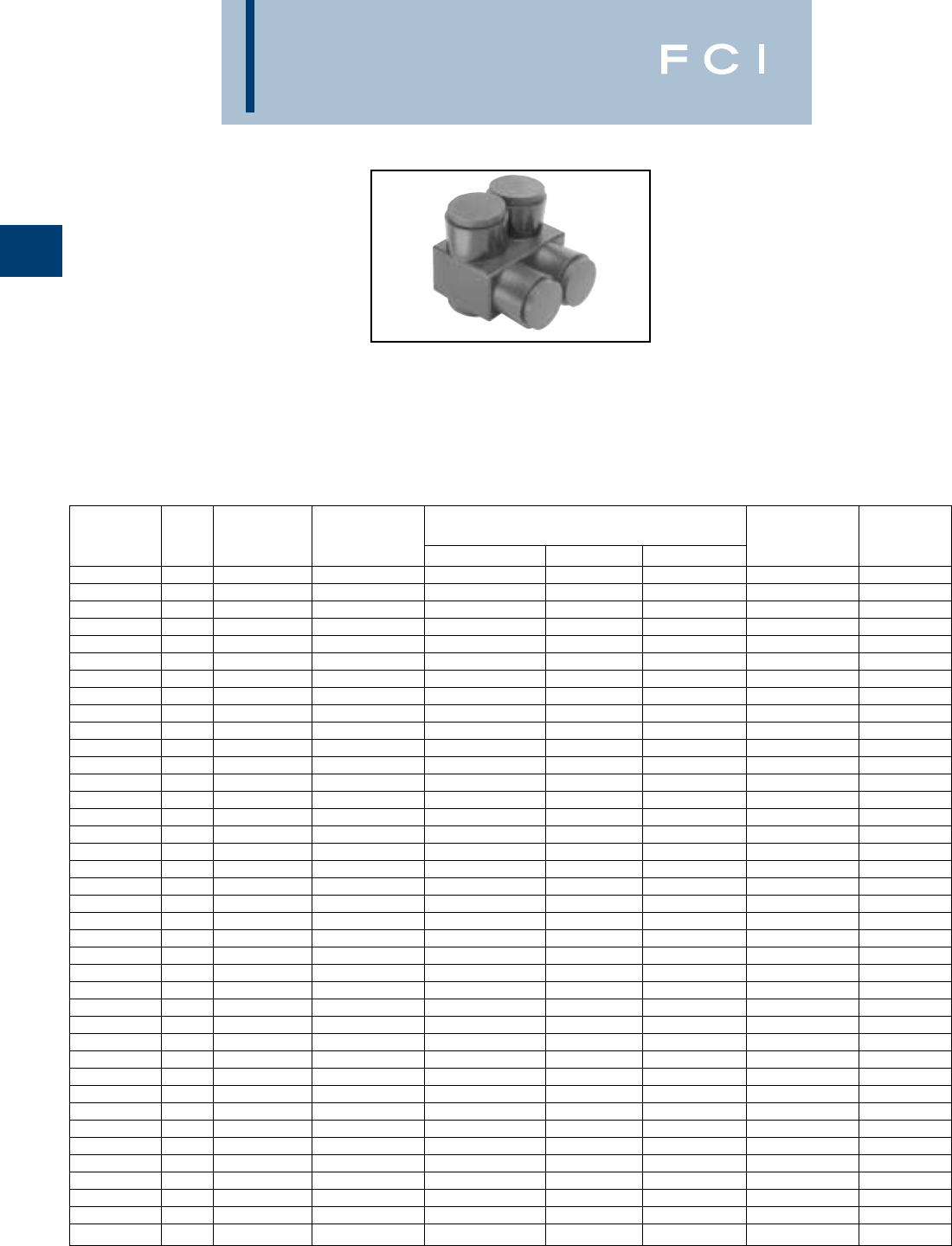
BURNDY
Mechanical
A-54
UV RATED
BLACK UNITAP™
For Direct Burial
600V, 90°C
Number Wire Hex Key Wire
Catalog Fig. of Range Dimensions (Inches) (Torque) Strip
Number No. Ports (AWG/kcmil) L W H (In.-lbs.) Length
1PL42 32 #14 - 4 1.16 1.16 1.25 1/8 (45) 5/8
1PLO42 42 #14 - 4 1.16 1.50 1.25 1/8 (45) 5/8
1PL2/02 32 #14 - 2/0 1.52 1.40 1.38 3/16 (120) 11/16
1PLO2/02 42 #14 - 2/0 1.52 1.56 1.38 3/16 (120) 11/16
1PL2502 32 #10 - 250 2.03 2.07 2.13 5/16 (275) 1
1PLO2502 42 #10 - 250 2.03 2.64 2.13 5/16 (275) 1
1PL3502 32 #10 - 350 2.22 2.32 2.50 5/16 (275) 1-1/8
1PL6002 32 #4 - 600 2.72 2.38 2.75 3/8 (375) 1-1/8
1PLO6002 42 #4 - 600 2.72 3.00 2.75 3/8 (375) 1-1/8
1PBS2 12 #14 - 2 2.38 0.75 1.22 5/32 (45) 3/4
1PBS1/0 12 #14 - 1/0 2.91 0.91 1.38 3/16 (120) 1
1PBS250 12 #10 - 250 4.01 1.19 2.10 5/16 (120) 1-3/16
1PBS350 12 #10 - 350 4.63 1.34 2.35 5/16 (275) 1-3/8
1PBS500 12 #6 - 500 5.00 1.62 2.62 3/8 (375) 1-1/2
1PL43 53 #14 - 4 1.59 1.25 1.25 1/8 (45) 5/8
1PL44 54 #14 - 4 2.03 1.25 1.25 1/8 (45) 5/8
1PL2/03 53 #14 - 2/0 2.19 1.31 1.38 3/16 (120) 11/16
1PL2503 53 #10 - 250 2.97 2.07 2.13 5/16 (275) 1
1PLD43 23 #14 - 4 1.59 1.50 1.25 1/8 (45) 5/8
1PLD44 24 #14 - 4 2.03 1.50 1.25 1/8 (45) 5/8
1PLD2/02 22 #14 - 2/0 1.52 1.56 1.25 3/16 (120) 11/16
1PLD2/03 23 #14 - 2/0 2.19 1.56 1.25 3/16 (120) 11/16
1PLD2/04 24 #14 - 2/0 2.86 1.56 1.25 3/16 (120) 11/16
1PLD2/06 26 #14 - 2/0 4.20 1.56 1.25 3/16 (120) 11/16
1PLD2502 22 #10 - 250 2.03 2.64 2.13 5/16 (275) 1
1PLD2503 23 #10 - 250 2.97 2.64 2.13 5/16 (275) 1
1PLD2504 24 #10 - 250 3.91 2.64 2.13 5/16 (275) 1
1PLD2506 26 #10 - 250 5.78 2.64 2.13 5/16 (275) 1
1PLD3502 22 #10 - 350 2.22 3.00 2.50 5/16 (375) 1-1/8
1PLD3503 23 #10 - 350 3.13 3.00 2.50 5/16 (375) 1-1/8
1PLD3504 24 #10 - 350 4.04 3.00 2.50 5/16 (375) 1-1/8
1PLD3506 26 #10 - 350 5.86 3.00 2.50 5/16 (375) 1-1/8
1PLD3508 28 #10 - 350 7.68 3.00 2.50 5/16 (375) 1-1/8
1PLD6002 22 #4 - 600 2.56 3.00 2.75 3/8 (375) 1-1/8
1PLD6003 23 #4 - 600 3.77 3.00 2.75 3/8 (375) 1-1/8
1PLD6004 24 #4 - 600 4.97 3.00 2.75 3/8 (375) 1-1/8
1PLD6005 25 #4 - 600 6.17 3.00 2.75 3/8 (375) 1-1/8
1PLD6006 26 #4 - 600 7.37 3.00 2.75 3/8 (375) 1-1/8
1PLD6008 28 #4 - 600 9.78 3.00 2.75 3/8 (375) 1-1/8
1PL = 2 Port Single Sided Entry
1PLO = 2 Port Offset Entry
1PBS = In-line Splice/Reducer
Features and Benefits
•UV Rated Plastisol covered AL6061-T6
aluminum body saves time by eliminating
the need for taping.
•Oxide inhibitor pre-installed inhibits
moisture and contaminants from
entering the contact area.
•Range-taking capability reduces the
number of connectors carried in inventory.
•UL486B Listed, AL9CU, 600V 90°C
1PL = Multi-Port Single Sided Entry
1PLD = Multi-Port Double Sided Entry

BURNDY
Compression
General Information ........................B-2, B-3
MIL. SPEC. Equivalent Tables ................B-4
Types T& YAD ........................................B-5
Types TP & BA ......................................B-6
Types TN & YAES ..........................B-7, B-8
Type YAE-G BOX ..................................B-9
Types YAE-N BOX & YAE-N ................B-10
Type YAES-K ..............................B-11, B-12
Types YAV BOX & YAV ................B-13, B-14
Types YAV-L BOX & YAV-L ........B-15, B-16
Types YAV-H BOX & YAV-H ..................B-17
Type YBM ............................................B-18
Types YAEV & YAEV-L................B-19, B-20
Type YAEV-H ..............................B-21, B-22
Types YAV-R & YAV-RS ........................B-23
Type YAEV-RS ......................................B-24
Type YAEV-RH ......................................B-25
Types T-F & YAD-F................................B-26
Types YAV-T-F BOX & YAV-T-F ............B-27
Types YAV-H-F BOX, YAV-H-F
& YAV-Z ............................................B-28
Types TN-F & YAES-F ..........................B-29
Types YAE-N-F BOX & YAE-N-F ..........B-30
Types TP-F & BA-EF ............................B-31
Types YAE-Z BOX & YAE-Z ..................B-32
Types TP-Z & BA-EZ ............................B-33
Types TP-LF & BA-EL ..........................B-34
Type Q-F................................................B-35
Type QP-F ............................................B-35
Type QP-M ............................................B-36
Type QN-M ............................................B-36
Types PGP & PGN ................................B-37
Types FQN-F & FQN-M ........................B-38
Type FL..................................................B-39
Uninsulated Splices ..............................B-40
Types YSV, YSV-H & YSV-L ................B-40
Type YSV-L............................................B-41
Type YSM ..............................................B-42
Type YSCM............................................B-43
Types YSES-K ......................................B-44
Types SP & BS......................................B-45
Insulated Splices ..................................B-46
Types SN, YSE-HN................................B-46
Types SNM, YSE BOX, YSES,
YSE-H BOX, YSE & YSE-H..............B-47
Types YSV & YRV-L ..............................B-48
Types YQE & RK ..................................B-49
B-1
SMALL HYDENT
TABLE OF CONTENTS
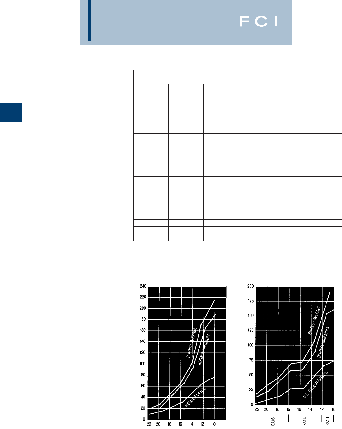
BURNDY
Compression
Performance
The terminals and splices in this catalog are
approved, per MIL-T-7928 and/or UL 486,
where indicated. Table 1 shows the perfor-
mance requirements for terminals used in
military and commercial equipment. The volt-
age drops listed are maximum allowable
values taken at currents well above rated cur-
rent for the wires. Tensile values assure that
the wires will not become separated from the
terminals under reasonably expected stresses.
UL tensile values are chosen to reflect the
severest expected duty. MIL Specification ten-
sile values apply only to crimp terminations
and reflect minimum values that are obtained
in good crimp joints. Actual performance of
Burndy terminals exceeds the requirements
of Table 1. Typical values are shown in Figs.
1-5. For High Temperature application
BURNDY®YAV series with nickel plating "-
NK" suffix provide for continuous operation to
650° F and 750° F intermittent service.
B-2
PERFORMANCE REQUIREMENTS - TERMINALS FOR COPPER WIRE
PER MIL-T-7928 PER UL 486
WIRE SIZE
TEST
CURRENT
(Amps)
MAX.
VOLTAGE
DROP
(Mv).
MIN.
TENSILE
STRENGTH
(Lbs.)
MIN.
TENSILE
STRENGTH
(Lbs.)
TEST
CURRENT
FOR MAX.
50˚C RISE
(Amps)
26 3 8 7 — —
24 4.5 8 10 — —
22 9 7 15 8 —
20 11 6 19 13 —
18 16 5 38 20 —
16 22 7 50 30 —
14 32 6 70 50 15
12 41 5 110 70 20
10 55 5 150 80 30
8 73 5 225 90 50
6101 5300 100 65
4135 5400 140 85
2181 5550 180 115
1211 5650 200 130
0245 5700 250 150
00 283 5750 300 175
000 320 5825 350 200
0000 380 5875 450 230
Fig 1. Tensile strength of YAD
HYLUG™ after axial
rotation stresses.
Fig 2. Tensile strength of BA
VINYLUG™ after axial
rotation stresses.
TENSILE STRENGTH IN POUNDS
COMMERCIAL WIRE SIZE COMMERCIAL WIRE SIZE
TENSILE STRENGTH IN POUNDS
Table 1
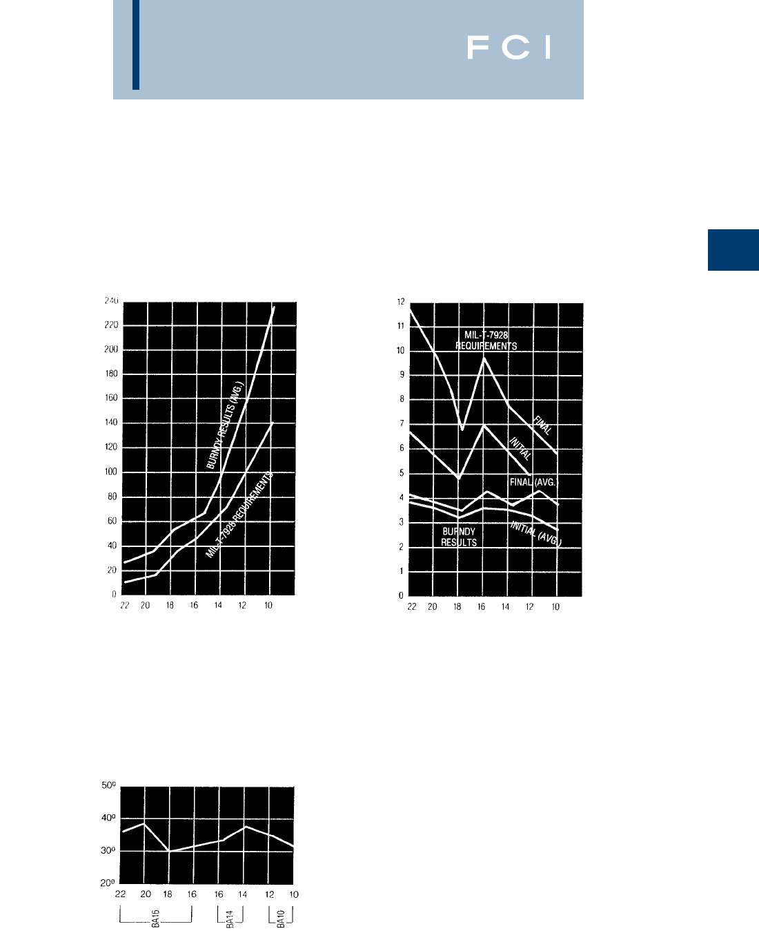
BURNDY
Compression
GENERAL
INFORMATION
(Continued)
B-3
Fig 3. Tensile strength of YAES
INSULUG™ after
vibration.
TENSILE STRENGTH IN POUNDS
AN WIRE SIZE
Fig 5. Voltage drops of YAES at
currents per Table 1 after
vibration.
VOLTAGE DROP mV
AN WIRE SIZE
Fig 4. Temperature rise of BA
VINYLUG™ at currents
per Table 1.
DEGREES CENTIGRADE
COMMERCIAL WIRE SIZE
TERMINAL
SIZE
BURNDY
Compression
EQUIVALENT TABLES
MILITARY SPECIFICATIONS
Ter minals
BURNDY®Equivalents to MS25036 in accor-
dance with Specification MIL-T-7928 (ASG)
Ter minals
BURNDY®Equivalents to MS20659 in accor-
dance with Specification MIL-T-7928 (ASG)
B-4
MS25036 Catalog Class Class Cage MS25036 Catalog Class Class Cage MS20659 Catalog Class Class Cage MS20659 Catalog Class Class Cage
Dash No. Number 1 2 Code Dash No. Number 1 2 Code Dash No. Number 1 2 Code Dash No. Number 1 2 Code
101 YAES18-N1 XX 124 YAEV4C-L4 X1NJK8 105 YAV10 XX1NJK8 134 YAV1C-L3 X1NJK8
YAE18-G43 X1NJK8 125 YAEV4C-L2 X1NJK8 106 YAV10-T2 XX1NJK8 135 YAV25-L3 X1NJK8
102 YAES18-N2 XX 126 YAEV2C-L1 X1NJK8 107 YAV8C-L X1NJK8 136 YAV26-L3 X1NJK8
YAE18-N21 X1NJK8 127 YAEV2C-L X1NJK8 108 YAV8C-L2 X1NJK8 137 YAV28-L54 X1NJK8
103 YAES18-N3 XX 128 YAEV2C-L4 X1NJK8 109 YAV6C-L X1NJK8 140 YAV8C-L14 X1NJK8
YAE18N X1NJK8 129 YAEV1C-L1 X1NJK8 110 YAV6C-L2 X1NJK8 141 YAV8C-L1 X1NJK8
104 YAES18-N4 XX 130 YAEV1C-L X1NJK8 111 YAV4C-L X1NJK8 142 YAV8C-L4 X1NJK8
YAE18-N3 X1NJK8 131 YAEV1C-L3 X1NJK8 112 YAV4C-L2 X1NJK8 143 YAV6C-L10 X1NJK8
105 YAES18-N5 XX 132 YAEV25-L1 X1NJK8 113 YAV2C-L1 X1NJK8 144 YAV4C-L3 X1NJK8
YAE18-N15 X1NJK8 133 YAEV25-L X1NJK8 114 YAV2C-L X1NJK8 145 YAV4C-L5 X1NJK8
106 YAES14-N6 XX 134 YAEV25-L3 X1NJK8 115 YAV1C-L1 X1NJK8 146 YAV2C-L3 X1NJK8
YAE14-N43 X1NJK8 135 YAEV26-L2 X1NJK8 116 YAV1C-L1 X1NJK8 147 YAV2C-L2 X1NJK8
107 YAES14-N7 XX 136 YAEV26-L X1NJK8 117 YAV25-L1 X1NJK8 148 YAV2C-L11 X1NJK8
YAE14-N43 X1NJK8 137 YAEV26-L3 X1NJK8 118 YAV25-L X1NJK8 149 YAV1C-L2 X1NJK8
108 YAES14-N8 XX 143 YAE22-G18 X1NJK8 119 YAV26-L2 X1NJK8 150 YAV1C-L4 X1NJK8
YAE14N X1NJK8 144 YAE22-G16 X1NJK8 120 YAV26-L X1NJK8 151 YAV25-L2 X1NJK8
109 YAES14-N9 XX 145 YAE22-G13 X1NJK8 121 YAV27-L X1NJK8 152 YAV25-L16 X1NJK8
YAE14-N3 X1NJK8 146 YAE22-G14 X1NJK8 122 YAV27-L1 X1NJK8 153 YAV26-L1 X1NJK8
110 YAES14-N10 XX 147 YAE22-G15 X1NJK8 123 YAV28-L X1NJK8 154 YAV26-L16 X1NJK8
YAE14-N4 X1NJK8 YAES18-N48 XX 124 YAV28-L12 X1NJK8 155 YAV27-L20 X1NJK8
111 YAES10-N11 XX 148 YAE18-N17 X1NJK8 128 YAV10-T4 XX1NJK8 156 YAV27-L18 X1NJK8
YAE10-N5 X1NJK8 YAES18-N49 XX 129 YAV8C-L3 X1NJK8 157 YAV28-L56 X1NJK8
112 YAES10-N12 XX 149 YAE18N1 X1NJK8 130 YAV6C-L1 X1NJK8 158 YAV28-L60 X1NJK8
YAE10N X1NJK8 YAES18-N50 XX 131 YAV6C-L4 X1NJK8 159 YAV28-L13 X1NJK8
113 YAES10-N13 XX 150 YAE18-N2 X1NJK8 132 YAV4C-L4 X1NJK8 160 YAV28-L14 X1NJK8
YAE10-N2 X1NJK8 152 YAES14-N52 XX1NJK8 133 YAV2C-L4 X1NJK8 165 YAV10-T7 XX1NJK8
114 YAES10-N14 XX YAES14-N53 XX
YAE10-N4 X1NJK8 153 YAE14-N1 X1NJK8
115 YAEV8C-L X1NJK8 YAES14-N54 XX
116 YAEV8C-L1 X1NJK8 154 YAE14-N2 X1NJK8
117 YAEV8C-L2 X1NJK8
118 YAEV8C-L3 X1NJK8 YAES10-N56 XX
119 YAEV6C-L1M X1NJK8 156 YAE10-N11 X1NJK8
120 YAEV6C-LM X1NJK8 YAES10-N57 XX
121 YAEV6C-L4M X1NJK8 157 YAE10-N3 X1NJK8
122 YAEV6C-L2M X1NJK8 158 YAES10-N58 XX1NJK8
123 YAEV4C-L X1NJK8
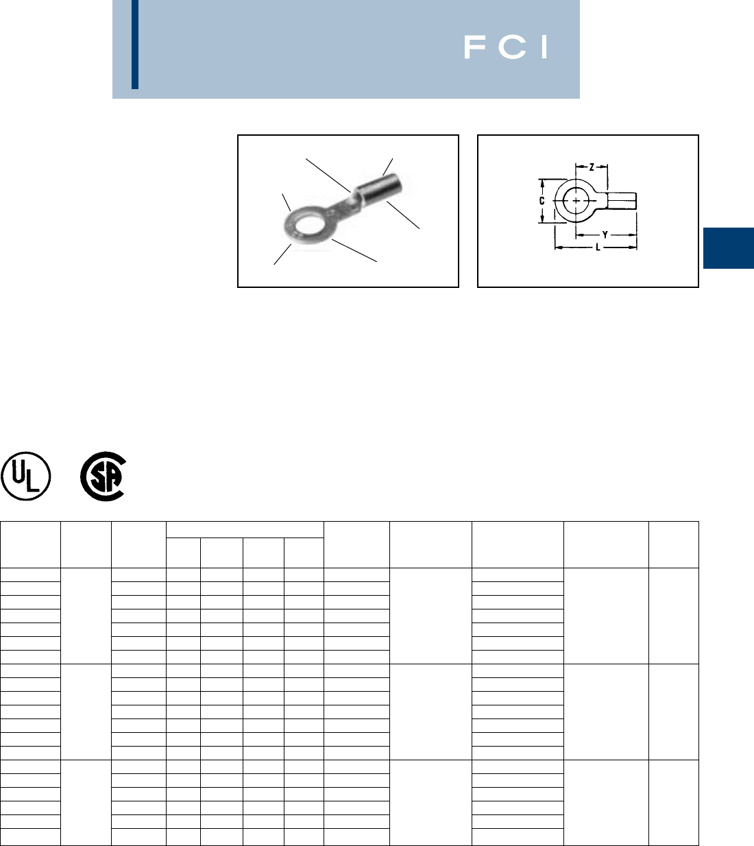
BURNDY
Compression
B-5
TYPES T AND YAD
HYLUG™
UNINSULATED
COMPRESSION TERMINAL,
RING TONGUE
The Type T uninsulated terminals are con-
structed of pure electrolytic copper. Designed
with a long brazed seam barrel, standard
neck, deep V groove inner serrations and
electro-tin plated. The terminals are ideal for
control wiring and other standard duty
applications.
The ring tongue provides a secure termina-
tion under the screw head that cannot be
removed without the complete removal of the
screw. Two or more terminals can easily be
stacked on a common stud.
ELECTRO-TIN
PLATED
WIRE
CRIMP
RING
TONGUE
WIRE RANGE
DEEP “V” GROOVE
SERRATIONS
LONG BRAZED
SEAM BARREL
Features and Benefits
•Constructed of pure electrolytic copper.
◊Provides maximum conductivity, low
resistance and ductility for excellent
crimp forming properties.
•Long brazed seam barrel and deep
V groove inner serrations.
◊Provides optimum conductivity reliability
and holding power after crimping.
•Electro-tin plated.
◊Provides durable long-lasting
corrosion resistance.
•Wire range is clearly marked on terminal.
◊Provides easy identification.
•Inspection hole.
◊Provides an easy visual check of
wire insertion.
•Long neck terminal.
◊Permits easy bending and stacking of
several terminals on a common stud.
*NOTE: UL Listed for 14-10 when installed with MR8G98
and Y8MRB-1 tools only.
•1000 pcs/reel.
DIMENSIONS BULK TAPE MOUNTED WIRE
CATALOG WIRE STUD L Y Z CATALOG INSTALLATION CATALOG NO. INSTALLATION STRIP
NUMBER RANGE SIZE C MAX. MAX. MIN. NUMBER* TOOLING 2000/Reel TOOLING LENGTH
T18-4 3, 4 .25 .65 .53 .24 YAD18-4 Non-Ratchet: YAD18-4M
T18-6 4-6 .25 .65 .53 .24 YAD18-6 Y10D, YAD18-6M
T18-8 6-8 .31 .77 .61 .33 YAD18-8 Y10-22 YAD18-8M TFM
T18-10 22-18 8-10 .31 .77 .61 .33 YAD18-10 Ratchet: YAD18-10M with 9/32
T18-14 1/4 .45 .96 .73 .44 YAD18-14 MR8G98, YAD18-14M DFM6D1
T18-516 5/16 .45 .96 .73 .44 YAD18-516 Y8MRB-1, YAD18-516M Die
T18-38 3/8 .53 1.05 .78 .49 YAD18-38 MR20 YAD18-38M
T14-4 3, 4 .25 .67 .55 .26 YAD14-4 Non-Ratchet: YAD14-4M
T14-6 4-6 .25 .67 .55 .26 YAD14-6 Y10D, YAD14-6M
T14-8 6-8 .31 .77 .61 .33 YAD14-8 Y10-22 YAD14-8M TFM
T14-10 20-14 8-10 .31 .77 .61 .33 YAD14-10 Ratchet: YAD14-10M with 9/32
T14-14 1/4 .45 .96 .73 .44 YD14-14 MR8G98, YAD14-14M DFM5D1
T14-516 5/16 .45 .96 .73 .44 YAD14-516 Y8MRB-1, YAD14-516M Die
T14-38 3/8 .53 1.05 .78 .49 YAD14-38 MR20 YAD14-38M
T10-6 4-6 .37 .83 .64 .29 YAD10-6 Non-Ratchet: •YAD10-6M
T10-8 6-8 .37 .83 .64 .29 YAD10-8 Y10D, Y10-22 •YAD10-8M TFM
T10-10 8-10 .37 .83 .64 .29 YAD10-10 Ratchet: •YAD10-10M with
T10-14 12-10* 1/4 .46 .97 .74 .39 YAD10-14 MR8G98, *YAD10-14M DFM4D1 11/32
T10-516 5/16 .53 1.02 .76 .41 YAD10-516 Y8MRB-1, *YAD10-516M Die
T10-38 3/8 .58 1.08 .79 .44 YAD10-38 MR20 *YAD10-38M
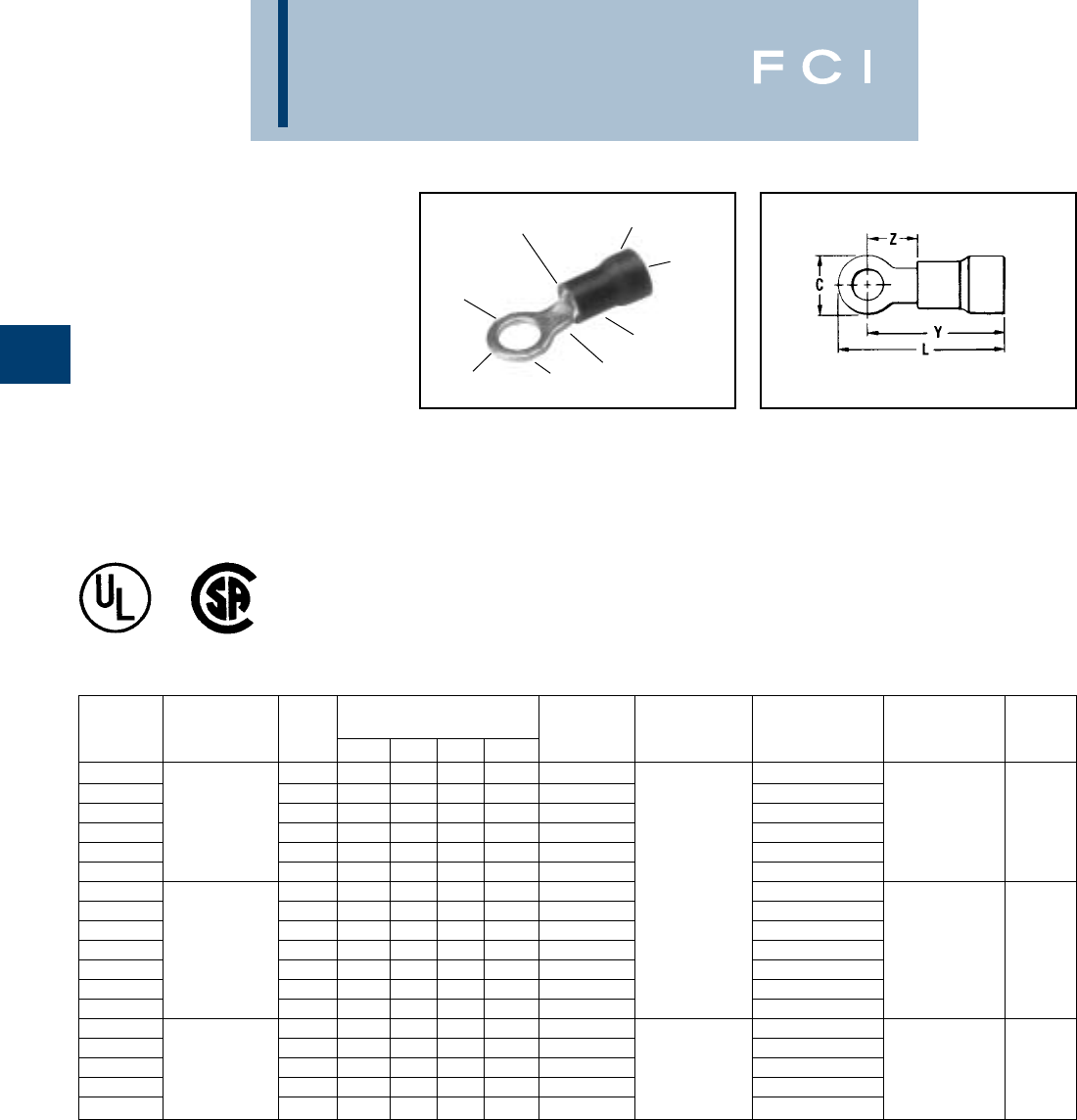
BURNDY
Compression
B-6
TYPES TP AND BA
VINYLUG™
TERMINAL -
POLYVINYLCHLORIDE
INSULATED, RING TONGUE
600 VOLTS MAX. 105° C MAX.
VINYLUG™ Type TP is designed for commer-
cial and light duty industrial control and power
circuit applications. Supplied with an expanded
polyvinyl chloride (PVC) insulation shroud,
many tongue variations and rated 600V
makes TP terminals versatile and economical.
RING
TONGUE
WIRE SIZE
RANGE TIN
PLATED
SMOOTH
ENTRY
EXPANDED SHROUD
INSULATION CRIMP
DEEP “V”
SERRATIONS
COLOR CODED
INSULATION
WIRE
CRIMP
*1000/Reel
Features and Benefits
•Expanded insulation support accepts
standard and large wire diameters.
◊Lowers inventory requirements,
permits greater flexibility and provides
insulation support.
•Funnel entry.
◊Easy wire insertion.
•Manufactured of pure electrolytic copper.
◊Provides maximum conductivity, low
resistance and ductility for excellent
crimp forming properties.
•Deep V groove serrations in the
inner barrel.
◊Provides added holding strength and
better conductivity.
•Electro-tin plated.
◊Provides durable long-lasting
corrosion resistance.
BULK TAPE MOUNTED WIRE
CATALOG WIRE STUD DIMENSIONS CATALOG INSTALLATION CATALOG NO. INSTALLATION STRIP
NUMBER RANGE SIZE C L Y Z NUMBER* TOOLING 2000/Reel TOOLING LENGTH
TP16-4 3-4 .22 .71 .61 .17 BA16E4 BA16E4M
TP16-6 22-16 4-6 .25 .74 .62 .18 BA16E6 BA16E6M TFM
TP16-8 Max. Insul. 6-8 .31 .85 .70 .26 BA16E8 BA16E8M with
TP16-10 Dia. Accom.: .145 8-10 .31 .85 .70 .26 BA16E10 Plier Type: BA16E10M DFM3D-1 13/64
TP16-14 Color Code: 12, 1/4 .40 .99 .79 .36 BA16E14 Y10-22, Y10D BA16E14M Die
TP16-38 Red 3/8 .53 1.15 .88 .45 BA16E38 or BA16E38M
TP14-4 3-4 .22 .71 .61 .17 BA14E4 Ratchet Tool: BA14E4M
TP14-6 16-14 4-6 .25 .74 .62 .18 BA14E6 MR8-89-1, BA14E6M
TP14-8 Max. Insul. 6-8 .31 .85 .70 .26 BA14E8 NR8-G96, BA14E8M TFM
TP14-10 Dia. Accom.: .180 8-10 .31 .85 .70 .26 BA14E10 MR15 BA14E10M with 13/64
TP14-14 Color Code: 12, 1/4 .40 .99 .79 .36 BA14E14 BA14E14M DFM2D-1
TP14-516 Blue 5/16 .53 1.15 .88 .45 BA14E516 BA14E516M Die
TP14-38 3/8 .53 1.15 .88 .45 BA14E38 BA14E38M
TP10-6 12-10 4-6 .31 .91 .75 .20 BA10E6 Plier Type: *BA10E6M
TP10-8 Max. Insul. 6-8 .36 1.00 .81 .26 BA10E8 Y10-22, Y10D *BA10E8M TFM
TP10-10 Dia. Accom.: .260 8-10 .36 1.00 .81 .26 BA10E10 or Ratchet: *BA10E10M with 19/64
TP10-14 Color Code: 12, 1/4 .53 1.22 .95 .40 BA10E14 MR8-89-1, *BA10E14M DFM1D5
TP10-38 Yellow 3/8 .53 1.27 1.00 .45 BA10E38 MR15 *BA10E38M Die
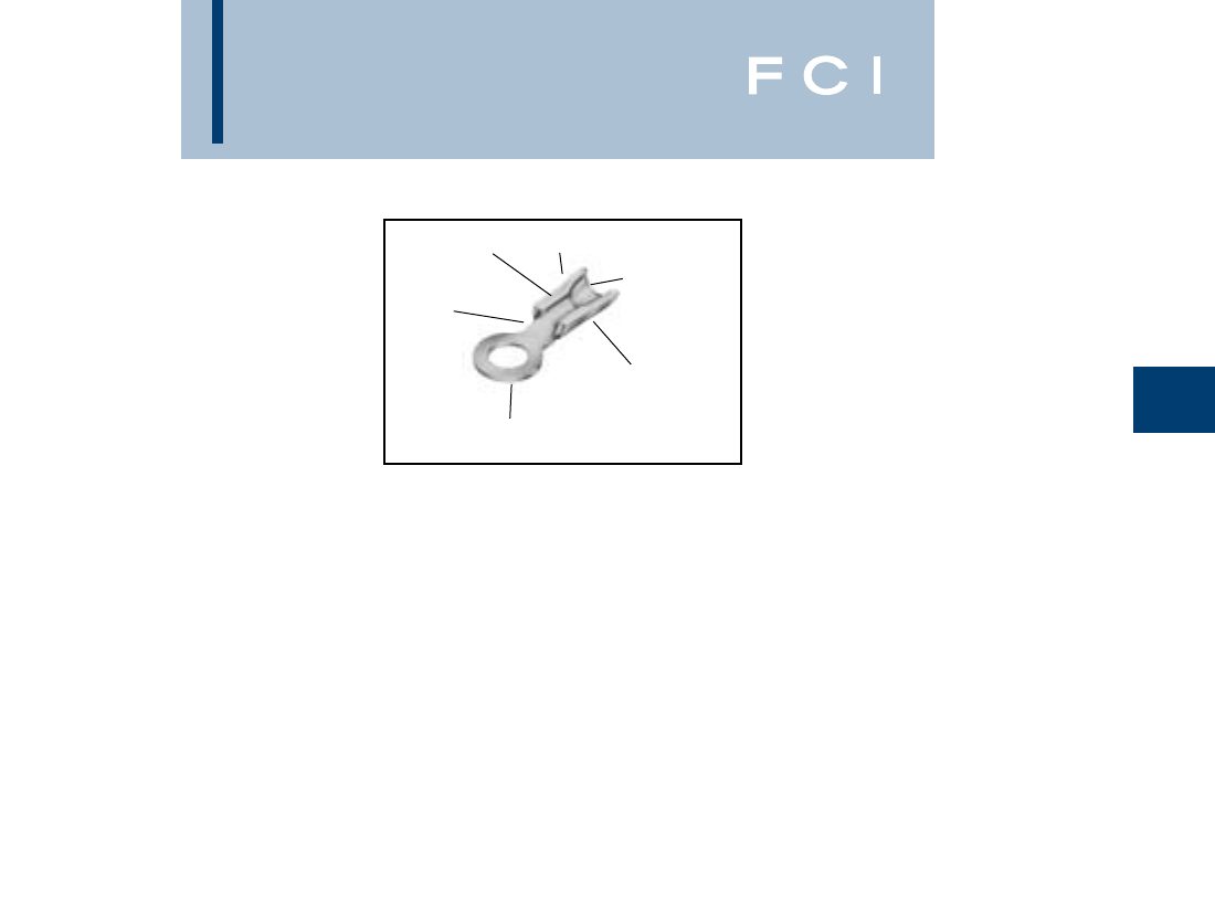
BURNDY
Compression
B-7
TYPES TN AND YAES
INSULUG™
TERMINAL -
NYLON INSULATED,
RING-TONGUE
300 VOLTS MAX. 105°C MAX.
INSULUG™ type TN Nylon-insulated termi-
nals are designed for heavy duty industrial,
utility and military power and control-circuit
applications for wire sizes 26 AWG through
10 AWG. They offer high dielectric strength
and stability in oily conditions and meet mili-
tary CLASS 1 and CLASS 2 requirements per
MS25036 and the requirements of military
specifications MIL-T-7928 (ASG).
COLOR CODED
NYLON INSULATION
WIRE SIZE
AND STUD SIZE
SMOOTH
FUNNEL ENTRY
INTEGRAL INSULATION
SUPPORT AND WIRE
STRAIN RELIEF
DEEP "V"
SERRATIONS
INTEGRAL
ONE PIECE
COPPER,
TIN PLATED
DESIGN
Features and Benefits
•An integral one-piece copper barrel /insula-
tion grip and wire strain relief design.
◊Provides improved physical strength
characteristics over a multi-piece design.
•Manufactured of pure electrolytic copper.
◊Provides maximum conductivity, low
resistance and ductility for excellent
crimp forming properties.
•Brazed seam.
◊Provides a stronger barrel design to
minimize any possible splitting and
eliminates folding.
•Deep inner barrel serrations.
◊Provides excellent electrical conductivity
and pullout strength values.
•Smooth funnel entry.
◊Easy wire insertion.
•The insulation is locked in place.
◊Will not twist off, thereby maintains
proper dielectric values.
•Electro-tin plated.
◊Provides durable long-lasting resistance
to corrosion.
•Color-coded and clearly marked.
◊Provides quick, easy wire size identifi-
cation.
•Ring Tongue.
◊Provides a secure termination under the
screw head that can not be removed
without complete removal of the screw.
•Two or more terminals may be stacked on
a common stud easily.
◊Provides flexibility and versatility.
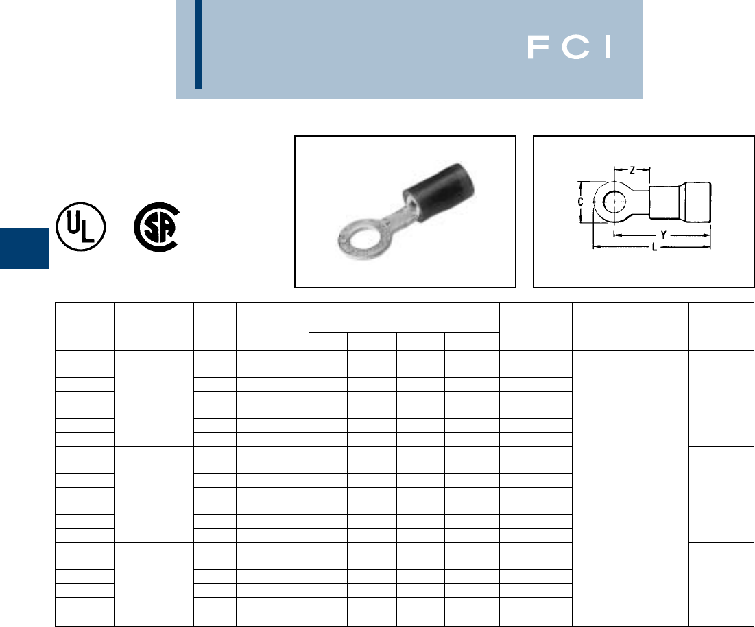
BURNDY
Compression
B-8
TYPES TN AND YAES
(Continued)
▲Class 1 and class 2. Meets the requirement of military
specification MILT-T-7928 (ASG)
* Use on #10 or #12 Str. Cu only.
** Meets requirements for Class 2 installation. For use as a
Class 1 connector, use tool conforming to MS25037,
Class 1.
WIRE
CATALOG WIRE STUD MIL. STD. DIMENSIONS BULK INSTALLATION STRIP
NUMBER RANGE SIZE MS25036- C L MAX. Y MAX. Z MAX. CAT. NO. TOOLING LENGTH
TN18-4 3-4 -148 .23 .76 .64 .20 YA ES18N48
TN18-6 22-18 4-6 -102 .25 .87 .74 .29 YAES18N1
TN18-8 Max. Insul. 6-8 -149 .31 .91 .76 .29 YA ES18N49
TN18-10 Dia. Accom.: .120 8-10 -103 .31 .91 .76 .29 YAES18N3 7/32”
TN18-14 Color Code: 12, 1/4 -150 .46 1.09 .87 .41 YA ES18N50
TN18-516 Red 5/16 -104 .46 1.09 .87 .41 YAES18N4 Non-Ratchet:
TN18-38 3/8 -105 .53 1.17 .91 .45 YAES18N5 Y10D,
TN14-4 3-4 -152 .25 .79 .67 .24 YAE14N52 Y1022
TN14-6 16-14 4-6 -106 .25 .79 .67 .24 YAES14N6
TN14-8 Max. Insul. 6-8 -153 .31 .89 .74 .31 YA ES14N53
TN14-10 Dia. Accom.: .153 8-10 -108 .31 .89 .74 .31 YAES14N8 7/32”
TN14-14 Color Code: 12, 1/4 -154 .45 1.08 .86 .43 YA ES14N54
TN14-516 Blue 5/16 -109 .45 1.08 .86 .43 YAES14N9
TN14-38 3/8 -110 .53 1.16 .90 .47 YA ES14N10 Ratchet:
TN10-6 4-6 -111 .37 1.12 .94 .26 YA ES10N11 MR8-83
TN10-8 12-10 6-8 -156 .37 1.12 .94 .26 YA ES10N56
TN10-10 Max. Insul. 8-10 -112 .37 1.12 .94 .26 YA ES10N12
TN10-14 Dia. Accom.: .210 12, 1/4 -157 .53 1.32 1.06 .37 YAES10N57 11/32”
TN10-516 Color Code: 5/16 -113 .53 1.32 1.06 .37 YAES10N13
TN10-38 Yellow 3/8 -114 .58 1.34 1.05 .40 YAES10N14
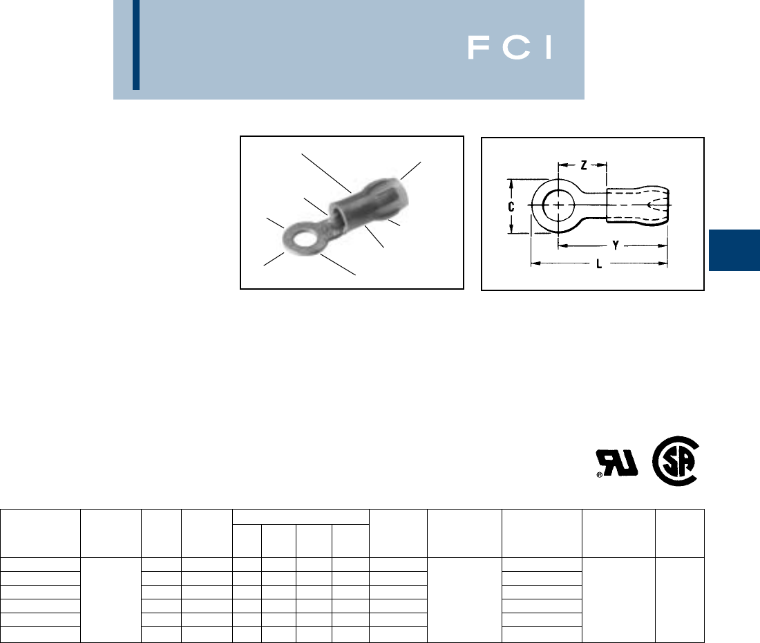
BURNDY
Compression
B-9
TYPE YAE-G BOX
INSULUG™
TERMINAL -
NYLON INSULATED,
RING-TONGUE
MULTI-FINGER
INSULATION GRIP
300 VOLTS MAX. 105° C MAX.
INSULUG™ Type YAE-N nylon insulated ter-
minals are designed with a multi-finger insu-
lation grip for paper, EPR and other elastic or
hard to grip insulations. The metal fingers
firmly grip the insulation providing superior
holding characteristics, cable support and
strain relief. Type YAE-N terminals are rated
105°C and meet military standard MS25036
class 2 and MIL-T-7928 (ASG) requirements.
•Not UL recognized
*1000/Reel
** Class 2
MULTI-FINGER
INSULATION GRIP
WIRE SIZE
RANGE RING TONGUE
INSULATION
CRIMP
COLOR CODED
NYLON INSULATION
DEEP "V"
SERRATIONS
WIRE CRIMP
TIN PLATED
Features and Benefits
•Multi-finger insulation grip.
◊Provides superior insulation holding
characteristics, especially on EPR
and other elastic-type insulations.
•Brazed seam.
◊Provides stronger more durable
termination.
•Manufactured of pure electrolytic copper.
◊Provides maximum conductivity, low
resistance and ductility for excellent
crimp forming properties.
•Deep V groove, inner barrel serrations.
◊Provide optimum conductivity, reliability,
and holding power.
•Smooth funnel entry.
◊Easy wire insertion.
MIL. DIMENSIONS BULK TAPE MOUNTED WIRE
CATALOG WIRE STUD STD.** L Y Z CATALOG INSTALLATION CATALOG NO. INSTALLATION STRIP
NUMBER RANGE SIZE MS25036 C MAX. MAX. MAX. NUMBER* TOOLING 2000/Reel TOOLING LENGTH
YAE22G18 BOX• 26-20 1.2 -148 .15 .70 .62 .22 YAE22G18• YAE22G18M•
YAE22G12 BOX• Max. Insul. 1.2 – .25 .75 .62 .22 YAE22G12• M8ND YAE22G12M• TFM
YAE22G16 BOX• Dia. Accom.: 3.4 -144 .18 .75 .62 .22 YAE22G16• with YAE22G16M• with
YAE22G13 BOX• .098 4-6 -145 .25 .75 .62 .22 YAE22G13• N14HET-25V1 YAE22G13M• DFM11D1 5/32
YAE22G14 BOX• Color Code: 6-8 -146 .32 .83 .67 .27 YAE22G14• Die YAE22G14M• Die
YAE22G15 BOX• Amber 8-10 -147 .32 .83 .67 .27 YAE22G15• YAE22G15M•
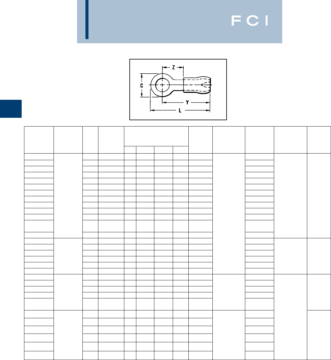
BURNDY
Compression
B-10
TYPES YAE-N BOX
AND YAE
(Continued)
INSULUG™
*1000/Reel
** Class 2
†Use Y10D or Y10-22 only when crimping #16 AWG.
TAPE
BULK MOUNTED WIRE
CATALOG WIRE STUD MIL STD.** DIMENSIONS CATALOG INSTALLATION CATALOG NO. INSTALLATION STRIP
NUMBER RANGE SIZE MS25036 C L MAX. Y MAX. Z MIN. NUMBER TOOLING 2000/REEL TOOLING LENGTH
YAE18N29 BOX 1-2 — .14 .75 .68 .19 YAE18N29 YAE18N29M
YAE18N27 BOX 2—.19 .77 .66 .19 YAE18N27 YAE18N27M
YAE18N7 BOX 4—.25 .80 .68 .19 YAE18-N7 YAE18-N7M
YAE18N17 BOX 4-148 .25 .80 .68 .19 YAE18N17 MR8-33T-1 YAE18N17M
YAE18N26 BOX 22-16 † 4 — .23 .78 .68 .19 YAE18N26 (no extra dies YAE18N26M
YAE18N21 BOX Max. Insul. 4-6 -102 .25 .89 .77 .28 YAE18N21 required) YAE18N21M TFM
YAE18N25 BOX Dia. 4-6 — .22 .79 .68 .19 YAE18N25 M8ND YAE18N25M with
YAE18G43 BOX Accom.: .125 4-6 — .25 .90 .68 .19 YAE18G43 with one of YAE18G43M DFM10D1 3/16
YAE18N24 BOX Color Code: 6-8 — .28 .92 .77 .28 YAE18N24 following dies: YAE18N24M die
YAE18N1 BOX Red 6-8 -149 .31 .92 .77 .28 YAE18N1 N14HET-25V1 YAE18N1M
YAE18N BOX 8-10 -103 .31 .92 .77 .28 YAE18N N10ET-9 YAE18NM
12, N14HET-15
YAE18N2 BOX 1/4 -150 .45 1.11 .88 .40 YAE18N2 YAE18N2M
YAE18N3 BOX 5/16 -104 .45 1.11 .88 .40 YAE18N3 or YAE18N3M
YAE14N43 BOX 16-14 4-6 -106 .25 .82 .69 .20 YAE14N43 YAE14N43M
YAE14N1 BOX Max. Insul. 6-8 -153 .31 .92 .75 .28 YAE14N1 Y10D YAE14N1M TFM
YAE14N BOX Dia. 8-10 -108 .31 .92 .75 .28 YAE14N Y10-22 YAE14NM with
YAE14N2 BOX Accom.: .156 1/4 -154 .45 1.11 .88 .40 YAE14N2 YAE14N2M DFM9D1 3/16
YAE14N3 BOX Color Code: 5/16 -109 .45 1.11 .88 .40 YAE14N3 YAE14N3M die
YAE14N4 BOX Blue 3/8 -110 .53 1.19 .93 .44 YAE14N4 YAE14N4M
YAE12N7 BOX 14-12 10 — .31 1.06 .93 .29 YAE12N7 MR8-33T-1 YAE12N7M
YAE12N9 BOX Max. Insul. 6-8 — .31 1.06 .90 .28 YAE12N9 (no extra dies YAE12N9M
YAE12N1 BOX Dia. 6-8 — .31 1.06 .90 .28 YAE12N1 required) YAE12N1M
YAE12N BOX Accom.: .180 8-10 — .31 1.06 .90 .28 YAE12N Y10D YAE12NM 21/64
Color Code: M8ND
YAE12N2 BOX Green 1/4 — .46 1.25 1.02 .40 YAE12N2 with die N12HET-1 YAE12N2M TFM
YAE10N5 BOX 4-6 -111 .38 1.15 .96 .28 YAE10N5 MR8-33T-1 * YAE10N5M with
YAE10N11 BOX 12-10 6-8 -156 .38 1.17 .98 .30 YAE10N11 (no extra dies * YAE10N11M DFM7D1
Max. Insul. required) die
YAE10N BOX Dia. 8-10 -112 .38 1.15 .96 .28 YAE10N M8ND with one of * YAE10NM
YAE10N3 BOX Accom.: .209 1/4 -157 .54 1.39 1.12 .44 YAE10N3 the following dies: * YAE10N3M 3/8
Color Code: N10HET-15
YAE10N2 Yellow 5/16 -113 .54 1.39 1.12 .44 YAE10N2 N10ET-9 * YAE1ON2M
YAE10N4 3/8 -114 .54 1.39 1.12 .44 YAE10N4 Y10D, Y10-22 * YAE10N4M

BURNDY
Compression
B-11
TYPE YAES-K
INSULUG™
NUCLEAR
TERMINALS
AND SPLICES
RADIATION RESISTANT
INSULATED TERMINALS,
RING TONGUE
POLYVINYLIDENE (PVF2)
INSULATED
200 MEGARADS, –60°
THROUGH 150° C, 600 VOLTS
The type YAES-K, radiation resistant
KYNAR®insulated terminals are designed
and have been tested to meet the require-
ments for class 1E critical circuits as set by
the Nuclear Regulatory Commission (NRC).
Additional testing for compatibility under loss
of coolant accident (LOCA) conditions with
cross-link polyethylene (XLP) and
HYPALON®insulations was completed suc-
cessfully. Compatibility with ethylene propy-
lene rubber (EPR) insulation was determined
by analysis. Each terminal is manufactured of
pure electrolytic copper per QQ-C 576 and
bright tin-plated per MIL-T-10727 and meets
or exceeds MIL-T-7928 using stranded cop-
per AWG wire. The KYNAR®insulation offers
200 megarad radiation resistance.
The Type YAES-K radiation resistant
KYNAR®- insulated terminals are suitable for
class 1E critical circuits and non-critical
nuclear associated applications.
Features and Benefits
• KYNAR®insulation.
◊Provides 200 megarad radiation resis-
tance plus successfully tested for insula-
tion compatibility.
•An integral one-piece copper barrel/insula-
tion grip and wire strain relief design.
◊Provides improved physical strength
characteristics over a multi-piece design.
•The KYNAR®insulation is locked in place.
◊The insulation will not move or twist
off, thereby maintains proper dielectric
values.
•Manufactured from pure electrolytic
copper.
◊Provides maximum conductivity, low
resistance and ductility for excellent
crimp forming properties.
•Bright tin-plated per MIL-T-10727.
◊Provides durable long-lasting resistance
to corrosion.
•Deep inner barrel serrations.
◊Provides excellent electrical conductivity
and tensile strength values.
•Brazed seam.
◊Provides a stronger barrel design to
minimize any possible splitting and
eliminates folding.
•Smooth funnel entry.
◊Easy wire insertion.
•Color coded terminals.
◊Provides easy wire size identification and
inspection.
•Coded raised dots in the die area of the
connection after compression.
◊Provides visual identification that the
correct tool and die were used for
proper installation.
•Inspection hole.
◊Permits visual check for proper wire
insertion.
•Ring tongue design.
◊Provides a secure termination under
screw head that cannot be removed
without the complete removal of the
screw.
•Multiple terminals may be stacked on a
common stud easily.
◊Provides flexibility and versatility.
KYNAR - is a registered trademark of the Pennwalt Corp. for
Polyvinylindene Floride (PVF2)
HYPALON - Is a registered trademark of the E.I. DuPont
deNemours & Co., Inc.
BRAZED SEAM
ON BARREL
WIRE SIZE
INTEGRAL
SUPPORT
INSULATION
SMOOTH
FUNNEL
ENTRY
COLOR CODED
KYNAR INSULATION
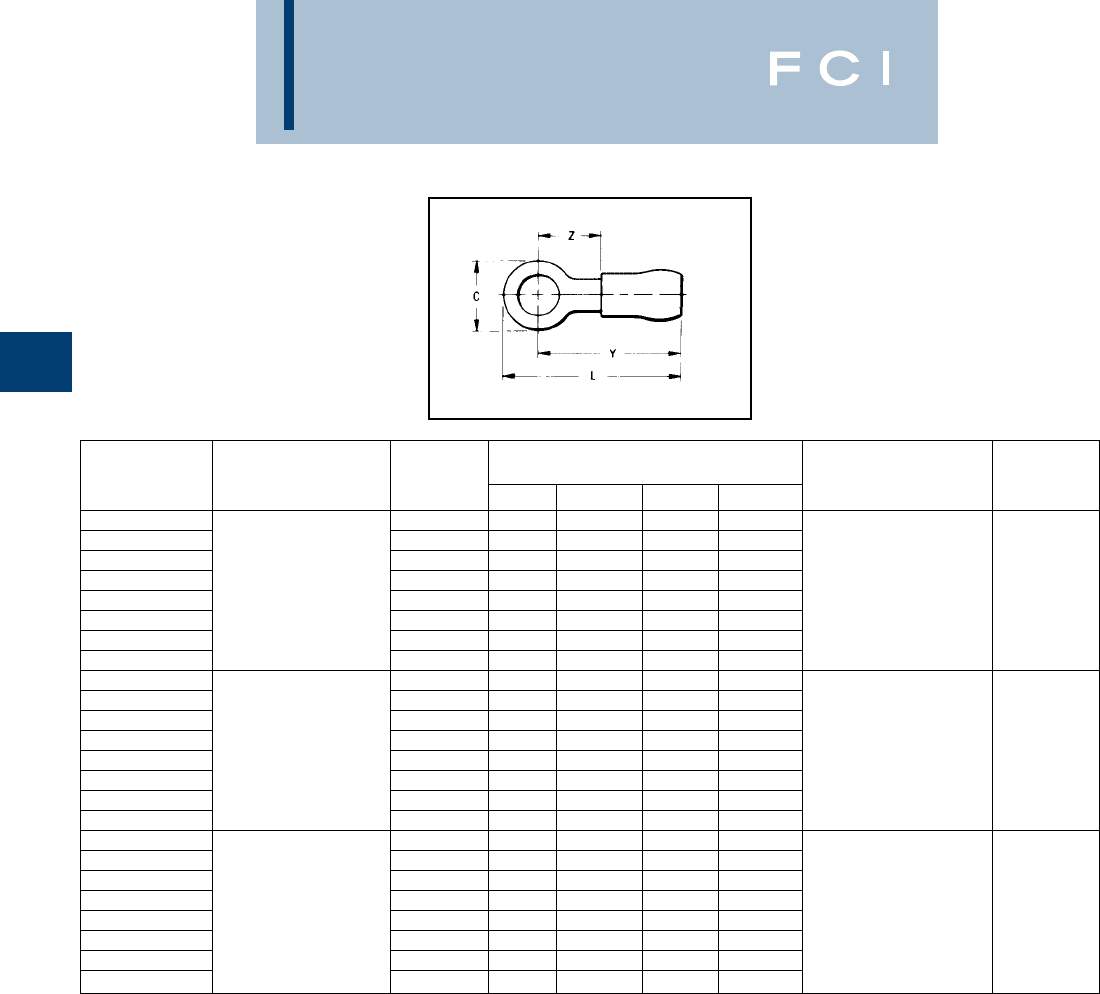
BURNDY
Compression
B-12
TYPE YAES-K
(Continued)
INSULUG™
WIRE
CATALOG WIRE STUD DIMENSIONS INSTALLATION STRIP
NUMBER RANGE SIZE C L MAX. Y MAX. Z MIN. TOOLING LENGTH
YAES18K48 4.23 .76 .64 .20 Ratchet Tool:
YAES18K-1 6.23 .76 .64 .20 MR10G6
YAES18K-2 22-18 AWG str. 6 .25 .87 .74 .29 Crimp Mark:
YAES18K-49 Max. Insul. 8 .31 .91 .76 .29 (1) Small Dot
YAES18K-3 Dia. Accom.: .120 10 .31 .91 .76 .29 Red Groove 7/32
YAES18K-50 Color Code: Red 1/4 .46 1.09 .86 .41
YAES18K-4 5/16 .46 1.09 .86 .41 Calibration Gauge:
YAES18K-5 3/8 .53 1.18 .91 .45 PG-373-1
YAES14K-52 4.25 .77 .65 .22 Ratchet Tool:
YAES14K-6 6.25 .77 .65 .22 MR10G6
YAES14K-7 16-14 AWG str. 6.31 .91 .76 .29 Crimp Mark:
YAES14K-53 Max. Insul. 8.31 .91 .76 .29 (2) Small Dots
YAES14K-8 Dia. Accom.: .153 10 .31 .91 .76 .29 Blue Groove 7/32
YAES14K-54 Stock Thickness: .032 1/4 .46 1.09 .86 .41
YAES14K-9 Color Code: Blue 5/16 .46 1.09 .86 .41 Calibration Gauge:
YAES14K-10 3/8 .53 1.18 .91 .45 PG-371-1
YAES10K-11 6.38 1.12 .94 .26 Ratchet Tool:
YAES10K-11T1 6.31 1.09 .94 .26 MR10G6
YAES10K-56 12-10 AWG str. 8.38 1.12 .94 .26 Crimp Mark:
YAES10K-12 Max. Insul. 10 .38 1.12 .94 .26 (1) Large Dot
YAES10K-57 Dia. Accom.: .210 1/4 .53 1.32 1.06 .37 3/8
YAES10K-13 Stock Thickness: .040 5/16 .53 1.32 1.06 .37
YAES10K-14 Color Code: Yellow 3/8 .58 1.34 1.05 .40 Calibration Gauge:
YAES10K-58 1/2 .72 1.41 1.06 .45 PG-372-1
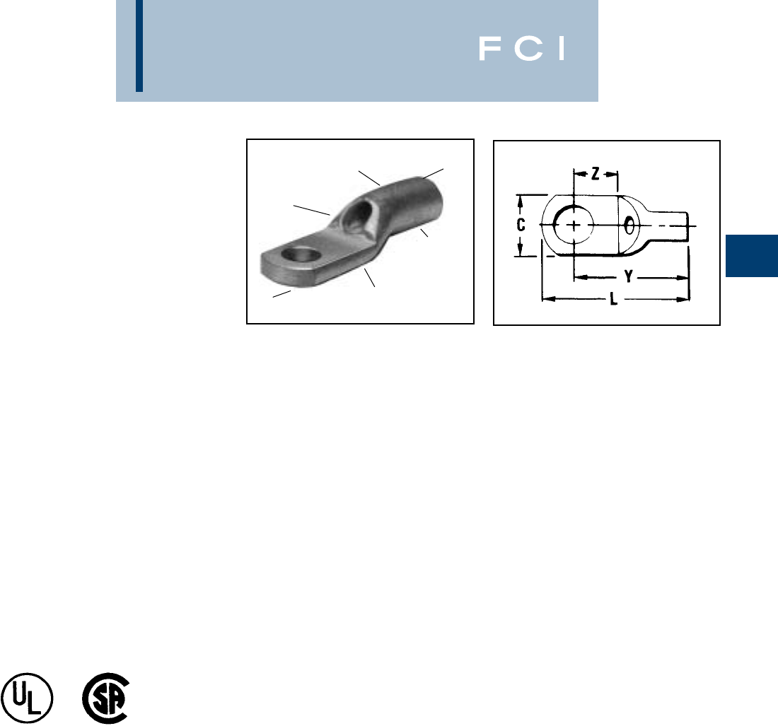
BURNDY
Compression
B-13
SEAMLESS
BARREL
ELECTRO-TIN
PLATED
DOUBLE THICK
TONGUE
CRIMP
INSPECTION
HOLE
BEVELED
ENTRY
(See table on following page for specifications)
TYPES YAV BOX
AND YAV
HYLUG™
SEAMLESS UNINSULATED
COMPRESSION HEAVY DUTY
RING TONGUE TERMINAL
#22-10 STRANDED AND
SOLID COPPER
HYLUG™ type YAV is a seamless,
heavy duty uninsulated compression
ring tongue terminal manufactured from
pure electrolytic copper tubing and is for
use on copper commercial (code) cable,
type AN aircraft cable and extra flexible
conductors. Because of its seamless
design, the YAV HYLUG™ also accom-
modates solid conductors.
The seamless tubing produces a double
thick tongue and a strong connector for
demanding applications that require
high reliability. Applications include
industrials, hospitals, electric utilities,
aircraft, shipboard and marine, com-
puters, steel mills, mining equipment
and other equipment that is subject to
vibration or requiring dependable elec-
trical performance.
The YAV-HYLUG™ terminals meet the
requirements of MIL-T-7928 (ASG).
Features and Benefits
•Manufactured from seamless pure
electrolytic copper tubing.
◊Provides maximum conductivity,
low resistance and excellent ductility
for crimping.
•Seamless tubular crimp barrel design.
◊No seams to split resulting in a very high
quality electrical connection. Also can be
used on solid conductor.
•Double thick tongue.
◊Provides a very strong terminal tongue.
•Produced from tubular copper.
◊Extra copper material assures the com-
pression connector will operate cooler
than the conductors it connects.
•Internally bevelled barrel.
◊Provides easy cable entry, especially
for flexible conductors.
•Inspection hole.
◊Provides easy visual check for proper
conductor insertion.
•Electro-tin plated.
◊Provides long lasting durable corrosion
resistance.
•Nickel plating available, add “NK” suffix.”
◊Nickel plated Hylugs™ provide high
temperature applications up to 650° F
continuous service and 750° F intermit-
tent service.
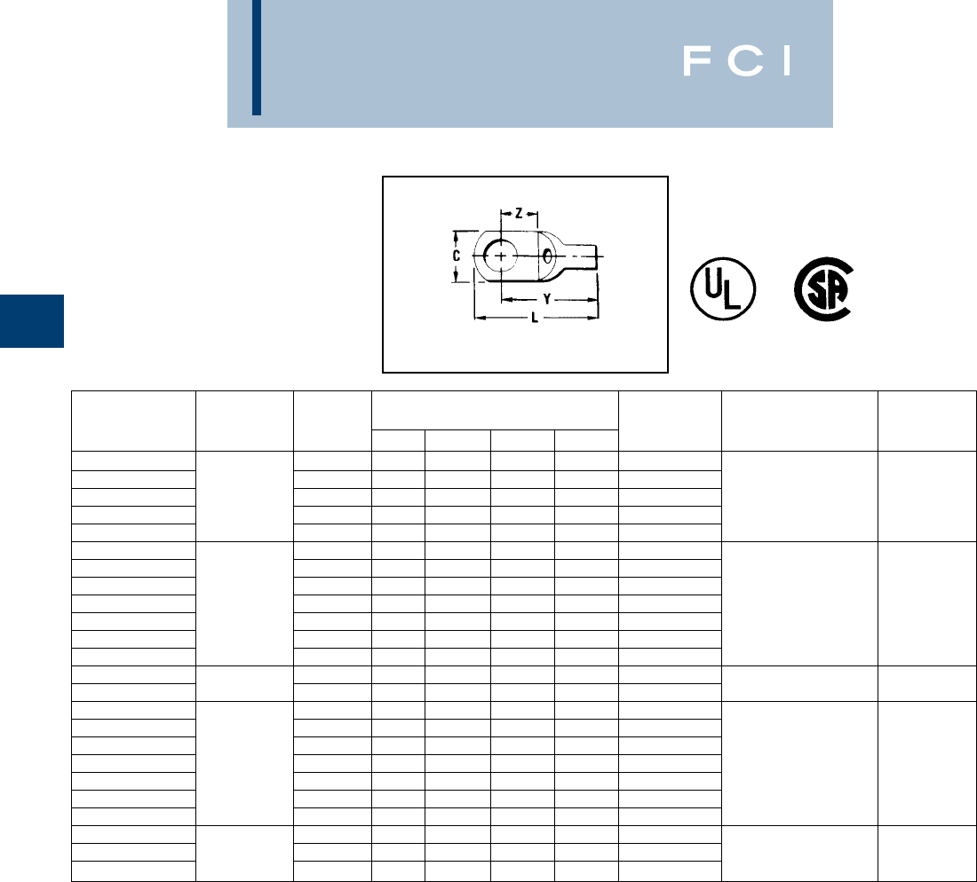
BURNDY
Compression
B-14
TYPES YAV BOX
AND YAV
HYLUG™
SEAMLESS UNINSULATED
COMPRESSION HEAVY DUTY
RING TONGUE TERMINAL
•Available in (90o) right angle design.
*Use #10 groove
■Use #14 groove
†UL listed for 14 Str. to #10 Sol. & Str. when installed with
MR8G98 and Y8MRB-1 tools only.
WIRE
CATALOG WIRE STUD DIMENSIONS BULK INSTALLATION STRIP
NUMBER RANGE SIZE C L MAX. Y MAX. Z MIN. CAT. NO. TOOLING LENGTH
YAV18-T4 BOX 3, 4 .19 .62 .54 .16 YAV18-T4 Non-Ratchet:
YAV18-L33 BOX 22-18 4-6 .25 .67 .55 .18 YAV18-L33 Y10D, Y10-22
YAV18-T5 BOX Str. 4-6 .31 .76 .61 .24 YAV18-T5 Ratchet: 9/32
YAV18-T1 BOX and 6-8 .31 .76 .61 .24 YAV18-T1 MR8G98, MR8-9Q,
YAV 18 BOX Sol. 8-10 .31 .76 .61 .24 YAV18 Y8MRB-1, MR20
YAV14-L33 BOX 4-6 .25 .71 .59 .18 YAV14-L33
YAV14-T5 BOX 20-14 4-6 .31 .79 .64 .24 YAV14-T5 Non-Ratchet:
YAV14-T1 BOX Str. 6-8 .31 .79 .64 .24 YAV14-T1 Y10D, Y10-22
YAV14-L36 BOX 8-10 .29 .74 .59 .18 YAV14-L36 Ratchet: 9/32
YAV 14 BOX 20-12 8-10 .31 .79 .64 .24 YAV14 MR8G98, MR8-9Q,
YAV14-T2 BOX Sol. 1/4 .42 .99 .75 .32 YAV14-T2 Y8MRB-1, MR20
YAV14-T3 BOX 5/16 .44 .99 .75 .32 YAV14-T3
YAV12-G2 BOX ■14-12 8-10 .30 .82 .67 .24 YAV12-G2 Y10D, Y8MRB-1
YAV12-G3 BOX ■Str. 1/4 .36 1.00 .76 .34 YAV12-G3 M8ND w/N14HT 9/32
YAV10-T7 BOX 4-6 .30 .93 .78 .24 YAV10-T7
YAV10-T11 BOX †14 Str. 6-8 .38 .97 .79 .26 YAV10-T11 Non-Ratchet:
YAV10-L36 BOX 12-10 8-10 .29 .86 .71 .23 YAV10-L36 Y10, Y10-22
YAV 10 BOX 8-10 .38 .97 .79 .26 YAV10 Ratchet: 7/16
YAV10-T3 BOX Str. 1/4 .47 1.10 .87 .32 YAV10-T3 MR8G98, MR8-9Q,
YAV10-T2 BOX and 5/16 .53 1.13 .87 .31 YAV10-T2 Y8MRB-1, MR20
YAV10-T4 BOX Sol. 3/8 .56 1.18 .90 .35 YAV10-T4
YAV9C-L36 BOX 8-10 .31 .97 .83 .15 YAV9C-L36 Ratchet:
YAV9C-T9 BOX 10-9 1/4 .44 1.19 .95 .31 YAV9C-T9 MR8-9Q, 7/16
YAV9C-T4 BOX Str. 5/16 .52 1.27 1.02 .36 — Y8MRB-1
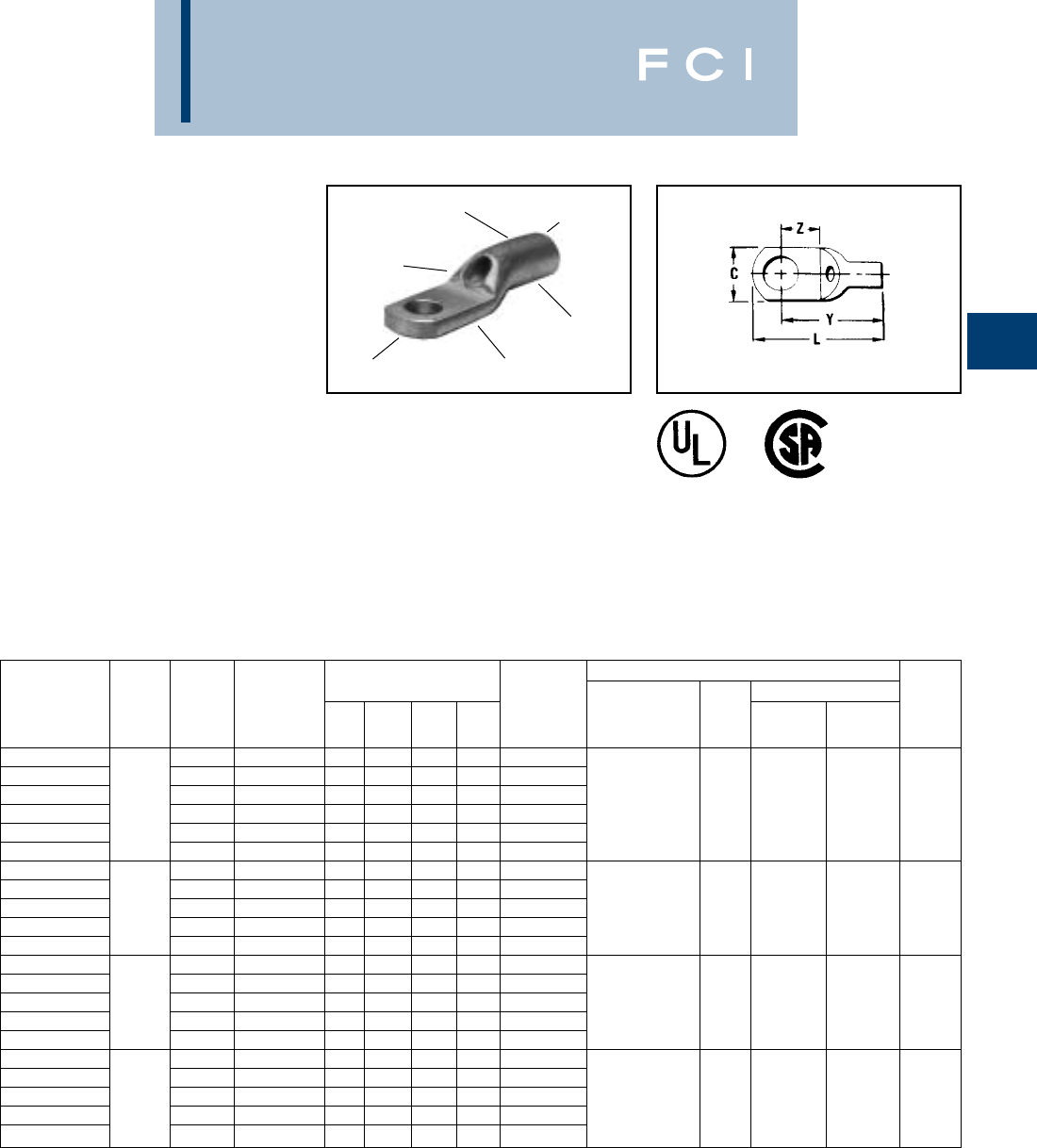
BURNDY
Compression
B-15
TYPES YAV-L BOX
AND YAV-L
HYLUG™
LARGE SIZE UNINSULATED
COMPRESSION TERMINALS
SEAMLESS UNINSULATED
COMPRESSION RING
TONGUE TERMINAL
#8-4/0 STR. COPPER
HYLUG™ Type YAV is a seamless, heavy duty
uninsulated compression terminal manufac-
tured from electrolytic copper and is for use on
Type AN aircraft cable, extra flexible conduc-
tors and commercial (code) conductors. The
seamless tubing produces a double thick
tongue and seamless barrel design provides a
ELECTRO-TIN
PLATED
INSPECTION
HOLE
SEAMLESS
BARREL BEVELED
ENTRY
CRIMP
DOUBLE THICK
TONGUE
strong connector for demanding applications
requiring high reliability.
Applications include aircraft, industrials, hos-
pitals, electric utilities, marine, computers,
and other equipment subject to vibration or
requiring dependable electrical performance.
The YAV HYLUG™ terminals meet the
requirements of MIL-T-7928 and are listed
per MS20659 for use with copper aircraft
cable per MIL-W-5086
The benefits of YAV-L connectors are
the same as YAV connectors for stranded
conductors.
†Class 1.
•Available in (90°) right angle design. Suffix "RS"
REPLACES SUFFIX "L".
▲Use Y35P3 INDENTOR ADAPTER with Y35 and Y39 Tool.
■Bench Mount Adapter - Cat. BMY-BCH-MT is available for
Type "MY" HYTOOLS™.
Add "NK" sufix for nickel plated Hylugs™ for high tempera-
ture applications up to 650° F continuous service and 750°
intermittent service.
INSTALLATION TOOLING
DIMENSIONS (INCH) HYPRESS WIRE
CATALOG WIRE STUD MS20659 L Y Z BULK DIE Y29B, Y35, Y39, STRIP
NUMBER RANGE SIZE DASH NO.† C MAX. MAX. MIN. CAT. NO. HYTOOL INDEX Y29NC Y750 ▲LENGTH
—6-8 -140 .41 1.15 .94 .28 YAV8C-L14• Non-Ratchet:
YAV 8 C-L BOX 88-10 -107 .41 1.15 .94 .28 YAV 8 C-L• Y10MV, MY29-11 DC8L-1 UV8L
YAV8C-L1 BOX Aircraft 1/4 -141 .46 1.22 .99 .32 YAV8C-L1• Ratchet: Nest Nest
YAV8C-L2 BOX AN 8 5/16 -108 .57 1.30 1.01 .34 YAV8C-L2 MR4C, MR8-9Q, 38 Y29PL Y34PL 1/2
YAV8C-L3 BOX Flex 3/8 -129 .57 1.30 1.01 .34 YAV8C-L3• Y8MR8-1, M8ND Indentor Indentor
YAV8C-L4 BOX 1/2 -142 .73 1.52 1.14 .48 YAV8C-L4• w/ N8CT Die Set (1) Crimp (1) Crimp
YAV6C-L1 BOX 8-10 -130 .48 1.31 1.06 .29 YAV6C-L1• Non-Ratchet: DC6L UV6L
YAV 6 C-L BOX 5 & 6 1/4 -109 .48 1.31 1.06 .29 YAV 6 C-L• MY28, Nest Nest
YAV6C-L4 BOX Aircraft 5/16 -131 .60 1.43 1.13 .35 YAV6C-L4• MY29-11 39 Y29PL Y34PLA 1/2
YAV6C-L2 BOX AN 5 & 6 3/8 -110 .60 1.43 1.13 .35 YAV6C-L2• Ratchet: Indentor Indentor
YAV6C-L10 BOX Flex 1/2 -143 .73 1.64 1.26 .49 YAV6C-L10 MR4C (1) Crimp (1) Crimp
YAV4C-L3 BOX 8-10 -144 .55 1.37 1.11 .28 YAV4C-L3• Non-Ratchet: DC4L UV4L
YAV 4 C-L BOX 41/4 -111 .55 1.37 1.11 .28 YAV 4C-L MY28, Nest Nest
YAV4C-L4 BOX Aircraft 5/16 -132 .63 1.48 1.17 .33 YAV4C-L4• MY29-11 40 Y29PL Y34PLA 1/2
YAV4C-L2 BOX AN 4 3/8 -112 .63 1.48 1.17 .33 YAV4C-L2• Ratchet: Indentor Indentor
YAV4C-L5 BOX Flex 1/2 -145 .73 1.68 1.30 .47 YAV4C-L5 MR4C (1) Crimp (1) Crimp
—8-10 -146 .69 1.72 1.37 .35 YAV2C-L3 DC2L UV2L
YAV2C-L1 BOX 21/4 -113 .69 1.72 1.37 .35 YAV2C-L1• Non-Ratchet: Nest Nest
YAV2C-L2 BOX Aircraft 5/16 -147 .69 1.72 1.37 .35 YAV2C-L2• MY28, 41 Y29PL Y34PLA 5/8
YAV 2 C-L BOX AN 2 3/8 -114 .69 1.72 1.37 .35 YAV2 C-L• MY29-11 Indentor Indentor
YAV2C-L4 BOX Flex 1/2 -133 .77 1.89 1.49 .46 YAV2C-L4 (1) Crimp (1) Crimp
BURNDY
Compression
B-16
TYPES YAV-L BOX
AND YAV-L
(Continued)
HYLUG™
†Class 1.
•Available in (90°) right angle design. Suffix "RS" replaces
suffix "L".
▲Use Y35P3 INDENTOR ADAPTER with Y35 and Y39 Tool.
■Bench Mount Adapter - Cat. BMY-BCH-MT is available for
Type "MY" HYTOOLS™.
Add "NK" sufix for nickel plated Hylugs™ for high
temperature applications up to 650° F continuous service
and 750° intermittent service.
INSTALLATION TOOLING
DIMENSIONS (INCH) HYPRESS WIRE
CATALOG WIRE STUD MS20659 L Y Z BULK DIE Y29B, Y35, Y39, STRIP
NUMBER RANGE SIZE DASH NO.† C MAX. MAX. MIN. CAT. NO. HYTOOL INDEX Y29NC Y750 ▲LENGTH
—8-10 — .76 1.67 1.32 .25 YAV1C-L6• DV1L UV1L
YAV1C-L1 BOX 11/4 -115 .76 1.84 1.45 .38 YAV1C-L1• Nest Nest
YAV1C-L2 BOX Aircraft 5/16 -149 .76 1.84 1.45 .38 YAV1C-L2• 42 Y29PL Y34PLA 5/8
YAV 1 C-L BOX AN 1 3/8 -116 .76 1.84 1.45 .38 YAV 1 C-L Indentor Indentor
YAV1C-L3 BOX Flex 1/2 -134 .86 1.97 1.54 .46 YAV1C-L3 (1) Crimp (1) Crimp
YAV25-L1 BOX 1/4 -117 .83 2.01 1.61 .43 YAV25-L1 DV25L UV25L
YAV25-L2 BOX 1/0 5/16 -151 .83 2.01 1.61 .43 YAV25-L2 Nest Nest
YAV25-L BOX Aircraft 3/8 -118 .83 2.01 1.61 .43 YAV25-L• 43 Y29PR Y34PA 11/16
YAV25-L3 BOX AN 1/0 1/2 -135 .88 2.09 1.64 .46 YAV25-L3• Indentor Indentor
YAV25-L4 BOX Flex 5/8 — .88 2.31 1.80 .62 YAV25-L4 (1) Crimp (1) Crimp
YAV26-L1 BOX 1/4 -153 .93 2.32 1.85 .48 YAV26-L1 Non-Ratchet: DV26L UV26L
YAV26-L2 BOX 2/0 5/16 -119 .93 2.32 1.85 .48 YAV26-L2 MY28, Nest Nest
YAV26-L BOX Aircraft 3/8 -120 .93 2.32 1.85 .48 YAV26-L• MY29-11 44 Y29PL Y34PA 13/16
YAV26-L3 BOX AN 2/0 1/2 -136 .93 2.32 1.85 .48 YAV26-L3• Indentor Indentor
YAV26-L12 BOX Flex 5/8 — .93 2.52 1.99 .62 YAV26-L12 (1) Crimp (1) Crimp
YAV27-L BOX
3/0 Aircraft
3/8 -121 1.03 2.45 1.93 .52 YAV27-L• UV27L Nest
YAV27-L1 BOX AN 3/0 1/2 -122 1.03 2.45 1.93 .52 YAV27-L1 45 — Y34PA Indentor 13/16
YAV27-L15 BOX Flex 5/8 — 1.03 2.60 2.04 .62 YAV27-L15 (1) Crimp
YAV28-L BOX 4/0 3/8 -123 1.12 2.72 2.16 .60 YAV28-L UV28L Nest
YAV28-L12 BOX Aircraft 1/2 -124 1.12 2.72 2.16 .60 YAV28-L12 Y34PA
YAV28-L13 BOX AN 4/0 5/8 -159 1.12 2.72 2.16 .60 YAV28-L13 46 — Indentor 7/8
YAV28-L14 BOX Flex 3/4 -160 1.23 2.95 2.33 .78 YAV28-L14 (1) Crimp
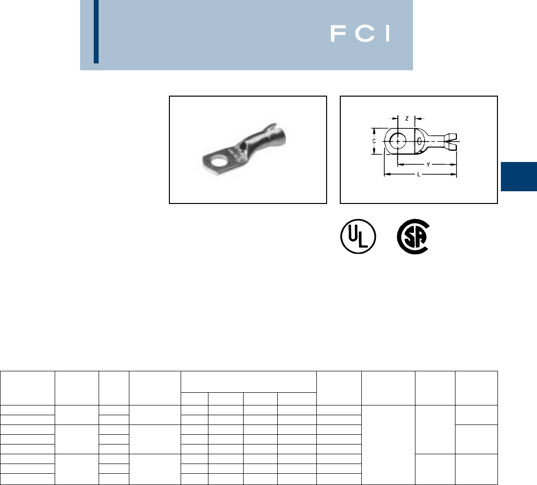
BURNDY
Compression
B-17
TYPES YAV-H BOX
AND YAV-H
HYLUG™
SEAMLESS UNINSULATED
COMPRESSION RING
TONGUE TERMINAL
WITH SHROUD
The type YAV-H HYLUG™ is a seamless
heavy duty uninsulated compression ring
tongue terminal with a shroud for an insulation
grip and cable support. They are manufac-
tured from pure electrolytic copper tubing for
use on copper commercial (code) cable, Type
AN aircraft cable and extra flexible conductors.
The seamless design produces a double thick
tongue and the seamless barrel provides a
strong highly reliable connection.
Meets the requirements of MIL-T-7928. The
benefits of the Type YAV apply to the
YAV-H HYLUG™.
Features and Benefits
•Shroud/insulation grip cable support
and strain relief.
◊Protects the wire against breaking
under vibration or flexing conditions.
*For conductor crimp only.
WIRE
CATALOG WIRE STUD MAX. INSUL. DIMENSIONS BULK INSTALL STRIP
NUMBER RANGE SIZE DIA. ACCOM. C L MAX. Y MAX. Z MIN. CAT. NO. TOOLING DIES LENGTH
YAV18-H1 BOX 6-8 .31 .91 .76 .24 YAV18-H1 Plier: M8ND,
YAV18-H BOX 22-18 8-10 .120
.31 .91 .76 .24 YAV18-H Y10D*, Y10-22* with 9/32
YAV14-H1 BOX 6-8 .31 .95 .80 .24 YAV14-H1 N14HT,
YAV14-H BOX 20-14 8-10 .150.31 .95 .80 .24 YAV14-H Ratchet: N14HT-5 9/32
YAV14-H2 BOX 1/4 .42 1.14 .90 .32 YAV14-H2 MR8-G98, Die
YAV 1 0-H25 BOX 6-8 .31 1.04 .90 .24 YAV10-H25 MR8-9Q, M8ND
YAV10-H BOX 12-10 8-10 .192.38 1.09 .91 .24 YAV10-H Y8MRB-1*, with N10HT 7/16
YAV10-H3 BOX 1/4 .47 1.22 .99 .32 YAV10-H3 MR20*, M8ND Die
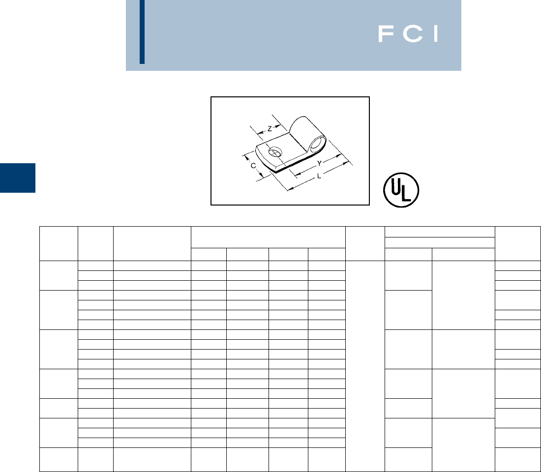
BURNDY
Compression
B-18
TYPE YBM
HYLUG™
FLAG-TYPE
RING-TONGUE TERMINALS
Made of pure electrolytic copper for maximum
conductivity and ductility. Seamless extrusion
tin plated to resist corrosion.
*Lead Plated available, contact factory.
INSTALLATION TOOLING WIRE
WIRE STUD CATALOG* DIMENSIONS IN INCHES HYPRESS Y29NC & Y29B STRIP
RANGE SIZE NUMBER C Z MIN. Y MAX. L MAX. HYTOOL NEST INDENTOR LENGTH
8-10 YBM8C 0.44 0.34 0.77 1.01 7/16
81/4 YBM8C-T2 0.50 0.37 0.80 1.07 DV8B 1/2
3/8 YBM8CT4 0.62 0.52 0.83 1.35 9/16
8-10 YBM6C-L9 0.50 0.37 0.85 1.09 Y29PBL-4
1/4 YBM6C-L 0.50 0.37 0.85 1.12 1/2
65/16 YBM6C-L2 0.56 0.43 0.91 1.21 DV6BL 9/16
3/8 YBM6C-L3 0.62 0.52 0.88 1.21 5/8
8-10 YBM4C-L4 0.50 0.37 0.99 1.18
1/4 YBM4C-L 0.50 0.37 0.94 1.21 1/2
45/16 YBM4C-L1 0.56 0.43 1.00 1.30 DV4BL Y29PBL 9/16
3/8 YBM4C-L2 0.62 0.52 0.97 1.30 MY28 5/8
1/4 YBM2C-L1 0.62 0.37 1.01 1.29
25/16 YBM2C-L2 0.62 0.43 1.07 1.38 DV2BL 5/8
3/8 YBM2C-L 0.62 0.37 1.01 1.35 Y29PL
1/2 YBM1C-L3 0.88 0.71 1.29 1.74 1
13/8 YBM1C-L 0.62 0.50 1.19 1.53 DV1BL
1/4 YBM25-L1 0.69 0.52 1.19 1.83 5/8
1/0 5/16 YBM25-L2 0.69 0.46 1.25 1.56 DV25BL-1
3/8 YBM25-L 0.69 0.58 1.26 1.59 Y29PR 3/4
2/0 3/8 YBM26-L 0.81 0.51 1.37 1.72 DV28L 13/16
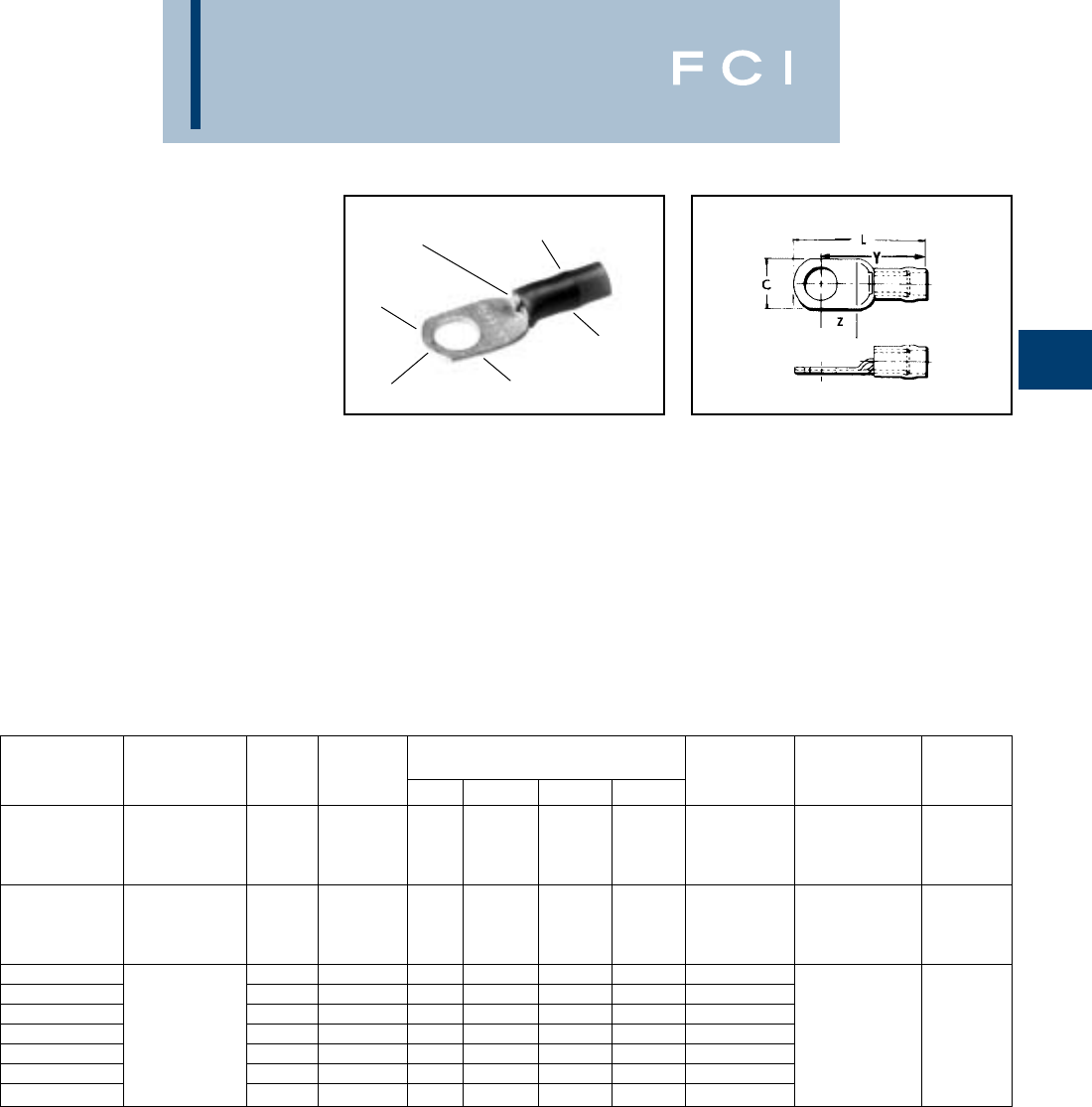
BURNDY
Compression
B-19
TYPES YAEV
AND YAEV-L
INSULUG™
TERMINAL -
NYLON INSULATED -
RING-TONGUE
300 VOLTS MAX. 105° C MAX.
The INSULUG™ type YAEV is designed for
very demanding high vibration applications
encountered in aircraft and aboard ships as
well as motor lead applications in hospitals,
industrials and generating plants. The nylon
insulated seamless, electrolytic copper barrel
with double thick tongue provides an extra
strong insulated connection. The terminal
is rated 105°C and meets MIL-T-7928
requirements.
TIN PLATED
RING
TONGUE
INSPECTION
HOLE
COLOR CODED
NYLON INSULATION
SEAMLESS
BARREL
DOUBLE THICK
TONGUE
Features and Benefits
•Double thick tongue.
◊Provides maximum reliability and
electrical capacity plus an extra strong
terminal tongue.
•Manufactured from one-piece pure
electrolytic copper.
◊Provides high conductivity, low resis-
tance with no seams to split plus ductility
for excellent crimp forming properties.
•Electro-tin plated.
◊Provides long-lasting corrosion
resistance.
•Nylon insulation is locked in place.
◊Insulation will not move or twist off.
•300 volt nylon insulation.
◊High dielectric strength and stability
in demanding oily environmental
conditions.
•Color Coded.
◊Provides quick, easy wire size
connector selection.
*No. 10 Str. Cu. only.
WIRE RANGE BULK WIRE
CATALOG AWG AN STUD MS25036-* DIMENSIONS CATALOG INSTALLATION STRIP
NUMBER AIRCRAFT SIZE DASH NO. C Z MIN. Y MAX. L MAX. NUMBER TOOLING LENGTH
22-18
Max. Insul. Ratchet:
YAEV18 BOX Dia. Accom.: .125 8-10 — .31 .24 .77 .91 YAEV18 MR8D94 1/4
Color Code: Red
18-14
Max. Insul. Ratchet:
YAEV14 BOX Dia. Accom.: .154 8-10 — .31 .24 .88 .94 YAEV14 MR18, 1/4
Color Code: Blue MR8D94
YAEV10-T7 BOX 4-5 — .30 .24 .95 1.09 YAEV10-T7 Ratchet:
YAEV10-T11 BOX 12-10 6-8 — .37 .26 .97 1.14 YAEV10-T11 MR8D94
YAEV10 BOX Max. Insul. 8-10 — .37 .26 .97 1.14 YAEV10 MR8-33-T1
YAEV10-L36 BOX Dia. Accom.: .209 8-10 — .30 .18 .89 1.04 YAEV10-L36 M8ND 5/16
YAEV10-T3 BOX Color Code: 1/4 — .47 .38 1.12 1.30 YAEV10-T3 with N10ET-9 DIE
YAEV10-T2 BOX Yellow 5/16 — .53 .31 1.12 1.30 YAEV10-T2 MR18*
YAEV10-T4 BOX 3/8 — .56 .35 1.12 1.35 YAEV10-T4 MR4 10M
BURNDY
Compression
B-20
TYPES YAEV AND
YAEV-L
(Continued)
INSULUG™
† Additional terminal stud sizes available.
*BMY, BNCH-MT bench mount adapter available.
** NOTE: Add suffix "M" to cat. number to conform to
MS25036 - standard for these items only
(example: YAEV6C-L1M).
See above. Contact Burndy for UL listed products.
BULK WIRE
CATALOG STUD MS25036 DIMENSIONS CATALOG INSTALLATION HYPRESS Y29NC STRIP
NUMBER WIRE RANGE SIZE † DASH NO. C Z MIN. Y MAX. L MAX. NUMBER TOOLING NEST INDENTOR LENGTH
Ratchet:
YAEV8C-L14 BOX 6-8 — .41 .28 1.20 1.40 YAEV8C-L14
M8ND with
YAEV8C-L BOX 8 Str. 8-10 -115 .41 .28 1.20 1.40 YA EV8C-L N8CET-2 Die
YAEV8C-L1 BOX Max. Insul. 1/4 -116 .46 .33 1.24 1.47 YAEV8-L1 Non-Ratchet:
YAEV8C-L2 BOX Dia. Accom.: .258 5/16 -117 .57 .35 1.28 1.55 YA EV8C-L2 MY28-6* DEV8L 7/16
YAEV8C-L3 BOX Color Code: Red 3/8 -118 .57 .35 1.39 1.55 YAEV8C-L3 Hydraulic:
Y35, Y39 with
YAEV8C-L4 BOX 1/2 — .73 .47 1.39 1.75 YA EV8C-L4 U8CET Die Set
—6 Str. 8-10 -119** .48 .29 1.33 1.56 YAEV6C-L1** Non-Ratchet: Y29PLE-1
—Max. Insul. 1/4 -120** .48 .29 1.33 1.56 YAEV6C-L** MY28-6* Y29PLE-1
—Dia. Accom.: .313 5/16 -121** .60 .36 1.39 1.68 YAEV6C-L4** Hydraulic: DEV6L 1/2
—Color Code: 3/8 -122** .60 .36 1.39 1.68 YAEV6C-L2** Y35, Y39 with
—Blue 1/2 — .73 .47 1.53 1.91 YAEV6C-L10 U6CET Die Set
—4 Str. 8-10 — .55 .28 1.40 1.62 YA EV4C-L3 Non-Ratchet:
—Max. Insul. 1/4 -123 .55 .28 1.37 1.62 YAEV4C-L MY28-6*
—Dia. Accom.: .374 5/16 -124 .63 .34 1.43 1.74 YA EV4C-L4 Hydraulic: DEV4L 1/2
—Color Code: 3/8 -125 .63 .34 1.43 1.74 YA EV4C-L2 Y35, Y39 with
—Yellow 1/2 — .73 .47 1.56 1.92 YA EV4C-L5 U4CET Die Set
—2 Str.10 — .69 .35 1.72 2.03 YA EV2C-L3 Non-Ratchet:
—Max. Insul. 1/4 -126 .69 .35 1.61 2.03 YA EV2C-L1 MY28-6*
—Dia. Accom.: .459 5/16 — .69 .35 1.68 2.03 YA EV2C-L2 Hydraulic: DEV2L 5/8
—Color Code: 3/8 -127 .69 .35 1.69 2.03 YA EV2C-L Y35, Y39 with
—Red 1/2 -128 .77 .47 1.80 2.16 YA EV2C-L4 U2CET Die Set
1 Str. Non-Ratchet:
—
Max. Insul.
1/4 -129 .76 .38 1.63 2.14 YAEV1C-L1
MY28-6*
—Dia. Accom.: .516 5/16 — .76 .38 1.71 2.14 YA EV1C-L2 Hydraulic: DV26L 5/8
—Color Code: 3/8 -130 .76 .38 1.72 2.14 YAEV1C-L Y35, Y39 with
—White 1/2 -131 .86 .47 1.86 2.27 YAEV1C-L3 U1CET Die Set Y29PLE
—1/0 Str. 1/4 -132 .83 .43 1.97 2.40 YAEV25-L1 Non-Ratchet: Y29PLE
—Max. Insul. 5/16 — .83 .43 1.97 2.40 YAEV25-L2 MY28-6*
—Dia. Accom.: .564 3/8 -133 .83 .43 1.97 2.40 YAEV25-L Hydraulic: DEV25L 11/16
—Color Code: 1/2 -134 .88 .47 2.02 2.46 YAEV25-L3 Y35, Y39 with
—Blue 5/8 — .88 .63 2.17 2.67 YAEV25-L4 U25ET Die Set
—2/0 Str.1/4 — .93 .49 2.19 2.72 YAEV26-L1 Non-Ratchet:
—Max. Insul. 5/16 -135 .93 .49 2.19 2.72 YAEV26-L2 MY28-6*
—Dia. Accom.: .628 3/8 -136 .93 .49 2.19 2.72 YAEV26-L Hydraulic: DEV26L 13/16
—Color Code: 1/2 -137 .93 .49 2.27 2.72 YAEV26-L3 Y35, Y39 with
—Yellow 5/8 — .93 .63 2.43 2.72 YAEV26-L12 U26ET Die Set
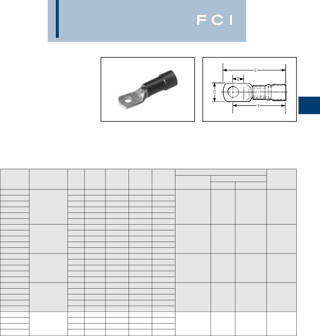
BURNDY
Compression
B-21
TYPE YAEV-H
INSULUG™
RING-TONGUE TERMINALS
NYLON-INSULATED FOR
EXPANDED INSULATION
Designed to accommodate larger conductor
insulation diameters. Made of one piece tin
plated pure electrolytic seamless copper
tubing for maximum conductivity and ductility.
Color-coded insulating sleeves are locked
into position. Inspection hole permits visual
check of wire insertion. Meets requirements
of MIL-T-7928
*BMY BNCH-MT bench mount adapter available.
BULK INSTALLATION TOOLING WIRE
CATALOG WIRE STUD Z Y L HYTOOL Y29NC STRIP
NUMBER RANGE SIZE C MIN. MAX. MAX. HYPRESS NEST INDENTOR LENGTH
YAEV8C-H14 6-8 .41 .25 1.32 1.54 M8ND
YAEV8C-H 88-10 .41 .25 1.34 1.54 with
YAEV8C-H1 Max. Insul. 1/4 .46 .28 1.37 1.61 N8CET-2 Die
YAEV8C-H2 Dia.: .30
5/16 .57 .33 1.39 1.68 MY28-6* DEV8K Y29PLE-1 7/16
YAEV8C-H3 Sleeve 3/8 .57 .33 1.39 1.68 Y35, Y39 with
YAEV8C-H4 Color: Red 1/2 .73 .47 1.52 1.91 U8CET Die
YAEV6C-H1 68-10 .48 .28 1.48 1.73
YAEV6C-H Max. Insul. 1/4 .48 .28 1.48 1.73 MY28-6*
YAEV6C-H4 Dia.: .385/16 .60 .33 1.54 1.85 Y35, Y39 DEV6L Y29PLE-1 1/2
YAEV6C-H2 Sleeve 3/8 .60 .34 1.54 1.85 with U6CET
YAEV6C-H10 Color: Blue 1/2 .73 .47 1.68 2.06 Die Set
YAEV4C-H3 48-10 .55 .28 1.60 1.87
YAEV4C-H Max. Insul. 1/4 .55 .28 1.60 1.87 MY28-6*
YAEV4C-H4 Dia.: .445/16 .62 .34 1.66 1.98 Y35, Y39 DEV4L Y29PLE-1 1/2
YAEV4C-H2 Sleeve 3/8 .62 .34 1.66 1.98 with
YAEV4C-H5 Color: Yellow 1/2 .73 .47 1.79 2.18 U4CET
YAEV2C-H3 28-10 .69 .35 1.98 2.34
YAEV2C-H1 Max. Insul. 1/4 .69 .35 1.98 2.34 MY28-6*
YAEV2C-H2 Dia.: .525/16 .69 .35 1.98 2.34 Y35, Y39 DEV2L Y29PLE 5/8
YAEV2C-H Sleeve 3/8 .69 .35 1.98 2.34 with
YAEV2C-H4 Color: Red 1/2 .77 .47 2.10 2.49 U2CET Die
YAEV1C-H1 11/4 .76 .38 2.10 2.49 MY28-6*
YAEV1C-H2 Max. Insul. 5/16 .76 .38 2.10 2.49 Y35, Y39
YAEV1C-H Dia.: .583/8 .76 .38 2.10 2.49 with DV26L Y29PLE 5/8
YAEV1C-H3 Sleeve Color: White 1/2 .86 .47 2.10 2.62 U1CET Die
CONSULT FACTORY
FOR AVAILABILITY
BURNDY
Compression
B-22
TYPE YAEV-H
(Continued)
*BMY BNCH-MT bench mount adapter available.
BULK INSTALLATION TOOLING WIRE
CATALOG WIRE STUD Z Y L HYTOOL Y29NC STRIP
NUMBER RANGE SIZE C MIN. MAX. MAX. HYPRESS NEST INDENTOR LENGTH
YAEV25-H1 1/0 1/4 .83 .43 2.39 2.82
YAEV25-H2 Max. Insul. 5/16 .83 .43 2.39 2.82 MY28-6*
YAEV25-H Dia.: .66” 3/8 .83 .43 2.39 2.82 Y35, Y39 DEV25L Y29PLE 11/16”
YAEV25-H3 Sleeve 1/2 .88 .47 2.43 2.88 with U25ET
YAEV25-H4 Color: Blue 5/8 .88 .62 2.59 3.10 Die Set
YAEV26-H1 2/0 1/4 .94 .48 2.65 3.13
YAEV26-H2 Max. Insul. 5/16 .94 .48 2.65 3.13 MY28-6*
YAEV26-H Dia.: .73” 3/8 .94 .48 2.65 3.13 Y35, Y39 DEV26L Y29PLE 13/16”
YAEV26-H3 Sleeve Color: 1/2 .94 .48 2.65 3.13 with U26ET
YAEV26-H12 Yellow 5/8 .94 .62 2.70 3.33 Die Set
CONSULT FACTORY
FOR AVAILABILITY
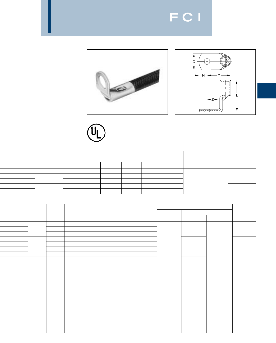
BURNDY
Compression
B-23
TYPES YAV-R,YAV-RS
HYLUG™
HEAVY DUTY RIGHT-ANGLE
TERMINALS
Factory formed right angle HYLUG™ con-
nectors made of seamless pure copper
tubing. These rugged terminals withstand the
most severe applications. Inspection hole in
barrel permits visual check of wire insertion.
Tin plated to resist corrosion. Meets require-
ments of MIL-T-7928.
*For aircraft applications (Flexible Cable) use die
DV8L-1
WIRE
CATALOG WIRE STUD DIMENSIONS INSTALLATION STRIP
NUMBER RANGE SIZE C L MAX. Y MAX. Z MIN. N TOOLING LENGTH
YAV18-R 22-18 8-10 .31 .35 .54 .25 .16 Non-Ratchet:
YAV14-RL33 4-6 .25 .37 .45 .21 .12 Y10D 1/4
YAV14-R 20-14 8-10 .31 .38 .57 .25 .16 Ratchet:
YAV10-R 8-10 .38 .55 .58 .25 .19 Y8MRB-1, MR20,
YAV10-R3 BOX 12-10 1/4 .47 .57 .60 .28 .23 MR8-G98, MR8-9Q 5/16
BULK INSTALLATION TOOLING WIRE
CATALOG DIMENSIONS IN INCHES HYPRESS Y29NC STRIP
NUMBER WIRE STUD C L MAX. Y MAX. Z MIN. N HYTOOL NEST INDENTOR LENGTH
YAV8C-RS 8-10 .41 1.00 .75 .25 .20
YAV8C-RS1 8 1/4 .41 1.00 .79 .28 .20 DV8L-1* 7/16
YAV8C-RS3 3/8 .56 1.00 .85 .34 .20
YAV6C-RS1 8-10 .50 1.02 .81 .28 .25
YAV6C-RS 1/4 .50 1.02 .81 .28 .25
YAV6C-RS4 65/16 .59 1.02 .89 .34 .31 DV6L
YAV6C-RS2 3/8 .59 1.02 .89 .34 .31
YAV4C-RS3 8-10 .53 1.04 .87 .28 .25 1/2
YAV4C-RS 1/4 .53 1.04 .87 .28 .25 MY28 Y29PL
YAV4C-RS4 45/16 .62 1.04 .95 .34 .31 MY29-11 DV4L
YAV4C-RS2 3/8 .62 1.04 .95 .34 .31
YAV2C-RS1 1/4 .68 1.27 1.05 .34 .33
YAV2C-RS2 2 5/16 .68 1.27 1.05 .34 .33 DV2L 5/8
YAV2C-RS 3/8 .68 1.27 1.05 .34 .33
YAV1C-RS1 1/4 .73 1.35 1.15 .34 .33
YAV1C-RS2 15/16 .73 1.35 1.15 .34 .33 DV1L 5/8
YAV25-RS 3/8 .82 1.51 1.29 .43 .39
YAV25-RS3 1/0 1/2 .88 1.51 1.32 .47 .44 DV25L 11/16
YAV26-RS 3/8 .92 1.63 1.40 .47 .39 Y29PR
YAV26-RS3 2/0 1/2 .92 1.63 1.40 .47 .39 DV26L 13/16
YAV27-RS 3/0 3/8 1.02 1.65 1.54 .47 .48
YAV28-RS 4/0 3/8 1.13 1.80 1.54 .47 .48 ——7/8
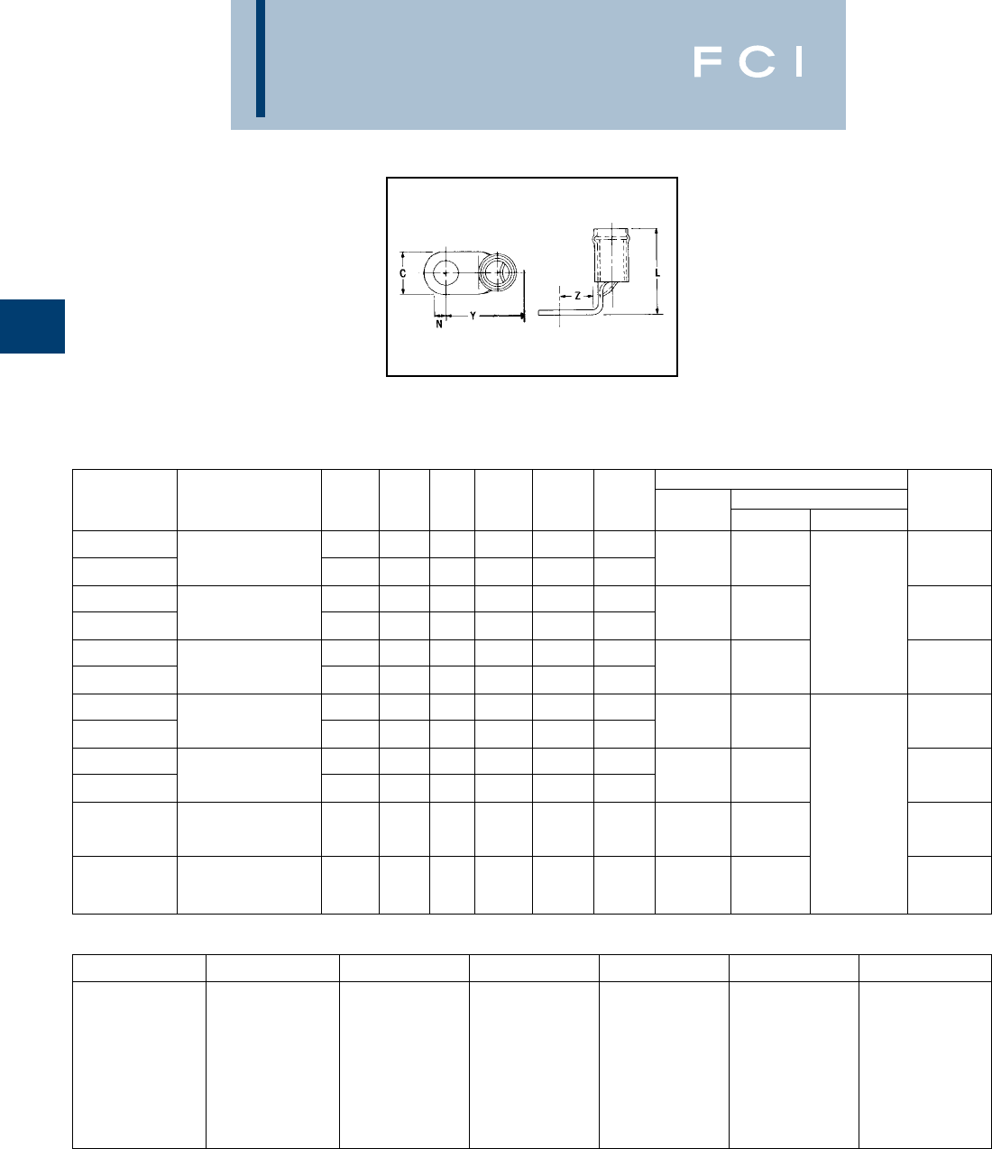
BURNDY
Compression
B-24
TYPES YAEV-RS
INSULUG™
RIGHT-ANGLE TERMINALS
NYLON-INSULATED
Factory formed right angle INSULUG™ con-
nectors made of seamless pure copper
tubing. These rugged terminals withstand the
most severe applications. Inspection hole in
barrel permits visual check of wire insertion.
Meets requirements of MIL-T-7928.
†† BMY BNCH-MT bench mount adapter available.
INSTALLATION TOOLING
CATALOG STUD HYPRESS Y29NC
NUMBER WIRE SIZE SIZE N C Z MIN. Y MAX. L MAX. HYTOOL NEST INDENTOR LENGTH
8
YAEV8C-RS
Max. Insul. Dia.: .258
8-10 .20 .41 .25 .82 1.25
ADEV8L 7/16
YAEV8C-RS1 Sleeve Color: Red 1/4 .25 .41 .28 .84 1.25
6
YAEV6C-RS1
Max. Insul. Dia.: .313
8-10 .25 .50 .28 .88 1.28
BDEV6L Y29PLE-1 1/2
YAEV6C-RS Sleeve Color: Blue 1/4 .25 .50 .28 .88 1.20
4
YAEV4C-RS
Max. Insul. Dia.: .374
1/4 .25 .53 .28 .95 1.28
CDEV4L 1/2
YAEV4C-RS2 Sleeve Color: Yellow 3/8 .31 .62 .34 1.02 1.28
2
YAEV2C-RS1
Max. Insul. Dia.: .459
1/4 .33 .68 .34 1.13 1.62
DDEV2L 5/8
YAEV2C-RS Sleeve Color: Red 3/8 .33 .68 .34 1.13 1.62
1
YAEV1C-RS2
Max. Insul. Dia.: .516
5/16 .33 .73 .34 1.22 1.65
EDEV26L 5/8
YAEV1C-RS Sleeve Color: White 3/8 .33 .73 .34 1.22 1.65
1/0 Y29PLE
YAEV25-RS Max. Insul. Dia.: .5643/8 .39 .81 .43 1.46 1.88 F DEV25L 11/16
Sleeve Color: Blue
2/0
YAEV26-RS Max. Insul. Dia.: .6283/8 .39 .92 .47 1.48 2.06 G DEV26 13/16
Sleeve Color: Yellow
ABCDEFG
Ratchet: Non-Ratchet: Non-Ratchet: Non-Ratchet: Non-Ratchet: Non-Ratchet: Non-Ratchet:
M8ND MY28-6†† MY28-6†† MY28-6†† MY28-6†† MY28-6†† MY28-6††
with Hydraulic: Hydraulic: Hydraulic: Hydraulic: Hydraulic: Hydraulic:
N8CET-2 Die Y35, Y39 with Y35, Y39 with Y35, Y39 with Y35, Y39 with Y35, Y39 with Y35, Y39 with
Non-Ratchet: U6CET U4CET U2CET U1CET U25ET U26ET
MY28-6†† Die Set Die Set Die Set Die Set Die Set Die Set
Hydraulic:
Y35, Y39 with
U8CET Die Set
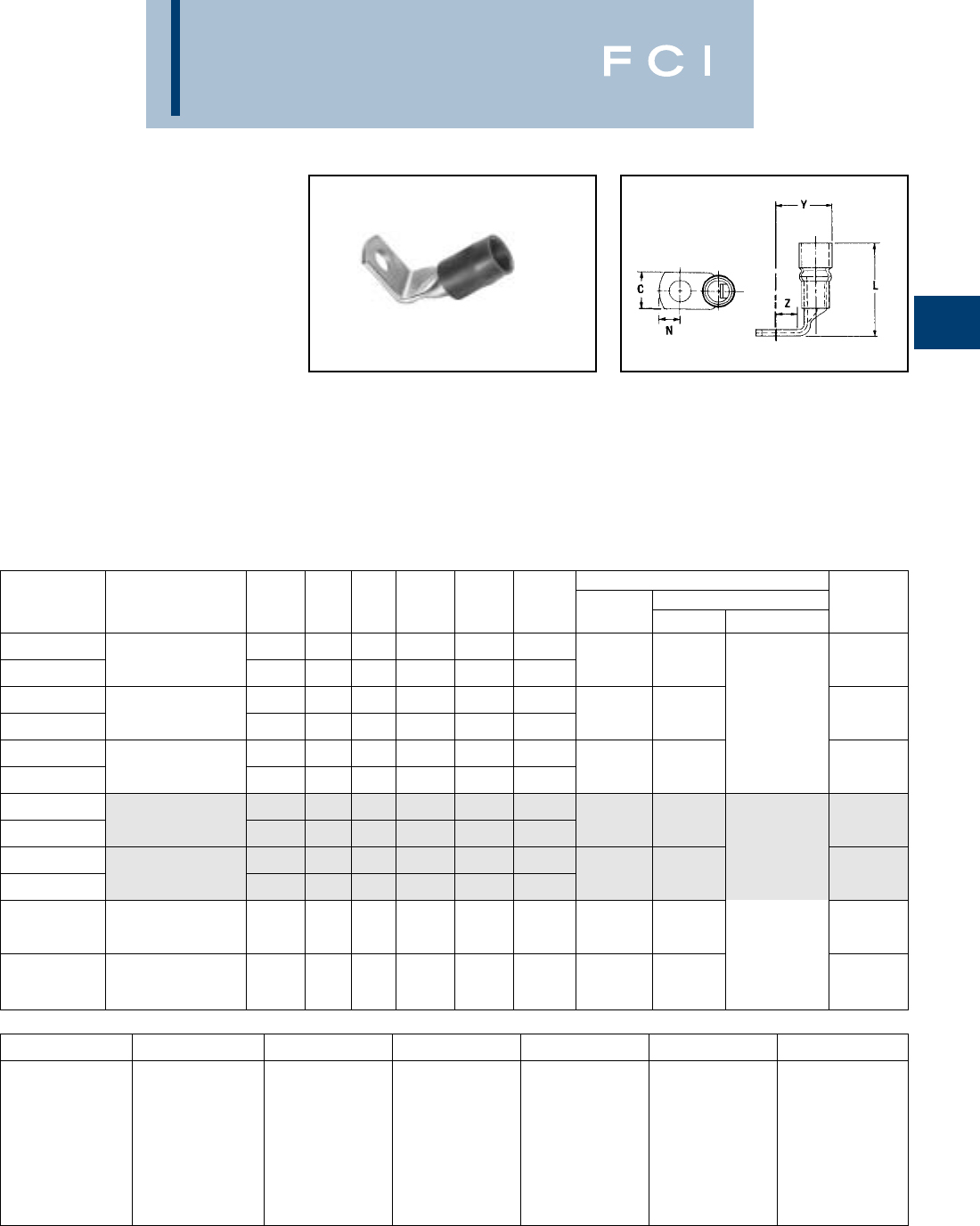
BURNDY
Compression
B-25
TYPE YAEV-RH
INSULUG™
RIGHT-ANGLE TERMINALS,
NYLON-INSULATED
DESIGNED TO
ACCOMMODATE
LARGER CONDUCTOR
INSULATION DIAMETERS
Factory formed right angle INSULUG™
connectors made of seamless pure copper
tubing. These rugged terminals withstand the
most severe applications. Inspection hole in
barrel permits visual check of wire insertion.
Tin plated to resist corrosion. Meets require-
ments of MIL-T-7928.
†† BMY BNCH-MT bench mount adapter available.
INSTALLATION TOOLING
CATALOG STUD HYPRESS Y29NC
NUMBER WIRE SIZE SIZE N C Z MIN. Y MAX. L MAX. HYTOOL NEST INDENTOR LENGTH
8
YAEV8C-RH
Max. Insul. Dia.: .30
8-10 .20 .41 .25 .87 1.38
ADEV8L 7/16
YAEV8C-RH1 Sleeve Color: Red 1/4 .25 .41 .28 .90 1.38
6
YAEV6C-RH1
Max. Insul. Dia.: .38
8-10 .25 .50 .28 .97 1.43
BDEV6L Y29PLE-1 1/2
YAEV6C-RH Sleeve Color: Blue 1/4 .25 .50 .28 .97 1.43
4
YAEV4C-RH
Max. Insul. Dia.: .44
1/4 .25 .53 .28 1.04 1.53
CDEV4L 1/2
YAEV4C-RH2 Sleeve Color: Yellow 3/8 .31 .62 .34 1.11 1.53
2
YAEV2C-RH1
Max. Insul. Dia.: .52
1/4 .33 .67 .34 1.22 1.88
DDEV2L 5/8
YAEV2C-RH Sleeve Color: White 3/8 .33 .67 .34 1.22 1.88
1
YAEV1C-RH2
Max. Insul. Dia.: .52
5/16 .33 .73 .34 1.32 1.99
EDV26L 5/18
YAEV1C-RH Sleeve Color: White 3/8 .33 .73 .34 1.32 1.99
1/0 Y29PLE
YAEV25-RH Max. Insul. Dia.: .663/8 .39 .81 .43 1.50 2.29 F DEV25L 11/16
Sleeve Color: Blue
2/0
YAEV26-RH Max. Insul. Dia.: .733/8 .39 .92 .47 1.60 2.42 G DEV26L 13/16
Sleeve Color: Yellow
ABCDEFG
Ratchet: Non-Ratchet: Non-Ratchet: Non-Ratchet: Non-Ratchet: Non-Ratchet: Non-Ratchet:
M8ND MY28-6†† MY28-6†† MY28-6†† MY28-6†† MY28-6†† MY28-6††
with Hydraulic: Hydraulic: Hydraulic: Hydraulic: Hydraulic: Hydraulic:
N8CET-2 Die Y35, Y39 with Y35, Y39 with Y35, Y39 with Y35, Y39 with Y35, Y39 with Y35, Y39 with
Non-Ratchet: U6CET U4CET U2CET U1CET U25ET U26ET
MY28-6†† Die Set Die Set Die Set Die Set Die Set Die Set
Hydraulic:
Y35, Y39 with
U8CET Die Set
CONSULT FACTORY
FOR AVAILABILITY
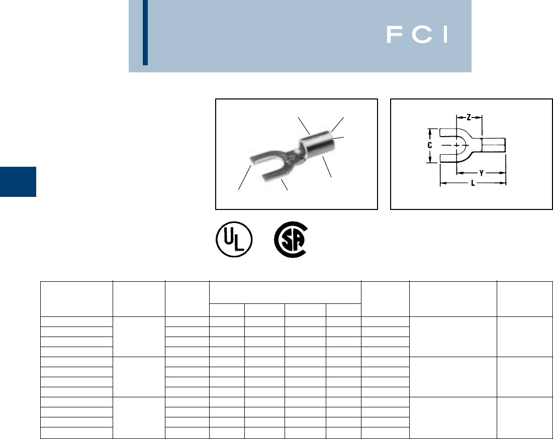
BURNDY
Compression
B-26
TYPES T-F AND YAD-F
HYLUG™
UNINSULATED
COMPRESSION TERMINAL,
FORK TONGUE
Type T-F is constructed in the same manner
as the type "T" and employs a fork tongue.
The fork permits rapid installation of the ter-
minal under a screw head without completely
removing the screw. Two or more terminals
may be stacked easily on a common stud.
ELECTRO-TIN
PLATED
BEVELED
ENTRY
LONG
NECK
FORKED
TONGUE
BRAZED
SEAM
DEEP “V” GROOVE
INNER SERRATIONS
AND INSPECTION HOLE
LONG
BARREL
WIRE
CATALOG WIRE STUD DIMENSIONS BULK INSTALLATION STRIP
NUMBER RANGE SIZE C L MAX. Y MAX. Z MIN. CAT. NO. TOOLING LENGTH
T18-6F 4-6 .28 .68 .55 .25 YAD18-6F Non-Ratchet:
T18-8F 6-8 .31 .74 .57 .27 YAD18-8F Y10D, Y10-22
T18-10F 22-18 8-10 .37 .74 .58 .29 YAD18-10F Ratchet: MR8G9 9/32
T18-14F .47 .92 .69 .39 YAD18-14F Y8MRB-1, MR20
T14-6F 4-6 .28 .68 .55 .25 YAD14-6F Non-Ratchet:
T14-8F 6-8 .31 .74 .57 .27 YAD14-8F Y10D, Y10-22
T14-10F 20-14 8-10 .37 .74 .58 .29 YAD14-10F Ratchet: MR8G98, 9/32
T14-14F .47 .92 .69 .39 YAD14-14F Y8MRB-1, MR20
T10-6F 4-6 .28 .74 .61 .25 YAD10-6F Non-Ratchet:
T10-8F 6-8 .31 .80 .63 .27 YAD10-8F Y10D, Y10-22
T10-10F 12-10 8-10 .41 .87 .68 .32 YAD10-10F Ratchet: MRG98, 11/32
T10-14F .50 1.00 .75 .39 YAD10-14F Y8MRB-1, MR20
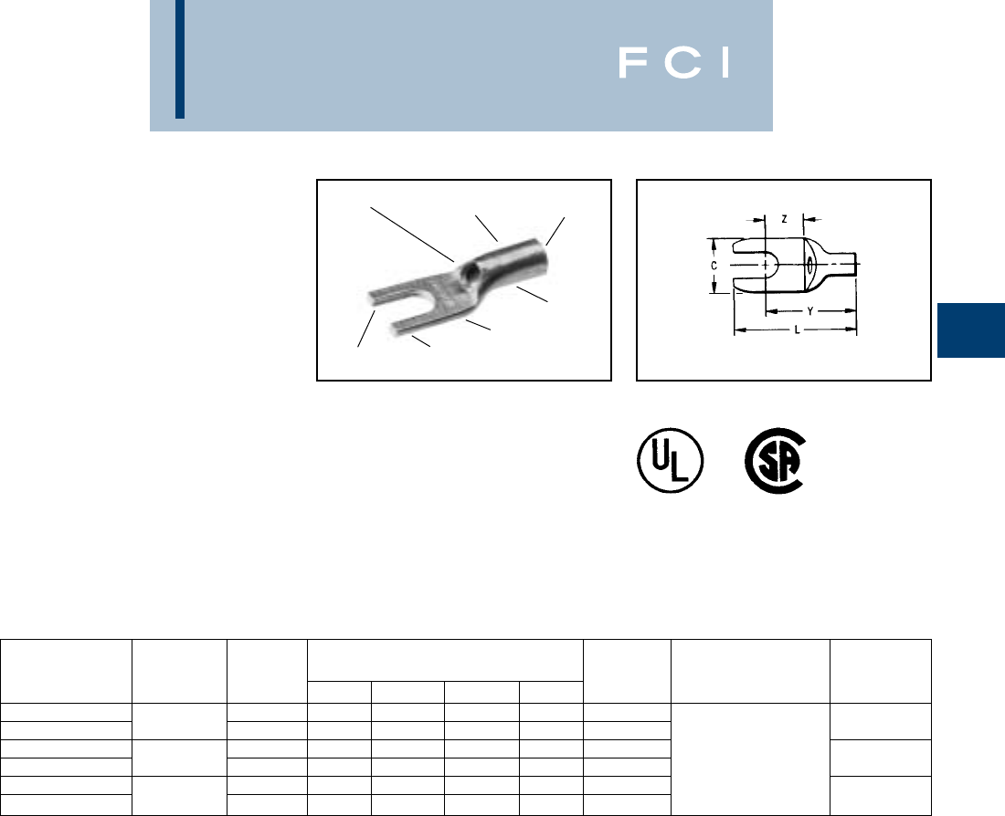
BURNDY
Compression
B-27
TYPES YAV-T-F BOX
AND YAV-T-F
HYLUG™
SEAMLESS UNINSULATED
COMPRESSION
FORK TONGUE TERMINAL
The type YAV-T-F HYLUG™ is a seamless
heavy duty uninsulated compression fork-
tongue terminal manufactured from electro-
lytic copper for use on copper commercial
(code) cable, Type AN aircraft cable and extra
flexible conductors.
The seamless design produces a double thick
tongue and the seamless barrel provides a
strong highly reliable connection.
All the benefits of the Type YAV apply for the
same wire sizes.
INSPECTION
HOLE
ELECTRO-TIN
PLATED DOUBLE THICK
FORK TONGUE
WIRE SIZE
SEAMLESS
BARREL BEVELED
ENTRY
CRIMP
Features and Benefits
•Fork tongue.
◊Allows installation of compression
terminal under screw head without
complete removal of the screw.
WIRE
CATALOG WIRE STUD DIMENSIONS BULK INSTALLATION STRIP
NUMBER RANGE SIZE C L MAX. Y MAX. Z MIN. CAT. NO. TOOLING LENGTH
YAV18-T19F BOX 4-6 .31 .80 .55 .25 YAV18-T19F
YAV18-T21F BOX 22-18 8-10 .37 .80 .55 .25 YAV18-T21F Non-Ratchet: 9/32
YAV14-T32F BOX 4-6 .31 .80 .57 .25 YAV14-T32F Y10D, Y10-22
YAV14-T34F BOX 20-14 8-10 .37 .82 .60 .26 YAV14-T34F Ratchet: 9/32
YAV10-T21F BOX 8-10 .38 .91 .69 .26 YAV10-21F MR8-G98, MR8-9Q,
YAV10-T23F BOX 12-10 1/4.47 1.00 .75 .34 YAV10T23F MR20, Y8MRB-1 7/16
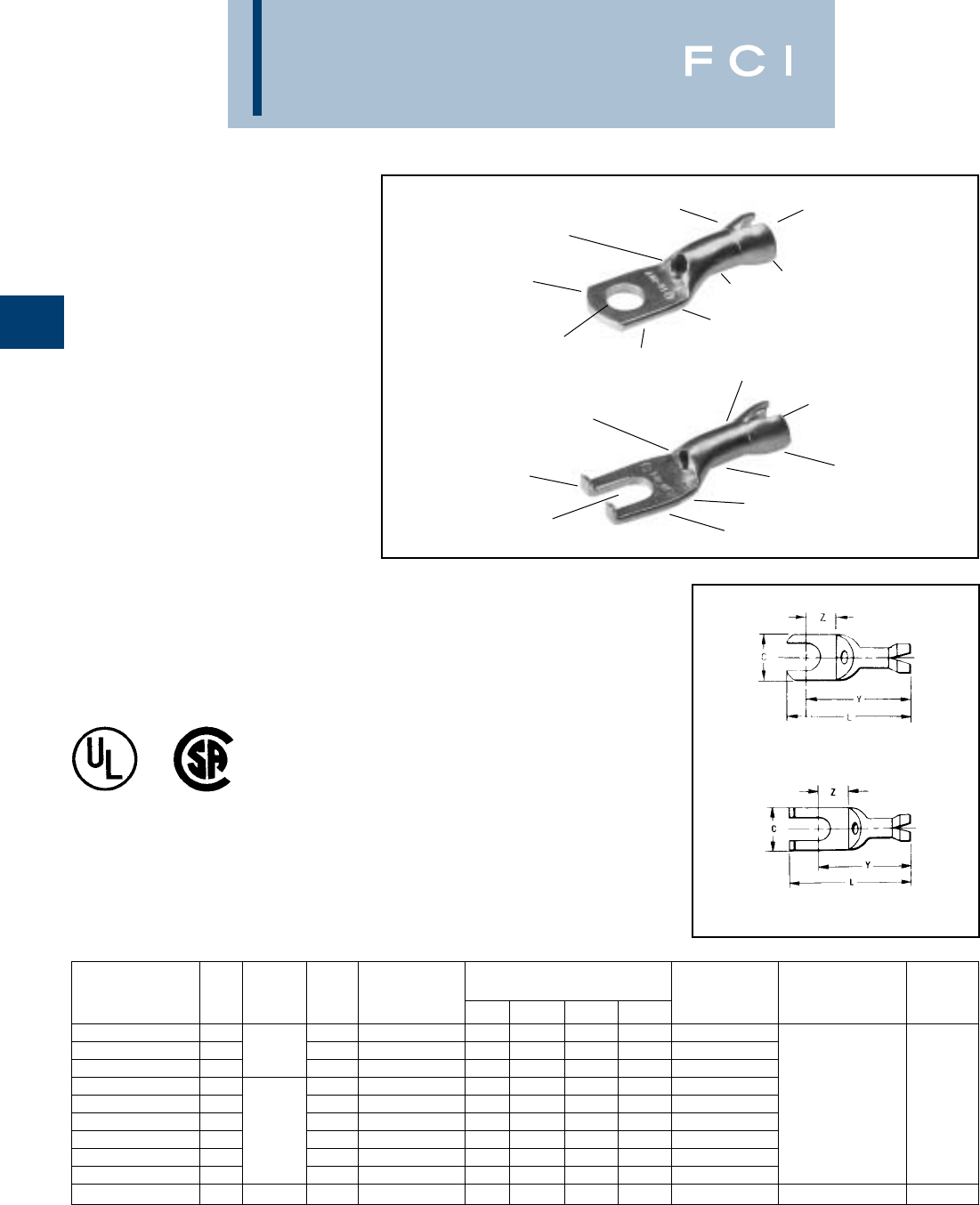
BURNDY
Compression
B-28
TYPE YAV-H-F BOX,
YAV-H-F AND YAV-Z
HYLUG™
UNINSULATED
COMPRESSION TERMINAL
FORK TONGUE WITH
SHROUD SEAMLESS
The type "YAV-H-F" HYLUG™ is a seamless
heavy duty uninsulated compression fork
tongue terminal with a shroud for an insula-
tion grip and cable support. Manufactured
from electrolytic copper tubing for use on
copper commercial (code) cable, Type "AN"
aircraft and extra flexible conductors.
The seamless tubing produces a double thick
tongue while the seamless barrel design
provides a very strong connector for very
demanding applications that require highly
reliable connections.
In addition to the benefits described for the
YAV box series of connectors the YAVH-F Box
and YAV-Z terminals provide the following
benefits.
Features and Benefits
•Fork tongue.
◊Allows installation of compression termi-
nal under screw head without complete
removal of the screw thereby lowering
installation costs.
•Flanged fork tongue.
◊Allows installation of compression termi-
nal under screw head without complete
removal of the screw plus aids in main-
taining the terminal on the stud should
the screw loosen slightly.
SEAMLESS
BARREL
ELECTRO-TIN
PLATED
DOUBLE THICK
TONGUE
CRIMP
INSPECTION
HOLE
FLANGED
FORK TONGUE
CRIMP
WIRE RANGE
INSULATION
GRIP AND
CABLE SUPPORT
SEAMLESS
BARREL
ELECTRO-TIN
PLATED
DOUBLE THICK
TONGUE
CRIMP
INSPECTION
HOLE
FLANGED
FORK TONGUE
CRIMP
WIRE RANGE
INSULATION
GRIP AND
CABLE SUPPORT
Fig. 1
Fig. 2
*Crimps conductor crimp only.
WIRE
CATALOG WIRE STUD MAX. INSUL. DIMENSIONS BULK INSTALLATION STRIP
NUMBER FIG. RANGE SIZE DIA. ACCOM. C L MAX. Y MAX. Z MIN. CAT. NO. TOOLING LENGTH
YAV18-H6F BOX 14-6.120 .25 .89 .80 .19 YAV18-H6F Plier:
YAV18-H19 BOX 122-18 4-6 .120 .30 .97 .75 .21 YAV18-H19F Y10D*, Y14MV,
YAV18-H21F BOX 18-10 .120 .37 .97 .76 .22 YAV18-H21F Y10-22*
YAV14-Z5 BOX 24-6.150 .31 .89 .69 .13 YAV14-Z5 Ratchet:
YAV14-H32F BOX 14-6.150 .30 .96 .78 .23 YAV14-H32F MR8-G98, 1/4
YAV14-H56F BOX 16-8.150 .30 .96 .78 .23 YAV14-H56F MR8-9Q,
YAV14-H34F BOX 120-14 8-10 .150 .37 .96 .78 .23 YAV14-H34F Y8MRB-1*,
YAV14-HF BOX 18-10 .150 .31 .93 .78 .23 YAV14-HF MR20, and M8ND
YAV14-Z6 BOX 28-10 .150 .37 1.04 .78 .21 YAV14-Z6 with N14HT-5 Die
YAV10-HF BOX 112-10 8-10 .192 .38 1.07 .92 .24 YAV10-HF N10HT Die 7/16
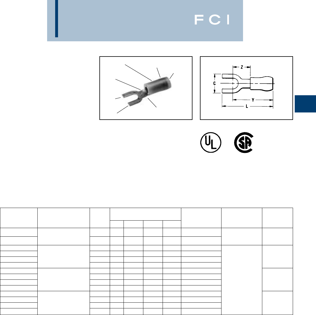
BURNDY
Compression
B-29
TYPES TN-F AND
YAES-F
INSULUG™
TERMINAL - NYLON
INSULATED, FORK TONGUE
300 VOLTS MAX. 105° C MAX
The type TN-F, nylon insulated fork tongue
terminal has the same high quality as the TN.
It is designed to meet the heavy-duty require-
ments of industrial and utility applications.
Used on both power and control circuits for
wire sizes #26 AWG through #10 AWG. The
TN-F provides high dielectric strength and
stability in oily conditions.
The TN-F is identical to the TN with the addi-
tion of a fork tongue which allows installation
without complete removal of its supporting
screw.
Features and Benefits
•Fork tongue.
◊Provides faster and easier installation
by permitting insertion under the screw
head without completely removing it.
TIN
PLATED
FORK
TONGUE
BRAZED
SEAM
WIRE CRIMP INSULATION
CRIMP SMOOTH
FUNNEL
ENTRY
DEEP “V”
SERRATIONS
*These sizes not UL listed.
** Or other tool conforming to military specification MS25037
or MS90413
WIRE
CATALOG WIRE STUD DIMENSIONS BULK INSTALLATION STRIP
NUMBERS RANGE SIZES C L MAX. Y MAX. Z MIN. CAT. NO. TOOLING LENGTH
26-20 Max. Insul. M8ND with
TN20-2F*
Dia. Accom.: .098
1-2 .18 .76 .65 .24 —
N14HET-25V1 3/16
TN20-6F* Color Code: Amber 4-6 .28 .80 .70 .28 — Die Set
TN18-6F 22-18 4-6 .28 .79 .65 .24 YAES18N1F
TN18-8F Max. Insul. 6-8 .31 .84 .67 .26 YAES18N49F
TN18-10F Dia. Accom.: .120 8-10 .37 .84 .68 .27 YAES18N3F Non-Ratchet: 7/32
TN18-14F Color Code: Red .47 1.03 .79 .38 YAES18N50F Y10D, Y10-22
TN14-6F 16-14 4-6 .28 .79 .65 .24 YAES14N6F
TN14-8F Max. Insul. 6-8 .31 .84 .67 .26 YAES14N53F
TN14-10F Dia. Accom.: .153 8-10 .37 .84 .68 .27 YAES14N8F 7/32
TN14-14F Color Code: Blue .47 1.03 .79 .38 YAES14N54F
TN10-6F 12-10 4-6 .28 .96 .82 .24 YAES10N11F Ratchet:
TN10-8F Max. Insul. 6-8 .31 1.01 .84 .26 YAES10N56F MR8-83**, MR18
TN10-10F Dia. Accom.: .209 8-10 .41 1.09 .89 .31 YAES10N12F 11/32
TN10-14F Color Code: Yellow .50 1.21 .96 .38 YAES10N57F
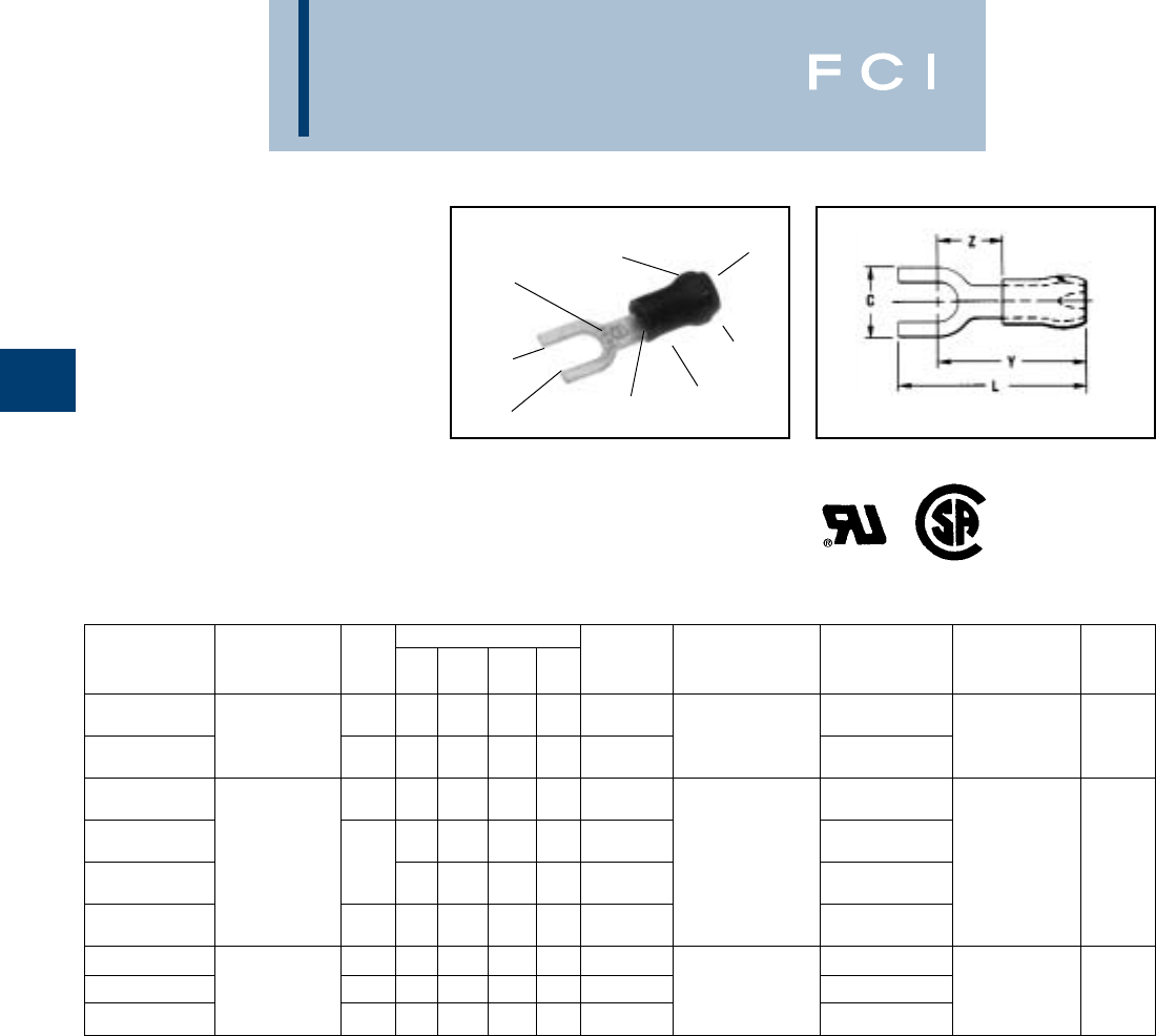
BURNDY
Compression
B-30
TYPES YAE-N-F BOX
AND YAE-N-F
INSULUG™
Ter minal — Nylon Insulated,
Fork Tongue
Multi-Finger Insulation Grip
300 Volts Max. 105° C Max.
INSULUG™ type YAE-N-F nylon insulated
terminals are designed with a Multi-Finger
Insulation grip, are rated 105° C and are
supplied with a fork tongue for easy terminal
insertion and removal.
FORK
TONGUE
ELECTRO-TIN
PLATED
WIRE SIZE
MULTI-FINGER
INSULATION GRIPS
AND CABLE SUPPORT
FUNNEL
ENTRY
INSULATION
CRIMP
WIRE
CRIMP
DEEP “V”
SERRATIONS
Features and Benefits
•Fork tongue.
◊Permits rapid easy installation of the
terminal under the screw head without
complete removal of the screw.
•Not UL recognized.
DIMENSIONS BULK TAPE MOUNTED WIRE
CATALOG WIRE STUD L Y Z CATALOG INSTALLATION CATALOG NO. INSTALLATION STRIP
NUMBER RANGE SIZE C MAX. MAX. MIN. NUMBER TOOLING 2000/Reel TOOLING LENGTH
24 - 20 Max. Insul. Ratchet: TFM
YAE22N65F BOX• Dia.: .0981 - 2 .18 .73 .65 .24 YAE22N65F• M8ND YAE22N65FM• with
Sleeve Color: N14HET25V1 DFM11D1 5/32
YAE22N66F BOX• Amber 4 - 6 .28 .80 .70 .28 YAE22N66F• Die YAE22N66FM• Die
Non-Ratchet: Y10D or
YAE18N60F BOX 4.21 .92 .73 .24 YAE18N60F Ratchet: MR8-33T-1, YAE18G60FM
22 - 16 M8ND TFM
YAE18G43F BOX Max. Insul. .25 .78 .68 .19 YAE18G43F With one of the YAE18G43FM with
Dia.: .1254 - 6 following Dies: DFM10D1 3/16
YAE18N56F BOX Sleeve Color: Red .28 .83 .76 .23 YAE18N56F N14HET-25V1, YAE18N56FM Die
N10ET-9,
YAE18N57F BOX 6 - 8 .31 .96 .78 .29 YAE18N57F N14HET-15 YAE18N57FM
YAE14N76F BOX 16 - 14 4 - 6 .28 .87 .76 .26 YAE14N76F Non-Ratchet: YAE14N76FM TFM
Max. Insul. Y10D or Y10-22 or with
YAE14N77F BOX Dia.: .1566 - 8 .31 .96 .78 .29 YAE14N77F Ratchet: YAE14N77FM DFM9D1 3/16
YAE14N78F BOX Sleeve Color: Blue 8 - 10 .36 1.01 .83 .34 YAE14N78F MR8-33T1 YAE14N78FM Die
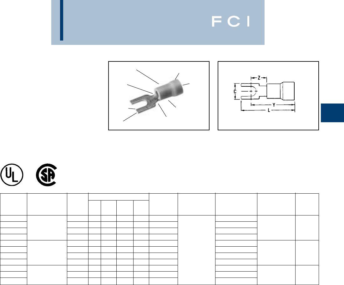
BURNDY
Compression
B-31
TYPES TP-F
AND BA-EF
VINYLUG™
TERMINAL -
POLYVINYLCHLORIDE
INSULATED, FORK TONGUE
600 VOLTS MAX. 105° C MAX
The Type TP-F is a fork tongue variation of
the TP design and makes installation easier.
Features and Benefits
•Fork tongue design.
◊Faster installation-screw needs only to
be loosened for termination.
•UL and CSA listed with MR8-89-1 and MR15.
*1000/Reel.
TIN
PLATED
FORK
TONGUE
WIRE SIZE
RANGE
WIRE
CRIMP EXPANDED SHROUD
INSULATION CRIMP
SMOOTH
ENTRY
COLOR CODED
INSULATION
DEEP “V”
SERRATIONS
DIMENSIONS BULK TAPE MOUNTED WIRE
CATALOG WIRE STUD L Y Z CATALOG INSTALLATION CATALOG NO. INSTALLATION STRIP
NUMBER RANGE SIZE C MAX. MAX. MIN. NUMBER • TOOLING 2000/Reel TOOLING LENGTH
TP16-2F 22-16 1-2 .17 .75 .66 .23 BA16EF2 BA16EF2M TFM
TP16-6F Max. Insul. 4-6 .28 .80 .66 .23 BA16EF6 BA16EF6M with
TP16-8F Dia. Accom.: .145 6-8 .31 .86 .69 .26 BA16EF8 Plier Type: BA16EF8M DFM3D-1 13/64
TP16-10F Color Code: Red 8-10 .41 .95 .75 .31 BA16EF10 Y10-22 BA16EF10M Die
TP14-2F 16-14 1-2 .17 .75 .66 .23 BA14EF2 BA14EF2M TFM
TP14-6F Max. Insul. 4-6 .28 .80 .66 .23 BA14EF6 BA14EF6M with
TP14-8F Dia. Accom.: .180 6-8 .31 .86 .69 .26 BA14EF8 Ratchet Tool: BA14EF8M DFM2D-1 13/64
TP14-10F Color Code: Blue 8-10 .41 .95 .75 .31 BA14EF10 MR8-89-1, BA14EF10M Die
TP10-6F 12-10 4-5 .28 .95 .81 .26 BA10EF6 MR15 *BA10EF6M TFM
TP10-8F Max. Insul. 6-8 .31 .98 .81 .26 BA10EF8 *BA10EF8M with 19/64
TP10-10F Color Code: Yellow 8-10 .41 1.07 .87 .31 BA10EF10 *BA10EF10M DFM1D5 Die
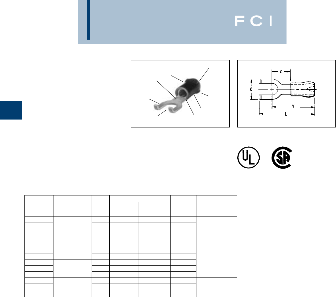
BURNDY
Compression
B-32
TYPES YAE-Z BOX
AND YAE-Z
INSULUG™
TERMINAL -
NYLON INSULATED,
FLANGED FORK
MULTI-FINGER
INSULATION GRIP
300 VOLTS MAX. 105° C MAX
INSULUG™ type YAE-Z is identical to type
YAE-N and employs a flanged fork tongue for
faster installation while maintaining security if
supporting screw becomes loose.
Features and Benefits
•Flanged fork.
◊Permits rapid, easy installation of the
terminal under the screw head without
complete removal of the screw.
Additionally, it may not be removed with
only a slight loosening of the screw.
•Not UL recognized.
MULTI-FINGER
INSULATION GRIPS
AND CABLE SUPPORT
WIRE SIZE
ELECTRO-TIN
PLATED
FLANGED
FORK DEEP “V”
SERRATIONS
WIRE CRIMP
INSULATION
CRIMP
FUNNEL
ENTRY
DIMENSIONS BULK
CATALOG WIRE STUD Z Y L CATALOG INSTALLATION
NUMBER RANGE SIZE C MAX. MAX. MAX. NUMBER TOOLING
YAE22Z1 BOX 26-20 Max. Insul. 1-2 .18 .24 .65 .75 YAE22Z1 M8ND with
YAE22Z2 BOX Dia.: .0984-6 .28 .28 .70 .83 YAE22Z2 N14HET-25V1 Die
YAE22Z3 BOX Sleeve Color: Amber 6-8 .31 .30 .72 .92 YAE22Z3 Y10D, Y10-22
YAE18Z1 BOX 1-2 .18 .22 .73 .83 YAE18Z1
YAE18Z2 BOX 22-16 Max. Insul. 4-6 .28 .26 .76 1.00 YAE18Z2 MR8-33T-1,
YAE18Z3 BOX Dia. Accom.: (125) 6-8 .31 .29 .78 1.00 YAE18Z3 M8ND
YAE18Z4 BOX Color Code: Red 8-10 .36 .34 .83 1.08 YAE18Z4 with one of the
YAE14Z2 BOX 16-14 Max. Insul. 4-6 .28 .26 .76 .90 YAE14Z2 following Dies:
YAE14Z3 BOX Dia. Accom.: (156) 6-8 .31 .29 .78 1.00 YAE14Z3 N14HET-15, N10HET-9,
YAE14Z4 BOX Color Code: Blue 8-10 .36 .34 .83 1.08 YAE14Z4 Y10D, Y10-22
YAE12Z2 BOX 14-12 Max. Insul. 4-6 .28 .27 .90 1.04 YAE12Z2 MR833T-1, M8ND
YAE12Z3 BOX Dia. Accom.: (180) 6-8 .31 .32 .96 1.16 YAE12Z3 with N12HET-1,
YAE12Z4 BOX Color Code: Green 8-10 .36 .35 1.00 1.23 YAE12Z4 Y10D, Y10-22

BURNDY
Compression
B-33
TYPES TP-Z
AND BA-EZ
VINYLUG™
TERMINAL -
POLYVINYLCHLORIDE
INSULATED, FLANGED
FORK TONGUE
600 VOLTS MAX. 105° C MAX
VINYLUG™ Type TP-Z is a variation of the
Type TP and employs a flanged fork tongue
for fast installation and security.
Features and Benefits
•Flange fork tongue design.
◊Allows fast installation—screw only has
to be loosened for termination.
•The flanges on the end of the fork terminal
aid in preventing a slightly loose terminal
from becoming fully disconnected from
the screw.
◊Flanges make re-securing a loose
terminal easier.
*1000/Reel.
EXPANDED SHROUD
INSULATION
CRIMP
WIRE
CRIMP
WIRE SIZE
RANGE
FLANKED
FORK TIN PLATED
DEEP “V”
SERRATIONS
FUNNEL
ENTRY
DIMENSIONS BULK
CATALOG WIRE STUD L Y Z CATALOG INSTALLATION
NUMBER RANGE SIZE C MAX. MAX. MIN. NUMBER TOOLING
TP16-2Z 22-16 1-2 .17 .78 .66 .23 BA16EZ2
TP16-6Z Max. Insul. 4-6 .28 .83 .66 .23 BA16EZ6
TP16-8Z Dia. Accom.: .145 6-8 .31 .88 .69 .26 BA16EZ8 Plier Type:
TP16-10Z Color Code: Red 8-10 .41 .96 .75 .31 BA16EZ10 Y10-22
TP14-2Z 16-14 1-2 .17 .78 .66 .23 BA14EZ2
TP14-6Z Max. Insul. 4-6 .28 .83 .66 .23 BA14EZ6
TP14-8Z Dia. Accom.: .180 6-8 .31 .88 .69 .26 BA14EZ8 Ratchet Tool:
TP14-10Z Color Code: Blue 8-10 .41 .96 .75 .31 BA14EZ10 MR8-89-1,
TP10-6Z 12-10 Max. Insul. 4-6 .28 .99 .81 .26 BA10EZ6 MR15
TP10-8Z Dia. Accom.: .260 6-8 .31 1.01 .81 .26 BA10EZ8
TP10-10Z Color Code: Yellow 8-10 .41 1.09 .81 .31 BA10EZ10
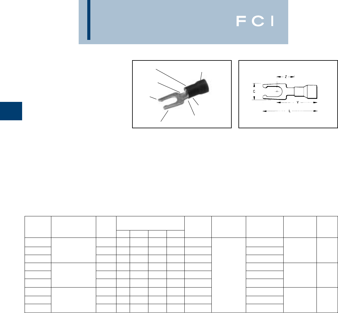
BURNDY
Compression
B-34
TYPES TP-LF AND
BA-EL
VINYLUG™
TERMINAL -
POLYVINYLCHLORIDE
INSULATED,
LOCKING FORK TONGUE
600 VOLTS MAX. 105° C MAX
Type TP-LF is a variation of the Type TP
design and employs a locking fork tongue for
fast installation and security.
•UL and CSA listed with MR8-89-1 and MR15.
*1000/Reel.
Features and Benefits
•Locking fork tongue design.
◊Allows fast installation—screw only has
to be loosened for termination.
•Internal configuration of the fork.
◊Prevents the terminal from coming
off the screw without applying a
pulling force.
•Locking fork is made from a copper alloy.
◊Permits many installations while main-
taining proper spring retention of forks.
LOCKING
FORK
WIRE SIZE
RANGE
WIRE
CRIMP EXPANDED SHROUD
INSULATION CRIMP
COLOR CODED
INSULATION
DEEP “V”
SERRATIONS
TIN PLATED
BULK TAPE MOUNTED WIRE
CATALOG WIRE STUD DIMENSIONS CATALOG INSTALLATION CATALOG NO. INSTALLATION STRIP
NUMBER RANGE SIZE C L MAX. Y MAX. Z MIN. NUMBER • TOOLING 2000/Reel TOOLING LENGTH
22-16 TFM
TP16-6LF
MAX. INSUL.
4-6 .28 .80 .66 .23 BA16EL6 BA16EL6M
WITH
TP16-8LF DIA. ACCOM.: .145 6-8 .31 .86 .69 .26 BA16EL8 PLIER TYPE: BA16EL8M DFM3D-1 13/64
TP16-10LF COLOR CODE: Red 8-10 .41 .95 .75 .31 BA16EL10 Y10-22 BA16EL10M DIE
16-14 TFM
TP14-6LF
MAX. INSUL.
4-6 .28 .80 .66 .23 BA14EL6 BA14EL6M
WITH
TP14-8LF DIA. ACCOM.: .180 6-8 .31 .86 .69 .26 BA14EL8 RATCHET BA14EL8M DFM2D-1 13/64
TP14-10LF COLOR CODE: Blue 8-10 .41 .95 .75 .31 BA14EL10 TOOL: BA14EL10M DIE
12-10 MR8-89-1
TP10-6LF
MAX. INSUL.
4-6 .28 .95 .81 .26 BA10EL6
MR15
* BA10EL6M TFM
TP10-8LF DIA. ACCOM.: .260 6-8 .31 .98 .81 .26 BA10EL8 * BA10EL8M WITH 19/64
TP10-10LF COLOR CODE: Yellow 8-10 .41 1.07 .87 .31 BA10EL10 * BA10EL10M DFM1D5 DIE
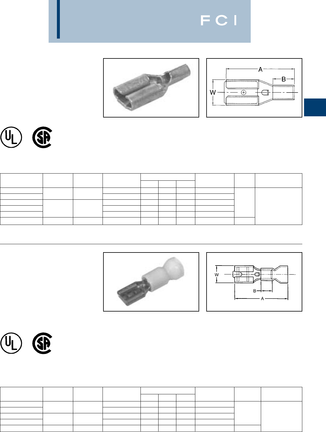
BURNDY
Compression
B-35
TYPE Q-F FINGRIP™
NON-INSULATED FEMALE
QUICK DISCONNECTS
MATERIAL: TIN-PLATED
BRASS
Features and Benefits
•Butted seam.
•Chamfered barrel opening.
◊Assures quick and easy wire insertion.
•Dimpled female socket detent.
◊Ensures firm grip.
STANDARD STD. PKG. WIRE NEMA TAB DIMENSIONS BULK BULK INSTALLATION
CATALOG NO. QTY. RANGE SIZE A B W CATALOG NO. QTY. TOOL*
Q18F18X02D .187 .020 0.58 0.17 0.23 Q18F18X02B
Q18F25X03D 100 18-22 .250 .032 0.62 0.17 0.29 Q18F25X03B
Q14F11X02D .110 .020 0.55 0.17 0.14 Q14F11X02B 1000 MR20,
Q14F18X02D 100 14-16 .187 .020 0.58 0.17 0.20 Q14F18X02B Y10D
Q14F25X03D .250 .032 0.62 0.17 0.29 Q14F25X03B
Q10F25X03D 50 10-12 .250 .032 0.73 0.27 0.29 Q10F25X03B 500
FEMALE BARE DISCONNECT TERMINAL (Mates with Type Q-M male disconnects)
*For UL listed applications consult BURNDY®factory.
TYPE QP-F FINGRIP™
VINYL INSULATED FEMALE
QUICK DISCONNECTS
MATERIAL: TIN-PLATED
BRASS
600 VOLTS MAX. 105 C MAX.
Features and Benefits
•Butted seam.
•Insulated connectors.
◊Eliminate the need for post installation
insulation.
•Funnel entry barrel opening.
◊Assures quick and easy wire insertion.
•Dimpled female socket detent.
◊Ensures firm grip.
STANDARD STD. PKG. WIRE NEMA TAB DIMENSIONS BULK BULK PKG. INSTALLATION
CATALOG NO. QTY. RANGE SIZE A B W CATALOG NO. QTY. TOOL*
QP18F18X02D .187 .020 0.86 0.17 0.22 QP18F18X02B
QP18F25X03D 100 18-22 .250 .032 0.91 0.17 0.29 QP18F25X03B
QP14F18X02D .187 .020 0.87 0.17 0.23 QP14F18X02B 1000 Y10D
QP14F25X03D 100 14-16 .250 .032 0.92 0.17 0.29 QP14F25X03B
QP10F25X03D 50 10-12 .250 .032 1.08 0.27 0.29 QP10F25X03B 500
FEMALE VINYL DISCONNECT TERMINAL (Mates with Type QP-M male disconnects)
*For UL listed applications consult BURNDY®factory.
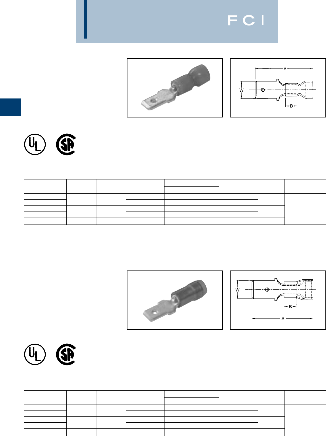
BURNDY
Compression
B-36
TYPE QP-M
FINGRIP™
VINYL INSULATED MALE
QUICK DISCONNECTS
MATERIAL: TIN-PLATED
BRASS
600 VOLTS MAX. 105 C MAX. Features and Benefits
•Butted seam.
•Funnel entry barrel opening.
◊Assures quick and easy wire insertion.
•Mates with dimpled female socket detent.
◊Ensures firm grip.
STANDARD STD. PKG. WIRE NEMA TAB DIMENSIONS BULK BULK PKG. INSTALLATION
CATALOG NO. QTY. RANGE SIZE A B W CATALOG NO. QTY. TOOL*
QP18M18X02D .187 .020 0.83 0.17 0.19 QP18M18X02B
QP18M25X03D 100 18-22 .250 .032 0.95 0.17 0.25 QP18M25X03B 1000
QP14M18X02D .187 .020 0.83 0.17 0.19 QP14M18X02B Y10D
QP14M25X03D 100 14-16 .250 .032 0.95 0.17 0.25 QP14M25X03B 1000
QP10M250D 50 10-12 .250 .032 1.12 0.17 0.25 — —
MALE VINYL DISCONNECT TERMINAL (Mates with Type QP-F female disconnects)
*For UL listed applications consult BURNDY®factory.
TYPE QN-M
FINGRIP™
NYLON INSULATED MALE
QUICK DISCONNECTS
MATERIAL: TIN-PLATED
BRASS
300 VOLTS MAX. 105 C MAX. Features and Benefits
•Sleeved barrel.
•Funnel entry barrel opening.
◊Assures quick and easy wire insertion.
•Mates with dimpled female socket detent.
◊Ensures firm grip.
STANDARD STD. PKG. WIRE NEMA TAB DIMENSIONS BULK BULK PKG. INSTALLATION
CATALOG NO. QTY. RANGE SIZE A B W CATALOG NO. QTY. TOOL*
QN18M18X02D .187 .020 0.82 0.17 0.19 QN18M18X02B
QN18M25X03D 100 18-22 .250 .032 0.91 0.17 0.25 QN18M25X03B 1000
QN14M18X02D .187 .020 0.84 0.17 0.19 QN14M18X02B Y10D
QN14M25X03D 100 14-16 .250 .032 0.91 0.17 0.25 QN14M25X03B 1000
QN10M250D 50 10-12 .250 .032 1.12 0.17 0.25 — —
MALE NYLON DISCONNECT TERMINAL (Mates with Type QN-F female disconnects)
*For UL listed applications consult BURNDY®factory.
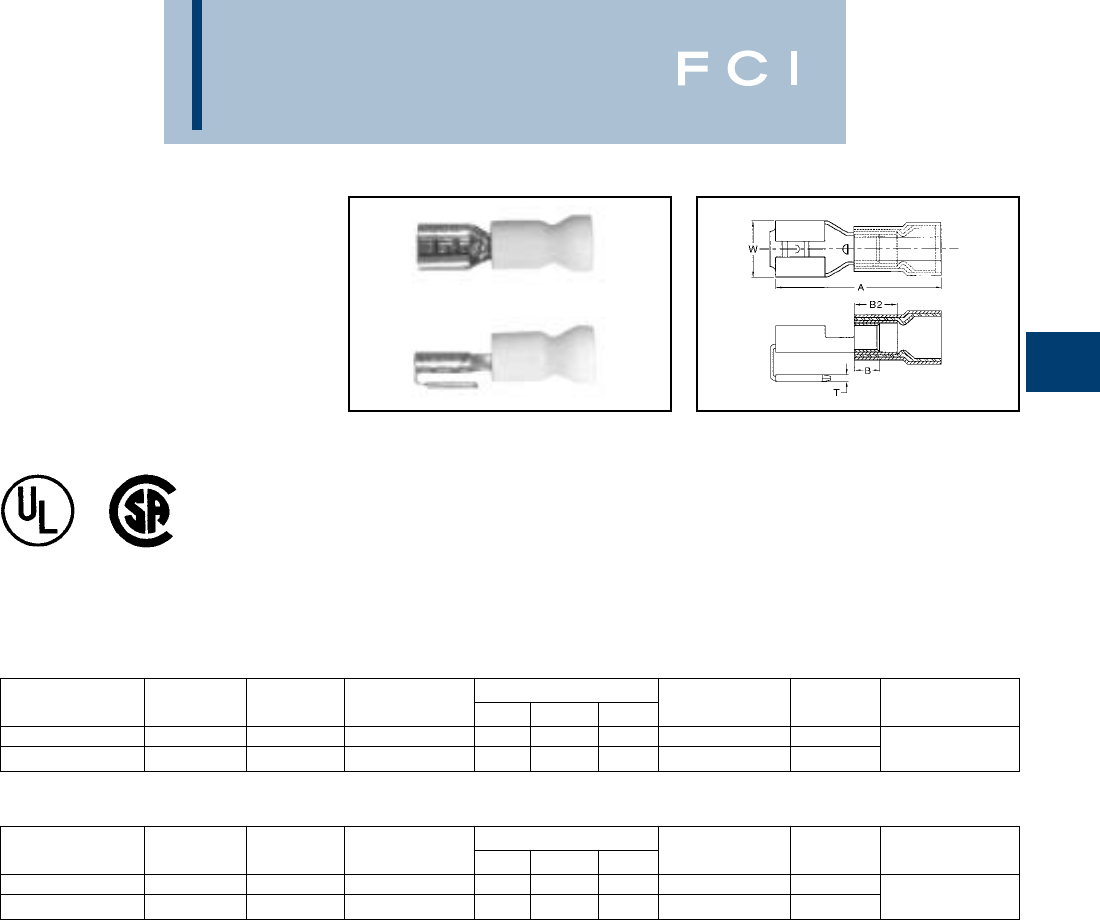
BURNDY
Compression
B-37
TYPES PGP, AND
PGN FINGRIP™
MALE/FEMALE COMBINATION
QUICK DISCONNECTS
MATERIAL: TIN-PLATED
BRASS
Features and Benefits
•Sleeved barrel.
•Combination connector.
◊Allows for more than one connection to a
circuit.
•Funnel entry barrel opening.
◊Assures quick and easy wire insertion.
•Dimpled female socket detent.
◊Ensures firm grip.
*For UL listed applications consult BURNDY®factory.
STANDARD STD. PKG. WIRE NEMA TAB DIMENSIONS BULK BULK PKG. INSTALLATION
CATALOG NO. QTY. RANGE SIZE A B W CATALOG NO. QTY. TOOL*
PGP1825X03D 100 18-22 .250 .032 0.91 0.17 0.30 PGP1825X03B 1000
PGP1425X03D 100 14-16 .250 .032 0.91 0.17 0.30 PGP1425X03B 1000 Y10D
VINYL COMBINATION DISCONNECT TERMINAL 600 VOLTS MAX. 105 C MAX.
STANDARD STD. PKG. WIRE NEMA TAB DIMENSIONS BULK BULK PKG. INSTALLATION
CATALOG NO. QTY. RANGE SIZE A B W CATALOG NO. QTY. TOOL*
PGN1825X03D 100 18-22 .250 .032 0.90 0.17 0.30 PGN1825X03B 1000
PGN1425X03D 100 14-16 .250 .032 0.90 0.17 0.30 PGN1425X03B 1000 Y10D
NYLON COMBINATION DISCONNECT TERMINAL 300 VOLTS MAX. 105 C MAX.
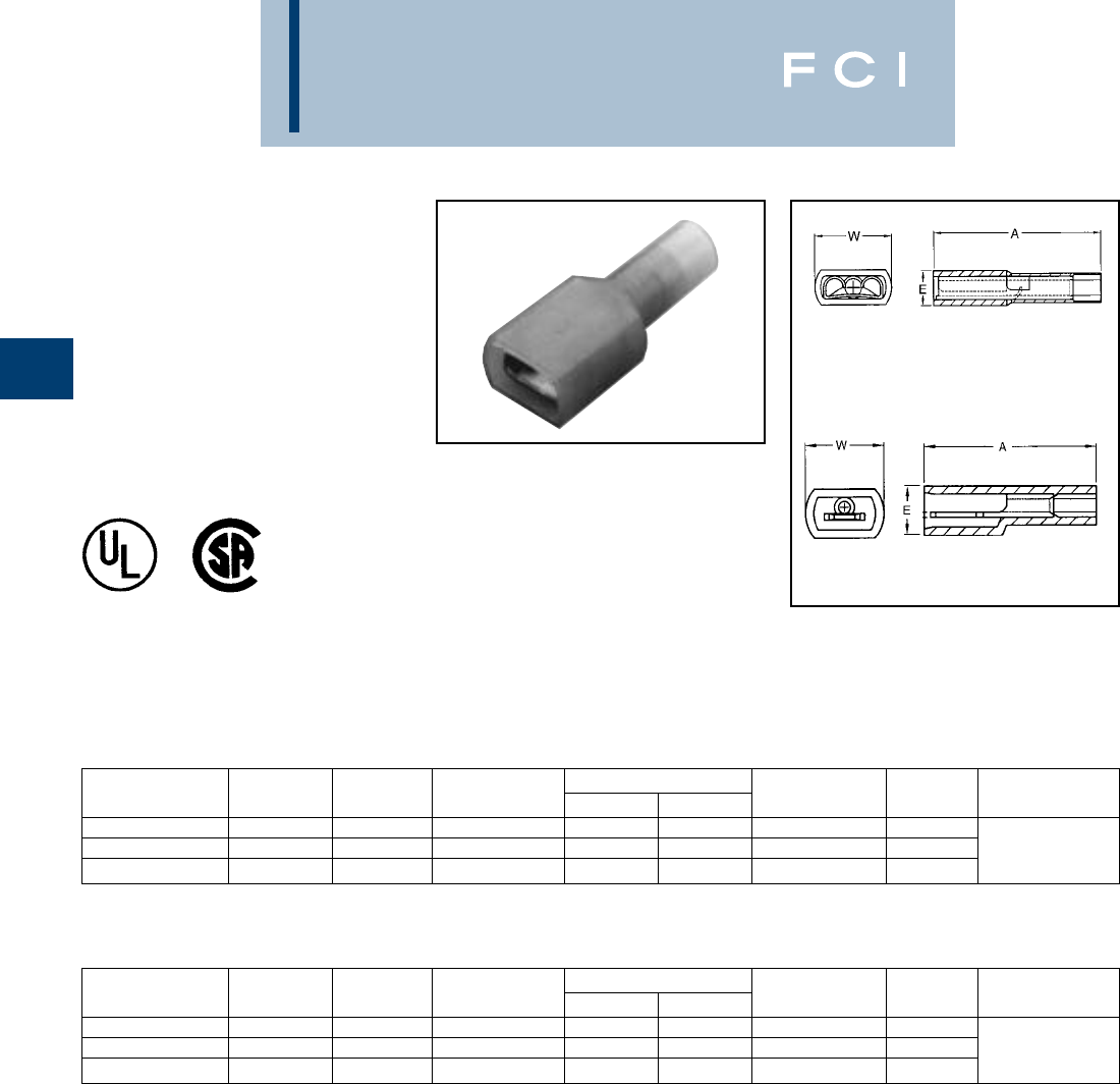
BURNDY
Compression
B-38
TYPES FQN-F AND
FQN-M FINGRIP™
NYLON FULLY INSULATED
FEMALE AND MALE
QUICK
DISCONNECTS
MATERIAL: TIN-PLATED
BRASS
300 VOLTS MAX. 105 C MAX.
Features and Benefits
•Fully insulated connectors.
◊Eliminate the need for post installation
insulation.
•Funnel entry barrel opening.
◊Assures quick and easy wire insertion.
•Dimpled female socket detent.
◊Ensures firm grip.
STANDARD STD. PKG. WIRE NEMA TAB DIMENSIONS BULK BULK PKG. INSTALLATION
CATALOG NO. QTY. RANGE SIZE A W CATALOG NO. QTY. TOOL*
FQN18F25X03D 50 18-22 .250 .032 0.98 0.40 FQN18F25X03B 1000
FQN14F25X03D 50 14-16 .250 .032 0.96 0.40 FQN14F25X03B 1000 Y10D
FQN10F25X03D 25 10-12 .250 .032 0.99 0.41 FQN10F25X03B 500
FULLY INSULATED FEMALE NYLON DISCONNECT TERMINAL (Fig. 1)
STANDARD STD. PKG. WIRE NEMA TAB DIMENSIONS BULK BULK PKG. INSTALLATION
CATALOG NO. QTY. RANGE SIZE A W CATALOG NO. QTY. TOOL*
FQN18M25X03D 50 18-22 .250 .032 1.05 0.48 FQN18M25X03B 1000
FQN14M25X03D 50 14-16 .250 .032 1.03 0.48 FQN14M25X03B 1000 Y10D
FQN10M25X03D 25 10-12 .250 .032 1.03 0.48 FQN10M25X03B 500
FULLY INSULATED MALE NYLON DISCONNECT TERMINAL (Fig. 2)
Fig. 1
Fig. 2
*For UL listed applications consult BURNDY®factory.
** For Mylar tape reels consult BURNDY®factory.
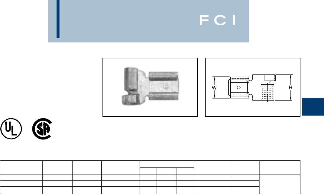
BURNDY
Compression
B-39
TYPE FL FINGRIP™
FLAG-STYLE FEMALE
QUICK
DISCONNECT
MATERIAL: TIN-PLATED
BRASS
Features and Benefits
•Dimpled female socket detent.
◊Ensures firm grip.
STANDARD STD. PKG. WIRE NEMA TAB DIMENSIONS BULK BULK PKG. INSTALLATION
CATALOG NO. QTY. RANGE SIZE A B W CATALOG NO. QTY. TOOL
FL1825X03D 100 18-22 .250 .032 0.67 0.17 0.25 FL1825X03B 1000
FL1425X03D 100 14-16 .250 .032 0.67 0.17 0.25 FL1425X03B 1000 Consult
FL1025X03D 50 10-12 .250 .032 0.67 0.17 0.25 FL1025X03B 500 Factory
FEMALE BARE DISCONNECT TERMINAL
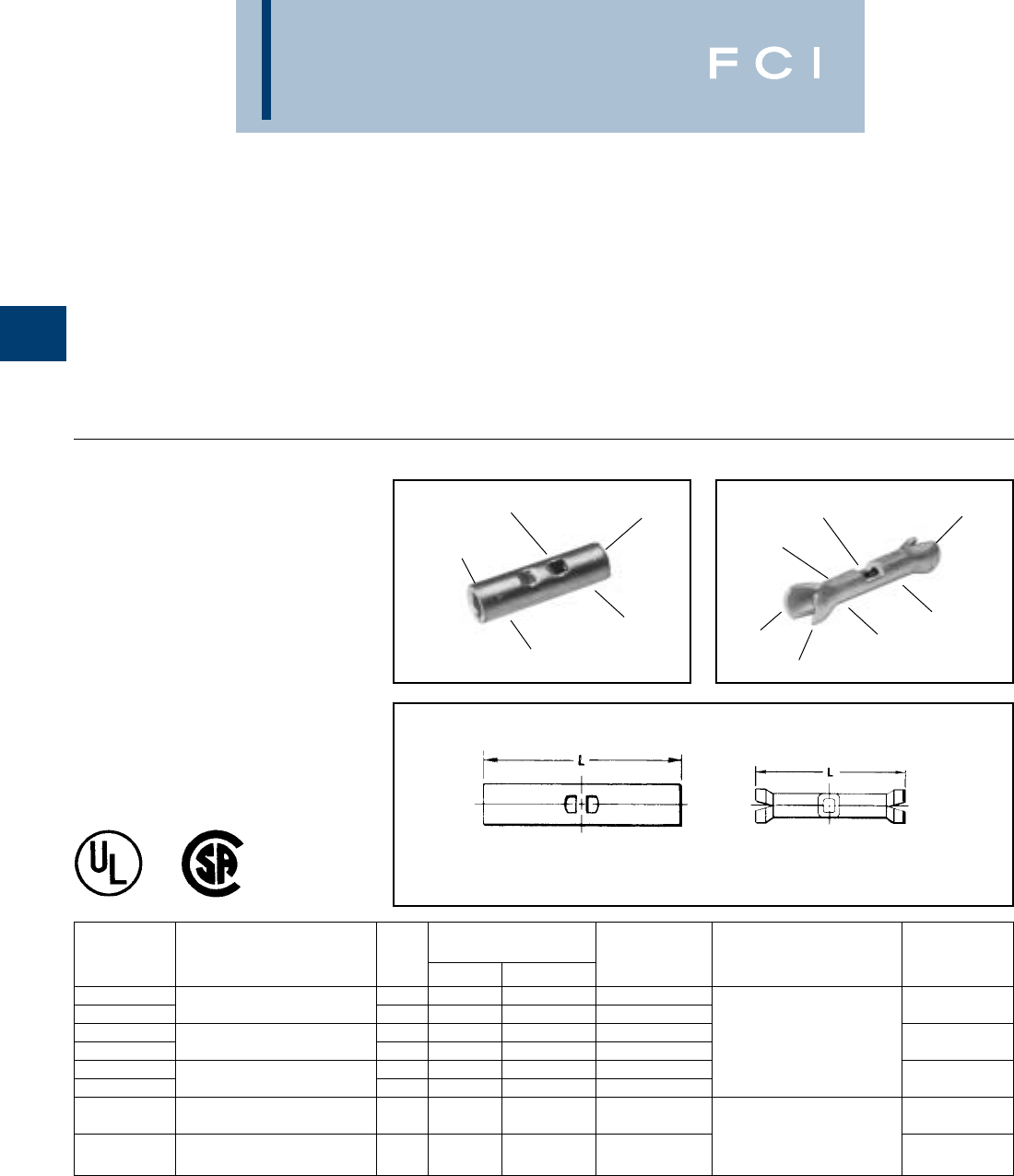
BURNDY
Compression
B-40
UNINSULATED
SPLICES
BURNDY®manufactures several designs of
uninsulated butt splices. Each type is
designed to meet specific application require-
ments and provide a high quality, electrical
splice connection that is easily installed. The
following features and benefits apply to all
BURNDY®uninsulated splices.
TYPES YSV,YSV-H
AND YSV-L
HYLINK™
UNINSULATED BUTT SPLICE
600 VOLTS MAXIMUM
HYLINK™ type YSV seamless splice connec-
tor is used to splice stranded and solid copper
conductors in virtually all heavy duty indus-
trial and general purpose applications.
The type YSV-H HYLINK™ seamless splice
connector has the added benefit of an insula-
tion support and cable strain relief.
Features and Benefits
•Manufactured from seamless tubing.
◊A high quality design with no seams
to split.
•Electrolytic copper.
◊Provides maximum conductivity, low
resistance and ductility for excellent
crimp forming properties.
•Electro-tin plated.
◊Provides durable long lasting resistance
to corrosion.
* Remove stop plate.
▲Y2MR for 8 str. only
†Use #10 groove
Use MR8 series tools for (-H) series.
Fig. 1 Fig. 2
SEAMLESS
TUBING
CRIMP
TIN-PLATED
CRIMP
INSPECTION HOLE
AND WIRE STOP BEVELED
ENTRY
SEAMLESS
TUBING
CRIMP
TIN-PLATED CRIMP
CABLE SUPPORT
INSPECTION HOLE
AND WIRE STOP
BEVELED
ENTRY
•Positive center wire stops.
◊Provides proper depth of wire insertion.
•Marked with wire size.
◊Provides easy wire size identification.
•The HYLINK™ splice connectors have
inspection holes.
◊Provides easy visual inspection for
proper wire insertion.
WIRE RANGE CODE AWG. INSTALLATION WIRE
CATALOG STR. AND SOL. DIMENSIONS BULK TOOLING STRIP
NUMBER AIRCRAFT-AN FIG. L MAX. DIA. CAT. NO. HYTOOL LENGTH
YSV18 BOX 22-18 1 .62 — YSV18
YSV18-H BOX str. & sol. 2 .89 .120 YSV18-H Non-Ratchet: 1/4
YSV14 BOX 20-14 str. 1 .64 — YSV14 Y10D, Y1022
YSV14-H BOX 20-12 sol. 2 .94 .150 YSV14-H Ratchet: 1/4
YSV10 BOX 12-10 1 .75 — YSV10 MR20, Y8MRB-1,
YSV10-H BOX str. & sol. 2 1.06 .192 YSV10-H MR8-9Q*, MR8-G98 5/16
Non-Ratchet: MY28,
YSV9C-L BOX 9 str. 1 .75 — YSV9C-L MY29-3, MY29-11 5/16
Ratchet: MY28, Y8MRB-1†,
YSV8C-L BOX 8 str. 1 1.00 — YSV8C-L MR8-9Q*, Y2MR ▲7/16
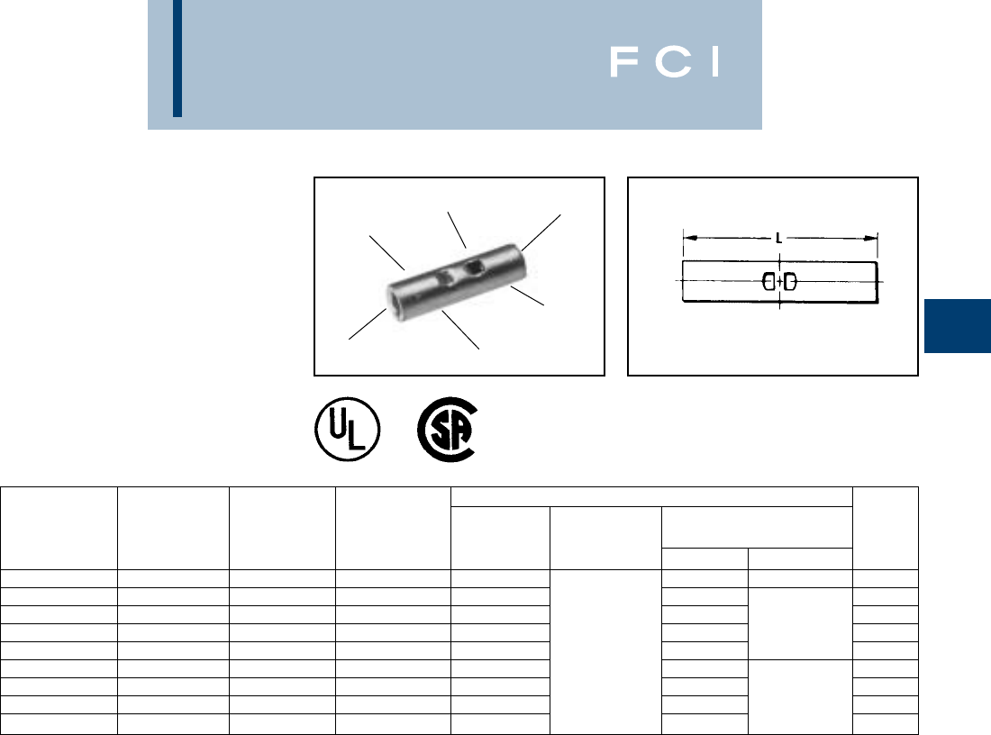
BURNDY
Compression
B-41
TYPE YSV-L
HYLINK™
UNINSULATED BUTT SPLICE
600 VOLTS MAXIMUM
#8 THROUGH 4/0 COPPER
HYLINK™ type YSV-L seamless splice con-
nector is used to splice Type AN aircraft cables
plus commercial stranded and solid AWG
conductors. Suitable for aircraft, light duty
industrial and general purpose applications.
*Remove stop plate
•Use Y35P3 Indentor Adaptor.
** Bench Mount Adaptor - Cat. No. BMY-BCH-MT is available
for Type MY HYTOOLS™.
INSPECTION HOLE
AND WIRE STOP
SEAMLESS
TUBING
ELECTRO-TIN
PLATED CRIMP
CRIMP
BEVELED
ENTRY
WIRE RANGE INSTALLATION TOOLING Y34PA
AIRCRAFT-AN” HYPRESS• H35, WIRE
CATALOG COMM’L-AWG. DIMENSIONS BULK Y35BH, Y39, Y39BH STRIP
NUMBER STR. & SOL. L CAT. NO. RATCHET HYTOOL * * NEST INDENTOR LENGTH
YSV8C-L BOX 81.00 YSV8C-L UV8L-1 Y34PL 7/16
YSV6C-L BOX 61.12 YSV6C-L Y2MR, MR4C TYPE AH UV6L 1/2
YSV4C-L BOX 41.12 YSV4C-L Y2MR, MR4C AIRCRAFT UV4L 5/8
YSV2C-L BOX 21.41 YSV2C-L Y2MR CABLE: MY28 UV2L Y34PLA 5/8
YSV1C-L BOX 11.46 YSV1C-L —UV1L 5/8
YSV25-L BOX 1/0 1.53 YSV25-L —All Others: UV25L 11/16
YSV26-L BOX 2/0 1.78 YSV26-L —MY29-3, UV26L 13/16
YSV27-L BOX 3/0 1.81 YSC27-L —MY29-11 UV27L Y34PA 13/16
YSV28-L BOX 4/0 1.94 YSV28-L —1 Crimp UV28L 7/8
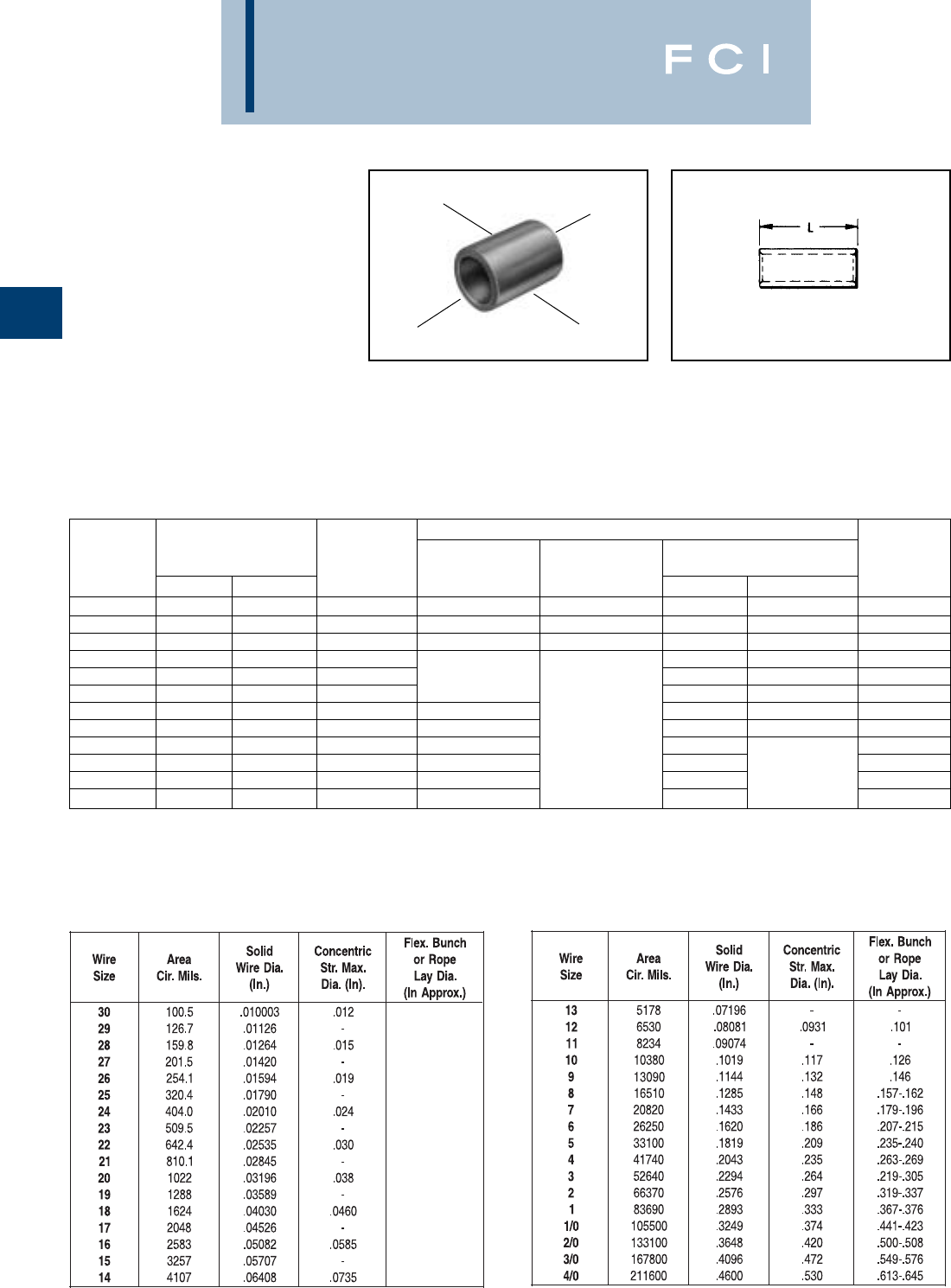
BURNDY
Compression
B-42
TYPE YSM
HYLINK™
UNINSULATED
PARALLEL SPLICE
HYLINK™ type YSM seamless parallel splice
connector permits wires to be laid parallel
inside the connector and spliced together
with Burndy's compression HYTOOL™. Each
YSM connector accommodates a wide com-
bination of round, square, and rectangular
copper conductors that have a total combined
circular mil area listed in the table below. The
conductors to be spliced must physically fit
within title splice without being forced.
SEAMLESS
TUBING
CRIMP
ELECTRO-TIN
PLATED
BEVELED
ENTRY
*Remove stop plate.
•Use Y35P indentor adapter, with Y35BH and Y39BH
HYPRESSES.
INSTALLATION TOOLING
HYPRESS WIRE
CATALOG CIRCULAR MIL. RANGE DIMENSIONS MECHANICAL Y35BH, Y39BH* STRIP
NUMBER MIN. MAX. L RATCHET HYTOOL NEST INDENTOR LENGTH
YSM18 300 1,909 .25 MR8-9Q* — — — 5/16
YSM14 477 4,107 .25 MR8-9Q* — — — 5/16
YSM10 4,107 10,380 .36 MR8-9Q*, MR4CQ — — — 7/16
YSM8C 6,088 16,864 .41 UV8L-1 1/2
YSM6C 10,380 26,813 .44 MR4CQ UV6L 1/2
YSM4C 26,813 42,613 .50 Y2MR UV4L Y29PQ 9/16
YSM2C 42,613 66,832 .62 Y2MR MY29-11 UV2L 11/16
YSM1C 66,832 81,807 .62 — or UV1L 11/16
YSM25 81,807 104,110 .69 — MY28 UV25L 3/4
YSM26 104,110 133,650 .81 — (1) Crimp UV26L 7/8
YSM27 133,650 167,332 .81 — UV27L Y29PQ-6 7/8
YSM28 167,332 211,954 .88 — UV28L 15/16
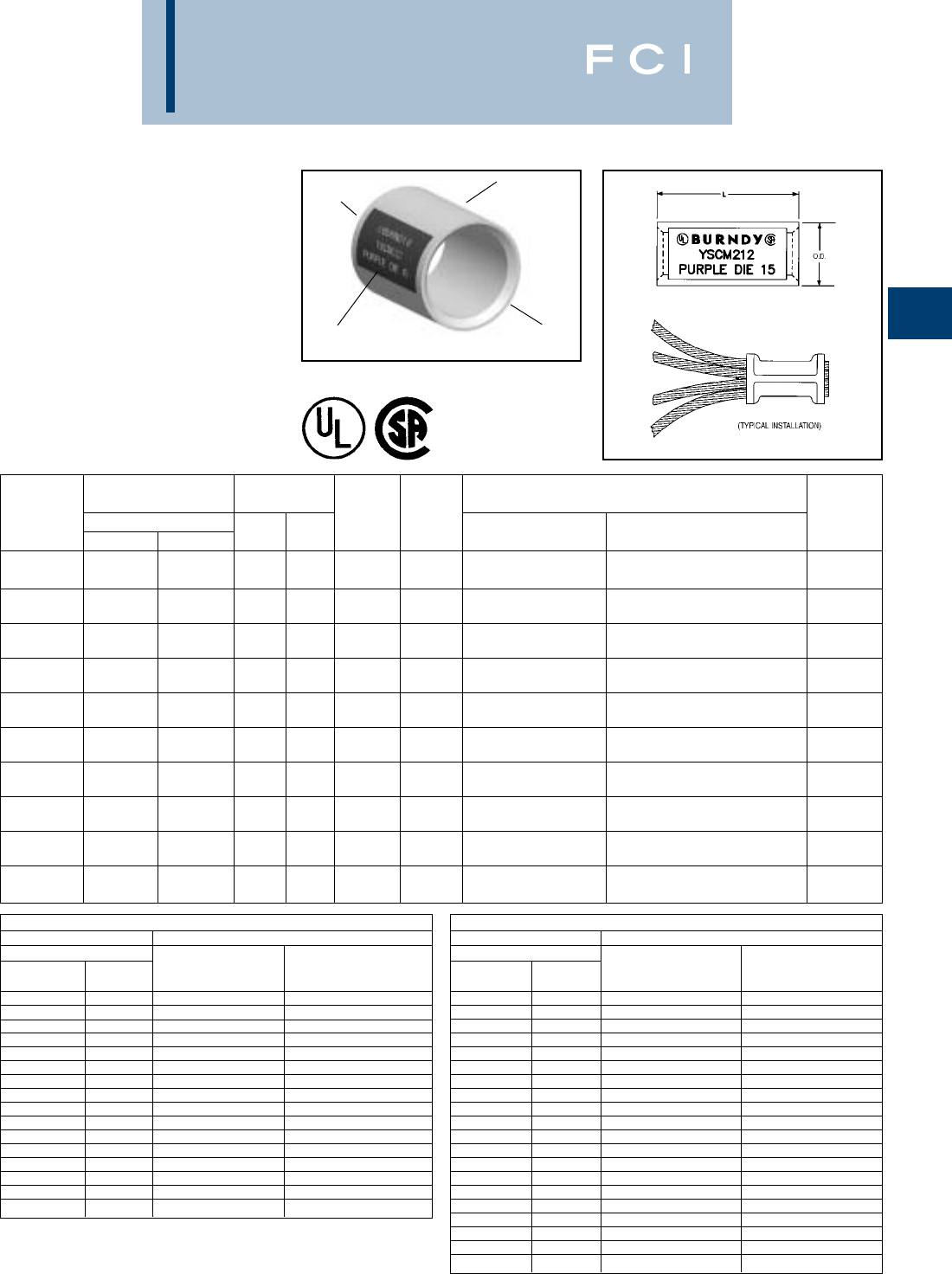
BURNDY
Compression
B-43
TYPE YSCM
HYLINK™
COLOR-CODED UNINSULATED
PARALLEL SPLICE
Type YSCM HYLINK™ seamless parallel
splice connectors permit stranded wires to be
laid parallel inside the connector and spliced
together with BURNDY®compression tools.
Each YSCM connector accommodates a
wide range of conductors and is color-coded
to ensure proper tool and die match. YSCM
connectors are UL 486A Listed for applica-
tions up to 600V and CSA Listed.
SEAMLESS
TUBING ELECTRO-TIN
PLATED
BEVELED
ENTRY
1. Material: Copper per ASTM B75.
2. Finish: Tin plated. For nickel plating, add suffix “NK” to the
Catalog Number.
3. Dimensions in brackets [ ] are in millimeters rounded off to
the nearest millimeter, unless otherwise noted, and are for
reference only.
CIRCULAR MIL TABLE PER ASTM B8
SIZE ASTM STRANDINGS
STRANDED CABLE
CIRCULAR DIAMETER
MILS AWG CLASS INCHES
1,022 20 B 0.036
1,624 18 B 0.045
2,583 16 B 0.057
4,107 14 B 0.072
6,530 12 B 0.091
10,380 10 B 0.116
13,090 9 B 0.130
16,510 8 B 0.146
20,820 7 B 0.164
26,250 6 B 0.184
33,100 5 B 0.206
41,740 4 AA 0.254
41,740 4 B&A 0.232
52,630 3 AA 0.285
CIRCULAR MIL TABLE PER ASTM B8
SIZE ASTM STRANDINGS
STRANDED CABLE
CIRCULAR DIAMETER
MILS AWG CLASS INCHES
52,630 3 B&A 0.260
66,370 2 AA 0.320
66,370 2 B&A 0.292
83,690 1 AA 0.360
83,690 1 A 0.328
83,690 1 B 0.332
105,500 1/0 A&A 0.368
105,500 1/0 — 0.390
105,500 1/0 B 0.373
133,100 2/0 A&A 0.414
133,100 2/0 — 0.438
133,100 2/0 B 0.419
167,800 3/0 A&A 0.464
167,800 3/0 — 0.492
167,800 3/0 B 0.470
211,600 4/0 A&A 0.522
211,600 4/0 — 0.522
211,600 4/0 B 0.528
➃Recommended strip length. Strip length dependant on
size, no. of wires and insulation thickness.
➄Refer to Circular Mil Table per ASTM B8 for total Class B
Circular Mil calculations.
COLOR-CODE
AND DIE INDEX
CONDUCTOR RANGE DIMENSIONS
CABLE ➄INCH [mm] RECOMMENDED INSTALLATION TOOLING WIRE
CATALOG CIRCULAR MILS L O.D. COLOR DIE OUR840, Y500CTHS, Y35, Y750, BAT35, BAT750, STRIP ➃
NUMBER MIN. MAX. ±.03 ±.01 CODE INDEX BCT500HS SERIES PAT750 SERIES LENGTH
.50 .27
YSCM17 13,060 16,910 [13] [7] Red 49 X8CRT, W8CRT U8CRT 11/16
.50 .31
YSCM27 16,910 26,890 [13] [8] Blue 7 X5CRT, W5CRT U5CRT 11/16
.50 .38
YSCM42 29.970 41,520 [13] [10] Gray 8 X4CRT, W4CRT U4CRT 11/16
.62 .47
YSCM66 42,750 66,040 [16] [12] Brown 10 X2CRT, W2CRT U2CRT 3/4
.62 .52
YSCM80 67,980 80,020 [16] [13] Green 11 X1CRT, W1CRT U1CRT-1 3/4
.69 .57
YSCM104 82,870 103,630 [18] [14] Pink 12 X25RT, W25RT U25RT 15/16
.81 .64
YSCM133 104,960 133,220 [21] [16] Black 13 X26RT, W26RT U26RT 1-1/16
.81 .70
YSCM167 134,340 166,560 [21] [18] Orange 14 X27RT, W27RT U27RT 1-1/16
.88 .78
YSCM212 167,380 211,820 [22] [20] Purple 15 X28RT, W28RT U28RT 1-1/16
1.05 .81
YSCM231 —230,800 [27] [21] Yellow 16 X29RT, W29RT U29RT 1-1/16
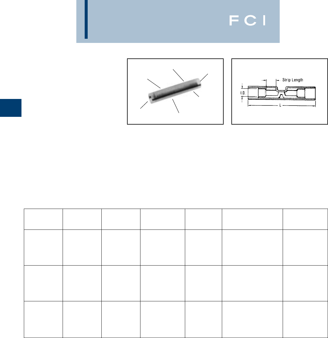
BURNDY
Compression
B-44
TYPES YSES-K
INSULINK™
RADIATION RESISTANT
INSULATED BUTT SPLICE
POLYVINYLIDENE FLOURIDE
(PVF2) INSULATED
200 MEGARADS - 60° C
THROUGH 150° C, 600 VOLTS
The type YSES-K radiation resistant KYNAR®
insulated splices are suitable for class 1E
applications plus non critical nuclear associ-
ated applications. The splice is manufactured
from pure electrolytic copper seamless tubing
which eliminates potential splitting of seams.
A color code stripe is used for wire size
identification and a window is provided for
inspection of proper wire insertion.
*Remove terminal locator from tool when installing
INSULINK™ splices.
KYNAR®is the registered trademark for Pennwalt Corp. for
Polyvinyllidene Flouride (PFV2)
INSPECTION
WINDOW
INTEGRAL METAL
CABLE SUPPORT
AND STRAIN RELIEF
COLOR CODED
INSULATOR
SEAMLESS
ELECTRO-TIN
PLATED SPLICE
KYNAR
INSULATED SMOOTH
FUNNEL
ENTRY
DIMENSIONS WIRE
CATALOG WIRE COLOR MAX. INSUL. L INSTALLATION STRIP
NUMBER RANGE STRIPE DIA. ACCOM. MAX. TOOLING LENGTH
Ratchet Tool: MR10G8*
Red Groove
Calibration Gauge:
YSES18K 22-18 Red .112 1.00 PG-373-1 3/16
Crimp ID. Mark:
(1) Small Dot
Ratchet Tool: MR10G8*
Blue Groove
Calibration Gauge:
YSES14K 16-14 Blue .153 1.00 PG-371-1 3/16
Crimp ID. Mark:
(2) Small Dot
Ratchet Tool: MR10G8*
Yellow Groove
Calibration Gauge:
YSES10K 12-10 Yellow .210 1.38 PG-372-1 7/16
Crimp ID. Mark:
(1) Large Dot
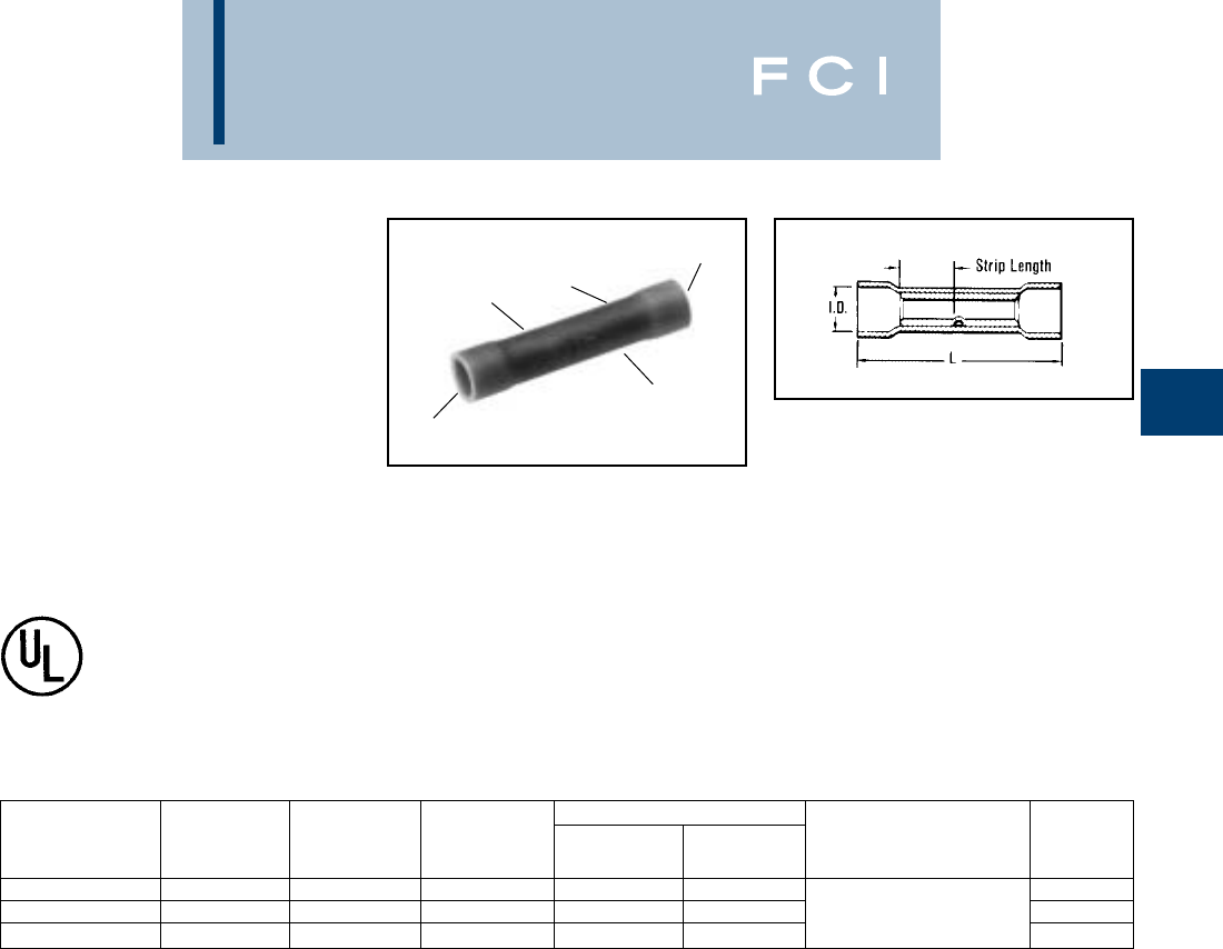
BURNDY
Compression
B-45
•Expanded insulation support.
◊Lower inventory requirements.
•Red wire range of 22-16.
◊Lower inventory requirements.
•Vinyl insulator.
◊Economical means of providing
high dielectric values and cable
insulation support.
TYPES SP AND BS
VINYLINK™
SPLICE,
POLYVINYLCHLORIDE-
INSULATED
600 VOLTS, 105° C
The type SP VINYLINK™ is a PVC insulated
seamless butt splice. Type SP VINYLINK™ is
designed to accommodate a broad range of
600 volt cables.
Features and Benefits
•Manufactured from seamless electrolytic
copper tubing.
◊Provides maximum conductivity and
tensil strength, in a high quality design
with NO seams to split.
•Funnel entry.
◊Provides easy wire insertion.
•Electro-tin plated.
◊Provides durable long lasting
resistance to corrosion.
SMOOTH
ENTRY
COLOR CODED
CRIMP
CRIMP
INSULATION
SUPPORT
DIMENSION (INCHES) WIRE
CATALOG WIRE COLOR BULK L MAX. MAX. INSTALLATION STRIP
NUMBER RANGE CODE CAT. NO. INSUL. DIA. TOOLING LENGTH
SP16 22-16 Red BS16 1.00 .145 1/4
SP14 16-14 Blue BS14 1.00 .180 Non-Ratchet: Y10D-22, Y10D 1/4
SP10 12-10 Yellow BS10 1.23 .260 Ratchet: MR8-9-1, MR15 21/64
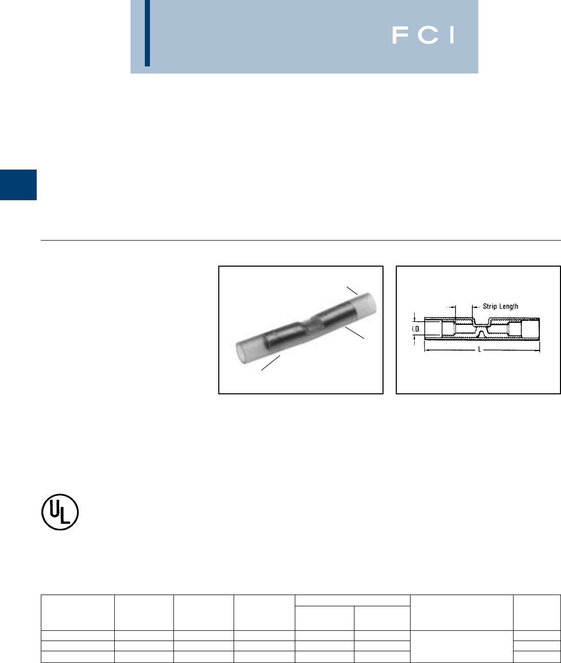
BURNDY
Compression
B-46
TYPES SN AND
YSE-HN
INSULINK™
BUTT SPLICE, NYLON-
INSULATED
600 VOLTS MAXIMUM,
105° C MAXIMUM
The type SN INSULINK™ is a high quality
nylon-insulated butt splice designed to meet
heavy duty application requirements.
Meets the functional requirements of MIL-T-
7928 (ASG) and conforms to the require-
ments of NAS1388.
Features and Benefits
•Manufactured from one-piece tin-plated
seamless copper tubing with an integral
barrel/insulation grip.
◊Provides maximum tensile strength, plus
excellent cable support and strain relief
and eliminates failures due to vibration.
•Smooth funnel entry.
◊Provides easy wire insertion.
•Window position locator for full cycle ratchet
tool crimp.
◊Provides proper tool/connector alignment
for correct crimp.
SEAMLESS ELECTRO-TIN
PLATED SPLICE
INTEGRAL METAL
CABLE SUPPORT
AND STRAIN RELIEF
NYLON
INSULATION
600 VOLTS, 105° C
(1000 VOLTS, MAX. INSIDE SIGN OR FIXTURE)
•Nylon insulation offers high dielectric
strength and stability in oily enviromental
conditions.
◊Maintains a high quality connection in
demanding applications.
•The nylon is locked into position.
◊The connector will not move.
INSULATED SPLICES
BURNDY®manufactures several designs of
insulated butt splices. Each type is designed
to meet specific application requirements and
provide a high quality electrically pre-insulat-
ed splice that is easily installed. The following
features and benefits apply to all BURNDY®
pre-insulated butt splices.
Features and Benefits
•Manufactured from seamless tubing.
◊A high quality design with no seams
to split.
•Pure electrolytic copper.
◊Provides maximum conductivity, low
resistance and ductility for excellent
crimp forming properties.
•Electro-tin plated.
◊Provides durable long-lasting resistance
to corrosion.
•Positive center wire stops.
◊Provides for proper depth of
wire insertion.
•Color-coded in red, blue and yellow.
◊Provides easy wire size identification.
DIMENSIONS WIRE
CATALOG WIRE COLOR BULK L MAX. MAX. INSTALLATION STRIP
NUMBER RANGE CODE CAT. NO. INSUL. DIA. TOOLING LENGTH
SN18 22-18 Red YSE18HN 1.25 .115 15/64
SN14 16-14 Blue YSE14HN 1.25 .150 Plier: Y10D 7/32
SN10 12-10 Yellow YSE10HN 1.64 .220 Ratchet: MR8-85, MR18 3/8
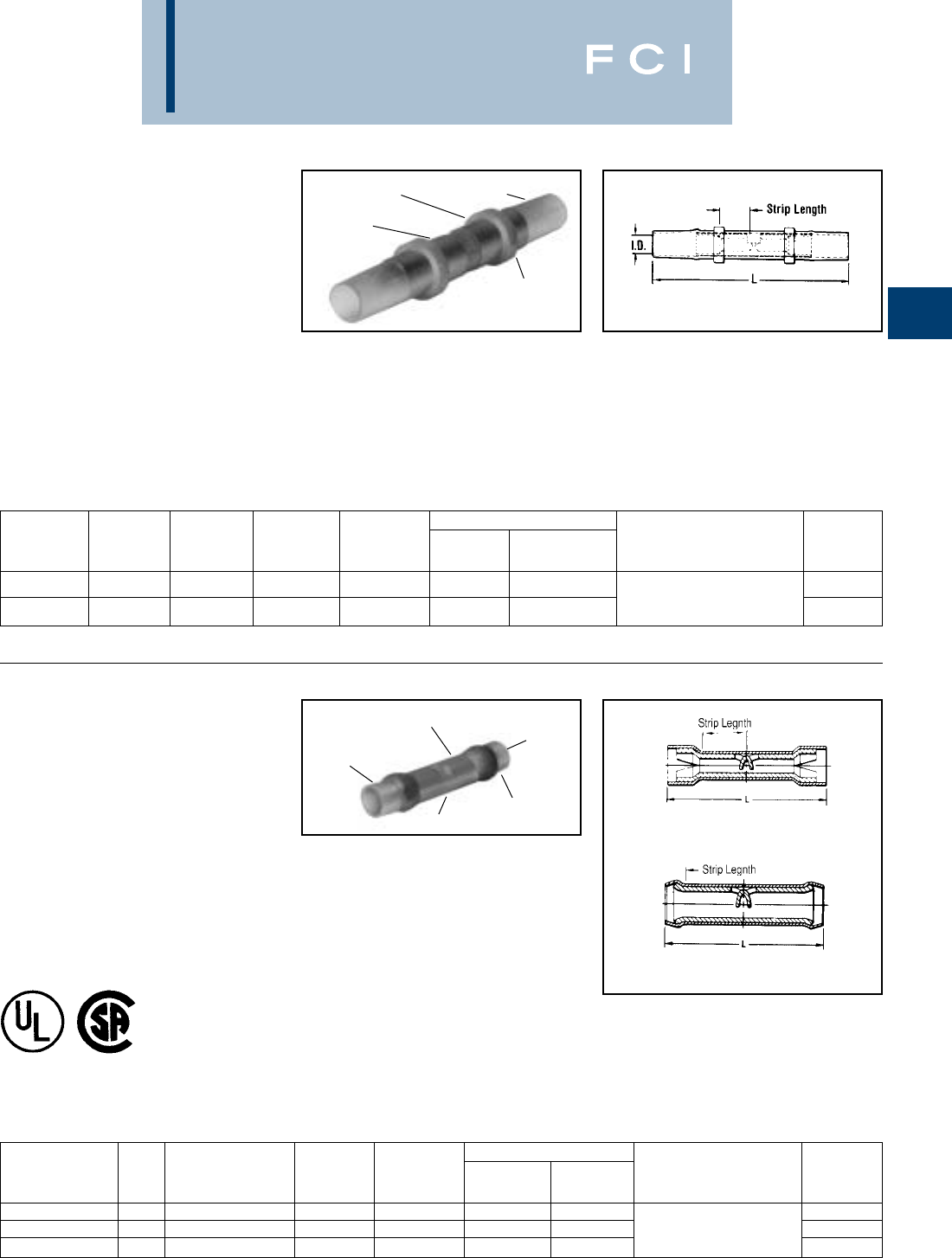
BURNDY
Compression
B-47
TYPES SNM AND
YSES
INSULINK™
BUTT SPLICE, NYLON
INSULATED
MS25181, CLASS 1 SPLICE
300 VOLTS, 105° C
The type SNM INSULINK™ is a high quality
nylon insulated butt splice designed to meet
military MS25181, class 1 requirements.
TYPES YSE BOX,
YSE-H BOX,YSE,YSES
AND YSE-H
INSULINK™
600 VOLTS, 105° C
The types YSE and YSE-H INSULINKS™ are
high quality nylon insulated butt splices
designed for splicing aircraft and commercial
flexible cables.
Features and Benefits
•Manufactured from tin plated, seamless
copper tubing with an integral
barrel/insulation grip.
◊Provides maximum tensil strength, plus
excellent cable support and strain relief.
•Smooth funnel entry.
◊Provides easy wire insertion.
Features and Benefits
•Manufactured from tin plated, seamless
electrolitic copper tubing with integral
barrel/insulation grip.
◊Provides maximum conductivity and ten-
sile strength, plus excellent cable support
and strain relief.
•Split heavy wall insulation grip.
◊Provides stronger insulation grip and
strain relief.
•Smooth funnel entry.
◊Provides easy wire insertion.
•Transparent nylon insulation.
◊Permits easy wire inspection.
LOCATOR RING
INSPECTION
WINDOW
INTEGRAL METAL
INSULATION GRIP
AND STRAIN RELIEF
NYLON
INSULATION
Fig. 1
Fig. 2
600 VOLTS 105°C
SEAMLESS
SPLIT HEAVY
WALL INSULATION
GRIP
NYLON
INSULATION
INSPECTION
WINDOW FUNNEL
ENTRY
•Transparent nylon insulation.
◊Permits easy wire inspection.
•External ring locator.
◊Provides proper tool alignment for
correct crimp.
DIMENSIONS WIRE
CATALOG WIRE COLOR BULK MS25181 L MAX. INSTALLATION STRIP
NUMBER RANGE CODE CAT. NO. DASH NO. MAX. DIA. INSUL. TOOLING LENGTH
Plier: Y10D
SNM18 22-18 Red YSES18-1 -1 1.53 .120
Ratchet: MR8-83 or
7/32
SNM14 16-14 Blue YSES14-2 -2 1.53 .150 MR8-85 MS25037 TOOL 7/32
WIRE RANGE WIRE DIMENSIONS WIRE
CATALOG CODE AWG. COLOR BULK L MAX. MAX. INSTALLATION STRIP
NUMBER FIG. AIRCRAFT AN CODE CAT. NO. INSUL. DIA. TOOLING LENGTH
YSE18H-BOX 122-18 Red YSE18H 1.220 .115 Y10D 9/32
YSE14H-BOX 116-14 Blue YSE14H 1.36 .150 Ratchet: 11/32
YSE10-BOX 212-10 Yellow YSE10 1.15 .209 MR8-33S-1 23/64
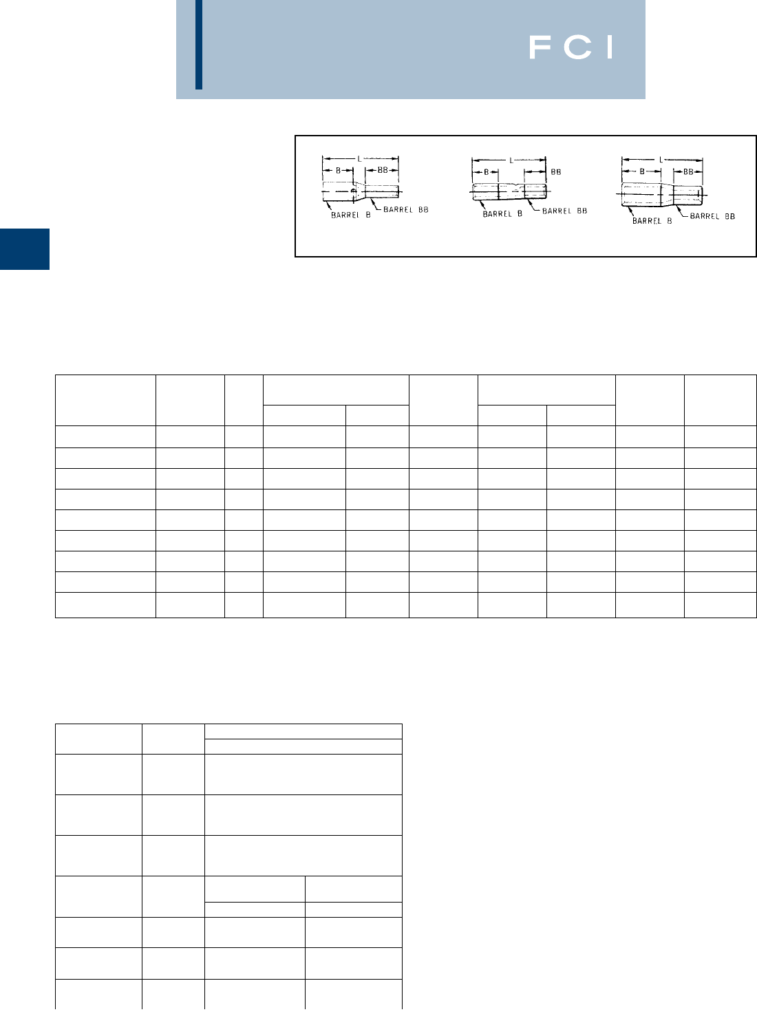
BURNDY
Compression
B-48
TYPES YSV,YRV-L
HYREDUCER™
REDUCER BUTT SPLICE
The HYREDUCER™ is a connector for
splicing two different size wires. The larger
conductor is inserted first and butts against the
center of the connector where the smaller bar-
rel begins. Constructed of pure electrolytic
copper tubing for maximum conductivity, tin
plated to resist corrosion, the HYREDUCER™
accommodates a wide range of cable sizes.
Dimensional information may be found in
Table 1. Table 2 is a comprehensive tooling
index for these connectors.
INDEX HAND TOOLS WITH DIES
NUMBER TOOLS Y29NC
1
MR8G98
Y8MRB-1
MR8-9Q†
MR20 -
2
MR8G98
Y8MRB-1
MR8-9Q†
MR20 -
4
MR8G98
Y8MRB-1
MR8-9Q†
MR20 -
5
Y8MRB-1
MY28
MR4C
Y2MR
NEST INDENTOR
DV8L-1* Y29PL
6MY28
Y2MR
MR4C DV6L Y29PL
7MY28
Y2MR
MR4C DV4L Y19PL
Y29PL
8Y2MR
MY28 DV2L
Fig. 1 Fig. 2 Fig. 3
TABLE 1
TABLE 2
*B and BB dimensions are wire strip lengths.
*For aircraft applications (flexible cables).
TOOL INDEX
BULK TOTAL
CATALOG WIRE FIG. B BARREL* TOOL BB BARREL* TOOL “L”
NUMBER RANGE NO. WIRE SIZE B DIM. INDEX WIRE SIZE BB DIM. INDEX MAX.
YSV1418 22 - 14 1 20 - 14 .27 1 22 - 18 .27 2 .64
YSV1214-G1 16 - 12 2 12 .31 4 16 - 14 .27 1 .83
YSV1014-G2 20 - 10 2 12 - 10 .31 4 20 - 14 .27 1 .83
YRV8CV14-L 20 - 8 3 8 .44 5 20 - 14 .39 1 1
YRV8CV10-L 12 - 8 3 8 .44 5 12 - 10 .53 4 1.18
YRV6CV10-L 12 - 6 3 6 .50 6 12 - 10 .53 4 1.28
YRV6CV8C-L 8 - 6 3 6 .50 6 8 .53 5 1.21
YRV4CV6C-L 6 - 4 3 4 .50 7 6 .54 6 1.27
YRV2CV6C-L 6 - 2 3 2 .62 8 6 .51 6 1.63
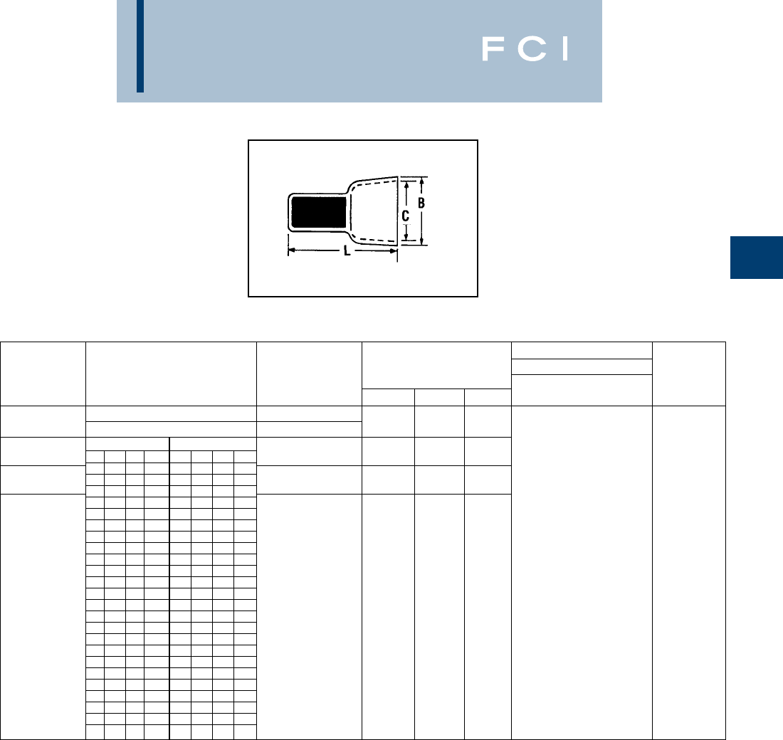
BURNDY
Compression
B-49
BURCAP TYPES YQE,
RK
PIGTAIL SPLICE,
NYLON-INSULATED
Rated at 600 volts for building wire and 1000
volts for fixtures and signs, the BURCAP is
designed to splice a wide range of different
cable sizes.
NOTE: * Convenience Package. For Box quantity, order
RK141ABOX100 and RK142ABOX100 respectively.
†This item is UL Listed
INSTALLATION TOOLS
DIMENSIONS DIE SET WIRE
CATALOG TOTAL AREA IN INCHES M8ND, STRIP
NUMBER WIRE COMBINATIONS CIRCULAR MILS L B C Y8ND LENGTH
1 #16 & 1 #18 4,205
YQE-91† 2 #18 3,250 .76 .30 .24 N150WT 5/16
.607 .311 .269
*RK141-2 500 5,180 (16, 4) (7, 9) (8, 6)
.722 .440 .384
*RK142-2 2,400 13,100 (18, 3) (11, 2) (9, 8)
RK141ABOX100 RK142ABOX100
22 20 18 16 18 16 14 12
711
61 2 1
51 31
42 1 1
41 2 1
32 3 1
32 11
3121
23 1 1
22 21
2131
14 221
12 2
1111
421
31 3 1
22 4 1
2112
12 2 2
1132
32
213
3
5
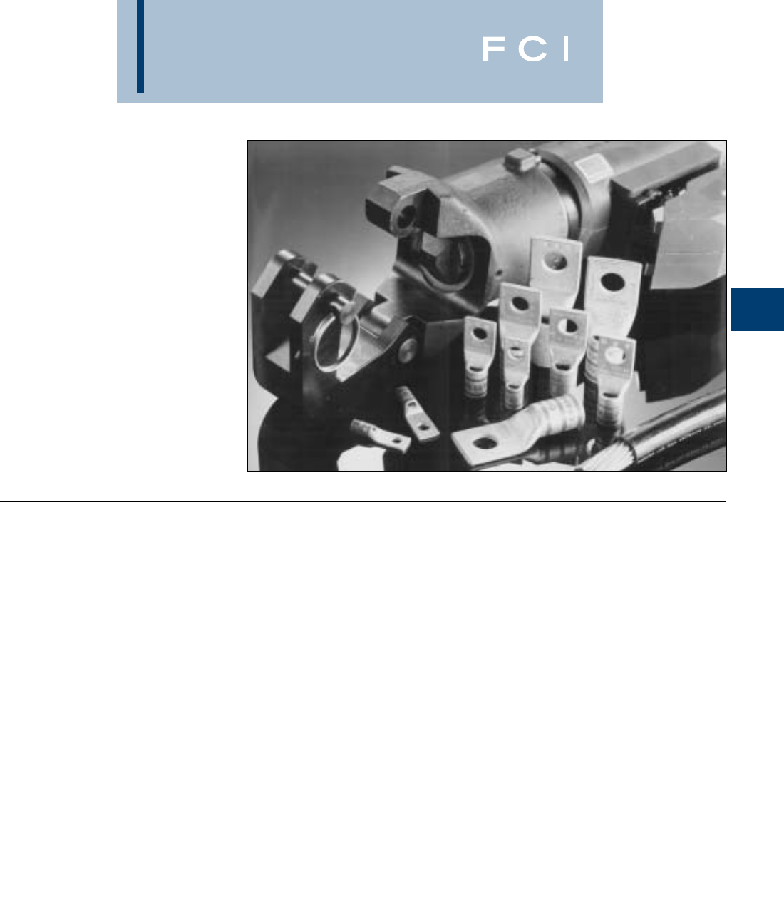
BURNDY
Compression
C-1
•Marked with the proper number and
location of crimps.
◊Lowers installed costs. Provides for
proper installations.
•Proper compression systems forms a
homogeneous mass.
◊The result is an excellent electrical
connection.
•Use up to 35 kV as indicated.
◊Suitable for high voltage applications.
•Expanded wire ranges when using
Y644 HYPRESS™ Dieless “1” Crimp.
◊Provides ability to complete emergency
repairs when connector and wire size
do not match.
•Crimp areas clearly marked.
◊Provides correct number and location
of crimps for proper installation.
•Hydraulic and Battery tooling crimp
embossment.
◊Provides permanent die index number
embossment on completed crimp for
inspection purposes.
INTRODUCTION
MEDIUM AND LARGE HYDENT™
Copper and aluminum compression terminals
and splices for terminating conductors from
#8 AWG through 2000 kcmil.
The medium and large HYDENT™ line is
designed for terminating and splicing medium
and large conductors in electrical power
applications.
HYLUG™
UNINSULATED COPPER
COMPRESSION TERMINALS
UL LISTED 90° C,
600 VOLTS TO 35 kV ◆
BURNDY's HYLUG™ terminals, types YA,
YA-TC, YA-L, YA-L-TC, YA-2N, YA-2TC, YA-L-
TC-FX, YA-L-2TC, and YA-2LN are designed
for terminating copper conductors in a wide
variety of electrical connections, including
heavy-duty industrial, utility, commercial, and
telecommunications applications.
The HYLUG™ terminals require simple cable
preparation for an easily installed permanent
and inspectable cable termination. The termi-
nals are listed by UL (UL STD. 486A) and
CSA certified to 600 volts, when applied with
the proper tool and die combination. The
terminals may be used in applications to
35KV. See each catalog page for UL 35kV
listings.
Features and Benefits
•Manufactured from seamless high
conductivity electrolytic copper tubing
with heavy duty wall thickness.
◊Provides maximum conductivity, low
resistance and ductility for an excellent
combination of electrical and crimp
forming properties.
•Barrel diameter closely matches
commercial (code) cable and Navy
cable diameters.
◊Provides an excellent relationship
of the conductor/connector combination
to produce a high quality electrical con-
nection with the recommended tooling.
•Electro-tin plated. Electro-lead plated.
Burndy’s proprietary brite finish.
◊Provides durable long-lasting
corrosion resistance.
•Internally beveled barrel end.
◊Provides easy cable insertion.
•Each connector is clearly marked with
the wire size and type, die index, and
color coding.
◊Provides easy identification and proper
tooling recommendation.

BURNDY
Compression
C-2
COPPER HYLUG™
TABLE OF CONTENTS
One Hole HYLUG™
Non-Insulated Copper Terminals ............C-88
HYSTACK™
Copper Terminals....................................C-94
HYLINK™
Splices ....................................................C-95
HYSPLICE™ and HYREDUCER™
In-Line Splice Kits.................................C-102
Copper Taps
C-Taps...................................................C-105
H-Taps...................................................C-108
Covers for H-Taps .................................C-112
“T” Connectors
Copper ..................................................C-113
HYPLUG™
Copper Connectors...............................C-115
Aluminum HYLUG™
Ter minals...............................................C-118
Transformer Lug Kits
Aluminum or Copper.............................C-121
HYPLUG™
Aluminum and Copper Connectors ......C-122
HYLINK™
Aluminum Splices .................................C-124
Aluminum to Copper Splices ................C-127
H-CRIMPIT™
Aluminum Connectors ..........................C-128
Insulating Covers ..................................C-129
BURNDY®Die Sets & Die Index Chart
12 Ton U-Dies ...........................................C-9
W-Dies ......................................................C-9
Index Chart .............................................C-10
One Hole HYLUG™ – Code Conductor
Standard Barrel.......................................C-11
Standard Barrel – Narrow Tongue ..........C-17
Long Barrel .............................................C-18
Long Barrel – With Inspection Window...C-23
One Hole HYLUG™ – Flex Conductor
Standard Barrel.......................................C-27
Standard Barrel – Belled End.................C-33
Standard Barrel – Lead Plated ...............C-34
Long Barrel – Belled End........................C-40
Long Barrel – With Inspection Window...C-42
Two Hole HYLUG™ – Code Conductor
Standard Barrel.......................................C-45
Standard Barrel – Narrow Tongue ..........C-52
Long Barrel .............................................C-53
Long Barrel – With Inspection Window...C-59
Two Hole HYLUG™ – Flex Conductor
Standard Barrel.......................................C-66
Standard Barrel – Lead Plated ...............C-73
Long Barrel – Belled End........................C-80
Long Barrel – With Inspection Window...C-82
Double Barrel..........................................C-93
E-Line HYLUG™ – Equipment Line
Type YAE Compression Terminals ..........C-86
Four Hole HYLUG™ – Code Conductor
Long Barrel .............................................C-87
BURNDY
Compression
C-3
COPPER
STD. LENGTH
LUGS
LONG
BARREL LUGS
COPPER
SPLICES
REDUCER
ADAPTER
COPPER
TAPS
STD. LENGTH
BARREL LUGS
LONG
BARREL-LUG
PIN
ADAPTER
SPLICE
COPPER
TAPS
LUGS
TRANSFORM.
LUG KIT
STACKING
ADAPTER
PIN
ADAPTER
SPLICES
REDUCERS
TAPS
STRANDED
“CODE”
CLASS “B”
CABLE
FLEXIBLE
EXTRA FLEX
Accepts Code and
Flex Cables Up to 4/0
ALUMINUM
ONE HOLE YA-L, YA-L-TC C-11 - C16
NARROW TONGUE YA-L-NT C17
NARROW TONGUE TWO HOLE YA-L-2NT C52
TWO HOLE YA-2L, YA-2LN, YA-L-2TC C45 - C51
ONE HOLE YA, YA-TC, YAZ C18 - C26
TWO HOLE YA-2N, YA-2TC, YAZ C53 - C65
FOUR HOLE YA-4N, YAB-4N C87
STANDARD LENGTH YS-L C95
LONG BARREL YS, YS-T, YSP-T C96, C100
REDUCER ADAPTER Y-R C97
TEE YST, NYT C113 - C114
C-TAP YC-C C106
LIGHT DUTY C TAP YC-L C105
ONE HOLE YA-L, YA-L-FX, YAV, YAV-L-FX C27 - C32
ONE HOLE — WIDE BELLED ENTRY YA-LB C33
ONE HOLE — LEAD PLATED YAG-L-TC-LD C34 - C39
TWO HOLE YA-L-2TC-FX, YAV-L-2TC-FX C66 - C72
TWO HOLE-LEAD PLATED YAG-L-2TC-LD C73 - C79
ONE HOLE YA-TC-FXB, YAV-TC-FXB, YAZV C40 - C44
TWO HOLE YA-2TC-FXB, YAV-2TC-FXB, YAZV C80 - C85
PIN ADAPTER YEV-P-FX, YEP-FX, YEP C115 - C117
SPLICE STANDARD LENGTH BELLED YS-LB C98 - C100
LONG BARREL — BELLED YS-FXB C101
C-TAP YCHC C107
H-TAP YH C108 - C110
LONG H TAP YSH C111
COVERS FOR H TAPS CF-FR C112
ONE HOLE YA-A, YA-A-TN C118 - C119
TWO HOLE YA-A C120
YA-A-KIT C121
ASA-U, CUSA C94
STRAIGHT AYP C122 - C123
OFFSET AYPO C122 - C123
STANDARD YS-A C124 - C125
TAPERED FOR HIGH VOLTAGE YS-AT C126
YRB C127
H-TAPS YFD, YFN, YFO, YFR C128
COVERS FOR H TAPS CFA, CFA-FR C129
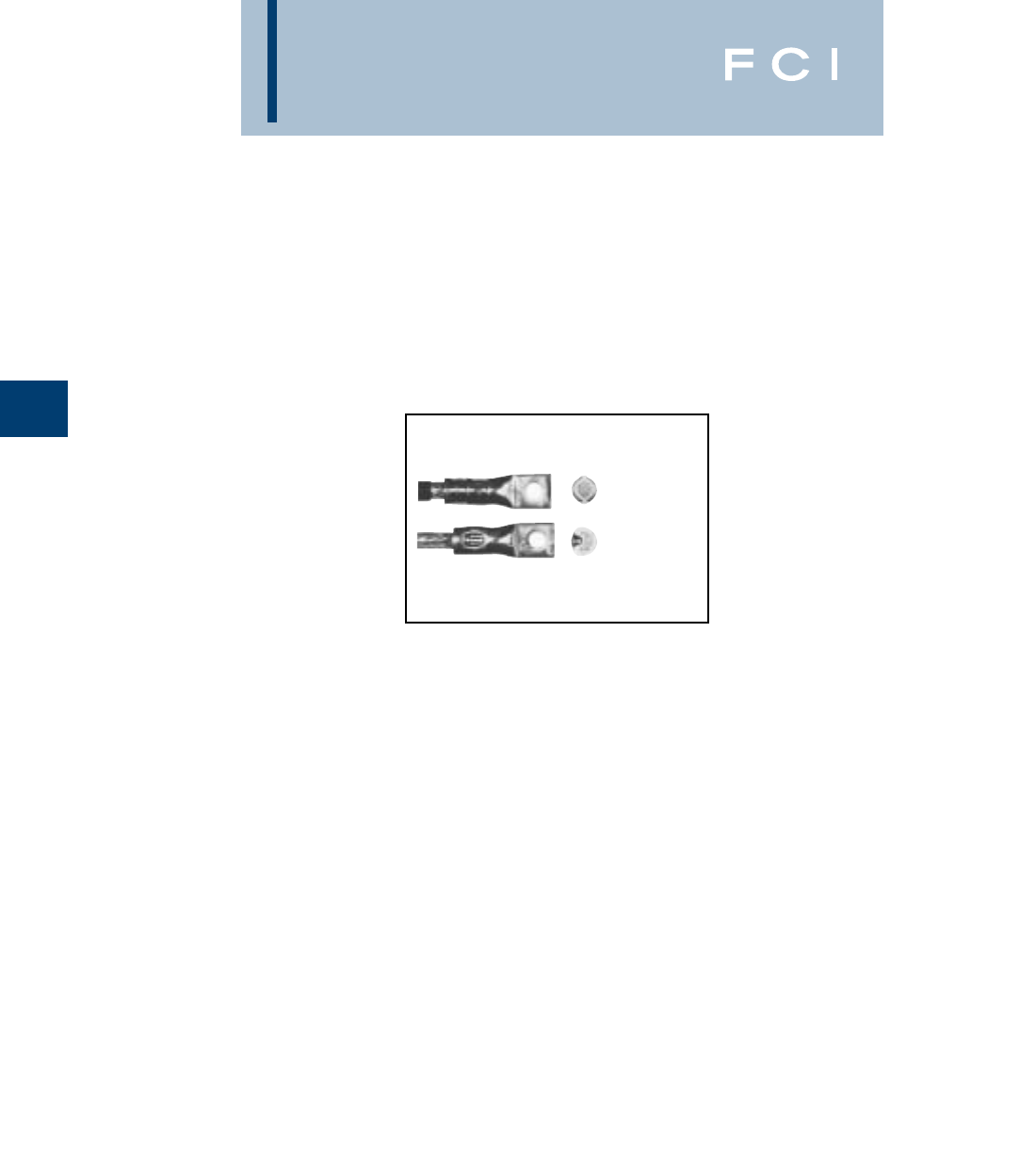
BURNDY
Compression
C-4
COMPRESSION
CONNECTORS
BURNDY's compression connectors are
designed for reliable and controllable electri-
cal connections. The complete installation is
fully inspectable. They are high conductivity
copper and operate cooler than the wire on
which they are installed.The connectors with-
stand a wide range of electrical and environ-
mental conditions, including current surges,
temperatures, corrosion and vibrations, for a
wide variety of applications. These features
mean a consistently high quality connection
at a low installed cost.
Copper compression connectors are manu-
factured from high-conductivity electrolytic
copper. The connectors are normally tin-
plated, lead-plated, or plated with proprietary
BURNDY®brite finish to provide durable
long-lasting corrosion resistance. The con-
nector design has been matched to the cable
size to provide the necessary physical
strength requirements for reliable electrical
performance.
Aluminum compression connectors are man-
ufactured from high conductivity, high purity
wrought aluminum. They are designed with
sufficient mass and are electro-tin plated to
minimize corrosion due to galvanic action
between dissimilar metals. The connector
barrels are pre-filled with PENETROX®,
BURNDY's oxide inhibiting compound.
PENETROX®contains homogeneously sus-
pended metallic particles which penetrate the
wire's oxides to establish excellent continuity
between the individual strands and the
connector barrel for a low-resistance connec-
tion. PENETROX®maintains an air-tight
connection. Each barrel end is covered with a
color-coded plastic dust cap which prevents
foreign matter from entering the connector
before it is used. The connector design has
been engineered to match the cable size to
provide the necessary physical strength
requirements for reliable electrical perfor-
mance.
SELECTION AND USE
Copper compression connectors are recom-
mended for use on copper conductors.
Aluminum compression connectors are
recommended for use on aluminum conduc-
tors. Dual-rated aluminum compression
connectors may be used on both copper and
aluminum conductors.
Two basic compression designs are available:
Circumferential and indent.
TOOLING
Tooling systems are essential for proper
installation of a compression connector.
Since connectors and dies are designed as a
unit for specific wire sizes, only the recom-
mended tools and dies should be used. Most
aluminum and copper HYLUG™ terminals
and HYLINK™ splices are marked with a die
index number and are color-coded to identify
the correct installation die. Dies marked with
the matching die index number and color can
be used to install the connector.
BURNDY®tooling installs a wide range of
connectors, is reliable, cost effective, and pre-
cision engineered for durable, long-lasting
service and quality connections. The tools
include small plier types, full cycle ratchet
designs and hydraulically-powered
HYPRESS™ heads and new Battery
Actuated Tools. Some have permanent die
grooves or adjustable dies, while others
require a change of die sets or nest die for
each connector size. BURNDY's recommend-
ed tools achieve crimp performance consis-
tent with UL and other industry standards.
Since several tools are suitable for most
connectors, the most economical and practi-
cal tool can be chosen for each application.
INDUSTRY STANDARDS
BURNDY's compression terminals, splices
and tap connectors requiring third party test-
ing and approval are listed by Underwriters'
Laboratories, Inc. Many have also received
CSA approval and are approved under MIL-
T-7928 and other military standards. All
conform to applicable sections of the National
Electrical Code.
BURNDY®also offers connectors and splices
which meet the (LOCA Seismec and Aging)
requirements of IEEE standards 323, 383
and 344 for class 1E critical circuits for use in
Nuclear Utility Applications. Certification to
10CFR50 and 10CFR21 available.
Detail catalog listings should be consulted to
obtain the appropriate standards for each
connector and splice.
After compression, virtually all the air is
removed leaving a tight homogeneous mass
of connector and conductor.
Circumferential
compression is solid
and symmetrical.
No sharp "Flash".
Indent compression.
The connector is swaged
to the conductor.
The circumferential crimp design is recom-
mended for color coded connectors in low
and high voltage applications. Die index
number embossment provides an easy
inspection where required to verify the use of
the proper connector/die combination. It is
also recommended for insulated connectors
and for terminating flexible and welding
cables.
The circumferential crimp design dies com-
press cable strands into polygonal shapes
forming intimate contact with each other and
the connector barrel. This compression forms
a tight homogeneous mass with virtually no
air pockets. The circumferential crimp
provides an excellent electrical connection
with high pull-out values. The circumferential
crimp is ideal for high voltage applications
leaving the connector barrel symmetrical,
which is easier to insulate.
The indent type crimp can be used in virtually
any application except polyvinylchloride
(PVC) insulated terminals and splices. It is an
excellent means of terminating flexible, extra
flexible and welding cables. The indentor
compresses the cable strands to form inti-
mate contact with each other and the
connector barrel. The result is an excellent
electrical connection with high pull-out
strength. Laboratory work testing curves
established the proper depth and shape of
indent for each type of connector and wire
combination.
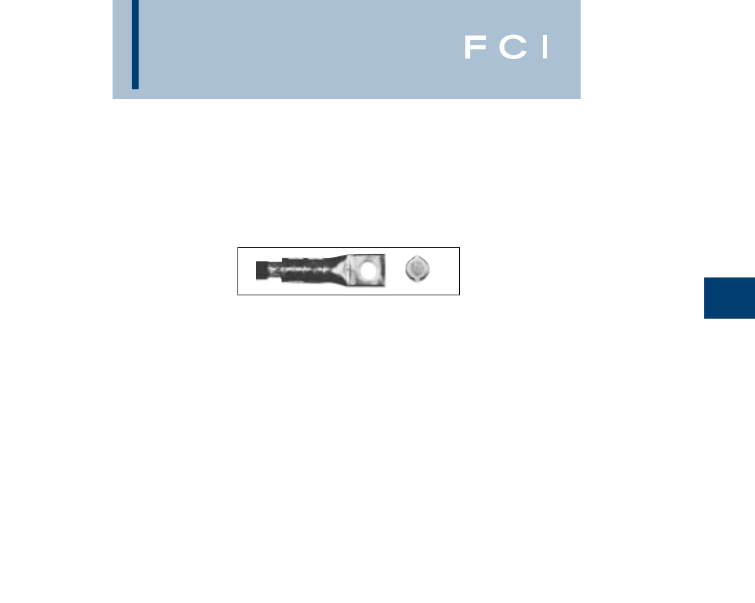
BURNDY
Compression
C-5
BURNDY®
Telecommunications
Connectors…
The industry’s first choice in
compression connections...
BURNDY®provides a complete selection of
one and two hole compression’s terminals,
H-taps, C-taps, and other compression con-
nection products specifically engineered to
meet the demanding applications of both the
Central Office and Wireless communications
markets.
All of BURNDY’s compression products are
designed for reliable and controllable
electrical connections. All connectors are
made from high conductivity electrolytic
copper and operate at cooler temperatures
than the conductor on which they are
installed. The connectors are normally
tin-plated, lead-plated, or plated with a propri-
etary BURNDY®brite finish to provide the
industry standard in long-lasting corrosion
resistance.
The complete installation is fully inspectable
and UL listed when installed with BURNDY®
dies. Every die in the system is color-coded
and provides die index embossment for
complete inspectability.
The Circumferential Crimp…
BURNDY’s circumferential crimp provides a
solid, homogenous connection, with high pull
out values and is rated for high voltage appli-
cations, more than sufficient for the 48 V DC
operating voltage common in the telecom
market. In addition the circumferential crimp
doesn’t require the removal of the copper
flash produced by other die systems. This not
only saves time in installation but removes a
potential safety hazard from the job.
All of the dies in the system are color-coded
to match the connectors and feature die index
and die number matching to the connector for
ease of installation.
BURNDY®Tooling…
the right choice for the job
BURNDY®tooling installs a wide range of
connectors, is reliable, cost effective, and pre-
cision engineered for durable, long-lasting
service and quality connections. BURNDY’s
compression tooling system ranges from full
cycle ratchet hand tools to 12 and 15 ton
hydraulically-powered HYPRESS™ heads.
Hydraulic tools are available in self-
contained, battery powered, and AC service
electrically powered pump and remote head
designs to meet all possible installation situa-
tions.
Industry Standards
BURNDY’s compression terminals, splices
and tap connectors requiring third party
testing and approval are listed by Underwriters
Laboratories, Inc. Many have also received
CSA approval, and all conform to the applica-
ble sections of the National Electric Code.
Circumferential compression is solid
and symmetrical. No sharp "Flash".
BURNDY
Compression
C-6
EXPANDED RANGES
The following connectors are range taking when crimped onto
code conductor using Y644HS family of tools:
COPPER ALUMINUM
COPPER HYLUG™ & HYLINK™ CONNECTORS
TYPES YA, YA-L, YAB, YS, YS-L, YST, YS-T, YSP-T
Catalog No. Standard Expanded
Terminal* Splice** Wire Size Wire Range
YA6C- YS6C- #6 AWG #6 AWG
YA5C- YS5C- #5 AWG #5 - #6 AWG
YA4C- YS4C- #4 AWG #4 - #6 AWG
YA3C- YS3C- #3 AWG #3 - #6 AWG
YA2C- YS2C- #2 AWG #2 - #6 AWG
YA1C- YS1C- #1 AWG #1 - #2 AWG
YA25- YS25- 1/0 AWG 1/0 - #1 AWG
YA26- YS26- 2/0 AWG 2/0 - #1 AWG
YA27- YS27- 3/0 AWG 3/0 - #1 AWG
YA28- YS28- 4/0 AWG 4/0 - #1 AWG
YA29- YS29- 250 Kcmil 250 Kcmil - 1/0 AWG
YA30- YS30- 300 Kcmil 300 Kcmil - 2/0 AWG
YA31- YS31- 350 Kcmil 350 Kcmil - 3/0 AWG
YA32- YS32- 400 Kcmil 400 Kcmil - 4/0 AWG
YA34- YS34- 500 Kcmil 500 Kcmil - 4/0 AWG
YA36- YS36- 600 Kcmil 600 - 250 Kcmil
YA39- YS39- 750 Kcmil 750 - 500 Kcmil
YA40- YS40- 800 Kcmil 800 - 500 Kcmil
YA44- YS44- 1000 Kcmil 1000 - 750 Kcmil
ALUMINUM HYLUG™ & HYLINK™ CONNECTORS
TYPES YA-A & YS-A
Catalog No. Standard Expanded
Terminal* Splice** Wire Size Wire Range
YA6CA- YS6CA- #6 AWG #6 AWG
YA4CA- YS4CA- #4 AWG #4 - #6 AWG
YA2CA- YS2CA- #2 AWG #2 - #6 AWG
YA1CA- YS1CA- #1 AWG #1 - #2 AWG
YA25A- YS25A- 1/0 AWG 1/0 - #1 AWG
YA26A- YS26A- 2/0 AWG 2/0 - #1 AWG
YA27A- YS27A- 3/0 AWG 3/0 - #1 AWG
YA28A- YS28A- 4/0 AWG 4/0 - #1 AWG
YA29A- YS29A- 250 Kcmil 250 Kcmil - 1/0 AWG
YA30A- YS30A- 300 Kcmil 300 Kcmil - 2/0 AWG
YA31A- YS31A- 350 Kcmil 350 Kcmil - 3/0 AWG
YA32A- YS32A- 400 Kcmil 400 Kcmil - 4/0 AWG
YA34A- YS34A- 500 Kcmil 500 Kcmil - 4/0 AWG
YA36A- YS36A- 600 Kcmil 600 - 250 Kcmil
YA39A- YS39A- 750 Kcmil 750 - 500 Kcmil
YA40A- YS40A- 800 Kcmil 800 - 500 Kcmil
YA44A- YS44A- 1000 Kcmil 1000 - 750 Kcmil
* 1 Crimp
** 1 Crimp per side
* 1 Crimp
** 1 Crimp per side
BURNDY
Compression
C-7
EXPANDED RANGES
The following connectors are range taking when crimped onto
code & flex conductor using 4-POINT™ family of tools:
ALUMINUM & COPPER CONDUCTOR (Code & Compact)
Conductor Connector
Wire Size Expanded Range Terminal Splice # Crimps
#8 AWG #8 AWG YA8CA- YS8CA- 1
#6 AWG #6 AWG YA6CA- YS6CA- 1
#4 AWG #6 - #4 AWG YA4CA- YS4CA- 1
#2 AWG #6-#2 AWG YA2CA- YS2CA- 2
#1 AWG #6-#1 AWG YA1CA- YS1CA- 2
1/0 AWG #6-1/0 AWG YA25A- YS25A- 2
2/0 AWG #4 - 2/0 AWG YA26A- YS26A- 2
3/0 AWG #2 - 3/0 AWG YA27A- YS27A- 2
4/0 AWG #1 - 4/0 AWG YA28A- YS28A- 2
250 kcmil 1/0 - 250 YA29A- YS29A- 2
300 kcmil 2/0 - 300 YA30A- YS30A- 2
350 kcmil 3/0 - 350 YA31A- YS31A- 3
400 kcmil 4/0 - 400 YA32A- YS32A- 4
500 kcmil 4/0 - 500 YA34A- YS34A- 4
600 kcmil 250 - 600 YA36A- YS36A- 4
750 kcmil 500-750 YA39A- YS39A- 4
ALUMINUM CONNECTORS
(Aluminum and Copper — Code & Compact)
Pin
Wire Size Expanded Range Straight Offset # Crimps
#6 AWG #6 AWG AYP6 — 1
#4 AWG #4 AWG AYP4 — 1
#2 AWG #4 - #2 AWG AYP2 — 1
#1 AWG #2 - #1 AWG AYP1 — 1
1/0 AWG #2 - 1/0 AWG AYP1/0 — 1
2/0 AWG #1 - 2/0 AWG AYP2/0 AYPO2/0 2
3/0 AWG 1/0 - 3/0 AWG AYP3/0 AYP03/0 2
4/0 AWG 2/0 - 4/0 AWG AYP4/0 AYPO4/0 2
250 kcmil 3/0 - 250 KCMIL AYP250 AYP0250 2
300 kcmil 4/0 - 300 KCMIL AYP300 AYP0300 2
350 kcmil 250 - 350 KCMIL AYP350 AYP0350 2
400 kcmil 350 - 500 KCMIL AYP400 AYP0400 2
500 kcmil 350 - 500 KCMIL AYP500 AYPO500 2
600 kcmil 400 - 600 KCMIL AYP600 AYPO600 3
750 kcmil 500 - 750 KCMIL AYP750 AYP0750 3
AYP/AYPO CONNECTORS
COPPER CONDUCTOR (Code & Compact)
Conductor Standard Barrel Long Barrell
Expanded # of # of
Wire Size Range Terminal Splice Crimps* Terminal Splice Crimps*
#8 AWG #8 AWG YA8CL- YS8CL- 1 YA8C- YS8C- 1
#6 AWG #6 AWG YA6CL- YS6CL- 1 YA6C- YS6C- 1
#4 AWG #6 - #4 YA4CL- YS4CL- 1 YA4C- YS4C- 1
#2 AWG #6-#2 YA2CL- YS2CL- 1 YA2C- YS2C- 2
#1 AWG #6-#1 YA1CL- YS1CL- 1 YA1C- YS1C- 2
1/0 AWG #6-1/0 YA25L- YS25L- 1 YA25- YS25- 2
2/0 AWG #4 - 2/0 YA26L- YS26L- 1 YA26- YS26- 2
3/0 AWG #2 - 3/0 YA27L- YS27L- 2 YA27- YS27- 2
4/0 AWG #1 - 4/0 YA28L- YS28L- 2 YA28- YS28- 2
250 kcmil 1/0 - 250 YA29L- YS29L- 2 YA29- YS29- 2
300 kcmil 2/0 - 300 YA30L- YS30L- 2 YA30- YS30- 3
350 kcmil 3/0 - 350 YA31L- YS31L- 2 YA31- YS31- 3
400 kcmil 4/0 - 400 YA32L- YS32L- 2 YA32- YS32- 3
500 kcmil 4/0 - 500 YA34L- YS34L- 2 YA34- YS34- 4
600 kcmil 250 - 600 YA36L- YS36L- 2 YA36- YS36- 4
700 kcmil 350-700 YA38L- YS38L- 3 YA38- YS38- 4
750 kcmil 500-750 YA39L- YS39L- 3 YA39- YS39- 4
800 kcmil 500-800 YA40L- YS40L- 3 YA40- YS40- 4
1000 kcmil 750-1000 YA44L- YS44L- 3 YA44- YS44- 4
COPPER CONNECTORS
*Same number of recommended crimps for both Standard and Expanded wire ranges
BURNDY
Compression
C-8
EXPANDED RANGES
The following connectors are range taking when crimped onto
code & flex conductor using 4-POINT™ family of tools:
COPPER CONNECTORS
*Same number of recommended crimps for both Standard and Expanded wire ranges
E-Line Connectors
Aluminium Copper
Expanded Offset Centerformed No. of Offset Centerformed No. of
Wire Size Wire Range Cat. No. Cat. No. Crimps Cat. No. Cat. No. Crimps
#8 AWG #8 AWG YA8CA-T-E 1
#6 AWG #6 AWG
#4 AWG #6 - #4
#2 AWG #6-#2 YA2CA-T-E YAC2CA-T-E 1
#1 AWG #6-#1
1/0 AWG #6-1/0 YA25A-T-E 1 YA25L-T-E YAC25L-T-E 1
2/0 AWG #4 - 2/0 YA26A-T-E 2 YA26L-T-E YAC26L-T-E 1
3/0 AWG #2 - 3/0 YA27A-T-E YAC27A-T-E 2
4/0 AWG #1 - 4/0 YA28A-T-E 2
250 kcmil 1/0 - 250
300 kcmil 2/0 - 300 YA30A-T-E 2 YA30L-T-E YAC30L-T-E 2
350 kcmil 3/0 - 350 YA31A-T-E YAC31A-T-E 2
400 kcmil 4/0 - 400 YA32A-T-E 4
500 kcmil 4/0 - 500 YA34A-T-E 4 YA34L-T-E 2
500 kcmil 4/0-500 YA342L-T-E 2
600 kcmil 250 - 600 YA36A-T-E 4 YA36L-T-E 2
600 kcmil 250-600 YA362L-T-E 2
700 kcmil 350-700
750 kcmil 500-750 YA39A-T-E 4 YA39L-T-E 2
750 kcmil 500-750 YA392L-T-E 2
800 kcmil 500-800
1000 kcmil 750-1000
COPPER CONDUCTOR (Flex Only)
Nominal Standard Barrel Long Barrell
Flex Wire Expanded # of Expanded # of
Size Range Terminal Splice Crimps Range Terminal Splice Crimps
#8 AWG #8 AWG YAV8CL- YSV8CL- 1 #8 AWG YAV8C- YSV8C- 1
#6 AWG #6 AWG YAV6CL- YSV6CL- 1 #6 AWG YAV6C- YSV6C- 1
#4 AWG #6 - #4 AWG YAV4CL- YSV4CL- 1 #6 - #4 AWG YAV4C- YSV4C- 1
#2 AWG #4-#2 AWG YAV2CL- YSV2CL- 1 #6-#2 AWG YAV2C- YSV2C- 1
#1 AWG #4-#1 AWG YAV1CL- YSV1CL- 1 #4-#1 AWG YAV1C- YSV1C- 1
1/0 AWG #4-1/0 AWG YAV25L- YSV25L- 1 #6-1/0 AWG YAV25- YSV25- 2
2/0 AWG #2 - 2/0 AWG YAV26L- YSV26L- 1 #4 - 2/0 AWG YAV26- YSV26- 2
3/0 AWG #1 - 3/0 AWG YAV27L- YSV27L- 1 #2 - 3/0 AWG YAV27- YSV27- 2
4/0 AWG 1/0 - 4/0 AWG YAV28L- YSV28L- 1 #1 - 4/0 AWG YAV28- YSV28- 2
250 kcmil 3/0 - 250 YAV29L- YSV29L- 1 1/0 - 250 YAV29- YS29- 2
300 kcmil 4/0 - 313.1 YA32L- YS32L- 1 2/0 - 313.1 YA32- YS32- 2
350 kcmil 250 - 373.7 YA34L- YS34L- 1 3/0 - 373.7 YA34- YS34- 2
450 kcmil 250 - 444.4 YA36L- YS36L- 1 4/0 - 444.4 YA36- YS36- 2
500 kcmil 373.7 - 535.3 YA38L- YS38L- 1 4/0 - 535.3 YA38- YS38- 2
600 kcmil 373.7 - 600 YA39L- YS39L- 2 250 - 600 YA39- YS39- 3
650 kcmil 444.4 - 646 YA40L- YS40L- 2 373.3 - 646 YA40- YS40- 3
750 kcmil 535.3 - 777.7 YA44L- YS44L- 2 535.3 - 777.7 YA44- YS44- 3
COPPER CONNECTORS
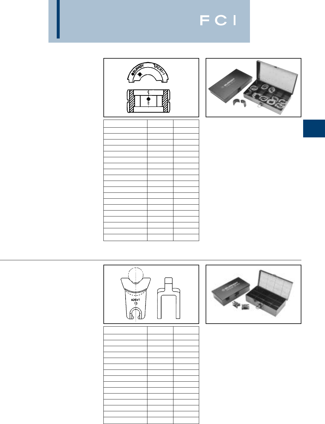
BURNDY
Compression
C-9
12-TON U DIES*
BURNDY®Die Sets
Fits Y35,Y39, Y750, BAT35,
BAT750, PAT750,Y46
(W/PUADP-1 Adapter)
U die case Part# PT29291, holds up to 15 dies
Wire Size Copper Aluminum
Small #8 U8CRT U8CABT
#6 U5CRT U6CABT
#4 U4CRT U4CABT
#3 U3CRT N/A
#2 U2CRT U2CABT
#1 U1CRT-1 U1CART
1/0 U25RT U25ART
2/0 U26RT U26ART
3/0 U27RT U27ART
4/0 U28RT U28ART
250 MCM U29RT U29ART
300 MCM U30RT U30ART
350 MCM U31RT U31ART
400 MCM U32RT U32ART
500 MCM U34RT U34ART
535 Flex MCM U38XRT N/A
600 MCM U36RT U36ART
750 MCM U39RT U39ART-2
Large 777 Flex U44XRT N/A
*Non-tension U-type 12-ton dies for YA, YS, YA-A, YS-A style
connectors.
NOTE: N/A = not applicable.
W DIES
BURNDY®Die Sets
Fits Tools MD6, MD7,
Y500CTHS, BAT500,
BCT500HS
Wire Size Copper Aluminum
Small #8 W8CVT X8CART
#6 W5CVT W161
#4 W4CVT W162
#3 W3CRT N/A
#2 W2CVT W239
#1 W1CVT W163
1/0 W25VT W241
2/0 W26VT W245
3/0 W27VT W166
4/0 W28VT W660
250 *W29VT N/A
300 *W30VT N/A
350 *W31VT *W31ART
400 *W32VT N/A
Large 500 *W34VT N/A
*These sizes (250-500) for Y500CT, MD7-34(R), BAT500,
BCT500 only.
NOTE: N/A = not applicable.
Suitable for use on YA, YS, YA-A, YS-A type non-tension
connectors.
W die case Part# PT4946, holds up to 12 dies
BURNDY
Compression
C-10
INSTALLATION TOOLING SYSTEM
LUGS & SPLICES TAPS TAPS TAPS
One & Two T&B Thin-Wall C-taps Heavy Duty C-Taps H-Taps
Conductor HOLE Index Run=Tap, AWG only Run=Tap Run=Tap
Code
AWG FLEX Die Color Index (Flex) Die Color Index Die Color Index Die Color Index
#8/#6 W8CVT
sol #8 U8CRT RED 49 21 W4CVT GRAY 8U240 RED 240 U11T-1 GREEN 11
W5CVT
#6 #6 U5CRT BLUE 724W2CVT BROWN 10 UC BROWN CUBGRT ORANGE BG
W4CVT
#4 #4 U4CRT GRAY 829W25VT PINK 12 UC BROWN CUCBROWN C
#3/#2 W3CRT
sol U3CRT WHITE 9W26VT BLACK 13 UC BROWN CUCBROWN C
W2CVT
#2 #2 U2CRT BROWN 10 33 W27VT ORANGE 14 UC BROWN CUCBROWN C
W1CVT
#1 #1 U1CRT-1 GREEN 11 W28VT PURPLE 15 U997 ORANGE 997 U654 PURPLE 654
W25VT 42
1/0 1/0 U25RT PINK 12 (45) W29VT YELLOW 16 U997 ORANGE 997 U654 PURPLE 654
REFER
2/0 2/0 W26VT BLACK 13 45 TO U997 ORANGE 997 U654 PURPLE 654
U26RT (50) CATALOG
W27VT
3/0 3/0 U27RT ORANGE 14 U997 ORANGE 997 U654 PURPLE 654
W28VT 54
4/0 4/0 U28RT PURPLE 15 (62) ---U997 ORANGE 997 U654 PURPLE 654
4/0/250
250 class W29VT YELLOW 16 - - - U997 ORANGE 997 U654 PURPLE 654
G & H U29RT
262/250
300
class
W30VT WHITE 17 - - - U1104 BROWN 1104 U1104 BROWN 1104
I, K & M
U30RT
W31VT
350 313 U31RT RED 18 71 - - - U1104 BROWN 1104 U1104 BROWN 1104
350/ W32VT
373 U32RT BLUE 19 - - - U1104 BROWN 1104 U1104 BROWN 1104
W34VT
500 444 U34RT BROWN 20 87 - - - U1104 BROWN 1104 U1104 BROWN 1104
500/
535 U38XRT PINK L99 - - - P1103 BLUE 1103 PYFR YELLOW KR
600 U36RT GREEN 22 (99) - - - P1103 BLUE 1103 PYFR YELLOW KR
700 U38RT PINK 400 - - - P1103 BLUE 1103 PYFR YELLOW KR
750 646 U39RT BLACK 24 106 - - - P1103 BLUE 1103 PYFR YELLOW KR
750/
777 U44XRT YELLOW L115
800 P40RT ORANGE 25 (115) - - - P1102 WHITE 1102 PYFR YELLOW KR
1000 P44RT WHITE 27 - - - P1102 WHITE 1102 PYFR YELLOW KR
BURNDY
Compression
C-11
ONE HOLE HYLUG™
CODE CONDUCTOR
STANDARD BARREL
TYPES YA-L,YA-L-TC
COPPER COMPRESSION
TERMINAL
UL Listed 90° C,
600 Volts to 35 KV ◆
B
B
B
TTT
L
45°
90°
L
L
*Use PUADP-1 adapter with "U" dies in Y46 HYPRESS™.
** P-RT die sets for use in Y46 HYPRESS™ only, PUADP-1
adapter not required.
*** The MM2conductor sizes listed are the recommendations
for Class 2 conductor.
ELECTRO-TIN
PLATED CABLE
ACCOMMODATION
CRIMP
DIE AND COLOR
CODE INFORMATION
INSPECTION
WINDOW
BEVELED
ENTRY
Fig. 1 Fig. 2 Fig. 3
Conductor ▲Installation Tooling
Stud Figure Mechanical Hydraulic Wire
*** Hole Tongue Dimensions Dieless MD6, OUR840, BCT500HS, Y35, Y39, Y750, Color Die Strip
Catalog Number Fig # AWG MM2Size Width (B) (T) (L) (# of crimps) MD7-34R Y500CTHS
Y46*, PAT750
Code Index Length
YAV10-45-BOX 2.405.058.92
YAV10-BOX 1#14-#10 8-10 .38.405.0581.02
YAV10R-BOX 3STR .375.058.77
YAV 10R3-BOX 361/4.47.405.047.83
Y8MRB-1 (1) - - - - 7/16
YAV10T2-BOX 15/16.53.38.0471.12
YAV10T3-45-BOX 2#12-#10 1/4.47.405.0471.10
YAV10T3-BOX 1SOL 1/4.47.405.0471.10
YAV10T4-BOX 13/8.56.38.0471.18
YA8CL1-BOX 11.26
YA8CL1-45 21/4.44.44.081.24
YA8CL1-90 3.80
YA8CL2-BOX 11.38Y1MR (1)
YA8CL2-45 2#8 AWG 5/16.52.44.061.34Y8MRB-1 (1)
YA8CL2-90 3.92Y2MR (1)
YA8CL3-BOX 1#8 WELD †1.51MY29-3 (1) W8CVT (1) W8CVT (1)
YA8CL3-45 23/8.58.44.061.45MY29-11 (1) W8CRT (1) W8CRT (1) U8CRT (1) Red 49 7/16
YA8CL3-90 337/24 10 1.04MRC840 (1) X8CRT (1) X8CRT (1)
YA8CL4-BOX 11.76Y81KFT (1)
YA8CL4-45 2#6 SOLID 1/2.71.44.051.67
Y81KFTMBH (1)
YA8CL4-90 31.28
PAT81KFT-18V (1)
YA8CL-BOX 11.16
YA8CL-45 28-10 .41.44.081.16
YA8CL-90 3.71
YA6CL-BOX 11.18
YA6CL-45 21/4.45.54.081.08Y1MR (1)
YA6CL-90 3.81MY29-3 (1)
W5CVT (1) W5CVT (1)
YA6CL1-BOX 1.41.54.09.99MY29-11 (1)
W5CRT (1) W5CRT (1)
YA6CL1-45 2#6 AWG 8-10 .41.54.09.89MRC840 (1) U5CRT (1) Blue 7 7/8
YA6CL1-90 3.42.54.09.72Y2MR (1) X5CRT (1) X5CRT (1)
YA6CL3-BOX 11.24Y81KFT (1) X8CART (1) X8CART (1)
YA6CL3-45 25/16.52.54.071.06
Y81KFTMBH (1)
YA6CL3-90 3.93
PAT81KFT-18V (1)
†The MM2conductor size listed is for both Class 2 and
Class 5 conductor.
▲See tooling section of this catalog for complete tool and die
listings.
◆For applications greater than 2000 Volts, consult cable
manufacturer for voltage stress relief instructions.

BURNDY
Compression
C-12
ONE HOLE HYLUG™
CODE CONDUCTOR
STANDARD BARREL
(Continued)
*Use PUADP-1 adapter with "U" dies in Y46 HYPRESS™.
** P-RT die sets for use in Y46 HYPRESS™ only, PUADP-1
adapter not required.
B
B
B
TTT
L
45°
90°
L
L
Fig. 2 Fig. 3Fig. 1
*** The MM2conductor sizes listed are the recommendations
for Class 2 conductor.
▲See tooling section of this catalog for complete tool and die
listings.
◆For applications greater than 2000 Volts, consult cable
manufacturer for voltage stress relief instructions.
Conductor ▲Installation Tooling
Stud Figure Mechanical Hydraulic Wire
*** Hole Tongue Dimensions Dieless MD6, OUR840, BCT500HS, Y35, Y39, Y750, Color Die Strip
Catalog Number Fig # AWG MM2Size Width (B) (T) (L) (# of crimps) MD7-34R Y500CTHS
Y46*, PAT750
Code Index Length
YA6CL4-BOX 11.28
YA6CL4-45 23/8.63.54.061.17Y1MR (1) W5CVT (1) W5CVT (1)
YA6CL4-90 3#6 AWG 1.05MY29-3 (1) W5CRT (1) W5CRT (1) U5CRT (1) Blue 7 7/8
YA6CL6-BOX 11.60MY29-11 (1) X5CRT (1) X5CRT (1) UBCABT (1)
YA6CL6-45 21/2.75.54.121.54MRC840 (1) X8CART (1) X8CART (1)
YA6CL6-90 31.30Y2MR (1)
YA5CL-BOX 11.65Y81KFT (1) W5CRT (1) W5CRT (1)
YA5CL-45 2#5 AWG 1/4.44.81.071.31
Y81KFTMBH (1)
W5CVT (1) X5CRT (1) U5CRT (1) Blue 7 7/8
YA5CL-90 3.81
PAT81KFT-18V (1)
X5CRT (1) W5CVT (1)
YA4CL-BOX 11.74
YA4CL-45 21/4.50.81.091.44
YA4CL-90 3.84
YA4CL1-BOX 11.58
YA4CL1-45 28-10 .50.81.091.28
YA4CL1-90 3.75
YA4CL3-BOX 11.92W4CVT (1) W4CVT (1) U4CRT (1)
YA4CL3-45 2#4 AWG 5/16.58.81.081.68W4CRT (1) W4CRT (1) Gray 8 7/8
YA4CL3-90 3.96X4CRT (1) X4CRT (1) U6CABT (1)
YA4CL4-BOX 11.92
YA4CL4-45 23/8.58.81.081.68Y1MR (2)
YA4CL4-90 31.08MY29-3 (1)
YA4CL6-BOX 12.20MY29-11 (1)
YA4CL6-45 21/2.71.81.062.02MRC840 (1)
YA4CL6-90 31.32Y2MR (2)
YA3CL 11.88Y644HS (1)
YA3CL-45 2# 3 STR 25 5/16.55.88.091.76Y81KFT (1) W3CRT (1) W3CRT (1) U3CRT (1)
White
915/16
YA3CL-90 3# 2 SOL .98
Y81KFTMBH (1)
YA2CL2-BOX 11.88
PAT81KFT-18V (1)
YA2CL2-45 21/4.61.88.111.55
YA2CL2-90 3.89
YA2CL-BOX 11.93
YA2CL-45 25/16.61.88.111.62W2CVT (1) W2CVT (1)
YA2CL-90 3#2 AWG 35 1.01W2CRT (1) W2CRT (1) U2CRT (1)
Brown
10 15/16
YA2CL4-BOX 12.06X2CRT (1) X2CRT (1)
YA2CL4-45 23/8.61.88.111.74
YA2CL4-90 31.14
YA2CL6-BOX 12.32
YA2CL6-45 21/2.73.88.092.17
YA2CL6-90 31.37
YA1CL2 11.81
YA1CL2-45 21/4.68.88.101.70
YA1CL2-90 3.91Y1MR (2)
YA1CL-BOX 11.94MY29-3 (1)
YA1CL-45 25/16.68.88.011.82MY29-11 (1) W1CVT (1) W1CVT (1)
YA1CL-90 3#1 AWG 50 1.03MRC840 (1)
W1CRT-1 (1) W1CRT-1 (1)
U1CRT-1 (1)
Green
11 15/16
YA1CL4-BOX 12.06Y644HS (1)
X1CRT-1 (1) X1CRT-1 (1)
U4CABT (1)
YA1CL4-45 23/8.68.88.101.95Y81KFT (1)
YA1CL4-90 31.16
Y81KFTMBH (1)
YA1CL6-BOX 12.37
PAT81KFT-18V (1)
YA1CL6-45 21/2.73.88.092.22
YA1CL6-90 31.40

BURNDY
Compression
C-13
ONE HOLE HYLUG™
CODE CONDUCTOR
STANDARD BARREL
(Continued)
*Use PUADP-1 adapter with "U" dies in Y46 HYPRESS™.
** P-RT die sets for use in Y46 HYPRESS™ only, PUADP-1
adapter not required.
Conductor ▲Installation Tooling
Stud Figure Mechanical Hydraulic Wire
*** Hole Tongue Dimensions Dieless MD6, OUR840, BCT500HS, Y35, Y39, Y750, Color Die Strip
Catalog Number Fig # AWG MM2Size Width (B) (T) (L) (# of crimps) MD7-34R Y500CTHS
Y46*, PAT750
Code Index Length
YA25L2-BOX 11.84
YA25L2-45 21/4.75.88.121.76
YA25L2-90 3.94
YA25L4-BOX 12.09
YA25L4-45 23/8.75.88.122.01W25VT (2) W25VT (2) U25RT (1)
YA25L4-90 31/0 AWG 1.19W25RT (2) W25RT (2)
Pink
12 15/16
YA25L6-BOX 12.34X25RT (2) X25RT (2) U2CABT (1)
YA25L6-45 21/2.75.88.122.26
YA25L6-90 31.44
YA25L-BOX 11.96
YA25L-45 25/16.75.88.121.88
YA25L-90 31.07
YA26L2-BOX 11.94MY29-3 (1)
YA26L2-45 21/4.83.94.121.78MY29-11 (1)
YA26L2-90 3.96MRC840 (2)
YA26L3-BOX 12.06Y644HS (1)
YA26L3-45 25/16.83.94.121.91Y81KFT (1)
YA26L3-90 31.09
Y81KFTMBH (1)
YA26L-BOX 12.19
PAT81KFT-18V (1)
YA26L-45 23/8.83.94.122.03
YA26L-90 31.21W26VT (2) W26VT (2)
YA26L60 12/0 AWG 70 2.96W26RT (2) W26RT (2) U26RT (1)
Black
13 1
YA26L60-45 23/4.96.94.122.77X26RT (2) X26RT (2)
YA26L60-90 31.89
YA26L6-BOX 12.44
YA26L6-45 21/2.83.94.122.28
YA26L6-90 31.46
YA26L7-BOX 12.69
YA26L7-45 25/8.88.94.112.50
YA26L7-90 31.71
YA26LNT516 15/16.62.94.132.62
YA27L2-BOX 12.04
YA27L2-45 21/41.001.00.131.91
YA27L2-90 3.99
YA27L3 12.16
YA27L3-45 25/16.911.00.132.03
YA27L3-90 31.12W27VT (2) W27VT (2)
YA27L4-BOX 13/0 AWG 2.29MY29-3 (1) W27RT (2) W27RT (2) U27RT (1)
Orange
14 1-1/16
YA27L4-45 23/8.911.00.131.91MY29-11 (1) X27RT (3) X27RT (3)
YA27L4-90 3.99MRC840 (2)
YA27L-BOX 12.54Y644HS (1)
YA27L-45 21/2.911.00.132.41Y81KFT (2)
YA27L-90 31.49
Y81KFTMBH (2)
YA27LNT38 3/8.761.00.12
PAT81KFT-18V (2)
YA28L17-BOX 12.71
YA28L17-45 25/81.02.88.142.64W28VT (2) W28VT (2)
YA28L17-90 34/0 AWG 1.79W28RT (2) W28RT (2) U28RT (1)
Purple
15 1-1/8
YA28L2-BOX 11.96X28RT (3) X28RT (3)
YA28L2-45 21/41.02.88.141.89
*** The MM2conductor sizes listed are the recommendations
for Class 2 conductor.
▲See tooling section of this catalog for complete tool and die
listings.
◆For applications greater than 2000 Volts, consult cable
manufacturer for voltage stress relief instructions.
B
B
B
TTT
L
45°
90°
L
L
Fig. 2 Fig. 3Fig. 1

BURNDY
Compression
C-14
ONE HOLE HYLUG™
CODE CONDUCTOR
STANDARD BARREL
(Continued)
*** The MM2conductor sizes listed are the recommendations
for Class 2 conductor.
▲See tooling section of this catalog for complete tool and die
listings.
Conductor ▲Installation Tooling
Stud Figure Mechanical Hydraulic Wire
*** Hole Tongue Dimensions Dieless MD6, OUR840, BCT500HS, Y35, Y39, Y750, Color Die Strip
Catalog Number Fig # AWG MM2Size Width (B) (T) (L) (# of crimps) MD7-34R Y500CTHS
Y46*, PAT750
Code Index Length
YA28L2-90 31/41.02.88.141.04
YA28L3 12.08
YA28L3-45 25/161.02.88.142.01
YA28L3-90 31.16
YA28L4-BOX 12.21MY29-3 (1)
YA28L4-45 23/81.02.88.142.14MY29-11 (1)
W28VT (2) W28VT (2)
YA28L4-90 34/0 AWG 1.29MRC840 (2)
W28RT (2) W28RT (2) U28RT (1)
Purple
15 1-1/8
YA28L56 12.90Y644HS (1)
X28RT (2) X28RT (3)
YA28L56-45 23/41.05.88.132.81Y81KFT (2)
YA28L56-90 31.97
Y81KFTMBH (2)
YA28L-BOX 12.46
PAT81KFT-18V (2)
YA28L-45 21/21.02.88.142.39
YA28L-90 31.54
YA28LNT38 13/8.76.88.162.79
YA29L2 12.17
YA29L2-45 21/41.111.06.162.07
YA29L2-90 31.08
YA29L4 12.42
YA29L4-45 23/81.111.06.162.32
YA29L4-90 31.33MY29-3 (1)
YA29L7 12.30MY29-11 (1) W29VT (2)
YA29L7-45 2250 kcmil 5/161.111.06.162.20Y644HS (1) W29VT (2) W29RT (2) U29RT (1)
Yellow
16 1-1/8
YA29L7-90 31.20Y81KFT (2) X29RT (4) X29RT (4)
YA29LTC78 13.36
Y81KFTMBH (2)
YA29LTC78-45 27/81.111.06.143.23
PAT81KFT-18V (2)
YA29LTC78-90 32.26
YA29LNT38 3/8.961.06.162.96
YA29L-BOX 12.67
YA29L-45 21/21.111.06.162.57
YA29L-90 31.58
YA30L 12.69
YA30L-45 21/21.201.03.162.60
YA30L-90 31.61
YA30L1 12.31
YA30L1-45 25/161.201.03.162.22
YA30L1-90 31.24
YA30L24 12.44
YA30L24-45 23/81.201.03.162.35
W30VT (2) W30VT (2) U30RT (2)
White
17 1-1/16
YA30L24-90 3300 kcmil 150 1.36Y644HS (1) W30RT (2) U28ART (2)
YA30L27 13.37Y81KFT (2)
YA30L27-45 27/81.201.03.163.29
Y81KFTMBH (2)
YA30L27-90 32.30
PAT81KFT-18V (2)
YA30L28 13/41.201.03.163.12
YA30L7 12.94
YA30L7-45 25/81.201.03.162.85
YA30L7-90 31.86
YA31L 12.75
W31VT (2) U31RT (2)
YA31L-45 2350 kcmil 185 1/21.291.06.182.75W31VT (2)
Red
18 1-3/16
YA31L-90 31.65W31RT (2) U29ART (2)
*Use PUADP-1 adapter with "U" dies in Y46 HYPRESS™.
** P-RT die sets for use in Y46 HYPRESS™ only, PUADP-1
adapter not required.
◆For applications greater than 2000 Volts, consult cable
manufacturer for voltage stress relief instructions.
B
B
B
TTT
L
45°
90°
L
L
Fig. 2 Fig. 3Fig. 1
BURNDY
Compression
C-15
ONE HOLE HYLUG™
CODE CONDUCTOR
STANDARD BARREL
(Continued)
*Use PUADP-1 adapter with "U" dies in Y46 HYPRESS™.
** P-RT die sets for use in Y46 HYPRESS™ only, PUADP-1
adapter not required.
Conductor ▲Installation Tooling
Stud Figure Mechanical Hydraulic Wire
*** Hole Tongue Dimensions Dieless MD6, OUR840, BCT500HS, Y35, Y39, Y750, Color Die Strip
Catalog Number Fig # AWG MM2Size Width (B) (T) (L) (# of crimps) MD7-34R Y500CTHS
Y46*, PAT750
Code Index Length
YA31L11 12.50
YA31L11-45 23/81.291.06.182.42
YA31L11-90 31.40
YA31L36 14.02
YA31L36-45 2350 kcmil 185 7/81.291.06.184.02W31VT (2) U31RT (2)
YA31L36-90 33.94W31VT (2) W31RT (2) U29ART (2)
Red
18 1-3/16
YA31L7 13.00
YA31L7-45 25/81.291.06.183.00
YA31L7-90 31.90
YA31LNT38 3/8961.06.183.37
YA32L 13.18
YA32L-45 25/81.381.19.193.08
YA32L-90 31.95
YA32L1 12.93
YA32L1-45 21/21.401.19.192.83
YA32L1-90 3400 kcmil 1.70
W32VT (2) W32VT (2) U32RT (2)
Blue
19 1-1/4
YA32L14 12.68W32RT (2) U30ART (2)
YA32L14-45 23/81.381.19.192.58
YA32L14-90 31.45
YA32LTC78 13.62
YA32LTC78-45 27/81.401.19.193.52
YA32LTC78-90 32.38
YA33L 13.57
W33VT (2)
YA33L-45 2450 kcmil 5/81.481.50.213.30Y644HS (1) W33VT (2) U33RT (2)
Gray
326 1-9/16
YA33L-90 32.00Y81KFT (2) W33RT (2)
YA34L 13.37
Y81KFTMBH (2)
YA34L-45 25/81.551.27.233.30
PAT81KFT-18V (2)
YA34L-90 32.03
YA34L20 14.05
YA34L20-45 211.551.27.233.99
YA34L20-90 32.72
YA34L37 12.87
YA34L37-45 23/81.551.27.232.80
YA34L37-90 3500 kcmil 240 1.53
W34VT (2) W34VT (2) U34RT (2)
Brown
20 1-7/16
YA34L6 13.12W34RT (2) U31ART (2)
YA34L6-45 21/21.551.27.233.05
YA34L6-90 31.78
YA34L8 13.55
YA34L8-45 23/41.551.27.233.49
YA34L8-90 32.22
YA34L9 13.80
YA34L9-45 27/81.551.27.233.74
YA34L9-90 32.47
YA35L 13.81
YA35L-45 2550 kcmil 5/81.651.69.253.67--U35RT (2)
Yellow
21 1-3/4
YA35L-90 32.08
YA36L11 11/21.741.38.273.29
YA36L 13.72
YA36L-45 2600 kcmil 300 5/81.741.38.273.51--U36RT (2)
Green
22 1-3/4
YA36L-90 32.11
*** The MM2conductor sizes listed are the recommendations
for Class 2 conductor.
▲See tooling section of this catalog for complete tool and die
listings.
◆For applications greater than 2000 Volts, consult cable
manufacturer for voltage stress relief instructions.
B
B
B
TTT
L
45°
90°
L
L
Fig. 2 Fig. 3Fig. 1

BURNDY
Compression
C-16
ONE HOLE HYLUG™
CODE CONDUCTOR
STANDARD BARREL
(Continued)
*Use PUADP-1 adapter with "U" dies in Y46 HYPRESS™.
** P-RT die sets for use in Y46 HYPRESS™ only, PUADP-1
adapter not required.
Conductor ▲Installation Tooling
Stud Figure Mechanical Hydraulic Wire
*** Hole Tongue Dimensions Dieless MD6, OUR840, BCT500HS, Y35, Y39, Y750, Color Die Strip
Catalog Number Fig # AWG MM2Size Width (B) (T) (L) (# of crimps) MD7-34R Y500CTHS Y46*, PAT750 Code Index Length
YA36LTC78 13.97Y644HS (1)
YA36LTC78-45 2600 kcmil 300 7/81.741.38.273.95Y81KFT (2) - - U36RT (2)
Green
22 1-3/4
YA36LTC78-90 32.55
Y81KFTMBH (2)
U32ART (2)
YA37L 13.57
YA37L-45 2650 kcmil 5/81.801.39.273.55
--U37RT (2)
Orange
23
1-15/16
YA37L-90 32.14
YA37L1 13.76
YA38L 13.66
YA38L-90 2700 kcmil 5/81.841.45.273.60--U38RT (2)
Pink
400
1-15/16
YA38L-45 32.15
YA39L 13.67
YA39L-45 25/81.911.42.273.61Y644HS (1)
YA39L-90 32.17Y81KFT (3)
YA39L2 14.10
Y81KFTMBH (3)
YA39L2-45 27/81.911.42.274.05
PAT81KFT-18V (3)
YA39L2-90 32.61U39RT (2)
YA39L9 1750 kcmil 4.85--P39RT (2)
Black
24
1-15/16
YA39L9-45 21-1/41.911.42.274.80**
YA39L9-90 33.36
YA39LNT38 3/81.121.42.274.70
YA39L6 13.41
YA39L6-45 21/21.911.42.273.36
YA39L6-90 31.92
YA40L 13.81
YA40L-45 2800 kcmil 400 5/81.981.42.303.69--P40RT(3)
Orange
25
1-15/16
YA40L-90 32.21**
YA41L 14.15Y644HS (1)
YA41L-45 2850 kcmil 5/82.011.88.314.03Y81KFT (3) -- -
Gold
26
1-15/16
YA41L-90 32.23
Y81KFTMBH (3)
YA44L 14.04
PAT81KFT-18V (3)
YA44L-45 25/82.191.65.334.01Y644MBH (1)
YA44L-90 31000 kcmil 500 2.32
PAT644-18V (1)
--P44RT(3)
White
27
1-15/16
YA44L2 11/22.491.65.333.98**
YA44L23 112.191.65.334.73
YA-45L 14.68
YA-45L-45 21250 kcmil 3/42.462.00.384.64--P45RT(3)
Yellow
29
2-1/16
YA-45L-90 32.62**
YA-453L 14.71
YA-453L-45 21300 kcmil 3/42.532.00.394.68-- -
Orange
30
2-1/16
YA-453L-90 32.65
YA46L 14.78--
YA46L-45 21500 kcmil 3/42.692.00.404.75--P46RT (3)
Green
31
2-1/16
YA46L-90 32.71-- **
YA47L 15.05-- -
YA47L-45 21750 kcmil 3/42.902.19.425.00-- -
Gray
33
2-1/4
YA47L-90 32.79-- -
YA48L 15.19-- -
YA48L-45 22000 kcmil 3/43.102.25.465.19-- -
Brown
34
2-1/4
YA48L-90 32.89-- -
*** The MM2conductor sizes listed are the recommendations
for Class 2 conductor.
▲See tooling section of this catalog for complete tool and die
listings.
◆For applications greater than 2000 Volts, consult cable
manufacturer for voltage stress relief instructions.
B
B
B
TTT
L
45°
90°
L
L
Fig. 2 Fig. 3Fig. 1
Conductor ▲Installation Tooling
Stud Figure **** Mechanical Hydraulic Wire
*** Hole Tongue Dimensions Dieless MD6, OUR840, BCT500HS, Y35, Y39, Y750, Color Die Strip
Catalog Number Fig # AWG MM2Size Width (B) (T) (L) (# of crimps) MD7-34R Y500CTHS Y46*, PAT750 Code Index Length
Y8MRB-1 (1)
Y2MR (1)
MY29-3 (1)
** MY29-11 (1)
YA8CLNT6 1#8 AWG 10 6 .29.44.091.08
MRC840 (1) W8CVT (1) X8CRT (1) U8CRT (1)
Red
49 1/2
Y81KFT (1)
Y81KFTMBH (1)
PAT81KFT-18V (1)
YA6CLNT6 1#6 AWG - 6 .29.54.091.17Y1MR (1) W5CVT (1) X5CRT (1) U5CRT (1)
Blue
77/8
YA4CLNT10 1#4 AWG - # 10 .40.81.091.73Y2MR (1) W4CVT (1) X4CRT (1) U4CRT (1)
Gray
87/8
YA3CLNT516 1#3 AWG 25 5/16.49.88.091.80MY29-3 (1) W3CVT (1) W3CVT (1) U3CRT (1)
White
915/16
#2 SOL MY29-11 (1)
YA2CLNT10 1# 10 .48.88.111.80MRC840
YA2CLNT14 11/4.50.88.111.80Y644HS (1)
*35 Y81KFT (1) W2CVT (1) X2CRT (1) U2CRT (1)
Brown
10 15/16
YA2CLNT516 1#2 AWG 5/16.49.88.111.82
Y81KFTMBH (1)
PAT81KFT-18V (1)
YA1CLNT10 150 # 10 .50.88.102.23
W1CVT (1) X1CRT (1) U1CRT (1)
Green
11 15/16
YA1CLNT14 1#1 AWG 1/4.50.88.102.23MY29-3 (1)
YA25LNT10 11/0 AWG - # 10 .62.88.122.28MY29-11 (1)
W25VT (2) X25RT (2) U25RT (1)
Pink
12 15/16
YA25LNT516 15/16.62.88.122.28MRC840
YA26LNT10 1# 10 .62.94.132.62Y644HS (1)
YA26LNT516 12/0 AWG 70 5/16.62.94.132.62Y81KFT (1)
W26VT (2) X26RT (2) U26RT (1)
Black
13 1
YA26LNT516U 1-.62.94.132.62
Y81KFTMBH (1)
YA26LNT38 13/8.72.94.122.48
PAT81KFT-18V (1)
YA27LNT38 13/0 AWG - 3/8.761.00.122.73W27VT (2) X27RT (3) U27RT (1)
Orange
14 1-1/16
YA28LNT38 14/0 AWG - 3/8.76.88.142.67W28VT (2) X28RT (3) U28RT (1)
Purple
15 1-1/8
YA29LNT38 1250 kcmil - 3/8.961.06.162.96W29VT (2) X29RT (4) U29RT (1)
Yellow
16 1-1/8
YA29LENT38 1.761.06.162.96Y644HS (1) W29VT (2) X29RT (4) U29RT (1)
Yellow
16 1-1/8
YA30LNT38 1300 kcmil 150 3/8.961.03.162.97Y81KFT (2) W30VT (4) - U30RT (2)
White
17 1-1/8
YA31LNT38 1350 kcmil 185 3/8.961.06.183.31
Y81KFTMBH (2)
W31VT (4) - U31RT (2)
Red
18 1-3/16
YA32LNT38 1400 kcmil - 3/8.961.19.203.21
PAT81KFT-18V (2)
W32VT (4) - U32RT (2)
Blue
19 1-1/4
YA34LNT38 1500 kcmil 240 3/8.961.27.233.65W34VT (4) - U34RT (2)
Brown
20 1-7/16
YA36LNT38 1600 kcmil 300 3/81.121.38.274.09--U36RT (2)
Green
22 1-3/4
Y81KFT (3)
YA39LNT38 1750 kcmil - 3/81.121.42.274.24
Y81KFTMBH (3)
--U39RT (2)
Black
24 1
-15/16
PAT81KFT-18V (3)
BURNDY
Compression
C-17
ONE HOLE HYLUG™
CODE CONDUCTOR
STANDARD BARREL
NARROW TONGUE
TYPES YA-L-NT
COPPER COMPRESSION
NARROW TONGUE
TERMINAL
UL Listed 90° C,
600 Volts to 35 KV ◆
ELECTRO-TIN
PLATED CABLE
ACCOMMODATION
CRIMP
DIE AND COLOR
CODE INFORMATION
INSPECTION
WINDOW
BEVELED
ENTRY
L
45°
90°
L
L
BB
B
TTT
Fig. 1 Fig. 2 Fig. 3
*Use PUADP-1 adapter with "U" dies in Y46 HYPRESS™.
** The MM2conductor size listed is for Class 2 and Class 5
conductor.
*** The MM2conductor sizes listed are the recommendations
for Class 2 conductor.
**** Y644M is not recommended for standard barrel length #6
AWG HYLUGs.
▲See tooling section of this catalog for complete tool and die
listings. Use ONLY color-coded die recommendations for
“-FX”connectors. For nest/indentor system contact factory.
◆For applications greater than 2000 Volts consult cable
manufacturer for voltage stress relief instructions.
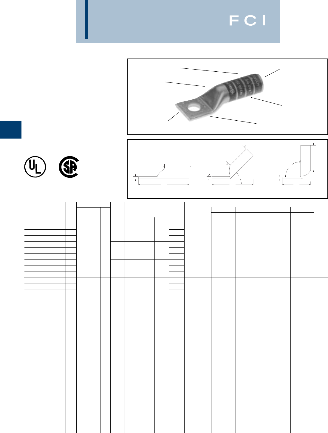
Conductor ▲Installation Tooling
Stud Figure Mechanical Hydraulic Wire
*** Hole Tongue Dimensions Dieless MD6, OUR840, BCT500HS, Y35, Y39, Y750 Color Die Strip
Catalog Number Fig # AWG MM2Size Width (B) (T) (L) (# of crimps) MD7-34R Y500CTHS Y46*, PAT750 Code Index Length
YA8C-TC10 11.57
YA8C-TC10-45 2#8 AWG # 10 .38.81.081.46MRC840 (2)
YA8C-TC10-90 3.68Y8MBR-1 (1)
YA8C-TC14 1#8 WELD †1.69Y2MR (2) W8CVT (2) X8CRT (2)
YA8C-TC14-45 21/4.41.81.081.57Y1MR (2) W8CRT (2) W8CVT (2) U8CRT (2)
Red
49 1
YA8C-TC14-90 337/24 10 .86Y81KFT (1) X8CRT (2) W8CRT (2)
YA8C-TC38 11.88
Y81KFTMBH (1)
YA8C-TC38-45 2#6 SOL 3/8.58.81.061.71
PAT81KFT-18V (1)
YA8C-TC38-90 31.04
YA6C-TC10 11.89MRC840 (2)
YA6C-TC10-45 2# 10 .411.12.091.72MY29-3 (2)
YA6C-TC10-90 3.75MY29-11 (2) W5CVT (2) W5CVT (2)
YA6C -N 12.64Y2MR (2) W5CRT (2) W5CRT (2) U5CRT (2)
YA6C-N-45 2#6 AWG - 1/2.831.12.122.53Y644HS (1) X5CRT (2) X5CRT (2) U8CABT (2)
Blue
71-3/16
YA6C-N-90 31.52 Y1MR (2) X8CART (2) X8CART (2)
YA6C 11.81Y81KFT (1)
YA6C-45 21/4.411.12.091.24
Y81KFTMBH (1)
YA6C-90 3.81
PAT81KFT-18V (1)
YA5C 11.98Y1MR (2)
YA5C-45 21/4.441.12.071.75MRC840 (2)
YA5C-90 3.81MY29-3 (2)
YA5C -N 12.67MY29-11 (2) W5CVT (2) W5CVT (2)
YA5C-N-45 2#5 AWG - 2.55Y2MR (2) W5CRT (2) W5CRT (2) U5CRT (2)
Blue
71-3/16
Y644HS (1) X5CRT (2) X5CRT (2)
1/2.831.12.12
Y81KFT (1)
YA5C-N-90 31.52
Y81KFTMBH (1)
PAT81KFT-18V (1)
YA4C-TC10 11.94MRC840 (2)
YA4C-TC10-45 2# 10 .491.12.091.94MY29-3 (2)
YA4C-TC10-90 31.75MY29-11 (2)
YA4C 11.87Y2MR (4) W4CVT (2) W4CVT (2) U4CRT (2)
#4 AWG Y644HS (1) W4CRT (2) W4CRT (2) U6CABT (2)
Gray
81-3/16
1/4.501.12.09Y81KFT (1) X4CRT (2) X4CRT (2)
YA4C-45 21.52
Y81KFTMBH (1)
PAT81KFT-18V (1)
BURNDY
Compression
C-18
ONE HOLE HYLUG™
CODE CONDUCTOR
LONG BARREL
TYPES YA,YA-TC
UNINSULATED COPPER
COMPRESSION TERMINAL
UL Listed 90° C,
600 Volts to 35 KV ◆
ELECTRO-TIN
PLATED
CABLE
ACCOMMODATION
CRIMPS
DIE AND COLOR
CODE INFORMATION
NO INSPECTION
WINDOW
BEVELED
ENTRY
*Use PUADP-1 adapter with "U" dies in Y46 HYPRESS™.
** P-RT die sets for use in Y46 HYPRESS™ only, PUADP-1
adapter not required.
*** The MM2conductor sizes listed are the recommendations
for Class 2 conductor.
B
B
B
T T T
L
45°
90°
LL
Fig. 1 Fig. 2 Fig. 3
†The MM2conductor size listed is for Class 2 and Class 5
conductor.
▲See tooling section of this catalog for complete tool and die
listings. Use ONLY color coded die recommendations for "-
FX" connectors. For nest/indentor system contact factory.
•Available undrilled. Add suffix "U" to catalog number
(example: YA25U).
◆For applications greater than 2000 Volts consult cable
manufacturer for voltage stress relief instructions.

Conductor ▲Installation Tooling
Stud Figure Mechanical Hydraulic Wire
*** Hole Tongue Dimensions Dieless MD6, OUR840, BCT500HS, Y35, Y39, Y750, Color Die Strip
Catalog Number Fig # AWG MM2Size Width (B) (T) (L) (# of crimps) MD7-34R Y500CTHS Y46*, PAT750 Code Index Length
YA4C-90 31/4.561.12’ .09.84MRC840 (2)
YA4C-TC38 12.25MY29-3 (2)
YA4C-TC38-45 23/8.581.12.082.02MY29-11 (2)
YA4C-TC38-90 31.08Y2MR (4) W4CVT (2) W4CVT (2)
YA4C -N 1#4 AWG - 2.69Y644HS (1) W4CRT (2) W4CRT (2) U4CRT (2)
Gray
81-3/16
YA4C-N-45 22.56Y1MR (4) X4CRT (2) X4CRT (2) U6CABT (2)
1/2.831.12.12Y81KFT (1)
YA4C-N-90 31.54
Y81KFTMBH (1)
PAT81KFT-18V (1)
YA3C-TC14 12.23
YA3C-TC14-45 21/4.551.25.091.99
YA3C-TC14-90 3.92
YA3C 12.30MY29-3 (2)
YA3C-45 2#3 AWG 5/16.551.25.092.05MY29-11 (2)
YA3C-90 325 .98Y644HS (1)
YA3C-TC38 1#2 SOLID 2.42Y81KFT (2) W3CRT (2) W3CRT (2) U3CRT (2)
White
91-1/2
YA3C-TC38-45 23/8.611.25.082.16
Y81KFTMBH (2)
YA3C-TC38-90 31.10
PAT81KFT-18V (2)
YA3CN 12.86
YA3CN-45 21/2.811.25.122.68
YA3CN-90 31.56
YA2C-TC10 12.10
YA2C-TC10-45 2# 10 .611.25.111.90
YA2C-TC10-90 3.82Y1MR (4)
YA2C-TC14 12.23MRC840 (2)
YA2C-TC14-45 21/4.601.25.112.02MY29-3 (2)
YA2C-TC14-90 3#2 AWG 35 .95MY29-11 (2) W2CVT (2) W2CVT (2)
YA2C 12.29Y2MR (4) W2CRT (2) W2CRT (2) U2CRT (2)
Brown
10 1-5/16
YA2C-45 25/16.611.25.112.09Y644HS (1) X2CRT (2) X2CRT (2)
YA2C-90 31.01Y81KFT (2)
YA2C -N 12.88
Y81KFTMBH (2)
YA2C-N-45 21/2.831.25.122.70
PAT81KFT-18V (2)
YA2C-N-90 31.58
YA1C-TC10 12.27
YA1C-TC10-45 2# 10 .681.38.102.00Y1MR (4)
YA1C-TC10-90 3.84MRC840 (2)
YA1C 12.45MY29-3 (2) W1CVT (2) W1CVT (2)
YA1C-45 2#1 AWG 50 5/16.681.38.102.19MY29-11 (2)
W1CRT-1 (2) W1CRT-1 (2)
U1CRT-1 (2)
Green
11 1-7/16
YA1C-90 31.03Y644HS (1)
X1CRT-1 (2) X1CRT-1 (2)
U4CABT (2)
YA1C -N 13.06Y81KFT (2)
YA1C-N-45 21/2.831.38.122.82
Y81KFTMBH (2)
YA1C-N-90 31.60
PAT81KFT-18V (2)
YA25TC10 12.30
YA25TC10-45 2# 10 .751.38.122.06MRC840 (4)
YA25TC10-90 3.88MY29-3 (2)
YA25 12.48MY29-11 (2) W25VT (4) W25VT (4)
YA25-45 21/0 AWG - 5/16.751.38.12” 2.25Y644HS (1) W25RT (4) W25RT (4) U25RT (2)
Pink
12 1-7/16
YA25-90 31.07Y81KFT (2) X25RT (4) X25RT (4) U2CABT (2)
YA25TC38 12.61
Y81KFTMBH (2)
YA25TC38-45 23/8.751.38.122.37
PAT81KFT-18V (2)
YA25TC38-90 31.19
BURNDY
Compression
C-19
*Use PUADP-1 adapter with "U" dies in Y46 HYPRESS™.
** P-RT die sets for use in Y46 HYPRESS™ only, PUADP-1
adapter not required.
ONE HOLE HYLUG™
CODE CONDUCTOR
LONG BARREL
(Continued)
B
B
B
T T T
L
45°
90°
LL
Fig. 1 Fig. 2 Fig. 3
*** The MM2conductor sizes listed are the recommendations
for Class 2 conductor.
▲See tooling section of this catalog for complete tool and die
listings. Use ONLY color coded die recommendations for
"-FX" connectors. For nest/indentor system contact factory.
•Available undrilled. Add suffix "U" to catalog number
(example: YA25U).
◆For applications greater than 2000 Volts consult cable
manufacturer for voltage stress relief instructions.
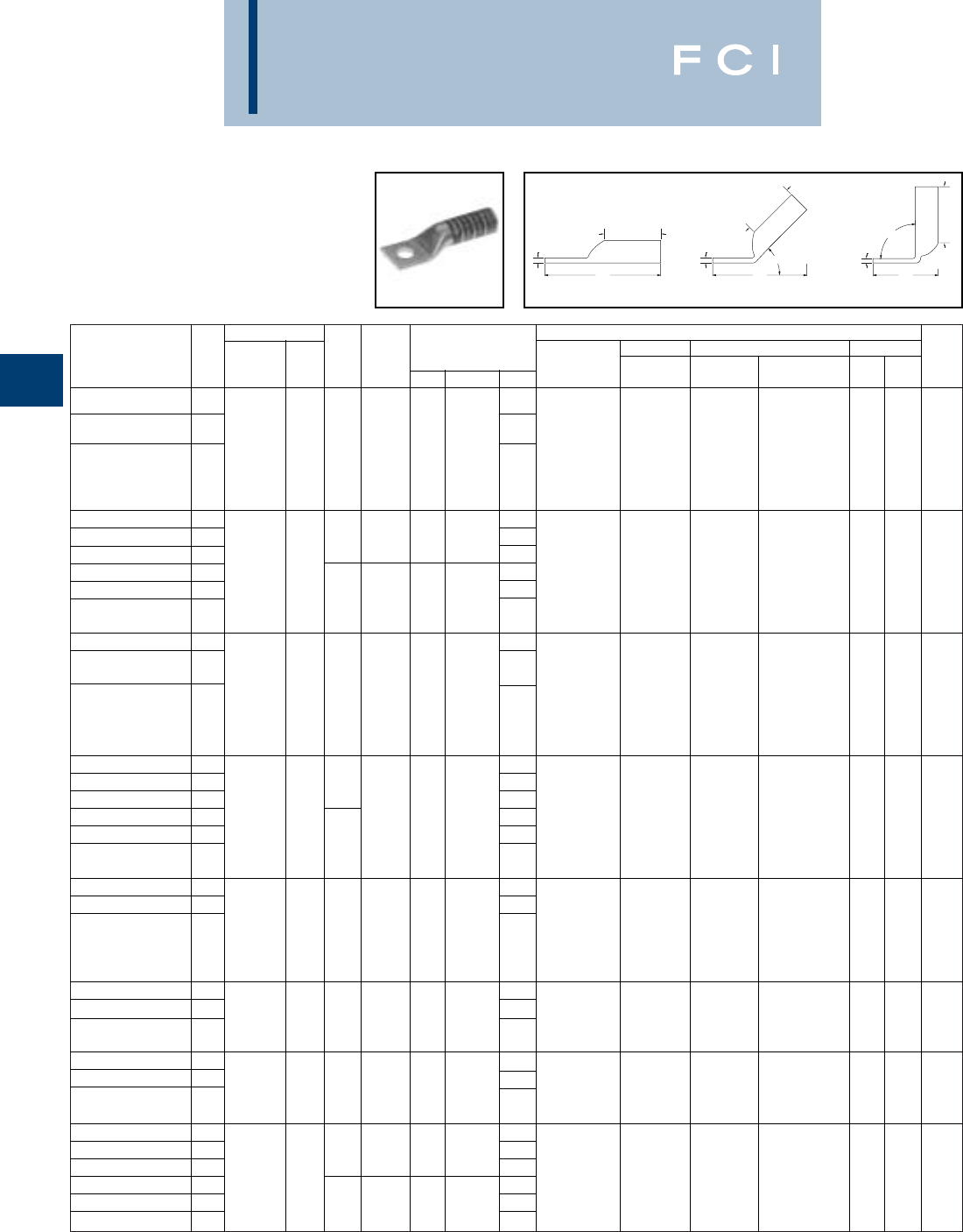
Conductor ▲Installation Tooling
Stud Figure Mechanical Hydraulic Wire
*** Hole Tongue Dimensions Dieless MD6, OUR840, BCT500HS, Y35, Y39, Y750, Color Die Strip
Catalog Number Fig # AWG MM2Size Width (B) (T) (L) (# of crimps) MD7-34R Y500CTHS Y46*, PAT750 Code Index Length
YA25N 13.05MRC840 (4)
MY29-3 (2)
YA25N-45 22.79MY29-11 (2) W25VT(4) W25VT (4)
1/0 -1/2.811.38.11Y644HS (1) W25RT (4) W25RT (4) U25RT (2)
Pink
12
1-7/16
AWG Y81KFT (2) X25RT (4) X25RT (4) U2CABT (2)
YA25N-90 31.62
Y81KFTMBH (2)
PAT81KFT-18V (2)
YA26 12.77MRC840 (4)
YA26-45 23/8.831.50.122.49MY29-3 (2)
YA26-90 31.22MY29-11 (2) W26VT (4) W26VT (4)
YA26N 12/0 70 3.21Y644HS (1) W26RT (4) W26RT (4) U26RT (2)
Black
13
1-9/16
YA26N-45 2AWG 2.93Y81KFT (2) X26RT (4) X26RT (4)
1/2.831.50.12
Y81KFTMBH (2)
YA26N-90 31.65
PAT81KFT-18V (2)
YA27 13.06MRC840 (4)
MY29-3 (2)
YA27-45 22.78
MY29-11 (2) W27VT (4) W27VT (4)
3/0 AWG - 1/2.911.50.13Y644HS (1) W27RT (4) W27RT (4) U27RT (2)
Orange
14
1-9/16
Y81KFT (2) X27RT (6) X27RT (6)
YA27-90 31.49
Y81KFTMBH (2)
PAT81KFT-18V (2)
YA28TC38 12.98MRC840 (4)
YA28TC38-45 23/82.68MY29-3 (2)
YA28TC38-90 31.29MY29-11 (2) W28VT (4) W28VT (4)
YA28 14/0 AWG - 1.021.62.143.23Y644HS (1) W28RT (4) W28RT (4) U28RT (2)
Purple
15
1-1/16
YA28-45 22.93Y81KFT (2) X28RT (6) X28RT (6)
1/2
Y81KFTMBH (2)
YA28-90 31.54
PAT81KFT-18V (2)
YA29 13.26MY29-3 (2)
YA29-45 22.99MY29-11 (2)
Y644HS (1) W29VT (4) W29VT (4)
250 kcmil - 1/21.111.62.16
Y81KFT (2) X29RT (8) W29RT (4) U29RT (2)
Yellow
16
1-1/16
YA29-90 31.58
Y81KFTMBH (2)
X29RT (8)
PAT81KFT-18V (2)
YA30 13.69Y644HS (1)
YA30-45 23.31Y81KFT (3) W30VT (4) U30RT (4) 17 or
300 kcmil 150 1/21.202.00.16
Y81KFTMBH (3)
W30VT (4) W30RT (4) U28ART (4)
White
298
2-1/16
YA30-90 31.61
PAT81KFT-18V (3)
YA31 13.73Y644HS (1)
YA31-45 23.36Y81KFT (3) W31VT (4) U31RT (4) 18 or
350 kcmil 185 1/21.292.00.18
Y81KFTMBH (3)
W31VT (4) W31RT (4) U29ART (4)
Red
324
2-1/16
YA31-90 31.65
PAT81KFT-18V (3)
YA32N 14.09
YA32N-45 21/21.382.12.193.71Y644HS (1)
YA32N-90 31.88Y81KFT (3) W32VT (4) U32RT (4) 19 or
YA32 1400 kcmil -4.15
Y81KFTMBH (3)
W32VT (4) W32RT (4) U30ART (4)
Blue
470
2-3/16
YA32-45 25/81.382.12.193.77
PAT81KFT-18V (3)
YA32-90 31.95
BURNDY
Compression
C-20
ONE HOLE HYLUG™
CODE CONDUCTOR
LONG BARREL
(Continued)
*Use PUADP-1 adapter with "U" dies in Y46 HYPRESS™.
** P-RT die sets for use in Y46 HYPRESS™ only, PUADP-1
adapter not required.
*** The MM2conductor sizes listed are the recommendations
for Class 2 conductor.
▲See tooling section of this catalog for complete tool and die
listings. Use ONLY color coded die recommendations for
"-FX" connectors. For nest/indentor system contact factory.
•Available undrilled. Add suffix "U" to catalog number
(example: YA25U).
◆For applications greater than 2000 Volts consult cable
manufacturer for voltage stress relief instructions.
B
B
B
T T T
L
45°
90°
LL
Fig. 1 Fig. 2 Fig. 3

Conductor ▲Installation Tooling
Stud Figure Mechanical Hydraulic Wire
*** Hole Tongue Dimensions Dieless MD6, OUR840, BCT500HS, Y35, Y39, Y750, Color Die Strip
Catalog Number Fig # AWG MM2Size Width (B) (T) (L) (# of crimps) MD7-34R Y500CTHS Y46*, PAT750 Code Index Length
YA33 14.24-
YA33-45 25/81.482.13.213.87
YA33-90 32.00W33VT (4)
326 or
YA33-N 1450 kcmil - 4.17W33VT (4) W33RT (4) U33RT (4)
Gray
538
2-5/16
YA33-N-45 21/21.482.13.213.81
YA33-N-90 31.94
YA34N 14.32
YA34N-45 21/21.522.25.233.96
YA34N-90 3500 kcmil 240 1.97
W34VT (4) W34VT (4) U34RT (4)
Brown
20 or
2-5/16
YA34 14.39W34RT (4) U31ART (4) 299
YA34-45 25/81.522.25.234.02
YA34-90 32.03
YA35 14.79
YA35-45 25/81.652.63.254.37
YA35-90 3550 kcmil - 2.08
--U35RT (4)
Yellow
21
2-11/16
YA35-N 14.73
YA35-N-45 21/21.652.63.254.30
YA35-N-90 32.01
YA36N 14.83
YA36N-45 21/21.692.69.274.41
YA36N-90 3600 kcmil 300 2.05
--U36RT (4)
Green
22 or
2-3/4
YA36 14.90Y644HS (1) U32ART (4) 472
YA36-45 25/81.692.69.274.47Y81KFT (4)
YA36-90 32.11
Y81KFTMBH (4)
YA37 15.05
PAT81KFT-18V (4)
YA37-45 25/81.802.81.274.59
YA37-90 3650 kcmil - 2.14
--U37RT (4)
Orange
23
2-7/8
YA37-N 14.98
YA37-N-45 21/21.802.81.274.53
YA37-N-90 32.08
YA38 15.07
YA38-45 25/81.842.81.274.60
YA38-90 3700 kcmil - 2.15
--U38RT (4)
Pink
400
2-7/8
YA38-N 15.01
YA38-N-45 21/21.842.81.274.53
YA38-N-90 32.08-
YA39N 15.11
YA39N-45 21/21.892.88.274.62
YA39N-90 3750 kcmil - 2.11U39RT (4)
YA39 15.17--P39RT (4)
Black
24
2-15/16
YA39-45 25/81.892.88.274.68**
YA39-90 32.17
YA40 15.25
YA40-45 25/81.982.94.304.80
YA40-90 3800 kcmil 400 2.21P40RT (4)
YA40-N 15.19-- **
Orange
25 3
YA40-N-45 21/21.982.94.304.74
YA40-N-90 32.15
BURNDY
Compression
C-21
ONE HOLE HYLUG™
CODE CONDUCTOR
LONG BARREL
(Continued)
*Use PUADP-1 adapter with "U" dies in Y46 HYPRESS™.
** P-RT die sets for use in Y46 HYPRESS™ only, PUADP-1
adapter not required.
*** The MM2conductor sizes listed are the recommendations
for Class 2 conductor.
▲See tooling section of this catalog for complete tool and die
listings. Use ONLY color coded die recommendations for "-
FX" connectors. For nest/indentor system contact factory.
•Available undrilled. Add suffix "U" to catalog number
(example: YA25U).
◆For applications greater than 2000 Volts consult cable
manufacturer for voltage stress relief instructions.
B
B
B
T T T
L
45°
90°
LL
Fig. 1 Fig. 2 Fig. 3
Conductor ▲Installation Tooling
Stud Figure Mechanical Hydraulic Wire
*** Hole Tongue Dimensions Dieless MD6, OUR840, BCT500HS, Y35, Y39, Y750, Color Die Strip
Catalog Number Fig # AWG MM2Size Width (B) (T) (L) (# of crimps) MD7-34R Y500CTHS Y46*, PAT750 Code Index Length
YA41 15.26
YA41-45 25/82.012.94.314.82
YA41-90 32.23
YA41-N 1850 kcmil - 5.20-- -
Gold
26 3
YA41-N-45 21/22.012.91.314.76Y644HS (1)
YA41-N-90 32.17Y81KFT (4)
YA44 15.45
Y81KFTMBH (4)
YA44-45 25/82.173.00.335.01
PAT81KFT-18V (4)
YA44-90 31000 kcmil 500 2.32
--
P44RT (4)
White
27 3-1/16
YA44-N 15.38**
YA44-N-45 21/22.193.00.334.95
YA44-N-90 32.26
YA45 15.93
YA45-45 23/42.463.19.385.52
YA45-90 31250 kcmil - 2.62
--
P45RT (6)
Yellow
29 3-1/4
YA45-N 15.68**
YA45-N-45 21/22.463.19.385.27
YA45-N-90 32.37
YA46 16.04
YA46-45 23/42.693.19.405.64
YA46-90 31500 kcmil - 2.71P46RT (6)
Green
31 3-5/16
YA46-N 15.79-- **
YA46-N-45 21/22.693.19.405.39
YA46-N-90 32.46
YA47 16.38
YA47-45 23/42.903.44.425.94
YA47-90 31750 kcmil - 2.79
YA47-N 16.13-- -
Gray
33 3-1/2
YA47-N-45 21/22.903.44.425.69
YA47-N-90 32.54
YA48 16.47
YA48-45 23/43.103.44.466.09
YA48-90 32000 kcmil - 2.89
YA48-N 16.22-- -
Brown
34 3-1/2
YA48-N-45 21/23.103.44.465.84
YA48-N-90 32.64
BURNDY
Compression
C-22
ONE HOLE HYLUG™
CODE CONDUCTOR
LONG BARREL
(Continued)
*Use PUADP-1 adapter with "U" dies in Y46 HYPRESS™.
** P-RT die sets for use in Y46 HYPRESS™ only, PUADP-1
adapter not required.
*** The MM2conductor sizes listed are the recommendations
for Class 2 conductor.
▲See tooling section of this catalog for complete tool and die
listings. Use ONLY color coded die recommendations for
"-FX" connectors. For nest/indentor system contact factory.
•Available undrilled. Add suffix "U" to catalog number
(example: YA25U).
◆For applications greater than 2000 Volts consult cable
manufacturer for voltage stress relief instructions.
B
B
B
T T T
L
45°
90°
LL
Fig. 1 Fig. 2 Fig. 3
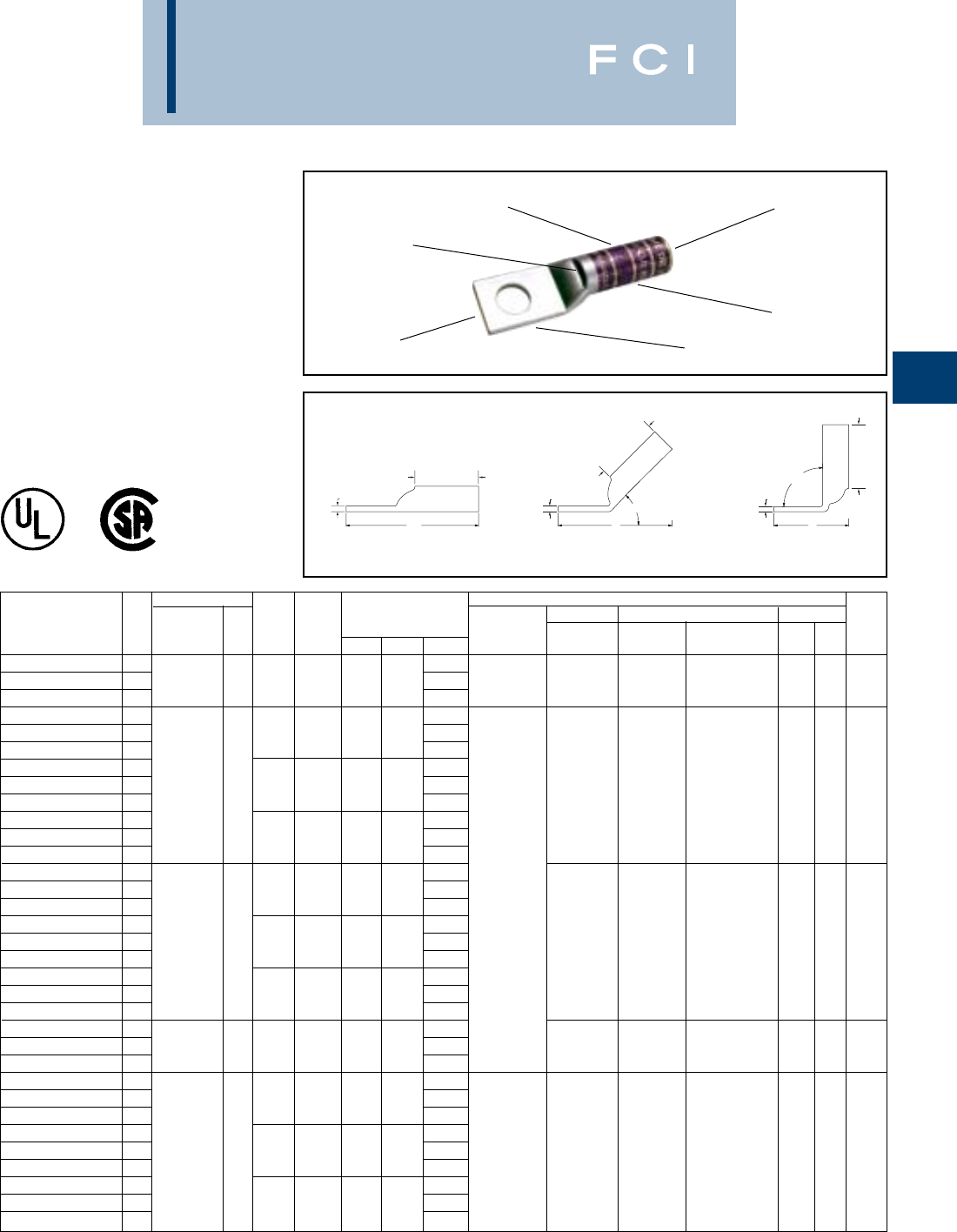
BURNDY
Compression
C-23
ONE HOLE HYLUG™
CODE CONDUCTOR
LONG BARREL WITH
INSPECTION WINDOW
TYPE YAZ
UNINSULATED COPPER
COMPRESSION TERMINAL
UL Listed 90° C,
600 Volts to 35 KV ◆
ELECTRO-TIN
PLATED
CABLE
ACCOMMODATION
CRIMP
DIE AND COLOR
CODE INFORMATION
INSPECTION
WINDOW
BEVELED
ENTRY
TT
90°
L
L
45°
L
B
T
B
B
Fig. 1 Fig. 2 Fig. 3
*Use PUADP-1 adapter with "U" dies in Y46 HYPRESS™.
** P-RT die sets for use in Y46 HYPRESS™ only, PUADP-1
adapter not required.
*** The MM2conductor sizes listed are the recommendations
for Class 2 conductor.
Conductor ▲Installation Tooling
Stud Figure Mechanical Hydraulic Wire
*** Hole Tongue Dimensions Dieless MD6, OUR840, BCT500HS, Y35, Y39, Y750, Color Die Strip
Catalog Number Fig # AWG MM2Size Width (B) (T) (L) (# of crimps) MD7-34R Y500CTHS Y46*, PAT750 Code Index Length
YAZV10-TC14 1#14 - 10 Str 1.54
YAZV10-TC14-45 261/4.41.69.051.41Y8MRB-1 - - - - - 3/4
YAZV10-TC14-90 3#12 - 10 Sol ..83
YAZ8C-TC10 11.58
YAZ8C-TC10-45 2#10 .41.75.081.47
YAZ8C-TC10-90 3.75
YAZ8C-TC14 1#8 AWG
†1.71W8CVT (2) W8CVT (2)
YAZ8C-TC14-45 2#8 WELD
10 1/4.44.75.081.58W8CRT (2) W8CRT (2) U8CRT (2) Red 49 7/8
YAZ8C-TC14-90 337/24 .87X8CRT (2) X8CRT (2)
YAZ8C-TC38 1#6 SOL 1.89Y1MR (2)
YAZ8C-TC38-45 21/4.58.75.061.72Y2MR (2)
YAZ8C-TC38-90 31.05MY29-3 (2)
YAZ6C-TC14 12.03MY29-11 (2)
YAZ6C-TC14-45 21/4.451.12.081.83MRC840 (2)
YAZ6C-TC14-90 3..89Y644HS (1) W5CVT (2) W5CVT (2)
YAZ6C-TC38 12.22Y81KFT (1) W5CRT (2) W5CRT (2)
YAZ6C-TC38-45 2#6 AWG - 3/8.581.12.061.97
Y81KFTMBH (1)
X5CRT (2) X5CRT (2)
U5CRT (2) Blue 7 or
1-3/16
YAZ6C-TC38-90 31.06
PAT81KFT-18V (1)
X8CART (2) X8CART (2)
U8CABT (2) 374
YAZ6C-TC12 12.65
YAZ6C-TC12-45 21/2.831.12.122.54
YAZ6C-TC12-90 3.1.53
YAZ5C-TC12 1.2.68W5CRT (2) W5CVT (2)
YAZ5C-TC12-45 2#5 AWG - 1/2.831.12.122.56W5CVT (2) X5CRT (2) U5CRT (2) Blue 7 or
1-3/16
YAZ5C-TC12-90 31.53X5CRT (2) W5CRT (2) 374
YAZ4C-TC14 12.05Y1MR (4)
YAZ4C-TC14-45 21/4.491.12.091.87Y2MR (4)
YAZ4C-TC14-90 3.92MY29-3 (2)
YAZ4C-TC38 12.23MY29-11 (2) W4CVT (2) W4CVT (2)
YAZ4C-TC38-45 2#4 AWG - 3/8.581.12.082.01MRC840 (2) W4CRT (2) W4CRT (2) U4CRT (2) Gray 8 or
1-3/16
YAZ4C-TC38-90 31.09Y644HS (1) X4CRT (2) X4CRT (2) U6CABT (2) 346
YAZ4C-TC12 12.67Y81KFT (1)
YAZ4C-TC12-45 21/2.831.12.122.55
Y81KFTMBH (1)
YAZ4C-TC12-90 31.55
PAT81KFT-18V (1)
†The MM2conductor size listed is for Class 2 and Class 5
conductor.
▲See tooling section of this catalog for complete tool and die
listings.
•Available undrilled. Add suffix "U" to catalog number
(example: YA25U).
◆For applications greater than 2000 Volts consult cable
manufacturer for voltage stress relief instructions.

Conductor ▲Installation Tooling
Stud Figure Mechanical Hydraulic Wire
*** Hole Tongue Dimensions Dieless MD6, OUR840, BCT500HS, Y35, Y39, Y750, Color Die Strip
Catalog Number Fig # AWG MM2Size Width (B) (T) (L) (# of crimps) MD7-34R Y500CTHS Y46*, PAT750 Code Index Length
YAZ3C-TC14 12.21
YAZ3C-TC14-45 21/4.551.25.091.97
YAZ3C-TC14-90 3.93
YAZ3C-TC38 1#3 AWG 2.39
YAZ3C-TC38-45 2253/8.581.25.082.13W3CRT (2) W3CRT (2) U3CRT (2)
White
91-5/16
YAZ3C-TC38-90 3#2 SOL 1.11Y1MR (4)
YAZ3C-TC12 12.83Y2MR (4)
YAZ3C-TC12-45 21/2.831.25.072.66MY29-3 (2)
YAZ3C-TC12-90 31.57MY29-11 (2)
YAZ2C-TC14 12.23MRC840 (2)
YAZ2C-TC14-45 21/4.601.25.112.03Y644HS (1)
YAZ2C-TC14-90 3.96Y81KFT (2)
YAZ2C-TC38 12.41
Y81KFTMBH (2)
W2CVT (2) W2CVT (2)
YAZ2C-TC38-45 2#2 AWG 35 3/8.601.25.112.21
PAT81KFT-18V (2)
W2CRT (2) W2CRT (2) U2CRT (2)
Brown
10 1-5/16
YAZ2C-TC38-90 31.14X2CRT (2) X2CRT (2)
YAZ2C-TC12 12.85
YAZ2C-TC12-45 21/2.831.25 .092.57
YAZ2C-TC12-90 31.57
YAZ1C-TC14 12.39
YAZ1C-TC14-45 21/4.671.38.102.13Y1MR (4)
YAZ1C-TC14-90 3.98MY29-3 (2)
YAZ1C-TC38 12.57MY29-11 (2)
W1CVT (2) W1CVT (2)
U1CRT-1 (2) 11 or
YAZ1C-TC38-45 2#1 AWG 50 3/8.671.38.102.31MRC840 (2)
W1CRT-1 (2) W1CRT-1 (2)
Green
1-7/16
YAZ1C-TC38-90 31.16Y644HS (1)
X1CRT-1 (2) X1CRT-1 (2)
U4CABT (2) 375
YAZ1C-TC12 13.01Y81KFT (2)
YAZ1C-TC12-45 21/2.831.38.092.7
Y81KFTMBH (2)
YAZ1C-TC12-90 31.59
PAT81KFT-18V (2)
YAZ25-TC14 12.42
YAZ25-TC14-45 21/4.751.38.122.19
YAZ25-TC14-90 31.02
YAZ25-TC516 12.47
YAZ25-TC516-45 25/16.751.38.122.24W25VT (4) W25VT (4) U25RT (2) 12 or
YAZ25-TC516-90 31/0 AWG - 1.08W25RT (4) W25RT (4)
Pink
1-7/16
YAZ25-TC38 12.6X25RT (4) X25RT (4) U2CABT (2) 348
YAZ25-TC38-45 23/8.751.38.122.37
YAZ25-TC38-90 31.2
YAZ25-TC12 13.04MY29-3 (2)
YAZ25-TC12-45 21/2.831.38.122.77MY29-11 (2)
YAZ25-TC12-90 31.63MRC840 (4)
YAZ26-TC14 12.58Y644HS (1)
YAZ26-TC14-45 21/4.831.50.122.3Y81KFT (2)
YAZ26-TC14-90 31.04
Y81KFTMBH (2)
YAZ26-TC38 12.76
PAT81KFT-18V (2)
W26VT (4) W26VT (4)
YAZ26-TC38-45 22/0 AWG 70 3/8.831.50.122.48W26RT (4) W26RT (4) U26RT (2)
Black
13 1-9/16
YAZ26-TC38-90 31.22X26RT (4) X26RT (4)
YAZ26-TC12 13.2
YAZ26-TC12-45 21/2.831.50.122.92
YAZ26-TC12-90 31.66
YAZ27-TC38 12.8W27RT (4) W27VT (4)
YAZ27-TC38-45 23/0 AWG - 3/8.901.50.122.52W27VT (4) W27RT (4) U27RT (2)
Orange
14 1-9/16
YAZ27-TC38-90 31.25X27RT (6) X27RT (6)
BURNDY
Compression
C-24
ONE HOLE HYLUG™
CODE CONDUCTOR
LONG BARREL WITH
INSPECTION WINDOW
(Continued)
*Use PUADP-1 adapter with "U" dies in Y46 HYPRESS™.
** P-RT die sets for use in Y46 HYPRESS™ only, PUADP-1
adapter not required.
TT
90°
L
L
45°
L
B
T
B
B
Fig. 1 Fig. 2 Fig. 3
*** The MM2conductor sizes listed are the recommendations
for Class 2 conductor.
▲See tooling section of this catalog for complete tool and die
listings.
•Available undrilled. Add suffix "U" to catalog number
(example: YA25U).
◆For applications greater than 2000 Volts consult cable
manufacturer for voltage stress relief instructions.

Conductor ▲Installation Tooling
Stud Figure Mechanical Hydraulic Wire
*** Hole Tongue Dimensions Dieless MD6, OUR840, BCT500HS, Y35, Y39, Y750, Color Die Strip
Catalog Number Fig # AWG MM2Size Width (B) (T) (L) (# of crimps) MD7-34R Y500CTHS Y46*, PAT750 Code Index Length
YAZ27-TC12 13.23W27RT (4) W27VT (4)
YAZ27-TC12-45 23/0 AWG - 1/2.911.50.122.96MY29-3 (2) W27VT (4) W27RT (4) U27RT (2)
Orange
14 1-9/16
YAZ27-TC12-90 31.69MY29-11 (2) X27RT (6) X27RT (6)
YAZ28-TC38 12.99MRC840 (4)
YAZ28-TC38-45 2-3/81.021.620.142.69Y644HS (1)
YAZ28-TC38-90 34/0 AWG 1.3Y81KFT (2) W28VT (4) W28VT (4)
YAZ28-TC12 13.4
Y81KFTMBH (2)
W28RT (4) W28RT (4) U28RT (2)
Purple
15
1-11/16
YAZ28-TC12-45 2-1/21.021.620.143.11
PAT81KFT-18V (2)
X28RT (6) X28RT (6)
YAZ28-TC12-90 31.73
YAZ29-TC38 12.99MY29-3 (2)
YAZ29-TC38-45 23/81.101.620.162.73MY29-11 (2)
YAZ29-TC38-90 3250 kcmil - 1.34Y644HS (1) W29VT (4) W29VT (4)
YAZ29-TC12 13.43Y81KFT (2) X29RT (8) W29RT (4) U29RT (2)
Ye l l o w
16
1-11/16
YAZ29-TC12-45 21/21.101.620.163.17
Y81KFTMBH (2)
X29RT (6)
YAZ29-TC12-90 31.77
PAT81KFT-18V (2)
YAZ30-TC38 13.42
YAZ30-TC38-45 23/81.202.163.04
YAZ30-TC38-90 3300 kcmil 150 1.37
W30VT (4) W30VT (4) U30RT (4)
White
17 or
2-1/16
YAZ30-TC12 13.85W30RT (4) U28ART (4) 298
YAZ30-TC12-45 21/21.202.163.48
YAZ30-TC12-90 31.81
YAZ31-TC38 13.45
YAZ31-TC38-45 23/81.2920.18 3.1Y644HS (1)
YAZ31-TC38-90 3350 kcmil 185 1.41Y81KFT (3) W31VT (4) W31VT (4) U31RT (4) Red 18 or
2-1/16
YAZ31-TC12 13.89
Y81KFTMBH (3)
W31RT (4) U29ART (4) 324
YAZ31-TC12-45 21/21.2920.18 3.54
PAT81KFT-18V (3)
YAZ31-TC12-90 31.85
YAZ32-TC38 13.62
YAZ32-TC38-45 2-3/81.402.12.193.25
YAZ32-TC38-90 3400 kcmil 1.46
W32VT (4) W32VT (4) U32RT (4) Blue 19 or
2-3/16
YAZ32-TC12 14.06W32RT (4) U30ART (4) 470
YAZ32-TC12-45 2-1/21.402.12.193.69
YAZ32-TC12-90 31.89
YAZ33-TC12 14.14
W33VT (4)
YAZ33-TC12-45 2450 kcmil - 1/21.482.12.213.79W33VT (4) U33RT (4) Gray
326 2-5/16
YAZ33-TC12-90 31.95W33RT (4)
YAZ34-TC38 13.85
YAZ34-TC38-45 23/81.552.25.233.5
YAZ34-TC38-90 3500 kcmil 240 1.54Y644HS (1) W34VT (4) W34VT (4) U34RT (4)
Brown
20 or
2-5/16
YAZ34-TC12 14.29Y81KFT (4) W34RT (4) U31ART (4) 299
YAZ34-TC12-45 21/21.552.25.233.94
Y81KFTMBH (4)
YAZ34-TC12-90 31.98
PAT81KFT-18V (4)
YAZ35-TC12 14.7
YAZ35-TC12-45 2550 kcmil - 1/21.652.62.254.28--U35RT (4)
Ye l l o w
21
2-11/16
YAZ35-TC12-90 32.02
YAZ36-TC38 14.55
U36RT (4) 22 or
YAZ36-TC38-45 2600 kcmil 300 3/81.742.69.264.14--
Green
2/4
YAZ36-TC38-90 31.81U32ART (4) 472
BURNDY
Compression
C-25
ONE HOLE HYLUG™
CODE CONDUCTOR
LONG BARREL WITH
INSPECTION WINDOW
(Continued)
*Use PUADP-1 adapter with "U" dies in Y46 HYPRESS™.
** P-RT die sets for use in Y46 HYPRESS™ only, PUADP-1
adapter not required.
*** The MM2conductor sizes listed are the recommendations
for Class 2 conductor.
▲See tooling section of this catalog for complete tool and die
listings.
•Available undrilled. Add suffix "U" to catalog number
(example: YA25U).
◆For applications greater than 2000 Volts consult cable
manufacturer for voltage stress relief instructions.
TT
90°
L
L
45°
L
B
T
B
B
Fig. 1 Fig. 2 Fig. 3
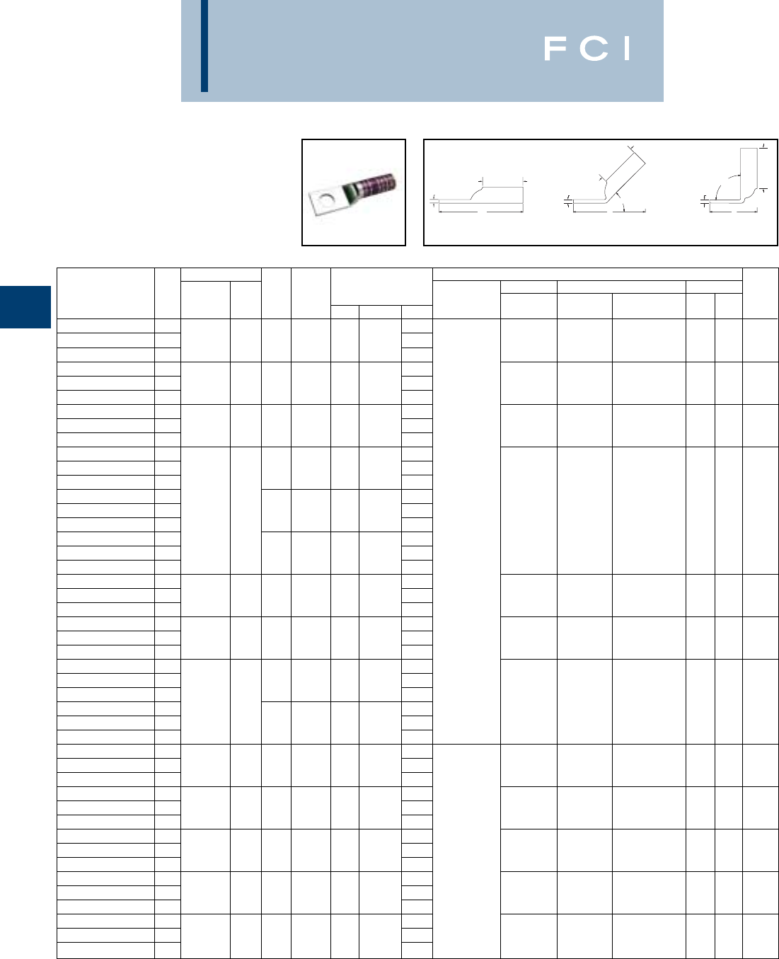
BURNDY
Compression
C-26
ONE HOLE HYLUG™
CODE CONDUCTOR
LONG BARREL WITH
INSPECTION WINDOW
(Continued)
*Use PUADP-1 adapter with "U" dies in Y46 HYPRESS™.
** P-RT die sets for use in Y46 HYPRESS™ only, PUADP-1
adapter not required.
*** The MM2conductor sizes listed are the recommendations
for Class 2 conductor.
▲See tooling section of this catalog for complete tool and die
listings.
Conductor ▲Installation Tooling
Stud Figure Mechanical Hydraulic Wire
*** Hole Tongue Dimensions Dieless MD6, OUR840, BCT500HS, Y35, Y39, Y750, Color Die Strip
Catalog Number Fig # AWG MM2Size Width (B) (T) (L) (# of crimps) MD7-34R Y500CTHS Y46*, PAT750 Code Index Length
YAZ36-TC12 14.80
22 or
YAZ36-TC12-45 2600 kcmil 300 1/21.742.69.264.39--U36RT (4)
Green
2/4
YAZ36-TC12-90 32.06472
YAZ37-TC12 14.95
YAZ37-TC12-45 2650 kcmil - 1/21.802.81.274.51--U37RT (4)
Orange
23 2-7/8
YAZ37-TC12-90 32.09
YAZ38-TC12 14.97
YAZ38-TC12-45 2700 kcmil - 1/21.842.81.274.51--U38RT (4)
Pink
400 2-7/8
YAZ38-TC12-90 32.09
YAZ39-TC38 14.82
YAZ39-TC38-45 23/81.912.88.274.34
YAZ39-TC38-90 31.87
YAZ39-TC12 15.07U39RT (4)
YAZ39-TC12-45 2750 kcmil - 1/21.912.88.274.59Y644HS (1) - - P39RT (4)
Black
24
2-15/16
YAZ39-TC12-90 32.12Y81KFT (4) **
YAZ39-NT12 15.07
Y81KFTMBH (4)
YAZ39-NT12-45 21/21.632.88.274.59
PAT81KFT-18V (4)
YAZ39-NT12-90 32.12
YAZ40-TC12 15.14
YAZ40-TC12-45 2800 kcmil 400 1/21.982.94.304.71--P40RT (4)
Orange
25 3
YAZ40-TC12-90 32.16**
YAZ41-TC12 15.16
YAZ41-TC12-45 2850 kcmil - 1/22.012.94.314.73-- -
Gold
26 3
YAZ41-TC12-90 32.18
YAZ44-TC38 15.09
YAZ44-TC38-45 23/82.193.00.334.66
YAZ44-TC38-90 31000 kcmil 500 2.02P44RT (4)
YAZ44-TC12 15.33-- **
White
27 3-1/16
YAZ44-TC12-45 21/22.193.00.334.91
YAZ44-TC12-90 32.27
YAZ45-TC12 15.63
YAZ45-TC12-45 21250 kcmil - 1/22.463.19.385.24--P45RT (6)
Ye l l o w
29 3-1/4
YAZ45-TC12-90 32.38**
YAZ453-TC12 15.66
YAZ453-TC12-45 21300 kcmil - 1/22.533.19.395.28-- -
Orange
30 2-1/16
YAZ453-TC12-90 32.41
YAZ46-TC12 15.73
YAZ46-TC12-45 21500 kcmil 1/22.693.19.405.35--P46RT (6)
Green
31 3-5/16
YAZ46-TC12-90 32.47**
YAZ47-TC12 16.07
YAZ47-TC12-45 21750 kcmil - 1/22.903.44.425.65-- -
Gray
33 3-1/2
YAZ47-TC12-90 32.55
YAZ48-TC12 16.14
YAZ48-TC12-45 22000 kcmil 1/23.103.44.465.79-- -
Brown
34 3-1/2
YAZ48-TC12-90 32.65
•Available undrilled. Add suffix "U" to catalog number
(example: YA25U).
◆For applications greater than 2000 Volts consult cable
manufacturer for voltage stress relief instructions.
TT
90°
L
L
45°
L
B
T
B
B
Fig. 1 Fig. 2 Fig. 3
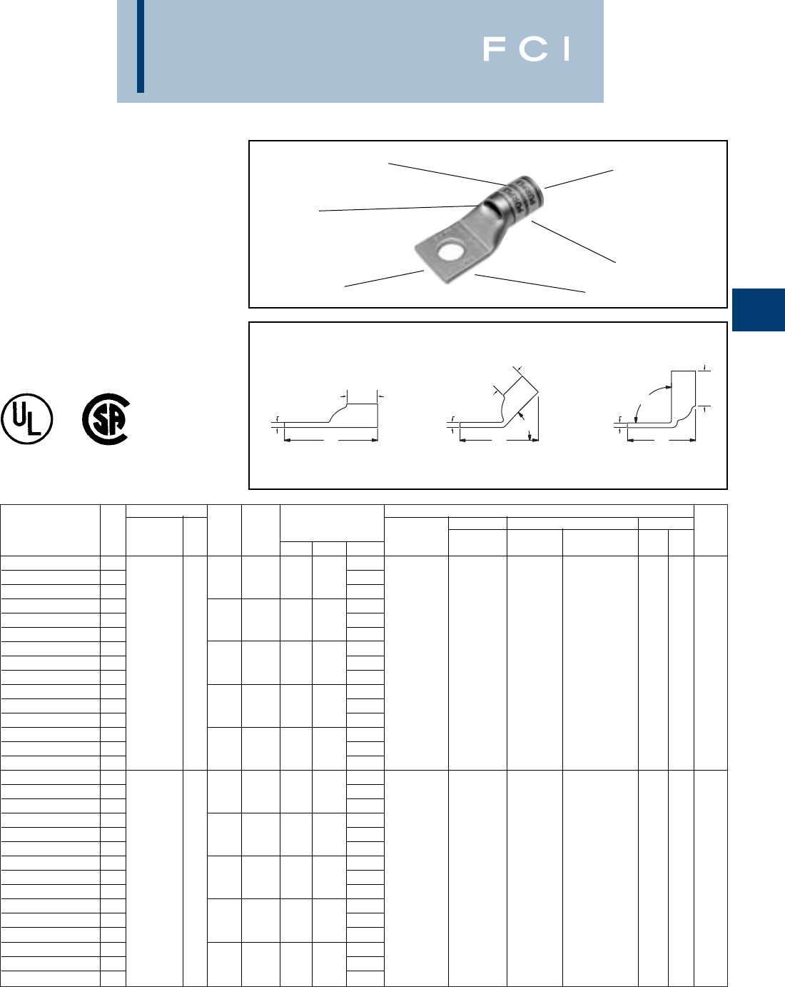
Conductor ▲Installation Tooling
Stud Figure Mechanical Hydraulic Wire
*** Hole Tongue Dimensions Dieless MD6, OUR840, BCT500HS, Y35, Y39, Y750, Color Die Strip
Catalog Number Fig # AWG MM2Size Width (B) (T) (L) (# of crimps) MD7-34R Y500CTHS Y46*, PAT750 Code Index Length
YA8CL-BOX 11.16
YA8CL-45 28-10 .41.44.081.16
YA8CL-90 3.71
YA8C-L1-BOX 11.26
YA8C-L1-45 21/4.44.44.081.24Y1MR (1)
YA8C-L1-90 337/24 .80Y8MRB-(1)
YA8C-L2-BOX 1** 1.38Y2MR (1) W8CVT (1) W8CVT (1)
YA8C-L2-45 2#8 Weld 5/16.52.44.081.34MY29-11 (1) W8CRT (1) W8CRT (1) U8CRT (1) Red 49 7/16
YA8C-L2-90 310 .92Y81KFT (1) X8CRT (1) X8CRT (1)
YA8C-L3-BOX 1#8 AWG 1.51
Y81KFTMBH (1)
YA8C-L3-45 23/8.58.44.081.45
PAT81KFT-18V (1)
YA8C-L3-90 31.04
YA8C-L4-BOX 11.76
YA8C-L4-45 21/2.71.44.081.67
YA8C-L4-90 31.28
YAV6CL-TC10-FX
11.30
YAV6CL-TC10-FX-45
28-10 .48.50.081.26
YAV6CL-TC10-FX-90
3.76
YAV6CL-TC12-FX
11.86
YAV6CL-TC12-FX-45
21/2.75.50.121.92
YAV6CL-TC12-FX-90
361/24 1.34Y1MR (1)
YAV6CL-TC14-FX
1** 1.43Y2MR (1) W5CVT (1) W5CVT (1)
YAV6CL-TC14-FX-45
2#6 WELD 1/4.48.50.081.39MY29-11 (1) W5CRT (1) W5CRT (1) U5CRT (1) Blue 7 1/2
YAV6CL-TC14-FX-90
316 .88Y81KFT (1) X5CRT (1) X5CRT (1)
YAV6CL-TC38-FX
1#6 AWG 1.61
Y81KFTMBH (1)
YAV6CL-TC38-FX-45
23/8.60.50.061.54
PAT81KFT-18V (1)
YAV6CL-TC38-FX-90
31.06
YAV6CL-TC516-FX
11.49
YAV6CL-TC516-FX-45
25/16.60.500.071.44
YAV6CL-TC516-FX-90
3.94
BURNDY
Compression
C-27
ONE HOLE HYLUG™
FLEX CONDUCTOR
STANDARD BARREL
TYPES YA-L,YA-L-FX,YAV,
YAV-L-FX
COPPER COMPRESSION
TERMINAL
UL Listed 90° C,
600 Volts to 35 KV ◆
ELECTRO-TIN
PLATED CABLE
ACCOMMODATION
CRIMP
DIE AND COLOR
CODE INFORMATION
INSPECTION
WINDOW
BEVELED
ENTRY
TT
BB
B
T
L
45°
90°
L
L
Fig. 1 Fig. 2 Fig. 3
*Use PUADP-1 adapter with "U" dies in Y46 HYPRESS™.
** The MM2conductor size listed is for both Class 2 and
Class 5 conductors.
*** The MM2 conductor sizes listed are the recommendations
for Class 5 conductor.
▲See tooling section of this catalog for complete tool and die
listings. Use ONLY color-coded die recommendations for
“-FX” connectors. For nest/indentor system contact factory.
◆For applications greater than 2000 Volts consult cable
manufacturer for voltage stress relief instructions.

Conductor ▲Installation Tooling
Stud Figure Mechanical Hydraulic Wire
*** Hole Tongue Dimensions Dieless MD6, OUR840, BCT500HS, Y35, Y39, Y750, Color Die Strip
Catalog Number Fig # AWG MM2Size Width (B) (T) (L) (# of crimps) MD7-34R Y500CTHS Y46*, PAT750 Code Index Length
YAV6CL-TC34-FX
12.30Y2MR (1)
MY29-11 (1)
YAV6CL-TC34-FX-45
261/24 ** 2.39Y644HS (1)
#6 WELD 16 3/41.05.50.13
Y81KFT (1) W5CVT (1) X5CRT (1) U5CRT (1)
Blue
71/2
YAV6CL-TC34-FX-90
3#6 AWG 1.78
Y81KFTMBH (1)
PAT81KFT-18V (1)
YAV4CL-TC10-FX
11.32
YAV4CL-TC10-FX-45
210-8 .55.50.091.30
YAV4CL-TC10-FX-90
3.79
YAV4CL-TC12-FX
11.92
YAV4CL-TC12-FX-45
291/24 1/2.71.50.071.84
YAV4CL-TC12-FX-90
31.34
YAV4CL-TC14-FX
1105/24 1.44W4CVT (1) W4CVT (1)
YAV4CL-TC14-FX-45
2-1/4.55.50.091.43W4CRT (1) W4CRT (1) U4CRT (1)
Gray
81/2
YAV4CL-TC14-FX-90
3#4 WELD .92X4CRT (1) X4CRT (1)
YAV4CL-TC38-FX
11.67
YAV4CL-TC38-FX-45
2#4 AWG 3/8.58.50.081.63
YAV4CL-TC38-FX-90
31.10
YAV4CL-TC516-FX
11.51Y1MR (2)
YAV4CL-TC516-FX-45
25/16.55.50.091.49Y2MR (2)
YAV4CL-TC516-FX-90
3.98MY29-11 (1)
YAV2CL-TC10-FX
11.50Y81KFT (1)
YAV2CL-TC10-FX-45
1# 10 .68.63.101.46
Y81KFTMBH (1)
YAV2CL-TC10-FX-90
1.84
PAT81KFT-18V (1)
YAV2CL-TC12-FX
12.12
YAV2CL-TC12-FX-45
1125/24 1/2.77.630.09 2.03
YAV2CL-TC12-FX-90
11.40
YAV2CL-TC14-FX
1150/24 1.62W2CVT (1) W2CVT (1)
YAV2CL-TC14-FX-45
2351/4.68.63.101.58W2CRT (1) W2CRT (1) U2CRT (1)
Brown
10 11/16
YAV2CL-TC14-FX-90
3#2 WELD .97X2CRT (1) X2CRT (1)
YAV2CL-TC38-FX
11.81
YAV2CL-TC38-FX-45
2#2 AWG 3/8.68.63.101.77
YAV2CL-TC38-FX-90
31.15
YAV2CL-TC516-FX
11.69
YAV2CL-TC516-FX-45
25/16.68.63.101.65
YAV2CL-TC516-FX-90
31.03
YAV1CL-TC10-FX
11.59
YAV1CL-TC10-FX-45
2# 10 .75.69.121.56
YAV1CL-TC10-FX-90
3.88
YAV1CL-TC12-FX
32.15
YAV1CL-TC12-FX-45
2175/24 1/2.75.69.122.12
YAV1CL-TC12-FX-90
3144
YAV1CL-TC14-FX
2225/24 1.71MY29-11 (1) W1CVT (1) W1CVT (1)
YAV1CL-TC14-FX-45
3-1/4.75.69.121.69Y81KFT (1)
W1CRT-1 (1) W1CRT-1 (1)
U1CRT (1)
Green
11 11/16
YAV1CL-TC14-FX-90
3#1 WELD 1.00
Y81KFTMBH (1)
X1CRT-1 (1) X1CRT-1 (1)
YAV1CL-TC38-FX
11.90
PAT81KFT-18V (1)
YAV1CL-TC38-FX-45
2#1 AWG 3/8.75.69.121.87
YAV1CL-TC38-FX-90
31.19
YAV1CL-TC516-FX
11.78
YAV1CL-TC516-FX-45
25/16.75.69.121.75
YAV1CL-TC516-FX-90
31.07
BURNDY
Compression
C-28
ONE HOLE HYLUG™
FLEX CONDUCTOR
STANDARD BARREL
(Continued)
*Use PUADP-1 adapter with "U" dies in Y46 HYPRESS™
** The 16 MM2is for both Class 2 and Class 5 conductors.
*** The MM2 conductor sizes listed are the recommendations
for Class 5 conductor.
TT
BB
B
T
L
45°
90°
L
L
Fig. 2 Fig. 3Fig. 1
▲See tooling section of this catalog for complete tool and die
listings. Use ONLY color-coded die recommendations for
“-FX” connectors. For nest/indentor system contact factory.
◆For applications greater than 2000 Volts consult cable
manufacturer for voltage stress relief instructions.

Conductor ▲Installation Tooling
Stud Figure Mechanical Hydraulic Wire
*** Hole Tongue Dimensions Dieless MD6, OUR840, BCT500HS, Y35, Y39, Y750, Color Die Strip
Catalog Number Fig # AWG MM2Size Width (B) (T) (L) (# of crimps) MD7-34R Y500CTHS Y46*, PAT750 Code Index Length
YAV25L-TC12-FX
12.19
YAV25L-TC12-FX-45
21/2.83.69.122.15
YAV25L-TC12-FX-90
31.47
YAV25L-TC14-FX
1275/24 1.75
YAV25L-TC14-FX-45
21/4.83.69.121.71MY29-11 (1) W25VT (2) W25VT (2)
YAV25L-TC14-FX-90
31/0 WELD 50 1.03Y81KFT (1) W25RT (2) W25RT (2) U25RT (1)
Pink
12 11/16
YAV25L-TC38-FX
11.94
Y81KFTMBH (1)
X25RT (2) X25RT (2)
YAV25L-TC38-FX-45
21/0 AWG 3/8.83.69.121.90
PAT81KFT-18V (1)
YAV25L-TC38-FX-90
31.22
YAV25L-TC516-FX
11.81
YAV25L-TC516-FX-45
25/16.83.69.121.77
YAV25L-TC516-FX-90
31.09
YAV26L-TC10-FX
11.80
YAV26L-TC10-FX-45
2# 10 .93.81.131.73
YAV26L-TC10-FX-90
3.94
YAV26L-TC12-FX
12.36
YAV26L-TC12-FX-45
21/2.93.81.132.29
YAV26L-TC12-FX-90
31.51
YAV26L-TC14-FX
11.92
YAV26L-TC14-FX-45
21/4.93.81.131.85
YAV26L-TC14-FX-90
3325/24 1.07
YAV26L-TC34-FX
12.89W26VT (2) W26VT (2)
YAV26L-TC34-FX-45
22/0 WELD 70 3/41.10.81.112.75W26RT (2) W26RT (2) U26RT (1)
Black
13 13/16
YAV26L-TC34-FX-90
31.93X26RT (2) X26RT (2)
YAV26L-TC38-FX
12/0 AWG 2.11
YAV26L-TC38-FX-45
23/8.93.81.132.04
YAV26L-TC38-FX-90
31.26
YAV26L-TC516-FX
11.98
YAV26L-TC516-FX-45
25/16.93.81.131.92MY29-11 (1)
YAV26L-TC516-FX-90
31.13Y644HS (1)
YAV26L-TC58-FX
12.61Y81KFT (1)
YAV26L-TC58-FX-45
15/8.93.81.132.54
Y81KFTMBH (1)
YAV26L-TC58-FX-90
11.76
PAT81KFT-18V (1)
YAV27L-TC10-FX
12.03
YAV27L-TC10-FX-45
2# 10 1.031.00.141.91
YAV27L-TC10-FX-90
3.98
YAV27L-TC12-FX
12.59
YAV27L-TC12-FX-45
21/21.031.00.142.47
YAV27L-TC12-FX-90
3450/24 1.54
YAV27L-TC14-FX
12.15W27VT (2) W27VT (2)
YAV27L-TC14-FX-45
23/0 WELD 95 1/41.031.00.142.04W27RT (2) W27RT (2) U27RT (1)
Orange
14 1
YAV27L-TC14-FX-90
31.10X27RT (3) X27RT (3)
YAV27L-TC38-FX
13/0 AWG 2.34
YAV27L-TC38-FX-45
23/81.031.00.142.22
YAV27L-TC38-FX-90
31.29
YAV27L-TC516-FX
12.21
YAV27L-TC516-FX-45
25/161.031.00.142.10
YAV27L-TC516-FX-90
31.17
BURNDY
Compression
C-29
ONE HOLE HYLUG™
FLEX CONDUCTOR
STANDARD BARREL
(Continued)
*Use PUADP-1 adapter with "U" dies in Y46 HYPRESS™
*** The MM2 conductor sizes listed are the recommendations
for Class 5 conductor.
▲See tooling section of this catalog for complete tool and die
listings. Use ONLY color-coded die recommendations for
“-FX” connectors. For nest/indentor system contact factory.
◆For applications greater than 2000 Volts consult cable
manufacturer for voltage stress relief instructions.
TT
BB
B
T
L
45°
90°
L
L
Fig. 2 Fig. 3Fig. 1

BURNDY
Compression
C-30
ONE HOLE HYLUG™
FLEX CONDUCTOR
STANDARD BARREL
(Continued)
*Use PUADP-1 adapter with "U" dies in Y46 HYPRESS™
** The 120 MM2referenced here is for both Class 2 and
Class 5.
*** The MM2 conductor sizes listed are the recommendations
for Class 5 conductor.
Conductor ▲Installation Tooling
Stud Figure Mechanical Hydraulic Wire
*** Hole Tongue Dimensions Dieless MD6, OUR840, BCT500HS, Y35, Y39, Y750, Color Die Strip
Catalog Number Fig # AWG MM2Size Width (B) (T) (L) (# of crimps) MD7-34R Y500CTHS Y46*, PAT750 Code Index Length
YAV28L-TC12-FX
12.67
YAV28L-TC12-FX-45
21/21.141.030.15 254
YAV28L-TC12-FX-90
31.58
YAV28L-TC14-FX
12.23
YAV28L-TC14-FX-45
21/41.141.03.152.11
YAV28L-TC14-FX-90
31.14
YAV28L-TC34-FX
13.11
YAV28L-TC34-FX-45
2550/24 3/41.141.03.152.98MY29-11 (1)
W28VT (2) W28VT (2)
YAV28L-TC34-FX-90
3** 2.02Y644HS (1)
W28RT (2) W28RT (2) U28RT (1)
Purple
15 1-1/16
YAV28L-TC38-FX
14/0 WELD 120 2.42Y81KFT (1)
X28RT (2) X28RT (3)
YAV28L-TC38-FX-45
23/81.141.03.152.29
Y81KFTMBH (1)
YAV28L-TC38-FX-90
34/0 AWG 1.33
PAT81KFT-18V (1)
YAV28L-TC516-FX
22.29
YAV28L-TC516-FX-45
25/161.141.03.152.17
YAV28L-TC516-FX-90
31.21
YAV28L-TC58-FX
12.92
YAV28L-TC58-FX-45
25/81.141.03.152.79
YAV28L-TC58-FX-90
31.83
YAV29L-TC12-FX
12.67
YAV29L-TC12-FX-45
21/21.141.03.16254
YAV29L-TC12-FX-90
31.58
YAV29L-TC14-FX
12.23
YAV29L-TC14-FX-45
21/41.141.03.162.11
YAV29L-TC14-FX-90
31.14
YAV29L-TC34-FX
13.11
YAV29L-TC34-FX-45
2550/24 3/41.141.03.162.98
YAV29L-TC34-FX-90
32.02
YAV29L-TC38-FX
1-2.42
YAV29L-TC38-FX-45
24/0 WELD 3/81.141.03.162.29
YAV29L-TC38-FX-90
31.33
YAV29L-TC516-FX
22.29
YAV29L-TC516-FX-45
25/161.141.03.162.17Y644HS (1) W29VT (2)
YAV29L-TC516-FX-90
31.21Y81KFT (1) W29VT (2) W29RT (2) U29RT (1)
Ye l l o w
16 1-1/16
YAV29L-TC58-FX
12.92
Y81KFTMBH (1)
X29RT (4) X29RT (4)
YAV29L-TC58-FX-45
25/81.141.03.162.79
PAT81KFT-18V (1)
YAV29L-TC58-FX-90
31.83
YA30L-TC516-FX
12.31
YA30L-TC516-FX-45
25/161.201.03.162.22
YA30L-TC516-FX-90
3250 FLEX 1.24
YA30L-TC38-FX
12.44
YA30L-TC38-FX-45
2CLASS G 3/81.201.03.162.35
YA30L-TC38-FX-90
3259 STR. - 1.36
YA30L-TC12-FX
12.69
YA30L-TC12-FX-45
21/21.201.03.162.60
YA30L-TC12-FX-90
3CLASS H 1.61
YA30L-TC58-FX
1427 STR. 2.94
YA30L-TC58-FX-45
25/81.201.03.162.85
YA30L-TC58-FX-90
31.86
▲See tooling section of this catalog for complete tool and die
listings. Use ONLY color-coded die recommendations for
“-FX” connectors. For nest/indentor system contact factory.
◆For applications greater than 2000 Volts consult cable
manufacturer for voltage stress relief instructions.
TT
BB
B
T
L
45°
90°
L
L
Fig. 2 Fig. 3Fig. 1
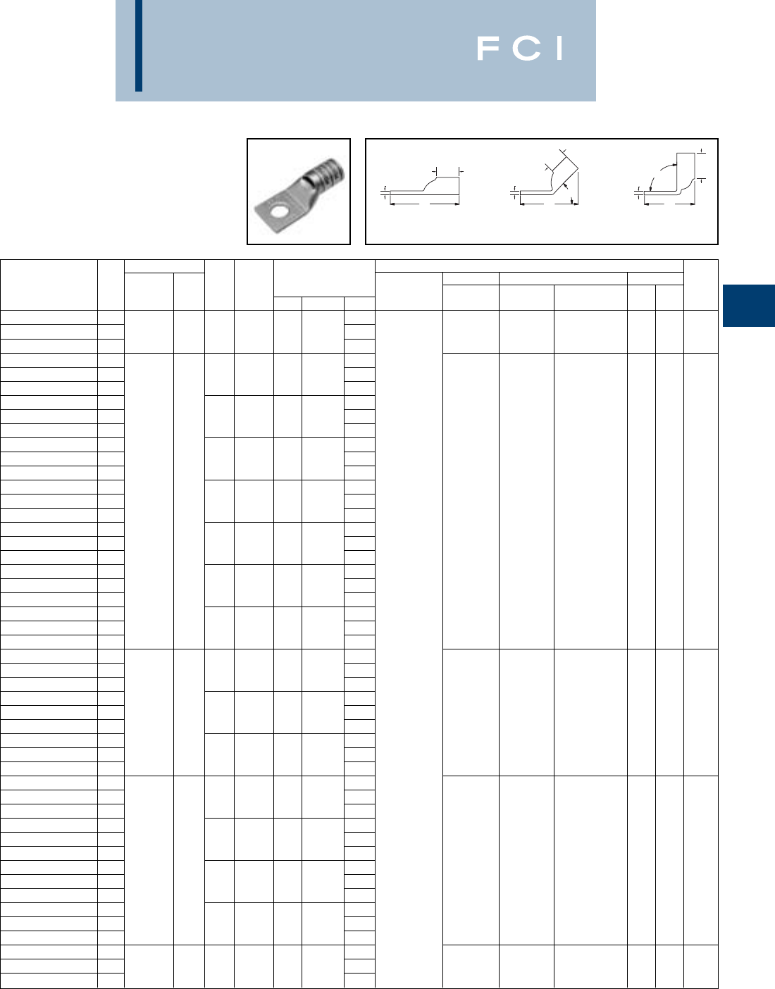
BURNDY
Compression
C-31
ONE HOLE HYLUG™
FLEX CONDUCTOR
STANDARD BARREL
(Continued)
*Use PUADP-1 adapter with "U" dies in Y46 HYPRESS™
*** The MM2 conductor sizes listed are the recommendations
for Class 5 conductor.
Conductor ▲Installation Tooling
Stud Figure Mechanical Hydraulic Wire
*** Hole Tongue Dimensions Dieless MD6, OUR840, BCT500HS, Y35, Y39, Y750, Color Die Strip
Catalog Number Fig # AWG MM2Size Width (B) (T) (L) (# of crimps) MD7-34R Y500CTHS Y46*, PAT750 Code Index Length
YA30L-TC34-FX
1250 FLEX 3.12
W29VT (2) X29RT (4)
YA30L-TC34-FX-45
2
CLASS G 259 STR.
-3/41.201.03.163.04W29VT (2) U29RT (1)
Ye l l o w
16 1-1/16
YA30L-TC34-FX-90
3
CLASS H 427 STR
2.05X29RT (4) W29RT (2)
YA31L-TC14-FX
12.31
YA31L-TC14-FX-45
21/41.291.06.182.23
YA31L-TC14-FX-90
31.19
YA31L-TC516-FX
12.37
YA31L-TC516-FX-45
25/161.291.06.182.30
YA31L-TC516-FX-90
31.27
YA31L-TC38-FX
12.50
YA31L-TC38-FX-45
23/81.291.06.182.42
YA31L-TC38-FX-90
3
250 FLEX
1.40
YA31L-NT12-FX
12.75
W30VT (2)
YA31L-NT12-FX-45
2
637/24
150 1/2.961.06.182.67W30VT (2) U30RT (2)
White
17 1-1/8
YA31L-NT12-FX-90
31.65W30RT (2)
YA31L-TC12-FX
1
CLASS I, K, M
2.75
YA31L-TC12-FX-45
21/21.291.06.182.67
YA31L-TC12-FX-90
31.65
YA31L-TC58-FX
13.00
YA31L-TC58-FX-45
25/81.291.06.182.92
YA31L-TC58-FX-90
31.90
YA31L-TC34-FX
13.19Y644HS (1)
YA31L-TC34-FX-45
23/41.291.06.183.11Y81KFT (1)
YA31L-TC34-FX-90
32.09
Y81KFTMBH (1)
YA32L-TC38-FX
12.68
PAT81KFT-18V (1)
YA32L-TC38-FX-45
23/81.401.19.192.58
YA32L-TC38-FX-90
3
313.1 KCMIL
1.45
YA32L-TC12-FX
12.93
W31VT (2)
YA32L-TC12-FX-45
2
775/24
185 1/21.401.19.192.83W31VT (2) U31RT (2) Red 18 1-1/4
YA32L-TC12-FX-90
31.70W31RT (2)
YA32L-TC58-FX
1
300 FLEX
3.18
YA32L-TC58-FX-45
25/81.401.19.193.08
YA32L-TC58-FX-90
31.95
YA34L-TC516-FX
12.74
YA34L-TC516-FX-45
25/161.551.27.232.68
YA34L-TC516-FX-90
31.41
YA34L-TC38-FX
12.87
YA34L-TC38-FX-45
2
373.7 KCMIL
3/81.551.27.232.80
YA34L-TC38-FX-90
31.53
W32VT (2) W32VT (2) U32RT (2) Blue 19 1-5/16
YA34L-TC12-FX
1
925/24
240 3.12W32RT (2)
YA34L-TC12-FX-45
21/21.551.27.233.05
YA34L-TC12-FX-90
3
350 FLEX
1.78
YA34L-TC58-FX
13.37
YA34L-TC58-FX-45
25/81.551.27.233.30
YA34L-TC58-FX-90
32.03
YA36L-TC12-FX
13.29
YA36L-TC12-FX-45
2
444.4 KCMIL
-1/21.741.38.273.26--U34RT (2)
Brown
20 1-3/8
YA36L-TC12-FX-90
3
450 FLEX
1.86
▲See tooling section of this catalog for complete tool and die
listings. Use ONLY color-coded die recommendations for
“-FX” connectors. For nest/indentor system contact factory.
◆For applications greater than 2000 Volts consult cable
manufacturer for voltage stress relief instructions.
TT
BB
B
T
L
45°
90°
L
L
Fig. 2 Fig. 3Fig. 1
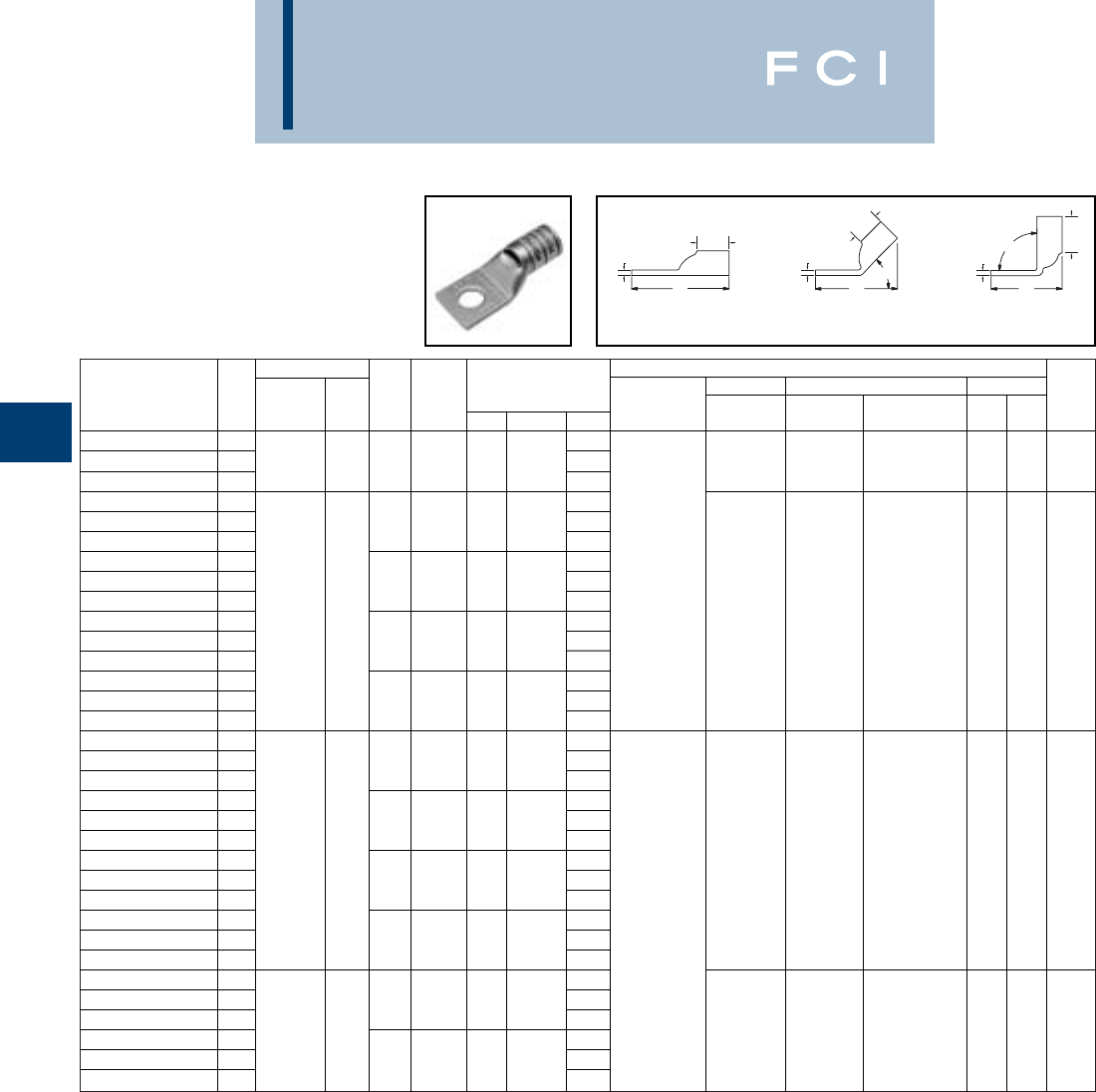
Conductor ▲Installation Tooling
Stud Figure Mechanical Hydraulic Wire
*** Hole Tongue Dimensions Dieless MD6, OUR840, BCT500HS, Y35, Y39, Y750, Color Die Strip
Catalog Number Fig # AWG MM2Size Width (B) (T) (L) (# of crimps) MD7-34R Y500CTHS Y46*, PAT750 Code Index Length
YA36L-TC58-FX
13.54
YA36L-TC58-FX-45
21100/24 - 5/81.741.38.273.51--U34RT (2)
Brown
20 1-3/8
YA36L-TC58-FX-90
32.11
YA38L-TC12-FX
13.41
YA38L-TC12-FX-45
21/21.841.45.273.35
YA38L-TC12-FX-90
31.90
YA38L-TC58-FX
1
535.3 KCMIL
3.66Y644HS (1)
YA38L-TC58-FX-45
25/81.841.45.273.60Y81KFT (1)
YA38L-TC58-FX-90
3
1325/24
300 2.15
Y81KFTMBH (1)
--U38XRT (2) Pink L99 1-7/16
YA38L-TC516-FX
13.03
PAT81KFT-18V (1)
YA38L-TC516-FX-45
2
500 FLEX
5/161.841.45.272.97
YA38L-TC516-FX-90
31.52
YA38L-TC38-FX
13.34
YA38L-TC38-FX-45
23/81.841.45.273.29
YA38L-TC38-FX-90
31.83
YA40L-TC516-FX
13.05
YA40L-TC516-FX-45
25/161.981.42.303.06
YA40L-TC516-FX-90
31.59
YA40L-TC38-FX
13.38
YA40L-TC38-FX-45
2
646 KCMIL
3/81.981.42.303.38
YA40L-TC38-FX-90
3400 1.91
--U39RT (2) Black 24 1-5/16
YA40L-TC12-FX
1
1600/24
3.43
YA40L-TC12-FX-45
21/21.981.42.303.44Y644HS (1)
YA40L-TC12-FX-90
31.96Y81KFT (2)
YA40L-TC58-FX
13.68
Y81KFTMBH (2)
YA40L-TC58-FX-45
25/81.981.42.303.69
PAT81KFT-18V (2)
YA40L-TC58-FX-90
32.21
YA44L-TC12-FX
13.79
YA44L-TC12-FX-45
21/22.191.65.333.76
YA44L-TC12-FX-90
3
777.7 KCMIL
500 2.07
--U44XRT (2)
Ye l l o w
L115 1-5/8
YA44L-TC58-FX
1
1925/24
4.04
YA44L-TC58-FX-45
25/82.191.65.334.01
YA44L-TC58-FX-90
32.32
BURNDY
Compression
C-32
ONE HOLE HYLUG™
FLEX CONDUCTOR
STANDARD BARREL
(Continued)
*Use PUADP-1 adapter with "U" dies in Y46 HYPRESS™
*** The MM2 conductor sizes listed are the recommendations
for Class 5 conductor.
▲See tooling section of this catalog for complete tool and die
listings. Use ONLY color-coded die recommendations for
“-FX” connectors. For nest/indentor system contact factory.
◆For applications greater than 2000 Volts consult cable
manufacturer for voltage stress relief instructions.
TT
BB
B
T
L
45°
90°
L
L
Fig. 2 Fig. 3Fig. 1
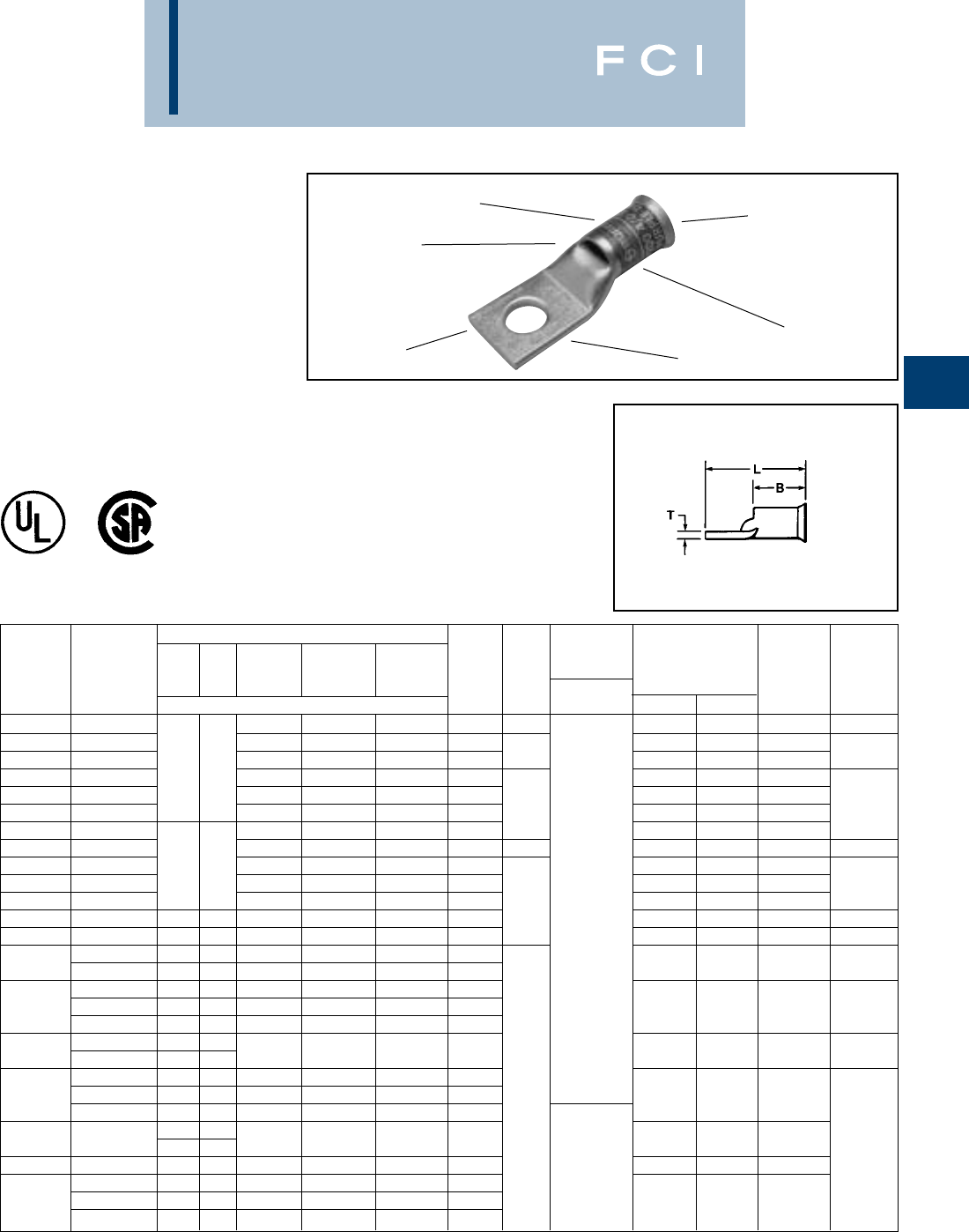
BURNDY
Compression
C-33
ONE HOLE HYLUG™
FLEX CONDUCTOR
STANDARD BARREL
BELLED END
TYPE YA-LB
COPPER COMPRESSION
TERMINAL
UL Listed 90° C,
600 Volts to 35 KV ◆
ELECTRO-TIN
PLATED FLEXIBLE CONDUCTOR
ACCOMMODATION
CRIMPS
DIE AND COLOR
CODE INFORMATION
INSPECTION
WINDOW
BELLED END
ASSISTS FLEXIBLE
WIRE INSERTION
Stranding Class (Size of Strand)
Flexible Battery Welding Installation
Conductor I Cable K Cable M Loco- Tooling Wire
Catalog Size G H (#24 Str.) (#30 Str.) (#34 Str.) Motive Bolt Dieless Dimensions Die Strip
Number AWG/kcmil Number of Strands Cable Size (# of crimps) C L Index Length
YA8C-LB 8 AWG 41 168 420 37/24 10 .411.12 1013 7/16
YA5C-LB 6 AWG 63 266 665 61/24 .441.73 1014
YA4C-LB 5 AWG 84 336 836 91/24 1/4.501.92 1015 7/8
YA3C-LB 4 AWG 49 133 105 420 1064 105/24 .551.94 1016
YA2C-LB 3 AWG 133 532 1323 125/24 .611.97 1017
YA1C-LB 2 AWG 161 665 1666 150/24 5/16
.682.02 1018 5/16
YA25-LB 1 AWG 210 836 2107 225/24 .752.26 1019
YA26-LB 1/0 AWG 266 1064 2646 275/24 3/8.832.61 1020 1
YA27-LB 2/0 AWG 133 259 342 1323 3325 325/24 .912.67 1021
YA28-LB 3/0 AWG 418 1666 4256 450/24 Y81KFT (1) 1.022.77 1022 1-1/16
YA29-LB 4/0 AWG - - - - 1/2
Y81KFTMBH (1)
1.112.82 1023
YA30-LB 250 kcmil 259 427 532 2107 5320 550/24
PAT81KFT-18V (1)
1.202.93 1024 1-1/8
YA31-LB 262.2 kcmil - - 637 2499 6384 650/24 1.293.31 1025 1-3/16
300 kcmil 259 427 735 2898 7851 -
YA32-LB 313.1 kcmil - - - - - 775/24 1.403.56 1026 1-1/4
350 kcmil - - - 3458 8806 -
YA34-LB 373.3 kcmil - - - - - 925/24 1.523.83 1027 1-7/16
400 kcmil 259 427 980 - - -
444.4 kcmil - - - - - 1100/24
YA36-LB 450 kcmil - - 1127 4522 11396 - 1.694.31 1028 1-3/4
500 kcmil - - - - -
YA38-LB 535.3 kcmil - - - - - 1325/24 5/8
1.814.27 1029
550 kcmil 427 703 1372 - - -
-- - 5054 13664 -
YA39-LB 600 kcmil 427 - - - - - Y81KFT (2) 1.894.27 1030 1-15/16
YA40-LB --703 1470 - 14945 1600/24
Y81KFTMBH (2)
1.954.27 1031
650 kcmil - - - - - P
AT81KFT-18 (2)
YA44-LB 750 kcmil 427 703 - - - - 2.174.5 1032
777.7 kcmil - - - - - 1925/24
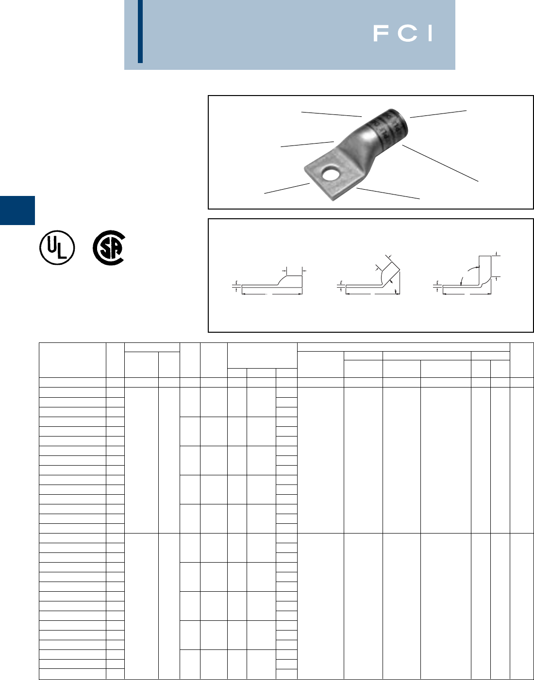
BURNDY
Compression
C-34
ONE HOLE HYLUG™
FLEX CONDUCTOR
STANDARD BARREL
LEAD PLATED
TYPE YAG-L-TC-LD
UL Listed 90° C,
600 Volts to 35KV ◆
BB
B
TT
T90°
L
45°
L
L
*Use PUADP-1 adapter with "U" dies in Y46 HYPRESS™
** The MM2conductor size referenced here is for both Class
2 and Class 5 conductor.
*** The MM2 conductor sizes listed are the recommendations
for Class 5 conductor.
FLEXIBLE CONDUCTOR
ACCOMMODATION
CRIMPS
LEAD PLATED
DIE AND COLOR
CODE INFORMATION BEVELED ENTRY
Fig. 1 Fig. 2 Fig. 3
NO INSPECTION
WINDOW
Conductor ▲Installation Tooling
Stud Figure Mechanical Hydraulic Wire
*** Hole Tongue Dimensions Dieless MD6, OUR840, BCT500HS, Y35, Y39, Y750, Color Die Strip
Catalog Number Fig # AWG MM2Size Width (B) (T) (L) (# of crimps) MD7-34R Y500CTHS Y46*, PAT750 Code Index Length
YAG18TC516LD 1
22-18 AWG
5/16.52.25.061.42MR20 (1) – – 1/4
YAG8CLTC10LD 11.19
YAG8CLTC10LD45 2# 10 .41.44.081.20
YAG8CLTC10LD90 3.74
YAG8CLTC14LD 11.32
YAG8CLTC14LD45 21/4.44.44.081.31
YAG8CLTC14LD90 337/24 .86MY29-11 (1)
YAG8CLTC516LD 1** 1.38Y2MR (1) W8CVT (1) W8CVT (1)
YAG8CLTC516LD45 2#8 WELD 5/16.52.44.061.34Y1MR (1) W8CRT (1) W8CRT (1) U8CRT (1) Red 49 7/16
YAG8CLTC516LD90 310 .92Y81KFT (1) X8CRT (1) X8CRT (1)
YAG8CLTC38LD 18 AWG 1.51
Y81KFTMBH (1)
YAG8CLTC38LD45 23/8.58.44.061.45
PAT81KFT-18V (1)
YAG8CLTC38LD90 31.04
YAG8CLTC12LD 11.76
YAG8CLTC12LD45 21/2.71.44.051.67
YAG8CLTC12LD90 31.28
YAG6CLTC10LD 11.30
YAG6CLTC10LD45 2# 10 .41.50.081.26
YAG6CLTC10LD90 3.76
YAG6CLTC14LD 11.43
YAG6CLTC14LD45 21/4.48.50.081.39
YAG6CLTC14LD90 361/24 .88Y1MR (1)
YAG6CLTC516LD 1** 1.49MY29-11 (1) W5CVT (1) W5CVT (1)
YAG6CLTC516LD45 2#6 WELD 5/16.52.50.071.44Y2MR (1) W5CRT (1) W5CRT (1) U5CRT (1) Blue 7 1/2
YAG6CLTC516LD90 316 .94Y81KFT (1) X5CRT (1) X5CRT (1)
YAG6CLTC38LD 1#6 AWG 1.61
Y81KFTMBH (1)
YAG6CLTC38LD45 23/8.58.50.061.54
PAT81KFT-18V (1)
YAG6CLTC38LD90 31.06
YAG6CLTC12LD 11.86
YAG6CLTC12LD45 21/2.75.50.121.92
YAG6CLTC12LD90 31.34
▲See tooling section of this catalog for complete tool and die
listings.
†Alternate Tooling includes Y8MRB-1, MY29-11
◆For applications greater than 2000 Volts consult cable
manufacturer for voltage stress relief instructions.

BURNDY
Compression
C-35
ONE HOLE HYLUG™
FLEX CONDUCTOR
STANDARD BARREL
LEAD PLATED
(Continued)
*Use PUADP-1 adapter with "U" dies in Y46 HYPRESS™
*** The MM2 conductor sizes listed are the recommendations
for Class 5 conductor.
▲See tooling section of this catalog for complete tool and die
listings.
BB
B
TT
T90°
L
45°
L
L
Fig. 1 Fig. 2 Fig. 3
Conductor ▲Installation Tooling
Stud Figure Mechanical Hydraulic Wire
*** Hole Tongue Dimensions Dieless MD6, OUR840, BCT500HS, Y35, Y39, Y750, Color Die Strip
Catalog Number Fig # AWG MM2Size Width (B) (T) (L) (# of crimps) MD7-34R Y500CTHS Y46*, PAT750 Code Index Length
YAG4CLTC10LD 11.36
YAG4CLTC10LD45 2# 10 .55.50.091.33
YAG4CLTC10LD90 3.79
YAG4CLNT10LD 11.36
YAG4CLNT10LD45 2# 10 .41.50.091.33
YAG4CLNT10LD90 3.79
YAG4CLTC14LD 1
91/24 - 105/24
1.48Y1MR (2)
YAG4CLTC14LD45 21/4.55.50.091.46MY29-11 (1)
YAG4CLTC14LD90 3
#4 WELD
.92Y2MR (2) W4CVT (1) W4CVT (1)
YAG4CLTC516LD 11.55Y81KFT (1) W4CRT (1) W4CRT (1) U4CRT (1) Gray 8 1/2
YAG4CLTC516LD45 2
4 AWG
5/16.55.50.081.52
Y81KFTMBH (1)
X4CRT (1) X4CRT (1)
YAG4CLTC516LD90 3.98
PAT81KFT-18V (1)
YAG4CLTC38LD 11.67
YAG4CLTC38LD45 23/8.58.50.081.63
YAG4CLTC38LD90 31.10
YAG4CLTC12LD 11.92
YAG4CLTC12LD45 21/2.71.50.071.84
YAG4CLTC12LD90 31.34
YAG2CLTC10LD 11.52
YAG2CLTC10LD45 2#10 .68.63.101.47
YAG2CLTC10LD90 3.84
YAG2CLTC14LD 11.64
YAG2CLTC14LD45 21/4.68.63.101.60
YAG2CLTC14LD90 3
125/24
.97Y1MR (2)
YAG2CLTC516LD 11.70MY29-11 (1) W2CRT (1) W2CRT (1)
YAG2CLTC516LD45 2
#2 WELD
35 5/16.68.63.101.66Y2MR (2) W2CVT (1) W2CVT (1) U2CRT (1)
Brown
10 11/16
YAG2CLTC516LD90 31.03Y81KFT (1) X2CRT (1) X2CRT (1)
YAG2CLTC38LD 1
2 AWG
1.83
Y81KFTMBH (1)
YAG2CLTC38LD45 23/8.68.63.101.78
PAT81KFT-18V (1)
YAG2CLTC38LD90 31.15
YAG2CLTC12LD 12.12
YAG2CLTC12LD45 21/2.77.63.102.03
YAG2CLTC12LD90 31.40
YAG1CLTC10LD 11.61
YAG1CLTC10LD45 2# 10 .75.69.121.57
YAG1CLTC10LD90 3.88
YAG1CLTC14LD 11.73
YAG1CLTC14LD45 21/4.83.69.121.70
YAG1CLTC14LD90 3
225/24
1.00
YAG1CLTC516LD 11.80MY29-11 (1)
W1CVT (1) W1CVT (1)
YAG1CLTC516LD45 2
175/24 - #1 WELD
5/16.75.69’’ .121.76Y81KFT (1)
W1CRT-1 (1) W1CRT-1 (1)
U1CRT-1 (1)
Green
11 11/16
YAG1CLTC516LD90 31.07
Y81KFTMBH (1)X1CRT-1 (1) X1CRT-1 (1)
YAG1CLTC38LD 1
1 AWG
1.92
PAT81KFT-18V (1)
YAG1CLTC38LD45 23/8.75.69.121.89
YAG1CLTC38LD90 31.19
YAG1CLTC12LD 12.17
YAG1CLTC12LD45 21/2.75.69.122.14
YAG1CLTC12LD90 31.44
†Alternate Tooling includes Y8MRB-1, MY29-11
◆For applications greater than 2000 Volts consult cable
manufacturer for voltage stress relief instructions.

BURNDY
Compression
C-36
ONE HOLE HYLUG™
FLEX CONDUCTOR
STANDARD BARREL
LEAD PLATED
(Continued)
*Use PUADP-1 adapter with "U" dies in Y46 HYPRESS™
*** The MM2 conductor sizes listed are the recommendations
for Class 5 conductor.
▲See tooling section of this catalog for complete tool and die
listings.
Conductor ▲Installation Tooling
Stud Figure Mechanical Hydraulic Wire
*** Hole Tongue Dimensions Dieless MD6, OUR840, BCT500HS, Y35, Y39, Y750, Color Die Strip
Catalog Number Fig # AWG MM2Size Width (B) (T) (L) (# of crimps) MD7-34R Y500CTHS Y46*, PAT750 Code Index Length
YAG25LTC14LD 11.77
YAG25LTC14LD45 21/4.83.69.121.73
YAG25LTC14LD90 31.03
YAG25LTC516LD 1275/24 1.84
YAG25LTC516LD45 25/16.83.69.121.79MY29-11 (1)
YAG25LTC516LD90 31/0 WELD 50 1.09Y81KFT (1) W25RT (2) W25RT (2)
YAG25LTC38LD 11.96
Y81KFTMBH (1)
W25VT (2) W25VT (2) U25RT (1) Pink 12 11/16
YAG25LTC38LD45 21/0 AWG 3/8.83.69.121.92
PAT81KFT-18V (1)
X25RT (2) X25RT (2)
YAG25LTC38LD90 31.22
YAG25LTC12LD 12.21
YAG25LTC12LD45 21/2.83.69.122.17
YAG25LTC12LD90 31.47
YAG26LTC10LD 11.82
YAG26LTC10LD45 2# 10 .93.81.131.75
YAG26LTC10LD90 3.94
YAG26LTC14LD 11.95
YAG26LTC14LD45 21/4.93.81.131.87
YAG26LTC14LD90 31.07
YAG26LTC516LD 12.01
YAG26LTC516LD45 25/16.93.81.131.93
YAG26LTC516LD90 3325/24 1.13MY29-11 (1)
YAG26LTC38LD 12.13Y644HS (1) W26VT (2) W26VT (2)
YAG26LTC38LD45 22/0 WELD 70 3/8.93.81.132.06Y81KFT (1) W26RT (2) W26RT (2) U26RT (1) Black 13 13/16
YAG26LTC38LD90 31.26
Y81KFTMBH (1)
X26RT (2) X26RT (2)
YAG26LTC12LD 12/0 AWG 2.38
PAT81KFT-18V (1)
YAG26LTC12LD45 21/2.93.81.132.31
YAG26LTC12LD90 31.51
YAG26LTC58LD 12.63
YAG26LTC58LD45 25/8.93.81.132.56
YAG26LTC58LD90 31.76
YAG26LTC34LD 12.89
YAG26LTC34LD45 23/4.93.81.112.75
YAG26LTC34LD90 31.93
YAG27LTC10LD 12.05
YAG27LTC10LD45 2#10 1.03 1.00.141.93
YAG27LTC10LD90 3.98
YAG27LTC14LD 12.18
YAG27LTC14LD45 21/41.03 1.00.142.06
YAG27LTC14LD90 3450/24 1.10
YAG27LTC516LD 12.24MY29-11 (1) W27VT (2) W27VT (2)
YAG27LTC516LD45 23/0 WELD 95 5/161.03 1.00.142.12Y81KFT (1) X27RT (3) X27RT (3) U27RT (1)
Orange
14 1
YAG27LTC516LD90 31.17
Y81KFTMBH (1)
W27RT (2) W27RT (2)
YAG27LTC38LD 13/0 AWG 2.37
PAT81KFT-18V (1)
YAG27LTC38LD45 23/81.03 1.00.142.24
YAG27LTC38LD90 31.29
YAG27LTC12LD 12.62
YAG27LTC12LD45 21/21.03 1.00.142.49
YAG27LTC12LD90 31.54
†Alternate Tooling includes Y8MRB-1, MY29-11
◆For applications greater than 2000 Volts consult cable
manufacturer for voltage stress relief instructions.
BB
B
TT
T90°
L
45°
L
L
Fig. 1 Fig. 2 Fig. 3
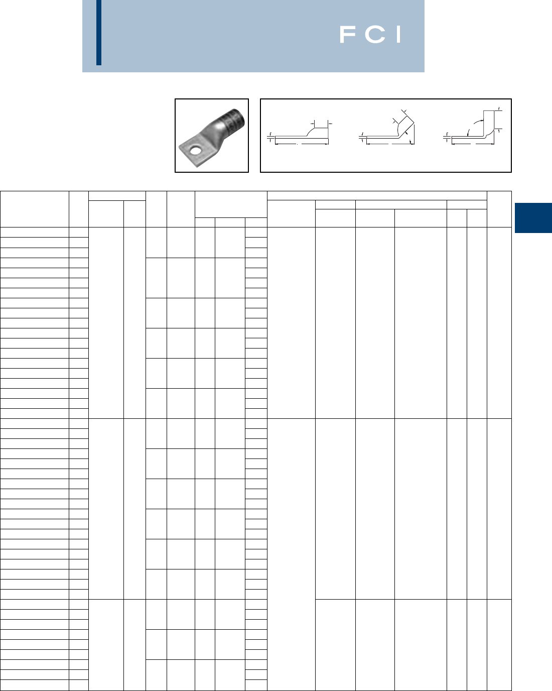
BURNDY
Compression
C-37
ONE HOLE HYLUG™
FLEX CONDUCTOR
STANDARD BARREL
LEAD PLATED
(Continued)
*Use PUADP-1 adapter with "U" dies in Y46 HYPRESS™
** The 120 MM2referenced here is for both Class 2 and
Class 5 conductor.
*** The MM2 conductor sizes listed are the recommendations
for Class 5 conductor.
Conductor ▲Installation Tooling
Stud Figure Mechanical Hydraulic Wire
*** Hole Tongue Dimensions Dieless MD6, OUR840, BCT500HS, Y35, Y39, Y750, Color Die Strip
Catalog Number Fig # AWG MM2Size Width (B) (T) (L) (# of crimps) MD7-34R Y500CTHS Y46*, PAT750 Code Index Length
YAG28LTC14LD 12.26
YAG28LTC14LD45 21/41.141.03.152.13
YAG28LTC14LD90 31.14
YAG28LTC516LD 12.32
YAG28LTC516LD45 25/161.141.03.152.19
YAG28LTC516LD90 31.21
YAG28LTC516N66LD 12.64
YAG28LTC38LD 1550/24 2.45MY29-11 (1)
YAG28LTC38LD45 2**3/81.141.03.152.32Y644HS (1) W28VT (2) W28VT (2)
YAG28LTC38LD90 34/0 WELD 1.33Y81KFT (1) X28RT (3) X28RT (3) U28RT (1)
Purple
15 1-1/16
YAG28LTC12LD 1120 2.70
Y81KFTMBH (1)
W28RT (2) W28RT (2)
YAG28LTC12LD45 24/0 AWG 1/21.141.03.152.57
PAT81KFT-18V (1)
YAG28LTC12LD90 31.58
YAG28LTC58LD 12.95
YAG28LTC58LD45 25/81.141.03.152.82
YAG28LTC58LD90 31.83
YAG28LTC34LD 13.14
YAG28LTC34LD45 23/41.141.03.153.00
YAG28LTC34LD90 32.02
YAG29LTC14LD 12.26
YAG29LTC14LD45 21/41.141.03.162.13
YAG29LTC14LD90 31.14
YAG29LTC516LD 12.32
YAG29LTC516LD45 25/161.141.03.162.19
YAG29LTC516LD90 31.21
YAG29LTC38LD 12.45
YAG29LTC38LD45 2550/24 3/81.141.03.162.32
W29VT (2)
YAG29LTC38LD90 31.33W29VT (2) X29RT (4) U29RT (1)
Ye l l o w
16 1-1/16
YAG29LTC12LD 12.70X29RT (4) W29RT (2)
YAG29LTC12LD45 24/0 WELD 1/21.141.03.162.57
YAG29LTC12LD90
31.58Y644HS (1)
YAG29LTC58LD 12.95Y81KFT (1)
YAG29LTC58LD45 25/81.141.03.162.82
Y81KFTMBH (1)
YAG29LTC58LD90 31.83
PAT81KFT-18V (1)
YAG29LTC34LD 13.14
YAG29LTC34LD45 23/41.141.03.163.00
YAG29LTC34LD90 32.02
YAG30LTC516LD 12.34
YAG30LTC516LD45 25/161.201.03.162.25
YAG30LTC516LD90 3250 FLEX 1.24
YAG30LTC38LD 12.47
W29VT (2) W29VT (2)
YAG30LTC38LD45 2
CLASS G - 259 STR.
3/81.201.03.162.37
X29RT (4) X29RT (4) U29RT (1)
Ye l l o w
16 1-1/16
YAG30LTC38LD90 31.36W29RT (2)
YAG30LTC12LD 1
CLASS H - 427 STR.
2.72
YAG30LTC12LD45 21/21.201.03.162.62
YAG30LTC12LD90 31.61
▲See tooling section of this catalog for complete tool and die
listings.
†Alternate Tooling includes Y8MRB-1, MY29-11
◆For applications greater than 2000 Volts consult cable
manufacturer for voltage stress relief instructions.
BB
B
TT
T90°
L
45°
L
L
Fig. 1 Fig. 2 Fig. 3
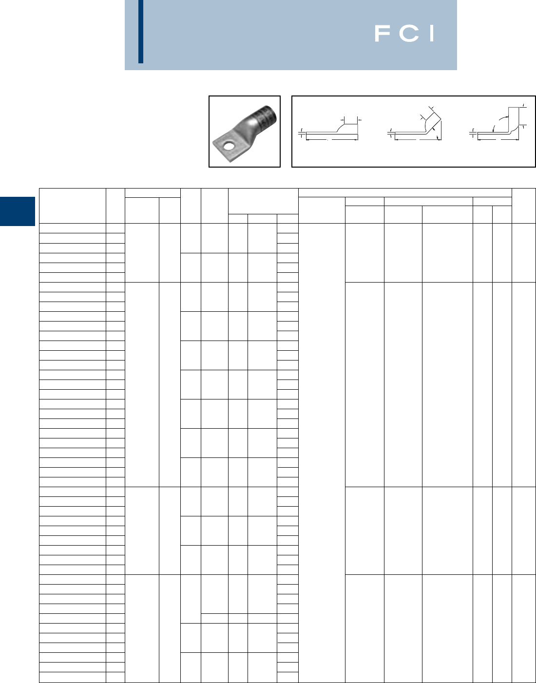
BURNDY
Compression
C-38
ONE HOLE HYLUG™
FLEX CONDUCTOR
STANDARD BARREL
LEAD PLATED
(Continued)
*Use PUADP-1 adapter with "U" dies in Y46 HYPRESS™
*** The MM2 conductor sizes listed are the recommendations
for Class 5 conductor.
▲See tooling section of this catalog for complete tool and die
listings.
Conductor ▲Installation Tooling
Stud Figure Mechanical Hydraulic Wire
*** Hole Tongue Dimensions Dieless MD6, OUR840, BCT500HS, Y35, Y39, Y750, Color Die Strip
Catalog Number Fig # AWG MM2Size Width (B) (T) (L) (# of crimps) MD7-34R Y500CTHS Y46*, PAT750 Code Index Length
YAG30LTC58LD
12.97
YAG30LTC58LD45
2
250 FLEX
5/81.201.03.162.87
W29VT (2)
YAG30LTC58LD90
3
CLASS G - 259 STR.
1.86W29VT (2) X29RT (4) U29RT (1)
Ye l l o w
16 1-1/16
YAG30LTC34LD
1
CLASS H - 427 STR.
3.16X29RT (4) W29RT (2)
YAG30LTC34LD45
23/41.201.03.163.06
YAG30LTC34LD90
32.05
YAG31LTC14LD
12.35
YAG31LTC14LD45
21/41.291.06.182.26
YAG31LTC14LD90
31.19
YAG31LTC516LD
12.41
YAG31LTC516LD45
25/161.291.06.182.32
YAG31LTC516LD90
31.27
YAG31LTC38LD
12.53
YAG31LTC38LD45
23/81.291.06.182.45
YAG31LTC38LD90
3
637/259
1.40
YAG31LTC12LD
12.78
W30VT (2)
YAG31LTC12LD45
2
250 FLEX
150 1/21.291.06.182.70W30VT (2) U30RT (2)
White
17 1-1/8
YAG31LTC12LD90
31.65W30RT (2)
YAG31LNT12LD
1
CLASS I, K, M
2.78
YAG31LNT12LD45
21/2.961.06.182.70
YAG31LNT12LD90
31.65
YAG31LTC58LD
13.03Y644HS (1)
YAG31LTC58LD45
25/81.291.06.182.95Y81KFT (1)
YAG31LTC58LD90
31.90
Y81KFTMBH (1)
YAG31LTC34LD
13.22
PAT81KFT-18V (1)
YAG31LTC34LD45
23/41.291.06.183.13
YAG31LTC34LD90
32.09
YAG32LTC38LD
12.72
YAG32LTC38LD45
23/81.401.19.192.61
YAG32LTC38LD90
31.45
YAG32LTC12LD
1
775/24-300 FLEX
2.97
W31VT (2)
YAG32LTC12LD45
2185 1/21.401.19.192.86W31VT (2) U31RT (2) Red 18 1-1/4
YAG32LTC12LD90
3
313.1 kcmil
1.70W31RT (2)
YAG32LTC58LD
13.22
YAG32LTC58LD45
25/81.401.19.193.11
YAG32LTC58LD90
31.95
YAG34LTC516LD
12.78
YAG34LTC516LD45
21.551.27.232.71
YAG34LTC516LD90
35/161.41
YAG34LTC516N66LD
13.09
YAG34LNT516N66LD
1
925/24-350 FLEX
.961.27.233.09
W32VT (2)
YAG34LTC38LD
1240 2.91W32VT (2) U32RT (2) Blue 19 1-5/16
YAG34LTC38LD45
2
373.7 kcmil
3/81.551.27.232.83W32RT (2)
YAG34LTC38LD90
31.53
YAG34LTC12LD
13.16
YAG34LTC12LD45
21/21.731.27.233.08
YAG34LTC12LD90
31.78
†Alternate Tooling includes Y8MRB-1, MY29-11
◆For applications greater than 2000 Volts consult cable
manufacturer for voltage stress relief instructions.
BB
B
TT
T90°
L
45°
L
L
Fig. 1 Fig. 2 Fig. 3
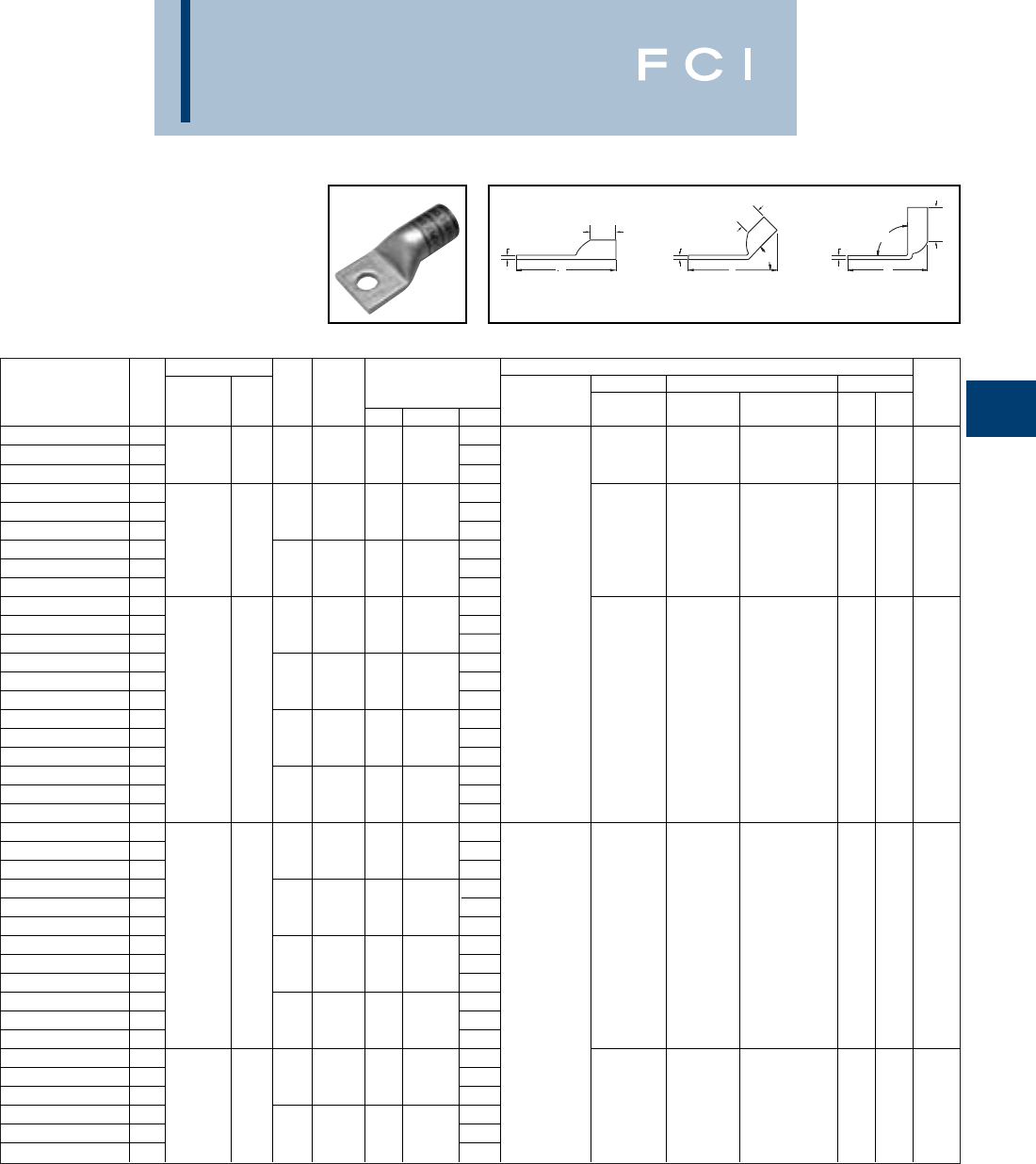
Conductor ▲Installation Tooling
Stud Figure Mechanical Hydraulic Wire
*** Hole Tongue Dimensions Dieless MD6, OUR840, BCT500HS, Y35, Y39, Y750, Color Die Strip
Catalog Number Fig # AWG MM2Size Width (B) (T) (L) (# of crimps) MD7-34R Y500CTHS Y46*, PAT750 Code Index Length
YAG34LTC58LD
1
925/24-350 FLEX
3.41
W32VT (2)
YAG34LTC58LD45
25/81.731.27.233.33W32VT (2) U32RT (2) Blue 19 1-5/16
YAG34LTC58LD90
3
373.7 kcmil
2.03W32RT (2)
YAG36LTC12LD
13.34
YAG36LTC12LD45
2
1100/24-450 FLEX
1/21.731.38.273.30
YAG36LTC12LD90
31.86
YAG36LTC58LD
13.59--U34RT (2) Brown 20 1-3/8
YAG36LTC58LD45
2
444.4 kcmil
5/81.731.38.273.55
YAG36LTC58LD90
32.11
YAG38LTC516LD
13.08Y644HS (1)
YAG38LTC516LD45
25/161.841.45.273.01
Y81KFT (1)
YAG38LTC516LD90
31.52
Y81KFTMBH (1)
YAG38LTC38LD
11325/24 3.39
PAT81KFT-18V (1)
YAG38LTC38LD45
23/81.841.45.273.32
YAG38LTC38LD90
3500 FLEX 300 1.83
--U38XRT (2) Pink L99 1-7/16
YAG38LTC12LD
13.46
YAG38LTC12LD45
2535.3 kcmil 1/21.841.45.273.38
YAG38LTC12LD90
31.90
YAG38LTC58LD
13.71
YAG38LTC58LD45
25/81.841.45.273.63
YAG38LTC58LD90
32.15
YAG40LTC516LD
13.11
YAG40LTC516LD45
25/161.961.42.303.10
YAG40LTC516LD90
31.59
YAG40LTC38LD
13.42
YAG40LTC38LD45
2
1600/24-646 kcmil
3/81.961.42.303.42
YAG40LTC38LD90
3400 1.91
--U39RT (2) Black 24 1-5/16
YAG40LTC12LD
13.48
YAG40LTC12LD45
2650 FLEX 1/21.961.42.303.47Y644HS (1)
YAG40LTC12LD90
31.96Y81KFT (2)
YAG40LTC58LD
13.73
Y81KFTMBH (2)
YAG40LTC58LD45
25/81.961.42.303.72
PAT81KFT-18V (2)
YAG40LTC58LD90
32.21
YAG44LTC12LD
13.85
YAG44LTC12LD45
21925/24 1/22.181.65.333.81
YAG44LTC12LD90
32.07
--U44XRT (2) Yellow L115 1-5/8
YAG44LTC58LD
1750 FLEX 500 4.10
YAG44LTC58LD45
25/82.181.65.334.06
YAG44LTC58LD90
3777.7 kcmil 2.32
BURNDY
Compression
C-39
ONE HOLE HYLUG™
FLEX CONDUCTOR
STANDARD BARREL
LEAD PLATED
(Continued)
*Use PUADP-1 adapter with "U" dies in Y46 HYPRESS™
*** The MM2 conductor sizes listed are the recommendations
for Class 5 conductor.
▲See tooling section of this catalog for complete tool and die
listings.
†Alternate Tooling includes Y8MRB-1, MY29-11
◆For applications greater than 2000 Volts consult cable
manufacturer for voltage stress relief instructions.
BB
B
TT
T90°
L
45°
L
L
Fig. 1 Fig. 2 Fig. 3
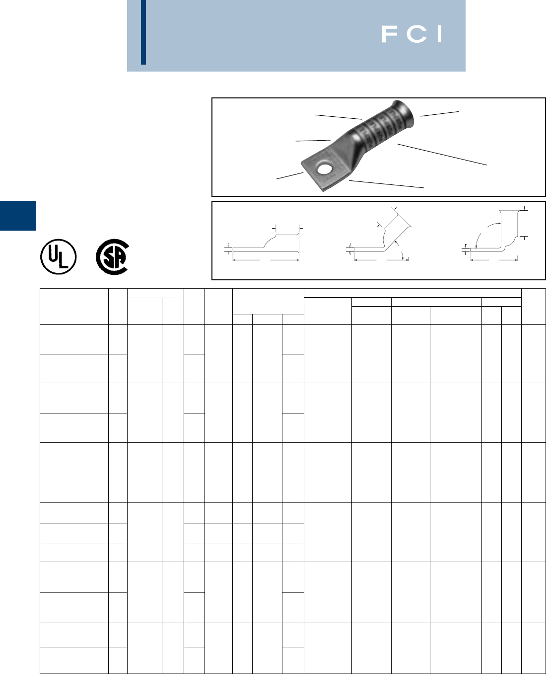
Conductor ▲Installation Tooling
Stud Figure Mechanical Hydraulic Wire
*** Hole Tongue Dimensions Dieless MD6, OUR840, BCT500HS, Y35, Y39, Y750 Color Die Strip
Catalog Number Fig # AWG MM2Size Width (B) (T) (L) (# of crimps) MD7-34R Y500CTHS Y46*, PAT750 Code Index Length
MRC840 (2)
YA8C-TC10-FXB 18-10 1.64MY29-11 (2)
37/24 #8 WELD
**
Y2MR + Y1MR (2)
8 AWG 10 .41.90.08
Y81KFT (1) W8CVT (2) W8CVT (2) U8CRT (2) Red 49 1
YA8C-TC14-FXB 11/41.76
Y81KFTMBH (1
)
PAT81KFT-18V (1)
8-10 MY29-11 (2)
YAV6C-TC10-FXB 11.90
Y2MR + Y1MR (2)
61/24 #6 WELD
** Y644HS (1)
#6 AWG 16 .481.22.08
Y81KFT (1) W5CVT (2) W5CVT (2) U5CRT (2) Blue 7 1-5/16
YAV6C-TC14-FXB 1
91/24 #5 STR
1/42.11
Y81KFTMBH (1
)
PAT81KFT-18V (1)
MY29-11 (2)
Y2MR + Y1MR (2)
Y644HS (1)
YAV5C-TC14-FXB 1#5 AWG 1/4.441.22.072.11
Y81KFT (1) W5CVT (2) W5CVT (2) U5CRT (2) Blue 7 1-5/16
Y81KFTMBH (1
)
PAT81KFT-18V (1)
MY29-11 (2)
YAV4C-TC10-FXB 18-10 .551.22.092.03
Y2MR + Y1MR (4)
91/24 105/24
Y644HS (1)
YAV4C-TC14-FXB 1
#4 WELD
1/4.551.22.092.16
Y81KFT (1) W4CVT (2) W4CVT (2) U4CRT (2) Gray 8 1-5/16
#4 AWG
Y81KFTMBH (1
)
YAV4C-TC516-FXB 15/16.631.22.092.22
PAT81KFT-18V (1)
MY29-11 (2)
YAV2C-TC10-FXB 18-10 2.23
Y2MR + Y1MR (4)
125/24 150/24
Y644HS (1)
#2 WELD #2 AWG
35 .671.35.10
Y81KFT (1) W2CVT (2) W2CVT (2) U2CRT (2)
Brown
10 1-7/16
YAV2C-TC516-FXB 15/162.42
Y81KFTMBH (1
)
PAT81KFT-18V (1)
MY29-11 (2)
YAV1C-TC10-FXB 18-10 2.40Y644HS (1)
175/24 225/24
.691.50.12Y81KFT (1) W1CVT (2) W1CVT (2) U1CRT-1 (2)
Green
11 1-9/16
#1 WELD #1AWG
Y81KFTMBH (1
)
YAV1C-TC516-FXB 15/162.59
PAT81KFT-18V (1)
BURNDY
Compression
C-40
ONE HOLE HYLUG™
FLEX CONDUCTOR
LONG BARREL
BELLED END
TYPES YA-TC-FXB,
YAV-TC-FXB
UL Listed 90° C,
600 Volts to 35 KV ◆
*Use PUADP-1 adapter with “U” dies in Y46 HYPRESS™
** The MM2conductor sizes referenced here are for both
Class 2 and Class 5 conductor.
*** The MM2 conductor sizes listed are the recommendations
for Class 5 conductor.
ELECTRO-TIN
PLATED FLEXIBLE CONDUCTOR
ACCOMMODATION
CRIMPS
DIE AND COLOR
CODE INFORMATION
NO INSPECTION
WINDOW
BELLED END
ASSISTS FLEXIBLE
WIRE INSERTION
BB
B
T
L
45°
90°
L
L
TT
Fig. 1 Fig. 2 Fig. 3
‡P44RT for use with Y46 HYPRESS™ only.
PUADP-1 adapter not required.
▲See tooling section of this catalog for complete tool and die
listings. Use ONLY color-coded die recommendations for
“-FX” connectors. For nest/indentor system contact factory.
◆For applications greater than 2000 Volts consult cable
manufacturer for voltage stress relief instructions.
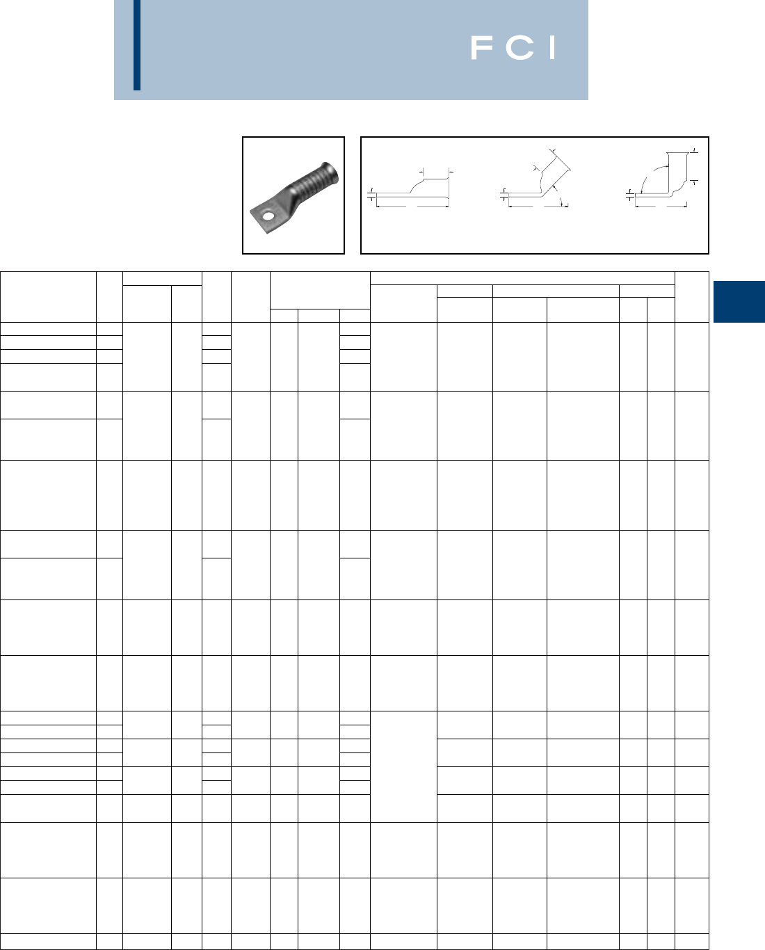
Conductor ▲Installation Tooling
Stud Figure Mechanical Hydraulic Wire
*** Hole Tongue Dimensions Dieless MD6, OUR840, BCT500HS, Y35, Y39, Y750 Color Die Strip
Catalog Number Fig # AWG MM2Size Width (B) (T) (L) (# of crimps) MD7-34R Y500CTHS Y46*, PAT750 Code Index Length
YAV25-TC10-FXB 18-10 2.44MY29-11 (2)
YAV25-TC516-FXB 1275/24 5/162.63Y644HS (1)
YAV25-TC38-FXB 11/0 WELD 50 3/8.831.50.122.75Y81KFT (2) W25VT (4) W25VT (4) U25RT (2) Pink 12 1-9/16
1/0 AWG
Y81KFTMBH (2)
YAV25-TC12-FXB 11/23.19
PAT81KFT-18V (2)
MY29-11 (2)
YAV26-TC38-FXB 1
352/24 2/0 WELD
3/82.94
Y644HS (1)
2/0 AWG
70 .931.63.13Y81KFT (2) W26VT (4) W26VT (4) U26RT (2)
Black
13
1-13/16
YAV26-TC12-FXB 1
450/24 3/0 WELD
1/23.37
Y81KFTMBH (2)
PAT81KFT-18V (2)
MY29-11 (2)
Y644HS (1)
YAV27-TC12-FXB 1
3/0 AWG
95 1/21.101.64.143.43Y81KFT (2) W27VT (4) W27VT (4) U27RT (2)
Orange
14
1-13/16
Y81KFTMBH (2)
PAT81KFT-18V (2)
MY29-11 (2)
YAV28-TC38-FXB 1
550/24 4/0 WELD
** 3/83.17
Y644HS (1)
4/0 AWG
120 1.121.77.14Y81KFT (2) W28VT (4) W28VT (4) U28RT (2)
Purple
15 1-7/8
YAV28-TC12-FXB 1
250 FLEX
1/23.61
Y81KFTMBH (2)
PAT81KFT-18V (2)
Y644HS (1)
Class G 259 str.
Y81KFT (2)
YA30-TC12-FXB 1
Class H 427 str.
1/21.202.16.164.02
Y81KFTMBH (2)
W29VT (4) W29VT (4) U29RT (2)
Ye l l o w
16 2-1/4
250 FLEX
PAT81KFT-18V (2)
Y644HS (1)
637/24 Y81KFT (2)
YA31-TC12-FXB 1
Class I,K,M
150 1/21.282.18.184.08
Y81KFTMBH (2)
W30VT (4) W30VT (4) U30RT (4) White 17 2-1/4
PAT81KFT-18V (2)
YA32-TC12-FXB 11/24.28
YA32-TC58-FXB 1
313.1 kcmil
185 5/81.382.32.19
4.34W31VT (4) W31VT (4) U31RT (4) Red 18 2-1/4
YA34-TC12-FXB 1
373.7 kcmil
1/24.54Y644HS (1)
YA34-TC58-FXB 1925/24 240 5/81.502.48.23
4.60Y81KFT (2) W32VT (4) W32VT (4) U32RT (4) Blue 19 2-9/16
YA36-TC12-FXB 1
444.4 kcmil
1/25.09
Y81KFTMBH (2)
YA36-TC58-FXB 11100/24 5/81.692.95.26
5.15
PAT81KFT-18V (2)
U34RT (4)
Brown
20 3-1/16
535.3 kcmil
YA38-TC58-FXB 11325/24 300 5/81.813.08.275.32--U38XRT (4) Pink L99 3-3/16
Y644HS (1)
Y81KFT (3)
YA40-TC58-FXB 1
646 kcmil - 1600/24
400 5/81.953.24.305.53
Y81KFTMBH (3)
--U39RT (4) Black 24 3-5/16
PAT81KFT-18V (3)
Y644HS (1)
Y81KFT (3)
YA44-TC58-FXB 1
777.7 kcmil - 1925/24
500 5/82.173.33.335.71
Y81KFTMBH (3)
--U44XRT (4)
Ye l l o w
L115 3-7/16
PAT81KFT-18V (3)
YA46-TC58-FXB 11111 kcmil 5/82.693.58.396.19--**P45RT (4)
Ye l l o w
29
3-11/16
BURNDY
Compression
C-41
*Use PUADP-1 adapter with “U” dies in Y46 HYPRESS™
** The 16 MM2and 120 MM2referenced here are for both
Class 2 and Class 5 conductor.
*** The MM2 conductor sizes listed are the recommendations
for Class 5 conductor.
‡P44RT for use with Y46 HYPRESS™ only.
PUADP-1 adapter not required.
ONE HOLE HYLUG™
FLEX CONDUCTOR
LONG BARREL
BELLED END
(Continued)
BB
B
T
L
45°
90°
L
L
TT
Fig. 2 Fig. 3Fig. 1
▲See tooling section of this catalog for complete tool and die
listings. Use ONLY color-coded die recommendations for
“-FX” connectors. For nest/indentor system contact factory.
◆For applications greater than 2000 Volts consult cable
manufacturer for voltage stress relief instructions.
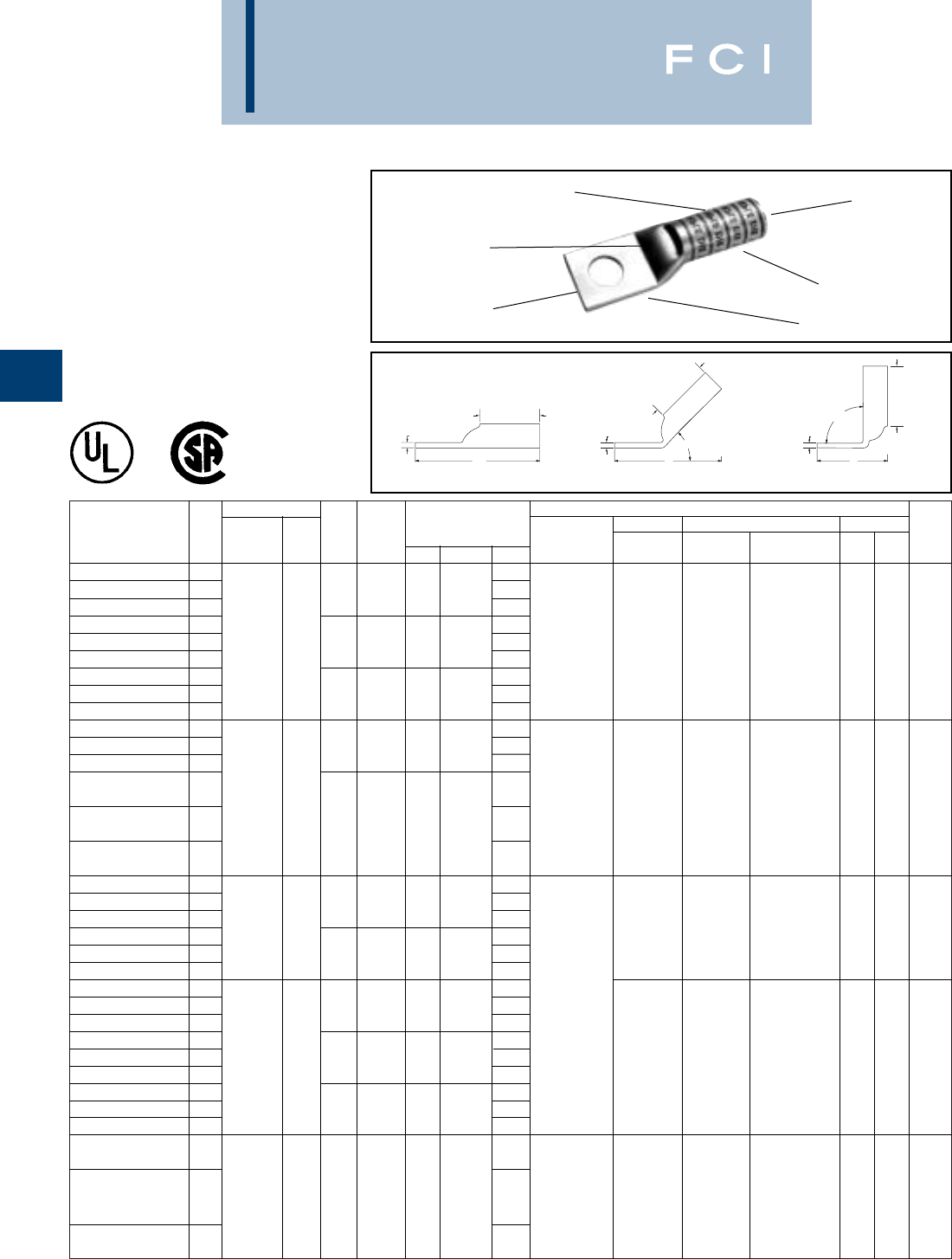
Conductor ▲Installation Tooling
Stud Figure Mechanical Hydraulic Wire
*** Hole Tongue Dimensions Dieless MD6, OUR840, BCT500HS, Y35, Y39, Y750, Color Die Strip
Catalog Number Fig # AWG MM2Size Width (B) (T) (L) (# of crimps) MD7-34R Y500CTHS Y46*, PAT750 Code Index Length
YAZ8C-TC10 11.58Y1MR (2)
YAZ8C-TC10-45 2# 10 .41.75.081.47Y8MRB-1 (2)
YAZ8C-TC10-90 3.75Y2MR (2)
YAZ8C-TC14 137/24 1.7MY29-3 (2) W8CVT (2) W8CVT (2)
YAZ8C-TC14-45 2#8 WELD ** 1/4.44.75.081.58MY29-11 (2) W8CRT (2) W8CRT (2) U8CRT (2) Red 49 7/16
YAZ8C-TC14-90 3#8 AWG 10 .87MRC840 (2) X8CRT (2) X8CRT (2)
YAZ8C-TC38 11.89Y81KFT (1)
YAZ8C-TC38-45 23/8.58.75.061.72
Y81KFTMBH (1)
YAZ8C-TC38-90 31.05
PAT81KFT-18V (1)
YAZV6CTC14FX 12.03Y1MR(2)
YAZV6CTC14FX45 21/4.48.75.081.83Y2MR (2)
YAZV6CTC14FX90 3.89MY29-3 (2)
61/24 MY29-11 (2) W5CVT (2) W5CVT (2)
YAZV6CTC38FX 1#6 WELD ** 2.22
MRC840 (2) W5CRT (2) W5CRT (2) U5CRT (2) Blue 7 1-3/16
#6 AWG 16 Y644HS (1) X5CRT (2) X5CRT (2)
YAZV6CTC38FX45 23/8.58.75.061.97
Y81KFT (1)
Y81KFTMBH (1)
YAZV6CTC38FX90 31.06
PAT81KFT-18V (1)
YAZV4CTC14FX 12.21
YAZV4CTC14FX45 291/24 1/4.551.25.091.97
W4CVT (2) W4CVT (2)
YAZV4CTC14FX90 3105/24 -.93
W4CRT (2) W4CRT (2) U4CRT (2) Gray 8 1-5/16
YAZV4CTC38FX 1#4 WELD 2.39Y1MR (4) X4CRT (2) X4CRT (2)
YAZV4CTC38FX45 2#4 AWG 3/8.581.25.082.13Y2MR (4)
YAZV4CTC38FX90 31.11MY29-3 (2)
YAZV2CTC14FX 12.39MY29-11 (2)
YAZV2CTC14FX45 21/4.681.38.102.13MRC840 (2)
YAZV2CTC14FX90 3125/24 .98Y644HS (1)
YAZV2CTC38FX 1150/24 2.57Y81KFT (1) W2CVT (2) W2CVT (2)
YAZV2CTC38FX45 2#2 WELD 35 3/8.681.38.102.31
Y81KFTMBH (1)
W2CRT (2) W2CRT (2) U2CRT (2)
Brown
10 1-7/16
YAZV2CTC38FX90 3#2 AWG 1.16
PAT81KFT-18V (1)
X2CRT (2) X2CRT (2)
YAZV2CTC12FX 13.01
YAZV2CTC12FX45 21/2.831.38.092.75
YAZV2CTC12FX90 31.6
MY29-3 (2)
YAZV1CTC14FX 1.2.42
MY29-11 (2)
MRC840 (2)
W1CRT-1 (2) W1CRT-1 (2)
YAZV1CTC14FX45 2175/24 - 1/4751.38.122.19Y644HS (1) W1CVT (2) W1CVT (2) U1CRT-1 (2)
Green
11 11/16
Y81KFT (1)
X1CRT-1 (2) X1CRT-1 (2)
Y81KFTMBH (1)
YAZV1CTC14FX90 31.02
PAT81KFT-18V (1)
BURNDY
Compression
C-42
ONE HOLE HYLUG™
FLEX CONDUCTOR
LONG BARREL WITH
INSPECTION WINDOW
TYPES YAZ,YAZV
COPPER COMPRESSION
TERMINAL
UL Listed 90° C,
600 Volts to 35 KV ◆
ELECTRO-TIN
PLATED CABLE
ACCOMMODATION
CRIMP
DIE AND COLOR
CODE INFORMATION
INSPECTION
WINDOW
BEVELED
ENTRY
TT
90°
L
L
45°
L
B
T
B
B
Fig. 1 Fig. 2 Fig. 3
*Use PUADP-1 adapter with "U" dies in Y46 HYPRESS™
** The MM2conductor size referenced here is for both Class
2 and Class 5 conductor.
*** The MM2 conductor sizes listed are the recommendations
for Class 5 conductor.
▲See tooling section of this catalog for complete tool and die
listings. Use ONLY color-coded die recommendations for
“-FX” connectors. For nest/indentor system contact factory.
◆For applications greater than 2000 Volts consult cable
manufacturer for voltage stress relief instructions.

Conductor ▲Installation Tooling
Stud Figure Mechanical Hydraulic Wire
*** Hole Tongue Dimensions Dieless MD6, OUR840, BCT500HS, Y35, Y39, Y750, Color Die Strip
Catalog Number Fig # AWG MM2Size Width (B) (T) (L) (# of crimps) MD7-34R Y500CTHS Y46*, PAT750 Code Index Length
YAZV1CTC516FX 12.47
YAZV1CTC516FX45 2225/24 5/16.751.38.122.24Y644HS (1)
W1CRT-1 (2) W1CRT-1 (2)
YAZV1CTC516FX90 3#1 WELD - 1.08Y81KFT (1) W1CVT (2) W1CVT (2) U1CRT-1 (2)
Green
11 1-7/16
YAZV1CTC38FX 1#1 AWG 2.60
Y81KFTMBH (1) X1CRT-1 (2) X1CRT-1 (2)
YAZV1CTC38FX45 23/8.751.38.122.37
PAT81KFT-18V (1)
YAZV1CTC38FX90 31.20
YAZV25TC14FX 12.58
YAZV25TC14FX45 21/4.831.50.122.30
YAZV25TC14FX90 31.04
YAZV25TC38FX 1275/24 2.76W25VT (4) W25VT (4)
YAZV25TC38FX45 21/0 WELD 50 3/8.831.50.122.48W25RT (4) W25RT (4) U25RT (2) Pink 12 1-9/16
YAZV25TC38FX90 31/0 AWG 1.23X25RT (4) X25RT (4)
YAZV25TC12FX 13.20
YAZV25TC12FX45 21/2.831.50.122.92
YAZV25TC12FX90 31.66
YAZV26TC14FX 12.58
YAZV26TC14FX45 21/4.931.50.132.30
YAZV26TC14FX90 31.04
YAZV26TC38FX 1325/24 2.76W26VT (4) W26VT (4)
YAZV26TC38FX45 22/0 WELD 70 3/8.931.50.132.48W26RT (4) W26RT (4) U26RT (2) Black 13 1-9/16
YAZV26TC38FX90 32/0 AWG 1.23X26RT (4) X26RT (4)
YAZV26TC12FX 13.20MY29-11 (2)
YAZV26TC12FX45 21/2.931.50: .132.92Y644HS (1)
YAZV26TC12FX90 31.66Y81KFT (2)
YAZV27TC38FX 1450/24 2.80
Y81KFTMBH (2)
W27RT (4) W27RT (4)
YAZV27TC38FX45 23/0 WELD 95 3/81.031.50.142.52
PAT81KFT-18V (2)
W27VT (4) W27VT (4) U27RT (2)
Orange
14 1-9/16
YAZV27TC38FX90 33/0 AWG 1.25X27RT (4) X27RT (4)
YAZV28NT38FX 12.96
YAZV28NT38FX-45 23/8.941.62.142.67
YAZV28NT38FX-90 31.30
YAZV28TC38FX 1550/24 ** 2.96W28VT (4) W28VT (4)
YAZV28TC38FX45 24/0 WELD 3/81.141.62.142.67W28RT (4) W28RT (4) U28RT (2)
Purple
15
1-11/16
YAZV28TC38FX90 34/0 AWG 120 1.30X28RT (6) X28RT (6)
YAZV28TC12FX 13.18
YAZV28TC12FX45 21/21.141.62.142.89
YAZV28TC12FX90 31.52
YAZV29NT516FX 1550/24 2.87
W29VT (4) W29RT (4)
YAZV29NT516FX-45 2-5/16.962.00.162.60W29VT (4) U29RT (2)
Ye l l o w
16 2-1/16
YAZV29NT516FX-90 34/0 WELD 1.21X29RT (8) X29RT (8)
YAZ30TC38FX 1250 FLEX 3.42
W29VT (4) W29RT (4)
YAZ30TC38FX-45 2
CLASS G 259 STR.
-3/81.202.00.163.05W29VT (4) U29RT (2)
Ye l l o w
16 2-1/16
YAZ30TC38FX-90 3
CLASS H 427 STR.
1.37X29RT (8) X29RT (8)
YAZ31TC38FX 1
262.2 FLEX
3.45Y644HS (1)
W30VT (4)
YAZ31TC38FX45 2637/24 150 3/81.282.00.183.10Y81KFT (2) W30VT (4) U30RT (4)
White
17 2-1/16
YAZ31TC38FX90 3
CLASS I, K, M
1.41
Y81KFTMBH (2)
W30RT (4)
YAZ32TC38FX 1775/24 3.62
PAT81KFT-18V (2)
W31VT (4)
YAZ32TC38FX45 2
313.1 kcmil
185 3/81.552.12.193.25W31VT (4) U31RT (4) Blue 19 2-3/16
YAZ32TC38FX90 3300 FLEX 1.46W31RT (4)
BURNDY
Compression
C-43
ONE HOLE HYLUG™
FLEX CONDUCTOR
LONG BARREL WITH
INSPECTION WINDOW
(Continued)
*Use PUADP-1 adapter with "U" dies in Y46 HYPRESS™
** The 120 MM2referenced here is for both Class 2 and
Class 5 conductor.
*** The MM2 conductor sizes listed are the recommendations
for Class 5 conductor.
TT
90°
L
L
45°
L
B
T
B
B
Fig. 1 Fig. 2 Fig. 3
▲See tooling section of this catalog for complete tool and die
listings. Use ONLY color-coded die recommendations for “-
FX” connectors. For nest/indentor system contact factory.
◆For applications greater than 2000 Volts consult cable
manufacturer for voltage stress relief instructions.
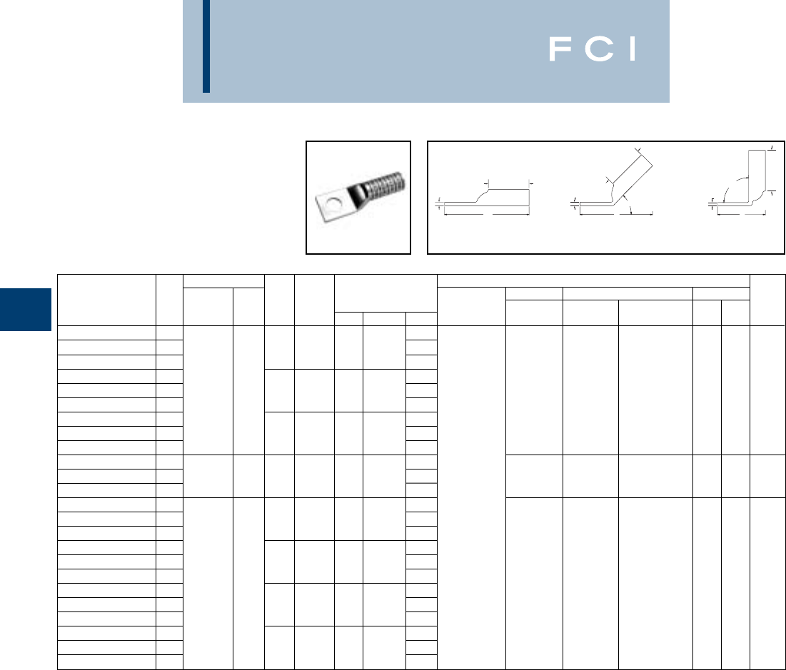
BURNDY
Compression
C-44
ONE HOLE HYLUG™
FLEX CONDUCTOR
LONG BARREL WITH
INSPECTION WINDOW
(Continued)
*Use PUADP-1 adapter with "U" dies in Y46 HYPRESS™.
Catalog # PUADP-1 adapter is required to use “U” dies in
Y46 series tools.
*** The MM2 conductor sizes listed are the recommendations
for Class 5 conductor.
Conductor ▲Installation Tooling
Stud Figure Mechanical Hydraulic Wire
*** Hole Tongue Dimensions Dieless MD6, OUR840, BCT500HS, Y35, Y39, Y750 Color Die Strip
Catalog Number Fig # AWG MM2Size Width (B) (T) (L) (# of crimps) MD7-34R Y500CTHS Y46*, PAT750 Code Index Length
YAZ34NT38FX 13.85
YAZ34NT38FX-45 23/8.962.25.233.5
YAZ34NT38FX-90 31.54
YAZ34TC38FX 1925/24 3.85
YAZ34TC38FX45 2
373.3 kcmil
240 3/81.522.25.233.5W32VT (4) W32VT (4) U32RT (4) Blue 19 2-5/16
YAZ34TC38FX90 3350 FLEX 1.54W32RT (4)
YAZ34TC12FX 14.29
YAZ34TC12FX45 21/21.522.25.233.94
YAZ34TC12FX90 31.98
YAZ36TC38FX 11100/24 4.55
YAZ36TC38FX45 2
444.4 kcmil
-3/81.722.69.264.14Y644HS(1) - - U34RT (4)
Brown
20 2-3/4
YAZ36TC38FX90 3450 FLEX 1.81Y81KFT (2)
YAZ38NT38FX 14.72
Y81KFTMBH (2)
YAZ38NT38FX-45 23/81.632.81.274.26
PAT81KFT-18V (2)
YAZ38NT38FX-90 31.84
YAZ38TC38FX 14.72
YAZ38TC38FX45 21325/24 3/81.812.81.274.26
YAZ38TC38FX90 3
535.3 kcmil
300 1.84
--U38XRT (4) Pink L99 2-7/8
YAZ38NT12FX 1500 FLEX 4.97
YAZ38NT12FX-45 21/21.632.81.274.51
YAZ38NT12FX-90 32.09
YAZ38TC12FX 14.97
YAZ38TC12FX45 21/21.812.81.274.51
YAZ38TC12FX90 32.09
▲See tooling section of this catalog for complete tool and die
listings. Use ONLY color-coded die recommendations for
“-FX” connectors. For nest/indentor system contact factory.
◆For applications greater than 2000 Volts consult cable
manufacturer for voltage stress relief instructions.
TT
90°
L
L
45°
L
B
T
B
B
Fig. 1 Fig. 2 Fig. 3
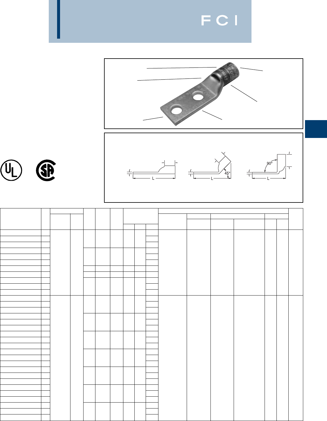
BURNDY
Compression
C-45
TWO HOLE HYLUG™
CODE CONDUCTOR
STANDARD BARREL
TYPES YAV-2TC,YA-L2L,
YA-2LN, AND YA-L-2TC
COPPER COMPRESSION
TERMINAL
UL Listed 90° C,
600 Volts to 35 KV ◆
-- Color code not assigned.
*Use PUADP-1 adapter with "U" dies in Y46 HYPRESS™.
** P-RT die sets for use in Y46 HYPRESS™ only, PUADP-1
adapter not required.
ELECTRO-TIN
PLATED CABLE
ACCOMMODATION
CRIMP
DIE AND COLOR
CODE INFORMATION
INSPECTION
WINDOW
BEVELED
ENTRY
TTT
BB
B
Fig. 1 Fig. 2 Fig. 3
Conductor ▲Installation Tooling
Stud
Stud
Figure Mechanical Hydraulic Wire
Fig *** Hole
Hole Tongue
Dimensions Dieless MD6, OUR840, BCT500HS, Y35, Y39, Y750, Color Die Strip
Catalog Number # AWG MM2Size
Spacing Width
(B) (T) (L) (# of crimps) MD7-34R Y500CTHS Y46*, PAT750 Code Index Length
YAV102TC10 11.72
YAV102TC10-45 2# 10 5/8.38.38.061.70
YAV102TC10-90 31.33
YAV102TC14 11.84
YAV102TC14-45 2
#14-10 STR
1/45/8.47.38.061.81
YAV102TC14-90 36 1.45Y8MRB-1 (1) - - - 7/16
YAV102TC14E1 1
#12-10 SOL
1/41.47.38.052.22
YAV102TC14E2 11/43/4.47.38.051.97
YAV102TC38 12.40
YAV102TC38-45 23/81.56.38.042.34
YAV102TC38-90 32.01
YA8CL-2TC10 11.83
YA8CL-2TC10-45 2# 10 5/8.41.44.081.83
YA8CL-2TC10-90 31.37
YA8CL-2TC10E2 11.95
YA8CL-2TC10E2-45 2# 10 3/4.41.44.081.96
YA8CL-2TC10E2-90 31.50
YA8CL-2TC14 11.95Y1MR (1)
YA8CL-2TC14-45 2#8 AWG 1/45/8.41.44.081.94Y2MR (1)
YA8CL-2TC14-90 31.49Y8MRB-1 (1)
YA8CL-2TC14E1 1#8 WELD † 2.33MY29-3 (1) W8CVT (1) W8CVT (1)
YA8CL-2TC14E1-45 21/41.41.44.082.32MY29-11 (1) W8CRT (1) W8CRT (1) U8CRT (1) Red 49 1/2
YA8CL-2TC14E1-90 337/24 10 1.87MRC840 (1) X8CRT (1) X8CRT (1)
YA8CL-2TC14E2 12.08Y81KFT (1)
YA8CL-2TC14E2-45 2#6 SOL 1/43/4.41.44.082.07
Y81KFTMBH (1)
YA8CL-2TC14E2-90 31.62
PAT81KFT-18V (1)
YA8CL-2TC38 12.52
YA8CL-2TC38-45 23/81.57.44.062.46
YA8CL-2TC38-90 32.05
YA8C-2LN 13.75
YA8C-2LN-45 21/21-3/40.83 .44.123.83
YA8C-2LN-90 33.27
*** The MM2conductor sizes listed are the recommendations
for Class 2 conductor.
†The MM2conductor size referenced here is for both Class
2 and Class 5.
▲See tooling section of this catalog for complete tool and die
listings.
◆For applications greater than 2000 volts consult cable man-
ufacturer for voltage stress relief instructions.

BURNDY
Compression
C-46
TWO HOLE HYLUG™
CODE CONDUCTOR
STANDARD BARREL
(Continued)
-- Color code not assigned.
▲See tooling section of this catalog for complete tool and die
listings.
TTT
BB
B
Fig. 1 Fig. 2 Fig. 3
Conductor ▲Installation Tooling
Stud
Stud
Figure Mechanical Hydraulic Wire
Fig *** Hole
Hole Tongue
Dimensions Dieless MD6, OUR840, BCT500HS, Y35, Y39, Y750, Color Die Strip
Catalog Number # AWG MM2Size
Spacing Width
(B) (T) (L) (# of crimps) MD7-34R Y500CTHS Y46*, PAT750 Code Index Length
YA6C-2L 12.01
YA6C-2L-45 21/45/8.45.081.98
YA6C-2L-90 31.45
YA6C-2LN 13.87
YA6C-2LN-45 21/21-3/4.81.123.91
YA6C-2LN-90 33.28
YA6CL-2TC10 11.94
YA6CL-2TC10-45 2# 10 5/8.42.091.94
YA6CL-2TC10-90 31.39
YA6CL-2TC14 12.07
YA6CL-2TC14-45 21/45/8.45.082.04
YA6CL-2TC14-90 31.51
YA6CL-2TC14E 11.94
YA6CL-2TC14E-45 21/41/2.45.081.91
YA6CL-2TC14E-90 31.38
YA6CL-2TC14E1 12.44
YA6CL-2TC14E1-45 21/41.45.082.41Y1MR (1)
YA6CL-2TC14E1-90 31.88Y2MR (1)
YA6CL-2TC14E2 16 AWG - .54
2.19MY29-3 (1) W5CVT (1) W5CVT (1)
YA6CL-2TC14E2-45 21/43/4.44.082.16MY29-11 (1) W5CRT (1) W5CRT (1) U5CRT (1) Blue 7 7/8
YA6CL-2TC14E2-90 31.63MRC840 (1) X5CRT (1) X5CRT (1) U8CABT (1)
YA6CL-2TC38 12.63Y81KFT (1) X8CART (1) X8CART (1)
YA6CL-2TC38-45 23/81.63.062.56
Y81KFTMBH (1)
YA6CL-2TC38-90 32.06
PAT81KFT-18V (1)
YA6C-2L51 11.79
YA6C-2L51-45 2# 10 1/2.42.091.78
YA6C-2L51-90 31.23
YA6C L -2TC516 12.51
YA6CL-2TC516-45 25/161.52.072.45
YA6CL-2TC516-90 31.94
YA6CL-2TC516E2 12.26
YA6CL-2TC516E2-45 25/163/4.52.072.20
YA6CL-2TC516E2-90 31.69
YA6C-2L52 11.88
YA6C-2L52-45 21/41/2.45.081.85
YA6C-2L52-90 31.32
YA5C-2L 12.28
YA5C-2L-45 25 AWG 1/45/8.44.81.072.15
YA5C-2L-90 31.44
YA4C-2L 12.30
YA4C-2L-45 21/45/8.49.81.092.21
YA4C-2L-90 31.48Y1MR (2)
YA4CL-2TC14 12.36Y2MR (2)
YA4CL-2TC14-45 21/45/8.49.81.092.27MY29-3 (1)
YA4CL-2TC14-90 34 AWG - 1.54MY29-11 (1) W4CVT (1) W4CVT (1) U4CRT (1)
YA4CL-2TC38 12.96MRC840 (1) W4CRT (1) W4CRT (1) U6CABT (1) Gray 8 7/8
YA4CL-2TC38-45 23/81.58.81.082.82Y644HS (1) X4CRT (1) X4CRT (1)
YA4CL-2TC38-90 32.09Y81KFT (1)
YA4CL-2TC14E1 12.74
Y81KFTMBH (1)
YA4CL-2TC14E1-45 21/41.49.81.092.65
PAT81KFT-18V (1)
YA4CL-2TC14E1-90 31.91
◆For applications greater than 2000 volts consult cable
manufacturer for voltage stress relief instructions.
*Use PUADP-1 adapter with "U" dies in Y46 HYPRESS™.
** P-RT die sets for use in Y46 HYPRESS™ only, PUADP-1
adapter not required.
*** The MM2conductor sizes listed are the recommendations
for Class 2 conductor.
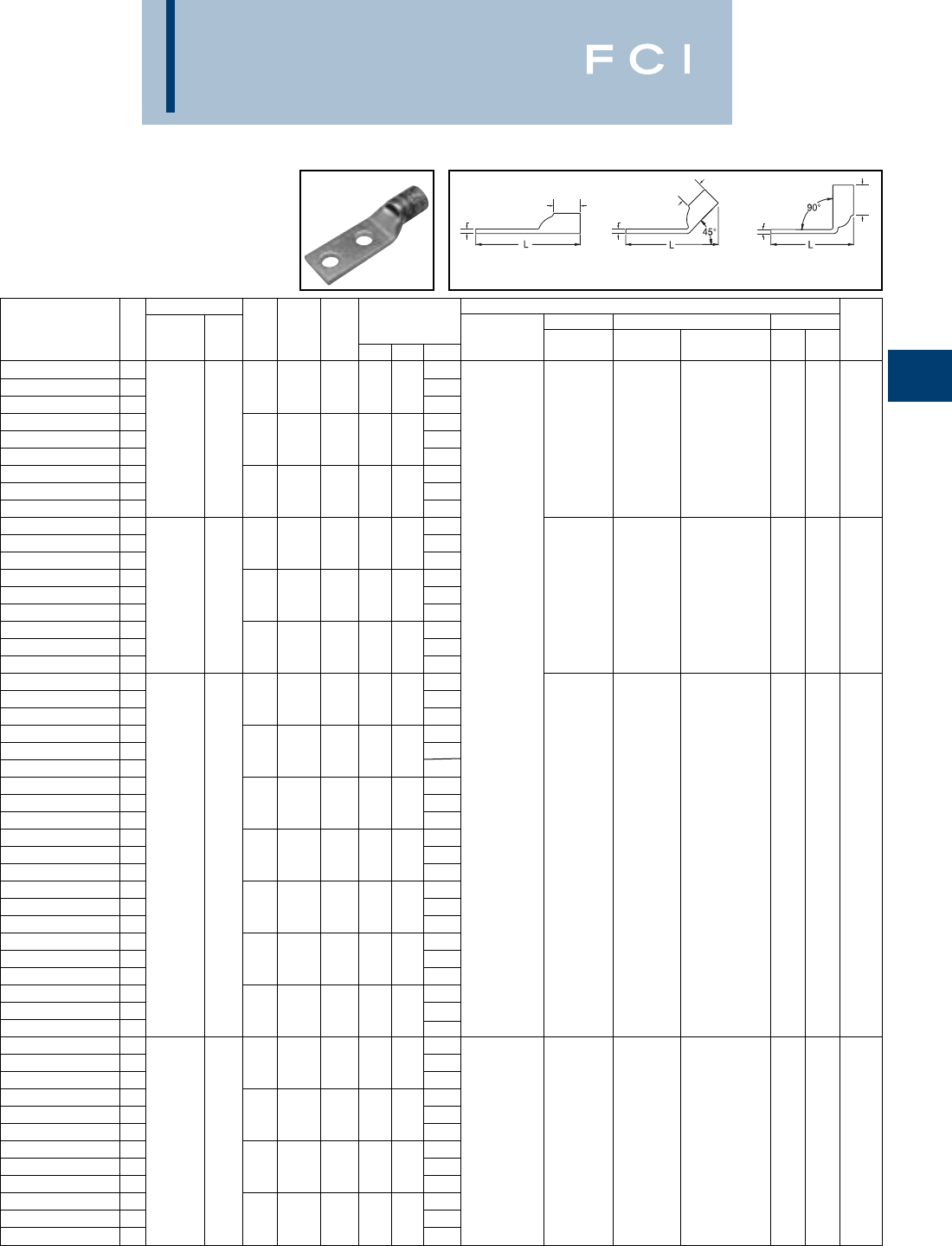
BURNDY
Compression
C-47
TWO HOLE HYLUG™
CODE CONDUCTOR
STANDARD BARREL
(Continued)
** P-RT die sets for use in Y46 HYPRESS™ only, PUADP-1
adapter not required.
*** The MM2conductor sizes listed are the recommendations
for Class 2 conductor.
Conductor ▲Installation Tooling
Stud
Stud
Figure Mechanical Hydraulic Wire
Fig *** Hole
Hole Tongue
Dimensions Dieless MD6, OUR840, BCT500HS, Y35, Y39, Y750, Color Die Strip
Catalog Number # AWG MM2Size
Spacing Width
(B) (T) (L) (# of crimps) MD7-34R Y500CTHS Y46*, PAT750 Code Index Length
YA4C-2LN 14.14
YA4C-2LN-45 21/21-3/4.83.81.124.10
YA4C-2LN-90 33.30
YA4CL-2TC14E2 12.49
YA4CL-2TC14E2-45 24 AWG-1/43/4.49.81.092.40W4CVT (1) X4CRT (1) U4CRT (1) Gray 8 7/8
YA4CL-2TC14E2-90 31.66
YA4CL-2TC516 12.80
YA4CL-2TC516-45 25/161.52.81.092.69
YA4CL-2TC516-90 31.97
YA3CL-2TC14 12.45
YA3CL-2TC14-45 21/45/8.55.81.092.33
YA3CL-2TC14-90 31.55
YA3C-2L 12.64
YA3C-2L-45 23 AWG 25 5/165/8.55.88.092.52W3CRT (1) W3CRT (1) U3CRT (1)
White
915/16
YA3C-2L-90 3#2 Sol. 1.74
YA3CL-2TC38 13.06Y1MR (2)
YA3CL-2TC38-45 23/81.58.88.082.90Y2MR (2)
YA3CL-2TC38-90 32.11MY29-3 (1)
YA2C-2L 12.67MY29-11 (1)
YA2C-2L-45 25/163/4.60.88.112.57MRC840 (1)
YA2C-2L-90 31.77Y644HS (1)
YA2C-2LN 14.27Y81KFT (1)
YA2C-2LN-45 21/21-3/4.83.88.114.19
Y81KFTMBH (1)
YA2C-2LN-90 33.14
PAT81KFT-18V (1)
YA2CL-2TC14 12.47
YA2CL-2TC14-45 21/45/8.60.88.112.38
YA2CL-2TC14-90 31.58
YA2CL-2TC14E1 12.85W2CVT (1) W2CVT (1)
YA2CL-2TC14E1-45 22 AWG351/41.60.88.112.77W2CRT (1) W2CRT (1) U2CRT (1)
Brown
10 15/16
YA2CL-2TC14E1-90 31.96X2CRT (1) X2CRT (1)
YA2CL-2TC14E2 12.60
YA2CL-2TC14E2-45 21/43/4.60.88.112.51
YA2CL-2TC14E2-90 31.71
YA2CL-2TC38 13.03
YA2CL-2TC38-45 23/81.60.88.112.94
YA2CL-2TC38-90 32.15
YA2CL-2TC516 12.91
YA2CL-2TC516-45 25/161.60.88.112.82
YA2CL-2TC516-90 32.02
YA1C-2LN 14.32
YA1C-2LN-45 21/21-3/4.81.88.124.23
YA1C-2LN-90 33.36Y1MR (2)
YA1C-2L 12.82MY29-3 (1)
YA1C-2L-45
25/167/8.68.88.102.71MY29-11 (1)
W1CVT (1) W1CVT (1)
YA1C-2L-90 31 AWG 50 1.92MRC840 (1)
W1CRT-1 (1) W1CRT-1 (1)
U1CRT-1 (1)
Green
11 15/16
YA1CL-2TC14 12.51Y644HS (1)
X1CRT-1 (1) X1CRT-1 (1)
U4CABT (1)
YA1CL-2TC14-45 21/45/8.68.88.102.40Y81KFT (1)
YA1CL-2TC14-90 31.60
Y81KFTMBH (1)
YA1CL-2TC14E2 12.64
PAT81KFT-18V (1)
YA1CL-2TC14E2-45 21/43/4.68.88.102.52
YA1CL-2TC14E2-90 31.73
-- Color code not assigned.
▲See tooling section of this catalog for complete tool and die
listings.
◆For applications greater than 2000 volts consult cable man-
ufacturer for voltage stress relief instructions.
*Use PUADP-1 adapter with "U" dies in Y46 HYPRESS™.
TTT
BB
B
Fig. 1 Fig. 2 Fig. 3

Conductor ▲Installation Tooling
Stud
Stud
Figure Mechanical Hydraulic Wire
Fig *** Hole
Hole Tongue
Dimensions Dieless MD6, OUR840, BCT500HS, Y35, Y39, Y750, Color Die Strip
Catalog Number # AWG MM2Size
Spacing Width
(B) (T) (L) (# of crimps) MD7-34R Y500CTHS Y46*, PAT750 Code Index Length
YA1CL-2TC38
13.07
YA1CL-2TC38-45
22.96
-3/81.68.88.10W1CVT (1) X1CRT-1 (1) U1CRT (1) Green 11 15/16
YA1CL-2TC38-90
32.17
YA25-2L
12.85
YA25-2L-45
25/167/8.75.88.122.77
YA25-2L-90
31.95
YA252LN
14.29
YA252LN-45
21/21-3/4.83.88.114.20
YA252LN-90
33.38
YA25L-2TC14
12.64
YA25L-2TC14-45
21/45/8.75.88.122.45W25VT (2) W25VT (2)
YA25L-2TC14-90
31/0 AWG - 1.58W25RT (2) W25RT (2) U25RT (1) Pink 12 15/16
YA25L-2TC14E1
13.01X25RT (2) X25RT (2) U2CABT (1)
YA25L-2TC14E1-45
21/41 .75.88.122.91
YA25L-2TC14E1-90
31.95
YA25L-2TC14E2
12.66
YA25L-2TC14E2-45
21/43/4.75.88.122.58
YA25L-2TC14E2-90
31.70
YA25L-2TC38
13.10
YA25L-2TC38-45
23/81.75.88.123.02MY29-3 (1)
YA25L-2TC38-90
32.14MY29-11 (1)
YA26-2L
12.95MRC840 (2)
YA26-2L-45
25/167/8.83.94.122.84Y644HS (1)
YA26-2L-90
31.98Y81KFT (1)
YA262LN
14.39
Y81KFTMBH (1)
YA262LN-45
21/21-3/4.83.94.124.27
PAT81KFT-18V (1)
YA262LN-90
33.41
YA26L-2TC14
12.64
YA26L-2TC14-45
21/45/8.83.94.122.52W26VT (2) W26VT (2)
YA26L-2TC14-90
32/0 AWG 70 1.66W26RT (2) W26RT (2) U26RT (1) Black 13 1
YA26L-2TC14E1
13.01X26RT (2) X26RT (2)
YA26L-2TC14E1-45
21/41.83.94.122.90
YA26L-2TC14E1-90
32.04
YA26L-2TC14E2
12.76
YA26L-2TC14E2-45
21/43/4.83.94.122.65
YA26L-2TC14E2-90
31.79
YA26L-2TC38
13.20
YA26L-2TC38-45
23/81.83.94.123.09
YA26L-2TC38-90
32.22
YA272LN
14.48
YA272LN-45
21/21-3/4.911.00.134.35
YA272LN-90
33.44
YA27L-2TC14E2
12.86W27VT (2) W27VT (2)
YA27L-2TC14E2-45
23/0 AWG - 1/43/4.911.00.122.73W27RT (2) W27RT (2) U27RT (1)
Orange
14 1-1/16
YA27L-2TC14E2-90
31.81X27RT (3) X27RT (3)
YA27L-2TC38
13.30
YA27L-2TC38-45
23/81.911.00.123.17
YA27L-2TC38-90
32.25
BURNDY
Compression
C-48
TWO HOLE HYLUG™
CODE CONDUCTOR
STANDARD BARREL
(Continued)
-- Color code not assigned.
▲See tooling section of this catalog for complete tool and die
listings.
◆For applications greater than 2000 volts consult cable
manufacturer for voltage stress relief instructions.
*Use PUADP-1 adapter with "U" dies in Y46 HYPRESS™.
** P-RT die sets for use in Y46 HYPRESS™ only, PUADP-1
adapter not required.
*** The MM2conductor sizes listed are the recommendations
for Class 2 conductor
TTT
BB
B
Fig. 1 Fig. 2 Fig. 3

BURNDY
Compression
C-49
TWO HOLE HYLUG™
CODE CONDUCTOR
STANDARD BARREL
(Continued)
-- Color code not assigned.
▲See tooling section of this catalog for complete tool and die
listings.
◆For applications greater than 2000 volts consult cable man-
ufacturer for voltage stress relief instructions.
*Use PUADP-1 adapter with "U" dies in Y46 HYPRESS™.
Conductor ▲Installation Tooling
Stud
Stud
Figure Mechanical Hydraulic Wire
Fig *** Hole
Hole Tongue
Dimensions Dieless MD6, OUR840, BCT500HS, Y35, Y39, Y750, Color Die Strip
Catalog Number # AWG MM2Size
Spacing Width
(B) (T) (L) (# of crimps) MD7-34R Y500CTHS Y46*, PAT750 Code Index Length
YA28-2L516 13.84
YA28-2L516-45 25/161-3/41.02.88.143.77
YA28-2L516-90 32.92
YA282LN 14.41
YA282LN-45 21/21-3/41.02.88.144.34
YA282LN-90 33.49
YA28L-2TC14E1 13.03MY29-3 (1)
YA28L-2TC14E1-45 21/411.02.88.142.96MY29-11 (1)
YA28L-2TC14E1-90 34/0 AWG - 2.11MRC840 (2) W28VT (2) W28VT (2)
YA28L-2TC14E2 12.78Y644HS (1) W28RT (2) W28RT (2) U28RT (1) Purple 15 1-1/8
YA28L-2TC14E2-45 21/43/41.02.88.142.71Y81KFT (1) X28RT (3) X28RT (3)
YA28L-2TC14E2-90 31.86
Y81KFTMBH (1)
YA28L-2TC38E2 12.97
PAT81KFT-18V (1)
YA28L-2TC38E2-45 23/83/41.02.88.142.90
YA28L-2TC38E2-90 32.05
YA28L-2TC38 13.22
YA28L-2TC38-45 23/811.02.88.143.15
YA28L-2TC38-90 32.30
YA292LN 14.62MY29-3 (1)
YA292LN-45 21/21-3/41.111.06.164.52MY29-11 (1)
YA292LN-90 3250 kcmil - 3.52Y644HS (1) W29VT (2) W29VT (2)
YA29L-2TC38 13.45Y81KFT (1) X29RT (4) W29RT (2) U29RT (1) Yellow 16 1-1/8
YA29L-2TC38-45 23/811.111.06’ .163.33
Y81KFTMBH (1)
X29RT (4)
YA29L-2TC38-90 32.34
PAT81KFT-18V (1)
YA302LN 14.63
YA302LN-45 21/21-3/41.201.03.164.55
YA302LN-90 3300 kcmil 150 3.56W30VT (2) U30RT (2)
YA30L-2TC-38 13.45W30VT (2) W30RT (2) U28ART (2) White 17 1
YA30L-2TC-38-45 23/811.201.03.163.36
YA30L-2TC-38-90 32.37
YA312LN 14.70
YA312LN-45 21/21-3/41.291.06.184.62
YA312LN-90 33.60
YA31L-2TC12 14.01
YA31L-2TC12-45 21/21-1/41.29 1.06.183.93Y644HS (1)
YA31L-2TC12-90 32.91Y81KFT (1)
YA31L-2TC14E2 13.07
Y81KFTMBH (1)
YA31L-2TC14E2-45 2350 kcmil 185 1/43/41.291.06.182.99
PAT81KFT-18V (1)
W31VT (2) W31VT (2) U31RT (2) Red 18 1-1/8
YA31L-2TC14E2-90 31.97W31RT (2) U29ART (2)
YA31L-2TC38 13.51
YA31L-2TC38-45 23/811.291.06.183.43
YA31L-2TC38-90 32.41
YA31L-2NTC516 14.13
YA31L-2NTC516-45 25/161-3/41.291.06.184.06
YA31L-2NTC516-90 33.03
YA322LN 14.88
YA322LN-45 2400 kcmil 1/21-3/41.381.19.194.78W32VT (2) W32VT (2) U32RT (2) Blue 19 1-1/4
YA322LN-90
33.64W32RT (2)
U30ART (2)
** P-RT die sets for use in Y46 HYPRESS™ only, PUADP-1
adapter not required.
*** The MM2conductor sizes listed are the recommendations
for Class 2 conductor.
TTT
BB
B
Fig. 1 Fig. 2 Fig. 3

BURNDY
Compression
C-50
TWO HOLE HYLUG™
CODE CONDUCTOR
STANDARD BARREL
(Continued)
-- Color code not assigned.
▲See tooling section of this catalog for complete tool and die
listings.
◆For applications greater than 2000 volts consult cable
manufacturer for voltage stress relief instructions.
Conductor ▲Installation Tooling
Stud
Stud
Figure Mechanical Hydraulic Wire
Fig *** Hole
Hole Tongue
Dimensions Dieless MD6, OUR840, BCT500HS, Y35, Y39, Y750, Color Die Strip
Catalog Number # AWG MM2Size
Spacing Width
(B) (T) (L) (# of crimps) MD7-34R Y500CTHS Y46*, PAT750 Code Index Length
YA32L-2TC38E5
13.75
YA32L-2TC38E5-45
23/8
1-1/16
1.40
1.19
.19
3.66
YA32L-2TC38E5-90
32.52
W32VT (2) U32RT (2)
YA32L-2TC38
400 kcmil 3/
81
1.38
1.19
.19
3.69
W32VT (2) Blue 19 1-1/4
YA32-2L
13.75
W32RT (2) U30ART (2)
YA32-2L-45
23/8
1
1.40
1.19
.19
3.66
YA32-2L-90
32.52
YA33-2LN
15.23
W33VT (2)
YA33-2LN-45
2450 kcmil 1/2
1-3/4
1.48
1.50
.21
5.10
W33VT (2) U33RT (2) Gray 326 1-9/16
YA33-2LN-90
33.70
W33RT (2)
YA342LN
15.06
YA342LN-45
21/2
1-3/4
1.52
1.27
.23
5.00
YA342LN-90
33.73
YA34L-2TC12
14.38
YA34L-2TC12-45
21/2
1-1/4
1.52
1.27
.23
4.31
YA34L-2TC12-90
33.04
YA34L-2TC14E2
13.44
YA34L-2TC14E2-45
2500 kcmil 240 1/4
3/4
1.52
1.27
.23
3.37
W34VT (2) W34VT (2) U34RT (2)
Brown
20 1-7/16
YA34L-2TC14E2-90
32.10
W34RT (2) U31ART (2)
YA34L-2TC38
13.88
YA34L-2TC38-45
23/8
1
1.52
1.27
.23
3.81
YA34L-2TC38-90
32.54
Y644HS (1)
YA34-2L
13.94
Y81KFT (1)
YA34-2L-45
23/8
1
1.55
1.27
.23
3.87
Y81KFTMBH (1)
YA34-2L-90
32.59
PAT81KFT-18V (1)
YA35-2L
14.64
YA35-2L-45
23/8
1-1/8
1.65
1.69
.25
3.95
YA35-2L-90
3550 kcmil - 2.60
--U35RT (2)
Ye l l o w
21 1-3/4
YA35-2LN
1
YA35-2LN-45
21/2
1-3/4
1.65
1.69
.25
5.07
YA35-2LN-90
33.73
YA362LN
14.36
YA362LN45
21/2
1-3/4
1.74
1.38
.27
5.21
YA362LN90
3600 kcmil 300 3.81
--
U36RT (2)
Green
22 1-3/4
YA36L-2TC38
14.23
U32ART (2)
YA36L-2TC38-45
23/8
1
1.73
1.38
.27
4.21
YA36L-2TC38-90
32.81
YA37-2L
14.40
YA37-2L-45
23/8
1-1/8
1.80
1.39
.27
4.37
YA37-2L-90
3650 kcmil - 2.96
--U37RT (2)
Orange
23
1-15/16
YA37-2LN
15.27
YA37-2LN-45
21/2
1-3/4
1.80
1.39
.27
5.25
YA37-2LN-90
33.84
YA38-2L
14.48
YA38-2L-45
23/8
1-1/8
1.84
1.45
.27
4.42
YA38-2L-90
3700 kcmil - 3.23
--U38RT (2) Pink 400
1-15/16
YA38-2LN
15.35
YA38-2LN-45
21/2
1-3/4
1.81
1.45
.27
5.29
YA38-2LN-90
33.84
*Use PUADP-1 adapter with "U" dies in Y46 HYPRESS™.
** P-RT die sets for use in Y46 HYPRESS™ only, PUADP-1
adapter not required.
*** The MM2conductor sizes listed are the recommendations
for Class 2 conductor.
TTT
BB
B
Fig. 1 Fig. 2 Fig. 3
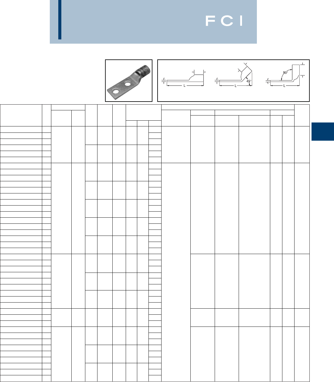
Conductor ▲Installation Tooling
Stud
Stud
Figure Mechanical Hydraulic Wire
Fig *** Hole
Hole Tongue
Dimensions Dieless MD6, OUR840, BCT500HS, Y35, Y39, Y750, Color Die Strip
Catalog Number # AWG MM2Size
Spacing Width
(B) (T) (L) (# of crimps) MD7-34R Y500CTHS Y46*, PAT750 Code Index Length
YA38L-2TC12
14.67
YA38L-2TC12-45
21/21-1/21.811.45.274.61Y644HS (1)
YA38L-2TC12-90
3700 kcmil - 3.16Y81KFT (1) --U38RT (2) Pink 400
1-15/16
YA38L-2TC38
14.35
Y81KFTMBH (1)
YA38L-2TC38-45
23/811.811.45.274.30
PAT81KFT-18V (1)
YA38L-2TC38-90
32.84
YA392L
14.48
YA392L-45
23/81-1/81.911.42.274.43
YA392L-90
33.00
YA392LN
15.36
YA392LN45
21/21-3/41.891.42.275.31
YA392LN-90
33.87
YA39L-2TC12E3
14.92U39RT (2)
YA39L-2TC12E3-45
2750 kcmil - 1/21-1/21.891.42.274.87--P39RT (2)
Black
24
1-15/16
YA39L-2TC12E3-90
33.43**
YA39L-2TC38
14.36
YA39L-2TC38-45
23/811.891.42.274.31
YA39L-2TC38-90
32.87
YA39L-2TC58
15.17
YA39L-2TC58-45
25/81-1/21.891.42.275.12
YA39L-2TC58-90
33.68
YA40-2L
14.63
YA40-2L-45
23/81-1/81.981.42.304.51Y644HS (1)
YA40-2L-90
33.04Y81KFT (2)
YA402LN
15.51
Y81KFTMBH (2)
YA402LN-45
2800 kcmil 400 1/21-3/41.891.42.305.39
PAT81KFT-18V (2)
--P40RT (3)
Orange
25
1-15/16
YA402LN-90
33.91**
YA40L-2TC38
14.51
YA40L-2TC38-45
23/811.951.42.304.38
YA40L-2TC38-90
32.91
YA41-2L
14.97
YA41-2L-45
2850 kcmil - 3/81-1/82.011.88.314.86-- -Gold 26
1-15/16
YA41-2L-90
33.05
YA442LN
15.74
A442LN-45
21/21-3/42.171.65.335.71
YA442LN-90
34.02
YA44-2L
15.24**
YA44-2L-45
21000 kcmil 500 1/21-1/42.191.65.335.21--P44RT (3)
White
27
1-15/16
YA44-2L-90
33.52
YA44L-2TC12
15.05
YA44L-2TC12-45
21/21-1/42.171.65.335.02
YA44L-2TC12-90
33.33
BURNDY
Compression
C-51
TWO HOLE HYLUG™
CODE CONDUCTOR
STANDARD BARREL
(Continued)
-- Color code not assigned.
▲See tooling section of this catalog for complete tool and die
listings.
◆For applications greater than 2000 volts consult cable man-
ufacturer for voltage stress relief instructions.
*Use PUADP-1 adapter with "U" dies in Y46 HYPRESS™.
** P-RT die sets for use in Y46 HYPRESS™ only, PUADP-1
adapter not required.
*** The MM2conductor sizes listed are the recommendations
for Class 2 conductor.
TTT
BB
B
Fig. 1 Fig. 2 Fig. 3
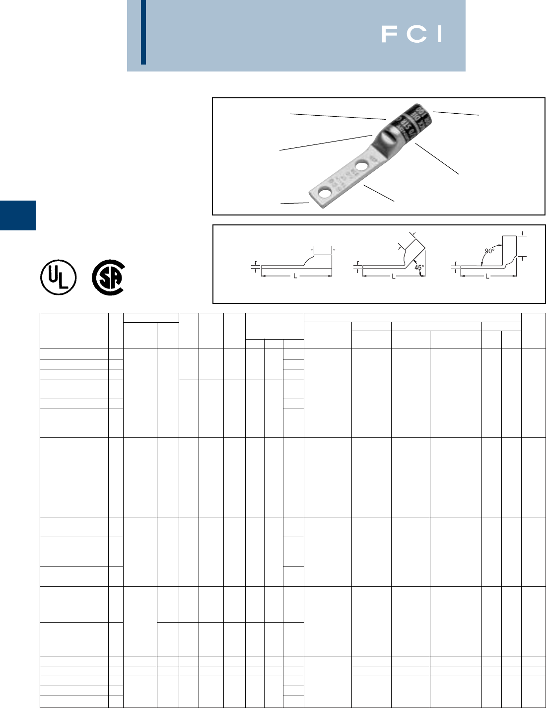
Conductor ▲Installation Tooling
Stud
Stud
Figure Mechanical Hydraulic Wire
Fig *** Hole
Hole Tongue
Dimensions Dieless MD6, OUR840, BCT500HS, Y35, Y39, Y750, Color Die Strip
Catalog Number # AWG MM2Size
Spacing Width
(B) (T) (L) (# of crimps) MD7-34R Y500CTHS Y46*, PAT750 Code Index Length
YA2CL2NT14
12.47MRC840 (1)
YA2CL2NT1445
21/45/8.48.88.112.38MY29-3 (1)
YA2CL2NT1490
31.58MY29-11 (1)
YA2CL2NT14E2
11/43/4.48.88.112.60Y2MR (2)
YA2CL2NT14E1
1#2 AWG 35 2.84Y644HS (1) W2CVT (1) W2CVT (1) U2CRT (1)
Brown
10 15/16
YA2CL2NT14E145
22.76Y1MR (2)
1/41.48.88.11Y81KFT (1)
YA2CL2NT14E190
31.96
Y81KFTMBH (1)
PAT81KFT-18V (1)
MRC840 (1)
MY29-3 (1)
MY29-11 (1)
Y1MR (2)
YA1CL2NT14E2
1#1 AWG 50 1/43/4.50.88.102.68
Y644HS (1) W1CVT (1) W1CRT (1) U1CRT (1)
Green
11 15/16
Y81KFT (1)
Y81KFTMBH (1)
PAT81KFT-18V (1)
MRC840 (2)
YA25L2NT14E1
13.28
MY29-3 (1)
MY29-11 (1)
YA25L2NT14E145
21/0 AWG - 1/41.48.88.122.83Y644HS (1) W25VT (2) W25VT (1) U25RT (1) Pink 12 15/16
Y81KFT (1)
Y81KFTMBH (1)
YA25L2NT14E190
31.95
PAT81KFT-18V (1)
MRC840 (2)
YA26L2NT14
1701/45/8.48.94.122.66MY29-3 (1)
MY29-11 (1)
2/0 AWG Y644HS (1) W26VT (2) W26VT (1) U26RT (1)
Black
13 1
Y81KFT (1) X26RT (1)
YA26L2NT14E1
1-1/41.48.94.123.03
Y81KFTMBH (1)
PAT81KFT-18V (1)
YA31L2NT38
1350 kcmil 185 3/81.961.06.183.51W31VT (4) W31VT (4) U31RT (2) Red 18 1-1/8
YA34L2NT38
1500 kcmil 240 3/81.961.27.233.65Y644HS (1) W34VT (4) W34VT (4) U34RT (2)
Brown
20 1-7/16
YA39L2NT38
14.34Y81KFT (2)
YA39L2NT3845
2750 kcmil - 3/811.631.42.274.31
Y81KFTMBH (2)
--U39RT (2)
Black
24
1-1/2
YA39L2NT3890
32.87
PAT81KFT-18V (2)
BURNDY
Compression
C-52
TWO HOLE HYLUG™
CODE CONDUCTOR
STANDARD BARREL
NARROW TONGUE
TYPES YA-L-2NT
COPPER COMPRESSION
TERMINAL
UL Listed 90° C,
600 Volts to 35 KV ◆
ELECTRO-TIN
PLATED CABLE
ACCOMMODATION
CRIMP
DIE AND COLOR
CODE INFORMATION
INSPECTION
WINDOW
BEVELED
ENTRY
TTT
BB
B
Fig. 1 Fig. 2 Fig. 3
*Use PUADP-1 adapter with "U" dies in Y46 HYPRESS™.
*** The MM2conductor sizes listed are the recommendations
for Class 2 conductor.
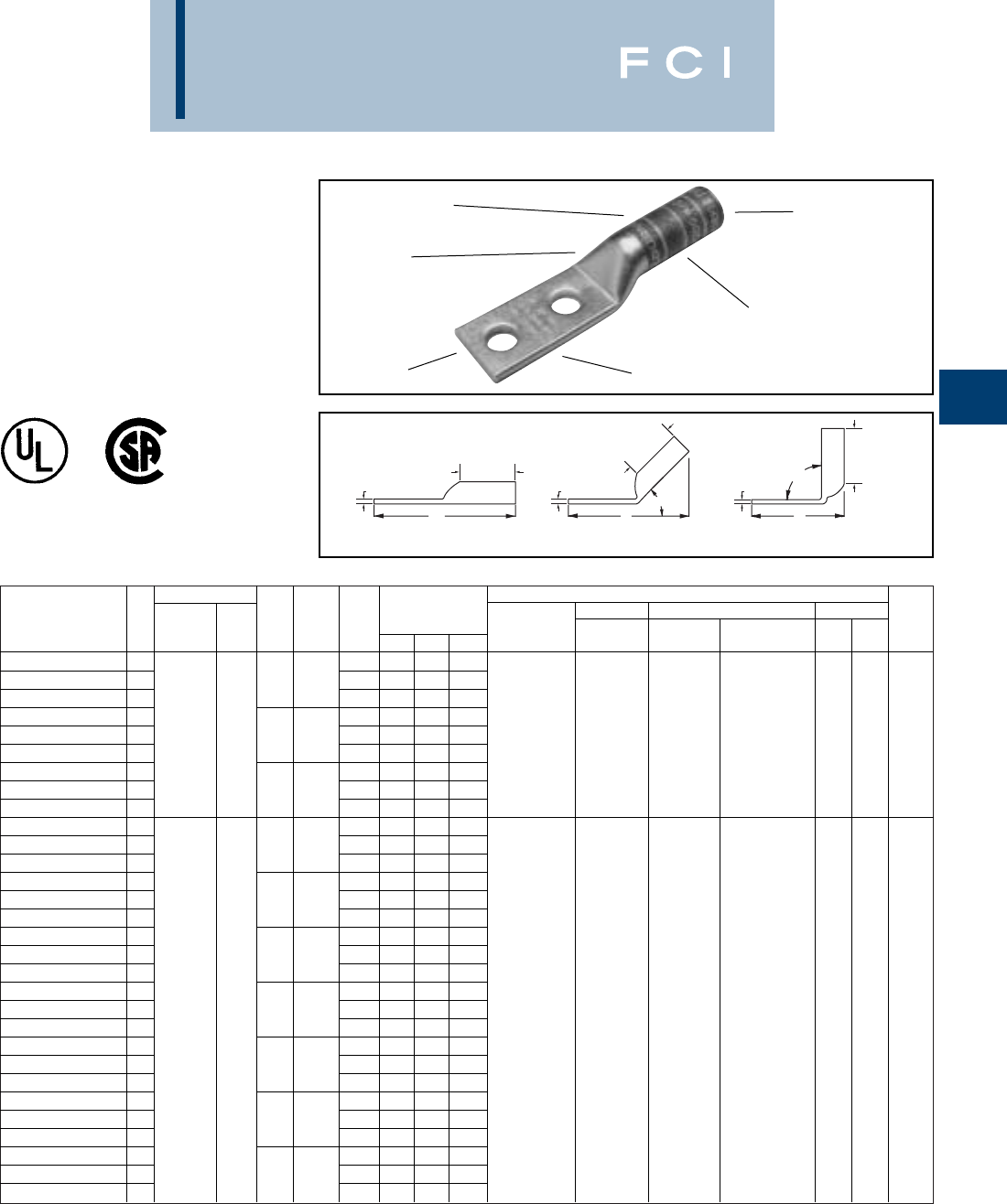
Conductor ▲Installation Tooling
Stud
Stud
Figure Mechanical Hydraulic Wire
Fig *** Hole
Hole Tongue
Dimensions Dieless MD6, OUR840, BCT500HS, Y35, Y39, Y750, Color Die Strip
Catalog Number # AWG MM2Size
Spacing Width
(B) (T) (L) (# of crimps) MD7-34R Y500CTHS Y46*, PAT750 Code Index Length
YA8C2TC14 1.402.33
YA8C2TC14-45 21/45/8.40.81.082.20Y2MR (2)
YA8C2TC14-90 3#8 STR. .411.49Y8MRB-1 (2)
YA8C2TC14E2 1† .412.45MY29-3 (2) W8CVT (2) W8CVT (2)
YA8C2TC14E2-45 2#6 SOL 1/43/4.41.81.082.33MY29-11 (2) W8CRT (2) W8CRT (2) U8CRT (1) Red 49 1
YA8C2TC14E2-90 310 .411.62MRC840 (2) X8CRT (2) X8CRT (2)
YA8C2TC38 137/24 .732.89Y81KFT (1)
YA8C2TC38-45 23/81.73.81.062.72
Y81KFTMBH (1)
YA8C2TC38-90 3.732.05
PAT81KFT-18V (1)
YA6C2N 1.814.40
YA6C2N-45 21/21-3/4.811.12.124.29
YA6C2N-90 3.813.28
YA6C2TC14 1.452.65
YA6C2TC14-45 21/45/8.451.12.082.45
YA6C2TC14-90 3.451.51
YA6C2TC14E1 1.453.03
YA6C2TC14E1-45 21/41.451.12.082.83Y1MR (2)
YA6C2TC14E1-90 3.451.88Y2MR (2)
YA6C2TC14E2 1.452.78MY29-3 (2) W5CVT (2) W5CVT (2)
YA6C2TC14E2-45 2#6 AWG - 1/43/4.451.12.082.58MY29-11 (2) W5CRT (2) W5CRT (2) U5CRT (2) Blue 7 1-3/16
YA6C2TC14E2-90 3.451.63MRC840 (2) X5CRT (2) X5CRT (2) U8CABT (2)
YA6C2TC38 1.633.22Y81KFT (1) X8CART (2) X8CART (2)
YA6C2TC38-45 23/81.631.12.062.97
Y81KFTMBH (1)
YA6C2TC38-90 3.632.06
PAT81KFT-18V (1)
YA6C2TC38E2 1.632.97
YA6C2TC38E2-45 23/83/4.631.12.062.72
YA6C2TC38E2-90 3.631.81
YA6C2TC38E6 1.633.09
YA6C2TC38E6-45 23/87/8.631.12.062.85
YA6C2TC38E6-90 3.631.94
BURNDY
Compression
C-53
TWO HOLE HYLUG™
CODE CONDUCTOR
LONG BARREL
TYPES YA-2N,YA-2TC,
YA-4N
UL Listed 90° C,
600 Volts to 35 KV ◆
ELECTRO-TIN
PLATED CABLE
ACCOMMODATION
CRIMP
DIE AND COLOR
CODE INFORMATION
NO INSPECTION
WINDOW
BEVELED
ENTRY
T T T
B
B
B
90°
L
45°
LL
Fig. 1 Fig. 2 Fig. 3
▲See tooling section of this catalog for complete tool and die
listings.
*Use PUADP-1 adaptor with "U" -dies in Y46 HYPRESS™.
** P-RT die sets for use in Y46 HYPRESS™ only, PUADP-1
adapter not required.
*** The MM2conductor sizes listed are the recommendations
for Class 2 conductor.
†The MM2conductor size listed here is for Class 2 and
Class 5 conductor.
"Available undrilled. Add suffix "U" to catalog number
(example: YA25U).
◆For applications greater than 2000 Volts consult cable
manufacturer for voltage stress relief instructions.

Conductor ▲Installation Tooling
Stud
Stud
Figure Mechanical Hydraulic Wire
Fig *** Hole
Hole Tongue
Dimensions Dieless MD6, OUR840, BCT500HS, Y35, Y39, Y750, Color Die Strip
Catalog Number # AWG MM2Size
Spacing Width
(B) (T) (L) (# of crimps) MD7-34R Y500CTHS Y46*, PAT750 Code Index Length
MY29-3 (2)
YA5C2N 14.43
MY29-1 (2)
MRC840 (2) W5CRT (2) X5CRT (2)
YA5C2N-45 25 AWG - 1/21-3/4.831.12.124.31Y644HS (1) W5CVT (2) X5CVT (2) U5CRT (2) Blue 7 1-3/16
Y81KFT (1) X5CRT (2) W5CRT (2)
Y81KFTMBH (1)
YA5C2N-90 33.28
PAT81KFT-18V (1)
YA4C2N 14.45
YA4C2N-45 21/21-3/4.811.12.124.32
YA4C2N-90 33.30
YA4C2TC14 12.70
YA4C2TC14-45 21/45/8.501.12.092.51
YA4C2TC14-90 31.54W4CVT (2) W4CVT (2) U4CRT (2)
YA4C2TC14E2 14 AWG - 2.83W4CRT (2) W4CRT (2) U6CABT (2) Gray 8 1-3/16
YA4C2TC14E2-45 21/43/4.501.12.092.64X4CRT (2) X4CRT (2)
YA4C2TC14E2-90 31.66
YA4C2TC38 1.3.26Y1MR (4)
YA4C2TC38-45 23/81.561.12.083.03Y2MR (4)
YA4C2TC38-90 32.09MY29-3 (2)
YA3C2N 14.62MY29-11 (2)
YA3C2N-45 21/21-3/4.811.25.124.44MRC840 (2)
YA3C2N-90 33.32Y644HS (1)
YA3C2TC14 12.87Y81KFT (1)
YA3C2TC14-45 21/45/8.551.25.092.62
Y81KFTMBH (1)
YA3C2TC14-90 3#3 STR 1.55
PAT81KFT-18V (1)
YA3C2TC14E2 12.99
YA3C2TC14E2-45 2# 3 AWG25 1/43/4.551.25.092.75W3CRT (2) W3CRT (2) U3CRT (2) White 9 1-5/16
YA3C2TC14E2-90 31.68
YA3C2TC38 1#2 SOL 3.43
YA3C2TC38-45 23/81.581.25.083.16
YA3C2TC38-90 32.11
YA3C2TC38E2 13.18
YA3C2TC38E2-45 23/83/4.581.25.082.91
YA3C2TC38E2-90 31.86
YA2C2N 14.64
YA2C2N-45 21/21-3/4.811.25.124.46
YA2C2N-90 33.34
YA2C2TC14 12.86
YA2C2TC14-45 21/45/8.601.25.112.66
YA2C2TC14-90 31.58Y1MR (4)
YA2C2TC14E2 12.98Y2MR (4)
YA2C2TC14E2-45 21/43/4.601.25.112.78MY29-3 (2) W2CVT (2) W2CVT (2)
YA2C2TC14E2-90 3#2 AWG 35 1.71MY29-11 (2) W2CRT (2) W2CRT (2) U2CRT (2) Brown 10 1-5/16
YA2C2TC38E2 13.17MRC840 (2) X2CRT (2) X2CRT (2)
YA2C2TC38E2-45 23/83/4.601.25.112.97Y644HS (1)
YA2C2TC38E2-90 31.90Y81KFT (2)
YA2C2TC516E2 13.05
Y81KFTMBH (2)
YA2C2TC516E2-45 25/163/4.601.25.112.84
PAT81KFT-18V (2)
YA2C2TC516E2-90 31.77
YA2C2NTC38 14.17
YA2C2NTC38-45 23/81-3/4.601.25.113.97
YA2C2NTC38-90 32.90
BURNDY
Compression
C-54
▲See tooling section of this catalog for complete tool and die
listings.
*Use PUADP-1 adaptor with "U" -dies in Y46 HYPRESS™.
TWO HOLE HYLUG™
CODE CONDUCTOR
LONG BARREL
(Continued)
T T T
B
B
B
90°
L
45°
LL
Fig. 1 Fig. 2 Fig. 3
** P-RT die sets for use in Y46 HYPRESS™ only, PUADP-1
adapter not required.
*** The MM2conductor sizes listed are the recommendations
for Class 2 conductor.
"Available undrilled. Add suffix "U" to catalog number
(example: YA25U).
◆For applications greater than 2000 Volts consult cable
manufacturer for voltage stress relief instructions.
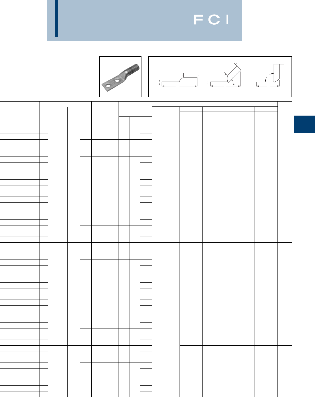
BURNDY
Compression
C-55
▲See tooling section of this catalog for complete tool and die
listings.
*Use PUADP-1 adaptor with "U" -dies in Y46 HYPRESS™.
** P-RT die sets for use in Y46 HYPRESS™ only, PUADP-1
adapter not required.
TWO HOLE HYLUG™
CODE CONDUCTOR
LONG BARREL
(Continued)
Conductor ▲Installation Tooling
Stud
Stud
Figure Mechanical Hydraulic Wire
Fig *** Hole
Hole Tongue
Dimensions Dieless MD6, OUR840, BCT500HS, Y35, Y39, Y750, Color Die Strip
Catalog Number # AWG MM2Size
Spacing Width
(B) (T) (L) (# of crimps) MD7-34R Y500CTHS Y46*, PAT750 Code Index Length
YA2C2TC38 13.42Y1MR (4)
YA2C2TC38-45 23/81.601.25.113.22Y2MR (4)
YA2C2TC38-90 32.14MY29-3 (2)
YA2C2TC38E6 13.30MY29-11 (2) W2CVT (2) W2CVT (2)
YA2C2TC38E6-45 2#2 AWG 35 3/87/8.601.25.113.10MRC840 (2) W2CRT (2) W2CRT (2) U2CRT (2) Brown 10 1-5/16
YA2C2TC38E6-90 32.02Y644HS(1) X2CRT (2) X2CRT (2)
YA2C2TC516E2 13.05Y81KFT (2)
YA2C 2TC516E2-45 25/163/4.601.25.112.84
Y81KFTMBH (2)
YA2C 2TC516E2-90 31.77
PAT81KFT-18V (2)
YA1C2N 14.82
YA1C2N-45 21/21-3/4.811.38.124.58
YA1C2N-90 33.36Y1MR (4)
YA1C2TC14 13.03MY29-3 (2)
YA1C2TC14-45 21/45/8.681.38.102.76MY29-11 (2) W1CVT (2) W1CVT (2)
YA1C2TC14-90 31 AWG 50 1.60MRC840 (2) W1CRT-1 (2) W1CRT-1 (2) U1CRT-1 (2) Green 11 1-1/2
YA1C2TC14E2 13.15Y644HS (1) X1CRT-1 (2) X1CRT-1 (2) U4CABT (2)
YA1C2TC14E2-45 21/43/4.751.38.102.88Y81KFT (2)
YA1C2TC14E2-90 31.73
Y81KFTMBH (2)
YA1C2TC38 13.59
PAT81KFT-18V (2)
YA1C2TC38-45 23/81.681.38.103.32
YA1C2TC38-90 32.16
YA252N 14.81
YA252N-45 21/21-3/4.811.38.11’ 4.56
YA252N-90 33.38
YA252TC14 13.05
YA252TC14-45 21/45/8.751.38.122.82
YA252TC14-90 31.64
YA252TC14E2 13.18
YA252TC14E2-45 21/43/4.751.38.122.94
W25VT (4) W25VT (4)
YA252TC14E2-90 31/0 AWG - 1.76
W25RT (4) W25RT (4) U25RT (2) Pink 12 1-7/16
YA252TC38 13.62
X25RT (4) X25RT (4) U2CABT (2)
YA252TC38-45 23/81.751.38.123.38MY29-3 (2)
YA252TC38-90 32.20MY29-11 (2)
YA252TC516 13.49MRC840 (4)
YA252TC516-45 25/161.751.38.123.26Y644HS (1)
YA252TC516-90 32.08Y81KFT (2)
YA252NTC38 14.37
Y81KFTMBH (2)
YA252NTC38-45 23/81-3/4.751.38.124.13
PAT81KFT-18V (2)
YA252NTC38-90 32.95
YA262N 14.97
YA262N-45 21/21-3/4.831.50.124.69
YA262N-90 33.41
YA262TC14 1.3.22W26VT (4) W26VT (4)
YA262TC14-45 22/0 AWG 70 1/45/8.831.50.122.94W26RT (4) W26RT (4) U26RT (2) Black 13 1-9/16
YA262TC14-90 31.66X26RT (4) X26RT (4)
YA262TC14E2 1.3.34
YA262TC14E2-45 21/43/4.831.50.123.06
YA262TC14E2-90 31.79
*** The MM2conductor sizes listed are the recommendations
for Class 2 conductor.
"Available undrilled. Add suffix "U" to catalog number
(example: YA25U).
◆For applications greater than 2000 Volts consult cable
manufacturer for voltage stress relief instructions.
T T T
B
B
B
90°
L
45°
LL
Fig. 1 Fig. 2 Fig. 3
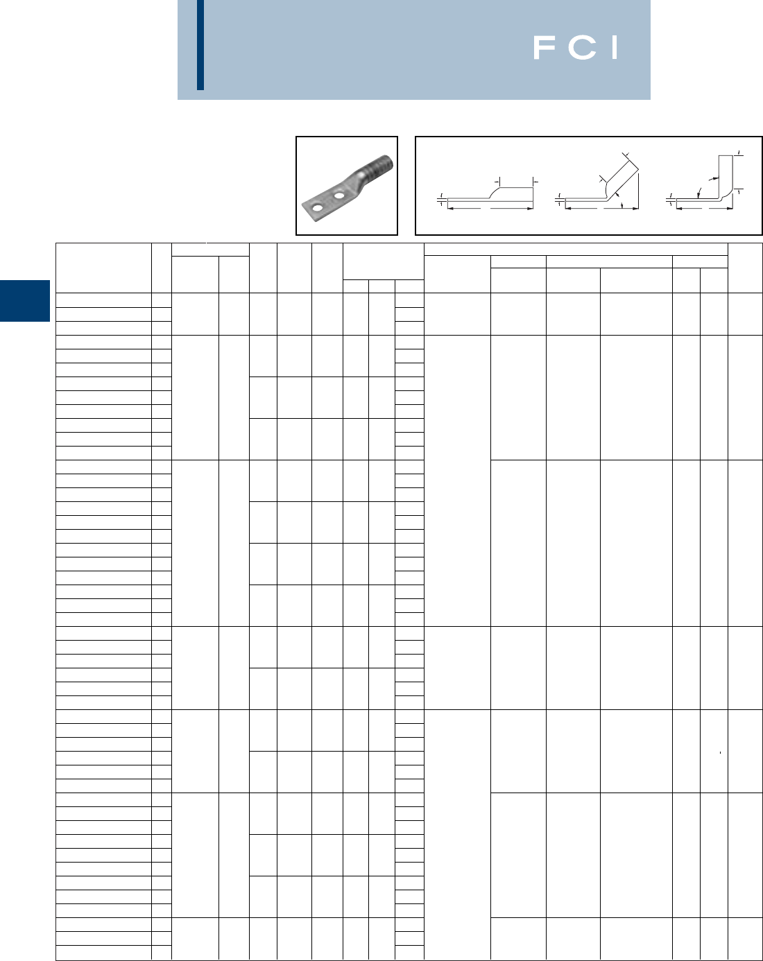
Conductor ▲Installation Tooling
Stud
Stud
Figure Mechanical Hydraulic Wire
Fig *** Hole
Hole Tongue
Dimensions Dieless MD6, OUR840, BCT500HS, Y35, Y39, Y750, Color Die Strip
Catalog Number # AWG MM2Size
Spacing Width
(B) (T) (L) (# of crimps) MD7-34R Y500CTHS Y46*, PAT750 Code Index Length
YA262TC38 13.78Y81KFT (1) W26VT (4) W26VT (4)
YA262TC38-45 22/0 AWG 70 3/81.831.50.123.50
Y81KFTMBH (1)
W26RT (4) W26RT (4) U26RT (2) Black 13 1-9/16
YA262TC38-90 32.22
PAT81KFT-18V (1)
X26RT (4) X26RT (4)
YA272N 15.01
YA272N-45 21/21-3/4.911.50.134.73
YA272N-90 33.44
YA272TC14E2 13.38W27VT (4) W27VT (4)
YA272TC14E2-45 23/0 AWG - 1/43/4.911.50.123.10W27RT (4) W27RT (4) U27RT (2)
Orange
14 1-9/16
YA272TC14E2-90 31.82X27RT (6) X27RT (6)
YA272TC38 13.82
YA272TC38-45 23/81.901.50.123.54MY29-3 (2)
YA272TC38-90 32.25MY29-11 (2)
YA282N 15.17MRC840 (4)
YA282N-45 21/21-3/41.021.62.144.88Y644HS (1)
YA282N-90 33.49Y81KFT (2)
YA282TC38 13.99
Y81KFTMBH (2)
YA282TC38-45 23/811.021.62.143.69
PAT81KFT-18V (2)
W28VT (4) W28VT (4)
YA282TC38-90 34/0 AWG - 2.30
W28RT (4) W28RT (4) U28RT (2)
Purple
15
1-11/16
YA282TC14E2 13.55
X28RT (6) X28RT (6)
YA282TC14E2-45 21/43/41.021.62.143.25
YA282TC14E2-90 31.86
YA282NTC38 14.74
YA282NTC38-45 23/81-3/41.021.62.144.44
YA282NTC38-90 33.05
YA292N 15.21MY29-3 (2)
YA292N-45 21/21-3/41.111.62.164.94MY29-11 (2) W29VT (4)
YA292N-90 3250 kcmil - 3.52Y644HS (1) W29VT (4) W29RT (4) U29RT (2) Yellow 16
1-11/16
YA292TC38 14.02Y81KFT (2) X29RT (8) X29RT (8)
YA292TC38-45 23/811.101.62.163.75
Y81KFTMBH (2)
YA292TC38-90 32.34
PAT81KFT-18V (2)
YA302TC38 14.45
YA302TC38-45 23/811.202.00.164.07
YA302TC38-90 3300 kcmil 150 2.37
W30VT (4) W30VT (4) U30RT (4) White 17 2
YA302N 15.64W30RT (4) U28ART (4)
YA302N-45 21/21-3/41.202.00.165.26
YA302N-90 33.56
YA312N 15.68
YA312N-45 21/21-3/41.292.00.185.31Y644HS (1)
YA312N-90 33.60Y81KFT (3)
YA312TC14E2 14.05
Y81KFTMBH (3)
W31VT (4) U31RT (4)
YA312TC14E2-45 2350 kcmil 185 1/43/41.292.00.183.68
PAT81KFT-18V (3)
W31VT (4) Red 18 2-1/16
YA312TC14E2-90 31.97W31RT (4) U29ART (4)
YA312TC38 14.49
YA312TC38-45 23/811.292.00.184.12
YA312TC38-90 32.41
YA322N 15.85
W32VT (4) U32RT (4)
YA322N-45 2400 kcmil - 1/21-3/41.382.12.195.47W32VT (4) Blue 19 2-3/16
YA322N-90 33.64W32RT (4) U30ART (4)
BURNDY
Compression
C-56
▲See tooling section of this catalog for complete tool and die
listings.
*Use PUADP-1 adaptor with "U" -dies in Y46 HYPRESS™.
** P-RT die sets for use in Y46 HYPRESS™ only, PUADP-1
adapter not required.
TWO HOLE HYLUG™
CODE CONDUCTOR
LONG BARREL
(Continued)
*** The MM2conductor sizes listed are the recommendations
for Class 2 conductor.
"Available undrilled. Add suffix "U" to catalog number
(example: YA25U).
◆For applications greater than 2000 Volts consult cable
manufacturer for voltage stress relief instructions.
T T T
B
B
B
90°
L
45°
LL
Fig. 1 Fig. 2 Fig. 3
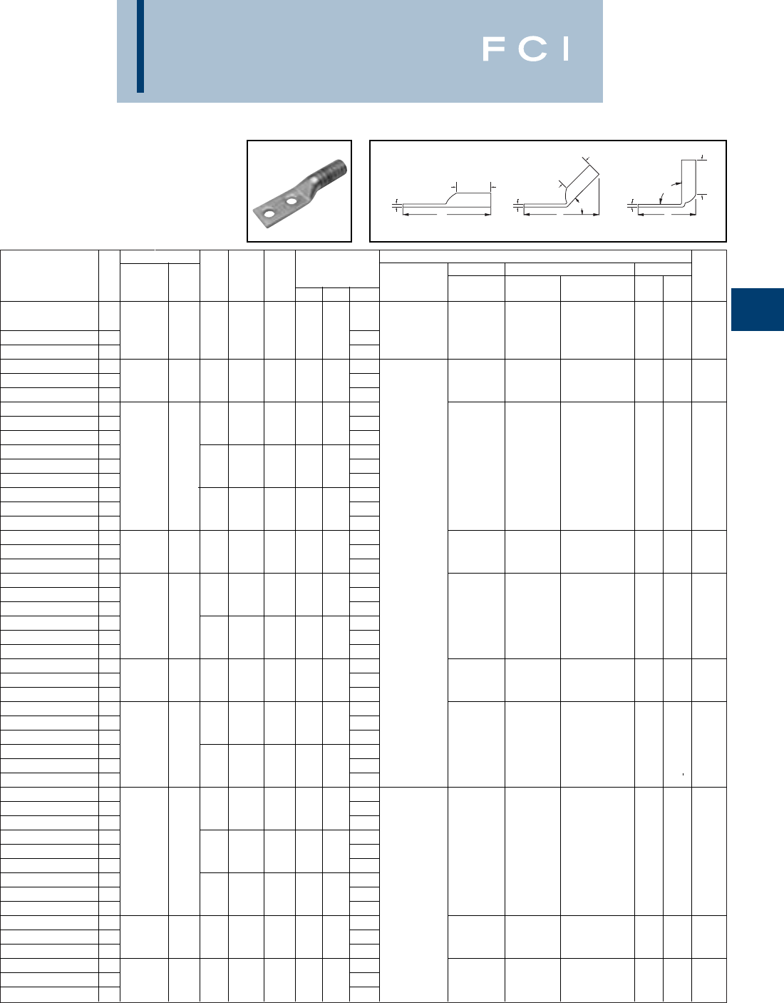
Conductor ▲Installation Tooling
Stud
Stud
Figure Mechanical Hydraulic Wire
Fig *** Hole
Hole Tongue
Dimensions Dieless MD6, OUR840, BCT500HS, Y35, Y39, Y750, Color Die Strip
Catalog Number # AWG MM2Size
Spacing Width
(B) (T) (L) (# of crimps) MD7-34R Y500CTHS Y46*, PAT750 Code Index Length
Y644HS (1)
YA322TC38 14.66
Y81KFT (3) W32VT (4) U32RT (4)
YA322TC38-45 2400 kcmil - 3/811.382.12.194.28
Y81KFTMBH (3)
W32VT (4) Blue 19 2-3/16
YA322TC38-90 32.46
PAT81KFT-18V (3)
W32RT (4) U30RT (4)
YA332N 15.93
W33VT (4) 2-3/16
YA332N-45 2450 kcmil - 1/21-3/41.482.12.215.57W33VT (4) U33RT Gray 326 2-5/16
YA332N-90 33.70W33RT (4)
YA342N 16.06
YA342N-45 21/21-3/41.552.25.235.72
YA342N-90 33.73
YA342TC14E2 14.46
W34VT (4) U34RT (4)
YA342TC14E2-45 2500 kcmil 240 1/43/41.552.25.234.09W34VT (4)
Brown
20 2-1/2
YA342TC14E2-90 32.10W34RT (4) U31ART (4)
YA342TC38 14.90
YA342TC38-45 23/811.552.25.234.53
YA342TC38-90 32.54
YA352N 16.49
YA352N-45 2550 kcmil - 1/21-3/41.652.63.256.06Y644HS (1) - - U35RT (4)
Ye l l o w
21
2-11/16
YA352N-90 33.77Y81KFT (4)
YA362N 16.59
Y81KFTMBH (4)
YA362N-45 21/21-3/41.746.17
PAT81KFT-18V (4)
YA362N-90 3600 kcmil 300 2.69.273.81
--
U36RT (4)
Green
22 2-3/4
YA362TC38 15.59U32ART (4)
YA362TC38-45 23/811.742.69.265.17
YA362TC38-90 32.81
YA372N 16.74
YA372N-45 2650 kcmil - 1/21-3/41.802.81.276.29--U37RT (4)
Orange
23 2-7/8
YA372N-90 33.84
YA382N 16.77
YA382N-45 21/21-3/41.842.81.276.29
YA382N-90 3700 kcmil - 3.84
--U38RT (4) Pink 400 2-7/8
YA382TC38 15.76
YA382TC38-45 23/811.842.81.275.29
YA382TC38-90 32.84
YA392N 16.87
YA392N-45 21/21-3/41.912.88.276.38
YA392N-90 33.87
YA392NT38 15.87U39RT (4)
YA392NT38-45 2750 kcmil - 3/811.632.88.275.38--P39RT (4) Black 24 2-3/4
YA392NT38-90 32.87**
YA392TC38 15.87Y644HS (1)
YA392TC38-45 23/811.912.88.275.38Y81KFT (3)
YA392TC38-90 32.87
Y81KFTMBH (3)
YA402N 16.95
PAT81KFT-18V (3)
YA402N-45 2800 kcmil 400 1/21-3/41.952.94.306.50--P40RT (4)
Orange
25 3
YA402N-90 33.91**
YA412N 16.96
YA412N-45 2850 kcmil - 1/21-3/42.012.94.316.52-- -Gold 26 3
YA412N-90 33.93
BURNDY
Compression
C-57
▲See tooling section of this catalog for complete tool and die
listings.
*Use PUADP-1 adaptor with "U" -dies in Y46 HYPRESS™.
** P-RT die sets for use in Y46 HYPRESS™ only, PUADP-1
adapter not required.
TWO HOLE HYLUG™
CODE CONDUCTOR
LONG BARREL
(Continued)
*** The MM2conductor sizes listed are the recommendations
for Class 2 conductor.
"Available undrilled. Add suffix "U" to catalog number
(example: YA25U).
◆For applications greater than 2000 Volts consult cable
manufacturer for voltage stress relief instructions.
T T T
B
B
B
90°
L
45°
LL
Fig. 1 Fig. 2 Fig. 3
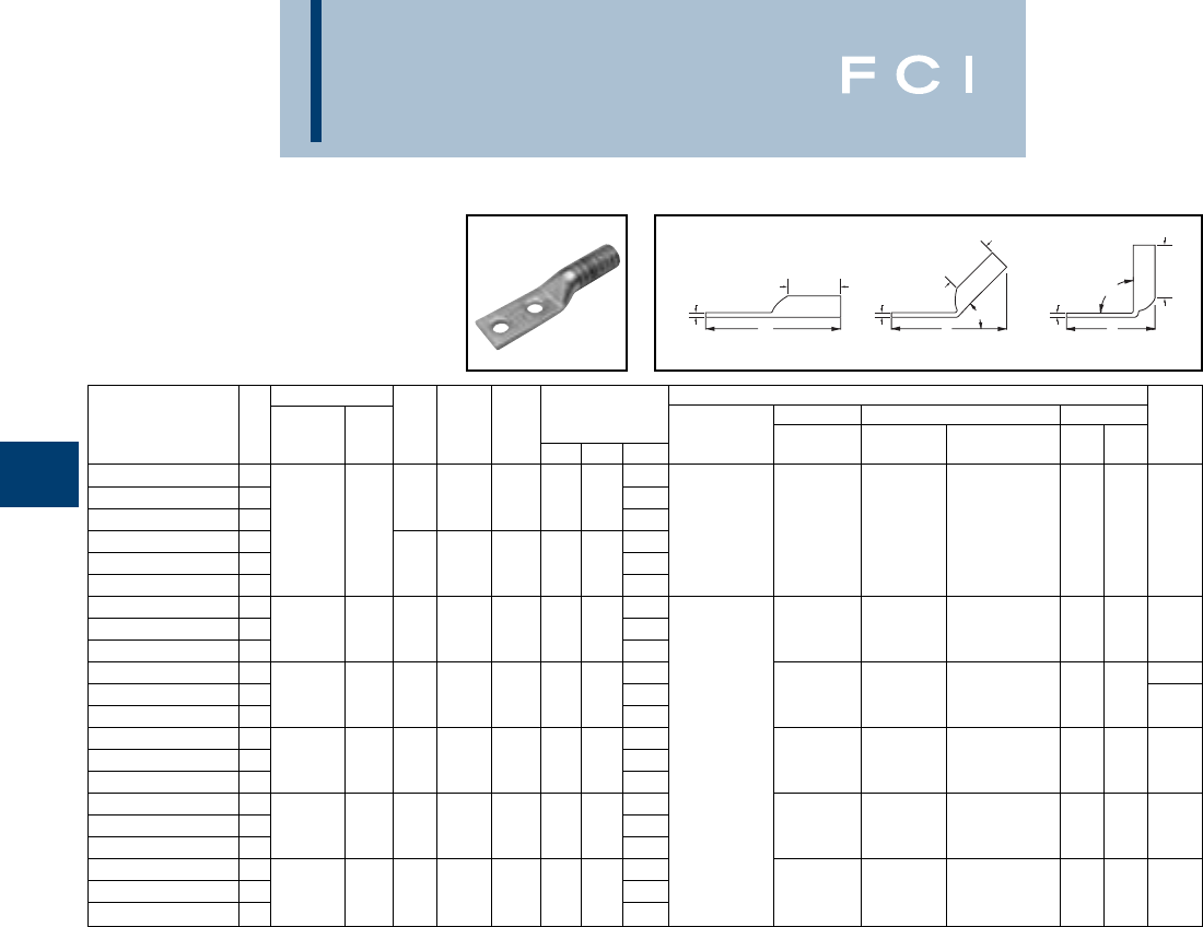
BURNDY
Compression
C-58
▲See tooling section of this catalog for complete tool and die
listings.
*Use PUADP-1 adaptor with "U" -dies in Y46 HYPRESS™.
** P-RT die sets for use in Y46 HYPRESS™ only, PUADP-1
adapter not required.
TWO HOLE HYLUG™
CODE CONDUCTOR
LONG BARREL
(Continued)
Conductor ▲Installation Tooling
Stud
Stud
Figure Mechanical Hydraulic Wire
Fig *** Hole
Hole Tongue
Dimensions Dieless MD6, OUR840, BCT500HS, Y35, Y39, Y750, Color Die Strip
Catalog Number # AWG MM2Size
Spacing Width
(B) (T) (L) (# of crimps) MD7-34R Y500CTHS Y46*, PAT750 Code Index Length
YA442N 17.14
YA442N-45 21/21-3/42.173.00.336.71Y644HS (1)
YA442N-90 31000 kcmil 500 4.02Y81KFT (3) P44RT (4)
YA442TC38 16.14
Y81KFTMBH (3)
-- **
White
27 3-1/16
YA442TC38-45 23/812.193.00.335.71
PAT81KFT-18V (3)
YA442TC38-90 33.02
YA452N 17.44
YA452N-45 21250 kcmil - 1/21-3/42.463.19.387.03--P45RT (6)
Ye l l o w
29 3-1/4
YA452N-90 34.13**
YA4532N 17.483-1/4
YA4532N-45 21300 kcmil - 1/21-3/42.533.19.397.07-- -
Orange
30 2-1/16
YA4532N-90 34.16
YA462N 17.55
YA462N-45 21500 kcmil - 1/21-3/42.673.19.407.15--P46RT (6)
Green
31 3-1/4
YA462N-90 34.22**
YA472N 17.89
YA472N-45 21750 kcmil - 1/21-3/42.903.44.427.45-- -Gray333-1/2
YA472N-90 34.30
YA482N 17.98
YA482N-45 22000 kcmil - 1/21-3/43.103.44.467.60-- -
Brown
34 3-1/2
YA482N-90 34.40
*** The MM2conductor sizes listed are the recommendations
for Class 2 conductor.
"Available undrilled. Add suffix "U" to catalog number
(example: YA25U).
◆For applications greater than 2000 Volts consult cable
manufacturer for voltage stress relief instructions.
T T T
B
B
B
90°
L
45°
LL
Fig. 1 Fig. 2 Fig. 3
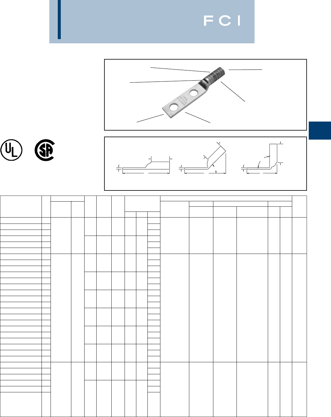
Conductor ▲Installation Tooling
Stud
Stud
Figure Mechanical Hydraulic Wire
Fig *** Hole
Hole Tongue
Dimensions Dieless MD6, OUR840, BCT500HS, Y35, Y39, Y750, Color Die Strip
Catalog Number # AWG MM2Size
Spacing Width
(B) (T) (L) (# of crimps) MD7-34R Y500CTHS Y46*, PAT750 Code Index Length
YAZV10-2TC14 12.16
YAZV10-2TC14-45 21/45/8.41.69.052.03
YAZV10-2TC14-90 3
14-10 AWG
61.45
Y8MRB-1 (2) - - - - - 3/4
YAZV10-2TC14E2 12.28
YAZV10-2TC14E2-45 21/43/4.41.69.052.16
YAZV10-2TC14E2-90 31.58
YAZ8C-2TC10 12.20
YAZ8C-2TC10-45 2#10 5/8.41.75.082.09
YAZ8C-2TC10-90 31.37
YAZ8C-2TC10E2 12.33
YAZ8C-2TC10E2-45 2#10 3/4.41.75.082.22
YAZ8C-2TC10E2-90 31.50Y1MR (2)
YAZ8C-2TC14 1#8 STR 2.33Y8MRB-1 (2)
YAZ8C-2TC14-45 2†1/45/8.44.75.082.20Y2MR (2) W8CVT (2) W8CVT (2)
YAZ8C-2TC14-90 3#6 SOL 1.49MY29-3 (2) W8CRT (2) W8CRT (2) U8CRT (2) Red 49 7/8
YAZ8C-2TC14E2 110 2.45MY29-11 (2) X8CRT (2) X8CRT (2)
YAZ8C-2TC14E2-45 237/24 1/43/4.44.75.082.33MRC840 (2)
YAZ8C-2TC14E2-90 31.62Y81KFT (1)
YAZ8C-2TC14E1 12.70
Y81KFTMBH (1)
YAZ8C-2TC14E1-45 21/41.44.75.082.58
PAT81KFT-18V (1)
YAZ8C-2TC14E1-90 31.87
YAZ8C-2TC38 12.89
YAZ8C-2TC38-45 23/81.58.75.062.72
YAZ8C-2TC38-90 32.05
YAZ6C-2N 14.40Y2MR (2)
YAZ6C-2N-45 21/21-3/4 .831.12.124.29MY29-3 (2)
YAZ6C-2N-90 33.28MY29-11 (2)
YAZ6C-2TC10E2 12.65MRC840 (2) W5CVT (2) W5CVT (2)
YAZ6C-2TC10E2-45 2#6 AWG - 2.48Y644HS (1) W5CRT (2) X5CRT (2) U5CRT (2) Blue 7 or 1-1/16
Y1MR (2) X5CRT (2) X5CRT (2) U8CABT (2) 374
#10 3/4.421.12.09
Y81KFT (1) X8CART (2) X8CART (2)
YAZ6C-2TC10E2-90 31.51
Y81KFTMBH (1)
PAT81KFT-18V (1)
BURNDY
Compression
C-59
TWO HOLE HYLUG™
CODE CONDUCTOR
LONG BARREL WITH
INSPECTION WINDOW
TYPES YAZ-2N,YAZ-2TC
UL Listed 90° C,
600 Volts to 35 KV ◆
ELECTRO-TIN
PLATED CABLE
ACCOMMODATION
CRIMP
DIE AND COLOR
CODE INFORMATION
INSPECTION
WINDOW
BEVELED
ENTRY
90°
L
45°
LL
B
B
B
TTT
Fig. 1 Fig. 2 Fig. 3
▲See tooling section of this catalog for complete tool and die
listings.
*Use PUADP-1 adaptor with "U" -dies in Y46 HYPRESS™.
** P-RT die sets for use in Y46 HYPRESS™ only, PUADP-1
adapter not required.
*** The MM2conductor sizes listed are the recommendations
for Class 2 conductor.
†The MM2conductor size referred to here is for Class 2 and
Class 5 conductor.
"Available undrilled. Add suffix "U" to catalog number
(example: YA25U).
◆For applications greater than 2000 Volts consult cable
manufacturer for voltage stress relief instructions.

Conductor ▲Installation Tooling
Stud
Stud
Figure Mechanical Hydraulic Wire
Fig *** Hole
Hole Tongue
Dimensions Dieless MD6, OUR840, BCT500HS, Y35, Y39, Y750, Color Die Strip
Catalog Number # AWG MM2Size
Spacing Width
(B) (T) (L) (# of crimps) MD7-34R Y500CTHS Y46*, PAT750 Code Index Length
YAZ6C-2TC14 12.65
YAZ6C-2TC14-45 21/45/8.451.12.082.45
YAZ6C-2TC14-90 31.51
YAZ6C-2TC14E2 12.78
YAZ6C-2TC14E2-45 21/43/4.451.12.082.58
YAZ6C-2TC14E2-90 31.63
YAZ6C-2TC14E1 13.03Y1MR (2)
YAZ6C-2TC14E1-45 21/41.451.12.082.83Y2MR (2) W5CVT (2) W5CVT (2)
YAZ6C-2TC14E1-90 3#6 AWG - 1.63MY29-3 (2) W5CRT (2) X5CRT (2) U5CRT (2) Blue 7 or 1-1/6
YAZ6C-2TC38E2 12.97MY29-11 (2) X5CRT (2) X5CRT (2) U8CABT (2) 374
YAZ6C-2TC38E2-45 23/83/4.581.12.062.72MRC840 (2) X8CART (2) X8CART (2)
YAZ6C-2TC38E2-90 31.81Y644HS (2)
YAZ6C-2TC38E6 13.09Y81KFT (1)
YAZ6C-2TC38E6-45 23/87/8.581.12.062.85
Y81KFTMBH (1)
YAZ6C-2TC38E6-90 31.94
PAT81KFT-18V (1)
YAZ6C-2TC38 13.22
YAZ6C-2TC38-45 23/81.581.12.062.97
YAZ6C-2TC38-90 32.06
YAZ5C-2N 14.43W5CRT (2) W5CVT (2) 7 or
YAZ5C-2N-45 2#5 AWG - 1/21-3/4.831.12.124.31W5CVT (2) W5CRT (2) U5CRT (2) Blue 1/16
YAZ5C-2N-90 33.28X5CRT (2) X5CRT (2) 374
YAZ4C-2N 14.42
YAZ4C-2N-45 21/21-3/4.831.12.124.30
YAZ4C-2N-90 33.30
YAZ4C-2TC10-E2 12.67Y1MR (4)
YAZ4C-2TC10-E245 2#10 3/4.491.12.092.49Y2MR (4)
YAZ4C-2TC10-E290 31.54MY29-3 (2)
YAZ4C-2TC14 12.67MY29-11 (2) W4CVT (2) W4CVT (2) U4CRT (2) 8 or
YAZ4C-2TC14-45 2#4 AWG - 1/45/8.491.12.092.49MRC840 (2) W4CRT (2) W4CRT (2) Gray 1-1/16
YAZ4C-2TC14-90 31.54Y644HS (2) X4CRT (2) X4CRT (2) U6CABT (2) 346
YAZ4C-2TC14E2 12.80Y81KFT (1)
YAZ4C-2TC14E2-45 21/43/4.491.12.092.61
Y81KFTMBH (1)
YAZ4C-2TC14E2-90 31.66
PAT81KFT-18V (1)
YAZ4C-2TC38 1.3.23
YAZ4C-2TC38-45 23/81.581.12.083.01
YAZ4C-2TC38-90 32.09
YAZ3C-2N 14.58
YAZ3C-2N-45 21/21-3/4.831.25.124.41
YAZ3C-2N-90 33.32Y1MR (4)
YAZ3C-2TC14 12.83Y2MR (4)
YAZ3C-2TC14-45 2#3 AWG 1/45/8.551.25.092.59MY29-3 (2)
YAZ3C-2TC14-90 325 1.55MY29-11 (2)
W3CRT (2) W3CRT (2) U3CRT (2) White 9 1-5/16
YAZ3C-2TC14E2 12.95MRC840 (2)
YAZ3C-2TC14E2-45 2#2 SOL 1/43/4.551.25.092.72Y644HS (2)
YAZ3C-2TC14E2-90 31.68Y81KFT (2)
YAZ3C-2TC38E2 13.14
Y81KFTMBH (2)
YAZ3C-2TC38E2-45 23/83/4.581.25.082.88
PAT81KFT-18V (2)
)
YAZ3C-2TC38E2-90 31.86
BURNDY
Compression
C-60
TWO HOLE HYLUG™
CODE CONDUCTOR
LONG BARREL WITH
INSPECTION WINDOW
(Continued)
▲See tooling section of this catalog for complete tool and die
listings.
*Use PUADP-1 adaptor with "U" -dies in Y46 HYPRESS™.
** P-RT die sets for use in Y46 HYPRESS™ only, PUADP-1
adapter not required.
90°
L
45°
LL
B
B
B
TTT
Fig. 1 Fig. 2 Fig. 3
*** The MM2conductor sizes listed are the recommendations
for Class 2 conductor.
"Available undrilled. Add suffix "U" to catalog number
(example: YA25U).
◆For applications greater than 2000 Volts consult cable
manufacturer for voltage stress relief instructions.
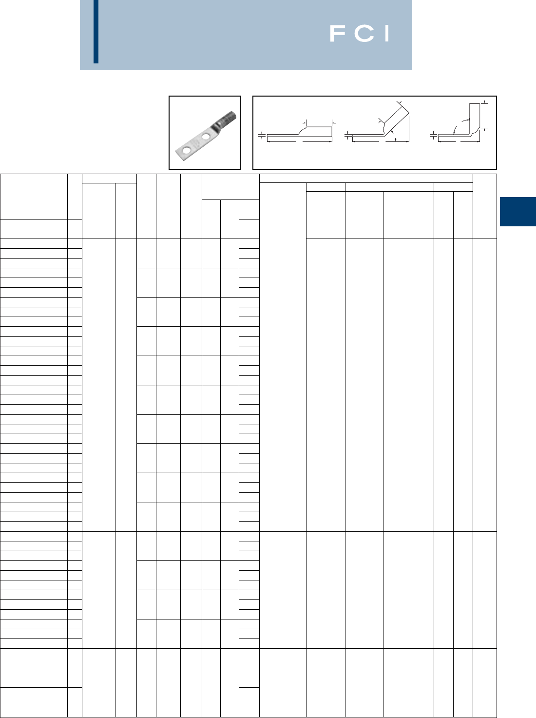
Conductor ▲Installation Tooling
Stud
Stud
Figure Mechanical Hydraulic Wire
Fig *** Hole
Hole Tongue
Dimensions Dieless MD6, OUR840, BCT500HS, Y35, Y39, Y750, Color Die Strip
Catalog Number # AWG MM2Size
Spacing Width
(B) (T) (L) (# of crimps) MD7-34R Y500CTHS Y46*, PAT750 Code Index Length
YAZ3C-2TC38
1#3 AWG 3.39
YAZ3C-2TC38-45
2253/81.581.25.083.13W3CRT (2) W3CRT (2) U3CRT (2)
White
91-5/16
YAZ3C-2TC38-90
3#2 SOL 2.11
YAZ2C-2N
14.60
YAZ2C-2N-45
21/21-3/4.831.25.124.32
YAZ2C-2N-90
33.32
YAZ2C-2TC10E2
12.85
YAZ2C-2TC10E2-45
2#10 3/4.601.25.112.65
YAZ2C-2TC10E2-90
31.58
YAZ2C-2TC14
12.85
YAZ2C-2TC14-45
21/45/8.601.25.112.65
YAZ2C-2TC14-90
31.58
YAZ2C-2TC14E2
12.97Y1MR (4)
YAZ2C-2TC14E2-45
21/43/4.601.25.112.77Y2MR (4)
YAZ2C-2TC14E2-90
31.71MY29-3 (2)
YAZ2C-2TC14E1
13.22MY29-11 (2)
YAZ2C-2TC14E1-45
21/41.601.25.113.02MRC840 (2)
YAZ2C-2TC14E1-90
31.96Y644HS (1) W2CVT (2) W2CVT (2)
YAZ2C-2TC516E2
1#2 AWG 35 3.03Y81KFT (2) W2CRT (2) W2CRT (2) U2CRT (2)
Brown
10 1-5/16
YAZ2C-2TC516E2-45
25/163/4.601.25.112.84
Y81KFTMBH (2)
X2CRT (2) X2CRT (2)
YAZ2C-2TC516E2-90
31.77
PATKFT-18V (2)
YAZ2C-2TC38E2
13.16
YAZ2C-2TC38E2-45
23/83/4.601.25.112.96
YAZ2C-2TC38E2-90
31.90
YAZ2C-2TC38E6
13.28
YAZ2C-2TC38E6-45
23/87/8 .601.25.113.09
YAZ2C-2TC38E6-90
32.02
YAZ2C-2TC38
13.41
YAZ2C-2TC38-45
23/81.601.25.113.21
YAZ2C-2TC38-90
32.14
YAZ2C-2NTC38
14.16
YAZ2C-2NTC38-45
23/81-3/4.601.25.113.96
YAZ2C-2NTC38-90
32.90
YAZ1C-2N
14.76
YAZ1C-2N-45
21/21-3/4.831.38.124.45
YAZ1C-2N-90
33.34Y1MR (4)
YAZ1C-2TC14
13.01MY29-3 (2)
YAZ1C-2TC14-45
21/45/8.671.38.102.75MY29-11 (2)
W1CVT (2) W1CVT (2)
YAZ1C-2TC14-90
3#1 AWG 50 1.60MRC840 (2)
W1CRT-1 (2) W1CRT-1 (2)
U1CRT-1 (2)
Green
11 or 1-7/16
YAZ1C-2TC14E2
13.13Y644HS (1)
X1CRT-1 (2) X1CRT-1 (2)
U4CABT (2) 375
YAZ1C-2TC14E2-45
21/43/4.671.38.102.87Y81KFT (2)
YAZ1C-2TC14E2-90
31.73
Y81KFTMBH (2)
YAZ1C-2TC38
13.57
PATKFT-18V (2)
YAZ1C-2TC38-45
23/81.671.38.103.31
YAZ1C-2TC38-90
32.16
MY29-3 (2)
YAZ25-2N
14.79
MY29-11 (2)
MRC840 (4) W25RT (4) W25VT (4)
YAZ25-2N-45 21/0 AWG - 1/21-3/4.831.38.114.52
Y644HS (1) W25VT (4) X25RT (4) U25RT (2) Pink 12 or 1-7/16
Y81KFT (2) X25RT (4) W25RT (4) U2CABT (2) 348
YAZ25-2N-90
33.38
Y81KFTMBH (2)
PATKFT-18V (2)
BURNDY
Compression
C-61
TWO HOLE HYLUG™
CODE CONDUCTOR
LONG BARREL WITH
INSPECTION WINDOW
(Continued)
▲See tooling section of this catalog for complete tool and die
listings.
*Use PUADP-1 adaptor with "U" -dies in Y46 HYPRESS™.
** P-RT die sets for use in Y46 HYPRESS™ only, PUADP-1
adapter not required.
*** The MM2conductor sizes listed are the recommendations
for Class 2 conductor.
"Available undrilled. Add suffix "U" to catalog number
(example: YA25U).
◆For applications greater than 2000 Volts consult cable
manufacturer for voltage stress relief instructions.
90°
L
45°
LL
B
B
B
TTT
Fig. 1 Fig. 2 Fig. 3

BURNDY
Compression
C-62
TWO HOLE HYLUG™
CODE CONDUCTOR
LONG BARREL WITH
INSPECTION WINDOW
(Continued)
▲See tooling section of this catalog for complete tool and die
listings.
*Use PUADP-1 adaptor with "U" -dies in Y46 HYPRESS™.
** P-RT die sets for use in Y46 HYPRESS™ only, PUADP-1
adapter not required.
Conductor ▲Installation Tooling
Stud
Stud
Figure Mechanical Hydraulic Wire
Fig *** Hole
Hole Tongue
Dimensions Dieless MD6, OUR840, BCT500HS, Y35, Y39, Y750, Color Die Strip
Catalog Number # AWG MM2Size
Spacing Width
(B) (T) (L) (# of crimps) MD7-34R Y500CTHS Y46*, PAT750 Code Index Length
YAZ25-2TC14 13.04
YAZ25-2TC14-45 21/45/8.751.38.122.81
YAZ25-2TC14-90 31.64
YAZ25-2TC14E2 13.16
YAZ25-2TC14E2-45 21/43/4.751.38.122.93
YAZ25-2TC14E2-90 31.76
YAZ25-2TC14E1 13.41
YAZ25-2TC14E1-45 21/41.751.38.123.18
YAZ25-2TC14E1-90 32.01
YAZ25-2TC516E6 13.35W25RT (4) W25VT (4) U25RT (2) 12 or
YAZ25-2TC516E6-45 21/0 AWG - 5/167/8.751.38.123.12W25VT (4) W25RT (4) Pink 1-7/16
YAZ25-2TC516E6-90 31.95X25RT (4) W25RT (4) U2CABT (2) 348
YAZ25-2TC516 13.47
YAZ25-2TC516-45 25/161.751.38.123.24
YAZ25-2TC516-90 32.08
YAZ25-2TC38 13.60
YAZ25-2TC38-45 23/81.751.38.123.37
YAZ25-2TC38-90 32.20
YAZ25-2NTC38 14.35
YAZ25-2NTC38-45 23/81-3/4.751.38.124.12
YAZ25-2NTC38-90 32.95
YAZ26-2N 14.95MY29-3 (2)
YAZ26-2N-45 21/21 3/4.831.50.124.67MY29-11 (2)
YAZ26-2N-90 33.41MRC840 (4)
YAZ26-2TC14 13.20Y644HS (1)
YAZ26-2TC14-45 21/45/8.831.50.122.92Y81KFT (2)
W26VT (4) W26VT (4)
YAZ26-2TC14-90 32/0 AWG 70 1.66
Y81KFTMBH (2)
W26RT (4) W26RT (4) U26RT (2) Black 13 1-9/16
YAZ26-2TC14E2 13.32
PAT81KFT-18V (2)
X26RT (4) X26RT (4)
YAZ26-2TC14E2-45 21/43/4.831.50.123.05
YAZ26-2TC14E2-90 31.79
YAZ26-2TC38 13.76
YAZ26-2TC38-45 23/81.831.50.123.48
YAZ26-2TC38-90 32.22
YAZ27-2N 14.98
YAZ27-2N-45 21/21-3/4.911.50.134.71
YAZ27-2N-90 33.44
YAZ27-2TC14E2 13.36W27VT (4) W27VT (4)
YAZ27-2TC14E2-45 23/0 AWG - 1/43/4.901.50.123.08W27RT (4) W27RT (4) U27RT (2)
Orange
14 1-9/16
YAZ27-2TC14E2-90 31.82X27RT (6) X27RT (6)
YAZ27-2TC38 13.80
YAZ27-2TC38-45 23/81.901.50.123.52
YAZ27-2TC38-90 32.25
YAZ28-2N 15.15
YAZ28-2N-45 21/21-3/41.021.62.144.86
W28VT (4) W28VT (4)
YAZ28-2N-90 34/0 AWG - 3.48
W28RT (4) W28RT (4) U28RT (2)
Purple
15
1-11/16
YAZ28-2TC14E2 13.55
X28RT (6) X28RT (6)
YAZ28-2TC14E2-45 21/43/41.021.62.143.25
YAZ28-2TC14E2-90 31.86
*** The MM2conductor sizes listed are the recommendations
for Class 2 conductor.
"Available undrilled. Add suffix "U" to catalog number
(example: YA25U).
◆For applications greater than 2000 Volts consult cable
manufacturer for voltage stress relief instructions.
90°
L
45°
LL
B
B
B
TTT
Fig. 1 Fig. 2 Fig. 3

Conductor ▲Installation Tooling
Stud
Stud
Figure Mechanical Hydraulic Wire
Fig *** Hole
Hole Tongue
Dimensions Dieless MD6, OUR840, BCT500HS, Y35, Y39, Y750, Color Die Strip
Catalog Number # AWG MM2Size
Spacing Width
(B) (T) (L) (# of crimps) MD7-34R Y500CTHS Y46*, PAT750 Code Index Length
YAZ28-2TC38 13.99MY29-3 (2)
YAZ28-2TC38-45 23/811.021.62.143.69MY29-11 (2)
YAZ28-2TC38-90 32.30MRC840 (4) W28VT (4) W28VT (4)
YAZ28-2NTC38 14/0 AWG - 4.74Y644HS (1) W28RT (4) W28RT (4) U28RT (2)
Purple
15
1-11/16
YAZ28-2NTC38-45 24.44Y81KFT (2) X28RT (6) X28RT (6)
3/81-3/41.021.62.14
Y81KFTMBH (2)
YAZ28-2NTC38-90 33.05
PAT81KFT-18V (2)
YAZ29-2N 15.18MY29-3 (2)
YAZ29-2N-45 21/21-3/41.101.62.164.92MY29-11(2)
YAZ29-2N-90 3250 kcmil - 3.52Y644HS (1) W29VT (4) X29RT (8)
YAZ29-2TC38 13.99Y81KFT (2) X29RT (8) W29VT (4) U29RT (2)
Ye l l o w
16
1-11/16
YAZ29-2TC38-45 23/811.101.62.143.73
Y81KFTMBH (2)
W29RT (4)
YAZ29-2TC38-90 32.34
PAT81KFT-18V (2)
YAZ30-2N 15.60
YAZ30-2N-45 21/21-3/41.202.00.165.23
YAZ30-2N-90 3300 kcmil 150 3.56
W30VT (4) W30VT (4) U30RT (4)
White
17 or 2-1/16
YAZ30-2TC38 14.42W30RT (4) U28ART (4) 298
YAZ30-2TC38-45 23/811.202.00.164.04
YAZ30-2TC38-90 32.37
YAZ31-2N 15.64
YAZ31-2N-45 21/21-3/41.292.00.185.29
YAZ31-2N-90 33.60
YAZ31-2TC14E2 14.02Y644HS (1)
W31VT (4) U31RT (4) 18 or
YAZ31-2TC14E2-45 2350 kcmil 185 1/43/41.292.00.183.66Y81KFT (3) W31VT (4) Red 2-1/16
YAZ31-2TC14E2-90 31.97
Y81KFTMBH (3)
W31RT (4) U29ART (4) 324
YAZ31-2TC38 14.45
PAT81KFT-18V (3)
YAZ31-2TC38-45 23/811.292.00.184.10
YAZ31-2TC38-90 32.41
YAZ32-2N 15.81
YAZ32-2N-45 21/21-3/41.402.12.195.44
YAZ32-2N-90 3400 kcmil - 3.64
W32VT (4) W32VT (4) U32RT (4) Blue 19 or 2/16
YAZ32-2TC38 14.62W32RT (4) U30ART (4) 470
YAZ32-2TC38-45 23/811.402.12.194.25
YAZ32-2TC38-90 32.46
YAZ33-2N 15.89
W33VT (4)
326 or
YAZ33-2N-45 2450 kcmil - 1/21-3/41.482.13.215.54W33VT (4) U33RT (4) Gray 2-5/16
YAZ33-2N-90 33.70W33RT (4) 538
YAZ34-2N 16.04
YAZ34-2N-45 21/21-3/41.552.25.235.69
YAZ34-2N-90 33.73
YAZ34-2TC14E2 14.42Y644HS (1)
W34VT (4) U34RT (4) 20 or
YAZ34-2TC14E2-45 2500 kcmil 240 1/43/41.552.25.234.06Y81KFT (4) W34VT (4)
Brown
2-5/16
YAZ34-2TC14E2-90 32.10
Y81KFTMBH (4)
W34RT (4) U31ART (4) 299
YAZ34-2TC38 14.85
PAT81KFT-18V (4)
YAZ34-2TC38-45 23/811.552.25.234.50
YAZ34-2TC38-90 32.54
YAZ35-2N 16.45
YAZ35-2N-45 2550 kcmil - 1/21-3/41.652.63.256.03--U35RT (4)
Ye l l o w
21
2-11/16
YAZ35-2N-90 33.77
BURNDY
Compression
C-63
TWO HOLE HYLUG™
CODE CONDUCTOR
LONG BARREL WITH
INSPECTION WINDOW
(Continued)
▲See tooling section of this catalog for complete tool and die
listings.
*Use PUADP-1 adaptor with "U" -dies in Y46 HYPRESS™.
** P-RT die sets for use in Y46 HYPRESS™ only, PUADP-1
adapter not required.
*** The MM2conductor sizes listed are the recommendations
for Class 2 conductor.
"Available undrilled. Add suffix "U" to catalog number
(example: YA25U).
◆For applications greater than 2000 Volts consult cable
manufacturer for voltage stress relief instructions.
90°
L
45°
LL
B
B
B
TTT
Fig. 1 Fig. 2 Fig. 3
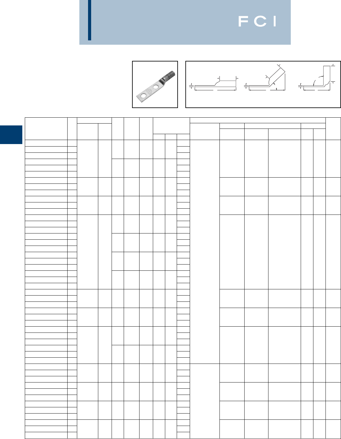
BURNDY
Compression
C-64
▲See tooling section of this catalog for complete tool and die
listings.
*Use PUADP-1 adaptor with "U" -dies in Y46 HYPRESS™.
** P-RT die sets for use in Y46 HYPRESS™ only, PUADP-1
adapter not required.
TWO HOLE HYLUG™
CODE CONDUCTOR
LONG BARREL WITH
INSPECTION WINDOW
(Continued)
Conductor ▲Installation Tooling
Stud
Stud
Figure Mechanical Hydraulic Wire
Fig *** Hole
Hole Tongue
Dimensions Dieless MD6, OUR840, BCT500HS, Y35, Y39, Y750, Color Die Strip
Catalog Number # AWG MM2Size
Spacing Width
(B) (T) (L) (# of crimps) MD7-34R Y500CTHS Y46*, PAT750 Code Index Length
YAZ36-2N 16.55
YAZ36-2N-45 21/21-3/41.742.69.276.14
YAZ36-2N-90 3600 kcmil 300 3.81
--
U36RT (4)
Green
22 or 2/4
YAZ36-2TC38 15.55U32ART (4) 472
YAZ36-2TC38-45 23/811.742.69.265.14
YAZ36-2TC38-90 32.81
YAZ37-2N 16.70
YAZ37-2N-45 2650 kcmil - 1/21-3/41.802.81.276.26--U37RT (4)
Orange
23 2-7/8
YAZ37-2N-90 33.84
YAZ38-2N 16.72
YAZ38-2N-45 2700 kcmil - 1/21-3/41.842.81.276.26--U38RT (4) Pink 400 2-7/8
YAZ38-2N-90 33.84
YAZ39-2N 16.82
YAZ39-2N-45 21/21-3/41.912.88.276.34
YAZ39-2N-90 33.87
YAZ39-2NT38 15.82Y644HS (1)
YAZ39-2NT38-45 23/811.632.88.275.34Y81KFT (4) U39RT (4)
YAZ39-2NT38-90 3750 kcmil - 2.87
Y81KFTMBH (4)
--P39RT (4) Black 24
2-15/16
YAZ39-2TC38 15.82
PAT81KFT-18V (4)
**
YAZ39-2TC38-45 23/811.912.88.275.34
YAZ39-2TC38-90 32.87
YAZ39-2NNT 16.82
YAZ39-2NNT-45 21/21-3/41.632.88.276.34
YAZ39-2NNT-90 33.87
YAZ40-2N 16.89
YAZ40-2N-45 2800 kcmil 400 1/21-3/41.982.94.306.46--
P40RT (4)
Orange
25 3
YAZ40-2N-90 33.91**
YAZ41-2N 16.91
YAZ41-2N-45 2850 kcmil - 1/21-3/42.012.94.316.48-- -Gold 3
YAZ41-2N-90 33.93
YAZ44-2N 17.08
YAZ44-2N-45 21/21-3/42.193.00.336.66
YAZ44-2N-90 31000 kcmil 500 4.02
--
P44RT (4)
White
27 3-1/16
YAZ44-2TC38 16.09**
YAZ44-2TC38-45 23/812.193.00.335.66
YAZ44-2TC38-90 33.02
YAZ45-2N 17.38
YAZ45-2N-45 21250 kcmil - 1/21-3/42.463.19.386.99--
P45RT (6)
Ye l l o w
29 3-1/4
YAZ45-2N-90 34.13**
YAZ453-2N 17.41
YAZ453-2N-45 21300 kcmil - 1/21-3/42.533.19.397.03-- -
Orange
30 2-1/16
YAZ453-2N-90 34.16
YAZ46-2N 17.48
YAZ46-2N-45 21500 kcmil - 1/21-3/42.693.19.407.10--
P46RT (6) Green 31 3-5/16
YAZ46-2N-90 34.22**
YAZ47-2N 17.82
YAZ47-2N-45 21750 kcmil - 1/21-3/42.903.44.427.40-- -Gray333-1/2
YAZ47-2N-90 34.30
*** The MM2conductor sizes listed are the recommendations
for Class 2 conductor.
"Available undrilled. Add suffix "U" to catalog number
(example: YA25U).
◆For applications greater than 2000 Volts consult cable
manufacturer for voltage stress relief instructions.
90°
L
45°
LL
B
B
B
TTT
Fig. 1 Fig. 2 Fig. 3
BURNDY
Compression
C-65
▲See tooling section of this catalog for complete tool and die
listings.
*Use PUADP-1 adaptor with "U" dies in Y46 HYPRESS™.
** P-RT die sets for use in Y46 HYPRESS™ only, PUADP-1
adapter not required.
TWO HOLE HYLUG™
CODE CONDUCTOR
LONG BARREL WITH
INSPECTION WINDOW
(Continued)
Conductor ▲Installation Tooling
Stud
Stud
Figure Mechanical Hydraulic Wire
Fig *** Hole
Hole Tongue
Dimensions Dieless MD6, OUR840, BCT500HS, Y35, Y39, Y750, Color Die Strip
Catalog Number # AWG MM2Size
Spacing Width
(B) (T) (L) (# of crimps) MD7-34R Y500CTHS Y46*, PAT750 Code Index Length
YAZ48-2N
17.89
YAZ48-2N-45
2
2000 kcmil
-1/21-3/43.103.44.467.54--
Brown
34 3-1/2
YAZ48-2N-90
34.40
*** The MM2conductor sizes listed are the recommendations
for Class 2 conductor.
"Available undrilled. Add suffix "U" to catalog number
(example: YA25U).
◆For applications greater than 2000 Volts consult cable
manufacturer for voltage stress relief instructions.
90°
L
45°
LL
B
B
B
TTT
Fig. 1 Fig. 2 Fig. 3
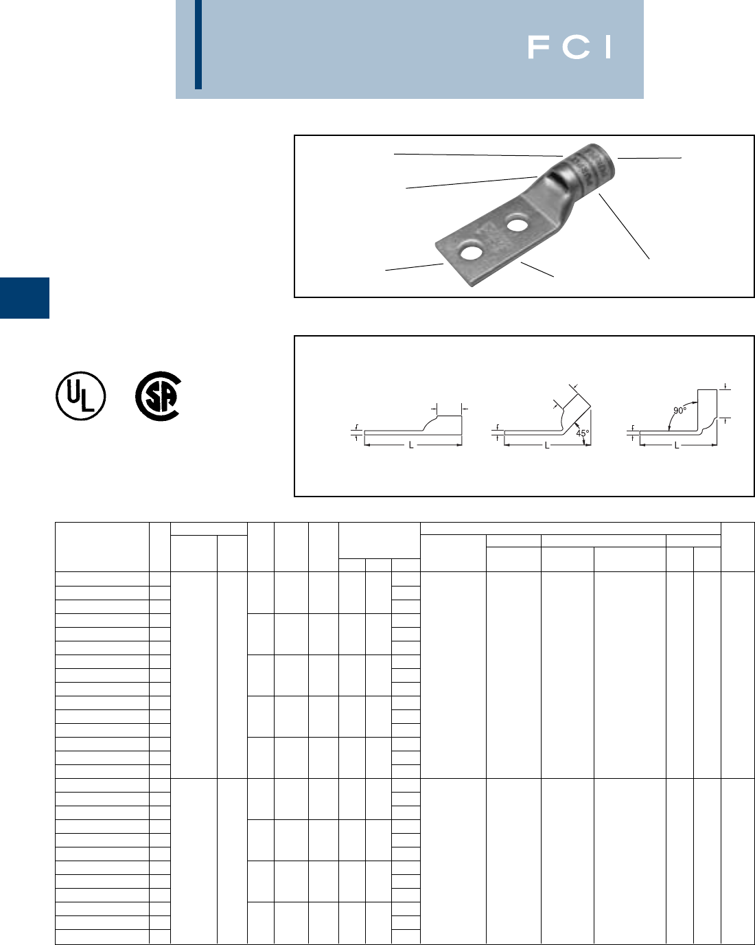
BURNDY
Compression
C-66
TWO HOLE HYLUG™
FLEX CONDUCTOR
STANDARD BARREL
TYPES YA-L-2TC,YA-L-2TC-FX,
YAV-L-2TC-FX
COPPER COMPRESSION
TERMINAL
UL Listed 90° C,
600 Volts to 35 KV ◆
ELECTRO-TIN
PLATED CABLE
ACCOMMODATION
CRIMP
COLOR CODE AND
DIE INFORMATION
INSPECTION
WINDOW
BEVELED
ENTRY
◆For applications greater than 2000 Volts consult cable
manufacturer for voltage stress relief instructions.
TTT
BB
B
Fig. 1 Fig. 2 Fig. 3
*Use PUADP-1 adaptor with "U" dies in Y46 HYPRESS™.
** The MM2conductor size referenced here is for both Class
2 and Class 5 conductor.
*** The MM2conductor sizes listed are the recommendations
for Class 5 conductor.
Conductor ▲Installation Tooling
Stud
Stud
Figure Mechanical Hydraulic Wire
Fig *** Hole
Hole Tongue
Dimensions Dieless MD6, OUR840, BCT500HS, Y35, Y39, Y750, Color Die Strip
Catalog Number # AWG MM2Size
Spacing Width
(B) (T) (L) (# of crimps) MD7-34R Y500CTHS Y46*, PAT750 Code Index Length
YA8CL2TC10 11.84
YA8CL2TC10-45 2# 10 5/8.41.44.081.83
YA8CL2TC10-90 31.37
YA8CL2TC14 11.95MRC840 (1)
YA8CL2TC14-45 21/45/8.44.44.081.94MY29-3 (1)
YA8CL2TC14-90 337/24 1.49MY29-11 (1)
YA8CL2TC14E1 1** 2.33Y8MRB-1 (1) W8CVT (1) W8CVT (1)
YA8CL2TC14E1-45 2#8 WELD 1/41.44.44.082.32Y2MR (1) W8CRT (1) W8CRT (1) U8CRT (1) Red 49 7/16
YA8CL2TC14E1-90 310 1.87Y1MR (1) X8CRT (1) X8CRT (1)
YA8CL2TC14E2 1#8 AWG 2.08Y81KFT (1)
YA8CL2TC14E2-45 21/43/4.44.44.082.07Y81KFTMBH (1)
YA8CL2TC14E2-90 31.62
PAT81KFT-18V (1
)
YA8CL2TC38 12.52
YA8CL2TC38-45 23/81.58.44..062.46
YA8CL2TC38-90 32.05
YAV6C-L2TC10-FX 11.94
YAV6C-L2TC10-FX-45 2# 10 5/8.44.50.071.86
YAV6C-L2TC10-FX-90 31.38
YAV6C-L2TC10E2-FX 161/24 2.06MRC840 (1)
YAV6C-L2TC10E2-FX-45 2** # 10 3/4.48.50.082.06MY29-11 (1)
W5CVT (1) W5CVT (1)
YAV6C-L2TC10E2-FX-90 3#6 WELD 1.57Y2MR (1)
W5CRT (1) W5CRT (1) U5CRT (1) Blue 7 1/2
YAV6C-L2TC10E4-FX 116 2.00Y1MR (1)
X5CRT (1) X5CRT (1)
YAV6C-L2TC10E4-FX-45 2#6 AWG # 10 11/16.44.50.071.95Y81KFT (1)
YAV6C-L2TC10E4-FX-90 31.44Y81KFTMBH (1)
YAV6C-L2TC10E9-FX 11.81
PAT81KFT-18V (1
)
YAV6C-L2TC10E9-FX-45 2# 10 1/2.48.50.081.77
YAV6C-L2TC10E9-FX-90 31.27
▲See tooling section of this catalog for complete tool and die
listings. Use ONLY color-coded die recommendations for “-
FX” connectors. For nest/indentor system contact factory.
◆For applications greater than 2000 Volts consult cable
manufacturer for voltage stress relief instructions.
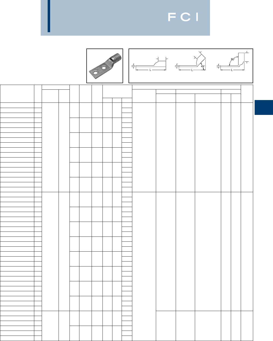
BURNDY
Compression
C-67
TWO HOLE HYLUG™
FLEX CONDUCTOR
STANDARD BARREL
(Continued)
*Use PUADP-1 adaptor with "U" dies in Y46 HYPRESS™.
** The 16 MM2referenced here is for both Class 2 and Class
5 conductor.
*** The MM2 conductor sizes listed are the recommendations
for Class 5 conductor.
TTT
BB
B
Fig. 1 Fig. 2 Fig. 3
Conductor ▲Installation Tooling
Stud
Stud
Figure Mechanical Hydraulic Wire
Fig *** Hole
Hole Tongue
Dimensions Dieless MD6, OUR840, BCT500HS, Y35, Y39, Y750, Color Die Strip
Catalog Number # AWG MM2Size
Spacing Width
(B) (T) (L) (# of crimps) MD7-34R Y500CTHS Y46*, PAT750 Code Index Length
YAV6C-L2TC14-FX 12.06
YAV6C-L2TC14-FX-45 21/45/8.48.50.082.02
YAV6C-L2TC14-FX-90 31.52
YAV6C-L2TC14E2-FX 12.19
YAV6C-L2TC14E2-FX-45 21/43/4.48.50.082.15
YAV6C-L2TC14E2-FX-90 31.64
YAV6C-L2TC14E1-FX 161/24 2.44MY29-11 (1)
YAV6C-L2TC14E1-FX-45 2**1/41.48.50.082.40Y2MR (1)
YAV6C-L2TC14E1-FX-90 3#6 WELD 1.89Y1MR (1) W5CVT (1) W5CVT (1)
YAV6C-L2TC516-FX 116 2.50Y81KFT (1) W5CRT (1) W5CRT (1) U5CRT (1) Blue 7 7/16
YAV6C-L2TC516-FX-45 2#6 AWG 5/161.52.50.072.45Y81KFTMBH (1) X5CRT (1) X5CRT (1)
YAV6C-L2TC516-FX-90 31.95
PAT81KFT-18V (1)
YAV6C-L2TC38-FX 12.62
YAV6C-L2TC38-FX-45 23/81.58.50.062.56
YAV6C-L2TC38-FX-90 32.07
YAV6C-L2NTC-FX 13.81
YAV6C-L2NTC-FX-45 21/21-3/4.83.50.123.67
YAV6C-L2NTC-FX-90 33.29
YAV4C-L2NT10-FX 11.95
YAV4C-L2NT10-FX-45 2# 10 5/8.41.50.091.94
YAV4C-L2NT10-FX-90 31.43
YAV4C-L2NT10E1-FX 12.33
YAV4C-L2NT10E1-FX-45 2# 101.41.50.092.31
YAV4C-L2NT10E1-FX-90 31.80
YAV4C-L2TC14-FX 12.08
YAV4C-L2TC14-FX-45 21/45/8.55.50.092.06
YAV4C-L2TC14-FX-90 391/24 1.55
YAV4C-L2TC14E2-FX 12.20
YAV4C-L2TC14E2-FX-45 2105/24 1/43/4.55.50.092.19W4CVT (1) W4CVT (1)
YAV4C-L2TC14E2-FX-90 3- 1.68W4CRT (1) W4CRT (1) U4CRT (1) Gray 8 1/2
YAV4C-L2TC14E1-FX 1#4 WELD 2.45MY29-11 (1) X4CRT (1) X4CRT (1)
YAV4C-L2TC14E1-FX-45 21/41.55.50.092.44Y2MR (2)
YAV4C-L2TC14E1-FX-90 3#4 AWG 1.93Y1MR (2)
YAV4C-L2TC516-FX 12.52Y81KFT (1)
YAV4C-L2TC516-FX-45 25/161.55.50.092.50Y81KFTMBH (1)
YAV4C-L2TC516-FX-90 31.99
PAT81KFT-18V (1)
YAV4C-L2TC38-FX 12.68
YAV4C-L2TC38-FX-45 23/81.58.50.082.64
YAV4C-L2TC38-FX-90 32.11
YAV4C-L2NTC-FX 13.87
YAV4C-L2NTC-FX-45 21/21-3/4.83.50.123.91
YAV4C-L2NTC-FX-90 33.32
YAV2C-L2TC14-FX 12.26
YAV2C-L2TC14-FX-45 2125/24 1/45/8.68.63.102.22
YAV2C-L2TC14-FX-90 3150/24 35 1.60W2CVT (1) W2CVT (1)
YAV2C-L2TC14E2-FX 1#2 WELD 2.38W2CRT (1) W2CRT (1) U2CRT (1) Brown 10 11/16
YAV2C-L2TC14E2-FX-45 2#2 AWG 1/43/4.68.63.102.34X2CRT (1) X2CRT (1)
YAV2C-L2TC14E2-FX-90 31.73
▲See tooling section of this catalog for complete tool and die
listings. Use ONLY color-coded die recommendations for
“-FX” connectors. For nest/indentor system contact factory.
◆For applications greater than 2000 Volts consult cable
manufacturer for voltage stress relief instructions.

Conductor ▲Installation Tooling
Stud
Stud
Figure Mechanical Hydraulic Wire
Fig *** Hole
Hole Tongue
Dimensions Dieless MD6, OUR840, BCT500HS, Y35, Y39, Y750, Color Die Strip
Catalog Number # AWG MM2Size
Spacing Width
(B) (T) (L) (# of crimps) MD7-34R Y500CTHS Y46*, PAT750 Code Index Length
Y
AV2C-L2TC14E1-FX 12.63
YAV2C-L2TC14E1-FX-45 21/41.68.63.102.60
YAV2C-L2TC14E1-FX-90 31.98
YAV2C-L2TC516-FX 1150/24 2.71MY29-11 (1)
YAV2C-L2TC516-FX-45 25/161.68.63.102.70Y2MR (2) W2CVT (1) W2CVT (1)
YAV2C-L2TC516-FX-90 3#2 WELD 35 2.04Y1MR (2) W2CRT (1) W2CRT (1) U2CRT (1) Brown 10 11/16
YAV2C-L2TC38-FX 12.82
Y81KFT (1)
X2CRT (1) X2CRT (1)
YAV2C-L2TC38-FX-45 2#2 AWG 3/81.68.63.102.78
Y81KFTMBH (1)
YAV2C-L2TC38-FX-90 32.17PAT81KFT-18V (1)
YAV2C-L2NTC-FX 14.07
YAV2C-L2NTC-FX-45 21/21-3/4.83.63.083.93
YAV2C-L2NTC-FX-90 33.34
YAV1C-L2TC14-FX 12.35
YAV1C-L2TC14-FX-45 21/45/8.75.69.122.32
YAV1C-L2TC14-FX-90 31.64
YAV1C-L2TC14E1-FX 12.71
YAV1C-L2TC14E1-FX-45 21/41.75.69.122.69
YAV1C-L2TC14E1-FX-90 3175/24 2.00
YAV1C-L2TC14E2-FX 12.47
YAV1C-L2TC14E2-FX-45 2225/24 1/43/4.75.69.122.45W1CVT (1) W1CVT (1)
YAV1C-L2TC14E2-FX-90 3- 1.76W1CRT-1 (1) W1CRT-1 (1) U1CRT-1 (1) Green 11 11/16
YAV1C-L2TC516-FX 1#1 WELD 2.79X1CRT-1 (1) X1CRT-1 (1)
YAV1C-L2TC516-FX-45 25/161.75.69:.122.76
YAV1C-L2TC516-FX-90 3#1 AWG 2.08
YAV1C-L2TC38-FX 12.91
YAV1C-L2TC38-FX-45 23/81.75.69.122.88
YAV1C-L2TC38-FX-90 32.20
YAV1C-L2NTC-FX 14.10
YAV1C-L2NTC-FX-45 21/21-3/4.83.69.114.04MY29-11 (1)
YAV1C-L2NTC-FX-90 33.38
Y81KFT (1)
YAV25-L2TC14-FX 12.39
Y81KFTMBH (1)
YAV25-L2TC14-FX-45 21/45/8.83.69.122.35PAT81KFT-18V (1)
)
YAV25-L2TC14-FX-90 31.66
YAV25-L2TC14E2-FX 12.51
YAV25-L2TC14E2-FX-45 21/43/4.83.69.122.47
YAV25-L2TC14E2-FX-90 31.79
YAV25-L2TC516E2-FX 1275/24 2.57
YAV25-L2TC516E2-FX-45 25/163/4.83.69.122.53W25VT (2) W25VT (2)
YAV25-L2TC516E2-FX-90 31/0 WELD 50 1.85W25RT (2) W25RT (2) U25RT (1) Pink 12 11/16
YAV25-L2TC516-FX 1.2.82X25RT (2) X25RT (2)
YAV25-L2TC516-FX-45 21/0 AWG 5/161.83.69.122.78
YAV25-L2TC516-FX-90 32.10
YAV25-L2TC38-FX 12.95
YAV25-L2TC38-FX-45 23/81.83.69.122.91
YAV25-L2TC38-FX-90 32.23
YAV25-L2TC12E1-FX 13.20
YAV25-L2TC12E1-FX-45 21/21.83.69.123.16
YAV25-L2TC12E1-FX-90 32.48
BURNDY
Compression
C-68
TWO HOLE HYLUG™
FLEX CONDUCTOR
STANDARD BARREL
(Continued)
*Use PUADP-1 adaptor with "U" dies in Y46 HYPRESS™.
*** The MM2 conductor sizes listed are the recommendations
for Class 5 conductor.
▲See tooling section of this catalog for complete tool and die
listings. Use ONLY color-coded die recommendations for
“-FX” connectors. For nest/indentor system contact factory.
TTT
BB
B
Fig. 1 Fig. 2 Fig. 3
◆For applications greater than 2000 Volts consult cable
manufacturer for voltage stress relief instructions.

BURNDY
Compression
C-69
TWO HOLE HYLUG™
FLEX CONDUCTOR
STANDARD BARREL
(Continued)
*Use PUADP-1 adaptor with "U" dies in Y46 HYPRESS™.
** The 120 MM2referenced here is for both Class 2 and
Class 5 conductor.
*** The MM2 conductor sizes listed are the recommendations
for Class 5 conductor.
Conductor ▲Installation Tooling
Stud
Stud
Figure Mechanical Hydraulic Wire
Fig *** Hole
Hole Tongue
Dimensions Dieless MD6, OUR840, BCT500HS, Y35, Y39, Y750, Color Die Strip
Catalog Number # AWG MM2Size
Spacing Width
(B) (T) (L) (# of crimps) MD7-34R Y500CTHS Y46*, PAT750 Code Index Length
YAV25-L2NTC-FX 1275/24 4.14
YAV25-L2NTC-FX-45 21/0 AWG50 1/21-3/4.83.69.124.10W25VT (2) W25VT (2) U25RT (1) Pink 12 11/16
YAV25-L2NTC-FX-90 31/0 WELD 3.41
YAV26-L2TC14-FX 12.56
YAV26-L2TC14-FX-45 21/45/8.93.81.132.49
YAV26-L2TC14-FX-90 31.70
YAV26-L2TC14E2-FX 12.68
YAV26-L2TC14E2-FX-45 21/43/4.93.81.132.61
YAV26-L2TC14E2-FX-90 31.83
YAV26-L2TC516-FX 1325/24 2.99
YAV26-L2TC516-FX-45 25/161.93.81.132.93W26VT (2) W26VT (2)
YAV26-L2TC516-FX-90 32/0 WELD 70 2.14W26RT (2) W26RT (2) U26RT (1) Black 13 13/16
YAV26-L2TC38-FX 13.12X26RT (2) X26RT (2)
YAV26-L2TC38-FX-45 22/0 AWG 3/81.93.81.133.05
YAV26-L2TC38-FX-90 32.26
YAV26-L2TC12E1-FX 13.37
YAV26-L2TC12E1-FX-45 21/21.93.81.133.30
YAV26-L2TC12E1-FX-90 32.51
YAV26-L2NTC-FX 14.31
YAV26-L2NTC-FX-45 21/21-3/4.93.81.134.24
YAV26-L2NTC-FX-90 33.45
YAV27-L2TC14-FX 12.83MY29-11 (1)
YAV27-L2TC14-FX-45 21/45/81.031.00.142.69Y644HS (1)
YAV27-L2TC14-FX-90 31.74Y81KFT (1)
YAV27-L2TC38-FX 1450/24 3.35Y81KFTMBH (1)
YAV27-L2TC38-FX-45 23/811.031.00.143.23
PAT81KFT-18V (1)
W27VT (2) W27VT (2)
YAV27-L2TC38-FX-90 33/0 WELD 95 2.30W27RT (2) W27RT (2) U27RT (1)
Orange
14 1
YAV27-L2NTC-FX 14.54X27RT (3) X27RT (3)
YAV27-L2NTC-FX-45 23/0 AWG 1/21-3/41.031.00.144.42
YAV27-L2NTC-FX-90 33.49
YAV27-L2NTC516-FX 13.22
YAV27-L2NTC516-FX-45 25/1611.031.00.143.11
YAV27-L2NTC516-FX-90 32.18
YAV28-L2TC14E2-FX 12.91
YAV28-L2TC14E2-FX-45 21/43/41.121.03.152.80
YAV28-L2TC14E2-FX-90 31.86
YAV28-L2TC14-FX 12.86
YAV28-L2TC14-FX-45 21/45/81.121.03.152.74
YAV28-L2TC14-FX-90 3550/24 1.78
YAV28-L2TC516-FX 1** 3.30W28VT (2) W28VT (2)
YAV28-L2TC516-FX-45 24/0 WELD 5/1611.121.03.153.18W28RT (2) W28RT (2) U28RT (1) Purple 15 1-1/16
YAV28-L2TC516-FX-90 3120 2.22X28RT (3) X28RT (3)
YAV28-L2TC38-FX 14/0 AWG3.43
YAV28-L2TC38-FX-45 23/811.121.03.153.30
YAV28-L2TC38-FX-90 32.34
YAV28-L2NTC-FX 14.18
YAV28-L2NTC-FX-45 21/21-3/41.201.03.154.05
YAV28-L2NTC-FX-90 33.09
▲See tooling section of this catalog for complete tool and die
listings. Use ONLY color-coded die recommendations for
“-FX” connectors. For nest/indentor system contact factory.
◆For applications greater than 2000 Volts consult cable
manufacturer for voltage stress relief instructions.
TTT
BB
B
Fig. 1 Fig. 2 Fig. 3

BURNDY
Compression
C-70
TWO HOLE HYLUG™
FLEX CONDUCTOR
STANDARD BARREL
(Continued)
*Use PUADP-1 adaptor with "U" dies in Y46 HYPRESS™.
** The 120 MM2referenced here is for both Class 2 and
Class 5 conductor.
*** The MM2 conductor sizes listed are the recommendations
for Class 5 conductor.
Conductor ▲Installation Tooling
Stud
Stud
Figure Mechanical Hydraulic Wire
Fig *** Hole
Hole Tongue
Dimensions Dieless MD6, OUR840, BCT500HS, Y35, Y39, Y750, Color Die Strip
Catalog Number # AWG MM2Size
Spacing Width
(B) (T) (L) (# of crimps) MD7-34R Y500CTHS Y46*, PAT750 Code Index Length
YAV28-L2TC14E2 12.99
YAV28-L2TC14E2-45 21/43/41.141.03.152.87
YAV28-L2TC14E2-90 31.90
YAV28-L2NT38-FX 13.44
YAV28-L2NT38-FX-45 23/81.941.03.153.36
YAV28-L2NT38-FX-90 3550/24 2.36MY29-11 (1)
YAV28-LTC12E1-FX 1** 3.68Y644HS (1) W28VT (2) W28VT (2)
YAV28-LTC12E1-FX-45 24/0 WELD 1/211.141.03.153.55Y81KFT (1) W28RT (2) W28RT (2) U28RT (1) Purple 15 1-1/16
YAV28-LTC12E1-FX-90 3120 2.59Y81KFTMBH (1) X28RT (3) X28RT (3)
YAV28-L2TC12-FX 14/0 AWG3.93
PAT81KFT-18V (1)
YAV28-L2TC12-FX-45 21/21-1/41.141.03.153.80
YAV28-L2TC12-FX-90 32.84
YAV28-L2NTC-FX 14.62
YAV28-L2NTC-FX-45 21/21-3/41.141.03.154.49
YAV28-L2NTC-FX-90 33.53
YAV29-L2TC14E2-FX 12.91
YAV29-L2TC14E2-FX-45 21/43/41.121.03.162.80
YAV29-L2TC14E2-FX-90 31.86
YAV29-L2TC14-FX 12.86
YAV29-L2TC14-FX-45 21/45/81.121.03.162.74
YAV29-L2TC14-FX-90 31.78
YAV29-L2TC516-FX 13.30
YAV29-L2TC516-FX-45 25/1611.121.03.163.18
YAV29-L2TC516-FX-90 32.22
YAV29-L2TC38-FX 13.43
YAV29-L2TC38-FX-45 2550/24 3/811.121.03.163.30Y644HS (1) W29VT (2) W29VT (2)
YAV29-L2TC38-FX-90 3- 2.34Y81KFT (1) W29RT (2) U29RT (1) Yellow 16 1-1/16
YAV29-L2NTC-FX 14/0 WELD 4.18Y81KFTMBH (1) X29RT (4) X29RT (4)
YAV29-L2NTC-FX-45 21/21-3/41.201.03.164.05
PAT81KFT-18V (1)
YAV29-L2NTC-FX-90 33.09
YAV29-L2NT38-FX 13.44
YAV29-L2NT38-FX-45 23/81.941.03.163.36
YAV29-L2NT38-FX-90 32.36
YAV29-LTC12E1-FX 13.68
YAV29-LTC12E1-FX-45 21/211.141.03.163.55
YAV29-LTC12E1-FX-90 32.59
YAV29-L2TC12-FX 13.93
YAV29-L2TC12-FX-45 21/21-1/41.141.03.163.80
YAV29-L2TC12-FX-90 32.84
YA30-L2TC38-FX 13.45
YA30-L2TC38-FX-45 23/811.201.03.163.36
YA30-L2TC38-FX-90 32.37
YA30-L2TC12-FX 1250 FLEX 3.95Y644HS (1)
W29VT (2) W29VT (2)
YA30-L2TC12-FX-45 2
CLASS G 259 STR
-1/21-1/41.201.03.163.86Y81KFT (1) W29RT (2) U29RT (1) Yellow 16 1-1/16
YA30-L2TC12-FX-90 3
CLASS H 427 STR
2.87Y81KFTMBH (1) X29RT (4) X29RT (4)
YA30-L2NTC-FX 14.63
PAT81KFT-18V (1)
YA30-L2NTC-FX-45 21/21-3/41.201.03.164.55
YA30-L2NTC-FX-90 33.56
▲See tooling section of this catalog for complete tool and die
listings. Use ONLY color-coded die recommendations for
“-FX” connectors. For nest/indentor system contact factory.
◆For applications greater than 2000 Volts consult cable
manufacturer for voltage stress relief instructions.
TTT
BB
B
Fig. 1 Fig. 2 Fig. 3

BURNDY
Compression
C-71
TWO HOLE HYLUG™
FLEX CONDUCTOR
STANDARD BARREL
(Continued)
*Use PUADP-1 adaptor with "U" dies in Y46 HYPRESS™.
*** The MM2 conductor sizes listed are the recommendations
for Class 5 conductor.
▲See tooling section of this catalog for complete tool and die
listings. Use ONLY color-coded die recommendations for
“-FX” connectors. For nest/indentor system contact factory.
Conductor ▲Installation Tooling
Stud
Stud
Figure Mechanical Hydraulic Wire
Fig *** Hole
Hole Tongue
Dimensions Dieless MD6, OUR840, BCT500HS, Y35, Y39, Y750, Color Die Strip
Catalog Number # AWG MM2Size
Spacing Width
(B) (T) (L) (# of crimps) MD7-34R Y500CTHS Y46*, PAT750 Code Index Length
YA31-L2TC38-FX
13.51
YA31-L2TC38-FX-45
23/811.291.06.183.43
YA31-L2TC38-FX-90
32.41
YA31-L2TC12-FX
14.01
YA31-L2TC12-FX-45
2250 FLEX 1/21-1/41.291.06.183.93
YA31-L2TC12-FX-90
32.91
W30VT (2) W30VT (2) U30RT (2) White 17 1-1/8
YA31-L2NTC-FX
1637/24 150 4.70W30RT (2)
YA31-L2NTC-FX-45
21/21-3/41.291.06.184.62
YA31-L2NTC-FX-90
3
CLASS I, K, M
3.60
YA31-L2NTC38-FX
14.26
YA31-L2NTC38-FX-45
23/81-3/41.291.06.184.18
YA31-L2NTC38-FX-90
33.16
YA32-L2TC38-FX
13.69
YA32-L2TC38-FX-45
2775/24 3/811.381.19.193.59
YA32-L2TC38-FX-90
3185 2.45
W31VT (2) W31VT (2) U31RT (2) Red 18 1-1/4
YA32-L2NTC-FX
1
313.1 kcmil
4.88W31RT (2)
YA32-L2NTC-FX-45
21/21-3/41.381.19.194.78
YA32-L2NTC-FX-90
33.64
YA34-L2TC38-FX
13.88
YA34-L2TC38-FX-45
23/811.521.27.233.81
YA34-L2TC38-FX-90
32.54
YA34-L2TC12-FX
14.38Y644HS (1)
YA34-L2TC12-FX-45
21/21-1/41.521.27.234.31
Y81KFT (1)
YA34-L2TC12-FX-90
33.04
Y81KFTMBH (1)
YA34-L2NTC-FX
1
373.7 kcmil
5.06
PAT81KFT-18V (1)
YA34-L2NTC-FX-45
21/21-3/41.521.27.235.00
W32VT (2)
YA34-L2NTC-FX-90
3925/24 240 3.73W32VT (2) U32RT (2) Blue 19 1-5/16
YA34-L2TC516-FX
13.75W32RT (2)
YA34-L2TC516-FX-45
2
(350 MCM NOM)
5/1611.551.27.233.69
YA34-L2TC516-FX-90
32.42
YA34-L2NT38-FX
13.88
YA34-L2NT38-FX-45
23/81.961.27.233.81
YA34-L2NT38-FX-90
32.54
YA34-L2NTC38-FX
14.63
YA34-L2NTC38-FX-45
23/81-3/41.551.27.234.56
YA34-L2NTC38-FX-90
33.29
YA36-L2TC38-FX
14.24
YA36-L2TC38-FX-45
21100/24 3/811.721.38.274.21
YA36-L2TC38-FX-90
3-2.81
--U34RT (2) Brown 20 1-7/16
YA36-L2NTC-FX
1
444.4 kcmil
5.24
YA36-L2NTC-FX-45
21/21-3/41.721.38.275.21
YA36-L2NTC-FX-90
33.81
YA38-L2TC38-FX
14.35
YA38-L2TC38-FX-45
2
535.3 kcmil
3/811.811.45.274.30
YA38-L2TC38-FX-90
31325/24 300 2.84
--U38XRT (2) Pink L99 1-7/16
YA38-L2TC12-FX
1
(500 MCM NOM)
4.67
YA38-L2TC12-FX-45
21/21-1/41.811.45.274.61
YA38-L2TC12-FX-90
33.16
◆For applications greater than 2000 Volts consult cable
manufacturer for voltage stress relief instructions.
TTT
BB
B
Fig. 1 Fig. 2 Fig. 3
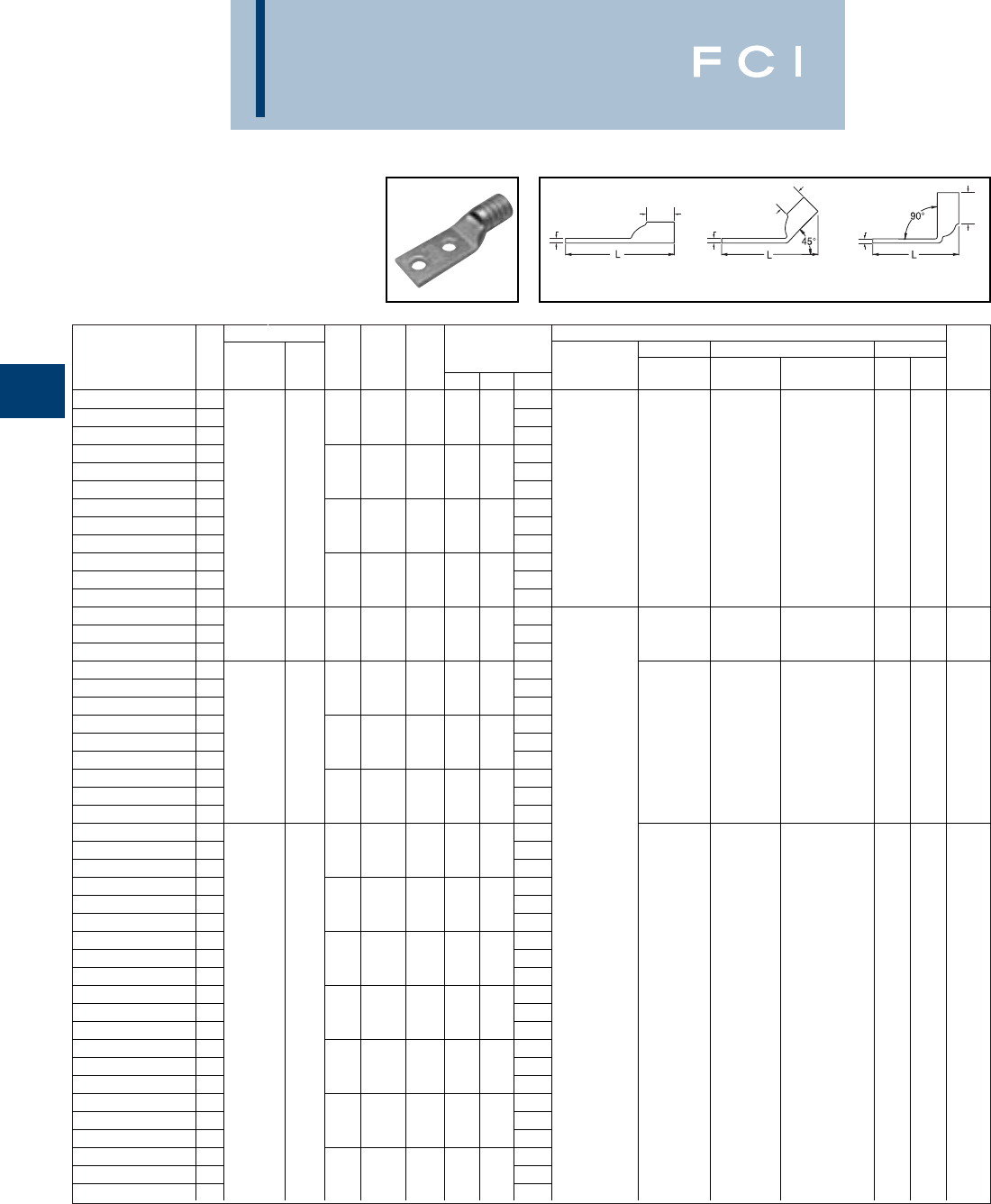
Conductor ▲Installation Tooling
Stud
Stud
Figure Mechanical Hydraulic Wire
Fig *** Hole
Hole Tongue
Dimensions Dieless MD6, OUR840, BCT500HS, Y35, Y39, Y750, Color Die Strip
Catalog Number # AWG MM2Size
Spacing Width
(B) (T) (L) (# of crimps) MD7-34R Y500CTHS Y46*, PAT750 Code Index Length
YA38-L2NTC-FX
15.35
YA38-L2NTC-FX-45
21/21-3/41.811.45.275.30
YA38-L2NTC-FX-90
33.84
YA38-L2TC516-FX
14.04
YA38-L2TC516-FX-45
2
535.3 kcmil
5/1611.841.45.273.98Y644HS (1)
YA38-L2TC516-FX-90
32.53
Y81KFT (1)
--U38XRT (2) Pink L99 1-7/16
YA38-L2NT38-FX
11325/24 300 4.35
Y81KFTMBH (1)
YA38-L2NT38-FX-45
23/811.631.45.274.30
PAT81KFT-18V (1)
YA38-L2NT38-FX-90
3
(500 MCM NOM)
2.84
YA38-L2NNT-FX
15.35
YA38-L2NNT-FX-45
21/21-3/41.631.45.275.30
YA38-L2NNT-FX-90
33.84
YA39-L2NTC-FX
15.36
YA39-L2NTC-FX-45
2600 kcmil - 1/21-3/41.911.42.275.31--U38RT (2) Purple 23 1-3/8
YA39-L2NTC-FX-90
33.87
YA40-L2NTC-FX
15.38
YA40-L2NTC-FX-45
21/21-3/41.951.42.305.38
YA40-L2NTC-FX-90
33.91
YA40-L2TC38-FX
1646 kcmil 4.28
YA40-L2TC38-FX-45
2400 3/811.981.42.304.20--U39RT (2) Black 24 1-5/16
YA40-L2TC38-FX-90
31600/24 2.72
YA40-L2NNT-FX
15.38
YA40-L2NNT-FX-45
21/21-3/41.631.42.305.38
YA40-L2NNT-FX-90
33.91
YA44-L2TC38-FX
14.74
YA44-L2TC38-FX-45
23/812.191.65.334.71
YA44-L2TC38-FX-90
33.02
YA44-L2NTC-FX
15.74Y644HS (1)
YA44-L2NTC-FX-45
21/21-3/42.191.65.335.71
Y81KFT (2)
YA44-L2NTC-FX-90
34.02
Y81KFTMBH (2)
YA44-L2TC58-FX
15.55
PAT81KFT-18V (2)
YA44-L2TC58-FX-45
25/81-1/22.191.65.335.52
YA44-L2TC58-FX-90
3
777.7 kcmil
3.83
YA44-L2TC12-FX
15.05
YA44-L2TC12-FX-45
21925/24 500 1/21-1/42.191.65.335.02--U44XRT (2)
Ye l l o w
L115 1-5/8
YA44-L2TC12-FX-90
33.33
YA44-L2TC12E3-FX
1
(750 MCM NOM)
5.30
YA44-L2TC12E3-FX-45
21/21-1/22.191.65.335.27
YA44-L2TC12E3-FX-90
33.58
YA44-L2NT38-FX
14.74
YA44-L2NT38-FX-45
23/811.631.65.334.71
YA44-L2NT38-FX-90
33.02
YA44-L2NNT-FX
15.74
YA44-L2NNT-FX-45
21/21-3/41.631.65.335.71
YA44-L2NNT-FX-90
34.02
BURNDY
Compression
C-72
TWO HOLE HYLUG™
FLEX CONDUCTOR
STANDARD BARREL
(Continued)
*Use PUADP-1 adaptor with "U" dies in Y46 HYPRESS™.
*** The MM2 conductor sizes listed are the recommendations
for Class 5 conductor.
▲See tooling section of this catalog for complete tool and die
listings. Use ONLY color-coded die recommendations for
“-FX” connectors. For nest/indentor system contact factory.
◆For applications greater than 2000 Volts consult cable
manufacturer for voltage stress relief instructions.
TTT
BB
B
Fig. 1 Fig. 2 Fig. 3

BURNDY
Compression
C-73
TWO HOLE HYLUG™
FLEX CONDUCTOR
STANDARD BARREL
LEAD PLATED
TYPE YAG-L-2TC-LD
COPPER COMPRESSION
TERMINAL
UL Listed 90° C,
600 Volts to 35 KV ◆
*Use PUADP-1 adapter with "U" dies in Y46 HYPRESS™.
** The MM2conductor size referenced here is for both Class
2 and Class 5 conductor.
LEAD
PLATED CABLE
ACCOMMODATION
CRIMPS
DIE AND COLOR
CODE INFORMATION
NO INSPECTION
WINDOW
BEVELED
ENTRY
BB
B
TT
T90°
L
45°
L
L
Fig. 1 Fig. 2 Fig. 3
Conductor ▲Installation Tooling
Stud
Stud
Figure Mechanical Hydraulic Wire
Fig *** Hole
Hole Tongue
Dimensions Dieless MD6, OUR840, BCT500HS, Y35, Y39, Y750, Color Die Strip
Catalog Number # AWG MM2Size
Spacing Width
(B) (T) (L) (# of crimps) MD7-34R Y500CTHS Y46*, PAT750 Code Index Length
YAG8CL-2TC14-LD 11.95 W8CVT W8CVT U8CRT Red 49 1/2
YAG8CL-2TC14-LD-45 21/45/8.41.44.081.94
YAG8CL-2TC14-LD-90 31.00
YAG8CL-2TC38-LD 12.52MRC840 (1)
YAG8CL-2TC38-LD-45 23/81.57.44.062.46MY29-3 (1)
YAG8CL-2TC38-LD-90 3#8 WELD 2.05MY29-11 (1)
YAG8CL-2TC10-LD 1** 1.84Y8MRB-1 (1) W8CVT (1) W8CVT (1)
YAG8CL-2TC10-LD-45 237/24 # 10 5/8.41.44.081.83Y2MR (1) W8CRT (1) W8CRT (1) U8CRT (1) Red 49 7/16
YAG8CL-2TC10-LD-90 310 1.37Y1MR (1) X8CRT (1) X8CRT (1)
YAG8CL-2TC14E1-LD 1#8 AWG 2.33Y81KFT (1)
YAG8CL-2TC14E1-LD-45 21/41.44.44.082.32Y81KFTMBH (1)
YAG8CL-2TC14E1-LD-90 31.87
PAT81KFT-18V (1)
YAG8CL-2TC14E2-LD 12.08
YAG8CL-2TC14E2-LD-45 21/43/4.44.44.082.07
YAG8CL-2TC14E2-LD-90 31.62
YAG6CL-2TC10-LD 11.94
YAG6CL-2TC10-LD-45 2# 10 5/8.44.50.071.86
YAG6CL-2TC10-LD-90 31.38
YAG6CL-2TC10E2-LD 12.06
YAG6CL-2TC10E2-LD-45 2# 10 3/4.48.50.082.02
YAG6CL-2TC10E2-LD-90 31.57
YAG6CL-2TC10E4-LD 1#6 WELD 2.00MY29-11 (1)
YAG6CL-2TC10E4-LD-45 2** # 10 11/16.44.50.071.95Y2MR (1) W5CVT (1) W5CVT (1)
YAG6CL-2TC10E4-LD-90 361/24 1.44Y1MR (1) W5CRT (1) W5CRT (1) U5CRT (1) Blue 7 1/2
YAG6CL-2TC10E-LD 116 1.81Y81KFT (1) X5CRT (1) X5CRT (1)
YAG6CL-2TC10E-LD-45 2#6 AWG # 10 1/2.48.50.081.77Y81KFTMBH (1)
YAG6CL-2TC10E-LD-90 31.27
PAT81KFT-18V (1)
YAG6CL-2TC14-LD 12.06
YAG6CL-2TC14-LD-45 21/45/8.48.50.082.02
YAG6CL-2TC14-LD-90 31.52
YAG6CL-2TC14E1-LD 12.44
YAG6CL-2TC14E1-LD-45 21/41.48.50.082.40
YAG6CL-2TC14E1-LD-90 31.89
*** The MM2conductor sizes listed are the recommendations
for Class 5 conductor.
◆For applications greater than 2000 Volts consult cable
manufacturer for voltage stress relief instructions.

BURNDY
Compression
C-74
TWO HOLE HYLUG™
FLEX CONDUCTOR
STANDARD BARREL
LEAD PLATED
(Continued)
*Use PUADP-1 adapter with "U" dies in Y46 HYPRESS™.
** The 16 MM2referenced here is for both Class 2 and Class
5 conductor.
BB
B
TT
T90°
L
45°
L
L
Fig. 1 Fig. 2 Fig. 3
Conductor ▲Installation Tooling
Stud
Stud
Figure Mechanical Hydraulic Wire
Fig *** Hole
Hole Tongue
Dimensions Dieless MD6, OUR840, BCT500HS, Y35, Y39, Y750, Color Die Strip
Catalog Number # AWG MM2Size
Spacing Width
(B) (T) (L) (# of crimps) MD7-34R Y500CTHS Y46*, PAT750 Code Index Length
YAG6CL-2TC14E2-LD 12.18
YAG6CL-2TC14E2-LD-45 21/43/4.48.50.082.15
YAG6CL-2TC14E2-LD-90 31.64
YAG6CL-2TC516-LD 12.50MY29-11 (1)
YAG6CL-2TC516-LD-45 2#6 WELD
** 5/161.52.50.072.45Y2MR (1)
YAG6CL-2TC516-LD-90 31.95Y1MR (1) W5CVT (1) W5CVT (1)
YAG6CL-2TC38-LD 161/24 16 2.62
Y81KFT (1)
W5CRT (1) W5CRT (1) U5CRT (1) Blue 7 1/2
YAG6CL-2TC38-LD-45 23/81.58.50.062.56
Y81KFTMBH (1)
X5CRT (1) X5CRT (1)
YAG6CL-2TC38-LD-90 3#6 AWG 2.07PAT81KFT-18V (1)
YAG6CL-2NTC-LD 13.81
YAG6CL-2NTC-LD-45 21/21-3/4.83.50.123.67
YAG6CL-2NTC-LD-90 33.29
YAG4CL-2NT10-LD 11.99
YAG4CL-2NT10-LD-45 2# 10 5/8.41.50.091.97
YAG4CL-2NT10-LD-90 31.43
YAG4CL-2NT10E1-LD 12.37
YAG4CL-2NT10E1-LD-45 2# 101.41.50.092.34
YAG4CL-2NT10E1-LD-90 31.80
YAG4CL-2TC14-LD 12.11
YAG4CL-2TC14-LD-45 21/45/8.55.50.092.09
YAG4CL-2TC14-LD-90 31.55
YAG4CL-2TC14E2-LD 1#4 WELD 2.24
YAG4CL-2TC14E2-LD-45 21/43/4.55.50.092.22W4CVT (1) W4CVT (1)
YAG4CL-2TC14E2-LD-90 391/24 -1.68W4CRT (1) W4CRT (1) U4CRT (1) Gray 8 1/2
YAG4CL-2TC14E1-LD 1105/24 2.49X4CRT (1) X4CRT (1)
YAG4CL-2TC14E1-LD-45 21/41.55.50.092.47
YAG4CL-2TC14E1-LD-90 3#4 AWG 1.93MY29-11 (1)
YAG4CL-2TC38-LD 12.68Y2MR (2)
YAG4CL-2TC38-LD-45 23/81.58.50.082.64Y1MR (2)
YAG4CL-2TC38-LD-90 32.11
Y81KFT (1)
YAG4CL-2TC516-LD 12.56
Y81KFTMBH (1)
YAG4CL-2TC516-LD-45 25/161.55.50.092.53PAT81KFT-18V (1)
YAG4CL-2TC516-LD-90 3.1.99
YAG4CL-2NTC-LD 13.87
YAG4CL-2NTC-LD-45 21/21-3/4.83.50.123.91
YAG4CL-2NTC-LD-90 33.32
YAG2CL-2TC14-LD 12.28
YAG2CL-2TC14-LD-45 21/45/8.68.63.102.23
YAG2CL-2TC14-LD-90 31.60
YAG2CL-2TC14E1-LD 1#2 WELD 2.63
YAG2CL-2TC14E1-LD-45 21/41.68.63.102.60W2CVT (1) W2CVT (1)
YAG2CL-2TC14E1-LD-90 3125/24 35 1.98W2CRT (1) W2CRT (1) U2CRT (1) Brown 10 11/16
YAG2CL-2TC14E2-LD 1150/24 2.40X2CRT (1) X2CRT (1)
YAG2CL-2TC14E2-LD-45 21/43/4.68.63.102.36
YAG2CL-2TC14E2-LD-90 3#2 AWG 1.73
YAG2CL-2TC38-LD 12.84
YAG2CL-2TC38-LD-45 23/81.68.63.102.79
YAG2CL-2TC38-LD-90 32.17
*** The MM2 conductor sizes listed are the recommendations
for Class 5 conductor.
◆For applications greater than 2000 Volts consult cable
manufacturer for voltage stress relief instructions.

Conductor ▲Installation Tooling
Stud
Stud
Figure Mechanical Hydraulic Wire
Fig *** Hole
Hole Tongue
Dimensions Dieless MD6, OUR840, BCT500HS, Y35, Y39, Y750, Color Die Strip
Catalog Number # AWG MM2Size
Spacing Width
(B) (T) (L) (# of crimps) MD7-34R Y500CTHS Y46*, PAT750 Code Index Length
YAG2CL-2TC516-LD 12.71MY29-11 (1)
YAG2CL-2TC516-LD-45 2#2 WELD 5/161.68.63.102.67Y2MR (2)
YAG2CL-2TC516-LD-90 3125/24 35 2.04Y1MR (2) W2CVT (1) W2CVT (1)
YAG2CL-2NTC-LD 1150/24 4.03
Y81KFT (1)
W2CRT (1) W2CRT (1) U2CRT (1) Brown 10 11/16
YAG2CL-2NTC-LD-45 2#2 AWG 1/21-3/4.83.63.083.94
Y81KFTMBH (1)
X2CRT (1) X2CRT (1)
YAG2CL-2NTC-LD-90 33.34PAT81KFT-18V (1)
YAG1CL-2TC14-LD 12.37
YAG1CL-2TC14-LD-45 21/45/8.75.69.12’’ 2.33
YAG1CL-2TC14-LD-90 31.64
YAG1CL-2TC14E2-LD 12.49
YAG1CL-2TC14E2-LD-45 21/43/4.75.69.122.46
YAG1CL-2TC14E2-LD-90 31.76
YAG1CL-2TC14E1-LD 1#1 WELD 2.73
YAG1CL-2TC14E1-LD-45 21/41.75.69.122.70W1CVT (1) W1CVT (1)
YAG1CL-2TC14E1-LD-90 3175/24 -2.00W1CRT-1 (1) W1CRT-1 (1) U1CRT-1 (1) Green 11 11/16
YAG1CL-2TC516-LD 1225/24 2.81X1CRT-1 (1) X1CRT-1 (1)
YAG1CL-2TC516-LD-45 25/161.75.69.122.77
YAG1CL-2TC516-LD-90 3#1 AWG 2.08
YAG1CL-2TC38-LD 12.93
YAG1CL-2TC38-LD-45 23/81.75.69.122.90
YAG1CL-2TC38-LD-90 32.20
YAG1CL-2NTC-LD 14.12
YAG1CL-2NTC-LD-45 21/21-3/4.83.69.114.06
YAG1CL-2NTC-LD-90 33.38
YAG25L-2TC14-LD 12.41
YAG25L-2TC14-LD-45 21/45/8.83.69.122.36
YAG25L-2TC14-LD-90 31.66MY29-11 (1)
YAG25L-2TC14E2-LD 12.53
Y81KFT (1)
YAG25L-2TC14E2-LD-45 21/43/4.83.69.122.49
Y81KFTMBH (1)
YAG25L-2TC14E2-LD-90 31.79PAT81KFT-18V (1)
YAG25L-2TC516E2-LD 12.60
YAG25L-2TC516E2-LD-45 25/163/4.83.69.122.55
YAG25L-2TC516E2-LD-90 31/0 WELD 1.85
YAG25L-2TC516-LD 12.85W25VT (2) W25VT (2)
YAG25L-2TC516-LD-45 2275/24 50 5/161.83.69.12’’ 2.80W25RT (2) W25RT (2) U25RT (1) Pink 12 11/16
YAG25L-2TC516-LD-90 32.10X25RT (2) X25RT (2)
YAG25L-2TC38-LD 11/0 AWG 2.97
YAG25L-2TC38-LD-45 23/81.83.69.122.92
YAG25L-2TC38-LD-90 32.23
YAG25L-2NTC-LD 14.16
YAG25L-2NTC-LD-45 21/21-3/4.83.69.124.11
YAG25L-2NTC-LD-90 33.41
YAG25L-2TC12E1-LD 13.22
YAG25L-2TC12E1-LD-45 21/21.83.69.123.17
YAG25L-2TC12E1-LD-90 32.48
YAG26L-2TC14-LD 12.58MY29-11 (1)
2/0 WELD Y644HS (1) W26RT (2) W26RT (2)
YAG26L-2TC14-LD-45 2325/24 70 1/45/8.93.81.132.51
Y81KFT (1)
W26VT (2) W26VT (2) U26RT (1) Black 13 13/16
2/0 AWG
Y81KFTMBH (1)
X26RT (2) X26RT (2)
YAG26L-2TC14-LD-90 31.70PAT81KFT-18V (1)
BURNDY
Compression
C-75
TWO HOLE HYLUG™
FLEX CONDUCTOR
STANDARD BARREL
LEAD PLATED
(Continued)
*Use PUADP-1 adapter with "U" dies in Y46 HYPRESS™.
*** The MM2 conductor sizes listed are the recommendations
for Class 5 conductor.
◆For applications greater than 2000 Volts consult cable
manufacturer for voltage stress relief instructions.
BB
B
TT
T90°
L
45°
L
L
Fig. 1 Fig. 2 Fig. 3

BURNDY
Compression
C-76
TWO HOLE HYLUG™
FLEX CONDUCTOR
STANDARD BARREL
LEAD PLATED
(Continued)
*Use PUADP-1 adapter with "U" dies in Y46 HYPRESS™.
** The 120 MM2referenced here is for both Class 2 and
Class 5 conductor.
*** The MM2conductor sizes listed are the recommendations
for Class 5 conductor.
Conductor ▲Installation Tooling
Stud
Stud
Figure Mechanical Hydraulic Wire
Fig *** Hole
Hole Tongue
Dimensions Dieless MD6, OUR840, BCT500HS, Y35, Y39, Y750, Color Die Strip
Catalog Number # AWG MM2Size
Spacing Width
(B) (T) (L) (# of crimps) MD7-34R Y500CTHS Y46*, PAT750 Code Index Length
YAG26L-2TC14E2-LD 12.71
YAG26L-2TC14E2-LD-45 21/43/4.93.81.132.63
YAG26L-2TC14E2-LD-90 31.83
YAG26L-2TC516-LD 13.02
YAG26L-2TC516-LD-45 22/0 WELD 5/161.93.81.132.94W26RT (2) W26RT (2)
YAG26L-2TC516-LD-90 32.14W26VT (2) W26VT (2) U26RT (1) Black 13 13/16
YAG26L-2TC38-LD 1325/24 70 3.14X26RT (2) X26RT (2)
YAG26L-2TC38-LD-45 23/81.93.81.133.39
YAG26L-2TC38-LD-90 32/0 AWG 3.32
YAG26L-2NTC-LD 14.33
YAG26L-2NTC-LD-45 21/21-3/4.93.81.134.26
YAG26L-2NTC-LD-90 33.45
YAG27L-2TC14-LD 12.81
YAG27L-2TC14-LD-45 21/45/81.031.00.142.67
YAG27L-2TC14-LD-90 31.74
YAG27L-2TC14E2-LD 12.94
YAG27L-2TC14E2-LD-45 21/43/41.031.00.142.82
YAG27L-2TC14E2-LD-90 33/0 WELD 1.86
YAG27L-2TC516-LD 13.25W27VT (2) W27VT (2)
YAG27L-2TC516-LD-45 2450/24 95 5/1611.031.00.143.13W27RT (2) W27RT (2) U27RT (1) Orange 14 1.00 in.
YAG27L-2TC516-LD-90 32.18X27RT (3) X27RT (3)
YAG27L-2TC38-LD 13/0 AWG3.38MY29-11 (1)
YAG27L-2TC38-LD-45 23/811.031.00.143.25Y644HS (1)
YAG27L-2TC38-LD-90 32.30Y81KFT (1)
YAG27L-2NTC-LD 14.56Y81KFTMBH (1)
YAG27L-2NTC-LD-45 21/21-3/41.031.00.144.44
PAT81KFT-18V (1)
YAG27L-2NTC-LD-90 33.49
YAG28L-2TC14-LD 12.90
YAG28L-2TC14-LD-45 21/45/81.141.03 .152.76
YAG28L-2TC14-LD-90 31.78
YAG28L-2TC14E2-LD 13.02
YAG28L-2TC14E2-LD-45 21/43/41.141.03.152.89
YAG28L-2TC14E2-LD-90 31.90
YAG28L-2TC516-LD 13.33
YAG28L-2TC516-LD-45 25/1611.141.03.153.20
YAG28L-2TC516-LD-90 34/0 WELD 2.22
YAG28L-2TC38-LD 1** 3.46W28VT (2) W28VT (2)
YAG28L-2TC38-LD-45 2550/24 3/811.141.03.153.33W28RT (2) W28RT (2) U28RT (1) Purple 15 1-1/16
YAG28L-2TC38-LD-90 3120 2.34X28RT (3) X28RT (3)
YAG28L-2NT38-LD 14/0 AWG3.48
YAG28L-2NT38-LD-45 23/81.941.03.173.38
YAG28L-2NT38-LD-90 32.36
YAG28L-2TC12E1-LD 13.71
YAG28L-2TC12E1-LD-45 21/211.141.03.173.58
YAG28L-2TC12E1-LD-90 32.59
YAG28L-2TC12-LD 13.96
YAG28L-2TC12-LD-45 21/21-1/41.141.03.173.83
YAG28L-2TC12-LD-90 32.84
◆For applications greater than 2000 Volts consult cable
manufacturer for voltage stress relief instructions.
BB
B
TT
T90°
L
45°
L
L
Fig. 1 Fig. 2 Fig. 3
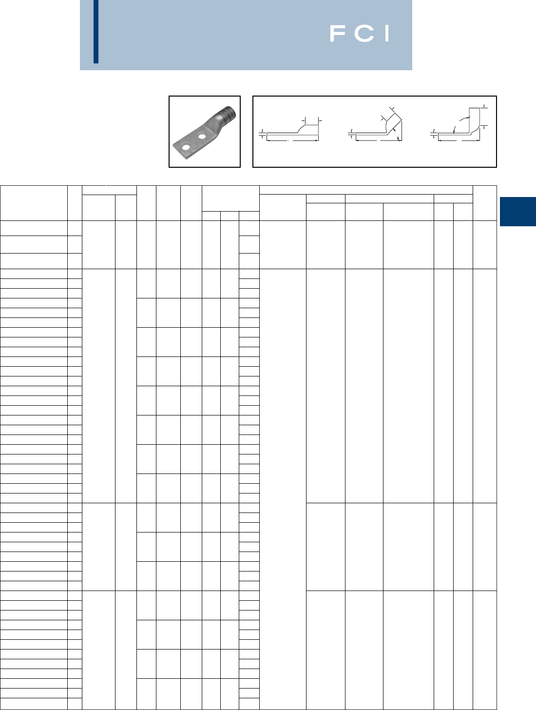
Conductor ▲Installation Tooling
Stud
Stud
Figure Mechanical Hydraulic Wire
Fig *** Hole
Hole Tongue
Dimensions Dieless MD6, OUR840, BCT500HS, Y35, Y39, Y750, Color Die Strip
Catalog Number # AWG MM2Size
Spacing Width
(B) (T) (L) (# of crimps) MD7-34R Y500CTHS Y46*, PAT750 Code Index Length
MY29-11(1)
YAG28L-2NTC-LD 1
4/0 WELD
4.65
Y644HS (1) W28VT (2) W28VT (2)
YAG28L-2NTC-LD-45 2550/24 ** 1/21-3/41.141.03.154.51Y81KFT (1) W28RT (2) W28RT (2) U28RT (1) Purple 15 1-1/16
4/0 AWG 120 Y81KFTMBH (1) X28RT (3) X28RT (3)
YAG28L-2NTC-LD-90 33.53
PAT81KFT-18V (1
)
YAG29L-2TC14-LD 12.90
YAG29L-2TC14-LD-45 21/45/81.141.03.162.76
YAG29L-2TC14-LD-90 31.78
YAG29L-2TC14E2-LD 13.02
YAG29L-2TC14E2-LD-45 21/43/41.141.03.162.89
YAG29L-2TC14E2-LD-90 31.90
YAG29L-2TC516-LD 13.33
YAG29L-2TC516-LD-45 25/1611.141.03.163.20
YAG29L-2TC516-LD-90 32.22
YAG29L-2TC38-LD 13.46
YAG29L-2TC38-LD-45 24/0 WELD 3/811.141.03.163.33
W29VT (2) W29VT (2)
YAG29L-2TC38-LD-90 3- 2.34W29RT (2) U29RT (1) Yellow 16 1-1/16
YAG29L-2NT38-LD 1550/24 3.48X29RT (4) X29RT (4)
YAG29L-2NT38-LD-45 23/81.941.03.163.38
YAG29L-2NT38-LD-90 32.36
YAG29L-2TC12E1-LD 13.71
YAG29L-2TC12E1-LD-45 21/211.141.03.163.58
YAG29L-2TC12E1-LD-90 32.59
YAG29L-2TC12-LD 13.96
YAG29L-2TC12-LD-45 21/21-1/41.141.03.163.83
YAG29L-2TC12-LD-90 32.84Y644HS (1)
YAG29L-2NTC-LD 14.65Y81KFT (1)
YAG29L-2NTC-LD-45 21/21-3/41.141.03.164.51Y81KFTMBH (1)
YAG29L-2NTC-LD-90 33.53
PAT81KFT-18V (1)
YAG30L-2TC38-LD 13.48
YAG30L-2TC38-LD-45 23/811.201.03.163.38
YAG30L-2TC38-LD-90 3250 kcmil 2.37
YAG30L-2TC12-LD 13.98W29VT (2)
YAG30L-2TC12-LD-45 2
CLASS G 259 STR
-1/21-1/41.201.03.163.88W29VT (2) W29RT (2) U29RT (1) Yellow 16 1-1/16
YAG30L-2TC12-LD-90 32.87X29RT (4) X29RT (4)
YAG30L-2NTC-LD 1
CLASS H 427 STR
4.67
YAG30L-2NTC-LD-45 21/21-3/41.201.03.164.57
YAG30L-2NTC-LD-90 33.56
YAG31L-2TC38-LD 23.54
YAG31L-2TC38-LD-45 23/811.291.06.183.46
YAG31L-2TC38-LD-90 22.41
YAG31L-2NTC38-LD 14.30
YAG31L-2NTC38-LD-45 2250 WELD 3/81-3/41.291.06.184.20
YAG31L-2NTC38-LD-90 33.20
W30VT (2) W30VT (2) U30RT (2) White 17 1-1/8
YAG31L-2TC12-LD 1637/24 150 4.04W30RT (2)
YAG31L-2TC12-LD-45 21/21-1/41.291.06.183.96
YAG31L-2TC12-LD-90 3
CLASS I,K,M
2.91
YAG31L-2NTC-LD 14.73
YAG31L-2NTC-LD-45 21/21-3/41.291.06.184.64
YAG31L-2NTC-LD-90 33.60
BURNDY
Compression
C-77
TWO HOLE HYLUG™
FLEX CONDUCTOR
STANDARD BARREL
LEAD PLATED
(Continued)
*Use PUADP-1 adapter with "U" dies in Y46 HYPRESS™.
** The 120 MM2referenced here is for both Class 2 and
Class 5 conductor.
*** The MM2 conductor sizes listed are the recommendations
for Class 5 conductor.
◆For applications greater than 2000 Volts consult cable
manufacturer for voltage stress relief instructions.
BB
B
TT
T90°
L
45°
L
L
Fig. 1 Fig. 2 Fig. 3

Conductor ▲Installation Tooling
Stud
Stud
Figure Mechanical Hydraulic Wire
Fig *** Hole
Hole Tongue
Dimensions Dieless MD6, OUR840, BCT500HS, Y35, Y39, Y750, Color Die Strip
Catalog Number # AWG MM2Size
Spacing Width
(B) (T) (L) (# of crimps) MD7-34R Y500CTHS Y46*, PAT750 Code Index Length
YAG32L-2TC38-LD 13.73
YAG32L-2TC38-LD-45 2775/24 3/811.401.19.193.62
YAG32L-2TC38-LD-90 3185 2.45
W31VT (2) W31VT (2) U31RT (2) Red 18 1-1/4
YAG32L-2NTC-LD 1313.1 kcmil 4.91W31RT (2)
YAG32L-2NTC-LD-45 21/21-3/41.401.19.194.81
YAG32L-2NTC-LD-90 33.64
YAG34L-2TC516-LD 13.79
YAG34L-2TC516-LD-45 25/1611.551.27.233.72
YAG34L-2TC516-LD-90 32.42
YAG34L-2TC38-LD 13.92
YAG34L-2TC38-LD-45 23/811.551.27.233.84
YAG34L-2TC38-LD-90 3373.7 kcmil 2.54
YAG34L-2NT38-LD 14.67
W32VT (2)
YAG34L-2NT38-LD-45 2925/24 240 3/81-3/4.961.27.234.59W32VT (2) U32RT (2) Blue 19 1-5/16
YAG34L-2NT38-LD-90 33.29W32RT (2)
YAG34L-2TC12-LD 1
350 kcmil CLASS I
4.42
YAG34L-2TC12-LD-45 21/21-1/41.551.27.233.34
YAG34L-2TC12-LD-90 33.04
YAG34L-2NTC-LD 15.11
YAG34L-2NTC-LD-45 21/21-3/41.551.27.235.03Y644HS (1)
YAG34L-2NTC-LD-90 33.73Y81KFT (1)
YAG36L-2TC38-LD 14.28Y81KFTMBH (1)
YAG36L-2TC38-LD-45 21100/24 3/811.731.38.274.24
PAT81KFT-18V (1)
YAG36L-2TC38-LD-90 3-2.81
--U34RT (2) Brown 20 1-3/8
YAG36L-2NTC-LD 1444.4 kcmil 5.28
YAG36L-2NTC-LD-45 21/21-3/41.731.38.275.24
YAG36L-2NTC-LD-90 33.81
YAG38L-2TC516-LD 14.09
YAG38L-2TC516-LD-45 25/1611.821.45.274.02
YAG38L-2TC516-LD-90 32.53
YAG38L-2NT38-LD 14.40
YAG38L-2NT38-LD-45 23/811.631.45.274.33
YAG38L-2NT38-LD-90 3535.3 kcmil 2.84
YAG38L-2TC38-LD 14.28
YAG38L-2TC38-LD-45 21325/24 300 3/811.821.45.274.24--U38XRT (2) Pink 20 1-3/8
YAG38L-2TC38-LD-90 32.81
YAG38L-2TC12-LD 1
500 kcmil CLASS I
4.72
YAG38L-2TC12-LD-45 21/21-1/41.821.45.274.64
YAG38L-2TC12-LD-90 33.16
YAG38L-2NTC-LD 15.28
YAG38L-2NTC-LD-45 21/21-3/41.821.45.275.24
YAG38L-2NTC-LD-90 33.81
YAG39L-2NTC-LD 15.29
YAG39L-2NTC-LD-45 2600 kcmil - 1/21-3/41.901.19.275.26Y644HS (1) - - U38RT (2) Purple 400 1-3/8
YAG39L-2NTC-LD-90 33.87Y81KFT (2)
YAG40L-2TC38-LD 1646 kcmil 4.33Y81KFTMBH (2)
YAG40L-2TC38-LD-45 2400 3/811.981.42.304.23
PAT81KFT-18V (2)
--U39RT (2) Black 24 1-5/16
YAG40L-2TC38-LD-90 31600/24 2.72
BURNDY
Compression
C-78
TWO HOLE HYLUG™
FLEX CONDUCTOR
STANDARD BARREL
LEAD PLATED
(Continued)
*Use PUADP-1 adapter with "U" dies in Y46 HYPRESS™.
*** The MM2 conductor sizes listed are the recommendations
for Class 5 conductor.
◆For applications greater than 2000 Volts consult cable
manufacturer for voltage stress relief instructions.
BB
B
TT
T90°
L
45°
L
L
Fig. 1 Fig. 2 Fig. 3
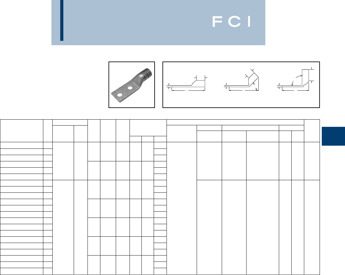
BURNDY
Compression
C-79
TWO HOLE HYLUG™
FLEX CONDUCTOR
STANDARD BARREL
LEAD PLATED
(Continued)
*Use PUADP-1 adapter with "U" dies in Y46 HYPRESS™.
*** The MM2 conductor sizes listed are the recommendations
for Class 5 conductor.
Conductor ▲Installation Tooling
Stud
Stud
Figure Mechanical Hydraulic Wire
Fig *** Hole
Hole Tongue
Dimensions Dieless MD6, OUR840, BCT500HS, Y35, Y39, Y750, Color Die Strip
Catalog Number # AWG MM2Size
Spacing Width
(B) (T) (L) (# of crimps) MD7-34R Y500CTHS Y46*, PAT750 Code Index Length
YAG40L-2NNT-LD
15.43
YAG40L-2NNT-LD-45
2646 kcmil 1/21-3/41.631.42.305.42
YAG40L-2NNT-LD-90
33.91
--U39RT (2) Black 24 1-5/16
YAG40L-2NTC-LD
1-5.43
YAG40L-2NTC-LD-45
21600/24 1/21-3/41.981.42.305.42
YAG40L-2NTC-LD-90
33.91
YAG44L-2TC38-LD
14.80
YAG44L-2TC38-LD-45
23/812.181.65.334.75
YAG44L-2TC38-LD-90
33.02
YAG44L-2TC12-LD
15.11Y644HS (1)
YAG44L-2TC12-LD-45
21/21-1/42.181.65.335.07
Y81KFT (2)
YAG44L-2TC12-LD-90
3
777.7 kcmil
3.33
Y81KFTMBH (2)
YAG44L-2TC12E3-LD
15.36
PAT81KFT-18V (2)
YAG44L-2TC12E3-LD-45
21925/24 500 1/21-1/22.181.65.335.32--U44XRT (2)
Ye l l o w
L115 1-5/8
YAG44L-2TC12E3-LD-90
33.58
YAG44L-2NTC-LD
1
750 kcmil CLASS I
5.80
YAG44L-2NTC-LD-45
21/21-3/42.181.65.335.75
YAG44L-2NTC-LD-90
34.02
YAG44L-2TC58-LD
15.61
YAG44L-2TC58-LD-45
25/81-1/22.181.65.335.57
YAG44L-2TC58-LD-90
33.83
◆For applications greater than 2000 Volts consult cable
manufacturer for voltage stress relief instructions.
BB
B
TT
T90°
L
45°
L
L
Fig. 1 Fig. 2 Fig. 3
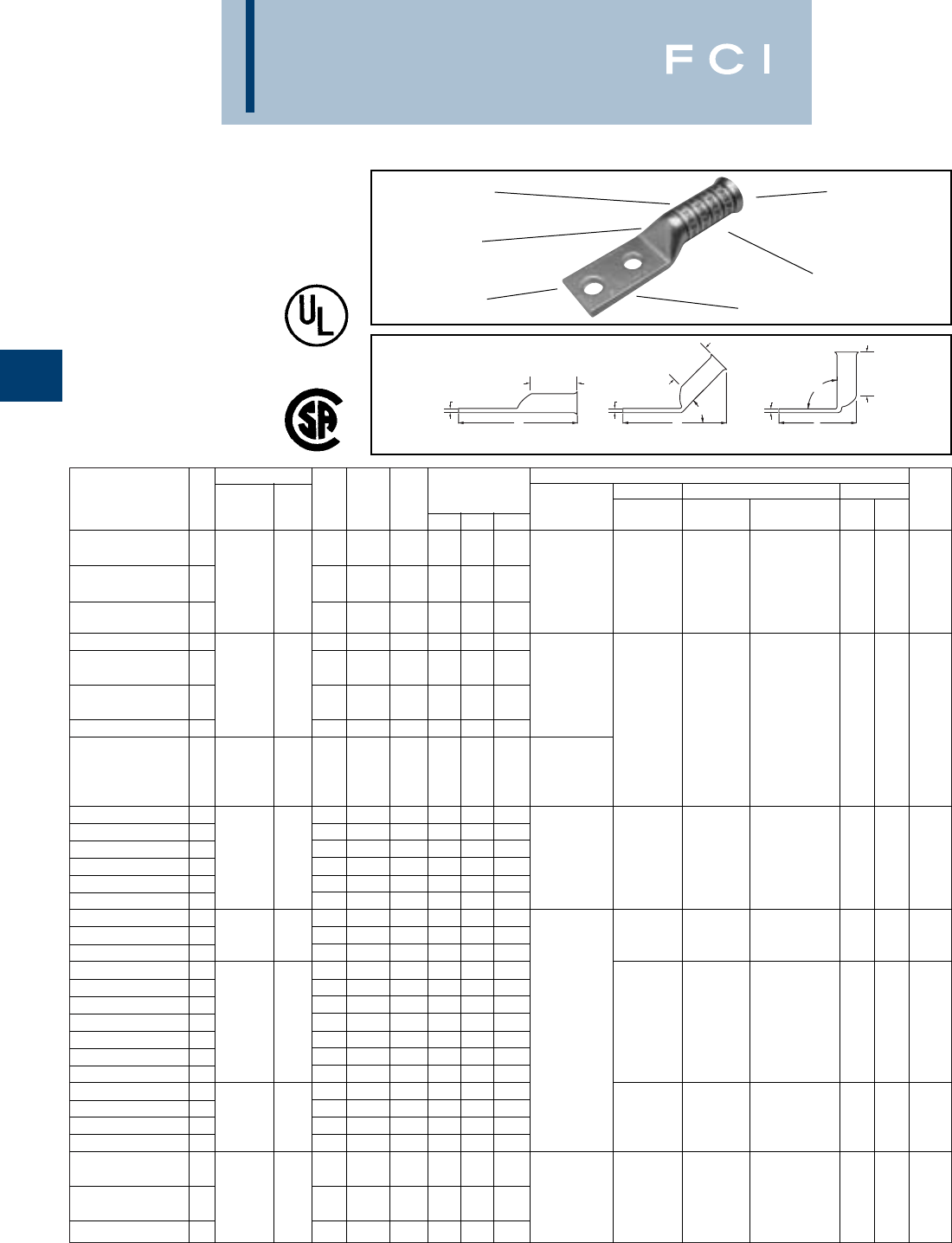
Conductor ▲Installation Tooling
Stud
Stud
Figure Mechanical Hydraulic Wire
Fig *** Hole
Hole Tongue
Dimensions Dieless MD6, OUR840, BCT500HS, Y35, Y39, Y750, Color Die Strip
Catalog Number # AWG MM2Size
Spacing Width
(B) (T) (L) (# of crimps) MD7-34R Y500CTHS Y46*, PAT750 Code Index Length
Y8MRB-1 (2)
YA8C2TC14E2-FXB
11/43/4.41.90.082.54
Y2MR + Y1MR (2)
37/24 ** MY29-11 (2) W8CRT (2) W8CVT (2)
YA8C2TC14-FXB
1# 8 WELD 10 1/45/8.41.90.082.41
Y81KFT (1)
W8CVT (2) W8CRT (2) U8CRT (2) Red 49 1
#8 AWG
Y81KFTMBH (1)
X8CRT (2) X8CRT (2)
YA8C2TC38-FXB
13/81.57.90.062.98
PAT81KFT-18V (1)
YAV6C2TC14E2-FXB
11/43/4.481.22082.88
Y2MR + Y1MR (2)
MY29-11 (2)
YAV 6 C2TC14-FXB
161/24 ** 1/45/8.481.22.082.76
Y644HS (1)
#6 WELD 16
Y81KFT (1)
YAV 6 C2TC38-FXB
1#6 AWG 3/81.601.22.063.32
Y81KFTMBH (1)
W5CVT (2) W5CVT (2)
YAV6C2N-FXB
11/21-3/4.771.22.044.51
PAT81KFT-18V (1)
W5CRT (2) W5CRT (2) U5CRT (2) Blue 7 1-5/16
Y644HS (1) X5CRT (2) X5CRT (2)
-
Y81KFT (1)
YAV 5 C2TC14-FXB
1#5 AWG 1/45/8.441.22.072.76
Y81KFTMBH (1)
PAT81KFT-18V (1)
YAV4C2TC14E2-FXB
11/43/4.551.22.092.93
Y2MR + Y1MR (4)
YAV4C2TC14E1-FXB
11/41.551.22.093.18MY29-11 (2)
YAV 4 C2TC14-FXB
1
91/24 - 105/24
-1/45/8.551.22.092.81Y644HS (1) W4CVT (2) W4CVT (2)
YAV4C2TC516-FXB
1#4 WELD 5/161.551.22.093.24
Y81KFT (1)
W4CRT (2) W4CRT (2) U4CRT (2) Gray 8 1-5/16
YAV 4 C2TC38-FXB
1#4 AWG 3/81.631.22.093.37
Y81KFTMBH (1)
X4CRT (2) X4CRT (2)
YAV4C2N-FXB
11/21-3/4.771.22.094.56
PAT81KFT-18V (1)
YA3C2TC516-FXB
1
105/24 - 125/24
5/161.551.48.093.51
YA3C2TC38-FXB
1#3 WELD - 3/81.581.48.093.64W3CRT (2) W3CRT (2) U3CRT (2)
White
91-9/16
YA3C2N-FXB
1#3 AWG 1/21-3/4.771.48.094.83
YAV 2 C2TC14-FXB
11/45/8.671.35.103.00
YAV2C2TC14E2-FXB
1
125/24 - 150/24
1/43/4.671.35.103.13
YAV2C2TC14E1-FXB
11/41.671.35.103.38MY29-11 (2) W2CVT (2) W2CVT (2)
YAV2C2TC516-FXB
1#2 WELD 35 5/161.671.35.103.44Y644HS (1) W2CRT (2) W2CRT (2) U2CRT (2)
Brown
10 1-7/16
YAV 2 C2TC38-FXB
13/81.671.35.103.57
Y81KFT (1)
X2CRT (2) X2CRT (2)
YAV 2 C2NT38-FXB
1#2 AWG 3/81.481.35.103.57
Y81KFTMBH (1)
YAV2C2N-FXB
11/21-3/4.771.35.094.76
PAT81KFT-18V (1)
YAV 1 C2TC14-FXB
1
175/24 - 225/24
1/45/8.751.50.123.17
YAV1C2TC14E2-FXB
1#1 WELD - 1/43/4.751.50.123.30W1CVT (2) W1CVT (2)
YAV 1 C2TC38-FXB
1#1 AWG 3/81.751.50.123.74
W1CRT-1 (2) W1CRT-1 (2)
U1CRT-1 (2)
Green
11 1-9/16
YAV1C2N-FXB
11/21-3/4.771.50.124.92
X1CRT-1 (2) X1CRT-1 (2)
MY29-11 (2)
YAV252TC14-FXB
11/45/8.831.50.123.21
Y644HS (1) W25RT (4) W25RT (4)
275/24 50
Y81KFT (2)
W25VT (4) W25VT (4) U25RT (2) Pink 12 1-9/16
YAV252TC14E2-FXB
11/0 WELD 1/43/4.831.50.123.34
Y81KFTMBH (2)
X25RT (4) X25RT (4)
YAV252TC38-FXB
13/81.831.50.123.78
PAT81KFT-18V (2)
BURNDY
Compression
C-80
Consult cable manufacturers for stress relief instructions.
◆For applications greater than 2000 Volts consult cable
manufacturer for voltage stress relief instructions.
*Use PUADP-1 adaptor with "U" -dies in Y46 HYPRESS™.
** The MM2conductor sizes referenced here are for both
Class 2 and Class 5 conductors.
T
B
B
B
TT90°
L
L45°
L
Fig. 1 Fig. 2 Fig. 3
TWO HOLE HYLUG™
FLEX CONDUCTOR
LONG BARREL
BELLED END
TYPES YA-2TC-FXB,
YAV-2TC-FXB
COPPER COMPRESSION
TERMINAL
UL Listed 90° C,
600 Volts to 35 KV ◆
ELECTRO-TIN
PLATED CABLE
ACCOMMODATION
CRIMPS
DIE AND COLOR
CODE INFORMATION
NO INSPECTION
WINDOW
BELLED END
ASSISTS
FLEXIBLE WIRE
INSERTION
*** The MM2conductor sizes listed are the recommendations
for Class 5 conductor.
‡P-RT die sets for use in Y46 HYPRESS™ only, PUADP-1
adapter not required.
▲See tooling section of this catalog for complete tool and die
listings. Use ONLY color-coded die recommendations for “-
FX” connectors.
Consult shielded cable manufacturers for stress relief
instructions.
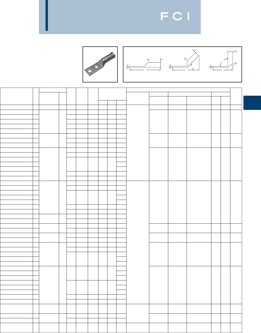
Conductor ▲Installation Tooling
Stud
Stud
Figure Mechanical Hydraulic Wire
Fig *** Hole
Hole Tongue
Dimensions Dieless MD6, OUR840, BCT500HS, Y35, Y39, Y750, Color Die Strip
Catalog Number # AWG MM2Size
Spacing Width
(B) (T) (L) (# of crimps) MD7-34R Y500CTHS Y46*, PAT750 Code Index Length
YAV252N-FXB
11/0 AWG 50 1/21-3/4.831.50.124.96
YAV262TC14-FXB
11/45/8.931.63.133.40
YAV262TC14E2-FXB
1325/24 1/43/4.931.63.133.52W26VT (4) W26VT (4)
YAV262TC38-FXB
12/0 WELD 70 3/81.931.63`.133.96W26RT (4) W26RT (4) U26RT (2) Black 13
1-13/16
YAV262NTC38-FXB
12/0 AWG 3/81-3/4.931.63.134.71X26RT (4) X26RT (4)
YAV262N-FXB
11/21-3/4.931.63.135.15
YAV272TC14E2-FXB
1450/24 1/43/41.021.64.143.58MY29-11 (2) W27RT (4) W27RT (4)
YAV272TC38-FXB
13/0 WELD 95 3/811.021.64.144.01Y644HS (1) W27VT (4) W27VT (4) U27RT (2)
Orange
14
1-13/16
YAV272N-FXB
13/0 AWG 1/21-3/41.021.64.145.20
Y81KFT (2)
X27RT (4) X27RT (4)
YAV282TC14E2-FXB
11/43/41.141.77.143.76
Y81KFTMBH (2)
YAV282NT38-FXB
13/81.751.77.144.20
PAT81KFT-18V (2)
YAV282TC38-FXB
1550/24 4.20W28VT (4) W28VT (4)
YAV282TC38-FXB-45
24/0 WELD ** 3/811.141.77.143.92W28RT (4) W28RT (4) U28RT (2)
Purple
15 1-7/8
YAV282TC38-FXB-90
34/0 AWG 120 2.39X28RT (6) X28RT (6)
YAV282NTC38-FXB
13/81-3/41.141.77.144.20
YAV282N-FXB
11/21-3/41.141.77.145.39
YAV292TC14E2-FXB
11/43/41.142.00.153.76
YAV292NT38-FXB
13/81.752.00.154.20
YAV292TC38-FXB
1550/24 4.20
YAV292TC38-FXB-45
2-3/811.142.00.153.92
W29VT (4) W29VT (4)
YAV292TC38-FXB-90
34/0 WELD 2.39W29RT (4) U29RT (2)
Yellow
16 1-7/8
YAV292NTC38-FXB
13/81-3/41.142.00.154.20X29RT (6) X29RT (6)
YAV292N-FXB
11/21-3/41.142.00.155.39
YA302TC38-FXB
1
250 FLEX - CLASS G 259 STR
-3/811.202.16.164.61
YA302N-FXB
1
CLASS H 427 STR
-1/21-3/41.202.12.165.80
YA312TC38-FXB
1250 FLEX 3/811.292.18.184.66
W30VT (4) W30RT (4) U30RT (4)
White
17 2-1/4
YA312N-FXB
1
637/24 CLASS I, K, M
150 1/21-3/41.292.18.185.85W30VT (4)
YA322TC38-FXB
1775/24 3/811.402.32.194.85Y644HS (1)
W31VT (4) W31RT (4) U31RT (4) Red 18 2-1/4
YA322N-FXB
1
313.1 kcmil
185 1/21-3/41.402.32.196.04
Y81KFT (2)
W31VT (4)
YA342TC14E2-FXB
11/43/41.552.48.234.66
Y81KFTMBH (2)
YA342TC38-FXB
1925/24 3/811.552.48.235.10
PAT81KFT-18V (2)
W32VT (4)
YA342N-FXB
1
373.7 kcmil
240 6.29W32VT (4) U32RT (4) Blue 19 2-9/16
YA342N-FXB-45
2
(350 kcmil nom.)
1/21-3/41.552.48.235.93W32RT (4)
YA342N-FXB-90
33.73
YA382TC38-FXB
16.01
YA382TC38-FXB-45
23/811.843.08.265.46
YA382TC38-FXB-90
32.86
YA382N-FXB
11325/24 300 7.01
YA382N-FXB-45
2
535.3 kcmil (500kcmil nom.)
1/21-3/41.843.08.266.46--U38XRT (4) Pink L99 3-3/16
YA382N-FXB-90
33.84
YA382-FXBG2
13/821.843.08.276.82
YA382-FXBG3
11/21-7/81.843.08.276.26
Y644HS (1)
YA402N-FXB
1
1600/24 646 kcmil
400 1/21-3/41.983.24.307.22
Y81KFT (3)
--U39RT (4) Black 24 3-5/16
YA442TC38-FXB
11925/24 500 3/812.193.33.336.44
Y81KFTMBH (3)
YA442N-FXB
1
777.7 kcmil (750kcmil nom.)
1/21-3/42.193.33.337.44
PAT81KFT-18V (3)
--U44XRT (4)
Yellow
L115 3-7/16
YA462N-FXB
12750/24 - 1/21-3/42.693.58.397.91--
P45RT (4)
Yellow
29
3-11/16
1111 kcmil (1000kcmil nom.)
**
BURNDY
Compression
C-81
Consult cable manufacturers for stress relief instructions.
◆For applications greater than 2000 Volts consult cable
manufacturer for voltage stress relief instructions.
*Use PUADP-1 adaptor with "U" -dies in Y46 HYPRESS™.
TWO HOLE HYLUG™
FLEX CONDUCTOR
LONG BARREL
BELLED END
(Continued)
T
B
B
B
TT90°
L
L45°
L
Fig. 1 Fig. 2 Fig. 3
** The MM2conductor sizes referenced here are for both
Class 2 and Class 5 conductors.
*** The MM2conductor sizes listed are the recommendations
for Class 5 conductor.
‡P-RT die sets for use in Y46 HYPRESS™ only, PUADP-1
adapter not required.
▲See tooling section of this catalog for complete tool and
die listings. Use ONLY color-coded die recommendations
for “-FX” connectors.
Consult shielded cable manufacturers for stress relief
instructions.
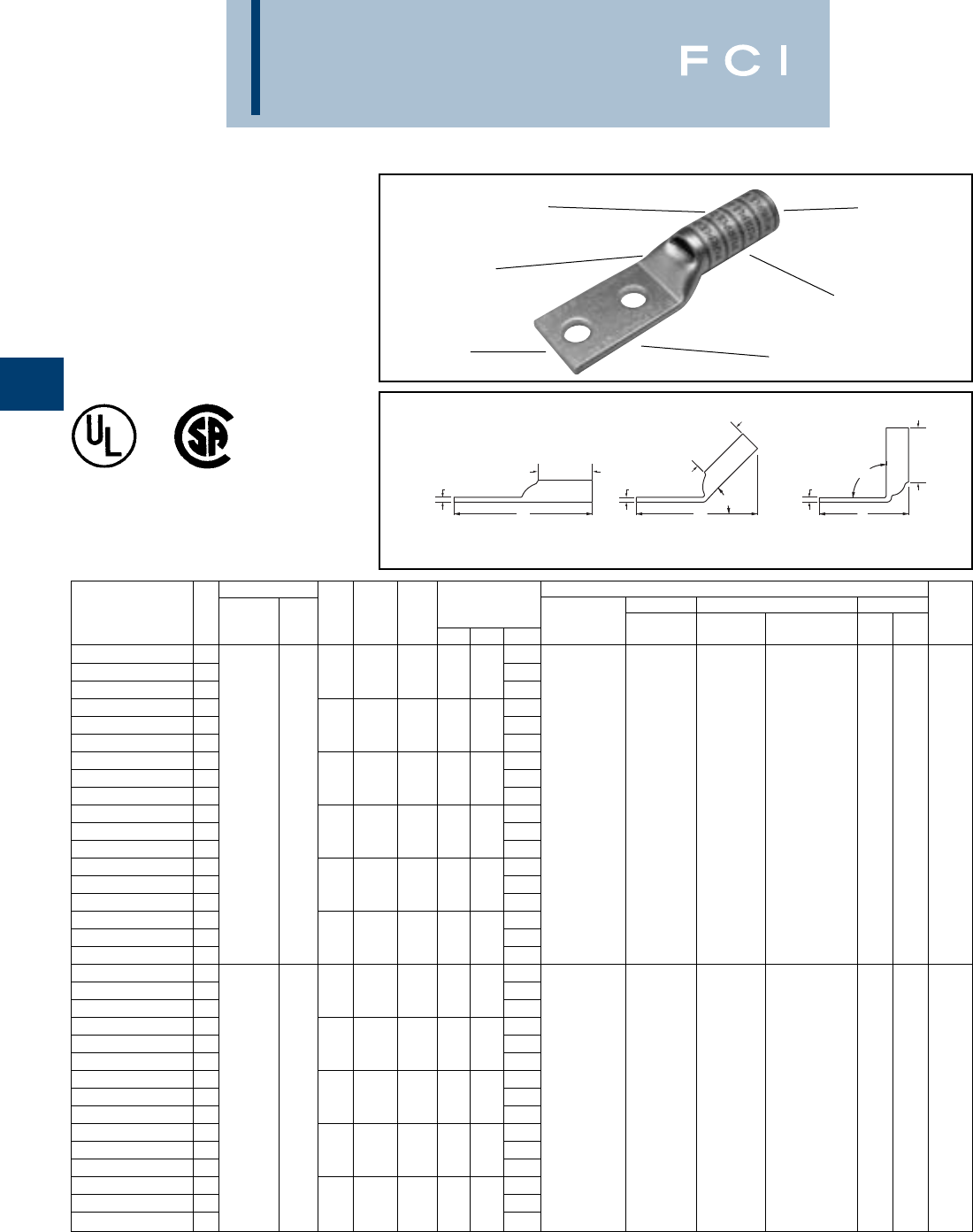
BURNDY
Compression
C-82
TWO HOLE HYLUG™
FLEX CONDUCTOR
LONG BARREL WITH
INSPECTION WINDOW
TYPE YAZ-FX
UL Listed 90° C,
600 Volts to 35 KV ◆
ELECTRO-TIN
PLATED CABLE
ACCOMMODATION
CRIMPS
DIE AND COLOR
CODE INFORMATION
INSPECTION
WINDOW
BEVELED
ENTRY
90°
L
45°
LL
B
B
B
TTT
Fig. 1 Fig. 2 Fig. 3
*Use PUADP-1 adaptor with "U" -dies in Y46 HYPRESS™.
** The MM2conductor size referenced here is for both Class
2 and Class 5 conductor.
*** The MM2 conductor size listed are the recommendations
for Class 5 conductor.
Conductor ▲Installation Tooling
Stud
Stud
Figure Mechanical Hydraulic Wire
Fig *** Hole
Hole Tongue
Dimensions Dieless MD6, OUR840, BCT500HS, Y35, Y39, Y750, Color Die Strip
Catalog Number # AWG MM2Size
Spacing Width
(B) (T) (L) (# of crimps) MD7-34R Y500CTHS Y46*, PAT750 Code Index Length
YAZ8C2TC10FX
12.20
YAZ8C2TC10FX45
2# 10 5/8.41.75.082.09
YAZ8C2TC10FX90
31.37
YAZ8C2TC10E2FX
12.33
YAZ8C2TC10E2FX45
2# 10 3/4.41.75.082.22
YAZ8C2TC10E2FX90
31.50
YAZ8C2TC14E1FX
12.70Y8MRB-1 (1)
YAZ8C2TC14E1FX45
237/24 1/41.44.75.082.60Y2MR (2)
YAZ8C2TC14E1FX90
3** 1.87MY29-11 (2) W8CVT (2) W8CVT (2)
YAZ8C2TC14FX
1#8 WELD 10 2.32Y1MR (2) W8CRT (2)) W8CRT (2) U8CRT (2) Red 49 1
YAZ8C2TC14FX45
21/45/8.44.75.082.20
Y81KFT (1)
X8CRT (2) X8CRT (2)
YAZ8C2TC14FX90
3#3 AWG 1.
Y81KFTMBH (1)
YAZ8C2TC14E2FX
12.45
PAT81KFT-18V (1)
YAZ8C2TC14E2FX45
21/43/4.44.75:.082.33
YAZ8C2TC14E2FX90
31.62
YAZ8C2TC38FX
12.89
YAZ8C2TC38FX45
23/81.58.75.062.72
YAZ8C2TC38FX90
32.05
YAZV6C2TC10E2FX
12.64
YAZV6C2TC10E2FX45
2# 10 3/4.48.75.082.48
YAZV6C2TC10E2FX90
31.51
YAZV6C2TC14FX
12.65
YAZV6C2TC14FX45
21/45/8.48.75.082.45Y2MR (2)
YAZV6C2TC14FX90
361/24 1.51MY29-11 (2)
YAZV6C2TC14E2FX
12.78Y644HS (1) W5CVT (2) W5CVT (2)
YAZV6C2TC14E2FX45
2#6 WELD ** 1/43/4.48.75.082.58Y1MR (2) W5CRT (2) W5CRT (2) U5CRT (2) Blue 7 1-3/16
YAZV6C2TC14E2FX90
316 1.63
Y81KFT (1)
X5CRT (2) X5CRT (2)
YAZV6C2TC14E1FX
1#6 AWG 3.03
Y81KFTMBH (1)
YAZV6C2TC14E1FX45
21/41.48.75.082.83
PAT81KFT-18V (1
)
YAZV6C2TC14E1FX90
31.88
YAZV6C2TC38FX
13.22
YAZV6C2TC38FX45
23/81.58.75.062.97
YAZV6C2TC38FX90
32.06
▲See tooling section of this catalog for complete tool and die
listings. Use ONLY color-coded die recommendations for
“-FX” connecotrs. For nest/indentor system contact factory.
◆For applications greater than 2000 Volts consult cable
manufacturer for voltage stress relief instructions.

BURNDY
Compression
C-83
TWO HOLE HYLUG™
FLEX CONDUCTOR
LONG BARREL WITH
INSPECTION WINDOW
(Continued)
*Use PUADP-1 adaptor with "U" -dies in Y46 HYPRESS™.
** The MM2conductor size referenced here is for both Class
2 and Class 5 conductor.
*** The MM2 conductor sizes listed are the recommendations
for Class 5 conductor.
90°
L
45°
LL
B
B
B
TTT
Fig. 1 Fig. 2 Fig. 3
Conductor ▲Installation Tooling
Stud
Stud
Figure Mechanical Hydraulic Wire
Fig *** Hole
Hole Tongue
Dimensions Dieless MD6, OUR840, BCT500HS, Y35, Y39, Y750, Color Die Strip
Catalog Number # AWG MM2Size
Spacing Width
(B) (T) (L) (# of crimps) MD7-34R Y500CTHS Y46*, PAT750 Code Index Length
YAZV6C2TC38E2FX 12.97
Y2MR + Y1MR (2)
YAZV6C2TC38E2FX-45 23/83/4.58.75.062.72MY29-11 (2)
YAZV6C2TC38E2FX-90 361/24 ** 1.81Y644HS (1) W5CVT (2) W5CVT (2)
YAZV6C2TC38E6FX 1#6 WELD 16 3.09
Y81KFT (1)
W5CRT (2) W5CRT (2) U5CRT (2) Blue 7 1-3/16
YAZV6C2TC38E6FX-45 2#6 AWG 3/87/8.58.75.062.85
Y81KFTMBH (1)
X5CRT (2) X5CRT (2)
YAZV6C2TC38E6FX-90 31.94
PAT81KFT-18V (1)
YAZV4C2TC38E2-FX 13.14
YAZV4C2TC38E2-FX-45 23/83/4.581.25082.88
YAZV4C2TC38E2-FX-90 31.86
YAZV4C2TC38FX 13.39
YAZV4C2TC38FX45 2
91/24-105/24
3/81.581.25.083.13
YAZV4C2TC38FX90 32.11W4CVT (2) W4CVT (2)
YAZV4C2TC14FX 1#4 WELD - 2.83W4CRT (2) W4CRT (2) U4CRT (2) Gray 8 1-5/16
YAZV4C2TC14FX45 21/45/8.551.25.092.59X4CRT (2) X4CRT (2)
YAZV4C2TC14FX90 3#4 AWG 1.55Y1MR (4)
YAZV4C2TC14E2FX 12.95Y2MR (4)
YAZV4C2TC14E2FX45 21/43/4.551.25.092.72MY29-11 (2)
YAZV4C2TC14E2FX90 31.68Y644HS (1)
YAZV2C2TC14FX 13.01
Y81KFT (1)
YAZV2C2TC14FX45 21/45/8.681.38.102.75
Y81KFTMBH (1)
YAZV2C2TC14FX90 31.60
PAT81KFT-18V (1)
YAZV2C2TC14E2FX 1
125/24-150/24
3.13
YAZV2C2TC14E2FX45 21/43/4.681.38.102.87
W2CVT (2) W2CVT (2)
YAZV2C2TC14E2FX90 3#2 WELD 35 1.73
W2CRT (2) W2CRT (2) U2CRT (2) Brown 10 1-7/16
YAZV2C2TC38FX 13.57
X2CRT (2) X2CRT (2)
YAZV2C2TC38FX45 2#2 AWG 3/81.681.38.103.31
YAZV2C2TC38FX90 32.16
YAZV2C2NTCFX 14.76
YAZV2C2NTCFX45 21/21-3/4.831.38.104.50
YAZV2C2NTCFX90 33.35
YAZV1C2TC14FX 13.04
YAZV1C2TC14FX45 21/45/8.751.38.122.81
YAZV1C2TC14FX90 31.64
YAZV1C2TC14E1FX 13.41
YAZV1C2TC14E1FX45 21/41.751.38.123.18
YAZV1C2TC14E1FX90 32.01
YAZV1C2TC14E2FX 1
175/24-225/24
3.16
YAZV1C2TC14E2FX45 21/43/4.751.38.122.93MY29-11 (2)
YAZV1C2TC14E2FX90 3#1 WELD - 1.76Y644HS (1) W1CVT (2) W1CVT (2)
YAZV1C2TC38FX 13.60
Y81KFT (1)
W1CRT-1 (2) W1CRT-1 (2) U1CRT-1 (2) Green 11 1-7/16
YAZV1C2TC38FX45 2#1 AWG 3/81.751.38.123.37
Y81KFTMBH (1)
X1CRT-1 (2) X1CRT-1 (2)
YAZV1C2TC38FX90 32.20
PAT81KFT-18V (1)
YAZV1C2TC516E6FX 13.35
YAZV1C2TC516E6FX-45
25/167/8.751.38.123.12
YAZV1C2TC516E6FX-90
31.95
YAZV1C2TC516FX 13.47
YAZV1C2TC516FX45 25/161.751.38.123.24
YAZV1C2TC516FX90 32.08
▲See tooling section of this catalog for complete tool and die
listings. Use ONLY color-coded die recommendations for
“-FX” connecotrs. For nest/indentor system contact factory.
◆For applications greater than 2000 Volts consult cable
manufacturer for voltage stress relief instructions.
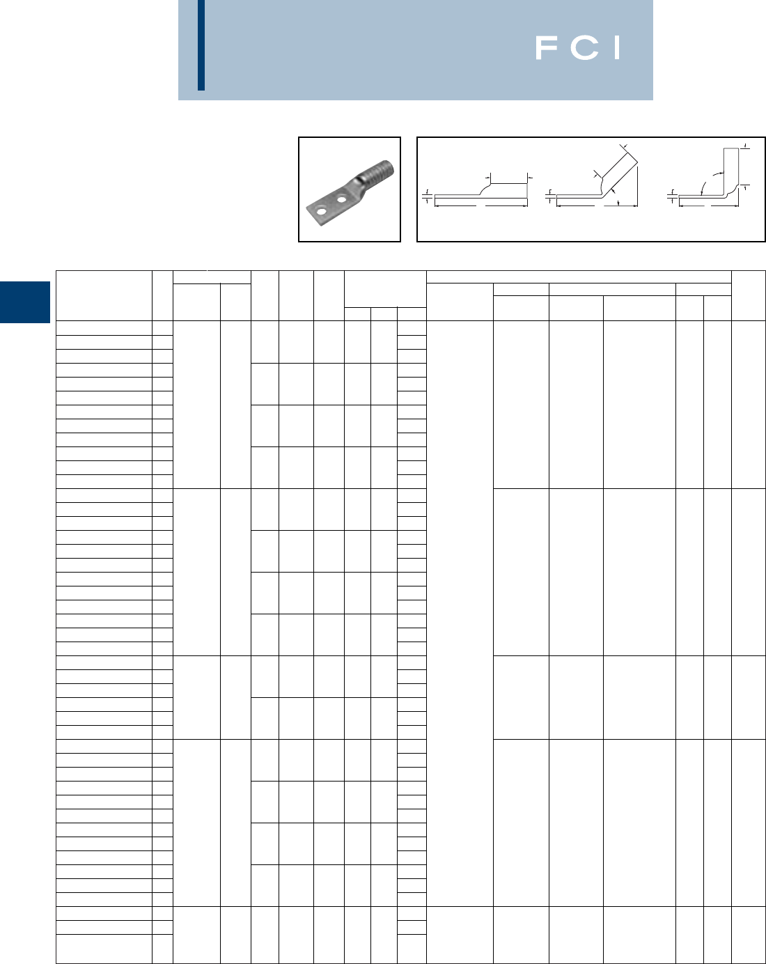
Conductor ▲Installation Tooling
Stud
Stud
Figure Mechanical Hydraulic Wire
Fig *** Hole
Hole Tongue
Dimensions Dieless MD6, OUR840, BCT500HS, Y35, Y39, Y750, Color Die Strip
Catalog Number # AWG MM2Size
Spacing Width
(B) (T) (L) (# of crimps) MD7-34R Y500CTHS Y46*, PAT750 Code Index Length
YAZV252TC14FX
13.20
YAZV252TC14FX45
21/45/8.831.50.122.92
YAZV252TC14FX90
31.66
YAZV252TC14E2FX
1275/24 3.32
YAZV252TC14E2FX45
21/43/4.831.50.123.04
W25VT (4) W25VT (4)
YAZV252TC14E2FX90
31/0 WELD 50 1.79
W25RT (4) W25RT (4) U25RT (2) Pink 12 1-9/16
YAZV252TC38FX
13.76
X25RT (4) X25RT (4)
YAZV252TC38FX45
21/0 AWG 3/81.831.50.123.48
YAZV252TC38FX90
32.23
YAZV252NTCFX
14.95
YAZV252NTCFX45
21/21-3/4.831.50.124.67
YAZV252NTCFX90
33.41
YAZV262TC14FX
13.20
YAZV262TC14FX45
21/45/8.931.50.132.92
YAZV262TC14FX90
31.66
YAZV262TC14E2FX
13.32
YAZV262TC14E2FX45
2325/24 1/43/4.931.50.133.05
W26VT (4) W26VT (4)
YAZV262TC14E2FX90
31.79
W26RT (4) W26RT (4) U26RT (2) Black 13 1-9/16
YAZV262TC38FX
12/0 WELD 70 3.76MY29-11 (2) X26RT (4) X26RT (4)
YAZV262TC38FX45
23/81.931.50.133.48Y644HS (1)
YAZV262TC38FX90
32/0 AWG 2.23
Y81KFT (2)
YAZV262NTCFX
14.95
Y81KFTMBH (2)
YAZV262NTCFX45
21/21-3/4.931.50.134.67
PAT81KFT-18V (2)
YAZV262NTCFX90
33.41
YAZV272TC14E2FX
13.36
YAZV272TC14E2FX-45
21/43/41.031.50.143.08
YAZV272TC14E2FX-90
3450/24 1.82W27VT (4) W27VT (4)
YAZV272TC38FX
13/0 WELD 95 3.80W27RT (4) W27RT (4) U27RT (2)
Orange
14 1-9/16
YAZV272TC38FX45
23/0 AWG 3/811.031.50.143.52X27RT (4) X27RT (4)
YAZV272TC38FX90
32.25
YAZV282TC14E2FX
13.52
YAZV282TC14E2FX45
21/43/41.141.62.153.23
YAZV282TC14E2FX90
31.86
YAZV282NT38FX
1550/24 3.96
YAZV282NT38FX-45
23/81.941.62.153.67
W28VT (4) W28VT (4)
YAZV282NT38FX-90
34/0 WELD ** 2.30
W28RT (4) W28RT (4) U28RT (2)
Purple
15
1-11/16
YAZV282TC38FX
13.96
X28RT (6) X28RT (6)
YAZV282TC38FX45
24/0 AWG
120 3/811.141.62.153.67
YAZV282TC38FX90
32.30
YAZV282NTCFX
14.93
YAZV282NTCFX45
21/21-3/41.141.62.154.64
YAZV282NTCFX90
33.27
YAZV292NT516FX
14.62Y644HS (1)
YAZV292NT516FX-45
2550/24 4.35
Y81KFT (2)
W29VT (4) W29RT (4)
4/0 WELD -5/161-3/41.202.00.16
Y81KFTMBH (2)
X29RT (8) W29VT (4) U29RT (2)
Yellow
16
1-11/16
YAZV292NT516FX-90
32.96
PAT81KFT-18V (2)
X29RT (8)
BURNDY
Compression
C-84
TWO HOLE HYLUG™
FLEX CONDUCTOR
LONG BARREL WITH
INSPECTION WINDOW
(Continued)
*Use PUADP-1 adaptor with "U" -dies in Y46 HYPRESS™.
** The MM2conductor size referenced here is for both Class
2 and Class 5 conductor.
*** The MM2 conductor sizes listed are the recommendations
for Class 5 conductor.
▲See tooling section of this catalog for complete tool and die
listings. Use ONLY color-coded die recommendations for
“-FX” connectors. For nest/indentor system contact factory.
◆For applications greater than 2000 Volts consult cable
manufacturer for voltage stress relief instructions.
90°
L
45°
LL
B
B
B
TTT
Fig. 1 Fig. 2 Fig. 3

BURNDY
Compression
C-85
TWO HOLE HYLUG™
FLEX CONDUCTOR
LONG BARREL WITH
INSPECTION WINDOW
(Continued)
*Use PUADP-1 adaptor with "U" -dies in Y46 HYPRESS™.
*** The MM2conductor sizes listed are the recommendations
for Class 5 conductor.
▲See tooling section of this catalog for complete tool and die
listings. Use ONLY color-coded die recommendations for
“-FX” connecotrs. For nest/indentor system contact factory.
Conductor ▲Installation Tooling
Stud
Stud
Figure Mechanical Hydraulic Wire
Fig *** Hole
Hole Tongue
Dimensions Dieless MD6, OUR840, BCT500HS, Y35, Y39, Y750, Color Die Strip
Catalog Number # AWG MM2Size
Spacing Width
(B) (T) (L) (# of crimps) MD7-34R Y500CTHS Y46*, PAT750 Code Index Length
YAZ302TC38FX
1250 FLEX 4.42W29RT (4)
YAZ302TC38FX-45
2
CLASS G 259 STR
.
3/811.202.00.164.05W29VT (4) W29VT (4) U29RT (2)
Ye l l o w
16 2-1/16
YAZ302TC38FX-90
3
CLASS H 427 STR
.
2.37X29RT (8) X29RT (8)
YAZ312TC38FX
14.45
YAZ312TC38FX45
2250 FLEX 3/811.282.00.184.10
YAZ312TC38FX90
3637/24 150 2.41
W30VT (4) W30VT (4) U30RT (4)
White
17 2-1/16
YAZ312TC14E2FX
1
CLASS I, K, M
4.02W30RT (4)
YAZ312TC14E2FX-45
21/43/41.292.00.183.66
YAZ312TC14E2FX-90
31.97
YAZ322TC38FX
1775/24 4.62
W31VT (4)
YAZ322TC38FX45
2185 3/811.552.12.194.25W31VT (4) U31RT (4) Red 18 2-3/16
YAZ322TC38FX90
3
313.1 kcmil
2.46W31RT (4)
YAZ342TC14E2FX
14.42
YAZ342TC14E2FX-45
21/43/41.552.25.234.06
YAZ342TC14E2FX-90
32.10
YAZ342NT38FX
1
373.3 kcmil
4.85
YAZ342NT38FX-45
23/81.962.25.234.50
YAZ342NT38FX-90
3925/24 240 2.54
W32VT (4) W32VT (4) U32RT (4) Blue 19 2-5/16
YAZ342TC38FX
14.85Y644HS (1) W32RT (4)
YAZ342TC38FX45
2
(350 MCM NOM)
3/811.552.25.234.50
Y81KFT (2)
YAZ342TC38FX90
32.54
Y81KFTMBH (2)
YAZ342NTCFX
16.04
PAT81KFT-18V (2)
YAZ342NTCFX45
21/21-3/41.552.25.235.69
YAZ342NTCFX90
33.73
YAZ362TC38FX
11100/24 5.55
YAZ362TC38FX45
2-3/811.722.69.275.14--U34RT (4)
Brown
20 2-3/4
YAZ362TC38FX90
3
444.4 kcmil
2.81
YAZ382NT38FX
15.72
YAZ382NT38FX-45
23/811.632.81.275.26
YAZ382NT38FX-90
32.84
YAZ382TC38FX
1
535.3 kcmil
5.72
YAZ382TC38FX45
23/811.812.81.275.26
YAZ382TC38FX90
31325/24 300 2.84
--U38XRT (4) Pink L99 2-7/8
YAZ382NNTFX
16.72
YAZ382NNTFX-45
2
(500 MCM NOM)
1/21-3/41.632.81.276.26
YAZ382NNTFX-90
33.84
YAZ382NTCFX
16.72
YAZ382NTCFX45
21/21-3/41.812.81.276.26
YAZ382NTCFX90
33.84
◆For applications greater than 2000 Volts consult cable
manufacturer for voltage stress relief instructions.
90°
L
45°
LL
B
B
B
TTT
Fig. 1 Fig. 2 Fig. 3
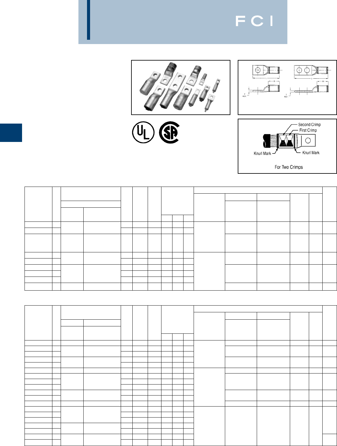
BURNDY
Compression
C-86
E-LINE HYLUG™
EQUIPMENT LINE
TYPE YAE
COPPER AND ALUMINUM
COMPRESSION TERMINAL
UL Listed 90° C,
600 Volts to 35 KV ◆
YA-E Equipment terminals are designed to
provide replacements for original equipment
mechanical or other compression terminals.
These narrow tongue terminals are specially
designed to fit in tight areas. Whether you’re
upgrading or replacing, YA-E connectors will
† Installation Tooling
Conductor Accommodations Mechanical Hydraulic
Copper Only Bolt Tongue Y35, Y750, Y46*, Wire
Catalog Fig Conventional Expanded Wire Range Bolt Hole Width Dimensions Dieless MD6, MD7 PAT750 Color Die Strip
Number No. Wire Size using Y644M Size Spacing (max) B T L (number of crimps) (number of crimps) (number of crimps) Code Index Length
YA25LN50T14E 11/4 - 0.50 0.88 0.12 1.84
Y644HS (1)
W25RT (2) U25RT (1) 12
YA25LN64T516E 11/0 AWG #6 - 1/0 AWG 5/16 - 0.64 0.88 0.12 1.96
PAT644HS (1)
W25VT (2) U2CABT (1) Pink 348 15/16
Y81KFT (1)
YA26LN50T14E 12/0 AWG #4 - 2/0 AWG 1/4 - 0.50 0.94 0.12 1.94
Y81KFTMBH (1)
W26RT (2) U26RT (1) Black 13 1
PAT81KFT-18V (1)
W26VT (2)
YA30LN98T516E 15/16 - 0.98 1.03 0.16 2.31 U30RT (2) 17
YA30L24N100T38E 1300 Kcmil 2/0 AWG - 300 Kcmil 3/8 - 1.00 1.03 0.16 2.44
Y644HS (1)
W30RT (2) U28ART (2) White 298 1-1/16
YA342LNN119T12E 21/2 1.75 1.19 1.27 0.23 5.06 PAT644HS (1) U34RT (2)
YA342LNN131T12E 2500 Kcmil 4/0 AWG - 500 Kcmil 1/2 1.75 1.31 1.27 0.23 5.06
Y81KFT (2)
U31ART (2) Brown 20 1-5/16
YA34L6N131T12E 11/2 - 1.31 1.27 0.23 3.31
Y81KFTMBH (2)
P34RT (2) 299
YA39L6N131T12E 1750 Kcmil 500 - 750 Kcmil 1/2 - 1.31 1.42 0.27 3.61
PAT81KFT-18V (2)
U39RT (2) Black 24 1-1/2
COPPER E-LINE HYLUG™ COMPRESSION TERMINALS
† Installation Tooling
Conductor Accommodations Mechanical Hydraulic
Aluminum Copper or Aluminum Bolt Tongue Y35, Y750, Y46*, Wire
Catalog Fig Conventional Expanded Wire Range Bolt Hole Width Dimensions Dieless MD6, MD7, Y500CT PAT750 Color Die Strip
Number No. Wire Size using Y644M Size Spacing (max) B T L (number of crimps) (number of crimps) (number of crimps) Code Index Length
YA8CA3S56T14E 1#8 AWG #8 AWG 1/4 - 0.56 0.62 0.09 1.65
Y644HS (1)
-U8CABT (1) Blue 374 11/16
YA2CA5S53T14E 11/4 - 0.53 1.00 0.22 2.25
PAT644HS (1)
YA2CA1S91T516E 1#2 AWG #6 - #2 AWG 5/16 - 0.91 1.12 0.16 2.50
Y81KFT (1)
-U2CABT (1) Pink 348 1-3/16
YA25A1S60T516E 15/16 - 0.63 1.00 0.21 2.29
Y81KFTMBH (1)
YA25A3N69T38E 11/0 AWG #1 - 1/0 AWG 3/8 - 0.69 1.05 0.21 2.38
PAT81KFT-18V (1)
-U25ART (1) Tan 296 1-1/8
YA27A10S76T516E 13/0 AWG #1 - 3/0 AWG 5/16 - 0.76 1.11 0.26 2.58 - U27ART (2) Ruby 467 1-3/16
YA30A9N100T516E 15/16 - 1.00 1.53 0.36 3.12
Y644HS (1)
YA30A6N100T38E 1300 Kcmil 2/0 AWG - 300 Kcmil 3/8 - 1.00 1.53 0.36 3.20
PAT644HS (1)
-U30ART (2) Blue 470 1-5/8
YA30A1N131T12E 11/2 - 1.31 1.53 0.35 3.57
Y81KFT (2)
YA31A11N100T516E 15/16 - 1.00 1.85 0.39 3.51
Y81KFTMBH (2)
YA31A9N100T38E 1350 Kcmil 3/0 AWG - 350 Kcmil 3/8 - 1.00 1.85 0.39 3.59
PAT81KFT-18V (2)
-U31ART (2) Brown 299 1-7/8
YA32A8N106T516E 1400 Kcmil 4/0 AWG - 400 Kcmil 5/16 - 1.06 2.26 0.43 3.92 - U32ART (4) Green 472 2-5/16
YA34A8N131T38E 13/8 - 1.31 1.64 0.35 3.88
YA34A3N131T12E 2500 Kcmil 4/0 AWG - 500 Kcmil 1/2 1.75 1.31 1.64 0.35 5.71
Y644HS (2)
YA34A7N131T12E 11/2 - 1.31 1.64 0.35 3.88
PAT644HS (2)
1-11/16
YA36A9N131TD12E 11/2 - 1.31 1.64 0.39 3.98
Y81KFT (3)
U34ART (4) Pink 300
YA36A3N131TD12E 2600 Kcmil 250 - 600 Kcmil 1/2 1.75 1.31 1.64 0.39 5.71
Y81KFTMBH (3)
YA39A5N131TD12E 2500 - 750 Kcmil Aluminum 1/2 1.75 1.31 1.86 0.31 6.09
PAT81KFT-18V (3)
YA39A1N131TD12E 1750 Kcmil 500 Kcmil Copper Only 1/2 - 1.31 1.86 0.31 4.28 1-15/16
ALUMINUM E-LINE HYLUG™ COMPRESSION TERMINALS
Fig. 1 Fig. 2
provide for any of your cable termination
needs. When installed with our dieless tool,
these terminals can accomodate a range of
conductor sizes.
†A variety of BURNDY®installation tools are available and
not all tools are listed. If you require additional tooling infor-
mation, please feel free to call our customer service depart-
ment for other recommendations.
*Use PUADP-1 adapter with “U” dies in Y46 HYPRESS™,
P-RT die sets for use in Y46 HYPRESS™ only. PUADP-1
adapter not required.
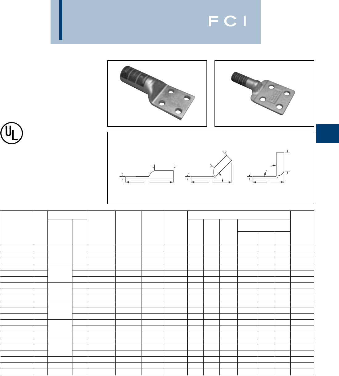
BURNDY
Compression
C-87
FOUR HOLE
HYLUG™
CODE CONDUCTOR
TYPE YA
T T T
B
B
B
90°
L
45°
LL
Fig. 1 Fig. 2 Fig. 3
YA-4N YAB-4N
Available undrilled. Add suffix “U” to catalog number
(example YA444NU).
*Use PUADP-1 adaptor with "U" dies in Y46 HYPRESS™.
** “P” dies for use with Y46 HYPRESS™ only. PUADP-1
adapter not required.
Conductor Installation Tooling
Hydraulic
(Y35,Y39,Y750, Y46*) Wire
Catalog *** Stud Hole Stud Hole Tongue Tongue * Color Die Strip
Number Fig.# AWG MM2Size Spacing Width Angle B T L ** Code Index Length
YA444N 11/2
1.753
Straight 3.00 .23 7.14 P44RT White 27 3-1/16
YA444N-45 21000 kcmil 500 1/2
1.753
45 Degree 3.00 .23 6.71 P44RT White 27 1-15/16
YA444N-90 31/2
1.753
90 Degree 3.00 .23 4.02 P44RT White 27 1-15/16
YA-454N 1-1/2
1.753
Straight 3.19 .30 7.44 P45RT Yellow 29 3-1/4
YA-454N-45 21250 kcmil - 1/2
1.753
45 Degree 3.19 .30 7.03 P45RT Yellow 29 2-1/16
YA-454N-90 3-1/2
1.753
90 Degree 3.19 .30 4.13 P45RT Yellow 29 2-1/16
YA464N 1-1/2
1.753
Straight 3.19 .34 7.55 P46RT Green 31 3-1/4
YA464N-45 21500 kcmil - 1/2
1.753
45 Degree 3.19 .34 7.15 P46RT Green 31 3-5/16
YA464N-90 3-1/2
1.753
90 Degree 3.19 .34 4.29 P46RT Green 31 3-5/16
YA47N 1-1/2
1.753.10
Straight 3.44 .39 7.89 ‡L47RT Gray 33 3-1/2
YA47N-45 21750 kcmil - 1/2
1.753.10
45 Degree 3.44 .39 7.45 ‡L47RT Gray 33 3-1/2
YA47N-90 3-1/2
1.753.10
90 Degree 3.44 .39 4.30 ‡L47RT Gray 33 3-1/2
YA484N 1-1/2
1.753.06
Straight 3.44 .46 7.98 ‡L48RT Brown 34 3-1/2
YA484N-45 22000 kcmil - 1/2
1.753.06
45 Degree 3.44 .46 7.60 ‡L48RT Brown 34 3-1/2
YA484N-90 3-1/2
1.753.06
90 Degree 3.44 .46 4.40 ‡L48RT Brown 34 3-1/2
YA4864N 1-1/2
1.753.46
Straight 4.69 .52 9.38 ‡L486RT - - 4-3/4
YA4864N-45 22500 kcmil - 1/2
1.753.46
Straight 4.69 .52 8.72 ‡L486RT - - 4-3/4
YA4864N-90 3-1/2
1.753.46
Straight 4.69 .52 4.55 ‡L486RT - - 4-3/4
YAB344N 1500 kcmil - 1/2
1.753.00
Straight 2.25 .25 6.33 U36RT Green 22 2-1/2
YAB444N 11000 kcmil - 1/2
1.753.03
Straight 3.00 .50 7.67 P44RT White 27 3-1/16
YAB464N 11500 kcmil - 1/2
1.753.00
Straight 3.19 .50 7.63 P46RT Green 31 3-1/4
*** The MM2conductor sizes listed are for Class 2 conductor.
For applications greater than 2000 Volts, consult cable
manufacturer for voltage stress relief instructions.
‡Requires Y60BHU HYPRESS™
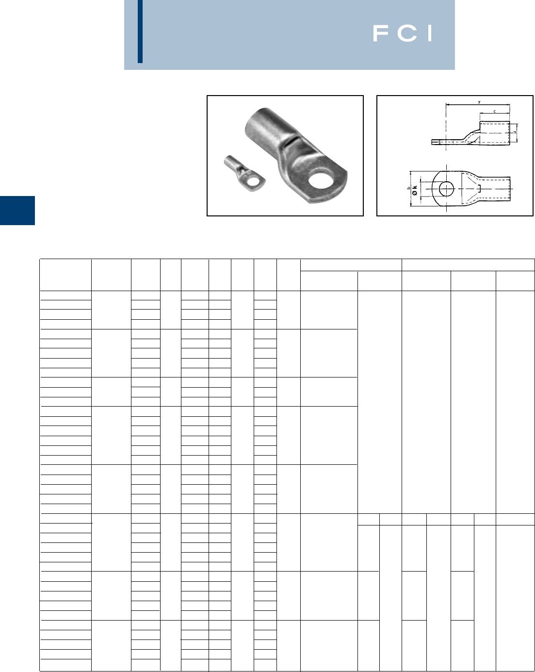
BURNDY
Compression
C-88
TYPE YAV
HYLUG™
NON-INSULATED COPPER
TUBULAR TERMINALS
0.3 - 1000 mm2
Made from electrolytic copper tube, electro
tinned. Range of copper tube formed termi-
nals taking wires from 0.3 - 1000 mm2.Heat
resistant up to +125° C.
Mechanical tools Hydraulic tools
Catalog Stud Pack Tooling Y29BH Y35BH
Number mm2size d y b c Øk Qty. number MRD29 Y29NC Y35 Y644M
YAV18T4 3.0 13.7 4.8 3.1
YAV18T5 3.5 15.5 6.1 3.7
YAV18T1 0.3 - 1.2 4.0 1.4 15.5 8.0 6.9 4.3 100 Y10R4BY
YAV18 5.0 15.5 8.0 5.1
YAV025M35 3.5 13.7 6.0 3.7
YAV025M4 4.0 15.2 8.0 4.3
YAV025M5 1.5 - 2.5 5.0 2.3 15.2 8.0 6.9 5.3 100 Y10R4BY
YAV025M6 6.0 16.7 10.4 6.4
YAV14T3 8.0 17.9 11.1 8.4
YAV04M4 4.0 15.2 6.9 4.3
YAV04M5 2.5 - 4 5.0 2.6 15.2 7.6 6.9 5.3 100 Y10R4BY
YAV04M6 6.0 16.7 9.1 6.4
YAV06M35 3.5 17.9 7.0 3.7
YAV06M4 4.0 19.4 8.0 4.3
YAV06M5 5.0 19.9 10.0 5.3
YAV06M6 4 - 6 6.0 3.3 20.9 11.0 9.5 6.4 50 Y10R4BY
YAV06M8 8.0 23.4 13.0 8.4
YAV10T38 10.0 22.5 14.2 10.5
YAV06FM4 4.0 18.1 8.0 4.3
YAV06FM5 5.0 19.1 9.7 5.3
YAV06FM6 Flex 6 6.0 3.8 20.1 11.0 9.9 6.4 50 Y10R4BY
YAV06FM8 8.0 22.1 13.0 8.4
YAV06FM10 10.0 24.1 14.0 10.5
YAV10M4 4.0 19.4 10.3 4.3 N I N I N I
YAV10M5 5.0 20.4 10.3 5.3
YAV10M6 6.0 21.4 11.1 6.4 Y10R4BY
YAV10M8 10 8.0 4.6 23.4 14.3 12.0 8.4 50 MY2913GE2
YAV10M10 10.0 25.4 14.3 10.5
YAV10M12 12.0 28.4 18.5 12.3
YAV16M5 5.0 22.9 12.7 5.3
YAV16M6 6.0 23.9 12.7 6.4
YAV16M8 16 8.0 5.7 25.9 15.0 14.0 8.4 50 MY2913GE2
YAV16M10 10.0 27.9 15.0 10.5
YAV16M12 12.0 30.9 18.5 13.2
YAV25M5 5.0 24.7 13.9 5.3
YAV25M6 6.0 25.7 13.9 6.4
YAV25M8 25 8.0 7.2 27.7 15.9 15.0 8.4 50 MY2913GE2
YAV25M10 10.0 29.7 15.9 10.5
YAV25M12 12.0 32.7 18.5 13.2
N = Nest die, I = Indentor
50NC2 50NC1 50NC1
50PIO-25C
DV4L DV6L DV8L
Y29PL
UV4CD UV6CD UV8CD
Y35P1 + Y29PQS (Y29PQ10B1 UK)
DIELESS
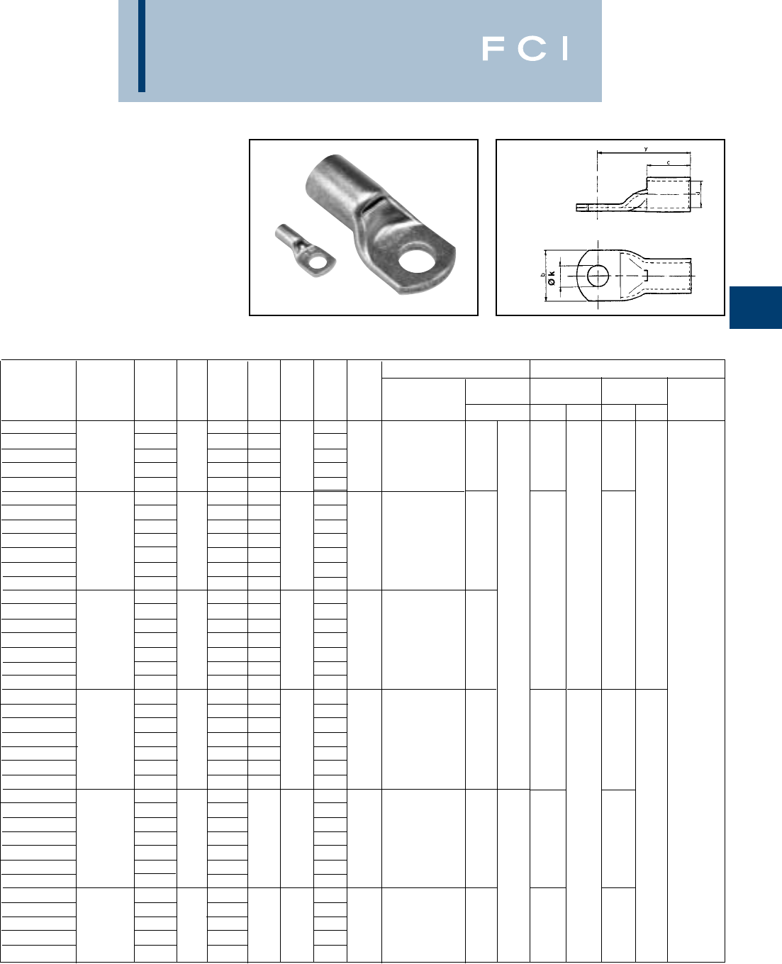
BURNDY
Compression
C-89
TYPE YAV
HYLUG™
NON-INSULATED COPPER
TUBULAR TERMINALS
0.3 - 1000 mm2
(Continued)
Mechanical tools Hydraulic tools
Y29BH Y35BH
Catalog Stud Pack Tooling MRD29 Y29NC Y35
Number mm2size d y b c Øk Qty. number NIN I NI Y644M
YAV35M5 527.4 15.9 5.3
YAV35M6 628.4 15.9 6.4
YAV35M8 35 8 8.5 30.4 15.9 17.0 8.4 50 MY2913GE2
YAV35M10 10 32.4 15.9 10.5
YAV35M12 12 35.4 19.8 13.2
YAV50M5 530.9 18.2 5.3
YAV50M6 631.9 18.2 6.4
YAV50M8 833.9 18.2 8.4
YAV50M10 50 10 9.5 35.9 18.2 20.0 10.5 50 MY2913GE2
YAV50M12 12 38.9 19.8 13.2
YAV50M14 14 38.9 21.5 15.0
YAV50M16 16 41.9 22.4 17.0
YAV50FM5 530.9 18.2 5.3
YAV50FM6 631.9 19.5 6.4
YAV50FM8 833.9 19.5 8.4
YAV50FM10 Flex 50 10 10.0 35.9 19.5 20.0 10.5 50 MY2913GE2
YAV50FM12 12 38.9 21.8 13.2
YAV50FM14 14 38.9 21.8 15.0
YAV50FM16 16 41.9 22.4 17.0
YAV70M5 532.4 21.4 5.3
YAV70M6 633.4 21.4 6.4
YAV70M8 835.4 21.4 8.4
YAV70M10 70 10 11.3 37.4 21.4 21.0 10.5 25 MY2913GE2
YAV70M12 12 40.4 22.4 13.2
YAV70M14 14 40.4 22.4 15.0
YAV70M16 16 43.4 22.4 17.0
YAV70FM5 537.4 5.3
YAV70FM6 638.4 6.4
YAV70FM8 840.4 8.4
YAV70FM10 Flex 70 10 12.8 42.4 23.8 25.0 10.5 25 MY2913GE2
YAV70FM12 12 45.4 13.2
YAV70FM14 14 45.4 15.0
YAV70FM16 16 48.4 17.0
YAV95M8 841.4 8.4
YAV95M10 10 43.4 10.5
YAV95M12 95 12 13.4 46.4 25 25.0 13.2 25 MY2913GE2
YAV95M14 14 46.4 15.0
YAV95M16 16 49.4 17.0
N = Nest die, I = Indentor
*DV27L - DV28L - only for Y29BH
50NC2 - 2X 50NC1 - 2X 50NC1 -2X 50NC12 50NC2 50NC2
50P95-120C 50P35-70C
DV27L* DV26L DV25L DV1L DV2L
Y29PR Y29PL
UV27D UV26D UV25D UV1CD UV2CD
Y35P1 + Y29PQ6S (Y29PQ12B1 UK) Y35P1 + Y29PQS (Y29PQ11B1 UK)
DIELESS
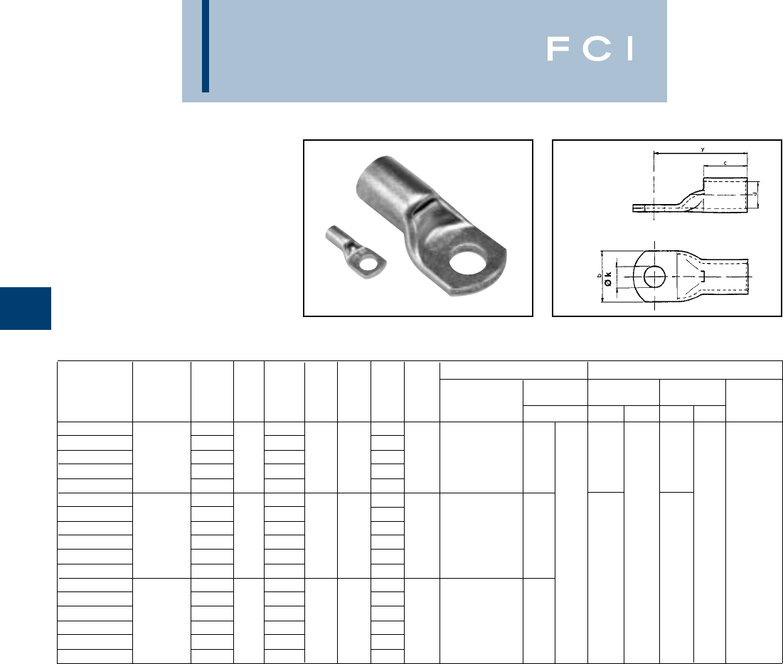
BURNDY
Compression
C-90
TYPE YAV
HYLUG™
NON-INSULATED COPPER
TUBULAR TERMINALS
0.3 - 1000 mm2
(Continued)
Mechanical tools Hydraulic tools
Y29BH Y35BH
Catalog Stud Pack Tooling MRD29 Y29NC Y35
Number mm2size d y b c Øk Qty. number NIN I NI Y644M
YAV95FM8 841.4 8.4
YAV95FM10 10 43.4 10.5
YAV95FM12 Flex 95 12 14.2 46.4 25.0 25.0 13.2 25 MY2913GE2
YAV95FM14 14 46.4 15.0
YAV95FM16 16 49.4 17.0
YAV120M8 844.4 8.4
YAV120M10 10 46.4 10.5
YAV120M12 12 49.4 13.2
YAV120M14 120 14 15.0 49.4 29.0 27.0 15.0 25 MY2913GE2
YAV120M16 16 52.4 17.0
YAV120M20 20 58.4 21.0
YAV120FM8 844.4 8.4
YAV120FM10 10 46.4 10.5
YAV120FM12 12 49.4 13.2
YAV120FM14 Flex 120 14 15.9 49.4 29.0 27.0 15.0 25 MY2913GE2
YAV120FM16 16 52.4 17.0
YAV120FM20 20 58.4 21.0
50NC1 - 2X 50NC1 - 2X 50NC2 -2X
50P95-120C
DV28L* DV27L*
Y29PR
UV28D UV27D
Y35P1 + Y29PQ6S (Y29PQ12B1 UK)
DIELESS
N = Nest die, I = Indentor
*DV27L - DV28L - only for Y29BH
Y260DBHM takes U-Dies with adaptor 26UADP
Y46 takes U-Dies with adaptor PUADP-1
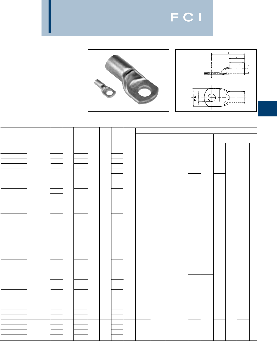
BURNDY
Compression
C-91
TYPE YAV
HYLUG™
NON-INSULATED COPPER
TUBULAR TERMINALS
0.3 - 1000 mm2
(Continued)
Hydraulic tools
Y35BH UK
Catalog Stud Pack Y35 Y260DBHM Y46* Y22BH
Number mm2size d y b c Øk Qty. NIY644M NININI
YAV150M10 10 52.3 10.5
YAV150M12 12 55.3 13.2
YAV150M14 150 14 16.5 55.3 30.4 27.0 15.0 10
YAV150M16 16 58.3 17.0
YAV150M20 20 64.3 21.0
YAV150FM10 10 55.9 10.5
YAV150FM12 12 58.9 13.2
YAV150FM14 Flex 150 UK 14 17.8 58.9 32.8 28.6 15.0 10
YAV150FM16 16 61.9 17.0
YAV150FM20 20 67.9 21.0
YAV185M10 10 61.8 10.5
YAV185M12 12 64.8 13.2
YAV185M14 185 14 18.4 64.8 35.7 30.2 15.0 10
YAV185M16 16 67.8 17.0
YAV185M20 20 73.8 21.0
YAV185FM10 10 61.8 10.5
YAV185FM12 12 64.8 13.2
YAV185FM14 Flex 185 UK 14 19.4 64.8 35.7 30.2 15.0
YAV185FM16 16 67.8 17.0
YAV185FM20 20 73.8 21.0
YAV240M10 10 68.2 10.5
YAV240M12 12 71.2 13.2
YAV240M14 240 14 21.2 71.2 39.6 34.9 15.0 10
YAV240M16 16 74.2 17.0
YAV240M20 20 80.2 21.0
YAV240FM10 10 73.4 10.5
YAV240FM12 12 76.4 13.2
YAV240FM14 Flex 240 UK 14 22.0 76.4 41.0 36.0 15.0 10
YAV240FM16 16 79.4 17.0
YAV240FM20 20 85.4 21.0
YAV300M12 12 77.3 13.2
YAV300M14 14 78.3 15.0
YAV300M16 300 16 23.4 80.3 43.0 43.0 17.0 10
YAV300M20 20 86.3 21.0
YAV300FM12 12 81.4 13.2
YAV300FM14 14 82.4 15.0
YAV300FM16 Flex 300 UK 16 24.2 84.4 45.0 43.0 17.0 10
YAV300FM20 20 90.4 21.0
N = Nest die, I = Indentor
Y260DBHM takes U-Dies with adaptor 26UADP
*Y46 takes U-Dies with adaptor PUADP-1
Y22BH takes U-Dies with adaptor 22UADP
U37BD U36D U35BD U34D U32D U31D U30D
Y35P1 + Y29PQ7S (Y29PQ12B1 UK)
DIELESS
26M37BD 26M36D 26M35BD 26M34D 26M32D 26M31D 26M30D
26P36C 26P30-34C
U37BD U36D U35BD U34D U32D U31D U30D
PUADP + Y35P3 + Y34PR
ED37BD ED35BD ED32BD ED31BD
EDBP1 + Y20PQ10 EDBP1 + Y20PQ8
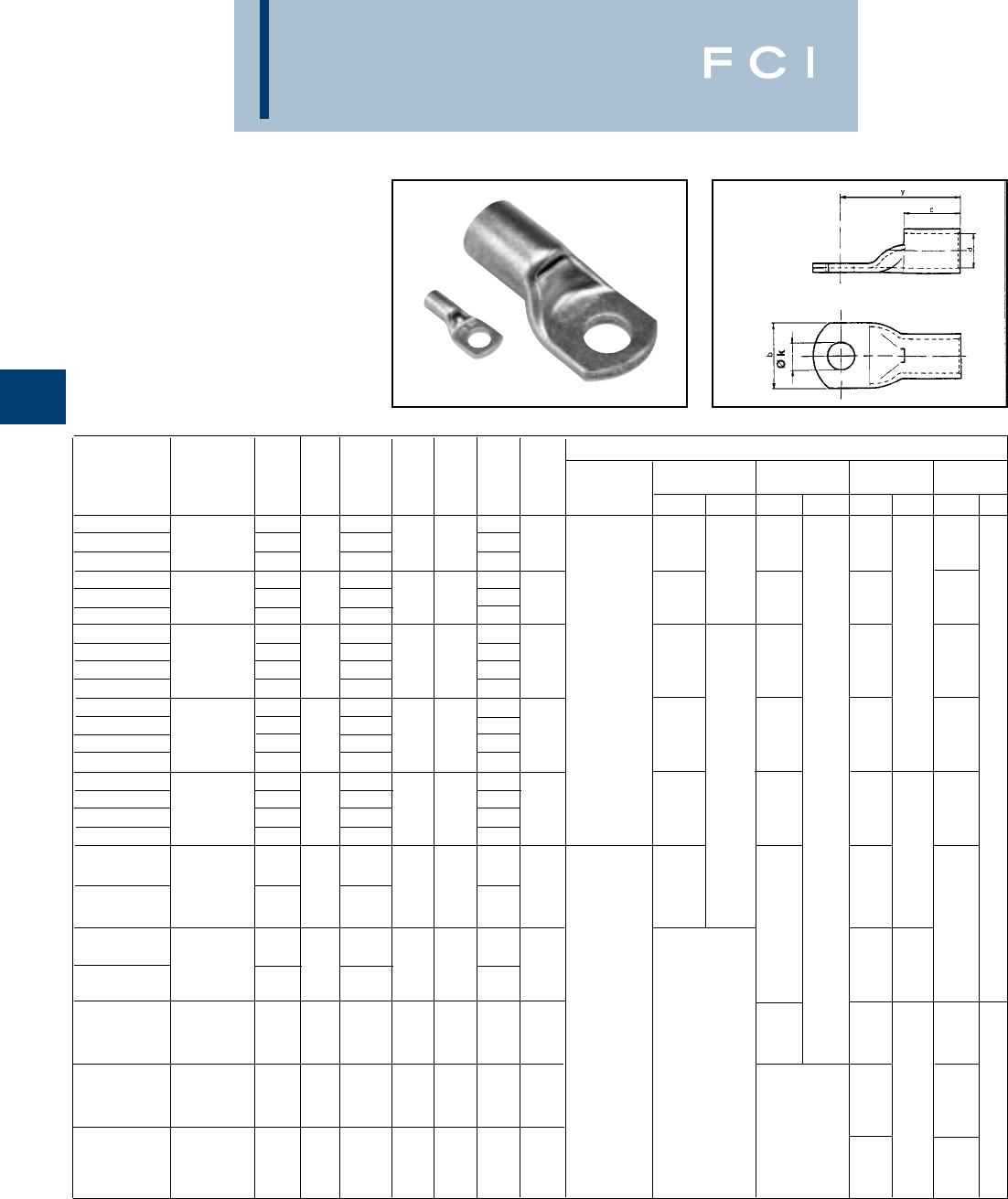
BURNDY
Compression
C-92
TYPE YAV
HYLUG™
NON-INSULATED COPPER
TUBULAR TERMINALS
0.3 - 1000 mm2
(Continued)
Hydraulic tools
Catalog Stud Pack Y260DBHM Y46* UK-Y22BH Y530DBHM
Number mm2size d y b c Øk Qty. Y644M NININI
NI
YAV350M12 350 12 77.3 13.2
YAV350M16 16 25.0 80.3 46.0 43.0 17.0 10
YAV350M20 (700 MCM) 20 86.3 21.0
YAV375M12 375 12 81.3 13.2
YAV375M16 16 26.2 84.3 48.0 43.0 17.0 10
YAV375M20 (750 MCM) 20 90.3 21.0
YAV400M12 12 81.3 13.2
YAV400M14 400 14 26.7 82.3 49.5 43.0 15.0 10
YAV400M16 16 84.3 17.0 DIELESS
YAV400M20 20 90.3 21.0
YAV400FM12 12 83.6 13.2
YAV400FM14 14 84.6 15.0
YAV400FM16 Flex 400 UK 16 27.2 86.6 51.0 44.0 17.0 10
YAV400FM20 20 92.6 21.0
YAV500M12 12 87.8 13.2
YAV500M14 14 88.8 15.0
YAV500M16 500 16 29.8 90.8 55.1 47.7 17.0 10
YAV500M20 20 96.8 21.0
YAV630M16 16 96.7 17.0
630 33.3 61.8 51.0 10
YAV630M20 20 102.7 21.0
YAV630FM20 20 104.6 21.0
Flex 630 UK 34.4 63.0 53.0 10
YAV630FM22 22 106.6 23.8
800
YAV800M20* 20 38.0 113.6 67.5 52.0 21.0 10
(1500 MCM)
800
YA47L 20 39.6 116.4 67.5 52.0 21.0 10
(1750 MCM)
1000
YA48L 20 42.2 127.2 77.7 55.0 21.0 10
(2000 MCM)
N = Nest die, I = Indentor
Y260DBHM takes U-Dies with adaptor 26UADP
*Y46 takes U-Dies with adaptor PUADP-1
Y22BH takes U-Dies with adaptor 22UADP
Y530DBHM takes U-Dies with adaptor 53UADP.
26M45D 26M44D 26M41D 26M40D 26M39D 26M38D
26P40-45C 26P-36C
HEAD P45D P44D P41D P40D P39D P38D
P44PR
ED488D ED466BD ED453BD ED44BD ED41BD
EDPB2 +
EDPB2 + Y48PQ2 Y22PQ12 EDPB1 + Y20PQ11 EDPB1 + Y20PQ10
5
3M48D 53M47D 53M46D 53M45D 53M44D 53M41D 53M40D 53M39D 53M38D
53P46-48C 53P40-45C

BURNDY
Compression
C-93
TYPE YAS-L-2TC-FX,60
TWO HOLE HYLUG™ -
DOUBLE BARREL
COPPER COMPRESSION
TERMINAL
UL Listed 90° C,
600 Volts to 35 KV ◆
◆For applications greater than 2000 Volts consult cable
manufacturer for voltage stress relief instructions.
*Use PUADP-1 adapter with "U" dies in Y46 HYPRESS™.
** Type YASV series have inspection hole.
*** The MM2conductor sizes listed are the recommendations
for Class 2 and Class 5 conductor.
Fig. 1 Fig. 2
CONDUCTOR DIMENSIONS INSTALLATION TOOLING
MECHANICAL HYDRAULIC
MD7-34 Y1MRTC WIRE
*** BOLT FIG. T Y DIE COLOR MD6 Y2MR Y750, Y35, STRIP
CATALOG NUMBER FLEX AWG MM2SIZE NO. B C E H L REF. MIN. INDEX CODE OUR840 Y8MRB-1 Y39, Y46* LENGTH
2.7 Y8MRB-1
YASG8CL-2TC14E2-FX #8 1–(70) W8CVT Y2MR
WELD #8 10 1/4.44 .44 .75 .08 1.14 49 RED W8CRT (1) U8CRT 1/2
37/24 AWG (11) (11) (19) .66 2.6 (2) (29) (1) Y1MRTC (1)
YASG8CL-2TC14E2-FX-60 2
(17) (67) (1)
3.0 Y2MR
YASG6CL-2TC14E2-FX #6 1 .50 .48 .75 –(78) .08 1.14 7 or W5CVT (1) U5CRT
WELD #6 16 1/4
(13) (12) (19) .68 2.9 (2) (29) 374 BLUE W5CRT Y1MRTC (1) 9/16
YASG6CL-2TC14E2-FX-60 61/24 AWG 2 (17) (75) (1) (1)
3.0 Y2MR
YASV6CL-2TC14E2-FX** #6 #6 1.50 .48 .75 –(78) .08 1.14 7 or W5CVT (1) U5CRT
WELD AWG 16 1/4
(13) (12) (19) .68 2.9 (2) (29) 374 BLUE W5CRT Y1MRTC (1) 9/16
YASV6CL-2TC14E2-FX-60** 61/24 2 (17) (75) (1) (1)
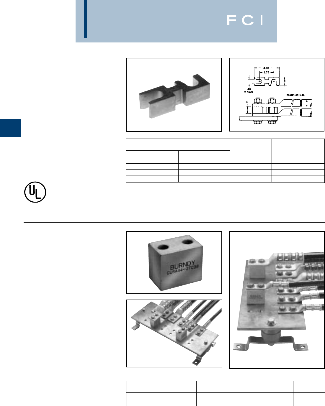
BURNDY
Compression
C-94
TYPE ASA-U
HYSTACK™
TERMINAL STACKING
ADAPTOR FOR
ALUMINUM AND
COPPER TERMINALS
The HYSTACK™ adaptor is specially
designed to allow standard terminals to be
stacked on two or four hole NEMA trans-
former or equipment terminal pads.
HYSTACK™ is tin-plated, high-conductivity
aluminum to provide optimum corrosion
resistance. Only three sizes accommodate
terminals from 250 mcm through 1000 mcm
to help keep costly inventories to a minimum.
To stack 4 hole NEMA drilled terminals use 2 adaptors
assembled side by side.
ASA-U stacking adaptors are recommended for use with any
BURNDY®UL listed compression terminal, 2 or 4 hole NEMA
pad aluminum and copper lugs,types YA, YA-L, YA-A, and for
all 2-hole NEMA spaced lugs in the OVERHEAD and
UNDERGROUND catalog sections.
Catalog Stud Hole Stud Hole
Number Size Spacing Length Width Height
CUSA442TC38
3/8" 1" 1.75" 1.12" 1.50"
CUSA442NTC
1/2" 1 - 3/4" 2.50" 1.12" 1.50"
Reference: Catalog number TMH332.
This TMH332 Kit has just the right hardware
when using the CUSA442TC38 HYSTACK™
on a 1/4
" bus
bar with a 4/0 through 750 kcmil
HYLUG™
.
TYPE CUSA
HYSTACK™
TERMINAL STACKING
ADAPTOR
This HYSTACK™ adaptor is specially
designed to get terminals to the back end of a
bus bar or other areas that require terminals
to be elevated off the mounting surface. This
HYSTACK™ is made from high conductivity
copper and tin-plated to provide optimum cor-
rosion resistance. It will accommodate #10
AWG through 750 kcmil HYLUGS™.
ACCOMMODATES COPPER AND ALUMINUM
COMPRESSION TERMINALS
CONDUCTOR INSULATION CATALOG
MAX. O.D. NUMBER C H
250 mcm .868 ASA250U 1.00 .77
800 mcm 1.372 ASA800U 1.00 1.13
1000 mcm 1.494 ASA1000U 1.25 1.25
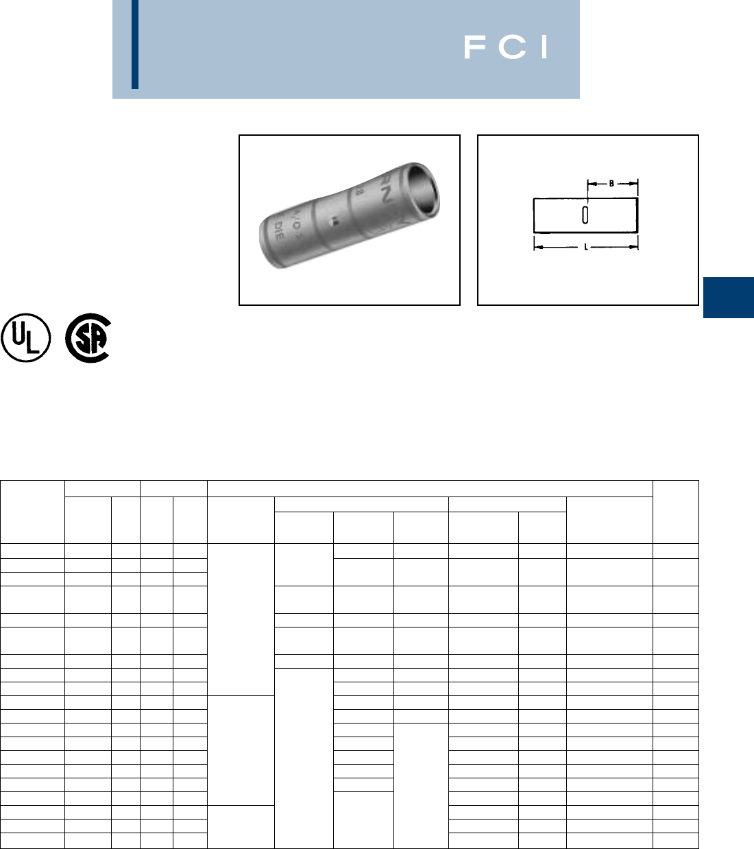
BURNDY
Compression
C-95
TYPE YS-L
HYLINK™ SPLICE
STANDARD BARREL
COPPER COMPRESSION
UL Listed 90° C,
600 Volts to 35 KV ◆
Features and Benefits
•Standard barrel length.
◊Ideal for limited space applications while
providing ample barrel length for proper
crimp.
•Four (4) center conductor stops.
◊Provides a center wire stop for proper
conductor insertion.
▲See tooling section of this catalog for complete tool and die
listings.
*Use PUADP-1 adapter with "U" dies in Y46 HYPRESS™.
Conductor Dimensions Installation Tooling ▲
Mechanical Y35, ■Y39, Y750, Y46* ▲Wire
Catalog *** Dieless Y1MRTC MD6 Die Number Color Die Index Strip
Number AWG MM2LB(# of crimps) Y2MR MD7-34R OUR840 (# crimps) Code & Embossment Length
YS8C-L-BOX
8 str. 10 1.24 .41 W8CVT (1) X8CRT (1) U8CRT (1) Red 49 1/2
YS6C-L BOX
6 str. –– 1.75 .81 Y2MR (1)
YS5C-L BOX
5 str. 16 1.90 .81 Y1MRTC (1) W5CVT (1) X5CRT (1) UCRT (1) Blue 7 or 374 7/8
Y2MR (2)
YS4C-L BOX
4 str. –– 1.93 .81 Y81KFT (1) Y1MRTC (2) W4CVT (1) X4CRT (1) U4CRT (1) Gray 8 or 346 7/8
YS3C-L
3 str. 25 2.05 .88 Y81KFTMBH (1) Y1MRTC (2) –– –– U3CRT (1) White 9 15/16
PAT81KFT-18V (1) Y2MR (2)
YS2C-L BOX
2 str. –– 2.07 .88 Y1MRTC (2) W2CVT (1) X2CRT (1) U2CRT (1) Brown 10 15/16
YS1C-L BOX
1 str. 50 2.06 .88 Y1MRTC (2) W1CVT (1) X1CRT (1) U1CRT-1 (1) Green 11 or 375 15/16
YS25-L BOX
1/0 str. –– 2.08 .88 W25VT (2) X25RT (2) U25RT (1) Pink 12 or 348 15/16
YS26-L BOX
2/0 str. 70 2.17 .94 W26VT (2) X26RT (2) U26RT (1) Black 13 1
YS27-L BOX
3/0 str. 95 2.30 1.00 W27VT (2) X27RT (2) U27RT (1) Orange 14 1-1/16
YS28-L BOX
4/0 str. –– 2.32 1.00 W28VT (2) X28RT (2) U28RT (1) Purple 15 1-1/16
YS29-L BOX
250 kcmil 120 2.46 1.06 W29VT (2) U29RT (1) Yellow 16 1-1/8
YS30-L
300 kcmil 150 2.47 1.06 Y81KFT (2) W30VT (2) U30RT (2) White 17 or 298 1-1/8
YS31-L
350 kcmil 185 2.60 1.12 Y81KFTMBH (2) —W31VT (2) U31RT (2) Red 18 or 324 1-3/16
YS32-L
400 kcmil –– 2.74 1.19 PAT81KFT-18V (2) W32VT (2) U32RT (2) Blue 19 or 470 1-1/4
YS34-L
500 kcmil 240 3.15 1.38 W34VT (2) — U34RT (2) Brown 20 or 299 1-7/16
YS36-L
600 kcmil 300 3.22 1.38 U36RT (2) Green 22 or 472 1-7/16
YS38-L
700 kcmil –– 3.22 1.38 Y81KFT (3) U38RT (2) Pink 400 1-7/16
YS39-L
750 kcmil –– 3.72 1.62 Y81KFTMBH (3) —U39RT (2) Black 24 1-11/16
YS44-L
1000 kcmil 500 4.28 1.88 PAT81KFT-18V (3) P44RT** (2) White 27 1-15/16
** P44RT for use with Y46 HYPRESS™ only. PUADP-1
adaptor not required.
*** The MM2conductor sizes listed are the recommendations
for Class 2 conductor.
■The maximum size for the Y35 is 400 kcmil insulated code
cable.
■For applications greater than 2000 Volts consult cable
manufacturer for voltage stress relief instuctions.
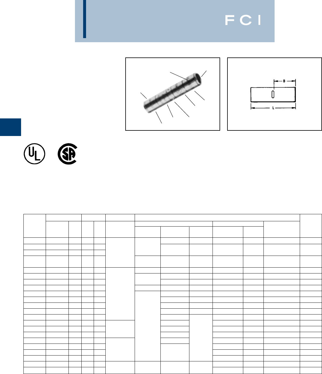
BURNDY
Compression
C-96
TYPE YS
HYLINK™ SPLICE -
LONG BARREL
COPPER COMPRESSION
SPLICE
UL Listed 90° C,
600 Volts to 35 KV ◆
ELECTRO-TIN
PLATED
(4) CENTER
WIRE STOPS
CRIMP
CRIMP
CRIMP
CRIMP
DIE AND COLOR
CODE INFORMATION
BEVELED
ENTRY
Features and Benefits
•Long barrel length.
◊Ideal for 600 volt heavy duty applications.
Also may be used at higher voltages up to
35KV.
•Four (4) center conductor stops.
◊Provides a center wire stop for proper
conductor insertion.
•High pull out force.
◊Provides added security for much greater
mechanical and electrical properties.
➀Not color coded.
*Use PUADP-1 adapter with "U" dies in Y46 HYPRESS™.
** P44RT for use with Y46 HYPRESS™ only. PUADP-1
adapter not required.
Conductor Dimensions Installation Tooling ▲
Mechanical Y35 ■,Y39, Y750, Y46* ▲Wire
Catalog *** Dieless Y1MRTC MD6 Die Number Color Die Index Strip
Number AWG MM2LB(# of crimps) Y2MR MD7-34R OUR840 (# crimps) Code & Embossment Length
YS8C
8 str. 10 1.75 .78 W8CVT (2) X8CRT (2) U8CRT (2) Red 49 7/8"
YS6C
6 str. –– 2.38 1.09 Y81KFT (1) Y2MR (2)
YS5C
5 str. 16 2.55 1.09 Y81KFTMBH (1) Y1MRTC (2) W5CVT (2) X5CRT (2) U5CRT (2) Blue 7 or 374 1-3/16"
PAT81KFT-18V (1) Y2MR (4)
YS4C
4 str. –– 2.55 1.09 Y1MRTC (4) W4CVT (2) X4CRT (2) U4CRT (2) Gray 8 or 346 1-3/16"
YS3C
3 str./2 sol. 25 2.80 1.22 Y1MRTC (4) –– –– –– White 9 1-5/16"
YR2C2WT
2 str. - 2 sol. 25 2.90 1.44 Y2MR (4) W2CVT/W2CRT W2CVT/W2CRT U2CRT (2) Brown 10 1-5/8"
YS2C
2 str. 35 2.82 1.22 Y1MRTC (4) W2CVT (2) X2CRT (2) U2CRT (2) Brown 10 1-5/16"
YS1C
1 str. 50 3.07 1.34 Y81KFT (2) Y1MRTC (4) W1CVT (2) X1CRT (2) U1CRT-1 (2) Green 11 or 375 1-7/16"
YS25
1/0 str. –– 3.06 1.34 Y81KFTMBH (2) W25VT (4) X25RT (4) U25RT (2) Pink 12 or 348 1-7/16"
YS26
2/0 str. 70 3.30 1.45 PAT81KFT-18V (2) W26VT (4) X26RT (4) U26RT (2) Black 13 1-9/16"
YS27
3/0 str. –– 3.30 1.45 W27VT (4) X27RT (4) U27RT (2) Orange 14 1-9/16"
YS28
4/0 str. –– 3.57 1.58 W28VT (4) X28RT (4) U28RT (2) Purple 15 1-11/16"
YS29
250 kcmil 120 3.58 1.58 W29VT (4) U29RT (2) Yellow 16 1-11/16"
YS30
300 kcmil 150 4.34 1.95 Y81KFT (3) W30VT (4) U30RT (4) White 17 or 298 2-1/16"
YS31
350 kcmil 185 4.35 1.95 Y81KFTMBH (3) –– W31VT (4) U31RT (4) Red 18 or 324 2-1/16"
YS32
400 kcmil –– 4.62 2.08 PAT81KFT-18V (3) W32VT (4) U32RT (4) Blue 19 or 470 2-3/16"
YS34
500 kcmil 240 4.91 2.20 W34VT (4) –– U34RT (4) Brown 20 or 299 2-5/16"
YS36
600 kcmil 300 5.85 2.63 Y81KFT (4) U36RT (4) Green 22 or 472 2-3/4"
YS39
750 kcmil –– 6.38 2.81 Y81KFTMBH (4) –– U39RT (4) Black 24 2-15/16"
YS44
1000 kcmil 500 6.95 2.94 PAT81KFT-18V (4) P44RT** (4) White 27 3-1/16"
YS46
1500 kcmil –– 7.01 3.13 P46RT** (6) Green 31 3-1/4"
YS48
2000 kcmil –– 7.57 3.27 —–– –– ––
L48RT (4) Brown 34 3-3/8"
*** The MM2conductor sizes listed are the recommendations
for Class 2 conductor.
■The maximum size for the Y35 is 400 kcmil.
▲See tooling section of this catalog for complete tool and die
listings.
◆For applications greater than 2000 Volts consult cable
manufacturer for voltage stress relief instuctions.
†Requires Y60BHU HYPRESS™ with L48RT die set.
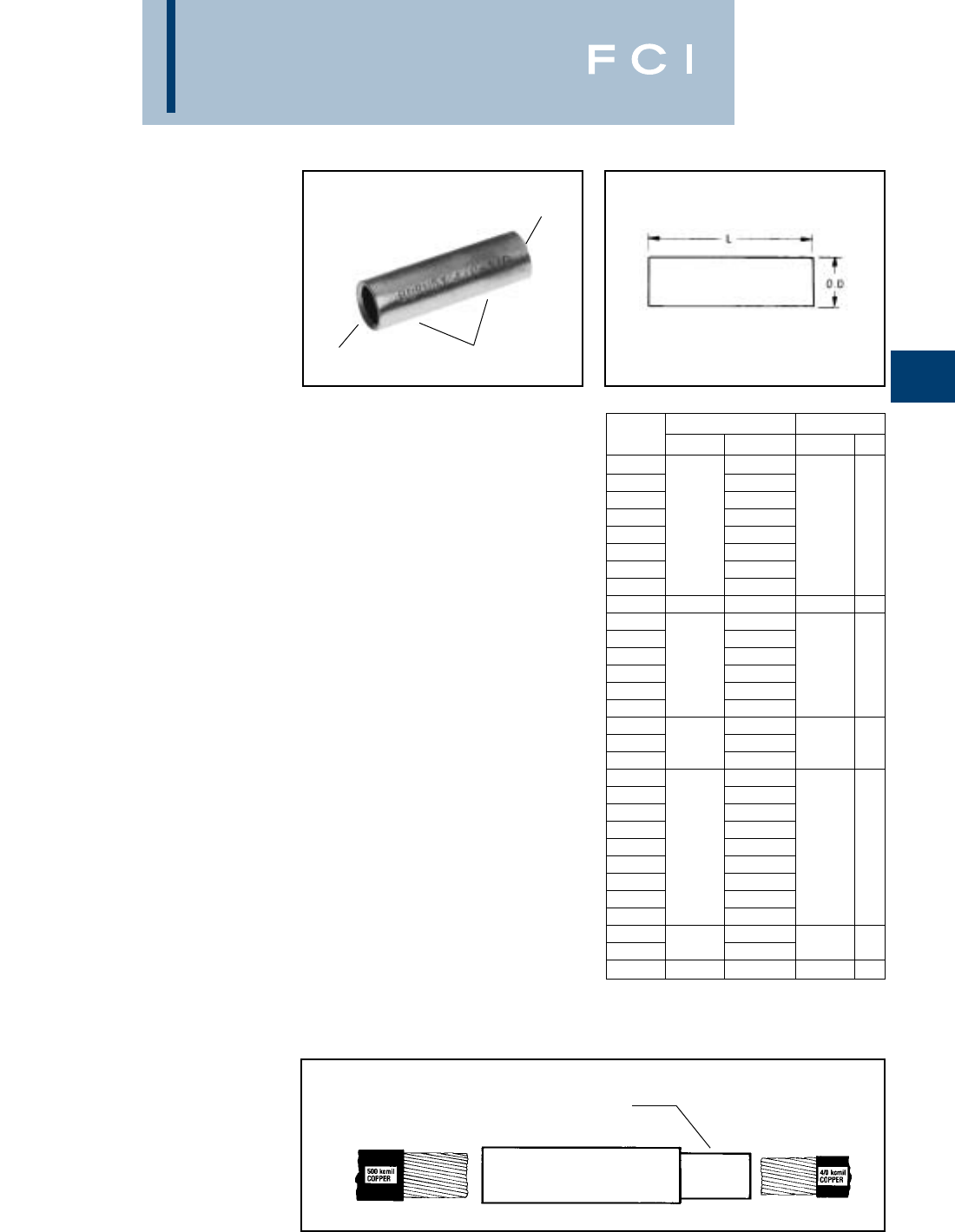
BURNDY
Compression
C-97
TYPES Y-R
REDUCING ADAPTER
FOR COPPER
600 Volts to 35 KV◆
The Y-R reducing adapter has been designed
to allow large size, long barrel, copper long
barrel HYDENT™, HYSPLICE™ and
HYTEE™ terminals, splices, and "T" taps to
be used on smaller conductor sizes. To use,
simply insert the reducer into the barrel,
insert the wire into the reducer adapter and
crimp the outer barrel using its recommended
tooling.
Crimp with U34RT, 2 crimps each side.
Features and Benefits
•Wide range of conductors are
accommodated.
◊Lowers inventory requirements and
affords maximum versatility.
•Same die set for all legs of the connection.
◊Permits the same tool and die
combination normally used on
the compression barrel.
•Length fits the long barrel connector
design (YS, YA).
◊Can be used on all long barrel
connectors. Field cut to fit shorter length
compression barrels (YS-L, YA-L).
•Manufactured from high conductivity
electrolytic copper and electro-tin plated.
◊Provides maximum conductivity low
resistance and ductility for an excellent
combination of electrical and crimp
forming properties, and provides
long lasting corrosion resistance.
Y3428R
APPLICATION EXAMPLE
ELECTRO-TIN
PLATED
INTERNALLY
BEVELED ENDS
WIRE RANGE
Insert reducing adapter into splice connection as shown.
CATALOG WIRE RANGE DIMENSIONS
NUMBER FROM TO MAX O.D. L
Y286CR 6, 8 str. 6 sol.
Y284WR 4 sol.
Y284CR 4 str.
Y282CR 2 str.
Y281CR 4/0 str. 1 str. .534 1.75
Y2825R 1/0 str.
Y2826R 2/0 str.
Y2827R 3/0 str.
Y2928R 250 kcmil 4/0 .582 1.62
Y302CR 2
Y304CR 4
Y3025R 1/0
Y3026R 300 kcmil 2/0 .637 2.00
Y3027R 3/0
Y3028R 4/0
Y3126R 2/0
Y3128R 350 kcmil 4/0 .687 2.00
Y3129R 250
Y342CR 2 str.
Y3425R 1/0 str.
Y3426R 2/0 str.
Y3427R 3/0 str.
Y3428R 500 kcmil 4/0 str. .821 2.50
Y3429R 250 kcmil
Y3430R 300 kcmil
Y3431R 350 kcmil
Y3432R 400 kcmil
Y3934R 500 kcmil
Y3936R 750 kcmil 600 kcmil .637 2.50
Y4439R 1000 kcmil 750 kcmil 1.296 3.19
YS34
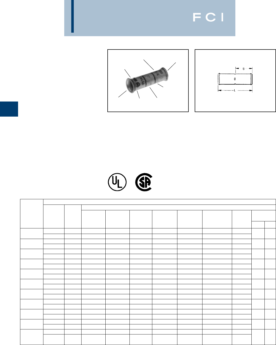
BURNDY
Compression
C-98
TYPE YS-LB
HYLINK™
UNINSULATED
BELLED COPPER
COMPRESSION SPLICE
STANDARD LENGTH
BELLED BARREL
UL Listed 90° C,
600 Volts to 35 kV◆
HYLINK™ type YS-LB splices are designed
for flexible and extra flexible copper conduc-
tors used in mining machines, locomotives,
welding cables and other flexible cable appli-
cations. The seamless, high conductivity
copper, electro-tin plated belled barrel
provides for easy insertion of flexible strand-
ed conductors and the nest indentor die
system provides an excellent electrical and
mechanical connection.
Features and Benefits
•Belled barrel ends.
◊Provides easy cable insertion into the
splice barrel and smooth cable strain
relief during cable flexing and movement.
•Standard length barrel.
◊Permits easy passage around pulleys
yet is long enough for easy crimping.
•Contact BURNDY®for conductors not shown.
◆For applications greater than 2000 Volts consult cable
manufacturer for voltage stress relief instructions.
DIE AND COLOR
CODE INFORMATION
ELECTRO-TIN
PLATED
BELLED
END
CRIMP
(4) CENTER
WIRE STOP
CRIMP
BELLED
END
COPPER CABLES *
CODE FLEXIBLE AND EXTRA FLEXIBLE CABLES
CABLE BATTERY WELDING
CATALOG FLEX NAVY CABLE CABLE LOCOMOTIVE METRIC DIMENSION
NUMBER CABLE CABLE CLASS “G” CLASS “H” CLASS “I” CLASS “K” CLASS “M” CABLE CABLE “B” “L”
—— — — — — — — —
YS5C-LB 6 FLEX — #6 (49 str) #6 (133 str) #6 (63/24) #6 (266/30) #6 (665/34) #6 (61/24) — .81 1.75
—— — — — — — — —
YS4C-LB 5 FLEX — #5 (49 str) #5 (133 str) #5 (84/24) #5 (336/30) #5 (836/34) #5 (91/24) — .81 1.75
—— — — — — — — —
YS3C-LB 4 FLEX — #4 (49 str) #4 (133 str) #4 (105/24) #4 (420/30) #4 (1064/34) #4 (105/24) — .81 1.88
—— — — — — — — —
YS2C-LB 3 FLEX — #3 (49 str) #3 (133 str) #3 (133/24) #3 (532/30) #3 (1323/24) #3 (125/24) — .81 1.88
—— — — — — — — —
YS1C-LB 2 FLEX — #2 (49 str) #2 (133 str) #2 (161/24) #2 (665/30) #2 (1666/34) #2 (150/24) — .81 1.88
—— — — — — — — —
YS25-LB 1 FLEX — #1 (133 str) #1 (259 str) #1 (210/24) #1 (836/30) #1 (2107/34) #1 (225/24) — .81 1.88
—— — — — — — — —
YS26-LB 1/0 FLEX — 1/0 (133 str) 1/0 (259 str) 1/0 (266/24) 1/0 (1064/30) 1/0 (2646/34) 1/0 (275/24) — .94 2.00
—— — — — — — — —
YS27-LB 2/0 FLEX — 2/0 (133 str) 2/0 (259 str) 2/0 (342/24) 2/0 (1323/30) 2/0 (3325/34) 2/0 (325/24) — 1.00 2.13
—— — — — — — — —
YS28-LB 3/0 FLEX — 3/0 (133 str) 3/0 (259 str) 3/0 (418/24) 3/0 (1666/30) — 3/0 (450/24) — 1.00 2.13
—— — — — — — — —
YS29-LB 4/0 FLEX — 4/0 (133 str) 4/0 (259 str) — — — — — 1.06 2.25
—— — — — — — — —
YS30-LB 250 kcmil 250 kcmil 1.06 2.25
4/0 - 250 FLEX
—(259 str) (427 str) 4/0 (532/24) 4/0 (2107/30) 4/0 (5320/34) 4/0 (550/24) —
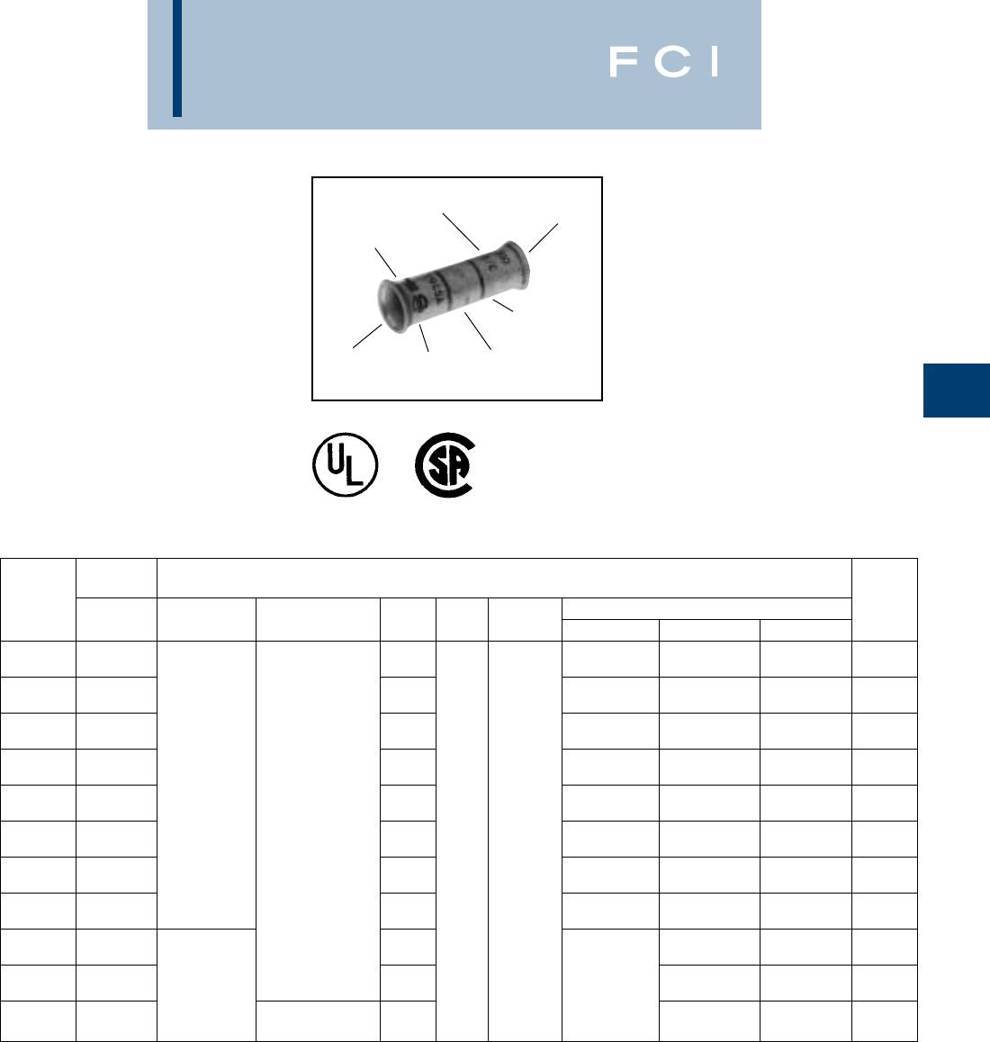
BURNDY
Compression
C-99
TYPE YS-LB
HYLINK™
UNINSULATED BELLED
COPPER COMPRESSION
SPLICE
STANDARD LENGTH
BELLED BARREL
UL Listed 90° C,
600 Volts to 35 kV◆
(INSTALLATION TOOLING)
†Use Y35P3 adaptor with Y34PR indentor.
*Use PUADP-1 adaptor with U-DIES in Y46 HYPRESS™.
▲See Tooling section in this catalog for complete tool and
die listings.
①Not color coded
◆For applications greater than 2000 Volts consult cable
manufacturer for voltage stress relief instructions.
DIE AND COLOR
CODE INFORMATION
ELECTRO-TIN
PLATED
BELLED
END
CRIMP
(4) CENTER
WIRE STOP
CRIMP
BELLED
END
Code
Cable Installation Tooling ▲WIRE
Catalog Flex Dieless Dieless HYTOOL Die Color Hydraulic Tooling, Die Sets, (# of crimps) ▲STRIP
Number Cable (# of crimps) (# of crimps) Index Code Die Type Y35† Y39†, Y750† Y46*† LENGTH
➀U6CD-1 (1) U6CD-1 (1) U6CD-1 (1)
YS5C-LB 6 flex 1014 Y34PR (1) Y34PR (1) Y34PR (1) 7/8
U4CD-1 (1) U4CD-1 (1) U4CD-1 (1)
YS4C-LB 5 flex 1015 Y34PR (1) Y34PR (1) Y34PR (1) 7/8
U3CD-1 (1) U3CD-1 (1) U3CD-1 (1)
YS3C-LB 4 flex 1016 Y34PR (1) Y34PR (1) Y34PR (1) 15/16
U2CD-1 (1) U2CD-1 (1) U2CD-1 (1)
YS2C-LB 3 flex Y81KFT (1) 1017 Y34PR (1) Y34PR (1) Y34PR (1) 15/16
Y81KFTMBH (1) U1CD-1 (1) U1CD-1 (1) U1CD-1 (1)
YS1C-LB 2 flex
PAT81KFT-18V (1)
MY29-11 (1) 1018 Y34PR (1) Y34PR (1) Y34PR (1) 15/16
(1 Crimp/end) Nest U25D-1 (1) U25D-1 (1) U25D-1 (1)
YS25-LB 1 flex 1019 — Indentor Y34PR-2 (1) Y34PR-2 (1) Y34PR-2 (1) 15/16
U26D-1 (1) U26D-1 (1) U26D-1 (1)
YS26-LB 1/0 flex 1020 Y34PR-2 (1) Y34PR-2 (1) Y34PR-2 (1) 1
U27D-1 (1) U27D-1 (1) U27D-1 (1)
YS27-LB 2/0 flex 1021 Y34PR-2 (1) Y34PR-2 (1) Y34PR-2 (1) 1-1/16
U28D-1 (1) U28D-1 (1)
YS28-LB 3/0 flex 1022 Y34PR-2 (1) Y34PR-2 (1) 1-1/16
Y81KFT (2) U29D-1 (1) U29D-1 (1)
YS29-LB 4/0 flex Y81KFTMBH (2) 1023 — Y34PR-2 (1) Y34PR-2 (1) 1-1/16
PAT81KFT-18V (2)
U30D-1 (1) U30D-1 (1)
YS30-LB 4/0-250 flex — 1024 Y34PR-2 (1) Y34PR-2 (1) 1-1/8
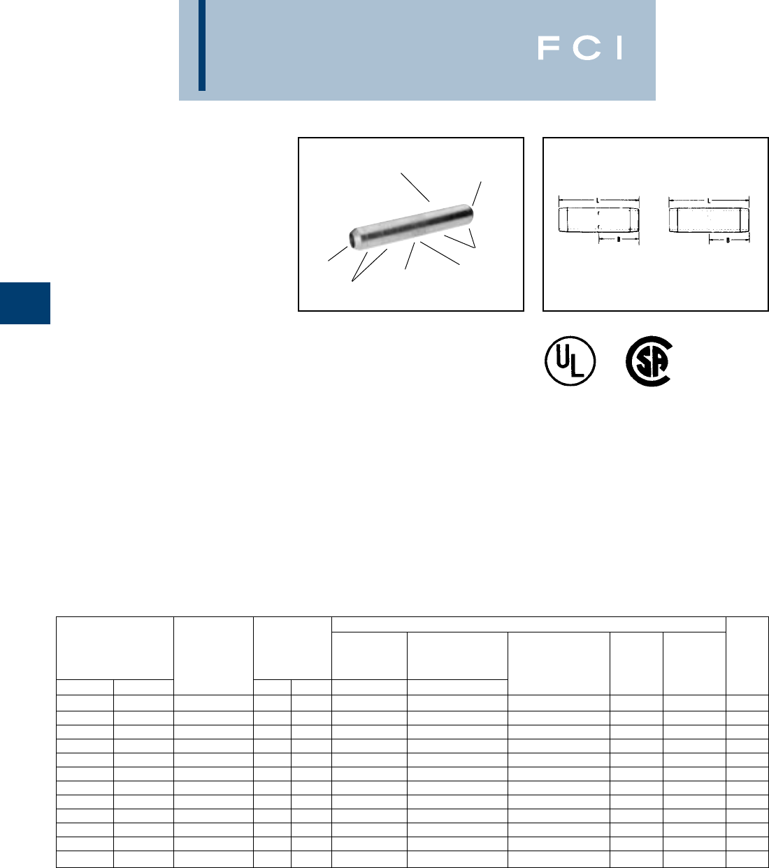
BURNDY
Compression
C-100
Features and Benefits
•Tapered connector ends per
EEI standard TD160.
◊Suitable for use on voltages 5KV
through 35KV to aid in preventing
corona emission and simplify taping
thus lowering installed cost.
•Type YS-T four center wire stops.
◊Provides a center wire stop for proper
conductor insertion.
•Type YSP-T has a center plug permanently
brazed in place.
◊Prevents oil within oil-filled conductors
from passing through the splice
connector and provides a center
strip for proper conductor insertion.
TYPES YS-T
AND YSP-T
HIGH-VOLTAGE HYLINKS™
UNINSULATED HIGH
VOLTAGE COPPER
COMPRESSION SPLICE
STANDARD BARREL -
TAPERED ENDS
UL Listed 90° C,
600 Volts to 35 KV◆
Seamless types YS-T and YSP-T high con-
ductivity copper electro-tin plated compres-
sion HYLINK™ high-voltage splices with
standard barrel and tapered ends are ideally
suited for higher voltage applications from
5KV through 35 KV.
Type YS-T splice connector has four center
wire stops for proper conductor insertion.
Type YSP-T splice connector has a brazed in
place center plug to prevent the passage of
oil between two oil filled conductors or
between conductors without oil and conduc-
tors with oil and acts as a center wire stop for
proper conductor insertion.
*Use adapter PUADP-1 with "U" Dies in Y46 HYPRESS™.
Y46 HYPRESS™ uses the same nest indentor and
adaptor as the Y35, Y39 and Y750, but with the PUADP-1
adaptors.
■The maximum size for the Y35 is 400 kcmil.
▲See tooling section of this catalog for complete tool and
die listings.
◆For applications greater than 2000 Volts consult cable
manufacturer for voltage stress relief instructions.
YSP-T
CENTER OIL STOP
YS-T
CRIMPING
INFORMATION ELECTRO-TIN
PLATED
CRIMP
(4) CENTER
WIRE STOPS
(TYPE YS-T)
BRAZED CENTER
OIL STOP PLUG
(TYPE YSP-T)
CRIMP
TAPERED
END
INSTALLATION TOOLING - NEST/INDENTOR ▲
Y34B Y35, Y39, Y750 Y35, Y39, Y750
Y34PR Y34PR INDENTOR Y46*, PAT750 WIRE
CATALOG NUMBER CODE DIMENSIONS INDENTOR Y35P3 ADAPTOR DIE NUMBER (# OF DIE NO. OF STRIP
YS-T YSP-T CONDUCTORS B L NEST DIE NEST DIE CRIMPS PER END) INDEX ▲INDENT LENGTH
YS6C-T YSP6C-T 6 str. .90 2.16 B6CD U6CD-1 U5CRT (2) 7 1 15/16
YS4C-T YSP4C-T 4 str. .90 2.16 B4CD U4CD-1 U4CRT (2) 8 1 15/16
YS2C-T YSP2C-T 2 str. .98 2.34 B2CD U2D-1 U2CRT (2) 10 1 1
YS1C-T YSP1C-T 1 str. .97 2.31 B1CD U1D-1 U1CRT-1 (2) 11 1 1
YS25-T YSP25-T 1/0 str. .98 2.35 B25D U25D-1 U25RT (2) 12 1 1-3/32
YS26-T YSP26-T 2/0 str. 1.04 2.47 B26D U26D-1 U26RT (2) 13 1 1-3/32
YS28-T YSP28-T 4/0 str. 1.13 2.67 B28D U28D-1 U28RT (2) 15 1 1-3/16
YS29-T YSP29-T 250 kcmil 1.21 2.85 B29D U29D-1 U29RT (2) 16 1 1-3/32
YS30-T —300 kcmil 1.22 2.87 B30D U30D-1 U30RT (4) 17 2 1-5/16
YS31-T YSP31-T 350 kcmil 1.32 3.09 B31D U31D-1 U31RT (4) 18 2 1-3/5
YS34-T YSP34-T 500 kcmil 1.68 3.86 No Die Needed U34D-1 U34RT (4) 20 2 1-3/4
YS39-T YSP39-T 750 kcmil 2.00 4.60 — — U39RT (4) 24 2 2-1/8
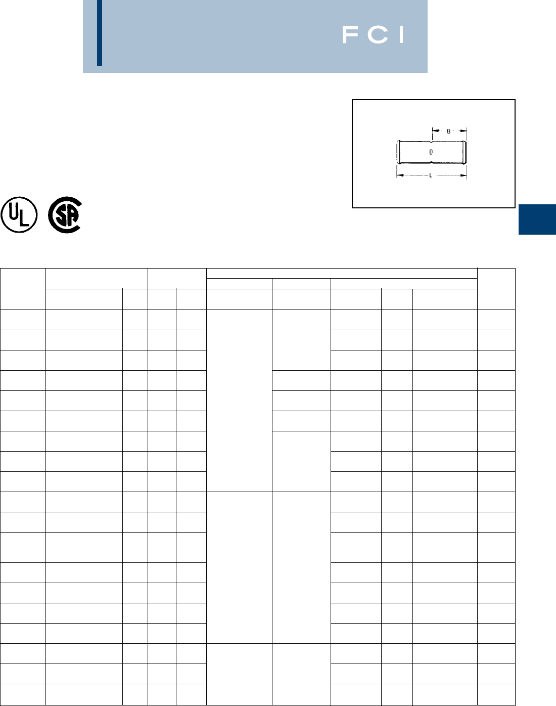
BURNDY
Compression
C-101
TYPE YS-FXB
HYLINK™ - SPLICE - BELLED
LONG BARREL
UL Listed 90° C,
600 Volts to 35 KV ◆
*Use PUADP-1 adapter with "U" dies in Y46 HYPRESS™.
** P44RT and P46RT dies sets are for use with Y46
HYPRESS™ only. PUADP-1 adapter not required.
*** The MM2conductor sizes listed are the recommendations
for Class 5 conductor.
Features and Benefits
•Long barrel length.
◊High voltage terminations.
•Four (4) center conductor stops.
◊Provides a center wire stop for proper
conductor insertion.
•High pull out force.
◊Provides added security for greater
mechanical and electrical properties.
•Belled cable entry.
◊A funnel type entry provide easy inser-
tion of extra flexable cables plus offers
mechanical strain relief for individual
strands.
Installation Tooling ▲
Conductor Dimensions Mechanical Y35 ■,Y39, Y750, Y46* Cable
Catalog Flexible Cable *** L B Dieless Y1MRTC Embossed Color Die Number (# of Strip
Number Code AWG MM2(mm) (mm) (# of crimps/end) Y2MR Die Index Code crimps/end) Length
#8 Str. (37/24) 1.99 .90 1"
YS8C-FXB #8 AWG 10 (51) (23) 49 Red U8CRT (2) (25)
#6 Str. (61/24) † 2.62 1.22 Y2MR (2) 1-5/16"
YSV6C-FXB #6 AWG 16 (67) (31) Y1MR (2) 7Blue U5CRT (2) (33)
#5 Str. (91/24) 2.62 1.22 1-5/16"
YS5C-FXB #5 AWG —(67) (31) 7Blue U5CRT (2) (33)
#4 Str. (91/24-105/24) 2.62 1.22 Y2MR (4) 1-5/16"
YSV4C-FXB #4 AWG —(67) (31) Y1MR (4) 8Gray U4CRT (2) (33)
#3 Str. (105/24-125/24) 2.87 1.47 Y81KFT (1) 1-9/16"
YS3C-FXB #3 AWG 25 (73) (37) Y81KFTMBH (1) Y1MR (4) 9 White U3CRT (2) (40)
#2 Str. (125/24-150/24) 2.89 1.35 PAT81KFT-18V (1) Y2MR (4) 1-7/16"
YSV2C-FXB #2 AWG 35 (73) (34) Y1MR (4) 10 Brown U2CRT (2) (37)
#1 Str. (175/24-225/24) 3.18 1.50 1-9/16"
YSV1C-FXB #1 AWG —(81) (38) 11 Green U1CRT-1 (4) (40)
1/0 Str. (275/24) 3.18 1.50 1-9/16"
YSV25-FXB 1/0 AWG 50 (81) (38) —12PinkU25RT (4) (40)
2/0 Str. (325/24) 3.44 1.63 1-11/16"
YSV26-FXB 2/0 AWG 70 (87) (41) 13 Black U26RT (4) (43)
3/0 Str. (450/24) 3.46 1.64 1-11/16"
YSV27-FXB 3/0 AWG 95 (88) (42) 14 Orange U27RT (4) (43)
4/0 Str. (550/24) † 3.72 1.77 1-7/8"
YSV28-FXB 4/0 AWG 120 (94) (45) 15 Purple U28RT (4) (48)
250 kcmil Flex
YS30-FXB Class G 259 STR. — 4.51 2.16 16 Yellow U29RT (4) 2-1/4"
Class H 427 STR. (115) (55) Y81KFT (2) (57)
263 kcmil (650/24) 4.54 2.18 Y81KFTMBH (2) — 2-1/4"
YS31-FXB 250 Flex Class I, K, M 150 (115) (55) PAT81KFT-18V (2) 17 White U30RT (4) (57)
313.1 kcmil (775/24) 4.82 2.32 2-7/16"
YS32-FXB 300 kcmil Nom. 185 (122) (59) 18 Red U31RT (4) (62)
373 kcmil (925/24) 5.14 2.48 2-9/16"
YS34-FXB 350 kcmil Nom. 240 (131) (63) 19 Blue U32RT (4) (65)
444.4 kcmil (1100/24) 6.09 2.95 3-1/16"
YS36-FXB 450 kcmil Nom. 300 (155) (75) 20 Brown U34RT (4) (79)
535.3 kcmil (1325/24) 6.34 3.08 3-3/16"
YS38-FXB 500 kcmil Nom. —(161) (78) L99 Pink U38XRT (4) (81)
646 kcmil (1600/24) 6.66 3.24 Y81KFT (3) 3-5/16"
YS40-FXB 600 kcmil Nom. 400 (1.69) (82) Y81KFTMBH (3) –– 24 Black U39RT (4) (84)
777.7 kcmil (1925/24) 6.84 3.33 PAT81KFT-18V (3) 3-7/16"
YS44-FXB 750 kcmil Nom. 500 (174) (85) – L115 Yellow U44XRT (4) (87)
†16mm2and 120mm2referenced are for both Class 2 and
Class 5
■The maximum size for the Y35 is 373.7 kcmil.
▲See tooling section of this catalog for complete tool and die
listings.
◆For applications greater than 2000 Volts consult cable
manufacturer for voltage stress relief instructions.
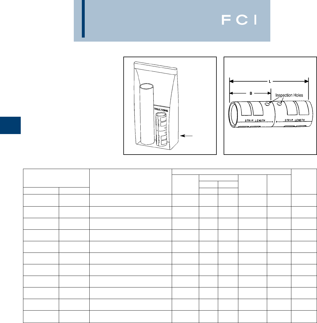
BURNDY
Compression
C-102
TYPE YS-TC
HYSPLICE™
In-line Splice Kits for
Telecommunications
Applications
YS-TC kits are for splicing cables and cover-
ing the connection with clear heat shrink.
Splices are constructed from seamless, high
conductivity electrolytic copper tubing for
maximum conductivity and tin-plated to resist
corrosion. Each YS-TC splice is provided with
inspection holes and cable stops. The YS-TC
family also features the BURNDY®color code
system.
Connector
* Clear Dimensions
Wire Size Heat Shrink Kit Barrel Barrel Length Wire Strip
AWG mm2Catalog Number Type BL
Color Code Die Index Length
750 kcmil 500 mm2
FLEX Class 5 YS44FXLTCKITC Standard 1.90 4.30 Yellow L115 1.96
750 kcmil
CODE —YS39LTCKITC Standard 1.62 3.68 Black 23 1.67
500 kcmil 300 mm2
FLEX Class 5 YS38FXLTCKITC Standard 1.71 3.87 Pink L99 1.77
500 kcmil 240 mm2
CODE Class 2 YS34LTCKITC Standard 1.56 3.51 Brown 20 1.60
350 kcmil 240 mm2
FLEX Class 5 YS34FXLTCKITC Standard 1.56 3.51 Blue 19 or L80 1.60
350 kcmil 185 mm2
CODE Class 2 YS31LTCKITC Standard 1.39 3.10 Red 17 1.42
4/0 AWG
FLEX —YS29FXLTCKITC Standard 1.36 2.98 Yellow 16 1.38
4/0 AWG
CODE —YS28LTCKITC Standard 1.23 2.69 Purple 15 1.24
2/0 AWG 70 mm2
FLEX or CODE Class 5 YS26FXLTCKITC Standard 1.09 2.41 Black 13 1.10
1/0 AWG 50 mm2
FLEX or CODE Class 5 YS25FXLTCKITC Standard 0.98 2.18 Pink 12 1.00
#2 AWG 35 mm2
FLEX or CODE Class 5 YS2CFXLTCKITC Standard 0.77 1.73 Brown 10 0.78
*Clear Heatshrink – UL224 VW1 Listed – passes
TELCORDIA GR-347-CORE “Abrasion and Cut Test”.
(Up to 750 kcmil Class B code cable. Contact factory for
750 flex cable applications.)
Plastic
Bag/Kit
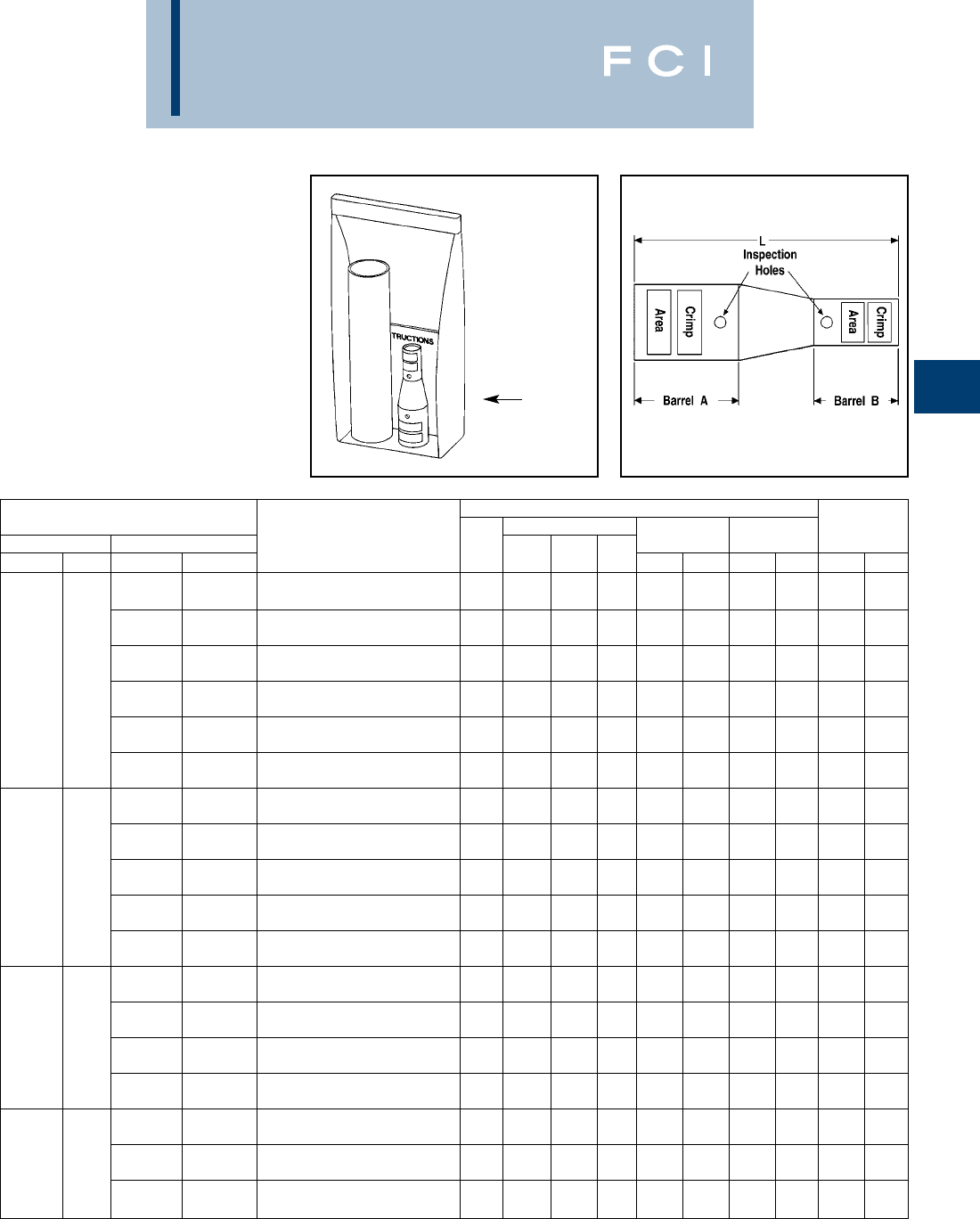
BURNDY
Compression
C-103
TYPE YSR-TC
HYREDUCER™
In-line Reducer Splice Kits for
Telecommunications
Applications
YSR-TC reducing splice kits provide for splic-
ing two different cable sizes with inspection
holes. The larger conductor is inserted first
and butts against the center of the connector
where the smaller barrel begins. Constructed
from seamless, high conductivity electrolytic
copper tubing for maximum conductivity, and
tin plated to resist corrosion. The YSR-TC
family also features the BURNDY®color code
system.
Plastic
Bag/Kit
Connector
Wire Range
** Clear
Dimensions Wire Strip
Barrel A Barrel B
Heat Shrink Kit
Barrel Color Code Die Index Length
AWG mm2AWG mm2
Catalog Number
Type Barrel A Barrel B L Barrel A Barrel B Barrel A Barrel B Barrel A Barrel B
750 Kcmil
CODE —
YSR44FX39LTCKITC
Standard 2.09 1.78 4.38 Yellow Black L115 24 1.96 1.67
500 Kcmil 240 mm
2
CODE Class 2
YSR44FX34LTCKITC
Standard 2.09 1.69 4.91 Yellow Brown L115 20 1.96 1.60
500 Kcmil 300 mm
2
750 kcmil 500 mm
2
FLEX Class 5
YSR44FX38FXLKITC
Standard 2.09 1.88 4.61 Yellow Pink L115 L99 1.96 1.77
FLEX Class 5 350 Kcmil 185 mm
2
CODE Class 2
YSR44FX31LTCKITC
Standard 2.09 1.49 5.18 Yellow Red L115 18 1.96 1.41
350 Kcmil 240 mm
2
FLEX Class 5
YSR44FX34FXLKITC
Standard 2.09 1.69 4.91 Yellow Blue L115 19 or L80 1.96 1.60
4/0 AWG
FLEX —
YSR44FX29FXLKITC
Standard 2.09 1.44 5.33 Yellow Yellow L115 16 1.96 1.38
500 Kcmil 300 mm
2
FLEX Class 5
YSR3938FXLKITC
Standard 1.78 1.88 3.79 Black Pink 24 L99 1.67 1.77
350 Kcmil 185 mm
2
CODE Class 2
YSR3931LTCKITC
Standard 1.78 1.49 4.36 Black Red 24 18 1.67 1.41
750 kcmil 350 Kcmil 240 mm
2
CODE —FLEX Class 5
YSR3934FXLKITC
Standard 1.78 1.69 4.09 Black Blue 24 19 or L80 1.67 1.60
4/0 AWG
CODE —
YSR3928LTCKITC
Standard 1.78 1.30 4.65 Black Purple 24 15 1.67 1.24
4/0 AWG
FLEX —
YSR3929FXLKITC
Standard 1.78 1.44 4.51 Black Yellow 24 16 1.67 1.38
350 Kcmil 185 mm
2
CODE Class 2
YSR38FX31LTCKITC
Standard 1.88 1.49 4.33 Pink Red L99 18 1.77 1.41
350 Kcmil 240 mm
2
500 kcmil 300 mm
2
FLEX Class 5
YSR38FX34FXLKITC
Standard 1.88 1.69 4.06 Pink Blue L99 19 or L80 1.77 1.60
FLEX Class 5 4/0 AWG
CODE —
YSR38FX28LTCKITC
Standard 1.88 1.30 4.62 Pink Purple L99 15 1.77 1.24
4/0 AWG
FLEX —
YSR38FX29FXLKITC
Standard 1.88 1.44 4.48 Pink Yellow L99 16 1.77 1.38
350 Kcmil 185 mm
2
CODE Class 2
YSR3431LTCKITC
Standard 1.69 1.49 3.66 Brown Red 20 18 1.60 1.41
500 kcmil 240 mm
2
350 Kcmil 240 mm
2
CODE Class 2 FLEX Class 5
YSR3434FXLKITC
Standard 1.69 1.69 3.39 Brown Blue 20 19 or L80 1.60 1.60
4/0 AWG
CODE —
YSR3428LTCKITC
Standard 1.69 1.30 3.95 Brown Purple 20 15 1.60 1.24
†Provided with 2 heat shrink tubings. One will overlap the
other. Install the smaller first and larger second.
** Clear Heatshrink – UL224 VW1 Listed – passes
TELCORDIA GR-347-CORE “Abrasion and Cut Test”.
(Up to 750 kcmil Class B code cable. Contact factory for
750 flex cable applications.)
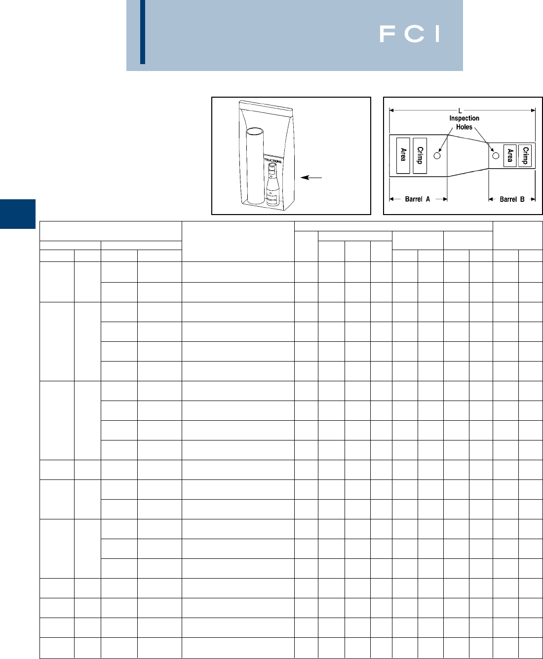
BURNDY
Compression
C-104
TYPE YSR-TC
HYREDUCER™
(Continued)
In-line Reducer Splice Kits for
Telecommunications
Applications
Plastic
Bag/Kit
Connector
Wire Range
** Clear
Dimensions Wire Strip
Barrel A Barrel B
Heat Shrink Kit
Barrel Color Code Die Index Length
AWG mm2AWG mm2
Catalog Number
Type Barrel A Barrel B L Barrel A Barrel B Barrel A Barrel B Barrel A Barrel B
4/0 AWG
500 kcmil 240 mm
2
FLEX —
YSR3429FXLKITC
Standard 1.69 1.44 3.81 Brown Yellow 20 16 1.60 1.38
CODE Class 2 1/0 AWG 50 mm
2
FLEX or CODE Class 5
YSR3425FXLTCKITC
Standard 1.69 1.04 4.01 Brown Pink 20 12 1.60 1.00
4/0 AWG 120 mm
2
FLEX Class 5 or Class 2
YSR34FX28FXLTCKITC
Standard 1.69 1.43 3.86 Blue Purple 19 or L80 15 1.60 1.36
4/0 AWG
350 kcmil 240 mm
2
CODE —
YSR34FX28LTCKITC
Standard 1.69 1.30 3.95 Blue Purple 19 or L80 15 1.60 1.24
FLEX Class 5 4/0 AWG
FLEX —
YSR34FX29FXLKITC
Standard 1.69 1.44 3.81 Blue Yellow 19 or L80 16 1.60 1.38
1/0 AWG 50 mm
2
CODE Class 5
YSR34FX25FXLTCKITC
Standard 1.69 1.04 4.01 Blue Pink 19 or L80 12 1.60 1.00
4/0 AWG
CODE —
YSR3128LTCKITC
Standard 1.49 1.30 3.27 Red Purple 18 15 1.41 1.24
4/0 AWG
350 kcmil 185 mm
2
FLEX —
YSR3129FXLKITC
Standard 1.49 1.44 3.13 Red Yellow 18 16 1.41 1.38
CODE Class 2 1/0 AWG 50 mm
2
FLEX or CODE Class 5
YSR3125FXLTCKITC
Standard 1.49 1.04 3.33 Red Pink 18 12 1.41 1.00
#2 AWG 35 mm
2
FLEX or CODE Class 5 or Class 2
YSR312CFXLTCKITC
Standard 1.49 0.82 3.37 Red Brown 18 10 1.41 0.78
300 kcmil 185 mm
2
4/0 AWG 120 mm
2
FLEX Class 5 FLEX Class 5 or Class 2
YSR32FX29FXLTCKITC
Standard 1.57 1.43 3.46 Red Yellow 18 16 1.48 1.36
1/0 AWG 50 mm
2
4/0 AWG FLEX or CODE Class 5
YSR29FX25FXLTCKITC
Standard 1.44 1.04 3.10 Yellow Pink 16 12 1.38 1.00
FLEX —#2 AWG 35 mm
2
FLEX or CODE Class 5 or Class 2
YSR29FX2CFXLTCKITC
Standard 1.44 0.82 3.13 Yellow Brown 16 10 1.38 0.78
1/0 AWG 50 mm
2
FLEX or CODE Class 5
YSR2825FXLTCKITC
Standard 1.30 1.04 2.66 Purple Pink 15 12 1.24 1.00
4/0 AWG #2 AWG 35 mm
2
CODE —FLEX or CODE Class 5 or Class 2
YSR282CFXLTCKITC
Standard 1.30 0.82 2.70 Purple Brown 15 10 1.24 0.78
#6 AWG 16 mm
2
FLEX or CODE Class 5 or Class 2
YSR286CFXLTCKITC
Standard 1.30 0.73 2.99 Purple Blue 15 7 1.24 0.70
2/0 AWG 70 mm
2
#6 AWG 16 mm
2
FLEX or CODE Class 5 FLEX or CODE Class 5 or Class 2
YSR26FX6CFXLTCKITC†
Standard 1.16 0.73 2.71 Black Blue 13 7 1.10 0.70
1/0 AWG 50 mm
2
#6 AWG 16 mm
2
FLEX or CODE Class 5 FLEX or CODE Class 5 or Class 2
YSR25FX6CFXLTCKITC†
Standard 1.04 0.73 2.42 Pink Blue 12 7 1.00 0.70
#2 AWG 35 mm
2
#6 AWG 16 mm
2
FLEX or CODE Class 5 FLEX or CODE Class 5 or Class 2
YSR2CFX6CFXLTCKITC
Standard 0.82 0.73 1.93 Brown Blue 10 7 0.78 0.70
#4 AWG #6 AWG 16 mm
2
FLEX or CODE —FLEX or CODE Class 5 or Class 2
YSR4CFX6CFXLTCKITC
Standard 0.74 0.73 1.67 Gray Blue 8 7 0.71 0.70
†Provided with 2 heat shrink tubings. One will overlap the
other. Install the smaller first and larger second.
** Clear Heatshrink – UL224 VW1 Listed – passes
TELCORDIA GR-347-CORE “Abrasion and Cut Test”.
(Up to 750 kcmil Class B code cable. Contact factory for
750 flex cable applications.)
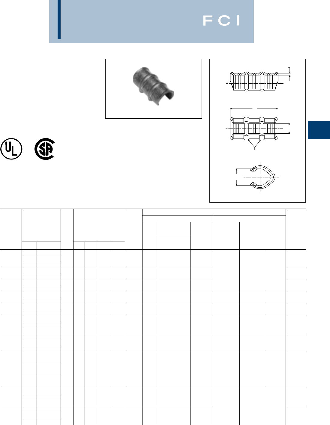
BURNDY
Compression
C-105
TYPE YC-L
THIN-WALL COPPER C-TAP
UL Listed to 600 Volts
Type YC-L is a thin-wall high conductivity
copper connector for making copper tap and
parallel connections from #14 to 3/0 AWG.
T
D
RIBS
C
B
▲See tooling section of this catalog for complete tool and die
listings.
*Use PUADP-1 adapter with “U” dies in Y46 HYPRESS™
For Tin plating add “TN” suffix (example = YC10L12TN)
Features and Benefits
•Manufactured form high conductivity
wrought copper.
◊Provides low resistance and excellent
electrical conductivity.
•Range-taking connector.
◊Lowers inventory requirements.
•Reinforced ribs.
◊Provides maximum pull-out values.
•Compact size.
◊Easy to tape and insulate connection.
•Economical.
◊Provides low installed cost.
INSTALLATION TOOLING
MECHANICAL HYDRAULIC
MD6, OUR840 & DIE ▲BCT500, Y35, Y39, DIE ▲
NO. MD7-34R INDEX Y500CT, Y750, Y45 INDEX WIRE
CATALOG ACCOMMODATES OF DIMENSIONS COLOR DIE NO. EMBOSS- BAT500 Y46* EMBOSS- STRIP
NUMBER RUN TAP RIBS B C D T CODE Y2MR (# CRIMPS) MENT (# CRIMPS) (# CRIMPS) MENT LENGTH
14 16-14
YC10L12 12 16-14 0 .18 .11 .40 .060 Red Red W8CVT 49 3/8
10 14 [4.6] [2.8] [10.2] [1.65] (1) (1)
10 10 .25 .21 .60 .072 Blue W5CVT
YC8L12 812
0[6.4] [3.8] [15.2] [1.83] Blue (1) (1) 75/8
810-8 .33 .25 .60 .072 Gray W4CVT
YC6L12 612-10 0[8.4] [5.1] [15.2] [1.83] Gray (2) (1) 85/8
68-6 .38 .28 1.18 .072 Brown W2CVT WC4 UC4
YC4L12 5,4 12-8 1[9.7] [6.1] [30.2] [1.83] Brown (2) (2) 10 (1) (1) 10M 1-3/16
5,4 6-5 .48 .37 1.18 .081 W1CVT
YC3L12 312-6 1[11.4] [6.4] [30.2] [2.06] Green – (2) 11 1-3/16
44
YC2L12 351
.50 .36 1.18 .081 Pink – W25VT 12 WC2 UC2 12M 1-3/16
212-6 [12.7] [7.6] [30.2] [2.06] (2) (1) (1)
34-3
YC1L12 25-4 2 .56 .45 1.75 .081 Black – W26VT 13 WC1 UC1 13M 1-13/16
112-5 [14.2] [8.6] [44.4] [2.06] (3) (2) (1)
2 Str. 2 Str. 2 Sol.
2 Sol. 3 Str. 3 Sol.
1 Str. 4 Str. 4 Sol. .62 .50 1.75 .090 W27VT WC25 UC25
YC25L12 1 Sol. 3 Str. 3 Sol. 2[15.7] [9.6] [44.4] [2.29] Orange – (3) 14 (2) (1) 14M 1-13/16
1/0 Str. 12 Str. 12 Sol.
1/0 Sol. - 4 Str. 4 Sol.
12-1
YC26L12 1/0 3-2 2 .69 .53 1.75 .090 Purple – W28VT 15 1-13/16
2/0 12-3 [17.5] [10.7] [44.4] [2.29] (3)
1/0 1-1/0
YC27L12 2/0 2-1 2 .81 .54 1.75 .090 Yellow – W29VT 16 1-13/16
3/0 12-2 [20.6] [11.9] [44.4] [2.29] (3)
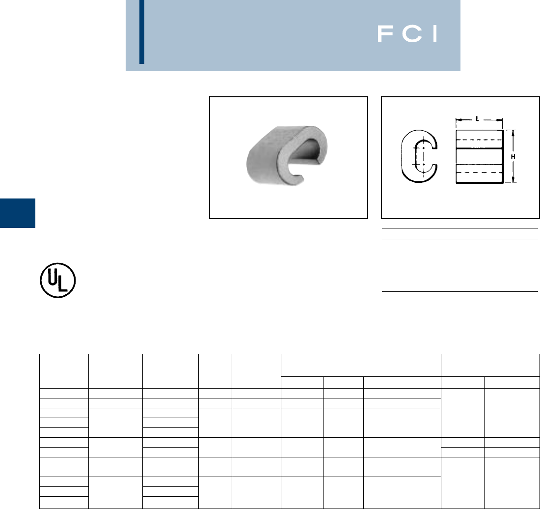
BURNDY
Compression
C-106
TYPES YC-C
COPPER CRIMPIT™
UL Listed 90° C,
600 Volts to 35kV◆
Type YC-C copper CRIMPIT™ connector is a
range-taking C shape compression connector
for making tap or parallel copper
connections from #12 sol. to 4/0 strand
conductor. Features and Benefits
•Range-taking connector.
◊Lowers inventory requirments.
•Compact size.
◊Easy to tape and insulate connection.
•Manufactured from high conductivity
wrought copper.
◊Provides low resistance and excellent
electrical conductivity.
•Economical
◊Provides low installed cost.
†Not UL Listed.
‡Number of Crimps.
▲See tooling section of this catalog for complete tool and
die listings.
*Use PUADP-1 adapter when using "U" dies in the Y46
HYPRESS™.
Copperweld-Copper Conductors
8A - Use CRIMPITS™ accommodating 6 str. Copper
6A - Use CRIMPITS™ accommodating 4 Str. Copper
4A - Use CRIMPITS™ accommodating 2 Str. Copper
2A - Use CRIMPITS™ accommodating 1/0 and 2/0
Copper
** Multiple crimp die set. Makes more than one crimp per tool
compression. Figure ( ) indicates number of compres-
sions.
◆For applications greater than 2000 Volts consult cable
manufacturer for voltage stress relief instructions.
TOOLS, DIE SET, CATALOG NO., CRIMPIT FOR 1 STR.
CATALOG ▲DIE and (‡No. of Crimps) ▲COPPER
NUMBER RUN TAP L INDEX MD6 OUR840 Y35, Y750, Y45, Y46* RUN TAP
YC10C10 † 12 Sol. - 10 Str. 12 Sol. - 10 Str. 3/8238 W238 (1) W238 (1) U-238 (1)
YC8C8 8 Sol. - 8 Str. 10 Sol. - 8 Str. 1/2162 or K W162 (2) W162 (2) U162** (1)
YC4C8 8 Sol. - 8 Str. ——
YC4C6 6 Sol. - 4 Str. 6 Sol. - 6 Str. 5/8BG or 5/8 BG (2) XNBG (2) U-BG (1)
YC4C4 4 Sol. - 4 Str. W-BG** (1)
YC2C4 8 Sol. - 4 Str. 1 Str. 6.8 Str., 8 Sol.
YC2C2 2 Sol. - 2 Str. 2 Sol. - 2 Str. 3/4CW-C (2) — U-C (1) ——
YC26C2 8 Sol. - 2 Str. U-E (3) 1 Str. 1 or 2 Str.
YC26C26 1/0 Sol. - 2/0 Str. 1/0 Sol. - 2/0 Str. 7/8E or O — — U-O (1)
YC28C2 6 Sol. - 2 Str.
YC28C26 3/0 Sol. - 4/0 Str. 1/0 Sol. - 2/0 Str. 1-1/16F or D3 — — U-F (3) — —
YC28C28 3/0 Sol. - 4/0 Str. U-D3** (1)
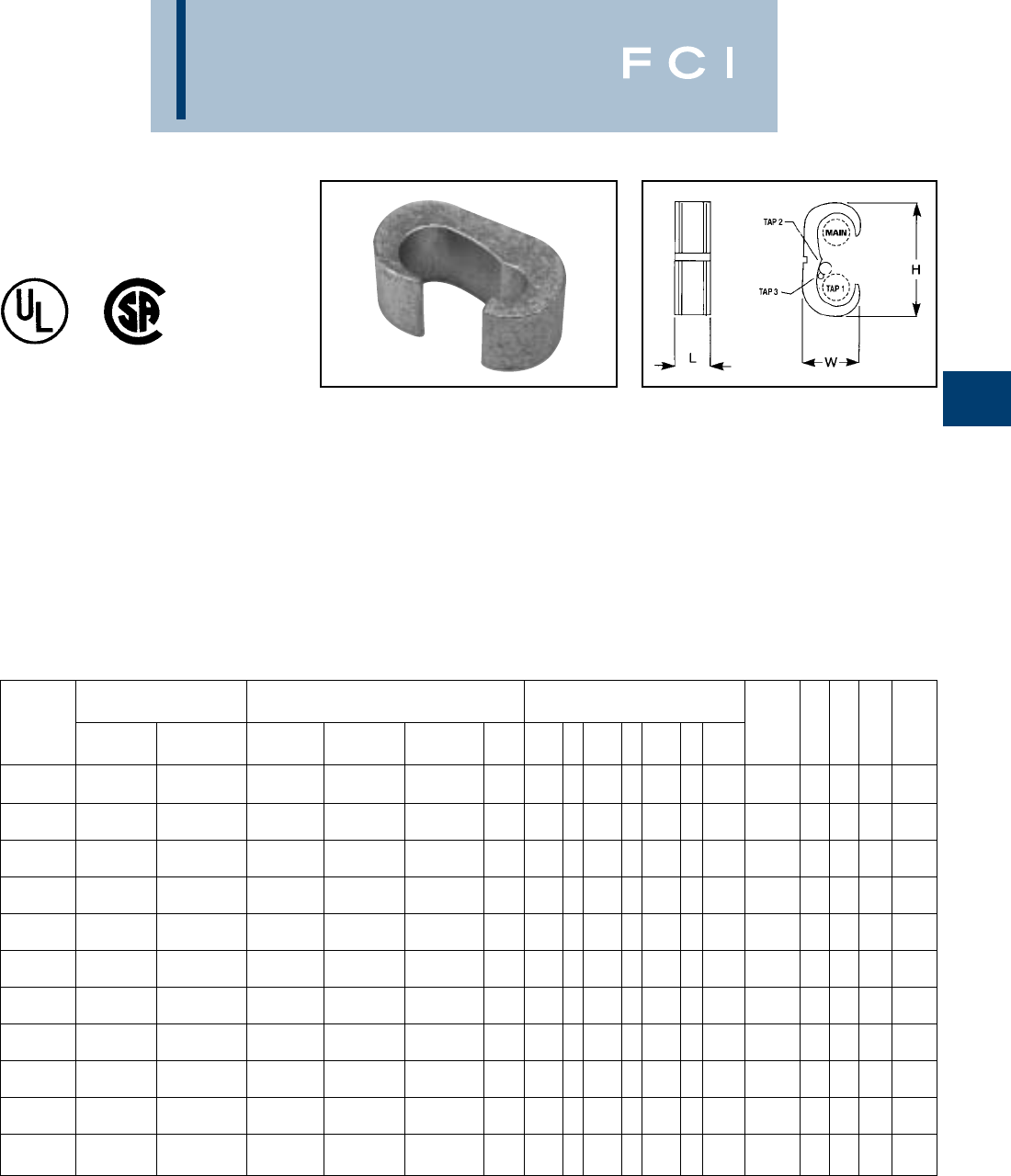
BURNDY
Compression
C-107
TYPE YCHC
C-TAP COPPER CRIMPIT™
90° C
NOTE: To properly use tap 2 and/or tap 3 conductors in YCHC
connector a conductor from the tap 1 cable range must be
included in the tap 1 groove.
‡To obtain covers made of polyethylene remove suffix-FR
(example: CFO). CFO is not flame retardant.
*Use PUADP-1 adaptor with "U" dies in Y46.
Features and Benefits
•Wide range of run/tap combinations includ-
ing Class B code I and locomotive flexible
conductor combinations. All (B/B, B/I, I/I)
combinations are recommended.
◊Each connector accommodates many
cable combinations, allowing maximum
flexibility for the design and installation of
a system.
•Color-coded on the connector that
matches the die.
◊Provides matched system for fast and
easy installation.
•Each connector has a recommended
insulating cover available. Flame retardant
type CF-FR covers meet oxygen index
28 and UL94 V-O requirements.
◊A complete insulated UL listed instal-
lation is provided.
•Die index embossed on connector after
completion of crimp.
◊Permanent inspectability of installed
connector is insure consistently reliable
and dependable connections.
▲See tooling section of Master Catalog for complete tool
and die listings.
◆For applications requiring flame retardant cover, use either
a CCFB-FR (Clear) or CFB-FR (Black) cover and YH2C2C
connector by ordering YH8C8CWCC (Clear) or
YH8C8CWC (Black).
▲Die
BURNDY Flame Retardant Cover Condutor Sizes Code/(Flex) Cable ▲Tooling (
†
No. of Crimps) Index &
Catalog Clear Black Color Emboss- Strip
Number Cat. No. Cat. No.
‡
Main Tap 1 Tap 2 Tap 3 Y35
†
Y750
†
Y46*
†
Code ment H W L Length
1000-750 1000-750
YCHC44TC44 CCFR-FR CFR-FR (750-500) (750-500) ————P1102 1 White 1102 3.59 1.73 1.16 1-1/4
750-500 750-350
YCHC39TC39 CCFR-FR CFR-FR (550-500) (550-350) ————P1103 1 Blue 1103 3.12 1.53 1.06 1-1/8
750-500 350-2 2-6 STR./SOL. 8-14
YCHC39TC31 CCFR-FR CFR-FR (550-500) (250-2) (2-8) (8-14) ————P1103 1 Blue 1103 2.96 1.53 1.31 1-3/8
750-500 2-6 STR./SOL. 8-14
YCHC39TC2 CCFR-FR CFR-FR (550-500) (2-8) (8-14) ————P1103 1 Blue 1103 2.66 1.53 1.31 1-3/8
500-4/0 500-4/0
YCHC34TC34 CCFN-FR CFN-FR (350-4/0) (350-4/0) ——U1104 2 P1104 1 Brown 1104 2.97 1.38 1.16 1-1/4
500-4/0 250-2 2-6 STR./SOL.
YCHC34TC29 CCFN-FR CFN-FR (350-4/0) (4/0-2) (2-8) ——U1104 2 P1104 1 Brown 1104 2.45 1.26 .94 1
500-4/0 2-6 STR./SOL. 8-14
YCHC34TC2 CCFN-FR CFN-FR (350-4/0) (2-8) (8-14) ——U1104 2 P1104 1 Brown 1104 2.45 1.26 .94 1
250-2 250-2
YCHC29TC29 CCFD-FR CFD-FR (4/0-2) (4/0-2) ——U997 1 U997 1 Orange 997 2.12 .98 .94 1
250-2 2-6 STR./SOL. 8-14
YCHC29TC2 CCFD-FR CFD-FR (4/0-2) (2-8) (8-14) ——U251 1 U251 1 Red 251 1.78 .97 .81 1
2-6 STR./SOL. 2-6 STR./SOL. 8-14
YCHC2TC2 CCFO-FR CFO-FR (2-8) (2-8) (8-14) U-C 1 U-C 1 U-C 1 Brown C 1.22 .60 .81 1
8-12 8-12
YCHC8TC8
♦♦
(8-12) (8-12) U-240 1 U-240 1 U-240 1 Red 240 .53 .35 .56 5/8
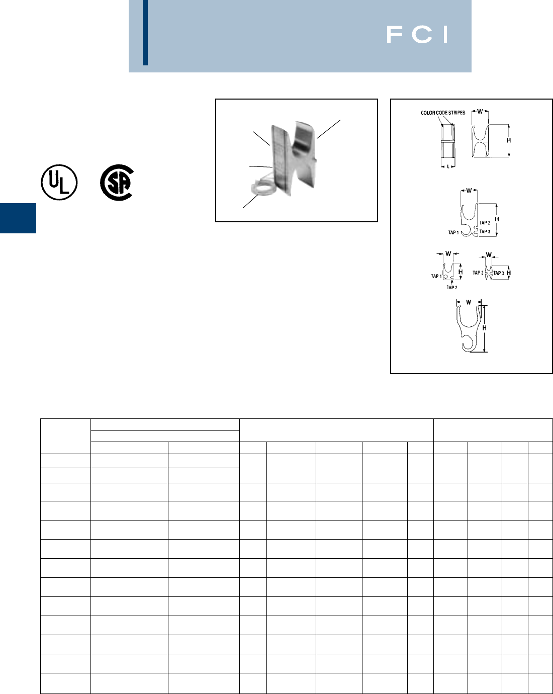
BURNDY
Compression
C-108
TYPE YH
H-TAP COPPER CRIMPIT™
ELECTRO-TIN
PLATED
PATENTED
“THIRD HAND”
COLOR CODE
DIE AND
CRIMP
INFORMATION
CONDUCTOR
RANGE
Fig. 1
Fig. 2
Fig. 3 Fig. 4
Fig. 5
•Die index embossed on connector after
completion of crimp.
◊Permanent inspectability of installed
connectors to insure consistently reliable
and dependable connections.
•Recommended flame retardant type CF-
FR insulating covers meet oxygen index
28 and UL94 V-O requirements.
◊A complete insulated UL listed instal-
lation is provided.
•“Third Hand” constrains conductors while
installer completes crimp. Included with
each connector.
◊Simplifies installation, reducing
installed cost.
Features and Benefits
•Accommodates a wide range of run/tap
copper cable combinations including both
flexible and code combinations. All (B/B,
B/I, I/B, I/I) combinations acceptable.
◊Each connector has many copper cable
combination applications allowing maxi-
mum flexibility for the design and instal-
lation of a system.
•Tap grooves function independently of
each other. Use of one tap is required.
Balance may be used or left empty.
◊Provides maximum design and instal-
lation flexibility.
•Color code on the connector matches
installation die.
◊Provides matched system for fast and
easy installation.
•Use PUADP-1 adaptor with "U" dies in Y46.
▲See tooling section of this catalog for complete tool and die
listings.
TABLE 1 CODE CONDUCTOR AND METRIC EQUIVALENT
Kit Catalog Number
H-Tap Flame Retardant Cover Conductor Sizes Code/(Flex Cable) Metric Conductor Sizes (mm2)
Connector Clear Black Fig. # Main Tap 1 Tap 2 Tap 3 Main Tap 1 Tap 2 Tap 3
1000-750 1000-750
YH4444 YH4444WCC YH444WC 1(750-500) (750-500) — — 500-400 500-400 — —
YH4434* YH4434WCC* YH4434WC* (750) (350)
YH4429 YH4429WCC YH4429WC 51000-750 250-2 ——500-400 150-35 — —
(777-500) (4/0-2)
YH3939 YH3939WCC YH3939WC 1750-500 750-350 ——300-300 300-185 — —
(550-500) (550-350)
YH3931 YH3931WCC YH3931WC 2750-350 4/0-1/0 1-6 STR/SOL 2-14 300-185 95-70 35-16 35-2.5
(550-500) (250-1/0) (1-8) (2-14)
YH3434 YH3434WCC YH3434WC 1500-250 500-4/0 ——240-150 240-120 — —
(350-4/0) (350-4/0)
YH3429 YH3429WCC YH3429WC 2500-4/0 250/1/0 1-6 STR/SOL 8-14 240-120 120-70 35-16 6-2.5
(350-4/0) (4/0-1/0) (1-8) #8
YH2929 YH2929WCC YH2929WC 1250-2 250-2 ——120-35 120-35 — —
(4/0-2) (4/0-2)
YH292C YH292CWCC YH292CWC 3250-2 2-6 STR/SOL 8-14 —120-35 35-16 6-2.5 —
(4/0-2) (2-8) (8-14)
YH298C YH298CWCC YH298CWC 3250-2 8-14 8-14 —120-35 6-2.5 6-2.5 —
(4/0-2) (8-14) (8-14)
YH2C2C YH2C2CWCC YH2C2CWC 42-6 STR/SOL 2-6 STR/SOL 8-14 8-14 35-16 35-16 6-2.5 6-2.5
(2-8) (2-8) (8-14) (8-14)
YH6C6C YH6C6CWCC YH6C6CWC 16-10 6-14 ——10-6 10-2.5 — —
(6-10) (6-14)
YH8C8C YH8C8CWCC YH8C8CWC 18-14 8-14 ——6-2.5 6-2.5 — —
(8-14) (8-14)
*Not CSA approved.
Note: All H-Taps ROHS compliant.
BURNDY
Compression
C-109
TYPE YH
H-TAP COPPER CRIMPIT™
(Continued)
•Use PUADP-1 adaptor with "U" dies in Y46.
▲See tooling section of this catalog for complete tool and die
listings.
MAXIMUM MIMIMUM
CONDUCTOR IN MAXIMUM METRIC CONDUCTOR IN MINIMUM METRIC
RANGE DIMENSIONS RANGE DIMENSIONS
FLEX FLEX
CATALOG CONDUCTOR DIAMETER CONDUCTOR DIAMETER
NUMBER (AWG/kcmil) mm2mm (AWG/kcmil) mm2mm
Main 777 393 28 500 253 24
YH4444 Tap 1 777 393 28 500 253 24
Main 777 393 28 750 380 31
YH4434 Tap 1 – – – 350 177 20
YH4429 Main 777 393 28 500 253 24
Tap 1 4/0 107 15.5 2 33.6 8
YH3939 Main 550 278 25 500 253 24
Tap 1 550 278 25 350 177 20
Main 550 278 25 500 253 24
YH3931 Tap1 250 126 17 1/0 53.5 11
Tap 2 1 42 9 8 8 4
Tap 3 2 33.6 8 14 2 2
YH3434 Main 350 177 20 4/0 107 15.5
Tap 1 350 177 20 4/0 107 15.5
Main 350 177 20 4/0 107 15.5
YH3429 Tap 1 4/0 107 15.5 1/0 53 11
Tap 2 1 42 9 8 8 4
Tap 3 8 8 4 14 2 2
YH2929 Main 4/0 107 15.5 2 33.6 8
Tap 1 4/0 107 15.5 2 33.6 8
Main 4/0 107 15.5 2 33.6 8
YH292C Tap1 2 33.6 8 8 8 4
Tap 2 8 8 4 14 2 2
Main 4/0 107 15.5 2 33.6 8
YH298C Tap1 8 8 4 14 2 2
Tap 2 8 8 4 14 2 2
Main 2 33.6 8 8 8 4
YH2C2C Tap 1 2 33.6 8 8 8 4
Tap 2 8 8 4 14 2 2
Tap 3 8 8 4 14 2 2
YH6C6C Main 6 13 5 10 5 3
Tap 1 6 13 5 14 2 2
YH8C8C Main 8 8 4 14 2 2
Tap 1 8 8 4 14 2 2
TABLE 2 FLEX AND METRIC CONDUCTOR RANGES
ELECTRO-TIN
PLATED
“THIRD HAND”
COLOR CODE
DIE AND
CRIMP
INFORMATION
CONDUCTOR
RANGE
*Not CSA approved.
Note: All H-Taps ROHS compliant.
BURNDY
Compression
C-110
TYPE YH
H-TAP COPPER CRIMPIT™
(Continued)
TABLE 3 INSTALLATION TOOLING + DIMENSIONS
•Use PUADP-1 adaptor with "U" dies in Y46.
▲See tooling section of this catalog for complete tool and die
listings.
Fig. 1
Fig. 2
Fig. 3 Fig. 4
Fig. 5
ELECTRO-TIN
PLATED
“THIRD HAND”
COLOR CODE
DIE AND
CRIMP
INFORMATION
CONDUCTOR
RANGE
*Not CSA approved.
Note: All H-Taps ROHS compliant.
BURNDY Kit Catalog Number ▲Tooling († No. of Crimps)
Catalog Flame Retardant Cover Color ▲Die Index & Strip
Number Clear Black ‡Fig. No. Y35 † Y750 † Y46*†Code Embossment H W L Length
YH4444 YH4444WCC YH4444WC
YH4434* YH4434WCC* YH4434WC* 1————P1102 1 White 1102 3.38 1.70 1.00 1-1/8
YH4429 YH4429WCC YH4429WC 5PYFR 1 Yellow K-R 3.22 1.70 1.00 1-3/8
YH3939 YH3939WCC YH3939WC 1————PYFR 1 Yellow K-R 2.97 1.50 1.25 1-3/8
YH3931 YH3931WCC YH3931WC 2————PYFR 1 Yellow K-R 2.97 1.50 .95 1-1/16
U1104M 1 P1104
YH3434 YH3434WCC YH3434WC 1——
U1104 2 U1104M 1Brown 1104 2.43 1.15 1.00 1-1/8
U1104M 1 P1104
YH3429 YH3429WCC YH3429WC 2——
U1104 2 U1104M 1Brown 1104 2.23 1.31 1.00 1-1/8
U654
YH2929 YH2929WCC YH2929WC 1——U654 1 P654 1Purple 654 1.85 .90 .90 1-1/16
U654
YH292C YH292CWCC YH292CWC 3——U654 1 P654 1Purple 654 1.52 .90 .90 1-1/16
U654
YH298C YH298CWCC YH298CWC 3——U654 1 P654 1Purple 654 1.52 .90 .90 1-1/16
YH2C2C YH2C2CWCC YH2C2CWC 4U-C 1 U-C 1 U-C 1 Brown C 1.25 .60 .75 7/8
YH6C6C YH6C6CWCC YH6C6CWC 1UBGRT 1 UBGRT 1 UBGRT 1 Orange BG .81 .39 .60 3/4
YH8C8C YH8C8CWCC YH8C8CWC 1U11T-1 1 U11T-1 1 U11T-1 1 Green 11 .63 .40 .60 3/4
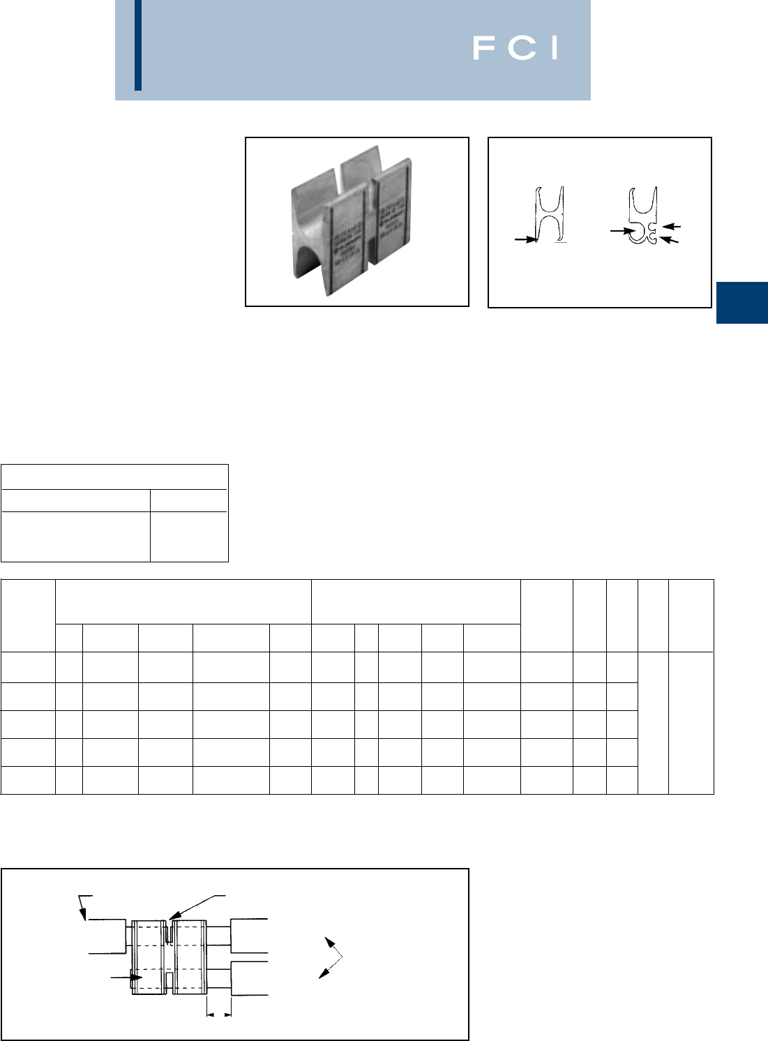
BURNDY
Compression
C-111
TYPES YSH
H COPPER CRIMPIT™
COPPER SPLIT
COMPRESSION WYE TAP
CONNECTOR
Type YSH heavy duty connectors are
designed for insulated underground wye
splices. The split H copper CRIMPIT™ con-
nector is longer than our standard H copper
CRIMPIT™ and is suitable for use on high
voltage (15 kV) power cables with copper
conductors. The connectors can not be used
with oil filled or mass impregnated cables
since no oil stop is provided.The connector is
installed with standard BURNDY®
HYPRESS™ tools and is made of tin-plated
electrolytic copper.
Features and Benefits
•Accommodates a wide range of run/tap
copper cable combinations including both
flexible and code combinations. All (B/B,
B/I, I/B, I/I) combinations acceptable.
◊Each connector has many copper cable
combination applications allowing
maximum flexibility for the design and
installation of a system.
•Tap grooves function independently from
each other. Use of one tap is required.
Balance may be used or left empty.
◊Provides maximum design and instal-
lation flexibility.
TAP 1
TAP 1
TAP 3
TAP 2
Fig. 1 Fig. 2
•Color code on the connector matches
installation die.
◊Provides matched system for fast and
easy installation.
•Die index embossed on connector after
completion of crimp.
◊Permanent inspectability of installed
connectors to ensure consistently reli-
able and dependable connections.
•Insulation is not provided. Insulation can
be obtained from Raychem (800-272-
9243) type HVSY Splice kits for 15 kV
installations.
◊A complete IEEE 404 15 kV installation
is provided.
Expanded TAP 1 Components
Expanded Catalog Number TAP 1 Range
YSH-294C-E #4
YSH-292C-E #2
YSH-2925-E 1/0
Die
Conductor Sizes Code Expanded TAP 1 Index
(Flex Cable) ▲Tooling (†Number of Crimps) ▲&
Catalog Color Emboss Strip
Number Fig. Main TAP 1 TAP 2 TAP 3 Y750 † Y46* † Code ment H W L Length
250-2 250-2 U654
YSH2929 1(4/0-2) (4/0-2) U654 (4) P654 (4)/(2) Purple 654 1.85 .90
500-4/0 250-1/0 1-6 Str./Sol. 8-14 U1104
YSH3429 2(350-4/0) (4/0-1/0) (1-8) (8-14) U1104 (4) P1104 (4)/(2) Brown 1104 2.23 1.31
500-250 500-4/0 U1104
YSH3434 1(350-4/0) (350-4/0) U1104 (4) P1104 (4)/(2) Brown 1104 2.43 1.15 3.00
750-350 350-1/0 1-6 Str./Sol. 2-14 - - PYFR
YSH3931 2(550-500) (350-1/0) (1-8) (2-14) - - 2Yellow K-R 2.97 1.50
750-350 750-350 PYFR
YSH3939 1(550-500) (550-350) -- 2Yellow K-R 2.97 1.50
See Application Notes Below
*Use PUADP-1 adaptor with “U” dies in Y46. The
Y46 and P dies result in a smooth crimp surface
and is recommended for voltages above 600V.
Main Conductor
YSH Connector
Main Conductor
Tap Conductor
For continuous and/or tap
connections refer to table
for conductor ranges.
Strip Length 1–1/2” Conductor ends remain visible
when conductor is split
①①Due to thickness of underground wire insulation the minimum
recommended strip length from the connector edge is 1 inch.
▲See tooling section of this catalog for complete
tool and die listings.
†Number of crimps per connector.“U” -dies require
double crimps.
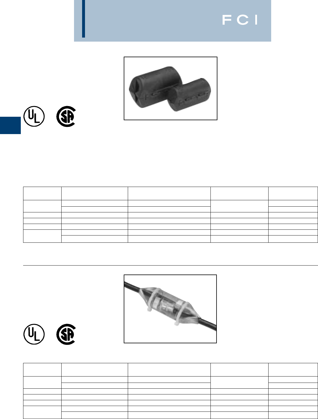
BURNDY
Compression
C-112
TYPE CF-FR
H-TAP - FLAME
RETARDANT COVER
UL Listed to 600 Volts
600 VOLT 90° C
*Use CFN-FR for single tap installation; use CFR-FR when
2 or more tap conductors are installed.
Features and Benefits
•One-piece design.
◊No extra parts or hardware required.
•Slips over connector and latches
securely shut.
◊Fast, easy, reliable insulation of
H-Tap compression.
•Eliminates tapping.
◊Economical, fast, easy installation.
•Flash barriers.
◊Protects against electrical flashover.
•CF-FR flame retardant design.
◊Self-extinguishing retardant properties.
•Minimum 28 oxygen index.
◊Self-extinguishing retardant properties.
•UL 94 V-O rated.
◊Self-extinguishing retardant properties.
CATALOG MAX. CONDUCTOR MAX. CONNECTOR CONNECTOR
NUMBER ACCOMMODATED MATCHED H COPPER CRIMPIT™ LENGTH COLOR CODE
#8 AWG YH8C8C Green
CFBG-FR #6 AWG YH6C6C .65 Orange
CFO-FR #2 AWG YH2C2C .80 Brown
CFD-FR 250 kcmil YH292C, YH298C, YH2929 .95 Purple
CFN-FR 500 kcmil YH3434, YH3429* 1.10 Brown
750 kcmil YH3939, YH3931, YH4429 1.30 Yellow
CFR-FR †1000 kcmil YH4434 ,YH4444 1.10 Yellow, White
TYPE CCF-FR
CLEAR H-TAP - FLAME
RETARDANT COVER
UL Listed to 600 Volts
600 VOLT 90° C
CATALOG MAX. CONDUCTOR MAX. CONNECTOR CONNECTOR
NUMBER ACCOMMODATED MATCHED H COPPER CRIMPIT™ LENGTH COLOR CODE
#8 AWG YH8C8C Green
CCFBG-FR #6 AWG YH6C6C .65 Orange
CCFO-FR #2 AWG YH2C2C .80 Brown
CCFD-FR 250 kcmil YH292C, YH298C, YH2929 .95 Purple
CCFN-FR 500 kcmil YH3434, YH3429* 1.10 Brown
750 kcmil YH3939, YH3931, YH4429 1.30 Yellow
CCFR-FR †1000 kcmil YH4434, YH4444 1.10 White
†Two-piece design packaged together.
Note: ROHS compliant
*Use CFN-FR for single tap installation; use CFR-FR when
2 or more tap conductors are installed.
†Two-piece design packaged together.
Note: ROHS compliant
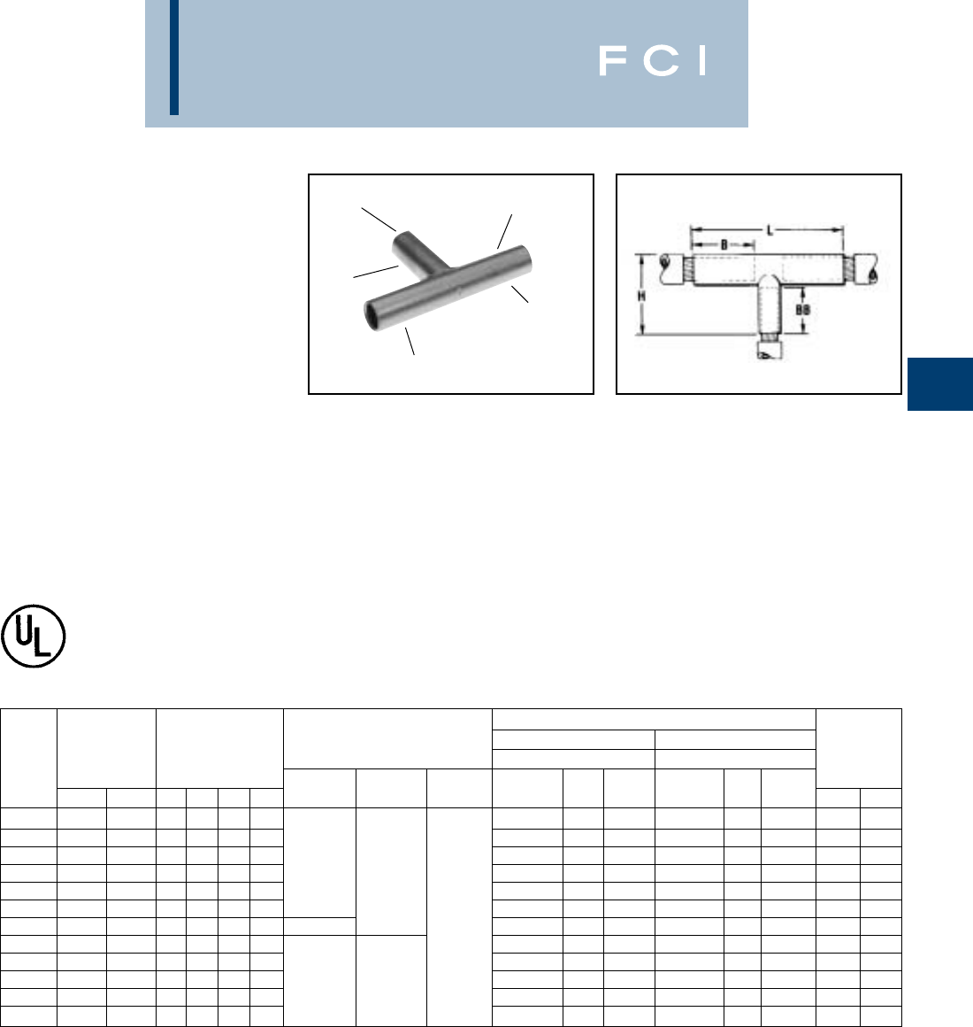
BURNDY
Compression
C-113
TAP
CRIMP
ELECTRO-TIN
PLATED
CRIMP
RUN
CRIMP
Features and Benefits
•Manufactured from seamless high conduc-
tivity electrolytic copper tubing with heavy
duty wall thickness.
◊Provides maximum conductivity, low
resistance and ductility for an excellent
combination of electrical and crimp form-
ing properties.
•Long barrel design on all three (3) legs.
◊Provides for an additional crimp or indent
with almost twice the pull out strength
properties as a standard length barrel
plus a connection that will operate cooler
under heavy loading.
*Use adapter PUADP-1 with "U" Dies in Y46 HYPRESS™.
■The maximum size for the Y35 is 400 kcmil.
•Contact factory for conductor combinations not shown.
▲See tooling section of this catalog for complete tool and
die listings.
•Long barrel permits the use of the Y-R
reducers.
◊Affords total flexibility and versatility for
virtually any conductor combination.
•Electro-tin plated.
◊Provides durable long-lasting corrosion
resistance.
•Barrel diameter closely matches commer-
cial (code) cable and Navy cable diameters.
◊Provides an excellent relationship of the
conductor/ connector combination to pro-
duce a high quality electrical connection
with the recommended tooling.
TYPES YST
UNINSULATED “T”
COPPER HYTEE™ COUPLER
UL Listed 90° C,
600 Volts to 35 KV◆
Type YST copper compression tee is
designed for connecting a run conductor with
a perpendicular tap conductor.
YST connectors are commonly used in junc-
tion boxes and manholes to make a radial tap
off a main run. They are needed in many
industrial, utility generation and commercial
applications. The most common cable combi-
nations are listed below. BURNDY®Type Y-R
reducers can be used to accommodate most
cable combinations.
◆For applications greater than 2000 Volts consult cable
manufacturer for voltage stress relief instructions.
Installation Tooling ▲
Run Conductors Tap Conductors
Code • Dieless Y35, ▲Y39, Y750, Y46* Y35, ▲Y39, Y750, Y46*
Catalog Conductors Dimensions Mechanical Hydraulic Die Number Color Die Die Number Color Die Wire Length
Number Run Tap B BB H L (# of crimps) HYTOOL HYPRESS (# of crimps) Code Index (# of crimps) Code Index▲Run Tap
YST4C4C 4 str. 4 str. 1.44 1.38 1.72 3.25 U4CRT (2) Gray 8 or 346 U4CRT (2) Gray 8 or 346 1-3/161-3/16
YST2C2C 2 str. 2 str. 1.56 1.56 1.98 3.56 U2CRT (2) Brown 10 U2CRT (2) Brown 10 1-5/161-5/16
YST2525 1/0 str. 1/0 str. 1.62 1.56 1.91 3.81 Y81KFT (1) MY29-3 (2) U24RT (2) Pink 12 or 348 U25RT (2) Pink 12 or 348 1-7/161-7/16
YST2626 2/0 str. 2/0 str. 1.69 1.67 2.18 3.94 Y81KFTMBH (1) MY29-11 (2) U26RT (2) Black 13 U26RT (2) Black 13 1-9/161-9/16
YST282C 4/0 str. 2 str. 1.75 1.50 2.12 3.94
PAT81KFT-18V (1)
(2-crimps/end) U28RT (2) Purple 15 U2CRT (2) Brown 10 1-11/161-5/16
YST2825 4/0 str. 1/0 str. 1.75 1.56 2.25 4.00 Y644HS (1) U28RT (2) Purple 15 U25RT (2) Pink 12 or 348 1-11/161-3/16
YST2828 4/0 str. 4/0 str. 1.75 1.75 2.44 4.19 (1 crimp/end) U28RT (2) Purple 15 U28RT (2) Purple 15 1-11/161-11/16
YST2929 250 kcmil 250 kcmil 1.75 1.78 2.53 4.25 U29RT (2) Yellow 16 U29RT (2) Yellow 16 1-11/161-11/16
YST3131 350 kcmil 350 kcmil 2.31 2.25 3.12 5.50 Y81KFT (2) U31RT (4) Red 18 or 324 U31RT (4) Red 18 or 324 22
YST3428 500 kcmil 4/0 str. 2.56 1.75 2.81 5.81 Y81KFTMBH (2) — U34RT (4) Brown 20 or 299 U28RT (2) Purple 15 2-5/161-11/16
YST3434 500 kcmil 500 kcmil 2.25 2.70 3.76 6.19
PAT81KFT-18V (2)
U34RT (4) Brown 20 or 299 U34RT (4) Brown 20 or 299 2-5/162-5/16
YST3939 750 kcmil 750 kcmil 3.46 3.34 4.64 8.12 U39RT (4) Black 24 or 473 U39RT (4) Black 24 or 473 2-15/162-15/16
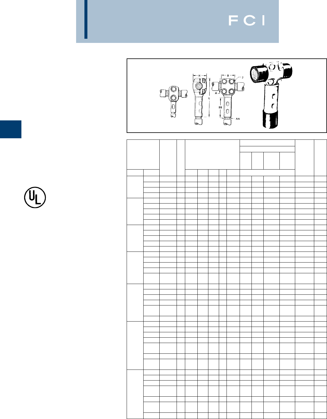
BURNDY
Compression
C-114
*Y48B HYPRESS™ with Y48PR indentor.
◆For applications greater than 2000 Volts consult cable
manufacturer for voltage stress relief instructions.
T-CONNECTOR
TYPE NYT
CABLE RUN — CABLE TAP
UL Listed 90° C,
600 Volts to 35 KV ◆
A “T” connector designed to provide a clamp-
type element on the run and a permanent
HYPRESS™ connection on the tap.
Recommended for use on ring buses or for
applications where occasional disconnects
from the run conductor are desired without
disturbing the tap connection. Tin plated.
For proper installation of tap cable, see
table below.
Fig. 1 Fig. 2
NOTE: Circumferential dies may be used. For information
contact BURNDY®.
INSTALLATION INFORMATION
HYPRESS™ AND INDENTOR DIE
Y29B Y34A Y34B Y44B APP.
WITH WITH WITH WITH SHIP.
CONDUCTOR SIZE CATALOG FIG. DIMENSIONS IN INCHES Y29PR Y34PR Y34PR Y44PR (NO. OF WT. IN
RUN A TAP AA NUMBER NO. B BB H J L NEST DIE INDENTS) LBS.
#2 STR. NYT282C 11-3/8 1-1/4 1-3/8 3/8 3-13/16 D2CL A2CD B2CD — (1) 1.5
1/0 STR. NYT2825 11-3/8 1-3/8 1-3/8 3/8 4 D25L A25D B25D — (1) 1.5
4/0 STR. 2/0 STR. NYT2826 11-3/8 1-1/2 1-3/8 3/8 4-1/8 D26L A26D B26D — (1) 1.5
4/0 STR. NYT2828 221-5/8 1-3/8 3/8 4-5/16 D28L A28D B28D E28D (1) 2.2
#2 STR. NYT292C 11-3/8 1-1/4 1-7/16 3/8 3-13/16 D2CL A2CD B2CD — (1) 1.5
1/0 STR. NYT2925 11-3/8 1-3/8 1-7/16 3/8 4-1/16 D25L A25D B25D — (1) 1.5
250 MCM 2/0 STR. NYT2926 11-3/8 1-1/2 1-7/16 3/8 4-3/16 D26L A26D B26D — (1) 1.5
4/0 STR. NYT2928 221-5/8 1-7/16 3/8 4-3/8 D28L A28D B28D E28D (1) 2.2
250 MCM NYT2929 221-5/8 1-7/16 3/8 4-7/16 D29L A29D B29D E29D (1) 2.2
1/0 STR. NYT3125 11-3/8 1-3/8 1-1/2 3/8 4-1/8 D25L A25D B25D — (1) 1.5
2/0 STR. NYT3126 11-3/8 1-1/2 1-1/2 3/8 4-5/16 D26L A26D B26D — (1) 1.5
350 MCM 4/0 STR. NYT3128 221-5/8 1-1/2 3/8 4-1/2 D28L A28D B28D E28D (1) 2.2
250 MCM NYT3129 221-5/8 1-1/2 3/8 4-9/16 D29L A29D B29D E29D (1) 2.2
350 MCM NYT3131 22 21-1/2 3/8 5 — A31D B31D E31D (2) 2.5
2/0 STR. NYT3426 11-3/8 1-1/2 1-5/8 3/8 4-7/16 D26L A26D B26D — (1) 1.7
4/0 STR. NYT3428 221-5/8 1-5/8 3/8 4-5/8 D28L A28D B28D E28D (1) 2.5
250 MCM NYT3429 221-5/8 1-5/8 3/8 4-5/8 D29L A29D B29D E29D (1) 2.5
500 MCM 350 MCM NYT3431 22 21-5/8 3/8 5-1/16 — A31D B31D E31D (2) 2.5
No Nest
500 MCM NYT3434 222-1/4 1-5/8 3/8 5-3/8 — A34D Die Req. E34D (2) 2.5
2/0 STR. NYT3926 11-3/8 1-1/2 1-7/8 3/8 4-5/8 D26L A26D B26D — (1) 1.7
4/0 STR. NYT3928 221-5/8 1-7/8 3/8 4-13/16 D28L A28D B28D E28D (1) 2.5
250 MCM NYT3929 221-5/8 1-7/8 3/8 4-13/16 D29L A29D B29D E29D (1) 2.5
750 MCM 350 MCM NYT3931 22 21-7/8 3/8 5-1/4 — A31D B31D E31D (2) 2.5
No Nest
500 MCM NYT3934 222-1/4 1-7/8 3/8 5-9/16 — A34D Die Req. E34D (2) 2.7
750 MCM NYT3939 222-7/8 1-7/8 3/8 6-1/4 — — — E39D (2) 3.0
2/0 STR. NYT4426 11-3/8 1-1/2 2-1/8 3/8 4-3/4 D26L A26D B26D — (1) 1.7
4/0 STR. NYT4428 221-5/8 2-1/8 3/8 4-15/16 D28L A28D B28D E28D (1) 2.5
250 MCM NYT4429 221-5/8 2-1/8 3/8 5 D29L A29D B29D E29D (1) 2.5
350 MCM NYT4431 22 22-1/8 3/8 5-7/16 — A31D B31D E31D (2) 2.5
1000 MCM No Nest
500 MCM NYT4434 222-1/4 2-1/8 3/8 5-3/4 — A34D Die Req. E34D (2) 2.7
750 MCM NYT4439 222-7/8 2-1/4 3/8 6-3/8 — — — E39D (2) 3.0
No Nest
1000 MCM NYT4444 22-11/16 3 2-5/16 1/2 7 — — — Die Req. (2) 3.2
4/0 STR. NYT4628 221-5/8 2-1/16 3/8 5-3/8 D28L A28D B28D E28D (1) 4.7
250 MCM NYT4629 221-5/8 2-1/16 3/8 5-7/16 D29L A29D B29D E29D (1) 4.7
350 MCM NYT4631 22 22-1/16 3/8 5-7/8 — A31D B31D E31D (2) 4.7
No Nest
1500 MCM 500 MCM NYT4634 222-1/4 2-1/16 3/8 6-3/16 — A34D Die Req. E34D (2) 4.7
750 MCM NYT4639 222-7/8 2-1/16 3/8 6-3/4 — — — E39D (2) 5.2
No Nest
1000 MCM NYT4644 22-11/16 3 2-3/4 1/2 7-1/8 — — — Die Req. (2) 7.5
1500 MCM NYT4646 22-11/16 3-3/16 2-3/4 1/2 7-11/16 — — — C46D* (2) 8.0
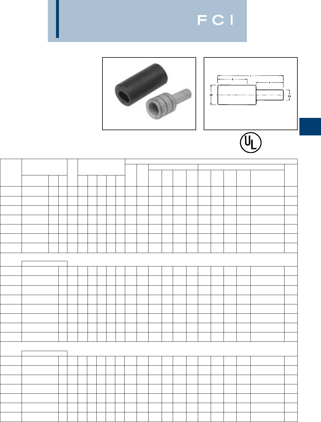
BURNDY
Compression
C-115
TYPE YE-P,YE-P-FX
HYPLUG™ FOR COPPER
CONDUCTOR
Type YE-P copper compression adapters are
designed for reliable termination of copper
conductor when the current capacity of the
conductor is downsized, but larger conductor
is utilized. Typical applications are for voltage
drop protection when oversized conductors
are used or flex conductor is used. These
adapters facilitate the termination into exist-
ing mechanical set screw connectors for
various stranded copper cables.
600 v, 900C EPDM rubber cover
90° C
INSTALLATION DATA
ACCOMMODATES PIN MECH TOOLS (# OF CRIMPS) HYDRAULIC TOOLS (# OF CRIMPS)
COPPER WIRE SIZES SIZE DIMENSIONS Y644M (ACCOMMODATES CABLE
CATALOG CODE EQUIV- A DIA. B L P OD COLOR DIE MD6/ Y35/Y39 EXPANDED STRIP
NUMBER FLEX CABLE AWG NAVY ALENT [MM] [MM] [MM] [MM] [MM] CODE INDEX MY Y2MR MD7-34R MD7 Y750 Y45
➃
Y46 Y60BHU WIRE RANGE) LENGTH
#4 STR. .20 1.37 2.27 .75 .38 MY29-11 Y2MR W4CVT W4CRT U4CRT U4CRT U4CRT #4 - #6 AWG
YEV4CP20X75FX (91/24-105/24) #4 40 #4 [5] [35] [58] [19] [10] Gray 8 (2) (4) (4) (4) (2) (2) (2) —(1) 1-15/32
#2 STR. .26 1.65 2.60 .75 .46 MY29-11 Y2MR W2CVT W2CRT U2CRT U2CRT U2CRT #2 - #6 AWG
YEV2CP26X75FX (125/24-150/24) #2 60 #2 [7] [42] [66] [19] [12] Brown 10 (2) (4) (4) (4) (2) (2) (2) —(1) 1-3/4
#1 STR. .29 1.66 2.63 .75 .51 MY29-11 W1CVT W1CRT U1CRT-1 U1CRT-1 U1CRT-1 #1 - #6 AWG
YEV1CP29X75FX (175/24-225/24) #1 75 #1 [8] [42] [67] [19] [13] Green 11 (2) —(4) (4) (2) (2) (2) —(1) 1-3/4
1/0 STR. .33 1.80 2.80 .75 .56 MY29-11 W25VT W25RT U25RT U25RT U25RT 1/0 - #6 AWG
YEV25P33X75FX (275/24) 1/0 100 1/0 [8] [46] [71] [19] [14] Pink 12 (2) —(4) (4) (2) (2) (2) —(1) 1-7/8
2/0 STR. .37 1.82 2.86 .75 .63 MY29-11 W26VT W26RT U26RT U26RT U26RT 2/0 - #4 AWG
YEV26P37X75FX (325/24) 2/0 125 2/0 [9] [46] [73] [19] [16] Black 13 (2) —(4) (4) (2) (2) (2) —(1) 1-7/8
3/0 STR. .41 1.97 3.11 .82 .70 MY29-11 W27VT W27RT U27RT U27RT U27RT 3/0 - #2 AWG
YEV27P41X82FX (450/24) 3/0 150 3/0 [10] [50] [77] [21] [18] Orange 14 (2) —(4) (4) (2) (2) (2) —(1) 2-1/16
4/0 STR. .46 1.99 3.28 .92 .77 MY29-11 W28VT W28RT U28RT U28RT U28RT 4/0 - #1 AWG
YEV28P46X92FX (550/24) 4/0 200 4/0 [12] [51] [81] [23] [20] Purple 15 (2) —(4) (4) (2) (2) (2) —(1) 2-1/16
FLEX CABLE ONLY
250 kcmil FLEX 250 .50 2.37 3.75 1.00 .81 MY29-11 W29VT W29RT U29RT U29RT U29RT L29RT
YE30P50X100FX CLASS G 259 CLASS H 427 —kcmil [10] [60] [95] [25] [21] Yellow 16 (2) —(4) (4) (2) (2) (2) (1) (1) 2-3/8
262.6 kcmil FLEX 262.6 .51 2.39 3.82 1.02 .88 W30VT W30RT U30RT U30RT U30RT L30RT
YE31P51X102FX 250 FLEX CLASS I, K, M —kcmil [13] [61] [97] [26] [22] White 17 — — (8) (8) (4) (4) (4) (1) (1) 2-1/2
313.1 kcmil (775/24) 300 .55 2.53 4.08 1.10 .95 W31VT W31RT U31RT U31RT U31RT L31RT
YE32P55X110FX (300 kcmil NOM) —kcmil [14] [65] [104] [28] [24] Red 18 — — (8) (8) (4) (4) (4) (1) (1) 2-5/8
373.7 kcmil (925/24) 350 .59 2.68 4.36 1.18 1.06 W32VT W32RT U32RT U32RT U32RT L32RT
YE34P59X118FX (350 kcmil NOM) —kcmil [15] [68] [111] [30] [27] Blue 19 — — (8) (8) (4) (4) (4) (2) 1 (1) 2-3/4
444.4 kcmil (1100/24) 450 .67 3.14 5.04 1.34 1.19 U34RT U34RT U34RT L34RT
YE36P67X134FX (450 kcmil NOM) —kcmil [17] [80] [128] [34] [30] Brown 20 — — — — (4) (4) (4) (2) (1) 3-1/4
535.3 kciml (1325/24) 500 .71 3.29 5.30 1.42 1.25 U38XRT U38XRT U38XRT
YE38P71X142FX (500 kcmil NOM) —kcmil [18] [84] [135] [36] [32] Pink L99 — — — — (4) (4) (4) —(1) 3-3/8
646 kcmil (1600/24) 600 .78 3.31 5.51 1.56 1.35 U39RT U39RT U39RT L39RT
YE40P78X156FX (600 kcmil NOM) —kcmil [20] [84] [140] [40] [34] Black 24 — — — — (4) (4) (4) (2) (1) 3-7/16
777.7 kcmil (1925/24) 750 .87 3.54 5.99 1.74 1.50 U44XRT U44XRT U44XRT
YE44P87X174FX (750 kcmil NOM) —kcmil [22] [90] [152] [44] [38] Yellow L115 — — — — (4) (4) (4) —(1) 3-5/8
CODE CONDUCTOR ONLY AWG
250 .50 1.99 3.33 1.00 .75 MY29-11 W29VT W29RT U29RT U29RT U29RT L29RT 250 kcmil - 1/0 AWG
YE29P50X100 250 kcmil 250 kcmil [13] [51] [84] [25] [19] Yellow 16 (2) —(4) (4) (2) (2) (2) (1) (1) 2-1/2
300 .55 2.37 3.85 1.10 .81 W30VT W30RT U30RT U30RT U30RT L30RT 300 kcmil - 2/0 AWG
YE30P55X110 300 kcmil 300 kcmil [14] [60] [98] [28] [21] White 17 — — (8) (8) (4) (4) (4) (1) (1) 2-5/8
350 .59 2.39 3.98 1.18 .88 W31VT W31RT U31RT U31RT U31RT L31RT 350 kcmil - 3/0 AWG
YE31P59X118 350 kcmil 350 kcmil [15] [61] [101] [30] [22] Red 18 — — (8) (8) (4) (4) (4) (1) (1) 2-3/4
400 .63 2.53 4.24 1.26 .95 W32VT W32RT U32RT U32RT U32RT L32RT 450 kcmil - 4/0 AWG
YE32P63X126 400 kcmil 400 kcmil [16] [65] [108] [32] [24] Blue 19 — — (8) (8) (4) (4) (4) (1) (1) 3-1/4
500 .71 2.68 4.60 1.42 1.06 W34VT W34RT U34RT U34RT U34RT L34RT 500 kcmil - 4/0 AWG
YE34P71X142 500 kcmil — kcmil [18] [68] [117] [36] [27] Brown 20 — — (8) (8) (4) (4) (4) (2) (1) 3-3/8
600 .78 3.14 5.25 1.56 1.19 U36RT U36RT U36RT L36RT 600 kcmil - 250 kcmil
YE36P78X156 600 kcmil — kcmil [20] [80] [133] [40] [30] Green 22 — — — — (4) (4) (4) (2) (1) 3-7/16
750 .87 3.37 5.73 1.74 1.30 U39RT U39RT U39RT L39RT 750 kcmil - 500 kcmil
YE39P87X174 750 kcmil — kcmil [22] [86] [145] [44] [33] Black 24 — — — — (4) (4) (4) (2) (1) 3-5/8
1For sizes above 4/0 the MD6-6R2 must be used. ➃To use "U" Dies in Y46 HYPRESS™, catalog number
PUADP-1 die adaptor is required.
BURNDY
Compression
C-116
1For sizes above 4/0 the MD6-6R2 must be used.
➃To use "U" Dies in Y46 HYPRESS™, Catalog number
PUADP-1 die adaptor is required.
REDUCED PIN DIAMETER
INSTALLATION DATA
ACCOMMODATES PIN MECH TOOLS (# OF CRIMPS) HYDRAULIC TOOLS (# OF CRIMPS)
COPPER WIRE SIZES SIZE DIMENSIONS Y644M (ACCOMMODATES CABLE
CATALOG CODE EQUIV- A DIA. B L P OD COLOR DIE MD6/ Y35/Y39 EXPANDED STRIP
NUMBER FLEX CABLE AWG NAVY ALENT [MM] [MM] [MM] [MM] [MM] CODE INDEX MY Y2MR MD7-34R MD7 Y750 Y45
➃
Y46 Y60BHU WIRE RANGE) LENGTH
#4 STR. .19 1.37 2.27 .75 .38 MY29-11 Y2MR W4CVT W4CVT U4CRT U4CRT U4CRT #4 - #6 AWG
YEV4CP19X75FX (91/24-105/24) #4 40 #5 [5] [35] [58] [19] [10] Gray 8 (2) (4) (2) (2) (2) (2) (2) —(1) 1-15/32
#2 STR. .23 1.65 2.60 .75 .46 MY29-11 Y2MR W2CVT W2CVT U2CRT U2CRT U2CRT #2 - #6 AWG
YEV2CP23X75FX (125/24-150/24) #2 60 #3 [6] [42] [66] [19] [12] Brown 10 (2) (4) (2) (2) (2) (2) (2) —(1) 1-3/4
#1 STR. .26 1.66 2.63 .75 .51 MY29-11 W1CVT W1CVT U1CRT U1CRT U1CRT #1 - #6 AWG
YEV1CP26X75FX (175/24-225/24) #1 75 #2 [7] [42] [67] [19] [13] Green 11 (2) —(2) (2) (2) (2) (2) —(1) 1-3/4
1/0 STR. .29 1.80 2.80 .75 .56 MY29-11 W25VT W25VT U25RT U25RT U25RT 1/0 - #6 AWG
YEV25P29X75FX (275/24) 1/0 100 #1 [8] [46] [71] [19] [14] Pink 12 (2) —(4) (4) (2) (2) (2) —(1) 1-7/8
2/0 STR. .33 1.82 2.86 .75 .63 MY29-11 W26VT W26VT U26RT U26RT U26RT 2/0 - #4 AWG
YEV26P33X75FX (325/24) 2/0 125 1/0 [8] [46] [73] [19] [16] Black 13 (2) —(4) (4) (2) (2) (2) —(1) 1-7/8
3/0 STR. .37 1.97 3.04 .75 .70 MY29-11 W27VT W27VT U27RT U27RT U27RT 3/0 - #2 AWG
YEV27P37X75FX (450/24) 3/0 150 2/0 [9] [50] [77] [19] [18] Orange 14 (2) —(4) (4) (2) (2) (2) —(1) 2-1/16
4/0 STR. .41 1.99 3.18 .75 .77 MY29-11 W28VT W28VT U28RT U28RT U28RT 4/0 - #1 AWG
YEV28P41X75FX (550/24) 4/0 200 3/0 [10] [51] [81] [21] [20] Purple 15 (2) —(4) (4) (2) (2) (2) —(1) 2-1/16
FLEX CABLE ONLY
250 kcmil FLEX .46 2.37 3.67 .92 .81 MY29-11 W29VT W29VT U29RT U29RT U29RT L29RT
YE30P46X92FX CLASS G 259 CLASS H 427 —4/0 [12] [60] [93] [23] [21] Yellow 16 (2) —(4) (4) (2) (2) (2) (1) (1) 2-3/8
262.6 kcmil FLEX .46 2.39 3.72 .92 .88 W30VT U30RT U30RT U30RT L30RT
YE31P46X92FX 250 FLEX CLASS I, K, M —4/0 [12] [61] [94] [23] [22] White 17 — — (8) —(4) (4) (4) (1) (1) 2-1/2
313.1 kcmil (775/24) 250 .51 2.53 4.00 1.02 .95 W31VT U31RT U31RT U31RT L31RT
YE32P51X102FX (300 kcmil NOM) —kcmil [13] [65] [102] [26] [24] Red 18 — — (8) —(4) (4) (4) (1) (1) 2-5/8
373.7 kcmil (925/24) 300 .55 2.68 4.28 1.10 1.06 W32VT U32RT U32RT U32RT L32RT
YE34P55X110FX (350 kcmil NOM) —kcmil [14] [68] [109] [28] [27] Blue 19 — — (8) —(4) (4) (4) (2) (1) 2-3/4
444.4 kcmil (1100/24) 350 .59 3.14 4.88 1.18 1.19 U34RT U34RT U34RT L34RT
YE36P59X118FX (450 kcmil NOM) —kcmil [15] [80] [124] [30] [30] Brown 20 — — — — (4) (4) (4) (2) (1) 3-1/4
535.3 kcmil (1325/24) 450 .67 3.29 5.22 1.34 1.25 U38XRT U38XRT U38XRT
YE38P67X134FX (500 kcmil NOM) —kcmil [17] [84] [133] [34] [32] Pink L99 — — — — (4) (4) (4) —(1) 3-3/8
646 kcmil (1600/24) 500 .71 3.31 5.27 1.42 1.35 U39RT U39RT U39RT L39RT
YE40P71X142FX (600 kcmil NOM) —kcmil [18] [84] [136] [36] [34] Black 24 — — — — (4) (4) (4) (2) (1) 3-7/16
777.7 kcmil (1925/24) 600 .78 3.54 5.81 1.56 1.50 U44XRT U44XRT U44XRT
YE44P78X156FX (750 kcmil NOM) —kcmil [20] [90] [148] [40] [38] Yellow L115 — — — — (4) (4) (4) —(1) 3-5/8
CODE CONDUCTOR ONLY AWG
.46 2.37 3.25 .92 .75 MY29-11 W29VT W29RT U29RT U29RT U29RT L29RT 250 kcmil - 1/0 AWG
YE29P46X92 250 kcmil 250 4/0 [12] [60] [82] [23] [19] Yellow 16 (2) —(4) (4) (2) (2) (2) (1) (1) 2-1/2
250 .51 2.39 3.75 1.00 .81 W30VT W30RT U30RT U30RT U30RT L30RT 300 kcmil - 2/0 AWG
YE30P50X100 300 kcmil 300 kcmil [13] [61] [95] [25] [21] White 17 — — (8) (8) (4) (4) (4) (1) (1) 2-5/8
300 .55 2.53 3.90 1.10 .88 W31VT W31RT U31RT U31RT U31RT L31RT 350 kcmil - 3/0 AWG
YE31P55X110 350 kcmil 350 kcmil [14] [65] [99] [28] [22] Red 18 — — (8) (8) (4) (4) (4) (1) (1) 2-3/4
350 .59 2.68 4.16 1.18 .95 W32VT W32RT U32RT U32RT U32RT L32RT 450 kcmil - 4/0 AWG
YE32P59X118 400 kcmil 400 kcmil [15] [68] [106] [30] [24] Blue 19 — — (8) (8) (4) (4) (4) (2) (1) 3-1/4
400 .63 3.14 4.44 1.26 1.06 W34VT W34RT U34RT U34RT U34RT L34RT 500 kcmil - 4/0 AWG
YE34P63X126 500 kcmil — kcmil [16] [80] [113] [32] [27] Brown 20 — — (8) (8) (4) (4) (4) (2) (1) 3-3/8
500 .71 3.37 5.11 1.42 1.19 U36RT U36RT U36RT L36RT 600 kcmil - 250 kcmil
YE36P71X142 600 kcmil — kcmil [18] [86] [130] [36] [30] Green 22 — — — — (4) (4) (4) (2) (1) 3-7/16
600 .78 3.37 5.55 1.56 1.30 U39RT U39RT U39RT L39RT 750 kcmil - 500 kcmil
YE39P78X156 750 kcmil — kcmil [20] [86] [141] [40] [33] Black 24 — — — — (4) (4) (4) (2) (1) 3-5/8
BURNDY
Compression
C-117
REDUCED PIN DIAMETER
INSTALLATION DATA
ACCOMMODATES PIN MECH TOOLS (# OF CRIMPS) HYDRAULIC TOOLS (# OF CRIMPS)
COPPER WIRE SIZES SIZE DIMENSIONS Y644M (ACCOMMODATES CABLE
CATALOG CODE EQUIV- A DIA. B L P OD COLOR DIE MD6/ Y35/Y39 EXPANDED STRIP
NUMBER FLEX CABLE AWG NAVY ALENT [MM] [MM] [MM] [MM] [MM] CODE INDEX MY Y2MR MD7-34R MD7 Y750 Y45
➃
Y46 Y60BHU WIRE RANGE) LENGTH
#4 STR. .16 1.37 2.27 .75 .38 MY29-11 Y2MR W4CVT W4CRT U4CRT U4CRT U4CRT #4 - #6 AWG
YEV4CP16X75FX (91/24-105/24) #4 40 #6 [4] [35] [58] [19] [10] Gray 8 (2) (4) (4) (4) (2) (2) (2) —(1) 1-15/32
#2 STR. .20 1.65 2.60 .75 .46 MY29-11 Y2MR W2CVT W2CRT U2CRT U2CRT U2CRT #2 - #6 AWG
YEV2CP20X75FX (125/24-150/24) #2 60 #4 [5] [42] [66] [19] [12] Brown 10 (2) (4) (4) (4) (2) (2) (2) —(1) 1-3/4
#1 STR. .23 1.66 2.63 .75 .51 MY29-11 W1CVT W1CRT U1CRT-1 U1CRT-1 U1CRT-1 #1 - #6 AWG
YEV1CP23X75FX (175/24-225/24) #1 75 #3 [6] [42] [67] [19] [13] Green 11 (2) —(4) (4) (2) (2) (2) —(1) 1-3/4
1/0 STR. .26 1.80 2.80 .75 .56 MY29-11 W25VT W25RT U25RT U25RT U25RT 1/0 - #6 AWG
YEV25P26X75FX (275/24) 1/0 100 #2 [7] [46] [71] [19] [14] Pink 12 (2) —(4) (4) (2) (2) (2) —(1) 1-7/8
2/0 STR. .29 1.82 2.86 .75 .63 MY29-11 W26VT W26RT U26RT U26RT U26RT 2/0 - #4 AWG
YEV26P29X75FX (325/24) 2/0 125 #1 [8] [46] [73] [19] [16] Black 13 (2) —(4) (4) (2) (2) (2) —(1) 1-7/8
3/0 STR. .33 1.97 3.04 .75 .70 MY29-11 W27VT W27RT U27RT U27RT U27RT 3/0 - #2 AWG
YEV27P33X75FX (450/24) 3/0 150 1/0 [8] [50] [77] [19] [18] Orange 14 (2) —(4) (4) (2) (2) (2) —(1) 2-1/16
4/0 STR. .37 1.99 3.11 .75 .77 MY29-11 W28VT W28RT U28RT U28RT U28RT 4/0 - #1 AWG
YEV28P37X75FX (550/24) 4/0 200 2/0 [9] [51] [81] [19] [20] Purple 15 (2) —(4) (4) (2) (2) (2) —(1) 2-1/16
FLEX CABLE ONLY
250 kcmil FLEX .41 2.37 3.57 .82 .81 MY29-11 W29VT W29RT U29RT U29RT U29RT L29RT
YE30P41X82FX CLASS G 259 CLASS H 427 —3/0 [10] [60] [91] [21] [21] Yellow 16 (2) —(4) (4) (2) (2) (2) (1) (1) 2-3/8
262.6 kcmil FLEX .41 2.39 3.62 .82 .88 W30VT W30RT U30RT U30RT U30RT L30RT
YE31P41X82FX 250 FLEX CLASS I, K, M —3/0 [10] [61] [92] [21] [22] White 17 — — (8) (8) (4) (4) (4) (1) (1) 2-1/2
313.1 kcmil (775/24) .46 2.53 3.90 .92 .95 W31VT W31RT U31RT U31RT U31RT L31RT
YE32P46X92FX (300 kcmil NOM) —4/0 [12] [65] [99] [23] [24] Red 18 — — (8) (8) (4) (4) (4) (1) (1) 2-5/8
373.7 kcmil (925/24) 250 .51 2.68 4.20 1.02 1.06 W32VT W32RT U32RT U32RT U32RT L32RT
YE34P51X102FX (350 kcmil NOM) —kcmil [13] [68] [107] [26] [27] Blue 19 — — (8) (8) (4) (4) (4) (2) 1 (1) 2-3/4
444.4 kcmil (1100/24) 300 .55 3.14 4.80 1.10 1.19 U34RT U34RT U34RT L34RT
YE36P55X110FX (450 kcmil NOM) —kcmil [14] [80] [122] [28] [30] Brown 20 — — — — (4) (4) (4) (2) (1) 3-1/4
535.3 kciml (1325/24) 350 .59 3.29 5.06 1.18 1.25 U38XRT U38XRT U38XRT
YE38P59X118FX (500 kcmil NOM) —kcmil [15] [84] [129] [30] [32] Pink L99 — — — — (4) (4) (4) —(1) 3-3/8
646 kcmil (1600/24) 450 .67 3.31 5.29 1.34 1.35 U39RT U39RT U39RT L39RT
YE40P67X134FX (600 kcmil NOM) —kcmil [17] [84] [134] [34] [34] Black 24 — — — — (4) (4) (4) (2) (1) 3-7/16
777.7 kcmil (1925/24) 500 .71 3.54 5.67 1.42 1.50 U44XRT U44XRT U44XRT
YE44P71X142FX (750 kcmil NOM) —kcmil [18] [90] [144] [36] [38] Yellow L115 — — — — (4) (4) (4) —(1) 3-5/8
CODE CONDUCTOR ONLY AWG
1.99 3.32 1.09 .75 MY29-11 W29VT W29RT U29RT U29RT U29RT L29RT 250 kcmil - 1/0 AWG
YE29P31X109 #1 .31 [51] [79] [28] [19] Yellow 16 (2) —(4) (4) (2) (2) (2) (1) (1) 2-1/2
250 kcmil 250 .41 1.99 3.15 .82 .75 MY29-11 W29VT W29RT U29RT U29RT U29RT L29RT 250 kcmil - 1/0 AWG
YE29P41X82 3/0 [10] [51] [80] [21] [19] Yellow 16 (2) —(4) (4) (2) (2) (2) (1) (1) 2-1/2
.46 2.37 3.67 .92 .81 W30VT W30RT U30RT U30RT U30RT L30RT 300 kcmil - 2/0 AWG
YE30P46X92 300 kcmil 300 4/0 [12] [60] [93] [23] [21] White 17 — — (8) (8) (4) (4) (4) (1) (1) 2-5/8
250 .51 2.39 3.80 1.00 .88 W31VT W31RT U31RT U31RT U31RT L31RT 350 kcmil - 3/0 AWG
YE31P50X100 350 kcmil 350 kcmil [13] [61] [96] [25] [22] Red 18 — — (8) (8) (4) (4) (4) (1) (1) 2-3/4
300 .55 2.53 4.08 1.10 .95 W32VT W32RT U32RT U32RT U32RT L32RT 450 kcmil - 4/0 AWG
YE32P55X110 400 kcmil 400 kcmil [14] [65] [104] [28] [24] Blue 19 — — (8) (8) (4) (4) (4) (1) (1) 3-1/4
350 .59 2.68 4.36 1.18 1.06 W34VT W34RT U34RT U34RT U34RT L34RT 500 kcmil - 4/0 AWG
YE34P59X118 500 kcmil — kcmil [15] [68] [111] [30] [27] Brown 20 — — (8) (8) (4) (4) (4) (2) (1) 3-3/8
400 .63 3.14 4.95 1.26 1.19 U36RT U36RT U36RT L36RT 600 kcmil - 250 kcmil
YE36P63X126 600 kcmil — kcmil [16] [80] [126] [32] [30] Green 22 — — — — (4) (4) (4) (2) (1) 3-7/16
500 .71 3.37 5.41 1.42 1.30 U39RT U39RT U39RT L39RT 750 kcmil - 500 kcmil
YE39P71X142 750 kcmil — kcmil [18] [86] [137] [36] [33] Black 24 — — — — (4) (4) (4) (2) (1) 3-5/8
1For sizes above 4/0 the MD6-6R2 must be used.
➃To use "U" Dies in Y46 HYPRESS™, Catalog number
PUADP-1 die adaptor is required.
BURNDY
Compression
C-118
DIE AND CRIMP
INFORMATION
ELECTRO-TIN
PLATED
CLOSED
BARREL
COLOR CODED
END CAP
CRIMP
CRIMP
CABLE
ACCOMMODATION
TYPES YA-A
AND YA-A-TN
HYLUG™
UNINSULATED ALUMINUM
COMPRESSION TERMINAL
1-HOLE DESIGN
UL Listed 90° C,
600 Volts to 35 KV◆
Type YA-A aluminum tin-plated compression
HYLUG™ terminals are dual-rated and
designed for use on both aluminum and
copper conductors from #12 sol. through
2000 kcmil.
They are designed for heavy duty applica-
tions to 35KV. YA-A terminals are prefilled
with PENETROX®, and assembled with color-
coded end caps. Available with one, two, and
four-hole NEMA tongues, the aluminum
HYLUG™ terminals are designed
for a permanent trouble-free electrical
termination.
Features and Benefits
•Manufactured from high conductivity,
wrought aluminum with heavy duty
wall thickness.
◊Provides maximum conductivity, low
resistance and ductility for an excellent
combination of electrical and crimp
forming properties.
•Electro-tin plated.
◊Provides durable long lasting
corrosion resistance.
•Internally bevelled barrel.
◊Provides easy cable insertion.
•Meets UL486B 90° C requirements.
◊Provides a quality electrical
dual connection.
•Connector is clearly marked with wire
size, die index, color-code and the
proper number and location of crimps.
◊Provides easy identification and tooling
recommendation for a proper compres-
sion which forms a homogeneous
mass resulting in an excellent electrical
connection.
•Factory prefilled with PENETROX®
oxide inhibiting compound.
◊Oxide inhibiting compound contains
homogeneously suspended metallic
particles to penetrate the wires' oxides,
establish electrical continuity and forms
an airtight connection.
•Color-coded end caps inserted
in barrel end.
◊Prevents foreign materials from entering
and contaminating the connector prior
to usage plus identifies the proper
color-coded die for a reliable connection.
Dimensions Installation Tooling ▲
No. of Dieless (# of crimps) Y35, Y39, Y70, Y46* ▲Wire
Catalog Code Stud Holes T Z Mechanical Hydraulic Die Number Color Die Strip
Number Conductor • Size in Pad C D L N REF. Min. Tooling HYPRESS (# of crimps) Code Index Length
YA12WA-TN ‡12 sol. 12 1 .41 .50 1.19 .20 .08 .30
YA12A-TN ‡12 str. 10 1 .41 .50 1.22 .20 .08 .30 MR8-27 (1) — — ➀—5/8
YA10A-TN ‡10 str. 10 1 .41 .50 1.22 .20 .08 .30
YA8CA1 10 .53 .60 1.50 .20 .09 .40
Y81KFT (1)
8 str. 1
Y81KFTMBH (1)
U8CABT (1) Blue 374 5/8
YA8CA3 1/4 .53 .75 1.65 .25 .09 .50 MY29-3 (1)
PAT81KFT-18V (1)
YA6CA1 1/4 .47 .75 1.84 .33 .14 .42
Y81KFT (1)
MY644M (1)
Y81KFTMBH (1)
Y81KFT (1)
YA6CA3 6 str. 3/8 1.65 1.19 2.28 .44 .09 .75
PAT81KFT-18V (1)
Y81KFTMBH (1)
U6CABT (1) Gray 346 3/4
PAT81KFT-18V (1)
•Contact BURNDY®for conductor, stud sizes and hole
drillings not shown.
◆See tooling section of this catalog for complete tool and
die listings.
➀No color code assigned.
‡UL Listed for Aluminum only.
*Use PUADP-1 adaptor with "U" dies in Y46 HYPRESS™.
◆For applications greater than 2000 Volts consult cable
manufacturer for voltage stress relief instructions.
BURNDY
Compression
C-119
TYPES YA-A
AND YA-A-TN
(Continued)
HYLUG™
UNINSULATED ALUMINUM
COMPRESSION TERMINAL
1-HOLE DESIGN
UL Listed 90° C,
600 Volts to 35 KV◆
AL9CU
•Contact BURNDY®for conductor, stud sizes and hole
drillings not shown.
▲See tooling section of this catalog for complete tool and
die listings.
Y644HS DIELESS HYPRESS™
RANGE-TAKING
CAPABILITIES
The following size HYDENT™ lugs and two
way splices, when crimped with the Y644HS
DIELESS HYPRESS™ tool, produce the
following range taking capabilities:
DIE AND CRIMP
INFORMATION
ELECTRO-TIN
PLATED
CLOSED
BARREL
COLOR CODED
END CAP
CRIMP
CRIMP
CABLE
ACCOMMODATION
ALUMINUM CONNECTORS
STANDARD EXPANDED STANDARD EXPANDED STANDARD EXPANDED
WIRE SIZE WIRE RANGE WIRE SIZE WIRE RANGE WIRE SIZE WIRE RANGE
#6 AWG #6 AWG 1/0 AWG 1/0 - #1 AWG 250 kcmil 250 kcmil - 1/0 AWG
#4 AWG #4 - #6 AWG 2/0 AWG 2/0 - #1 AWG 300 kcmil 300 kcmil - 2.0 AWG
#2 AWG #2 - #6 AWG 3/0 AWG 3/0 - #1 AWG 350 kcmil 350 kcmil - 3/0 AWG
#1 AWG #1 - #2 AWG 4/0 AWG 4/0 - #1 AWG 400 kcmil 400 kcmil - 4/0 AWG
500 kcmil 500 kcmil - 4/0 AWG
600 kcmil 600 - 250 kcmil
750 kcmil 750 - 500 kcmil
*Use PUADP-1 adaptor with "U" dies in Y46 Hypress™.
** P44ART for use with Y46 HYPRESS™ only. PUADP-1
adapter not required.
Dimensions Installation Tooling ▲
Dieless (# of crimps) Y35, Y39, Y70, Y46* ▲Wire
Catalog Code Stud No. of T Z Mechanical Hydraulic Die Number Color Die Strip
Number Conductor Size Holes in Pad C D L N REF. Min. Tooling HYPRESS (# of crimps) Code Index Length
YA4CA1 1/4 .47 .75 2.13 .33 .18 .42 Y81KFT (1)
YA4CA3 5/16 .80 .87 2.25 .41 .12 .46
Y81KFTMBH (1)
4 str. 1 MY29-3 (1)
PAT81KFT-18V (1)
U4CABT (1) Green 375 7/8
YA4CA6 3/8 .80 .94 2.32 .44 .12 .50 Y644HS (1)
YA2CA5 1/4 .50 .91 2.25 .32 .22 .43
YA2CA1 2 str. 5/16 1 .88 1.03 2.50 .41 .16 .47 U2CABT (1) Pink 348 1-1/8
YA2CA3 3/8 .88 1.03 2.56 .44 .16 .50
YA1CA1 1 str. 3/8 1 .76 1.19 2.59 .44 .19 .75 MY29-3 (1) U1CART (1) Gold 471 15/16
YA25A1 5/16 .60 .87 2.31 .41 .21 .46
YA25A3 1/0 str. 3/8 1 .82 1.18 2.67 .63 .21 .55 U25ART (1) Tan 296 1-1/16
YA25A9 1/2 1.03 1.34 2.67 .63 .17 .71 Y81KFT (2)
YA26A6 3/8 .67 1.18 2.79 .44 .24 .74
Y81KFTMBH (2)
YA26A1 2/0 str. 1/2 11.03 1.36 3.03 .63 .20 .73 Y644HS (1) U26ART (2) Olive 297 1-3/8
YA27A1 3/8 .73 1.18 2.88 .44 .26 .74
PAT81KFT-18V (2)
YA27A3 3/0 str. 1/2 11.04 1.37 3.27 .63 .26 .74 MY29-3 (2) U27ART (2) Ruby 467 1-1/2
YA28A1 3/8 1.17 1.18 3.26 .44 .30 .74
YA28A3 4/0 str. 1/2 11.17 1.36 3.44 .63 .30 .73 U28ART (2) White 298 1-5/8
YA29A1 250 kcmil 1/2 1 1.26 1.36 3.53 .63 .33 .73 U29ART (2) Red 324 1-5/8
YA30A6 3/8 1.38 1.37 3.90 .63 .36 .74
YA30A1 300 kcmil 1/2 11.38 1.37 3.90 .63 .36 .74 U30ART (2) Blue 470 1-3/4
Y644HS (1)
Y81KFT (3)
YA31A1 350 kcmil 1/2 1 1.52 1.37 4.33 .63 .39 .74
Y81KFTMBH (3)
U31ART (2) Brown 299 2-1/8
PAT81KFT-18V (3)
YA32A1 400 kcmil 5/8 1 1.62 1.88 4.92 .88 .43 1.00 U32ART (4) Green 472 2-1/2
YA34A1 500 kcmil 5/8 1 1.80 1.91 5.56 .88 .46 1.03 Y644HS (1) U34ART (4) Pink 300 2-5/8
YA36A1 600 kcmil 5/8 1 1.97 1.88 5.82 .88 .52 1.00 — Y81KFT (4) U36ART (4) Black 473 2-7/8
YA39A1 700/750 1/2 2.05 1.34 5.26 .63 .43 .71
Y81KFTMBH (4)
YA39A3 kcmil 5/8 12.05 1.88 5.80 .88 .43 1.00
PAT81KFT-18V (4)
U39ART-2 (4) Yellow 936 2-7/8
YA44A1 1000 kcmil 5/8 1 2.50 1.89 6.50 .88 .43 1.01 P44ART** (4) Brown 302 3
◆For applications greater than 2000 Volts consult cable
manufacturer for voltage stress relief instructions.
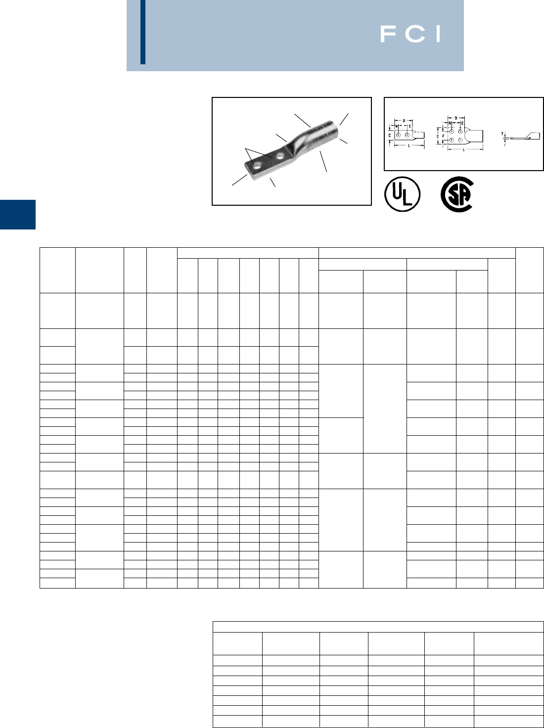
BURNDY
Compression
C-120
◆For applications greater than 2000 Volts consult cable
manufacturer for voltage stress relief instructions.
•Contact BURNDY®or conductor, stud sizes and hole
drillings not shown.
▲See tooling section of this catalog for complete tool and
die listings.
‡Use Y60 BHU HYPRESS™ with L46ART and L48ART die
sets.
90° C Rated.
TYPE YA-A
HYLUG™
UNINSULATED ALUMINUM
COMPRESSION TERMINAL
2-HOLE AND 4-HOLE
DESIGNS
UL Listed 90° C,
600 Volts to 35 KV◆
Type YA-A 2- and 4-hole pads inhibit connec-
tor rotation and increase area contact. These
aluminum terminals have the same design
features and benefits as the 1-hole YA-A with
an added stud hole for a more secure termi-
DIE AND CRIMP
INFORMATION COLOR CODED
END CAP
(2) HOLE
DRILLING
CLOSED
BARREL
ELECTRO-TIN
PLATED
BEVELED
ENTRY
CRIMPS
CABLE
ACCOMIDATION
*Use PUADP-1 adaptor with "U" dies in Y46 HYPRESS™.
** P39ART and P44ART die sets for use with Y46
HYPRESS™ only. PUADP-1 adapter not required.
Y644HS DIELESS HYPRESS™
RANGE-TAKING
CAPABILITIES
The following size HYDENT™ lugs and two
way splices, when crimped with the Y644HS
DIELESS HYPRESS™ tool, produce the
following range taking capabilities:
ALUMINUM CONNECTORS
STANDARD EXPANDED STANDARD EXPANDED STANDARD EXPANDED
WIRE SIZE WIRE RANGE WIRE SIZE WIRE RANGE WIRE SIZE WIRE RANGE
#6 AWG #6 AWG 1/0 AWG 1/0 - #1 AWG 250 kcmil 250 kcmil - 1/0 AWG
#4 AWG #4 - #6 AWG 2/0 AWG 2/0 - #1 AWG 300 kcmil 300 kcmil - 2.0 AWG
#2 AWG #2 - #6 AWG 3/0 AWG 3/0 - #1 AWG 350 kcmil 350 kcmil - 3/0 AWG
#1 AWG #1 - #2 AWG 4/0 AWG 4/0 - #1 AWG 400 kcmil 400 kcmil - 4/0 AWG
500 kcmil 500 kcmil - 4/0 AWG
600 kcmil 600 - 250 kcmil
750 kcmil 750 - 500 kcmil
●
Dimensions Installation Tooling ▲
●
No. of E Dieless (# of crimps) Y35, Y39, Y750, Y46* ▲Wire
Catalog Code Stud Holes & T Z Mechanical Hydraulic Die Number Color Die Strip
Number Conductor Size in Pad C D F L N REF. Min. Tooling HYPRESS (# of crimps) Code Index Length
Y644HS (1)
Y81KFT (1)
YA2CA9 2 str. 1/2 2-NEMA 1.12 1.03 1.75 4.73 .63 .16 .73 MY29-3 (1)
Y81KFTMBH (1)
U2CABT (1) Pink 348 1-1/8
PAT81KFT-18V (1
)
Y644HS (1)
YA25A5 3/8 2 .82 2.24 1.06 3.73 .63 .21 .55 Y81KFT (2)
1/0 str. MY29-3 (1)
Y81KFTMBH (2)
U25ART (1) Tan 296 1-1/16
YA25A7 1/2 2-NEMA 1.03 3.10 1.75 4.59 .63 .17 .72
PAT81KFT-18V (2
)
YA26A3 1/2 2-NEMA 1.03 3.11 1.75 4.78 .63 .20 .73
YA26A5 2/0 str. 3/8 2 .92 1.89 1.00 3.56 .44 .24 .45 U26ART (2) Olive 297 1-3/8
YA27A5 1/2 2-NEMA 1.04 3.12 1.75 5.02 .63 .26 .74
YA27A7 3/0 str. 3/8 2 1.04 1.89 1.00 3.79 .44 .26 .45 MY29-3 (2) Y644HS (1) U27ART (2) Ruby 467 1-1/2
YA28A5 1/2 2-NEMA 1.17 3.11 1.75 5.19 .63 .30 .73 Y81KFT (2)
YA28A7 4/0 str. 3/8 2 1.17 1.89 1.00 3.97 .44 .30 .45
Y81KFTMBH (2)
U28ART (2) White 298 1-5/8
YA29A3 1/2 2-NEMA 1.26 3.11 1.75 5.28 .63 .33 .73
PAT81KFT-18V (2
)
YA29A5 250 kcmil 3/8 2 1.26 1.89 1.00 4.06 .44 .33 .45 U29ART (2) Red 324 1-5/8
YA30A3 1/2 2-NEMA 1.38 3.11 1.75 5.69 .63 .36 .73 MY29-3 (2)
YA30A5 300 kcmil 3/8 2 1.38 1.89 1.00 5.64 .44 .36 .45 U30ART (2) Blue 470 1-3/4
YA31A5 3/8 2 1.52 1.89 1.00 4.85 .44 .39 .45 Y644HS (1)
YA31A3 350 kcmil 1/2 2-NEMA 1.52 3.11 1.75 6.07 .63 .39 .73 Y81KFT (3) U31ART (2) Brown 299 2-1/8
Y81KFTMBH (3)
YA32A5 400 kcmil 3/8 2 1.62 1.89 1.00 4.93 .44 .43 .94
PAT81KFT-18V (3
)
U32ART (4) Green 472 2
YA34A3 1/2 2-NEMA 1.62 3.15 1.75 6.80 .63 .46 .77
YA34A5 500 kcmil 3/8 2 1.80 1.89 1.00 5.54 .44 .46 .45 U34ART (4) Pink 300 2-5/8
YA36A3 1/2 2-NEMA 1.62 3.15 1.75 7.09 .63 .52 .77 Y644HS (1)
YA36A5 600 kcmil 3/8 2 1.97 1.89 1.00 5.83 .44 .52 .45 Y81KFT (4) U36ART (4) Black 473 2-7/8
YA39A7 3/8 2 2.05 1.89 1.00 5.81 .44 .43 .45
Y81KFTMBH (4)
YA39A5 700/750 1/2 2-NEMA 1.62 3.15 1.75 7.07 .63 .43 .77
PAT81KFT-18V (4
)
U39ART (4) Yellow 936 2-7/8
YA39AM2 kcmil 1/2 2-NEMA 1.69 3.12 1.75 7.31 .63 .57 .74 P39ART** (4) Red 301 2-7/8
YA44A3 1000 kcmil 1/2 2-NEMA 1.65 3.15 1.75 7.76 .63 .66 .77 P44ART** (4) Brown 302 3
YA46A3 1/2 2-NEMA 3.09 3.16 1.75 8.75 .63 .81 .78
YA46A5 1500 kcmil 1/2 4-NEMA 3.09 3.16 1.75 8.75 .63 .81 .78 ——L46ART (2) Red 478 2-3/4
YA48A3 2000 kcmil 1/2 2-NEMA 3.57 3.11 1.75 8.49 .63 .90 .73 L48ART (2) Red 479 4-1/8
nation to various types of equipment pads.
They are dual-rated for use on both aluminum
and copper conductors.
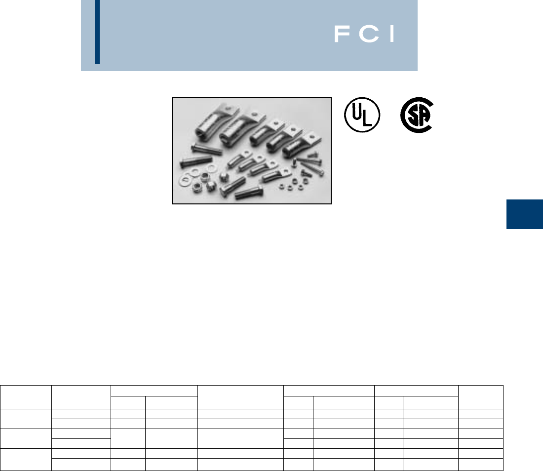
BURNDY
Compression
C-121
HH- Hex Head
HN- Hex Nut
See Mechanical section for set screw terminal kits.
Features and Benefits
•UL listed AL9CU dual rated compression
terminals and CSA certified.
◊Ensure the transformer feeders and
taps are terminated properly.
•Plated steel cap screws and hex nuts
with captive conical washers or individual
Belleville washers.
◊Terminal to bus connections are made
using proper hardware resulting in true
torque to pressure performance.
Compensates for dissimilar metal
expansion and contraction.
•Hardware packed in plastic bag.
◊No lost hardware prior to installation.
TYPE YA-A-KIT
TRANSFORMER
LUG KIT
Each kit contains the UL listed and CSA
certified AL9CU rated aluminum compression
connectors and tongue mounting hardware
needed to terminate aluminum or copper
cables in “dry type” transformers. The KVA
rating gives an approximate cross reference
to the appropriate kit.
CONNECTOR
CATALOG TERMINALS WIRE RANGE BOLT HARDWARE
NUMBER KVA QTY. CAT. NO. WITH Y644M QTY. QTY. WASHER
15-37.5 1Ø 8 YA2C-A5 #6-2 AWG 8 1/4-20 3/4 8 1/2 20HN Captive
YA-A-KIT1 15-45 3 1Ø 4 YA30-A7 2/0 AWG-300 kcmil
50-75 1Ø 8 1/4-20 3/4 16 1/4 20HN Captive
YA-AKIT2 75-112.5 3Ø 12 YA30-A7 2/0 AWG-300 kcmil 81/4-20 2
100-167 1Ø 3 YA30-A7 2/0 AWG-300kcmil 3 1/4-20 3/4 3 1/4 20 Captive
YA-AKIT3 150-300 3Ø 22 YA39-A1 500-750 kcmil 16 1-2-13 2161/2-13 1/2 Belleville
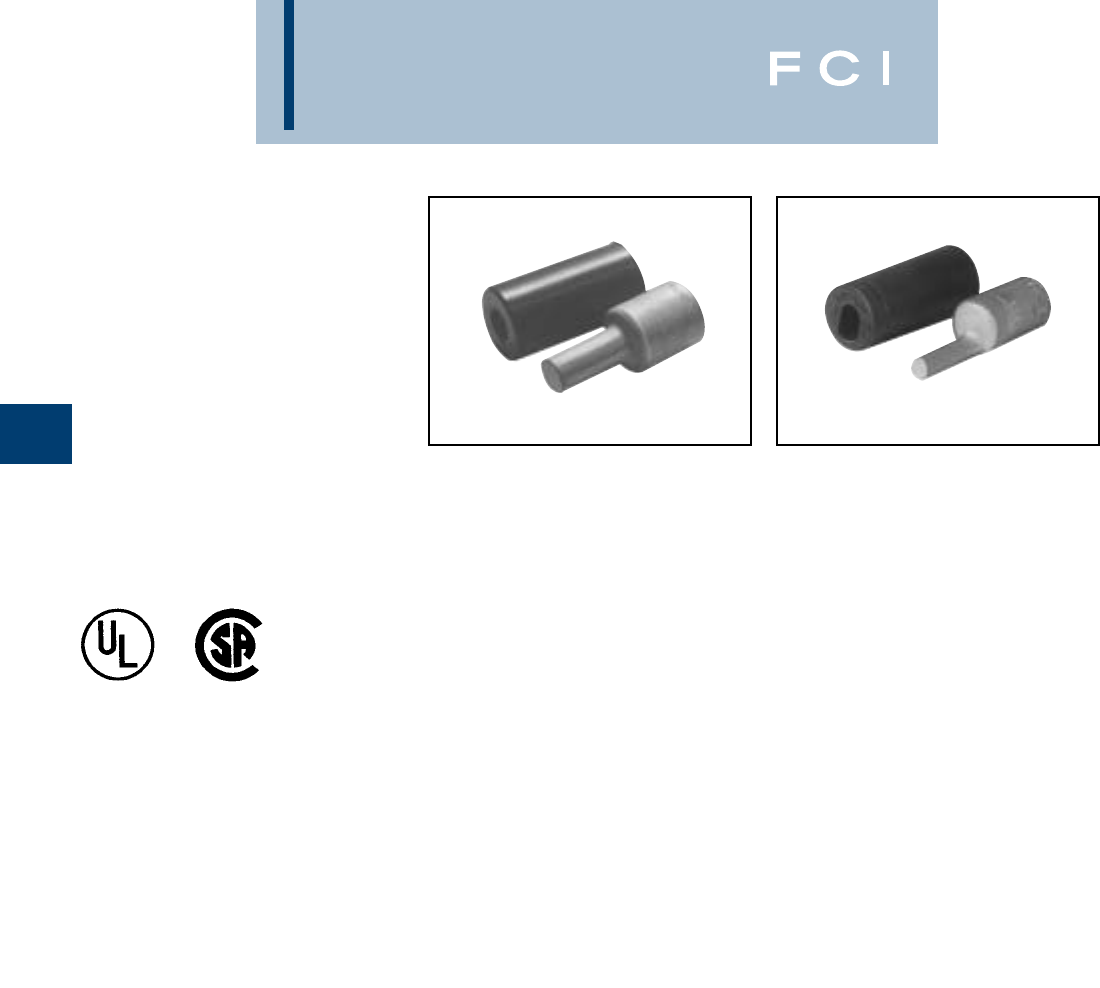
BURNDY
Compression
C-122
TYPE AYP, AYPO
HYPLUG™
FOR ALUMINUM AND COPPER
CONDUCTOR
UL Listed 90° C,
600 Volts to 35 KV◆
Types AYP and AYPO aluminum compres-
sion adapters are designed for reliable termi-
nation of aluminum and copper conductor in
mechanical connectors. Typical applications
include mechanical connectors in molded
case circuit breakers, panel board equipment
and meter sockets.
◆For applications greater than 2000 Volts consult cable
manufacturer for voltage stress relief instructions.
Features and Benefits
•All-aluminum electro-tin plated design.
◊Eliminates possible bi-metallic corrosion
and provides the shortest connector
length design possible.
•Shortest connector length design possible.
◊Permits easy installation in equipment
with limited working space.
•Solid electro-tin plated aluminum plug.
◊Proper electrical connection made easily.
Eliminates "how tight is tight" problem.
•Smooth surface on the solid EC aluminum
electro-tin plated plug.
◊Provides greater area contact establish-
ing excellent electrical conductivity.
•Solid plug has same diameter as current
carrying equivalent copper wire.
◊Permits use of larger aluminum wire
to connect equipment.
•Offset plug design available in sizes
2/0 through 750 kcmil.
◊Provides flexibility and maximizes
the use of limited space eliminating
interference between conductors and
equipment.
•Electro-tin plated.
◊Resists corrosion.
•Factory prefilled with the proper amount
of PENETROX®joint compound.
◊PENTROX®, BURNDY's oxide inhibiting
compound with conductive metallic
particles penetrates aluminum oxide
between strands and forms an
air-tight connection.
•EPDM rubber covers are supplied with
each connector.
◊Eliminates taping.
•Only (5) die sets install the complete
line from #6 to 750 kcmil.
◊Lowers inventory requirements and
saves money.
•Supplied in a plastic convenience pack.
◊The cover and connector are kept
together and free of foreign material
until used.
•Connectors are clearly marked with
catalog number, wire size, and color
coded die index.
◊Provides clear, easy to use information
to lower installed cost.
TYPE AYP TYPE AYPO
AL9CU
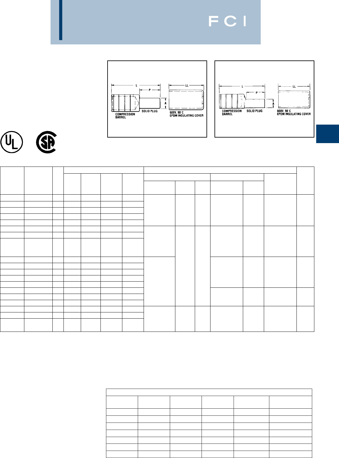
BURNDY
Compression
C-123
TYPE AYP, AYPO
HYPLUG™
FOR ALUMINUM AND COPPER
CONDUCTOR
UL Listed 90° C,
600 Volts to 35 KV◆
Fig 1: TYPE AYP (STRAIGHT) Fig 2: TYPE AYPO (OFFSET)
Scratch brush aluminum conductor before installation.
▲See tooling section of this catalog for complete tool and
die listings.
** For MY29-3 use aluminum index plate at 1/0 setting for
sizes #6 through 1/0 or at 4/0 setting for sizes 2/0 through
4/0.
+Not UL listed.
Y644HS DIELESS HYPRESS™
RANGE-TAKING
CAPABILITIES
The following HYPLUG™ lugs and two way
splices, when crimped with the Y644HS
DIELESS HYPRESS™ tool, produce the
following range- taking capabilities:
ALUMINUM CONNECTORS
STANDARD
WIRE SIZE EXPANDED
WIRE RANGE STANDARD
WIRE SIZE EXPANDED
WIRE RANGE STANDARD
WIRE SIZE EXPANDED
WIRE RANGE
#6 AWG #6 AWG 1/0 AWG 1/0 - #1 AWG 250 kcmil 250 kcmil - 1/0 AWG
#4 AWG #4 - #6 AWG 2/0 AWG 2/0 - #1 AWG 300 kcmil 300 kcmil - 2/0 AWG
#2 AWG #2 - #6 AWG 3/0 AWG 3/0 - #1 AWG 350 kcmil 350 kcmil - 3/0 AWG
#1 AWG #1 - #2 AWG 4/0 AWG 4/0 - #1 AWG 400 kcmil 400 kcmil - 4/0 AWG
500 kcmil 500 kcmil - 4/0 AWG
600 kcmil 600 - 250 kcmil
750 kcmil 750 - 500 kcmil
AL9CU
Dimensions Installation Tooling ▲
Copper & A P L LL HYTOOLS Y35, Y39, Y750, Y46* ▲ Die Wire
Catalog Aluminum Fig. Plug Plug HYPLUG Cover Dieless Tools + + Die Number Color Index & Strip
Number Conductor No. Dia. Length Length Length (# of crimps) OH25 MD6 (# of crimps) Code Embossment Length
AYP6 #6 str 1 .23 .68 1.85 1.78 MY29-3 (2) **
AYP4 #4 str 1 .23 .68 1.85 1.78 Y644HS (1)
AYP2 #2 str 1 .23 .68 1.85 1.78 Y81KFT (1) 1 crimp W241 U25ART (1) Tan 296 1-1/16
AYP1 #1 str 1 .26 .84 2.01 1.78 Y81KFTMBH (1)
AYP1/0 1/0 str 1 .29 .84 2.01 1.78
PAT81KFT-18V (1)
AYPO2/0 2/0 str 2 .33 1.09 2.70 2.44 MY29-3 (2) **
AYPO3/0 3/0 str 2 .37 1.22 2.80 2.44 Y644HS (1)
Y81KFT (2) U28ART (2) White 298 1-1/8
AYPO4/0 4/0 str 2 .42 1.22 2.80 2.44 Y81KFTMBH (2)
PAT81KFT-18V (2)
AYP250 250 kcmil 1 .47 1.22 2.63 2.54
AYPO250 250 kcmil 2 .47 1.22 2.98 2.88
AYPO300 300 kcmil 2 .53 1.34 3.08 2.88 Hydraulic: ——U31ART (2) Brown 299 1-1/8
AYP350 350 kcmil 1 .57 1.34 2.75 2.54 Y644HS (1)
AYPO350 350 kcmil 2 .57 1.34 3.08 2.88 Y81KFT (2)
AYPO400 400 kcmil 2 .63 1.60 3.43 3.16 Y81KFTMBH (2)
AYP500 500 kcmil 1 .68 1.60 3.08 2.81
PAT81KFT-18V (2)
U34ART (2) Pink 300 1-9/16
AYPO500 500 kcmil 2 .68 1.60 3.43 3.16
AYPO600 600 kcmil 2 .73 1.64 4.02 4.06 Y644HS (1)
AYP750 700/750 kcmil 1 .81 1.76 3.79 3.66 Y81KFT (3)
Y81KFTMBH (3) ——U39ART-2 (3) Yellow 936 1-3/4
AYPO750 700/750 kcmil 2 .81 1.76 4.16 4.06
PAT81KFT-18V (3)
*Use PUADP-1 adaptor with "U" dies in Y46 HYPRESS™.
■■
Also accomodates compressed and compact conductors
(except for 700 kcmil in 750 kcmil barrel).
◆For applications greater than 2000 Volts consult cable
manufacturer for voltage stress relief instructions.
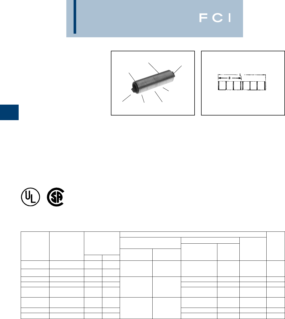
BURNDY
Compression
C-124
TYPE YS-A
HYLINK™
UNINSULATED ALUMINUM
COMPRESSION SPLICE
UL Listed 90° C,
600 Volts to 35 KV◆
Type YS-A is a high-conductivity aluminum
tin-plated compression butt splice for use on
all combinations of aluminum to aluminum,
aluminum to copper, and copper to copper
conductor combinations.
They are designed to accommodate conduc-
tors from #12 str. through 1,000 kcmil in stan-
dard and heavy duty applications. Prefilled
with PENETROX™ oxide inhibiting com-
pounds and assembled with color-coded end
caps, the connectors provide a permanent
trouble-free electrical splice with flexibility and
low installed cost.
DIE AND COLOR
CODE INFORMATION
ELECTRO-TIN
PLATED
BELLED
END
CRIMP
(4) CENTER
WIRE STOP
CRIMP
BELLED
END
Features and Benefits
•Manufactured from high-conductivity
wrought aluminum with heavy duty
wall thickness.
◊Provides high-conductivity/low
resistance and ductility for an
excellent combination of electrical
and crimp forming properties.
•Electro-tin plated.
◊Provides durable long lasting
corrosion resistance.
•Internally bevelled barrel.
◊Provides easy cable entry.
•Solid center stop and prefilled with
PENETROX™ oxide inhibiting compound.
◊Provides stop for proper conductor
insertion and an aid in forcing the
PENETROX™ between the individual
wire strands.
•Color-coded end caps.
◊Provides easy wire size and die code
identification plus prevents foreign
materials from entering and contaminat-
ing the connector prior to usage.
•Connector is clearly marked with wire
size, die index and the proper number
and location of crimps.
◊Provides easy identification and tooling
recommendation. Proper compression
forms a homogeneous mass resulting
in an excellent electrical connection.
◆See tooling section of this catalog for complete tool and
die listing.
①No color code assigned.
‡UL Listed for Aluminum only. Not CSA Certified.
*Use PUADP-1 adaptor with "U" dies in Y46 HYPRESS™.
■The largest size for the Y35 is 400 kcmil.
◆For applications greater than 2000 Volts consult cable
manufacturer for voltage stress relief instructions.
•Also accomodates compressed and compact conductors
(except for 700 kcmil in 750 kcmil barrel).
Installation Tooling ▲
Y35, ■Y39, Y750, Y46*
Dieless (# of crimps/end) Die Number Die Index & Wire
Catalog Code •Dimensions Mechanical Hydraulic (# of crimps Color Embossment Strip
Number Conductor B L HYTOOL HYPRESS per end) Code ▲Length
YS12AG1 #12 str. .39 1.03 Ratchet: ——
①—5/8”
YS10WAG1 ‡ #10 str. .44 1.12 MR8-27 (1)
YS8CA1 8 str. .59 1.44 Y644HS (1) U8CABT (1) Blue 374 5/8”
YS6CA1 6 str. .72 1.70 Y81KFT (1) U6CABT (1) Gray 346 3/4”
MY29-3 (1) Y81KFTMBH (1)
YS4CA1 4 str. .86 1.97
PAT81KFT-18V (1)
U4CABT (1) Green 375 7/8”
Y644HS (1)
YS2CA1 2 str. 1.09 2.44 Y81KFT (2) U2CABT (1) Pink 348 1-1/8”
YS1CA1 1 str. .90 2.05 MY29-3 (1)
Y81KFTMBH (2)
U1CART (1) Gold 471 15/16”
YS25A1 1/0 str. 1.06 2.37
PAT81KFT-18V (2)
U25ART (1) Tan 296 1-1/16”
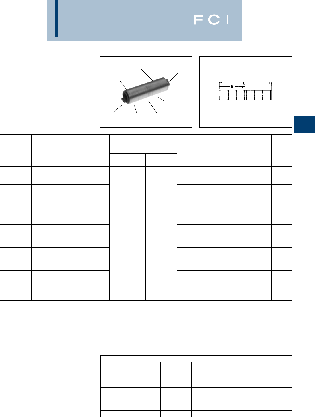
BURNDY
Compression
C-125
TYPE YS-A
(Continued)
HYLINK™
UNINSULATED ALUMINUM
COMPRESSION SPLICE
UL Listed 90° C,
600 Volts to 35 KV◆
▲See tooling section of this catalog for complete tool and
die listings.
‡UL Listed for Aluminum only. Not CSA certified.
*Use PUADP-1 adaptor with "U" dies in Y46 HYPRESS™.
** P39ART and P44ART for use with Y46 HYPRESS™ only.
PUADP-1 adapter not required.
Y644HS DIELESS HYPRESS™
RANGE-TAKING
CAPABILITIES
The following size HYDENT™ lugs and two
way splices, when crimped with the Y644HS
DIELESS HYPRESS™ tool, produce the
following range-taking capabilities:
DIE AND COLOR
CODE INFORMATION
ELECTRO-TIN
PLATED
BELLED
END
CRIMP
(4) CENTER
WIRE STOP
CRIMP
BELLED
END
ALUMINUM CONNECTORS
STANDARD EXPANDED STANDARD EXPANDED STANDARD EXPANDED
WIRE SIZE WIRE RANGE WIRE SIZE WIRE RANGE WIRE SIZE WIRE RANGE
#6 AWG #6 AWG 1/0 AWG 1/0 - #1 AWG 250 kcmil 250 kcmil - 1/0 AWG
#4 AWG #4 - #6 AWG 2/0 AWG 2/0 - #1 AWG 300 kcmil 300 kcmil - 2/0 AWG
#2 AWG #2 - #6 AWG 3/0 AWG 3/0 - #1 AWG 350 kcmil 350 kcmil - 3/0 AWG
#1 AWG #1 - #2 AWG 4/0 AWG 4/0 - #1 AWG 400 kcmil 400 kcmil - 4/0 AWG
500 kcmil 500 kcmil - 4/0 AWG
600 kcmil 600 - 250 kcmil
750 kcmil 750 - 500 kcmil
■The largest size for the Y35 is 400 kcmil.
*** Y60BHU only.
90° C Rated.
•Also accommodates compressed and compact conductors.
(Except 700 kcmil in 750 kcmil barrel)
Installation Tooling ▲
Y35, ■Y39, Y750, Y46*, Y60BHU
Dieless (# of crimps/end) Die Number Die Index & Wire
Catalog Code Dimensions Mechanical Hydraulic (# of crimps Color Embossment Strip
Number Conductor B L HYTOOL HYPRESS per end) Code ▲Length
YS26A1 2/0 str. 1.18 2.61 U26ART (2) Olive 297 1-3/8”
YS27A1 3/0 str. 1.31 2.88 Y644HS (1) U27ART (2) Ruby 467 1-1/2”
YS28A1 4/0 str. 1.40 3.06 MY29-3 (2) Y81KFT (2) U28ART (2) White 298 1-5/8”
YS29A1 250 kcmil 1.46 3.18 Y81KFTMBH (2) U29ART (2) Red 324 1-5/8”
YS30A1 300 kcmil 1.47 3.20
PAT81KFT-18V (2)
U30ART (2) Blue 470 1-3/4”
Y644HS (1)
Y81KFT (3)
YS31A1 350 kcmil 1.89 4.04 Y81KFTMBH (3) U31ART (2) Brown 299 2-1/8”
PAT81KFT-18V (3)
YS32A1 400 kcmil 2.30 4.86 U32ART (4) Green 472 2-1/2”
YS34A1 500 kcmil 2.38 5.00 U34ART (4) Pink 300 2-5/8”
YS36A1 600 kcmil 2.44 5.14 Y644HS (1) U36ART (4) Black 473 2-7/8”
700/750 Y81KFT (4)
YS39A1* kcmil 2.50 5.26 Y81KFTMBH (4) U39ART-2 (4) Yellow 936 2-7/8”
700/750
PAT81KFT-18V (4)
YS39AM1* kcmil 2.63 5.58 P39ART** (4) Red 301 2-7/8”
YS44A1 1000 kcmil 2.84 5.94 —P44ART** (4) Brown 302 3”
YS45A1 1250 kcmil 2.84 6.21 P48PR1/L44ART** Brown 302 2-7/8”
YS46A1 1500 kcmil 3.40 7.05 L46ART*** Blue 478 3-3/8”
YS47A1 1750 kcmil 3.99 8.31 L47ART*** White 587 4”
YS48A1 2000 kcmil 3.66 7.58 —L48ART*** Red 479 3-5/8”
2250 kcmil
YS483A1 ALUMINUM ONLY 3.66 7.58 L48ART*** Red 479 3-5/8”
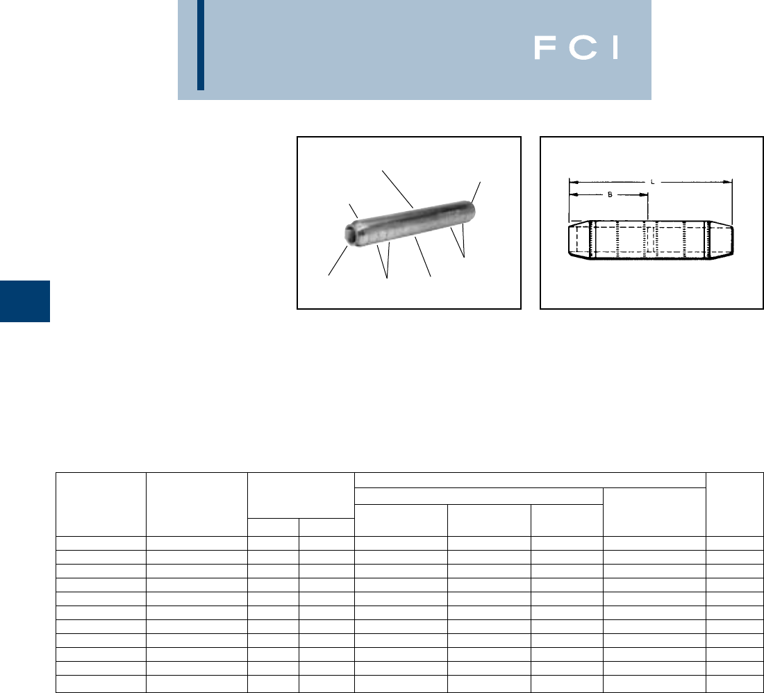
BURNDY
Compression
C-126
TYPE YS-AT
HIGH VOLTAGE
UNINSULATED
ALUMINUM
COMPRESSION SPLICE
Type YS-AT is a high-conductivity aluminum
electro-tin plated compression butt splice with
tapered ends for high voltage applications up
to 35 KV.
The YS-AT provides the same benefits as the
YS-A with the addition of tapered ends for
easy installation of high voltage insulating
kits. Tapered ends aid in preventing corona
emission and insulation breakdown.
Recommended for high voltage splice
applications.
Features and Benefits
•Tapered ends for applications
through 35KV.
◊Permits easy taping and aids in
preventing corona emission and
insulation breakdown.
•Heavy wall aluminum tubing.
◊For use with combinations of AL-AL,
AL-CU, CU-CU
†Contact BURNDY®for conductor sizes not shown.
*Use PUADP-1 adapter for "U" dies.
** P39ART and P44ART for use with Y46 HYPRESS™ only.
PUADP-1 adapter not required.
■The maximum size for the Y35 is 400 kcmil.
DIE AND CRIMP
INFORMATION
PRE-FILLED WITH
PENETROX
COLOR CODED
END CAPS
CENTER
STOP
CRIMPS
CRIMPS
TAPERED
END
▲See tooling section of this catalog for complete tool and
die listings.
•Also accommodates compressed and compact conductors
(except 700 kcmil in 750 kcmil barrel).
INSTALLATION TOOLING ▲
Y35, ■Y39, Y750, Y46* WIRE
CATALOG • † CODE DIMENSIONS DIE (CRIMPS COLOR DIE INDEX & STRIP
NUMBER CONDUCTOR B L NUMBER PER END) CODE EMBOSSMENT ▲LENGTH
YS2CAT 2 str. 1.58 4.00 U2CABT (2) Pink 348 2-1/4
YS25AT 1/0 str. 1.96 4.73 U25ART (2) Tan 296 2-5/8
YS26AT 2/0 str. 1.83 4.29 U26ART (3) Olive 297 2-3/8
YS27AT 3/0 str. 2.04 4.69 U27ART (3) Ruby 467 2-5/8
YS28AT 4/0 str. 2.16 5.05 U28ART (3) White 298 2-3/4
YS29AT 250 kcmil 2.29 5.37 U29ART (3) Red 324 2-7/8
YS30AT 300 kcmil 2.54 5.91 U30ART (3) Blue 470 3-1/8
YS31AT 350 kcmil 2.68 6.23 U31ART (3) Brown 299 3-3/8
YS34AT 500 kcmil 3.39 7.79 U34ART (6) Pink 300 4-1/8
YS39AT 700/750 kcmil • 3.69 8.57 P39ART** (6) Red 301 4-1/2
YS44AT 1000 kcmil 3.77 9.69 P44ART** (6) Brown 302 4-3/4
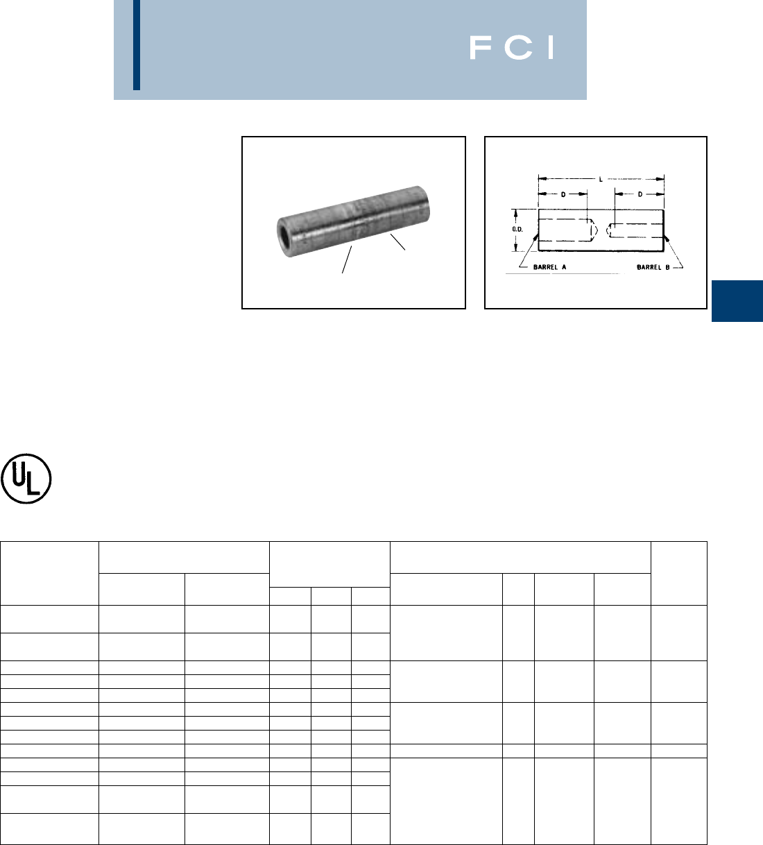
BURNDY
Compression
C-127
TYPE YRB
HYREDUCER™
FOR ALUMINUM TO COPPER
AND ALUMINUM TO
ALUMINUM
UL Listed 90° C,
600 Volts to 35 KV◆
HYREDUCER™ type YRB reducer butt splice
is designed to splice two different conductor
sizes and is UL listed for aluminum to copper
and aluminum to aluminum applications. The
outside diameter is held constant to minimize
installation dies and is factory prefilled with
PENETROX™.
Features and Benefits
•Constant outside diameters. Electro
tin-plated.
◊Minimizes installation dies and provides
a smooth profile for easy taping.
Provides durable long lasting
corrosion resistance.
•Factory prefilled with BURNDY's
PENETROX™ oxide inhibiting compound.
◊Contains Homogeneously suspended
conductive metallic particles which pene-
trate oxides between conductor strands
and forms an air tight connection.
CRIMP
CRIMP
•Solid center barrier.
◊Provides center stop for correct cable
insertion and aids the thorough penetra-
tion of PENETROX™ oxide inhibiting
compound between conductor strands.
•Connectors are clearly marked with cata-
log number, wire size, and color-coded
die index.
◊Provides clear, easy to use information
to lower installed costs.
•Each barrel end has a plastic end cap.
◊Keeps the connector barrels free of
foreign materials.
†Contact BURNDY®for conductor sizes not shown.
▲See tooling section of this catalog for complete tool and
die listings.
‡Number of crimps.
*Use PUADP-1 adaptor with "U" dies shown in Y46
HYPRESS™.
■The maximum size for the Y35 is 400 kcmil.
◆For applications greater than 2000 Volts consult cable
manufacturer for voltage stress relief instructions.
•Also accommodates compressed and compact conductors
(except 700 kcmil in 750 kcmil barrel).
CONDUCTOR RANGE • INSTALLATION TOOLING ▲
ALUM. or CU. SIZE †HYDRAULIC TOOLS, DIE SETS (NO. OF CRIMPS ‡)WIRE
CATALOG BARREL BARREL DIMENSIONS Y35 ■,Y39, Y750 DIE ▲COLOR STRIP
NUMBER A B O.D. B L Y46* ‡ INDEX CODE LENGTH
1 str. 4 str.
YRB2U4 2 str. 3 str. .62 .88 2.00
1 str. U25ART (1) 296 Tan 1-1/16
YRB25U2 1/0 str. 2 str. .62 .88 2.00
YRB27U25 3/0 str. 1/0 str. .85 1.36 3.31
YRB27U26 3/0 str. 2/0 str. .85 1.36 3.31 U28ART (2) 298 White 1-5/8
YRB28U26 4/0 str. 2/0 str. .85 1.36 3.31
YRB29U28 250 kcmil 4/0 str. 1.11 1.73 4.21
YRB31U28 350 kcmil 4/0 str. 1.11 1.73 4.21 U31ART (2) 299 Brown 2-1/8
YRB31U29 350 kcmil 250 kcmil 1.11 1.73 4.21
YRB34U31 500 kcmil 350 kcmil 1.31 2.11 5.12 U34ART (4) 300 Pink 2-5/8
YRB36U31 600 kcmil 350 kcmil 1.46 2.25 5.57
YRB36U34 600 kcmil 500 kcmil 1.46 2.25 5.57
700 kcmil
YRB39U34 750 kcmil • 500 kcmil 1.46 2.25 5.57 U39ART-2 (4) 936 Yellow 2-7/8
700 kcmil
YRB39U36 750 kcmil • 600 kcmil 1.46 2.25 5.57
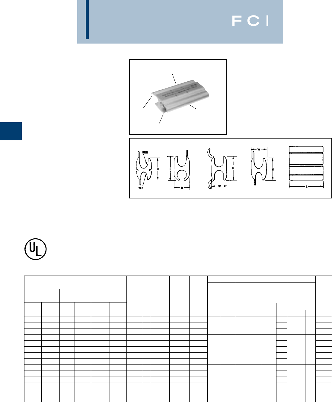
BURNDY
Compression
C-128
Features and Benefits
•Each connector is factory sealed
in polyethylene.
◊Maintains the connector free of dirt and
foreign materials prior to being used.
•When installed the connector has a
smooth profile.
◊Easy to tape or to install an insulating
crimpit cover (See Types CFA and
CFA-FR) thereby lowering installed costs.
TYPES YFD,YFN,YFO
AND YFR
H-CRIMPIT™
UNINSULATED
ALUMINUM COMPRESSION
TAP CONNECTOR
FOR ALUMINUM TO
COPPER AND ALUMINUM
TO ALUMINUM
UL Listed 90° C,
600 Volts to 35 kV◆
H-CRIMPIT™ compression tap connectors
Types YFD, YFN, YFO and YFR are for use
with aluminum to aluminum and aluminum to
copper connections.
The H-CRIMPIT™ is ideal for making both
parallel and tap compression connections in
risers and gutters. It should only be installed
with hydraulic tools.
▲See tooling section of this catalog for complete tool and
die listings.
†Do not use U-YFN die set with P-UADP-1 adapter in Y46
HYPRESS™. Use P-YFN only.
◆For applications greater than 2000 Volts consult cable
manufacturer for voltage stress relief instructions.
*CSA listed.
NOTES:
1. Material: Aluminum.
➁For Conductor combinations of AL to AL or AL to CU.
➂Catalog Number PUADP-1-Adaptor is required to use "U"
type dies in Y46 tools.
➃Other conductors not listed in table can be accommodated
as long as the conductor diameter falls within diameter
range specified.
DIE AND COLOR CODE
AND CRIMP INFORMATION
ELECTRO-TIN
PLATED
CRIMP
PRE-FILLED WITH
PENETROX
Fig. 1 Fig. 2 Fig. 3 Fig. 4
INSTALLATION TOOLING ▲
ACCOMODATES
➁
DIELESS TOOLS
COPPER OR ▲HYDRAULIC TOOLS, DIE ADAPTOR, WIRE
ALUMINUM COMPACT
➃
DIA. RANGE CAT. FIG. DIE COLOR DIE SETS (NO. OF CRIMPS) (NO. OF CRIMPS) STRIP
RUNTAP RUN TAP RUN TAP NO. NO. HEIGHT LENGTH WIDTH INDEX CODE Y750, Y35, Y39 Y46
➂
( ) Y644M, Y644MBH LENGTH
1/0-6 STR 1-6 STR 2/0-6 1-6 STR .398-.162 .332-.162 YFO-140* 11.15 (29.2) 1.62 (41.1) .70 (17.8) 0 Green UYFO, U-O (2) PT30541 (1) 1-7/8”
4/0-1 STR 1-6 STR 250-1/0 1-6 STR .563-.338 .332-.162 YFD-265* 11.47 (37.3) 1.88 (47.8) .89 (22.6) (2) 1-1/8”
4/0-1 STR 2/0-1 STR 250-1/0 3/0-1/0 .563-.338 .477-.338 YFD-365* 11.42 (36.1) 2.50 (63.5) .89 (22.6) D3 Blue U-D3 (3) PT30540 (2) 2-3/4”
4/0-3/0 STR 4/0-3/0 STR
250-3/0 250-3/0 .563-.426 .563-.426 YFD-415* 11.40 (35.6) 2.50 (63.5) .89 (22.6) U-YFD (3) 2-3/4”
400-4/0 400-4/0 500-250 500-250 .750-.522 .750-.522 YFN-465 41.86 (47.2) 3.50 (89) 1.25 (31.8) (3) 3-3/4”
500-4/0 2/0-6 STR 500-250
3/0-6 STR
.815-.522 .450-.160 YFN-515 41.96 (50) 2.00 (51) 1.28 (32.5) P-N (2) 2-1/4”
500-4/0 500-4/0 500-250 500-250 .815-.522 .815-.522 YFN-540 31.82 (46.2) 4.50 (114.3) 1.23 (31.2) N Red U-N P-YFN (3) — — 4-7/8”
500-250
4/0-2/0 STR
500-300 250-3/0 .815-.573 .565-.410 YFN565 41.89 (48) 2.00 (51) 1.27 (32.3) U-YFN (2) 2-1/4”
500-250 350-250 500-300 350-300 .815-.573 .685-.570 YFN-615 41.99 (50.5) 3.50 (88.9) 1.28 (32.5) (3) 3-3/4”
600-350 350-2/0 600-400 350-300 .893-.659 .684-.398 YFR-715 43.04 (77.2) 3.50 (88.9) 1.74 (44.2) (3) 3-3/4”
600-350 600-350 600-400 600-400 893-.659 893-.659 YFR-765 43.04 (77.2) 4.62 (117.3) 1.74 (44.2) (4) 5”
900-600 350-2/0 900-700 350-3/0 1.108-.877 .685-.398 YFR-815 43.05 (77.5) 3.50 (88.9) 1.74 (44.2) Yellow P-KR (3) ——
3-3/4”
900-600 600-350 900-700 600-400 1.108-.877 .893-.659 YFR-865 43.04 (77.2) 4.62 (117.3) 1.74 (44.2) KR ——P-YFR (4) 5”
900-600 900-600 900-700 900-700 1.108-.877 1.108-.877 YFR-915 42.97 (75.4) 4.62 (117.3) 1.74 (44.2) (4) — — 5”
1000-350 1000-350 1000-400 1000-400
1.165-.659 1.165-.659 YFR-965 33.12 (80) 6.00 (152.4) 1.67 (42.4) (5) — — 6-1/4”
•Connectors are color-coded to match
installation die.
◊Easy die selections lower installed cost.
•UL 486B Listed.
◊Provides a quality electrical connection.
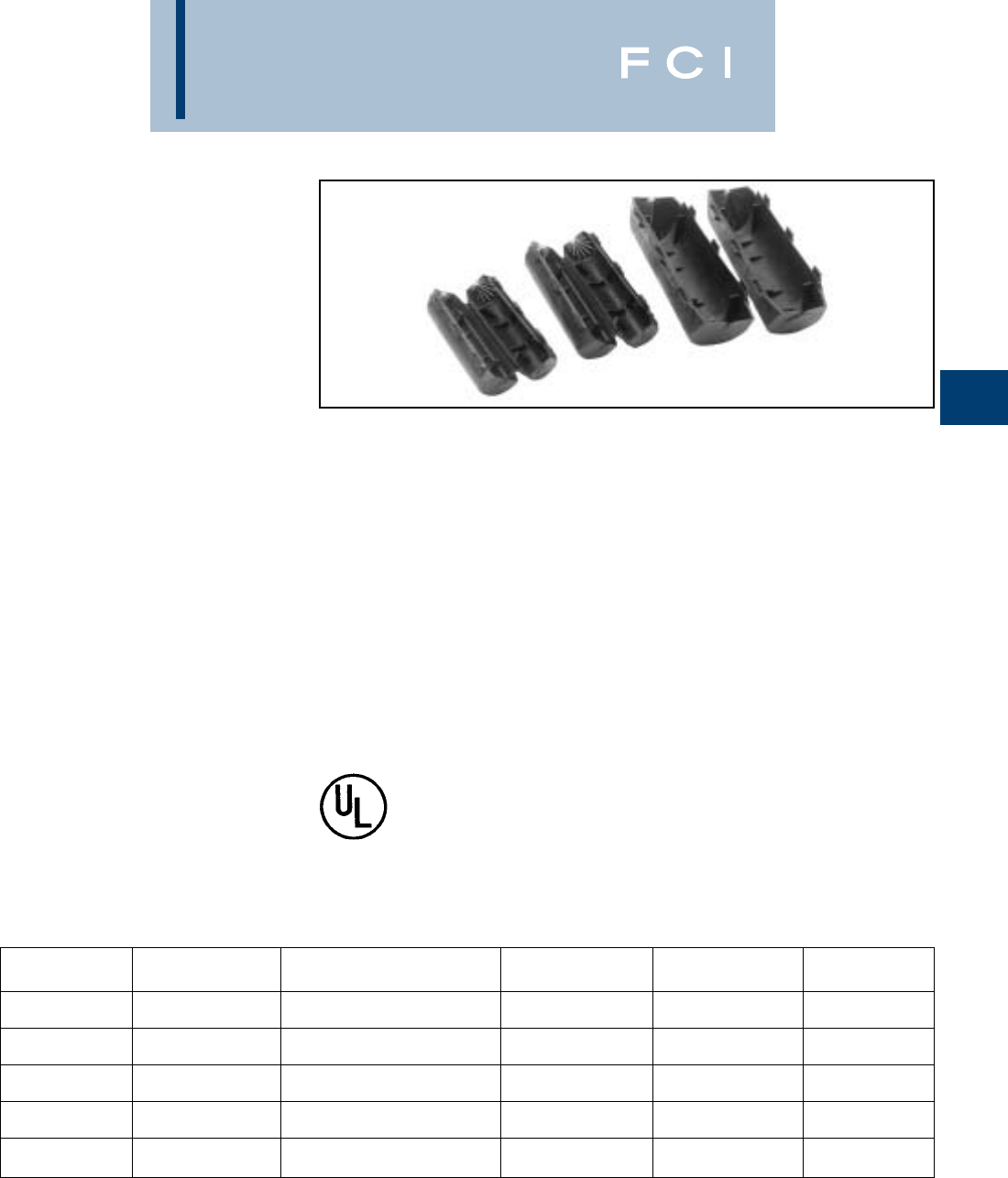
BURNDY
Compression
C-129
TYPES CFA AND
CFA-FR
H-CRIMPIT™
INSULATING COVERS
H-CRIMPIT™ FLAME
RETARDANT INSULATING
COVERS
FOR O, D3, N, AND KR DIE
SIZE H-TAP COMPRESSION
CONNECTORS
UL Listed to 600 Volts
Type CFA insulating covers are made of high
impact, high density polyethylene to insulate
H-tap CRIMPIT™ compression connectors.
Overlapping flash barriers protect both
seams against possible electrical flashover.
End fingers remain closed or wrap closely
around conductors. Multiple latches lock
cover closed securely.
Type CFA-FR flame retardant insulating cov-
ers are made of high impact, high density
polypropylene with a minimum 28 oxygen
index.This cover incorporates all the features
of the CF design plus the benefit of self-
extinguishing flame retardant properties.
Material is UL 94V-O rated.
Both CFA and CFA-FR types are suitable for
indoor and outdoor use. Pliable in cool
weather application.
600 VOLTS 90° C
Features and Benefits
•One-piece design.
◊No extra parts or hardware required.
•Slips over connector and latches
securely shut.
◊Fast, easy, reliable insulation of
H-Tap compression connectors.
•Eliminates taping.
◊Economical, fast, easy installation.
•Flash barriers.
◊Protects against electrical flashover.
•CFA-FR flame retardant design.
Minimum 28 oxygen index.
UL 94 V-O rated.
◊Self-extinguishing flame retardant
properties.
*Two piece design packaged together.
CATALOG MAX. CONDUCTOR INSULATED H-TAP MAX. CONNECTOR CONNECTOR CONNNECTOR
NUMBER ACCOMMODATED CRIMPIT™ CONNECTORS LENGTH DIE INDEX COLOR CODE
CFAO
CFAO-FR 1/0 YFO140 2-1/2OGreen
CFAD
CFAD-FR 4/0 YFD265, YFD365,YFD415 3-1/8DBlue
CFAN N-Short
CFAN-FR 500 kcmil YFN515, YFN565 2-1/2
Connector Red
CFANL N-Long
CFANL-FR 500 kcmil YFN465, YFN540, YFN615 5-1/2
Connector Red
CFAR *YFR715, YFR765, YFR815, YFR865
CFAR-FR *900 kcmil YFR915 4-7/8KR Yellow

BURNDY
Grounding
D-1
TABLE OF CONTENTS
HYGROUND™ IRREVERSIBLE COMPRESSION GROUNDING
AND INSTALLATION TOOLING
Type YGIB .....................D-20 - D-21
Type GSTUD-HY .......................D-22
Types YGT & YTTAG ................D-23
Type YG-B..................................D-24
MECHANICAL GROUNDING
Types KC, K2C .........................D-25
Types KC22J12T13,
EQC632C, KS-DB ..................D-26
Types KS-DB, GKA,
KPB, CL50-1............................D-27
Type GAR ......................D-28 - D-29
Types GAR-BU & GAR
3900 Series & GAR-RB .........D-30
Type GAR-TC ...........................D-31
HYGROUND™ Features
and Benefits ...................D-5 - D-6
Type YGL-C ................................D-7
Type YGLR-C ..............................D-8
Type YGHP-C .............................D-9
Type YGHP-C ...........................D-10
Type YGHC-C ...........................D-11
Type YGC ..................................D-12
Type YSHG ................................D-13
Type YGHR-C .......................... D-14
Type YGHR-C ..........................D-15
Type YGHA ...............................D-16
Type YGHS ...............................D-16
Type YGA ..................................D-17
Type YGS ..................................D-18
Type YGF ..................................D-19
LIGHTNING PROTECTION INFO.
Basic rules for selection are:
1. Must be like material to the conductor.
2. Two bolts to ground rod –– minimum, for mechanical.
3. Cable to cable connections can be installed with – one bolt,
two bolt, or compression.
4. Cable to steel structure must have 8 in.2contact with steel.
5. Heavy duty stacks –– mechanical only.
6. On all connectors with heavy duty stack rating, we must
offer 1/16thick lead plating as an option. Reason is closest
25 ft. to stack opening must use lead coated product.
7. UL 96 Listing.
BURNDY
Grounding
D-2
TABLE OF CONTENTS
MECHANICAL GROUNDING (Continued)
Types GC, GCM ........................D-46
Type GL ....................................D-47
Type GZ ....................................D-47
Type GC-CT ..............................D-48
Type GIE-G ...............................D-49
Rail Connector ..........................D-50
Type QGFL ...............................D-51
Type GA-H ................................D-51
Type GRF ..................................D-52
Raised Floor Grounding
Types GP-G1, GPRT..................D-53
Raised Floor Grounding
Type GD ....................................D-32
Type GP ....................................D-33
Type GK ....................................D-33
Water Pipe Grounding ..D-34 - D-39
Type GC-A ................................D-40
Type GG ....................................D-41
Type GQ ....................................D-42
Type GX ....................................D-43
Type GRC .................................D-43
Type B............................D-44 - D-45
Types GB, GBM ........................D-46
BURNDY
Grounding
D-3
TABLE OF CONTENTS
BURNDYWeld™
BURNDY Weld™
Introduction ................................D-55
Making a BURNDYWeld™
Connection ..........................D-56
WELD METAL ..........................D-57
Type BCC-1 ..............................D-58
Type BCC-2 ..............................D-59
Type BCC-4 ..............................D-60
Type BCC-11 ............................D-61
Type BCC-6 ..............................D-62
Type BCC-14 ............................D-62
Type BCC-7 ..............................D-63
Type BCR-1................................D-64
Type BCR-2 ............................. D-65
Type BCR-3 .............................D-66
Type BCR-17 ............................D-67
Type BCR-24 ............................D-68
Type BCS-1 ...............................D-70
Type BCS-8 ...............................D-70
Type BCS-2 ...............................D-71
Type BCS-9 ...............................D-71
Type BCS-3 ...............................D-72
Type BCS-23 .............................D-73
Type BCS-4 ...............................D-74
Type BCS-6 ...............................D-74
Type BCS-7................................D-75
Type BCS-18 .............................D-75
Type BCS-5 ...............................D-76
Type BCRE-1 ............................D-77
Type BCRE-2 ............................D-78
BURNDY
Grounding
D-4
TABLE OF CONTENTS
BURNDYWeld™ (Continued)
Type BCRE-3 ............................D-79
Type BCRE-4 ............................D-80
Type BCRE-6 ............................D-81
BURNDYWeld™ FILL ..............D-82
BURNDYWeld™ SET ...............D-84
BURNDYWeld™ Prefabricated
Wire Mesh .............................D-86
Types B-106 & B-107
Handle Clamps .....................D-88
B40-0106-75
Handle Attachment ...............D-88
Mold Support Clamp .................D-88
Vertical Magnetic
Clamps ..................................D-89
Horizontal & Vertical
Chain Clamps .......................D-89
SINGLE SHOT MOLDS
Type BCR-1 ..............................D-69
Type BCR-2 ..............................D-69
Type BCR-24 ............................D-69
Type BCR-25 ............................D-69
ACCESSORIES
B38-0330-00 Cable Clamp .......D-90
Cable Cleaning Brush ...............D-90
Card Cloth Brush ......................D-90
Mold Cleaning Brush ................D-90
Mold Cleaners ...........................D-90
Packing Material ........................D-90
BURNDYWeld™ Tool Kit ..........D-91
BURNDYWeld™ Tools ..............D-91
B38-0101-00 Rasp ....................D-91
B38-0309-00 Flint Ignitor ..........D-91
Ground Rod
Driving Sleeves .....................D-92
Shim Stock and
Adapter Sleeves ....................D-92
Tips..................................D-93 - D94
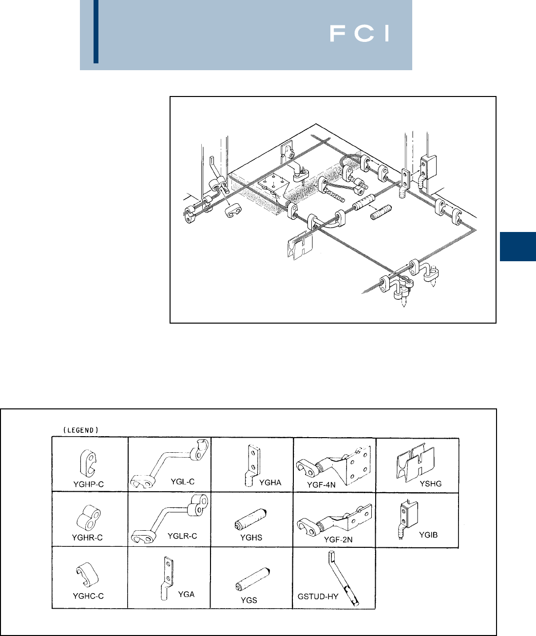
BURNDY
Grounding
THE HYGROUND™
IRREVERSIBLE
COMPRESSION
SYSTEM
BURNDY®has developed an irreversible
compression ground system which meets the
most stringent safety and performance
requirements, including those of OSHA and
nuclear power plant design. Performance
excellence and long life expectancy are the
system’s basic design guidelines. It is a com-
plete system which consists of connectors for
grid cross connections, taps, splices, cable to
ground rod, ground plates and terminations.
Our irreversible compression ground connec-
tors employ well-proven design principles
and technology that have been in existence
for over 60 years.
Connectors are just one component of our
Irreversible Compression Ground System.
Installation tooling is also an integral part of
this system. BURNDY®pioneered the com-
pression connector principle and continues
today to be the leader in compression tech-
nology. Our tooling package is the most
extensive in the industry and affords the user
many options.
D-5

BURNDY
Grounding
THE HYGROUND™
IRREVERSIBLE
COMPRESSION
SYSTEM
(Continued)
D-6
Features and Benefits
•Irreversible compression.
◊Meets 1999 NEC code, section 250-50
and 250-64.
•Material-pure wrought copper extrusions,
rod and seamless tubing––identical
material to the conductor.
◊Completely eliminates the possibility of
corrosion due to dissimilar metals.
•Heavy duty connector design.
◊All connectors will carry the equivalent
or greater current carrying capacity
of the conductor while maintaining
high mechanical strength and
electrical integrity.
•Range taking design––minimum number of
connector combinations required to install
a conductor range of #6 solid to 500 kcmil
plus 1/2, 5/8, 3/4, and 1ground rods
and rebar.
◊Inventories are kept to a minimum and
product selection is simplified.
•System engineered tooling.
◊Each tooling recommendation has
been designed to ensure reliability
of the connection.
•Irreversible compression connectors
can be installed in all kinds of weather.
◊Eliminates costly construction delays
and enables the installer to better
schedule his job.
•May be installed without special training
or special tools.Y750 crimps entire range.
◊Low installed cost.
Simplified installation.
•Each connection can be made in less than
3 minutes.
◊Low installed cost.
Simplified installation.
•Each connector is clearly marked with
catalog number, conductor size and
installation die information.
◊Easy and accurate identification.
•Inspection ports are provided to assure
proper insertion of the conductor.
◊Built-in quality assurance.
•The die index number is embossed on the
connector after completion of the crimp.
◊Facilitates speedy inspection of installed
connectors to insure consistently reliable
and sound connections.
•Most HYGROUND™ irreversible compres-
sion elements are prefilled with
PENETROX™ and individually sealed
in clear polyethylene sheet.
◊Ensures that all contact surfaces are in
the proper condition for installation.
◊Ensures the electrical integrity of the
finished connection by inhibiting moisture
and contaminates from entering the
contact area.
•All HYGROUND™ irreversible compres-
sion connectors are Listed in conformance
with Underwriters Laboratories Standard
UL467 and conform to applicable sections
of the National Electrical Code.
◊May be used in direct burial or concrete
embedded grounding applications.
•All HYGROUND™ irreversible connectors
(with the exception of type YGA and YGS)
have been tested successfully according
to requirements of Standard IEEE 837
latest revision.
◊Meets tough industry performance
requirements.
◊UPRECRIMP™ dies give added
mechanical strength. UPRECRIMP™ 34
for 3/4rod, UPRECRIMP™ 12 for 1/2
rod, and UPRECRIMP™ 58 for 5/8rod
(now includes undersized U.S. market
place rods).
•Allows connection to most sizes of
structural steel with no drilling, tapping,
or welding.
◊Safely installed at low cost. Hot work per-
mits are not required to install in
hazardous areas
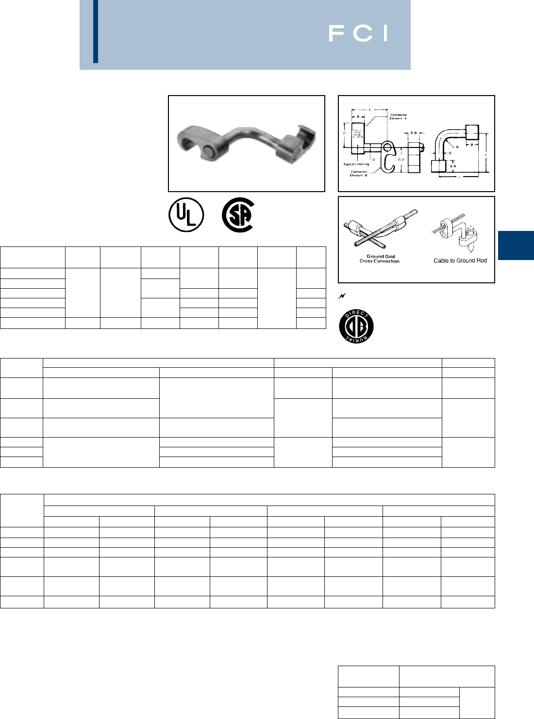
BURNDY
Grounding
D-7
TYPE YGL-C
HYGRID CROSS CONNECTOR
An irreversable compression ground grid
cross connector which allows adjustment of
the compression elements prior to installa-
tion. Only six connectors and four dies are
required to install all combinations from #6
solid through 500 kcmil. UL467 Listed.
Acceptable for direct burial in earth and con-
crete. Prefilled with PENETROX™ compound
and strip sealed.
NOTES:
•Before crimping, both connector elements can
be turned on rod diameter "D" to any desired
position.
• Clean rust and/or protective coatings from rebar
prior to installation.
•When attaching connector to ground rod, ground
rod must be embossed with appropriate PRE-
CRIMP™ die. For connections that must meet
IEEE 837 requirements UPRECRIMP™ - type
PRE crimp dies must be used for maximum
clamping retention.
ORDERING INFORMATION
1.Where a "U" or "PU" die is recommended with Y45
HYPRESS™, a PT6515 adapter must be used.
2. Where a "U" or "PU" die is recommended with the Y46
HYPRESS™, a PUADP-1 adapter must be used.
➂Polarized die for the PAT750-18V.
UL96 Listed for Lightning Protection.
467 96
CATALOG CABLE TO CABLE CABLE TO GROUND ROD TO REBAR
NUMBER ELEMENT “A” ELEMENT “B” ELEMENT “A” ELEMENT “B” ELEMENT “A”
YGL2C2 #6 SOL. (.162) – #2 STR. (.292)
{59500} – {59500} #6 SOL. (.162) – #2 STR. (.292)
YGL29C2 #1 STR. (.332) – 250 kcmil (.575) {59500} – {59500} #6 SOL. (.162) – #2 STR. (.292) 3/8"– 1/2"
{98500} – {131500} 1/2"– 5/8"Rod
YGL29C29 #2 STR. (.292) – 250 kcmil (.575) #2 STR. (.292) – 250 kcmil (.575) #2 STR. (.292) – 250 kcmil (.575) #3 – 4 Rebar
{65500} – {131500} {65500} – {131500}
YGL34C2 #6 SOL. (.162) – #2 STR. (.292) #6 SOL. (.162) – #2 STR. (.292) 5/8"– 3/4"
YGL34C29 250 kcmil (.575) – 500 kcmil (.813) #2 STR. (.292) – 250 kcmil (.575) 5/8"– 3/4"Rod #2 STR. (.292) – 250 kcmil (.575)
YGL34C34 250 kcmil (.575) – 500 kcmil (.813) 250 kcmil (.575) – 500 kcmil (.813) #5 – 6 Rebar
Dimensions in brackets { } represent lightning
protection conductors.
*These connectors can only be installed using the Y750,
Y45, or Y46 HYPRESS™ with the recommended dies.
These connectors CANNOT be installed with the Y35 and
Y39 HYPRESS™.
INSTALLATION TOOLS, DIE SET CAT. NO. (NUMBER OF CRIMPS)
CATALOG Y750/Y35/Y39 HYPRESS PAT750-18V Y45 HYPRESS Y46 HYPRESS
NUMBER ELEMENT “A” ELEMENT “B” ELEMENT “A” ELEMENT “B” ELEMENT “A” ELEMENT “B” ELEMENT “A” ELEMENT “B”
YGL2C2 U-0 (1) U-0 (1) U-0 (1) U-0 (1) U-0 (1) U-0 (1) U-0 (1) U-0 (1)
YGL29C2 U997 (1) U-0 (1) ➂ U997P (1) U-0 (1) U997 (1) U-0 (1) U997 (1) U-0 (1)
YGL29C29 U997 (1) U997 (1) ➂ U997P (1) ➂ U997P (1) U997 (1) U997 (1) U997 (1) U997 (1)
S998 or P998 or
YGL34C2* PU998 (1) U-0 (1) PU998 (1) U-0 (1) PU998 (1) U-0 (1) PU998 (1) U-0 (1)
S998 or PU998 or
YGL34C29* PU998 (1) U997 (1) PU998 (1) ➂ U997P (1) PU998 (1) U997 (1) PU998 (1) U997 (1)
YGL34C34* U1011 (3) U1011 (3) U1011 (3) U1011 (3) S1011 (3) S1011 (3) P1011 (3) P1011 (3)
CATALOG
NUMBER B B-B C C-C D L R
YGL2C2 1.09
YGL29C2 1.09 .313 .31
YGL29C29 .75 .75 1.66 1.66 .500 .50
YGL34C2 1.09 .313 2.50 .31
YGL34C29 2.09 1.66 .500 .50
YGL34C34 1.10 1.10 2.28 2.28 .750 .75
GROUND ROD
DIA. PRECRIMP DIES
1/2UPRECRIMP 12
5/8UPRECRIMP 58 U2CABT
3/4UPRECRIMP 34
MEETS ALL
IEEE
837 REQUIREMENTS
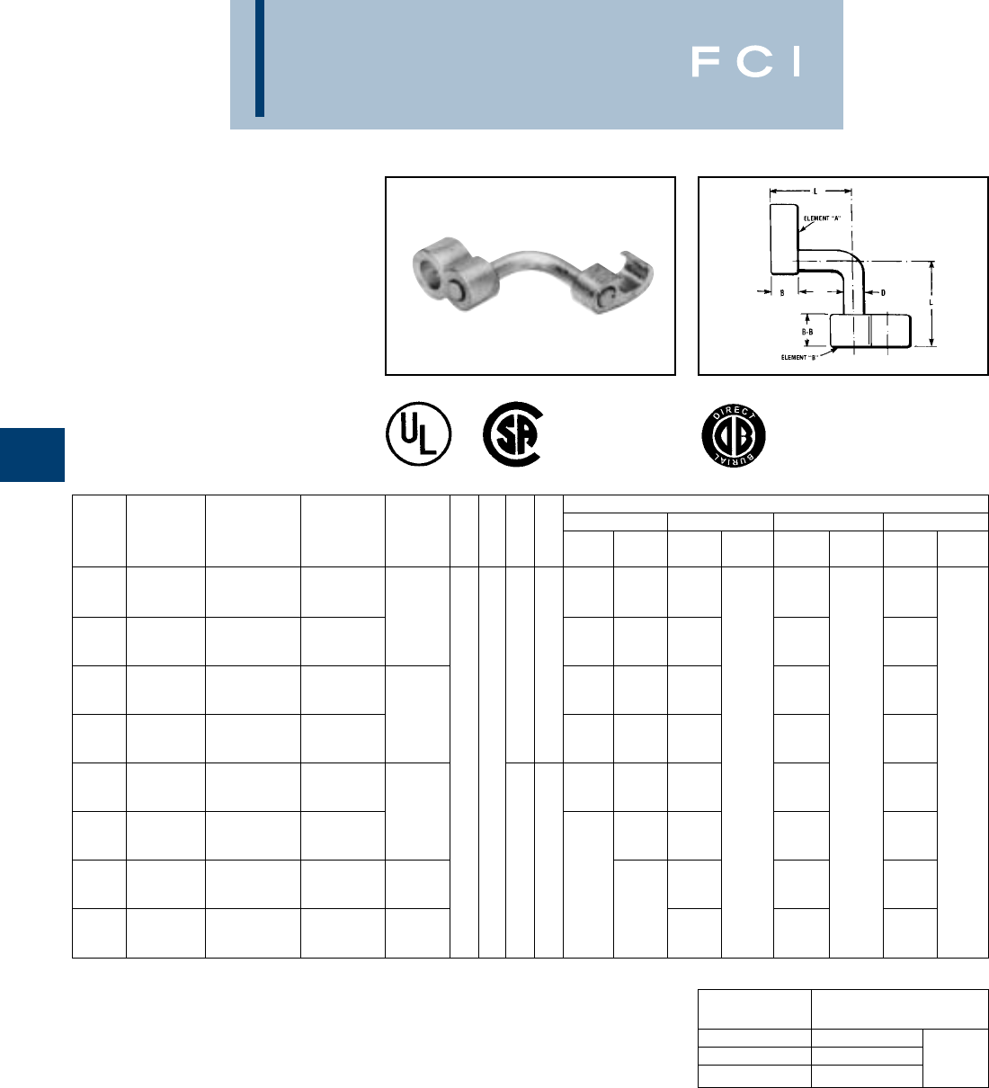
BURNDY
Grounding
TYPE YGLR-C
GRIDLOK
High Strength
Irreversible
Compression Ground Rod to
Grid Connector
Ground grid connector for a wide range of
copper cable to ground rod. Provides high
torque strength on ground rod. UL467
Listed. Acceptable for direct burial in earth
and concrete. Prefilled with PENETROX™
compound and strip sealed.
D-8
When attaching connector to ground rod, ground
rod must be embossed with appropriate PRE-
CRIMP™ die. For connections that must meet IEEE
837 requirements UPRECRIMP™ - type PRE crimp
dies must be used for maximum clamping retention.
NOTES:
1. Before crimping, both connector elements can be
turned on rod diameter 'D' to any desired position.
2. Grooves are filled with PENETROX™.
3. Suitable for direct burial in earth or concrete.
4. The catalog numbers shown are for unplated
copper connectors for use on copper clad or
stainless steel ground rod. To order electro-tin
plated connectors for use on galvanized steel
ground rod add suffix "TN" to the catalog number,
only if the Figure 8 connector (Element “B”) is tin
plated, the Figure 6 connector (Element “A”) is
unplated. Note: The ground rod hole diameter is
larger for galvanized steel ground rod in the tin
plated connector.
Element B
Element A
5. Ground rod must be pre-crimped with die
U2CABT (Index No. 348) when crimping the
ground rod element (Element “B”) with the PU998
dies in the Y750, Y35, Y39, Y45, or Y46 tools. Pre-
crimping is not required when the S1012, P1011
or U1011 dies are used. See precrimp die chart.
6. Where a 'U' or 'PU' die is recommended with the
Y45 HYPRESS™, a PT6515 adapter must be
used.
7. Where a 'U' or 'PU' die is recommended with the
Y46 HYPRESS™, a PUADP-1 adapter must be
used.
8. Dimensions in bracket [ ] are in millimeters.
9. Die "1011" appears on Element "B" of the
connector only.
GROUND ROD
DIA. PRECRIMP DIES
1/2UPRECRIMP 12
5/8UPRECRIMP 58 U2CABT
3/4UPRECRIMP 34
COMMERCIAL INSTALLATION TOOLS, DIE SET CAT. NO., (NUMBER OF CRIMPS)
COPPER METRIC COPPER COPPER WELD GROUND ROD Y35/Y39 HYPRESS™ Y750/PAT750 Y45 HYPRESS™ Y46 HYPRESS™
CATALOG CABLE RANGE CABLE RANGE CABLE RANGE DIA. ELEMENT ELEMENT ELEMENT ELEMENT ELEMENT ELEMENT ELEMENT ELEMENT
NUMBER ELEMENT “A” ELEMENT “A” ELEMENT “A” ELEMENT “B” B B-B D L “A” “B” “A” “B” “A” “B” “A” “B”
#2 Str. (.292 Dia.) 35mm2(7.62mm Dia.) 91.65 kcmil (.343 Dia.)
YGLR29C12 thru thru thru U997 (1) PU998 (1) U997 (1) U997 (1) U997 (1)
250 kcmil (.575 Dia.) 120 mm2(14.40mm Dia.) 248.8 kcmil (.572 Dia.) 1/2
250 kcmil (.575 Dia.) 120 mm2(14.40mm Dia.) 248.8 kcmil (.572 Dia.) [12.7] U1011 S998 P998
YGLR34C12 thru thru thru — or or or
500 kcmil (.813 Dia.) 240 mm2(20.35mm Dia.) 498.8 kcmil (.810 Dia.) .313 2.53 PU998 (1) PU998 (1) PU998 (1)
#2 Str. (.292 Dia.) 35 mm2(7.62mm Dia.) 91.65 kcmil (.343 Dia.) [7.9] [64.3]
YGLR29C58 thru thru thru U997 (1) PU998 (1) U997 (1) U997 (1) U997 (1)
250 kcmil (.575 Dia.) 120 mm2(14.40mm Dia.) 248.8 kcmil (.572 Dia.) 5/8
250 kcmil (.575 Dia.) 120 mm2(14.40mm Dia.) 248.8 kcmil (.572 Dia.) [15.9] U1011 S998 P998
YGLR34C58 thru thru thru — or U1011 (2) or S1012 (2) or P1011(2)
500 kcmil (.813 Dia.) 240 mm2(20.35mm Dia.) 498.8 kcmil (.810 Dia.) .75 .88 PU998 (1) or PU998 (1) or PU998 (1) or
#2 Str. (.292 Dia.) 35 mm2(7.62mm Dia.) 91.65 kcmil (.343 Dia.) [19.1] [22.4] PU998 (1) PU998 (1) PU998 (1)
YGLR29C34 thru thru thru U997 (1) PU998 (1) U997 (1) U997 (1) U997 (1)
250 kcmil (.575 Dia.) 120 mm2(14.40mm Dia.) 248.8 kcmil (.572 Dia.) 3/4
250 kcmil (.575 Dia.) 120 mm2(14.40mm Dia.) 248.8 kcmil (.572 Dia.) [19.1] U1011 (2) U1011 (2) U1011 (2)
YGLR34C34 thru thru thru or or or
500 kcmil (.813 Dia.) 240 mm2(20.35mm Dia.) 496.8 kcmil (.810 Dia.) .500 2.63 PU998 PU998 PU998
#2 Str. (.292 Dia.) 35 mm2(7.62mm Dia.) 91.65 kcmil (.343 Dia.) [12.7] [66.8]
YGLR29C100 thru thru thru 1
—U997 (1) U997 (1) U997 (1)
250 kcmil (.575 Dia.) 120 mm2(14.40mm Dia.) 248.8 kcmil (.572 Dia.) [25.4]
250 kcmil (.575 Dia.) 120 mm2(14.40mm Dia.) 248.8 kcmil (.572 Dia.) —U1011 (2) U1011 (2) U1011 (2)
YGLR34C100 thru thru thru 1
or or or
500 kcmil (.813 Dia.) 240 mm2(20.35mm Dia.) 498.8 kcmil (.810 Dia.) [25.4] PU998 (1) PU998 PU998
MEETS ALL
IEEE
837 REQUIREMENTS
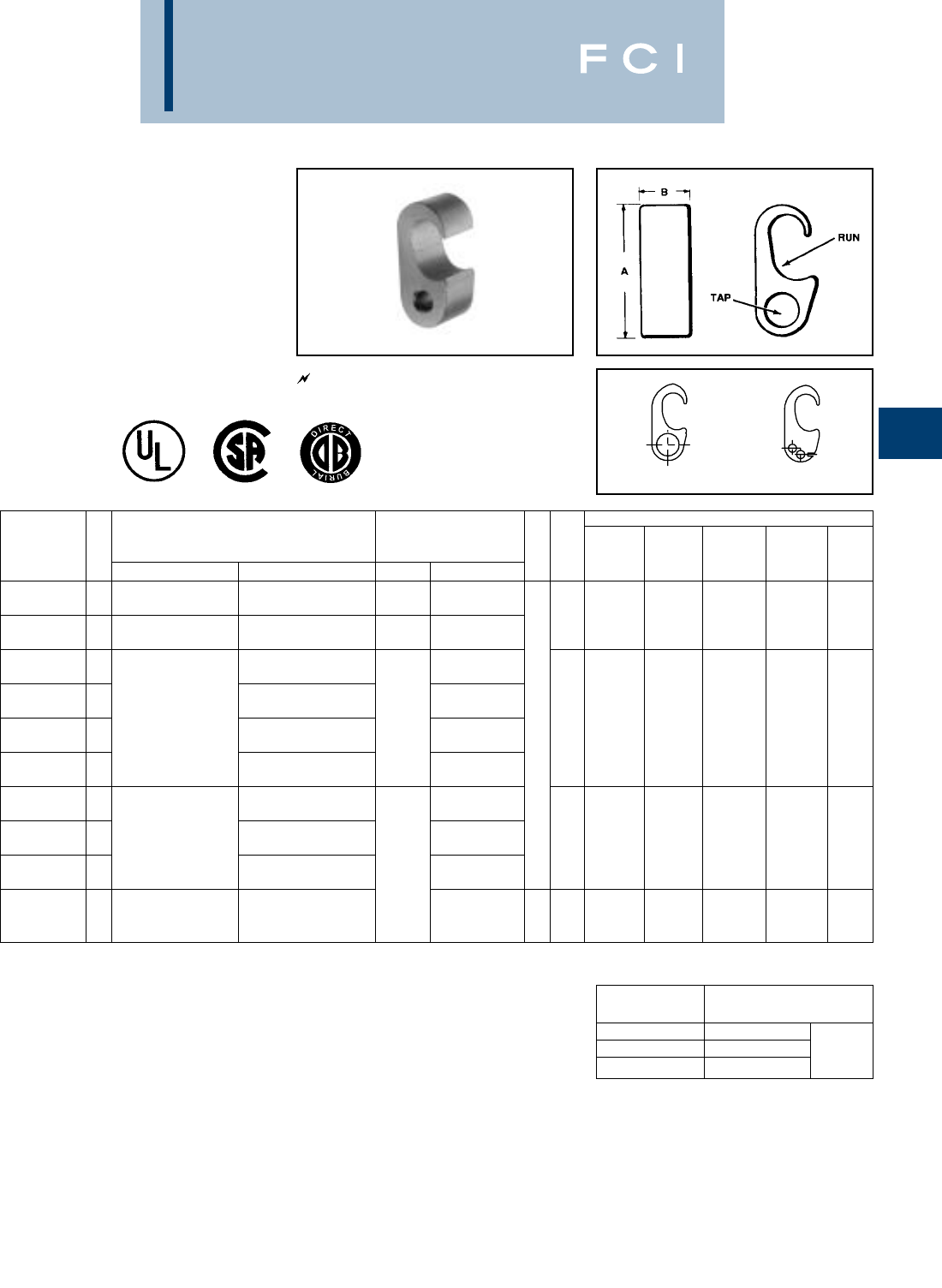
BURNDY
Grounding
D-9
TYPE YGHP-C
HYTAP™ CONNECTOR
Irreversible compression ground tap figure 6
can be used as a tap connector or as a tap
splice connector. Four die sets and eight con-
nectors can accommodate a conductor range
from #8 solid through 500 kcmil plus 1/2, 5/8,
and 3/4copper bonded ground rods. UL467
Listed. Acceptable for direct burial in earth and
concrete. Prefilled with PENETROX™
compound and strip sealed.
NOTES:
➀When using #6 Sol. in tap, fold conductor double to improve
fill in YGHP2C2.
➁For YGHP29C29 when using 3/0 in tap, minimum run
conductor is 2/0 STR.
➂Where a 'U' or 'PU' die is recommended with the Y45
HYPRESS™, a PT6515 adapter must be used.
➃Where a 'U' or 'PU' die is recommended with the Y45
HYPRESS™, a P-UADP-1 adapter must be used. For increased rotational resistance on ground rods,
pre-crimp ground rod with U2CABT die Index 348 or
uprecrimp dies may be used for even greater rota-
tion and vibration resistance on ground rods.
CABLE TO GROUND ROD
CABLE TO REBAR
CABLE TO CABLE
FOR CONCRETE ENCASED
ELECTRODE GROUNDING
APPLICATIONS
Fig. 1 Fig. 2
UL96 Listed for Lightning Protection.
INSTALLATION DATA
➄
DIE Y750/Y35
➂➃
CATALOG FIG. ACCOMMODATES CABLE TO REBAR INDEX Y39 Y45 Y46 NO. OF
NUMBER NO. RUN TAP RUN TAP B NO. HYPRESS™ PAT750-18V HYPRESS™ HYPRESS™ CRIMPS
YGHP2C2 1#6 SOL. (0.162) {59500} –
➀
#6 SOL. (0.162) {#2 STR.} – ——
#2 STR. (0.292) {59500} #2 STR. (0.292) {#2 STR.} 0U0 U0U0 U01
YGHP2C6W6W
➇
2#6 SOL. (0.162) – #8 SOL. (0.128) – ——
#2 STR. (0.292) 6 STR. (0.184) QTY. 2
YGHP29C6W6W
➇
2#8 SOL. (0.128) – #8 SOL. – 6 STR.
6 STR. (0.184) QTY. 2 #3 REBAR
YGHP29C2 11/0 STR. (0.372) {98500} – #4 SOL. (0.204) {#4 SOL.} – 3/8 #2 STR.
250 kcmil (0.575) {131500} #2 STR. (0.292) {#2 STR.} 997 U997
➆
U997P U997 U997 1
YGHP29C26 11/2"– 5/8"ROD 1/0 STR. (0.372) {98500} – THRU
1/0 STR. – 2/0 STR. .75
2/0 STR. (0.419) {98500} 1/2 [19]
YGHP29C29
➁
13/0 STR. (0.470) {131500} – #4 REBAR 3/0 STR. – 250 kcmil
250 kcmil (0.575) {211500}
YGHP34C2
➅
1#4 SOL. (0.204) – #5 REBAR —
#2 STR. (0.292) 5/8
YGHP34C26
➅
1
250 kcmil (0.575) {250 kcmil} –
1/0 STR. (0.372) {98500} – 1/0 STR. – 2/0 STR. 998 PU998 PU998 PU998 or PU998 or 1500 kcmil (0.813) {500 kcmil} 2/0 STR. (0.419) {98500} S998 P998
YGHP34C29
➅
1
5/8"– 3/4"ROD 3/0 STR. (0.470) {131500} – THRU
3/0 STR. – 250 kcmil
250 kcmil (0.575) {211500}
250 kcmil (0.575) – 350 kcmil (0.681) –
3/4
1.10
YGHP34C34
➅
1500 kcmil (0.813) #6 REBAR
350 kcmil – 500 kcmil
1011
➅
U1011 U1011 S1011 P1011 3
5/8"– 3/4"ROD 500 kcmil (0.843) [28]
Dimensions in brackets { } represent lightning protection
conductors.
467 96
➄Clean rust and protective coatings from rebar before con-
nector installation to provide a proper ground connection.
Precrimping is not required.
➅These connectors can only be installed using the Y750, Y45
or Y46 HYPRESS™ with the recommended dies. These
connectors can not be installed with the Y35 and Y39
HYPRESS™.
➆Polarized die for the PAT750-18V.
➇Not UL96/CSA.
GROUND ROD
DIA. PRECRIMP DIES
1/2UPRECRIMP 12
5/8UPRECRIMP 58 U2CABT
3/4UPRECRIMP 34
MEETS ALL
IEEE
837 REQUIREMENTS
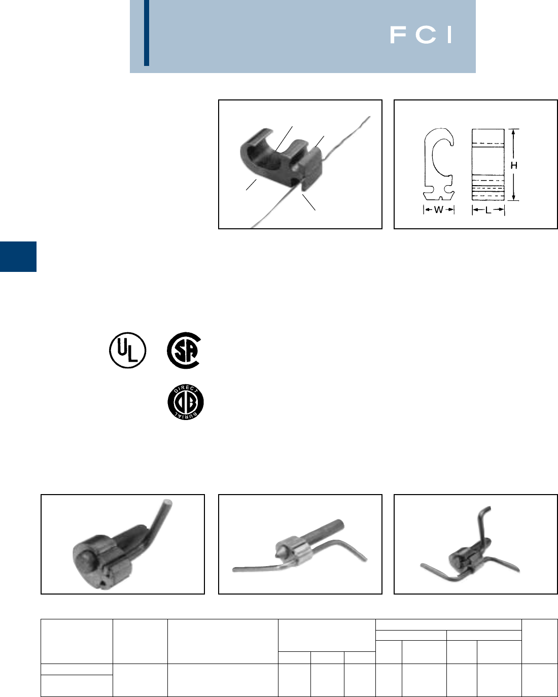
BURNDY
Grounding
D-10
TYPE YGHP-C
HYTAP™ CONNECTOR
High Strength
Copper Irreversible
Compression
Ground Rod Tap
Connector
Type YGHP-C irreversible compression
ground tap figure 6 can be used as a ground
rod tap connector for both continuous run and
tapping applications. An open groove allows
ground rod to be connected to a continuous
run or tap. The second groove is for a tap
only. Prefilled with PENETROX-E™ and strip
sealed. UL467 Listed for direct burial in earth
or concrete.
Features and Benefits
•Tap (A) accepts a continuous run on
tap conductor
Tap (B) accepts a tap conductor only.
◊One connector style can be used for
many applications, reducing number
of connectors in inventory.
•Material is high conductivity wrought
copper extrusion, identical material to
the conductor.
◊High-conductivity copper minimizes
resistance and voltage drop. Eliminates
the possibility of corrosion due to
dissimiliar metals.
•System engineered tooling.
◊The tooling recommendation has been
designed to ensure a reliable, depend-
able connection every time.
•The die index number is embossed on
conductor after completion of crimp.
◊Faciliates speedy inspection of installed
connectors to insure consistently reliable
and dependable connections.
NOTE: A 12" bend radius is recommended for the conductor.
• Use PUADP-1 with ‘U’-dies in Y46.
▲See tooling section in Master Catalog for complete tool and
die listing.
+ Either tap position may be left void when fewer than (2)
conductors are used.
SINGLE TAP CONTINUOUS RUN CONTINUOUS RUN AND TAP
PATENTED
TAP (A)
TAP (B)
PREFILLED WITH
PENETROX-E
DIE INDEX
AND CONDUCTOR
INFORMATION
“THIRD HAND”
•Prefilled with PENETROX™ and individual-
ly sealed in clear polyethylene sheet.
◊Ensures the electrical integrity of the
finished connection by inhibiting moisture
and contaminates from entering the
contact area. Maintains long-term
high-conductivity.
•UL467 Listed.
◊May be used in direct burial or concrete
embedded grounding applications.
Provides quality assurance to recognized
industry NEC standards from an
independent party.
•“Third Hand” constrains conductors while
installer completes crimp. Included with
each connector.
◊Simplifies installation, reducing
installed cost.
■Ground rod must be precrimped with die U2CABT (Index
No. 348).
For even greater rotational resistance use U-PRECRIMP
die.
For Galvanized Steel Rods order YGHP58C2W-2TN.
▲INSTALLATION TOOLING
Y35/Y750/PAT750 Y46 •
CATALOG GROUND DIMENSIONS DIE NO. OF DIE NO. OF DIE
NUMBER ROD DIA. ■TAP CONDUCTOR + H B W NO. CRIMPS NO. CRIMPS INDEX
YGHP58C2W-2 #2 Sol. - #6 Sol. Copper
1/2- 5/8(1) Continuous run and (1) Tap or 1.90.75.94U997 (1) U997 (1) 997
YGHP58C2W-2TN up to (2) taps may be connected.
MEETS ALL
IEEE
837 REQUIREMENTS
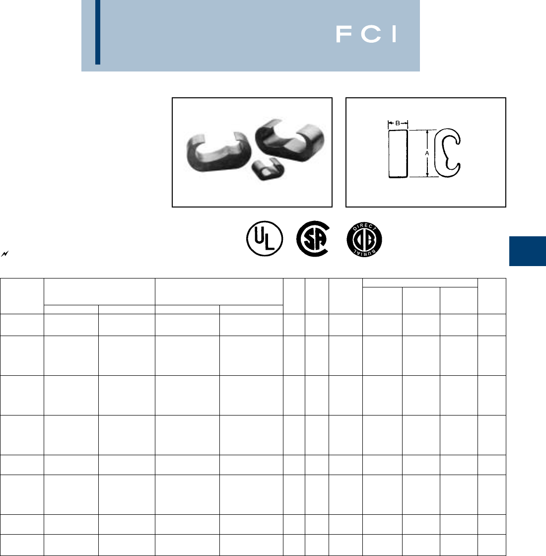
BURNDY
Grounding
D-11
TYPE YGHC-C
HYTAP™ CONNECTOR
Irreversible compression ground tap figure
"C" connectors. Accomodates all cable
combinations from #6 solid through 500
kcmil. "C"- shaped opening permits placing
two continuous parallel cables into conductor
groove. UL 467 Listed. Acceptable for direct
burial in earth or concrete. Prefilled with
PENETROX™ compound and strip sealed.
NOTES:
➀Where a "U" or "PU" die is recommended with
the Y45 HYPRESS™, PT6515 adapter must be
used.
➁Where a "U" or "PU" die is recommended with
the Y46 HYPRESS™, a PUADP-1 adapter must
be used.
3. Listed under UL486A for copper wire connec-
tors
4. Dimensions in brackets [ ] are in millimeters.
UL96 Listed for Lightning Protection. 467 96
INSTALLATION DATA
COMMERCIAL COPPER STRANDED COPPER DIE Y750/Y35/
➀➁
CATALOG
CABLE RANGE CABLE RANGE INDEX PAT750/Y39 Y45 Y46 NO. OF
NUMBER
RUNTAP RUN TAP A B NO. HYPRESS™ HYPRESS™ HYPRESS™ CRIMPS
YGHC2C2
#6 SOL. (0.162) #6 SOL. (0.162) 10 mm2(4.12 mm) 10 mm2(4.12 mm) 1.16 0.75 CU-C U-C U-C 1
#2 STR. (0.292) #2 STR. (0.292) 35 mm2(7.62 mm) 35 mm2(7.62 mm) [30] [19]
1 STR. (0.328) #6 SOL. (0.162) 35 mm2(7.62 mm) 10 mm2(4.12 mm)
YGHC26C2
{98500} {#6 SOL.} 1.41 0.75 0U-O U-O U-O 1
2/0 STR. (0.419) #2 STR. (0.292)
70 mm2(10.9 mm) 35 mm2(7.62 mm) [36] [19]
{98500} {#2 STR.}
1 STR. (0.328) 1 STR. (0.328) 35 mm2(7.62 mm) 35 mm2(7.62 mm)
YGHC26C26
{98500} {98500} 1.54 0.75 0U-O U-O U-O 1
2/0 STR. (0.419) 2/0 STR. (0.419) 70 mm2(10.9 mm) 70 mm2(10.9 mm)
[39] [19]
{98500} {98500}
3/0 STR. (0.470) 6 SOL. (0.419) 95 mm2(12.5 mm) 10 mm2(4.12 mm)
YGHC29C26
{3/0 STR.} {59500} 1.97 0.75 997 U997 U997 U997 1
250 kcmil (0.575) 2/0 STR. (0.419) 120 mm2(14.4 mm) 70 mm2(10.9 mm) [50] [19]
{250 kcmil} {98500}
YGHC29C29
3/0 STR. (0.470) 3/0 STR. (0.470) 95 mm2(12.5 mm) 95 mm2(12.5 mm) 2.06 0.88 997 U997 U997 U997 1
250 kcmil (0.575) 250 kcmil (0.575) 120 mm2(14.4 mm) 120 mm2(14.4 mm) [52] [22]
300 kcmil (0.630) #6 SOL. (0.162) 150 mm2(16 mm) 10 mm2(4.12 mm)
YGHC34C26
➅{300 kcmil} {59500} 2.42 0.88 1011 U1011 S1011 P1011 2
500 kcmil (0.813) 2/0 STR. (0.419)
240 mm2(20.35 mm)
70 mm2(10.9 mm) [62] [22]
{500 kcmil} {98500}
YGHC34C29
➅300 kcmil (0.630) 3/0 STR. (0.470) 150 mm2(16 mm) 95 mm2(12.5 mm) 2.67 0.88 1011 U1011 S1011 P1011 2
500 kcmil (0.813) 250 kcmil (0.575) 240 mm2(20.35 mm) 120 mm2(14.4 mm)
[66] [22]
YGHC34C34
➅300 kcmil (0.630) 300 kcmil (0.630) 150 mm2(16 mm) 150 mm2(16 mm) 2.91 1.1 1011 U1011 S1011 P1011 3
500 kcmil (0.813) 500 kcmil (0.813) 240 mm2(20.35 mm) 240 mm2(20.35 mm)
[74] [28]
Dimensions in brackets { } represent lightning protection conductors.
5. In referencing connectors without PENETROX™
oxide inhibitor add suffix "NP" to the end of the
Catalog Number.
➅These connectors can only be installed using
the Y750, Y45 or Y46 HYPRESS™ with the
recommended dies.
These connectors cannot be installed with the
Y35 and Y39 HYPRESS™.
MEETS ALL
IEEE
837 REQUIREMENTS
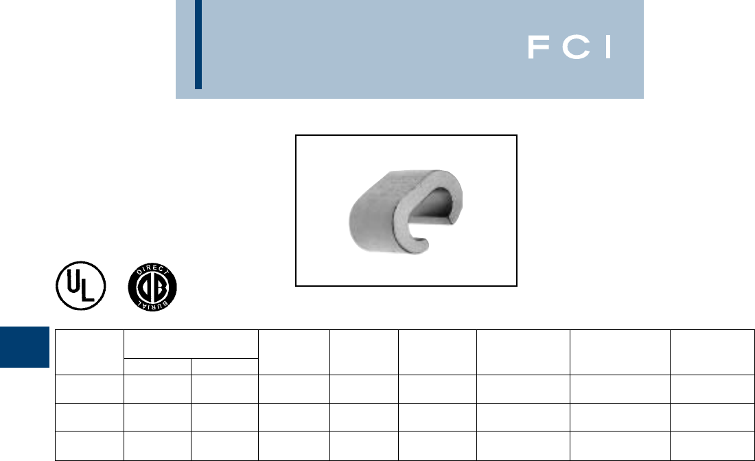
BURNDY
Grounding
D-12
TYPE YGC
COPPER CRIMPIT™
UL 467 Listed for direct burial in earth or
concrete. Prefilled with PENETROX™ E2
oxide inhibitor.
COPPER
CATALOG CONDUCTOR
NUMBER RUN TAP H L INDEX OUR840 MD6/MD7 CRIMPS
#8 SOL. #8 SOL.
YGC8C8 #8 STR. #8 STR. .46 .52 162 W162 W162 2
#6 SOL. #8 SOL.
YGC6C8 #6 STR. #8 STR. .73 .62 BG XBG WBG 2
#6 SOL. #6 SOL.
YGC6C6 #6 STR. #6 STR. .76 .62 BG XBG WBG 2
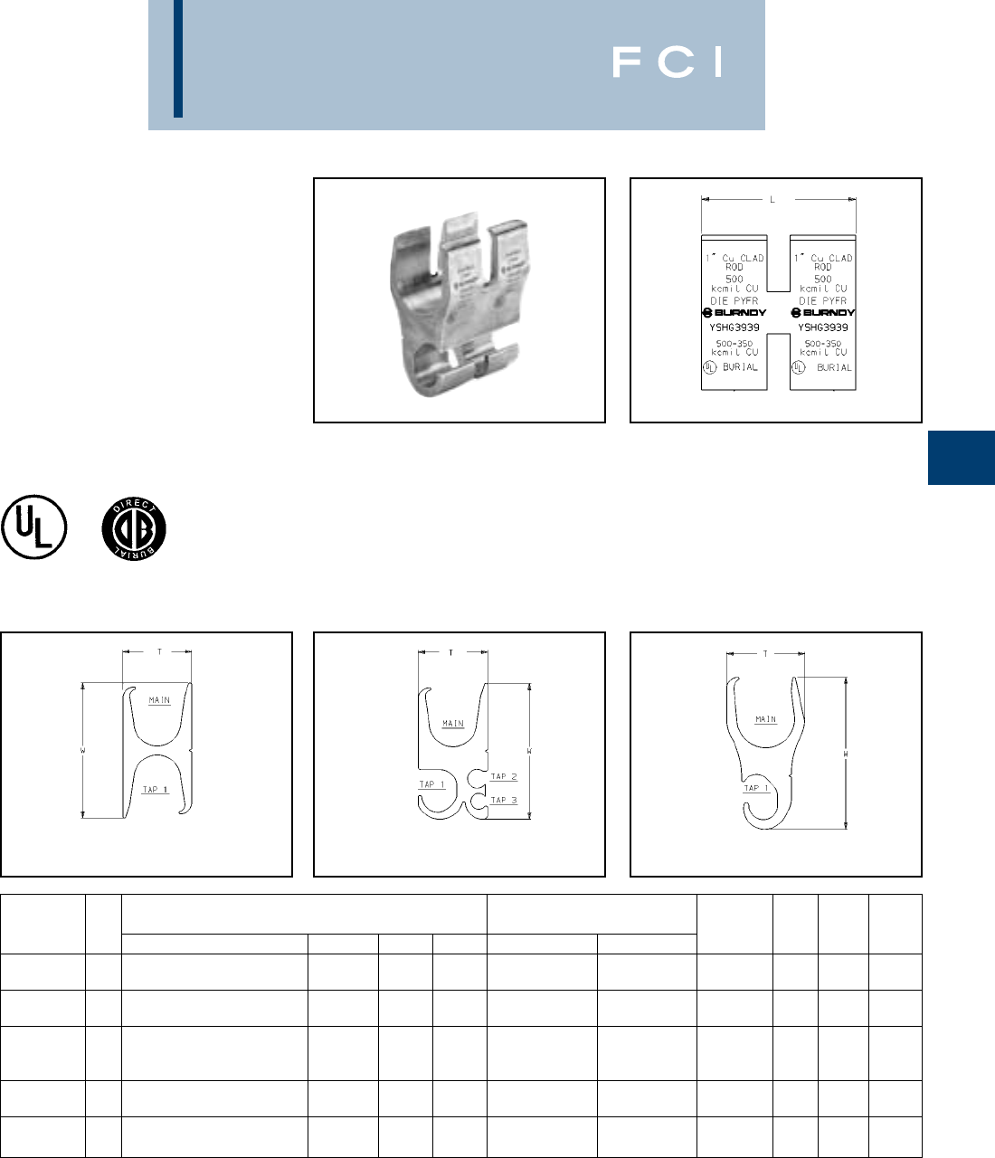
BURNDY
Grounding
D-13
TYPE YSHG
HIGH STRENGTH
COPPER IRREVERSIBLE
COMPRESSION
Double H-Tap Connector
Type YSHG Double H-Tap grounding series is
comprised of five connectors designed to
accommodate wire range sizes #14 through
500 kcmil, including ground rod sizes: 3/4,
1, and rebar sizes: #6, #8 and #9. Prefilled
with PENETROX™ E2 and strip sealed. Features and Benefits
•UL467 Listed.
◊Suitable for direct burial in earth
or concrete.
•Material is high conductivity
copper extrusion.
◊Minimizes resistance, eliminates
corrosion due to dissimilar metals.
*NOTE: Not for use on 1steel ground rod.
†Use PUADP-1 adapter.
Fig. 1 Fig. 2 Fig. 3
•Grooves are prefilled with PENETROX™ E2
oxide inhibitor and individually sealed.
◊Inhibits moisture and contaminants
ensuring electrical integrity.
Tooling Index
Catalog Fig. Conductor Sizes (number of crimps) Emboss- W T L
Number No. Main Tap 1 Tap 2 Tap 3 PAT750/Y750 Y46 ment .06 .04 .06
#9 & #8 Rebar, 1[25] Ground 3.22 1.70 2.44
YSHG4429 3Rod 250 - 2 PYFR (2) K-R [82] [43] [62]
1[25] Cu Clad Ground Rod 2.97 1.50 2.94
* YSHG3939 1500 kcmil Copper 500 - 350 PYFR (2) K-R [75] [38] [75]
#6 Rebar, 1[25] Cu Clad
* YSHG3931 2Ground Rod, 3/4Ground Rod 4/0 - 1/0 1 - 6 2 - 14 PYFR (2) K-R 2.97 1.50 2.34
500 - 350 kcmil Copper [75] [38] [59]
#6 Rebar, 3/4[19] Ground Rod P1104 (2) 2.43 1.15 2.44
YSHG3434 1400 - 250 kcmil COPPER 400 - 4/0 U1104 (4) †U1104 (4) 1104 [62] [29] [62]
#6 Rebar, 3/4[19] Ground Rod P1104 (2) 2.23 1.31 2.44
YSHG3429 2400 - 4/0 kcmil Copper 3/0 - 1/0 1 - 4 8 - 14 U1104 (4) †U1104 (4) 1104 [57] [33] [62]
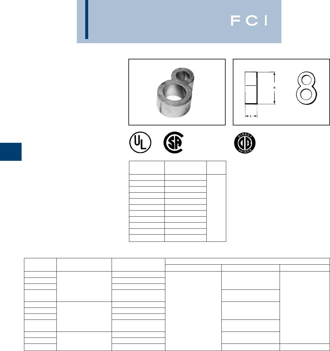
BURNDY
Grounding
TYPE YGHR-C
HYTAIL™
High Strength
Irreversible
Compression Ground Rod Tap
Connectors
High torque strength ground rod connectors.
Accommodates a wide range of copper
conductors to ground rod. UL467 Listed.
Acceptable for direct burial in earth or con-
crete. Prefilled with PENETROX™ compound
and strip sealed.
D-14
NOTES:
•The catalog numbers shown are for unplated copper
connectors for use on copper clad or stainless steel ground
rod. To order electro-tin plated connectors for use on
galvanized steel ground rod add suffix "TN" to the catalog
number. Note: The ground rod hole diameter is larger for
galvanized steel ground rod in the tin plated connector.
①Ground rod must be pre-crimped with die U2CABT (Index
No. 348) when the PU998 dies are used in the Y750, Y35,
Y39, Y45, or Y46 tools. Pre-crimping is not required when
the P1011, S1011, S1012 or U1011 dies are used. UPRE-
CRIMP™ dies may be used for additional mechanical resis-
tance on ground rods.
➁Where a PU998 die is recommended with the Y45
HYPRESS™, a PT6515 adapter must be used.
➂Where a PU998 die is recommended with the Y46
HYPRESS™, a PUADP-1 adapter must be used.
➃These die numbers do not appear on the connector.
*These connectors can only be installed using the Y750, Y45
or the Y46 HYPRESS™ with the recommended dies. These
connectors CAN NOT be installed with the Y35 and Y39
HYPRESS™. When attaching connector to ground rod,
ground rod must be embossed with appropriate PRE-
CRIMP™ die. For connections that must meet IEEE 837
requirements UPRECRIMP™ - type PRE crimp dies must
be used for maximum clamping retention.
CATALOG
NUMBER H B
YGHR26C12 1.94[49.3]
YGHR26C58 1.97[50.0]
YGHR26C34 2.19[55.6]
YGHR26C100 2.55[56.2]
YGHR29C12 1.94[49.3] .88
YGHR29C58 2.14[54.4]
YGHR29C34 2.19[55.6] [22.4]
YGHR29C100 2.45[62.2]
YGHR34C58 2.14[54.4]
YGHR34C34 2.44[62.0]
YGHR34C100 2.70[68.6]
CATALOG COMMERCIAL COPPER NOMINAL GROUND INSTALLATION TOOLS, DIE SET CAT. NO. (NUMBER OF CRIMPS)
NUMBER CABLE RANGE ROD DIA. PAT750/Y750/Y35/Y39 ①Y45 HYPRESS ①Y46 HYPRESS ①
YGHR26C12 1/2[12.7] S1012 (2)
YGHR26C58 #2 STR. (.292 DIA.) 5/8[15.9] ➃
YGHR26C34 thru 3/4[19.0] PU998 (1) ②
2/0 STR. (.419 DIA.) S1011 (2) S1012 (2)
YGHR26C100* 1[25.4] PU998 (1)
YGHR29C12 1/2[12.7] U1011 (2) S1012 (2) P1011 (2)
YGHR29C58 #4/0 STR. (.528 DIA.) 5/8[15.9] ➃➃➃
YGHR29C34 thru 3/4[19.0] PU998 (1) PU998 (1) ②PU998 (1)
250 kcmil (.575 DIA.) S1011 (2) S1012 (2) ③
YGHR29C100* 1[25.4] ➃PU998 (1)
YGHR34C58 300 kcmil (.630 DIA.) 5/8[15.9] S1012 (2)
YGHR34C34* thru 3/4[19.0] ➃PU998 (1) ②
YGHR34C100* 500 kcmil (.813 DIA.) 1[25.4] S1011 (2) P1011 (2)
MEETS ALL
IEEE
837 REQUIREMENTS
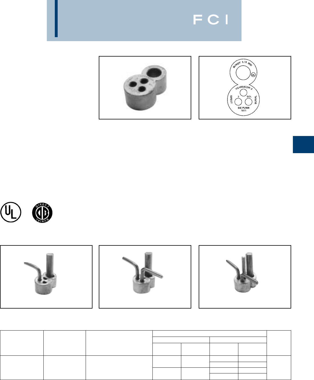
BURNDY
Grounding
D-15
TYPE YGHR-C
HYTAIL™
High Strength
Irreversible
Compression Ground Rod Tap
Connectors
Type YGHR-C irreversible compression
grounding connector is engineered specifical-
ly for the Telecommunications Industry for
(1, 2 or 3) #2 solid, tinned or bare conductor
taps. UL467 Listed. Acceptable for direct burial
in earth or concrete. BURNDY®has designed
this connector to meet the stringent require-
ments of OSHA, the National Electric Code
(NEC), UL, and the Telecommunications
Industry. Performance and long life are this
connector’s basic design guidelines.
Features and Benefits
•Tap side 1, 2 or 3 conductors.
◊One connector style can be used for
many applications.
•Material is high conductivity wrought
copper extrusion, identical material to
the conductor.
◊High-conductivity copper minimizes
resistance and voltage drop. Eliminates
the possibility of corrosion due to
dissimilar metals.
•System engineered tooling.
◊Each tooling recommendation has
been designed to provide a reliable,
dependable connection.
•Contact BURNDY®for other ground rod diameters.
* PU998 and U1011 die sets require PUADP-1 adapter for
use in the Y46 HYPRESS™.
Tap positions may be left void when fewer than (3) conduc-
tors are used.
+To order electro-tin plated connector for use on galvanized
steel ground rod add suffix -“TN” to the catalog number.
NOTE: The ground rod hole diameter is larger for galvanized
steel ground rod in the tin plated connector.
TAP TAP
RUN RUN
AND
•The die index number is embossed on
connector after completion of crimp.
◊Facilitates speedy inspection of installed
connectors to ensure consistently
reliable and dependable connections.
•Prefilled with PENETROX™ and individually
sealed in clear polyethylene sheet.
◊Ensures the electrical integrity of the
finished connection by inhibiting moisture
and contaminates from entering the
contact area. Maintains long-term
high-conductivity.
•UL 467 Listed. Acceptable for direct burial.
◊May be used in direct burial or concrete
embedded grounding applications.
Provides quality assurance to recognized
industry NEC standards from an
independent party.
†Ground rod must be precrimped with die U2CABT (Index
No. 348) when PU998 die set is used in the Y35, Y750 or
Y46
▲HYPRESS™ tools. For even greater mechanical resistance
use UPRECRIMP™ 58 dies.
** The Y750 utilizes PU dies and the U1011 die. The Y35 only
uses PU998 die set.
NOTE: A 12" bend radius is recommended for the conductor.
INSTALLATION TOOLING
PAT750/Y35/Y750** Y46*
CATALOG GROUND ROD DIE NO. OF DIE NO. OF DIE
NUMBER+ DIAMETER • TAP CONDUCTOR ▲NO. CRIMPS NO. CRIMPS INDEX
PU998† (1)
#2 Sol. Copper 1, 2, or 3 PU998† (1) U1011 (2) 998 or
YGHR58C2W-3 5/8
may be connected P998 (1) 1011
U1011 (2) P1011 (2)
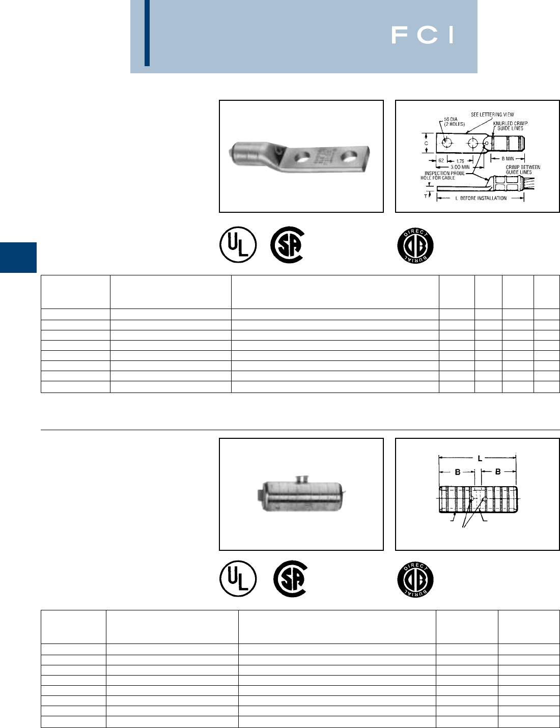
BURNDY
Grounding
D-16
TYPE YGHA
HYLUG™
Heavy Duty Irreversible
Compression Terminals
Heavy duty HYLUG™ irreversible compres-
sion terminals designed not only to carry
short circuit load, but to also withstand high
mechanical stress. Each conductor element
has an inspection probe hole to insure proper
cable insertion. UL467 Listed. Acceptable for
direct burial in earth or concrete. UL486A
Listed. Prefilled with PENETROX™ com-
pound and strip sealed.
TYPE YGHS
HYLINK™
Heavy Duty Irreversible
Compression Terminals
Heavy duty HYLINK™ ground splice
designed not only to carry short circuit load,
but to also withstand high mechanical stress.
Each conductor element has an inspection
probe hole and a center stop to ensure
proper cable insertion. UL467 Listed.
Acceptable for direct burial in earth or
concrete. UL486A Listed. Prefilled with
PENETROX™ compound and strip sealed.
①Where a “U” or “PU” die is recommended with the Y45
HYPRESS™, a PT6515 adapter must be used.
➁Where a “U” or “PU” die is recommended with the Y46
HYPRESS™, a PUADP-1 adapter must be used.
①Where a “U” or “PU” die is recommended with the Y45
HYPRESS™, a PT6515 adapter must be used.
➁Where a “U” or “PU” die is recommended with the Y46
HYPRESS™, a PUADP-1 adapter must be used.
INSPECTION PROBE HOLES
FOR CABLE STOP
KNURLED
RINGS
MEETS ALL
IEEE
837 REQUIREMENTS
MEETS ALL
IEEE
837 REQUIREMENTS
INSTALLATION TOOLS, DIE SET CAT. NO.,
CATALOG AND (NUMBER OF CRIMPS)
NUMBER COPPER CONDUCTOR SIZE HYPRESS™ Y35/Y39/Y45 ①/Y46 ②/Y750 /PAT750 B C L T
YGHA2C-2N 2 str. U1CRT (1) .75 .97 4.21 .26
YGHA25-2N 1/0 str. U27RT (1) .83 .91 4.60 .19
YGHA26-2N 2/0 str. U28RT (1) .83 .97 4.38 .26
YGHA27-2N 3/0 str. U29RT (1) 1.18 1.08 4.94 .29
YGHA28-2N 4/0 str. U30RT (2) 1.18 1.22 4.94 .30
YGHA29-2N 250 kcmil U31RT (2) 1.18 1.28 4.94 .34
YGHA31-2N 350 kcmil U34RT (2) 1.18 1.62 5.00 .43
YGHA34-2N 500 kcmil U36RT (3) 1.48 1.72 5.42 .40
INSTALLATION TOOLS, DIE SET CAT. NO.,
CATALOG AND (NUMBER OF CRIMPS)
NUMBER COPPER CONDUCTOR SIZE HYPRESS™ Y35/Y39/Y45 ①/Y46 ②/Y750 /PAT750 B L
YGHS2C 2 str. U1CRT (1) .75 1.73
YGHS25 1/0 str. U27RT (1) .83 1.89
YGHS26 2/0 str. U28RT (1) .83 1.89
YGHS27 3/0 str. U29RT (1) 1.18 2.59
YGHS28 4/0 str. U30RT (2) 1.18 2.59
YGHS29 250 kcmil U31RT (2) 1.18 2.59
YGHS31 350 kcmil U34RT (2) 1.18 2.59
YGHS34 500 kcmil U36RT (3) 1.48 3.19
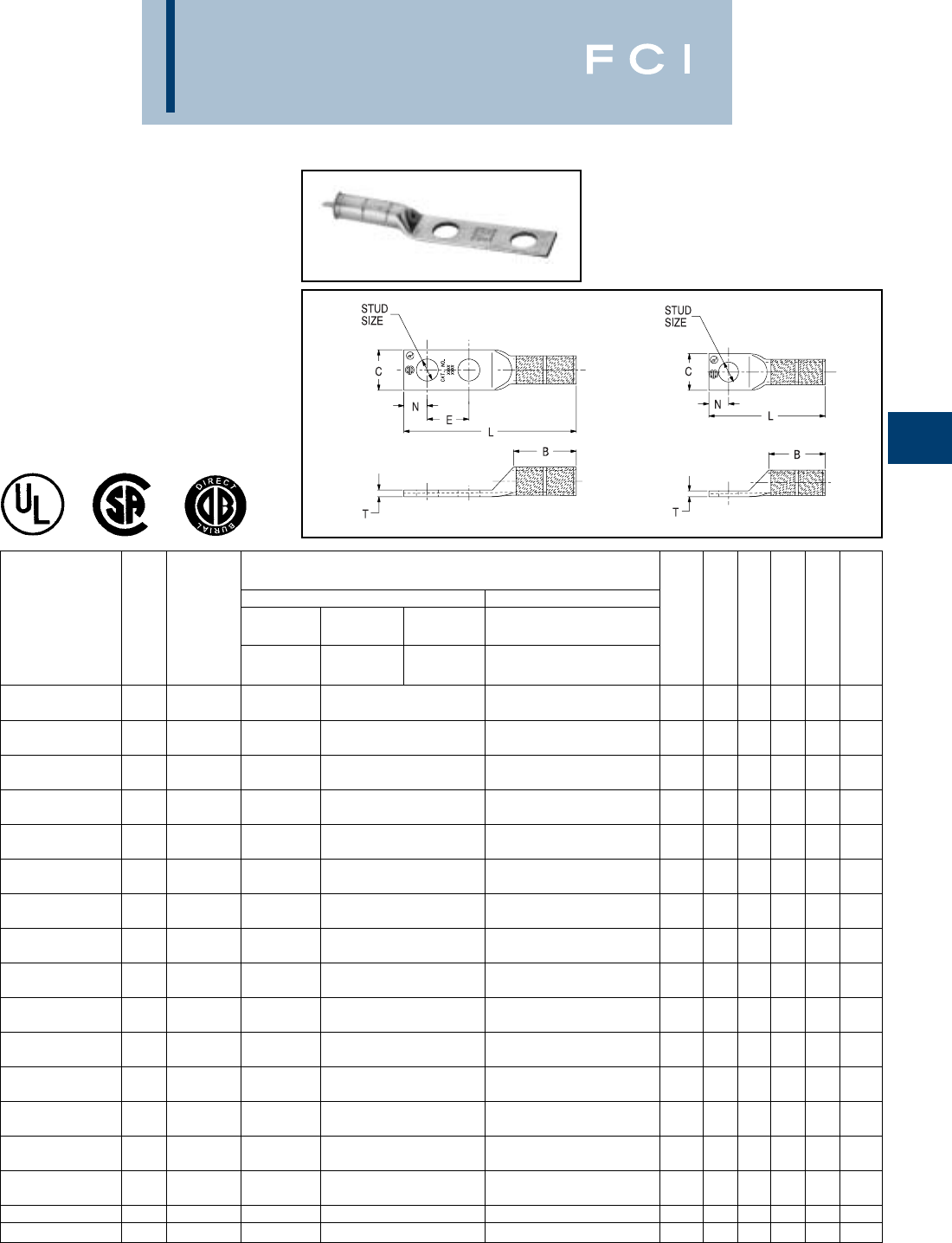
BURNDY
Grounding
D-17
TYPE YGA
HYLUG™
Grounding Irreversible
Compression Terminals
Irreversible compression HYLUG™ Ground
terminal specifically designed for grounding
applications. Each connector has an inspec-
tion probe hole to insure proper cable inser-
tion. UL467 Listed. Acceptable for direct
burial in earth or concrete. UL486A Listed.
Prefilled with PENETROX™ compound and
strip sealed.
①Where a “U” or “PU” die is recommended with the Y45
HYPRESS™, a PT6515 adapter must be used.
Fig. 1 Fig. 2
Installation Tools, Die Set Cat. No., and
(number of crimps)
Mechanical Hydraulic
Y35/Y39/Y45/PAT750 ①
Copper Y2MR MD7-34R OUR840 /Y46 ②/Y750
Catalog Fig. Conductor Die # (# of Die # (# of Die # (# of Die # (# of Stud
Number No. Size crimps) crimps) crimps) crimps) Size B C L T E
W8CVT (2)
YGA8C-TC10 28 sol./8 str. Red (4) X8CRT (2) U8CRT (2) #10 .81 .41 1.57 .08 —
W8CVT (2)
YGA8C-TC14 28 sol./8 str. Red (4) X8CRT (2) U8CRT (2) 1/4 .81 .44 1.69 .08 —
W8CVT (2)
YGA8C-TC516 28 sol./8 str. Red (4) X8CRT (2) U8CRT (2) 5/16 .81 .51 1.75 .06 —
W8CVT (2)
YGA8C-2N 18 sol./8 str. Red (4) X8CRT (2) U8CRT (2) 1/2 .81 .71 4.09 .05 —
W5CVT (2)
YGA6C-TC10 26 sol./6 str. Blue (4) X5CRT (2) U5CRT (2) #10 1.12 .42 1.89 .09 —
W5CVT (2)
YGA6C-TC14 26 sol./6 str. Blue (4) X5CRT (2) U5CRT (2) 1/4 1.12 .45 2.02 .08 —
W5CVT (2)
YGA6C-TC516 26 sol./6 str. Blue (4) X5CRT (2) U5CRT (2) 5/16 1.12 .51 2.08 .07 —
W5CVT (2)
YGA6C-2TC38E2G1 16 sol./6 str. Blue (4) X5CRT (2) U5CRT (2) 3/8 1.12 .58 3.42 .06 .75
W5CVT (2)
YGA6C-2N 16 sol./6 str. Blue (4) X5CRT (2) U5CRT (2) 1/2 1.12 .83 4.40 .12 1.75
W2CVT (2)
YGA2C-2TC38 12 sol./2 str. Brown (4) X2CRT (2) U2CRT (2) 3/8 1.25 .60 3.48 .12 1.00
W2CVT (2)
YGA2C-2TC38E2G1 12 sol./2 str. Brown (4) X2CRT (2) U2CRT (2) 3/8 1.25 .60 3.66 .12 .75
W2CVT (2)
YGA2C-2N 12 str. Brown (4) X2CRT (2) U2CRT (2) 1/2 1.22 .81 4.71 .12 1.75
W25VT (4)
YGA25-2N 11/0 str. — X25RT (4) U25RT (2) 1/2 1.35 .81 4.91 .12 1.75
W26VT (4)
YGA26-2N 12/0 str. — X26RT (4) U26RT (2) 1/2 1.45 .81 4.89 .12 1.75
W28VT (4)
YGA28-2N 14/0 str. — X28RT (4) U28RT (2) 1/2 1.57 1.00 5.06 .14 1.75
YGA29-2N 1250 kcmil — W29VT (4) U29RT (2) 1/2 1.57 1.09 5.16 .16 1.75
YGA34-2N 1500 kcmil — W34VT (4) U34RT (4) 1/2 2.20 1.52 5.94 .23 1.75
➁Where a “U” or “PU” die is recommended with the Y46
HYPRESS™, a PUADP-1 adapter must be used.
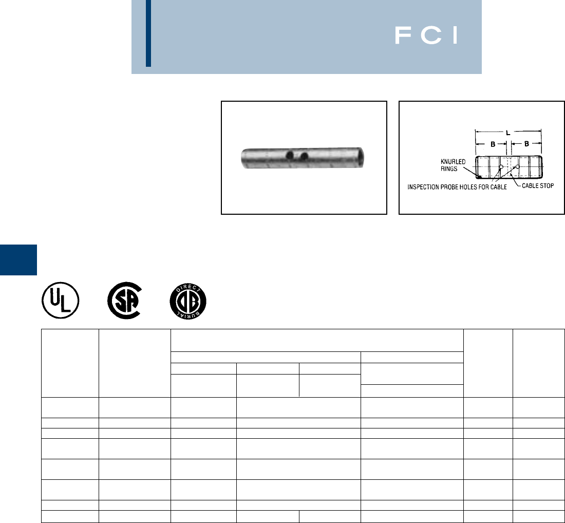
BURNDY
Grounding
D-18
TYPE YGS
HYLINK™
Grounding Irreversible
Compression Splices
Irreversible compression HYLINK™ ground
splices specifically designed for grounding
applications. Each conductor element has an
inspection probe hole and a center stop to
ensure proper cable insertion. UL467 Listed.
Acceptable for direct burial in earth or
concrete. UL486A Listed. Prefilled with
PENETROX™ compound and strip sealed.
①Where a “U” or “PU” die is recommended with the Y45
HYPRESS™, a PT6515 adapter must be used.
➁Where a “U” or “PU” die is recommended with the Y46
HYPRESS™, a PUADP-1 adapter must be used.
③Use "X" with OUR840, "W" with MD6/MD7.
INSTALLATION TOOLS, DIE SET CAT. NO., AND
(NUMBER OF CRIMPS)
MECHANICAL HYDRAULIC
COPPER Y2MR MD7-34R OUR840 Y35/Y39/Y45①
CATALOG CONDUCTOR DIE # (# OF DIE # (# OF DIE # (# OF /Y46②/Y750/PAT750
NUMBER SIZE CRIMPS) CRIMPS) CRIMPS) DIE # (# OF CRIMPS) B L
W2CVT (2)
YGS2C 2 str. Brown (4) X2CRT (2) U2CRT (2) 1.22 2.67
YGS8C #8 sol./str. — X8CRT, W8CRT, W8CVT ➂U8CRT (2) .78 1.75
YGS6C #6 sol./str. — X5CRT, W5CRT, W5CVT ➂U6CRT (2) 1.09 2.38
W25VT (4)
YGS25 1/0 str. — X25RT (4) U25RT (2) 1.35 2.97
W26VT (4)
YGS26 2/0 str. — X26RT (4) U26RT (2) 1.45 3.13
W28VT (4)
YGS28 4/0 str. — X28RT (4) U28RT (2) 1.57 3.37
YGS29 250 kcmil — W29VT (4) U29RT (2) 1.57 3.37
YGS34 500 kcmil — W34VT (4) — U34RT (4) 2.20 4.63

BURNDY
Grounding
TYPE YGF
GROUNDING PLATE
The irreversible compression ground plate is
designed to withstand the rigors of concrete
construction. The ground plates are made of
high strength, high-conductivity cast copper
alloy body with a pure wrought copper
compression element. In addition to the
tapped NEMA size holes and spacing on the
face, the plate comes with a tapped hole on
the underside for ease of positioning prior to
pouring the concrete. UL467 Listed.
Acceptable for direct burial in earth or
concrete. Prefilled with PENETROX™
compound and strip sealed.
D-19
NOTES:
①This tapped hole may be used to position the grounding
plate on a threaded rod prior to placement of the concrete.
ORDERING INFORMATION
①Where a “U” or “PU” die is recommended
with the Y45 HYPRESS™, a PT6515
adapter must be used.
Fig. 1
Fig. 2
MEETS ALL
IEEE
837 REQUIREMENTS
①3/8-16 thread with 1.00 EFF. Thread is standard. If other
thread is required, add appropriate Code No. to Catalog No.
for desired thread.
-50 (1/2 -13, .94 EFF. Thread), -62 (5/8 -11, .94 EFF.
Thread) and -75 (3/4 -10, .81 EFF. Thread)
Example: YGF34-4N-50 is YGF34-4N with 1/2 -13 Thread
②Plastic plugs are provided to keep dirt out of the threaded
holes until the attachment of grounding terminals.
Catalog
Number Fig. No. C D H L T Y
YGF29-2N 12.00 3.25 3.62 5.78 1.31 2.00
YGF29-4N 23.25 3.25 3.62 5.78 1.31 2.00
YGF34-2N 12.00 3.25 4.62 5.40 1.31 2.19
YGF34-4N 23.75 3.75 4.62 5.90 1.31 2.19
Installation Tools,
Die Set Cat. No., and
(number of crimps)
Catalog Copper Tapped Holes HYPRESS™
Number Conductor Range Size Hole Centers PAT750/Y750/Y35/Y39 Y45 ①Y46 ②
YGF29-2N 2 - 250 kcmil 1/2 - 13 1-3/4 U997 (1) U997 (1) U997 (1)
YGF29-4N 2 - 250 kcmil 1/2 - 13 1-3/4 U997 (1) U997 (1) U997 (1)
YGF34-2N* 250 - 500 kcmil 1/2 - 13 1-3/4 U1011 (3) S1011 (2) P1011 (2)
YGF34-4N* 250 - 500 kcmil 1/2 - 13 1-3/4 U1011 (3) S1011 (2) P1011 (2)
➁Where a “U” or “PU” die is recommended
with the Y46 HYPRESS™, a PUADP-1
adapter must be used.
*These connectors can only be installed
using the Y750, Y45 or Y46 HYPRESS™
with recommended dies. These connec-
tors CAN NOT be installed with the Y35 or
Y39 HYPRESS™.
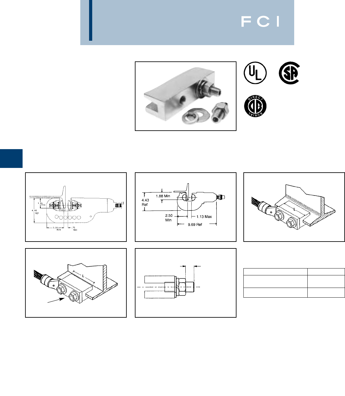
BURNDY
Grounding
D-20
NOTES:
1. Te r minal conector to be ordered separately. When I-beam
connector is used with type "YGHA" terminal, the connec-
tion meets IEEE 837-1989 requirements. YGA-2N, YA-2N
and other BURNDY®2-hole NEMA copper terminals are
suitable.
2. Order "TMHG" Terminal Mounting Hardware Kit separate-
ly. Kit consists of 2 studs, 2 flat washers, 2 lockwashers
and 2 hex nuts.
3. Using the 1/4 hex key wrench, screw the stud into the
connector until stud bottoms out in connector. Install a
"YGHA" terminal, flat washer, lockwasher and hex nut
onto stud. Tighten and torque to 480 pound-inches.
TYPE YGIB
GROUNDLINK™ CONNECTOR
An irreversible compression ground connec-
tion which allows attachment to a structural
steel standard (angled) or wide flange
(parallel) beam. Installed with a required
5-piece die set, Catalog PIBEAMKIT or
UIBEAMKIT. Die index 1105.
GROUNDLINK™ connectors are made of
high-conductivity wrought copper and come
pre-filled with PENETROX™ E compound
and strip sealed. Order terminal mounting
hardware separately.
NOTE: Use TMHG-D92 to double stack lugs.
Fig. 1
Fig. 2
Connector shipped with thread protection studs only. Order
TMHG kits separately.
1.84 IN. Minimum flange depth.
3.06 IN. Minimum flange width.
STANDARD BEAMS
(FLANGE ANGLED) USE YGIBS
WIDE FLANGE BEAMS
(FLANGE PARALLEL) USE YGIBW
TERMINAL
MOUNTING HARDWARE
“T” REF MAXIMUM
TERMINAL PAD
THICKNESS
Y46 SERIES
USE PIBEAMKIT Y750 SERIES
USE UIBEAMKIT
2 HOLE NEMA
SPACING
➃➃
MEETS ALL
IEEE
837 REQUIREMENTS
➃Dimensions shown reflect the minimum dimensions
required on a beam to properly install the I-beam
connector.
5. To correctly determine the appropriate YGIB connector to
use based on flange thickness, order either
YGIBGAUGE1 or YGIBKIT1 (KIT1 contains wiremike).
CATALOG NUMBER “T”
TMHG-42 .42
TMHG-92 .92
BURNDY
Grounding
D-21
TYPE YGIB
(Continued)
GROUNDLINK™ CONNECTOR
COPPER iBEAM
CONDUCTOR FIG. FLANGE SUGGESTED TERMINALS
RANGE CATALOG NUMBER NO. “L” “J” THICKNESS COPPER CONDUCTOR TERMINAL “T” REF.
#2 STR. AWG YGHA2C-2N .26
YGIBS28-338-2N 13.00 1/0 STR. AWG YGHA25-2N .19
2 - 4/0 AWG .250
2/0 STR. AWG YGHA26-2N .26
YGIBW28-338-2N 23.00 to 4/0 STR. AWG YGHA28-2N .30
YGIBS34-338-2N 1.338
250 kcmil YGHA29-2N .34
250 - 500 kcmil YGIBW34-338-2N 26.00 500 kcmil YGHA34-2N .40
#2 STR. AWG YGHA2C-2N .26
YGIBS28-400-2N 13.00 1/0 STR. AWG YGHA25-2N .19
2 - 4/0 AWG .338
2/0 STR. AWG YGHA26-2N .26
YGIBW28-400-2N 23.00 to 4/0 STR. AWG YGHA28-2N .30
YGIBS34-400-2N 1.400
250 kcmil YGHA29-2N .34
250 - 500 kcmil YGIBW34-400-2N 26.00 500 kcmil YGHA34-2N .40
#2 STR. AWG YGHA2C-2N .26
YGIBS28-462-2N 13.00 1/0 STR. AWG YGHA25-2N .19
2 - 4/0 AWG .400
2/0 STR. AWG YGHA26-2N .26
YGIBW28-462-2N 23.00 to 4/0 STR. AWG YGHA28-2N .30
YGIBS34-462-2N 1.462
250 kcmil YGHA29-2N .34
250 - 500 kcmil YGIBW34-462-2N 26.00 500 kcmil YGHA34-2N .40
1/2 - 13 #2 STR. AWG YGHA2C-2N .26
YGIBS28-550-2N 13.00 1/0 STR. AWG YGHA25-2N .19
2 - 4/0 AWG 4.62
2/0 STR. AWG YGHA26-2N .26
YGIBW28-550-2N 23.00 to 4/0 STR. AWG YGHA28-2N .30
YGIBS34-550-2N 1.550
250 kcmil YGHA29-2N .34
250 - 500 kcmil YGIBW34-550-2N 26.00 500 kcmil YGHA34-2N .40
#2 STR AWG YGHA2C-2N .26
YGIBS28-613-2N 13.00 1/0 STR. AWG YGHA25-2N .19
2 - 4/0 AWG .550
2/0 STR. AWG YGHA26-2N .26
YGIBW28-613-2N 23.00 to 4/0 STR. AWG YGHA28-2N .30
YGIBS34-613-2N 1.613
250 kcmil YGHA29-2N .34
250 - 500 kcmil YGIBW34-613-2N 26.00 500 kcmil YGHA34-2N .40
#2 STR. AWG YGHA2C-2N .26
YGIBS28-675-2N 13.00 1/0 STR. AWG YGHA25-2N .19
2 - 4/0 AWG .613
2/0 STR. AWG YGHA26-2N .26
YGIBW28-675-2N 23.00 to 4/0 STR. AWG YGHA28-2N .30
YGIBS34-675-2N 1.675
250 kcmil YGHA29-2N .34
250 - 500 kcmil YGIBW34-675-2N 26.00 500 kcmil YGHA34-2N .40
BURNDY
Grounding
D-22
TYPE GSTUD-HY
VERSITAIL™
Structural Steel Grounding
Connector
INSTALLATION
1. Weld the VERSITAIL™ to the steel
member.
2. Select the proper connector for your
specific application.
a. FOR COMPRESSION CONNECTORS
Select the proper BURNDY®“YGHP,”
connector. Clean the conductor, join the
VERSITAIL™ and the grounding con-
ductor together with the recommended
tool and die set, then crimp the connec-
tor over the knurled area of the VERSI-
TAIL™.
b. FOR MECHANICAL CONNECTORS
Select the properly sized BURNDY®
connector. Clean the conductor, then
apply PENETROX™ E oxide inhibiting
compound on the contact area for
increased effectiveness and service life.
Put the connector over the knurled area
of the VERSITAIL™ and apply the
recommended torque value for correct
installation.
SPECIFICATIONS
•Low Carbon, hot rolled steel.
•Pure copper plated finish.
FEATURES
•The VERSITAIL™ may be welded to steel
surfaces quickly and easily with normal
construction equipment.
•The VERSITAIL™ eliminates costly disk
grinding and the need to expose virgin
metal. The welding process burns through
the oxidation and “scale” to establish
excellent electrical grounding continuity.
•The VERSITAIL™ may be installed by the
welder in the field or at the steel fabricator
based on customer preference.
•The VERSITAIL™ pure copper coating over
low carbon, hot rolled steel is compatible
with standard welding processes.
No toxic gasses are generated.
•The VERSITAIL™ knurled surface is
copper plated and specifically designed to
ensure excellent mechanical gripping and
electrical integrity for BURNDY®compres-
sion and mechanical connectors in all
grounding applications.
•The VERSITAIL™ may be installed during
adverse weather conditions thus eliminating
costly construction delays.
BENEFITS
Low installation cost.
•No drilling . . . No cleaning . . .
•No special preparation
*This is the equivalent rating for continuous service. Larger
conductors may be connected using both compression and
bolted connectors in potential ground fault applications.
A (STOCK
DIA.)
KNURLED
END
B (DIA. OVER KNURL)
T
(FLATTENING
RESULTANT)
1.25
[32]
TYPICAL
LETTERING
2.19
[56]
L
45°
ELECTRICAL
EQUIVALENT
NOM. DIMENSIONS COPPER
CATALOG ROD A B L T CONDUCTOR SIZE
NUMBER SIZE IN. [MM] IN. [MM] IN. [MM] IN. [MM] (AWG.)*
GSTUD14HY 1/4.25 [6.3] .26 [6.6] 4.81 [122.2] .19 [4.8] #6
GSTUD38HY 3/8.38 [9.7] .39 [9.9] 5.81 [147.6] .25 [6.4] #3
GSTUD916HY 5/8.56 [14.2] .57 [14.5] 5.68 [144.3] .38 [9.7] 1/0
GSTUD34HY 3/4.75 [19.0] .76 [19.3] 5.81 [147.6] .51 [13.0] 4/0
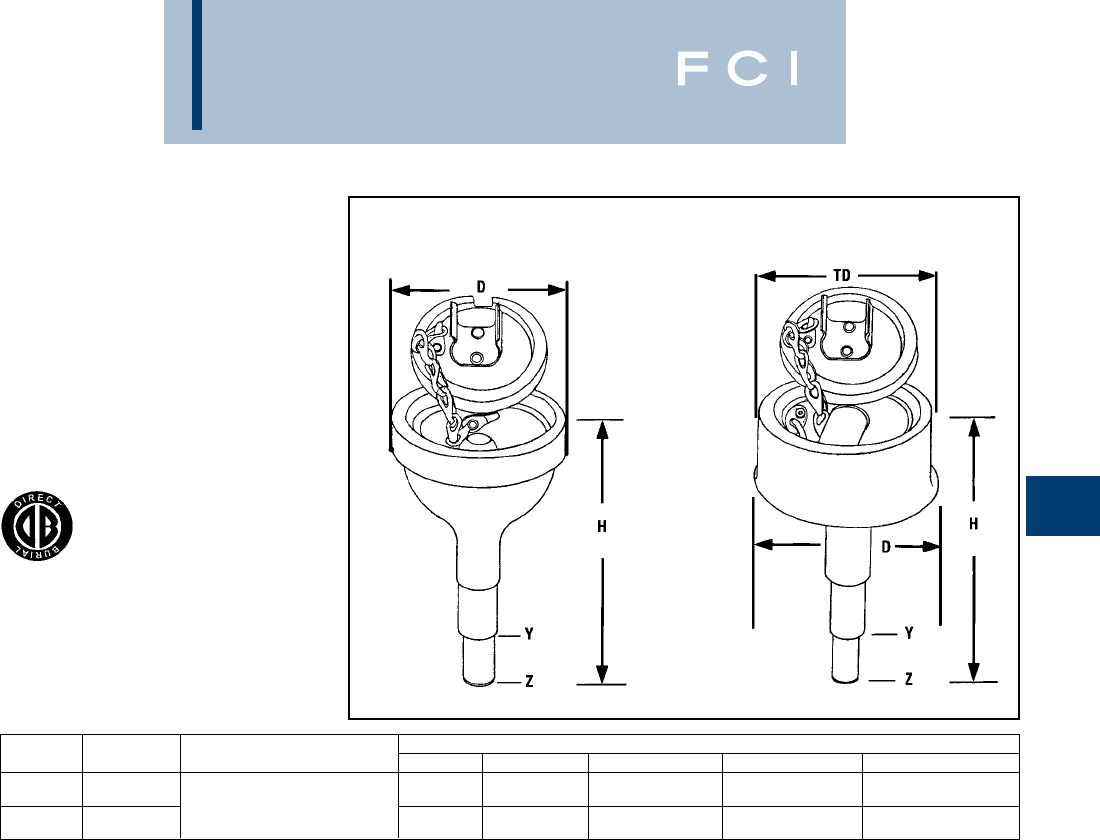
BURNDY
Grounding
D-23
TYPES YGT & YTTAG
STATIC GROUNDING
RECEPTACLE
Type YGT static grounding receptacles are
designed for static grounding of equipment.
The receptacle is connected to the ground
grid with HYGROUND™ compression
connectors and finished flush with surface to
provide a permanent corrosion proof ground-
ing point.
* When using U or PU dies with Y46 HYPRESS™, a PUADP-1
adapter is required.
NOTES:
1. Ground rod must be pre-crimped with U2CABT die set when
PU998 die is used or for even higher mechanical resistance
use special UPRECRIMP™ dies on ground rods.
2. Pre-crimping of ground is not necessary when P1011 die is
used. Install YGHR or YGLR on hub Y. Hub Z is inserted into
1/2" rigid conduit. The conduit is driven into earth to provide
support and provide correct level of receptacle prior to
cement pour.
Type YTTAG Combination
Static Grounding Receptacle
and Aircraft Tie Down Bar
Type YGT Static
Grounding Receptacle
with Cover
Fig. 1 Fig. 2
Catalog Figure Dimensions
Number Number * HYGROUND Connector H D Y Dia. Z Dia. “TD”
YGT275 1Select suitable YGHR or 5.5 2.75 .75 .56 —
YGLR for 3/4ground rod and
YTTAG388 2sized to ground conductor. 6.5 4.75 .75 .56 4.3
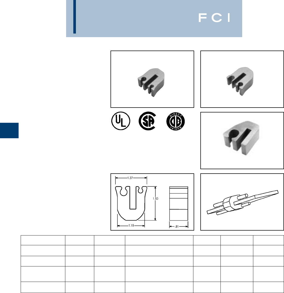
BURNDY
Grounding
D-24
TYPE YG-B
BUS BAR CONNECTOR
BURNDY’s YG14B2TC2C6C Compression
Bus Bar Connector is ideally suited for cellu-
lar tower applicatons and is easier to use than
exothermic connections. This high conduc-
tivity wrought copper connector allows
attachment of the ground conductor to the
ground bus with just one crimp using the
BURNDY®Y750 HYPRESS™ Hydraulic
Compression tool and the U1105 die set.This
exclusive patent pending design allows the
user to attach #2 AWG sol./str. and/or #6
sol./str. copper conductor to 1/4" thick copper
bus bar. This connection is suitable using (1)
or (2) conductors for power, grounding and
bonding applictions. UL Listed to both UL486
and UL467 (suitable for direct burial) ensures
that this connector will meet the rigors of
either application. Prefilled with PEN-
ETROX™ E compound and strip sealed.
GROUND BAR BUS BAR INSTALLATION
CATALOG NUMBER FIG NO. THICKNESS TAP CONDUCTORS TOOLING DIE NO. NO. OF CRIMPS
YG14B2TC2C6C 11/4" #2 SOL/and/or STR COPPER
#6 SOL/and/or STR COPPER PAT750, Y750 U1105 1
YG14B2TC2C2C* 21/4" #2
#2 PAT750, Y750 U1105 1
#1 FLEX CABLE
YG14BTC26 31/4" through PAT750, Y750 U1105 1
2/0 FLEX CABLE
4/0 AWG STR to 1/0
YG14BTC28 31/4” AWG STR COPPER PAT750, Y750 U1105 1
NOTE: Suitable for use with either (1) or (2) conductors
(excluding YG14BTC26 and YG14BTC28).
*For continuous uncut conductor applications.
Fig. 1 Fig. 2
Fig. 3
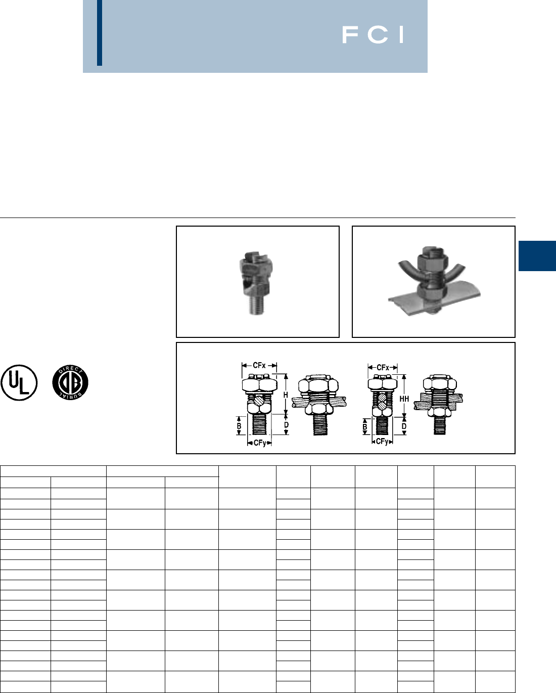
BURNDY
Grounding
D-25
MECHANICAL
GROUNDING
CONNECTORS
More than 60 years of technological innova-
tion has made BURNDY®mechanical
grounding connectors one of the most widely
used, highly respected lines in the industry.
There is virtually no grounding application
TYPES KC, K2C
SERVIT POST™
For Copper Cable to Flat
SERVIT POST™ used to ground one or two
cables to steel structures, fence posts, trans-
formers. Also used to tap one or two cables
from bus bar. One-wrench installation.
KC K2C
problem that this diversified line cannot help
solve.
All BURNDY®mechanical grounding connec-
tors have been designed for easy installation
and for outstanding durability. Only the finest
†For 1 conductor.
‡For 1 or 2 conductors.
Add “NSP” suffix to have connector supplied w/split lockwasher
and nut.
high copper alloys are used in their manufac-
ture, ensuring top performance under the
most extreme environmental conditions.
UL467 Listed for direct burial applications in
earth or concrete.
Catalog Number Conductor Stud
Type KC † Type K2C ‡ Stranded Solid Diameter B CFx CFy D H HH
KC15 K2C15 3/8 1/2
KC15B1 K2C15B1 12 - 9 12 - 8 1/4 - 20 7/8 1/2 3/8 15/8 7/8
KC17 K2C17 3/8 1/2
KC17B1 K2C17B1 10 - 7 10 - 6 1/4 - 20 7/8 5/8 7/16 17/8 1
KC20 K2C20 13/32 5/8
KC20B1 K2C20B1 10 - 5 10 - 4 5/16 - 18 27/32 11/16 1/2 17/8 1-1/8
KC22 K2C22 15/32 5/8
KC22B1 K2C22B1 10 - 3 10 - 2 3/8 - 16 31/32 3/4 5/8 1-1/8 11-1/4
KC23 K2C23 15/32 5/8
KC23B1 K2C23B1 8 - 2 10 - 1 3/8 - 16 31/32 13/16 5/8 1-1/8 11-3/8
KC25 K2C25 9/16 3/4
KC25B1 K2C25B1 2 - 1/0 2 - 2/0 1/2 - 13 1-1/16 15/16 3/4 1-1/4 1-1/8 1-5/8
KC26 K2C26 17/32 3/4
KC26B1 K2C26B1 2 - 2/0 2 - 3/0 1/2 - 13 1-1/16 17/8 1-1/4 1-3/8 1-7/8
KC28 K2C28 3/4 1
KC28B1 K2C28B1 1 - 4/0 1 - 4/0 5/8 - 11 1-1/4 1-1/2 1-3/16 1-1/2 1-3/4 2-1/4
KC31 K2C31 3/4 1
KC31B1 K2C31B1 1 - 350 — 5/8 - 11 1-1/4 1-11/16 1-3/8 1-1/2 2-1/4 2-7/8
KC34 K2C34 11-1/4
KC34B1 K2C34B1 3/0 - 500 — 3/4 - 10 1-1/2 21-5/8 1-3/4 2-3/8 3-1/4
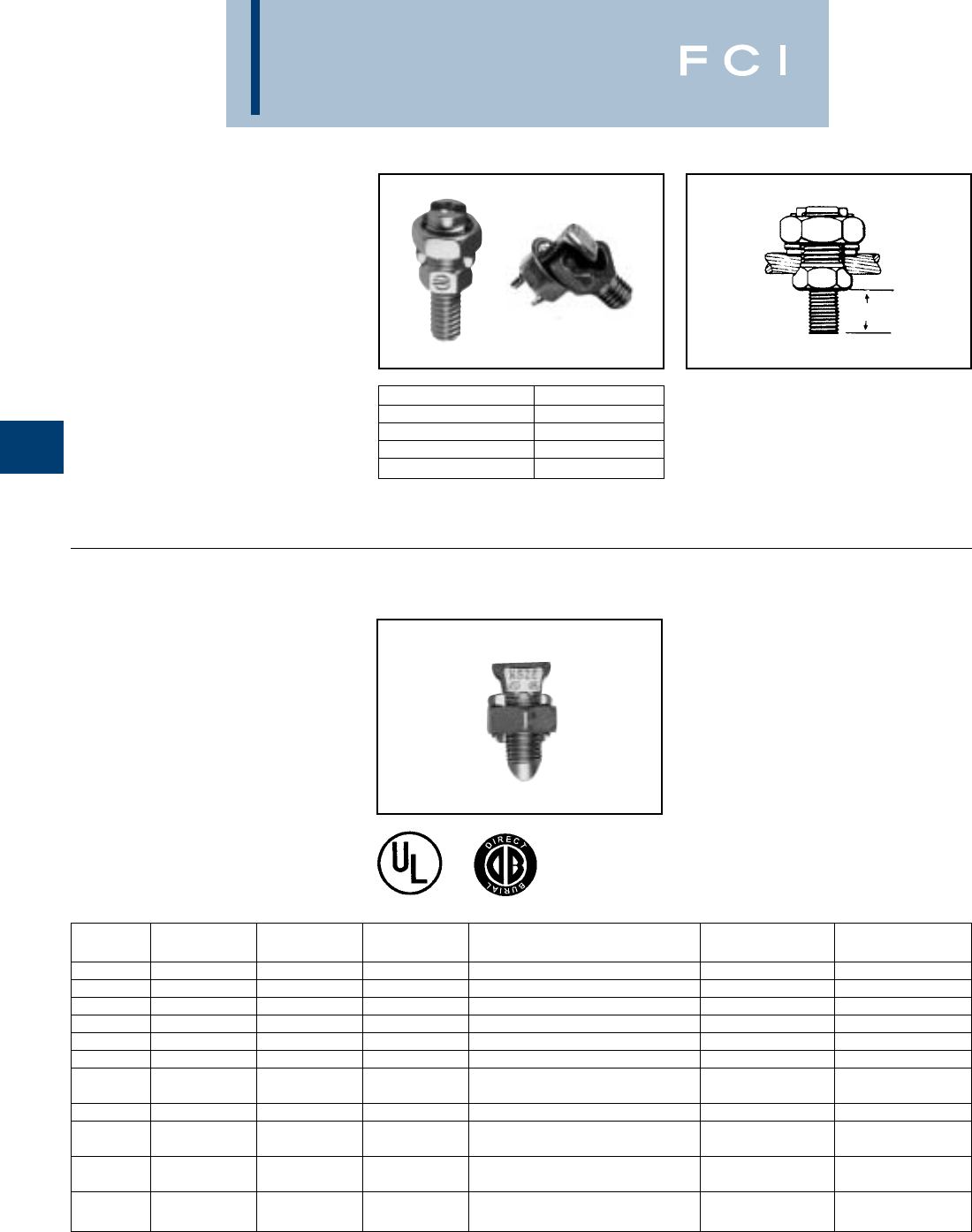
BURNDY
Grounding
D-26
TYPE KS-DB
SERVIT™
For Copper
UL467 Listed for direct burial applications in
earth or concrete. Compact, high-strength,
high copper alloy SERVIT™ split-bolt has
free-running threads and easy to grip wrench
flats. Highly resistant to cracking and
corrosion.
TYPES KC22J12T13,
EQC632C
TRANSFORMER GROUND
CONNECTORS
For Copper
Fits all standard EEI NEMA distribution
transformers as a tank grounding terminal.
Both, one-wrench installation.
Type EQC632C Type KC22J12T13Stud Size = 1⁄2”- 13
.6
CATALOG NUMBER RANGES
KC22J12T13 8 Sol. - 2 Sol.
KC26 2 Sol. - 2/0 Str.
KC34J12T13 3/0 - 500 Str.
EQC632C 8 Sol. - 2 Str.
Catalog Copper Conductor Range Rebar w/ (1) Recommended
Number Cross Flats L W (Sol. - Str.) No. 8 Sol. Cu Torque In. Lb.
KS15-DB .50 .85 .38 12 AWG - 8 AWG N/A 80
KS17-DB .63 1.14 .45 8 AWG - 6 AWG N/A 165
KS20-DB .69 1.20 .51 8 AWG - 4 AWG N/A 165
KS22-DB .75 1.50 .60 6 AWG - 3 AWG N/A 275
KS23-DB .82 1.54 .62 6 AWG - 2 AWG N/A 275
KS25-DB .94 1.77 .73 4 AWG - 1/0 N/A 385
2 AWG - 2/0 #3
KS26-DB 1.05 1.94 .82 6 AWG - 8 AWG Str./Sol. (3/8)385
KS27-DB 1.36 1.86 1.17 1 AWG - 3/0 N/A 500
1 AWG - 250 kcmil #4
KS29-DB 1.36 2.07 1.17 6 AWG - 8 AWG Str./Sol. (1/2)650
1/0 AWG - 350 kcmil #5
KS31-DB 1.70 2.51 1.41 6 AWG - 8 AWG Str./Sol. (5/8)650
2/0 AWG - 500 kcmil #6
KS34-DB 1.82 2.79 1.48 6 AWG - 8 AWG Str./Sol. (3/4)825
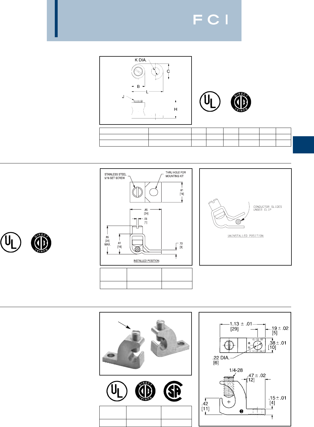
BURNDY
Grounding
D-27
TYPE GKA
For Copper
UL467 Listed for direct burial applications in
earth or concrete. One-piece forged body
construction insures mechanical integrity in
an underground environment. Supplied with a
stainless steel headless screw.
TYPE KPB
For Copper
UL467 Listed for direct burial in earth or con-
crete. UL 486 listed.This exclusive BURNDY®
design accommodates #10 - #4 copper
where continuous conductor runs are
preferable.
1. To be assembled with TMH322 stainless steel hardware kit.
Ordered separately.
TYPE CL50-1
COPPER LAY-IN QIKLUG™
For Copper
The Lay-In QIKLUG™ is manufactured from
high strength pure electrolytic copper to
ensure maximum strength and conductivity.
UL467 Listed for direct burial in earth or con-
crete. The open-faced design allows for fast
lay-in of the conductor without the need for
cutting or breaking.
CATALOG WIRE RANGE
NUMBER COPPER STUD HOLE
CL50-1 #14 - #4 CU #10
CATALOG
NUMBER RANGE STUD HOLE
KPB4CG1 #10 - #4 CU #10 1
1. To be assembled with TMH322 stainless steel hardware kit.
Ordered separately.
CATALOG NUMBER CABLE RANGE B C H J K L
GKA8C 1#10 SOL. - #8 STR. .31 .38 .58 #10 - 32 .21 .81
GKA4C 2#14 SOL. - #4 STR. .46 .54 .71 5/16 - 24 .28 1.13
2. To be assembled with TMH 323 stainless steel hardware kit.
Ordered separately.
Stainless Steel Screw
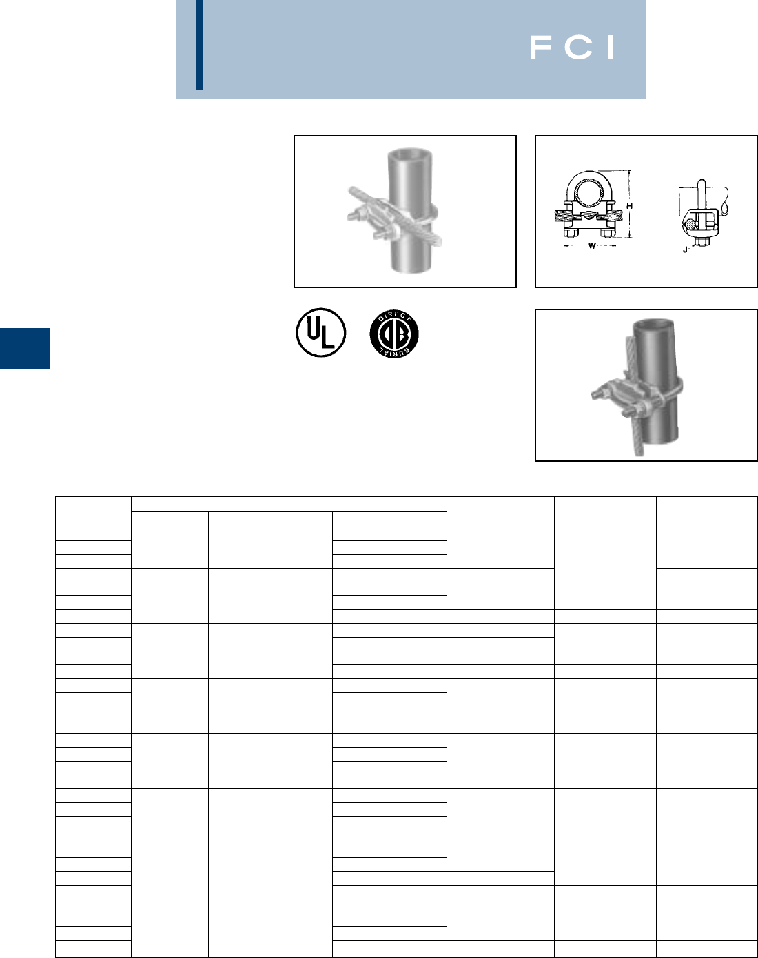
BURNDY
Grounding
D-28
TYPE GAR
FENCE POST GROUNDING
CONNECTOR
For Parallel or 90°
Copper Cable
Connection
To Rod or Pipe with
the Same Connector
High copper alloy ground connector for join-
ing a range of cable, parallel or at right angles
to rod or tube. Especially good for fence
posts. High copper alloy cast body with
DURIUM™ U-bolts, nuts and lockwashers,
permit entire connection to be buried in
ground or concrete without danger of
corrosion.
•One-wrench installation.
•UL467 Listed.
•Acceptable for direct burial.
Catalog Conductor
Number Tube I.P.S. Rod Size or O.D. Range Cable H J W
GAR114C 8 Sol. - 4 Str.
GAR1126 1/4 1/2 4 Sol. - 2/0 Str. 2-1/2 1-7/8
GAR1129 2/0 Sol. - 250
GAR644C 8 Sol. - 4 Str. 3/8
GAR6426 4 Sol. - 2/0 Str. 2-7/8 2-1/8
GAR6429 3/8 5/8 - 3/4 2/0 Sol. - 250
GAR6434 300 - 500 3-1/2 1/2 2-1/2
GAR144C 8 Sol. - 4 Str. 2-3/4
GAR1426 4 Sol. - 2/0 Str. 3/8 2-3/8
GAR1429 1/2 - 3/4 7/8 - 1 2/0 Sol. - 250 3
GAR1434 300 - 500 3-3/4 1/2 2-3/4
GAR154C 8 Sol. - 4 Str.
GAR1526 4 Sol. - 2/0 Str. 2-7/8 3/8 2-5/8
GAR1529 11-1/8 - 1-1/4 2/0 Sol. - 250 3-3/8
GAR1534 300 - 500 4-1/2 1/2
GAR164C 8 Sol. - 4 Str.
GAR1626 4 Sol. - 2/0 Str. 3-1/2 3/8 3
GAR1629 1-1/4 1-3/8 - 1-1/2 2/0 Sol. - 250
GAR1634 300 - 500 4-1/4 1/2 3-3/8
GAR174C 8 Sol. - 4 Str.
GAR1726 4 Sol. - 2/0 Str. 4 3/8 3-1/4
GAR1729 1-1/2 1-5/8 - 1-7/8 2/0 Sol. - 250
GAR1734 300 - 500 4-5/8 1/2 2-5/8
GAR184C 8 Sol. - 4 Str.
GAR1826 4 Sol. - 2/0 Str. 4-1/4 3/8 3-3/4
GAR1829 22 - 2-3/8 2/0 Sol. - 250 4-1/2
GAR1834 300 - 500 5-1/4 1/2 4-1/8
GAR194C 8 Sol. - 4 Str.
GAR1926 4 Sol. - 2/0 Str. 5 3/8 4-1/4
GAR1929 2-1/2 2-1/2 - 7/8 2/0 Sol. - 250
GAR1934 300 - 500 5-5/8 1/2 4-5/8
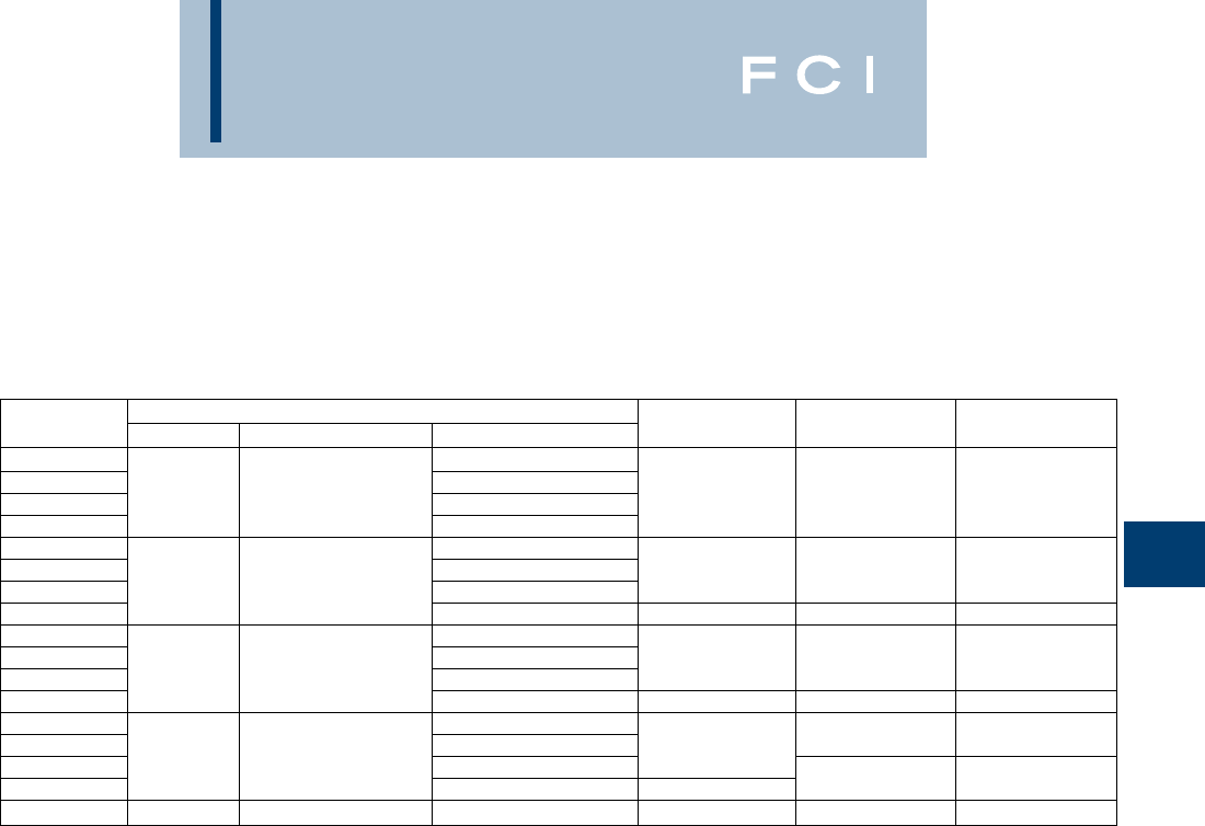
BURNDY
Grounding
D-29
TYPE GAR
(Continued)
FENCE POST GROUNDING
CONNECTOR
Contact BURNDY®for additional pipe and wire size
combinations not shown.
Catalog Conductor
Number Tube I.P.S. Rod Size or O.D. Range Cable H J W
GAR204C 8 Sol. - 4 Str. 5-5/8 3/8 4-3/4
GAR2026 4 Sol. - 2/0 Str.
GAR2029 33 - 3-1/2 2/0 Sol. - 250
GAR2034 300 - 500 6-3/8 1/2 5-1/4
GAR214C 8 Sol. - 4 Str.
GAR2126 4 Sol. - 2/0 Str. 6-1/4 3/8 5-3/8
GAR2129 3-1/2 3-1/2 - 4 2/0 Sol. - 250
GAR2134 300 - 500 6-3/4 1/2 5-3/4
GAR224C 8 Sol. - 4 Str.
GAR2226 4 Sol. - 2/0 Str. 6-3/8 3/8 5-7/8
GAR2229 44 - 4-1/2 2/0 Sol. - 250
GAR2234 300 - 500 6-7/8 1/2 6-1/4
GAR244C 8 Sol. - 4 Str.
GAR2426 4 Sol. - 2/0 Str. 7-3/4 3/8 6-7/8
GAR2429 5—
2/0 Sol. - 250
GAR2434 300 - 500 8-5/8 1/2 7-1/4
GAR8629 6—2/0 Sol. - 250 8-13/16 1/2 8-3/8
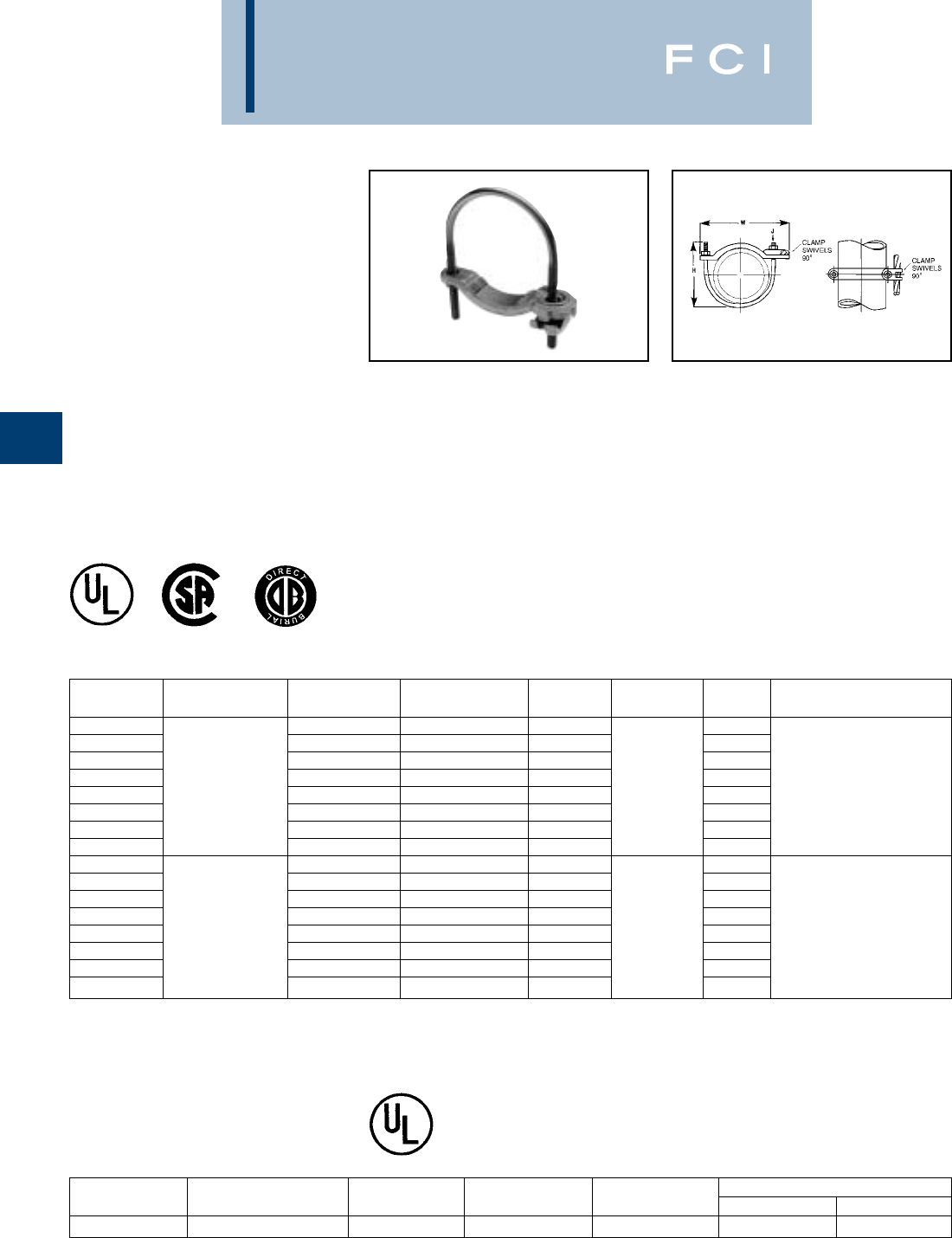
BURNDY
Grounding
D-30
TYPES GAR-BU AND
GAR3902 SERIES
GROUND CONNECTORS
Type GAR-BU is a high-conductivity copper
ground connector for connecting a small to
medium range copper ground conductor to
water pipe as well as structural and reinforc-
ing rod shapes. Universal acceptance of
several sizes of cylindrical shapes makes this
suitable for industrial construction and main-
tenance work as well as cathodic protection.
Cable clamp swivels to permit parallel
grounding of one pipe or 90° degree cable
run for grounding several parallel pipes.
Single wrench installation. UL467 Listed and
CSA certified.
TYPE GAR-RB
For Reinforcement Bar
*Type GAR-BU is supplied with DURIUM™ silicon bronze
hardware and is listed for direct burial.
UL467 listed for direct burial in earth or concrete.
Features and benefits
•Cable clamp swivels at 90°.
◊Permits parallel grounding of one pipe
or a 90° cable run for grounding several
parallel pipes.
•One-wrench installation.
◊Simplified installation.
•DURIUM™ silicon bronze hardware (-BU
Series)*.
◊Long lasting corrosion resistance and
acceptable for direct burial in earth
or concrete.
•UL467 Listed.
◊Provides quality assurance to recognized
industry NEC standards from an
independent party.
*
CATALOG RECOMMENDED
NUMBER * CABLE RANGE IPS SIZE O.D. RANGE H J W TIGHTENING TORQUE
GAR3902-BU 1/2- 1.840 - 1.32 3.50 3.25
GAR3903-BU 1-1/4- 21.66 - 2.38 4.00 4.25
GAR3904-BU 2-1/2- 3-1/22.88 - 4.00 6.50 6.00
GAR3905-BU 4- 54.50 - 5.56 7.50 7.50
GAR3906-BU #4 - 4/0 AWG 66.62 8.50 3/8- 16 8.62 240 in. - lbs.
GAR3907-BU 88.62 10.00 10.62
GAR3908-BU 1010.75 12.00 12.75
GAR3909-BU 1212.75 14.00 14.75
GAR3902 1/2- 1.840 - 1.32 3.50 3.25
GAR3903 1-1/4- 21.66 - 2.38 4.00 4.25
GAR3904 2-1/2- 3-1/22.88 - 4.00 6.50 6.00
GAR3905 4- 54.50 - 5.56 7.50 7.50
GAR3906 #4 - 4/0 AWG 66.62 8.50 3/8- 16 8.62 240 in. - lbs.
GAR3907 88.62 10.00 10.62
GAR3908 1010.75 12.00 12.75
GAR3909 1212.75 14.00 14.75
CATALOG COPPER CONDUCTOR
NUMBER REBAR IPS SIZE O.D. RANGE ROD MIN. MAX.
GAR644C-RB #3 - 6 (.375 - .750) 3/8 .625 - .75 5/8 - 3/4 8 Sol. 4 Str.
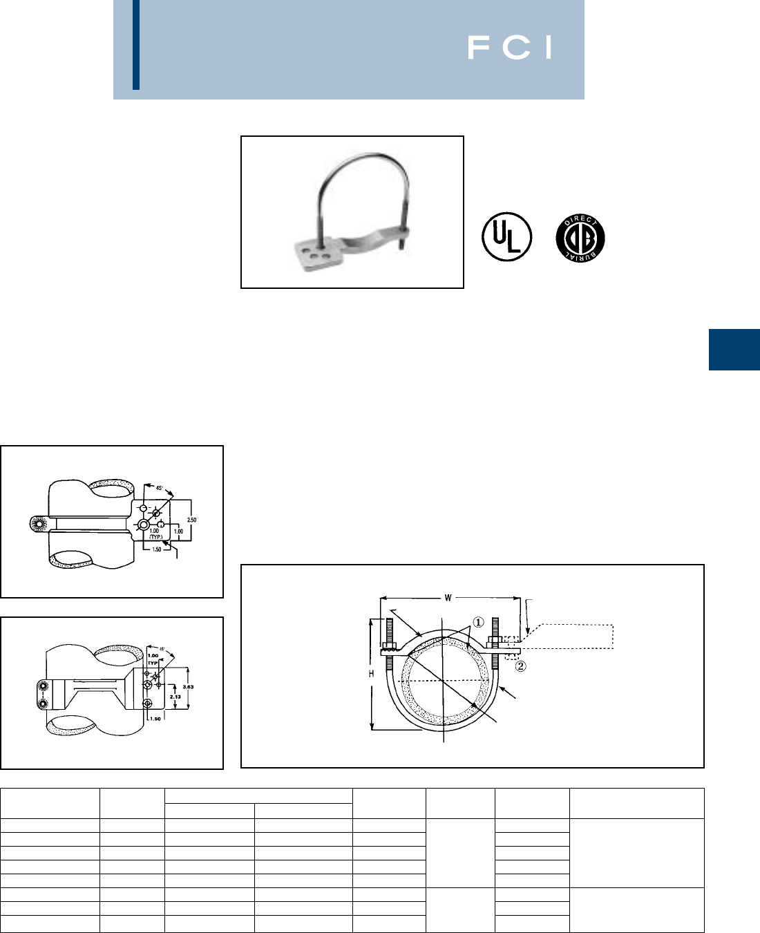
BURNDY
Grounding
D-31
TYPE GAR-TC
WATER PIPE GROUND
CONNECTOR
Type GAR-TC is a high-conductivity copper
ground connector that features a pre-drilled
pad, allowing a 2-hole compression terminal
to be directly connected to water pipe as well
as structural and reinforcing rod shapes.
Universal acceptance of several sizes of
cylindrical shapes makes this suitable for
industrial construction and maintenance work
as well as telecommunications grounding.
Terminal may be mounted parallel, 45° or 90°
degrees to the pipe. Acceptable for direct
burial.
Features and Benefits
•Large, smooth connector contact area
between pipe and ground clamp
◊Provides large surface contact area
to maximize contact area between
connector and pipe.
•The GAR-TC mounting pad permits
parallel, 45° or 90° angle connections
to the pipe.
◊Provides maximum flexibility for
field installation.
•Pre-drilled pad for (2) 3/8bolts on
1centers.
◊Allows direct mounting of (2) hole
compression terminals up to 750 kcmil
to pipe.
①Add suffix “-TNET” for electro-tin plated connector and
electro-tin plated DURIUM™ silicon bronze hardware. Tin
plated catalog number includes mounting hardware for
second bolt hole.
②TMH-289 includes (1) 38 x 125 HEB, (1) 38 CHEN, (1) 38
SW and (2) 38 FW. Order separately.
Fig. 1
Fig. 2
PATENTED
MOUNTING PAD
FOR (2) 3/8"
BOLTS - 1" L
J
MOUNTING PAD
DURIUM 3/8"
SILICON BRONZE
HARDWARE
•DURIUM™ silicon bronze hardware.
◊Provide long lasting corrosion resistance
acceptable for direct burial in earth
or concrete.
•One-wrench installation.
◊Simplified installation.
•UL467 Listed.
◊Provides quality assurance to recognized
industry NEC standards from an
independent party. Type GAR-TC is
acceptable for direct burial
PIPE DIA.
CAST HIGH COPPER ALLOY SADDLE
COMPRESSION LUG WITH PAD
FOR (2) 3/8" DIA. BOLTS
ON 1" CENTERS. 750 KCMIL MAX.
CATALOG FIG. ACCOMMODATES RECOMMENDED
NUMBER NO. I.P.S. O.D. SIZE H J W TIGHTENING TORQUE
GAR3902TC 11/2- 1.840 - 1.32 3.50 3.75
GAR3903TC 11-1/4- 21.66 - 2.38 4.00 4.75
GAR3904TC 12-1/2- 3-1/22.88 - 4.00 6.50 3/8- 16 6.50 240 in.-lbs.
GAR3905TC 14- 54.50 - 5.56 7.50 8.00
GAR3906TC 166.62 8.50 9.12
GAR3907TC 288.62 10.00 11.25
GAR3908TC 21010.75 12.00 3/8- 16 13.25 240 in.-lbs.
GAR3909TC 21212.75 14.00 15.25
NOTE: Clean pipe surface beneath saddle until virgin metal is
exposed, install GAR-TC ground connector and for
maximum
conductivity, apply PENETROX®-E oxide inhibiting
compound around perimeter of the saddle.

BURNDY
Grounding
D-32
TYPE GD
CABLE TO ROD/TUBE
GROUND CONNECTOR
For Two Copper Cables to Rod
or Tube
High copper alloy ground connector for join-
ing a range of two parallel cables to rod or
pipe. Especially good for grounding fence
posts. High copper alloy cast body with
DURIUM™ U-bolts, nuts, and lockwashers
make the GD suitable for burial in ground or
concrete. One-wrench installation. UL467
Listed. Acceptable for direct burial in earth
or concrete.
Complies with NFPA 78-86 HEAVY DUTY stacks.
(Order: LD for lead plating for HEAVY DUTY stack
applications.)
Catalog Conductor
Number Tube I.P.S. Rod Size or O.D. Range Cable H J W
GD1526 4 Sol. - 2/0 Str.
GD1529 11-1/8 - 1-1/4 2/0 Sol. - 250 3-3/8 2-5/8
GD1626 4 Sol. - 2/0 Str. 3
GD1629 1-1/4 1-3/8 - 1-1/2 2/0 Sol. - 250 3-1/2 3/8
GD174C 8 Sol. - 4 Str.
GD1726 4 Sol. - 2/0 Str. 4 3-1/4
GD1729 1-1/2 1-5/8 - 1-7/8 2/0 Sol. - 250
GD1734 300 - 500 4-5/8 1/2 3-5/8
GD184C 8 Sol. - 4 Str.
GD1826 4 Sol. - 2/0 Str. 4-3/8 3/8 3-3/4
GD1829 22 - 2-3/8 2/0 Sol. - 250
GD1834 300 - 500 5-3/8 1/2 4-1/8
GD194C 8 Sol. - 4 Str.
GD1926 4 Sol. - 2/0 Str. 3/8 4-1/4
GD1929 2-1/2 2-1/2 - 2-7/8 2/0 Sol. - 250 5
GD1934 300 - 500 1/2 4-5/8
GD204C 8 Sol. - 4 Str.
GD2026 4 Sol. - 2/0 Str. 5-5/8 3/8 4-7/8
GD2029 33 - 3-1/2 2/0 Sol. - 250
GD2034 300 - 500 6-3/8 1/2 5-1/4
GD214C 8 Sol. - 4 Str.
GD2126 4 Sol. - 2/0 Str. 6-1/4 3/8 5-3/8
GD2129 3-1/2 3-1/2 - 4 2/0 Sol. - 250
GD2134 300 - 500 6-7/8 1/2 5-3/4
GD224C 8 Sol. - 4 Str.
GD2226 4 Sol. - 2/0 Str. 6-3/8 3/8 5-7/8
GD2229 44 - 4-1/2 2/0 Sol. - 250
GD2234 300 - 500 6-7/8 1/2 6-1/4
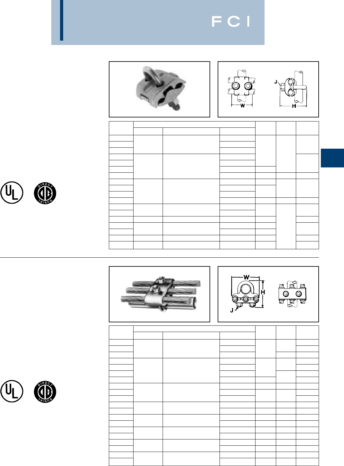
BURNDY
Grounding
D-33
TYPE GP
GROUND CONNECTOR
For Two Copper Cables
to Rod or Pipe
High copper alloy ground connector for join-
ing a range of parallel cables perpendicular to
rod, pipe or column. Also used with one
groove for run, the other for tap to equipment.
High copper alloy cast body and DURIUM™
U-bolts, nuts, and lockwashers make the GP
suitable for direct burial in the ground or
concrete. One-wrench installation. UL467
Listed. Acceptable for direct burial in earth
or concrete.
TYPE GK
GROUND CONNECTOR
For Three Copper Cables to
Rod or Pipe
High copper alloy ground connector for join-
ing three equal cables to rod or tube. Cable
grooves take a wide range of cable. High
copper alloy cast body and DURIUM™
U-bolts, nuts, and lockwashers make the GK
suitable for direct burial in soil or concrete.
One-wrench installation. UL467 Listed.
Acceptable for direct burial in earth or
concrete.
Catalog Conductor
Number Tube I.P.S. Rod Size or O.D. Range Cable H J W
GP114C 8 Sol. - 4 Str.
GP1126 1/4 1/2 4 Sol. - 2/0 Str. 1-7/8
GP1129 2/0 Sol. - 250 2-1/2
GP644C 8 Sol. - 4 Str. 3/8
GP6426 4 Sol. - 2/0 Str. 2-1/8
GP6429 3/8 5/8 - 3/4 2/0 Sol. - 250 2-7/8
GP6434 300 - 500 3-1/2 1/2 2-1/2
GP144C 8 Sol. - 4 Str. 2-3/4
GP1426 4 Sol. - 2/0 Str. 38 2-3/8
GP1429 1/2 - 3/4 7/8 - 1 3/0 Sol. - 250 3
GP1434 300 - 500 3-3/4 1/2 2-3/4
GP164C 8 Sol. - 4 Str.
GP1629 1-1/4 1-5/8 2/0 Sol. - 250 3-1/2 3
GP1726 1-1/2 1-7/8 4 Sol. - 2/0 Str. 4 3-1/4
GP184C 8 Sol. - 4 Str. 4-1/8 3/8
GP1826 22-3/8 4 Sol. - 2/0 Str. 4-3/8 3-11/16
GP2026 33-1/2 4 Sol. - 2/0 Str. 5-1/2 4-13/16
GP2226 44-1/2 4 Sol. - 2/0 Str. 6-3/8 5-13/16
Catalog Conductor
Number Tube I.P.S. Rod Size or O.D. Range Cable H J W
GK114C 8 Sol. - 4 Str. 2-1/2
GK1126 1/4 1/2 4 Sol. - 2/0 Str. 2-1/2 3/8 2-3/4
GK1129 2/0 Sol. - 250 1/2 3-3/8
GK644C 8 Sol. - 4 Str. 2-5/8
GK6426 4 Sol. - 2/0 Str. 2-7/8 3/8 3
GK6429 3/8 5/8 - 3/4 2/0 Sol. - 250 3-1/2
GK6434 300 - 500 3-1/2 1/2 4
GK1426 4 Sol. - 2/0 Str. 2-3/4 38 3-1/4
GK1429 1/2 - 3/4 7/8 - 1 2 Sol. - 250 3-7/8
GK1434 300 - 500 3-3/4 1/2 4-3/8
GK1526 4 Sol. - 2/0 Str. 3-3/8 3/8 3-1/2
GK1529 11-1/8 - 1-1/4 2/0 Sol. - 250 3-3/4 1/2 4-1/8
GK1626 4 Sol. - 2/0 Str. 3-1/2 3/8 3-7/8
GK1629 1-1/4 1-3/8 - 1-1/2 2/0 Sol. - 250 4-1/4 1/2 4-1/2
GK1726 4 Sol. - 2/0 Str. 4 3/8 4-1/8
GK1729 1-1/2 1-5/8 - 1-7/8 2/0 Sol. - 250 4-5/8 1/2 4-3/4
GK1826 4 Sol. - 2/0 Str. 4-1/4 3/8 4-5/8
GK1829 22 - 2-3/8 2/0 Sol. - 250 4-3/8 1/2 5-1/8
GK1926 4 Sol. - 2/0 Str. 5 3/8 5-1/8
GK1929 2-1/2 2-1/2 - 2-7/8 2/0 Sol. - 250 5 1/2 5-5/8
BURNDY
Grounding
D-34
CAST BRONZE
CLAMPS FOR
CONDUIT
Pressure bar type conduit hub adjusts for
1/2, 3/4EMT or 1/2rigid conduit. Hub
swings 360° for easy alignment. Zinc plated
hardware.
CAST BRONZE
GROUND CLAMPS
For connecting grounding conductor to water
pipe or copper tube. "D" indicates UL467
Listed for direct burial in earth and concrete
and are supplied with silicon bronze hard-
ware. "B" indicates brass hardware.
BUDGET PRICE
CAST BRONZE
GROUND CLAMP
Similar to above but lighter duty.
RECOMMENDED
ACCOMMODATES REFERENCE SCREW TORQUE
CONDUCTOR RANGE DIMENSIONS “INCH POUNDS”
CATALOG WATER HUB PIPE WIRE
NUMBER PIPE GROUND SIZE H L W CLAMP CLAMP
1/2 - 1 2.07 3.19
C-11JPT [13 - 25] [53] [81]
1-1/4 - 2 10 - 6 1/2 2.70 3.83 2.70
C-22JPT [32 - 51] Sol. [13] [69] [97] [69] 50 in.-lb. 50 in.-lb.
2-1/2 - 4 4.39 5.15
C-4JPT [64 - 102] [112] [131]
RECOMMENDED
ACCOMMODATES SCREW TORQUE
CONDUCTOR RANGE “INCH POUNDS”
CATALOG WATER REFERENCE DIMENSIONS PIPE WIRE
NUMBER PIPE REBAR GROUND H L W C CLAMP CLAMP
C-11N —
C-11D 1/2 - 1 #4 - #6 10 - 2 1.81 2.25 .63 .63
C-11B [13 - 25] Str. [46] [56] [16] [16]
C-22 1-1/4 - 2 10 - 2 2.38 3.63 .75 1.00
C-22D [32 - 51] Str. [60] [92] [19] [25] 50 in.-lb. 50 in.-lb.
2-1/2 - 4 —10 - 2 4.13 6.25 .96 1.88
C-4 [64 - 114] Str. [105] [159] [24] [48]
4-1/2 - 6 10 - 2 4.29 8.34 1.25 1.88
C-8 [114 - 165] Str. [109] [212] [32] [48]
RECOMMENDED
ACCOMMODATES SCREW TORQUE
CONDUCTOR RANGE “INCH POUNDS”
CATALOG WATER REFERENCE DIMENSIONS PIPE WIRE
NUMBER PIPE REBAR GROUND H L W C CLAMP CLAMP
C-5 1/2 - 1 10 - 2 1.56 2.25 .56 .50
(JUNIOR) [13 - 25] —Str. [40] [56] [14] [13] 50 in.-lb. 50 in.-lb.
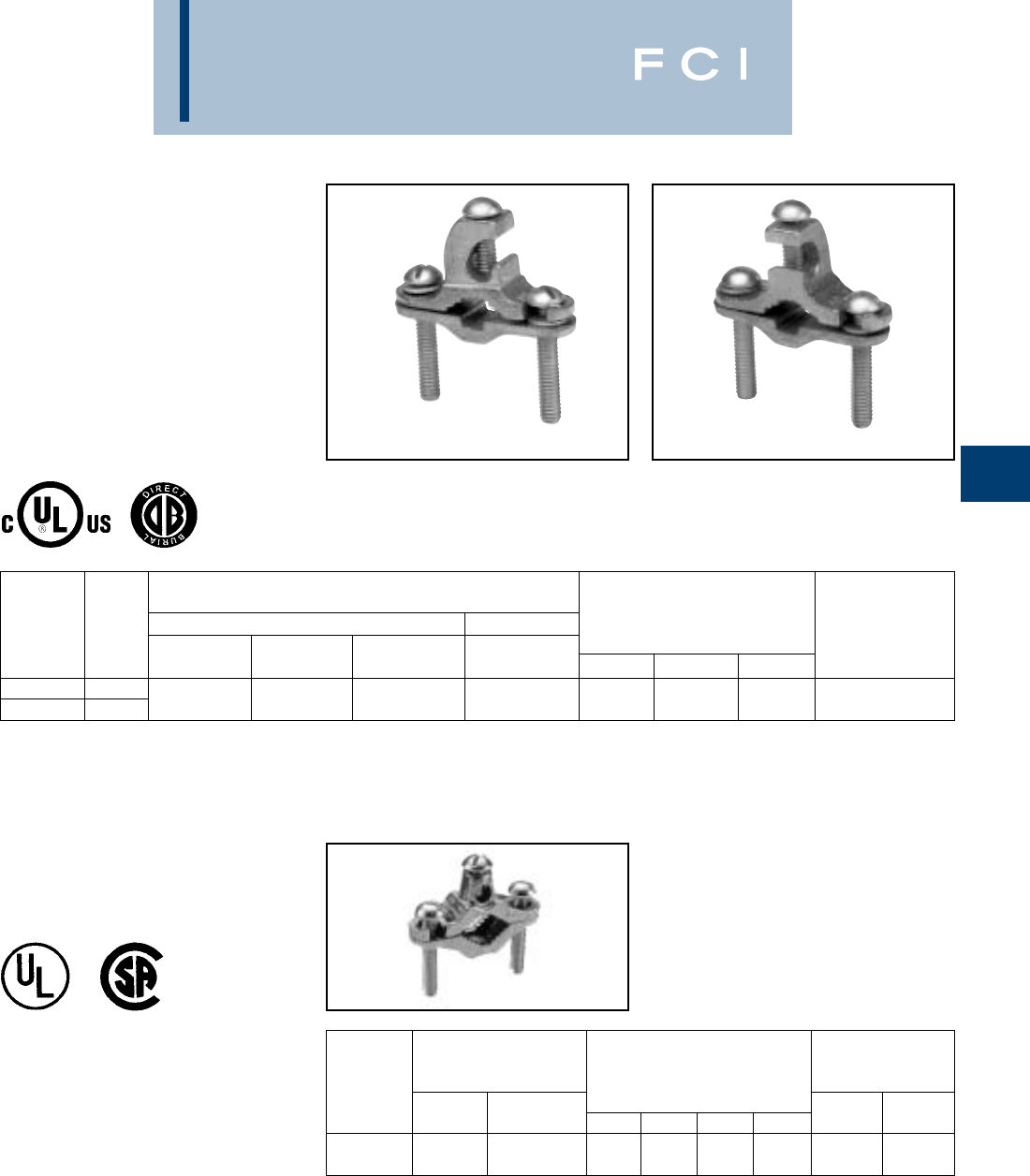
BURNDY
Grounding
D-35
CAST BRONZE
GROUND CLAMPS
With Lay-in Feature
For connecting grounding conductor to water
pipe, copper tube, ground rod or rebar. The
open face design allows for fast lay-in of the
tap conductor without the need for cutting.
Simply reverse bottom clamp for smaller size
rebar or rod. Connectors are provided with
Silicon Bronze hardware.
ACCOMMODATES
CONDUCTOR RANGE
MAIN TAP REFERENCE RECOMMENDED
CATALOG WATER GROUND DIMENSIONS SCREW TORQUE
NUMBER FIG # PIPE REBAR ROD GROUND H L W “INCH POUNDS”
C11K16D Fig 1 1/2- 1#10 - #2
C11K17D Fig 2 [13 - 25] #4 - #6 3/8- 1
Str. 1.64 2.28 0.66 50 in.-lbs.
Fig. 2
DIE CAST CLAMPS
Die cast zinc with zinc plated screws.
RECOMMENDED
ACCOMMODATES SCREW TORQUE
CONDUCTOR RANGE “INCH POUNDS”
CATALOG WATER REFERENCE DIMENSIONS PIPE WIRE
NUMBER PIPE GROUND H L W C CLAMP CLAMP
1/2 - 1 10 - 2 1.56 2.25 .56 .50
CZ-11 [13 - 25] Str. [40] [56] [14] [13] 50 in.-lb. 50 in.-lb.
Fig. 1
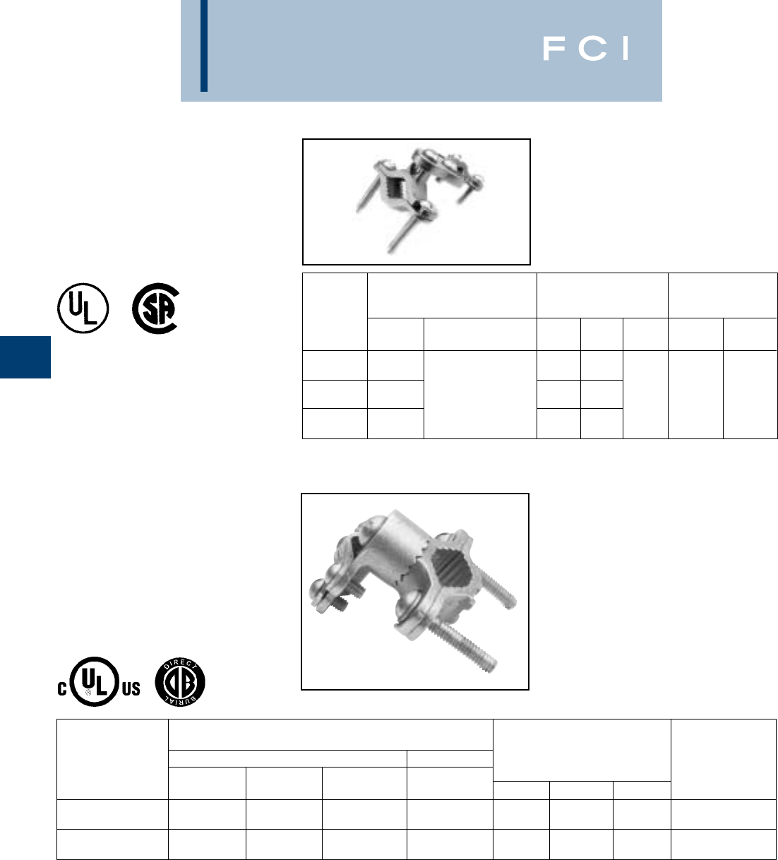
BURNDY
Grounding
D-36
CAST BRONZE
GROUND CLAMPS
For connecting grounding conductor, EMT or
rigid conduit to water pipe, copper tube,
ground rod or rebar. Hub swings 360° for
easy alignment. Simply reverse bottom clamp
for smaller size rebar or rod. Connectors are
provided with Silicon Bronze hardware.
ACCOMMODATES
CONDUCTOR RANGE
MAIN TAP REFERENCE RECOMMENDED
CATALOG WATER GROUND DIMENSIONS SCREW TORQUE
NUMBER PIPE REBAR ROD GROUND H L W “INCH POUNDS”
1/2- 1#8 - 4/0
C11HD4/0DB [13 - 25] #4 - #6 3/8- 1
AWG 2.25 2.65 1.56 50 in.-lbs.
1-1/4- 2#8 - 4/0
C22HD4/0DB [32 - 51] ——
AWG 2.70 3.60 1.56 50 in.-lbs.
CAST BRONZE
CLAMPS
To connect armored cable to water pipe. Zinc
plated screws. Pressure bar grips armor or
outer cable insulation. 360° swing hub for
easy alignment.
RECOMMENDED
ACCOMMODATES REFERENCE SCREW TORQUE
CONDUCTOR RANGE DIMENSIONS “INCH POUNDS”
CATALOG WATER ARMORED PIPE WIRE
NUMBER PIPE CONDUCTOR H L W CLAMP CLAMP
1/2 - 1 1.38 3.05
C-11JA [13 - 25] [35] [77]
1-1/4 - 2 10 - 6 2.60 3.69 1.41
C-22JA [32 - 51] Sol. [66] [94] [36] 50 in.-lb. 50 in.-lb.
2-1/2 - 4 4.29 5.01
C-4JA [64 - 102] [109] [128]
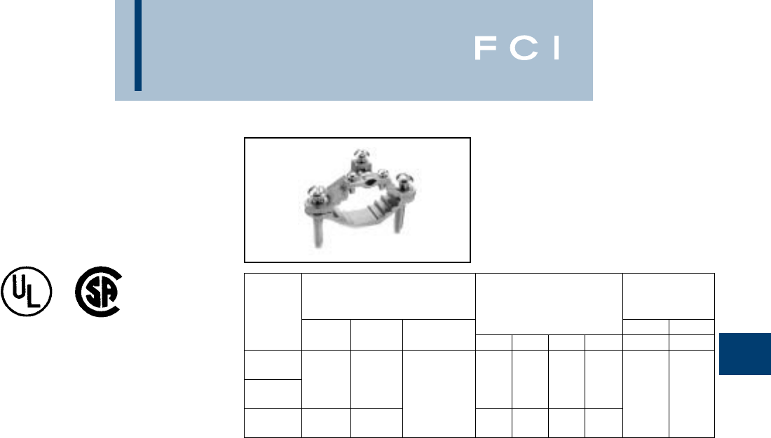
BURNDY
Grounding
D-37
CAST BRONZE
CLAMPS
For connecting armored cable to water pipe.
Zinc plated screws. "D" indicates UL467 for
direct burial in earth and concrete, supplied
with silicon bronze hardware.
RECOMMENDED
ACCOMMODATES SCREW TORQUE
CONDUCTOR RANGE “INCH POUNDS”
CATALOG WATER GROUND REFERENCE DIMENSIONS PIPE WIRE
NUMBER PIPE GROUND CLAMP H L W C CLAMP CLAMP
C-6 1/2 - 1 10 - 2 Bare Armored 1.60 2.34 1.06 .63
[13 - 25] Str. Unarmored [41] [59] [27] [16]
C-6D Wire Cables 50 in.-lb. 50 in.-lb.
1-1/4 - 2 10 - 2 or Cords 2.38 3.62 .94 1.00
C-7 [32 - 51] Str. [60] [92] [24] [25]
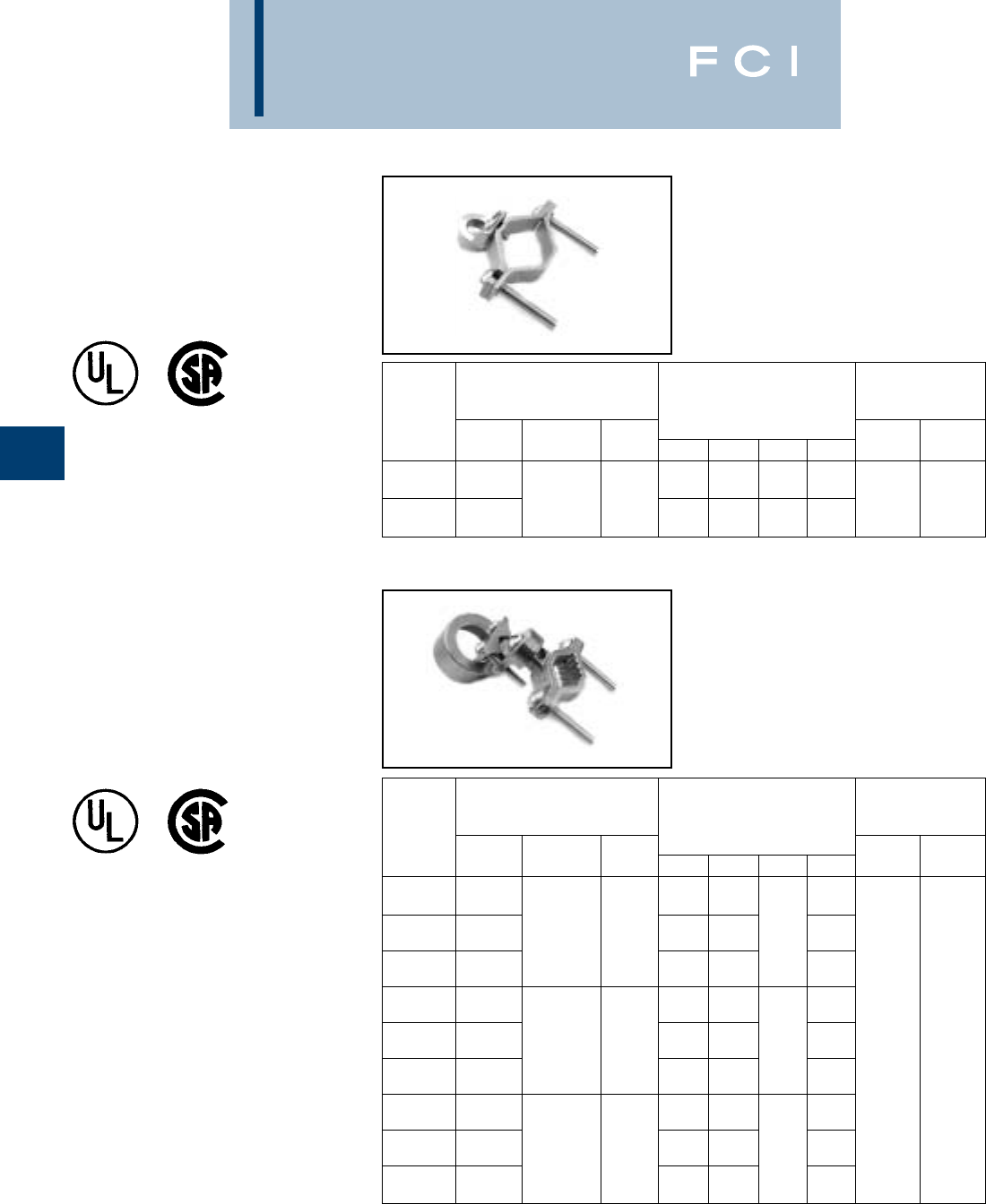
BURNDY
Grounding
D-38
CAST BRONZE
CLAMP FOR
RIGID CONDUIT
For grounding rigid conduit systems.
Zinc plated screws.
CAST BRONZE
CLAMPS FOR
CONDUIT
For grounding rigid conduit systems.
Continuity from rigid conduit systems to
ground provided by cast bronze threaded
conduit hub. Zinc plated screws.
RECOMMENDED
ACCOMMODATES SCREW TORQUE
CONDUCTOR RANGE “INCH POUNDS”
CATALOG WATER HUB REFERENCE DIMENSIONS PIPE WIRE
NUMBER PIPE GROUND SIZE H L W C CLAMP CLAMP
1/2 - 1 2.07 2.34 1.34 1.06
C-61 [13 - 25] #6 Sol. 1/2 [53] [59] [34] [27]
1-1/4 - 2 Max. [13] 2.69 3.62 1.34 1.40 50 in.-lb. 50 in.-lb.
C-66 [32 - 51] [68] [92] [34] [36]
RECOMMENDED
ACCOMMODATES SCREW TORQUE
CONDUCTOR RANGE “INCH POUNDS”
CATALOG WATER HUB REFERENCE DIMENSIONS PIPE WIRE
NUMBER PIPE GROUND SIZE H L W C CLAMP CLAMP
1/2 - 1 2.25 3.23 .97
C-11LH-1 [13 - 25] [57] [83] [25]
1-1/4 - 2 10 Str. - 1/2 2.88 3.50 .69 1.34
C-22LH-1 [32 - 51] 6 Sol. [13] [73] [89] [18] [34]
2-1/2 - 4 4.56 4.82 2.44
C-4LH-1 [54 - 102] [116] [122] [62]
1/2 - 1 2.56 2.86 1.13
C-11LH-2 [13 - 25] [65] [73] [29]
1-1/4 - 2 2/0 - 10 3/4 3.19 3.50 1.00 1.50
C-22LH-2 [32 - 51] Str. [19] [65] [89] [25] [38] 50 in.-lb. 50 in.-lb.
2-1/2 - 4 4.88 4.82 2.38
C-4LH-2 [64 - 102] [124] [122] [60]
1/2 - 1 2.69 2.86 1.19
C-11LH-3 [13 - 25] [68] [73] [30]
1-1/4 - 2 3/0 - 10 1 3.32 3.50 1.13 1.56
C-22LH-3 [32 - 51] Str. [25] [59] [89] [29] [40]
2-1/2 - 4 5.01 4.82 2.44
C-4LH-3 [63 - 102] [127] [122] [62]
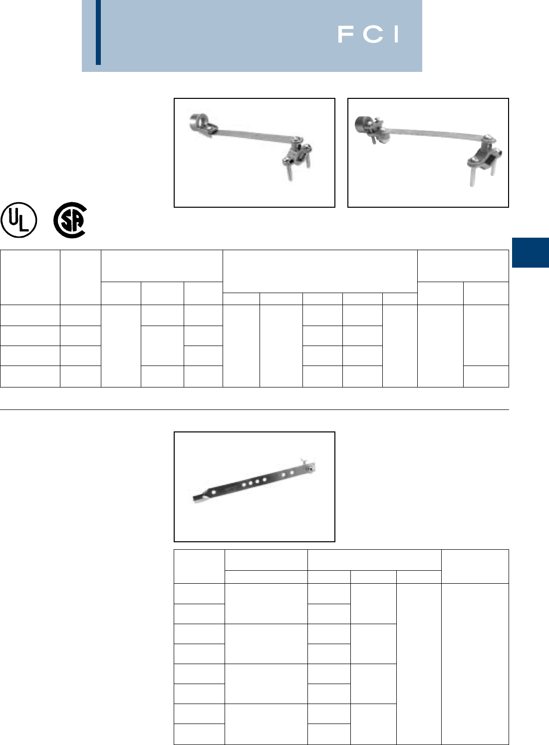
BURNDY
Grounding
D-39
CAST BRONZE
CLAMP WITH
COPPER STRAP
For grounding rigid conduit systems. Strap
helps protect conduit system from water
system vibrations. Zinc plated screws. Strap
ETP copper.
GROUND STRAPS,
ADJUSTABLE
BURNDY®adjustable ground straps are
made from pure annealed copper. The heavy
type is .050thick and 3/4wide. The light
type is .025thick and 3/4wide. The bolts,
nuts and washers are plated steel. Four sizes
cover a ground pipe range of 3/8to 4.
Ground wire connection can be soldered or
solderless.
RECOMMENDED
ACCOMMODATES SCREW TORQUE
CONDUCTOR RANGE “INCH POUNDS”
CATALOG WATER HUB REFERENCE DIMENSIONS PIPE WIRE
NUMBER FIG. # PIPE GROUND SIZE H L W C D CLAMP CLAMP
6 Sol. 1/2 1.06 1.06
C-11CSH-1 Fig. 1 Max. [13] [27] [27]
3/4 1.25 1.50
C-11CSH-2 Fig. 1 1/2 - 1 4/0 Str. [19] 1.75 8.50 [32] [38] 6.12 50 in.-lb.
[13 - 25] Max. 1 [44] [216] 1.50 1.75 [155] 50 in.-lb.
C-11CSH-3 Fig. 1 [25] [38] [44]
#10 - 2/0 1/2 1.18 1.06
C11CSLH12 Fig. 2 AWG [13] [27] 45 in.-lb.
RECOMMENDED
CATALOG ACCOMMODATES REFERENCE DIMENSIONS SCREW TORQUE
NUMBER WATER PIPE H L W “INCH POUNDS”
.050
GS1T50 3/8 - 1 [1] 5.61
[10 - 25] .025 [142]
GS1T25 [1]
.050
GS2T50 3/8 - 2 [1] 9.38
[10 - 51] .025 [238]
GS2T25 [1] .75
.050 [19] 50 in.-lb.
GS3T50 3/8 - 3 [1] 13.20
[10 - 76] .025 [335]
GS3T25 [1]
.050
GS4T50 3/8 - 4 [1] 17.00
[10 - 102] .025 [432]
GS4T25 [1]
Fig. 1 Fig. 2

BURNDY
Grounding
D-40
TYPE GC-A
DUAL RATED
GROUND CLAMP
For Copper and
Aluminum Cable
GC-A ground clamps are UL Listed for use
with either copper or aluminum conductors to
copper water pipe, galvanized pipe or steel
conduit. All clamps are constructed from tin
plated high-strength extruded aluminum alloy.
PENETROX™ oxide inhibiting joint com-
pounds are recommended for all aluminum
applications. Features and Benefits
•Clamps are dual rated for both copper
and aluminum conductors.
◊Maximum flexibility of application.
•All connectors are tin plated.
◊Provide low contact resistance and
prevents galvanic corrosion.
•All clamps are range taking.
◊Only 3 catalog numbers covers complete
range of applications from 1/2 - 4 inches.
Catalog Conduit, Pipe, or Wire Screw Hex
Number Water Tube Size Range Type W L Size
GC15A 1/2 - 3/4 - 1 1/0 - 14 Slotted 11/16 2-1/4 S
GC18A 1-1/4 - 1-1/2 - 2 250 MCM - 6 Hex Socket 13/16 3-3/4 5/16
GC22A 2-1/2 - 3 - 3-1/2 - 4 250 MCM - 6 Hex Socket 1 6-5/16 5/16
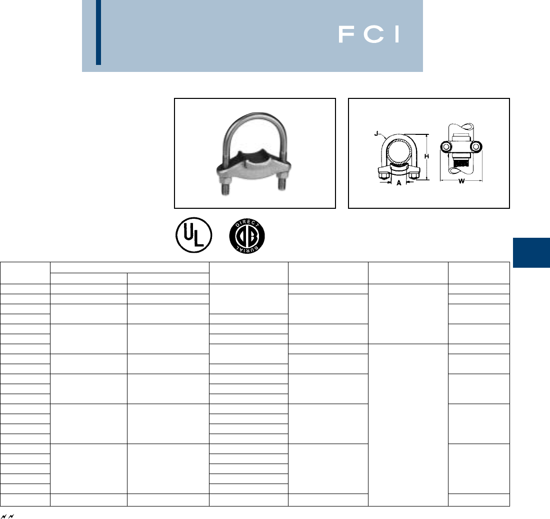
BURNDY
Grounding
D-41
TYPE GG
GROUND CONNECTOR
For Copper Bar, Strap, Braid or
Cable to Rod or Tube
High copper alloy ground connector for join-
ing bar, strap, braid or cable to rod or tube.
High copper alloy cast body, DURIUM™
U-bolts, nuts and lockwashers make the GG
particularly effective for use with braid for
ground rods, switch handles, fence posts and
gates. One-wrench installation.
See note page D-1
Catalog Conductor
Number Tube I.P.S. Rod A H J W
GG15-1 11-1/8 - 1-1/4 3-3/8 2-5/8
GG16-1 1-1/4 1-3/8 - 1-1/2 1 3
GG17-1 3-1/2
GG17-15 1-1/2 1-5/8 - 1-7/8 1-1/2 3/8 3-1/4
GG18-1 1
GG18-15 22 - 2-3/8 1-1/2 4-1/4 3-3/4
GG18-2 4-3/8 4-1/8
GG19-2 2
GG19-25 2-1/2 2-1/2 - 2-7/8 2-1/2 54-5/8
GG20-2 2
GG20-25 33 - 3-1/2 2-1/2 6-3/8 5-1/4
GG20-3 3
GG21-2 2
GG21-25 2-1/2
GG21-3 3-1/2 3-1/2 - 4 35-7/8 1/2 5-3/4
GG21-35 3-1/2
GG22-2 2
GG22-25 2-1/2
GG22-3 44 - 4-1/2 3 6-1/2 6-1/4
GG22-35 3-1/2
GG22-4 4
GG24-2 5— 27-5/8 7-1/4
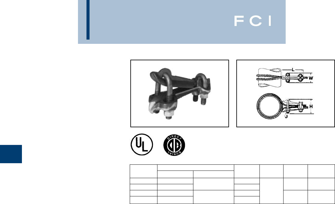
BURNDY
Grounding
D-42
TYPE GQ
GROUND CONNECTOR
For Copper Cable to Tube
High copper alloy ground connector for cross
connecting a wide range of cable. High
copper alloy, cast body, DURIUM™ U-bolts,
nuts, and lockwashers make the GQ suitable
for burial in soil or concrete. One-wrench
installation. UL467 Listed. Acceptable for
direct burial in earth or concrete.
Catalog Conductor
Number Tube I.P.S. Cable H J L W
GQ2626 6Max. 4-1/2
GQ26-1 Above 64 Str. - 2/0 Str. 7-1/8 52-1/2
GQ2929 6Max. 4-1/8 1/2
GQ29-1 Above 62/0 Str. - 250 7-1/2 62-3/4
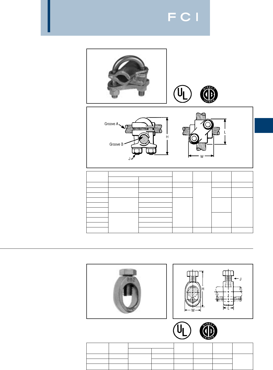
BURNDY
Grounding
D-43
TYPE GX
GROUND CONNECTOR
For Copper Cables
High copper alloy ground connector for cross
connecting a wide range of cable. The high
copper alloy cast body, DURIUM™ U-bolts,
nuts, and lockwashers make the GX suitable
for burial in soil or concrete. One-wrench
installation. UL467 Listed. Acceptable for
direct burial in earth or concrete.
TYPE GRC
HIGH STRENGTH
GROUND ROD CLAMP
For Copper Cable to Rod
High copper alloy ground connector for
joining a range of cable to copper clad,
galvanized steel, and stainless steel ground
rods. Slips over end of rod, one-wrench
installation. UL467 Listed for direct burial in
earth and concrete. REA LISTED
Catalog Conductor
Number Groove A Groove B H J L W
GX4C4C 8 Sol. - 4 Str. 8 Sol. - 4 Str. 1-7/8 1-5/8 1-5/8
GX264C 8 Sol. - 4 Str.
GX2626 4 Sol. - 2/0 Str. 4 Sol. - 2/0 Str. 2-1/2 1-3/4 1-3/4
GX294C 8 Sol. - 4 Str.
GX2926 2/0 Sol. - 250 4 Sol. - 2/0 Str. 3/8 1-7/8
GX2929 2/0 Sol. - 250
GX344C 8 Sol. - 4 Str. 2-3/4 1-7/8
GX3426 4 Sol. - 2/0 Str. 2-1/8
GX3429 300 - 500 2/0 Sol. - 250
GX3434 300 - 500 4-1/4 1/2 2-5/8 2-5/8
Catalog Drive Conductor Range
Number Rod Min. Max. H W L J
GRC12 1/2 2 Str. 2.00 .89 .63
GRC58 5/8 10 Sol. 1 Str. 2.19 .95 .63 3/8
GRC34 3/4 8 Sol. 1/0 Str. 2.47 1.09 .65
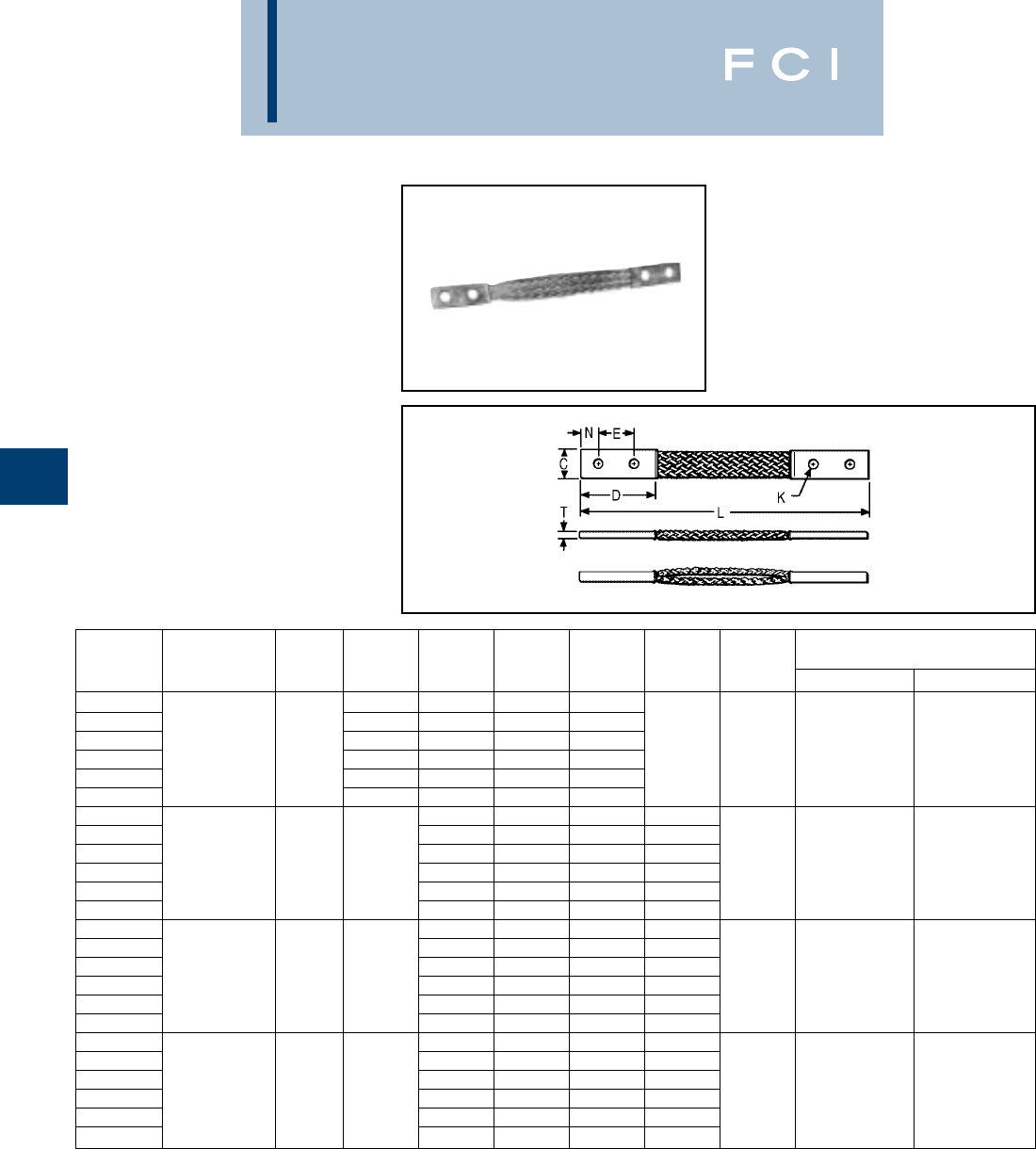
BURNDY
Grounding
D-44
TYPE B
FLEXIBLE COPPER BRAID
Flexible copper braid jumpers designed to
take up linear expansion and contraction,
compensate for misalignment and absorb
vibratory movement of electrical equipment
and devices.
Made of flat extra flexible, tinned, pure copper
braid, with unplated, seamless, pure copper
ferrules formed into a rectangular shape on
each end.
Last two numbers in catalog number indicate
total length of braid in inches (e.g., BD12N or
BD12 is 12long braid jumper).
Other lengths, plating and drilling are
available. Refer to factory or Section G
(Substation).
*This rating may vary with ambient conditions, orientation of
the braid and other service conditions.
** Tongue drilled per (2) hole NEMA standard.
NUMBER OF
CATALOG BRAIDS IN APPROXIMATE AMP
NUMBER FERRULES C D E K L N T INDOOR OUTDOOR
BD12 2.50 1.25 .44 12
BD12N** 3.00 1.75 .56 12
BD18 2.50 1.25 .44 18
BD18N** 1.94 3.00 1.75 .56 18 .62 .13 190 225
BD24 2.50 1.25 .44 24
BD24N** 3.00 1.75 .56 24
BE12 1.50 .44 12 .75
BE12N** 1.75 .56 12 .62
BE18 1.50 .44 18 .75
BE18N** 11.50 3.00 1.75 .56 18 .62 .17 340 405
BE24 1.50 .44 24 .75
BE24N** 1.75 .56 24 .62
BF12 1.50 .44 12 .75
BF12N** 1.75 .56 12 .62
BF18 1.50 .44 18 .75
BF18N** 11.19 3.00 1.75 .56 18 .62 .25 360 430
BF24 1.50 .44 24 .75
BF24N** 1.75 .56 24 .62
BG12 1.50 .44 12 .75
BG12N** 1.75 .56 12 .62
BG18 1.50 .44 18 .75
BG18N** 11.50 3.00 1.75 .56 18 .62 .25 415 495
BG24 1.50 .44 24 .75
BG24N** 1.75 .56 24 .62
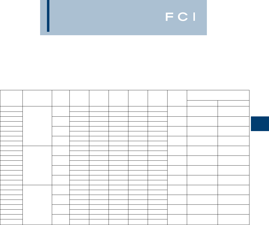
BURNDY
Grounding
D-45
FLEXIBLE COPPER
BRAID
(Continued)
TYPE B
*This rating may vary with ambient conditions, orientation of
the braid and other service conditions.
** Tongue drilled per (2) hole NEMA standard.
NUMBER OF
CATALOG BRAIDS IN APPROXIMATE AMP
NUMBER FERRULES C D E K L N T INDOOR OUTDOOR
B2D12 2.50 1.25 .44 12 .62
B2D12N** .94 3.00 1.75 .56 12 .62 .25 380 455
B2E12 3.00 1.50 .44 12 .75
B2E12N** 1.62 3.00 1.75 .56 12 .62 .25 530 635
B2F12 23.00 1.50 .44 12 .75
B2F12N** 1.38 3.00 1.75 .56 12 .62 .38 600 720
B2G12 3.00 1.50 .44 12 .75
B2G12N** 1.50 3.00 1.75 .56 12 .62 .50 700 840
B3D12 2.50 1.25 .44 12 .62
B3D12N** 1.19 3.00 1.75 .56 12 .62 .25 470 560
B3E12 3.00 1.50 .44 12 .75
B3E12N** 1.64 3.00 1.75 .56 12 .62 .31 700 840
B3F12 33.00 1.50 .44 12 .75
B3F12N** 1.44 3.00 1.75 .56 12 .62 .56 820 980
B3G12 3.00 1.50 .44 12 .75
B3G12N** 1.69 3.00 1.75 .56 12 .62 .69 960 1150
B4D12 2.50 1.25 .44 12 .62
B4D12N** 1.19 3.00 1.75 .56 12 .62 .32 600 720
B4E12 3.00 1.50 .44 12 .75
B4E12N** 1.64 3.00 1.75 .56 12 .62 .36 850 1020
B4F12 43.00 1.50 .44 12 .75
B4F12N** 1.50 3.00 1.75 .56 12 .62 .78 1000 1200
B4G12 3.00 1.50 .44 12 .75
B4G12N** 1.69 3.00 1.75 .56 12 .62 .94 1200 1440
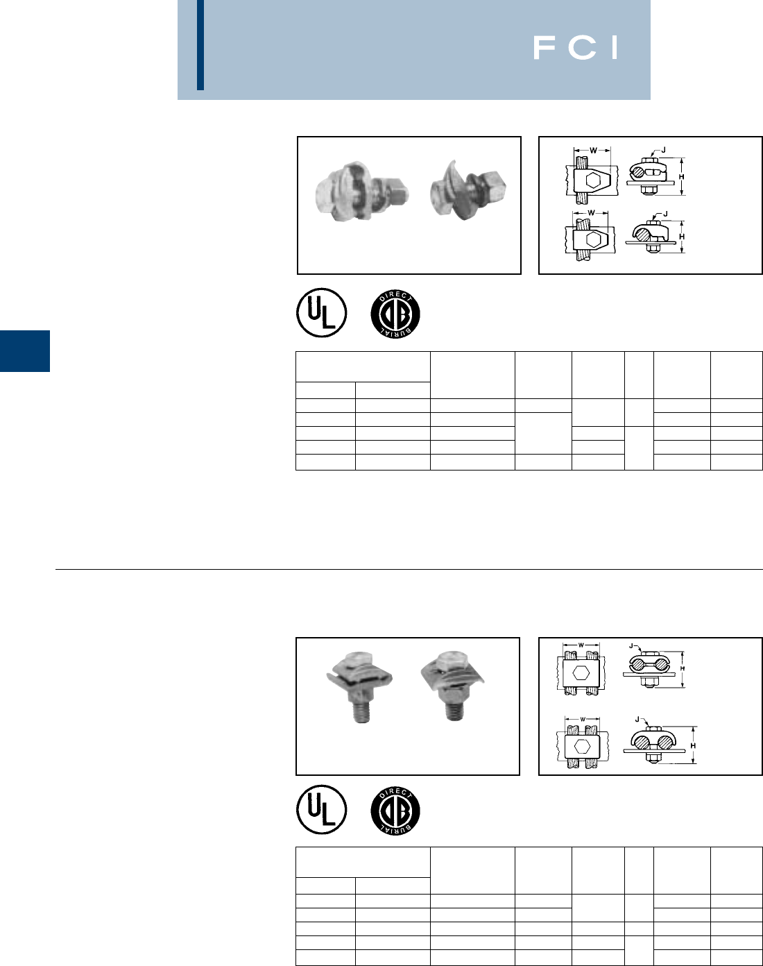
BURNDY
Grounding
D-46
TYPES GB, GBM
GROUND CONNECTOR
For Copper Cable to Bar
High copper alloy ground connector for
joining a range of cable to 1/4thick bar.*
Type GB separates cable from bar, GBM
clamps cable directly on bar surface.
One-wrench installation. UL467 Listed. The
high copper alloy cast body and DURIUM™
bolts, nuts, and lockwashers make the GB
and GBM suitable for direct burial in concrete
or ground.
TYPES GC, GCM
GROUND CONNECTOR
For Two Copper
Cables to Bar
High copper alloy ground connector for
joining a wide range of two parallel cables to
1/4thick bar.* Type GC separates cable from
bar, GCM clamps cable to bar surface.
One-wrench installation. UL467 Listed. The
high copper alloy cast body and DURIUM™
bolts, nuts, and lockwashers make the GC
and GCM suitable for direct burial in concrete
or ground.
+GBL30 is not UL listed.
Add "GS" suffix for galvanized steel hardware.
*For other bar thicknesses see note at bottom of page D-46.
Smooth oval-shank bolts are available upon request for cable-
tray applications (example: GC30G3). Also refer to type GC-CT.
Add "GS" suffix for galavanized steel hardware.
*For other bar thicknesses see note at bottom of page D-44.
Type
GC
Type
GCM
Type
GB
Type
GBM
Type
GBM
Type
GB
Type
GC Type
GCM
HH WW
Catalog Number Type Type Type Type
Type GB Type GBM Conductor GB/GBL GBM J GB/GBL GBM
GB4C GBM4C 8 Sol. - 4 Str. 1-1/2 1-1/4 1-1/4
GB26 GBM26 4 Sol. - 2/0 Str. 1-1/2 3/8 1-1/2 1-1/2
+GBL30 4 Sol. - 300 2 7/8 0
GB29 GBM29 2/0 Sol. - 250 2 1/2 2 2
GB34 GBM34 300 - 500 3 2-1/4 2-3/8 2-3/8
HH WW
Catalog Number Type Type Type Type
Type GC Type GCM Conductor GC/GCL GCM J GC/GCL GCM
GC4C4C GCM4C 8 Sol. - 4 Str. 1-1/2 1-3/8 1
GC2626 GCM26 4 Sol. - 2/0 Str. 2 1-1/2 3/8 1-3/4 1-3/8
GCL30 GCM30 4 Str. - 300 2 — — 1 —
GC2929 GCM29 2/0 Sol. - 250 2-1/4 2 — 2-1/4 2
GC3434 GCM34 300 - 500 2-7/8 2-1/4 1/2 2-7/8 2-5/8
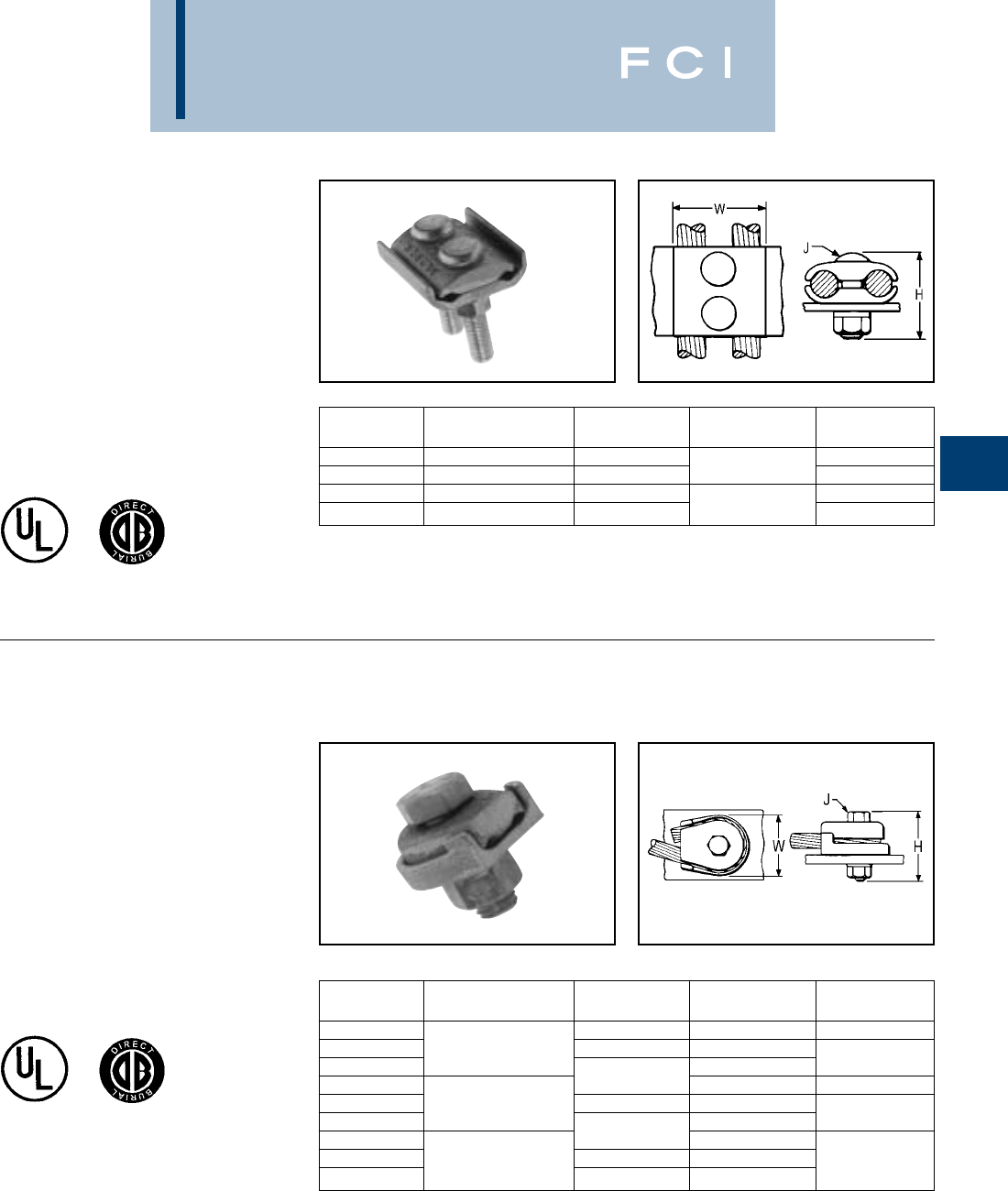
BURNDY
Grounding
D-47
TYPE GL
GROUND CONNECTOR
For Two Copper
Cables to Bar
High copper alloy ground connector for join-
ing a wide range of two parallel cables to 1/4
thick bar.* Two-bolt design, separates cable
from bar. One-wrench installation. UL467
Listed. The high copper alloy cast body and
DURIUM™ bolts, nuts, and lockwashers
make them suitable for direct burial in
concrete or ground.
TYPE GZ
GROUND CONNECTOR
For Copper Cable to Bar
High copper alloy ground connector for
joining a wide range of cable to 1/4thick
bar*. Cable is gripped by curving it around the
clamping bolt in connector groove. UL467
Listed. The high copper alloy cast body and
DURIUM™ bolts, nuts, and lockwashers
make them suitable for direct burial in
concrete or ground.
*For other bar thicknesses see note at bottom of page.
NOTE:
*The GB, GBM, GC, GCM, GL and GZ are all
used for joining a range of cable to bar. The
catalog numbers in each table accommodate the
indicated cable range and up to 1/4thick bar.
Optional bolt lengths are available to accommo-
date up to 1thick bar. For bar thicknesses from
1/4to 1/2, add the suffix “T4” to the catalog
number in the table. For bar thicknesses from
1/2to 1, add the suffix “T8” to the catalog
number in the table.
Catalog
Number* Conductor H J W
GL4C4C 8 Sol. - 4 Str. 1-1/2 1-3/8
GL2626 4 Sol. - 2/0 Str. 2 3/8 1-3/4
GL2929 2/0 Sol. - 250 2-1/4 2-1/4
GL3434 300 - 500 2-7/8 1/2 2-7/8
Catalog
Number* Conductor H J W
GZ4C-38 1-1/2 3/8 1-1/8
GZ4C-12 8 Str. - 4 Str. 1-7/8 1/2
GZ4C-58 5/8 1-3/4
GZ26-38 23/8 1-5/8
GZ26-12 3 Str. - 2/0 Str. 2-1/8 1/2
GZ26-58 5/8 1-3/4
GZ29-38 2-1/4 3/8
GZ29-12 3/0 Str. - 250 2-3/8 1/2 2-1/4
GZ29-58 2-1/2 5/8
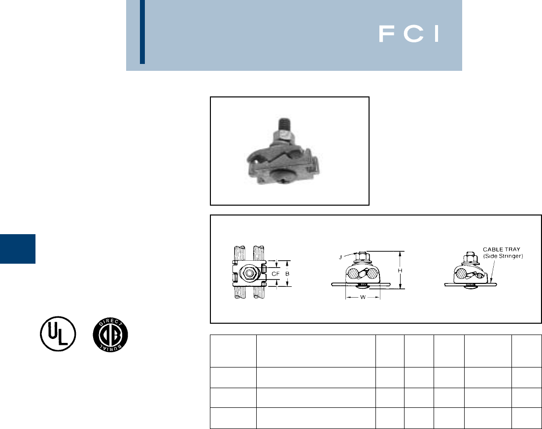
BURNDY
Grounding
D-48
TYPE GC-CT
CABLETRAY
GROUND CLAMP
This unique connector incorporates features
which are unmatched. Made of tin-plated cast
copper alloy, it accommodates either one or
two conductors, copper or aluminum cable. In
addition to a low profile head with a deep
Phillips recess, the galvanized steel bolt has
a ribbed neck which prevents rotation during
installation when installed in a .44 diameter
hole. When used on aluminum conductor, the
cable must be scratch brushed and
PENETROX™ A joint compound must be
used on cable and connector.
UL467 Listed for copper conductor only.
Suitable for direct burial in concrete or earth.
NOTE:
The bolt head is mounted on the inside wall of cabletray to avoid
damage to the cable insulation.
May be used with aluminum or galvanized steel cable tray.
ACCOMMODATES COPPER OR
CATALOG ALUMINUM CONDUCTOR
NUMBER IN EITHER GROOVE B CF H J W
#6 Sol. (.162 Dia.) -
GC2525CT 1/0 Str. (.372 Dia.) 1.12 .56 1.95 3/8” - 16 1.45
#2 Sol. (.258 Dia.) -
GC2626CT 2/0 Str. (.419 Dia.) 1.12 .56 1.95 3/8” - 16 1.70
2/0 Str. (.414 Dia.) -
GC2929CT 250 kcmil (.575 Dia.) 1.12 .56 2.20 3/8” - 16 1.98
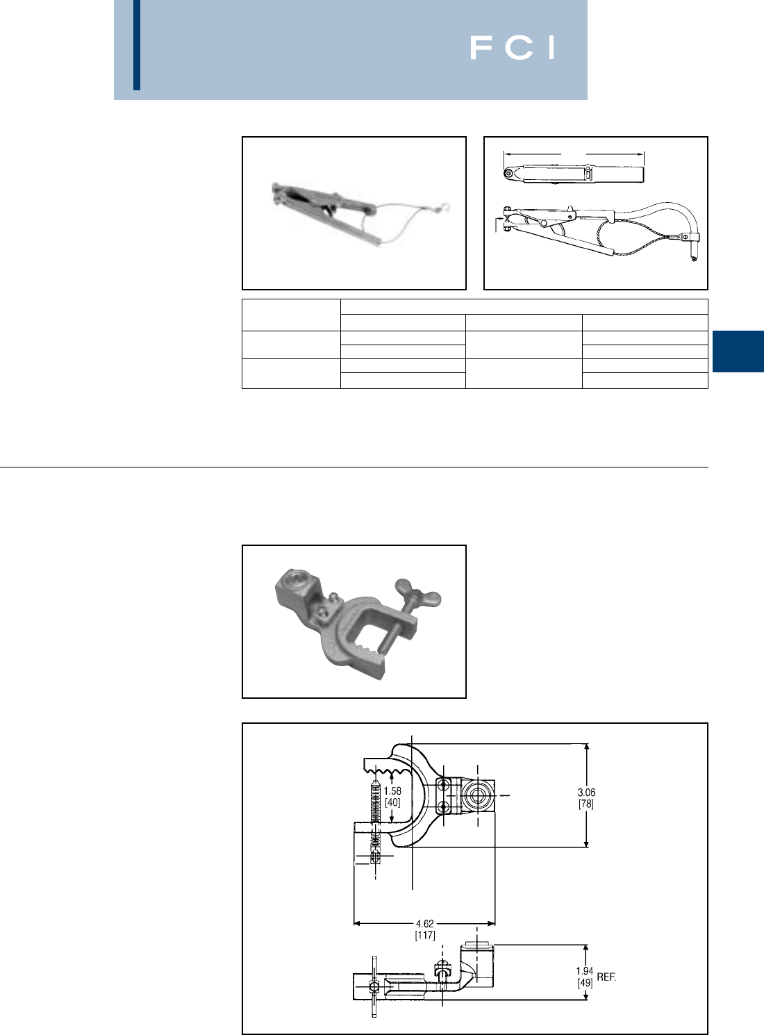
BURNDY
Grounding
D-49
TYPE GIE-G
GROUND CONNECTOR
For Vehicle Grounding
Heavy Duty Construction
High-strength copper alloy ground clamps for
grounding gasoline trucks, tank cars, aircraft
and other vehicles where danger of explosion
due to static electricity exists. Corrosion resis-
tant and supplied with nonsparking,
adjustable, replaceable contact grip screws.
Automatic safety release disconnects should
a vehicle unexpectedly move from the
grounded area. Accommodates 4 Str. flexible
copper cable.
1.2
MAX.
OPENING
TYPE GIE-G
GROUND CONNECTOR
Accommodates flexible rubber sheath cable
ranging from #6 to #2 conductor.
Catalog Number: GIE2CG3
8 1⁄8
Replaceable Contact Grip Screws
Catalog Number Catalog Number Material Point Configuration
GIE4CG3P5 Cone Point
GIE4CG3 GIE4CG3P7 Beryllium Copper Cup Point
GIE4CG4P5 Cone Point
GIE4CG4 GIE4CG4P7 Stainless Steel Cup Point
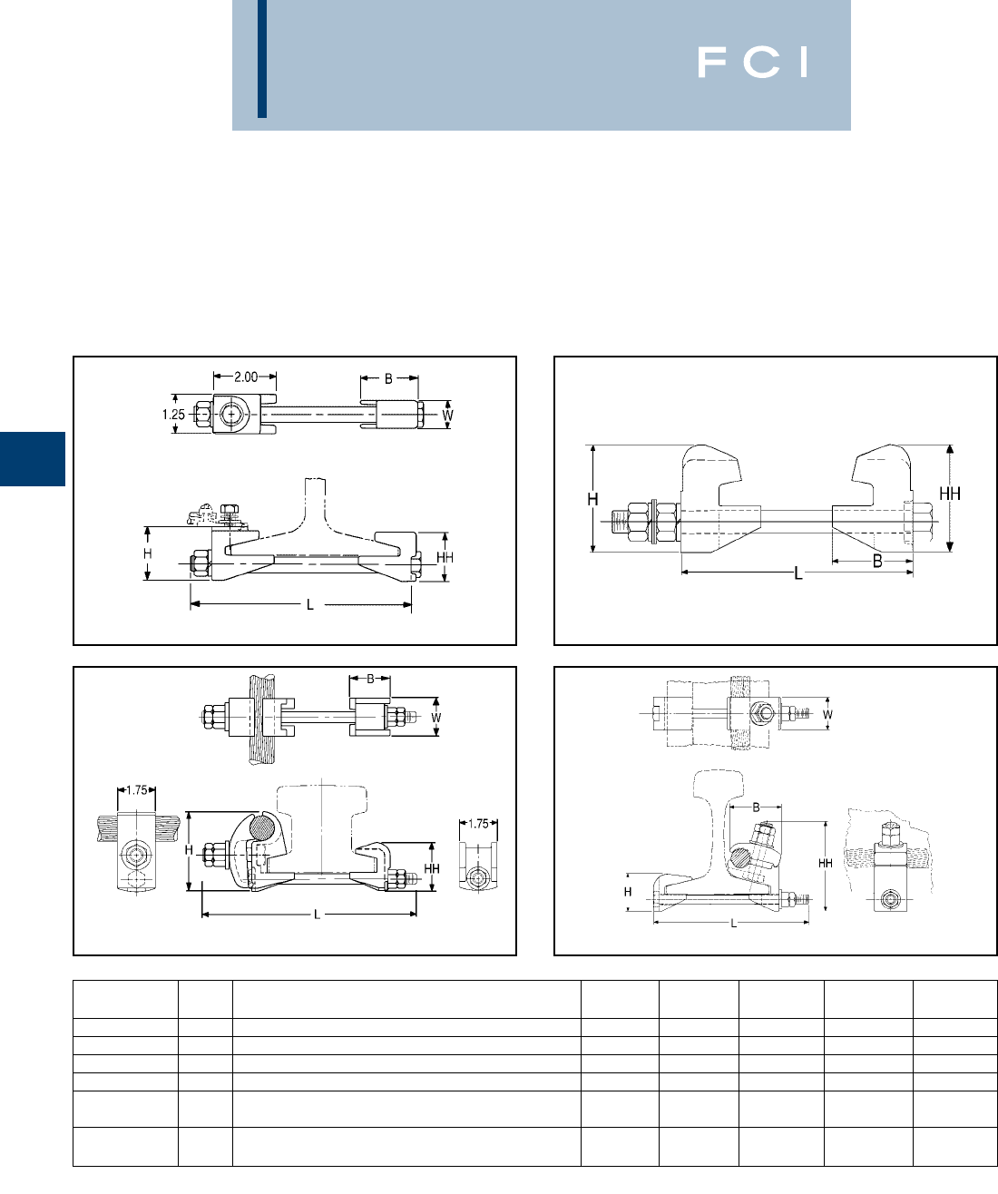
BURNDY
Grounding
D-50
RAIL CONNECTOR
Mechanical clamp connectors designed for
use in power, contact or running rail appli-
cations. Connectors are cast of a high
conductivity copper alloy, tin-plated, and
assembled with high-strength DURIUM™
hardware. Connectors designed for extended
service life.
*Tin-plated.
Fig. 1 Fig. 2
Fig. 3 Fig. 4
Catalog Fig.
Number No. Accomodates B H HH L W
J278 1100 LBS. A.R.E.A. RUNNING RAIL 1.81 1.88 1.72 7.50 .88
J279 175 or 90 LBS. RUNNING RAIL 1.81 1.71 1.55 7.50 .88
J280 1150 LBS. CONTACT RAIL 2.12 2.08 1.92 7.00 1.25
J295 2150 LBS. THIRD RAIL 2.62 3.50 3.50 7.75 3.00
150 LBS. NMC CONTACT RAIL and
RGC44G1* 3(1) 800-1000 kcmil CU CABLE 1.75 2.82 2.25 10.00 1.75
115 LBS. CONTACT or RUNNING RAIL and
RGC39G1* 4(1) 500-750 kcmil CU CABLE 2.75 2.00 4.78 8.32 1.25
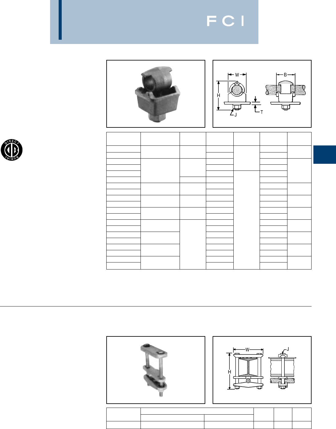
BURNDY
Grounding
D-51
TYPE QGFL
BARTAP™
For Copper Cable to
Flat Bar or Pad
High copper alloy BARTAP™ for joining a
range of cable to bar or pad. One-wrench
installation. DURIUM™ nut and lockwasher.
TYPE GA-H
GROUND CONNECTOR
For Copper Cable
to “H” Beam
High copper alloy ground connector for join-
ing a wide range of cable parallel to “H”
beams or square tube. Hardware is
made from DURIUM™ for superior corrosion
protection.
* Can be installed side by side or in line on NEMA drilled bar.
Catalog T
Number Conductor B H J (Max.) W
QGFL1CB1 1-7/8 1/4
QGFL1CB1T6 10 Sol. - 1 Str. 1-1/8 2-3/8 3/4 1
QGFL26B1 2-1/8 3/8 1/4
QGFL26B1T6 1-1/4 2-5/8 3/4
QGFL26B2* 8 Sol. - 2/0 Str. 1-1/2 1/4 1-1/8
QGFL26B2T6* 1-1/2 2-7/8 3/4
QGFL29B1* 2-5/8 1/4
QGFL29B1T6* 6 Str. - 250 1-5/8 3-1/8 3/4 1-3/8
QGFL31B1* 2-7/8 1/4
QGFL31B1T6* 2 Sol. - 350 1-3/4 3-1/4 3/4 1-5/8
QGFL34B1 3-1/8 1/4
QGFL34B1T6 1/0 Sol. - 500 2 3-5/8 3/4 1-3/4
QGFL39B1 3-1/4 1/2 1/4
QGFL39B1T6 350 - 750 3-5/8 3/4 1-3/4
QGFL44B1 3-3/8 1/4
QGFL44B1T6 750 - 1000 4-1/8 3/4 2-1/8
QGFL46B1 2-1/4 41/4
QGFL46B1T6 1000 - 1500 4-1/2 3/4 2-1/2
QGFL48B1 4-3/4 1/4
QGFL48B1T6 1500 - 2000 5-1/4 3/4 3
CATALOG CONDUCTOR
NUMBER “H” BEAM CABLE H J W
GA25H26 1-7/81-7/8- 2-1/22-1/24 Sol. - 2/0 Str. 4-3/4 3/8 4
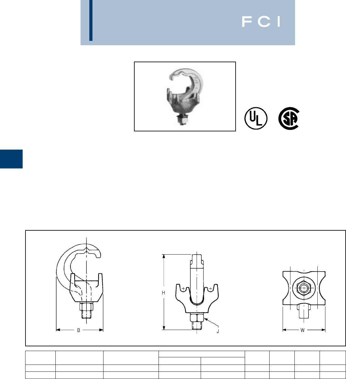
BURNDY
Grounding
D-52
TYPE GRF
UNIGROUND®RAISED FLOOR
GROUNDING CONNECTOR
The BURNDY®UNIGROUND™ is a universal
grounding clamp, specifically designed for all
raised flooring systems. It can be installed on
round or square pedestals and can
accommodate one or two grounding wires to
make an efficient grid. The underfloor signal
reference grid provides the low impedance
ground path that attenuates high frequency
static and 60 Hz transient noise for cleaner
data output. UL467 Listed.
Features and Benefits
•One connector fits all applications.
◊Ease of specification and installation.
•Single bolt design.
◊Ease of installation:
◊— No need to disassemble.
◊— Single wrench installation.
•Accepts 1 or 2 ground conductors.
◊Requires less connectors to install
signal reference grid.
•Tin plated cast bronze construction.
◊Resists corrosion and provides extended
life ground connection.
•Grounds all pedestals (round or square).
Will handle up to 7/8square and 1round.
◊Ease of installation. One connector
does it all
•Serves 3 needs:
1. Signal Reference Grid.
2. Static Ground.
3. Fault Current Ground.
◊UNIGROUND™ solves all possible
grounding problems found in computer
applications today.
CATALOG NUMBER OF CONDUCTOR PEDESTAL TYPE
NUMBER CONDUCTORS SIZE SOL. & STR. ROUND SQUARE B H J W
GRF4C-3 1 or 2 #8 - #2 Up to 1Up to 7/81.96 3.14 3/81.76
GRF4C-4 1 or 2 #8 - #2 Up to 3/4Up to 5/81.79 3.13 3/81.40
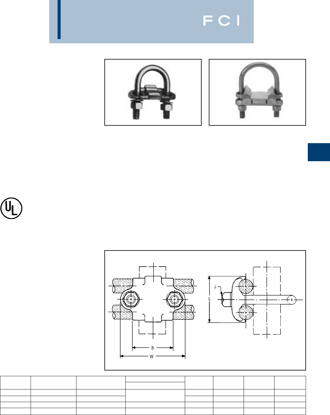
BURNDY
Grounding
D-53
TYPES GP-G1, GP-RT
RAISED FLOOR
GROUNDING CLAMPS
High copper alloy ground connector for raised
floor computer grounding applications. These
connectors can be installed on round and
square pedestal applications and will accom-
modate one or two grounding wires to make
an efficient grid. The underfloor signal refer-
ence grid provides the low impedance ground
path that attenuates high frequency static and
60 Hz transient noise for cleaner data output.
UL467 Listed.
In addition we offer the GP1726RT, which is
especially designed for penetrating epoxy
paint on pedestals. This patented connector
offers a low impedance, time saving connec-
tion between conductors and the Pedestal.
Features and Benefits
•Accepts 1 or 2 Ground Conductors
◊Requires less connectors to install signal
reference grid.
•Made of copper alloy.
•DURIUM™ U-Bolts, nuts and lockwashers.
◊Provides a low impedance ground path
for maximum performance.
•Grounds all pedestals (round or square).
•Will handle from 3⁄4to 1round or square.
◊Ease of installation.
•Serves 3 needs.
1. Signal Reference Grid.
2. Static Ground.
3. Fault Current Ground.
◊Connectors solves all possible
grounding problems found in computer
applications today.
GP1726RT
CATALOG NUMBER OF CONDUCTOR PEDESTAL TYPE
NUMBER CONDUCTORS SIZE SOL. & STR. ROUND OR SQUARE B J L W
GP654CG1 1 or 2 #8 Sol. - 4 Str. 3/4- 1Round 1.5 3/81.31 2.38
GP64526G1 1 or 2 #4 Sol. - 2/0 Str. 3/4- 7/8Square 1.5 3/81.69 2.38
GP1526G1 1 or 2 #4 Sol. - 2/0 Str. 1-1/4Round 1.75 3/81.69 2.62
GP1726RT 1 or 2 #6 Sol. - 2/0 Str. 2Round 2.12 3/81.50 3.22
BURNDY
Grounding
D-54
TABLE OF CONTENTS
BURNDYWeld™
BURNDY Weld™
Introduction ................................D-55
Making a BURNDYWeld™
Connection ..........................D-56
WELD METAL ..........................D-57
Type BCC-1 ..............................D-58
Type BCC-2 ..............................D-59
Type BCC-4 ..............................D-60
Type BCC-11 ............................D-61
Type BCC-6 ..............................D-62
Type BCC-14 ............................D-62
Type BCC-7 ..............................D-63
Type BCR-1................................D-64
Type BCR-2 ............................. D-65
Type BCR-3 .............................D-66
Type BCR-17 ............................D-67
Type BCR-24 ............................D-68
Type BCS-1 ...............................D-70
Type BCS-8 ...............................D-70
Type BCS-2 ...............................D-71
Type BCS-9 ...............................D-71
Type BCS-3 ...............................D-72
Type BCS-23 .............................D-73
Type BCS-4 ...............................D-74
Type BCS-6 ...............................D-74
Type BCS-7................................D-75
Type BCS-18 .............................D-75
BURNDYWeld™ FILL ..............D-82
BURNDYWeld™ SET ...............D-84
BURNDYWeld™ Prefabricated
Wire Mesh..............................D-86
For mold types or BURNDYWeld™ items not shown, please
contact factory or refer to full BURNDYWeld™ catalog.
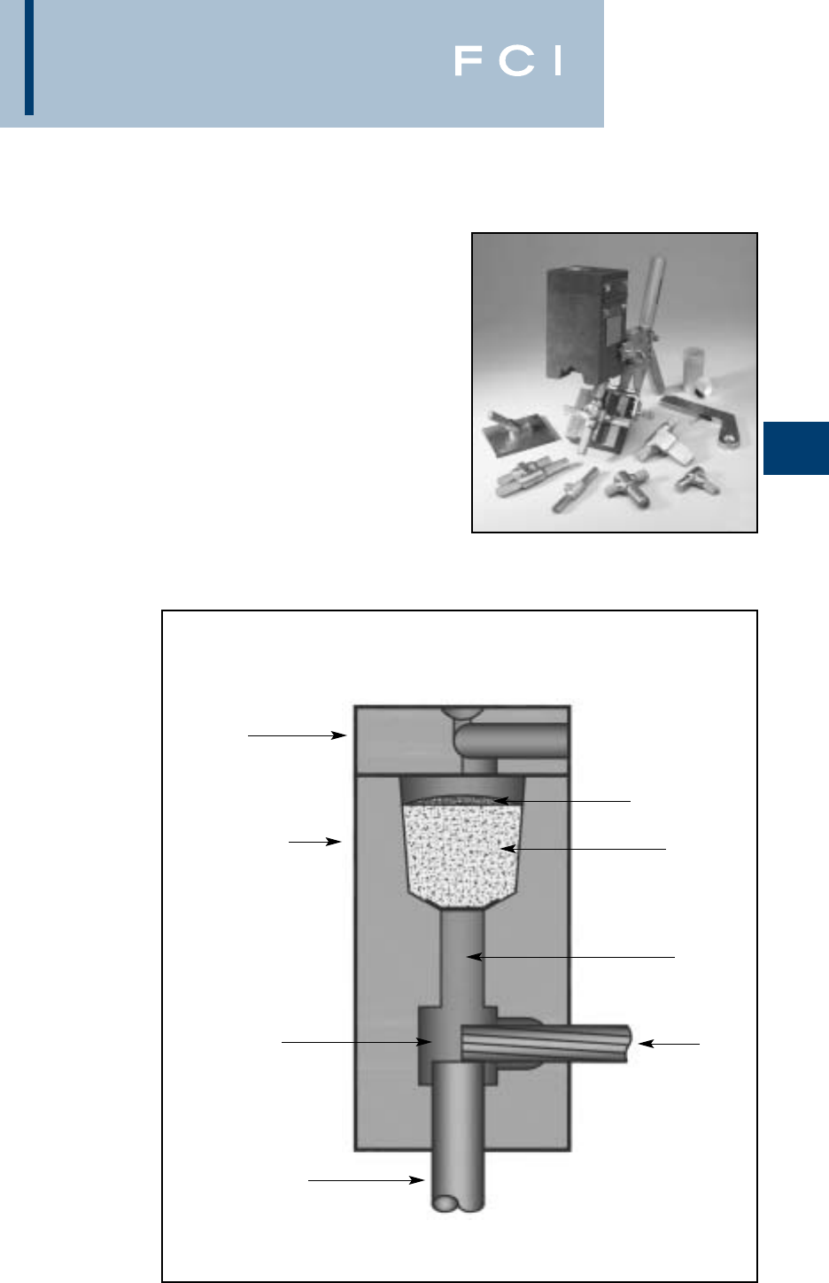
BURNDY
Grounding
D-55
BURNDYWeld™
The BURNDYWeld™ connection process is a
simple, efficient method of welding copper to
copper or copper to steel. One advantage is
that NO outside power is required when using
the BURNDYWeld™ exothermic process.The
BURNDYWeld™ process uses high tempera-
ture reaction of powdered copper oxide and
aluminum.The reaction takes place in a semi-
permanent graphite mold. These molds will
last for fifty or more welds if proper care is
given. The reaction takes place very rapidly,
therefore the total amount of heat applied to
the conductors or surfaces is considerably
less than that of brazing or soldering. It is
important to remember this when welding to
insulated cable or thin wall pipe.
This system is very field friendly, since it is
light and portable and requires no outside
power source. It requires very little time or
skill to obtain an efficient, maintenance free
connection when using the BURNDYWeld™
process.
For more information visit our website at
www.fciconnect.com
The BURNDYWeld™ process has been used
to weld materials other than copper for elec-
trical purposes. Materials welded include:
Stainless Steel Columbium Brass
Copperweld® Plain Steel Bronze
Nichrome V Everdur® Niobium
Galvanized Steel Kama Chromax
Silcone Bronze Steel Rail Cast Iron
Copper Clad Steel Cor-Ten® Monel
When welding to galvanized steel it is recom-
mended to resurface exposed bare steel.
The BURNDYWeld™ connection is a molec-
ular weld. The weld metal has the same
melting point as copper. These factors along
with the increased cross section of the
connection, BURNDYWeld™ connections:
1. Will not be affected by a high current
surge.Tests have shown that the electrical
conductor will melt before the
BURNDYWeld™ connection when sub-
jected to high short circuit current. Consult
IEEE Standard 837-1989.
2. Will not loosen or corrode at the point of
weld. There are no contact surfaces or
mechanical pressures involved. A
BURNDYWeld™ connection becomes an
integral part of the conductor.
3. Have a current-carrying capacity equal to
or greater than that of the conductors.
Lid
Graphite Mold
Weld Cavity
Ground Rod
Cable
Tap Hole
Weld Metal
Starting Powder
For mold types or BURNDYWeld™ items not shown, please
contact factory or refer to full BURNDYWeld™ catalog.
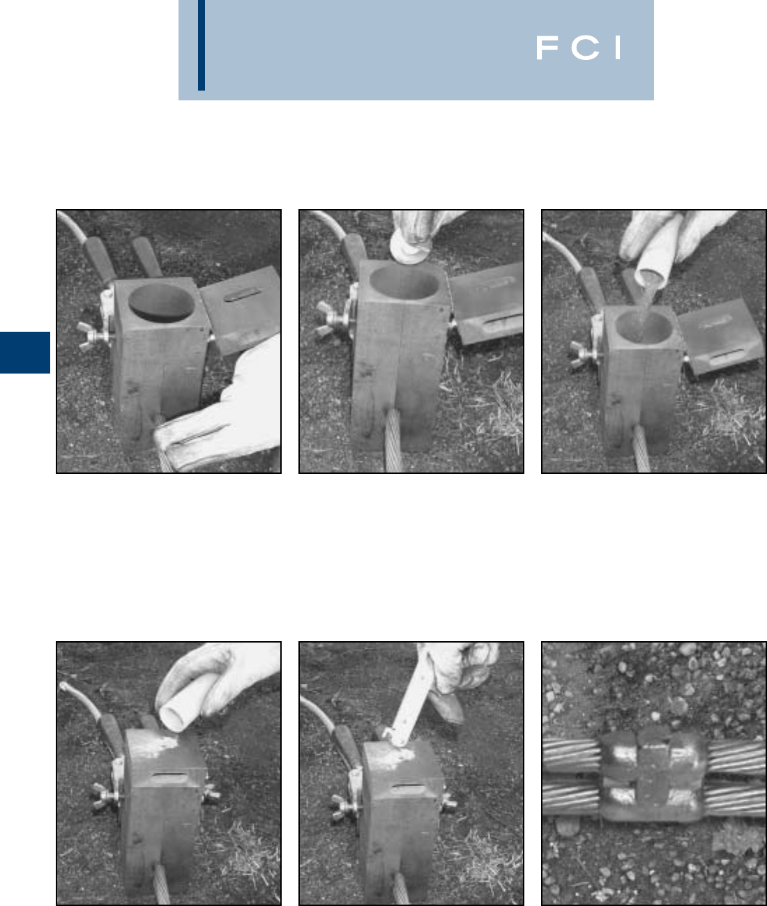
BURNDY
Grounding
D-56
Making a BURNDYWeld™ Connection
Step 1
Position cleaned conductors in mold after
making sure mold is dry, by pre-heating or
making a test joint.
Step 2
Place metal disc in bottom of mold crucible.
Step 3
Dump powder into crucible, being careful not
to loosen all the starting powder.
Step 4
Close lid and place a small amount of start-
ing powder in the ignition pocket.
Step 6
Wait 15 seconds, then remove weld and
clean mold before making next connection.
Step 5
Ignite the starting powder with the Flint
Ignitor.
For mold types or BURNDYWeld™ items not shown, please
contact factory or refer to full BURNDYWeld™ catalog.
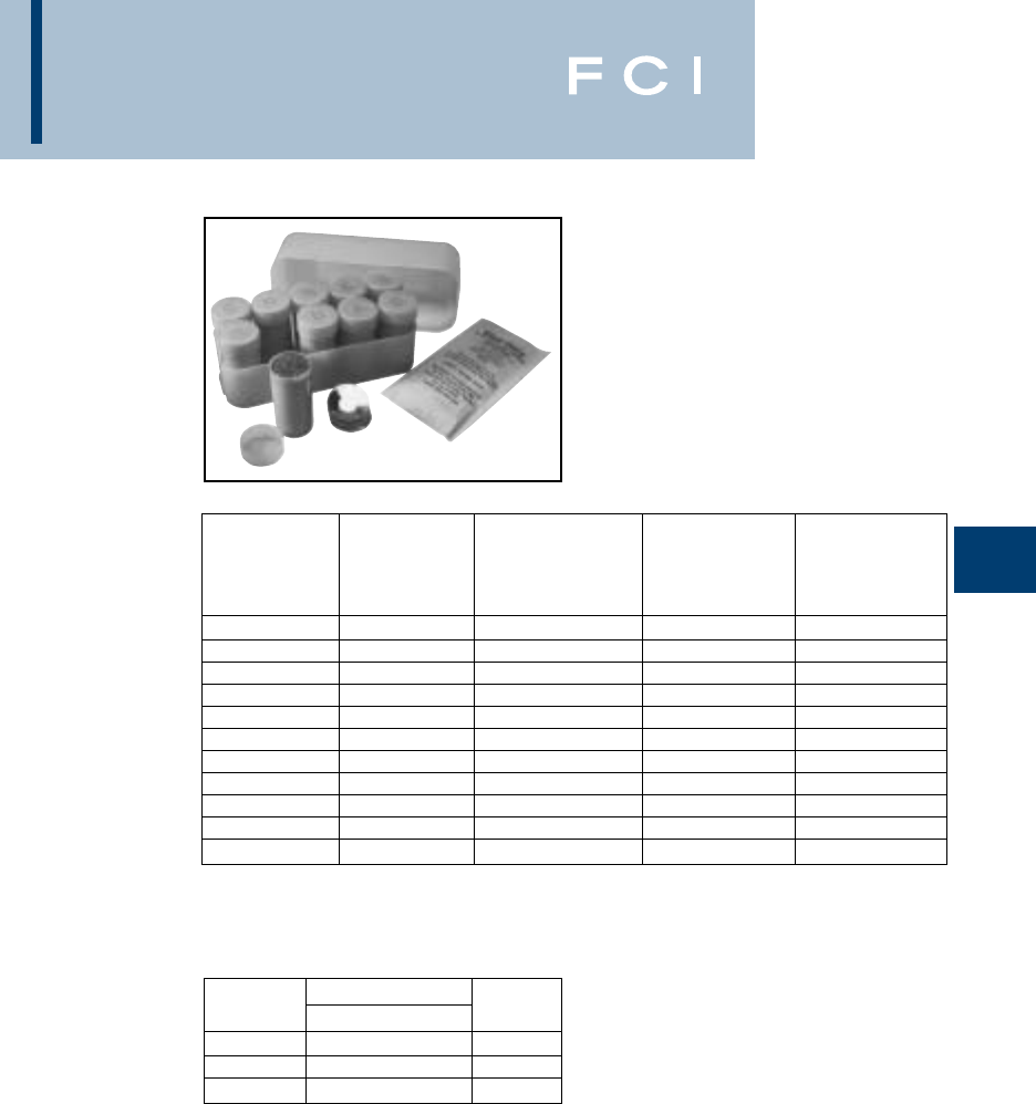
BURNDY
Grounding
D-57
WELD METAL
BURNDYWeld™ Weld Metal is packed in
moisture-resistant plastic cartridges that have
tight fitting caps. These cartridges, along with
the necessary steel discs, are then packed in
boxes that are hermetically-sealed. This
ensures the powder arriving in good condi-
tion, always dry and ready for fast positive
ignition.
BURNDYWeld™ Weld Metal comes in sever-
al types; one for welding copper to copper,
copper to steel, copper to rail, copper to cast
iron and one for welding copper to steel for
cathodic protection. The size and weight (in
grams) of the cartridge are marked on each
individual cartridge.
Cathodic
Standard Cast Iron Protection Rail
Cartridge Cartridge Cartridge Cartridge Cartridges
Size Size Size Size Per Box
15 15Cl 15CP 15R 20
25 25Cl 25CP 25R 20
32 32Cl 32CP 32R 10
45 45Cl 45CP 45R 20
65 65Cl 65CP 65R 20
90 90Cl —90R 10
115 115Cl —115R 10
150 — — 150R 10
200 — — 200R 10
250 — — 250R 10
500 — — 500R 10
BURNDYWeld™ Weld Metal is sold in box quantities only.
Weld Catalog Number Package
Metal Size Steel Discs Only Quantity
15 to 65 B370320-01 20
90 to 115 B370320-02 10
150 to 500 B370320-03 10
Steel Discs Sold Separately
For mold types or BURNDYWeld™ items not shown, please
contact factory or refer to full BURNDYWeld™ catalog.
BURNDY
Grounding
D-58
BCC-1 TYPE MOLDS
Horizontal End to End
BCC-1 Type Molds are used for horizontal
end to end cable connections.
Size range is #6 through 1000 MCM solid or
concentric stranded copper conductors.
Contact BURNDY®Products for information
on molds for conductors not listed below.
Price Weld Handle
Cable Mold Number Key Metal Clamps
#8 Use Type BCC-14 On Page 16 — — —
#6 Use Type BCC-14 On Page 16 — — —
#4 B-5623 18 † * 25 N/A
#3 B-5624 18 † * 32 N/A
#2 B-5625 18 † * 32 N/A
#1 B-5626 18 † * 32 N/A
1/0 B-205 445B-106
2/0 B-206 465B-106
3/0 B-207 490B-106
4/0 B-208 490B-106
250 MCM B-209 4115 B-106
300 MCM B-210 4115 B-106
350 MCM B-211 4150 B106
500 MCM B-213 4200 B-107
750 MCM B-214 52-150 B-107
1000 MCM B-215 52-200 B-107
•For sizes not listed, contact BURNDY®Products.
•Molds listed are for concentric stranded cable. Add suffix
“-S” to mold number for solid conductors.
•For heavy duty molds, molds with wear plates or molds for
Copperweld®cable, contact BURNDY®Products.
•For expedited service, contact BURNDY®Products.
Required Tools:
Handle Clamps (see chart for correct handles)
† Sold complete with handles
* B38-0309-00 Flint Ignitor (included)
Other recommended accessories:
B38-3922-00 Mold Cleaning Brush (pg D-85)
B38-0135-00 Cable Cleaning Brush (pg D-85)
B38-0330-00 Cable Clamp (pg D-85)
For mold types or BURNDYWeld™ items not shown, please
contact factory or refer to full BURNDYWeld™ catalog.
BURNDY
Grounding
D-59
TYPE BCC-2 MOLDS
Horizontal Cable Tap to
Horizontal Cable Run
Type BCC-2 Molds are used to join horizontal
cable tap to a horizontal run cable.
Size range is #6 through 750 MCM solid or
concentric stranded copper conductors.
Contact BURNDY®Products for information
on molds for conductors not listed below.
Cable Price Weld Handle
Run Tap Mold Number Key Metal Clamps
#6 #6
Use Type BCC-14 on Page 16
—— —
#4 #4 B-221 432 B-106
#2 B-223 445 B-106
#2 #4 B-224 445 B-106
#1 B-225 445 B-106
#1 #2 B-226 445 B-106
#4 B-227 445 B-106
1/0 B-228 490 B-106
#1 B-229 445 B-106
1/0 #2 B-230 445 B-106
#4 B-231 445 B-106
2/0 B-232 490 B-106
1/0 B-233 490 B-106
2/0 #1 B-234 445 B-106
#2 B-235 445 B-106
#4 B-5475 445 B-106
3/0 B-236 4115 B-106
2/0 B-237 490 B-106
1/0 B-238 490 B-106
3/0 #1 B-239 445 B-106
#2 B-240 445 B-106
#4 B-5574 445 B-106
4/0 B-241 4150 B-106
3/0 B-242 4115 B-106
2/0 B-243 490 B-106
4/0 1/0 B-244 490 B-106
#1 B-245 490 B-106
#2 B-246 490 B-106
#4 B-5021 490 B-106
250 MCM B-247 4150 B-106
4/0 B-248 4150 B-106
3/0 B-249 4150 B-106
250 MCM 2/0 B-250 490 B-106
1/0 B-251 490 B-106
#1 B-252 490 B-106
#2 B-253 490 B-106
Cable Price Weld Handle
Run Tap Mold Number Key Metal Clamps
300 MCM B-254 4200 B-106
250 MCM B-255 4150 B-106
4/0 B-256 4150 B-106
3/0 B-257 4150 B-106
300 MCM 2/0 B-258 490B-106
1/0 B-259 490B-106
#1 B-260 490B-106
#2 B-261 490B-106
350 MCM B-262 4200 B-106
300 MCM B-263 4200 B-106
250 MCM B-264 4200 B-106
4/0 B-265 4150 B-106
350 MCM 3/0 B-266 4150 B-106
2/0 B-267 490B-106
1/0 B-268 490B106
#1 B-269 490B-106
#2 B-270 490B-106
500 MCM B-280 42-150 B-106
350 MCM B-282 4200 B-106
300 MCM B-283 4200 B-106
250 MCM B-284 4200 B-106
500 MCM 4/0 B-285 4150 B-106
2/0 B-286 490B-106
1/0 B-287 490B-106
#1 B-288 490B-106
#2 B-289 490B-106
750 MCM B-290 5500 B-107
500 MCM B-291 52-200 B-107
350 MCM B-293 4250 B-106
300 MCM B-294 4200 B-106
750 MCM 250 MCM B-295 4200 B-106
4/0 B-296 4150 B-106
2/0 B-297 4150 B-106
1/0 B-298 4150 B-106
•For sizes not listed, contact BURNDY®Products.
•Molds listed are for concentric stranded cable. Add suffix “-S” to mold number for solid
conductors.
•For heavy duty molds, molds with wear plates or molds for Copperweld®cable, contact
BURNDY®Products.
•For expedited service, contact BURNDY®Products.
Required Tools:
Handle Clamps (see chart for correct handles)
B38-0309-00 Flint Ignitor
Other recommended accessories:
B40-0319-01 Mold Cleaner for cartridge sizes #15-#65 (pg D-85)
B40-0319-03 Mold Cleaner for cartridge sizes #90-#500 (pg D-85)
B38-3922-00 Mold Cleaning Brush (pg D-85)
B38-0135-00 Cable Cleaning Brush (pg D-85)
B38-0330-00 Cable Clamp (pg D-85)
For mold types or BURNDYWeld™ items not shown, please
contact factory or refer to full BURNDYWeld™ catalog.
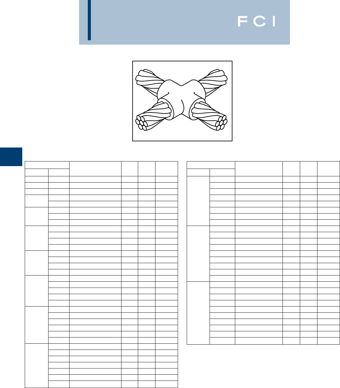
BURNDY
Grounding
D-60
TYPE BCC-4 MOLDS
Horizontal to Horizontal
Cable Cross
Type BCC-4 Molds are used to join two hori-
zontal cables at right angles. One cable is cut
and the other is a through run.
Size range is #6 through 500 MCM solid or
concentric stranded copper conductors.
Contact BURNDY®Products for information
on molds for conductors not listed below.
Cable Price Weld Handle
Run Tap Mold Number Key Metal Clamps
#6 #6
Use Type BCC-11 on page 16
#4 #4 B-423 445 B-106
#3 #3 B-424 445 B-106
#2 B-425 465 B-106
#2 #4 B-426 465 B-106
#1 B-427 465 B-106
#1 #2 B-428 465 B-106
#4 B-429 465 B-106
1/0 B-430 490 B-106
#1 B-431 490 B-106
1/0 #2 B-432 490 B-106
#4 B-433 490 B-106
2/0 B-434 4115 B-106
1/0 B-435 4115 B-106
2/0 #1 B-436 4115 B-106
#2 B-437 4115 B-106
3/0 B-438 4150 B-106
2/0 B-439 4150 B-106
3/0 1/0 B-440 4115 B-106
#1 B-441 4115 B-106
#2 B-442 4115 B-106
4/0 B-443 4200 B-106
3/0 B-444 4200 B-106
2/0 B-445 4150 B-106
4/0 1/0 B-442 4150 B-106
#1 B-447 4115 B-106
#2 B-448 4115 B-106
250 MCM B-449 4200 B-106
4/0 B-450 4200 B-106
3/0 B-451 4200 B-106
250 MCM 2/0 B-452 4150 B-106
1/0 B-453 4150 B-106
#1 B-454 4115 B-106
#2 B-455 4115 B-106
Cable Price Weld Handle
Run Tap Mold Number Key Metal Clamps
300 MCM B-456 4250 B-106
250 MCM B-457 4250 B-106
4/0 B-458 4200 B-106
3/0 B-459 4200 B-106
300 MCM 2/0 B-460 4150 B-106
1/0 B-461 4150 B-106
#1 B-462 4115 B-106
#2 B-463 4115 B-106
350 MCM B-464 4250 B-106
300 MCM B-465 4250 B-106
250 MCM B-466 4250 B-106
4/0 B-467 4200 B-106
350 MCM 3/0 B-468 4200 B-106
2/0 B-469 4200 B-106
1/0 B-470 4200 B-106
#1 B-471 4150 B-106
#2 B-472 4150 B-106
500 MCM B-483 5500 B-107
350 MCM B-485 52-200 B-107
300 MCM B-486 52-200 B-107
250 MCM B-487 52-150 B-107
4/0 B-488 52-150 B-107
500 MCM 3/0 B-489 52-150 B-107
2/0 B-490 4250 B-106
1/0 B-491 4250 B-106
#1 B-492 4200 B-106
#2 B-493 4200 B-106
•For sizes not listed, contact BURNDY®Products.
•Molds listed are for concentric stranded cable. Add suffix “-S” to mold number for solid
conductors.
•For heavy duty molds, molds with wear plates or molds for Copperweld®cable, contact
BURNDY®Products.
•For expedited service, contact BURNDY®Products.
Required Tools:
Handle Clamps (see chart for correct handles)
B38-0309-00 Flint Ignitor
Other recommended accessories:
B40-0319-01 Mold Cleaner for cartridge sizes #15-#65 (pg D-85)
B40-0319-03 Mold Cleaner for cartridge sizes #90-#500 (pg D-85)
B38-3922-00 Mold Cleaning Brush (pg D-85)
B38-0135-00 Cable Cleaning Brush (pg D-85)
B38-0330-00 Cable Clamp (pg D-85)
For mold types or BURNDYWeld™ items not shown, please
contact factory or refer to full BURNDYWeld™ catalog.
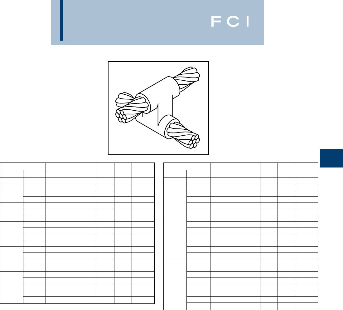
BURNDY
Grounding
D-61
TYPE BCC-11 MOLDS
Horizontal to Horizontal
Cable Cross
Type BCC-11 Molds are used to join uncut
horizontal cables at right angles to each
other.
Size range is #6 through 500 MCM solid or
concentric stranded copper conductors.
Contact BURNDY®Products for information
on molds for conductors not listed below.
Cable Price Weld Handle
Run Tap Mold Number Key Metal Clamps
#6 #6 B-5432 191* 45 N/A
#4 #4 B-2687 465 B-106
#2 B-2689 490 B-106
#2 #4 B-2690 465 B-106
#1 B-2691 4115 B-106
#1 #2 B-2692 490 B-106
#4 B-2693 490 B-106
1/0 B-2694 22 150 B-106
#1 B-2695 22 150 B-106
1/0 #2 B-2696 22 115 B-106
#4 B-2697 22 115 B-106
2/0 B-2698 22 200 B-106
1/0 B-2699 22 200 B-106
2/0 #1 B-2700 22 150 B-106
#2 B-2701 22 150 B-106
3/0 B-2702 22 250 B-106
2/0 B-2703 22 200 B-106
3/0 1/0 B-2704 22 200 B-106
#1 B-2705 22 150 B-106
#2 B-2706 22 150 B-106
Cable Price Weld Handle
Run Tap Mold Number Key Metal Clamps
4/0 B-2707 22 250 B-106
3/0 B-2708 22 250 B-106
2/0 B-2709 22 200 B-106
4/0 1/0 B-2710 22 200 B-106
#1 B-2711 22 150 B-106
#2 B-2712 22 150 B-106
250 MCM B-2713 22 2-150 B-106
4/0 B-2714 22 2-150 B-106
3/0 B-2715 22 2-150 B-106
250 MCM 2/0 B-2716 22 250 B-106
1/0 B-2717 22 150 B-106
#1 B-2718 22 200 B-106
#2 B-2719 22 150 B-106
500 MCM B-2747 23 3-250 B-107
250 MCM B-2751 23 500 B-107
4/0 B-2752 23 500 B-107
3/0 B-2753 23 500 B-107
500 MCM 2/0 B-2754 23 2-200 B-107
1/0 B-2755 22 2-150 B-106
#1 B-2756 22 250 B-106
#2 B-2757 22 250 B-106
•For sizes not listed, contact BURNDY®Products.
•Molds listed are for concentric stranded cable. Add suffix “-S” to mold number for solid
conductors.
•For heavy duty molds, molds with wear plates or molds for Copperweld® cable, contact
BURNDY®Products.
•For expedited service, contact BURNDY®Products.
Required Tools:
Handle Clamps (see chart for correct handles)
† Sold complete with handles
* B38-0309-00 Flint Ignitor
Other recommended accessories:
B40-0319-01 Mold Cleaner for cartridge sizes #15-#65 (pg D-85)
B40-0319-03 Mold Cleaner for cartridge sizes #90-#500 (pg D-85)
B38-3922-00 Mold Cleaning Brush (pg D-85)
B38-0135-00 Cable Cleaning Brush (pg D-85)
B38-0330-00 Cable Clamp (pg D-85)
For mold types or BURNDYWeld™ items not shown, please
contact factory or refer to full BURNDYWeld™ catalog.
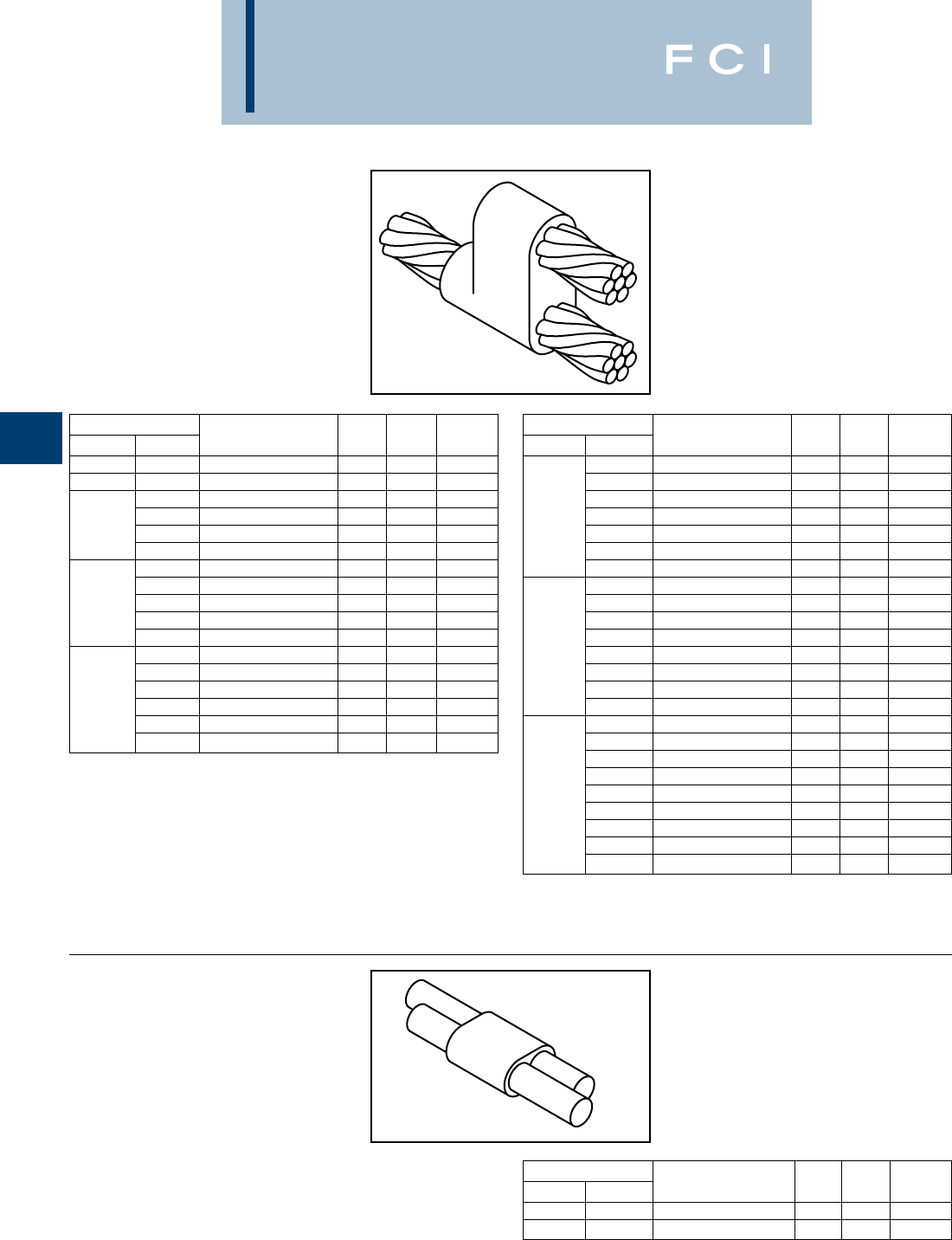
BURNDY
Grounding
D-62
BCC-6 TYPE MOLDS
Horizontal Parallel Tap
BCC-6 Type Molds are used to join horizontal
parallel tap to run connections. The tap cable
is over the run cable.
Size range is #6 through 4/0 solid or concen-
tric stranded copper conductors.
Contact BURNDY®Products for information
on molds for conductors not listed below.
Cable Price Weld Handle
Run Tap Mold Number Key Metal Clamps
#6 Sol #6 Sol B-1270 425 B-106
#6 #6 B-1271 425 B-106
#4 B-1272 432 B-106
#6 B-1273 432 B-106
#4 #6 Sol B-1274 432 B-106
#8 Sol B-1275 432 B-106
#2 B-1276 465 B-106
#4 B-1277 445 B-106
#2 #6 B-1278 432 B-106
#6 Sol B-1279 432 B-106
#8 Sol B-1280 432 B-106
#1 B-1281 465 B-106
#2 B-1282 465 B-106
#4 B-1283 445 B-106
#1 #6 B-1284 445 B-106
#6 Sol B-1285 445 B-106
#8 Sol B-1286 445 B-106
Cable Price Weld Handle
Run Tap Mold Number Key Metal Clamps
1/0 B-1287 490 B-106
#1 B-1288 490 B-106
#2 B-1289 465 B-106
1/0 #4 B-1290 465 B-106
#6 B-1291 445 B-106
#6 Sol B-1292 445 B-106
#8 Sol B-1293 445 B-106
2/0 B-1294 4115 B-106
1/0 B-1295 4115 B-106
#1 B-1296 490 B-106
#2 B-1297 490 B-106
2/0 #4 B-1298 465 B-106
#6 B-1299 465 B-106
#6 Sol B-1300 465 B-106
#8 Sol B-1301 465 B-106
4/0 B-1302 4150 B-106
2/0 B-1303 4115 B-106
1/0 B-1304 4115 B-106
#1 B-1305 4115 B-106
4/0 #2 B-1306 4115 B-106
#4 B-1307 490 B-106
#6 B-1308 490 B-106
#6 Sol B-1309 490 B-106
#8 Sol B-1310 490 B-106
•For sizes not listed, contact BURNDY®Products.
•Molds listed are for concentric stranded cable. Add suffix “-S” to mold number for solid
conductors.
•For heavy duty molds, molds with wear plates or molds for Copperweld®cable, contact
BURNDY®Products.
•For expedited service, contact BURNDY®Products.
Required Tools:
Handle Clamps (see chart for correct handles)
Sold complete with handles
B38-0309-00 Flint Ignitor
Other recommended accessories:
B38-3922-00 Mold Cleaning Brush (pg D-85)
B38-0135-00 Cable Cleaning Brush (pg D-85)
B38-0330-00 Cable Clamp (pg D-85)
BCC-14 TYPE MOLDS
Horizontal Parallel through
Cables
BCC-14 Type Molds are used to join horizon-
tal parallel through run cables. Cables run
side by side in the mold.
Size range is #8 through #6 solid or concen-
tric stranded copper conductors.
Contact BURNDY®Products for information
on molds for conductors not listed.
Cable Price Weld Handle
Run Tap Mold Number Key Metal Clamps
#8 #8 B-5709 18+ 15 N/A
#6 #6 B-5618 18+ 25 N/A
For mold types or BURNDYWeld™ items not shown, please
contact factory or refer to full BURNDYWeld™ catalog.
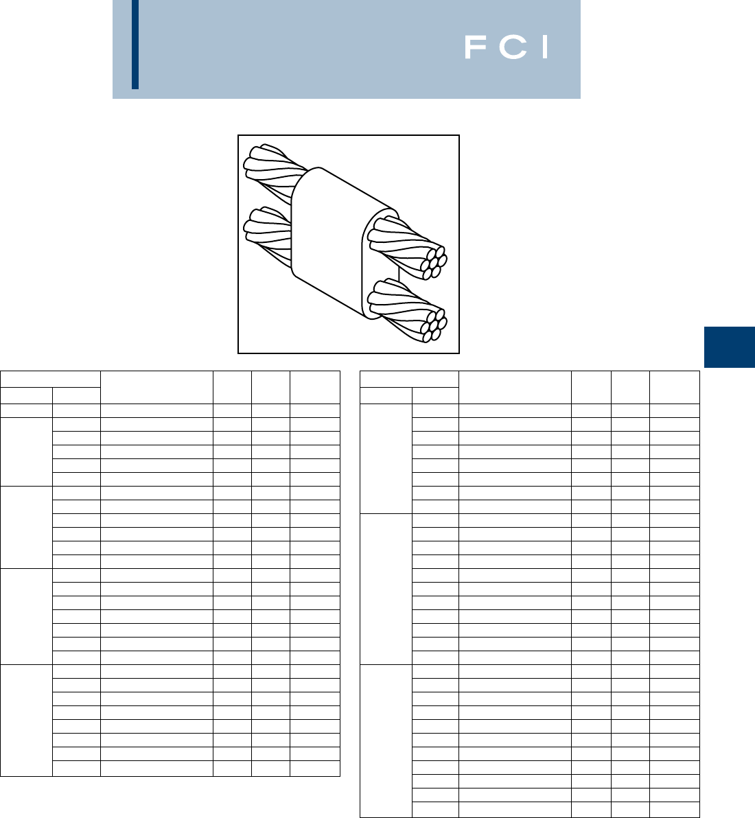
BURNDY
Grounding
D-63
BCC-7 TYPE MOLDS
Horizontal Parallel through
Cables
BCC-7 Type Molds are used to join horizontal
parallel through run cables. One cable runs
above the other cable in the mold.
Size range is #6 through 4/0 solid or concen-
tric stranded copper conductors.
Contact BURNDY®Products for information
on molds for conductors not listed below.
Cable Price Weld Handle
Run Tap Mold Number Key Metal Clamps
#6 #6
Use Type BCC-14 on Page 16
—— —
#4 B-1311 432 B-106
#6 B-5627 432 B-106
#4 #6 Sol B-8882 432 B-106
#8 B-5629 432 B-106
#8 Sol B-5630 432 B-106
#2 B-1313 465 B-106
#4 B-1314 465 B-106
#6 B-5631 445 B-106
#2 #6 Sol B-5632 445 B-106
#8 B-5634 445 B-106
#8 Sol B-5635 445 B-106
#1 B-1315 465 B-106
#2 B-1316 465 B-106
#4 B-1317 465 B-106
#1 #6 B-5636 465 B-106
#6 Sol B-5637 465 B-106
#8 B-5638 445 B-106
#8 Sol B-5639 445 B-106
1/0 B-1318 490 B-106
#1 B-1319 465 B-106
#2 B-1320 465 B-106
#4 B-1321 465 B-106
1/0 #6 B-5642 465 B-106
#6 Sol B-1208 465 B-106
#8 B-5644 465 B-106
#8 Sol B-5645 465 B-106
Cable Price Weld Handle
Run Tap Mold Number Key Metal Clamps
2/0 B-1322 4115 B-106
1/0 B-1323 4115 B-106
#1 B-1324 490 B-106
#2 B-1325 490 B-106
2/0 #4 B-5659 490 B-106
#6 B-5342 490 B-106
#6 Sol B-5652 490 B-106
#8 B-5668 465 B-106
#8 Sol B-5943 465 B-106
3/0 B-1326 4150 B-106
2/0 B-1327 4150 B-106
1/0 B-1328 4115 B-106
#1 B-1329 4115 B-106
3/0 #2 B-1330 4115 B-106
#4 B-6046 4115 B-106
#6 B-5676 490 B-106
#6 Sol B-5679 490 B-106
#8 B-5680 490 B-106
#8 Sol B-5682 490 B-106
4/0 B-1331 4200 B-106
3/0 B-1332 4200 B-106
2/0 B-1333 4150 B-106
1/0 B-1334 4150 B-106
#1 B-1335 4150 B-106
4/0 #2 B-1336 4150 B-106
#4 B-5340 4150 B-106
#6 B-5684 490 B-106
#6 Sol B-6552 490 B-106
#8 B-5686 490 B-106
#8 Sol B-5688 490 B-106
•For sizes not listed, contact BURNDY®Products.
•Molds listed are for concentric stranded cable. Add suffix “-S” to mold number for solid
conductors.
•For heavy duty molds, molds with wear plates or molds for Copperweld® cable, contact
BURNDY®Products.
•For expedited service, contact BURNDY®Products. Required Tools:
Handle Clamps (see chart for correct handles)
B38-0309-00 Flint Ignitor
Other recommended accessories:
B38-3922-00 Mold Cleaning Brush (pg D-85)
B38-0135-00 Cable Cleaning Brush (pg D-85)
B38-0330-00 Cable Clamp (pg D-85)
For mold types or BURNDYWeld™ items not shown, please
contact factory or refer to full BURNDYWeld™ catalog.
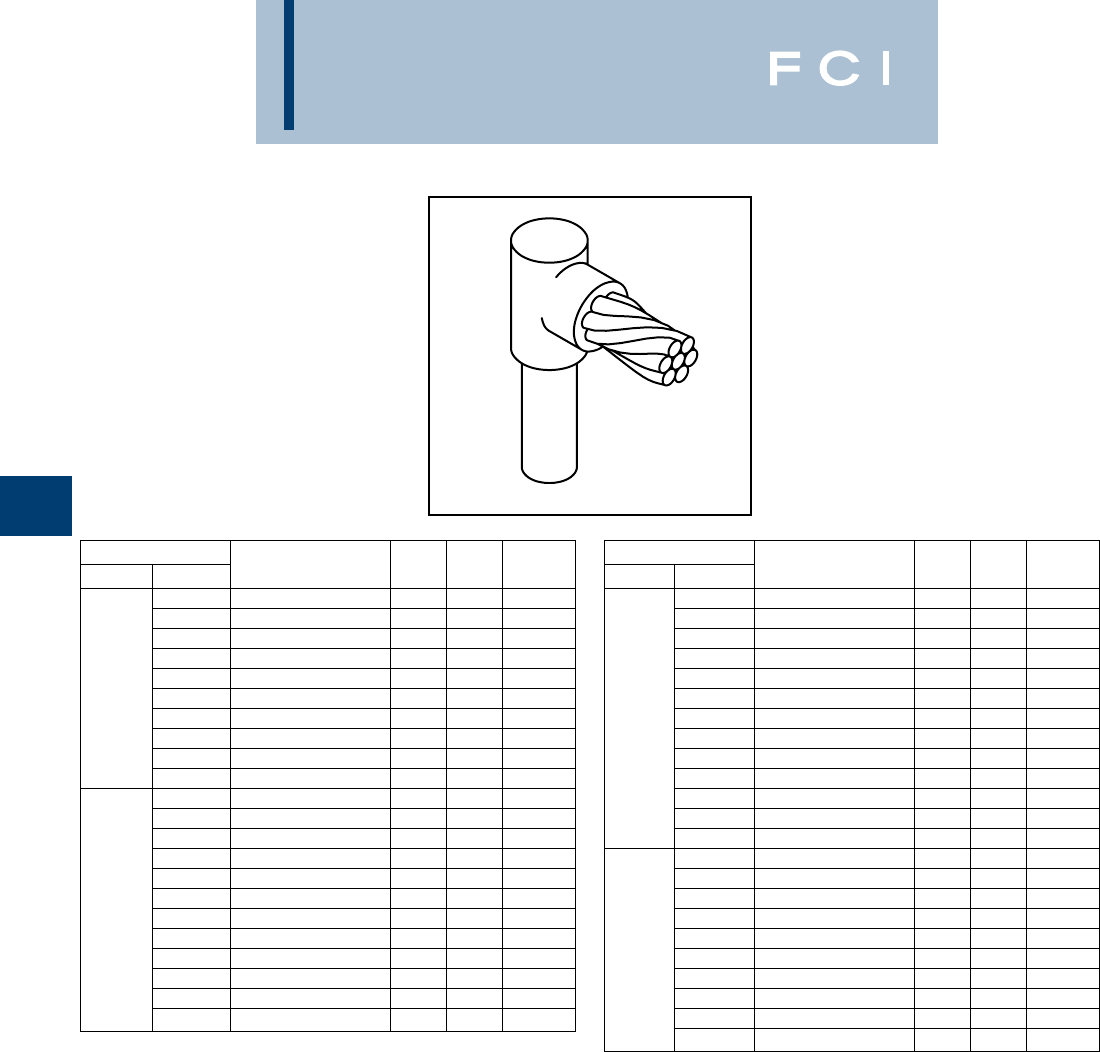
BURNDY
Grounding
D-64
TYPE BCR-1 MOLDS
Horizontal Cable Terminal to
Ground Rod
Type BCR-1 Molds are used to terminate hor-
izontal copper cable at the top of a vertical
ground rod.
Size range is #6 through 1000 MCM solid or
concentric stranded copper conductors; 1/2
through 1for the ground rod.
Contact BURNDY®Products for information
on molds for conductors not listed below.
Cable Price Weld Handle
Grd Rod Tap Mold Number Key Metal Clamps
#6 B-8402 18†* 25 N/A
#4 B-8403 18†* 25 N/A
#2 B-495 465 B-106
#1 B-496 465 B-106
1/0 B-497 490 B-106
1/2
2/0 B-498 490 B-106
3/0 B-499 490 B-106
4/0 B-500 490 B-106
250 MCM B-501 490 B-106
300 MCM B-502 490 B-106
#6 B-8414 18† 32 N/A
#4 B-8415 18† 32 N/A
#2 B-503 465 B-106
#1 B-504 465 B-106
1/0 B-505 490 B-106
5/82/0 B-506 490 B-106
3/0 B-507 490 B-106
4/0 B-508 490 B-106
250 MCM B-509 490 B-106
300 MCM B-510 4115 B-106
350 MCM B-511 4115 B-106
500 MCM B-513 4150 B-106
Cable Price Weld Handle
Grd Rod Tap Mold Number Key Metal Clamps
#6 B-8422 181* 32 N/A
#4 B-8426 191* 45 N/A
#2 B-5781 490 B-106
#1 B-514 490 B-106
1/0 B-515 490 B-106
2/0 B-516 490 B-106
3/43/0 B-517 490 B-106
4/0 B-518 490 B-106
250 MCM B-519 490 B-106
300 MCM B-520 4115 B-106
350 MCM B-521 4115 B-106
500 MCM B-523 4150 B-106
750 MCM B-524 4250 B-106
1/0 B-525 4150 B-106
2/0 B-526 4150 B-106
3/0 B-527 4150 B-106
4/0 B-528 4150 B-106
250 MCM B-529 4150 B-106
1
300 MCM B-530 4200 B-106
350 MCM B-531 4200 B-106
500 MCM B-533 4200 B-106
750 MCM B-534 4250 B-106
1000 MCM B-535 52-150 B-106
•For sizes not listed, contact BURNDY®Products.
•Molds listed are for concentric stranded cable. Add suffix “-S” to mold number for solid
conductors.
•Molds listed are for copperclad ground rods. For welding to steel, stainless steel or galva-
nized steel ground rods add suffix “-N” to mold number.
•For heavy duty molds, molds with wear plates or molds for Copperweld®cable, contact
BURNDY®Products.
•For expedited service, contact BURNDY®Products.
Required Tools:
Handle Clamps (see chart for correct handles)
† Sold complete with handles
* B38-0309-00 Flint Ignitor (included)
Other recommended accessories:
B38-3922-00 Mold Cleaning Brush (pg D-85)
B38-0135-00 Cable Cleaning Brush (pg D-85)
B38-0304-00 File (pg D-85)
B38-0330-00 Cable Clamp (pg D-85)
For mold types or BURNDYWeld™ items not shown, please
contact factory or refer to full BURNDYWeld™ catalog.
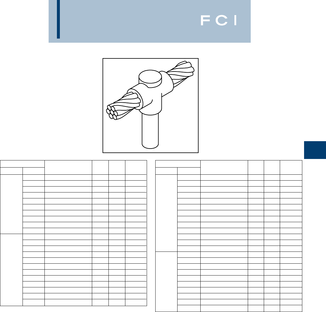
BURNDY
Grounding
D-65
TYPE BCR-2 MOLDS
Horizontal Cable to
Ground Rod
Type BCR-2 Molds are used to join horizontal
through copper cable to the top of a vertical
ground rod.
Size range is #6 through 1000 MCM solid or
concentric stranded copper conductors; 1/2
through 1for the ground rod.
Contact BURNDY®Products for information
on molds for conductors not listed below.
Cable Price Weld Handle
Grd Rod Tap Mold Number Key Metal Clamps
#6 B-8434 181†* 32 N/A
#4 B-8435 18†* 32 N/A
#2 B-537 490 B-106
#1 B-538 490 B-106
1/0 B-539 490 B-106
1/2
2/0 B-540 490 B-106
3/0 B-541 4115 B-106
4/0 B-542 4115 B-106
250 MCM B-543 4150 B-106
300 MCM B-544 4200 B-106
#6 B-8441 18†* 32 N/A
#4 B-8442 18†* 32 N/A
#2 B-545 490 B-106
#1 B-546 490 B-106
1/0 B-547 490 B-106
2/0 B-548 4115 B-106
5/8
3/0 B-549 4115 B-106
4/0 B-550 4115 B-106
250 MCM B-551 4150 B-106
300 MCM B-532 4200 B-106
350 MCM B-553 4200 B-106
500 MCM B-555 4250 B-106
Cable Price Weld Handle
Grd Rod Tap Mold Number Key Metal Clamps
#6 B-8452 19†* 45 N/A
#4 B-8454 19†* 65 N/A
#2 B-556 490 B-106
#1 B-557 490 B-106
1/0 B-558 4115 B-106
2/0 B-559 4115 B-106
3/4
3/0 B-560 4115 B-106
4/0 B-561 4115 B-106
250 MCM B-562 4150 B-106
300 MCM B-563 4200 B-106
350 MCM B-564 4200 B-106
500 MCM B-566 4250 B-106
750 MCM B-567 52-200 B-107
1/0 B-569 4150 B-106
2/0 B-570 4150 B-106
3/0 B-571 4150 B-106
4/0 B-572 4150 B-106
250 MCM B-573 4200 B-106
1
300 MCM B-574 4200 B-106
350 MCM B-575 4200 B-106
500 MCM B-577 4250 B-106
750 MCM B-578 52-200 B-107
1000 MCM B-579 5500 B-107
•For sizes not listed, contact BURNDY®Products.
•Molds listed are for concentric stranded cable. Add suffix “-S” to mold number for solid
conductors.
•Molds listed are for copperclad ground rods. For welding to steel, stainless steel or
galvanized steel ground rods add suffix “-N” to mold number.
•For heavy duty molds, molds with wear plates or molds for Copperweld®cable, contact
BURNDY®Products.
•For expedited service, contact BURNDY®Products.
Required Tools:
Handle Clamps (see chart for correct handles)
† Sold complete with handles
*B38-0309-00 Flint Ignitor (included)
Other recommended accessories:
B38-3922-00 Mold Cleaning Brush (pg D-85)
B38-0135-00 Cable Cleaning Brush (pg D-85)
B38-0304-00 File (pg D-85)
B38-0330-00 Cable Clamp (pg D-85)
For mold types or BURNDYWeld™ items not shown, please
contact factory or refer to full BURNDYWeld™ catalog.
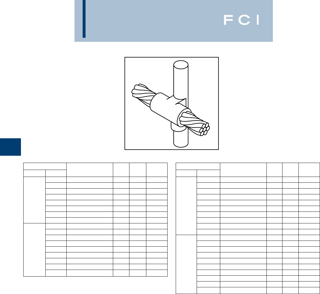
BURNDY
Grounding
D-66
TYPE BCR-3 MOLDS
Horizontal Through Cable to
Ground Rod
Type BCR-3 Molds are used to join horizontal
through run cable to the side of a vertical
ground rod.
Size range is #6 through 1000 MCM solid or
concentric stranded copper conductors; 1/2
through 1for the ground rod.
Contact BURNDY®Products for information
on molds for conductors not listed below.
Cable Price Weld Handle
Grd Rod Tap Mold Number Key Metal Clamps
#6 B-5321 24 65 B-106
#4 B-2154 24 90 B-106
#2 B-2155 24 90 B-106
1/2#1 B-2156 24 115 B-106
1/0 B-1581 24 115 B-106
2/0 B-1582 24 115 B-106
4/0 B-1583 24 150 B-106
250 MCM B-1584 24 150 B-106
#6 B-5660 24 65 B-106
#4 B-2157 24 90 B-106
#2 B-2158 24 90 B-106
#1 B-2159 24 115 B-106
5/81/0 B-1586 24 115 B-106
2/0 B-1587 24 115 B-106
4/0 B-1588 24 150 B-106
250 MCM B-1589 24 150 B-106
500 MCM B-1593 13 2-200 B-107
Cable Price Weld Handle
Grd Rod Tap Mold Number Key Metal Clamps
#6 B-6630 24 65 B-106
#4 B-2160 24 90 B-106
#2 B-2161 24 90 B-106
#1 B-2162 24 115 B-106
1/0 B-1594 24 115 B-106
3/42/0 B-1595 24 115 B-106
#4 B-1596 24 150 B-106
250 MCM B-1597 24 200 B-106
500 MCM B-1601 13 500 B-107
750 MCM B-1602 13 3-250 B-107
#6 B-6906 24 90 B-106
#4 B-2163 24 90 B-106
#2 B-2164 24 90 B-106
#1 B-2165 24 115 B-106
11/0 B-1603 24 15 B-106
2/0 B-1604 24 115 B-106
4/0 B-1605 24 150 B-106
250 MCM B-1606 24 200 B-106
500 MCM B-1610 13 500 B-107
750 MCM B-1611 13 3-250 B-107
•For sizes not listed, contact BURNDY®Products.
•Molds listed are for concentric stranded cable. Add suffix “-S” to mold number for solid
conductors.
•Molds listed are for copperclad ground rods. For welding to steel, stainless steel or
galvanized steel ground rods add suffix “-N” to mold number.
•For heavy duty molds, molds with wear plates or molds for Copperweld®cable, contact
BURNDY®Products.
•For expedited service, contact BURNDY®Products.
Required Tools:
Handle Clamps (see chart for correct handles)
B38-0309-00 Flint Ignitor
Other recommended accessories:
B38-3922-00 Mold Cleaning Brush (pg D-85)
B38-0135-00 Cable Cleaning Brush (pg D-85)
B38-0330-00 Cable Clamp (pg D-85)
B38-0304-00 File (pg D-85)
For mold types or BURNDYWeld™ items not shown, please
contact factory or refer to full BURNDYWeld™ catalog.
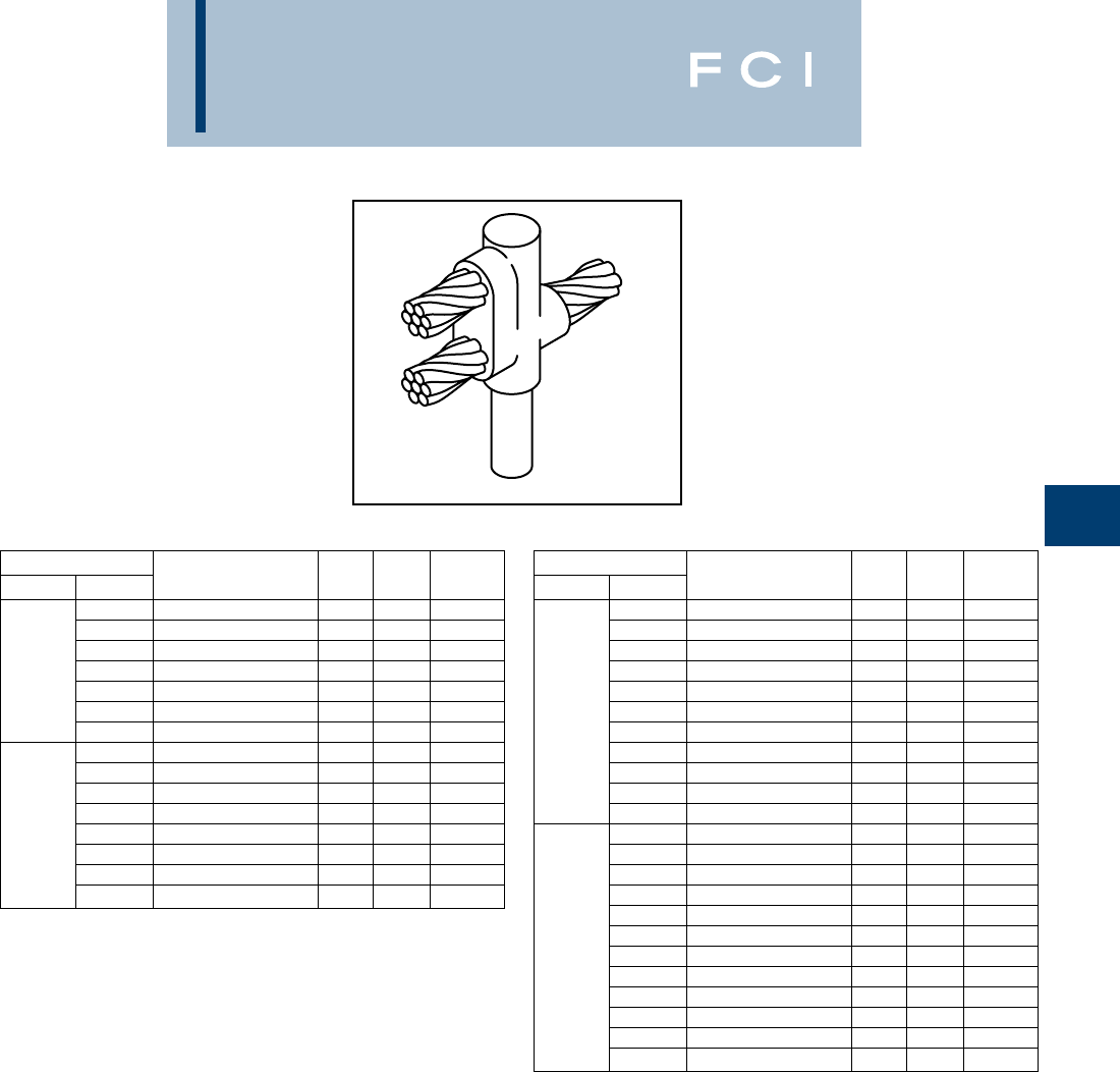
BURNDY
Grounding
D-67
TYPE BCR-17 MOLDS
Horizontal Run and Tap
Cables to Ground Rod
Type BCR-17 Molds are used to join horizon-
tal run and tap cables to the top of a vertical
ground rod.
Size range is #4 through 750 MCM solid or
concentric stranded copper conductors; 1/2
through 1for the ground rod.
Contact BURNDY®Products for information
on molds for conductors not listed below.
Cable Price Weld Handle
Grd Rod Tap Mold Number Key Metal Clamps
#4 B-5416 490 B-106
#2 B-6165 490 B-106
#1 B-5830 490 B-106
1/21/0 B-5940 4115 B-106
2/0 B-5850 4150 B-106
3/0 B-5833 4200 B-106
4/0 B-5380 4200 B-106
#4 B-5972 490 B-106
#2 B-5935 4115 B-106
#1 B-5699 4115 B-106
1/0 B-5746 4150 B-106
5/8
2/0 B-5963 4200 B-106
3/0 B-5734 4250 B-106
4/0 B-5732 4250 B-106
250 MCM B-5722 52-150 B-107
Cable Price Weld Handle
Grd Rod Tap Mold Number Key Metal Clamps
#4 B-5698 490 B-106
#2 B-5294 4115 B-106
#1 B-5390 4115 B-106
1/0 B-6025 4150 B-106
2/0 B-5738 4200 B-106
3/4
3/0 B-6003 4250 B-106
4/0 B-2566 4250 B-106
250 MCM B-5904 52-150 B-107
300 MCM B-5857 52-200 B-107
350 MCM B-5777 52-200 B-107
500 MCM B-5961 53-200 B-106
#4 B-5556 4115 B-106
#2 B-5555 4150 B-106
#1 B-6048 4150 B-106
1/0 B-5992 4200 B-106
2/0 B-5877 4250 B-106
3/0 B-5821 52-150 B-107
1
4/0 B-5820 52-150 B-107
250 MCM B-5804 52-200 B-107
300 MCM B-5803 5500 B-107
350 MCM B-5561 5500 B-107
500 MCM B-5515 63-250 B-107
750 MCM B-5513 62-500 B-107
•For sizes not listed, contact BURNDY®Products.
•Molds listed are for concentric stranded cable. Add suffix “-S” to mold number for solid
conductors.
•Molds listed are for copperclad ground rods. For welding to steel, stainless steel or
galvanized steel ground rods add suffix “-N” to mold number.
•For heavy duty molds, molds with wear plates or molds for Copperweld®cable, contact
BURNDY®Products.
•For expedited service, contact BURNDY®Products.
Required Tools:
Handle Clamps (see chart for correct handles)
B38-0309-00 Flint Ignitor
Other recommended accessories:
B38-3922-00 Mold Cleaning Brush (pg D-85)
B38-0135-00 Cable Cleaning Brush (pg D-85)
B38-0330-00 Cable Clamp (pg D-85)
B38-0304-00 File (pg D-85)
For mold types or BURNDYWeld™ items not shown, please
contact factory or refer to full BURNDYWeld™ catalog.
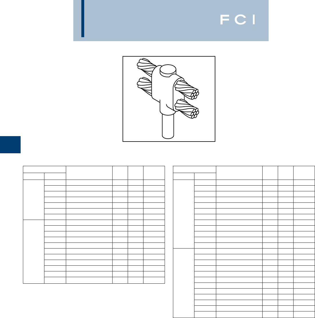
BURNDY
Grounding
D-68
TYPE BCR-24 MOLDS
Horizontal Parallel Run Cables
to Ground Rod
Type BCR-24 Molds are used to join horizon-
tal parallel cables to the top of a vertical
ground rod.
Size range is #4 through 750 MCM solid or
concentric stranded copper conductors; 1/2
through 1for the ground rod.
Contact BURNDY®Products for information
on molds for conductors not listed below.
Cable Price Weld Handle
Grd Rod Tap Mold Number Key Metal Clamps
#4 B-5640 4115 B-106
#2 B-5667 4115 B-106
#1 B-6002 4115 B-106
1/21/0 B-5767 4150 B-106
2/0 B-5604 4200 B-106
3/0 B-5560 4250 B-106
4/0 B-6766 4250 B-106
#4 B-6208 4115 B-106
#2 B-5702 4150 B-106
#1 B-5517 4150 B-106
1/0 B-5573 4200 B-106
2/0 B-8451 4250 B-106
5/83/0 B-2510 52-150 B-107
4/0 B-5428 52-150 B-107
250 MCM B-1212 52-200 B-107
300 MCM B-2084 5500 B-107
350 MCM B-2558 5500 B-107
500 MCM B-2450 53-250 B-107
Cable Price Weld Handle
Grd Rod Tap Mold Number Key Metal Clamps
#4 B-8011 4115 B-106
#2 B-2320 4150 B-106
#1 B-2235 4150 B-106
1/0 B-6051 4200 B-106
2/0 B-8802 4250 B-106
3/0 B-8726 52-150 B-107
3/4
4/0 B-5677 52-150 B-107
250 MCM B-8461 52-200 B-107
300 MCM B-8428 5500 B-107
350 MCM B-6294 5500 B-107
500 MCM B-8214 53-250 B-107
750 MCM B-8027 62-500 B-107
#4 B-5330 4150 B-106
#2 B-5332 4200 B-106
#1 B-5333 4200 B-106
1/0 B-5334 4250 B-106
2/0 B-5335 52-150 B-107
3/0 B-5336 52-200 B-107
1
4/0 B-5337 52-200 B-107
250 MCM B-5338 5500 B-107
300 MCM B-5341 53-200 B-107
350 MCM B-5351 53-200 B-107
500 MCM B-5352 62-500 B-107
750 MCM B-5353 64 5-250 B-107
•For sizes not listed, contact BURNDY®Products.
•Molds listed are for concentric stranded cable. Add suffix “-S” to mold number for solid
conductors.
•Molds listed are for copperclad ground rods. For welding to steel, stainless steel or
galvanized steel ground rods add suffix “-N” to mold number.
•For heavy duty molds, molds with wear plates or molds for Copperweld®cable, contact
BURNDY®Products.
•For expedited service, contact BURNDY®Products.
Required Tools:
Handle Clamps (see chart for correct handles)
B38-0309-00 Flint Ignitor
‡ Crucible B-181 required
Other recommended accessories:
B38-3922-00 Mold Cleaning Brush (pg D-85)
B38-0135-00 Cable Cleaning Brush (pg D-85)
B38-0330-00 Cable Clamp (pg D-85)
B38-0304-00 File (pg D-85)
For mold types or BURNDYWeld™ items not shown, please
contact factory or refer to full BURNDYWeld™ catalog.
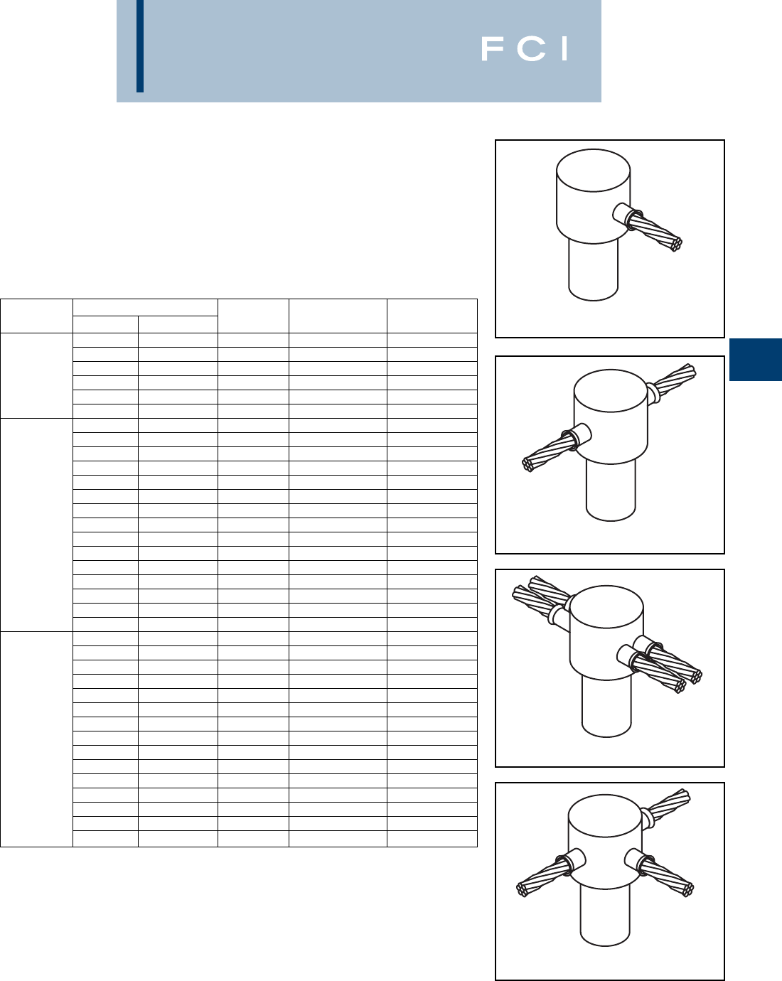
BURNDY
Grounding
D-69
SINGLE SHOT MOLDS
BURNDYWeld™ Single Shot Molds are an
economical way to make cable connections
onto the top of a ground rod. The Single Shot
is a disposable single use ceramic mold that
comes complete with everything required
except the Flint Ignitor.
Ground Cable Size Mold Cadweld®
Rod Size Solid Stranded Type Number Part #
#6, #8 #8 BCR-1 BS-2009 GR1-141G
#3, #4 #4, #6 BCR-1 BS-2010 GR1-141L
#1, #2 #2, #3 BCR-1 BS-2011 GR1-141V
1/2
#6, #8 #8 BCR-2 BS-2024 GT1-141G
#3, #4 #4, #6 BCR-2 BS-2025 GT1-141L
#1, #2 #2, #3 BCR-2 BS-2026 GT1-141V
#6, #8 #8 BCR-1 BS-2012 GT1-161G
#3, #4 #4, #6 BCR-1 BS-2013 GT1-141L
#1, #2 #2, #3 BCR-1 BS-2014 GR1-161V
2/0, 1/0 1/0, #1 BCR-1 BS-2015 GR1-162C
2/0 BCR-1 BS-2016 GR1-162G
#6, #8 #8 BC R-2 BS-2027 FRT1-161G
#3, #4 #4, #6 BCR-2 BS-2028 GT1-161L
5/8
#1, #2 #2, #3 BCR-2 BS-2029 GT1-161V
2/0, 1/0 1/0, #1 BCR-2 BS-2030 GT1-162C
#6, #8 #8 BCR-24 BS-2105 NX1-161G
#3, #4 #4, #6 BCR-14 BS-2106 NX1-161L
#1, #2 #2, #3 BCR-24 BS-2107 NX1-161V
#6, #8 #8 BCR-25 BS-2006 NT1-161G
#3, #4 #4, #6 BCR-25 BS-2007 NT1-161L
#1, #2 #2, #3 BCR-25 BS-2008 NT1-161V
#6, #8 #8 BCR-1 BS-2017 GR1-181G
#3, #8 #4, #6 BCR-1 BS-2018 GR1-181L
#1, #2 #2, #3 BCR-1 BS-2019 GR1-181V
2/1, 1/0 1/0, #1 BCR-1 BS-2020 GR1-182C
2/0 BCR-1 BS-2021 GR1-182G
#6, #8 #8 BCR-2 BS-2031 GT1-181G
#3, #4 #4, #6 BCR-2 BS-2032 GT1-181L
3/4#1, #2 #2, #3 BCR-2 BS-2033 GT1-181V
2/0, 1/0 1/0, #1 BCR-2 BS-2034 T1-182C
#6, #8 #8 BCR-24 BS-2108 NX1-181G
#3, #4 #4, #6 BCR-24 BS-2109 NX1-181L
#1, #2 #2, #3 BCR-24 BS-2110 NX1-181V
#6, #8 #8 BCR-25 BS-2068 NT1-181G
#3, #4 #4, #6 BCR-25 BS-2069 NT1-181L
#1, #2 #2, #3 BCR-25 BS-2070 NT1-181V
BCR-1
BCR-2
BCR-24
BCR-25
Cadweld®is a registered trademark of the Erico International Corporation
For mold types or BURNDYWeld™ items not shown, please
contact factory or refer to full BURNDYWeld™ catalog.
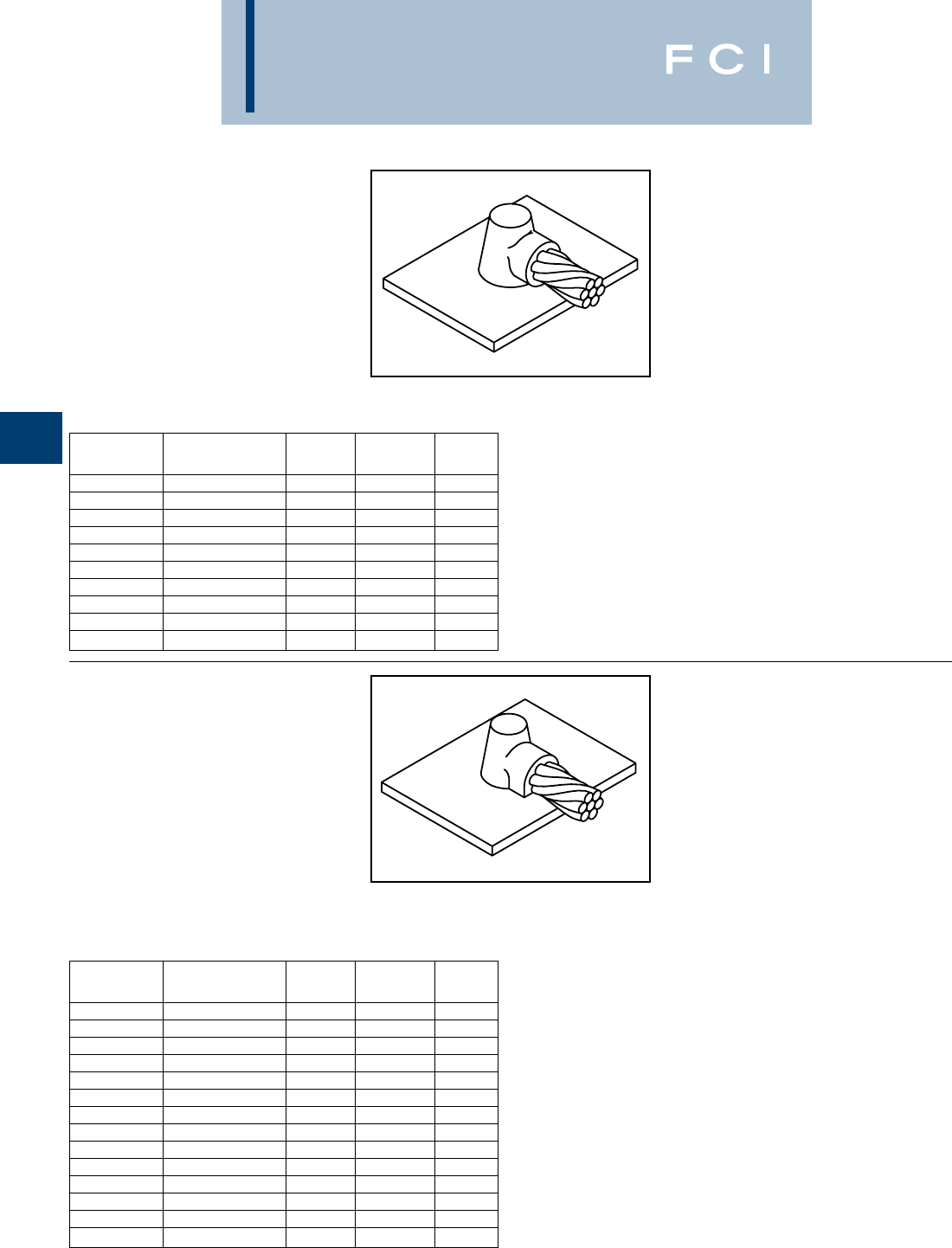
BURNDY
Grounding
D-70
TYPE BCS-1 MOLDS
Horizontal Cable to Horizontal
Steel Surface
Type BCS-1 Molds are used to terminate a
horizontal copper cable to any horizontal steel
surface. Note that the cable is OFF the surface.
Size range is 1/0 through 1000 MCM solid or
concentric stranded copper conductors.
Contact BURNDY®Products for information
on molds for conductors not listed below.
Price Weld Handle
Cable Size Mold Number Key Metal Clamps
1/0 B-644 490B-106
2/0 B-645 490B-106
3/0 B-646 4115 B-106
4/0 B-647 4115 B-106
250 MCM B-648 4115 B-106
300 MCM B-649 4150 B-106
350 MCM B-650 4200 B-106
500 MCM B-652 4200 B-106
750 MCM B-653 52-150 B-106
1000 MCM B-654 52-200 B-107
Price Weld Handle
Cable Size Mold Number Key Metal Clamps
#6 B-628 3†** 45 N/A
#4 B-629 3†* 45 N/A
#2 B-630 3†* 45 N/A
#1 B-631 3†* 65 N/A
1/0 B-7146 490B-106
2/0 B-7075 490B-106
3/0 B-2199 4115 B-106
4/0 B-6114 4115 B-106
250 MCM B-2200 4115 B-106
300 MCM B-2506 4150 B-106
350 MCM B-2507 4200 B-106
500 MCM B-2509 4200 B-106
750 MCM B-2542 52-150 B-107
1000 MCM B-2511 52-200 B-107
•For sizes not listed, contact BURNDY®Products.
•Molds listed are for concentric stranded cable. Add suffix “-S” to mold number for solid
conductors.
•For heavy duty molds, molds with wear plates or molds for Copperweld®cable, contact
BURNDY®Products.
•For expedited service, contact BURNDY®Products.
Required Tools:
Handle Clamps (see chart for correct handles)
B38-0309-00 Flint Ignitor
Other recommended accessories:
B38-3922-00 Mold Cleaning Brush (pg D-85)
B38-0135-00 Cable Cleaning Brush (pg D-85)
B38-0330-00 Cable Clamp (pg D-85)
B38-0101-00 Rasp (pg D-85)
•For sizes not listed, contact BURNDY®Products.
•Molds listed are for concentric stranded cable. Add suffix “-S” to mold number for solid
conductors.
•For heavy duty molds, molds with wear plates or molds for Copperweld®cable, contact
BURNDY®Products.
•For expedited service, contact BURNDY®Products.
Required Tools:
Handle Clamps (see chart for correct handles)
† Sold complete with frame
* B38-0309-00 Flint Ignitor (included)
Other recommended accessories:
B38-3922-00 Mold Cleaning Brush (pg D-85)
B38-0135-00 Cable Cleaning Brush (pg D-85)
B38-0330-00 Cable Clamp (pg D-85)
B38-0101-00 Rasp (pg D-85)
TYPE BCS-8 MOLDS
Horizontal Cable to Horizontal
Steel Surface
Type BCS-8 Molds are used to terminate a
horizontal copper cable to any horizontal
steel surface. Note that the cable is ON the
surface.
Size range is #6 through 1000 MCM solid or
concentric stranded copper conductors.
Contact BURNDY®Products for information
on molds for conductors not listed below.
For mold types or BURNDYWeld™ items not shown, please
contact factory or refer to full BURNDYWeld™ catalog.
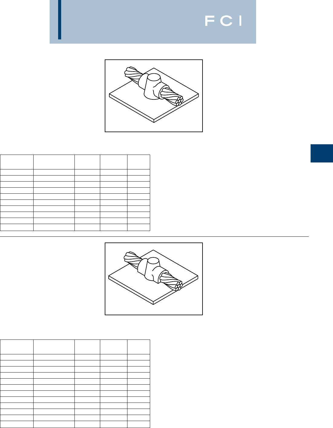
BURNDY
Grounding
D-71
TYPE BCS-2 MOLDS
Horizontal Through Cable to
Horizontal Steel Surface
Type BCS-2 Molds are used to join horizontal
through copper cable to any horizontal steel
surface. Note the cable is OFF the surface.
Size range is 1/0 through 1000 MCM solid or
concentric stranded copper conductors.
Contact BURNDY®Products for information
on molds for conductors not listed below.
Price Weld Handle
Cable Size Mold Number Key Metal Clamps
1/0 B-616 490B-106
2/0 B-617 4115 B-106
3/0 B-618 4115 B-106
4/0 B-619 4150 B-106
250 MCM B-620 4150 B-106
300 MCM B-621 4200 B-106
350 MCM B-622 4250 B-106
500 MCM B-624 52-150 B-107
750 MCM B-625-H 53-250 B-107
1000 MCM B-626-H 52-500 B-107
Price Weld Handle
Cable Size Mold Number Key Metal Clamps
#6 B-602 3†* 45 N/A
#4 B-603 3†* 45 N/A
#2 B-604 3†* 45 N/A
#1 B-605 3†* 65 N/A
1/0 B-8379 490B-106
2/0 B-5331 4115 B-106
3/0 B-8381 4115 B-106
4/0 B-7192 4150 B-106
250 MCM B-8413 4150 B-106
300 MCM B-8423 4200 B-106
350 MCM B-8410 4250 B-106
500 MCM B-5065 52-150 B-107
•For sizes not listed, contact BURNDY®Products.
•Molds listed are for concentric stranded cable. Add suffix “-S” to mold number for solid
conductors.
•For heavy duty molds, molds with wear plates or molds for Copperweld® cable, contact
BURNDY®Products.
•For expedited service, contact BURNDY®Products.
Required Tools:
Handle Clamps (see above for correct handles)
B38-0309-00 Flint Ignitor
Other recommended accessories:
B38-3922-00 Mold Cleaning Brush (pg D-85)
B38-0135-00 Cable Cleaning Brush (pg D-85)
B38-0101-00 Rasp (pg D-85)
•For sizes not listed, contact BURNDY®Products.
•Molds listed are for concentric stranded cable. Add suffix “-S” to mold number for solid
conductors.
•For heavy duty molds, molds with wear plates or molds for Copperweld®cable, contact
BURNDY®Products.
•For expedited service, contact BURNDY®Products.
Required Tools:
Handle Clamps (see chart for correct handles)
† Sold complete with handle frame
* B38-0309-00 Flint Ignitor (included)
Other recommended accessories:
B40-0319-01 Mold Cleaner for cartridge sizes #15-#65 (pg D-85)
B40-0319-03 Mold Cleaner for cartridge sizes #90-#500 (pg D-85)
B38-3922-00 Mold Cleaning Brush (pg D-85)
B38-0135-00 Cable Cleaning Brush (pg D-85)
B38-0101-00 Rasp (pg D-85)
TYPE BCS-9 MOLDS
Horizontal Through Cable to
Horizontal Steel Surface
Type BCS-9 Molds are used to join horizontal
through copper cable to any horizontal steel
surface. Note the cable is ON the surface.
Size range is #6 through 500 MCM solid or
concentric stranded copper conductors.
Contact BURNDY®Products for information
on molds for conductors not listed below.
For mold types or BURNDYWeld™ items not shown, please
contact factory or refer to full BURNDYWeld™ catalog.

BURNDY
Grounding
D-72
TYPE BCS-3 MOLDS
Angular Cable Drop to Vertical
Steel Surface
Type BCS-3 Molds are used to join the end of
a copper cable at a 45˚ angle to a vertical
steel surface.
Size range is #6 through 1000 MCM solid or
concentric stranded copper conductors.
Contact BURNDY®Products for information
on molds for conductors not listed below.
Price Weld Handle
Cable Size Mold Number Key Metal Clamps
#6 B-585 445B-106
#4 B-586 445B-106
#3 B-587 445B-106
#2 B-588 445B-106
#1 B-589 465B-106
1/0 B-590 490B-106
2/0 B-591 490B-106
3/0 B-592 4115 B-106
4/0 B-593 4115 B-106
250 MCM B-594 4115 B-106
300 MCM B-595 4150 B-106
350 MCM B-596 4200 B-106
500 MCM B-598 4200 B-106
750 MCM B-599 52-150 B-107
1000 MCM B-600 52-200 B-107
Cable Pipe Mold Price Weld Handle
Size Size Number Key Metal Clamps
1-1/4to 4B-2476 445 B-106
4to 6B-2477 445 B-106
#4 6to 10B-2478 445 B-106
12& up B-586‡4 45 B-106
1-1/4to 4B-9233-S 445 B-106
4to 6B-2480-S 445 B-106
#2 Sol 6to 10B-2583-S 445 B-106
12& up B-588-S‡4 45 B-106
1-1/4to 4B-9233 445 B-106
4to 6B-2480 445 B-106
#2 6to 10B-2688 445 B-106
12& up B-588‡4 45 B-106
1-1/4to 4B-2482 465 B-106
4to 6B-2483 465 B-106
#1 6to 10B-2484 465 B-106
12& up B-589‡4 65 B-106
1-1/4to 4B-2486 490 B-106
4to 6B2487 490 B-106
1/0 6to 10B-2488 490 B-106
12& up B-590‡4 90 B-106
1-1/4to 4B-8833 490 B-106
4to 6B-2490 490 B-106
2/0 6to 10B-2491 490 B-106
12& upB-591‡4 90 B-106
1-1/4to 4B-2493 4115 B-106
4to 6B-2494 4115 B-106
3/0 6to 10B2495 4115 B-106
12& up B-592‡4 115 B-106
1-1/4to 4B-9021 4115 B-106
4to 6B2497 4115 B-106
4/0 6to 10B2498 4115 B-106
12& up B593‡4 115 B-106
•For sizes not listed, contact BURNDY®Products.
•Molds listed are for concentric stranded cable. Add suffix “-S” to mold number for solid
conductors.
•For heavy duty molds, molds with wear plates or molds for Copperweld®cable, contact
BURNDY®Products.
•For expedited service, contact BURNDY®Products.
Required Tools:
Handle Clamps (see chart for correct handles)
B38-0309-00 Flint Ignitor
Other recommended accessories:
Magnetic Clamps to hold molds against vertical steel (pg D-84)
B38-3922-00 Mold Cleaning Brush (pg D-85)
B38-0135-00 Cable Cleaning Brush (pg D-85)
B38-0101-00 Rasp (pg D-85)
•For sizes not listed, contact BURNDY®Products.
•Molds listed are for concentric stranded cable. Add suffix “-S” to mold number for solid
conductors.
•For heavy duty molds, molds with wear plates or molds for Copperweld® cable, contact
BURNDY®Products.
•For expedited service, contact BURNDY®Products.
Required Tools:
Handle Clamps (see chart for correct handles)
B38-0309-00 Flint Ignitor
Other recommended accessories:
B106-32 Ver tical Chain Clamp w/ B-106 Handles for 4Pipe & smaller
B40-0106-27 20Chain Extension for 4to 10Pipe
Use (2) 20Chain Extensions for pipe sizes between 10and 16
B38-3922-00 Mold Cleaning Brush (pg D-85)
B38-0135-00 Cable Cleaning Brush (pg D-85)
B38-0101-00 Rasp (pg D-85)
‡ Flat Surface Mold
Cable to Flat Steel Cable to Pipe
Cable to Flat Steel Cable to Pipe
For mold types or BURNDYWeld™ items
not shown, please contact factory
or refer to full BURNDYWeld™ catalog.
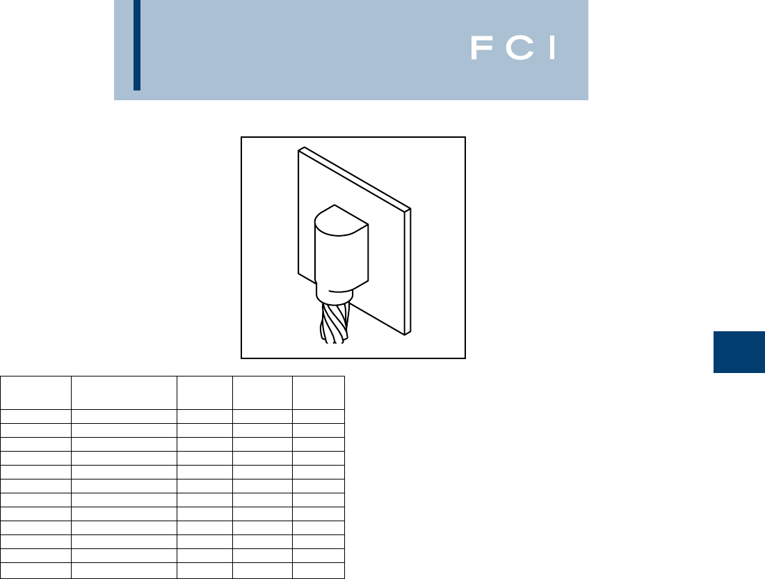
BURNDY
Grounding
D-73
TYPE BCS-23 MOLDS
Vertical Cable Drop to
Vertical Steel Surface
Type BCS-23 Molds are used to join vertical
cable down to a vertical steel surface. Note
that the cable is OFF the surface.
Size range is #6 through 500 MCM solid or
concentric stranded copper conductors.
Contact BURNDY®Products for information
on molds for conductors not listed below.
Price Weld Handle
Cable Size Mold Number Key Metal Clamps
#6 B-5389 445B-106
#4 B-5359 465B-106
#2 B-2781 465B-106
#1 B-5361 490B-106
1/0 B-2189 4115 B-106
2/0 B-2540 4115 B-106
3/0 B-5362 4150 B-106
4/0 B-8718 4150 B-106
250 MCM B-8165 4200 B-106
300 MCM B-5363 4200 B-106
350 MCM B-9029 4250 B-106
500 MCM B-8512 17 2-150 B-106
•For sizes not listed, contact BURNDY®Products.
•Molds listed are for concentric stranded cable. Add suffix “-S” to mold number for solid
conductors.
•For heavy duty molds, molds with wear plates or molds for Copperweld®cable, contact
BURNDY®Products.
•For expedited service, contact BURNDY®Products.
Required Tools:
Handle Clamps (see chart for correct handles)
B38-0309-00 Flint Ignitor
Other recommended accessories:
Magnetic Clamps to hold molds against vertical steel
B38-3922-00 Mold Cleaning Brush (pg D-85)
B38-0135-00 Cable Cleaning Brush (pg D-85)
B38-0101-00 Rasp (pg D-85)
For mold types or BURNDYWeld™ items not shown, please
contact factory or refer to full BURNDYWeld™ catalog.
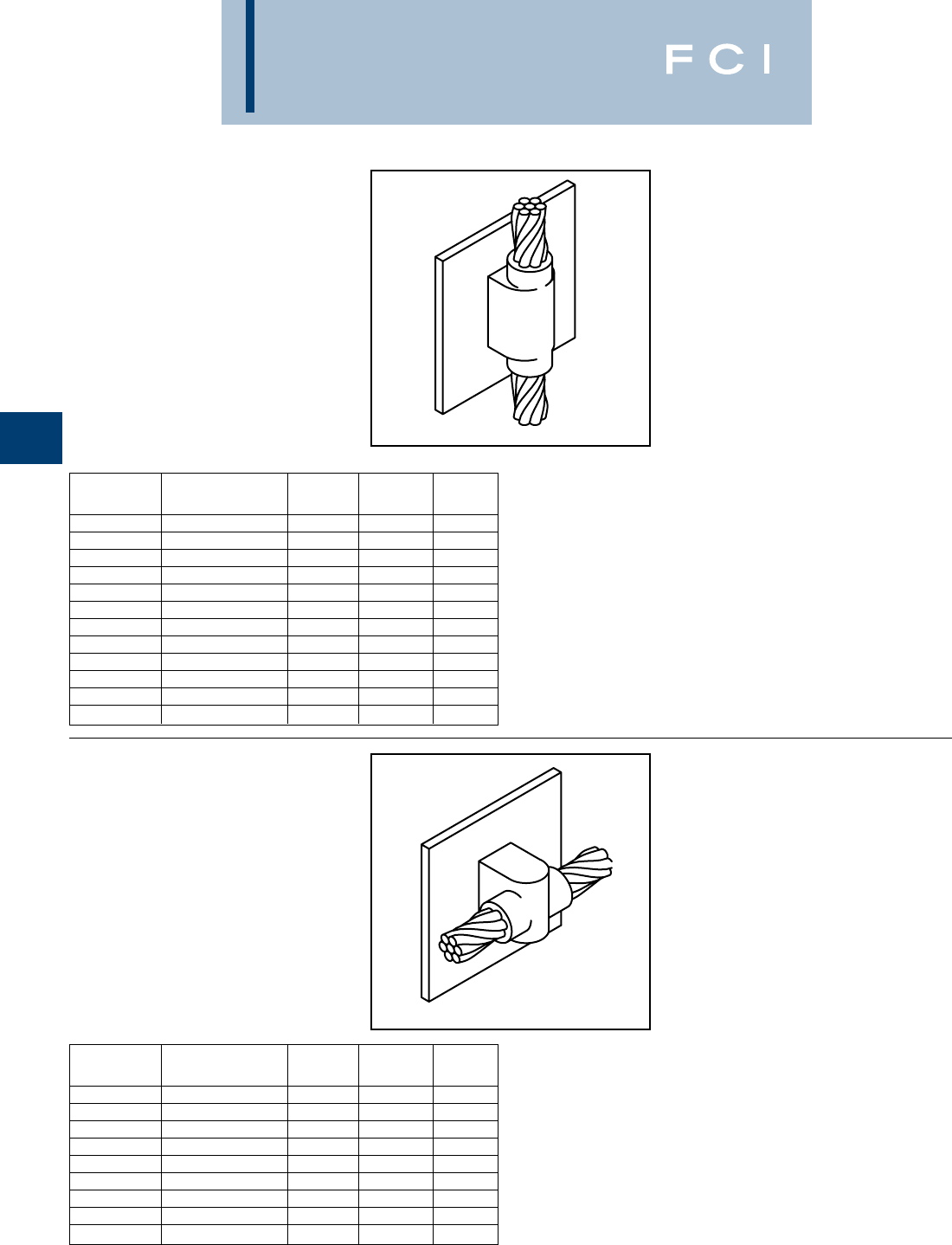
BURNDY
Grounding
D-74
TYPE BCS-4 MOLDS
Vertical Through Cable to
Vertical Steel Surface
Type BCS-4 Molds are used to join a vertical
through copper cable to a vertical steel sur-
face. Note that the cable is OFF the surface.
For molds with the cable on the surface, con-
tact BURNDY®Products.
Size range is #6 through 500 MCM solid or
concentric stranded copper conductors.
Contact BURNDY®Products for information
on molds for conductors not listed below.
Price Weld Handle
Cable Size Mold Number Key Metal Clamps
#6 B-1215 490B-106
#4 B-1216 490B-106
#2 B-1218 4115 B-106
#1 B-1219 4115 B-106
1/0 B-1220 17 200 B-106
2/0 B-1221 17 200 B-106
3/0 B-1222 17 250 B-106
4/0 B-1223 17 250 B-106
250 MCM B-1224 17 250 B-106
300 MCM B-1225-H 6500 B-107
350 MCM B-1226-H 63-200 B-107
500 MCM B-1228-H 63-250 B-107
Price Weld Handle
Cable Size Mold Number Key Metal Clamps
#6 B-1626 465B-106
#4 B-1627 465B-106
#2 B-1628 465B-106
#1 B-1629 490B-106
1/0 B-1630 4115 B-106
2/0 B-1631 4115 B-106
3/0 B-1632 4150 B-106
4/0 B-1633 4150 B-106
250 MCM B-1634 4150 B-106
•For sizes not listed, contact BURNDY®Products.
•Molds listed are for concentric stranded cable. Add suffix “-S” to mold number for solid
conductors.
•For heavy duty molds, molds with wear plates or molds for Copperweld®cable, contact
BURNDY®Products.
•For expedited service, contact BURNDY®Products.
Required Tools:
Handle Clamps (see chart for correct handles)
B38-0309-00 Flint Ignitor
Other recommended accessories:
Magnetic Clamps to hold molds against vertical steel
B38-3922-00 Mold Cleaning Brush (pg D-85)
B38-0135-00 Cable Cleaning Brush (pg D-85)
B38-0101-00 Rasp (pg D-85)
•For sizes not listed, contact BURNDY®Products.
•Molds listed are for concentric stranded cable. Add suffix “-S” to mold number for solid
conductors.
•For heavy duty molds, molds with wear plates or molds for Copperweld®cable, contact
BURNDY®Products.
•For expedited service, contact BURNDY®Products.
Required Tools:
Handle Clamps (see chart for correct handles)
B38-0309-00 Flint Ignitor
Other recommended accessories:
B40-0319-01 Mold Cleaner for cartridge sizes #15-#65 (pg D-85)
B40-0319-03 Mold Cleaner for cartridge sizes #90-#500 (pg D-85)
B38-3922-00 Mold Cleaning Brush (pg D-85)
B38-0135-00 Cable Cleaning Brush (pg D-85)
B38-0101-00 Rasp (pg D-85)
TYPE BCS-6 MOLDS
Horizontal Through Cable to
Vertical Steel Surface
Type BCS-6 Molds are used to join horizontal
through copper cable to a vertical steel sur-
face. Note that the cable is OFF the surface.
Size range is #6 through 250 MCM solid or
concentric stranded copper conductors.
Contact BURNDY®Products for information
on molds for conductors not listed below.
For mold types or BURNDYWeld™ items not shown, please
contact factory or refer to full BURNDYWeld™ catalog.
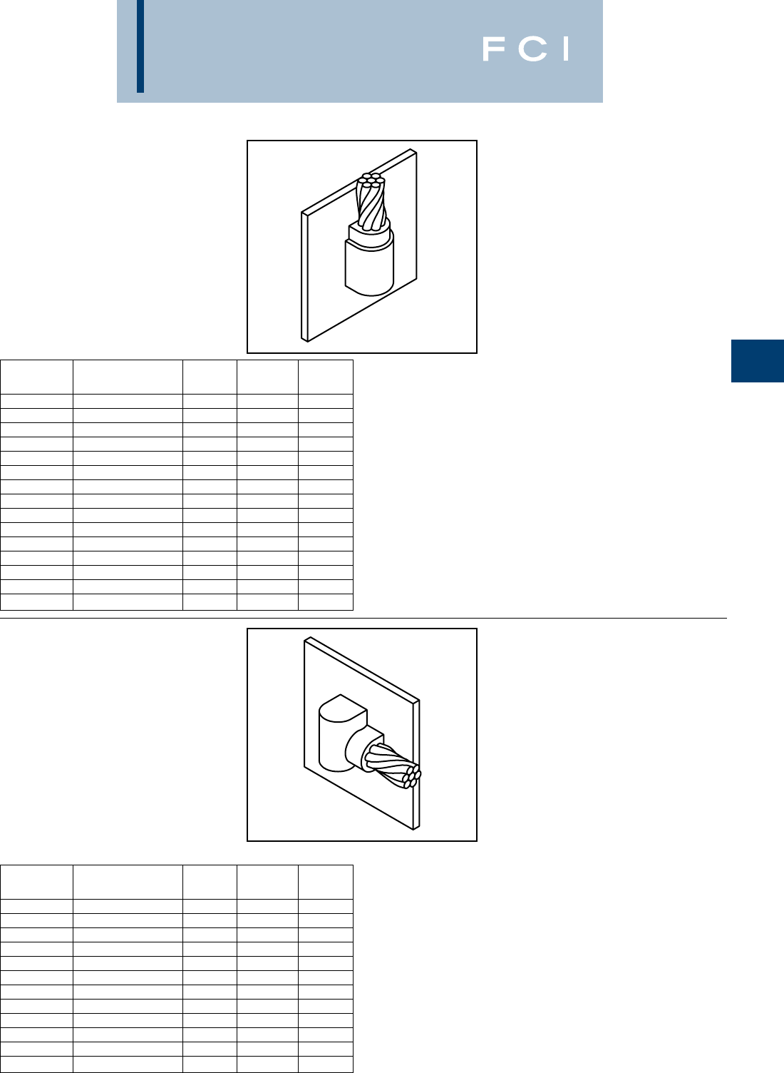
BURNDY
Grounding
D-75
TYPE BCS-7 MOLDS
Overhead Vertical Tap Cable
to Vertical Steel Surface
Type BCS-7 Molds are used to join an over-
head vertical copper conductor drop tap to a
vertical steel surface.
Size range is #6 through 1000 MCM solid or
concentric stranded copper conductors.
Contact BURNDY®Products for information
on molds for conductors not listed below.
Price Weld Handle
Cable Size Mold Number Key Metal Clamps
#6 B-1635 465B-106
#4 B-1636 465B-106
#3 B-1637 465B-106
#2 B-1638 465B-106
#1 B-1639 490B-106
1/0 B-1640 4150 B-106
2/0 B-1641 4150 B-106
3/0 B-1642 17 200 B-106
4/0 B-1643 17 200 B-106
250 MCM B-1644 17 200 B-106
300 MCM B-1645 17 250 B-106
350 MCM B-1646 62-150 B-107
500 MCM B-1648 62-200 B-107
750 MCM B-1649 6500 B-107
1000 MCM B-1650 63-200 B-107
Price Weld Handle
Cable Size Mold Number Key Metal Clamps
#6 B-5910 445B-106
#4 B-2761 445B-106
#2 B-2569 445B-106
#1 B-6060 465B-106
1/0 B-5419 490B-106
2/0 B-2567 490B-106
3/0 B-6072 4115 B-106
4/0 B-9253 4115 B-106
250 MCM B-2568 4115 B-106
300 MCM B-6061 4150 B-106
350 MCM B-6067 4200 B-106
500 MCM B-8359 4200 B-106
•For sizes not listed, contact BURNDY®Products.
•Molds listed are for concentric stranded cable. Add suffix “-S” to mold number for solid
conductors.
•For heavy duty molds, molds with wear plates or molds for Copperweld®cable, contact
BURNDY®Products.
•For expedited service, contact BURNDY®Products.
Required Tools:
Handle Clamps (see chart for correct handles)
B38-0309-00 Flint Ignitor
Other recommended accessories:
Magnetic Clamps to hold molds against vertical steel
B38-3922-00 Mold Cleaning Brush (pg D-85)
B38-0135-00 Cable Cleaning Brush (pg D-85)
B38-0101-00 Rasp (pg D-85)
NOTE: Add (-R) to mold number for right hand mold or (-L) for left hand mold. Right hand (-R)
mold will be furnished if not specified.
•For sizes not listed, contact BURNDY®Products.
•Molds listed are for concentric stranded cable. Add suffix “-S” to mold number for solid
conductors.
•For heavy duty molds, molds with wear plates or molds for Copperweld®cable, contact
BURNDY®Products.
•For expedited service, contact BURNDY®Products.
Required Tools:
Handle Clamps (see chart for correct handles)
B38-0309-00 Flint Ignitor
Other recommended accessories:
Ver tical Chain Clamps
B38-3922-00 Mold Cleaning Brush (pg D-85)
B38-0135-00 Cable Cleaning Brush (pg D-85)
B38-0101-00 Rasp (pg D-85)
TYPE BCS-18 MOLDS
Horizontal Tap Cable to
Vertical Steel Surface
Type BCS-18 Molds are used to connect a
horizontal conductor to a vertical steel sur-
face. Note that the cable is
ON the surface.
Size range is #6 through 500 MCM solid or
concentric stranded copper conductors.
Contact BURNDY®Products for information
on molds for conductors not listed below.
For mold types or BURNDYWeld™ items
not shown, please contact factory
or refer to full BURNDYWeld™ catalog.
For mold types or BURNDYWeld™ items
not shown, please contact factory
or refer to full BURNDYWeld™ catalog.
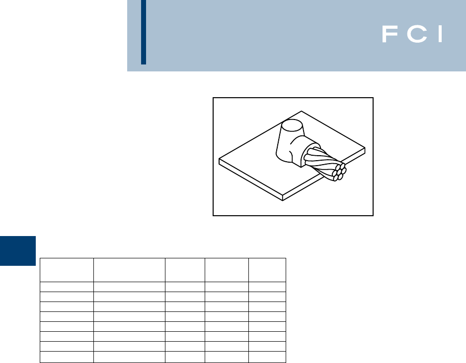
BURNDY
Grounding
D-76
TYPE BCS-5 MOLDS
Horizontal Cable Tap to
Horizontal Cast Iron Surface
Type BCS-5 Molds are used to join horizontal
cable taps to horizontal cast iron surfaces.
Note that the cable is ON the surface.
Size range is #6 through #1 solid or concen-
tric stranded copper conductors.
Contact BURNDY®Products for information
on molds for conductors not listed below.
Price Weld Handle
Cable Size Mold Number Key Metal Clamps
#6 Sol B-1613 3+ 2SCI N/A
#6 B-1614 3+ 25CI N/A
#4 Sol B-1615 3+ 45CI N/A
#4 B-1616 3+ 45CI N/A
#2 Sol B-1617 3+ 45CI N/A
#2 B-1618 3+ 45CI N/A
#1 Sol B-1619 3+ 65CI N/A
#1 B-1620 3+ 65CI N/A
•For sizes not listed, contact BURNDY®Products.
•Molds listed are for concentric stranded cable. Add suffix “-S” to mold number for solid
conductors.
•For heavy duty molds, molds with wear plates or molds for Copperweld®cable, contact
BURNDY®Products.
•For expedited service, contact BURNDY®Products.
Required Tools:
† Sold complete with frame
B38-0309-00 Flint Ignitor (included)
Other recommended accessories:
B38-3922-00 Mold Cleaning Brush (pg D-85)
B38-0135-00 Cable Cleaning Brush (pg D-85)
B38-0101-00 Rasp (pg D-85)
DO NOT use Type BCS-5 molds on Soil Pipe (ASTM A74-82). A
test weld should be made on a section of the pipe being used
to determine the possibility of detrimental metallurgical effects.
For mold types or BURNDYWeld™ items not shown, please
contact factory or refer to full BURNDYWeld™ catalog.
BURNDY
Grounding
D-77
TYPE BCRE-1 MOLDS
Horizontal Parallel Tap
to Rebar
Type BCRE-1 Molds are recommended for
parallel, horizontal connections for solid or
concentric stranded conductors #6 through
4/0 joined to reinforcing bars #3 through #6
and larger. The high copper content joint has
a higher current carrying capacity than the
conductors being joined and is impervious to
vibration and moisture.
Contact BURNDY®Products for information
on molds for conductors not listed below.
Rebar Cable Mold Packing Price Weld Handle
Size Size Number Material ‡ Key Metal Clamps
#6 B-7500 838-4060-00 4 25 B-106
#4 B-7501 838-4060-00 4 32 B-106
#2 B-7502 838-4060-00 4 45 B-106
#1 B-7503 838-4060-00 4 65 B-106
#3 1/0 B-7504 838-4060-00 4 90 B-106
2/0 B-7505 838-4060-00 4 90 B-106
3/0 B-7506 838-4060-00 4 115 B-106
4/0 B-7507 838-4060-00 4 115 B-106
#6 B-7508 838-4061-00 3+ 25 N/A
#4 #4 B-7509 838-4061-00 3+ 32 N/A
 B-7510 838-4061-00 3+ 45 N/A
Larger #1 B-7511 838-4061-00 3+ 65 N/A
1/0 B-7512 838-4060-00 4 90 B-106
2/0 B-7513 838-4060-00 4 90 B-106
#4 3/0 B-7514 838-4060-00 4 115 B-106
4/0 B-7515 838-4060-00 4 115 B-106
1/0 B-7520 838-4060-00 4 90 B-106
2/0 B-7521 838-4060-00 4 90 B-106
#5 3/0 B-7522 838-4060-00 4 115 B-106
4/0 B-7523 838-4060-00 4 115 B-106
1/0 B-7528 838-4062-00 14+ 90 N/A
#6 2/0 B-7529 838-4062-00 14+ 90 N/A
&3/0 B-7530 838-4062-00 14+ 115 N/A
Larger 4/0 B-7531 838-4062-00 14+ 115 N/A
•For sizes not listed, contact BURNDY®Products.
•Molds listed are for concentric stranded cable. Add suffix “-S” to mold number for solid
conductors.
•For heavy duty molds, molds with wear plates or molds for Copperweld®cable, contact
BURNDY®Products.
•For expedited service, contact BURNDY®Products.
Required Tools:
Handle Clamps (see chart for correct handles)
† Sold complete with frame
B38-0309-00 Flint Ignitor
Other recommended accessories:
B38-3922-00 Mold Cleaning Brush (pg D-85)
B38-0135-00 Cable Cleaning Brush (pg D-85)
B38-0304-00 File (pg D-86)
‡ PACKING MATERIAL NOTE
A packing pad is necessary when mak-
ing BURNDYWeld™ connections to
Rebar. Packing Material B38-4060-00 is
a special, patented copper-wool packing,
with enough in each bag to do between
40 and 50 connections. Packing Material
No.’s B38-4061-00, B38-4062-00 and
B38-4063-00 are a ceramic fiber materi-
al and can be used for one connection
only. Be sure to specify Packing Material
No. when ordering Mold and Weld Metal.
For mold types or BURNDYWeld™ items not shown, please
contact factory or refer to full BURNDYWeld™ catalog.
BURNDY
Grounding
D-78
TYPE BCRE-2 MOLDS
Horizontal Cable Tap to
Horizontal Rebar Run
Type BCRE-2 Molds are recommended for
right angle, horizontal connections for solid or
concentric stranded conductors #6 through
4/0 joined to reinforcing bars #3 through #6.
The high copper content joint has a higher
current carrying capacity than the conductors
being joined and is impervious to vibration
and moisture.
Contact BURNDY®Products for information
on molds for conductors not listed below.
Rebar Cable Mold Packing Price Weld Handle
Size Size Number Material ‡ Key Metal Clamps
#6 B-7588 838-4060-00 4 45 B-106
#4 B-7589 838-4060-00 4 45 B-106
#2 B-7590 838-4060-00 4 65 B-106
#1 B-7591 838-4060-00 4 65 B-106
#3 1/0 B-7592 838-4060-00 4 90 B-106
2/0 B-7593 838-4060-00 4 90 B-106
3/0 B-7594 838-406000 4 115 B-106
4/0 B-7595 838-4060-00 4 115 B-106
#6 B-7596 838-4060-00 4 45 B-106
#4 B-7597 838-4060-00 4 45 B-106
#2 B-7598 838-4060-00 4 65 B-106
#1 B-7599 838-4060-00 4 65 B-106
#4 1/0 B-7600 838-4060-00 4 90 B-106
2/0 B-7601 838-4060-00 4 90 B-106
3/0 B-7602 838-4060-00 4 115 B-106
4/0 B-7603 838-4060-00 4 115 B-106
#6 B-7604 838-4606-00 4 90 B-106
#4 B-7605 838-4060-00 4 90 B-106
#2 B-7606 838-4060-00 4 90 B-106
#1 B-7607 838-4060-00 4 90 B-106
#5 1/0 B-7608 838-4060-00 4 115 B-106
2/0 B-7609 838-4060-00 4 115 B-106
3/0 B-7610 838-4060-00 4 150 B-106
4/0 B-7611 838-4060-00 4 150 B-106
#6 B-7612 838-4060-00 4 90 B-106
#4 B-7613 838-4060-00 4 90 B-106
#2 B-7614 8384060-00 4 90 B-106
#1 B-7615 838-4060-00 4 90 B-106
#6 1/0 B-7616 838-4060-00 4 115 B-106
2/0 B-7617 838-4060-00 4 115 B-106
3/0 B-7618 838-4060-00 4 150 B-106
4/0 B-7619 838-4060-00 4 150 B-106
•For sizes not listed, contact BURNDY®Products.
•Molds listed are for concentric stranded cable. Add suffix “-S” to mold number for solid
conductors.
•For heavy duty molds, molds with wear plates or molds for Copperweld®cable, contact
BURNDY®Products.
•For expedited service, contact BURNDY®Products.
Required Tools:
Handle Clamps (see chart for correct handles)
B38-0309-00 Flint Ignitor
Other recommended accessories
B40-0319-01 Mold Cleaner for cartridge sizes #15-#65 (pg D-85)
B40-0319-03 Mold Cleaner for cartridge sizes #90-#500 (pg D-85)
B38-3922-00 Mold Cleaning Brush (pg D-85)
B38-0135-00 Cable Cleaning Brush (pg D-85)
B38-0304-00 File (pg D-86)
‡ PACKING MATERIAL NOTE
Apacking pad is necessary when mak-
ing BURNDYWeld™ connections to
Rebar. Packing Material B38-4060-00 is
a special, patented copper-wool pack-
ing, with enough in each bag to do
between 40 and 50 connections.
Packing Material No.’s B38-4061-00,
B38-4062-00 and B38-4063-00 are a
ceramic fiber material and can be used
for one connection only. Be sure to spec-
ify Packing Material No. when ordering
Mold and Weld Metal.
For mold types or BURNDYWeld™ items
not shown, please contact factory
or refer to full BURNDYWeld™ catalog.
BURNDY
Grounding
D-79
TYPE BCRE-3 MOLDS
Horizontal through Cable to
Vertical Rebar
Type BCRE-3 Molds are recommended for
horizontal conductors to vertical rebar con-
nections for solid or concentric stranded con-
ductors #6 through 4/0 joined to reinforcing
bars #3 through #7 & larger. The high copper
content joint has a higher current carrying
capacity than the conductors being joined
and is impervious to vibration and moisture.
Contact BURNDY®Products for information
on molds for conductors not listed below.
Rebar Cable Mold Packing Price Weld Handle
Size Size Number Material ‡ Key Metal Clamps
#6 B-7620 838-4060-00 24 90 B-106
#4 B-7621 838-4060-00 24 90 B-106
#2 B-7622 838-4060-00 24 90 B-106
#1 B-7623 838-4060-00 24 115 B-106
#3 1/0 B-7624 838-4060-00 24 115 B-106
2/0 B-7625 838-4060-00 24 115 B-106
3/0 B-7626 838-4060-00 24 150 B-106
4/0 B-7627 838-4060-00 24 150 B-106
#6 B-7628 838-4060-00 24 90 B-106
#4 B-7629 838-4060-00 24 90 B-106
#2 B-7630 838-4060-00 24 90 B-106
#1 B-7631 838-4060-00 24 115 B-106
#4 1/0 B-7632 838-4060-00 24 115 B-106
2/0 B-7633 838-4060-00 24 115 B-106
3/0 B-7634 838-4060-00 24 150 B-106
4/0 B-7635 838-4060-00 24 150 B-106
#6 B-7636 838-4060-00 24 90 B-106
#4 B-7637 838-4060-00 24 90 B-106
#2 B-7638 838-4060-00 24 90 B-106
#1 B-7639 838-4060-00 24 115 B-106
#5 1/0 B-7640 838-4060-00 24 115 B-106
2/0 B-7641 838-4060-00 24 115 B-106
3/0 B-7642 838-4060-00 24 150 B-106
4/0 B-7643 838-4060-00 24 150 B-106
#6 B-7644 838-4060-00 24 90 B-106
#4 B-7645 838-4060-00 24 90 B-106
#2 B-7646 838-4060-00 24 90 B-106
#1 B-7647 838-4060-00 24 115 B-106
#6 1/0 B-7648 838-4060-00 24 115 B-106
2/0 B-7649 838-4060-00 24 115 B-106
3/0 B-7650 838-4060-00 24 150 B-106
4/0 B-7651 838-4060-00 24 150 B-106
#6 B-7652 838-4063-00 4+ 90 B-106-41
#4 B-7653 838-4063-00 4+ 90 B-106-41
#2 B-7654 838-4063-00 4+ 90 B-106-41
#7 #1 B-7655 838-4063-00 4+ 115 B-106-41
&1/0 B-7656 838-4063-00 4+ 115 B-106-41
Larger 2/0 B-7657 838-4063-00 4+ 115 B-106-41
3/0 B-7658 838-4063-00 4+ 150 B-106-41
4/0 B-7659 838-4063-00 4+ 150 B-106-41
•For sizes not listed, contact BURNDY®Products.
•Molds listed are for concentric stranded cable. Add suffix
“-S” to mold number for solid conductors.
•For heavy duty molds, molds with wear plates or molds for
Copperweld®cable, contact BURNDY®Products.
•For expedited service, contact BURNDY®Products.
Required Tools:
Handle Clamps (see chart for correct handles)
B38-0309-00 Flint Ignitor
Other recommended accessories:
Ver tical Chain Clamps
† B40-0319-03 Mold Cleaner for cartridge sizes #90-#500
(pg D-85)
B38-3922-00 Mold Cleaning Brush (pg D-85)
B38-0135-00 Cable Cleaning Brush (pg D-85)
B38-0304-00 File (pg D-85)
‡ PACKING MATERIAL NOTE
Apacking pad is necessary when mak-
ing BURNDYWeld™ connections to
Rebar. Packing Material B38-4060-00 is
a special, patented copper-wool pack-
ing, with enough in each bag to do
between 40 and 50 connections.
Packing Material No.’s B38-4061-00,
B38-4062-00 and B38-4063-00 are a
ceramic fiber material and can be used
for one connection only. Be sure to spec-
ify Packing Material No. when ordering
Mold and Weld Metal.
For mold types or BURNDYWeld™ items
not shown, please contact factory
or refer to full BURNDYWeld™ catalog.
BURNDY
Grounding
D-80
TYPE BCRE-4 MOLDS
Horizontal through Cable to
Horizontal Rebar
Type BCRE-4 Molds are recommended for
horizontal through conductors to horizontal
rebar at right angle connections for solid or
concentric stranded conductors #6 through
4/0 joined to reinforcing bars #3 through #6 &
larger. The high copper content joint has a
higher current carrying capacity than the con-
ductors being joined and is impervious to
vibration and moisture.
Contact BURNDY®Products for information
on molds for conductors not listed below.
Rebar Cable Mold Packing Price Weld Handle
Size Size Number Material ‡ Key Metal Clamps
#6 B-7708 838-4060-00 4 90 B-106
#4 B-7709 838-4060-00 4 90 B-106
#2 B-7710 838-4060-00 4 90 B-106
#1 B-7711 838-4060-00 4 115 B-106
#3 1/0 B-7712 838-4060-00 22 115 B-106
2/0 B-7713 838-4060-00 22 115 B-106
3/0 B-7714 838-4060-00 22 150 B-106
4/0 B-7715 838-4060-00 22 150 B-106
#6 B-7716 838-4060-00 4 90 B-106
#4 B-7717 838-4060-00 4 90 B-106
#2 B-7718 838-4060-00 4 90 B-106
#1 B-7719 838-4060-00 22 115 B-106
#4 1/0 B-7720 838-4060-00 22 115 B-106
2/0 B-7721 838-4060-00 22 115 B-106
3/0 B-7722 838-4060-00 22 150 B-106
4/0 B-7723 838-4060-00 22 150 B-106
#6 B-7724 838-4060-00 4 90 B-106
#4 B-7725 838-4060-00 4 90 B-106
#2 B-7726 838-4060-00 4 90 B-106
#1 B-7727 838-4060-00 22 115 B-106
#5 1/0 B-7728 838-4060-00 22 115 B-106
2/0 B-7729 838-4060-00 22 115 B-106
3/0 B-7730 838-4060-00 22 150 B-106
4/0 B-7731 838-4060-00 22 150 B-106
#6 B-7732 838-4061-00 14+ 90 N/A
#4 B-7733 868-4061-00 14+ 90 N/A
#2 B-7734 838-4061-00 14+ 90 N/A
#6 #1 B-7735 838-406100 14+ 115 N/A
&1/0 B-7736 838-4062-00 14+ 115 N/A
Larger 2/0 B-7737 838-4062-00 14+ 115 N/A
3/0 B-7738 838-4062-00 14+ 150 N/A
4/0 B-7739 838-4062-00 14+ 150 N/A
•For sizes not listed, contact BURNDY®Products.
•Molds listed are for concentric stranded cable. Add suffix
“-S” to mold number for solid conductors.
•For heavy duty molds, molds with wear plates or molds for Copperweld®cable, contact BURNDY®Products.
•For expedited service, contact BURNDY®Products.
Required Tools:
Handle Clamps (see chart for correct handles)
† Sold complete with frame
B38-0309-00 Flint Ignitor
Other recommended accessories:
B40-0319-03 Mold Cleaner for cartridge sizes #90-#500 (pg D-85)
B38-3922-00 Mold Cleaning Brush (pg D-85)
B38-0135-00 Cable Cleaning Brush (pg D-85)
B38-0304-00 File (pg D-86)
‡ PACKING MATERIAL NOTE
Apacking pad is necessary when mak-
ing BURNDYWeld™ connections to
Rebar. Packing Material B38-4060-00 is
a special, patented copper-wool pack-
ing, with enough in each bag to do
between 40 and 50 connections.
Packing Material No.’s B38-4061-00,
B38-4062-00 and B38-4063-00 are a
ceramic fiber material and can be used
for one connection only. Be sure to spec-
ify Packing Material No. when ordering
Mold and Weld Metal.
For mold types or BURNDYWeld™ items
not shown, please contact factory
or refer to full BURNDYWeld™ catalog.
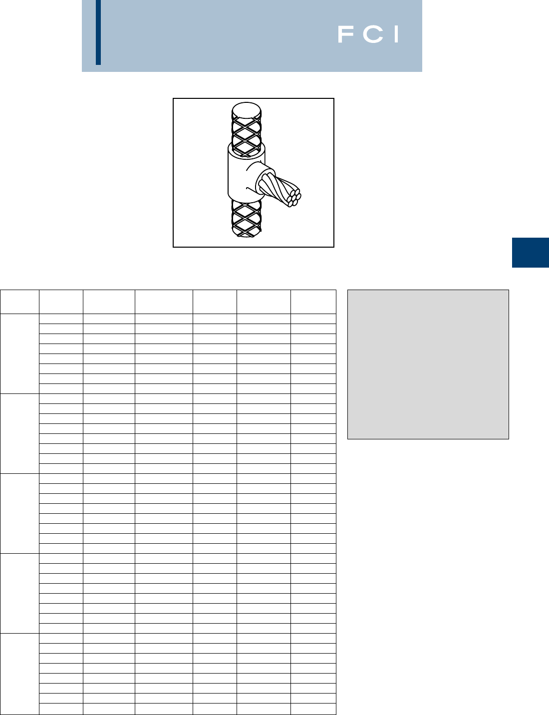
BURNDY
Grounding
D-81
TYPE BCRE-6 MOLDS
Horizontal Cable Tap to
Vertical Rebar
Type BCRE-6 Molds are recommended for
horizontal conductors terminating at right
angles to vertical rebar connections for solid
or concentric stranded conductors #6 through
4/0 joined to reinforcing bars #3 through #7
and larger. The high copper content joint has
a higher current carrying capacity than the
conductors being joined and is impervious to
vibration and moisture.
Contact BURNDY®Products for information
on molds for conductors not listed below.
Rebar Cable Mold Packing Price Weld Handle
Size Size Number Material ‡ Key Metal Clamps
#6 B-7884 838-4060-00 4 90 B-106
#4 B-7885 838-4060-00 4 90 B-106
#2 B-7886 838-4060-00 4 90 B-106
#1 B-7887 838-4060-00 4 115 B-106
#3 1/0 B-7888 838-4060-00 4 115 B-106
2/0 B-7889 838-4060-00 4 115 B-106
3/0 B-7890 838-4060-00 4 150 B-106
4/0 B-7891 838-4060-00 4 150 B-106
#6 B-7892 838-4060-00 4 90 B-106
#4 B-7893 838-4060-00 4 90 B-106
#2 B-7894 838-4060-00 4 90 B-106
#1 B-7895 838-4060-00 4 115 B-106
#4 1/0 B-7896 838-4060-00 4 115 B-106
2/0 B-7897 838-4060-00 4 115 B-106
3/0 B-7898 838-4060-00 4 150 B-106
4/0 B-7899 838-4060-00 4 150 B-106
#6 B-7900 838-4060-00 4 90 B-106
#4 B-7901 838-4060-00 4 90 B-106
#2 B-7902 838-4060-00 4 90 B-106
#1 B-7903 838-4060-00 4 115 B-106
#5 1/0 B-7904 838-4060-00 4 115 B-106
2/0 B-7905 838-4060-00 4 115 B-106
3/0 B-7906 838-4060-00 4 150 B-106
4/0 B-7907 838-4060-00 4 150 B-106
#6 B-7908 838-4060-00 4 90 B-106
#4 B-7909 838-4060-00 4 90 B-106
#2 B-7910 838-4060-00 4 90 B-106
#1 B-7911 838-4060-00 4 115 B-106
#6 1/0 B-7912 838-4060-00 4 115 B-106
2/0 B-7913 838-4060-00 4 115 B-106
3/0 B-7914 838-4060-00 4 150 B-106
4/0 B-7915 838-4060-00 4 150 B-106
#6 B-7916 838-4063-00 4 90 B-106-32
#4 B-7917 838-4063-00 4 90 B-106-32
#2 B-7918 838-4063-00 4 90 B-106-32
#7 #1 B-7919 838-4063-00 4 115 B-106-32
&1/0 B-7920 838-4063-00 4 115 B-106-32
Larger 2/0 B-7921 838-4063-00 4 115 B-106-32
3/0 B-7922 838-4063-00 4 150 B-106-32
4/0 B-7923 838-4063-00 4 150 B-106-32
•For sizes not listed, contact BURNDY®Products.
•Molds listed are for concentric stranded cable. Add suffix
“-S” to mold number for solid conductors.
•For heavy duty molds, molds with wear plates or molds for
Copperweld®cable, contact BURNDY®Products.
•For expedited service, contact BURNDY®Products.
Required Tools:
Handle Clamps (see chart for correct handles)
B38-0309-00 Flint Ignitor
Other recommended accessories:
B38-3922-00 Mold Cleaning Brush (pg D-85)
B38-0135-00 Cable Cleaning Brush (pg D-85)
B38-0304-00 File (pg D-86)
‡ PACKING MATERIAL NOTE
Apacking pad is necessary when mak-
ing BURNDYWeld™ connections to
Rebar. Packing Material B38-4060-00 is
a special, patented copper-wool pack-
ing, with enough in each bag to do
between 40 and 50 connections.
Packing Material No.’s B38-4061-00,
B38-4062-00 and B38-4063-00 are a
ceramic fiber material and can be used
for one connection only. Be sure to spec-
ify Packing Material No. when ordering
Mold and Weld Metal.
*The B106-32 comes complete with a B-106 handle clamp
and B40-0106-76 vertical chain clamp. Although good for use
on all sizes of rebar, vertical chain clamps are strongly recom-
mended on large size rebar as they hold the mold to the rebar
securely. If you already have a B-106 handle clamp, you can
purchase the vertical chain clamps separately. See page 76
for a variety of options.
For mold types or BURNDYWeld™ items not shown, please
contact factory or refer to full BURNDYWeld™ catalog.
BURNDY
Grounding
D-82
BURNDYWeld FILL*
BURNDYWeld™ FILL is an economical solu-
tion for areas with very difficult grounding
issues. BURNDYWeld™ FILL is highly con-
ductive in a wet or dry application and does
not require moisture to lower the resistance of
your grounding system. BURNDYWeld™
FILL contains a corrosion inhibitor which
forms a film on copper, creating a barrier
against corrosion.
BURNDYWeld™ FILL can be poured in dry or
pumped in slurry form. No tamping required.
It is very contractor friendly. No special tools
required.
*BURNDYWeld™ FILL is the catalog number.
BURNDYWeld™ FILL
Advantages:
•Easy to install.
•Electrically conductive.
•Environmentally friendly.
•Will not leach into the ground.
•Positive low resistance, electrical connec-
tion to earth.
•Does not contain any hazardous chemicals.
•Compatible with all copper grounding
systems.
•Contains a corrosion inhibitor to protect
copper.
•Will not expand or shrink.
•Not affected by freezing.
•Excellent shelf life.
•Typical resistivity <10 Ohm-cm
Material Required Per Linear Foot of Trench
Width of Trench (Inches)
4681012 14 16 18 20 22 24
24.1 6.2 8.1 10.1 12.1 14.1 16.2 18.2 20.2 22.2 24.2
36.2 9.3 12.1 15.2 18.2 21.2 24.2 27.3 30.3 33.3 36.4
48.2 12.3 16.2 20.2 24.2 28.3 32.3 36.4 40.4 44.5 48.5
510.3 15.4 20.2 25.3 30.3 35.4 40.4 45.5 50.5 55.6 60.6
612.3 18.5 24.2 30.3 36.4 42.4 48.5 54.6 60.6 66.7 72.7
714.4 21.6 28.3 35.4 42.4 49.5 56.6 63.7 70.7 77.8 84.9
816.4 24.7 32.3 40.4 48.5 56.0 64.7 72.7 80.8 88.9 97.0
918.5 27.8 36.4 45.5 54.6 63.7 72.7 81.8 90.9 100.0 109.1
10 20.6 30.8 40.4 50.5 60.6 70.7 80.8 90.9 101.0 111.1 121.2
Thickness of
BURNDYWeld™ FILL
(Inches)
To calculate the lbs. of material required to fill a trench:
•Determine desired thickness.
•Move to the right until you are under the known width of the trench. This number will be the
weight of the material in lbs./linear ft.
•Take this number and multiply by the length of the trench in feet.Your answer will be the amount
of BURNDYWeld™ FILL material required to fill the trench to the desired level in lbs.
Example:
Thickness: = 6 inches
Width = 18 inches
54.6 lbs. per linear ft. (from the table above)
Answer = 54.6 lbs. per linear ft. x 25 ft. trench = 1,365 lbs. of BURNDYWeld™ FILL
=28 (50 lb.) bags of BURNDYWeld™ FILL
For mold types or BURNDYWeld™ items not shown, please
contact factory or refer to full BURNDYWeld™ catalog.
BURNDY
Grounding
D-83
BURNDYWeld™ FILL*
Application Information
*BURNDYWeld™ FILL is the catalog number.
Vertical Installation
Drill or bore a hole the desired diameter and
depth. Suspend ground electrode in center of
hole to be filled. Pour BURNDYWeld™ FILL
until desired level is obtained. No tamping is
required.
Dry Volume of Ground Resistance
BURNDYWeld™ FILL Comparison of
vs. Hole Size Bare Rod vs.
Lbs. of Hole Size with Percent Resistance
Hole BURNDYWeld™ FILL 5/8x 10Rod in Compared to Rod
Size Per Ft. Center of 15Hole Only (100%)
46.5 452%
614.5 647%
825.8 844%
1040.4 1042%
1258.1 1240%
Steady State Leakage Resistance‡ Using 4/0 Copper Wire vs. BURNDYWeld™ FILL
Percentage of Resistance with .475
Wire Plus BURNDYWeld™ FILL in
Various Diameters Compared
.475Diameter to Wire Only (100%)
Length Wire Only 2346
25100% 83% 78% 74% 69%
50100% 85% 81% 77% 73%
75100% 86% 82% 79% 75%
100100% 87% 83% 80% 77%
150100% 88% 84% 82% 78%
200100% 88% 85% 83% 79%
250100% 89% 85% 83% 80%
300100% 89% 86% 84% 80%
Horizontal or Grid
Construction†
Pour into horizontal trench until level of
ground wire is reached. Place ground wire.
Pour in additional BURNDYWeld™ FILL until
wire is covered to desired height. Cover with
fill. No tamping required.
For grid construction, pour BURNDYWeld™
FILL and spread over ground grid until
desired thickness is achieved. Cover with fill.
†Entire grounding system should be surrounded by
BURNDYWeld™ FILL. Conductors should be
insulated as they exit BURNDYWeld™ FILL
column.
‡The use of BURNDYWeld™ FILL around the
grounding system will also reduce surge imped-
ance by increasing the effective contact area of
the electrode to soil.
Horizontal Construction
BURNDYWeld™ FILL
Copper Wire
Earth or Fill
Earth or Fill
BURNDYWeld™ FILL
Copper Wire
Grid Construction
For mold types or BURNDYWeld™ items not shown, please
contact factory or refer to full BURNDYWeld™ catalog.

BURNDY
Grounding
D-84
BURNDYWeld SET*
Certain applications require a permanent hard-
ening grounding material. BURNDYWeld™
SET is the product of choice. BURNDYWeld™
SET is compatible with all standard copper
grounding systems. It is an economical solu-
tion to difficult grounding issues in hard to
deal with areas. BURNDYWeld™ SET is
manufactured from environmentally safe
material and is extremely stable. When mixed
with water or exposed to moisture,
BURNDYWeld™ SET attains the hardening
characteristics of cement while retaining its
highly conductive properties. BURNDYWeld™
SET will remain highly conductive during a
drought or when exposed to extremely low
temperatures. Since BURNDYWeld™ SET
does not have any shrinkage or expansion
properties it will remain in constant contact
with the earth.
BURNDYWeld™ SET can be poured in dry or
pumped in slurry form. No tamping required.
It is very contractor friendly. No special tools
required.
*BURNDYWeld™ SET is the catalog number.
BURNDYWeld™ SET
Advantages:
•Easy to install.
•Will attain a hardened state.
•Electrically conductive.
•Environmentally friendly.
•Will not leach into the ground.
•Positively low resistance, electrical connec-
tion to the earth.
•Does not contain any hazardous chemicals.
•Compatible with all copper grounding sys-
tems.
•Will not expand or shrink.
•Not effected by freezing.
•Excellent shelf life.
•Typical resistivity <10 Ohm-cm
Material Required Per Linear Foot of Trench
Width of Trench (Inches)
4681012 14 16 18 20 22 24
23.6 5.4 7.2 9.0 10.8 12.6 14.4 16.2 18.0 19.7 21.5
35.4 8.1 10.8 13.5 16.2 18.8 21.5 24.2 26.9 29.6 32.3
47.2 10.8 14.4 18.0 21.5 25.1 28.7 32.3 35.9 39.5 43.1
59.0 13.5 18.0 22.4 26.9 31.4 35.9 40.4 44.9 49.4 53.9
610.8 16.3 21.5 26.9 32.3 37.7 43.1 48.5 53.9 59.2 64.6
712.6 19.0 25.1 31.4 37.7 44.0 50.3 56.5 62.8 69.1 75.4
814.4 21.7 28.7 35.9 43.1 50.3 57.4 64.6 71.8 79.0 86.2
916.3 24.4 32.3 40.4 48.5 56.5 64.6 72.7 80.8 88.9 96.9
10 18.1 27.1 35.9 44.9 53.9 62.8 71.8 80.8 89.8 98.7 107.7
Thickness of
BURNDYWeld™ SET
(Inches)
To calculate the lbs. of material required to fill a trench:
•Determine desired thickness of BURNDYWeld™ SET.
•Move to the right until you are under the known width of the trench. This number will be the
weight of the material in lbs./linear ft.
•Take this number and multiply by the length of the trench in feet.Your answer will be the amount
of BURNDYWeld™ SET material required to fill the trench to the desired level in lbs.
Example:
Thickness: = 6 inches
Width = 18 inches
48.5 lbs. per linear ft. (from the table above)
Answer = 48.5 lbs. per linear ft. x 25 ft. trench = 1,212.5 lbs. of BURNDYWeld™ SET
=24 (50 lb.) bags of BURNDYWeld™ SET
For mold types or BURNDYWeld™ items not shown, please
contact factory or refer to full BURNDYWeld™ catalog.

BURNDY
Grounding
D-85
BURNDYWeld™ SET*
Application Information
*BURNDYWeld™ SET is the catalog number.
Vertical Installation
Drill or bore a hole to the desired diameter
and depth. Suspend ground electrode in cen-
ter of hole to be filled. Pour BURNDYWeld™
SET until desired level is obtained. Remove
excess water prior to pumping. If necessary,
BURNDYWeld™ SET may be premixed and
pumped under water.
Dry Volume of Ground Resistance
BURNDYWeld™ SET Comparison of
vs. Hole Size Bare Rod vs.
Lbs. of Hole Size with Percent Resistance
Hole BURNDYWeld™ SET 5/8x 10Rod in Compared to Rod
Size Per Ft. Center of 15Hole Only (100%)
45.7 452%
612.8 647%
822.7 844%
1035.5 1042%
1251.1 1240%
Steady State Leakage Resistance‡ Using 4/0 Copper Wire vs. BURNDYWeld™ SET
Percentage of Resistance with .475
Wire Plus BURNDYWeld™ SET in
Various Diameters Compared
.475Diameter to Wire Only (100%)
Length Wire Only 2346
25100% 83% 78% 74% 69%
50100% 85% 81% 77% 73%
75100% 86% 82% 79% 75%
100100% 87% 83% 80% 77%
150100% 88% 84% 82% 78%
200100% 88% 85% 83% 79%
250100% 89% 85% 83% 80%
300100% 89% 86% 84% 80%
Horizontal or Grid
Construction†
Pour into horizontal trench until level of
ground wire is reached. Place ground wire.
Pour in additional BURNDYWeld™ SET until
wire is covered to desired height. Cover with
fill. No tamping required. Remove excess
water prior to installation.
For grid construction, pour BURNDYWeld™
SET and spread over ground grid until
desired thickness is achieved. Cover with fill.
Use ground staples to maintain ground wire
in center of BURNDYWeld™ SET.
†Entire grounding system should be surrounded by
BURNDYWeld™ SET. Conductors should be
insulated as they exit BURNDYWeld™ SET
column. BURNDYWeld™ SET should be used as
a ground enhancement material when a setting fill
is specified.
‡The use of BURNDYWeld™ SET around the
grounding system will also reduce surge imped-
ance by increasing the effective contact area of
the electrode to soil.
Horizontal Construction
BURNDYWeld™ FILL
Copper Wire
Earth or Fill
Earth or Fill
BURNDYWeld™ FILL
Copper Wire
Grid Construction
For mold types or BURNDYWeld™ items not shown, please
contact factory or refer to full BURNDYWeld™ catalog.
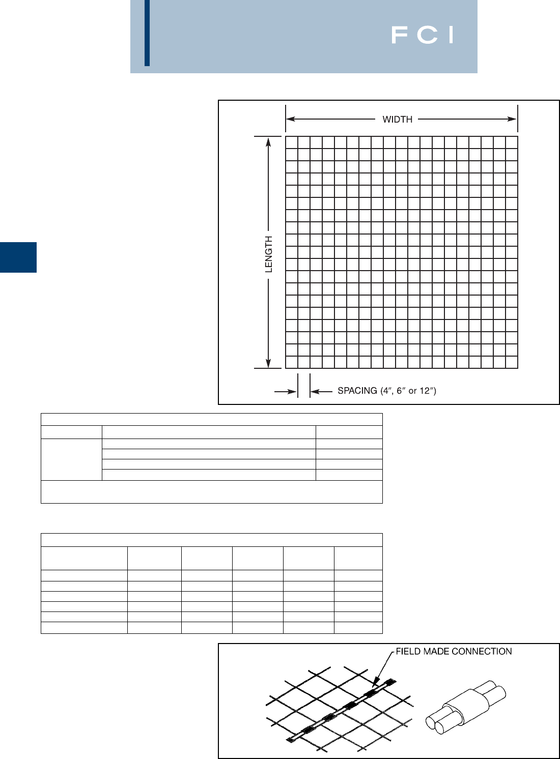
BURNDY
Grounding
D-86
Prefabricated Wire Mesh
Part Number Description Weight/Sq Ft.
#10 Solid Copper Wire Mesh on 4Centers 0.192
Contact #6 Solid Copper Wire Mesh on 4Centers 0.487
Factory #6 Solid Copper Wire Mesh on 6Centers 0.325
#6 Solid Copper Wire Mesh on 12Centers 0.163
Copperclad Wire Mesh may be ordered
contact factory for part numbers
When ordering, specify wire type and size, width, length and
spacing.
Molds for Connecting Prefabricated Wire Mesh
Weld Mold Price Handle Weld
Wire Size Type Number Key Clamp Metal
#6 Sol Copper BCC-14 B-6205 18 included #25
#6 Sol Copperweld BCC-14 B-6207 18 included #15
#8 Sol Copper BCC-14 B-6209 18 included #15
#8 Sol Copperweld BCC-14 B-6210 18 included #15
#10 Sol Copper BCB-34 B-6211 18 included #15
#10 Sol Copperweld BCB-34 B-6212 18 included #15
BURNDYWeld™
PREFABRICATED
WIRE MESH
Grounding, Personal Safety
Mats, Equipotential Planes,
Signal Reference Grid
Prefabricated wire mesh is:
•manufactured from bare solid copper or
copperclad conductors.
•spaced on 4, 6or 12centers.
•factory silver brazed at each crossover
using 35% silver and a non-corrosive flux.
•furnished in sections with widths from 2 ft
to 18 ft (length limited by weight).
•shipped on tubes and protected for trans-
porting.
•interconnected in the field using
BURNDYWeld™ molds and powder.
Adjoining sections of mesh are to be
exothermically welded by installer using
BURNDYWeld™ molds and powder.
For mold types or
BURNDYWeld™ items not
shown, please contact
factory or refer to full
BURNDYWeld™ catalog.

BURNDY
Grounding
D-87
BURNDYWeld™
PREFABRICATED
WIRE MESH
The prefabricated wire mesh is a convenient,
efficient and economical means of improving
grounding systems at facilities where large
area grounds are required.
Wire Choices
Wire mesh is made from solid wire, either
copper clad steel or pure copper. Copper
clad steel wire has the strength of steel com-
bined with the higher conductivity and corro-
sion resistance of copper. The two metals are
permanently bonded and act as a single
material.
Silver Brazed Joints
The long wires and cross wires of wire mesh
are silver brazed at their crossing points.This
method provides joints with a breaking
strength strong enough to resist separation
during installation and strong enough to bear
the traffic of heavy vehicles.
Like the wire itself, the silver brazed joints are
highly resistant to corrosion. Moreover, elec-
trical continuity of a silver brazed joint is
excellent.
Installation
Wire mesh is easily and economically
installed. No expensive, special equipment is
necessary, and there are no time consuming
special handling procedures. The strong, pli-
able mesh is simply unrolled over the ground,
interconnected using BURNDYWeld™ con-
nections to attach adjacent sections of mesh,
and BURNDYWeld™ to the main ground grid
or ground rods. The mesh may be covered
with a layer of earth or crushed stone.
When used to control step and touch poten-
tials in an electrical substation, the mesh
does not replace the main ground grid.
However, the main grid can be installed to
control the station resistance without regard
to the step and touch potentials. A properly
designed system employing prefabricated
mesh which is periodically interconnected to
the main grid, will control the step and touch
potentials.
Interconnecting
The BURNDYWeld™ process provides a
rapid, economical, permanent, and highly
conductive method of interconnecting wire
mesh in the field.
The BURNDYWeld™ process is a controlled
reaction involving molten, superheated cop-
per. It is ideal for connecting mesh because
the reaction occurs quickly which fuses the
wires together into a solid mass.The resulting
weld is permanent and corrosion resistant.
The large weld area provides current carrying
capacity equal to the mesh conductors.
A semipermanent graphite mold is used in
making the BURNDYWeld™ connections.
The mold controls the direction and speed of
the molten metal and determines the shape
of the weld. The equipment is lightweight,
portable and easy to use. No outside source
of heat or power is needed, and only a mini-
mum of training is necessary. The mesh can
be interconnected by this process even under
adverse working conditions.
The adjacent mesh sections are best joined
by the exothermic parallel type BCC-14
connection.
For mold types or BURNDYWeld™ items not shown, please
contact factory or refer to full BURNDYWeld™ catalog.
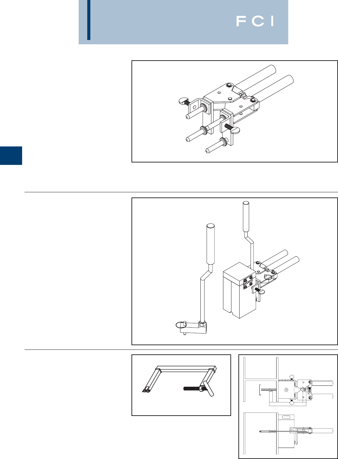
BURNDY
Grounding
D-88
B-106 & B-107
HANDLE CLAMPS
BURNDYWeld™ Handle Clamps make possi-
ble the use of many different sizes and types
of molds with only two different clamps. The
two handle clamps are catalog numbers
B-106 and B-107. These will fit 95% of all
standard BURNDYWeld™ molds.
1. Use B-106 clamps for all molds having a
price key 4, 7, 17, 22 or 24. These molds
are a nominal 3 1/8x 3 1/8square.
2Use B-107 clamps for all molds having a
price key 5, 6, 8 or 23. These molds are a
nominal 4x 4square.
3. All molds having a price key 2, 3, 9, 10,
11, 12, 14, 15 or 16 have an attached
frame; separate handles are not required.
B40-0106-75 HANDLE
ATTACHMENT
This Handle Attachment is used to hold Price
Key-14 molds in position. It easily attaches to
the B-106 Handle Clamp. This Handle
Attachment can be used with weld types
BCRE-1 and BCRE-4.
Catalog Number B40-0106-75
MOLD SUPPORT
CLAMP
The Mold Support Clamp is used to hold a
mold in position on a vertical steel column or
angle. It is easily attached to the Handle
Clamps. The Mold Support Clamp can be
used with weld types BCS-3, BCS-18,
BCS-23 and BCS-27.
Catalog Number B40-3657-00
B40-0106-75
B40-0106-75 Shown Attached
to B-106 Handle Clamps
For mold types or BURNDYWeld™ items not shown, please
contact factory or refer to full BURNDYWeld™ catalog.
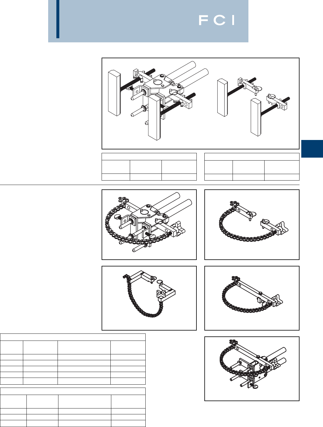
BURNDY
Grounding
D-89
Chain Clamp Only (Handle Clamps Not Included)
Catalog Fits Handle For Use With
Number Clamp Weld Types Pipe Position
B40-0106-76 B-106 & B-107 BCS-3, 4, 7, 23 & BCRE-6 Vertical
B40-0106-78 B-106 & B-107 BCS-1, 2, 5, 8 & 9 Horizontal
B40-0106-77 B-106 & B-107 BCS-6, 18 & BCRE-3 Vertical
VERTICAL MAGNETIC
CLAMPS
Magnetic Clamps are used to hold a mold in
position on a vertical steel surface. The mag-
netic clamp can be purchased complete with
B-106 Handle Clamps or if you already have
a set of handle clamps, you can order just the
magnetic mounting assembly. The mounting
assembly can easily be mounted on the
prongs of your existing B-106 handle clamps.
A minimum of 10is required.
Magnetic Clamps With B106 Handle
Catalog Fits Molds For Use With
Number W/Price Key Weld Types
8404431-00 4 & 17 BCS-3, 4, 7 & 23
Chain Clamps
Catalog Fits Molds For Use With
Number W/Price Key Weld Types Pipe Position
B106-32 4, 17, 22 & 24 BCS-3, 4, 7, 23 & BCRE-6 Vertical
B107-32 5, 6 & 23 BCS-3, 4, 7 & 23 Vertical
B106-37 4, 17, 22 & 24 BCS-1, 2, 5, 8 & 9 Horizontal
B107-37 5, 6 & 23 BCS-1, 2, 5, 8 & 9 Horizontal
B106-41 4, 17 BCS-6, 18 & BCRE-3 Vertical
HORIZONTAL &
VERTICAL
CHAIN CLAMPS
Chain Clamps are used to hold a mold in posi-
tion on horizontal or vertical pipe up to 4in
diameter. For larger pipe a 20chain extension
is available to allow the chain clamps to be
used on pipe up to 10in diameter. The chain
clamp can be purchased complete with B-106
or B-107 Handle Clamps or if you already
have a set of handle clamps, you can order
just the chain clamp and mounting assembly.
The mounting assembly can easily attached to
your existing handle clamps. 20Chain
Extension catalog number B40-0106-27.
B40-4431-00 B40-4431-01
Magnetic Clamp Only
Catalog Fits Handle For Use With
Number Clamps Weld Types
840-4431-01 B-106 & B-107 BCS-3, 4, 7 & 23
B106-32/B107-32 B40-0106-76
B40-0106-78 B40-0106-77
B106-41/B107-41
For mold types or BURNDYWeld™ items
not shown, please contact factory or
refer to full BURNDYWeld™ catalog.
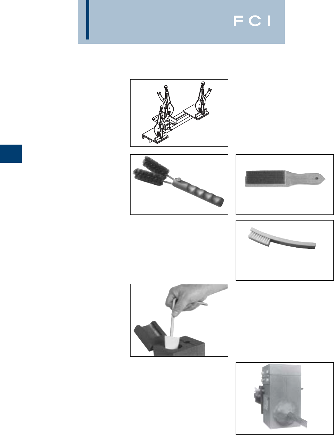
BURNDY
Grounding
D-90
BURNDYWeld™ ACCESSORIES
CABLE CLEANING AND
CARD CLOTH BRUSH
The Cable Cleaning Brush is recommended
for cleaning heavily oxidized cables. The
V-shape brushes permit their use over a wide
range of cable sizes. Brush assembly con-
sists of a handle with two stiff wire bristle
brushes that are rotatable, for longer life and
are replaceable.
The Card Cloth Brush is used for cleaning
large conductors and bus bar. It has short stiff
bristles. These brushes are for cleaning cable
only, not molds.
The Mold Cleaning Brush B38-3922-00 is
used to clean the graphite mold without
scratching the mold.
MOLD CLEANERS
Mold Cleaners are used to clean the slag
from molds that are not split through the
crucible.
B40-0319-01 for cartridge sizes #15
through #65
B40-0319-03 for cartridge sizes #90
through #500
B38-0330-00 CABLE CLAMP
The BURNDYWeld™ Cable Clamp is recom-
mended for holding a wide range of cables
properly in place in molds when welding
cables that are under tension. This prevents
the cables from pulling out of the mold when
the weld is made.
B38-0135-00 B38-0306-00
B38-3922-00
PACKING MATERIAL
Packing material is used to prevent the
molten weld metal from leaking out of the
mold.When the cable opening becomes worn
from heavy use, the packing material may be
used to prolong mold use. It is also used
around 7 strand cable to prevent leaking.
Packing material comes in a 1 lb. or 5 lb.
package.
Catalog Number Description
B38-4129-00 1 lb. package
B38-4129-05 5 lb. package
Cable Cleaning Brush B38-0135-00
Replacement Brush B38-0135-01
Card Cloth Brush B38-0306-00
Mold Cleaning Brush B38-3922-00
For mold types or BURNDYWeld™ items not shown, please
contact factory or refer to full BURNDYWeld™ catalog.
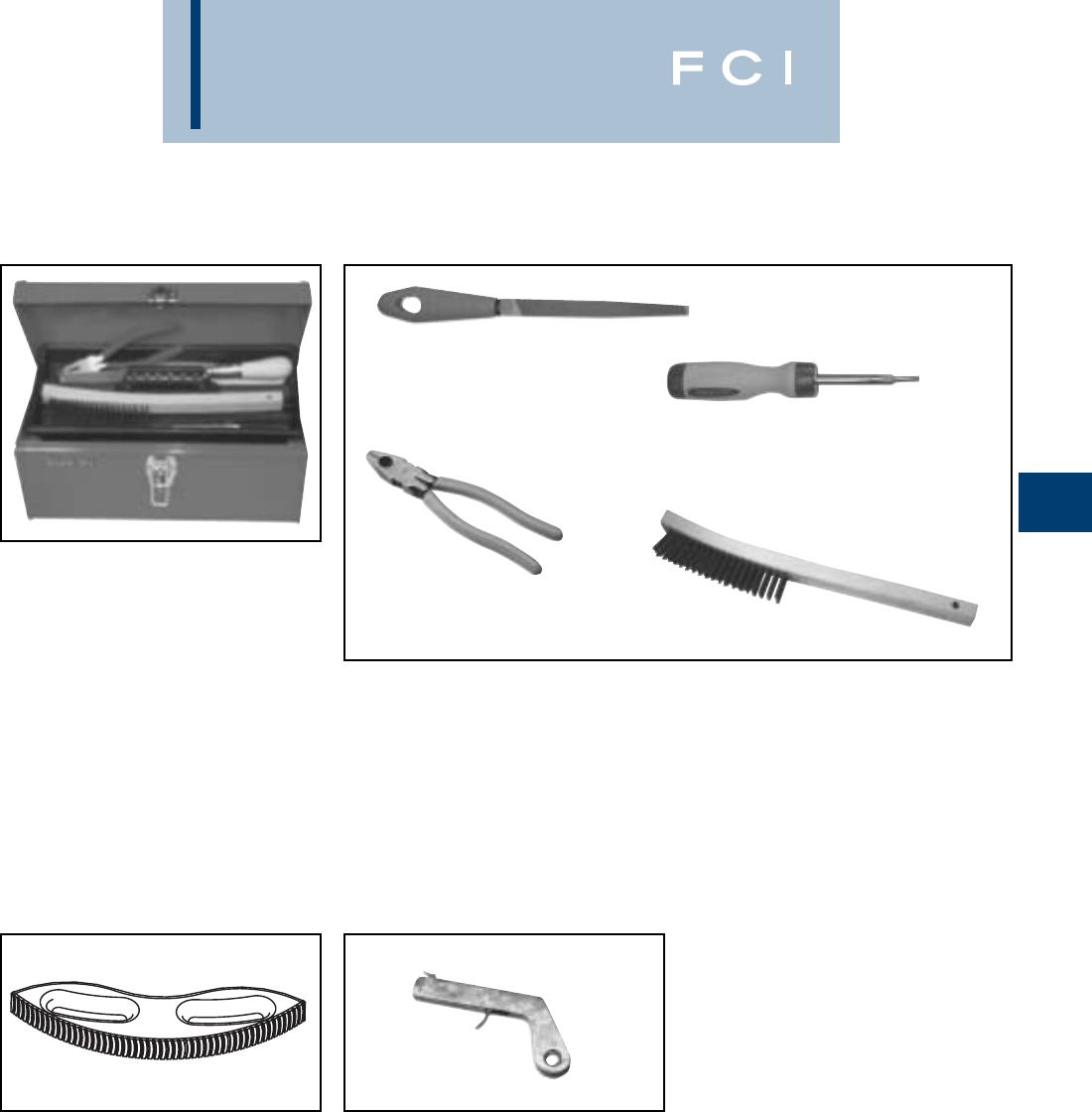
BURNDY
Grounding
D-91
BURNDYWeld™ ACCESSORIES
BURNDYWeld™ TOOL KIT
B38-0302-00 Tool Kit with Tools Shown
except Rasp
B38-0302-02 Tool Kit with Tools Shown
and Rasp
B38-0303-00 Tool Box only
B38-0309-00 FLINT IGNITOR
The B38-0309-00 Flint Ignitor is used to ignite
the starting powder. Each mold that is sold
with a frame has a Flint Ignitor included. For
added safety a Flint Ignitor extension is avail-
able, catalog number B38-0904-00, that
attaches to the B38-0309-00 Flint Ignitor. This
allows installers to stay approximately 36
away from the mold.
To order replacement flints, specify part
number B38-0309-01.
BURNDYWeld™ TOOLS
B38-0309-00 Flint Ignitor
B38-0304-00 8File
B38-0307-00 Crimping Tool
B38-3922-00 Mold Cleaning Brush
B38-0308-00 6Screwdriver
B38-0305-00 Wire Brush
B38-0101-00 Rasp
B38-0306-00 Card Cloth Brush
B38-0101-00 RASP
This tempered steel, curved rasp is recom-
mended for removing rust and mill scale from
steel and cast iron surfaces. The blade is
replaceable.To order replacement rasp blade,
specify catalog number B38-0101-01.
Not recommended for use on galvanized
surfaces.
For mold types or BURNDYWeld™ items not shown, please
contact factory or refer to full BURNDYWeld™ catalog.
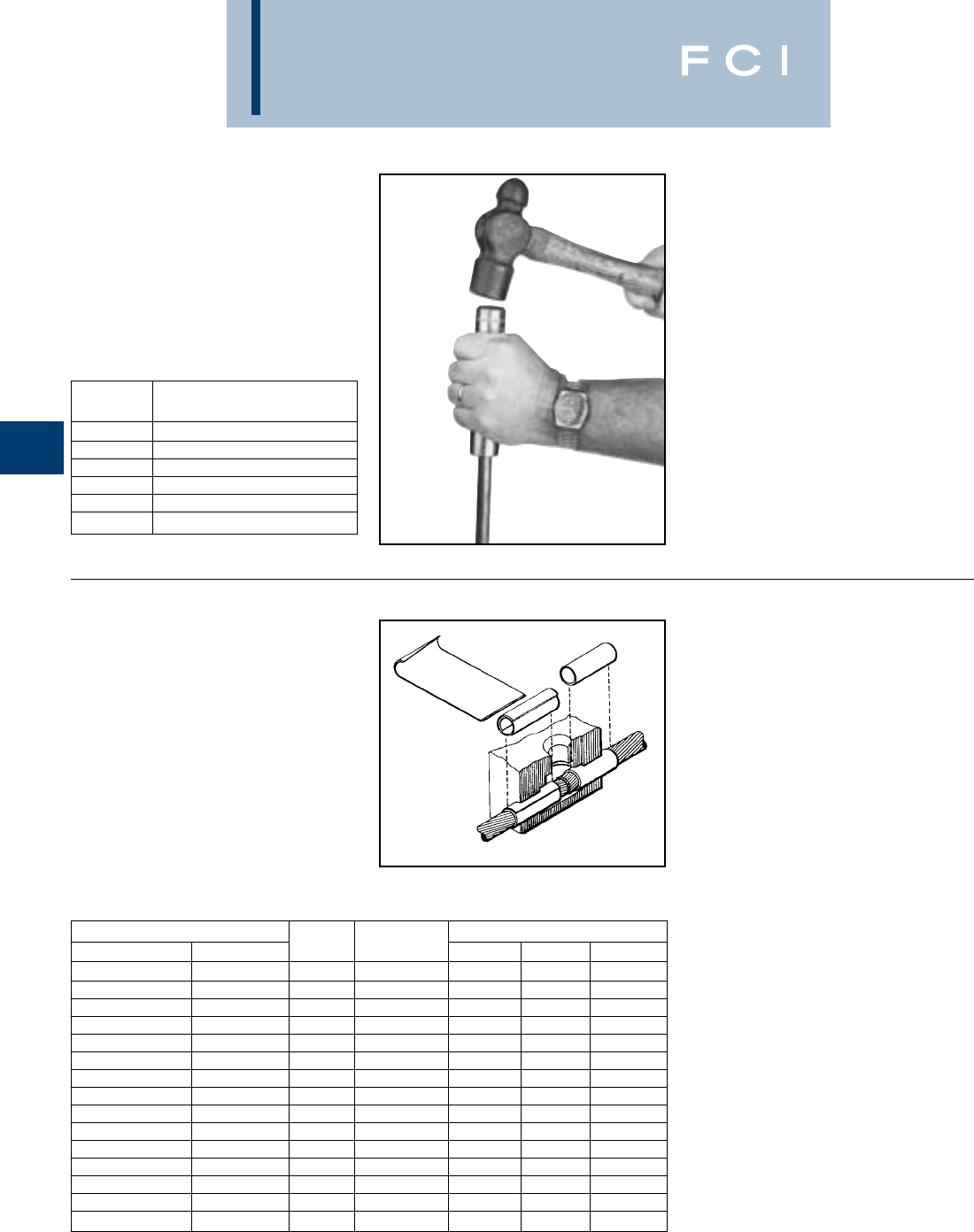
BURNDY
Grounding
D-92
GROUND ROD
DRIVING SLEEVES
Ground Rod Driving Sleeves are placed over
the top of a ground rod while driving it into the
ground. This prevents the top from mush-
rooming or flaring out. Ground rod driving
sleeves are available in sizes to fit all stan-
dard unthreaded ground rods.
Catalog
Number For Use On
B38-3662-01 1/2Copper Clad or Steel Ground Rod
B38-3662-02 5/8Copper Clad Ground Rod
B38-3662-05 5/8Steel Ground Rod
B38-3662-03 3/4Copper Clad Ground Rod
B38-3662-06 3/4Steel Ground Rod
B38-3662-04 1Copper Clad Ground Rod
For Use on Cable Size Part Use in Sleeve Dimensions
Stranded Solid No. Mold Size O.D. I.D. Length
#12, #14 #10, #12, #14 BA-200 #6 STR & Sol .156 .111 1.00
#9. #10 #8. #9. #10 BA-208 #4 Sol .203 .140 1.00
#7, #8, #10 #6, #8 BA-201 #4 .227 .177 1.00
#6 #5 BA-202 #2 .292 .198 1.00
#4, #5 #3, #4 BA-207 #2 .302 .246 1.00
#4 #2 BA-204 #1 .340 .246 1.00
#2 #1 BA-203 1/0 .370 .307 1.00
#1 1/0 BA-209 2/0 .420 .359 1.00
1/0, #1 2/0 BA-205 3/0 & 4/0 Sol .469 .385 1.00
2/0, 1/0 3/0 BA-240 4/0 .524 .437 1.50
4/0 — BA-211 300 MCM .625 .545 1.25
250 MCM — BA-212 350 MCM .677 .595 1.25
350,400 MCM — BA-213 500 MCM .811 .762 1.50
250, 300, 350 MCM — BA-214 500 MCM .811 .700 1.50
750,800 MCM — BA-215 1000 MCM 1.156 1.05 1.50
SHIM STOCK AND
ADAPTER SLEEVES
BURNDYWeld™ molds designed for larger
cable sizes can be used on smaller diameter
cables if copper adapter sleeves or shim
stock are utilized. The copper shim stock,
.0108x 1-1/2x 3, is normally wrapped
around cable until the diameter is about equal
to the cable opening. A tight fit is not neces-
sary as the shim stock will unwrap slightly
and prevent leakage of weld metal. To order
shim stock use part number B38-0329-00.
Shim stock comes 100 pieces per box.
For mold types or BURNDYWeld™ items not shown, please
contact factory or refer to full BURNDYWeld™ catalog.
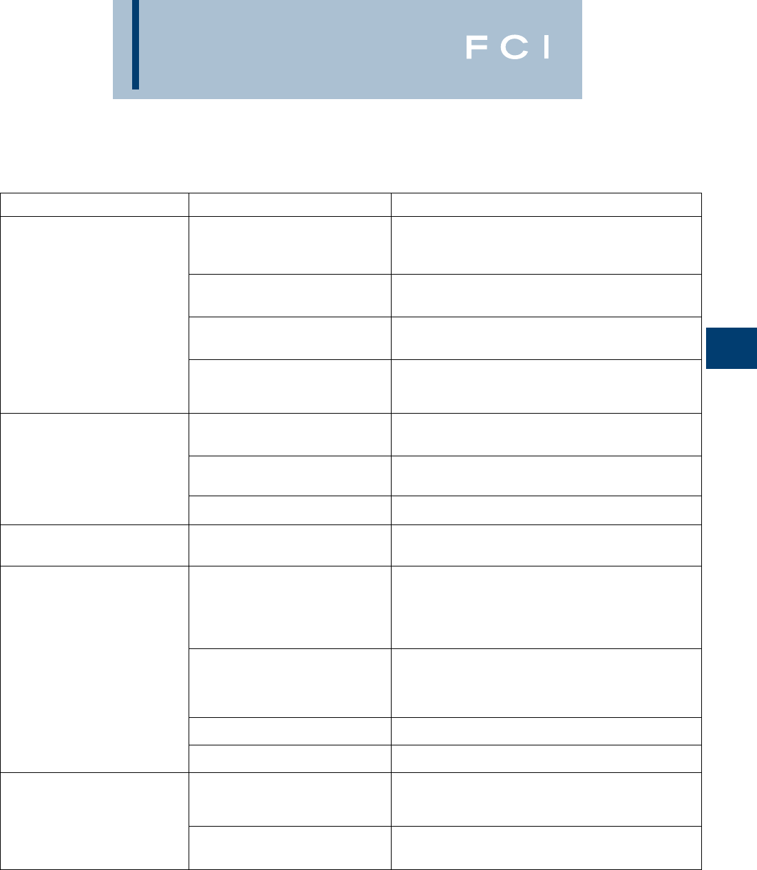
BURNDY
Grounding
D-93
PROBLEM PROBABLE CAUSE CORRECTION TO MAKE
Insufficient metal to Worn mold resulting in Replace mold. If only worn around conductor opening,
make weld. leaking weld metal. use duct seal around conductor. Do not get duct seal
into mold cavity.
Wrong size cartridge for mold. Check ID plate for mold and compare with number
on bottom of cartridge.
Too much spillage when Carefully open lid while holding over crucible and dump.
dumping powder.
Wrong mold for conductor Replace with correct mold. In some applications, shim
being used. stock or adapter sleeves can be used to enlarge cable
to fit mold.
Mold does not close tightly Handle clamps not properly adjusted. Remove cotter pin between the handles of the mold and
causing weld metal to leak out. adjust handle tension by backing out the eye bolt.
Dirt or slag stuck in parting Clean mold thoroughly between connections.
line of mold.
Bent or out-of-round cable. Straighten or cut out bad section of cable.
Handle clamps will not lock Handle clamps not properly adjusted. Remove cotter pin between the handles of the mold and
closed. adjust handle tension by backing out the eye bolt.
Excessively high weld, bubbly or Moisture in mold. Pre-heat mold to above 220˚ F with a propane torch,
gassy appearance, poor weld. or ignite a sacrificial shot in mold with pieces of
scrap conductor in it. If it is a horizontally split mold,
shoot 3/4 of the recommended cartridge to make sure
you do not lock up mold.
Oil, grease, moisture or foreign Pre-heat conductors with propane torch then use a clean
material on conductors. wire brush on conductor to remove any residue left on
conductors. If welding to cast iron or steel surface,
weld area must be cleaned down to bright metal.
Duct seal in weld cavity. Take special precautions to keep duct seal out of weld cavity.
Weld powder has gotten wet. Replace with fresh, dry weld powder.
Weld metal blows out top of mold. Mold worn or chipped around disc Replace mold.
seal allowing powder to leak into
mold cavity.
Forgot to use steel disc or did not Make sure disc is seated at bottom of crucible
seat it properly at bottom of crucible. before pouring the powder into crucible.
TROUBLE SHOOTING TIPS
BURNDY
Grounding
D-94
TROUBLE SHOOTING TIPS
(continued)
PROBLEM PROBABLE CAUSE CORRECTION TO MAKE
Cannot ignite powder. Insufficient starting powder Place at least half of starting powder in ignition pocket of
in ignition pocket on mold lid. mold lid. Use all starting powder for each connection.
Flint ignitor not shooting Clean flint ignitor according to directions on box or replace
enough spark. flint ignitor.
Starting powder lumped together. Break up starting powder on lid with edge of powder tube.
Starting powder has gotten wet. Remove shot from mold and replace with a dry cartridge.
Mold wearing out too fast. Improper cleaning of mold. Use mold cleaner, soft natural bristle brush or clean rag
to clean mold between shots. Do not use wire brush or
screwdriver on molds.
Bent or out of round cable causes Use caution when closing mold. Do not force mold shut
chipping and premature wear of around bent, twisted or out of round conductors.
the mold.
Poor weld to ground rod. Weight of mold not supported Use locking pliers on ground rod under mold to support
during reaction causing mold to the weight of the mold during the reaction.
slip when cable melts.
Moisture or contaminant on Pre-heat conductors with propane torch then use a
cable or ground rod. clean wire brush on conductors to remove any residue
left on conductors.
Weld will not stick to steel surface. Improperly cleaned area on steel. An area larger than the weld area should be cleaned down
to bright clean metal.
Moisture or contaminant on cable Pre-heat conductors with propane torch then use a
or ground rod. clean wire brush on conductors to remove any residue
left on conductors.
Cable is improperly positioned in Position cable in mold in accordance with directions for
mold, blocking the flow of weld metal. mold. If directions are not available, position top of cable
in the center of where the liquid weld metal hits the steel.
Weld will not stick to cast iron All of the causes listed under
surface. welding to steel surface also
apply to this section.
Not using CI (Cast Iron) powder. Specify “CI” behind cartridge when ordering
powder (i.e. 25 CI).
Cable pulls out of mold when Cables are either twisted or Use B38-0330-00 cable clamp or other method to remove
it is fired. under tension. tension. Cut out severely twisted cable.
BURNDY
Overhead
PRODUCT LINE
TABLE OF CONTENTS
E-1
TAP CONNECTORS
Mechanical (Bolted)..........................E-4 - E-17
Compression...................................E-17 - E-38
Transformer and Equipment ...........E-39 - E-41
COMPRESSION SPLICES
Service Entrance ............................E-44 - E-46
Neutral .......................................................E-47
Jumper............................................E-48 - E-52
Repair Sleeve .................................E-53 - E-54
Full Tension.....................................E-55 - E-68
DEADEND FITTING AND ACCESSORIES
Loop................................................E-70 - E-71
Primary and Strain Bus ..................E-72 - E-73
Full Tension Distribution or
Transmission.................................E-74 - E-79
Stockbridge Damper..................................E-80
COMPRESSION TERMINALS
AND ACCESSORIES........................E-81 - E-89
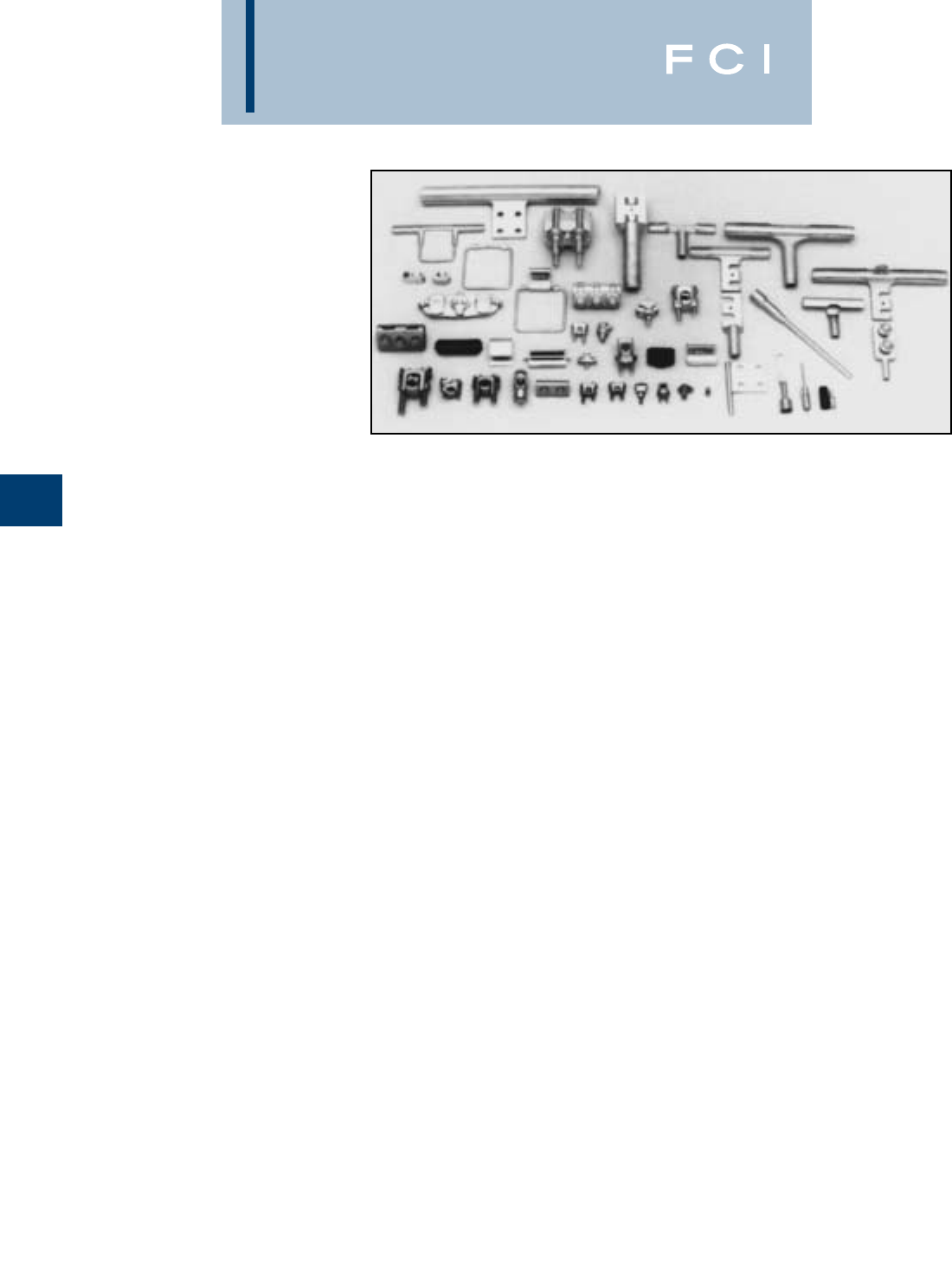
BURNDY
Overhead
TAP CONNECTORS
TABLE OF CONTENTS
MECHANICAL (BOLTED)
Mechanical Tap Connectors............................E-3
Types KS & KS-3.............................................E-4
Type SC...........................................................E-4
Type KSU ........................................................E-5
Type KVS.........................................................E-5
Type KVSW .....................................................E-6
Types KVSU & KVS ........................................E-7
Type KVS-A.....................................................E-8
Types UC-L, UC-K...........................................E-9
Type CP-A .....................................................E-10
Type VP .........................................................E-11
Type UW-R ....................................................E-11
Type UC.........................................................E-12
Type CP.........................................................E-12
Type QPX ......................................................E-13
Type VT .........................................................E-14
Types UCG-R & UCG-RS .............................E-15
Types UC-R & UC-RS...................................E-15
Type LSC.......................................................E-16
COMPRESSION
Compression Tap Connectors.......................E-17
Type YC-C .....................................................E-18
Type YP-C .....................................................E-18
Type YC-A .....................................................E-19
Type YP-U .....................................................E-20
Type YPC-U...................................................E-21
Type YC-U .....................................................E-22
Types YPC-A-U & YPC-R-U ..........................E-22
Type CC.........................................................E-23
Seven Connector Selector Chart ..................E-24
Types YHO & YHD.........................................E-25
Types YHN & YHR.........................................E-26
LOKTAP™ .....................................................E-27
Type YCT.......................................................E-28
Type YOT .......................................................E-28
Type YTU-R-R ...............................................E-29
Type YOT-R-R ................................................E-30
Type YNT-R-R................................................E-30
Type YNTA-R .................................................E-31
Type STS-4N.................................................E-31
Type YTA-R-2N..............................................E-32
Types YKA-R-2N & YKA-A-2N.......................E-33
Type YSA-R-2N .............................................E-34
Type YTA-2N..................................................E-34
Type YKA-2N.................................................E-35
Type YCB-R...................................................E-36
Types YCB-U & YCB-R-U..............................E-37
Types J990 & J1252......................................E-37
Types YHO-J, YHD-J, YHN-J.........................E-38
TRANSFORMER AND EQUIPMENT
Type E-C-G....................................................E-39
Types KC2 & EQC632C................................E-40
Type YA-2LH..................................................E-40
Type YE-LH ...................................................E-41
Type YE-R, YE-W ..........................................E-41
E-2
BURNDY
Overhead
MECHANICAL
(BOLTED)
TAP CONNECTORS
BURNDY's line of mechanical tap connectors
is the most complete, dependable and eco-
nomical available. These mechanical connec-
tors consist of service, parallel, and midspan
types.
Generally the alloys and hardware used
depend on whether the connector is for a
strain or current carrying application, and is
made of aluminum or copper. Particular alloys
and hardware are selected for strength, con-
ductivity, durability, ductility and resistance to
corrosion.
In a copper connector high strength alloys are
used in mechanical clamping components
and high conductivity alloy in current carrying
elements.
Aluminum clamp type connectors are made
of alloy 356, which is impervious to stress
corrosion. In its heat-treated state, it has high
strength and is used for both current carrying
and clamping elements.
E-3
Features and Benefits
•High strength alloys.
◊Provides efficient and reliable
performance.
•Range taking.
◊Accommodates a large range of
conductors in either groove reducing
inventory to a minimum.
•Matched groove designs.
◊Ensures maximum contact with
conductors accomodated.
•Hex bolts, nuts and washers.
◊Provides high contact pressure
and rapid assembly.
Hardware is high strength and corrosion-
resistant. In copper connectors, DURIUM™,
a silicone bronze alloy, is used. Anodized
aluminum alloy 2024-T4 bolts and 6061-T6
nuts are used in aluminum connectors. They
provide the best combination of strength,
resistance to galling and corrosion, and their
thermal coefficient of expansion is most suit-
able for aluminum. To insure dependable
connections, bolts should be tightened to the
recommended torque values shown below.
These mechanical tap connectors are mainly
used in overhead distribution systems to pro-
vide primary service taps and/or secondary
service drop connections to the end users.
A few of the key features and benefits of
these connectors are:
RECOMMENDED TIGHTENING TORQUE STANDARD WRENCH SIZE
BOLT SIZE RECOMMENDED TORQUE (Inch
Lbs.) BOLT NUT
DURIUM AND GALVANIZED STEEL HARDWARE
1/4 - 20 80 7/16 7/16
5/16 - 18 180 1/2 1/2
3/8 - 16 240 9/16 9/16
1/2 - 13 480 3/4 3/4
5/8 - 11 660 15/16 15/16
3/4 - 10 1050 1-1/8 1-1/8
ALUMINUM HARDWARE*
1/2 - 13 300 3/4 3/4
5/8 - 11 480 15/16 15/16
3/4 - 10 650 1-1/8 1-1/8
*Aluminum bolts are lubricated.

BURNDY
Overhead
TYPES KS & KS-3
SERVIT®
For Copper,
Copperweld
Compact, high strength, high copper alloy
SERVIT®split-bolt has free-running threads,
and easy to grip wrench flats. Highly resistant
to season cracking and corrosion, the
SERVIT®provides maximum pressure and
assures secure connection on all combina-
tions of run and tap conductors. Type KS-3,
similar to Type KS, accommodates 3 maxi-
mum size conductors.
TYPE SC
SERVIT®COVER
HUG-A-BUG
Used indoors or outdoors this compact, one-
piece plastic SERVIT®cover, saves time and
material, eliminates costly taping of split-bolts.
Positive latch snaps easily and quickly over
connector, ideal for tight quarters. Self posi-
tioning plastic fingers wrap around wires fully
insulating joint. UL listed for 600 volt indoor
application. Three covers accommodate a
range of 6 SERVIT®sizes through 2/0 Str.
E-4
*UL listing of Type SC Cover applies to use on BURNDY®
SERVIT™ Type KS and to equivalent split-bolt connectors
indicated strip length is maintained, maximum indicated
* Not UL or CSA listed.
conductor sizes are not exceeded, and connector is properly
located within recess provided for it.
CONDUCTOR
COPPER COPPERWELD
RANGE FOR MIN. TAP MAXIMUM
CATALOG EQUAL RUN WITH MAX. TYPE TYPE
NUMBER AND TAP RUN SOL. STR. A D
KS90 12 Str. - 8 Str. 16 Str. #10 — — —
KS15 10 Str. - 8 Str. 14 Str. #8 — — —
KS17 8 Str. - 6 Sol. 14 Str. #6 3 #12 8A 9-1/2D
KS17-3* 8 Str. - 6 Sol. 14 Str. #6 3 #12 8A 9-1/2D
KS20 8 Str. - 4 Sol. 14 Str. #4 3 #10 6A 8D
KS20-3* 8 Str. - 4 Sol. 14 Str. #4 3 #10 6A 8D
KS22 6 Str. - 2 Sol. 14 Str. #2 3 #8 4A 6D
KS22-3* 6 Str. - 2 Sol. 14 Str. #2 3 #8 4A 6D
KS23 6 Str. - 2 Str. 14 Str. #1 3 #7 3A 5D
KS25 4 Str. - 1/0 Str. 14 Str. 2/0 3 #5 2A 4D
KS26 2 Str. - 2/0 Str. 14 Str. 3/0 7 #7 — —
KS27 1 Str. - 3/0 Str. 8 Sol. ————
KS29 1 Str. - 250 8 Str. 4/0 7 #5 — —
KS31 1/0 Str. - 350 1/0 Str. — 19 #8 — —
KS34 2/0 Str. - 500 2/0 Str. — 19 #6 — —
KS39 4/0 Str. - 750 4/0 Str. — 19 #5 — —
KS44 300 - 1000 4/0 Str. ————
CONDUCTOR RANGE *FOR FOR
CATALOG RANGE FOR EQUAL RUN AND TAP MIN. TAP WITH MAX. CABLE RUN USE USE
NUMBER MIN. MAX. MIN. MAX. WITH WITH
SC4 8 Str. 6 Sol. 14 Str. 6 Sol. KS17 —
SC4 8 Str. 4 Sol. 14 Str. 4 Sol. KS20 —
SC2 6 Str. 2 Sol. 14 Str. 2 Sol. KS22 KSA6
SC2 6 Str. 2 Str. 14 Str. 2 Str. KS23 KSA4
SC2/0 4 Str. 1/0 Str. 14 Str. 1/0 Str. KS25 KSA2
SC2/0 2 Str. 2/0 Str. 14 Str. 2/0 Str. KS26 KSA1/0
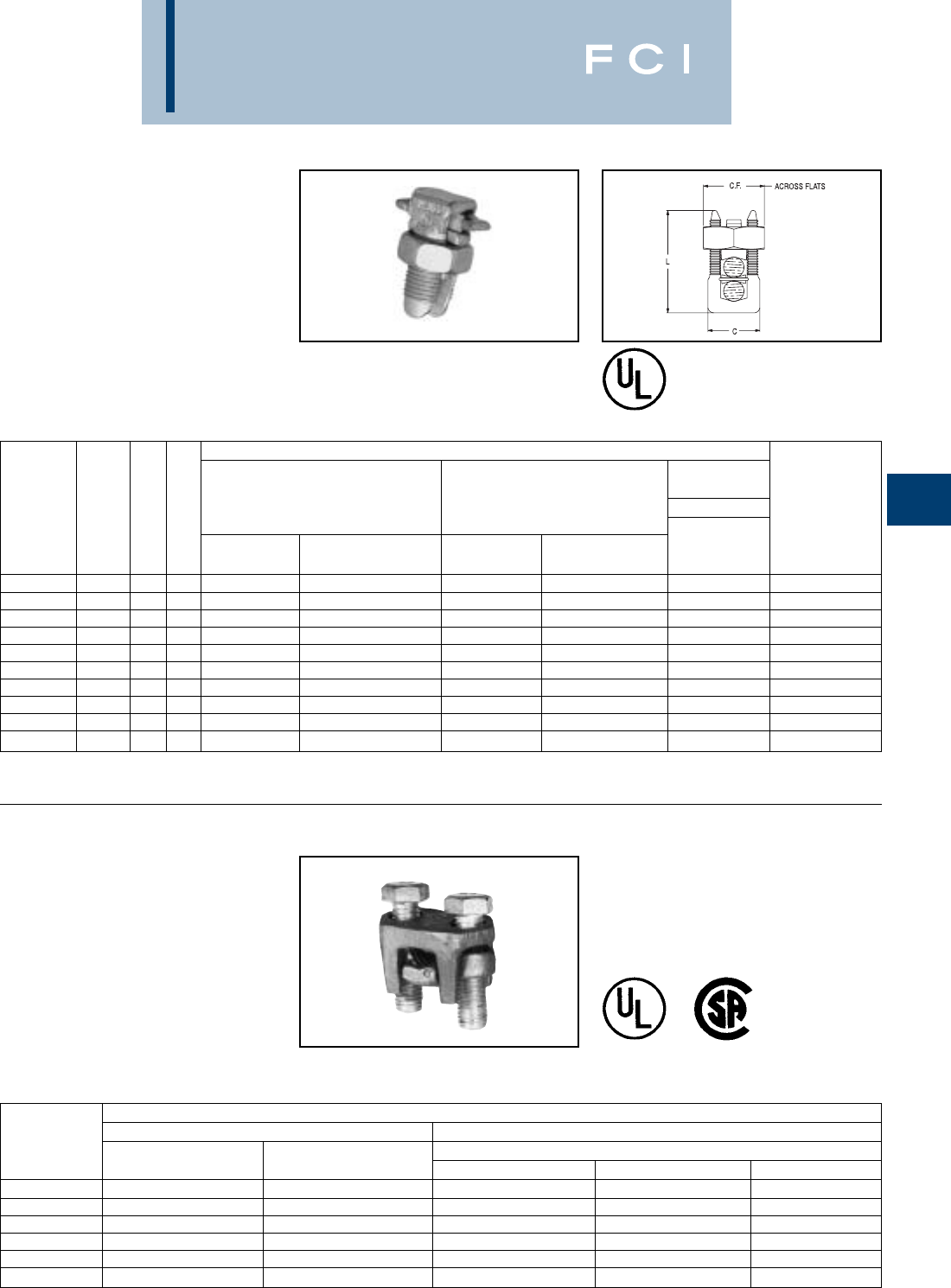
BURNDY
Overhead
TYPE KSU
UNIVERSAL SERVIT®
For All Combinations of
Copper, Aluminum, ACSR,
AAAC, 5005, & Steel
Tin-plated, high strength copper alloy
SERVIT®with spacer. Spacer separates
dissimilar conductors and provides long con-
tact length that prevents high pressure point
contacts between run and tap conductors.
TYPE KVS
OKLIP™
Mechanical Connector for
Copper and Copperweld
Compact, two-piece, high strength; high cop-
per alloy BURNDY®OKLIP™ recommended
for heavy duty connections. Neoprene rings
hold bolts in place during installation.
Installed with ordinary wrench.
E-5
486A
Copper Only
Use of PENETROX™ joint compound recom-
mended with aluminum or ACSR.
CONDUCTOR
MAXIMUM
CONDUCTOR
STEEL
RUNTAP SOL. 3 STR. RECOMMENDED
CATALOG CROSS COPPER & ACSR, AAAC, COPPER & ACSR, AAAC, NOM. BWG TIGHTENING
NUMBER FLAT L W ALUMINUM 5005 ALUMINUM 5005 BWG DIA. TORQUE in.-lb.
KSU17 .62 .92 .70 12 Sol. - 6 Sol. 8 (6 - 1) 12 Sol. - 6 Sol. 8 (6 - 1) 8 — 5/32
KSU20 .69 1.05 .78 10 Sol. - 4 Sol. 6 (6 - 1) 10 Sol. - 4 Sol. 6 (6 - 1) 6 8 7/32 165
KSU22 .74 1.25 .84 10 Sol. - 2 Sol. 6 (6 - 1) - 4 (7 - 1) 10 Sol. - 2 Sol. 6 (6 - 1) - 4 (7 - 1) 4 6 1/4 275
KSU23 .81 1.48 .94 8 Str. - 2 Str. 3 (6 - 1) - 2 (6 - 1) 8 Sol. - 2 Str. 6 (6 - 1) - 2 (6 - 1) — 4 5/16 275
KSU25 .93 1.77 1.06 2 Str. - 1/0 Str. 3 (6 - 1) - 1 (6 - 1) 10 Str. - 1/0 Str. 6 (6 - 1) - 1 (6 - 1) — — 3/8 385
KSU26 1.04 1.93 1.19 1/0 Str. - 2/0 Str. 1 (6 - 1) - 1/0 (6 - 1) 8 Str. - 2/0 Str. 6 (6 - 1) - 1/0 (6 - 1) — — 7/16 385
KSU27 1.38 2.34 1.58 1 Str. - 3/0 Str. 1 (6 - 1) - 2/0 (6 - 1) 8 Sol. - 3/0 Str. 8 (6 - 1) - 2/0 (6 - 1) — — 1/2 500
KSU29 1.38 2.50 1.58 1 Str. - 250 2/0 (6 - 1) - 4/0 (6 - 1) 8 Str. - 250 6 (6 - 1) - 4/0 (6 - 1) — — 1/2 650
KSU31 1.69 2.88 1.91 4/0 Str. - 350 3/0 (6 - 1) - 4/0 (6 - 1) 4 Str. - 350 4 (6 - 1) - 4/0 (6 - 1) — — 5/8 650
KSU34 2.00 3.12 2.28 400 - 500 336 (30 - 7) - 477 (18 - 1) 2 Str. - 500 2 (6 - 1) - 477 (18 - 1) — — — 825
CONDUCTOR
COPPER COPPERWELD
CATALOG MAX. RUN AND TAP
NUMBER RUN TAP SOL. STR. TYPE V
KVS26 1 Str. - 2/0 Str. 6 Str. - 2/0 Str. 3/0 7 #8 —
KVS28 1/0 Str. - 4/0 Str. 10 Str. - 4/0 Str. 4/0 7 #6 V3/0
KVS31 250 - 350 10 Str. - 350 — 19 #8 V250
KVS34 400 - 500 10 Str. - 500 — 19 #6 V350
KVS40 400 - 800 3/0 Str. - 800 — 19 #5 —
KVS44 500 - 1000 3/0 Str. - 1000 — — —
BURNDY
Overhead
TYPE KVSW
OKLIP™
Mechanical Connector for
Copper and Copperweld
Similar to OKLIP™ Type KVS except for high
copper alloy spacer that separates run and
tap conductor. Provides high contact pres-
sure, confines conductor strands, and
assures vibration proof connection. Longer
peened bolt, permits swivel action for
easier installation.
E-6
CATALOG CONDUCTOR
NUMBER RUN TAP
KVSW26 2 Str. - 2/0 Str. 6 Sol. - 2/0 Str.
KVSW28 1/0 Str. - 4/0 Str. 6 Sol. - 4/0 Str.
KVSW31 250 - 350 4 Sol. - 350
KVSW34 400 - 500 4 Str. - 500
KVSW40 400 - 800 4/0 - 800
KVSW44 500 - 1000 250 - 1000
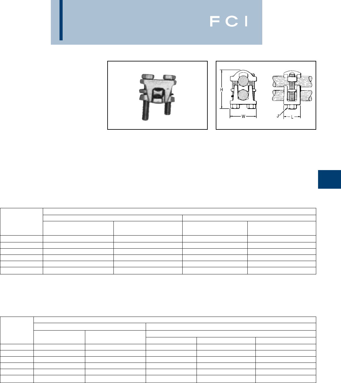
BURNDY
Overhead
TYPES KVSU, KVS
UNIVERSAL OKLIP™
Mechanical Connector for All
Combinations of Copper,
Aluminum†, ACSR†, AAAC and
5005
Compact, tin-plated, high strength, high cop-
per allow two-piece connector with spacer
and tin-plated silicone bronze DURIUM™
hardware. Recommended for heavy duty con-
nections. Spacer separates dissimilar con-
ductors and provides long contact length.
Neoprene ring prevents loss of shorter bolt
during installation. Longer peened bolt,
permits swivel action for easier installation.
Use of PENETROX™ joint compound recom-
mended with aluminum and ACSR.
E-7
†Accommodates compressed conductors within diameter
range.
CONDUCTOR
RUN TAP
CATALOG COPPER & ACSR†, AAAC, COPPER & ACSR†, AAAC,
NUMBER ALUMINUM† & 5005 ALUMINUM† & 5005
KVSU26 2 Str. - 2/0 Str. 3 - 2/0 6 Str. - 2/0 Str. 6 - 2/0
KVSU28 1/0 Str. - 4/0 Str. 1/0 - 4/0 6 Str. - 4/0 Str. 6 - 4/0
KVSU31 250 - 350 4/0 - 300 5 - 350 6 - 300
KVSU34 400 - 500 336.4 - 397.5 4 -500 5 - 397.5
KVSU40 400 - 800 336.4 - 715.5 4/0 - 800 3/0 - 715.5
KVSU44 500 - 1000 397.5 - 900 4/0 - 1000 4/0 - 900
CONDUCTOR
COPPER COPPERWELD
CATALOG MAX. RUN AND TAP
NUMBER RUN TAP SOL. STR. TYPE V
KVS26 1 Str. - 2/0 Str. 6 Str. - 2/0 Str. 3/0 7 #8 —
KVS28 1/0 Str. - 4/0 Str. 10 Str. - 4/0 Str. 4/0 7 #6 V3/0
KVS31 250 - 350 10 Str. - 350 — 19 #8 V250
KVS34 400 - 500 10 Str. - 500 — 19 #6 V350
KVS40 400 - 800 3/0 Str. - 800 — 19 #5 —
KVS44 500 - 1000 3/0 Str. - 1000 — — —
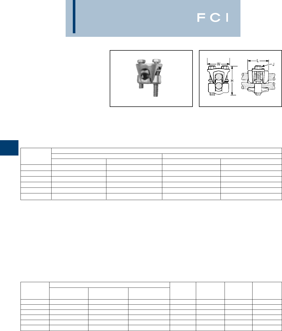
BURNDY
Overhead
TYPE KVS-A
ALUMINUM OKLIP™
Mechanical Connector for All
Combinations of Copper,
Aluminum†, ACSR†, AAAC &
5005
Three-piece, high-conductivity, non-copper
bearing aluminum alloy connector with thick
spacer and aluminum hardware. Hardware in
KVS26A and KVS28A is stainless steel.
Recommended for heavy duty dissimilar
metal applications. Spacer separates conduc-
tors and provides long contact length. Belted
E-8
† Accommodates compressed conductors within diameter
range.
THESE CONNECTORS
CAN ACCOMMODATE
ACSR CONDUCTORS
OVER ARMOR ROD WITHIN
THE DIAMETER RANGE
INDICATED.
Application Over Armor Rod
entrances prevent chafing and permit easier
assembly of conductors. Longer, peened bolt,
permits swivel action for easier installation.
Neoprene ring prevents loss of shorter bolt.
PENETROX™ joint compound recommended
with aluminum and ACSR.
CONDUCTOR
CATALOG RUN TAP
NUMBER COPPER & ALUMINUM† ACSR†, AAAC, & 5005 COPPER & ALUMINUM† ACSR†, AAAC, 5005
KVS26A 2STR. - 2/0 STR. 4 - 2/0 10 STR. - 2/0 STR. 6 - 2/0
KVS28A 1/0 STR. - 4/0 STR. 1/0 - 4/0 10 STR. - 4/0 STR. 6 - 4/0
KVS31A 250 - 350 4/0 - 336.4 6 STR. - 350 6 - 336.4
KVS34A 400 - 500 336.4 - 397.5 4 STR. - 500 5 - 397.5
KVS40A 400 - 800 336.4 - 715.5 3/0 STR. - 800 3/0 - 715.5
KVS44A 500 - 1000 397.5 - 900 3/0 STR. - 1000 3/0 - 900
CONDUCTOR RANGE BY DIAMETER
CATALOG MIN. RUN MIN. TAP MAX. RUN &
NUMBER DIA. DIA. TAP DIA. H J L W
KVS26A .281 .116 .447 2 5/16 1-3/8 1-5/8
KVS28A .360 .116 .564 2-3/8 3/8 1-5/8 2
KVS31A .565 .184 .681 3 1/2 2 2-5/8
KVS34A .728 .216 .814 3-3/8 1/2 2-1/2 2-5/8
KVS40A .728 .470 1.036 4 1/2 3-1/8 3
KVS44A .806 .470 1.162 4-1/2 5/8 3-1/2 3-3/8
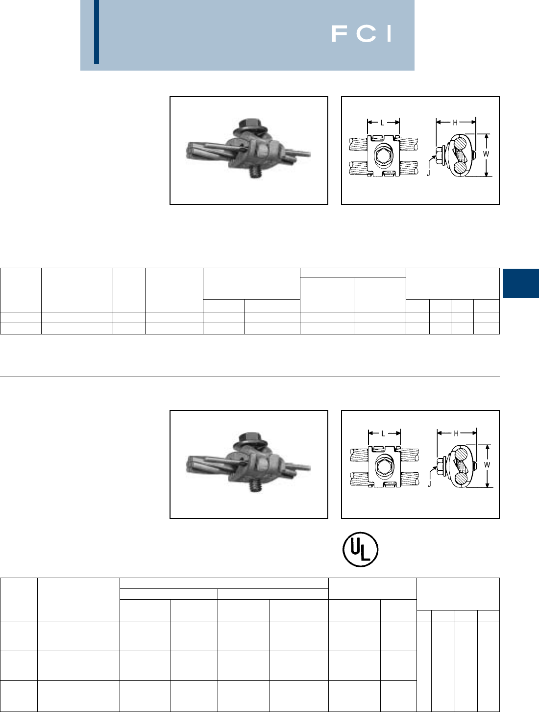
BURNDY
Overhead
TYPE UC-L
UNIVERSAL
PARALLEL CLAMP
For All Combinations of Copper,
Aluminum†, ACSR†, 6201,
5005, Steel and Copperweld
Interlocking finger design accommodates
large range of conductor sizes. Tin-plated,
cast of high copper alloy and clamped
with plated steel bolt, PENETROX™ joint
compound recommended with aluminum
and ACSR.
TYPE UC-K
UNIVERSAL
PARALLEL CLAMP
For All Combinations of Copper,
Aluminum†, ACSR, Steel and
Copperweld
Interlocking finger design accommodates
large range of conductor sizes. Tin-plated,
cast of high copper alloy and clamped with
silicon bronze DURIUM™ bolt, PENETROX™
E-9
†Accommodates compressed conductors within diameter
range.
†Accommodates compressed conductors within diameter
range.
joint compound recommended with ACSR.
Applications include grounding for the Cable
TV industry.
INSTALLATION TOOLING
ACSR†, COPPER TIGHTENING
CATALOG COPPER & ALUM. 6201, STEEL CONDUCTOR TORQUE DIMENSIONS
NUMBER (EITHER GROOVE) 5005 COPPERWELD NOM. DIA. AWG SIZE (AWG) (in.-lbs.) L H J W
UC8W26-L 8 Sol. - 2/0 Str. 6 - 1/0 8 Sol. - 7 #7 5/32 - 7/16 8 Sol. - 4-3 Str. #8 75 1 1-1/2 5/16 1-7/16
*UC2W28-L 2 Sol. - 4/0 Str. 3 - 4/0 3 #8 - 7 #6 9/32 - 9/16 4-3 Str. - 4-3 Str. #6 - #4 110 1-1/8 1-1/2 3/8 1-3/4
CONDUCTOR RANGE INSTALLATION
GROOVE A GROOVE B TORQUES
CATALOG MAXIMUM MINIMUM MAXIMUM MINIMUM CONDUCTOR TORQUE DIMENSIONS
NUMBER FOR USE WITH: SIZE SIZE SIZE SIZE SIZE (in.-lbs.) L H J W
Aluminum or Galvanized 1/0 ACSR or 2/0 Str. Copper
UCK-1† Steel Strand to Copper or 7/16 Galvanized #6 ACSR 7/16 Copperweld, #8 Sol. Copper #8 75
Copper Bonded Steel Wire Steel Strand 2A Copperweld 9-1/2D Copperweld
Aluminum or Galvanized 1/0 ACSR or 1/0 ACSR or
UCK-2 Steel Strand to Aluminum or 7/16 Galvanized #6 ACSR 7/16 Galvanized #6 ACSR #6 - #4 110 1 1-7/16 5/16 1-7/16
Galvanized Steel Strand Steel Strand Steel Strand
2/0 Str. Copper #8 Sol. Copper 2/0 Str. Copper
UCK-3* Copper to Copper 7/16 Copperweld, 9-1/2D 7/16 Copperweld #8 Sol. Copper 1/0 - 2/0 150
2A Copperweld Copperweld 2A Copperweld 9-1/2D Copperweld

BURNDY
Overhead
TYPES CP-A
PARALLEL CLAMP
For All Combinations of Copper,
Aluminum†, ACSR†, 6201 &
5005
Type CP-A is recommended for tap or paral-
lel connections. High strength, high conduc-
tivity aluminum body and hardware provide
corrosion resistant assembly. Long contact
surface insures excellent contact and full
conductivity. PENETROX™ joint compound
recommended for all combinations.
E-10
†Accommodates compact and compressed conductors within
diameter range.
For other sizes contact factory.
Fig. 1 Fig. 2
GROOVE A GROOVE B
CATALOG COPPER & COPPER & FIG. DIMENSIONS
NUMBER ACSR, 6201, 5005 ALUMINUM ACSR, 6201, 5005 ALUMINUM NO. L H W
CP26A26A 1/0 3/0 Sol. - 2/0 Str. 1/0 3/0 Sol. - 2/0 Str.
2/0 2/0
CP27A27A 101.8 (12-7) 4/0 Sol. - 3/0 Str. 101.8 (12-7) 4/0 Sol. - 3/0 Str.
110.8 (12-7) 110.8 (12-7)
3/0 3/0 1 4 2-1/8
CP28A28A 134.6 (12-7) 4/0 Str. 134.6 (12-7) 4/0 Str.
4/0 4/0
CP29A29A 159 (12-7) 250 159 (12-7) 250 2-7/8
203 (8-7) 266.8 203 (8-7) 266.8
176.9 (12-7) 176.9 (12-7)
CP30A30A 190.8 (12-7) 300 190.8 (12-7) 300
266.8 (18-1, 6-7, 26-7) 266.8 (18-1, 6-7, 26-7)
211.3 (12-7) 211.3 (12-7) 4-1/2 2-3/8
CP31A31A 300 (26-7, 30-7) 336.4 300 (26-7, 30-7) 336.4
336.4 (18-1) 350 336.4 (18-1) 350
203.2 (16-19) 203.2 (16-19)
CP32A32A 336.4 (26-7, 30-7) 397.5 336.4 (26-7, 30-7) 397.5
397.5 (18-1) 400 397.5 (18-1) 400 2
450 450 532-1/2
CP34A34A 397.5 (26-7, 30-7) 477 397.5 (26-7, 30-7) 477
477 (18-1) 500 477 (18-1) 500
500 (30-7) 500 (30-7)
556.5 (24-7, 26-7, 30-7) 556.5 (24-7, 26-7, 30-7)
CP37A37A 636 (36-1) 636 636 (36-1) 636 5-1/4 3-3/8 3
605 (24-7) 605 (24-7)
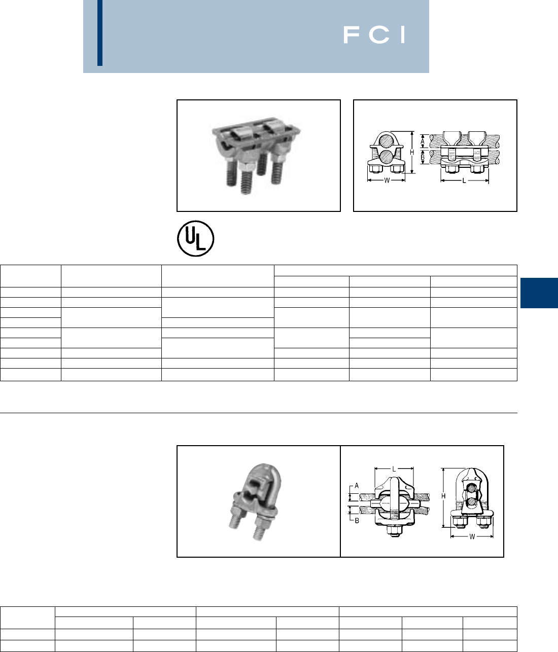
BURNDY
Overhead
E-11
TYPE VP
PARALLEL CLAMP
For Copper
Multiple V-bolt connector especially suited for
flexible or extra flexible conductors. Made of
high strength, high conductivity copper.
Clamping elements accommodate a range of
conductor sizes in either groove. V-bolts
provide high pressure and compress the
conductor over long contact area. Also
recommended for jumper connections.
TYPE UW-R
CLIPIT™
Deadend Clamp for Aluminum†,
ACSR†, 6201 and 5005
High strength aluminum casting with galva-
nized steel U-bolt, extra long aluminum
spacer, and caps that confine strands.
Holding strength of installations using two
CLIPIT™ deadends exceeds rated breaking
strength of conductor. Use of PENETROX™
joint compound is recommended.
†Accommodates compressed conductors within diameter
range.
CATALOG DIMENSIONS
NUMBER GROOVE A GROOVE B H L W
VP2828 1/0 Str. - 4/0 Str. 1/0 Str. - 4/0 Str. 2-1/8 2-3/4 1-3/4
VP3030 1/0 Str. - 300 2-1/2 3-1/8 2
VP3430 1/0 Str. - 300
VP3434 300 - 500 300 - 500 3-1/8 3-1/4 2-1/2
VP4030 1/0 Str. - 300 3-1/2
VP4040 500 - 800 4-3/8 3-3/4 2-7/8
VP4440 750 - 1000 500 - 800 53-7/8 3-1/4
VP4646 1000 - 1500 1000 - 1500 5-3/8 4-1/2 3-1/2
VP4844 1500 - 2000 750 - 1000 6-3/8 4-3/4 4-1/8
CATALOG RUN A TAP B DIMENSIONS
NUMBER ACSR, 6201, 5005 ALUMINUM ACSR, 6201, 5005 ALUMINUM L H W
UW2R 6 - 2 6 Str. - 2 Str. 6 - 2 6 Str. - 2 Str. 1-1/2 2-5/8 1-7/8
UW25R 6 - 1/0 6 Str. - 2/0 Str. 6 - 1/0 6 Str. - 2/0 Str. 1-7/8 2-7/8 2
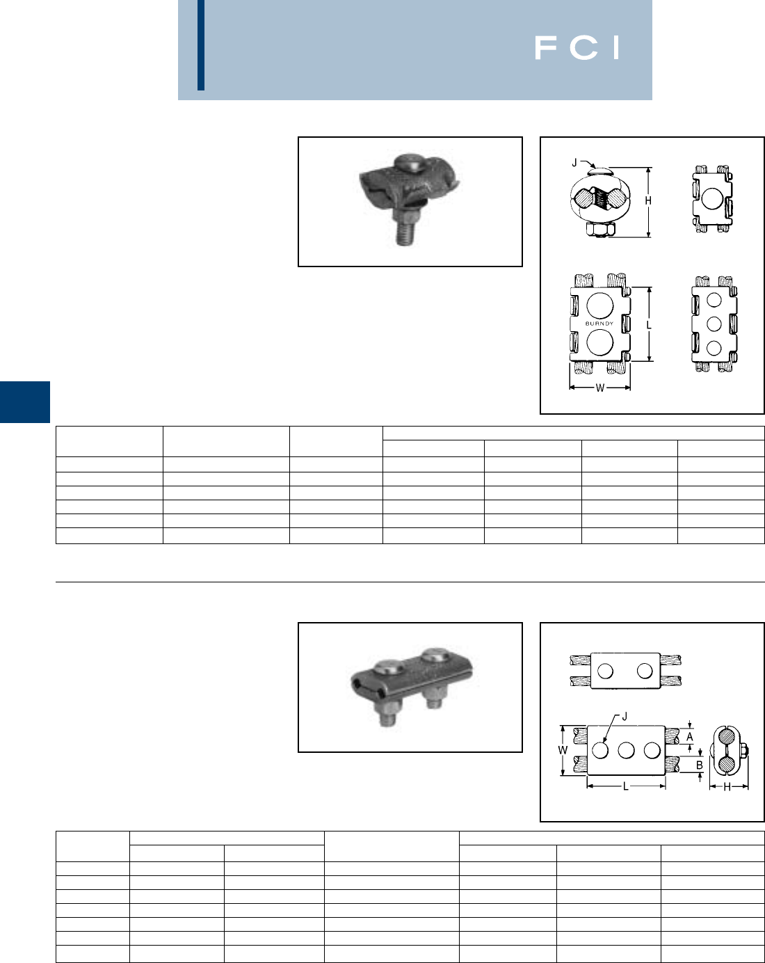
BURNDY
Overhead
E-12
TYPE UC
PARALLEL CLAMP
For Range of Copper
Type UC connector accommodates large
range of conductors in either groove, reduc-
ing inventory to a minimum. Interlocking
finger design provides firm grip with maxi-
mum contact length. High strength, corrosion
resistant silicone bronze hardware. One
wrench installation.
TYPE CP
PARALLEL CLAMP
For Copper
High strength, high copper alloy Type CP is
recommended for heavy duty parallel
connections. Silicone bronze DURIUM™
hardware and cast copper body provides
corrosion resistant assembly. Long contact
surface provides excellent contact and
assures full conductivity.
For other sizes contact factory.
Fig. 1
Fig. 1
Fig. 2
Fig. 2
Fig. 3
End View
Type UC
CATALOG CONDUCTOR FIG. DIMENSIONS’
NUMBER (EITHER GROOVE) NO. L H J W
UC6W25 6 Sol. - 1/0 Str. 1 1-3/4 1-5/8 3/8 1-3/8
UC4W28 4 Sol. - 4/0 Str. 2 2-1/8 2 3/8 1-3/4
UC2W30 2 Sol. - 300 2 2-3/8 2-1/8 3/8 2
UC2834 4/0 Str. - 500 3 4-1/4 2-7/8 1/2 2-1/2
UC3040 300 - 800 3 4-1/4 3-3/8 1/2 3
UC3444 500 - 1000 3 4-1/4 3-5/8 1/2 3-1/2
CATALOG GROOVE FIG. DIMENSIONS
NUMBER A B NO. L J W
CP2C2C 2 Str. 2 Str. 1 2-1/2 3/8 1-1/4
CP2525 1/0 Str. 1/0 Str. 1 3 3/8 1-5/8
CP2626 2/0 Str. 2/0 Str. 1 3 3/8 1-5/8
CP282C 4/0 Str. 2 Str. 1 2-3/4 3/8 1-3/8
CP2828 4/0 Str. 4/0 Str. 2 4 3/8 2
CP2929 250 250 2 4 3/8 2
CP3434 500 500 2 5 1/2 2-1/2
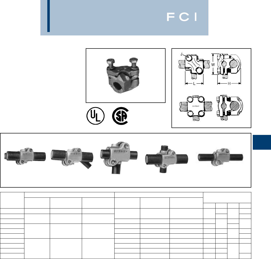
BURNDY
Overhead
E-13
TYPE QPX
VERSITAP™ PARALLEL CLAMP
For Copper, Copperweld and
Copperweld-Copper
The VERSITAP™ Type QPX is recommended
for Tee, Cross, Parallel, Butt and Tap connec-
tions. Range-taking, only 10 connectors
required to accommodate conductor sizes
from #6 Str. to 1000 kcmil. Edges are rounded
for easy taping. Made of high strength, high
conductivity copper alloy and silicone bronze
DURIUM™ hardware.
PARALLEL TAP TEE CROSS BUTT
RUN TAP
CATALOG COPPERWELD COPPERWELD DIMENSIONS
NUMBER COPPER COPPERWELD -COPPER COPPER COPPERWELD -COPPER L H J W
QPX2C2C 6 Str. - 2 Str. 5 Sol. - 3 #7 8A - 4A 1-5/8 1-3/8
QPX282C 6 Str. - 2 Str. 5 Sol. - 3 #7 8A - 4A 1-3/8 25/16 1-5/8
QPX2828 1 Str. - 4/0 Str. 7 #9 - 7 #5 3A - 3/0V 1 Str. - 4/0 Str. 7 #9 - 7 #5 3A - 3/0V 1-7/8 3/8
QPX342C 6 Str. - 2 Str. 5 Sol. - 3 #7 8A - 4A 1-3/8 2-1/8 5/16 1-7/8
QPX3428 250 - 500 19 #19 - 19 #6 4/0 EK 1 Str. - 4/0 Str. 7 #9 - 7 #5 3A - 3/0V 1-3/4 2-1/2 2
QPX3434 250 - 500 19 #9 - 19 #6 4/0 EK 2 2-3/4 3/8 2-1/8
QPX442C 6 Str. - 2 Str. 5 Sol. - 3 #7 8A - 4A 1-3/8 2-5/8 5/16 2-1/4
QPX4428 1 Str. - 4/0 Str. 7 #9 - 7 #5 3A - 3/0V 1-7/8 2-7/8
QPX4434 500 - 1000 19 #6 — 250 - 500 19 #19 - 19 #6 4/0 EK 2 3 3/8 2-3/8
QPX4444 500 - 1000 19 #6 — 2-5/8 3-3/8 2-5/8
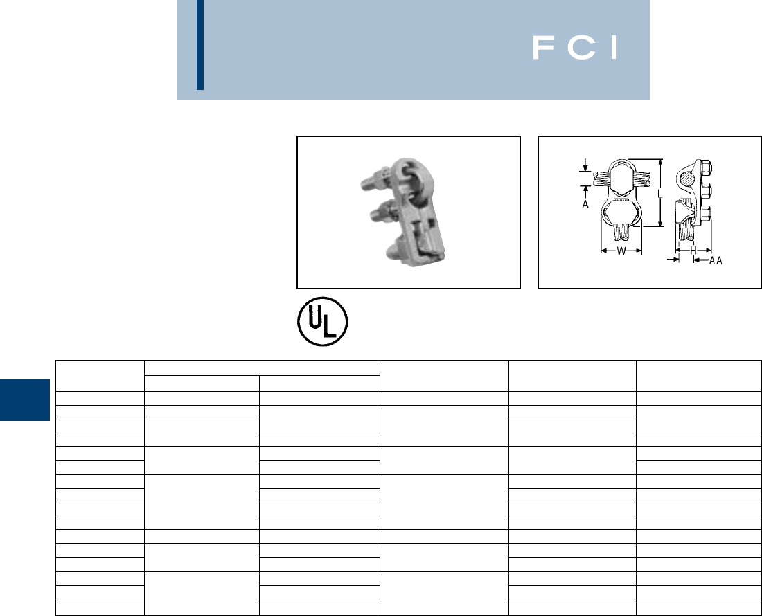
BURNDY
Overhead
E-14
TYPE VT
T-CONNECTOR
For Copper Cable to Cable
High copper alloy T-connector for cable run,
cable tap. DURIUM™ V-bolt clamping
elements accommodate large range of cable
and are particularly suited for extra flexible
cable. (One-wrench installation).
CATALOG CONDUCTOR
NUMBER RUN (A) TAP (AA) H L W
VT2C2C 8 Sol. - 2 Str. 8 Sol. - 2 Str. 1-3/8 2-3/8 1
VT2525 6 Sol. - 1/0 Str. 2-5/8
VT2825 6 Sol. - 1/0 Str. 1-5/8 1-1/4
VT2828 1/0 Str. - 4/0 Str. 1/0 Str. - 4/0 Str. 3-1/8 1-3/4
VT3025 6 Sol. - 1/0 Str. 1-1/8
VT3030 1/0 Str. - 300 1/0 Str. - 300 1-7/8 3-3/8 2
VT3425 6 Sol. - 1/0 Str. 3-1/4 1-1/4
VT3428 1/0 Str. - 4/0 Str. 3-1/2 1-3/4
VT3430 300 - 500 1/0 Str. - 300 2-3/8 3-5/8 2
VT3434 300 - 500 3-3/4 2-1/4
VT4040 500 - 800 500 - 800 2-5/8 4-3/4 2-5/8
VT4425 6 Sol. - 1/0 Str. 4-3/8 1-1/4
VT4428 750 - 1000 1/0 Str. - 4/0 Str. 2-7/8 4-1/8 1-3/4
VT4834 300 - 500 5-1/4 2-1/4
VT4844 1500 - 2000 750 - 1000 4-1/4 5-3/4 2-1/8
VT4848 1500 - 2000 6-1/4 3-3/4

BURNDY
Overhead
E-15
TYPES UCG-R &
UCG-RS
TAPIT™ PARALLEL CLAMP
For All Combinations of Copper,
Aluminum†, ACSR†, 6201 &
5005
Multiple purpose parallel groove clamp made
of high strength, high conductivity, non-
copper bearing aluminum alloy. Properly
proportioned to minimize stress corrosion
and deterioration by galvanic action.
Interlocking fingers on connector body halves
prevent mismatching. Square shank, hex
*Maximum recommended combinations: 1/0 Aluminum or
ACSR Run - #2 Str. Copper Tap; 1/0 Copper Run - 1/0
Aluminum or ACSR Tap.
*Maximum recommended combinations: 4/0 aluminum or
ACSR RUN - #2 Str. copper TAP.
TYPES UC-R & UC-RS
TAPIT™ PARALLEL CLAMP
For All Combinations of Copper,
Aluminum†, ACSR†, 6201 &
5005
High strength, high conductivity, non-copper
bearing aluminum alloy, properly propor-
tioned to minimize stress corrosion and
deterioration by galvanic action.
Keying tabs on connector body halves
prevent mismatching. Square shank, high
head, round collar, high strength galvanized
steel bolt allows one or two-wrench
installation.
Also supplied pre-filled with PENETROX™
joint compound and Stripsealed.
strength galvanized steel bolt allows one
wrench installation.
Also supplied pre-filled with PENETROX™
joint compound and Stripsealed.
†Accommodates compact and compressed conductors within
diameter range.
** Supplied with galvanized steel, square shank bolt.
†Accommodates compact and compressed conductors within
diameter range.
CATALOG NUMBER GROOVE A GROOVE B
WITH WITHOUT COPPER & ACSR†, 6201, COPPER & ACSR†, 6201, DIMENSIONS
STRIPSEAL STRIPSEAL ALUMINUM† & 5005 ALUMINUM† 5005 L H J W
UCG25R2RS** UCG25R2R** 6 Sol. - 1/0 Str. 8 - 1/0 6 Sol. - 2 Str. 8 - 2 1-1/8 1-7/8 5/16 1-3/8
UCG25RS UCG25R 8 Str. - 1/0 Str. 6 - 1/0 8 Str. - 1/0 Str.* 6 - 1/0 1-3/8 2-1/8 3/8 1-5/8
UCG28RS UCG28R 1/0 Str. - 4/0 Str. 1/0 - 4/0 1/0 Str. - 4/0 Str. 6 - 4/0 1.38 2.21 3/8-16 1.87
UCG32RS UCG32R 1/0 Str. - 397.5 1/0 - 336.4 8 Str. - 2/0 Str. 6 - 1/0 1-1/2 2-5/8 3/8 2-1/8
CATALOG NUMBER GROOVE A GROOVE B
WITH WITHOUT COPPER & ACSR†, 6201, COPPER & ACSR†, 6201, DIMENSIONS
STRIPSEAL STRIPSEAL ALUMINUM† & 5005 ALUMINUM† 5005 L H J W
UC25R2RS UC25R2R 8 Sol. - 1/0 Str. 6 - 1/0 8 Sol. - 2 Str. 6 - 2 1-1/8 1-5/8 5/16 1-3/8
UC28RS UC28R 1/0 Str. - 4/0 Str. 1/0 - 4/0 8 Sol. - 1/0 Str.* 6 - 1/0 1-3/8 2-3/8 3/8 1-7/8
UC32RS UC32R 1/0 Str. - 397.5 1/0 - 336.4 (26-7) 6 Sol. - 2/0 Str. 6 - 1/0 1-1/2 2-3/8 3/8 2-1/4
—UC33R 4/0 Str. - 400 3/0 - 336.4 (30-7) 6 Sol. - 2/0 Str. 6 - 2/0 1-3/4 2-3/4 1/2 2-1/4
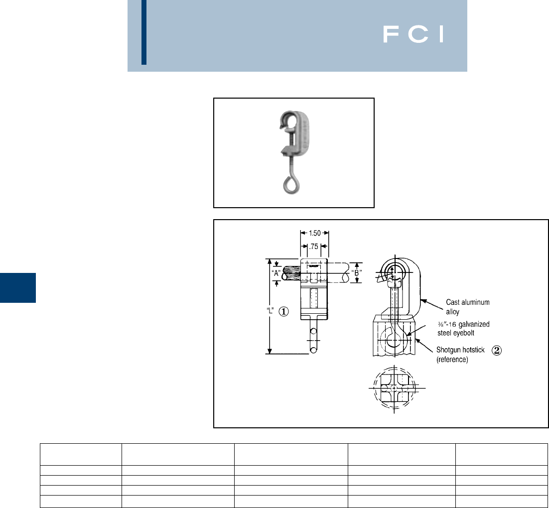
BURNDY
Overhead
E-16
TYPE LSC
CATCHER
For Aluminum and ACSR
Primary Covered
Conductor (Tree Wire)
Cast aluminum lightning shield clamp with a
galvanized steel eye bolt for use on covered
aluminum and ACSR primary overhead
distribution conductors ("Tree Wire").
They are designed to protect the "Tree Wire"
from burn-down causing service interruption
during high lightning activity. For further appli-
cation details contact the factory.
Conductor groove is pre-filled with PENE-
TROX™ A13, which is compatible with cable
insulation and individually bagged.
①Approx. assembly length over eyebolt with cable clamped.
Also approx. eyebolt position when shipped.
②Assembly can be installed using a shotgun hotstick as
shown. Assembly instructions are supplied with each
connector.
CATALOG ACCOMMODATES
NUMBER CABLE CABLE DIA. “A” INSUL. DIA. “B” (MAX.) “L”
LSC1/0 1/0 Str. AAC - 1/0 ACSR .368 - .398 .65 4.5
LSC1/0-1 1/0 Str. AAC - 1/0 ACSR .368 - .398 .83 4.5
LSC556 4/0 Str. - 556.5 AAC .528 - .858 1.16 5.9
LSC556-1 4/0 Str. - 556.5 AAC .528 - .858 1.34 5.9

BURNDY
Overhead
E-17
COMPRESSION
TAP CONNECTORS
BURNDY®compression tap connectors are
wide range-taking; accommodate copper,
aluminum, and ACSR; are easy to install; and
are dependable and economical. They are
designed to be installed with BURNDY®
"matched" hand, hydraulic, and power-driven
hydraulic tooling. The connector line consists
of C-shaped, Figure 3, Figure 6-shaped and
HYCRIMP™ tap connectors, disconnectable
T-taps, terminals and stirrups.
The copper CRIMPIT™ is a range-taking,
reversible, C-shaped compression tap
connector for combinations of copper con-
ductors.Twelve connectors take tap combina-
tions from #10 AWG through 4/0, and all sizes
are installed with dies that also install
aluminum connectors. Sizes accommodating
conductors up to No. 2 may be installed with
the MD6 and OUR840; all sizes may be
installed with the Y35 or Y750. They make
"hot" installation easy by permitting the
lineman to grip the CRIMPIT™ in the com-
pression tool and then place it on the line.The
tap is then inserted and the CRIMPIT™ is
compressed. Massive C-shape forces tap
and line conductors together to form depend-
able, low-cost, low-resistance connections.
The CABELOK CRIMPIT™ is a range-taking,
universal and reversible, Figure 3-shaped
aluminum compression tap connector with an
adjustable spacer which separates the
conductors. It accommodates combinations
of copper, aluminum, and ACSR conductors
from No. 6 up to 4/0, and is installed with the
common O and D3 dies. The broad range
capacity of each CABELOK CRIMPIT™
reduces the number of connectors required
and simplifies connector selection.
The spacer holds the run or tap in place
permitting the lineman either to approach the
line with the connector held in the tool and
with the tap in the connector, or to assemble
the connector and tap on the line and then
bring up the tool to crimp.
Each CABELOK CRIMPIT™ is pre-filled with
PENETROX™ joint compound and individu-
ally bagged. These packages are clearly
marked with the entire conductor range of the
connector as well as pertinent tooling infor-
mation. The open side of the CABELOK
CRIMPIT™ makes "hot" installations easy by
allowing the connector to be carried to the
energized line in the crimping tool (MD6, Y35
or Y750 hot-line types).
The Figure 6-shaped aluminum compression
tap connector is one of the widest range-
taking compression tap connectors available.
It accommodates copper, aluminum, or
ACSR conductors in very broad ranges. Only
four connectors are required to accommodate
a range from No. 6 to 600 kcmil. This broad
range is made possible by the long ram
stroke of the Y35 and Y750.
HYCRIMP™ compression tap connectors
accommodate ACSR, stranded copper or
aluminum, solid copper or aluminum, and
compact conductors. Seventeen sizes are
available to accommodate all conductors
from #6 solid to 954 MCM compact. All
HYCRIMP™ connectors can be installed
with industry standard O, D, N and R dies.
Each connector is factory filled with
BURNDY®PENETROX™ and individually
boxed for ease of handling, identification, and
installation.
BURNDY's disconnectable T-taps and jumper
loop splices offer an economical approach to
sectionalizing or isolating equipment on ener-
gized lines.They combine the best features of
compression and mechanical connectors.
The pads can be easily assembled or
separated from each other with hot-line tools.
The STIRRUP™ combines a compression
C-shaped Figure 6-shaped or H-shaped
element for the run conductor, and a factory
installed bail which accommodates a hot-line
clamp. The line element can be gripped in the
tool and carried to the line and then crimped.
Note: Aluminum bodied compression tap
connectors are not recommended for making
copper to copper connections. Two connec-
tors are recommended when feeding a line in
both directions.
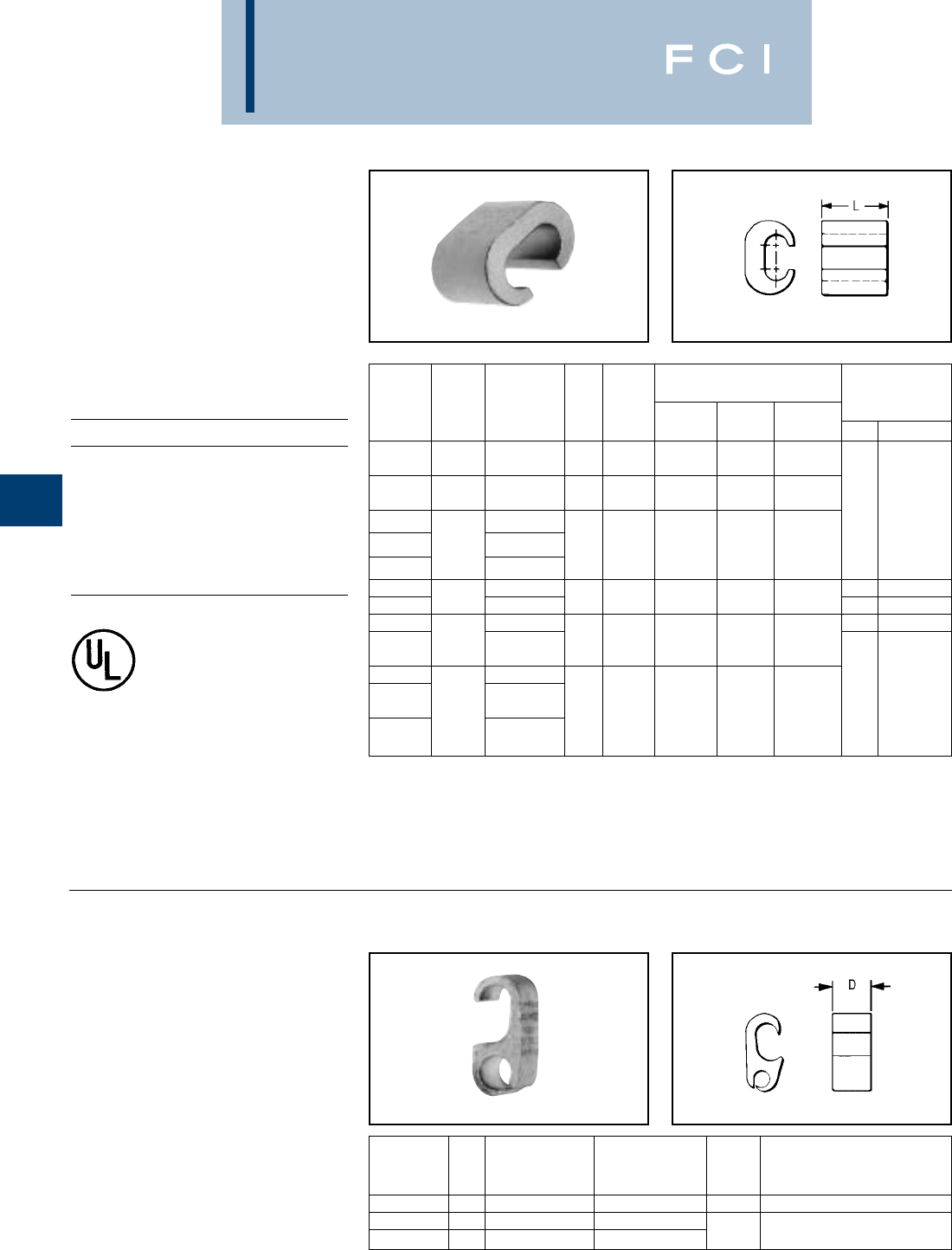
BURNDY
Overhead
E-18
YC-C
COPPER CRIMPIT™
Line Tap for Range of Copper
Range-taking compression tap connector
made of pure copper. Designed to be gripped
in the jaws or dies of installation tool, then
slipped directly over line for easy installation.
Also used for deadending.
Copperweld-Copper Conductors
8A - Use CRIMPITS™ accommodating
6 str. Copper
6A - Use CRIMPITS™ accommodating
4 Str. Copper
4A - Use CRIMPITS™ accommodating
2 Str. Copper
2A - Use CRIMPITS™ accommodating
1/0 & 2/0 Copper
TYPE YP-C
COPPER CRIMPIT™
Line Tap for Extra Wide Range
of Copper
Figure "6" -shaped, wide range-taking
copper, compression tap connector for
primary service taps and secondary service
drops. Connector can be gripped in tool and
slipped over the line for easy installation.
** Multiple crimp die set. Makes more than one crimp per tool
compression. Figure ( ) indicates number of compressions.
†U Die with adapter PT-6515.
‡U Die with adapter PUADP-1.
*Not UL listed.
†U Die with adapter PT-6515.
‡U Die with adapter PUADP-1.
TOOLS, DIE SET CATALOG NO.,
& (NUMBER OF CRIMPS) CRIMPIT™ FOR
CATALOG DIE Y35, Y750, 1 STR. COPPER
NUMBER RUN TAP L INDEX MD7, MD6 OUR840 Y45†, Y46‡ RUN TAP
12 Sol. -
YC10C10* 10 Str. 12 Sol. - 10 Str. 3/8 238 W238 (1) W238 (1) U238 (1)
8 Sol. -
YC8C8 8 Str. 10 Sol. - 8 Str. 1/2 162 or K W 162 (2) W162 (2) U162** (1)
YC4C8 8 Sol. - 8 Str.
——
6 Sol. - BG (2)
YC4C6 4 Str. 6 Sol. - 6 Str. 5/8 BG or 5/8 W-BG** (1) XBG (2) U-BG (1)
YC4C4 4 Sol. - 4 Str.
YC2C4 2 Sol. - 8 Sol. - 4 Str. 1 Str. 6.8 Str., 8 Sol.
YC2C2 2 Str. 2 Sol. - 2 Str. 3/4 C W-C (2) — U-C (1) ——
YC26C2 8 Sol. - 2 Str. 1 Str. 1 or 2 Str.
1/0 Sol. - 1/0 Sol. - 7/8 E or O — — U-E (3)
YC26C26 2/0 Str. 2/0 Str. U-O (1)
YC28C2 6 Sol. - 2 Str.
1/0 Sol. -
YC28C26 3/0 Sol. - 2/0 Str. 1-1/16 F or D3 — — U-F (3) — —
4/0 Str. 3/0 Sol. - U-D3 ** (1)
YC28C28 4/0 Str.
TOOLS, DIE SET CATALOG
CATALOG DIE NO., & (NUMBER OF CRIMPS)
NUMBER D RUN TAP INDEX Y35, Y750, Y45†, Y46‡
YP2C2 .75 6 Sol. - 2 Str. 6 Sol. - 2 Str. 0 U-O (1)
YP28C28 1.00 2/0 Str. - 4/0 Str. 2/0 Str. - 4/0 Str.
YP29C26 .75 1/0 Str. - 250 4 Sol. - 2/0 Str. D≥U-D3 (1)
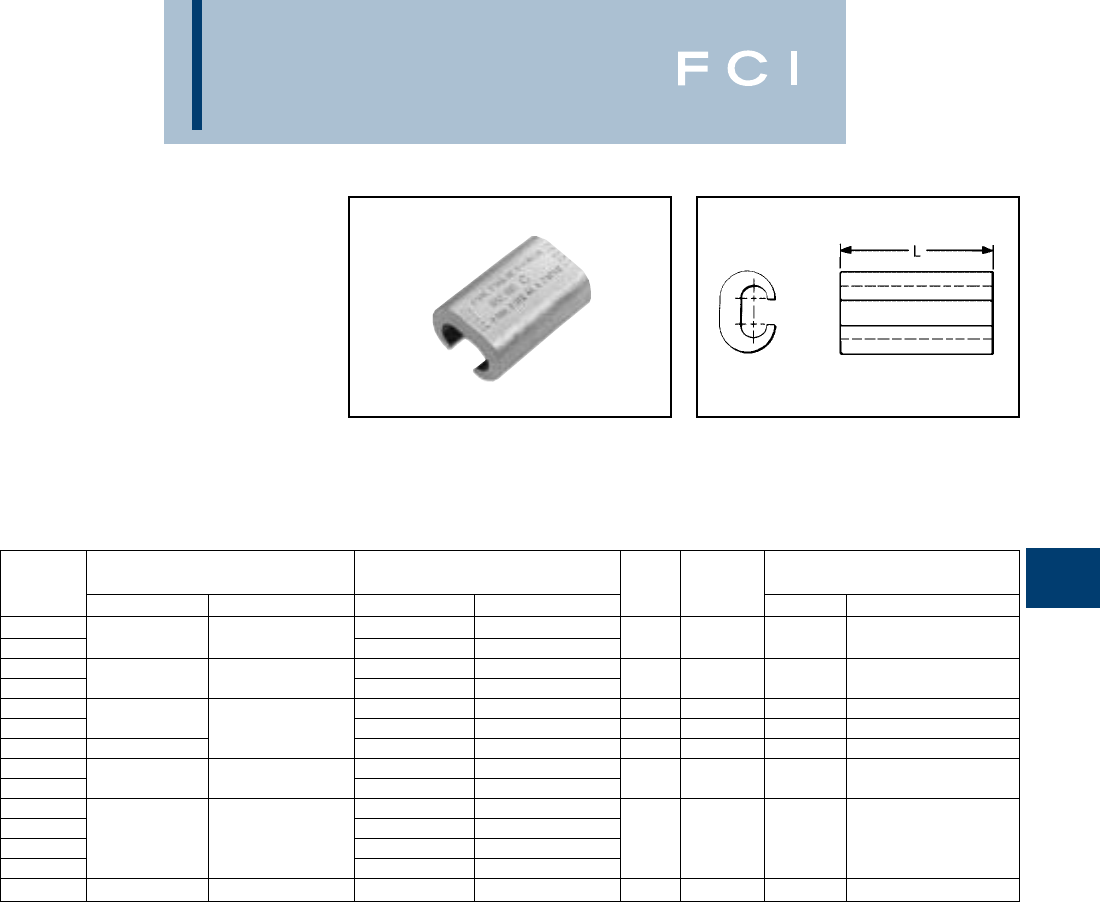
BURNDY
Overhead
E-19
TYPE YC-A
ALUMINUM CRIMPIT™
Line Tap for Combinations of
Aluminum, ACSR, 6201, 5005,
Compressed and
Compact Conductors
Range-taking, C-shaped aluminum compres-
sion tap, or dead-ending connector designed
to eliminate effects of cold flow. Can be
gripped in tool and slipped over line for easy
crimping. Pre-filled with PENETROX™ joint
compound and Stripsealed.
*Multiple crimp die set; makes more than one crimp per tool
compression. Figure indicates number of compressions.
** Index number "D" is not "D3" Cabelok CRIMPIT™ die.
†U Die with adapter PT-6515.
‡U Die with adapter PUADP-1.
TOOLS, DIE SET CATALOG NO.,
CATALOG RUN TAP DIE & (NUMBER OF CRIMPS)
NUMBER ALUMINUM ACSR, 6201, 5005 ALUMINUM ACSR, 6201, 5005 L INDEX MD7, MD6 Y35, Y750, Y45†, Y46‡
YC4A6 6 Sol. & Str. — BG (4)
YC4A4 6 Sol. - 4 Str. 6 4 Sol. & Str. 6 1-1/4 BG or 5/8 W-BG (2)* U-BG (2)*
YC2A4 4 Sol. & Str. 6
YC2A2 2 Sol. & Str. 4 - 2 2 Sol. & Str. 4 - 2 1-1/2 C W-C (4) U-C (2)*
YC25A4 6 Str. - 4 Str. 6 - 4 1-1/2 C W-C (4) U-C (2)*
YC25A2 1/0 Str. 1/0 2 Sol. & Str. 2 2-1/4 C W-C (6) U-C (3)*
YC25A25 1/0 Str. - 2/0 Str. 1/0 Str. - 2/0 Str. 1/0 1-3/4 Q W-Q (6)*
YC26A25 1/0 Str. 1/0
YC26A26 1/0 Str. - 2/0 Str. 1/0 - 2/0 2/0 Str. 2/0 2-1/2 D** — U-D (3)
YC28A2 6 Sol. - 2 Str. 6 - 2
YC28A25 1/0 Str. 1/0
YC28A26 3/0 Str. - 4/0 Str. 3/0 - 4/0 2/0 Str. 2/0 2-3/4 H — U-H (3)
YC28A28 3/0 Str. - 4/0 Str. 3/0 - 4/0
YC33R26 300 - 397.5 336.4 (18-1) (26-7) 2 Str. - 2/0 Str. 2 - 1/0 1-1/2 R — U-R (2)
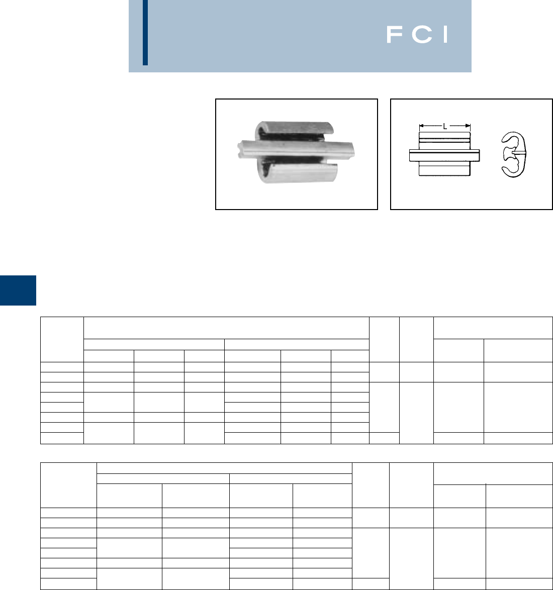
BURNDY
Overhead
E-20
TYPE YP-U
CABELOK CRIMPIT™
Line Tap for Copper,
Aluminum or ACSR
Wide range, universal and reversible, Figure
"3" -shaped aluminum connector with
adjustable overhanging spacer that separates
conductors. Spacer holds run or tap in place
permitting lineman to either approach the line
ready to crimp, or to assemble connector and
tap on run and then crimp. Massive aluminum
design minimizes conductor corrosion due to
galvanic action. Pre-filled with PENETROX™
joint compound and Stripsealed. Conductor
range and tooling information clearly printed
on connector and package.
* TAKE UP to #2 ACSR maximum in either groove if other
wire is #2 solid or smaller.
** TAKES DOWN to #2 ACSR minimum in either groove if
other groove wire is 1/0 stranded or larger.
†U Die with adapter PT-6515.
‡U Die with adapter PUADP-1.
TOOL, DIE SET CATALOG NO.,
CONDUCTOR (SEE CHART BELOW FOR COMPRESSED CONDUCTOR) & (NUMBER OF CRIMPS)
CATALOG GROOVE A GROOVE B DIE Y35, Y750,
NUMBER SOLID STRANDED ACSR SOLID STRANDED ACSR L INDEX MD7, MD6 Y45†, Y46‡
YP2U3* 6, 4, 3, 2 6, 4, 3, 6, 4 6, 4, 3, 2, 6, 4, 3 6, 4
YP26AU2 1, 1/0, 2/0, 3/0 2, 1, 1/0, 2/0 3, 2, 1, 1/0 6, 4, 3, 2, 1, 1/0 6, 4, 3, 2, 1 6 ,4, 3, 2 1-1/2 0 W-O (4) U-O(1)
YP25U25** 2/0, 3/0 1, 1/0, 2/0 1, 1/0 2/0, 3/0 1, 1/0, 2/0 1, 1/0
YP27AU4 6, 4, 3, 2, 6, 4, 3 6, 4
YP27AU2 2/0, 3/0, 4/0 1/0, 2/0, 3/0 1/0, 2/0 2, 1, 1/0 3, 2, 1 4, 3, 2 1-5/8 MD6 (4) U-D3 (1)
YP27AU26 3/0, 4/0 2/0, 3/0 2/0 2/0, 3/0 1/0, 2/0 1, 1/0, 2/0 D3
YP28U2 2, 1, 1/0 4, 3, 2, 1 4, 3, 2
YP28U26 —4/0 3/0, 4/0 2/0, 3/0 1/0, 2/0 1, 1/0, 2/0 3-1/2 MD6 (9) U-D3 (2)
COMPRESSED CONDUCTOR TOOL, DIE SET CATALOG NO.,
GROOVE A GROOVE B & (NUMBER OF CRIMPS)
CATALOG STRANDED STRANDED DIE Y36, Y750,
NUMBER ALUMINUM ACSR ALUMINUM ACSR L INDEX MD7, MD6 Y45†, Y46‡
YP2U3* 6, 4, 3, 2 6, 4, 3 6, 4, 3, 2 6, 4, 3
YP26AU2 2, 1, 1/0, 2/0 2. 1. 1/0, 2/0 6, 4, 3, 2, 1 6, 4, 3, 2, 1 1-1/2 0 W-O (4) U-O (1)
YP25U25** 1/0, 2/0 1/0, 2/0 1/0, 2/0 1/0, 2/0
YP27AU4 6, 4, 3 6, 4, 3
YP27AU2 2/0, 3/0 1/0, 2/0, 3/0 3, 2, 1 4, 3, 2, 1 1-5/8 MD (4) U-D3 (1)
YP27AU26 3/0 2/0, 3/0 1/0, 2/0, 3/0 1/0, 2/0 D3
YP28U2 3, 2, 1 4, 3, 2, 1
YP28U26 4/0, 250, 266.8 4/0, 266.8, (18/1) 1/0, 2/0, 3/0 1/0, 2/0 3-1/2 MD6 (9) U-D3 (1)
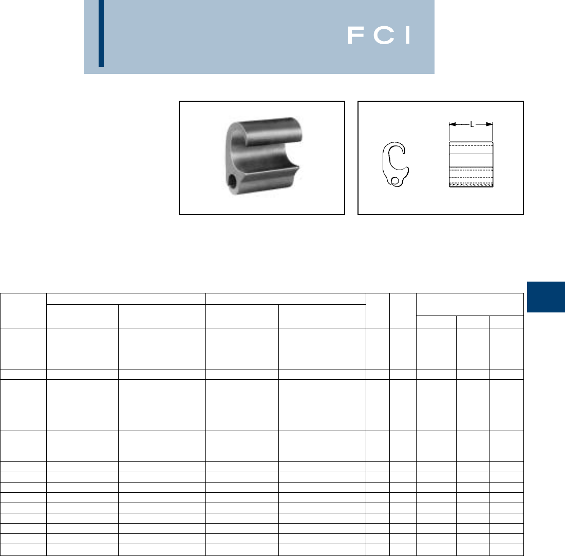
BURNDY
Overhead
E-21
TYPE YPC-U
UNIVERSAL CRIMPIT™
Line Tap for Combinations of
Copper, Aluminum, ACSR,
6201, 5005 and Compressed
and Compact Conductors
Extra wide range universal connector. Two
dies and 5 connectors take run sizes 1/0-600,
and tap sizes 6-400. Wide range made
possible by long ram travel of BURNDY®
HYPRESS™ tools. Figure "6"- shape
separates run and tap wires, and minimizes
galvanic corrosion of conductors. Connector
can be gripped in tool and slipped over line
for easy installation. Pre-filled with
PENETROX™ joint compound and
Stripsealed.
①2/0 Str. Cu Aluminum and 2/0 ACSR may also be installed
in run when tap is 3/0 Str. or larger.
②YPC28U4 only may be installed with MD6 HYTOOL™ and
the BCT500HS with D3groove.
†U Die with adapter PT-6515.
‡U Die with adapter PUADP-1.
RUNTAP TOOLS, DIE SET CATALOG
CATALOG ALUMINUM ALUMINUM DIE NO., & (NUMBER OF CRIMPS)
NUMBER & COPPER ACSR, 5005 & COPPER ACSR, 5005 L INDEX Y35, Y750 Y45† Y46‡
6, 4, 3 Str.
3/0 - 4/0 Str. & 3/0 - 4/0 & 6, 4, 3, 2 Sol. & 6, 4 & 6, 4, 3 D3
YPC28U4 4/0, 250, 266.8 4/0, 266.8 (18/1) 6, 4, 3, Alum. ACSR Compressed 1-5/8 ②U-D3 (1) U-D3 (1) U-D3 (1)
Alum. Compressed ACSR Compressed Compressed
YPC28U26 1/0 (7) - 4/0 (7) 1/0 - 4/0 3 Sol. - 2/0 (7) 4 - 1/0 2-3/4 D3 U-D3 (2) — —
2/0, 3/0, 4/0 Str.
3/0, 4/0 Str. 3/0 - 4/0 & 3/0 - 4/0 4/0 Sol. & 2/0, 3/0, 4/0 &
YPC28U28 4/0 Sol. & 266.8 (18/1) 3/0, 4/0, 250 3/0, 4/0, 266.8 (18/1) 2-3/4 D3 U-D3 (2) U-D3 (2) U-D3 (2)
①4/0, 250, 266.8 ACSR Compressed 266.8 Alum. ACSR Compressed
Alum. Compressed Compressed
3/0, 4/0 Str. & 3/0 - 4/0 & 3/0 - 4/0 Str. &
YPC28R28A 4/0, 250, 266.8 4/0, 266.8 (18/1) 4/0 Alum. 3/0 & 4/0 2-3/4 D3 U-D3 (2) U-D3 (2) U-D3 (2)
Alum. Compressed ACSR Compressed Compressed ACSR Compressed
YPC33R26U 250 (37) - 400 (37) 266.8 (18-1) - 397.5 (18-1) 6 Sol. - 2/0 (19) 6 - 1/0 2-1/8 N U-N (2) S-N (2) P-N (2)
YPC33R28R 250 (37) - 477 (37) 266.8 (18-1) - 397.5 (18-1) 2/0 (19) - 4/0 (19) 2/0 - 4/0 8-7/8 N U-N (3) S-N (3) P-N (3)
YPC33R33R 250 (37) - 400 (37) 266.8 (18-1) - 397.5 (18-1) 250 (37) - 400 (37) 266.8 (18-1) - 397.5 (18-1) 8-7/8 N U-N (3) S-N (3) P-N (3)
YPC38R26U 477 (19) - 600 (61) 397.5 (26-7) - 556.5 (18-1) 6 Sol. - 2/0 (19) 6 - 1/0 2-1/8 N U-N (2) S-N (2) P-N (2)
YPC36A32 397.5 (19) - 600 (61) 336.5 (26-7) - 556.5 (18-1) 2/0 (7) - 400 (37) 2/0 (6-1) - 397.5 (18-1) 5 Z — S-Z (3) —
YPC36A36 397.5 (19) - 600 (61) 336.5 (26-7) - 556.5 (18-1) 397.5 (19) - 600 (61) 397.5 (26-7) - 556.5 (18-1) 6-3/4 Z — S-Z (4) —
YPC40A32 600 (61) - 800 (61) 556.5 (18-1) - 795 (26-7) 2/0 (7) - 400 (37) 2/0 (6-1) - 397.5 (18-1) 5 T — S-T (3) —
YPC40A36 600 (61) - 800 (61) 556.5 (18-1) - 795 (26-7) 397.5 (19) - 600 (61) 336.4 (26-7) - 556.5 (18-1) 5 T — S-T (3) —
YPC40A40 600 (61) - 954 (61) 556.5 (18-1) - 795 (26-7) 600 (61) - 954 (61) 556.5 (18-1) - 795 (26-7) 9-7/8 T — S-T (6) —
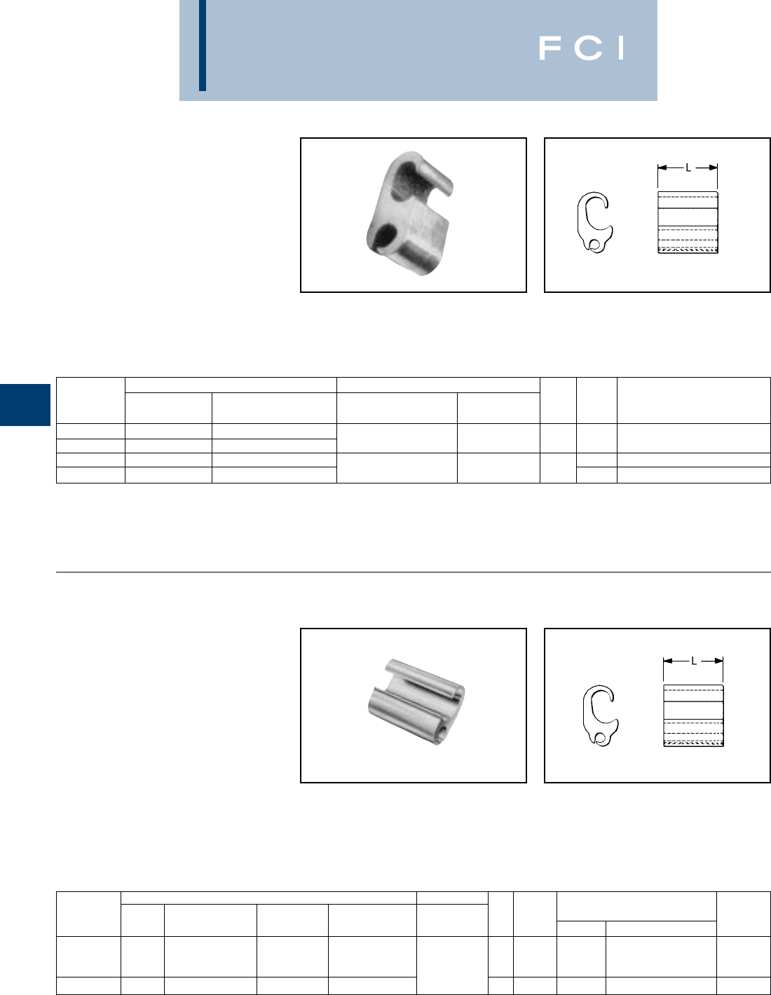
BURNDY
Overhead
E-22
TYPE YC-U
UNIVERSAL CRIMPIT™
Line Tap Combinations of
Copper, Aluminum, ACSR,
6201, 5005 and Compressed
and Compact Conductors
Figure "6" -shaped, wide range-taking
aluminum compression tap connector for
smaller primary service taps and secondary
service drops. Minimizes galvanic corrosion
of conductors. Connector can be gripped in
TYPES YPC-A-U,
YPC-R-U
CRIMPIT™
Street Lighting Tap for
Combinations of Copper,
Aluminum, ACSR, Compressed
and Compact Conductors
Compact compression connector designed to
tap small lighting wires from secondaries.
Figure "6" -shape separates run and tap, and
minimizes galvanic corrosion. Connector can
*Multiple crimp die set, makes more than one crimp per tool
compression. Figure indicates number of compressions.
†U Die with adapter PT-6515.
‡U Die with adapter PUADP-1.
*Die Index "D" is not Die Index "D3" (Cabelok & Universal
CRIMPIT™ Die).
†U Die with adapter PT-6515.
‡U Die with adapter PUADP-1.
RUNTAP TOOLS, DIE SET CATALOG
CATALOG ALUMINUM ALUMINUM DIE NO., & (NUMBER OF CRIMPS)
NUMBER & COPPER ACSR, 6201, & 5005 ACSR, 6201, & 5005 & COPPER L INDEX Y35, Y750, Y45†, Y46‡
YC4U1 4 Sol. - 4 Str. 4
YC1U1 2 Str. - 1 Str. 2 6 - 1 Str. 6 Sol. - 2 Str. 1-7/8 D* U-D (2)
YC28U26 1/0 Str. - 4/0 Str. 1/0 - 4/0 H U-H (2)
YC33R26U 300 - 400 266.8 (6-7) - 336.4 (30-7) 6 - 1/0 6 Sol. - 2/0 Str. 2-1/8 RU-R (2)
RUNTAP TOOLS, DIE SET CATALOG
CATALOG COMPRESSED ALUMINUM COMPRESSED ALUMINUM DIE NO., & (NUMBER OF CRIMPS)
NUMBER ACSR ACSR & COPPER ALUMINUM & COPPER L INDEX
MD7, MD6
Y35, Y750, Y45†, Y46‡
OUR840
BG
YPC2A8U 6 - 4 6 - 2 4 - 2 Sol. 4 - 2 5/8 or BG (2) U-BG (1)* XBG
6 - 2 Str. 14 Sol. - 8 Str. 5/8 W-BG (1)*
YPC26R8U 2 - 3/0 1 - 3/0 1 - 3/0 Str. 1/0 - 3/0 3/4 0 W-O (2) U-O (1) W-O
be gripped in tool and slipped over line for
easier installation. Pre-filled with
PENETROX™ joint compound and
Stripsealed.
tool and slipped over line for easy installation.
Installed with aluminum CRIMPIT™ dies.
Pre-filled with PENETROX™ joint compound
and Stripsealed.
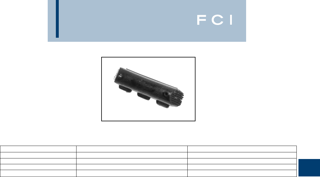
BURNDY
Overhead
E-23
TYPE CC
CRIMPIT™ COVER
For All O, D and N Die Tap
Connectors
High density polyethylene cover accommo-
dates most industry connectors in the O, D
and N range. Four sizes cover the full #6-600
kcmil conductor range. One piece design. No
extra hardware needed. Simply slip over
connector and snap shut. Supplied in Black.
CATALOG NUMBER MAXIMUM CONNECTOR LENGTH CONNECTOR SERIES ACCOMMODATED
CCO 2-1/2 O Die
CCD 2-3/4 D Die
CCN 2-1/8 Short N Die
CCNL 5-3/16 Long N Die and YP28U26
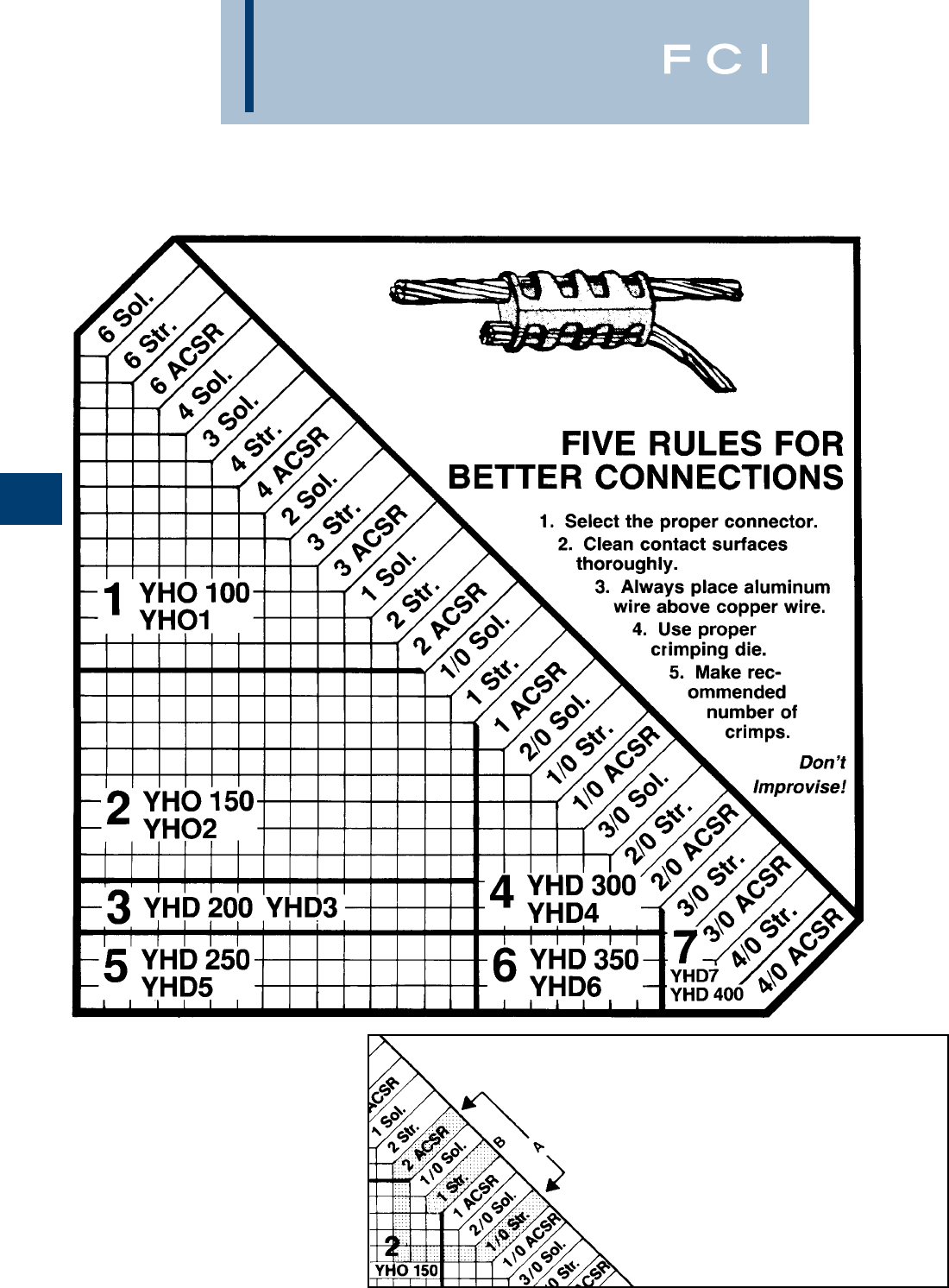
BURNDY
Overhead
E-24
SEVEN CONNECTOR
SELECTOR CHART
For Compression
Tap Connectors
BURNDY®HYCRIMP™
and LOKTAP™
THREE SIMPLE
SELECTION STEPS
1. Follow down from the smaller wire.
2. Across from the larger wire.
3. Intersection is in the area of the
proper connector.
Example:
A. For #2 ACSR to #1/0 Str.
select No. 2 connector.
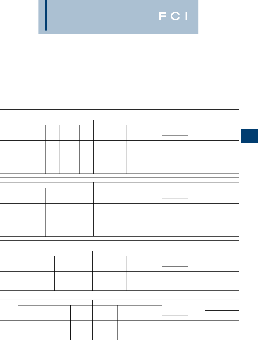
BURNDY
Overhead
E-25
TYPES YHO & YHD
HYCRIMP™
Line Tap for Copper, Aluminum or
ACSR and Compact Conductors
Wide range, universal and reversible figure H
shaped aluminum connector. Conductors are
separated by the shape of the connector.
Bendable tabs secure both run and tap
conductors freeing the linemans hands to
work with the installation tool. Massive
aluminum design minimizes corrosion
due to galvanic corrosion. Prefilled with
†U Die with adapter PT-6515
‡U Die with adapter PUADP.
①See page E-25 for Seven Connector Selector Chart.
②Permanent dies in tool install all sizes.
PENETROX™ joint compound and individually
packaged. Conductor ranges and tooling
clearly printed on connector and package.
HANDTOOL OR HYDRAULIC 7 CONNECTOR PROGRAM
CONDUCTORS (SEE BELOW FOR COMPACT CONDUCTORS) INSTALLATION DATA
GROOVE A (RUN) GROOVE B (TAP) TOOL, DIE SET CAT.
①
WIRE WIRE NO. & (NO. OF CRIMPS)
CATALOG CODE DIAMETER DIAMETER DIMENSIONS DIE MD7-8 Y35, Y750,
NUMBER NO. RANGE SOL. STR. ACSR RANGE SOL. STR. ACSR H L W INDEX MD6-8 Y45†, Y46‡
YHO-100 1.162 - .332 #6 - #1 #6 - #1; 7 Str. #6 - #2 .162 - .332 #6 - #1 #6 - #1, 7 Str. #6 - #2 1.12 1.50 .70 O (4) U-O (2)
YHO-150 2.260 - .419 #1 - 2/0 #3.3 Str. - 2/0 #3 - 1/0 .162 - .332 #6 - 1/0 #6 - 1, 19 Str. #6 - #2 1.12 1.75 .70 O (5) U-O (2)
YHD-200 3.398 - .470 3/0 - 4/0 2/0 - 3/0 1/0 - 2/0 .162 - .332 #6 - 1/0 #6 - #1, 19 Str. #6 - #2 1.44 1.88 .89 D3 (5) UD3 (2)
YHD-250 5.475 - .563 250 - 300 4/0 3/0 - 4/0 .162 - .332 #6 - 1/0 #6 - #1, 19 Str. #6 - #2 1.47 1.88 .89 D3
②
(5) UD3 (2)
YHD-300 4.336 - .470 2/0 - 4/0 #1, 3 Str. - 3/0 #1 - 2/0 .336 - .447 2/0 - 3/0 #1, 3 Str. - 2/0 #1 - 2/0 1.42 1.88 .89 D3 (5) UD3 (2)
YHD-350 6.461 - .563 250 - 300 3/0 - 4/0 3/0 - 4/0 .338 - .447 2/0 - 3/0 #1, 3 Str. - 2/0 #1 - 2/0 1.42 2.50 .89 D3 (7) UD3 (3)
YHD-400 7.461 - .563 250 - 200 3/0 - 4/0 3/0 - 4/0 .461 - .563 250 - 300 3/0 - 4/0 3/0 - 4/0 1.49 2.50 .89 D3 (7) UD3 (3)
COMPACT CONDUCTORS INSTALLATION DATA
GROOVE A (RUN) GROOVE B (TAP) TOOL, DIE SET CAT.
①
WIRE WIRE NO. & (NO. OF CRIMPS)
CATALOG CODE DIAMETER COMPACT DIAMETER COMPACT DIMENSIONS DIE Y35, Y750,
NUMBER NO. RANGE COMPACT ACSR CU or AL RANGE COMPACT ACSR CU or AL H L W INDEX MD6-8 Y45†, Y46‡
YHO-100 1.162 - .336 #6 - #3 #6 - #1 .162 - .268 #6 - #3 #6 - #1 1.12 1.50 .70 O (4) U-O (2)
YHO-150 2.260 - .414 #2 - 1/0 #2 - 2/0 .162 - .332 #6 - #1 #6 - #1 1.12 1.75 .70 O (5) U-O (2)
YHD-200 3.398 - .470 2/0 - 3/0 3/0 .162 - .332 #6 - #1 #6 - #1 1.44 1.88 .89 D3 (5) UD3 (2)
YHD-250 5.475 - .563 4/0 - 266 (18/1) 4/0 - 266 .162 - .332 #6 - #1 #6 - #1 1.47 1.88 .89 D3
②
(5) UD3 (2)
YHD-300 4.336 - .470 1/0 - 3/0 1/0 - 3/0 .338 - .477 1/0 - 2/0 1/0 - 3/0 1.42 1.88 .89 D3 (5) UD3 (2)
YHD-350 6.461 - .563 3/0 - 266 (18/1) 4/0 - 266 .338 - .447 1/0 - 2/0 1/0 - 3/0 1.42 2.50 .89 D3 (7) UD3 (3)
YHD-400 7.461 - .563 3/0 - 266 (18/1) 4/0 - 266 .461 - .563 3/0 - 266 (18/1) 4/0 - 266 1.49 2.50 .89 D3 (7) UD3 (3)
HYDRAULIC TOOL ONLY 4 CONNECTOR PROGRAM
CONDUCTORS (SEE BELOW FOR COMPACT CONDUCTORS) INSTALLATION DATA
GROOVE A (RUN) GROOVE B (TAP) TOOL, DIE SET CAT.
WIRE WIRE NO. & (NO. OF CRIMPS)
CATALOG DIAMETER DIAMETER DIMENSIONS DIE Y35, Y750,
NUMBER RANGE SOL. STR. ACSR RANGE SOL. STR. ACSR H L W INDEX Y45†, Y46‡
YHO-125 .162 - .398 #6 - 2/0 #6 - 1/0 #6 - 1/0 .162 - .332 #6 - 1/0 #6 - #1, 19 Str. #6 - #2 1.15 1.62 .70 O U-O (2)
YHD-250 .338 - .563 2/0 - 300 #1.3 Str. - 4/0 #1 - 4/0 .162 - .332 #6 - 1/0 #6 - #1, 19 Str. #6 - #2 1.47 1.88 .89 D3 UD3 (2)
YHD-350 .338 - .563 2/0 - 300 #1, 3 Str. - 4/0 #1 - 4/0 .338 - .477 2/0 - 3/0 #1, 3 Str. - 2/0 #1 - 2/0 1.42 2.50 .89 D3 UD3 (3)
YHD-400 .426 - .563 4/0 - 300 3/0 - 4/0 2/0 - 4/0 .426 - .563 4/0 - 300 3/0 - 4/0 2/0 - 4/0 1.49 2.50 .89 D3 UD3 (3)
COMPACT CONDUCTORS INSTALLATION DATA
GROOVE A (RUN) GROOVE B (TAP) TOOL, DIE SET CAT.
WIRE WIRE NO. & (NO. OF CRIMPS)
CATALOG DIAMETER COMPACT COMPACT DIAMETER COMPACT COMPACT DIMENSIONS DIE Y35, Y750,
NUMBER RANGE ACSR CU or AL RANGE ACSR CU or AL H L W INDEX Y45†, Y46‡
YHO-125 .162 - .398 #6 - 1/0 #6 - 2/0 .162 - .332 #6 - #1 #6 - #1 1.15 1.62 .70 O U-O (2)
YHD-250 .338 - .563 1/0 - 266 (18/1) 1/0 - 266 .162 - .332 #6 - #1 #6 - #1 1.47 1.88 .89 D3 UD3 (2)
YHD-350 .338 - .563 1/0 - 266 (18/1) 1/0 - 266 .336 - .477 1/0 - 2/0 1/0 - 3/0 1.42 2.50 .89 D3 UD3 (3)
YHD-400 .426 - .563 3/0 - 266 (18/1) 3/0 - 266 .426 - .563 3/0 - 266 (18/1) 3/0 - 266 1.49 2.50 .89 D3 UD3 (3)
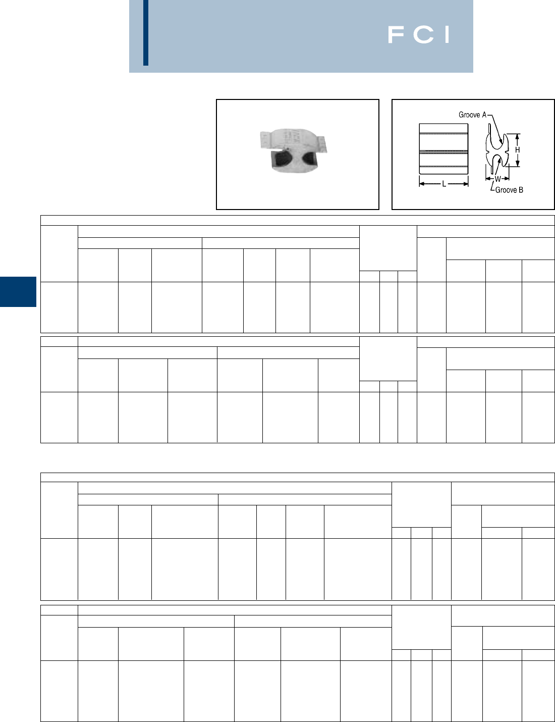
BURNDY
Overhead
E-26
TYPE YHN & YHR
HYCRIMP™
Line Tap for Copper, Aluminum
or ACSR and Compact
Conductors
*HYCRIMP™ connectors can be installed with competitive
R dies.
** DIE INDEX S-T and S-Z may also be used on sizes 700-
900 only. S-KR required for 950 and S-Z.
N DIE CONNECTORS*
CONDUCTORS (SEE BELOW FOR COMPACT CONDUCTORS) INSTALLATION DATA
GROOVE A (RUN) GROOVE B (TAP) TOOL, DIE SET CAT.
WIRE WIRE NO. & (NO. OF CRIMPS)
CATALOG DIAMETER DIAMETER DIMENSIONS DIE Y35,
NUMBER RANGE STR. ACSR RANGE SOL. STR. ACSR H L W INDEX Y750 Y45 Y46
YHN-450 .522 - .750 4/0 - 400 4/0 - 397 (18/1) .522 - .750 336 - 477 4/0 - 400 4/0 - 397 (18/1) 2.05 3.50 1.25 N U-N (3) S-N (3) P-N (3)
YHN-500 .522 - .815 4/0 - 500 4/0 - 477 (18/1) .160 - .450 #6 - 3/0 #6 - 2/0 #6 - 2/0 2.00 2.00 1.28 N U-N (2) S-N (2) P-N (2)
YHN-525 .814 - .522 4/0 - 500 4/0 - 477 (18/1) .814 - .522 — 4/0 - 500 4/0 - 477 (18/1) 1.824 4.50 1.23 N U-N (3) S-N (3) P-N (3)
YHN-550 .573 - .815 250 - 500 266 - 477 (18/1) .410 - .505 3/0 - 300 2/0 - 4/0 2/0 - 4/0 1.96 2.00 1.28 N U-N (2) S-N (2) P-N (2)
YHN-600 .573 - .815 250 - 500 266 - 477 (18/1) .570 - .685 336 - 400 250 - 350 266 - 336.4 (18/1) 2.00 3.50 1.28 N U-N (3) S-N (3) P-N (3)
COMPACT CONDUCTORS INSTALLATION DATA
GROOVE A (RUN) GROOVE B (TAP) TOOL, DIE SET CAT.
WIRE WIRE NO. & (NO. OF CRIMPS)
CATALOG DIAMETER COMPRESSED COMPACT DIAMETER COMPRESSED COMPACT DIMENSIONS DIE Y35,
NUMBER RANGE ACSR CU or AL RANGE ACSR CU or AL H L W INDEX Y750 Y45 Y46
YHN-450 .522 - .750 226 - 477 (18/1) 250 - 500 .522 - .750 266 - 477 (18/1) 250 - 500 2.05 3.50 1.25 N U-N (3) S-N (3) P-N (3)
YHN-500 .522 - .815 266 - 556 250 - 556 .160 - .450 #6 - 2/0 #6 - 3/0 2.00 2.00 1.28 N U-N (2) S-N (2) P-N (2)
YHN-525 .814 - .522 266.8 - 556.5 250 - 556 .814 - .522 266.8 - 556.5 250 - 556 1.824 4.50 1.23 N U-N (3) S-N (3) P-N (3)
YHN-550 .573 - .815 300 - 556 300 - 556 .410 - .565 2/0 - 266 3/0 - 266 1.96 2.00 1.28 N U-N (2) S-N (2) P-N (2)
YHN-600** .573 - .815 300 - 556 300 - 556 .570 - .685 300 - 397 300 - 397 2.00 3.50 1.28 N U-N (3) S-N (3) P-N (3)
R DIE CONNECTORS*
CONDUCTORS (SEE BELOW FOR COMPACT CONDUCTORS)
GROOVE A (RUN) GROOVE B (TAP) INSTALLATION DATA
WIRE WIRE TOOL, DIE SET CAT.
CATALOG DIAMETER DIAMETER DIMENSIONS DIE NO. & (NO. OF CRIMPS)
NUMBER RANGE STR. ACSR RANGE SOL. STR. ACSR H L W INDEX Y45 Y46
YHR-700 .666 - .893 336 - 600 300 - 556 (18/1) .398 - .684 3/0 - 350 2/0 - 350 1/0 - 336.4 (18/1) 3.04 3.50 1.74 KR S-KR (3) P-KR (3)
YHR-750 .666 - .893 336 - 600 300 - 556 (18/1) .666 - .893 — 300 - 600 300 - 556 (18/1) 3.04 4.62 1.74 KR S-KR (4) P-KR (4)
YHR-800 .879 - 1.108 600 - 900 556.5 (18/1) - 795 (26/7) .398 - .684 3/0 - 350 2/0 - 350 1/0 - 336.4 (18/1) 3.05 3.50 1.74 KR S-KR (3) P-KR (3)
YHR-850 .879 - 1.108 600 - 900 556.5 (18/1) - 795 (26/7) .666 - .893 — 336 - 600 300 - 556 (18/1) 3.04 4.62 1.74 KR S-KR (4) P-KR (4)
YHR-900 .879 - 1.108 600 - 900 556.5 (18/1) - 795 (26/7) .879 - 1.108 — 600 - 900 556.5 (18/1) - 795 (26/7) 2.97 4.62 1.74 KR S-KR (4) P-KR (4)
YHR-950 .666 - 1.165 336.4 - 1000 556.5 (18/1) - 795 (26/7) .666 - 1.165 — 336.4 - 1000 336.4 (18/1) - 954 (45/7) 3.14 6.00 1.66 KR S-KR (5) P-KR (5)
COMPACT CONDUCTORS
GROOVE A (RUN) GROOVE B (TAP) INSTALLATION DATA
WIRE WIRE TOOL, DIE SET CAT.
CATALOG DIAMETER COMPRESSED COMPACT DIAMETER COMPRESSED COMPACT DIMENSIONS DIE NO. & (NO. OF CRIMPS)
NUMBER RANGE ACSR CU or AL RANGE ACSR CU or AL H L W INDEX Y45 Y46
YHR-700 .666 - .893 397 - 636 477 - 636 .398 - .684 2/0 - 397 (18/1) 3/0 - 397.5 3.04 3.50 1.74 KR S-KR (3) P-KR (3)
YHR-750 .666 - .893 397 - 636 477 - 636 .666 - .893 397 - 636 477 - 636 3.04 4.62 1.74 KR S-KR (4) P-KR (4)
YHR-800 .879 - 1.108 795 - 954 795 - 954 .398 - .684 2/0 - 397 (18/1) 3/0 - 397.5 3.05 3.50 1.74 KR S-KR (3) P-KR (3)
YHR-850 .879 - 1.108 795 - 954 795 - 954 .666 - .893 397 - 636 477 - 636 3.04 4.62 1.74 KR S-KR (4) P-KR (4)
YHR-900 .879 - 1.108 795 - 954 795 - 954 .879 - 1.108 795 - 954 795 - 954 2.97 4.62 1.74 KR S-KR (4) P-KR (4)
YHR-950 .666 - 1.165 — — .666 - 1.165 — — 3.14 6.00 1.66 KR S-KR (5) P-KR (5)
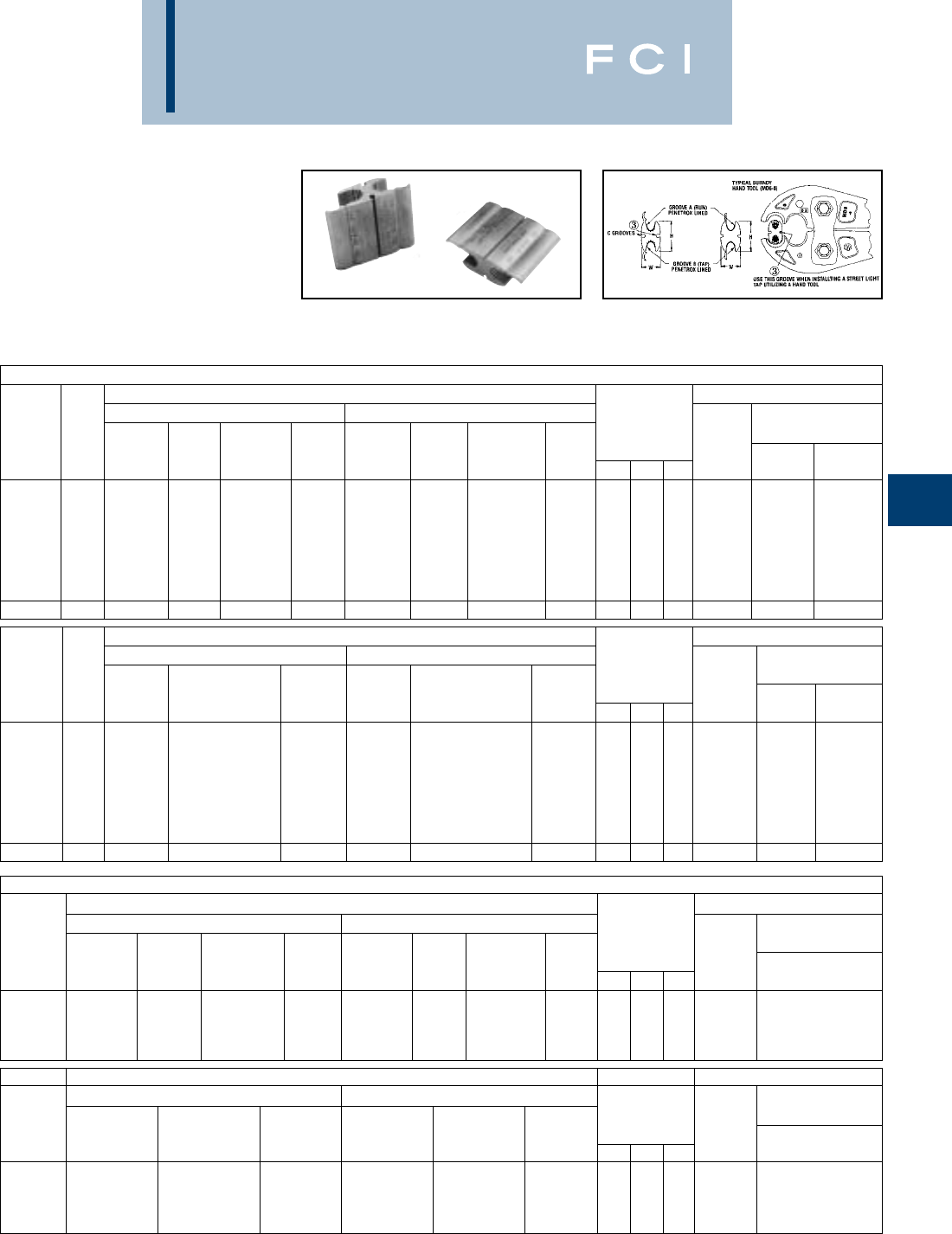
BURNDY
Overhead
E-27
LOKTAP™
LOKTAP™ compression connectors are high
quality, range-taking devices which accom-
modate combinations of aluminum to copper,
and aluminum to aluminum conductors.
BURNDY®seven connector program accom-
modates a conductor range from #6 Sol. to
4/0 ACSR. In addition, LOKTAP™ products
feature a "C" groove on both sides of the
connector for use in street lighting applica-
tions from #14 Sol. to #10 Sol.
** YHO-10: These ranges are for aluminum only.
Use only #4 Str. concentric copper tap.
† U Die with adapter PT-6515.
‡ U Die with adapter PUADP-1.
installation. When utilizing two (2) "C" groove taps, installa-
tion to be made with HYDRAULIC TOOL ONLY. All four (4)
grooves CANNOT be utilized if using a hand tool. When
hand tool is used, only one (1) "C" groove can be utilized
and connector MUST be positioned as shown in FIG.5
HANDTOOL OR HYDRAULIC 7 CONNECTOR PROGRAM
①
CONDUCTORS (SEE BELOW FOR COMPACT CONDUCTORS) INSTALLATION DATA
GROOVE A (RUN) GROOVE B (TAP) TOOL, DIE SET CAT.
①
WIRE WIRE NO. & (NO. OF CRIMPS)
CATALOG CODE DIAMETER DIAMETER DIMENSIONS DIE Y35, Y750,
NUMBER NO. RANGE SOL. STR. ACSR RANGE SOL. STR. ACSR H L W INDEX MD7, MD6 Y45†, Y46‡
YHO-1 1.162 - .332 #6 - #1 #6 - #1, 7 Str. #6 - #2 .162 - .332 #6 - #1 #6 - #1, 7 Str. #6 - #2 1.11 1.35 .67 O (4) U-O (2)
YHO-2 2.260 - .419 #1 - 2/0 #3.3 Str. - 2/0 #3 - 1/0 .162 - .332 #6 - 1/0 #6 - #1, 19 Str. #6 - #2 1.12 1.69 .64 O (5) U-O (2)
YHD-3 3.398 - .470 3/0 - 4/0 2/0 - 3/0 1/0 - 2/0 .162 - .332 #6 - 1/0 #6 - #1, 19 Str. #6 - #2 1.47 1.88 .76 D3 (5) UD3 (2)
YHD-5 5.475 - .563 250 - 300 4/0 3/0 - 4/0 .162 - .332 #6 - 1/0 #6 - #1, 19 Str. #6 - #2 1.47 1.88 .87 D3 (5) UD3 (2)
YHD-4 4.336 - .470 2/0 - 4/0 #1, 3 Str. - 3/0 #1 - 2/0 .336 - .477 2/0 - 3/0 #1, 3 Str. - 2/0 #1 - 2/0 1.42 1.88 .83 D3
②
(5) UD3 (2)
YHD-6 6.461 - .563 250 - 300 3/0 - 4/0 3/0 - 4/0 .336 - .447 2/0 - 3/0 #1, 3 Str. - 2/0 #1 - 2/0 1.42 2.25 .83 D3 (6) UD3 (3)
YHD-7 7.461 - .563 250 - 300 3/0 - 4/0 3/0 - 4/0 .461 - 563 250 - 300 3/0 - 4/0 3/0 - 4/0 1.40 2.52 .84 D3 (7) UD3 (3)
YHD-10** —.232 - .419** #2 - #1** #4 - 2/0** #4 - 1/0 .232 - .419** #2 - #1** #4 - 2/0** #4 - 1/0 1.18 1.50 .68 O (4) U-O (2)
COMPACT CONDUCTORS INSTALLATION DATA
GROOVE A (RUN) GROOVE B (TAP) TOOL, DIE SET CAT.
①
WIRE WIRE NO. & (NO. OF CRIMPS)
CATALOG CODE DIAMETER COMPACT DIAMETER COMPACT DIMENSIONS DIE Y35, Y750,
NUMBER NO. RANGE COMPACT ACSR CU or AL RANGE COMPACT ACSR CU or AL H L W INDEX MD6 Y45†, Y46‡
YHO-1 1.162 - .332 #6 - #1 #6 - #1 .162 - .332 #6 - #1 #6 - #1 1.11 1.35 .67 O (4) U-O (2)
YHO-2 2.260 - .419 #2 - 1/0 #2 - 2/0 .162 - .332 #6 - #1 #6 - #1 1.12 1.69 .64 O (5) U-O (2)
YHD-3 3.398 - .470 2/0 - 3/0 3/0 .162 - .332 #6 - #1 #6 - #1 1.47 1.88 .76 D3 (5) UD3 (2)
YHD-5 5.475 - .563 4/0 - 266 (18/1) 4/0 - 256 .162 - .332 #6 - #1 #6 - #1 1.47 1.88 .87 D3 (5) UD3 (2)
YHD-4 4.336 - .470 1/0 - 3/0 1/0 - 3/0 .338 - .447 1/0 - 2/0 1/0 - 3/0 1.42 1.88 .83 D3
②
(5) UD3 (2)
YHD-6 6.461 - .563 3/0 - 266 (18/1) 4/0 - 266 .338 - .447 1/0 - 2/0 1/0 - 3/0 1.42 2.25 .83 D3 (6) UD3 (3)
YHD-7 7.461 - .563 3/0 - 266 (18/1) 4/0 - 266 .461 - 563 3/0 - 266 (18/1) 4/0 - 266 1.40 2.52 .84 D3 (7) UD3 (3)
YHO-10** —.232 - .419** #4 - 2/0 #2 - 2/0** .232 - .419** #4 - 2/0 #2 - 2/0** 1.18 1.50 .68 O (4) U-O (2)
HYDRAULIC TOOL ONLY 4 CONNECTOR PROGRAM
CONDUCTORS (SEE BELOW FOR COMPACT CONDUCTORS) INSTALLATION DATA
GROOVE A (RUN) GROOVE B (TAP) TOOL, DIE SET CAT.
WIRE WIRE NO. & (NO. OF CRIMPS)
CATALOG DIAMETER DIAMETER DIMENSIONS DIE Y35, Y750,
NUMBER RANGE SOL. STR. ACSR RANGE SOL. STR. ACSR H L W INDEX Y45†, Y46‡
—.162 - .398 #6 - 2/0 #6 - 1/0 #6 - 1/0 .162 - .332 #6 - 1/0 #6 - #1, 19 Str. #6 - #2 1.15 1.62 .70 O U-O (2)
YHD-5 .336 - .563 2/0 - 300 #1.3 Str. - 4/0 #1 - 4/0 .162 - .332 #6 - 1/0 #6 - #1, 19 Str. #6 - #2 1.47 1.88 .87 D3 UD3 (2)
YHD-6 .336 - .563 2/0 - 300 #1, 3 Str. - 4/0 #1 - 4/0 .336 - .477 2/0 - 3/0 #1.3 Str. - 2/0 #1 - 2/0 1.42 2.25 .83 D3 UD3 (3)
YHD-7 .414 - .563 4/0 - 300 3/0 - 4/0 2/0 - 4/0 .461 - .563 4/0 - 300 3/0 - 4/0 2/0 - 4/0 1.40 2.52 .86 D3 UD3 (3)
COMPACT CONDUCTORS INSTALLATION DATA
GROOVE A (RUN) GROOVE B (TAP) TOOL, DIE SET CAT.
WIRE WIRE NO. & (NO. OF CRIMPS)
CATALOG DIAMETER COMPACT COMPACT DIAMETER COMPACT COMPACT DIMENSIONS DIE Y35, Y750,
NUMBER RANGE ACSR CU or AL RANGE ACSR CU or AL H L W INDEX Y45†, Y46‡
—.162 - .398 #6 - 1/0 #6 - 2/0 .162 - .332 #6 - #1 #6 - #1 1.15 1.62 .70 O U-O (2)
YHD-5 .336 - .563 1/0 - 266 (18/1) 1/0 - .256 .162 - .332 #6 - #1 #6 - #1 1.47 1.88 .87 D3 UD3 (2)
YHD-6 .336 - .563 1/0 - 266 (18/1) 1/0 - .256 .336 - .447 1/0 - 2/0 1/0 - 3/0 1.42 2.25 .83 D3 UD3 (3)
YHD-7 .414 - .563 3/0 - 266 (18/1) 3/0 - .256 .414 - .563 3/0 - .266 (18/1) 3/0 - 266 1.40 2.52 .86 D3 UD3 (3)
LOKTAP™ connectors are designed to be
installed with BURNDY®mechanical or
hydraulic tools and matching O and D3die set.
①See page E-25 for Seven Connector Selector Chart.
②PERMANENT DIES IN TOOL INSTALL ALL SIZES.
③"C" grooves accommodate #10 Sol. - #14 Sol. RANGE,. 116
in.-.064 in. No "C" grooves on CAT. NO. YH0125. When
utilizing "C" groove(s) apply PENETROX™ A13 prior to wire
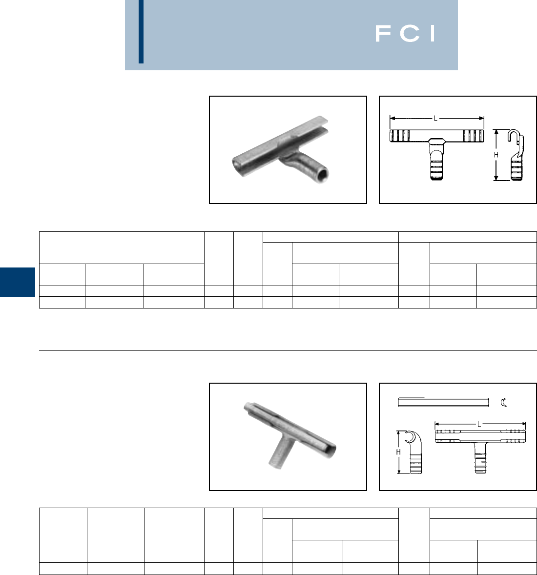
BURNDY
Overhead
E-28
TYPE YCT
HYTEE
T-Tap for Copper
One-piece, copper compression tap connec-
tor with U-shaped run element and tubular
tap for joining hard and medium-hard drawn
copper. Preformed run element simplifies
installation on larger conductors. Uses same
die as equivalent full-tension sleeve.
TYPE YOT
HYTEE
T-Tap for Copper
Cast copper T-tap connector with two-piece
line element and tubular tap for joining hard
and medium drawn copper. Design simplifies
installation on large conductors. Uses same
die as equivalent sleeve.
†U Die with adapter PT-6515.
‡U Die with adapter PUADP-1.
†U Die with adapter PT-6515
‡U Die with adapter PUADP-1.
RUN TAP
TOOLS, DIE SET CATALOG TOOLS, DIE SET CATALOG
CONDUCTORS NO., & (CRIMPS PER END) NO., & (CRIMPS PER END)
CATALOG DIE Y35, Y750, DIE Y35, Y750,
NUMBER RUN TAP H L INDEX MD7, MD6 Y45†, Y46‡ INDEX MD6 Y45†, Y46‡
YCT2626 2/0 (7, 12, 19) 2/0 (7, 12, 19) 3.26 5.62 166 W166 (4) U166/U459 (2) 166 W166 (6) U-166 (3)
YCT2828 4/0 (7, 12, 19) 4/0 (7, 12, 19) 4 5.72 168 U168 (2) 168 U-168 (3)
RUN TAP
TOOLS, DIE SET CATALOG TOOLS, DIE SET CATALOG
NO., & (CRIMPS PER END) NO., & (CRIMPS PER END)
CATALOG DIE Y35, Y750, DIE Y35, Y750,
NUMBER RUN TAP H L INDEX Y45†, Y46‡ Y60B INDEX Y45†, Y46‡ Y60BHU
YOT3434 500 (19, 37) 500 (19, 37) 4.82 10.38 210 U210 (6) L210 (2) 210 U210 (6) L210 (2)
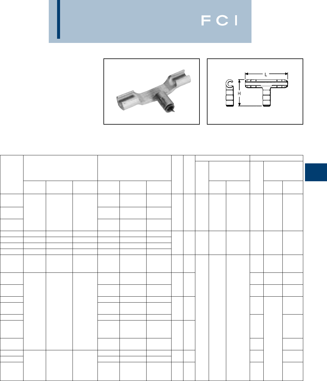
BURNDY
Overhead
E-29
TYPE YTU-R-R
T-Tap for Combinations of
Aluminum, Copper, ACSR,
6201, 5005 Compressed and
Compact Conductors
One-piece heavy-wall aluminum compression
tap connector for secondary service drop and
transformer tap to primary or secondary.
Connector can be gripped in tool for easy
installation. Pre-filled with PENETROX™
joint compound.
*Multiple crimp die set, makes more than one crimp per tool
compression. Figure indicates number of compressions.
†U Die with adapter PT-6515
‡U Die with adapter PUADP-1.
RUN TAP
TOOLS, DIE SET TOOLS, DIE SET
CATALOG NUMBER, CATALOG NUMBER,
RUNTAP & (CRIMPS PER END) & (CRIMPS PER END)
CATALOG ACSR, 6201, ACSR, 6201, DIE MD7, Y35, Y750, DIE MD7, Y35, Y750,
NUMBER 5005 ALUMINUM COPPER 5005 ALUMINUM COPPER H L INDEX MD6 Y45†, Y46‡ INDEX MD6 Y45, Y46‡
#4 (7) #4 (3, 7)
YTU25R2W #4 #2 SLD #2 SLD
1/0 #4 (7) #4 (7) BG (3)
YTU25R4W 80 (8-1) 1/0 (7, 19) 1/0 (7, 12, 19) #6 #4 SLD #4 SLD 2-3/8 4-7/8 C W-C (2) U-C (1)* BG W-BG (1)* U-BG (1)*
1/0
YTU25R25R 80 (8-1) 1/0 (7, 19) —
YTU26R26R 2/0 2/0 (7, 19) 2/0 (7, 12, 19) 2/0 2/0 (7, 19) 2/0 (7, 12, 19)
YTU27R27R 3/0 3/0 (7, 19) 3/0 (7, 12, 19) 3/0 3/0 (7, 19) 3/0 (7, 12, 19)
YTU28R25R 4/0 (6-1) 4/0 (7, 19) 4/0 (7, 12, 19) 1/0 (6-1) 1/0 (7, 19) 1/0 (7, 12, 19) 3-3/8 7 L W-L (4) U-L (2) L — U-L (2)
YTU28R28R 4/0 4/0 (7, 19) 4/0 (7, 12, 19) 4/0 4/0 (7, 19) 4/0 (7, 12, 19)
266.8 266.7 (7, 19, 37) 266.7 (7, 19, 37)
YTU30R30R (18-1, 26-7, 250 (19, 37) 250 (12, 19, 37) 266.8 (18-1, 250 (19, 37) 250 (12, 19, 37) 4-3/8 8-3/4 M — U-M (3)
6-7) 300 (19, 37) 300 (19, 37) 26-7, 6-7) 300 (19, 37)
BG (3)
YTU321R2R 22 (7 Str.) 2 (3, 7 Str.) BG W-BG (1)* U-BG (1)*
1/0 2-5/8 6-5/8
YTU321R25R 80 (8-1) 1/0 (7, 19) 1/0 (7, 12, 19) C W-C (3) U-C (1)*
YTU321R26R 2/0 2/0 (7, 19) 2/0 (7, 12, 19)
LU-L (2)
YTU321R27R 300 (26-7) 350 (19, 37) 350 (19, 37) 3/0 3/0 (7, 19) 3/0 (7, 12, 19) 3-1/2 8-5/8
YTU321R28R 336.4 (18-1) 336.4 (19, 37) 4/0 4/0 (7, 19) 4/0 (7, 12, 19) M — U-M (3)
266.7 (7, 19, 37)
YTU321R30R 266.8 (18-1, 250 (19, 37) 250 (12, 19, 37) M U-M (3)
26-7, 6-7) 300 (19, 37) 300 (19, 37) 4-3/8 8-3/4
336.4 (18-1) 336.4 (19, 37) —
YTU321R321R 300 (26-7) 350 (19, 37) 350 (19, 37) M U-M (2)
YTU33R26R 2/0 2/0 (7, 19) 2/0 (7, 12, 19)
YTU33R28R 336.4 (30.7) 4/0 4/0 (7, 19) 4/0 (7, 12, 19) 3-1/2 8-5/8 L U-L (2)
(26-7) 397.5 (19, 37) 400 (19, 37) 336.4 (30.7)
YTU33R33R 397.5 (18-1) 400 (19, 37) (26-7) 397.5 (19, 37) 400 (19, 37) 4-3/8 8-3/4 M U-M (3)
397.5 (18-1) 400 (19, 37)
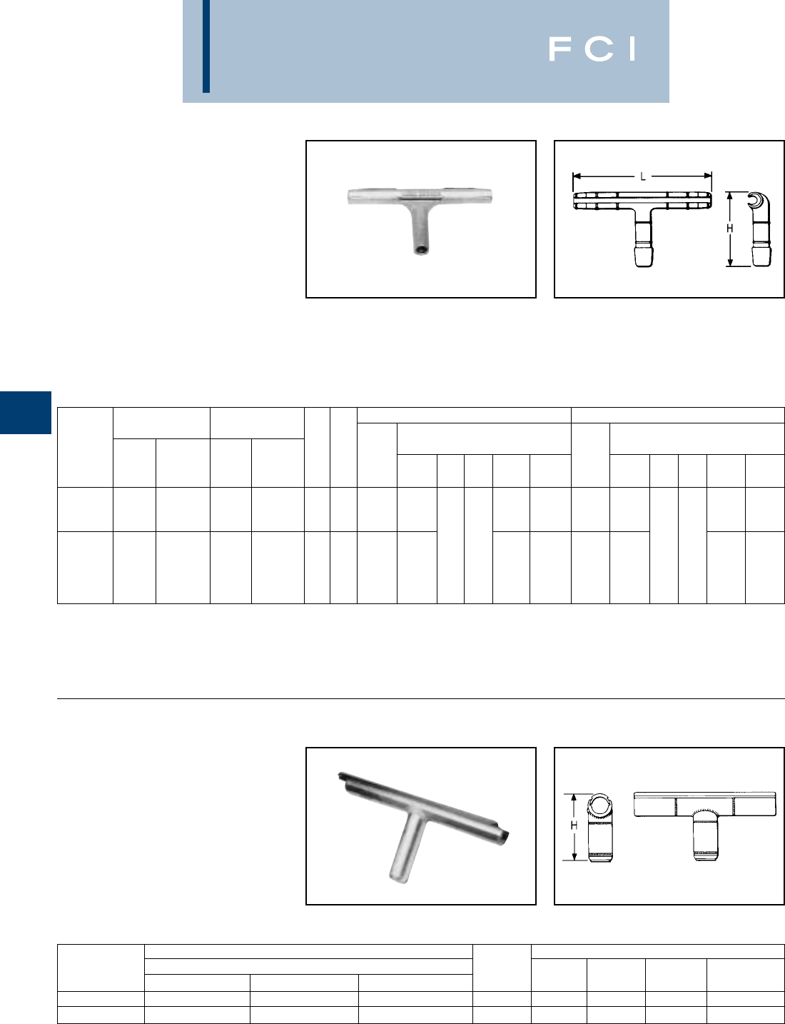
BURNDY
Overhead
E-30
TYPE YOT-R-R
HYTEE
T-Tap for Combinations of
Aluminum, ACSR, 6201, 5005,
Compressed and Compact
Conductors
Heavy duty cast aluminum connector with
two-piece line element and barrel tap.
Recommended for aluminum and ACSR runs
with aluminum, ACSR. Uses same die as
equivalent full-tension HYSPLICE™ sleeve.
Tap element pre-filled with PENETROX™
joint compound and capped.
*Multiple crimp die set, makes more than one crimp per tool
compression. Figure indicates number of compressions.
†U Die with adapter PT-6515
‡U Die with adapter PUADP-1.
TYPE YNT-R-R
T-Tap Compression Tap for
ACSR, ACAR and Stranded
Aluminum Cable
Two-piece compression T-Tap for ACSR,
ACAR and SAC transmission lines. Installed
with same dies as equivalent full tension
splice. Tap element pre-filled with PENE-
TROX™ joint compound and sealed.
*For Extra High Voltage (EHV) applications add suffix "T" to
catalog number (e.g., YNT49R49RT).
** Overlap crimps.
CONDUCTOR TOOLS, DIE SETS
CATALOG RUN AND TAP DIE
NUMBER* ACAR ALUMINUM ACSR H INDEX Y45** Y46** Y60BHU**
YNT451R451R 840.2 - 927.2 795 - 1000 715.5 - 874.5 7-1/2 725 S725 P725 L725
YNT49R49R 983.1 - 1198 1033.5 - 1272 900 - 1113 45/7 7-3/4 727 — — L727
RUN TAP
RUNTAP TOOLS, DIE SET CATALOG TOOLS, DIE SET CATALOG
ACSR, ACSR, NO., & (CRIMPS PER END) NO., & (CRIMPS PER END)
CATALOG 6201, 6201, DIE Y35, DIE Y35,
NUMBER 5005 ALUMINUM 5005 ALUMINUM H L INDEX Y750 Y45† Y46‡ Y48B Y60B INDEX Y750 Y45† Y46‡ Y48B Y60BHU
(19)
YOT361R361R 477 (18-1) 477 477 (18-1) 477 (19, 37) 6-1/4 12-3/8 347, 426 U317 (60 C317 (2) L317 (2) 317, 426 U317 (6) C137 (2) L317 (2)
(37) or M U-M (4) ——
or M U-M (4) — —
(24-7) (24-7)
477 (26-7) (19) 477 (26-7) †‡ † ‡
YOT37R37R (30-7) 556 (30-7) 556 (19, 37) 6-3/8 12-1/2 261, 318 U261 (6) C61 (2) L261 (2) 261, 318 U261 (6) C261 (2) L261 (2)
556 (18-1) (37) 556 (18-1) or M U-M (4) ——
or M U-M (4) — —
(24-7) (24-7)

BURNDY
Overhead
E-31
TYPE YNTA-R
T-TAP WITH PAD TAP
For ACSR, ACAR and Stranded
Aluminum Cable
*For Extra High Voltage (EHV) applications order two tap pad
shielding caps STS43A-4N. Catalog number indicates one
cap (see chart below).
** Overlap crimps.
TYPE STS-4N
STREAMLINED PAD CAPS
Streamlined caps for shielding hardware
when bolting terminals to flat pads singly or
back to back. Caps are for 4 NEMA tongues.
Adapter is attached with tongue hardware.
Shielding cap is fastened to adapter with
stainless steel cap screw. Order one (1) STS
for each side of pad.
Fig. 1
Fig. 2
CONDUCTOR TOOLS, DIE SETS
CATALOG FIG. DIE
NUMBER ACAR ALUMINUM ACSR NO. C H T INDEX Y45** Y46** Y60BHU
YNTA32R 395.1 - 395.2 336.4 - 350 300 - 336.4 2 5 1/2 717 S717 P717 L717
YNTA39R 634.9 - 653.1 600 - 650 556.5 12-1/4 5-1/4 722 S722 P722 L722
YNTA43R* —700 - 800 605 - 666.6 5-3/8 724 S724 P724 L724
YNTA451R* 840.2 - 927.2 795 - 1000 715.5 - 874.5 3-1/4 5-1/2 9/16 725 S725 P725 L725
YNTA49R* 983.1 - 1198 1033.5 - 1272 900 - 1113 45/7 25-7/8 727 L727
YNTA58R* —2000 1780 3-5/8 6-1/4 11/16 735 —— L735
CATALOG NUMBER PAD SIZE MAXIMUM SHIELDED AREA
STS33A-4N 3333
STS43A-4N 43
STS44A-4N 4444
STS53A-4N 535-1/43-1/8
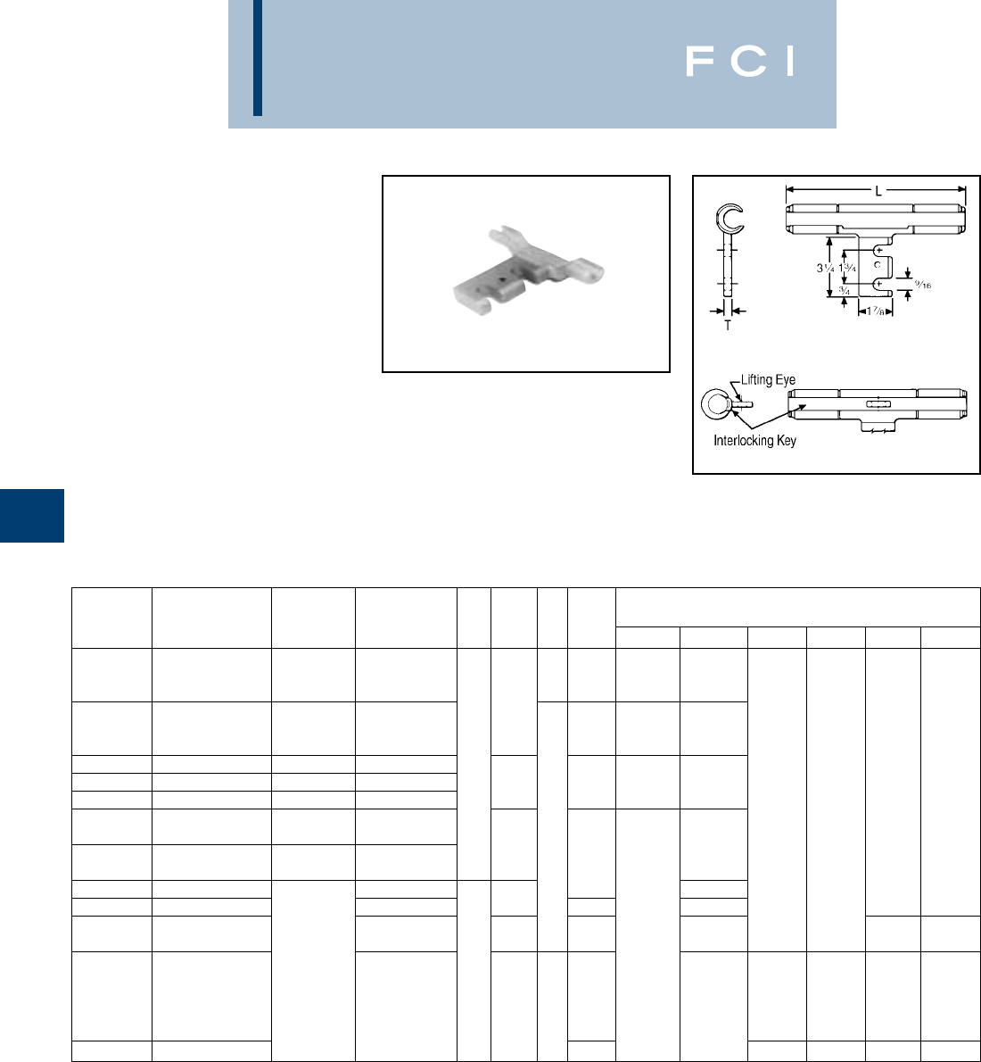
BURNDY
Overhead
E-32
TYPE YTA-R-2N
DISCONNECTABLE T-TAP
(WITH PAD)
For Copper, Aluminum, ACSR,
6201, 5005, Compressed and
Compact Conductors
Aluminum primary T-tap connector with slot-
ted tap pad designed for easy disconnecting
of tap conductor. Tap pad accommodates
compression terminals Types YKA-R-2N and
YKA-A-2N, and has positioning socket for
proper alignment. On sizes larger than 336.4
ACSR, the YTA-R-2N run element has two-
piece interlocking-key with lifting eye that
simplifies hotline installations. Catalog
number does not include mating terminal.
Fig. 1
Fig. 2
*Multiple crimp die set, makes more than one crimp per tool
compression. Figure indicates number of compressions.
†U Die with adapter PT-6515.
‡U Die with adapter PUADP-1.
TOOLS, DIE SET CATALOG NUMBER,
CATALOG FIG. DIE & (NUMBER OF CRIMPS PER END)
NUMBER ACSR, 6201, 5005 COPPER ALUMINUM NO. L T INDEX
MD7, MD6
Y35, Y750 Y45† Y46‡ Y48B Y60BHU
BG BG (2)
YTA2R-2N 22 (3, 7) 2 (7) 3/8 or W-BG (1)* U-BG (1)*
1 (7) 1 (7) 243 W243 (2) U243 (1)
6-1/8 659 U659 (1)
YTA25R-2N 1/0 1/0 (7, 12, 19) 1/0 (7, 19) C, W-C (4) U-C (1)*
247 W247 (1) U247(1)
YTA26R-2N 2/0 2/0 (7, 12, 19) 2/0 (7, 19) 1 L
YTA27R-2N 3/0 3/0 (7, 12, 19) 3/0 (7, 19) 7-7/8 or W-L (4) U-L (2) ——
YTA28R-2N 4/0 4/0 (7, 12 19) 4/0 (7, 19) 251 U251 (3) ——
300 (26-7) 336.4 (19, 37, 61)
YTA321R-2N 336.4 (18-1) 350 (19, 37) 350 (19, 37, 61) 1/2 U-M (3)
336.4 (26-7, 30-7) 397.5 (19, 37, 61) 9-1/2
YTA33R-2N 397.5 (18-1) 400 (19, 37) 400 (19, 37, 61) U317 (4)
YTA361R-2N 477 (18-1)
YTA37R-2N
477 (24-7, 26-7, 30-7)
556.6 (19, 37) 13-1/8 MU-M (5)
636 (37) —
YTA39R-2N 556.5 (24-7, 26-7) 650 (61) 16-1/4 608 U608 (9) C608 (3) L608 (3)
605 (30-19)
605 (30-9) —2
292
YTA43R-2N 636 or S292 (9) P292 (9) C292 (3) L292 (3)
(24-7, 26-7, 30-19) 795 (37, 61) 16-1/2 3/4 319 —S319 (9) P319 (9) C319 (3) L319 (3)
666.6 (24-7)
YTA391A-2N —342 S342 (9) P342 (9) C342 (3) L342 (3)
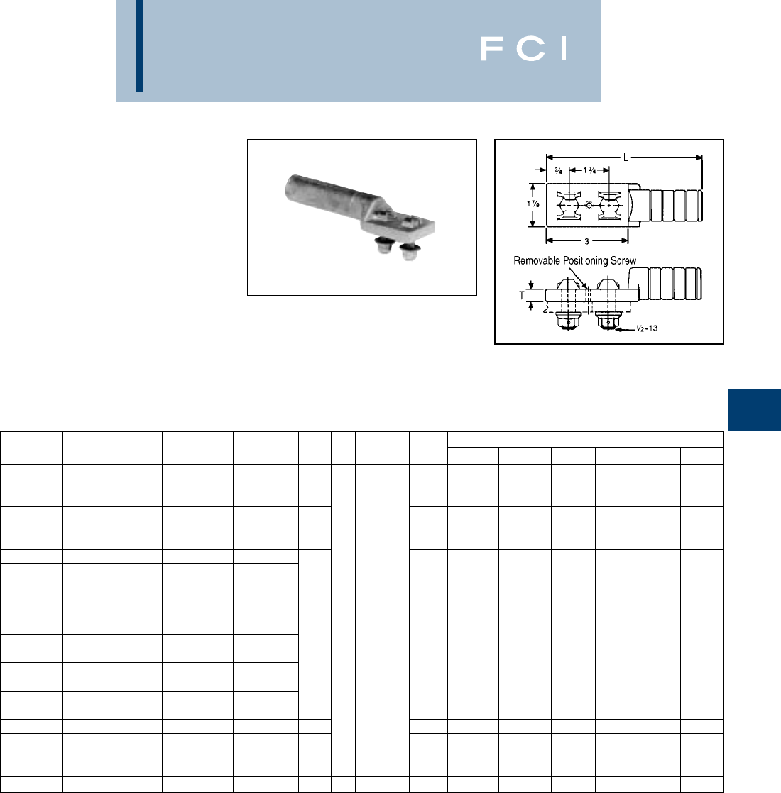
BURNDY
Overhead
E-33
TYPES YKA-R-2N &
YKA-A-2N
DISCONNECTABLE TERMINAL
(WITH FIXED HARDWARE)
For Copper, Aluminum, ACSR,
6201, 5005, Compressed and
Compact Conductors
Aluminum compression terminal with fixed
hardware and positioning pin for making dis-
connectable tap or jumper connections. Used
with slotted YTA-R-2N T-tap or YSA-R-2N
terminal. Supplied with aluminum bolts and
washer-face, self locking nuts. Prefilled with
PENETROX™ joint compound and capped.
*Multiple crimp die set, makes more than one crimp per tool
compression. Figure indicates number of compressions.
†U Die with adapter PT-6515
‡U Die with adapter PUADP-1.
CATALOG BOLT DIE TOOLS, DIE SET CATALOG NO., & (NO. OF CRIMPS)
NUMBER ACSR, 6201, 5005 COPPER ALUMINUM L T LENGTH INDEX MD7, MD6 Y35, Y750 Y45† Y46‡ Y48B Y60BHU
BG BG (8)
YKA2R-2N 21 (7) 1 (7) 5-1/2 or W-BG (4)* U-BG (3)* ————
2 (3, 7) 2 (7) 243 W243 (4) U243 (2)
C
YKA25R-2N 1/0 1/0 (7, 19) 1/0 (7, 19) 5-5/8 or W-C (6) U-C (3)* ————
659 —U659 (2)
YKA26R-2N 2/0 2/0 (7, 19) 2/0 (7, 19)
3/0 LU-L (2)
YKA27R-2N 110.8 (12-7) 3/0 (7, 19) 3/0 (7, 19) 6 or — U251 (3) ————
YKA28R-2N 4/0 4/0 (7, 19) 4/0 (7, 19) 251
250 (12, 19, 37) 250 (7, 37)
YKA30R-2N 266.8 (18-1, 6-7, 26-7) 300 (19, 37) 266 (19) 3/8 1-3/4
336.4 (18-1) 300 (37, 61)
YKA321R-2N 300 (26-7) 350 (19, 37) 350 (37, 61) MU-M (3)
336.4 (26-7, 30-7) 397.5 (19) 7-1/4 or — U317 (4) ————
YKA33R-2N 397.5 (18-1) —400 (37) 317
397.5 (26-7, 30-7) 477 (19, 37)
YKA361R-2N 477 (18-1) —500 (37, 61)
YKA37R-2N 477 (24-7, 26-7, 30-7) — 556.5 (19, 37) 7-3/8 M — U-M (3) ————
352
YKA34CA-2N 397.5 (26-7, 30-7) 500 (19, 37) 477 (19, 37) or — — S352 (9) P352 (9) C352 (3) L352 (3)
477 (18-1) 500 (37, 61) 579 S579 (9) P579 (9) C579 (3) L579 (3)
YKA391A-2N ——795 (37, 61) 9-1/2 3/4 2-1/2 342 — — S342 (9) P342 (9) C342 (3) L342 (3)
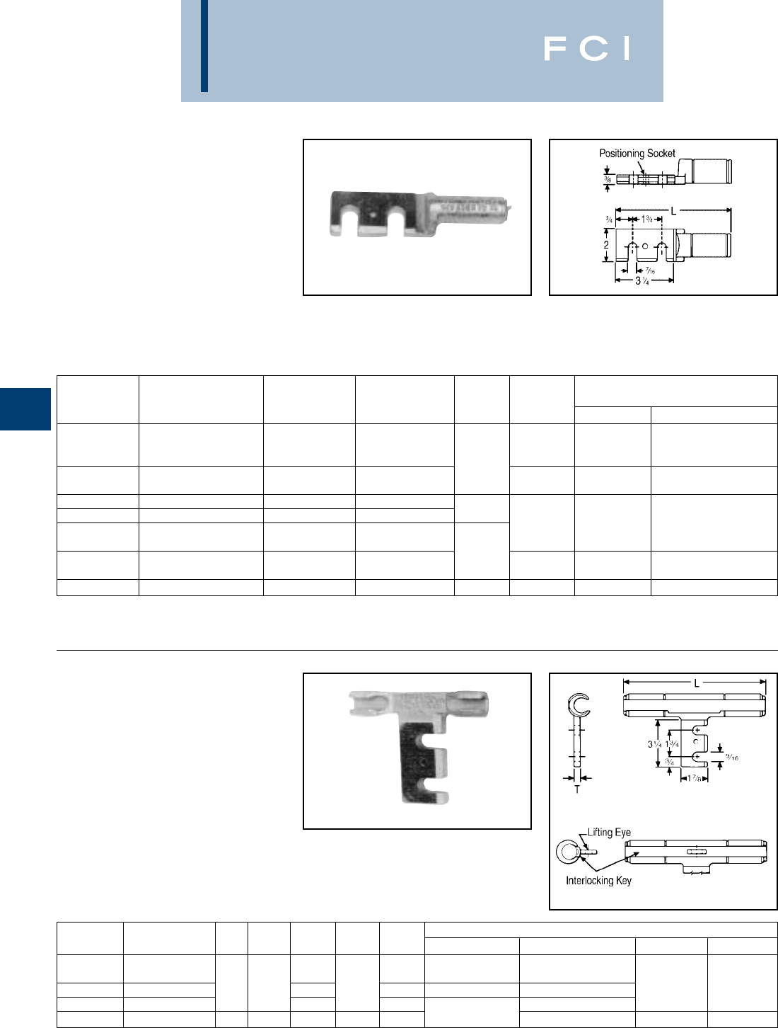
BURNDY
Overhead
E-34
TYPE YSA-R-2N
DISCONNECTABLE TERMINAL
(WITH SLOTTED PAD)
For Copper, Aluminum, ACSR,
6201, 5005, Compressed and
Compact Conductors
Aluminum compression terminal with slotted
pad and positioning socket for making dis-
connectable tap or jumper connections. Used
with YKA-R-2N fixed hardware terminal.
*Multiple crimp die set, makes more than one crimp per tool
compression. Figure indicates number of compressions.
TYPE YTA-2N
DISCONNECTABLE T-TAP
For Copper
Cast copper primary t-tap connector with
slotted tap pad for easy disconnecting of tap
conductor. Tap pad accommodates compres-
sion terminal Type YKA-2N. On sizes larger
that 4/0, the YTA-2N run element has a two-
piece, interlocking-key with lifting eye that
simplifies hot installations. Catalog number
does not include terminal or hardware.
Fig. 1
Fig. 2
TOOLS, DIE SET CATALOG NO.,
CATALOG DIE & (NUMBER OF CRIMPS)
NUMBER ACSR, 6201, 5005 COPPER ALUMINUM L INDEX MD7, MD8 Y35, Y750, Y45†, Y46‡
BG BG (8)
YSA2R-2N 22 (3, 7) 2 (7) or W-BG (4)* U-BG (3)*
1 (7) 1 (7) 6-1/4 243 W243 (4) U243 (2)
C or U-C (3)*
YSA25R-2N 1/0 1/0 (7, 19) 1/0 (7, 19) 659 —U659 (2)
YSA26R-2N 2/0 2/0 (7, 19) 2/0 (7, 19)
YSA28R-2N 4/0 4/0 (7, 19) 4/0 (7, 19) 6-5/8 L or U-L
250 (12, 19, 37) 250 (37) 251 —U251
YSA30R-2N 266.8 (18-1, 6-7, 26-7) 300 (19, 37) 266.8 (7, 19)
336.4 (18-1) 300 (37, 61) 7-3/4 M or U-M (3)
YSA321R-2N 300 (26-7) 350 (19, 37) 350 (37, 61) 317 —U317 (4)
YSA37R-2N 477 (24-7, 26-7, 30-7) — 556.5 (19, 37) 7-7/8 M — U-M (3)
Pre-filled with PENETROX™ joint compound
and capped.
†U Die with adapter PT-6515
‡U Die with adapter PUADP-1.
CATALOG FIG. DIE TOOLS, DIE SET CATALOG NUMBER, & (CRIMPS PER END)
NUMBER CONDUCTOR NO. C L T INDEX MD7, MD6 Y35, Y750, Y45†, Y46‡ Y48B Y60BHU
W163 (3)
YTA2C-2N 2 (7) 5-5/8 163 Crimps Overlap U163 (1)*
YTA26-2N 2/0 (7, 19) 11-1/2 7-3/8 3/8 166 W166 (6) U166 (3) ——
YTA28-2N 4/0 (7, 12, 19) 7-5/8 168 U168 (4)
YTA34-2N 500 (19, 37, 61) 2 2 11-7/8 1/2 210 —U210 (6) C210 (2) L210 (2)
*Multiple crimp die set, makes more than one crimp per tool
compression. Figure indicates number of compressions.
†U Die with adapter PT-6515
‡U Die with adapter PUADP-1.

BURNDY
Overhead
E-35
TYPE YKA-2N
DISCONNECTABLE TERMINAL
(WITH FIXED HARDWARE)
For Copper
Tin-plated copper compression terminal with
fixed hardware for making disconnectable tap
or jumper connections. Used with slotted
YTA-2N T-tap or YSA-R-2N terminal. Supplied
with tin-plated DURIUM™ bolts and washer-
face nuts.
*Multiple crimp die set, makes more than one crimp per tool
compression. Figure indicates number of compressions.
†U Die with adapter PT-6515
‡U Die with adapter PUADP-1.
CATALOG DIE TOOLS, DIE SET CATALOG NUMBER, & (NUMBER OF CRIMPS)
NUMBER CONDUCTOR C L T INDEX MD7, MD6 Y35, Y750, Y45†, Y46‡ Y48B Y60BHU
YKA6C-2N 6 (7) W163 (2)
YKA4C-2N 4 (7) 7/8 5 3/8 163 Crimps U163 (1)*
YKA2C-2N 2 (7) Overlap ——
YKA26-2N 2/0 (7, 19, 37) 1 5-1/4 1/4 166 W166 (4) U166 (3)
YKA28-2N 4/0 (7, 12, 19, 37) 1-1/4 5-3/8 168 U168 (3) C168 (1) L168 (1)
YKA29-2N 250 (12, 19, 37) 1-3/8 3/8 169 U169 (4) C169 (1) L169 (1)
YKA30-2N 300 (19, 37, 61) 1-1/2 5-1/2 170 U170 (5) C170 (1) L170 (1)
YKA34-2N 500 (19, 37, 61) 1-7/8 6-1/2 1/2 210 —U210 (6) C210 (2) L210 (2)
YKA39-2N 750 (37, 61) 2-3/8 7-1/4 5/8 627 C627 (3) L627 (3)
YKA44-2N 1000 (61) 2 7-5/8 1/2 345 —C345 (4) L345 (4)
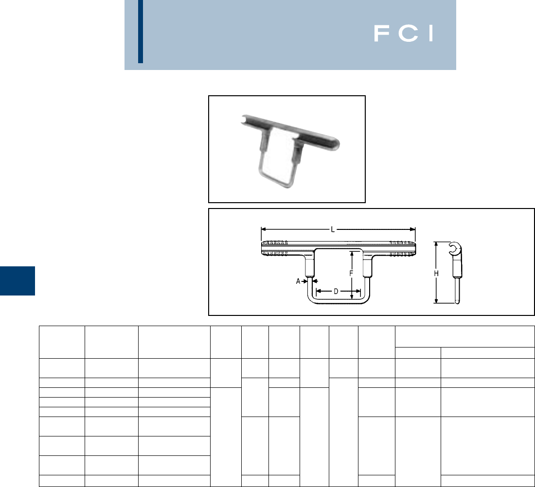
BURNDY
Overhead
E-36
TYPE YCB-R
STIRRUP HOT-LINE CLAMP
ADAPTERS
For Aluminum, ACSR, 6201,
5005, Compressed and
Compact Conductors
Permanent compression hot-line clamp
adapter with aluminum run and copper bail.
Accommodates any standard copper hot-line
clamp on bail elements. Permits hot-line
tapping without arcing or chafing damage to
aluminum conductor. Installed with standard
tools and dies.
*Multiple crimp die set, makes more than one crimp per tool
compression. Figure indicates number of compressions.
†U Die with adapter PT-6515
‡U Die with adapter PUADP-1.
TOOLS, DIE SET CATALOG
CATALOG DIE NUMBER, & (CRIMPS PER END)
NUMBER ALUMINUM ACSR, 6201, 5005 A H L D F INDEX MD7, MD6 Y35, Y750, Y45†, Y46‡
BG (6)
YCB2R 2 Str. - 6 Sol. 2 - 4 2 Sol. 3-3/4 9 2-1/2 2-1/2 BG W-BG (2)* U-BG (2)*
YCB25R 1/0 (7, 19) 1/0 - 80 (8-1) 9-3/4 C W-C (4) U-C (2)*
YCB26R 2/0 (7, 19) 2/0
YCB27R 3/0 (7, 19) 3/0 511-1/8 L W-L (4) U-L (2)
YCB28R 4/0 (7, 19) 4/0
350 (19, 37) 336.4 (18-1)
YCB321R 336.4 (19, 37) 300 (26-7) 3-1/2
400 (19, 37) 336.4 (26-7, 30-7) 1/0 Sol. 3-1/2
YCB33R 397.5 (19, 37) 397.5 (18-1) 5-3/8 12-3/4 M —U-M (3)
500 (37, 61) 397.5 (26-7)
YCB35R 477 (19, 37) (30-7)
YCB361R 477 (19, 37) 477 (18-1) 5-1/4 13-1/4 317 U317 (3)
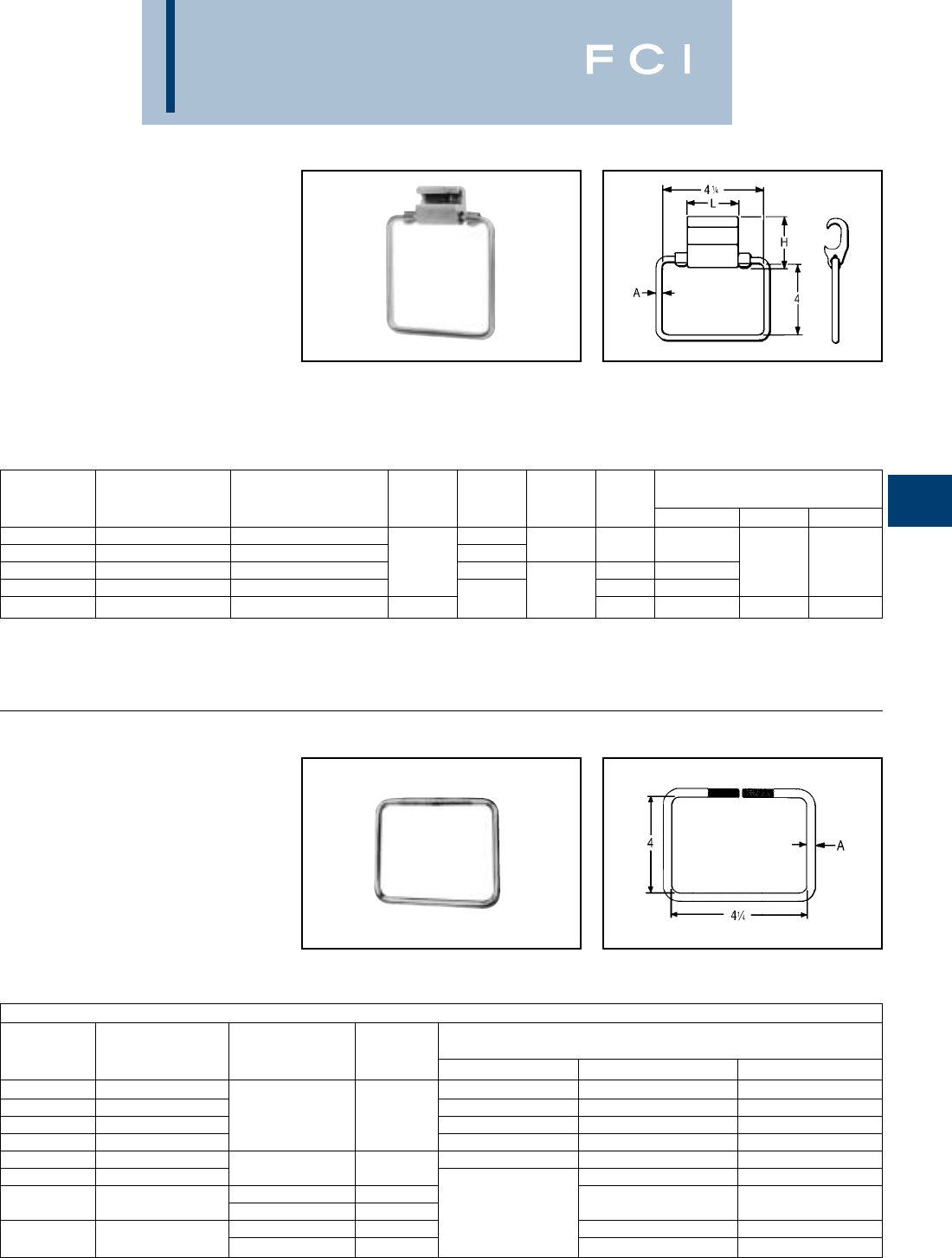
BURNDY
Overhead
E-37
TYPES YCB-U
& YCB-R-U
CRIMPIT™ STIRRUP
Hot-Line Clamp Adapter for
Aluminum, ACSR, 6201, 5005,
Compressed and Compact
Conductors
Combines Figure "6" -shaped aluminum
CRIMPIT™ tap connector with tin-plated cop-
per bail. Can be gripped in tool and slipped
*Index number "D" is not "D3" Cabelok CRIMPIT™ die.
†U Die with adapter PT-6515
‡U Die with adapter PUADP-1.
*For additional run conductors see specific connector catalog
page.
TYPES J990 & J1252
HOT-LINE CLAMP BAILS
Designed to make hot-line clamp adapter
using HYCRIMP™, CABELOK CRIMPIT™ or
Figure "6" -Shaped CRIMPIT™ connectors.
Where hot sticks are used, the CABELOK
CRIMPIT™ or Figure "6" -shaped CRIMPIT™
are recommended. The line can be
approached with the connector and bail held
in the tool. Bails are tin-plated, hard drawn
copper.
over line for easy installation. Five sizes take
range from #4 to 600 Mcm. Pre-filled with
PENETROX™ joint compound and
Stripsealed.
TOOLS, DIE SET CATALOG
CATALOG DIE NUMBER, & (NUMBER OF CRIMPS)
NUMBER ALUMINUM ACSR, 6201, 5005 A H L INDEX Y35, Y750 Y45 Y46
YCB4U1 4 Sol. - 4 (7) 4 1-1/2
YCB1U1 2 (7) - 1 (7) 2 1-5/8 1-7/8 D* U-D (2)
YCB28U26 1/0 (7) - 4/0 (19) 1/0 - 4/0 2 Sol. 2HU-H (2) †‡
YCB33R26U 300 (37) - 400 (37) 266.8 (6-7) - 336.4 (30-7) 2-1/8 R U-R (2)
YCB38R26U 397.5 (19) - 600 (61) 336.4 (26-7) - 556.5 (18-1) 1/0 Sol. 2-1/4 NU-N (2) S-N (2) P-N (2)
RECOMMENDED CONNECTOR & BAIL COMBINATIONS
CABELOK
HYCRIMP™ CRIMPIT™ RUN CONDUCTORS ACCOMMODATED*
CAT. NO. CAT. NO. BAIL A SOL. AL STR. AL ACSR
YHO-100 YP2U3 6 - 2 6 - 3 (7 Str.) 6, 4
YHO-150 YP26AU2 1 - 2/0 3 (3 Str.) - 1/0 3 - 1/0
YHD-200 YP27AU4 J990 #2 3/0, 4/0 2/0 - 3/0 1/0, 2/0
YHD-250 YPC28U4 —4/0 3/0, 4/0
YHD-300 YP27AU26 3/0 2/0, 3/0 2/0
YHD350 YP28U26 J1252 2/0 4/0 3/0, 4/0
J990 #2
—YPC28U26 J1252 2/0 — 1/0 (7) - 4/0 1/0 - 4/0
J990 #2 250 (37) 266.8 (18-1)
YHN-500 YPC33R26U J1252 2/0 400 (37) 397.5 (18-1)
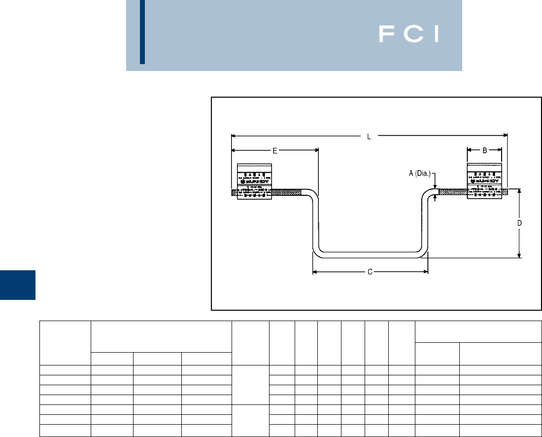
BURNDY
Overhead
E-38
TYPES YHO-J,YHD-J,
YHN-J
HYCRIMP™ STIRRUP
Utilizing H-Framed Aluminum Tap Connectors
with tin-plated copper bail. Bendable tabs
secure run and bail freeing the lineman’s
hands to work with the installation tool con-
ductor grooves. Prefilled with PENETROX™
joint compound.
①Permanent dies in tool install all sizes.
†U Die with adapter PT-6515
‡U Die with adapter PUADP-1.
TOOLS, DIE SET CATALOG
NUMBER, & (NO. OF CRIMPS)
CATALOG RUN CONDUCTOR ACCOMMODATES DIE MD7-8
NUMBER SOL. AL STR. AL ACSR A B C D E L INDEX MD6-8
①Y35, Y750, Y45†, Y46‡
YHO100J1444 6 - 1 6 - 1 (7 Str.) 6 - 2 1.50 5.00 3.00 3.75 12.0 O (4) U-O (2)
YHO150J1444 1 - 2/0 3 - 2/0 3 - 1/0 2 Sol. 1.75 5.00 3.00 3.75 12.0 O (5) U-O (2)
YHD200J1444 3/0 - 4/0 2/0 - 3/0 1/0 - 2/0 (.258 dia.) 1.88 5.00 3.00 3.75 12.0 D3 (5) UD-3 (2)
YHD250J1444 250 - 300 4/0 3/0 - 4/0 1.88 5.00 3.00 3.75 12.0 D3 (5) UD-3 (2)
YHD300J1496 2/0 - 4/0 #1 (Str.) - 3/0 #1 - 2/0 1.88 5.00 4.75 5.62 15.5 D3 (5) UD-3 (2)
YHD350J1496 250 - 300 3/0 - 4/0 3/0 - 4/0 2/0 Sol. 2.50 5.00 4.75 5.62 15.5 D3 (7) UD-3 (2)
YHN500J1496 —4/0 - 500 4/0 - 477 (18/1) (.365 dia.) 2.00 5.00 4.75 5.62 15.5 N — U-N (2)
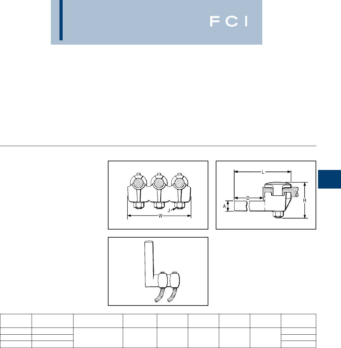
BURNDY
Overhead
E-39
TRANSFORMER AND
EQUIPMENT TAP
CONNECTORS
Transformer and equipment tap connectors
are specifically designed to provide single or
multi-tap connections from secondary trans-
former outlets, disconnects, circuit breaker
panels, and other equipment pads
or bar.
TYPE E-C-G
TRANSFORMER TAP
ADAPTER
For Copper
Multi-tap, range-taking cast copper alloy con-
nector designed to take 2, 3, or 4 conductors
from a single secondary transformer outlet.
CATALOG NUMBER OF
NUMBER CONDUCTORS CONDUCTOR SIZE A DIA. D H J L W
E2C34G1 23-1/2
E3C34G1 31/0 Sol. - 500 .78 3-3/4 3-7/8 1/2-13 6-1/4 5-1/4
E4C34G1 46-7/8

BURNDY
Overhead
E-40
TYPE KC22J12T13,
EQC632C
TRANSFORMER GROUND
CONNECTORS
For Copper
Fits all standard EEI-NEMA distribution trans-
formers as a tank grounding terminal.
Both, one-wrench installation.
TYPE YA-2LH
HYSEALUG
Terminal for Copper
Tin-plated, pure copper 2-hole NEMA com-
pression terminal with shrouded barrel for
terminating insulated copper conductor to
transformers and other equipment. Shroud
prevents seepage of water or moisture into
conductor strands and minimizes taping.
†U Die with adapter PT-6515
‡U Die with adapter PUADP-1.
Type EQC632C
CATALOG NUMBER RANGES
KC22J12T13 8 Sol. - 2 Sol.
KC26 2 Sol. - 2/0 Str.
KC34J12T13 3/0 - 500 Str.
EQC632C 8 Sol. - 2 Str.
SHROUD TOOLS, DIE SET CATALOG NUMBER,
CATALOG INSIDE & (NUMBER OF CRIMPS)
NUMBER CONDUCTOR BB DIA. C L T MD7, MD6 Y35, Y750, Y45†, Y46‡
YAB4C-2LH72 .57
YAB4C-2LH73 4 Str. 5/8 .84 6-1/4 W161 (2) U4CRT (2)
YAB2C-2LH74 .58 3/4 1/8
YAB2C2LH75 2 Str. 3/4 .91 6-1/2 W162 (4) U2CRT (2)
YAB25-2LH70 .69
YAB25-2LH71 1/0 Str. .98 6-3/4 3/8 W163 (4) U25RT (2)
YA26-2LH88 .73 7/8
YA26-2LH89 2/0 Str. 1.04 W241 (2) U26RT (2)
YA27-2LH97 .84 6-1/4
YA27-2LH98 3/0 Str. 1 1.06 W243 (2) U27RT (2)
YA28-2LH114 .86 1W-BG or
YA28-2LH115 4/0 Str. 1.24 W243 (2) U28RT (2)
YA29-2LH90 .88 6-5/8 1/8
YA29-2LH91 250 1.25 1-1/8 W166 (4) U29RT (2)
YA30-2LH85 .92
YA30-2LH86 300 1.32 1-1/4 7 — U30RT (2)
YA31-2LH89 1-1/4 1.03
YA31-2LH90 350 1.40 1-3/8 7-5/8 W-O (5) U31RT (2)
YA34-2LH110 1.14
YA34-2LH111 500 1-1/2 1.88 1-1/2 7-3/4 1/4 — U34RT (2)
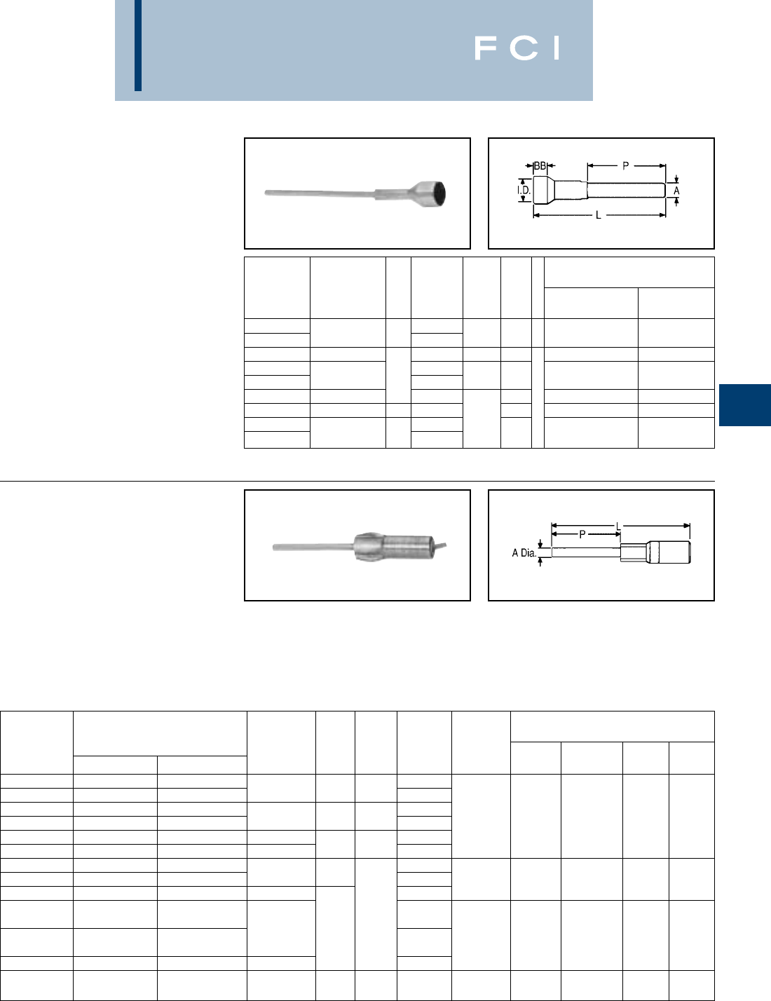
BURNDY
Overhead
E-41
TYPE YE-LH
HYSEALPLUG
Terminal Plug for Copper
Oil and water-tight terminal with shrouded,
tin-plated, copper barrel and brazed plug.
Recommended for terminating insulated
copper conductor at cutout, transformer and
arrestor; or for joining insulated copper riser
to overhead conductor. Shroud prevents
seepage of water or moisture into conductor
strands and minimizes taping. To obtain a
tight fit on some insulations in the shroud it
may be necessary to either "pencil" the insu-
lation down, or build it up with tape.
†U Die with adapter PT-6515.
‡U Die with adapter PUADP-1.
TYPES YE-R,YE-W
HYPLUG™
Terminal Plug for
Aluminum and ACSR
In 1989 BURNDY®began shipping an
improved pin type connector. A proprietary
coating system was developed through
intense research efforts which vastly
prolongs the life of this type of connection. To
help identify the new product a hex shaped
crimp is now used on the pin interface crimp
*All crimps overlap
†U Die with adapter PT-6515.
‡ U Die with adapter PUADP-1.
•BURNDY®furnishes many special versions of YE-R
including: pin length variations, factory applied pin angles,
etc. Contact your BURNDY®representative for your special
needs.
and BURNDY's overhead color coded end
caps are utilized.
Aluminum HYPLUG™ with tin-plated copper
plug for terminating aluminum or ACSR cable
at cut-out, transformer and arrestor. Plug may
be bent to desired angle for easier insertion.
Three die sets accommodate 4 Str.-500
MCM. Terminals are pre-filled with PENE-
TROX™ A-13 joint compound and sealed
with color coded end caps.
TOOLS, DIE SET CATALOG NO.,
SHROUD & (NUMBER OF CRIMPS)
CATALOG INSIDE Y35, Y750,
NUMBER CONDUCTOR BB DIA. A DIA. L P MD7, MD6 Y45†, Y46‡
YE2C-LH128 .58
YE2C-LH129 2 Str. 3/4 .91 2 Sol. 9 6 W162 (4) U2CRT (2)
YE25-LH97 1/0 Str. .98 1/0 Sol. 11-1/8 W163 (4) U25RT (2)
YE26-LH88 .73
YE26-LH89 2/0 Str. 1 1.04 2/0 Sol. 11-3/8 W241 (2) U26RT (2)
YE28-LH128 4/0 Str. 1.24 11-1/2 8 W-BG or W243 (2) U28RT (2)
YE31-LH96 350 1-1/4 1.03 12-1/4 W-O (5) U31RT (2)
YE34-LH119 1.14 4/0 Sol.
YE34-LH120 500 1-1/2 1.88 13-1/4 — U34RT (2)
TOOLS, DIE SET CATALOG NO.,
& (NUMBER OF CRIMPS)*
CATALOG CONDUCTOR COLOR DIE Y750, Y35,
NUMBER ALUMINUM ACSR A DIA. L P CODE INDEX
MD7, MD6
Y45†, Y46‡ Y48BH Y60BH
YE6R-25 5, 6 Str. 6 Blue
YE4R-25 3, 4 Str. 4 4 Sol. 4-5/8 2-1/2 Orange
YE1WAG1 #1 Sol. (.289) — 8.58 Red BG or 243 BG U-BG
YE2WAG5 #2 Sol. (.258) — .257 (218) 6 Orange WBG C243 L243
YE2R-25 1, 2 Str. 2 2 Sol. Red W243 U243
YE25R-25 1/0 Str. 1/0 2 Sol. 4-5/8 2-1/2 Yellow 5/8 - 1 UK5/8-1T
YE26R-60 2/0 Str. 2/0 Gray
YE27R-60 3/0 Str. 3/0 1/0 Sol. 9-1/2 Black 249 or W249 or U249 C249 L249
YE28R-60 4/0 Str. 4/0 3/8 Pink 840 W-K840 U-K840T
(26/7)
YE30R-60 300 266.8 (18/1) 6Blue U317
(26/7) 4/0 Sol. 10-5/8 317, 705, —U705 C317 L317
YE32R-60 350 - 400 336.4 (18/1) Green 1-1/8 - 1 U-K1-18-1T
YE361R-60 477, 500 477 (18/1) 9/16 Pink
(24/7)
YE39R-60 600 556.5 (26/7) 5/8 11-7/8 6 Yellow 608 — U608 C608 L608
BURNDY
Overhead
E-42
COMPRESSION
SPLICES
TABLE OF CONTENTS
COMPRESSION SPLICES...........................E-43
SERVICE ENTRANCE
Type ES.........................................................E-44
Type YSU ......................................................E-45
Type YSD ......................................................E-46
NEUTRAL
Types YSS, YCS-R, YDS-AT .........................E-47
JUMPER
Type YCS-R...................................................E-48
Type YCS-RL.................................................E-49
Type YCS-A...................................................E-50
Type YCR ......................................................E-50
Type YCR-R-G ..............................................E-51
Types YDS, YCS............................................E-52
Type YNS-R...................................................E-52
REPAIR SLEEVE
Type YCU-A...................................................E-53
Type YNU-R ..................................................E-53
Types YCU-R & YOU-R .................................E-54
Type YCU-R (Static Wire)..............................E-54
FULL TENSION
Types YDS-A & YDS-AT................................E-55
Types YDS & YDS-C .....................................E-56
Type YTS-A ...................................................E-57
Types YDS-W & YDS ....................................E-57
Types YDS-R, YDS-RP1, YDS-RP2.....E-58, E-59
Type AWS-R..................................................E-60
Types YTS-R & YTS-RS................................E-61
Type YTS-AR.................................................E-62
Type YDS-RLY...............................................E-63
Types YDS-RL & YDS-LT.....................E-64, E-65
Types YDS-A & YDS-AT................................E-65
Types YDS-R & YDS-RE...............................E-66
Types YDS-E, YDS-H, YDS-U .......................E-66
Type YDS-K...................................................E-67
Type YTS-E ...................................................E-67
Types YDS-KT & YDS-F................................E-68
Type YDS-M-T...............................................E-68

BURNDY
Overhead
E-43
COMPRESSION
SPLICES
BURNDY®service, full-tension, and jumper
sleeves provide a dependable, economical,
and easy-to-install method of splicing over-
head transmission and distribution lines.
A major part of the Total Burndy Compression
Program, they are available for copper,
aluminum, ACSR, COPPERWELD, ALUMO-
WELD, STEEL, 6201, 5005, ACSR/AW, AWA,
and compressed forms for aluminum and
ACSR. Each is clearly marked with the instal-
lation Die Index number and knurls are
provided which show the installer the correct
number of crimps and the spacing required.
Connections made with BURNDY®
INSULINK™ and HYSPLICE™ sleeves have
a lower resistance than an equal length of
conductor.
HYSPLICE™ sleeves are tapered or cham-
fered at the ends; externally to provide
gradual reduction of pressure on the conduc-
tor, and internally to facilitate conductor
insertion.
Service Sleeve Design
Service entrance connectors are available
insulated (INSULINK™) or uninsulated
(LINKIT™). Both are installed with the one-
hand OH25 and OUR840 HYTOOL™ or the
MD6 HYTOOL™. The INSULINK™ feature
polyethylene caps which seal out dirt and
moisture, and grip the cable insulation leaving
both hands free for crimping. The aluminum
insert is anchored to the Nylon jacket so that
it will not move when crimped, ensuring that
the insert is always under the die. The jacket
is color coded for easy identification of con-
ductor size.
The aluminum LINKIT™ minimizes the
effects of galvanic corrosion. It is designed for
easy location of crimps, and is color coded.
The service HYSPLICE™ connectors are
partial-tension sleeves for splicing the neutral
conductor of triplex service.They are installed
with MD6, OUR840 and the OH25
HYTOOL™ on aluminum and ACSR conduc-
tors from 6 to 1/0.
Copper HYSPLICE™ Sleeve Design
Full-tension holding strength and high con-
ductivity of BURNDY®copper HYSPLICE™
sleeves are accomplished through the
combined action of correct contact length,
proper number of circular crimps of precisely
controlled depth that perform a current
carrying and keying function between the
conductor and the sleeve.
Aluminum HYSPLICE™ Sleeve Design
HYSPLICE™ sleeves for aluminum conduc-
tor not only satisfy the basic tension require-
ments, but also deal with the problems of
"cold flow" of aluminum and the oxide film
which forms on the strands. "Cold flow" is
compensated for by carefully coordinating the
design of the sleeve and its associated
installation die. To offset the effects of the
non-conductive oxide film present on the
surfaces of aluminum cable, BURNDY®
HYSPLICE™ sleeves are pre-filled with
PENETROX™ joint compound and capped or
stripsealed. A solid center barrier forces the
PENETROX™ around the cable strands dur-
ing insertion.
ACSR HYSPLICE™ Sleeve Design
Two-piece, Full-tension HYSPLICE™
Two-piece, full-tension HYSPLICE™ for
ACSR consists of an inner steel sleeve for
joining the steel core, and an outer aluminum
sleeve for connecting the aluminum strands.
To install the two-piece HYSPLICE™, the
cable is cut, the aluminum sleeve slid onto the
cable, aluminum strands cut back and the
steel sleeve installed. The aluminum sleeve is
then centered over the steel sleeve,
PENETROX™ joint compound injected
(PENETROX™ is brushed on cable prior to
centering aluminum sleeve on smaller sizes),
and the sleeve is crimped.
Single-sleeve, Full-tension UNISPLICE™
The UNISPLICE™ is as easy to install as alu-
minum full-tension sleeves. The single, heavy
walled aluminum sleeve is filled with a special
inhibiting compound containing grit particles
which key the steel strand in place. The
UNISPLICE™ eliminates cutting back of
aluminum strands, the need for a separate
steel sleeve, and careful positioning of the
aluminum outer sleeve before crimping.
Since the standard pull-out tests are
inadequate for evaluating UNISPLICE™
performance, BURNDY®has developed the
sustained- tension test that subjects a
connector-conductor assembly to a 168 hour
sustained load equal to 90% of the conductor
strength. This test simulates a service life of
30-40 years at 60% of the conductor strength.
Jumper Sleeves
Since the holding strength required for
jumper sleeves is less than that required for
full-tension sleeves, the jumper HYSPLICE™
sleeve is shorter. Aluminum, ACSR, sleeves
are pre-filled with PENETROX™ joint
compound and installed with the same tools
and dies as the full-tension sleeves.
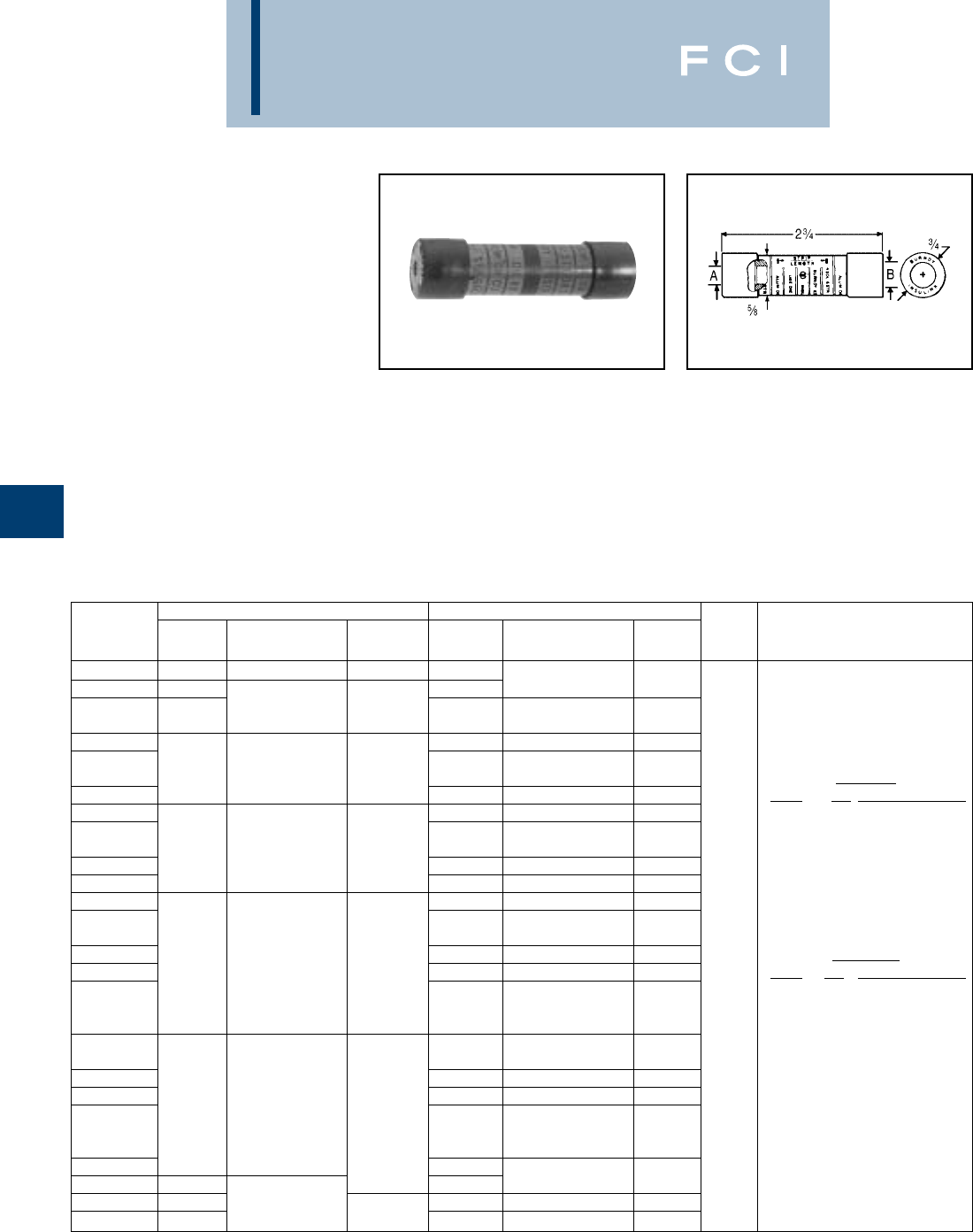
BURNDY
Overhead
E-44
TYPES ES
INSULINK™
Service Entrance Sleeve for
Insulated Combinations of
Copper, Aluminum, ACSR
Compressed.
For use in overhead distribution
applications.
Pre-insulated service entrance compression
connector installed with OH25, OUR840 and
MD6 HYTOOL™ as well as Y35 and Y750
HYPRESS™ tools. Polyethylene caps pre-
vent dirt from accumulating in barrel, grip
cable for easy two-hand installation, and seal
out moisture. Aluminum connector is
anchored to jacket, assuring the connector is
under the die when crimping. Nylon jacket
insulates connector electrically and protects
against water and weather. Superior color
coding. Pre-filled with PENETROX™ joint
compound. Do not use insulated sealed
connectors on bare conductors. Refer to
LINKIT™ type connectors.
ˇNot for use on bare conductors.
▲Accommodates 1/0 stranded aluminum and copper,
concentric, compressed and compact conductors.
SIDE A • SIDE B •
CATALOG ALUMINUM COLOR ALUMINUM COLOR DIE TOOLS, DIE SET CATALOG
NUMBER ACSR & COPPER CODE ACSR & COPPER CODE INDEX NUMBER, & (CRIMPS PER END)
ES8W8W —10 Str. 8 Sol. Brown —
ES6W8W ——
10 Str. 8 Sol. Brown
8 Str. 6 Sol. Green 8 Str. 6 Sol.
ES6W6W —#8 AL Compt — #8 AL Compt Green
ES4W8W —10 Str. 8 Sol. Brown
8 Str. 6 Sol.
ES4W6W 65, 6 Str. 4 Sol. Blue — #8 AL Compt Green HYTOOL™
ES4W4W 65, 6 Str. 4 Sol. Blue TOOL DIE (CRIMPS PER END)
ES2W8W —10 Str. 8 Sol. Brown OH25 (1)
8 Str. 6 Sol. MD6, MD7 (3)
ES2W6W 43, 4 Str. 2 Sol. Orange —#8 AL Compt Green MD6, MD7 W-BG (1)*
ES2W4W 65, 6 Str. 4 Sol. Blue OUR840 X-NBG (1)*
ES2W2W 43, 4 Str. 2 Sol. Orange
ES2R8W —10 Str. 8 Sol. Brown
8 Str. 6 Sol. BG
ES2R6W —#8 AL Compt Green or
ES2R4W 1 Str. 2 Str. 65, 6 Str. 4 Sol. Blue 5/8 HYPRESS™
ES2R2W 2#1 AL Compt Red 43, 4 Str. 2 Sol. Orange TOOL DIE (CRIMPS PER END)
#2 AL Compt 1 Str. 2 Str. Y35 U-BG (1)*
ES2R2R 2#1 AL Compt Red Y750
#2 AL Compt
8 Str. 6 Sol.
ES25R6W —#8 AL Compt Green *Multiple crimp die set, makes more
ES25R4W 65, 6 Str. 4 Sol. Blue than one crimp per tool compression.
ES25R2W 43, 4 Str. 2 Sol. Orange Figure indicates number of
1/0, 1 1/0 Str. 1-19 Str. Yellow 2 Str. 1 Str. compressions.
ES25R2R 2#1 AL Compt Red
#2 AL Compt
ES25R25R 1/0, 1
ES25A25A ——
1/0 Str. Yellow
ES25A4W —1/0 Str.▲65, 6 Str., 4 Sol. Blue
ES25A2W —Yellow 43, 4 Str., 2 Sol. Orange

BURNDY
Overhead
E-45
TYPE YSU
5/8" LINKIT™
Service Entrance Sleeve for
Combination of Copper,
Aluminum and ACSR
Compressed.
Heavy-walled aluminum tubing with solid
barrier minimizes galvanic corrosion of
conductors. Accommodates neutral strands
of Type SE Service Entrance conductor as
well as other conductors. Installed with
standard tooling. Color Coded. Pre-filled with
PENETROX™ joint compound and
Stripsealed.
▲Accommodates 1/0 standard aluminum and copper
concentric, compressed and compact conductors.
SIDE A SIDE B
CATALOG ALUMINUM COLOR ALUMINUM COLOR DIE TOOLS, DIE SET CATALOG
NUMBER ACSR & COPPER CODE ACSR & COPPER CODE INDEX NUMBER, & (CRIMPS PER END)
8 Str. 6 Sol. 8 Str. 6 Sol.
YSU6W6W —#8 AL Compt Green — #8 AL Compt Green
YSU4W8W —8 Sol. 10 Str. Brown
6 Sol. 8 Str.
YSU4W6W 5, 6 Str. 4 Sol. Blue — #8 AL Compt Green
#4 AL Compt 5, 6 Str. 4 Sol.
YSU4W4W 66
#4 AL Compt Blue HYTOOL™
YSU2W8W —8 Sol. 10 Str. Brown TOOL DIE (CRIMPS PER END)
6 Sol. 8 Str. OH25 (1)
YSU2W6W —#8 AL Compt Green MD6, MD7 (3)
43, 4 Str. 2 Sol. Orange 5, 6 Str. 4 Sol. MD6, MD7 W-BG (1)*
YSU2W4W 6#4 AL Compt Blue OUR840 X-NBG (1)*
YSU2W2W 43, 4 Str. 2 Sol. Orange
YSU2R8W —8 Sol. 10 Str. Brown
6 Sol. 8 Str.
YSU2R6W —#8 AL Compt Green BG
2 Str. 1 Str. 5, 6 Str. 4 Sol. or
YSU2R4W #1 AL Compt Red 6#4 AL Compt Blue 5/8 HYPRESS™
YSU2R2W 2#2 AL Compt 4 3, 4 Str. 2 Sol. Orange TOOL DIE (CRIMPS PER END)
2 Str. 1 Str. Y35 U-BG (1)*
YSU2R2R 2#1 AL Compt Red Y35L, Y750
#2 AL Compt
8 Str. 6 Sol.
YSU25R6W —#8 AL Compt Green *Multiple crimp die set, makes more
5, 6 Str. 4 Sol. than one crimp per tool compression.
YSU25R4W 6#4 AL Compt Blue Figure indicates number of
YSU25R2W 1/0 Str. 4 3, 4 Str. 2 Sol. Orange compressions.
1/0 2/0 AL Compt Yellow 2 Str. 1 Str.
YSU25R2R 1/0 AL Compt 2 #1 AL Compt Red
#2 AL Compt
1/0 Str.
YSU25R25R 1/0 2/0 AL Compt Yellow
1/0 AL Compt
YSU25A25A 1-1 1/0 Str. ▲Yellow 1/0 1/0 Str. Yellow

BURNDY
Overhead
E-46
TYPE YSD
.840" LINKIT™
Service Entrance Sleeve for
Combinations of Copper,
Aluminum, ACSR, 6201, 5005
and Compressed.
Aluminum compression sleeve with solid
center barrier. Designed for commercial and
heavy residential services. Installed
with standard tooling. Pre-filled with
PENETROX™ joint compound, and capped.
SIDE A SIDE B
CATALOG ACSR, ALUMINUM COLOR ACSR, ALUMINUM COLOR DIE TOOLS, DIE SET CATALOG
NUMBER 6201, 5005 & COPPER CODE 6201, 5005 & COPPER CODE INDEX NUMBER, & (CRIMPS PER END)
1/0 Str. 1/0
YSD25R25R 1/0 2/0 AL Compt Yellow 1/0 2/0 AL Compt Yellow
3, 4 Str. 2 Sol. HYTOOL™
YSD26R2W 4#2 AL Compt Orange TOOL DIE (CRIMPS PER END)
2 Str. 1 Str. MD6, WK-840 (7)
YSD26R2R 2/0 Str. 21/0 AL Compt Red MD7 W-249 (4)
2/0 3/0 AL Compt Gray 1/0 Str. X840 (7)
YSD26R25R 1/0 2/0 AL Compt Yellow OUR840 X249 (8)
2/0 Str.
YSD26R26R 2/0 3/0 AL Compt Gray
3, 4 Str. 2 Sol.
YSD27R2W 4#2 AL Compt Orange EEI
2 Str. 1 Str.
YSD27R2R 21/0 AL Compt Red IIA
3/0 Str. 1/0 Str.
YSD27R25R 3/0 4/0 AL Compt Black 1/0 2/0 AL Compt Yellow
2/0 Str.
YSD27R26R 2/0 3/0 AL Compt Gray
3/0 Str. 249 HYPRESS™
YSD27R27R 3/0 4/0 AL Compt Black TOOL DIE (CRIMPS PER END)
3, 4 Str. 2 Sol. 840 Y35
YSD28R2W 4#2 AL Compt Orange Y750* UK840 (4)
2 Str. 1 Str. Y35
YSD28R2R 21/0 AL Compt Red Y750* U249 (2)
1/0 Str.
YSD28R25R 4/0 Str. 1/0 2/0 AL Compt Yellow
4/0 300 AL Compt Pink 2/0 Str. *Multiple crimp die set, makes more
YSD28R26R 2/0 3/0 AL Compt Gray than one crimp per tool compression.
3/0 Str. Figure indicates number of
YSD28R27R 3/0 4/0 AL Compt Black compressions.
4/0 Str.
YSD28R28R 4/0 300 AL Compt Pink
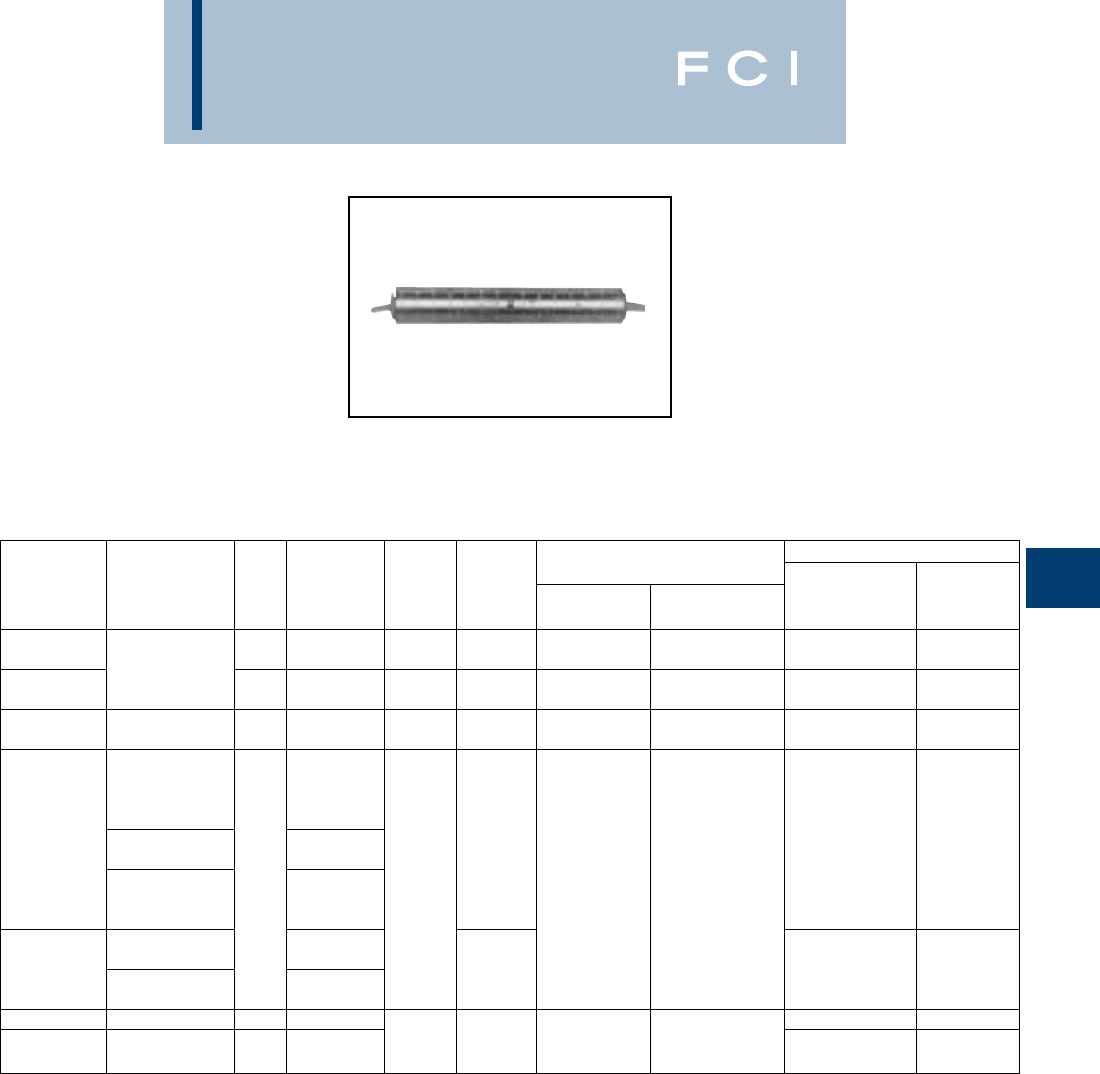
BURNDY
Overhead
E-47
TYPES YSS,YCS-R &
YDS-AT
HYSPLICE™
For Aluminum, ACSR, 6201,
5005 and Compressed.
Single aluminum sleeve designed for service
drop or short span overhead distribution
lines. Installed with OH25 one-hand tool, and
other standard tooling. Pre-filled with
PENETROX™ joint compound and color
coded capped.
*Multiple crimp die set; makes more than one crimp per tool
compression. Figure indicates number of compressions.
** Holding strength values up to 800 lbs. are obtained when
HYPRESS™ tools are used for installations.
†U Die with adapter PT-6515
‡U Die with adapter PUADP-1.
TOOLS, DIE SETS CATALOG OH25 APPLICATIONS
HOLDING NUMBER, & (CRIMPS PER END) OH25
CATALOG STRENGTH DIE COLOR Y35, Y750, (INDENTS
NUMBER CONDUCTOR L LBS. INDEX CODE MD7, MD6 Y45†, Y46‡ CONDUCTOR PER END)
900 BG or BG (6)
YSS6RG2 6 ACSR 4.00 700 5/8 Blue W-BG (3)* U-BG (3)* — —
4 Sol. Al 900
YSS6R 4.72 700 162 Blue W162 (4) U162 (2)* — —
YDS4WA 4 Sol. Al 750**
YDS4CA 4 Str. Al (7) 2.62 700** 162 Orange W162 (4) U162 (1)* — —
47 Al (3)
45005 Al (2)
4 ACSR 1000 45005 Al (3)
4(6-1) ACSR (3)
YSS4R Orange 4 (6-1) ACSR (2)
2 Sol. Al 800 4(7-1) ACSR (3)
3.78 BG or BG (6) U-BG (3)* 4 (7-1) ACSR (2)
2 Al (7) 700 5/8 W-BG (3)* 2Sol. Al (3)
2Sol. Al (2)
2(6-1) ACSR (3)
2 ACSR 1600 2(7-1) ACSR (3)
YSS2R Red 2(7-1) ACSR (2)
2 Al (7) 1200 27 Al (3)
YDS25AT 1/0 Al (7) 7.27 2000 BG, 5/8 1/0 7 Al (4)
or Yellow BG (12) U-BG (6)* 1/0 (6-1) ACSR (2)
YCS25R 1/0 ACSR 7.09 2320 243 W-BG (6)* 1/0 (6-1) ACSR (3)
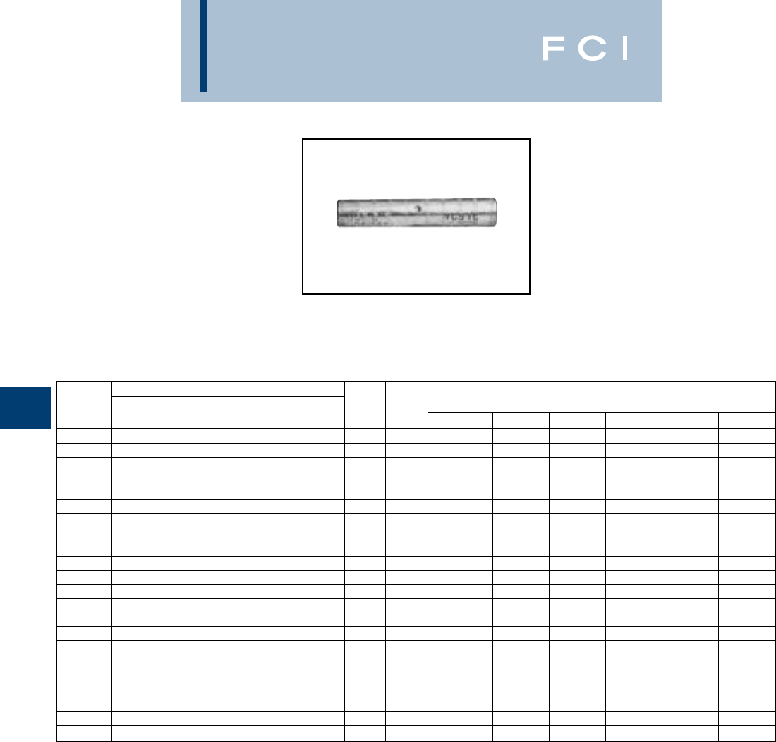
BURNDY
Overhead
E-48
TYPE YCS-R
HYSPLICE™
Jumper Sleeve for ACSR, All
Aluminum, 6201, 5005 and
Compressed
HYSPLICE™ sleeve designed to withstand
jumper loop tensile and vibration stresses.
Made of aluminum with staked-in cable stop.
Installed with same die as equivalent full-
tension sleeves. Pre-filled with PENETROX™
joint compound.
†U Die with adapter PT-6515
‡U Die with adapter PUADP-1.
CONDUCTOR
CATALOG ALL DIE TOOLS, DIE SET CATALOG NUMBER, & (CRIMPS PER END)
NUMBER ACSR, 6201, 5005 ALUMINUM L INDEX MD7, MD6 Y35, Y750 Y45 Y46 Y48B Y60BHU
YCS4R 44 (7) 5 237 W237 (4) U237 (2) † ‡ — —
YCS2R 22 (7) 5 239 W239 (4) U239 (2) † ‡ — —
WBG (10) UBG (10)
YCS25R 1/0 1/0 (7, 19) 7-1/8 243 or or † ‡ — —
W243 (6) U243 (3)
YCS26R 2/0 2/0 (7, 19) 7 245 W245 (6) U245 (3) † ‡ — —
3/0
YCS27R 110.8 (12-7) 3/0 (7, 19) 5-3/4 247 W247 (6) U247 (3) † ‡ — —
YCS28R 4/0 4/0 (7, 19) 5-3/4 249 W249 (6) U249 (3) † ‡ C249 (2) L249 (2)
YCS30R 266.8 (6/7, 18/1, 26/7) 266.8 6.47 251 W251 (10) U251 (6) † ‡ C251 (3) L251 (3)
YCS321R 336.4 (18-1) 300 336.4 (19) 6-1/2 490 — U490 (5) † ‡ C490 (3) L490 (3)
YCS33R 336.4 (26-7, 30-7) 397.5 (19) 8-3/4 316 — U316 (6) † ‡ C316 (2) L316 (2)
477 (19, 37)
YCS35R 397.5 (18-1, 26-7, 30-7) 500 (37, 61) 8-7/8 317 — U317 (6) † ‡ C317 (2) L317 (2)
YCS361R 477 (18-1) 500 (37, 61) 8-1/4 327 — U327 (6) † ‡ C327 (2) L327 (2)
YCS37R 477 (24-7, 26-7, 30-7) 556.5 (18-1) 556.5 (19, 37) 8-3/4 261 — U261 (6) † ‡ C261 (2) L261 (2)
YCS39R 556.5 (24-7, 26-7) — 10-3/4 608 — U608 (9) † ‡ C608 (3) L608 (3)
605 (30-19)
YCS43R 636 (24-7, 26-7, 30-19) 795 (37) 10-5/8 292 or ——
S292 (9) P292 (9) C292 (3) L292 (3)
666.6 (24-7, 54-7) 319 S319 (9) P319 (9) C319 (3) L319 (3)
YCD453R 795 (36-1, 45-7) — 10-5/8 292 — — S292 (9) P292 (9) C292 (3) L292 (3)
YCS45R 795 (26-7, 54-7) 900 (61, 91) 10-5/8 352 — — S352 (9) P352 (9) C352 (3) L352 (3)

BURNDY
Overhead
E-49
TYPE YCS-RL
UNISPLICE™
Jumper Sleeve for ACSR, All
Aluminum 6201, 5005
Compressed and Compact
Conductors.
Aluminum jumper sleeve, with cable stop,
designed to be installed with same dies as
equivalent full-tension UNISPLICE™.
Withstands jumper loop-tensile and vibration
stresses. Pre-filled with PENETROX™ joint
compound and capped.
*MD6 NON-BOW Dies produce straight sleeves without
rotating tool.
†U Die with adapter PT-6515
‡U Die with adapter PUADP-1.
††† Accommodates ACSR with aluminized steel core.
TOOLS, DIE SET CATALOG
CATALOG DIE NUMBER, & (CRIMPS PER END)
NUMBER CONDUCTOR ††† L INDEX MD7, MD6 Y35, Y750, Y45†, Y46‡
1/0 ACSR (6-1) W-C (12) —
1/0 6201 (7) — U247 (3)
YCS25RL 1/0 5005 (7) 6-1/4 C or 247 or 702 W702 (4)
1/0 AAC (7) NON-BOW* —
2/0 ACSR (6-1)
2/0 6201 (7)
YCS26RL 2/0 5005 (7) 5-5/8 659 — U659 (3)
2/0 AAC (7)
4/0 ACSR (6-1)
4/0 6201 (7)
YCS28RL 4/0 5005 (7) 5-1/4 654 — U654 (3)
4/0 AAC (7)
336.4 ACSR (18-1)
YCS321RL 336.4 AAC (19) 5-1/4 655 — U655 (3)
397.5 AAC (19)
397.5 ACSR (18-1)
400 AAC (37, 61)
YCS341RL 18-1 5-5/8 327 — U327 (4)
336.4 ACSR (26-7 )
30-7
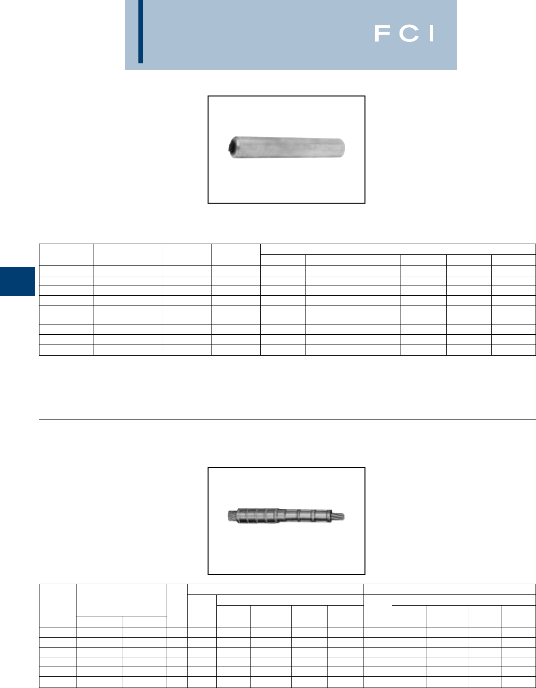
BURNDY
Overhead
E-50
TYPE YCS-A
JUMPER SLEEVE
For All Aluminum, Compressed
and Compact Conductors.
HYSPLICE™ sleeve designed to withstand
jumper loop tensile and vibration stresses.
Made of aluminum with staked-in cable stop.
Installed with same die as equivalent full-
tension sleeve. Pre-filled with PENETROX™
joint compound and capped.
†U Die with adapter PT-6515
‡U Die with adapter PUADP-1.
TYPE YCR
JUMPER SLEEVE REDUCER
For Copper Conductors.
Copper sleeve designed to join different size
copper conductors on transmission jumper
applications. installed with same dies as
full-tension sleeves.
*Multiple crimp die set; makes more than one crimp per tool
compression. Figure indicates number of compressions.
†UDie with adapter PT-6515.
‡U Die with adapter PUADP-1.
CATALOG DIE TOOLS, DIE SET CATALOG NUMBER, & (CRIMPS PER END)
NUMBER CONDUCTOR L INDEX MD7, MD6 Y35, Y750 Y45 Y46 Y48B Y60BHU
YCS26A 2/0 (7) 5-1/8 245 W245 (4) U245 (2) † ‡ — —
YCS28A 4/0 (7, 19) 4 249 W249 (4) U249 (2) † ‡ C249 (1) L249 (1)
YCS301A 336.4 (19, 37) 4-3/8 321 — U321 (3) † ‡ C321 (2) L321 (2)
YCS311A 397.5 (19) 5-5/8 468 — U468 (4) † ‡ — —
YCS331A 477 (19, 37, 61) 6-14 317 — U317 (6) † ‡ C317 (2) L317 (2)
YCS331A 500 (19, 37, 61) 6-1/4 317 — U317 (6) † ‡ C317 (2) L317 (2)
YCS351A 556.5 (19, 37) 8-3/4 261 — U261 (6) † ‡ C261 (2) L261 (2)
YCS361A 636 (37) 7-3/8 469 — — S469 (6) P469 (6) C469 (2) L469 (2)
YCS391A 795 (37, 61) 10-1/2 342 — — S342 (9) P342 (9) C342 (3) L342 (3)
TOOLS, DIE SET CATALOG NO., & (CRIMPS PER END) TOOLS, DIE SET CATALOG NO., & (CRIMPS PER END)
SIDE A SIDE B
CATALOG COPPER CONDUCTOR DIE Y35, Y750, DIE Y35, Y750,
NUMBER SIDE A SIDE B L INDEX MD7, MD6 Y45†, Y46‡ Y48B Y60BHU INDEX MD6 Y45†, Y46‡ Y48B Y60BHU
YCR2C4W 2 (7) 4 Sol. 3-3/4 163 W163 (3) U163 (1)* C163 (1)* L163 (1)* 162 W162 (4) U162 (1)* C162 (1)* L162 (1)
YCR2625 2/0 (7, 12, 19) 1/0 (7, 19) 3-3/8 166 W166 (6) U166/U459 C166 (1) L166 (1) 165 W165 (3) U165/U205 C165 (1) L165 (1)
YCR2725 3/0 (7, 19) 1/0 (7, 19) 3-1/2 167 — U167/U568 C167 (1) L167 (1) 165 W165 (3) U165/U205 C165 (1) L165 (1)
YCR2825 4/0 (7, 12, 19) 1/0 (7, 19) 3-3/8 168 — U168 (3) C168 (1) L168 (1) 165 W165 (3) U165/205 C165 (1) L165 (1)
YCR3228 400 (19, 37) 4/0 (7, 12, 19) 5-1/2 209 — U209 (6) C209 (2) L209 (2) 168 — U168 (3) C168 (1) L168 (1)
YCR3425 500 (19, 37) 1/0 (7, 19) 6 210 — U210 (6) C210 (2) L210 (2) 165 W165 (3) U165/205 C165 (1) L165 (1)
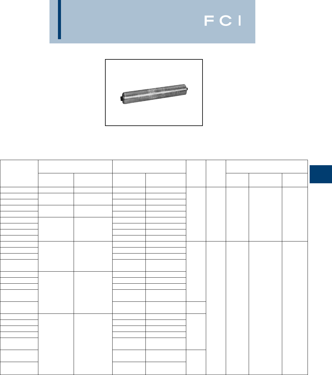
BURNDY
Overhead
E-51
TYPE YCR-R-G
HYSPLICE™
Jumper Sleeve Reducer for
ACSR, AAAC and Aluminum to
Copper.
Heavy-walled aluminum sleeve designed to
connect all aluminum or ACSR to copper
conductors, in all service conditions encoun-
tered in transmission and distribution. Sleeve
has solid center barrier and is pre-filled with
PENETROX™ joint compound and capped.
*Crimps overlap on both ends.
†U Die with adapter PT-6515
‡U Die with adapter PUADP-1.
TOOLS, DIE SET CATALOG
SIDE A SIDE B NO., & (CRIMPS PER END)
CATALOG ACSR, 6201, ALUMINUM, ACSR, 6201, ALUMINUM, DIE Y35, Y750,
NUMBER 5005 COPPER 5005 COPPER L O.D. INDEX Y45†, Y46‡ Y60B
YCR25RG6 1/0 (6-1) 1/0 (7, 12, 19) 1/0 (6-1) 1/0 (7, 12, 19)
YCR26RG2 1/0 (6-1) 1/0 (7, 12, 19)
YCR26RG3 2/0 (6-1) 2/0 (7, 12, 19) 2/0 (6-1) 2/0 (7, 12, 19) U654 L654
YCR27RG5 1/0 (6-1) 1/0 (7, 12, 19) 654 U705 —
YCR27RG6 3/0 (6-1) 3/0 (7, 12, 19) 2/0 (6-1) 2/0 (7, 12, 19) 6-3/8 1-1/16 or
YCR28RG5 1/0 (6-1) 1/0 (7, 12, 19) 705 Crimps Crimps
YCR28RG6 2/0 (6-1) 2/0 (7, 12, 19) Overlap Overlap
YCR28RG7 4/0 (6-1) 4/0 (7, 12, 19) 3/0 (6-1) 3/0 (7, 12, 19)
YCR28RG8 4/0 (6-1) 4/0 (7, 12, 19)
YCR291RG2 2/0 (6-10 2/0 (7, 12, 19)
YCR291RG3 3/0 (6-1) 3/0 (7, 12, 19)
YCR291RG4 266.8 (18-1) 250 (19, 37) 4/0 (6-1) 4/0 (7, 12, 19)
266.8 (7, 12, 19) 250 (19, 37)
YCR291RG5 266.8 (18-1) 266.8 (7, 12, 19)
YCR30RG4 1/0 (6-1) 1/0 (7, 12, 19) 7-3/8
YCR30RG6 3/0 (6-1) 3/0 (7, 12, 19)
YCR30RG7 4/0 (6-1) 4/0 (7, 12, 19) U317 L317
266.8 (26-7) 300 (19, 37) 250 (19, 37) U705 —
YCR30RG8 336.4 (19) 266.8 (18-1) 266.8 (7, 12, 19)
300 (19, 37) 317
YCR30RG9 266.8 (26-7) 336.4 (19) 6-5/8 1-1/4 or
YCR32RG1 1/0 (6-1) 1/0 (7, 12, 19) 705 Crimps Crimps
YCR32RG2 2/0 (6-1) 2/0 (7, 12, 19) Overlap Overlap
YCR32RG3 3/0 (6-1) 3/0 (7, 12, 19)
YCR32RG4 4/0 (6-1) 4/0 (7, 12, 19) 7-3/8
336.4 (18-1) 350 (19, 37) 250 (19, 37)
YCR32RG5 (26-7) 397.5 (19) 266.8 (18-1) 266.8 (7, 12, 19)
300 (19, 37)
YCR32RG6 266.8 (26-7) 336.4 (19)
336.4 (18-1) 350 (19, 37) 6-5/8
YCR32RG7 (26-7) 397.5 (19)
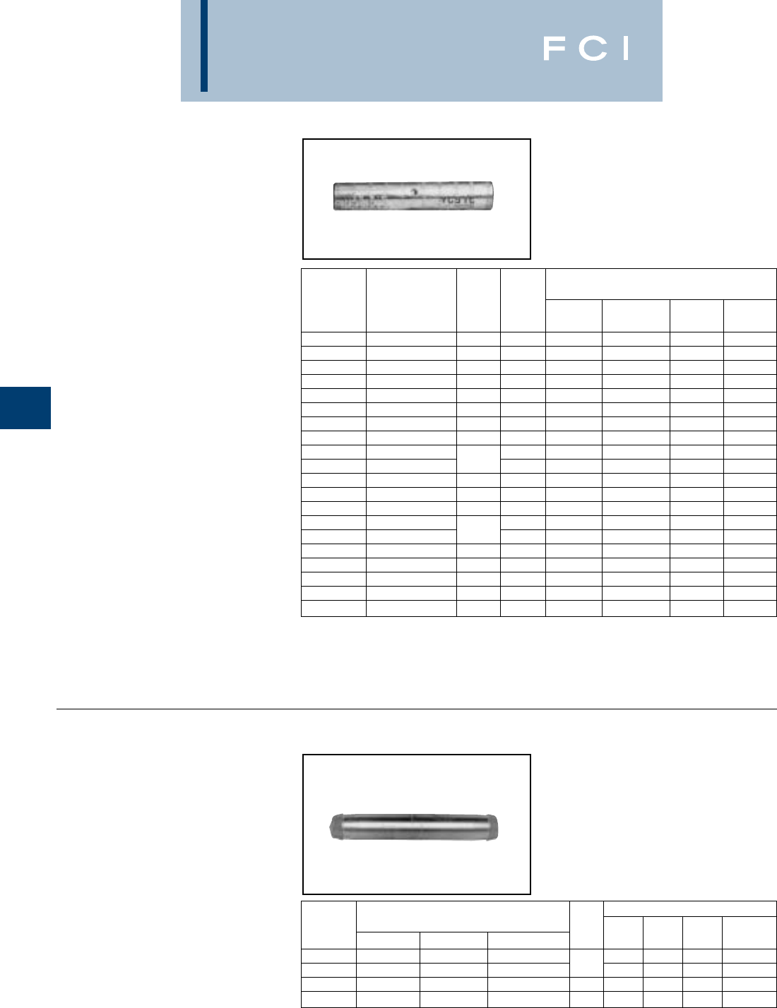
BURNDY
Overhead
E-52
TYPES YDS & YCS
HYSPLICE™
Jumper Sleeve for
Copper Conductors.
Loop HYSPLICE™ connector designed to
withstand jumper loop tensile and vibration
stresses. Made of pure copper tubing.
Installed with standard HYSPLICE™ tools
and dies.
*Multiple crimp die set; makes more than one crimp per tool
compression. Figure indicates number of compressions.
†U Die with adapter PT-6515
‡U Die with adapter PUADP-1.
TYPE YNS-R
Jumper Sleeve for ACSR, ACAR
and Stranded Aluminum Cable.
Jumper sleeve for ACSR, ACAR and SAC
transmission lines. Installed with same dies
as equivalent full tension splice. Sleeve is
pre-filled with PENETROX™ joint compound
and capped.
*For Extra High Voltage (EHV) applications add suffix "T" to
catalog number (e.g., YNS59RT).
** Overlap crimps.
TOOLS, DIE SET CATALOG
NO., & (CRIMPS PER END)
CATALOG DIE Y750, Y35,
NUMBER CONDUCTOR L INDEX MD7, MD6 Y45†, Y46‡ Y48B Y60BHU
YDS8W 8 Sol. 1-5/8 171 W171 (1) U171 (1)* — —
YDS6W 6 Sol. 2-5/8 161 W161 (2) U161 (1)* — —
YDS4W 4 Sol. 2-1/2 162 W162 (4) U162 (1)* — —
YDS2W 2 Sol. 3-3/4 163 W163 (6) U163 (2)* — —
YCS1W 1 Sol. 4 164 W164 (4) U164 (2)* — —
YDS6C 6 (7) 2-3/4 161 W161 (2) U161 (1)* — —
YDS4C 4 (7) 2-5/8 162 W162 (4) U162 (1)* — —
YDS2C 2 (7), 3 (3) 3-5/8 163 W163 (6) U163 (2)* — —
YDS1C 1 (7, 19) 164 W164 (4) U164 (2)* — —
YCS25 1/0 (7, 19) 3-1/8 165 W165 (3) U165 (3) — —
YCS26 2/0 (7, 11, 12, 19) 3-3/8 166 W166 (6) U166 (3) — —
YCS27 3/0 (7, 19) 3-1/4 167 — U167 (3) — —
YCS28 4/0 (7, 12, 19) 3-1/8 168 — U168 (3) C168 (1) L168 (1)
YCS29 250 (7, 19, 37) 169 — U169 (4) C169 (2) L169 (2)
YCS30 300 (19, 37) 3-5/8 170 — U170 (4) C170 (1) L170 (1)
YCS31 350 (12, 19, 37) 5-3/8 267 — U267 (6) C267 (2) L267 (2)
YCS32 400 (19, 37) 5-3/4 209 — U209 (6) C209 (2) L209 (2)
YCS34 500 (19, 37) 5-1/8 210 — U210 (6) C210 (2) L210 (2)
YCS39 750 (37) 6-7/8 627 — — C627 (3) L627 (3)
YCS44 1000 (37, 61) 7-3/4 345 — — C345 (4) L345 (4)
TOOLS, DIE SETS
CATALOG CONDUCTOR DIE
NUMBER ACAR ALUMINUM ACSR L INDEX Y45** Y46** Y60BHU**
YNS43R 700 - 800 605 - 666.6 724 S724 P724 L724
YNS451R 840.2 - 927.2 795 - 1000 715.5 - 874.5 10 725 S725 P725 L725
YNS49R 983.1 - 1198 1033.5 - 1272 900 - 1113 45/7 10-1/8 727 — — L727
YNS59R 2250 - 2300 2156 - 2167 14-1/2 735 — — L735
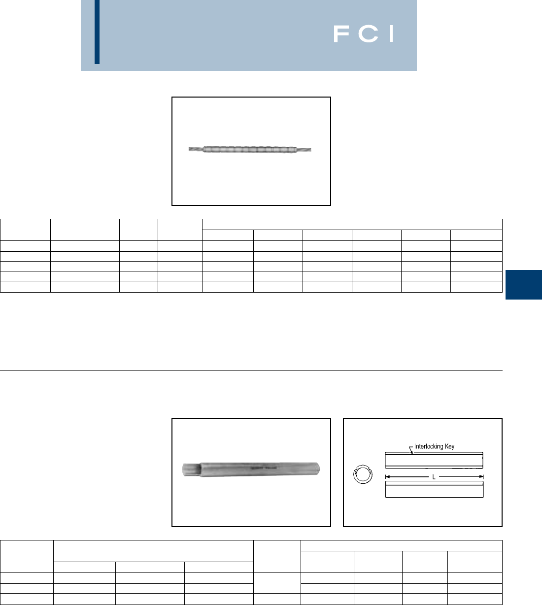
BURNDY
Overhead
E-53
TYPE YCU-A
Repair Sleeve for All Aluminum,
Compressed and Compact
Conductors
For restoring conductivity to damaged con-
ductors. Made of cast aluminum. Use same
die as equivalent full-tension sleeve. Use of
PENETROX™ joint compound required.
*Multiple crimp die set; makes more than one crimp per tool
compression. Figure indicates number of compressions.
†U Die with adapter PT-6515.
‡U Die with adapter PUADP-1.
TYPE YNU-R
Repair Sleeve for ACSR, ACAR
and Stranded Aluminum Cable
Two-piece repair sleeves for restoring con-
ductivity to damaged ACSR, ACAR or SAC
transmission lines. Installed with same dies
as equivalent full tension splice. Use of
PENETROX™ joint compound required.
*For High Voltage and Extra High Voltage (EHV) applications.
** Overlap crimps.
CATALOG DIE TOOLS, DIE SET CATALOG NO., & (NUMBER OF CRIMPS)
NUMBER CONDUCTOR L INDEX MD7, MD6 Y35, Y750 Y45 Y46 Y48B Y60BHU
YCU2CA 2 (7) 7-5/8 163 W163 (27) U163 (9)* † ‡ — —
YCU25A 1/0 (7) 8-3/4 243 W243 (20) U243 (10) † ‡ — —
YCU28A 4/0 (7, 19) 11-7/8 249 W249 (28) U249 (14) † ‡ C249 (7) L249 (7)
YCU291A 266.8 (7) 11-5/8 251 — U251 (20) † ‡ C251 (10) L251 (10)
YCU301A 336.4 (19, 37) 11-5/8 321 — U321 (20) † ‡ C321 (10) L321 (10)
TOOLS, DIE SETS
CATALOG CONDUCTOR DIE
NUMBER * ACAR ALUMINUM ACSR L INDEX Y45** Y46** Y60BHU**
YNU43R —700 - 800 605 - 666.6 724 S724 P724 L724
YNU451R 840.2 - 927.2 795 - 1000 715.5 - 874.5 16 725 S725 P725 L725
YNU49R —1033.5 - 1272 900 - 1113 16 727 — — L727
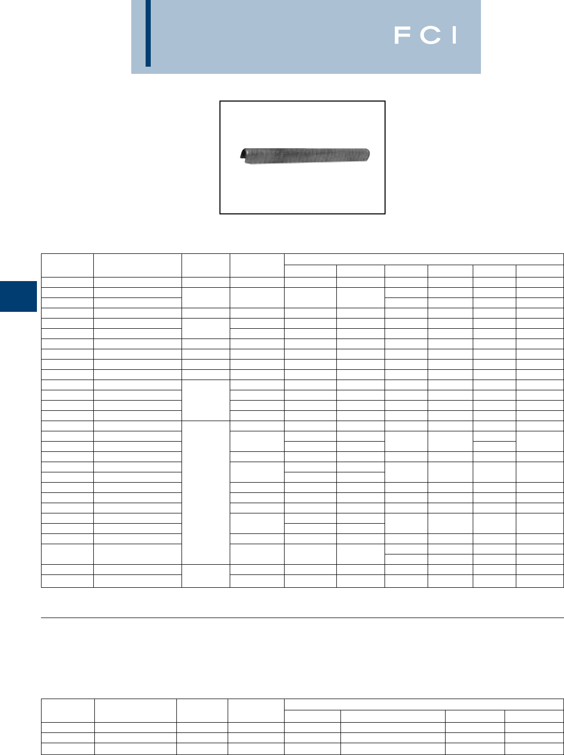
BURNDY
Overhead
E-54
TYPES YCU-R & YOU-R
Repair Sleeve for ACSR and
Compressed and Compact
Conductors
For restoring conductivity to damaged con-
ductors. Made of cast aluminum. Sizes up
thru 266.8 are U-shaped. For 300 and larger,
sleeves are two-piece interlocking elements.
Use same die as equivalent full-tension
sleeve. Use of PENETROX™ joint compound
required.
TYPE YCU-R
Repair Sleeve for
ACSR "Static Wire"
†U Die with adapter PT-6515.
†U Die with adapter PT-6515.
CATALOG DIE TOOLS, DIE SET CATALOG NO., & (NUMBER OF CRIMPS)
NUMBER CONDUCTOR L INDEX MD7, MD6 Y35, Y750 Y45 Y46 Y48B Y60BHU
YCU4R 4 (6-1, 7-1) 4AAC 6-1/4 237 W237 (12) U237 (6) † ‡ — —
YCU4RG1 4 (7-1) † ‡ — —
YCU2R 2 (6-1, 7-1) 8-1/4 239 W239 (16) U239 (8) †‡——
YCU25R 1/0 (6-1) 8-3/4 243 W243 (20) U243 (10) † ‡ — —
YCU26R 2/0 (6-1) 245 W245 (24) U245 (12) † ‡ — —
YCU27R 3/0 (6-1) 10 247 W247 (24) U247 (12) † ‡ — —
YCU28R 4/0 (6-1) 11-7/8 249 W249 (28) U249 (14) † ‡ C249 (7) L249 (7)
YCU30R 266.8 (6-7, 18-1, 26-7) 11-5/8 251 — U251 (20) † ‡ C251 (10) L251 (10)
YOU32R 300 (26-7) 13 316 — U316 (21) † ‡ C316 (7) L316 (7)
YCU321R 336.4 (18-1) 11-5/8 490, 547 — U490 (20) † ‡ C490 (10) L490 (10)
YOU33R 336.4 (26-7, 30-7) 316 — U316 (21) † ‡ C316 (7) L316 (7)
YOU35R 397.5 (18-1, 26-7, 30-7) 317, 426 — U317 (21) † ‡ C317 (7) L317 (7)
YOU361R 477 (18-1) 13 327 — U327 (21) † ‡ C327 (7) L327 (7)
YOU37R 477 (24-7, 26-7, 30-7) 261, 318 — U261 (21) † ‡ C261 (7) L261 (7)
YOU39R 556.5 (24-7, 26-7) 608 — U608 (24) † ‡ C608 (8) L608 (8)
YOU41R 605 (24-7, 54-7) — — C292 (8)
YOU43R 605 (30-19) 292, 578 ——
S292 (24) P292 (24) C352 (8) L292 (8)
YOU43R 605 (30-19) 319 — — S319 (24) P319 (24) C319 (8) L319 (8)
YOU421R 636 (36-1) — —
YOU43R 636 (26-7, 30-19) 292, 578 ——
S292 (24) P292 (24) C292 (8) L292 (8)
YOU43R 666.6 (24-7, 54-7) 319 — — S319 (24) P319 (24) C319 (8) L319 (8)
YOU453R 715.5 (26-7) 13-3/4 292578 — — S292 (24) P292 (24) C292 (8) L292 (8)
YOU453R 795 (36-1) 319 — — S319 (24) P319 (24) C319 (8) L319 (8)
YOU453R 795 (36-1) — —
YOU44R 715.5 (54-7) 292, 578 ——
S292 (24) P292 (24) C292 (8) L292 (8)
YOU44R 715.5 (54-7) 319 — — S319 (24) P319 (24) C319 (8) L319 (8)
S352 (24) P352 (24) C352 (8) L352 (8)
YOU45R 795 (26-7, 54-7) 352, 579 — — S579 (24) P579 (24) C579 (8) L579 (8)
YOU48R 900 (54-7) 954 (54-7) 575 — — — — C575 (10) L575 (10)
YOU49R 1033.5 (54-7) 14-1/4 422 — — — — — L422 (10)
‡U Die with adapter PUADP-1.
CATALOG DIE TOOLS, DIE SET CATALOG NO., & (NUMBER OF CRIMPS)
NUMBER CONDUCTOR L INDEX MD7, MD6 Y35, Y750, Y45†, Y46‡ Y48B Y60BHU
YCU27R 110.8 (12-7) 10 247 W247 (24) U247 (12) — —
YCU28R 159 (12-7) 11-7/8 249 W249 (28) U249 (14) C249 (7) L249 (7)
YCU30R 190.8 (12-7) 11-5/8 251 — U251 (20) C251 (10) L251 (10)
‡U Die with adapter PUADP-1.

BURNDY
Overhead
E-55
TYPES YDS-A
& YDS-AT
HYSPLICE™
Full Tension Sleeve for All
Aluminum Compressed and
Compact Conductors
Full-Tension HYSPLICE™ sleeve made of
aluminum tubing with staked-in cable stop.
Sizes 1/0 and larger tapered for gradual tran-
sition of stress. Installed with HYSPLICE™
tools and dies. Pre-filled with PENETROX™
joint compound and capped.
*Multiple crimp die set; makes more than one crimp per tool
compression. Figure indicates number of compressions.
†U Die with adapter PT-6515.
‡ U Die with adapter PUADP-1.
CATALOG DIE TOOLS, DIE SET CATALOG NO., & (NUMBER OF CRIMPS)
NUMBER CONDUCTOR L INDEX MD7, MD6 Y35, Y750 Y45 Y46 Y48B Y60BHU
YDS6WA 6 Sol. 3 161 W161 (2) U161 (1)* † ‡ — —
YDS4WA 4 Sol. 2-5/8 162 W162 (4) U162 (1)* † ‡ — —
YDS2WA 2 Sol. 3-7/8 163 W163 (6) U163 (2)* † ‡ — —
YDS6CA 6 (7) 3 161 W161 (2) U161 (1)* † ‡ — —
YDS4CA 4 (7) 2-5/8 162 W162 (4) U162 (1)* † ‡ — —
YDS2CA 2 (7) 3-7/8 163 W163 (6) U163 (2)* † ‡ — —
BG BG (12) BG (3)
YDS25AT 1/0 (7) 7-1/4 or or or † ‡ — —
243 W243 (6) U243 (3)
YDS26AT 2/0 (7) 9-1/4 245 W245 (8) U245 (4) † ‡ — —
YDS27AT 3/0 (7, 19) 7-1/4 247 W247 (8) U247 (4) † ‡ C247 (2) L247 (2)
YDS28AT 4/0 (7, 19) 10-1/2 249 W249 (12) U249 (6) † ‡ C249 (3) L249 (3)
YDS29AT 250 (19) 7-1/2 616 — U616 (6) † ‡ — —
YDS291AT 266.8 (7, 19) 8-5/8 251 — U251 (7) † ‡ C251 (4) L251 (4)
YDS301AT 336.4 (19, 37) 9-7/8 321 — U321 (8) † ‡ C321 (4) L321 (4)
YDS31AT 350 (19) 11 490 — U490 (9) † ‡ C490 (5) L490 (5)
YDS311AT 397.5 (19) 12-1/4 468 — U468 (10) † ‡ — —
YDS331AT 477 (19) 317 — U317 (9) † ‡ C317 (3) L317 (3)
YDS351AT 556.5 (19, 37) 12-3/4 261 — U261 (9) † ‡ C261 (3) L261 (3)
YDS361AT 636 (37) 13-1/2 469 — — S469 (12) P469 (12) C469 (4) L469 (4)
YDS391AT 795 (37, 800 (61)) 13-5/8 342 — — S342 (12) P342 (12) C342 (4) L342 (4)
YDS431AT 954 (37, 61) 17-5/8 352 — — S352 (15) P352 (15) C352 (5) L352 (5)
YDS451AT 1272 (61) 18-1/2 422 — — — — — L422 (6)
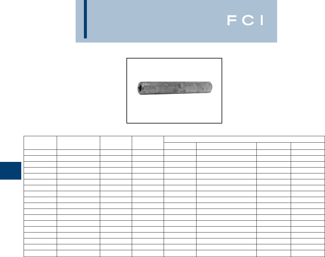
BURNDY
Overhead
E-56
TYPES YDS & YDS-C
HYSPLICE™
Full Tension Sleeve for Stranded
Copper Conductors.
Made of pure copper tubing. Designed to
develop the full rated breaking strength of
hard drawn or medium hard drawn copper
conductor. Installed with standard tooling.
*Multiple crimp die set; makes more than one crimp per tool
compression. Figure indicates number of compressions.
†U Die with adapter PT-6515.
‡U Die with adapter PUADP-1.
CATALOG STRANDED DIE TOOLS, DIE SET CATALOG NO., & (NUMBER OF CRIMPS)
NUMBER CONDUCTOR L INDEX MD7, MD6 Y35, Y750, Y45†, Y46‡ Y48B Y60BHU
YDS6C 6 (7) 2-3/4 161 W161 (2) U161 (1)* — —
YDS4C 4 (7) 2-5/8 162 W162 (4) U162 (1)* — —
YDS3C-3 3 (3) 5-1/4 163 W163 (9) U163 (3)* — —
YDS2C 2 (7) 3-5/8 163 W163 (6) U163 (2)* — —
YDS2C-3 2 (3) 3-5/8 163 W163 (6) U163 (2)* — —
YDS1C 1 (7, 19) 4-1/4 164 W164 (6) U164 (3)* — —
YDS1C-3 1 (3) 6-1/4 459 — U459 (6) — —
YDS25 1/0 (7, 19) 5-3/8 165 W165 (6) U165/U205 (6) — —
YDS26 2/0 (7, 12, 19) 6 166 W166 (12) U166/U459 (6) — —
YDS27 3/0 (7, 19) 6-3/4 167 — U167/U568 (7) — —
YDS28 4/0 (7, 12, 19) 6-7/8 168 — U168 (9) C168 (3) L168 (3)
YDS29 250 (7, 19, 37) 7-1/2 169 — U169 (9) C169 (3) L169 (3)
YDS30 300 (19, 37) 8-1/8 170 — U170 (13) C170 (3) L170 (3)
YDS31 350 (12, 19, 37) 10-1/4 267 — U267 (12) C267 (4) L267 (4)
YDS32 400 (19, 37) 12-3/4 209 — U209 (15) C209 (5) L209 (5)
YDS34 500 (19, 37) 11-5/8 210 — U210 (15) C210 (5) L210 (5)
YDS39 750 (37) 12-3/4 627 — — C627 (7) L627 (7)
YDS44 1000 (61, 37) 15-1/4 345 — — C345 (10) L345 (10)
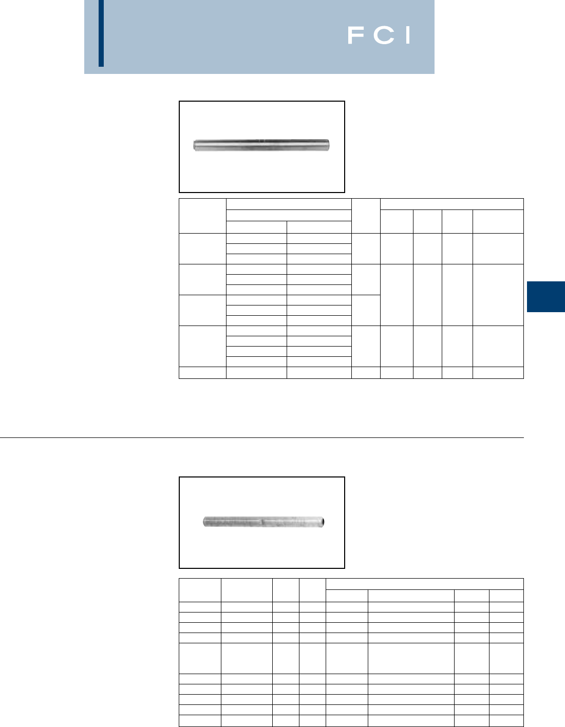
BURNDY
Overhead
E-57
TYPE YTS-A
Full Tension Splice for Stranded
Aluminum Cable
Full tension splice for SAC transmission lines.
Made of aluminum tube with staked-in cable
stop. Pre-filled with PENETROX™ joint
compound and capped.
*For Extra High Voltage (EHV) applications add suffix "T" to
catalog number (e.g., YTS391AT).
** Overlap crimps.
TYPES YDS-W & YDS
HYSPLICE™
Full Tension Sleeve for Solid
Copper Conductors
YDS-W is designed to develop full rated
breaking strength of hard drawn and medium
hard drawn solid copper conductor. Made
of pure copper tubing. Installed with
standard tooling.
*Multiple crimp die set; makes more than one crimp per tool
compression. Figure indicates number of compressions.
†U Die with adapter PT-6515.
‡U Die with adapter PUADP-1.
CONDUCTOR TOOLS, DIE SETS
CATALOG ALUMINUM DIE
NUMBER * CODE MCM. STR. L INDEX Y45** Y46** Y60BHU**
—450 37
YTS331A COSMOS 477 19 9-1/4 719 S719 P719 L719
SYRINGA 477 37
VIOLET 715.5 37
YTS39A NASTURTIUM 715.5 61 13-3/8
CATTAIL 750 61
ARBUTUS 795 37 724 S724 P724 L724
YTS391A LILAC 795 61 15-3/4
—800 61
—874.5 37
CROCUS 874.5 61
YTS431A MAGNOLIA 954 37 16-1/2 725 S725 P725 L725
GOLDENROD 954 61
YTS463A COREOPSIS 1590 61 21-1/2 728 — — L728
CATALOG SOLID DIE TOOLS, DIE SET CATALOG NO., & (CRIMPS PER END)
NUMBER CONDUCTOR L INDEX MD7, MD6 Y35, Y750, Y45†, Y46‡ Y48B Y60BHU
YDS8WG1 81-7/8 161 W161 (1) U161 (1) — —
YDS8W 81-1/2 171 W171 (1) U171 (1)* — —
YDS6W 62-5/8 161 W161 (2) U161 (1)* — —
YDS4W 42-5/8 162 W162 (4) U162 (1)* — —
163
YDS3W 32-7/8 or W163 (4) U163 (1)* ——
308 —U308 (2)*
YDS2W 24163 W163 (6) U163 (2)* — —
YDS1W 15-7/8 164 W164 (8) U164 (4)* — —
YDS75 1/0 6-1/4 165 W165 (6) U165/U205 (6) — —
YDS76 2/0 6-5/8 166 W166 (12) U166/U459 (6) — —
YDS78 4/0 7-7/8 168 — U168 (9) C168 (3) L168 (3)
BURNDY
Overhead
E-58
TYPES YDS-R SET,
YDS-RP1
ALUMINUM SLEEVE
YDS-RP2
STEEL SLEEVE
HYSPLICE™
Full Tension Sleeve for ACSR,
Compressed and Compact
Conductors
Two-piece, full tension HYSPLICE™,
consists of aluminum outer sleeve and steel
inner sleeve. Tapered outer sleeve provides
gradual transition of stress. Filler holes
provided for PENETROX™ joint compound.
Sizes 1/0 and larger supplied with plugs for
filler hole. Installed with standard
HYSPLICE™ tools and dies (thru 556 with
Y35 or Y750 HYPRESS™). Aluminum and
steel sleeves can be ordered separately or in
sets.
*Multiple crimp die set; makes more than one crimp per tool
compression. Figure indicates number of compressions.
†U Die with adapter PT-6515.
‡U Die with adapter PUADP-1.
TOOLS, DIE SET CATALOG
NO., & (CRIMPS PER END)
CATALOG NUMBER DIE Y35, Y750,
SET SLEEVES
CONDUCTOR
LINDEX MD7, MD6 Y45†, Y46‡ Y48B Y60BHU
Steel YDS25RP2 4-3/4 242 W242 (8) U242 (4)
YDS021R Alum. YDS021RP1 2 (7-1) 17 241 W241 (10) U241 (5) ——
Steel YDS1RP2 4-1/8 240 W240 (6) U240 (3) — —
YDS1R Alum. YDS1RP1 1 (6-1) 16-5/8 241 W241 (10) U241 (5) — —
Steel YDS25RP2 4-3/4 242 W242 (8) U242 (4) — —
YDS25R Alum. YDS25RP1 1/0 (6-1) 17 243 W243 (10) U243 (5) — —
Steel YDS26RP2 5-1/4 242 W242 (8) U242 (4) — —
YDS26R Alum. YDS26RP1 2/0 (6-1) 19-3/4 245 W245 (12) U245 (6) — —
Steel YDS27RP2 5-1/4 248 W246 (16) U248 (8) C248 (3)* L248 (3)*
YDS27R Alum. YDS27RP1 3/0 (6-1) 16-3/4 247 W247 (12) U247 (6) C247 (2)* L247 (2)*
Steel YDS28RP2 5-1/8 248 W248 (14) U248 (7) C248 (2)* L248 (2)*
YDS28R Alum. YDS28RP1 4/0 (6-1) 18-7/8 249 W249 (14) U249 (7) C249 (4) L249 (4)
Steel YDS1RP2 4-1/8 240 W240 (6) U240 (3) —
YDS291R Alum. YDS291RP1 266.8 (18-1) 19-3/4 251 — U251 (12) C251 (6) L251 (6)
Steel YDS30RP2 6250 — U250 (10) C250 (8) L250 (8)
YDS30R Alum. YDS30RP1 266.8 (26-7) 19-3/4 251 — U251 (10) C251 (5) L251 (5)
Steel YDS25RP2 4-3/4 242 W242 (8) U242 (4) C242 (2)* L242 (2)*
YDS321R Alum. YDS321RP1 336.4 (18-1) 17-7/8 490 — U490 (10) C490 (5) L490 (5)
Steel YDS32RP2 6-7/8 252 — U252 (9) C252 (3) L252 (3)
YDS32R Alum. YDS33RP1 336.4 (26-7) 22-1/4 316 — U316 (9) C316 (3) L316 (3)
Steel YDS41RP2 8-5/8 305 — U305 (9) C305 (3) L305 (3)
YDS33R Alum. YDS33RP1 336.4 (30-7) 22-1/4 316 — U316 (9) C316 (3) L316 (3)
Steel YDS34RP2 6-1/4 253 — U253 (9) C253 (3) L253 (3)
YDS34R Alum. YDS35RP1 397.5 (26-7) 25-5/8 317 — U317 (12) C317 (4) L317 (4)
Steel YDS44RP2 8255 — U255 (12) C255 (4) L255 (4)
YDS35R Alum. YDS35RP1 397.5 (30-7) 25-5/8 317 — U317 (12) C317 (4) L317 (4)
Steel YDS27RP2 5-1/4 248 W248 (16) U248 (8) C248 (4)* L248 (4)*
YDS361R Alum. YDS361RP1 477 (18-1) 25-3/8 327 — U327 (16) C327 (4) L327 (4)
Steel YDS34RP2 6-1/4 253 — U253 (9) C253 (3) L253 (3)
YDS326R Alum. YDS37RP1 477 (24-7) 26-3/8 261 — U261 (12) C261 (4) L261 (4)
Steel YDS36RP2 7-7/8 350 — U350 (12) C350 (4) L350 (4)
YDS36R Alum. YDS37RP1 477 (26-7) 26-3/8 261 — U261 (12) C261 (4) L261 (4)
BURNDY
Overhead
E-59
TYPES YDS-R SET,
YDS-RP1
ALUMINUM SLEEVE
YDS-RP2
STEEL SLEEVE
(Continued)
Full Tension Sleeve for ACSR
and Compressed and Compact
Conductors
*†U Die with adapter PT-6515.
‡U Die with adapter PUADP-1.
FOR ACSR "STATIC" WIRE
†U Die with adapter PT-6515.
‡U Die with adapter PUADP-1.
TOOLS, DIE SET CATALOG NO., & (CRIMPS PER END)
CATALOG NUMBER DIE MD7,
SET SLEEVES CONDUCTOR L INDEX MD6 Y35, Y750 Y45 Y46 Y48B Y60BHU
Steel YDS41RP2 8-5/8 305 — U305 (9) † ‡ C305 (3) L305 (3)
YDS392R Alum. YDS39RP1 556.5 (24-7) 26-1/8 608 — U608 (15) † ‡ C608 (5) L608 (5)
Steel YDS44RP2 8255 — U255 (12) † ‡ C255 (4) L255 (4)
YDS39R44RS Alum. YDS39RP1 556.5 (26-7) 26-1/8 608 — U608 (15) † ‡ C608 (5) L608 (5)
Steel YDS43RP2 8254 — — S254 (15) P254 (15) C254 (5) L254 (5)
YDS43R43RS Alum. YDS43RP1 636 (24-7) 32-1/2 319 — — S319 (18) P319 (18) C319 (6) L319 (6)
Steel YDS45RP2 9320 — — S320 (15) P320 (15) C320 (5) L320 (5)
YDS43R45RS Alum. YDS43RP1 636 (26-7) 32-1/2 319 — — S319 (18) P319 (18) C319 (6) L319 (6)
Steel YDS43RP2 8254 — — S254 (15) P254 (15) C254 (5) L254 (5)
YDS43R43RS Alum. YDS43RP1 666.6 (24-7) 32-1/2 319 — — S319 (18) P319 (18) C319 (6) L319 (6)
Steel YDS49RP2 10 419 — — S419 (21) P419 (21) C419 (7) L419 (7)
YDS451R49RS Alum. YDS451RP1 795 (26-7) 32-1/2 579 — — S579 (18) P579 (18) C579 (6) L579 (6)
Steel YDS45RP2 9320 — — S320 (15) P320 (15) C320 (5) L320 (5)
YDS45R45RS Alum. YDS45RP1 795 (54-7) 32-1/2 352 — — S352 (18) P352 (18) C352 (6) L352 (6)
Steel YDS34RP2 6-1/4 253 — U253 (9) † ‡ C253 (3) L253 (3)
YDS451R34RS Alum. YDS451RP1 900 (45-7) 32-1/2 579 — — S579 P579 C579 (6) L579 (6)
Steel YDS49RP2 10 419 — — — — C419 (7) L419 (7)
YDS49R49RS Alum. YDS49RP1 1033.5 (54-7) 37 422 — — — — — L422 (8)
Steel YDS36RP2 7-7/8 350 — U350 (12) † ‡ C350 (4) L350 (4)
YDS49R36RS Alum. YDS49RP1 1113 (45-7) 37 422 — — — — — L422 (8)
CATALOG NUMBER DIE TOOLS, DIE SET CATALOG NO., & (CRIMPS PER END)
SET SLEEVES CONDUCTOR L INDEX MD7, MD6 Y35, Y750, Y45†, Y46‡ Y48B Y60BHU
Steel YDS27RP2 5-1/4 248 W248 (16) U248 (8) — —
YDS011R Alum. YDS011RP1 80 (1-8) 19-3/4 245 W245 912) U245 (6) — —
Steel YDS34RP2 6-1/4 253 — U253 (9) C253 (3) L253 (3)
YDS251R Alum. YDS251RP1 101.8 (12-7) 22-1/4 316 — U316 (9) C316 93) L316 (3)
Steel YDS41RP2 8-5/8 305 — U305 (9) C305 (3) L305 (3)
YDS261R Alum. YDS261RP1 134.6 (12-7) 22-1/4 316 — U316 (9) C316 (3) L316 (3)
Steel YDS44RP2 8255 — U255 (12) C255 (4) L255 (4)
YDS271R Alum. YDS271RP1 159 (12-7) 25-5/8 317 — U317 (12) C317 (4) L317 (4)
BURNDY
Overhead
E-60
TYPE AWS-R
QIKSLEEVE™
Aluminum overhead line splice for AAC,
AAAC and ACSR conductors. QIKSLEEVE™
Aerial Wedge Splice is designed for use
on Tension and Slack Span overhead
applications.
Features
•Rated for both Tension and Slack Span
applications.
•Range-taking feature replaces several
conventional designs.
•All aluminum construction.
•Open Frame design allows visual
inspection and ease of installation.
•Anti-reverse clip assists in the initial
installation of the connector. A visual
indicator also ensures verification of
installation.
•QIKSLEEVE™ is easily adjustable for
flexibility during installation.
Benefits
◊Expands the capability of conventional field
splice applications.
◊Reduces warehouse and line truck
inventory when used in place of tubular
automatics.
◊All Aluminum open style design does not
trap water and eliminates dissimilar metal
interactive corrosion.
◊Installation Confidence: Verification that
your installation was done properly.
◊30% less resistance than conventional
designs. Less than a 3 year payback in kw
savings alone.
◊Field re-adjustment capability reduces the
potential of scrapping incorrectly applied
splices.
◊Four sizes cover .184to .858conductor
diameter ranges (#6 Str.-477 ACSR).
◊Designed for future higher temperature/
higher current applications.
Wedge Advance
Thumb Tab
Conductor installation
indicator/pointer
Anti-reverse locking
clip & release tab
Channel Lock®pliers
gripping tabs to lock
QIKSLEEVE in place
Catalog Height Length Width
Number Conductor (H) (L) (W)
#6 to 1/0 AAC 1.5 in. 7.7 in. 2.2 in.
AWS25R AAAC and ACSR [38 mm] [196 mm] [56 mm]
1/0 to 4/0 AAC
AWS28R AAAC and ACSR 2006
4/0 to 336.4 AAC
AWS33R AAAC and ACSR, 2.3 in. 12.0 in. 4.0 in.
397 AAC [59 mm] [305 mm] [102 mm]
336.4 to 477 AAC
AWS36R AAAC and ACSR, 2006
556 AAC
BURNDY
Overhead
E-61
TYPES YTS-R
& YTS-RS
Full Tension Splice for ACSR
Full tension two-piece splice for ACSR
transmission lines. Outer aluminum sleeve
and inner steel sleeve ordered separately.
Aluminum sleeve has filler hole and plugs for
PENETROX™ joint compound.
*For Extra High Voltage (EHV) applications add suffix "T" to
catalog number (e..g. YTS56RT).
CATALOG CATALOG
TOOLS, DIE SETS
CONDUCTOR
NUMBER* NUMBER
ALUM. SLEEVE STEEL SLEEVE
ACSR ALUM. STEEL DIE DIE
CODE MCM. STR. SLEEVE L SLEEVE LL INDEX Y60BHU** INDEX Y60BHU**
LINNET 26/7
WIDGEON 336.4 24/7 YTS32R 17-1/4 YTS34RS 5-3/4 717 L717 718 L718
IBIS 397.5 26/7 YTS34R 719 L719
FLICKER 24/7 YTS362RS
HAWK 477 26/7 YTS36R 18-1/4 YTS36RS 720 L720 721 L721
PARAKEET 24/7 5-7/8
DOVE 556.5 26/7 YTS39R 19-7/8 YTS43RS 722 L722 723 L723
EAGLE 556.5 30/7 YTS40R 24-7/8 YTS48RS 9724 L724 726 L726
PEACOCK 24/7
DUCK 605 54/7
SQUAB 26/7
ROOK 24/7 YTS43R 21-7/16 YTS43RS 5-7/8 724 L724 723 L723
GROSEBEAK
636 26/7
GULL 54/7
FLAMINGO 666.6 24/7
CROW 54/7 YTS449RS
STARLING 715.5 26/7 YTS48RS 9
TERN 45/7 YTS481RS 9-1/8
CUCKOO 24/7 YTS451R 725 L725 726 L726
CONDOR 795 54/7 YTS449RS 9
DRAKE 26/7 YTS48RS
MALLARD 30/19 YTS59RS 9-1/8
—24/7 YTS48RS 9
RAIL 45/7 28 YTS481RS 9-1/8
CARDINAL 954 54/7 YTS48R YTS48RS 727 L727 726 L726
—9
—1027.4 48/7 YTS449RS
ORTOLAN 45/7 YTS483RS 9-1/8
—1033.5 48/7 YTS449RS
CURLEW 54/7 YTS49R YTS48RS 9727 L727 726 L726
BLUEJAY 45/7 YTS483RS 9-1/8
—1113 48/7 YTS449RS
GRACKLE 54/19 YTS48RS
BUNTING 1192.5 45/7 9
—48/7 YTS521RS
BITTERN 45/7
PHEASANT 1272 54/19 YTS52R 41 YTS59RS 9-1/8 728 L728 726 L726
DIPPER 45/7 YTS521RS 9
MARTIN 1351.5 54/19 YTS59RS 9-1/8
BOBOLINK 1431 45/7 YTS521RS
FINCH 1113 54/19 YTS48RS
NUTHATCH 45/7 YTS521RS 9
—1510.5 48/7 YTS549RS
PARROT 54/19 YTS549R 31-3/4 YTS59RS 9-1/8 729 L729
LAPWING 45/7 YTS549RS 9
FALCON 1590 54/19 YTS56R YTS59RS 9-1/8 726 L726
CHUKAR 1780 84/19 YTS58R 31-1/4 YTS48RS
BLUEBIRD 2156 84/19 YTS59RS 4-1/4 735 L735
KIWI 2167 72/7 YTS59R 42 YTS521RS
** Overlap crimps.
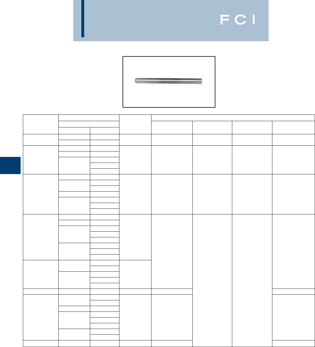
BURNDY
Overhead
E-62
TYPE YTS-AR
Full Tension Splice for ACAR
Full tension splice for ACAR transmission
lines made of aluminum tube with staked-in
cable stop. Pre-filled with PENETROX™ joint
compound and capped.
*For Extra High Voltage (EHV) applications add suffix "T"
to Catalog Number (e.g., YTS451ART).
** Overlap crimps.
*** Use die H814 in Alcoa Press H2H, die M814 in Alcoa
Press 150B and die MH814 in Alcoa Press 100A. These
dies are manufactured by BURNDY®.
CONDUCTOR TOOL, DIE SETS
CATALOG ACAR DIE
NUMBERS* MCM. STR. L INDEX Y45** Y46** Y60BHU**
395.1 12-7
YTS32AR 395.2 15-7 15-1/4 717 S717 P717 L717
634.9 12-7
649.5 18-19
YTS39AR 15-4 16-3/8 722 S722 P722 L722
653.1 12-7
18-19
840.2 24-13
30-7
853.7 24-13
YTS451AR 862.7 18-19 19-1/2 725 S725 P725 L725
30-7
927.2 24-13
18-19
983.1 30-7
1012.2 24-13
30-7
1024.5 24-13
YTS48AR 18-19 21-3/8
30-7
1081 24-13 727 L727
18-19
42-19
1277 54-7
YTS51AR 30-7 21-1/2
1280 24-13 — —
18-19
YTS55AR 1534 42-19 25-3/8 728 L728
54-7
2267 48-13
2277 42-19
54-7
YTS59AR 2338 48-13 23-1/2 814 ***
42-19
72-19
2335 30-61
YTS592AR 2493 54-37 28-3/8 990 ****
**** Use die H990 in Alcoa Press H2H, die M990 in Alcoa
Press 150B and die MH990 in Alcoa Press 100A. These
dies are manufactured by BURNDY®.

BURNDY
Overhead
E-63
TYPE YDS-RLY
UNISPLICE™ SINGLE-SLEEVE
Full Tension Sleeve for ACSR,
Aluminum, 6201 AND 5005
Single sleeve splice similar to UNISPLICE™
type YDS-RL, except designed to eliminate
possible conductor basketing on ACSR.
Installed by crimping from end of connector
towards center with standard tooling.
Supplied pre-filled with PENETROX™ joint
compound and capped. Factory installed
plugs in pressure relief holes must be in place
when conductors are inserted. Plugs drop out
when sleeve is crimped.
*Multiple crimp die set; makes more than one crimp per tool
compression. Figure indicates number of compressions.
** MD6 NON-BOW Dies produce straight sleeves without
rotating tool.
†U Die with adapter PT-6515.
‡U Die with adapter PUADP-1.
††† Accommodates ACSR with aluminized steel core.
CATALOG DIE TOOLS, DIE SET CATALOG NUMBER, & (CRIMPS PER END)
NUMBER CONDUCTOR ††† L INDEX MD7, MD6 Y35, Y750, Y45†, Y46‡ Y48B Y60BHU
4ACSR (7-1) BG (24)
4 ACSR (6-1) W-BG (12)* U-BG (8)* — —
YDS4RLY 4 6201 (7) 12-1/2 BG, or 687, or 243 W687 (12)
4 5005 (7) NON-BOW** ———
4 AAC (7) — U243 (6) C243 (3) L243 (3)
BG (20)
2 ACSR (6-1) W-BG (10)* U-BG (8)* — —
YDS2RLY 2 6201 (7) 12-3/8 BG, or 687, or 243 W687 (10)
2 5005 (7) NON-BOW** ———
2 AAC (7) —U243 (6) C243 (3) L243 (3)
W-C (28) — — —
2 ACSR (7-1) —U167 (14) C167 (7) L167 (7)
YDS021RLY 2 ACSR (6-1) 14-3/8 C, or 167, or —U247 (7)
2 6201 (7) 247, or 702 W702 (11)
2 AAC (7) NON-BOW** ———
W-C (32) — — —
1/0 ACSR (6-1) W660 (16) U660 (8) — —
1/0 6201 (7) C, or 660, or 167, or — U167 (16) C167 (5) L167 (5)
YDS25RLY 1/0 5005 (7) 17 247, or 702 — U247 (8) — —
1/0 AAC (7) W702 (12)
NON-BOW** ———
2/0 ACSR (6-1
2/0 6201 (7) U659
YDS26RLY 2/0 5005 (7) 15 659 — Crimps — —
2/0 AAC (7) Overlap
3/0 ACSR (6-1)
3/0 6201 (7) U658
YDS27RLY 3/0 5005 (7) 21 658 — Crimps — —
3/0 AAC (7) Overlap
4/0 ACSR (6-1)
4/0 6201 (7) U654
YDS28RLY 4/0 5005 (7) 21 654 — Crimps — —
4/0 AAC (7) Overlap
U655
YDS321RLY 336.4 ACSR (18-1) 20-1/2 655 — Crimps — —
336.4 AAC (19) Overlap
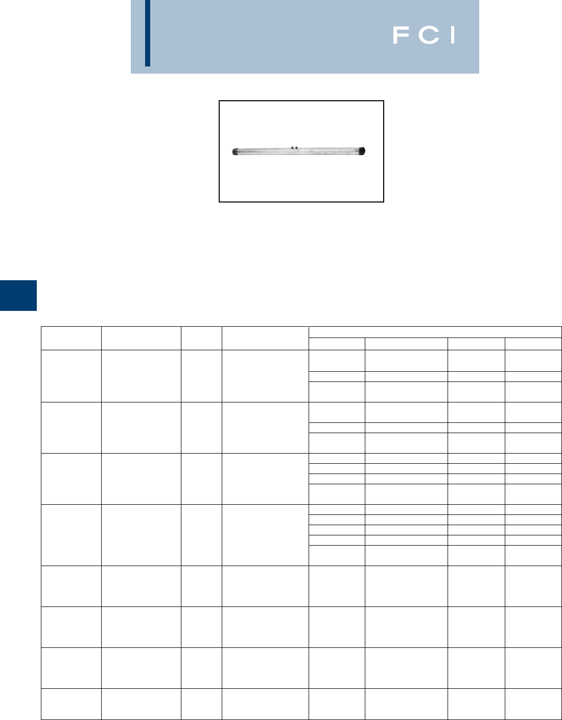
BURNDY
Overhead
E-64
TYPES YDS-RL &
YDS-LT
UNISPLICE™
Full Tension Sleeve for ACSR All
Aluminum, 5005, 6201,
Compressed Conductors.
Single-sleeve aluminum UNISPLICE™
designed to splice ACSR as simply as all-
aluminum. Pre-filled with PENETROX™ joint
compound and capped. Eliminates strand
stripping, installing separate steel sleeve and
filling with joint compound. Ends ACSR joint
failure due to faulty positioning of sleeve and
lack of joint compound. Simplifies hot-line
splicing. Electrical and mechanical perfor-
mance equal to two-piece sleeves.
*Multiple crimp die set; makes more than one crimp per tool
compression. Figure indicates number of compressions.
** MD6 NON-BOW Dies produce straight sleeves without
rotating tool.
†U Die with adapter PT-6515.
‡U Die with adapter PUADP-1.
††† Accommodates ACSR with aluminized steel core.
CATALOG DIE TOOLS, DIE SET CATALOG NUMBER, & (CRIMPS PER END)
NUMBER CONDUCTOR ††† L INDEX MD7, MD6 Y35, Y750, Y45†, Y46‡ Y48B Y60BHU
4 ACSR (7-1) BG (24)
4 ACSR (6-1) W-BG (12)* U-BG (8)* — —
YDS4RL 4 6201 (7) 11-7/8 BG, or 243, or 687 W243 (12) U243 (6) C243 (3) L243 (3)
4 5005 (7) W687 (12)
4 AAC (7) NON-BOW** ———
BG (20)
2 ACSR (6-1) (7-1) W-BG (10)* U-BG (8)* — —
YDS2RL 2 6201 (7) 10-1/4 BG, or 243, or 687 W243 (10) U243 (5) C243 (3) L243 (3)
2 5005 (7) W687 (10)
2 AAC (7) NON-BOW** ———
W-C (28) — — —
2 ACSR (7-1) — U167/U568 (16) C167 (7) L167 (7)
YDS021RL 2 ACSR (6-1) 11-1/4 C, or 167, or W247 (14) U247 (7) — —
2 6201 (7) 247, or 702 W702 (11)
2 AAC (7) NON-BOW** ———
W-C (32) — — —
1/0 ACSR (6-1) — U167/U568 (14) C167 (5) L167 (5)
1/0 6201 (7) C, or 167, or 660, W660 (16) U660 (8) — —
YDS25RL 1/0 5005 (7) 13-7/8 or 247, or 702 — U247 (8) — —
1/0 AAC (7) W702 (12)
NON-BOW** ———
2/0 ACSR (6-1)
2/0 6201 (7) U659
YDS26RL 2/0 5005 (7) 13-1/2 659 — Crimps — —
2/0 AAC (7) Overlap
3/0 ACSR (6-1)
3/0 6201 (7) U658
YDS27RL 3/0 5005 (7) 18-1/4 658 — Crimps — —
3/0 AAC (7) Overlap
4/0 ACSR (6-1)
4/0 6201 (7) U654
YDS28RL 4/0 5005 (7) 18-1/4 654 — Crimps — —
4/0 AAC (7) Overlap
336.4 ACSR (18-1) U655
YDS321RL 336.4 AAC (19) 18-1/4 655 — Crimps — —
350 AAC Overlap
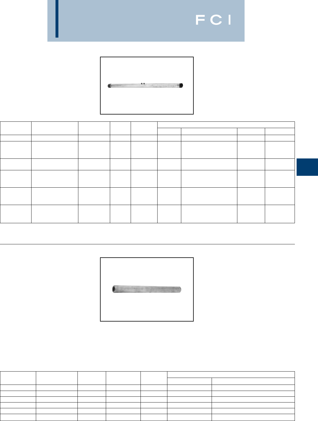
BURNDY
Overhead
E-65
TYPES YDS-RL &
YDS-LT (Continued)
UNISPLICE™
Full Tension Sleeve for ACSR All
Aluminum, 5005, 6201,
Compressed Conductors
** Y46 HYPRESS™ only.
TYPES YDS-A
& YDS-AT
HYSPLICE™
Full Tension Sleeve for
Aluminum (Installed with
BURNDY®or EEI Dies)
Full-tension HYSPLICE™ sleeve made of
aluminum and with cable stop. Designed to
be installed with BURNDY®or EEI dies.
BURNDY®and EEI die index numbers clear-
ly marked on sleeve. Sizes 1/0 and larger
tapered for gradual transition of stress. Pre-
filled with PENETROX™ joint compound and
capped.
†U Die with adapter PT-6515.
‡U Die with adapter PUADP-1.
CATALOG DIE TOOLS, DIE SET CATALOG NUMBER, & (CRIMPS PER END)
NUMBER CONDUCTOR CODE L INDEX MD7, MD6 Y35, Y750, Y45†, Y46‡ Y48B Y60BHU
YDS30LT 312.8 6201 BUTTE 317 U317 C317 L317
394.5 6201
YDS32LT 394.5 5005 CANTON 14-1/2 642 — U642 (12) C642 (4) L642 (4)
(336.4 E.C. Equiv.) RADIAN
397.5 ACSR (18-1)
YDS341RL 419.6 5005 REDE 22 327 — U327 (18) — —
477 (18-1) U-788 L720
YDS361RL 556.5 (18-1) RUBLE 23-1/4 788 —Crimps — Crimps
587.2 5005 720 Overlap Overlap
559.5 6201 C667 L667
YDS36LT 559.5 5005 DARIEN 16 667 — P667** Crimps Crimps
(477 E.C. Equiv.) REMEX Overlap Overlap
927.2 6201
YDS45LT 927.2 5005 GREELEY 21-3/8 648 — — — L648 (7)
(795 E.C. Equiv.) SOLAR
CATALOG EEI TOOLS, DIE SET CATALOG NUMBER, & (CRIMPS PER END)
NUMBER CONDUCTOR L DIE INDEX INDEX MD7, MD6 Y35, Y750, Y45†, Y46‡
YDS2CA 2 (7) 3-7/8 6A 693 W693 (8) U693 (2)
YDS25AT 1/0 (7) 7-1/4 8A 243 W243 (6) U243 (3)
YDS27AT 3/0 (7, 19) 7-1/4 10A 694 W694 (8) U694 (4)
YDS28AT 4/0 (7, 19) 10-1/2 11A 249 W249 (12) U249 (6)
YDS311AT 397.5 (19) 12-1/4 13A 655 — U655 (10)
YDS331AT 477 (19) 12-3/4 14A 317 — U317 (9)
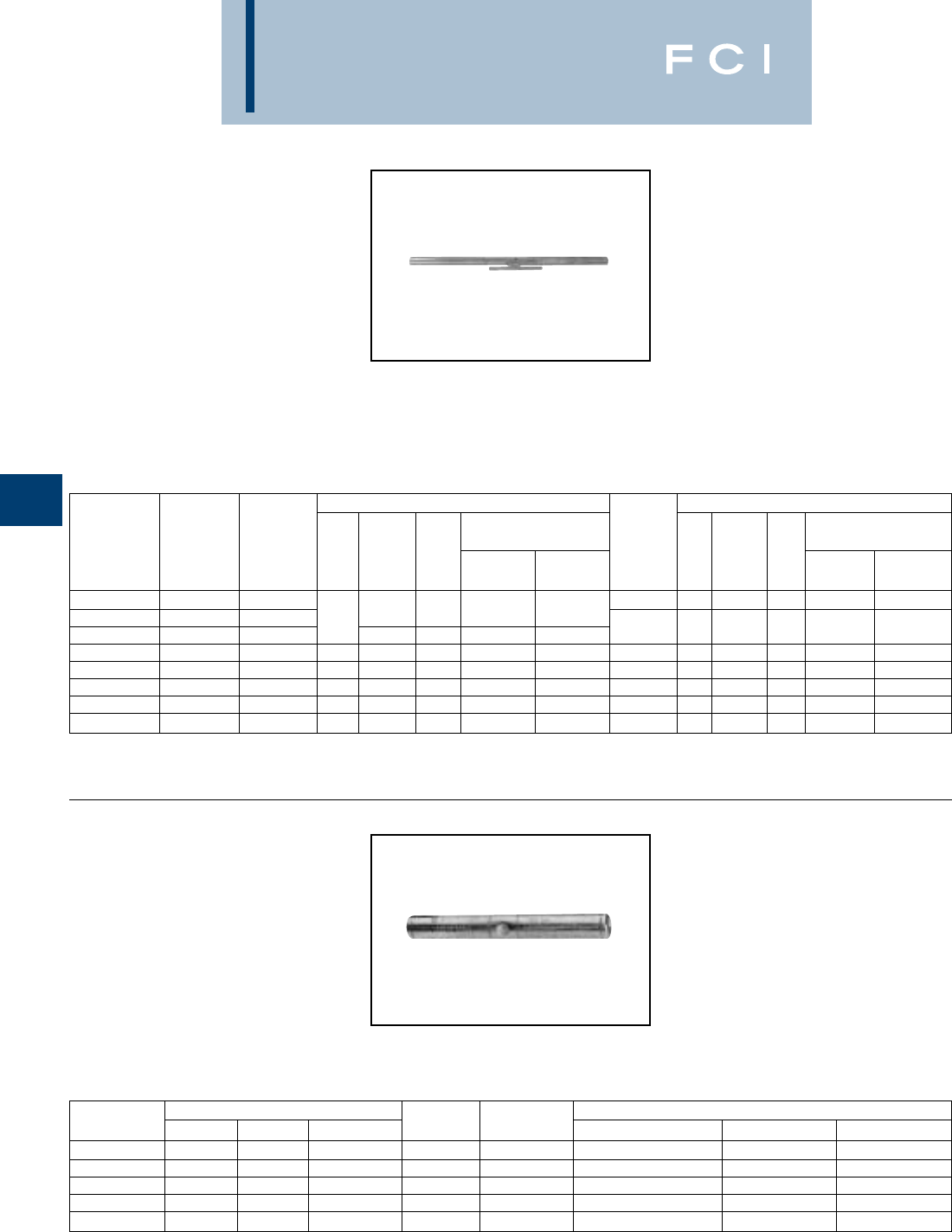
BURNDY
Overhead
E-66
TYPES YDS-R
& YDS-RE
HYSPLICE™
Full Tension Sleeve for ACSR
(Installed with BURNDY®
EEI Dies)
Two-piece, full-tension HYSPLICE™, made
of aluminum outer sleeve and steel sleeve for
steel core. Designed to be installed with
BURNDY®EEI dies. BURNDY®and EEI die
index numbers are clearly marked on the
sleeve.
†U Die with adapter PT-6515.
‡U Die with adapter PUADP-1.
*Multiple crimp die set makes more than one crimp per tool
compression. Figure indicates number of compressions.
†U Die with adapter PT-6515.
‡U Die with adapter PUADP-1.
TYPES YDS-E,YDS-H,
YDS-U
HYSPLICE™
Full Tension Sleeve for Steel
Full-tension HYSPLICE™ sleeves designed
for HS, EHS, Utilities (UT) or Siemens-Martin
(SM) galvanized steel guy, messenger, and
"Static" conductors. Made of hot-dip galva-
nized seamless milled steel tubing lined with
silicone carbide particles.
ALUMINUM OUTER SLEEVE STEEL INNER SLEEVE
CATALOG CATALOG TOOLS, DIE SET CATALOG CATALOG TOOLS, DIE SET CATALOG
NUMBER NUMBER EEI NO., & (CRIMPS PER END) NUMBER EEI NO., & (CRIMPS PER END)
ALUM. & STEEL ALUMINUM DIE DIE Y35, Y750, STEEL DIE DIE Y35, Y750,
SLEEVE SET SLEEVE CONDUCTOR L NUMBER INDEX MD6 Y45†, Y46‡ SLEEVE LL NUMBER INDEX MD6 Y45†, Y46‡
YDS2RE YDS021REP1 2 (6-1) YDS2REP2 4-1/8 1S 690 W690 (8) U690 (4)
YDS021RE YDS021REP1 2 (7-1) 17-1/8 6A 693 W693 (20) U693 (5)
YDS25RE YDS25RP1 1/0 (6-1) 8A 243 W243 (10) U243 (5) YDS25REP2 4-3/4 2S 691 W691 (9) U691 (3)
YDS26RE YDS26RP1 2/0 (6-1) 19-3/4 9A 245 W245 (12) U245 (6) YDS26REP2 5-1/4 4S 692 W692 (12) U692 (6)
YDS27RE YDS27RP1 3/0 (6-1) 16-3/4 10A 694 W694 (12) U694 (6) YDS27RP2 5-1/4 5S 248 W248 (8) U248 (8)
YDS28RE YDS28RP1 4/0 (6-1) 18-7/8 11A 249 W249 (14) U249 (7) YD28REP2 5-1/4 5S 248 W248 (8) U248 (8)
YDS321RE YDS321REP1 336.4 (18-1) 17-7/8 13A 655 U655 (9) YDS25REP2 4-3/4 2S 691 W691 (9) U691 (3)
YDS361R YDS361RP1 477 (18-1) 25-1/2 14A 327 W327 U327 (16) YDS27RP2 5-1/4 5S 248 W248 (8) U248 (3)
CATALOG CONDUCTOR DIE TOOLS, DIE SET CATALOG NUMBER, & (CRIMPS PER END)
NUMBER SIZE STR. GRADE L INDEX Y35, Y750, Y45†, Y46‡ Y48B Y60BHU
YDS250E 1/4 7 EHS 6-3/4 609 U609 (10) — —
YDS312H 5/16 7 HS 10-5/8 257 U257 (20) C257 (5)* L257 (5)*
YDS312E 5/16 7 EHS 8-1/2 305 U305 (6) C305 (3) L305 (3)
YDS375H 3/8 7 HS, UT 9 304 U304 (12) C304 (4) L304 (4)
YDS500H 1/2 7 HS 9-5/8 293 — C293 (6) L293 (6)
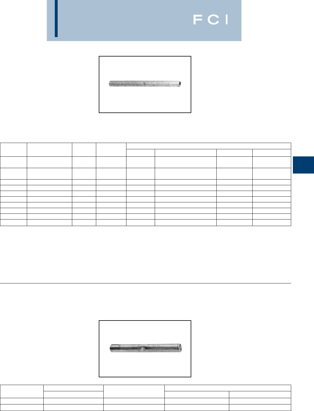
BURNDY
Overhead
E-67
TYPE YDS-K
HYSPLICE™
Full Tension Sleeve for
Copperweld
Full-tension HYSPLICE™ designed to
exceed the minimum rated breaking strength
of, 30% conductivity extra high strength
Copperweld, and lower strength conductors.
Made of pure copper tubing. Installed with
HYSPLICE™ tools and dies.
*Multiple crimp die set; makes more than one crimp per tool
compression. Figure indicates number of compressions.
†U Die with adapter PT-6515.
‡U Die with adapter PUADP-1.
*Overlap crimps.
†Sleeve is high strength aluminum alloy for optimum
corrosion resistance.
TYPE YTS-E
Full Tension Splice for EHS
Steel
Full tension splice for EHS steel guy,
messenger or "static" cable. Sleeve is pre-
filled with PENETROX™ joint compound and
capped.
CATALOG DIE TOOLS, DIE SET CATALOG NUMBER, & (CRIMPS PER END)
NUMBER CONDUCTOR L INDEX MD7, MD6 Y35, Y750, Y45†, Y46‡ Y48B Y60BHU
162 or
YDS8WK 8 Sol. 3-3/4 285 W162 (6) U285 (2) — —
162 or
YDS6WK 6 Sol. 4-3/8 276 W162 (6) U276 (6) — —
YDS3K10 (3 #10) 4-7/8 403 — U403 (3)* — —
YDS3K8 (3 #8) 5-5/8 205 — U205 (5) — —
YDS3K7 5/16 (7 #10) (3 #7) 10 167 — U167/U568 (10) C167 (4) L167 (4)
YDS3K6 11/32 (7 #9) (3 #6) 9-1/2 331 — U331 (9) C331 (9) L331 (3)
YDS3K5 3/8 (7 #8) (3 #5) 6-7/8 259 — U259 (6) C259 (2) L259 (2)
YDS7K7 7/16 (7 #7) 6-7/8 328 — — C328 (3) L328 (3)
YDS7K6 1/2 (7 #6) 9-3/8 260 — — C260 (4) L260 (4)
YDS7K5 9/16 (7 #5) 11-3/8 344 — — C344 (6) L344 (6)
CATALOG CONDUCTOR† TOOLS, DIE SETS
NUMBER EHS STEEL L DIE INDEX Y60BHU*
YTS375E 3/87 Str. 10-3/8 723 L723
YTS438E 7/167 Str. 11-7/8 726 L726
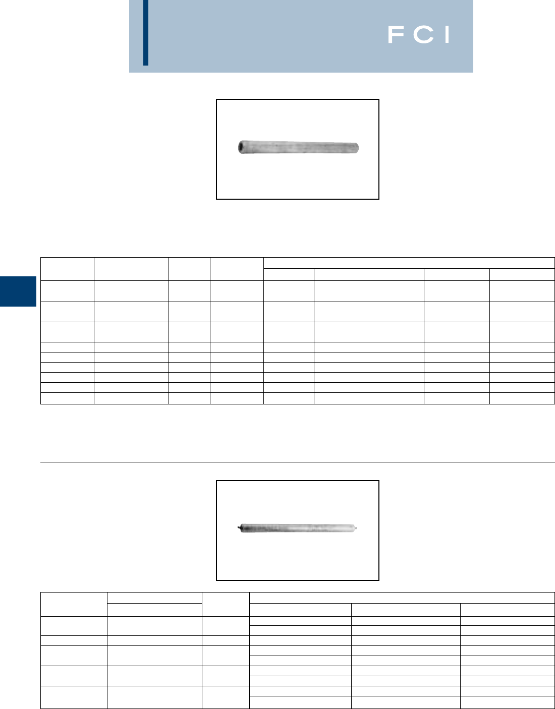
BURNDY
Overhead
E-68
TYPES YDS-KT
& YDS-F
HYSPLICE™
Full Tension Sleeve for
Copperweld-Copper
Full-tension HYSPLICE™ made of pure
copper tubing. Type YDS-KT is tapered to
provide gradual transition of stress on Type
"A" conductor. HYSPLICE™ Type YDS-F is
recommended for Type "F" conductor.
*Multiple crimp die set; makes more than one crimp per tool
compression. Figure indicates number of compressions.
†U Die with adapter PT-6515.
‡U Die with adapter PUADP-1.
TYPE YDS-M-T
Full Tension Sleeve for
Alumoweld
Full-tension splice for Alumoweld transmis-
sion lines. Five connectors accommodate
eight conductor sizes. Sleeve is pre-filled with
PENETROX™ joint compound and capped.
*Overlap crimps.
†U Die with adapter PT-6515.
‡ U Die with adapter PUADP-1.
††† Sleeve is high strength aluminum alloy for optimum
corrosion resistance.
CATALOG DIE TOOLS, DIE SET CATALOG NUMBER, & (CRIMPS PER END)
NUMBER CONDUCTOR L INDEX MD7, MD6 Y35, Y750, Y45†, Y46‡ Y48B Y60BHU
162 or W162 (4) —
YDS8KT 8A 5 202 — U202 (4)* ——
162 or W162 (10) —
YDS6KT 6A 6-1/8 203 — U203 (5)* ——
163 or W162 (13) —
YDS4KT 4A 6-3/8 204 — U204 (10) ——
YDS2KT 2A 7-3/4 205 — U205 (8) — —
YDS3K6 4D 9-1/2 331 — U331 (9) C331 (3) L331 (3)
YDS2F 2F 6-1/4 329 — U329 (4) — —
YDS25F 1/0F 8-3/4 568 — U167/U568 (8) — —
YDS26F 2/0F 9-5/8 552 — U552 (11) — —
YDS28F 4/0F 11-7/8 331 — U331 (12) C331 (4) L331 (4)
CATALOG††† CONDUCTOR TOOLS, DIE SETS
NUMBER ALUMOWELD L DIE INDEX Y35, Y750, Y45†, Y46‡ Y60BHU*
676 or U676 (8) —
YDS7M10T 7#10, 3 #7 10 721 — L721
YDS7M9T 7#9, 3 #6 10-3/8 677 U677 (10) —
668 or U668 (13) —
YDS7M8T 7#8, 3 #5 12-1/4 723 — L723
678 or U678 (19) —
YDS7M7T 7#7 14-1/2 726 — L726
679 or U679 (2) —
YDS7M6T 7#6 15-1/8 726 — L726
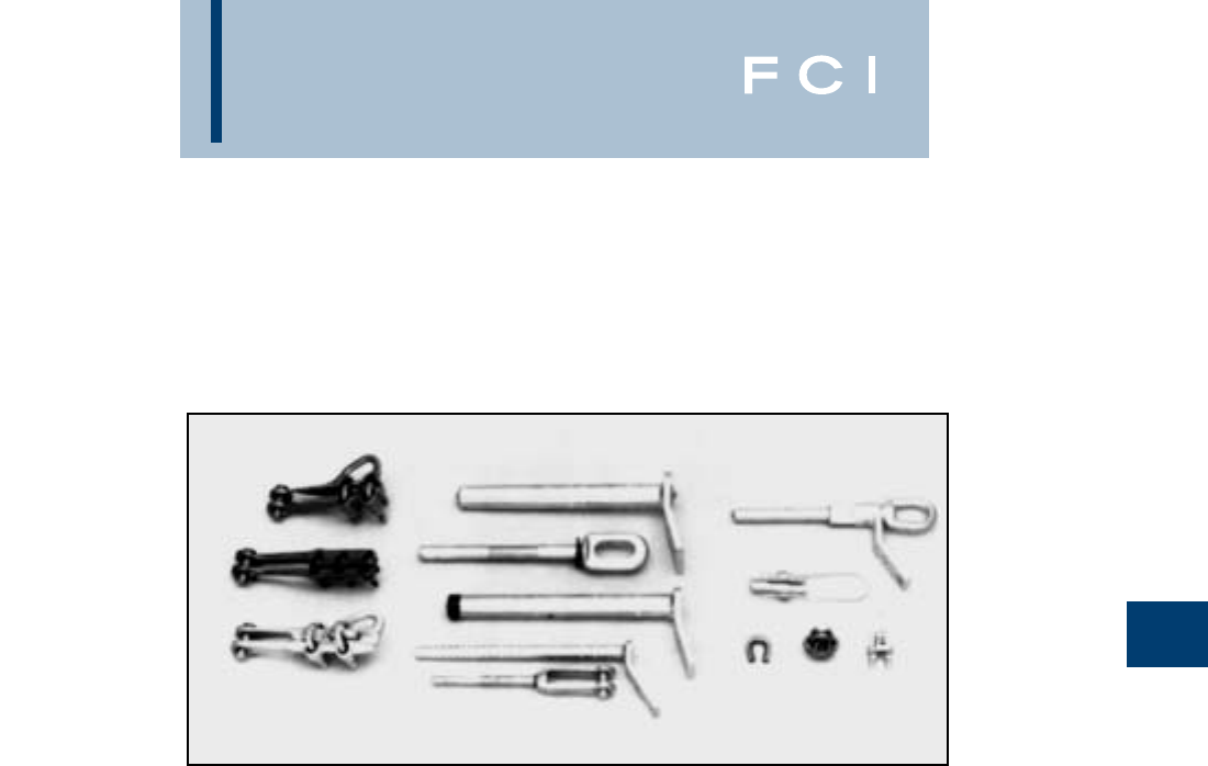
BURNDY
Overhead
E-69
DEADEND FITTING
AND ACCESSORIES
TABLE OF CONTENTS
LOOP
Type UP-R.....................................................E-70
Type BC.........................................................E-71
Type M...........................................................E-71
PRIMARY AND STRAIN BUS
Type CUW-E..................................................E-72
Type DUW .....................................................E-72
Type CUW-A-E & CUW-R-E..........................E-73
Type DUW-A & DUW-A-E .............................E-73
FULL TENSION DISTRIBUTION
OR TRANSMISSION
Type YTW-M-T & YTW-E...............................E-74
Type YDW-R ..................................................E-75
Type YTW-A, YTW-AD, YTW-AC,
YTW-AE, YTW-AM.............................E-76, E-77
Type YTW-R, YTW-RC,
YTW-RE, YTW-RM ............................E-78, E-79
(Refer to HYSPLICE™ introduction
for installation instructions.)
STOCKBRIDGE DAMPER
Type FR.........................................................E-80
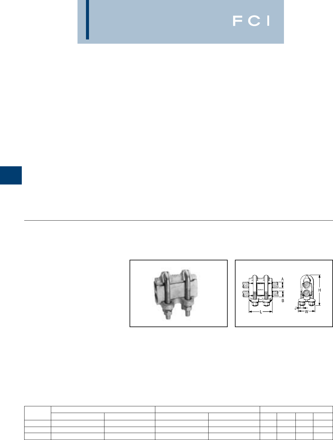
BURNDY
Overhead
E-70
DEADEND FITTINGS
AND ACCESSORIES
The deadend method selected for any partic-
ular application will depend upon the nature
of the application, the size of the conductor,
holding strength required, and preference for
mechanical or compression devices.
Secondaries are commonly deadended by
bending wire around a spool insulator and
snubbing with the same connectors used for
the secondary to service drop connection. On
copper conductor, connectors such as U-bolt
Clip BC, SERVIT™ KS, OKLIP™ KVS or
CRIMPIT™ YC-C are recommended. These
connectors provide high holding strength
without damaging conductor strands. On
aluminum wires, CLIPIT™ UW-R, mechanical
connector is recommended.
The same methods can also be used on
primaries. However, the straight line clamp
Type CUW-A-E is more popular for this appli-
cation. They are easier to install on either hot
or de-energized lines. They are particularly
well suited to hot-line maintenance, and allow
easy re-sagging of conductors.
Straight line types are also popular for dead-
ending strain buses. These are normally
large, hard to handle conductors that do not
lend themselves to snub or "quadrant" types.
Types DUW or CUW-E are recommended for
copper conductor and DUW-A and DUW-A-E
for aluminum and ACSR. The pulling eye on
the DUW-A-E is in line with the cable to make
installation easier.
TYPE UP-R
HEAVY DUTY PARALLEL
CLAMP
For All Combinations of Copper,
Aluminum†, ACSR†, 6201 and
5005
Heavy duty aluminum connector for feeder,
subtransmission and primary distribution.
Massive design and large spacer give maxi-
mum protection against galvanic action and
overload conditions. Spacing of U-bolts,
tapered bell mouths and modified V groove
minimize cold flow, eliminate cable damage,
and produce wiping action on conductors.
Spacer taps confine cable strands to prevent
splaying. Captured, heat treated aluminum
alloy U-bolts. PENETROX™ joint compound
recommended for all combinations.
†Accommodates compact and compressed conductors within
diameter range.
CATALOG GROOVE A GROOVE B DIMENSIONS
NUMBER ACSR †, 6201, 5055 COPPER OR ALUM. † ACSR †, 6201, 5005 COPPER OR ALUM. † H J L W
UP34R 110.8 (12-7) - 397.5 (18-1) 3/0 Str. - 400 110.8 (12.7) - 397.5 (18-1) 3/0 Str. - 400 4-5/8 1/2-13 4 2-5/8
UP45R36R 336.4 (30-7) - 795 (30-19) 397.5 - 954 110.8 (12-7) - 447 (18-1) 3/0 Str. - 500 5-1/4 1/2-13 4 2-7/8
UP45R 336.4 (30-7) - 795 (30-19) 397.5 - 954 336.4 (30-7) - 795 (30-19) 397.5 - 954 6-1/4 5/8-11 4-1/2 3-1/4
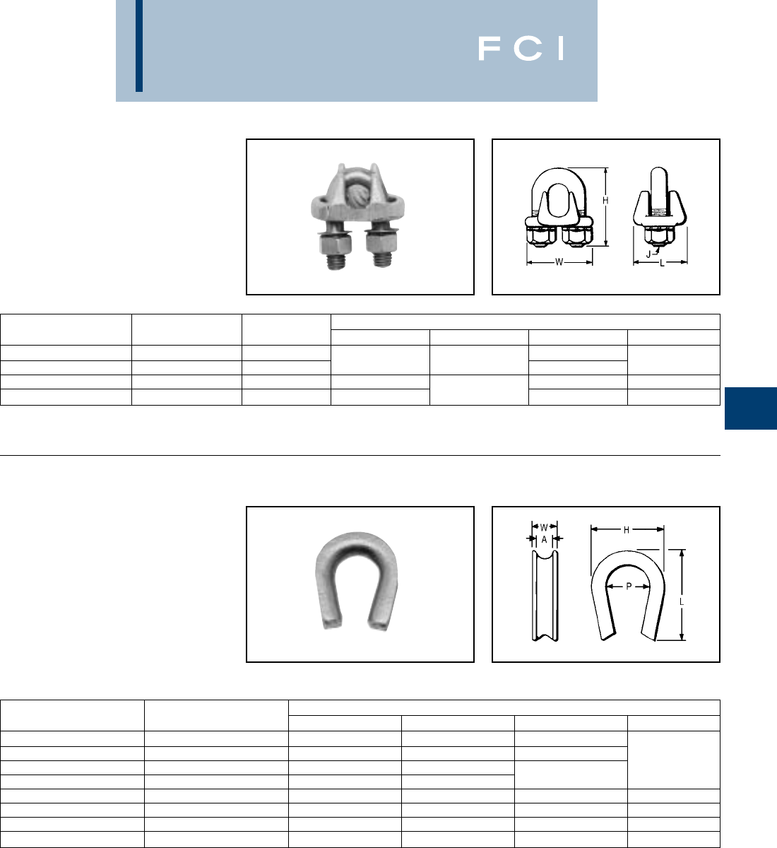
BURNDY
Overhead
E-71
TYPE BC
CLIP
Deadend Clamp for Guy Wire
Deadend CLIP with DURIUM™ silicone
bronze U-bolt, nuts, and washers. Saddle
made of high strength corrosion resistant
copper alloy.
TYPE M
DEADEND THIMBLE
Deadend Copper Conductor or
Guy Wire
High strength corrosion resistant copper alloy
thimble groove to fit any size guy wire used
for deadending. Generous radius prevents
kinking or overstressing outer strands of wire.
CATALOG GUY DIMENSIONS
NUMBER COPPER WIRE H J L W
BC2C 2 Sol. 5/16 1-1/4
BC25 1/0 Str. 3/8 23/8 1-3/8 1-3/4
BC28 2/0 Str. - 4/0 Str. 1/2 2-3/8 1-3/4 2-1/4
BC30 4/0 Str. - 300 5/8 2-3/4 1/2 22-3/8
CATALOG GROOVE DIMENSIONS
NUMBER SIZE A H L P W
M20 5/16 1-5/8 1-7/8 7/8
M30 3/8 1-7/8 2-1/8 1
M40 7/16 1-3/4 2-5/8 5/8
M50 1/2 1-7/8 2-1/4 1-1/8
M60 5/8 2-1/4 2-5/8 1-3/8 7/8
M70 3/4 2-5/8 3-1/4 1-1/2 1
M80 7/8 3 3-3/8 1-3/4 1-1/4
M90 13-3/8 3-3/4 2 1-3/8
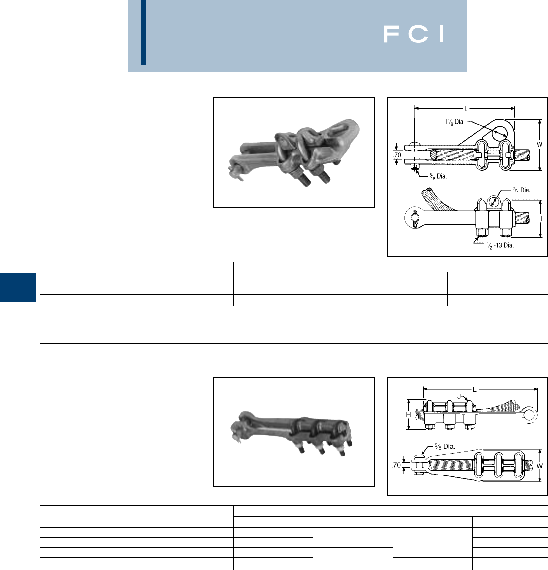
BURNDY
Overhead
E-72
TYPE CUW-E
DEADEND CLAMP
For Copper
High strength, two-bolt, cast copper alloy
strain clamp with single saddle designed for
short span distribution and strain bus applica-
tion. Galvanized steel clevis pin, and U-bolts.
TYPE DUW
DEADEND CLAMP
For Copper
High strength corrosion resistant copper alloy
strain clamp with three DURIUM™ U-bolts
and single serrated saddle. Galvanized steel
clevis pin.
CATALOG DIMENSIONS
NUMBER CONDUCTOR RANGE H L W
CUW34-E 4/0 Str. - 500 3 7-3/8 4
CUW44-E 500 - 1000 3-3/8 8-3/4 4-1/2
CATALOG DIMENSIONS
NUMBER CONDUCTOR H J L W
DUW28 1 Str. - 4/0 Str. 2-1/2 2-1/4
DUW31 4/0 Str. - 350 2 3/8 9-7/8 2-3/8
DUW34 350 - 500 2-5/8 2-3/4
DUW44 500 - 1000 2-7/8 1/2 11-3/8 3-1/4
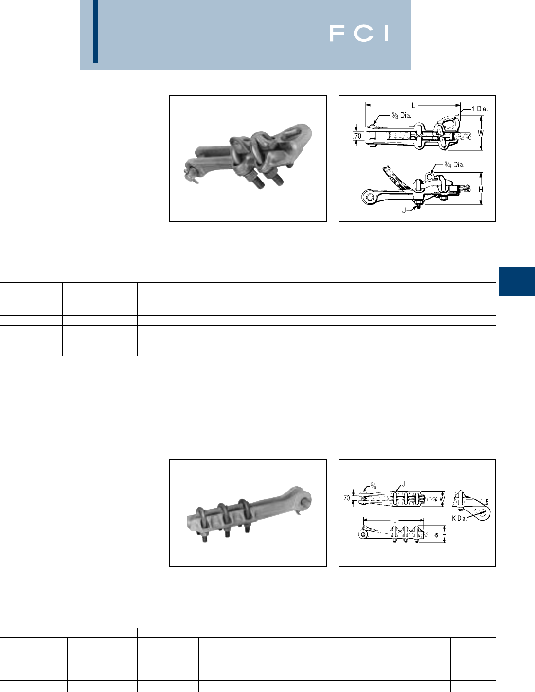
BURNDY
Overhead
E-73
TYPES CUW-A-E
& CUW-R-E
DEADEND CLAMP
For Aluminum†, ACSR†, 6201
and 5005
High strength aluminum clamp for deadend-
ing primary distribution lines. Straight-line
design, with hot stick lifting-eye, pulling-eye,
and captured, angled U-bolts, facilitates
installation and maintenance, especially on
hot-line work. Snub-pocket V-shaped, range-
taking conductor groove and galvanized steel
U-bolts provide high holding strength.
TYPES DUW-A
& DUW-A-E
DEADEND CLAMP
For Aluminum†, ACSR†, 6201
and 5005
High strength cast aluminum alloy clamp
recommended for strain bus applications.
Three galvanized steel U-bolts, single saddle
and headed clevis pin provide high holding
strength. Type DUW-A-E has pulling-eye in
line with conductor for easier installation.
†Accommodates compressed conductors within diameter
range.
CATALOG DIMENSIONS
NUMBER ALUMINUM† ACSR†, 6201, 5005 H J L W
CUW26RE-1 2 Str. - 2/0 (19) 4 - 2/0 3 3/8-16 8 3
CUW30A-E 1/0 (7) - 300 1/0 - 266.8 (18-1) 3-5/8 1/2-13 10 3-1/2
CUW32R-E 3/0 (7) - 350 3/0 - 336.4 (26-7) 4 1/2-13 10 3-5/8
CUW361R-E 4/0 - 500 4/0 - 477 (18-1) 4-1/8 1/2-13 11 3-5/8
CUW391A-E 336.4 - 795 300 (26-7) 636 (26-7) 4-7/8 1/2-13 11 4-1/8
CATALOG NUMBER CONDUCTOR DIMENSIONS
WITHOUT WITH
PULLING EYE PULLING EYE ALUMINUM† ACSR†, 6201, 5005 H J K L W
DUW28A DUW28A-E 1 - 4/0 2 (7-1) - 4/0 2 7/8 9-1/2 2-1/4
DUW31A DUW31A-E 4/0 - 350 4/0 - 336.4 (18-1) 2-5/8 3/8 19-5/8 2-3/8
DUW44A DUW44A-E 500 - 1000 397.5 (30-7) - 900 (54-7) 3-3/8 1/2 1-1/4 11-1/4 3-5/8
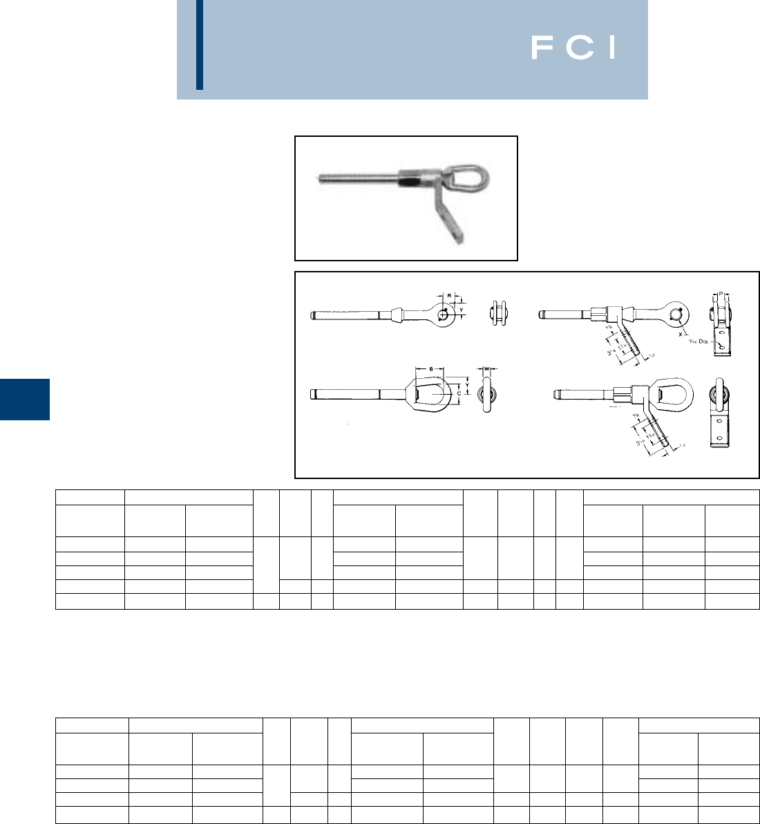
BURNDY
Overhead
E-74
TYPES YTW-M-T,
YTW-E
FULL TENSION DEADEND
For Alumoweld and EHS Steel
Full-tension compression deadend for
Alumoweld transmission lines. Supplied with
a single 30° angle two hole NEMA pad. Can
be supplied with clevis or eye. Aluminum
barrel is pre-filled with PENETROX™ joint
compound and sealed. Full tension compres-
sion deadend for EHS steel guy, messenger
or "static" cable. Standard connector has
single 30° angle two hole NEMA pad. Can be
supplied without pad and with clevis or eye.
Aluminum barrel is pre-filled with PENE-
TROX™ joint compound and sealed.
YTW-M-TC YTW-EC YTW-M-TCA
YTW-ECA
YTW-M-TEA
YTW-EEA
YTW-M-TE YTW-EE
*Overlap crimps.
** Sleeve is high strength aluminum alloy for optimum
corrosion resistance.
†Die with adapter PT-6515.
‡U Die with adapter PUADP-1.
** Overlap crimps.
CONDUCTOR CATALOG NUMBER CATALOG NUMBER TOOLS, DIE SETS, & (NO. OF CRIMPS)
CLEVIS CLEVIS EYE EYE DIE Y35, Y750,
ALUMOWELD NO PAD 30° PAD P R & Y X NO PAD 30° PAD B C W Y INDEX Y45†, Y46‡ Y60BHU**
7 #10, 3 #7 YTW7M10TC YTW7M10TC YTW7M10TE YTW7M10TE 676 or 721 U676 (8) L721
7 #9, 3 #6 YTW7M9TC YTW7M9TCA 3/4 5/8 YTW7M9TE YTW7M9TEA 2-3/8 1-3/4 5/8 1-1/2 677 U677 (10) —
7 #8, 3 #5 YTW7M8TC YTW7M8TCA 7/8 YTW7M8TE YTW7M8TEA 668 or 723 U668 (13) L723
7 #7 YTW7M7TC YTW7M7TCA 1-1/4 3/4 YTW7M7TE YTW7M7TEA 2-5/8 2 3/4 1-3/4 678 or 726 U678 (19) L726
7 #6 YTW7M6TC YTW7M6TCA 1-3/8 1-1/2 7/8 YTW7M6TE YTW7M6TEA 3-1/16 3-1/16 7/8 2 679 or 726 U679 (22) L726
CONDUCTOR CATALOG NUMBER** CATALOG NUMBER TOOLS, DIE SETS
EHS CLEVIS CLEVIS EYE EYE DIE
STEEL NO PAD 30° PAD P R & Y X NO PAD 30° PAD B C W Y INDEX Y60BHU
5/16” 7 Str. YTW312EC YTW312ECA YTW312EE YTW312EEA 721 L721
3/8” 7 Str. YTW375EC YTW375ECA 7/8 3/4 5/8 YTW375EE YTW375EEA 2-3/8 1-3/4 5/8 1-1/2 723 L723
7/16” 7 Str. YTW438EC YTW438ECA 1-1/4 3/4 YTW438EE YTW438EEA 2-5/8 2 3/4 1-3/4 726 L726
1/2” 7 Str. YTW500EC YTW500ECA 1-3/8 1-1/2 1 YTW500EE YTW500EEA 3-1/16 2-1/4 7/8 2 789 L789
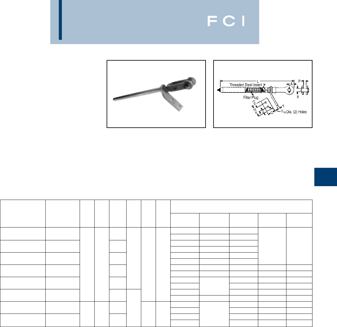
BURNDY
Overhead
E-75
TYPE YDW-R
COMPRESSION DEADEND
For ACSR, Compressed and
Compact
Full-tension compression assembly designed
for deadending, and for tap or jumper loop
terminating at 30° with HYLUG™ Types
YCA-R, YCA-A, etc. The assembly consists of
an outer aluminum body with inner steel
sleeve bearing surface for steel core. Installed
with equivalent two-piece, full-tension sleeve
dies. Filler-hole and plug provide for injection
of PENETROX®.
Cat. No. YDW-R includes: aluminum body,
steel sleeve, steel clevis pin, cotter pin.
Neoprene sealing disc, and aluminum hard-
ware for attaching jumper terminals.
*Multiple crimp die set; makes more than one crimp per tool
compression. Figure indicates number of compressions.
** Number of crimps shown for aluminum (i.e., 10/4 crimps
over cable, 4 crimps over steel insert threads).
†U Die with adapter PT-6515.
††U Die with adapter PUADP-1.
INSTALLATION DATA
CATALOG TOOLS, DIE SET CATALOG NO., & (NUMBER OF CRIMPS)**
NUMBER Y35, Y750,
(COMPLETE SET) CONDUCTOR A C L T P X DIE INDEX MD7, MD6 Y45†, Y46‡ Y48B Y60BHU
Alum. 243 W243 (10/4) U243 (5/2)
YDW25R 1/0 (6-1) 7-3/8 Steel 242 W242 (8) U242 (9)
Alum. 245 W245 (12/4) U245 (6/2)
YDW26R 2/0 (6-1) 18-3/4 Steel 242 W242 (8) U242 (4) ——
Alum. 247 W247 (12/4) U247 (6/2)
YDW27R 3/0 (6-1) 18-1/8 3/8 Steel 248 W282 (16) U248 (8)
3/4 1-1/2 7/8 5/8 Alum. 249 W249 (14/4) U249 (7/2) C249 (4/1) L249 (4/1)
YDW28R 4/0 (6-1) 19-1/8 Steel 248 W248 (14) U248 (7) C248 (2)* L248 (2)*
Alum. 251 U251 (10/2) C251 (5/1) L251 (5/1)
YDW30R 266.8 (26-7) 18-1/4 Steel 250 — U250 (10) C250 (3) L250 (3)
Alum. 490 U490 (10/2) C490 (4/1) L490 (4/1)
YDW321R 336.4 (18-1) 17-3/8 Steel 242 W242 (8) U242 (4) C242 (2)* L242 (2)*
Alum. 316 U316 (9/3) C316 (3/1) L316 (3/1)
YDW32R 336.4 (26-7) 21-1/4 1/2 Steel 252 U252 (9) C252 (3) L252 (3)
1-1/4 2-1/4 13/16 3/4 Alum. 261 —U261 (12/3) C261 (4/1) L261 (4/1)
YDW36R 477 (26-7) 24-1/2 Steel 350 U350 (12) C350 (4) L350 (4)
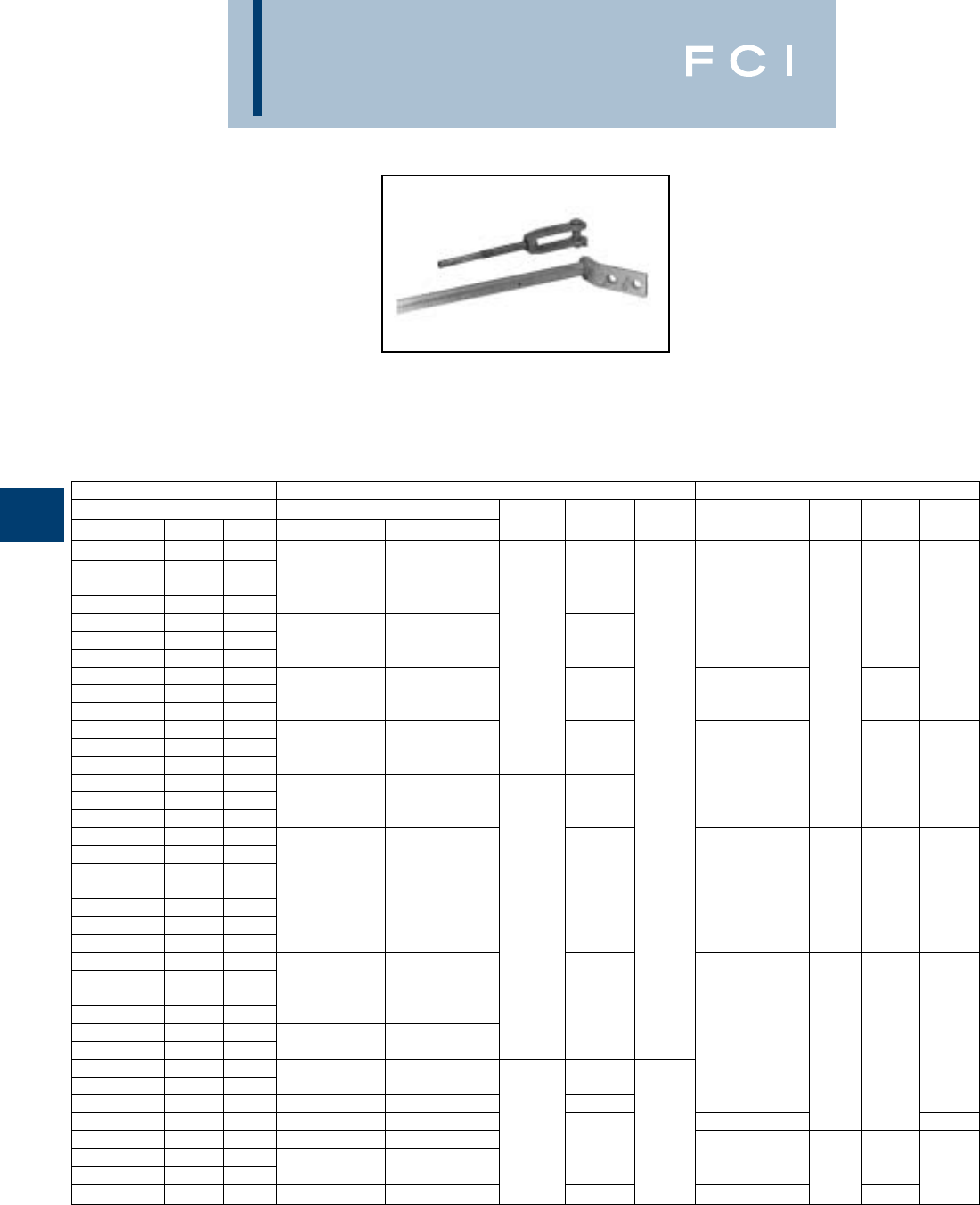
BURNDY
Overhead
E-76
TYPES YTW-A,
YTW-AD,YTW-AC
YTW-AE,YTW-AM
Full Tension Deadend for
Stranded Aluminum Cable
Full tension compression deadend for SAC
transmission lines. One design for applica-
tions up to and including 230 KV. Streamlined
design for 345KV and higher (EHV)*. Two
hole NEMA tap pad thru 636 MCM. Larger
sizes have 4 holes NEMA pad. Standard 15°
*For Extra High Voltage (EHV) applications add suffix "T" to
be the catalog number (e.g., YTW484A-T).
➀Complete deadend assembly which includes Aluminum
Body and Steel (Clevis Eye or Adjustable Clevis). Fitting
must beordered separately from BURNDY®.
CONDUCTOR ALUMINUM BODY* ➀STEEL CLEVIS ➀
ALUMINUM CATALOG NUMBER CATALOG
CODE MCM. STR. ONE PAD TWO PADS C L T NUMBER P R & Y X
TULIP 336.4 19
—350 37 YTW301A YTW301AD
CANNA 397.5 19 9-5/8
—400 37 YTW311A YTW311AD YTW331AC 13/16
—450 37
COSMOS 477 19 YTW331A YTW331AD 9-3/4 5/8
CYRINGA 477 37 2-1/4
HYACINTH 500 37
DAHLIA 556.5 19 YTW351A YTW351AD 11-5/8 YTW351AC 7/8 7/8
MISTLETOE 556.5 37
—600 61
—600 91 YTW361A YTW361AD 12-1/4
ORCHID 636 37
VIOLET 715.5 37 YTW39AC 1-1/16 3/4
NASTURTIUM 715.5 61 YTW39A YTW39AD 12-3/4 1/2
CATTAIL 750 61
ARBUTUS 795 37
LILAC 795 61 YTW391A YTW391AD 14-3/8
—800 61
—874.5 37 YTW431AC 1-1/8 1-3/16 1
CROCUS 874.5 61
MAGNOLIA 954 37 YTW431A YTW431AD 3-1/4 14-3/4
GOLDENROD 954 61
BLUEBELL 1033.5 37
LARKSPUR 1033.5 61
—1113 37 YTW445A YTW445AD
MARIGOLD 1113 61 15-5/8
HAWTHORN 1192.5 61 YTW463AC 1-1/8
NARCISSUS 1272 61 YTW451A YTW451AD 1-1/2 1-3/8
COLUMBINE 1351.5 61
CARNATION 1431 61 YTW457A YTW457AD 16-1/2
COREOPSIS 1590 61 YTW463A YTW463AD 17-1/8
JESSAMINE 1750 61 YTW47A YTW47AD YTW47AC 1
COWSLIP 2000 91 YTW48A YTW48AD 45/8
SAGEBRUSH 2250 91 16-3/8 YTW484AC 1-1/2
—2300 61 YTW484A YTW484AD 1-5/8 1-1/8
LUPINE 2500 91 YTW486A YTW486AD 18-1/2 YTW486AC 1-3/4
tap pad when used with YNA-R15 HYLUG™
terminal provides either 0° or 30° tap.
Aluminum body is pre-filled with PENE-
TROX®joint compound and capped.
Type YNA-R15, shown in module section H, page 88, must
also be ordered separately for making tap connections from
deadend body tap pad.
Suffix NP = No pad.
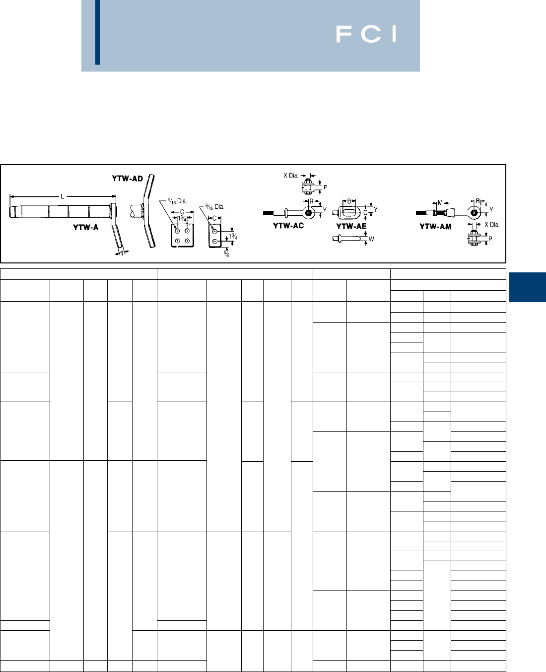
BURNDY
Overhead
E-77
** Overlap crimps.
Suffix NP = No pad.
STEEL EYE ➀STEEL ADJUSTABLE CLEVIS ➀TOOLS, DIE SETS CONDUCTOR
CATALOG CATALOG M MAX. DIE ALUMINUM
NUMBER B C W Y NUMBER ADJ. P R & Y X INDEX Y60BHU** MCM. STR. CODE
336.4 19 TULIP
717 L717 350 37 —
397.5 19 CANNA
YTW331AE YTW331AM 400
719 L719 450 —
5/8 7/8 5/8 19 COSMOS
477 SYRINGA
500 HYACINTH
YTW351AE 2-1/2 7/8 1-1/8 YTW351AM 720 L720 19 DAHLIA
556.5 37 MISTLETOE
61
3-3/8 1-1/4 722 L722 600 91 —
636 ORCHID
YTW39AE 11/16 YTW39AM 15/16 3/4 VIOLET
715.5 NASTURTIUM
750 CATTAIL
724 L724 37 ARBUTUS
795 LILAC
800
YTW431AE 3/4 1-3/8 YTW431AM 1-1/4 37 —
874.5 61 CROCUS
725 L725 37 MAGNOLIA
954 61 GOLDENROD
37 BLUEBELL
11033.5 61 LARKSPUR
37 —
2-11/16 1-1/4 727 L727 1113 MARIGOLD
YTW463AE YTW463AM 1192.5 HAWTHORN
1-1/2 4-1/4 1-3/8 1-1/2 1272 NARCISSUS
11351.5 61 COLUMBINE
1431 CARNATION
728 L728 1590 COREOPSIS
YTW47AE YTW47AM 1750 JESSAMINE
2000 COWSLIP
YTW484AE 1-5/8 YTW484AM Y35 L735 2250 61 SAGEBRUSH
5-1/8 1-5/8 1-3/4 1-1/8 2300 —
YTW486AE 43-1/8 1-1/4 2-3/4 YTW486AM 740 L740 2500 91 LUPINE
TYPES YTW-A,
YTW-AD,YTW-AC
YTW-AE,YTW-AM
(Continued)
➀Complete deadend assembly which includes Aluminum
Body and Steel (Clevis Eye or Adjustable Clevis). Fitting
must beordered separately from BURNDY®.
BURNDY
Overhead
E-78
TYPES YTW-R,
YTW-RC,YTW-RE,
YTW-RM
Full Tension Deadend for ACSR
Full-tension compression deadend for ACSR
transmission lines. One design for applica-
tions up to and including 230KV. Streamlined
design for 345KV and higher (EHV)*. Two
hole NEMA tap pad thru 556.5 MCM. Larger
sizes have 4-hole NEMA pad. Standard 15°
tap pad when used with YNA-R15 HYLUG™
terminal provides either 0° or 30° tap.
*For Extra High Voltage (EHV) applications add suffix "T" to
catalog number (e.g., YTW49RT or YTW49RTY30).
➀Complete deadend assembly which includes Aluminum
Body and Steel (Clevis Eye or Adjustable Clevis) fitting
must be ordered separately from BURNDY®.
CONDUCTOR ALUMINUM BODY *
ACSR ➁CATALOG *
CODE MCM. STR. NUMBER ➀LTC Y
ORIOLE 30/7
WIDGEON 336.4 24/7 YTW32R 13-1/4 7-1/4
LINNET
IBIS 397.5 26/7 YTW34R 2-1/4 7-1/8
FLICKER 24/7
HAWK 477 26/7 YTW36R 14-5/8 7-1/2
PARAKEET 24/7
DOVE 556.5 26/7 YTW39R 15-1/8 8
PEACOCK 24/7
DUCK 605 54/7
SQUAB 26/7
ROOK 24/7 YTW43R 16 7-3/4
GROSBEAK 636 26/7
GULL 54/7
FLAMINGO 666.6 24/7
CROW 54/7 1/2
STARLING 715.5 26/7
TERN 45/7
CUCKOO 24/7 YTW451R 9
CONDOR 795 54/7 3-1/4
DRAKE 26/7
RUDY 900 45/7
—24/7 19-1/2
RAIL 45/7
CARDINAL 954 54/7 YTW48R
—1027.4 48/7 8-1/2
ORTOLAN 45/7
—1033.5 48/7
CURLEW 54/7 YTW49R
BLUEJAY 45/7
—1113 48/7
FINCH
GRACKLE 54/19
BUNTING 1192.5 45/7
—48/7 YTW52R 26-1/8
BITTERN 45/7
PHEASANT 1272 54/19
DIPPER 45/7
MARTIN 1351.5 54/19
BOBOLINK 1431 45/7
NUTHATCH 45/7 5/8 4
—1510.5 48/7 11-1/4
PARROT 54/19 YW549R 22
LAPWING 1590 45/7
FALCON 1590 54/19 YTW56R
CHUKAR 1780 84/19 YTW58R
2034.5 23
—2032.1 72/7 YTW585R
BLUEBIRD 2156 84/19
KIWI 2167 72/7 YTW59R 26-3/4
—2300 96/19 YTW594R 24-5/8
Type YNA-15, shown on page E87, must also be ordered
separately for making tap connections from deadend body
tap pad.
➁For other sizes consult factory.
Suffix NP = No pad.
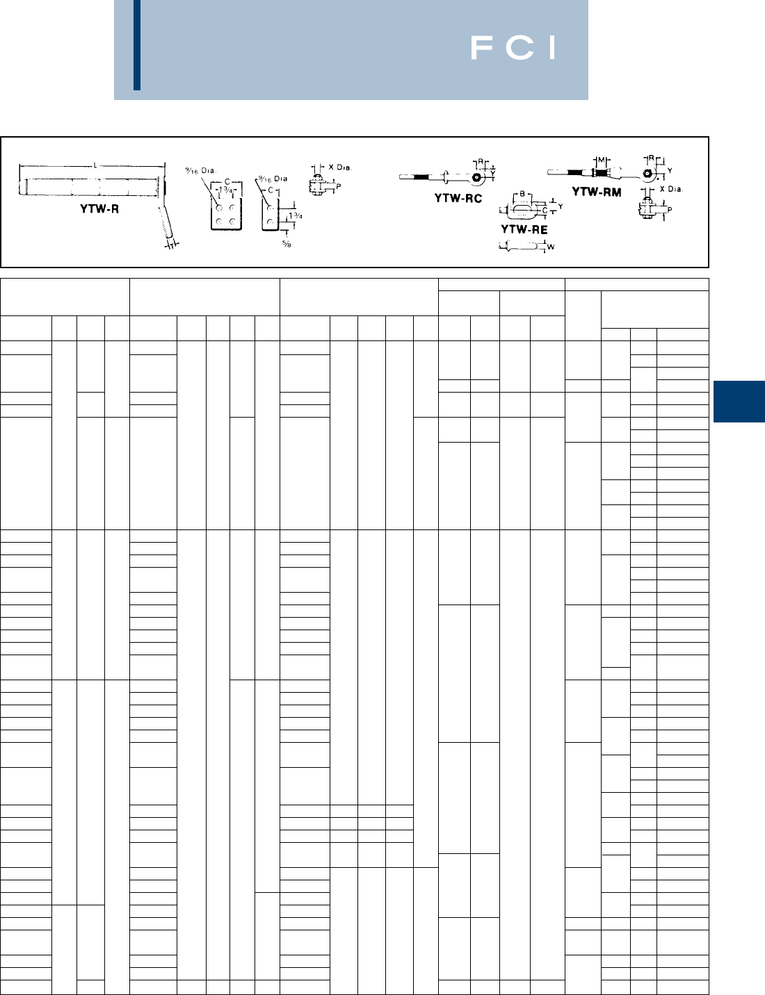
BURNDY
Overhead
E-79
** Overlap crimps.
Suffix NP = No pad.
TOOL DIE SETS CONDUCTOR
PENE-
STEEL CLEVIS STEEL EYE STEEL ADJUSTABLE CLEVIS ALUM. BODY STEEL BODY TROX®
CATALOG CATALOG CATALOG MAX DIE DIE GALLON ACSR
NUMBER P R&Y X NUMBER B C W Y NUMBER ADJ. P R&Y X INDEX Y60** INDEX Y60BHU PER C MCM STR. CODE
YTW33RC YTW33RE YTW33RM 30/7
ORIOLE
717 L717 5/8 336.4 24/7
WIDGEON
YTW34RC 13/16 YTW34RE YTW34RM 718 L718
LINNET
5/8 5/8 5/8 719 L719 1/2 397.5 26/7
IBIS
YTW362RC YTW362RE YTW362RM 24/7
FLICKER
YTW36RC 7/8 YTW36RE YTW36RM 720 L720 721 L721 477 26/7
HAWK
7/8 24/7
PARAKEET
7/8 2-1/2 7/8 1-1/8 3-3/8 7/8 1-1/4 722 L722 556.5 26/7
DOVE
24/7
PEACOCK
605 54/7
DUCK
YTW43RC 1-1/16 3/4 YTW43RE 11/16 YTW43RM 3/4 723 L723 26/7
SQUAB
724 L724 1-1/4 24/7
ROOK
636 26/7
GROSBEAK
54/7
GULL
666.6 24/7
FLAMINGO
YTW45RC YTW45RE YTW45RM 54/7
CROW
YTW48RC YTW48RE YTW48RM 715.5 26/7
STARLING
YTW481RC YTW481RE YTW481RM 45/7
TERN
725 L725 1-3/4 24/7
CUCKOO
YTW45RC YTW45RE YTW45RM 795 54/7
CONDOR
YTW48RC YTW48RE YTW48RM 26/7
DRAKE
YTW481RC 1-1/8 1-3/16 1 YTW481RE 3/4 1-3/8 YTW481RM 900 45/7
RUDY
YTW48RC YTW48RE YTW48RM 24/7
—
YTW481RC YTW481RE YTW481RM 45/7
RAIL
YTW48RC YTW48RE YTW48RM 2954 54/7
CARDINAL
YTW45RC YTW45RE YTW45RM 4-1/4 1-3/8 1-1/2 727 L727 1027.4 48/7
—
YTW483RC YTW483RE YTW483RM 145/7
ORTOLAN
YTW449RC YTW449RE YTW449RM 1033.5 48/7
—
YTW50RC YTW50RE YTW50RM 2-5/8 54/7
CURLEW
YTW483RC YTW483RE YTW483RM 45/7
BLUEJAY
YTW449RC YTW449RE YTW449RM 1113 48/7
—
FINCH
YTW50RC YTW50RE 2-11/16 1-1/4 YTW50RM 726 L726 54/19
GRACKLE
1192.5 45/7
BUNTING
YTW521RC YTW521RE 1-1/2 YTW521RM 48/7
—
1-1/2 1-3/8 45/7
BITTERN
YTW56RC YTW56RE YTW56RM 5-1/8 1-5/8 1-3/4 728 L728 4-1/4 1272 54/19
PHEASANT
YTW521RC YTW521RE YTW521RM 4-1/4 1-3/8 1-1/2 45/7
DIPPER
YTW56RC 1-1/8 YTW56RE 1YTW56RM 5-1/8 1-5/8 1-3/4 1351 54/19
MARTIN
1431
BOBOLINK
YTW521RC YTW521RE YTW521RM 4-1/4 1-3/8 1-1/2 45/7
NUTHATCH
YTW549RC YTW549RE YTW549RM 1510.5 48/7
—
YTW56RC YTW56RE YTW56RM 54/19
PARROT
YTW549RC YTW549RE YTW549RM 729 L729 5 45/7
LAPWING
YTW590RC YTW590RE YTW590RM 1590 54/19
FALCON
YTW58RC YTW58RE YTW58RM 5-1/4 1780 84/19
CHUKAR
1-5/8 5-1/8 1-5/8 1-3/4 1-1/8 2034.5
YTW591RC 1-5/8 1-1/2 YTW591RE YTW591RM 735 L735 62032.1 72/7
—
YTW59RC YTW59RE YTW59RM 2156 84/19
BLUEBIRD
YTW591RC YTW591RE YTW591RM 7-3/4 2167 72/7
KIWI
YTW594RC 1-3/4 YTW594RE 43-1/8 1-1/4 2-3/4 YTW594RM 740 L740 789 L789 2300 96/16
—
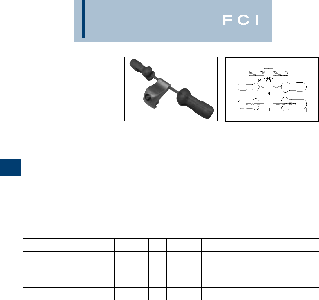
BURNDY
Overhead
E-80
STOCKBRIDGE
DAMPER
Conductors: ACSR, ALLOY, AAC and Static Wires: Galvanized Steel, Alumoweld and Copperweld
CATALOG CONDUCTOR RANGE WRENCH TORQUE INSTALLATION
NUMBER DIAMETER INCHES [mm] N P L SIZE In.-Lb. (m.daN) WEIGHT POINT
0.24– 0.611.652.212.485/8269.38 in.-lb. 3.74 Lb. Consult
FR20 [6 – 15.5] [42] [56] [317] [15.8] (3m.daN) (1.700 Kg) Factory
0.59– 1.021.972.9514.43/4347.18 in.-lb. 6.06 Lb. Consult
FR35 [15 – 26] [50] [75] [366] [19] (4m.daN) (2.750 Kg) Factory
0.63– 1.222.443.1520.2413/16453.97 in.-lb. 10.14 Lb. Consult
FR40 [21 – 31] [62] [80] [514] [20.5] (5m.daN) (4.600 Kg) Factory
0.98– 1.52.563.9421.6515/16477.37 in.-lb. 11.46 Lb. Consult
FR50 [25 – 38] [65] [100] [550] [23.8] (5.5m.daN) (5.200 Kg) Factory
Features and Benefits
•Clamps designed around common conduc-
tor sizes.
◊Ease to specification.
•Single bolt design.
◊Ease of installation.
◊Single wrench installation.
•Accurate components assembly represents
greater energy dissipation.
◊Provides extended life overhead lines.
•Messenger cable and weights have a
corrosion-resistant finish.
◊Weight design eliminates water entrap-
ment.
◊Smooth surfaces and rounded edges to
eliminate possible corona discharge.
Standards
The Stockbridge Dampers meet the follow-
ing Standards:
•IEC 61897, Overhead lines—
Requirements and Tests for Stockbridge
type Aeolian Vibration Dampers.
•IEEE Std 664-1993, IEEE Guide for
Laboratory Measurement of the Power
Dissipation Characteristics of Aeolian
Vibration Dampers for Single Conductors.
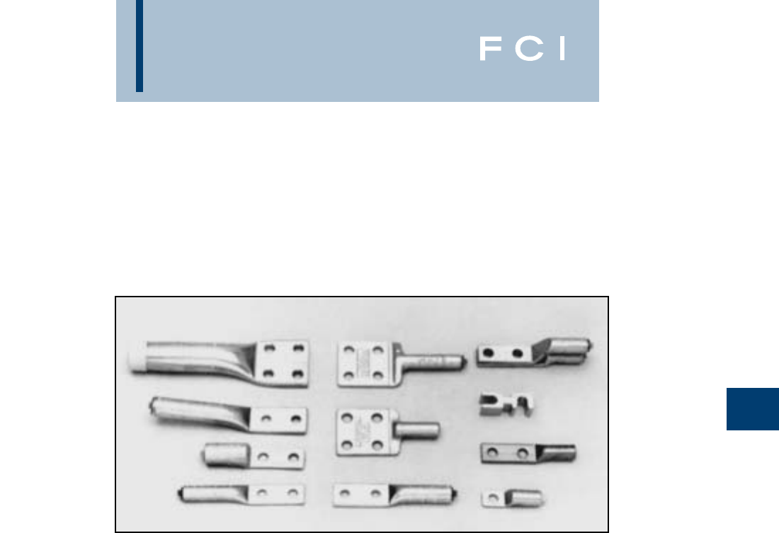
BURNDY
Overhead
E-81
COMPRESSION
TERMINALS AND
ACCESSORIES
TABLE OF CONTENTS
Type YCA-2N & YCAB-4N .............................E-82
Type YCA-RL-2N............................................E-83
Types YCA-R-N & YCAK-R-N...............E-84, E-85
Type YNA-M-T................................................E-85
Types YNA-R15 & YNA-R ..............................E-86
Type YAK-A-2G ..............................................E-87
Types YAS-R-2N & YASO-R-2N.....................E-88
Types YCAK-A & YRA....................................E-89
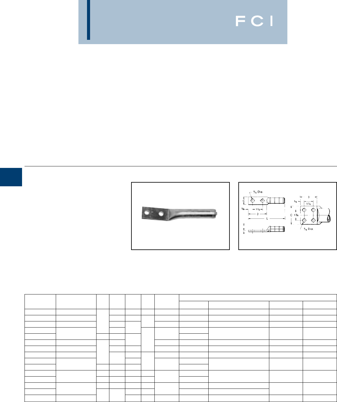
BURNDY
Overhead
E-82
COMPRESSION
TERMINALS &
ACCESSORIES
Compression terminals are used to make
convenient and reliable connections to switch
pads, transformers, and other electrical
equipment. They accommodate either cop-
per, aluminum, ACSR, ACAR, Alumoweld, or
steel conductor and come with one, two or
four hole NEMA drilled pads to match the
equipment drilling. Standard copper and
aluminum terminals are also listed in the
compression section B.
TYPES YCA-2N
& YCAB-4N
HYLUG™
Compression Terminal for
Copper
Compression HYLUG™ terminals designed
for terminating copper conductors to switch
pads and other substation or switch yard
apparatus. NEMA standard mounting holes.
Made of pure copper. Installed with same die
as equivalent full-tension jumper loop and
repair sleeves.
Fig. 1 Fig. 2
YCAB have brazed pads.
†U Die with adapter PT-6515.
‡U Die with adapter PUADP-1.
CATALOG FIG. DIE TOOLS, DIE SET CATALOG NO., & (NUMBER OF CRIMPS)
NUMBER CONDUCTOR NO. C L T INDEX MD7, MD6 Y35, Y750, Y45†, Y46‡ Y48B Y60BHU
YCA25-2N 1/0 (7, 19) 7/8 5-3/8 1/8 165 W165 (3) U165/U205 (3) — —
YCA26-2N 2/0 (7, 19, 37) 1 5-1/4 166 W166 (6) U166/U459 (3) — —
YCA27-2N 3/0 (7, 19) 11-1/8 1/4 167 — U167/U568 (3) C167 (1) L167 (1)
YCA28-2N 1-1/4 5-3/8 —
YCAB28-4N 4/0 (7, 12, 19) 23 168 —U168 (3) C168 (1) L168 (1)
YCA29-2N 250 (7, 19, 37) 1-3/8 5-5/8 3/8 169 — U169 (4) C169 (1) L169 (1)
YCA30-2N 300 (19, 37) 1-1/2 5-1/2 170 — U170 (5) C170 (1) L170 (1)
YCA31-2N 350 (12, 19, 37) 16-1/2 267 — U267 (6) C267 (2) L267 (2)
YCA32-2N 1-5/8 6-3/4 1/2 —
YCAB32-4N 400 (19, 37) 237-1/8 209 —U209 (6) C209 (2) L209 (2)
YCA34-2N 11-7/8 6-1/2 3/8 —
YCAB34-4N 500 (19, 37) 236-7/8 1/2 210 —U210 (6) C210 (2) L210 (2)
YCA39-2N 12-3/8 7-1/4 5/8 — —
YCAB39-4N 750 (37, 61) 7-1/2 1/2 627 ——
C627 (3) L627 (3)
YCAB44-4N 1000 (61) 23
7-7/8 5/8 345 — — C345 (4) L345 (4)
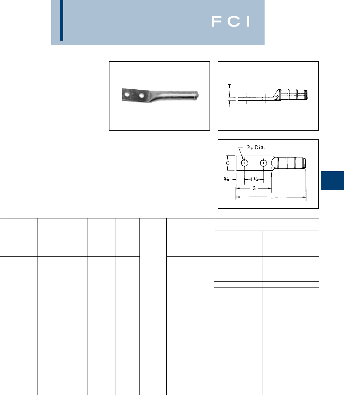
BURNDY
Overhead
E-83
TYPE YCA-RL-2N
HYLUG™
Compression Terminals for
Aluminum, ACSR, 6201, 5005,
Compressed and Compact
Conductors
Aluminum compression HYLUG™ for termi-
nating overhead conductors to switch pads
and other substation or switch yard appara-
tus. NEMA standard mounting holes.
Installed with same die as equivalent full-
tension UNISPLICE™. Pre-filled with PENE-
TROX™ joint compound and capped.
†U Die with adapter PT-6515.
‡U Die with adapter PUADP-1.
TOOLS, DIE SET CATALOG NO.
CATALOG DIE & NUMBER OF CRIMPS
NUMBER CONDUCTOR C L T INDEX MD7, MD6 Y35, Y750, Y45†Y46‡
4 ACSR (6-1, 7-1) W-BG (8)
YCA4RL-2N 4 6201 (7) 7/8 6 BG, 687, 243 FIXED BG (8) U243
4 AAC (7) W687 (4)
2 ACSR (6-1, 7-1) W-BG (8)
YCA2RL-2N 2 6201 (7) 7/8 6 BG, 687, 243 FIXED BG (8) U243
2 AAC (7) W687 (4)
1/0 ACSR (6-1) WC 12 —
1/0 6201 (7) —U247 3
YCA25RL-2N 1/0 5005 (7) 7C, or 247, or 702 W702 4
1/0 AAC (7) NON-BOW —
2/0 ACSR (6-1) 1-1/8
2/0 6201 (7)
YCA26RL-2N 2/0 5005 (7) 3/8 659 U659 3
2/0 AAC (7)
3/0 ACSR (6-1)
3/0 6201 (7)
YCA27RL-2N 3/0 AAC (7) 1-1/4 658 U658 3
3/0 AAC (7) 6-1/2 —
4/0 ACSR (6-1)
4/0 6201 (7)
YCA28RL-2N 4/0 5005 (7) 1-1/2 654 U654 3
4/0 AAC (7)
336.4 ACSR (18-1)
YCA321RL-2N 336.4 AAC (19) 1-5/8 655 U655 3
350 AAC
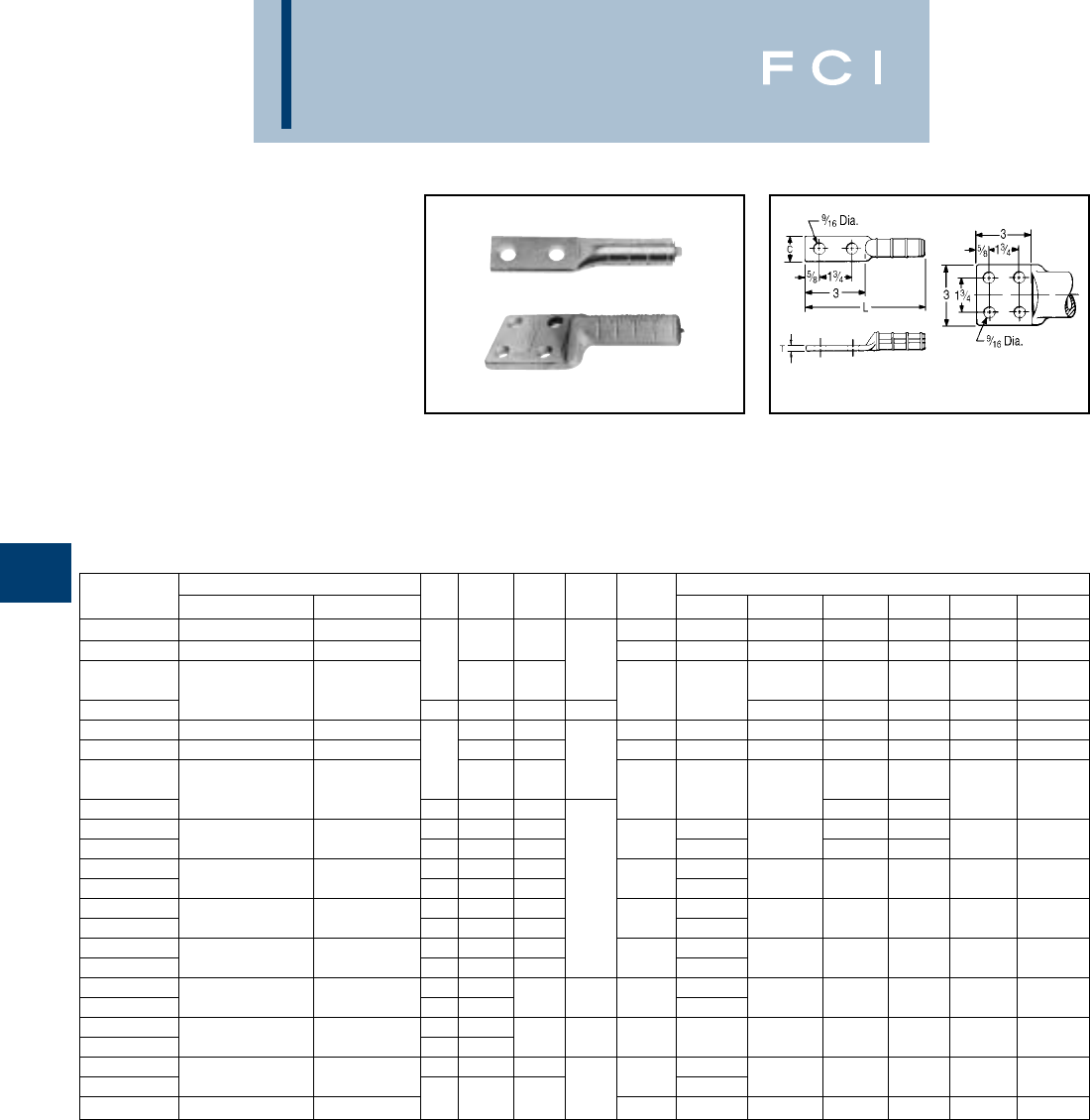
BURNDY
Overhead
E-84
TYPES YCA-R-N &
YCAK-R-N
Compression Terminals for
Aluminum, ACSR, 6201, 5005,
Compressed and Compact
Conductors
Aluminum compression HYLUG™ for termi-
nating jumper loops and equipment taps at
switchpads and other substation apparatus,
or to YDW-R deadends. NEMA standard
mounting holes. Installed with same dies as
equivalent full-tension sleeves. Pre-filled with
PENETROX™ joint compound.
*Multiple crimp die set; makes more than one crimp per tool
compression. Figure indicates number of compressions.
†U Die with adapter PT-6515.
‡U Die with adapter PUADP-1.
YCA HYLUGS™ are made from heavy walled tubing. YCA4R-
2N, YCA2R-2N and all YCAK HYLUGS™ are cast aluminum
alloy.
(Table continued on next page.)
Fig. 1 Fig. 2
CATALOG CONDUCTOR FIG. DIE TOOLS, DIE SET CATALOG NO., & (NUMBER OF CRIMPS)
NUMBER ACSR, 6201, 5005 ALUMINUM NO. C L T INDEX
MD7, MD6
Y35, Y750 Y45 Y46 Y48B Y60BHU
YCA4R-2N 44 (7) 237 W237 (3) U237 (2) † ‡ — —
YCA2R-2N 22 (7) 1-1/4 5-5/8 239 W239 (3) U239 (2) † ‡ — —
11/4 KS18, BG (8)
YCA25R-2N 1/0 1/0 (7, 19) 7/8 6-1/4 BG, or W-BG (4)* U-BG (4) † ‡ — —
YCAK25R-4N 236-7/8 3/8 243, 8A U243 (2) U243 (2) † ‡ C243 (2) L243 (1)
YCA26R-2N 2/0 2/0 (7, 19) 1 6-3/8 245, 9A W245 (4) U245 (2) † ‡ C245 (2) L245 (1)
YCA27R-2N 3/0 - 110.8 (12-7) 3/0 7, 19) 1-1/8 6-3/4 247 W247 (6) U247 (3) † ‡ C247 (3) L247 (2)
11/4 K840,
YCA28R-2N 4/0 (6-1, 6-7) 4/0 (7, 19) 1-1/4 6-7/8 249 W249 (6) U249 (3) †‡
C249 (1) L249 (2)
YCAK28R-4N 237-3/8 11A † ‡
YCA30R-2N 266.8 1 1-1/2 6-3/4 — † ‡
YCAK30R-4N (18-1, 6-7, 26-7) 266.8 (7, 19) 237-3/8 251 —U251 (4) †‡
C251 (2) L251 (2)
YCA321R-2N 336.4 (19) - 1 1-1/2 7 —
YCAK321R-4N 336.4 (18-1) 350 (19, 37, 61) 2 3 7-1/8 3/8 321 —U321 (4) † ‡ C321 (2) L321 (2)
YCA33R-2N 336.4 (26-7, 30-7) 1 1-5/8 7-1/4 —
YCAK33R-4N 397.5 (18-1) 397.5 (19) 237-3/8 316 —U316 (4) † ‡ C316 (2) L316 (2)
YCA35R-2N 477 (19, 37) - 1 1-7/8 7-1/2 —
YCAK35R-4N 397.5 (26-7, 30-7) 500 (37, 61) 2 3 7-3/8 317 —U317 (4) † ‡ C317 (2) L317 (2)
YCA361R-2N 11-7/8 —
YCAK361R-4N 477 (18-1) 500 (37, 61) 23
7-5/8 7/16 327 —U327 (4) † ‡ C327 (2) L327 (2)
YCA37R-2N 556.5 (18-1) 1 2
YCAK37R-4N
477 (24-7, 26-7, 30-7)
556.5 (19, 37) 23
8-1/8 3/8 261 —U261 (5) † ‡ C261 (2) L261 (2)
YCA39R-2N 12-1/8 8-3/8 —
YCAK39R-4N 556.5 (24-7, 26-7) — 1/2 608 —U608 (6) † ‡ C608 (2) L608 (2)
YCAK361A-4N —636 (37) 238-1/8 469 — — S469 (6) P469 (6) C469 (2) L469 (2)
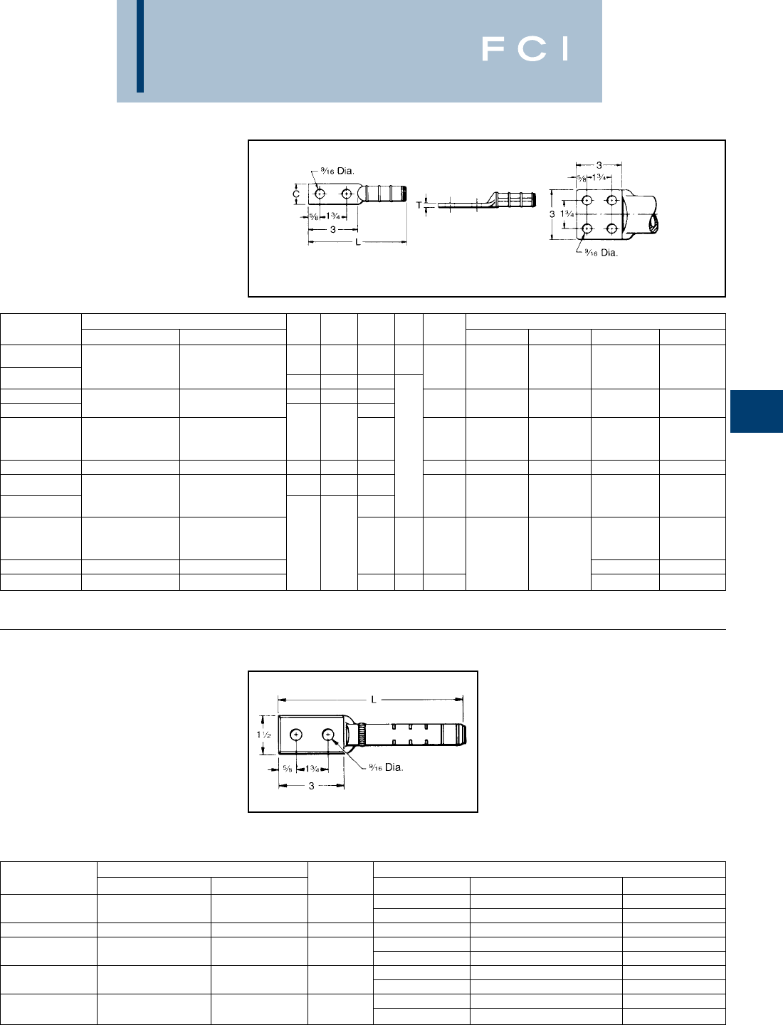
BURNDY
Overhead
E-85
TYPES YCA-R-N
& YCAK-R-N
(Continued)
Compression Terminals for
Aluminum, ACSR, 6201, 5005,
Compressed and Compact
Conductors
Fig. 1
Fig. 2
TYPE YNA-M-T
Compression Terminal for
Alumoweld and EHS Steel
Compression terminal for joining Alumoweld
and EHS steel to YTW-M-T or YTW-E dead-
end. Installed with same dies as equivalent
full tension splice and deadend. Barrel is
pre-filled with PENETROX™ joint compound
and capped.
*Overlap crimps.
†U Die with adapter PT-6515.
‡ U Die with adapter PUADP-1.
CATALOG CONDUCTOR FIG. DIE
TOOLS, DIE SET CATALOG NO., & (NO. OF CRIMPS
)
NUMBER ACSR, 6201, 5005 ALUMINUM NO. C L T INDEX Y45 Y46 Y48B Y60BHU
605 (30-19) 795 (37, 61) 292
YCA43R-2N
636 (24-7, 26-7, 30-19)
700 (61) 12-/12 10-1/4 3/4 or S292 (6) P292 (6) C292 (3) L292 (3)
YCAK43R-4N 666.6 (24-7) 750 (61) 2 3 9-5/8 319 S319 (6) P319 (6) C319 (3) L319 (3)
YCA391A-2N 795 (37) 1 2-3/8 10-1/8
YCAK391A-4N —750 (61) 9-7/8 342 S342 (6) P342 (6) C342 (3) L342 (3)
795 (36-1)
YCAK453R-4N 715.5 (26-7) — 23
9-5/8 292, S292 (6) P292 (6) C292 (6) L292 (3)
795 (45-7) 5/8 578
YCA44A2NG2 —1000 1 2-3/8 11 342 S342 (6) P342 (6) C342 (3) L342 (3)
900 (61, 91)
YCA45R-2N
795 (26-7, 54-7) 954 (37, 61)
12-1/2 10-1/4
352 S352 (6) P352 (6) C352 (3) L352 (3)
YCAK45R-4N 1000 (61) 9-5/8 S579 (6) P579 (6) C579 (3) L579 (3)
900 (54-7)
YCA48R-4N 954 (54-7) (45-7) — C575 (3) L575 (3)
1033.5 (45-7) (36-1) 23103/4 575 ——
YCA441A-4N —
1033.5 (37, 61) - 113 (61)
C575 (3) L575 (3)
YCA451A-4N 1113 (54-19) 1272 (61) 10-1/4 5/8 422 — L422 (3)
CATALOG CONDUCTOR TOOLS, DIE SETS, & (NUMBER OF CRIMPS)
NUMBER ALUMOWELD EHS STEEL L DIE INDEX Y35, Y750, Y45†, Y46‡ Y60BHU**
676 or U676 (4) —
YNA7M10T 7 #10, 3 #7 5/167 Str. 8-1/2 721 — L721
YNA7M9T 7 #9, 3 #6 — 8-3/4 677 U677 (5) —
668 or U688 (7) —
YNA7M8T 7 #8, 3 #5 3/87 Str. 9-3/4 723 — L723
678 or U678 (10) —
YNA7M7T 7 #7 7/167 Str. 9-7/8 726 — L726
679 or U679 (11) —
YNA7M6T 7 #6 1/27 Str. 9-3/4 726 — L726
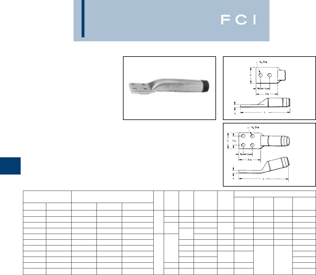
BURNDY
Overhead
E-86
TYPES YNA-R15
& YNA-R
Compression Terminal for
ACSR, ACAR and Stranded
Aluminum Cable
Compression terminal for ACSR, ACAR and
SAC Transmission lines. Two hole NEMA
tongue through 556.5 MCM ACSR. Four hole
NEMA supplied on larger sizes. When used
with YTW-R or YTW-A, the 15° angle tongue
provides either a 0° or 30° tap. Uses same
dies as equivalent full-tension sleeve or dead-
end. Barrel pre-filled with PENETROX™ joint
compound and capped. Pad coated with
oxide retardant.
*To specify mounting hardware for bolting to corresponding
deadend pad, add suffix "H" to catalog number
(e.g., YNA54RTH).
** For Extra High Voltage (EHV) applications add suffix "T" to
catalog number (e.g., YNA451RT).
†Overlap crimps.
‡If shielding caps are required for this item,
use #STS43A-4N.
Fig. 1
Fig. 2
CATALOG* TOOLS, DIE SETS
NUMBER** CONDUCTOR FIG. L L DIE
15° STRAIGHT ACAR ALUMINUM ACSR NO. C 15° STRAIGHT T INDEX Y45† Y46‡ Y60BHU†
YNA32R15 YNA32R 395.1 - 395.2 336.4 - 350 300 - 336.4 1-5/8 9-1/8 9 3/8 717 S717 P717 L717
YNA34R15 YNA34R —397.5 - 477 397.5 1-3/4 9-5/16 9-1/8 7/16 719 S719 P719 L719
YNA36R15 YNA36R —500 - 556.5 477 19-5/8 9-1/2 720 S720 P720 L720
YNA39R15 YNA39R 634.9 - 653.1 600 - 650 556.5 29-3/4 1/2 722 S722 P722 L722
YNA43R15 YNA43R —700 - 800 605 - 666.6 10-1/8 10 3/8 724 S724 P724 L724
YNA451R15‡ YNA451R-T‡ 840.2 - 927.2 795 - 1000 715.5 - 874.5 10-1/4 10-1/4 7/16 725 S725 P725 L725
YNA49R15‡ YNA49R-T‡ 983.1 - 1198 1033.5 - 1272 900 - 1113 45/7 3-1/4 10-3/8 10-1/2 1/2 727 L727
YNA52R15‡ YNA52R-T‡ 1277 - 1280 1351.5 - 1510 1113 54/19 - 1351 2 12-1/8 12-1/4 L728
YNA54R15‡ YNA54R-T‡ 1534 1590 - 1600 1431 13-5/16 13-1/2 11/16 728 ——L728
YNA56R15‡ YNA56R-T‡ —1700 - 1800 1510.5 - 1590 3-7/16 12-1/2 12-3/4 7/8 729 L729
YNA594R15‡ YNA594R-T‡ 2267 - 2500 2500 2300 3-11/16 12-7/8 14-1/4 11/16 740 L740
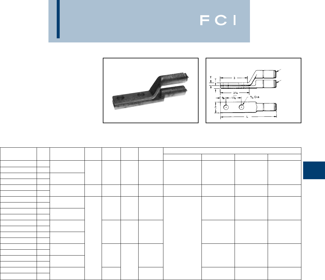
BURNDY
Overhead
E-87
TYPE YAK-A-2G
STACKING HYLUG™
For Aluminum
Cast aluminum HYLUG™ with a special
tongue configuration for stacking of conduc-
tors on two and four hole NEMA transformer
or equipment terminal pads. Up to eight
conductors may be stacked on one four hole
NEMA pad. HYLUG™ is pre-filled with
PENETROX™ joint compound and capped.
*Overlap crimps.
** Accommodates 4/0 Str., Al. or Cu.
†U Die with adapter PT-6515.
‡U Die with adapter PUADP-1.
Fig. 1
Fig. 2
CATALOG FIG. DIE TOOLS, DIE SET CATALOG NO., & (NO. OF CRIMPS)
NUMBER NO. CONDUCTOR C L T INDEX
MD7, MD6 SERIES
Y35, Y750 Y45 Y46
YAK2CA2G1 1BGBG (3) U-BG (1)
YAK2CA2G2 22 Str. W-BG (1) †‡
YAK25A-2G1 17/8 5-5/8 1/4 K 5/8 UK 581T (3) †‡
YAK25A-2G2 21/0 Str. 243 W243 (1) U243 (1) †‡
YAK28A-2G1 1249 W249* † ‡
YAK28A-2G2 24/0 Str.** 1-1/8 6-1/4 5/16 K840 W-K840* U249* †‡
YAK29A-2G1 1
YAK29A-2G2 2250 299 U299* † ‡
YAK31A-2G1 16-7/8 3/8 705 U705 † ‡
YAK31A-2G2 2350
YAK311A-2G1 1
YAK311A-2G2 2397.5 317 U317* † ‡
YAK34A-2G1 17-3/4 7/16 705 U705* † ‡
YAK34A-2G2 2500 1-5/8 —
YAK-361A-2G1 1600
YAK-361A-2G2 2636 608 U608* †‡
YAK39A-2G1 1700 8-1/4 786 U786* S786* P786*
YAK39A-2G2 2750 5/8 722 S722* P722*
YAK44A-2NG8 1
YAK44A-2NG7 21000 8-7/8 302 — S44ART* P44ART*
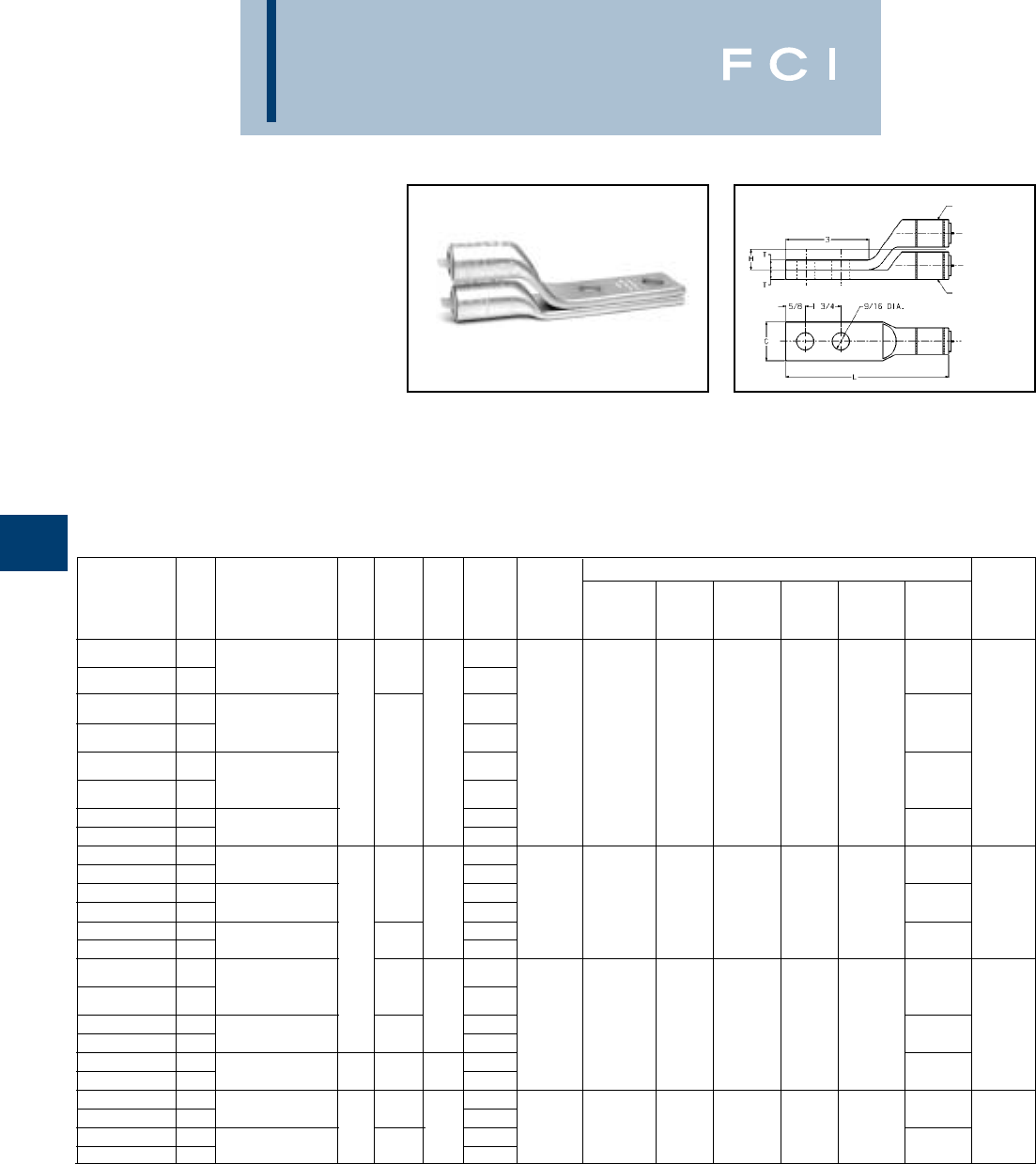
BURNDY
Overhead
E-88
TYPES YAS-R-2N &
YASO-R-2N
ALUMINUM HYLUG™
STACKING TERMINALS
For Aluminum, Copper or ACSR
Aluminum HYLUG™ with a special tongue
configuation for stacking of conductors on two
or four hole NEMA transformer or equipment
pads. Up to eight conductors may be stacked
on one four hole NEMA Pad. HYLUGS™ are
color coded, prefilled with PENETROX™ joint
compound and capped.
*U Die with Adapter PT6515.
** U Die with Adapter PUADP-1.
Available tin plated. Add suffix "TN" to Catalog Number
(example: YAS-28R-2NTN).
Available with sealed barrel. Add "P" to Catalog Number
(example: YASP28R-2N and YASOP28R-2N).
Fig. 1
Fig. 2
TOOLS, DIE SET CATALOG NO. & (NO. OF CRIMPS)
Y45*, Y46**, WIRE
CATALOG FIG. DIE Y35, Y39, MD7, COLOR STRIP
NUMBER NO. CONDUCTOR C L T H INDEX Y750 MD6 OUR840 Y48B Y60BHU CODE LENGTH
YAS6R-2N 16 (7 STR)-5 (7 STR) -
AL, CU 4-5/8 BLUE
YASO6R-2N 26 (6/1) ACSR 9⁄16
YAS4R-2N 14 (7 STR)-3 (7 STR) -
AL, CU BG U-BG BG X-BG ORANGE
YASO4R-2N 24 (6⁄1) ACSR 7⁄8 1⁄4 9/16 243 (3) (3) (3) -- 1-3⁄32
YAS1R-2N 12 (7 STR)-1 (19 STR) - K5⁄8-1 U-243 W-BG X-NBG
AL, CU 4-3⁄4 (1) (1) (4) RED
YASO1R-2N 22 (6/1) ACSR 9/16
YAS25R-2N 11/0 (19 STR) AL, CU -
YASO25R-2N 21/0 (6/1) ACSR 9/16 YELLOW
YAS26R-2N 12/0 (19 STR) AL, CU -
YASO26R-2N 22⁄0 (6⁄1) ACSR
5-5⁄8 11/16 U-K840 U249 GRAY
YAS27R-2N 13/0 (19 STR) AL, CU 5⁄16 -249 (2) (4)
-- -BLACK 1-19⁄32
YASO27R-2N 23/0 (6/1) ACSR 11/16 K840
U249 W840
YAS28R-2N 14/0 (19 STR) AL, CU 1-1⁄4 5-3⁄4 -(1) (4) PINK
YASO28R-2N 24/0 (6/1) ACSR 11/16
YAS30R-2N 1250, 300 (37 STR) -
AL, CU 6-9/16 BLUE
YAS030R-2N 2266 (18/1) ACSR
3/8
7⁄8
317
U705
YAS321R-2N 1350 (37 STR) AL, CU 6-7/8 -705
(2)
--
C31AR L31ART 2
YASO321R-2N 2336 (18/1) ACSR 7/8 K1-1⁄8 U317 (1) (1) GREEN
YAS33R-2N 1400 (37 STR) AL, CU 1-5⁄8 7-3⁄16 7⁄16 -(2)
YASO33R-2N 2397 (18/1) ACSR 7/8 GREEN
YAS361R-2N 1500 (37 STR) AL, CU 7-1/2 -
608 PINK
YASO361R-2N 2477 (18/1) ACSR 1-5/16 722 U608 --
C722 L608 2-19/32
YAS39A-2N 1700 (61 STR) AL
2-1⁄8 1⁄2 -K1-5⁄16 (4) (2) (2)
YASO39A-2N 2750 (61 STR) AL 7-13/16 1-5/16 YELLOW
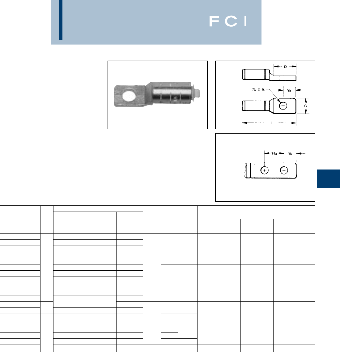
BURNDY
Overhead
E-89
TYPES YCAK-A &
YRA
ALUMINUM HYLUG™
For Aluminum, Copper or ACSR
Aluminum HYLUG™ for joining aluminum
and copper cable to transformer and equip-
ment pads. HYLUG™ is pre-filled with PENE-
TROX™ joint compound and capped.
Installed with standard tooling, five die sets
install fourteen terminal size.
Fig. 1
Fig. 2
*Overlap crimps.
** YRA1CU-1 not recommended for 2 comp. conductor.
†U Die with adapter PT-6515.
‡U Die with adapter PUADP-1.
CONDUCTOR DIE SET, TOOLS,
ALUMINUM CATALOG NO., & (NO. OF CRIMPS)
CATALOG FIG. CONC. & DIE MD7, MD6
NUMBER NO. COPPER COMPACT ACSR C D L INDEX SERIES Y35, Y750 Y45 Y46
YRA8CU-1 6 Sol. - 8 Sol. 8 Str. —
YRA6CU-1 4 Sol. - 6 Str. 4 Sol. - 6 Str. 6 (6-1) BG (3) U-BG (1) † ‡
YRA4CU-1 2 Sol. - 4 Str. 2 Sol. - 4 Str. 4 (6-1, 7-1) 1-1/16 2-9/16 BG K 5/8 U-K-5/8-1T (3) † ‡
YRA1CU-1 1 Str. - 2 Str. 1 Str. - 2 Str.** 2 (6-1, 7-1) 243 243 (1) U243 (1) † ‡
YRA25A-1 —1/0 Str.—
YRAL4CU 12 Sol. - 4 Str. 2 Sol. - 4 Str. 4 (6-1, 7-1) 15/16
YRAL1CU 1 Str. - 2 Str. 1 Str. - 2 Str. 2 (6-1, 7-1)
YRA25U 1/0 Str. 1/0 Str. 1/0 (6-1) 249 W249* U249* † ‡
YRA26U 2/0 Str. 2/0 Str. 2/0 (6-1) 1-1/4 3-1/4 K840 WK840* UK-840 † ‡
YRA27U 3/0 Str. 3/0 Str. —
YRA28U —
YCAK28A-2G1* 4/0 Str. 4/0 Str. —
YCAK29A-2G1* 2250 250 4/0 (6-1) 35-5/8 317 U317* †‡
YCAK31AG1* 11-1/4 1-5/16 4-1/2 705 —U705* S705* P705*
YCAK31A-2G1* 350 350 — 6-1/4 †‡
YCAK34A-2G3* 500 500 — † ‡
YCAK36A-2G1* 2— 600 — 1-1/2 3 6-1/2 608 — U608* S786* P786*
YCAK39A-2G2* —750 — 6-15/16 786 — U786* †‡
YCAK44A-2G2* —1000 — 1-11/16 7-1/2 302 — — S44ART* P44ART*

BURNDY
Wedge
THE WEJTAP™
SYSTEM
FOR ELECTRIC UTILITY
DISTRIBUTION AND
TRANSMISSION
CONNECTIONS
F-1

BURNDY
Wedge
Introduction..................................................F-3
WEJTAP™ Connection System..................F-4
WEJTAP™ and Test Data ............................F-5
Aluminum Connectors ................................F-6
WEJTAP™ Power Lug ................................F-7
WEJTAP™ Ordering Information ..............F-8
Copper Connectors ....................................F-9
Connector Selection
By Conductor Size........................F-10 - F-14
By Diameter..................................F-15 - F-17
Stirrup Selection........................................F-18
By Conductor Size........................F-19 - F-23
By Diameter ............................................F-24
Large Conductor Connectors........F-25 - F-26
WEJTAP™ Cover
WCCR, WCCB, WCCSY, WCCLY ..........F-27
Installation Tools
WTRB, WTY, WTB, WTHRB, WTHY ......F-28
Installation Tool Accessories
WTOCBR, WTOCY, WTCK......................F-29
Hot Stick Tool WTBGBW ..........................F-30
WEJTAP™ Hotstick Accessories
WHSCWH, WHSPBC..............................F-30
WHS90ADP, WHSWADP,
WCHAWAS, WHSTA, WHSWB ..........F-31
WHSGB, WHHWB ..................................F-32
WEJTAP™ Kits ..........................................F-33
F-2
TABLE OF CONTENTS

BURNDY
Wedge
INTRODUCTION
The BURNDY®WEJTAP™ System com-
ponents are designed to provide the most
reliable connections available, with safer and
easier installations.
The system consists of a WEJTAP™ connec-
tor, WEJTAP™ installation tools and power-
boosters.
The detailed information on power-boosters,
installation tools and accessories follows.
The BURNDY®WEJTAP™ connector uses
an aluminum alloy wedge that is power-driven
between the run and tap cables locking them
into a ‘‘C” shaped aluminum alloy spring-body.
A wiping action takes place during installation
between the conductors and Wedge which
provides additional cleaning of surface oxides
to supplement wire brushing. In addition, the
contact grooves are lined with a patented
PENETROX™ oxide inhibiting compound to
enhance superior contact surface integrity.
The Wedge is automatically locked onto the
spring-body by a skiving action produced by a
lance located at the forward end of the instal-
lation tool.
During the life of the connection, the spring-
body continues to maintain pressure to
ensure a reliable connection.
THE WEJTAP™
CONNECTOR
■Tested to NEMA and CSA Class A heat
cycle requirements to ensure long term
reliability.
■Accommodates a full range of run and tap
conductors from #8 to 1590 ACSR in all
commonly used conductors to meet the
needs of electrical distribution systems.
■Color-coded connector, boosters, and
tools to assist the installer to make the
correct selection.
■“Run locator” chamfer is machined into
the Wedge at the end of the “large” groove
to provide positive visual or/and hand
contact identification of the large run
groove for correct installation.
■Removable design allows tap removal
with minimum conductor damage.
■Tool embosses BURNDY®identifier on
end of Wedge to provide system identifi-
cation.
Ask about our unique WEJTAP™ Tool
System and Power-Booster which provides
safer and easier installations.
F-3
BURNDY
Wedge
BURNDY WEJTAP™
CONNECTION SYSTEM
BURNDY®, a leading manufacturer of quality
electrical connectors for over 70 years, intro-
duces the WEJTAP™ SYSTEM, a system
that adds further dimension to the existing
BURNDY®group of proven, reliable connec-
tion systems.
WEJTAP™ COMPONENTS are designed to
provide a reliable system connection. The
system consists of WEJTAP™ connectors,
installation tools (including a variety of hotline
and lineman accessories) and a unique
power-booster.
WEJTAP™ CONNECTORS use an alu-
minum alloy wedge that is power-driven
between the run and the tap cables locking
them into a “C” shaped tempered aluminum
alloy spring-body. The spring-body maintains
consistent pressure throughout the life of the
connection to ensure reliability during severe
electrical and climatic conditions. The
wedge’s wiping action combined with factory
installed PENETROX™ PENA 13 provides
superior contact integrity. The wedge is auto-
matically locked onto the spring-body by a
skiving action produced by a lance at the for-
ward end of the WEJTAP™ installation tool.
THE WEJTAP™ TOOL is a one-piece assem-
bly that consists of a head and power unit.
Two color-coded interchangeable heads
accept all WEJTAP™ connectors and STIR-
RUP™. The design of the tool recognizes the
need for simplicity and speed of operation as
well as outstanding safety features such as
automatic gas release vented away from the
operator, fast simple breech loading and fast
advance when engaging the connector
assembly. No loose parts to drop or misplace
and a booster ejection system that provides
further safety to the operator. Fewer simplified
hotline devices and handy lineman acces-
sories complete an outstanding tool package.
THE WEJTAP™ POWER-BOOSTER
Patented is a self-contained device that
provides the force necessary to drive the
wedge into direct contact with the conductors.
The booster is activated only when properly
positioned in the tool assembly. A power cell
in the booster is recessed to guard against
premature discharge. The tool/booster
system is designed to activate and deactivate
the booster automatically should the operator
decide to remove the tool from a connector
prior to completing the installation. The deac-
tivated booster may be safely removed from
the tool.
F-4
Features and Benefits
•Large conductor chamfer on ends
of wedge.
◊Instant hand or visual identification of
large run grooves. Ensures correct
wedge orientation.
•Color-coded WEJTAP™ connector
and booster packaged together.
◊Easy selection by installer.
•Factory coated grooves with
PENETROX™ PENA 13.
◊Maintains low contact resistance,
assists in protection against climatic
conditions and is compatible with
common insulations.
•One-piece tool.
◊No project delays due to dropped or
lost parts.
•Fewer and improved hotstick accessories
◊Simplifies hotline installation and
saves time.
•Contained booster ejection system.
◊Safe for operator guards against the
booster being ejected in direction of
the installer.
•Automatic gas release vented away
from operator.
◊Eliminates manual gas venting and
improves safety.
•Simplified loading.
◊Speeds installation––no threads––just
depress safety bar, twist and pull
open––load––push and twist to close
prior to applying connector.
•Acme-type threads.
◊Provides smooth, fast engagement of
tool and connector-saves installer’s time.
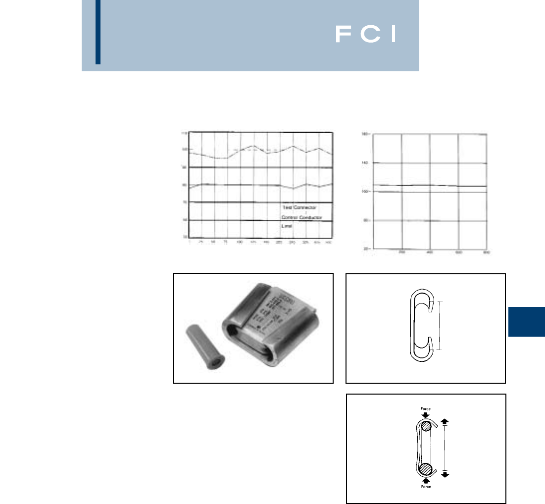
BURNDY
Wedge
WEJTAP™ AND
TEST DATA
WEJTAP™ connectors have been subjected
to extensive tests simulating the most severe
service and weather conditions. In addition,
the WEJTAP™ system meets or exceeds the
industry standards of ANSI C119.4 Class 3,
NEMA CC3 1973 Class A 500 Heat Cycles.
As with all BURNDY®connectors, the WEJ-
TAP™ has been designed to operate cooler
than the attached conductors. The WEJ-
TAP™ connectors have also been subjected
to the ASTM B117-73 Salt Spray Test. The
results are shown to the right.
F-5
WEJTAP™
Spring-bodies are color-coded and the
wedges are marked with nominal conductor
run and tap ranges. WEJTAP™ connector
packages are labeled with a variety of com-
mon conductors with their nominal ranges.
■WEJTAP™ connector wedges are marked
with nominal ACSR, Aluminum and Copper
concentric standard conductors.
■Red WEJTAP™ connector range Run 8-1/0
Tap 8-2
■Blue WEJTAP™ connector range Run
2-300 Tap 6-300
■Yellow WEJTAP™ connector range Run
266.8-1590 Tap 6-1590
All WEJTAP™ wedges contain a clearly
defined chamfer on the large end of the run
conductor groove to identify the “large run”
groove. Installers will appreciate the conve-
nience of visual or hand identification for
correct wedge positioning.
WEJTAP™ wedges are driven between the
run and tap conductors and activate the
spring characteristics of the “C” shaped body.
This action maintains contact pressure even
when the connection is subjected to severe
climatic and electrical conditions.
ANSI C119.4 - 1986 Heat Cycle Test
Average Temperature Rise vs. Current Cycles
Temperature Rise (Deg. C.)
Relative Resistance (Percent)
Hours
Detailed test report packages are available upon request.
ASTM Salt Spray Test
Average % Relative Resistance vs. Hours of Salt Spray Exposure
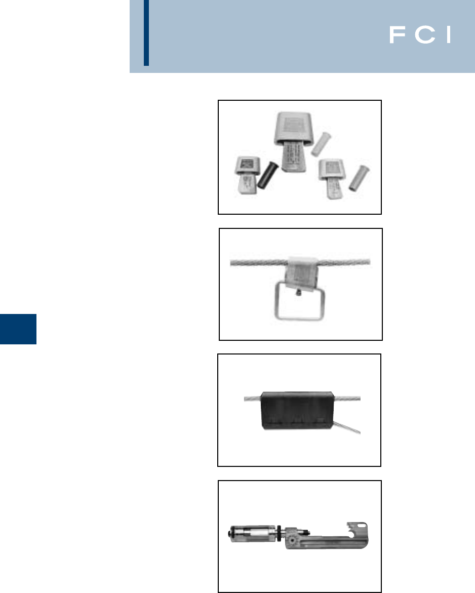
BURNDY
Wedge
ALUMINUM
WEJTAP™
CONNECTORS
The WEJTAP™ CONNECTOR SYSTEM
provides TAPS, STIRRUPS and COVERS,
conductor ranges #8 through 1590. Tap stir-
rup conductor ranges #6 - 1033.6.
F-6
TAPS WEJTAP™ connector ranges are
divided into three color-coded groups.
RUN TAP
RED 8-1/0 8-2
BLUE 2-300 6-300
YELLOW 266.8-1590 6-1590
STIRRUPS™ are available from #6 through
1033.6 nominal conductor ranges. Tinned
copper bails are permanently attached in
sizes 2, 1/0, 2/0, 4/0 to provide a rugged “Hot
Tap” connection point.
COVERS are installed on WEJTAP™ con-
nectors to prevent them from coming in
contact with other taps or exposed ground
points. The WEJTAP™ covers are rugged
snap-on devices available in four sizes to
cover all connector sizes, and are cold
weather tested for easy installations.
SAFETY FEATURES
■Contained booster ejection system that
guards against potential hazard of spent
boosters being ejected at installers.
■Automatic gas release vented away from
the operator eliminates manual venting
toward the operator.
■Power-boosters can only be activated
when properly positioned in the tool and
engaged on the connector. Power-
boosters are automatically deactivated
should the operator decide to remove the
tool from the connector prior to complet-
ing the installation.The deactivated boost-
er may be safely removed, all to provide a
safer tool for your line personnel.
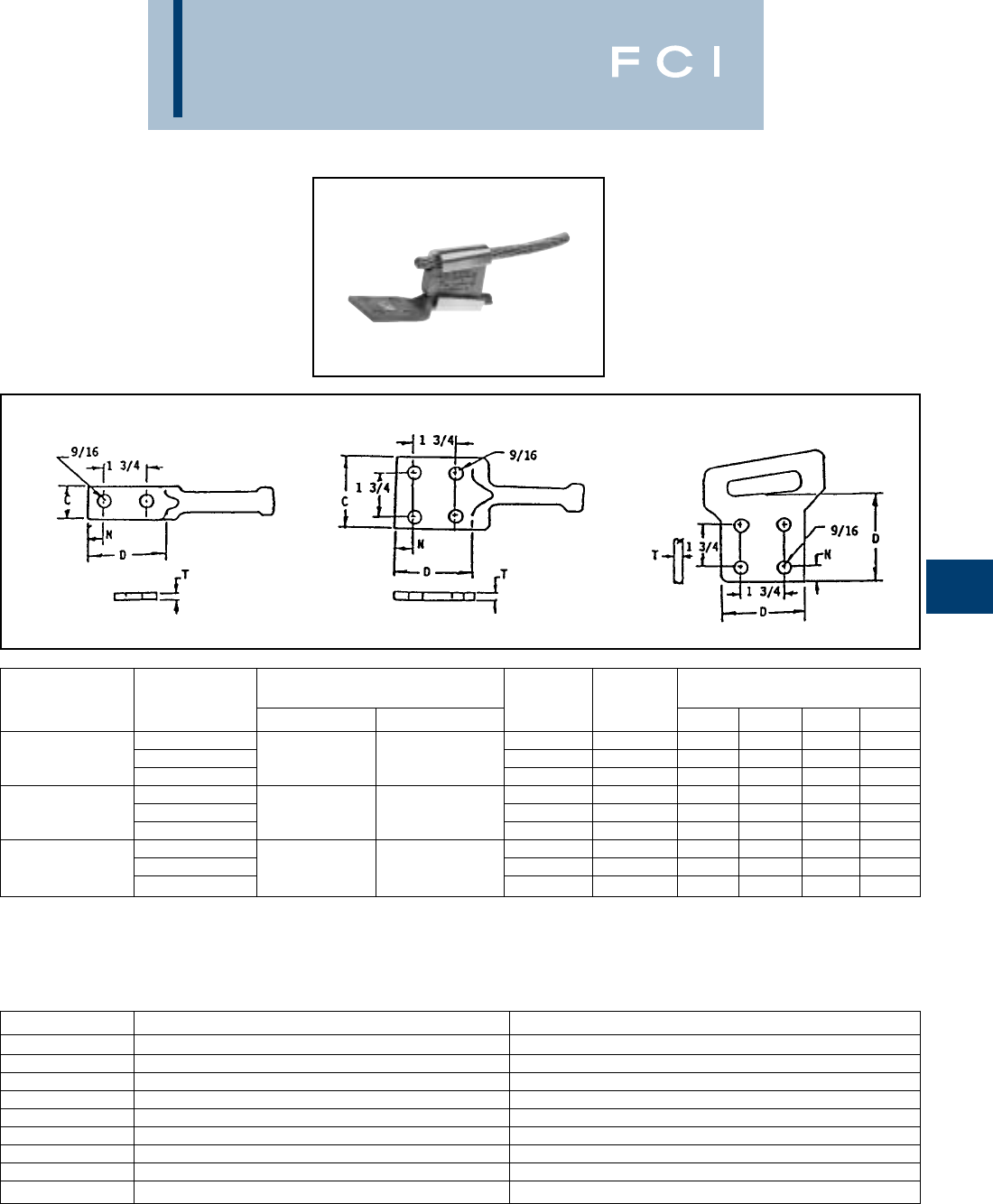
BURNDY
Wedge
WEJTAP™
POWER LUG
WEJTAP™ POWERLUG™ terminals are
made of cast aluminum alloy for termination
of ACSR and Aluminum conductors.
F-7
Fig. 1 Fig. 2 Fig. 3
2 HOLE POWER LUG 4 HOLE POWER LUG 4 HOLE FLAG
MULTIPLE CONDUCTOR TAP APPLICATION
*Electrically, the three smaller conductors are the
likely taps, however, during installation, they are
located in the larger run groove due to their larger
aggregate sum.
NOTE: The recommended connector and booster are ordered
separately. Catalog number is for the POWERLUG™ only.
TAP GROOVE
FOR CONNECTOR CATALOG STANDARD CONDUCTOR HOLES DIMENSIONS
SELECTION NUMBER ACSR ASC/AAC FIGURE IN PAD C D N T
4/0 WCAB30R-2N 121-1/4 3 5/8 0.34
STANDARD WCAB30R-4N 6 Str. - 266.8 6 Str. - 300 2 4 3 3 5/8 0.30
ACSR WCBB30R-4N 341-3/4 3-1/2 7/8 0.30
336.4 WCAY39R-2N 121-1/4 3 5/8 0.34
STANDARD WCAY39R-4N 266.8 - 556.5 336.4 - 636 2 4 3 3 5/8 0.30
ACSR WCBY39R-4N 343-3/4 3-1/2 1 0.30
795 WCAY49R-2N 121-3/4 3-1/2 5/8 0.69
STANDARD WCAY49R-4N 605 - 1033.5 715.5 - 1113 2 4 3-1/2 3-1/2 5/8 0.69
ACSR WCBY49R-4N 34443/4 0.69
CONNECTOR *RUN GROOVE *TAP GROOVE
WCY 64 PB Three - 1/0 ACSR (6/1) Diameter = 0.398One - 4/0 ACSR (6/1) Diameter = 0.563
WCY 65 PB Three - 1/0 ACSR (6/1) Diameter = 0.398One - 3/0 ACSR (6/1) Diameter = 0.502
WCY 63 PB Three - 2/0 ACSR (6/1) Diameter = 0.447One - 4/0 ACSR (6/1) Diameter = 0.563
WCB 11 PB Three - #4 stranded Diameter = 0.232One - 1/0 ACSR (6/1) Diameter = 0.398
WCY 54 PB Three - 1/0 stranded Diameter = 0.368One - 4/0 stranded Diameter = 0.522
WCY 53 PB Three - 1/0 stranded Diameter = 0.368One - 3/0 stranded Diameter = 0.464
WCY 64 PB Three - 2/0 stranded Diameter = 0.414One - 4/0 stranded Diameter = 0.522
WCB 11 PB Three - #4 stranded Diameter = 0.232One - 1/0 stranded Diameter = 0.368
WCB 12 PB Three - #4 stranded Diameter = 0.232One - #4 solid copper hard drawn Diameter = 0.204
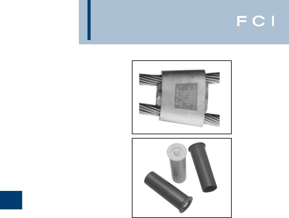
BURNDY
Wedge
The BURNDY®WEJTAP™ System has a
wide variety of connectors available for
many different conductor ranges.
The following pages list some common
conductors and the appropriate connector.
ACSR to ACSR page F10
ACSR to AAC page F11
ACSR to Copper page F12
AAC to AAC page F13
AAC to Copper page F14
Stirrup Information pages F18 through F24
ORDERING INFORMATION
■Power boosters may be ordered
separately in boxes of 25.
Red boosters Cat. #WPBRN Box 25
Blue boosters Cat. #WPBBN Box 25
Yellow boosters Cat. #WPBYN Box 25
For information about conductors which
are not listed, and for further ordering
information, please contact BURNDY®at
1-800-346-4175.
F-8
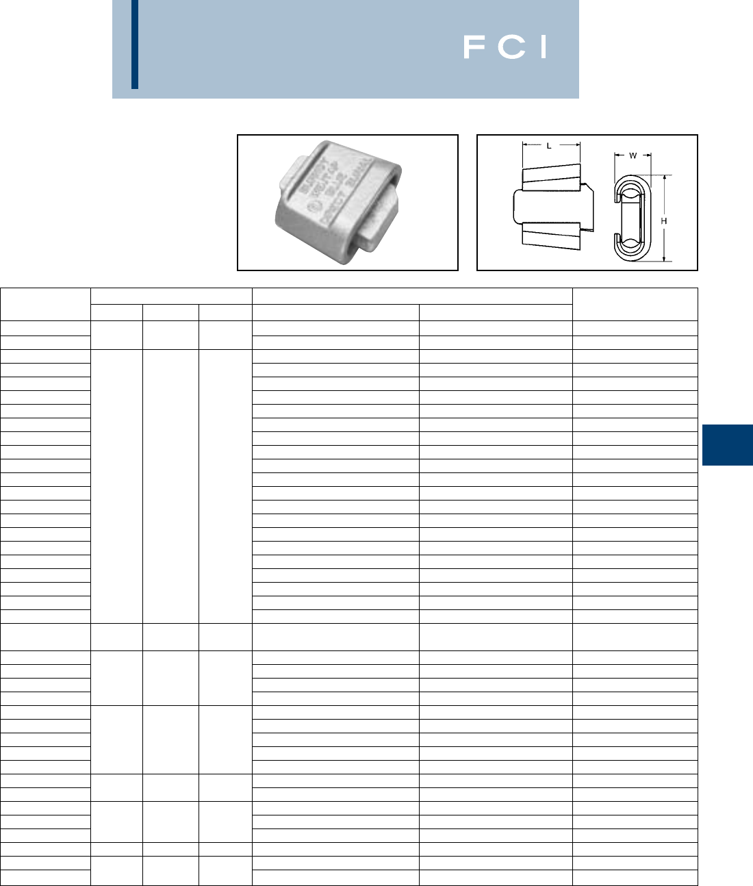
BURNDY
Wedge
F-9
WEJTAP™
COPPER WEJTAP
WEJTAP™ powder actuated copper connec-
tion system for use in standard grounding
applications Listed under UL467 and over-
head copper-to-copper tap applications
Listed under UL486A.
CATALOG DIMENSIONS COPPER CONDUCTORS ACCOMMODATED INSTALLATION
NUMBER H L W RUN TAP BOOSTER COLOR
WCR33C-1 1.65 1.26 .79 #6 Str./Sol., #4 Str./Sol. #6 Str./Sol. Red
WCR32C-1 [42] [32] [20] #4 Str./Sol., #2 Str./Sol. #6 Str./Sol., #4 Str./Sol. Red
WCB2C2C #2 Str./Sol., #1 Sol. #2 Str./Sol. Blue
WCB25C4C 1/0 Str. #6 Str./Sol., #4 Str./Sol. Blue
WCB25C1C 1/0 Str. #2 Str./Sol., #1 Sol. Blue
WCB25C25 1/0 Str. 1/0 Str. Blue
WCB26C4C 2/0 Str. #6 Str./Sol., #4 Str./Sol. Blue
WCB26C1C 2/0 Str. #2 Str./Sol., #1 Sol. Blue
WCB26C26 2/0 Str. 1/0 Str., 2/0 Str. Blue
WCB27C4C 3/0 Str. #4 Sol. Blue
WCB27C1C 3/0 Str. #2 Str. Blue
WCB27C26 2.40 1.63 1.02 3/0 Str. 1/0 Str., 2/0 Str. Blue
WCB27C27 [61] [41] [26] 3/0 Str. 3/0 Str. Blue
WCB28C4C 4/0 Str. #6 Str./Sol., #4 Str./Sol. Blue
WCB28C1C 4/0 Str. #2 Str./Sol., #1 Sol. Blue
WCB28C26 4/0 Str. 1/0 Str., 2/0 Str. Blue
WCB28C28 4/0 Str. 4/0 Str. Blue
WCB29C1C 250 kcmil #3 Str., #2 Str./Sol., #1 Str./Sol. Blue
WCB29C25 5/8Cu Clad Rod 1/0 Str. Blue
WCB29C26 250 kcmil 1/0 Str., 2/0 Str. Blue
WCB29C28 250 kcmil, 5/8Cu Clad Rod 3/0 Str., 4/0 Str. Blue
WCB29C29 250 kcmil 250 kcmil Blue
2.81 2.00 1.30
WCB30C4C [71] [51] [33] 300 kcmil #4 Str., #2 Sol. Blue
WCB30C25 300 kcmil 1/0 Str. Blue
WCB30C27 2.64 2.00 1.16 300 kcmil 3/0 Str. Blue
WCB30C29 [67] [51] [29] 300 kcmil 5/8Cu Clad Rod Blue
WCB30C30 300 kcmil 300 kcmil Blue
WCB31C5C 350 kcmil, 3/4Cu Clad Rod #6 Str., #5 Str., #4 Sol. Blue
WCB31C4C 3/4Cu Clad Rod #4 Str. Blue
WCB31C2C 2.81 2.00 1.30 3/4Cu Clad Rod #2 Str. Blue
WCB31C26 [71] [51] [33] 350 kcmil, 3/4Cu Clad Rod 2/0 Str. Blue
WCB31C28 350 kcmil, 3/4Cu Clad Rod 4/0 Str. Blue
WCB31C31 350 kcmil 350 kcmil Blue
WCB33C30 ——— 400 kcmil, 450 kcmil 250 kcmil, 300 kcmil Blue
WCB34C2C 500 kcmil #2 Str. Blue
WCB34C26 2.81 2.00 1.30 500 kcmil 2/0 Str. Blue
WCB34C28 [71] [51] [33] 500 kcmil 4/0 Str. Blue
WCB34C29 ——— 500 kcmil 250 kcmil, 5/8Cu Clad Rod Blue
WCY34C34 3.65 3.00 1.45 500 kcmil 500 kcmil Yellow
WCY36C36 [93] [76] [37] 600 kcmil 500 kcmil, 600 kcmil Yellow

BURNDY
Wedge
F-10
BURNDY WEJTAP™
CONNECTOR
SELECTOR CHART
By Conductor Size
•When ordering, add WC and color code
before number
•Further information may be obtained by
contacting BURNDY®at 1-800-346-4175
34 37 37 36 35
33 33 32 12 12 12 15 21 40 59 59 70 85 02 02
32 31 13 13 13 16 22 41 58 58 69 84 01 01
10 10 10 11 11 23 42 57 57 67 83 00 00
10 11 11 17 24 43 66 66 65 81 99 98
11 17 18 25 44 65 65 64 81 98 97
18 19 26 45 64 64 63 79 97 96
20 27 46 64 64 63 79 96 95
28 47 63 63 62 78 96 95
47 62 62 61 77 95 94
62 61 61 76 94 93
61 61 75 93 92
ACSR TO ACSR 60 74 92 91
72 89 88
87 87
86
TAP
ACSR#8-6/1
ACSR#6-6/1
ACSR#4-6/1
ACSR#2-6/1
ACSR-1/0-6/1
ACSR-2/0-6/1
ACSR-3/0-6/1
ACSR-4/0-6/1
ACSR-266.8-18/1
ACSR-336.4-18/1
ACSR-397.5-18/1
ACSR-477.0-18/1
ACSR-556.5-18/1
ACSR-795.0-36/1
ACSR-954.0-36/1
ACSR-1033.5-36/1
ACSR #8-6/1
ACSR #6-6/1
ACSR #4-6/1
ACSR #2-6/1
ACSR-1/0-6/1
ACSR-2/0-6/1
ACSR-3/0-6/1
ACSR-4/0-6/1
ACSR-266.8-18/1
ACSR-336.4-18/1
ACSR-397.5-18/1
ACSR-477.0-18/1
ACSR-556.5-18/1
ACSR-795.0-36/1
ACSR-954.0-36/1
ACSR-1033.5-36/1
RUN
COLOR NUMBER CODE CONNECTOR
BLUE 10-28 B WCB20
BLUE 40-47 B WCB40
RED 29-37 R WCR30
YELLOW 48-99 Y WCY99
YELLOW 00-39 Y WCY100
(100-139) IF YELLOW, INSERT 1 BEFORE 00-39
BURNDY
Wedge
F-11
BURNDY WEJTAP™
CONNECTOR
SELECTOR CHART
By Conductor Size
TAP
34 37 37 36 35
33 33 32 12 12 12 15 21 40 59 59 70 85 02 02
32 31 13 13 13 16 22 41 58 58 69 84 01 01
30 10 10 11 11 23 42 57 57 68 83 00 00
10 11 11 17 24 43 67 67 66 82 00 99
11 17 18 25 44 66 66 65 81 98 98
18 19 26 45 65 65 64 80 98 97
20 27 46 64 64 63 79 97 96
28 46 63 63 62 78 96 95
47 62 62 62 77 95 94
62 62 61 77 94 93
61 61 76 93 92
ACSR TO AAC 60 75 92 92
72 89 88
88 87
86
ACSR# 8-6/1
ACSR# 6-6/1
ACSR# 4-6/1
ACSR# 2-6/1
ACSR-1/0-6/1
ACSR-2/0-6/1
ACSR-3/0-6/1
ACSR-4/0-6/1
ACSR-266.8-18/1
ACSR-336.4-18/1
ACSR-397.5-18/1
ACSR-477.0-18/1
ACSR-556.5-18/1
ACSR-795.0-36/1
ACSR-954.0-36/1
ACSR-1033.5-36/1
AAC #8
AAC #6
AAC #4
AAC #2
AAC-1/0
AAC-2/0
AAC-3/0
AAC-4/0
AAC-266.8
AAC-336.4
AAC-397.5
AAC-477.0
AAC-556.5
AAC-795.0
AAC-954.0
AAC-1033.5
RUN
•When ordering, add WC and color code
before number
•Further information may be obtained by
contacting BURNDY®at 1-800-346-4175
COLOR NUMBER CODE CONNECTOR
BLUE 10-28 B WCB20
BLUE 40-47 B WCB40
RED 29-37 R WCR30
YELLOW 48-99 Y WCY99
YELLOW 00-39 Y WCY100
(100-139) IF YELLOW, INSERT 1 BEFORE 00-39
BURNDY
Wedge
F-12
BURNDY WEJTAP™
CONNECTOR
SELECTOR CHART
By Conductor Size
TAP
COPPER #8
COPPER #6
COPPER #4
COPPER #2
COPPER-1/0
COPPER-2/0
COPPER-3/0
COPPER-4/0
COPPER-250.0
COPPER-350.0
COPPER-500.0
COPPER-750.0
COPPER-1000.0
34 37 37 36 35
33 33 32 12 12 12 15 21 40 59 59 70 85 02 02
32 31 13 13 13 16 22 41 58 58 69 84 01 01
30 10 10 11 11 23 42 57 57 68 83 00 00
10 11 11 17 24 43 67 67 66 82 00 99
11 17 18 25 44 66 66 65 81 98 98
18 19 26 45 65 65 64 80 98 97
20 27 46 64 64 63 79 97 96
27 46 63 62 62 78 96 95
47 62 62 61 77 95 94
62 61 61 75 93 92
76 75 72 90 89
ACSR TO COPPER 92 89 87 87
RUN
ACSR# 8-6/1
ACSR# 6-6/1
ACSR# 4-6/1
ACSR# 2-6/1
ACSR-1/0-6/1
ACSR-2/0-6/1
ACSR-3/0-6/1
ACSR-4/0-6/1
ACSR-266.8-18/1
ACSR-336.4-18/1
ACSR-397.5-18/1
ACSR-477.0-18/1
ACSR-556.5-18/1
ACSR-795.0-36/1
ACSR-954.0-36/1
ACSR-1033.5-36/1
•When ordering, add WC and color code
before number
•Further information may be obtained by
contacting BURNDY®at 1-800-346-4175
COLOR NUMBER CODE CONNECTOR
BLUE 10-28 B WCB20
BLUE 40-47 B WCB40
RED 29-37 R WCR30
YELLOW 48-99 Y WCY99
YELLOW 00-39 Y WCY100
(100-139) IF YELLOW, INSERT 1 BEFORE 00-39
BURNDY
Wedge
F-13
BURNDY WEJTAP™
CONNECTOR
SELECTOR CHART
By Conductor Size
TAP
34 37 37 36 35
33 33 32 12 12 12 15 21 40 48 59 59 85 02 02
32 31 13 13 13 16 22 41 49 58 58 84 01 01
30 29 10 14 11 23 42 50 57 57 83 00 00
10 14 11 17 24 43 51 67 66 82 99 00
11 17 18 25 44 52 66 65 81 98 98
18 19 26 45 53 65 64 80 98 97
20 27 46 54 64 63 79 97 96
28 46 55 63 62 78 96 95
47 56 62 62 77 95 94
56 62 61 77 94 93
62 61 76 93 92
AAC TO AAC 60 75 92 92
72 89 88
88 87
86
AAC #8
AAC #6
AAC #4
AAC #2
AAC-1/0
AAC-2/0
AAC-3/0
AAC-4/0
AAC-266.8
AAC-336.4
AAC-397.5
AAC-477.0
AAC-556.5
AAC-795.0
AAC-954.0
AAC-1033.5
AAC-#8
AAC-#6
AAC-#4
AAC-#2
AAC-1/0
AAC-2/0
AAC-3/0
AAC-4/0
AAC-266.8
AAC-336.4
AAC-397.5
AAC-477.0
AAC-556.5
AAC-795.0
AAC.954.0
AAC-1033.5
RUN
•When ordering, add WC and color code
before number
•Further information may be obtained by
contacting BURNDY®at 1-800-346-4175
COLOR NUMBER CODE CONNECTOR
BLUE 10-28 B WCB20
BLUE 40-47 B WCB40
RED 29-37 R WCR30
YELLOW 48-99 Y WCY99
YELLOW 00-39 Y WCY100
(100-139) IF YELLOW, INSERT 1 BEFORE 00-39
BURNDY
Wedge
F-14
BURNDY WEJTAP™
CONNECTOR
SELECTOR CHART
By Conductor Size
TAP
COPPER #8
COPPER #6
COPPER #4
COPPER #2
COPPER-1/0
COPPER-2/0
COPPER-3/0
COPPER-4/0
COPPER-250.0
COPPER-350.0
COPPER-500.0
COPPER-750.0
COPPER-1000.0
34 37 37 36 35
33 33 32 12 12 12 15 21 40 48 59 59 85 02 02
32 31 13 13 13 16 22 41 49 58 58 84 01 01
30 29 10 14 11 23 42 50 57 57 83 00 00
10 14 11 17 24 43 51 67 66 82 99 00
11 17 18 25 44 52 66 65 81 98 98
18 19 26 45 53 65 64 80 98 97
20 27 46 54 64 63 79 97 96
27 46 55 63 62 78 96 95
47 56 62 61 77 95 94
62 61 61 75 93 92
76 75 72 90 89
AAC TO COPPER 92 89 88 87
AAC-#8
AAC-#6
AAC-#4
AAC-#2
AAC-1/0
AAC-2/0
AAC-3/0
AAC-4/0
AAC-266.8
AAC-336.4
AAC-397.5
AAC-477.0
AAC-556.5
AAC-795.0
AAC.954.0
AAC-1033.5
RUN
•When ordering, add WC and color code
before number
•Further information may be obtained by
contacting BURNDY®at 1-800-346-4175
COLOR NUMBER CODE CONNECTOR
BLUE 10-28 B WCB20
BLUE 40-47 B WCB40
RED 29-37 R WCR30
YELLOW 48-99 Y WCY99
YELLOW 00-39 Y WCY100
(100-139) IF YELLOW, INSERT 1 BEFORE 00-39
BURNDY
Wedge
F-15
BURNDY WEJTAP™
SELECTION CHART
By Diameter
Catalog Sum of Diameters Run Tap
Number Max Min Max Min Max Min
Installed with blue booster
WCB10 0.795 0.621 0.482 0.316 0.437 0.257
WCB11 0.901 0.763 0.568 0.364 0.457 0.257
WCB12 0.707 0.526 0.568 0.364 0.204 0.162
WCB13 0.761 0.6 0.568 0.364 0.258 0.204
WCB14 0.839 0.69 0.568 0.364 0.398 0.257
WCB15 0.769 0.622 0.568 0.364 0.204 0.162
WCB16 0.823 0.664 0.568 0.364 0.258 0.204
WCB17 0.963 0.804 0.568 0.364 0.464 0.257
WCB18 1.011 0.867 0.568 0.364 0.572 0.364
WCB19 1.068 0.938 0.568 0.364 0.572 0.379
WCB20 1.13 0.975 0.568 0.364 0.572 0.386
WCB21 0.846 0.711 0.65 0.532 0.204 0.162
WCB22 0.9 0.765 0.65 0.532 0.258 0.204
WCB23 0.972 0.818 0.65 0.532 0.33 0.257
WCB24 1.052 0.897 0.65 0.532 0.5 0.324
WCB25 1.104 0.963 0.65 0.532 0.562 0.364
WCB26 1.163 1.015 0.65 0.532 0.562 0.409
WCB27 1.221 1.08 0.65 0.532 0.575 0.46
WCB28 1.284 1.141 0.65 0.532 0.65 0.525
WCB40 0.888 0.762 0.684 0.603 0.204 0.162
WCB41 0.942 0.794 0.684 0.6 0.258 0.204
WCB42 1.011 0.857 0.684 0.6 0.333 0.257
WCB43 1.094 0.936 0.684 0.6 0.5 0.324
WCB44 1.146 1.009 0.684 0.6 0.562 0.364
WCB45 1.204 1.057 0.684 0.6 0.562 0.409
WCB46 1.284 1.119 0.684 0.6 0.592 0.46
WCB47 1.368 1.188 0.684 0.6 0.684 0.6
Installed with red booster
WCR29 0.723 0.584 0.398 0.257 0.398 0.257
WCR30 0.656 0.516 0.398 0.257 0.325 0.206
WCR31 0.602 0.464 0.398 0.257 0.258 0.162
WCR32 0.53 0.41 0.326 0.204 0.258 0.162
WCR33 0.459 0.331 0.258 0.169 0.23 0.162
WCR34 0.324 0.256 0.162 0.128 0.162 0.128
WCR35 0.56 0.452 0.398 0.257 0.162 0.128
WCR36 0.487 0.387 0.398 0.257 0.162 0.128
WCR37 0.416 0.297 0.258 0.169 0.162 0.128
Installed with yellow booster
WCY100 1.572 1.4 1.25 0.893 0.351 0.257
WCY101 1.503 1.343 1.25 0.893 0.261 0.204
WCY102 1.454 1.284 1.25 0.893 0.198 0.162
WCY103 2.604 2.484 1.302 1.242 1.302 1.242
BURNDY
Wedge
F-16
BURNDY WEJTAP™
SELECTION CHART
By Diameter
Catalog Sum Of Diameters Run Tap
Number Max. Min. Max. Min. Max. Min.
Installed with yellow booster
WCY104 2.567 2.407 1.302 1.242 1.265 1.165
WCY105 2.489 2.329 1.302 1.242 1.187 1.087
WCY106 2.418 2.258 1.302 1.242 1.116 1.016
WCY107 2.373 2.213 1.302 1.242 1.071 0.971
WCY108 2.318 2.158 1.302 1.242 1.016 0.916
WCY109 2.255 2.095 1.302 1.242 0.953 0.853
WCY110 2.179 2.019 1.302 1.242 0.877 0.777
WCY111 2.102 1.942 1.302 1.242 0.8 0.7
WCY112 2.044 1.884 1.302 1.242 0.742 0.642
WCY113 1.961 1.801 1.302 1.242 0.659 0.559
WCY114 1.94 1.74 1.35 1.242 0.59 0.498
WCY115 1.863 1.663 1.35 1.242 0.513 0.421
WCY116 1.812 1.612 1.35 1.242 0.462 0.37
WCY117 1.762 1.562 1.35 1.242 0.412 0.32
WCY118 1.703 1.503 1.35 1.242 0.353 0.261
WCY119 1.631 1.431 1.35 1.242 0.281 0.189
WCY120 1.58 1.38 1.35 1.242 0.23 0.138
WCY121 2.844 2.642 1.422 1.314 1.422 1.328
WCY122 2.764 2.562 1.422 1.314 1.342 1.248
WCY123 2.68 2.479 1.422 1.314 1.258 1.164
WCY124 2.596 2.394 1.422 1.314 1.174 1.08
WCY125 2.535 2.333 1.422 1.314 1.113 1.019
WCY126 2.481 2.279 1.422 1.314 1.059 0.965
WCY127 2.426 2.224 1.422 1.314 1.004 0.91
WCY128 2.376 2.174 1.422 1.314 0.954 0.86
WCY129 2.286 2.084 1.422 1.314 0.864 0.77
WCY130 2.216 2.014 1.422 1.314 0.794 0.7
WCY131 2.152 1.95 1.422 1.314 0.73 0.636
WCY132 2.07 1.868 1.422 1.314 0.648 0.554
WCY133 1.99 1.786 1.422 1.314 0.568 0.472
WCY134 1.931 1.729 1.422 1.314 0.509 0.415
WCY135 1.876 1.674 1.422 1.314 0.454 0.36
WCY136 1.831 1.629 1.422 1.314 0.409 0.315
WCY137 1.771 1.569 1.422 1.314 0.349 0.255
WCY138 1.706 1.504 1.422 1.314 0.284 0.19
WCY139 1.664 1.462 1.422 1.314 0.242 0.148
WCY48 0.932 0.765 0.75 0.537 0.204 0.162
WCY49 1.012 0.807 0.75 0.537 0.271 0.203
WCY50 1.069 0.86 0.75 0.537 0.355 0.257
WCY51 1.141 0.927 0.75 0.537 0.557 0.324
WCY52 1.19 1.001 0.75 0.537 0.588 0.364
WCY53 1.236 1.012 0.75 0.537 0.619 0.409
WCY54 1.302 1.063 0.75 0.537 0.63 0.46
WCY55 1.37 1.14 0.75 0.537 0.714 0.499
WCY56 1.456 1.245 0.75 0.537 0.75 0.524
WCY57 1.19 0.979 0.893 0.666 0.326 0.257
BURNDY
Wedge
F-17
BURNDY WEJTAP™
SELECTION CHART
By Diameter
Catalog Sum Of Diameters Run Tap
Number Max. Min. Max. Min. Max. Min.
Installed with yellow booster
WCY58 1.118 0.931 0.893 0.666 0.258 0.204
WCY59 1.061 0.891 0.893 0.666 0.199 0.162
WCY60 1.854 1.686 0.95 0.722 0.95 0.722
WCY61 1.741 1.524 0.94 0.683 0.94 0.666
WCY62 1.594 1.379 0.94 0.683 0.75 0.573
WCY63 1.5 1.297 0.94 0.683 0.75 0.481
WCY64 1.421 1.216 0.94 0.683 0.65 0.436
WCY65 1.36 1.147 0.94 0.683 0.562 0.382
WCY66 1.305 1.097 0.94 0.683 0.562 0.336
WCY67 1.27 1.054 0.94 0.683 0.45 0.315
WCY68 1.253 1.115 0.94 0.683 0.326 0.257
WCY69 1.187 1.059 0.94 0.683 0.262 0.204
WCY70 1.13 1.013 0.94 0.683 0.204 0.162
WCY71 2.216 2.074 1.133 0.907 1.156 0.947
WCY72 2.133 1.999 1.133 0.907 1.142 0.927
WCY73 2.098 1.946 1.133 0.907 1.142 0.907
WCY74 2.035 1.891 1.133 0.907 1.142 0.858
WCY75 1.969 1.822 1.133 0.889 0.927 0.763
WCY76 1.901 1.741 1.133 0.889 0.9 0.7
WCY77 1.829 1.677 1.133 0.889 0.75 0.575
WCY78 1.75 1.599 1.133 0.889 0.729 0.525
WCY79 1.67 1.526 1.133 0.889 0.722 0.364
WCY80 1.61 1.466 1.133 0.889 0.608 0.364
WCY81 1.555 1.411 1.133 0.889 0.608 0.364
WCY82 1.506 1.362 1.133 0.889 0.436 0.324
WCY83 1.44 1.288 1.133 0.889 0.398 0.257
WCY84 1.369 1.221 1.133 0.889 0.333 0.203
WCY85 1.306 1.158 1.133 0.889 0.258 0.162
WCY86 2.496 2.332 1.25 0.893 1.25 0.999
WCY87 2.418 2.251 1.25 0.893 1.25 0.856
WCY88 2.354 2.194 1.25 0.893 1.211 0.971
WCY89 2.297 2.137 1.25 0.893 1.2 0.923
WCY90 2.238 2.083 1.25 0.893 1.159 0.868
WCY91 2.173 2.013 1.25 0.893 1.13 0.856
WCY92 2.104 1.95 1.25 0.893 0.904 0.72
WCY93 2.029 1.869 1.25 0.893 0.9 0.7
WCY94 1.967 1.831 1.25 0.893 0.75 0.588
WCY95 1.888 1.728 1.25 0.893 0.722 0.525
WCY96 1.811 1.648 1.25 0.893 0.609 0.364
WCY97 1.748 1.591 1.25 0.893 0.598 0.385
WCY98 1.695 1.533 1.25 0.893 0.598 0.364
WCY99 1.644 1.489 1.25 0.893 0.398 0.324
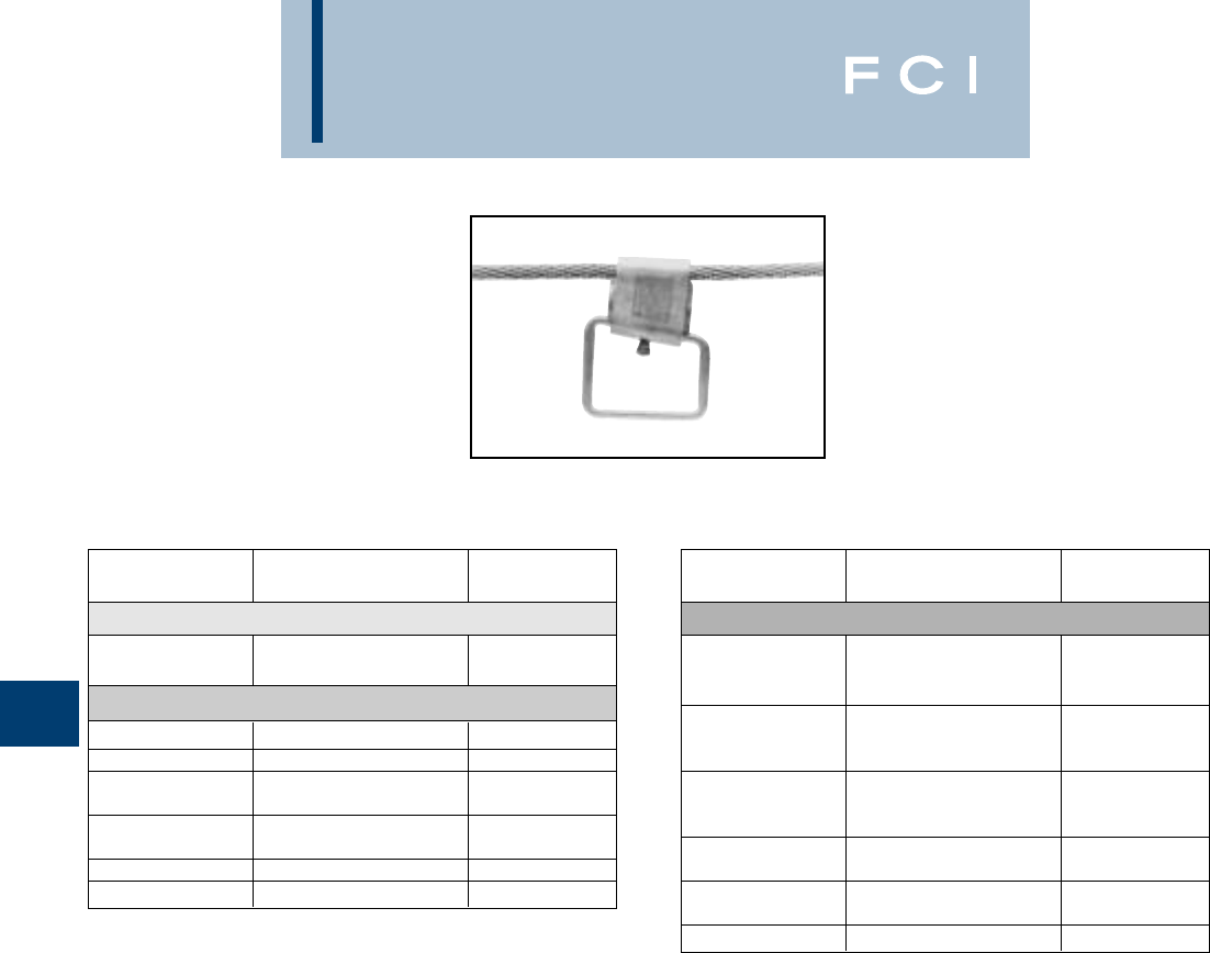
BURNDY
Wedge
F-18
WEJTAP™
STIRRUP™ AND
POWER BOOSTERS
(Large) Run Conductor position is identified
on all wedges via a distinct chamfer.
QIK Selector - for common ACSR, Aluminum and Copper Conductors
CATALOG NOMINAL CABLE BAIL
NUMBER RANGE SIZE
SMALL RED CABLE RANGE 6-2
WSS1 6
WSS2 5, 4, 2 2
MEDIUM BLUE CABLE RANGE 1-300
WSM1 1, 1/0, 2/0 2
WSM2 2/0, 3/0 2
WSM3 2
WSM4 3/0 - 4/0 2/0
WSM5 2
WSM6 266.8 1/0
WSM7 350 1/0
WSM11 266.8 - 336.4 4/0
CATALOG NOMINAL CABLE BAIL
NUMBER RANGE SIZE
LARGE YELLOW CABLE RANGE 300-1033.5
WSL1 1/0
WSL2 336.4 2/0
WSL3 4/0
WSL4 1/0
WSL5 397.5 - 477 2/0
WSL6 4/0
WSL7 1/0
WSL8 556.5 2/0
WSL9 4/0
WSL10 4/0
WSL11 636 2/0
WSL12 2/0
WSL13 795 4/0
WSL14 1033.5 4/0
BURNDY
Wedge
F-19
WEJTAP™ STIRRUP™
SELECTION BY
CABLE SIZE
MEDIUM CABLE RANGE
1-300
WSS1 WSS2
BURNDY
Wedge
F-20
WEJTAP™ STIRRUP™
SELECTION BY
CABLE SIZE
LARGE CABLE RANGE
300-1033.5
WSM1 WSM2 WSM3 WSM4
WSM5 WSM6 WSM7
BURNDY
Wedge
F-21
WEJTAP™ STIRRUP™
SELECTION BY
CABLE SIZE
LARGE CABLE RANGE
300-1033.5
WSL1 WSL2 WSL3
WSL4 WSL5 WSL6
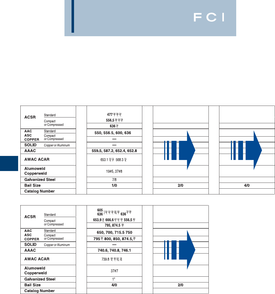
BURNDY
Wedge
F-22
WEJTAP™ STIRRUP™
SELECTION BY
CABLE SIZE
LARGE CABLE RANGE
300-1033.5
WSL7 WSL8 WSL9
WSL10 WSL11
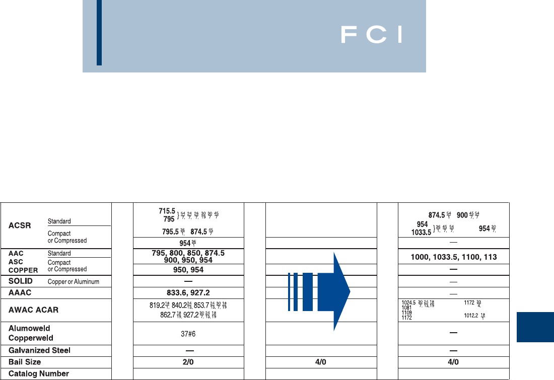
BURNDY
Wedge
F-23
WEJTAP™ STIRRUP™
SELECTION BY
CABLE SIZE
LARGE CABLE RANGE
300-1033.5
WSL12 WSL13 WSL14
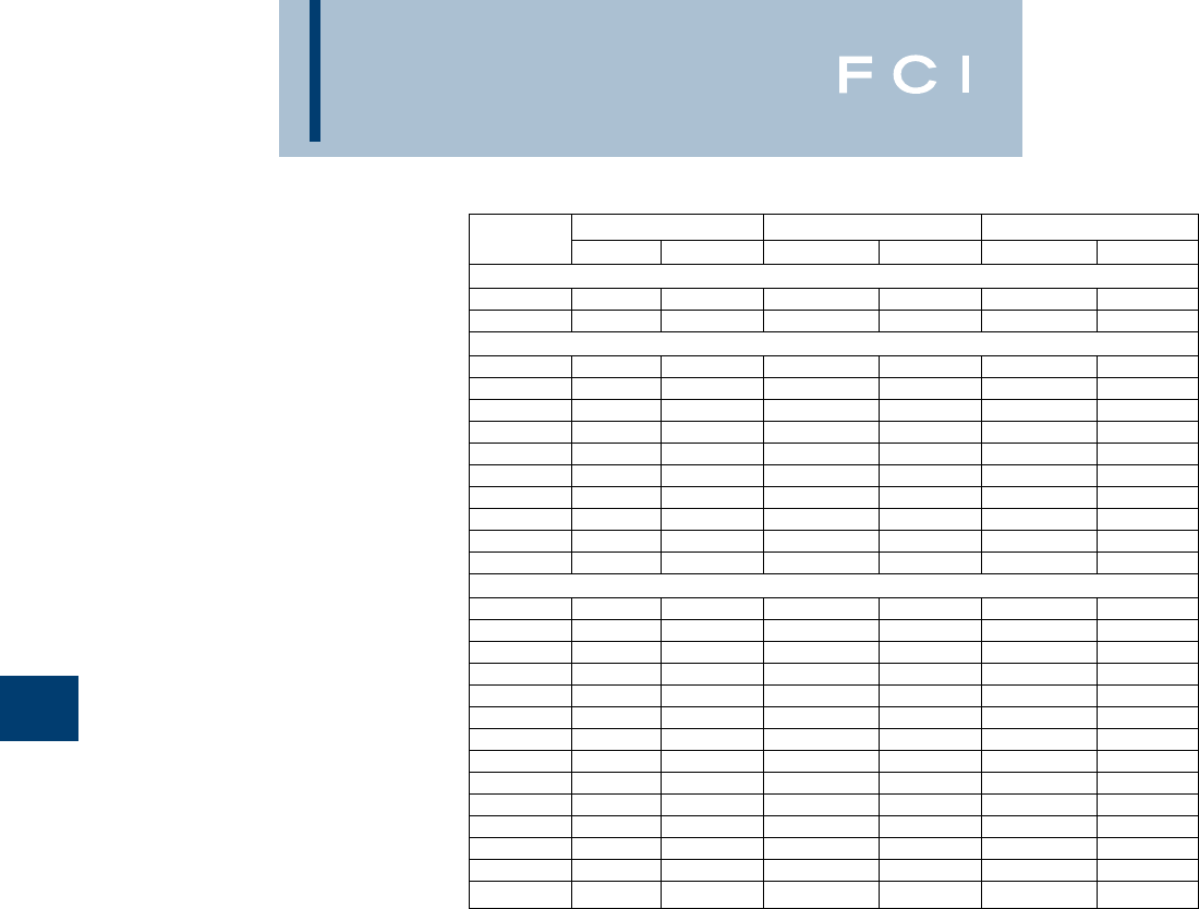
BURNDY
Wedge
F-24
BURNDY WEJTAP™
STIRRUP SELECTION
CHART
By Diameter
Catalog Sum Of Diameters Run Tap
Number Max. Min. Max. Min. Max. Min.
Small stirrups
WSS1 0.454 0.412 0.204 0.162 0.25 0.25
WSS2 0.575 0.456 0.325 0.206 0.25 0.25
Medium sized stirrups
WSM1 0.697 0.575 0.447 0.325 0.25 0.25
WSM10 0.887 0.784 0.563 0.46 0.324 0.324
WSM2 0.752 0.615 0.502 0.365 0.25 0.25
WSM3 0.813 0.66 0.563 0.41 0.25 0.25
WSM4 0.938 0.835 0.563 0.46 0.375 0.375
WSM5 0.892 0.787 0.642 0.537 0.25 0.25
WSM6 0.968 0.861 0.642 0.537 0.324 0.324
WSM7 1.008 0.898 0.684 0.574 0.324 0.324
WSM8 0.934 0.824 0.684 0.574 0.25 0.25
WSM9 0.771 0.649 0.447 0.325 0.324 0.324
Large stirrups
WSL1 1.05 0.927 0.726 0.603 0.324 0.324
WSL10 1.479 1.389 1.019 0.929 0.46 0.46
WSL11 1.394 1.304 1.019 0.929 0.375 0.375
WSL12 1.515 1.399 1.14 1.024 0.375 0.375
WSL13 1.6 1.484 1.14 1.024 0.46 0.46
WSL14 1.708 1.606 1.248 1.146 0.46 0.46
WSL2 0.976 0.853 0.726 0.603 0.25 0.25
WSL3 1.186 1.063 0.726 0.603 0.46 0.46
WSL4 1.186 1.046 0.862 0.722 0.324 0.324
WSL5 1.237 1.097 0.862 0.722 0.375 0.375
WSL6 1.322 1.182 0.862 0.722 0.46 0.46
WSL7 1.251 1.17 0.927 0.846 0.324 0.324
WSL8 1.302 1.221 0.927 0.846 0.375 0.375
WSL9 1.387 1.306 0.927 0.846 0.46 0.46
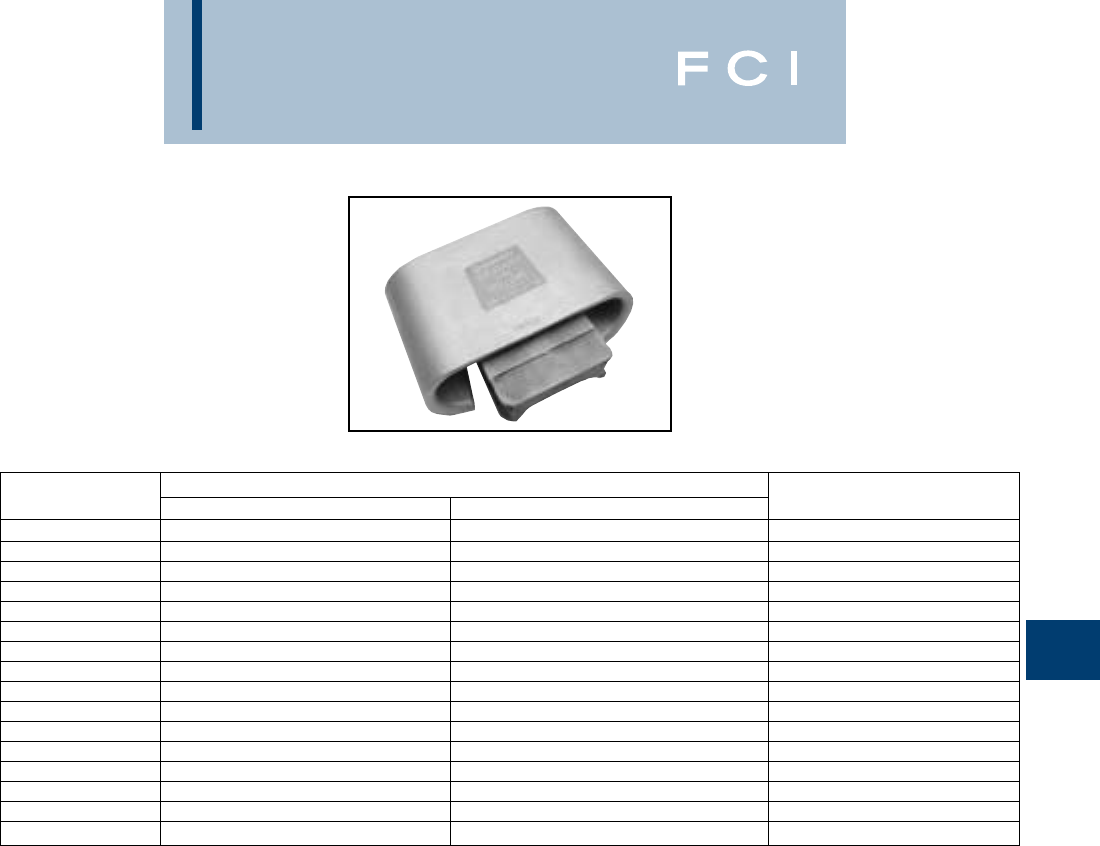
BURNDY
Wedge
F-25
WEJTAP™
Large WEJTAP™ system connectors for use
in tap applications using large run and tap
conductor sizes.
CATALOG CONDUCTOR TYPE
NUMBER RUN TAP BOOSTER COLOR
WCY106 1272 AAC 61 STR 795 ACSR 45/7 Yellow
WCY107 1272 AAC 61 STR 636 ACSR 26/7 Yellow
WCY108 1272 AAC 61 STR 556.5 ACSR 26/7 Yellow
WCY109 1192.5 ACSR 45/7 556.5 SSAC 24/1 Yellow
WCY110 1272 AAC 61 STR 477 AAC Yellow
WCY111 1272 AAC 61 STR 397.5 AAC 19 STR Yellow
WCY112 1272 AAC 61 STR 336.4 ACSR 18/1 Yellow
WCY113 1272 AAC 61 STR 266.8 AAC Yellow
WCY114 1272 AAC 61 STR 4/0 ACSR 6/1 Yellow
WCY121 1272 ACSR 45/7 1272 ACSR 45/7 Yellow
WCY122 1272 ACSR 45/7 1272 AAC 61 STR Yellow
WCY125 1272 ACSR 45/7 795 ACSR 45/7 Yellow
WCY130 1272 ACSR 45/7 397.5 AAC 19 STR Yellow
WCY131 1272 ACSR 45/7 336.4 ACSR 18/1 Yellow
WCY140 1590 ACSR 45/7 1590 ACSR 45/7 Yellow
WCY145 1590 ACSR 45/7 795 ACSR 45/7 Yellow
BURNDY
Wedge
F-26
CATALOG SUM OF THE DIAMETERS (in) FOR NEW WEJTAP™ CONNECTORS
NUMBER Max. Sum Min. Sum Max. Run Min. Run Max. Tap Min. Tap
WCY106 2.418 2.258 1.302 1.242 1.187 1.087
WCY107 2.373 2.213 1.302 1.242 1.071 0.971
WCY108 2.318 2.158 1.302 1.242 1.016 0.916
WCY109 2.255 2.095 1.302 1.242 0.953 0.853
WCY110 2.179 2.095 1.302 1.242 0.877 0.777
WCY111 2.102 1.942 1.302 1.242 0.800 0.700
WCY112 2.044 1.884 1.302 1.242 0.742 0.642
WCY113 1.961 1.801 1.302 1.242 0.659 0.559
WCY114 1.940 1.740 1.350 1.242 0.590 0.498
WCY121 2.844 2.642 1.422 1.314 1.422 1.328
WCY122 2.764 2.562 1.422 1.314 1.342 1.248
WCY125 2.535 2.333 1.422 1.314 1.113 1.019
WCY130 2.216 2.014 1.422 1.314 0.794 0.700
WCY131 2.152 1.950 1.422 1.314 0.730 0.636
WCY140 3.045 2.090 1.533 1.471 1.547 1.471
WCY145 2.596 2.534 1.533 1.032 1.094 1.032
CATALOG METRIC SUM OF THE DIAMETERS (mm) FOR NEW WEJTAP™ CONNECTORS
NUMBER Max. Sum Min. Sum Max. Run Min. Run Max. Tap Min. Tap
WCY106 61.4 57.3 33.1 31.6 30.2 27.6
WCY107 60.3 56.2 33.1 31.6 27.2 24.7
WCY108 58.9 54.8 33.1 31.6 25.8 23.3
WCY109 57.3 53.2 33.1 31.6 24.2 21.6
WCY110 55.4 53.2 33.1 31.6 22.3 19.7
WCY111 53.4 49.3 33.1 31.6 20.3 17.8
WCY112 51.9 47.9 33.1 31.6 18.9 16.3
WCY113 49.8 45.7 33.1 31.6 16.7 14.2
WCY114 49.3 44.2 34.3 31.6 15.0 12.7
WCY121 72.2 67.1 36.1 33.4 36.1 33.7
WCY122 70.2 65.1 36.1 33.4 34.1 31.7
WCY125 64.4 59.3 36.1 33.4 28.3 25.9
WCY130 56.3 51.2 36.1 33.4 20.2 17.8
WCY131 54.7 49.5 36.1 33.4 18.5 16.2
WCY140 77.3 53.1 38.9 37.4 39.3 37.4
WCY145 65.9 64.4 38.9 26.2 27.8 26.2
LARGE WEJTAP™
(Continued)
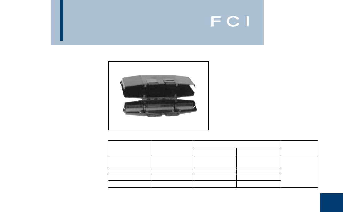
BURNDY
Wedge
F-27
WEJTAP™ COVER
WEJTAP™ Covers are installed on
WEJTAP™ connectors to prevent them from
coming in contact with other taps or exposed
ground points. The covers are rugged snap-
on devices available in four sizes to cover all
connector sizes.
COVER WEJTAP NOMINAL CONDUCTOR RANGE COVER
CATALOG NO. SIZE RUN TAP COLOR
Small Old
WCCR Style Red 8 - 1/0 8 - 2 Black
WCCB Red & Blue 2 - 300 6 - 300 Weather
WCCSY Small (Yellow) 300 - 556.5 6 - 556.5 Rated
WCCLY Large (Yellow) 556.5 - 1033.5 556.5 - 1033.5
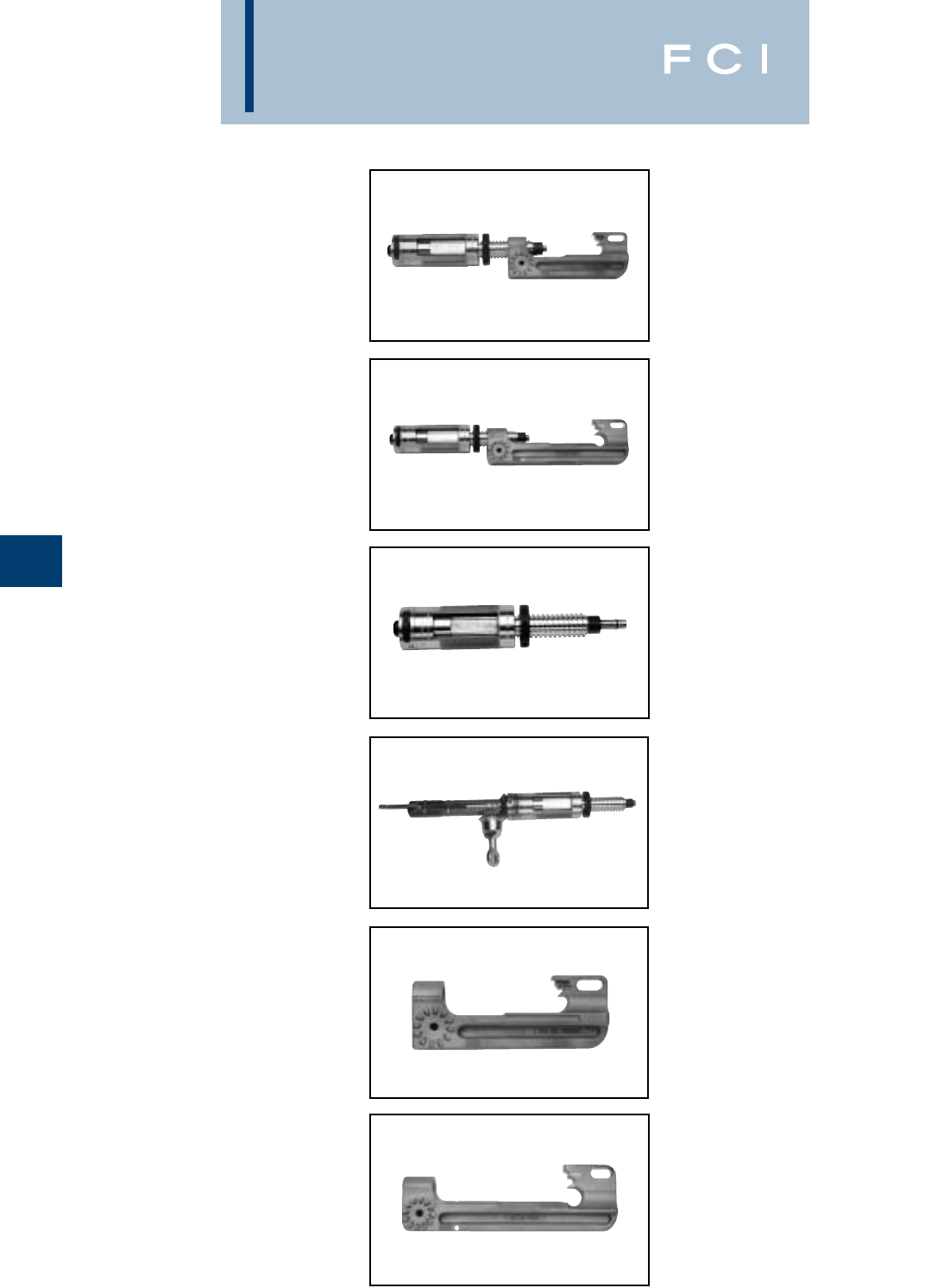
BURNDY
Wedge
F-28
WEJTAP™
INSTALLATION
TOOLS
Patented
Type WTRB
WEJTAP™ tool assembly with small head for
small and medium range taps - #8 through
350 kcmil and stirrups.
Type WTY
WEJTAP™ tool assembly with large head for
medium and large range taps - 336.4 through
1590 kcmil ACSR, and stirrups.
Type WTB
WEJTAP™ tool body one-piece assembly
basic drive mechanism used to install WEJ-
TAP™ connectors and STIRRUPs range - #8
awg through 1590 kcmil ACSR.
Type WTHRB1S
WEJTAP™ tool head operating platform for
small and medium range (red/blue coded)
connectors.
Type WTHY1S
WEJTAP™ tool head operating platform for
medium and large range (yellow coded)
connectors.
Type WTBGBW
WEJTAP™ self firing tool body. Used to install
WEJTAP™ connectors and stirrups. Utilizes a
self firing actuator for use with hotsticks.
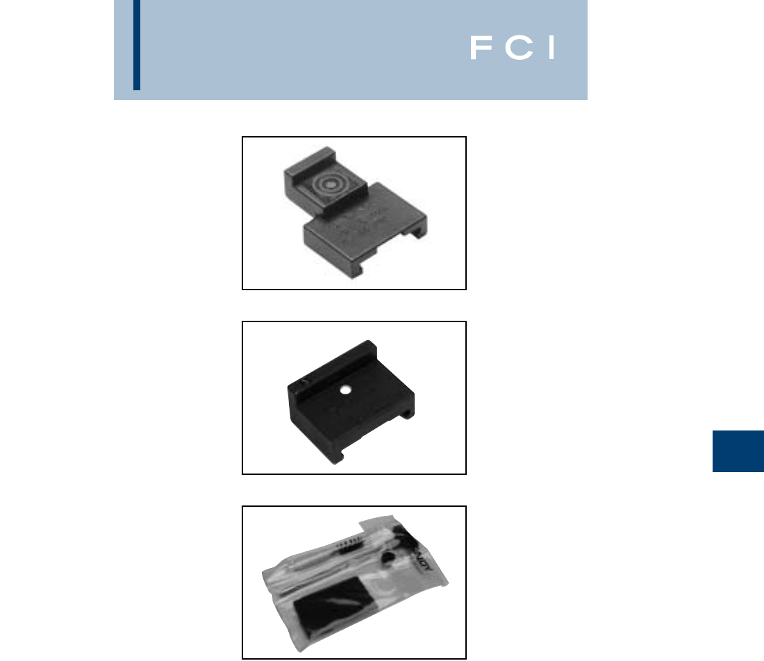
BURNDY
Wedge
F-29
WEJTAP™
INSTALLATION TOOL
ACCESSORIES
Type WTOCBR
WEJTAP™ removal clip for red type II and
medium (blue coded) tap connectors used
with type WTHRB tool head.
Type WTOCY
WEJTAP™ removal clip for large (yellow
coded) tap connectors used with type WTHY
tool head.
Type WTCK
WEJTAP™ tool cleaning/maintenance kit for
use with type WTB tool body.
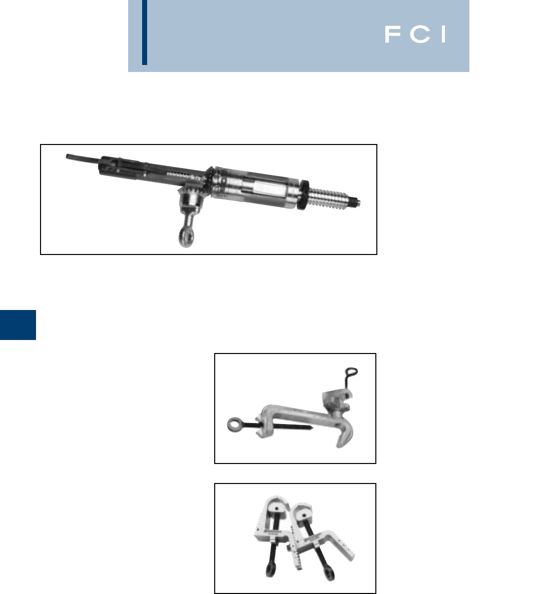
BURNDY
Wedge
F-30
WEJTAP™
HOTSTICK TOOL
Type WTBGBW
WEJTAP™ Self firing tool body. Used to
install WEJTAP™ connectors and stirrups.
Similar to Type WTB tool except utilizes a self
firing actuator for use with hotsticks.
WEJTAP™ HOTSTICK
ACCESORIES
Type WHSCWH
WEJTAP™ hotstick connector clamp used to
hold the tap connector spring-body and
wedge for installation on energized lines with
the shotgun hotstick.
Type WHSPBC
WEJTAP™ hotstick dual cable clamp used to
hold run and tap conductors in position dur-
ing hotline installation. Universal for all appli-
cations from #8-1272 ACSR.
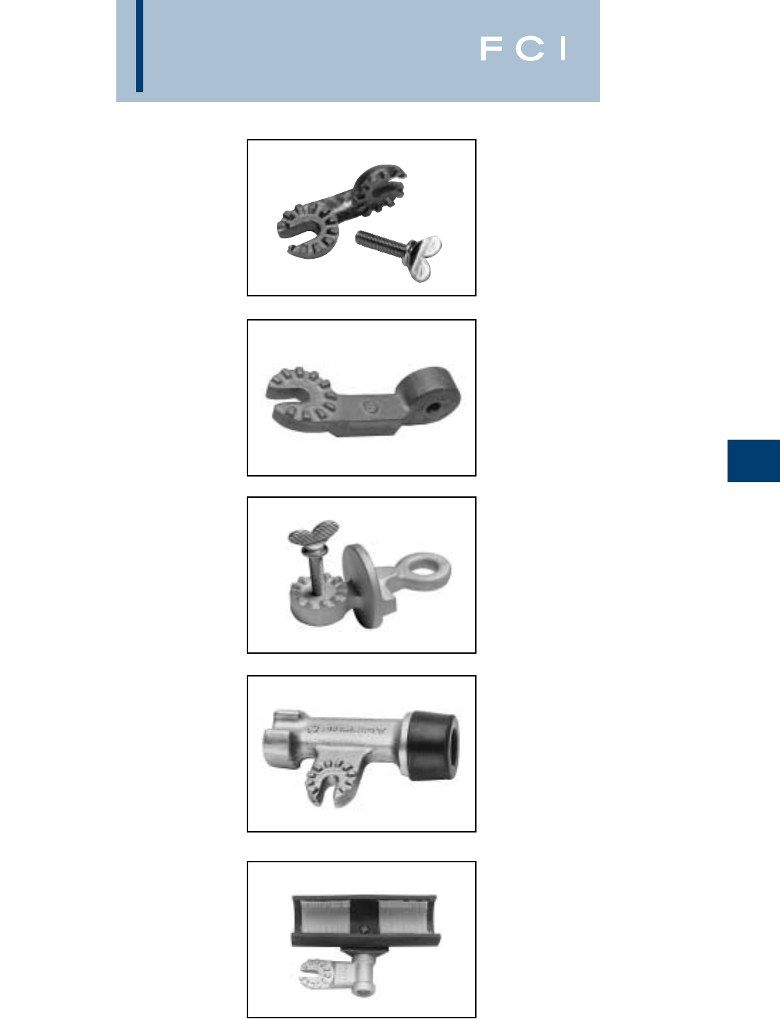
BURNDY
Wedge
F-31
WEJTAP™ HOTSTICK
ACCESSORIES
Type WHS90ADP
WEJTAP™ hotstick angle adapter used to
attach tool to universal hotstick for hotline
installation.
Type WHSWHADP
WEJTAP™ hotstick angle wedge holder
adapter attaches wedge clamp to universal
hotstick for hotline installation.
Type WCHAWAS
WEJTAP™ hotstick angle wedge holder
adapter attaches wedge clamp to universal
hotstick for hotline installation with shotgun
stick.
Type WHSTA
WEJTAP™ hotstick tool (actuator) hammer
attaches to the universal hotstick for striking
the tool actuator button to complete the instal-
lation.
Type WHSWB
WEJTAP™ hotstick wirebrush attaches to the
universal hotstick for cleaning the contact sur-
face of the line conductor.
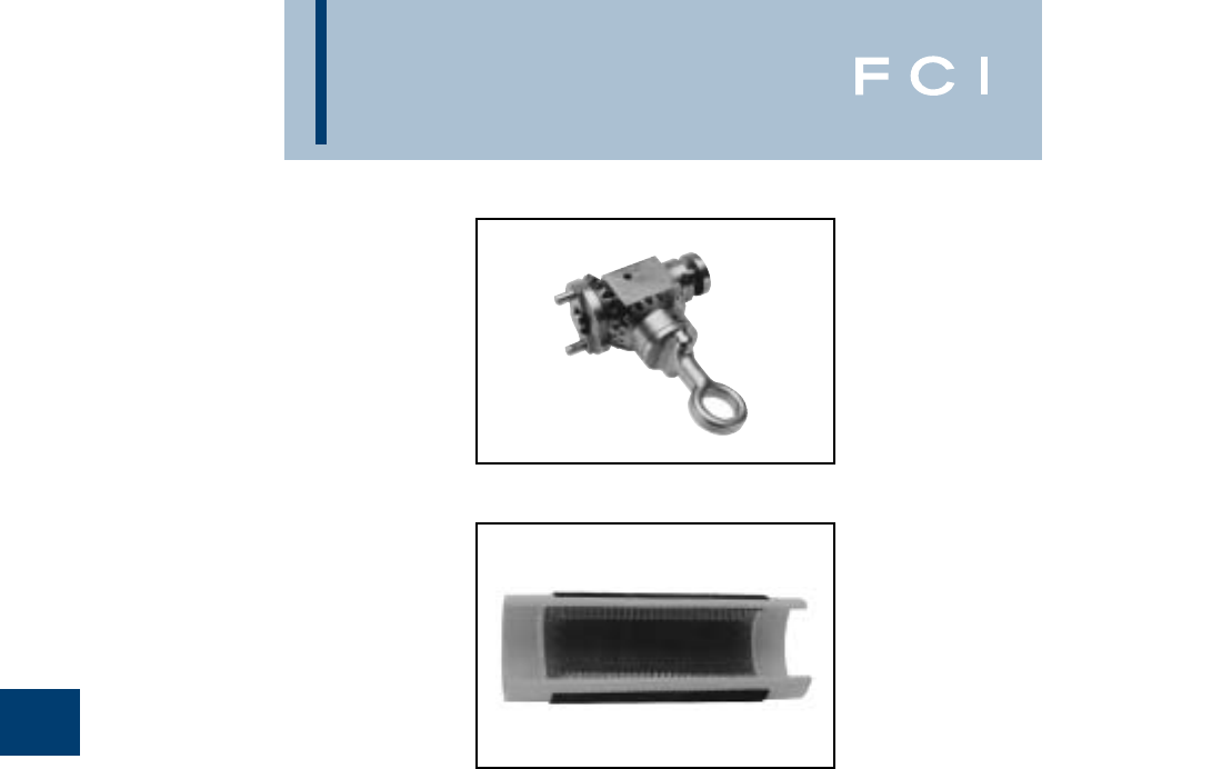
BURNDY
Wedge
F-32
WEJTAP™ HOTSTICK
ACCESSORIES
(Continued)
Type WHSGB
WEJTAP™ hotstick breech drive. Geared
shotgun hotstick adapter easily latches to the
breech end of WEJTAP installation tool with-
out disassembly for use on energized lines.
Type WHHWB
WEJTAP™ hand-held wire brush for cleaning
surface contact areas on non-energized
conductors.
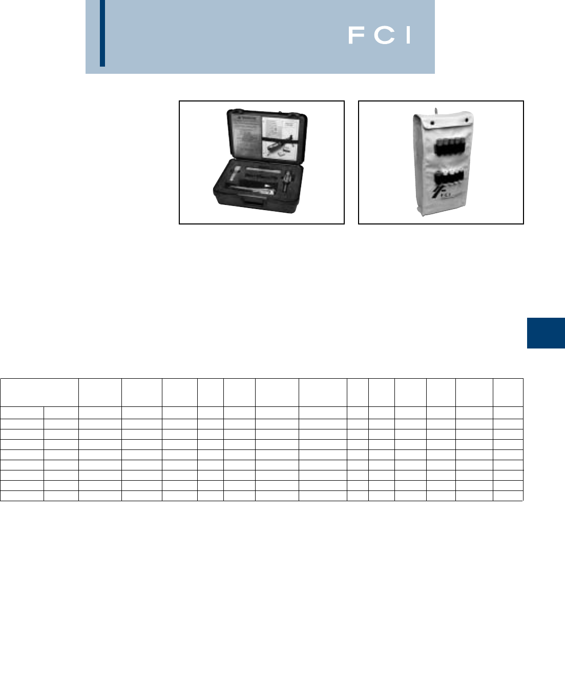
BURNDY
Wedge
F-33
WEJTAP™ KITS
Tools included in Kit (Quantity)
Type WABAG
WEJTAP™ accessories bag is designed for
use in carrying installation tool(s), removal
clips, and cleaning kit. Hotstick accessories
may be accommodated as well. Holders for
power boosters are conveniently located on
the outside of the bag.
WT2B2RBY WT2BRBY WTRBYK WTYK WTRBK WT2BRBYK WT2B2RBYK WTY WTRB WTY WTRB WTBGBW WTRBY
WABAGWABAG WABAG WABAG RBYK WABAG
Power Unit WTB 22111 2 2 111 1 1
Self Firing Tool WTBGBW 1
Large Frame WTHY1S 111111111
Large T.O. Clip WTOCY 11111 111
Small Frame WTHRB-1S 111 11 2 1 111
Cleaning Kit WTCK 11111 1 1 111 1 1 1
Small T.O. Clip WTOCBR 111 11 1 111
Carrying Case WTCC 1111 1
Carrying Case WABAG 11 11 1
Contact your BURNDY representative for a WEJTAP™ demonstration or contact the factory at
1-800-346-4175
TYPE WTCC
(Carrying Case Only)
WEJTAP™ plastic carrying case. Designed
for rugged use in all weather conditions. It
accommodates WEJTAP™ installation tool,
removal clips, and cleaning kit.
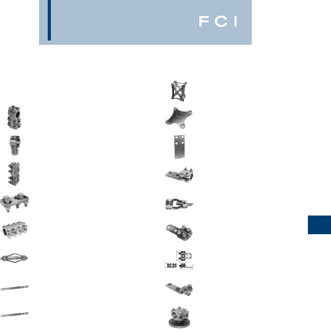
BURNDY
Substation
COPPER SUBSTATION
Introduction .............................G-3
Type NT
Tube to Tube ............................G-4
Type NSNT/NHNT
Tube to Cable ..........................G-5
Type NSNT/NHNT
Cable to Cable ........................G-6
Type VT
Cable to Cable .......................G-7
Type NS
Tube to Tube.............................G-7
Type XP
Tube to Tube.............................G-8
Type B
Flexible Braid Jumper ...G-8 - G-11
Type B Assembly Components
Expansion Coupler ................G-12
Type HFBW
Bar Clamp ..............................G-13
Type HFB-P1
Bar Clamp ..............................G-14
Type HFB-N
Tap Pad Adapter.....................G-15
Type NA
Tube to Flat ............................G-16
Type XA
Tube to Flat, Expandable .......G-16
Type NAS/NAH
Cable to Flat (Terminal)..........G-17
Type N2AH
Two Cables to Flat..................G-18
Type VA, VVA
Cable to Flat (Terminal)..........G-19
Type UH
Bus Support, Tube..................G-20
G-1
TABLE OF CONTENTS
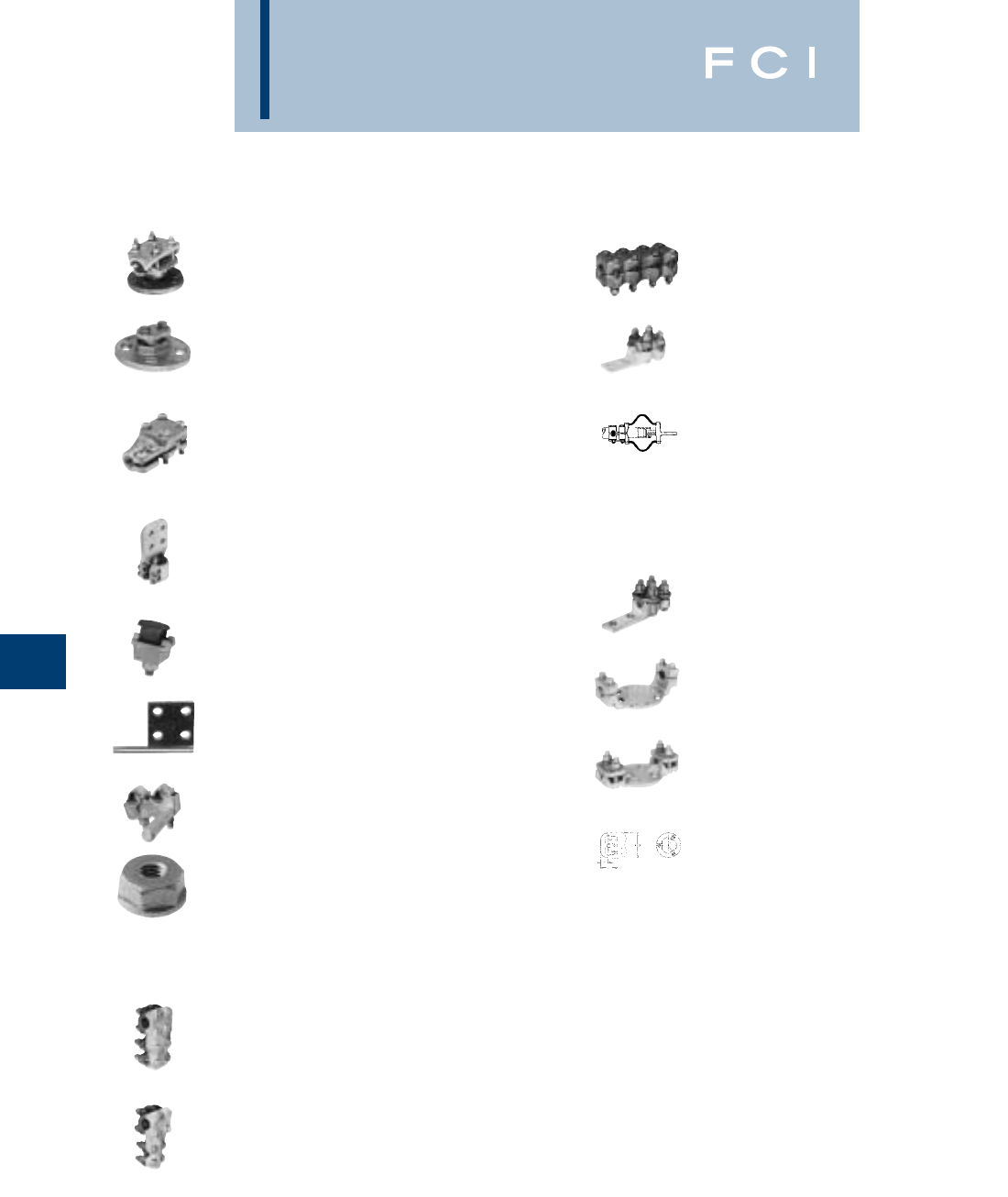
BURNDY
Substation
G-2
Type UHR
Bus Support, Tube or Cable ...G-20
Types LH, LHR
Bus Support, Tube or Cable ...G-21
Type NDR
Stud Connector, Cable,
Tube, Flat Bar .......................G-22
Type FD
Stud Connector, Stud to
Flat Bar.................................G-23
Type QGFL
Bar Tap, Cable to Flat.............G-24
Type FCB
Transformer Tap Adapter ........G-24
Type E-C-G
Transformer Tap Adapter ........G-25
Type FN .................................G-25
ALUMINUM SUBSTATION
Introduction.............................G-26
Type NNT-A
Tube to Tube ...........................G-27
Type NNTR-A
Tube to Cable, Cable to
Cable.. .........................G-27 - G-28
Type NS-A
Tube to Tube ...........................G-28
Type NA-A
Tube to Flat.............................G-29
Type XA-A
Tube to Flat.............................G-29
Type NBC-A
Tube to Flat .................G-30 - G-31
Type NAR-A
Cable to Flat ...........................G-32
Type UHG-A
Bus Support, Tube..................G-33
Type UHKR-A
Bus Support, Tube or Cable ...G-33
Type LB-A
End Cap, Aluminum Tube.......G-34
Type WAS-A
Ter minal Connector ................G-35
Type WASC-A-N
Centerformed Terminal ...........G-36
Type WG-A
Weldment Ground Stud..........G-37
TABLE OF CONTENTS (Continued)
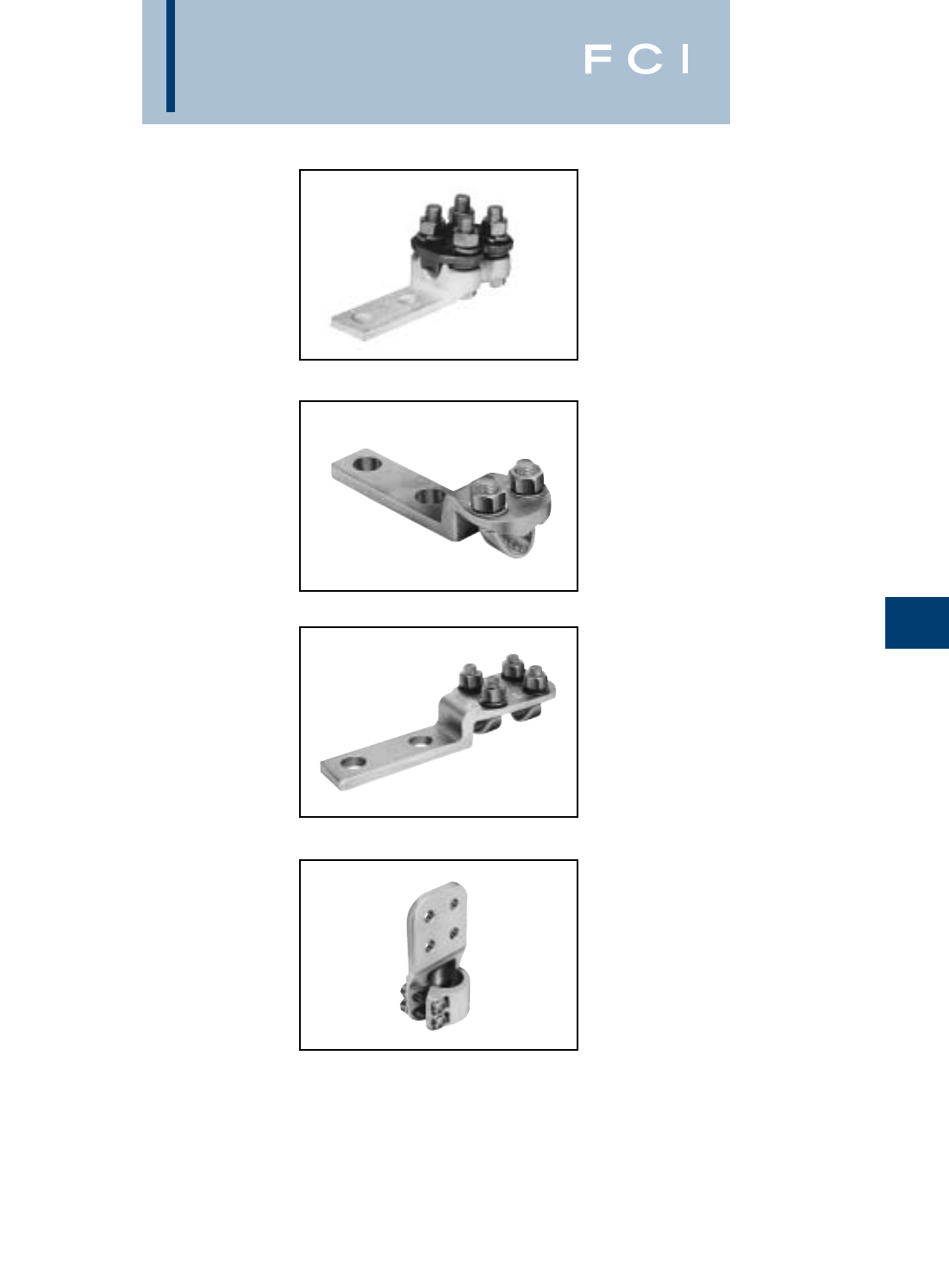
BURNDY
Substation
COPPER
SUBSTATION
CONNECTORS
INTRODUCTION
BURNDY®electrical connectors are designed
to be installed with a minimum of effort, to run
cooler than the conductors being joined and
to provide optimum performance under all
operating conditions.
To achieve this type of performance, exten-
sive research and development time is spent
by BURNDY®engineers and scientists to
improve manufacturing techniques, materials
and designs. As these improvements become
available, they are incorporated into both
existing and new product lines. This continu-
ous program of product innovation and
improvement insures that, as new and more
critical applications evolve, high quality con-
nectors from BURNDY®will be available to
meet the need.
Flat pad connectors used to join cable or
tubing terminals to equipment studs.
A variety of bus supports are also available
for tube or cable. Some can be adjusted for
either a rigid or slide-fit by rotating the clamp-
ing cap 180°.
Expansion connectors are used to absorb the
stress imposed on the bus by settling ground,
thermal expansion and shocks, as in circuit
breaker operations. The flexible elements are
flat-tinned, copper braid, with sufficient cross
sectional area to carry the rated current of the
conductors being joined.
G-3
N-Line connectors are two-piece copper alloy
castings assembled with DURIUM™ (silicon
bronze) hex bolts, nuts and washers. They
are available for connecting tube or cable.
The Variline incorporates a modified V-bolt as
the clamping element for heavy-duty applica-
tions. This line is particularly suited for use
with flexible and extra flexible cables.
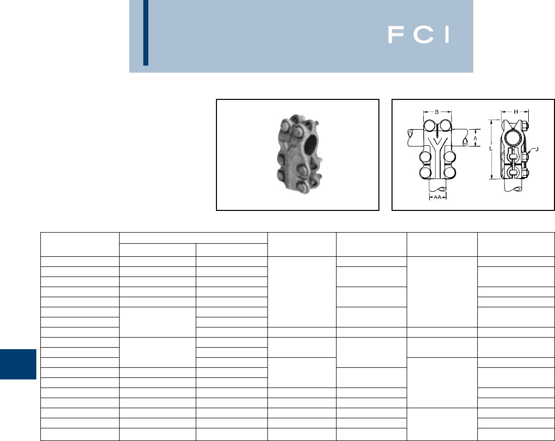
BURNDY
Substation
TYPE NT
T-CONNECTOR
FOR COPPER TUBE TO TUBE
High copper alloy T-Connector for tubing run
and tap. Slots between bolts provide indepen-
dent high-pressure areas of contact.
One-wrench installation.
G-4
CATALOG CONDUCTOR
NUMBER RUN ‘A’ TAP ‘AA’ B H J L
NT1313 1/2 1/2 1-3/4 4
NT1413 3/4 1/2
NT1414 3/4 3/4 24-1/8
NT1514 13/4 2 3/8 4-3/8
NT1515 11 2-1/8 4-1/2
NT1614 3/4
NT1615 1-1/4 1 2-1/2 4-3/4
NT1616 1-1/4 2-3/4 2-5/8 1/2 5-3/4
NT1714 3/4
NT1715 1-1/2 1 22-3/4 3/8 5-1/8
NT1717 1-1/2 6-1/8
NT1816 21-1/4 2-3/4
NT1817 21-1/2 3-1/4 1/2 6-5/8
NT1818 223-1/8 3-3/8 6-3/4
NT1919 2-1/2 2-1/2 3-5/8 3-7/8 7-1/4
NT2020 334-3/8 4-5/8 8-5/8
NT2121 3-1/2 3-1/2 4-7/8 5-1/4 5/8 9-1/4
NT2222 445-1/2 5-3/4 9-7/8
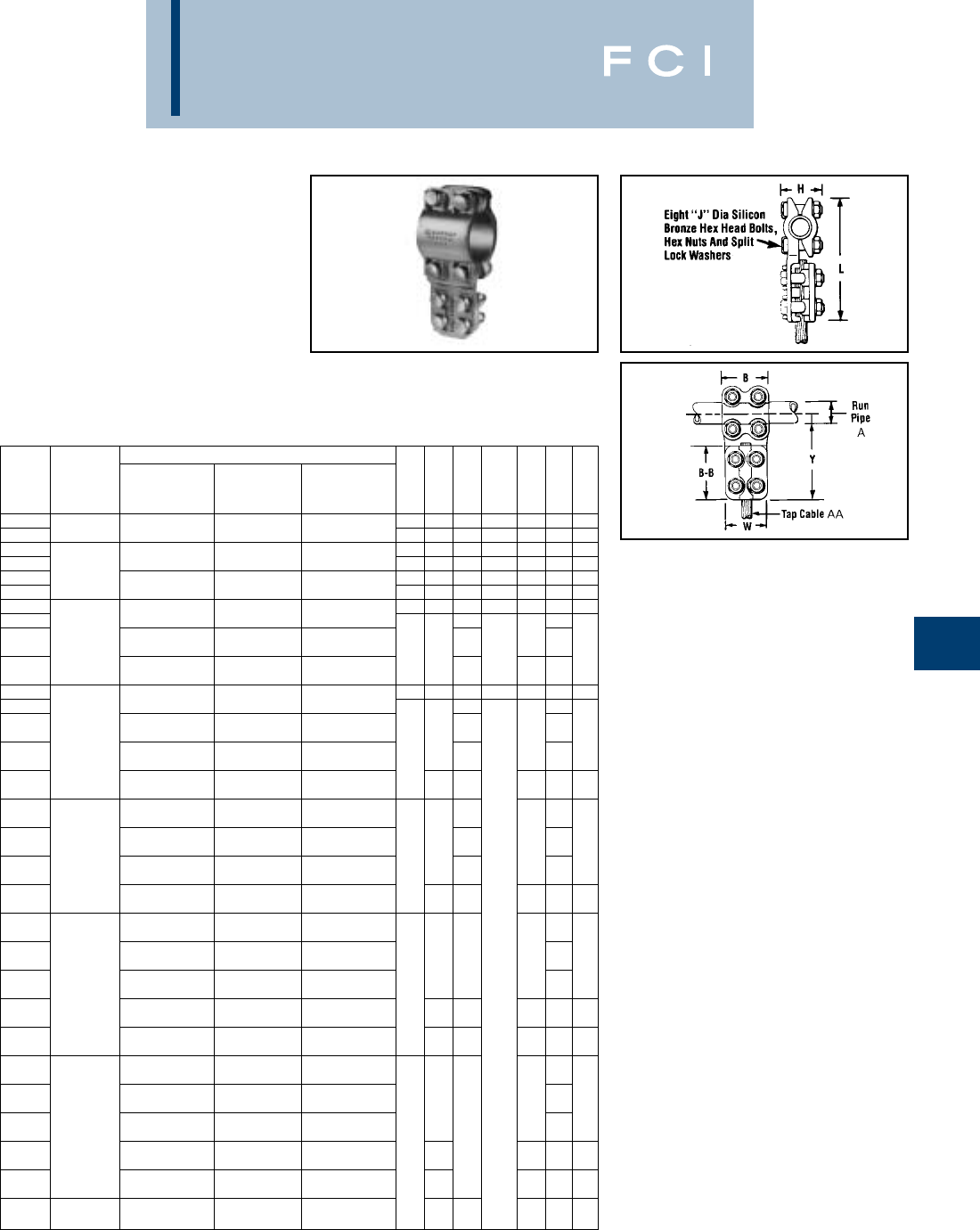
BURNDY
Substation
TYPE NSNT/NHNT
T-CONNECTOR
FOR COPPER TUBE
TO CABLE
High copper alloy T-Connector for joining cop-
per tubing run to a wide range of copper tap
cable. Tap utilizes reversible cap to achieve
large conductor range and the connector is
designed for one-wrench installation.
G-5
①
Complete cable range may be accommodated by reversing cap.
RUN COMMERCIAL COPPER CABLE RANGE
IPS COMPLETE ➀SMALL LARGE
CATALOG OR TAP CABLE TAP TAP “J”
NUMBER EHPS A RANGE AA GROOVE GROOVE B B-B H DIA. L W Y
NSNT1329 6 Sol. (.162 Dia.) to 6 Sol. (.162 Dia.) to 2/0 Str. (.420 Dia.) to 2.00 2.38 2.00 3/8-16 5.08 1.96 3.89
NHNT1329 1/2(.840 Dia.) 250 kcmil (.575 Dia.) 1/0 Str. (.372 Dia.) 250 kcmil (.575 Dia.) 2.25 2.62 2.32 1/2-13 5.82 2.44 4.38
NSNT1429 6 Sol. (.162 Dia.) to 6 Sol. (.162 Dia.) to 2/0 Str. (.420 Dia.) to 2.00 2.38 2.00 3/8-16 5.08 1.96 3.89
NHNT1429 250 kcmil (.575 Dia.) 1/0 Str. (.372 Dia.) 250 kcmil (.575 Dia.) 2.25 2.62 2.32 1/2-13 5.82 2.44 4.38
NSNT1434 3/4(1.050 Dia.) 1/0 Sol. (.325 Dia.) to 1/0 Sol. (.325 Dia.) to 250 kcmil (.575 Dia.) to 2.00 2.38 2.10 3/8-16 5.08 2.20 3.89
NHNT1434 500 kcmil (.813 Dia.) 4/0 Str. (.529 Dia.) 500 kcmil (.813 Dia.) 2.25 2.62 2.42 1/2-13 5.82 2.56 4.38
NSNT1529 6 Sol. (.162 Dia.) to 6 Sol. (.162 Dia.) to 2/0 Str. (.420 Dia.) to 2.00 2.38 2.00 3/8-16 5.34 1.96 4.02
NHNT1529 250 kcmil (.575 Dia.) 1/0 Str. (.372 Dia.) 250 kcmil (.575 Dia.) 2.57 2.44
1/0 Sol. (.325 Dia.) to 1/0 Sol. (.325 Dia.) to 250 kcmil (.575 Dia.) to 5.92
NHNT1534 1(1.315 Dia.) 500 kcmil (.813 Dia.) 4/0 Str. (.529 Dia.) 500 kcmil (.813 Dia.) 2.25 2.62 2.57 1/2-13 2.56 4.43
2/0 Str. (.420 Dia.) to 2/0 Str. (.420 Dia.) to 500 kcmil (.813 Dia.) to
NHNT1540 800 kcmil (1.031 Dia.) 500 kcmil (.813 Dia.) 800 kcmil (1.03 Dia.) 2.60 — 2.78
NSNT1629 6 Sol. (1.62 Dia.) to 6 Sol (.162 Dia.) to 2/0 Str. (.420 Dia.) to 2.00 2.38 2.37 3/8-16 5.78 1.96 4.24
NHNT1629 250 kcmil (.575 Dia.) to 1/0 Str. (.372 Dia.) 250 kcmil (.575 Dia.) 2.57 2.44
1/0 Sol. (.325 Dia.) to 1/0 Sol. (.325 Dia.) to 250 kcmil (.575 Dia.) to
NHNT1634 500 kcmil (.813 Dia.) 4/0 Str. (.529 Dia.) 500 kcmil (.813 Dia.) 2.62 2.60 6.32
2.56
4.63
1-1/4(1.660 Dia.) 2/0 Str. (.420 Dia.) to 2/0 Str. (.420 Dia.) to 500 kcmil (.813 Dia.) to 2.69
NHNT1640 800 kcmil (1.031 Dia.) 500 kcmil (.813 Dia.) 800 kcmil (1.031 Dia.) 2.68 2.78
4/0 Str. (.529 Dia.) to 4/0 Str. (.529 Dia.) to 750 kcmil (.998 Dia.) to
NHNT1644 1000 kcmil (1.152 Dia.) 750 kcmil (.998 Dia.) 1000 kcmil (1.152 Dia.) 2.88 2.69 6.58 2.90 4.89
6 Sol. (.162 Dia.) to 6 Sol. (.162 Dia.) to 210 Str. (.420 Dia.) to
NHNT1729 250 kcmil (.575 Dia.) 1/0 Str. (.372 Dia.) 250 kcmil (.575 Dia.) 2.70 2.44
1/0 Sol. (.325 Dia.) to 1/0 Sol. (.325 Dia.) to 250 kcmil (.575 Dia.) to
NHNT1734 500 kcmil (.813 Dia.) 4/0 Str. (.529 Dia.) 500 kcmil (.813 Dia.) 2.62 2.70 6.76 2.56 4.85
1-1/2(1.900 Dia.) 2/0 Str. (.420 Dia.) to 2/0 Str. (.420 Dia.) to 500 kcmil (.813 Dia.) to 2.69
NHNT1740 800 kcmil (1.031 Dia.) 500 kcmil (.813 Dia.) 800 kcmil (1.031 Dia.) 2.78 2.78
4/0 Str. (.529 Dia.) to 4/0 Str. (.529 Dia.) to 750 kcmil (.998 Dia.) to
NHNT1744 1000 kcmil (1.152 Dia.) 750 kcmil (.998 Dia.) 1000 kcmil (1.152 Dia.) 2.88 2.80 7.02 2.90 5.11
6 Sol. (.162 Dia.) to 6 Sol. (.162 Dia.) to 2/0 Str. (.420 Dia.) to
NHNT1829 250 kcmil (.575 Dia.) 1/0 Str. (.372 Dia.) 250 kcmil (.575 Dia.) 2.44
1/0 Sol. (.325 Dia.) to 1/0 Sol. (.325 Dia.) to 250 kcmil (.575 Dia.) to
NHNT1834 500 kcmil (.813 Dia.) 4/0 Str. (.529 Dia.) 500 kcmil (.813 Dia.) 2.62 3.06 1/2-13 7.44 2.56 5.19
2/0 Str. (.420 Dia.) to 2/0 Str. (.420 Dia.) to 500 kcmil (.813 Dia.)
NHNT1840 2(2.375 Dia.) 800 kcmil (1.031 Dia.) 500 kcmil (.813 Dia.) 800 kcmil (1.031 Dia.) 2.69 2.78
4/0 Str. (.529 Dia.) to 4/0 Str. (.529 Dia.) to 750 kcmil (.998 Dia.) to
NHNT1844 1000 kcmil (1.152 Dia.) 750 kcmil (.998 Dia.) 1000 kcmil (1.152 Dia.) 2.88 3.06 7.70 2.90 5.45
1000 kcmil (1.152 Dia.) to 1000 kcmil (1.152 Dia.) to
NHNT1846 1500 kcmil (1.412 Dia.) —1500 kcmil (1.412 Dia.) 3.06 3.23 7.88 3.16 5.63
6 Sol. (.162 Dia.) to 6 Sol. (.162 Dia.) to 2/0 Str. (.420 Dia.) to
NHNT1929 250 kcmil (.575 Dia.) 1/0 Str. (.372 Dia.) 250 kcmil (.575 Dia.) 2.44
1/0 Sol. (.325 Dia.) to 1/0 Sol. (.325 Dia.) to 250 kcmil (.575 Dia.) to
NHNT1934 500 kcmil (.813 Dia.) 4/0 Str. (.529 Dia.) 500 kcmil (.813 Dia.) 2.62 8.06 2.56 5.50
2/0 Str. (.420 Dia.) to 2/0 Str. (.420 Dia.) to 500 kcmil (.813 Dia.) to
NHNT1940 2-1/2(2.875 Dia.) 800 kcmil (1.031 Dia.) 500 kcmil (.813 Dia.) 800 kcmil (1.031 Dia.) 3.64 2.78
4/0 Str. (.529 Dia.) to 4/0 Str. (.529 Dia.) to 750 kcmil (.998 Dia.) to 2.69
NHNT1944 1000 kcmil (1.152 Dia.) 750 kcmil (.998 Dia.) 1000 kcmil (1.152 Dia.) 2.88 8.32 2.90 5.76
1000 kcmil (1.152 Dia.) to 1000 kcmil (1.152 Dia.) to
NHNT1946 1500 kcmil (1.412 Dia.) —1500 kcmil (1.412 Dia.) 3.06 8.50 3.16 5.94
4/0 Str. (.529 Dia.) to 4/0 Str. (.529 Dia.) to 750 kcmil (.998 Dia.) to
NHNT2044 3(3.500 Dia.) 1000 kcmil (1.152 Dia.) 750 kcmil (.998 Dia.) 1000 kcmil (1.152 Dia.) 5.75 4.26 8.95 2.90 6.07
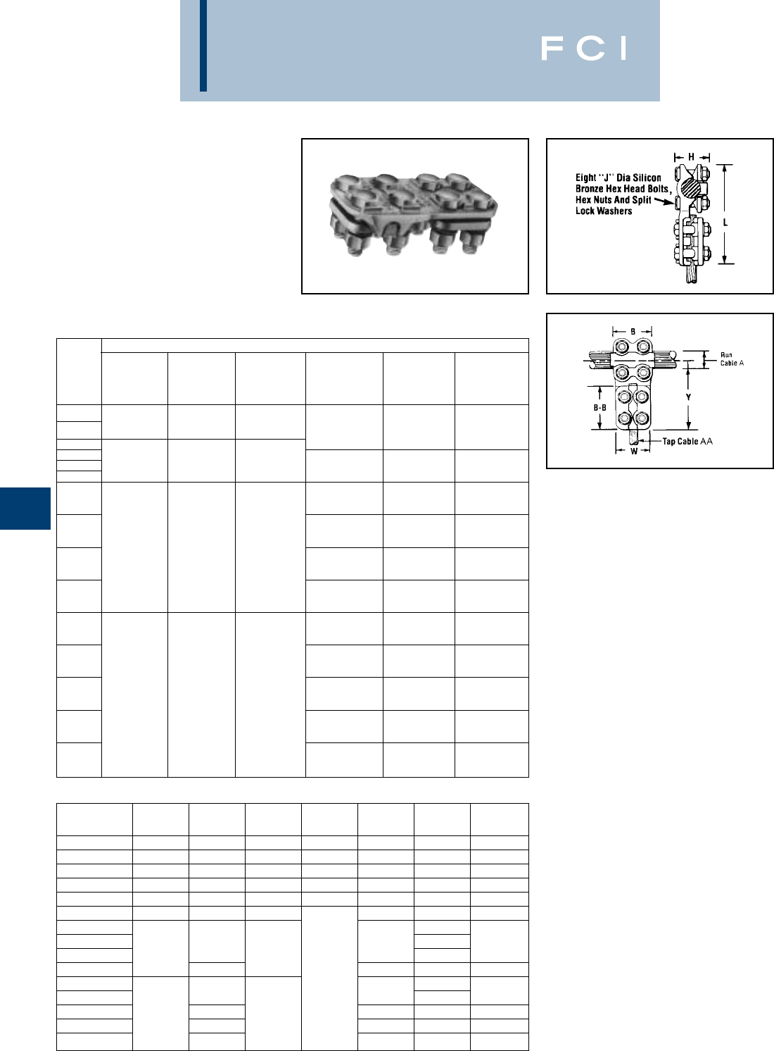
BURNDY
Substation
TYPE NSNT/NHNT
T-CONNECTOR
FOR COPPER CABLE
TO CABLE
High copper alloy reversible T-Connector for
joining a wide range of run and tap cables.
Connector is designed for one-wrench instal-
lation. “S” standard 3/8hardware and
“H” heavy duty 1/2hardware.
G-6
CATALOG
NUMBER B B-B H “J” DIA. L W Y
NSNT2929 2.38 2.38 1.75 3/8-16 4.60 1.96 3.62
NHNT2929 2.62 2.62 2.07 1/2-13 5.32 2.44 4.10
NSNT3429 2.38 2.38 2.00 3/8-16 4.84 1.96 3.74
NHNT3429 2.62 2.62 2.32 1/2-13 5.44 2.44 4.16
NSNT3434 2.38 2.38 2.00 3/8-16 4.84 2.20 3.74
NHNT3434 2.62 2.62 2.32 5.38 2.56 4.10
NHNT4429 2.44
NHNT4434 2.62 5.78 2.56 4.33
NHNT4440 2.88 2.57 2.78
NHNT4444 2.88 6.03 2.90 4.58
NHNT4834 1/2-13 2.56
NHNT4840 2.62 6.26 2.78 4.57
NHNT4844 3.25 2.88 3.07 6.51 2.90 4.82
NHNT4846 3.06 6.76 3.16 5.07
NHNT4848 3.25 6.94 3.38 5.25
COMMERCIAL COPPER CABLE RANGE
COMPLETE COMPLETE
RUN CABLE SMALL LARGE TAP CABLE SMALL LARGE
CATALOG RANGE RUN RUN RANGE TAP TAP
NUMBER A ➀GROOVE GROOVE AA ➀GROOVE GROOVE
6 Sol. (.162 Dia.) 6 Sol. (.162 Dia.) 2/0 Str. (.420 Dia.)
NSNT2929
to 250 kcmil to 1/0 Str. to 250 kcmil 6 Sol. (.162 Dia.) 6 Sol. (.162 Dia.) 2/0 Str. (.420 Dia.)
NHNT2929 (.575 Dia.) (.372 Dia.) (.575 Dia.) to 250 kcmil to 1/0 Str. to 250 kcmil
NSNT3429 1/0 Sol. 1/0 Sol. 250 kcmil (.575 Dia.) (.372 Dia.) (.575 Dia.)
NHNT3429 (.325 Dia.) (.325 Dia.) (.575 Dia.) 1/0 Sol. (.325 Dia.) 1/0 Sol. (.325 Dia.) 250 kcmil (.575 Dia.)
NSNT3434 to 500 kcmil to 4/0 Str. to 500 kcmil to 500 kcmil to 4/0 Str. to 500 kcmil
NHNT3434 (.813 Dia.) (.529 Dia.) (.813 Dia.) (.813 Dia.) (.529 Dia.) (.813 Dia.)
6 Sol. (.162 Dia.) 6 Sol. (.162 Dia.) 2/0 Str. (.420 Dia.)
NHNT4429 to 250 kcmil to 1/0 Str. to 250 kcmil
(.575 Dia.) (.372 Dia.) (.575 Dia.)
1/0 Sol. (.325 Dia.) 1/0 Sol. (.325 Dia.) 250 kcmil (.575 Dia.)
NHNT4434 4/0 Str. 4/0 Str. 750 kcmil to 500 kcmil to 4/0 Str. to 500 kcmil
(.529 Dia.) (.529 Dia.) (.998 Dia.) (.813 Dia.) (.529 Dia.) (.813 Dia.)
to 1000 kcmil to 750 kcmil to 1000 kcmil 2/0 Str. (.420 Dia.) 2/0 Str. (.420 Dia.) 500 kcmil (.813 Dia.)
NHNT4440 (1.152 Dia.) (.998 Dia.) (1.152 Dia.) to 800 kcmil to 500 kcmil to 800 kcmil
(1.031 Dia.) (.813 Dia.) (1.031 Dia.)
4/0 Str. (.529 Dia.) 4/0 Str. (.529 Dia.) 750 kcmil (.998 Dia.)
NHNT4444 to 1000 kcmil to 750 kcmil to 1000 kcmil
(1.152 Dia.) (.998 Dia.) (1.152 Dia.)
1/0 Sol. (.325 Dia.) 1/0 sol. (.325 Dia.) 250 kcmil (.575 Dia.)
NHNT4834 to 500 kcmil to 4/0 Str. to 500 kcmil
(.813 Dia.) (.529 Dia.) (.813 Dia.)
2/0 Str. (.420 Dia.) 2/0 Str. (.420 Dia.) 500 kcmil (.813 Dia.)
NHNT4840 to 800 kcmil to 500 kcmil to 800 kcmil
(1.031 Dia.) (.813 Dia.) (1.031 Dia.)
500 kcmil 500 kcmil 1500 kcmil 4/0 Str. (.529 Dia.) 4/0 Str. (.529 Dia.) 750 kcmil (.998 Dia.)
NHNT4844 (.813 Dia.) (.813 Dia.) (1.412 Dia.) to 1000 kcmil to 750 kcmil to 1000 kcmil
to 2000 kcmil to 1500 kcmil to 2000 kcmil (1.152 Dia.) (.998 Dia.) (1.152 Dia.)
(1.632 Dia.) (1.412 Dia.) (1.632 Dia.) 1000 kcmil (1.152 Dia.) 1000 kcmil (1.152 Dia.)
NHNT4846 to 1500 kcmil — to 1500 kcmil
(1.412 Dia.) (1.412 Dia.)
500 kcmil (.813 Dia.) 500 kcmil (.813 Dia.) 1500 kcmil (1.412 Dia.)
NHNT4848 to 2000 kcmil to 1500 kcmil to 2000 kcmil
(1.632 Dia.) (1.412 Dia.) (1.632 Dia.)
①
Complete cable range may be accommodated by reversing cap.
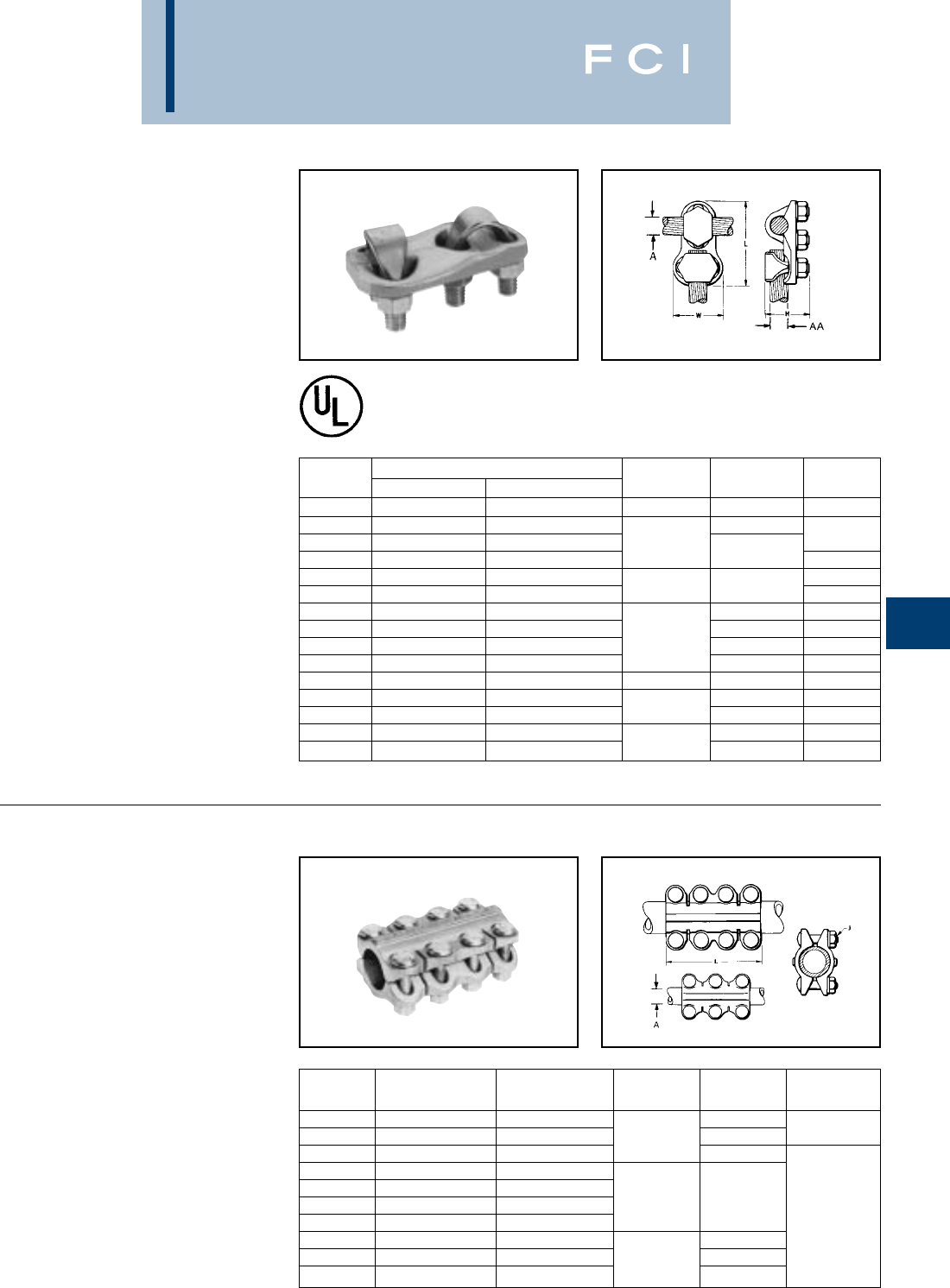
BURNDY
Substation
TYPE VT
T-CONNECTOR
FOR COPPER CABLE
TO CABLE
High copper alloy T-Connector for cable run,
cable tap, V-bolt clamping elements accom-
modate large range of cable and are particu-
larly suited for extra flexible cable. One-
wrench installation.
TYPE NS
COUPLER
FOR COPPER TUBE TO TUBE
High copper alloy coupler for joining equal
sizes of tube end to end. Slots between bolts
provide independent high pressure areas of
contact. One-wrench installation.
G-7
Fig. 1
Fig. 2
Catalog Conductor
Number Run - A Tap - AA H L W
VT2C2C 8 Sol. - 2 Str. 8 Sol. - 2 Str. 1-3/8 2-3/8 1
VT2525 6 Sol. - 1/0 Str. 6 Sol. - 1/0 Str. 2-5/8
VT2825 1/0 Str. - 4/0 Str. 6 Sol. - 1/0 Str. 1-5/8 1-1/4
VT2828 1/0 Str. - 4/0 Str. 1/0 Str. - 4/0 Str. 3-1/8 1-3/4
VT3025 1/0 Str. - 300 6 Sol. - 1/0 Str. 1-1/8
VT3030 1/0 Str. - 300 1/0 Str. - 300 1-7/8 3-3/8 2
VT3425 300 - 500 6 Sol. - 1/0 Str. 3-3/4 1-1/4
VT3428 300 - 500 1/0 Str. - 4/0 Str. 3-1/2 1-3/4
VT3430 300 - 500 1/0 Str. - 300 2-3/8 3-5/8 2
VT3434 300 - 500 300 - 500 3-3/4 2-1/4
VT4040 500 - 800 500 - 800 2-5/8 4-1/2 2-5/8
VT4425 750 - 1000 6 Sol. - 1/0 Str. 4-3/8 1-1/4
VT4428 750 - 1000 1/0 Str. - 4/0 Str. 2-7/8 4-1/8 1-3/4
VT4834 1500 - 2000 300 - 500 5-1/4 2-1/4
VT4844 1500 - 2000 750 - 1000 4-1/4 5-3/4 2-7/8
Catalog Fig.
Number Conductor - A Conductor - B J L No.
NS1313 1/2 1/2 3-1/4
NS1414HC 3/4 3/4 3/8 4 1
NS1515 11 4-1/4
NS1616HC 1-1/4 1-1/4
NS1717 1-1/2 1-1/2
NS1818 22
1/2 5-3/4
NS1919 2-1/2 2-1/2 2
NS2020 33 7-1/4
NS2121 3-1/2 3-1/2 5/8 8
NS2222 44 8-1/2
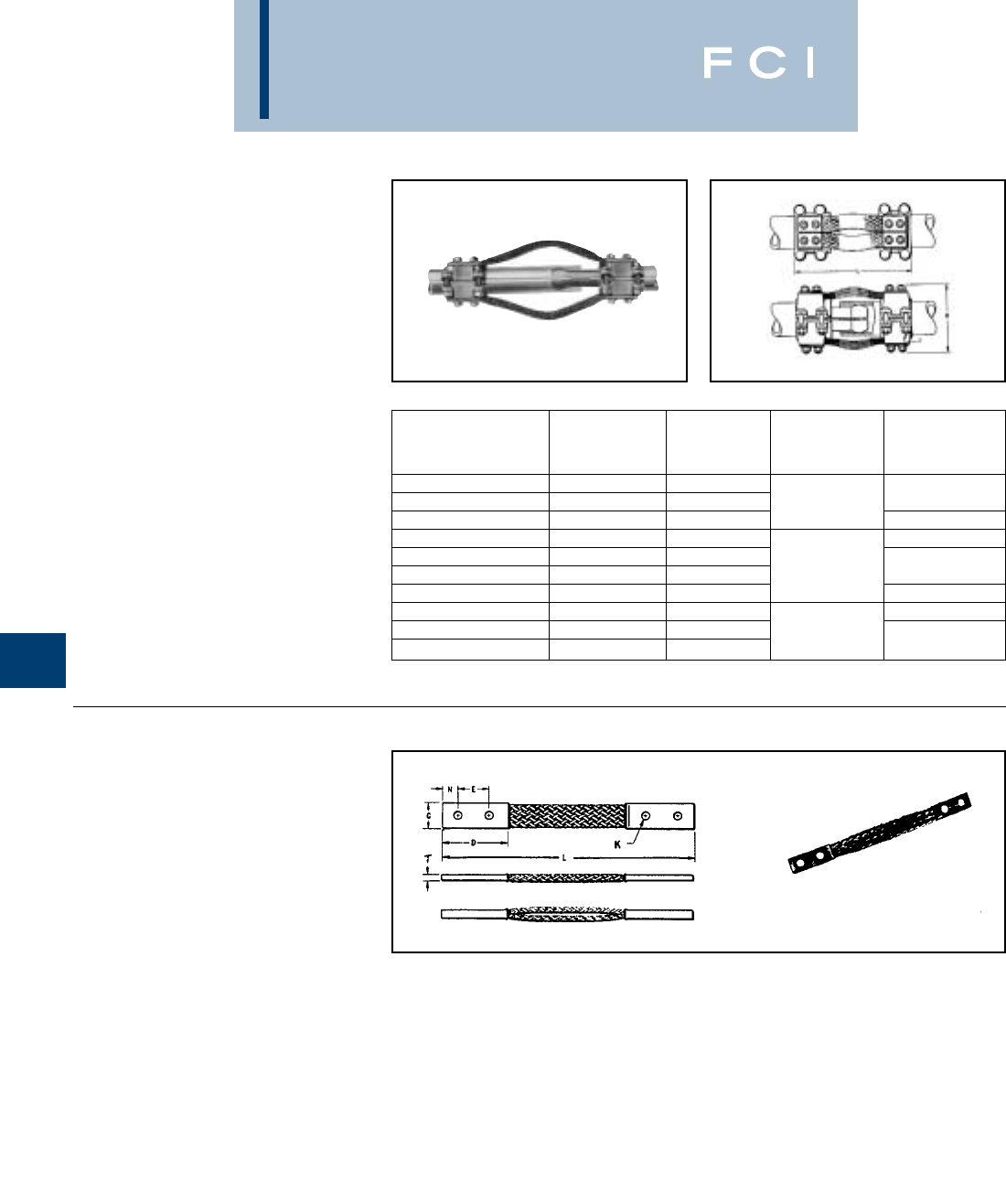
BURNDY
Substation
TYPE XP
EXPANSION COUPLER
FOR COPPER TUBE TO TUBE
High alloy copper expansion coupler for join-
ing equal size tube on end. Extra flexible
tinned copper braid allows longitudinal move-
ment of the tube. Type XP has alignment
guide. One-wrench installation.
TYPE B
FLEXIBLE COPPER
BRAID JUMPER
Flexible copper braid jumpers designed to
take up linear expansion and contraction,
compensate for misalignment and absorb
vibratory movement of electrical equipment
and devices.
Made of flat, extra flexible, tinned, pure
copper braid, with unplated, seamless, pure
copper ferrules formed into a rectangular
shape on each end.
Last two numbers in catalog number indicate
total length of braid in inches, e.g., BD12N or
BD12 is standard 12long braid jumper. All
braids are available in 12, 18, and 24
lengths.
Other lengths, plating and drilling are avail-
able. Refer to factory.
G-8
Catalog Number
Standard IPS
With Guide Conductor H J L
XP1313 1/2 3-7/8
XP1414 3/4 4-1/8 3/8 8-3/4
XP1515 14-3/8 9-1/2
XP1616 1-1/4 5-7/8 11-1/2
XP1717 1-1/2 6-1/2
XP1818 27
1/2 12
XP1919 2-1/2 8-1/2 13
XP2020 37-3/4 13-1/2
XP2121 3-1/2 8 5/8
XP2222 49-1/8 13-5/8
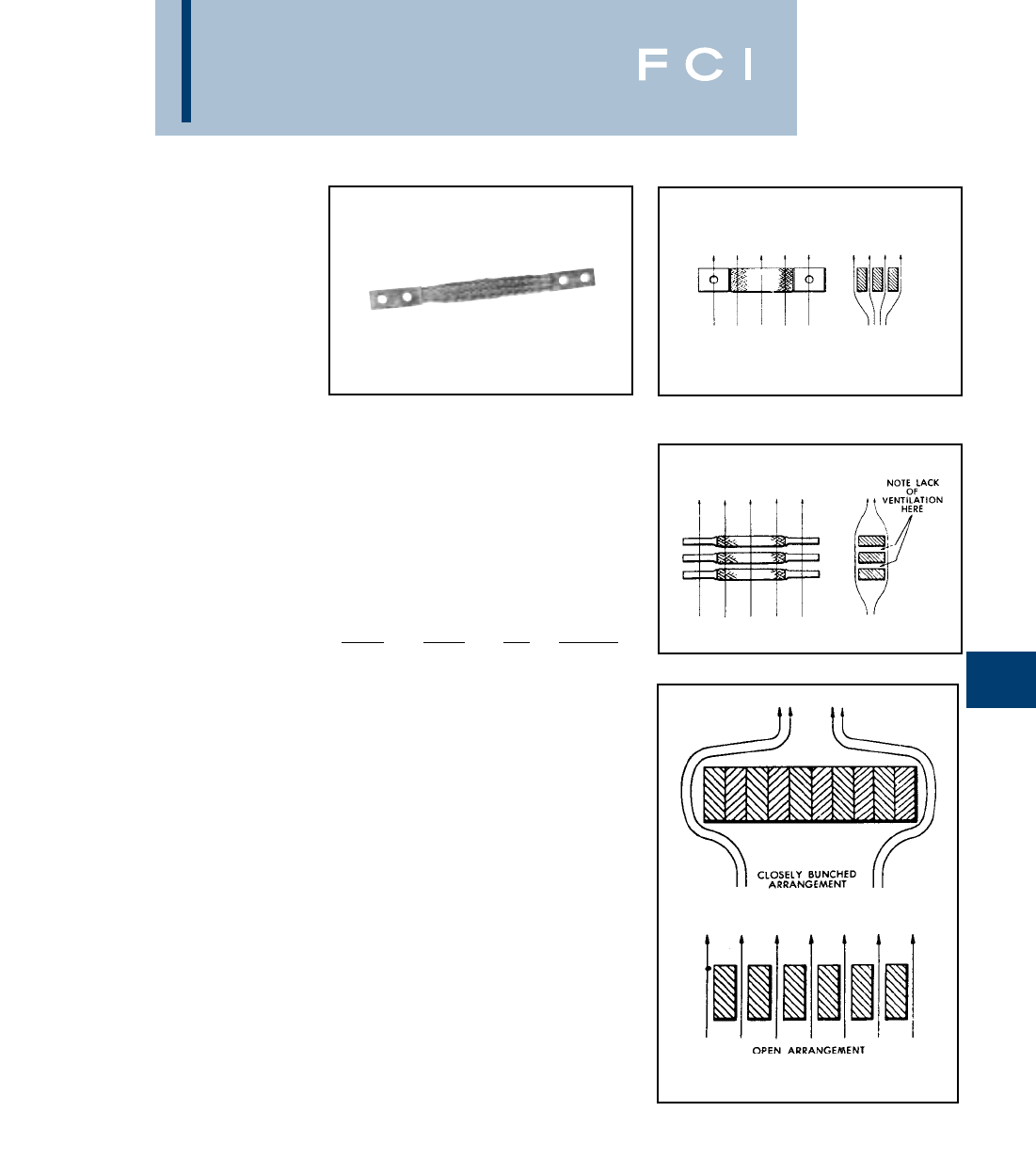
BURNDY
Substation
FLEXIBLE COPPER
BRAID JUMPER
Copper braid is made of tinned, pure copper
wire woven and flattened into a rectangular
shape for greater flexibility. Seamless, pure
copper ferrules are formed and assembled
on each end to provide appropriate
contact surfaces.
Braid is used extensively to compensate for
expansion and contraction of moving parts
and for thermal movement of rigid devices; to
prevent breakage of insulators or bushings or
equipment because of misalignment during
settling of substation foundations; to absorb
shock and vibration of operating equipment;
and to provide flexible current carrying leads
between moving parts of heavy machinery
or equipment.
CURRENT CARRYING
CAPACITY
Flexible copper braid has generally better
heat dissipation properties than flat bar, cable
or other conductors, and therefore can be
expected to have a greater current carrying
capacity for a given cross-sectional area. This
is due to its greater surface area resulting
from the woven construction of fine strands.
However, ventilation, due to the vertical con-
vection current of air, is appreciably better
when the long axis of the braid is vertical
rather than horizontal, so that the long sides
of the braid, rather than the edges, are
exposed to the moving air. This is particularly
true when spaced braids are used in
multiple as can be seen by comparing
Figures 1 and 2.
To take full advantage of ventilation, the
cooling convection current of air should be
permitted to flow freely between the braids.
Therefore, if possible, the braids should be
spaced apart, rather than bunched together,
as illustrated in Figure 3. The effectiveness of
spacing is, or course, greater when the braids
are in a vertical position.
G-9
BULK BRAID
Bulk braid can be ordered with a minimum
order quantity of 10 feet. Specify feet in num-
ber of inches.
Example: 10 feet of 190 ampere braid is
Catalog No. BB077L120.
INDOOR EQUIV APPROX
RATING CIRCULAR CAT WEIGHT
AMPS AREA NO.PER* FT
190 77,184 BB077L .24
340 153,700 BB154L .49
360 231,552 BB226L .76
415 300,000 BB300L 1.06
Fig. 1
Fig. 2
Fig. 3
Cooling Due to Convection Currents Much
More Effective with Spaced Braid
BURNDY
Substation
FLEXIBLE
COPPER BRAID
CUSTOM DESIGNS
Flexible copper braid offers an economical
and efficient means of protecting electrical
equipment from the potentially harmful
effects of shock and vibration, terminal
expansion, movement of components and
misalignment that may occur during the
service life of the equipment.
Many varieties of braid are required to meet
those needs which we can build to your
specifications.
We also offer engineering assistance in the
selection of the most appropriate standard
or custom braid configuration for your
application.
CUSTOM VARIATIONS
Drilling
*Undrilled
*Elongated (slotted) holes
*Special hole patterns and location
*Metric
*NEMA
Plating
*Tin
*Silver
*Nickel
*Unplated
Length
*Jumper (overall)
*Ferrule(s) contact
Insulated (covered)
*Tubular
*Heat shrink
Split Braid Assemblies
*Stacked
*Side-by-side
Multiple Ferrules
Preformed Configurations
*Offset contact surfaces
*Angular (e.g., 90°, 180°) bends
*Ferrule contact surfaces rotated 90°
on braid axis
Combined Braid Assemblies
Combined Connector - Braid Assemblies
Ferrule Variations
*Belled/unbelled
*Width/thickness
*Contact length
*Special shaping
*Bent at angle °
High Ampacity Requirements
G-10

BURNDY
Substation
TYPE B
FLEXIBLE COPPER
BRAID JUMPER
G-11
* This rating may vary with ambient conditions, orientation of
the braid and other service conditions.
** Tongue drilled per NEMA Standard - 9/16diameter for 1/2
diameter bolts on 13/4 C to C.
NO. OF
CATALOG BRAIDS IN APPROX. AMP
NUMBER FERRULES C D E K L N T INDOOR OUTDOOR
BD12 2.50 1.25 .44 12
BD12N** 3.00 1.75 .56 12
BD18 2.50 1.25 .44 18
BD18N** 1.94 3.00 1.75 .56 18 .62 .13 190 225
BD24 2.50 1.25 .44 24
BD24N** 3.00 1.75 .56 24
BE12 1.50 .44 12 .75
BE12N** 1.75 .56 12 .62
BE18 1.50 .44 18 .75
BE18N** 11.50 3.00 1.75 .56 18 .62 .17 340 405
BE24 1.50 .44 24 .75
BE24N** 1.75 .56 24 .62
BF12 1.50 .44 12 .75
BF12N** 1.75 .56 12 .62
BF18 1.50 .44 18 .75
BF18N** 11.19 3.00 1.75 .56 18 .62 .25 360 430
BF24 1.50 .44 24 .75
BF24N** 1.75 .56 24 .62
BG12 1.50 .44 12 .75
BG12N** 1.75 .56 12 .62
BG18 1.50 .44 18 .75
BG18N** 11.50 3.00 1.75 .56 18 .62 .25 415 495
BG24 1.50 .44 24 .75
BG24N** 1.75 .56 24 .62
B2D12 2.50 1.25 .44 12 .62
B2D12N** .94 3.00 1.75 .56 12 .62 .25 380 455
B2E12 3.00 1.50 .44 12 .75
B2E12N** 1.62 3.00 1.75 .56 12 .62 .25 530 635
B2F12 23.00 1.50 .44 12 .75
B2F12N** 1.38 3.00 1.75 .56 12 .62 .38 600 720
B2G12 3.00 1.50 .44 12 .75
B2G12N** 1.50 3.00 1.75 .56 12 .62 .50 700 840
B3D12 2.50 1.25 .44 12 .62
B3D12N** 1.19 3.00 1.75 .56 12 .62 .25 470 560
B3E12 3.00 1.50 .44 12 .75
B3E12N** 1.64 3.00 1.75 .56 12 .62 .31 700 840
B3F12 33.00 1.50 .44 12 .75
B3F12N** 1.44 3.00 1.75 .56 12 .62 .56 820 980
B3G12 3.00 1.50 .44 12 .75
B3G12N** 1.69 3.00 1.75 .56 12 .62 .69 960 1150
B4D12 2.50 1.25 .44 12 .62
B4D12N** 1.19 3.00 1.75 .56 12 .62 .32 600 720
B4E12 3.00 1.50 .44 12 .75
B4E12N** 1.64 3.00 1.75 .56 12 .62 .38 850 1020
B4F12 43.00 1.50 .44 12 .75
B4F12N** 1.50 3.00 1.75 .56 12 .62 .78 1000 1200
B4G12 3.00 1.50 .44 12 .75
B4G12N** 1.69 3.00 1.75 .56 12 .62 .94 1200 1440
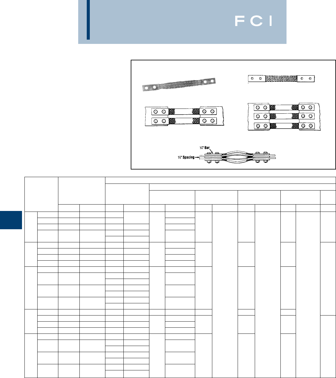
BURNDY
Substation
G-12
TYPE B
EXPANSION COUPLER
ASSEMBLY COMPONENTS
FOR COPPER BAR
To build your own expansion coupler assem-
bly for single or multiple flat bar(s), using
extra flexible tinned copper braid (shown on
page 9) and clamping hardware, the following
table has been provided. The assembly takes
up longitudinal and lateral motion.
Fig. 1
Fig. 2 Fig. 3
①Components ordered separately from BURNDY.
②See page 9 for flexible copper braid jumper dimensions
and drilling.
③Bars listed are 1/4thick. Multiple bars are spaced1/4.
④For two hole NEMA drilling in each ferrule add suffix letter
“N” to catalog number of braid jumper as shown on page 9.
EXAMPLE: B2E12 drilling is .44 dia. holes on 1 .50
centers.
B2E12N drilling is .56 dia. holes on 1.75
centers.
When specifying NEMA drilling bolt diameter
in table must be changed from 38 to 50 (length
is not changed).
NOTE: Minimum length of each ferrule with NEMA drilling
is 3.00.
⑤Braid jumper ferrule (pad) thickness is larger than 1/4
requiring assembly to outer contact surface(s) of multiple
(1/4spaced ) bars.
➅These ratings may vary with ambient conditions, orientation
of the braid and other service conditions.
⑦For other combinations and configurations of flat bar
contact BURNDY.
EXPANSION COUPLER ASSEMBLY COMPONENTS ➀
CONDUCTOR FLEXIBLE SILICON BRONZE CLAMPING HARDWARE
COPPER BAR APPROXIMATE ➃COPPER ➁SPLIT
WIDTH ➁AMPERE RATING BRAID JUMPER BOLTS NUTS LOCKWASHER FLAT WASHER FIG.
NUMBER ➂INDOOR OUTDOOR QTY. CAT. NO. QTY. CAT. NO. QTY. CAT. NO. QTY. CAT. NO. QTY. CAT. NO. NO.
1700 840 2 38X125HEB
21100 1320 3 B2E12 38X175HEB
23 1600 1920 4 BG12 438X225HEB 4481
3B2E12
41800 2160 1B3E12 ➄38X250HEB
11000 1200 4 BG12 38X125HEB
21650 1980 6 B2E12 38X175HEB
332000 2400 8 BG12 838X225HEB 8816
42200 2640 8 BG12 38X250HEB
11350 1620 4 B2E12 38X125HEB
2B2E12
22250 2700 4B2G12 ➄38X225HEB 2
42B2G12 ➄88816
32700 3240 6BG12 38X250HEB 38CHEN 38SW 38FW
4B2G12 ➄
43000 3600 6BG12 38X325HEB
11600 1920 4 B3E12 838X125HEB 8816
22650 3180 9 B2E12 38X175HEB
533200 3840 12 BG12 12 38X225HEB 12 12 24
43500 4200 15 BG12 38X275HEB
11900 2280 6 B2E12 38X125HEB
3B2E12
23150 3780 6B3E12 38X175HEB 3
69BG12 12 12 12 24
33800 4560 3B2G12 ➄38X250HEB
9BG12
44200 5040 6B2G12 ➄38X325HEB
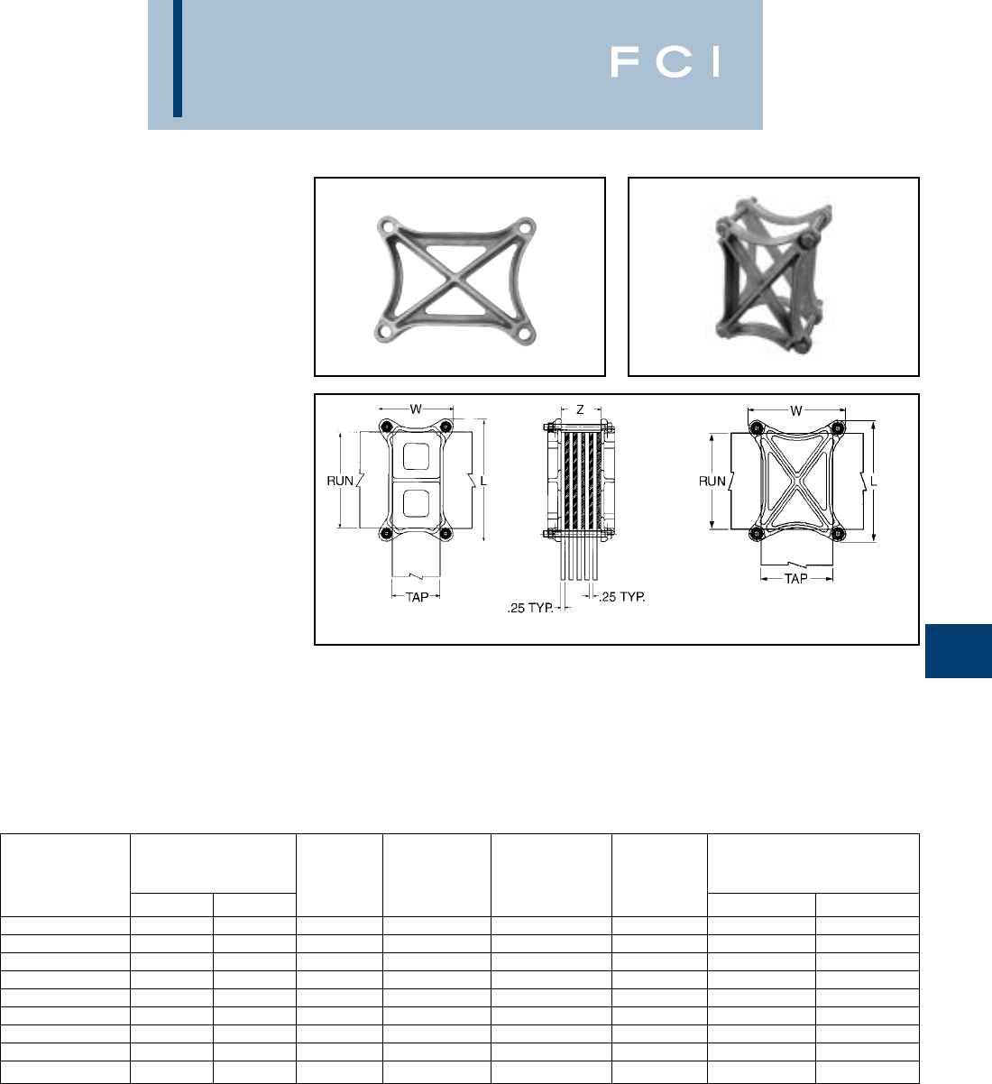
BURNDY
Substation
G-13
TYPE HFBW
BAR CLAMP
FOR COPPER BAR
The clamp assembly eliminates the need for
drilling the flat bar and is used in indoor and
outdoor applications.
The open web design provides a uniform
clamping pressure while minimizing the
weight of the connector.
FEATURES
•Web design cast copper body.
•Fully threaded yellow galvanized bolts with
split-lockwashers and nuts included.
•Flat bar accommodation molded into body.
BENEFITS
•Increased tortional resistance.
•Reduced weight.
•Simple installation.
•Easy identification.
TOTAL NO.
STD. OF FLAT
CATALOG CONDUCTOR FIG. MAX. ‘Z’ BARS (STD. DIMENSIONS
NUMBER * RUN TAP NO. DIM. 1/4” THICK) BOLT SIZE W L
HFBW86T20CG1 8.0 6.0 2 5.00 20 5/8”-11 8.13 10.13
HFBW66T16CG1 6.0 6.0 2 4.00 16 1/2”-13 7.75 7.75
HFBW64T17CG1 6.0 4.0 2 4.25 17 1/2”-13 5.75 7.75
HFBW63T10CG1 6.0 3.0 1 2.50 10 3/8”-16 4.70 7.63
HFBW62T10CG1 6.0 2.0 1 2.50 10 3/8”-16 3.44 7.44
HFBW44T17CG1 4.0 4.0 2 4.25 17 1/2”-13 5.68 5.68
HFBW43T10CG1 4.0 3.0 2 2.50 10 3/8”-16 4.42 5.42
HFBW42T10CG1 4.0 2.0 1 2.50 10 3/8”-16 3.54 5.55
HFBW32T5CG1 3.0 2.0 1 1.25 5 3/8”-16 3.54 4.55
*Catalog number based on standard maximum “Z”
dimension. Refer to your FCI representative for non-
standard “Z” dimensions.
Add TN suffix for tin plating (example: HFBW86T20CG1TN).
All dimensions in inches.
Fig. 1 Fig. 2
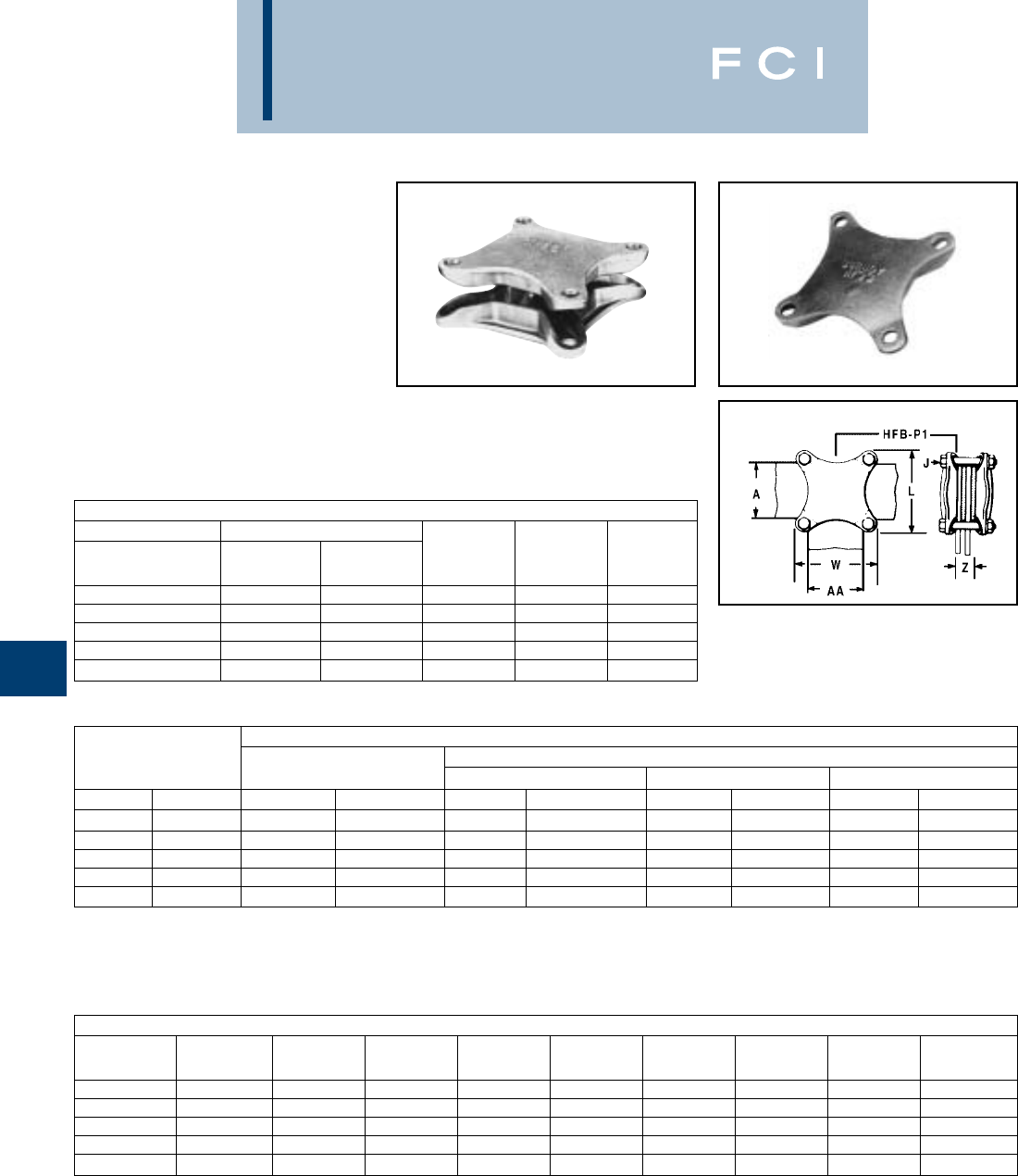
BURNDY
Substation
G-14
TYPE HFB-P1
BAR CLAMP ASSEMBLY
COMPONENTS
FOR COPPER BAR
To build your own high strength clamp assem-
bly for multiple flat bar using type HFB-P1 bar
clamps & clamping hardware, the following
tables have been provided. The clamp
assembly eliminates the need for drilling the
flat bar and is used in indoor and outdoor
applications.
†Ordered separately from BURNDY®.
*Z = Space between the bar clamp contact surfaces.
* * See table below when ordering assembly clamping bolts to
specify correct bolt length in Cat. #.
Position for assembly
Bar Clamp
Assembly
(2) Req’d
for assembly
ONE CLAMP HALF
BAR CLAMP BUS BAR “J”
CATALOG RUN TAP BOLT
NUMBER ‘A’ ‘AA’ DIA. L W
HFB33P1 3.00 3.00 3/8 4.38 4.38
HFB44P1 4.00 4.00 1/2 5.75 5.75
HFB63P1 6.00 3.00 1/2 7.75 4.75
HFB66P1 6.00 6.00 5/8 8.12 8.12
HFB88P1 8.00 8.00 3/4 10.50 10.50
COPPER BAR CLAMP ASSEMBLY COMPONENTS †
BUS BAR SILICON BRONZE CLAMPING HARDWARE
WIDTH (INCHES) BAR CLAMP BOLTS** NUTS SPLIT LOCKWASHERS
RUN-A TAP-AA QTY. CAT. NO. QTY. CAT. NO. QTY. CAT. NO. QTY. CAT. NO.
33 2HFB33P1 438 X (*) HEB 438CHEN 438SW
44 2HFB44P1 450 X (*) HEB 450CHEN 450SW
63 2HFB63P1 450 X (*) HEB 450CHEN 450SW
66 2HFB66P1 462 X (*) HEB 462CHEN 462SW
88 2HFB88P1 475 X (*) HEB 475CHEN 475SW
BOLT LENGTH**
CLAMP ‘J’ WHEN WHEN WHEN WHEN WHEN WHEN WHEN WHEN
NUMBER BOLT DIA. Z=1.25* Z=1.50* Z=1.75* Z=2.00* Z=2.25* Z=2.50* Z=2.75* Z=3.00*
HFB33P1 3/8(-16) 3.00 3.25 3.50 4.00 4.00 4.50 4.50 5.00
HFB44P1 1/2(-13) 3.25 3.50 3.75 4.00 4.50 4.50 5.00 5.00
HFB63P1 1/2(-13) 3.25 3.50 3.75 4.00 4.50 4.50 5.00 5.00
HFB66P1 5/8(-11) 3.50 4.00 4.00 4.50 4.50 5.00 5.00 6.00
HFB88P1 3/4(-10) 3.75 4.00 4.50 4.50 5.00 5.00 5.50 5.50

BURNDY
Substation
G-15
TYPE HFB-N
BAR CLAMP TAP PAD
ADAPTER
FOR COPPER BAR
High conductivity copper, tap pad adapter
provides a NEMA drilled contact pad when
assembled to the HFB-P1 clamps. Tap con-
nections can be made from copper bus bar(s)
without drilling by bolting standard mechani-
cal or compression terminal pads directly to
the pre-drilled tap pad adapter.
❶‘H’ Clamp (two required per assembly) and hardware
(as shown) not included with bar clamp tap pad, order
separately.
Fig. 1
Fig. 2
CATALOG FIG. ❶ USE WITH ‘H’
NUMBER NO. A-C E & F L N CLAMP CAT. NO.
HFB33-4N 13.00 1.75 7.00 .62 HFB33P1
HFB44-4N 14.00 1.75 9.12 1.12 HFB44P1
HFB66-6N 26.00 1.75 11.31 1.12 HFB66P1
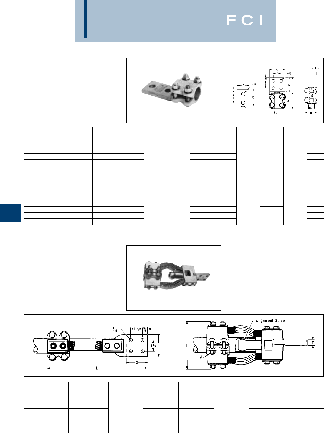
BURNDY
Substation
G-16
TYPE NA
TERMINAL
FOR COPPER TUBE TO FLAT
High copper alloy terminal for joining copper
tube to a flat pad. Letter “N” on end of catalog
number indicates pad drilled to NEMA
standards. One-wrench installation.
TYPE XA
EXPANSION TERMINAL
FOR COPPER TUBE TO FLAT
High copper alloy expansion terminal for tube
to flat. Provides for longitudinal movement of
tubing. Extra flexible braid carries full load of
joint. One-wrench installation.
* Conforms to NEMA Standards
NO. OF
CATALOG HOLES
NUMBER CONDUCTOR IN PAD C D E & F H J K L N T
NA13-2N 1/2 2 1-1/2 1-3/4 3/8 3/8
NA14-2N 3/4 2 1-5/8 2 3/8 3/8
NA15-2N 121-7/8 2-1/8 3/8 5-1/4 3/8
NA15-4N 143 2-1/8 3/8 3/8
NA16-2N 1-1/4 2 2-1/4 2-5/8 1/2 1/2
NA16-4N 1-1/4 4 3 2-5/8 1/2 1/2
NA17-2N 1-1/2 2 2-1/2 3 1-3/4 2-3/4 1/2 9/16 5/8 1/2
NA17-4N 1-1/2 4 3 2-3/4 1/2 61/2
NA18-4N 243-1/8 3-1/ 1/2 1/2
NA19-4N 2-1/2 4 3-1/4 3-3/4 1/2 3/4
NA20-4N 344-3/8 4-3/8 5/8 3/4
NA21-4N 3-1/2 4 4-3/8 5 5/8 6-5/8 7/8
NA22-4N 445-1/4 5-1/2 5/8 7/8
Catalog Number Number
Standard I.P.S. of Holes
With Guide Conductor in Pad* C H J L T
XA18-4N 23715-1/4 1/2
XA19-4N 2-1/2 3-3/4 7-1/2 1/2 16-1/8 5/8
XA20-4N 344-3/8 8 16-3/4 3/4
XA21-4N 3-1/2 4-3/4 8-1/4 5/8 17 7/8
XA22-4N 45-1/4 9-1/2 17 7/8
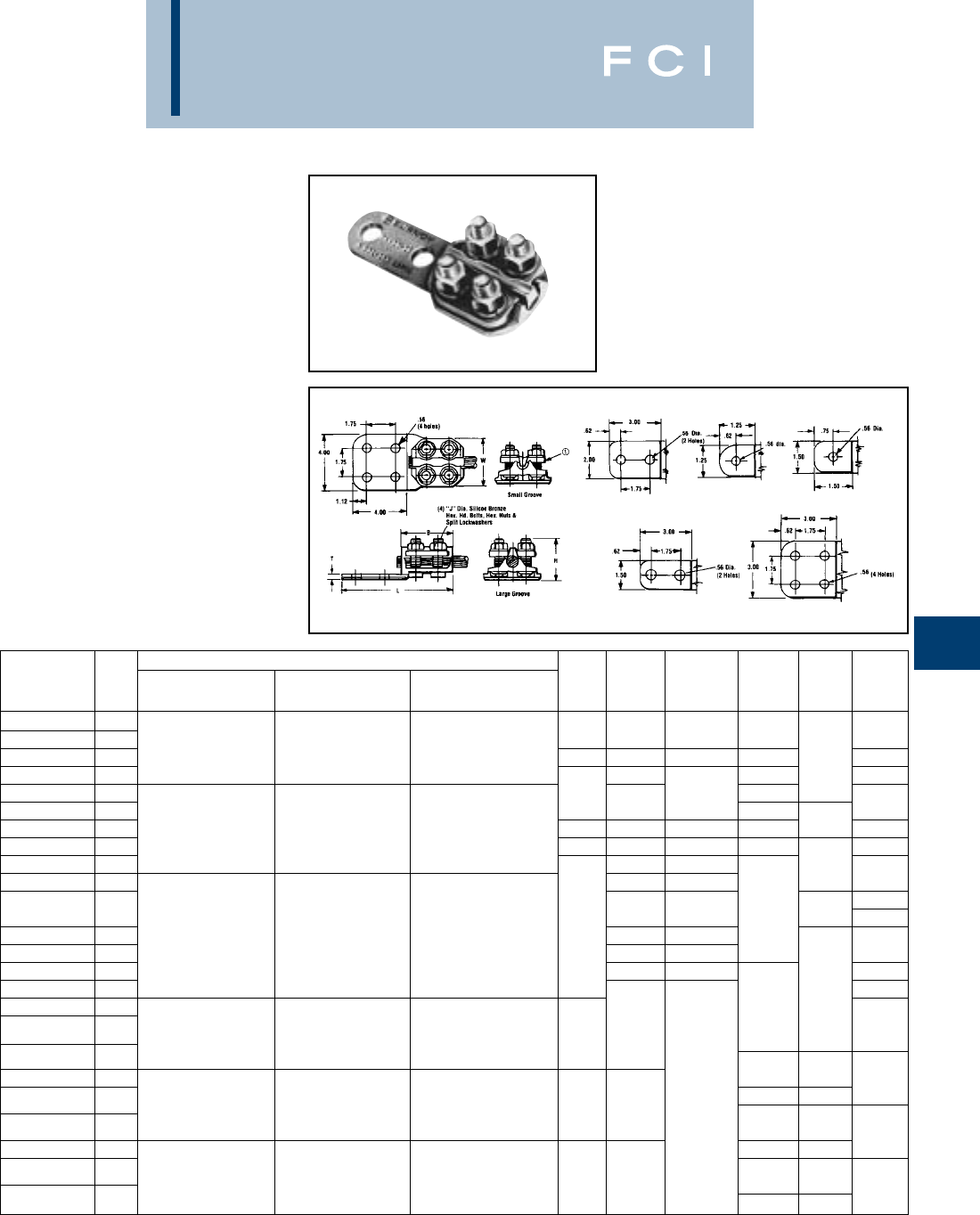
BURNDY
Substation
G-17
TYPE NAS/NAH
TERMINAL
FOR COPPER CABLE
High copper alloy reversible cap terminal for
joining a wide range of cable to equipment
pads. Tongue is side formed to provide
adequate clearance and terminal is designed
for one-wrench installation.
Fig. 1
Fig. “A” Fig. “B” Fig. “C”
Fig. “D” Fig. “E”
COPPER CABLE RANGE
CATALOG FIG. COMPLETE SMALL LARGE
NUMBER NO. CABLE RANGE GROOVE GROOVE B H J DIA. L T W
NAS29-N 1B 3.58
NAS29-2N 1D 6 Sol. (.162 Dia.) to 6 Sol. (.162 Dia.) to 2/0 Str. (.419 Dia.) to 2.38 1.80 3/8-16 5.62 2.00
NAH29-2N 1D 250 kcmil (.575 Dia.) 1/0 Str. (.373 Dia.) 250 kcmil (.575 Dia.) 2.62 2.12 1/2-13 5.88 .25 2.44
NAS29-34N 1E 1.80 5.62 2.00
NAS34-N 1C 2.38 3/8-16 4.12
NAS34-2N 1A 2.05 5.62 2.20
NAH34-2N 1A 1/0 Sol. (.325 Dia.) to 1/0 Sol. (.325 Dia.) to 250 kcmil (.575 Dia.) to 2.62 2.38 1/2-13 5.88 .31 2.56
NAS34-34N 1E 500 kcmil (.813 Dia.) 4/0 Str. (.529 Dia.) 500 kcmil (.813 Dia.) 2.38 2.05 3/8-16 5.62 2.20
NAH34-34N 1E 2.30 1/2-13 .25
NAS40-2N 1A 2.30 3/8-16 2.56
2.44
NAH40-2N 1A 2.62 1/2-13 5.88 .38 2.81
NAS40-34N 1E 2/0 Sol. (.365 Dia.) to 2/0 Sol. (.365 Dia.) to 500 kcmil (.813 Dia.) to 2.62 2.30 3/8-16
NAH40-34N 1E 800 kcmil (1.031 Dia.) 500 kcmil (.813 Dia.) 800 kcmil (1.031 Dia.) 2.62 1/2-13 2.44
NAS40-44N 12.30 3/8-16 .31 2.81
NAH40-44N 16.88 2.44
NAH44-2N 1A 2.62
4/0 Str. (.528 Dia.) to 4/0 Str. (.528 Dia.) to 750 kcmil (.998 Dia.) to 2.88 2.81
NAH44-34N 1E
1000 kcmil (1.152 Dia.) 750 kcmil (.998 Dia.) 1000 kcmil (1.152 Dia.)
NAH44-44N 1.44
NAH46-2N 1A 6.12 .38 2.88
1000 kcmil (1.152 Dia.) 1000 kcmil (1.152 Dia.) 1/2-13 7.12 .31
NAH46-34N 1E to 1500 kcmil — to 1500 kcmil 3.06 2.88 .50
NAH46-44N 1(1.412 Dia.) (1.412 Dia.) 6.31 .41 3.19
NAH48-2N 1A 7.31 .38
500 kcmil (.813 Dia.) to 500 kcmil (.813 Dia.) to 1500 kcmil (1.412 Dia.) to .69
NAH48-34N 1E
2000 kcmil (1.632 Dia.) 1500 kcmil (1.412 Dia.) 2000 kcmil (1.632 Dia.) 3.25 3.12 6.50 .50 3.38
NAH48-44N 17.50 .44
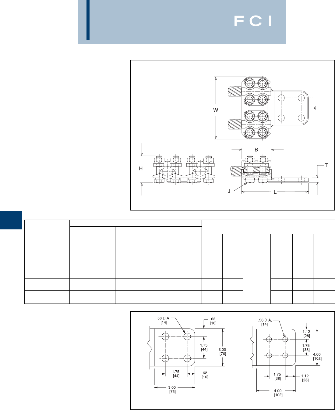
BURNDY
Substation
G-18
TYPE N2AH
TERMINAL
FOR TWO COPPER
CABLES TO FLAT
High copper alloy, reversible cap terminal for
joining a wide range of two copper cables to
equipment pads. Tongue is side formed to
provide adequate clearance and terminal is
designed for one-wrench installation.
Fig. 1 Fig. 2
COPPER CABLE RANGE
CATALOG FIG. COMPLETE SMALL LARGE DIMENSIONS IN/[mm]
NUMBER NO. CABLE RANGE GROOVE GROOVE B H J DIA. L T W
1/0 Str. (.325) to 1/0 Sol. (.325) to 250 kcmil (.575) to 2.63 2.30 6.13 .31 3.88
N2AH34-34N 1500 kcmil (.813) 4/0 Str. (.529) 500 kcmil (.813) [67] [58] [156] [8] [99]
2/0 Str. (.420) to 2/0 Str. (.420) to 500 kcmil (.813) to 2.63 2.62 5.88 .31 5.70
N2AH40-34N 1800 kcmil (1.031) 500 kcmil (.813) 800 kcmil (1.031) [67] [67] [149] [8] [145]
4/0 Str. (.529) to 4/0 Str. (.529) to 750 kcmil (.998) to 2.88 2.62 6.38 .50 4.69
N2AH44-34N 11000 kcmil (1.152) 750 kcmil (.998) 1000 kcmil (1.152) [73] [67] 1/2 - 13 [175] [13] [119]
4/0 Str. (.529) to 4/0 Sol. (.529) to 750 kcmil (.998) to 2.88 2.25 7.32 .50 6.12
N2AH44-44N 21000 kcmil (1.152) 750 kcmil (.998) 1000 kcmil (1.152) [73] [57] [186] [13] [155]
1000 kcmil (1.152) to 3.07 2.50 7.46 .75 6.50
N2AH46-44N 21500 kcmil (1.411) ——
[78] [64] [189] [19] [165]
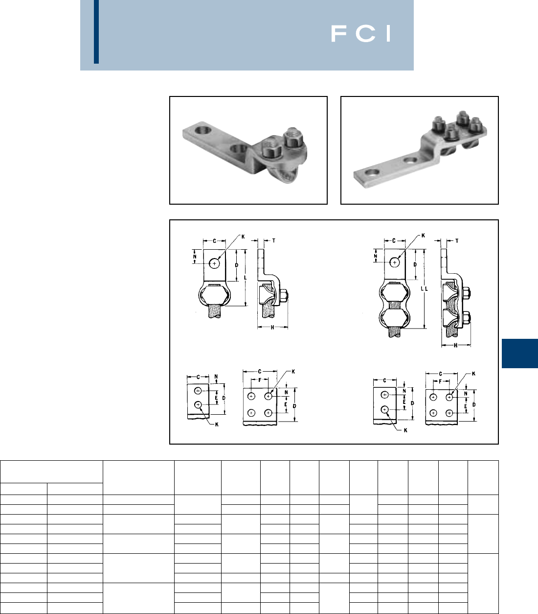
BURNDY
Substation
G-19
TYPE VA, VVA
VARILUG
FOR COPPER CABLE
High copper alloy terminal for joining a wide
range of cable to equipment pads or bar.
Particularly suitable for use on extra flexible
cable. One-wrench installation. Type VVA,
twin elements secure joint against vibration
and flexing. Particularly recommended for
use on extra flexible cables. One-wrench
installation.
*“N” indicates NEMA standard stud holes.
Type VA
Type VVA
NO. OF
CATALOG NUMBER* HOLES
TYPE VA TYPE VVA CONDUCTOR IN PAD C D E & F H K L LL N T
VA2C VVA2C 8 Sol. - 2 Str. 13/16 1-1/4 — 1-1/2 2-3/4 4-1/8 3/8
VA25 VVA25 6 Sol. - 1/0 Str. 17/8 1-3/8 — 1-7/8 7/16 2-1/8 4-3/8 1/2 1/4
VA28 VVA28 11-1/2 — 7/16 2-5/8 4-1/8 1/2
VA28-2N VVA28-2N 1/0 Str. - 4/0 Str. 2 NEMA 1-1/16 3-1/2 1-3/4 1-7/8 9/16 5 6-1/4 5/8
VA30 VVA30 11-5/8 — 7/16 3-1/4 4-5/8 5/8 5/16
VA30-2N VVA30-2N 1/0 Str. - 300 2 NEMA 1-1/8 3-5/8 1-3/4 2-1/4 9/16 5-1/4 6-5/8 5/8
VA34 VVA34 12—9/16 3-7/8 5-3/8 7/8
VA34-2N VVA34-2N 300 - 500 2 NEMA 1-3/8 3-5/8 1-3/4 2-5/8 9/16 5-3/8 6-1/8 5/8
VA34-4N VVA34-4N 4 NEMA 3 3-1/16 1-3/4 2-9/16 9/16 5-3/8 6-7/8 5/8
VA40 VVA40 12-3/8 — 11/16 4-1/2 6-3/8 1 3/8
VA40-2N VVA40-2N 500 - 800 2 NEMA 1-5/8 3-5/8 1-3/4 2-1/8 9/16 5-7/8 7-3/4 5/8
VA40-4N VVA40-4N 4 NEMA 3 2-5/8 1-3/4 9/16 5-7/8 7-3/4 5/8
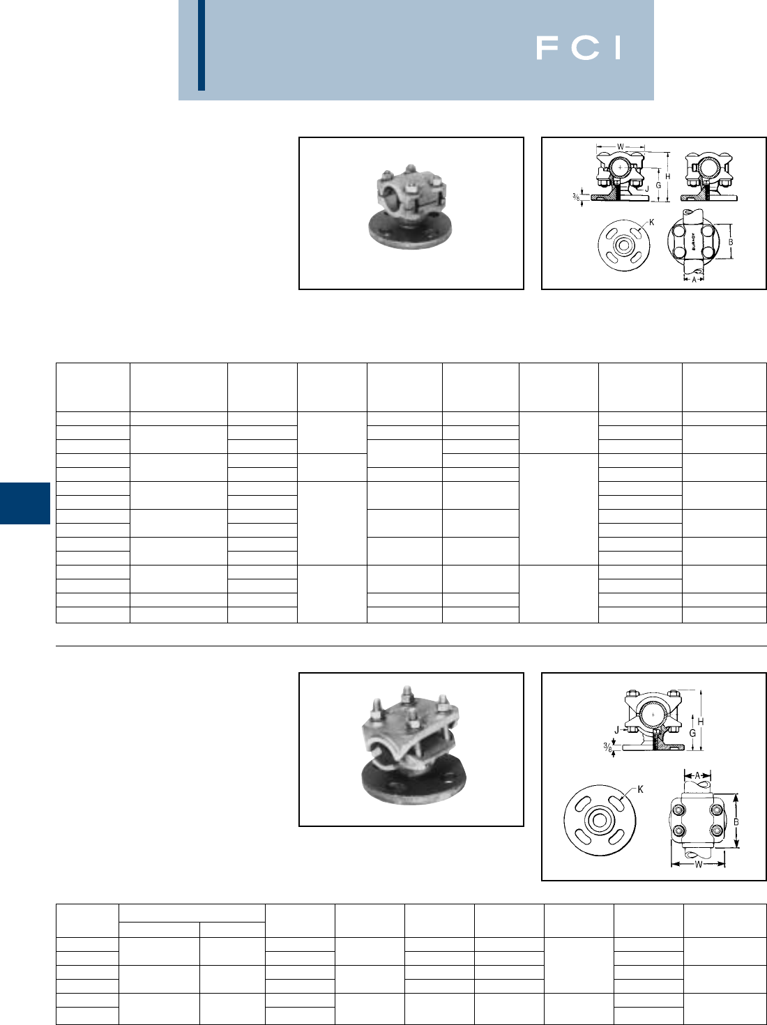
BURNDY
Substation
G-20
TYPE UH
BUS SUPPORT
FOR COPPER TUBE
High copper alloy bus support for mounting
tube on a post or pedestal type insulator.
Single bolt allows rotation to any angle.
Rotate cap 180° for slip or rigid fit. One-
wrench installation. Supplied with hardware
for mounting to cap of insulator. Specify base
mounting hardware, if required, by adding
suffix “B” to Catalog No.
TYPE UHR
BUS SUPPORT
FOR COPPER CABLE
OR TUBE
High copper alloy bus support clamp for
mounting a wide range of cable or tube on
post or pedestal type insulators. Single bolt
allows rotation to any angle. Supplied with
hardware for mounting to cap of insulator.
Specify base mounting hardware, if required,
by adding suffix “-B” to Catalog No.
* With maximum conductor in place.
COPPER
CATALOG CONDUCTOR BOLT
NUMBER IPS “A” CIRCLE B G H J K W
UH14-3 3/4 3 2 2-7/8 9/16 2-5/8
UH15-3 32-1/2 2 3 3/8 9/16
UH15-5 153-1/4 11/16 2-7/8
UH16-3 32-1/4 3-1/2 9/16
UH16-5 1-1/4 52-11/16 2-3/8 3-5/8 11/16 3-1/2
UH17-3 39/16
UH17-5 1-1/2 52-1/2 3-7/8 11/16 4
UH18-3 31/2 9/16
UH18-5 2532-3/4 4-3/8 11/16 4-5/8
UH19-3 39/16
UH19-5 2-1/2 53-1/8 5 11/16 5-1/4
UH20-3 39/16
UH20-5 353-5/8 5-7/8 11/16 6-1/4
UH21-5 3-1/2 5 3-1/4 46-1/2 5/8 11/16 6-7/8
UH22-5 45 4-1/2 7-1/4 11/16 7-1/2
Catalog Copper Conductor “A” Bolt
Number Cable Tube Circle B G* H J K W
UHR13-3 31-3/4 3 9/16
UHR13-5 6 Str. - 500 1/8 - 1/2 53-5/8 2-1/8 3-3/8 11/16 2-1/4
UHR15-3 323-1/2 3/8 9/16
UHR15-5 4/0 Str. - 1250 1/4 - 1 53-3/4 2-1/4 3-3/4 11/16 2-3/4
UHR17-3 39/16
UHR17-5 750 - 2500 3/4 - 1-1/2 52-7/8 2-1/2 4-1/4 1/2 11/16 4
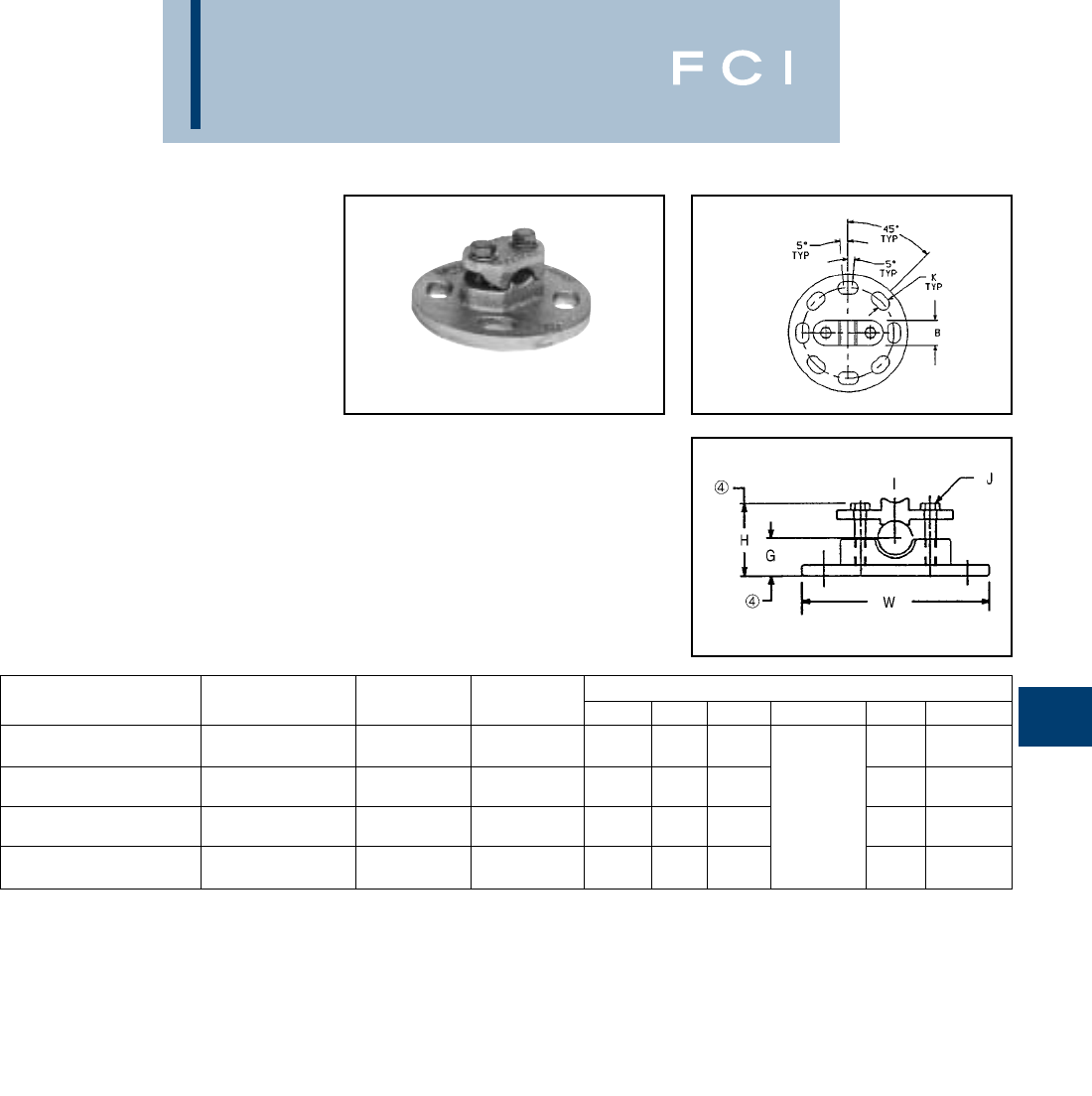
BURNDY
Substation
G-21
NOTES:
1Material:
Connector: Cast copper alloy
Clamping Hardware: Silicon bronze
Mounting Hardware: Galvanized steel
2Dimensions in brackets [ ] are in millimeters.
➂Complete range may be accommodated by reversing the
cap.
➃Dimension with maximum conductor in place.
TYPES LH, LHR
BUS SUPPORT
FOR COPPER CABLE
OR TUBE
High copper alloy, light duty bus support for
mounting a wide range of cable or tube on
post or pedestal type insulators. One-wrench
installation. Supplied with hardware for
mounting to cap of insulator. Specify base
mounting hardware, if required, by adding
suffix “-B” to Catalog No.
➄Cap mounting hardware is supplied as standard. 3.00
Dia. bolt circle furnished with four 1/2 -13 1.00 long
galvanized steel hex head bolts and split lockwashers.
5.00 Dia. bolt circle furnished as above except bolts are
.625 1.75.
➅If base mounting is desired, add “-B” to the Catalog
Number and the following hardware will be supplied: 3.00
Dia. bolt circle furnished 1/2 -13 1-1/2 long galvanized
steel hex head bolt, hex nuts, and 5.00 Dia. bolt circle
furnished as above except bolts are .625 1.75.
COPPER CABLE RANGE TUBING ➄BOLT ➅CATALOG DIMENSIONS IN/[mm]
COMPLETE RANGE SCH. 40/80 CIRCLE NUMBER B G ➃H ➃JKW
1.69 1.25 2.62 .56 4.25
6 Sol. - 4/0 Str. — 3LH28-3 [43] [32] [66.5] [14] [108]
1.00 1.23 2.03 .56 4.25
➂ #8 - 250 kcmil 1/8 - 1/4 3LHR29-3 [25] [31] [52] [14] [108]
1.38 1.38 2.50 3/8 - 16 .56 4.25
2/0 Str. - 500 kcmil 1/4 - 1/2 3LH34-3 [35] [35] [63.5] [14] [108]
1.00 1.33 2.51 .69 6.25
➂ 4/0 - 1000 kcmil 1/4 - 3/4 5LHR44-5 [25] [34] [64] [18] [158]
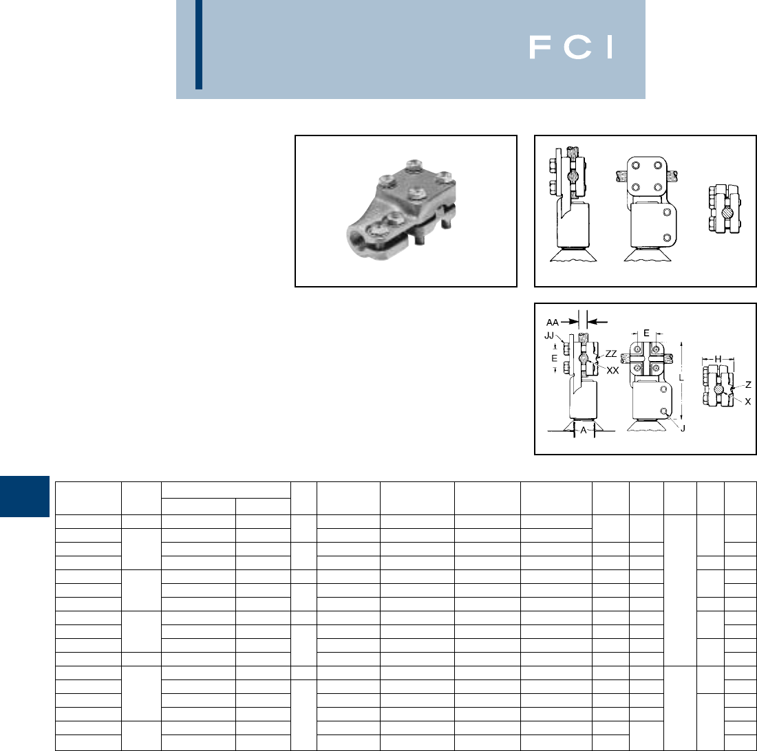
BURNDY
Substation
G-22
TYPE NDR
STUD CONNECTOR
FOR COPPER CABLE,
TUBE, FLAT BAR
High copper alloy reversible and rotatable cap
stud connector joins cable, tube and flat bar
in-line or at right angles to equipment studs.
Accommodates a wide range of cables or
tubes. One-wrench installation.
Fig. 1
Fig. 2
Catalog Stud Complete Range AA Fig. X XX Z ZZ
Number A Cable Tube I.P.S. No. Groove Groove Groove Groove E H J JJ L
NDR6328T13 1/2-13 6 Sol. - 4/0 Str. — 6 Sol. - 1 Str. 2/0 Sol. - 4/0 Str.
NDR6428T16 6 Sol. - 4/0 Str. — 16 Sol. - 1 Str. 2/0 Sol. - 4/0 Str. 1-1/16 1-3/4 3/8 3-5/8
NDR6434T16 3/4-16 6 Sol. - 500 3/8 - 1/2 250 - 350 400 - 500 6 Sol. - 2 Str. 1/0 Sol. - 4/0 Str. 1-7/16 2-1/4 4-1/8
NDR6444T16 2 Sol. - 1000 3/8 - 3/4 2550 - 700 750 - 1000 2 Sol. - 250 300 - 500 1-7/8 2-7/8 1/2 4-5/8
NDR6528T14 6 Sol. - 4/0 Str. — 1 6 Sol. - 1 Str. 2/0 Sol. - 4/0 Str. 1-1/16 1-3/4 4-1/8
NDR6534T14 1-14 6 Sol. - 500 3/8 - 1/2 250 - 350 400 - 500 6 Sol. - 2 Str. 1/0 Sol. - 4/0 Str. 1-7/16 2-1/4 3/8 3/8 4
NDR6544T14 2 Sol. - 1000 3/8 - 3/4 2550 - 700 750 - 1000 2 Sol. - 250 300 - 500 1-7/8 2-7/8 1/2 4-3/4
NDR65528T12 6 Sol. - 4/0 Str. — 1 6 Sol. - 1 Str. 2/0 Sol. - 4/0 Str. 1-1/16 1-3/4 4-1/8
NDR65534T12 1-1/8-12 6 Sol. - 500 3/8 - 1/2 250 - 350 400 - 500 6 Sol. - 2 Str. 1/0 Sol. - 4/0 Str. 1-7/16 2-1/4 3/8 4
NDR65544T12 2 Sol. - 1000 3/8 - 3/4 2 550 - 700 750 - 1000 2 Sol. - 250 300 - 500 1-7/8 2-7/8 4-5/8
NDR6644T12 1-1/4-12 2 Sol. - 1000 3/8 - 3/4 550 - 700 750 - 1000 2 Sol. - 250 300 - 500 1-7/8 2-7/8 1/2 4-5/8
NDR6728T12 6 Sol. - 4/0 Str. — 1 6 Sol. - 1 Str. 2/0 Sol. - 4/0 Str. 1-1/16 2-1/4 4-3/4
NDR6734T12 6 Sol. - 500 3/8 - 1/2 250 - 350 400 - 500 6 Sol. - 2 Str. 1/0 Sol. - 4/0 Str. 1-7/16 2-3/8 3/8 5
NDR6744T12 1-1/2-12 2 Sol. - 1000 3/8 - 3/4 550 - 700 750 - 1000 2 Sol. - 250 300 - 500 1-7/8 2-7/8 5-1/8
NDR6748T12 4/0 Str. - 2000 3/8-1-1/4 2 1250 - 1600 1700 - 2000 4/0 Str. - 600 650 - 1200 2-3/8 3-1/4 1/2 5-3/4
NDR6844T12 2 Sol. - 1000 3/8 - 3/4 550 - 700 750 - 1000 2 Sol. - 250 300 - 500 1-7/8 1/2 6-1/8
NDR6848T12 2-12 4/0 Str. - 2000 3/8-1-1/4 1250 - 1600 1700 - 2000 4/0 Str. - 600 650 - 1200 2-3/8 2-7/8 6-5/8
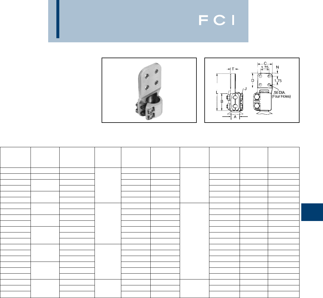
BURNDY
Substation
G-23
TYPE FD
STUD CONNECTOR
FOR STUD TO FLAT BAR
High copper alloy stud connector allows bolt-
ing cable and tubing terminals to equipment
studs. Hex head captured bolts provide one-
wrench installation. One pad contact surface
is on centerline of stud. Pad is finished on
both sides. All pads are four hole
NEMA drilled.
NOTES:
➀Indoor Rating
2. Contact factory for other variations in drilling, plating, etc.
Nominal
Catalog Stud Ampere
Number A Rating ➀BCD J LNT
FD64C5T16 3/4-16 1000 3.00 3.00 5.72 .62 .31
FD65C6T14 1-14 1075 3.00 3.00 5.72 .62 .38
FD655C6 1075 3.00 3.00 5.80 .62 .38
FD655D6 1-1/8-12 1300 1.75 4.00 4.00 3/8-16 6.86 1.12 .38
FD66C6 1075 3.00 3.00 5.78 .62 .38
FD66D6 1-1/4-12 1300 4.00 4.00 6.84 1.12 .38
FD67C6 1075 3.00 3.00 6.23 .62 .38
FD67D8 1-1/2-12 1450 4.00 4.00 7.30 1.12 .50
FD675C8 1220 3.00 3.00 6.32 .62 .50
FD675D8 1-3/4-12 1450 2.18 4.00 4.00 7.39 1.12 .50
FD68C8 1220 3.00 3.00 6.35 .62 .50
FD68D8 2-12 1450 4.00 4.00 7.42 1.12 .50
FD68D12 2100 4.00 4.00 1/2-13 7.42 1.12 .75
FD685C8 1220 3.00 3.00 6.71 .62 .50
FD685D8 2-1/4-12 1450 4.00 4.00 7.77 1.12 .50
FD685D12 2100 4.00 4.00 7.77 1.12 .75
FD69C8 1220 2.50 3.00 3.00 6.77 .62 .50
FD69D8 2-1/2-12 1450 4.00 4.00 8.03 1.12 .50
FD69D12 2100 4.00 4.00 8.03 1.12 .75
FD70D8 1450 4.00 4.00 8.28 1.12 .50
FD70D12 3-12 2100 2.88 4.00 4.00 5/8-11 8.26 1.12 .75
FD70D16 3000 4.00 4.00 8.24 1.12 1.00
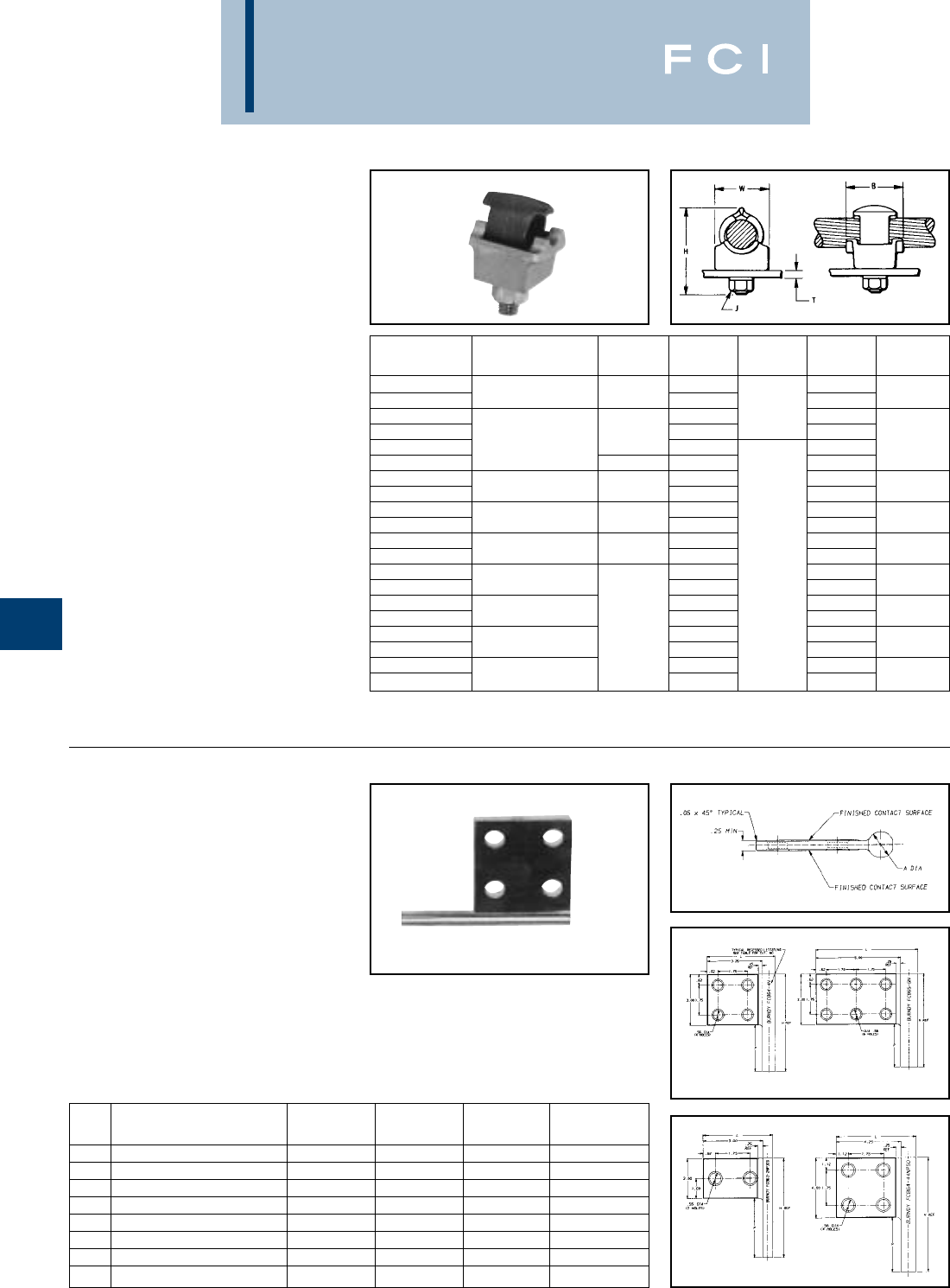
BURNDY
Substation
G-24
TYPE QGFL
BARTAP™
FOR COPPER CABLE TO FLAT
High copper alloy BARTAP™ for joining a range
of cable to bar or pad. One-wrench installation.
TYPE FCB
TRANSFORMER
TAP ADAPTER
FOR COPPER AND ALUMINUM
Cast in one piece from copper alloy.
Transformer tap adapter designed to accom-
modate from 1 to 6 NEMA drilled copper or
aluminum terminal taps from a single
secondary transformer outlet. Tin-plated.
Order mounting hardware and tap terminals
separately.
*Can be installed side by side or in-line on NEMA drilled bar.
Fig. 1 Fig. 2
Fig. 3 Fig. 4
Catalog T
Number Conductor B H J (MAX.) W
QGFL1CB1 1-7/8 1/4
QGFL1CB1T6 10 Sol. - 1 Str. 1-1/8 2-3/8 3/4 1
QGFL26B1 2-1/8 3/8 1/4
QGFL26B1T6 1-1/4 2-5/8 3/4
QGFL26B2* 8 Sol. - 2/0 Str. 1-1/2 1/4 1-1/8
QGFL26B2T6* 1-1/2 2-7/8 3/4
QGFL29B1* 2-5/8 1/4
QGFL29B1T6* 6 Str. - 250 1-5/8 3-1/8 3/4 1-3/8
QGFL31B1* 2-7/8 1/4
QGFL31B1T6* 2 Sol. - 350 1-3/4 3-1/4 3/4 1-5/8
QGFL34B1 3-1/8 1/4
QGFL34B1T6 1/0 Sol. - 500 2 3-5/8 3/4 1-3/4
QGFL39B1 3-1/4 1/2 1/4
QGFL39B1T6 350 - 750 3-5/8 3/4 1-3/4
QGFL44B1 3-3/8 1/4
QGFL44B1T6 750 - 1000 4-1/8 3/4 2-1/8
QGFL46B1 2-1/4 41/4
QGFL46B1T6 1000 - 1500 4-1/2 3/4 2-1/2
QGFL48B1 4-3/4 1/4
QGFL48B1T6 1500 - 2000 5-1/4 3/4 3
FIG. CATALOG A H
NO. NUMBER DIA. REF L P
1FCB63-4N .50 5.25 3.75 2.25
2FCB63-6N .50 5.25 5.50 2.25
1FCB64-4N .75 5.75 4.00 2.75
2FCB64-6N .75 5.75 5.75 2.75
1FCB65-4N 1.00 7.00 4.25 4.00
2FCB65-6N 1.00 7.00 6.00 4.00
3FCB63-2NP300 .50 5.00 3.50 3.00
4FCB64-44NP50 .75 9.00 5.00 5.00
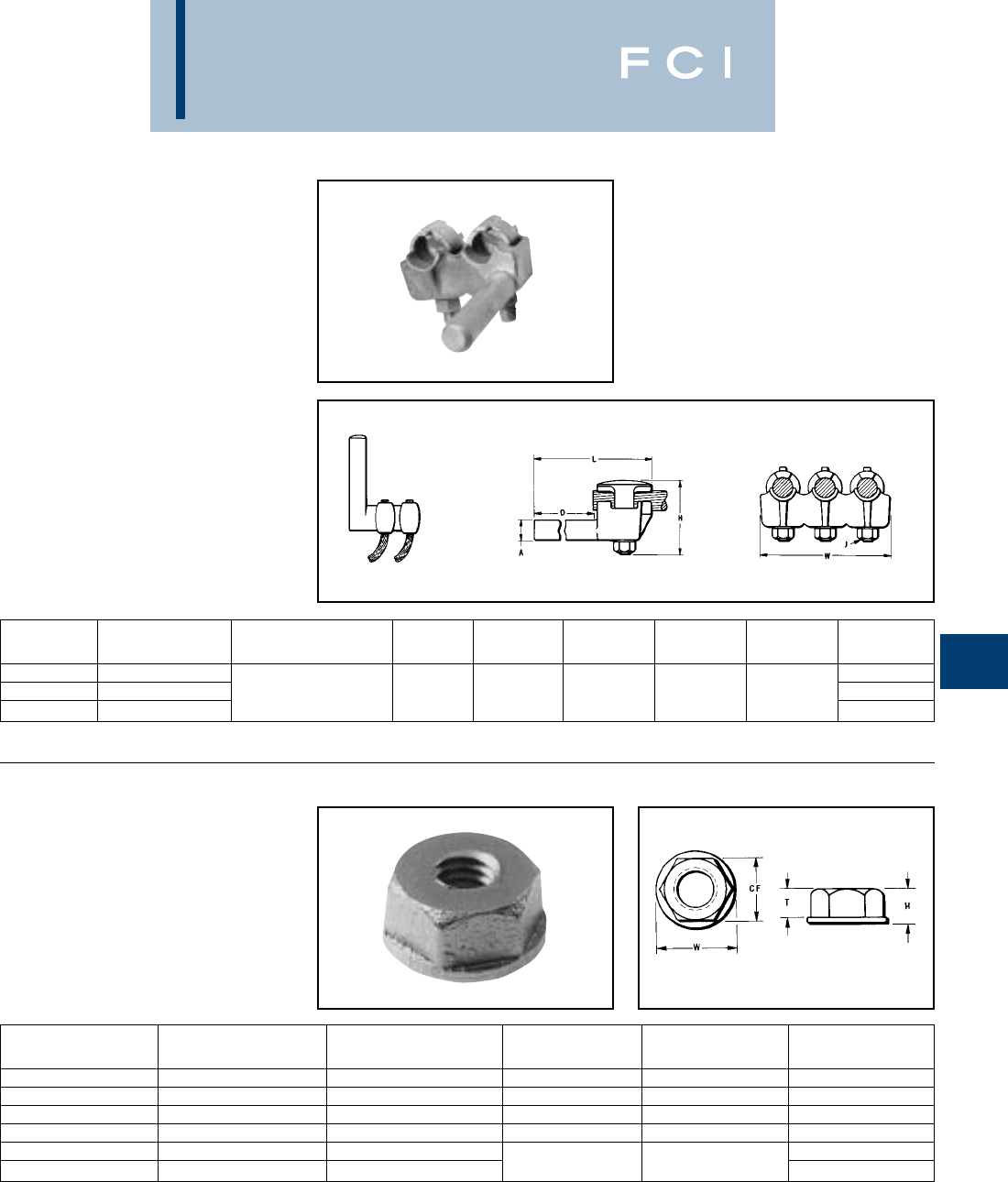
BURNDY
Substation
G-25
TYPE E-C-G
TRANSFORMER
TAP ADAPTER
FOR COPPER CABLE
Multi-tap, range-taking cast copper alloy con-
nector designed to take 2, 3, or 4 conductors
from a single secondary transformer outlet.
TYPE FN
CONTACT NUT
FLAT TO STUD
High copper alloy contact nut for joining bar or
terminal pads to studs. Designed to carry full
current load from flat to stud.
CATALOG NO. OF A
NUMBER CONDUCTORS CONDUCTOR SIZE DIA. D H J L W
E2C34G1 23-1/2
E3C34G1 31/0 Sol. to 500 .78 3-3/4 3-7/8 1/2-13 6-1/4 5-1/4
E4C34G1 46-7/8
Catalog Number Stud Dia. and CF
Type FN Threads per Inch (Cross Flats) H T W
FN62T16 3/8 - 16 3/4 3/8 5/16 7/8
FN63T13 1/2 - 13 1 15/32 3/8 1-1/4
FN64T16 3/4 - 16 1-1/4 3/4 9/16 1-1/2
FN655T12 1-1/8 - 12 1-3/4 1 3/4 2-1/8
FN66T14 1-1/4 - 14 2 2-3/8
FN67T12 1-1/2 - 12 2-3/8 1-1/8 7/8 2-3/4
BURNDY
Substation
G-26
CONNECTORS FOR
ALUMINUM CONDUCTORS
Bolted aluminum connectors are cast of alu-
minum alloy and assembled with aluminum
alloy bolts, nuts and galvanized steel
washers.The hex head bolts are captured for
one-wrench installation. The connectors
accommodate aluminum or copper conduc-
tor. The “mass anode” design pioneered by
BURNDY®minimizes the effect of galvanic
corrosion on aluminum (anode+) connectors
when used with copper (cathode –) conductor
(Reference Fig. 1).
Joint deterioration caused by relaxation or
“cold flow” of the aluminum is eliminated by
the massive design. Generous contact areas
distribute clamping forces evenly over the
conductor, eliminating points of high stress
that cause “cold flow.” These contact areas
are factory treated to remove surface oxides
and coated with an oxide inhibitor to prevent
their reformation. Large radiating surfaces
allow the connectors to run cooler than the
copper conductor compensating for the fact
that aluminum has a higher coefficient of ther-
mal expansion. Connector and conductor
expand and contract together during load
cycles, eliminating stresses on the aluminum
body that can cause relaxation of the joint.
CONNECTOR SELECTION
Generally, copper connectors are recom-
mended for copper conductor and aluminum
connectors for aluminum conductor. Where
aluminum connectors are recommended for
use on both aluminum and copper conduc-
tors, the copper must be positioned parallel to
or below the aluminum to prevent contamina-
tion of the aluminum by copper salts washed
down by rain.
Except where indicated, all rigid connectors
accept standard or extra heavy I.P.S. and all
flexible connectors standard I.P.S. If extra
heavy I.P.S. is to be used with a flexible joint,
it must be spelled out at the time of ordering
so that the proper cross sectional area of the
flexible element may be supplied for the
increased conductor rating.
CONDUCTOR PREPARATION
To obtain optimum performance from any
connector, the conductor surface must be
thoroughly cleaned before installation. The
surface oxides that form on all conductors act
as insulation. Failure to remove them
can result in high resistance joint and, ulti-
mately, failure.
Conductor contact surfaces should be
scratch brushed until bright and shiny.
Aluminum conductor (new or old) should be
coated with BURNDY®PENETROX™ after
scratch brushing. PENETROX™ is a joint
compound that aids in the establishment of
low resistance joints and prevents aluminum
oxides from reforming.
ALUMINUM INTRODUCTION
Fig. 1
Many aluminum ions
removed by current flow
Few aluminum ions removed
by current flow
Copper Cathode
Aluminum Anode
Aluminum Anode
Copper Cathode
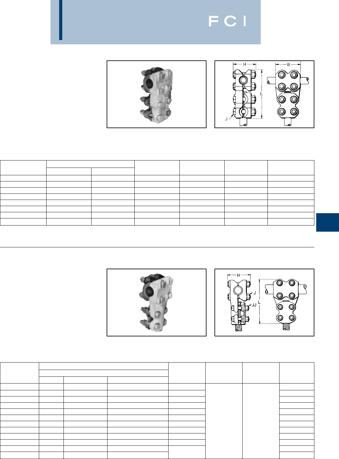
BURNDY
Substation
G-27
TYPE NNT-A
T-CONNECTOR
FOR ALUMINUM AND COPPER
TUBE TO TUBE
Aluminum alloy T-Connector for tubing run
and tap. Properly proportioned to permit use
on copper-aluminum conductor combina-
tions. Captured hex head bolts permit one-
wrench installation. PENETROX™ joint
compound recommended on contact sur-
faces.
TYPE NNTR-A
T-CONNECTOR
FOR ALUMINUM & COPPER
TUBE TO CABLE
Aluminum alloy T-Connector for tube run,
range of cable tap. Properly proportioned to
permit use on copper-aluminum combina-
tions. One-wrench installation. PENETROX™
joint compound recommended on contact
surfaces.
Catalog Conductor
Number Run Tap B H J L
NNT15A15A 113-1/2 3-3/8 1/2 6-7/8
NNT16A16A 1-1/4 1-1/4 3-3/4 3-3/8 1/2 7-/12
NNT17A17A 1-1/2 1-1/2 4 3-7/8 1/2 7-7/8
NNT18A18A 224-1/4 4-1/2 5/8 9
NNT19A19A 2-1/2 2-1/2 4-/12 5 5/8 9
NNT20A20A 33555/811
NNT21A20A 3-1/2 3 5-1/2 5-5/8 5/8 11-5/8
NNT22A22A 4466-1/4 5/8 12-5/8
Conductor
Catalog Tap
Number Run Alum. or Cu. ACSR H J JJ L
NNTR14A29A 3/4 1/0 Str. - 250 1/0 (6-1) - 4/0 (6-1) 3-1/8 5-7/8
NNTR14A36A 3/4 350 - 600 336.4 (18-1) - 477 (30-7) 3-1/8 6-3/8
NNTR15A36A 1350 - 600 336.4 (18-1) - 477 (30-7) 3-3/8 6-5/8
NNTR15A42A 1600 - 900 477 (30-7) - 795 (54-7) 3-3/8 6-7/8
NNTR16A29A 1-1/4 1/0 Str. - 250 1/0 (6-1) - 4/0 (6-1) 3-3-/8 6-1/2
NNTR16A32A 1-1/4 250 - 400 4/0 (6-1) - 397.5 (18-1) 3-3/8 6-3/4
NNTR16A42A 1-1/4 600 - 900 477 (30-7) - 795 (54-7) 3-7/8 1/2 1/2 7-1/4
NNTR17A29A 1-1/2 1/0 Str. - 250 1/0 (6-1) - 4/0 (6-1) 3-7/8 6-3/4
NNTR18A29A 21/0 Str. - 250 1/0 (6-1) - 4/0 (6-1) 4-1/2 7-5/8
NNTR19A42A 2-1/2 600 - 900 477 (30-7) - 795 (54-7) 4-5/8 8-7/8
NNTR20A32A 3250 - 400 4/0 (6-1) - 397.5 (18-1) 9
NNTR22A46A 41250 - 1600 1113 (54-9) - 1431 (45-7) 59-1/4
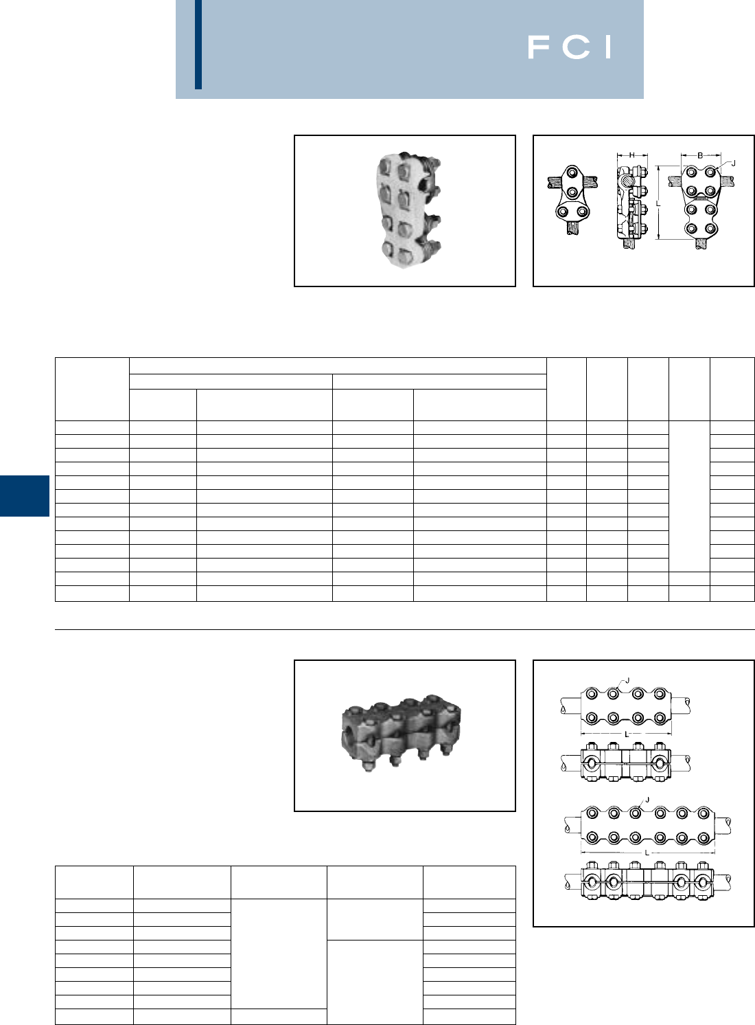
BURNDY
Substation
G-28
TYPE NNTR-A
T-CONNECTOR
FOR ALUMINUM AND COPPER
CABLE TO CABLE
Aluminum alloy T-Connector for a range of
copper, aluminum and ACSR cable on run
and tap. Properly proportioned to permit use
on copper-aluminum conductor com-
binations. One-wrench installation. PENE-
TROX™ joint compound recommended on
contact surfaces.
TYPE NS-A
COUPLER
FOR ALUMINUM AND COPPER
TUBE TO TUBE
Aluminum alloy coupler for joining equal sizes
of tube end to end. Properly proportioned to
permit use on aluminum-copper conductor
combinations. One-wrench installation.
PENETROX™ joint compound recommend-
ed on contact surfaces.
Fig. 1
Fig. 2
Fig. 1 Fig. 2
Conductor
Run Tap
Catalog Alum. or Alum. or Fig.
Number Copper ACSR Copper ACSR No. B H J L
NNTR29A29A 1/0 Str. - 250 1/0 (6-1) - 4/0 (6-1) 1/0 Str. - 250 1/0 (6-1) - 4/0 (6-1) 2 2-3/4 2-5/8 5-5/8
NNTR32A25A 250 - 400 4/0 (6-1) - 397.5 (18.1) 4 Str. - 1/0 Str. 4 (6-1) - 1/0 (6-1) 1 1-7/8 2-5/8 4-7/8
NNTR32A32A 250 - 400 4/0 (6-1) - 397.5 (18-1) 250 - 400 4/0 (6-1) - 397.5 (18-1) 2 3 2-5/8 6
NNTR36A25A 350 - 600 336.4 (18-1) - 477 (30-7) 4 Str. - 1/0 Str. 4 (6-1) - 1/0 (6-1) 1 1-7/8 2-5/8 5
NNTR36A29A 350 - 600 336.4 (18-1) - 477 (30-7) 1/0 Str. - 250 1/0 (6-1) - 4/0 (6-1) 2 3-1/4 2-5/8 5-7/8
NNTR36A36A 350 - 600 336.4 (18-1) - 477 (30-7) 350 - 600 336.4 (18-1) - 477 (30-7) 2 3-1/4 2-5/8 1/2 6-3/8
NNTR42A32A 600 - 900 477 (30-7) - 795 (54-7) 250 - 400 4/0 (6-1) - 397.5 (18-1) 2 3-1/2 3-1/8 6-3/8
NNTR42A36A 600 - 900 477 (30-7) - 795 (54-7) 350 - 600 336.4 (18-1) - 477 (30-7) 2 3-1/2 3-1/8 6-5/8
NNTR42A42A 600 - 900 477 (30-7) - 795 (54-7) 600 - 900 477 (30-7) - 795 (54-7) 2 3-1/2 3-1/8 6-7/8
NNTR45A45A 900 - 1250 715.5 (30-19) - 1113 (54-19) 900 - 1250 715.5 (30-19) - 1113 (54-19) 2 3-3/4 3-1/4 7-3/8
NNTR46A42A 1250 - 1600 1113 (54-19) - 1431 (45-7) 600 - 900 477 (30-7) - 795 (54-7) 2 3-3/4 3-1/2 7-1/4
NNTR46A46A 1250 - 1600 1113 (54-19) - 1431 (45-7) 1250 - 1600 1113 (54-19) - 1431 (45-7) 2 4-3/8 3-3/4 5/8 8-3/8
NNTR48A48A 1500 - 2000 1272 (54-19) - 1780 (84-19) 1500 - 2000 1272 (54-19) - 1780 (84-19) 2 4-3/8 3-7/8 5/8 8-5/8
CATALOG CONDUCTOR FIG.
NUMBER I.P.S. NO. J L
NS14A14A 3/4 6-3/4
NS15A15A 11/2 7-1/4
NS17A17A 1-1/2 8-1/4
NS18A18A 28-3/4
NS19A19A 2-1/2 19-1/4
NS20A20A 310-1/4
NS21A21A 3-1/2 5/8 11-1/4
NS22A22A 412-1/4
NS24A24A 52 14-1/4
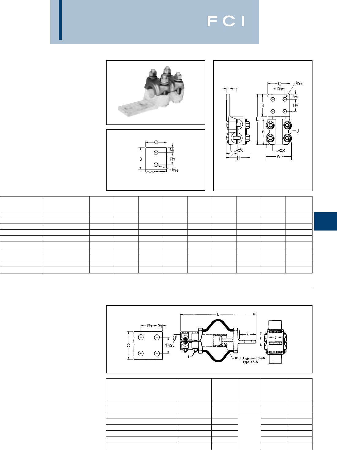
BURNDY
Substation
G-29
TYPE NA-A
TERMINAL
FOR ALUMINUM AND COPPER
TUBE TO FLAT
Aluminum alloy terminal for joining copper or
aluminum tube to copper or aluminum pad.
Properly proportioned to minimize conductor
corrosion due to galvanic action. Drilling in
pad conforms to NEMA standards. One-
wrench installation. PENETROX™ joint com-
pound recommended on contact surfaces.
TYPE XA-A
EXPANSION TERMINAL
FOR ALUMINUM AND COPPER
TUBE TO FLAT
Aluminum alloy expansion connector for join-
ing tube to copper or aluminum bar or equip-
ment pads. Flexible aluminum straps allow
longitudinal or lateral movement and carries
full current load of the joint. PENETROX™
joint compound recommended on contact
surfaces. Pad contact surface is on centerline
of conductor.
*Conforms to 4-hole NEMA mounting standards.
Fig. 1
Fig. 2
CATALOG FIG.
NUMBER CONDUCTOR NO. B C G H J L T W
NA15A-2N 123-1/2 1-7/8 1.50 3-3/8 1/2 6-3/4 3/8 3-1/16
NA15A-4N 113-1/2 3 1.50 3-3/8 1/2 6-3/4 3/8 3-1/16
NA16A-4N 1-1/4 1 3-3/4 3 1.60 3-3/8 1/2 7 1/2 3-7/16
NA17A-2N 1-1/2 2 4 2-1/2 1.76 3-7/8 1/2 7-1/2 1/2 3-11/16
NA17A-4N 1-1/2 1 4 3 1.76 3-7/8 1/2 7-1/2 1/2 3-11/16
NA18A-2N 224-1/4 2-3/4 2.05 4-1/2 5/8 7-1/2 1/2 4-1/2
NA18A-4N 214-1/4 3-1/8 2.05 4-1/2 5/8 7-1/2 1/2 4-1/2
NA19A-4N 2-1/2 1 4-1/2 3-3/4 2.19 5 5/8 7-3/4 3/4 5
NA20A-4N 3154-3/8 2.43 5-1/2 5/8 8-3/8 3/4 5-5/8
NA22A-4N 4165-1/4 2.94 6-1/4 5/8 9-3/8 7/8 6-5/8
Catalog Number*
STANDARD I.P.S.
(Schedule 40) With Guide Conductor C J L T
XA15A-4N 13 12-3/4 3/8
XA16A-4N 1-1/4 3 1/2 13-5/8 1/2
XA18A-4N 23 15-1/2 1/2
XA19A-4N 2-1/2 3-3/4 17 5/8
XA20A-4N 34-3/8 18-5/8 5/8
XA21A-4N 3-1/2 4-3/4 5/8 20 7/8
XA22A-4N 45-1/4 21 7/8
XA24A-4N 56-1/2 24-1/8 7/8
BURNDY
Substation
G-30
TYPE NBC-A
BARTAP™
Aluminum alloy bolted type terminal for join-
ing aluminum tube to copper or aluminum
pads. Drilling in pad conforms to NEMA
Standards. PENETROX™ joint compound
recommended on contact surfaces.
Fig. 1 Fig. 2
Fig. 3
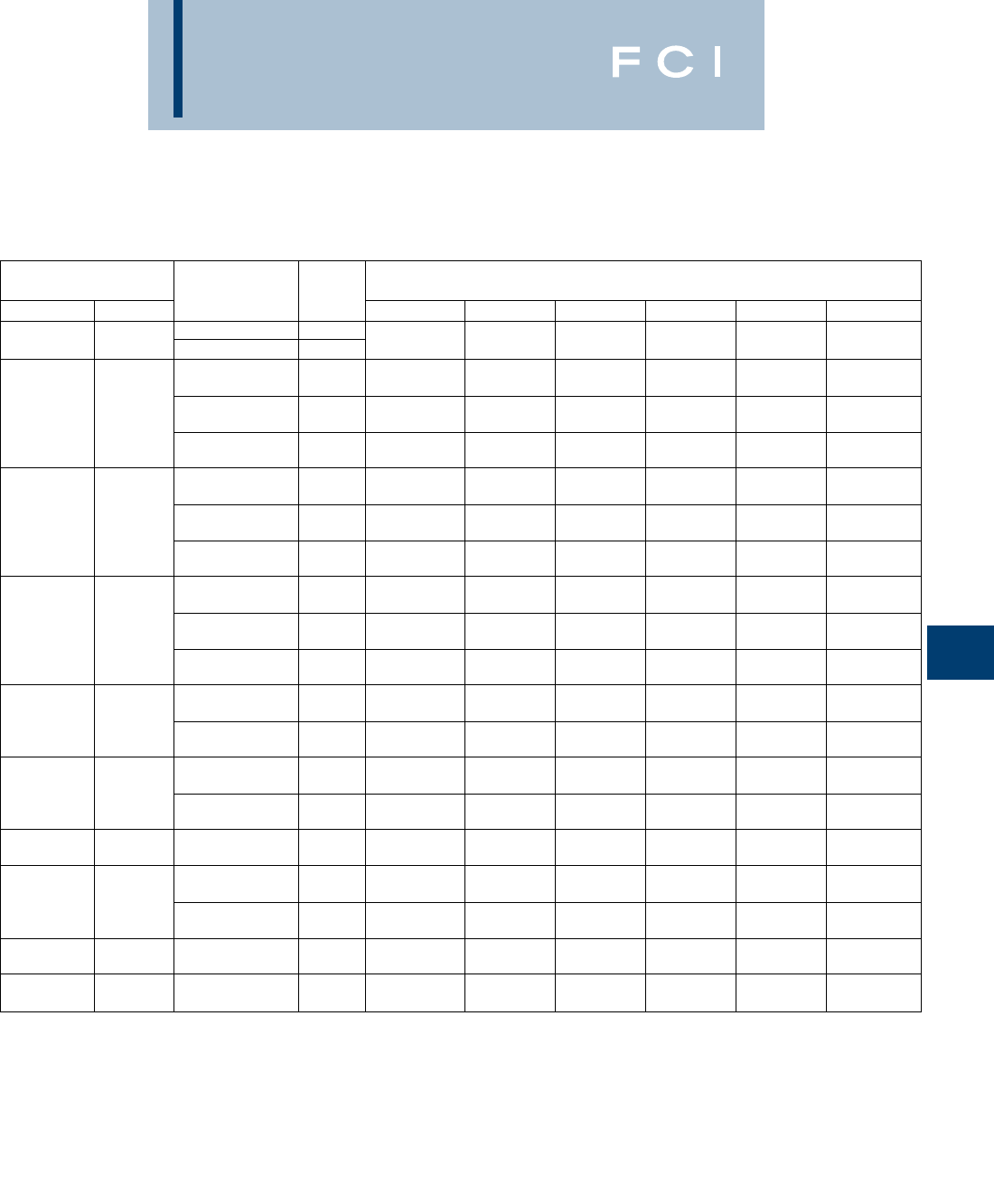
BURNDY
Substation
G-31
TYPE NBC-A
(Continued)
NOTES:
1. Materials:
Connector: Cast Aluminum Alloy
Hardware: Aluminum Alloy
2. Scratch brush connector contact, surface dry then apply an
oxide inhibitor, “PENETROX™ A”. “PENETROX™ A” can be
purchased from BURNDY®Corporation in can or plastic
squeeze bottles.
3. Recommended Tightening Torque:
1/2-13 300 Inch Pounds
5/8-11 480 Inch Pounds
4. All dimensions in brackets [ ] are in millimeters.
CONDUCTOR
ALUMINUM CATALOG FIG. DIMENSIONS IN [mm]
IPS/EHPS A NUMBER NO. B H J L T Y
1.32 NBC15A-2N 13.50 3.00 6.81 .38 5.28
1” [33] NBC15A-34N 2[89] [76] 1/2 - 13 [173] [10] [134]
3.75 3.25 7.15 .38 5.45
NBC16A-2N 1[95] [76] 1/2 - 13 [182] [10] [138]
1.66 3.75 3.25 7.15 .38 5.45
1-1/4” [42] NBC16A-34N 2[95] [76] 1/2 - 13 [182] [10] [138]
3.75 3.25 8.15 .38 6.45
NBC16A-44N 3[95] [76] 1/2 - 13 [207] [10] [164]
4.00 3.50 7.39 .38 5.57
NBC17A-2N 1[102] [89] 1/2 - 13 [188] [10] [141]
1.90 4.00 3.50 7.39 .38 5.57
1-1/2” [48] NBC17A-34N 2[102] [89] 1/2 - 13 [188] [10] [141]
4.00 3.50 8.39 .38 6.57
NBC17A-44N 3[102] [89] 1/2 - 13 [213] [10] [167]
4.25 4.00 8.25 .38 6.00
NBC18A-2N 1[108] [76] 5/8 - 11 [210] [10] [152]
2.38 4.25 4.00 8.25 .38 6.00
2” [42] NBC18A-34N 2[108] [76] 5/8 - 11 [210] [10] [152]
4.25 4.00 9.25 .38 7.00
NBC18A-44N 3[108] [76] 5/8 - 11 [135] [10] [178]
4.50 4.50 8.75 .50 6.25
2.88 NBC19A-34N 2[114] [114] 5/8 - 11 [222] [13] [159]
2-1/2” [73] 4.50 4.50 9.75 .50 7.25
NBC19A-44N 3[114] [114] 5/8 - 11 [248] [13] [184]
5.00 4.50 9.37 .50 6.56
3.00 NBC20A-34N 2[127] [114] 5/8 - 11 [238] [13] [167]
3” [76] 5.00 4.50 10.37 .50 7.56
NBC20A-44N 3[127] [114] 5/8 - 11 [263] [13] [192]
4.50 5.50 5.00 10.89 .62 7.82
3-1/2” [33] NBC21A-44N 3[140] [127] 5/8 - 11 [277] [16] [199]
6.00 5.50 10.37 .62 7.06
4.50 NBC22A-34N 2[152] [140] 5/8 - 11 [263] [16] [179]
4” [114] 6.00 5.50 11.37 .62 8.06
NBC22A-44N 3[152] [140] 5/8 - 11 [289] [16] [205]
5.56 7.00 6.00 12.45 .62 8.60
5” [141] NBC24A-34N 2[178] [152] 5/8 - 11 [316] [16] [218]
6.62 8.00 7.25 13.51 .75 9.13
6” [168] NBC86A-44N 3[203] [184] 5/8 - 11 [343] [19] [232]
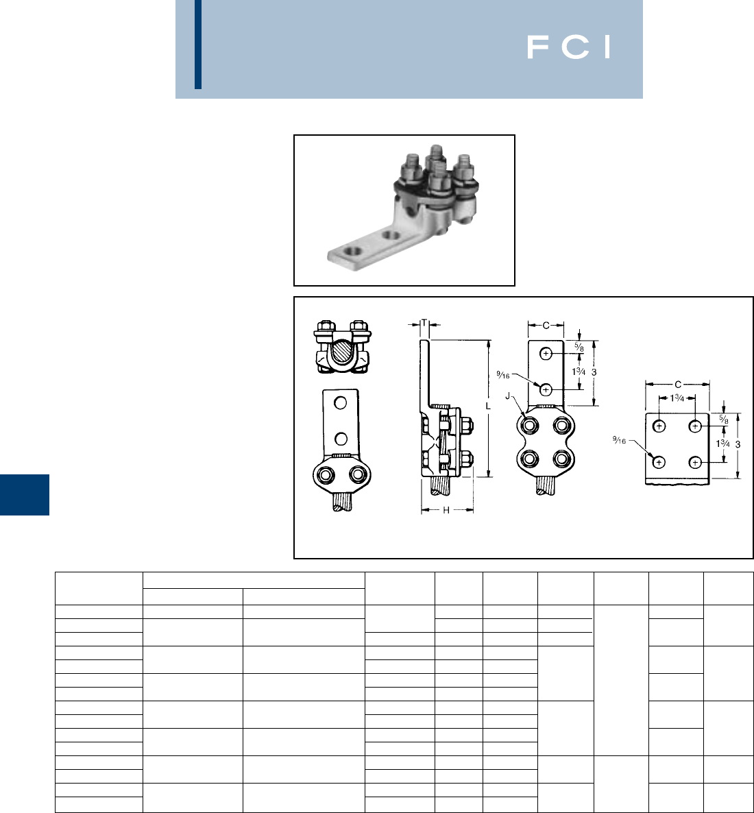
BURNDY
Substation
G-32
TYPE NAR-A
TERMINAL
FOR ALUMINUM AND COPPER
CABLE TO FLAT
Aluminum alloy terminal for joining a wide
range of copper or aluminum cable to copper
or aluminum pad. Properly proportioned to
minimize conductor corrosion due to galvanic
action. Drilling in pad conforms to NEMA
standards. One-wrench installation. PENE-
TROX™ A joint compound recommended on
contact surfaces.
*Available with 90 degree pad as shown
(example: NAR36A-4N90).
** Available with 45 degree pad as shown
(example: NAR42A-2N45).
Fig. 1 Fig. 2 Fig. 2A
Catalog Conductor No. of holes Fig.
Number Alum. or Copper ACSR in pad No. C H J L T
NAR25A-2N 4 Str. - 1/0 Str. 4 (6-1) - 1/0 (6-1) 1 1-1/4 2-3/8 5-1/4
NAR29A-2N* 2 NEMA 21-5/8 2-7/8 5/16
NAR29A-4N* 1/0 Str. - 250 1.0 (6-1) - 4/0 (6-1) 4 NEMA 2A 3 2-3/4 6-1/8
NAR32A-2N 2 NEMA 2 1-5/8
NAR32A-4N 250 - 400 4/0 (6-1) - 397.5 (18-1) 4 NEMA 2A 3 6-3/8
NAR36A-2N 2 NEMA 2 1-3/4 2-7/8 1/2 3/8
NAR36A-4N* 350 - 600 336.4 (18-1) - 477 (30-7) 4 NEMA 2A 3 6-5/8
NAR42A-2N** 2 NEMA 2 2
NAR42A-4N* 600 - 900 477 (30-7) - 795 (54-7) 4 NEMA 2A 3 6-7/8
NAR45A-2N 2 NEMA 2 2-5/8 3-3/8 1/2
NAR45A-4N 900 - 1250 715 (30-19) - 1113 (54-19) 4 NEMA 2A 3 7-1/8
NAR46A-2N 2 NEMA 2 2-3/4
NAR46A-4N* 1250 - 1600 1113 (54-19) - 1431 (54-7) 4 NEMA 2A 3 3-3/4 7-3/4 5/8
NAR48A-2N 2 NEMA 2 2-3/4 5/8
NAR48A-4N 1500 - 2000 1272 (54-19) - 1780 (84-19) 4 NEMA 2A 3 47-7/8 3/4
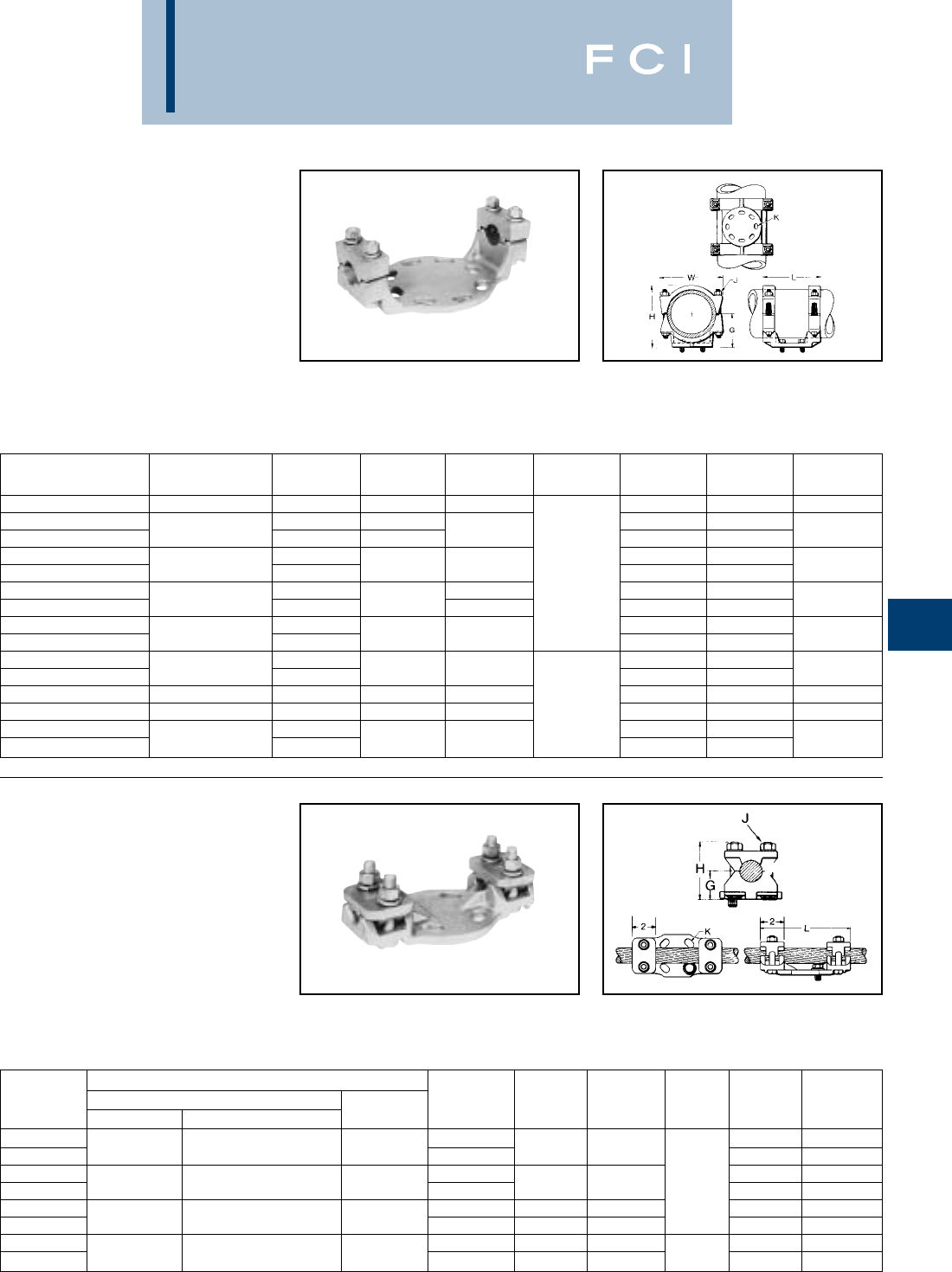
BURNDY
Substation
G-33
TYPE UHG-A
BUS SUPPORT
FOR ALUMINUM AND
COPPER TUBE
Aluminum alloy bus support for mounting
tube on post or pedestal insulators. Properly
proportioned to minimize conductor corrosion
due to galvanic action. Rotate caps 180° for
slip or rigid fit. One-wrench installation.
Supplied with hardware for mounting to
cap of insulator. Specify base mounting
TYPE UHKR-A
BUS SUPPORT
FOR ALUMINUM
CABLE OR TUBE
Aluminum alloy bus support for mounting a
wide range of cable or tube on post or
pedestal type insulators. Supplied with hard-
ware for mounting to cap of insulator. Specify
base mounting hardware, if required, by
adding suffix “-B” to Catalog Number.
*With maximum conductor in place.
CATALOG BOLT
NUMBER CONDUCTOR CIRCLE G H J K L W
UHG14A-3 3/4 3 2 3-1/2 9/16 7-1/2 3
UHG15A-3 32 9/16 7-1/2
UHG15A-5 152-1/4 3-5/8 11/16 9-7/8 3-1/8
UHG17A-3 39/16 7-3/4
UHG17A-5 1-1/2 52-1/2 4-1/8 1/2 11/16 10-1/8 3-3/4
UHG18A-3 35-1/4 9/16 7-3/4
UHG18A-5 252-3/4 4-5/8 11/16 10-1/8 4-1/8
UHG19A-3 39/16 7-3/4
UHG19A-5 2-1/2 53-1/8 5-1/4 11/16 10-5/8 4-5/8
UHG20A-3 39/16 8-1/4
UHG20A-5 353-5/8 6-1/8 11/16 10-5/8 5-5/8
UHG21A-3 3-1/2 3 4 6-3/4 9/16 8-1/4 6-1/4
UHG22A-5 454-1/2 7-1/2 5/8 11/16 10-5/8 6-5/8
UHG24A-3 39/16 8-3/4
UHG24A-5 555-1/4 8-7/8 11/16 11-5/8 7-3/4
hardware, if required, by adding suffix “-B”
to Catalog Number. For static clips add “-CH”
to Catalog Number.
CONDUCTOR
CATALOG CABLE TUBE BOLT
NUMBER ALUMINUM ACSR SCH. 40/80 CIRCLE G * H J K L
UHKR11A-3 39/16 7-5/8
UHKR11A-5 4 Sol. - 4/0 Str. 6 (6-1) - 4/0 (6-1) 1/4 51-1/8 2-5/8 11/16 9-1/2
UHKR13A-3 39/16 7-5/8
UHKR13A-5 250 - 550 266.8 (6-7) - 477 (30-7) 3/8 - 1/2 51-3/8 2-7/8 1/2 11/16 8-7/8
UHKR14A-3 31-3/4 3-5/8 9/16 7-5/8
UHKR14A-5 600 - 1113 556.5 (26-7) - 1033.5 (54-7) 3/4 51-1/2 3-3/8 11/16 9-1/8
UHKR16A-3 31-31/32 4-1/16 9/16 7-9/16
UHKR16A-5 1000 - 2000 1113 (54-19) - 1780 (84-19) 1 - 1-1/4 51-13/16 3-7/8 1/2 11/16 9-1/4
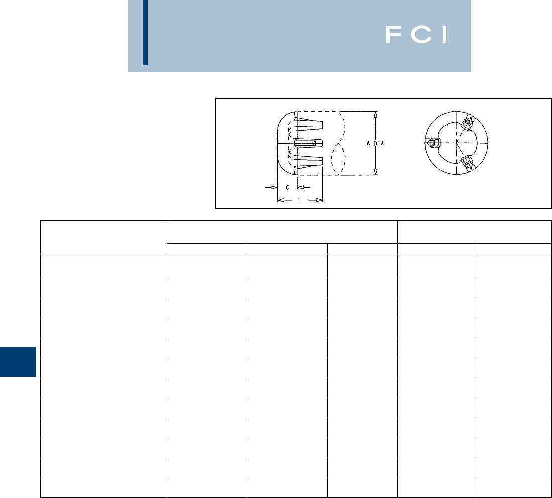
BURNDY
Substation
G-34
TYPE LB-A
END CAP
Aluminum alloy end cap for aluminum tube.
Driven into place for a secure fit. Seals out
moisture, reduces electrostatic loss and elim-
inates hazards created by nesting birds.
NOTES:
1. Material: Cast Aluminum Alloy.
2. Dimensions in brackets [ ] are in millimeters.
CONDUCTOR
ALUMINUM DIMENSIONS IN/[mm] CATALOG NUMBER
PIPE SIZE A C L SCHD. 40 SCHD. 80
.84 .38 1.25
1/2
[21] [9.7] [32] LB13A LB53A
1.05 .50 1.37
3/4
[27] [13] [35] LB14A LB54A
1.32 .50 1.43
1
[34] [13] [36] LB15A LB55A
1.66 .50 1.43
1-1/4
[42] [13] [36] LB16A LB56A
1.90 .50 1.45
1-1/2
[48] [13] [37] LB17A LB57A
2.38 .88 1.85
2
[60] [22] [47] LB18A LB58A
2.88 .88 2.01
2-1/2
[73] [22] [51] LB19A LB59A
3.50 .88 2.10
3
[89] [22] [53] LB20A LB90A
4.00 .88 2.15
3-1/2
[102] [22] [55] LB21A LB91A
4.50 .88 2.22
4
[114] [22] [56] LB22A LB92A
5.56 .88 2.34
5
[141] [22] [59] LB24A LB94A
6.63 .88 2.46
6
[168] [22] [62] LB86A LB96A
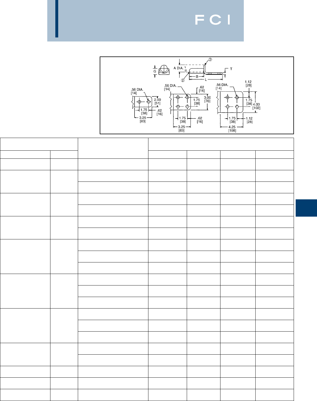
BURNDY
Substation
G-35
TYPE WAS-A
TERMINAL CONNECTOR
Aluminum alloy weld type terminal for joining
aluminum tube to copper or aluminum pads.
Drilling in pad conforms to NEMA standards.
PENETROX™ joint compound recommend-
ed on pad contact surfaces.
NOTES:
1Material: Cast Aluminum Alloy.
➁WELDING TO BE DONE BY THE CUSTOMER.
For welding recommendation see drawing SD73608
3After welding, scratch brush connector contact
surface dry then apply an oxide inhibitor
“PENETROX™ A”.
“PENETROX™ A” can be purchased from BURNDY®
Corporation in cans or plastic squeeze bottles.
CONDUCTOR
ALUMINUM CATALOG DIMENSIONS IN/[mm]
SCH. 40/SCH. 80 A NUMBER B G L T
1.05 2.50 1.50 6.50 .38
3/4
[27] WAS14A-2N [64] [38] [165] [9.7]
2.75 1.19 6.75 .38
1.32 WAS15A-2N [70] [30] [171] [9.7]
1
[34] 2.75 1.19 6.75 .38
WAS15A-34N [70] [30] [171] [9.7]
3.00 1.38 7.00 .38
1.66 WAS16A-2N [76] [35] [178] [9.7]
1-1/4
[42] 3.00 1.38 7.00 .38
WAS16A-34N [76] [35] [178] [9.7]
3.25 1.50 7.25 .44
1.90 WAS17A-2N [83] [38] [184] [11]
1-1/2
[48] 3.25 1.50 7.25 .38
WAS17A-34N [83] [38] [184] [9.7]
3.50 1.75 7.50 .44
WAS18A-2N [89] [44] [19] [11]
2.38 3.50 1.75 7.50 .38
2
[60] WAS18A-34N [89] [44] [19] [10]
3.63 1.75 8.62 .50
WAS18A-44N [92] [44] [219] [13]
3.63 2.00 7.87 .56
WAS19A-2N [92] [51] [200] [14]
2.88 3.63 2.00 7.87 .56
2-1/2
[73] WAS19A-34N [92] [51] [200] [14]
3.63 2.00 8.87 .50
WAS19A-44N [92] [51] [225] [13]
3.67 2.38 8.25 .69
WAS20A-2N [93] [60] [21] [18]
3.50 3.75 2.38 8.25 .62
3
[89] WAS20A-34N [95] [60] [21] [16]
3.75 2.38 9.25 .62
WAS20A-44N [95] [60] [235] [16]
4.25 2.62 8.50 .62
4.00 WSA21A-34N [108] [67] [216] [16]
3-1/2
[102] 4.25 2.62 9.50 .62
WAS21A-44N [108] [67] [241] [16]
4.50 4.25 2.88 9.50 .75
4
[114] WAS22A-44N [108] [73] [241] [19]
5.56 4.25 3.62 9.50 .75
5
[141] WAS24A-44N [108] [92] [241] [19]
6.63 4.25 4.00 9.75 1.00
6
[168] WAS86A-44N [108] [102] [248] [25]
4Dimensions in brackets [ ] are in millimeters.
5Tongue finished on ONE SIDE ONLY (bottom).
For tongue finished on both sides, add suffix letter "Q"
to Catalog Number (e.g., WAS22A-44NQ).
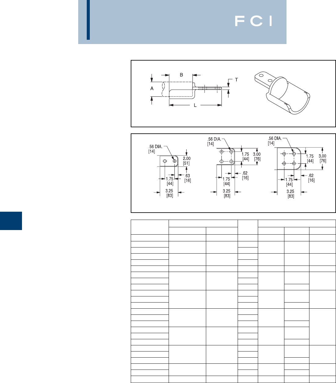
BURNDY
Substation
G-36
TYPE WASC-A-N
CENTERFORMED
WELDMENT TERMINAL
Aluminum alloy weldment terminal. Type
WASC-A-N has one contact surface on the
center line of the tube. Holes are NEMA
spaced for terminating aluminum or copper
mating pads. PENETROX™ joint compound
recommended for use on contact surfaces.
For tongue finished on both sides add suffix letter "Q" to
Catalog Number (e.g., WASC14A2NQ).
Fig. 1 Fig. 2 Fig. 3
CATALOG ALUMINUM CONDUCTOR FIG. DIMENSIONS IN/[mm]
NUMBER SCH. 40/80 A [mm] NO. B L T
WASC14A2N 3/41.05 [27] 1 2.50 [64] 6.44 [164] .22 [6]
WASC15A2N 1
WASC15A34N 11.32 [33] 22.75 [70] 6.69 [170] .38 [10]
WASC16A2N 1
WASC16A34N 1-1/41.66 [42] 23.00 [76] 7.00 [178] .38 [10]
WASC17A34N 1-1/21.90 [48] 2 3.25 [83] 7.31 [186] .44 [11]
WASC18A2N 1
WASC18A34N 22.38 [60] 2 3.50 [90] 7.56 [192] .50 [13]
WASC18A44N 38.56 [217]
WASC19A2N 1
WASC19A34N 2-1/22.88 [73] 2 3.75 [95] 7.88 [200] .56 [14]
WASC19A44N 38.88 [226]
WASC20A2N 1
WASC20A34N 33.50 [89] 2 4.00 [102] 8.13 [207]
WASC20A44N 39.13 [232]
WASC21A2N 1.62 [16]
WASC21A34N 3-1/24.00 [102] 2 4.25 [108] 8.38 [213]
WASC21A44N 39.38 [238]
WASC22A2N 1
WASC22A34N 44.50 [114] 2 4.25 [108] 8.38 [213] .75 [19]
WASC22A44N 39.38 [238]
WASC24A34N 28.50 [216]
WASC24A44N 55.56 [141] 34.25 [108] 9.50 [241] .75 [19]
WASC86A44N 66.63 [168] 3 4.25 [108] 9.50 [241] 1.00 [25]
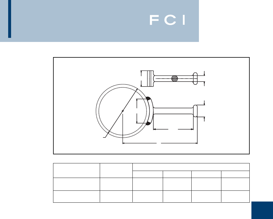
BURNDY
Substation
G-37
"A" DIA.
6.00
[152]
Y
1.50 DIA.
[38]
.75 DIA.
[19]
W
B
TYPE WG-A
WELDMENT GROUND STUD
Range-taking weldment stud for grounding
Aluminum tube.
Dimensions in brackets [ ] are in millimeters
DIMENSIONS IN/[mm]
CATALOG NUMBER ALUM IPS A B W Y
1.315 - 2.88 3.00 1.32 8.19
WG19A 1- 2-1/2
[33] - [73] [76] [34] [208]
3.50 - 6.62 2.00 3.06 10.31
WG86A 3- 6
[89] - [168] [51] [78] [262]
BURNDY
EHV
H-1
TABLE OF CONTENTS
Introduction................................................................H-3
Nomogram..................................................................H-4
Gradient Calibrator....................................................H-5
Formula Gradient.......................................................H-6
Nomogram..................................................................H-7
Interference &
Contamination .......................................................H-8
APPLICATION SELECTOR
TERMINALS
Straight Tubing
SWA-A-N
550 kV.....................................H-9
Straight Cable
SWA-A-N
550 kV...................................H-10
Center Formed Tubing
SWAC-A-N
550 kV...................................H-11
Expansion
SWXA-A-NK
345 kV...................................H-12
Expansion
SWXA-A-N
550 kV...................................H-13
COUPLERS
Light Design
WSLB-A
550 kV...................................H-14
Standard Design
WS-A
550 kV...................................H-15
Expansion
SWXP-A-A
550 kV...................................H-16
TEE CONNECTORS
Tap-off Pad
SWAB-A-N............................H-17
Standard T
SWT-A-A .....................H-18, H-19
75 Degree T
SWT-A-A-75..........................H-20
V Tap
SWAT-A-A-30........................H-21
BUS SUPPORTS
Rigid
SWOH-A
550 kV...................................H-22
Slide
SWSUH-A
550 kV...................................H-23
Rigid/Slip
SWHRH-A
550 kV...................................H-24
Vertical
SWVH-A
550 kV...................................H-25
Expansion
SWXHP-A
550 kV...................................H-26
MISCELLANEOUS
90 Degree Elbow
SWL-A
550 kV...................................H-27
End Plug
WLB-A
550 kV...................................H-28
Corona Bell
SCB-A
500 kV...................................H-28
Ground Stud
SWCB-A
500 kV...................................H-29
BURNDY
EHV
H-2
TABLE OF CONTENTS (Continued)
MISCELLANEOUS
(Continued)
Shielding Cap
(Two Piece)
STS-A-N
550 kV...................................H-30
Shielding Cap
(One Piece)
STS-A-NCG
550 kV...................................H-30
CABLE SPACERS
(Two Conductor)
Single Bolt
Spacer
S2GBP-A
550 kV.....................H-31, H-32
Single Bolt
Tap
S2GBPA-A
550 kV.....................H-31, H-32
Single Bolt
Bus Support
SH2GBP-A
550 kV.....................H-31, H-32
Two Bolt
Spacer
S2GBP-AB2
550 kV.....................H-33, H-34
Two Bolt
Tap
S2GBPA-AB2
550 kV.....................H-33, H-34
Two Bolt
Bus Support
SH2GBP-A-B2
550 kV.....................H-33, H-34
Four Bolt
Spacer
S2GBP-AB4
550 kV.....................H-35, H-36
Four Bolt
Tap
S2GBPA-AB4
550 kV.....................H-35, H-36
Four Bolt
Bus Support
SH2GBP-A-B4
550 kV.....................H-35, H-36
CABLE SPACERS
(Three Conductor)
Spacer
S3GBP-A
550 kV...................................H-37
BIFURCATING
TERMINAL
Terminal
SF2A-NL-EX
550 kV...................................H-38
TRIFURCATING
CONNECTORS
Coupler
SW3A-A44N8
550 kV...................................H-39
T-Tap
SW3AB-A44N8
550 kV...................................H-40
Terminal
SF3A44N8
550 kV...................................H-41

BURNDY
EHV
H-3
Connectors for use in EHV Substations must
meet essentially the same electrical and
mechanical requirements as those for other
power connectors. However, operation at
extra high voltages imposes an important
additional requirement. They must not pro-
duce corona discharges that interfere with
radio reception and cause energy loss.
Corona forms when the voltage gradient at
the surface of a conducting material exceeds
a critical value and ionizes the surrounding
air. For conductors, the four basic factors that
determine surface voltage gradient are dis-
tance from ground, conductor diameter,
phase spacing and voltage.
In A.C. circuits, there are two basic kinds of
corona. Negative corona forms during the
negative half cycle, and positive corona dur-
ing the positive half cycle. Negative corona
generally appears as a glow on conventional
conductors at about 20 kV rms/cm. Its ampli-
tude is relatively low and causes no signifi-
cant radio interference. Positive corona
appears as a plume at above 30 kV rms/cm.
Its amplitude is about 50 times higher than
that for negative corona and is the major
cause of radio interference.
BURNDY®EHV Connectors are designed so
that under fair weather operating conditions,
the voltage gradient at the connector surface
will be at a level that will not cause corona
and the resultant radio interference. (RIV)
BURNDY®DESIGN CRITERIA
Cable Connectors
For reasons of economy, EHV systems using
stranded conductor are generally designed to
operate at voltage gradients close to the neg-
ative corona onset level. It is essential, there-
fore, that connectors provide corona-free
performance superior to that of the cable. So
our design criterion calls for the voltage at
which corona extinguishes from the connec-
tor to be higher than the voltage at which it
extinguishes from the cable. This criterion is
met by eliminating all projections and by pro-
viding smooth contours on all surfaces. On
compression elements, the ends are espe-
cially critical. Carefully designed tapers are
provided to keep the voltage gradient at a
level lower than that on the conductor. Of
course, it is still necessary during installation
to smooth crimped elements.
On accessories, like spacers for bundled
lines, the critical areas are those at the edges
of the bundle. The bundle itself generally
shields those parts that fall within it. Many
projections that would cause corona on a
single conductor line are quiet when they fall
within the shielding influence of a bundle.
However, those parts that fall at the edges are
carefully finished at the factory to insure
corona-free operation.
Tubular Bus Connectors
Station designers choose tubular bus sizes
on the basis of mechanical rather than elec-
trical requirements. For instance, stations that
only need 4" IPS to meet electrical and coro-
na requirements often have 6" IPS as main
buses. The resultant voltage gradient on
these buses is very low, perhaps only 10 kV
rms/cm, well below the corona onset level.
It is impractical, therefore, to require that con-
nectors operate quieter than the bus regard-
less of voltage. Under some circumstances, it
might be impossible to meet such criteria. In
most cases, it would be prohibitively expen-
sive to do so.
Of course, theoretically optimum connectors
could be designed for each application,
based on the design voltage gradient for indi-
vidual stations. However, in most cases even
differences as great as that between 345 and
500 kV don’t have a meaningful impact on
connector costs. So, from a practical point of
view, it is feasible to design most connectors
for 500 kV operation. This makes it more con-
venient for station designers to select and
order connectors.
Bus connectors are designed to provide
corona-free performance under conditions of
actual operation. This is done by calculating
the voltage gradient on the surface of the bus
at 500 kV, using the phase spacing and
ground distance typical for this voltage.
Connectors are then designed to operate
corona free when the voltage gradient on the
bus is 10% above this value.
The exceptions to this rule are the flexible
expansion connectors. Those designed for
345 kV are self-shielding. Those for 500 kV
have separate shielding rings. Experimental
work on self-shielding 500 kV expansion con-
nectors indicates that the margin of safety is
too small to justify recommending them for
this voltage.
CONTROLLING CORONA
Since corona is caused when the voltage gra-
dient at the surface of a conducting material
reaches a level that causes the surrounding
air to break down, then obviously, the way to
prevent corona is to keep the gradient below
this critical level.
From the point of view of the connector
designer, this can be accomplished in
three ways:
1. By providing generous radii on all out-
side surfaces to keep the voltage
stresses to a minimum.
2. By providing shielding rings.
3. By placing the connector within the
shielding influence of some part of the
bus structure.
Since it is impossible for the connector
designer to know the exact configuration of
every bus system where the connectors
might be used, the third approach is not
practical. So, for purposes of developing a
standard line, we concentrate on the first two.
Whenever possible, connectors are designed
to be self-shielding. This approach leads to
less costly and less obstrusive designs. Only
in the case of complicated connector configu-
rations do BURNDY®EHV designs use
corona rings. Examples of such applications
are disconnectable equipment taps, expan-
sion couplers and equipment terminals which
often have configurations that preclude the
use of self-shielding designs.
INTRODUCTION
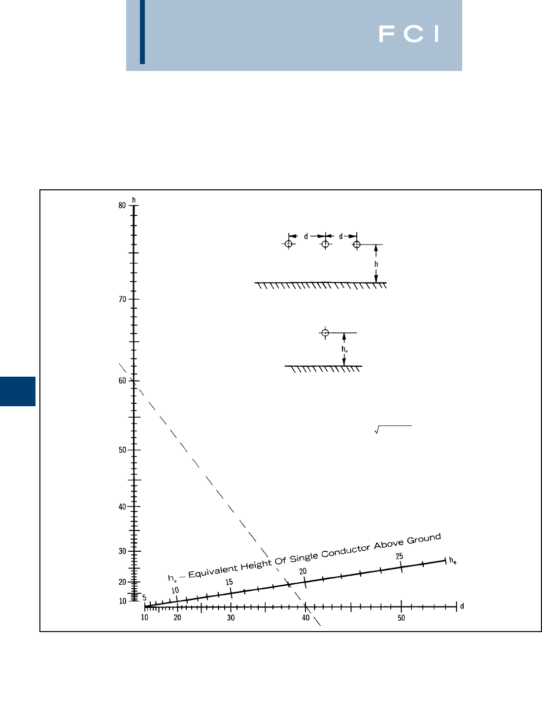
BURNDY
EHV
H-4
NOMOGRAM FOR
DETERMINING THE
EQUIVALENT
HEIGHT (he) OF A
THREE PHASE LINE
Nomogram for determining the equivalent
height of a single conductor line having the
same average voltage of gradient as the
CENTER conductor of a horizontally spaced
d-Phase To Phase Spacing
h-Three Phase Line Height Above Ground
Example:
For a three phase line height, (h), of 60 ft. and a phase spacing, (d),
of 40 ft., the equivalent height, (he), is 19 ft.
hd
he = ——————
(4h2+ d2)
three phase line, with the same line to ground
voltage and the same conductor size. All
dimensions measured in the same units.

BURNDY
EHV
H-5
The use of the laboratory is based on the fact
that it is the surface voltage gradient that
causes corona. Although most systems con-
sist of 3 phase conductors and a ground
plane, it is a rather simple matter to duplicate
in the laboratory the conductor surface volt-
age gradient as it exists on any of these
phase conductors with a single conductor
and a ground plane.
The following formula and nomograms give
this three phase to single phase equivalency.
Because this conversion is possible, all EHV
testing is done single phase; and there is no
necessity for 3 phase testing with its high cost
in terms of equipment and space.
Since voltage gradient is the significant factor,
the single phase test does not have to be
done at the full voltage of an operation
system. By setting up the test closer to the
ground plane, the operation voltage gradient
can be obtained with a lower test voltage.
There is a limit, however, below which the
height cannot be lowered lest corona onset
and flashover occur simultaneously.
Generally, the minimum test height should be
about 10 times the diameter of the test
conductor.
GRADIENT CALIBRATOR
Normally, the conductor surface voltage
gradient at the extinction of corona in the lab-
oratory is calculated using the accompanying
equations. However, for test setups involving
unusual conductor configurations, the con-
ductor gradient cannot be readily calculated.
In these cases, a gradient calibrator may be
used. This is a small sphere mounted on the
conductor. It has previously been calibrated
for each conductor size to establish the
surface voltage gradient that starts positive
corona on the sphere. With it tests can be
duplicated in any number of laboratories. The
applied voltages and ground distances could
all be different.But the voltage gradient on the
surface of the conductor when the corona
occurs on the sphere will always be the same.
The calibrator provides a convenient bench
mark for measuring the corona performance
of connectors.
In use, the sphere is mounted on the conduc-
tor in a connector test setup. The voltage is
raised until there is a corona on the sphere.
We already know from previous calibration
what the voltage gradient on the surface of
the conductor is at this point.
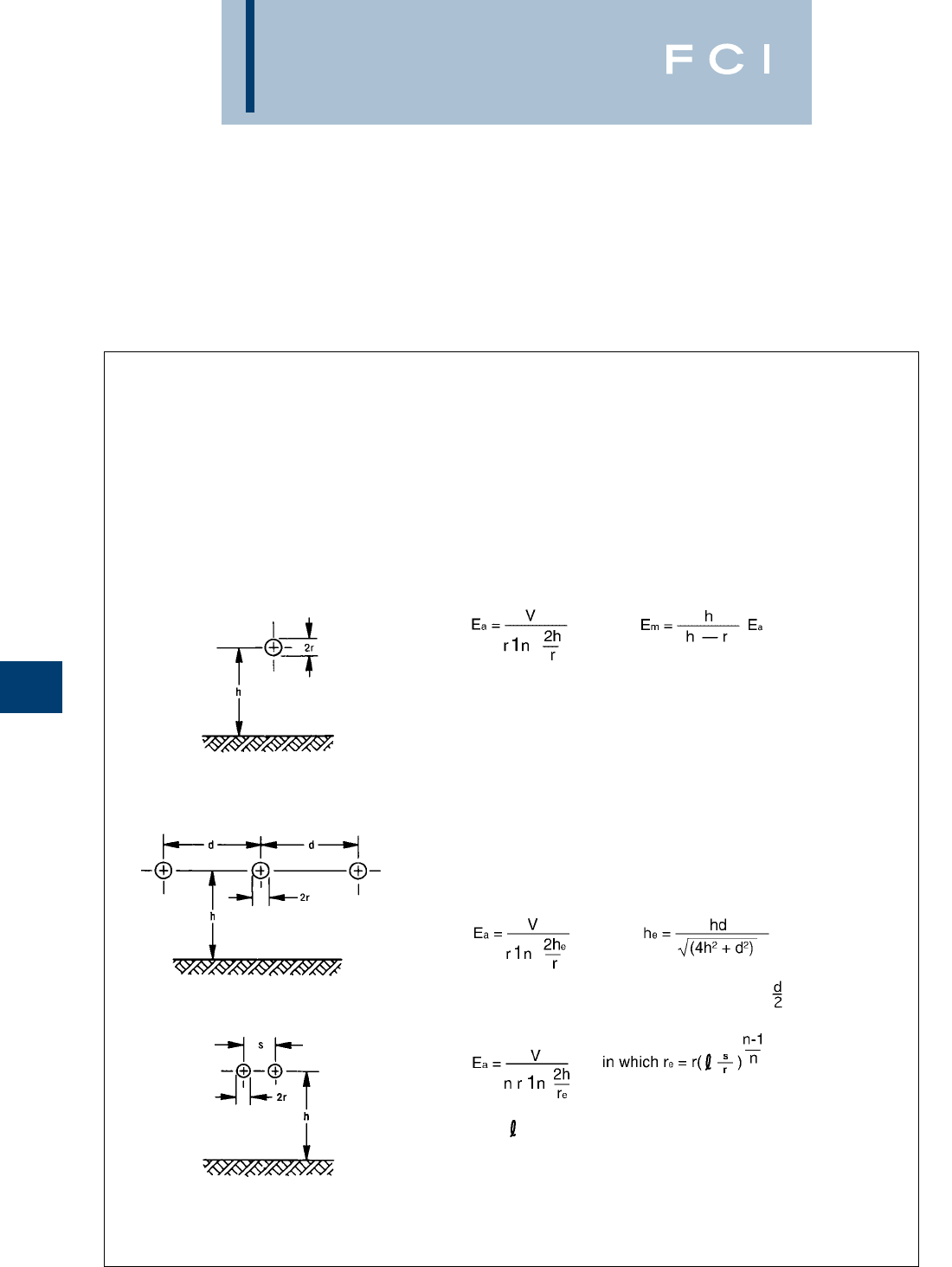
BURNDY
EHV
H-6
The sphere is removed and the voltage raised
until there is a corona on the connector. Since
the voltage gradient increases directly with
increases in applied voltage, the gradient on
the conductor at this point can be readily
calculated.
It is important to note that the significant
parameter is the voltage gradient on the
surface of the conductor. It is not necessary
to know the gradient on the connector. The
conductor gradient in any given substation
is controlled by its design parameters and
may be calculated using the following
formulae and nomograms. Once the
gradient is known, it is unnecessary to have
any other information to design connectors.
As long as connectors are corona-free at a
conductor voltage gradient higher than that
planned for the conductor, the connector will
be corona-free under fair weather operating
conditions.
There may on occasion be unusual situations
where choice of conductor, station geometry
or clearance problems cause the need for
connectors of special design. Where this is
the case, BURNDY®is prepared to design
corona-free devices to operate under such
conditions.
The center conductor has a gradient about 5% higher than the
outside conductors. The gradient on the center phase may be
calculated using the formula for the single conductor.
Single phase system and substituting (he) from the following formula
or attached nomograms for the height above ground (h). For the
center phase:
Bundled Conductor - Single Phase
Bundled Conductor - Three Phase
This case may be reduced to the single bundled conductor case by replacing h with hein the equation. The
definition of heis identical to that given for the single conductor –– three phase situation.
Single Conductor - Three Phase
The maximum gradient (Em) occurs on the side facing the ground
plane.
Single Conductor - Single Phase
Formula for Determining The Voltage Gradient
Notations Used
h = line to ground distance (cm) he= equivalent single phase line to ground distance (cm)
r = radius of the individual conductor (cm) re= equivalent single conductor radius (cm) of bundled
s = conductor spacing in the bundle (cm) conductors
d = phase to phase spacing of the line (cm) n = number of conductors in the bundle
V = line to ground voltage (kV)
Ea= average gradient at the surface of the conductor (kV/cm)
Em= maximum gradient on the surface of a single conductor
It should be noted that heis somewhat smaller than
The value of is unity for 1-, 2-, and 3- conductor bundles and 1.12
for 4- conductor bundles.
Fig. 1
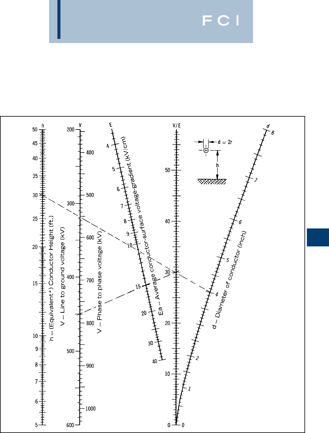
BURNDY
EHV
H-7
NOMOGRAM FOR FINDING
THE AVERAGE
CONDUCTOR-SURFACE
VOLTAGE-GRADIENT
FROM LINE DIMENSIONS
AND VOLTAGE.
Example: For a 30 ft. high single phase
bus* of 4" diameter, V/E = 30. At 450 kV
to ground the average conductor-surface
voltage-gradient is 15 kV RMS/CM.
*For the equivalent single phase height
(he) of a 3 phase bus arrangement see
page 5.
Ea = ————
r 1n —
2h
r
V
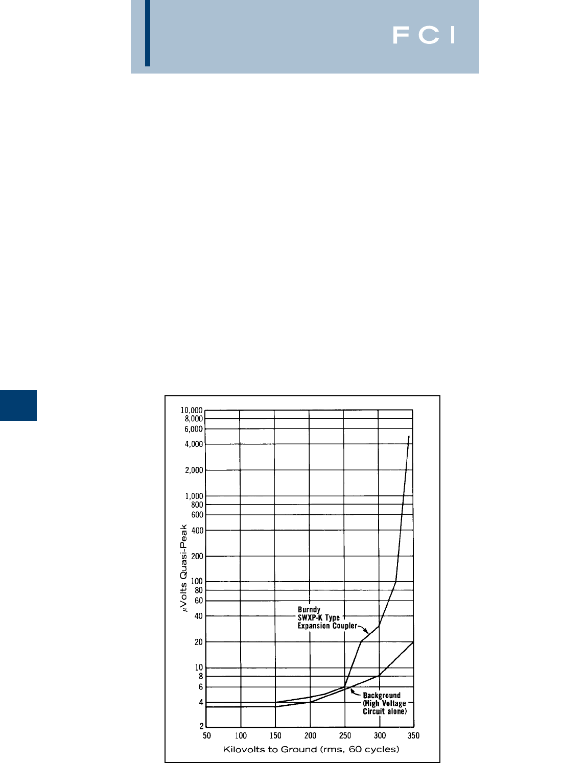
BURNDY
EHV
H-8
RADIO INTERFERENCE
VOLTAGE
There is serious question as to whether mea-
surement of RIV on connectors makes a
meaningful contribution to quieter station
operation.
Under test conditions, there is generally no
significant indication on the radio noise meter
until the onset of visible positive corona. At
this point, the RIV reading goes into the hun-
dreds of thousands of microvolts. The effect
of this phenomenon is to provide a visibly dis-
cernable point at which RIV will become
excessive. It eliminates the necessity to
make, record and plot RIV measurements.
Where there is no corona, there is no RIV. So
our test criterion calling for no visible corona
insures that there will be no radio interference
generated by the connector under operating
conditions.
EFFECT OF CONDUCTOR
SIZE ON TESTING
Conductor diameter has a significant effect
on potential corona problems. The larger the
diameter, the lower the surface voltage gradi-
ent for a given test voltage. This means that
smaller conductors produce corona at lower
voltages than larger ones.
Many connector designs have the same basic
configuration for various conductor sizes. The
only difference being the size of the attaching
elements. This is particularly true for many of
the welded type connectors.Where this is the
case, it is often sufficient to test the connec-
tor only on the smallest conductor, since it
yields the lowest corona extinction voltage.
When there is any doubt, each size is tested.
CONTAMINATION
Much work has been done to establish the
relationship between the corona onset
voltage for contaminated as compared to
clean hardware. Experiments in the
BURNDY®laboratory indicate that this value
can be reduced to half of the voltage for clean
hardware. However, the relationship varies
with the kind of contamination, atmospheric
condition and type of connector.
There have been a number of attempts to
produce artifical contamination and atmos-
pheres in laboratories. However, there is as
yet no clearly established relationship
between the corona performance of hardware
contaminated in the laboratory. Until such a
relationship is established, the only testing
that provides comparable data is on clean
hardware under fair weather conditions.
CONCLUSION
For almost 70 years, BURNDY®has been
designing connectors for the industry’s most
critical applications. Connectors for EHV are
an outgrowth of this tradition. Whether your
need is for catalog items or special designs,
you can count on electrical, mechanical and
corona-free performance, commensurate
with the application.
TYPICAL CURVE
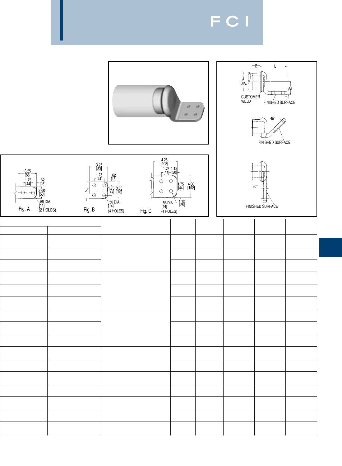
BURNDY
EHV
H-9
NOTES:
1. Dimensions in brackets [ ] are in millimeters.
2.
Conductor smaller than 3 inch bus size not recommended
for 550 kV.
3. DOES NOT INCLUDE SHIELDING CAPS. For EHV
applications, shielding caps are required. Order separately
WELDED TERMINAL
CONNECTOR
SWA-A-N
Weld type
Application:
Bus to Two or Four Hole
Pad (offset terminal)
EHV RATED: UP TO 550 kV
when used with
Shielding Caps
Material: Cast 356 Aluminum Alloy
CATALOG NUMBERS ACCOMMODATES “A”
IPS (SCH40) EHPS (SCH80) DIA. ALUM. TUBE FIG. B G L T
1.25 1.72 5.88 .50
SWA18A-2N SWA58A-2N A[32] [44] [149] [13]
1.25 1.72 5.88 .50
SWA18A-34N SWA58A-34N 2(2.375 DIA.) B [32] [44] [149] [13]
1.25 1.72 6.95 .50
SWA18A-44N SWA58A-44N C[32] [44] [177] [13]
1.50 1.97 6.36 .56
SWA19A-2N SWA59A-2N A[38] [50] [162] [14]
1.50 1.97 6.36 .56
SWA19A-34N SWA59A-34N 2-1/2(2.875 DIA) B [38] [50] [162] [14]
1.50 1.97 7.40 .56
SWA19A-44N SWA59A-44N C[38] [50] [188] [14]
1.75 2.34 6.41 .62
SWA20A-2N SWA90A-2N A[44] [59] [163] [16]
1.75 2.34 6.41 .62
SWA20A-34N SWA90A-34N 3(3.500 DIA.) B [44] [59] [163] [16]
1.75 2.34 7.46 .62
SWA20A-44N SWA90A-44N C[44] [59] [189] [16]
1.75 2.59 6.40 .62
SWA21A-34N SWA91A-34N B[44] [66] [163] [16]
3-1/2(4.000 DIA.) 1.75 2.59 7.47 .62
SWA21A-44N SWA91A-44N C[44] [66] [190] [16]
2.00 2.84 7.51 .75
SWA22A-44N SWA92A-44N 4(4.500 DIA.) C [51] [72] [191] [19]
2.00 3.09 7.77 .75
SWA23A-44N SWA93A-44N 4-1/2(5.000 DIA.) C [51] [78] [197] [19]
2.00 3.38 6.80 .75
SWA24A-34N SWA94A-34N B[51] [86] [173] [19]
5(5.563 DIA.) 2.00 3.38 7.82 .75
SWA24A-44N SWA94-44N C[51] [86] [199] [19]
2.50 4.00 7.90 1.00
SWA86A-44N SWA96A-44N 6(6.625 DIA.) C [64] [102] [201] [25]
(type STS) shown on page 32 or ADD SUFFIX “STS” to
catalog number (example: SWA22A44NSTS), includes one
shielding cap.
4. One surface of pad finished. For finished pad on both sides
add SUFFIX “Q” to the catalog. number (example:
SWA22A-44NQ).
5. For 45 or 90 degree angle add SUFFIX “45” or “90” to
catalog number (example: SWA22A44N90).
6. For six hole NEMA pad contact factory.
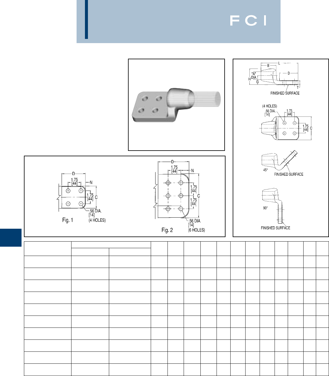
BURNDY
EHV
H-10
WELDED TERMINAL
CONNECTOR
SWA-A-N for Cable
Weld type
Application: Cable to Two or Four
Hole Pad (offset
terminal)
EHV RATED: UP TO 550 kV
when used with
shielding caps
Material: Cast 356 Aluminum Alloy
CATALOG ACCOMMODATES “A” DIA. MAX. MAX. FIG.
NUMBERS ALUM. CABLE ACSR CABLE STR. DIA. DIA. NO. B C D G H L N T
700 kcmil THRU 605 kcmil THRU 26-7 .961 1.085 1.50 4.00 4.25 1.12 2.00 6.25 1.12 .50
SWA44R-44N 874.5 kcmil 874.5 kcmil 30-19 [24] [28] 1[38] [102] [108] [28] [51] [159] [28] [13]
2000 kcmil THRU 1.606 1.740 2.62 4.00 4.25 1.83 3.18 7.50 1.12 .82
SWA48A-44N 2250 kcmil 2167 kcmil 72-7 [41] [44] 1[67] [102] [108] [47] [81] [191] [28] [21]
1400 kcmil THRU 1272 kcmil THRU 1.341 1.470 2.00 4.00 4.25 1.38 2.56 6.56 1.12 .56
SWA54R-44N 1600 kcmil 1510.5 kcmil 45-7 [34] [37] 1[51] [102] [108] [35] [65] [167] [28] [14]
1700 kcmil THRU 1510.5 kcmil THRU 54-49 1.471 1.605 2.50 4.00 4.25 1.58 2.83 7.25 1.12 .69
SWA58R-44N 1900 kcmil 1780 kcmil 54-19 [37] [41] 1[64] [102] [108] [40] [72] [184] [28] [18]
900 kcmil THRU 795 kcmil THRU 1.086 1.210 1.75 4.00 4.25 1.21 2.19 6.56 1.12 .50
SWA444A-44N 1100 kcmil 954 kcmil 54-7 [28] [31] 1[44] [102] [108] [31] [56] [167] [28] [13]
1113 kcmil THRU 1033.5 kcmil THRU 45-7 1.211 1.340 2.00 3.00 3.00 1.22 2.31 5.44 .62 .50
SWA454A-4N 1351.1 kcmil 1192.5 kcmil 54-19 [31] [34] 1[51] [76] [76] [31] [59] [138] [57] [13]
2300 kcmil THRU 2156 kcmil THRU 84-19 1.741 1.875 2.62 3.00 3.00 1.84 3.31 6.12 .62 1.12
SWA486A-4N 2500 kcmil 2300 kcmil 96-19 [44] [48] 1[67] [76] [76] [47] [84] [156] [57] [28]
2300 kcmil THRU 2156 kcmil THRU 84-19 1.741 1.875 2.62 4.00 4.25 1.84 3.31 7.50 1.12 1.12
SWA486A-44N 2500 kcmil 2300 kcmil 96-19 [44] [48] 1[67] [102] [108] [47] [84] [191] [28] [28]
2300 kcmil THRU 2156 kcmil THRU 84-19 1.741 1.875 2.62 6.00 4.25 1.84 3.31 7.50 1.12 1.12
SWA486A-66N 2500 kcmil 2300 kcmil 96-19 [44] [48] 2[67] [152] [108] [47] [84] [191] [28] [28]
127 1.876 2.05 3.00 3.00 3.00 2.12 3.75 6.75 .62 1.00
SWA493R-4N 3000 kcmil —— 169 [48] [52] 1[76] [76] [76] [54] [92] [172] [16] [25]
NOTES:
1. Dimensions in brackets [ ] are in millimeters.
2. DOES NOT INCLUDE SHIELDING CAPS. For EHV
applications, shielding caps are required. Order separately
(type) shown on page 32 or ADD SUFFIX “STS” to catalog
number (example: SWA54R-44NSTS), includes one
shielding cap.
3. One surface of pad finished. For finished pad on both sides
add SUFFIX “Q” to the catalog number (example:
SWA22A-44NQ).
4. For 45 or 90 degree angle add SUFFIX “45” or “90” to
catalog number (example: SWA54R-44N90).
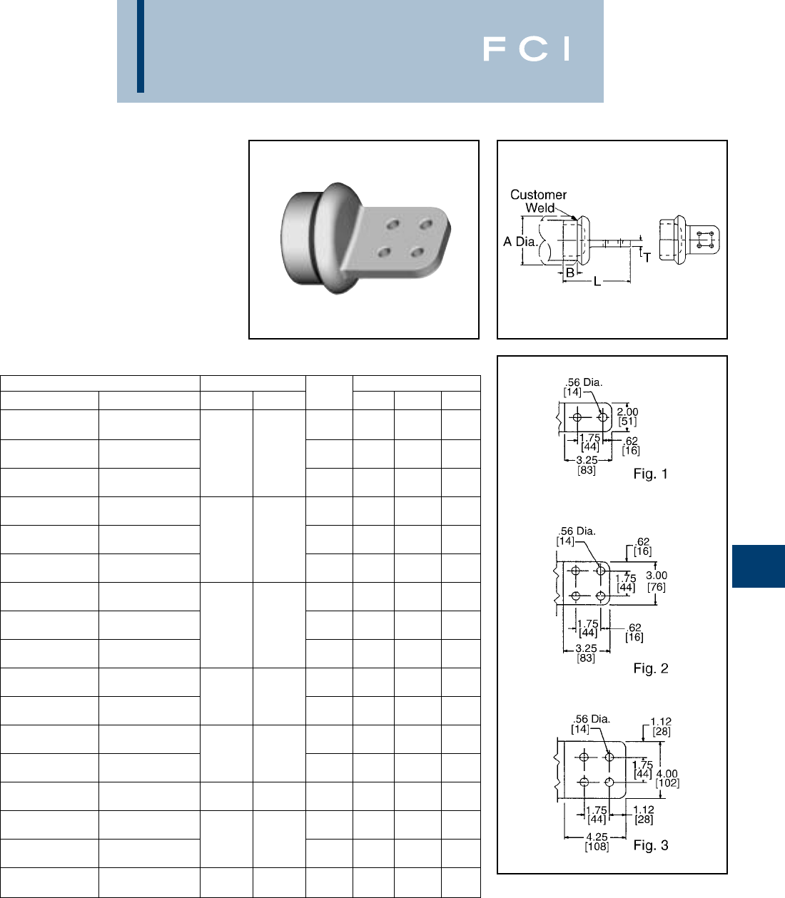
BURNDY
EHV
H-11
WELDED TERMINAL
CONNECTOR
SWAC-A-N
Weld type
Application: Bus to Two or Four
Hole Pad (center
formed)
EHV RATED: UP TO 550 kV
when used with
Shielding Caps
Material: Cast 356 Aluminum Alloy
NOTES:
1. Dimensions in brackets [ ] are in millimeters.
2. Conductor smaller than 3 inch bus size not recommended
for 550 kV.
3. DOES NOT INCLUDE SHIELDING CAPS. For EHV
applications, shielding caps are required. Order separately
(Type STS) shown on page 32 or ADD SUFFIX “STS” to
Catalog Number (example: SWAC22A44NSTS), includes
two shielding caps.
4. Pad surface finished on both sides of tongue.
5. For six hole NEMA pad contact factory.
CATALOG NUMBER CONDUCTOR FIG. DIMENSIONS IN / [mm]
IPS (SCH40) EHPS (SCH80) IPS A NO. B L T
1.25 5.80 .50
SWAC18A-2N SWAC58A-2N 1[32] [147] [13]
2.38 1.25 5.80 .50
SWAC18A-34N SWAC58A-34N 2
[60] 2[32] [147] [13]
1.25 6.86 .50
SWAC18A-44N SWAC58A-44N 3[32] [174] [13]
1.50 6.23 .56
SWAC19A-2N SWAC59A-2N 1[38] [158] [14]
2.88 1.50 6.23 .56
SWAC19A-34N SWAC59A-34N 2-1/2
[73] 2[38] [158] [14]
1.50 7.29 .56
SWAC19A-44N SWAC59A-44N 3[38] [185] [14]
1.75 6.30 .62
SWAC20A-2N SWAC90A-2N 1[44] [160] [16]
3.50 1.75 6.30 .62
SWAC20A-34N SWAC90A-34N 3
[89] 2[44] [160] [16]
1.75 7.36 .62
SWAC20A-44N SWAC90A-44N 3[44] [187] [16]
1.75 6.30 .62
SWAC21A-34N SWAC91A-34N 4.00 2[44] [160] [16]
3-1/2
[102] 1.75 7.36 .62
SWAC21A-44N SWAC91A-44N 3[44] [187] [16]
2.00 6.40 .75
SWAC22A-34N SWAC92A-34N 4.50 2[51] [163] [14]
4
[114] 2.00 7.40 .75
SWAC22A-44N SWAC92A-44N 3[51] [188] [19]
5.00 2.00 6.23 .56
SWAC23A-34N SWAC93A-34N 4-1/2
[127] 2[51] [158] [19]
2.00 6.68 .75
SWAC24A-34N SWAC94A-34N 5.56 2[51] [170] [19]
5
[141] 2.00 7.72 .75
SWAC24A-44N SWAC94A-44N 3[51] [196] [19]
6.62 2.50 7.75 1.00
SWAC86A-44N SWAC96A-44N 6
[168] 3[64] [197] [25]
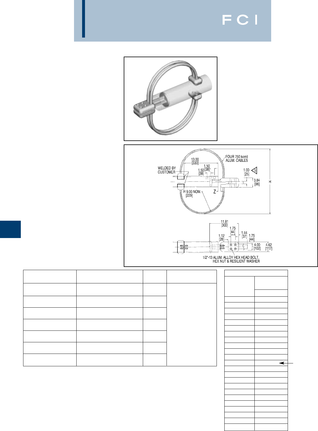
BURNDY
EHV
H-12
WELDED EXPANSION
TERMINAL
CONNECTOR
SWXA-A-NK
Welded type
Application:
Bus to Four Hole
Pad
(Expansion Terminal
with Corona
protection)
EHV RATED: SELF-SHIELDING
UP TO 345 kV
Material: Cast 356 Aluminum Alloy
Straps: Aluminum Cables
Rings: Aluminum Alloy Cable
Hardware:
Ring mounting:
Aluminum
Base mounting:
Galvanized Steel
NOTES:
1. Table is based on 90/ft. max BUS run.
2. Dimensions in brackets [ ] are in millimeters.
3. Shielding caps not required.
4. One side of pad finished. On Centerline of tubing. For finish
pad on both sides add SUFFIX “Q” to catalog number
(example: SWXA22A4NK8Q).
5Accommodates maximum pad thickness of 1.00.
CATALOG ACCOMMODATES HARDWARE
NUMBER “A” DIA. ALUM. TUBE H LENGTH
26.38
SWXA20A-4NK8 3IPS (3.500 DIA.) SCH 40 [670]
27.00
SWXA22A-4NK8 4IPS (5.500 DIA.) SCH 40 [686]
28.06
SWXA24A-4NK8 5IPS (5.563 DIA.) SCH 40 [713]
29.12
SWXA86A-4NK8 6IPS (6.625 DIA.) SCH 40 [740] 1/2–13 2-3/4LG.
27.00
SWXA92A-4NK8 4IPS (4.500 DIA.) SCH 80 [686]
28.06
SWXA94A-4NK8 5IPS (5.563 DIA.) SCH 80 [713]
29.12
SWXA96A-4NK8 6IPS (6.625 DIA.) SCH 80 [740]
INSTALLATION DATA
BUS 3TOTAL
TEMP MOVEMENT
F° Z
–20 3.50
–10 3.36
03.23
10 3.09
20 2.95
30 2.82
40 2.68
50 2.54
60 2.41
70 2.27
80 2.14
90 2.00
100 1.86
110 1.73
120 1.59
130 1.45
140 1.32
150 1.18
160 1.04
170 .91
180 .77
190 .64
200 .50
NOMINAL
POSITION
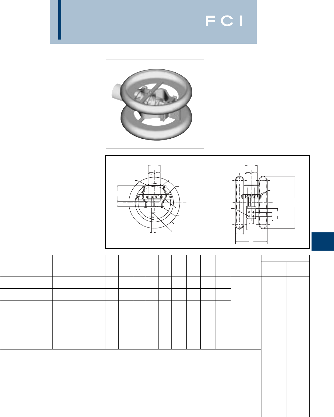
BURNDY
EHV
H-13
CUSTOMER
WELD
M
Z
CAST ALUM. ALLOY
TFINISHED
SURFACE
CORONA RING
ALUM. ALLOY
CAST ALUM. ALLOY
LAMINATED
ALUM. STRAPS
ALUM. MTG.
BRACKET
“K” DIA.
(4 HOLES)
A
DIA.
ALUM.
HARDWARE
D
N
C
F
E
26.00 DIA.
[660]
A
DIA.
W
3.62
[92]
WELDED EXPANSION
TERMINAL
CONNECTOR
SWXA-A-N
Welded type
Application:
Bus to four or six hole
pad (Expansion
Terminal with Corona
Rings)
EHV RATED: SELF-SHIELDING
UP TO 550 kV
Material: Cast 356 Aluminum Alloy
Straps: Laminated Aluminum
Rings: Aluminum Alloy
Hardware:
Ring mounting:
Aluminum
Base mounting:
Galvanized Steel
NOTES:
1. Table is based on 60/ft. max BUS run.
2. Dimensions in brackets [ ] are in millimeters.
3. Shielding caps not required.
4. One side of pad finished. On Centerline of tubing. For finish
pad on both sides add SUFFIX “Q” to catalog number
(example: SWXA22A4NQ).
5. For six hole NEMA pad change the suffix to 66N
(example: SWXA22A66N).
INSTALLATION DATA
CATALOG ACCOMMODATES W TOTAL BUS.
NUMBER “A” DIA. ALUM. TUBE C D E F K M N T REF. MOVEMENT TEMP. OF Z
4.00 4.25 1.75 1.75 .56 7.87 .62 .75 13.18 –20 2.50
SWXA20A-44N 3(3.500 DIA.) SCH 40 [101] [108] [44] [44] [14] [200] [16] [19] [335] –10 2.61
4.00 4.25 1.75 1.75 .56 9.56 .62 .86 13.87 0 2.32
SWXA22A-44N 4(4.500 DIA.) SCH 40 [101] [108] [44] [44] [14] [243] [16] [22] [352] 10 2.21
4.00 4.25 1.75 1.75 .56 10.77 .62 .81 14.50 20 2.14
SWXA24A-44N 5(5.563 DIA.) SCH 40 [101] [108] [44] [44] [14] [274] [16] [21] [368] 2.00 30 2.01
4.00 4.25 1.75 1.75 .56 11.63 1.12 1.00 15.50 [51] 40 1.95
SWXA86A-44N 6(6.625 DIA.) SCH 40 [101] [108] [44] [44] [14] [295] [28] [25] [394] 50 1.86
4.00 4.25 1.75 1.75 .56 9.56 .62 .86 13.87 60 1.77
SWXA92A-44N 4(4.500 DIA.) SCH 80 [101] [108] [44] [44] [14] [243] [16] [22] [352] 70 1.68
4.00 4.25 1.75 1.75 .56 10.77 1.12 .86 14.50 80 1.57
SWXA94A-44N 5(5.563 DIA.) SCH 80 [101] [108] [44] [44] [14] [274] [28] [22] [368] 90 1.50
100 1.41
110 1.32
120 1.23
130 1.14
140 1.04
150 .95
160 .86
170 .77
180 .68
190 .59
200 .50
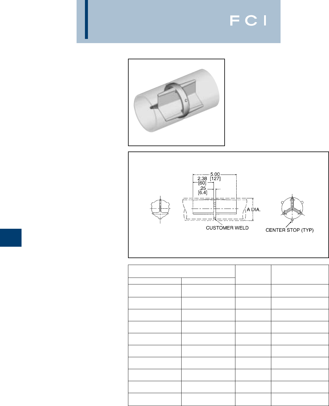
BURNDY
EHV
H-14
CONDUCTOR
CATALOG NUMBER ALUMINUM
SCH. 40 SCH. 80 OD TUBING SIZE
1.32
WSLB15A WSLB55A [34] 1
1.66
WSLB16A WSLB56A [42] 1-1/4
1.90
WSLB17A WSLB57A [48] 1-1/2
2.38
WSLB18A WSLB58A [60] 2
2.88
WSLB19A WSLB59A [73] 2-1/2
3.50
WSLB20A WSLB90A [89] 3
4.00
WSLB21A WSLB91A [102] 3-1/2
4.50
WSLB22A WSLB92A [114] 4
5.56
WSLB24A WSLB94A [141] 5
6.62
WSLB86A WSLB96A [168] 6
WELDED RIGID
COUPLER
WSLB-A
Weld type
Application: Bus to Bus Coupler
EHV RATED: SELF-SHIELDING
UP TO 550 kV
Material: Cast 356 Aluminum Alloy
NOTES:
1. Dimensions in brackets [ ] are in millimeters.
2. Conductors smaller than 3 inch bus size are not
recommended for 550 kV.
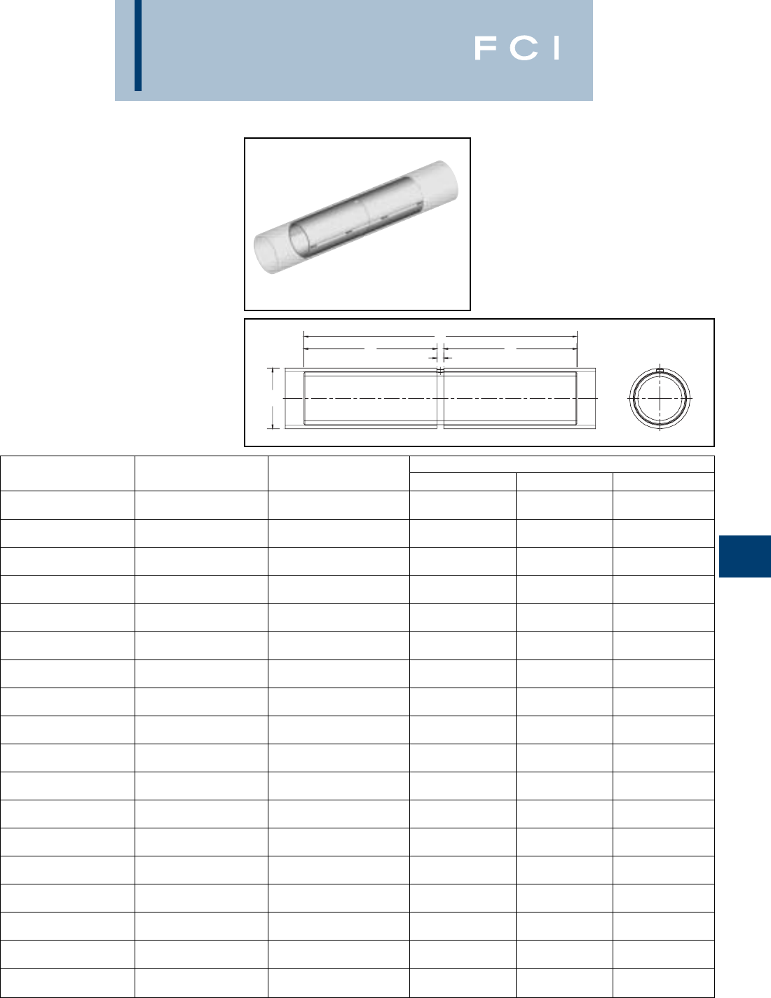
BURNDY
EHV
H-15
WELDED RIGID
COUPLER
WS-A
Weld type
Application: Bus to Bus Coupler
EHV RATED: SELF-SHIELDING
UP TO 550 kV
Material: Cast 356 Aluminum Alloy
A
BL
FB
CONDUCTOR (IPS) “A” CONDUCTOR (EHPS) “A” DIMENSIONS INCHES / [mm]
CATALOG NUMBER SCHEDULE 40 SCHEDULE 80 B F L
2.13 .23 4.50
WS14A 3/4(1.050 DIA.) — [54.1] [5.8] [114.3]
2.13 .23 4.50
WS15A 1(DIA.) — [54.1] [5.8] [114.3]
3.60 .28 7.50
WS16A 1-1/4(1.660 DIA.) — [91.4] [7.1] [190.5]
4.36 .29 9.00
WS17A 1-1/2(1.900 DIA.) — [110.7] [7.4] [228.6]
5.88 .31 12.00
WS18A 2(2.375 DIA.) — [149.4] [7.9] [304.8]
7.31 .39 15.00
WS19A 2-1/2(2.875) — [185.7] [9.9] [381.0]
8.81 .44 18.00
WS20A 3(3.500 DIA.) — [223.8] [11.2] [457.2]
8.75 .47 18.00
WS21A 3-1/2(4.000 DIA.) — [222.3] [11.9] [457.2]
8.75 .47 18.00
WS22A 4(4.500 DIA.) — [222.3] [11.9] [457.2]
8.75 .50 18.00
WS24A 5(5.563 DIA.) — [222.3] [12.7] [457.2]
8.75 .56 18.00
WS86A 6(6.625 DIA.) — [222.3] [14.2] [457.2]
5.88 .31 12.00
WS58A —2(2.375 DIA.) [149.4] [7.9] [304.8]
7.31 .39 15.00
WS59A —2-1/2(2.875) [185.7] [9.9] [381.0]
8.81 .44 18.00
WS90A —3(3.500 DIA.) [223.8] [11.2] [457.2]
8.75 .47 18.00
WS91A —3-1/2(4.000 DIA.) [222.3] [11.9] [457.2]
8.75 .47 18.00
WS92A —4(4.500 DIA.) [222.3] [11.9] [457.2]
8.75 .50 18.00
WS94A —5(5.563 DIA.) [222.3] [12.7] [457.2]
8.75 .56 18.00
WS96A —6(6.625 DIA.) [222.3] [14.2] 457.2]
NOTES:
1. Dimensions in brackets [ ] are in millimeters.
2. Conductor smaller than 3 inch bus size not recommended
for 550 kV.
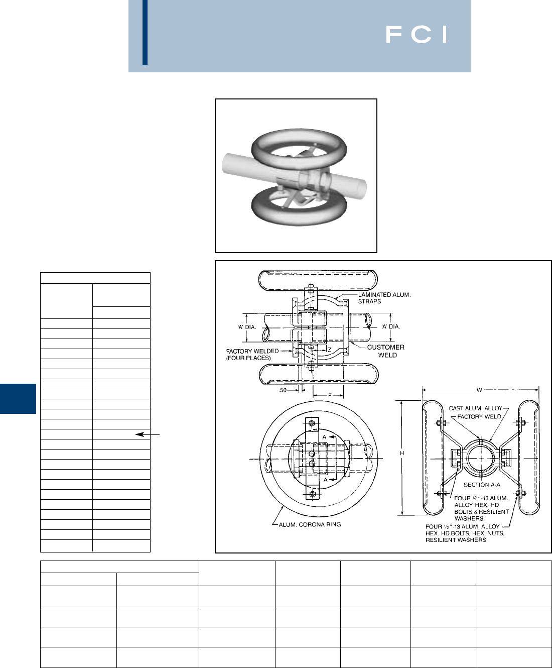
BURNDY
EHV
H-16
NOTES:
➀Maximum movement per end equals one-half of total
movement specified in table. Table is based on 90 ft. bus
run (total) or 45 ft. per end.
2. Dimensions in brackets [ ] are in millimeters.
3. Conductors smaller than 3 inch not recommended for
550 kV.
WELDED EXPANSION
COUPLER
SWXP-A-A
Weld type
Application: Bus to Bus Expansion
EHV RATED: SELF-SHIELDING
UP TO 550 kV
Material: Cast 356 Aluminum Alloy
Hardware: Aluminum Alloy
Corona Rings: Aluminum Alloy
Straps: Laminated Aluminum Strap
CATALOG NUMBER “A” DIA. TOTAL ➀
SCH 40 SCH 80 ALUM. TUBE F H W MOVEMENT
3(3.50 DIA.) 5.25 22.00 17.05 3.00
SWXP20A20A SWXP90A90A [89] [133] [559] [433] [76]
4(4.50 DIA.) 6.38 22.00 18.89 4.00
SWXP22A22A SWXP92A92A [114] [162] [559] [480] [102]
5(5.56 DIA.) 7.88 26.00 19.25 4.00
SWXP24A24A SWXP94A94A [141] [200] [660] [489] [102]
6(6.63 DIA.) 8.88 26.00 20.31 4.00
SWXP86A86A SWXP96A96A [168] [226] [660] [516] [102]
INSTALLATION DATA
BUS 3TOTAL
TEMP MOVEMENT
F° Z
–20 .50
–10 .64
0.77
10 .91
20 1.04
30 1.18
40 1.32
50 1.45
60 1.59
70 1.73
80 1.86
90 2.00
100 2.14
110 2.27
120 2.41
130 2.54
140 2.68
150 2.82
160 2.95
170 3.09
180 3.23
190 3.36
200 3.50
NOMINAL
POSITION

BURNDY
EHV
H-17
NOTES:
1. Dimensions in brackets [ ] are in millimeters.
2. Conductor smaller than 3 inch bus size not recommended
for 550 kV.
3. DOES NOT INCLUDE SHIELDING CAPS. For EHV
applications, shielding caps are required. Order separately
WELDED
T-CONNECTOR
SWAB-A-N
Weld type
Application: Bus to Pad
EHV RATED: UP TO 550 kV
when used with
Shielding Caps
Material: Cast 356 Aluminum Alloy
DIMENSIONS – INCHES / [mm]
CATALOG COMPLETE RANGE FIGURE ALUMINUM IPS PIPE
NUMBER ALUMINUM TUBE NUMBER B T W NOMINAL A Y
1.32 4.45
1
[34] [113]
3.00 .38 1.66 4.67
SWAB19A-2N 11[76] [10] 1-1/4
[42] [119]
1.32 1.90 4.80
To [34] 1-1/2
[48] [122]
2-1/22.38 5.08
4.00 .50 2
[60] [129]
SWAB19A-34N 2[102] [13] 2.88 5.32
2-1/2
[73] [135]
2.88 5.25
3.00 2-1/2
[73] [133]
SWAB22A-2N 2-1/21[76] 3.50 5.62
.75 2.40 3
[89] [143]
To 4.00 [19] [61] 4.00 5.92
SWAB22A-34N 42[102] 3-1/2
[102] [150]
4.50 4.50 6.21
SWAB22A-44N 3[114] 4
[114] [158]
3.50 5.58
3
[89] [142]
4.00 6.08
3.00 3-1/2
[102] [154]
SWAB86A-2N 31[76] 4.50 6.36
1.00 2.62 4
[114] [162]
To [25] [67] 5.00 6.36
64-1/2
[127] [162]
4.00 5.56 6.67
SWAB86A-34N 2[102] 5
[141] [169]
4.50 6.62 7.24
SWAB86A-44N 3[114] 6
[168] [184]
(Type STS) shown on page 32 or ADD SUFFIX “STS” to
Catalog Number (example: SWAB22A44NSTS), includes
two shielding caps.
4. Pad surface finished on both sides of tongue.
5. For six hole NEMA pad contact factory.
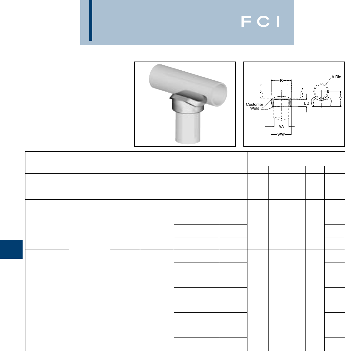
BURNDY
EHV
H-18
NOTES:
1. Dimensions in brackets [ ] are in millimeters.
2. Conductor smaller than 3 inch bus size not recommended
for 550 kV.
WELDED
T-CONNECTOR
SWT-A-A
Weld type
Application: Bus to Bus
T-Connector
EHV RATED: SELF-SHIELDING
UP TO 550 kV
Material: Cast 356 Aluminum Alloy
RUN ‘A’ TAP ‘AA’
CATALOG ALUMINUM ALUMINUM TUBE RUN DATA DIMENSIONS Inches/[mm]
NUMBER TUBE TUBE AA NOM. TUBE A B BB W WW Y
1.90 1.90 3.19 1.00 2.64 2.52 2.16
SWT17A17A 1-1/21/2[48] 1-1/2[48] [81] [25] [67] [64] [55]
2.88 2.88 4.00 1.38 3.78 3.78 3.02
SWT19A19A 2-1/22-1/2[27] 2-1/2[73] [54] [35] [96] [96] [37]
2.38 2.13
2[60.4] [54]
2.88 2.47
1.05 2-1/2[73] 2.12 .75 1.75 1.64 [42]
SWT21A14A 3/4[28] 3.50 [54] [19] [44] [42] 2.84
3[89] [72]
4.00 3.12
3-1/2[102] [51]
2.38 2.12
2[60.4] [54]
288 2.50
21.32 2-1/2[73] 2.38 .75 2.28 1.88 [64]
SWT21A15A To 1[34] 3.50 [60.4] [19] [60] [48] 2.87
3-1/23[89] [73]
4.00 3.16
3-1/2[102] [80]
2.38 2.38
2[60.4] [60]
2.88 2.76
1.66 2-1/2[73] 2.69 1.00 2.36 2.26 [70]
SWT21A16A 1-1/4[42] 3.50 [68] [25] [60] [57] 3.14
3[89] [80]
4.00 3.42
3-1/2[102] [87]
(Table continued on next page)
BURNDY
EHV
H-19
WELDED T-CONNECTOR
(Continued)
SWT-A-A
NOTES:
1. Dimensions in brackets [ ] are in millimeters.
RUN ‘A’ TAP ‘AA’
CATALOG ALUMINUM ALUMINUM TUBE RUN DATA DIMENSIONS Inches/[mm]
NUMBER TUBE TUBE AA NOM. TUBE A B BB W WW Y
2.38 2.35
2[60.4] [60]
22.88 2.75
1.90 2-1/2[73] 3.19 1.00 2.62 2.52 [70]
SWT21A17A To 1-1/2[48] 3.50 [81] [25] [67] [64] 3.14
3-1/23[89] [80]
4.00 3.43
3-1/2[102] [87]
2.38 2.40
2[60.4] [61]
2.88 2.71
22.38 2-1/2[73] 4.00 1.00 3.33 3.00 [69]
SWT21A18A To 2[60.4] 3.50 [102] [25] [84] [76] 3.07
3-1/23[90] [78]
4.00 3.34
3-1/2[102] [85]
2.88 3.02
2-1/2[73] [77]
2-1/22.88 3.50 4.00 1.38 3.78 3.68 3.40
SWT21A19A To 2-1/2[73] 3[90] [102] [35] [96] [93] [86]
3-1/2” 4.00 3.70
3-1/2[102] [94]
3.50 4.56 1.38 4.52 4.34 3.33
23.50 3[102] [116] [35] [115] [110] [87]
SWT21A20A To 3[90] 4.00 4.56 1.38 4.52 4.34 3.70
3-1/23-1/2[102] [116] [35] [115] [110] [55]
2.38 4.00 1.00 3.50 3.00 3.45
SWT22A18A 2[60.4] [102] [13] [102] [76] [87]
2.88 4.00 1.38 4.80 3.70 3.83
SWT22A19A 2-1/2[73] [102] [35] [122] [94] [97]
3.50 4.50 4.56 1.38 4.50 4.38 3.83
SWT22A20A 43[102] 4[114] [116] [35] [114] [64] [97]
4.00 5.50 4.38 5.00 4.88 3.87
SWT22A21A 3-1/2[102] [140] [25] [127] [124] [98]
4.50 6.00 1.38 5.60 5.46 3.89
SWT22A22A 4[114] [152] [35] [142] [139] [99]
3.50 4.72 1.38 4.30 4.40 4.33
SWT24A20A 3[48] [120] [35] [109] [112] [110]
4.00 5.50 1.38 5.00 4.86 4.41
SWT24A21A 3-1/2[102] 5.56 [140] [35] [127] [123] [112]
54.50 5[141] 6.00 1.38 5.60 5.46 4.41
SWT24A22A 4[114] [152] [35] [142] [139] [112]
5.56 7.38 1.62 6.84 6.64 4.66
SWT24A24A 5[141] [187] [41] [174] [169] [118]
3.50 4.56 1.88 5.00 4.40 4.89
SWT86A20A 3[90] [116] [48] [127] [112] [124]
4.00 5.50 1.38 5.50 4.40 4.94
SWT86A21A 3-1/2[102] [140] [35] [140] [112] [125]
4.50 6.62 6.00 1.38 6.66 5.50 4.75
SWT86A22A 64[114] 6[168] [152] [35] [169] [140] [121]
5.56 7.38 1.62 6.84 6.66 5.17
SWT86A24A 5[141] [187] [41] [174] [169] [131]
6.62 8.00 1.62 8.00 7.82 5.00
SWT86A86A 6[168] [203] [41] [203] [199] [127]
2. Conductor smaller than 3 inch bus size not recommended
for 550 kV.
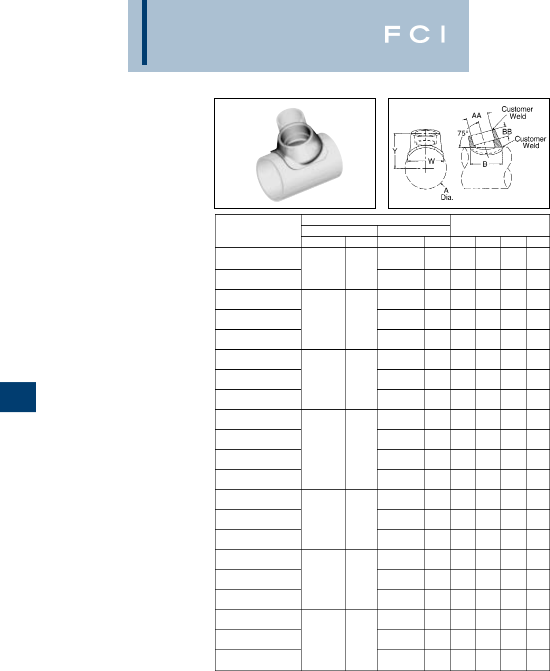
BURNDY
EHV
H-20
WELDED
T-CONNECTOR
SWT-A-A-75
Weld type
Application: Bus “A” Frame
Connector (75°)
EHV RATED: SELF-SHIELDING
UP TO 550 kV
Material: Cast 356 Aluminum Alloy
NOTES:
1. Dimensions in brackets [ ] are in millimeters.
2. Conductor smaller than 3 inch bus size not recommended
for 550 kV.
ALUMINUM TUBE
RUN TAP DIMENSIONS IN / [mm]
CATALOG NUMBER NOMINAL A NOMINAL AA B BB W Y
1.66 2.69 1.00 2.36 2.57
SWT18A16A-75 2.38 1-1/4
[42] [68] [25] [60] [65]
2
[60.4] 1.90 3.19 1.00 2.60 2.60
SWT18A17A-75 1-1/2
[48] [81] [25] [66] [66]
1.66 2.69 1.00 2.72 2.83
SWT19A16A-75 1-1/4
[42] [68] [25] [69] [72]
2.88 1.90 3.19 1.00 2.60 2.87
SWT19A17A-75 2-1/2
[73] 1-1/2
[48] [81] [25] [66] [73]
2.38 4.00 1.00 3.10 2.92
SWT19A18A-75 2
[60] [102] [25] [79] [74]
1.90 3.19 1.00 2.48 3.17
SWT20A17A-75 1-1/2
[48] [81] [25] [63] [81]
3.50 2.38 4.00 1.00 3.10 3.23
SWT20A18A-75 3
[89] 2
[60] [102] [25] [79] [82]
2.88 4.00 1.38 3.80 3.65
SWT20A19A-75 2-1/2
[73] [102] [35] [97] [93]
1.66 2.69 1.00 2.80 3.37
SWT21A16A-75 1-1/4
[42] [68] [25] [71] [86]
1.90 3.19 1.00 3.00 3.41
SWT21A17A-75 4.00 1-1/2
[48] [68] [25] [76] [87]
3-1/2
[102] 2.38 4.00 1.00 3.50 3.47
SWT21A18A-75 2
[42] [68] [25] [89] [88]
2.88 4.00 1.38 3.78 3.89
SWT21A19A-75 2-1/2
[73] [68] [35] [96] [99]
2.38 4.12 1.00 3.75 3.71
SWT22A18A-75 2
[60] [105] [25] [95] [94]
4.50 2.88 4.00 1.38 4.20 4.16
SWT22A19A-75 4
[114] 2-1/2
[73] [102] [35] [107] [106]
3.50 4.56 1.38 4.50 4.24
SWT22A20A-75 3
[89] [116] [35] [114] [108]
2.38 4.00 1.00 3.60 4.26
SWT24A18A-75 2
[60] [102] [25] [91] [108]
5.56 2.88 4.00 1.38 4.90 4.76
SWT24A19A-75 5
[141] 2-1/2
[73] [102] [35] [124] [121]
3.50 4.56 1.38 4.98 4.77
SWT24A20A-75 3
[89] [116] [35] [126] [121.2]
3.50 4.56 1.38 5.08 5.31
SWT86A20A-75 3
[89] [116] [35] [129] [135]
6.62 4.00 5.50 1.38 5.47 5.43
SWT86A21A-75 6
[168] 3-1/2
[102] [140] [35] [139] [138]
4.50 6.00 1.38 6.06 5.47
SWT86A22A-75 4
[114] [152] [35] [154] [139]
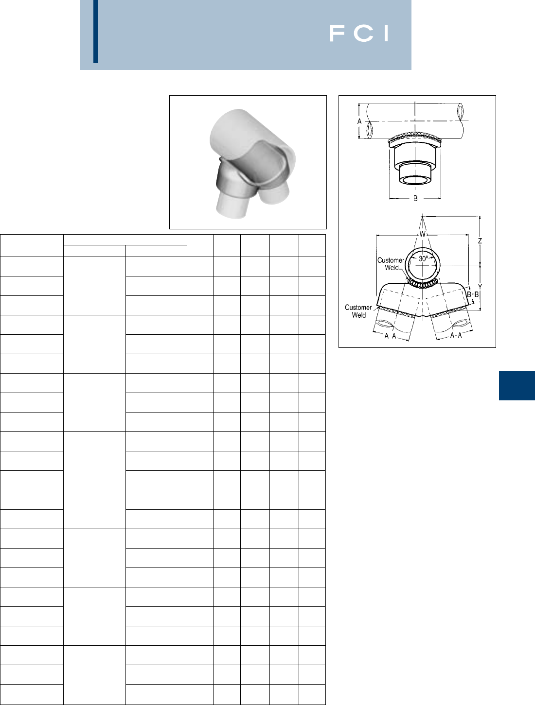
BURNDY
EHV
H-21
WELDED
V-CONNECTOR
SWAT-A-A-30
Weld type
Application: Bus “A” Frame
Connector (30°)
EHV RATED: SELF-SHIELDING
UP TO 550 kV
Material: Cast 356 Aluminum Alloy
CATALOG ALUMINUM I.P.S.
NUMBER RUN “A” TAP “A-A” B B-B W Y Z
3.25 1.00 4.81 3.19 1.76
SWAT18A16A-30 1-1/4(1.660 DIA.) [83] [25] [122] [81] [45]
3.50 1.00 5.25 3.00 2.34
SWAT18A17A-30 2(2.375 DIA.) 1-1/2(1.900 DIA.) [89] [25] [133] [76] [59]
4.00 1.00 6.38 3.12 3.46
SWAT18A18A-30 2(2.375 DIA.) [102] [25] [160] [71] [88]
3.25 1.00 4.82 3.31 1.74
SWAT19A16A-30 1-1/4(2.375 DIA.) [83] [25] [122] [84] [44]
3.50 1.00 5.25 3.28 2.00
SWAT19A17A-30 2-1/2(2.875 DIA.) 1-1/2(1.900 DIA.) [89] [25] [132] [83] [51]
4.00 1.00 6.19 3.19 3.04
SWAT19A18A-30 2(2.375 DIA.) [102] [25] [157] [81] [77]
3.50 1.00 5.12 3.44 1.87
SWAT20A17A-30 1-1/2(1.900 DIA.) [89] [25] [130] [87] [47]
4.00 1.00 6.25 3.50 2.71
SWAT20A18A-30 3(3.500 DIA.) 2(2.375 DIA.) [102] [25] [159] [89] [69]
4.38 1.38 7.19 3.88 3.41
SWAT2019A-30 2-1/2(2.875 DIA.) [111] [35] [183] [99] [87]
3.25 1.00 5.06 3.34 2.07
SWAT21A16A-30 1-1/4(2.375 DIA.) [83] [25] [129] [85] [53]
3.50 1.00 5.25 3.44 1.97
SWAT21A17A-30 1-1/2(1.900 DIA.) [89] [25] [132] [87] [50]
4.00 1.00 6.31 3.16 2.68
SWAT21A18A-30 3-1/2(4.000 DIA.) 2(2.375 DIA.) [102] [25] [160] [80] [68]
4.38 1.38 7.38 4.00 3.09
SWAT21A19A-30 2-1/2(2.0875 DIA.) [111] [35] [187] [102] [78]
5.00 1.38 8.38 4.12 4.21
SWAT21A20A-30 3(3.500 DIA.) [127] [35] [213] [105] [107]
4.00 1.00 6.50 3.81 2.82
SWT22A18A-30 2(2.375 DIA.) [102] [25] [165] [97] [72]
4.38 1.38 7.41 4.09 3.13
SWT22A19A-30 4(4.500 DIA.) 2-1/2(2.875 DIA.) [111] [35] [188] [104] [80]
5.12 1.38 8.62 4.28 4.05
SWAT22A20A-30 3(3.500 DIA.) [130] [1.38] [219] [109] [103]
4.00 1.00 6.50 3.81 3.06
SWAT24A18A-30 2(2.375 DIA.) [102] [25] [165] [97] [78]
4.38 1.38 7.38 4.47 2.87
SWAT24A19A-30 5(5.563 DIA.) 2-1/2(2.875 DIA.) [111] [35] [187] [114] [73]
2.12 1.38 8.62 4.62 3.76
SWAT24A20A-30 3(3.500 DIA.) [130] [35] [219] [117] [96]
5.12 1.38 8.69 4.81 3.57
SWAT86A20A-30 3(3.500 DIA.) [130] [35] [221] [122] [91]
5.88 1.38 9.69 5.19 4.11
SWAT86A21A-30 6(6.625 DIA.) 3-1/2(4.000 DIA.) [149] [35] [246] [132] [104]
6.25 1.38 10.62 5.00 5.15
SWAT86A22A-30 4(4.500 DIA.) [159] [35] [270] [127] [131]
NOTES:
1. Dimensions in brackets [ ] are in millimeters
2. Conductor smaller than 3 inch bus size not recommended
for 550 kV.
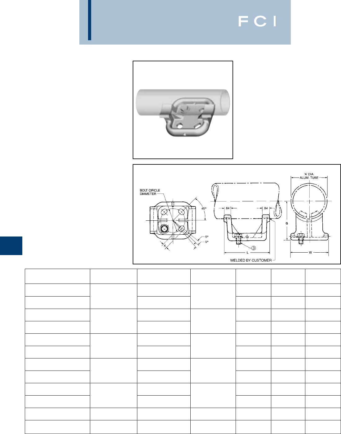
BURNDY
EHV
H-22
WELDED RIGID BUS
SUPPORT
SWOH-A
Weld type
Application: Fixed Bus Support to
Insulator
EHV RATED: SELF-SHIELDING
UP TO 550 kV—
When used on
Corona free Post
Insulators
Material: Cast 356 Aluminum Alloy
“A” DIA. BOLT CIRCLE
CATALOG NUMBER ALUM. TUBE DIA. G K L W
3.00 .56 5.60 4.96
SWOH18A-3 2(2.375 DIA.) [76] 2.75 [14] [142] [126]
[60] 5.00 [70] .69 7.48 6.76
SWOH18A-5 [127] [18] [190] [172]
3.00 .56 6.06 5.19
SWOH19A-3 2-1/2(2.875 DIA.) [76] 3.12 [14] [154] [132]
[73] 5.00 [79] .69 7.62 6.80
SWOH19A-5 [127] [18] [194] [173]
3.00 .56 5.78 4.96
SWOH20A-3 3(3.500 DIA.) [76] 3.00 [14] [147] [126]
[89] 5.00 [76] .69 7.20 6.29
SWOH20A-5 [127] [18] [183] [160]
3.00 .56 5.80 4.96
SWOH21A-3 3-1/2(4.000 DIA.) [76] 4.00 [14] [147] [126]
[102] 5.00 [102] .69 7.58 6.76
SWOH21A-5 [127] [18] [193] [172]
3.00 .56 5.82 4.96
SWOH22A-3 4(4.500 DIA.) [76] 4.50 [14] [148] [126]
[114] 5.00 [114] .69 7.68 6.57
SWOH22A-5 [127] [18] [195] [167]
5(5.563 DIA.) 5.00 5.00 .69 7.68 6.57
SWOH24A-5 [141] [127] [127] [18] [195] [167]
6(6.625 DIA.) 5.00 5.50 .69 7.68 6.57
SWOH86A-5 [168] [127] [140] [18] [195] [167]
NOTES:
1. Dimensions in brackets [ ] are in millimeters.
2. “G” dimension conforms to NEMA standards.
➂Cap mounting (galvanized steel) hardware supplied as
standard. For Base Mounting hardware add SUFFIX “B” to
catalog number (example: SWOH22A-5B).
4. Conductors smaller than 3 inch bus size not
recommended for 550 kV.
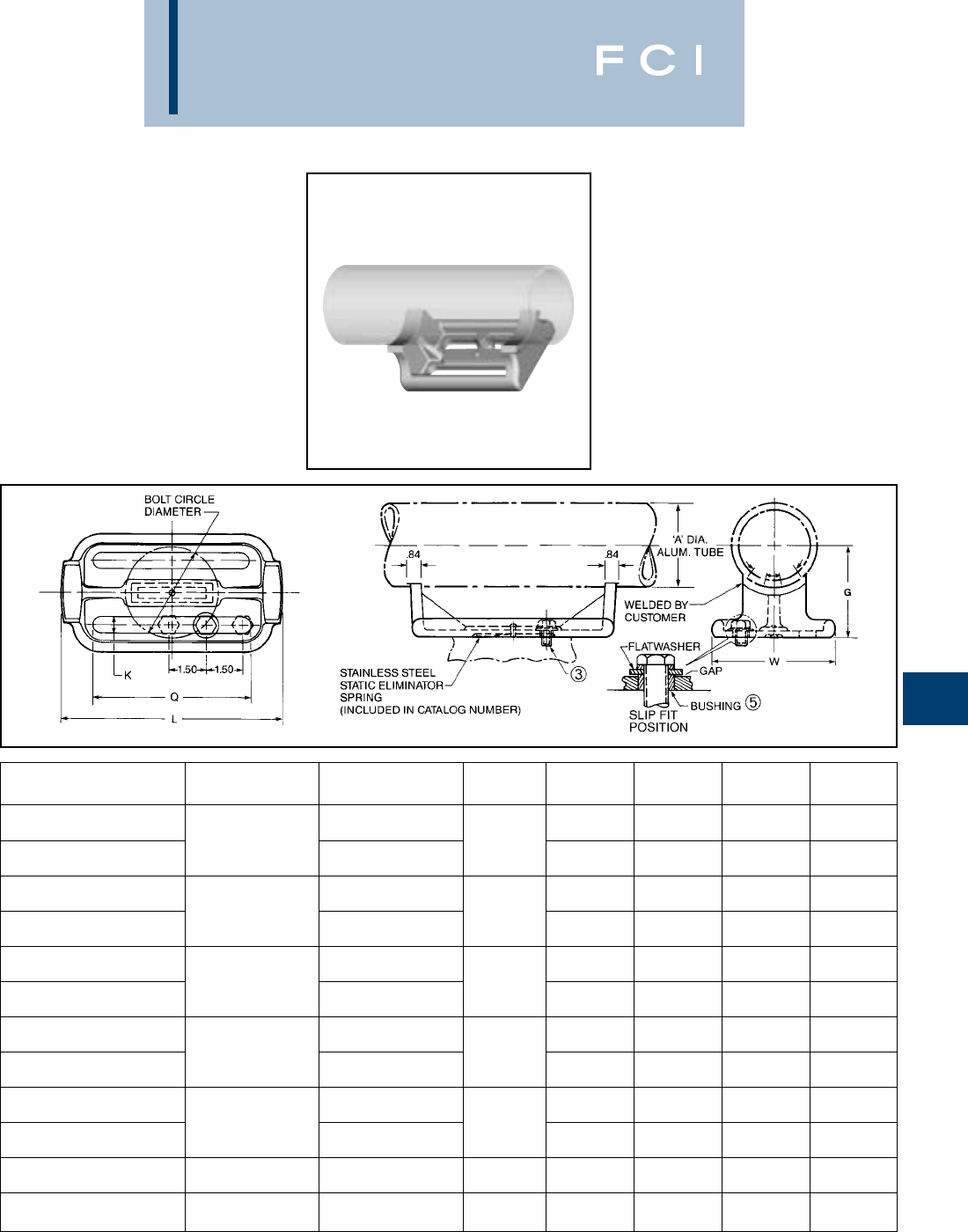
BURNDY
EHV
H-23
WELDED SLIDE
SUPPORT
SWSUH-A
Weld type
Application: Slide or Fixed Bus
Support to Insulator
EHV RATED: SELF-SHIELDING
UP TO 550 kV—
When used on
Corona free Post
Insulators
Material: Cast 356 Aluminum Alloy
“A” DIA. BOLT CIRCLE
CATALOG NUMBER ALUM. TUBE DIA. G K L Q W
3.00 .81 8.75 5.94 5.00
SWSUH18A-3 2(2.375 DIA.) [76] 2.75 [20] [222] [151] [127]
[60] 5.00 [70] .88 10.62 7.11 6.75
SWSUH18A-5 [127] [22] [270] [181] [171]
3.00 .81 8.75 5.94 5.00
SWSUH19A-3 2-1/2(2.875 DIA.) [76] 3.12 [20] [222] [151] [127]
[73] 5.00 [79] .88 10.62 7.42 6.75
SWSUH19A-5 [127] [22] [270] [188] [171]
3.00 .81 8.75 5.94 5.00
SWSUH20A-3 3(3.500 DIA.) [76] 3.62 [20] [222] [151] [127]
[89] 5.00 [92] .88 10.62 7.42 6.75
SWSUH20A-5 [127] [22] [270] [188] [171]
3.00 .81 8.75 5.94 5.00
SWSUH21A-3 3-1/2(4.000 DIA.) [76] 4.00 [20] [222] [151] [127]
[102] 5.00 [102] .88 10.62 7.42 6.75
SWSUH21A-5 [127] [22] [270] [188] [171]
3.00 .81 8.75 5.94 5.00
SWSUH22A-3 4(4.500 DIA.) [76] 4.50 [20] [222] [151] [127]
[114] 5.00 [114] .88 10.62 7.42 6.75
SWSUH22A-5 [127] [22] [270] [188] [171]
5(5.563 DIA.) 5.00 5.00 .88 10.62 7.42 6.75
SWSUH24A-5 [141] [127] [127] [22] [270] [188] [171]
6(6.625 DIA.) 5.00 5.50 .88 10.62 7.42 6.75
SWSUH86A-5 [168] [127] [140] [22] [270] [188] [171]
NOTES:
1. Dimensions in brackets [ ] are in millimeters.
2. “G” dimension conforms to NEMA standards.
➂Cap mounting (galvanized steel) hardware supplied as
standard. For Base Mounting hardware add SUFFIX “B” to
catalog number (example: SWSUH22A-5B).
4. Conductors smaller than 3 inch bus size not
recommended for 550 kV.
➄Four aluminum alloy bushings are supplied for slip fit
installations.
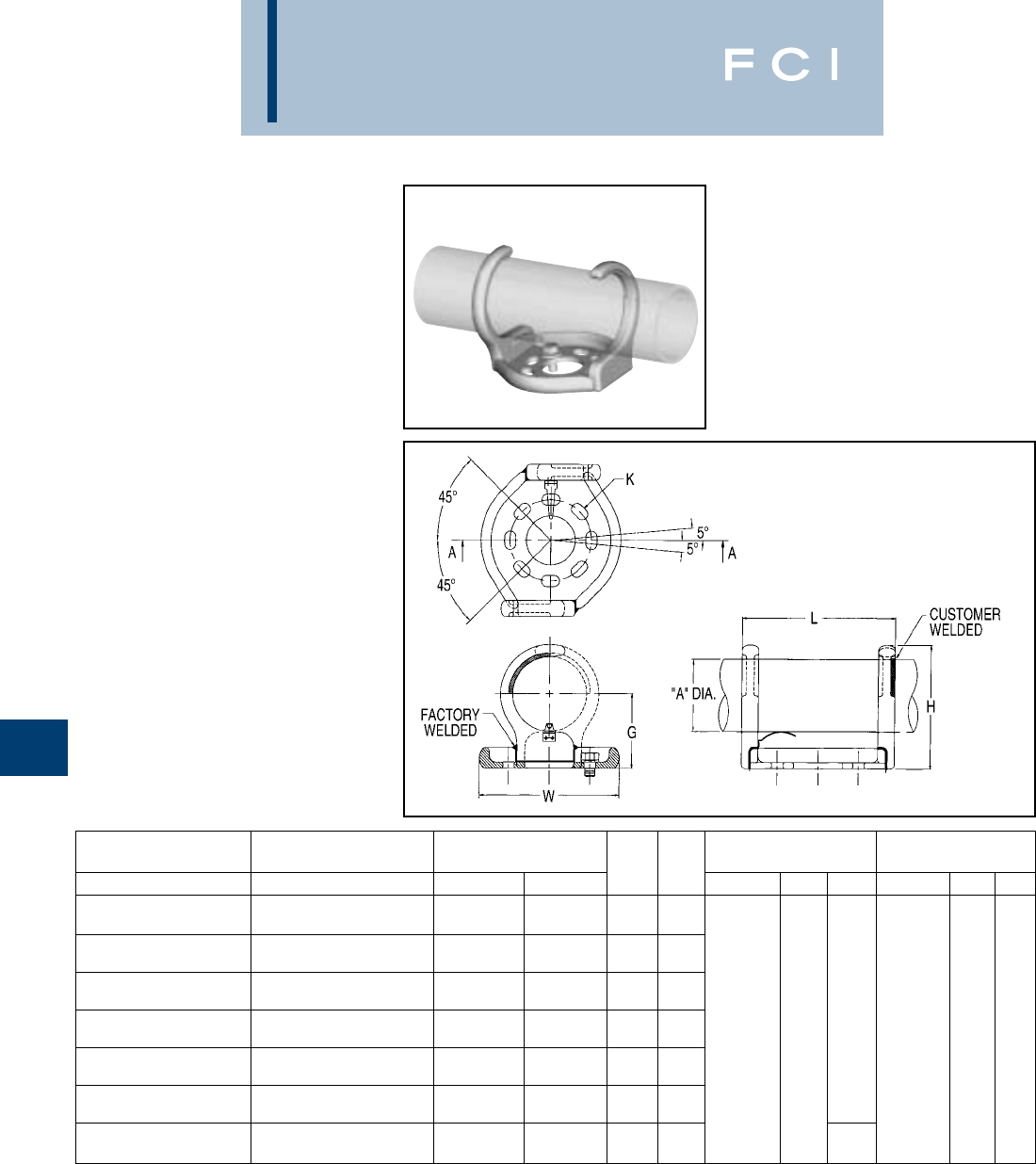
BURNDY
EHV
H-24
WELDED RIGID OR
SLIP FIT BUS
SUPPORT
SWHRH-A
Welded type
Application: Fixed or Slip Fit Bus
Support to Insulator.
EHV RATED: SELF-SHIELDING
UP TO 550 kV—
When used on
corona free Post
Insulators.
Material: Cast 356 Aluminum Alloy
NOTES:
1. Dimensions in brackets [ ] are in millimeters.
2. G dimension conforms to NEMA standards.
3. Cap mounting (galvanized steel) hardware supplied as
standard. For Base mounting hardware add SUFFIX “B’” to
catalog number (example: SWHRH22A-5B).
4. Conductors smaller than 3 inch bus size not recommended
for 550 kV.
ALUMINUM
CATALOG NUMBER CATALOG NUMBER CONDUCTOR 3BOLT CIRCLE 5BOLT CIRCLE
3BOLT CIRCLE 5BOLT CIRCLE IPS/EHPS “A” DIA. G H K L W K L W
2.38 2.75 4.58
SWHRH18A-3CH SWHRH18A-5CH 2
[60] [70] [116]
2.88 3.12 5.21
SWHRH19A-3CH SWHRH19A-5CH 2-1/2
[73] [79] [132]
3.50 3.62 6.15
SWHRH20A-3CH SWHRH20A-5CH 3
[89] [92] [156] .56 .75 7.76 6.26 .69 .88 9.37 8.61
4.00 4.00 6.77 [159]
SWHRH21A-3CH SWHRH21A-5CH 3-1/2
[102] [102] [172] [14 19] [197] [18 22] [238] [219]
4.50 4.50 7.52
SWHRH22A-3CH SWHRH22A-5CH 4
[114] [114] [191]
5.56 5.00 8.68
SWHRH24A-3CH SWHRH24A-5CH 5
[141] [127] [220]
6.63 5.50 9.71 8.61
SWHRH86A-3CH SWHRH86A-5CH 6
[168] [140] [247] [219]
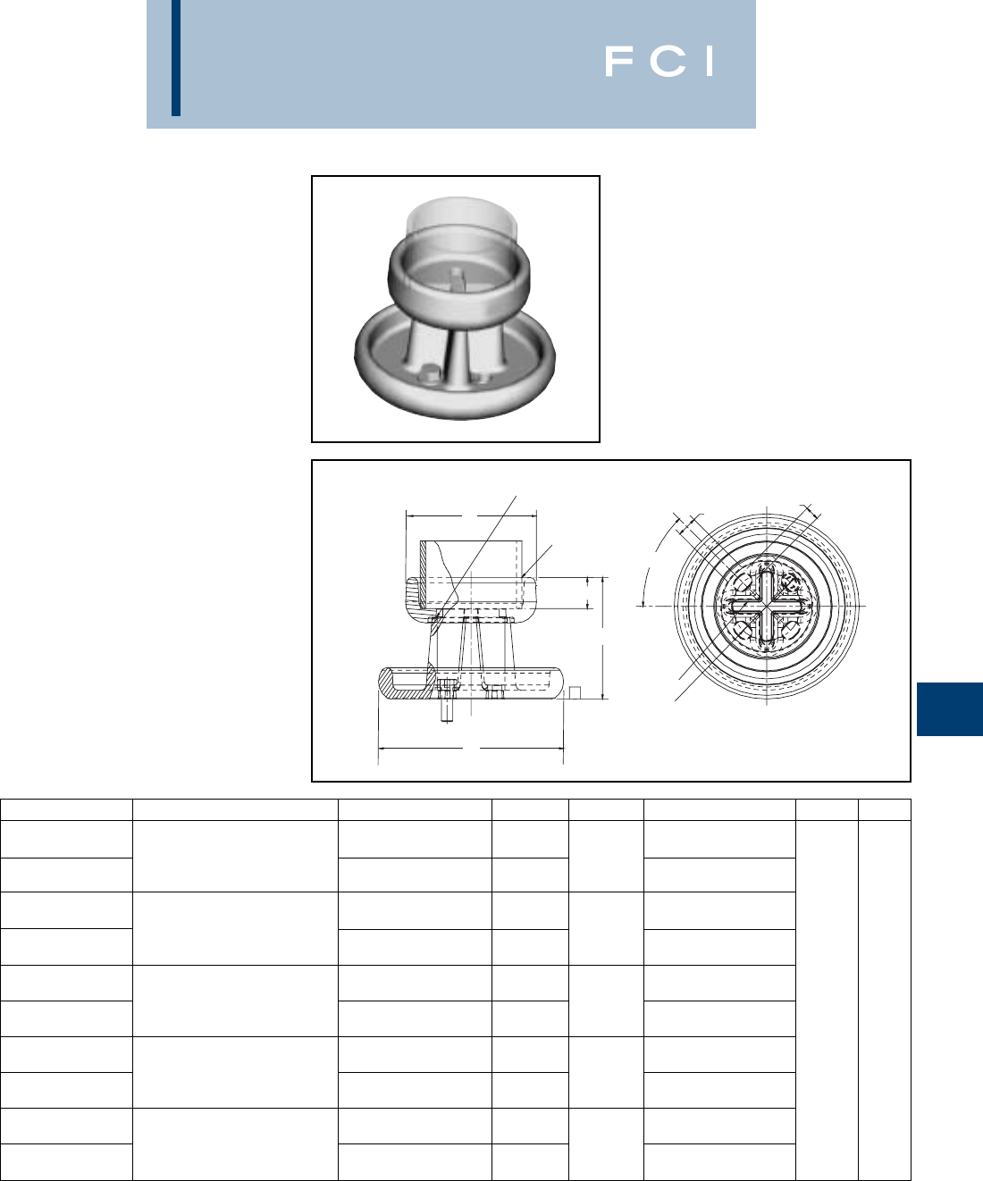
BURNDY
EHV
H-25
WELDED VERTICAL
BUS SUPPORT
SWVH-A
Weld type
Application: Bus to insulator
(Vertical Position)
EHV RATED: SELF-SHIELDING
UP TO 550 kV
Material: Cast 356 Aluminum Alloy
Hardware: Galvanized Steel
CATALOG NO. ACCOMMODATES BOLT CIRCLE DIA. “A” DIA. “B” DIA. “K” & “M” SLOT N R
8.19 .69 1.12
SWVH19A-5 2-1/2IPS (2.88 DIA.) 5
[208] 4.16 [18] [28]
[73] 10.25 [106] .81 1.44
SWVH19A-7 ALUM. TUBE 7
[260] [21] [37]
8.19 .69 1.12
SWVH20A-5 3IPS (3.50 DIA.) 5
[208] 4.79 [18] [28]
[89] 10.25 [122] .81 1.44
SWVH20A-7 ALUM. TUBE 7
[260] [21] [37]
8.19 .69 1.12
SWVH22A-5 4IPS (4.50 DIA.) 5
[208] 5.79 [18] [28] 1.38 5.38
[114] 10.25 [147] .81 1.44 [35] [137]
SWVH22A-7 ALUM. TUBE 7
[260] [21] [37]
8.19 .69 1.12
SWVH24A-5 5IPS (5.56 DIA.) 5
[208] 6.87 [18] [28]
[141] 10.25 [175] .81 1.44
SWVH24A-7 ALUM. TUBE 7
[260] [21] [37]
8.19 .69 1.12
SWVH86A-5 6IPS (6.63 DIA.) 5
[208] 7.93 [18] [28]
[168] 10.25 [201] .81 1.44
SWVH86A-7 ALUM. TUBE 7
[260] [21] [37]
-A-
R
Customer
Weld
Factory
Weld
Weld
Factory
Bolt
Circle
Dia.
45
MK
N
B
A
NOTES:
1.Dimensions in brackets [ ] are in millimeters.
2.Cap mounting hardware supplied. For base mounted
hardware add SUFFIX “B” to catalog number
(example: SWVH22A5B).
3.Conductors smaller than 3 inch not recommended for
550 kV.
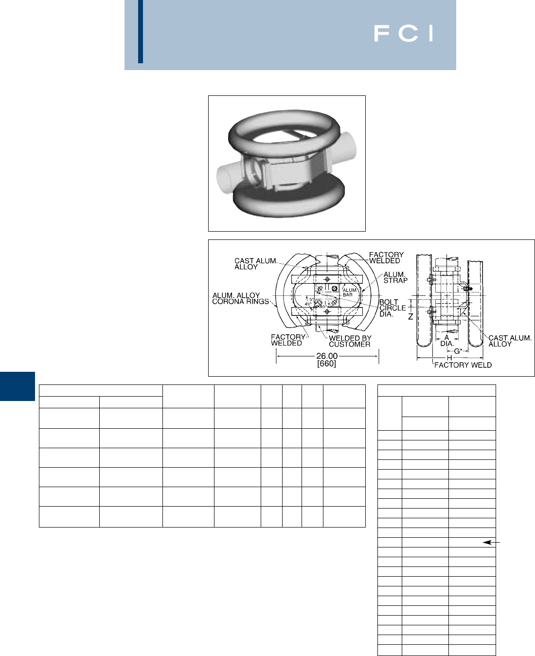
BURNDY
EHV
H-26
NOTES:
*Conforms to NEMA standards.
➀Maximum movement per end equals one-half of total
movement specified in table.
2. Dimensions in brackets [ ] are in millimeters.
3. Cap mounting hardware supplied (Galvanized Steel). For
base mounted hardware add SUFFIX “B” to catalog
number (example: SWXHP20A5B).
4. Conductors smaller than 3 inch not recommended for
550 kV.
5. Bus support couplers are supplied without bus end plugs.
If end plugs are required, add SUFFIX “EP” to catalog
number (example: SWXHP20A5EP).
➅Table is based on 80 ft. max. bus run (total) or 40 ft. per
end.
➆Table is based on 110 ft. max. bus run (total) or 55 ft. per
end.
WELDED EXPANSION
BUS SUPPORT
COUPLER
SWXHP-A
Weld type
Application: Bus to Bus Expansion
Coupler to Insulator
EHV RATED: SELF-SHIELDING
up to 550 kV
Material: Cast 356 Aluminum Alloy
Corona Rings: Aluminum Alloy
Straps: Laminated Aluminum Strap
CATALOG NUMBER “A” DIA. BOLT TOTAL
➀
SCH 40 SCH 80 ALUM. TUBE CIRCLE DIA. G* K H MOVEMENT
2-1/2(2.88 DIA.) 5.00 3.12 .69 12.77 3.00
SWXHP19A-5 SWXHP59A-5 [73] [127] [79] [18] [324] [76]
3(3.50 DIA.) 5.00 3.62 .69 13.62 3.00
SWXHP20A-5 SWXHP90A-5 [89] [127] [92] [18] [346] [76]
3-1/2(4.00 DIA.) 5.00 4.00 .69 14.25 3.00
SWXHP21A-5 SWXHP91A-5 [102] [127] [102] [18] [362] [76]
4(4.50 DIA.) 5.00 4.50 .69 14.90 4.00
SWXHP22A-5 SWXHP92A-5 [114] [127] [114] [18] [378] [102]
5(5.56 DIA.) 5.00 5.25 .69 16.31 4.00
SWXHP24A-5 SWXHP94A-5 [141] [127] [133] [18] [414] [102]
6(6.63 DIA.) 5.00 5.50 .69 17.34 4.00
SWXHP86A-5 SWXHP96A-5 [168] [127] [140] [18] [440] [102]
INSTALLATION DATA
BUS 3TOTAL 4TOTAL
TEMP MOVEMENT MOVEMENT
F° Z ➅Z ➆
–20 .75 .75
–10 .82 .84
0.89 .83
10 .95 1.02
20 1.02 1.11
30 1.09 1.20
40 1.16 1.29
50 1.23 1.39
60 1.30 1.48
70 1.36 1.57
80 1.43 1.66
90 1.50 1.75
100 1.57 1.84
110 1.64 1.93
120 1.70 2.02
130 1.77 2.11
140 1.84 2.20
150 1.91 2.29
160 1.98 2.39
170 2.05 2.48
180 2.11 2.57
190 2.18 2.66
200 2.25 2.75
NOMINAL
POSITION
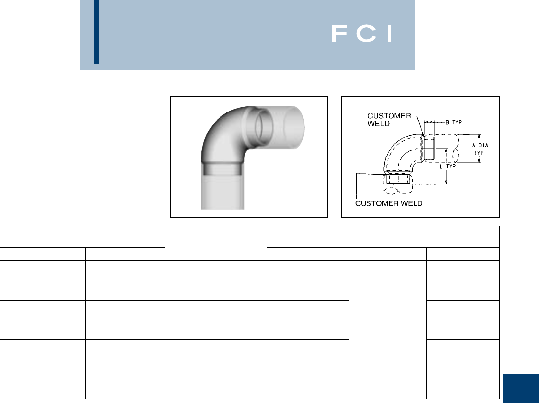
BURNDY
EHV
H-27
WELDED 90° ELBOW
SWL-A
Weld type
Application: Bus to Bus Elbow, 90°
EHV RATED: SELF-SHIELDING
UP TO 550 kV
Material: Cast 356 Aluminum Alloy
NOTES:
1. Dimensions in brackets [ ] are in millimeters.
2. Conductor smaller than 3 inch bus size not recommended
for 550 kV
3. For 45° angle ADD SUFFIX "45" to catalog number
(example: SWL22A-45).
CONDUCTOR
CATALOG NUMBER ALUMINUM DIMENSIONS IN / [mm]
SCH. 40 SCH. 80 TUBING SIZE A DIA. B L
2.38 1.00 3.50
SWL18A SWL58A 2
[60.4] [25] [89]
2.88 3.88
SWL19A SWL59A 2-1/2
[73] [99]
3.50 4.68
SWL20A SWL90A 3
[89] 1.38 [119]
4.00 [35] 5.12
SWL21A SWL91A 3-1/2
[102] [130]
4.50 5.63
SWL22A SWL92A 4
[114] [143]
5.56 6.16
SWL24A SWL93A 5
[141] 1.62 [156]
6.63 [41] 6.16
SWL86A SWL96A 6
[168] [156]
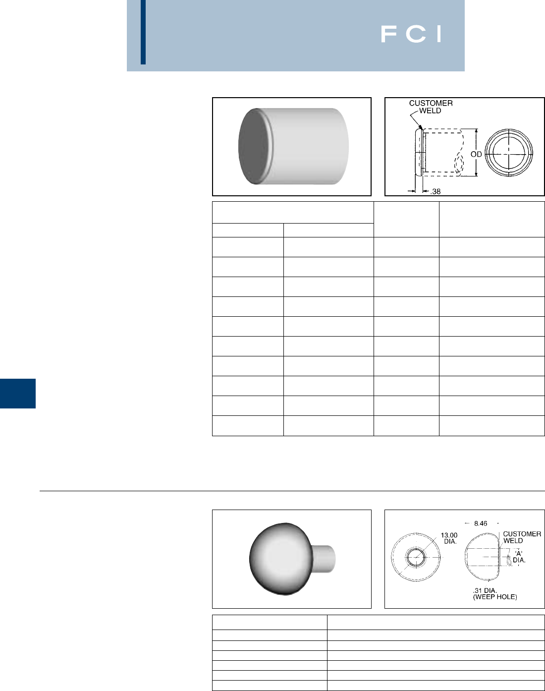
BURNDY
EHV
H-28
NOTES:
1. Dimensions in brackets [ ] are in millimeters.
2. Conductor smaller than 3 inch bus size not recommended
for 550 kV.
NOTES:
1. For bolted design contact factory.
2. Dimensions in brackets [ ] are in millimeters.
3. Conductor smaller than 3 inch bus size not recommended
for 550 kV.
CATALOG NUMBER ACCOMMODATES ‘A’ DIA. ALUMINUM TUBE
SCB19A 2-1/2(2.875 DIA.)
SCB20A 3(3.500 DIA.)
SCB21A 3-1/2(4.000 DIA.)
SCB22A 4(4.500 DIA.)
SCB24A 5(5.563 DIA.)
SCB86A 6(6.625 DIA.)
WELDED CORONA
BELL
SCB-A
Weld type
Application: Bus to Corona Bell
EHV RATED: SELF-SHIELDING
UP TO 550 kV
Material: Aluminum Alloy
WELDED END PLUG
WLB-A
Weld type
Application: Bus to End Cap, used
with shielded bus
support/expansion
couplers
EHV RATED: UP TO 550 kV
when used with
shielded bus and
expansion
connectors
Material: Cast 356 Aluminum Alloy
CONDUCTOR
CATALOG NUMBER ALUMINUM
SCH. 40 SCH. 80 OD TUBING SIZE
1.32
WLB15A WLB55A [34] 1
1.66
WLB16A WLB56A [42] 1-1/4
1.90
WLB17A WLB57A [48] 1-1/2
2.38
WLB18A WLB58A [60] 2
2.88
WLB19A WLB59A [73] 2-1/2
3.50
WLB20A WLB90A [89] 3
4.00
WLB21A WLB91A [102] 3-1/2
4.50
WLB22A WLB92A [114] 4
5.56
WLB24A WLB94A [141] 5
6.62
WLB86A WLB96A [168] 6
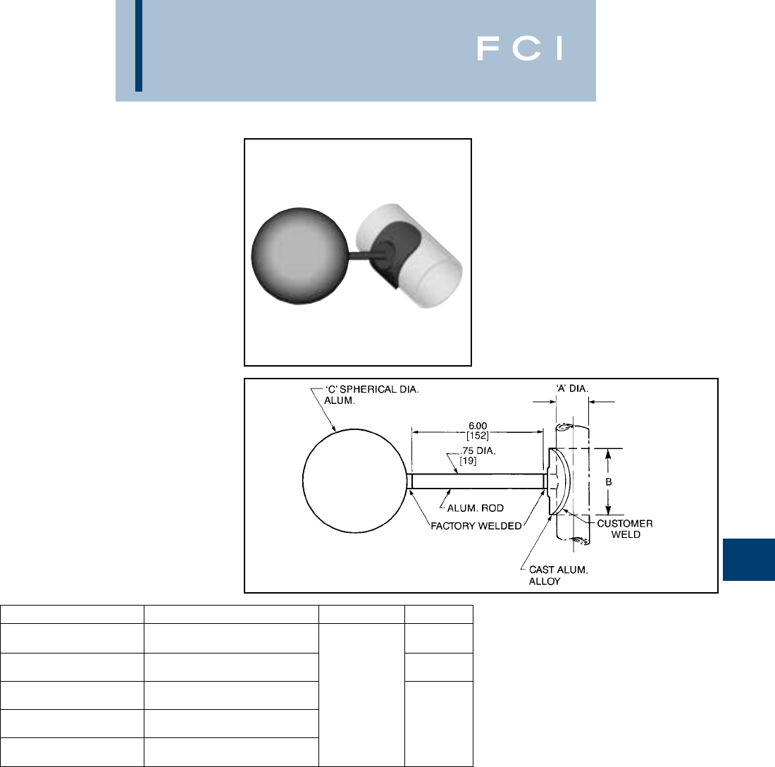
BURNDY
EHV
H-29
WELDED GROUND
STUD
SWCB-A
Weld type
Application: Bus to corona sphere
EHV RATED: SELF-SHIELDING
UP TO 550 kV
Material: Cast 356 Aluminum Alloy
Corona Sphere:
Aluminum Alloy
NOTES:
1. Dimensions in brackets [ ] are in millimeters.
2. Conductor smaller than 3 inch bus size not recommended
for 550 kV.
CATALOG NUMBER ‘A’ DIA. ALUMINUM TUBE ‘C’ DIA. B
2-1/2I.P.S. (2.875 DIA.) 1.50
SWCB19A [73] [38]
3I.P.S. (3.500 DIA.) 3.00
SWCB20A [89] [76]
4I.P.S. (4.500 DIA.) 9.00
SWCB22A [114] [229]
5I.P.S. (5.563 DIA.) 4.00
SWCB24A [141] [102]
6I.P.S. (6.625 DIA.)
SWCB86A [168]
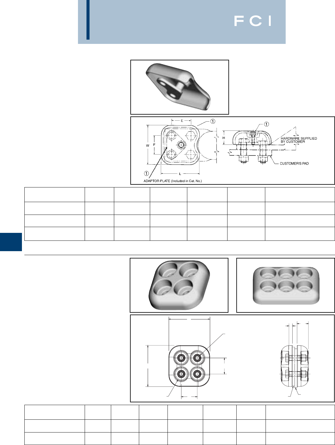
BURNDY
EHV
H-30
TERMINAL PAD CAP
(Two Piece)
STS-A-N
Bolted type
Application: Pad shielding
EHV RATED: SELF-SHIELDING
UP TO 550 kV
Material: Cast 356 Aluminum Alloy
Hardware: 1/4–20 3-3/4LG
Stainless Steel Hex Hd. Bolt
and Split Lockwasher
➀Catalog number includes one pad cap, one adapter plate,
and stainless steel adaptor hardware.
CATALOG MAX. SHIELDED
NUMBER ➀EF HLW AREA
1.75 1.75 1.25 3.48 3.62 3 3
STS33A-4N [44] [44] [32] [88] [92] [76] [76]
1.75 1.75 1.31 3.36 4.50 4.00 3.12
STS43A-4N [44] [44] [33] [85] [114] [102 79]
1.75 1.75 1.25 4.50 4.62 4 4
STS44A-4N ➁[44] [44] [32] [114] [117] [102 102]
F
W
L
E
1.44
[37]
(4) 1/2 Dia. Bolts,
Nuts and Split
Lockwasher
Supplied by Customer
H
.38 TYP
[10]
Customer
Pad
Terminal
Pad
TERMINAL PAD CAP
(One Piece)
STS-A-NCG
Bolted type
Application: Pad shielding
EHV RATED: SELF-SHIELDING
UP TO 550 kV
Material: Cast 356 Aluminum Alloy
CATALOG MAX. SHIELDED
NUMBER E F H J DIA. L W AREA
1.75 1.75 1.25 4.50 4.50
STS44A-4NCG2 [44] [44] [32] 1/2–13 [114] [114] 4 4
1.75 1.75 1.25 4.50 6.50
STS46A-6NCG1 [44] [44] [32] 1/2–13 [114] [165] 6 4
NOTES:
1. Dimensions in brackets [ ] are in millimeters.
2. Catalog number is for one shielding cap only. If more than
one is required, specifiy total quantity.
➁Used with YNA451R-T and YNA451R-T15 through
YNA594R-T and YNA594R-T15 compresseion terminals.

BURNDY
EHV
H-31
BOLTED BUNDLED
CABLE SPACER
S2GBP-A (Spacer)
S2GBPA-A (Terminal Tap)
SH2GBP-A (Bus Support)
Bolted type
Applications
:Cable to Cable spacer
(Two Cables), Cable
spacer with four hole
pad, and Cable spacer
to insulator.
EHV RATED: SELF-SHIELDING
UP TO 550 kV
Material: Cast 356 Aluminum Alloy
Hardware: Aluminum Alloy
Fig. 1
Fig. 2
Fig. 3
CATALOG NUMBER CABLE RANGE CABLE DIA.
FIG. 1 FIG. 2 FIG. 3 A.A.C. A.C.S.R. MIN. MAX. “L” “J” DIA.
18.00
S2GBP41A S2GBPA41A SH2GBP41A5 795 kcmil 37 STR. (1.026 DIA.) 715 kcmil 24/7 STR. (1.036 DIA.) 1.026 1.092 [457] 5/8–11 X 1-1/2LG.
874.5 kcmil 61 STR. (1.077 DIA.) 715.5 kcmil 26/7 STR. (1.051 DIA.) [26] [28] 12.00 ALUM. ALLOY
S2GBP41A12 S2GBPA41A12 SH2GBP41A512 [305]
18.00
S2GBP44A S2GBPA44A SH2GBP44A5 795 kcmil 24/7 STR. (1.092 DIA.) 1.092 1.165 [457]
954 kcmil 61 STR. (1.126 DIA.) 795 kcmil 54/7 STR. (1.093 DIA.) [28] [30] 12.00
S2GBP44A12 S2GBPA44A12 SH2GBP44A512 [305]
18.00
S2GBP445A S2GBPA445A SH2GBP445A5 1033.5 kcmil 37 STR. (1.170 DIA.) 954 kcmil 45/7 STR. (1.165 DIA.) 1.165 1.246 [457] 5/8–11 X 1-3/4LG.
1113 kcmil 61 STR. (1.216 DIA.) 1033.5 kcmil 45/7 STR. (1.213 DIA.) [30] [32] 12.00 ALUM. ALLOY
S2GBP445A12 S2GBPA445A12 SH2GBP445A512 [305]
18.00
S2GBP45A S2GBPA45A SH2GBP45A5 1192 kcmil 61 STR. (1.258 DIA.) 1033.5 kcmil 54/7 STR. (1.246 DIA.) 1.246 1.382 [457]
1272 kcmil 61 STR. (1.300 DIA.) 1192.5 kcmil 54/19 STR. (1.333 DIA.) [32] [35] 12.00
S2GBP45A12 S2GBPA45A12 SH2GBP45A512 [305]
NOTES:
1. Dimensions in brackets [ ] are in millimeters.
2. For stainless steel hardware add SUFFIX “SS” to catalog
number (example: S2GBP41ASS).
3. For variations in cable spacing contact factory.
4. Not recommended for overhead transmission lines.
Fig. 1
Fig. 2
Fig. 3
(Table continued on next page)
5. For pad rotated 90° on S2GBPA-A add suffix R90 to the
catalog number (example: S2GBPA44AR90).
6. For Bolt Circles other than 5 inch on type SH2GBP-A
contact factory.
7. S2GBPA-A connectors rated 550 kV when used with
type “STS” Shielding Caps. Ordered separately, refer to
page 32.
BURNDY
EHV
H-32
CATALOG NUMBER CABLE RANGE CABLE DIA.
FIG. 1 FIG. 2 FIG. 3 A.A.C. A.C.S.R. MIN. MAX. “L” “J” DIA.
18.00
S2GBP46A S2GBPA46A SH2GBP46A5 1590 kcmil 61 STR. (1.453 DIA.) 1272 kcmil 54/19 STR. (1.382 DIA.) 1.382 1.504 [457] 5/8–11 X 1-3/4LG.
1600 kcmil 127 STR. (1.454 DIA.) 1431 kcmil 54/19 STR. (1.465 DIA.) [35] [38] 12.00 ALUM. ALLOY
S2GBP46A12 S2GBPA46A12 SH2GBP46A512 [305]
18.00
S2GBP48A S2GBPA48A SH2GBP48A5 1750 kcmil 127 STR. (1.526 DIA.) 1590 kcmil 45/7 STR. (1.502 DIA.) 1.504 1.632 [457]
2000 kcmil 91 STR. (1.630 DIA.) 1750 kcmil 84/19 STR. (1.602 DIA.) [38] [41] 12.00
S2GBP48A12 S2GBPA48A12 SH2GBP48A512 [305]
18.00
S2GBP483A S2GBPA483A SH2GBP483A5 2000 kcmil 91 STR. (1.630 DIA.) 1890 kcmil 84/19 STR. (1.650 DIA.) 1.632 1.737 [457] 5/8–11 X 2LG.
2250 kcmil 91 STR. (1.729 DIA.) 2167 kcmil 72/7 STR. (1.737 DIA.) [41] [44] 12.00 ALUM. ALLOY
S2GBP483A12 S2GBPA483A12 SH2GBP483A512 [305]
18.00
S2GBP486A S2GBPA486A SH2GBP486A5 2300 kcmil 61 STR. (1.750 DIA.) 2167 kcmil 72/7 STR. (1.737 DIA.) 1.737 1.824 [457]
2500 kcmil 127 STR. (1.823 DIA.) 2156 kcmil 84/19 STR. (1.762 DIA.) [44] [46] 12.00
S2GBP486A12 S2GBPA486A12 SH2GBP486A512 [305]
BOLTED BUNDLED
CABLE SPACER
(Continued)
S2GBP-A (Spacer)
S2GBPA-A (Terminal Tap)
SH2GBP-A (Bus Support)
NOTES:
1. Dimensions in brackets [ ] are in millimeters.
2. For stainless steel hardware add SUFFIX “SS” to catalog
number (example: S2GBP41ASS).
3. For variations in cable spacing contact factory.
4. Not recommended for overhead transmission lines.
5. For pad rotated 90° onS2GBPA-A add suffix R90 to the
catalog number (example: S2GBPA44AR90).
6. For Bolt Circles other than 5 inch on type SH2GBP-A
contact factory.
7. S2GBPA-A connectors rated 550 kV when used with
type “STS” Shielding Caps. Ordered separately, refer to
page 32.
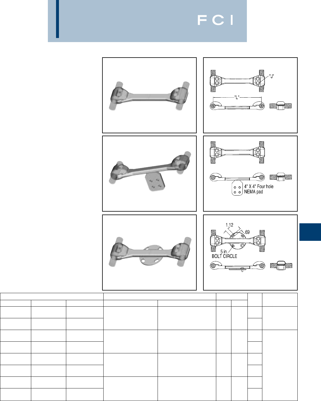
BURNDY
EHV
H-33
BOLTED BUNDLED
CABLE SPACER
(Two Bolt Clamping)
S2GBP-AB2 (Spacer)
S2GBPA-AB2 (Terminal Tap)
SH2GBP-A-B2 (Bus Support)
Bolted type
Applications:
Cable to Cable spacer
(Two Cables), Cable
spacer with four hole
pad, and Cable spacer
to insulator.
EHV RATED: SELF-SHIELDING
UP TO 550 kV
Material: Cast 356 Aluminum Alloy
Hardware: Aluminum Alloy
Fig. 1
Fig. 2
Fig. 3
CATALOG NUMBER CABLE RANGE CABLE DIA.
FIG. 1 FIG. 2 FIG. 3 A.A.C. A.C.S.R. MIN. MAX. “L” “J” DIA.
18.00
S2GBP41AB2 S2GBPA41AB2 SH2GBP41A5B2 795 kcmil 37 STR. (1.026 DIA.) 715 kcmil 24/7 STR. (1.036 DIA.) 1.026 1.092 [457] 5/8–11 X 1-1/2LG.
874.5 kcmil 61 STR. (1.077 DIA.) 715.5 kcmil 26/7 STR. (1.051 DIA.) [26] [28] 12.00 ALUM. ALLOY
S2GBP41A12B2 S2GBPA41A12B2 SH2GBP41A512B2 [305]
18.00
S2GBP44AB2 S2GBPA44AB2 SH2GBP44A5B2 795 kcmil 24/7 STR. (1.092 DIA.) 1.092 1.165 [457]
954 kcmil 61 STR. (1.126 DIA.) 795 kcmil 54/7 STR. (1.093 DIA.) [28] [30] 12.00
S2GBP44A12B2 S2GBPA44A12B2 SH2GBP44A512B2 [305]
18.00
S2GBP445AB2 S2GBPA445AB2 SH2GBP445A5B2 1033.5 kcmil 37 STR. (1.170 DIA.) 954 kcmil 45/7 STR. (1.165 DIA.) 1.165 1.246 [457] 5/8–11 X 1-3/4LG.
1113 kcmil 61 STR. (1.216 DIA.) 1033.5 kcmil 45/7 STR. (1.213 DIA.) [30] [32] 12.00 ALUM. ALLOY
S2GBP445A12B2 S2GBPA445A12B2 SH2GBP445A512B2 [305]
18.00
S2GBP45AB2 S2GBPA45AB2 SH2GBP45A5B2 1192 kcmil 61 STR. (1.258 DIA.) 1033.5 kcmil 54/7 STR. (1.246 DIA.) 1.246 1.382 [457]
1272 kcmil 61 STR. (1.300 DIA.) 1192.5 kcmil 54/19 STR. (1.333 DIA.) [32] [35] 12.00
S2GBP45A12B2 S2GBPA45A12B2 SH2GBP45A512B2 [305]
NOTES:
1. Dimensions in brackets [ ] are in millimeters.
2. For stainless steel hardware add SUFFIX “SS” to catalog
number (example: S2GBP41AB2SS).
3. For variations in cable spacing contact factory.
4. Not recommended for overhead transmission lines.
Fig. 1
Fig. 2
Fig. 3
(Table continued on next page)
5. For pad rotated 90° on S2GBPA-AB2 add suffix R90 to the
catalog number (example: S2GBPA44AB2R90).
6. For Bolt Circles other than 5 inch on type SH2GBP-A-B2
contact factory.
7. S2GBPA-B2 connectors rated 550 kV when used with
type “STS” Shielding Caps. Ordered separately, refer to
page 32.
BURNDY
EHV
H-34
CATALOG NUMBER CABLE RANGE CABLE DIA.
FIG. 1 FIG. 2 FIG. 3 A.A.C. A.C.S.R. MIN. MAX. “L” “J” DIA.
18.00
S2GBP46AB2 S2GBPA46AB2 SH2GBP46A5B2 1590 kcmil 61 STR. (1.453 DIA.) 1272 kcmil 54/19 STR. (1.382 DIA.) 1.382 1.504 [457] 5/8–11 X 1-3/4LG.
1600 kcmil 127 STR. (1.454 DIA.) 1431 kcmil 54/19 STR. (1.465 DIA.) [35] [38] 12.00 ALUM. ALLOY
S2GBP46A12B2 S2GBPA46A12B2 SH2GBP46A512B2 [305]
18.00
S2GBP48AB2 S2GBPA48AB2 SH2GBP48A5B2 1750 kcmil 127 STR. (1.526 DIA.) 1590 kcmil 45/7 STR. (1.502 DIA.) 1.504 1.632 [457]
2000 kcmil 91 STR. (1.630 DIA.) 1750 kcmil 84/19 STR. (1.602 DIA.) [38] [41] 12.00
S2GBP48A12B2 S2GBPA48A12B2 SH2GBP48A512B2 [305]
18.00
S2GBP483AB2 S2GBPA483AB2 SH2GBP483A5B2 2000 kcmil 91 STR. (1.630 DIA.) 1890 kcmil 84/19 STR. (1.650 DIA.) 1.632 1.737 [457] 5/8–11 X 2LG.
2250 kcmil 91 STR. (1.729 DIA.) 2167 kcmil 72/7 STR. (1.737 DIA.) [41] [44] 12.00 ALUM. ALLOY
S2GBP483A12B2 S2GBPA483A12B2 SH2GBP483A512B2 [305]
18.00
S2GBP486AB2 S2GBPA486AB2 SH2GBP486A5B2 2300 kcmil 61 STR. (1.750 DIA.) 2167 kcmil 72/7 STR. (1.737 DIA.) 1.737 1.824 [457]
2500 kcmil 127 STR. (1.823 DIA.) 2156 kcmil 84/19 STR. (1.762 DIA.) [44] [46] 12.00
S2GBP486A12B2 S2GBPA486A12B2 SH2GBP486A512B2 [305]
BOLTED BUNDLED
CABLE SPACER
(Continued)
(Two Bolt Clamping)
S2GBP-AB2 (Spacer)
S2GBPA-AB2 (Terminal Tap)
SH2GBP-A-B2 (Bus Support)
NOTES:
1. Dimensions in brackets [ ] are in millimeters.
2. For stainless steel hardware add SUFFIX “SS” to catalog
number (example: S2GBP41AB2SS).
3. For variations in cable spacing contact factory.
4. Not recommended for overhead transmission lines.
5. For pad rotated 90° on S2GBPA-AB2 add suffix R90 to the
catalog number (example: S2GBPA44AB2R90).
6. For Bolt Circles other than 5 inch on type SH2GBP-A-B2
contact factory.
7. S2GBPA-B2 connectors rated 550 kV when used with
type “STS” Shielding Caps. Ordered separately, refer to
page 32.
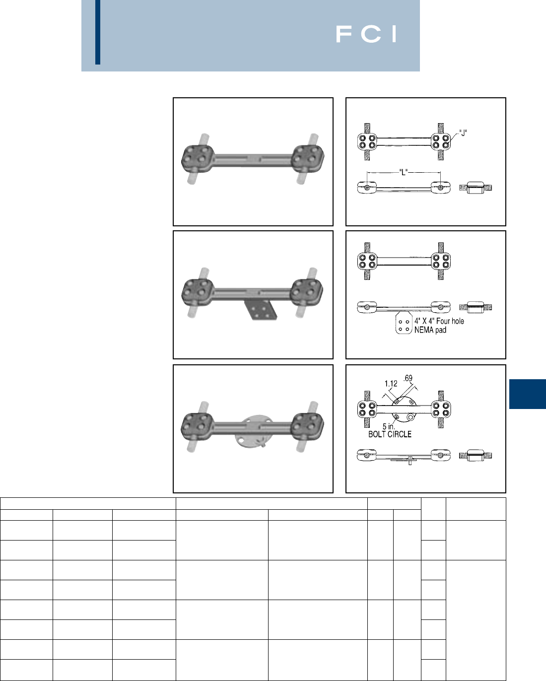
BURNDY
EHV
H-35
BOLTED BUNDLED
CABLE SPACER
(Four Bolt Clamping)
S2GBP-AB4 (Spacer)
S2GBPA-AB4 (Terminal Tap)
SH2GBP-A-B4 (Bus Support)
Bolted type
Applications:
Cable to Cable spacer
(Two Cables), Cable
spacers with four hole
pad, and Cable spacer
to bus support
insulator.
EHV RATED: SELF-SHIELDING
UP TO 550 kV
Material: Cast 356 Aluminum Alloy
Hardware: Aluminum Alloy
Fig. 1
Fig. 2
Fig. 3
CATALOG NUMBER CABLE RANGE CABLE DIA.
FIG. 1 FIG. 2 FIG. 3 A.A.C. A.C.S.R. MIN. MAX. “L” “J” DIA.
18.00
S2GBP41AB4 S2GBPA41AB4 SH2GBP41A5B4 795 kcmil 37 STR. (1.026 DIA.) 715 kcmil 24/7 STR. (1.036 DIA.) 1.026 1.092 [457] 5/8–11 X 1-1/2LG.
874.5 kcmil 61 STR. (1.077 DIA.) 715.5 kcmil 26/7 STR. (1.051 DIA.) [26] [28] 12.00 ALUM. ALLOY
S2GBP41A12B4 S2GBPA41A12B4 SH2GBP41A512B4 [305]
18.00
S2GBP44AB4 S2GBPA44AB4 SH2GBP44A5B4 795 kcmil 24/7 STR. (1.092 DIA.) 1.092 1.165 [457]
954 kcmil 61 STR. (1.126 DIA.) 795 kcmil 54/7 STR. (1.093 DIA.) [28] [30] 12.00
S2GBP44A12B4 S2GBPA44A12B4 SH2GBP44A512B4 [305]
18.00
S2GBP445AB4 S2GBPA445AB4 SH2GBP445A5B4 1033.5 kcmil 37 STR. (1.170 DIA.) 954 kcmil 45/7 STR. (1.165 DIA.) 1.165 1.246 [457] 5/8–11 X 1-3/4LG.
1113 kcmil 61 STR. (1.216 DIA.) 1033.5 kcmil 45/7 STR. (1.213 DIA.) [30] [32] 12.00 ALUM. ALLOY
S2GBP445A12B4 S2GBPA445A12B4 SH2GBP445A512B4 [305]
18.00
S2GBP45AB4 S2GBPA45AB4 SH2GBP45A5B4 1192 kcmil 61 STR. (1.258 DIA.) 1033.5 kcmil 54/7 STR. (1.246 DIA.) 1.246 1.382 [457]
1272 kcmil 61 STR. (1.300 DIA.) 1192.5 kcmil 54/19 STR. (1.333 DIA.) [32] [35] 12.00
S2GBP45A12B4 S2GBPA45A12B4 SH2GBP45A512B4 [305]
NOTES:
1. Dimensions in brackets [ ] are in millimeters.
2. For stainless steel hardware add SUFFIX “SS” to catalog
number (example: S2GBP41AB4SS).
3. For variations in cable spacing contact factory.
4. Not recommended for overhead transmission lines.
Fig. 1
Fig. 2
Fig. 3
(Table continued on next page)
5. For pad rotated 90° on S2GBPA-AB4 add suffix R90 to the
catalog number (example: S2GBPA44AB4R90).
6. For Bolt Circles other than 5 inch on type SH2GBP-A-B2
contact factory.
7. S2GBPA-B4 connectors rated 550 kV when used with
type “STS” Shielding Caps. Ordered separately, refer to
page 32.
BURNDY
EHV
H-36
CATALOG NUMBER CABLE RANGE CABLE DIA.
FIG. 1 FIG. 2 FIG. 3 A.A.C. A.C.S.R. MIN. MAX. “L” “J” DIA.
18.00
S2GBP46AB4 S2GBPA46AB4 SH2GBP46A5B4 1590 kcmil 61 STR. (1.453 DIA.) 1272 kcmil 54/19 STR. (1.382 DIA.) 1.382 1.504 [457] 5/8–11 X 1-3/4LG.
1600 kcmil 127 STR. (1.454 DIA.) 1431 kcmil 54/19 STR. (1.465 DIA.) [35] [38] 12.00 ALUM. ALLOY
S2GBP46A12B4 S2GBPA46A12B4 SH2GBP46A512B4 [305]
18.00
S2GBP48AB4 S2GBPA48AB4 SH2GBP48A5B4 1750 kcmil 127 STR. (1.526 DIA.) 1590 kcmil 45/7 STR. (1.502 DIA.) 1.504 1.632 [457]
2000 kcmil 91 STR. (1.630 DIA.) 1750 kcmil 84/19 STR. (1.602 DIA.) [38] [41] 12.00
S2GBP48A12B4 S2GBPA48A12B4 SH2GBP48A512B4 [305]
18.00
S2GBP483AB4 S2GBPA483AB4 SH2GBP483A5B4 2000 kcmil 91 STR. (1.630 DIA.) 1890 kcmil 84/19 STR. (1.650 DIA.) 1.632 1.737 [457] 5/8–11 X 2LG.
2250 kcmil 91 STR. (1.729 DIA.) 2167 kcmil 72/7 STR. (1.737 DIA.) [41] [44] 12.00 ALUM. ALLOY
S2GBP483A12B4 S2GBPA483A12B4 SH2GBP483A512B4 [305]
18.00
S2GBP486AB4 S2GBPA486AB4 SH2GBP486A5B4 2300 kcmil 61 STR. (1.750 DIA.) 2167 kcmil 72/7 STR. (1.737 DIA.) 1.737 1.824 [457]
2500 kcmil 127 STR. (1.823 DIA.) 2156 kcmil 84/19 STR. (1.762 DIA.) [44] [46] 12.00
S2GBP486A12B4 S2GBPA486A12B4 SH2GBP486A512B4 [305]
BOLTED BUNDLED
CABLE SPACER
(Continued)
(Four Bolt Clamping)
S2GBP-AB4 (Spacer)
S2GBPA-AB4 (Terminal Tap)
SH2GBP-A-B4 (Bus Support)
NOTES:
1. Dimensions in brackets [ ] are in millimeters.
2. For stainless steel hardware add SUFFIX “SS” to catalog
number (example: S2GBP41AB4SS).
3. For variations in cable spacing contact factory.
4. Not recommended for overhead transmission lines.
5. For pad rotated 90° on S2GBPA-AB4 add suffix R90 to the
catalog number (example: S2GBPA44AB4R90).
6. For Bolt Circles other than 5 inch on type SH2GBP-A-B2
contact factory.
7. S2GBPA-B4 connectors rated 550 kV when used with
type “STS” Shielding Caps. Ordered separately, refer to
page 32.
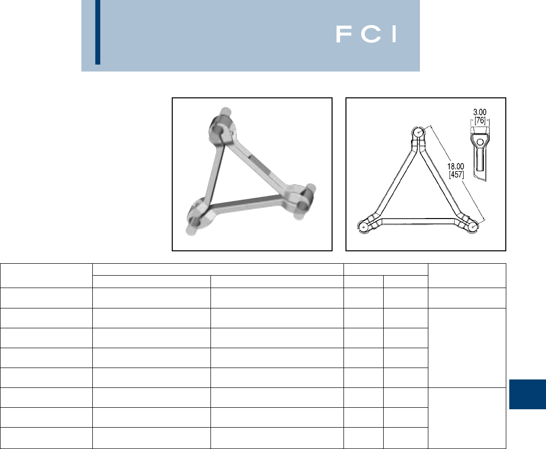
BURNDY
EHV
H-37
BOLTED BUNDLED
CABLE SPACER
(Three Conductor)
S3GBP-A
Bolted type
Application:
Cable to Cable Spacer
(three cables)
EHV RATED: SELF-SHIELDING
UP TO 550 kV
Material: Cast 356 Aluminum Alloy
Hardware: Aluminum Alloy
CABLE RANGE CABLE DIA.
CATALOG NUMBER A.A.C. A.C.S.R. MIN. MAX. “J” DIA.
795 kcmil 37 STR. (1.026 DIA.) 715 kcmil 24/7 STR. (1.036 DIA.) 1.026 1.092 5/8’-11 1-1/2” LG.
S3GBP41A 874.5 kcmil 61 STR. (1.077 DIA.) 715.5 kcmil 26/7 STR. (1.051 DIA.) [26] [28] ALUM. ALLOY
795 kcmil 24/7 STR. (1.092 DIA.) 1.092 1.165
S3GBP44A 954 kcmil 61 STR. (1.126 DIA.) 795 kcmil 54/7 STR. (1.093 DIA.) [28] [30]
1033.5 kcmil 37 STR. (1.170 DIA.) 954 kcmil 45/7 STR. (1.165 DIA.) 1.165 1.246
S3GBP445A 1113 kcmil 61 STR. (1.216 DIA.) 1033.5 kcmil 45/7 STR. (1.213 DIA.) [30] [32] 5/8”-11 1-3/4” LG.
1192 kcmil 61 STR. (1.258 DIA.) 1033.5 kcmil 54/7 STR. (1.246 DIA.) 1.246 1.382 ALUM. ALLOY
S3GBP45A 1272 kcmil 61 STR. (1.300 DIA.) 1192.5 kcmil 54/19 STR. (1.333 DIA.) [32] [35]
1590 kcmil 61 STR. (1.453 DIA.) 1272 kcmil 54/19 STR. (1.382 DIA.) 1.382 1.504
S3GBP46A 1600 kcmil 127 STR. (1.454 DIA.) 1431 kcmil 54/19 STR. (1.465 DIA.) [35] [38]
1750 kcmil 127 STR. (1.526 DIA.) 1590 kcmil 45/7 STR. (1.502 DIA.) 1.504 1.632
S3GBP48A 2000 kcmil 91 STR. (1.630 DIA.) 1750 kcmil 84/19 STR. (1.602 DIA.) [38] [41]
2000 kcmil 91 STR. (1.630 DIA.) 1890 kcmil 84/19 STR. (1.650 DIA.) 1.632 1.737 5/8”-11 2” LG.
S3GBP483A 2250 kcmil 91 STR. (1.729 DIA.) 2167 kcmil 72/7 STR. (1.737 DIA.) [41] [44] ALUM ALLOY
2300 kcmil 61 STR. (1.750 DIA.) 2167 kcmil 72-/7 STR. (1.737 DIA.) 1.737 1.824
S3GBP486A 2500 kcmil 127 STR. (1.823 DIA.) 2156 kcmil 84/19 STR. (1.762 DIA.) [44] [46]
NOTES:
1. Dimensions in brackets [ ] are in millimeters.
2. For stainless steel hardware add SUFFIX “SS” to catalog
number (example: S3GBP48ASS).
3. For variations in cable spacing contact factory.
4. Not recommended for overhead transmission lines.
5. For four hole straight pad tap or 90° version or bus support
three bundled cable spacer, contact the factory.
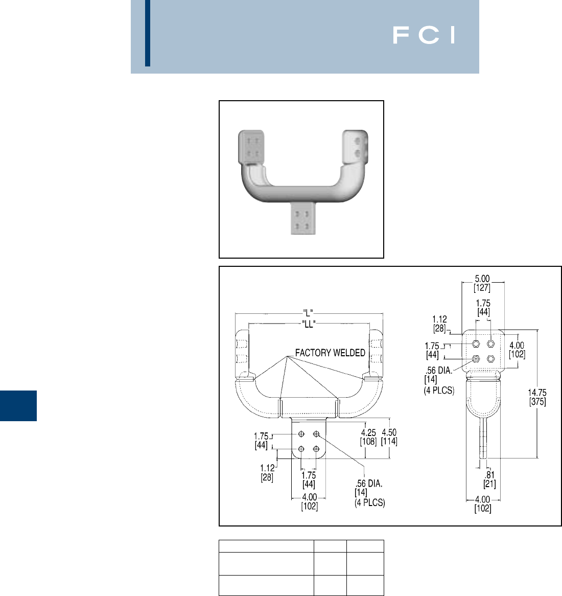
BURNDY
EHV
H-38
BIFURCATING
TERMINAL
CONNECTOR
SF2A-NL-EX
Bolted type
Application:
Four to Six Hole
NEMA Pad to Two
Four Hole NEMA
Recessed Pads
Bifurcating Terminal
EHV RATED: SELF-SHIELDING
UP TO 550 kV
Material: Cast 356 Aluminum Alloy
CATALOG NUMBER “L” “LL”
17.21 13.97
SF2A44NL12EX
[437] [355]
21.51 18.27
SF2A44NL18EX
[546] [464]
NOTES:
1. Dimensions in brackets [ ] are in millimeters.
2. One surface of pad finished. For finished pad on both sides
add SUFFIX “Q” to the catalog number
(example: SF2A44NL12EXQ).
3. Shielding caps are not required when terminals are
installed within the recessed Housing. Hardware ordered
separately.
4. Shielding caps are required when installing to center
(non recessed) four hole NEMA Pad. Reference STS
type shielding caps on page 32.
5. For six hole NEMA pad add “66” to catalog number
(example: SF2A66NL12EX).

BURNDY
EHV
H-39
TRIFURCATING
COUPLER
CONNECTOR
SW3A-A44N8
Weld type
Application:
Bus to Trifurcating
Terminals
EHV RATED: SELF-SHIELDING
UP TO 550 kV
Material: Cast 356 Aluminum Alloy
NOTES:
1. Dimensions in brackets [ ] are in millimeters.
2. Shielding caps are not required when terminals are
installed within the recessed housing. Hardware ordered
separately.
ACCOMMODATES
CATALOG NUMBER ALUM. TUBING SIZE “A” DIA. “B” DIA.
33.56 5.06
SW3A20A44N8 [76] [90] [129]
44.57 6.09
SW3A22A44N8 [101] [116] [155]
55.65 7.16
SW3A24A44N8 [127] [144] [182]
66.72 8.00
SW3A86A44N8 [152] [171] [203]
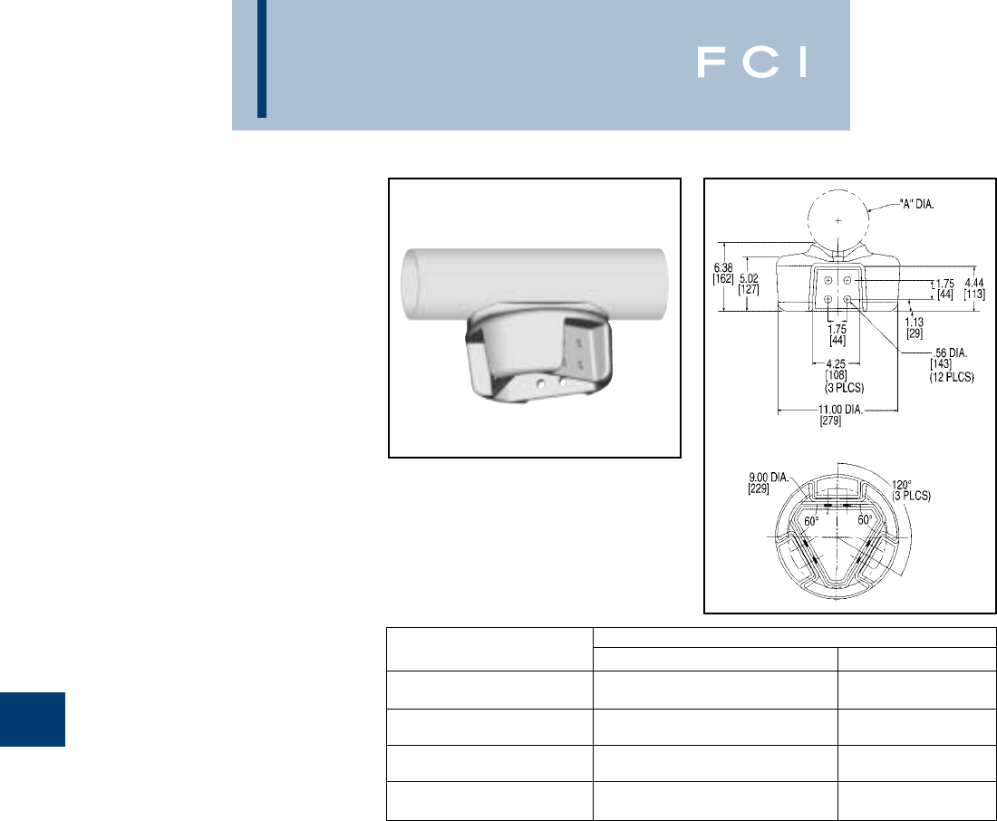
BURNDY
EHV
H-40
TRIFURCATING TEE
CONNECTOR
SW3AB-A44N8
Weld type
Application:
Bus to Trifurcating
Terminals
EHV RATED: SELF-SHIELDING
UP TO 550 kV
Material: Cast 356 Aluminum Alloy
NOTES:
1. Dimensions in brackets [ ] are in millimeters.
2. Shielding caps are not required when terminals are
installed within the recessed housing. Hardware ordered
separately.
ACCOMMODATES
CATALOG NUMBER ALUM. TUBING SIZE “A” DIA.
33.50
SW3AB20A44N8 [76] [89]
44.50
SW3AB22A44N8 [101] [114]
55.56
SW3AB24A44N8 [127] [141]
66.62
SW3AB86A44N8 [152] [168]
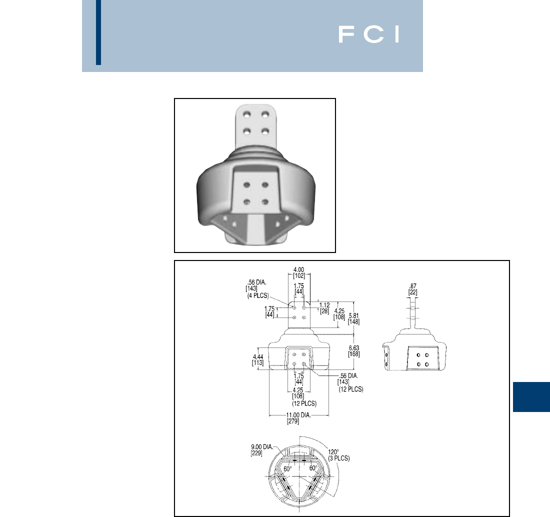
BURNDY
EHV
H-41
TRIFURCATING
TERMINAL
CONNECTOR
SF3A44N8
Bolted type
Application:
Pad-to-Pad Trifurcating
Terminal
EHV RATED: SELF-SHIELDING
UP TO 550 kV
Material: Cast 356 Aluminum Alloy
NOTES:
1. Dimensions in brackets [ ] are in millimeters.
2. One surface of pad finished. For finished pad on both sides
add SUFFIX ‘Q’ to the catalog number
(example: SF3A44N8Q).
3. Shielding caps are not required when terminals are
installed within the recessed housing. Hardware ordered
separately. For terminals not installed within the recessed
housing shielding caps are required. Reference STS
shielding caps page 32. Ordered separately.
4. For six hole NEMA external (non-recessed) pad order
SF3A44N866N.
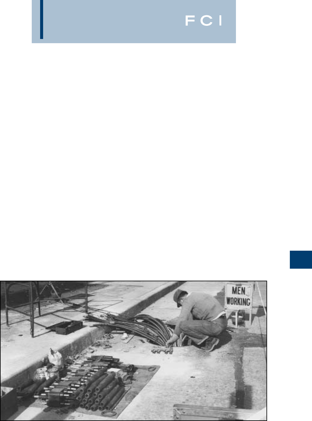
BURNDY
Network Underground
I-1
UNDERGROUND SYSTEM CONNECTION AND PROTECTION
Nowhere in the distribution of electric power
are the problems of connecting conductors
and protecting them and equipment against
the effects of fault currents as complex as in
underground systems. For more than 70
years, BURNDY®engineers have worked
closely with utilities to develop devices for
connecting and protecting conductors and
associated equipment in underground sys-
tems. These devices, with their inherent
dependability and economy, have contributed
to the rapid growth of underground systems
throughout the country. To assist utility per-
sonnel in more effectively selecting and
applying these devices, the engineering
talent and experience of BURNDY®have
been pooled to prepare this technical section,
and the catalog information that follows.
The devices are designed for use in both
radial and network type underground sys-
tems. Radial systems (Fig. 1) distribute power
economically except in high load density
areas where a high degree of service reliabil-
ity is required.
Network systems (Fig. 2) have become stan-
dard for AC power distribution where load
density is high and service continuity must be
assured under nearly all conditions. The
improved equipment and methods which are
described in this catalog have been designed
to meet these secondary network system
requirements and to reduce the cost of instal-
lation and maintenance.
Early Problems in Underground
Connections
Despite the many advantages of underground
distribution, a major problem was that of mak-
ing connections in congested manholes or
junction boxes. The necessary procedure—
soldering conductors, taping joints, and wip-
ing lead covered cable—was so complex, that
it demanded considerable skill and was time
consuming and costly. This involved proce-
dure had to be repeated each time a service
was added to a main. When completed, the
multiple-branch joints were excessively bulky
and their electrical and mechanical perfor-
mance suffered from the shortcomings of sol-
dered connections.
The installation of underground distribution
made greater strides as those early connection
methods gave way to specialized products and
techniques developed by BURNDY®at the
request of, and in close collaboration with,
engineers of leading utilities.These specialized
connectors were easier and more economical
to install, more compact, and more depend-
able electrically and mechanically.
For installation in conjunction with these con-
nectors, BURNDY®also developed products
to protect the secondary system from the
effects of fault currents. The continuing
improvement of these products, based on
field experience and laboratory research, is
contributing to even greater dependability
and economy in underground distribution.
Design Objectives in Connectors for
Underground
While each of the principal types of equip-
ment described in the following pages has
been designed to meet particular service
requirements, all have several basic objec-
tives in common:
Reliability: To minimize outages and their
serious consequences in the high load den-
sity areas served by underground systems.
Ease of Installation: Compact for easy instal-
lation in the confined space of a manhole and
transformer vaults. Mechanical connections
that eliminate difficult solder joints.
Economy: By reducing the time and skill
required for installation of a dependable,
insulated compact connection.
Versatility: For permitting easier changes,
expansion, and additional services with a
minimum of system shutdown.
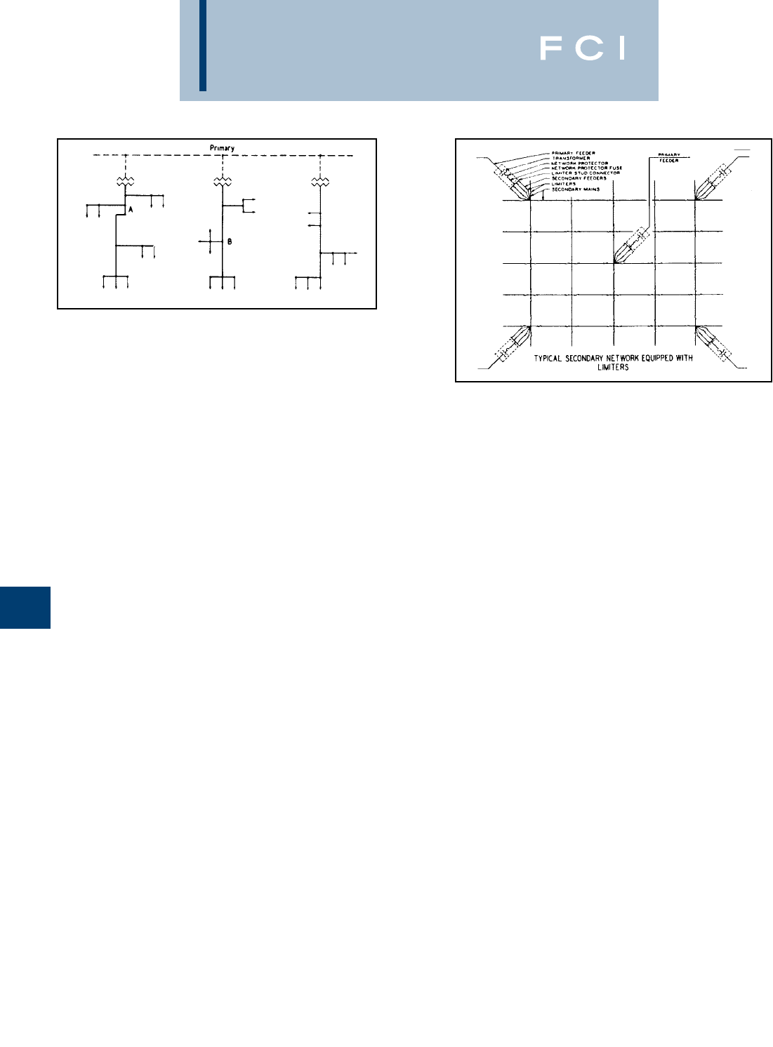
BURNDY
Network Underground
TYPES OF BURNDY®UNDERGROUND
CONNECTORS AND ACCESSORIES
The MOLE™ and HYCRAB™
The most popular of the engineered connec-
tors developed specifically for underground
manholes and transformer vaults are the
MOLE™ and the HYCRAB™ that provide for
multiple connections at a single junction point
of main, feeder, and service cables. Pre-
insulated to eliminate extensive taping, these
connectors are essentially bus bars with sev-
eral cable outlets: mechanical installation in
the MOLE™, and compression installation in
the HYCRAB™.
Limiters and Fuses
To prevent “roasting” of cable insulation,
resulting from fault current, BURNDY®has
developed cable limiters that are inserted in
each secondary cable at all junction points.
Network protector fuses have been designed
to back up the protector breaker in the event
of a malfunction during a transformer or pri-
mary cable fault. By coordinating the time cur-
rent characteristics of the fuse with those of
the cable limiters, the possibility of limiter
blowing on primary faults is eliminated, which
in turn reduces the fault finding task. Also, lim-
iter, fuse, and cable insulation characteristics
must be carefully coordinated to assure isolat-
ing a fault on the secondary before it can
cause extensive damage or interrupt service
in other sections of the secondary system.
High Capacity Limiter 200,000 Amperes at
600 Volts
The BURNDY®High Capacity Limiter is
designed to economically protect electrical
distribution systems from the destructive
effect of high energy faults. The increasing
number of 600 volt secondary network instal-
lations for industrial and commercial applica-
tions demand a cable limiter that can safely
interrupt 200,000 amperes (symmetrical
available) and one that will also completely
coordinate with the higher voltage nework
protector fuses.
Available fault currents as high as 200,000
amperes rms at 600 volts across the fusible
elements have been interrupted during tests
on the BURNDY®High Capacity Limiter. The
power factor during these tests was less than
15%, thereby imposing the most difficult
clearing conditions. No external distrubance
is experienced upon clearing fault currents
from the "float" value to 200,000 amperes.
The quartz filler absorbs the intense energy
gererated by interrupting the fault current.
The quartz fuses into tubular fulgurites, with
a high dielectric strength, and forms an insu-
lating barrier between the melted link sec-
tions. This action prevents restrike of the
internal arc. The rugged glass melamine
housing provides a vessel that completely
contains the developed energy.
The carefully developed time-current charac-
teristics and rigid manufacturing tolerances
assure proper coordination with the network
protector fuses and the insulation damage
characteristics of 4/0, 250, 350, 500 and 750
kcmil cable.
The High Capacity Limiter is available in four
variations to accommodate a variety of instal-
lation practices. The Type HYS has cable
sockets at both ends, which allow for indent-
ing to the cable ends with a hydraulic
BURNDY®HYPRESS™. The HYAO has an
offset lug on one end which permits back-to-
back mounting on bus bar.
For those installations where BURNDY®
Moles™ are used for manhole junctions or
transformer vault buses, the Type HYM per-
mits a replaceable connection of the limiter
directly to the Mole outlet at one end and a
compression cable connection at the other.
Modern electrical distribution systems require
low cost protection to safeguard costly equip-
ment and quickly isolate faults, so that the
undamaged portions of the system may func-
tion normally. BURNDY®High Capacity
Limiters assure positive, economical protection
when installed in properly designed systems.
Compression Connectors
BURNDY®HYDENT™ compression type
connectors, and installation tools, have been
designed for splicing and terminating copper
as well as aluminum underground cables, in
both primary and secondary circuits.
BURNDY®tools and dies are custom
designed to produce sound electrical, and
mechanical joints on BURNDY®connectors.
The use of BURNDY’s matched tools and
connectors assures optimum results.
Residential Underground
The trend toward improvement in neighbor-
hood appearances, and the elimination of
storm outages, tree trimming, etc., has creat-
ed the need for residential underground
distribution. To meet these needs, BURNDY®
offers: Mechanical type pre-insulated multi-
conductor terminal connectors for sub-
mersible transformer locations; and compact
multiconductor connectors for above ground
transformer and enclosures. For service taps,
BURNDY®offers: Pre-insulated, multi-
conductor compression and mechanical
connectors; and a range taking compression
connector for below grade service. Power
pedestals for direct burial, above ground
application, and conduit systems are offered.
Residential Underground Fuse Block assem-
bly with replaceable fuse for each service
cable is also available.
I-2
Figure 1 RADIAL SECONDARY DISTRIBUTION SYSTEM
Figure 2
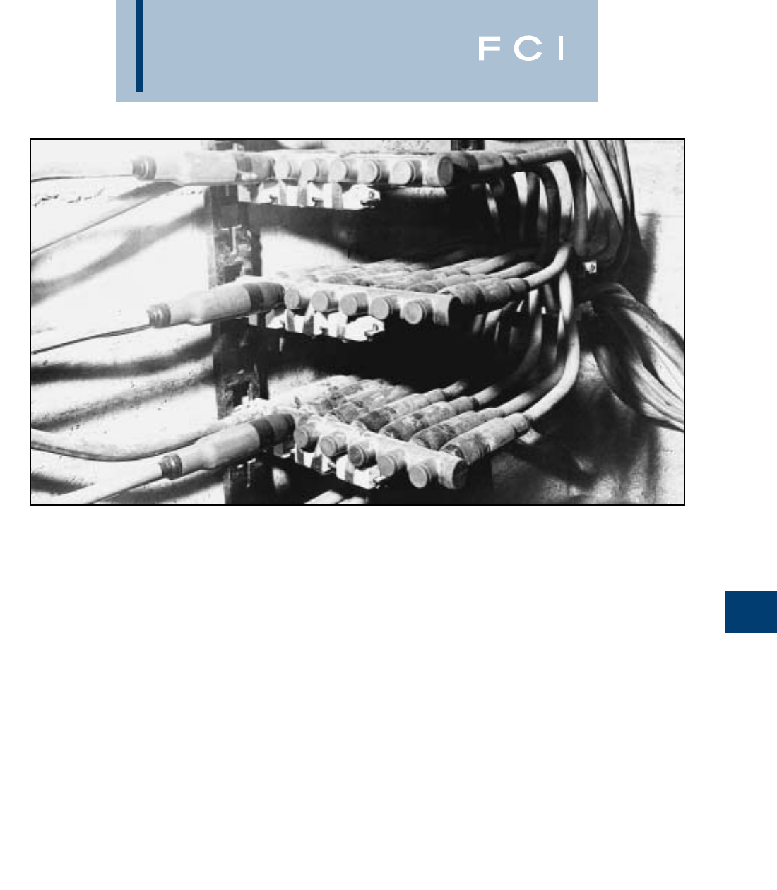
BURNDY
Network Underground
Connectors for Aluminum
For systems where aluminum is used, con-
nectors especially designed for aluminum
conductors are available in bolted and com-
pression types: HYCRAB™, HYPLUG™,
HYREDUCER™, and HYSOCKET. Aluminum
conductors can be connected to standard
MOLE™ connectors by using HYPLUG™
adapters.
Multiple Outlet Connectors
The increasing use in modern electrical dis-
tribution systems of junction points where
several relatively large cables must be con-
nected, has brought about the development
of BURNDY®MOLE™ line equipment to
speed up and simplify the making of such
connections. The modern tendency toward
network systems not only in underground
utility practice but also in industrial wiring, has
greatly increased the number of multi-
connection joints.
The BURNDY®MOLE™ and HYCRAB™
connectors are insulated bus bars with multi-
ple connector outlets for service cables,
secondary mains, or equipment leads. In the
MOLE™, clamping action secures conduc-
tors to the connector; in the HYCRAB™, con-
nections are made by indenting with a
compression tool. Both lines of insulated con-
nectors offer the following basic advantages:
1. Ease and Economy of Installations: The
ease and reduction of time required to make
and insulate dependable multi-connections
greatly reduces the cost of installation. The
compact design makes maximum use of
space and provides for simplified racking.
2. Versatility for System Modification: The
MOLE™ and HYCRAB™ are designed to
accommodate the standard secondary main
and service cables, and permit easy modifi-
cation or later additions. The numerous avail-
able connector configurations permit a wide
variety of arrangements of cables and equip-
ment connections. The 600 volt rating of the
MOLE™ and HYCRAB™ insulation provides
for efficient operation at all standard utiliza-
tion voltages.
3. Efficient, Dependable Performance: The
MOLE™ and HYCRAB™ connectors assure
permanent, high conductivity connections,
good moisture seal, and insulation that
resists the severest condition encountered in
underground installations.
MOLE™ and HYCRAB™ Insulation
The location in vaults and manholes often
exposes these connectors to immersion in
water, chemical, and other contaminants, as
well as to heat from overload or fault currents.
The MOLE™ and HYCRAB™ insulations
provide electrical, mechanical, and thermal
properties essential to assure the service
continuity of underground distribution
systems.
Recognizing the importance of proper
connector insulation, BURNDY®established
performance specifications exceeding those
of 600 volt cable insulation.
I-3
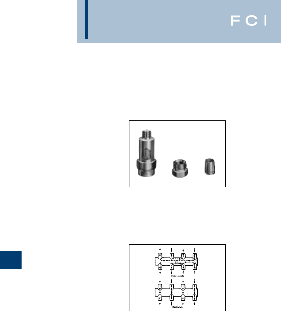
BURNDY
Network Underground
MULTIPLE OUTLET
CONNECTORS
(Continued)
MOLE™ and MOLE™ Accessories
The BURNDY®MOLE™ is a multi-cable con-
nector that consists of a pre-insulated copper
bus bar with threaded outlets that permit a
minimum of two cables to be connected by
means of a socket, nut, and cone assembly
(Illustration A). The clamping action of the
socket, nut and cone assembly on the cable
develops high contact pressures that main-
tain joint conductivities greater than 100% of
the continuous conductor. A compression
socket that is threaded into the MOLE™
insert is also available. The MOLE™ design
affords exceptional versatility in four ways:
1. MOLE™ outlets can be plugged-off until
needed for the addition of cables.
2. Installed cables can be easily removed.
3. Cable sizes can be increased by changing
the socket, nut and cone assembly.
4. The number of outlets may be increased by
joining MOLE™ connectors with a
MOLE™ coupler.
Insulation
The copper bus bar insert is encased in a
molded insulating jacket that eliminates
crotch taping. The thickness of the jacket
prevents any possibility of the insert weight to
cause the insulation at the supports to flow
away at the high temperatures of fault
conditions.
Ratings
MOLE™ connectors are rated at 1500, 2000,
2500, and 3000 amperes, based on the max-
imum current the insert cross-section can
carry. Each outlet can carry the full rated cur-
rent of the cable connected to it.
To avoid exceeding the insert rating, the
cables should be arranged in such a manner
that most current flows directly across the
insert. (See Illustration B)
Installation
Cables are connected to the MOLE™ by
means of a socket, nut and compression
cone assembly. The socket is threaded into
I-4
the MOLE™ insert. The stripped cable end is
inserted into nut and compression cone, and
then into the socket where it is securely
clamped by tightening the nut. The joint is
then sealed watertight in one of three ways:
Illustration B
Illustration A
Taping; MOLE™ Outlet Insulating Sleeves,
sealed with a minimum of taping; or Notape
MOLE™ Sleeve, sealed to the cable and
mole insulation by two non-corrosive hose
clamps.
Tests under flooding and other adverse
conditions demonstrate that such joints are
impervious to water.
Accessories
A socket, cone and nut assembly is screwed
into each MOLE™ outlet to which a cable is
to be connected. The socket has a tapered
recess into which the clamping nut forces the
cable and the compression cone. The cone is
slotted to controlled widths and depths for
maximum flexibility, and its inside surface is
serrated for low contact resistance and high
pullout strength.
A compression socket is available that
threads directly into the MOLE™ outlet and
provides a compression sleeve for connecting
the cable with HYPRESS™ tools.
Plugs seal MOLE™ outlets not in use. The
MOLE™ is delivered with one-fourth of its
outlets sealed with plugs. Additional plugs
may be ordered.
MOLE™ couplers facilitate system expansion
by joining additional MOLE™ connectors to
those already installed. Couplers are easily
installed in end or side outlets of the
MOLE™, and make connections that are
effective both electrically and mechanically.
(Continued)
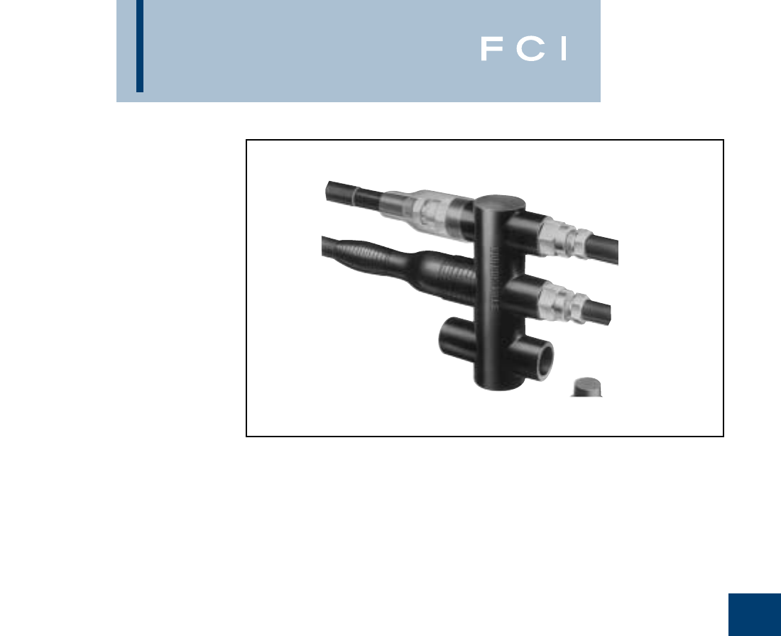
BURNDY
Network Underground
MULTIPLE OUTLET
CONNECTORS
(Continued)
BURNDY®manufactures
a complete line of
Networking products.
For more information on these specialized
BURNDY®NETWORK UNDERGROUND
products, please contact our Customer
Satisfaction Center at: 800-346-4175 or write
us at:
FCI BURNDY Products
P.O. Box 9507
Manchester, NH 03108-9507
Attention Customer Satisfaction Center.
I-5
BURNDY
URD Underground
J-1
URD
UNDERGROUND RESIDENTIAL DISTRIBUTION
For over 70 years, BURNDY®has pioneered
and produced economical, dependable
connectors and protective devices for urban
underground distribution systems.This exten-
sive experience has been applied to the
development of equipment for low cost
underground distribution systems for light
commercial and residential areas.
Increasing interest by home buyers and
developers has created a need for URD com-
ponents comparable in cost with those used
in overhead systems.
Using connectors designed for other purpos-
es, early URD installations were relatively
expensive. Recognizing the need to reduce
installation costs BURNDY®developed a line
of connectors specifically for URD.
These products are shown in this section.
They are the result of a continuing search for
new materials and more efficient production
methods to bring down cost to meet the
requirements of low cost underground
construction.
Type Y-LOK .................................J-5
Type YRB-U.........................J-6 - J-8
Type YRB-T.......................J-9 - J-12
Type K-P-C.................................J-13
Type YPC-C ...............................J-13
Types K6B & K33B....................J-14
Type F-A.....................................J-15
Type K6A34U-6N.......................J-15
Type K-P-UC..............................J-15
Types BPD & BPD2...................J-16
URD SECTION
Type RDMD-28G..........................J-2
Type RDMD-2858D......................J-2
Type RDMD-28 CR ......................J-2
Type RDM-28 ...............................J-2
Type RDM-28T.............................J-3
Types RYA-UC, RYA-AC,
RYA-UCR, RYA-ACR Tap Kits...J-3
Types RA6UC-SL,
RA6UCR-SL Tap Kits................J-4
Type YS-CG
Insulated Splice Kit..................J-5
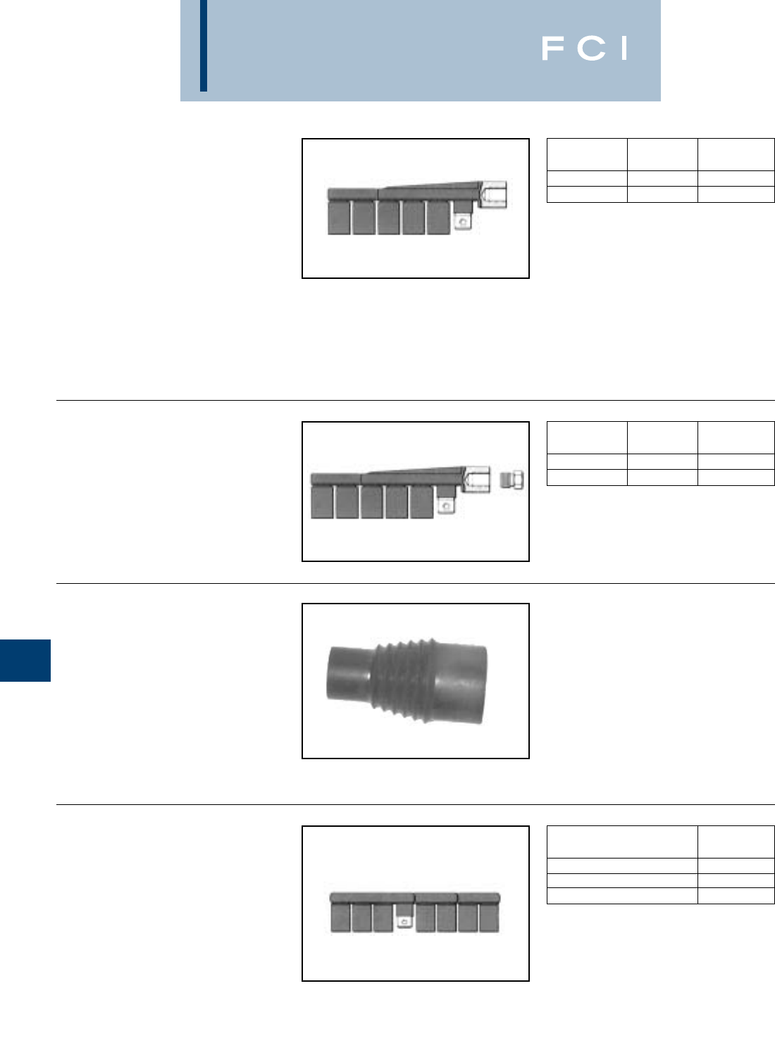
BURNDY
URD Underground
URD
STUD MOLE™
TYPE RDMD-28G
The RDMD-28G Stud MOLE™ is a sub-
mersible junction designed to accommodate
a range of copper and aluminum conductors.
The Stud MOLE™ is designed for use on
transformers where a dead front secondary is
required. It is insulated with molded EPT rub-
ber. Mates with a 5/8-11 copper stud. A jam
nut is supplied with the MOLE™ to secure
and lock it to the stud.
STUD MOLE™
TYPE RDMD-2858D
The RDMD-2858D Stud MOLE™ is identical
to the insulated RDMD-28G except an
adapter is supplied, allowing MOLE™ to be
removed from transformer stud without dis-
connecting the individual services.
It is available with either four or six outlets. All
outlets except one have factory installed
removable sealing caps. Tap kits are ordered
separately. REA listed.
Also available without insulation and sealing
caps.
RUBBER
INSULATING BOOT
TYPE RDMD-28CR
The EPDM rubber force fit boot is designed to
provide a completely dead-front and moisture
tight installation when used with either the
Type RDMD-28G3 or Type RDMD-2858D
Stud MOLE™. Bushing end will seal any
diameter from .875 to 1.125 inch.
URD MOLE™
TYPE RDM-28
FOR ALUMINUM OR COPPER
Type RDM-28 MOLE™ is an economical,
insulated, submersible service junction suit-
able for direct burial or for use in enclosures.
Disconnectable joints allow additions of new
services without disturbing previous installa-
tions. Taping is eliminated, heat-shrink or
force-fit rubber sleeves insulate each joint.
Rubber is used to insulate the MOLE™ body.
Removable sealing covers are supplied on all
J-2
CATALOG NO. OF
NUMBER OUTLETS INSULATED
RDMD4-28G3 4Yes
RDMD6-28G3 6Yes
CATALOG NO. OF
NUMBER OUTLETS INSULATED
RDMD4-2858D 4Yes
RDMD6-2858D 6Yes
NO. OF
CATALOG NUMBER OUTLETS
RDM4-28 4
RDM6-28 6
RDM8-28 8
outlets but two. REA listed Tap Kits, including
HYLUG™, hardware and sleeve are ordered
separately.
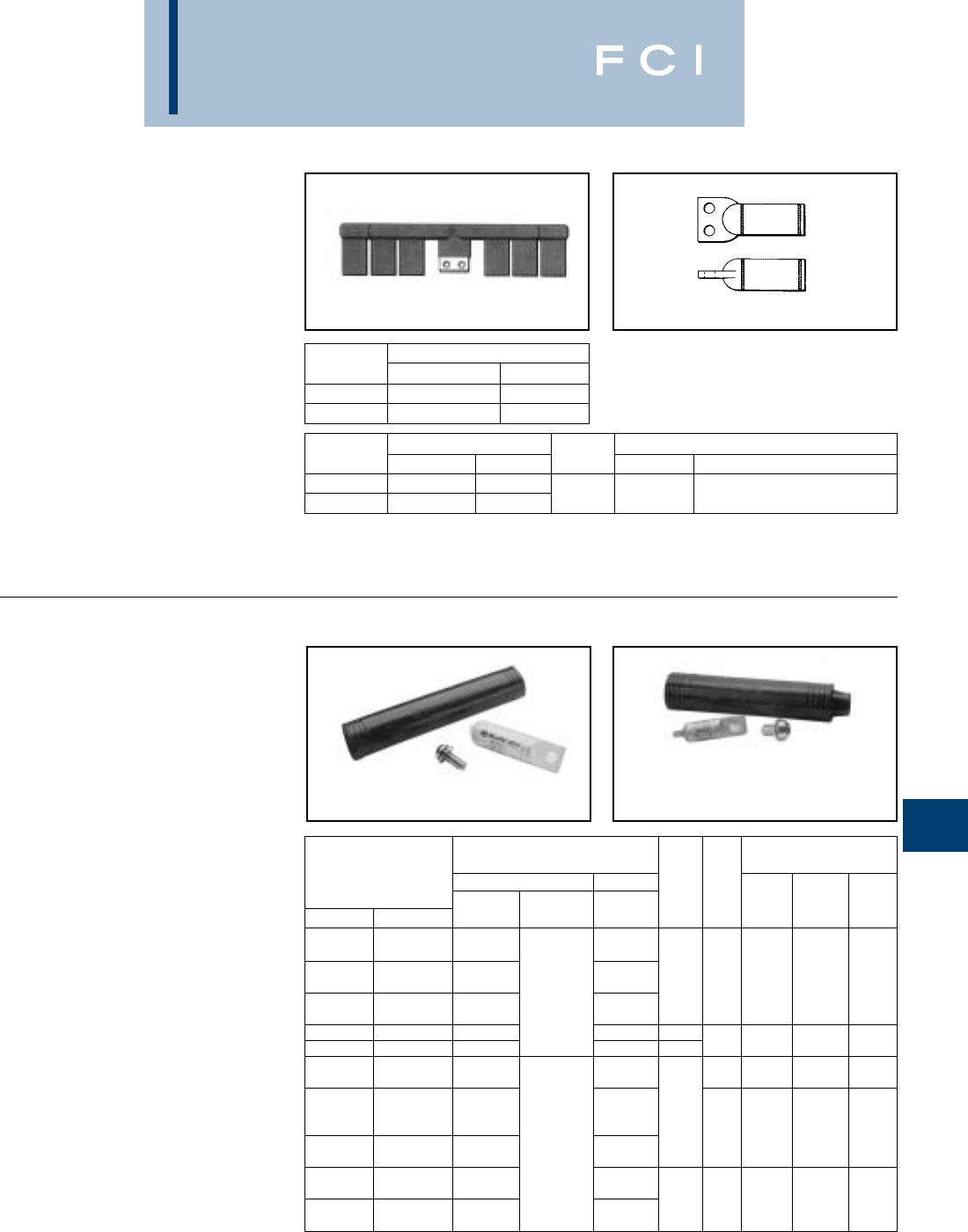
BURNDY
URD Underground
URD
MOLE™ TYPE RDM-28T
FOR ALUMINUM
AND COPPER
The RDM-28T MOLE™ is available with five
or seven outlets. The single hole outlets are
the same size as the RDM-28 series and
accommodate the same RYA-UC or
RYA-UCR tap kits. The larger two-hole outlet
accommodates the 500 or 350 kcmil copper
cable secondary supplied with many sub-
surface transformers. These cables are
extended to a junction point where secondary
mains or services are connected. Tin-plated
copper RYA-C-2 tap kits are used to join the
500 or 350 kcmil copper secondaries to the
RDM-28T MOLE™.
J-3
MOLE™ TAP KITS
TYPES RYA-UC, RYA-AC
FOR ALUMINUM OR COPPER
FOR USE WITH TYPE RDM-28
URD MOLE™
The kit consists of: Universal HYLUG™,
mounting hardware and heat-shrink sleeve.
The HYLUG™ is pre-filled with PENE-
TROX™ joint compound and sealed. Installed
with common installation tools, three die sets
install a range of 4 str.- 350 kcmil. The heat-
shrink sleeve is lined with a mastic material,
providing a positive seal. Installed with stan-
dard propane torch, or 500°F electric heat
gun. Acetylene heat is too intense and is not
recommended.
TYPES RYA-UCR, RYA-ACR
The kit consists of: Universal HYLUG™,
mounting hardware and pre-lubricated force-
fit rubber sleeve. The HYLUG™ is pre-filled
with PENETROX™ joint compound and
sealed. Installed with common installation
tools, three die sets install a range of 4 str.-
350MCM. The rubber sleeve has internal
sealing rings that provide a positive moisture
seal by exerting circumferential force on cable
and MOLE™ insulation. Pre-lubricating
sleeve makes installation easier. REA listed.
No trimming required.
*Overlap Crimps.
** Do not use EEI Die. (11A) to install 4/0 Sol. EC-O.
NOTE: Standard mounting hardware is 3/8" button head
socket cap screw with captive conical washer. For
HEX HEAD bolt with captive conical washer add
“HEX” suffix.
TYPE RYA-UC, RYA-AC TYPE RYA-UCR, RYA-ACR
*Y35 U-Dies with adapter PT6515 can also be used in Y45
series HYPRESSES™. Same number of crimps as Y35.
NOTE: Example: RYA4UCR-HEX. For HEX HEAD bolt and
captive flat washer add suffix “HEX1”. For HEX HEAD
bolt and non-captive flat washer add suffix “HEX2”.
For HEX HEAD bolt and non-captive conical washer
add suffix “HEX3”. For Stainless Steel HEX HEAD
bolt add “HEX355” suffix.
CATALOG NO. OF OUTLETS
NUMBER 12 SOL. - 350 350 - 500
RDM5-28T 41
RDM7-28T 61
COPPER CATALOG NUMBER TOOLS, DIE SET, CATALOG NO. & (NO. OF CRIMPS)
CONDUCTOR HEAT SHRINK FORCE FIT DIE INDEX Y34A Y35* SERIES Y750, 739
350 RYA31C-2 RYA31CR-2
500 RYA34C-2 RYA34CR-2 20 A34R (4) U34RT (4)
TOOLS, DIE SET CATALOG NO.,
CATALOG NUMBER & (NUMBER OF CRIMPS)
HEAT SHRINK FORCE FIT Y39,
CONDUCTOR COMPLETE SHRINK COMPLETE EEI DIE DIE MD6 Y35, Y750
COPPER ALUMINUM SET SLEEVE ONLY SET INDEX INDEX SERIES SERIES OUR840
2 Sol. - 4 Str.
2 Sol. - 4 Str. 4 Str. Comp. RYA4UC RYA4UCR
2 Str. - 1/0 Sol. BG or W-BG (1) U-BG (1) XBG (3)
2 Str. - 1/0 Sol. 2-1 Str. Comp. RYA2UC RYA2UCR 8A 5/8 - 1 BG3 UK58-IT (3) XNBG (2)
1/0 Str. - 2/0 Sol. RYAC25 or 243 or W243 U243 (1)
1/0 Str. 1/0 Str. Comp. RYA25UC RYA25UCR
2 Sol. EC-O RYA2WAC RYA2WACR BG (5) BG (5) — XBG (5)
1/0 Sol. EC-O RYA75AC RYA75ACR ——UK58-IT (5) XNBG (3)
2/0 Str. 249 or W249 (3) U249 (2)* X249 (6)
2/0 Str. 2/0 Str. Comp. RYA26UC RYA26UCR 840 WK840 (5) UK840T (3) X840 (5)
3/0 Str.
3/0 Str. 3/0 Str. Comp. RYA27UC RYA27UCR ** 249
4/0 Sol. EC-O** 11 or W249 (4) U249 (2) X249 (8)
4/0 Str. RYAC31 840 WK840 (7) UK840T (4) X840 (7)
4/0 Str.
4/0 Str. - 250 Comp.
RYA28UC RYA28UCR
250
250 MCM 250 Comp. RYA29UC RYA29UCR 299 or U31ART (2)
300 - 350 13A 655 or U655 (3)
—300 - 350 Comp. RYA31AC RYA31ACR 705 U705 (2)
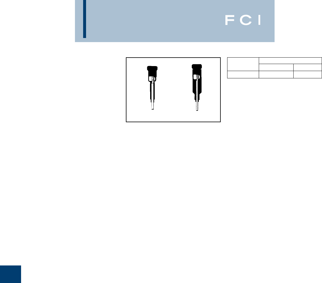
BURNDY
URD Underground
URD
URD STREET LIGHTING
TAP KIT TYPES RA6UC-SL,
RA6UCR-SL
FOR ALUMINUM OR COPPER
URD tap kit for making street lighting taps
from URD MOLE™ types RDM-28 and RDM-
28T. Each kit accommodates 6 str. - 12 sol.
Kits include connector, mounting hardware
and insulating sleeve.
J-4
Cat. No. RA6UC-SL Cat. No. RA6URC-SL
CATALOG NUMBER
CONDUCTOR HEAT SHRINK FORCE FIT
6 Str. - 12 Sol. RA6UC-SL RA6UCR-SL

BURNDY
URD Underground
URD
URD INSULATED SPLICE KIT
TYPE YS-CG
FOR ALL ALUMINUM
OR COPPER/ALUMINUM
COMBINATIONS
Type YS-CG URD insulated splice kit consists
of a standard YSU or YSD LINKIT™ and a
heat-shrink sleeve. Used to splice URD
secondary lines up to 600 volts. It is installed
with common installation tools. Heat-shrink
sleeve is installed with standard propane
torch, or 500° F electric heat gun. Acetylene
is not recommended.
Y-LOK FOR LOCKING
ENCLOSURES
Assembly consists of aluminum-clad steel
wire loop and a compression type aluminum
connector. Installed with BG groove of MD6 or
OUR840 Compression Tools. Can also be
installed with 5/8 or 5/8-1 grooves.
J-5
*Use to join copper to aluminum or ACSR, not copper to
copper.
** Multiple crimp die set, makes more than one crimp per
compression.
J1592
J1207
Compression Y-LOK installed with BG or
5/8 groove
CONDUCTOR CATALOG NUMBER TOOLS, DIE SET CATALOG NO., & (NO. OF CRIMPS)
BOTH SIDES COMPLETE HEAT SHRINK DIE MD6
ALUMINUM ACSR COPPER* SPLICE KIT SLEEVE INDEX SERIES Y34A Y35 SERIES
1-2 Str. 2 (6-1, 7-1) 1-2 Str. YS2UCGI BG (3)
1/0 Str. RYAC25 BG W-BG (1)** —U-BG (1)**
1/0 Comp. 1/0 (6-1) 1/0 Str. YS25UCGI 243 W243 (2) A243 (1) U243 (1)
2/0 Str.
2/0 Comp. 2/0 (6-1) 2/0 Str. YS26UCGI
3/0 Str. W249 (4) A249 (2) U249 (2)
3/0 Comp. 3/0 (6-1) 3/0 Str. YS27UCGI RYAC31-1 249/840 W-K840 (7) — U-K840T (4)
4/0 Str.
4/0 Comp. 4/0 (6-1) 4/0 Str. YS28UCGI
350 U299 (2)
350 Comp. —350 YS31ACGI RYAC31 299/705 — — U705 (1)
INSTALLATION
TOOLING
CATALOG D1D6, Y35, Y750,
NUMBER OUR840 Y46 L C D
J1207 WBG 2.28 .75 1.00
J1592 XBG UBG 2.31 .75 .75
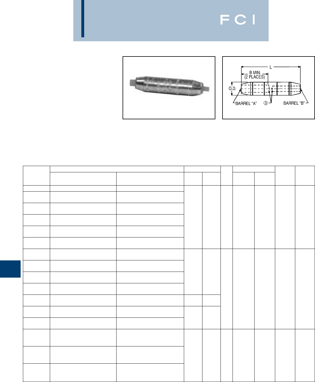
BURNDY
URD Underground
J-6
TYPE YRB-U
HYREDUCER™ SPLICE
FOR ALUMINUM-TO-ALUMINUM
AND ALUMINUM-TO-COPPER
Type YRB-U splice is designed for use within
underground systems. Aluminum splices are
tin-plated and recommended for use on
Aluminum-to-Aluminum and Aluminum-to-
Copper cables. All splices have solid center
stop for use with oil filled and non-oil filled
cables. The Outside Diameter is held
constant to minimize installation dies and
connectors are prefilled with PENETROX™.
Rated up to 35 kV.
CONDUCTOR RANGE DIMENSIONS WIRE STRIP LENGTH
CATALOG BARREL “A” BARREL “B” B BARREL BARREL DIE COLOR
NUMBER CU & ALUM. CU & ALUM. MIN. L O.D. “A” “B” NUMBER CODE
YRB2U3TTN #2 (.292 Dia.) 7 Str. #3 (.260 Dia.) 7 Str.
#1 (.332 Dia.) 19 Str. or
YRB1CU2TTN 1/0 CMPCT (.336 Dia.) 19 Str. #2 (.292 Dia.) 7 Str.
#1 (.332 Dia.) 19 Str. or #1 (.332 Dia.) 19 Str. or
YRB1CU1TTN 1/0 CMPCT (.336 Dia.) 19 Str. 1/0 CMPCT (.336 Dia.) 19 Str.
1/0 (.373 Dia.) 19 Str. or 1.35 3.25 .65 1-3/41-3/4296 Tan
YRB25U3TTN 1/0 CMPCT (.336 Dia.) 19 Str. #3 (.260 Dia.) 7 Str. [34] [83] [17]
1/0 (.373 Dia.) 19 Str. or
YRB25U2TTN 1/0 CMPCT (.336 Dia.) 19 Str. #2 (.292 Dia.) 7 Str.
1/0 (.373 Dia.) 19 Str. or 1/0 (.373 Dia.) 19 Str. or
YRB25U25TTN 1/0 CMPCT (.336 Dia.) 19 Str. 1/0 CMPCT (.336 Dia.) 19 Str.
3/0 (.470 Dia.) 19 Str. or 1/0 (.373 Dia.) 19 Str. or
YRB27U25TW 3/0 CMPCT (.423 Dia.) 19 Str. 1/0 CMPCT (.336 Dia.) 19 Str.
4/0 (.528 Dia.) 19 Str. or
YRB28U3TW 4/0 CMPCT (.475 Dia.) 19 Str. #3 (.260 Dia.) 7 Str. 1.53 3.69
4/0 (.528 Dia.) 19 Str. or #2 (.292 Dia.) 7 Str. or [39] [94]
YRB28U2TW 4/0 CMPCT (.475 Dia.) 19 Str. #2 CMPCT (.268 Dia.) 7 Str.
4/0 (.528 Dia.) 19 Str. or #1 (.332 Dia.) 19 Str. or .85
YRB28U1TW 4/0 CMPCT (.475 Dia.) 19 Str. 1/0 CMPCT (.299 Dia.) 7 Str. [22] 1-1/21-1/2298 White
4/0 (.528 Dia.) 19 Str. or 1/0 (.373 Dia.) 19 Str. or 1.53 3.70
YRB28U25TW 4/0 CMPCT (.475 Dia.) 19 Str. 1/0 CMPCT (.336 Dia.) 19 Str. [39] [94]
4/0 (.528 Dia.) 19 Str. or 2/0 (.419 Dia.) 19 Str. or
YRB28U26TW 4/0 CMPCT (.475 Dia.) 19 Str. 2/0 CMPCT (.376 Dia.) 19 Str. 1.53 3.69
4/0 (.528 Dia.) 19 Str. or 4/0 (.528 Dia.) 19 Str. or [39] [94]
YRB28U28TW 4/0 CMPCT (.475 Dia.) 19 Str. 4/0 CMPCT (.475 Dia.) 19 Str.
350 kcmil (.681 Dia.) 37 Str. or
YRB31U25TW 350 kcmil CMPCT (.616 Dia.) 19 Str. AL; 1/0 (.373 Dia.) 19 Str. or
37 Str. AL & CU 1/0 CMPCT (.336 Dia.) 19 Str.
350 kcmil (.681 Dia.) 37 Str. or
YRB31U28TW 350 kcmil (.616 Dia.) 19 Str. AL; 4/0 (.528 Dia.) 19 Str. or 2.34 5.43 1.11 2-1/42-1/4299 Brown
37 Str. AL & CU 250 kcmil CMPCT (.520 Dia.) 37 Str. [59] [138] [28]
350 kcmil (.681 Dia.) 37 Str. or 350 kcmil (.681 Dia.) 37 Str. or
YRB31U31TW 350 kcmil CMPCT (.616 Dia.) 19 Str. AL; 350 kcmil CMPCT (.616 Dia.) 19 Str. AL;
37 Str. AL & CU 37 Str. AL & CU
1Material: Aluminum.
2Finish: Electro-tin plated.
➂Barrels are partially filled with PENETROX™ and sealed.
4Scratch brushing of all conductors before making
installation is recommended.
5Not for use with Copper-to-Copper applications.
6Dimensions in brackets [ ] are in millimeters rounded off
to the nearest millimeter, unless otherwise noted, and are
for reference only.
➆Catalog number PT6515 Adaptor is required to use “U”
dies in Y45 series tools.
⑧Catalog number PUADP-1 Adaptor is required to use “U”
dies in Y46 series tools.
9On MY29-3 HYTOOL™ use alum. Index plate settings as
follows, for 1/0 conductor use 1/0 setting. For conductor
smaller than 1/0 size use 2/0 setting.
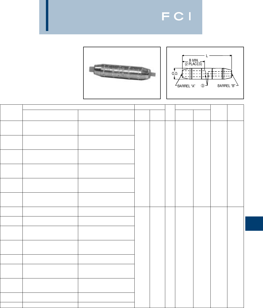
BURNDY
URD Underground
J-7
TYPE YRB-U
HYREDUCER™ SPLICE
(Continued)
FOR ALUMINUM-TO-ALUMINUM
AND ALUMINUM-TO-COPPER
CONDUCTOR RANGE DIMENSIONS WIRE STRIP LENGTH
CATALOG BARREL “A” BARREL “B” B BARREL BARREL DIE COLOR
NUMBER CU & ALUM. CU & ALUM. MIN. L O.D. “A” “B” NUMBER CODE
500 kcmil (.813 Dia.) 37 Str. or
YRB34U25TW 500 kcmil CMPCT (.736 Dia.) 19 Str. AL; 1/0 (.373 Dia.) 19 Str.
37 Str. AL & CU
500 kcmil (.813 Dia.) 37 Str. or
YRB34U28TW 500 kcmil CMPCT (.736 Dia.) 19 Str. AL; 4/0 (.528 Dia.) 19 Str. or
37 Str. AL & CU 4/0 CMPCT (.475 Dia.) 19 Str.
500 kcmil (.813 Dia.) 37 Str. or
YRB34U29TW 500 kcmil CMPCT (.736 Dia.) 19 Str. AL; 250 kcmil (.575 Dia.) 37 Str.
37 Str. AL & CU 2.70 6.00 1.31
500 kcmil (.813 Dia.) 37 Str. or [69] [152] [33] 1-1/81-1/8300 Pink
YRB34U30TW 500 kcmil CMPCT (.736 Dia.) 19 Str. AL; 300 kcmil (.630 Dia.) 37 Str.
37 Str. AL & CU
500 kcmil (.813 Dia.) 37 Str. or 350 kcmil (.681 Dia.) 37 Str.
YRB34U31TW 500 kcmil CMPCT (.736 Dia.) 19 Str. AL; 350 kcmil CMPCT (.616 Dia.) 19 Str. AL;
37 Str. AL & CU 37 Str. AL & CU
500 kcmil (.813 Dia.) 37 Str. or 500 kcmil (.813 Dia.) 37 Str. or
YRB34U34TW 500 kcmil CMPCT (.736 Dia.) 19 Str. AL; 500 kcmil CMPCT (.736 Dia.) 19 Str. AL;
37 Str. AL & CU 37 Str. AL & CU
750 kcmil (.998 Dia.) 61 Str. or 4/0 (.528 Dia.) 19 Str. or
YRB39U28TW 750 kcmil CMPCT (.908 Dia.) 61 Str. 4/0 CMPCT (.475 Dia.) 19 Str.
750 kcmil (.998 Dia.) 61 Str. or
YRB39U30TW 750 kcmil CMPCT (.908 Dia.) 61 Str. 300 kcmil (.630 Dia.) 37 Str.
350 kcmil (.681 Dia.) 37 Str. or
YRB39U31TW 750 kcmil (.998 Dia.) 61 Str. or 350 kcmil CMPCT (.616 Dia.) 19 Str. AL;
750 kcmil CMPCT (.908 Dia.) 61 Str. 37 Str. AL & CU
500 kcmil (.813 Dia.) 37 Str. or
YRB39U34TW 750 kcmil (.998 Dia.) 61 Str. or 500 kcmil CMPCT (.736 Dia.) 19 Str. AL;
750 kcmil CMPCT (.908 Dia.) 61 Str. 37 Str. AL & CU
750 kcmil (.998 Dia.) 61 Str. or 750 kcmil (.998 Dia.) 61 Str. or 2.87 6.74 1.46 33-11/16936 Yellow
YRB39U39TW 750 kcmil CMPCT (.908 Dia.) 61 Str. 750 kcmil CMPCT (.908 Dia.) 61 Str. [73] [171 [37]
350 kcmil (.681 Dia.) 37 Str. or
YRB44U31TW 1000 kcmil (1.152 Dia.) 61 Str. 350 kcmil CMPCT (.616 Dia.) 19 Str. AL;
37 Str. AL & CU
500 kcmil (.813 Dia.) 37 Str. or
YRB44U34TW 1000 kcmil (1.152 Dia.) 61 Str. 500 kcmil CMPCT (.736 Dia.) 19 Str. AL;
37 Str. AL & CU
750 kcmil (.998 Dia.) 61 Str. or
YRB44U39TW 1000 kcmil (1.152 Dia.) 61 Str. 750 kcmil CMPCT (.908 Dia.) 61 Str.
YRB44U44TW 1000 kcmil (1.152 Dia.) 61 Str. 1000 kcmil (1.152 Dia.) 61 Str.
1Material: Aluminum.
2Finish: Electro-tin plated.
➂Barrels are partially filled with PENETROX™ and sealed.
4Scratch brushing of all conductors before making
installation is recommended.
5Not for use with Copper-to-Copper applications.
6Dimensions in brackets [ ] are in millimeters rounded off
to the nearest millimeter, unless otherwise noted, and are
for reference only.
➆Catalog number PT6515 Adaptor is required to use “U”
dies in Y45 series tools.
⑧Catalog number PUADP-1 Adaptor is required to use “U”
dies in Y46 series tools.
9On MY29-3 HYTOOL™ use alum. Index plate settings as
follows, for 1/0 conductor use 1/0 setting. For conductor
smaller than 1/0 size use 2/0 setting.
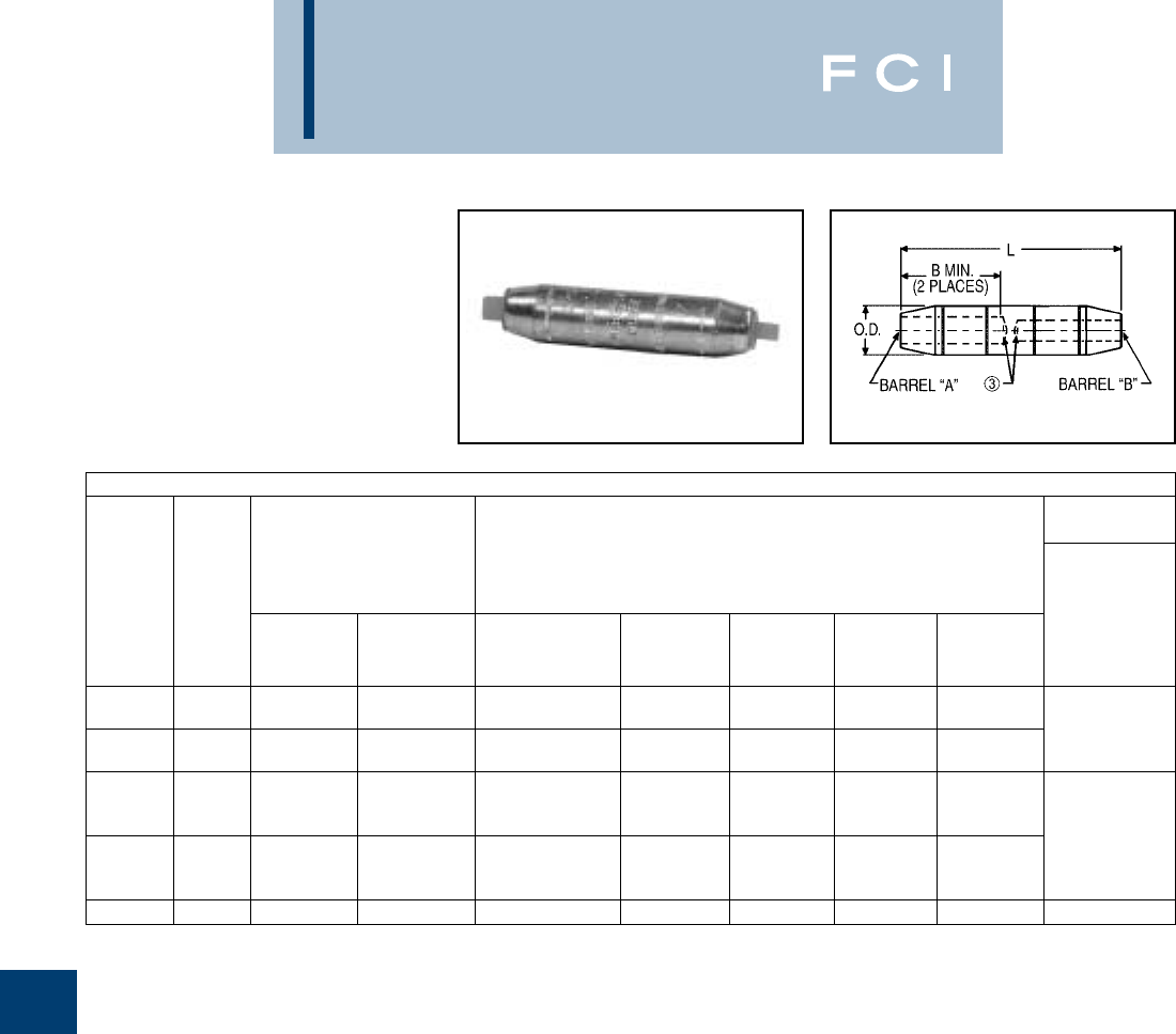
BURNDY
URD Underground
J-8
TYPE YRB-U
HYREDUCER™ SPLICE
(Continued)
FOR ALUMINUM-TO-ALUMINUM
AND ALUMINUM-TO-COPPER
1Material: Aluminum.
2Finish: Electro-tin plated.
➂Barrels are partially filled with PENETROX™ and sealed.
4Scratch brushing of all conductors before making
installation is recommended.
➄Not for use with Copper-to-Copper applications.
6Dimensions in brackets [ ] are in millimeters rounded off
to the nearest millimeter, unless otherwise noted, and are
for reference only.
INSTALLATION TOOLING (NUMBER OF CRIMPS PER END)
➄DIELESS
(# OF CRIMPS)
Mechanical:
MY29-3 (1)
MECHANICAL RATCHET HYDRAULIC MY29-11 (1)
Y35, Y39, Y750 Hydraulic:
COLOR DIE BAT35, Y644M (1)
CODE INDEX OUR840 MD6, MD7 BAT750, PAT750 ➇Y46 ➆Y45 Y48B Y60BHU PAT644-18V (1)
MY29-3 (1)
Tan 296 — — U25ART (1) U25ART (1) U25ART (1) C25AR (1) — MY29-11 (1)
Y644M (1)
White 298 — — U28ART (2) U28ART (2) U28ART (2) C28AR (2) — PAT644-18V (1)
U31ART U31ART U31ART
Brown 299 — — Overlap Overlap Overlap C31AR (1) L31ART (1)
Crimp Crimp Crimp Y644M (1)
U34ART U34ART U34ART PAT644-18V (1)
Pink 300 — — Overlap Overlap Overlap C34AR (1) L34ART
Crimp Crimp Crimp
Yellow 936 — — U39ART-2 (4) U39ART-2 (4) U39ART-2 (4) C39AR (2) L39ART (2) —
➆Catalog number PT6515 Adaptor is required to use “U”
dies in Y45 series tools.
⑧Catalog number PUADP-1 Adaptor is required to use “U”
dies in Y46 series tools.
9On MY29-3 HYTOOL™ use alum. Index plate settings as
follows, for 1/0 conductor use 1/0 setting. For conductor
smaller than 1/0 size use 2/0 setting.
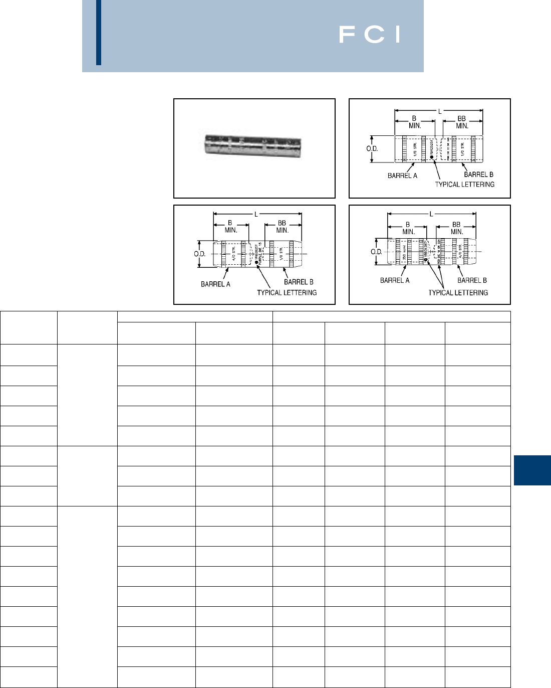
BURNDY
URD Underground
J-9
TYPE YRB-T
HYREDUCER™ SPLICE
FOR COPPER-TO-COPPER
Type YRB-T splice is designed for use within
underground systems. Copper splices are
tapered and recommended for use on
copper-to-copper cables.
All splices have solid center stops for use with
oil filled and non-oil filled cables.
The Outside Diameter is held constant to
minimize installation dies. Rated up to 35 kV.
Fig. 1
Fig. 2 Fig. 3
CONDUCTOR SIZE DIMENSIONS
CATALOG ➁BBB
NUMBER ➆FIGURE NO. BARREL “A” BARREL “B” MIN. MIN. L O.D.
.90 .90 2.05 .29
YRB6C6CT #6 Str. (.184) #6 Str. (.184) [23] [23] [52] [7]
.90 .90 2.05 .34
YRB4C4CT #4 Str. (.232) #4 Str. (.232) [23] [23] [52] [9]
.98 .98 2.21 .42
YRB2C2CT 1#2 Str. (.292) #2 Str. (.292) [25] [25] [56] [11]
.98 .98 2.63 .51
YRB2525T 1/0 (.372) 1/0 (.372) [25] [25] [67] [13]
1.04 1.04 2.36 .69
YRB2626T 2/0 (.419) 2/0 (.419) [26] [26] [60] [18]
1.16 1.16 2.84 .69
YRB2825T 4/0 (.528) 1/0 (.372) [29] [29] [73] [18]
1.16 1.16 2.84 .69
YRB2828T 24/0 (.528) 4/0 (.528) [29] [29] [73] [18]
1.25 1.25 3.12 .75
YRB2929T 250 kcmil (.575) 250 kcmil (.575) [32] [32] [79] [19]
1.36 1.36 3.34 .88
YRB3128T 350 kcmil (.681) 4/0 (.528) [35] [35] [85] [85]
1.36 1.36 3.34 .88
YRB3131T 350 kcmil (.681) 350 kcmil (.681) [35] [35] [85] [85]
1.38 1.38 3.48 .95
YRB3228T 400 kcmil (.728 4/0 (.528) [35] [35] [88] [24]
1.73 1.73 4.50 1.06
YRB3428T 500 kcmil (.813) 4/0 (.528) [44] [44] [114] [27]
1.73 1.73 4.50 1.06
YRB3431T 3500 kcmil (.813) 350 kcmil (.681) [44] [44] [114] [27]
1.73 1.73 4.50 1.06
YRB3432T 500 kcmil (.813) 400 kcmil (.728) [44] [44] [114] [27]
1.73 1.73 4.50 1.06
YRB3434T 500 kcmil (.813) 500 kcmil (.813) [44] [44] [114] [27]
2.06 2.06 4.75 1.23
YRB3728T 650 kcmil (.929) 4/0 (.528) [52] [52] [120] [31]
2.06 2.06 4.75 1.23
YRB3734T 650 kcmil (.929) 500 kcmil (.813) [52] [52] [120] [31]
1Material: Copper.
➁For Tin-Plating, add suffix “TN” to the Catalog Number
(ex.: YRB2825TN). For Hot Tin dipped add suffix “W” to the
catalog number (ex.: YRB2825TW).
➂Catalog Number PT6515 Adaptor is required to use “U”
dies in Y45 series tools.
➃Catalog Number PUADP-1 is required to use “U” dies in
Y46 series tools.
5Dimensions in brackets [ ] are in millimeters rounded off
to the nearest millimeter, unless otherwise specified, and
are for reference only.
➅For use by customers that have this HYPRESS™. No new
Y34 HYPRESS™ tools are being processed.
➆Suffix “TN” and “W” will not be stamped on part.
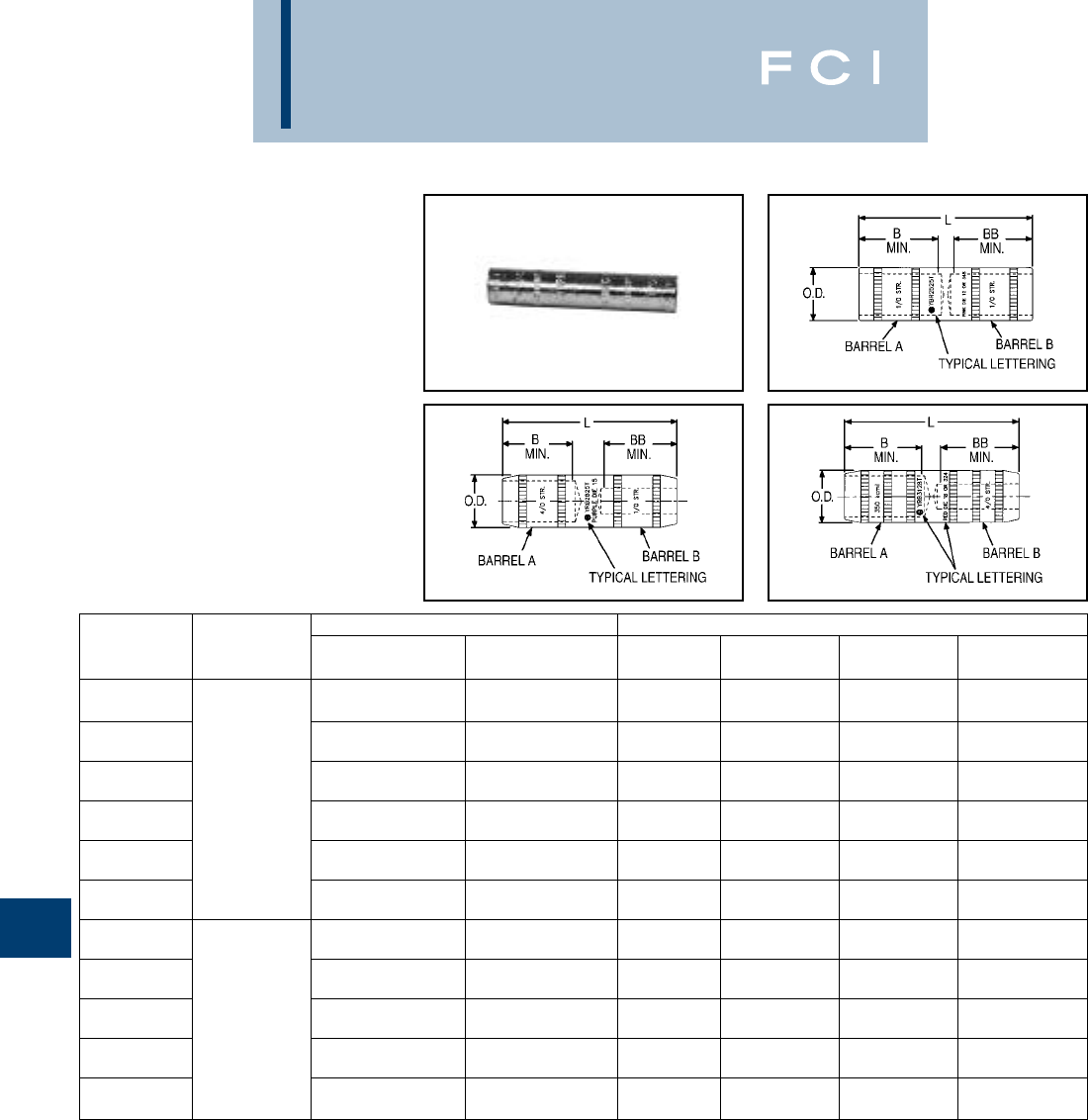
BURNDY
URD Underground
J-10
TYPE YRB-T
HYREDUCER™ SPLICE
(Continued)
FOR COPPER-TO-COPPER
Fig. 1
Fig. 2 Fig. 3
CONDUCTOR SIZE DIMENSIONS
CATALOG ➁BBB
NUMBER ➆FIGURE NO. BARREL “A” BARREL “B” MIN. MIN. L O.D.
2.06 2.06 4.75 1.23
YRB3737T 650 kcmil (.929) 650 kcmil (.929) [52] [52] [120] [31]
2.06 2.06 4.75 1.30
YRB3931T 750 kcmil (.998) 350 kcmil (.681) [52] [52] [120] [33]
2.06 2.06 4.75 1.30
YRB3934T 750 kcmil (.998) 500 kcmil (.813) [52] [52] [120] [33]
32.06 2.06 4.75 1.30
YRB3936T 750 kcmil (.998) 600 kcmil (.893) [52] [52] [120] [33]
2.06 2.06 4.75 1.30
YRB3937T 750 kcmil (.998) 650 kcmil (.929) [52] [52] [120] [33]
2.06 2.06 4.75 1.30
YRB3939T 750 kcmil (.998) 750 kcmil (.998) [52] [52] [120] [33]
2.13 2.13 4.89 1.35
YRB4028T 800 kcmil (1.031) 4/0 (.528) [54] [54] [124] [34]
2.13 2.13 4.89 1.35
YRB4037T 800 kcmil (1.031) 650 kcmil (.929) [54] [54] [124] [34]
2.13 2.13 4.89 1.35
YRB4039T 2800 kcmil (1.031) 750 kcmil (.998) [54] [54] [124] [34]
2.50 2.50 5.86 1.50
YRB4439T 1000 kcmil (1.152) 750 kcmil (.998) [64] [64] [149] [38]
2.50 2.05 5.86 1.50
YRB4444T 1000 kcmil (1.152) 1000 kcmil (1.152) [64] [64] [149] [38]
1Material: Copper.
➁For Tin-Plating, add suffix “TN” to the Catalog Number
(ex.: YRB2825TN). For Hot Tin dipped add suffix “W” to the
catalog number (ex.: YRB2825TW).
➂Catalog Number PT6515 Adaptor is required to use “U”
dies in Y45 series tools.
➃Catalog Number PUADP-1 is required to use “U” dies in
Y46 series tools.
5Dimensions in brackets [ ] are in millimeters rounded off
to the nearest millimeter, unless otherwise specified, and
are for reference only.
➅For use by customers that have this HYPRESS™. No new
Y34 HYPRESS™ tools are being processed.
➆Suffix “TN” and “W” will not be stamped on part.
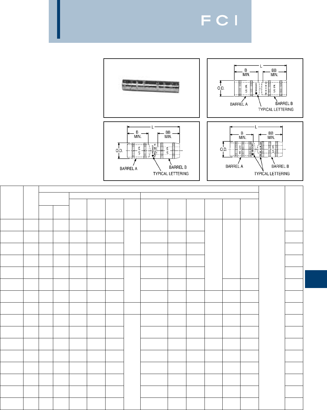
BURNDY
URD Underground
J-11
TYPE YRB-T
HYREDUCER™ SPLICE
(Continued)
FOR COPPER-TO-COPPER
Fig. 1
Fig. 2 Fig. 3
INSTALLATION TOOLING (NUMBER OF CRIMPS)
DIE MECHANICAL HYDRAULIC
INFORMATION Y35, Y39, Y750, WIRE
CATALOG ➁COLOR DIE MD7 BAT35, BAT750, BCT500, DIELESS STRIP
NUMBER ➆CODE INDEX TYPE OUR840 MD7-34R MD6 Y34A ➅PAT750 Y500CT Y46 ➃Y45 ➂Y48B Y60BHU (# OF CRIMPS) LENGTH
Die 7 Blue
YRB6C6CT Blue or 374 Die Set X5CRT (2) W5CVT 92) X5CVT (2) U5CRT (2) W5CVT (2) U5CRT (2) 31/32
Die 8 Gray
YRB4C4CT Gray or 346 Die Set X4CRT (2) W4CVT (2) X4CRT (2) — U4CRT (2) W4CVT (2) U4CRT (2) 31/32
Brown
YRB2C2CT Brown Die 10 Die Set X2CRT (2) W2CVT (2) X2CVT (2) U2CRT (2) W2CVT (2) U2CRT (2) — — 1-1/16
Die 12 Pink X25RT (4) —
YRB2525T Pink or 348 Die Set X25VT (4) W25RT (4) X25VT (4) A25R (1) U25RT (1) W25RT (4) U25RT (1) 1-1/16
Black W26VT (4) W26VT (4)
YRB2626T Black Die 13 Die Set W26RT (4) W26VT (4) W26RT (4) U26RT (1) W26RT (4) U26RT (1) 1-1/8
Purple X28VT (4)
YRB2825T Purple Die 15 Die Set X28RT (4) X28VT (4) X28RT (4) — U28RT (1) — U28RT (1) C28R (1) L29ART (1) 1-7/32
Purple X28VT (4)
YRB2828T Purple Die 15 Die Set X28RT (4) X28VT (4) X28RT (4) U28RT (1) — U28RT (1) U28RT (1) C28R (1) L29ART (1) 1-7/32
Yellow X29RT (4) Hydraulic:
YRB2929T Yellow Die 16 Die Set X29RT (4) W29VT (4) W29VT (4) A29R (1) U29RT (1) W29VT (4) U29RT (1) U29RT (1) C29R (1) L29RT (1) Y644M (1) 1-3/8
Die 18 Red U31RT (2) W31VT (2) U31RT (2) U31RT (2) C31R (2) L31RT (1) BAT644M (1)
YRB3128T Red or 324 Die Set —— — U29ART (2) W31RT (2) U29ART (2) U29ART (2) C31AR (1) L29ART (1) PAT644M (1) 1-7/16
Die 18 Red U31RT (2) W31VT (2) U31RT (2) U31RT (2) C31R (2) L31RT (1)
YRB3131T Red or 324 Die Set —— — U29ART (2) W31RT (2) U29ART (2) U29ART (2) C31AR (1) L29ART (1) 1-7/16
Die 19 Blue U32RT (2) W32RT (2) U32RT (2) U32RT (2) C32R (1) L32RT (1)
YRB3228T Blue or 470 Die Set —— — U30ART (2) W32VT (2) U30ART (2) U30ART (2) C30AR (1) L30ART (1) 1-1/2
Die 20 Brown U34RT (2) W34VT (2) U34RT (2) U34RT (2) C34R (1)
YRB3428T Brown or 299 Die Set —— — U31ART (2) W34RT (2) U31ART (2) U31ART (2) C31AR (1) L34RT (1) 1-13/16
Die 20 Brown — U34RT (2) W34VT (2) U34RT (2) U34RT (2) C34R (1)
YRB3431T Brown or 299 Die Set —— — U31ART (2) W34RT (2) U31ART (2) U31ART (2) C31AR (1) L34RT (1) 1-13/16
Die 20 Brown U34RT (2) W34VT (2) U34RT (2) U34RT (2) C34R (1)
YRB3432T Brown or 299 Die Set —— — U31ART (2) W34RT (2) U31ART (2) U31ART (2) C31AR (1) L34RT (1) 1-13/16
Die 20 Brown U34RT (2) W34VT (2) U34RT (2) U34RT (2) C34R (1)
YRB3434T Brown or 299 Die Set —— — U31ART (2) W34RT (2) U31ART (2) U31ART (2) C31AR (1) L34RT (1) 1-13/16
Orange
YRB3728T Orange Die 23 Die Set —— — U37RT (2) — U37RT (2) U37RT (2) C37R (1) L37RT (1) 2-3/16
1Material: Copper.
➁For Tin-Plating, add suffix “TN” to the Catalog Number
(ex.: YRB2825TN). For Hot Tin dipped add suffix “W” to the
catalog number (ex.: YRB2825TW).
➂Catalog Number PT6515 Adaptor is required to use “U”
dies in Y45 series tools.
➃Catalog Number PUADP-1 is required to use “U” dies in
Y46 series tools.
5Dimensions in brackets [ ] are in millimeters rounded off
to the nearest millimeter, unless otherwise specified, and
are for reference only.
➅For use by customers that have this HYPRESS™. No new
Y34 HYPRESS™ tools are being processed.
➆Suffix “TN” and “W” will not be stamped on part.
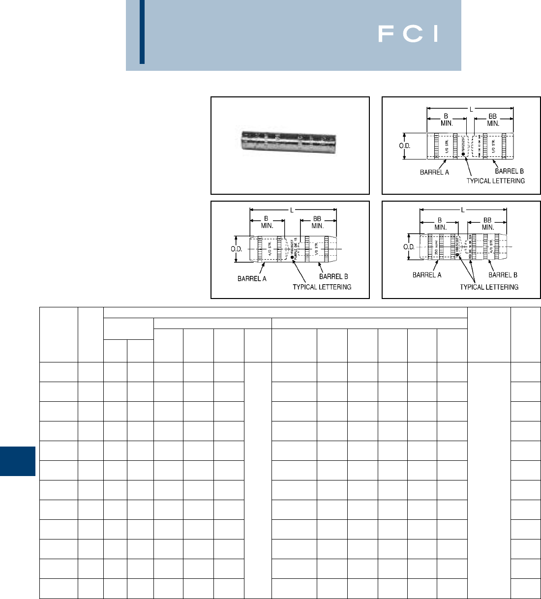
BURNDY
URD Underground
J-12
TYPE YRB-T
HYREDUCER™ SPLICE
(Continued)
FOR COPPER-TO-COPPER
Fig. 1
Fig. 2 Fig. 3
INSTALLATION TOOLING (NUMBER OF CRIMPS)
DIE MECHANICAL HYDRAULIC
INFORMATION Y35, Y39, Y750, WIRE
CATALOG ➁COLOR DIE MD7 BAT35, BAT750, BCT500, DIELESS STRIP
NUMBER ➆CODE INDEX TYPE OUR840 MD7-34R MD6 Y34A ➅PAT750 Y500CT Y46 ➃Y45 ➂Y48B Y60BHU (# OF CRIMPS) LENGTH
Orange
YRB3734T Orange Die 23 Die Set —— — U37RT (2) — U37RT (2) U37RT (2) C37R (1) L37RT (1) 2-3/16
Orange
YRB3737T Orange Die 23 Die Set —— — U37RT (2) — U37RT (2) U37RT (2) C37R (1) L37RT (1) 2-3/16
Black U39RT (2) U39RT (2) C39R (1) L39RT (1)
YRB3931T Black Die 24 Die Set —— — U39RT (2) — P39RT (2) S39RT (2) C36AR (1) L36ART (1) 2-1/8
Black U39RT (2) U39RT (2) C39R (1) L39RT (1)
YRB3934T Black Die 24 Die Set —— — U39RT (2) — P39RT (2) S39RT (2) C36AR (1) L36ART (1) 2-1/8
Black U39RT (2) U39RT (2) C39R (1) L39RT (1)
YRB3936T Black Die 24 Die Set —— — U39RT (2) — P39RT (2) S39RT (2) C36AR (1) L36ART (1) 2-1/8
Black U39RT (2) U39RT (2) C39R (1) L39RT (1) Hydraulic:
YRB3937T Black Die 24 Die Set —— — U39RT (2) — P39RT (2) S39RT (2) C36AR (1) L36ART (1) Y644M (1) 2-1/8
Black —U39RT (2) U39RT (2) C39R (1) L39RT (1) BAT644M (1)
YRB3939T Black Die 24 Die Set —— — U39RT (2) — P39RT (2) S39RT (2) C36AR (1) L36ART (1) PAT644M (1) 2-1/8
Orange
YRB4028T Orange Die 25 Die Set —— ———P40RT (2) S40RT (2) C40R (1) L40RT (1) 2-7/32
Orange
YRB4037T Orange Die 25 Die Set —— ———P40RT (2) S40RT (2) C40R (1) L40RT (1) 2-7/32
Orange
YRB4039T Orange Die 25 Die Set —— ———P40RT (2) S40RT (2) C40R (1) L40RT (1) 2-7/32
White
YRB4439T White Die 27 Die Set —— ———P44RT (2) S44RT (2) C44R (1) L44RT (1) 2-5/8
White
YRB4444T White Die 27 Die Set —— ———P44RT (2) S44RT (2) C44R (1) L44RT (1) 2-5/8
1Material: Copper.
➁For Tin-Plating, add suffix “TN” to the Catalog Number
(ex.: YRB2825TN). For Hot Tin dipped add suffix “W” to the
catalog number (ex.: YRB2825TW).
➂Catalog Number PT6515 Adaptor is required to use “U”
dies in Y45 series tools.
➃Catalog Number PUADP-1 is required to use “U” dies in
Y46 series tools.
5Dimensions in brackets [ ] are in millimeters rounded off
to the nearest millimeter, unless otherwise specified, and
are for reference only.
➅For use by customers that have this HYPRESS™. No new
Y34 HYPRESS™ tools are being processed.
➆Suffix “TN” and “W” will not be stamped on part.
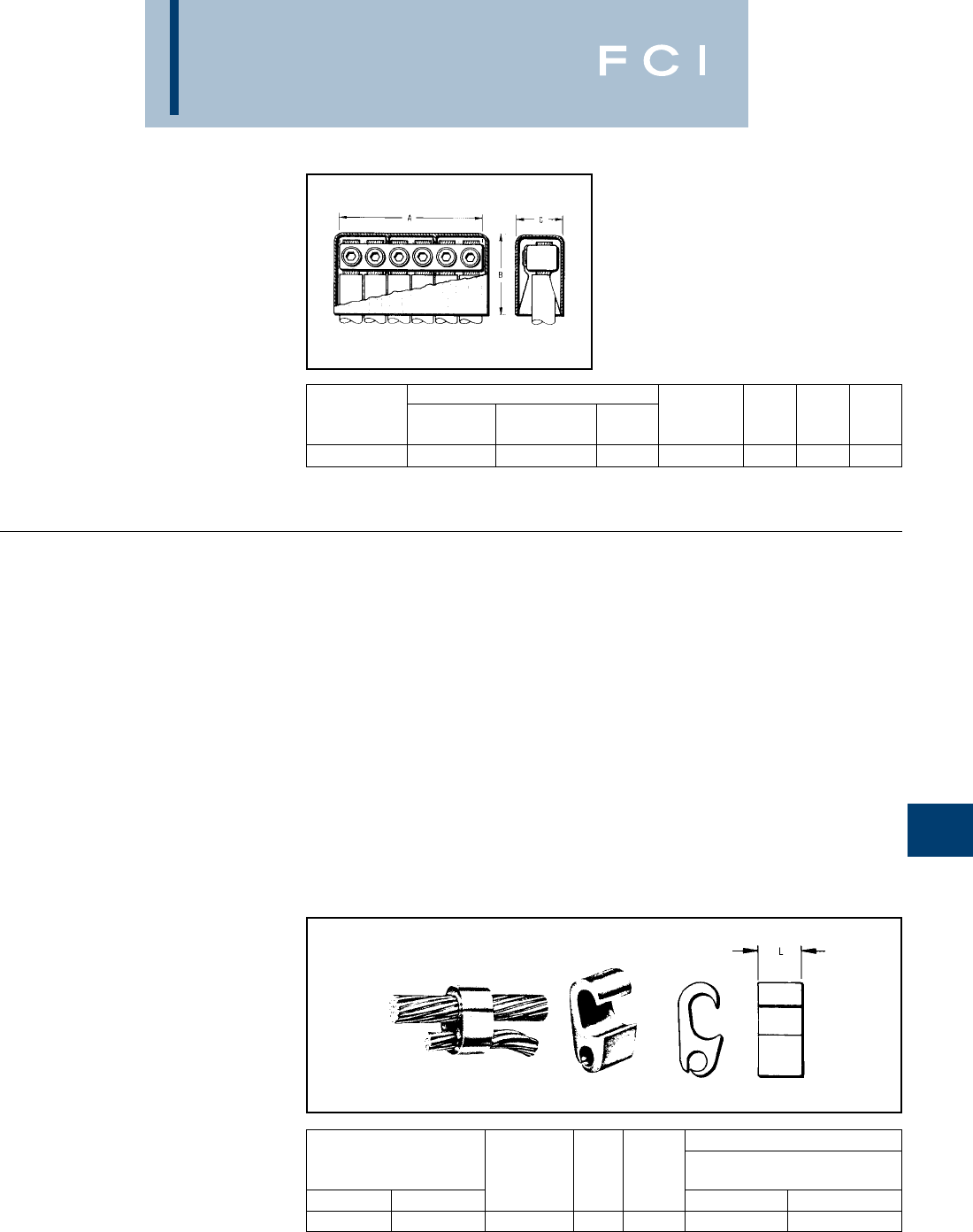
BURNDY
URD Underground
J-13
URD
TYPE K-P-C
URD SERVICE TAP FOR
COPPER CONDUCTORS
These compact, wide-range-taking, multiple
outlet connectors are made of high conduc-
tivity copper alloy. Spherical point Allen set
screws provide even clamping forces on
conductors up to 4/0 Str. Each connector is
supplied with an insulating cover. The
mechanical clamping elements allow individ-
ual cables to be disconnected without
disturbing adjacent connections.
COMPRESSION
SERVICE TAPS AND
TRANSFORMER
TERMINALS
Where compression-type service taps are
required, the wide-range-taking, figure "6"
shaped, tap connectors are recommended.
They can be gripped in a HYPRESS™ and
slipped over the secondary main for easy
installation. For above-grade installation,
commercially available insulating tubes are
often used to cover a series of these taps on
each main cable stub. Separation of run and
tap cables simplifies taping.
TYPE YPC-C
TIN-PLATED COPPER
CRIMPIT™ FOR COPPER
CONDUCTORS
Made of tin-plated pure copper this connector
is recommended for copper service taps in
above-grade enclosures or for direct burial.
The streamlined design facilitates taping.The
plating eliminates reaction with insulators.
*Y35 HYPRESS™ U-Dies with adapter PUADP-1 can also
be used with Y46. Same number of crimps as Y35.
CATALOG NUMBER NUMBER
COMPLETE CONNECTOR COVER OF
CONDUCTOR ASSEMBLY ONLY ONLY OUTLETS A B C
6 Str. - 4/0 Str. K6P28C K6P28 K-PC28 65-1/8 2-3/4 1-5/8
Installation Tooling
Y35, Y750, Y46
Conductor Catalog Die HYPRESS
Run Tap Number L Index Die Cat. No. (No. of Crimps)
2/0 Str. - 250 4 Str. - 2/0 Str YPC29C26 1.00 D3 U-D3 (1)
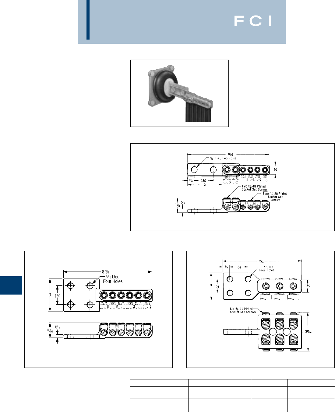
BURNDY
URD Underground
J-14
URD
TRANSFORMER TERMINALS
TYPES K6B AND K33B
FOR COPPER CONDUCTORS
These terminals are companion connectors
of the various types of DOME-TAP, and
possess the same advantages of wide
conductor range and compactness. These
features simplify cable terminations in the
secondary compartments of pad-mounted
transformers.The design also permits individ-
ual cables to be disconnected without
disturbing adjacent joints.
Made of a high conductivity copper alloy,
these compact range-taking connectors
provide for connecting up to six copper cables
at the transformer terminals. The outlets are
equipped with spherical point, tin-plated
brass socket set-screws to provide even
clamping forces on the conductors through-
out the cable range.
Where cable sizes exceed 4/0 STR., a pres-
sure bar is added to assure optimum perfor-
mance.
Fig. 1
Fig. 2 Fig. 3
CONDUCTOR CATALOG NUMBER FIG. NO. NEMA Tongue
Two Outlets: #6 - 4/0
Four Outlets: 6 Str. - 2/0 K6B2826-2N 12-Hole
Six Outlets: 6 Str. - 4/0 Str. K6B28-4N 24-Hole
Six Outlets: 4/0 Str. - 500 K33B34-4N 34-Hole
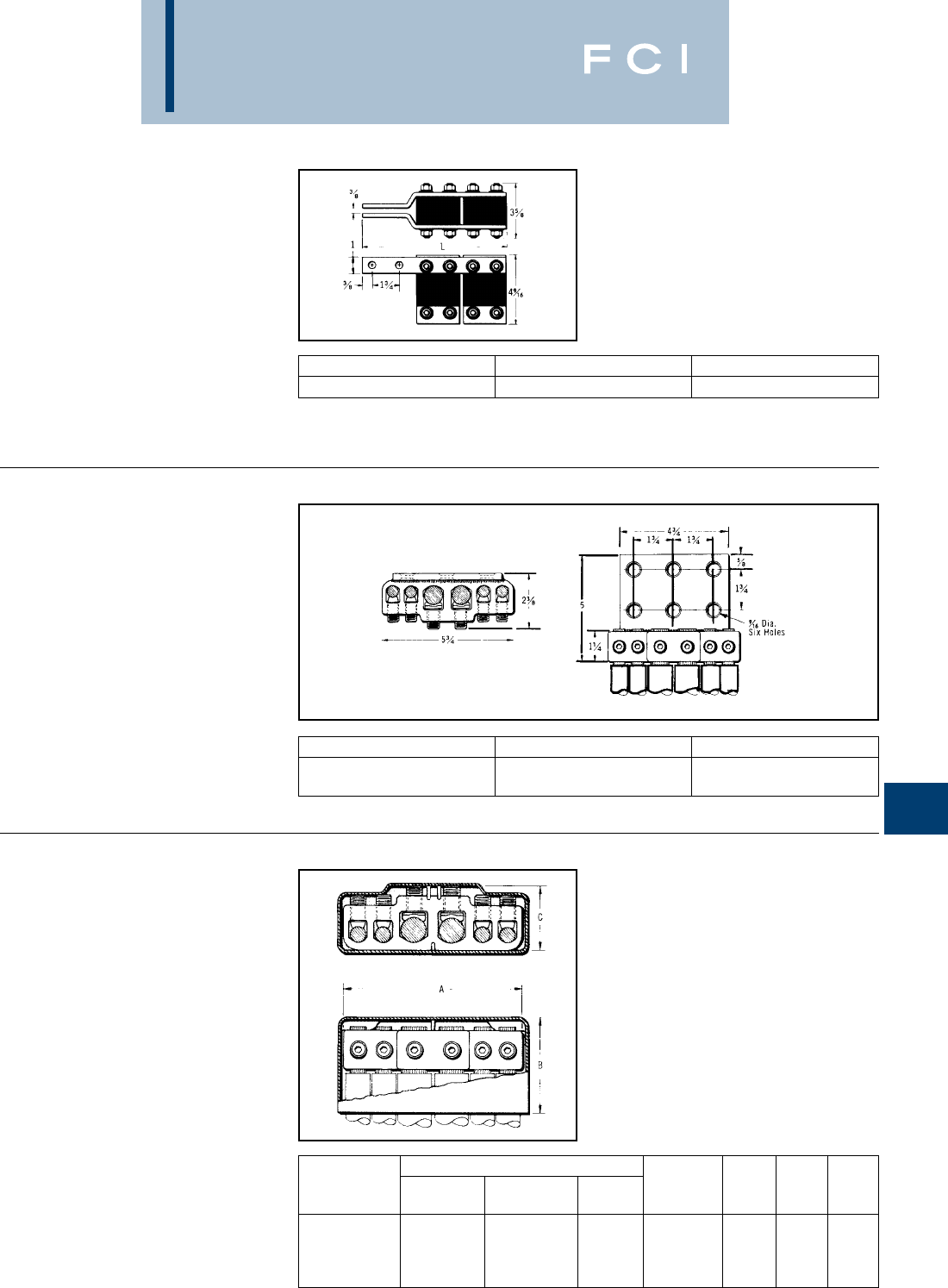
BURNDY
URD Underground
J-15
URD
FUSED TRANSFORMER
TERMINALS
TYPE F-A
These Transformer Tap assembles bolt direct-
ly to the secondary terminal pad. They
provide for up to eight cables to be fused
directly at the secondary terminals. This may
be all service taps or combinations of
secondary mains and service taps. Type LF LIMITER and HYLUG™ (copper or aluminum)
Compression terminals must be ordered separately.
TRANSFORMER
TERMINALS
FOR ALUMINUM AND
COPPER CONDUCTORS
Made of aluminum alloy, the massive design
minimizes conductor corrosion due to gal-
vanic action. Each outlet is pre-filled with
PENETROX™ joint compound and sealed.
Plated aluminum socket head pressure
screws and aluminum pressure bars prevent
conductor damage. Six hole pad allows for
adjustable positioning on four hole NEMA
spades.
UNIVERSAL URD
SERVICE TAP
TYPE K-P-UC
FOR ALUMINUM OR COPPER
Made of aluminum alloy, the massive design
minimizes conductor corrosion due to galvan-
ic action. Each outlet is pre-filled with PENE-
TROX™ joint compound and sealed. Plated
aluminum socket head pressure screws and
aluminum pressure bars prevent conductor
damage. Each connector is supplied with an
insulating cover.
CATALOG NUMBER NUMBER OF FUSES L INCHES
F22A28 46-1/2
CONDUCTOR CATALOG NUMBER NUMBER OF OUTLETS
Two Outlets 2 Str. - 500
Four Outlets 6 Str. - 4/0 Str. K6A34U-6N 6
CATALOG NUMBER NUMBER
COMPLETE CONNECTOR COVER OF
CONDUCTOR ASSEMBLY ONLY ONLY OUTLETS A B C
Two Outlets
2 Str. - 500
Four Outlets K6P34UC K6P34U K6PC34U 65-3/4 3-1/8 2-1/8
6 Str. - 4/0 Str.
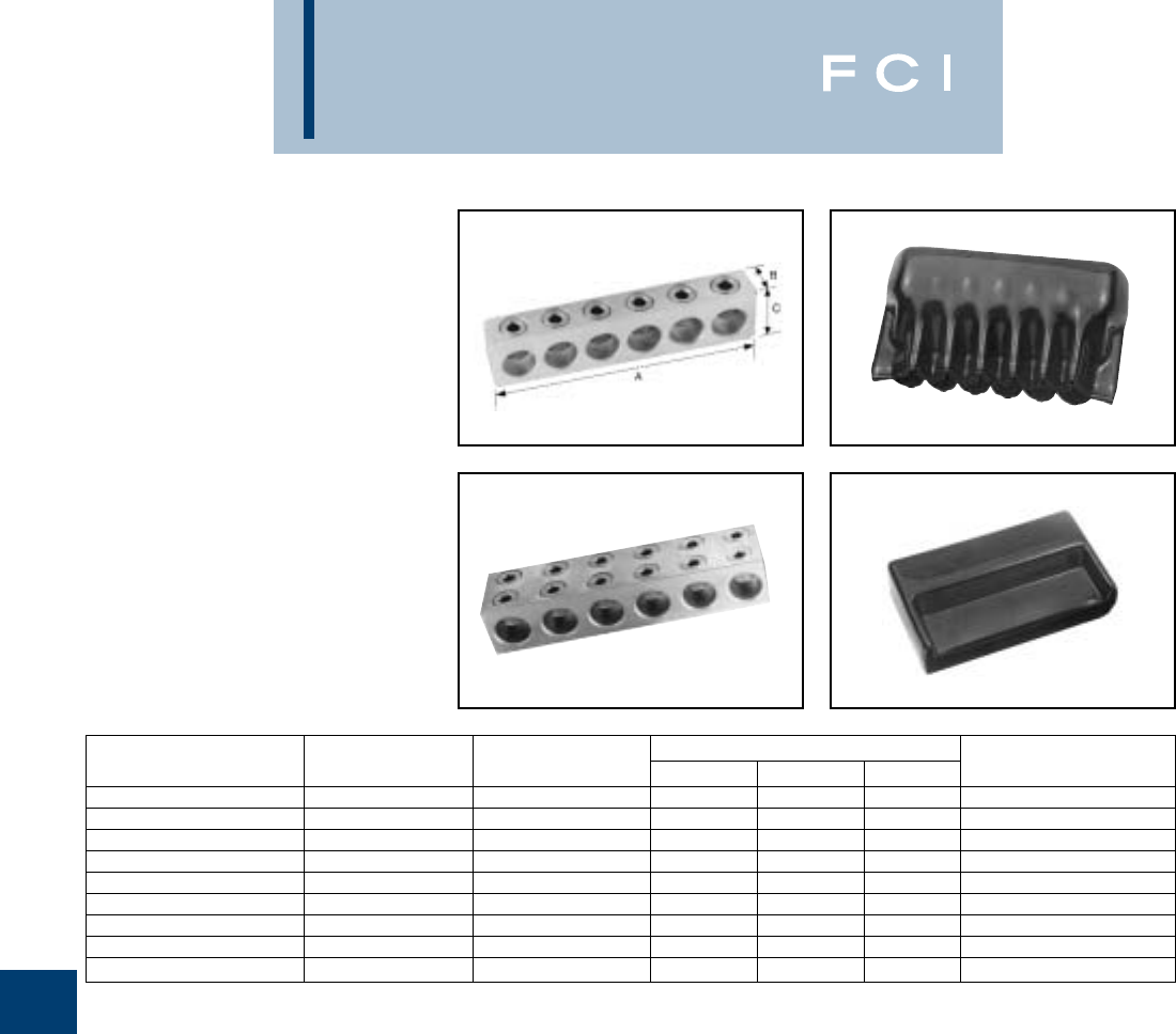
BURNDY
URD Underground
J-16
TYPES BPD & BPD2
POWER DISTRIBUTION
BLOCKS
Dual rated ground pedestal lugs. Rated for
600 volt. Constructed from high strength
aluminum alloy 6061-T6. Connectors are all
plated to provide low contact resistance.
Plastisol covers dielectric strength rating
of 120 volts per mil. Nominal thickness is
156 mils. Covers purchased separately.
BPD
BPD2
BIC
BIC2
WIRE RANGE NUMBER OF DIMENSIONS
CATALOG NUMBER AL OR CU. CONDUCTORS A B C INSULATING COVER
BPD-4-350 #6 - 350 4 3.88 1.38 1.00 BIC-4-350
BPD-6-350 #6 - 350 6 5.69 1.38 1.00 BIC-6-350
BPD-8-350 #6 - 350 8 7.50 1.38 1.00 BIC-8-350
BPD-4-500 #2 - 500 4 4.75 1.63 1.00 BIC-4-500
BPD-6-500 #2 - 500 6 7.00 1.63 1.00 BIC-6-500
BPD-8-500 #2 - 500 8 9.25 1.63 1.00 BIC-8-500
BPD2-4-750 #2 - 750 4 6.56 2.00 2.50 BIC2-4-750
BPD2-6-750 #2 - 750 6 9.88 2.00 2.50 BIC2-6-750
BPD2-8-750 #2 - 750 8 13.81 2.00 2.50 BIC2-8-750

BURNDY
Cable Ties
K-1
TABLE OF CONTENTS
UNIRAP™
Cable Tie Features and Specs........K-2 - K-4
Military Spec Cable Ties...........................K-5
Standard Cable Ties........................K-6 - K-7
Releaseable Cable Ties............................K-8
Identification Cable Ties............................K-9
Mounting Hole Cable Ties ........................K-9
Halar®Cable Ties...................................K-10
Tefzel®Cable Ties ..................................K-10
Stainless Steel Ties ................................K-11
Type TFV-B
Hook and Loop Straps............................K-13
Mounting Bases
(4-Way) ...................................................K-14
(2-Way) ...................................................K-14
Cable Hangers...........................................K-15
Cable Tie Tools ..........................................K-16
Stainless Steel Strap and Accessories
Buckles ...................................................K-17
Stainless Steel Strap Installation Tools
OPV, OPC..............................................K-18

BURNDY
Cable Ties
K-2
UNIRAP™
NYLON CABLE TIES
UNIRAP™ cable ties are fabricated of one-
piece Nylon with no metal parts. The straps
are tough, resilient, lightweight and abrasion
resistant. They offer high tensile strength and
are chemically resistive to solvents, alkalies,
oils, grease and diluted acids. Self-locking,
they secure without twisting or leaving sharp
projections.
FCI BURNDY®cable ties consist of three
components: strap, head, and tail. These
components are specifically designed to
function together to make FCI BURNDY®
UNIRAP™ cable ties superior in quality and
performance.
Precision Engineering
1. Includes load bearing serrations.
2. Features flats between the serrations.
3. Features the double outer rail system.
4. The pawl is integrally formed with the
head.
5. The pawl is stepped in order to wedge
against the serrations in the strap to form
the lock.
6. The shoulders, or the sides of the head,
guide the strap and prevent it from dis-
engaging from the pawl during loaded
conditions.
7. The back supports the strap during the
wedging of the lock formation.
8. Features a bent tip.
9. Includes a ribbed grip.
Enhanced Performance
1. Serrations provide complete adjustability
within the fastening range.
2. Flats reduce stress concentrations and
help make the tie stronger.
3. Smooth rails promote low drag, as well
as minimize chafing.
4. The locking unit will not disengage. It
also promotes low insertion with high pull
out force for very easy installation.
5. The tie’s ultimate strength achieves
optimum levels.
6. Promotes cable tie strength, endurance,
and longevity.
7. Ensures optimum locking capability.
8. Easy pick-up for installers, which leads to
fast assembly.
9. Allows for easy, no-slip grip.
Component
Strap
1
23
Compact heads and pre-bent tips facilitate
cable bundling in a minimum of time and
space.
UNIRAP™ cable ties are designed for both
field and production line use and may be
installed easily by hand.
Head
6
7
4
5
Tail
9
8
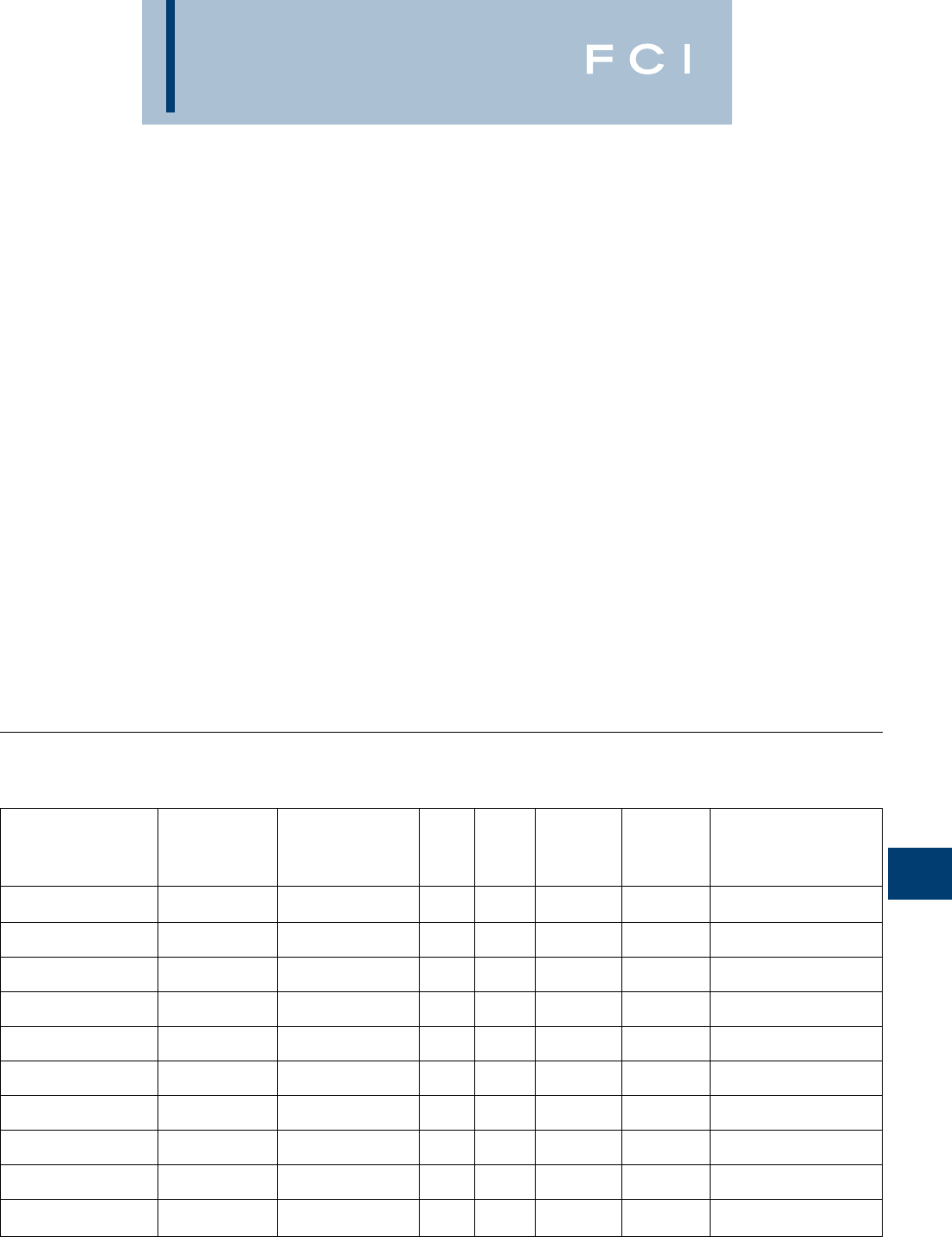
BURNDY
Cable Ties
K-3
Nylon 6/6 — General Purpose
General purpose nylon 6/6 features light
weight, high strength and a wide temperature
range. It is halogen free so it does not release
dangerous gases, such as chlorine, bromine,
fluorine and iodine when burned. Nylon 6/6 is
hygroscopic, and therefore, absorbs or
releases moisture depending on its environ-
ment. Thus, the moisture level of the material
will affect tensile strength, stiffness and elon-
gation of the product.
Nylon 6/6 — Heat Stabilized
With similar properties and benefits as nylon
6/6, products manufactured with heat stabi-
lized nylon 6/6 material have a chemical
stabilizer added for higher continuous
temperature applications.
Nylon 6/6 — UV Stabilized
Chemical inhibitors are used to give nylon 6/6
material added properties to fight against
premature aging of products due to the
effects of ultraviolet rays.
Nylon 6/6 — UV Stabilized
(2% Carbon for Military Specification)
The physical properties of this material
include carbon, which acts as a UV stabilizer,
prolonging the life of the product under ultra-
violet conditions. It also allows cable ties to
meet the particular military specification for
cable ties.
Nylon 6/6 — V0 Flame Retardant
This material meets UL 94V-0 flammability
requirements. Flame retardant additives
generally reduce tensile strength when com-
pared to general-purpose nylon 6/6, but this
resin has been formulated to minimize such
effects.
Nylon 6/6 — High Impact
Impact modifiers are added to increase flexi-
bility. High impact nylon 6/6 has stable tensile
strength due to its reduced influence from
moisture. It is excellent for high vibration
applications, as within the aircraft and auto-
mobile industries and performs better than
nylon 6/6 against ultraviolet rays. Good for
outdoor use.
Polypropylene
Polypropylene is used in environments where
chemical effects on nylon are a concern. It is
not affected by inorganic acids (hydrochloric),
polyhydric alcohols (ethyleneglycol), neutral
salts (sodium chloride) and basic salts
(sodium bicarbonate). Polypropylene also
resists a number of other chemicals with
good results, although it has lower tensile
strength than nylon 6/6 (about half).
Polypropylene has good UV resistance.
Tefzel®
Although about two-thirds the strength of
nylon 6/6, Tefzel is resistant to a wide range
of chemicals, such as concentrated hydroflu-
oric and sulfuric acids. It is also a low water
absorbing material, therefore, is not adverse-
ly affected by water. Tefzel is radiation resis-
tant up to 100 megarads and meets the fire
and smoke requirements of IEEE 383. Tefzel
also withstands high temperatures and ultra-
violet light exposure. Products made from
Tefzel material also have non-outgassing
properties for zero gravity applications.
Halar®
Halar is similar to Tefzel in performance and
benefits. Halar is recognized for its low smoke
density attribute when burned. This makes
products made out of Halar more desirable
for use in areas where smoke generation is a
concern, as when bundling wire and cable in
air handling spaces.
Available Materials
Continuous*
Operating Tensile Strength at UL Gamma
Temperature 73° F Dry as Molded Flame Oxygen Radiation UV Military, Federal, ASTM,
Material Max. Min. ASTM D-638 (PSI) Rating Index % Resistance Resistance and FDA Specifications
Nylon 6/6 — 185° F –40° F ASTM D-4066PA0111
General Purpose (CT) 85° C –40° C 12,000 94V-2 28 1 105Rads Poor FDA CFR177.1500
Nylon 6/6 — 220° F –40° F
Heat Stabilized (CTHS) 105° C –40° C 12,000 94V-2 26 1 105Rads Poor ASTM D-4066PA0121
Nylon 6/6 — 185° C –40° F
UV Stabilized (O) 85° C –40° C 12,000 94V-2 26 1 105Rads Good ASTM D4066PA0191
Nylon 6/6 — 2% Carbon 220° F –40° F ASTM D-4066PA0181
UV Stabilized (OO) 105° C –40° C 12,000 94V-2 26 1 105Rads Good MS3367/8
Nylon 6/6 — 185° F –40° F
Flame Retardant (CTV) 85° C –40° C 10,800 94V-0 34 1 105Rads Poor ASTM D-4066PA0110
Nylon 6/6 — 185° F –40° F
High Impact 85° C –40° C 8,800 94-HB 19 1 105Rads Good ASTM D-4066PA0150
Polypropylene — 185° F –40° F ASTM D-4101PP0320
Chemical Resistant (CTPP) 85° C –40° C 3,400 94-HB N/A 1 105Rads Good FDA CFR177.1520
Nylon 12 — 176° F –40° F
UV Stabilized 80° C –40° C 5,800 94-HB N/A 9 106Rads Good ASTM D-4066PA411
302° F –50° F UL2043 Grade 1
Tefzel®(CTZ) 150° C –46° C 5,800 94V-0 30 2 108Rads Excellent ASTM D-3159 Type 1
284° F –50° F ASTM D-3275 Type 3
Halar®(CTH) 140° C –46° C 6,100 94V-0 52 2 108Rads Excellent FDA CRF177.1380
Material Specifications
*Elevated temperatures, over time, will affect materials’ prop-
erties such as tensile strength, stiffness, elongation and
appearance.
FCI BURNDY®recommends the evaluation of cable ties in
the actual application to determine the suitability of the tie
for that application.
Tefzel®is a registered trademark of E.I. DuPont Corporation.
Halar®is a registered trademark of Ausimont Chemical Co.
BURNDY
Cable Ties
K-4
Material Performance Guide
Nylon 6/6 Nylon 6/6 Nylon 6/6 Nylon 6/6 Nylon 6/6
General Heat Nylon 6/6 2% Carbon Flame Ret. High Poly- Nylon 12
Selection Purpose Stab. UV Stab. UV Stab. V0 Impact propylene UV Stab. Tefzel® Halar®
Tensile Strength 8 8 8 9782455
High Temp. 2 3 2 222211010
Flammability 5 5 5 5 10 2 2 2 10 10
UV Resistance 1 1 5 812531010
Radiation 3 3 3 333631010
Chemical 6 6 6 666881010
— Hydrocarbons 8 8 8 888681010
— Chlorinated 6 6 6 666381010
— Hydrocarbons 2 2 2 222851010
— Acids-Bases 6 6 6 666861010
— Salts 3 3 3 3 3 3 10 8 10 10
Relative Cost Low Low Med. Med. Med. Med. Med. Med. High High
1 = Least Recommended 10 = Most Recommended
The following chart is meant to help you
understand FCI BURNDY’s cable tie catalog
numbering system. Not every cable tie is
available in every listed option. See below
Catalog Numbering System Charts or contact
Type Tensile Bundle Dia. Feature Package Color
CT 50 175 C
BET = 18 = 18 lbs. 075 = 3/4EPR = Extended Pawl Releasable V = 5 1 = Brown
Burndy Extended Tie 30 = 30 lbs. 087 = 7/8ID = Single Head ID X = 10 2 = Red
40 = 40 lbs. 100 = 1ID2 = Double Head ID Q = 25 3 = Orange
CT = Nylon 6/6 50 = 50 lbs. 125 = 1-1/4ID3 = Triple Head ID L = 50 4 = Yellow
Standard 120 = 120 lbs. 137 = 1-3/8FL = ID Flag C = 100 5 = Green
175 = 175 lbs. 150 = 1-1/2MH4 = Mounting Hole #4 B = 250 6 = Blue
CTAS = 250 = 250 lbs. 175 = 1-3/4MH6 = Mounting Hole #6 D = 500 7 = Purple
Aerial Support 200 = 2MH8 = Mounting Hole #8 M = 1000 8 = Grey
250 = 2-1/2MH10 = Mounting Hole #10 None = Natural
CTH = 300 = 3MH14 = Mounting Hole #14 10 = White
Halar ®400 = 4PM = Push Mount Tie 11 = Telco Gray
500 = 5PML = Push Mount Tie w/Louvers 0 = UV Black1
CTZ = 600 = 6PMW = Push Mount Tie w/Wing 00 = UV Black2
Tefzel ®700 = 7R = Releasable Tie 02 = Red
800 = 8LP = Low Profile Tie 20 = Black
CTHS = Nylon 6/6 900 = 9PS = Positive Stop
Heat Stabilized 1000 = 10
1100 = 11
CTV = Nylon 6/6 1200 = 12
Flame Retardant UL94V-0 1300 = 13
1400 = 14
CTPP = 1500 = 15
Polypropylene 1600 = 16
FCI BURNDY®Customer Service for more
information.
Grey bars contain catalog number examples.
Type Tensile Bundle Dia. Package
CTSS 100 200 C
CTSS = 100 = 100 lbs. Same as Same as
304 Stainless Steel 250 = 250 lbs. above above
1Material: Nylon 6/6 — UV Stabilized 2Material: Nylon 6/6 — 2% Carbon UV Stabilized (Mil. Spec.)
Type Size Mount Method Feature Quantity Color
CTB 125 RA 4 C 0
CTB = 075 = 3/4” RA = Rubber Adhesive 2 = 2 way L = 50 0 = UV Black
Cable Tie Base 125 = 1-1/4” AA = Acrylic Adhesive 4 = 4 way C = 100
150 = 1=1/2” S = Screw Mounted D = 500
M = 1000
BURNDY
Cable Ties
K-5
Military Specification
UNIRAP™ Cable Ties
The FCI BURNDY®cable ties shown below
meet the requirements of SAE AS23190A
(formerly MIL-S-23190) in accordance with
specification MS3367, MS3368, and are
QPL-23190 listed.
Distributor Pack Bulk Pack Description
Mil Spec Catalog Number Catalog Number (Bundle Dia. - Tensile Strength)
MS3367-1-9 CT50175C CT50175M 1.75- 50 lbs.
MS3367-2-9 CT50400C CT50400M 4- 50 lbs.
MS3367-3-9 CT120400L CT120400D 4- 120 lbs.
MS3367-3-9 CT175400Q N/A 4- 175 lbs.
MS3367-3-9 CT175600Q N/A 6- 175 lbs.
MS3367-4-9 CT18075C CT18075M .75- 18 lbs.
MS3367-5-9 CT30125C CT30125M 1.25- 30 lbs.
MS3367-6-9 CT120900L CT120900D 9- 120 lbs.
MS3367-6-9 CT175900Q N/A 9- 175 lbs.
MS3367-7-9 CT50300C CT50300M 3- 50 lbs.
Natural Cable Ties
Distributor Pack Bulk Pack Description
Mil Spec Catalog Number Catalog Number (Bundle Dia. - Tensile Strength)
MS3367-1-0 CT50175C00 CT50175M00 1.75- 50 lbs.
MS3367-2-0 CT50400C00 CT50400M00 4- 50 lbs.
MS3367-3-0 CT120400L00 CT120400D00 4- 120 lbs.
MS3367-3-0 CT175400Q00 N/A 4- 175 lbs.
MS3367-3-0 CT175600Q00 N/A 6- 175 lbs.
MS3367-4-0 CT18075C00 CT18075M00 .75- 18 lbs.
MS3367-5-0 CT30125C00 CT30125M00 1.25- 30 lbs.
MS3367-6-0 CT120900L00 CT120900D00 9- 120 lbs.
MS3367-6-0 CT175900Q00 N/A 9- 175 lbs.
MS3367-7-0 CT50300C00 CT50300M00 3- 50 lbs.
UV Resistant Black Cable Ties
Distributor Pack Bulk Pack Description
Mil Spec Catalog Number Catalog Number (Bundle Dia. - Tensile Strength)
MS3368-1-A CT50175IDC N/A 1.75- 50 lbs.
MS3368-2-A CT50400IDC N/A 4- 50 lbs.
MS3368-3-C CT50175ID2L N/A 1.75- 50 lbs. Double Strap
MS3368-4-D CT50175ID3L N/A 1.75- 50 lbs. Triple Strap
MS3368-5-E CT18075IDC N/A .75- 18 lbs.
Natural Identification
Cable Ties
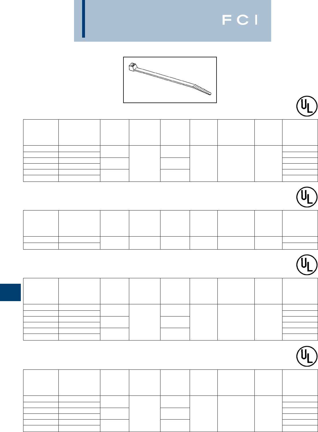
BURNDY
Cable Ties
K-6
UNIRAP™
STANDARD CABLE TIES
STANDARD MAXIMUM MINIMUM BULK
PACKAGE BUNDLE TENSILE PACKAGE
CATALOG DIAMETER STRENGTH LENGTH WIDTH INSTALLATION TOOL CATALOG
NUMBER MATERIAL In. [mm] Lbs. (N) In. [mm] In. [mm] TOOL SETTING NUMBER
CT18075C Natural Nylon 6/6 CT18075M
CT18075C0 Black Nylon 6/6 UV .75 [19] 4.00 [102] CT18075M0
CT18125C Natural Nylon 6/6 CT18125M
CT18125C0 Black Nylon 6/6 UV 1.25 [32] 18 (80) 5.67 [144] .10 [2.5] TWT1, MK7 Mini CT18125M0
CT18200C Natural Nylon 6/6 CT18200M
CT18200C0 Black Nylon 6/6 UV 2.00 [51] 8.00 [203] CT18200M0
18 Lb. Minimum
Tensile Strength
STANDARD MAXIMUM MINIMUM BULK
PACKAGE BUNDLE TENSILE PACKAGE
CATALOG DIAMETER STRENGTH LENGTH WIDTH INSTALLATION TOOL CATALOG
NUMBER MATERIAL In. [mm] Lbs. (N) In. [mm] In. [mm] TOOL SETTING NUMBER
CT30125C Natural Nylon 6/6 CT30125M
CT30125C0 Black Nylon 6/6 UV 1.25 [32] 30 (133) 6.00 [152] .14 [3.6] TWT1, MK7 Intermediate CT30125M0
30 Lb. Minimum
Tensile Strength
STANDARD MAXIMUM MINIMUM BULK
PACKAGE BUNDLE TENSILE PACKAGE
CATALOG DIAMETER STRENGTH LENGTH WIDTH INSTALLATION TOOL CATALOG
NUMBER MATERIAL In. [mm] Lbs. (N) In. [mm] In. [mm] TOOL SETTING NUMBER
CT40200C Natural Nylon 6/6 CT40200M
CT40200C0 Black Nylon 6/6 UV 2.00 [51] 8.50 [216] CT40200M0
CT40300C Natural Nylon 6/6 CT40300M
CT40300C0 Black Nylon 6/6 UV 3.00 [76] 40 (178) 11.50 [292] .15 [3.8] TWT1, MK7 Intermediate CT40300M0
CT40400C Natural Nylon 6/6 CT40400M
CT40400C0 Black Nylon 6/6 UV 4.00 [102] 14.50 [368] CT40400M0
40 Lb. Minimum
Tensile Strength
STANDARD MAXIMUM MINIMUM BULK
PACKAGE BUNDLE TENSILE PACKAGE
CATALOG DIAMETER STRENGTH LENGTH WIDTH INSTALLATION TOOL CATALOG
NUMBER MATERIAL In. [mm] Lbs. (N) In. [mm] In. [mm] TOOL SETTING NUMBER
CT50175C Natural Nylon 6/6 CT50175M
CT50175C0 Black Nylon 6/6 UV 1.75 [44] 8.00 [203] CT50175M0
CT50300C Natural Nylon 6/6 CT50300M
CT50300C0 Black Nylon 6/6 UV 3.00 [76] 50 (222) 11.75 [298] .18 [4.6] TWT1, MK7 Standard CT50300M0
CT50400C Natural Nylon 6/6 CT50400M
CT50400C0 Black Nylon 6/6 UV 4.00 [102] 15.50 [394] CT50400M0
50 Lb. Minimum
Tensile Strength
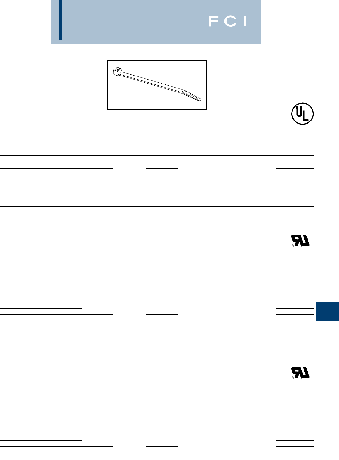
BURNDY
Cable Ties
K-7
UNIRAP™
STANDARD CABLE TIES
(Continued)
STANDARD MAXIMUM MINIMUM BULK
PACKAGE BUNDLE TENSILE PACKAGE
CATALOG DIAMETER STRENGTH LENGTH WIDTH INSTALLATION TOOL CATALOG
NUMBER MATERIAL In. [mm] Lbs. (N) In. [mm] In. [mm] TOOL SETTING NUMBER
CT120200L Natural Nylon 6/6 CT120200D
CT120200L0 Black Nylon 6/6 UV 2.00 [51] 8.87 [226] CT120200D0
CT120300L Natural Nylon 6/6 CT120300D
CT120300L0 Black Nylon 6/6 UV 3.00 [76] 11.87 [302] CT120300D0
CT120400L Natural Nylon 6/6 120 (534) .30 [7.6] TWT2, MK9 Standard CT120400D
CT120400L0 Black Nylon 6/6 UV 4.00 [102] 15.25 [387] CT120400D0
CT120900L Natural Nylon 6/6 CT120900D
CT120900L0 Black Nylon 6/6 UV 9.00 [229] 29.75 [776] CT120900D0
120 Lb. Minimum
Tensile Strength
STANDARD MAXIMUM MINIMUM BULK
PACKAGE BUNDLE TENSILE PACKAGE
CATALOG DIAMETER STRENGTH LENGTH WIDTH INSTALLATION TOOL CATALOG
NUMBER MATERIAL In. [mm] Lbs. (N) In. [mm] In. [mm] TOOL SETTING NUMBER
CT175400Q Natural Nylon 6/6
CT175400Q0 Black Nylon 6/6 UV 4.00 [102] 15.00 [381]
CT175600Q Natural Nylon 6/6
CT175600Q0 Black Nylon 6/6 UV 6.00 [152] 21.00 [533]
CT175900Q Natural Nylon 6/6
CT175900Q0 Black Nylon 6/6 UV 9.00 [229] 175 (778) 32.00 [813] .35 [8.9] TWT2, MK9 Heavy
CT1751100Q Natural Nylon 6/6
CT1751100Q0 Black Nylon 6/6 UV 11.00 [279] 36.00 [914]
CT1751400Q Natural Nylon 6/6
CT1751400Q0 Black Nylon 6/6 UV 14.00 [356] 52.00 [1321]
175 Lb. Minimum
Tensile Strength
STANDARD MAXIMUM MINIMUM BULK
PACKAGE BUNDLE TENSILE PACKAGE
CATALOG DIAMETER STRENGTH LENGTH WIDTH INSTALLATION TOOL CATALOG
NUMBER MATERIAL In. [mm] Lbs. (N) In. [mm] In. [mm] TOOL SETTING NUMBER
CT250600Q Natural Nylon 6/6
CT250600Q0 Black Nylon 6/6 UV 6.00 [152] 23.00 [584]
CT250800Q Natural Nylon 6/6
CT250800Q0 Black Nylon 6/6 UV 8.00 [203] 29.00 [737]
CT2501000Q Natural Nylon 6/6 250 (1112) .50 [12.7] TWT2, MK9 Heavy
CT2501000Q0 Black Nylon 6/6 UV 10.00 [254] 35.00 [889]
CT2501200Q Natural Nylon 6/6
CT2501200Q0 Black Nylon 6/6 UV 12.00 [305] 40.00 [1016]
250 Lb. Minimum
Tensile Strength
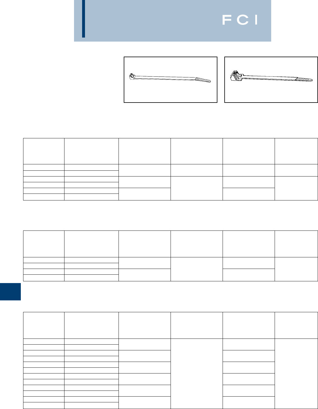
BURNDY
Cable Ties
K-8
UNIRAP™
RELEASABLE CABLE TIES
Perfect for prototype construction, releasable
cable ties are ideal for temporary installa-
tions. Releasable ties are also good for
applications where service requires adding or
subtracting wires from an existing wire
bundle.
Standard Releasable Ties Extended Pawl Releasable Ties
STANDARD MAXIMUM MINIMUM
PACKAGE BUNDLE TENSILE
CATALOG DIAMETER STRENGTH LENGTH WIDTH
NUMBER MATERIAL In. [mm] Lbs. (N) In. [mm] In. [mm]
CT40200RC Natural Nylon 6/6
CT40200RC0 Black Nylon 6/6 UV 2.00 [51] 40 (178) 8.50 [216] .16 [4]
CT50137RC Natural Nylon 6/6
CT50137RC0 Black Nylon 6/6 UV 1.38 [35] 6.50 [165]
CT50400RC Natural Nylon 6/6 50 (222) .18 [4.6]
CT50400RC0 Black Nylon 6/6 UV 4.00 [102] 15.50 [394]
Standard Releasable Cable Ties
STANDARD MAXIMUM MINIMUM
PACKAGE BUNDLE TENSILE
CATALOG DIAMETER STRENGTH LENGTH WIDTH
NUMBER MATERIAL In. [mm] Lbs. (N) In. [mm] In. [mm]
CT250200RQ Natural Nylon 6/6
CT250200RQ0 Black Nylon 6/6 UV 2.00 [51] 9.00 [229]
CT250500RQ Natural Nylon 6/6
CT250500RQ0 Black Nylon 6/6 UV 5.00 [127] 20.00 [508]
CT250600RQ Natural Nylon 6/6
CT250600RQ0 Black Nylon 6/6 UV 6.00 [152] 23.00 [584]
CT250800RQ Natural Nylon 6/6 250 (1112) .50 [12.7]
CT250800RQ0 Black Nylon 6/6 UV 8.00 [203] 29.00 [737]
CT2501000RQ Natural Nylon 6/6
CT2501000RQ0 Black Nylon 6/6 UV 10.00 [254] 35.00 [889]
CT2501200RQ Natural Nylon 6/6
CT2501200RQ0 Black Nylon 6/6 UV 12.00 [305] 40.00 [1016]
STANDARD MAXIMUM MINIMUM
PACKAGE BUNDLE TENSILE
CATALOG DIAMETER STRENGTH LENGTH WIDTH
NUMBER MATERIAL In. [mm] Lbs. (N) In. [mm] In. [mm]
CT50137EPRC Natural Nylon 6/6
CT50137EPRC0 Black Nylon 6/6 UV 1.38 [35] 5.50 [140]
CT50250EPRC Natural Nylon 6/6 50 (222) .291 [7.4]
CT50250EPRC0 Black Nylon 6/6 UV 2.50 [64] 9.80 [249]
Extended Pawl
Releasable Cable Ties
Heavy Duty
Releasable Cable Ties
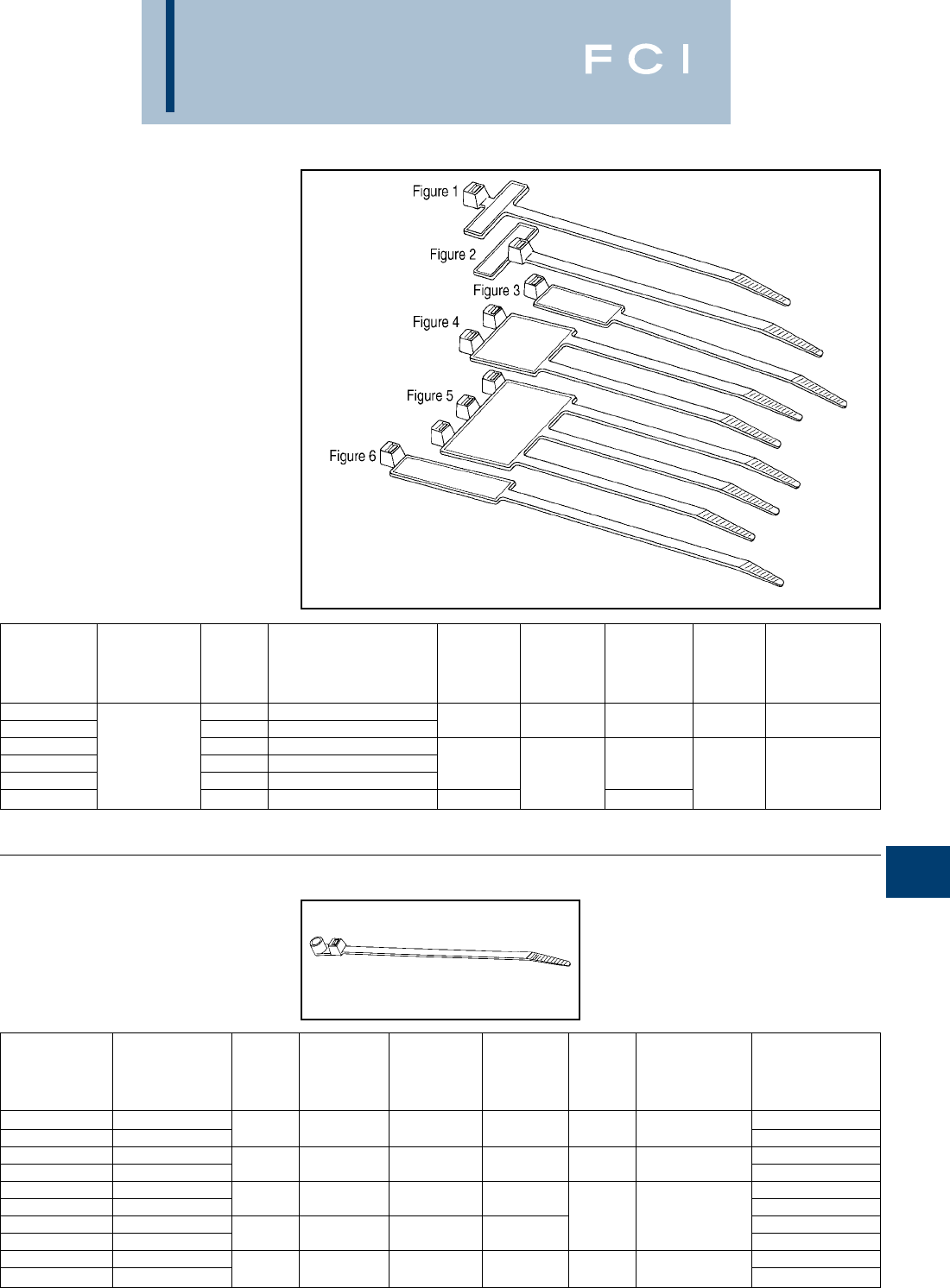
BURNDY
Cable Ties
K-9
UNIRAP™
IDENTIFICATION CABLE TIES
Identification cable ties are used in both
bundling and identifying wire groups at the
same time.
STANDARD MAXIMUM MINIMUM
PACKAGE BUNDLE TENSILE INSTALLATION
CATALOG MARKING PAD SIZE DIAMETER STRENGTH LENGTH WIDTH TOOL
NUMBER MATERIAL FIG. NO. In. [mm] In. [mm] Lbs. (N) In. [mm] In. [mm] & (SETTING)
CT18075IDC 11 19/64 [25.4 7.5] 4.00 [102]
CT18075FLC 213/16 5/16 [20.5 7.9] .75 [19] 18 (80) 4.25 [108] .10 [2.5] MK7 (MIN)
CT50175IDC 31 7/16 [25.4 11.1]
CT50175ID2L Natural Nylon 6/6 41-11/16 5/16 [29.8 23.8] 1.75 [44] 8.00 [203]
CT50175ID3L 51-13/16 15/16 [46 23.8] 50 (222) .18 [4.6] MK7 (STD)
CT50400IDC 61/2 2-1/8 [12.7 54] 4.00 [107] 15.00 [381]
UNIRAP™
MOUNTING HOLE
CABLE TIES
STANDARD MAXIMUM MINIMUM BULK
PACKAGE BUNDLE TENSILE INSTALLATION PACKAGE
CATALOG SCREW DIAMETER STRENGTH LENGTH WIDTH TOOL CATALOG
NUMBER MATERIAL SIZE In. [mm] Lbs. (N) In. [mm] In. [mm] & (SETTING) NUMBER
CT18075MH4C Natural Nylon 6/6 CT18075MH4M
CT18075MH4C0 Black Nylon 6/6 UV #4 (M2,5) .75 [19] 18 (80) 4.25 [108] .10 [2.5] MK7 (MIN) CT18075MH4M0
CT30125MH8C Nylon 6/6 CT30125MH8M
CT30125MH8C0 Nylon 6/6 UV #8 (M4) 1.25 [32] 30 (133) 6.25 [159] .14 [3.6] MK7 (INT) CT30125MH8M0
CT50175MH10C Nylon 6/6 CT50175MH10M
CT50175MH10C0 Nylon 6/6 UV #10 (M5) 1.75 [44] 50 (222) 8.50 [216] CT50175MH10M0
CT50400MH10C Nylon 6/6 GP .18 [4.6] MK7 (STD) CT50400MH10M
CT50400MH10C0 Nylon 6/6 UV #10 (M5) 4.00 [102] 50 (222) 16.00 [406] CT50400MH10M0
CT120400MH14L Nylon 6/6 CT120400MH14D
CT120400MH14L0 Nylon 6/6 UV 1/4(M6) 4.00 [102] 120 (534) 16.25 [413] .30 [7.6] MK9 (STD) CT120400MH14D0
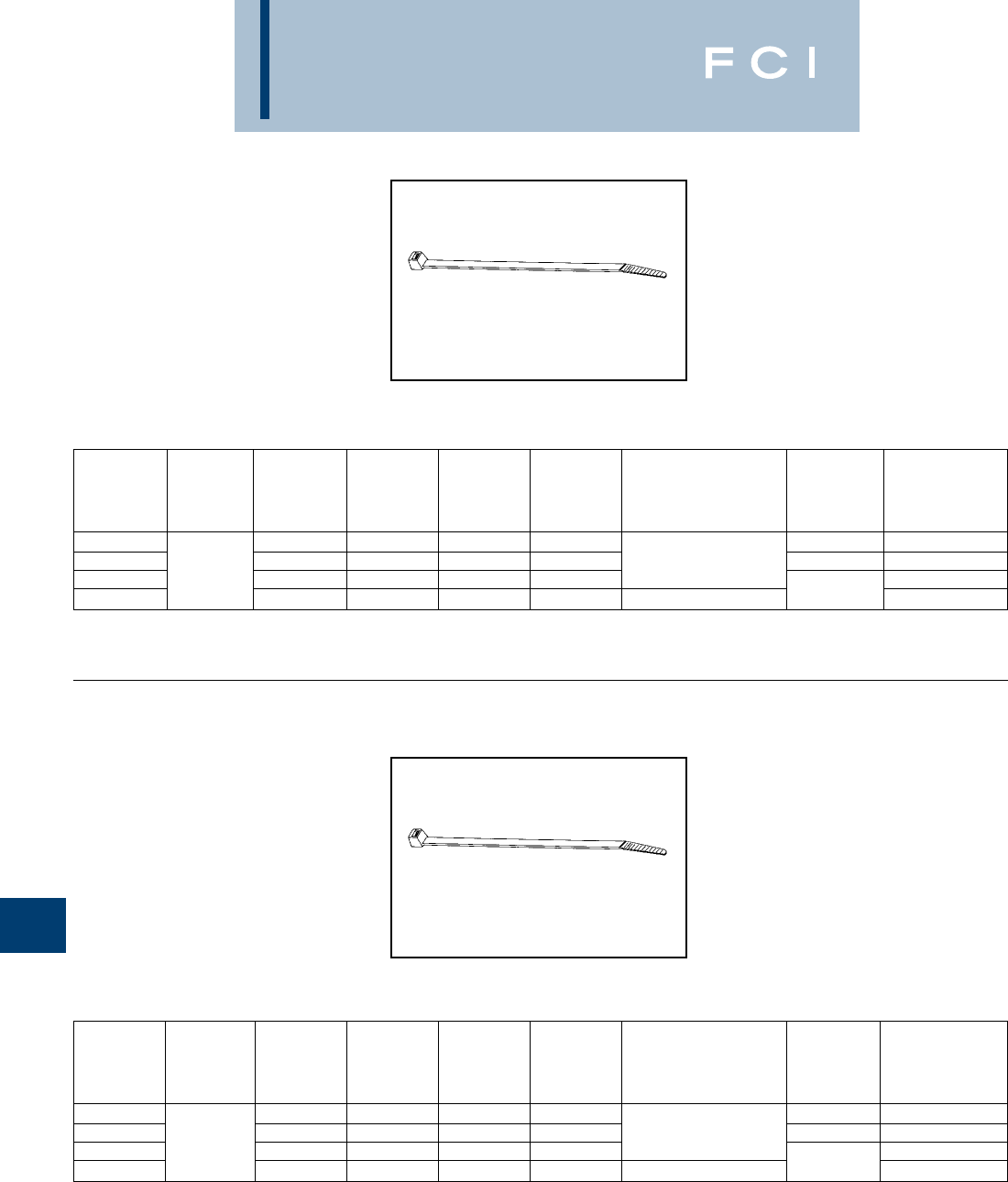
BURNDY
Cable Ties
K-10
UNIRAP™
HALAR®TIES
Halar®ties meet NEC regulations and can be
used in applications where low smoke and
low flame are a concern, as in air handling
spaces. The raw material used to manufac-
ture FCI BURNDY®Halar®cable ties is
UL 94V-0 rated. These ties come in a distinct
color of red for easy identification.
UNIRAP™
TEFZEL®TIES
Tefzel®ties provide excellent protection
against radiation, ultraviolet light, and a wide
range of chemicals. It is also rated for low out-
gassing applications. FCI BURNDY®Tefzel®
ties offer temperature stability to 150° C and
come in a standard color of blue for easy
identification.
STANDARD MAXIMUM MINIMUM BULK
PACKAGE BUNDLE TENSILE PACKAGE
CATALOG DIAMETER STRENGTH LENGTH WIDTH TOOL CATALOG
NUMBER MATERIAL In. [mm] Lbs. (N) In. [mm] In. [mm] INSTALLATION TOOL SETTING NUMBER
CTH18075C .75 [19] 18 (80) 4.00 [102] .10 [2.5] Mini CTH18075M
CTH30200C 2.00 [51] 30 (133) 8.00 [203] .14 [3.6] MK7 Intermediate CTH30200M
CTH50175C Halar 1.75 [44] 50 (222) 8.00 [203] .18 [4.6] CTH50175M
CTH120400L 4.00 [102] 120 (534) 15.25 [387] .18 [4.6] MK9 Standard CTH120400D
Halar®Cable Ties
STANDARD MAXIMUM MINIMUM BULK
PACKAGE BUNDLE TENSILE PACKAGE
CATALOG DIAMETER STRENGTH LENGTH WIDTH TOOL CATALOG
NUMBER MATERIAL In. [mm] Lbs. (N) In. [mm] In. [mm] INSTALLATION TOOL SETTING NUMBER
CTZ18075C .75 [19] 18 (80) 4.00 [102] .10 [2.5] Mini CTZ18075M
CTZ30200C 2.00 [51] 30 (133) 8.00 [203] .14 [3.6] MK7 Intermediate CTZ30200M
CTZ50175C Tefzel 1.75 [44] 50 (222) 8.00 [203] .18 [4.6] CTZ50175M
CTZ120400L 4.00 [102] 120 (534) 15.25 [387] .18 [4.6] MK9 Standard CTZ120400D
Tefzel®Cable Ties
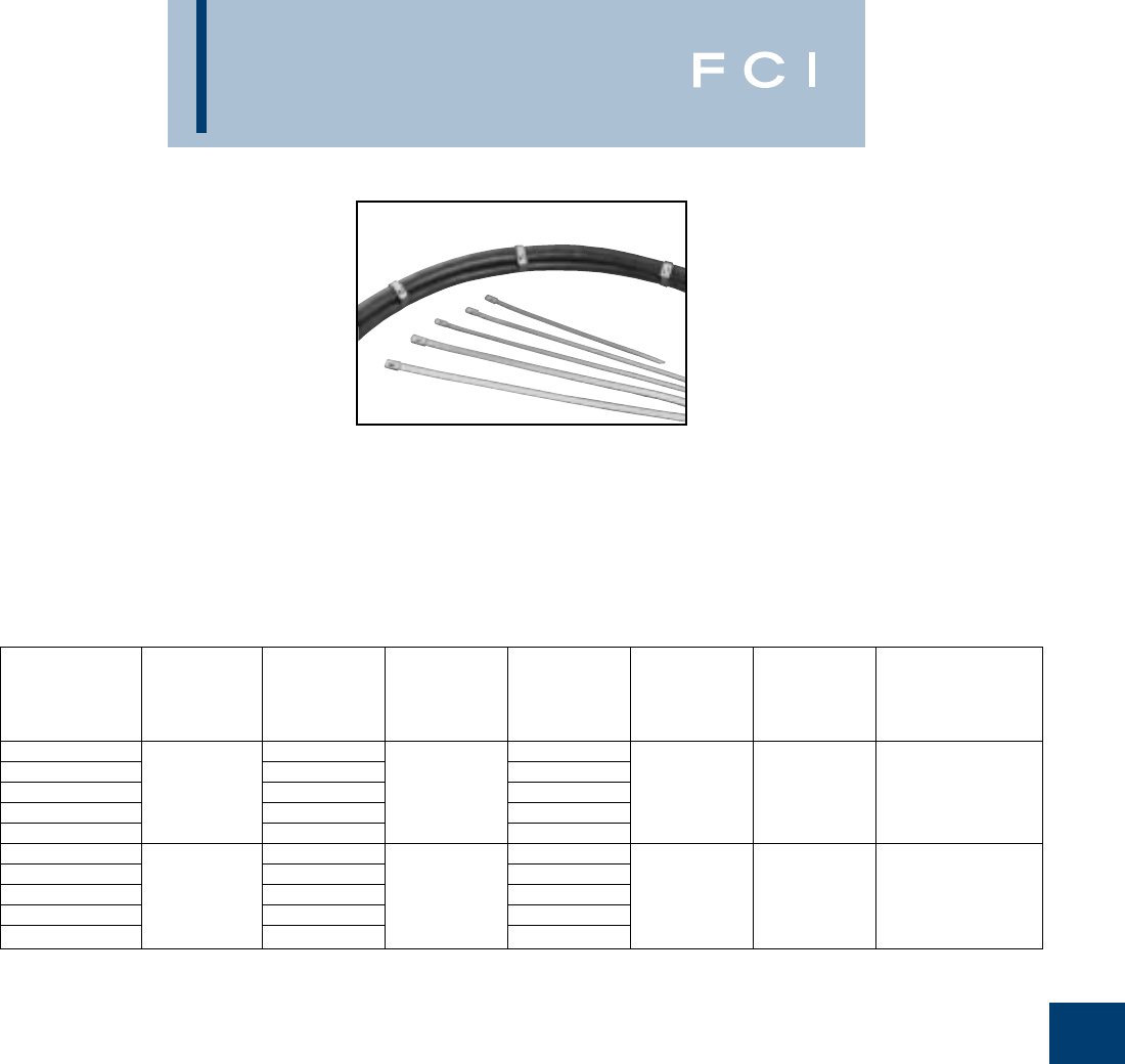
BURNDY
Cable Ties
K-11
UNIRAP™
STAINLESS STEEL TIES
FCI BURNDY's Stainless Steel ties are
designed to secure hoses, cables, poles,
pipes, and more when harsh environmental
conditions may adversely affect the bundling
application. Used where corrosion, vibration,
weathering, radiation, and temperature
extremes are a concern, FCI BURNDY's
Stainless Steel ties can be used in virtually
any indoor, outdoor, and underground
application.
FCI BURNDY®Stainless Steel ties are made
from Grade 304 Stainless Steel. This tie is
designed with a low profile clamping bearing
head with fully adjustable strap accommodat-
ing many bundle diameters.
Features
•Smooth, rounded edges help ensure safe,
efficient handling.
•Ergonomically designed installation tool
consistently tensions and cuts off ties
leaving flush edges.
•Flame retardant and non-toxic for applica-
tions where safety from fire is critical.
STANDARD MAXIMUM MINIMUM
PACKAGE BUNDLE TENSILE HEAD STRAP INSTALLATION
CATALOG DIAMETER STRENGTH LENGTH WIDTH WIDTH TOOL
NUMBER MATERIAL In. [mm] Lbs. (N) In. [mm] In. [mm] In. [mm] & (SETTING)
CTSS100200C 1.96 [50] 7.90 [201]
CTSS100400C 3.93 [100] 14.30 [363]
CTSS100600C 304 SS 5.90 [150] 100 (444) 20.50 [521] .26 [4.6] .18 [4.6] MK9SST (INT)
CTSS100800C 7.87 [200] 26.80 [681]
CTSS1001000C 9.84 [250] 33.00 [838]
CTSS250200L 1.96 [50] 7.90 [201]
CTSS250400L 3.93 [100] 14.30 [363]
CTSS250600L 304 SS 5.90 [150] 250 (1112) 20.50 [521] .39 [9.8] .31 [7.9] MK9SST (STD)
CTSS250800L 7.87 [200] 26.80 [681]
CTSS2501000Q 9.84 [250] 33.00 [838]
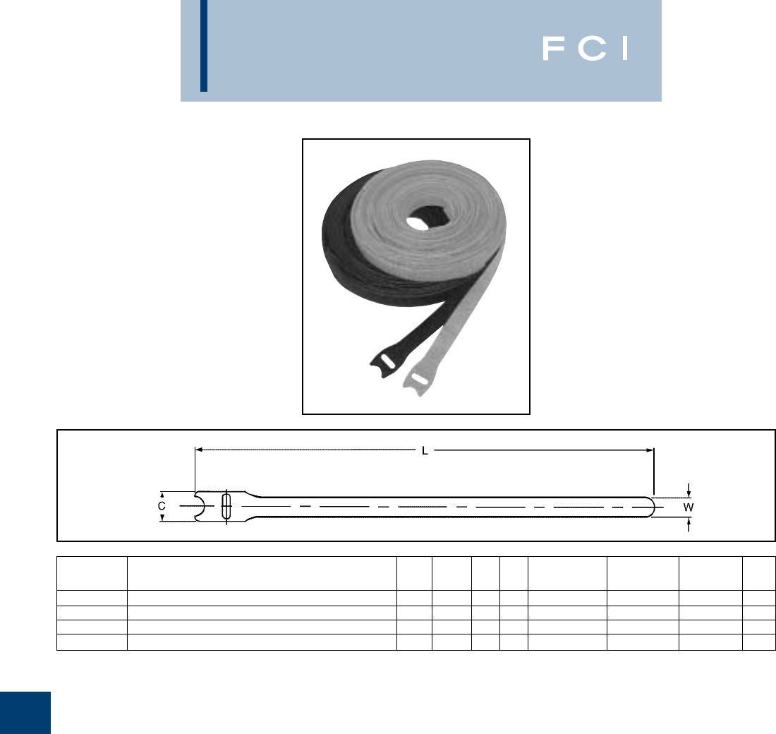
BURNDY
Cable Ties
K-12
TYPE TFV-B
HOOK AND LOOP STRAPS
Reusable and flexible BURNDY®Hook and
Loop Straps are a unique self-gripping
fastening system.
These ties are specifically used on
fiberoptic applications.
The TFV-V2 flame retardant straps are UL
Listed Wire Positioning Devices (ZODZ),
UL94-V2 rated for use in air handling
spaces in accordance with the NEC
section 300-22 (c) and (d). Perfect for
plenum areas.
25 straps are conveniently packaged in each
polybag.
*Straps sold by the package, quantity 1 package equals 25
straps.
** UL94-V2 listed.
VELCRO®is a registered trademark of Velcro USA, Inc.
CATALOG MAX. AVG. SHEER AVG. PEEL PKG.
NUMBER PRODUCT DESCRIPTION C L W T BUNDLE DIA. (PSI) (PIW) QTY.
TFV3B12V2** VELCRO®hook and loop strap, 3/412, Black, 25pk 0.7512.00.50.093.029 .6 *1
TFV3B18V2** VELCRO®hook and loop strap, 3/418, Black, 25pk 0.7518.00.50.095.029 .6 *1
TFV3BLU12 VELCRO®hook and loop strap, 3/412, Royal Blue, 25pk 0.7512.00.50.093.023 .5 *1
TFV3BLU18 VELCRO®hook and loop strap, 3/418, Royal Blue, 25pk 0.7518.00.50.095.023 .5 *1
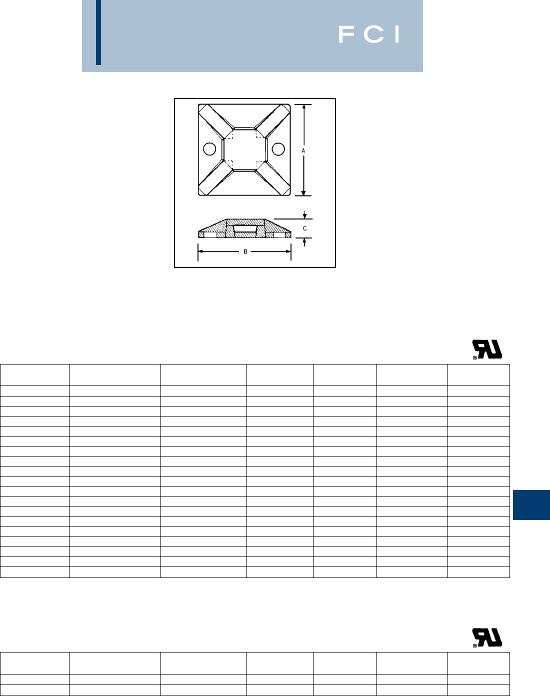
BURNDY
Cable Ties
K-13
MOUNTING BASES
FCI BURNDY®offers a wide variety of mount-
ing bases suited for many applications.
Mounting bases are used in conjunction with
cable ties to stabilize and secure wire bun-
dles, both indoors and outdoors. Mounting
bases can be secured to a surface using rub-
ber based adhesive, acrylic adhesive, or also
can be screw mounted.
FCI BURNDY’s 4-way mounting bases are
available in four sizes to accommodate CT18
through CT150 series cable ties. Insertion of
ties can be made from all sides. Each mount
may be secured with two screws, with
adhesive backing, or both, for ease of appli-
cation and stability. For applications where
higher temperatures, certain chemicals, or
UV radiation are a concern and an adhesive
is the preferred method for securing, the
acrylic adhesive 4-way mounting bases are
recommended.
CATALOG MOUNTING MAX. TIE DIMENSION DIMENSION DIMENSION PKG.
NUMBER METHOD SLOT WIDTH A B C QTY.
CTB075S4C #4 Screw .14.75.75.15100
CTB075S4M #4 Screw .14.75.75.151000
CTB075AA4C Acrylic Adhesive .14.75.75.15100
CTB075AA4M Acrylic Adhesive .14.75.75.151000
CTB075RA4C Rubber Adhesive .14.75.75.15100
CTB075RA4M Rubber Adhesive .14.75.75.151000
CTB125S4C #8 Screw .201.1251.125.19100
CTB125S4D #8 Screw .201.1251.125.19500
CTB125AA4C Acrylic Adhesive .201.1251.125.19100
CTB125AA4D Acrylic Adhesive .201.1251.125.19500
CTB125RA4C Rubber Adhesive .201.1251.125.19100
CTB125RA4L Rubber Adhesive .201.1251.125.1950
CTB125RA4D Rubber Adhesive .201.1251.125.19500
CTB150S4C #8 Screw .351.51.5.25100
CTB150S4B #8 Screw .351.51.5.25250
CTB150AA4C Acrylic Adhesive .351.51.5.25100
CTB150AA4B Acrylic Adhesive .351.51.5.25250
CTB150RA4C Rubber Adhesive .351.51.5.25100
CTB150RA4B Rubber Adhesive .351.51.5.25250
4-Way
All bases listed above are natural. UV Black mounting bases
are also available in nearly every size. Insert “0” after the part
number.
The 2-way mounting bases may be secured
with one screw, with adhesive backing, or
both, and allow ties to be inserted from two
sides.
CATALOG MOUNTING MAX. TIE DIMENSION DIMENSION DIMENSION PKG.
NUMBER METHOD SLOT WIDTH A B C QTY.
CTB125S2C #6 Screw .181.1251.125.21100
CTB125RA2C Rubber Adhesive .181.1251.125.21100
2-Way
All bases listed above are natural. UV Black mounting bases
are also available in nearly every size. Insert “0” after the part
number.
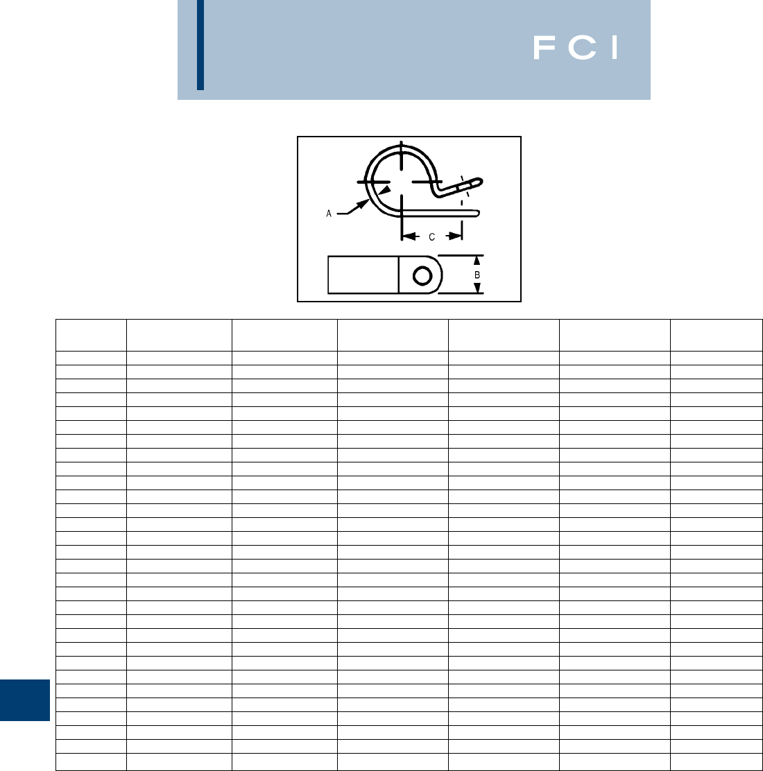
BURNDY
Cable Ties
K-14
CABLE HANGERS
Cable Hangers provide a contact area range
of 1/2to 3/8in width. All contact edges have
a full radius for product protection, and sizes
are clearly marked on each clamp.
Cable Hangers are injection molded.
Available in white nylon 6/6 and black
nylon 6/6.
Catalog Mounting Max. Dimension Dimension Dimension Pkg.
Number Screw Bundle A B C Qty.
CH2C #10 Screw .125.125.375.329100
CH2M #10 Screw .125.125.375.3291000
CH3C #10 Screw .187.188.375.430100
CH3M #10 Screw .187.188.375.4301000
CH4C #10 Screw .25.250.375.410100
CH4M #10 Screw .25.250.375.4101000
CH5C #10 Screw .312.313.375.495100
CH5M #10 Screw .312.313.375.4951000
CH6C #10 Screw .375.375.375.595100
CH6M #10 Screw .375.375.375.5951000
CH7C #10 Screw .437.438.375.574100
CH7M #10 Screw .437.438.375.5741000
CH8C #10 Screw .5.5.375.605100
CH8M #10 Screw .5.5.375.6051000
CH9C #10 Screw .563.563.375.606100
CH9M #10 Screw .563.563.375.6061000
CH10C #10 Screw .625.625.375.606100
CH10M #10 Screw .625.625.375.6061000
CH11C #10 Screw .625.625.5.655100
CH11M #10 Screw .625.625.5.6551000
CH12C #10 Screw .750.750.5.78100
CH12M #10 Screw .750.750.5.781000
CH14C #10 Screw .875.875.5.845100
CH14M #10 Screw .875.875.5.8451000
CH16C #10 Screw 11.5.91100
CH16M #10 Screw 11.5.911000
CH18C #10 Screw 1.121.125.5.97100
CH18M #10 Screw 1.121.125.5.971000
CH24L #10 Screw 1.51.5.51.1950
CH24C #10 Screw 1.51.5.51.19100
All hangers listed above are natural. UV Black cable hangers
are also available in nearly every size. Insert “0” after the part
number.
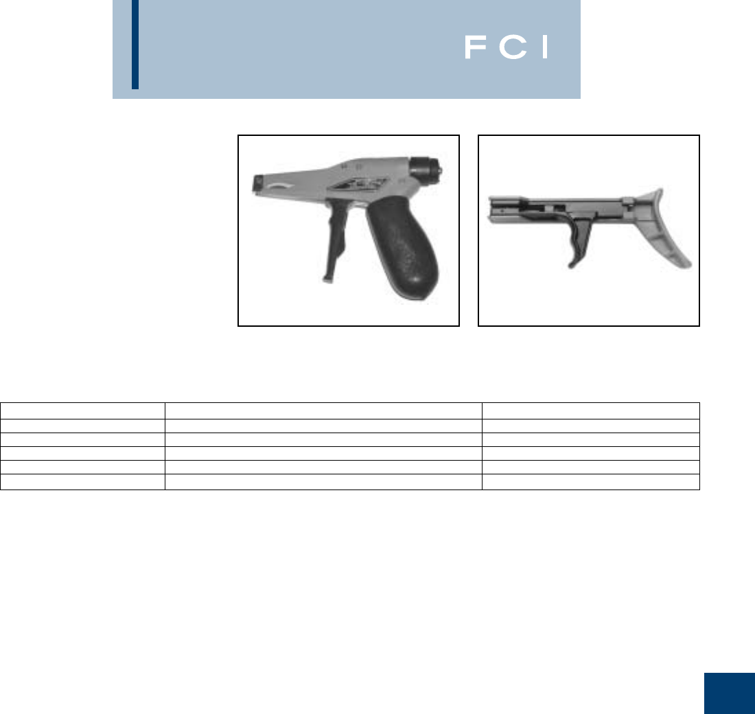
BURNDY
Cable Ties
K-15
CABLE TIE TOOLS
Ergonomics and the prevention of repetitive
motion injuries, coupled with the need to con-
tinually improve assembly efficiencies and
procedures, are a major concern with most
cable tie users. FCI BURNDY®cable tie tools
effectively address both issues. FCI
BURNDY®has world class cable tie tools to
complement its line of high quality cable ties.
FCI BURNDY®cable tie tools are truly state-
of-the-art in both design and performance.
FCI BURNDY®tools make it easier for opera-
tors to install cable ties, while maintaining
correct tension and flush cut-off. Worker
safety is further enhanced as the tools can
eliminate the sharp edges of a cut-off cable
tie.
Catalog Number Description For Use On
MK7 Adjustable Tensioning Tool for Width .10” to .19” CT18 - CT50 Series Ties
MK9 Adjustable Tensioning Tool for Width .19” to .35” CT18 - CT250 Series Ties
MK9SST Adapted for use with Stainless Steel Ties CTSS Series Ties
TWT1 Non-adjustable Tensioning Tool for Width .10” to .19” CT18 - CT50 Series Ties
TWT2 Non-adjustable Tensioning Tool for Width .19” to .35” CT120 - CT175 Series Ties
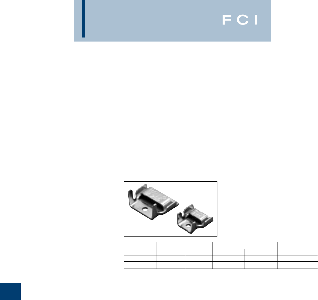
BURNDY
Cable Ties
K-16
STAINLESS STEEL
STRAP AND
ACCESSORIES
Stainless Steel straps are designed for use in
many applications where a wrap around
method is required for securing objects to
outside perimeter surfaces.The FCI Stainless
Steel Strap system includes strap in conve-
nient tote carrying packages, buckles for
securing the strap and installation tooling
designed for a convenient and reliable clamp-
ing application. Straps and buckles are
manufactured from a type 301 stainless steel
which provides a high strength and corrosion
resistant application.
BUCKLES
Type 301 Stainless Steel buckles are
designed to provide secure installation of
stainless straps.
Catalog Width Weight per 100
Number Inches mm Lbs Kg For Use With
A100 0.433 11 0.771 0.350 F107C31
A200 0.826 21 1.830 0.830 F207C31
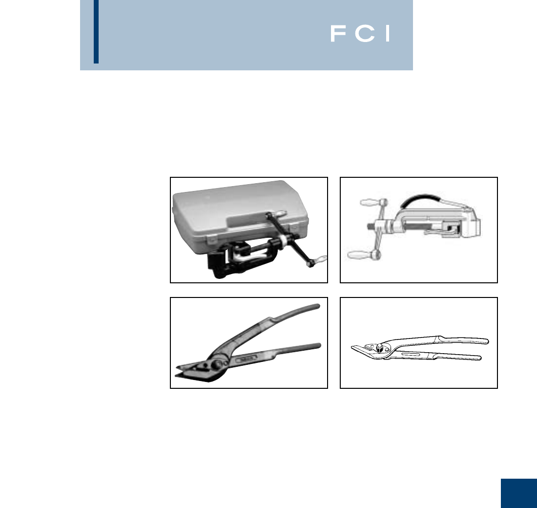
BURNDY
Cable Ties
K-17
STAINLESS STEEL
STRAP
INSTALLATION
TOOLS
TYPE OPV
OPV - Bench screw type band installation tool
with carrying case. Bench screw type tool
provides tensioning capability with a built in
cutter. This tool incorporates a gripper to
secure the strap and a spin handle for easy
tensioning.
4 lbs. 1.8 kg
TYPE OPC
The OPC cutting tool is manufactured from
heat treated steel and includes a strap cutting
guide for safe, easy cutting operations.
1.50 lbs. 0.68 kg

BURNDY
Hardware
L-1
TABLE OF CONTENTS
Aluminum Hardware
Bolts ..........................................................L-6
Nuts...........................................................L-6
Flat Washer ...............................................L-6
Split Lockwashers .....................................L-6
Stainless Steel Hardware
Bolts ..........................................................L-7
Nuts...........................................................L-7
Flat Washer ...............................................L-7
Split Lockwashers .....................................L-7
Belleville Washers .......................................L-7
DURIUM™ U-Bolts ......................................L-8
DURIUM™ Hardware
Bolts ..........................................................L-2
Nuts...........................................................L-3
Flat Washer ...............................................L-3
Split Lockwasher .......................................L-3
Internal Tooth Lockwasher ........................L-3
TMH Hardware Kits
Durium™ ...................................................L-4
Stainless Steel ..........................................L-4
Galvanized Steel Hardware
Bolts ..........................................................L-5
Nuts...........................................................L-5
Flat Washer ...............................................L-5
Internal Tooth Lockwashers.......................L-5
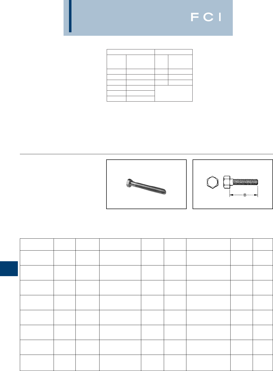
BURNDY
Hardware
L-2
DURIUM™ BOLT
SILICON BRONZE
BURNDY®introduced silicon-bronze bolts,
nuts, and other hardware items on outdoor
connector applications in 1927. Today the
DURIUM™ trademark is a standard for
this use.
DURIUM™ bolts combine high strength with
corrosion resistance. Bolts up to 2 inches
long are fully threaded; longer bolts are
threaded for two inches. Heads have
HARDWARE DATA
RECOMMENDED
TIGHTENING TORQUE
The hardware used in connectors must be
compatible with the connector material, have
high mechanical strength and be corrosion
resistant and correspond to NEMA
recommendations.
Copper alloy connectors have hardware
made of DURIUM™, which is BURNDY's
trade name for silicon bronze alloy ASTMB99
type B. This material was first introduced by
BURNDY®in 1927 for use in outdoor
construction, and today, is the standard
throughout the industry.
Aluminum connectors generally have
aluminum alloy hardware. The bolts are
2024T4 and anodized to resist corrosion. The
nuts are 6061T6, which is resistant to corro-
sion and does not require anodizing. Both
nuts and bolts are lubricated to eliminate
galling and to provide consistent clamping
forces.
DURIUM™ and Steel Hardware Aluminum Hardware
Bolt
Size
Recommended
Torque
(Inch Pounds)
Bolt
Size
Recommended
Torque
(Inch Pounds)
1/4 - 20 80 1/2 - 13
5/8 - 11
3/4 - 10
300
5/16 - 18 180 480
3/8 - 16 240 650
1/2 - 13 480
5/8 - 11 660
3/4 - 10 1,050
The size material for clamping hardware are
selected to provide the required force when
tightened to the recommended torque. To
reduce or greatly exceed the recommended
torque can adversely affect the performance
of the connector.
Thread B Thread B Thread B
Catalog Number Size Length Catalog Number Size Length Catalog Number Size Length
25x50 HEB BOX 1/4-20 1/238x125 HEB BOX 3/8-16 1-1/450x300 HEB BOX 1/2-13 3
25x62 HEB BOX 1/4-20 5/838x150 HEB BOX 3/8-16 1-1/250x325 HEB BOX 1/2-13 3-1/4
25x75 HEB BOX 1/4-20 3/438x175 HEB BOX 3/8-16 1-3/450x350 HEB BOX 1/2-13 3-1/2
25x100 HEB BOX 1/4-20 138x200 HEB BOX 3/8-16 250x375 HEB BOX 1/2-13 3-3/4
25x125 HEB BOX 1/4-20 1-1/438x225 HEB BOX 3/8-16 2-1/450x400 HEB BOX 1/2-13 4
25x150 HEB BOX 1/4-20 1-1/238x250 HEB BOX 3/8-16 2-1/250x450 HEB BOX 1/2-13 4-1/2
25x200 HEB BOX 1/4-20 238x275 HEB BOX 3/8-16 2-3/450x500 HEB BOX 1/2-13 5
25x250 HEB BOX 1/4-20 2-1/238x300 HEB BOX 3/8-16 350x550 HEB BOX 1/2-13 5-1/2
25x300 HEB BOX 1/4-20 338x325 HEB BOX 3/8-16 3-1/450x600 HEB BOX 1/2-13 6
31x50 HEB BOX 5/16-18 1/238x350 HEB BOX 3/8-16 3-1/262x100 HEB BOX 5/8-11 1
31x62 HEB BOX 5/16-18 5/838x400 HEB BOX 3/8-16 462x125 HEB BOX 5/8-11 1-1/4
31x75 HEB BOX 5/16-18 3/438x450 HEB BOX 3/8-16 4-1/262x150 HEB BOX 5/8-11 1-1/2
31x100 HEB BOX 5/16-18 138x500 HEB BOX 3/8-16 562x175 HEB BOX 5/8-11 1-3/4
31x125 HEB BOX 5/16-18 1-1/4 44x150 HEB BOX 7/16-14 1-1/262x200 HEB BOX 5/8-11 2
31x150 HEB BOX 5/16-18 1-1/244x200 HEB BOX 7/16-14 262x225 HEB BOX 5/8-11 2-1/4
31x175 HEB BOX 5/16-18 1-3/450x75 HEB BOX 1/2-13 3/462x250 HEB BOX 5/8-11 2-1/2
31x200 HEB BOX 5/16-18 250x100 HEB BOX 1/2-13 162x275 HEB BOX 5/8-11 2-3/4
31x250 HEB BOX 5/16-18 2-1/250x125 HEB BOX 1/2-13 1-1/462x300 HEB BOX 5/8-11 3
31x300 HEB BOX 5/16-18 350x150 HEB BOX 1/2-13 1-1/262x325 HEB BOX 5/8-11 3-1/4
38x50 HEB BOX 3/8-16 1/250x175 HEB BOX 1/2-13 1-3/462x350 HEB BOX 5/8-11 3-1/2
38x62 HEB BOX 3/8-16 5/850x200 HEB BOX 1/2-13 262x400 HEB BOX 5/8-11 4
38x75 HEB BOX 3/8-16 3/450x225 HEB BOX 1/2-13 2-1/462x450 HEB BOX 5/8-11 4-1/2
38x88 HEB BOX 3/8-16 7/850x250 HEB BOX 1/2-13 2-1/262x500 HEB BOX 5/8-11 5
38x100 HEB BOX 3/8-16 150x275 HEB BOX 1/2-13 2-3/462x600 HEB BOX 5/8-11 6
American Standard dimension, and the
threads are per American National Coarse
Series, Class #2 fit. The silicon bronze is per
ASTM B99.
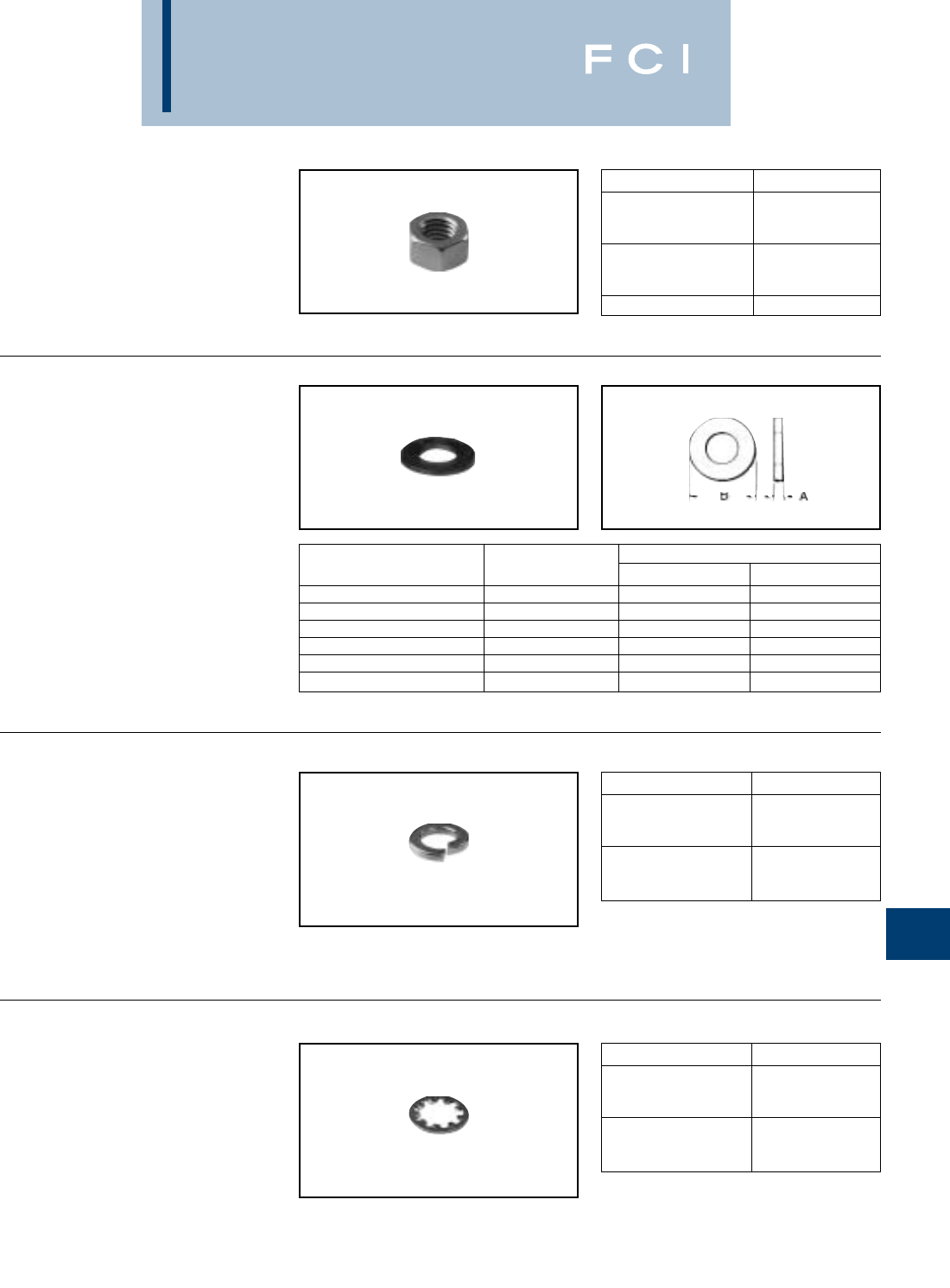
BURNDY
Hardware
L-3
DURIUM™ NUT
SILICON BRONZE
DURIUM™ hexagon regular nuts are non-
magnetic and are made to American
Standard dimensions. American National
Coarse Series threads, #2 fit.
DURIUM™
FLAT WASHER
SILICON BRONZE
High strength DURIUM™ Flat Washers are
non-magnetic and free from galvanic action
when in contact with copper. Conforms to
SAE standards.
DURIUM™ SPLIT
LOCKWASHER
SILICON BRONZE
DURIUM™ spring type lockwasher has high
resiliency and exerts constant pressure on
the face of the nut, preventing vibration from
loosening the nut.
DURIUM™
INTERNAL TOOTH
LOCKWASHER
SILICON BRONZE
DURIUM™ Internal Tooth Lockwashers are
available as illustrated. The teeth are twisted
slightly and present biting edges which grip
the nut and the part being clamped, prevent-
ing the nut from backing off.
Catalog Number Thread Size
25C HEN BOX 1/4-20
31C HEN BOX 5/16-18
38C HEN BOX 3/8-16
44C HEN BOX 7/16-14
50C HEN BOX 1/2-13
62C HEN BOX 5/8-11
75C HEN BOX 3/4-10
For Bolt Nominal Dimensions in Inches
Catalog Number Size A B
25 FW BOX 1/4 1/16 5/8
31 FW BOX 5/16 1/16 11/16
38 FW BOX 3/8 1/16 13/16
44 FW BOX 7/16 1/16 15/16
50 FW BOX 1/2 3/32 1-1/16
62 FW BOX 5/8 3/32 1-5/16
Catalog Number For Bolt Size
25 SW BOX 1/4
31 SW BOX 5/16
38 SW BOX 3/8
44 SW BOX 7/16
50 SW BOX 1/2
62 SW BOX 5/8
Catalog Number For Bolt Size
25 NW BOX 1/4
31 NW BOX 5/16
38 NW BOX 3/8
44 NW BOX 7/16
50 NW BOX 1/2
62 NW BOX 5/8
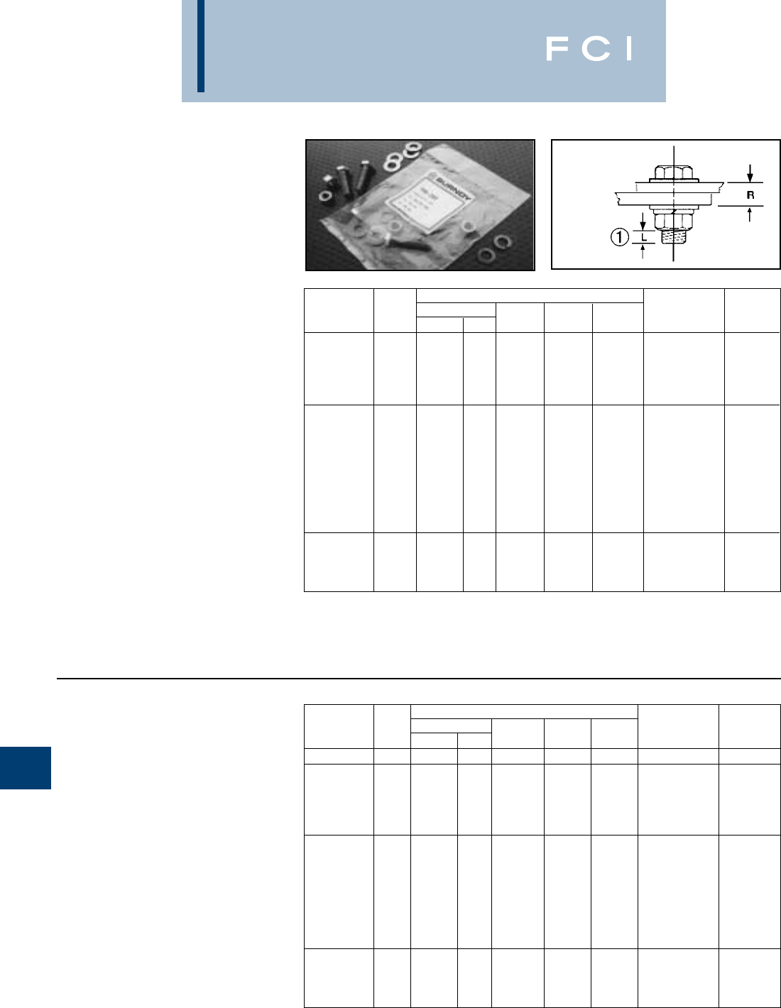
BURNDY
Hardware
L-4
TYPE TMH
DURIUM™ SILICON BRONZE
HARDWARE KITS
Type TMH are DURIUM™ silicon bronze
hardware kits. The kits can be ordered for
specific applications ensuring the proper type
and amount of hardware for each installation.
Packaged in separate sealed bags, they are
convenient to use, eliminating mismatched
quantities. DURIUM™ silicon bronze material
provides long lasting corrosion resistance.
† For use with CUSA750-2TC38 copper spacer adaptor, (2)
terminals and ˚" thick equipment bus bar.
For other combinations contact BURNDY®.
†† For use with all GAR-TC connectors. "R" dimension is
allowable pad thickness of terminal
Each TMH Kit Includes: Working Installation
Catalog Bolt Flat Split Hex Range Torque
Number Size Length Qty. Washer Washer Nut R (In-lbs)
TMH322SS 10 - 32 0.875 1 0 1 1 - 45
TMH262SS 0.75 2 4 2 2 0.09 - 0.34
TMH263SS 1.00 2 4 2 2 0.34 - 0.59
TMH264SS 1/4-20 1.25 2 4 2 2 0.59 - 0.84 80
TMH265SS 1.50 2 4 2 2 0.84 - 1.09
TMH323SS 0.75 1 0 1 1 -
TMH266SS 0.75 2 4 2 2 0.00 - 0.19
TMH267SS 1.00 2 4 2 2 0.19 - 0.44
TMH268SS 1.25 2 4 2 2 0.44 - 0.69
TMH269SS 1.50 2 4 2 2 0.69 - 0.94
TMH270SS 3/8-16 1.75 2 4 2 2 0.94 - 1.19 240
TMH271SS 2.00 2 4 2 2 1.19 - 1.44
TMH261SS †3.00 2 4 2 2 2.15 - 2.40
TMH289SS †† 1.25 1 2 1 1 0.02 - 0.27
TMH295SS 1.25 2 4 2 2 0.27 - 0.49
TMH272SS 1.50 2 4 2 2 0.49 - 0.74
TMH294SS 1/2-13 1.75 2 4 2 2 0.74 - 0.99 480
TMH69SS 2.00 2 4 2 2 0.99 - 1.24
TYPE TMH-SS
STAINLESS STEEL
HARDWARE KITS
Type TMH-SS are Grade 5 stainless steel
hardware kits.Just like the standard TMH kits,
these kits can be ordered for specific applica-
tions ensuring the proper type and amount of
hardware for each installation. They are pack-
aged in separate sealed bags and convenient
for use and ordering.
Each TMH Kit Includes: Working Installation
Catalog Bolt Flat Split Hex Range Torque
Number Size Length Qty. Washer Washer Nut R (In-lbs)
TMH262 0.75 2 4 2 2 0.09 - 0.34
TMH263 1.00 2 4 2 2 0.34 - 0.59
TMH264 1/4-20 1.25 2 4 2 2 0.59 - 0.84 80
TMH265 1.50 2 4 2 2 0.84 - 1.09
TMH323 0.75 1 0 1 1 -
TMH266 0.75 2 4 2 2 0.00 - 0.19
TMH267 1.00 2 4 2 2 0.19 - 0.44
TMH268 1.25 2 4 2 2 0.44 - 0.69
TMH269 1.50 2 4 2 2 0.69 - 0.94
TMH270 3/8-16 1.75 2 4 2 2 0.94 - 1.19 240
TMH271 2.00 2 4 2 2 1.19 - 1.44
TMH332 22.75 2 4 2 2 -
TMH261 †3.00 2 4 2 2 2.15 - 2.40
TMH289 †† 1.25 1 2 1 1 0.02 - 0.27
TMH295 1.25 2 4 2 2 0.27 - 0.49
TMH272 1.50 2 4 2 2 0.49 - 0.74
TMH294 1/2-13 1.75 2 4 2 2 0.74 - 0.99 480
TMH69 2.00 2 4 2 2 0.99 - 1.24
*For other combinations contact BURNDY®.
➀"L" dimension never exceeds .25"
2For use with CUSA442TC38 on 1/4" bus bar and
HYLUG™ 4/0 - 750 kcmil.
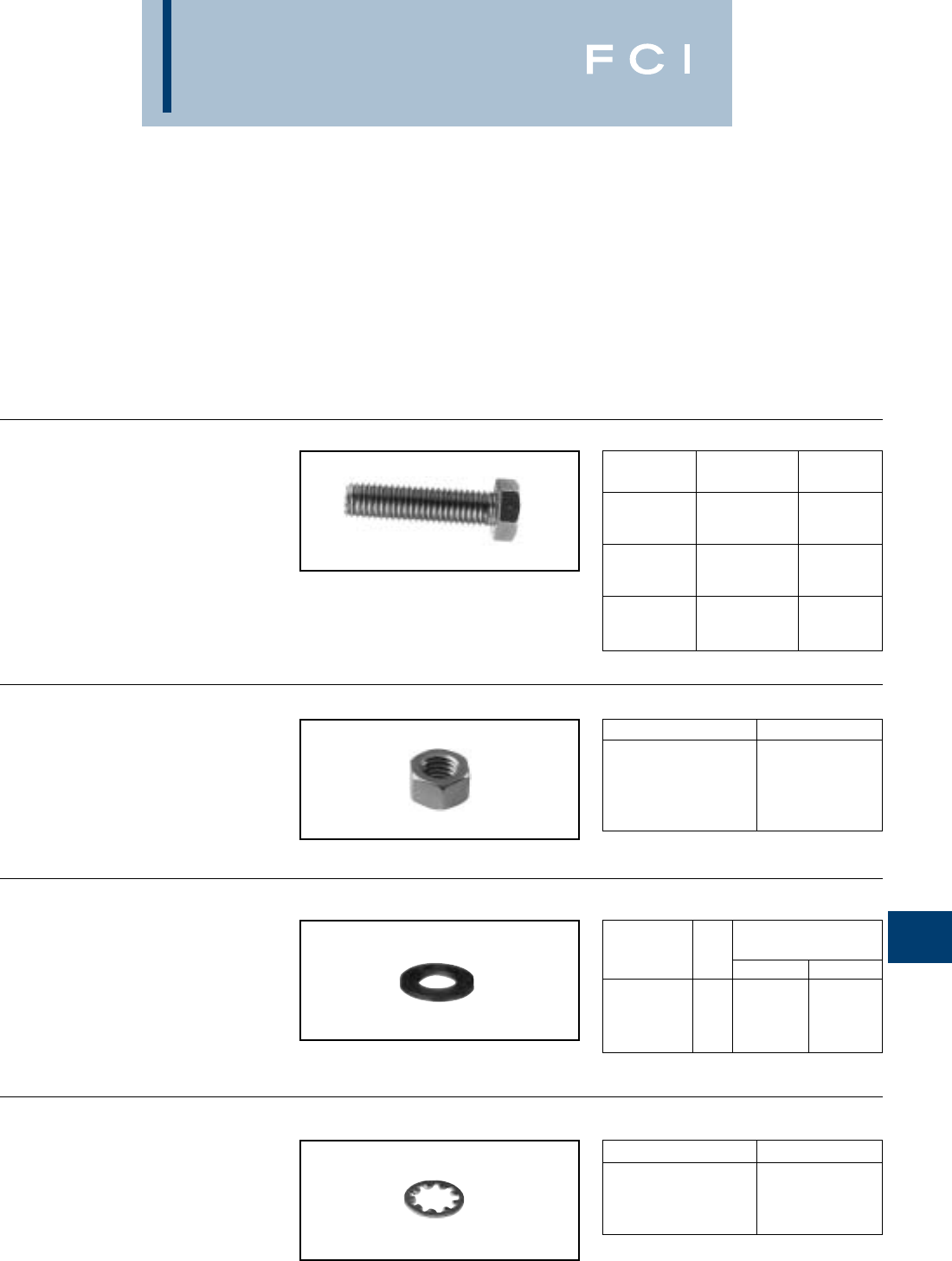
BURNDY
Hardware
L-5
GALVANIZED
STEEL HARDWARE
Galvanized bolts, nuts, flatwashers, and inter-
nal tooth lockwashers are manufactured per
ASTM307 Grade A. Bolts up to 2 inches long
are fully threaded; longer bolts are threaded
for 2 inches. Nut surfaces and bolt heads
have American Standard dimensions, and the
threads are per American National Coarse
Series, Class #2 fit. Galvanizing is per ASTM
A153.
BOLTS
NUTS
FLATWASHER
INTERNAL TOOTH
LOCKWASHERS
CATALOG
NUMBER THREAD SIZE LENGTH (B)
38x125 HGSB 3/8-16 1.25
38x275 HGSB 3/8-16 2.75
38x225 HGSB 3/8-16 2.25
50x100 HGSB 1/2-13 1.00
50x150 HGSB 1/2-13 1.50
50x200 HGSB 1/2-13 2.00
62x125 HGSB 5/8-11 1.00
62x175 HGSB 5/8-11 1.75
75x125 HGSB 3/4-10 1.25
CATALOG NUMBER THREAD SIZE
31CHGSN 5/16-18
38 HGSN-009 3/8-16
38 HGSN 3/8-16
50 HGSN 1/2-13
62 HGSN 5/8-11
NOMINAL DIMENSIONS
CATALOG BOLT (INCHES)
NUMBER SIZE I.D. A O.D. B
38x81 FWGS 3/8 0.406 0.813
50x106 FWGS 1/2 0.531 1.06
62x31 FWGS 5/8 0.656 1.75
75 FWGS 3/4 0.812 1.50
CATALOG NUMBER BOLT SIZE
38 NWGS 3/8
50 NWGS 1/2
62 NWGS 5/8
75 NWGS 3/4
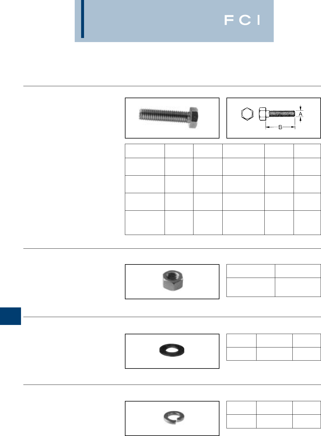
BURNDY
Hardware
L-6
ALUMINUM
HARDWARE
NUTS
BURNDY®aluminum nuts are manufactured
of alloy 6061-T6, are finished type, coarse
thread, class 2B fit.
BOLTS
BURNDY®aluminum hexagon head bolts are
manufactured of alloy 2024-T4 and are
finished with anodic coating and lubricated.
Threads are coarse series, class 2A fit.
FLATWASHER
BURNDY®aluminum flat washers are manu-
factured of alloy 2024-T4 and are medium
design.
SPLIT LOCKWASHERS
BURNDY®aluminum split lockwashers are
manufactured of alloy 7075-T6 and are regu-
lar design.
CATALOG THREAD B CATALOG THREAD B
NUMBER SIZE LENGTH NUMBER SIZE LENGTH
50x150 HAB BOX 1/2-13 1-1/250x500 HAB BOX 1/2-13 5
50x175 HAB BOX 1/2-13 1-3/450x550 HAB BOX 1/2-13 5-1/2
50x200 HAB BOX 1/2-13 262x175 HAB BOX 5/8-11 1-3/4
50x225 HAB BOX 1/2-13 2-1/462x200 HAB BOX 5/8-11 2
50x250 HAB BOX 1/2-13 2-1/262x225 HAB BOX 5/8-11 2-1/4
50x275 HAB BOX 1/2-13 2-3/462x250 HAB BOX 5/8-11 2-1/2
50x300 HAB BOX 1/2-13 362x300 HAB BOX 5/8-11 3
50x325 HAB BOX 1/2-13 3-1/462x350 HAB BOX 5/8-11 3-1/2
50x350 HAB BOX 1/2-13 3-1/262x400 HAB BOX 5/8-11 4
50x375 HAB BOX 1/2-13 3-3/462x450 HAB BOX 5/8-11 4-1/2
50x400 HAB BOX 1/2-13 462x500 HAB BOX 5/8-11 5
50x425 HAB BOX 1/2-13 4-1/462x550 HAB BOX 5/8-11 5-1/2
50x450 HAB BOX 1/2-13 4-1/262x600 HAB BOX 5/8-11 6
CATALOG
NUMBER THREAD SIZE
50 HAN BOX 1/2-13
62 HAN BOX 5/8-11
75 HAN BOX 3/4-10
CATALOG FOR
NUMBER DESCRIPTION BOLT SIZE
50 FWA BOX Flat Washer 1/2
62 FWA BOX Flat Washer 5/8
CATALOG FOR
NUMBER DESCRIPTION BOLT SIZE
50 SWAL BOX Split Washer 1/2
62 SWAL BOX Split Washer 5/8
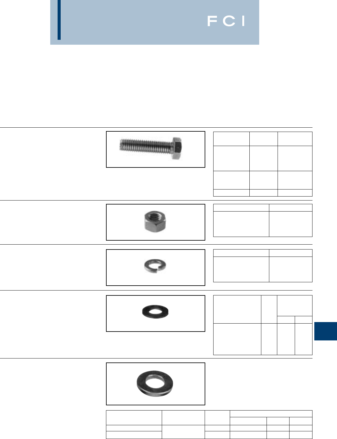
BURNDY
Hardware
L-7
STAINLESS STEEL
HARDWARE
Stainless steel bolts, nuts, flatwashers and
split lockwashers are manufactured from
18-8 non-magnetic material. Bolts up to
2 inches long are fully threaded; longer bolts
are threaded for 2 inches. Nut surfaces and
bolt heads have American National Coarse
Series, Class #2 fit.
NUTS
BOLTS
FLATWASHER
SPLIT LOCKWASHERS
BELLEVILLE
WASHERS
Any bolted "pad to flat" electrical connection
should include a bolt, two flatwashers, and
the nut. In addition, if any of the flat compo-
nents is aluminum, a properly designed
Belleville washer should be interposed
between one of the flatwashers and either the
bolt head or the nut, with the hollow of the
Belleville washer placed against the flat
washer. BURNDY®Belleville washers are
designed to maintain substantial force when
tightened to NEMA - recommended values
and finely finished to avoid galling.
The stainless washers are 301 stainless steel.
CATALOG THREAD LENGTH B
NUMBER SIZE (INCHES)
38X125 HSSB 3/8-16 1.25
38x225 HSSB 3/8-16 2.25
38x250 HSSB 3/8-16 2.50
38x275 HSSB 3/8-16 2.75
50x200 HSSB 1/2-13 2.00
50x250 HSSB 1/2-13 2.50
50x300 HSSB 1/2-13 3.00
62x300 HSSB 5/8-11 3.00
CATALOG NUMBER THREAD SIZE
25 HSSN 1/4-20
38 HSSN 3/8-16
50 HSSN 1/2-13
62 HSSN 5/8-11
CATALOG NUMBER FOR BOLT SIZE
25 SWSS LT 1/4
38 SWSSMD 3/8
50 SWSSMD 1/2
62 SWSSMD 5/8
NOMINAL
DIMENSIONS
CATALOG BOLT (INCHES)
NUMBER SIZE I.D. A O.D. B
25 FWSS 1/4 0.266 0.688
38 FWSS 3/8 0.406 1.000
50 FWSS 1/2 0.594 1.125
62 FWSS 5/8 0.656 1.312
75 FLATWASHER (VC)
3/4 0.812 2.000
BOLT NOMINAL DIMENSIONS
CATALOG NUMBER MATERIAL SIZE THICKNESS I.D. O.D.
38x75 BWSS 3/8 .062 .388 .750
50x106 BWSS Stainless 1/2 .095 .530 1.06
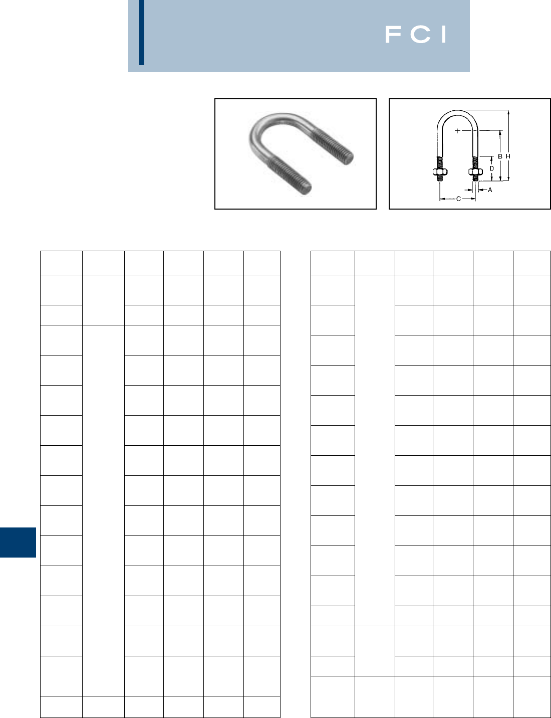
BURNDY
Hardware
L-8
DURIUM™ U-BOLTS
SILICON BRONZE
TYPE UB
DURIUM™ U-BOLTS are specifically
designed for electrical connections to pipe
and rod. The U-BOLTS are threaded on the
straight portion of the legs only allowing for
more contact surface on the pipe or rod.
American National Coarse Threads Class #2
fit. The silicon bronze is per ASTM B99.
Catalog Thread
Number Size H C D B
UB101 1.38 0.75 0.75 0.88
UB104 1.81 1.12 0.88 1.12
UB105 1/4-20 2.03 1.31 1.00 1.25
UB106 2.31 1.62 1.12 1.38
UB107 2.66 1.94 1.31 1.56
UB336 1.50 0.88 0.62 0.88
UB337 1.94 1.12 0.75 1.19
UB178 2.00 0.88 0.75 1.38
UB354 2.44 1.25 1.00 1.62
UB187 2.47 1.16 1.06 1.69
UB271 2.50 1.00 1.19 1.81
UB284 2.50 1.38 1.00 1.62
UB467 2.62 1.04 1.28 1.91
UB222 2.69 1.50 1.12 1.75
UB242 2.72 1.16 1.31 1.94
UB383 2.75 0.94 1.47 2.09
UB269 2.78 1.19 1.38 2.00
UB357 2.78 1.69 1.12 1.75
UB466 2.88 1.09 1.52 2.14
UB384 2.91 1.44 1.38 2.00
UB249 3.00 1.50 1.44 2.06
UB1031 3.31 1.75 1.90 2.25
UB244 3.31 1.75 1.62 2.25
UB199 3/8-16 3.41 2.34 1.44 2.05
UB204 3.47 2.06 1.62 2.25
UB124 3.50 2.75 1.31 1.94
UB268 3.97 2.34 2.00 2.62
UB257 4.16 2.81 1.94 2.56
UB1032 4.41 2.81 2.56 2.81
UB310 4.41 2.81 2.19 2.81
UB266 4.97 3.31 2.50 3.12
UB275 5.09 3.31 3.62 4.25
UB267 5.53 3.94 2.75 3.38
UB258 5.56 4.00 2.75 3.38
UB264 6.16 4.44 3.12 3.75
UB1033 6.16 4.44 3.50 3.75
UB261 6.34 4.94 3.06 3.69
UB422 7.69 6.00 3.88 4.50
UB1027 8.12 7.12 2.88 4.38
UB1028 9.62 9.12 2.88 4.88
UB1029 11.20 11.25 2.88 5.38
UB1030 12.70 13.25 2.88 5.88
UB224 2.44 1.12 0.88 1.62
UB358 1/2-13 2.66 1.31 1.00 1.75
Catalog Thread
Number Size H C D B
UB226 2.75 1.25 1.12 1.88
UB291 2.81 1.19 1.22 1.97
UB293 2.81 1.75 1.19 1.69
UB507 2.97 1.31 1.31 2.06
UB464 3.12 1.81 1.31 1.96
UB468 3.16 1.69 1.31 2.06
UB540 3.19 1.38 1.75 2.25
UB460 3.25 1.50 1.50 2.25
UB254 3.41 1.31 1.75 2.50
UB328 3.41 2.94 0.94 1.69
UB469 3.50 1.62 1.69 2.44
UB465 3.50 1.75 1.62 2.38
UB463 3.59 2.17 1.50 2.25
UB400 4.03 1.31 2.38 3.12
UB462 4.16 2.10 2.12 2.86
UB256 4.16 2.22 2.06 2.81
UB230 4.34 2.94 1.88 2.62
UB360 1/2-13 4.44 1.62 2.62 3.38
UB311 4.44 1.88 2.50 3.25
UB302 4.62 2.47 2.38 3.12
UB232 4.97 3.44 2.25 3.00
UB260 5.34 2.94 2.88 3.62
UB390 5.38 2.50 3.12 3.88
UB263 5.78 4.56 2.50 3.25
UB388 6.16 4.56 2.88 3.62
UB282 6.31 4.12 3.25 4.00
UB236 6.41 5.06 2.88 3.62
UB399 6.66 1.31 5.00 5.75
UB436 6.66 4.56 3.62 4.12
UB262 6.78 5.06 3.25 4.00
UB392 7.06 1.62 5.25 6.00
UB416 7.53 5.06 4.00 4.75
UB300 7.62 6.12 3.56 4.31
UB306 7.88 6.12 3.81 4.56
UB437 8.56 6.12 4.50 5.25
UB294 3.50 1.38 1.75 2.50
UB314 3.66 2.09 1.56 2.31
UB425 5/8-11 3.72 2.31 1.50 2.25
UB317 4.97 1.81 3.00 3.75
UB315 5.56 2.09 3.44 4.19
UB332 4.22 1.81 2.19 2.94
UB318 4.22 2.44 1.87 2.62
UB344 3/4-10 4.72 1.94 2.63 3.38
UB319 6.34 2.44 4.00 4.75

BURNDY
Accessories
M-1
TABLE OF CONTENTS
Heavy Wall Heat Shrinkable End Cap.......M-9
Clear Heat Shrink Tubing.........................M-10
Thin Wall Polyvinyl Chloride
Heat Shrink Tubing ...............................M-11
MISCELLANEOUS ACCESSORIES:
Terminal Blocks........................................M-12
Panel Lights ..............................................M-12
Pigtail Connectors....................................M-13
Alligator Clips...........................................M-13
Steinel®Hot Air Gun.................................M-14
Circuit Tester.............................................M-14
Alligator Test Leads..................................M-14
Introduction.................................................M-2
PENETROX™
(Install Connections).................................M-2
PENETROX™ A, PENA-1 LB,
PENETROX™ A-13, PENETROX®E...........M-3
PENETROX™
Technical & Ordering Information.............M-4
Thin Wall Heat Shrink Tubing —
6 Inch Lengths..........................................M-5
4 Foot Reels.............................................M-6
25 Foot Reels...........................................M-7
Heavy Wall Heat Shrink Tubing —
4 Foot Sticks.............................................M-8
Cut Lengths..............................................M-8
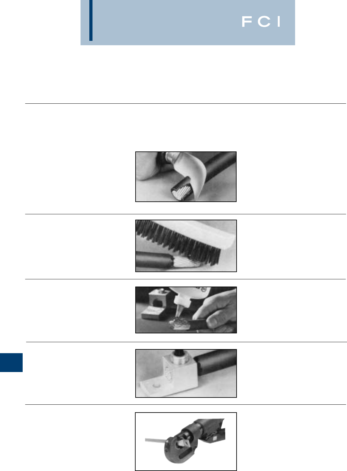
BURNDY
Accessories
INTRODUCTION
BURNDY®wiring accessories have been
designed to supplement and enhance
BURNDY®connector selection and use. All
have been designed and engineered for easy
M-2
PENETROX™
HOW TO INSTALL
CONNECTORS:
1. Select the right connector.
Always use an aluminum connector for
aluminum or copper conductor. And choose a
connector that's marked for the wire size
you're using. Never use a copper connector
on aluminum conductor.
2. Strip carefully.
Remove the insulation without nicking
the wire.
installation and long life, reflecting over 65
years of experience and resulting contribu-
tions to all aspects of the electrical industry.
3. Brush thoroughly.
Always wire-brush the stripped portion of the
wire. An unplated terminal pad, and the
surface to which the terminal will be attached
should also be wire-brushed.
4. Apply PENETROX™
For mechanical connectors, apply PENE-
TROX™ joint compound liberally to the
conductor to prevent the formation of surface
oxides once the connection is made. Also
apply PENETROX™ to any terminal pad.
5. Tighten completely.
For mechanical connectors, use wrench or
screwdriver to securely tighten the aluminum
connectors, as recommended by BURNDY®.
6. Crimp.
For compression connectors, choose the
right die and the right tool. Insert the wire
completely and make the recommended
number of crimps. BURNDY®takes the
guesswork out of aluminum connections
because the connectors and crimp dies are
color coded. Crimps can be easily located
between marks.
BURNDY
Accessories
TYPES PENETROX™
A, A-13 AND E
OXIDE-INHIBITING
JOINT COMPOUNDS
PENETROX™ oxide-inhibiting compounds
produce low initial contact resistance, seal
out air and moisture, prevent oxidation or cor-
rosion, exhibit superior weathering character-
istics, are usable over wide temperature
ranges, and provide a high conductivity "gas-
tight" joint. All PENETROX™ compounds
contain homogeneously suspended metal
particles. The suspended metal particles
assist in penetrating thin oxide films, act as
electrical "bridges" between conductor
strands, aid in gripping the conductor,
improve electrical conductivity and enhance
the integrity of the connection.
The specially formulated PENETROX™
compounds are for use with compression and
bolted connectors providing an improved
service life for both copper and aluminum
connections. Additionally, the non-toxic
compounds are an excellent lubricant for
threaded applications reducing galling and
seizing.
PENA-1 LB
PENA-1 LB is a 1 lb. cartridge filled with
PENETROX-A. It's designed to fit standard
caulking guns for easy insertion into trans-
mission and distribution connectors.
Additionally, this packaging design provides a
convenient method for applying PENE-
TROX™ to many different applications.
M-3
PENETROX A
PENETROX A is a natural (petroleum) base
compound with evenly suspended zinc parti-
cles. It is recommended for aluminum to alu-
minum, aluminum to copper connections and
aluminum conduit threads. It is not recom-
mended for use with rubber or polyethylene
insulated conductors. UL listed to 600V.
PENETROX A-13
PENETROX A-13 is a synthetic base com-
pound with evenly suspended zinc particles.
It is recommended for aluminum to alu-
minum, aluminum to copper connection plus
aluminum conduit threads. It is compatible
with rubber, polyethylene and other insulating
materials. UL listed for all voltages.
PENETROX E
PENETROX E is a synthetic base compound
with evenly suspended copper particles. It is
recommended for copper to copper, copper
threads and all grounding applications. UL
listed.
BURNDY
Accessories
M-4
PENETROX E
PENETROX E consists of a non-petroleum
base vehicle in which copper granules are
suspended. Recommended for copper to
copper applications, grounding and for use
on copper conduit threads. UL listed.
Easy to apply:
1. Scratch brush the conductor surfaces until
bright and clean.
2. Immediately apply PENETROX™ to the
conductive surfaces.
3. For EHV applications, remove all excess
PENETROX™ after installation is com-
plete.
SHELF LIFE
When stored in its original container in cool
(under 100° F) dry environment, PENE-
TROX™ oxide inhibiting compound will
remain workable and functional for (5) years
from the date marked on the container pro-
vided it is mixed per instructions prior to use.
CATALOG NUMBER CONTAINER CONTAINER
PENETROX™ A PENETROX™ A-13 PENETROX™ E TYPE SIZE
PENA 1/2 ——TUBE 1/2 oz.
PEN A-4 PEN A13-4 PEN E-4 SQUEEZE BOTTLE 4 oz.
P8A PEN A13-8 PEN E-8 SQUEEZE BOTTLE 8 oz.
PEN A-1LB PENA13-1LB —CARTRIDGE 1 lb.*
PEN A-QT PEN A13-QT PEN E-QT PLASTIC TUB 1 QUART
PEN A-GAL PEN A13-GAL PEN E-GAL CAN 1 GALLON
PEN A-5GAL PEN A13-5GAL PEN E-5GAL PAIL 5 GALLONS
PEN A-55GAL PEN A13-55GAL PEN E-55GAL DRUM 55 GALLONS
* 1 lb. cartridge will fit standard caulking guns.
VALUE
PENETROX™ PENETROX™
PROPERTY DEFINITION E & A13 A
PENETRATION
(UNWORKED) 250 230
DROPPING
POINT (MIN) 500° F 230° F
POUR POINT
(MAX.) –10° F –15° F
PENETROX A,
A-13 AND E
TECHNICAL INFORMATION
PENETROX A
PENETROX A consists of a natural (petro-
leum) base vehicle in which zinc particles are
suspended. For aluminum to aluminum,
aluminum to copper applications and
aluminum conduit threads. It is not recom-
mended for use with rubber and polyethylene
insulated conductors. UL listed to 600 volts.
PENETROX A-13
PENETROX A-13 consists of a non-
petroleum base vehicle in which zinc parti-
cles are suspended. Recommended for
aluminum to aluminum, aluminum to copper
applications and aluminum conduit threads.
Compatible with insulating materials such as
rubber, or polyethylene. UL listed and recom-
mended for all voltages.
ORDERING INFORMATION
PROPERTIES OF PENETROX®
* MSDS sheets available through customer service.
The value in accordance to ASTM D217 indi-
cates the consistency of a grease. The higher
the number, the softer the grease.
The temperature at which the grease passes
from the semi-solid to a liquid state under test
conditions.
The lowest temperature at which the compound
will flow. Pour point is the lubricant’s ability to
perform in cold conditions.
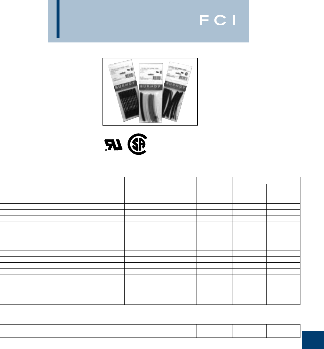
BURNDY
Accessories
M-5
TYPE HS-T-PF
THIN WALL HEAT
SHRINK TUBING
CROSS-LINKED POLYOLEFIN
6 INCH LENGTHS
Type HS-T-PF is a flexible thin wall, flame
retardant heat shrink tubing made of cross-
linked polyolefin. The 2:1 shrink ratio allows
for faster shrink recovery, covering wire sizes:
#18 AWG to 300 kcmil. Operating tempera-
tures from –55° C to 135° C with a shrink
temperature of 120° C.
Meets MIL-I-23053/5
600 VOLTS
Nominal Min. Max. Nom. Wall Pcs. per Package
Catalog Diameter Exp. Recov. Thickness Conductor # Pcs. # Pcs. Ea.
Number Inches I.D. In. I.D. In. In. Range Black Color
HSM116T6PF26 1/16 0.06 0.03 0.018 #18 8 3
HSB116T6PF26 1/16 0.06 0.03 0.018 #18 26 0
HSM332T6PF24 3/32 0.09 0.05 0.020 #18 - 16 6 3
HSB332T6PF24 3/32 0.09 0.05 0.020 #18 - 16 24 0
HSM18T6PF20 1/8 0.12 0.06 0.020 #18 - 14 2 3
HSB18T6PF20 1/8 0.12 0.06 0.020 #18 - 14 20 0
HSM316T6PF18 3/16 0.19 0.09 0.020 #18 - 12 6 2
HSB316T6PF18 3/16 0.19 0.09 0.020 #18 - 12 18 0
HSM14T6PF14 1/4 0.25 0.12 0.180 #14 - 10 2 2
HSB14T6PF14 1/4 0.25 0.12 0.180 #14 - 10 14 0
HSM38T6PF12 3/8 0.38 0.19 0.020 #8 - 6 6 1
HSB38T6PF12 3/8 0.38 0.19 0.020 #8 - 6 12 0
HSM12T6PF10 1/2 0.50 0.12 0.020 #6 - 2 4 1
HSB12T6PF10 1/2 0.50 0.12 0.020 #6 - 2 10 0
HSM34T6PF8 3/4 0.75 0.38 0.020 #1 - 3/0 2 1
HSB34T6PF8 3/4 0.75 0.38 0.020 #1 - 3/0 8 0
HSM100T6PF7 11.00 0.50 0.180 2/0 - 300 1 1
HSB100T6PF7 11.00 0.50 0.180 2/0 - 300 7 0
HSB11612T6PF14 1/16, 3/32, 1/8, 3/16, 1/4, 3/8, 1/2 14 0
HSB38100T6PF8 3/8, 1/2, 3/4, 180
HSB series — all black
HSM series — multiple colors: black, blue, clear, green, red, white, yellow
Multiple diameter packages contain two pieces of each size listed: Black only.
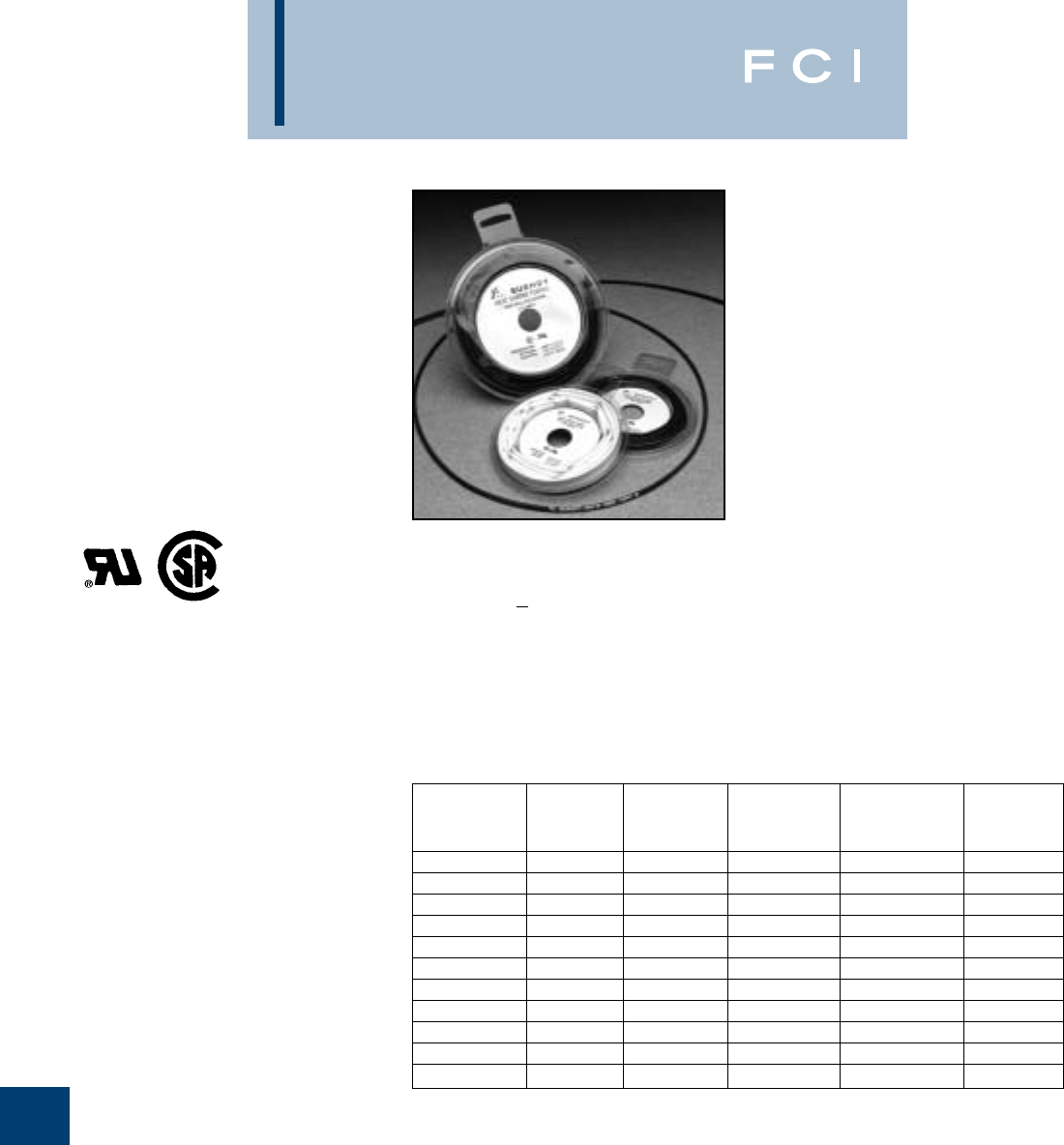
BURNDY
Accessories
M-6
TYPE HS-T-PF
THIN WALL HEAT
SHRINK TUBING
CROSS-LINKED POLYOLEFIN
4 FOOT REELS
Type HS-T-PF is a flexible thin wall, flame
retardant heat shrink tubing made of cross-
linked polyolefin. The 2:1 shrink ratio allows
for faster shrink recovery, covering wire sizes
#18 AWG to 300 kcmil. Operating tempera-
tures from –55° C to 135° C with a shrink
temperature of 120° C.
SPECIFY COLOR CODE IN THIRD
POSITION OF CATALOG NUMBER:
Example: HSC116T48PF
B: BLACK
BL: BLUE
C: CLEAR
G: GREEN
R: RED
W: WHITE
Y: YELLOW
Meets MIL-I-23053/5
600 VOLTS
Nominal Min. Max. Nom. Wall
Catalog Diameter Exp. Recov. Thickness Conductor
Number Inches I.D. In. I.D. In. In. Range
HS_116T48PF 1/16 0.06 0.03 0.018 #18
HS_332T48PF 3/32 0.09 0.05 0.020 #18 - 16
HS_18T48PF 1/8 0.12 0.06 0.020 #18 - 14
HS_316T48PF 3/16 0.19 0.09 0.020 #18 - 12
HS_14T48PF 1/4 0.25 0.12 0.180 #14 - 10
HS_38T48PF 3/8 0.38 0.19 0.020 #8 - 6
HS_12T48PF 1/2 0.50 0.12 0.020 #6 - 2
HS_34T48PF 3/4 0.75 0.38 0.020 #1 - 3/0
HS_100T48PF 11.00 0.50 0.180 2/0 - 300
HS_150T48PF 1-1/2 1.50 .75 0.180 2/0 - 350
HS_200T48PF 22.00 1.00 0.180 250 - 500
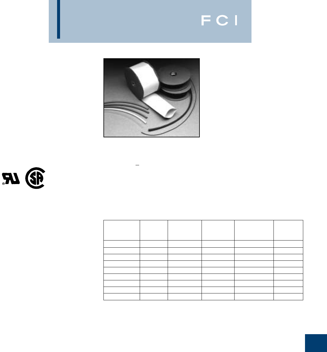
BURNDY
Accessories
M-7
TYPE HS-T-PF
THIN-WALL HEAT
SHRINK TUBING
CROSS-LINKED POLYOLEFIN
25 FOOT REELS
Type HS-T-PF is a flexible thin wall, flame
retardant heat shrink tubing made of cross-
linked polyolefin. The 2:1 shrink ratio allows
for faster shrink recovery, covering wire sizes
#18 AWG to 300 kcmil. Operating tempera-
tures from –55° C to 135° C with a shrink
temperature of 120° C.
SPECIFY COLOR CODE IN THIRD
POSITION OF CATALOG NUMBER:
Example: HSC116T300PF
B: BLACK
BL: BLUE
C: CLEAR
G: GREEN
R: RED
W: WHITE
Y: YELLOW
Meets MIL-I-23053/5
600 VOLTS
Nominal Min. Max. Nom. Wall
Catalog Diameter Exp. Recov. Thickness Conductor
Number Inches I.D. In. I.D. In. In. Range
HS_116T300PF 1/16 0.06 0.03 0.018 #18
HS_332T300PF 3/32 0.09 0.05 0.020 #18 - 16
HS_18T300PF 1/8 0.12 0.06 0.020 #18 - 14
HS_316T300PF 3/16 0.19 0.09 0.020 #18 - 12
HS_14T300PF 1/4 0.25 0.12 0.180 #14 - 10
HS_38T300PF 3/8 0.38 0.19 0.020 #8 - 6
HS_12T300PF 1/2 0.50 0.12 0.020 #6 - 2
HS_34T300PF 3/4 0.75 0.38 0.020 #1 - 3/0
HS_100T300PF 11.00 0.50 0.180 2/0 - 300
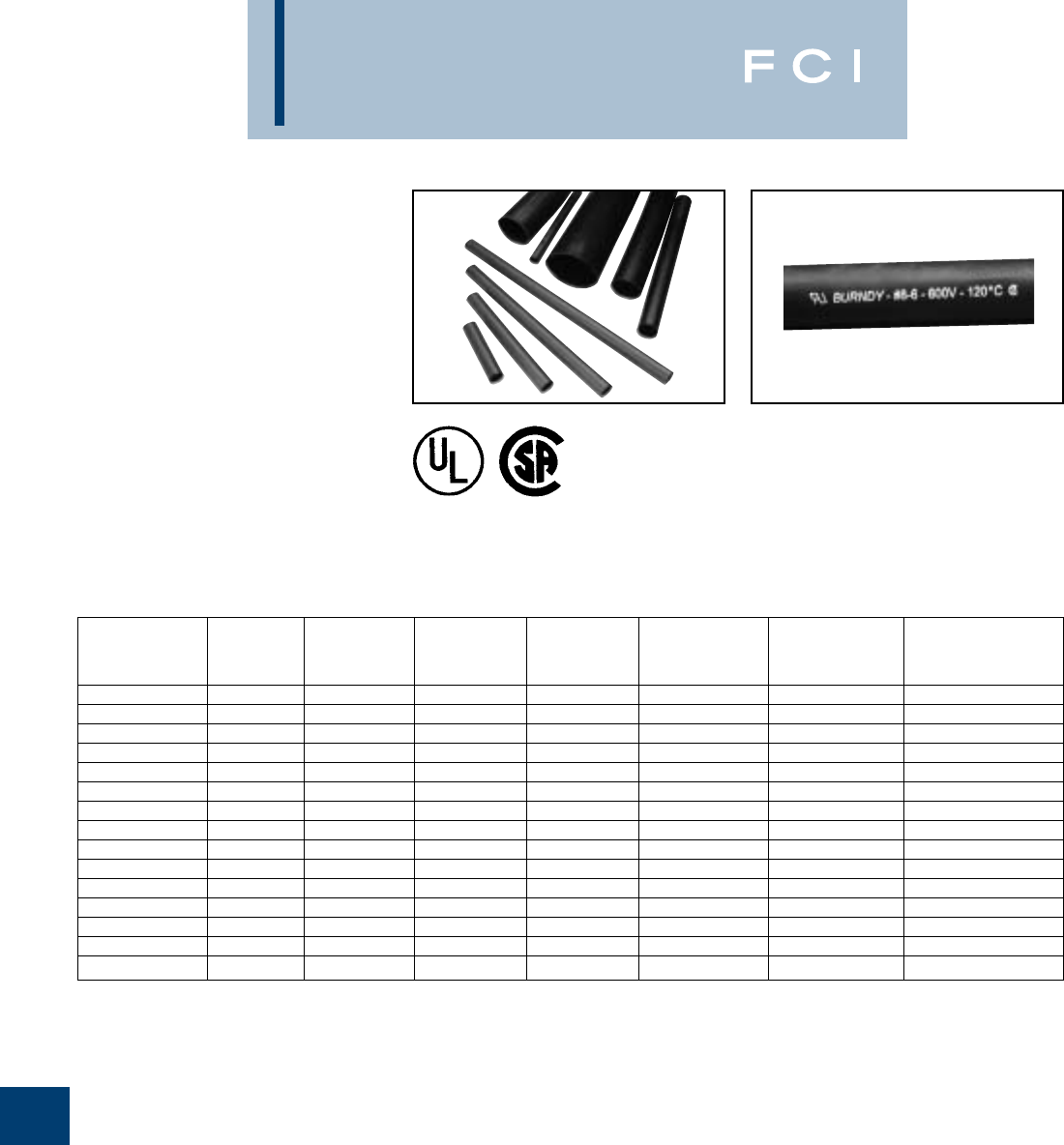
BURNDY
Accessories
M-8
TYPE HS-H-PF
HEAVY WALL HEAT
SHRINK TUBING
CROSS-LINKED POLYOLEFIN
CUT LENGTHS AND
4 FOOT STICKS
Type HS-H-PF is a heavy wall, flame retar-
dant heat shrink tubing made of cross-linked
polyolefin. The shrink ratio is 3:1, and the
inside diameter is coated with an adhesive
sealant to protect against moisture and
corrosion. UL486D Listed for direct burial
applications. Accommodates #14 AWG - 500
kcmil conductors. Operating temperatures
from –55° C to 135° C with a shrink temper-
ature of 120° C.
Available in black only.
Meets MIL-I-23053/5
600 VOLTS
SURFACE MARKED
Nominal Min. Max. Nom. Wall Number
Catalog Diameter Exp. Recov. Thickness Conductor of Pcs.
Number Length Inches ID In. ID In. In. Range Per Package
HSB35H3PF25 3.350 .350 .150 0.070 #14-10 25
HSB35H6PF25 6.350 .350 .150 0.070 #14-10 25
HSB35H48PF5 4.350 .350 .150 0.070 #14-8 5
HSB34H6PF10 6.750 .750 .220 0.090 #6-2 10
HSB34H9PF10 9.750 .750 .220 0.090 #6-2 10
HSB34H48PF5 4.750 .750 .220 0.090 #6-2 5
HSB110H6PF5 61.100 1.100 .400 0.120 #1-3/0 5
HSB110H9PF5 91.100 1.100 .400 0.120 #1-3/0 5
HSB110H48PF5 41.100 1.100 .400 0.120 #1-3/0 5
HSB150H9PF3 91.500 1.500 .500 0.160 2/0-350 3
HSB150H12PF3 121.500 1.500 .500 0.160 2/0-350 3
HSB150H48PF5 41.500 1.500 .500 0.160 2/0-350 5
HSB200H9PF2 92.000 2.000 .750 0.160 250-500 2
HSB200H12PF2 122.000 2.000 .750 0.160 250-500 2
HSB200H48PF2 42.000 2.000 .750 0.160 250-500 2
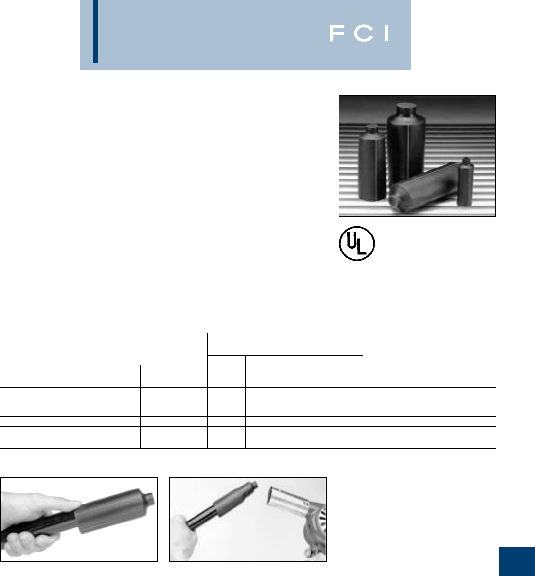
BURNDY
Accessories
M-9
TYPE HSIC - FR
HEAVY WALL HEAT
SHRINKABLE END CAP
UL LISTED TO 600V
Type HSIC-FR, Heat Shrink Insulating End
Cap Fire Retardant is a heavy wall, fire retar-
dant end cap made of cross-linked thermally
stabilized black polyolefin. Used to insulate
exposed conductors in energized appli-
cations. The 3:1 shrink ratio offers greater
range, accommodating copper wire sizes, #8
AWG thru 2500+ kcmil. Performs effectively
over lead, aluminum, steel, polyethylene,
EPR, and PVC jacketed materials. Blue
thermal chromatic lines disappear indicating
correct installation temperature and provide
inspectability. I.D. adhesive provides
superior moisture and weather resistant
characteristics.
Features and Benefits
•Minimum 28 Oxygen index, UL94-VO
rated.
◊Self-extinguishing flame retardant
properties.
•3:1 shrink ratio.
◊Minimum inventory required.
•Thermal chromatic lines.
◊Indicate proper installation.
•Low shrink temperature, 150°C.
◊Only requires common hot air gun
to apply.
•Meets sealing requirements:
ANSI-C119.1, UL486D
◊Weather and moisture resistant.
1. Slide the HSIC-FR end cap onto the cable
and hold in place using forefinger or
thumb.
2. Beginning at closed end apply heat, blue
thermochromatic lines will begin to disap-
pear at 150° C. Gradually, move heat
source to open end and around cap.
Once lines are no longer visible and
adhesive flows out of open end, discon-
tinue heating.
INTERNAL WALL
DIAMETER THICKNESS LENGTH NUMBER
CATALOG 600V CABLE (MIN) (MAX) REC. 20% OF PCS. PER
NUMBER CODE FLEX EXP. REC. EXP. 20% EXP. REC. PACKAGE
HSIC8-1FR #8 - #1 #8 - #4 .50 .16 .034 .080 3.0 2.50 10
HSIC4-40FR #4 - 4/0 #4 - 2/0 .75 .24 .030 .080 3.5 2.50 10
HSIC10-500FR 1/0 - 500 kcmil #1 - 313.1 kcmil 1.10 .35 .039 .120 4.0 3.00 5
HSIC30-1000FR 3/0 - 1000 kcmil 2/0 - 646 kcmil 1.50 .47 .054 .160 4.5 3.25 5
HSIC200FR 300 - 1750 kcmil 250 - 1111 kcmil 2.00 .63 .050 .160 4.5 3.50 5
HSIC269FR 600 - 2500 kcmil – 2.68 .87 .050 .160 5.0 4.00 5
HSIC350FR 1250 kcmil (min) – 3.50 1.18 .051 .160 5.0 4.50 5

BURNDY
Accessories
M-10
TYPE HSC-FR
VISI-SHRINK
FIRE RETARDANT CLEAR
HEAT SHRINK TUBING
UL RECOGNIZED TO 600V
Type HSC-FR is a flexible polyvinyl chloride
clear heat-shrink tubing. Excellent flame
retardant properties and a 2:1 shrink ratio, the
VISI-SHRINK tubing enables inspectors to
read die index embossments on installed
connectors easily. UL recognized, 105° C,
600V, the operating temperature from –20° C
to 105° C with a shrink temperature of 135° C.
Features and Benefits
•UL 224, VW-1 Rated.
◊Self-extinguishing flame retardant
properties.
•Clear Tubing.
◊Allows inspection of die index embossed
and shiner after installation is complete.
Should any corrosion occur it will be
visible during inspection.
•Low Shrink Temperature.
◊Only requires common hot air guns
to apply.
NOTES:
1Shrink temperature is 135° C (275° F).
2For best results move heat gun along the length of
heat shrink to avoid concentrations.
3To extend useful life, store material below 70°F.
4For additional Heat Shrinkable Tubing see "URD"
section Type RYAC and RK169-2, RK170-2 in this
section.
STANDARD
CATALOG I.D. I.D. AFTER WALL CONDUCTOR RANGE REEL SIZE
NUMBER EXPANDED RECOVERY THICKNESS CODE FLEX (FEET)
HSC18FR .125 .062 .025 #16 - #14 #16 - #14 50
HSC18FR250 .125 .062 .025 #16 - #14 #16 - #14 250
HSC14FR .250 .125 .025 #12 - #8 #12 - #10 50
HSC14FR250 .250 .125 .025 #12 - #8 #12 - #10 250
HSC38FR .375 .187 .025 #6 - #4 #8 - #6 50
HSC38FR250 .375 .187 .025 #6 - #4 #8 - #6 250
HSC12FR .500 .250 .025 #4 - #1 #6 - #4 50
HSC12FR250 .500 .250 .025 #4 - #1 #6 - #4 250
HSC34FR .750 .375 .030 1/0 - 3/0 #2 - 1/0 50
HSC34FR250 .750 .375 .030 1/0 - 3/0 #2 - 1/0 250
HSC100FR 1.00 .500 .035 4/0 - 3/0 1/0 - 4/0 25
HSC100FR100 1.00 .500 .035 4/0 - 3/0 1/0 - 4/0 100
HSC112FR 1.50 .750 .040 350 - 750 250 - 500 25
HSC112FR100 1.50 .750 .040 350 - 750 250 - 500 100
HSC200FR 2.00 1.00 .045 800 - 1000 500 - 750 25
HSC200FR100 2.00 1.00 .045 800 - 1000 500 - 750 100
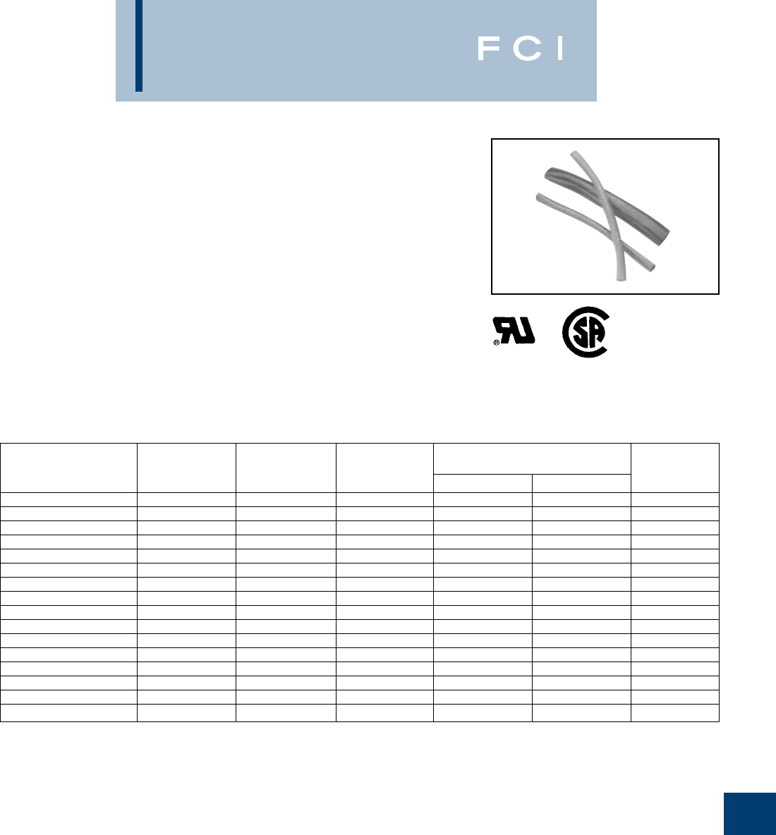
BURNDY
Accessories
M-11
TYPE HS-FR
THIN-WALL HEAT SHRINK
FIRE RETARDANT
HEAT SHRINK TUBING
UL RECOGNIZED TO 600V
Type HS-FR is a flexible polyvinyl chloride
thin-wall heat-shrink. Offering insulating, color
identification and strain relieving properties
for terminations and splices. The 2:1 shrink
ratio allows for faster shrink recovery, cover-
ing wire sizes: #16 AWG to 1000 kcmil. UL
recognized, 105° C, 600V, operating
temperatures from –20° C to 105° C with a
shrink temperature of 135° C.
Features and Benefits
•UL 224, VW-1 Rated
◊Self-extinguishing flame retardant
properties.
•Multi-use Tubing
◊Insulate, strain relief.
•Easy Identification
◊Available in wide range of colors.
•Low Shrink Temperature
◊Only requires common hot air guns
to apply.
NOTES:
1Shrink temperature is 105° C (221° F).
2For best results move heat gun along the length of heat
shrink to avoid concentrations.
3To extend useful life, store material below 70° F.
4For additional Heat Shrinkable Tubing see "URD" section
Type RYAC and RK169-2, RK170-2 in this section.
How to Order Ex: HSB18FR
B-Black
BLU -Blue
G-Green
R-Red
W-White
Y-Yellow
STANDARD
CATALOG I.D. I.D. AFTER WALL CONDUCTOR RANGE REEL SIZE
NUMBER EXPANDED RECOVERY THICKNESS CODE FLEX (FEET)
HS_18FR .125 .062 .025 #16 - #14 #16 - #14 50
HS_18FR250 .125 .062 .025 #16 - #14 #16 - #14 250
HS_14FR .250 .125 .025 #12 - #8 #12 - #10 50
HS_14FR250 .250 .125 .025 #12 - #8 #12 - #10 250
HS_38FR .375 .187 .025 #6 - #4 #8 - #6 50
HS_38FR250 .375 .187 .025 #6 - #4 #8 - #6 250
HS_12FR .500 .250 .025 #4 - #1 #6 - #4 50
HS_12FR250 .500 .250 .025 #4 - #1 #6 - #4 250
HS_34FR .750 .375 .030 1/0 - 3/0 #2 - 1/0 50
HS_34FR250 .750 .375 .030 1/0 - 3/0 #2 - 1/0 250
HS_100FR 1.00 .500 .035 4/0 - 3/0 1/0 - 4/0 25
HS_100FR100 1.00 .500 .035 4/0 - 3/0 1/0 - 4/0 100
HS_112FR 1.50 .750 .040 350 - 750 250 - 500 25
HS_112FR100 1.50 .750 .040 350 - 750 250 - 500 100
HS_200FR 2.00 1.00 .045 800 - 1000 500 - 750 25
HS_200FR100 2.00 1.00 .045 800 - 1000 500 - 750 100
BURNDY
Accessories
M-12
MISCELLANEOUS
ACCESSORIES
TERMINAL BLOCKS
PANEL LIGHTS
SNAP-IN TYPES*
For bulk pack contact factory.
*Available in convenience packaging only.
NUMBER
OF OVERALL CATALOG
CIRCUITS LENGTH GENERAL DESCRIPTION NUMBER
22-3/32Moulded General RK149-2
23-7/32Purpose Phenolic Base RK150-2
64-11/3230 amps, #10 studs RK225-2
85-15/321 piece, per card RK151-2
10 6-19/32600-volt rating RK152-2
12 7-23/32RK226-2
14 8-27/32RK153-2
16 9-31/32RK227-2
VOLTAGE LENS MOUNTING HOLE CATALOG CARD
RATING COLOR DIAMETER LEADS NUMBER QUANTITY
125V Red 1/26RK160-2 1
125V Yellow 1/26RK161-2 1
125V Green 1/26RK162-2 1
125V Red 5/166RK236-2 1
125V Yellow 5/166RK237-2 1
125V Green 5/166RK238-2 1
28V Red 1/26RK231-2 1
28V Yellow 1/26RK230-2 1
28V Green 1/26RK232-2 1
12V Red 1/26RK163-2 1
12V Yellow 1/26RK164-2 1
12V Green 1/26RK165-2 1
Meets UL component requirements:
CLASS B:
Commercial Equipment 600 V RMS
CLASS C:
General Industrial 600 V RMS
Withstands volts, Vdc 10,500
BURNDY
Accessories
M-13
PIGTAIL WIRE CONNECTORS*
ALLIGATOR CLIPS*
*Available in convenience packaging only.
*Available in convenience packaging only.
PACKAGE WIRE COMBINATION RANGE CATALOG
QUANTITY AND COLOR CODE NUMBER
25 Black 22 - 14 AWG—Min. 3 #20 Max. 3 #16 RK239-2
25 Orange 22 - 14 AWG—Min. 3 #20 Max. 3 #16 & 1 #18 RK240-2
25 Yellow 18 - 12 AWG—Min. 1 #14 & 1 #18 Max. 4 #14 & 1 #18 RK241-2
20 Red 18 - 10 AWG—Min. 2 #14 Max. 2 #10 & 2 #14 RK242-2
10 Blue 12 - 6 AWG—Min. 1 #10 & 1 #12 Max. 1 #6 & 2 #8 RK257-2
JAWCATALOG CARD
WIRE RANGE LENGTH LENGTH NUMBER QUANTITY
22 - 16 AWG 1-11/165/16RK154-2 4
22 - 14 AWG 27/16RK155-2 4
22 - 10 AWG 2-7/83/4RK229-2 4
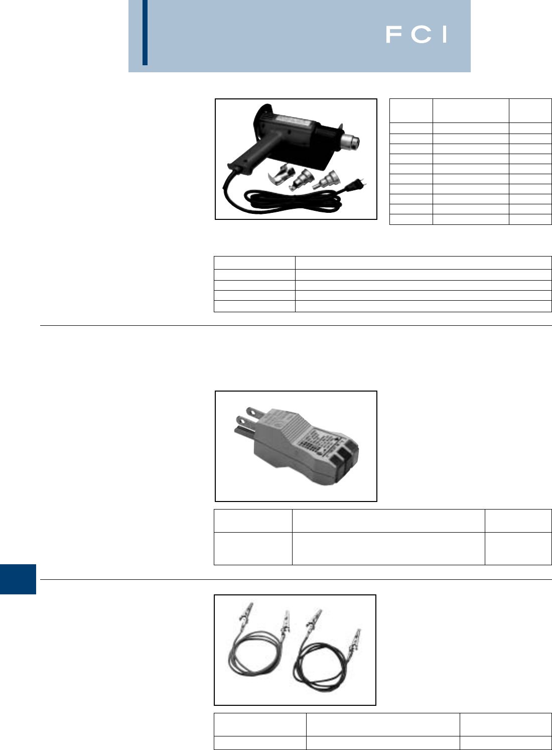
BURNDY
Accessories
M-14
MISCELLANEOUS
ACCESSORIES
CIRCUIT TESTER
FOR 3 WIRE 125V CIRCUITS
ALLIGATOR TEST LEADS
TYPE HL1802E
STEINEL®HOT AIR GUN
120° – 1100° F (50° – 650° C)
STEINEL®professional hot air gun and
accessories are recommended for all of your
BURNDY®heat shrink applications. The
HL1802E hot air gun is UL and CSA Listed for
120 volts. It has a temperature range of 120°
– 1100° F (50° – 650° C) and a cool air stage.
Accessories
Technical UL/CSA
Specifications Listed
Voltage 230 V AC 120 V AC
Output 2,000 Watts 1,500 Watts
Temperature Setting 1: 50°C 120°F
Setting 2: 50° - 650°C 120 - 1100° F
Setting 3: 50° - 650°C 120 - 1100° F
Air Flow Setting 1: 08.8 cfm
Setting 2: 09.5 cfm
Setting 3: 17.6 cfm
Weight 30.7 oz.
Noise < 70 dB (A)
CATALOG NUMBER DESCRIPTION
HSREDUCER 3/8Reduction Nozzle for concentrated air flow.
HSREFLECTOR1 1-1/4Reflector Nozzle accommodating up to 1tubing.
HSREFLECTOR1/2 5/8Reflector Nozzle accommodating up to 1/2tubing.
HSSTAND Metal Stand for bench work applications.
VOLTAGE CATALOG
RATING GENERAL DESCRIPTION NUMBER
125V Indicates: Correct wiring, open ground, reverse RK228-2
polarity, open hot wire, open neutral, hot and ground
reversed, and hot on neutral and hot open.
CATALOG
JUMPER LENGTH NUMBER
600 V 18 AWG 32RK191-2
BURNDY
Tooling
N-1
TABLE OF CONTENTS
Y29BH (6000 Psi)...........................................N-40
Y750BH (10000 Psi).......................................N-41
LPHY750 (KOMPRESSOR™) .......................N-42
LPHY46 (KOMPRESSOR™) .........................N-43
Y644MBH .......................................................N-44
Y81KFTMBH ..................................................N-45
Y45 (10000 Psi)..............................................N-46
Y46 & Y46C (10000 Psi) ................................N-47
Y48BH (8800 Psi)...........................................N-48
Y60BHU & Y60BHU-D....................................N-49
RHCC129ACSR .............................................N-50
MCC500 & MCC1000.....................................N-51
RCC556 & RCC1000 .....................................N-52
HYDRAULIC PUMPS
HAND PUMPS
HP10 (10000 Psi) ..........................................N-53
HP8 (8800 Psi) ..............................................N-53
HP6 (6000 Psi) ..............................................N-53
FOOT PUMPS
FP10 (10000 Psi) ..........................................N-54
FP8 (8800 Psi) ..............................................N-54
FP6 (6000 Psi) ..............................................N-54
ELECTRIC PUMPS
EPP10 & EPP6...............................................N-55
EPAC10, EPAC8 & EPAC6 .............................N-56
EP10, EP8, EP6, EP10-2, EP8-2 & EP6-2 ....N-57
EP10-1HP, EP8-1HP, EP6-1HP,
EP10-1HP-2, EP8-1HP-2 & EP6-1HP-2 ......N-58
GASOLINE PUMPS
GP10 (10000 Psi)..........................................N-59
GP8 (8800 Psi)..............................................N-59
GP6 (6000 Psi)..............................................N-59
Hydraulic Hoses ...........................................N-60
Accessories ..................................................N-61
RK147-2 & Wire Mike....................................N-62
Y29NC Pneumatic HYPRESS™...................N-63
TFM Tape Fed Machine ................................N-64
TFM Installation Tooling Chart....................N-65
HAND-HELD TOOLS
Y10D.................................................................N-3
Y10-22..............................................................N-4
Y8MRB-1..........................................................N-5
MR8 & MR10....................................................N-6
MR15, MR18 & MR20 ......................................N-7
MR4C ...............................................................N-8
Y1MRTC...........................................................N-9
M8ND .............................................................N-10
MECHANICAL TOOLS
MRC840 .........................................................N-11
MY29 & MY28 ................................................N-12
OH25 ..............................................................N-13
OUR840..........................................................N-14
MD6, MD6-4, MD6-6, MD6-12,
MD6-14, MD6-37 & MD6-38 ........................N-15
MD7, MD7-6 & MD7-8....................................N-16
MD7-34R ........................................................N-17
MD6/MD7 Accessories...................................N-18
MD6R .............................................................N-19
MD6 Hotstick Tools.........................................N-20
SELF-CONTAINED
HYDRAULIC
Y500CT-HS.....................................................N-21
Y35 & Y35-2 ...................................................N-22
Y35 Accessories.............................................N-23
Y39 .................................................................N-24
Y750HS & Y750-2HS .....................................N-25
Y644HS ..........................................................N-26
Y81KFT ..........................................................N-27
YCUT129ACSR..............................................N-28
BATTERY ACTUATED
TOOLS
PAT750-18V....................................................N-29
PAT644-18V....................................................N-30
PAT81KFT-18V................................................N-31
PAT600-18V....................................................N-32
PATCUT129ACSR-18V...................................N-33
PATCUT245CUAL-18V ...................................N-34
BCC1000CUAL...............................................N-35
Y700DC-1B ....................................................N-36
REMOTE HYDRAULIC
Y35BH (10000 Psi).........................................N-37
Y39BH (10000 Psi).........................................N-38
Y34BH (10000 Psi).........................................N-39

BURNDY
Tooling
INTRODUCTION
INSTALLATION TOOLS
FCI Electrical’s total compression program
offers the most complete line of installation
tools, mechanical, full cycle ratchet, self con-
tained hydraulic, remote controlled hydraulic,
power actuated pumps, hoses and acces-
sories, available to the electrical industry.These
tools have been designed to integrate with the
complete line of BURNDY®compression con-
nectors. Whether you’re a small contractor
working with #22 wire or a large utility working
with 2500 kcmil conductor, there’s a BURNDY®
compression tool available to do the job.
The benefits of compression are many, how-
ever, probably the most significant benefit is
reliability.There’s nothing more important to the
electrical industry today than reliability. It rep-
resents the one area that leads to economical
installations that will endure for the life of the
installation.
TOOL CENTER
An important element of the BURNDY®com-
pression program is the Tool Center, 150
Burndy Road, Littleton, NH 03561 (800-426-
8720). This center provides advice and infor-
mation on the operation, maintenance and
repair of BURNDY®tools. The repair center is
staffed with specialized technicians who pro-
vide the best possible tool repair service, for all
BURNDY®tools, pumps and accessories.
We designed and produced the first self
contained hydraulic compression electrical
connector installation tool in 1934. In our con-
tinuing efforts to provide the highest quality and
highest value connection systems, we offer the
current BURNDY®tool policy.
LIMITED WARRANTY
The full line of FCI BURNDY Products® tools
are warranted to be free of defects in materi-
als and workmanship for a period of five (5)
years from the date of shipment. If inspection
by a certified tool technician shows the trou-
ble is caused by defective workmanship or
material, BURNDY will repair (or at our
option), replace the tool.
This Warranty does not apply where:
•Repairs or alterations have been made or
attempted by others.
•Repairs are required because of normal
wear and tear.
•The tool has been abused, misused or
improperly maintained.
•The use of any non-BURNDY® products
has resulted in damage to the tool.
STANDARD LIMITED WARRANTY AND
LIMITATION OF LIABILITY
FCI BURNDY Products® warrants that the
goods and services stated on the face here-
of, when furnished to Buyer by FCI, conform
with FCI’s current written specifications and
drawings (or with those of the Buyer specifi-
cally accepted by FCI in writing), and will be
free of defects in materials and workmanship.
FCI’s sole obligation (and Buyer’s sole and
exclusive remedy) for any breach of warranty
under the foregoing warranty shall be to
repair (at location designated by FCI) or, at
FCI’s option: To replace FOB the original
point of delivery any goods which are non-
conforming or defective and are so specified
by buyer in a written certified mail notice to an
officer of FCI within the applicable warranty
period. FCI expressly disclaims any and all
express or implied warranties other than the
warranty of its title to goods and the warranty
hereinabove set forth. Such disclaimer
includes, without limitation, warranty of fit-
ness for a particular purpose and warranty of
merchantable quality.
Limitation of Liability—FCI will not, under
any circumstances, be liable for the cost of
removal or reinstallation of goods or the cost
of disassembly or reassembly of equipment in
connection therewith, or for loss of the use of
Buyer’s equipment or facilities, or for loss of
business or good will or profits, or for cost of
inspection or storage, or for any incidental or
consequential damages of any nature or
description whatever which may arise from
FCI’s sale of goods to Buyer.
REPAIR POLICY
All non-warranty repaired tools are complete-
ly reconditioned and receive a limited 1-year
warranty. Non-warranty repair returns tools to
like new condition at a maximum cost of 40%
of a new tool. A nominal service charge of
$5.00 is applied to all repairs to cover shop
supplies, oil disposal and other miscella-
neous services not covered as part of the
standard repair.
If the decision is made not to repair, a han-
dling charge of $25.00 will be applied plus
return freight costs.
RETURN PROCEDURE
All tools sent to the Burndy Tool Center or an
authorized repair center must be accompa-
nied by a purchase order with detailed bill to
and ship to address authorizing repair.
Requests for repair charges before work is
done must be stated on the purchase order.
All tools sent to the Burndy Tool Center or an
authorized repair center as a warranty claim
must be accompanied by a proof of purchase
such as a BURNDY® invoice or invoice from
any BURNDY® distributor.
All tools must be shipped at the owner’s
expense, prepaid. BURNDY pays for the
return freight, same surface freight as
received. Airfreight returns will be returned
same way collect for non-warranty repair and
prepaid for warranty repairs.
This warranty and repair policy supercedes
all previous policies and is in effect January 1,
2005.
N-2
BURNDY
Tooling
TYPE Y10D
HYTOOL™
TWO TOOLS IN ONE
#22-10 AWG NYLON
INSULATED CONNECTORS
#22-10 AWG UNINSULATED
CONNECTORS
Hand-held plier type tool that will install #10-
22 AWG nylon insulated and uninsulated
terminals and splices, with a precision
machined wire cutter for aluminum and cop-
per wire in the nose of the tool. Long handles
provide greater mechanical advantage.
5-year limited warranty. Also available in con-
venience package as catalog number
RK195-2.
N-3
SPECIFICATIONS
Length: 9-3/4
Weight: 13.5 oz.
FOR USE ON
BOX CAT. TYPES BULK CAT. TYPES
#10-22 AWG nylon insulated terminals
TN YAES
TN-F YAES-E
YAE-N BOX YAE-N
YAE-N-F BOX YAE-N-F
YAE-Z BOX YAE-Z
YAEV BOX YAEV
#10-22 AWG nylon insulated splices
SN YSE-HN *
SNM YSES
YSE-H BOX * YSE-H *
#10-22 AWG uninsulated (bare) terminals.
TYAD
T-FYAD-F
YAV BOX YAV
YAV-T-F BOX YAV-T-F
YAV-H BOX * YAV-H *
YAV-H-F BOX * YAV-H-F *
YAV-Z BOX YAV-Z
#10-22 AWG uninsulated (bare) splices
YSV BOX YSV
YSV-H BOX * YSV-H *
BENEFITS
•Easy wire cutting with precision machined
cutting blade.
•Save time, money and lower installed costs
with one tool for both nylon insulated and
uninsulated (bare) connectors.
•Easy tool operation out of the carton.
No need to break in the tool prior to
actual usage.
•A heavy duty forged steel tool, that has
a rust resistant finish will provide a long
durable life.
BENEFITS (CONTINUED)
•Easier crimping on #22-10 bare and nylon
insulated connectors because of the longer
handles that provides greater mechanical
advantage.*
•Comfort grip handles fit hands comfortably
helping make the tool easy to use.
•Terminals and splice connectors are UL
listed and CSA certified when installed
with the Y10D HYTOOL™.
•5-year limited warranty.
*Conductor crimp only.
Features
COMFORT
GRIP HANDLES READY TO USE
LUBRICATED PIVOT HEAVY DUTY
FORGED STEEL
PRECISION
MACHINED
WIRE CUTTER
LONG HANDLES
FOR GREATER
MECHANICAL
ADVANTAGE
RUST RESISTANT FINISH #22-10
UNINSULATED
(BARE)
#22-10
NYLON
INSULATED
BURNDY
Tooling
TYPE Y10-22
HYTOOL™
#22-10 AWG INSULATED
CONNECTORS
#22-10 AWG UNINSULATED
CONNECTORS
Hand-held plier type tool to install #10-22
AWG insulated and uninsulated terminals
and splices with a wire cutter in the nose of
the tool. Will strip #10-22 AWG wire and cut
common size mild steel and non-ferrous
screws. 5-year limited warranty. Also available
in convenience package as RK102-2.
SPECIFICATIONS
Length: 8-5/8
Weight: 11 oz.
FOR USE ON
BOX CAT. TYPES BULK CAT. TYPES
#10-22 AWG NYLON INSULATED
TERMINALS
TN YAES
TN-F YAES-F
YAE-N BOX YAE-N
YAE-N-F BOX YAE-N-F
YAE-Z BOX YAE-Z
YAEV BOX YAEV
#10-22 AWG NYLON INSULATED
SPLICES
SN YSE-HN *
SNM YSES
YSE-H BOX *YSE-H *
#10-22 AWG VINYL INSULATED
TERMINALS
TP BA
TP-F BA-EF
TP-ZBA-EZ
#10-22 AWG VINYL INSULATED SPLICES
SP BS
#10-22 AWG UNINSULATED
(BARE) TERMINALS
TYAD
T-FYAD-F
YAV BOX YAV
YAV-T-F BOX YAV-T-F
YAV-H-F BOX * YAV-H-F *
YAV-Z BOX YAV-Z
#10-22 AWG UNINSULATED
(BARE) SPLICES
YSV BOX YSV
YSV-H BOX * YSV-H *
N-4
BENEFITS
•Easy wire cutting with anvil type wire
cutter design.
•Crimps full range of insulated terminals
and splices #22-10 AWG.
•Cut off dies for common size mild steel
and non-ferrous screws.
•Crimps full range of uninsulated terminals
and splices #22-10 AWG.
•Full range insulation strippers for wire
sizes #22-10. One step stripping.
•Comfort grip handles fit hands comfortably
helping make the tool easy to use.
•5-year limited warranty.
*Conductor crimp only.
Features
WIRE CUTTERS ONE STEP INDIVIDUALLY
SIZED WIRE STRIPPERS SCREW AND
BOLT CUTTERS
#12-10 INSULATED
COLOR CODE YELLOW
WIRE CUTTER
#22-14 INSULATED
COLOR CODE
RED & BLUE
#22-10
UNINSULATED
COMFORT GRIP
PLASTIC HANDLES
BURNDY
Tooling
N-5
TYPE Y8MRB-1
HYTOOL™
#22-8 AWG
Hand-held full cycle ratchet tool for #8-22
AWG uninsulated terminals and splices. Full
cycle feature builds in reliability and removes
the human factor from the finished instal-
lation. 5-year limited warranty.
SPECIFICATIONS
Length: 9-1/2
Weight: 1.21 lbs.
FOR USE ON
BOX CAT. TYPES BULK CAT. TYPES
UNINSULATED TERMINALS
TYAD
T-FYAD-F
YAV BOX YAV
YAV-L BOX YAV-L
YAV-T-F BOX YAV-T-F
YAV-Z BOX YAV-Z
UNINSULATED SPLICES
YSV BOX YSV
YSV-L BOX YSV-L
BENEFITS
•One tool to accommodate #22-8 AWG.
•Lightweight.
•Full cycle ratchet for positive crimping.
•Inspection (PG) gauges available to check
each groove.
Groove Gauge#
#18 PG395-1
#14 PG396-1
#10 PG397-1
# 8 PG398-1
•Each indentor has its own identifying mark
for inspectability.
•Jaw opening orientation, molded finger and
palm grips and the easy reach frame mini-
mize user fatigue.
Features
FULL CYCLE
RATCHET
MECHANISM
EMERGENCY
RELEASE
COMFORT GRIPS
MOLDED FINGER GRIPS
STEEL
BODY
NEST/INDENTORS
SIZE RANGE
#22-8 AWG
BURNDY
Tooling
N-6
TYPES MR8
AND MR10
HYTOOL™
FULL CYCLE RATCHET
HAND TOOLS
The Types MR8- and MR10-series
HYTOOLS™ incorporate a full cycle ratchet
mechanism that provides a complete, positive
crimp each time. Once started the ratchet
mechanism does not allow the handles to be
opened until after the full ratcheting cycle is
completed. This provides for a completed
crimp before a connector can be removed
from the tool. The MR8- and MR10-series of
tools are specifically designed with the
ratchet mechanism completely inside the
body of the tool without a path to reach and
defeat the mechanism. This permits the tools
to be used in the most critical applications
including nuclear-class 1E terminations,
heavy duty industrial, utility generation, OEM,
aircraft, and other applications where a
dependable electrical termination is needed.
5-year limited warranty.
SPECIFICATIONS
Length: 10-1/2
Weight: 1-1/2 lbs.
FOR USE ON
CONNECTORS
AWG BOX BULK
SIZE CAT. CAT.
TOOL RANGE TYPES TYPES
MR8-1A #10-22 AN INSULUG™ YAE
Copper Cable
MR8-9Q #8-18 AN
Copper Cable YAV BOX YAV, YSV
#10-22 AWG YSV BOX YAD,
Sol. Cable T YAD-F
#8-22 Str. AWG T-F
Cable
MR8-33S-1 #10-18 YSE BOX YSE
MIL-W-5086 YSE-H BOX YSE-H
Str.
MR8-83 #10-22 TN YAES
MR8-85 #10-22 SN YSE-HN
MR8-G96 #14-22 TP BA
MR8-89-1 #10-22 TP, SP BA, BS
MR8-91 #10-22 T YAD
MR8-92 #14-22 PQ-R-D PQ
MR8-G98 #10-22 YAV, T YAD, YAV
FINGRIP
MR10-D2 #10-12 PQ PQ
FORK-LOK
MR10-D3 #10-22 TP-LF BA-EL
FINGRIP
MR10-D4 #14-22 PQ PQ
NUCLEAR
MR10-G6 #10-22 YAES-K
BENEFITS
•Lightweight aluminum permits easier
continuous usage.
•One tool to accommodate #22-10 AWG.
•Easy groove identification with
color-coded dies.
•Long life expectancy with fully protected
ratchet mechanism.
•Easy one-hand tool operation with long
handle length for greater mechanical
advantage.
•5-year limited warranty.
Features
LONG HANDLES
PROVIDE GREATER
MECHANICAL ADVANTAGE
ADJUSTABLE STOP
FOR TERMINALS
LOWERS FOR SPLICES
COLOR CODED
DIE GROOVERS
REINFORCED HEAVY
DUTY BACK
HIGH STRENGTH
ALUMINUM BODY
FULLY PROTECTED
RATCHET MECHANISM
BURNDY
Tooling
N-7
TYPES MR15, MR18,
MR20
HYTOOL™
FULL CYCLE RATCHET
HAND TOOLS
The Types MR15, MR18 and MR20 series
HYTOOL™ incorporate a full cycle ratchet
mechanism that provides a complete, positive
crimp each time. Once started the ratchet
mechanism does not allow the handles to be
opened until after the full ratcheting cycle is
completed, unless the user actuates the
emergency release lever. This provides for a
completed crimp before a connector can be
removed from the tool.
FOR USE ON
MR15 Vinyl Insulated Terminals and
Splices (Wire Range 22-10 AWG)
Vinyl Terminals Vinyl Splices
TP BA SP BS
TP-F BA-EF
TP-Z BA-EZ
TP-LF BA-EL
MR18 Nylon Insulated Terminals and
Splices
Nylon Terminals Nylon Splices
TN SN
TN-F SNM
YAES YSE-HN
YAES-F YSES
MR20 Uninsulated Terminals and Splices
Terminals Splices
TYAD-F YSV
T-F YAV-H* YSV-H*
YAVYAV-H-F*
YAD
YAV-T-F
*Conductor crimps only.
BENEFITS
•UL listed for use with BURNDY®connectors.
•Fully ratcheted tool to assure properly
crimped connections.
•Easy groove indentification with color
coded dies.
•Maximum crimping comfort grips.
•Compact, narrow nose to work in confined
areas.
•5-year limited warranty.
Features
HEAVY DUTY FORGED
STEEL FRAME
EMERGENCY RELEASE
PERMANENT DIE SETS
COMFORT GRIP HANDLES
FULL CYCLE
RATCHET MECHANISM
MR15
MR18
MR20
SPECIFICATIONS
Length: 8.86
Weight: 1.10 lbs.
Open: 5.90
Closed 2.50
Wire Range: #22-10 Awg.
BURNDY
Tooling
N-8
TYPE MR4C
#9-4 AWG UNINSULATED
TERMINALS AND SPLICES
Hand-held full cycle ratchet tool for #9-4 AWG
uninsulated terminals and splices. Full cycle
feature builds in reliability and removes the
human factor from the completed installation.
Long handles provide greater leverage.
5-year limited warranty.
SPECIFICATIONS
Length: 1-3/4
Weight: 2-1/4
FOR USE ON
Terminals YAV-L
YA-L
Splices YSV
YSM
YS-L
BENEFITS
•High strength aluminum body.
•Fully protected ratchet mechanism.
•Reinforced heavy duty back.
•Long handles provide greater mechanical
advantages.
•Lightweight aluminum permits easier con-
tinuous usage.
•One tool to accommodate #9-4 AWG.
•Inspection (PG) gauges available to check
each groove.
Groove Gauge#
9-8 - PG121-1
6- PG125-1
4-PG133-1
•Spring loaded indentor jaw holds
connector in groove prior to crimping
or ratchet engaging.
•5-year limited warranty.
Features
FULL CYCLE
RATCHET
MECHANISM
SPRING LOADED
INDENTOR HOLDS
CONNECTOR
REINFORCED
HEAVY DUTY
ALUM. BACK
LONG HANDLES
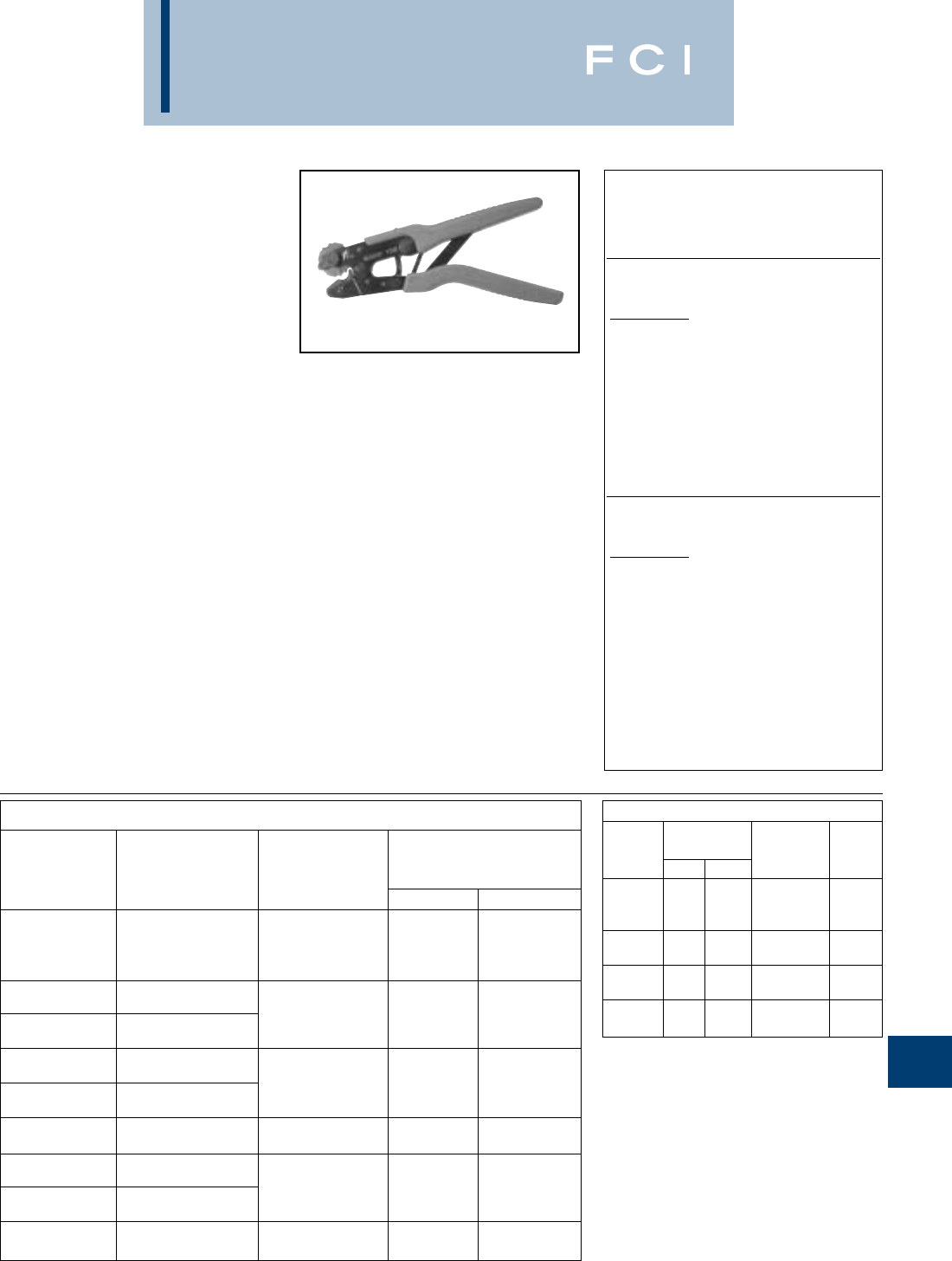
BURNDY
Tooling
N-9
TYPE Y1MRTC
HYTOOL™
#8 – #1 COPPER HYDENT
TERMINALS, SPLICES, AND
#6–#6 THIN-WALL C-TAPS
Type Y1MRTC mechanical full cycle ratchet
HYTOOL™ will accommodate copper com-
pression HYDENT™ connectors for #8
through #1 code conductor, #8 through #2
Class I flexible strand copper conductor, and
#2 solid. The color coded die wheel rotates to
provide a proper match of the die and color
coded connector. The die index is embossed
on the crimped connector for permanent
inspectability. A ratchet mechanism assures
the tool must complete a full cycle before
releasing.
BENEFITS
•Rotating die is color coded to match color
coded connectors
•Die index embossment allows permanent
inspectability of installed connectors to
insure consistently reliable and dependable
connections.
•Molded comfort grips reduce fatigue during
continuous use.
•Ratchet mechanism assures a complete
crimp every time.
•Emergency release mechanism allows tool
to be removed from connector in case of
mistaken die choice or to reposition tool.
•5-year limited warranty.
SPECIFICATIONS
Length: 9.875
Height: 2.72(closed)
Width: .73
Weight: 1.7 lbs.
Wire Range: #8-#1 code conductor,
#8-#2 Class I Flex,
#2 Solid
Up to #6-#6 (Brown)
type “YC-L CTAP”
Cu Lug and Splice Connectors
# of Crimps
Connector Die Per Barrel
Copper Catalog Index # Length
Wire Size Types (Color) Std Long
YA8C-
# 8 AWG YS8C- 49
Code & Flex YAV8C- (Red) 12
YSV8C-
#6 AWG YA6C-
Code YS6C- 7
#6 AWG YAV6C- (Blue) 12
Code & Flex YSV6C-
#4 AWG YA4C-
Code YS4C- 8
#4 AWG YAV4C- (Grey) 24
Code & Flex YSV4C-
#3 AWG YA3C- 9
#2 Sol. YS3C- (White) 24
#2 AWG YA2C-
Code YS2C- 10**
#2 AWG YAV2C- (Brown) 24
Code & Flex YSV2C-
#1 AWG YA1C- 11**
Code YS1C- (Green) 24
** Die Index 10 (Brown Die) and 11 (Green Die) use the same
die wheel crimp groove.
Y1MRTC
Wire Range: #8-#1 AWG Class B,
#8-#2 Class I Flex.
#2 Solid & #3 Stranded
Y1MRKIT
Kit Contains:
Y1MRTC Full-cycle Ratchet Tool
Sturdy Metal Carrying Case
Terminals:
YA8CL, YA8CL1, YA6CL,
YAV6CLTC14FX, YA4CL,
YAV4CLTC14FX, YA2CL,
YAV2CLTC516FX, YA1CL
Splices:
YS8CL, YS6CL, YS4CL,
YS2CL, YS1CL
Y1MRTCKIT
Kit Contains:
Y1MRTC Full-cycle Ratchet Tool
Sturdy Metal Carrying Case
Terminals:
YA8CL2TC14, YA8CL2TC38,
YA6C2TC38, YA6CL2TC14,
YA6CL2TC14E1, YA6CL2TC14E2,
YA6CL2TC38, YAV6CL2TC14E2FX,
YAV6CL2TC14FX, YA4CL2TC14,
YA4CL2TC38, YA3C2TC38,
YA2C2TC28, YA2CL2TC38
Thin-Wall C-Taps:
YC4L12
Cu C-Tap Connectors
Wire Size Cu Str.
Catalog
AWG
Die Index #
# of
Number Run Tap (Color) Crimps
14 16-14
YC10L12 12 16-14 49 1
10 16 (Red)
10 10 7
YC8L12 812(Blue) 1
810-8 8
YC6L12 612-10 (Grey) 1
68-6 10
YC4L12 5,4 12-8 (Brown) 2
Die Index Number Embossment on Connector after Crimp
for inspection verification.
FOR USE ON
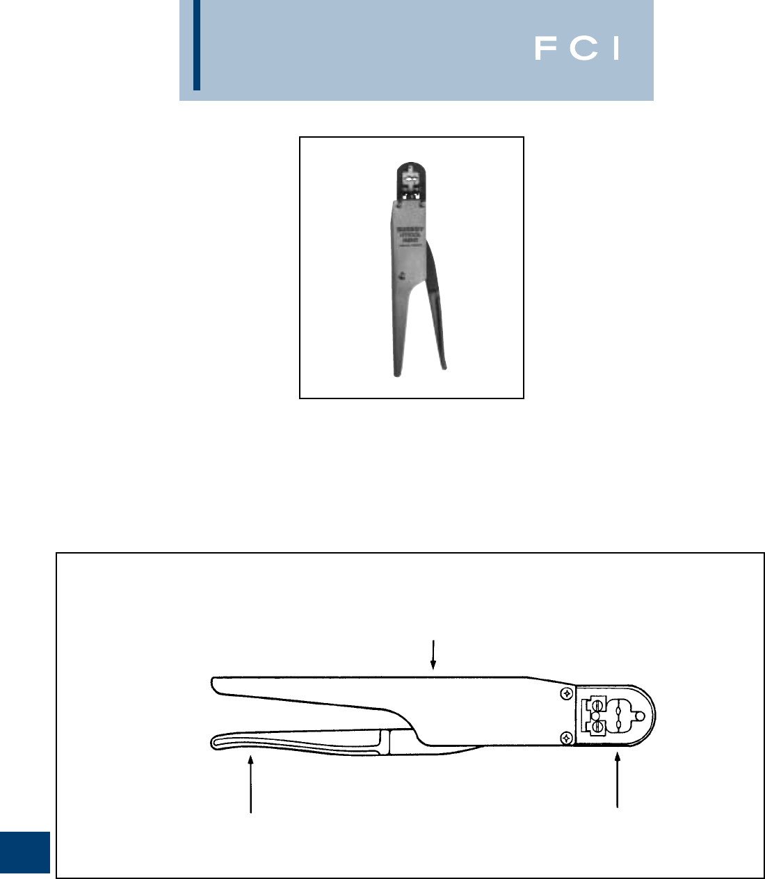
BURNDY
Tooling
N-10
TYPE M8ND
#26-8 AWG TERMINALS
AND SPLICES
Hand-held full cycle ratchet tool for #8-26
AWG terminals and splices. Full cycle feature
builds in reliability and removes the human
element from the completed installation. Long
handles provide greater leverage. 5-year
limited warranty.
SPECIFICATIONS
Length: 10-3/4
Width: 1-3/4
FOR USE ON
Terminals
YAD BA-E
YAD-F BA-EF
YAE BA-ES
YAE-F BA-EZ
YAE-Z BA-EL
YAES
YAEV-H
YAEV-L
YAV
YAV-F
YAV-H
YAV-H-F
Splices
YSV YSM
YSV-H YRV-L
BENEFITS
•Fully protected ratchet mechanism.
•Reinforced heavy duty back.
•Long handles provide greater mechanical
advantages.
•Easy groove identification with color-coded
dies.
•5-year limited warranty.
Features
REMOVABLE DIE SETS
LONG COMFORTABLE HANDLE
FULL CYCLE
RATCHET
MECHANISM
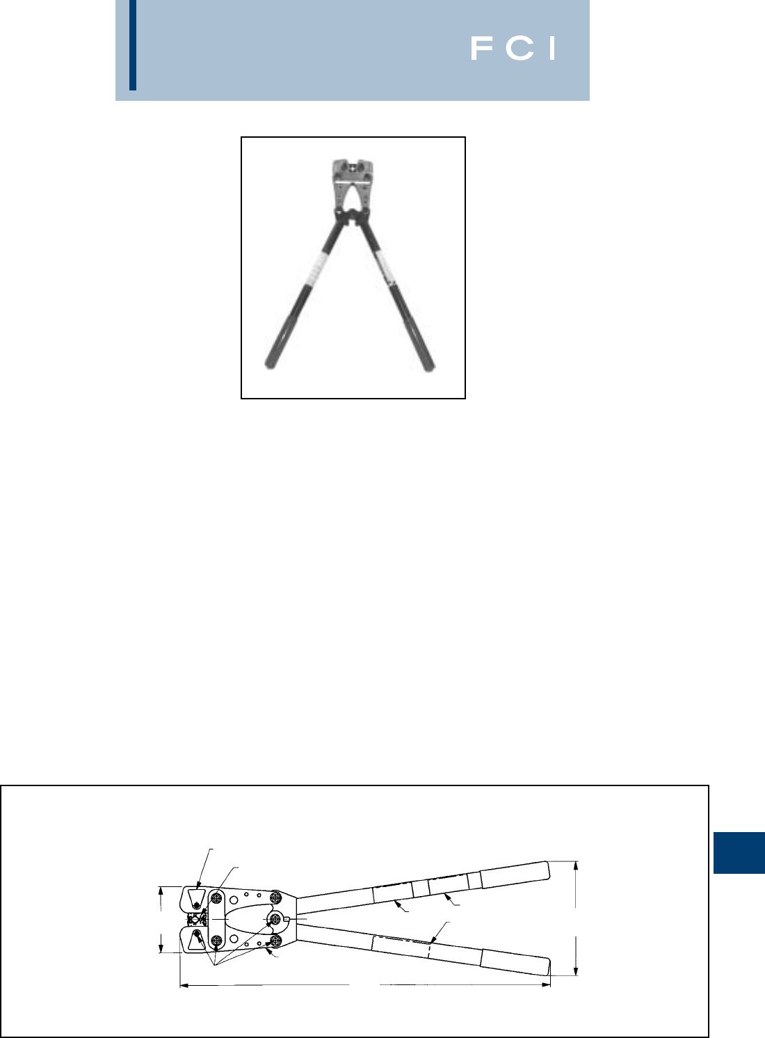
BURNDY
Tooling
N-11
TYPE MRC840
HYTOOL™
#8-4/0 AWG NON-INSULATED
COPPER CONNECTORS
The MRC840 Mechanical Rotating Crimp
Tool will accommodate copper compression
BURNDY®HYDENT™ connectors from # 8
AWG str. - 4/0 AWG str. copper conductor.
Butting steel jaw and over center cam action
assure full crimp force.
Rotatable die wheel is color-coded and
stamped with the conductor size to provide
an easy match of the die and color-coded
BURNDY®HYDENT™ connector. BURNDY®
YA and YS series connectors are U.L. listed
when installed with this tool. 1-year limited
warranty.
SPECIFICATIONS
Length: 26
Height: 8
Weight: 8-1/4 lbs.
Features and Benefits
•Comfort grip handles.
◊Aids in prevention of hand slippage.
Reduces fatigue during continuous use.
•Heat treated steel jaws
◊Reduces jaw buckling and misalignment
under heavy loading.
•Approximately 9000 crimp cycle life.
◊Lasts longer than imitations and will still
be working when others have worn out.
•Multiple grip selections on rotatable
die wheels.
◊No lost dies, 9 position color-coded
rotatable die wheels.
•High strength fasteners.
◊Increase tool life by reducing tool wear.
•Plated jaws.
◊Provide enhanced corrosion protection.
•Engraved crimp groove (Die index number).
◊Die index embossment allows permanent
inspectability of installed connectors to
ensure consistently reliable and depend-
able connections.
Features
COLOR COATED ROTATABLE DIE WHEEL
MARKED WITH AWG SIZES
SPRING LOADED MECHANISM LOCKS DIE WHEEL INTO
POSITION. PRESS MECHANISM TO RELEASE. ROTATE
DIE WHEEL TO DESIRED CRIMP GROOVE.
26.0
[660]
8.0
[203]
5.0
[127]
JAW. STEEL
OIL
LOCATING
PRODUCT LABEL
WARNING LABEL
INSTALLATION
CHART
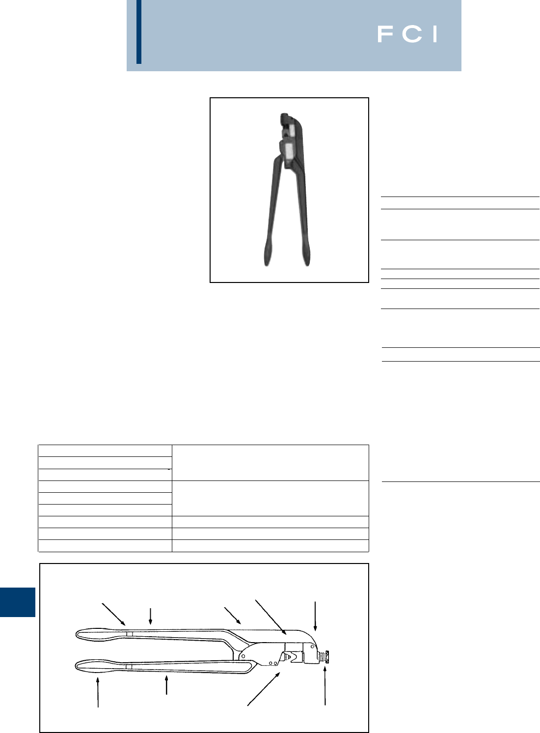
BURNDY
Tooling
N-12
TYPE MY
DIELESS HYTOOL™
#8 STR. THROUGH 250 KCMIL
COPPER- #8 STR. THROUGH
4/0 STR. ALUMINUM
CONDUCTORS
SPECIFICATIONS
Length: 22.65
Width: 8 lbs. approx.
Depth: 4.86
Width: 1.12
Bench Mount Adapter
Cat. No. BMY-BCH-MT
FOR USE ON
TOOL CONNECTORS
MY29-3
MY29-3C Copper-YA, YA-L, YS-L
MY29-3CF Aluminum-YA-A, YS-A
MY29-11 Copper-YA, YA-L, YS
MY29-11C YAV-FX
YS-L, YAV-L, YSV-L
MY28 YAV-L, YSV-L
MY28-4 YAV-A-L, YSV-A-L, YAV-A-R
MY28-6 YAE-L, YAEV-RS, YAEV-H,
YAEV-RH
BENEFITS
•Save on capital investment with the type
MY HYTOOL™ that accommodates a wide
range of connector/conductor combinations
from #8 str.-250 kcmil.
•Save time, money, and lower installed
cost with the original dieless MY tool
design. No separate dies required to
purchase or to lose.
•Fast and easy tool setting for the connec-
tor/conductor combination simply by align-
ing the white scribe on the nest die with
the wire size on the gauge for proper
crimping results.
•Easy to adjust nest die with knurled steel
knob and machine threads.
•Quality tool with precision machines inden-
tor, component parts and tool body.
•Fast, medium and high volume crimping
is easily accomplished by bench mounting
the type MY tool in the BMY-BCH-MT
bench mount adapter. A single bolt holds
the MY HYTOOL™ securely using the
.31 dia. mounting hole in the bench
mount adapter.
Features
KNURLED STEEL
ADJUSTING KNOB
INDENTOR DIE
EXTRA STRONG
HEAVY DUTY
REINFORCED
HANDLES
COMFORT GRIPS
HEAVY DUTY
FORGED STEEL
BACK BODY
AND HANDLES
TWO-PLY COVERED
HANDLES ON MY29-3C
AND MY29-11C DESIGNS
SETTING
PLATE
.31" DIA. HOLE
FOR BENCH
MOUNTING
OPERATIONS.
MY29-3 #8 str.-250 kcmil Copper commercial (code) cable
MY29-3C (covered handles) 30 Navy-250 Navy Copper Navy Cable
MY29-3CF (fully covered) #8 str.-4/0 str. Aluminum commercial (code) cable
MY29 UNIVERSAL KIT #8 str.-250 kcmil Copper commercial (code) cable
MY29-11 30 Navy-250 Navy Copper Navy cable
MY29-11C (covered handles) #8 str.-4/0 str. Flexible copper mine machine cable
MY28 #8 str.-4/0 str. Copper aircraft cable
MY28-4 #8 str.-4/0 str. Aluminum aircraft cable
MY28-6
(nylon covered connector)
#8 str.-2/0 str. Copper aircraft cable (flexible)
STRONG
REINFORCED
FORGED STEEL
BACK
ACCESSORIES
BMY-BCH-MT BENCH MOUNT ADAPTER
MY29 UNIVERSAL KIT CONTENTS:
1 EA MY29-11
50 EA YA8CLBOX
50 EA YAV6CLTC14FX
50 EA YAV4CLTC516FX
50 EA YAV2CLTC516FX
50 EA YAV1CLTC38FX
10 EA YAV25LTC38FX
10 EA YAV26LTC516FX
10 EA YAV27LTC12FX
10 EA YAV28LTC12FX
10 EA YA29LBOX
1 EA CASE
BENEFITS (CONTINUED)
•High quality rugged tool design manufac-
tured from heavy duty forged steel with
strong reinforced back and handles.
•
Covered handles available on the MY29-3C,
MY29-11C and MY29-3CF HYTOOL™.
•Comfort grip handles for long periods
of usage.
•Compression terminals and splices are
UL listed and CSA certified when installed
with type MY HYTOOL™.
•5-year limited warranty.

BURNDY
Tooling
N-13
TYPE OH25
HYTOOL™
ONE-HAND OPERATION,
DIELESS, FULL CYCLE
RATCHET TOOL
Installs service entrance splice connectors.
Conductor range: #10 through 1/0.
The OH25 incorporates a full cycle ratchet
and cam mechanism allowing an easy, one-
hand crimping operation. The ratchet mecha-
nism provides for properly completed crimps
every time before the tool can be removed
from the connection.The OH25 is designed to
install 5/8INSULINK™ and LINKIT™ ser-
vice entrance connectors with only (1) crimp
per connector end, speeding installation time.
The single crimp covers the complete contact
area, eliminating possible overlapping or fail-
ure to make the proper number of crimps.
5-year limited warranty.
SPECIFICATIONS
Handle force: 50 lbs. max.
Max force developed: 6,000 lbs.
Weight: 2 lbs. 11 oz.
Length: 12-1/4
ACCESSORIES
Leather Holster
Cat. #PT4583
No-Go Gauge
Cat. #PT8504
The PT8504 NO-GO Gauge is used to check
the OH25 HYTOOL™ crimp dimensions.
FOR USE ON
•5/8" Service entrance sleeves
•INSULINK™ Type ES (insulated) #10
through 1/0 str.
•LINKIT™ type YSU (bare) #8 through 1/0
str.
•5/8" neutral tension sleeves HYSPLICE™
types YS-S YCS-R YDS-AT #4 through 1/0.
•AYP HYPLUG™ #6-1/0 str.
BENEFITS
•One crimp speeds installation.
•No dies to lose.
•Long dependable life with forged steel jaws
and stainless steel indentor.
•Convenient hole to hang tool.
•Protection of internal parts provides
long life.
•Ratchet mechanism provides proper
crimp and uniform quality installations.
•Easy one-hand tool operation with
spring loaded comfort grip handles.
•Proven reliable with years of
dependable service.
•5-year limited warranty.
Features
COMFORT GRIP
HANDLES PROTECTED
RATCHET
MECHANISM
REPLACEMENT
STAINLESS
STEEL INDENTOR
SPRING
LOADED
HANDLES
HEAT
TREATED
STEEL
1/4" HOLE
FOR SNAP
FASTENER NEST DIE
FORGED
STEEL
JAWS
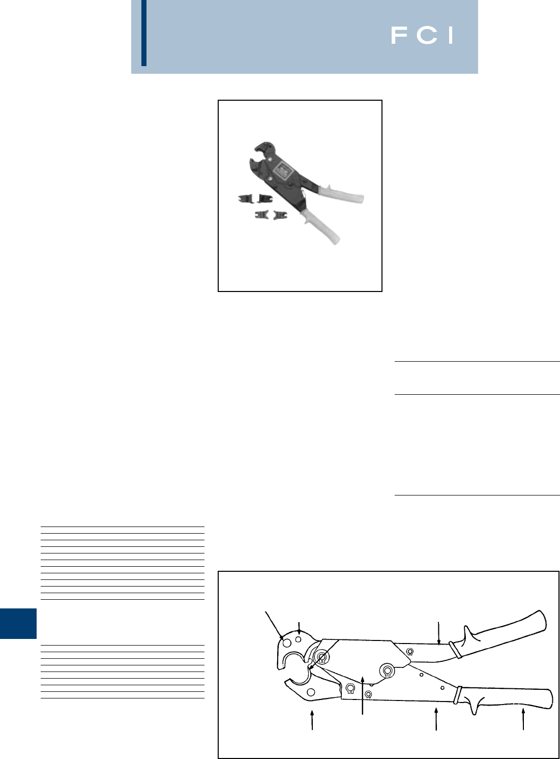
BURNDY
Tooling
N-14
TYPE OUR840
840 POPPER HYTOOL™
ONE-HANDED OPERATION,
OVERHEAD/UNDERGROUND,
FULL CYCLE RATCHET TOOL
INSTALLS A RANGE OF
CONNECTORS (TAPS,
SPLICES, TERMINALS)
The OUR840 incorporates a full cycle ratchet
and cam mechanism allowing an easy, one
hand crimping action. Designed for low main-
tenance operation. The OUR840 has a five
(5) year warranty. The ratchet mechanism
provides for properly completed crimps every
time before the tool can be removed from the
connection. With nest and indentor dies, it will
install 5/8INSULINK™ and LINKIT™ ser-
vice entrance connectors with only one (1)
crimp per end. With the use of reduced han-
dle force “X” dies, additional splices, taps, and
terminals can be properly installed. The die
inserts snap into the permanent groove easi-
ly with one hand and lock securely in the tool
with the spring loaded positive lock die retain-
er buttons. Tool operation is simple:
A. Slip the tool over the connector.
B. The first few strokes grip the connector.
C. Stroke until automatic tool release signi-
fies a completed compression.
SPECIFICATIONS
Max. crimp force: 8,000 lbs.
Max Handle Force: 8 lbs. approx.
Weight: 2 lbs. 14 oz.
Length: 13
FOR USE ON
SELECTED APPLICATIONS
Aluminum connectors from #8 AWG to
250 kcmil.
ACCESSORIES
Cat. No.
OUR840-WH Leather Holder
• Top grain cowhide saddle leather.
• Large grommet.
(Order Separately)
OUR840-WC Metal carrying case
with die tray.
• Holds one (1) OUR840 and up to eleven
(11) “X” dies. Dies not included.
(Order Separately) OUR840 DIES
X-DIES RECOMMENDED
CAT. DIE “W” DIE CRIMP
NO. INDEX RATIO
XNBG BG 2*
XBG BG 2
X161 161 3*
X241 241 2
X245 245 2
X247 247 2
X249 249 2
X660 660 2
X840 840 1
XOH25 -OH 25 EQUIV.
*Overlap crimps
•“W” Dies with a die index listed above are not recommended
for the OUR840. Since the standard “W” Dies are wider than
the “X” Dies, additional crimps are required depending on
the connector and the die index.
INSTALLATION TOOLING
CONNECTOR OUR-840
(COPPER)
CONDUCTOR
HYLUG™ HYLINK™
COLOR DIE (# CRIMPS)
(COPPER) TERM SPLICE CODE DIE INDEX STD. LONG
#8 AWG STR. YA8C- YS8C- RED X8CRT 49 1 2
#6 AWG STR. YA6C- YS6C- BLUE X5CRT 7 1 2
#5 AWG STR. YA5C- YS5C- BLUE X5CRT 7 1 2
#4 AWG STR. YA4C- YS4C- GRAY X4CRT 8 1 2
#2 AWG STR. YA2C- YS2C- BROWN X2CRT 10 1 2
#1 AWG STR. YA1C- YS1C- GREEN X1CRT 11 1 2
1/0 AWG STR. YA25- YS25- PINK X25RT 12 2 4
2/0 AWG STR. YA26- YS26- BLACK X26RT 13 2 4
3/0 AWG STR. YA27- YS27- ORANGE X27RT 14 3 6
4/0 AWG STR. YA28- YS28- PURPLE X28RT 15 3 6
250 Kcmil YA29- YS29- YELLOW X29RT 16 4 8
WVT DIES MAY BE SUBSTITUED
CONNECTOR OUR-840
(ALUMINUM)
CONDUCTOR
HYLUG™ HYLINK™
COLOR DIE NO OF
(ALUMINUM) TERM SPLICE CODE DIE INDEX CRIMPS
#8 AWG STR. YA8CA- YS8CA- BLUE X8CART 374 2
#6 AWG STR. YA6CA- YS6CA- GRAY X6CART 346 2
#4 AWG STR. YA4CA- YS4CA- GREEN X4CART 375 3
#2 AWG STR. YA2CA- YS2CA- PINK X2CART 348 4
#1 AWG STR. YA1CA YS1CA GOLD X1CART 471 3
1/0 AWG STR. YA25A- YS25A- TAN X25ART 296 4
2/0 AWG STR. YA26A- YS26A- OLIVE X26ART 297 4
3/0 AWG STR. YA27A- YS27A RUBY X27ART 467 4
4/0 AWG STR. YA28A- YS28A- WHITE X28ART 298 6
BENEFITS
•Allows proper crimping of sleeves and
terminations in crimping underground
applications.
•Proper crimps are assured with butting
surface inspection and full cycle ratchet
mechanism.
•Uses reduced handles force “X” dies.
•One tool for most service applications.
•Improved service through redesign and
improvement of many internal parts.
•Easy visual field check for proper tool
adjustment with butting surfaces.
•Easier tool operation is provided with mini
strokes and anti-slip grips.
•Nest and indenter dies available.
•W-28K cutter die permits use of OUR840
tool as a cable cutter. Conductor range:
#4-4/0 ACSR. Aluminum and Copper.
•UL Listed connections when color coded
“X” dies are used on BURNDY®connec-
tors.
•5-year limited warranty.
Features
COMFORT
GRIP HANDLES
HEAT TREATED STEEL
CONSTRUCTION
RUGGED AND PROTECT-
ED RATCHET MECHANISM
HIGH
STRENGTH
STEEL
BUTTING SURFACES
PROVIDE VISUAL CHECK
FOR TOOL ADJUSTMENT
1/4 HOLE
FOR SNAP
FASTENER
SPRING
LOADED
POSITIVE
LOCK DIE
RETAINER
BUTTONS
SPRING
LOADED
HANDLE
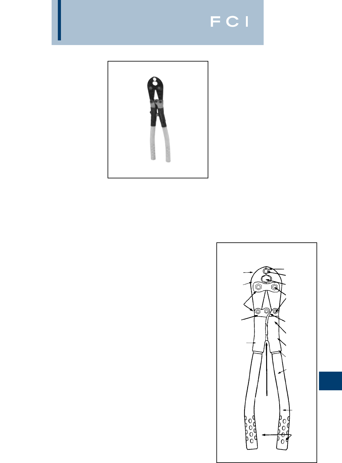
BURNDY
Tooling
N-15
TYPE MD6-8
HYTOOL™
HAND-OPERATED TOOL
Installs full range of connectors (taps, splices,
terminals): #14 through 4/0. Applications: Full
Tension and Non-Tension.
The MD6-8 has a five (5) year warranty and is
designed to provide over 90,000 reliable
crimps installing full-tension and non-tension
connectors.
The MD6-8 installs almost all of the line, pole
and house connections in the Burndy
Compression Connector Program with only
one (1) extra die set (W-BG).The tool has two
(2) permanent die grooves, “O” and “D3”for
distribution tap connectors. The “D3”groove
also serves as a seat for die inserts to install
additional splices, taps and terminal connec-
tors. The die inserts snap into the D3 groove
easily with one hand and lock securely in the
tool with the spring loaded positive lock die
retainer buttons.
SPECIFICATIONS
Crimp force: 9000 lbs.
Length: 25-3/8
Weight: 6 lbs.
Quality Unsurpassed!
Life cycle tested under full operating forces
for over 90,000 cycles successfully without
adjustment or any parts replacement.
FOR USE ON
•Copper, Aluminum, ACSR, Copperweld,
Alumoweld, Steel, 6201, 5005,
Compressed and compact conductors.
•Copper Taps: #10 sol.-2/0 str.
•Aluminum, ACSR Taps: #14 sol.-4/0 ACSR
•Stirrups: #6 ACSR-4/0 ACSR
•Overhead Full Tension Deadend, Full
Tension Splices, Non Tension Splices,
and Terminals Conductor Range:
#10 str.-4/0 ACSR.
•Code conductor connectors: #6-4/0 str.
Copper and Aluminum
To Check Tool Adjustment
Simply close the tool handles until the jaws
initially butt. When the orange alignment
grooves are in line, the tool is in correct
adjustment.
BENEFITS
•Proper crimps are assured with butting
steel jaws.
• No additional dies required for “O” and
“D3”size tap connectors.
• Increased strength and greater bearing
area is provided with larger steel bolts.
• Fast, easy, one-hand die insertion.
• No lost dies with spring loaded positive
lock die retainer buttons.
•Easy visual field check for proper tool
adjustment with orange alignment
guide lines.
•Over 90,000 crimps provided with
Teflon impregnated steel backed
bronze bushings.
•Full crimp force assured with over center
cam action.
•Easy tool adjustment with allen wrench.
•Operator protection provided with butt
stops and heat shrink tubing.
•Long life expectancy provided with select
clear hickory handles and lightweight high
strength aluminum alloy castings.
•Easier tool operation is provided with bent
handles and anti-slip grips.
•The “D3”groove accommodates the com-
plete line of type “W-” die inserts.
•5-year limited warranty.
Features
HIGH STRENGTH
FORGED STEEL
JAWS
SPRING LOADED
POSITIVE LOCK
DIE RETAINER
BUTTONS
PTFE*
IMPREGNATED
STEEL BACKED
BRONZE
BUSHINGS
ORANGE
ALIGNMENT
GROOVES
PROVIDE
VISUAL CHECK
FOR TOOL
ADJUSTMENT
HIGH STRENGTH
CAST ALUMINUM
ANTI-SLIP
HANDLE
GRIPS
BENT
HANDLES
PROVIDE
EASIER TOOL
OPERATION
HANDLE
BUTT
STOPS
HIGH QUALITY
CLEAR HICKORY
HANDLES
HEAT SHRINK
TUBING
ADJUSTMENT
LOCKING
SCREW
ADJUSTMENT
SCREW
OVER CENTER
CAM ACTION
LARGE
DIAMETER
HARDENED
STEEL BOLTS
PERMANENT “D3”
DIE GROOVE
PERMANENT “O”
DIE GROOVE
JAWS BUTT
EASY DIE INSERTION/REMOVAL
MD6 Tool Variations
MD6 Standard MD6 with permanent
“BG” (5/8) and “D3”grooves.
Installs CABLELOK CRIMPIT and
HYCRIMP™ Tap Connectors with
one additional die insert (W-O). All
other tool features and connector
ranges are the same as the MD6-8
described above.
MD6-4 Standard MD6 with permanent
“BG” (5/8) and “D3”grooves and
straight fiberglass handles 24"
long. Fiberglass rated at 100KV per
foot for 5 minutes.
MD6-14 Standard MD6 with permanent
“BG” (5/8) and “D3”grooves and
straight fiberglass handles 19" long
including bent aluminum grips.
Fiberglass rated at 100KV per foot
for 5 minutes.
MD6-12 Standard MD6-8 jaws with perma-
nent “O” and “D3”grooves and
straight fiberglass handles 24"
long. Fiberglass rated at 100KV per
foot for 5 minutes.
MD6-6 “Snub-Nose” variation of MD6 has
a permanent “D3”groove in jaw.
Recommended for use where
space for tool jaw is limited.
MD6-37 Permanent 161, 162, 163, 171
dies in the jaw. (J, M&P, T & X)
MD6-38 Permanent K, BG, C, dies in
the jaw.
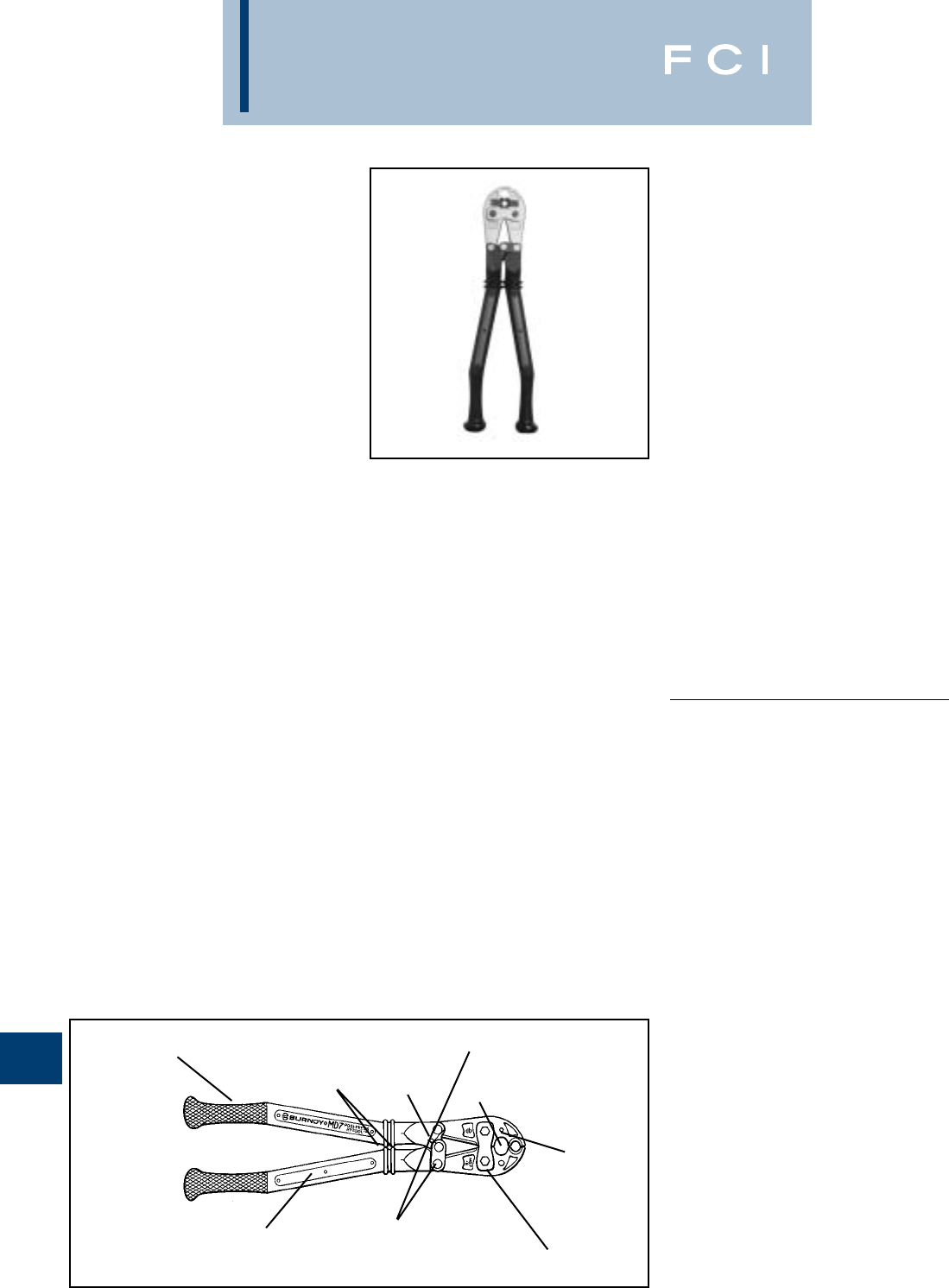
BURNDY
Tooling
N-16
TYPE MD7
POSI-PRESS
HYTOOL™
HAND-OPERATED TOOL
The MD7 POSI-PRESS HYTOOL™ is a
composite polymer handle installation tool
that requires no adjustment for the life of the
tool. This assures users of the MD7 tool, that
all connections installed with the MD7
POSI-PRESS HYTOOL™ are consistent and
reliable over the life of the tool. This new tech-
nology tool provides a visual wear indicator
that makes verification of the tool's condition
easy to determine. Once the tool has worn
beyond its useful life, it can be returned to
BURNDY's Tool Repair Center for re-fitting at
a fraction of the price of a new tool.
Installs full range of connectors, (taps,
splices, terminals): #14 Awg through 4/0 Awg.
Applications: Full-Tension and Non-Tension.
The MD7 series of tooling has a five (5) year
warranty and is designed to provide over
99,000 reliable crimps installing both full-
tension and non-tension connectors.
The MD7-8 POSI-PRESS HYTOOL™ installs
almost all of the line, pole, and house con-
nections in the Burndy Compression
Connector Program with only one (1) extra
die set (W-BG). The MD7-8 tool has two (2)
permanent die grooves, "O" and D3" for
distribution tap connectors. For other tool
versions, see the MD7 Tool Variations sec-
tions below. The "D3" groove also serves as a
seat for die inserts to install splices, taps, and
terminal connectors. The die inserts snap into
the "D3" groove easily with only one hand,
and lock securely in the tool with the spring
loaded, positive lock, die retainer buttons.
Handles have been tested at 100 Kv per foot
for five (5) minutes.
SPECIFICATIONS
Crimp force: 9,000 lbs.
60 lbs. Handle Force
Length: 25
Width: 8(at handle end)
4-1/2(at jaw end)
Width: 7 lbs.
Unsurpassed Quality that no one else
can match!
Life cycle tested under the full range of
operating forces for over 99,000 cycles
successfully without failure or any
parts replacement.
FOR USE ON
•Copper, Aluminum, ACSR, Copperweld,
Alumoweld, Steel, 6201 5005.
Compressed and compact conductors
•Copper Taps: #10 sol. - 2/0 str.
•Aluminum, ACSR Taps: #14 sol.
- 4/0 ACSR
•Stirrups: #6 ACSR - 4/0 ACSR
•Overhead Full Tension Deadend, Full
Tension Splices, Non Tension Splices,
and Terminals Conductor Range:
#10 str. - 4/0 ACSR
•Code conductor connectors: #6 - 4/0 str.
Copper and Aluminum
BENEFITS
•Easier tool operation due to unique
handle design, and anti-slip grips.
•Improves operation by preventing slipping.
•Proper crimps are assured with
butting jaws.
•Provides reliable and consistent crimps
every time.
•Lasts up to 6 times longer than cheap
imitations, and will still be working when
others have long since worn out.
•No lost dies and one-hand die insertion.
•Allows use of the complete line of Burndy
"W" and "X" die inserts.
•Increases life of tool by reducing tool wear.
•5-year limited warranty
Features
ELECTROLESS NICKEL PLATED JAWS
AND JAW LINKS PROVIDE ENHANCED
CORROSION RESISTANCE
HIGH STRENGTH STAINLESS STEEL
PINS RESIST CORROSION AND HELP
PROVIDE LONG TOOL LIFE
BLANK INSERT PROVIDED FOR PERSONALIZ-
ING TOOL FOR IDENTIFICATION AND INVENTO-
RY PURPOSES
REINFORCED POLYMER COMPOSITE
HANDLES TESTED FOR 100KV PER
FOOT FOR FIVE MINUTES WHEN NEW
AND WHEN PROPERLY CLEANED
HANDLE BUTT STOPS
COMFORT GRIP DESIGN WITH CHECKED
SURFACE AND ERGONOMIC HANDLE
ENDS PROVIDE A POSITIVE,
SLIP-FREE GRIP.
PERMINATE “D3”
DIE GROOVE
SPRING LOADED POSI-
TIVE LOCK DIE RETAINER
BUTTONS
GROOVE
INDICATOR
FEATURES
•Ergonomically designed, one-piece,
composite polymer handles.
•Comfort grip handles.
•Time-proven steel jaw designs.
•No tool adjustment required.
•99,000 crimp/cycle life.
•Positive lock, spring loaded die
retainer buttons.
•Permanent "D3" die groove.
•PTFE impregnated steel/bronze bushings
and stainless steel pins.
•Electroless nickel plated jaws and jaw links.
MD7 Tool Variations
MD7-8 MD7 with permanent "O" and "D3"
grooves. Installs almost all of the
line, pole, and house connections in
the Burndy Compression Connector
Program with only one (1) extra die
set (W-BG).
MD7-6 "Snub-Nose" variation of MD7
has a permanent "D3" groove jaw.
Accepts the full-line of BURNDY®
"W" and "X" die inserts.
Recommended for use where space
for tool jaw
is limited.
MD7 Standard MD7 with permanent
"BG" (5/8) and "D3" grooves.
Installs Cablelok Crimpit and
HYCRIMP™ Tap connectors with
one (1) additional die insert (W-O).
All other tool features and connector
ranges are the same as the MD7-8.
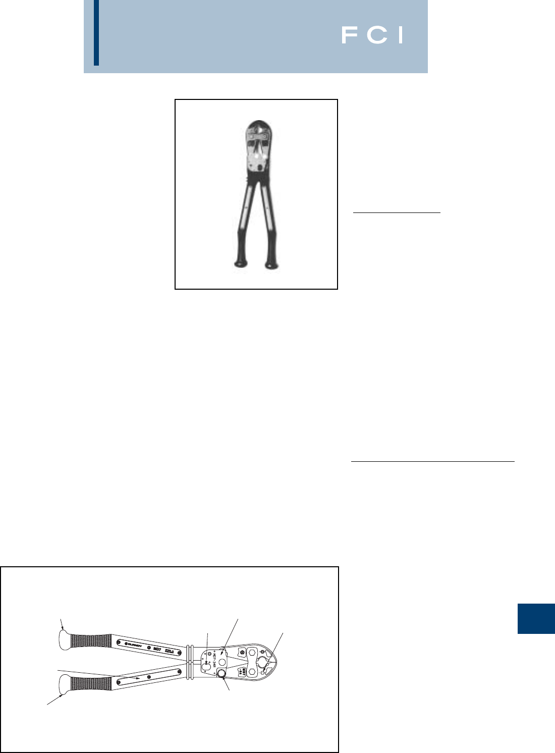
BURNDY
Tooling
N-17
TYPE MD7-34R
POSI-PRESS
HYTOOL™
HAND-OPERATED FULL
CYCLE RATCHET TOOL
The MD7-34R POSI-PRESS HYTOOL™ has
a full stroke ratchet that assures the user has
cycled the tool completely for a consistent
crimp every time. The tool handles are manu-
factured from a new reinforced composite
polymer that requires no adjustment for the
life of the tool. This new tool design assures
users that all connections installed with the
MD7-34R are consistent and reliable over the
life of the tool. A visual wear indicator
provides easy verification of the tool's condi-
tion. An emergency ratchet release allows
tool removal in case of mistaken die choice or
to reposition tool. The MD7-34R crimps color
coded lugs and splices for #8-500 kcmil class
B code conductor and #8-350 kcmil Cu Flex
conductor. It will also crimp thin wall C-Taps
from #12 - 3/0 AWG class B code conductor.
The color coded W-VT dies snap into the jaw
grooves easily with only one hand and lock
securely into the tool with the spring loaded,
positive lock, die retainer buttons. The die
index number is engraved in the crimping
groove to emboss the finished connection.
This makes inspection and verification of
proper installation an easy process. Due to
the one piece handle design, if the tool ever
wears beyond it's useful life, it can be
returned to BURNDY's Tool Repair Center for
refitting at a fraction of the price of a new tool.
A rubber covered version, the MD7-34R-C,
is available.
SPECIFICATIONS
Crimp force: 9,000 lbs.
Length: 26
Width: 8
at handles 4-1/2
at jaws
Jaw Covering: EPDM Rubber
(MD7-34RC).
Handle Material : Reinforced composite
polymer
Warranty: 5 years
MD7-34 Tool Variations
MD7-34R - #8-500 Cu HYDENT™, Full
Stroke Ratchet
MD7-34R-KIT 1 - MD7-34R, metal carrying
case and all dies for #8-500 kcmil Cu
HYDENT™ and C-Taps
MD7-34 - Supplied without the ratchet
mechanism
MD7-34-KIT1 - MD7-34, metal carrying
case, and all dies for #8-500 kcmil Cu
HYDENT™ and C-Taps for #12 - 3/0 AWG.
FOR USE ON
•Copper Lugs and Splices #8-500 kcmil.
Types YA, YA-L, YA-L-TC, YA-L-NT,
YS-L, YS, YST, YA-TC
•Copper Lugs and Splices #8-350 kcmil
Flex. Types YAV-L-TC-FX, YA-LB,
YA-TC-FXB, YSV-L, YAV-L-NT-FX,
YAV-L-FX, YAV-FXB
•Copper Battery Lugs #8-350 kcmil Flex.
Types YAG-TC-LD
•Thin wall C-taps #12 - 3/0 AWG.
Types YC-L
Features
HIGH STRENGTH
STAINLESS STEEL PINS
RESIST CORROSION
AND HELP PROVIDE
LONG TOOL LIFE
REINFORCED POLYMER COMPOSITE HANDLES RATED
FOR 100 KV PER FOOT FOR FIVE MINUTES WHEN NEW
AND WHEN PROPERLY CLEANED
EMERGENCY
RATCHET RELEASE
COMFORT GRIP DESIGN WITH CHECKERED
SURFACE AND ERGONOMIC HANDLE ENDS
PROVIDE A POSITIVE, SLIP-FREE GRIP
BLANK INSERT PROVIDED FOR
PERSONALIZING TOOL FOR IDENTIFICATION
AND INVNETORY PURPOSES
FULL STROKE
RATCHET
MECHANISM SPRING LOADED
POSITIVE LOCK
DIE RETAINER
BUTTONS
JAWS BUTT AT
COMPLETED
CRIMP
FEATURES
•Full Stroke Ratchet Mechanism.
•Ergonomically designed, one piece,
composite polymer handles.
•Comfort grip handles.
•Time-proven forged steel jaw designs.
•No tool adjustment required.
•Positive lock, spring loaded die retainer
buttons.
•PTFE impregnated steel/bronze bushings
and stainless steel pins.
•Color Coded Dies.
•DIE index embossed on finished
connection.
BENEFITS
•Easier tool operation due to unique handle
design, and anti-slip grips.
•Grips and handle knobs improve operation
by preventing slipping.
•Butting jaws assure proper crimps.
•Wear indicator allows instant inspection
of calibration.
•Full cycle ratchet assures complete
consistent crimp.
•High grade hardware increases tool life
and durability.
•Allows use of complete line of BURNDY®
W-VT, W-RT and X-RT series dies.
•Color Coded dies simplify selection of
correct connector and die combinations.
•Die index embossment on crimp provides
easy inspection and quality assurance.
•99,000 crimps without needing adjustment.
•5-year limited warranty.
BURNDY
Tooling
N-18
TYPE MD6/MD7
TOOLING ACCESSORIES
Dies for Special Applications
(See present installation tool index in ref-
erence section for complete W-Die listing.)
W-BG
The W-BG die is a double groove die set
requiring only one (1) crimp per end on
service entrance sleeves and only 1/2 the
number of crimps on other 5/8sleeves.
W-28K
The W-28K cutter die permits use of
MD6/MD7 type tools as a cable cutter.
Conductor range: 4-4/0 ACSR, Aluminum
or Copper.
Cat. No. PT6744
The semi-rigid Neoprene cover, a non-
conductive material, is provided for the MD6-6
“Snub-Nose” HYTOOL™ to avoid damage.
Fits all MD6-6 Snub-Nose variations.
Cat. No. PT4925
Canvas Bag
The PT4925 is a sturdy canvas bag for pro-
tecting the MD6/MD7 tools with or without
rubber covers plus up to (9) die sets. Dies
purchased separately.
Cat. No. PT6733
Hot-Line Tool Carrying Bag
The PT6733 is a heavy-duty, adjustable can-
vas bag for the storage and protection of Hot-
Line Tools. The bag accommodates 48, 60
and 72variations of the MD6 and Y35 Hot-
Line Tools.
PT4931-1
Die Button Repair Kit
Cat. No. PT4952-1
Steel Carrying Case
The PT4952-1 steel carrying case provides
storage and protection for the MD6 tools with
or without rubber covers plus up to (18) die
sets.Tool and die sets not included. Fits MD6,
MD6-6, MD6-8, MD6-14, MD6-37 , MD6-38,
MD7 and MD7-6.
Cat. No. MD6-CP1
The laminated vinyl covers, a non-conductive
material, are provided for the MD6/MD7
HYTOOL™ to avoid damage. Compact in
size, the covers snap easily into place over
the jaw edges without obstructing vision.
The MD6-CP1 fits all MD6/MD7 tool varia-
tions except the Snub-Nose MD6-6/MD7-6
type design. Supplied as a set.
Non-Bowing Dies
Cat. Nos. W-687 and W-702
The Non-Bowing die sets install one-piece,
full-tension UNISPLICE™ sleeves on ACSR
conductors without bowing.
UNISPLICE™ ONE-PIECE SLEEVES:
W-687 Installs: #4 ACSR 6/1, 7/1-YDS4RL
and YDS4RLY
#2 ACSR 6/1-YDS2RL
and YDS2RLY
W-702 Installs: #2 ACSR 7/1-YDSO21RL
and YDS021RLY
1/0 ACSR-YDS25RL
and YDS25RLY
Protective Jaw Covers
Cat. No. WDIETREE
W Die Holder
This innovative W-Die Holder replaces the
standard metal carrying case designed for
BURNDY®W-Dies. Its straight forward design
allows for easy insertion of the W-Dies onto
the holder, providing greater flexibility and
secure storage.
Cat. No. PT4946
Compact Steel Die Case
Compact die case for (12) "W"
or "X" die sets. Dies purchased separately.
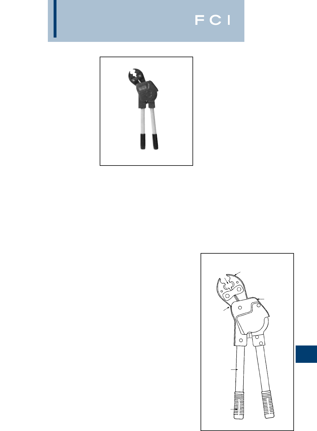
BURNDY
Tooling
N-19
TYPE MD6R
HYTOOL™
FULL-CYCLE RATCHET TOOL
Installs full range of connectors (Taps,
Splices, Terminals): #6 through 4/0 AWG.
Applications: Overhead and underground ––
full-tension and non-tension. Use MD6-6R2
for code cable terminals and splices through
500 kcmil copper.
The MD6R full-cycle ratchet tool installs all
the same connectors using the same “W”-
type dies that the MD6 tool installs plus the
addition of code cable connectors through
500 kcmil copper.
A maximum handle force of 40 lbs. plus short
handle opening and angled head combine to
provide an ideal tool for difficult overhead
and tight underground applications. Five-
year limited warranty.
SPECIFICATIONS
Output force: 12,000 lbs.
Handle input force: 40 lbs.
Number of strokes: 5
Weight: 10 lbs.
Length : 24
FOR USE ON
•Copper, Aluminum, ACSR, Copperweld,
Alumoweld, Steel, 6201, 5005,
Compressed and compact conductors.
•Copper Taps: #10 sol.- 2/0 str.
•Aluminum, ACSR Taps: #14 sol.-
4/0 ACSR.
•Stirrups: #6 ACSR- 4/0 ACSR.
•Overhead Full Tension Deadends, Full
Tension Splices, Non Tension Splices,
and Terminals Conductor Range:
#10 str.-4/0 ACSR.
•Code conductor connectors:
#6-500kcmil. Copper.
BENEFITS
•Precise crimping everytime is provided
with the ratchet mechanism and automatic
release only after five (5) handle strokes.
•Easy tool operation is provided with
40 lbs. maximum handle force reducing
possible back strain.
•Convenient operator usage for difficult to
reach overhead and tight underground
trench applications is provided with the
angled head, short handle stroke and
minimal handle force requirements.
•Easy handling and insertion is provided
with spring loaded handles.
•The D3groove accommodates the
complete line of “W” die inserts.
•5-year limited warranty
MD6R Variations:
Cat. No. Permanent Die Grooves
MD6R BG (5/8) and D3
MD6-6R D3Snub-Nose
MD6-6R-2 D3Modified for copper
color coded dies #8 through
500 kcmil.
MD6-8R O and D3
Accessories:
Cat. No. PT4925
The PT4925 is a heavy-duty canvas carrying
bag for the storage and protection of the
MD6...R tools. Pockets for dies are included.
Cat. No. PT17188
ABS Cover Kit
The PT17188 is the heavy-duty ABS plastic
cover kit including (3) piece ABS cover, label
and hardware.
Features
12,000 LBS.
CRIMP
FORCE
45° ANGLED
HEAD
SPRING
LOADED
STRAIGHT
HICKORY
HANDLES
PLASTIC
COMFORT
GRIPS
60° HANDLE
OPENING
FULL CYCLE
RATCHET
MECHANISM
40 LB. MAX
HANDLE
FORCE
REQUIRED
FIVE (5)
STROKES
REQUIRED
FOR COM-
PLETED
CRIMP AND
AUTOMATIC
RELEASE
HEAVY
GAUGE ABS
PLASTIC
PROTECTS
RATCHET
MECHANISM
STANDARD
MD6 JAW
VARATIONS
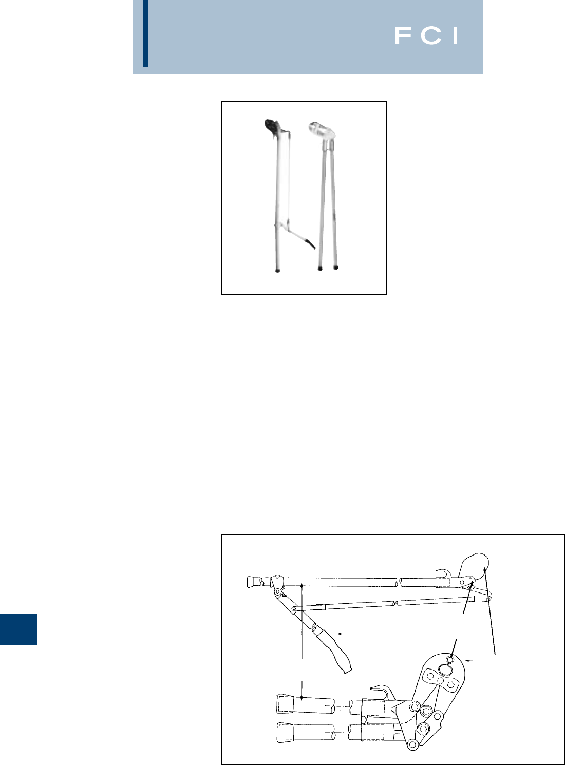
BURNDY
Tooling
N-20
MD6 HOTSTICK
TOOLS
The MD6 Type Hotstick tools incorporate
either a pantograph toggle action handle or
straight handles. They use standard MD6
Type jaws so that they will do everything the
standard MD6 will do only they can be used
for energized installations. The fiberglass
handles are rated at 100 kv/ft for 5 minutes.
5-year limited warranty.
SPECIFICATIONS
Handle
Cat. No. Length Weight/Lbs.
MD6HS60 6015.5
MD6HS72 7216.5
MD6-6HS60 6015.5
MD6-6HS72 7216.5
MD6-8HS60 6015.5
MD6-8HS72 7216.5
MD6-AH48 4813.75
MD6-6AH48 4813.75
MD6-8AH48 4813.75
FOR USE ON
•Copper, Aluminum, ACSR, Copperweld,
Alumoweld, Steel, 6201, 5005.
Compressed and compact conductors.
•Copper Taps: #10 sol.-2/0 str.
•Aluminum, ACSR Taps: #14 sol.-
4/0 ACSR.
•Stirrups: #6 ACSR-4/0 ACSR.
•Overhead Full Tension Deadends, Full
Tension Splices, Non Tension Splices,
and Terminals Conductor Range:
#10 str.- 4/0 ACSR.
•Code conductor connectors:
#6 - 4/0 str. Copper and Aluminum.
BENEFITS
•The MD6-HS type Hot-Line Tool incor-
porates a pantograph, toggle-action design
to install connectors with the same handle
force as the standard MD6-type tooling.
•All fiberglass handles rated at 100KV per
foot for five minutes.
•Angled head and lightweight makes
connector installation easier.
•Supplied with MD6, MD6-6, and MD6-8
jaw variations.
•The MD6-AH type Hot-Line Tool incor-
porates an angled head to make hard to
reach hot-line connections easier.
•Straight 48" fiberglass handles rated
at 100 KV per foot for five minutes.
•Supplied in MD6, MD6-6 and MD6-8
jaw variations.
•5-year limited warranty.
Features
STD MD6
JAWS
TOGGLE
ACTION
HANDLE
FIBERGLASS
HANDLES
ANGLED
HEAD
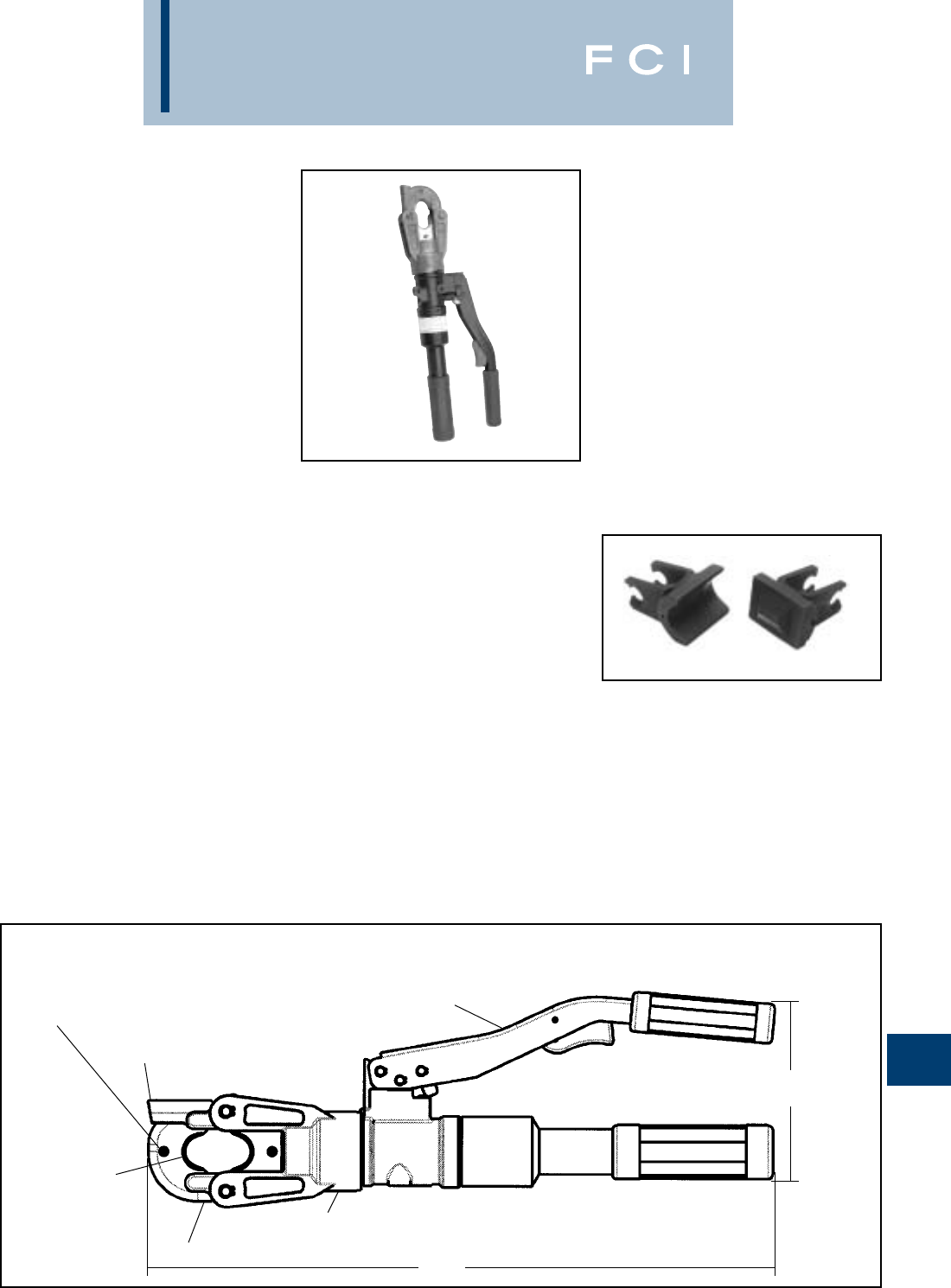
BURNDY
Tooling
N-21
TYPE Y500CT-HS
L'IL CRIMP™
6 TON - HYDRAULIC
CRIMP TOOL
The BURNDY®Y500CT-HS HYPRESS™
connector installation tool provides 6 U.S.
Short tons of force in a compact and easy to
use, hand-held hydraulic tool. The Y500CT-
HS incorporates a specialized latch style
head with a generous working stroke for a
wide variety of crimping applications. The
specialized head allows interference-free clo-
sures on tap connectors up to the BURNDY®
YHD-400 size. The head is fitted onto a light-
weight tool body with handles that are
ergonomically designed to provide slip-free
grip and easier crimping. The tool features a
patented high speed ram advance mecha-
nism that minimizes crimp cycle time along
with an ergonomic trigger drain mechanism
that allows the ram to return to the preset
position. The tool accommodates all
BURNDY®“X”, “W”, and “W-VT” style dies
that seat in the permanent “D3”crimping
groove. Installation applications include #6
AWG to 600 kcmil copper lugs and splices, #6
AWG to 350 AWG aluminum lugs and splices,
and up to 4/0 aluminum tap connections. The
permanent “D3”groove and 180 degree rotat-
able head are standard on the Y500CT-HS.
Each Y500CT-HS HYPRESS™ tool uses
BURNDY®dies and off-the-shelf connectors
that are available worldwide.Your Y500CT-HS
HYPRESS™ comes equipped with a durable
metal carry case to hold the tool and a
multitude of die sets.
SPECIFICATIONS
Output Force: 6 tons (5.4 metric tons)
Tool Weight: 7.8 lbs. (3.5 kg)
Total Strokes: 7 (w/o connector)
Height: 6.0(152 mm)
Length: 17.6(447 mm)
FOR USE ON
•Copper, Aluminum, ASCR, Steel,
Copperweld, Alumoweld, 6201, 5005,
Compressed, Compact, Stranded &
Solid conductors
•Installs splices, taps, or terminations:
#8 - 600 kcmil Copper Str
#8 - 350 kcmil Flex
#8 - 350 AWG Aluminum
Features and Benefits
•Light weight latch head design.
◊Provides enhanced clearance for tap
connectors.
•180° head rotation.
◊Versatile tool head allowing user crimp
access into tight spaces.
•Ergonomic handle design.
◊Easier operation, helping reduce fatigue.
•Audible pressure "pop-off" valve.
◊Indicates properly completed crimp.
•Permanent "D3" crimp groove accepts all
BURNDY®“W” and “X” dies.
◊Standard die design with proven
performance.
•Durable metal carrying case.
◊Provides superior protection and stores
all accessories.
•High speed ram advance.
◊Provides faster crimps.
•Handle trigger drain.
◊Convenient ram retraction.
•5-year limited warranty.
◊Customer satisfaction and technical
support.
Features
17.6
[447]
FUNCTIONAL
D3DIE GROOVE
ERGONOMIC
HANDLE DESIGN
SPRING LOADED DIE RETAINING PINS
180° ROTATABLE HEAD
SPECIALIZED LATCH DESIGN
LATCH HEAD RELEASE
6.0
[152]
RANGE TAKING DIES
WDC4500: #4-500 Cu STR.
#2-4/0 Cu FLEX
UL and CSA for use on YA and YS series.
Also for use on YAV and YSV series.
WDA8300: #8-300 Al
#6-400 Cu STR.
#2-4/0 Cu FLEX
UL and CSA for use on YA, YS, YA-A, and
YS-A series. Also for use on
YAV and YSV series.
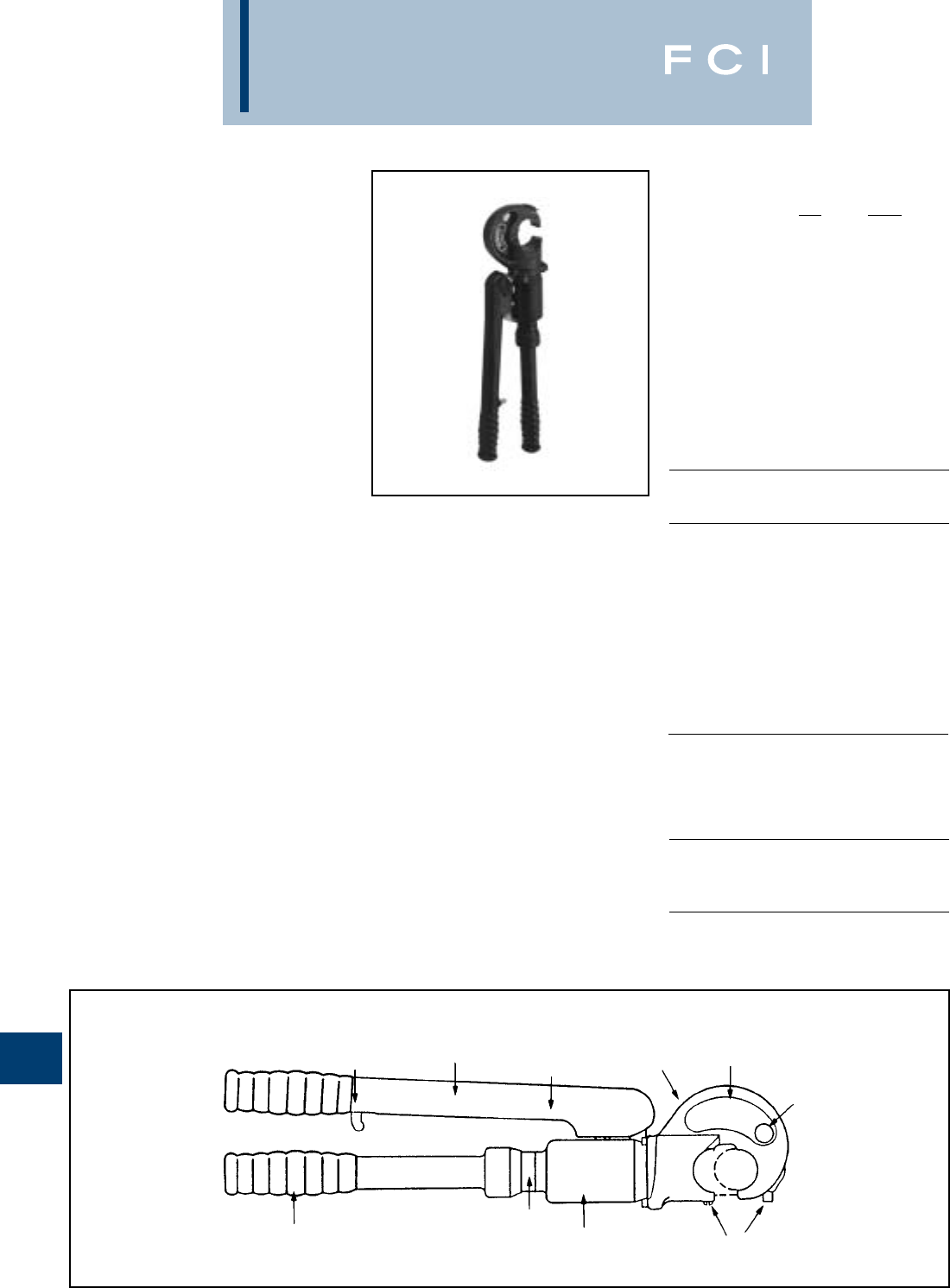
BURNDY
Tooling
N-22
TYPE Y35 AND
Y35-2 HYPRESS™
HAND-OPERATED -
HYDRAULIC TOOL
The Y35 HYPRESS™ Tool incorporates a
C-shaped, rotatable head for overhead line
work and compression grounding applica-
tions.The hook style head with extensive ram
travel provides for easy tapping and splicing
of overhead lines as well as HYGROUND™
compression grounding systems.
The Y35-2 HYPRESS™ head, body and
handles are covered with 3/16rubber for tool
impact protection.
Order the hot-line handle assembly, “U” dies
and accessories separately. 5-year limited
warranty.
SPECIFICATIONS
Y35 Y35-2
Force developed: 12 tons 12 tons
Operating pressure: 10,000 psi 10,000 psi
Weight (less case): 13 lbs. 13-1/2 lbs.
Overall length: 23-1/4
24
Head width: 4-3/4
6
Molded Covering: Body & Head, Body
Handles and Handles
FOR USE ON
BENEFITS
•Compact “C” shaped head allows easy
placement and removal from continuous
conductor lengths.
•Easy to position tool for work with 180°
head rotation.
•Versatile and economical-tool works with
all commonly used copper, aluminum and
ACSR conductors from #6 str. to #556.5
26/7 stranding.
•Body and handles covered with 3/16
molded rubber for tool impact protection.
•Easy die change accomplished with push
button die locks.
•Quality assurance is provided with auto-
matic 10,000 PSI blow-off pressure release
valve for positive crimping.
Features
COMFORT GRIP HANDLES TRIGGER
CONTROLLED
RAM RELEASE
SHORT
HANDLE
THROW RUBBER
COVERED
HANDLES
180° HEAD
ROTATION ‘C’ SHAPED HEAD
HOLE FOR LIFTING
EYE
POSITIVE PUSH
BUTTON DIE LOCKS
RUBBER
BODY
COVERING
BUILT-IN AUTOMATIC
10,000 PSI “BLOW-OFF
PRESSURE RELEASE
VALVE
RAPID RAM
ADVANCE
HANDLE
Y35-2 HAS RUBBER COVERED HEAD
Copper
#8 str.-500 kcmil
Code Cables
Copper
#8 str.-kcmil and up
to 3/4" ground rod
Copper
#8 str.-750 kcmil
Code Cables
N30-N500
Navy Cables
Flexible and
Extra Flex
Aluminum
#8 str.-750 kcmil
Code Cables
ACSR
Terminals-grounding
YGH, YGHA, YGF
Splices-grounding
YGS, YGHS
Taps-grounding
YGHC-C, YGHP-C
YGHR-C
Terminals Uninsulated
YA, YA-2N, YA-L, YA-LB
YA-2LN
Terminals Insulated
YAEV-L Box, YAEV-L
YAEV-H, YAEV-RS,
YAEV-RH
Splices To Size
400 kcmil
YS, YS-T, YS-L
YS-LB, YSV-L Box
YSV-L, YSM
Terminals
YA-A
AYP, AYPO
Splices To Size
350 kcmil
YSA, YRB, YS-AT
See Burndy Overhead
Transmission and
Distribution Catalog
Module
BENEFITS (CONTINUED)
•Rapid ram advance reduces installation
time by eliminating need to pump handles
to advance ram to connector.
•Saves installation time with trigger con-
trolled return release which returns ram to
its preset starting point.
•Long continuous usage is aided with
comfort grip handles.
•Compression terminal and splice connec-
tors are UL listed and CSA certified when
installed with recommended die set.
•5- year limited warranty.
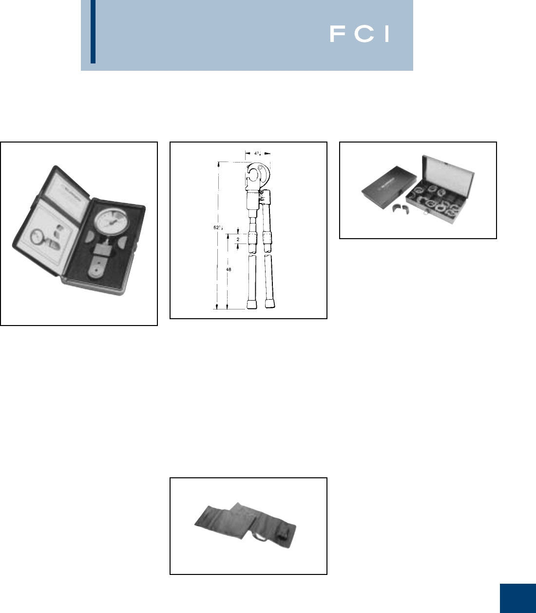
BURNDY
Tooling
N-23
Y35 SERIES
ACCESSORIES
Cat. No. HH5-RL48
Hot-Line Handle Assembly
The HH5-RL48 is a 48" long fiberglass
handle assembly that easily attaches to a
standard Y35 HYPRESS™ tool. Rotation of
the handles controls the rapid ram advance
and release mechanisms. The handles are
rated at 100KV per foot for five minutes. The
Catalog Number does not include the Y35.
For factory assembled unit order Catalog
Number Y35-16.
Cat. No. PT6733
Hot-Line Tool (Heavy-Duty)
Carrying Bag
The PT6733 is a heavy-duty, adjustable
canvas bag for the storage and protection of
hot-line tools. The bag accommodates 48
through 72variations of the Y35 and MD6
hot-line tools.
Cat. No. PT29291
Die Case
Steel case designed for storage and protec-
ton of “U” dies used with the Y35 and other
BURNDY®tools. Holds 15 die sets. Length 9
1/2, width 6, height 1-1/2.Dies sold
separately.
Y34A INDENTOR ADAPTOR:
To use Y34A indentors in a Y35, Y39,
or Y750 tool.
Cat. No. Y35P3
SEAL REPAIR KIT:
Cat. No. Y35/Y39 REP KIT A
Steel Carrying Case
Cat. No. PT2972 for Y35
Cat. No. PT29360 for Y35-2
PT 29279-2
Force Test Gauge
The PT 29279-2 Force Test Gauge is
designed to provide an accurate visual read-
ing of the output force produced by the hand-
hydraulic Y35, Y35-2, Y39 and Y750
HYPRESS™ tools. It is not recommended for
any remote powered HYPRESS™ heads
such as the Y35BH. The PT 29279-2 Force
Test Gauge is factory calibrated and inspect-
ed to very stringent tolerances providing the
customer accuracy and an excellent means
for quality assurance control. Supplied with
padded storage case.
BENEFITS
•Easy to read
•Provides means for quality assurance
control.
•Blank (test) “U” dies are provided for
testing procedure.
•Tool output force is applied to load cell
for visual read out of the resulting force
on the dial.
•The blank (test) “U” set is included with
the Force Test Gauge.
•An easy to read operating and main-
tenance manual is included.
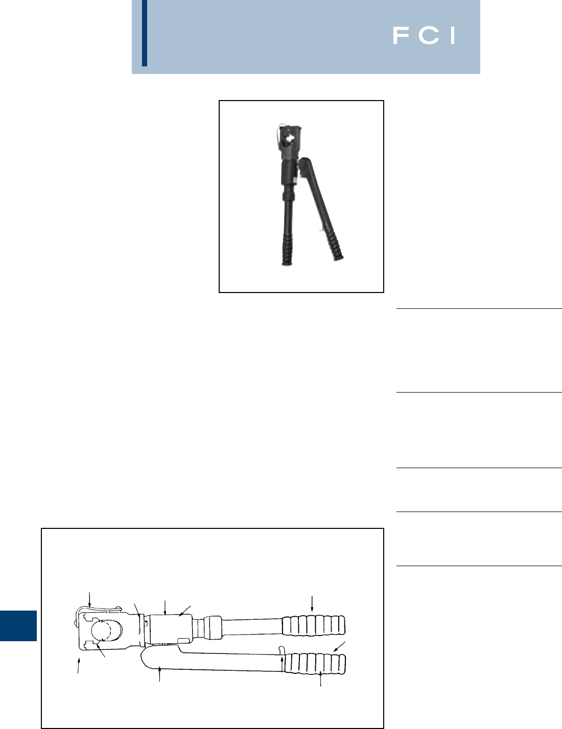
BURNDY
Tooling
N-24
TYPE Y39
HYPRESS™
HYDRAULIC TOOL -
HAND-OPERATED
The versatile, lightweight Y39 weighs 13 lbs.,
and its small 3-1/8wide head rotates 180°
for convenience and flexibility. The tool pro-
vides 12 tons of crimping power, while its
built-in overload valve automatically releases
pressure when the crimp is completed.
The Y39 is designed for easy die insertion
and removal without ball checks or set
screws. Its rapid ram advance and trigger-
controlled release eliminate unnecessary
pumping after every crimp. 5-year limited
warranty.
SPECIFICATIONS
Force developed: 12 tons
Operating force: 10,000 PSI
Weight - less case: 12 lbs.
Overall length: 23
Max. head width: 3-1/8
Die accommodation: U-dies
FOR USE ON
COPPER
#6 AWG -750 Kcmil str.
Code Cable
N30 - N650 Navy Cable
Flexible and Extra Flexible
Terminals -Uninsulated
YA, YA-L, YA-LB, YGH, YGHA
Splices & Tees - Uninsulated
YS, YS-L, YS-LB, YS-T, YSP-T, YST
COPPER- AN or AIR
#6 AWG-#4/0 str. Code Cable
AN6-AN #4/0 Aircraft Cable
Flexible and Extra Flexible
Terminals - Uninsulated
YAV-L Box, YAV-L, YAV-Rs Box, YAV-RS
Splices - Uninsulated
YSV-L Box, YSV-L
COPPER-INSULATED TERMINALS
#8 AWG - #2/0 str. Code Cable
AN8 - AN #2/0 Aircraft Cable
Flexible and Extra Flexible
Terminals-Insulated
YAEV- L Box, YAEV- L, YAEV- RS Box,
YAEV- RS, YAEV-RH
COPPER-TAPS
#12 AWG Solid-250 kcmil
Taps -YC-C, YGHC -C, YGHP -C, YGHR -C,
YH, YCHC -TC
ALUMINUM
#8 AWG-750 kcmil str.
Code Cable
Terminals-YA-A
Splices-YS-A, YS-AT, YRB
ALUMINUM
#6 str.-500 kcmil
Taps -YFD, YFN, YFO
BENEFITS
•Easy to work in small tight spaces with
only a 3-1/8wide compression head
and short handle throw.
•Easy to position tool for work with 180°
head rotation.
•Versatile and economical-tool works on
all commonly used copper and aluminum
conductors from #6 str. to 750 kcmil.
•Body and handles covered with 3/16
rubber.
•Easy to locate and hold dies in position
with the positive push button die locks
plus die changing is accomplished easily
without ball checks or set screws.
•Easy to remove or lock into position die
holder with recessed spring latch plus
leather strap to prevent loss.
Features
LEATHER DIE
RETAINER
STRAP 180° HEAD
ROTATION
RUBBER
BODY
COVER
RAPID RAM
ADVANCE
HANDLE
SHORT
HANDLE
STROKE
COMFORT
GRIP HANDLES
TRIGGER
CONTROLLED
RAM RELEASE
RUBBER
COVERED
HANDLES
POSITIVE PUSH
BUTTON DIE LOCKS
RECESSED
DIE RETAINER
SPRING LATCH
BUILT IN AUTOMATIC
10,000 PSI “BLOW-OFF”
PRESSURE RELEASE
VALVE
BENEFITS (CONTINUED)
•Quality assurance is provided with
automatic 10,000 psi “blow off” pressure
release valve for positive crimping.
•Rapid ram advance elmininates require-
ment for pumping handles to advance
ram to connector.
•Trigger release allows ram to return to
preset position.
•Long continuous usage is aided with
comfort grip handles.
•Compression terminal, tap and splice
connectors are UL listed and CSA certified
when installed with the Y39 tool and
recommended die set.
•5-year limited warranty.
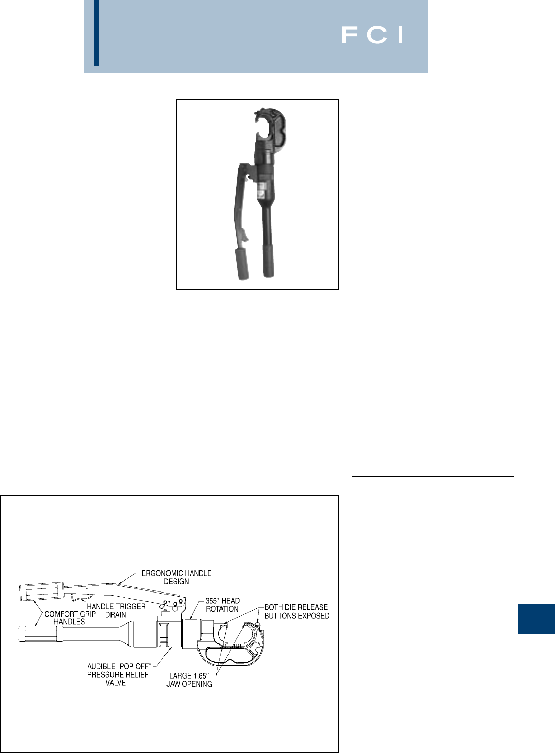
BURNDY
Tooling
N-25
TYPES Y750HS AND
Y750-2HS RUBBER
COVERED HEAD
750 REVOLVER HYPRESS™
HYDRAULIC HAND OPERATED
TOOL — 12 TON CRIMP FORCE
CONDUCTOR RANGE:
#12-750 KCMIL CU/AL
AND #4-556.5 KCMIL ACSR
The BURNDY®Y750HS Series HYPRESS™
is a wide mouth (1.65) hand operated
hydraulic 12 ton crimping tool for use on
virtually all compression applications. The
C-shaped head rotates 355° relative to the
handle and is mated to a patented rapid
advance pump. The Y750HS provides easy
tapping, splicing, and terminating of overhead
lines, the full line of HYGROUND™ compres-
sion grounding connectors, NEC cable
connections, and N30-N650 Navy cable
connections.
The Y750HS accepts all BURNDY®“U” dies
for use on conductor ranges of
#12-750 kcmil AL/CU and #4-556.5 kcmil
ACSR conductors.
The Y750-2HS HYPRESS™ has a rubber-
covered head and handles for tool impact
protection.
SPECIFICATIONS
Force developed: 12 tons
Weight: 14.5 lbs. (5.4 kg)
Length: 23.5(7162 mm)
Height: 2.75(838 mm)
Width: 8.0(2438 mm)
Jaw opening: 1.65(42 mm)
FOR USE ON
•Tension Sleeves
Copper #8 sol.-500 kcmil
Aluminum #8 sol.-587-2 kcmil
ACSR #4-556.5 kcmil
•Taps
Copper #14 sol.-500 kcmil
Aluminum #8-500 kcmil
•Aerial Cable
Copper #6-500 kcmil
•Terminals & Splices
Aluminum #8-750 kcmil
Copper #8-750 kcmil
ACSR #4-556 kcmil
•HYGROUND™ (Compression Ground)
Copper #8-500 kcmil
(cable/ground rod)
Ground Rods 1/2 - 1Diameter
ACCESSORIES:
Cat. No. Description
Y750HSCASE Plastic Carrying Case for
Y750HS and Y750-2HS
BENEFITS
•Covers a wide range of applications with
a lightweight, self-contained system and
provides easy tool removal from continu-
ous conductors with its C-shaped head.
•Easy tool positioning with its 355° head
rotation.
•Patented rapid advance pump for faster
crimps.
•Exposed positive die lock buttons for easy
die change out and die retention.
•Handle trigger drain for convenient ram
retraction.
•Quality assurance is provided with an audi-
ble “Pop-Off” pressure relief valve.
•Comfort grip handles help ease operator
fatigue with continuous use.
Features BENEFITS (Continued)
•Long life expectancy from the company
that provided the industry with the first self-
contained hydraulic tool in 1934.
•Rubber covered head and handles on
Y750-2HS for tool impact protection.
•Supplied with high impact plastic carrying
case.
•5-year limited warranty.
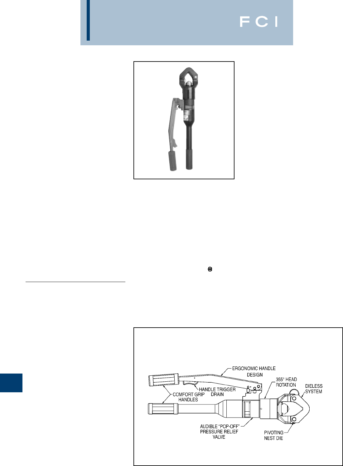
BURNDY
Tooling
N-26
TYPE Y644HS
DIELESS HYPRESS™
THE “1” CRIMP RANGE
TAKING TOOL
HYDRAULIC HAND OPERATED
TOOL — 11 TON CRIMP FORCE
#6 - 1000 KCMIL COPPER
HYLUG™ TERMINALS AND
HYLINK™ SPLICES
#6 - 750 KCMIL ALUMINUM
HYLUG™ TERMINALS AND
HYLINK™ SPLICES
The Y644HS dieless HYPRESS™ is a hand
operated 11 ton hydraulic crimping tool. Only
1 crimp is required for each wire termination
for both long and standard length barrels on
HYLUG™ terminals and HYLINK™ splices.
The Y644HS has a latch style head which
provides easy tool removal from continuous
conductor runs. The head rotates 355°
relative to the handles and is mated to a
patented rapid advance pump. The Y644HS
weighs only 15 pounds and delivers 11 tons
of crimping force. The result is easy terminat-
ing and splicing using BURNDY®HYLUG™
and HYLINK™ terminals and splices.
SPECIFICATIONS
Output Force: 11 tons (22,000 lbs.)
Weight: 15 lbs. (5.6 kg)
Length: 22.5(572.5 mm)
Height: 2.75(70 mm)
Width: 8.0(207 mm)
FOR USE ON
AWG/KCMIL CONNECTOR
SIZE RANGE TYPE
Copper Terminals
#6-1000 kcmil YA-L, YA-2LN, YA, YA-FXB
YA-2N, YA-L-2TC, YA-L-FX
YAB-4N, YA-L-TC,
YA-2L, YA-4N, YEV-P-FX,
YE-P, 4E-P-FX
Splices
YS-L, YS, YS-T
Aluminum Terminals
#6-750 kcmil YA-A, YA-A-TN
Splices
YS-A
Aluminum HYPLUG™
#6-750 kcmil AYP, AYPO
ACCESSORIES
Cat. No.
Y644HSCASE
•Plastic Carrying Case
BENEFITS
•Dieless system, eliminates the need to
purchase and maintain dies.
•Patented rapid advance pump for faster
crimps.
•Pressure relief “Pop-Off” valve provides
audible indication that crimp is complete.
•Handle trigger drain for convenient ram
retraction.
•355° head rotation for versatile tool head
positioning in tight areas.
•Easy inspection and positive identification
is provided with the BURNDY “ ”.
•Comfort grip handles help ease fatigue
with continuous use.
•Supplied with high impact plastic carrying
case.
•5-year limited warranty.
Features
Y644HS Dieless HYPRESS™ Range Taking
Capabilities. The following size HYDENT™
lugs and two way splices, when crimped with
the Y644HS Dieless HYPRESS™ Tool,
produce the following UL listed range taking
capabilities.
ALUMINUM CONNECTORS COPPER CONNECTORS
Standard Expanded Standard Expanded
Wire Size Wire Range Wire Size Wire Range
#6 AWG #6 AWG #6 AWG #6 AWG
#5 AWG #5-#6 AWG #5 AWG #5-#6 AWG
#4 AWG #4-#6 AWG #4 AWG #4-#6 AWG
#3 AWG #3-#6 AWG #3 AWG #3-#6 AWG
#2 AWG #2-#6 AWG #2 AWG #2-#6 AWG
#1 AWG #1-#2 AWG #1 AWG #1-#6 AWG
1/0 AWG 1/0-#1 AWG 1/0 AWG 1/0-#6 AWG
2/0 AWG 2/0-#1 AWG 2/0 AWG 2/0-#4 AWG
3/0 AWG 3/0-#1 AWG 3.0 AWG 3/0-#2 AWG
4/0 AWG 4/0-#1 AWG 4/0 AWG 4/0-#1 AWG
250 kcmil 250-1/0 AWG 250 kcmil 250-1/0
300 kcmil 300-2/0 AWG 300 kcmil 300-2/0
350 kcmil 350-3/0 AWG 350 kcmil 350-3/0
400 kcmil 400-4/0 AWG 400 kcmil 400-4/0
500 kcmil 500-4/0 AWG 500 kcmil 500-4/0
600 kcmil 600-250 kcmil 600 kcmil 600-250
750 kcmil 750-500 kcmil 750 kcmil 750-500
800 kcmil 800-500
1000 kcmil 1000-750
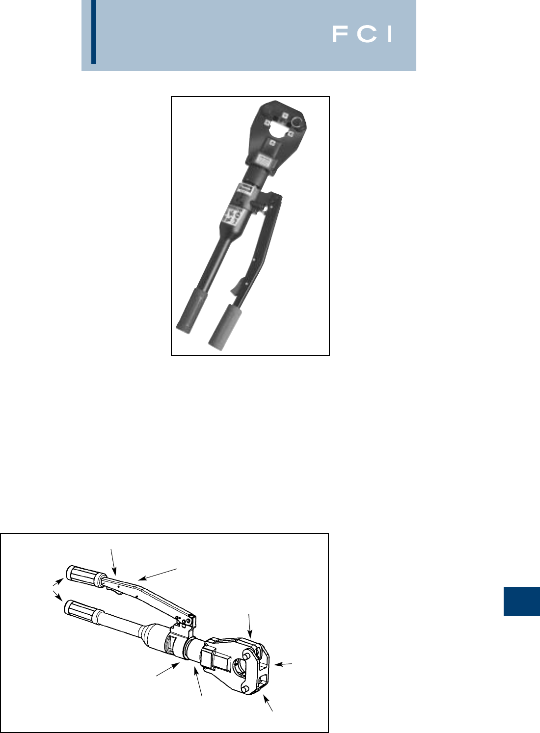
BURNDY
Tooling
N-27
TYPE 4-POINT™
Y81KFT
DIELESS HYPRESS™
HYDRAULIC HAND
OPERATED CRIMPING TOOL
#8 – 1000 KCMIL COPPER HYLUG™
TERMINALS and HYLINK™ SPLICES
#8 – 750 KCMIL ALUMINUM HYLUG™
TERMINALS and HYLINK™ SPLICES
The Y81KFT 4-POINT™ dieless HYPRESS™
is a hand operated 6 ton hydraulic crimping
tool for use on a wide variety of terminal and
splice compression applications.The Y81KFT
incorporates a dieless latch style head that
provides easy tool removal from continuous
conductor runs and eliminates the need to
purchase and maintain dies.The head rotates
360º relative to the handles and is mated to a
patented rapid advance pump. The Y81KFT
weighs only 12 pounds and delivers 6 tons of
crimping force. The result is easy termination
and splicing using BURNDY®HYLUG™ and
HYLINK™ terminals and splices.
The Y81KFT is supplied with a molded high
impact plastic case and comes complete with
a 5-year limited warranty.
Y81KFT dieless HYPRESS™ Range Taking
Capabilities: The Y81KFT provides range tak-
ing capabilities that is UL and CSA listed for
Copper (Code, Compact and Flex) and
Aluminum (Code and Compact) conductors
when used in conjunction with BURNDY®
HYLUG™ terminals and HYLINK™ splices.
See chart for connector, conductor and range
taking combinations.
Features and Benefits
•Dieless installation system.
◊Eliminates the need to purchase and
maintain dies.
•UL Listed and CSA Certified with Range
Taking Capabilities
◊Provides the installer with a UL Listed
and CSA Certified crimps with Range
Taking Capabilities when used in con-
junction with BURNDY® HYLUG™
Terminals and HYLINK™ Splices
•Flip top head design.
◊For easy loading and removal of installed
terminals and splices, saving time.
SPECIFICATIONS
Output Force: 6 tons (12,000lbs)
(5450 kg)
Weight: 12 lbs (5.45 kg)
Length: 25.6 in (650 mm)
Height: 7.7in (196 mm)
Width: 2.5in (64 mm)
FOR USE ON
•Copper, Aluminum, Compressed,
Compact, Stranded, Solid and Flex
Conductors.
•Installs Splices, Taps and Terminations:
#8 - 1000 kcmil Copper (YA, YA-L, YS,
YS-L, YS-T, Y-R )
#8 - 777.7 (750 Nominal Flex Wire Size)
kcmil Flex (YA-FX, YAV, YA-L-FX, YS,
YSV-FXB)
#8 - 750 kcmil Aluminum (YA-A, YS-A)
#8 - 750 kcmil Aluminium Pin Adapters
(AYP, AYPO)
DIELESS
SYSTEM
HANDLE TRIGGER DRAIN
LOCKING LATCH PIN
AUDIBLE “POP-OFF” PRESSURE
RELIEF VALVE
PIVOTING
NEST DIE
•Audible pressure "pop-off" valve and die
embossment providing 360º inspectability.
◊Assures proper crimps with both audible
and visual indicators for the installer.
•Handle Trigger release.
◊Convenient ram release located in the
handle.
•Advanced high speed pump design.
◊Provides fast crimps, longer life, efficien-
cy, and reliability.
•360 Degree head rotation.
◊Versatile tool head positioning lets the
user get into tight areas easier.
•Durable high impact formed carrying case.
◊Provides tool protection and stores all
accessories.
•5-year limited warranty on tool, 1 year on
batteries and charger.
◊Customer satisfaction and support.
COMFORT
GRIP HANDLES
360° HEAD
ROTATION
ERGONOMIC HANDLE
DESIGN
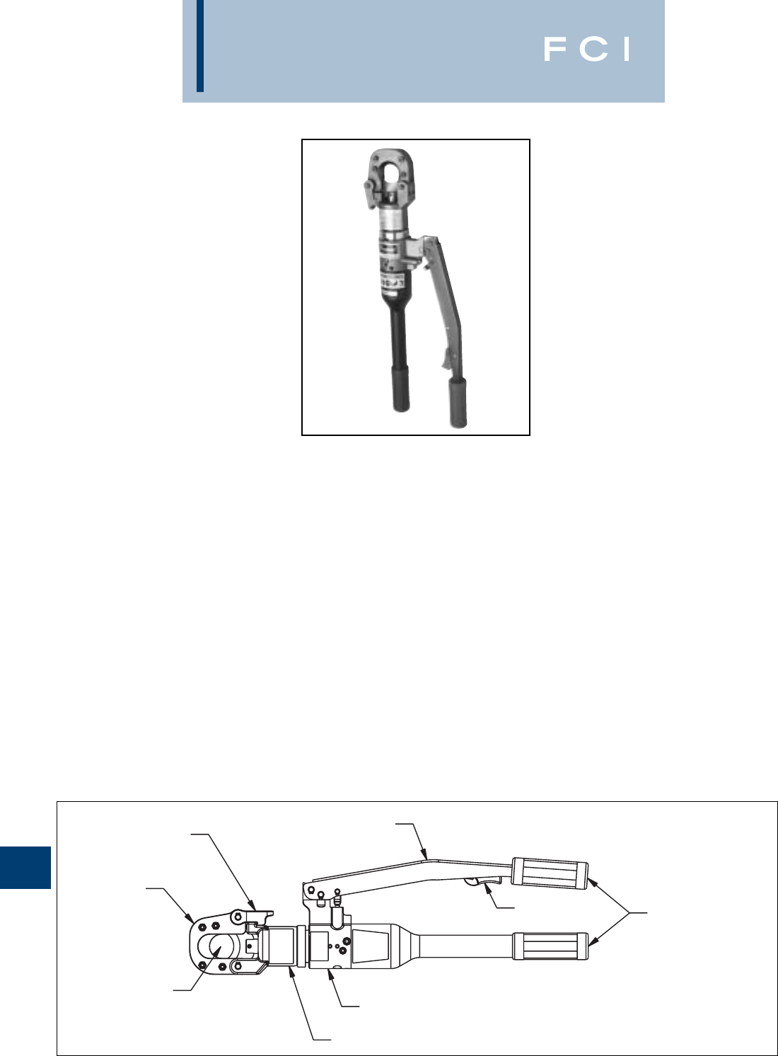
BURNDY
Tooling
N-28
YCUT129ACSR
Hydraulic Hand Operated
Cutter
The BURNDY®YCUT129ACSR incorporates
a specialized latch style cutting head that
allows interference-free closure for mid-span
cuts. The cutter head rotates 180 degrees to
allow users to get into tight areas easier. The
YCUT129ACSR weighs only 11.4 pounds,
yet delivers 7 tons of cutting force. The
YCUT129ACSR with its hardened steel
blades is capable of cutting up to 1.29diam-
eter bare or insulated copper and aluminum
cable, 1113 ACSR, 5/8" ground rod, 1/2
rebar and 5/8diameter soft steel bolts 1/2
standard guy strand and up to 3/8EHS guy
strand.
The YCUT129ACSR comes equipped with a
high impact formed carrying case to hold the
tool and accessories. The BURNDY®
YCUT129ACSR is provided with a 5-year lim-
ited warranty (excluding blades).
Features and Benefits
•Patented rapid advance pump.
◊Faster cuts with less hand strokes.
•Specialized latch head design.
◊Interference free closure on mid-span
cuts.
•Handle trigger drain
◊For convenient blade retraction.
•Hardened steel blades.
◊Ability to cut ACSR, ground rods, rebar
and guy wire.
•Comfort grip handles.
◊Help ease fatigue with continuous use.
•180-degree head rotation.
◊Versatile head positioning to get into tight
areas easier.
•Durable high impact formed carrying case.
◊Provides tool protection and stores
accessories.
•5-year limited warranty on tool (excluding
blades).
◊Customer satisfaction and support.
SPECIFICATIONS
Force Developed: 7 U.S. short tons
Tool Weight: 11.4 lbs. (5.1 kg)
Length: 22.4 (56.9 cm)
Width: 2.5 (6.4 cm)
Height: 6.6 (16.8 cm)
FOR USE ON
•Copper Cable: up to 1.29
•Aluminum Cable: up to 1.29
•ACSR: up to 1113 ACSR
•Ground Rod: up to 5/8
•Rebar: up to 1/2
•Soft Steel Bolts: up to 5/8
•Standard Guy Strand: up to 1/2
•EHS Guy Strand: up to 3/8
ACCESSORIES
•Carrying Case: Cat# PT10024162
•Replacement Blades:
Cat# PT10037388
(Moving Blade)
Cat# PT10037384
(Fixed Blade)
SPECIALIZED
LATCH HEAD
DESIGN
PRECISION
CUTTING
BLADES
1.29CUTTING
CAPACITY
ERGONOMIC HANDLE DESIGN
PATENTED RAPID
ADVANCE PUMP
180° HEAD DESIGN
COMFORT
GRIP HANDLES
HANDLE TRIGGER
DRAIN
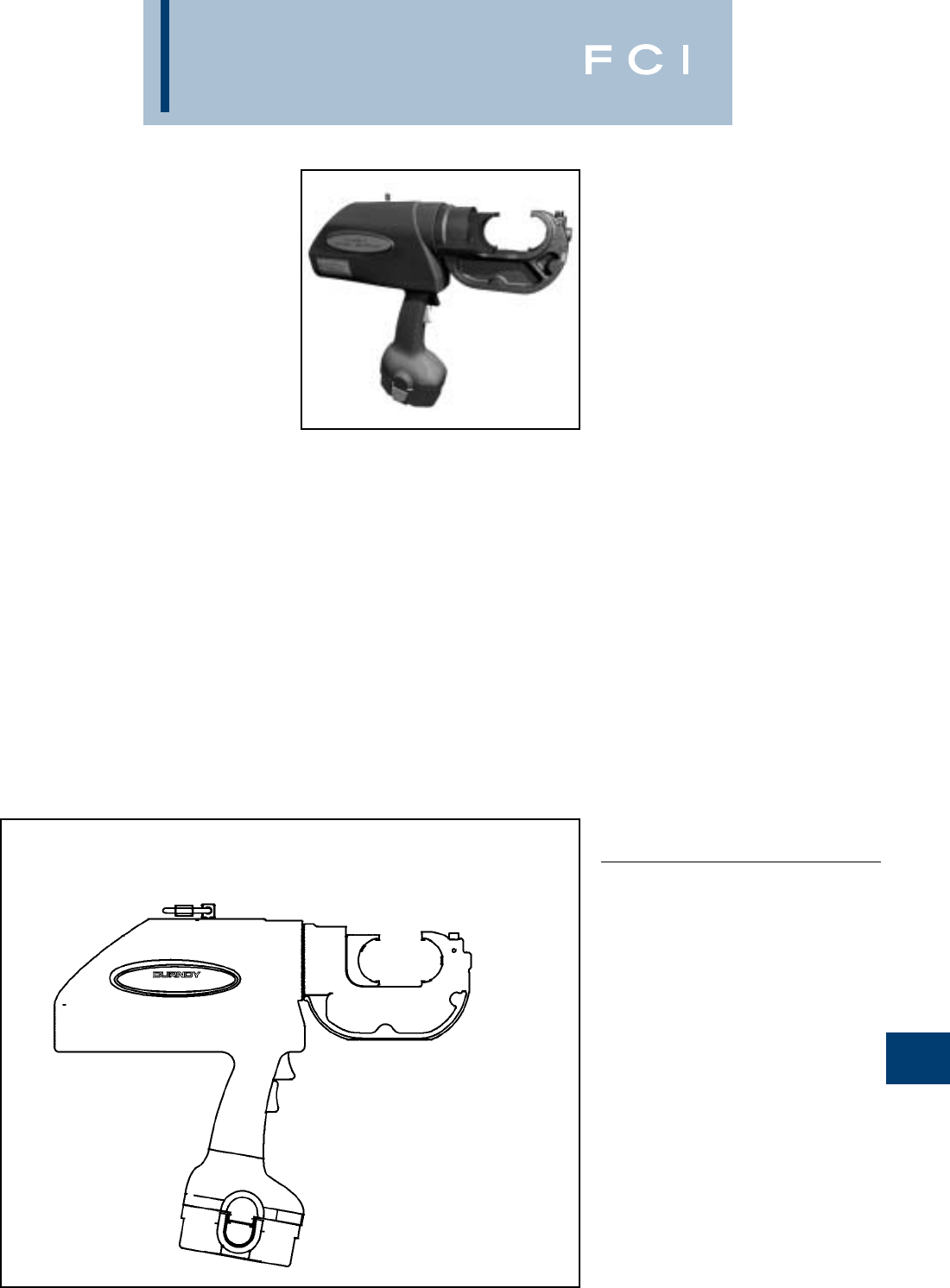
BURNDY
Tooling
N-29
TYPE PATRIOT®
PAT750-18V
BATTERY ACTUATED TOOL –
Hydraulic Self-Contained –
12 Ton
The BURNDY®PATRIOT®can be operated
with only one hand, making them the only
true, one-handed battery powered crimping
tools available in the world today.
The BURNDY®PATRIOT®PAT750-18V
incorporates the latest engineering
technology with patent pending pump, trans-
mission and piston component designs. Our
self-contained hydraulic tool provides a con-
sistent, reliable connection every time. The
PAT750-18V features BURNDY’s Y750 tool
head, capable of using all “U” style dies, and
incorporates a patent pending bearing and
alignment guide for use on HYGROUND™
and other asymmetrical connectors. Features
reliable head rotation design for operation in
virtually any position.
Each PATRIOT®uses standard BURNDY®
dies and off-the-shelf connectors available
worldwide. Supplied with a durable high
impact formed carrying case to hold the tool,
battery charger, two batteries, tool retention
lanyard, and die compartment to hold “U” die
sets. (Dies sold separately.) All BURNDY®
PATOOL™ 18V series tools are provided with
a 5-year limited warranty.
SPECIFICATIONS
Crimp Force: 12 Tons
(10.9 metric tons)
Tool Weight: 16.5 lbs (7.5 kg)
Length: 15-1/2(39.37 cm)
Width: 3-1/2(8.89 cm)
Height: 13-7/8(35.24 cm)
Operating Voltage: 18 V-DC
Recharge Time: < 45 mins.
FOR USE ON
•Tension Sleeves
Copper #8 sol.–500 kcmil
Aluminum #8 sol.–587-2 kcmil
ACSR #4–556.5 kcmil
•Taps
Copper #14 sol.–500 kcmil
Aluminum #8 sol.–500 kcmil
•Aerial Cable
Copper #6–500 kcmil
•Terminals and Splices
Aluminum #8–750 kcmil
Copper #8–750 kcmil
ACSR #4–556 kcmil
•HYGROUND™ (Compression Ground)
Copper #8–500 kcmil
(cable/ground rods)
Ground Rods 1/2 – 1Diameter
ACCESSORIES
•Battery:
Hi-capacity Ni-MH
(2200 mA-hr) Cat# BAT18V
•Charger:
120V-AC Cat# BATCHGR-18V
12/24V-DC Cat# BCT/PATDCCHGR
•Lanyard: Cat# PT208620
FEATURES
•True, one-handed operation for advance,
retract, and hold.
•12-ton output force.
•State of the art crimping head design,
360head rotation.
•Audible “pop-off” and Green indicator
indicates properly completed crimps.
•Ergonomically balanced tool design.
•Durable High Impact Formed carrying
case.
•PAT750C-18V – with rubber covered head
is available.
Ni-MH battery eliminates voltage
depression (memory issues).
•5-year limited warranty on tool.
•1-year limited warranty on batteries and
charger.
Features
ROTATIONAL HEAD
FOR USE WITH “U”
STYLE DIES
SAFETY LANYARD
CONNECTION
AUDIBLE “POP-OFF” WITH
GREEN INDICATOR
LARGE JAW OPENING
TO ACCOMMODATE
ASYMMETRICAL
CONNECTORS
NI-MH 18 VOLT BATTERY
12 TON OUTPUT FORCE
ERGONOMICALLY
BALANCED TOOL
DESIGN
BENEFITS
•Easier tool operation.
•Versatile tool head positioning lets user
get into tight areas easier.
•Allows use of standard BURNDY®dies
already in use.
•Less “down-time” due to high capacity,
high voltage 18 volt battery.
•Assures proper crimps with both audible
and visual indicators, leaving no doubt for
the tool user.
•Ergonomically balanced tool eases
operation and helps lessen fatigue.
•Smoother, quieter, more efficient tool
operation.
•Durable high impact formed case provides
superior protection and stores all
accessories.
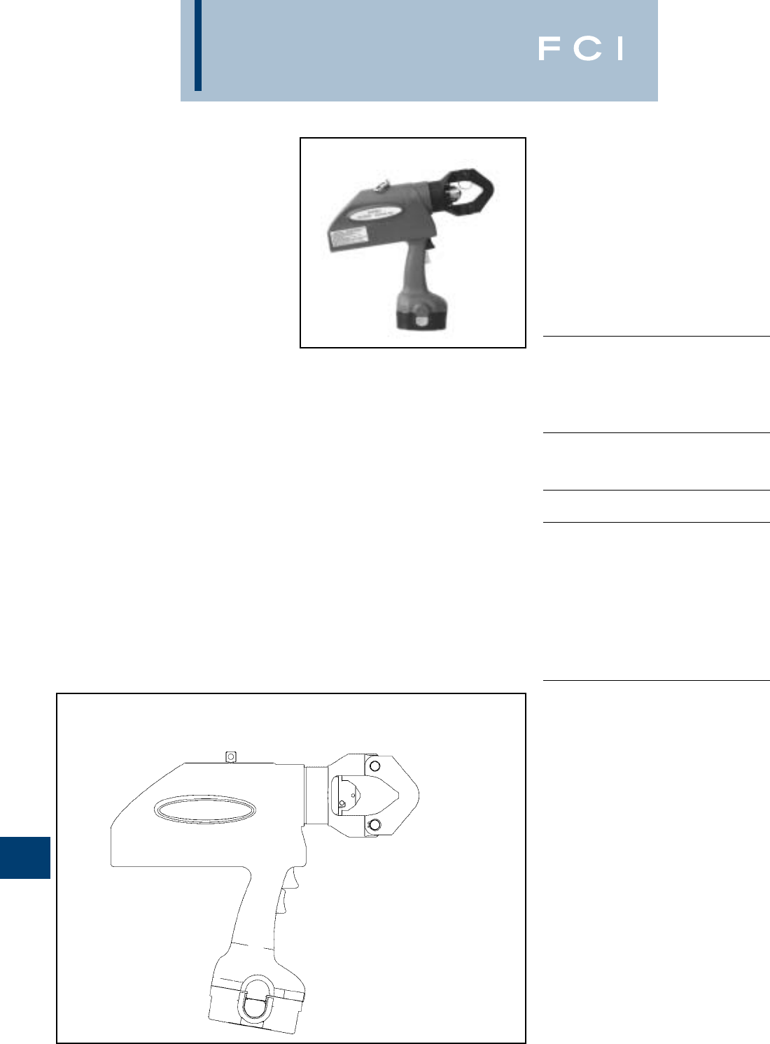
BURNDY
Tooling
N-30
TYPE PATRIOT®
PAT644-18V
BATTERY ACTUATED TOOL –
Hydraulic Self-Contained –
11 Ton
The BURNDY®PATRIOT®series of battery
actuated tools can be operated with only one
hand, which allows the other hand to be free
to position the connector and conductor prior
to crimping.
The BURNDY®PATRIOT®PAT644-18V
incorporates the latest engineering
technology with patent pending pump, trans-
mission and piston component designs. Our
self-contained hydraulic tool provides a con-
sistent, reliable connection every time. The
PAT644-18V features BURNDY’s Y644 die-
less latch head tool which eliminates the
need to purchase and maintain dies. Features
reliable head rotation design for operation in
virtually any position.
Each PATRIOT®uses standard BURNDY®
off-the-shelf connectors available worldwide.
Supplied with a durable high impact formed
carrying case to hold the tool, battery
charger, two batteries, and tool retention
lanyard. All BURNDY®PATOOL™ 18V series
tools are provided with a 5-year limited
warranty.
PAT644-18V Range Taking Capabilities:
Please refer to the individual connector
pages for detailed information on the
PAT644-18V range taking capabilities.
SPECIFICATIONS
Crimp Force: 11 Tons
(10.9 metric tons)
Tool Weight: 17 lbs (7.7 kg)
Length: 15-1/2(39.37 cm)
Width: 3-1/2(8.89 cm)
Height: 13-7/8(35.24 cm)
Operating Voltage: 18 V-DC
Recharge Time: < 45 mins.
FOR USE ON
AWG/KCMIL CONNECTOR
WIRE SIZE RANGE TYPES
Copper Terminals
#6 - 1000 kcmil YA-L, YA-2LN, YA,
YA-2N, YA-L-2TC,
YAB-4N, YA-L-TC,
YA-2L, YA-4N
Splices
YS-L, YS, YS-T
Aluminum Terminals
#6 - 750 kcmil YA-A, YA-A-TN
Splices
YS-A
Aluminum HYPLUG™
#6 - 750 kcmil AYP, AYPO
ACCESSORIES
•Battery:
Hi-capacity Ni-MH
(2200 mA-hr) Cat# BAT18V
•Charger:
120V-AC Cat# BATCHGR-18V
12/24V-DC Cat# BCT/PATDCCHGR
•Lanyard: Cat# PT208620
FEATURES
•Dieless system.
•True, one-handed operation for advance,
retract, and hold.
•11-ton output force.
•State of the art crimping head design, 360
head rotation.
•Audible “pop-off” and Green indicator
indicates properly completed crimps.
•Ergonomically balanced tool design.
•Durable High Impact Formed carrying
case.
•Ni-MH battery eliminates voltage
depression (memory issues).
•5-year limited warranty on tool.
•1-year limited warranty on batteries and
charger.
Features
ROTATIONAL NEST AND
INDENTOR LATCH HEAD
ELIMINATES THE NEED
FOR DIES
SAFETY LANYARD
CONNECTIONAUDIBLE “POP-OFF” WITH
GREEN INDICATOR
NI-MH 18 VOLT BATTERY
11 TON OUTPUT FORCE
ERGONOMICALLY
BALANCED TOOL
DESIGN
BENEFITS
•Eliminates the need to purchase and
maintain dies.
•Easier tool operation.
•Versatile tool head positioning lets user get
into tight areas easier.
•Less “down-time” due to high capacity,
high voltage 18 volt battery.
•Assures proper crimps with both audible
and visual indicators, leaving no doubt for
the tool user.
•Ergonomically balanced tool eases
operation and helps lessen fatigue.
•Smoother, quieter, more efficient tool
operation.
•Durable high impact formed case provides
superior protection and stores all
accessories.
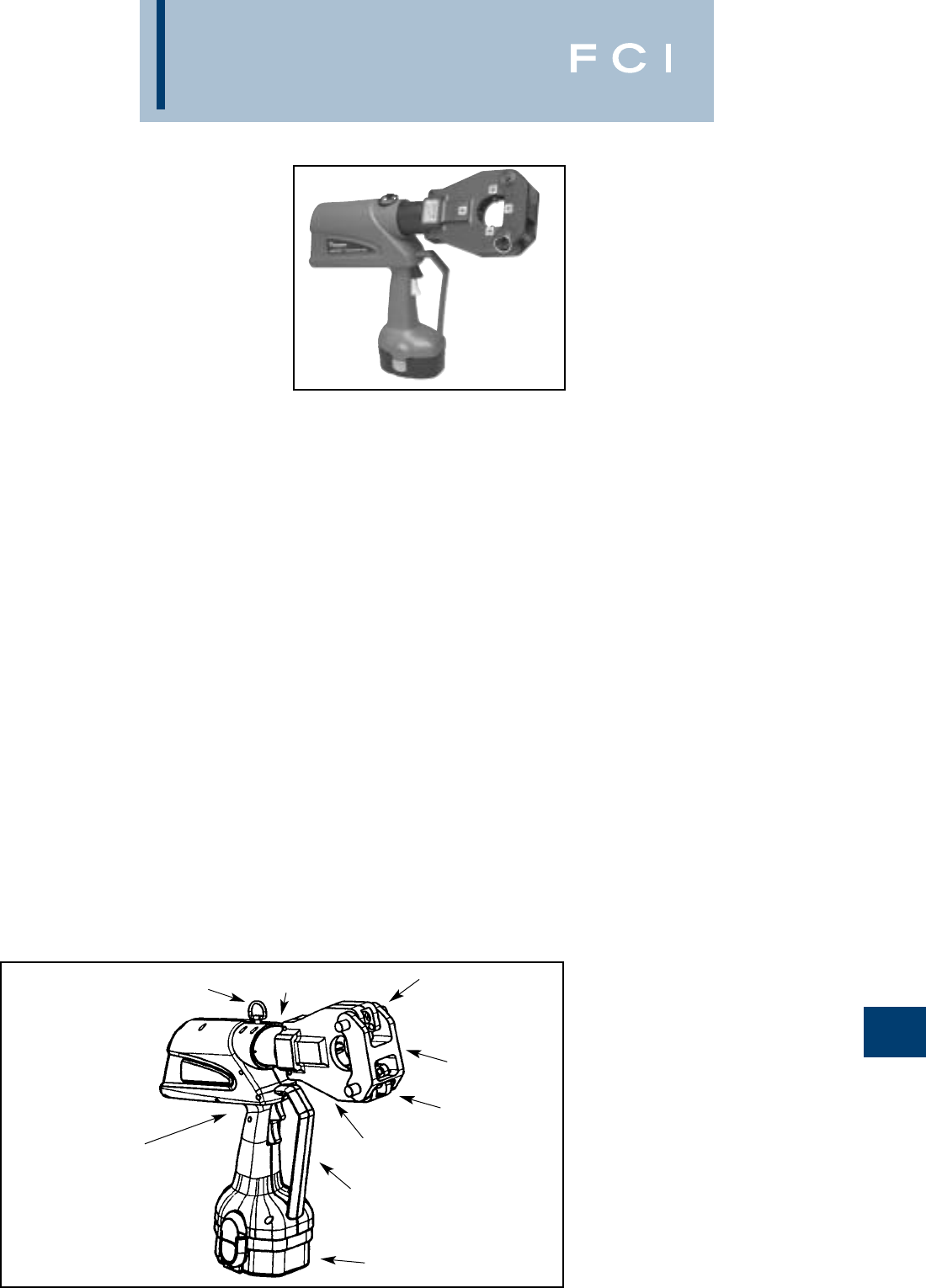
BURNDY
Tooling
N-31
TYPE 4-POINT™
PATRIOT®
PAT81KFT-18V
BATTERY ACTUATED TOOL
Hydraulic Self-Contained
Crimping Tool
#8-1000 KCMIL COPPER HYLUG™
TERMINALS and HYLINK™ SPLICES
#8-750 KCMIL ALUMINUM HYLUG™
TERMINALS and HYLINK™ SPLICES
The BURNDY®PAT81KFT-18V is a battery
powered crimping tool that provides a power-
ful 6 tons of crimping force. It is compact, fast,
easy to use and incorporates the latest in bat-
tery tool technology. The ergonomic design
allows for one hand operation so that the
other is free to position the connectors and
conductor prior to crimping. The PAT81KFT-
18V features a dieless latch head design
which eliminates the need to purchase and
maintain dies. Featuring 360° head rotation,
the PAT81KFT-18V is designed for easy oper-
ation in virtually any position.
The PAT81KFT-18V is supplied with a high
impact carrying case, battery charger, lan-
yard and two batteries. The PAT81KFT-18V
comes complete with a 5-year limited warran-
ty on the tool and 1 year limited warranty on
the batteries.
PAT81KFT-18V Dieless HYPRESS™ Range
Taking Capabilities: The PAT81KFT-18V pro-
vides range taking capabilities that is UL and
CSA listed for Copper (Code, Compact and
Flex) and Aluminum (Code and Compact)
conductors when used in conjunction with
BURNDY®HYLUG™ terminals and
HYLINK™ splices. See chart for connector,
conductor and range taking combinations.
Features and Benefits
Dieless installation system.
◊Eliminates the need to purchase and
maintain dies.
•UL Listed and CSA Certified with Range
Taking Capabilities
◊Provides the installer with UL Listed and
CSA Certified crimps with Range Taking
Capabilities when used in conjunction
with BURNDY®HYLUG™ Terminals and
HYLINK™ Splices
•Audible pressure “pop-off” valve and die
embossment providing 360º inspectability.
◊Assures proper crimps with both audible
and visual indicators for the installer.
•Battery powered crimp technology.
◊Easy Tool Operation and portability.
•Advanced high speed pump design.
◊Provides faster crimps, longer life, effi-
ciency, and reliability.
•Ergonomic design allows one hand opera-
tion for ram advance and ram retraction.
◊User always has one hand free to
manipulate connector and conductor.
•360 Degree head rotation.
◊Versatile tool head positioning lets the
user get into tight areas easier.
•Ram holds position when trigger is
released.
◊Provides the ability to hold the connector
between the indentors and check for
alignment prior to crimping action.
SPECIFICATIONS
Output Force: 6 tons (5.4 Metric
Tons)
Weight: 14 lbs (6.35 kg)
Length: 17.6 (447 mm)
Height: 13.9 in (354 mm)
Width: 3.7 in (94 mm)
Operating Voltage: 18V-DC
Battery Recharge
Time: <45 Mins
FOR USE ON
•Copper, Aluminum, Compressed,
Compact, Stranded, Solid and Flex
Conductors.
•Installs Splices, Taps and Terminations:
#8 - 1000 kcmil Copper (YA, YA-L, YS,
YS-L, YS-T, Y-R )
#8 - 777.7 (750 Nominal Flex Wire Size)
kcmil Flex (YA-FX, YAV, YA-L-FX, YS,
YSV-FXB)
#8 - 750 kcmil Aluminum (YA-A, YS-A)
#8 - 750 kcmil Aluminium Pin Adapters
(AYP, AYPO)
ACCESSORIES
•
Battery: Cat# BAT18V
Hi Capacity Ni-MH
(2200 mA-hr)
•
Charger:
120V-AC Cat# BATCHGR-18V
12/240V-DC Cat# BCT/PATDCCHGR
•
Lanyard Cat# PT208620
ERGONOMICALLY
BALANCED TOOL
DESIGN
DIELESS
SYSTEM
AUDIBLE “POP-
OFF” VALVE
NI-MH 18-VOLT BATTERY
•Mechanical ram release.
◊Reliable ram release (no battery
consumption).
•Uses 18 volt Ni-MH batteries.
◊Eliminates voltage depression or
“memory”.
•Audible pressure “pop-off” value.
◊Indicates properly completed crimps.
•Durable high impact formed carrying case.
◊Provides tool protection and stores all
accessories.
•5-year limited warranty on tool, 1 year on
batteries and charger.
◊Customer satisfaction and support.
360° HEAD
ROTATION
SAFETY LANYARD
CONNECTION
TRIGGER
GUARD
PIVOTING
NEST DIE
LOCKING
LATCH PIN
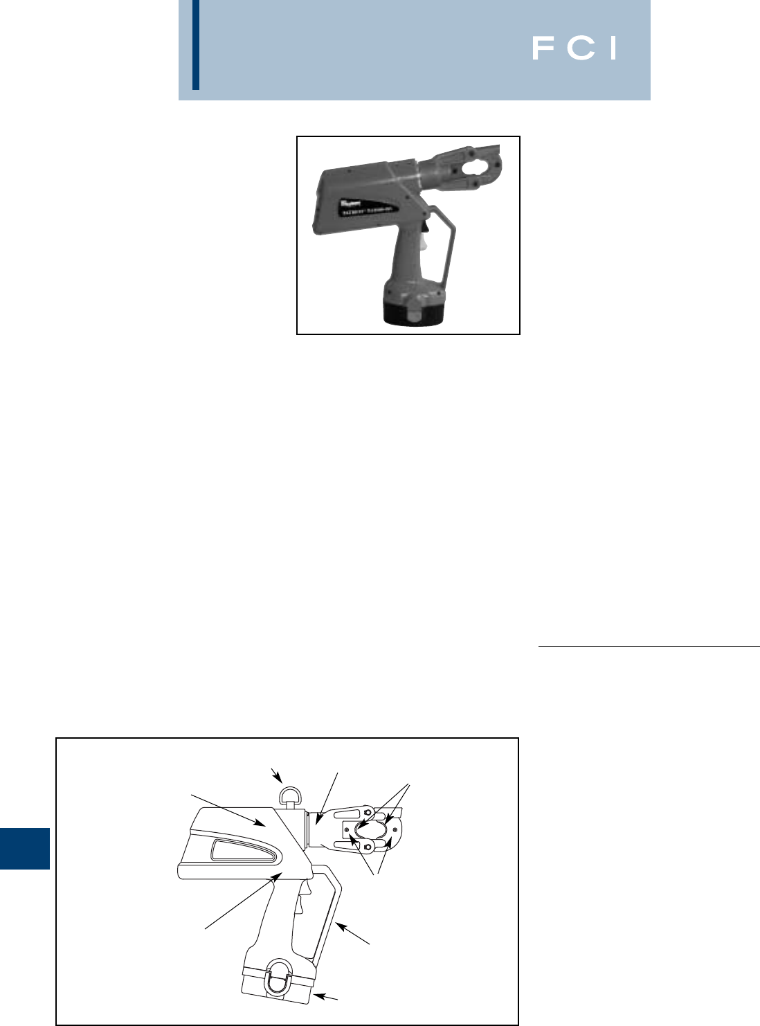
BURNDY
Tooling
N-32
TYPE PATRIOT®
PAT600-18V
BATTERY ACTUATED TOOL –
Hydraulic Self-Contained –
6 Ton
The BURNDY®PAT600-18V battery powered
crimping tool provides a powerful 6 tons of
crimping force and completes a crimp in
approximately 3 seconds. The PAT600-18V is
compact, easy to use and incorporates the
latest in battery tool technology. The PAT600-
18V tool incorporates a specialized latch style
head with enhanced working stroke and
clearance capabilities. The specialized head
allows interference-free closure on tap con-
nections up to the BURNDY®YHD-400 size
including 350 kcmil aluminum connectors.Die
selection with this tool includes all BURNDY®
“W” and “W-VT” style dies which seat in the
permanent “D3”crimping groove. Installation
applications include #8 AWG to 600 kcmil
copper lugs and splices, #8 AWG to 350 kcmil
aluminum lugs and splices (YA-A and YS-A),
and up to 4/0 aluminum tap connections. The
permanent “D3”groove and 180 degree rotat-
able head are standard on the PAT600-18V.
Each PAT600-18V tool uses BURNDY®dies
and off-the-shelf connectors available world-
wide. The PAT600-18V comes equipped with
a high impact formed carrying case to hold
the tool, a battery charger and two batteries.
The case houses up to 10 “W” dies (dies pur-
chased separately). The PAT600-18V uses
industry standard batteries and chargers.The
PAT600-18V comes complete with a 5-year
limited warranty and one year on batteries
and charger.
Features and Benefits
•Battery powered crimp technology.
◊Easy tool operation and portability.
•Advance design high speed pump com-
pletes crimp in approximately 3 seconds.
◊Longer life, efficiency, and reliability.
•Ergonomic design allows one hand opera-
tion for ram advance and ram retraction.
◊User always has one hand free to
manipulate connector and conductor.
•Variable speed trigger.
◊Provides flexibility in speed of ram
advance.
•Ram holds position when trigger is
released.
◊Provides ability to hold the connector
between dies and check for proper
alignment prior to crimping action.
•Mechanical ram release.
◊Reliable ram release (no battery power
consumption).
•Specialized latch head design.
◊Provides enhanced clearance on tap
connectors when compared with compet-
itive designs.
6 TON OUTPUT FORCE
ERGONOMICALLY BALANCED
TOOL DESIGN
180° HEAD ROTATION
SPRING LOADED DIE
RETAINING PINS
FUNCTIONAL D3
DIE GROOVE
SAFETY LANYARD
CONNECTION
TRIGGER GUARD
NI-MH 18 VOLT
BATTERY
SPECIFICATIONS
Crimp Force: 6 Tons (US)
(5.4 metric tons)
Tool Weight: 10.9 lbs (4.9 kg)
Length: 14.5(36.8 cm)
Width: 3.5(8.9 cm)
Height: 13.75(34.9 cm)
Operating Voltage: 18 V-DC
Crimp Time: Approx. 3 seconds
Recharge Time: < 45 mins.
FOR USE ON
•Copper, Aluminum, ACSR, Steel,
Copperweld, Alumoweld, 6201, 5005,
Compressed, Compact, Stranded & Solid
•Installs splices, taps, or terminations:
#8 - 600 kcmil Copper Str. (YA, YA-L,YS,
YS-L)
#8 - 350 kcmil Flex
#8 - 350 kcmil Aluminum (YA-A & YS-A)
ACCESSORIES
•Lanyard: Cat# PT208620
•W Die Holder Cat# WDIETREE
•Battery:
Hi-capacity Cat# BAT18V
(2200 mA-hr)
•Battery with LED light:
(3000 mA-hr) Cat# BAT18VLED
•Charger:
120V-AC Cat# PATCHGR18V
12/24V-DC Cat# BCT/PATDCCHGR
240/250V-AC Cat# PATCHGR250V
•180 degree head rotation.
◊Versatile tool head positioning lets user
get into tight areas easier.
•Uses 18 volt Ni-MH batteries.
◊Eliminates voltage depression or
“memory”.
•Audible pressure “pop-off” valve.
◊Indicates properly completed crimp.
•Permanent D3crimp groove accepts all
“W-Dies”.
◊Uses standard die design with proven
performance.
•PAT600C-18V with covered head is avail-
able.
◊Covered head for impact protection.
•Durable high impact formed carrying case.
◊Provides tool protection and stores all
accessories.
•5-year limited warranty on tool, 1 year on
batteries and charger.
◊Customer satisfaction and support.

BURNDY
Tooling
N-33
TYPE PATRIOT™
PATCUT129ACSR-18V
BATTERY ACTUATED TOOL –
Hydraulic Self-Contained –
Cutter
The BURNDY® PATCUT129ACSR-18V bat-
tery powered cutting tool is compact, fast,
easy to use and incorporates the latest in bat-
tery tool technology. The ergonomic design
allows one hand operation so that the other is
free to manipulate the conductor in the prop-
er cutting position. The PATCUT129ACSR-
18V incorporates a specialized latch style
cutting head that allows interference-free clo-
sure for mid-span cuts. The cutter head
rotates 180 degrees to allow users to get into
tight areas easier. The PATCUT129ACSR-
18V is capable of cutting up to 1.29diameter
copper and aluminum cable, 1113 ACSR,
5/8ground rod, 1/2 rebar, 5/8diameter soft
steel bolts, up to 1/2standard guy strand,
and up to 3/8EHS guy strand.
The PATCUT129ACSR-18V operates on
industry standard 18-volt Ni/MH batteries that
eliminate voltage depression or "memory"
issues. The PATCUT129ACSR-18V comes
equipped with a high impact formed carrying
case to hold the tool, a tool retention lanyard,
a battery charger and two batteries.The PAT-
CUT129ACSR-18V is provided with a 5-year
limited warranty (excluding blades), and 1-
year on batteries and charger.
Made in the USA.
Features and Benefits
•Battery powered cutting technology.
◊Easy tool operation and portability.
•Advance design high-speed pump com-
pletes tough cuts faster.
◊Longer life, efficiency, and reliability.
•Specialized latch head design.
◊Interference free closure for mid-span
cuts.
•Ergonomic design allows one hand opera-
tion.
◊User has one hand free to manipulate
material to be cut.
•180 degree head rotation.
◊Versatile head positioning allows user to
get into tight areas easier.
•Mechanical ram release.
◊Reliable ram release (no battery power
consumption).
•Operates on 18 volt Ni-MH batteries.
◊Eliminates voltage depression or
“memory” issues.
•Durable high impact formed carrying case.
◊Provides tool protection and stores all
accessories.
•5-year limited warranty on tool (excluding
blades) and 1 year on batteries and
charger.
◊Customer satisfaction and support.
SPECIFICATIONS
Tool Weight: 11 lbs.
Length: 14.5
Width: 3.5
Height: 13.5
Operating Voltage: 18 V-DC
Recharge Time: < 45 mins.
FOR USE ON
•Copper Cable: up to 1.29
•Aluminum Cable: up to 1.29
•ACSR: up to 1113 ACSR
•Ground Rod: up to 5/8
•Rebar: up to 1/2
•Soft Steel Bolts: up to 5/8
•Standard Guy Strand: up to 1/2
•EHS Guy Strand: up to 3/8
ACCESSORIES
•Lanyard: Cat# PT208620
•Battery:
Hi-capacity Cat# BAT18V
(2200 mA-hr)
•Battery with LED light:
(3000 mA-hr) Cat# BAT18VLED
•Charger:
120V-AC Cat# PATCHGR18V
12/24V-DC Cat# BCT/PATDCCHGR
240/250V-AC Cat# PATCHGR250V
•Replacement Blades:
Cat# PT10037388
(Moving Blade)
Cat# PT10037384
(Fixed Blade)
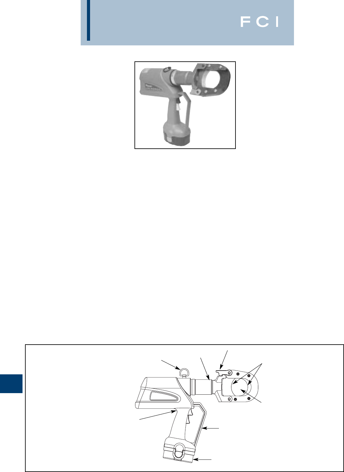
BURNDY
Tooling
N-34
PATRIOT®
PATCUT245CUAL-18V
BATTERY ACTUATED TOOL –
Hydraulic Self Contained
Cutter
The BURNDY®PATCUT245CUAL-18V bat-
tery powered cutting tool is compact, fast,
easy to use and incorporates the latest in bat-
tery tool technology. The ergonomic design
allows one hand operation so that the other is
free to manipulate the conductor in the prop-
er cutting position. The PATCUT245CUAL-
18V incorporates a specialized latch style
cutting head that allows interference-free clo-
sure for mid-span cuts. The cutter head
rotates 180 degrees to allow users to get into
tight areas easier. The PATCUT245CUAL-
18V is capable of cutting up to 2.45diameter
copper and aluminum cable.
The PATCUT245CUAL-18V operates on
industry standard 18-volt Ni/MH batteries that
eliminate voltage depression or "memory"
issues. The PATCUT245CUAL-18V comes
equipped with a high impact formed carrying
case to hold the tool, a tool retention lanyard,
a battery charger and two batteries.The PAT-
CUT245CUAL-18V is provided with a 5-year
limited warranty (excluding blades), and 1-
year on batteries and charger.
Features and Benefits
•Battery powered cutting technology.
◊Easy tool operation and portability.
•Advance design high-speed pump com-
pletes tough cuts faster.
◊Longer life, efficiency, and reliability.
•Specialized latch head design.
◊Interference free closure for mid-span
cuts.
•Ergonomic design allows one hand opera-
tion.
◊User has one hand free to manipulate
material to be cut.
•180-degree head rotation.
◊Versatile head positioning allows user to
get into tight areas easier.
•Mechanical ram release.
◊Reliable ram release (no battery power
consumption).
•Operates on 18-volt Ni/MH batteries.
◊Eliminates voltage depression or
"memory" issues.
•Durable high impact formed carrying case.
◊Provides tool protection and stores all
accessories.
•5-year limited warranty on tool (excluding
blades) and 1-year on batteries and
charger.
◊Customer satisfaction and support.
SPECIFICATIONS
Tool Weight: 14.5 lbs (5.4 kg)
With Battery
Length: 18(45.7 cm)
Width: 3.75(9.5 cm)
Height: 14.75(37.5 cm)
Operating Voltage: 18 V-DC
Recharge Time: < 45 mins.
FOR USE ON
Copper and Up to 2.45O.D
Aluminum Cable: (62.2 mm)
FOR COPPER AND ALUMINUM CABLE
ONLY. DO NOT CUT STEEL, GROUND
ROD, REBAR, OR GUY WIRE.
ACCESSORIES
•
Carrying Case: Cat# PT10044980
•Lanyard: Cat#
PT208620
•Battery:
Hi-capacity Cat# BAT18V
(2200 mA-hr)
•Battery with LED light:
(3000 mA-hr) Cat# BAT18VLED
•Charger:
120V-AC Cat# PATCHGR18V
12/24V-DC Cat# BCT/PATDCCHGR
240/250V-AC Cat# PATCHGR250V
•Replacement Blades:
Cat#
PT10038657
(Moving Blade)
Cat#
PT10040663
(Fixed Blade)
SAFETY LANYARD
ATTACHMENT
180° HEAD
ROTATION
SPECIALIZED LATCH
HEAD DESIGN
PRECISION
CUTTING BLADES
2.45CUTTING
CAPACITY
TRIGGER GUARD
18 VOLT Ni-MH
BATTERY
ERGONOMICALLY BALANCED
TOOL DESIGN
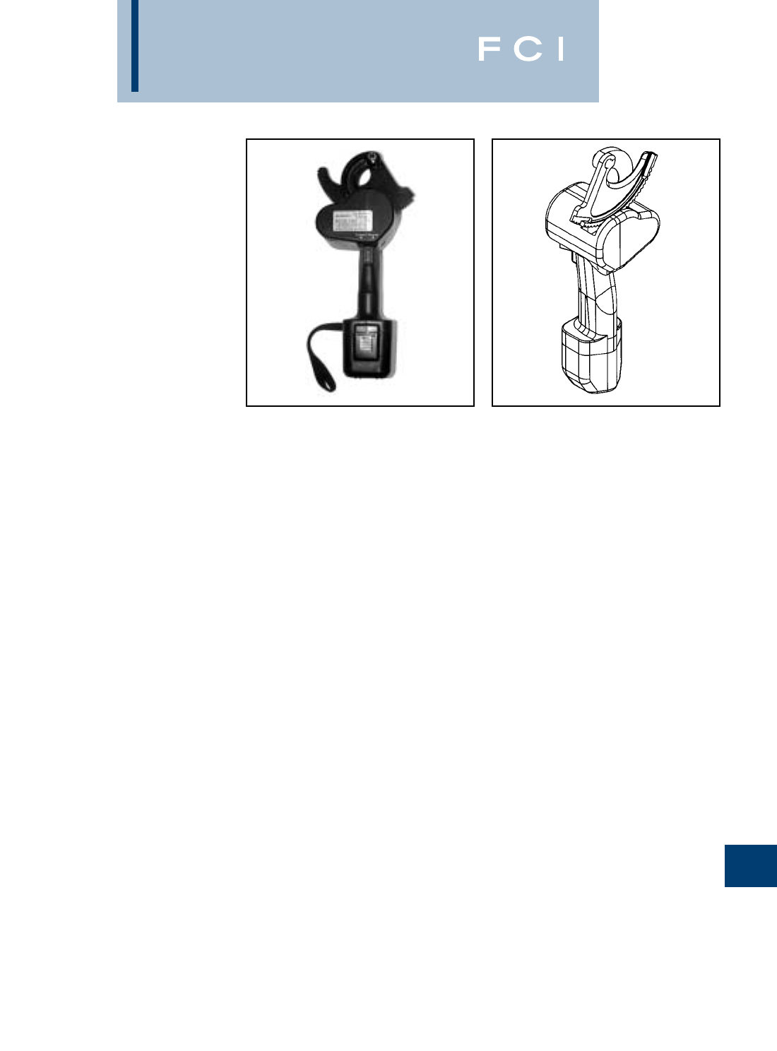
BURNDY
Tooling
N-35
TYPE BCC1000CUAL
BATTERY ACTUATED
CABLE CUTTER
The BURNDY®BCC1000CUAL is a 12-V-DC
battery actuated cable cutter capable of cut-
ting up to 750 kcmil hard drawn copper cable,
and up to 1000 kcmil soft drawn copper and
up to 2O.D. aluminum cable. DO NOT CUT
STEEL or ACSR.The BCC1000CUAL comes
with battery powered cutting tool, sealed nick-
el cadmium 12V battery, 120V AC charger,
carrying case, and wrist loop which provides
added security when making cuts overhead.
The BURNDY®BCC1000CUAL is designed
to cut copper and aluminum cables in a limit-
ed amount of space. The BCC1000CUAL
makes fast reliable cuts without stress to the
user. Just squeeze the trigger and it will cut
through your toughest copper and aluminum
cables. The BCC1000CUAL has a three-way
switch (forward, reverse, and neutral) which
allows the user to make partial cuts, back off
cables, or make adjustments during cutting.
The battery charge time is approximately 1
hour for a fast charge (80%), 4 to 6 hours for
a quick charge, and 14 to 16 hours for a stan-
dard charge (100%). The 12V battery can be
recharged approximately 1,000 times.
The BCC1000CUAL (excluding cutting
blades) is warranted to be free of defects in
material and workmanship for a period of 90
days, except in the case of abuse or
modification.
SPECIFICATIONS
Specifications Description
Cutting Tool:
Drive Unit: 12.0V DC Motor
Dimensions: 4L 4.5W 14.5H
Weight: 6 lb
Cutting Capacity: 1000 kcmil soft drawn
copper, 750 kcmil hard
drawn copper and up to
2O.D. aluminum
Battery:
Battery Type: Sealed nickel cadmium
Voltage: 12.0V DC
Rated Capacity: 1.2A/hr
Charge Time: Fast, approx. 1 hour
Quick, 4-6 hours
Standard, 14-16 hours
Dimensions:
2.75L 2.7W 4.75H
Weight: 1.4 lb
Battery Charger:
Input Voltage: 120V AC
Input Frequency: 60 Hz
Input Current 110/120V
Dimensions: 5.7L 3W 2.8H
Weight: 2.2 lb
FOR USE ON
Maximum conductors accommodated:
750 kcmil hard drawn copper
1000 kcmil soft drawn copper
1000 kcmil alumimum
ACCESSORIES
Catalog Number Item Description
BCCBAT12V BCC1000CUAL Battery
BCCCHGR BCC1000CUAL Charger
BCCCASE BCC1000CUAL
Carrying Case
RP50RP03 BCC1000CUAL
Moving Blade
RP50RP02 BCC1000CUAL
Fixed Blade
FEATURES
•Hook head design.
•Three way switch.
•Hardened steel blades.
•Ergonomic design.
•Wrist loop.
BENEFITS
•Simplifies conductor cutting and allows
working in tight spaces.
•Allows backing off cable, partial cuts,
and adjusting during cutting.
•Helps ensure consistent cuts and longer
blade life.
•Prevents hand/wrist injury.
•Withstands rugged use. Resists oil
and solvents.
•Added security when cutting cables
overhead.
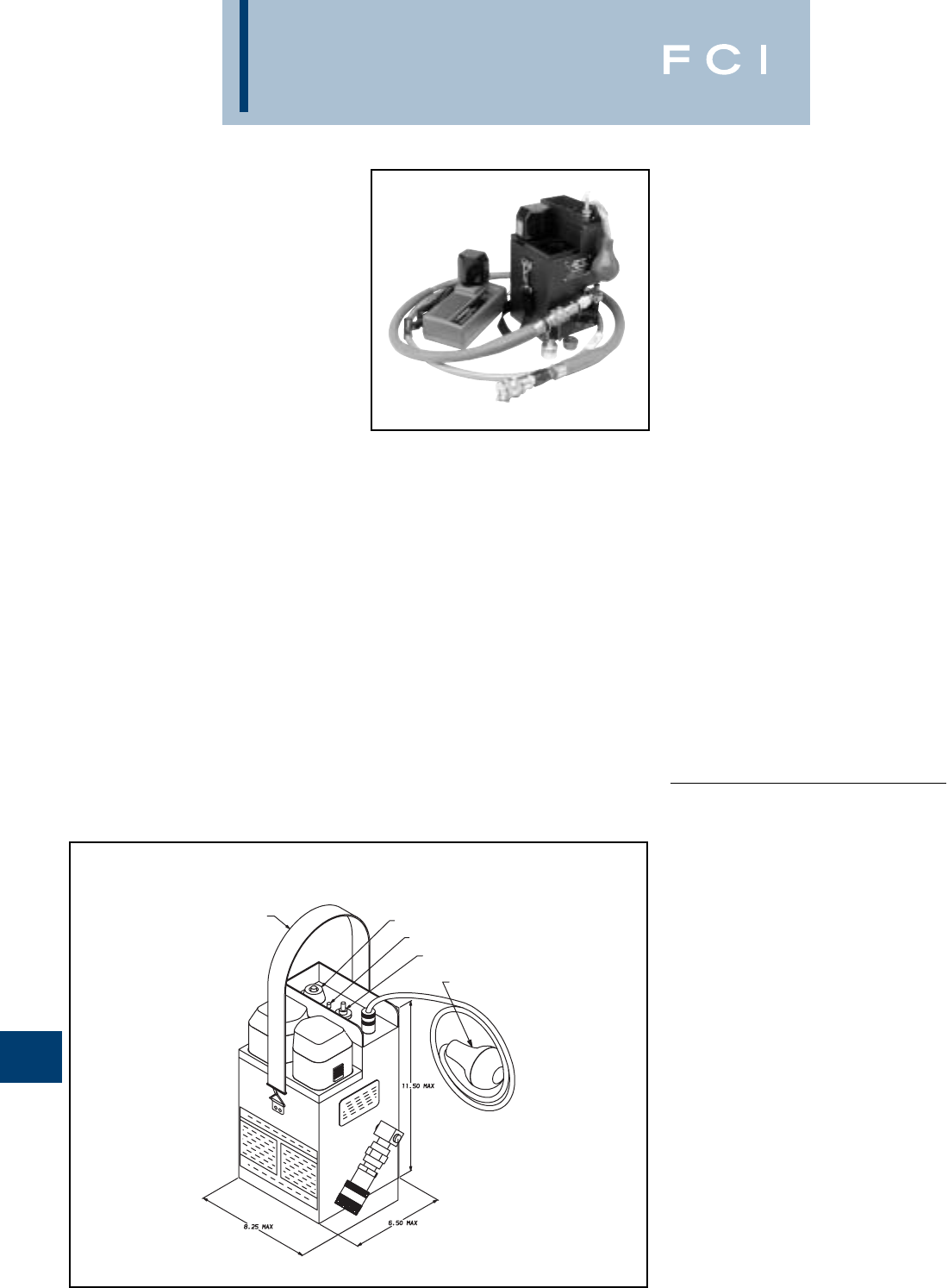
BURNDY
Tooling
N-36
TYPE Y700DC-1B
Y-DC BATTERY POWERED
HYDRAULIC PUMP
HYDRAULIC OUTPUT
PRESSURE OF:
10,000 PSI
The lightweight, portable, battery powered
hydraulic pump unit for use with almost all
BURNDY®HYPRESS™ remote tool heads
and cutters. The pump will provide approxi-
mately 30 operations before requiring a
recharge of the batteries, which can be
recharged in under 15 minutes, utilizing the
rapid charger provided. The high capacity 12
VDC batteries and charging system will allow
1,000 charge/discharge cycles per battery
providing more than double the life of other
batteries. The pump is supplied with a dielec-
tric grade 6’ long hydraulic hose, 1 rapid bat-
tery charger, and 2 rechargeable batteries.
Also included is an air-bulb control switch that
allows remote operation of the pump, or users
may opt for the built-in switch to operate the
unit. The Y700DC-1B provides consistent,
reliable compression connections due to the
factory-set “pop-off” pressure relief valve. The
full automatic operation allows the operator to
control functions such as “Advance”, “Hold”,
and “Retract” at will, truly making the
Y700DC-1B a versatile, go-anywhere pump
unit.
PUSH BUTTON CONTROL SWITCH
BATTERY STATUS INDICATOR
ON/OFF CONTROL SWITCH
AIR BULB CONTROL
SINGLE OR DUAL
BATTERY OPERABLE
CARRY STRAP
SPECIFICATIONS
MOTOR
Type: Electric (12V-DC)
Power Source: 12V-DC batteries (2)
Max Output: 280 watt
Max Draw: 35 amp
PUMP
Operating PSI: Low-0.98 Mpa
High -68.6 + 3.4 Mpa
Hydraulic Fluid: BURNDY®ALFLUID™
Control Type: Air-bulb or switch
COMPLETE UNIT
DIMENSIONS
Weight: 15-1/2 lbs. with fluid
and two batteries
Height: 11.5
Width: 8.25
Depth: 6.5
FOR USE ON
Battery
Pump Psi Tools and Cutters
Y700DC-1B 10,000 Y34BH, Y35BH, Y35BH-4,
Y39BH, Y75OBH, Y75OBH-2,
Y644MBH, Y45, Y45-1, Y46,
Y46-C, RHCC Series Cutters
ACCESSORIES
•Steel Carry Case: Cat# YDC-CASE
Holds pump (w/2 batteries), Charger,
6Hose, and air-bulb control
•Batteries: Cat# BAT12B
•Charger: Cat# BATCHGR
BENEFITS (Continued)
•Unit allows operation with only 1 battery
while the other recharging the other.
•Built-in device prevents operation when
batteries have insufficient power to com-
plete crimping cycle.
•Able to operate in remote locations without
electric power source.
Features
FEATURES
•Lightweight, easy to carry.
•Two modes of operation.
•Transparent reservoir.
•Charged/Low battery indicator.
•Rapid battery recharger
(less than 15 mins.).
•Allows use of wide range of remote
tool heads and cutters.
BENEFITS
•Lightweight and easy to lift, carry, and
transport to/around job site.
•Advance and hold feature permits final
inspection before completing crimp cycle.
•Transparent reservoir allows viewing for
daily checking of fluid level.
•Choice of operation method with either
mounted switch or remote air-bulb
control devices.
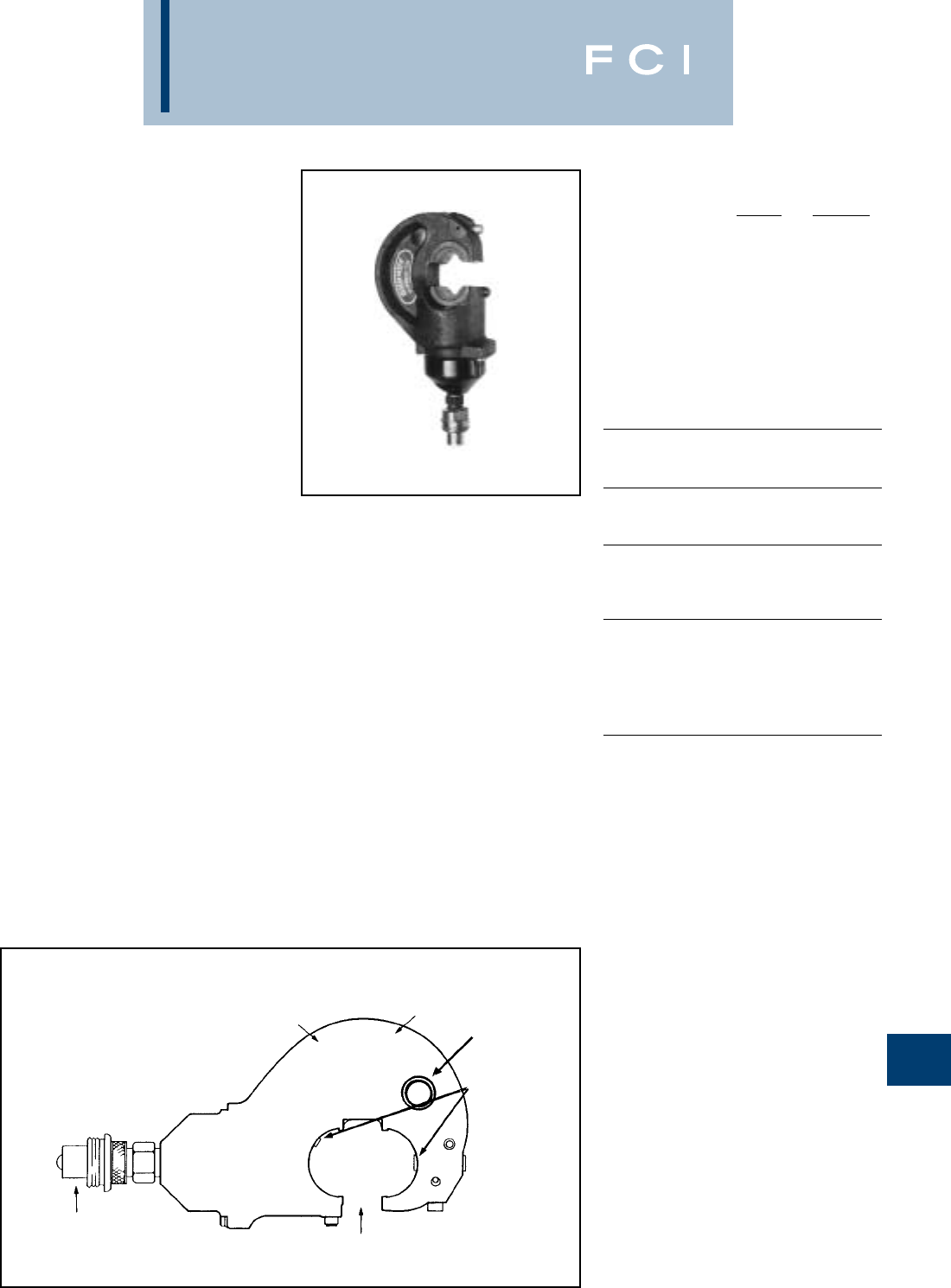
BURNDY
Tooling
N-37
TYPE Y35BH
HYPRESS™
10,000 PSI
REMOTE POWER OPERATED
COMPRESSION TOOLS
The Y35BH...series remote head is designed
for remote power operation and incorporates
the same C-shaped head as the Y35. The
hook style head with extensive ram travel pro-
vides for easy tapping and splicing of over-
head lines as well as HYGROUND™ com-
pression grounding systems.
The remote power operated Y35 heads are
available covered with 3/16molded rubber
cover for tool impact protection.
Order head, hose, pump, dies and acces-
sories separately. Five-year limited warranty.
BENEFITS
•Easy tool removal from line conductor after
compression taps are installed with the
open “C” shaped head.
•Easily lifted into working position using
the lifting eye.
•Easy die changing plus secure die align-
ments provided with the positive die
lock buttons.
•Long life expectancy is provided with
heavy duty reinforced back.
•Mates with all universal type Hot-stick
tooling.
•Rapid assembly and disassembly is
provided with the quick disconnect
hydraulic fitting.
•Type Y35BH-4 head is covered with
3/16molded rubber.
•5-year limited warranty.
HEAVY-DUTY
REINFORCED BACK C-SHAPE HEAD
LIFTING EYE
POSITIVE DIE
LOCK BUTTONS
LARGE JAW
OPENING
QUICK DISCONNECT
HYDRAULIC FITTING
FEATURES
SPECIFICATIONS
Y35BH Y35BH-4
Operating pressure: 10,000 psi 10,000 psi
Jaw Opening: .95.95
Force developed: 12 tons 12 tons
Weight (less case): 8 lbs. 9 lbs.
Maximum width: 4-3/46
Maximum height: 9-1/410-1/2
Molded covering: — Yes
FOR USE ON
CONNECTOR CONDUCTOR
TYPE RANGE
Tension Sleeves Copper #8 sol.-500 kcmil
Aluminum #6 sol.-636 kcmil
ACSR #4 -556.5 (26/7)
Taps #14-556.5 ACSR (18/1)
Aerial Cable Copper #6 str.-500 kcmil
Connectors Aluminum #4 str.-600 kcmil
Code Conductors Copper #8 str.-750 kcmil Term
(400 kcmil splice)
Aluminum #6 str.-750 kcmil Term
(400 kcmil splices)
HYGROUND™ Copper #6-500 kcmil
Compression (cable/cable)
Grounding
Copper #6-250 kcmil
(cable/grd. rod)
Ground Rods 1/2–3/4
Y35BH Variations:
Y35BH Head Only.
Y35H Includes the Y35BH HYPRESS™
head, PT29402-1 universal
hot-stick adapter, and steel
carrying case.
Y35B Includes the Y35BH HYPRESS™
head, PT91 steel reinforced
hydraulic hose and an FP10
foot pump in a steel carrying
case. Note: NOT for use on
energized conductors.
Y35BH-4 Permanent Molded Rubber Head.
The Y35BH-4 is covered with
3/16molded rubber for tool
impact protection (not insulation).

BURNDY
Tooling
N-38
TYPE Y39BH
HYPRESS™
10,000 PSI
REMOTE POWER OPERATED
COMPRESSION TOOL
The Y39BH Remote Head is designed for
remote power operation and incorporates the
same small head as the Y39. Convenient die
holder with recessed spring latch makes it
easy to remove or lock into position. Dies are
located and held in position with positive
push button die locks. Dies sold separately.
Five-year limited warranty.
SPECIFICATIONS
Operating pressure: 10,000 psi
Force developed: 12 tons
Weight: 6-1/2 lbs.
Maximum head width: 3-1/8
Minimum height: 9-1/8
FOR USE ON
COPPER
#6 AWG-750 kcmil str.
Code Cable
N30-N650 Navy Cable
Flexible and Extra Flexible
Terminals-Uninsulated
YA, YA-L, YA-LB, YGH, YGHA
Splices and Tees-Uninsulated
YS, YS-L, YS-LB, YS-T, YSP-T, YST
COPPER-AN or AIR
#6 AWG-4/0 str. Code Cable
AN6-AN 4/0 Aircraft Cable
Flexible and Extra Flexible
Terminals-Uninsulated
YAV-L Box, YAV-L, YAV-Rs Box, YAV-RS
Splices and Tees-Uninsulated
YSV-L Box, YSV-L
COPPER-INSULATED TERMINALS
#8-AWG-2/0 str. Code Cable
AN8-AN 2/0 Aircraft Cable
Flexible and Extra Flexible
Terminals-Insulated
YAEV-L Box, YAEV-L, YAEV-RS Box,
YAEV-RS, YAEV-RH
COPPER - TAPS
#12 AWG Solid-250 kcmil
Taps-YC-C, YGHC-C, YGHP-C, YGHR-C,
YH, YCHC
ALUMINUM
#8 AWG-750 kcmil str.
Code Cable
Terminals-YA-A
Splices-YS-A, YS-AT, YRB
ALUMINUM
#6 str.-500 kcmil
Taps-YFD, YFN, YFO
BENEFITS
•Easy to work in small tight spaces with
only a 3-1/8wide compression head.
•Easy to locate and hold dies in position
with the positive push button die locks plus
die changing is accomplished easily with-
out ball checks or set screws.
•Easy to remove or lock into position die
holder with recessed spring latch plus
leather strap to prevent loss.
•Compression terminal, tap and splice
connectors are UL listed and CSA certified
when installed with the Y39 tool and
recommended die set.
•Very versatile tool that is able to work
with 10,000 PSI pumps.
•5-year limited warranty.
QUICK DISCONNECT
HYDRAULIC FITTING
RECESSED DIE
RETAINER
SPRING LATCH
SMALL 3 1/8”
WIDE HEAD
POSITIVE PUSH
BUTTON DIE
LOCKS
LEATHER DIE
RETAINER
STRAP
FEATURES
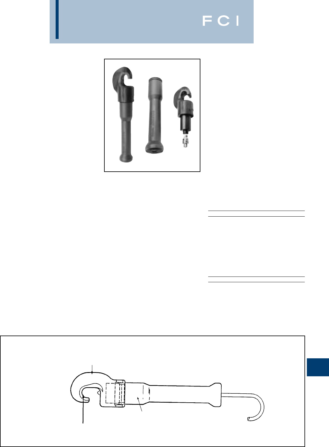
BURNDY
Tooling
N-39
TYPE Y34BH
HYPRESS™
HYDRAULIC TOOL - REMOTE
OPERATED 10,000 PSI
9 ton remote power operated hydraulic tool.
The Y34BH HYPRESS™ tool is designed for
remote hydraulic power operation. Its new
10,000 PSI operating pressure makes it
easily adaptable to most remote power sys-
tems. Its small C-shaped head is light-weight,
compact and with a relatively large jaw
opening ideally suited for NETWORK
UNDERGROUND systems. The tool comes
standard with permanent molded head with
3/16" rubber and includes a separate molded
rubber boot that covers the lower body and
hydraulic coupler for tool impact protection.
Together, with other BURNDY®hydraulic
accessories, the Y34BH HYPRESS™ tool
may be used on lines. The Y34BH-1 has a ten
foot non-conductive 10,000 PSI hose
attached at the factory. The Y34BH Series
tool has a 5-year limited warranty.
BENEFITS
•Allows for easy placement and removal
from continuous conductor lengths.
•Long life.
•Fast ram retraction.
•Moldedrubber covering on head, body, and
hose fittings.
•Standard operating pressure.
•Ease in handling.
•Greater reliability.
•Reduced tool life cycle cost.
•5-year limited warranty.
MOLDED RUBBER
COVERING
COMPACT “C” SHAPED
FORGED HEAD
MOLDED RUBBER BOOT
LIGHTWEIGHT
DESIGN
ACCOMMODATES
“B” DIES
HEAVY DUTY
RETURN SPRING
OPERATES ON
STANDARD
10,000 PSI PUMPS
FEATURES
SPECIFICATIONS
Operating pressure: 10,000 psi
Jaw opening: 1-1/2
Max force generated: 9 Tons
Head and body rubberized
Accommodates “B” dies
Head length: 11-1/2
Overall dimensions: 16-3/4(incl. boot)
Total weight: Approx. 8 lbs.
FOR USE ON
• Copper #4-500 kcmil str.
Welding Cable-350 kcmil
N40 to N500 Navy Cable
Flexible and Extra Flexible
#4 to 4/0 Aircraft Cable
Hylugs™-Terminals-Uninsulated
Hylinks™-Splices and Tees-Uninsulated
• Hycrabs-Burndy Network Connector System.
Copper #4-500 kcmil str.
Aluminum-#6-300 kcmil
MAX. CONDUCTOR
INSTALLATION DIE SIZE
Nest Indentor Copper Aluminum
B4CD Y34PA #6 STR.
B1CD Y34PA #4 STR.
B26D Y34PA #2 STR.
B26D Y34PR-5 #1 STR.
B27D Y34PR-5 1/0 STR.
B29D Y34PR-5 2/0 STR.
B30D Y34PR-5 3/0 STR.
B31D Y34PR-5 4/0 STR.
B32D Y34PR-5 250 kcmil
No die req’d. Y34PR-11 300 kcmil
MAX. CONDUCTOR
INSTALLATION DIE SIZE
Nest Indentor Copper Aluminum
B4CD Y34PR #4 STR.
B2CD Y34PR #2 STR.
B1CD Y34PR #1 STR.
B25D Y34PR 1/0 STR.
B26D Y34PR 2/0 STR.
B27D Y34PR 3/0 STR.
B28D Y34PR 4/0 STR.
B29D Y34PR 250 kcmil
B30D Y34PR 300 kcmil
B31D Y34PR 350 kcmil
No die req’d. Y34PR 500 kcmil
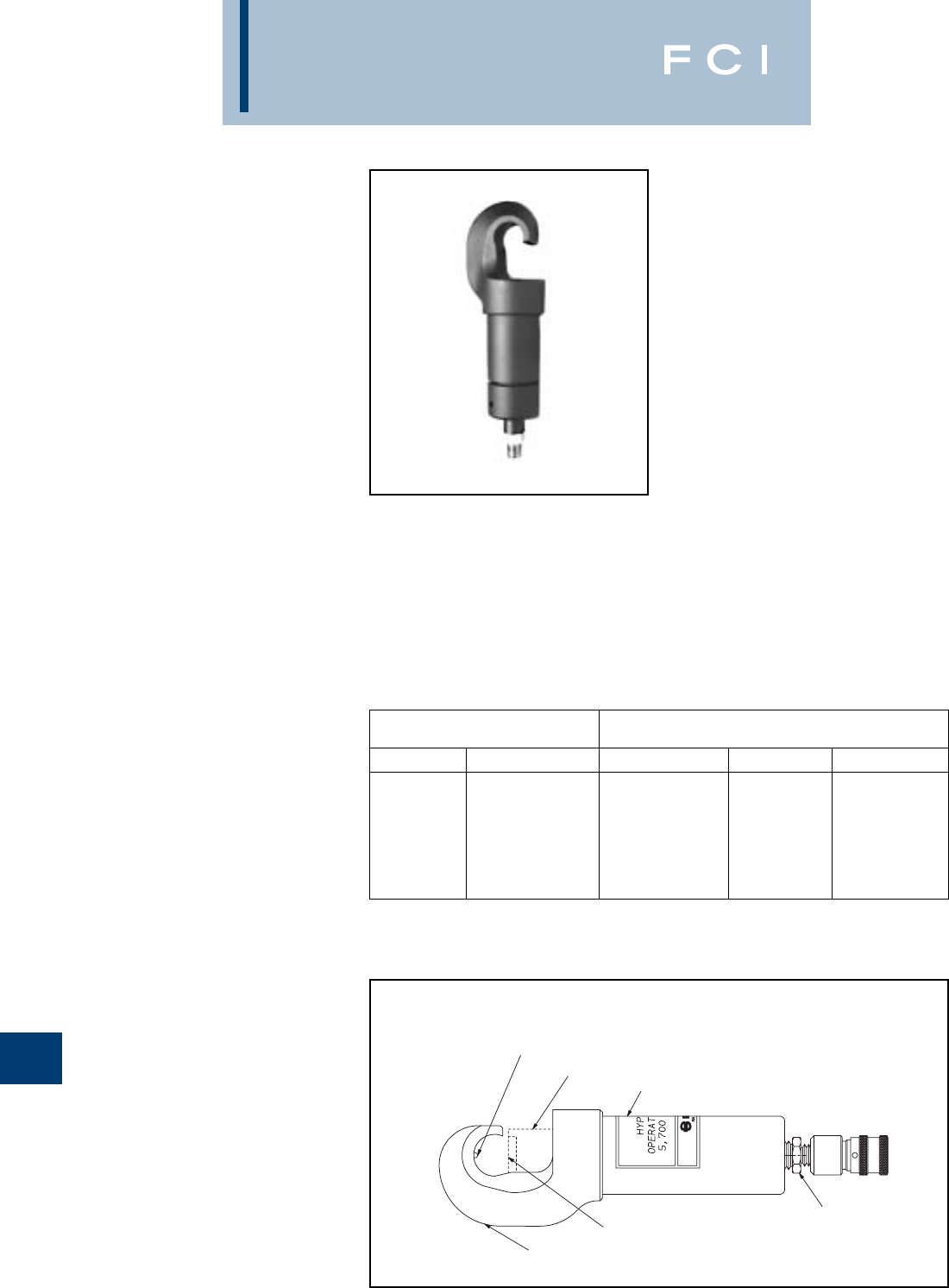
BURNDY
Tooling
N-40
TYPE Y29BH
HYPRESS™ 6000 PSI
HYDRAULIC TOOL -
REMOTE OPERATED
4.5 Ton remote power operated hydraulic tool.
The Y29BH HYPRESS™ tool is designed for
remote hydraulic power operation. Its small,
'C' shaped head is lightweight, designed for
use in confined areas, where visibility and
space is limited. Accommodates D-(series)
nest dies and Y29-(series) indentor dies, for
use with code or flex connector/conductor
applications. Ideal for OEM applications. Dies
sold separately. The Y29BH has a 5-year
limited warranty.
SPECIFICATIONS
Operating Pressure: 6000 psi
Height: 3
Length: 10.75
(including coupler fitting)
Head Width: 1.15
Jaw Opening: 1.2
Weight: 5 lbs
Output Force: 4.5 tons (9000 lbs)
Crimp Type: Nest/Indentor
FOR USE ON
COPPER #8 - 4/0 AWG, code/flex
Nylon Insulated Lugs
(Connectors meet MIL-T-7928 requirements)
•YAEV-L, YAEV-H, YAEV-RS, YAEV-RH
Non-Insulated Lugs
(Connectors meet MIL-T-7928 requirements)
•YAV-L, YAV-R, YAV-RS
Non-Insulated Splices
(Type YSV-L connectors UL Listed, CSA
Certifed)
•YSM, YSV-L
(Consult ‘Section B' of Catalog for detailed
connector descriptions)
BENEFITS
•Easy placement/removal on continuous
conductor lengths.
•Lightweight, portable head design
•Companion tool of Y29NC pneumatic
HYPRESS™.
•Installs a wide variety of lugs and splices
•Ideal for AN, flex and code conductor
terminations.
•5-year limited warranty.
NEST DIE
LOCATION RAM FULLY
EXTENDED OPERATING
PRESSURE LABEL
HYDRAULIC
COUPLER
INDENTOR
DIE LOCATION
‘C’ SHAPED HEAD
FEATURES
UNINSULATED MAXIMUM INSULATED
CONNECTORS CONDUCTOR CONNECTORS
NEST IND. SIZE NEST IND
DV8L-1 Y29PL #8 AWG DEV8L Y29PLE-1
DV6L Y29PL #6 AWG DEV6L Y29PLE-1
DV4L Y29PL #4 AWG DEV4L Y29PLE-1
DV2L Y29PL #2 AWG DEV2L Y29PLE
DV1L Y29PL #1 AWG DEV6L Y29PLE
DV25L Y29PL 1/0 AWG DEV25L Y29PLE
DV26L Y29PL 2/0 AWG DEV26L Y29PLE
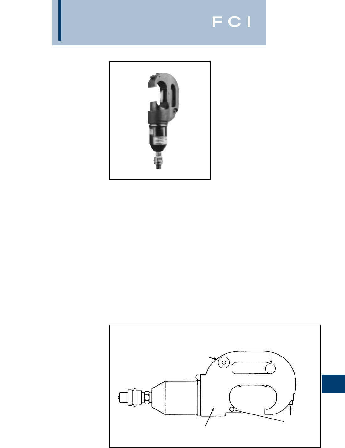
BURNDY
Tooling
N-41
TYPE Y750BH
HYPRESS™
10,000 PSI
12 TON REMOTE
POWER OPERATED
HYDRAULIC TOOL
CONDUCTOR RANGE:
#14-750 kcmil AL/CU
#4-556.5 kcmil ACSR
12 ton remote power operated hydraulic tool.
The Y750BH HYPRESS™ incorporates a
wide mouth (1.65") C-shaped head for all
compression applications. The hook style
head provides for easy tapping, splicing, and
terminating of overhead lines as well as the
full range of HYGROUND™ compression
grounding system connectors, NEC cable
connections and N30-N650 Navy cable appli-
cations.
All standard BURNDY®Y35 series U dies fit
the Y750BH HYPRESS™. Dies and acces-
sories sold separately.
The Y750BH-2 has a permanently molded
rubber head and includes a separate rubber
molded boot that covers the lower body and
hydraulic fitting for tool impact protection.
Five-year limited warranty.
BENEFITS
•Covers a wide range of applications and
provides easy tool removal from continu-
ous conductors with its C-shaped head
(1.65opening).
•Easy die change out and retention within
exposed positive die lock buttons.
•Uses all standard BURNDY®U-dies.
•Y750BH-2 provides molded rubber cover-
ing on head, body and hose fittings.
•Hot stick adapter sold separately.
•Infinitely rotatable head, so hydraulic
couplers won’t easily loosen.
•5-year limited warranty.
BOTH DIE
RELEASE
BUTTONS
EXPOSED
HEAVY DUTY HEAD ROTATES
360° SO HYDRAULIC COUPLERS
WON’T LOOSEN
LIFTING EYE HOLE
MODULAR
COMPONENT
DESIGN
HOT STICK
ATTACHMENT
STANDARD ON
ALL VERSIONS
FEATURES
SPECIFICATIONS
Y750BH Y750BH-2
Operating pressure: 10,000 psi 10,000 psi
Force developed: 12 tons 12 tons
Jaw opening: 1.651.65
Length: 1218.93
(includes boot)
Weight: 10.3 lbs. 11.8 lbs.
Head width: 4.434.92
Molded Covering: — Yes
FOR USE ON
•Tension Sleeves
Copper #8 sol-500 kcmil
Aluminum #6 sol.-587-2 kcmil
ACSR #4-556.5 kcmil
•Taps
Copper #14 solid 500 kcmil
Aluminum #6-500 kcmil
•Aerial Cable
Copper #6-500 kcmil
•Terminals and Splices
Aluminum #8-750 kcmil
Copper #8-750 kcmil
ACSR #4-556 kcmil
•HYGROUND™(Compression Ground)
Copper #6-500 kcmil
(cable/grd. rod)
Ground Rods 1/2 "-1" Diameter
ACCESSORIES:
Cat. No.:
PT23484
Description:
Hot stick adapter.

BURNDY
Tooling
N-42
TYPE KOMPRESSOR™
LPHY750
REMOTE OPERATED 12 TON
LOW PRESSURE HYDRAULIC
COMPRESSION TOOL
The BURNDY®LPHY750 KOMPRESSOR™
is a lightweight, compact, low pressure,
hydraulic 12 ton crimping tool. The LPHY750
is double acting for hydraulic ram advance
and retract. The KOMPRESSOR™ also has
an industry exclusive spring back up for ram
retraction in case of loss of hydraulic pres-
sure. The LPHY750 comes equipped with an
ergonomic handle designed for better
balance, which helps lessen fatigue to the
operator.
The LPHY750 KOMPRESSOR™ features
the BURNDY®Y750 tool head with a 1.65
jaw opening capable of using all industry
standard BURNDY®“U” dies. The LPHY750
also has an industry exclusive visual crimp
indicator to assure the operator of a properly
completed crimp. The LPHY750 also has an
audible crimp indicator.
The LPHY750 is powered directly from open
center or closed center hydraulic tool circuits
present on most utility line trucks or can be
operated from individual low-pressure
hydraulic power units. The LPHY750 can be
switched from open center to closed center
operation with a simple external adjustment.
The LPHY750 does not require any additional
tooling such as boosters, intensifiers, or hand
controls in the bucket. Five-year limited
warranty.
SPECIFICATIONS
LPHY750Flow Rate: 3 - 9 GPM
(11 - 34 LPM)
Operating Pressure: 1,500 - 2,500 psi
(103 - 172 BAR)
Force Developed: 12 Tons
Weight: 21 lbs (9.5 kg)
Overall Length: 20.65 in (524 mm)
Width: 15 in (381 mm)
Jaw Opening: 1.65 in (42 mm)
Max. Back Pressure: 250 psi (17 BAR)
Crimp Time: Approximately
2 seconds
FOR USE ON
•Tension Sleeves
Copper #8 sol - 500 kcmil
Aluminum #8 sol - 587.2 kcmil
ACSR #4 - 556.5 kcmil
•Taps
Copper #14 sol - 500 kcmil
Aluminum #8 sol - 500 kcmil
•Aerial Cable
Copper #6 - 500 kcmil
•Terminals and Splices
Copper #8 - 750 kcmil
Aluminum #8 - 750 kcmil
ACSR #4 - 556.5 kcmil
•HYGROUND™
Copper #8 - 500 kcmil
Ground Rods 1/2- 1diameter
ACCESSORIES
Hoses:
Cat No. LPHTHOSNCR66668OP
Direct connect 8non-conductive hose set
Cat No. LPHTHOSNCR666610OP
Direct connect 10non-conductive hose set
*Cat No. LPHTHOSNCR66668
8non-conductive hose set
*Cat No. LPHTHOSNCR666610
10non-conductive hose set
Hydraulic Fittings:
Cat No. LPHTHTMANOSE66
Male coupler 3/8HTMA
Cat No. LPHTHTMABODY66
Female coupler 3/8HTMA
Cat No. LPHTADPSMFOP66
Swivel Adapter
*These hoses are used with the
LPHTADPSMFOP66 swivel adapter.
BENEFITS
•Visual and audible crimp indicator assures
properly completed crimps with 12 tons of
force.
•Covers a wide range of applications with
its 1.65jaw opening.
•350head rotation for versatile tool head
positioning allowing the user to get into
tight areas easier.
•Uses all standard BURNDY®“U” dies.
•Operates on open center or closed center
hydraulic systems.
•Ergonomic handle design for better
balance and helps lessen fatigue.
•Double acting tool for hydraulic ram
advance and retraction.
•Spring back up for ram retraction if
hydraulic system shuts down.
•5-year limited warranty.
Open Center,
Closed Center
Adjustment
Visual Crimp
Indicator
Ergonomically Balanced Tool
and Handle Design
Internal Ram Retraction
Backup Spring
12 Tons of
Output Force
Y750 Tool Head
Exposed Die
Release Buttons
for BURNDY®
Style “U” dies
Large 1.65Jaw
Opening
Activation Trigger

BURNDY
Tooling
N-43
TYPE KOMPRESSOR™
LPHY46
REMOTE OPERATED 15 TON
LOW PRESSURE HYDRAULIC
COMPRESSION TOOL
The BURNDY®LPHY46 KOMPRESSOR™ is
a compact, low pressure, hydraulic 15 ton
crimping tool. The LPHY46 is double acting
for hydraulic ram advance and retract. The
KOMPRESSOR™ also has an industry
exclusive spring back up for ram retraction in
case of loss of hydraulic pressure. The
LPHY46 comes equipped with an ergonomic
handle designed for better balance, which
helps lessen fatigue to the operator.
The LPHY46 KOMPRESSOR™ features the
BURNDY®Y46 tool head with a 2jaw open-
ing capable of using all industry standard
BURNDY®“P” dies, and “U” dies, with
PUADP-1 adapter. The LPHY46 has a visual
and audible crimp indicator that assures
properly completed crimps with 15 tons of
force.
The LPHY46 is powered directly from open
center or closed center hydraulic tool circuits
present on most utility line trucks or can be
operated from individual low-pressure
hydraulic power units. The LPHY46 can be
switched from open center to closed center
operation with a simple external adjustment.
The LPHY46 does not require any additional
tooling such as boosters, intensifiers, or hand
controls in the bucket. Five-year limited
warranty.
SPECIFICATIONS
LPHY46 Flow Rate: 3-9 GPM (11-34 LPM
)
Operating Pressure: 1,550-2,500 psi
(107-172 BAR)
Force Developed: 15 Tons
Weight: 28.5 lbs (13 kg)
Overall Length: 18 in (465 mm)
Width: 6 in (153 mm)
Max. Back Pressure: 250 psi (17 BAR)
Crimp Time: Approximately
2 seconds
FOR USE ON
CONNECTOR CONDUCTOR
TYPE RANGE
Copper
Ter minals-grounding to 500 kcmil
#8-AWG str. - YGA, YGHA, YGF
1500 kcmil Terminals-Uninsulated #8 to
Code Cable 1500 kcmil YA, YA-2N, YA-L
Navy Cables YA-LB, YA-TC, YA-2LN, YAB-4N
Flexible and
Extra Flexible YAV-L Box, YAV-L,
1/2-1Ground YAV-RS Box, YAV-RS,
Rods YA-TC-FX
Terminals-Insulated #8 to 2/0
YAEV-L Box, YAEV-L,
YAEV-H, YAEV-RS, YAEV-RH
Splices #8 to 1500 kcmil
YS, YS-T, YS-L, YS-LB, YST,
YSP-T, YGS, YGHS
Taps
YH, YCHC #14 to 1000 kcmil
YC-C to 4/0 AWG
Taps-Grounding to 500 kcmil
YGHC-C, YGHP-C, YGHR-C
Aluminum Terminals
#8 AWG- YA-A, AYP, AYPO
1250 kcmil Splices
Code Cables YS-A, YS-AT, YRB
Taps
YFD, YFN, YFO, YFR
ACSR See Burndy Overhead
Transmission and Distribution
Catalog Module
ACCESSORIES
Cat No. PUADP-1
“U” - Die adapter
Cat No. P15K
Cutter die (max. 1.2dia.)
Hoses:
Cat No. LPHTHOSNCR66668OP
Direct connect 8non-conductive hose set
Cat No. LPHTHOSNCR666610OP
Direct connect 10non-conductive hose set
*Cat No. LPHTHOSNCR66668
8non-conductive hose set
*Cat No. LPHTHOSNCR666610
10non-conductive hose set
Hydraulic Fittings:
Cat No. LPHTHTMANOSE66
Male coupler 3/8HTMA
Cat No. LPHTHTMABODY66
Female coupler 3/8HTMA
Cat No. LPHTADPSMFOP66
Swivel Adapter
*These hoses are used with the
LPHTADPSMFOP66 swivel adapter.
BENEFITS
•Visual and audible crimp indicator assures
properly completed crimps with 15 tons of
force.
•Covers a wide range of applications with
its 2jaw opening.
•350head rotation for versatile tool head
positioning allowing the user to get into
tight areas easier.
•Uses all standard BURNDY®“P” dies, and
“U” dies with PUADP-1 adapter.
•Operates on open center or closed center
hydraulic systems.
•Ergonomic handle design for better
balance and helps lessen fatigue.
•Double acting tool for hydraulic ram
advance and retraction.
•Spring back up for ram retraction if
hydraulic system shuts down.
•5-year limited warranty.
Open Center,
Closed Center
Adjustment
Visual Crimp
Indicator
Ergonomically Balanced Tool
and Handle Design
15 Tons of Output Force
Y46 Tool Head
Exposed Die
Release Buttons
for BURNDY®
Style “P” Dies or
“U” Dies with
Adapter
Large 2Jaw Opening Variable Speed Trigger
350° Head Rotation
Lifting Eyes
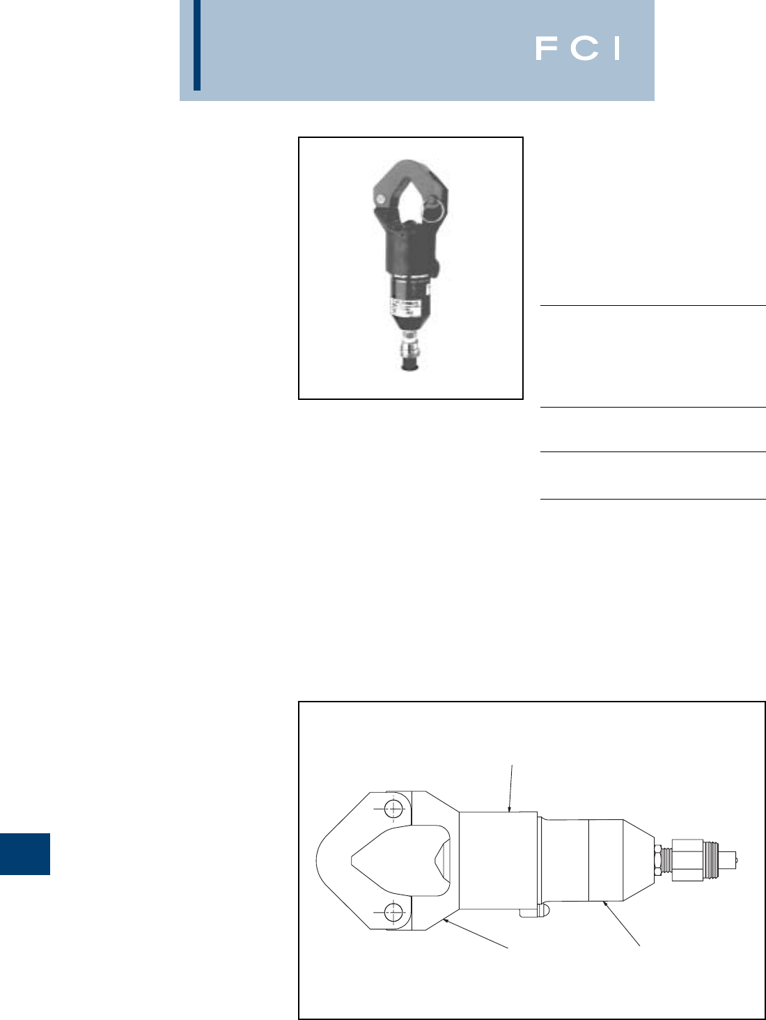
BURNDY
Tooling
N-44
TYPE Y644MBH
DIELESS HYPRESS™
10,000 PSI
HYDRAULIC TOOL -
REMOTE OPERATED
The "1" Crimp-Range Taking 11-Ton Force -
Hydraulic Remote Tool #6-1000 kcmil Copper
HYLUG™ Terminals and HYLINK™ Splices
#6-1000 kcmil Aluminum HYLUG™ Terminal
and HYLINK™ Splices
The "1" Crimp Type Y644MBH Dieless
HYPRESS™ Remote Tool, crimps 195 differ-
ent copper and aluminum HYLUG™ termi-
nals and HYLINK™ splices, which cover the
breadth of 38 code conductor sizes and 15
Navy cable sizes.
Only one (1) crimp is required for each wire
termination for both long and standard length
barrels on BURNDY®HYLUG™ and
HYLINK™connectors throughout the entire
conductor range. The Y644MBH dieless
remote head tool operates on 10,000 psi
hydraulic pressure and develops an output
force of 11 tons, the same as the self-con-
tained Y644M Dieless HYPRESS™.
Installation of BURNDY®YFO and YFD series
H-CRIMPIT™ connectors can be accom-
plished by using the accessory adapters listed
below, purchased separately. Five-year limited
warranty.
SPECIFICATIONS
Force Developed: 11 Tons
Operating Pressure: 10,000 psi
Head Width: 3.93
Overall Length: 12
Weight (less case): 9-1/2 lbs.
FOR USE ON
AWG/KCMIL WIRE CONNECTOR
SIZE RANGE TYPE
Copper Terminals
#6-1000 kcmil YA-L, YA-2LN, YA,
YA-2N, YA-L-2TC,
YAB-4N, YA-L-TC,
YA-2L, YA-4N
Splices
YS-L, YS-T, YS
Aluminum Terminals
#6-1000 kcmil YA-A, YA-A-TN
Splices
YS-A
Aluminum HYPLUG™
#6-750 kcmil AYP, AYPO
Aluminum Taps
#6-250 kcmil H-CRIMPIT™
YFO, YFD
ACCESSORIES
Cat. No.
PT30541
•Die for YFO series H-CRIMPIT™
Cat. No.
PT30540
•Die for YFD series H-CRIMPIT™
BENEFITS
•Dieless system, eliminates the need to
purchase and maintain dies.
•Easy tool positioning with its infinitely
rotatable head.
•Easy inspection and positive identification
is provided with the BURNDY®logo.
•H-CRIMPIT™ dies to crimp YFO and
YFD type H-CRIMPIT™ taps offered as
accessory option.
•Five-year limited warranty.
INFINITELY
ROTATABLE HEAD
HEAVY DUTY HEAD
PIVOTING DIE NEST
FEATURES
The following size Hydent™ lugs and two way splices,
when crimped with the Y644MBH Dieless Hypress™
Tool, produce the following range taking capabilites.
ALUMINUM CONNECTORS COPPER CONNECTORS
Standard Expanded Standard Expanded
Wire Size Wire Range Wire Size Wire Range
#6 AWG #6 AWG #6 AWG #6 AWG
#5 AWG #5-#6 AWG #5 AWG #5-#6 AWG
#4 AWG #4-#6 AWG #4 AWG #4-#6 AWG
#3 AWG #3-#6 AWG #3 AWG #3-#6 AWG
#2 AWG #2-#6 AWG #2 AWG #2-#6 AWG
#1 AWG #1-#2 AWG #1 AWG #1-#6 AWG
1/0 AWG 1/0-#1 AWG 1/0 AWG 1/0-#6 AWG
2/0 AWG 2/0-#1 AWG 2/0 AWG 2/0-#4 AWG
3/0 AWG 3/0-#1 AWG 3/0 AWG 3/0-#2 AWG
4/0 AWG 4/0-#1 AWG 4/0 AWG 4/0-#1 AWG
250 kcmil 250-1/0 AWG 250 kcmil 250-1/0
300 kcmil 300-2/0 AWG 300 kcmil 300-2/0
350 kcmil 350-3/0 AWG 350 kcmil 350-3/0
400 kcmil 400-4/0 AWG 400 kcmil 400-4/0
500 kcmil 500-4/0 AWG 500 kcmil 500-4/0
600 kcmil 600-250 kcmil 600 kcmil 600-250
750 kcmil 750-500 kcmil 750 kcmil 750-500
1000 kcmil 1000-750 kcmil 800 kcmil 800-500
1000 kcmil 1000-750
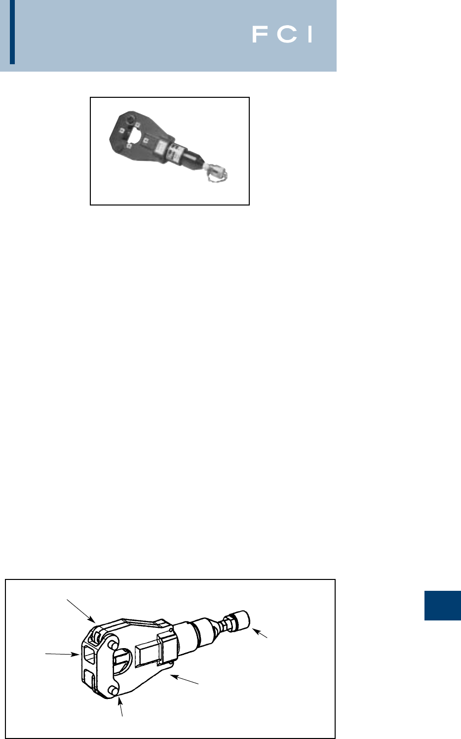
BURNDY
Tooling
N-45
TYPE 4-POINT™
Y81KFTMBH
DIELESS HYPRESS™
10,000 PSI
DIELESS HYDRAULIC TOOL – REMOTE
OPERATED
#8 - 1000 KCMIL COPPER HYLUG™
TERMINALS and HYLINK™ SPLICES
#8 - 750 KCMIL ALUMINUM HYLUG™
TERMINALS and HYLINK™ SPLICES
The Y81KFTMBH 4-POINT™ dieless
HYPRESS™ is a remote powered 6 ton
hydraulic crimping tool for use on a wide vari-
ety of terminal and splice compression appli-
cations. The Y81KFTMBH incorporates a die-
less latch style head that provides easy tool
removal from continuous conductor runs and
eliminates the need to purchase and maintain
dies. The Y81KFTMBH dieless remote head
tool operates on 10,000 psi hydraulic pres-
sure and develops an output force of 6 tons,
the same as the self contained Y81KFTMBH.
The result is easy termination and splicing
using BURNDY®HYLUG™ and HYLINK™
terminals and splices.
The Y81KFTMBH is supplied with a canvas
bag and quick connect fittings and comes
complete with a 5-year limited warranty.
Y81KFTMBH dieless HYPRESS™ Range
Taking Capabilities: The Y81KFTMBH pro-
vides range taking capabilities that is UL and
CSA listed for Copper (Code, Compact and
Flex) and Aluminum (Code and Compact)
conductors when used in conjunction with
BURNDY®HYLUG™ terminals and
HYLINK™ splices. See chart for connector,
conductor and range taking combinations.
Features and Benefits
•Dieless installation system.
◊Eliminates the need to purchase and
maintain dies.
•UL Listed and CSA Certified with Range
Taking Capabilities
◊Provides the installer with UL Listed and
CSA Certified crimps with Range Taking
Capabilities when used in conjunction
with BURNDY®HYLINK™ Terminals and
HYLINK™ Splices.
•Flip top head design.
◊For easy loading and removal of installed
terminals and splices, saving time.
•Incorporates Parker type quick connect
couplers.
◊Eases installation time.
•Audible pressure “pop-off” valve and die
embossment providing 360° inspectability.
◊Assures proper crimps with both audible
and visual indicators for the installer.
•5-year limited warranty on tool.
◊Customer satisfaction and support.
SPECIFICATIONS
Output Force: 6 tons (12,000 lbs.)
(5.4 Metric Tons)
Weight: 8.5 lbs (3.86 kg)
Overall Length: 13.9 in (354 mm)
Head Width: 5.4 in (138 mm)
Operating Pressure: 10,000 psi (68.9
MPa)
FOR USE ON
•Copper, Aluminum, Compressed, Compact,
Stranded, Solid and Flex Conductors.
•Installs Splices, Taps and Terminations:
#8 - 1000 kcmil Copper (YA, YA-L, YS,
YS-L, YS-T, Y-R )
#8 - 777.7 (750 Nominal Flex Wire Size)
kcmil Flex (YA-FX, YAV, YA-L-FX, YS,
YSV-FXB)
#8 - 750 kcmil Aluminum (YA-A, YS-A)
#8 - 750 kcmil Aluminium Pin Adapters
(AYP, AYPO)
DIELESS
SYSTEM
PIVOTING
NEST DIE
QUICK DISCONNECT
MALE COUPLER
AUDIBLE “POP-OFF” PRESSURE
RELIEF VALVE
LOCKING LATCH PIN
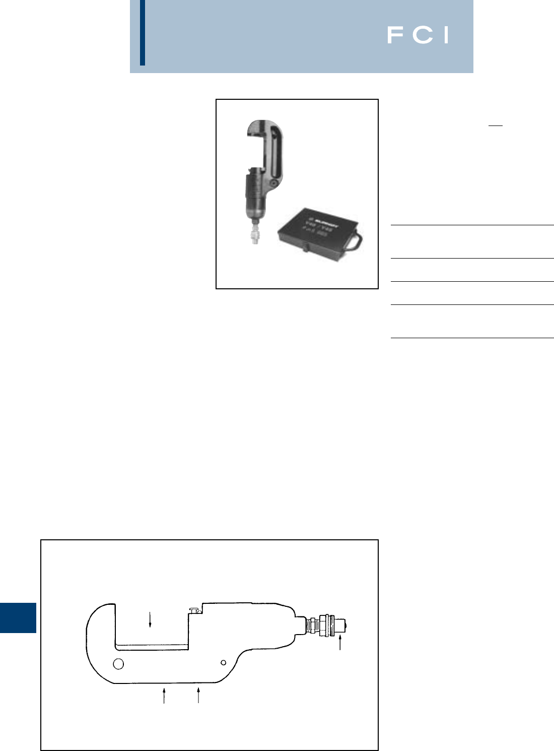
BURNDY
Tooling
N-46
TYPE Y45 HYPRESS™
10,000 PSI
15 TON REMOTE POWER
OPERATED HYDRAULIC
TOOLS
The Y45 Series is designed for remote
hydraulic operation. A C-shaped head design
provides easy installation of tap and splice
connectors. The hook style head with
extensive ram travel operates easily on large
distribution and transmission conductors.
Together with accessories, the Y45 Series
tooling may be used on overhead lines. The
small light-weight head design is very adapt-
able for work in underground trenches and
manholes.
Cat. No. PT6515 is required to use “U-” type
dies in all Y45 variations. Order Head, Hose,
Pump, Dies, and accessories separately.
5-year limited warranty.
SPECIFICATIONS
Y45
Operating pressure: 10,000 psi
Force developed: 15 Tons
Weight (less case): 15-3/4 lbs.
Maximum Width: 7-1/4
Maximum Height: 14-1/4
FOR USE ON
AWG/KCMIL WIRE CONNECTOR
SIZE RANGE TYPE
Tension Sleeves Copper #8 sol.-500 kcmil
Aluminum #6 sol.-954 kcmil
ACSR #4 -795 (26/7)
Taps Aluminum
#14-954 (18/1) ACSR
ACSR #6-795 (54/7)
Aerial Cable Copper #6 str.-1500 kcmil
Connectors Aluminum #4 str.-1000 kcmil
HYGROUND™
Compression Copper #6-500 kcmil
Grounding 1/2 - 1ground rods
Code Cable
Terminals Copper #8-1500 kcmil
and Splices Aluminum #8-1000 kcmil
Taps Copper #14-1000 kcmil
Aluminum #14-900 kcmil
ACCESSORIES:
Cat. No. PT6515
Description:
Adapter for use with "U-"die sets.
Cat. No. PT6547-2
Description:
Universal Hot-stick adapter for Y45
HYPRESS™ tools.
Cat. No. PT6581
Description:
Fiberglass handle adapter for Y45
(10,000 PSI)
Cat. No. PT6545
Description:
Die carrying case for “S-” type dies used
with Y45 HYPRESS™ tools. Holds eight (8)
die sets. (Dies sold separately.)
BENEFITS
•Easy connector installation and tool
removal from line conductors with the
open C-shaped head.
•Easily lifted into working position using
lifting eye.
•Easy die changing plus secure die
alignment is provided with the positive
die lock buttons.
•Long life expectancy is provided with fully
protected ram and die buttons.
•Rapid assembly and disassembly is
provided with the quick disconnect
hydraulic coupler.
•Rugged design provides long life
expectancy.
•5-year limited warranty.
HEAVY DUTY REINFORCED
FORGED STEEL BODY
QUICK DISCONNECT
HYDRAULIC FITTING
C-SHAPED HOOK
STYLE HEAD
LARGE JAW
OPENING
FEATURES
PT6545
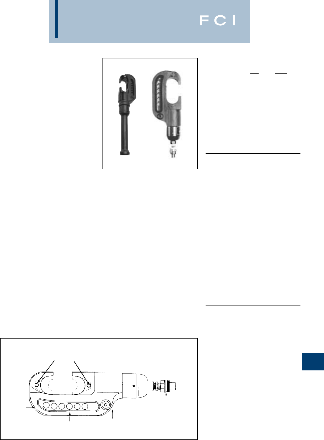
N-47
BURNDY
Tooling
TYPE Y46 AND Y46C
HYPRESS™
10,000 PSI
15 TON FORCE -
REMOTE OPERATED
HYDRAULIC TOOL
The Y46 standard tool and Y46C rubber cov-
ered tools are lightweight, compact and
versatile with installation dies for both circum-
ferential and nest-indentor types. Accessories
include “U-” die adapter, a cable cutting die
for 1.2diameter non-steel conductors, plus a
lifting eye and universal hot-stick adapter for
overhead line construction. 5-year limited
warranty. BENEFITS
•Compact “C” shaped head allows easy
placement and removal from continuous
conductor lengths.
•Versatile and economical-HYPRESS™
tools work on all commonly used copper
and aluminum products.
•Dies and adapters lock into or remove from
tool head easily with the positive push but-
ton die locks.
•Safety, strength and high quality is provid-
ed with strong forged steel and precision
machined components.
•Excellent for HYGROUND™ compression
grounding applications through 1" ground
rods and up to 500 kcmil taps, terminals
and splices.
•Compression terminal, splice and tap con-
nectors are UL listed and CSA certified
when installed with the Y46 and Y46C
HYPRESS™ and recommended die set.
•Y46C has a permanently molded head
of 3/16" rubber and includes a separate
molded rubber boot to cover the lower
HYPRESS™ body and hydraulic coupler
for impact protection.
MALE QUICK
DISCONNECT
10,000 PSI
HYDRAULIC FITTING
FORGED
STEEL
BODY
PRECISION
MACHINED STEEL
COMPONENTS
STRONG
REINFORCED
BACK
LARGE 2”
JAW
OPENING
POSITIVE
PUSH
BUTTON
DIE LOCK
FEATURES
SPECIFICATIONS
Y46 Y46C
Force developed: 15 Tons 15 Tons
Operating pressure: 10,000 psi 10,000 psi
Jaw opening: 22
Maximum width: 4-1/24-3/4
Overall length: 1521-3/4
(incl. boot)
Weight (less case): 16 lbs. 17-1/2 lbs.
Molded Covering: No Yes
FOR USE ON
CONNECTOR CONDUCTOR
TYPE RANGE
Copper Terminals-grounding to 500 kcmil
#8 AWG str.- YGA, YGHA, YGF
1500 kcmil Terminals-Uninsulated #8 to
Code Cable 1500 kcmil YA, YA-2N, YA-L,
Navy Cables YA-LB, YA-TC, YA-2LN, YAB-4N,
Flexible and
Extra Flexible YAV-L Box, YAV-L, YAV-RS Box,
1/2"-1" Ground Rods YAV-RS, YA-TC-FX
Terminals-Insulated #8 to 2/0
YAEV-L Box, YAEV-L, YAEV-H,
YAEV-RS, YAEV-RH
Splices #8 to 1500 kcmil
YS, YS-T, YS-L, YS-LB, YST,
YSP-T, YGS, YGHS
Taps
YH, YCHC #14 to 1000 kcmil
YC-C to 4/0 AWG
Taps-Grounding to 500 kcmil
YGHC-C, YGHP-C, YGHR-C
Aluminum Terminals
#8 AWG- YA-A, AYP, AYPO
1250 kcmil Splices
Code Cables YS-A, YS-AT, YRB
Taps
YFD, YFN, YFO, YFR
ACSR See Burndy Overhead
Transmission and
Distribution Catalog Module
ACCESSORIES:
Cat. No.
P15K Cutter die max. 1.2dia.
PUADP-1 “U”-die adapter
PT10121 Lifting eye
PT10128 Universal hotstick adapter-Y46
PT10131 Universal hotstick adapter-Y46C
Y46-2 Same as Y46 with Female
coupler
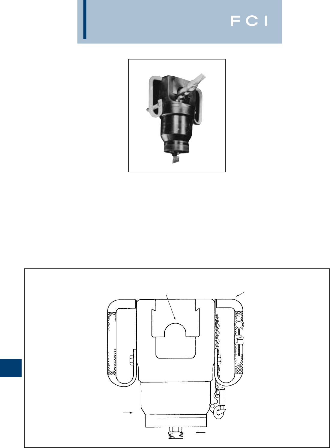
BURNDY
Tooling
N-48
TYPE Y48BH
HYPRESS™ 8,800 PSI
40 TON REMOTE
POWER OPERATED
HYDRAULIC TOOL
The Y48 series is designed for remote
hydraulic power operation. It features a “U”
type head which makes it convenient to
remove from installed splices. The head is
insulated from the assembled hose and
pump.The Y48 is designed for easy die inser-
tion without set screws. Operates at 8,800
PSI and provides 40 tons of force. Uses “C”
dies. Dies sold separately. Five-year limited
warranty.
SPECIFICATIONS
Operating pressure: 8800 psi
Forced developed: 40 Tons
Weight: 26 lbs.
Maximum width: 8-1/2
Height: 10
FOR USE ON
Copper
4/0-2,000 mcm
Terminals
YA, YA-2N, YAB-4N, YA-L, YA-2LN, YA-LB
Splices
YS, YST, YS-L, YS-T, YSP-T
Aluminum
3/0-1,500 mcm
Terminals
YA-A
Splices
YS-A, YS-AT
Full Tension Splices
COPPER-4/0-1,000 mcm-YDS
ACSR-3/0 (6-1)-795 (54-7)-YDS-R
ALUMINUM-4/0-795 mcm-YDS-AT
Cat. No.
Y48BH Head Only
Cat. No.
Y48B Includes head, carry case,
PT76 8long steel braided hose and
FP8 foot pump.
BENEFITS
•Easy die changing is provided with
ball checks.
•Rugged design provides long life
expectancy
•Head is insulated from assembled
hose and pump.
•Provides 40 tons of force.
•Handles on both side of head makes
it easy to carry and position.
•5-year limited warranty.
CARRYING HANDLES
“U” SHAPED HEAD
INSULATING DISC
FEATURES
HOSE FITTING
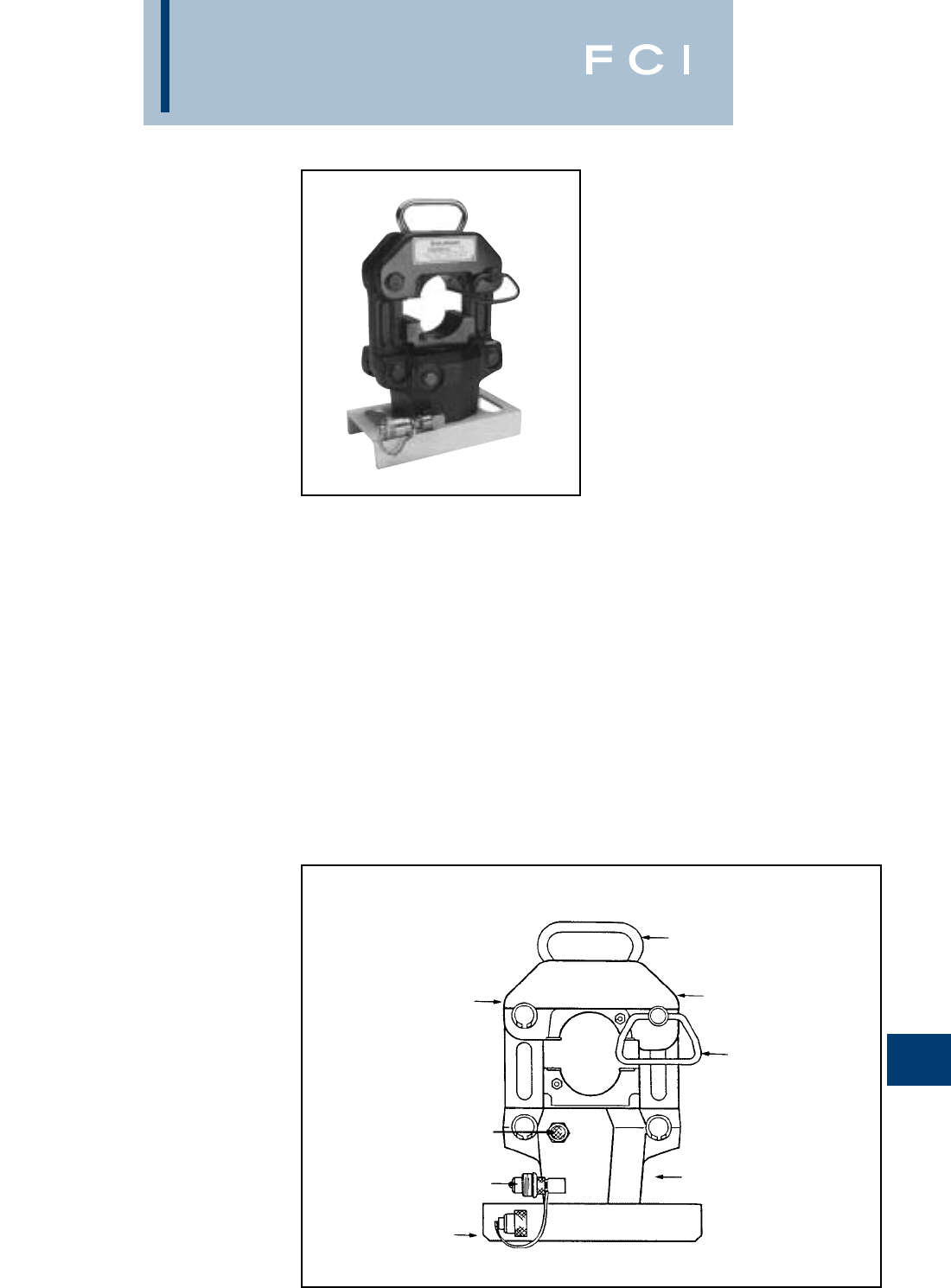
BURNDY
Tooling
N-49
TYPE Y60BHU
AND Y60BHU-D
HYPRESS™
60 TON REMOTE
POWER OPERATED
HYDRAULIC TOOLS
SINGLE AND DOUBLE
ACTING HYDRAULIC
TOOL DESIGNS
The Y60BHU HYPRESS™, single acting, and
Y60BHU-D HYPRESS™, double acting, are
both designed to provide fast, easy operation
plus a durable and substantially longer
design life expectancy. Both Y60BHU and
Y60BHU-D HYPRESS tools accommodate
the same “L” dies. The “L” dies are designed
for copper and aluminum code cables and
aerial conductor sizes through 2500 kcmil
and will accommodate ACSR through 2156
(84/19) str. Five-year limited warranty.
BENEFITS
•Easy to carry with heavy duty handle.
•Easy to remove splices with nest that
pivots open.
•Safety and security is provided with
captive locking pin for nest die.
•Long life expectancy (50,000 cycles)
with heavy duty steel frame.
•Fast easy die changing and secure die
positioning with positive die release
locking pins.
•Faster retraction with double acting
hydraulic system (Y60BHUD).
•Protected male coupler with captive cap.
•Stability is provided with sturdy steel base.
•Easy, less costly repairs with fewer parts
that are easily accessible. Ex: Bottom
die holder.
•5-year limited warranty.
HEAVY DUTY HANDLE
POSITIVE PUSH
BUTTON DIE LOCKS
AND DIE RELEASE
CAPTIVE LOCKING
PIN AND HANDLE
FOR TOOL NEST
HEAVY DUTY
STEEL FRAME
10,000 PSI MALE
COUPLER AND COVER
STURDY STEEL BASE
PORT FOR DOUBLE
ACTING HYDRAULIC SYSTEM
NEST HINGE
ALLOWS FULLY
OPEN POSITIONING
FEATURES
SPECIFICATIONS
Force developed: 60 tons
Operating pressure: 10,000 psi
Hydraulic oil: BURNDY®ALFLUID
Life expectancy: 50,000 cycles min.
Height: 16.62
Weight (less case): 70 lbs.
Shipping weight: 97 lbs.
FOR USE ON
COPPER
300 kcmil-2000 kcmil
Str. Code Cable
Terminals
YA, YA-2N, YAB-4N, YA-L, YA-2LN, YA-LB
Splices
YS, YST, YS-L, YS-T, YSP-T
ALUMINUM
250 kcmil-2000 kcmil
Str. Code Cable
Terminals
YA-A
Splices
YS-A, YS-AT
TRANSMISSION AND DISTRIBUTION
CONNECTORS
Tension Sleeves:
Copper: 1/0 str.-1000 kcmil
Aluminum: 1/0 str.-2300 kcmil
ACSR: 1/0-2156 (84/19 str.)
Aerial:
Copper: 4/0 str.-2500 kcmil
Aluminum: 3/0 str.-2500 kcmil
YTS, YTN, YNS, YNA, YNT, YNTA, YNU,
YDS, YDN, YCS, YCA, YCU
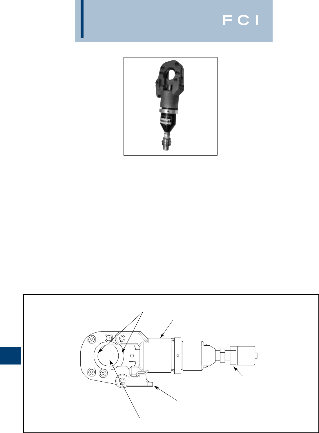
BURNDY
Tooling
N-50
TYPE RHCC129ACSR
10,000 PSI Remote Cable
Cutter
REMOTE POWER OPERATED
HYDRAULIC CABLE CUTTER
The BURNDY®RHCC129ACSR remote
hydraulic cable cutter incorporates a special-
ized latch style cutting head that allows inter-
ference-free closure for mid-span cuts. The
RHCC129ACSR with its precision cutting
blades is capable of cutting up to 1.29diam-
eter bare or insulated copper and aluminum
cable, 1113 ACSR, 5/8ground rod, 1/2
rebar, 5/8diameter soft steel bolts, 1/2stan-
dard guy strand, and up to 3/8EHS guy
strand.
The RHCC129ACSR is provided with a
5-year limited warranty (excluding blades).
Features and Benefits
•Specialized latch head design.
◊Interference free closure for mid-span
cuts.
•Precision cutting blades.
◊For clean cuts on Cu/Al, ACSR, ground
rods, rebar, guy strand, and soft steel
bolts.
•High strength steel cylinder.
◊For durability and long life.
•Lightweight ergonomic design allows one
hand operation.
◊User has one hand free to manipulate
material to be cut.
•Durable canvas carrying bag.
◊Provides tool protection and stores all
accessories.
•5-year limited warranty on tool (excluding
blades).
◊Customer satisfaction and support.
SPECIFICATIONS
Operating Pressure: 10,000 psi (700 bar)
Tool Weight: 5.85 lbs. (2.65 kg)
Length: 11.25(286 mm)
Width: 3.7(94 mm)
FOR USE ON
•Copper Cable: up to 1.29
•Aluminum Cable: up to 1.29
•ACSR: up to 1113 ACSR
•Ground Rod: up to 5/8
•Rebar: up to 1/2
•Soft Steel Bolts: up to 5/8
•Standard Guy Strand: up to 1/2
•EHS Guy Strand: up to 3/8
ACCESSORIES
Canvas Bag: Cat# PT10043890
Replacement Blades: Cat# PT10037388
(Moving Blade)
Cat# PT10037384
(Fixed Blade)
PRECISION CUTTING BLADES
HIGH STRENGTH
STEEL CYLINDER
QUICK DISCONNECT
HYDRAULIC FITTING
SPECIALIZED LATCH
HEAD DESIGN
1.29CUTTING
CAPACITY
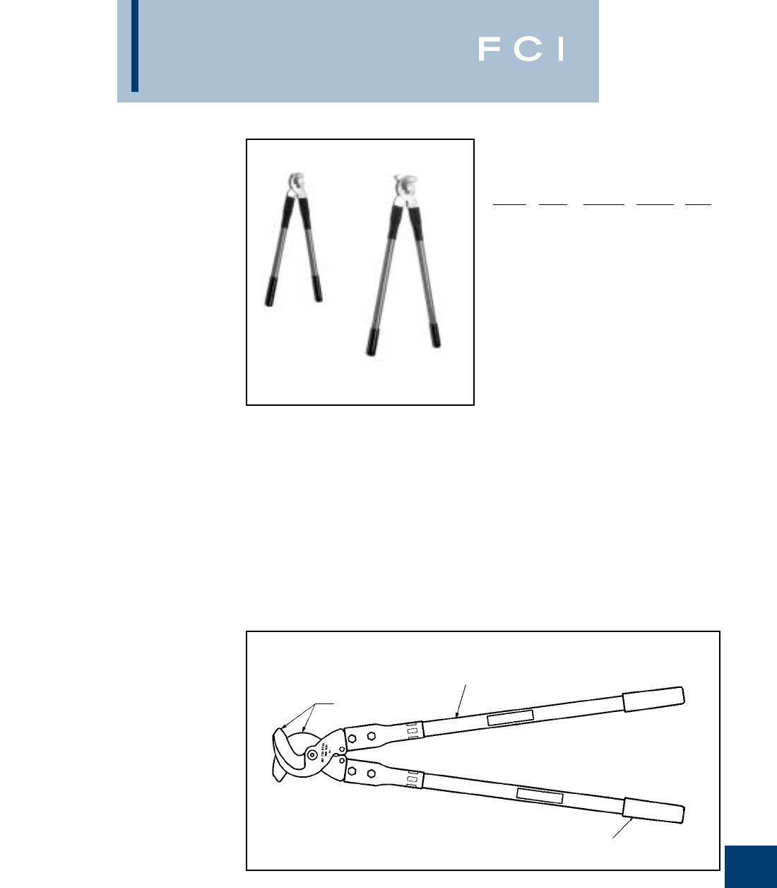
BURNDY
Tooling
N-51
TYPE MCC500
AND MCC1000
MANUAL CABLE CUTTERS
The MCC500 and MCC1000 manual cable
cutters are precision high quality tools
designed to cut up to 500 kcmil and 1000 kcmil
copper and aluminum cables respectively.
Rugged steel blades and fiberglass handle
construction provide cutting ease, minimum
cable distortion and long life.The MCC500 and
MCC1000 cable cutters are warranted to be
free of defects in material (excluding blades)
and workmanship for five years except in the
case of abuse or modification.
SPECIFICATIONS
Capacity Max.
Catalog Overall Copper and Insulation
Number Length Aluminum Diameter Weight
MCC500 21500 kcmil 1.253.5 lbs
(533 mm) (32 mm) (1.5 kg)
MCC1000 321000 kcmil 1.909.0 lbs
(813 mm) (48 mm) (4.0 kg)
FOR USE ON
Maximum conductors accommodated:
MCC500:
500 kcmil Copper and Aluminum
MCC1000:
1000 kcmil Copper and Aluminum
FEATURES
•High quality design and construction.
•Rugged high quality steel blades.
•Fiberglass handles with soft grips.
BENEFITS
•Easy cutting with minimum cable distortion
and long life.
•Excellent cutting edge performance.
•Provides comfortable tool operation and
long life.
HANDLE GRIPS
HANDLES
REPLACEMENT
BLADES
MCC500
MCC1000
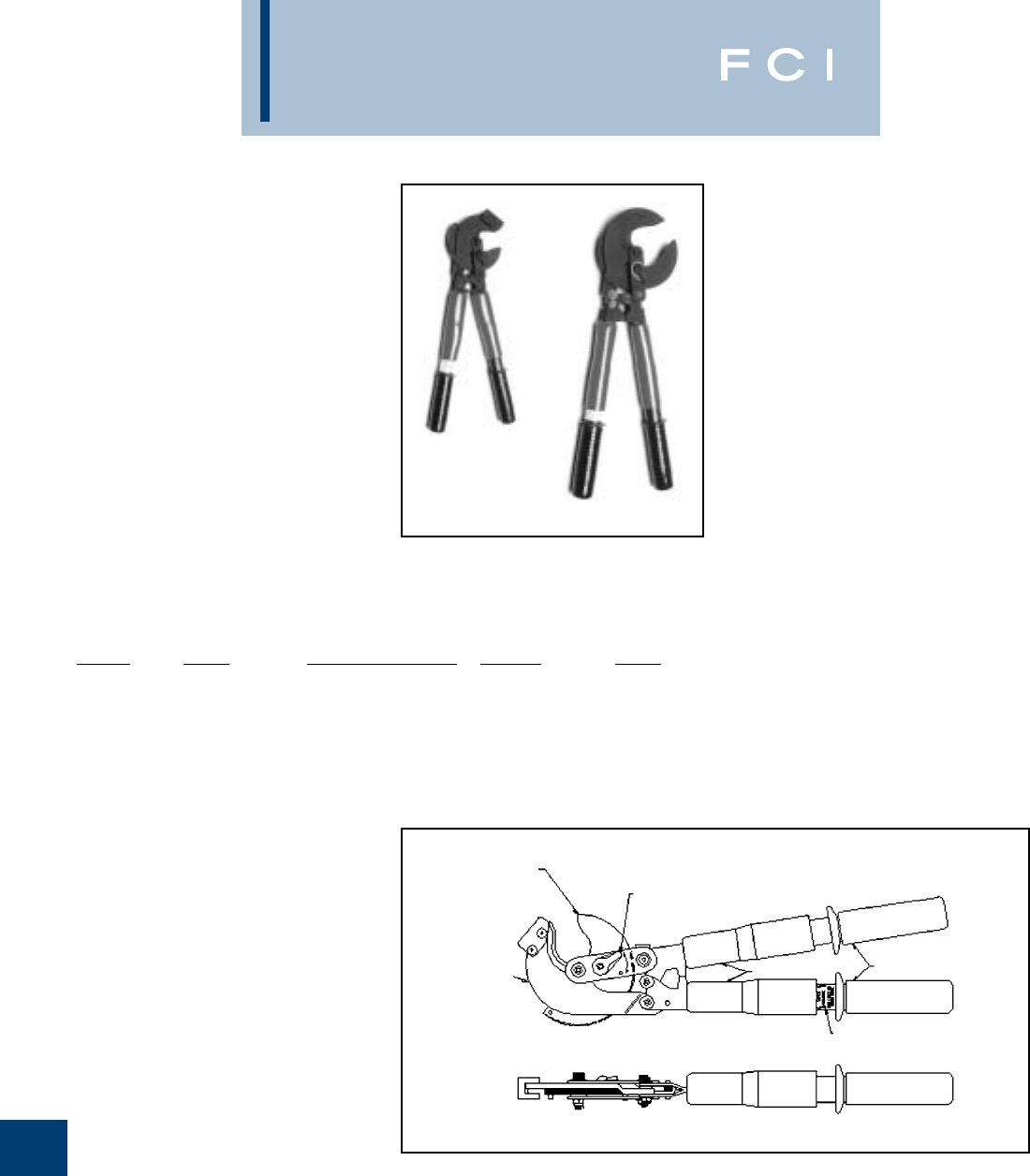
BURNDY
Tooling
N-52
TYPE RCC556
AND RCC1000
RATCHET CABLE CUTTERS
The RCC556 and RCC1000 ratchet cable
cutters are precision high quality tools
designed to cut up to 556 ACSR and 1000
kcmil copper and aluminum cables respec-
tively. The tools are equipped with rugged
steel blades, a precision bi-directional ratchet
mechanism for positive blade control, a fast
action thumb slide collar for fast blade move-
ment (when not cutting) and rugged fiber-
glass handles. The RCC556 and RCC1000
ratchet cable cutters are warranted to be free
of defects in material (excluding blades) and
workmanship for five years except in the case
of abuse or modification.
DIRECTION
OPEN/CLOSE
COVER
STATIONARY
JAW
RAPID ADVANCE
FEATURE
HANDLE GRIPS
MOVABLE
JAWS
SPECIFICATIONS
Catalog Overall Capacity: ACSR, Max. Insulation
Number Length Copper and Aluminum Diameter Weight
RCC556 21556 ACSR 1.253.5 lbs
(533 mm) 600 kcmil Al/Cu (1.5 kg)
(32 mm)
RCC1000 321000 kcmil AL/Cu 1.909.0 lbs
(813 mm) (48 mm) (4.0 kg)
FEATURES
•Patented, high strength steel blades.
•Bi-directional ratchet mechanism.
•Thumb-controlled rapid blade movement
feature (fast action mode).
•Fiberglass handles with soft grips.
•Stiffener bar (RCC556 only).
BENEFITS
•Provides ease of cutting and long life.
•Provides positive control of blade
movement and greater cutting capacity.
•Provides convenient quick closing or
opening of blades when cutting is not
being done.
•Provides comfortable tool operation
and long life.
•Increases operator safety when cutting
ACSR cable.
FOR USE ON
Maximum conductors accommodated:
RCC556:556 ACSR
600 kcmil Copper
and Aluminum
RCC1000:1000 kcmil Copper
and Aluminum
Do not cut steel or ACSR
RCC556
RCC1000
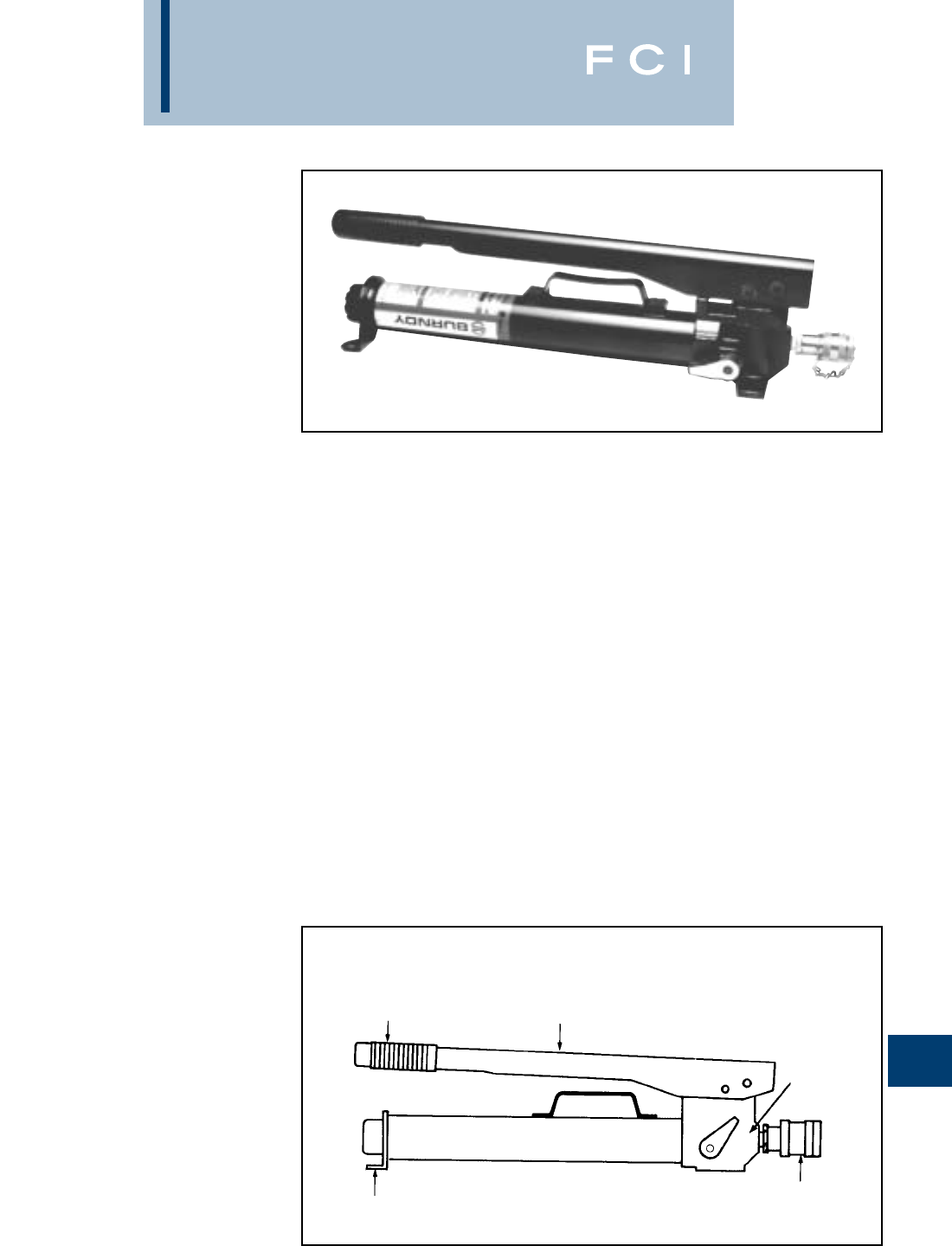
BURNDY
Tooling
N-53
TYPES HP10, HP8,
AND HP6
HP SERIES MANUAL
HYDRAULIC HAND PUMPS
HYDRAULIC OUTPUT
PRESSURES OF: 10,000 PSI,
8,800 PSI, AND 6,000 PSI
Hand pumps are designed to match the out-
put pressure requirements of HYPRESS™
heads and cutters. Each pump is equipped
with a built-in, factory set pressure release
valve with audible click to signal completion of
crimp cycle.
LONG ARM
BUILT-IN FACTORY
SET PRESSURE
RELIEF VALVE
STURDY LEG
STABILIZERS
LIGHTWEIGHT
RUGGED DESIGN
PORTABLE
QUICK DISCONNECT
HYDRAULIC FITTING
HANDLE GRIP
SPECIFICATIONS
Reservoir volume: 1-1/8 qts.
Length: 24-3/4
Width: 5
Weight: 18 lbs.
Closed height: 6-3/4
Height (with handle open): 20
FOR USE ON
HP10 10,000 Y34BH, Y35BH, Y35BH-4,
Y750BH, Y750BH-2, Y39BH,
Y45, Y46C, Y46, Y60BHU,
RHCC Series Cutters
HP8 8,800 Y48BH
HP6 6,000 Y35-L, RHCC Series Cutters
ACCESSORIES
Extended leg pad stablilizes (w/hardware)
Cat # BP10PADKIT
FEATURES
BENEFITS
•Durable, long life expectancy.
•Easy to transport and move tool around
job site with built in handle.
•Maximum mechanical advantage provided
with long handle.
•Solid tool base provided with sturdy broad
leg stabilizers.
•Save time with quick disconnect
hydraulic fitting.
•High quality crimps provided with built-in,
factory set pressure release valve and
audible click to signal completion of crimp.
•5-year limited warranty.
HANDLE

BURNDY
Tooling
N-54
TYPES FP10, FP8,
AND FP6
FP SERIES MANUAL
HYDRAULIC FOOT PUMPS
HYDRAULIC OUTPUT
PRESSURES OF: 10,000 PSI,
8,800 PSI, AND 6,000 PSI
Foot pumps are designed to match the output
pressure requirements for use with all
HYPRESS™ heads and cutters. Each pump
is equipped with a built-in, factory set pres-
sure release valve with audible click to signal
completion of a crimp cycle.
LONG ARM
SPRING
LOADED ARM
STURDY LEG
STABILIZERS
LIGHTWEIGHT
RUGGED DESIGN
PORTABLE
DIAMOND PLATE
STEEL FOOT PAD
SPECIFICATIONS
Reservoir volume: 1-1/8 qts.
Length: 24-3/4
Width: 5
Weight: 19 lbs.
Closed height: 6-1/2
Height (with handle open): 17
FOR USE ON
FP-10 10,000 Y34BH, Y35BH, Y35BH-4,
Y750BH, Y750BH-2, Y39BH,
Y45, Y46C, Y46, Y60BHU,
Y750BH, RHCC Series
Cutters
FP-8 8,800 Y48BH
FP-6 6,000 Y35-L, RHCC Series Cutters
ACCESSORIES
Extended leg pad stablilizes (w/hardware)
Cat # BP10PADKIT
FEATURES
BENEFITS
•Easy to lift and carry.
•Durable. Long life expectancy.
•Easy to transport and move tool around
job site with built in handle.
•Easy operation provided with spring
assisted return arm.
•Maximum mechanical advantage
provided with long arm extending
beyond pump body.
•Quality, heavy duty foot pad provided
with diamond plate steel.
•Solid tool base provided with sturdy
broad leg stabilizers.
•Time saving quick disconnect hydraulic
fitting.
•High quality crimps provided with factory
set pressure release valve with audible
click to signal completion of crimp.
•5-year limited warranty.
BUILT-IN
FACTORY SET
PRESSURE
RELIEF VALVE
QUICK
DISCONNECT
HYDRAULIC
FITTING
N-55
BURNDY
Tooling
TYPE EPP10 AND EPP6
EPP SERIES ELECTRIC/
HYDRAULIC PUMP
HYDRAULIC OUTPUT
PRESSURE OF:
10,000 PSI AND 6,000 PSI
The lightweight and durable EPP10 elec-
tric/hydraulic pump is for use with all
BURNDY HYPRESS™ remote heads and
cutters requiring 10,000 PSI operating pres-
sure. Both the EPP10 and the EPP6 are
equipped with a built-in, factory set pressure
relief valve. An audible “pop” and recycling of
the pump and relaxing of the hose, signals
completion of the crimping/cutting cycle. Both
pumps are supplied with a durable hand-held
electric pendant switch, for remote operation
of the unit, and have a manual selection
switch mounted for operation of the unit at the
pump. The operator can select which method
is best suited for the application.
An optional carry/shipping case can be
ordered. All EPP Series pumps have been life
cycle tested to over 100,000 cycles without
failure, and are warranted to be free of defects
in materials and workmanship for five (5) years
when properly maintained and operated.
SPECIFICATIONS
Motor: 115 V-AC/60 Hz
1/2 HP @ 3450 RPM
Maximum
current draw: 12.5 amperes
Reservoir volume: 2 qts.
Height: 16
Base: 68
Weight: 30 lbs.
FOR USE ON
EPP10 10,000 Y34BH, Y35BH, Y35BH-4,
Y39BH, Y45, Y46, Y46C,
Y60BHU, 750BH,
Y750BH-2, Y644MBH,
RHCC Series Cutters
EPP6 6,000 Y35L, Y28B, RHCC Series
Cutters
ACCESSORIES
Cat. No. EPPCASE-1
Steel carrying case with handle and locking
latch.
FEATURES
•Lightweight.
•Small size.
•Factory set relief valve.
•100,000 (+) life cycles.
•Sealed electric pendant switch.
BENEFITS
•High quality crimps are achieved with
built in, factory set pressure release valve
and audible recycling of pump to signal
completion of crimp cycle.
•Easy to lift, carry and transport tool
around job site with lightweight body
and handle.
•Convenient 115 V-AC electric powered
motor.
•Durable remote pendent switch.
•Easy operation controlled with pendent
switch, or manual switch.
•Saves time with quick disconnect
hydraulic fitting.
•Long durable life expectancy with light-
weight cast aluminum reservoir body.
•5-year limited warranty.

BURNDY
Tooling
N-56
TYPES EPAC10,
EPAC8, AND EPAC6
EPAC SERIES ELECTRIC/
HYDRAULIC PUMP,
AIR CONTROL
HYDRAULIC OUTPUT
PRESSURES OF: 10,000 PSI,
8,800 PSI, AND 6,000 PSI
The EPAC10, EPAC8, and EPAC6 electrically
driven hydraulic pumps feature exclusive
automatic or manual “jog and hold” operation
control provided by a unique air control
switch, which provides the safest operation
method of any pump available. All EPAC’s are
remotely controlled by an improved air control
switch which electrically isolates the operator
from the unit, and can be operated by either
hand or foot activation. A three (3) position
toggle switch mounted on the control box
allows the operator to select either full
automatic, off, or manual operation.
The automatic mode advances the remote
tool into a “hold” position without crimping the
connector so the operator can inspect the
orientation before completing the crimp. Once
the crimp is completed, the pump auto-
matically turns the pump off, allowing the
retraction of the remote tool and resets itself
for the next operation.
The manual position allows the operator to
jog the tool forward without the tool ram
retracting. To retract the tool prior to complet-
ing the crimp, turn the control switch to “off,”
the pump will stop and the tool will retract. In
the manual mode the pump advances only
while the control is being depressed. To
complete a crimp, squeeze and hold the air
control switch until the pump reaches the pre-
set pressure and shuts off.
The EPAC Series of electrically driven
hydraulic pumps incorporate a heavy-duty roll
cage design that is both rugged and portable.
All EPAC Series pumps have been life cycle
tested to over 100,000 cycles without failure,
and are warranted to be free of defects in
material and workmanship for five (5) years
when properly maintained and operated.
SPECIFICATIONS
Motor: 1/2 HP 115/230 V-AC,
60 Cycle
(EPAC**-2 versions): 1/2 HP 220/230 V-AC,
50 Cycle
Maximum current
draw: 10 amperes
Reservoir volume: 8 quarts max,
2 quarts min
Height: 17-1/2
Base: 11-3/418-1/2
Dry weight: 68 lbs
(82 lbs w/max fluid)
(1/2 HP @ 3450 RPM)
FOR USE ON
EPAC10 10,000 Y34BH, Y35BH,
EPAC10-2 Y35BH-4,Y39BH,
Y45,Y46,Y46-C,
Y60BHU, Y750BH,
Y750BH-2, Y644MBH,
RHCC Series Cutters
EPAC-8 8,800 Y48BH
EPAC-6 6,000 Y35L, RHCC Series
Cutters
FEATURES
•Roll cage
•3 position switch and control box
•Factory set output pressure
•Quick disconnect hydraulic coupler
•Oil level window
•8 quart reservoir
BENEFITS
•Permits final inspection of connector
before completing crimp cycle.
•Extra supply hydraulic fluid 8-quart
reservoir.
•Full automatic or manual “Jog and
Hold” cycles.
•Operator safety with power loss “smart
circuit,” freezes unit in event of power
disruption.
•Method of operation desired is permitted
with 3-position selection switch.
•Safety is provided against hazardous
shock with airbulb actuator and air line.
•Saves time with quick disconnect
hydraulic fitting.
•Windows allows easy inspection of
proper oil level.
•High quality crimps are achieved with built-
in factory set pressure release valve.
•5-year limited warranty.
BURNDY
Tooling
N-57
TYPES EP10, EP8,
EP6 AND EP10-2,
EP8-2, EP6-2
EP SERIES ELECTRIC/
HYDRAULIC PUMPS
HYDRAULIC OUTPUT
PRESSURES OF 10,000 PSI,
8,800 PSI, AND 6,000 PSI
Electrically driven hydraulic pumps are
supplied with a durable, hand-held electric
pendent switch that remotely controls the
pump and matches the output requirements
of all HYPRESS™ remote heads and cutters.
Each pump is equipped with a built-in, factory
set, pressure relief valve. An audible “pop”
and recycling of the pump and relaxing of the
hose, signals completion of the crimping/cut-
ting cycle.
All EP series pumps are supplied with 115/230
- 220/230 voltage, 60/50 hertz, 1/2 horsepower
motor and can be wired for use with any elec-
tric power source worldwide. A three prong,
grounded plug is wired standard on the units.
All EP Series pumps have been life cycle
tested to over 100,000 cycles without failure,
and are warranted to be free of defects in
materials and workmanship for five (5) years
when properly maintained and operated.
OIL LEVEL WINDOW
1/2 HP MOTOR
DUAL VOLTAGE/HERTZ
QUICK DISCONNECT
HYDRALIC COUPLER
8 QUART
RESERVOIR
FACTORY
SET OUTPUT
PRESSURE
ROLL CAGE
SPECIFICATIONS
Motor: 1/2 HP 115/230 V-AC,
60 cycle
(EP**-2 versions): 1/2 HP 220/230 V-AC,
50 cycle
Maximum current
draw: 10 amperes
Reservoir volume: 8 quarts max,
2 quarts min
Height: 17-1/2
Base: 11-3/418-1/2
Dry weight: 68 lbs (86 lbs with
max fluid)
(1/2 hp @ 3450 rpm)
FOR USE ON
EP10 10,000 Y34BH, Y35BH, Y35BH-4,
EP10-2 Y39BH, Y45, Y46, Y46-C,
Y60BHU, Y750BH,
Y750BH-2, RHCC Series
Cutters
EP8 8,800 Y48BH
EP8-2
EP6 6,000 Y35L, RHCC Series Cutters
EP6-2
FEATURES
BENEFITS
•Provides fast sure pump action plus a long
life expectancy.
•It’s portable. Roll cage allows easy moving
on the job site.
•Durable 1/2 HP dual voltage motor.
•Extra supply of hydraulic fluid with
8 quart reservoir.
•Saves time with quick-disconnect
hydraulic fitting.
•Easy operator control is provided with
remote pendent switch.
•Easy inspection of proper oil level is
provided by see through window.
•High quality crimps are achieved with
built-in, factory set, pressure release
valve and audible recycling of pump
which signals completion of crimp.
•5-year limited warranty.
BURNDY
Tooling
N-58
TYPES EP10-1HP,
EP8-1HP, EP6-1HP
AND EP10-1HP-2,
EP8-1HP-2, EP6-1HP-2
EP-1HP SERIES ELECTRIC/
HYDRAULIC PUMPS
HYDRAULIC OUTPUT
PRESSURES OF:
10,000 PSI, 8,800 PSI,
AND 6,000 PSI
Heavy duty electrically driven hydraulic
pumps are supplied with a durable, hand-held
electric pendent switch that remotely controls
the pump and matches the output require-
ments of all HYPRESS™ remote heads and
cutters. Each pump is equipped with a built-
in, factory set, pressure relief valve. An
audible “pop” and recycling of the pump and
relaxing of the hose, signals completion of the
crimping/cutting cycle.
All EP-1HP series pumps are supplied with
115/230 - 220/230 voltage, 60/50 hertz,
1 horsepower motors and can be wired for use
with any electric power source worldwide. A
three prong, grounded plug is wired standard
on the units. All EP-1HP Series pumps have
been life cycle tested to over 100,000 cycles
without failure, and are warranted to be free
of defects in materials and workmanship for
five (5) years when properly maintained and
operated.
SPECIFICATIONS
Motor: 1/2 HP 115/230 V-AC,
60 cycle
(EP**-2 versions): 1/2 HP 220/230 V-AC,
50 cycle
Maximum current
draw:
10 amperes
Reservoir volume: 8 quarts max,
2 quarts min
Height: 17-1/2
Base: 11-3/418-1/2
Dry weight: 68 lbs (86 lbs
with max fluid)
(1/2 hp @ 3450 rpm)
FOR USE ON
EP10-1HP 10,000 Y34BH, Y35BH,
EP10-1HP-2 Y35BH-4, Y39BH,
Y45, Y46, Y46-C,
Y60BHU, Y750BH,
Y750BH-2, RHCC
Series Cutters
EP8-1HP 8,800 Y48BH
EP8-1HP-2
EP6-1HP 6,000 Y35L, RHCC Series
Cutters
EP6-1HP-2
FEATURES
•Heavy duty design.
•Roll cage.
•Quick disconnect hydraulic coupler.
•Oil level window.
•8 quart reservoir.
•Factory set output pressure.
•1 HP motor dual voltage/hertz.
BENEFITS
•Provides fast sure pump action plus a long
life expectancy.
•Its portable roll cage allows easy moving
on the job site.
•Strong durable motor provided with
(1) H.P. dual voltage design.
•Extra supply of hydraulic fluid with
8 quart reservoir.
•Saves time with quick-disconnect
hydraulic fitting.
•Easy operator control is provided with
remote pendant switch.
•Easy inspection of proper oil level is
provided by see through window.
•High quality crimps are achieved with
built-in, factory set, pressure release valve
and audible recycling of pump which
signals completion of crimp.
•5-year limited warranty.
BURNDY
Tooling
N-59
FEATURES
TYPES GP10,
GP8, AND GP6
GP SERIES GASOLINE
ENGINE DRIVEN
HYDRAULIC PUMP
HYDRAULIC OUTPUT
PRESSURES OF: 10,000 PSI,
8,800 PSI, AND 6,000 PSI
The GP series gasoline engine driven
hydraulic pump is a heavy-duty design that is
rugged and portable. Supplied with a four (4)
H.P. engine, the pump operates all BURNDY®
remote compression heads and cable cutters.
All GP style pumps have a built-in, factory
pre-set, automatic pressure release overload
valve with a definite pulsing and recycling to
signal the completion of a crimp. The manual
control valve allows user to "Jog and Hold"
due to the unique check valve design that
keeps pressure in the output line until
retracted.
Specifications
Engine: 4 H.P., 4 cycle
Reservoir volume: 2 gallons (8 qts.)
Pump height: 19-3/4
Pump width: 13
Pump length: 18
Overall height: 22-1/4
Overall width: 16
Overall length: 21
Pump and motor
dry weight: 64-1/4 lbs.
Overall dry weight: 77-3/4 lbs.
FOR USE ON
Pump PSI
Hydraulic Tools and Cutter
GP10 10,000 Y34BH, Y35BH, Y35BH-4,
Y39BH, Y45, Y46, Y46C,
Y60BHU, Y60BHU-D,
Y750BH, Y750BH-2, RHCC
Series Cutters
GP8 8,800 Y48BH
GP6 6,000 Y35L, RHCC Series Cutters
BENEFITS
•Portable pump with sturdy steel roll cage.
•Durable heavy-duty four (4) H.P. engine
for all HYPRESS™ applications and long
life expectancy.
•Manual control valve permits easy control
of crimping or cutting operations.
•Manual control valve permits easy control
of crimping or cutting operations.
•Fast hose assembly with quick disconnect
pressure matched hydraulic couplers.
•Ample hydraulic capacity with (8) quart
reservoir.
•5-year limited warranty.
STURDY STEEL ROLL
CAGE DESIGN
MANUAL CONTROL VALVE
QUICK DISCONNECT
HYDRAULIC COUPLER
OIL LEVEL
INSPECTION WINDOW
8 QUART
RESERVOIR
HEAVY-DUTY
GASOLINE
ENGINE
BURNDY
Tooling
N-60
HYDRAULIC HOSES
NON CONDUCTIVE HOSES*
6,000 PSI 10,000 PSI
Cat. No. Description
PT 29900-10 10- 3/16diameter - non
conductive hose with stack-
able couplers (male/female) -
orange
PT 29900-15 15- 3/16diameter - non
conductive hose with stack-
able couplers (male/female) -
orange
PT 29900-25 25- 3/16diameter - non
conductive hose with stack-
able couplers (male/female) -
orange
PT 29901-10 10- 1/4diameter - non
conductive hose with stack-
able couplers (male/female) -
orange
PT 29901-15 15- 1/4diameter - non
conductive hose with stack-
able couplers (male/female) -
orange
PT 29901-25 25- 1/4diameter - non
conductive hose with stack-
able couplers (male/female) -
orange
NOTE: 1/4diameter hose provides higher
flow rate for faster ram movement.
*For proper care and maintenance of hydraulic
hoses, consult the “Hydraulic Hose Care” manual,
Form No. 7828
Cat. No. Description
PT 29902-10 10- non conductive hose
with stackable couplers
(male/female) - orange
PT 29902-15 15- non conductive hose
with stackable couplers
(male/female) - orange
PT 29902-25 25- non conductive hose
with stackable couplers
(male/female) - orange
PT 29074-1 Non conductive hose carrying
bag
*For proper care and maintenance of hydraulic
hoses, consult the “Hydraulic Hose Care” manual,
Form No. 7828
Cat. No. Description
PT 91 8- steel braided hose
with steel spring reinforced
ends. Stackable couplers
(male/female) - Black. No
electrical rating. DO NOT
use on energized conductor.
8,800 PSI
Cat No. Description
PT 76 8- steel braided hose
with steel spring reinforced
ends. Stackable couplers
(male/female) - Black. No
electrical rating. DO NOT
use on energized conductor.
*
For proper care and maintenance of hydraulic
hoses, consult the “Hydraulic Hose Care” manual,
Form No. 7828.
CONDUCTIVE HOSES*
Do not attempt to repair or recouple the hose yourself!
10,000 PSI
NON CONDUCTIVE HOSES*
BURNDY
Tooling
N-61
ACCESSORIES
PT 29074-1 Insulated hose carrying bag
Designed to provide protection and clean-
liness of non conductive hoses. Accomodates
100 ft. of non conductive coiled to 17-1/2
O.D. and 3-3/4wide. Max. carrying capacity:
10 lbs.
Replacement Coupler 6,000 psi operating
pressure
PT 29091 (male)
PT 29214-1 (female)
Replacement Coupler 10,000 psi operating
pressure
PT 94 (male)
PT 93 (female)
Adjustable Head Grip For joining
HYPRESS™ heads to universal hot sticks
PT 29075 (for Y35L)
PT 29402-1 (for Y35BH)
PT 6547-2 (for Y45)
PT 10128 (for Y46)
PT 10131 (for Y46C)
DIE CASES
PT 29291
(Y750, Y35/Y39) die case for
“U” -type die sets
PT 6545
(Y45) die case for
“S” -type die sets
ALFLUID
ALFLUID QT.
ALFLUID GAL.
(available in quart and gallon size containers)
Use ALFLUID™ in hand operated tools dur-
ing extended use below 32 degrees.
All weather HYDRAULIC fluid for BURNDY®
pumps:
HP hand pump
FP foot pump
GP gasoline pump
EPP. electric pump
AC-3H auto/man. elect. pump
DC-3H auto/man. elect. pump
TOOL TOOL CARRY CASE CAT#
Y35 HYPRESS™ #PT2972 - Steel w/ 13 die holder tray
Y35-2, Non Conductive version Y35 #PT29360 - Steel w/ 13 die holder tray
Y39 HYPRESS™ #PT12814 - Steel w/ 13 die holder tray
Y750 & Y750-2, Revolver HYPRESS™
#PT23490 - Steel w/ 13 die holder tray
Y644M, Die-less HYPRESS™ #PT30539 - Steel case, no die holder tray
(Y644 tool, obsolete) (#PT30007 - Steel carry case)
Y35BH, 12 Ton Remote Y35 #PT29413 - Steel w/ 6 die holder tray
Y35BH-4, Non Conductive Y35BH ttol N/A, (use Y50BH-2 case, # PT23607)
Y39BH, 12 Ton Remote Y39 #PT12821 - Steel w/ 6 die holder tray
Y750BH, 12 Ton Remote Y750 #PT23492 - Steel w/ 6 die holder tray
Y750BH2, Non Conductive Y750BH #PT23607 - Steel w/ 6 die holder tray
TOOL TOOL CARRY CASE CAT#
Y644MBH, Die-less remote #PT207190-01 - Steel, no die holder
Y45, 15 Ton Remote HYPRESS #411-206016-014 - Steel, 1 die holder
Y45, 15 Ton Remote HYPRESS #411-206091-018 - Steel, w/ 1 die holder
(Y45L-1, old style press) (#PT6573 - Steel, w/ 1 die holder)
Y46, 15 Ton Remote HYPRESS #433-206016-010 - Steel, w/ 1 die holder
Y46C, Non Conductive version Y46 #433-206071-012 - Steel, w/ 1 die holder
Y60BHU, 60 Ton Remote HYPRESS #PT22648 - Steel, no die holders
Y29BH, Remote HYPRESS #PT30250 - Steel, w/ die holder
FP/HP Series Foot & Hand Pumps #PT8 - Steel, fits Pump, Hose, and Head
(new style pumps)
HYFLUID
HYFLUID QT.
HYFLUID GAL.
(available in quart and gallon size containers)
Hydraulic fluid for BURNDY®HYPRESS™
hand operated tools:
Y35 and Y35-2 HYPRESS™ tools
Y39 HYPRESS™ tool
Y750 REVOLVER HYPRESS™ tools
In-line Pressure Gauge 10,000 psi operating
pressure for hydraulic pumps
PT 11018
Pressure Tee*
Y106PSI (10,000 to 6,000 p.s.i.)
Y108PSI (10,000 to 8,800 p.s.i.)
Allows use of 10,000 p.s.i. pumps in conjunc-
tion with BURNDY®6,000 p.s.i. and 8,800
p.s.i. HYPRESS™ tools.
*For proper care and maintenance of
hydraulic hoses, consult the “Hydraulic
Hose Care” manual, Form No. 7828
BURNDY
Tooling
N-62
WIRE MIKE
RK 194-2
The wire mike is a useful instrument designed
for measuring ACSR, stranded and solid
conductors, I.P.S. tubing, rigid and thinwall
conduit, plus inside and outside dimensions
of tubing and pipe sizes. A ruler is also
included.
TYPE RK147-2
CONSTRUCTION/
MAINTENANCE
WIRE STRIPPERS
These two lightweight strippers feature pre-
cision ground blades that give a precise and
rapid strip for small wire applications. The
RK190-2 has presize stripping grooves for
#10-#20 AWG solid and a copper wire cutting
blade. The RK147-2 is an adjustable stripper
cutter with a simple cam screw adjustment for
multi-varied wire sizes and insulation thick-
ness up to #12 AWG solid or stranded wire.
Both tools are part of BURNDY’s convenience
package program and are shipped on
merchandising rack cards.
RK147-2
Wire Stripping Range: No minimum,
up to #12 AWG
Overall Length: 5.31
Weight: .18 lbs.
FOR USE ON:
•ACSR: #6 - 336.4 (26/7) str.
•Stranded: #18 str. - 2,000 kcmil
•Solid: #20 sol. - 4/0 sol.
•IPS Tubing (Cu/Al) &
Rigid conduit: 1/4- 2-1/2
•Tubing sizes: 3-11/8inside max.
2-15/16outside max.
•Thinwall conduit: 3/8- 2-1/2
BENEFITS:
•Provides quick and easy identification of
commonly used conductors (ACSR,
stranded and solid AWG).
•Provides quick and easy identification of
IPS tubing and rigid conduit.
•Provides quick and easy identification of
thinwall conduit.
•Measures I.D. and O.D. of tubing.
•Provides easy conversion of information.
•Strong, durable, long lasting, high quality
stainless steel wire mike.
•Convenient size makes it easy to carry.
•Available with your company name and
logo. Customer must supply camera ready
artwork. Contact BURNDY®for details.
Minimum order required.
BURNDY
Tooling
N-63
Y29NC
PNEUMATIC HYPRESS™
The Y29NC Pneumatic HYPRESS™ oper-
ates on 85-100 PSI and will install insulated
and uninsulated terminals from
#8-2/0 copper. Uses DV type nest with Y29
type indentor.
SPECIFICATIONS
Weight: 12-1/2 lbs.
Length: 17-1/2
Air line pressure: 85 – 100 psi
FOR USE ON
Wire Range: #8–2/0 Cu
YAEV-L, YAEV-H, YAEV-RS, YAEV-RH,
YAV-L,YAV-R
YAV-RS, YSV-L, YSM
DIE INDEX NEST/INDENTER
38/631 DV8L/Y29PL
6/631 DV8L/Y29PL
39/632 DV6LY29PL
7D6CL/Y29PL
40/633 DV4L/Y29PL
9D3CL/Y29PR
41/634 DV2CL/Y29PL
42 DVIL/Y29PR
43 DV256/Y29PR
13 D26L/Y29PR
44 DV26L/Y29PR
49 DV8L/Y29PL
BENEFITS
•Portable or bench mounted.
•Adjustable blow off valve to insure proper
indenting force.
•Uses DV type nest with Y29 type indentor.
•Hand operated.
•5-year limited warranty.
HAND ACTUATOR
STEEL CONSTRUCTION
REMOVABLE
DIE SETS
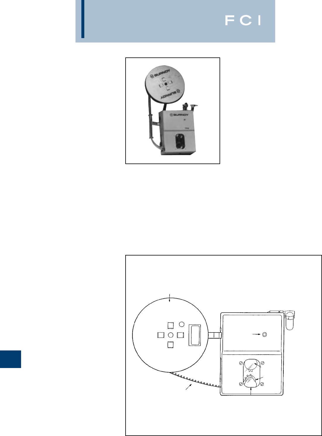
BURNDY
Tooling
N-64
TFM-TAPE FED
MACHINE
FOR AUTOMATIC
INSTALLATION OF TAPE
MOUNTED TERMINALS
The BURNDY®TFM machine installs vinyl
insulated, nylon insulated and uninsulated
terminal sizes #26-#10 without time-
consuming die changes. A rotating turret die
holder consists of three die sets.With the new
TFM, your operators can crimp from 1,500 to
2,500 terminals per hour.
BURNDY®has made a breakthrough in die
changing-the TFM is the first and only turret
die holder to crimp terminals automatically.
No long complicated setups or paying for
duplicate machines: Once the dies are secure
to the die holder there’s never a need to
remove them. No adjustments. No calibra-
tions. Just a simple twist of the wrist. An
operator can change reels, terminals and
dies in seconds flat.
SPECIFICATIONS
Height: 16
Width: 13
Depth: 6
Weight: 35 lbs.
FOR USE ON
#26 - #10 AWG Cu
VINYL INSULATED TERMINALS:
BA-EF-M, BA-EL-M, BA-EM, BA-EZ-M
NYLON INSULATED TERMINALS:
YAE-M, YAE-FM, YAE-ZM
NON-INSULATED TERMINALS:
YAD-M, YAD-FM
VINYL INSULATED DISCONNECTS:
PQ-M
BENEFITS
•Ensures proper wire termination.
•Minimizes repetitive hand motion injuries.
•Smooth rotation advance of connectors.
•Eliminates need for earplugs/noise
dampeners.
•Inexpensive alternative to buying.
•High volume production capability.
•Minimizes production downtime.
FEATURES
•Positive wire locator.
•Foot-actuated crimp.
•Lightweight Reel.
•Quiet operation.
•Lease policy.
•Can crimp up to 1,500 to 2,500 terminals
per hour.
•An operator can change reels, terminals
and dies in 30 seconds.
•Rotating turret die holder permits terminal
change over in seconds.
TWO POSITON REEL HOLDER FITS
LIGHTWEIGHT, CARDBOARD REEL.
HOLDS UP TO 2000 TERMINALS.
CAT.# TFM1D5R
(LEASE ONLY)
TERMINALS ARE SECURED MOUNTED
TO MYLAR FILM AND RELEASED
FROM THE FILM AFTER THE CRIMP
110 V/AC POWER IN
(POWER CORD SUPPLIED)
SMALL OPENING, FOR SAFER WIRE
INSERTION, ELIMINATES ACCI-
DENTS. NO FINGER CAN GET IN.
OSHA APPROVED
FOOT ACTUATED
CRIMP PEDAL
(NOT SHOWN)
80-100 PSI SHOP
AIR IN (HOSE
NOT PROVIDED)
3-WAY
ADJUSTABLE
STAND
WARNING
LIGHT
TOOLIS IN
TFM
ROTATING
DIE TURRETS FOR
FASTER CHANGEOVERS
BURNDY
Tooling
N-65
TFM INSTALLATION TOOLING CHART
* 1000 per Reel
TAPE MOUNTED
CATALOG NO. INSTALLATION
2000/REEL TOOLING
BA16E4M
BA16E6M TFM
BA16E8M with
BA16E10M DFM3-1
BA16E14M Die
BA16E38M
BA14E4M
BA14E6M
BA14E8M TFM
BA14E10M with
BA14E14M DFM2-1
BA14E516M
BA14E38M
*BA10E6M
*BA10E8M TFM
*BA10E10M with
*BA10E14M DFM1D5
*BA10E38M Die
BA16EF2M TFM
BA16EF6M with
BA16EF8M DFM3-1
BA16EF10M Die
BA14EF2M TFM
BA14EF6M with
BA14EF8M DFM2-1
BA14EF10M Die
TFM
*BA10EF6M
with
*BA10EF8M DFM1D5
*BA10EF10M Die
TFM with
BA16EL6M
DFM20D1
BA16EL8M (20-22 AWG)
DFM3-1
BA16EL10M (16-10 AWG)
TFM
BA14EL6M
with
BA14EL8M DFM2-1
BA14EL10M DIE
TFM
*BA10EL6M
with
*BA10EL8M DFM1D5
*BA10EL10M Die
TAPE MOUNTED
CATALOG NO. INSTALLATION
2000/REEL TOOLING
YAD18-4M
YAD18-6M
YAD18-8M TFM
YAD18-10M with
YAD18-14M DFM6-1
YAD18-516M Die
YAD18-38M
YAD14-4M
YAD14-6M
YAD14-8M TFM
YAD14-10M with
YAD14-14M DFM5D1
YAD14-516M Die
YAD14-38M
*YAD10-6M
*YAD10-8M TFM
*YAD10-10M with
*TAD10-14M DFM4D1
*YAD10-516M Die
*YAD10-38M
TFM
YAE22N65FM with
DFM11D1
YAE22N66FM Die
YAE18N60FM TFM
YAE18G43FM with
YAE18N56FM DFM10D1
YAE18N57FM Die
TFM
YAE14N76FM
with
YAE14N77FM DFM9D1
YAE14N78FM Die
TAPE MOUNTED
CATALOG NO. INSTALLATION
2000/REEL TOOLING
YAE22G18M
YAE22G12M TFM
YAE22G16M with
YAE22G13M DFM11D1
YAE22G14M Die
YAE22G15M
YAE18N29M
YAE18N27M
YAE18-N7M
YAE18N17M
YAE18N26M
YAE18N21M TFM
YAE18N25M with
YAE18G43M DFM10D1
YAE-18N24M Die
YAE18N1M
YAE18NM
YAE18N2M
YAE18N3M
YAE14N43M
YAE14N1M TFM
YAE14NM with
YAE14N2M DFM9D1
YAE14N3M Die
YAE14N4M
YAE12N7M
YAE12N9M
YAE12N1M
YAE12NM
YAE12N2M TFM
YAE12N3M with
*YAE10N5M DFM7D1
*YAE10N11M Die
*YAE10NM
*YAE10N3M
*YAE10N2M
*YAE10N4M
TAPE MOUNTED
CATALOG NO. INSTALLATION
2000/REEL TOOLING
TFM
YAE22Z1M
with
YAE22Z2M DFM11D1
YAE22Z3M Die
YAE18Z1M TFM
YAE18Z2M with
YAE18Z3M DFM10D1
YAE18Z4M Die
TFM
YAE14Z2M
with
YAE14Z3M DFM9D1
YAE14Z4M Die
TFM
YAE12Z2M
with
YAE12Z3M DFM7D1
YAE12Z4M Die
BA16EZ2M TFM
BA16EZ6M with
BA16EZ8M DFM3-1
BA16EZ10M Die
BA14EZ2M TFM
BA14EZ6M with
BA14EZ8M DFM2-1
BA14EZ10M Die
TFM
*BA10EZ6M
with
*BA10EZ8M DFM1D5
*BA10EZ10M Die
TFM with
PQ18R257M
DFM13D1
PQ18R258M Die
TFM with
PQ14R257M
DFM12D1
PQ14R258M Die
TFM with
PQ10R258M DFM16D1 Die
TFM with
PQ18R256M DFM15D1 Die
TFM with
PQ14R256M DFM14D1 Die
TFM with
PQ18R187M
DFM13D1
PQ18R188M Die
TFM with
PQ14R187M
DFM12D1
PQ14R188M Die
* 1000 per Reel
* 1000 per Reel
* 1000 per Reel

BURNDY
Reference
O-1
TABLE OF CONTENTS
Compact ACSR Cable................................O-15
ACSR/TW Cable (Trap Wire)...........O-15 - O-16
AAC/TW Cable
(All aluminum trap wire)............................O-16
ACAR Cable ...............................................O-16
SSAC Cable................................................O-17
STEEL CONDUCTORS
Copperweld Cable ......................................O-18
Copperweld - Copper Cable.......................O-18
Galvanized Steel Cable ..............................O-18
Alumoweld Cable........................................O-19
AWG vs Metric Wire Sizes .......................O-19
Inches - Millimeters
Conversion Chart....................................O-20
Terminal Stud Size Chart.........................O-21
Die Set Conversion Chart
(Obsolete Dies)............................O-22 - O-28
BURNDY®Conductor
Numbering System .....................O-29 - O-30
Installation Tool Index...................O-31 - O-41
Catalog Numbers
Requiring MSDS .....................................O-42
Color Coding for Overhead
Connectors..............................................O-42
Color Coding for
AL/CU Connectors..................................O-43
Color Coding for Copper
Lugs and Splices....................................O-43
Alpha-Numeric Index ....................O-44 - O-67
Product/Trade Name Index ......................O-68
INTRODUCTION
Basic Connection Principles.........................O-2
HARDWARE DATA
DURIUM™ Steel/Aluminum
Tightening Torques .....................................O-6
DURIUM™ Hex Bolts Data...........................O-6
UL Tightening Torque UL486........................O-7
CABLE DATA (TABLES)
COPPER CABLE
Copper Tube .................................................O-8
Solid Copper Wire.........................................O-8
Stranded Copper Cable................................O-8
Compact Stranded Copper Cable ................O-9
Flexible Copper Stranded Cable.................O-10
ALUMINUM AND ACSR CABLE
Aluminum Tube ...........................................O-11
Aluminum 1350 Cable
Bare-Classes AA and A..........................O-11
Aluminum 1350 Cable
Bare-Class B ..........................................O-11
ACSR Cable ...............................................O-12
High Strength ACSR Cable ........................O-12
Compact Aluminum 1350 Cable.................O-13
Aluminum Alloy 5005 Cable .......................O-13
Aluminum 6201 Cable ................................O-13
Aluminum Alloy 8000 Series "O"
Temper Cable................................O-14 - O-15
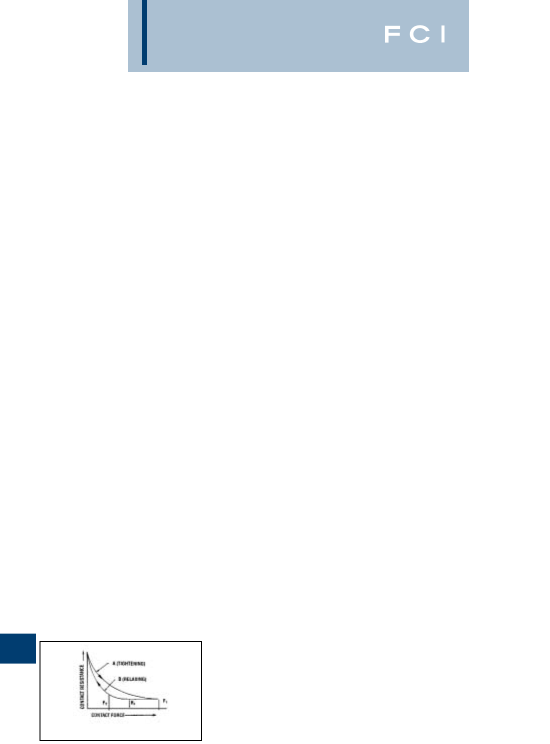
BURNDY
Reference
BASIC ELECTRICAL
CONNECTION PRINCIPLES
Basic Factors:
The basic factors which influence the design
and performance of pressure wire connec-
tions are as follows:
1. Creep
2. Surface Oxide
3. Corrosion
A fourth factor, known as thermal effects, is
also a consideration, but due to the technical
nature and length of the topic, it will not be
discussed in this publication.
At the outset it should be pointed out that
these factors give rise to much more difficult
problems in connections involving aluminum
conductors than those encountered in copper
to copper connections.
CREEP (COLD FLOW)
Creep is the cold flow of the metal under
pressure, and it continues until the pressure
reduces to a value at which any further creep
is negligible. Creep properties depend on the
particular metal or alloy and on its hardness;
alloys having less creep than pure metals,
and harder metals have less creep than soft
metals. In a typical connection, the conduc-
tors are generally of pure metal and often of
soft temper and therefore, subject to consid-
erable creep. In addition, the condition is
further exaggerated when aluminum is the
conductor as compared to copper, since its
creep rate is many times that of copper.
Effect of Creep: Figure 2 shows typical
curves of total contact resistance plotted
against total contact force. Curve A shows
how the contact resistance continually
decreases with increasing contact force.
When the full contact force F1 is reached, the
contact resistance reaches the low value of
R1. In general, the full tightening force on a
connector greatly exceeds the maximum force
for which there is no appreciable creep.
Therefore, the force will gradually settle down
to a value after which there will be no further
significant creep. Fortunately, however, the
resistance does not climb back up along curve
A, the tightening curve, but instead it follows a
new curve B, the relaxing curve, along which
the resistance changes very little, until the
force relaxes to a value such as F2.
Admittedly, the point of "no appreciable
creep" is difficult to define. For pure metals,
especially in the soft state, there is always
some creep, even at very low pressures at
room temperature. However, we do know that
the pressure required to produce the same
creep rate is several times greater for copper
than for aluminum. Thus, to permit the same
contact force F2 for aluminum and copper,
the contact area A required for aluminum can
be expected to be considerably greater than
that required for copper. This explains why
the contact areas for connectors for alu-
minum must be considerably greater than for
copper, and why many light duty connectors
for copper are entirely inadequate for alu-
minum, even when specially plated and when
recommended compounds are used on the
contact surfaces.
Relaxation: Relaxation of pressure due to
creep, or for any other reason, would be a
much more difficult factor in a pressure con-
nection were it not for the relationship of
contact pressure to contact resistance on the
relaxation curve as shown in Figure 2. It is
frequently observed that some time after the
bolts of a clamp type connector are tight-
ened, the bolt tensions are relaxed apprecia-
bly. The question arises as to whether it is
necessary to retighten the bolts to the
original torque value. In a properly designed
connector, retightening is unnecessary since
the contact resistance should increase very
little due to the relaxation of pressure, as
shown by the relaxation curve of Figure 2.
This fact is largely responsible for the
successful operation of a compression con-
nector. The application of the compression
tool applies very high pressure, establishing
very low contact resistance. The removal of
the compression tool releases a very large
proportion of this pressure, and creep further
relaxes this pressure. Fortunately, the contact
resistance increases very little due to this
pressure relaxation.
Contact Force: The previous analysis shows
that the total contact force largely determines
the contact resistance. Thus, to achieve the
desired low value of contact resistance, the
proper size and number of bolts in a clamp
type connector must be supplied, and the
compression tool must apply the proper force
to a compression connector. In addition, the
connector must be designed with sufficient
structural strength, contact area, and
resilience, to assure that the contact force
cannot relax beyond the point where contact
resistance begins to rise appreciably, as
shown in Figure 2.
SURFACE OXIDE
The contact of pure metallic surfaces cannot
be assured in practical connections. Surface
contamination must be expected, especially
surface oxidation. These surface films are
insulators as far as contact resistance is con-
cerned, and they must be broken to achieve
metal to metal contact to make an adequate
electrical connection. The difficulty of break-
ing the film depends on the nature of the film,
its thickness, and the metal on which it is
formed.
Copper oxide is generally broken down by
reasonably low values of contact pressure.
Unless the copper is badly oxidized, good
contact can be obtained with very little or no
cleaning.
Silver oxide is even more easily broken down
by the contact pressure; and since silver
oxide forms less readily at elevated tempera-
tures, silver contact surfaces are preferred
over copper when used for higher tempera-
tures. For this reason, it is considered good
practice to silver plate copper contact
surfaces that must operate at temperatures
over 200° C.
On the other hand, aluminum oxide is a hard,
tenacious, high resistance film that forms
very rapidly on the surface of aluminum
exposed to air. In fact, it is the toughness of
this film that gives aluminum its good corro-
sion resistance. The oxide film that forms
after more than a few hours is too thick and
tough to permit a low resistance contact with-
out cleaning. The aluminum oxide film is
transparent so that even the bright and clean
appearance of an aluminum connector is no
assurance that the low contact resistance
can be attained without cleaning.
In addition to the necessity for cleaning the
oxide from aluminum, the surface should be
covered with a good connector compound to
prevent the oxide from reforming. Common
practice is to clean the surface with a wire
brush or emery cloth. The compound should
be applied immediately after cleaning, or the
compound should be put on first and the
surface scraped through the compound.
Present practice is to scratch brush dry and
to apply the compound immediately there-
after. This allows a more thorough job of
cleaning the conductor.
O-2
Fig. 2
INTRODUCTION

BURNDY
Reference
Contact Compounds: Petrolatum or No-
Oxid are good contact surface compounds
for aluminum, but BURNDY®PENETROX A,
a petrolatum type compound containing zinc
dust, has the additional advantage of assist-
ing in the breaking down of the contact resis-
tance. How this is accomplished is not
certain, but it appears that the zinc particles
of PENETROX A probably act as current
bridges in the breaks in the oxide film. For
more complete information about the PENE-
TROX®line of compounds, refer to the
Accessories Section of this catalog.
Interstrand Resistance: The high contact
resistance due to the oxide on the strands of
an aluminum cable may be responsible for a
poor distribution of current among the strands
on the cable. Thus, the outer strands may
carry much more than their share of the
current and overheating of the cable may
result. Tests have shown that even on new
cable this effect of interstrand resistance can
be considerable unless a good contact
compound is used. The clamping action
tends to break down the oxide and force the
compound between the strands. This is par-
ticularly true of compression connectors due
to the very high unit pressures developed.
The most effective way to break down inter-
strand resistance of aluminum cable is to use
compression connectors filled with a com-
pound having zinc particles. Then, when the
end of the cable is inserted in the connector,
the compound is forced between the strands
where it very effectively breaks down the
interstrand resistance upon application of the
compressive force.
Plating Aluminum: Plating the contact sur-
faces of aluminum connectors will prevent the
formation of aluminum oxide. Electro-tin,
cadmium and zinc platings have been used
for this purpose. However, the use of a plated
aluminum conductor, does not make it less
necessary to scratch brush the aluminum
conductor, nor does it reduce the need for a
good contact compound. Additional problems
are introduced due to the plating on
aluminum which render it of very doubtful
value over the proper use of bare aluminum.
This will be more fully discussed later.
CORROSION
The electrical conductivity and mechanical
strength of an electrical connection must
remain stable under the deteriorating influ-
ences of the environment. This deterioration
is corrosion. It is the electrolytic action of
moisture and other elements of the atmos-
phere in conjunction with the metals of the
connection. If the conductors and connectors
are of copper or a corrosion resistant copper
alloy, corrosion is usually a minor factor.
However, it is a very vital factor if aluminum
is involved.
If moisture can be kept away from the con-
nection, corrosion will not be a factor. The
electrical connection of a high voltage splice
on insulated cable is generally free from
corrosion since the taping must be moisture-
proof. Similarly, taping may be used to avoid
corrosion on bare cable, provided it excludes
moisture. It is difficult to get a good tape seal
to the conductor itself, especially on stranded
cable. If moisture does penetrate the taping, it
will not dry out as readily as if the joint were
untaped. Various plastic materials are avail-
able today for covering low voltage connec-
tions or for bare conductor connections on
high voltage. Unless such coverings are
completely moisture-proof, it is better to
rely on installation with a good contact
compound, using a connector designed to
resist corrosion.
Galvanic Action: Whenever dissimilar
metals are in the presence of an electrolyte, a
difference in electric potential is developed.
One metal becomes the cathode and
receives a positive charge. The other
becomes the anode and receives a negative
charge. When these metals are in contact, an
electrical current will flow, as in the case of
any short-circuited electric cell. This elec-
trolytic action causes an attack of the anodic
metal, leaving the cathodic metal unharmed.
The extent of the attack is proportional to the
strength of the electrolytic current, which in
turn is proportional to the electric potential
difference developed.
The magnitude of the potential difference
generated between two dissimilar metals can
be seen by the position of these metals in the
electrolytic series. Figure 3 is such a series.
When two metals are in contact in an elec-
trolyte, the one higher up in this series is the
anode, the corroded metal, while the one
lower is the cathode, the protected metal.The
further apart the metals are in this series,
the greater the electrolytic potential differ-
ence, and the greater the attack to the
anodic metal.
Note that copper and aluminum are quite far
apart in the series, copper being cathodic and
aluminum anodic. Hence, when aluminum
and copper are in contact in an electrolyte,
the aluminum can be expected to be
severely attacked.
Crevice Corrosion: Electrolytic attack can
also occur between like metals due to a
phenomenon known as oxygen concentration
cell or crevice corrosion. Since oxygen is
necessary for corrosive action, a variation in
the concentration of oxygen where a metal is
exposed to an electrolyte will generate a
difference of potential, and cause a corrosive
attack in the oxygen starved area. Thus,
since an electrolyte in a deep crevice is freely
exposed to the air at the outside, the concen-
tration of oxygen will be greatest at the mouth
of the crevice. Then corrosion can be expect-
ed to occur in the crevice remote from the
surface. Crevice corrosion can be prevented
if the crevice is filled with a compound to
exclude moisture. Thus, within the contact
groove of an aluminum connector containing
an aluminum conductor, there will be numer-
ous crevices in which corrosion will take
place unless a good connector compound is
applied during installation. Copper, being a
more noble metal, appears to be much less
subject to crevice corrosion.
Corrosion Testing: The effectiveness of an
electrical connection to resist corrosion can
be tested in the laboratory under conditions
designed to greatly accelerate the natural
corrosive conditions of actual service. The
most widely accepted means is the standard
salt spray chamber. In this chamber the spec-
imens are placed in a salt fog made by atom-
izing a 20% salt solution at 100 deg F.
FCI - BURNDY Electrical as well as other
manufacturers and utility companies, have
done a great deal of testing and a consider-
able area of agreement has been reached.
There are, however, minor differences in
recommended practices. The problem is
concerned with aluminum and aluminum to
copper connections since the effect of corro-
sion on copper to copper connections is far
less serious. Let us study the recommended
practices.
Aluminum to Aluminum Connections: For
joining aluminum to aluminum conductors,
there is little disagreement that an aluminum
bodied connector is the proper choice, since
this obviously eliminates the galvanic corro-
sion of dissimilar metals. However, even in
this case, care must be taken to prevent
crevice corrosion and to select an alloy of
aluminum for the connector body that is free
from cracking due to stress corrosion.
Aluminum to Copper Connections:
Similarly, for joining aluminum to copper
conductors, an aluminum bodied connector is
the best choice since it prevents galvanic
O-3
INTRODUCTION (Continued)
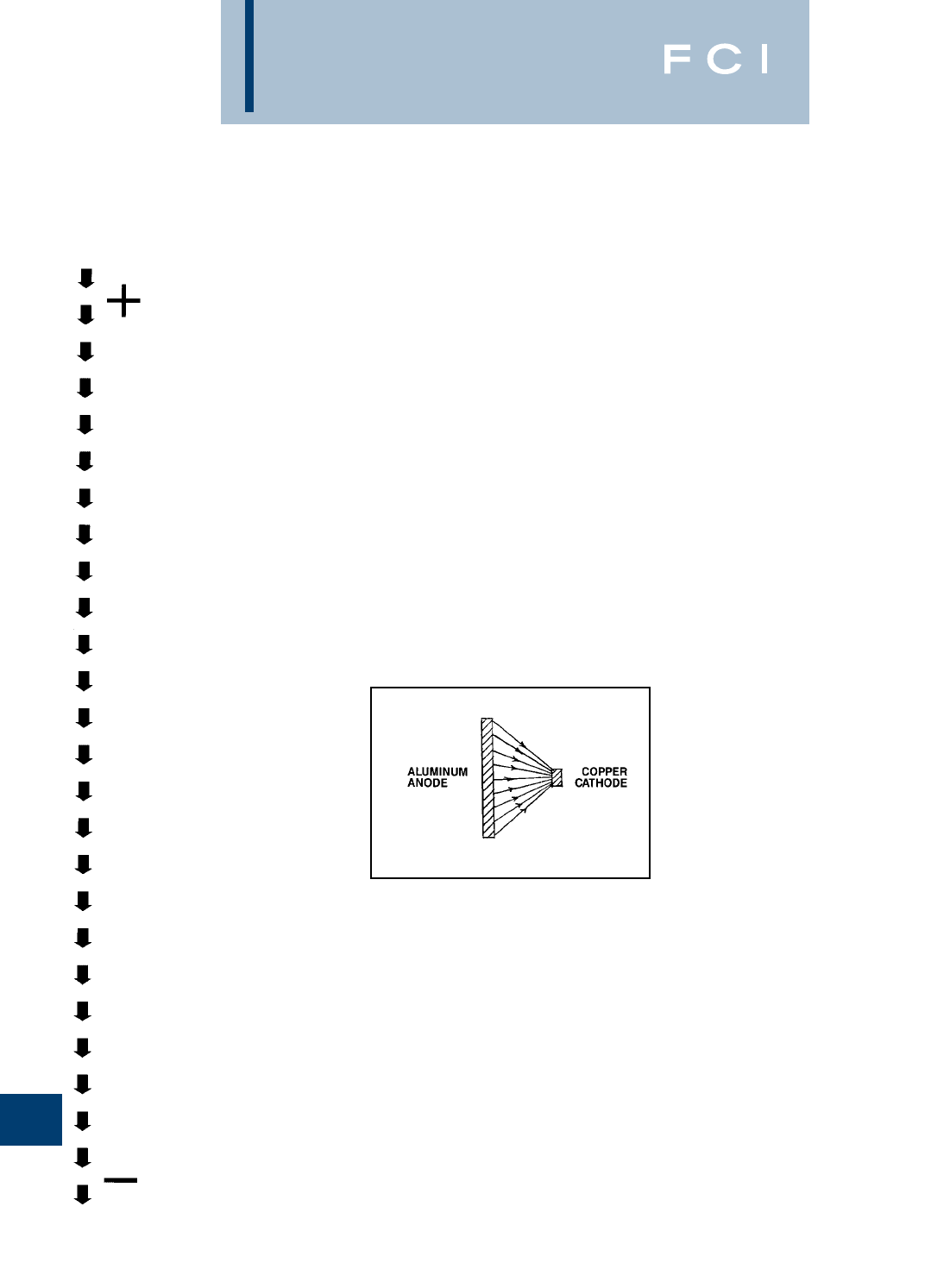
BURNDY
Reference
corrosion of the aluminum conductor, the
most vulnerable element to attack in the con-
nection. Realizing this, BURNDY®initiated a
research program aimed at finding the best
way to make an aluminum connector suitable
for joining aluminum to copper conductors.
This led to the evolution of the “Massive
Anode Principal” of connector design for join-
ing conductors of dissimilar metal. On the
basis of this principal, properly designed, all-
aluminum connectors became available for
universal use in joining aluminum to alu-
minum or aluminum to copper conductors.
Massive Anode Principle: By making the
aluminum connector massive in comparison
to the copper conductor, when the copper
conductor emerges from the connector, the
electrolytic current density over the exposed
face of the aluminum connector is greatly
reduced. This is schematically represented in
Figure 4. Since the rate of corrosion is direct-
ly related to the current density on the
surface of the anodic material, the relatively
large face of the aluminum connector will
suffer only minor attack.
In addition, because the aluminum connector
body is massive in the region where the cor-
rosion occurs, the small loss of metal caused
by corrosion is insignificant, even after long
periods of service. Furthermore, the connec-
tor design should be such that clamping bolts,
and areas of high stress which provide struc-
tural strength, are not in the regions subject to
galvanic attack.
The effectiveness of this theory has been
amply demonstrated in salt spray corrosion
tests in which the connectors were subject to
1,000 hours in the salt spray fog with only
minor corrosive pitting adjacent to the copper
conductor, as seen in Figure 5. In addition,
the aluminum conductor was completely
protected, and the joint resistance remained
virtually unchanged. The test involved a wide
variety of sizes and types of connectors
showing the effectiveness for small service
connectors as well as large power connec-
tors. Figure 6 shows a large all aluminum
clamp type T connector installed on 31⁄2"
diameter copper run and 750MCM aluminum
tap. The figure shows this connector opened
up after the 1,400 hours of the salt spray test.
Note that the contact surfaces are bright and
clean and the only evidence is minor pitting
along the faces adjacent to the copper.
*It should be emphasized that a good
compound should be used on the contact
surfaces whether aluminum or copper is used
in an aluminum connector.
Position of Conductor: A properly designed
aluminum connector for joining aluminum to
copper must provide adequate separation
between the conductors to prevent electro-
lytic attack on the aluminum conductor. Even
then, it is good practice to install the
aluminum conductor above the copper con-
ductor if possible. This will prevent pitting of
the aluminum conductor due to copper salts
being washed over the aluminum.
Plated Aluminum Connectors: Plating has
been used as a means to make an aluminum
connector suitable for copper conductor.
Such platings as copper, zinc, tin and cad-
mium have been used. The plating of
aluminum is much more critical than plating a
more noble metal such as copper. In addition,
a preplate, usually of copper or brass, must
be applied, thus introducing numerous
metals and further possibilities for galvanic
corrosion.
To be effective in reducing galvanic corrosion
between the copper conductor and the
aluminum connector, the plated metal must
be closer in the Electrolytic Series to copper
than is aluminum. It must therefore, be
cathodic to aluminum. Since porosity and
minor scratches are always present, galvanic
action can be expected in the presence of
moisture, resulting in attack of the aluminum
under the plating. Corrosion tests reveal
attack in the form of a mottled appearance
and flaking of the plating.
In addition, the presence of plated metal can
cause galvanic attack of the aluminum con-
ductor, thus reducing the protection offered to
this conductor in an aluminum connector.
Cleaning and the Use of Compound: It
should be emphasized that when aluminum
connectors or conductors are involved,
proper cleaning of the aluminum and the use
of a good connector compound, such as
BURNDY®PENETROX A, are essential for
trouble-free service. BURNDY®, as well as
other manufacturers, provide the contact
grooves with a coating to make it unneces-
sary to clean the connectors, but in all cases,
O-4
INTRODUCTION (Continued)
Fig. 3
Fig. 4
LESS NOBLE (ANODIC)
Magnesium
Magnesium alloys
Zinc
Aluminum 1100
Cadmium
Aluminum 2024-T4
Steel or Iron
Cast Iron
Chromium Iron
(Active)
Ni-Resist
Type 304 Stainless
(Active)
Type 316 Stainless
(Active)
Lead Tin Solders
Lead
Tin
Nickle (Active)
Inconel
Brasses
Copper
Bronzes
Copper-nickle alloys
Monel
Silver Solder
Nickel (Passive)
Inconel (Passive)
Chromium-Iron
(Passive)
Type 304 Stainless
(Passive)
Type 316 Stainless
(Passive)
Silver
Titanium
Graphite
Gold
Platinum
MORE NOBLE (CATHODIC)
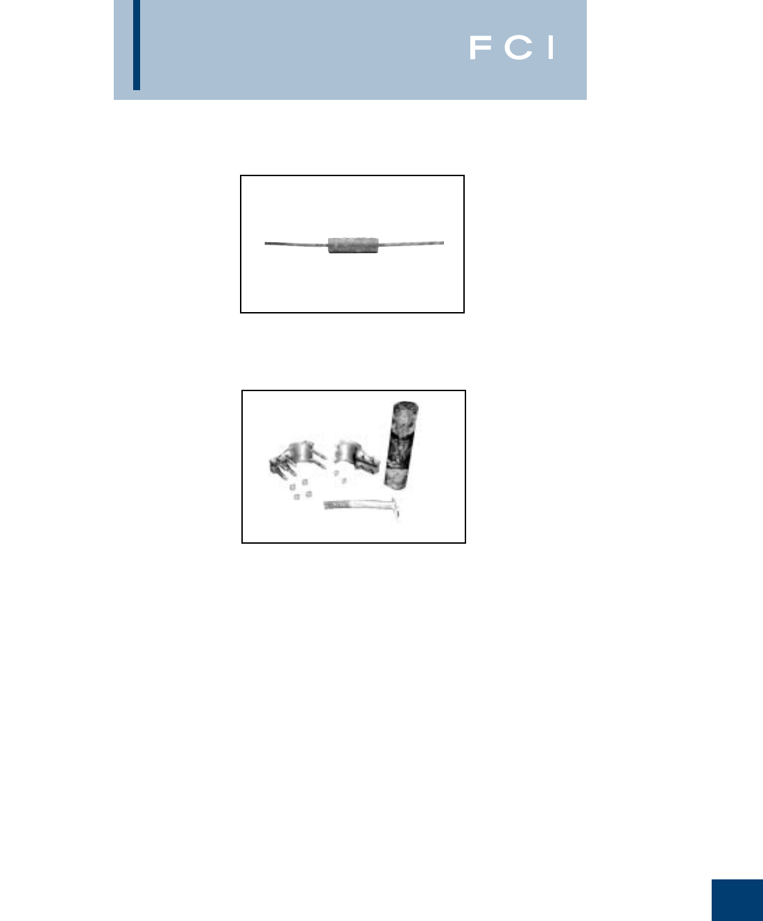
BURNDY
Reference
the aluminum conductor should be cleaned
by means such as scratch brushing, and
immediately coated with the connector
compound.
To simplify the application of the compound,
and to assure its use, almost all BURNDY®
aluminum connectors, except the large clamp
type substation connectors, are supplied
factory filled with PENETROX compound. For
the tubular compression connectors, the
tubular barrels are sufficiently filled with
PENETROX and capped. For other types, the
contact grooves are filled with PENETROX
and enclosed in plastic packaging in a
process called “Stripsealing”.
Clamp vs. Compression: In general, a
compression connection can be expected to
be more corrosion resistant than a clamp
connection. The high pressures applied in a
compression connector more effectively seal
the contact against the penetration of mois-
ture. The tubular sleeve of a compression
connector has no side openings such as exist
in clamp connectors between the clamping
members. On the other hand, the clamp
connector can be made more corrosion resis-
tant if the conductor grooves conform more
closely with the conductor contour. Thus a
clamp connector made to accommodate a
wide range of conductor sizes cannot be
expected to be as corrosion resistant as one
designed for one specific conductor size.
Nevertheless, the differences in effectiveness
of various designs can be minimized if a good
contact compound is used.
O-5
INTRODUCTION (Continued)
Fig. 5
Fig. 6
Negligible Corrosion of Severe Salt Spray on
Compression Connector Joining Aluminum
to Copper.
Large Aluminum Bolted Connector Joining
Copper Run to Aluminum Tap After Severe
Salt Spray Test.
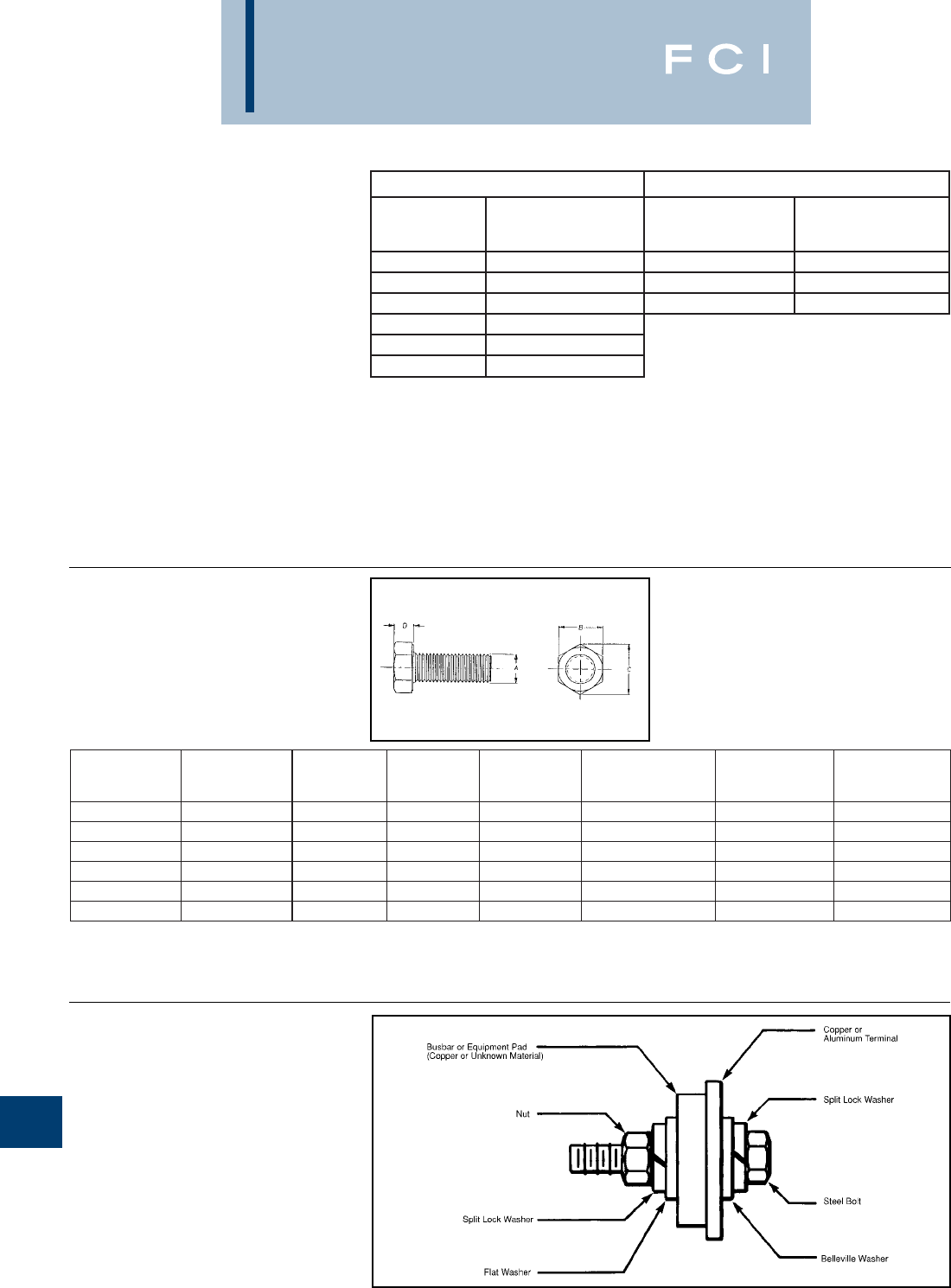
BURNDY
Reference
HARDWARE DATA
RECOMMENDED
TIGHTENING TORQUE
The hardware used in connectors must be
compatible with the connector material, have
high mechanical strength and be corrosion
resistant.
Copper alloy connectors have hardware
made of DURIUM™, which is BURNDY's
trade name for silicon bronze alloy
ASTMB99. This material was first introduced
by BURNDY®in 1927 for use in outdoor con-
struction, and today, is the standard through-
out the industry.
Aluminum connectors generally have alu-
minum alloy hardware. The bolts are 2024T4
and anodized to resist corrosion.The nuts are
6061T6, which is resistant to corrosion
and does not require anodizing. Bolts are
lubricated to eliminate galling and to provide
consistent clamping forces.
The size material for clamping hardware are
selected to provide the required force when
tightened to the recommended torque. To
reduce or greatly exceed the recommended
torque can adversely affect the performance
of the connector.
DURIUM™
(SILICON BRONZE)
HEXAGONAL BOLT DATA
O-6
erawdraHleetSerawdraHmunimulA
tloB eziS
dednemmoceR euqroT )sdnuoPhcnI( tloB eziS
dednemmoceR euqroT )sdnuoPhcnI(
02-4/10831-2/1003
81-61/508111-8/5084
61-8/304201-4/3056
31-2/1084
11-8/5066
01-4/30501
CATALOG NO.
SERIES "A" (BOLT
SIZE) "B" "C" "D" RECOMMENDED
TORQUE (in-lb)
MIN.
BREAKING
FORCE (lb)
MIN.
SHEARING
FORCE (lb)
25X_ _ _HEB 1/4 - 20 UNC 7/16 .50 .16 80 1,780 990
31X_ _ _HEB 5/16 - 18 UNC 1/2 .56 .21 180 2,930 1,640
38X_ _ _HEB 3/8 - 16 UNC 9/16 .65 .24 240 4,350 2,430
50X_ _ _HEB 1/2 - 13 UNC 3/4 .87 .32 480 7,950 4,460
62X_ _ _HEB 5/8 - 11 UNC 15/16 1.08 .40 660 12,700 7,100
75X_ _ _HEB 3/4 - 10 UNC 1-1/8 1.30 .48 1050 17,510 10,540
➁➂
1. Material: DURIUM™ (Silicon Bronze)
➁"_ _ _" is substituted for bolt length. Consult sales
representative for available lengths.
➂These torque values develop maximum bolt preload.
4. This drawing is based on BURNDY®engineering spec.
RECOMMENDED
TERMINATION
HARDWARE
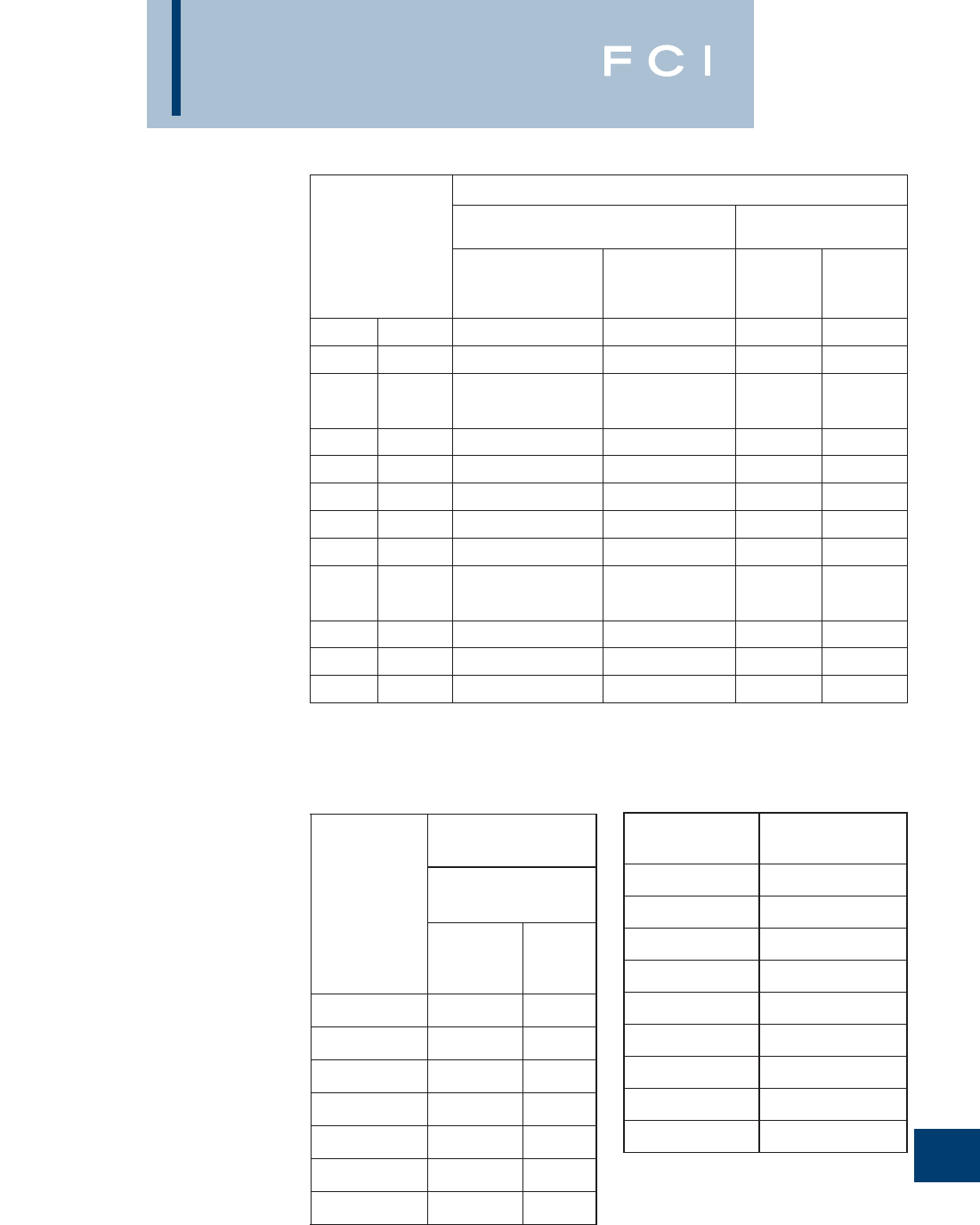
BURNDY
Reference
RECOMMENDED
TIGHTENING TORQUE
PER UL486A AND UL486B
O-7
Test Wire
Size Installed
In Connector
AWG or MCM (mm1)
Tightening Torque, Pound-Inches (N.m)
Slotted Head No. 10 and Larger1Hexagonal Head -
External Drive Socket Wrench
Slot Width -
0.047 Inch (1.2 mm) or Less
and Slot Length
1/4 Inch (6.4 mm) or Less
Slot Width -
Over 0.047 Inch (1.2 mm or
Slot Length -
Over 1/4 Inch (6.4 mm)
Split-Bolt
Connectors Other
Connectors
18-10 (.082-5.3) 20 (2.3) 35 (4.0) 80 (9.0) 75 (8.5)
8(8.4) 25 (2.8) 40 (4.5) 80 (9.0) 75 (8.5)
6-4 (13.3-21.2) 35 (4.0) 45 (5.1) 165 (18.6) 110 (12.4)
3(26.7) 35 (4.0) 50 (5.6) 275 (31.1) 150 (16.9)
2(33.6) 40 (4.5) 50 (5.6) 275 (31.1) 150 (16.9)
1(42.4) -50 (5.6) 275 (31.1) 150 (16.9)
1/0-2/0 (53.5-67.4) -50 (5.6) 385 (43.5) 180 (20.3)
3/0-4/0 (85.0-107.2) -50 (5.6) 500 (56.5) 250 (28.2)
250-350 (127-177) -50 (5.6) 650 (73.4) 325 (36.7)
400 (203) -50 (5.6) 825 (93.2) 325 (36.7)
500 (253) -50 (5.6) 825 (93.2) 375 (42.4)
600-750 (304-380) -50 (5.6) 1000 (113.0) 375 (42.4)
800-1000 (406-508) -50 (5.6) 1000 (124.3) 500 (56.5)
1250-2000 (635-1010) - - 1100 (124.3) 600 (67.8)
TABLE 7.4:
1For values of slot width or length not corresponding to those
specified, select the largest torque value associated with the
Socket Size Across
Flats Inch (mm)1Tightening Torque,
Pound-Inches (N-m)
1/8 (3.2) 45 (5.1)
5/32 (4.0) 100 (11.4)
3/16 (4.8) 120 (13.8)
7/32 (5.6) 150 (17.0)
1/4 (6.4) 200 (22.6)
5/16 (7.9) 275 (31.1)
3/8 (9.5) 375 (42.4)
1/2 (12.7) 500 (56.5)
9/16 (14.3) 600 (67.8)
Slot Length
of Screw
Inch (mm)2
Smaller Than
0.047 (1.2) 0.047 (1.2)
and Larger
Tightening Torque,
Pound-Inches
(N-m)
Slot Width of Screw
Inch (mm)1
Less than 5/32 (4) 7 (0.79) 9 (1.0)
5/32 (4) 7 (0.79) 12 (1.4)
3/16 (4.8) 7 (0.79) 12 (1.4)
7/32 (5.6) 7 (0.79) 12 (1.4)
1/4 (6.4) 9 (1.0) 12 (1.4)
9/32 (7.1) 15 (1.7)
Above 9/32 (7.1) 20 (2.3)
TABLE 7.5:
1Slot width is the nominal design value
2For slot lengths of intermediate values, select torques per-
taining to next shorter slot length. Also, see note 1to Table 7.4
for screws with multiple tightening means. Slot length is to be
measured at the bottom of the slot.
TABLE 7.6:
1See note 1to Table 7.4 for screws with multiple tightening
means.
conductor size. Slot width is the nominal design value. Slot
length is measured at the bottom of the slot.

BURNDY
Reference
COPPER TUBE (BUS) SOLID COPPER WIRE
(ASTM B1, B2, & B3)
STRANDED COPPER WIRE
(ASTM B8 EXCLUDING BREAKING LOADS)
O-8
CABLE DATA
SIZE OF TUBE
IPS
DIAMETER OF TUBE
(Inches) WALL
THICKNESS
(Inches)
OUTSIDE INSIDE
STANDARD PIPE SIZES
1/4"
3/8"
1/2"
3/4"
1"
1-1/4"
1-1/2"
2"
2-1/2"
3"
3-1/2"
4"
4-1/2"
5"
6"
0.540
0.675
0.840
1.050
1.315
1.660
1.900
2.375
2.875
3.500
4.000
4.500
5.000
5.563
6.625
0.375
0.494
0.625
0.822
1.062
1.368
1.600
2.062
2.500
3.062
3.500
4.000
4.500
5.063
6.125
0.082 5
0.090 5
0.107 5
0.114 0
0.126 5
0.146 0
0.150 0
0.156 5
0.187 5
0.219 0
0.250 0
0.250 0
0.250 0
0.250 0
0.250 0
EXTRA HEAVY PIPE SIZES
1/4"
3/8"
1/2"
3/4"
1"
1-1/4"
1-1/2"
2"
2-1/2"
3"
3-1/2"
4"
4-1/2"
5"
6"
0.540
0.675
0.840
1.050
1.315
1.660
1.900
2.375
2.875
3.500
4.000
4.500
5.000
5.563
6.625
0.294
0.421
0.542
0.736
0.951
1.272
1.494
1.933
2.315
2.892
3.358
3.818
4.250
4.813
5.751
0.123
0.127
0.149
0.157
0.182
0.194
0.203
0.221
0.280
0.304
0.321
0.341
0.375
0.375
0.437
DOUBLE EXTRA HEAVY PIPE SIZES
1/2"
3/4"
1"
1-1/4 "
1-1/2"
2"
2-1/2"
3"
3-1/2"
4"
4-1/2"
5"
6"
0.840
1.050
1.315
1.660
1.900
2.375
2.875
3.500
4.000
4.500
5.000
5.563
6.625
0.252
0.434
0.599
0.896
1.100
1.503
1.771
2.300
2.728
3.152
3.580
4.063
4.897
0.294
0.308
0.358
0.382
0.400
0.436
0.552
0.600
0.636
0.674
0.710
0.750
0.864
SIZE
AWG
(SOLID)
WIRE
DIA
Inch
HARD
DRAWN MEDIUM
DRAWN SOFT
DRAWN
NORMAL
BREAKING
LOAD
Pounds
MINIMUM
ELONGATION
IN 10 IN.
% MIN.
BREAKING
LOAD
Pounds
18
17
16
15
14
13
12
11
10
9
8
7
6
5
4
3
2
1
1/0
2/0
3/0
4/0
.040 30
.045 26
.050 82
.057 07
.064 08
.071 96
.080 81
.090 74
.101 9
.114 4
.128 5
.128 5
.162 0
.181 9
.204 3
.229 4
.257 6
.289 3
.324 9
.364 8
.409 6
.460 0
85.76
107.5
135.2
170.0
213.8
268.2
337.0
422.5
529.2
661.0
826.0
1,030
1,280
1,591
1,970
2,439
3,003
3,688
4,519
5,518
6,722
8,143
67.61
84.71
106.2
133.0
166.6
208.0
261.6
327.6
410.4
514.2
643.9
806.6
1,010
1,265
1,584
1,984
2,450
3,024
3,730
4,599
5,667
6,980
25
25
25
25
25
25
25
25
25
30
30
30
30
30
30
30
30
30
35
35
35
35
SIZE A.S.T.M.
STRANDINGS HARD
DRAWN MEDIUM
DRAWN SOFT
DRAWN
STRANDED
Class No. of
Wires
Cable
Diameter
Inches
Mimimum
Breaking
Load
Pounds
Mimimum
Breaking
Load
Pounds
Mimimum
Breaking
Load
Pounds
Circular
Mills AWG
1,022
1,624
2,583
4,107
6,530
10,380
13,090
16,510
20,820
26,250
33,100
41,740
41,740
52,630
20
18
16
14
12
10
9
8
7
6
5
4
4
3
B
B
B
B
B
B
B
B
B
B
B
AA
B&A
AA
7
7
7
7
7
7
7
7
7
7
7
3
7
3
0.036 3
0.045 6
0.057 6
0.072 6
0.091 5
0.116
0.130
0.146
0.164
0.184
0.206
0.254
0.232
0.285
50.04
78.99
124.7
197.1
311.1
491.7
618.2
777.2
977.1
1,288
1,542
1,879
1,938
2,359
40.67
63.91
100.4
157.7
247.7
388.9
487.4
610.7
765.2
958.6
1,201
1,465
1,505
1,835
32.09
51.03
81.14
124.2
197.5
314.0
395.9
499.2
629.5
793.8
1001
1213
1262
1530
Tube dimensions (excepting wall thickness, of double extra
heavy) taken from A.S.T.M. Specification B42-33.
Tubular values based on a density of 0.322 pound per cubic
inch.
*Conductivity of 98% I.A.C.S. at 20° C or 68° F.
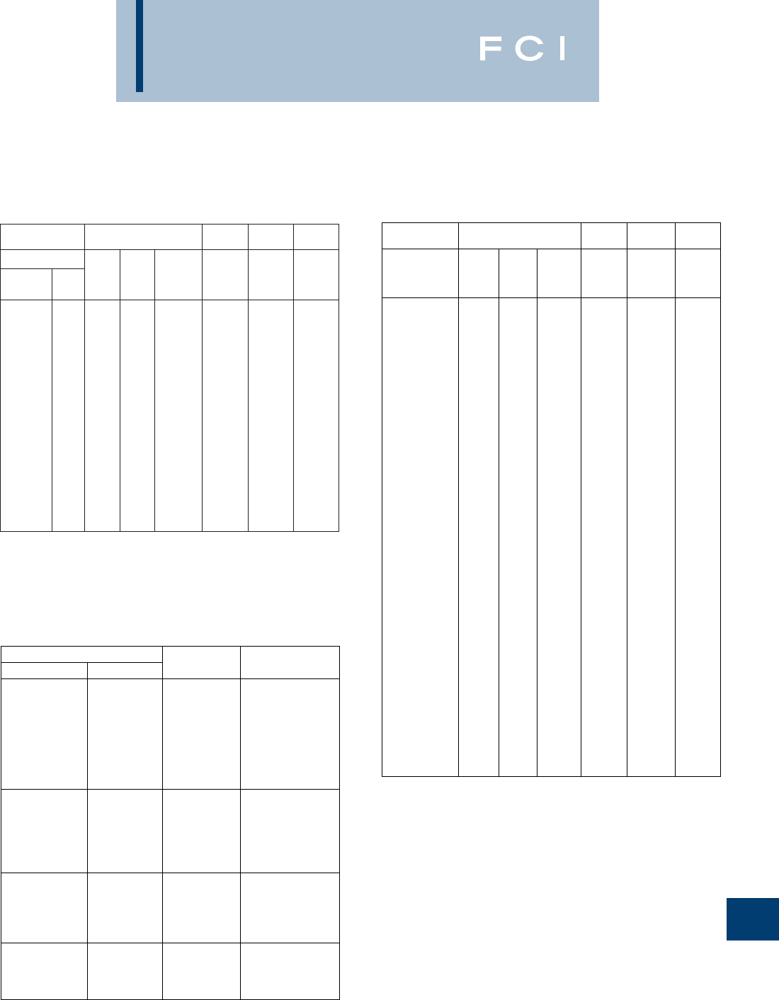
BURNDY
Reference
O-9
CABLE DATA (Continued)
250
250
250
300
300
300
350
350
350
400
400
450
450
500
500
600
600
700
700
750
750
800
800
900
900
1,000
1,000
1,250
1,250
1,500
1,500
1,750
1,750
2,000
2,000
AA
A
B
AA
A
B
AA
A
B
A&AA
B
AA
B&A
AA
B&A
A&AA
B
AA
B&A
AA
B&A
AA
B&A
AA
B&A
AA
B&A
A
B
A
B
A
B
A
B
12
19
37
12
19
37
12
19
37
19
37
19
37
19
37
37
61
37
61
37
61
37
61
37
61
37
61
61
91
61
91
91
127
91
127
0.600
0.574
0.575
0.657
0.628
0.630
0.710
0.679
0.681
0.726
0.728
0.770
0.772
0.811
0.813
0.891
0.893
0.963
0.964
0.997
0.998
1.029
1.031
1.092
1.094
1.151
1.152
1.288
1.289
1.411
1.412
1.526
1.526
1.630
1.632
11,130
11,360
11,560
13,170
13,510
13,870
15,140
15,590
16,060
17,810
18,320
19,750
20,450
21,950
22,510
27,020
27,530
31,170
31,820
33,400
34,090
35,120
36,360
39,510
40,520
43,830
45,030
55,670
56,280
65,840
67,540
77,930
78,800
87,790
90,050
8,717
8,986
8,952
10,390
10,530
10,740
12,040
12,200
12,450
13,950
14,140
15,590
15,900
17,320
17,550
21,060
21,350
24,410
24,740
26,150
26,510
27,710
28,270
31,170
31,590
34,400
35,100
43,590
43,880
51,950
52,650
61,020
61,430
69,270
70,210
7265
7265
7559
8718
8718
9071
10170
10170
10580
11620
11620
13080
13080
14530
14530
17440
18140
20340
20340
21790
21790
23250
23250
26150
26150
29060
29060
36320
36320
43590
43590
50850
50850
58120
58120
SIZE A.S.T.M.
STRANDINGS HARD
DRAWN MEDIUM
DRAWN SOFT
DRAWN
Class No. of
Wires
Cable
Diameter
Inches
Mimimum
Breaking
Load
Pounds
Mimimum
Breaking
Load
Pounds
Mimimum
Breaking
Load
Pounds
Circular
Mills
COMPACT STRANDED COPPER CABLE
(ASTM SPEC.B496)
CONDUCTOR SIZE NUMBER
OF WIRES CONDUCTOR
DIAMETER (IN.)
KCMIL (OR) AWG
1000
900
800
750
700
650
600
550
611
611
611
611
611
611
611
611
1.060
0.999
0.938
0.908
0.877
0.845
0.813
0.775
500
450
400
350
300
250
372
372
372
372
372
372
0.736
0.700
0.659
0.616
0.570
0.520
4/0
3/0
2/0
1/0
1
193
193
193
193
193
0.475
0.423
0.376
0.336
0.299
2
4
6
8
7
7
7
7
0.268
0.213
0.169
0.134
STRANDED COPPER WIRE (Continued)
(ASTM B8 EXCLUDING BREAKING LOADS)
52,630
66,370
66,370
83,690
83,690
83,690
105,500
105,500
105,500
133,100
133,100
133,100
167,800
167,800
167,800
211,600
211,600
211,600
3
2
2
1
1
1
1/0
1/0
1/0
2/0
2/0
2/0
3/0
3/0
3/0
4/0
4/0
4/0
B&A
AA
B&A
AA
A
B
A&A
—
B
A&A
—
B
A&A
—
B
A&A
—
B
7
3
7
3
7
19
7
12
19
7
12
19
7
12
19
7
12
19
0.260
0.320
0.292
0.360
0.328
0.332
0.368
0.390
0.373
0.414
0.438
0.419
0.464
0.492
0.470
0.522
0.522
0.528
2,433
2,913
3,045
3,621
3,804
3,899
4,752
4,841
4,901
5,926
6,048
6,152
7,366
7,556
7,698
9,154
9,483
9,617
1,885
2,299
2,361
2,879
2,958
3,037
3,705
3,755
3,805
4,640
4,703
4,765
5,812
5,890
5,970
7,278
7,378
7,479
1592
1929
2007
2432
2432
2531
3067
3191
3191
3867
3867
4024
4876
4876
5074
6149
6149
6149
SIZE A.S.T.M.
STRANDINGS HARD
DRAWN MEDIUM
DRAWN SOFT
DRAWN
STRANDED
Class No. of
Wires
Cable
Diameter
Inches
Mimimum
Breaking
Load
Pounds
Mimimum
Breaking
Load
Pounds
Mimimum
Breaking
Load
Pounds
Circular
Mills AWG
158 Wires Minimum
235 Wires Minimum
318 Wires MInimum
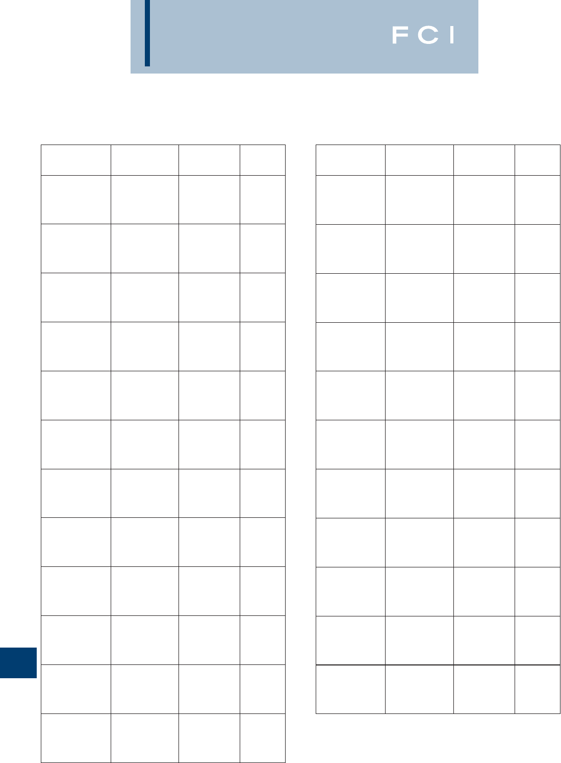
BURNDY
Reference
O-10
CABLE DATA (Continued)
CONDUCTOR SIZE
KCMIL OR B &SG
(AWG)
STRANDING AND
DIAMETER NOMINAL
DIAMETER CLASS
8
8
8
8
8
41/.0201
49/.0184
133/.0111
168/.010
420/.0063
.156
.166
.167
.157
.162
I
G
H
K
M
7
7
7
7
7
49/.0206
52/.0201
133/.0125
210/.010
532/.0063
.185
.185
.188
.179
.196
G
I
H
K
M
6
6
6
6
6
49/.0231
63/.0201
133/.0140
266/.010
665/.0063
.208
.207
.210
.210
.215
G
I
H
K
M
5
5
5
5
5
49/.0260
84/.0201
133/.0158
336/.010
836/.0063
.234
.235
.237
.235
.240
G
I
H
K
M
4
4
4
4
4
49/.0292
105/.0201
133/.0177
420/.010
1064/.0063
.263
.263
.266
.272
.269
G
I
H
K
M
3
3
3
3
3
49/.0328
133/.0199
133/.0201
532/.010
1323/.0063
.295
.299
.291
.304
.305
G
H
I
K
M
2
2
2
2
2
49/.0368
133/.0223
161/.0201
665/.010
1666/.0063
.331
.335
.319
.338
.337
G
H
I
K
M
1
1
1
1
1
133/.0251
210/.0201
259/.018
836/.010
2107/.0063
.377
.367
.378
.397
.376
G
I
H
K
M
1/0
1/0
1/0
1/0
1/0
133/.0282
259/.0202
266/.0201
1064/.010
2646/.0063
.423
.424
.441
.451
.423
G
H
I
K
M
2/0
2/0
2/0
2/0
2/0
133/.0316
259/.0227
342/.0201
1323/.010
3325/.0063
.474
.477
.500
.470
.508
G
H
I
K
M
3/0
3/0
3/0
3/0
3/0
133/.0355
259/.0255
418/.0201
1666/.010
4256/.0063
.533
.536
.549
.533
.576
G
H
I
K
M
4/0
4/0
4/0
4/0
4/0
133/.0399
259/.0286
532/.0201
2107/.010
5320/.0063
.599
.601
.613
.627
.645
G
H
I
K
M
250
250
250
250
250
259/.0311
427/.0242
637/.0201
2499/.010
6384/.0063
.650
.653
.682
.682
.713
G
H
I
K
M
300
300
300
300
300
259/.0340
427/.0265
735/.0201
2989/.010
7581/.0063
.714
.716
.737
.768
.768
G
H
I
K
M
350
350
350
350
350
259/.0368
427/.0286
882/.0201
3458/.010
8806/.0063
.773
.772
.800
.809
.825
G
H
I
K
M
400
400
400
400
400
259/.0393
427/.0306
980/.0201
3990/.010
10101/.0063
.825
.826
.831
.878
.901
G
H
I
K
M
450
450
450
450
450
259/.0417
427/.0325
1127/.0201
4522/.010
11396/.0063
.876
.878
.894
.933
.940
G
H
I
K
M
500
500
500
500
500
259/.0439
427/.0342
1225/.0201
5054/.010
12691/.0063
.922
.923
.941
.988
.997
G
H
I
K
M
600
600
600
600
600
427/.0375
703/.0292
1470/.0201
5985/.010
14945/.0063
1.013
1.022
1.027
1.125
1.084
G
H
I
K
M
700
700
700
700
700
427/.0405
703/.0316
1729/.0201
6916/.010
17507/.0063
1.094
1.106
1.194
1.207
1.183
G
H
I
K
M
800
800
800
800
800
427/.0433
703/.0337
1995/.0201
7980/.010
20069/.0063
1.169
1.180
1.290
1.305
1.256
G
H
I
K
M
900
900
900
900
900
427/.0459
703/.0358
2261/.0201
9065/.010
22631/.0063
1.239
1.253
1.372
1.323
1.331
G
H
I
K
M
1000
1000
1000
1000
1000
427/.0484
703/.0377
2527/.0201
10101/.010
25193/.0063
1.307
1.320
1.427
1.419
1.404
G
H
I
K
M
CONDUCTOR SIZE
KCMIL OR B &SG
(AWG)
STRANDING AND
DIAMETER NOMINAL
DIAMETER CLASS
FLEXIBLE COPPER STRANDED CABLE
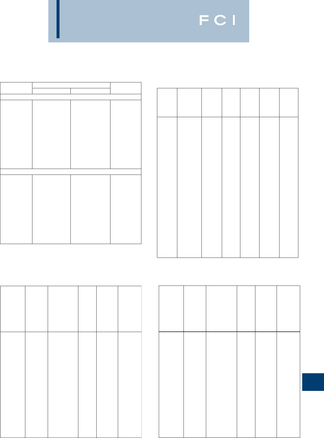
BURNDY
Reference
O-11
CABLE DATA (Continued)
SIZE OF
TUBE IPS DIAMETER OF TUBE (IN.) WALL
THICKNESS
OUTSIDE INSIDE
STANDARD PIPE SIZES
1/4
3/8
1/2
3/4
1
1-1/4
1-1/2
2
2-1/2
3
3-1/2
4
4-1/2
5
6
0.540
0.675
0.840
1.050
1.315
1.660
1.900
2.375
2.875
3.500
4.000
4.500
5.000
5.563
6.625
0.364
0.493
0.622
0.824
1.049
1.380
1.610
2.067
2.469
3.068
3.548
4.026
4.506
5.047
6.065
0.088
0.091
0.109
0.113
0.133
0.140
0.145
0.154
0.203
0.216
0.226
0.237
0.247
0.258
0.280
EXTRA HEAVY PIPE SIZES
1/4
3/8
1/2
3/4
1
1-1/4
1-1/2
2
2-1/2
3
3-1/2
4
4-1/2
5
6
0.540
0.675
0.840
1.050
1.315
1.660
1.900
2.375
2.875
3.500
4.000
4.500
5.000
5.563
6.625
0.302
0.423
0.546
0.742
0.957
1.278
1.500
1.939
2.323
2.900
3.364
3.826
4.290
4.813
5.761
0.119
0.126
0.147
0.154
0.179
0.191
0.200
0.218
0.276
0.300
0.318
0.337
0.355
0.375
0.432
CABLE
CODE
WORD
SIZE
Circular
mils or
A.W.G.
COPPER
EQUIVALENT
based on
equal D.C.
resistance,
Cu. 97%
Alum. 61%
NO. OF
WIRES
CABLE
ULTIMATE
STRENGTH
Pounds
DIA.
Inches
Mistletoe
Orchid
Violet
Nasturtium
Arbutus
Lilac
Anemone
Crocus
Magnolia
Goldenrod
Bluebell
Larkspur
Marigold
Narcissus
Carnation
Coreopsis
Dogwood
556500
636000
715500
715500
795000
795000
874500
874500
954000
954000
1033500
1033500
1113000
1272000
1431000
1590000
1590000
350000
400000
450000
450000
500000
500000
550000
550000
600000
600000
650000
650000
700000
800000
900000
1000000
100000
37
37
37
61
37
61
37
61
37
61
37
61
61
61
61
61
91
0.858
0.918
0.974
0.975
1.026
1.028
1.077
1.078
1.124
1.126
1.170
1.172
1.216
1.300
1.379
1.454
1.454
9830
11240
12640
13150
13770
14330
14830
15760
16180
16860
17530
18260
19660
22000
24300
27000
28100
ALUMINUM TUBE ALUMINUM 1350 CABLE
BARE-CLASS B
ALUMINUM 1350 CABLE
BARE-CLASSES AA AND A
HARD DRAWN
SIZE
Circular
Mils or
A.W.G.
STRANDING
No. of
Wires
Ultimate
Strength
Pounds
Hard
Drawn
Minimum
Ultimate
Strength
Pounds
3/4 Hard
Minimum
Ultimate
Strength
Pounds
Inter
Temper
Cable
DIA.
Inches
Copper
Equivelent
based upon
equal D.C.
resistance,
Co. 97%
Alum 51%
250000
300000
350000
400000
450000
500000
550000
600000
650000
700000
750000
800000
900000
1000000
1100000
1200000
1250000
1300000
1400000
1500000
1600000
1700000
1750000
1800000
1900000
2000000
2500000
3000000
3500000
157300
188800
220200
251500
283000
314500
346000
377000
409000
440000
472000
503000
566000
629000
692000
755000
786000
818000
880000
943000
1006000
1069000
1101000
1132000
1195000
1258000
1570000
1890000
2200000
37
37
37
37
37
37
61
61
61
61
61
61
61
61
91
91
91
91
91
91
127
127
127
127
127
127
127
169
169
0.575
0.629
0.681
0.728
0.772
0.813
0.855
0.893
0.929
0.964
0.998
1.031
1.094
1.152
1.209
1.263
1.289
1.315
1.364
1.412
1.459
1.504
1.526
1.548
1.590
1.632
1.824
1.998
2.158
4860
5831
6680
7352
8110
9012
10490
11450
11940
12860
13510
14410
15900
17670
20210
21630
22530
23430
24750
26500
28840
30630
31530
32450
33570
35340
43300
53010
60610
3338
4005
4673
5341
6007
6675
7344
8010
8678
9346
10010
10680
12010
13350
14680
16020
16690
17350
18700
20020
21360
22690
23350
24030
25360
26700
33380
40050
46730
2946
3534
4123
4713
5301
5890
6480
7068
7657
8247
8835
9424
10600
11780
12950
14130
14720
15310
16500
17670
18850
20020
20610
21210
22380
23560
29460
35340
41230
CABLE
CODE
WORD
SIZE
Circular
mils or
A.W.G.
COPPER
EQUIVALENT
based on
equal D.C.
resistance,
Cu. 97%
Alum. 61%
NO. OF
WIRES
CABLE
DIA.
Inches
Peachbell
Rose
Lily
Iris
Pansy
Poppy
Aster
Phlox
Oxlip
Daisy
Laurel
Tulip
Canna
Cosmos
Syringa
Dahlia
6
4
3
2
1
1/0
2/0
3/0
4/0
266800
266800
336400
397500
477000
477000
556500
8
6
5
4
3
2
1
1/0
2/0
3/0
3/0
4/0
250000
300000
300000
350000
7
7
7
7
7
7
7
7
7
7
19
19
19
19
37
19
0.184
0.232
0.260
0.292
0.328
0.368
0.414
0.464
0.522
0.586
0.593
0.666
0.724
0.793
0.795
0.856
528
826
1022
1266
1537
1865
2350
2845
3590
4525
4800
5940
6880
8090
8600
9440
ULTIMATE
STRENGTH
Pounds
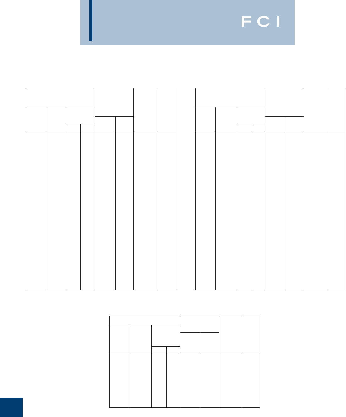
BURNDY
Reference
O-12
CABLE DATA (Continued)
ASCR DIAMETER
Inches
CODE
WORD
Cir.
Mils. or
A.W.G.
STRANDING
Number
of Strands
Turkey
Thrush
Swan
Swanate
Swallow
Sparrow
Sparate
Robin
Raven
Quail
Pigeon
Penquin
Waxwing
Owl
Partridge
Ostrich
Merlin
Linnet
Oriole
Chickadee
Brant
Ibis
Lark
Pelican
Flicker
Hawk
6
5
4
4
3
2
2
1
1/0
2/0
3/0
4/0
266800
266800
266800
300000
336400
336400
336400
397500
397500
397500
397500
477000
477000
477000
6
6
6
7
6
6
7
6
6
6
6
6
18
26
26
26
18
26
30
18
24
26
30
18
24
26
1
1
1
1
1
1
1
1
1
1
1
1
1
7
7
7
1
7
7
1
7
7
7
1
7
7
0.198
0.223
0.250
0.257
0.281
0.316
0.325
0.355
0.398
0.447
0.502
0.563
0.609
0.633
0.642
0.680
0.684
0.721
0.741
0.743
0.771
0.783
0.806
0.814
0.846
0.858
0.0661
0.0743
0.0834
0.1029
0.0937
0.1052
0.1299
0.1182
0.1327
0.1490
0.1672
0.1878
0.1217
0.2109
0.2364
0.2505
0.1367
0.2655
0.3177
0.1486
0.2575
0.2883
0.3453
0.1628
0.2820
0.3162
8
7
6
6
5
4
4
3
2
1
1/0
2/0
3/0
3/0
3/0
188700
4/0
4/0
4/0
250000
250000
250000
250000
300000
300000
300000
1170
1460
1830
2288
2250
2790
3525
3480
4280
5345
6675
8420
7100
9645
11250
12650
8950
14050
17040
10400
14690
16190
19980
12300
17200
19430
Alum. Steel
Complete
cable
Copper
Equivalent
based
upon equal
D.C.
resistance
Cu. 97%
Alum. 61%
Ultimate
Strength
Pounds
Steel
Core
ACSR
HIGH STRENGTH ACSR
ASCR DIAMETER
Inches
CODE
WORD
477000
556500
556500
556500
605000
605000
605000
636000
636000
636000
666600
715500
715500
715500
795000
795000
795000
874500
900000
954000
1033500
1113000
1272000
1431000
1590000
30
24
26
30
24
26
30
24
26
30
24
54
26
30
54
26
30
54
54
54
54
54
54
54
54
7
7
7
7
7
7
19
7
7
19
7
7
7
19
7
7
19
7
7
7
7
19
19
19
19
0.883
0.914
0.927
0.953
0.953
0.966
0.994
0.977
0.990
1.019
1.000
1.036
1.051
1.081
1.093
1.108
1.140
1.146
1.162
1.196
1.246
1.293
1.382
1.465
1.545
0.3783
0.3045
0.341
0.409
0.318
0.356
0.426
0.326
0.365
0.437
0.333
0.345
0.387
0.463
0.364
0.408
0.489
0.382
0.387
0.399
0.415
0.431
0.461
0.489
0.515
300000
350000
350000
350000
380500
380500
380500
400000
400000
400000
419000
450000
450000
450000
500000
500000
500000
550000
566000
600000
650000
700000
800000
900000
1000000
23300
19850
22400
27200
21500
24100
30000
22600
25000
31500
23700
26300
28100
34600
28500
31200
38400
31400
32300
34200
37100
40200
44800
50400
56000
Cir.
Mils. or
A.W.G.
STRANDING
Number
of Strands
Alum. Steel
Complete
cable
Copper
Equivalent
based
upon equal
D.C.
resistance
Cu. 97%
Alum. 61%
Ultimate
Strength
Pounds
Steel
Core
Hen
Parakeet
Dove
Eagle
Peacock
Squab
Teal
Rook
Grosbeak
Egret
Flamingo
Crow
Starling
Redwing
Condor
Drake
Mallard
Crane
Canary
Cardinal
Curlew
Finch
Pheasant
Plover
Falcon
ASCR DIAMETER
Inches
CODE
WORD
Grouse
Petrel
Minorca
Leghorn
Guinea
Dotterel
Dorking
Cochin
Brahma
80000
101800
110800
134600
159000
176900
190800
211300
203200
8
12
12
12
12
12
12
12
16
1
7
7
7
7
7
7
7
9
0.367
0.461
0.481
0.530
0.576
0.607
0.631
0.663
0.714
0.1670
0.2763
0.2883
0.3177
0.3453
0.3642
0.3783
0.3981
0.4885
50310
64160
69700
84600
100000
111200
120000
132900
127800
5200
9860
10730
12920
15200
16440
17730
19640
27500
Cir.
Mils. or
A.W.G.
STRANDING
Number
of Strands
Alum. Steel
Complete
cable
Copper
Equivalent
based
upon equal
D.C.
resistance
Cu. 97%
Alum. 61%
Ultimate
Strength
Pounds
Steel
Core
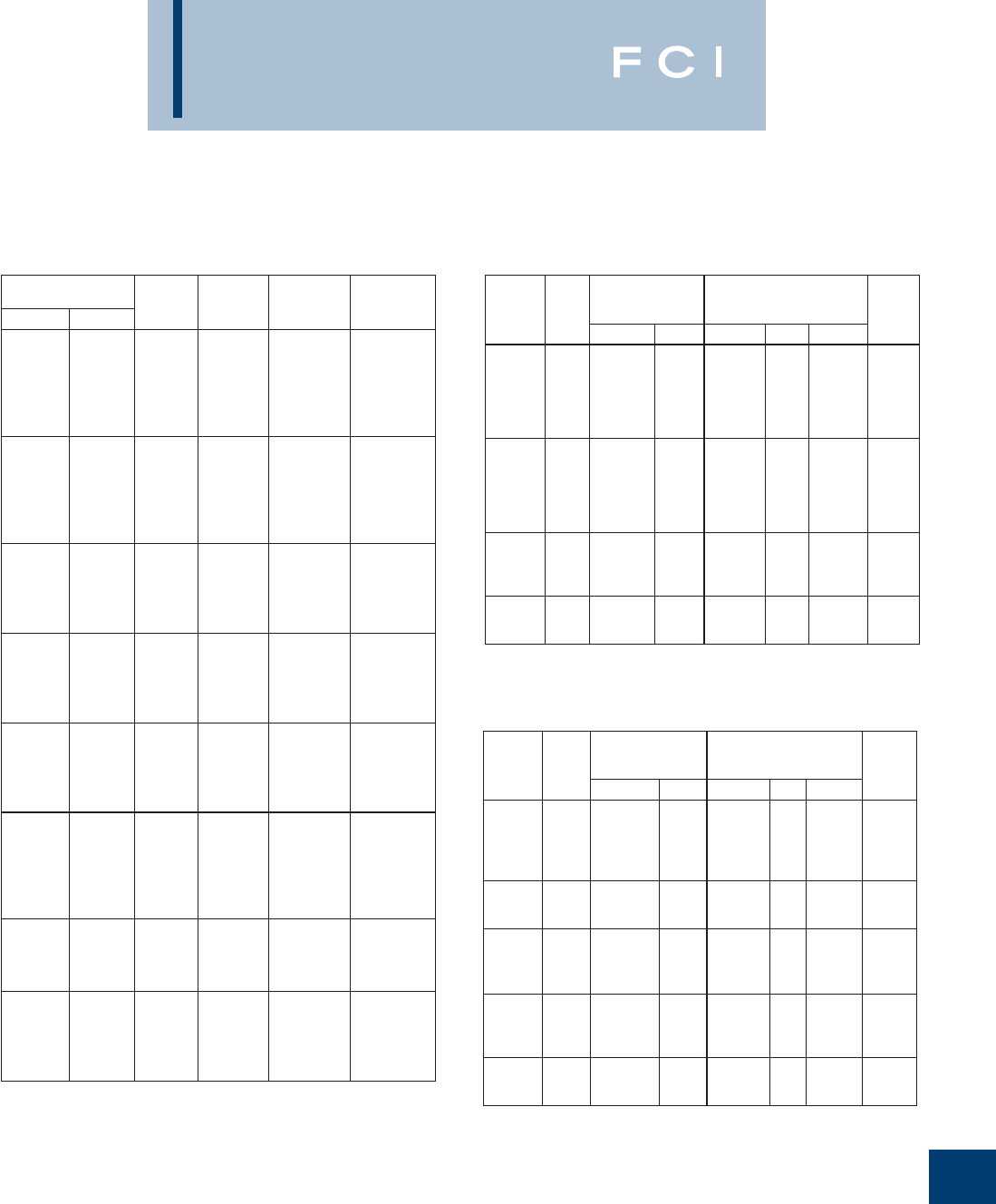
BURNDY
Reference
O-13
CABLE DATA (Continued)
Conductor Size Class Number
of Wire
Conductor
Diameter
Inches
Breaking
Strength
Lbs.
KCMIL AWG
1000
900
800
750
700
650
B
B
B
B
B
B
611
611
611
611
611
611
1.060
0.999
0.938
0.908
0.877
0.845
17,700
15,900
14,400
13,500
12,900
11,900
600
556
550
500
500
477
B
AA
B
B
AA
AA
611
193
611
372
193
193
0.813
0.780
0.775
0.736
0.736
0.722
11,500
9,750
10,500
9,110
8,760
8,360
450
400
397
350
350
B
B
AA, A
B
A
372
372
193
372
193
0.700
0.659
0.659
0.616
0.616
8,200
7,440
7,110
6,760
6,390
336
336
300
300
300
A
AA
B
A
AA
193
7
372
193
7
0.603
0.603
0.570
0.570
0.570
6,150
5,960
5,890
5,480
5,430
266
266
250
250
250
A
AA
B
A
AA
193
7
372
193
7
0.537
0.537
0.520
0.520
0.520
4,970
4,830
4,910
4,660
4,520
4/0
4/0
3/0
3/0
2/0
2/0
B
AA, A
B
AA, A
B
AA, A
193
7
193
7
193
7
0.475
0.475
0.423
0.423
0.376
0.376
4,020
3,830
3,310
3,040
2,670
2,510
1/0
1/0
1
1
B
AA, A
B
AA, A
193
7
193
7
0.336
0.336
0.299
0.299
2,160
1,990
1,740
1,640
2
3
4
6
8
AA, A, B
A, B
A, B
A, B
A, B
7
7
7
7
7
0.268
0.238
0.213
0.169
0.134
1,350
1,090
.881
.563
.312
COMPACT ALUMINUM 1350 CABLE
(ASTM B400) EXTRA HARD ALUMINUM ALLOY 5005 CABLE
(ASTM B397)
37
37
19
19
19
19
795,000
636,000
556,5000
506,500
477,000
435,500
—
—
—
—
—
—
795,000
636,000
556,500
556,500
477,000
477,500
—
—
—
—
—
—
26/7
26/7
26/7
18/1
26/7
18/1
23,900
19,300
16,200
14,600
13,900
12,500
19
19
19
19
19
19
397,500
362,000
336,400
306,400
266,800
242,900
—
—
—
—
—
—
397,500
397,500
336,400
336,400
266,800
266,800
—
—
—
—
—
—
26/7
18/1
26/7
18/1
26/7
18/1
12,200
11,200
10,500
9,600
8,450
7,610
7
7
7
7
211,600
167,800
133,100
105,600
4/0
3/0
2/0
1/0
211,600
167,800
133,100
105,600
4/0
3/0
2/0
1/0
6/1
6/1
6/1
6/1
6,330
5,020
4,280
3,440
927,200
740,800
652,400
587,200
559,500
503,600
465,400
419,400
394,500
355,100
312,800
281,400
246,900
195,700
155,400
123,300
77,470
48,690
30,580
7
7
7
66,360
41,740
26,240
2
4
6
66,360
41,740
26,240
2
4
6
6/1
6/1
6/1
2,200
1,430
922
Conductor
Size
cmil
Number
of
Wires
Rated
Strength
Lbs.
Approx. Aluminum
1350 Size having
Equivalent Resistance
Size & Stranding of ACSR with
Equal Diameter
cmil AWG cmil StrandingAWG
ALUMINUM ALLOY 6201 CABLE
(ASTM B399)
1439,200
1348,800
1259,600
1165,100
1077,400
61
61
61
61
61
1272,000
1192,500
1113,000
1033,500
954,000
—
—
—
—
—
1272,000
1192,500
1113,000
1033,500
954,000
—
—
—
—
—
54/7
54/7
54/7
54/7
54/7
46,800
43,900
41,000
37,900
35,000
927,200
740,800
652,400
37
37
19
795,000
636,000
556,500
—
—
—
795,000
636,000
556,500
—
—
—
26/7
26/7
26/7
30,500
24,400
21,900
559,500
465,400
394,500
312,800
19
19
19
19
477,000
397,500
336,400
266,800
—
—
—
—
477,000
397,500
336,400
266,800
—
—
—
—
26/7
26/7
26/7
26/7
18,800
15,600
13,300
11,000
246,900
195,700
155,400
123,300
7
7
7
7
211,600
167,800
133,100
105,600
4/0
3/0
2/0
1/0
211,600
167,800
133,100
105,600
4/0
3/0
2/0
1/0
6/1
6/1
6/1
6/1
8,560
6,790
5,390
4,460
77,470
48,690
30,580
7
7
7
66,360
41,740
26,240
2
4
6
66,360
41,740
26,240
2
4
6
6/1
6/1
6/1
2,800
1,760
1,110
Conductor
Size
cmil
Number
of
Wires
Rated
Strength
Lbs.
Approx. Aluminum
1350 Size having
Equivalent Resistance
Size & Stranding of ACSR with
Equal Diameter
cmil AWG cmil StrandingAWG
158 wires minimum
235 wires minimum
318 wires minimum

BURNDY
Reference
O-14
CABLE DATA (Continued)
CONDUCTOR SIZE NUMBER
OF WIRES† CLASS CONDUCTOR DIAMETER MIN. BREAKING
STRENGTH LBS.
KCMIL AWG Conventional In. Compressed In. Compact In.
1000
1000
1000
900
900
127
91
61
127
91
D
C
B, A
D
C
1.153
1.153
1.152
1.095
1.093
1.119
1.118
1.117
1.062
1.060
1.060
1.060
1.060
0.999
0.999
6010
6010
6010
5400
5400
900
800
800
800
750
61
127
91
61
127
B, A
D
C
B, A
D
1.093
1.032
1.032
1.031
0.998
1.060
1.001
1.001
1.000
0.968
0.999
0.938
0.938
0.938
0.908
5400
4800
4800
4800
4500
750
750
700
700
700
91
61
127
91
61
C
B, A
D
C
B, A
0.999
0.998
0.965
0.965
0.964
0.969
0.968
0.936
0.936
0.935
0.908
0.908
0.877
0.877
0.877
4500
4500
4200
4200
4200
650
650
650
650
600
127
91
61
37
127
D
C
B
A
D
0.930
0.930
0.929
0.928
0.893
0.902
0.902
0.901
0.900
0.866
0.845
0.845
0.845
0.845
0.813
3900
3900
3900
3950
3600
600
600
600
556
556
91
61
37
127
91
C
B
A
D
C
0.893
0.893
0.891
0.861
0.860
0.866
0.866
0.864
0.835
0.834
0.813
0.813
0.813
0.780
0.780
3600
3600
3640
3340
3340
556
556
550
550
550
61
37
127
91
61
B
A
D
C
B
0.860
0.858
0.855
0.855
0.855
0.834
0.832
0.829
0.829
0.829
0.780
0.780
0.775
0.775
0.775
3340
3380
3300
3300
3300
550
500
500
500
37
91
61
37
A
D
C
B, A
0.853
0.815
0.815
0.813
0.827
0.791
0.791
0.789
0.775
0.736
0.736
0.736
3340
3000
3000
3040
477
477
477
450
450
91
61
37
91
61
D
C
B, A
D
C
0.796
0.796
0.795
0.773
0.773
0.772
0.772
0.771
0.750
0.750
0.722
0.722
0.722
0.700
0.700
2860
2860
2900
2700
2700
450
400
400
400
397
37
91
61
37
91
B, A
D
C
B, A
D
0.772
0.729
0.729
0.728
0.727
0.749
0.707
0.707
0.706
0.705
0.700
0.659
0.659
0.659
0.659
2730
2400
2400
2430
2390
397
397
397
350
350
61
37
19
91
61
C
B
A
D
C
0.726
0.725
0.724
0.682
0.681
0.704
0.703
0.702
0.661
0.661
0.659
0.659
0.659
0.616
0.616
2390
2410
2470
2100
2100
350
350
336
336
336
37
19
61
37
19
B
A
C
B
A
0.681
0.679
0.669
0.668
0.666
0.661
0.659
0.649
0.648
0.646
0.616
0.616
0.603
0.603
0.603
2130
2170
2020
2040
2090
300
300
300
266
266
61
37
19
61
37
C
B
A
C
B
0.631
0.630
0.629
0.595
0.594
0.612
0.611
0.610
0.577
0.576
0.570
0.570
0.576
0.537
0.537
1800
1820
1860
1600
1620
266
250 19
61 A
C0.593
0.576 0.575
0.559 0.537
0.520 1660
1500
ALUMINUM ALLOY 8000 SERIES “O”TEMPER CABLE
(ASTM B801)
BURNDY
Reference
O-15
CABLE DATA (Continued)
CONDUCTOR SIZE NUMBER
OF WIRES† CLASS CONDUCTOR DIAMETER MIN. BREAKING
STRENGTH LBS.
KCMIL AWG Conventional In. Compressed In. Compact In.
250
250 4/0
37
19
37
B
A
C
0.575
0.574
0.529
0.558
0.557
0.513
0.520
0.520
0.475
1520
1550
1280
4/0
4/0
3/0
3/0
3/0
19
7
37
19
7
B
A
C
B
A
0.528
0.522
0.471
0.470
0.464
0.512
0.506
0.457
0.456
0.450
0.475
0.475
0.423
0.423
0.423
1310
1360
1020
1040
1070
2/0
2/0
1/0
1/0
1
19
7
19
7
19
B
A
B
A
B
0.419
0.414
0.373
0.368
0.332
0.406
0.402
0.362
0.357
0.322
0.376
0.376
0.336
0.336
0.229
826
853
655
676
519
2
3
4
6
8
7
7
7
7
7
B, A
B, A
B, A
B, A
B, A
0.292
0.260
0.232
0.184
0.146
0.283
0.252
0.225
0.178
0.142
0.268
0.238
0.213
0.169
0.134
425
337
267
168
106
ALUMINUM ALLOY 8000 SERIES “O”TEMPER CABLE (Continued)
ACSR/TW (TRAP WIRE) CABLE (Continued)
STRANDING
NOMINALCONDUCTOR
SIZE
KCMIL DIAMETER
INCHES
RATED
STRENGTH
LBS
Aluminum
Wires
Number ofNumber of Steel
Wires
405.1
571.7
565.3
664.8
666.6
14
18
20
20
20
1
7
7
7
7
0.68
0.85
0.86
0.93
0.91
10,200
20,600
22,900
26,600
24,000
762.8
768.2
768.9
795.0
795.0
20
20
27
20
20
7
7
1
7
7
0.99
0.98
0.93
0.99
1.01
30,500
27,700
16,400
28,200
31,800
946.7
954.0
954.0
954.0
957.2
35
30
32
20
32
7
7
7
7
7
1.08
1.05
1.06
1.08
1.06
29,600
23,700
25,900
33,500
26,000
1033.5
1033.5
1033.5
1113.0
1113.0
30
32
21
30
33
7
7
7
7
7
1.09
1.10
1.13
1.13
1.14
25,700
28,100
36,300
27,500
30,000
1113.0
1192.5
1192.5
1192.5
1272.0
38
30
33
38
30
19
7
7
19
7
1.19
1.17
1.18
1.22
1.20
39,100
29,500
32,400
41,900
31,400
1272.0
1272.0
1351.5
1351.5
1431.0
35
39
35
39
36
7
19
7
19
7
1.22
1.26
1.26
1.30
1.29
34,600
44,100
36,700
46,800
38,900
1431.0
1590.0
1590.0
1780.0
2156.0
39
36
42
37
64
19
7
19
19
19
1.34
1.36
1.41
1.45
1.61
49,600
42,200
55,100
50,700
61,100
COMPACT ACSR
(ASTM B401)
CONDUCTOR SIZE CONDUCTOR
DIAMETER (IN.) BREAKING
STRENGTH (LB)
KCMIL AWG
336.4
266.8 4/0
3/0
2/0
0.628
0.559
0.517
0.461
0.410
8,260
6,540
7,420
5,880
4,880
1/0
1
2
2
3
0.365
0.326
0.298
0.290
0.258
3,980
3,290
3,260
2,640
2,130
4
4
6
0.236
0.229
0.182
2,160
1,760
1,120
ACSR/TW (TRAP WIRE) CABLE
(ASTM B779)
STRANDING
NOMINALCONDUCTOR
SIZE
KCMIL
DIAMETER
INCHES
RATED
STRENGTH
LBS
Number of
Aluminum
Wires
Number of
Steel
Wires
336.4
477.0
477.0
556.5
556.5
14
18
18
18
20
1
7
7
7
7
0.63
0.78
0.79
0.84
0.85
8,600
17,200
19,400
20,000
22,600
636.0
636.0
636.0
795.0
795.0
27
18
20
17
18
1
7
7
7
7
0.85
0.89
0.91
0.96
0.98
13,500
22,900
25,400
21,000
25,900
†For compact-stranded constructions, the number of wires
may be reduced as follows:
19-Wire Constructions - 18 Wires Minimum
37-Wire Constructions - 35 Wires Minimum
61-Wire Constructions - 58 Wires Minimum
91-Wire Constructions - 87 Wires Minimum
127-Wire Constructions - 122 Wires Minimum
BURNDY
Reference
O-16
CABLE DATA (Continued)
STRANDING
NOMINAL
DIAMETER
INCHES
RATED
STRENGTH
LBS
Number of
Aluminum
Wires
Number of
CONDUCTOR
SIZE
KCMIL
Steel
Wires
959.6
966.2
1158.0
1158.4
1168.1
22
21
33
25
30
7
7
7
7
7
1.11
1.09
1.17
1.20
1.16
37,000
34,000
31,600
39,600
28,900
1233.6
1257.1
1272.0
1334.6
1359.7
38
35
30
39
36
19
7
7
19
7
1.25
1.21
1.20
1.29
1.26
42,900
34,200
31,400
46,300
36,900
1372.5
1433.6
1455.3
1467.8
1533.3
30
39
36
33
39
7
19
7
7
19
1.25
1.34
1.30
1.29
1.38
33,400
49,700
39,200
35,800
53,200
1557.4
1569.0
1622.0
1657.4
1730.6
36
33
39
36
39
7
7
19
7
19
1.35
1.33
1.42
1.39
1.47
41,900
38,200
57,500
44,000
59,400
1758.6
1926.9
1949.6
2153.8
2627.3
37
42
42
64
64
19
19
7
19
19
7.14
1.55
1.50
1.60
1.76
34,600
65,300
51,900
61,100
74,500
ACSR/TW (TRAP WIRE) CABLE (Continued)
CONDUCTOR SIZE NUMBER OF
WIRES NOMINAL OUTSIDE
DIAMETER
KCMIL AWG
2000
2000
1900
1800
1750
91
61
61
61
61
1.630
1.630
1.588
1.546
1.525
1700
1600
1500
1400
1300
61
61
61
61
61
1.502
1.458
1.411
1.364
1.314
1300
1250
1250
1200
1200
37
61
37
61
37
1.312
1.288
1.287
1.263
1.261
1100
1100
1000
1000
950
61
37
61
37
37
1.209
1.207
1.152
1.151
1.121
900
850
800
750
700
37
37
37
37
37
1.092
1.061
1.029
0.997
0.962
650
600
600
550
550
37
37
19
37
19
0.928
0.891
0.888
0.853
0.850
500
500
450
400
350
37
19
19
19
19
0.813
0.811
0.770
0.726
0.678
300
250
246.9
195.7 4/0
19
19
7
7
7
0.628
0.574
0.563
0.522
0.502
155.4
123.3
3/0
2/0
1/0
7
7
7
7
7
0.464
0.447
0.414
0.398
0.368
77.4
48.6
30.5
2
4
7
7
7
7
7
0.316
0.292
0.250
0.232
0.198
AAC/TW (ALL ALUMINUM TRAP WIRE)
(ASTM B778)
ACAR CABLE‡
(ASTM B524)
CONDUCTOR
SIZE, KCMIL
NOMINAL
DIAMETER,
IN.
NUMBER
OF WIRES RATED
STRENGTH, LBF
336.4
397.5
477.0
500.0
556.5
0.612
0.661
0.720
0.736
0.775
17
17
17
17
17
6,220
7,230
8,530
8,940
9,950
600.0
636.0
700.0
750.0
795.0
0.803
0.825
0.864
0.893
0.919
17
17
17
17
17
10,700
11,400
12,500
13,400
13,900
900.0
954.0
1000.0
1033.5
1113.0
0.990
1.018
1.041
1.057
1.095
31
31
31
31
31
15,800
16,700
17,500
18,100
19,500
1192.5
1272.0
1351.5
1431.0
1590.0
1.132
1.168
1.202
1.236
1.315
31
31
31
31
49
20,900
22,300
23,700
24,600
27,300
1750.0
2000.0 1.377
1.468 49
49 30,000
34,300
‡Refer to ASTM Specification B524 for breaking strengths.
BURNDY
Reference
O-17
CABLE DATA (Continued)
266.8
266.8
266.8
266.8
22
24
26
30
7
7
7
7
.622
.633
.642
.660
6030
7410
8880
11700
300.0 26 7.680 9970
336.4
336.4
336.4
336.4
336.4
20
22
24
26
30
7
7
7
7
7
.692
.701
.710
.720
.741
5990
7610
9340
11200
14800
397.5
397.5
397.5
397.5
397.5
20
22
24
26
30
7
7
7
7
7
.752
.762
.772
.783
.806
7090
8990
11000
13000
17500
477.0
477.0
477.0
477.0
477.0
20
22
24
26
30
7
7
7
7
7
.823
.834
.846
.858
.883
8490
10800
13000
15600
21000
500.0 30 7.904 22000
556.5
556.5
556.5
556.5
556.5
20
22
24
26
30
7
7
7
7
7
.890
.901
.914
.927
.953
9910
12600
15200
18200
24500
605.0
605.0
605.0
605.0
24
26
30
30
7
7
7
19
.953
.966
.994
.994
16500
19700
26000
26600
636.0
636.0
636.0
636.0
636.0
636.0
20
22
24
26
30
30
7
7
7
7
7
19
.951
.963
.977
.990
1.019
1.019
11300
14100
17300
20700
27400
28000
666.6
666.6 24
26 7
71.000
1.104 18200
21700
715.5
715.5
715.5
24
26
30
7
7
19
1.036
1.051
1.081
19500
23300
30800
795.0
795.0
795.0
795.0
795.0
795.0
795.0
795.0
42
20
45
22
24
54
26
30
7
7
7
7
7
7
7
19
1.055
1.063
1.063
1.077
1.092
1.092
1.108
1.140
11800
14200
14200
17700
21700
21700
25900
34300
900.0
900.0 45
54 7
71.131
1.162 15800
24600
954.0
954.0
954.0
954.0
954.0
954.0
954.0
42
20
45
48
24
54
30
7
7
7
7
7
7
19
1.155
1.185
1.165
1.175
1.196
1.196
1.248
14200
16700
16700
19700
26000
26000
41100
SIZE AWG
OR KCMIL
STRANDING CONDUCTOR
DIAMETER
RATED
STRENGTH
POUNDS
ALUMINUM STEEL
SSAC CABLE SSAC CABLE (Continued)
SIZE AWG
OR KCMIL
STRANDING CONDUCTOR
DIAMETER
RATED
STRENGTH
POUNDS
ALUMINUM STEEL
1033.5
1033.5
1033.5
1033.5
42
45
48
54
7
7
7
7
1.203
1.212
1.222
1.245
15400
18100
21300
28200
1113.0
1113.0
1113.0
1113.0
42
45
48
54
7
7
7
19
1.248
1.259
1.269
1.293
16300
19500
23000
30400
1192.5
1192.5
1192.5
1192.5
42
45
48
54
7
7
7
19
1.292
1.302
1.313
1.338
17500
20900
24600
32600
1272.0
1272.0
1272.0
1272.0
42
45
48
54
7
7
7
19
1.334
1.345
1.357
1.382
18700
22300
26200
34100
1351.5
1351.5
1351.5
1351.5
42
45
48
54
7
7
7
19
1.376
1.386
1.398
1.424
19900
23700
27900
36200
1431.0
1431.0
1431.0
1431.0
42
45
48
54
7
7
7
19
1.415
1.427
1.439
1.465
21000
25100
29500
38400
1510.5
1510.5 45
54 7
19 1.466
1.505 26500
40500
1590.0
1590.0
1590.0
1590.0
42
45
48
54
7
7
7
19
1.492
1.504
1.517
1.545
23400
27900
32200
42600
1780.0 84 19 1.602 35400
1869.0 68 71.603 21500
2034.5 72 71.681 27200
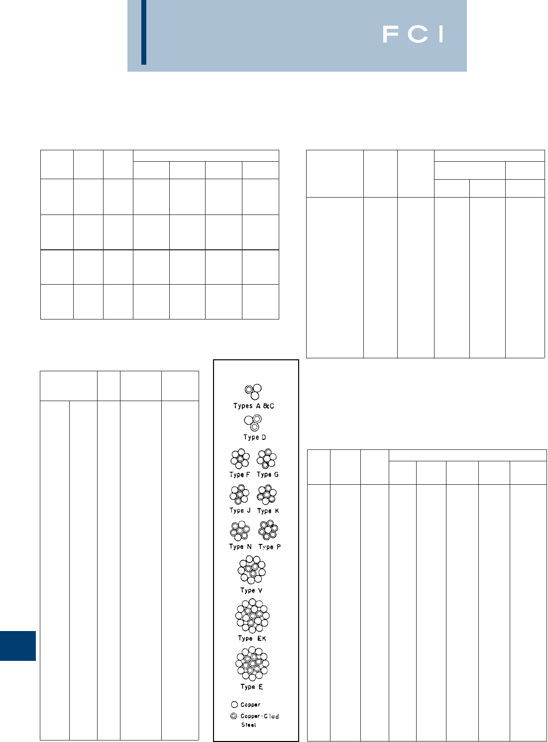
BURNDY
Reference
O-18
CABLE DATA
SOLID COPPERWELD CABLE
(ASTM B227)
Conductor
Size
(AWG)
Nominal
Diameter
(Inches) Circular
Mils
Minimum Breaking Load (lbs.)
Grade 40
HS Grade 40
EHS Grade 30
HS Grade 30
EHS
4
5
—
6
41,740
33,090
27,230
26,240
3,540
2,937
2,779
2,679
—
—
—
—
3,934
3,249
2,779
2,679
4,671
3,911
3,367
3,246
7
8
—
9
20,820
16,510
16,380
13,090
2,207
1,816
1,802
1,491
—
—
—
—
2,207
1,816
1,802
1,491
2,681
2,205
2,188
1,790
—
10
12
—
10,820
10,380
6,530
6,400
1,283
1,231
774
759
1,325
—
—
—
1,283
1,231
774
759
1,487
1,460
918
900
—
18
—
20
0.2043
0.1819
0.1650*
0.1620
0.1443
0.1285
0.1280*
0.1144
0.1040*
0.1019
0.0808
0.0800*
0.0640*
0.0403
0.0390*
0.0320
4,096
1,624
1,521
1,024
485
193
180
121
—
—
—
—
485
193
180
121
576
228
214
144
STRANDED COPPERWELD CABLE
(ASTM B228)
Nominal
Diameter†
(Inch) Size
A.W.G.‡ Circular
Mils Diameter*
(Inch)
Breaking Load Lbs.**
High Strength Extra High
Strength
40%
Cond. 30%
Cond. 30%
Cond.
7/8 (19 No. 5)
13/16 (19 No. 6)
23/32 (19 No. 7)
27/32 (19 No. 8)
9/16 (19 No. 9)
5/8 (7 No. 4)
9/16 (7 No. 5)
1/2 (7 No. 6)
7/16 (7 No. 7)
3/8 (7 No. 8)
11/32 (7 No. 9)
5/16 (7 No. 10)
3 No. 5
3 No. 6
3 No. 7
3 No. 8
3 No. 9
3 No. 10
3 No. 12
628,900
498,800
395,500
313,700
248,800
292,200
231,700
183,800
145,700
115,600
91,650
72,680
99,310
78,750
62,450
49,530
39,280
31,150
19,590
.910
.810
.721
.642
.572
.613
.546
.486
.433
.385
.343
.306
.392
.349
.311
.277
.247
.220
.174
50,240
41,600
34,390
28,380
23,390
22,310
18,510
15,330
12,670
10,460
8,616
7,121
8,373
6,934
5,732
4,730
3,898
3,221
2,236
55,570
45,830
37,740
31,040
25,500
24,780
20,470
16,890
13,910
11,440
9,393
7,758
9,262
7,639
6,291
5,174
4,250
3,509
—
66,910
55,530
45,850
37,690
30,610
29,430
24,650
20,460
16,890
13,890
11,280
9,196
11,860
9,754
7,922
6,282
5,129
4,160
—
GALVANIZED STEEL CABLE
(ASTM A475)
Minimum Breaking Load (lbs.)
Inches
Nominal
Diameter
of Strand
(mm)
Number
of Wires
in
Strand Utilities
Grade Common
Grade
Siemens-
Martin
Grade
High-
Strength
Grade
Extra High-
Strength
Grade
1/8
5/32
3/16
3/16
7/32
7/32
1/4
1/4
1/4
9/32
9/32
5/16
5/16
5/16
3/8
3/8
7/16
1/2
1/2
9/16
9/16
5/8
5/8
3/4
7/8
1
1
1-1/8
1-1/4
(3.18)
(3.97)
(4.76)
(4.76)
(5.56)
(5.56)
(6.35)
(6.35)
(6.35)
(7.14)
(7.14)
(7.94)
(7.94)
(7.94)
(9.52)
(9.52)
(11.11)
(12.70)
(12.70)
(14.29)
(14.29)
(15.88)
(15.88)
(19.05)
(22.22)
(25.40)
(25.40)
(28.58)
(31.75)
7
7
7
7
3
7
3
3
7
3
7
3
7
7
3
7
7
7
19
7
19
7
19
19
19
9
37
37
37
—
—
—
2,400
—
—
3,150
4,500
—
—
4,600
6,500
—
6,000
8,500
11,500
18,000
25,000
—
—
—
—
—
—
—
—
—
—
—
540
870
1,150
—
1,400
1,540
1,860
—
1,900
2,080
2,570
2,490
3,200
—
3,330
4,250
5,700
7,400
7,620
9,600
9,640
11,600
11,000
16,000
21,900
28,700
28,300
36,000
44,600
910
1,470
1,900
—
2,340
2,560
3,040
—
3,150
3,380
4,250
4,090
5,350
—
5,560
6,950
9,350
12,100
12,700
15,700
16,100
19,100
18,100
26,200
35,900
47,000
46,200
58,900
73,000
1,330
2,140
2,850
—
3,500
3,850
4,730
—
4,750
5,260
6,400
6,350
8,000
—
8,360
10,800
14,500
18,800
19,100
24,500
24,100
29,600
28,100
40,800
55,800
73,200
71,900
91,600
113,600
1,830
2,940
3,990
—
4,900
5,400
6,740
—
6,650
7,500
8,950
9,100
11,200
—
11,800
15,400
20,800
26,900
26,700
35,000
33,700
42,400
40,200
58,300
79,700
104,500
102,700
130,800
162,200
COPPERWELD-COPPER CABLE
(ASTM B229)
Conductor Size
Hard Drawn Copper
Equivalent TYPE
Nominal
Diameter of
Conductor
(inches)
Minimum
Breaking
Load
(pounds)
cmil AWG
350,000
350,000
350,000
300,000
300,000
300,000
250,000
250,000
250,000
211,600
211,600
211,600
211,600
167,800
167,800
167,800
167,800
167,800
167,800
133,100
133,100
133,100
133,100
133,100
105,600
105,600
105,600
105,600
83,690
83,690
83,690
83,690
83,690
66,360
66,360
66,360
66,360
66,360
66,360
66,360
55,620
52,620
52,620
52,620
52,620
41,740
41,740
41,740
41,740
33,090
33,090
33,090
26,240
26,240
26,240
20,820
20,820
16,510
16,510
16,510
11,750
—
—
—
—
—
211,600
—
—
—
4/0
4/0
4/0
4/0
4/0
3/0
3/0
3/0
3/0
3/0
3/0
2/0
2/0
2/0
2/0
2/0
1/0
1/0
1/0
1/0
1
1
1
1
1
2
2
2
2
2
2
2
3
3
3
3
3
4
4
4
4
5
5
5
6
6
6
7
7
8
8
8
9
E
EK
V
E
EK
V
E
EK
V
E
G
EK
V
F
E
J
G
EK
V
F
K
J
G
V
F
K
J
G
F
N
K
J
G
F
P
N
K
J
A
G
F
P
N
K
J
A
P
N
D
A
P
D
A
D
A
C
D
A
D
A
C
D
0.788
0.735
0.754
0.729
0.680
0.698
0.666
0.621
0.637
0.613
0.583
0.571
0.586
0.550
0.545
0.555
0.519
0.509
0.522
0.490
0.534
0.494
0.463
0.465
0.436
0.475
0.440
0.412
0.388
0.464
0.423
0.392
0.367
0.346
0.462
0.413
0.377
0.349
0.366
0.327
0.308
0.411
0.368
0.336
0.311
0.326
0.366
0.328
0.348
0.290
0.326
0.310
0.258
0.276
0.230
0.225
0.246
0.223
0.219
0.199
0.179
0.174
32,420
23,850
23,480
27,770
20,960
20,730
23,920
17,840
17,420
20,730
15,640
15,370
15,000
12,290
16,800
16,170
12,860
12,370
12,200
9,980
17,600
13,430
10,510
9,846
8,094
14,490
10,970
8,563
6,536
15,410
11,900
9,000
6,956
5,266
16,870
12,680
9,730
7,322
5,876
5,626
4,233
13,910
10,390
7,910
5,955
4,810
11,420
8,460
7,340
3,938
9,311
6,035
3,193
4,942
2,585
2,143
4,022
2,754
3,256
2,233
1,362
1,743
*These diameters are often employed by purchasers for communication lines BUT are not in
the American Wire Gauge (B & S Wire Gauge) series, as are the other diameters listed.
†The designation "Inch" is the approximate diameter in proper fraction of an inch.
‡The designation of "AWG" is a combination of the number of wires each of the American
Wire Gage size indicated by "No."
*Diameter of circumscribing.
** Breaking loads of 7-wire and 19-wire conductors are taken as 90% of the sum of the
breaking loads of individual wires; breaking load of 3-wire conductors is taken as 95%
of the sum of the breaking loads of the individual wires.

BURNDY
Reference
O-19
CABLE DATA
AWG VS. METRIC WIRE SIZES
ALUMINUM-COATED STEEL CABLE
(ASTM A474)
MINIMUM BREAKING STRENGTH, lbf
NOMINAL DIAMETER
OF STRAND (IN.) NUMBER OF WIRES
IN STRAND SIEMANS-MARTIN
GRADE HIGH-STRENGTH
GRADE EXTRA HIGH-
STRENGTH GRADE
UTILITIES GRADE* COMMON GRADE
3/16 71 150 1 900 2 850
3/16 72 400
1/4 33 150
1/4 34 500
1/4 71 900 3 150 4 750 6 650
9/32 74 600
5/16 36 500
5/16 73 200 5 350 8 000 11 200
5/16 76 000
3/8 38 500
3/8 711 500 4 250 6 950 10 800 15 400
7/16 718 000 5 350 9 350 14 500 20 800
1/2 725 000 7 400 12 100 18 800 26 900
CIRC.
MILS
EQUIV-
ALENT
CIRC.
MILS
METRIC
WIRE
SIZE
MM
AWG.
SIZE
STRANDING/WIRE
DIAMETER PER
STRAND
APPROXIMATE
OVERALL
DIAMETER
IN. MM IN. MM CIRC.
MILS
EQUIV-
ALENT
CIRC.
MILS
METRIC
WIRE
SIZE
MM
AWG.
SIZE
STRANDING/WIRE
DIAMETER PER
STRAND
APPROXIMATE
OVERALL
DIAMETER
IN. MM IN. MM
—
1020
—
1620
1620
—
—
937
—
1480
—
—
1974
1974
—
20
—
18
18
—
—
0.50
—
.075
—
—
1.0
1.0
1/.032
7/.0121
1/.039
1/.0103
7/.0152
1/.045
7/.017
1/.813
1/.307
1/.091
1/1.02
7/.386
1/1.14
7/.422
.032
.036
.039
.040
.046
.045
.061
.061
0.91
0.99
1.02
1.16
1.14
1.30
1
—
1/0
2/0
—
3/0
3/0
—
50
—
—
70
—
—
19/.0064
19/.073
19/.0745
19/.0837
19/.086
19/.094
36/.0673
19/1.50
19/1.85
19/1.59
19/2.13
19/2.18
19/2.59
37/1.71
.332
.365
.373
.419
.430
.470
.471
8.43
9.27
9.46
10.6
10.9
11.9
12.0
2580
2580
—
—
4110
4110
—
—
2960
2960
—
—
16
16
—
—
14
14
—
—
1.5
1.5
—
—
1/.0503
7/.0192
1/.055
7/.021
1/.0641
7/.0242
1/1.29
7/.468
1/1.40
7/5.33
1/1.63
7/.615
.051
.058
.055
.063
.064
.073
1.29
1.46
1.40
1.60
1.63
1.84
—
—
4/0
—
—
—
95
95
—
120
—
150
19/.101
37/.072
19/.1055
37/.081
37/.0822
37/.090
19/2.57
37/1.83
19/2.89
37/2.06
37/2.07
37/2.29
.505
.504
.528
.567
.575
.630
12.8
12.5
13.4
14.4
14.6
16.0
—
—
6530
6530
—
—
4934
4934
—
—
7894
7894
—
—
12
12
—
—
2.5
2.5
—
—
4
4
1/.071
7/.027
1/.0308
7/.0305
1/.089
7/.034
1/1.80
7/6.66
1/2.05
7/.775
1/2.26
7/.864
.071
.081
.081
.092
.089
.102
1.80
2.06
2.05
2.32
2.26
2.59
—
—
—
—
—
—
—
185
—
240
240
—
37/.0973
37/.100
37/104
37/.114
61/.089
37/.1162
37/2.47
37/2.54
37/2.64
37/2.90
61/2.26
37/2.95
.681
.700
.728
.798
.801
.813
17.3
17.8
18.5
20.3
20.3
20.7
10380
10380
—
—
13000
13090
—
—
11840
11840
—
—
10
10
—
—
9
9
—
—
6
6
—
—
1/.1019
7/.0355
1/.109
7/.042
1/.1144
7/.0432
1/2.59
7/.978
1/2.77
7/.107
1/2.91
7/1.10
.102
.116
.109
.126
.114
.130
2.59
2.93
2.77
3..21
2.91
3.30
—
—
—
—
—
—
—
300
—
—
—
—
61/.0905
61/.099
61/.0992
61/.1071
61/.1109
91/.0908
61/2.30
61/2.51
61/2.52
61/2.72
61/2.82
91/2.31
.814
.891
.893
.964
.998
.998
20.7
22.6
22.7
24.5
25.4
25.4
16510
16510
—
—
20520
20520
—
—
19740
19740
—
—
8
8
—
—
7
7
—
—
10
10
—
—
1/.1285
7/.0486
1/.141
7/.054
1/.1443
7/.0545
1/3.26
7/1.23
1/3.58
7/1.37
1/3.67
7/1.38
.128
.146
.141
.162
.144
.164
3.25
3.70
3.58
4.12
3.67
4.15
—
—
—
—
—
—
400
—
—
500
—
625
61/.114
61/.1145
91/.0938
61/.1280
91/.1048
91/.117
61/2.90
61/2.91
91/2.38
61/3.25
91/2.66
91/2.97
1.026
1.031
1.032
1.152
1.153
1.287
26.1
26.2
26.2
28.3
29.3
32.7
26240
26240
—
33090
41740
—
—
31580
—
—
6
6
—
5
4
—
—
16
—
—
1/.162
7/.0612
7/.008
7/.0688
7/.0772
1/4.11
7/1.55
7/1.73
7/1.75
7/1.96
.162
.184
.204
.206
.232
4.11
4.66
5.13
5.24
5.88
—
—
—
—
—
—
—
—
—
—
800
91/.1172
127/.0992
91/.1284
127/.1087
91/.132
91/2.93
127/2.52
91/3.26
127/2.76
91/3.35
1.289
1.200
1.412
1.413
1.452
32.7
32.8
36.9
36.9
36.9
—
—
52620
66300
—
—
49340
49340
—
—
69070
69070
—
—
3
2
—
—
25
25
—
—
35
35
7/.085
19/.052
7/.0867
7/.0974
7/.100
19/.001
7/2.16
10/1.32
7/2.20
7/2.47
7/2.54
19/1.55
.255
.260
.260
.292
.300
.305
6.48
6.60
6.61
7.42
7.62
7.75
—
—
—
—
98680
—
—
138100
—
—
187500
187500
—
237.8 MCM
—
—
—
365.1 MCM
—
473.6 MCM
473.6 MCM
—
—
592.1 MCM
—
—
—
—
789.4 MCM
—
—
986.8 MCM
—
1233.7 MCM
—
—
—
—
—
1578.8 MCM
1973.5 MCM
—
—
1000
—
—
83690
—
10500
133100
—
167800
167800
—
—
211600
—
250 MCM
300 MCM
350 MCM
—
400MCM
—
—
500 MCM
500MCM
—
600 MCM
700MCM
750 MCM
750 MCM
—
800 MCM
800 MCM
1000 MCM
1000 MCM
—
1250 MCM
1250 MCM
1500 MCM
1500 MCM
—
—
2000 MCM
2000 MCM
91/.147
127/.1255
169/.1088
91/3.73
127/3.19
169/2.76
1.617
1.632
1.632
41.1
41.5
41.5
*The Utilities Grade is used principally by communications and power and light industries.
BURNDY
Reference
O-20
INCHES & MILLIMETERS CONVERSION CHART
1
64
1
32
3
64
1
16
5
64
3
32
7
64
1
8
9
64
5
32
11
64
3
16
13
64
7
32
15
64
1
4
17
64
9
32
19
64
5
16
21
64
11
32
23
64
3
8
25
64
13
32
27
64
7
16
29
64
15
32
31
64
1
2
.015625 — 0.397
.03125 — 0.794
.046875 — 1.191
.0625 — 1.588
.078125 — 1.984
.09375 — 2.381
.109375 — 2.778
.1250 — 3.175
.140625 — 3.572
.15625 — 3.969
.171875 — 4.366
.1875 — 4.763
.203125 — 5.159
.21875 — 5.556
.234375 — 5.953
.2500 — 6.350
.265625 — 6.747
.28125 — 7.144
.296875 — 7.541
.3125 — 7.938
.328125 — 8.334
.34375 — 8.731
.359375 — 9.128
.3750 — 9.525
.390625 — 9.922
.40625 — 10.319
.421875 — 10.716
.4375 — 11.113
.453125 — 11.509
.46875 — 11.906
.484375 — 12.303
.5000 — 12.700
INCHES MILLIMETERS
33
64
17
32
35
64
9
16
37
64
19
32
39
64
5
8
41
64
21
32
43
64
11
16
45
64
23
32
47
64
3
4
49
64
25
32
51
64
13
16
53
64
27
32
55
64
7
1
8
57
64
29
32
59
64
15
16
61
64
31
32
63
64
.515625 — 13.097
.53125 — 13.494
.546875 — 13.891
.5625 — 14.288
.578125 — 14.684
.59375 — 15.081
.609375 — 15.478
.6250 — 15.875
.640625 — 16.272
.65625 — 16.669
.671875 — 17.066
.6875 — 17.463
.703125 — 17.859
.71875 — 18.256
.734375 — 18.653
.7500 — 19.050
.765625 — 19.447
.78125 — 19.844
.796875 — 20.241
.8125 — 20.638
.828125 — 21.034
.84375 — 21.431
.859375 — 21.828
.8750 — 22.225
.890625 — 22.622
.90625 — 23.019
.921875 — 23.416
.9375 — 23.813
.953125 — 24.209
.96875 — 24.606
.984375 — 25.003
1.000 — 25.400
INCHES MM
.1 — .0039
.2 — .0079
.3 — .0118
.4 — .0157
.5 — .0197
.6 — .0236
.7 — .0276
.8 — .0315
.9 — .0354
1 — .0394
2 — .0787
3 — .1181
4 — .1575
5 — .1969
6 — .2362
7 — .2756
8 — .3150
9 — .3543
10 — .3937
11 — .4331
12 — .4724
13 — .5118
14 — .5512
15 — .5906
16 — .6299
17 — .6693
18 — .7087
19 — .7480
20 — .7874
21 — .8268
22 — .8661
23 — .9055
24 — .9449
25 — .9843
26 — 1.0236
27 — 1.0630
28 — 1.1024
29 — 1.1417
30 — 1.1811
31 — 1.2205
32 — 1.2598
33 — 1.2992
34 — 1.3386
35 — 1.3780
36 — 1.4173
37 — 1.4567
38 — 1.4961
39 — 1.5354
40 — 1.5748
41 — 1.6142
42 — 1.6535
43 — 1.6929
44 — 1.7323
45 — 1.7717
INCHES MM
46 — 1.8110
47 — 1.8504
48 — 1.8898
48 — 1.9291
50 — 1.9685
51 — 2.0079
52 — 2.0472
53 — 2.0866
54 — 2.1260
55 — 2.1654
56 — 2.2047
57 — 2.2441
58 — 2.2835
59 — 2.3228
60 — 2.3622
61 — 2.4016
62 — 2.4409
63 — 2.4803
64 — 2.5197
65 — 2.5591
66 — 2.5984
67 — 2.6378
68 — 2.6772
69 — 2.7165
70 — 2.7559
71 — 2.7953
72 — 2.8346
73 — 2.8740
74 — 2.9134
75 — 2.9528
76 — 2.9921
77 — 3.0315
78 — 3.0709
79 — 3.1102
80 — 3.1496
81 — 3.1890
82 — 3.2283
83 — 3.2677
84 — 3.3071
85 — 3.3465
86 — 3.3858
87 — 3.4252
88 — 3.4646
89 — 3.5039
90 — 3.5433
91 — 3.5827
92 — 3.6220
93 — 3.6614
94 — 3.7008
95 — 3.7402
96 — 3.7795
97 — 3.8189
98 — 3.8583
99 — 3.8976
100 — 3.9370
INCHESMILLIMETERS
1mm = .03937.001= .0254 mm.
BURNDY
Reference
O-21
TERMINAL STUD SIZE CHART*
STUD SIZE #0 #1 #2 #3 #4 #5 #6 #8 #10 #12 #14 1/4" 5/16" 3/8"
.060
.437 .500 .625 .750 .875 1.000
29/64 33/64 21/32 29/32 29/32 1 - 1/32
.073 .086 .090 .112 .125 .138 .164 .190 .216 .242 .250 .312
.067 .093 .119 .145 .171 .197 .223 .250 17/64 21/64
.375
25/64
Stud Diameter
Stud Hole
STUD SIZE 7/16" 1/2" 5/8" 3/4" 7/8" 1"
Stud Diameter
Stud Hole
*Tolerance .003" on decimal and .005" on fractional dimensions
BURNDY
Reference
This catalog uses the new, BURNDY®simpli-
fied overhead lines die set catalog numbering
system, based on Die Index numbers
and letters.
The Die Index numbers are marked on the
connectors and die sets. Where a die set has
more than one Die Index, the catalog number
will generally be the lowest number assigned
or all indexes may be marked.
The Die Index numbers and letters in this
conversion chart are arranged in numerical or
alphabetical order.
To determine the new catalog number for old
die sets, cross reference the Die Index on the
connector, or the old die set, with the Die
Index shown on the chart. The new die set
catalog number or letters appear for each tool
in the previous table. NOTE: Many "A" dies
are available. Contact the factory. The
gage column lists quality control inspection
gages for the corresponding die index.
O-22
DIE SET CONVERSION CHART
FOR OBSOLETE DIES AND TOOLS
DIE INDEX
MECHANICAL
TOOLS HYDRAULIC TOOLS
GAGE NO.MD5 Y34A Y35 & Y35L Y45L Y48B Y486RB Y60B
AOLD A8YC U8YCMT
NEW A-A U-A
BG OLD MD5-3 U2YLCMT UG-BG
UG-BG-YSU
NEW MD5-3 U-BG
COLD MD5-3 A2YC U2YCMT
NEW MD5-3 A-C U-C
DOLD A26AYC U26AYCT
NEW A-D U-D
D3 OLD U28YPT
NEW U-D3
EOLD A26YC U26YCT
NEW A-E U-E
FOLD U28YCT
NEW U-F
HOLD U28AYCT
NEW U-H
KOLD MD5-3
NEW MD5-3
K-840 OLD
NEW U-K840
LOLD U28YTT
NEW U-L
MOLD U33YTT
NEW U-M
NOLD U33YPCT S33YPT
NEW U-N S-N
OOLD U26YPT
NEW U-O
QOLD
NEW
ROLD U33RYCT
NEW U-R
161 OLD MD5-2 A6CYD U6CYDMT
NEW MD5-2 A161 U161
162 OLD MD5-2 A4CYD U4CYDMT C4CYD F4CYD UG4C
NEW MD5-2 A162 U162 C162 F162
163 OLD MD5-2 A2CYD U2CYDMT C2CYD F2CYD UG2C
NEW MD5-2 A163 U163 C163 F163
164 OLD A1CYD U1CYDMT C1CYD F1CYD UG1C
NEW A164 U164 C164 F164
Same as 505
Same as 275
BURNDY
Reference
O-23
DIE SET CONVERSION CHART (Continued)
FOR OBSOLETE DIES AND TOOLS
DIE INDEX
MECHANICAL
TOOLS HYDRAULIC TOOLS
GAGE NO.MD5 Y34A Y35 & Y35L Y45L Y48B Y486RB Y60B
165 OLD A25YD U25YDT C25YD F25YD L25YDT UG25
NEW A165 U165 C165 F165 L165
166 OLD A26YD U26YDT C26YD F26YD L26YDT UG26
NEW A166 U166 C166 F166 L166
167 OLD A27YD U27YDT C27YD F27YD L27YDT UG27
NEW A167 U167 C167 F167 L167
168 OLD A28YD U28YDT C28YD F28YD L28YDT UG28
NEW A168 U168 C168 F168 L168
169 OLD A29YD U29YDT C29YD F29YD L29YDT UG29
NEW A169 U169 C169 F169 L169
170 OLD A30YD U30YDT C30YD F30YD L30YDT UG30
NEW A170 U170 C170 F170 L170
171 OLD MD5-2 A8WYD U8WYDMT
NEW D5-2 A171 U171
192 OLD A31RYD
NEW A192
193 OLD A33RYD U33RYDT C33RYD L33RYDT
NEW A193 U193 C193 L193
202 OLD A8KYD U8KYDMT
NEW A202 U202
203 OLD A6KYD U6KYDMT
NEW A203 U203
204 OLD A4KYD U4KYDT
NEW A204 U204
205 OLD A2KYD U2KYDT UG2K
NEW A205 U205
206 OLD A26YD U26YDT C26YD F26YD L26YDT UG26
NEW A166 U166 C166 F166 L166
207 OLD A27YD U27YDT C27YD F27YD L27YDT UG27
NEW A167 U167 C167 F167 L167
208 OLD A28YD U28YDT C28YD F28YD L28YDT UG28
NEW A168 U168 C168 F168 L168
209 OLD U32YDT C32YD F32YD L32YDT
NEW U209 C209 F209 L209
210 OLD U34YDT C34YD F34YD L34YDT UG34
NEW U210 C210 F210 L210
211 OLD A27YD U27YDT C27YD F27YD L27YDT UG27
NEW A167 U167 C167 F167 L167
236 OLD A4RSYF U4RSYFT C4RSYF UG4RS
NEW A236 U236 C236
237 OLD A4RYF U4RYFT C4RYF UG4R
NEW A237 U237 C237
238 OLD MD5-1 A2RSYF U2RSYFT C2RSYF UG2RS
NEW MD5-1 A238 U238 C238
239 OLD A2RYF U2RYFT C2RYF UG2R
NEW A239 U239 C239
240 OLD A1RSYF U1RSYFT C1RSYF
NEW A240 U240 C240
Same as 287
Same as 206
Same as 208
Same as 306
Same as 339
Same as 166
Same as 168
Same as 207, 211, 256
Same as 167, 211, 256
Same as 167, 211, 256
BURNDY
Reference
O-24
DIE SET CONVERSION CHART (Continued)
FOR OBSOLETE DIES AND TOOLS
DIE INDEX
MECHANICAL
TOOLS HYDRAULIC TOOLS
GAGE NO.MD5 Y34A Y35 & Y35L Y45L Y48B Y486RB Y60B
241 OLD A1RYF U1RYFT C1RYF UG1R
NEW A241 U241 C241
24 OLD A26RSYF U26RSYFT C26RSYF L26RSYFT UG26RS
NEW A242 U242 C242 L242
243 OLD A25RYF U25RYFT C25RYF L25RYFT UG25R
NEW A243 U243 C243 L243
244 OLD A26RSYF U26RSYFT C26RSYF L26RSYFT UG26RS
NEW A242 U242 C242 L242
245 OLD A26RYF U26RYFT C26RYF L26RYFT UG26R
NEW A245 U245 C245 L245
246 OLD A28RSYF U28RSYFT C28RSYF L28RSYFT UG28RS
NEW A248 U248 C248 L248
247 OLD A27RYF U27RYFT C27RYF L27RYFT UG27R
NEW A247 U247 C247 L247
248 OLD A28RSYF U28RSYFT C28RSYF L28RSYFT UG28RS
NEW A248 U248 C248 L248
249 OLD A28RYF U28RYFT C28RYF L28RYFT UG28R
NEW A249 U249 C249 L249
250 OLD A30RSYF U30RSYFT C30RSYF F30RSYF L30RSYFT UG30RS
NEW A250 U250 C250 F250 L250
251 OLD A30RYF U30RYFT C30RYF F30RYF L30RYFT UG30R
NEW A251 U251 C251 F251 L251
252 OLD U32RSYFT C32RSYF F32RSYF L32RSYFT UG32RS
NEW U252 C252 F252 L252
253 OLD U34RSYFT C34RSYF F34RSYF L34RSYFT UG34RS
NEW U253 C253 F253 L253
254 OLD C43RSYF F34RSYF L34RSYFT
NEW S254 C254 F254 L254
255 OLD U44RSYFT C44RSYF F44RSYF L44RSYFT
NEW U255 C255 F255 L255
256 OLD A27YD U27YDT C27YD F27YD L27YDT UG27
NEW A167 U167 C167 F167 L167
257 OLD A312HYD U312HYDT C312HYD L312HYDT
NEW A257 U257 C257 L257
259 OLD U3K5YDT C3K5YD UG3K5
NEW U259 C259
260 OLD C7K6YD F7K6YD L7K6YDT
NEW C260 F260 L260
261 OLD U37RYFT C37RYF F37RYF L37RYFT UG37R
NEW U261 C261 F261 L261
263 OLD A26YD-1 U26YDT-1
NEW A263 U263
267 OLD U31YDT C31YD F31YD L31YDT UG31
NEW U267 C267 F267 L267
275 OLD A1CYD U1CYDMT C1CYD F1CYD UG1C
NEW A164 U164 C164 F164
276 OLD A6WKYD U6WKYDT
NEW A276 U276
Same as 244
Same as 242
Same as 248
Same as 246
Same as 318
Same as 164
Same as 167, 207, 211

BURNDY
Reference
O-25
DIE SET CONVERSION CHART (Continued)
FOR OBSOLETE DIES AND TOOLS
DIE INDEX
MECHANICAL
TOOLS HYDRAULIC TOOLS
GAGE NO.MD5 Y34A Y35 & Y35L Y45L Y48B Y486RB Y60B
285 OLD A8WKYD U8WKYDMT
NEW A285 U285
287 OLD A25YD U25YDT C25YD F25YD L25YDT UG25
NEW A165 U165 C165 F165 L165
292 OLD C412RYF-1 F412RYF-1 L412RYFT-1 UG412R1
NEW S292 C292 F292 L292
293 OLD C412RSYF F412RSYF L412RSYFT
NEW C293 F293 L293
294 OLD C412RSYF F412RSYF L412RSYFT
NEW S293 C293 F293 L293
304 OLD U375HYDT C375HYD L375HYDT UG375H
NEW U304 C304 L304
305 OLD U41RSYFT C41RSYF F41RSYF L41RSYFT
NEW U305 C305 F305 L305
306 OLD A30YD U30YDT C30YD F30YD L30YDT UG30
NEW A170 U170 C170 F170 L170
308 OLD A3WYD U3WYDT
NEW A308 U308
313 OLD U47RSYFT C47RSYF F47RSYF L47RSYFT
NEW U313 C313 F313 L313
314 OLD C48RSYF F48RSYF L48RSYFT
NEW C314 F314 L314
316 OLD U33RYFT C33RYF F33RYF L33RYFT UG33R
NEW U316 C316 F316 L316
317 OLD U35RYFT C35RYF F35RYF L35RYFT UG35R
NEW U317 C317 F317 L317
318 OLD U37RYFT C37RYF F37RYF L37RYFT UG37R
NEW U261 C261 F261 L261
319 OLD C43RYF F43RYF L43RYFT
NEW S319 C319 F319 L319
320 OLD C45RSYF F45RSYF L45RSYFT
NEW S320 C320 F320 L320
321 OLD A301AYD U301AYDT C301AYD UG301A
NEW A321 U321 C321
322 OLD A30AYD U30AYDT
NEW A322 U322
327 OLD U361RYFT C361RYF L361RYFT UG361R
NEW U327 C327 L327
328 OLD C7K7YD
NEW C328
329 OLD A2FYD U2FYDT
NEW A329 U329
331 OLD U3K6YDT C3K6YD
NEW U331 C331
339 OLD A2KYD U2KYDT UG2K
NEW A205 U205
341 OLD U41RSYFT C41RSYF F41RSYF L41RSYFT
NEW U305 C305 F305 L305
Same as 165
Same as 578
Same as 293
Same as 170
Same as 376
Same as 426
Same as 261
Same as 205
Same as 205
Same as 341
BURNDY
Reference
O-26
DIE SET CONVERSION CHART (Continued)
FOR OBSOLETE DIES AND TOOLS
DIE INDEX
MECHANICAL
TOOLS HYDRAULIC TOOLS
GAGE NO.MD5 Y34A Y35 & Y35L Y45L Y48B Y486RB Y60B
342 OLD C391AYD F391AYD L391AYDT UG361A
NEW S342 C342 F342 L342
344 OLD C7K5YD
NEW C344
345 OLD C44YD F44YD L44YDT
NEW C345 F345 L345
350 OLD U36RSYFT C36RSYF F36RSYF L36RSYFT UG36RS
NEW U350 C350 F350 L350
352 OLD C45RYF F45RYF L45RYFT
NEW S352 C352 F352 L352
373 OLD A25YD-1 U25YDT-1
NEW A373 U373
376 OLD C48RSYF F48RSYF L48RSYFT
NEW C314 F314 L314
403 OLD A1CYD-1 U1CYDT-1
NEW A403 U403
406 OLD A26GYD
NEW A406
419 OLD C49RSYF F49RSYF L49RSYFT UG49RS
NEW C419 F419 L419
422 OLD F49RYF L49RYFT
NEW F422 L422
426 OLD U35RYFT C35RYF L35RYFT UG35R
NEW U317 C317 L317
459 OLD A1CYD-3 U1CYDT-3
NEW A459 U459
468 OLD A311AYD U311AYDT
NEW A468 U468
469 OLD C361AYD F361AYD L361AYDT
NEW S469 C469 F469 L469
490 OLD A321RYF U321RYFT C321RYF F321RYF L321RYFT UG321R
NEW A490 U490 C490 F490 L490
495 OLD C47RYF R47RYF L47RYFT
NEW C495 F495 L495
505 OLD MD5-2 A2CYD U2CYDMT C2CYD F2CYD L2CYDT UG2C
NEW MD5-2 A163 U163 C163 F163 L163
547 OLD A321RYF U321YRFT C321RYF F321RYF L321RYFT UG321R
NEW A490 U490 C490 F490 L490
552 OLD A26FYD U26FYDT
NEW A552 U552
568 OLD A25FYD U25FYDT
NEW A568 U568
575 OLD C48RYF F48RYF L48RYFT UG48R
NEW C575 F575 L575
576 OLD C36YD F36YD L36YDT
NEW C576 F576 L576
578 OLD C412RYF-1 F412RYF-1 L412RYFT-1 UG412R1
NEW S292 C292 F292 L292
Same as 314
Same as 317
Same as 547
Same as 163
Same as 490
Same as 292

BURNDY
Reference
O-27
DIE SET CONVERSION CHART (Continued)
FOR OBSOLETE DIES AND TOOLS
DIE INDEX
MECHANICAL
TOOLS HYDRAULIC TOOLS
GAGE NO.MD5 Y34A Y35 & Y35L Y45L Y48B Y486RB Y60B
579 OLD C451RYF F451RYF L451RYFT
NEW C579 F579 L579
607 OLD U281UYDT
NEW U607
608 OLD U39RYFT C39RYF F39RYF L39RYFT
NEW U608 C608 F608 L608
609 OLD A250EYD U250EYDT C250EYD
NEW A609 U609 C609
614 OLD C38RYF
NEW C614
616 OLD A29AYD
NEW A616
627 OLD C39YD F39YD L39YDT
NEW C627 F627 L627
642 OLD U32LYDT C32LYD
NEW U642 C642
643 OLD U32RLYDT
NEW U643
648 OLD F49RYF-1 L49RYFT-1 UG49R
NEW F648 L648
654 OLD A28RLYR U28RLYRT L28RLYRT
NEW A654 U654 L654
655 OLD U321RLYRT
NEW U655
657 OLD C39LYR
NEW C657
658 OLD A27RLYR U27RLYRT UG27RL
NEW A658 U658
659 OLD A26RLYR U26RLYRT UG26RL
NEW A659 U659
660 OLD A25RLYR U25RLYRT
NEW A660 U660
667 OLD C36RLYR-1
NEW C667
668 OLD U7M8YRT
NEW U668
676 OLD U7M10YRT
NEW U676
677 OLD U7M9YRT UG7M9
NEW U677
678 OLD U7M7YRT
NEW U678
679 OLD U7M6YRT
NEW U679
684 OLD F51RYR L51RYRT
NEW F684 L684
687 OLD
NEW
BURNDY
Reference
O-28
DIE SET CONVERSION CHART (Continued)
FOR OBSOLETE DIES AND TOOLS
DIE INDEX
MECHANICAL
TOOLS HYDRAULIC TOOLS
GAGE NO.MD5 Y34A Y35 & Y35L Y45L Y48B Y486RB Y60B
690 OLD U1SET
NEW U690
691 OLD U2SET
NEW U691
692 OLD U4SET
NEW U692
693 OLD U6AET
NEW U693
694 OLD U10AET
NEW U694
702 OLD
NEW
BURNDY
Reference
O-29
BURNDY CONDUCTOR NUMBERING SYSTEM
COPYRIGHT 1940 BY BURNDY ENGINEERING CO., INC.
OUTSIDE
DIA.
IN.
OUTSIDE
DIA.
MM.
STR. CABLE SOL. WIRE AREA
MM2A.C.S.R. PIPE SIZE CONDUCTOR TUBE & ROD
SERVIT NO.
Cat.
No. Size Cat.
No. Size
Copper Cable
Cat.
No. Cable Size Cat. No. ST D Cat.
No. Ex
Hvy Cat.
No. Dia.
.102 2.594 10W 10 5.261 KS90
.114 2.896 9W 96.634
.116 2.946 10 C 10 5.261
.125 3.175 60 1/8
.129 3.277 8W 88.366 KS15
.130 3.302 9 C 96.634
.144 3.658 7W 710.550
.146 3.708 8 C 88.366
.158 4.013 8R 8
.162 4.115 6W 613.300 KS17
.164 4.166 7 C 710.550
.176 4.470 7R 7
.182 4.597 5W 516.770
.184 4.648 6 C 613.300
.198 5.029 6R 6
.204 5.182 4W 421.150 KS20
.206 5.258 5 C 516.770
.223 5.664 5R 5
.229 5.817 3W 326.670
.232 5.867 4 C 421.150
.250 6.350 4R 461 1/4
.258 6.553 2W 233.630 KS22
.260 6.629 3 C 32.6670
.281 7.137 3R 3
.289 7.344 1W 142.410
.292 7.394 2 C 233.630 KS23
.316 8.026 2R 2
.325 8.255 75 1/0 53.480
.332 8.382 1 C 142.410
.355 9.017 1R 1
.365 9.274 76 2/0 67.430
.372 9.474 25 1/0 53.480 KS25
.375 9.525 62 3/8
.398 10.109 25R 1/0
.405 10.287 10 1/8 50 1/8
.410 10.414 77 3/0 85.030
.419 10.617 26 2/0 67.430 KS26
.447 11.354 26R 2/0
.460 11.684 78 4/0 107.20
.470 11.938 27 3/0 85.03
.500 12.700 63 1/2
.502 12.725 27R 3/0
.528 13.414 28 4/0 107.20 KS28
.540 13.716 11 1/4 51 1/4
.563 14.326 28R 4/0
.575 14.605 29 250 127.00
.630 16.002 30 300 152.00
.633 16.078 29R 266,800
.642 16.307 30R 266,800
.675 17.145 12 3/8 52 3/8
.680 17.272 31R 300,000
.681 17.297 31 350 177.00 KS31
.721 18.313 32R 336,400
.728 18.494 32 400 203.00
.741 18.824 33R 336,400
.750 19.050 64 3/4
.772 19.609 33 450 228.00
.783 19.888 34R 397,500
.806 20.472 35R 397,500
.813 20.676 34 500 253.00
.840 21.336 13 1/2 53 1/2
.855 21.717 35 550 279.00 KS34
.858 21.742 36R 477,000
BURNDY
Reference
O-30
BURNDY CONDUCTOR NUMBERING SYSTEM (Continued)
OUTSIDE
DIA.
IN.
OUTSIDE
DIA.
MM.
STR. CABLE SOL. WIRE A.C.S.R. PIPE SIZE CONDUCTOR TUBE & ROD
SERVIT NO.
Cat.
No. Size Cat.
No. Size Cat.
No. Cable Size Cat. No. ST D Cat.
No. Ex
Hvy Cat.
No. Dia.
.883 22.428 37R 477,000
.893 22.682 36 600 304.00
.904 22.962 38R 500,000
.927 23.546 39R 556,500
.929 23.597 37 650 329.00
.953 24.206 40R 556,500
.953 24.206 41R 605,000
.964 24.486 38 700 355.00
.977 24.714 42R 636,000
.998 25.349 39 750 380.00 KS39
1.000 25.400 43R 666,600 65 1
1.031 26.187 40 800 405.00
1.036 26.314 44R 715,500
1.050 26.670 14 54
1.062 26.975 41 850 431.00
1.094 27.762 42 900 456.00 45R 795,000
1.123 28.524 43 950 481.00
1.146 29.108 46R 874,500
1.152 29.264 44 1000 507.00 KS44
1.162 29.515 47R 900,000
1.196 30.378 48R 954,000
1.209 30.709 444 1100 557.00
1.246 31.648 49R 1,033,500
1.250 31.750 66 1
1.263 32.080 448 1200 608.00
1.289 32.744 45 1250 633.00
1.293 32.817 50R 1,113,000
1.315 33.404 452 1300 659.00 15 155 1
1.338 33.960 51R 1,192,500
1.364 34.646 456 1400 709.00
1.382 35.103 52R 1,272,000
1.412 35.865 46 1500 760.00
1.424 36.170 53R 1,351,500
1.459 37.059 464 1600 811.00
1.465 37.214 54R 1,431,000
1.500 38.100 67 1 1/2
1.504 38.202 468 1700 861.00
1.506 38.252 55R 1,510,500
1.526 38.786 47 1750 886.00
1.545 39.218 56R 1,590,000
1.548 39.319 472 1800 912.00
1.590 40.386 476 1900 963.00
1.632 41.427 48 2000 1013.00
1.660 42.164 16 1 56 1
1.729 43.917 483 2250 1140.00
1.824 46.330 486 2500 1267.00
1.900 48.260 17 1 1/2 57 1 1/2
1.914 48.616 490 2750 1393.00
1.988 50.495 493 3000 1520.00
2.000 50.800 68 2
2.375 60.325 18 258 2
2.500 63.500 69 2 1/2
2.875 73.025 19 2 1/2 59 2 1/2
3.000 76.200 70 3
3.500 88.900 20 390 371 3 1/2
4.000 101.600 21 3 1/2 91 3 1/2 72 4
4.500 114.300 22 492 473 4 1/2
5.000 127.000 23 4 1/2 93 4 1/2 74 5
5.563 141.300 24 594 5
6.063 154.000 85 5 1/2 95 5 1/2
6.625 168.275 86 696 6
7.625 193.675 87 797 7
8.625 219.075 88 898 8
AREA
MM2
Copper Cable
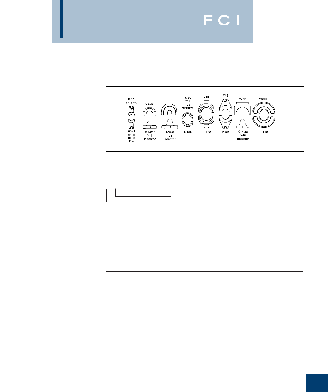
BURNDY
Reference
O-31
This chart provides a cross-reference between
die index numbers marked on BURNDY®
COMPRESSION CONNECTORS and the
CORRESPONDING DIE SETS used with the
various BURNDY®INSTALLATION TOOLS.
This is the only way to have a BURNDY®
compression system.
A die index number has been assigned to each
required groove configuration. A prefix letter is
used to indicate the specific installation tool for
which the die has been designed, as shown
below.
PRESENT INSTALLATION TOOL INDEX
CHART III
A - ALUMINUM
B - INDENTOR NEST (USED WITH INDENTOR DIE # Y34P**)
R - ROUND DIE (CIRCUMFERENTAL)
T - TWIN DIE (BOTH HALVES)
CHART II
12 - #12
10 - #10
8C - # 8
6C - # 6
5C - # 5
4C - #4
3C - #3
2C - #2
1C - #1
25 - 1/0
26 - 2/0
27 - 3/0
28 - 4/0
29 - 250 MCM
30 - 300 MCM
31 - 350 MCM
32 - 400 MCM
34 - 500 MCM
36 - 600 MCM
39 - 750 MCM
44 - 1000 MCM
OR INDEX
i.e., U312
312 Die Index
CHART I
U 34 ART
A - Y34A
B - Y34BH
C - Y48B
E - Y44B
F - Y486RB
G - Y34C
L - Y60B
P - Y46
S - Y45
U - Y35
W - MD-6/OUR840
X - OUR840/MD-6
TOOL TYPE (CHART I)
WIRE SIZE (CHART II) OR INDEX
USE CHART (CHART III)
Installation Tool
Corresponding Die Set
DIE IDENTIFICATION NUMBERING SYSTEM

BURNDY
Reference
O-32
PRESENT INSTALLATION TOOL INDEX
①Cat. No.Y35P3 Adaptor is required to use "Y34PR" type
indentors with "U" type nest dies in Y35 and Y750 series
tools.
➁Cat. No. PT6515 Adaptor is required to use "U" type dies in
Y45 series tools.
DIE DIELESS TOOLS INSTALLATION TOOLING USING DIES
GROOVE MECH. HYDR. DIE INFORMATION MECHANICAL HYDRAULIC
BURNDY EEI MR, MY Y644 TYPE COLOR MD6 OUR840 Y29B Y34B Y35
➀
Y39 Y750
➀
Y45
➁
Y46
➂
Y48B Y60BHU
ADIE SET U-A U-A U-A U-A U-A
BG DIE SET Perm GR
W-BG X-BG
X-NBG U-BG U-BG U-BG U-BG U-BG
CDIE SET BROWN W-C U-C U-C U-C U-C U-C
DDIE SET U-D U-D U-D U-D U-D
D3 DIE SET BLUE U-YFD U-YFD U-YFD U-YFD U-YFD
Perm GR U-D3 U-D3 U-D3 U-D3 U-D3
EDIE SET U-E U-E U-E U-E U-E
FDIE SET U-F U-F U-F U-F U-F
HDIE SET U-H U-H U-H U-H U-H
K-1/4 DIE SET WK14
K-5/16 DIE SET WK516 UK516T UK516T UK516T UK516T UK516T
K-3/8 DIE SET WK38 UK38T UK38T UK38T UK38T UK38T
K-1/2 DIE SET WK12
K-9/16 DIE SET WK916 UK916T UK916T UK916T UK916T UK916T
K-19/32 DIE SET WK1932
K-5/8-1 DIE SET UK581T UK581T UK581T UK581T UK581T
K-11/16 DIE SET WK1116 UK1116T UK1116T UK1116T UK1116T UK1116T
K-3/4 DIE SET UK34T UK34T UK34T UK34T UK34T
K-1 DIE SET UK1T UK1T UK1T UK1T UK1T
K-1-5/16 DIE SET UK1516T UK1516T UK1516T UK1516T UK1516T
K-635 DIE SET WK737 UK737T UK737T UK737T UK737T UK737T
K-747 DIE SET WK747
K-781 DIE SET WK781
K-840 DIE SET W-K840 U-K840 U-K840 U-K840 U-K840 U-K840
KB DIE SET WKB UKBT UKBT UKBT UKBT UKBT
KBKT DIE SET UKBKTT UKBKTT UKBKTT UKBKTT UKBKTT
KC DIE SET UKCT UKCT UKCT UKCT UKCT
KK DIE SET WKK
KR DIE SET YELLOW P-YFR
S-KR P-KR
KT DIE SET WKT
KU DIE SET UKUT UKUT UKUT UKUT UKUT
LDIE SET W-L U-L U-L U-L U-L U-L
L80 DIE SET — U34XRT U34XRT U34XRT U34XRT U34XRT
L99 DIE SET PINK U38XRT U38XRT U38XRT U38XRT U38XRT
L115 DIE SET YELLOW U44XRT U44XRT U44XRT U44XRT U44XRT
MDIE SET U-M U-M U-M U-M U-M
NDIE SET RED U-YFN U-YFN U-YFN U-YFN P-YFN
U-N U-N U-N S-N P-N
ODIE SET
GREEN U-YFO U-YFO U-YFO U-YFO U-YFO
Perm GR
W-O U-O U-O U-O U-O U-O
QDIE SET W-Q
➄
③Cat. No. PUADP-1 Adaptor is required to use "U" type dies
in Y46 series tools.
➃The MD6-6R2 ratchet tool is required on these sizes. The
standard MD6 or MD6R ratchet tools will not work.
⑤Also pnuematic version Y29NC.
BURNDY
Reference
O-33
PRESENT INSTALLATION TOOL INDEX (Continued)
①Cat. No.Y35P3 Adapter is required to accommodate
"Y34PR" type indentor in Y35, Y39, Y750 HYTOOLS and
with the PUADP-1 adapter in the Y46 and with the PT6515
adapter in the Y45.
➁Cat. No. PT6515 Adapter is required to use "U" type dies in
Y45 series tools.
③Cat. No. PUADP-1 Adapter is required to use "U" type dies
in Y46 series tools.
DIE DIELESS TOOLS INSTALLATION TOOLING USING DIES
GROOVE MECH. HYDR. DIE INFORMATION MECHANICAL HYDRAULIC
BURNDY EEI MR, MY Y644 TYPE COLOR MD6 OUR840 Y29B Y34B Y35 Y39 Y750 Y45 Y46 Y48 Y60BHU
RDIE SET U-R U-R U-R U-R U-R
TDIE SET S-T
ZDIE SET S-Z
7
94
MR4C
MY29-3
MY29-11
1
CRIMP
DIE SET BLUE W5CRT U5CRT U5CRT U5CRT U5CRT U5CRT
NEST
INDENTOR
D6CL B6CD U6CD-1 U6CD-1 U6CD-1 U6CD-1 U6CD-1
Y29PR Y34PR Y34PR Y34PR Y34PR Y34PR Y34PR
8
95
MR4C
MY29-3
MY29-11
1
CRIMP
DIE SET GRAY W4CRT W4CRT U4CRT U4CRT U4CRT U4CRT U4CRT
NEST
INDENTOR
D4CL B4CD U4CD-1 U4CD-1 U4CD-1 U4CD-1 U4CD-1
Y29PR Y34PR Y34PR Y34PR Y34PR Y34PR Y34PR
9
96
MY29-3
MY29-11 1
CRIMP
DIE SET WHITE W3CRT W3CRT U3CRT U3CRT U3CRT U3CRT U3CRT
NEST
INDENTOR
D3CL B3CD U3CD-1 U3CD-1 U3CD-1 U3CD-1 U3CD-1
Y29PR Y34PR Y34PR Y34PR Y34PR Y34PR Y34PR
10
97
MY29-3
MY29-11 1
CRIMP
DIE SET BROWN W2CRT U2CRT U2CRT U2CRT U2CRT U2CRT
NEST
INDENTOR
D2CL B2CD U2CD-1 U2CD-1 U2CD-1 U2CD-1 U2CD-1
Y29PR Y34PR Y34PR Y34PR Y34PR Y34PR Y34PR
11
98
MY29-3
MY29-11 1
CRIMP
DIE SET GREEN W1CRT U1CRT U1CRT U1CRT U1CRT U1CRT
NEST
INDENTOR
D1CL B1CD U1CD-1 U1CD-1 U1CD-1 U1CD-1 U1CD-1
Y29PR Y34PR Y34PR Y34PR Y34PR Y34PR Y34PR
12
99
MY29-3
MY29-11 1
CRIMP
DIE SET PINK W25RT W25RT U25RT U25RT U25RT U25RT U25RT
NEST
INDENTOR
D25L B25D U25D-1 U25D-1 U25D-1 U25D-1 U25D-1
Y29PR Y34PR Y34PR Y34PR Y34PR Y34PR Y34PR
13
100
MY29-3
MY29-11 1
CRIMP
DIE SET BLACK W26RT U26RT U26RT U26RT U26RT U26RT
NEST
INDENTOR
D26CL B26D U26D-1 U26D-1 U26D-1 U26D-1 U26D-1
Y29PR Y34PR Y34PR Y34PR Y34PR Y34PR Y34PR
14
101
MY29-3
MY29-11 1
CRIMP
DIE SET ORANGE W27RT U27RT U27RT U27RT U27RT U27RT
NEST
INDENTOR
D27L B27D U27D-1 U27D-1 U27D-1 U27D-1 U27D-1
Y29PR Y34PR Y34PR Y34PR Y34PR Y34PR Y34PR
15 MY29-3
MY29-11 1
CRIMP
DIE SET PURPLE W28RT U28RT U28RT U28RT U28RT U28RT C28R
NEST
INDENTOR
D28L B28D U28D-1 U28D-1 U28D-1 U28D-1 U28D-1 C28D
Y29PR Y34PR Y34PR Y34PR Y34PR Y34PR Y34PR Y48PR
16 MY29-3
MY29-11 1
CRIMP
DIE SET YELLOW W29RT U29RT U29RT U29RT U29RT U29RT C29R
NEST
INDENTOR
D29L B29D U29D-1 U29D-1 U29D-1 U29D-1 C29D
Y29PR Y34PR Y34PR Y34PR Y34PR Y34PR Y48PR
17 1
CRIMP
DIE SET WHITE W30RT U30RT U30RT U30RT U30RT U30RT C30R L30RT
NEST
INDENTOR
B30D U30D-1 U30D-1 U30D-1 U30D-1 C30D
Y34PR Y34PR Y34PR Y34PR Y34PR Y48PR
18 1
CRIMP
DIE SET RED W31RT U31RT U31RT U31RT U31RT U31RT C31R L31RT
NEST
INDENTOR
B31D U31D-1 U31D-1 U31D-1 U31D-1 C31D
Y34PR Y34PR Y34PR Y34PR Y34PR Y48PR
19 1
CRIMP
DIE SET BLUE W32RT U32RT U32RT U32RT U32RT U32RT C32R L32RT
NEST
INDENTOR
B32D U32D-1 U32D-1 U32D-1 U32D-1 C32D
Y34PR Y34PR Y34PR Y34PR Y34PR Y48PR
20 1
CRIMP
DIE SET BROWN W34RT U34RT U34RT U34RT U34RT U34RT C34R L34RT
NEST
INDENTOR
NO DIE U34D-1 U34D-1 U34D-1 U34D-1 C34D
Y34PR Y34PR Y34PR Y34PR Y34PR Y48PR
➄➀ ➀➁
➃
➃
➃
➃
➃
➂
➃The MD6-6R2 ratchet tool is required on these sizes. The
standard MD6 or MD6R ratchet tools will not work.
⑤Also pneumatic version Y29NC.
➅Use U11T-1 for YH8C8C.
⑦Hexagonal crimp.
⑧Die 302 recommended for 1.84 O.D. barrel.

BURNDY
Reference
O-34
PRESENT INSTALLATION TOOL INDEX (Continued)
①Cat. No.Y35P3 Adapter is required to accommodate
"Y34PR" type indentor in Y35, Y39, Y750 HYTOOLS and
with the PUADP-1 adapter in the Y46 and with the PT6515
adapter in the Y45.
➁Cat. No. PT6515 Adapter is required to use "U" type dies in
Y45 series tools.
DIE DIELESS TOOLS INSTALLATION TOOLING USING DIES
GROOVE MECH. HYDR. DIE INFORMATION MECHANICAL HYDRAULIC
BURNDY EEI MR, MY Y644 TYPE COLOR MD6 OUR840 Y29B Y34B Y35 Y39 Y750 Y45 Y46 Y48 Y60BHU
21 1
CRIMP
DIE SET YELLOW U35RT U35RT U35RT U35RT
NEST
INDENTOR
C35D
Y48PR
22 1
CRIMP
DIE SET GREEN U36RT U36RT U36RT U36RT C36R L36RT
NEST
INDENTOR
P36D C36D
P44PR Y48PR
23 1
CRIMP
DIE SET ORANGE C37R
NEST
INDENTOR
C37D
Y48PR
24 1
CRIMP
DIE SET BLACK U39RT U39RT S39RT P39RT C39R L39RT
NEST
INDENTOR
P39D C39D
P44PR Y48PR
25 1
CRIMP
DIE SET ORANGE S40RT P40RT C40R L40RT
NEST
INDENTOR
P40D C40D
P44PR Y48PR
26 1
CRIMP
DIE SET GOLD
NEST
INDENTOR
C41D
Y48PR
27 1
CRIMP
DIE SET WHITE S44RT P44RT C44R L44RT
NEST
INDENTOR
P44D C44D
P44PR Y48PR
28
DIE SET
NEST
INDENTOR
C443D
Y48PR
29
DIE SET YELLOW P45RT C45R L45RT
NEST
INDENTOR
C45D
Y48PR
30
DIE SET ORANGE
NEST
INDENTOR
C453D
Y48PR
31
DIE SET GREEN S46RT P46RT C46R L46RT
NEST
INDENTOR
No Nest C46D
Y44PR Y48PR
33
DIE SET GRAY C47R L47RT
NEST
INDENTOR
C47D
Y48PR
34
DIE SET BROWN L48RT
NEST
INDENTOR
C48D
Y48PR
38
MR4C
MR8G98
MR89Q
MY28
Y8MRB-1
NEST
INDENTOR
DV8L BV8L UV8L UV8L UV8L UV8L UV8L
Y29PL Y34PL Y34PL Y34PL Y34PL Y34PL Y34PL
39 MR4C
MY28 NEST
INDENTOR
DV6L BV6L UV6L UV6L UV6L UV6L UV6L
Y29PL Y34PLA Y34PLA Y34PLA Y34PLA Y34PLA Y34PLA
➂➁➀➀➄
③Cat. No. PUADP-1 Adapter is required to use "U" type dies
in Y46 series tools.
⑤Also pneumatic version Y29NC.
BURNDY
Reference
O-35
PRESENT INSTALLATION TOOL INDEX (Continued)
①Cat. No.Y35P3 Adapter is required to accommodate
"Y34PR" type indentor in Y35, Y39, Y750 HYTOOLS and
with the PUADP-1 adapter in the Y46 and with the PT6515
adapter in the Y45.
➁Cat. No. PT6515 Adapter is required to use "U" type dies in
Y45 series tools.
DIE DIELESS TOOLS INSTALLATION TOOLING USING DIES
GROOVE MECH. HYDR. DIE INFORMATION MECHANICAL HYDRAULIC
BURNDY EEI MR, MY Y644 TYPE COLOR MD6 OUR840 Y29B Y34B Y35 Y39 Y750 Y45 Y46 Y48 Y60BHU
40
MR4C
MY28 NEST
INDENTOR
DV4L BV4L UV4L UV4L UV4L UV4L UV4L
Y29PL Y34PLA Y34PLA Y34PLA Y34PLA Y34PLA Y34PLA
41
MY28 NEST
INDENTOR
DV2L BV2L UV2L UV2L UV2L UV2L UV2L
Y29PL Y34PLA Y34PLA Y34PLA Y34PLA Y34PLA Y34PLA
42
MY28 NEST
INDENTOR
DV1L BV1L UV1L UV1L UV1L UV1L UV1L
Y29PL Y34PLA Y34PLA Y34PLA Y34PLA Y34PLA Y34PLA
43
MY28 NEST
INDENTOR
DV25L BV25L UV25L UV25L UV25L UV25L UV25L
Y29PL Y34PA Y34PA Y34PA Y34PA Y34PA Y34PA
44
MY28 NEST
INDENTOR
DV26L BV26L UV26L UV26L UV26L UV26L UV26L
Y29PL Y34PA Y34PA Y34PA Y34PA Y34PA Y34PA
45
MY28 NEST
INDENTOR
BV27L UV27L UV27L UV27L UV27L UV27L
Y34PA Y34PA Y34PA Y34PA Y34PA Y34PA
46
MY28 NEST
INDENTOR
BV28L UV28L UV28L UV28L UV28L UV28L
Y34PA Y34PA Y34PA Y34PA Y34PA Y34PA
49
DIE SET
RED
W8CRT *U8CRT U8CRT U8CRT U8CRT U8CRT
161
DIE SET W161 X-161 U161 U161 U161 U161 U161
162
DIE SET W162 W162 U162 U162 U162 U162 U162 C162
163 505
DIE SET W163 W163 U163 U163 U163 U163 U163 C163
164 275
DIE SET W164 U164 U164 U164 U164 U164 C164
165
205,287
339
DIE SET W165 X-165 U165/
U205 U165/
U205 U165/
U205 U165/
U205 U165/
U205 C165 L165
166
206,459
DIE SET W166 U166/
U459 U166/
U459 U166/
U459 U166/
U459 U166/
U459 C166 L166
167
207,211
256,568
DIE SET W167 U167/
U568 U167/
U568 U167/
U568 U167/
U568 U167/
U568 C167 L167
168 208
DIE SET U168 U168 U168 U168 U168 C168 L168
169
DIE SET U169 U169 U169 U169 U169 C169 L169
170 306
DIE SET U170 U170 U170 U170 U170 C170 L170
171
DIE SET W171 U171 U171 U171 U171 U171
193
DIE SET U193 U193 U193 U193 U193 C193 L193
202
DIE SET U202 U202 U202 U202 U202
203
DIE SET U203 U203 U203 U203 U203
204
DIE SET U204 U204 U204 U204 U204
205
165,287
339
DIE SET X-165 U165/
U205 U165/
U205 U165/
U205 U165/
U205 U165/
U205
206
166
459
DIE SET
W166
U166/
U459 U166/
U459 U166/
U459 U166/
U459 U166/
U459 L166
207
167,211
256,568
DIE SET
W167
U167/
U568 U167/
U568 U167/
U568 U167/
U568 U167/
U568 C167 L167
208
168
DIE SET U168 U168 U168 U168 U168 C168 L168
209
DIE SET U209 U209 U209 U209 U209 C209 L209
210
DIE SET U210 U210 U210 U210 U210 C210 L210
➄➀➀➁➂
③Cat. No. PUADP-1 Adapter is required to use "U" type dies
in Y46 series tools.
⑤Also pneumatic version Y29NC.
*Add Nest (BV8L) & Indentor (Y34PL) for Y34B.
BURNDY
Reference
O-36
PRESENT INSTALLATION TOOL INDEX (Continued)
①Cat. No.Y35P3 Adapter is required to accommodate
"Y34PR" type indentor in Y35, Y39, Y750 HYTOOLS and
with the PUADP-1 adapter in the Y46 and with the PT6515
adapter in the Y45.
➀➁➂➀➄
DIE DIELESS TOOLS INSTALLATION TOOLING USING DIES
GROOVE MECH. HYDR. DIE INFORMATION MECHANICAL HYDRAULIC
BURNDY EEI MR, MY Y644 TYPE COLOR MD6 OUR840 Y29B Y34B Y35 Y39 Y750 Y45 Y46 Y48 Y60BHU
211
167, 211
256, 568 DIE SET W167 U167/
U568 U167/
U568 U167/
U568 U167/
U568 U167/
U568 C167 L167
236 DIE SET W236 U236 U236 U236 U236 U236
237 DIE SET W237 X-237 U237 U237 U237 U237 U237
238 DIE SET W238 U238 U238 U238 U238 U238
239 DIE SET W239 X-239 U239 U239 U239 U239 U239
240 DIE SET RED W240 U240 U240 U240 U240 U240
241 DIE SET W241 X-241 U241 U241 U241 U241 U241
242
244 3S/
4S DIE SET W242 U242 U242 U242 U242 U242 C242 L242
243 8A DIE SET W243 U243 U243 U243 U243 U243 C243 L243
244 242 3S DIE SET W242 U242 U242 U242 U242 U242 C242 L242
245 9A DIE SET W245 X-245 U245 U245 U245 U245 U245 C245 L245
246 248 5S DIE SET W248 U248 U248 U248 U248 U248 C248 L248
247 DIE SET W247 X-247 U247 U247 U247 U247 U247 C247 L247
248 246 5S DIE SET W248 U248 U248 U248 U248 U248 C248 L248
249 11A DIE SET W249 X-249 U249 U249 U249 U249 U249 C249 L249
250 DIE SET U250 U250 U250 U250 U250 C250 L250
251 12A DIE SET RED W251 U251 U251 U251 U251 U251 C251 L251
252 DIE SET U252 U252 U252 U252 U252 C252 L252
253 DIE SET U253 U253 U253 U253 U253 C253 L253
254 DIE SET S254 P254 C254 L254
255 DIE SET U255 U255 U255 U255 U255 C255 L255
256
167, 207
211, 568 DIE SET W167 U167/
U568 U167/
U568 U167/
U568 U167/
U568 U167/
U568 C167 L167
257 DIE SET U257 U257 U257 U257 U257 C257 L257
259 DIE SET U259 U259 U259 U259 U259
260 DIE SET C260 L260
261 318 15A DIE SET U261 U261 U261 U261 U261 C261 L261
263 DIE SET U263 U263 U263 U263 U263
267 DIE SET U267 U267 U267 U267 U267 C267 L267
275 164 DIE SET W164 U164 U164 U164 U164 U164 C164
276 DIE SET U276 U276 U276 U276 U276
285 DIE SET U285 U285 U285 U285 U285
287
165, 205
339 DIE SET W165 U165/
U205 U165/
U205 U165/
U205 U165/
U205 U165/
U205 L165
292 578 DIE SET S292 P292 C292 L292
293 294 DIE SET S293 P293 C293 L293
296 MY29-3 1
CRIMP
DIE SET TAN U25ART U25ART U25ART U25ART U25ART C25AR
NEST
INDENTER
P27D
P34PR5
297 MY29-3 1
CRIMP
DIE SET OLIVE U26ART U26ART U26ART U26ART U26ART C26AR
NEST
INDENTER
P29D
P34PR5
➁Cat. No. PT6515 Adapter is required to use "U" type dies in
Y45 series tools.
③Cat. No. PUADP-1 Adapter is required to use "U" type dies
in Y46 series tools.
⑤Also pneumatic version Y29NC.
BURNDY
Reference
O-37
PRESENT INSTALLATION TOOL INDEX (Continued)
①Cat. No.Y35P3 Adapter is required to accommodate
"Y34PR" type indentor in Y35, Y39, Y750 HYTOOLS and
with the PUADP-1 adapter in the Y46 and with the
PT6515 Adapter in the Y45.
➁Cat. No. PT6515 Adapter is required to use "U" type dies in
Y45 series tools.
③Cat. No. PUADP-1 Adapter is required to use "U" type dies
in Y46 series tools.
DIE DIELESS TOOLS INSTALLATION TOOLING USING DIES
GROOVE MECH. HYDR. DIE INFORMATION MECHANICAL HYDRAULIC
BURNDY EEI MR, MY Y644 TYPE COLOR MD6 OUR840 Y29B Y34B Y35 Y39 Y750 Y45 Y46 Y48 Y60BHU
298 MY29-3 1 CRIMP
DIE SET WHITE U28ART U28ART U28ART U28ART U28ART C28AR L28ART
NEST
INDENTOR
P31D
Y34PR5
299 1 CRIMP
DIE SET BROWN U31ART U31ART U31ART U31ART U31ART C31AR L31ART
NEST
INDENTOR
P35D C35D
P48PR1 Y48PR1
300 1 CRIMP
DIE SET PINK U34ART U34ART U34ART U34ART U34ART C34AR L34ART
NEST
INDENTOR
P39D C39D
P48PR1 Y48PR1
301 1 CRIMP
DIE SET RED S39ART P39ART C39AR L39ART
NEST
INDENTOR
P45D C45D
P48PR1 Y48PR1
302 1 CRIMP
DIE SET BROWN S44ART P44ART C44AR L44ART
NEST
INDENTOR
No Nest C46D
P48PR1 Y48PR1
304 DIE SET U304 U304 U304 U304 U304 C304 L304
305 341 DIE SET U305 U305 U305 U305 U305 C305 L305
306 170 DIE SET U170 U170 U170 U170 U170 C170 L170
308 DIE SET U308 U308 U308 U308 U308
313 DIE SET U313 U313 U313 U313 U313 C313 L313
314 376 DIE SET C314 L314
316 DIE SET U316 U316 U316 U316 U316 C316 L316
317 426 DIE SET U317 U317 U317 U317 U317 C317 L317
318 261 DIE SET U261 U261 U261 U261 U261 C261 L261
319 DIE SET S319 P319 C319 L319
320 DIE SET S320 P320 C320 L320
321 DIE SET U321 U321 U321 U321 U321 C321 L321
322 DIE SET U322 U322 U322 U322 U322
324 1 CRIMP
DIE SET RED U29ART U29ART U29ART U29ART U29ART C29AR L29ART
NEST
INDENTER
P32D
P34PR5
326 538 DIE SET U33RT U33RT U33RT U33RT U33RT
327 14A DIE SET U327 U327 U327 U327 U327 C327 L327
328 DIE SET C328 L328
329 DIE SET U329 U329 U329 U329 U329
331 DIE SET U331 U331 U331 U331 U331
339
165, 205
287 DIE SET X-339 U165/
U205 U165/
U205 U165/
U205 U165/
U205 U165/
U205
341 305 DIE SET U305 U305 U305 U305 U305 C305 L305
342 DIE SET S342 P342 C342 L342
344 DIE SET C344 L344
345 DIE SET C345 L345
346 1 CRIMP DIE SET GRAY U6CABT U6CABT U6CABT U6CABT U6CABT
➆
➀
➀➁➂
➅
➄
➃The MD6-6R2 ratchet tool is required on these sizes. The
standard MD6 or MD6R ratchet tools will not work.
⑤Also pneumatic version Y29NC.
➅Use C39AR round die 301 for 1.60 O.D. barrel. Use
C39AR-2 hex die 936 for 1.46 O.D. barrel.
⑦Hexagonal crimp.
⑧Die 302 recommended for 1.84 O.D. barrel.
BURNDY
Reference
O-38
PRESENT INSTALLATION TOOL INDEX (Continued)
①Cat. No.Y35P3 Adapter is required to accommodate
"Y34PR" type indentor in Y35, Y39, Y750 HYTOOLS and
with the PUADP-1 adapter in the Y46 and with the PT6515
adapter in the Y45.
➁Cat. No. PT6515 Adapter is required to use "U" type dies in
Y45 series tools.
DIE DIELESS TOOLS INSTALLATION TOOLING USING DIES
GROOVE MECH. HYDR. DIE INFORMATION MECHANICAL HYDRAULIC
BURNDY EEI MR, MY Y644 TYPE COLOR MD6 OUR840 Y29B Y34B Y35 Y39 Y750 Y45 Y46 Y48 Y60BHU
348 1 CRIMP DIE SET PINK U2CABT U2CABT U2CABT U2CABT U2CABT
350 DIE SET U350 U350 U350 U350 U350 C350 L350
352 DIE SET S352 P352 C352 L352
373 DIE SET U373 U373 U373 U373 U373
374 MY29-3 DIE SET BLUE U8CABT U8CABT U8CABT U8CABT U8CABT
375 MY29-3 1 CRIMP DIE SET GREEN U4CABT U4CABT U4CABT U4CABT U4CABT
376 314 DIE SET C314 L314
403 DIE SET U403 U403 U403 U403 U403
419 DIE SET S419 P419 C419 L419
422 DIE SET L422
426 317 DIE SET U317 U317 U317 U317 U317 U317
459 166 DIE SET U166/459 U166/459 U166/459 U166/459 U166/459
467 MY29-3 1 CRIMP
DIE SET RUBY U27ART A27ART U27ART U27ART U27ART C27AR
NEST
INDENTOR
P30D
P34PR5
468 DIE SET U468 U468 U468 U468 U468
469 DIE SET S469 P469 C469 L469
470 1 CRIMP
DIE SET BLUE U30ART U30ART U30ART U30ART U30ART C30AR L30ART
NEST
INDENTOR
P34D C34D
P48PR1 Y48PR1
471 MY29-3 1 CRIMP
DIE SET GOLD U1CART U1CART U1CART U1CART U1CART
NEST
INDENTOR
472 1 CRIMP
DIE SET GREEN U32ART U32ART U32ART U32ART U32ART C32AR L32ART
NEST
INDENTOR
P35D C35D
P48PR1 Y48PR1
473 1 CRIMP
DIE SET BLACK U36ART U36ART U36ART U36ART U36ART C36AR L36ART
NEST
INDENTOR
P44D C44D
P48PR1 Y48PR1
474 1 CRIMP
DIE SET GOLD S40ART P40ART C40AR L40ART
NEST
INDENTOR
C45D
Y48PR1
478 1 CRIMP
DIE SET BLUE C46AR L46ART
NEST
INDENTOR
C46AD
Y48PR11
479 DIE SET RED L48ART
490 547 DIE SET U490 U490 U490 U490 U490 C490 L490
495 DIE SET C495 L495
505 163 DIE SET W163 U163 U163 U163 U163 U163 L163
511 MY29-3 NEST
INDENTOR
B6CD
Y34PA
512 MY29-3 NEST
INDENTOR
B4CD
Y34PA
513 MY29-3 NEST
INDENTOR
B1CD
Y34PA
514 MY29-3 NEST
INDENTOR
B26D
Y34PA
➀➀➁➂
③Cat. No. PUADP-1 Adapter is required to use "U" type dies
in Y46 series tools.
➃The MD6-6R2 ratchet tool is required on these sizes. The
standard MD6 or MD6R ratchet tools will not work.
⑤Also pneumatic version Y29NC.
➅Hexagonal crimp.

BURNDY
Reference
O-39
PRESENT INSTALLATION TOOL INDEX (Continued)
①Cat. No.Y35P3 Adapter is required to accommodate
"Y34PR" type indentor in Y35, Y39, Y750 HYTOOLS and
with the PUADP-1 adapter in the Y46 and with the PT6515
adapter in the Y45.
➁Cat. No. PT6515 Adapter is required to use "U" type dies in
Y45 series tools.
DIE DIELESS TOOLS INSTALLATION TOOLING USING DIES
GROOVE MECH. HYDR. DIE INFORMATION MECHANICAL HYDRAULIC
BURNDY EEI MR, MY Y644 TYPE COLOR MD6 OUR840 Y29B Y34B Y35 Y39 Y750 Y45 Y46 Y48 Y60BHU
515 MY29-3 NEST
INDENTOR
B26D
Y34PR5
516 MY29-3 NEST
INDENTOR
B27D
Y34PR5
517 MY29-3 NEST
INDENTOR
B29D
Y34PR5
518 MY29-3 NEST
INDENTOR
B30D
Y34PR5
519 MY29-3 NEST
INDENTOR
B31D
Y34PR5
520 MY29-3 NEST
INDENTOR
B32D
Y34PR5
521 NEST
INDENTOR
No Nest C34D
Y34PR11 Y48PR-1
522 NEST
INDENTOR
C35D
Y48PR-1
523 NEST
INDENTOR
C35D
Y48PR-1
524 NEST
INDENTOR
C39D
Y48PR-1
525 NEST
INDENTOR
C44D
Y48PR-1
526 NEST
INDENTOR
C45D
Y48PR-1
527 NEST
INDENTOR
C45D
Y48PR-1
528 NEST
INDENTOR
C46D
Y48PR-1
529 NEST
INDENTOR
C46AD
Y48PR-11
538 326 DIE SET U33RT U33RT U33RT U33RT U33RT
547 490 DIE SET U490 U490 U490 U490 U490 C490 L490
552 DIE SET U552 U552 U552 U552 U552
568
167, 207
211, 256 DIE SET W167 U167/
U568 U167/
U568 U167/
U568 U167/
U568 U167/
U568
575 DIE SET C575 L575
576 DIE SET C576 L576
578 292 DIE SET S292 P292 C292 L292
579 DIE SET S579 P579 C579 L579
587 DIE SET L47ART
607 DIE SET U607 U607 U607 U607 U607
608 DIE SET U608 U608 U608 U608 U608 C608 L608
609 DIE SET U609 U609 U609 U609 U609 C609
627 DIE SET C627 L627
642 DIE SET U642 U642 U642 U642 U642 C642 L642
643 DIE SET U643 U643 U643 U643 U643
647 DIE SET C45AR L45ART
⑤
➀➀
➁➂
➄
③Cat. No. PUADP-1 Adapter is required to use "U" type dies
in Y46 series tools.
➃Also pneumatic version Y29NC.
⑤Die 302 recommended for 1.84 O.D. barrel.
BURNDY
Reference
O-40
PRESENT INSTALLATION TOOL INDEX (Continued)
①Cat. No.Y35P3 Adapter is required to accommodate
"Y34PR" type indentor in Y35, Y39, Y750 HYTOOLS and
with the PUADP-1 adapter in the Y46 and with the PT6515
adapter in the Y45.
➁Cat. No. PT6515 Adapter is required to use "U" type dies in
Y45 series tools.
③Cat. No. PUADP-1 Adapter is required to use "U" type dies
in Y46 series tools.
DIE DIELESS TOOLS INSTALLATION TOOLING USING DIES
GROOVE MECH. HYDR. DIE INFORMATION MECHANICAL HYDRAULIC
BURNDY EEI MR, MY Y644 TYPE COLOR MD6 OUR840 Y29B Y34B Y35 Y39 Y750 Y45 Y46 Y48 Y60BHU
648 DIE SET L648
654 DIE SET PURPLE U654 U654 U654 U654 P654 L654
655 13A DIE SET U655 U655 U655 U655 U655
658 DIE SET U658 U658 U658 U658 U658
659 DIE SET W659 U659 U659 U659 U659 U659
660 DIE SET W660 X-660 U660 U660 U660 U660 U660
667 DIE SET C667 L667
668 DIE SET U668 U668 U668 U668 U668 C668
676 DIE SET U676 U676 U676 U676 U676
677 DIE SET U677 U677 U677 U677 U677 L677
678 DIE SET U678 U678 U678 U678 U678
679 DIE SET U679 U679 U679 U679 U679
684 DIE SET L684
687 DIE SET W687 X-687
690 1S DIE SET W690 U690 U690 U690 U690 U690
691 2S DIE SET W691 U691 U691 U691 U691 U691
692 4S DIE SET W692 U692 U692 U692 U692 U692
693 6A DIE SET W693 U693 U693 U693 U693 U693
694 10A DIE SET W694 U694 U694 U694 U694 U694
702 DIE SET W702
705 DIE SET U705 U705 U705 U705 U705
717 DIE SET S717 P717 L717
718 DIE SET L718
719 DIE SET S719 P719 L719
720 DIE SET S720 P720 L720
721 DIE SET L721
722 DIE SET S722 P722 C722 L722
723 DIE SET C723 L723
724 DIE SET S724 P724 C724 L724
725 DIE SET S725 P725 C725 L725
726 DIE SET L726
727 DIE SET L727
728 DIE SET L728
729 DIE SET L729
735 DIE SET L735
740 DIE SET L740
786 DIE SET U786 U786 U786 U786 U786
788 DIE SET U788 U788 U788 U788 U788
789 DIE SET L789
936 1 CRIMP DIE SET YELLOW U39ART-2 U39ART-2 U39ART-2 U39ART-2 U39ART-2 C39ART-2 L39ART-2
997 DIE SET ORANGE U997 U997 U997 U997 U997
998 DIE SET PU998 S998 P998
999 DIE SET S999 P999
1011 DIE SET U1011 S1011 P1011
1012 DIE SET S1012
1013 MY29-11 NEST
INDENTOR
UV8L UV8L UV8L UV8L UV8L
Y34PL Y34PL Y34PL Y34PL Y34PL
➄➀➀
➁➂
➆
➆
➆
➆
➆
➆
➆
➆
➆
➆
➆
➆
➆
➆
➆
➆
➃The MD6-6R2 ratchet tool is required on these sizes. The
standard MD6 or MD6R ratchet tools will not work.
⑤Also pneumatic version Y29NC.
➅Use C39AR round die 301 for 1.60 O.D. barrel. Use
C39AR-2 hex die 936 for 1.46 O.D. barrel.
⑦Hexagonal crimp.
BURNDY
Reference
O-41
PRESENT INSTALLATION TOOL INDEX (Continued)
➀Cat. No.Y35P3 Adapter is required to accommodate
"Y34PR" type indentor in Y35, Y39, Y750 HYTOOLS and
with the PUADP-1 adapter in the Y46 and with the PT6515
adapter in the Y45.
➁Cat. No. PT6515 Adapter is required to use "U" type dies in
Y45 series tools.
DIE DIELESS TOOLS INSTALLATION TOOLING USING DIES
GROOVE MECH. HYDR. DIE INFORMATION MECHANICAL HYDRAULIC
BURNDY EEI MR, MY Y644 TYPE COLOR MD6 OUR840 Y29B
➃
Y34B Y35
➀
Y39 Y750
➀
Y45
➁
Y46
➂
Y48B Y60BHU
NEST U6CD1 U6CD1 U6CD1 U6CD1 U6CD1
1014
MY29-11 INDENTOR Y34PR Y34PR Y34PR Y34PR Y34PR
NEST U4CD1 U4CD1 U4CD1 U4CD1 U4CD1
1015
MY29-11 INDENTOR Y34PR Y34PR Y34PR Y34PR Y34PR
NEST U3CD1 U3CD1 U3CD1 U3CD1 U3CD1
1016
MY29-11 INDENTOR Y34PR Y34PR Y34PR Y34PR Y34PR
NEST U2CD1 U2CD1 U2CD1 U2CD1 U2CD1
1017
MY29-11 INDENTOR Y34PR Y34PR Y34PR Y34PR Y34PR
NEST U1CD1 U1CD1 U1CD1 U1CD1 U1CD1
1018
MY29-11 INDENTOR Y34PR Y34PR Y34PR Y34PR Y34PR
NEST U25D1 U25D1 U25D1 U25D1 U25D1
1019
MY29-11 INDENTOR Y34PR2 Y34PR2 Y34PR2 Y34PR2 Y34PR2
NEST U26D1 U26D1 U26D1 U26D1 U26D1
1020
MY29-11 INDENTOR Y34PR2 Y34PR2 Y34PR2 Y34PR2 Y34PR2
NEST U27D1 U27D1 U27D1 U27D1 U27D1
1021
MY29-11 INDENTOR Y34PR2 Y34PR2 Y34PR2 Y34PR2 Y34PR2
NEST U28D1 U28D1 U28D1 U28D1 U28D1
1022
MY29-11 INDENTOR Y34PR2 Y34PR2 Y34PR2 Y34PR2 Y34PR2
NEST U29D1 U29D1 U29D1 U29D1 U29D1
1023
MY29-11 INDENTOR Y34PR2 Y34PR2 Y34PR2 Y34PR2 Y34PR2
NEST U30D1 U30D1 U30D1 U30D1 U30D1
1024
INDENTOR Y34PR2 Y34PR2 Y34PR2 Y34PR2 Y34PR2
NEST U31D1 U31D1 U31D1 U31D1 U31D1
1025
INDENTOR Y34PR2 Y34PR2 Y34PR2 Y34PR2 Y34PR2
NEST U32D1 U32D1 U32D1 U32D1 U32D1
1026
INDENTOR Y34PR2 Y34PR2 Y34PR2 Y34PR2 Y34PR2
NEST U34D1 U34D1 U34D1 U34D1 U34D1
1027
INDENTOR Y34PR2 Y34PR2 Y34PR2 Y34PR2 Y34PR2
NEST P36D C36D
1028
INDENTOR P48PR1 Y48PR1
NEST P38D C38D
1029
INDENTOR P48PR1 Y48PR1
NEST P39D C39D
1030
INDENTOR P48PR1 Y48PR1
NEST P40D C40D
1031
INDENTOR P48PR1 Y48PR1
NEST P44D C44D
1032
INDENTOR P48PR1 Y48PR1
1102
DIE SET White P1102
1103
DIE SET Blue P1103
1104
DIE SET Brown U1104 P1104
1105
U1105 P1105
DIE SET Purple U38RT U38RT U38RT U38RT U38RT
400
NEST C38D
INDENTOR Y48PR
NEST U27B U27B U27B
2000
INDENTOR Y34PR15 Y34PR15 Y34PR15
➂Cat. No. PUADP-1 Adapter is required to use "U" type dies
in Y46 series tools.
➃Also pneumatic version Y29NC.
Available in PIBEAM KIT
BURNDY
Reference
CATALOG NUMBERS
REQUIRING MSDS
COLOR CODING FOR
OVERHEAD CONNECTORS
O-42
POWERCELL PENA13-3 PENE-8
PENA-3 PENA13-4 PENE-PT
PENA-4 PENA13-8 PENE QT
P8A PENA13PT PENE GAL
PENA 1LB PENA13QT PENE 5GAL
PENA PT PENA13GAL PENE 55GAL
PENA QT PENA13 5GAL ALFLUID QT
PENA GAL PENA13 55GAL ALFLUID GAL
PENA 5GAL PENE-3 HYFLUID QT
PENA 55GAL PENE-4 HYFLUID GAL
COLOR CODE ALUMINUM & COPPER
STR COMPACT SOL ASCR
BROWN 10 8
GREEN 8 6
BLUE 5, 6 4 6
ORANGE 3, 4 #2 2 4
RED 1-19, 2 1/0 1 2
YELLOW 1/0 2/0 1/0, 1
GRAY 2/0 3/0 2/0
BLACK 3/0 4/0 3/0
PINK 4/0 266, 300 4/0
RED 250
WHITE 266
BLUE 300 350 266.8 (26/7, 18/1)
BROWN 336
GREEN 350, 397, 400 336.4 (26/7, 18/1)
GRAY 450
PINK 500 477 (18/1)
GREEN 556
PURPLE 600
YELLOW 556.5 (24/7, 26/7)
BLUE 650
RED 700
YELLOW 750
ORANGE 800
WHITE 900
BROWN 1000
*All Wejtap catalog numbers ending in PB require MSDS for
Power Cell.
NOTE: This chart is only intended as a guide, for specific
applications refer to your catalog.
For connectors with a range, the color is keyed by the largest
conductor.
BURNDY
Reference
O-43
COLOR CODING FOR
AL/CU CONNECTORS
COLOR CODING FOR
COPPER LUGS AND SPLICES
COLOR CODE STR COLOR CODE STR
BLUE 8 BLUE 300
GRAY 6BROWN 350
GREEN 4GREEN 400
PINK 2PINK 500
GOLD 1BLACK 600
TAN 1/0 YELLOW 700/750
OLIVE 2/0 RED 700/750
RUBY 3/0 BROWN 1000
WHITE 4/0 BLUE 1500
RED 250 RED 2000
COLOR CODE CODE SIZE FLEX CABLE
STR SOL
RED 8 6 8
BLUE 6 6
BLUE 5
GRAY 4 4
WHITE 3 2
BROWN 2 2
GREEN 1 1
PINK 1/0 1/0
BLACK 2/0 2/0
ORANGE 3/0 3/0
PURPLE 4/0 4/0
YELLOW 250 4/0 & 250
WHITE 300 250
RED 350 313.1
BLUE 400 373.7
BROWN 500 444.4
GREEN 600
PINK 700 535.3
PURPLE 600
BLACK 750 646
YELLOW 777.7
ORANGE 800
WHITE 1000
YELLOW 1111
GREEN 1500
BROWN 2000
NOTE: This chart is only intended as a guide. For specific
applications refer to your catalog.
NOTE: This chart is only intended as a guide. For specific
applications refer to your catalog.
BURNDY
Alpha-numeric
O-44
CATALOG NO. PAGE NO. CATALOG NO. PAGE NO. CATALOG NO. PAGE NO. CATALOG NO. PAGE NO. CATALOG NO. PAGE NO.
115Cl D57
115R D57
1300A-12-3-10 A41
1300A-24-3-10 A41
1300A-30-3-10 A41
1300A-8-3-10 A41
1300A18-3-10 A41
1350A-12-3-12 A41
1350A-12-3-B A43
1350A-12-4-10 A42
1350A-12-4-B A43
1350A-18-3-12 A41
1350A-18-3-B A43
1350A-18-4-12 A42
1350A-18-4-B A43
1350A-24-3-12 A41
1350A-24-3-B A43
1350A-24-4-12 A42
1350A-24-4-B A43
1350A-30-3-12 A41
1350A-30-3-B A43
1350A-30-4-12 A42
1350A-30-4-B A43
1350A-8-3-12 A41
1350A-8-3-B A43
1350A-8-4-12 A42
1350A-8-4-B A43
1500A-12-3-10 A41
1500A-12-3-12 A41
1500A-12-3-B A43
1500A-12-4-12 A42
1500A-12-4-B A43
1500A-18-3-10 A41
1500A-18-3-12 A41
1500A-18-3-B A43
1500A-18-4-12 A42
1500A-18-4-B A43
1500A-24-3-10 A41
1500A-24-3-12 A41
1500A-24-3-B A43
1500A-24-4-12 A42
1500A-24-4-B A43
1500A-30-3-10 A41
1500A-30-3-12 A41
1500A-30-3-B A43
1500A-30-4-12 A42
1500A-30-4-B A43
150R D57
15Cl D57
15CP D57
15R D57
1PBS1/0 A54
1PBS2 A54
1PBS250 A54
1PBS350 A54
1PBS500 A54
1PL2/02 A54
1PL2/03 A54
1PL2502 A54
1PL2503 A54
1PL3502 A54
1PL42 A54
1PL43 A54
1PL44 A54
1PL6002 A54
1PLD2/02 A54
1PLD2/03 A54
1PLD2/04 A54
1PLD2/06 A54
1PLD2502 A54
1PLD2503 A54
1PLD2504 A54
1PLD2506 A54
1PLD3502 A54
1PLD3503 A54
1PLD3504 A54
1PLD3506 A54
1PLD3508 A54
1PLD43 A54
1PLD44 A54
1PLD6002 A54
1PLD6003 A54
1PLD6004 A54
1PLD6005 A54
1PLD6006 A54
1PLD6008 A54
1PLO2/02 A54
1PLO2502 A54
1PLO42 A54
1PLO6002 A54
200R D57
25 FW BOX L3
25 FWSS L7
25 HSSN L7
25 NW BOX L3
25 SW BOX L3
25 SWSS LT L7
250R D57
25C HEN BOX L3
25Cl D57
25CP D57
25R D57
25x100 HEB BOX L2
25x125 HEB BOX L2
25x150 HEB BOX L2
25x200 HEB BOX L2
25x250 HEB BOX L2
25x300 HEB BOX L2
25x50 HEB BOX L2
25x62 HEB BOX L2
25x75 HEB BOX L2
31 FW BOX L3
31 NW BOX L3
31 SW BOX L3
31C HEN BOX L3
31CHGSN L5
31x100 HEB BOX L2
31x125 HEB BOX L2
31x150 HEB BOX L2
31x175 HEB BOX L2
31x200 HEB BOX L2
31x250 HEB BOX L2
31x300 HEB BOX L2
31x50 HEB BOX L2
31x62 HEB BOX L2
31x75 HEB BOX L2
32Cl D57
32CP D57
32R D57
38 FW BOX L3
38 FWSS L7
38 HGSN L5
38 HGSN-009 L5
38 HSSN L7
38 NW BOX L3
38 NWGS L5
38 SW BOX L3
38 SWSSMD L7
38 X (*) HEB G14
38 x (*) HEB A22
38C HEN BOX L3
38CHEN A22, G12, G14
38FW G12
38SW A22, G12, G14
38x100 HEB BOX L2
38x125 HEB BOX L2
38x125 HGSB L5
38X125 HSSB L7
38X125HEB G12
38x150 HEB BOX L2
38x175 HEB BOX L2
38X175HEB G12
38x200 HEB BOX L2
38x225 HEB BOX L2
38x225 HGSB L5
38x225 HSSB L7
38X225HEB G12
38x250 HEB BOX L2
38x250 HSSB L7
38X250HEB G12
38x275 HEB BOX L2
38x275 HGSB L5
38x275 HSSB L7
38X275HEB G12
38x300 HEB BOX L2
38x325 HEB BOX L2
38X325HEB G12
38x350 HEB BOX L2
38x400 HEB BOX L2
38x450 HEB BOX L2
38x50 HEB BOX L2
38x500 HEB BOX L2
38x62 HEB BOX L2
38x75 BWSS L7
38x75 HEB BOX L2
38x81 FWGS L5
38x88 HEB BOX L2
411-206016-014 N61
411-206091-018 N61
433-206016-010 N61
433-206071-012 N61
44 FW BOX L3
44 NW BOX L3
44 SW BOX L3
44C HEN BOX L3
44x150 HEB BOX L2
44x200 HEB BOX L2
45Cl D57
45CP D57
45R D57
50 FW BOX L3
50 FWA BOX L6
50 FWSS L7
50 HAN BOX L6
50 HGSN L5
50 HSSN L7
50 NW BOX L3
50 NWGS L5
50 SW BOX L3
50 SWAL BOX L6
50 SWSSMD L7
50 X (*) HEB G14
50 x (*) HEB A22
500R D57
50C HEN BOX L3
50CHEN A22, G14
50SW A22, G14
50x100 HEB BOX L2
50x100 HGSB L5
50x106 BWSS L7
50x106 FWGS L5
50x125 HEB BOX L2
50x150 HAB BOX L6
50x150 HEB BOX L2
50x150 HGSB L5
50x175 HAB BOX L6
50x175 HEB BOX L2
50x200 HAB BOX L6
50x200 HEB BOX L2
50x200 HGSB L5
50x200 HSSB L7
50x225 HAB BOX L6
50x225 HEB BOX L2
50x250 HAB BOX L6
50x250 HEB BOX L2
50x250 HSSB L7
50x275 HAB BOX L6
50x275 HEB BOX L2
50x300 HAB BOX L6
50x300 HEB BOX L2
50x300 HSSB L7
50x325 HAB BOX L6
50x325 HEB BOX L2
50x350 HAB BOX L6
50x350 HEB BOX L2
50x375 HAB BOX L6
50x375 HEB BOX L2
50x400 HAB BOX L6
50x400 HEB BOX L2
50x425 HAB BOX L6
50x450 HAB BOX L6
50x450 HEB BOX L2
50x500 HAB BOX L6
50x500 HEB BOX L2
50x550 HAB BOX L6
50x550 HEB BOX L2
50x600 HEB BOX L2
50x75 HEB BOX L2
62 FW BOX L3
62 FWA BOX L6
62 FWSS L7
62 HAN BOX L6
62 HGSN L5
62 HSSN L7
62 NW BOX L3
62 NWGS L5
62 SW BOX L3
62 SWAL BOX L6
62 SWSSMD L7
62 X (*) HEB G14
62 x (*) HEB A22
62C HEN BOX L3
62CHEN A22, G14
62SW A22, G14
62x100 HEB BOX L2
62x125 HEB BOX L2
62x125 HGSB L5
62x150 HEB BOX L2
62x175 HAB BOX L6
62x175 HEB BOX L2
62x175 HGSB L5
62x200 HAB BOX L6
62x200 HEB BOX L2
62x225 HAB BOX L6
62x225 HEB BOX L2
62x250 HAB BOX L6
62x250 HEB BOX L2
62x275 HEB BOX L2
62x300 HAB BOX L6
62x300 HEB BOX L2
62x300 HSSB L7
62x31 FWGS L5
62x325 HEB BOX L2
62x350 HAB BOX L6
62x350 HEB BOX L2
62x400 HAB BOX L6
62x400 HEB BOX L2
62x450 HAB BOX L6
62x450 HEB BOX L2
62x500 HAB BOX L6
62x500 HEB BOX L2
62x550 HAB BOX L6
62x600 HAB BOX L6
62x600 HEB BOX L2
65Cl D57
65CP D57
65R D57
75 FLATWASHER (VC) L7
75 FWGS L5
75 HAN BOX L6
75 NWGS L5
75 X (*) HEB G14
75 x (*) HEB A22
75C HEN BOX L3
75CHEN A22, G14
75SW A22, G14
75x125 HGSB L5
840-4431-01 D89
8404431-00 D89
90Cl D57
90R D57
A100 K16
A200 K16
A442LN-45 C51
AGSKIT2 A31
AGSKIT250 A31
ALFLUID GAL N61
ALFLUID QT N61
AMS-0 A30
AMS-1000 A30
AMS-2 A30
AMS-250 A30
AMS-350 A30
AMS-4/0 A30
AMS-500 A30
AMS-750 A30
ASA1000U C94
ASA250U C94
ASA800U C94
AWS25R E60
AWS28R E60
AWS33R E60
AWS36R E60
AYP1 C123
AYP1/0 C123
AYP2 C123
AYP250 C123
AYP350 C123
AYP4 C123
AYP500 C123
AYP6 C123
AYP750 C123
AYPO2/0 C123
AYPO250 C123
AYPO3/0 C123
AYPO300 C123
AYPO350 C123
AYPO4/0 C123
AYPO400 C123
AYPO500 C123
AYPO600 C123
AYPO750 C123
B-106 D88
B-107 D88
B-1208 D63
B-1212 D68
B-1215 D74
B-1216 D74
B-1218 D74
B-1219 D74
B-1220 D74
B-1221 D74
B-1222 D74
B-1223 D74
B-1224 D74
B-1225-H D74
B-1226-H D74
B-1228-H D74
B-1270 D62
B-1271 D62
B-1272 D62
B-1273 D62
B-1274 D62
B-1275 D62
B-1276 D62
B-1277 D62
B-1278 D62
B-1279 D62
B-1280 D62
B-1281 D62
B-1282 D62
B-1283 D62
B-1284 D62
B-1285 D62
B-1286 D62
B-1287 D62
B-1288 D62
B-1289 D62
B-1290 D62
B-1291 D62
B-1292 D62
B-1293 D62
B-1294 D62
B-1295 D62
B-1296 D62
B-1297 D62
B-1298 D62
B-1299 D62
B-1300 D62
B-1301 D62

BURNDY
Alpha-numeric
O-45
CATALOG NO. PAGE NO. CATALOG NO. PAGE NO. CATALOG NO. PAGE NO. CATALOG NO. PAGE NO. CATALOG NO. PAGE NO.
B-1302 D62
B-1303 D62
B-1304 D62
B-1305 D62
B-1306 D62
B-1307 D62
B-1308 D62
B-1309 D62
B-1310 D62
B-1311 D63
B-1313 D63
B-1314 D63
B-1315 D63
B-1316 D63
B-1317 D63
B-1318 D63
B-1319 D63
B-1320 D63
B-1321 D63
B-1322 D63
B-1323 D63
B-1324 D63
B-1325 D63
B-1326 D63
B-1327 D63
B-1328 D63
B-1329 D63
B-1330 D63
B-1331 D63
B-1332 D63
B-1333 D63
B-1334 D63
B-1335 D63
B-1336 D63
B-1581 D66
B-1582 D66
B-1583 D66
B-1584 D66
B-1586 D66
B-1587 D66
B-1588 D66
B-1589 D66
B-1593 D66
B-1594 D66
B-1595 D66
B-1596 D66
B-1597 D66
B-1601 D66
B-1602 D66
B-1603 D66
B-1604 D66
B-1605 D66
B-1606 D66
B-1610 D66
B-1611 D66
B-1613 D76
B-1614 D76
B-1615 D76
B-1616 D76
B-1617 D76
B-1618 D76
B-1619 D76
B-1620 D76
B-1626 D74
B-1627 D74
B-1628 D74
B-1629 D74
B-1630 D74
B-1631 D74
B-1632 D74
B-1633 D74
B-1634 D74
B-1635 D75
B-1636 D75
B-1637 D75
B-1638 D75
B-1639 D75
B-1640 D75
B-1641 D75
B-1642 D75
B-1643 D75
B-1644 D75
B-1645 D75
B-1646 D75
B-1648 D75
B-1649 D75
B-1650 D75
B-205 D58
B-206 D58
B-207 D58
B-208 D58
B-2084 D68
B-209 D58
B-210 D58
B-211 D58
B-213 D58
B-214 D58
B-215 D58
B-2154 D66
B-2155 D66
B-2156 D66
B-2157 D66
B-2158 D66
B-2159 D66
B-2160 D66
B-2161 D66
B-2162 D66
B-2163 D66
B-2164 D66
B-2165 D66
B-2189 D73
B-2199 D70
B-2200 D70
B-221 D59
B-223 D59
B-2235 D68
B-224 D59
B-225 D59
B-226 D59
B-227 D59
B-228 D59
B-229 D59
B-230 D59
B-231 D59
B-232 D59
B-2320 D68
B-233 D59
B-234 D59
B-235 D59
B-236 D59
B-237 D59
B-238 D59
B-239 D59
B-240 D59
B-241 D59
B-242 D59
B-243 D59
B-244 D59
B-245 D59
B-2450 D68
B-246 D59
B-247 D59
B-2476 D72
B-2477 D72
B-2478 D72
B-248 D59
B-2480 D72
B-2480-S D72
B-2482 D72
B-2483 D72
B-2484 D72
B-2486 D72
B-2488 D72
B-249 D59
B-2490 D72
B-2491 D72
B-2493 D72
B-2494 D72
B-250 D59
B-2506 D70
B-2507 D70
B-2509 D70
B-251 D59
B-2510 D68
B-2511 D70
B-252 D59
B-253 D59
B-254 D59
B-2540 D73
B-2542 D70
B-255 D59
B-2558 D68
B-256 D59
B-2566 D67
B-2567 D75
B-2568 D75
B-2569 D75
B-257 D59
B-258 D59
B-2583-S D72
B-259 D59
B-260 D59
B-261 D59
B-262 D59
B-263 D59
B-264 D59
B-265 D59
B-266 D59
B-267 D59
B-268 D59
B-2687 D61
B-2688 D72
B-2689 D61
B-269 D59
B-2690 D61
B-2691 D61
B-2692 D61
B-2693 D61
B-2694 D61
B-2695 D61
B-2696 D61
B-2697 D61
B-2698 D61
B-2699 D61
B-270 D59
B-2700 D61
B-2701 D61
B-2702 D61
B-2703 D61
B-2704 D61
B-2705 D61
B-2706 D61
B-2707 D61
B-2708 D61
B-2709 D61
B-2710 D61
B-2711 D61
B-2712 D61
B-2713 D61
B-2714 D61
B-2715 D61
B-2716 D61
B-2717 D61
B-2718 D61
B-2719 D61
B-2747 D61
B-2751 D61
B-2752 D61
B-2753 D61
B-2754 D61
B-2755 D61
B-2756 D61
B-2757 D61
B-2761 D75
B-2781 D73
B-280 D59
B-282 D59
B-283 D59
B-284 D59
B-285 D59
B-286 D59
B-287 D59
B-288 D59
B-289 D59
B-290 D59
B-291 D59
B-293 D59
B-294 D59
B-295 D59
B-296 D59
B-297 D59
B-298 D59
B-423 D60
B-424 D60
B-425 D60
B-426 D60
B-427 D60
B-428 D60
B-429 D60
B-430 D60
B-431 D60
B-432 D60
B-433 D60
B-434 D60
B-435 D60
B-436 D60
B-437 D60
B-438 D60
B-439 D60
B-440 D60
B-441 D60
B-442 D60
B-443 D60
B-444 D60
B-445 D60
B-447 D60
B-448 D60
B-449 D60
B-450 D60
B-451 D60
B-452 D60
B-453 D60
B-454 D60
B-455 D60
B-456 D60
B-457 D60
B-458 D60
B-459 D60
B-460 D60
B-461 D60
B-462 D60
B-463 D60
B-464 D60
B-465 D60
B-466 D60
B-467 D60
B-468 D60
B-469 D60
B-470 D60
B-471 D60
B-472 D60
B-483 D60
B-485 D60
B-486 D60
B-487 D60
B-488 D60
B-489 D60
B-490 D60
B-491 D60
B-492 D60
B-493 D60
B-495 D64
B-496 D64
B-497 D64
B-498 D64
B-499 D64
B-500 D64
B-501 D64
B-502 D64
B-5021 D59
B-503 D64
B-504 D64
B-505 D64
B-506 D64
B-5065 D71
B-507 D64
B-508 D64
B-509 D64
B-510 D64
B-511 D64
B-513 D64
B-514 D64
B-515 D64
B-516 D64
B-517 D64
B-518 D64
B-519 D64
B-520 D64
B-521 D64
B-523 D64
B-524 D64
B-525 D64
B-526 D64
B-527 D64
B-528 D64
B-529 D64
B-5294 D67
B-530 D64
B-531 D64
B-532 D65
B-5321 D66
B-533 D64
B-5330 D68
B-5331 D71
B-5332 D68
B-5333 D68
B-5334 D68
B-5335 D68
B-5336 D68
B-5337 D68
B-5338 D68
B-534 D64
B-5340 D63
B-5341 D68
B-5342 D63
B-535 D64
B-5351 D68
B-5352 D68
B-5353 D68
B-5359 D73
B-5361 D73
B-5362 D73
B-5363 D73
B-537 D65
B-538 D65
B-5380 D67
B-5389 D73
B-539 D65
B-5390 D67
B-540 D65
B-541 D65
B-5416 D67
B-5419 D75
B-542 D65
B-5428 D68
B-543 D65
B-5432 D61
B-544 D65
B-545 D65
B-546 D65
B-547 D65
B-5475 D59
B-548 D65
B-549 D65
B-550 D65
B-551 D65
B-5513 D67
B-5515 D67
B-5517 D68
B-553 D65

BURNDY
Alpha-numeric
O-46
CATALOG NO. PAGE NO. CATALOG NO. PAGE NO. CATALOG NO. PAGE NO. CATALOG NO. PAGE NO. CATALOG NO. PAGE NO.
B-555 D65
B-5555 D67
B-5556 D67
B-556 D65
B-5560 D68
B-5561 D67
B-557 D65
B-5573 D68
B-5574 D59
B-558 D65
B-559 D65
B-560 D65
B-5604 D68
B-561 D65
B-5618 D62
B-562 D65
B-5623 D58
B-5624 D58
B-5625 D58
B-5626 D58
B-5627 D63
B-5629 D63
B-563 D65
B-5630 D63
B-5631 D63
B-5632 D63
B-5634 D63
B-5635 D63
B-5636 D63
B-5637 D63
B-5638 D63
B-5639 D63
B-564 D65
B-5640 D68
B-5642 D63
B-5644 D63
B-5645 D63
B-5652 D63
B-5659 D63
B-566 D65
B-5660 D66
B-5667 D68
B-5668 D63
B-567 D65
B-5676 D63
B-5677 D68
B-5679 D63
B-5680 D63
B-5682 D63
B-5684 D63
B-5686 D63
B-5688 D63
B-569 D65
B-5698 D67
B-5699 D67
B-570 D65
B-5702 D68
B-5709 D62
B-571 D65
B-572 D65
B-5722 D67
B-573 D65
B-5732 D67
B-5734 D67
B-5738 D67
B-574 D65
B-5746 D67
B-575 D65
B-5767 D68
B-577 D65
B-5777 D67
B-578 D65
B-5781 D64
B-579 D65
B-5803 D67
B-5804 D67
B-5820 D67
B-5821 D67
B-5830 D67
B-5833 D67
B-585 D72
B-5850 D67
B-5857 D67
B-586 D72
B-587 D72
B-5877 D67
B-588 D72
B-588-S D72
B-589 D72
B-590 D72
B-5904 D67
B-591 D72
B-5910 D75
B-592 D72
B-593 D72
B-5935 D67
B-594 D72
B-5940 D67
B-5943 D63
B-595 D72
B-596 D72
B-5961 D67
B-5963 D67
B-5972 D67
B-598 D72
B-599 D72
B-5992 D67
B-600 D72
B-6002 D68
B-6003 D67
B-602 D71
B-6025 D67
B-603 D71
B-604 D71
B-6046 D63
B-6048 D67
B-605 D71
B-6051 D68
B-6060 D75
B-6061 D75
B-6067 D75
B-6072 D75
B-6114 D70
B-616 D71
B-6165 D67
B-617 D71
B-618 D71
B-619 D71
B-620 D71
B-6205 D86
B-6207 D86
B-6208 D68
B-6209 D86
B-621 D71
B-6210 D86
B-6211 D86
B-6212 D86
B-622 D71
B-624 D71
B-625-H D71
B-626-H D71
B-628 D70
B-629 D70
B-6294 D68
B-630 D70
B-631 D70
B-644 D70
B-645 D70
B-646 D70
B-647 D70
B-648 D70
B-649 D70
B-650 D70
B-652 D70
B-653 D70
B-654 D70
B-6552 D63
B-6630 D66
B-6766 D68
B-6906 D66
B-7075 D70
B-7146 D70
B-7192 D71
B-7500 D77
B-7501 D77
B-7502 D77
B-7503 D77
B-7504 D77
B-7505 D77
B-7506 D77
B-7507 D77
B-7508 D77
B-7509 D77
B-7510 D77
B-7511 D77
B-7512 D77
B-7513 D77
B-7514 D77
B-7515 D77
B-7520 D77
B-7521 D77
B-7522 D77
B-7523 D77
B-7528 D77
B-7529 D77
B-7530 D77
B-7531 D77
B-7588 D78
B-7589 D78
B-7590 D78
B-7591 D78
B-7592 D78
B-7593 D78
B-7594 D78
B-7595 D78
B-7596 D78
B-7597 D78
B-7598 D78
B-7599 D78
B-7600 D78
B-7601 D78
B-7602 D78
B-7603 D78
B-7604 D78
B-7605 D78
B-7606 D78
B-7607 D78
B-7608 D78
B-7609 D78
B-7610 D78
B-7611 D78
B-7612 D78
B-7613 D78
B-7614 D78
B-7615 D78
B-7616 D78
B-7617 D78
B-7618 D78
B-7619 D78
B-7620 D79
B-7621 D79
B-7622 D79
B-7623 D79
B-7624 D79
B-7625 D79
B-7626 D79
B-7627 D79
B-7628 D79
B-7629 D79
B-7630 D79
B-7631 D79
B-7632 D79
B-7633 D79
B-7634 D79
B-7635 D79
B-7636 D79
B-7637 D79
B-7638 D79
B-7639 D79
B-7640 D79
B-7641 D79
B-7642 D79
B-7643 D79
B-7644 D79
B-7645 D79
B-7646 D79
B-7647 D79
B-7648 D79
B-7649 D79
B-7650 D79
B-7651 D79
B-7652 D79
B-7653 D79
B-7654 D79
B-7655 D79
B-7656 D79
B-7657 D79
B-7658 D79
B-7659 D79
B-7708 D80
B-7709 D80
B-7710 D80
B-7711 D80
B-7712 D80
B-7713 D80
B-7714 D80
B-7715 D80
B-7716 D80
B-7717 D80
B-7718 D80
B-7719 D80
B-7720 D80
B-7721 D80
B-7722 D80
B-7723 D80
B-7724 D80
B-7725 D80
B-7726 D80
B-7727 D80
B-7728 D80
B-7729 D80
B-7730 D80
B-7731 D80
B-7732 D80
B-7733 D80
B-7734 D80
B-7735 D80
B-7736 D80
B-7737 D80
B-7738 D80
B-7739 D80
B-7884 D81
B-7885 D81
B-7886 D81
B-7887 D81
B-7888 D81
B-7889 D81
B-7890 D81
B-7891 D81
B-7892 D81
B-7893 D81
B-7894 D81
B-7895 D81
B-7896 D81
B-7897 D81
B-7898 D81
B-7899 D81
B-7900 D81
B-7901 D81
B-7902 D81
B-7903 D81
B-7904 D81
B-7905 D81
B-7906 D81
B-7907 D81
B-7908 D81
B-7909 D81
B-7910 D81
B-7911 D81
B-7912 D81
B-7913 D81
B-7914 D81
B-7915 D81
B-7916 D81
B-7917 D81
B-7918 D81
B-7919 D81
B-7920 D81
B-7921 D81
B-7922 D81
B-7923 D81
B-8011 D68
B-8027 D68
B-8165 D73
B-8214 D68
B-8359 D75
B-8379 D71
B-8381 D71
B-8402 D64
B-8403 D64
B-8410 D71
B-8413 D71
B-8414 D64
B-8415 D64
B-8422 D64
B-8423 D71
B-8426 D64
B-8428 D68
B-8434 D65
B-8435 D65
B-8441 D65
B-8442 D65
B-8451 D68
B-8452 D65
B-8454 D65
B-8461 D68
B-8512 D73
B-8718 D73
B-8726 D68
B-8802 D68
B-8833 D72
B-8882 D63
B-9021 D72
B-9029 D73
B-9233 D72
B-9233-S D72
B-9253 D75
B106-32 D89
B106-37 D89
B106-41 D89
B107-32 D89
B107-37 D89
B107-41 D89
B2487 D72
B2495 D72
B2497 D72
B2498 D72
B2D12 D45, G11
B2D12N D45, G11
B2E12 D45, G11, G12
B2E12N D45, G11
B2F12 D45, G11
B2F12N D45, G11
B2G12 D45, G11, G12
B2G12N D45, G11
B370320-01 D57
B370320-02 D57
B370320-03 D57
B38-0101-00 D91
B38-0101-01 D91
B38-0135-00 D90
B38-0135-01 D90
B38-0302-00 D91
B38-0302-02 D91
B38-0303-00 D91
B38-0304-00 D91
B38-0305-00 D91
B38-0306-00 D90, D91
B38-0307-00 D91
B38-0308-00 D91

BURNDY
Alpha-numeric
O-47
CATALOG NO. PAGE NO. CATALOG NO. PAGE NO. CATALOG NO. PAGE NO. CATALOG NO. PAGE NO. CATALOG NO. PAGE NO.
B38-0309-00 D91
B38-0309-01 D91
B38-0329-00 D92
B38-0330-00 D90
B38-0904-00 D91
B38-3662-01 D92
B38-3662-02 D92
B38-3662-03 D92
B38-3662-04 D92
B38-3662-05 D92
B38-3662-06 D92
B38-3922-00 D90, D91
B38-4129-00 D90
B38-4129-05 D90
B3D12 D45, G11
B3D12N D45, G11
B3E12 D45, G11, G12
B3E12N D45, G11
B3F12 D45, G11
B3F12N D45, G11
B3G12 D45, G11
B3G12N D45, G11
B40-0106-27 D89
B40-0106-75 D88
B40-0106-76 D89
B40-0106-77 D89
B40-0106-78 D89
B40-0319-01 D90
B40-0319-03 D90
B40-3657-00 D88
B4D12 D45, G11
B4D12N D45, G11
B4E12 D45, G11
B4E12N D45, G11
B4F12 D45, G11
B4F12N D45, G11
B4G12 D45, G11
B4G12N D45, G11
B593 D72
BA-200 D92
BA-201 D92
BA-202 D92
BA-203 D92
BA-204 D92
BA-205 D92
BA-207 D92
BA-208 D92
BA-209 D92
BA-211 D92
BA-212 D92
BA-213 D92
BA-214 D92
BA-215 D92
BA-240 D92
BA10E10 B6
BA10E10M B6
BA10E14 B6
BA10E14M B6
BA10E38 B6
BA10E38M B6
BA10E6 B6
BA10E6M B6
BA10E8 B6
BA10E8M B6
BA10EF10 B31
BA10EF10M B31
BA10EF6 B31
BA10EF6M B31
BA10EF8 B31
BA10EF8M B31
BA10EL10 B34
BA10EL10M B34
BA10EL6 B34
BA10EL6M B34
BA10EL8 B34
BA10EL8M B34
BA10EZ10 B33
BA10EZ6 B33
BA10EZ8 B33
BA14E10 B6
BA14E10M B6
BA14E14 B6
BA14E14M B6
BA14E38 B6
BA14E38M B6
BA14E4 B6
BA14E4M B6
BA14E516 B6
BA14E516M B6
BA14E6 B6
BA14E6M B6
BA14E8 B6
BA14E8M B6
BA14EF10 B31
BA14EF10M B31
BA14EF2 B31
BA14EF2M B31
BA14EF6 B31
BA14EF6M B31
BA14EF8 B31
BA14EF8M B31
BA14EL10 B34
BA14EL10M B34
BA14EL6 B34
BA14EL6M B34
BA14EL8 B34
BA14EL8M B34
BA14EZ10 B33
BA14EZ2 B33
BA14EZ6 B33
BA14EZ8 B33
BA16E10 B6
BA16E10M B6
BA16E14 B6
BA16E14M B6
BA16E38 B6
BA16E38M B6
BA16E4M B6
BA16E6 B6
BA16E6M B6
BA16E8 B6
BA16E8M B6
BA16EA B6
BA16EF10 B31
BA16EF10M B31
BA16EF2 B31
BA16EF2M B31
BA16EF6 B31
BA16EF6M B31
BA16EF8 B31
BA16EF8M B31
BA16EL10 B34
BA16EL10M B34
BA16EL6 B34
BA16EL6M B34
BA16EL8 B34
BA16EL8M B34
BA16EZ10 B33
BA16EZ2 B33
BA16EZ6 B33
BA16EZ8 B33
BAT12B N36
BAT18V N29-N34
BAT18VLED N32-N34
BATCHGR N36
BATCHGR-18V N29-N31
BB077L G9
BB154L G9
BB226L G9
BB300L G9
BC25 E71
BC28 E71
BC2C E71
BC30 E71
BCC1000CUAL N35
BCCBAT12V N35
BCCCASE N35
BCCCHGR N35
BCT/PATDCCHGR N29-N34
BD12 D44, G11
BD12N D44, G11
BD18 D44, G11
BD18N D44, G11
BD24 D44, G11
BD24N D44, G11
BDA-11-2/0-1 A46, A48
BDA-11-500 A44, A47
BDA-112-350 A44, A47
BDA-14-2/0-1 A46, A48
BDA-16-350 A44, A47
BDA-16-500 A44, A47
BDA-212-500 A44, A47
BDA-22-350 A44, A47
BDA-22-500 A44, A47
BDA-24-500 A44, A47
BDA-26-350 A44, A47
BDA-26-500 A44, A47
BDB-11-2/0-1 A46, A48
BDB-11-2/0-2 A46, A48
BDB-11-2/0-3 A46, A48
BDB-11-350-1 A46, A48
BDB-11-350-2 A46, A48
BDB-11-350-3 A46, A48
BDB-11-500-1 A46, A47
BDB-11-500-2 A46, A47
BDB-11-500-3 A46, A47
BDB-112-350-1 A45, A47
BDB-112-350-2 A45, A47
BDB-112-350-3 A45, A47
BDB-14-500-1 A45, A48
BDB-14-500-2 A45, A48
BDB-14-500-3 A45, A48
BDB-16-2/0-1 A45, A48
BDB-16-2/0-2 A45, A48
BDB-16-2/0-3 A45, A48
BDB-16-350-1 A45, A47
BDB-16-350-2 A45, A47
BDB-16-350-3 A45, A47
BDB-16-500-1 A45, A47
BDB-16-500-2 A45, A47
BDB-16-500-3 A45, A47
BDB-162-500-1 A45, A48
BDB-162-500-2 A45, A48
BDB-162-500-3 A45, A48
BDB-212-500-1 A45, A47
BDB-212-500-2 A45, A47
BDB-212-500-3 A45, A47
BDB-22-2/0-1 A46, A48
BDB-22-2/0-2 A46, A48
BDB-22-2/0-3 A46, A48
BDB-22-350-1 A46, A47
BDB-22-350-2 A46, A47
BDB-22-350-3 A46, A47
BDB-22-500-1 A46, A47
BDB-22-500-2 A46, A47
BDB-22-500-3 A46, A47
BDB-24-500-1 A45, A47
BDB-24-500-2 A45, A47
BDB-24-500-3 A45, A47
BDB-26-2/0-1 A45, A48
BDB-26-2/0-2 A45, A48
BDB-26-2/0-3 A45, A48
BDB-26-350-1 A45, A47
BDB-26-350-2 A45, A47
BDB-26-350-3 A45, A47
BDB-26-500-1 A45, A47
BDB-26-500-2 A45, A47
BDB-26-500-3 A45, A47
BDB-430-500-1 A47
BDC-11-2/0-1 A46, A48
BDC-14-2/0-1 A46, A48
BE12 D44, G11
BE12N D44, G11
BE18 D44, G11
BE18N D44, G11
BE24 D44, G11
BE24N D44, G11
BF12 D44, G11
BF12N D44, G11
BF18 D44, G11
BF18N D44, G11
BF24 D44, G11
BF24N D44, G11
BG12 D44, G11, G12
BG12N D44, G11
BG18 D44, G11
BG18N D44, G11
BG24 D44, G11
BG24N D44, G11
BGBL-1/0 A15
BGBL-250 A15
BGBL-4 A15
BIBD2/0-10 A51
BIBD2/0-12 A51
BIBD2/0-14 A51
BIBD2/0-2 A51
BIBD2/0-3 A51
BIBD2/0-4 A51
BIBD2/0-5 A51
BIBD2/0-6 A51
BIBD2/0-8 A51
BIBD2/010MT A52
BIBD2/012MT A52
BIBD2/04MT A52
BIBD2/06MT A52
BIBD2/08MT A52
BIBD250-10 A51
BIBD250-12 A51
BIBD250-14 A51
BIBD250-2 A51
BIBD250-3 A51
BIBD250-4 A51
BIBD250-5 A51
BIBD250-6 A51
BIBD250-8 A51
BIBD25010MT A52
BIBD25012MT A52
BIBD2504MT A52
BIBD2506MT A52
BIBD2508MT A52
BIBD350-10 A51
BIBD350-12 A51
BIBD350-14 A51
BIBD350-2 A51
BIBD350-3 A51
BIBD350-4 A51
BIBD350-5 A51
BIBD350-6 A51
BIBD350-8 A51
BIBD35010MT A52
BIBD35012MT A52
BIBD3504MT A52
BIBD3506MT A52
BIBD3508MT A52
BIBD4-2 A51
BIBD4-3 A51
BIBD4-4 A51
BIBD4-5 A51
BIBD4-6 A51
BIBD4-8 A51
BIBD600-10 A51
BIBD600-12 A51
BIBD600-14 A51
BIBD600-2 A51
BIBD600-3 A51
BIBD600-4 A51
BIBD600-5 A51
BIBD600-6 A51
BIBD600-8 A51
BIBD60010MT A52
BIBD60012MT A52
BIBD6004MT A52
BIBD6006MT A52
BIBD6008MT A52
BIBD750-10 A51
BIBD750-12 A51
BIBD750-14 A51
BIBD750-2 A51
BIBD750-3 A51
BIBD750-4 A51
BIBD750-6 A51
BIBD750-8 A51
BIBS2/0-10 A50
BIBS2/0-12 A50
BIBS2/0-14 A50
BIBS2/0-3 A50
BIBS2/0-4 A50
BIBS2/0-5 A50
BIBS2/0-6 A50
BIBS2/0-8 A50
BIBS2/010MT A52
BIBS2/012MT A52
BIBS2/04MT A52
BIBS2/06MT A52
BIBS2/08MT A52
BIBS250-10 A50
BIBS250-12 A50
BIBS250-14 A50
BIBS250-3 A50
BIBS250-4 A50
BIBS250-5 A50
BIBS250-6 A50
BIBS250-8 A50
BIBS25010MT A52
BIBS25012MT A52
BIBS2504MT A52
BIBS2506MT A52
BIBS2508MT A52
BIBS350-10 A50
BIBS350-12 A50
BIBS350-14 A50
BIBS350-3 A50
BIBS350-4 A50
BIBS350-5 A50
BIBS350-6 A50
BIBS350-8 A50
BIBS35010MT A52
BIBS35012MT A52
BIBS3504MT A52
BIBS3506MT A52
BIBS3508MT A52
BIBS4-3 A50
BIBS4-4 A50
BIBS4-5 A50
BIBS4-6 A50
BIBS4-8 A50
BIBS600-10 A50
BIBS600-12 A50
BIBS600-14 A50
BIBS600-3 A50
BIBS600-4 A50
BIBS600-5 A50
BIBS600-6 A50
BIBS600-8 A50
BIBS60010MT A52
BIBS60012MT A52
BIBS6004MT A52
BIBS6006MT A52
BIBS6008MT A52
BIBS750-10 A50
BIBS750-12 A50
BIBS750-14 A50
BIBS750-3 A50
BIBS750-4 A50
BIBS750-6 A50
BIBS750-8 A50
BIC-4-350 J16
BIC-4-500 J16
BIC-6-350 J16
BIC-6-500 J16
BIC-8-350 J16
BIC-8-500 J16
BIC2-4-750 J16
BIC2-6-750 J16
BIC2-8-750 J16
BIPC1/0-2 A36
BIPC350-350 A36
BIPC350-4/0 A36
BIPC4/0-1/0 A36
BIPC4/0-6 A36

BURNDY
Alpha-numeric
O-48
CATALOG NO. PAGE NO. CATALOG NO. PAGE NO. CATALOG NO. PAGE NO. CATALOG NO. PAGE NO. CATALOG NO. PAGE NO.
BIPC500-4/0 A36
BISR1-DB A53
BISR1/0 A49
BISR2 A49
BISR250 A49
BISR250-DB A53
BISR3/0-DB A53
BISR350 A49
BISR4-DB A53
BISR500 A49
BIT2/0 A49
BIT250 A49
BIT350 A49
BIT4 A49
BIT600 A49
BIT750 A49
BITO2/0 A49
BITO250 A49
BITO350 A49
BITO4 A49
BITO600 A49
BITO750 A49
BMY-BCH-MT N12
BP10PADKIT N53, N54
BPD-4-350 J16
BPD-4-500 J16
BPD-6-350 J16
BPD-6-500 J16
BPD-8-350 J16
BPD-8-500 J16
BPD2-4-750 J16
BPD2-6-750 J16
BPD2-8-750 J16
BS-2006 D69
BS-2007 D69
BS-2008 D69
BS-2009 D69
BS-2010 D69
BS-2011 D69
BS-2012 D69
BS-2013 D69
BS-2014 D69
BS-2015 D69
BS-2016 D69
BS-2017 D69
BS-2018 D69
BS-2019 D69
BS-2020 D69
BS-2021 D69
BS-2024 D69
BS-2025 D69
BS-2026 D69
BS-2027 D69
BS-2028 D69
BS-2029 D69
BS-2030 D69
BS-2031 D69
BS-2032 D69
BS-2033 D69
BS-2034 D69
BS-2068 D69
BS-2069 D69
BS-2070 D69
BS-2105 D69
BS-2106 D69
BS-2107 D69
BS-2108 D69
BS-2109 D69
BS-2110 D69
BS10 B45
BS14 B45
BS16 B45
BURNDYWeld™ FILL D82
BURNDYWeld™ SET D84
C-11B D34
C-11CSH-1 D39
C-11CSH-2 D39
C-11CSH-3 D39
C-11D D34
C-11JA D36
C-11JPT D34
C-11LH-1 D38
C-11LH-2 D38
C-11LH-3 D38
C-11N D34
C-22 D34
C-22D D34
C-22JA D36
C-22JPT D34
C-22LH-1 D38
C-22LH-2 D38
C-22LH-3 D38
C-4 D34
C-4JA D36
C-4JPT D34
C-4LH-1 D38
C-4LH-2 D38
C-4LH-3 D38
C-5 (JUNIOR) D34
C-6 D37
C-61 D38
C-66 D38
C-6D D37
C-7 D37
C-8 D34
C11HD4/0DB D36
C11K16D D35
C11K17D D35
C22HD4/0DB D36
CCD E23
CCFBG-FR C112
CCFD-FR C107, C112
CCFN-FR C107, C112
CCFO-FR C107, C112
CCFR-FR C107, C112
CCN E23
CCNL E23
CCO E23
CFAD C129
CFAD-FR C129
CFAN C129
CFAN-FR C129
CFANL C129
CFANL-FR C129
CFAO C129
CFAO-FR C129
CFAR C129
CFAR-FR C129
CFBG-FR C112
CFD-FR C107, C112
CFN-FR C107, C112
CFO-FR C107, C112
CFR-FR C107, C112
CH10C K14
CH10M K14
CH11C K14
CH11M K14
CH12C K14
CH12M K14
CH14C K14
CH14M K14
CH16C K14
CH16M K14
CH18C K14
CH18M K14
CH24C K14
CH24L K14
CH2C K14
CH2M K14
CH3C K14
CH3M K14
CH4C K14
CH4M K14
CH5C K14
CH5M K14
CH6C K14
CH6M K14
CH7C K14
CH7M K14
CH8C K14
CH8M K14
CH9C K14
CH9M K14
CKS2/0 A4
CKS4 A4
CL50-1 A15, D27
CP2525 E12
CP2626 E12
CP26A26A E10
CP27A27A E10
CP2828 E12
CP282C E12
CP28A28A E10
CP2929 E12
CP29A29A E10
CP2C2C E12
CP30A30A E10
CP31A31A E10
CP32A32A E10
CP3434 E12
CP34A34A E10
CP37A37A E10
CPB10 A39
CPB12 A39
CPB16-5/8 A39
CPB21-1/4 A39
CPB6 A39
CPB8 A39
CPT10 A39
CPT12 A39
CPT16 A39
CPT6 A39
CPT8 A39
CT120200D K7
CT120200D0 K7
CT120200L K7
CT120200L0 K7
CT120300D K7
CT120300D0 K7
CT120300L K7
CT120300L0 K7
CT120400D K5, K7
CT120400D0 K7
CT120400D00 K5
CT120400L K5, K7
CT120400L0 K7
CT120400L00 K5
CT120400MH14D K9
CT120400MH14D0 K9
CT120400MH14L K9
CT120400MH14L0 K9
CT120900D K5, K7
CT120900D0 K7
CT120900D00 K5
CT120900L K5, K7
CT120900L0 K7
CT120900L00 K5
CT1751100Q K7
CT1751100Q0 K7
CT1751400Q K7
CT1751400Q0 K7
CT175400Q K5, K7
CT175400Q0 K7
CT175400Q00 K5
CT175600Q K5, K7
CT175600Q0 K7
CT175600Q00 K5
CT175900Q K5, K7
CT175900Q0 K7
CT175900Q00 K5
CT18075C K5, K6
CT18075C0 K6
CT18075C00 K5
CT18075FLC K9
CT18075IDC K5, K9
CT18075M K5, K6
CT18075M0 K6
CT18075M00 K5
CT18075MH4C K9
CT18075MH4C0 K9
CT18075MH4M K9
CT18075MH4M0 K9
CT18125C K6
CT18125C0 K6
CT18125M K6
CT18125M0 K6
CT18200C K6
CT18200C0 K6
CT18200M K6
CT18200M0 K6
CT2501000Q K7
CT2501000Q0 K7
CT2501000RQ K8
CT2501000RQ0 K8
CT2501200Q K7
CT2501200Q0 K7
CT2501200RQ K8
CT2501200RQ0 K8
CT250200RQ K8
CT250200RQ0 K8
CT250500RQ K8
CT250500RQ0 K8
CT250600Q K7
CT250600Q0 K7
CT250600RQ K8
CT250600RQ0 K8
CT250800Q K7
CT250800Q0 K7
CT250800RQ K8
CT250800RQ0 K8
CT30125C K5, K6
CT30125C0 K6
CT30125C00 K5
CT30125M K5, K6
CT30125M0 K6
CT30125M00 K5
CT30125MH8C K9
CT30125MH8C0 K9
CT30125MH8M K9
CT30125MH8M0 K9
CT40200C K6
CT40200C0 K6
CT40200M K6
CT40200M0 K6
CT40200RC K8
CT40200RC0 K8
CT40300C K6
CT40300C0 K6
CT40300M K6
CT40300M0 K6
CT40400C K6
CT40400C0 K6
CT40400M K6
CT40400M0 K6
CT50137EPRC K8
CT50137EPRC0 K8
CT50137RC K8
CT50137RC0 K8
CT50175C K5, K6
CT50175C0 K6
CT50175C00 K5
CT50175ID2L K5, K9
CT50175ID3L K5, K9
CT50175IDC K5, K9
CT50175M K5, K6
CT50175M0 K6
CT50175M00 K5
CT50175MH10C K9
CT50175MH10C0 K9
CT50175MH10M K9
CT50175MH10M0 K9
CT50250EPRC K8
CT50250EPRC0 K8
CT50300C K5, K6
CT50300C0 K6
CT50300C00 K5
CT50300M K5, K6
CT50300M0 K6
CT50300M00 K5
CT50400C K5, K6
CT50400C0 K6
CT50400C00 K5
CT50400IDC K5, K9
CT50400M K5, K6
CT50400M0 K6
CT50400M00 K5
CT50400MH10C K9
CT50400MH10C0 K9
CT50400MH10M K9
CT50400MH10M0 K9
CT50400RC K8
CT50400RC0 K8
CTB075AA4C K13
CTB075AA4M K13
CTB075RA4C K13
CTB075RA4M K13
CTB075S4C K13
CTB075S4M K13
CTB125AA4C K13
CTB125AA4D K13
CTB125RA2C K13
CTB125RA4C K13
CTB125RA4D K13
CTB125RA4L K13
CTB125S2C K13
CTB125S4C K13
CTB125S4D K13
CTB150AA4B K13
CTB150AA4C K13
CTB150RA4B K13
CTB150RA4C K13
CTB150S4B K13
CTB150S4C K13
CTH120400D K10
CTH120400L K10
CTH18075C K10
CTH18075M K10
CTH30200C K10
CTH30200M K10
CTH50175C K10
CTH50175M K10
CTSS1001000C K11
CTSS100200C K11
CTSS100400C K11
CTSS100600C K11
CTSS100800C K11
CTSS2501000Q K11
CTSS250200L K11
CTSS250400L K11
CTSS250600L K11
CTSS250800L K11
CTZ120400D K10
CTZ120400L K10
CTZ18075C K10
CTZ18075M K10
CTZ30200C K10
CTZ30200M K10
CTZ50175C K10
CTZ50175M K10
CUSA442NTC C94
CUSA442TC38 C94
CUW26RE-1 E73
CUW30A-E E73
CUW32R-E E73
CUW34-E E72
CUW361R-E E73
CUW391A-E E73
CUW44-E E72
CZ-11 D35
DUW28 E72
DUW28A E73
DUW28A-E E73
DUW31 E72
DUW31A E73
DUW31A-E E73
DUW34 E72
DUW44 E72
DUW44A E73
DUW44A-E E73
E2C34G1 A20, E39, G25

BURNDY
Alpha-numeric
O-49
CATALOG NO. PAGE NO. CATALOG NO. PAGE NO. CATALOG NO. PAGE NO. CATALOG NO. PAGE NO. CATALOG NO. PAGE NO.
E3C34G1 A20, E39, G25
E4C34G1 A20, E39, G25
EA25 A14
EA28 A14
EA28-2N A14
EA2C A14
EA34 A14
EA34-2N A14
EP10 N57
EP10-1HP N58
EP10-1HP-2 N58
EP10-2 N57
EP6 N57
EP6-1HP N58
EP6-1HP-2 N58
EP6-2 N57
EP8 N57
EP8-1HP N58
EP8-1HP-2 N58
EP8-2 N57
EPAC-6 N56
EPAC-8 N56
EPAC10 N56
EPAC10-2 N56
EPP10 N55
EPP6 N55
EPPCASE-1 N55
EQC632C D26, E40
ES25A25A E44
ES25A2W E44
ES25A4W E44
ES25R25R E44
ES25R2R E44
ES25R2W E44
ES25R4W E44
ES25R6W E44
ES2R2R E44
ES2R2W E44
ES2R4W E44
ES2R6W E44
ES2R8W E44
ES2W2W E44
ES2W4W E44
ES2W6W E44
ES2W8W E44
ES4W4W E44
ES4W6W E44
ES4W8W E44
ES6W6W E44
ES6W8W E44
ES8W8W E44
F22A28 J15
FCB63-2NP300 A34, G24
FCB63-4N A34, G24
FCB63-6N A34, G24
FCB64-44NP50 A34, G24
FCB64-4N A34, G24
FCB64-6N A34, G24
FCB65-4N A34, G24
FCB65-6N A34, G24
FD64C5T16 G23
FD655C6 G23
FD655D6 G23
FD65C6T14 G23
FD66C6 G23
FD66D6 G23
FD675C8 G23
FD675D8 G23
FD67C6 G23
FD67D8 G23
FD685C8 G23
FD685D12 G23
FD685D8 G23
FD68C8 G23
FD68D12 G23
FD68D8 G23
FD69C8 G23
FD69D12 G23
FD69D8 G23
FD70D12 G23
FD70D16 G23
FD70D8 G23
FL1025X03B B39
FL1025X03D B39
FL1425X03B B39
FL1425X03D B39
FL1825X03B B39
FL1825X03D B39
FN62T16 G25
FN63T13 G25
FN64T16 G25
FN655T12 G25
FN66T14 G25
FN67T12 G25
FP-10 N54
FP-6 N54
FP-8 N54
FP8 N48
FQN10F25X03B B38
FQN10F25X03D B38
FQN10M25X03B B38
FQN10M25X03D B38
FQN14F25X03B B38
FQN14F25X03D B38
FQN14M25X03B B38
FQN14M25X03D B38
FQN18F25X03B B38
FQN18F25X03D B38
FQN18M25X03B B38
FQN18M25X03D B38
FR20 E80
FR35 E80
FR40 E80
FR50 E80
GA25H26 D51
GAR1126 D28
GAR1129 D28
GAR114C D28
GAR1426 D28
GAR1429 D28
GAR1434 D28
GAR144C D28
GAR1526 D28
GAR1529 D28
GAR1534 D28
GAR154C D28
GAR1626 D28
GAR1629 D28
GAR1634 D28
GAR164C D28
GAR1726 D28
GAR1729 D28
GAR1734 D28
GAR174C D28
GAR1826 D28
GAR1829 D28
GAR1834 D28
GAR184C D28
GAR1926 D28
GAR1929 D28
GAR1934 D28
GAR194C D28
GAR2026 D29
GAR2029 D29
GAR2034 D29
GAR204C D29
GAR2126 D29
GAR2129 D29
GAR2134 D29
GAR214C D29
GAR2226 D29
GAR2229 D29
GAR2234 D29
GAR224C D29
GAR2426 D29
GAR2429 D29
GAR2434 D29
GAR244C D29
GAR3902 D30
GAR3902-BU D30
GAR3902TC D31
GAR3903 D30
GAR3903-BU D30
GAR3903TC D31
GAR3904 D30
GAR3904-BU D30
GAR3904TC D31
GAR3905 D30
GAR3905-BU D30
GAR3905TC D31
GAR3906 D30
GAR3906-BU D30
GAR3906TC D31
GAR3907 D30
GAR3907-BU D30
GAR3907TC D31
GAR3908 D30
GAR3908-BU D30
GAR3908TC D31
GAR3909 D30
GAR3909-BU D30
GAR3909TC D31
GAR6426 D28
GAR6429 D28
GAR6434 D28
GAR644C D28
GAR644C-RB D30
GAR8629 D29
GB26 D46
GB29 D46
GB34 D46
GB4C D46
GBL30 D46
GBM26 D46
GBM29 D46
GBM34 D46
GBM4C D46
GC15A D40
GC18A D40
GC22A D40
GC2525CT D48
GC2626 D46
GC2626CT D48
GC2929 D46
GC2929CT D48
GC3434 D46
GC4C4C D46
GCL30 D46
GCM26 D46
GCM29 D46
GCM30 D46
GCM34 D46
GCM4C D46
GD1526 D32
GD1529 D32
GD1626 D32
GD1629 D32
GD1726 D32
GD1729 D32
GD1734 D32
GD174C D32
GD1826 D32
GD1829 D32
GD1834 D32
GD184C D32
GD1926 D32
GD1929 D32
GD1934 D32
GD194C D32
GD2026 D32
GD2029 D32
GD2034 D32
GD204C D32
GD2126 D32
GD2129 D32
GD2134 D32
GD214C D32
GD2226 D32
GD2229 D32
GD2234 D32
GD224C D32
GG15-1 D41
GG16-1 D41
GG17-1 D41
GG17-15 D41
GG18-1 D41
GG18-15 D41
GG18-2 D41
GG19-2 D41
GG19-25 D41
GG20-2 D41
GG20-25 D41
GG20-3 D41
GG21-2 D41
GG21-25 D41
GG21-3 D41
GG21-35 D41
GG22-2 D41
GG22-25 D41
GG22-3 D41
GG22-35 D41
GG22-4 D41
GG24-2 D41
GIE2CG3 D49
GIE4CG3 D49
GIE4CG3P5 D49
GIE4CG3P7 D49
GIE4CG4 D49
GIE4CG4P5 D49
GIE4CG4P7 D49
GK1126 D33
GK1129 D33
GK114C D33
GK1426 D33
GK1429 D33
GK1434 D33
GK1526 D33
GK1529 D33
GK1626 D33
GK1629 D33
GK1726 D33
GK1729 D33
GK1826 D33
GK1829 D33
GK1926 D33
GK1929 D33
GK6426 D33
GK6429 D33
GK6434 D33
GK644C D33
GKA4C D27
GKA8C D27
GL2626 D47
GL2929 D47
GL3434 D47
GL4C4C D47
GP10 N59
GP1126 D33
GP1129 D33
GP114C D33
GP1426 D33
GP1429 D33
GP1434 D33
GP144C D33
GP1526G1 D53
GP1629 D33
GP164C D33
GP1726 D33
GP1726RT D53
GP1826 D33
GP184C D33
GP2026 D33
GP2226 D33
GP6 N59
GP6426 D33
GP6429 D33
GP6434 D33
GP644C D33
GP64526G1 D53
GP654CG1 D53
GP8 N59
GQ26-1 D42
GQ2626 D42
GQ29-1 D42
GQ2929 D42
GRC12 D43
GRC34 D43
GRC58 D43
GRF4C-3 D52
GRF4C-4 D52
GS1T25 D39
GS1T50 D39
GS2T25 D39
GS2T50 D39
GS3T25 D39
GS3T50 D39
GS4T25 D39
GS4T50 D39
GSTUD14HY D22
GSTUD34HY D22
GSTUD38HY D22
GSTUD916HY D22
GX2626 D43
GX264C D43
GX2926 D43
GX2929 D43
GX294C D43
GX3426 D43
GX3429 D43
GX3434 D43
GX344C D43
GX4C4C D43
GZ26-12 D47
GZ26-38 D47
GZ26-58 D47
GZ29-12 D47
GZ29-38 D47
GZ29-58 D47
GZ4C-12 D47
GZ4C-38 D47
GZ4C-58 D47
HFB22P1 A22
HFB33-4N A23, G15
HFB33P1 A22, A23, G14, G15
HFB42P1 A22
HFB44-4N A23, G15
HFB44P1 A22, A23, G14, G15
HFB63P1 A22, G14
HFB66-6N A23, G15
HFB66P1 A22, A23, G14, G15
HFB88P1 A22, G14
HFBW32T5CG1 G13
HFBW42T10CG1 G13
HFBW43T10CG1 G13
HFBW44T17CG1 G13
HFBW62T10CG1 G13
HFBW63T10CG1 G13
HFBW64T17CG1 G13
HFBW66T16CG1 G13
HFBW86T20CG1 G13
HH5-RL48 N23
HL1802E M14
HP10 N53
HP6 N53
HP8 N53
HS_100FR M11
HS_100FR100 M11
HS_100T300PF M7
HS_100T48PF M6
HS_112FR M11
HS_112FR100 M11
HS_116T300PF M7
HS_116T48PF M6
HS_12FR M11
HS_12FR250 M11
HS_12T300PF M7
HS_12T48PF M6
HS_14FR M11
HS_14FR250 M11
HS_14T300PF M7

BURNDY
Alpha-numeric
O-50
CATALOG NO. PAGE NO. CATALOG NO. PAGE NO. CATALOG NO. PAGE NO. CATALOG NO. PAGE NO. CATALOG NO. PAGE NO.
HS_14T48PF M6
HS_150T48PF M6
HS_18FR M11
HS_18FR250 M11
HS_18T300PF M7
HS_18T48PF M6
HS_200FR M11
HS_200FR100 M11
HS_200T48PF M6
HS_316T300PF M7
HS_316T48PF M6
HS_332T300PF M7
HS_332T48PF M6
HS_34FR M11
HS_34FR250 M11
HS_34T300PF M7
HS_34T48PF M6
HS_38FR M11
HS_38FR250 M11
HS_38T300PF M7
HS_38T48PF M6
HSB100T6PF7 M5
HSB110H48PF5 M8
HSB110H6PF5 M8
HSB110H9PF5 M8
HSB11612T6PF14 M5
HSB116T6PF26 M5
HSB12T6PF10 M5
HSB14T6PF14 M5
HSB150H12PF3 M8
HSB150H48PF5 M8
HSB150H9PF3 M8
HSB18T6PF20 M5
HSB200H12PF2 M8
HSB200H48PF2 M8
HSB200H9PF2 M8
HSB316T6PF18 M5
HSB332T6PF24 M5
HSB34H48PF5 M8
HSB34H6PF10 M8
HSB34H9PF10 M8
HSB34T6PF8 M5
HSB35H3PF25 M8
HSB35H48PF5 M8
HSB35H6PF25 M8
HSB38100T6PF8 M5
HSB38T6PF12 M5
HSC100FR M10
HSC100FR100 M10
HSC112FR M10
HSC112FR100 M10
HSC12FR M10
HSC12FR250 M10
HSC14FR M10
HSC14FR250 M10
HSC18FR M10
HSC18FR250 M10
HSC200FR M10
HSC200FR100 M10
HSC34FR M10
HSC34FR250 M10
HSC38FR M10
HSC38FR250 M10
HSIC10-500FR M9
HSIC200FR M9
HSIC269FR M9
HSIC30-1000FR M9
HSIC350FR M9
HSIC4-40FR M9
HSIC8-1FR M9
HSM100T6PF7 M5
HSM116T6PF26 M5
HSM12T6PF10 M5
HSM14T6PF14 M5
HSM18T6PF20 M5
HSM316T6PF18 M5
HSM332T6PF24 M5
HSM34T6PF8 M5
HSM38T6PF12 M5
HSREDUCER M14
HSREFLECTOR1 M14
HSREFLECTOR1/2 M14
HSSTAND M14
HYFLUID GAL N61
HYFLUID QT N61
J1207 J5
J1252 E37
J1592 J5
J278 D50
J279 D50
J280 D50
J295 D50
J990 E37
K-PC28 J13
K11A30U A28
k11a34u-2 A28
K11A36U-2 A28
K11A39U-2 A28
K21A36U-2 A28
K22A36U-2 A28
K22A39U-2 A28
K2A25U A25
K2A26U A25
K2A29U A25
K2A31U A25, A29
K2A31U-2N A25
K2A36U A25
K2A36U-2N A25
K2A40U A25, A29
K2A40U-2N A25
K2A44U A25
K2A44U-2N A25
K2C15 D25
K2C15B1 D25
K2C17 D25
K2C17B1 D25
K2C20 D25
K2C20B1 D25
K2C22 D25
K2C22B1 D25
K2C23 D25
K2C23B1 D25
K2C25 D25
K2C25B1 D25
K2C26 D25
K2C26B1 D25
K2C28 D25
K2C28B1 D25
K2C31 D25
K2C31B1 D25
K2C34 D25
K2C34B1 D25
K33B34-4N J14
K3A25U-2 A26
K3A25U-4 A27
K3A26U-2N A26
K3A27U-2N A26
K3A27U-4N A27
K3A29U-2N A26
K3A29U-4N A27
K3A2U-2 A26
K3A2U-4 A27
K3A31U-2N A26
K3A31U-4N A27
K3A36U-2N A26
K3A36U-4N A27
K3A40U-4N A27
K4A29U-4N A28
K4A31U-4N A28
K6A34U-6N J15
K6B28-4N J14
K6B2826-2N J14
K6P28 J13
K6P28C J13
K6P34U J15
K6P34UC J15
K6PC34U J15
KA25 A14
KA25-2TC 38 A14
KA25U A24
KA26U A24
KA28 A14
KA29U A24, A29
KA2U A24, A29
KA30U A24
KA31U A24
KA34 A14
KA34U A24
KA36U A24
KA36U-2N A24
KA40U A24
KA40U-2N A24
KA44U A24
KA44U-2N A24
KA4C A14
KA6U A24
KA8C A14
KAU-KIT1 A29
KAU-KIT2 A29
KAU-KIT3 A29
KAU-KIT4 A29
KC15 D25
KC15B1 D25
KC17 D25
KC17B1 D25
KC20 D25
KC20B1 D25
KC22 D25
KC22B1 D25
KC22J12T13 D26, E40
KC23 D25
KC23B1 D25
KC25 D25
KC25B1 D25
KC26 D25, D26, E40
KC26B1 D25
KC28 D25
KC28B1 D25
KC31 D25
KC31B1 D25
KC34 D25
KC34B1 D25
KC34J12T13 D26, E40
KK3A36U-2N A26
KK3A36U-4N A27
KK3A40U-2N A26
KK3A40U-4N A27
KK3A44U-2N A26
KK3A44U-4N A27
KK4A36U-4N A28
KK4A40U-4N A28
KKA31U-2N A24
KLU125 A13
KLU125TP A13
KLU175 A13
KLU175TP A13
KLU225 A13
KLU225TP A13
KLU25 A13
KLU25TP A13
KLU300 A13
KLU300TP A13
KLU35 A13
KLU35TP A13
KLU400 A13
KLU400TP A13
KLU70 A13
KLU70TP A13
KPA25 A11
KPA28 A11
KPA34 A11
KPA4C A11
KPA4CUP A12
KPA8C A11
KPA8CUP A12
KPB4CG1 D27
KPU29A26AC A35
KPU29A29AC A35
KPU34A26AC A35
KPU34A34AC A35
KPU39A26AC A35
KPU39A39AC A35
KS15 A4, E4
KS15-DB D26
KS17 A4, E4
KS17-3 A4, E4
KS17-DB D26
KS20 A4, E4
KS20-3 A4, E4
KS20-DB D26
KS22 A4, E4
KS22-3 A4, E4
KS22-DB D26
KS23 A4, E4
KS23-DB D26
KS25 A4, E4
KS25-DB D26
KS26 A4, E4
KS26-DB D26
KS27 A4, E4
KS27-DB D26
KS29 A4, E4
KS29-DB D26
KS31 A4, E4
KS31-DB D26
KS34 A4, E4
KS34-DB D26
KS39 A4, E4
KS44 A4, E4
KS90 A4, E4
KSA 1/0 A6
KSA 2/0 A6
KSA 350 A6
KSA 4/0 A6
KSA 500 A6
KSA2 A6
KSA4 A6
KSA6 A6
KSU17 A5, E5
KSU20 A5, E5
KSU22 A5, E5
KSU23 A5, E5
KSU25 A5, E5
KSU26 A5, E5
KSU27 A5, E5
KSU29 A5, E5
KSU31 A5, E5
KSU34 A5, E5
KVS26 A7, E5, E7
KVS26A A8, E8
KVS28 A7, E5, E7
KVS28A A8, E8
KVS31 A7, E5, E7
KVS31A A8, E8
KVS34 A7, E5, E7
KVS34A A8, E8
KVS40 A7, E5, E7
KVS40A A8, E8
KVS44 A7, E5, E7
KVS44A A8, E8
KVSU26 A7, E7
KVSU28 A7, E7
KVSU31 A7, E7
KVSU34 A7, E7
KVSU40 A7, E7
KVSU44 A7, E7
KVSW26 A8, E6
KVSW28 A8, E6
KVSW31 A8, E6
KVSW34 A8, E6
KVSW40 A8, E6
KVSW44 A8, E6
LB13A G34
LB14A G34
LB15A G34
LB16A G34
LB17A G34
LB18A G34
LB19A G34
LB20A G34
LB21A G34
LB22A G34
LB24A G34
LB53A G34
LB54A G34
LB55A G34
LB56A G34
LB57A G34
LB58A G34
LB59A G34
LB86A G34
LB90A G34
LB91A G34
LB92A G34
LB94A G34
LB96A G34
LH28-3 G21
LH34-3 G21
LHR29-3 G21
LHR44-5 G21
LPHTADPSMFOP66 N42, N43
LPHTHOSNCR666610
N42, N43
LPHTHOSNCR666610OP
N42, N43
LPHTHOSNCR66668 N42, N43
LPHTHOSNCR66668OP
N42, N43
LPHTHTMABODY66 N42, N43
LPHTHTMANOSE66 N42, N43
LPHY46 N43
LPHY750 N42
LSC1/0 E16
LSC1/0-1 E16
LSC556 E16
LSC556-1 E16
M20 E71
M30 E71
M40 E71
M50 E71
M60 E71
M70 E71
M80 E71
M8ND N10
M90 E71
MCC1000 N51
MCC500 N51
MD6 N15
MD6-12 N15
MD6-14 N15
MD6-37 N15
MD6-38 N15
MD6-4 N15
MD6-6 N15
MD6-6AH48 N20
MD6-6HS60 N20
MD6-6HS72 N20
MD6-6R N19
MD6-6R-2 N19
MD6-8AH48 N20
MD6-8HS60 N20
MD6-8HS72 N20
MD6-8R N19
MD6-AH48 N20
MD6-CP1 N18
MD6HS60 N20
MD6HS72 N20
MD6R N19
MD7 N16
MD7-34 N17
MD7-34-KIT1 N17
MD7-34R N17
MD7-34R-KIT 1 N17
MD7-6 N16
MD7-8 N16
MK7 K15
MK9 K15
MK9SST K15
MR10-D2 N6
MR10-D3 N6
MR10-D4 N6
MR10-G6 N6
MR15 N7

BURNDY
Alpha-numeric
O-51
CATALOG NO. PAGE NO. CATALOG NO. PAGE NO. CATALOG NO. PAGE NO. CATALOG NO. PAGE NO. CATALOG NO. PAGE NO.
MR18 N7
MR20 N7
MR4C N8
MR8-1A N6
MR8-33S-1 N6
MR8-83 N6
MR8-85 N6
MR8-89-1 N6
MR8-91 N6
MR8-92 N6
MR8-9Q N6
MR8-G96 N6
MR8-G98 N6
MRC840 N11
MY28 N12
MY28-4 N12
MY28-6 N12
MY29 UNIVERSAL KIT N12
MY29-11 N12
MY29-11C N12
MY29-3 N12
MY29-3C N12
MY29-3CF N12
N2AH34-34N G18
N2AH40-34N G18
N2AH44-34N G18
N2AH44-44N G18
N2AH46-44N G18
NA13-2N G16
NA14-2N G16
NA15-2N G16
NA15-4N G16
NA15A-2N G29
NA15A-4N G29
NA16-2N G16
NA16-4N G16
NA16A-4N G29
NA17-2N G16
NA17-4N G16
NA17A-2N G29
NA17A-4N G29
NA18-4N G16
NA18A-2N G29
NA18A-4N G29
NA19-4N G16
NA19A-4N G29
NA20-4N G16
NA20A-4N G29
NA21-4N G16
NA22-4N G16
NA22A-4N G29
NAH29-2N G17
NAH34-2N G17
NAH34-34N G17
NAH40-2N G17
NAH40-34N G17
NAH40-44N G17
NAH44-2N G17
NAH44-34N G17
NAH44-44N G17
NAH46-2N G17
NAH46-34N G17
NAH46-44N G17
NAH48-2N G17
NAH48-34N G17
NAH48-44N G17
NAR25A-2N G32
NAR29A-2N G32
NAR29A-4N G32
NAR32A-2N G32
NAR32A-4N G32
NAR36A-2N G32
NAR36A-4N G32
NAR42A-2N G32
NAR42A-4N G32
NAR45A-2N G32
NAR45A-4N G32
NAR46A-2N G32
NAR46A-4N G32
NAR48A-2N G32
NAR48A-4N G32
NAS29-2N G17
NAS29-34N G17
NAS29-N G17
NAS34-2N G17
NAS34-34N G17
NAS34-N G17
NAS40-2N G17
NAS40-34N G17
NAS40-44N G17
NBC15A-2N G31
NBC15A-34N G31
NBC16A-2N G31
NBC16A-34N G31
NBC16A-44N G31
NBC17A-2N G31
NBC17A-34N G31
NBC17A-44N G31
NBC18A-2N G31
NBC18A-34N G31
NBC18A-44N G31
NBC19A-34N G31
NBC19A-44N G31
NBC20A-34N G31
NBC20A-44N G31
NBC21A-44N G31
NBC22A-34N G31
NBC22A-44N G31
NBC24A-34N G31
NBC86A-44N G31
NDR6328T13 G22
NDR6428T16 G22
NDR6434T16 G22
NDR6444T16 G22
NDR6528T14 G22
NDR6534T14 G22
NDR6544T14 G22
NDR65528T12 G22
NDR65534T12 G22
NDR65544T12 G22
NDR6644T12 G22
NDR6728T12 G22
NDR6734T12 G22
NDR6744T12 G22
NDR6748T12 G22
NDR6844T12 G22
NDR6848T12 G22
NHNT1329 G5
NHNT1429 G5
NHNT1434 G5
NHNT1529 G5
NHNT1534 G5
NHNT1540 G5
NHNT1629 G5
NHNT1634 G5
NHNT1640 G5
NHNT1644 G5
NHNT1729 G5
NHNT1734 G5
NHNT1740 G5
NHNT1744 G5
NHNT1829 G5
NHNT1834 G5
NHNT1840 G5
NHNT1844 G5
NHNT1846 G5
NHNT1929 G5
NHNT1934 G5
NHNT1940 G5
NHNT1944 G5
NHNT1946 G5
NHNT2044 G5
NHNT2929 G6
NHNT3429 G6
NHNT3434 G6
NHNT4429 G6
NHNT4434 G6
NHNT4440 G6
NHNT4444 G6
NHNT4834 G6
NHNT4840 G6
NHNT4844 G6
NHNT4846 G6
NHNT4848 G6
NNT15A15A G27
NNT16A16A G27
NNT17A17A G27
NNT18A18A G27
NNT19A19A G27
NNT20A20A G27
NNT21A20A G27
NNT22A22A G27
NNTR14A29A G27
NNTR14A36A G27
NNTR15A36A G27
NNTR15A42A G27
NNTR16A29A G27
NNTR16A32A G27
NNTR16A42A G27
NNTR17A29A G27
NNTR18A29A G27
NNTR19A42A G27
NNTR20A32A G27
NNTR22A46A G27
NNTR29A29A G28
NNTR32A25A G28
NNTR32A32A G28
NNTR36A25A G28
NNTR36A29A G28
NNTR36A36A G28
NNTR42A32A G28
NNTR42A36A G28
NNTR42A42A G28
NNTR45A45A G28
NNTR46A42A G28
NNTR46A46A G28
NNTR48A48A G28
NS1313 G7
NS1414HC G7
NS14A14A G28
NS1515 G7
NS15A15A G28
NS1616HC G7
NS1717 G7
NS17A17A G28
NS1818 G7
NS18A18A G28
NS1919 G7
NS19A19A G28
NS2020 G7
NS20A20A G28
NS2121 G7
NS21A21A G28
NS2222 G7
NS22A22A G28
NS24A24A G28
NSNT1429 G5
NSNT1434 G5
NSNT1529 G5
NSNT1629 G5
NSNT2929 G6
NSNT3429 G6
NSNT3434 G6
NT1313 G4
NT1413 G4
NT1414 G4
NT1514 G4
NT1515 G4
NT1614 G4
NT1615 G4
NT1616 G4
NT1714 G4
NT1715 G4
NT1717 G4
NT1816 G4
NT1817 G4
NT1818 G4
NT1919 G4
NT2020 G4
NT2121 G4
NT2222 G4
NYT2825 C114
NYT2826 C114
NYT2828 C114
NYT282C C114
NYT2925 C114
NYT2926 C114
NYT2928 C114
NYT2929 C114
NYT292C C114
NYT3125 C114
NYT3126 C114
NYT3128 C114
NYT3129 C114
NYT3131 C114
NYT3426 C114
NYT3428 C114
NYT3429 C114
NYT3431 C114
NYT3434 C114
NYT3926 C114
NYT3928 C114
NYT3929 C114
NYT3931 C114
NYT3934 C114
NYT3939 C114
NYT4426 C114
NYT4428 C114
NYT4429 C114
NYT4431 C114
NYT4434 C114
NYT4439 C114
NYT4444 C114
NYT4628 C114
NYT4629 C114
NYT4631 C114
NYT4634 C114
NYT4639 C114
NYT4644 C114
NYT4646 C114
OH25 N13
OPC K17
OPV K17
OUR840 N14
OUR840-WC N14
OUR840-WH N14
P15K N43, N47
P8A M4
PAT600-18V N32
PAT644-18V N30
PAT750-18V N29
PAT81KFT-18V N31
PATCHGR18V N32-N34
PAT CHGR250V N32-N34
PATCUT129ACSR-18V N33
PATCUT245CUAL-18V N34
PEN A-1LB M4
PEN A-4 M4
PEN A-55GAL M4
PEN A-5GAL M4
PEN A-GAL M4
PEN A-QT M4
PEN A13-4 M4
PEN A13-55GAL M4
PEN A13-5GAL M4
PEN A13-8 M4
PEN A13-GAL M4
PEN A13-QT M4
PEN E-4 M4
PEN E-55GAL M4
PEN E-5GAL M4
PEN E-8 M4
PEN E-GAL M4
PEN E-QT M4
PENA 1/2 M4
PENA-1 LB M3
PENA13-1LB M4
PENETROX A M3
PENETROX A-13 M3
PENETROX E M3
PGN1425X03B B37
PGN1425X03D B37
PGN1825X03B B37
PGN1825X03D B37
PGP1425X03B B37
PGP1425X03D B37
PGP1825X03B B37
PGP1825X03D B37
PT 10128 N61
PT 10131 N61
PT 11018 N61
PT 29074-1 N60, N61
PT 29075 N61
PT 29091 N61
PT 29214-1 N61
PT 29279-2 N23
PT 29291 N61
PT 29402-1 N61
PT 29900-10 N60
PT 29900-15 N60
PT 29900-25 N60
PT 29901-10 N60
PT 29901-15 N60
PT 29901-25 N60
PT 29902-10 N60
PT 29902-15 N60
PT 29902-25 N60
PT 6545 N61
PT 6547-2 N61
PT 76 N60
PT 91 N60
PT 93 N61
PT 94 N61
PT10024162 N28
PT10037384 N28, N33, N50
PT10037388 N28, N33, N50
PT10038657 N34
PT10040663 N34
PT10043890 N50
PT10044980 N34
PT10121 N47
PT10128 N47
PT10131 N47
PT12814 N61
PT12821 N61
PT17188 N19
PT207190-01 N61
PT208620 N29-N34
PT22648 N61
PT23484 N41
PT23492 N61
PT23607 N61
PT29291 C9, N23
PT29360 N23, N61
PT29413 N61
PT2972 N23, N61
PT30007 N61
PT30250 N61
PT30540 N44
PT30541 N44
PT4583 N13
PT4925 N18, N19
PT4931-1 N18
PT4946 C9, N18
PT4952-1 N18
PT6515 N46
PT6545 N46
PT6547-2 N46
PT6573 N61
PT6581 N46
PT6733 N18, N23
PT6744 N18
PT76 N48
PT8 N61
PT8504 N13
PUADP-1 N43, N47
Q10F25X03B B35
Q10F25X03D B35
Q14F11X02B B35
Q14F11X02D B35

BURNDY
Alpha-numeric
O-52
CATALOG NO. PAGE NO. CATALOG NO. PAGE NO. CATALOG NO. PAGE NO. CATALOG NO. PAGE NO. CATALOG NO. PAGE NO.
Q14F18X02B B35
Q14F18X02D B35
Q14F25X03B B35
Q14F25X03D B35
Q18F18X02B B35
Q18F18X02D B35
Q18F25X03B B35
Q18F25X03D B35
Q2A1C-2 A17
Q2A26-2N A17
Q2A28-2N A17
Q2A28-4N A17
Q2A31-2N A17
Q2A31-4N A17
Q2A34-2N A17
Q2A34-4N A17
Q2A40-2N A17
Q2A40-4N A17
Q2A44-4N A17
Q2A46-4N A17
Q2B28-2N A18
Q2B31-2N A18
Q2B40-4N A18
Q3A28-2N A17
Q3A28-4N A17
Q3A31-2N A17
Q3A31-4N A17
Q3A34-2N A17
Q3A34-4N A17
Q3A40-4N A17
Q3A44-4N A17
Q3A46-4N A17
QA1C-2B A16
QA1C-B A16
QA26-2B A16
QA26-B A16
QA28-2B A16
QA28-2N A16
QA28-B A16
QA31-2B A16
QA31-2N A16
QA31-B A16
QA34-2B A16
QA34-2N A16
QA34-4B A16
QA34-B A16
QA40-2N A16
QA40-B A16
QA44-2N A16
QA44-4N A16
QA44-B A16
QA46-2N A16
QA46-B A16
QA4C-2B A16
QA4C-B A16
QA8C-2B A16
QA8C-B A16
QB1C A18
QB26 A18
QB28 A18
QB31-2N A18
QB4C A18
QB8C A18
QDA1C A19
QDA26 A19
QDA28 A19
QDA31 A19
QDA34 A19
QDA40 A19
QDA4C A19
QDA8C A19
QGFL1CB1 A33, D51, G24
QGFL1CB1T6 A33, D51, G24
QGFL26B1 A33, D51, G24
QGFL26B1T6 A33, D51, G24
QGFL26B2 A33, D51, G24
QGFL26B2T6 A33, D51, G24
QGFL29B1 A33, D51, G24
QGFL29B1T6 A33, D51, G24
QGFL31B1 A33, D51, G24
QGFL31B1T6 A33, D51, G24
QGFL34B1 A33, D51, G24
QGFL34B1T6 A33, D51, G24
QGFL39B1 A33, D51, G24
QGFL39B1T6 A33, D51, G24
QGFL44B1 A33, D51, G24
QGFL44B1T6 A33, D51, G24
QGFL46B1 A33, D51, G24
QGFL46B1T6 A33, D51, G24
QGFL48B1 A33, D51, G24
QGFL48B1T6 A33, D51, G24
QN10M250D B36
QN14M18X02B B36
QN14M18X02D B36
QN14M25X03B B36
QN14M25X03D B36
QN18M18X02B B36
QN18M18X02D B36
QN18M25X03B B36
QN18M25X03D B36
QP10F25X03B B35
QP10F25X03D B35
QP10M250D B36
QP14F18X02B B35
QP14F18X02D B35
QP14F25X03B B35
QP14F25X03D B35
QP14M18X02B B36
QP14M18X02D B36
QP14M25X03B B36
QP14M25X03D B36
QP18F18X02B B35
QP18F18X02D B35
QP18F25X03B B35
QP18F25X03D B35
QP18M18X02B B36
QP18M18X02D B36
QP18M25X03B B36
QP18M25X03D B36
QPX2828 A9, E13
QPX2828-Y A10
QPX282C A9, E13
QPX282C-Y A10
QPX2C2C A9, E13
QPX2C2C-Y A10
QPX3428 A9, E13
QPX3428-Y A10
QPX342C A9, E13
QPX342C-Y A10
QPX3434 A9, E13
QPX3434-Y A10
QPX4428 A9, E13
QPX442C A9, E13
QPX4434 A9, E13
QPX4444 A9, E13
QPX4444-Y A10
QQA1C A16
QQA1C-2 A16
QQA26 A16
QQA26-2 A16
QQA28 A16
QQA28-2N A16
QQA31 A16
QQA31-2N A16
QQA34 A16
QQA34-2N A16
QQA40-2N A16
QQA40-4N A16
QQA44-2N A16
QQA44-4N A16
QQA4C A16
QQA4C-2 A16
QQA8C A16
QQA8C-2 A16
QR1C A19
QR26 A19
QR28 A19
QR31 A19
QR34 A19
QR40 A19
QR4C A19
RA6UC-SL J4
RA6UCR-SL J4
RCC1000 N52
RCC556 N52
RDM4-28 J2
RDM5-28T J3
RDM6-28 J2
RDM7-28T J3
RDM8-28 J2
RDMD-28CR J2
RDMD4-2858D J2
RDMD4-28G3 J2
RDMD6-2858D J2
RDMD6-28G3 J2
RGC39G1 D50
RGC44G1 D50
RHCC129ACSR N50
RK 194-2 N62
RK141-2 B49
RK142-2 B49
RK147-2 N62
RK149-2 M12
RK150-2 M12
RK151-2 M12
RK152-2 M12
RK153-2 M12
RK154-2 M13
RK155-2 M13
RK160-2 M12
RK161-2 M12
RK162-2 M12
RK163-2 M12
RK164-2 M12
RK165-2 M12
RK191-2 M14
RK225-2 M12
RK226-2 M12
RK227-2 M12
RK228-2 M14
RK229-2 M13
RK230-2 M12
RK231-2 M12
RK232-2 M12
RK236-2 M12
RK237-2 M12
RK238-2 M12
RK239-2 M13
RK240-2 M13
RK241-2 M13
RK242-2 M13
RK257-2 M13
RP50RP02 N35
RP50RP03 N35
RYA25UC J3
RYA25UCR J3
RYA26UC J3
RYA26UCR J3
RYA27UC J3
RYA27UCR J3
RYA28UC J3
RYA28UCR J3
RYA29UC J3
RYA29UCR J3
RYA2UC J3
RYA2UCR J3
RYA2WAC J3
RYA2WACR J3
RYA31AC J3
RYA31ACR J3
RYA31C-2 J3
RYA31CR-2 J3
RYA34C-2 J3
RYA34CR-2 J3
RYA4UC J3
RYA4UCR J3
RYA75AC J3
RYA75ACR J3
RYAC25 J3, J5
RYAC31 J3, J5
RYAC31-1 J5
S2GBP41A H31
S2GBP41A12 H31
S2GBP41A12B2 H33
S2GBP41A12B4 H35
S2GBP41AB2 H33
S2GBP41AB4 H35
S2GBP445A H31
S2GBP445A12 H31
S2GBP445A12B2 H33
S2GBP445A12B4 H35
S2GBP445AB2 H33
S2GBP445AB4 H35
S2GBP44A H31
S2GBP44A12 H31
S2GBP44A12B2 H33
S2GBP44A12B4 H35
S2GBP44AB2 H33
S2GBP44AB4 H35
S2GBP45A H31
S2GBP45A12 H31
S2GBP45A12B2 H33
S2GBP45A12B4 H35
S2GBP45AB2 H33
S2GBP45AB4 H35
S2GBP46A H32
S2GBP46A12 H32
S2GBP46A12B2 H34
S2GBP46A12B4 H36
S2GBP46AB2 H34
S2GBP46AB4 H36
S2GBP483A H32
S2GBP483A12 H32
S2GBP483A12B2 H34
S2GBP483A12B4 H36
S2GBP483AB2 H34
S2GBP483AB4 H36
S2GBP486A H32
S2GBP486A12 H32
S2GBP486A12B2 H34
S2GBP486A12B4 H36
S2GBP486AB2 H34
S2GBP486AB4 H36
S2GBP48A H32
S2GBP48A12 H32
S2GBP48A12B2 H34
S2GBP48A12B4 H36
S2GBP48AB2 H34
S2GBP48AB4 H36
S2GBPA41A H31
S2GBPA41A12 H31
S2GBPA41A12B2 H33
S2GBPA41A12B4 H35
S2GBPA41AB2 H33
S2GBPA41AB4 H35
S2GBPA445A H31
S2GBPA445A12 H31
S2GBPA445A12B2 H33
S2GBPA445A12B4 H35
S2GBPA445AB2 H33
S2GBPA445AB4 H35
S2GBPA44A H31
S2GBPA44A12 H31
S2GBPA44A12B2 H33
S2GBPA44A12B4 H35
S2GBPA44AB2 H33
S2GBPA44AB4 H35
S2GBPA45A H31
S2GBPA45A12 H31
S2GBPA45A12B2 H33
S2GBPA45A12B4 H35
S2GBPA45AB2 H33
S2GBPA45AB4 H35
S2GBPA46A H32
S2GBPA46A12 H32
S2GBPA46A12B2 H34
S2GBPA46A12B4 H36
S2GBPA46AB2 H34
S2GBPA46AB4 H36
S2GBPA483A H32
S2GBPA483A12 H32
S2GBPA483A12B2 H34
S2GBPA483A12B4 H36
S2GBPA483AB2 H34
S2GBPA483AB4 H36
S2GBPA486A H32
S2GBPA486A12 H32
S2GBPA486A12B2 H34
S2GBPA486A12B4 H36
S2GBPA486AB2 H34
S2GBPA486AB4 H36
S2GBPA48A H32
S2GBPA48A12 H32
S2GBPA48A12B2 H34
S2GBPA48A12B4 H36
S2GBPA48AB2 H34
S2GBPA48AB4 H36
S3GBP41A H37
S3GBP445A H37
S3GBP44A H37
S3GBP45A H37
S3GBP46A H37
S3GBP483A H37
S3GBP486A H37
S3GBP48A H37
SC2 A4, E4
SC2/0 A4, E4
SC4 A4, E4
SCB19A H28
SCB20A H28
SCB21A H28
SCB22A H28
SCB24A H28
SCB86A H28
SF2A44NL12EX H38
SF2A44NL18EX H38
SF3A44N8 H41
SH2GBP41A5 H31
SH2GBP41A512 H31
SH2GBP41A512B2 H33
SH2GBP41A512B4 H35
SH2GBP41A5B2 H33
SH2GBP41A5B4 H35
SH2GBP445A5 H31
SH2GBP445A512 H31
SH2GBP445A512B2 H33
SH2GBP445A512B4 H35
SH2GBP445A5B2 H33
SH2GBP445A5B4 H35
SH2GBP44A5 H31
SH2GBP44A512 H31
SH2GBP44A512B2 H33
SH2GBP44A512B4 H35
SH2GBP44A5B2 H33
SH2GBP44A5B4 H35
SH2GBP45A5 H31
SH2GBP45A512 H31
SH2GBP45A512B2 H33
SH2GBP45A512B4 H35
SH2GBP45A5B2 H33
SH2GBP45A5B4 H35
SH2GBP46A5 H32
SH2GBP46A512 H32
SH2GBP46A512B2 H34
SH2GBP46A512B4 H36
SH2GBP46A5B2 H34
SH2GBP46A5B4 H36
SH2GBP483A5 H32
SH2GBP483A512 H32
SH2GBP483A512B2 H34
SH2GBP483A512B4 H36
SH2GBP483A5B2 H34
SH2GBP483A5B4 H36
SH2GBP486A5 H32
SH2GBP486A512 H32
SH2GBP486A512B2 H34
SH2GBP486A512B4 H36
SH2GBP486A5B2 H34
SH2GBP486A5B4 H36
SH2GBP48A5 H32

BURNDY
Alpha-numeric
O-53
CATALOG NO. PAGE NO. CATALOG NO. PAGE NO. CATALOG NO. PAGE NO. CATALOG NO. PAGE NO. CATALOG NO. PAGE NO.
SH2GBP48A512 H32
SH2GBP48A512B2 H34
SH2GBP48A512B4 H36
SH2GBP48A5B2 H34
SH2GBP48A5B4 H36
SN10 B46
SN14 B46
SN18 B46
SNM14 B47
SNM18 B47
SP10 B45
SP14 B45
SP16 B45
STS33A-4N E31, H30
STS43A-4N E31, H30
STS44A-4N E31, H30
STS44A-4NCG2 H30
STS46A-6NCG1 H30
STS53A-4N E31
SW3A20A44N8 H39
SW3A22A44N8 H39
SW3A24A44N8 H39
SW3A86A44N8 H39
SW3AB20A44N8 H40
SW3AB22A44N8 H40
SW3AB24A44N8 H40
SW3AB86A44N8 H40
SWA18A-2N H9
SWA18A-34N H9
SWA18A-44N H9
SWA19A-2N H9
SWA19A-34N H9
SWA19A-44N H9
SWA20A-2N H9
SWA20A-34N H9
SWA20A-44N H9
SWA21A-34N H9
SWA21A-44N H9
SWA22A-44N H9
SWA23A-44N H9
SWA24A-34N H9
SWA24A-44N H9
SWA444A-44N H10
SWA44R-44N H10
SWA454A-4N H10
SWA486A-44N H10
SWA486A-4N H10
SWA486A-66N H10
SWA48A-44N H10
SWA493R-4N H10
SWA54R-44N H10
SWA58A-2N H9
SWA58A-34N H9
SWA58A-44N H9
SWA58R-44N H10
SWA59A-2N H9
SWA59A-34N H9
SWA59A-44N H9
SWA86A-44N H9
SWA90A-2N H9
SWA90A-34N H9
SWA90A-44N H9
SWA91A-34N H9
SWA91A-44N H9
SWA92A-44N H9
SWA93A-44N H9
SWA94-44N H9
SWA94A-34N H9
SWA96A-44N H9
SWAB19A-2N H17
SWAB19A-34N H17
SWAB22A-2N H17
SWAB22A-34N H17
SWAB22A-44N H17
SWAB86A-2N H17
SWAB86A-34N H17
SWAB86A-44N H17
SWAC18A-2N H11
SWAC18A-34N H11
SWAC18A-44N H11
SWAC19A-2N H11
SWAC19A-34N H11
SWAC19A-44N H11
SWAC20A-2N H11
SWAC20A-34N H11
SWAC20A-44N H11
SWAC21A-34N H11
SWAC21A-44N H11
SWAC22A-34N H11
SWAC22A-44N H11
SWAC23A-34N H11
SWAC24A-34N H11
SWAC24A-44N H11
SWAC58A-2N H11
SWAC58A-34N H11
SWAC58A-44N H11
SWAC59A-2N H11
SWAC59A-34N H11
SWAC59A-44N H11
SWAC86A-44N H11
SWAC90A-2N H11
SWAC90A-34N H11
SWAC90A-44N H11
SWAC91A-34N H11
SWAC91A-44N H11
SWAC92A-34N H11
SWAC92A-44N H11
SWAC93A-34N H11
SWAC94A-34N H11
SWAC94A-44N H11
SWAC96A-44N H11
SWAT18A16A-30 H21
SWAT18A17A-30 H21
SWAT18A18A-30 H21
SWAT19A16A-30 H21
SWAT19A17A-30 H21
SWAT19A18A-30 H21
SWAT2019A-30 H21
SWAT20A17A-30 H21
SWAT20A18A-30 H21
SWAT21A16A-30 H21
SWAT21A17A-30 H21
SWAT21A18A-30 H21
SWAT21A19A-30 H21
SWAT21A20A-30 H21
SWAT22A20A-30 H21
SWAT24A18A-30 H21
SWAT24A19A-30 H21
SWAT24A20A-30 H21
SWAT86A20A-30 H21
SWAT86A21A-30 H21
SWAT86A22A-30 H21
SWCB19A H29
SWCB20A H29
SWCB22A H29
SWCB24A H29
SWCB86A H29
SWHRH18A-3CH H24
SWHRH18A-5CH H24
SWHRH19A-3CH H24
SWHRH19A-5CH H24
SWHRH20A-3CH H24
SWHRH20A-5CH H24
SWHRH21A-3CH H24
SWHRH21A-5CH H24
SWHRH22A-3CH H24
SWHRH22A-5CH H24
SWHRH24A-3CH H24
SWHRH24A-5CH H24
SWHRH86A-3CH H24
SWHRH86A-5CH H24
SWL18A H27
SWL19A H27
SWL20A H27
SWL21A H27
SWL22A H27
SWL24A H27
SWL58A H27
SWL59A H27
SWL86A H27
SWL90A H27
SWL91A H27
SWL92A H27
SWL93A H27
SWL96A H27
SWOH18A-3 H22
SWOH18A-5 H22
SWOH19A-3 H22
SWOH19A-5 H22
SWOH20A-3 H22
SWOH20A-5 H22
SWOH21A-3 H22
SWOH21A-5 H22
SWOH22A-3 H22
SWOH22A-5 H22
SWOH24A-5 H22
SWOH86A-5 H22
SWSUH18A-3 H23
SWSUH18A-5 H23
SWSUH19A-3 H23
SWSUH19A-5 H23
SWSUH20A-3 H23
SWSUH20A-5 H23
SWSUH21A-3 H23
SWSUH21A-5 H23
SWSUH22A-3 H23
SWSUH22A-5 H23
SWSUH24A-5 H23
SWSUH86A-5 H23
SWT17A17A H18
SWT18A16A-75 H20
SWT18A17A-75 H20
SWT19A16A-75 H20
SWT19A17A-75 H20
SWT19A18A-75 H20
SWT19A19A H18
SWT20A17A-75 H20
SWT20A18A-75 H20
SWT20A19A-75 H20
SWT21A14A H18
SWT21A15A H18
SWT21A16A H18
SWT21A16A-75 H20
SWT21A17A H19
SWT21A17A-75 H20
SWT21A18A H19
SWT21A18A-75 H20
SWT21A19A H19
SWT21A19A-75 H20
SWT21A20A H19
SWT22A18A H19
SWT22A18A-30 H21
SWT22A18A-75 H20
SWT22A19A H19
SWT22A19A-30 H21
SWT22A19A-75 H20
SWT22A20A H19
SWT22A20A-75 H20
SWT22A21A H19
SWT22A22A H19
SWT24A18A-75 H20
SWT24A19A-75 H20
SWT24A20A H19
SWT24A20A-75 H20
SWT24A21A H19
SWT24A22A H19
SWT24A24A H19
SWT86A20A H19
SWT86A20A-75 H20
SWT86A21A H19
SWT86A21A-75 H20
SWT86A22A H19
SWT86A22A-75 H20
SWT86A24A H19
SWT86A86A H19
SWVH19A-5 H25
SWVH19A-7 H25
SWVH20A-5 H25
SWVH20A-7 H25
SWVH22A-5 H25
SWVH22A-7 H25
SWVH24A-5 H25
SWVH24A-7 H25
SWVH86A-5 H25
SWVH86A-7 H25
SWXA20A-44N H13
SWXA20A-4NK8 H12
SWXA22A-44N H13
SWXA22A-4NK8 H12
SWXA24A-44N H13
SWXA24A-4NK8 H12
SWXA86A-44N H13
SWXA86A-4NK8 H12
SWXA92A-44N H13
SWXA92A-4NK8 H12
SWXA94A-44N H13
SWXA94A-4NK8 H12
SWXA96A-4NK8 H12
SWXHP19A-5 H26
SWXHP20A-5 H26
SWXHP21A-5 H26
SWXHP22A-5 H26
SWXHP24A-5 H26
SWXHP59A-5 H26
SWXHP86A-5 H26
SWXHP90A-5 H26
SWXHP91A-5 H26
SWXHP92A-5 H26
SWXHP94A-5 H26
SWXHP96A-5 H26
SWXP20A20A H16
SWXP22A22A H16
SWXP24A24A H16
SWXP86A86A H16
SWXP90A90A H16
SWXP92A92A H16
SWXP94A94A H16
SWXP96A96A H16
T10-10 B5
T10-10F B26
T10-14 B5
T10-14F B26
T10-38 B5
T10-516 B5
T10-6 B5
T10-6F B26
T10-8 B5
T10-8F B26
T14-10 B5
T14-10F B26
T14-14 B5
T14-14F B26
T14-38 B5
T14-4 B5
T14-516 B5
T14-6 B5
T14-6F B26
T14-8 B5
T14-8F B26
T18-10 B5
T18-10F B26
T18-14 B5
T18-14F B26
T18-38 B5
T18-4 B5
T18-516 B5
T18-6 B5
T18-6F B26
T18-8 B5
T18-8F B26
TFM1D5R N64
TFV3B12V2 K12
TFV3B18V2 K12
TFV3BLU12 K12
TFV3BLU18 K12
TMH261 L4
TMH261SS L4
TMH262 L4
TMH262SS L4
TMH263 L4
TMH263SS L4
TMH264 L4
TMH264SS L4
TMH265 L4
TMH265SS L4
TMH266 L4
TMH266SS L4
TMH267 L4
TMH267SS L4
TMH268 L4
TMH268SS L4
TMH269 L4
TMH269SS L4
TMH270 L4
TMH270SS L4
TMH271 L4
TMH271SS L4
TMH272 L4
TMH272SS L4
TMH289 L4
TMH289SS L4
TMH294 L4
TMH294SS L4
TMH295 L4
TMH295SS L4
TMH322SS L4
TMH323 L4
TMH323SS L4
TMH332 C94, L4
TMH69 L4
TMH69SS L4
TMHG-42 D20
TMHG-92 D20
TN10-10 B8
TN10-10F B29
TN10-14 B8
TN10-14F B29
TN10-38 B8
TN10-516 B8
TN10-6 B8
TN10-6F B29
TN10-8 B8
TN10-8F B29
TN14-10 B8
TN14-10F B29
TN14-14 B8
TN14-14F B29
TN14-38 B8
TN14-4 B8
TN14-516 B8
TN14-6 B8
TN14-6F B29
TN14-8 B8
TN14-8F B29
TN18-10 B8
TN18-10F B29
TN18-14 B8
TN18-14F B29
TN18-38 B8
TN18-4 B8
TN18-516 B8
TN18-6 B8
TN18-6F B29
TN18-8 B8
TN18-8F B29
TN20-2F B29
TN20-6F B29
TP10-10 B6
TP10-10F B31
TP10-10LF B34
TP10-10Z B33
TP10-14 B6
TP10-38 B6
TP10-6 B6
TP10-6F B31
TP10-6LF B34
TP10-6Z B33
TP10-8 B6
TP10-8F B31
TP10-8LF B34

BURNDY
Alpha-numeric
O-54
CATALOG NO. PAGE NO. CATALOG NO. PAGE NO. CATALOG NO. PAGE NO. CATALOG NO. PAGE NO. CATALOG NO. PAGE NO.
TP10-8Z B33
TP14-10 B6
TP14-10F B31
TP14-10LF B34
TP14-10Z B33
TP14-14 B6
TP14-2F B31
TP14-2Z B33
TP14-38 B6
TP14-4 B6
TP14-516 B6
TP14-6 B6
TP14-6F B31
TP14-6LF B34
TP14-6Z B33
TP14-8 B6
TP14-8F B31
TP14-8LF B34
TP14-8Z B33
TP16-10 B6
TP16-10F B31
TP16-10LF B34
TP16-10Z B33
TP16-14 B6
TP16-2F B31
TP16-2Z B33
TP16-38 B6
TP16-4 B6
TP16-6 B6
TP16-6F B31
TP16-6LF B34
TP16-6Z B33
TP16-8 B6
TP16-8F B31
TP16-8LF B34
TP16-8Z B33
TWT1 K15
TWT2 K15
U1CART C9
U1CRT-1 C9
U25ART C9
U25RT C9
U26ART C9
U26RT C9
U27ART C9
U27RT C9
U28ART C9
U28RT C9
U29ART C9
U29RT C9
U2CABT C9
U2CRT C9
U30ART C9
U30RT C9
U31ART C9
U31RT C9
U32ART C9
U32RT C9
U34ART C9
U34RT C9
U36ART C9
U36RT C9
U38XRT C9
U39ART-2 C9
U39RT C9
U3CRT C9
U44XRT C9
U4CABT C9
U4CRT C9
U5CRT C9
U6CABT C9
U8CABT C9
U8CRT C9
UB101 L8
UB1027 L8
UB1028 L8
UB1029 L8
UB1030 L8
UB1031 L8
UB1032 L8
UB1033 L8
UB104 L8
UB105 L8
UB106 L8
UB107 L8
UB124 L8
UB178 L8
UB187 L8
UB199 L8
UB204 L8
UB222 L8
UB224 L8
UB226 L8
UB230 L8
UB232 L8
UB236 L8
UB242 L8
UB244 L8
UB249 L8
UB254 L8
UB256 L8
UB257 L8
UB258 L8
UB260 L8
UB261 L8
UB262 L8
UB263 L8
UB264 L8
UB266 L8
UB267 L8
UB268 L8
UB269 L8
UB271 L8
UB275 L8
UB282 L8
UB284 L8
UB291 L8
UB293 L8
UB294 L8
UB300 L8
UB302 L8
UB306 L8
UB310 L8
UB311 L8
UB314 L8
UB315 L8
UB317 L8
UB318 L8
UB319 L8
UB328 L8
UB332 L8
UB336 L8
UB337 L8
UB344 L8
UB354 L8
UB357 L8
UB358 L8
UB360 L8
UB383 L8
UB384 L8
UB388 L8
UB390 L8
UB392 L8
UB399 L8
UB400 L8
UB416 L8
UB422 L8
UB425 L8
UB436 L8
UB437 L8
UB460 L8
UB462 L8
UB463 L8
UB464 L8
UB465 L8
UB466 L8
UB467 L8
UB468 L8
UB469 L8
UB507 L8
UB540 L8
UC25R2R E15
UC25R2RS E15
UC2834 E12
UC28R E15
UC28RS E15
UC2W28-L E9
UC2W30 E12
UC3040 E12
UC32R E15
UC32RS E15
UC33R E15
UC3444 E12
UC4W28 E12
UC6W25 E12
UC8W26-L E9
UCG25R E15
UCG25R2R E15
UCG25R2RS E15
UCG25RS E15
UCG28R E15
UCG28RS E15
UCG32R E15
UCG32RS E15
UCK-1 E9
UCK-2 E9
UCK-3 E9
UCU28AC A35
UGS350ULDB A32
UGSKIT2 A31
UGSKIT250 A31
UGSKIT8 A32
UH14-3 G20
UH15-3 G20
UH15-5 G20
UH16-3 G20
UH16-5 G20
UH17-3 G20
UH17-5 G20
UH18-3 G20
UH18-5 G20
UH19-3 G20
UH19-5 G20
UH20-3 G20
UH20-5 G20
UH21-5 G20
UH22-5 G20
UHG14A-3 G33
UHG15A-3 G33
UHG15A-5 G33
UHG17A-3 G33
UHG17A-5 G33
UHG18A-3 G33
UHG18A-5 G33
UHG19A-3 G33
UHG19A-5 G33
UHG20A-3 G33
UHG20A-5 G33
UHG21A-3 G33
UHG22A-5 G33
UHG24A-3 G33
UHG24A-5 G33
UHKR11A-3 G33
UHKR11A-5 G33
UHKR13A-3 G33
UHKR13A-5 G33
UHKR14A-3 G33
UHKR14A-5 G33
UHKR16A-3 G33
UHKR16A-5 G33
UHR13-3 G20
UHR13-5 G20
UHR15-3 G20
UHR15-5 G20
UHR17-3 G20
UHR17-5 G20
UP34R E70
UP45R E70
UP45R36R E70
UW25R E11
UW2R E11
VA25 A21, G19
VA28 A21, G19
VA28-2N A21, G19
VA2C A21, G19
VA30 A21, G19
VA30-2N A21, G19
VA34 A21, G19
VA34-2N A21, G19
VA34-4N A21, G19
VA40 A21, G19
VA40-2N A21, G19
VA40-4N A21, G19
VP2828 E11
VP3030 E11
VP3430 E11
VP3434 E11
VP4030 E11
VP4040 E11
VP4440 E11
VP4646 E11
VP4844 E11
VT2525 A20, E14, G7
VT2825 A20, E14, G7
VT2828 A20, E14, G7
VT2C2C A20, E14, G7
VT3025 A20, E14, G7
VT3030 A20, E14, G7
VT3425 A20, E14, G7
VT3428 A20, E14, G7
VT3430 A20, E14, G7
VT3434 A20, E14, G7
VT4040 A20, E14, G7
VT4425 A20, E14, G7
VT4428 A20, E14, G7
VT4834 A20, E14, G7
VT4844 A20, E14, G7
VT4848 A20, E14
VVA2 A21
VVA25 A21, G19
VVA28 A21, G19
VVA28-2N A21, G19
VVA2C G19
VVA30 A21, G19
VVA30-2N A21, G19
VVA34 A21, G19
VVA34-2N A21, G19
VVA34-4N A21, G19
VVA40 A21, G19
VVA40-2N A21, G19
VVA40-4N A21, G19
W-28K N18
W-687 N18
W-702 N18
W-BG N18
W161 C9
W162 C9
W163 C9
W166 C9
W1CVT C9
W239 C9
W241 C9
W245 C9
W25VT C9
W26VT C9
W27VT C9
W28VT C9
W29VT C9
W2CVT C9
W30VT C9
W31ART C9
W31VT C9
W32VT C9
W34VT C9
W3CRT C9
W4CVT C9
W5CVT C9
W660 C9
W8CVT C9
WABAG F33
WAS14A-2N G35
WAS15A-2N G35
WAS15A-34N G35
WAS16A-2N G35
WAS16A-34N G35
WAS17A-2N G35
WAS17A-34N G35
WAS18A-2N G35
WAS18A-34N G35
WAS18A-44N G35
WAS19A-2N G35
WAS19A-34N G35
WAS19A-44N G35
WAS20A-2N G35
WAS20A-34N G35
WAS20A-44N G35
WAS21A-44N G35
WAS22A-44N G35
WAS24A-44N G35
WAS86A-44N G35
WASC14A2N G36
WASC15A2N G36
WASC15A34N G36
WASC16A2N G36
WASC16A34N G36
WASC17A34N G36
WASC18A2N G36
WASC18A34N G36
WASC18A44N G36
WASC19A2N G36
WASC19A34N G36
WASC19A44N G36
WASC20A2N G36
WASC20A34N G36
WASC20A44N G36
WASC21A2N G36
WASC21A34N G36
WASC21A44N G36
WASC22A2N G36
WASC22A34N G36
WASC22A44N G36
WASC24A34N G36
WASC24A44N G36
WASC86A44N G36
WCAB30R-2N F7
WCAB30R-4N F7
WCAY39R-2N F7
WCAY39R-4N F7
WCAY49R-2N F7
WCAY49R-4N F7
WCB 11 PB F7
WCB 12 PB F7
WCB10 F15
WCB11 F15
WCB12 F15
WCB13 F15
WCB14 F15
WCB15 F15
WCB16 F15
WCB17 F15
WCB18 F15
WCB19 F15
WCB20 F15
WCB21 F15
WCB22 F15
WCB23 F15
WCB24 F15
WCB25 F15
WCB25C1C F9
WCB25C25 F9
WCB25C4C F9
WCB26 F15
WCB26C1C F9
WCB26C26 F9
WCB26C4C F9
WCB27 F15
WCB27C1C F9
WCB27C26 F9
WCB27C27 F9
WCB27C4C F9

BURNDY
Alpha-numeric
O-55
CATALOG NO. PAGE NO. CATALOG NO. PAGE NO. CATALOG NO. PAGE NO. CATALOG NO. PAGE NO. CATALOG NO. PAGE NO.
WCB28 F15
WCB28C1C F9
WCB28C26 F9
WCB28C28 F9
WCB28C4C F9
WCB29C1C F9
WCB29C25 F9
WCB29C26 F9
WCB29C28 F9
WCB29C29 F9
WCB2C2C F9
WCB30C25 F9
WCB30C27 F9
WCB30C29 F9
WCB30C30 F9
WCB30C4C F9
WCB31C26 F9
WCB31C28 F9
WCB31C2C F9
WCB31C31 F9
WCB31C4C F9
WCB31C5C F9
WCB33C30 F9
WCB34C26 F9
WCB34C28 F9
WCB34C29 F9
WCB34C2C F9
WCB40 F15
WCB41 F15
WCB42 F15
WCB43 F15
WCB44 F15
WCB45 F15
WCB46 F15
WCB47 F15
WCBB30R-4N F7
WCBY39R-4N F7
WCBY49R-4N F7
WCCB F27
WCCLY F27
WCCR F27
WCCSY F27
WCHAWAS F31
WCR29 F15
WCR30 F15
WCR31 F15
WCR32 F15
WCR32C-1 F9
WCR33 F15
WCR33C-1 F9
WCR34 F15
WCR35 F15
WCR36 F15
WCR37 F15
WCY 53 PB F7
WCY 54 PB F7
WCY 63 PB F7
WCY 64 PB F7
WCY 65 PB F7
WCY100 F15
WCY101 F15
WCY102 F15
WCY103 F15
WCY104 F16
WCY105 F16
WCY106 F16, F25, F26
WCY107 F16, F25, F26
WCY108 F16, F25, F26
WCY109 F16, F25, F26
WCY110 F16, F25, F26
WCY111 F16, F25, F26
WCY112 F16, F25, F26
WCY113 F16, F25, F26
WCY114 F16, F25, F26
WCY115 F16
WCY116 F16
WCY117 F16
WCY118 F16
WCY119 F16
WCY120 F16
WCY121 F16, F25, F26
WCY122 F16, F25, F26
WCY123 F16
WCY124 F16
WCY125 F16, F25, F26
WCY126 F16
WCY127 F16
WCY128 F16
WCY129 F16
WCY130 F16, F25, F26
WCY131 F16, F25, F26
WCY132 F16
WCY133 F16
WCY134 F16
WCY135 F16
WCY136 F16
WCY137 F16
WCY138 F16
WCY139 F16
WCY140 F25, F26
WCY145 F25, F26
WCY34C34 F9
WCY36C36 F9
WCY48 F16
WCY49 F16
WCY50 F16
WCY51 F16
WCY52 F16
WCY53 F16
WCY54 F16
WCY55 F16
WCY56 F16
WCY57 F16
WCY58 F17
WCY59 F17
WCY60 F17
WCY61 F17
WCY62 F17
WCY63 F17
WCY64 F17
WCY65 F17
WCY66 F17
WCY67 F17
WCY68 F17
WCY69 F17
WCY70 F17
WCY71 F17
WCY72 F17
WCY73 F17
WCY74 F17
WCY75 F17
WCY76 F17
WCY77 F17
WCY78 F17
WCY79 F17
WCY80 F17
WCY81 F17
WCY82 F17
WCY83 F17
WCY84 F17
WCY85 F17
WCY86 F17
WCY87 F17
WCY88 F17
WCY89 F17
WCY90 F17
WCY91 F17
WCY92 F17
WCY93 F17
WCY94 F17
WCY95 F17
WCY96 F17
WCY97 F17
WCY98 F17
WCY99 F17
WDA8300 N21
WDC4500 N21
WDIETREE N18, N32
WG19A G37
WG86A G37
WHHWB F32
WHS90ADP F31
WHSCWH F30
WHSGB F32
WHSPBC F30
WHSTA F31
WHSWB F31
WHSWHADP F31
WLB15A H28
WLB16A H28
WLB17A H28
WLB18A H28
WLB19A H28
WLB20A H28
WLB21A H28
WLB22A H28
WLB24A H28
WLB55A H28
WLB56A H28
WLB57A H28
WLB58A H28
WLB59A H28
WLB86A H28
WLB90A H28
WLB91A H28
WLB92A H28
WLB94A H28
WLB96A H28
WPBBN Box 25 F8
WPBRN Box 25 F8
WPBYN Box 25 F8
WS14A H15
WS15A H15
WS16A H15
WS17A H15
WS18A H15
WS19A H15
WS20A H15
WS21A H15
WS22A H15
WS24A H15
WS58A H15
WS59A H15
WS86A H15
WS90A H15
WS91A H15
WS92A H15
WS94A H15
WS96A H15
WSA21A-34N G35
WSL1 F18, F21, F24
WSL10 F18, F22, F24
WSL11 F18, F22, F24
WSL12 F18, F23, F24
WSL13 F18, F23, F24
WSL14 F18, F23, F24
WSL2 F18, F21, F24
WSL3 F18, F21, F24
WSL4 F18, F21, F24
WSL5 F18, F21, F24
WSL6 F18, F21, F24
WSL7 F18, F22, F24
WSL8 F18, F22, F24
WSL9 F18, F22, F24
WSLB15A H14
WSLB16A H14
WSLB17A H14
WSLB18A H14
WSLB19A H14
WSLB20A H14
WSLB21A H14
WSLB22A H14
WSLB24A H14
WSLB55A H14
WSLB56A H14
WSLB57A H14
WSLB58A H14
WSLB59A H14
WSLB86A H14
WSLB90A H14
WSLB91A H14
WSLB92A H14
WSLB94A H14
WSLB96A H14
WSM1 F18, F20, F24
WSM10 F24
WSM11 F18
WSM2 F18, F20, F24
WSM3 F18, F20, F24
WSM4 F18, F20, F24
WSM5 F18, F20, F24
WSM6 F18, F20, F24
WSM7 F18, F20, F24
WSM8 F24
WSM9 F24
WSS1 F18, F19, F24
WSS2 F18, F19, F24
WTB F28, F33
WTBGBW F28, F30, F33
WTCC F33
WTCK F29, F33
WTHRB-1S F33
WTHRB1S F28
WTHY1S F28, F33
WTOCBR F29, F33
WTOCY F29, F33
WTRB F28
WTY F28
X161 N14
X241 N14
X245 N14
X247 N14
X249 N14
X660 N14
X840 N14
X8CART C9
XA15A-4N G29
XA16A-4N G29
XA18-4N G16
XA18A-4N G29
XA19-4N G16
XA19A-4N G29
XA20-4N G16
XA20A-4N G29
XA21-4N G16
XA21A-4N G29
XA22-4N G16
XA22A-4N G29
XA24A-4N G29
XBG N14
XNBG N14
XOH25 N14
XP1313 G8
XP1414 G8
XP1515 G8
XP1616 G8
XP1717 G8
XP1818 G8
XP1919 G8
XP2020 G8
XP2121 G8
XP2222 G8
Y10-22 N4
Y106PSI N61
Y108PSI N61
Y10D N3
Y1MRKIT N9
Y1MRTC N9
Y1MRTCKIT N9
Y281CR C97
Y2825R C97
Y2826R C97
Y2827R C97
Y282CR C97
Y284CR C97
Y284WR C97
Y286CR C97
Y2928R C97
Y29BH N40
Y29NC N63
Y3025R C97
Y3026R C97
Y3027R C97
Y3028R C97
Y302CR C97
Y304CR C97
Y3126R C97
Y3128R C97
Y3129R C97
Y3425R C97
Y3426R C97
Y3427R C97
Y3428R C97
Y3429R C97
Y342CR C97
Y3430R C97
Y3431R C97
Y3432R C97
Y34BH N39
Y35 N22
Y35-16 N23
Y35-2 N22
Y35/Y39 REP KIT A N23
Y35B N37
Y35BH N37
Y35BH-4 N37
Y35H N37
Y35P3 N23
Y39 N24
Y3934R C97
Y3936R C97
Y39BH N38
Y4439R C97
Y45 N46
Y46 N47
Y46-2 N47
Y46C N47
Y48B N48
Y48BH N48
Y500CT-HS N21
Y60BHU N49
Y60BHU-D N49
Y644HS N26
Y644HSCASE N26
Y644MBH N44
Y700DC-1B N36
Y750-2HS N25
Y750BH N41
Y750BH-2 N41
Y750HS N25
Y750HSCASE N25
Y81KFT N27
Y81KFTMBH N45
Y8MRB-1 N5
YA-453L C16
YA-453L-45 C16
YA-453L-90 C16
YA-454N C87
YA-454N-45 C87
YA-454N-90 C87
YA-45L C16
YA-45L-45 C16
YA-45L-90 C16
YA-A-KIT1 C121
YA-AKIT2 C121
YA-AKIT3 C121
YA10A-TN C118
YA12A-TN C118
YA12WA-TN C118
YA1C C19
YA1C-2L C47
YA1C-2L-45 C47
YA1C-2L-90 C47
YA1C-2LN C47
YA1C-2LN-45 C47
YA1C-2LN-90 C47
YA1C-45 C19
YA1C-90 C19
YA1C-LB C33
YA1C-N C19

BURNDY
Alpha-numeric
O-56
CATALOG NO. PAGE NO. CATALOG NO. PAGE NO. CATALOG NO. PAGE NO. CATALOG NO. PAGE NO. CATALOG NO. PAGE NO.
YA1C-N-45 C19
YA1C-N-90 C19
YA1C-TC10 C19
YA1C-TC10-45 C19
YA1C-TC10-90 C19
YA1C2N C55
YA1C2N-45 C55
YA1C2N-90 C55
YA1C2TC14 C55
YA1C2TC14-45 C55
YA1C2TC14-90 C55
YA1C2TC14E2 C55
YA1C2TC14E2-45 C55
YA1C2TC14E2-90 C55
YA1C2TC38 C55
YA1C2TC38-45 C55
YA1C2TC38-90 C55
YA1CA1 C119
YA1CL-2TC14 C47
YA1CL-2TC14-45 C47
YA1CL-2TC14-90 C47
YA1CL-2TC14E2 C47
YA1CL-2TC14E2-45 C47
YA1CL-2TC14E2-90 C47
YA1CL-2TC38 C48
YA1CL-2TC38-45 C48
YA1CL-2TC38-90 C48
YA1CL-45 C12
YA1CL-90 C12
YA1CL-BOX C12
YA1CL2 C12
YA1CL2-45 C12
YA1CL2-90 C12
YA1CL2NT14E2 C52
YA1CL4-45 C12
YA1CL4-90 C12
YA1CL4-BOX C12
YA1CL6-45 C12
YA1CL6-90 C12
YA1CL6-BOX C12
YA1CLNT10 C17
YA1CLNT14 C17
YA25 C19
YA25-2L C48
YA25-2L-45 C48
YA25-2L-90 C48
YA25-45 C19
YA25-90 C19
YA25-LB C33
YA252LN C48
YA252LN-45 C48
YA252LN-90 C48
YA252N C55
YA252N-45 C55
YA252N-90 C55
YA252NTC38 C55
YA252NTC38-45 C55
YA252NTC38-90 C55
YA252TC14 C55
YA252TC14-45 C55
YA252TC14-90 C55
YA252TC14E2 C55
YA252TC14E2-45 C55
YA252TC14E2-90 C55
YA252TC38 C55
YA252TC38-45 C55
YA252TC38-90 C55
YA252TC516 C55
YA252TC516-45 C55
YA252TC516-90 C55
YA25A1 C119
YA25A1S60T516E C86
YA25A3 C119
YA25A3N69T38E C86
YA25A5 C120
YA25A7 C120
YA25A9 C119
YA25L-2TC14 C48
YA25L-2TC14-45 C48
YA25L-2TC14-90 C48
YA25L-2TC14E1 C48
YA25L-2TC14E1-45 C48
YA25L-2TC14E1-90 C48
YA25L-2TC14E2 C48
YA25L-2TC14E2-45 C48
YA25L-2TC14E2-90 C48
YA25L-2TC38 C48
YA25L-2TC38-45 C48
YA25L-2TC38-90 C48
YA25L-45 C13
YA25L-90 C13
YA25L-BOX C13
YA25L2-45 C13
YA25L2-90 C13
YA25L2-BOX C13
YA25L2NT14E1 C52
YA25L2NT14E145 C52
YA25L2NT14E190 C52
YA25L4-45 C13
YA25L4-90 C13
YA25L4-BOX C13
YA25L6-45 C13
YA25L6-90 C13
YA25L6-BOX C13
YA25LN50T14E C86
YA25LN64T516E C86
YA25LNT10 C17
YA25LNT516 C17
YA25N C20
YA25N-45 C20
YA25N-90 C20
YA25TC10 C19
YA25TC10-45 C19
YA25TC10-90 C19
YA25TC38 C19
YA25TC38-45 C19
YA25TC38-90 C19
YA26 C20
YA26-2L C48
YA26-2L-45 C48
YA26-2L-90 C48
YA26-2LH88 E40
YA26-2LH89 E40
YA26-45 C20
YA26-90 C20
YA26-LB C33
YA262LN C48
YA262LN-45 C48
YA262LN-90 C48
YA262N C55
YA262N-45 C55
YA262N-90 C55
YA262TC14 C55
YA262TC14-45 C55
YA262TC14-90 C55
YA262TC14E2 C55
YA262TC14E2-45 C55
YA262TC14E2-90 C55
YA262TC38 C56
YA262TC38-45 C56
YA262TC38-90 C56
YA26A1 C119
YA26A3 C120
YA26A5 C120
YA26A6 C119
YA26L-2TC14 C48
YA26L-2TC14-45 C48
YA26L-2TC14-90 C48
YA26L-2TC14E1 C48
YA26L-2TC14E1-45 C48
YA26L-2TC14E1-90 C48
YA26L-2TC14E2 C48
YA26L-2TC14E2-45 C48
YA26L-2TC14E2-90 C48
YA26L-2TC38 C48
YA26L-2TC38-45 C48
YA26L-2TC38-90 C48
YA26L-45 C13
YA26L-90 C13
YA26L-BOX C13
YA26L2-45 C13
YA26L2-90 C13
YA26L2-BOX C13
YA26L2NT14 C52
YA26L2NT14E1 C52
YA26L3-45 C13
YA26L3-90 C13
YA26L3-BOX C13
YA26L6-45 C13
YA26L6-90 C13
YA26L6-BOX C13
YA26L60 C13
YA26L60-45 C13
YA26L60-90 C13
YA26L7-45 C13
YA26L7-90 C13
YA26L7-BOX C13
YA26LN50T14E C86
YA26LNT10 C17
YA26LNT38 C17
YA26LNT516 C13, C17
YA26LNT516U C17
YA26N C20
YA26N-45 C20
YA26N-90 C20
YA27 C20
YA27-2LH97 E40
YA27-2LH98 E40
YA27-45 C20
YA27-90 C20
YA27-LB C33
YA272LN C48
YA272LN-45 C48
YA272LN-90 C48
YA272N C56
YA272N-45 C56
YA272N-90 C56
YA272TC14E2 C56
YA272TC14E2-45 C56
YA272TC14E2-90 C56
YA272TC38 C56
YA272TC38-45 C56
YA272TC38-90 C56
YA27A1 C119
YA27A10S76T516E C86
YA27A3 C119
YA27A5 C120
YA27A7 C120
YA27L-2TC14E2 C48
YA27L-2TC14E2-45 C48
YA27L-2TC14E2-90 C48
YA27L-2TC38 C48
YA27L-2TC38-45 C48
YA27L-2TC38-90 C48
YA27L-45 C13
YA27L-90 C13
YA27L-BOX C13
YA27L2-45 C13
YA27L2-90 C13
YA27L2-BOX C13
YA27L3 C13
YA27L3-45 C13
YA27L3-90 C13
YA27L4-45 C13
YA27L4-90 C13
YA27L4-BOX C13
YA27LNT38 C13, C17
YA28 C20
YA28-2L516 C49
YA28-2L516-45 C49
YA28-2L516-90 C49
YA28-2LH114 E40
YA28-2LH115 E40
YA28-45 C20
YA28-90 C20
YA28-LB C33
YA282LN C49
YA282LN-45 C49
YA282LN-90 C49
YA282N C56
YA282N-45 C56
YA282N-90 C56
YA282NTC38 C56
YA282NTC38-45 C56
YA282NTC38-90 C56
YA282TC14E2 C56
YA282TC14E2-45 C56
YA282TC14E2-90 C56
YA282TC38 C56
YA282TC38-45 C56
YA282TC38-90 C56
YA28A1 C119
YA28A3 C119
YA28A5 C120
YA28A7 C120
YA28L-2TC14E1 C49
YA28L-2TC14E1-45 C49
YA28L-2TC14E1-90 C49
YA28L-2TC14E2 C49
YA28L-2TC14E2-45 C49
YA28L-2TC14E2-90 C49
YA28L-2TC38 C49
YA28L-2TC38-45 C49
YA28L-2TC38-90 C49
YA28L-2TC38E2 C49
YA28L-2TC38E2-45 C49
YA28L-2TC38E2-90 C49
YA28L-45 C14
YA28L-90 C14
YA28L-BOX C14
YA28L17-45 C13
YA28L17-90 C13
YA28L17-BOX C13
YA28L2-45 C13
YA28L2-90 C14
YA28L2-BOX C13
YA28L3 C14
YA28L3-45 C14
YA28L3-90 C14
YA28L4-45 C14
YA28L4-90 C14
YA28L4-BOX C14
YA28L56 C14
YA28L56-45 C14
YA28L56-90 C14
YA28LNT38 C14, C17
YA28TC38 C20
YA28TC38-45 C20
YA28TC38-90 C20
YA29 C20
YA29-2LH90 E40
YA29-2LH91 E40
YA29-45 C20
YA29-90 C20
YA29-LB C33
YA292LN C49
YA292LN-45 C49
YA292LN-90 C49
YA292N C56
YA292N-45 C56
YA292N-90 C56
YA292TC38 C56
YA292TC38-45 C56
YA292TC38-90 C56
YA29A1 C119
YA29A3 C120
YA29A5 C120
YA29L-2TC38 C49
YA29L-2TC38-45 C49
YA29L-2TC38-90 C49
YA29L-45 C14
YA29L-90 C14
YA29L-BOX C14
YA29L2 C14
YA29L2-45 C14
YA29L2-90 C14
YA29L4 C14
YA29L4-45 C14
YA29L4-90 C14
YA29L7 C14
YA29L7-45 C14
YA29L7-90 C14
YA29LENT38 C17
YA29LNT38 C14, C17
YA29LTC78 C14
YA29LTC78-45 C14
YA29LTC78-90 C14
YA2C C19
YA2C-2L C47
YA2C-2L-45 C47
YA2C-2L-90 C47
YA2C-2LN C47
YA2C-2LN-45 C47
YA2C-2LN-90 C47
YA2C-45 C19
YA2C-90 C19
YA2C-LB C33
YA2C-N C19
YA2C-N-45 C19
YA2C-N-90 C19
YA2C-TC10 C19
YA2C-TC10-45 C19
YA2C-TC10-90 C19
YA2C-TC14 C19
YA2C-TC14-45 C19
YA2C-TC14-90 C19
YA2C2N C54
YA2C2N-45 C54
YA2C2N-90 C54
YA2C2NTC38 C54
YA2C2NTC38-45 C54
YA2C2NTC38-90 C54
YA2C2TC14 C54
YA2C2TC14-45 C54
YA2C2TC14-90 C54
YA2C2TC14E2 C54
YA2C2TC14E2-45 C54
YA2C2TC14E2-90 C54
YA2C2TC38 C55
YA2C2TC38-45 C55
YA2C2TC38-90 C55
YA2C2TC38E2 C54
YA2C2TC38E2-45 C54
YA2C2TC38E2-90 C54
YA2C2TC38E6 C55
YA2C2TC38E6-45 C55
YA2C2TC38E6-90 C55
YA2C2TC516E2 C54, C55
YA2C2TC516E2-45 C54, C55
YA2C2TC516E2-90 C54, C55
YA2CA1 C119
YA2CA1S91T516E C86
YA2CA3 C119
YA2CA5 C119
YA2CA5S53T14E C86
YA2CA9 C120
YA2CL-2TC14 C47
YA2CL-2TC14-45 C47
YA2CL-2TC14-90 C47
YA2CL-2TC14E1 C47
YA2CL-2TC14E1-45 C47
YA2CL-2TC14E1-90 C47
YA2CL-2TC14E2 C47
YA2CL-2TC14E2-45 C47
YA2CL-2TC14E2-90 C47
YA2CL-2TC38 C47
YA2CL-2TC38-45 C47
YA2CL-2TC38-90 C47
YA2CL-2TC516 C47
YA2CL-2TC516-45 C47
YA2CL-2TC516-90 C47
YA2CL-45 C12
YA2CL-90 C12
YA2CL-BOX C12
YA2CL2-45 C12
YA2CL2-90 C12
YA2CL2-BOX C12
YA2CL2NT14 C52
YA2CL2NT1445 C52
YA2CL2NT1490 C52

BURNDY
Alpha-numeric
O-57
CATALOG NO. PAGE NO. CATALOG NO. PAGE NO. CATALOG NO. PAGE NO. CATALOG NO. PAGE NO. CATALOG NO. PAGE NO.
YA2CL2NT14E1 C52
YA2CL2NT14E145 C52
YA2CL2NT14E190 C52
YA2CL2NT14E2 C52
YA2CL4-45 C12
YA2CL4-90 C12
YA2CL4-BOX C12
YA2CL6-45 C12
YA2CL6-90 C12
YA2CL6-BOX C12
YA2CLNT10 C17
YA2CLNT14 C17
YA2CLNT516 C17
YA30 C20
YA30-2LH85 E40
YA30-2LH86 E40
YA30-45 C20
YA30-90 C20
YA30-L2NTC-FX C70
YA30-L2NTC-FX-45 C70
YA30-L2NTC-FX-90 C70
YA30-L2TC12-FX C70
YA30-L2TC12-FX-45 C70
YA30-L2TC12-FX-90 C70
YA30-L2TC38-FX C70
YA30-L2TC38-FX-45 C70
YA30-L2TC38-FX-90 C70
YA30-LB C33
YA30-TC12-FXB C41
YA302LN C49
YA302LN-45 C49
YA302LN-90 C49
YA302N C56
YA302N-45 C56
YA302N-90 C56
YA302N-FXB C81
YA302TC38 C56
YA302TC38-45 C56
YA302TC38-90 C56
YA302TC38-FXB C81
YA30A1 C119
YA30A1N131T12E C86
YA30A3 C120
YA30A5 C120
YA30A6 C119
YA30A6N100T38E C86
YA30A9N100T516E C86
YA30L C14
YA30L-2TC-38 C49
YA30L-2TC-38-45 C49
YA30L-2TC-38-90 C49
YA30L-45 C14
YA30L-90 C14
YA30L-TC12-FX C30
YA30L-TC12-FX-45 C30
YA30L-TC12-FX-90 C30
YA30L-TC34-FX C31
YA30L-TC34-FX-45 C31
YA30L-TC34-FX-90 C31
YA30L-TC38-FX C30
YA30L-TC38-FX-45 C30
YA30L-TC38-FX-90 C30
YA30L-TC516-FX C30
YA30L-TC516-FX-45 C30
YA30L-TC516-FX-90 C30
YA30L-TC58-FX C30
YA30L-TC58-FX-45 C30
YA30L-TC58-FX-90 C30
YA30L1 C14
YA30L1-45 C14
YA30L1-90 C14
YA30L24 C14
YA30L24-45 C14
YA30L24-90 C14
YA30L24N100T38E C86
YA30L27 C14
YA30L27-45 C14
YA30L27-90 C14
YA30L28 C14
YA30L7 C14
YA30L7-45 C14
YA30L7-90 C14
YA30LN98T516E C86
YA30LNT38 C17
YA31 C20
YA31-2LH89 E40
YA31-2LH90 E40
YA31-45 C20
YA31-90 C20
YA31-L2NTC-FX C71
YA31-L2NTC-FX-45 C71
YA31-L2NTC-FX-90 C71
YA31-L2NTC38-FX C71
YA31-L2NTC38-FX-45 C71
YA31-L2NTC38-FX-90 C71
YA31-L2TC12-FX C71
YA31-L2TC12-FX-45 C71
YA31-L2TC12-FX-90 C71
YA31-L2TC38-FX C71
YA31-L2TC38-FX-45 C71
YA31-L2TC38-FX-90 C71
YA31-LB C33
YA31-TC12-FXB C41
YA312LN C49
YA312LN-45 C49
YA312LN-90 C49
YA312N C56
YA312N-45 C56
YA312N-90 C56
YA312N-FXB C81
YA312TC14E2 C56
YA312TC14E2-45 C56
YA312TC14E2-90 C56
YA312TC38 C56
YA312TC38-45 C56
YA312TC38-90 C56
YA312TC38-FXB C81
YA31A1 C119
YA31A11N100T516E C86
YA31A3 C120
YA31A5 C120
YA31A9N100T38E C86
YA31L C14
YA31L-2NTC516 C49
YA31L-2NTC516-45 C49
YA31L-2NTC516-90 C49
YA31L-2TC12 C49
YA31L-2TC12-45 C49
YA31L-2TC12-90 C49
YA31L-2TC14E2 C49
YA31L-2TC14E2-45 C49
YA31L-2TC14E2-90 C49
YA31L-2TC38 C49
YA31L-2TC38-45 C49
YA31L-2TC38-90 C49
YA31L-45 C14
YA31L-90 C14
YA31L-NT12-FX C31
YA31L-NT12-FX-45 C31
YA31L-NT12-FX-90 C31
YA31L-TC12-FX C31
YA31L-TC12-FX-45 C31
YA31L-TC12-FX-90 C31
YA31L-TC14-FX C31
YA31L-TC14-FX-45 C31
YA31L-TC14-FX-90 C31
YA31L-TC34-FX C31
YA31L-TC34-FX-45 C31
YA31L-TC34-FX-90 C31
YA31L-TC38-FX C31
YA31L-TC38-FX-45 C31
YA31L-TC38-FX-90 C31
YA31L-TC516-FX C31
YA31L-TC516-FX-45 C31
YA31L-TC516-FX-90 C31
YA31L-TC58-FX C31
YA31L-TC58-FX-45 C31
YA31L-TC58-FX-90 C31
YA31L11 C15
YA31L11-45 C15
YA31L11-90 C15
YA31L2NT38 C52
YA31L36 C15
YA31L36-45 C15
YA31L36-90 C15
YA31L7 C15
YA31L7-45 C15
YA31L7-90 C15
YA31LNT38 C15, C17
YA32 C20
YA32-2L C50
YA32-2L-45 C50
YA32-2L-90 C50
YA32-45 C20
YA32-90 C20
YA32-L2NTC-FX C71
YA32-L2NTC-FX-45 C71
YA32-L2NTC-FX-90 C71
YA32-L2TC38-FX C71
YA32-L2TC38-FX-45 C71
YA32-L2TC38-FX-90 C71
YA32-LB C33
YA32-TC12-FXB C41
YA32-TC58-FXB C41
YA322LN C49
YA322LN-45 C49
YA322LN-90 C49
YA322N C56
YA322N-45 C56
YA322N-90 C56
YA322N-FXB C81
YA322TC38 C57
YA322TC38-45 C57
YA322TC38-90 C57
YA322TC38-FXB C81
YA32A1 C119
YA32A5 C120
YA32A8N106T516E C86
YA32L C15
YA32L-2TC38 C50
YA32L-2TC38E5 C50
YA32L-2TC38E5-45 C50
YA32L-2TC38E5-90 C50
YA32L-45 C15
YA32L-90 C15
YA32L-TC12-FX C31
YA32L-TC12-FX-45 C31
YA32L-TC12-FX-90 C31
YA32L-TC38-FX C31
YA32L-TC38-FX-45 C31
YA32L-TC38-FX-90 C31
YA32L-TC58-FX C31
YA32L-TC58-FX-45 C31
YA32L-TC58-FX-90 C31
YA32L1 C15
YA32L1-45 C15
YA32L1-90 C15
YA32L14 C15
YA32L14-45 C15
YA32L14-90 C15
YA32LNT38 C17
YA32LTC78 C15
YA32LTC78-45 C15
YA32LTC78-90 C15
YA32N C20
YA32N-45 C20
YA32N-90 C20
YA33 C21
YA33-2LN C50
YA33-2LN-45 C50
YA33-2LN-90 C50
YA33-45 C21
YA33-90 C21
YA33-N C21
YA33-N-45 C21
YA33-N-90 C21
YA332N C57
YA332N-45 C57
YA332N-90 C57
YA33L C15
YA33L-45 C15
YA33L-90 C15
YA34 C21
YA34-2L C50
YA34-2L-45 C50
YA34-2L-90 C50
YA34-2LH110 E40
YA34-2LH111 E40
YA34-45 C21
YA34-90 C21
YA34-L2NT38-FX C71
YA34-L2NT38-FX-45 C71
YA34-L2NT38-FX-90 C71
YA34-L2NTC-FX C71
YA34-L2NTC-FX-45 C71
YA34-L2NTC-FX-90 C71
YA34-L2NTC38-FX C71
YA34-L2NTC38-FX-45 C71
YA34-L2NTC38-FX-90 C71
YA34-L2TC12-FX C71
YA34-L2TC12-FX-45 C71
YA34-L2TC12-FX-90 C71
YA34-L2TC38-FX C71
YA34-L2TC38-FX-45 C71
YA34-L2TC38-FX-90 C71
YA34-L2TC516-FX C71
YA34-L2TC516-FX-45 C71
YA34-L2TC516-FX-90 C71
YA34-LB C33
YA34-TC12-FXB C41
YA34-TC58-FXB C41
YA342LN C50
YA342LN-45 C50
YA342LN-90 C50
YA342LNN119T12E C86
YA342LNN131T12E C86
YA342N C57
YA342N-45 C57
YA342N-90 C57
YA342N-FXB C81
YA342N-FXB-45 C81
YA342N-FXB-90 C81
YA342TC14E2 C57
YA342TC14E2-45 C57
YA342TC14E2-90 C57
YA342TC14E2-FXB C81
YA342TC38 C57
YA342TC38-45 C57
YA342TC38-90 C57
YA342TC38-FXB C81
YA34A1 C119
YA34A3 C120
YA34A3N131T12E C86
YA34A5 C120
YA34A7N131T12E C86
YA34A8N131T38E C86
YA34L C15
YA34L-2TC12 C50
YA34L-2TC12-45 C50
YA34L-2TC12-90 C50
YA34L-2TC14E2 C50
YA34L-2TC14E2-45 C50
YA34L-2TC14E2-90 C50
YA34L-2TC38 C50
YA34L-2TC38-45 C50
YA34L-2TC38-90 C50
YA34L-45 C15
YA34L-90 C15
YA34L-TC12-FX C31
YA34L-TC12-FX-45 C31
YA34L-TC12-FX-90 C31
YA34L-TC38-FX C31
YA34L-TC38-FX-45 C31
YA34L-TC38-FX-90 C31
YA34L-TC516-FX C31
YA34L-TC516-FX-45 C31
YA34L-TC516-FX-90 C31
YA34L-TC58-FX C31
YA34L-TC58-FX-45 C31
YA34L-TC58-FX-90 C31
YA34L20 C15
YA34L20-45 C15
YA34L20-90 C15
YA34L2NT38 C52
YA34L37 C15
YA34L37-45 C15
YA34L37-90 C15
YA34L6 C15
YA34L6-45 C15
YA34L6-90 C15
YA34L6N131T12E C86
YA34L8 C15
YA34L8-45 C15
YA34L8-90 C15
YA34L9 C15
YA34L9-45 C15
YA34L9-90 C15
YA34LNT38 C17
YA34N C21
YA34N-45 C21
YA34N-90 C21
YA35 C21
YA35-2L C50
YA35-2L-45 C50
YA35-2L-90 C50
YA35-2LN C50
YA35-2LN-45 C50
YA35-2LN-90 C50
YA35-5 C21
YA35-90 C21
YA35-N C21
YA35-N-45 C21
YA35-N-90 C21
YA352N C57
YA352N-45 C57
YA352N-90 C57
YA35L C15
YA35L-45 C15
YA35L-90 C15
YA36 C21
YA36-45 C21
YA36-90 C21
YA36-L2NTC-FX C71
YA36-L2NTC-FX-45 C71
YA36-L2NTC-FX-90 C71
YA36-L2TC38-FX C71
YA36-L2TC38-FX-45 C71
YA36-L2TC38-FX-90 C71
YA36-LB C33
YA36-TC12-FXB C41
YA362LN C50
YA362LN45 C50
YA362LN90 C50
YA362N C57
YA362N-45 C57
YA362N-90 C57
YA362TC38 C57
YA362TC38-45 C57
YA362TC38-90 C57
YA36A1 C119
YA36A3 C120
YA36A3N131TD12E C86
YA36A5 C120
YA36A9N131TD12E C86
YA36L C15
YA36L-2TC38 C50
YA36L-2TC38-45 C50
YA36L-2TC38-90 C50
YA36L-45 C15
YA36L-90 C15
YA36L-TC12-FX C31
YA36L-TC12-FX-45 C31
YA36L-TC12-FX-90 C31
YA36L-TC58-FX C32
YA36L-TC58-FX-45 C32
YA36L-TC58-FX-90 C32
YA36L11 C15
YA36LNT38 C17
YA36LTC78 C16
YA36LTC78-45 C16

BURNDY
Alpha-numeric
O-58
CATALOG NO. PAGE NO. CATALOG NO. PAGE NO. CATALOG NO. PAGE NO. CATALOG NO. PAGE NO. CATALOG NO. PAGE NO.
YA36LTC78-90 C16
YA36N C21
YA36N-45 C21
YA36N-90 C21
YA37 C21
YA37-2L C50
YA37-2L-45 C50
YA37-2L-90 C50
YA37-2LN C50
YA37-2LN-45 C50
YA37-2LN-90 C50
YA37-45 C21
YA37-90 C21
YA37-N C21
YA37-N-45 C21
YA37-N-90 C21
YA372N C57
YA372N-45 C57
YA372N-90 C57
YA37L C16
YA37L-45 C16
YA37L-90 C16
YA37L1 C16
YA38 C21
YA38-2L C50
YA38-2L-45 C50
YA38-2L-90 C50
YA38-2LN C50
YA38-2LN-45 C50
YA38-2LN-90 C50
YA38-45 C21
YA38-90 C21
YA38-L2NNT-FX C72
YA38-L2NNT-FX-45 C72
YA38-L2NNT-FX-90 C72
YA38-L2NT38-FX C72
YA38-L2NT38-FX-45 C72
YA38-L2NT38-FX-90 C72
YA38-L2NTC-FX C72
YA38-L2NTC-FX-45 C72
YA38-L2NTC-FX-90 C72
YA38-L2TC12-FX C71
YA38-L2TC12-FX-45 C71
YA38-L2TC12-FX-90 C71
YA38-L2TC38-FX C71
YA38-L2TC38-FX-45 C71
YA38-L2TC38-FX-90 C71
YA38-L2TC516-FX C72
YA38-L2TC516-FX-45 C72
YA38-L2TC516-FX-90 C72
YA38-LB C33
YA38-N C21
YA38-N-45 C21
YA38-N-90 C21
YA38-TC58-FXB C41
YA382-FXBG2 C81
YA382-FXBG3 C81
YA382N C57
YA382N-45 C57
YA382N-90 C57
YA382N-FXB C81
YA382N-FXB-45 C81
YA382N-FXB-90 C81
YA382TC38 C57
YA382TC38-45 C57
YA382TC38-90 C57
YA382TC38-FXB C81
YA382TC38-FXB-45 C81
YA382TC38-FXB-90 C81
YA38L C16
YA38L-2TC12 C51
YA38L-2TC12-45 C51
YA38L-2TC12-90 C51
YA38L-2TC38 C51
YA38L-2TC38-45 C51
YA38L-2TC38-90 C51
YA38L-45 C16
YA38L-90 C16
YA38L-TC12-FX C32
YA38L-TC12-FX-45 C32
YA38L-TC12-FX-90 C32
YA38L-TC38-FX C32
YA38L-TC38-FX-45 C32
YA38L-TC38-FX-90 C32
YA38L-TC516-FX C32
YA38L-TC516-FX-45 C32
YA38L-TC516-FX-90 C32
YA38L-TC58-FX C32
YA38L-TC58-FX-45 C32
YA38L-TC58-FX-90 C32
YA39 C21
YA39-45 C21
YA39-90 C21
YA39-L2NTC-FX C72
YA39-L2NTC-FX-45 C72
YA39-L2NTC-FX-90 C72
YA39-LB C33
YA392L C51
YA392L-45 C51
YA392L-90 C51
YA392LN C51
YA392LN-90 C51
YA392LN45 C51
YA392N C57
YA392N-45 C57
YA392N-90 C57
YA392NT38 C57
YA392NT38-45 C57
YA392NT38-90 C57
YA392TC38 C57
YA392TC38-45 C57
YA392TC38-90 C57
YA39A1 C119
YA39A1N131TD12E C86
YA39A3 C119
YA39A5 C120
YA39A5N131TD12E C86
YA39A7 C120
YA39AM2 C120
YA39L C16
YA39L-2TC12E3 C51
YA39L-2TC12E3-45 C51
YA39L-2TC12E3-90 C51
YA39L-2TC38 C51
YA39L-2TC38-45 C51
YA39L-2TC38-90 C51
YA39L-2TC58 C51
YA39L-2TC58-45 C51
YA39L-2TC58-90 C51
YA39L-45 C16
YA39L-90 C16
YA39L2 C16
YA39L2-45 C16
YA39L2-90 C16
YA39L2NT38 C52
YA39L2NT3845 C52
YA39L2NT3890 C52
YA39L6 C16
YA39L6-45 C16
YA39L6-90 C16
YA39L6N131T12E C86
YA39L9 C16
YA39L9-45 C16
YA39L9-90 C16
YA39LNT38 C16, C17
YA39N C21
YA39N-45 C21
YA39N-90 C21
YA3C C19
YA3C-2L C47
YA3C-2L-45 C47
YA3C-2L-90 C47
YA3C-45 C19
YA3C-90 C19
YA3C-LB C33
YA3C-TC14 C19
YA3C-TC14-45 C19
YA3C-TC14-90 C19
YA3C-TC38 C19
YA3C-TC38-45 C19
YA3C-TC38-90 C19
YA3C2N C54
YA3C2N-45 C54
YA3C2N-90 C54
YA3C2N-FXB C80
YA3C2TC14 C54
YA3C2TC14-45 C54
YA3C2TC14-90 C54
YA3C2TC14E2 C54
YA3C2TC14E2-45 C54
YA3C2TC14E2-90 C54
YA3C2TC38 C54
YA3C2TC38-45 C54
YA3C2TC38-90 C54
YA3C2TC38-FXB C80
YA3C2TC38E2 C54
YA3C2TC38E2-45 C54
YA3C2TC38E2-90 C54
YA3C2TC516-FXB C80
YA3CL C12
YA3CL-2TC14 C47
YA3CL-2TC14-45 C47
YA3CL-2TC14-90 C47
YA3CL-2TC38 C47
YA3CL-2TC38-45 C47
YA3CL-2TC38-90 C47
YA3CL-45 C12
YA3CL-90 C12
YA3CLNT516 C17
YA3CN C19
YA3CN-45 C19
YA3CN-90 C19
YA40 C21
YA40-2L C51
YA40-2L-45 C51
YA40-2L-90 C51
YA40-45 C21
YA40-90 C21
YA40-L2NNT-FX C72
YA40-L2NNT-FX-45 C72
YA40-L2NNT-FX-90 C72
YA40-L2NTC-FX C72
YA40-L2NTC-FX-45 C72
YA40-L2NTC-FX-90 C72
YA40-L2TC38-FX C72
YA40-L2TC38-FX-45 C72
YA40-L2TC38-FX-90 C72
YA40-LB C33
YA40-N C21
YA40-N-45 C21
YA40-N-90 C21
YA40-TC58-FXB C41
YA402LN C51
YA402LN-45 C51
YA402LN-90 C51
YA402N C57
YA402N-45 C57
YA402N-90 C57
YA402N-FXB C81
YA40L C16
YA40L-2TC38 C51
YA40L-2TC38-45 C51
YA40L-2TC38-90 C51
YA40L-45 C16
YA40L-90 C16
YA40L-TC12-FX C32
YA40L-TC12-FX-45 C32
YA40L-TC12-FX-90 C32
YA40L-TC38-FX C32
YA40L-TC38-FX-45 C32
YA40L-TC38-FX-90 C32
YA40L-TC516-FX C32
YA40L-TC516-FX-45 C32
YA40L-TC516-FX-90 C32
YA40L-TC58-FX C32
YA40L-TC58-FX-45 C32
YA40L-TC58-FX-90 C32
YA41 C22
YA41-2L C51
YA41-2L-45 C51
YA41-2L-90 C51
YA41-45 C22
YA41-90 C22
YA41-N C22
YA41-N-45 C22
YA41-N-90 C22
YA412N C57
YA412N-45 C57
YA412N-90 C57
YA41L C16
YA41L-45 C16
YA41L-90 C16
YA44 C22
YA44-2L C51
YA44-2L-45 C51
YA44-2L-90 C51
YA44-45 C22
YA44-90 C22
YA44-L2NNT-FX C72
YA44-L2NNT-FX-45 C72
YA44-L2NNT-FX-90 C72
YA44-L2NT38-FX C72
YA44-L2NT38-FX-45 C72
YA44-L2NT38-FX-90 C72
YA44-L2NTC-FX C72
YA44-L2NTC-FX-45 C72
YA44-L2NTC-FX-90 C72
YA44-L2TC12-FX C72
YA44-L2TC12-FX-45 C72
YA44-L2TC12-FX-90 C72
YA44-L2TC12E3-FX C72
YA44-L2TC12E3-FX-45 C72
YA44-L2TC12E3-FX-90 C72
YA44-L2TC38-FX C72
YA44-L2TC38-FX-45 C72
YA44-L2TC38-FX-90 C72
YA44-L2TC58-FX C72
YA44-L2TC58-FX-45 C72
YA44-L2TC58-FX-90 C72
YA44-LB C33
YA44-N C22
YA44-N-45 C22
YA44-N-90 C22
YA44-TC58-FXB C41
YA442LN C51
YA442LN-90 C51
YA442N C58
YA442N-45 C58
YA442N-90 C58
YA442N-FXB C81
YA442TC38 C58
YA442TC38-45 C58
YA442TC38-90 C58
YA442TC38-FXB C81
YA444N C87
YA444N-45 C87
YA444N-90 C87
YA44A1 C119
YA44A3 C120
YA44L C16
YA44L-2TC12 C51
YA44L-2TC12-45 C51
YA44L-2TC12-90 C51
YA44L-45 C16
YA44L-90 C16
YA44L-TC12-FX C32
YA44L-TC12-FX-45 C32
YA44L-TC12-FX-90 C32
YA44L-TC58-FX C32
YA44L-TC58-FX-45 C32
YA44L-TC58-FX-90 C32
YA44L2 C16
YA44L23 C16
YA45 C22
YA45-45 C22
YA45-90 C22
YA45-N C22
YA45-N-45 C22
YA45-N-90 C22
YA452N C58
YA452N-45 C58
YA452N-90 C58
YA4532N C58
YA4532N-45 C58
YA4532N-90 C58
YA46 C22
YA46-45 C22
YA46-90 C22
YA46-N C22
YA46-N-45 C22
YA46-N-90 C22
YA46-TC58-FXB C41
YA462N C58
YA462N-45 C58
YA462N-90 C58
YA462N-FXB C81
YA464N C87
YA464N-45 C87
YA464N-90 C87
YA46A3 C120
YA46A5 C120
YA46L C16
YA46L-45 C16
YA46L-90 C16
YA47 C22
YA47-45 C22
YA47-90 C22
YA47-N C22
YA47-N-45 C22
YA47-N-90 C22
YA472N C58
YA472N-45 C58
YA472N-90 C58
YA47L C16, C92
YA47L-45 C16
YA47L-90 C16
YA47N C87
YA47N-45 C87
YA47N-90 C87
YA48 C22
YA48-45 C22
YA48-90 C22
YA48-N C22
YA48-N-45 C22
YA48-N-90 C22
YA482N C58
YA482N-45 C58
YA482N-90 C58
YA484N C87
YA484N-45 C87
YA484N-90 C87
YA4864N C87
YA4864N-45 C87
YA4864N-90 C87
YA48A3 C120
YA48L C16, C92
YA48L-45 C16
YA48L-90 C16
YA4C C18
YA4C-2L C46
YA4C-2L-45 C46
YA4C-2L-90 C46
YA4C-2LN C47
YA4C-2LN-45 C47
YA4C-2LN-90 C47
YA4C-45 C18
YA4C-90 C19
YA4C-LB C33
YA4C-N C19
YA4C-N-45 C19
YA4C-N-90 C19
YA4C-TC10 C18
YA4C-TC10-45 C18
YA4C-TC10-90 C18
YA4C-TC38 C19
YA4C-TC38-45 C19
YA4C-TC38-90 C19
YA4C2N C54
YA4C2N-45 C54
YA4C2N-90 C54

BURNDY
Alpha-numeric
O-59
CATALOG NO. PAGE NO. CATALOG NO. PAGE NO. CATALOG NO. PAGE NO. CATALOG NO. PAGE NO. CATALOG NO. PAGE NO.
YA4C2TC14 C54
YA4C2TC14-45 C54
YA4C2TC14-90 C54
YA4C2TC14E2 C54
YA4C2TC14E2-45 C54
YA4C2TC14E2-90 C54
YA4C2TC38 C54
YA4C2TC38-45 C54
YA4C2TC38-90 C54
YA4CA1 C119
YA4CA3 C119
YA4CA6 C119
YA4CL-2TC14 C46
YA4CL-2TC14-45 C46
YA4CL-2TC14-90 C46
YA4CL-2TC14E1 C46
YA4CL-2TC14E1-45 C46
YA4CL-2TC14E1-90 C46
YA4CL-2TC14E2 C47
YA4CL-2TC14E2-45 C47
YA4CL-2TC14E2-90 C47
YA4CL-2TC38 C46
YA4CL-2TC38-45 C46
YA4CL-2TC38-90 C46
YA4CL-2TC516 C47
YA4CL-2TC516-45 C47
YA4CL-2TC516-90 C47
YA4CL-45 C12
YA4CL-90 C12
YA4CL-BOX C12
YA4CL1-45 C12
YA4CL1-90 C12
YA4CL1-BOX C12
YA4CL3-45 C12
YA4CL3-90 C12
YA4CL3-BOX C12
YA4CL4-45 C12
YA4CL4-90 C12
YA4CL4-BOX C12
YA4CL6-45 C12
YA4CL6-90 C12
YA4CL6-BOX C12
YA4CLNT10 C17
YA5C C18
YA5C-2L C46
YA5C-2L-45 C46
YA5C-2L-90 C46
YA5C-45 C18
YA5C-90 C18
YA5C-LB C33
YA5C-N C18
YA5C-N-45 C18
YA5C-N-90 C18
YA5C2N C54
YA5C2N-45 C54
YA5C2N-90 C54
YA5CL-45 C12
YA5CL-90 C12
YA5CL-BOX C12
YA6C C18
YA6C-2L C46
YA6C-2L-45 C46
YA6C-2L-90 C46
YA6C-2L51 C46
YA6C-2L51-45 C46
YA6C-2L51-90 C46
YA6C-2L52 C46
YA6C-2L52-45 C46
YA6C-2L52-90 C46
YA6C-2LN C46
YA6C-2LN-45 C46
YA6C-2LN-90 C46
YA6C-45 C18
YA6C-90 C18
YA6C-N C18
YA6C-N-45 C18
YA6C-N-90 C18
YA6C-TC10 C18
YA6C-TC10-45 C18
YA6C-TC10-90 C18
YA6C2N C53
YA6C2N-45 C53
YA6C2N-90 C53
YA6C2TC14 C53
YA6C2TC14-45 C53
YA6C2TC14-90 C53
YA6C2TC14E1 C53
YA6C2TC14E1-45 C53
YA6C2TC14E1-90 C53
YA6C2TC14E2 C53
YA6C2TC14E2-45 C53
YA6C2TC14E2-90 C53
YA6C2TC38 C53
YA6C2TC38-45 C53
YA6C2TC38-90 C53
YA6C2TC38E2 C53
YA6C2TC38E2-45 C53
YA6C2TC38E2-90 C53
YA6C2TC38E6 C53
YA6C2TC38E6-45 C53
YA6C2TC38E6-90 C53
YA6CA1 C118
YA6CA3 C118
YA6CL-2TC10 C46
YA6CL-2TC10-45 C46
YA6CL-2TC10-90 C46
YA6CL-2TC14 C46
YA6CL-2TC14-45 C46
YA6CL-2TC14-90 C46
YA6CL-2TC14E C46
YA6CL-2TC14E-45 C46
YA6CL-2TC14E-90 C46
YA6CL-2TC14E1 C46
YA6CL-2TC14E1-45 C46
YA6CL-2TC14E1-90 C46
YA6CL-2TC14E2 C46
YA6CL-2TC14E2-45 C46
YA6CL-2TC14E2-90 C46
YA6CL-2TC38 C46
YA6CL-2TC38-45 C46
YA6CL-2TC38-90 C46
YA6CL-2TC516 C46
YA6CL-2TC516-45 C46
YA6CL-2TC516-90 C46
YA6CL-2TC516E2 C46
YA6CL-2TC516E2-45 C46
YA6CL-2TC516E2-90 C46
YA6CL-45 C11
YA6CL-90 C11
YA6CL-BOX C11
YA6CL1-45 C11
YA6CL1-90 C11
YA6CL1-BOX C11
YA6CL3-45 C11
YA6CL3-90 C11
YA6CL3-BOX C11
YA6CL4-45 C12
YA6CL4-90 C12
YA6CL4-BOX C12
YA6CL6-45 C12
YA6CL6-90 C12
YA6CL6-BOX C12
YA6CLNT6 C17
YA8C-2LN C45
YA8C-2LN-45 C45
YA8C-2LN-90 C45
YA8C-L1-45 C27
YA8C-L1-90 C27
YA8C-L1-BOX C27
YA8C-L2-45 C27
YA8C-L2-90 C27
YA8C-L2-BOX C27
YA8C-L3-45 C27
YA8C-L3-90 C27
YA8C-L3-BOX C27
YA8C-L4-45 C27
YA8C-L4-90 C27
YA8C-L4-BOX C27
YA8C-LB C33
YA8C-TC10 C18
YA8C-TC10-45 C18
YA8C-TC10-90 C18
YA8C-TC10-FXB C40
YA8C-TC14 C18
YA8C-TC14-45 C18
YA8C-TC14-90 C18
YA8C-TC14-FXB C40
YA8C-TC38 C18
YA8C-TC38-45 C18
YA8C-TC38-90 C18
YA8C2TC14 C53
YA8C2TC14-45 C53
YA8C2TC14-90 C53
YA8C2TC14-FXB C80
YA8C2TC14E2 C53
YA8C2TC14E2-45 C53
YA8C2TC14E2-90 C53
YA8C2TC14E2-FXB C80
YA8C2TC38 C53
YA8C2TC38-45 C53
YA8C2TC38-90 C53
YA8C2TC38-FXB C80
YA8CA1 C118
YA8CA3 C118
YA8CA3S56T14E C86
YA8CL-2TC10 C45
YA8CL-2TC10-45 C45
YA8CL-2TC10-90 C45
YA8CL-2TC10E2 C45
YA8CL-2TC10E2-45 C45
YA8CL-2TC10E2-90 C45
YA8CL-2TC14 C45
YA8CL-2TC14-45 C45
YA8CL-2TC14-90 C45
YA8CL-2TC14E1 C45
YA8CL-2TC14E1-45 C45
YA8CL-2TC14E1-90 C45
YA8CL-2TC14E2 C45
YA8CL-2TC14E2-45 C45
YA8CL-2TC14E2-90 C45
YA8CL-2TC38 C45
YA8CL-2TC38-45 C45
YA8CL-2TC38-90 C45
YA8CL-45 C11, C27
YA8CL-90 C11, C27
YA8CL-BOX C11, C27
YA8CL1-45 C11
YA8CL1-90 C11
YA8CL1-BOX C11
YA8CL2-45 C11
YA8CL2-90 C11
YA8CL2-BOX C11
YA8CL2TC10 C66
YA8CL2TC10-45 C66
YA8CL2TC10-90 C66
YA8CL2TC14 C66
YA8CL2TC14-45 C66
YA8CL2TC14-90 C66
YA8CL2TC14E1 C66
YA8CL2TC14E1-45 C66
YA8CL2TC14E1-90 C66
YA8CL2TC14E2 C66
YA8CL2TC14E2-45 C66
YA8CL2TC14E2-90 C66
YA8CL2TC38 C66
YA8CL2TC38-45 C66
YA8CL2TC38-90 C66
YA8CL3-45 C11
YA8CL3-90 C11
YA8CL3-BOX C11
YA8CL4-45 C11
YA8CL4-90 C11
YA8CL4-BOX C11
YA8CLNT6 C17
YAB25-2LH70 E40
YAB25-2LH71 E40
YAB2C-2LH74 E40
YAB2C2LH75 E40
YAB344N C87
YAB444N C87
YAB464N C87
YAB4C-2LH72 E40
YAB4C-2LH73 E40
YAD10-10 B5
YAD10-10F B26
YAD10-10M B5
YAD10-14 B5
YAD10-14F B26
YAD10-14M B5
YAD10-38 B5
YAD10-38M B5
YAD10-516 B5
YAD10-516M B5
YAD10-6 B5
YAD10-6F B26
YAD10-6M B5
YAD10-8 B5
YAD10-8F B26
YAD10-8M B5
YAD14-10 B5
YAD14-10F B26
YAD14-10M B5
YAD14-14F B26
YAD14-14M B5
YAD14-38 B5
YAD14-38M B5
YAD14-4 B5
YAD14-4M B5
YAD14-516 B5
YAD14-516M B5
YAD14-6 B5
YAD14-6F B26
YAD14-6M B5
YAD14-8 B5
YAD14-8F B26
YAD14-8M B5
YAD18-10 B5
YAD18-10F B26
YAD18-10M B5
YAD18-14 B5
YAD18-14F B26
YAD18-14M B5
YAD18-38 B5
YAD18-38M B5
YAD18-4 B5
YAD18-4M B5
YAD18-516 B5
YAD18-516M B5
YAD18-6 B5
YAD18-6F B26
YAD18-6M B5
YAD18-8 B5
YAD18-8F B26
YAD18-8M B5
YAE10-N11 B4
YAE10-N2 B4
YAE10-N3 B4
YAE10-N4 B4
YAE10-N5 B4
YAE10N B4, B10
YAE10N BOX B10
YAE10N11 B10
YAE10N11 BOX B10
YAE10N11M B10
YAE10N2 B10
YAE10N3 B10
YAE10N3 BOX B10
YAE10N3M B10
YAE10N4 B10
YAE10N4M B10
YAE10N5 B10
YAE10N5 BOX B10
YAE10N5M B10
YAE10NM B10
YAE12N B10
YAE12N BOX B10
YAE12N1 B10
YAE12N1 BOX B10
YAE12N1M B10
YAE12N2 B10
YAE12N2 BOX B10
YAE12N2M B10
YAE12N7 B10
YAE12N7 BOX B10
YAE12N7M B10
YAE12N9 B10
YAE12N9 BOX B10
YAE12N9M B10
YAE12NM B10
YAE12Z2 B32
YAE12Z2 BOX B32
YAE12Z3 B32
YAE12Z3 BOX B32
YAE12Z4 B32
YAE12Z4 BOX B32
YAE14-N1 B4
YAE14-N2 B4
YAE14-N3 B4
YAE14-N4 B4
YAE14-N43 B4
YAE14N B4, B10
YAE14N BOX B10
YAE14N1 B10
YAE14N1 BOX B10
YAE14N1M B10
YAE14N2 B10
YAE14N2 BOX B10
YAE14N2M B10
YAE14N3 B10
YAE14N3 BOX B10
YAE14N3M B10
YAE14N4 B10
YAE14N4 BOX B10
YAE14N43 B10
YAE14N43 BOX B10
YAE14N43M B10
YAE14N4M B10
YAE14N52 B8
YAE14N76F B30
YAE14N76F BOX B30
YAE14N76FM B30
YAE14N77F B30
YAE14N77F BOX B30
YAE14N77FM B30
YAE14N78F B30
YAE14N78F BOX B30
YAE14N78FM B30
YAE14NM B10
YAE14Z2 B32
YAE14Z2 BOX B32
YAE14Z3 B32
YAE14Z3 BOX B32
YAE14Z4 B32
YAE14Z4 BOX B32
YAE18-G43 B4
YAE18-N15 B4
YAE18-N17 B4
YAE18-N2 B4
YAE18-N21 B4
YAE18-N3 B4
YAE18-N7 B10
YAE18-N7M B10
YAE18G43 B10
YAE18G43 BOX B10
YAE18G43F B30
YAE18G43F BOX B30
YAE18G43FM B30
YAE18G43M B10
YAE18G60FM B30
YAE18N B4, B10
YAE18N BOX B10
YAE18N1 B4, B10
YAE18N1 BOX B10
YAE18N17 B10
YAE18N17 BOX B10
YAE18N17M B10
YAE18N1M B10
YAE18N2 B10
YAE18N2 BOX B10
YAE18N21 B10

BURNDY
Alpha-numeric
O-60
CATALOG NO. PAGE NO. CATALOG NO. PAGE NO. CATALOG NO. PAGE NO. CATALOG NO. PAGE NO. CATALOG NO. PAGE NO.
YAE18N21 BOX B10
YAE18N21M B10
YAE18N24 B10
YAE18N24 BOX B10
YAE18N24M B10
YAE18N25 B10
YAE18N25 BOX B10
YAE18N25M B10
YAE18N26 B10
YAE18N26 BOX B10
YAE18N26M B10
YAE18N27 B10
YAE18N27 BOX B10
YAE18N27M B10
YAE18N29 B10
YAE18N29 BOX B10
YAE18N29M B10
YAE18N2M B10
YAE18N3 B10
YAE18N3 BOX B10
YAE18N3M B10
YAE18N56F B30
YAE18N56F BOX B30
YAE18N56FM B30
YAE18N57F B30
YAE18N57F BOX B30
YAE18N57FM B30
YAE18N60F B30
YAE18N60F BOX B30
YAE18N7 BOX B10
YAE18NM B10
YAE18Z1 B32
YAE18Z1 BOX B32
YAE18Z2 B32
YAE18Z2 BOX B32
YAE18Z3 B32
YAE18Z3 BOX B32
YAE18Z4 B32
YAE18Z4 BOX B32
YAE1ON2M B10
YAE22-G13 B4
YAE22-G14 B4
YAE22-G15 B4
YAE22-G16 B4
YAE22-G18 B4
YAE22G12 B9
YAE22G12 BOX B9
YAE22G12M B9
YAE22G13 B9
YAE22G13 BOX B9
YAE22G13M B9
YAE22G14 B9
YAE22G14 BOX B9
YAE22G14M B9
YAE22G15 B9
YAE22G15 BOX B9
YAE22G15M B9
YAE22G16 B9
YAE22G16 BOX B9
YAE22G16M B9
YAE22G18 B9
YAE22G18 BOX B9
YAE22G18M B9
YAE22N65F B30
YAE22N65F BOX B30
YAE22N65FM B30
YAE22N66F B30
YAE22N66F BOX B30
YAE22N66FM B30
YAE22Z1 B32
YAE22Z1 BOX B32
YAE22Z2 B32
YAE22Z2 BOX B32
YAE22Z3 B32
YAE22Z3 BOX B32
YAES10-N11 B4
YAES10-N12 B4
YAES10-N13 B4
YAES10-N14 B4
YAES10-N56 B4
YAES10-N57 B4
YAES10-N58 B4
YAES10K-11 B12
YAES10K-11T1 B12
YAES10K-12 B12
YAES10K-13 B12
YAES10K-14 B12
YAES10K-56 B12
YAES10K-57 B12
YAES10K-58 B12
YAES10N11 B8
YAES10N11F B29
YAES10N12 B8
YAES10N12F B29
YAES10N13 B8
YAES10N14 B8
YAES10N56 B8
YAES10N56F B29
YAES10N57 B8
YAES10N57F B29
YAES14-N10 B4
YAES14-N52 B4
YAES14-N53 B4
YAES14-N54 B4
YAES14-N6 B4
YAES14-N7 B4
YAES14-N8 B4
YAES14-N9 B4
YAES14K-10 B12
YAES14K-52 B12
YAES14K-53 B12
YAES14K-54 B12
YAES14K-6 B12
YAES14K-7 B12
YAES14K-8 B12
YAES14K-9 B12
YAES14N10 B8
YAES14N53 B8
YAES14N53F B29
YAES14N54 B8
YAES14N54F B29
YAES14N6 B8
YAES14N6F B29
YAES14N8 B8
YAES14N8F B29
YAES14N9 B8
YAES18-N1 B4
YAES18-N2 B4
YAES18-N3 B4
YAES18-N4 B4
YAES18-N48 B4
YAES18-N49 B4
YAES18-N5 B4
YAES18-N50 B4
YAES18K-1 B12
YAES18K-2 B12
YAES18K-3 B12
YAES18K-4 B12
YAES18K-49 B12
YAES18K-5 B12
YAES18K-50 B12
YAES18K48 B12
YAES18N1 B8
YAES18N1F B29
YAES18N3 B8
YAES18N3F B29
YAES18N4 B8
YAES18N48 B8
YAES18N49 B8
YAES18N49F B29
YAES18N5 B8
YAES18N50 B8
YAES18N50F B29
YAEV10 B19
YAEV10 BOX B19
YAEV10-L36 B19
YAEV10-L36 BOX B19
YAEV10-T11 B19
YAEV10-T11 BOX B19
YAEV10-T2 B19
YAEV10-T2 BOX B19
YAEV10-T3 B19
YAEV10-T3 BOX B19
YAEV10-T4 B19
YAEV10-T4 BOX B19
YAEV10-T7 B19
YAEV10-T7 BOX B19
YAEV14 B19
YAEV14 BOX B19
YAEV18 B19
YAEV18 BOX B19
YAEV1C-H B21
YAEV1C-H1 B21
YAEV1C-H2 B21
YAEV1C-H3 B21
YAEV1C-L B4, B20
YAEV1C-L1 B4, B20
YAEV1C-L2 B20
YAEV1C-L3 B4, B20
YAEV1C-RH B25
YAEV1C-RH2 B25
YAEV1C-RS B24
YAEV1C-RS2 B24
YAEV25-H B22
YAEV25-H1 B22
YAEV25-H2 B22
YAEV25-H3 B22
YAEV25-H4 B22
YAEV25-L B4, B20
YAEV25-L1 B4, B20
YAEV25-L2 B20
YAEV25-L3 B4, B20
YAEV25-L4 B20
YAEV25-RH B25
YAEV25-RS B24
YAEV26-H B22
YAEV26-H1 B22
YAEV26-H12 B22
YAEV26-H2 B22
YAEV26-H3 B22
YAEV26-L B4, B20
YAEV26-L1 B20
YAEV26-L12 B20
YAEV26-L2 B4, B20
YAEV26-L3 B4, B20
YAEV26-RH B25
YAEV26-RS B24
YAEV2C-H B21
YAEV2C-H1 B21
YAEV2C-H2 B21
YAEV2C-H3 B21
YAEV2C-H4 B21
YAEV2C-L B4, B20
YAEV2C-L1 B4, B20
YAEV2C-L2 B20
YAEV2C-L3 B20
YAEV2C-L4 B4, B20
YAEV2C-RH B25
YAEV2C-RH1 B25
YAEV2C-RS B24
YAEV2C-RS1 B24
YAEV4C-H B21
YAEV4C-H2 B21
YAEV4C-H3 B21
YAEV4C-H4 B21
YAEV4C-H5 B21
YAEV4C-L B4, B20
YAEV4C-L2 B4, B20
YAEV4C-L3 B20
YAEV4C-L4 B4, B20
YAEV4C-L5 B20
YAEV4C-RH B25
YAEV4C-RH2 B25
YAEV4C-RS B24
YAEV4C-RS2 B24
YAEV6C-H B21
YAEV6C-H1 B21
YAEV6C-H10 B21
YAEV6C-H2 B21
YAEV6C-H4 B21
YAEV6C-L B20
YAEV6C-L1 B20
YAEV6C-L10 B20
YAEV6C-L1M B4
YAEV6C-L2 B20
YAEV6C-L2M B4
YAEV6C-L4 B20
YAEV6C-L4M B4
YAEV6C-LM B4
YAEV6C-RH B25
YAEV6C-RH1 B25
YAEV6C-RS B24
YAEV6C-RS1 B24
YAEV8-L1 B20
YAEV8C-H B21
YAEV8C-H1 B21
YAEV8C-H14 B21
YAEV8C-H2 B21
YAEV8C-H3 B21
YAEV8C-H4 B21
YAEV8C-L B4, B20
YAEV8C-L BOX B20
YAEV8C-L1 B4
YAEV8C-L1 BOX B20
YAEV8C-L14 B20
YAEV8C-L14 BOX B20
YAEV8C-L2 B4, B20
YAEV8C-L2 BOX B20
YAEV8C-L3 B4, B20
YAEV8C-L3 BOX B20
YAEV8C-L4 B20
YAEV8C-L4 BOX B20
YAEV8C-RH B25
YAEV8C-RH1 B25
YAEV8C-RS B24
YAEV8C-RS1 B24
YAG18TC516LD C34
YAG1CL-2NTC-LD C75
YAG1CL-2NTC-LD-45 C75
YAG1CL-2NTC-LD-90 C75
YAG1CL-2TC14-LD C75
YAG1CL-2TC14-LD-45 C75
YAG1CL-2TC14-LD-90 C75
YAG1CL-2TC14E1-LD C75
YAG1CL-2TC14E1-LD-45 C75
YAG1CL-2TC14E1-LD-90 C75
YAG1CL-2TC14E2-LD C75
YAG1CL-2TC14E2-LD-45 C75
YAG1CL-2TC14E2-LD-90 C75
YAG1CL-2TC38-LD C75
YAG1CL-2TC38-LD-45 C75
YAG1CL-2TC38-LD-90 C75
YAG1CL-2TC516-LD C75
YAG1CL-2TC516-LD-45 C75
YAG1CL-2TC516-LD-90 C75
YAG1CLTC10LD C35
YAG1CLTC10LD45 C35
YAG1CLTC10LD90 C35
YAG1CLTC12LD C35
YAG1CLTC12LD45 C35
YAG1CLTC12LD90 C35
YAG1CLTC14LD C35
YAG1CLTC14LD45 C35
YAG1CLTC14LD90 C35
YAG1CLTC38LD C35
YAG1CLTC38LD45 C35
YAG1CLTC38LD90 C35
YAG1CLTC516LD C35
YAG1CLTC516LD45 C35
YAG1CLTC516LD90 C35
YAG25L-2NTC-LD C75
YAG25L-2NTC-LD-45 C75
YAG25L-2NTC-LD-90 C75
YAG25L-2TC12E1-LD C75
YAG25L-2TC12E1-LD-45 C75
YAG25L-2TC12E1-LD-90 C75
YAG25L-2TC14-LD C75
YAG25L-2TC14-LD-45 C75
YAG25L-2TC14-LD-90 C75
YAG25L-2TC14E2-LD C75
YAG25L-2TC14E2-LD-45 C75
YAG25L-2TC14E2-LD-90 C75
YAG25L-2TC38-LD C75
YAG25L-2TC38-LD-45 C75
YAG25L-2TC38-LD-90 C75
YAG25L-2TC516-LD C75
YAG25L-2TC516-LD-45 C75
YAG25L-2TC516-LD-90 C75
YAG25L-2TC516E2-LD C75
YAG25L-2TC516E2-LD-45 C75
YAG25L-2TC516E2-LD-90 C75
YAG25LTC12LD C36
YAG25LTC12LD45 C36
YAG25LTC12LD90 C36
YAG25LTC14LD C36
YAG25LTC14LD45 C36
YAG25LTC14LD90 C36
YAG25LTC38LD C36
YAG25LTC38LD45 C36
YAG25LTC38LD90 C36
YAG25LTC516LD C36
YAG25LTC516LD45 C36
YAG25LTC516LD90 C36
YAG26L-2NTC-LD C76
YAG26L-2NTC-LD-45 C76
YAG26L-2NTC-LD-90 C76
YAG26L-2TC14-LD C75
YAG26L-2TC14-LD-45 C75
YAG26L-2TC14-LD-90 C75
YAG26L-2TC14E2-LD C76
YAG26L-2TC14E2-LD-45 C76
YAG26L-2TC14E2-LD-90 C76
YAG26L-2TC38-LD C76
YAG26L-2TC38-LD-45 C76
YAG26L-2TC38-LD-90 C76
YAG26L-2TC516-LD C76
YAG26L-2TC516-LD-45 C76
YAG26L-2TC516-LD-90 C76
YAG26LTC10LD C36
YAG26LTC10LD45 C36
YAG26LTC10LD90 C36
YAG26LTC12LD C36
YAG26LTC12LD45 C36
YAG26LTC12LD90 C36
YAG26LTC14LD C36
YAG26LTC14LD45 C36
YAG26LTC14LD90 C36
YAG26LTC34LD C36
YAG26LTC34LD45 C36
YAG26LTC34LD90 C36
YAG26LTC38LD C36
YAG26LTC38LD45 C36
YAG26LTC38LD90 C36
YAG26LTC516LD C36
YAG26LTC516LD45 C36
YAG26LTC516LD90 C36
YAG26LTC58LD C36
YAG26LTC58LD45 C36
YAG26LTC58LD90 C36
YAG27L-2NTC-LD C76
YAG27L-2NTC-LD-45 C76
YAG27L-2NTC-LD-90 C76
YAG27L-2TC14-LD C76
YAG27L-2TC14-LD-45 C76
YAG27L-2TC14-LD-90 C76
YAG27L-2TC14E2-LD C76
YAG27L-2TC14E2-LD-45 C76
YAG27L-2TC14E2-LD-90 C76
YAG27L-2TC38-LD C76
YAG27L-2TC38-LD-45 C76
YAG27L-2TC38-LD-90 C76
YAG27L-2TC516-LD C76
YAG27L-2TC516-LD-45 C76
YAG27L-2TC516-LD-90 C76
YAG27LTC10LD C36
YAG27LTC10LD45 C36
YAG27LTC10LD90 C36
YAG27LTC12LD C36
YAG27LTC12LD45 C36
YAG27LTC12LD90 C36

BURNDY
Alpha-numeric
O-61
CATALOG NO. PAGE NO. CATALOG NO. PAGE NO. CATALOG NO. PAGE NO. CATALOG NO. PAGE NO. CATALOG NO. PAGE NO.
YAG27LTC14LD C36
YAG27LTC14LD45 C36
YAG27LTC14LD90 C36
YAG27LTC38LD C36
YAG27LTC38LD45 C36
YAG27LTC38LD90 C36
YAG27LTC516LD C36
YAG27LTC516LD45 C36
YAG27LTC516LD90 C36
YAG28L-2NT38-LD C76
YAG28L-2NT38-LD-45 C76
YAG28L-2NT38-LD-90 C76
YAG28L-2NTC-LD C77
YAG28L-2NTC-LD-45 C77
YAG28L-2NTC-LD-90 C77
YAG28L-2TC12-LD C76
YAG28L-2TC12-LD-45 C76
YAG28L-2TC12-LD-90 C76
YAG28L-2TC12E1-LD C76
YAG28L-2TC12E1-LD-45 C76
YAG28L-2TC12E1-LD-90 C76
YAG28L-2TC14-LD C76
YAG28L-2TC14-LD-45 C76
YAG28L-2TC14-LD-90 C76
YAG28L-2TC14E2-LD C76
YAG28L-2TC14E2-LD-45 C76
YAG28L-2TC14E2-LD-90 C76
YAG28L-2TC38-LD C76
YAG28L-2TC38-LD-45 C76
YAG28L-2TC38-LD-90 C76
YAG28L-2TC516-LD C76
YAG28L-2TC516-LD-45 C76
YAG28L-2TC516-LD-90 C76
YAG28LTC12LD C37
YAG28LTC12LD45 C37
YAG28LTC12LD90 C37
YAG28LTC14LD C37
YAG28LTC14LD45 C37
YAG28LTC14LD90 C37
YAG28LTC34LD C37
YAG28LTC34LD45 C37
YAG28LTC34LD90 C37
YAG28LTC38LD C37
YAG28LTC38LD45 C37
YAG28LTC38LD90 C37
YAG28LTC516LD C37
YAG28LTC516LD45 C37
YAG28LTC516LD90 C37
YAG28LTC516N66LD C37
YAG28LTC58LD C37
YAG28LTC58LD45 C37
YAG28LTC58LD90 C37
YAG29L-2NT38-LD C77
YAG29L-2NT38-LD-45 C77
YAG29L-2NT38-LD-90 C77
YAG29L-2NTC-LD C77
YAG29L-2NTC-LD-45 C77
YAG29L-2NTC-LD-90 C77
YAG29L-2TC12-LD C77
YAG29L-2TC12-LD-45 C77
YAG29L-2TC12-LD-90 C77
YAG29L-2TC12E1-LD C77
YAG29L-2TC12E1-LD-45 C77
YAG29L-2TC12E1-LD-90 C77
YAG29L-2TC14-LD C77
YAG29L-2TC14-LD-45 C77
YAG29L-2TC14-LD-90 C77
YAG29L-2TC14E2-LD C77
YAG29L-2TC14E2-LD-45 C77
YAG29L-2TC14E2-LD-90 C77
YAG29L-2TC38-LD C77
YAG29L-2TC38-LD-45 C77
YAG29L-2TC38-LD-90 C77
YAG29L-2TC516-LD C77
YAG29L-2TC516-LD-45 C77
YAG29L-2TC516-LD-90 C77
YAG29LTC12LD C37
YAG29LTC12LD45 C37
YAG29LTC12LD90 C37
YAG29LTC14LD C37
YAG29LTC14LD45 C37
YAG29LTC14LD90 C37
YAG29LTC34LD C37
YAG29LTC34LD45 C37
YAG29LTC34LD90 C37
YAG29LTC38LD C37
YAG29LTC38LD45 C37
YAG29LTC38LD90 C37
YAG29LTC516LD C37
YAG29LTC516LD45 C37
YAG29LTC516LD90 C37
YAG29LTC58LD C37
YAG29LTC58LD45 C37
YAG29LTC58LD90 C37
YAG2CL-2NTC-LD C75
YAG2CL-2NTC-LD-45 C75
YAG2CL-2NTC-LD-90 C75
YAG2CL-2TC14-LD C74
YAG2CL-2TC14-LD-45 C74
YAG2CL-2TC14-LD-90 C74
YAG2CL-2TC14E1-LD C74
YAG2CL-2TC14E1-LD-45 C74
YAG2CL-2TC14E1-LD-90 C74
YAG2CL-2TC14E2-LD C74
YAG2CL-2TC14E2-LD-45 C74
YAG2CL-2TC14E2-LD-90 C74
YAG2CL-2TC38-LD C74
YAG2CL-2TC38-LD-45 C74
YAG2CL-2TC38-LD-90 C74
YAG2CL-2TC516-LD C75
YAG2CL-2TC516-LD-45 C75
YAG2CL-2TC516-LD-90 C75
YAG2CLTC10LD C35
YAG2CLTC10LD45 C35
YAG2CLTC10LD90 C35
YAG2CLTC12LD C35
YAG2CLTC12LD45 C35
YAG2CLTC12LD90 C35
YAG2CLTC14LD C35
YAG2CLTC14LD45 C35
YAG2CLTC14LD90 C35
YAG2CLTC38LD C35
YAG2CLTC38LD45 C35
YAG2CLTC38LD90 C35
YAG2CLTC516LD C35
YAG2CLTC516LD45 C35
YAG2CLTC516LD90 C35
YAG30L-2NTC-LD C77
YAG30L-2NTC-LD-45 C77
YAG30L-2NTC-LD-90 C77
YAG30L-2TC12-LD C77
YAG30L-2TC12-LD-45 C77
YAG30L-2TC12-LD-90 C77
YAG30L-2TC38-LD C77
YAG30L-2TC38-LD-45 C77
YAG30L-2TC38-LD-90 C77
YAG30LTC12LD C37
YAG30LTC12LD45 C37
YAG30LTC12LD90 C37
YAG30LTC34LD C38
YAG30LTC34LD45 C38
YAG30LTC34LD90 C38
YAG30LTC38LD C37
YAG30LTC38LD45 C37
YAG30LTC38LD90 C37
YAG30LTC516LD C37
YAG30LTC516LD45 C37
YAG30LTC516LD90 C37
YAG30LTC58LD C38
YAG30LTC58LD45 C38
YAG30LTC58LD90 C38
YAG31L-2NTC-LD C77
YAG31L-2NTC-LD-45 C77
YAG31L-2NTC-LD-90 C77
YAG31L-2NTC38-LD C77
YAG31L-2NTC38-LD-45 C77
YAG31L-2NTC38-LD-90 C77
YAG31L-2TC12-LD C77
YAG31L-2TC12-LD-45 C77
YAG31L-2TC12-LD-90 C77
YAG31L-2TC38-LD C77
YAG31L-2TC38-LD-45 C77
YAG31L-2TC38-LD-90 C77
YAG31LNT12LD C38
YAG31LNT12LD45 C38
YAG31LNT12LD90 C38
YAG31LTC12LD C38
YAG31LTC12LD45 C38
YAG31LTC12LD90 C38
YAG31LTC14LD C38
YAG31LTC14LD45 C38
YAG31LTC14LD90 C38
YAG31LTC34LD C38
YAG31LTC34LD45 C38
YAG31LTC34LD90 C38
YAG31LTC38LD C38
YAG31LTC38LD45 C38
YAG31LTC38LD90 C38
YAG31LTC516LD C38
YAG31LTC516LD45 C38
YAG31LTC516LD90 C38
YAG31LTC58LD C38
YAG31LTC58LD45 C38
YAG31LTC58LD90 C38
YAG32L-2NTC-LD C78
YAG32L-2NTC-LD-45 C78
YAG32L-2NTC-LD-90 C78
YAG32L-2TC38-LD C78
YAG32L-2TC38-LD-45 C78
YAG32L-2TC38-LD-90 C78
YAG32LTC12LD C38
YAG32LTC12LD45 C38
YAG32LTC12LD90 C38
YAG32LTC38LD C38
YAG32LTC38LD45 C38
YAG32LTC38LD90 C38
YAG32LTC58LD C38
YAG32LTC58LD45 C38
YAG32LTC58LD90 C38
YAG34L-2NT38-LD C78
YAG34L-2NT38-LD-45 C78
YAG34L-2NT38-LD-90 C78
YAG34L-2NTC-LD C78
YAG34L-2NTC-LD-45 C78
YAG34L-2NTC-LD-90 C78
YAG34L-2TC12-LD C78
YAG34L-2TC12-LD-45 C78
YAG34L-2TC12-LD-90 C78
YAG34L-2TC38-LD C78
YAG34L-2TC38-LD-45 C78
YAG34L-2TC38-LD-90 C78
YAG34L-2TC516-LD C78
YAG34L-2TC516-LD-45 C78
YAG34L-2TC516-LD-90 C78
YAG34LNT516N66LD C38
YAG34LTC12LD C38
YAG34LTC12LD45 C38
YAG34LTC12LD90 C38
YAG34LTC38LD C38
YAG34LTC38LD45 C38
YAG34LTC38LD90 C38
YAG34LTC516LD C38
YAG34LTC516LD45 C38
YAG34LTC516LD90 C38
YAG34LTC516N66LD C38
YAG34LTC58LD C39
YAG34LTC58LD45 C39
YAG34LTC58LD90 C39
YAG36L-2NTC-LD C78
YAG36L-2NTC-LD-45 C78
YAG36L-2NTC-LD-90 C78
YAG36L-2TC38-LD C78
YAG36L-2TC38-LD-45 C78
YAG36L-2TC38-LD-90 C78
YAG36LTC12LD C39
YAG36LTC12LD45 C39
YAG36LTC12LD90 C39
YAG36LTC58LD C39
YAG36LTC58LD45 C39
YAG36LTC58LD90 C39
YAG38L-2NT38-LD C78
YAG38L-2NT38-LD-45 C78
YAG38L-2NT38-LD-90 C78
YAG38L-2NTC-LD C78
YAG38L-2NTC-LD-45 C78
YAG38L-2NTC-LD-90 C78
YAG38L-2TC12-LD C78
YAG38L-2TC12-LD-45 C78
YAG38L-2TC12-LD-90 C78
YAG38L-2TC38-LD C78
YAG38L-2TC38-LD-45 C78
YAG38L-2TC38-LD-90 C78
YAG38L-2TC516-LD C78
YAG38L-2TC516-LD-45 C78
YAG38L-2TC516-LD-90 C78
YAG38LTC12LD C39
YAG38LTC12LD45 C39
YAG38LTC12LD90 C39
YAG38LTC38LD C39
YAG38LTC38LD45 C39
YAG38LTC38LD90 C39
YAG38LTC516LD C39
YAG38LTC516LD45 C39
YAG38LTC516LD90 C39
YAG38LTC58LD C39
YAG38LTC58LD45 C39
YAG38LTC58LD90 C39
YAG39L-2NTC-LD C78
YAG39L-2NTC-LD-45 C78
YAG39L-2NTC-LD-90 C78
YAG40L-2NNT-LD C79
YAG40L-2NNT-LD-45 C79
YAG40L-2NNT-LD-90 C79
YAG40L-2NTC-LD C79
YAG40L-2NTC-LD-45 C79
YAG40L-2NTC-LD-90 C79
YAG40L-2TC38-LD C78
YAG40L-2TC38-LD-45 C78
YAG40L-2TC38-LD-90 C78
YAG40LTC12LD C39
YAG40LTC12LD45 C39
YAG40LTC12LD90 C39
YAG40LTC38LD C39
YAG40LTC38LD45 C39
YAG40LTC38LD90 C39
YAG40LTC516LD C39
YAG40LTC516LD45 C39
YAG40LTC516LD90 C39
YAG40LTC58LD C39
YAG40LTC58LD45 C39
YAG40LTC58LD90 C39
YAG44L-2NTC-LD C79
YAG44L-2NTC-LD-45 C79
YAG44L-2NTC-LD-90 C79
YAG44L-2TC12-LD C79
YAG44L-2TC12-LD-45 C79
YAG44L-2TC12-LD-90 C79
YAG44L-2TC12E3-LD C79
YAG44L-2TC12E3-LD-45 C79
YAG44L-2TC12E3-LD-90 C79
YAG44L-2TC38-LD C79
YAG44L-2TC38-LD-45 C79
YAG44L-2TC38-LD-90 C79
YAG44L-2TC58-LD C79
YAG44L-2TC58-LD-45 C79
YAG44L-2TC58-LD-90 C79
YAG44LTC12LD C39
YAG44LTC12LD45 C39
YAG44LTC12LD90 C39
YAG44LTC58LD C39
YAG44LTC58LD45 C39
YAG44LTC58LD90 C39
YAG4CL-2NT10-LD C74
YAG4CL-2NT10-LD-45 C74
YAG4CL-2NT10-LD-90 C74
YAG4CL-2NT10E1-LD C74
YAG4CL-2NT10E1-LD-45 C74
YAG4CL-2NT10E1-LD-90 C74
YAG4CL-2NTC-LD C74
YAG4CL-2NTC-LD-45 C74
YAG4CL-2NTC-LD-90 C74
YAG4CL-2TC14-LD C74
YAG4CL-2TC14-LD-45 C74
YAG4CL-2TC14-LD-90 C74
YAG4CL-2TC14E1-LD C74
YAG4CL-2TC14E1-LD-45 C74
YAG4CL-2TC14E1-LD-90 C74
YAG4CL-2TC14E2-LD C74
YAG4CL-2TC14E2-LD-45 C74
YAG4CL-2TC14E2-LD-90 C74
YAG4CL-2TC38-LD C74
YAG4CL-2TC38-LD-45 C74
YAG4CL-2TC38-LD-90 C74
YAG4CL-2TC516-LD C74
YAG4CL-2TC516-LD-45 C74
YAG4CL-2TC516-LD-90 C74
YAG4CLNT10LD C35
YAG4CLNT10LD45 C35
YAG4CLNT10LD90 C35
YAG4CLTC10LD C35
YAG4CLTC10LD45 C35
YAG4CLTC10LD90 C35
YAG4CLTC12LD C35
YAG4CLTC12LD45 C35
YAG4CLTC12LD90 C35
YAG4CLTC14LD C35
YAG4CLTC14LD45 C35
YAG4CLTC14LD90 C35
YAG4CLTC38LD C35
YAG4CLTC38LD45 C35
YAG4CLTC38LD90 C35
YAG4CLTC516LD C35
YAG4CLTC516LD45 C35
YAG4CLTC516LD90 C35
YAG6CL-2NTC-LD C74
YAG6CL-2NTC-LD-45 C74
YAG6CL-2NTC-LD-90 C74
YAG6CL-2TC10-LD C73
YAG6CL-2TC10-LD-45 C73
YAG6CL-2TC10-LD-90 C73
YAG6CL-2TC10E-LD C73
YAG6CL-2TC10E-LD-45 C73
YAG6CL-2TC10E-LD-90 C73
YAG6CL-2TC10E2-LD C73
YAG6CL-2TC10E2-LD-45 C73
YAG6CL-2TC10E2-LD-90 C73
YAG6CL-2TC10E4-LD C73
YAG6CL-2TC10E4-LD-45 C73
YAG6CL-2TC10E4-LD-90 C73
YAG6CL-2TC14-LD C73
YAG6CL-2TC14-LD-45 C73
YAG6CL-2TC14-LD-90 C73
YAG6CL-2TC14E1-LD C73
YAG6CL-2TC14E1-LD-45 C73
YAG6CL-2TC14E1-LD-90 C73
YAG6CL-2TC14E2-LD C74
YAG6CL-2TC14E2-LD-45 C74
YAG6CL-2TC14E2-LD-90 C74
YAG6CL-2TC38-LD C74
YAG6CL-2TC38-LD-45 C74
YAG6CL-2TC38-LD-90 C74
YAG6CL-2TC516-LD C74
YAG6CL-2TC516-LD-45 C74
YAG6CL-2TC516-LD-90 C74
YAG6CLTC10LD C34
YAG6CLTC10LD45 C34
YAG6CLTC10LD90 C34
YAG6CLTC12LD C34
YAG6CLTC12LD45 C34
YAG6CLTC12LD90 C34
YAG6CLTC14LD C34
YAG6CLTC14LD45 C34
YAG6CLTC14LD90 C34
YAG6CLTC38LD C34
YAG6CLTC38LD45 C34
YAG6CLTC38LD90 C34
YAG6CLTC516LD C34
YAG6CLTC516LD45 C34
YAG6CLTC516LD90 C34
YAG8CL-2TC10-LD C73

BURNDY
Alpha-numeric
O-62
CATALOG NO. PAGE NO. CATALOG NO. PAGE NO. CATALOG NO. PAGE NO. CATALOG NO. PAGE NO. CATALOG NO. PAGE NO.
YAG8CL-2TC10-LD-45 C73
YAG8CL-2TC10-LD-90 C73
YAG8CL-2TC14-LD C73
YAG8CL-2TC14-LD-45 C73
YAG8CL-2TC14-LD-90 C73
YAG8CL-2TC14E1-LD C73
YAG8CL-2TC14E1-LD-45 C73
YAG8CL-2TC14E1-LD-90 C73
YAG8CL-2TC14E2-LD C73
YAG8CL-2TC14E2-LD-45 C73
YAG8CL-2TC14E2-LD-90 C73
YAG8CL-2TC38-LD C73
YAG8CL-2TC38-LD-45 C73
YAG8CL-2TC38-LD-90 C73
YAG8CLTC10LD C34
YAG8CLTC10LD45 C34
YAG8CLTC10LD90 C34
YAG8CLTC12LD C34
YAG8CLTC12LD45 C34
YAG8CLTC12LD90 C34
YAG8CLTC14LD C34
YAG8CLTC14LD45 C34
YAG8CLTC14LD90 C34
YAG8CLTC38LD C34
YAG8CLTC38LD45 C34
YAG8CLTC38LD90 C34
YAG8CLTC516LD C34
YAG8CLTC516LD45 C34
YAG8CLTC516LD90 C34
YAK-361A-2G1 E87
YAK-361A-2G2 E87
YAK25A-2G1 E87
YAK25A-2G2 E87
YAK28A-2G1 E87
YAK28A-2G2 E87
YAK29A-2G1 E87
YAK29A-2G2 E87
YAK2CA2G1 E87
YAK2CA2G2 E87
YAK311A-2G1 E87
YAK311A-2G2 E87
YAK31A-2G1 E87
YAK31A-2G2 E87
YAK34A-2G1 E87
YAK34A-2G2 E87
YAK39A-2G1 E87
YAK39A-2G2 E87
YAK44A-2NG7 E87
YAK44A-2NG8 E87
YAS030R-2N E88
YAS1R-2N E88
YAS25R-2N E88
YAS26R-2N E88
YAS27R-2N E88
YAS28R-2N E88
YAS30R-2N E88
YAS321R-2N E88
YAS33R-2N E88
YAS361R-2N E88
YAS39A-2N E88
YAS4R-2N E88
YAS6R-2N E88
YASG6CL-2TC14E2-FX C93
YASG6CL-2TC14E2-FX-60
C93
YASG8CL-2TC14E2-FX C93
YASG8CL-2TC14E2-FX-60
C93
YASO1R-2N E88
YASO25R-2N E88
YASO26R-2N E88
YASO27R-2N E88
YASO28R-2N E88
YASO321R-2N E88
YASO33R-2N E88
YASO361R-2N E88
YASO39A-2N E88
YASO4R-2N E88
YASO6R-2N E88
YASV6CL-2TC14E2-FX C93
YASV6CL-2TC14E2-FX-60
C93
YAV025M35 C88
YAV025M4 C88
YAV025M5 C88
YAV025M6 C88
YAV04M4 C88
YAV04M5 C88
YAV04M6 C88
YAV06FM10 C88
YAV06FM4 C88
YAV06FM5 C88
YAV06FM6 C88
YAV06FM8 C88
YAV 06M35 C88
YAV06M4 C88
YAV06M5 C88
YAV06M6 C88
YAV06M8 C88
YAV10 B4, B14
YAV10 BOX B14
YAV10-21F B27
YAV10-45-BOX C11
YAV10-BOX C11
YAV10-H B17
YAV10-H BOX B17
YAV10-H25 B17
YAV10-H25 BOX B17
YAV10-H3 B17
YAV10-H3 BOX B17
YAV10-HF B28
YAV10-HF BOX B28
YAV10-L36 B14
YAV10-L36 BOX B14
YAV10-R B23
YAV10-R3 BOX B23
YAV10-T11 B14
YAV10-T11 BOX B14
YAV10-T2 B4, B14
YAV10-T2 BOX B14
YAV10-T21F BOX B27
YAV10-T23F BOX B27
YAV10-T3 B14
YAV10-T3 BOX B14
YAV10-T4 B4, B14
YAV10-T4 BOX B14
YAV10-T7 B4, B14
YAV10-T7 BOX B14
YAV102TC10 C45
YAV102TC10-45 C45
YAV102TC10-90 C45
YAV102TC14 C45
YAV102TC14-45 C45
YAV102TC14-90 C45
YAV102TC14E1 C45
YAV102TC14E2 C45
YAV102TC38 C45
YAV102TC38-45 C45
YAV102TC38-90 C45
YAV 10M10 C88
YAV 10M12 C88
YAV10M4 C88
YAV10M5 C88
YAV10M6 C88
YAV10M8 C88
YAV10R-BOX C11
YAV10R3-BOX C11
YAV10T2-BOX C11
YAV10T23F B27
YAV10T3-45-BOX C11
YAV10T3-BOX C11
YAV10T38 C88
YAV10T4-BOX C11
YAV12-G2 B14
YAV12-G2 BOX B14
YAV12-G3 B14
YAV12-G3 BOX B14
YAV120FM10 C90
YAV120FM12 C90
YAV120FM14 C90
YAV120FM16 C90
YAV120FM20 C90
YAV120FM8 C90
YAV120M10 C90
YAV120M12 C90
YAV120M14 C90
YAV120M16 C90
YAV120M20 C90
YAV120M8 C90
YAV14 B14
YAV14 BOX B14
YAV14-H B17
YAV14-H BOX B17
YAV14-H1 B17
YAV14-H1 BOX B17
YAV14-H2 B17
YAV14-H2 BOX B17
YAV14-H32F B28
YAV14-H32F BOX B28
YAV14-H34F B28
YAV14-H34F BOX B28
YAV14-H56F B28
YAV14-H56F BOX B28
YAV14-HF B28
YAV14-HF BOX B28
YAV14-L33 B14
YAV14-L33 BOX B14
YAV14-L36 B14
YAV14-L36 BOX B14
YAV14-R B23
YAV14-RL33 B23
YAV14-T1 B14
YAV14-T1 BOX B14
YAV14-T2 B14
YAV14-T2 BOX B14
YAV14-T3 B14
YAV14-T3 BOX B14
YAV14-T32F B27
YAV14-T32F BOX B27
YAV14-T34F B27
YAV14-T34F BOX B27
YAV14-T5 B14
YAV14-T5 BOX B14
YAV14-Z5 B28
YAV14-Z5 BOX B28
YAV14-Z6 B28
YAV14-Z6 BOX B28
YAV14T3 C88
YAV150FM10 C91
YAV150FM12 C91
YAV150FM14 C91
YAV150FM16 C91
YAV150FM20 C91
YAV150M10 C91
YAV150M12 C91
YAV150M14 C91
YAV150M16 C91
YAV150M20 C91
YAV 16M10 C88
YAV 16M12 C88
YAV16M5 C88
YAV16M6 C88
YAV16M8 C88
YAV18 B14, C88
YAV18 BOX B14
YAV18-H B17
YAV18-H BOX B17
YAV18-H1 B17
YAV18-H1 BOX B17
YAV18-H19 BOX B28
YAV18-H19F B28
YAV18-H21F B28
YAV18-H21F BOX B28
YAV18-H6F B28
YAV18-H6F BOX B28
YAV18-L33 B14
YAV18-L33 BOX B14
YAV18-R B23
YAV18-T1 B14
YAV18-T1 BOX B14
YAV18-T19F B27
YAV18-T19F BOX B27
YAV18-T21F B27
YAV18-T21F BOX B27
YAV18-T4 B14
YAV18-T4 BOX B14
YAV18-T5 B14
YAV18-T5 BOX B14
YAV185FM10 C91
YAV185FM12 C91
YAV185FM14 C91
YAV185FM16 C91
YAV185FM20 C91
YAV185M10 C91
YAV185M12 C91
YAV185M14 C91
YAV185M16 C91
YAV185M20 C91
YAV18T1 C88
YAV18T4 C88
YAV18T5 C88
YAV1C-L B16
YAV1C-L BOX B16
YAV 1 C-L1 B4, B16
YAV1C-L1 BOX B16
YAV 1 C-L2 B4, B16
YAV1C-L2 BOX B16
YAV1C-L2NTC-FX C68
YAV1C-L2NTC-FX-45 C68
YAV1C-L2NTC-FX-90 C68
YAV1C-L2TC14-FX C68
YAV1C-L2TC14-FX-45 C68
YAV1C-L2TC14-FX-90 C68
YAV1C-L2TC14E1-FX C68
YAV1C-L2TC14E1-FX-45 C68
YAV1C-L2TC14E1-FX-90 C68
YAV1C-L2TC14E2-FX C68
YAV1C-L2TC14E2-FX-45 C68
YAV1C-L2TC14E2-FX-90 C68
YAV1C-L2TC38-FX C68
YAV1C-L2TC38-FX-45 C68
YAV1C-L2TC38-FX-90 C68
YAV1C-L2TC516-FX C68
YAV1C-L2TC516-FX-45 C68
YAV1C-L2TC516-FX-90 C68
YAV 1 C-L3 B4, B16
YAV1C-L3 BOX B16
YAV 1 C-L4 B4
YAV 1 C-L6 B16
YAV1C-RS1 B23
YAV1C-RS2 B23
YAV1C-TC10-FXB C40
YAV1C-TC516-FXB C40
YAV1C2N-FXB C80
YAV1C2TC14-FXB C80
YAV1C2TC14E2-FXB C80
YAV1C2TC38-FXB C80
YAV1CL-TC10-FX C28
YAV1CL-TC10-FX-45 C28
YAV1CL-TC10-FX-90 C28
YAV1CL-TC12-FX C28
YAV1CL-TC12-FX-45 C28
YAV1CL-TC12-FX-90 C28
YAV1CL-TC14-FX C28
YAV1CL-TC14-FX-45 C28
YAV1CL-TC14-FX-90 C28
YAV1CL-TC38-FX C28
YAV1CL-TC38-FX-45 C28
YAV1CL-TC38-FX-90 C28
YAV1CL-TC516-FX C28
YAV1CL-TC516-FX-45 C28
YAV1CL-TC516-FX-90 C28
YAV240FM10 C91
YAV240FM12 C91
YAV240FM14 C91
YAV240FM16 C91
YAV240FM20 C91
YAV240M10 C91
YAV240M12 C91
YAV240M14 C91
YAV240M16 C91
YAV240M20 C91
YAV25-L B4, B16
YAV25-L BOX B16
YAV25-L1 B4, B16
YAV25-L1 BOX B16
YAV25-L16 B4
YAV25-L2 B4, B16
YAV25-L2 BOX B16
YAV25-L2NTC-FX C69
YAV25-L2NTC-FX-45 C69
YAV25-L2NTC-FX-90 C69
YAV25-L2TC12E1-FX C68
YAV25-L2TC12E1-FX-45 C68
YAV25-L2TC12E1-FX-90 C68
YAV25-L2TC14-FX C68
YAV25-L2TC14-FX-45 C68
YAV25-L2TC14-FX-90 C68
YAV25-L2TC14E2-FX C68
YAV25-L2TC14E2-FX-45 C68
YAV25-L2TC14E2-FX-90 C68
YAV25-L2TC38-FX C68
YAV25-L2TC38-FX-45 C68
YAV25-L2TC38-FX-90 C68
YAV25-L2TC516-FX C68
YAV25-L2TC516-FX-45 C68
YAV25-L2TC516-FX-90 C68
YAV25-L2TC516E2-FX C68
YAV25-L2TC516E2-FX-45 C68
YAV25-L2TC516E2-FX-90 C68
YAV25-L3 B4, B16
YAV25-L3 BOX B16
YAV25-L4 B16
YAV25-L4 BOX B16
YAV 2 5-RS B23
YAV25-RS3 B23
YAV25-TC10-FXB C41
YAV25-TC12-FXB C41
YAV25-TC38-FXB C41
YAV25-TC516-FXB C41
YAV252N-FXB C81
YAV252TC14-FXB C80
YAV252TC14E2-FXB C80
YAV252TC38-FXB C80
YAV25L-TC12-FX C29
YAV25L-TC12-FX-45 C29
YAV25L-TC12-FX-90 C29
YAV25L-TC14-FX C29
YAV25L-TC14-FX-45 C29
YAV25L-TC14-FX-90 C29
YAV25L-TC38-FX C29
YAV25L-TC38-FX-45 C29
YAV25L-TC38-FX-90 C29
YAV25L-TC516-FX C29
YAV25L-TC516-FX-45 C29
YAV25L-TC516-FX-90 C29
YAV 25M10 C88
YAV 25M12 C88
YAV25M5 C88
YAV25M6 C88
YAV25M8 C88
YAV26-L B4, B16
YAV26-L BOX B16
YAV26-L1 B4, B16
YAV26-L1 BOX B16
YAV26-L12 B16
YAV26-L12 BOX B16
YAV26-L16 B4
YAV26-L2 B4, B16
YAV26-L2 BOX B16
YAV26-L2NTC-FX C69
YAV26-L2NTC-FX-45 C69
YAV26-L2NTC-FX-90 C69
YAV26-L2TC12E1-FX C69
YAV26-L2TC12E1-FX-45 C69
YAV26-L2TC12E1-FX-90 C69
YAV26-L2TC14-FX C69
YAV26-L2TC14-FX-45 C69
YAV26-L2TC14-FX-90 C69
YAV26-L2TC14E2-FX C69
YAV26-L2TC14E2-FX-45 C69
YAV26-L2TC14E2-FX-90 C69
YAV26-L2TC38-FX C69

BURNDY
Alpha-numeric
O-63
CATALOG NO. PAGE NO. CATALOG NO. PAGE NO. CATALOG NO. PAGE NO. CATALOG NO. PAGE NO. CATALOG NO. PAGE NO.
YAV26-L2TC38-FX-45 C69
YAV26-L2TC38-FX-90 C69
YAV26-L2TC516-FX C69
YAV26-L2TC516-FX-45 C69
YAV26-L2TC516-FX-90 C69
YAV26-L3 B4, B16
YAV26-L3 BOX B16
YAV26-RS B23
YAV26-RS3 B23
YAV26-TC12-FXB C41
YAV26-TC38-FXB C41
YAV262N-FXB C81
YAV262NTC38-FXB C81
YAV262TC14-FXB C81
YAV262TC14E2-FXB C81
YAV262TC38-FXB C81
YAV26L-TC10-FX C29
YAV26L-TC10-FX-45 C29
YAV26L-TC10-FX-90 C29
YAV26L-TC12-FX C29
YAV26L-TC12-FX-45 C29
YAV26L-TC12-FX-90 C29
YAV26L-TC14-FX C29
YAV26L-TC14-FX-45 C29
YAV26L-TC14-FX-90 C29
YAV26L-TC34-FX C29
YAV26L-TC34-FX-45 C29
YAV26L-TC34-FX-90 C29
YAV26L-TC38-FX C29
YAV26L-TC38-FX-45 C29
YAV26L-TC38-FX-90 C29
YAV26L-TC516-FX C29
YAV26L-TC516-FX-45 C29
YAV26L-TC516-FX-90 C29
YAV26L-TC58-FX C29
YAV26L-TC58-FX-45 C29
YAV26L-TC58-FX-90 C29
YAV27-L B4, B16
YAV27-L BOX B16
YAV27-L1 B4, B16
YAV27-L1 BOX B16
YAV27-L15 B16
YAV27-L15 BOX B16
YAV27-L18 B4
YAV27-L20 B4
YAV27-L2NTC-FX C69
YAV27-L2NTC-FX-45 C69
YAV27-L2NTC-FX-90 C69
YAV27-L2NTC516-FX C69
YAV27-L2NTC516-FX-45 C69
YAV27-L2NTC516-FX-90 C69
YAV27-L2TC14-FX C69
YAV27-L2TC14-FX-45 C69
YAV27-L2TC14-FX-90 C69
YAV27-L2TC38-FX C69
YAV27-L2TC38-FX-45 C69
YAV27-L2TC38-FX-90 C69
YAV27-RS B23
YAV27-TC12-FXB C41
YAV272N-FXB C81
YAV272TC14E2-FXB C81
YAV272TC38-FXB C81
YAV27L-TC10-FX C29
YAV27L-TC10-FX-45 C29
YAV27L-TC10-FX-90 C29
YAV27L-TC12-FX C29
YAV27L-TC12-FX-45 C29
YAV27L-TC12-FX-90 C29
YAV27L-TC14-FX C29
YAV27L-TC14-FX-45 C29
YAV27L-TC14-FX-90 C29
YAV27L-TC38-FX C29
YAV27L-TC38-FX-45 C29
YAV27L-TC38-FX-90 C29
YAV27L-TC516-FX C29
YAV27L-TC516-FX-45 C29
YAV27L-TC516-FX-90 C29
YAV28-L B4, B16
YAV28-L BOX B16
YAV28-L12 B4, B16
YAV28-L12 BOX B16
YAV28-L13 B4, B16
YAV28-L13 BOX B16
YAV28-L14 B4, B16
YAV28-L14 BOX B16
YAV28-L2NT38-FX C70
YAV28-L2NT38-FX-45 C70
YAV28-L2NT38-FX-90 C70
YAV28-L2NTC-FX C69, C70
YAV28-L2NTC-FX-45 C69, C70
YAV28-L2NTC-FX-90 C69, C70
YAV28-L2TC12-FX C70
YAV28-L2TC12-FX-45 C70
YAV28-L2TC12-FX-90 C70
YAV28-L2TC14-FX C69
YAV28-L2TC14-FX-45 C69
YAV28-L2TC14-FX-90 C69
YAV28-L2TC14E2 C70
YAV28-L2TC14E2-45 C70
YAV28-L2TC14E2-90 C70
YAV28-L2TC14E2-FX C69
YAV28-L2TC14E2-FX-45 C69
YAV28-L2TC14E2-FX-90 C69
YAV28-L2TC38-FX C69
YAV28-L2TC38-FX-45 C69
YAV28-L2TC38-FX-90 C69
YAV28-L2TC516-FX C69
YAV28-L2TC516-FX-45 C69
YAV28-L2TC516-FX-90 C69
YAV28-L54 B4
YAV28-L56 B4
YAV28-L60 B4
YAV28-LTC12E1-FX C70
YAV28-LTC12E1-FX-45 C70
YAV28-LTC12E1-FX-90 C70
YAV 2 8-RS B23
YAV28-TC12-FXB C41
YAV28-TC38-FXB C41
YAV282N-FXB C81
YAV282NT38-FXB C81
YAV282NTC38-FXB C81
YAV282TC14E2-FXB C81
YAV282TC38-FXB C81
YAV282TC38-FXB-45 C81
YAV282TC38-FXB-90 C81
YAV28L-TC12-FX C30
YAV28L-TC12-FX-45 C30
YAV28L-TC12-FX-90 C30
YAV28L-TC14-FX C30
YAV28L-TC14-FX-45 C30
YAV28L-TC14-FX-90 C30
YAV28L-TC34-FX C30
YAV28L-TC34-FX-45 C30
YAV28L-TC34-FX-90 C30
YAV28L-TC38-FX C30
YAV28L-TC38-FX-45 C30
YAV28L-TC38-FX-90 C30
YAV28L-TC516-FX C30
YAV28L-TC516-FX-45 C30
YAV28L-TC516-FX-90 C30
YAV28L-TC58-FX C30
YAV28L-TC58-FX-45 C30
YAV28L-TC58-FX-90 C30
YAV29-L2NT38-FX C70
YAV29-L2NT38-FX-45 C70
YAV29-L2NT38-FX-90 C70
YAV29-L2NTC-FX C70
YAV29-L2NTC-FX-45 C70
YAV29-L2NTC-FX-90 C70
YAV29-L2TC12-FX C70
YAV29-L2TC12-FX-45 C70
YAV29-L2TC12-FX-90 C70
YAV29-L2TC14-FX C70
YAV29-L2TC14-FX-45 C70
YAV29-L2TC14-FX-90 C70
YAV29-L2TC14E2-FX C70
YAV29-L2TC14E2-FX-45 C70
YAV29-L2TC14E2-FX-90 C70
YAV29-L2TC38-FX C70
YAV29-L2TC38-FX-45 C70
YAV29-L2TC38-FX-90 C70
YAV29-L2TC516-FX C70
YAV29-L2TC516-FX-45 C70
YAV29-L2TC516-FX-90 C70
YAV29-LTC12E1-FX C70
YAV29-LTC12E1-FX-45 C70
YAV29-LTC12E1-FX-90 C70
YAV292N-FXB C81
YAV292NT38-FXB C81
YAV292NTC38-FXB C81
YAV292TC14E2-FXB C81
YAV292TC38-FXB C81
YAV292TC38-FXB-45 C81
YAV292TC38-FXB-90 C81
YAV29L-TC12-FX C30
YAV29L-TC12-FX-45 C30
YAV29L-TC12-FX-90 C30
YAV29L-TC14-FX C30
YAV29L-TC14-FX-45 C30
YAV29L-TC14-FX-90 C30
YAV29L-TC34-FX C30
YAV29L-TC34-FX-45 C30
YAV29L-TC34-FX-90 C30
YAV29L-TC38-FX C30
YAV29L-TC38-FX-45 C30
YAV29L-TC38-FX-90 C30
YAV29L-TC516-FX C30
YAV29L-TC516-FX-45 C30
YAV29L-TC516-FX-90 C30
YAV29L-TC58-FX C30
YAV29L-TC58-FX-45 C30
YAV29L-TC58-FX-90 C30
YAV2C-L B4, B15
YAV2C-L BOX B15
YAV2C-L1 B4, B15
YAV2C-L1 BOX B15
YAV2C-L11 B4
YAV2C-L2 B4, B15
YAV2C-L2 BOX B15
YAV2C-L2NTC-FX C68
YAV2C-L2NTC-FX-45 C68
YAV2C-L2NTC-FX-90 C68
YAV2C-L2TC14-FX C67
YAV2C-L2TC14-FX-45 C67
YAV2C-L2TC14-FX-90 C67
YAV2C-L2TC14E1-FX C68
YAV2C-L2TC14E1-FX-45 C68
YAV2C-L2TC14E1-FX-90 C68
YAV2C-L2TC14E2-FX C67
YAV2C-L2TC14E2-FX-45 C67
YAV2C-L2TC14E2-FX-90 C67
YAV2C-L2TC38-FX C68
YAV2C-L2TC38-FX-45 C68
YAV2C-L2TC38-FX-90 C68
YAV2C-L2TC516-FX C68
YAV2C-L2TC516-FX-45 C68
YAV2C-L2TC516-FX-90 C68
YAV2C-L3 B4, B15
YAV2C-L4 B4, B15
YAV2C-L4 BOX B15
YAV2C-RS B23
YAV2C-RS1 B23
YAV2C-RS2 B23
YAV2C-TC10-FXB C40
YAV2C-TC516-FXB C40
YAV2C2N-FXB C80
YAV2C2NT38-FXB C80
YAV2C2TC14-FXB C80
YAV2C2TC14E1-FXB C80
YAV2C2TC14E2-FXB C80
YAV2C2TC38-FXB C80
YAV2C2TC516-FXB C80
YAV2CL-TC10-FX C28
YAV2CL-TC10-FX-45 C28
YAV2CL-TC10-FX-90 C28
YAV2CL-TC12-FX C28
YAV2CL-TC12-FX-45 C28
YAV2CL-TC12-FX-90 C28
YAV2CL-TC14-FX C28
YAV2CL-TC14-FX-45 C28
YAV2CL-TC14-FX-90 C28
YAV2CL-TC38-FX C28
YAV2CL-TC38-FX-45 C28
YAV2CL-TC38-FX-90 C28
YAV2CL-TC516-FX C28
YAV2CL-TC516-FX-45 C28
YAV2CL-TC516-FX-90 C28
YAV300FM12 C91
YAV300FM14 C91
YAV300FM16 C91
YAV300FM20 C91
YAV 3 00M12 C91
YAV 3 00M14 C91
YAV 3 00M16 C91
YAV 3 00M20 C91
YAV 3 50M12 C92
YAV 3 50M16 C92
YAV 3 50M20 C92
YAV 35M10 C89
YAV 35M12 C89
YAV35M5 C89
YAV35M6 C89
YAV35M8 C89
YAV 3 75M12 C92
YAV 3 75M16 C92
YAV 3 75M20 C92
YAV400FM12 C92
YAV400FM14 C92
YAV400FM16 C92
YAV400FM20 C92
YAV 4 00M12 C92
YAV 4 00M14 C92
YAV 4 00M16 C92
YAV 4 00M20 C92
YAV4C-L B4, B15
YAV4C-L BOX B15
YAV4C-L2 B4, B15
YAV4C-L2 BOX B15
YAV4C-L2NT10-FX C67
YAV4C-L2NT10-FX-45 C67
YAV4C-L2NT10-FX-90 C67
YAV4C-L2NT10E1-FX C67
YAV4C-L2NT10E1-FX-45 C67
YAV4C-L2NT10E1-FX-90 C67
YAV4C-L2NTC-FX C67
YAV4C-L2NTC-FX-45 C67
YAV4C-L2NTC-FX-90 C67
YAV4C-L2TC14-FX C67
YAV4C-L2TC14-FX-45 C67
YAV4C-L2TC14-FX-90 C67
YAV4C-L2TC14E1-FX C67
YAV4C-L2TC14E1-FX-45 C67
YAV4C-L2TC14E1-FX-90 C67
YAV4C-L2TC14E2-FX C67
YAV4C-L2TC14E2-FX-45 C67
YAV4C-L2TC14E2-FX-90 C67
YAV4C-L2TC38-FX C67
YAV4C-L2TC38-FX-45 C67
YAV4C-L2TC38-FX-90 C67
YAV4C-L2TC516-FX C67
YAV4C-L2TC516-FX-45 C67
YAV4C-L2TC516-FX-90 C67
YAV4C-L3 B4, B15
YAV4C-L3 BOX B15
YAV4C-L4 B4, B15
YAV4C-L4 BOX B15
YAV4C-L5 B4, B15
YAV4C-L5 BOX B15
YAV4C-RS B23
YAV4C-RS2 B23
YAV4C-RS3 B23
YAV4C-RS4 B23
YAV4C-TC10-FXB C40
YAV4C-TC14-FXB C40
YAV4C-TC516-FXB C40
YAV4C2N-FXB C80
YAV4C2TC14-FXB C80
YAV4C2TC14E1-FXB C80
YAV4C2TC14E2-FXB C80
YAV4C2TC38-FXB C80
YAV4C2TC516-FXB C80
YAV4CL-TC10-FX C28
YAV4CL-TC10-FX-45 C28
YAV4CL-TC10-FX-90 C28
YAV4CL-TC12-FX C28
YAV4CL-TC12-FX-45 C28
YAV4CL-TC12-FX-90 C28
YAV4CL-TC14-FX C28
YAV4CL-TC14-FX-45 C28
YAV4CL-TC14-FX-90 C28
YAV4CL-TC38-FX C28
YAV4CL-TC38-FX-45 C28
YAV4CL-TC38-FX-90 C28
YAV4CL-TC516-FX C28
YAV4CL-TC516-FX-45 C28
YAV4CL-TC516-FX-90 C28
YAV500M12 C92
YAV500M14 C92
YAV500M16 C92
YAV500M20 C92
YAV50FM10 C89
YAV50FM12 C89
YAV50FM14 C89
YAV50FM16 C89
YAV50FM5 C89
YAV50FM6 C89
YAV50FM8 C89
YAV50M10 C89
YAV50M12 C89
YAV50M14 C89
YAV50M16 C89
YAV50M5 C89
YAV50M6 C89
YAV50M8 C89
YAV5C-TC14-FXB C40
YAV5C2TC14-FXB C80
YAV630FM20 C92
YAV630FM22 C92
YAV630M16 C92
YAV630M20 C92
YAV6C-L B4, B15
YAV6C-L BOX B15
YAV6C-L1 B4, B15
YAV6C-L1 BOX B15
YAV6C-L10 B4, B15
YAV6C-L10 BOX B15
YAV6C-L2 B4, B15
YAV6C-L2 BOX B15
YAV6C-L2NTC-FX C67
YAV6C-L2NTC-FX-45 C67
YAV6C-L2NTC-FX-90 C67
YAV6C-L2TC10-FX C66
YAV6C-L2TC10-FX-45 C66
YAV6C-L2TC10-FX-90 C66
YAV6C-L2TC10E2-FX C66
YAV6C-L2TC10E2-FX-45 C66
YAV6C-L2TC10E2-FX-90 C66
YAV6C-L2TC10E4-FX C66
YAV6C-L2TC10E4-FX-45 C66
YAV6C-L2TC10E4-FX-90 C66
YAV6C-L2TC10E9-FX C66
YAV6C-L2TC10E9-FX-45 C66
YAV6C-L2TC10E9-FX-90 C66
YAV6C-L2TC14-FX C67
YAV6C-L2TC14-FX-45 C67
YAV6C-L2TC14-FX-90 C67
YAV6C-L2TC14E1-FX C67
YAV6C-L2TC14E1-FX-45 C67
YAV6C-L2TC14E1-FX-90 C67
YAV6C-L2TC14E2-FX C67
YAV6C-L2TC14E2-FX-45 C67
YAV6C-L2TC14E2-FX-90 C67
YAV6C-L2TC38-FX C67
YAV6C-L2TC38-FX-45 C67
YAV6C-L2TC38-FX-90 C67
YAV6C-L2TC516-FX C67
YAV6C-L2TC516-FX-45 C67
YAV6C-L2TC516-FX-90 C67
YAV6C-L4 B4, B15
YAV6C-L4 BOX B15

BURNDY
Alpha-numeric
O-64
CATALOG NO. PAGE NO. CATALOG NO. PAGE NO. CATALOG NO. PAGE NO. CATALOG NO. PAGE NO. CATALOG NO. PAGE NO.
YAV6C-RS B23
YAV6C-RS1 B23
YAV6C-RS2 B23
YAV6C-RS4 B23
YAV6C-TC10-FXB C40
YAV6C-TC14-FXB C40
YAV6C2N-FXB C80
YAV6C2TC14-FXB C80
YAV6C2TC14E2-FXB C80
YAV6C2TC38-FXB C80
YAV6CL-TC10-FX C27
YAV6CL-TC10-FX-45 C27
YAV6CL-TC10-FX-90 C27
YAV6CL-TC12-FX C27
YAV6CL-TC12-FX-45 C27
YAV6CL-TC12-FX-90 C27
YAV6CL-TC14-FX C27
YAV6CL-TC14-FX-45 C27
YAV6CL-TC14-FX-90 C27
YAV6CL-TC34-FX C28
YAV6CL-TC34-FX-45 C28
YAV6CL-TC34-FX-90 C28
YAV6CL-TC38-FX C27
YAV6CL-TC38-FX-45 C27
YAV6CL-TC38-FX-90 C27
YAV6CL-TC516-FX C27
YAV6CL-TC516-FX-45 C27
YAV6CL-TC516-FX-90 C27
YAV70FM10 C89
YAV70FM12 C89
YAV70FM14 C89
YAV70FM16 C89
YAV70FM5 C89
YAV70FM6 C89
YAV70FM8 C89
YAV 70M10 C89
YAV 70M12 C89
YAV 70M14 C89
YAV 70M16 C89
YAV70M5 C89
YAV70M6 C89
YAV70M8 C89
YAV800M20 C92
YAV8C-L B4, B15
YAV8C-L BOX B15
YAV8C-L1 B4, B15
YAV8C-L1 BOX B15
YAV8C-L14 B4, B15
YAV8C-L2 B4, B15
YAV8C-L2 BOX B15
YAV8C-L3 B4, B15
YAV8C-L3 BOX B15
YAV8C-L4 B4, B15
YAV8C-L4 BOX B15
YAV8C-RS B23
YAV8C-RS1 B23
YAV8C-RS3 B23
YAV95FM10 C90
YAV95FM12 C90
YAV95FM14 C90
YAV95FM16 C90
YAV95FM8 C90
YAV 95M10 C89
YAV 95M12 C89
YAV 95M14 C89
YAV 95M16 C89
YAV95M8 C89
YAV9C-L36 B14
YAV9C-L36 BOX B14
YAV9C-T4 BOX B14
YAV9C-T9 B14
YAV9C-T9 BOX B14
YAZ1C-2N C61
YAZ1C-2N-45 C61
YAZ1C-2N-90 C61
YAZ1C-2TC14 C61
YAZ1C-2TC14-45 C61
YAZ1C-2TC14-90 C61
YAZ1C-2TC14E2 C61
YAZ1C-2TC14E2-45 C61
YAZ1C-2TC14E2-90 C61
YAZ1C-2TC38 C61
YAZ1C-2TC38-45 C61
YAZ1C-2TC38-90 C61
YAZ1C-TC12 C24
YAZ1C-TC12-45 C24
YAZ1C-TC12-90 C24
YAZ1C-TC14 C24
YAZ1C-TC14-45 C24
YAZ1C-TC14-90 C24
YAZ1C-TC38 C24
YAZ1C-TC38-45 C24
YAZ1C-TC38-90 C24
YAZ25-2N-45 C61
YAZ25-2N-90 C61
YAZ25-2NTC38 C62
YAZ25-2NTC38-45 C62
YAZ25-2NTC38-90 C62
YAZ25-2TC14 C62
YAZ25-2TC14-45 C62
YAZ25-2TC14-90 C62
YAZ25-2TC14E1 C62
YAZ25-2TC14E1-45 C62
YAZ25-2TC14E1-90 C62
YAZ25-2TC14E2 C62
YAZ25-2TC14E2-45 C62
YAZ25-2TC14E2-90 C62
YAZ25-2TC38 C62
YAZ25-2TC38-45 C62
YAZ25-2TC38-90 C62
YAZ25-2TC516 C62
YAZ25-2TC516-45 C62
YAZ25-2TC516-90 C62
YAZ25-2TC516E6 C62
YAZ25-2TC516E6-45 C62
YAZ25-2TC516E6-90 C62
YAZ25-TC12 C24
YAZ25-TC12-45 C24
YAZ25-TC12-90 C24
YAZ25-TC14 C24
YAZ25-TC14-45 C24
YAZ25-TC14-90 C24
YAZ25-TC38 C24
YAZ25-TC38-45 C24
YAZ25-TC38-90 C24
YAZ25-TC516 C24
YAZ25-TC516-45 C24
YAZ25-TC516-90 C24
YAZ26-2N C62
YAZ26-2N-45 C62
YAZ26-2N-90 C62
YAZ26-2TC14 C62
YAZ26-2TC14-45 C62
YAZ26-2TC14-90 C62
YAZ26-2TC14E2 C62
YAZ26-2TC14E2-45 C62
YAZ26-2TC14E2-90 C62
YAZ26-2TC38 C62
YAZ26-2TC38-45 C62
YAZ26-2TC38-90 C62
YAZ26-TC12 C24
YAZ26-TC12-45 C24
YAZ26-TC12-90 C24
YAZ26-TC14 C24
YAZ26-TC14-45 C24
YAZ26-TC14-90 C24
YAZ26-TC38 C24
YAZ26-TC38-45 C24
YAZ26-TC38-90 C24
YAZ27-2N C62
YAZ27-2N-45 C62
YAZ27-2N-90 C62
YAZ27-2TC14E2 C62
YAZ27-2TC14E2-45 C62
YAZ27-2TC14E2-90 C62
YAZ27-2TC38 C62
YAZ27-2TC38-45 C62
YAZ27-2TC38-90 C62
YAZ27-TC12 C25
YAZ27-TC12-45 C25
YAZ27-TC12-90 C25
YAZ27-TC38 C24
YAZ27-TC38-45 C24
YAZ27-TC38-90 C24
YAZ28-2N C62
YAZ28-2N-45 C62
YAZ28-2N-90 C62
YAZ28-2NTC38 C63
YAZ28-2NTC38-45 C63
YAZ28-2NTC38-90 C63
YAZ28-2TC14E2 C62
YAZ28-2TC14E2-45 C62
YAZ28-2TC14E2-90 C62
YAZ28-2TC38 C63
YAZ28-2TC38-45 C63
YAZ28-2TC38-90 C63
YAZ28-TC12 C25
YAZ28-TC12-45 C25
YAZ28-TC12-90 C25
YAZ28-TC38 C25
YAZ28-TC38-45 C25
YAZ28-TC38-90 C25
YAZ29-2N C63
YAZ29-2N-45 C63
YAZ29-2N-90 C63
YAZ29-2TC38 C63
YAZ29-2TC38-45 C63
YAZ29-2TC38-90 C63
YAZ29-TC12 C25
YAZ29-TC12-45 C25
YAZ29-TC12-90 C25
YAZ29-TC38 C25
YAZ29-TC38-45 C25
YAZ29-TC38-90 C25
YAZ2C-2N C61
YAZ2C-2N-45 C61
YAZ2C-2N-90 C61
YAZ2C-2NTC38 C61
YAZ2C-2NTC38-45 C61
YAZ2C-2NTC38-90 C61
YAZ2C-2TC10E2 C61
YAZ2C-2TC10E2-45 C61
YAZ2C-2TC10E2-90 C61
YAZ2C-2TC14 C61
YAZ2C-2TC14-45 C61
YAZ2C-2TC14-90 C61
YAZ2C-2TC14E1 C61
YAZ2C-2TC14E1-45 C61
YAZ2C-2TC14E1-90 C61
YAZ2C-2TC14E2 C61
YAZ2C-2TC14E2-45 C61
YAZ2C-2TC14E2-90 C61
YAZ2C-2TC38 C61
YAZ2C-2TC38-45 C61
YAZ2C-2TC38-90 C61
YAZ2C-2TC38E2 C61
YAZ2C-2TC38E2-45 C61
YAZ2C-2TC38E2-90 C61
YAZ2C-2TC38E6 C61
YAZ2C-2TC38E6-45 C61
YAZ2C-2TC38E6-90 C61
YAZ2C-2TC516E2 C61
YAZ2C-2TC516E2-45 C61
YAZ2C-2TC516E2-90 C61
YAZ2C-TC12 C24
YAZ2C-TC12-45 C24
YAZ2C-TC12-90 C24
YAZ2C-TC14 C24
YAZ2C-TC14-45 C24
YAZ2C-TC14-90 C24
YAZ2C-TC38 C24
YAZ2C-TC38-45 C24
YAZ2C-TC38-90 C24
YAZ30-2N C63
YAZ30-2N-45 C63
YAZ30-2N-90 C63
YAZ30-2TC38 C63
YAZ30-2TC38-45 C63
YAZ30-2TC38-90 C63
YAZ30-TC12 C25
YAZ30-TC12-45 C25
YAZ30-TC12-90 C25
YAZ30-TC38 C25
YAZ30-TC38-45 C25
YAZ30-TC38-90 C25
YAZ302TC38FX C85
YAZ302TC38FX-45 C85
YAZ302TC38FX-90 C85
YAZ30TC38FX C43
YAZ30TC38FX-45 C43
YAZ30TC38FX-90 C43
YAZ31-2N C63
YAZ31-2N-45 C63
YAZ31-2N-90 C63
YAZ31-2TC14E2 C63
YAZ31-2TC14E2-45 C63
YAZ31-2TC14E2-90 C63
YAZ31-2TC38 C63
YAZ31-2TC38-45 C63
YAZ31-2TC38-90 C63
YAZ31-TC12 C25
YAZ31-TC12-45 C25
YAZ31-TC12-90 C25
YAZ31-TC38 C25
YAZ31-TC38-45 C25
YAZ31-TC38-90 C25
YAZ312TC14E2FX C85
YAZ312TC14E2FX-45 C85
YAZ312TC14E2FX-90 C85
YAZ312TC38FX C85
YAZ312TC38FX45 C85
YAZ312TC38FX90 C85
YAZ31TC38FX C43
YAZ31TC38FX45 C43
YAZ31TC38FX90 C43
YAZ32-2N C63
YAZ32-2N-45 C63
YAZ32-2N-90 C63
YAZ32-2TC38 C63
YAZ32-2TC38-45 C63
YAZ32-2TC38-90 C63
YAZ32-TC12 C25
YAZ32-TC12-45 C25
YAZ32-TC12-90 C25
YAZ32-TC38 C25
YAZ32-TC38-45 C25
YAZ32-TC38-90 C25
YAZ322TC38FX C85
YAZ322TC38FX45 C85
YAZ322TC38FX90 C85
YAZ32TC38FX C43
YAZ32TC38FX45 C43
YAZ32TC38FX90 C43
YAZ33-2N C63
YAZ33-2N-45 C63
YAZ33-2N-90 C63
YAZ33-TC12 C25
YAZ33-TC12-45 C25
YAZ33-TC12-90 C25
YAZ34-2N C63
YAZ34-2N-45 C63
YAZ34-2N-90 C63
YAZ34-2TC14E2 C63
YAZ34-2TC14E2-45 C63
YAZ34-2TC14E2-90 C63
YAZ34-2TC38 C63
YAZ34-2TC38-45 C63
YAZ34-2TC38-90 C63
YAZ34-TC12 C25
YAZ34-TC12-45 C25
YAZ34-TC12-90 C25
YAZ34-TC38 C25
YAZ34-TC38-45 C25
YAZ34-TC38-90 C25
YAZ342NT38FX C85
YAZ342NT38FX-45 C85
YAZ342NT38FX-90 C85
YAZ342NTCFX C85
YAZ342NTCFX45 C85
YAZ342NTCFX90 C85
YAZ342TC14E2FX C85
YAZ342TC14E2FX-45 C85
YAZ342TC14E2FX-90 C85
YAZ342TC38FX C85
YAZ342TC38FX45 C85
YAZ342TC38FX90 C85
YAZ34NT38FX C44
YAZ34NT38FX-45 C44
YAZ34NT38FX-90 C44
YAZ34TC12FX C44
YAZ34TC12FX45 C44
YAZ34TC12FX90 C44
YAZ34TC38FX C44
YAZ34TC38FX45 C44
YAZ34TC38FX90 C44
YAZ35-2N C63
YAZ35-2N-45 C63
YAZ35-2N-90 C63
YAZ35-TC12 C25
YAZ35-TC12-45 C25
YAZ35-TC12-90 C25
YAZ36-2N C64
YAZ36-2N-45 C64
YAZ36-2N-90 C64
YAZ36-2TC38 C64
YAZ36-2TC38-45 C64
YAZ36-2TC38-90 C64
YAZ36-TC12 C26
YAZ36-TC12-45 C26
YAZ36-TC12-90 C26
YAZ36-TC38 C25
YAZ36-TC38-45 C25
YAZ36-TC38-90 C25
YAZ362TC38FX C85
YAZ362TC38FX45 C85
YAZ362TC38FX90 C85
YAZ36TC38FX C44
YAZ36TC38FX45 C44
YAZ36TC38FX90 C44
YAZ37-2N C64
YAZ37-2N-45 C64
YAZ37-2N-90 C64
YAZ37-TC12 C26
YAZ37-TC12-45 C26
YAZ37-TC12-90 C26
YAZ38-2N C64
YAZ38-2N-45 C64
YAZ38-2N-90 C64
YAZ38-TC12 C26
YAZ38-TC12-45 C26
YAZ38-TC12-90 C26
YAZ382NNTFX C85
YAZ382NNTFX-45 C85
YAZ382NNTFX-90 C85
YAZ382NT38FX C85
YAZ382NT38FX-45 C85
YAZ382NT38FX-90 C85
YAZ382NTCFX C85
YAZ382NTCFX45 C85
YAZ382NTCFX90 C85
YAZ382TC38FX C85
YAZ382TC38FX45 C85
YAZ382TC38FX90 C85
YAZ38NT12FX C44
YAZ38NT12FX-45 C44
YAZ38NT12FX-90 C44
YAZ38NT38FX C44
YAZ38NT38FX-45 C44
YAZ38NT38FX-90 C44
YAZ38TC12FX C44
YAZ38TC12FX45 C44
YAZ38TC12FX90 C44
YAZ38TC38FX C44
YAZ38TC38FX45 C44
YAZ38TC38FX90 C44
YAZ39-2N C64
YAZ39-2N-45 C64
YAZ39-2N-90 C64
YAZ39-2NNT C64
YAZ39-2NNT-45 C64

BURNDY
Alpha-numeric
O-65
CATALOG NO. PAGE NO. CATALOG NO. PAGE NO. CATALOG NO. PAGE NO. CATALOG NO. PAGE NO. CATALOG NO. PAGE NO.
YAZ39-2NNT-90 C64
YAZ39-2NT38 C64
YAZ39-2NT38-45 C64
YAZ39-2NT38-90 C64
YAZ39-2TC38 C64
YAZ39-2TC38-45 C64
YAZ39-2TC38-90 C64
YAZ39-NT12 C26
YAZ39-NT12-45 C26
YAZ39-NT12-90 C26
YAZ39-TC12 C26
YAZ39-TC12-45 C26
YAZ39-TC12-90 C26
YAZ39-TC38 C26
YAZ39-TC38-45 C26
YAZ39-TC38-90 C26
YAZ3C-2N C60
YAZ3C-2N-45 C60
YAZ3C-2N-90 C60
YAZ3C-2TC14 C60
YAZ3C-2TC14-45 C60
YAZ3C-2TC14-90 C60
YAZ3C-2TC14E2 C60
YAZ3C-2TC14E2-45 C60
YAZ3C-2TC14E2-90 C60
YAZ3C-2TC38 C61
YAZ3C-2TC38-45 C61
YAZ3C-2TC38-90 C61
YAZ3C-2TC38E2 C60
YAZ3C-2TC38E2-45 C60
YAZ3C-2TC38E2-90 C60
YAZ3C-TC12 C24
YAZ3C-TC12-45 C24
YAZ3C-TC12-90 C24
YAZ3C-TC14 C24
YAZ3C-TC14-45 C24
YAZ3C-TC14-90 C24
YAZ3C-TC38 C24
YAZ3C-TC38-45 C24
YAZ3C-TC38-90 C24
YAZ40-2N C64
YAZ40-2N-45 C64
YAZ40-2N-90 C64
YAZ40-TC12 C26
YAZ40-TC12-45 C26
YAZ40-TC12-90 C26
YAZ41-2N C64
YAZ41-2N-45 C64
YAZ41-2N-90 C64
YAZ41-TC12 C26
YAZ41-TC12-45 C26
YAZ41-TC12-90 C26
YAZ44-2N C64
YAZ44-2N-45 C64
YAZ44-2N-90 C64
YAZ44-2TC38 C64
YAZ44-2TC38-45 C64
YAZ44-2TC38-90 C64
YAZ44-TC12 C26
YAZ44-TC12-45 C26
YAZ44-TC12-90 C26
YAZ44-TC38 C26
YAZ44-TC38-45 C26
YAZ44-TC38-90 C26
YAZ45-2N C64
YAZ45-2N-45 C64
YAZ45-2N-90 C64
YAZ45-TC12 C26
YAZ45-TC12-45 C26
YAZ45-TC12-90 C26
YAZ453-2N C64
YAZ453-2N-45 C64
YAZ453-2N-90 C64
YAZ453-TC12 C26
YAZ453-TC12-45 C26
YAZ453-TC12-90 C26
YAZ46-2N C64
YAZ46-2N-45 C64
YAZ46-2N-90 C64
YAZ46-TC12 C26
YAZ46-TC12-45 C26
YAZ46-TC12-90 C26
YAZ47-2N C64
YAZ47-2N-45 C64
YAZ47-2N-90 C64
YAZ47-TC12 C26
YAZ47-TC12-45 C26
YAZ47-TC12-90 C26
YAZ48-2N C65
YAZ48-2N-45 C65
YAZ48-2N-90 C65
YAZ48-TC12 C26
YAZ48-TC12-45 C26
YAZ48-TC12-90 C26
YAZ4C-2N C60
YAZ4C-2N-45 C60
YAZ4C-2N-90 C60
YAZ4C-2TC10-E2 C60
YAZ4C-2TC10-E245 C60
YAZ4C-2TC10-E290 C60
YAZ4C-2TC14 C60
YAZ4C-2TC14-45 C60
YAZ4C-2TC14-90 C60
YAZ4C-2TC14E2 C60
YAZ4C-2TC14E2-45 C60
YAZ4C-2TC14E2-90 C60
YAZ4C-2TC38 C60
YAZ4C-2TC38-45 C60
YAZ4C-2TC38-90 C60
YAZ4C-TC12 C23
YAZ4C-TC12-45 C23
YAZ4C-TC12-90 C23
YAZ4C-TC14 C23
YAZ4C-TC14-45 C23
YAZ4C-TC14-90 C23
YAZ4C-TC38 C23
YAZ4C-TC38-45 C23
YAZ4C-TC38-90 C23
YAZ5C-2N C60
YAZ5C-2N-45 C60
YAZ5C-2N-90 C60
YAZ5C-TC12 C23
YAZ5C-TC12-45 C23
YAZ5C-TC12-90 C23
YAZ6C-2N C59
YAZ6C-2N-45 C59
YAZ6C-2N-90 C59
YAZ6C-2TC10E2 C59
YAZ6C-2TC10E2-45 C59
YAZ6C-2TC10E2-90 C59
YAZ6C-2TC14 C60
YAZ6C-2TC14-45 C60
YAZ6C-2TC14-90 C60
YAZ6C-2TC14E1 C60
YAZ6C-2TC14E1-45 C60
YAZ6C-2TC14E1-90 C60
YAZ6C-2TC14E2 C60
YAZ6C-2TC14E2-45 C60
YAZ6C-2TC14E2-90 C60
YAZ6C-2TC38 C60
YAZ6C-2TC38-45 C60
YAZ6C-2TC38-90 C60
YAZ6C-2TC38E2 C60
YAZ6C-2TC38E2-45 C60
YAZ6C-2TC38E2-90 C60
YAZ6C-2TC38E6 C60
YAZ6C-2TC38E6-45 C60
YAZ6C-2TC38E6-90 C60
YAZ6C-TC12 C23
YAZ6C-TC12-45 C23
YAZ6C-TC12-90 C23
YAZ6C-TC14 C23
YAZ6C-TC14-45 C23
YAZ6C-TC14-90 C23
YAZ6C-TC38 C23
YAZ6C-TC38-45 C23
YAZ6C-TC38-90 C23
YAZ8C-2TC10 C59
YAZ8C-2TC10-45 C59
YAZ8C-2TC10-90 C59
YAZ8C-2TC10E2 C59
YAZ8C-2TC10E2-45 C59
YAZ8C-2TC10E2-90 C59
YAZ8C-2TC14 C59
YAZ8C-2TC14-45 C59
YAZ8C-2TC14-90 C59
YAZ8C-2TC14E1 C59
YAZ8C-2TC14E1-45 C59
YAZ8C-2TC14E1-90 C59
YAZ8C-2TC14E2 C59
YAZ8C-2TC14E2-45 C59
YAZ8C-2TC14E2-90 C59
YAZ8C-2TC38 C59
YAZ8C-2TC38-45 C59
YAZ8C-2TC38-90 C59
YAZ8C-TC10 C23, C42
YAZ8C-TC10-45 C23, C42
YAZ8C-TC10-90 C23, C42
YAZ8C-TC14 C23, C42
YAZ8C-TC14-45 C23, C42
YAZ8C-TC14-90 C23, C42
YAZ8C-TC38 C23, C42
YAZ8C-TC38-45 C23, C42
YAZ8C-TC38-90 C23, C42
YAZ8C2TC10E2FX C82
YAZ8C2TC10E2FX45 C82
YAZ8C2TC10E2FX90 C82
YAZ8C2TC10FX C82
YAZ8C2TC10FX45 C82
YAZ8C2TC10FX90 C82
YAZ8C2TC14E1FX C82
YAZ8C2TC14E1FX45 C82
YAZ8C2TC14E1FX90 C82
YAZ8C2TC14E2FX C82
YAZ8C2TC14E2FX45 C82
YAZ8C2TC14E2FX90 C82
YAZ8C2TC14FX C82
YAZ8C2TC14FX45 C82
YAZ8C2TC14FX90 C82
YAZ8C2TC38FX C82
YAZ8C2TC38FX45 C82
YAZ8C2TC38FX90 C82
YAZV10-2TC14 C59
YAZV10-2TC14-45 C59
YAZV10-2TC14-90 C59
YAZV10-2TC14E2 C59
YAZV10-2TC14E2-45 C59
YAZV10-2TC14E2-90 C59
YAZV10-TC14 C23
YAZV10-TC14-45 C23
YAZV10-TC14-90 C23
YAZV1C2TC14E1FX C83
YAZV1C2TC14E1FX45 C83
YAZV1C2TC14E1FX90 C83
YAZV1C2TC14E2FX C83
YAZV1C2TC14E2FX45 C83
YAZV1C2TC14E2FX90 C83
YAZV1C2TC14FX C83
YAZV1C2TC14FX45 C83
YAZV1C2TC14FX90 C83
YAZV1C2TC38FX C83
YAZV1C2TC38FX45 C83
YAZV1C2TC38FX90 C83
YAZV1C2TC516E6FX C83
YAZV1C2TC516E6FX-45 C83
YAZV1C2TC516E6FX-90 C83
YAZV1C2TC516FX C83
YAZV1C2TC516FX45 C83
YAZV1C2TC516FX90 C83
YAZV1CTC14FX C42
YAZV1CTC14FX45 C42
YAZV1CTC14FX90 C42
YAZV1CTC38FX C43
YAZV1CTC38FX45 C43
YAZV1CTC38FX90 C43
YAZV1CTC516FX C43
YAZV1CTC516FX45 C43
YAZV1CTC516FX90 C43
YAZV252NTCFX C84
YAZV252NTCFX45 C84
YAZV252NTCFX90 C84
YAZV252TC14E2FX C84
YAZV252TC14E2FX45 C84
YAZV252TC14E2FX90 C84
YAZV252TC14FX C84
YAZV252TC14FX45 C84
YAZV252TC14FX90 C84
YAZV252TC38FX C84
YAZV252TC38FX45 C84
YAZV252TC38FX90 C84
YAZV25TC12FX C43
YAZV25TC12FX45 C43
YAZV25TC12FX90 C43
YAZV25TC14FX C43
YAZV25TC14FX45 C43
YAZV25TC14FX90 C43
YAZV25TC38FX C43
YAZV25TC38FX45 C43
YAZV25TC38FX90 C43
YAZV262NTCFX C84
YAZV262NTCFX45 C84
YAZV262NTCFX90 C84
YAZV262TC14E2FX C84
YAZV262TC14E2FX45 C84
YAZV262TC14E2FX90 C84
YAZV262TC14FX C84
YAZV262TC14FX45 C84
YAZV262TC14FX90 C84
YAZV262TC38FX C84
YAZV262TC38FX45 C84
YAZV262TC38FX90 C84
YAZV26TC12FX C43
YAZV26TC12FX45 C43
YAZV26TC12FX90 C43
YAZV26TC14FX C43
YAZV26TC14FX45 C43
YAZV26TC14FX90 C43
YAZV26TC38FX C43
YAZV26TC38FX45 C43
YAZV26TC38FX90 C43
YAZV272TC14E2FX C84
YAZV272TC14E2FX-45 C84
YAZV272TC14E2FX-90 C84
YAZV272TC38FX C84
YAZV272TC38FX45 C84
YAZV272TC38FX90 C84
YAZV27TC38FX C43
YAZV27TC38FX45 C43
YAZV27TC38FX90 C43
YAZV282NT38FX C84
YAZV282NT38FX-45 C84
YAZV282NT38FX-90 C84
YAZV282NTCFX C84
YAZV282NTCFX45 C84
YAZV282NTCFX90 C84
YAZV282TC14E2FX C84
YAZV282TC14E2FX45 C84
YAZV282TC14E2FX90 C84
YAZV282TC38FX C84
YAZV282TC38FX45 C84
YAZV282TC38FX90 C84
YAZV28NT38FX C43
YAZV28NT38FX-45 C43
YAZV28NT38FX-90 C43
YAZV28TC12FX C43
YAZV28TC12FX45 C43
YAZV28TC12FX90 C43
YAZV28TC38FX C43
YAZV28TC38FX45 C43
YAZV28TC38FX90 C43
YAZV292NT516FX C84
YAZV292NT516FX-45 C84
YAZV292NT516FX-90 C84
YAZV29NT516FX C43
YAZV29NT516FX-45 C43
YAZV29NT516FX-90 C43
YAZV2C2NTCFX C83
YAZV2C2NTCFX45 C83
YAZV2C2NTCFX90 C83
YAZV2C2TC14E2FX C83
YAZV2C2TC14E2FX45 C83
YAZV2C2TC14E2FX90 C83
YAZV2C2TC14FX C83
YAZV2C2TC14FX45 C83
YAZV2C2TC14FX90 C83
YAZV2C2TC38FX C83
YAZV2C2TC38FX45 C83
YAZV2C2TC38FX90 C83
YAZV2CTC12FX C42
YAZV2CTC12FX45 C42
YAZV2CTC12FX90 C42
YAZV2CTC14FX C42
YAZV2CTC14FX45 C42
YAZV2CTC14FX90 C42
YAZV2CTC38FX C42
YAZV2CTC38FX45 C42
YAZV2CTC38FX90 C42
YAZV4C2TC14E2FX C83
YAZV4C2TC14E2FX45 C83
YAZV4C2TC14E2FX90 C83
YAZV4C2TC14FX C83
YAZV4C2TC14FX45 C83
YAZV4C2TC14FX90 C83
YAZV4C2TC38E2-FX C83
YAZV4C2TC38E2-FX-45 C83
YAZV4C2TC38E2-FX-90 C83
YAZV4C2TC38FX C83
YAZV4C2TC38FX45 C83
YAZV4C2TC38FX90 C83
YAZV4CTC14FX C42
YAZV4CTC14FX45 C42
YAZV4CTC14FX90 C42
YAZV4CTC38FX C42
YAZV4CTC38FX45 C42
YAZV4CTC38FX90 C42
YAZV6C2TC10E2FX C82
YAZV6C2TC10E2FX45 C82
YAZV6C2TC10E2FX90 C82
YAZV6C2TC14E1FX C82
YAZV6C2TC14E1FX45 C82
YAZV6C2TC14E1FX90 C82
YAZV6C2TC14E2FX C82
YAZV6C2TC14E2FX45 C82
YAZV6C2TC14E2FX90 C82
YAZV6C2TC14FX C82
YAZV6C2TC14FX45 C82
YAZV6C2TC14FX90 C82
YAZV6C2TC38E2FX C83
YAZV6C2TC38E2FX-45 C83
YAZV6C2TC38E2FX-90 C83
YAZV6C2TC38E6FX C83
YAZV6C2TC38E6FX-45 C83
YAZV6C2TC38E6FX-90 C83
YAZV6C2TC38FX C82
YAZV6C2TC38FX45 C82
YAZV6C2TC38FX90 C82
YAZV6CTC14FX C42
YAZV6CTC14FX45 C42
YAZV6CTC14FX90 C42
YAZV6CTC38FX C42
YAZV6CTC38FX45 C42
YAZV6CTC38FX90 C42
YBM1C-L B18
YBM1C-L3 B18
YBM25-L B18
YBM25-L1 B18
YBM25-L2 B18
YBM26-L B18
YBM2C-L B18
YBM2C-L1 B18
YBM2C-L2 B18
YBM4C-L B18
YBM4C-L1 B18
YBM4C-L2 B18
YBM4C-L4 B18
YBM6C-L B18
YBM6C-L2 B18
YBM6C-L3 B18
YBM6C-L9 B18
YBM8C B18

BURNDY
Alpha-numeric
O-66
CATALOG NO. PAGE NO. CATALOG NO. PAGE NO. CATALOG NO. PAGE NO. CATALOG NO. PAGE NO. CATALOG NO. PAGE NO.
YBM8C-T2 B18
YBM8CT4 B18
YC10C10 C106, E18
YC10L12 C105, N9
YC1L12 C105
YC1U1 E22
YC25A2 E19
YC25A25 E19
YC25A4 E19
YC25L12 C105
YC26A25 E19
YC26A26 E19
YC26C2 C106, E18
YC26C26 C106, E18
YC26L12 C105
YC27L12 C105
YC28A2 E19
YC28A25 E19
YC28A26 E19
YC28A28 E19
YC28C2 C106, E18
YC28C26 C106, E18
YC28C28 C106, E18
YC28U26 E22
YC2A2 E19
YC2A4 E19
YC2C2 C106, E18
YC2C4 C106, E18
YC2L12 C105
YC33R26 E19
YC33R26U E22
YC3L12 C105
YC4A4 E19
YC4A6 E19
YC4C4 C106, E18
YC4C6 C106, E18
YC4C8 C106, E18
YC4L12 C105, N9
YC4U1 E22
YC6L12 C105, N9
YC8C8 C106, E18
YC8L12 C105, N9
YCA25-2N E82
YCA25R-2N E84
YCA25RL-2N E83
YCA26-2N E82
YCA26R-2N E84
YCA26RL-2N E83
YCA27-2N E82
YCA27R-2N E84
YCA27RL-2N E83
YCA28-2N E82
YCA28R-2N E84
YCA28RL-2N E83
YCA29-2N E82
YCA2R-2N E84
YCA2RL-2N E83
YCA30-2N E82
YCA30R-2N E84
YCA31-2N E82
YCA32-2N E82
YCA321R-2N E84
YCA321RL-2N E83
YCA33R-2N E84
YCA34-2N E82
YCA35R-2N E84
YCA361R-2N E84
YCA37R-2N E84
YCA39-2N E82
YCA391A-2N E85
YCA39R-2N E84
YCA43R-2N E85
YCA441A-4N E85
YCA44A2NG2 E85
YCA451A-4N E85
YCA45R-2N E85
YCA48R-4N E85
YCA4R-2N E84
YCA4RL-2N E83
YCAB28-4N E82
YCAB32-4N E82
YCAB34-4N E82
YCAB39-4N E82
YCAB44-4N E82
YCAK25R-4N E84
YCAK28A-2G1 E89
YCAK28R-4N E84
YCAK29A-2G1 E89
YCAK30R-4N E84
YCAK31A-2G1 E89
YCAK31AG1 E89
YCAK321R-4N E84
YCAK33R-4N E84
YCAK34A-2G3 E89
YCAK35R-4N E84
YCAK361A-4N E84
YCAK361R-4N E84
YCAK36A-2G1 E89
YCAK37R-4N E84
YCAK391A-4N E85
YCAK39A-2G2 E89
YCAK39R-4N E84
YCAK43R-4N E85
YCAK44A-2G2 E89
YCAK453R-4N E85
YCAK45R-4N E85
YCB1U1 E37
YCB25R E36
YCB26R E36
YCB27R E36
YCB28R E36
YCB28U26 E37
YCB2R E36
YCB321R E36
YCB33R E36
YCB33R26U E37
YCB35R E36
YCB361R E36
YCB38R26U E37
YCB4U1 E37
YCD453R E48
YCHC29TC2 C107
YCHC29TC29 C107
YCHC2TC2 C107
YCHC34TC2 C107
YCHC34TC29 C107
YCHC34TC34 C107
YCHC39TC2 C107
YCHC39TC31 C107
YCHC39TC39 C107
YCHC44TC44 C107
YCHC8TC8 C107
YCR25RG6 E51
YCR2625 E50
YCR26RG2 E51
YCR26RG3 E51
YCR2725 E50
YCR27RG5 E51
YCR27RG6 E51
YCR2825 E50
YCR28RG5 E51
YCR28RG6 E51
YCR28RG7 E51
YCR28RG8 E51
YCR291RG2 E51
YCR291RG3 E51
YCR291RG4 E51
YCR291RG5 E51
YCR2C4W E50
YCR30RG4 E51
YCR30RG6 E51
YCR30RG7 E51
YCR30RG8 E51
YCR30RG9 E51
YCR3228 E50
YCR32RG1 E51
YCR32RG2 E51
YCR32RG3 E51
YCR32RG4 E51
YCR32RG5 E51
YCR32RG6 E51
YCR32RG7 E51
YCR3425 E50
YCS1W E52
YCS25 E52
YCS25R E47, E48
YCS25RL E49
YCS26 E52
YCS26A E50
YCS26R E48
YCS26RL E49
YCS27 E52
YCS27R E48
YCS28 E52
YCS28A E50
YCS28R E48
YCS28RL E49
YCS29 E52
YCS2R E48
YCS30 E52
YCS301A E50
YCS30R E48
YCS31 E52
YCS311A E50
YCS32 E52
YCS321R E48
YCS321RL E49
YCS331A E50
YCS33R E48
YCS34 E52
YCS341RL E49
YCS351A E50
YCS35R E48
YCS361A E50
YCS361R E48
YCS37R E48
YCS39 E52
YCS391A E50
YCS39R E48
YCS43R E48
YCS44 E52
YCS45R E48
YCS4R E48
YCT2626 E28
YCT2828 E28
YCU25A E53
YCU25R E54
YCU26R E54
YCU27R E54
YCU28A E53
YCU28R E54
YCU291A E53
YCU2CA E53
YCU2R E54
YCU301A E53
YCU30R E54
YCU321R E54
YCU4R E54
YCU4RG1 E54
YCUT129ACSR N28
YD14-14 B5
YD28REP2 E66
YDC-CASE N36
YDS011R E59
YDS011RP1 E59
YDS021R E58
YDS021RE E66
YDS021REP1 E66
YDS021RL E64
YDS021RLY E63
YDS021RP1 E58
YDS1C E52, E56
YDS1C-3 E56
YDS1R E58
YDS1RP1 E58
YDS1RP2 E58
YDS1W E57
YDS25 E56
YDS250E E66
YDS251R E59
YDS251RP1 E59
YDS25AT E47, E55, E65
YDS25F E68
YDS25R E58
YDS25RE E66
YDS25REP2 E66
YDS25RL E64
YDS25RLY E63
YDS25RP1 E58, E66
YDS25RP2 E58
YDS26 E56
YDS261R E59
YDS261RP1 E59
YDS26AT E55
YDS26F E68
YDS26R E58
YDS26RE E66
YDS26REP2 E66
YDS26RL E64
YDS26RLY E63
YDS26RP1 E58, E66
YDS26RP2 E58
YDS27 E56
YDS271R E59
YDS271RP1 E59
YDS27AT E55, E65
YDS27R E58
YDS27RE E66
YDS27RL E64
YDS27RLY E63
YDS27RP1 E58, E66
YDS27RP2 E58, E59, E66
YDS28 E56
YDS28AT E55, E65
YDS28F E68
YDS28R E58
YDS28RE E66
YDS28RL E64
YDS28RLY E63
YDS28RP1 E58, E66
YDS28RP2 E58
YDS29 E56
YDS291AT E55
YDS291R E58
YDS291RP1 E58
YDS29AT E55
YDS2C E52, E56
YDS2C-3 E56
YDS2CA E55, E65
YDS2F E68
YDS2KT E68
YDS2RE E66
YDS2REP2 E66
YDS2RL E64
YDS2RLY E63
YDS2W E52, E57
YDS2WA E55
YDS30 E56
YDS301AT E55
YDS30LT E65
YDS30R E58
YDS30RP1 E58
YDS30RP2 E58
YDS31 E56
YDS311AT E55, E65
YDS312E E66
YDS312H E66
YDS31AT E55
YDS32 E56
YDS321R E58
YDS321RE E66
YDS321REP1 E66
YDS321RL E64
YDS321RLY E63
YDS321RP1 E58
YDS326R E58
YDS32LT E65
YDS32R E58
YDS32RP2 E58
YDS331AT E55, E65
YDS33R E58
YDS33RP1 E58
YDS34 E56
YDS341RL E65
YDS34R E58
YDS34RP2 E58, E59
YDS351AT E55
YDS35R E58
YDS35RP1 E58
YDS361AT E55
YDS361R E58, E66
YDS361RL E65
YDS361RP1 E58, E66
YDS36LT E65
YDS36R E58
YDS36RP2 E58, E59
YDS375H E66
YDS37RP1 E58
YDS39 E56
YDS391AT E55
YDS392R E59
YDS39R44RS E59
YDS39RP1 E59
YDS3C-3 E56
YDS3K10 E67
YDS3K5 E67
YDS3K6 E67, E68
YDS3K7 E67
YDS3K8 E67
YDS3W E57
YDS41RP2 E58, E59
YDS431AT E55
YDS43R43RS E59
YDS43R45RS E59
YDS43RP1 E59
YDS43RP2 E59
YDS44 E56
YDS44RP2 E58, E59
YDS451AT E55
YDS451R34RS E59
YDS451R49RS E59
YDS451RP1 E59
YDS45LT E65
YDS45R45RS E59
YDS45RP1 E59
YDS45RP2 E59
YDS49R36RS E59
YDS49R49RS E59
YDS49RP1 E59
YDS49RP2 E59
YDS4C E52, E56
YDS4CA E47, E55
YDS4KT E68
YDS4RL E64
YDS4RLY E63
YDS4W E52, E57
YDS4WA E47, E55
YDS500H E66
YDS6C E52, E56
YDS6CA E55
YDS6KT E68
YDS6W E52, E57
YDS6WA E55
YDS6WK E67
YDS75 E57
YDS76 E57
YDS78 E57
YDS7K5 E67
YDS7K6 E67
YDS7K7 E67
YDS7M10T E68
YDS7M6T E68
YDS7M7T E68
YDS7M8T E68
YDS7M9T E68
YDS8KT E68
YDS8W E52, E57
YDS8WG1 E57
YDS8WK E67
YDW25R E75

BURNDY
Alpha-numeric
O-67
CATALOG NO. PAGE NO. CATALOG NO. PAGE NO. CATALOG NO. PAGE NO. CATALOG NO. PAGE NO. CATALOG NO. PAGE NO.
YDW26R E75
YDW27R E75
YDW28R E75
YDW30R E75
YDW321R E75
YDW32R E75
YDW36R E75
YE1WAG1 E41
YE25-LH97 E41
YE25R-25 E41
YE26-LH88 E41
YE26-LH89 E41
YE26R-60 E41
YE27R-60 E41
YE28-LH128 E41
YE28R-60 E41
YE29P31X109 C117
YE29P41X82 C117
YE29P46X92 C116
YE29P50X100 C115
YE2C-LH128 E41
YE2C-LH129 E41
YE2R-25 E41
YE2WAG5 E41
YE30P41X82FX C117
YE30P46X92 C117
YE30P46X92FX C116
YE30P50X100 C116
YE30P50X100FX C115
YE30P55X110 C115
YE30R-60 E41
YE31-LH96 E41
YE31P41X82FX C117
YE31P46X92FX C116
YE31P50X100 C117
YE31P51X102FX C115
YE31P55X110 C116
YE31P59X118 C115
YE32P46X92FX C117
YE32P51X102FX C116
YE32P55X110 C117
YE32P55X110FX C115
YE32P59X118 C116
YE32P63X126 C115
YE32R-60 E41
YE34-LH119 E41
YE34-LH120 E41
YE34P51X102FX C117
YE34P55X110FX C116
YE34P59X118 C117
YE34P59X118FX C115
YE34P63X126 C116
YE34P71X142 C115
YE361R-60 E41
YE36P55X110FX C117
YE36P59X118FX C116
YE36P63X126 C117
YE36P67X134FX C115
YE36P71X142 C116
YE36P78X156 C115
YE38P59X118FX C117
YE38P67X134FX C116
YE38P71X142FX C115
YE39P71X142 C117
YE39P78X156 C116
YE39P87X174 C115
YE39R-60 E41
YE40P67X134FX C117
YE40P71X142FX C116
YE40P78X156FX C115
YE44P71X142FX C117
YE44P78X156FX C116
YE44P87X174FX C115
YE4R-25 E41
YE6R-25 E41
YEV1CP23X75FX C117
YEV1CP26X75FX C116
YEV1CP29X75FX C115
YEV25P26X75FX C117
YEV25P29X75FX C116
YEV25P33X75FX C115
YEV26P29X75FX C117
YEV26P33X75FX C116
YEV26P37X75FX C115
YEV27P33X75FX C117
YEV27P37X75FX C116
YEV27P41X82FX C115
YEV28P37X75FX C117
YEV28P41X75FX C116
YEV28P46X92FX C115
YEV2CP20X75FX C117
YEV2CP23X75FX C116
YEV2CP26X75FX C115
YEV4CP16X75FX C117
YEV4CP19X75FX C116
YEV4CP20X75FX C115
YFD-265 C128
YFD-365 C128
YFD-415 C128
YFN-465 C128
YFN-515 C128
YFN-540 C128
YFN-615 C128
YFN565 C128
YFO-140 C128
YFR-715 C128
YFR-765 C128
YFR-815 C128
YFR-865 C128
YFR-915 C128
YFR-965 C128
YG14B2TC2C2C D24
YG14B2TC2C6C D24
YG14BTC26 D24
YG14BTC28 D24
YGA25-2N D17
YGA26-2N D17
YGA28-2N D17
YGA29-2N D17
YGA2C-2N D17
YGA2C-2TC38 D17
YGA2C-2TC38E2G1 D17
YGA34-2N D17
YGA6C-2N D17
YGA6C-2TC38E2G1 D17
YGA6C-TC10 D17
YGA6C-TC14 D17
YGA6C-TC516 D17
YGA8C-2N D17
YGA8C-TC10 D17
YGA8C-TC14 D17
YGA8C-TC516 D17
YGC6C6 D12
YGC6C8 D12
YGC8C8 D12
YGF29-2N D19
YGF29-4N D19
YGF34-2N D19
YGF34-4N D19
YGHA25-2N D16
YGHA26-2N D16
YGHA27-2N D16
YGHA28-2N D16
YGHA29-2N D16
YGHA2C-2N D16
YGHA31-2N D16
YGHA34-2N D16
YGHC26C2 D11
YGHC26C26 D11
YGHC29C26 D11
YGHC29C29 D11
YGHC2C2 D11
YGHC34C26 D11
YGHC34C29 D11
YGHC34C34 D11
YGHP29C2 D9
YGHP29C26 D9
YGHP29C29 D9
YGHP29C6W6W D9
YGHP2C2 D9
YGHP2C6W6W D9
YGHP34C2 D9
YGHP34C26 D9
YGHP34C29 D9
YGHP34C34 D9
YGHP58C2W-2 D10
YGHP58C2W-2TN D10
YGHR26C100 D14
YGHR26C12 D14
YGHR26C34 D14
YGHR26C58 D14
YGHR29C100 D14
YGHR29C12 D14
YGHR29C34 D14
YGHR29C58 D14
YGHR34C100 D14
YGHR34C34 D14
YGHR34C58 D14
YGHR58C2W-3 D15
YGHS25 D16
YGHS26 D16
YGHS27 D16
YGHS28 D16
YGHS29 D16
YGHS2C D16
YGHS31 D16
YGHS34 D16
YGIBS28-338-2N D21
YGIBS28-400-2N D21
YGIBS28-462-2N D21
YGIBS28-550-2N D21
YGIBS28-613-2N D21
YGIBS28-675-2N D21
YGIBS34-338-2N D21
YGIBS34-400-2N D21
YGIBS34-462-2N D21
YGIBS34-550-2N D21
YGIBS34-613-2N D21
YGIBS34-675-2N D21
YGIBW28-338-2N D21
YGIBW28-400-2N D21
YGIBW28-462-2N D21
YGIBW28-550-2N D21
YGIBW28-613-2N D21
YGIBW28-675-2N D21
YGIBW34-338-2N D21
YGIBW34-400-2N D21
YGIBW34-462-2N D21
YGIBW34-550-2N D21
YGIBW34-613-2N D21
YGIBW34-675-2N D21
YGL29C2 D7
YGL29C29 D7
YGL2C2 D7
YGL34C2 D7
YGL34C29 D7
YGL34C34 D7
YGLR29C100 D8
YGLR29C12 D8
YGLR29C34 D8
YGLR29C58 D8
YGLR34C100 D8
YGLR34C12 D8
YGLR34C34 D8
YGLR34C58 D8
YGS25 D18
YGS26 D18
YGS28 D18
YGS29 D18
YGS2C D18
YGS34 D18
YGS6C D18
YGS8C D18
YGT275 D23
YH2929 C108-C110
YH2929WC C108, C110
YH2929WCC C108, C110
YH292C C108-C110
YH292CWC C108, C110
YH292CWCC C108, C110
YH298C C108-C110
YH298CWC C108, C110
YH298CWCC C108, C110
YH2C2C C108-C110
YH2C2CWC C108, C110
YH2C2CWCC C108, C110
YH3429 C108-C110
YH3429WC C108, C110
YH3429WCC C108, C110
YH3434 C108-C110
YH3434WC C108, C110
YH3434WCC C108, C110
YH3931 C108-C110
YH3931WC C108, C110
YH3931WCC C108, C110
YH3939 C108-C110
YH3939WC C108, C110
YH3939WCC C108, C110
YH4429 C108-C110
YH4429WC C108, C110
YH4429WCC C108, C110
YH4434 C108-C110
YH4434WC C108, C110
YH4434WCC C108, C110
YH4444 C108-C110
YH4444WC C110
YH4444WCC C108, C110
YH444WC C108
YH6C6C C108-C110
YH6C6CWC C108, C110
YH6C6CWCC C108, C110
YH8C8C C108-C110
YH8C8CWC C108, C110
YH8C8CWCC C108, C110
YHD-10 E27
YHD-200 E25, E37
YHD-250 E25, E37
YHD-3 E27
YHD-300 E25, E37
YHD-350 E25
YHD-4 E27
YHD-400 E25
YHD-5 E27
YHD-6 E27
YHD-7 E27
YHD200J1444 E38
YHD250J1444 E38
YHD300J1496 E38
YHD350 E37
YHD350J1496 E38
YHN-450 E26
YHN-500 E26, E37
YHN-525 E26
YHN-550 E26
YHN-600 E26
YHN500J1496 E38
YHO-1 E27
YHO-10 E27
YHO-100 E25, E37
YHO-125 E25
YHO-150 E25, E37
YHO-2 E27
YHO100J1444 E38
YHO150J1444 E38
YHR-700 E26
YHR-750 E26
YHR-800 E26
YHR-850 E26
YHR-900 E26
YHR-950 E26
YKA25R-2N E33
YKA26-2N E35
YKA26R-2N E33
YKA27R-2N E33
YKA28-2N E35
YKA28R-2N E33
YKA29-2N E35
YKA2C-2N E35
YKA2R-2N E33
YKA30-2N E35
YKA30R-2N E33
YKA321R-2N E33
YKA33R-2N E33
YKA34-2N E35
YKA34CA-2N E33
YKA361R-2N E33
YKA37R-2N E33
YKA39-2N E35
YKA391A-2N E33
YKA44-2N E35
YKA4C-2N E35
YKA6C-2N E35
YNA32R E86
YNA32R15 E86
YNA34R E86
YNA34R15 E86
YNA36R E86
YNA36R15 E86
YNA39R E86
YNA39R15 E86
YNA43R E86
YNA43R15 E86
YNA451R-T E86
YNA451R15 E86
YNA49R-T E86
YNA49R15 E86
YNA52R-T E86
YNA52R15 E86
YNA54R-T E86
YNA54R15 E86
YNA56R-T E86
YNA56R15 E86
YNA594R-T E86
YNA594R15 E86
YNA7M10T E85
YNA7M6T E85
YNA7M7T E85
YNA7M8T E85
YNA7M9T E85
YNS43R E52
YNS451R E52
YNS49R E52
YNS59R E52
YNT451R451R E30
YNT49R49R E30
YNTA32R E31
YNTA39R E31
YNTA43R E31
YNTA451R E31
YNTA49R E31
YNTA58R E31
YNU43R E53
YNU451R E53
YNU49R E53
YOT3434 E28
YOT361R361R E30
YOT37R37R E30
YOU32R E54
YOU33R E54
YOU35R E54
YOU361R E54
YOU37R E54
YOU39R E54
YOU41R E54
YOU421R E54
YOU43R E54
YOU44R E54
YOU453R E54
YOU45R E54
YOU48R E54
YOU49R E54
YP25U25 E20
YP26AU2 E20, E37
YP27AU2 E20
YP27AU26 E20, E37
YP27AU4 E20, E37
YP28C28 E18
YP28U2 E20
YP28U26 E20, E37
YP29C26 E18

BURNDY
Alpha-numeric
O-68
CATALOG NO. PAGE NO. CATALOG NO. PAGE NO. CATALOG NO. PAGE NO. CATALOG NO. PAGE NO. CATALOG NO. PAGE NO.
YP2C2 E18
YP2U3 E20, E37
YPC26R8U E22
YPC28R28A E21
YPC28U26 E21, E37
YPC28U28 E21
YPC28U4 E21, E37
YPC29C26 J13
YPC2A8U E22
YPC33R26U E21, E37
YPC33R28R E21
YPC33R33R E21
YPC36A32 E21
YPC36A36 E21
YPC38R26U E21
YPC40A32 E21
YPC40A36 E21
YPC40A40 E21
YQE-91 B49
YR2C2WT C96
YRA1CU-1 E89
YRA25A-1 E89
YRA25U E89
YRA26U E89
YRA27U E89
YRA28U E89
YRA4CU-1 E89
YRA6CU-1 E89
YRA8CU-1 E89
YRAL1CU E89
YRAL4CU E89
YRB1CU1TTN J6
YRB1CU2TTN J6
YRB2525T J9, J11
YRB25U2 C127
YRB25U25TTN J6
YRB25U2TTN J6
YRB25U3TTN J6
YRB2626T J9, J11
YRB27U25 C127
YRB27U25TW J6
YRB27U26 C127
YRB2825T J9, J11
YRB2828T J9, J11
YRB28U1TW J6
YRB28U25TW J6
YRB28U26 C127
YRB28U26TW J6
YRB28U28TW J6
YRB28U2TW J6
YRB28U3TW J6
YRB2929T J9, J11
YRB29U28 C127
YRB2C2CT J9, J11
YRB2U3TTN J6
YRB2U4 C127
YRB3128T J9, J11
YRB3131T J9, J11
YRB31U25TW J6
YRB31U28 C127
YRB31U28TW J6
YRB31U29 C127
YRB31U31TW J6
YRB3228T J9, J11
YRB3428T J9, J11
YRB3431T J9, J11
YRB3432T J9, J11
YRB3434T J9, J11
YRB34U25TW J7
YRB34U28TW J7
YRB34U29TW J7
YRB34U30TW J7
YRB34U31 C127
YRB34U31TW J7
YRB34U34TW J7
YRB36U31 C127
YRB36U34 C127
YRB3728T J9, J11
YRB3734T J9, J12
YRB3737T J10, J12
YRB3931T J10, J12
YRB3934T J10, J12
YRB3936T J10, J12
YRB3937T J10, J12
YRB3939T J10, J12
YRB39U28TW J7
YRB39U30TW J7
YRB39U31TW J7
YRB39U34 C127
YRB39U34TW J7
YRB39U36 C127
YRB39U39TW J7
YRB4028T J10, J12
YRB4037T J10, J12
YRB4039T J10, J12
YRB4439T J10, J12
YRB4444T J10, J12
YRB44U31TW J7
YRB44U34TW J7
YRB44U39TW J7
YRB44U44TW J7
YRB4C4CT J9, J11
YRB6C6CT J9, J11
YRV2CV6C-L B48
YRV4CV6C-L B48
YRV6CV10-L B48
YRV6CV8C-L B48
YRV8CV10-L B48
YRV8CV14-L B48
YS10WAG1 C124
YS12AG1 C124
YS1C C96
YS1C-L BOX C95
YS1C-LB C98, C99
YS1C-T C100
YS1CA1 C124
YS25 C96
YS25-L BOX C95
YS25-LB C98, C99
YS25-T C100
YS25A1 C124
YS25AT C126
YS25FXLTCKITC C102
YS25UCGI J5
YS26 C96
YS26-L BOX C95
YS26-LB C98, C99
YS26-T C100
YS26A1 C125
YS26AT C126
YS26FXLTCKITC C102
YS26UCGI J5
YS27 C96
YS27-L BOX C95
YS27-LB C98, C99
YS27A1 C125
YS27AT C126
YS27UCGI J5
YS28 C96
YS28-L BOX C95
YS28-LB C98, C99
YS28-T C100
YS28A1 C125
YS28AT C126
YS28LTCKITC C102
YS28UCGI J5
YS29 C96
YS29-L BOX C95
YS29-LB C98, C99
YS29-T C100
YS29A1 C125
YS29AT C126
YS29FXLTCKITC C102
YS2C C96
YS2C-L BOX C95
YS2C-LB C98, C99
YS2C-T C100
YS2CA1 C124
YS2CAT C126
YS2CFXLTCKITC C102
YS2UCGI J5
YS30 C96
YS30-FXB C101
YS30-L C95
YS30-LB C98, C99
YS30-T C100
YS30A1 C125
YS30AT C126
YS31 C96
YS31-FXB C101
YS31-L C95
YS31-T C100
YS31A1 C125
YS31ACGI J5
YS31AT C126
YS31LTCKITC C102
YS32 C96
YS32-FXB C101
YS32-L C95
YS32A1 C125
YS34 C96
YS34-FXB C101
YS34-L C95
YS34-T C100
YS34A1 C125
YS34AT C126
YS34FXLTCKITC C102
YS34LTCKITC C102
YS36 C96
YS36-FXB C101
YS36-L C95
YS36A1 C125
YS38-FXB C101
YS38-L C95
YS38FXLTCKITC C102
YS39 C96
YS39-L C95
YS39-T C100
YS39A1 C125
YS39AM1 C125
YS39AT C126
YS39LTCKITC C102
YS3C C96
YS3C-FXB C101
YS3C-L C95
YS3C-LB C98, C99
YS40-FXB C101
YS44 C96
YS44-FXB C101
YS44-L C95
YS44A1 C125
YS44AT C126
YS44FXLTCKITC C102
YS45A1 C125
YS46 C96
YS46A1 C125
YS47A1 C125
YS48 C96
YS483A1 C125
YS48A1 C125
YS4C C96
YS4C-L BOX C95
YS4C-LB C98, C99
YS4C-T C100
YS4CA1 C124
YS5C C96
YS5C-FXB C101
YS5C-L BOX C95
YS5C-LB C98, C99
YS6C C96
YS6C-L BOX C95
YS6C-T C100
YS6CA1 C124
YS8C C96
YS8C-FXB C101
YS8C-L-BOX C95
YS8CA1 C124
YSA25R-2N E34
YSA26R-2N E34
YSA28R-2N E34
YSA2R-2N E34
YSA30R-2N E34
YSA321R-2N E34
YSA37R-2N E34
YSC27-L B41
YSCM104 B43
YSCM133 B43
YSCM167 B43
YSCM17 B43
YSCM212 B43
YSCM231 B43
YSCM27 B43
YSCM42 B43
YSCM66 B43
YSCM80 B43
YSD25R25R E46
YSD26R25R E46
YSD26R26R E46
YSD26R2R E46
YSD26R2W E46
YSD27R25R E46
YSD27R26R E46
YSD27R27R E46
YSD27R2R E46
YSD27R2W E46
YSD28R25R E46
YSD28R26R E46
YSD28R27R E46
YSD28R28R E46
YSD28R2R E46
YSD28R2W E46
YSE10 B47
YSE10-BOX B47
YSE10HN B46
YSE14H B47
YSE14H-BOX B47
YSE14HN B46
YSE18H B47
YSE18H-BOX B47
YSE18HN B46
YSES10K B44
YSES14-2 B47
YSES14K B44
YSES18-1 B47
YSES18K B44
YSH-2925-E C111
YSH-292C-E C111
YSH-294C-E C111
YSH2929 C111
YSH3429 C111
YSH3434 C111
YSH3931 C111
YSH3939 C111
YSHG3429 D13
YSHG3434 D13
YSHG3931 D13
YSHG3939 D13
YSHG4429 D13
YSM10 B42
YSM14 B42
YSM18 B42
YSM1C B42
YSM25 B42
YSM26 B42
YSM27 B42
YSM28 B42
YSM2C B42
YSM4C B42
YSM6C B42
YSM8C B42
YSP1C-T C100
YSP25-T C100
YSP26-T C100
YSP28-T C100
YSP29-T C100
YSP2C-T C100
YSP31-T C100
YSP34-T C100
YSP39-T C100
YSP4C-T C100
YSP6C-T C100
YSR25FX6CFXLTCKITC C104
YSR26FX6CFXLTCKITC C104
YSR2825FXLTCKITC C104
YSR282CFXLTCKITC C104
YSR286CFXLTCKITC C104
YSR29FX25FXLTCKITC C104
YSR29FX2CFXLTCKITC C104
YSR2CFX6CFXLTCKITC C104
YSR3125FXLTCKITC C104
YSR3128LTCKITC C104
YSR3129FXLKITC C104
YSR312CFXLTCKITC C104
YSR32FX29FXLTCKITC C104
YSR3425FXLTCKITC C104
YSR3428LTCKITC C103
YSR3429FXLKITC C104
YSR3431LTCKITC C103
YSR3434FXLTEL34 C103
YSR34FX25FXLTCKITC C104
YSR34FX28FXLTCKITC C104
YSR34FX28LTCKITC C104
YSR34FX29FXLKITC C104
YSR38FX28LTCKITC C103
YSR38FX29FXLTEL14 C103
YSR38FX31LTCKITC C103
YSR38FX34FXLTEL38 C103
YSR3928LTCKITC C103
YSR3929FXLTEL2 C103
YSR3931LTCKITC C103
YSR3934FXLTEL26 C103
YSR3938FXLTEL42 C103
YSR44FX29FXLTEL6 C103
YSR44FX31LTCKITC C103
YSR44FX34FXLTEL30 C103
YSR44FX34LTCKITC C103
YSR44FX38FXLTEL46 C103
YSR44FX39LTCKITC C103
YSR4CFX6CFXLTCKITC C104
YSS2R E47
YSS4R E47
YSS6R E47
YSS6RG2 E47
YST2525 C113
YST2626 C113
YST2825 C113
YST2828 C113
YST282C C113
YST2929 C113
YST2C2C C113
YST3131 C113
YST3428 C113
YST3434 C113
YST3939 C113
YST4C4C C113
YSU25A25A E45
YSU25R25R E45
YSU25R2R E45
YSU25R2W E45
YSU25R4W E45
YSU25R6W E45
YSU2R2R E45
YSU2R2W E45
YSU2R4W E45
YSU2R6W E45
YSU2R8W E45
YSU2W2W E45
YSU2W4W E45
YSU2W6W E45
YSU2W8W E45
YSU4W4W E45
YSU4W6W E45
YSU4W8W E45
YSU6W6W E45
YSV10 B40
YSV10 BOX B40
YSV10-H B40
YSV10-H BOX B40
YSV1014-G2 B48
YSV1214-G1 B48

BURNDY
Alpha-numeric
O-69
CATALOG NO. PAGE NO. CATALOG NO. PAGE NO. CATALOG NO. PAGE NO. CATALOG NO. PAGE NO. CATALOG NO. PAGE NO.
YSV14 B40
YSV14 BOX B40
YSV14-H B40
YSV14-H BOX B40
YSV1418 B48
YSV18 B40
YSV18 BOX B40
YSV18-H B40
YSV18-H BOX B40
YSV1C-FXB C101
YSV1C-L B41
YSV1C-L BOX B41
YSV25-FXB C101
YSV25-L B41
YSV25-L BOX B41
YSV26-FXB C101
YSV26-L B41
YSV26-L BOX B41
YSV27-FXB C101
YSV27-L BOX B41
YSV28-FXB C101
YSV28-L B41
YSV28-L BOX B41
YSV2C-FXB C101
YSV2C-L B41
YSV2C-L BOX B41
YSV4C-FXB C101
YSV4C-L B41
YSV4C-L BOX B41
YSV6C-FXB C101
YSV6C-L B41
YSV6C-L BOX B41
YSV8C-L B40, B41
YSV8C-L BOX B40, B41
YSV9C-L B40
YSV9C-L BOX B40
YTA25R-2N E32
YTA26-2N E34
YTA26R-2N E32
YTA27R-2N E32
YTA28-2N E34
YTA28R-2N E32
YTA2C-2N E34
YTA2R-2N E32
YTA321R-2N E32
YTA33R-2N E32
YTA34-2N E34
YTA361R-2N E32
YTA37R-2N E32
YTA391A-2N E32
YTA39R-2N E32
YTA43R-2N E32
YTS32AR E62
YTS32R E61
YTS331A E57
YTS34R E61
YTS34RS E61
YTS362RS E61
YTS36R E61
YTS36RS E61
YTS375E E67
YTS391A E57
YTS39A E57
YTS39AR E62
YTS39R E61
YTS40R E61
YTS431A E57
YTS438E E67
YTS43R E61
YTS43RS E61
YTS449RS E61
YTS451AR E62
YTS451R E61
YTS463A E57
YTS481RS E61
YTS483RS E61
YTS48AR E62
YTS48R E61
YTS48RS E61
YTS49R E61
YTS51AR E62
YTS521RS E61
YTS52R E61
YTS549R E61
YTS549RS E61
YTS55AR E62
YTS56R E61
YTS58R E61
YTS592AR E62
YTS59AR E62
YTS59R E61
YTS59RS E61
YTTAG388 D23
YTU25R25R E29
YTU25R2W E29
YTU25R4W E29
YTU26R26R E29
YTU27R27R E29
YTU28R25R E29
YTU28R28R E29
YTU30R30R E29
YTU321R25R E29
YTU321R26R E29
YTU321R27R E29
YTU321R28R E29
YTU321R2R E29
YTU321R30R E29
YTU321R321R E29
YTU33R26R E29
YTU33R28R E29
YTU33R33R E29
YTW301A E76
YTW301AD E76
YTW311A E76
YTW311AD E76
YTW312EC E74
YTW312ECA E74
YTW312EE E74
YTW312EEA E74
YTW32R E78
YTW331A E76
YTW331AC E76
YTW331AD E76
YTW331AE E77
YTW331AM E77
YTW33RC E79
YTW33RE E79
YTW33RM E79
YTW34R E78
YTW34RC E79
YTW34RE E79
YTW34RM E79
YTW351A E76
YTW351AC E76
YTW351AD E76
YTW351AE E77
YTW351AM E77
YTW361A E76
YTW361AD E76
YTW362RC E79
YTW362RE E79
YTW362RM E79
YTW36R E78
YTW36RC E79
YTW36RE E79
YTW36RM E79
YTW375EC E74
YTW375ECA E74
YTW375EE E74
YTW375EEA E74
YTW391A E76
YTW391AD E76
YTW39A E76
YTW39AC E76
YTW39AD E76
YTW39AE E77
YTW39AM E77
YTW39R E78
YTW431A E76
YTW431AC E76
YTW431AD E76
YTW431AE E77
YTW431AM E77
YTW438EC E74
YTW438ECA E74
YTW438EE E74
YTW438EEA E74
YTW43R E78
YTW43RC E79
YTW43RE E79
YTW43RM E79
YTW445A E76
YTW445AD E76
YTW449RC E79
YTW449RE E79
YTW449RM E79
YTW451A E76
YTW451AD E76
YTW451R E78
YTW457A E76
YTW457AD E76
YTW45RC E79
YTW45RE E79
YTW45RM E79
YTW463A E76
YTW463AC E76
YTW463AD E76
YTW463AE E77
YTW463AM E77
YTW47A E76
YTW47AC E76
YTW47AD E76
YTW47AE E77
YTW47AM E77
YTW481RC E79
YTW481RE E79
YTW481RM E79
YTW483RC E79
YTW483RE E79
YTW483RM E79
YTW484A E76
YTW484AC E76
YTW484AD E76
YTW484AE E77
YTW484AM E77
YTW486A E76
YTW486AC E76
YTW486AD E76
YTW486AE E77
YTW486AM E77
YTW48A E76
YTW48AD E76
YTW48R E78
YTW48RC E79
YTW48RE E79
YTW48RM E79
YTW49R E78
YTW500EC E74
YTW500ECA E74
YTW500EE E74
YTW500EEA E74
YTW50RC E79
YTW50RE E79
YTW50RM E79
YTW521RC E79
YTW521RE E79
YTW521RM E79
YTW52R E78
YTW549RC E79
YTW549RE E79
YTW549RM E79
YTW56R E78
YTW56RC E79
YTW56RE E79
YTW56RM E79
YTW585R E78
YTW58R E78
YTW58RC E79
YTW58RE E79
YTW58RM E79
YTW590RC E79
YTW590RE E79
YTW590RM E79
YTW591RC E79
YTW591RE E79
YTW591RM E79
YTW594R E78
YTW594RC E79
YTW594RE E79
YTW594RM E79
YTW59R E78
YTW59RC E79
YTW59RE E79
YTW59RM E79
YTW7M10TC E74
YTW7M10TE E74
YTW7M6TC E74
YTW7M6TCA E74
YTW7M6TE E74
YTW7M6TEA E74
YTW7M7TC E74
YTW7M7TCA E74
YTW7M7TE E74
YTW7M7TEA E74
YTW7M8TC E74
YTW7M8TCA E74
YTW7M8TE E74
YTW7M8TEA E74
YTW7M9TC E74
YTW7M9TCA E74
YTW7M9TE E74
YTW7M9TEA E74
YW549R E78

BURNDY
Alpha-numeric
O-70
ALFLUID N
AUTOMATIC CRIMP N
BARTAP A, G
BATOOL N
BATTERY CHARGER N
BATTERY CRIMPER N
BATTERY TOOLS N
BOLTS L
BOOSTERS F, N
BRAID D, G
BURNDY
BURNDYWELD D
B-CRIMP B
C COPPER CRIMPIT C,E
CABELOK E
CABLE CLAMP
CABLE CUTTERS N
CABLE TIES M
CABLE TRAY CLAMP D
CALIPERS M
CABLE STRIPPERS N
CIRCUIT TESTER M
CLIPIT E
COAXIAL K
COMPRESSION CONNECTOR B, C
COUPLINGS N
CRIMPERS N
CRIMPIT E
CRIMPS
CUTTERS M, N
DIE INDEX O
DIES N
DURICOMP I
DURIUM L
ELECTRO-RAIL A
FINGRIP B
FINLINK B
FLAGLOK B
FLEXI-TAP A
FORKLOK B
GRIDLOK D
GROUNDEM D
GROUNDING D
GROUNDIT D
GUAGES N
GUTTER TAP A
H-CRIMPIT E, C
H COPPER CRIMIPIT C
HARDWARE L
HEAT SHRINK M, J
HOSES N
HOT LINE TOOLS F, N
HYBOOST N
HYBUTTIN B
HYCRAB I
HYCRIMP E, C
HYDENT C
HYDR COUPLING N
HYDR FITTINGS N
HYDRAULIC FLUID N
HYDRAULIC HOSE N
HYFLUID N
HYGRID D
HYGROUND D
HYLINK C
HYLUG C
HYPLUG C
HYPRESS N
HYRACK B
HYREDUCER C
HYSEALPLUG E
HYSEALUG E
HYSPLICE C, E, J
HYSTACK C, E
HYTAIL D
HYTAP C, E
HYTEE C, E
HYTOOL N
I-BEAM CLAMP D
INSULINK E
INSULUG B
INTENSIFIERS N
KA-LUG A
KITS
LIGHTNING D
LINKIT E
L’IL CRIMP N
LOCK WASHERS L
LOKTAP E
LUG
MARKING PEN M
MOLE I, J
MOLIMITER I
MOUNTING BASES M
NOTAPE I
NUTS L
NYLOCLIP M
OKLIP A
OXIDE INHIBITOR M
PATO O L S N
PAT R I OT N
PENETROX M
POLYTAP A
POPPER N
POSI-PRESS N
POWERLINK I
POWERLUG F
PRESSES N
PRESSURE GAUGES N
PUMPS N
NETWORK UNDGRD I
QIKLINK A
QIKLUG A
QIKPWR C
QIKSLEEVE E
QIKSTOCK B, C
QIKSTOP B, C
QIKTAP A
RAISED FLOOR D
REDUCERS B, C, E
REFERENCE DATA O
REMOTE HEADS N
REVOLVER N
RISERTAP A
SCRULINK A
SCRULUG A
SERVIT A, E
SERVIT POST D
SILCON BRONZE L
SPANTAP E
SPEC-BLOK A
SPLICE
SPLICE KITS J
SPLICE-BLOK A
SPLICIT B
SPLIT BOLT A, E
STAINLESS HDWR L
STEP-TAP J
STIRRUP E
STRIPPERS N
STUD MOLE I, J
SUBSTATION G, H
TAPIT E
TERMINAL
TERMINAL BLOCKS M, A
TEST LEADS M
TOOL BAGS F, N
TOOL CASES N
TOOL KITS B, N, C
TOOLS N, M
TRITAP A
TRITAP SERVIT A
TUBING M, J
UNIGROUND D
UNIRAP M
UNITAP A
UNISPLICE E
URD J
U-BLOK A
U-TAPS A
VARILINK A
VARITAP A
VERSILUG A
VERSITAP A
VINYLINK B
VINYLUG B
VISI-SHRINK M
WASHERS L
WEJIT E
WEJTAP F
WIRE BRUSH M
WIRE CONNECTOR
WIRE CUTTERS N
WIRE MARKERS M
WIRE NUTS M
WIRE STRIPPERS N
Y-LOK B
PRODUCT/TRADE CATALOG PRODUCT/TRADE CATALOG PRODUCT/TRADE CATALOG
NAME SECTION NAME SECTION NAME SECTION
PRODUCT/TRADE NAME INDEX
