Volume 01—Residential And Light Commercial
101954-Attachment 101954-Attachment 101954-Attachment 786685 Batch5 unilog cesco-content
24837-Catalog 24837-Catalog 24837-Catalog 786685 Batch5 unilog cesco-content
24837-Catalog 24837-Catalog 24837-Catalog 786676 Batch5 unilog cesco-content
101954-Attachment 101954-Attachment 101954-Attachment 786849 Batch5 unilog cesco-content
24837-Catalog 24837-Catalog 24837-Catalog 786849 Batch5 unilog cesco-content
2014-07-05
: Pdf 101954-Attachment 101954-Attachment 782116 Batch5 unilog
Open the PDF directly: View PDF ![]() .
.
Page Count: 419 [warning: Documents this large are best viewed by clicking the View PDF Link!]
- Vol01_Tab05.pdf
- Vol01_Tab05 (Sept).pdf
- Vol01_Tab05 (Linked).pdf
- Vol01_Tab05 (Linked).pdf
- Vol01_Tab05 (Linked).pdf
- Vol01_Tab01 (linked).pdf
- Vol01_Tab01.pdf
- Vol01_Tab01 (linked).pdf
- Vol01_Tab01.pdf
- Vol01_Tab01.pdf
- Vol01_Tab05.pdf
- Vol01_Tab05 (Linked).pdf
- Vol01_Tab01 (linked).pdf
- Vol01_Tab05 (Linked).pdf
- Vol01_Tab01 (linked).pdf
- Vol01_Tab05 (Linked).pdf
- Vol01_Tab01 (linked).pdf
- Vol01_Tab01.pdf
- Vol01_Tab01-linked.pdf
- Vol01_Tab01.pdf

Volume 1 Residential and Light Commercial
Electrical Sector Solutions
Eaton Corporation
Electrical Sector
1111 Superior Ave.
Cleveland, OH 44114
United States
877-ETN-CARE (877-386-2273)
Eaton.com
© 2010 Eaton Corporation
All other trademarks are property
of their respective owners.
All Rights Reserved
Printed in USA
Publication No. CA08100002E / MSC
December 2010
Volume 1:
Residential and
Light Commercial
Volume 1—Residential and Light Commercial
Tab 1—Loadcenters and Circuit Breakers . . . . . . . . . . . . . . . . . . . . . . V1-T1-1
Tab 2—Surge Protection . . . . . . . . . . . . . . . . . . . . . . . . . . . . . . . . . . . . V1-T2-1
Tab 3—Residential Standby Backup Power Solutions . . . . . . . . . . . . V1-T3-1
Tab 4—Structured Wiring . . . . . . . . . . . . . . . . . . . . . . . . . . . . . . . . . . . V1-T4-1
Tab 5—Metering Products . . . . . . . . . . . . . . . . . . . . . . . . . . . . . . . . . . V1-T5-1
Tab 6—Power Pedestals . . . . . . . . . . . . . . . . . . . . . . . . . . . . . . . . . . . . V1-T6-1
Tab 7—Air Conditioning Disconnects . . . . . . . . . . . . . . . . . . . . . . . . . V1-T7-1
Appendix 1—Eaton Terms & Conditions . . . . . . . . . . . . . . . . . . . . . . . V1-A1-1
Appendix 2—Catalog Parent Number Index . . . . . . . . . . . . . . . . . . . . V1-A2-1
Appendix 3—Alphabetical Product Index . . . . . . . . . . . . . . . . . . . . . . V1-A3-1
1

Copyright
Dimensions, Weights and Ratings
Dimensions, weights and ratings given in this catalog are approximate and should not
be used for construction purposes. Drawings containing exact dimensions are available
upon request. All listed product specifications and ratings are subject to change without
notice. Photographs are representative of production units.
Terms and Conditions
All prices and discounts are subject to change without notice. When price changes
occur, they are published in Eaton’s Price and Availability Digest (PAD). All orders
accepted by Eaton’s Electrical Sector are subject to the general terms and conditions
as set forth in Appendix 1—Eaton Terms & Conditions.
Technical and Descriptive Publications
This catalog contains brief technical data for proper selection of products. Further
information is available in the form of technical information publications and illustrated
brochures. If additional product information is required, contact your local Eaton
Products Distributor, call 1-800-525-2000 or visit our website at www.eaton.com.
Compliance with Nuclear Regulation 10 CFR 21
Eaton products are sold as commercial grade products not intended for application in
facilities or activities licensed by the United States Nuclear Regulatory Commission
for atomic purposes, under 10 CFR 21. Further certification will be required for use of
these products in a safety-related application in any nuclear facility licensed by the
U.S. Nuclear Regulatory Commission.
WARNING
The installation and use of Eaton products should be in accordance with the provisions
of the U.S. National Electrical Code® and/or other local codes or industry standards that
are pertinent to the particular end use. Installation or use not in accordance with these
codes and standards could be hazardous to personnel and/or equipment.
Copyright ©2014 Eaton, All Rights Reserved.
These catalog pages do not purport to cover all details or variations in equipment, nor to provide for
every possible contingency to be met in connection with installation, operation or maintenance.
Should further information be desired or should particular problems arise which are not covered
sufficiently for the purchaser’s purposes, the matter should be referred to the local Eaton Products
Distributor or Sales Office. The contents of this catalog shall not become part of or modify any prior
or existing agreement, commitment or relationship. The sales contract contains the entire
obligation of Eaton’s Electrical Sector. The warranty contained in the contract between the parties
is the sole warranty of Eaton. Any statements contained herein do not create new warranties or
modify the existing warranty.

Volume 1—Residential and Light Commercial CA08100002E—April 2014 www.eaton.com i
Introduction
Eaton is a global leader in power distribution, power quality,
control and automation, and monitoring products.
At Eaton, we believe a reliable, efficient and safe power system is the foundation of every
successful enterprise. Through innovative technologies, cutting-edge products and our highly
skilled services team, we empower businesses around the world to achieve a powerful advantage.
In addition, Eaton is committed to creating and maintaining powerful customer relationships built
on a foundation of excellence. From the products we manufacture to our dedicated customer
service and support, we know what’s important to you.
Solutions
Eaton takes the complexity out of power systems management with a holistic and strategic
approach, leveraging our industry-leading technology, solutions and services. We focus on
the following three areas in all we do:
●Reliability—maintain the
appropriate level of power
continuity without
disruption or unexpected
downtime
●Efficiency—minimize
energy usage, operating
costs, equipment footprint
and environmental impact
●Safety—identify and
mitigate electrical hazards
to protect what you value
most
Using the Eaton Catalog Library
As we grow, it becomes increasingly difficult to include all products in one or two comprehensive
catalogs. Knowing that each user has their specific needs, we have created a library of catalogs for our
products that when complete, will contain 15 volumes. Since the volumes will continuously be a work
in progress and updated, each volume will stand alone. Refer to our volume directory, MZ08100001E,
for a quick glance of where to look for the products you need. The 15 volumes include:
●Volume 1—Residential
and Light Commercial
(CA08100002E)
●Volume 2—Commercial
Distribution (CA08100003E)
●Volume 3—Power
Distribution and Control
Assemblies (CA08100004E)
●Volume 4—Circuit
Protection (CA08100005E)
●Volume 5—Motor Control
and Protection
(CA08100006E)
●Volume 6—Solid-State
Motor Control
(CA08100007E)
●Volume 7—Logic Control,
Operator Interface and
Connectivity Solutions
(CA08100008E)
●Volume 8—Sensing
Solutions (CA08100010E)
●Volume 9—Original
Equipment Manufacturer
(CA08100011E)
●Volume 10—Enclosed
Control (CA08100012E)
●Volume 11—Vehicle and
Commercial Controls
(CA08100013E)
●Volume 12—Aftermarket,
Renewal Parts and Life
Extension Solutions
(CA08100014E)
●Volume 13—Counters,
Timers and Tachometers
(CA08100015E)—Available
in electronic format only
●Volume 14—Fuses
(CA08100016E)—Available
in electronic format only
●Volume 15—Solar Inverters
and Electrical Balance of
System (CA08100018E)
These volumes are not all-inclusive of every product, but they are meant to be an overview
of our product lines. For our full range of product solutions and additional product information,
consult Eaton.com/electrical and other catalogs and product guides in our literature library.
These references include:
●The Consulting Application
Guide (CA08104001E)
●The Eaton Power Quality
Product Guide (COR01FYA)
If you don’t have the volume that contains the product or information that you are looking for,
not to worry. You can access every volume of the catalog library at Eaton.com/electrical in the
Literature Library.
By installing our Automatic Tab Updater (ATU), you can be sure you always have the most recent
version of each volume and tab.

ii Volume 1—Residential and Light Commercial CA08100002E—April 2014 www.eaton.com
Introduction
Icons
Green Leaf
Eaton Green Solutions are products, systems or solutions that represent Eaton
benchmarks for environmental performance. The green leaf symbol is our
promise that the solution has been reviewed and documented as offering
exceptional, industry-leading environmental benefits to customers, consumers
and our communities. Though all of Eaton’s products and solutions are
designed to meet or exceed applicable government standards related to
protecting the environment, our products with the Green Leaf designation
further provide “exceptional environmental benefit.”
Learn Online
When you see the Learn Online icon, go to Eaton.com/electrical and search for
the product or training page. There you will find 100-level training courses,
podcasts, webcasts or games and puzzles to learn more.
Drawings Online
When you see the Drawings Online icon, go to Eaton.com/electrical and find the
products page. There you will find a tab that includes helpful product drawings
and illustrations.
Contact Us
If you need additional help, you can find contact information
under the Customer Care heading of Eaton.com/electrical.
Volume 1—Residential and Light Commercial CA08100002E—June 2014 www.eaton.com V1-T1-1
1
1
1
1
1
1
1
1
1
1
1
1
1
1
1
1
1
1
1
1
1
1
1
1
1
1
1
1
1
1
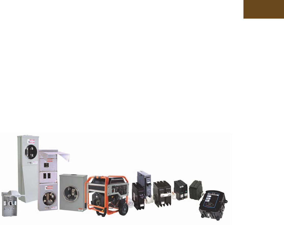
Loadcenters and Circuit Breakers
Residential Loadcenters
and Breaker Family
1.1 Type CH Loadcenters and Circuit Breakers
Overview . . . . . . . . . . . . . . . . . . . . . . . . . . . . . . . . . . . . . . . . . . . . . . V1-T1-2
Single-Phase. . . . . . . . . . . . . . . . . . . . . . . . . . . . . . . . . . . . . . . . . . V1-T1-7
Three-Phase . . . . . . . . . . . . . . . . . . . . . . . . . . . . . . . . . . . . . . . . . . V1-T1-12
CH Specialty Products. . . . . . . . . . . . . . . . . . . . . . . . . . . . . . . . . . . . . V1-T1-14
Spa Panels . . . . . . . . . . . . . . . . . . . . . . . . . . . . . . . . . . . . . . . . . . . V1-T1-14
Surge Panel . . . . . . . . . . . . . . . . . . . . . . . . . . . . . . . . . . . . . . . . . . V1-T1-15
Plug-On Neutral Loadcenter . . . . . . . . . . . . . . . . . . . . . . . . . . . . . . V1-T1-17
Type CH Renovation Loadcenter . . . . . . . . . . . . . . . . . . . . . . . . . . V1-T1-18
Type CH Retrofit Interior Kits . . . . . . . . . . . . . . . . . . . . . . . . . . . . . V1-T1-19
Non-Metallic Loadcenter . . . . . . . . . . . . . . . . . . . . . . . . . . . . . . . . V1-T1-21
CH Circuit Breakers . . . . . . . . . . . . . . . . . . . . . . . . . . . . . . . . . . . . . . V1-T1-31
1.2 Type BR Loadcenters and Circuit Breakers
Overview . . . . . . . . . . . . . . . . . . . . . . . . . . . . . . . . . . . . . . . . . . . . . . . V1-T1-42
Single-Phase. . . . . . . . . . . . . . . . . . . . . . . . . . . . . . . . . . . . . . . . . . V1-T1-48
Three-Phase . . . . . . . . . . . . . . . . . . . . . . . . . . . . . . . . . . . . . . . . . . V1-T1-54
BR Specialty Products. . . . . . . . . . . . . . . . . . . . . . . . . . . . . . . . . . . . . V1-T1-57
Spa Panels . . . . . . . . . . . . . . . . . . . . . . . . . . . . . . . . . . . . . . . . . . . V1-T1-57
Riser Panel . . . . . . . . . . . . . . . . . . . . . . . . . . . . . . . . . . . . . . . . . . . V1-T1-58
Type BR Renovation Loadcenter. . . . . . . . . . . . . . . . . . . . . . . . . . . V1-T1-59
Type BR Retrofit Interior Kits . . . . . . . . . . . . . . . . . . . . . . . . . . . . . V1-T1-72
BR Circuit Breakers . . . . . . . . . . . . . . . . . . . . . . . . . . . . . . . . . . . . . . . V1-T1-75
1.3 Loadcenter Interiors/OEM Loadcenters
Product Description. . . . . . . . . . . . . . . . . . . . . . . . . . . . . . . . . . . . . . . V1-T1-88
Standards and Certifications . . . . . . . . . . . . . . . . . . . . . . . . . . . . . . . . V1-T1-89
Product Selection . . . . . . . . . . . . . . . . . . . . . . . . . . . . . . . . . . . . . . . . V1-T1-89
1.4 Enclosed Breakers
Product Overview . . . . . . . . . . . . . . . . . . . . . . . . . . . . . . . . . . . . . . . . V1-T1-93
Product Selection . . . . . . . . . . . . . . . . . . . . . . . . . . . . . . . . . . . . . . . . V1-T1-94
1.5 Classified Circuit Breakers
Product Description. . . . . . . . . . . . . . . . . . . . . . . . . . . . . . . . . . . . . . . V1-T1-96
Product Selection . . . . . . . . . . . . . . . . . . . . . . . . . . . . . . . . . . . . . . . . V1-T1-97
Accessories . . . . . . . . . . . . . . . . . . . . . . . . . . . . . . . . . . . . . . . . . . . . . V1-T1-99
Technical Data . . . . . . . . . . . . . . . . . . . . . . . . . . . . . . . . . . . . . . . . . . . V1-T1-99
Wiring Diagrams . . . . . . . . . . . . . . . . . . . . . . . . . . . . . . . . . . . . . . . . . V1-T1-100
Learn
Online
V1-T1-2 Volume 1—Residential and Light Commercial CA08100002E—June 2014 www.eaton.com
1
1
1
1
1
1
1
1
1
1
1
1
1
1
1
1
1
1
1
1
1
1
1
1
1
1
1
1
1
1
1.1
Loadcenters and Circuit Breakers
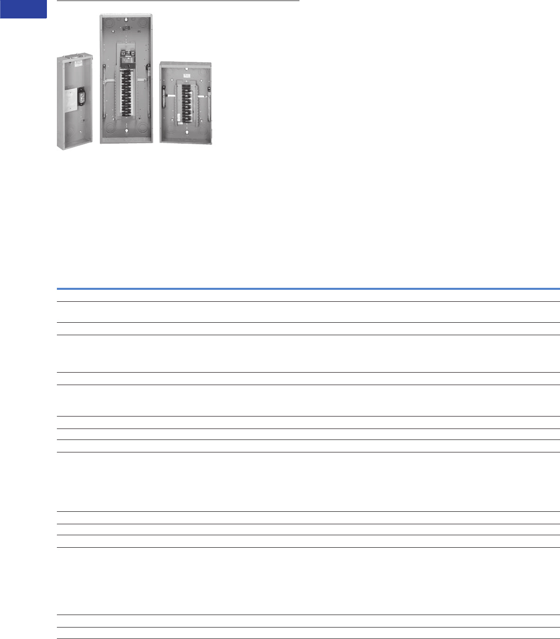
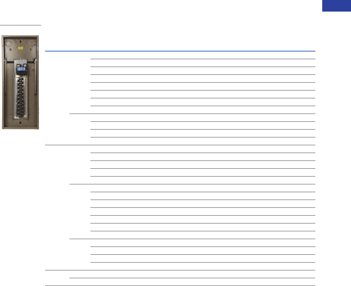
Type CH Loadcenters and Circuit Breakers
Eaton Type CH Convertible Family
Contents
Description Page
Overview
Product Description . . . . . . . . . . . . . . . . . . . . . V1-T1-3
Features, Benefits and Functions . . . . . . . . . . V1-T1-3
Standards and Certifications . . . . . . . . . . . . . . V1-T1-4
Catalog Number Selection . . . . . . . . . . . . . . . . V1-T1-6
Product Selection. . . . . . . . . . . . . . . . . . . . . . . V1-T1-7
Technical Data and Specifications . . . . . . . . . . V1-T1-29
CH Specialty Products . . . . . . . . . . . . . . . . . . . . . V1-T1-14
CH Loadcenter Options and Accessories . . . . . . . V1-T1-22
CH Circuit Breakers. . . . . . . . . . . . . . . . . . . . . . . . V1-T1-31
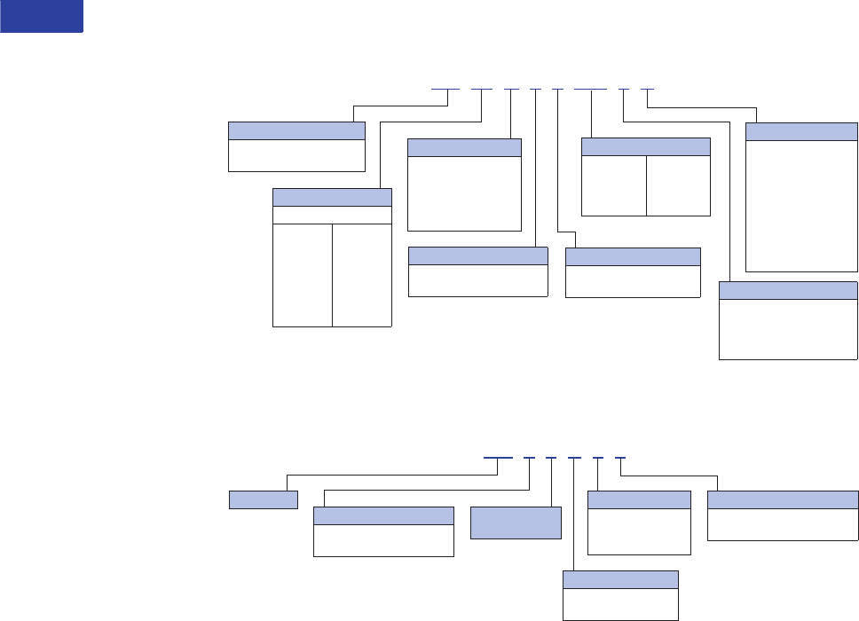
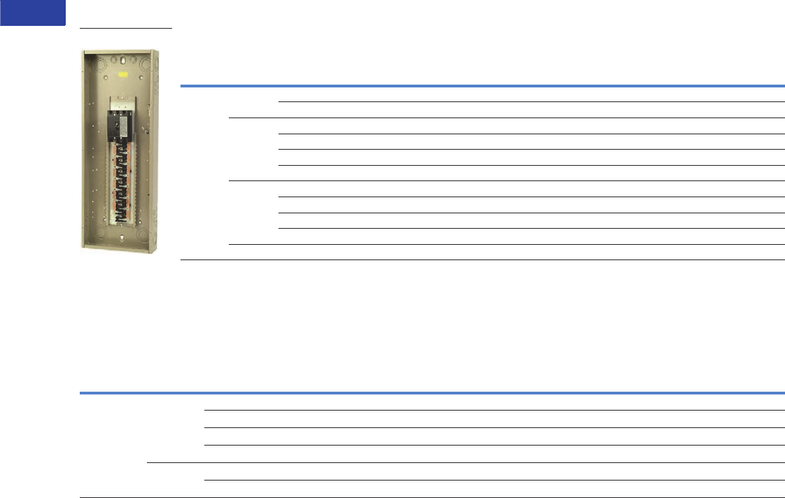
Overview
Product Selection Guide
CH Loadcenters
Description
Service
Single-phase, three-wire, 120/240 Vac
Three-phase, three-wire, 240V corner grounded delta
Three-phase, four-wire, 208Y/120 Vac
Three-phase, three-wire, 240 Vac delta
Short-Circuit Current Rating
10 kAIC: All single- and three-phase loadcenters 40–400A, 2–42 circuits except when
series ratings are applied
25 kAIC: All factory-installed main breakers single-phase loadcenters rated 150–225A
using Type CSR main breakers
35 kAIC available on convertible units using CSH main breaker
42 and 100 kAIC are available on some styles: single-phase and three-phase
Main Breaker/Main Lug Loadcenters
Single-phase
Main breaker: 100, 125, 150, 200, 225, 400A
Main lugs: 40, 70, 125, 150, 200, 225, 400A
Three-phase
Main breaker: 150, 200, 225, 300, 400A
Main lugs: 125, 150, 200, 225, 400A
Convertible Loadcenters
Main breaker or main lugs: single-phase up to 225A
Branch Breakers
Type CH: 10–150A. Single-, two- and three-pole. Selected amperages available in shunt
trip, HACR and switching duty
Ground fault circuit interruptors: 15–60A
Type CH-HID: 15–30A. Single-, two- and three-pole
CH-HM high magnetic
CH-M50 high ambient
Type CH-AFCI arc fault circuit interrupter
Type CHP: 10–125A. Single-, two- and three-pole. three-position commercial trip
Selected amperages available in HACR switching duty
Type CHP-HID: 15–30A. Single-, two- and three-pole
Type CHP-GFCI: 15–30A. Single-pole ground fault breakers
Enclosures
NEMA® Type 1 indoor NEMA Type 3R outdoor.
Loadcenter and Breaker Accessories
Branch circuit breaker:
Auxiliary components
Hold-down kits
Handle ties
Lockoffs
Lockdogs
Complete line of ground bar kits 5, 10, 14 and 21 circuits, some with additional #2/0 lugs
Each terminal will accommodate: (3) #14–#10 Cu/Al or (1) #14–#4 Cu/Al
Sub-feed lugs 125, 150A—two- and three-pole
Shunt trips
Universal rainproof conduit hubs Group One: 3/4, 1, 1-1/4, 1-1/2, 2 inches (19.1, 25.4, 31.8, 38.1, 50.8 mm)
Group Two: 2, 2-1/2, 3 inches (50.8, 63.5, 76.2 mm)
Adapter plate
Bussing
Silver flash plated copper bus is a standard feature

Volume 1—Residential and Light Commercial CA08100002E—June 2014 www.eaton.com V1-T1-3
1
1
1
1
1
1
1
1
1
1
1
1
1
1
1
1
1
1
1
1
1
1
1
1
1
1
1
1
1
1
1.1
Loadcenters and Circuit Breakers
Type CH Loadcenters and Circuit Breakers
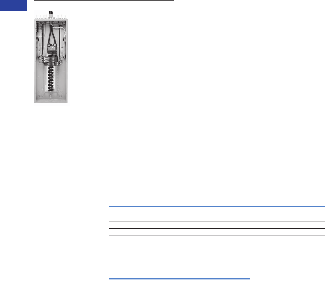
Product Description
Loadcenters are enclosures
specifically designed to
house the branch circuit
breakers and wiring required
to distribute power to
individual circuits. They
contain either a main breaker
when used at the service
entrance point or a main lug
when used as a sub-panel
to add circuits to existing
service. The main breaker
protects the main entire
panel and can be used as
a service disconnect. The
branch breakers protect the
wires leading to individual
electrical loads such as
fixtures and outlets.
Features, Benefits and Functions
Loadcenter Construction
Eaton’s Type CH loadcenters
feature silver flash plated
copper bus in all interiors. Stabs
are rated 200A throughout
the CH line. Therefore, the
sum of the handle ratings
connected to any one stab is
limited to 200A maximum.
NEMA 1 boxes are
manufactured from
cold rolled 16 gauge sheet
steel. Raintight boxes are
manufactured from galvanized
steel. All boxes and trims are
finished using an electrostatic
powder coat, baked urethane
paint process.
Neutrals
Eaton Type CH loadcenters
feature two types of neutrals:
Insulated/Bondable Split
Neutral
Panels are supplied with split
insulated neutrals with an
insulated cross strap. For
service entrance applications,
the neutral must be bonded
by using the bonding strap
supplied with the panel. For
non-service entrance (sub-
panel) applications, the panel
may be installed with the
bonding strap not connected
to the neutral. Separate
ground bars must be used on
non-service entrance panels.
Insulated/Bondable Single
Neutral
Panels are supplied with a
single insulated neutral. For
service entrance applications,
all that is required to bond the
neutral is to loosen the
bonding screw and the
neutral screw directly beside
it, insert the bonding strap
into the neutral bar, and re-
tighten both connections. The
single neutral can be moved
by the contractor to the other
side of the panel, if desired.
When used as a service
entrance panel, unused
neutral connections may be
used for the termination of
equipment grounds. For non-
service entrance (sub-panel)
applications, the panel may
be installed with the bonding
strap not connected to the
neutral. Separate ground bars
must be used on non-service
entrance panels.
Inboard Plug-On Neutral
Code changes and higher
safety standards are
leading to more arc fault
circuit interrupter (AFCI)
installations. With the
electrical contractor in mind,
Eaton has revolutionized the
way Combination AFCIs are
installed with the Plug-on
Neutral line of loadcenters
and breakers. This unique
product solution enables the
contractor to connect the
breaker directly to the neutral
bar, eliminating the need for
wiring a pigtail.
Grounds
In service entrance
applications where the
neutral is bonded, unused
neutral holes may be used
for terminating ground
conductors. In sub-feed
panels, the neutral must be
isolated (non-bonded), and
ground wires must be
terminated on a separate
ground bar.
The insulated/bondable
single/split neutral panels
have sufficient terminations
for both ground and neutral
conductors. The insulated/
bondable single split neutral
panels are supplied with a
separate factory-installed
ground bar if the catalog
number contains a “G.” If
not, a separate ground bar
should be installed. Insulated/
Bondable Single Neutral
panels are supplied without a
ground bar (unless otherwise
noted), and ground bar kits, if
needed, must be purchased
separately.

V1-T1-4 Volume 1—Residential and Light Commercial CA08100002E—June 2014 www.eaton.com
1
1
1
1
1
1
1
1
1
1
1
1
1
1
1
1
1
1
1
1
1
1
1
1
1
1
1
1
1
1
1.1
Loadcenters and Circuit Breakers
Type CH Loadcenters and Circuit Breakers
Standards and Certifications
UL® Listings
All Eaton Type CH loadcenters
are listed under UL File E8741.
Neutral and Ground Terminals
The standard terminals on
grounds and neutrals are rated
to accept (3)—#14–#10 Cu/Al
or (1)—#14–4 wires. For larger
cables, add-on neutral lugs
may be ordered from the
Accessories.
Note: NEC® allows only one
current carrying conductor
per hole on neutrals unless
otherwise noted.
Bottom-Fed Loadcenters
When the power cable is
brought into the loadcenter
from below the panel; then
the main lug panels, and
single-phase, 225A and
below, loadcenters can be
rotated 180 degrees to allow
straight-in wiring of power
cables to the main terminals.
Because the CSR main circuit
breaker handle operates
horizontally, the orientation
of the main circuit breaker
handle is consistent with
the requirements of NEC
Article 240.81.
Gutter Splicing
Loadcenters are not UL listed
as wiring troughs. Therefore,
gutter splicing of riser cables
to tap off to the main device
is not permitted. Refer to
NEC Article 373.8.
Fire Rating
Due to the numerous
openings in both loadcenter
boxes and trims, they should
not be mounted in firewalls.
There is no approval method
for sealing the enclosures for
this application.
Date Code
The date of manufacture of
each loadcenter is printed on
the outside of the carton as
well as inside the loadcenter.
On the carton, the date code
is printed on the end carton
label. In the loadcenter, the
date code is located on the
small white label located on
the right side wall (with the
main device on top).
The date code is in the
following format: F # # # &.
The “F” is the numeric code
for the Lincoln, IL plant,
and the three numbers
are the year and week of
manufacture, e.g., 023. The
“&” sign at the end signifies
the decade of the 2000s.
The “!” at the end signifies
the decade of the 2010s.
Therefore, the date code
F023& would indicate
that the product was
manufactured in the 23rd
week of 2000. The 1980s
are represented by a
“+” sign and the 1990s
are represented by a “=”
at the end of the code.
Plug-On Type CH Breakers
Quick-make, quick-break
switch mechanism combined
with inverse time element
tripping operation and trip-
free handle design. Type CH
circuit breakers trip to the
OFF position eliminating
nuisance callbacks. The
thermal-magnetic trip curve
avoids nuisance tripping on
mild overloads while reacting
almost instantaneously
to severe short-circuit
conditions. CHF breakers
include a ‘trip flag’ to
differentiate between a
tripped breaker and one that
has been turned off.
Multipole breakers have
internal common trip
connection to operate all
poles simultaneously.
Handles are marked with
ON-OFF indication and
ampere rating of the breaker.
Type CH breakers meet
UL Standard 489, NEMA
standards, and Federal Spec
Classification W-C 375 b/Gen.
They are UL listed under File
Number E11713, E8741,
E3624 and E51287: and
CSA® certified file number
LR87196, except Type
CHT breakers.
Type CH Circuit Breaker Ratings
Single- and double-pole CH
breakers rated 15 and 20A
have low instantaneous
magnetic trip levels. The 15
and 20A breakers with “HM”
suffix have high magnetic trip
settings recommended for
circuits with inherently high
inrush currents. All Type CH
breakers are marked for
heating, air conditioning
and refrigeration (HACR)
equipment application.
Single-pole 15–20A breakers
are also suitable for switching
duty (SWD). Shunt trip coils
operate on 120 Vac and
require one additional pole
space per breaker.
Volume 1—Residential and Light Commercial CA08100002E—June 2014 www.eaton.com V1-T1-5
1
1
1
1
1
1
1
1
1
1
1
1
1
1
1
1
1
1
1
1
1
1
1
1
1
1
1
1
1
1
1.1
Loadcenters and Circuit Breakers
Type CH Loadcenters and Circuit Breakers
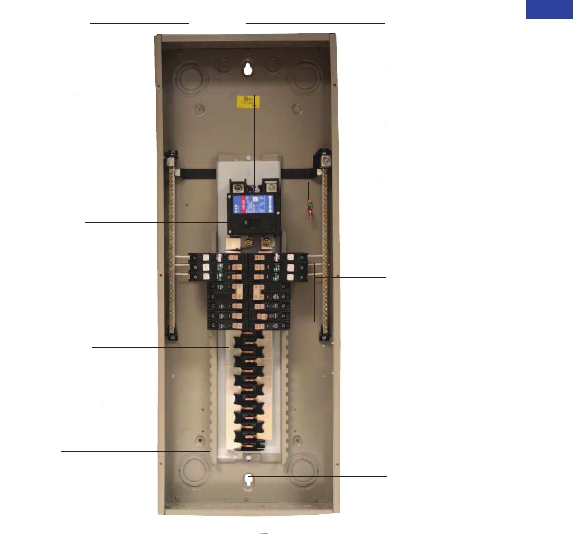
Type CH Loadcenter
Warranty
The minimum warranty
for residential loadcenters,
breakers and surge protection
devices shall be as follows:
●Lifetime loadcenter
warranty
●Lifetime warranty on
CH circuit breakers
●Lifetime warranty on
CHSPT2ULTRA including
$75,000 connected
equipment warranty
●1-year warranty on plug-in
surge protective device
(CHSA)
Single Keyhole Mounting
One keyhole at the top
and bottom provides easier
mounting and leveling
Neutral Bus (Strap)
Easily removable for
sub-panel applications
Bonding Z-Strap
Provides easy field
conversion for service
entrance applications
Twin Neutral Bars
Minimum 150% neutral
capacity
Extra 1.5 inch Knockout
(38.1 mm)
Larger knockout provides
easier installation and time
savings for renovation
installations
“Tangential” Center Knockout
Easier installation for conduit
applications
Commercial Grade Main
Breaker
25 kAIC series rated main
breaker in 150A–225A load-
centers. 35, 42 and 100 kAIC
series ratings are available
Optional convertible design—
reduces inventory
requirements
2/0 Lug
Easily removable and can be
installed in any location
on the neutral bar
Drywall Marking on Enclosure
Indicates proper mounting
depth for flush applications
One Piece Silver-Flashed
Copper Bus
Provides superior conductivity,
corrosion resistance and durability
Steel Backpan
Provides solid and reliable
breaker mounting—single
piece design for stability
and durability
Top or Bottom Feed
Straight-in wiring saves labor
and material
One panel for either top or
bottom applications
Type CHF AFCI/GFCI/Thermal -
Magnetic Breakers
Advanced electronics
effectively reduce nuisance
tripping
CHF AFCI breakers have a
standard diagnostic LED
indicating 1 of 7 trip codes
Mechanical flag for trip
indication (on thermal-magnetic
AFCI and GFCI)
All CH breakers provide
industry exclusive 2-position
handle with simple
1 step reset
Unique Sandalwood Finish
Aesthetically appealing,
scratch-resistant powder
coating
■
■
■
■
■
■
■
■
■
■
■
■
■
■
■
■
■
■
■
V1-T1-6 Volume 1—Residential and Light Commercial CA08100002E—June 2014 www.eaton.com
1
1
1
1
1
1
1
1
1
1
1
1
1
1
1
1
1
1
1
1
1
1
1
1
1
1
1
1
1
1
1.1
Loadcenters and Circuit Breakers
Type CH Loadcenters and Circuit Breakers
Catalog Number Selection
Loadcenters 100–225A and 12–42 Circuits
Indoor Covers Ordered Separately
Note: All combinations are not valid, refer to the catalog section.
LC Type
Type CH 3/4-inch (19.1 mm)
branch circuit breakers
Number of Circuits
Selection circuits
2
4
8
12
14
16
18
20
22
24
28
30
32
42
Main Device
L= Main lug only
B= Main breaker
N= Convertible
H= High AIC
main breaker
CH 42 B200 K
Construction
Blank = Standard
PN = Plug-on neutral
Phases
Blank = Single-phase
3= Three-phase Accessories
Blank = Standard
EC = Surge ready
SUR = Surge factory
installed
Bus Amperes
40
70
100
125
150
200
225
Box Sizes
B
C
D
E
G
J
K
L
R = Outdoor (no cover)
CH 8 K F
Type CH
Loadcenter
Cover Series
Factory Options
Blank = Standard
SUR = Surge/surge ready
Accessories
Blank = Standard
M= Mechanical interlock
Mounting
F= Combination
flush/surface
S= Surface
Box Size
Indicated in loadcenter
catalog number
Volume 1—Residential and Light Commercial CA08100002E—June 2014 www.eaton.com V1-T1-7
1
1
1
1
1
1
1
1
1
1
1
1
1
1
1
1
1
1
1
1
1
1
1
1
1
1
1
1
1
1
1.1
Loadcenters and Circuit Breakers
Type CH Loadcenters and Circuit Breakers
Product Selection
Single-Phase—Main Circuit Breaker Loadcenters—10/25 kAIC
Single-Phase Three-Wire—120/240 Vac—Insulated/Bondable Split Neutral (Unless Otherwise Noted)
Notes
1 All main circuit breaker loadcenters are listed for use as service entrance equipment.
2 Ground bar kits priced separately. See Page V1-T1-25.
3 Combination style covers may be used in surface or flush applications.
4 Can be top or bottom fed by rotating the enclosure and trim 180 degrees.
5 Rainproof panels are furnished with hub closure plates. For rainproof hubs, refer to Page V1-T1-25.
6 Panel includes #4–300 kcmil feed-through lugs.
7 This cover is for flush applications only (not combination).
Box sizes Pages V1-T1-27 and V1-T1-28.
Main
Breaker
Type
Main
Ampere
Rating
Maximum Number
3/4-Inch (19.1 mm)
of Poles
Enclosure
Type
Box
Size
Wire Size Range
Cu/Al 60°C or 75°C
for Main Breaker
Loadcenter 12
Catalog Number
Loadcenter Cover
Catalog Number
Combination 3Surface
CH
10 kAIC
100 14 Indoor B #6–1/0 CH14B100B 4CH8BF CH8BS
14 Outdoor B #6–1/0 CH14B100R 5——
18 Indoor C #6–1/0 CH18B100C 4CH8CF CH8CS
18 Outdoor C #6–1/0 CH18B100R 5——
22 Indoor C #6–1/0 CH22B100C 4CH8CF CH8CS
22 Outdoor C #6–1/0 CH22B100R 5——
30 Indoor D #6–1/0 CH30B100D 4CH8DF CH8DS
30 Outdoor D #6–1/0 CH30B100R 5——
125 22 Indoor C #6–1/0 CH22B125C 4CH8CF CH8CS
22 Outdoor C #6–1/0 CH22B125R 5——
30 Indoor D #6–1/0 CH30B125D 4CH8DF CH8DS
30 Outdoor D #6–1/0 CH30B125R 5——
CSR
25 kAIC
150 8 Outdoor E #2–300 kcmil CH8B150RF 6——
24 Indoor E #2–300 kcmil CH24B150E 4CH8EF CH8ES
24 Outdoor E #2–300 kcmil CH24B150R 5——
32 Indoor J #2–300 kcmil CH32B150J 4CH8JF CH8JS
32 Outdoor J #2–300 kcmil CH32B150R 5——
200 8 Outdoor E #2–300 kcmil CH8B200RF 6——
24 Indoor E #2–300 kcmil CH24B200E 4CH8EF CH8ES
24 Outdoor E #2–300 kcmil CH24B200R 5——
32 Indoor J #2–300 kcmil CH32B200J 4CH8JF CH8JS
32 Outdoor J #2–300 kcmil CH32B200R 5——
42 Indoor K #2–300 kcmil CH42B200K 4CH8KF CH8KS
42 Outdoor K #2–300 kcmil CH42B200R 5——
225 32 Indoor J #2–300 kcmil CH32B225J 4CH8JF CH8JS
32 Outdoor J #2–300 kcmil CH32B225R 5——
42 Indoor K #2–300 kcmil CH42B225K 4CH8KF CH8KS
42 Outdoor K #2–300 kcmil CH42B225R 5——
DK
10 kAIC
300 42 Indoor PM (2) 3/0–250 kcmil CH42PM300 CH7PMF 7CH7PMS
400 42 Indoor PM (2) 3/0–250 kcmil CH42PM400 CH7PMF 7CH7PMS
CH42B200K

V1-T1-8 Volume 1—Residential and Light Commercial CA08100002E—June 2014 www.eaton.com
1
1
1
1
1
1
1
1
1
1
1
1
1
1
1
1
1
1
1
1
1
1
1
1
1
1
1
1
1
1
1.1
Loadcenters and Circuit Breakers
Type CH Loadcenters and Circuit Breakers
Single-Phase—High Interrupting Rated Main Circuit Breaker Loadcenters—100 kAIC
Single-Phase Three-Wire—120/240 Vac—Insulated/Bondable Split Neutral
Notes
1All main circuit breaker loadcenters are listed for use as service entrance equipment.
2Combination style covers may be used in surface or flush applications.
3Loadcenter can be top or bottom fed by rotating the enclosure and trim 180 degrees.
4Rainproof panels are furnished with hub closure plates. For rainproof hubs, refer to Page V1-T1-25.
5Series rated for 100 kAIC with all Types CH, CHT and CHP breakers.
Main
Breaker
Type
Main
Ampere
Rating
Maximum Number
3/4-Inch (19.1 mm)
Poles
Enclosure
Type
Box
Size
Wire Size Range
Cu/Al 60°C or 75°C
for Main Breaker
Loadcenter 1
Catalog Number
Loadcenter Cover
Catalog Number
Combination 2Surface
CHB4
100 kAIC 5
100 32 Indoor L #6–1/0 CH32H100L 3CH8LF CH8LS
32 Outdoor L #6–1/0 CH32H100R 4——
CHH
100 kAIC 5
150 32 Indoor L #2/0–300 kcmil CH32H150L CH8LF CH8LS
32 Outdoor L #2/0–300 kcmil CH32H150R 4——
200 32 Indoor L #2/0–300 kcmil CH32H200L CH8LF CH8LS
32 Outdoor L #2/0–300 kcmil CH32H200R 4——
42 Indoor L #2/0–300 kcmil CH42H200L CH8LF CH8LS
42 Outdoor L #2/0–300 kcmil CH42H200R 4——
225 42 Indoor L #2/0–300 kcmil CH42H225L CH8LF CH8LS
42 Outdoor L #2/0–300 kcmil CH42H225R 4——
Volume 1—Residential and Light Commercial CA08100002E—June 2014 www.eaton.com V1-T1-9
1
1
1
1
1
1
1
1
1
1
1
1
1
1
1
1
1
1
1
1
1
1
1
1
1
1
1
1
1
1
1.1
Loadcenters and Circuit Breakers
Type CH Loadcenters and Circuit Breakers
Single-Phase—Main Lug Loadcenters
Single-Phase Three-Wire—120/240 Vac—Insulated/Bondable Single Neutral
Notes
1 Requires the use of Type CHNT breakers.
2 Ground bar kits priced separately, see Page V1-T1-25.
– For 2/4 and 6/12 circuit loadcenters use Type GBK5 or GBK520 ground bar
– For 4/8 and 8/16 circuit loadcenters use Type GBK10 ground bar
– Ground bars mount to the left side wall of the enclosure for the 4/8, 6/12 and 8/16 circuit loadcenters
3 Suitable for use as service equipment when not more than two service disconnecting mains are provided or when not used as a lighting and appliance panelboard
(see Article 408.34 of the NEC).
4 Rainproof panels are furnished with hub closure plates. For rainproof hubs, refer to Page V1-T1-25.
5 For use as service entrance applications only.
6 Neutral/ground holes (6) #14–6 and (3) #14–2/0 AWG Cu/AI.
7 Suitable for use as service equipment when not more than two service disconnecting mains are provided or when not more than six service disconnecting mains are
provided and when not used as a lighting and appliance panelboard (see Article 408.34 of the NEC).
8 Suitable for use as service equipment when a main breaker is used or when not more than six service disconnecting mains are provided and when not used as a lighting
and appliance panelboard (see Article 408.34 of the NEC).
Box sizes Pages V1-T1-27 and V1-T1-28.
Main
Ampere
Rating
Maximum Number
3/4-Inch (19.1 mm) Enclosure
Type
Type of Trim
(Included)
Box
Size
Wire Size Range
Cu/Al 60°C or 75°C
for Main Lugs
Loadcenter
Catalog NumberSpace Poles
40 2 4 1Indoor Surface (no door) 5 #14–6 CH2L40SP 23
24
1Outdoor — 5R #14–6 CH2L40RP 234
24
1Indoor Flush (no door) 5 #14–6 CH2L40FP 23
70 2 4 1Indoor Surface (no door) 5 #14–2 CH2L70SP 23
24
1Outdoor — 5R #14–2 CH2L70RP 234
24
1Indoor Flush (no door) 5 #14–2 CH2L70FP 23
125 2 4 1Indoor Surface (no door) 6 #14–1/0 CH2L125SP 23
24
1Outdoor — 6R #14–1/0 CH2L125RP 234
2 2 Outdoor — — #14–1/0 CH2L125RSE2P 456
24
1Indoor Flush (no door) 6 #14–1/0 CH2L125FP 23
48
1Indoor Surface (no door) 7 #14–1/0 CH4L125SP 27
48
1Outdoor — 7R #14–1/0 CH4L125RP 247
48
1Indoor Flush (no door) 7 #14–1/0 CH4L125FP 27
612
1Outdoor — 6R #14–1/0 CH6L125R 267
816
1Indoor Surface (no door) 7 #6–1/0 CH8L125SP 28
816
1Outdoor — 7R #6–1/0 CH8L125RP 267
816
1Indoor Flush (no door) 7 #6–1/0 CH8L125FP 28
Surface Outdoor
Flush Outdoor
Surface (No Door)
Flush (No Door)
Outdoor
V1-T1-10 Volume 1—Residential and Light Commercial CA08100002E—June 2014 www.eaton.com
1
1
1
1
1
1
1
1
1
1
1
1
1
1
1
1
1
1
1
1
1
1
1
1
1
1
1
1
1
1
1.1
Loadcenters and Circuit Breakers
Type CH Loadcenters and Circuit Breakers
Single-Phase Three-Wire—120/240 Vac—Insulated/Bondable Split Neutral—Factory-Installed Ground Bar
Notes
1 Suitable for use as service equipment when not more than six disconnecting means are provided and when not used as a lighting and appliance panelboard
(see Article 408.34 of the NEC).
2 Rainproof panels are furnished with hub closure plates. For rainproof hubs, refer to Page V1-T1-25.
3 Suitable for use as service equipment when a circuit breaker is used as a main breaker. The main breaker is backfed and requires hold-down bracket kit
catalog number CH125RB.
4 Suitable for use as service equipment when a circuit breaker is used as a main breaker. The main breaker is backfed and must be a Type CHB.
The breaker cannot be a Type CH.
5 This cover is for flush application only (not combination).
Box sizes Pages V1-T1-27 and V1-T1-28.
Main
Ampere
Rating
Maximum Number
3/4-Inch (19.1 mm)
Poles
Enclosure
Type
Box
Size
Wire Size Range
Cu/Al 60°C or 75°C
for Main Lugs
Loadcenter
Catalog Number
Loadcenter Cover
Catalog Number
Combination Surface
125 12 Indoor B #6–2/0 CH12L125B 1CH8BF CH8BS
12 Outdoor B #6–2/0 CH12L125R 12 ——
16 Indoor B #6–2/0 CH16L125B 1CH8BF CH8BS
16 Outdoor B #6–2/0 CH16L125R 12 ——
20 Indoor C #6–2/0 CH20L125C 1CH8CF CH8CS
20 Outdoor C #6–2/0 CH20L125R 12 ——
24 Indoor C #6–2/0 CH24L125C 1CH8CF CH8CS
24 Outdoor C #6–2/0 CH24L125R 12 ——
150 24 Indoor D #4–300 kcmil CH24L150D 1CH8DF CH8DS
24 Outdoor D #4–300 kcmil CH24L150R 23 ——
32 Indoor D #4–300 kcmil CH32L150D 1CH8DF CH8DS
32 Outdoor D #4–300 kcmil CH32L150R 23 ——
200 12 Indoor D #4–300 kcmil CH12L200D 1CH8DF CH8DS
12 Outdoor D #4–300 kcmil CH12L200R 23 ——
16 Indoor D #4–300 kcmil CH16L200D 1CH8DF CH8DS
16 Outdoor D #4–300 kcmil CH16L200R 23 ——
225 24 Indoor D #4–300 kcmil CH24L225D 1CH8DF CH8DS
24 Outdoor D #4–300 kcmil CH24L225R 23 ——
32 Indoor D #4–300 kcmil CH32L225D 1CH8DF CH8DS
32 Outdoor D #4–300 kcmil CH32L225R 23 ——
42 Indoor G #4–300 kcmil CH42L225G 3CH8GF CH8GS
42 Outdoor G #4–300 kcmil CH42L225R 23 ——
400 42 Indoor P (2) 1/0–300 kcmil
(1) 750 kcmil
CH42PL400 4CH7PF 5CH7PS
CH42L225G

Volume 1—Residential and Light Commercial CA08100002E—June 2014 www.eaton.com V1-T1-11
1
1
1
1
1
1
1
1
1
1
1
1
1
1
1
1
1
1
1
1
1
1
1
1
1
1
1
1
1
1
1.1
Loadcenters and Circuit Breakers
Type CH Loadcenters and Circuit Breakers
Convertible Loadcenters MCB or MLO—Base Units and Main Devices—10/25/35 kAIC
Complete assembly consists of: loadcenter, cover, and either main breaker kit or main lug kit.
Indoor—Single-Phase—Three-Wire—120/240V—Insulated/Bondable Split Neutral—Top or Bottom Feed
Outdoor—Single-Phase—Three-Wire—120/240V—Insulated/Bondable Split Neutral (Unless Otherwise Noted)
Notes
1Panel does not include main. Order main breaker or main lug kit separately.
2If 35 kAIC is required, use CSH breaker.
3Hold-down kit included.
435 kAIC series combination rating is obtained when Types CH, CHT and CHP branch breakers are used with CSH main.
5Rainproof panels are furnished with hub closure plates. For rainproof hubs, refer to Page V1-T1-25.
6Includes feed-through lugs for both phase and neutral conductors.
7Insulated/bondable single neutral.
Interrupting rating depends on main circuit breaker selected.
Maximum
Main Ampere
Rating
Maximum
Number of
Single Poles
Box
Size
Loadcenter Box
and Panel
Catalog Number 1
Loadcenter Cover
Catalog Number Main Lug Kit Main Breaker Kit
Catalog NumberCombination Surface
Wire
Size
Catalog
Number
kAIC
Rating
Wire
Size
125 22 C CH22N125C CH8CF CH8CS #10–1/0 CHL125N 10 #10–1/0 CH2100N 3—
CH2125N 3—
200 32 J CH32N200J CH8JF CH8JS #4–300
kcmil
CHL225N 25/35 2#2–300
kcmil
CSR2125N CSH2125N
4
CSR2150N CSH2150N
4
CSR2175N CSH2175N
4
CSR2200N CSH2200N
4
225 42 K CH42N225K CH8KF CH8KS #4–300
kcmil
CHL225N 25/35 2#2–300
kcmil
CSR2125N CSH2125N
4
CSR2150N CSH2150N
4
CSR2175N CSH2175N
4
CSR2200N CSH2200N
4
CSR2225N CSH2225N
4
Maximum
Main Ampere
Rating
Maximum
Number of
Single Poles
Box
Size
Loadcenter Box
and Panel
Catalog Number 1
Main Lug Kit
Catalog
Number
Main Breaker Kit
Catalog Number
Wire
Size
kAIC
Rating
Wire
Size
125 22 C CH22N125R 5#10–1/0 CHL125N 10 #10–1/0 CH2100N 3—
CH2125N 3—
200 8 E CH8N200RF 567 #4–300 kcmil CHL225N 25/35 2#2–300 kcmil CSR2125N CSH2125N
CSR2150N CSH2150N
CSR2175N CSH2175N
CSR2200N CSH2200N
200 32 J CH32N200R 5#4–300 kcmil CHL225N 25/35 2#2–300 kcmil CSR2125N CSH2125N
4
CSR2150N CSH2150N
4
CSR2175N CSH2175N
4
CSR2200N CSH2200N
4
225 42 K CH42N225R 5#4–300 kcmil CHL225N 25/35 2#2–300 kcmil CSR2125N CSH2125N
4
CSR2150N CSH2150N
4
CSR2175N CSH2175N
4
CSR2200N CSH2200N
4
CSR2225N CSH2225N
4
V1-T1-12 Volume 1—Residential and Light Commercial CA08100002E—June 2014 www.eaton.com
1
1
1
1
1
1
1
1
1
1
1
1
1
1
1
1
1
1
1
1
1
1
1
1
1
1
1
1
1
1
1.1
Loadcenters and Circuit Breakers
Type CH Loadcenters and Circuit Breakers
Three-Phase—Main Circuit Breaker Loadcenters—10 kAIC
Three-Phase Four-Wire—208Y/120 Vac or 240 Vac Insulated/Bondable Split Neutral
Three-Phase—High Interrupting Rated Main Circuit Breaker Loadcenters—100 kAIC
Three-Phase Four-Wire—208Y/120 Vac or 240 Vac Insulated/Bondable Split Neutral
Notes
1All main circuit breaker loadcenters are listed for use as service entrance equipment.
2Ground bar kits priced separately. For ground bar kits, see Page V1-T1-25.
3Rainproof loadcenters are furnished with hub closure plates. For rainproof hubs, refer to Page V1-T1-25.
4This cover for flush application only (not combination).
5100 kAIC series combination rating is obtained when Types CH and CHP branch breakers are used with CHH main.
Main
Breaker
Type
Main
Ampere
Rating
Maximum Number
3/4-Inch (19.1 mm)
Poles
Enclosure
Type
Box
Size
Wire Size Range
Cu/Al 60°C or 75°C
for Main Breaker
Loadcenter 12
Catalog Number
Loadcenter Cover
Catalog Number
Combination Surface
CC
10 kAIC
150 30 Indoor L #1–4/0 CH30B3150L CH8LF CH8LS
30 Outdoor L #1–4/0 CH30B3150R 3——
200 30 Indoor L #2/0–300 kcmil CH30B3200L CH8LF CH8LS
30 Outdoor L #2/0–300 kcmil CH30B3200R 3——
42 Indoor L #2/0–300 kcmil CH42B3200L CH8LF CH8LS
42 Outdoor L #2/0–300 kcmil CH42B3200R 3——
225 30 Indoor L #2/0–300 kcmil CH30B3225L CH8LF CH8LS
30 Outdoor L #2/0–300 kcmil CH30B3225R 3——
42 Indoor L #2/0–300 kcmil CH42B3225L CH8LF CH8LS
42 Outdoor L #2/0–300 kcmil CH42B3225R 3——
400 42 Indoor PM (2) 3/0–350 kcmil CH424PM400 CH7PMF 4CH7PMS
Main
Breaker
Type
Main
Ampere
Rating
Maximum Number
3/4-Inch (19.1 mm)
of Poles
Enclosure
Type
Box
Size
Wire Size Range
Cu/Al 60°C or 75°C
for Main Breaker
Loadcenter
Catalog Number 12
Loadcenter Cover
Catalog Number
Combination Surface
CHH
100 kAIC 5
200 30 Indoor L #2/0–300 kcmil CH30H3200L CH8LF CH8LS
30 Outdoor L #2/0–300 kcmil CH30H3200R 3——
42 Indoor L #2/0–300 kcmil CH42H3200L CH8LF CH8LS
42 Outdoor L #2/0–300 kcmil CH42H3200R 3——
225 42 Indoor L #2/0–300 kcmil CH42H3225L CH8LF CH8LS
42 Outdoor L #2/0–300 kcmil CH42H3225R 3——
CH42B3200L

Volume 1—Residential and Light Commercial CA08100002E—June 2014 www.eaton.com V1-T1-13
1
1
1
1
1
1
1
1
1
1
1
1
1
1
1
1
1
1
1
1
1
1
1
1
1
1
1
1
1
1
1.1
Loadcenters and Circuit Breakers
Type CH Loadcenters and Circuit Breakers
Three-Phase—Main Lug Loadcenters
Three-Phase Four-Wire—208Y/120 Vac or 240 Vac Insulated/Bondable Split Neutral (Unless Otherwise Noted)
Notes
1Requires the use of CHNT breakers.
2Suitable for use as service equipment when not more than two service disconnecting means are provided or when not more than six service disconnecting means are provided and when not used as
a lighting and appliance panelboard (see Article 408.34 of the NEC).
3Ground bar kits priced separately, see Page V1-T1-25.
– Use GBK10 ground bar
– Ground bars mount to the left side wall of the enclosure.
4Insulated/bondable single neutral.
5Rainproof loadcenters are furnished with hub closure plates. For rainproof hubs, refer to Page V1-T1-25.
6Ground bar Type GBK14 is installed.
7Suitable for use as service equipment when a circuit breaker is used as a main breaker. The main breaker is backfed and requires hold-down bracket kit catalog number Type CH125RB. Suitable for
use as service equipment when not more than six service disconnecting means are provided and when not used as a lighting and appliance panelboard (see Article 408.34 of the NEC).
8Ground bar Type GBK21 is installed.
9Suitable for use as service equipment when a circuit breaker is used as a main breaker. The main breaker is backfed and requires hold-down kit catalog number Type CH125RB.
jFor ground bar kits, see Page V1-T1-25.
kSuitable for use as service equipment when a circuit breaker is used as a main breaker. The main breaker is backfed and must be a Type CHB. The breaker cannot be a Type CH.
lThis cover for flush application only (not combination).
Box sizes Pages V1-T1-27 and V1-T1-28.
Main
Ampere
Rating
Maximum Number
3/4-Inch (19.1 mm) Enclosure
Type
Type of Trim
Included
Box
Size
Wire Size Range
Cu/Al 60°C or 75°C
for Main Lugs
Loadcenter
Catalog Number
Loadcenter
Cover Catalog Number
Spaces Poles Combination Single
125 6 12 1Indoor Surface, no door 7 #14–1/0 CH6L3125SP 234 ——
612
1Outdoor — 7R #14–1/0 CH6L3125RP 2345 ——
612
1Indoor Flush, no door 7 #14–1/0 CH6L3125FP 234 ——
12 12 Indoor — B #6–2/0 CH12L3125B 67 CH8BF CH8BS
12 12 Outdoor — B #6–2/0 CH12L3125R 567 ——
18 18 Indoor — C #6–2/0 CH18L3125C 67 CH8CF CH8CS
18 18 Outdoor — C #6–2/0 CH18L3125R 678 ——
24 24 Indoor — C #6–2/0 CH24L3125C 67 CH8CF CH8CS
24 24 Outdoor — C #6–2/0 CH24L3125R 678 ——
150 30 30 Indoor — D #4–300 kcmil CH30L3150D 67 CH8DF CH8DS
30 30 Outdoor — D #4–300 kcmil CH30L3150R 569 ——
225 24 24 Indoor — D #4–300 kcmil CH24L3225D 67 CH8DF CH8DS
24 24 Outdoor — D #4–300 kcmil CH24L3225R 569 ——
30 30 Indoor — D #4–300 kcmil CH30L3225D 67 CH8DF CH8DS
30 30 Outdoor — D #4–300 kcmil CH30L3225R 569 ——
42 42 Indoor — G #4–300 kcmil CH42L3225G 89 CH8GF CH8GS
42 42 Outdoor — G #4–300 kcmil CH42L3225R 589 ——
400 42 42 Indoor — P (2) 1/0–300 kcmil
(1) 750 kcmil
CH424PL400 jk CH7PF lCH7PS
V1-T1-14 Volume 1—Residential and Light Commercial CA08100002E—June 2014 www.eaton.com
1
1
1
1
1
1
1
1
1
1
1
1
1
1
1
1
1
1
1
1
1
1
1
1
1
1
1
1
1
1
1.1
Loadcenters and Circuit Breakers
Type CH Loadcenters and Circuit Breakers
Spa Panels
Contents—CH Specialty Products
Description Page
Overview . . . . . . . . . . . . . . . . . . . . . . . . . . . . . . . . V1-T1-2
CH Specialty Products
Spa Panels
Surge Panel . . . . . . . . . . . . . . . . . . . . . . . . . . . . V1-T1-15
Plug-On Neutral Loadcenter . . . . . . . . . . . . . . . V1-T1-17
Type CH Renovation Loadcenter . . . . . . . . . . . . V1-T1-18
Type CH Retrofit Interior Kits . . . . . . . . . . . . . . V1-T1-19
CH Loadcenter Options and Accessories. . . . . . . . V1-T1-22
CH Circuit Breakers . . . . . . . . . . . . . . . . . . . . . . . . V1-T1-31
CH Specialty Products
Spa Panels
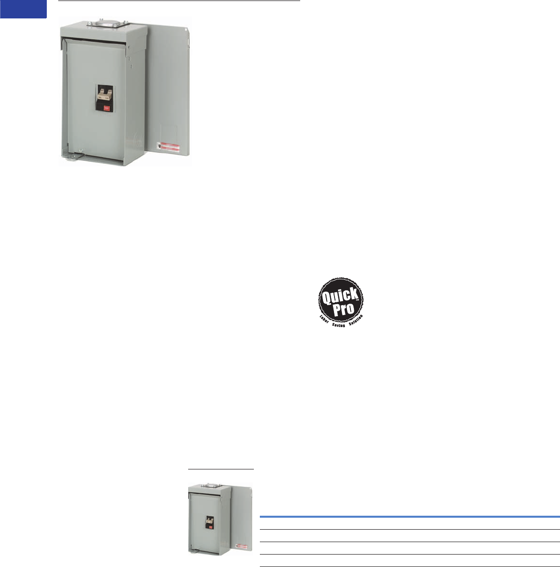
Product Description:
Eaton’s CH Spa Panels are
premium factory-assembled
“combination” units that
provide ground fault
protection, as well as a
convenient way to turn spa
pumps on and off. The NEC
requires that all pool and spa
pumps be protected by a
ground fault interrupter and
a disconnect switch mounted
within 10 feet of the tub
or the spa.
Features
●Two extra circuits for
additional loads
●Limited lifetime warranty
●UL Listed
●Tough powder-coated
galvanized steel enclosure
●Factory-installed
two-pole ground fault
circuit interrupter (GFCI)
Quick-ProSM
All you need to
know to save
time and make
more money.
Specified on
certain Eaton products, the
Quick-Pro symbol allows for
immediate recognition of
products that
are designed for
straightforward
installation.
When you see Quick-Pro, you
know you can install quickly—
sometimes up to 50% less
than the usual installation
time—and move on to your
next job.
Product Selection
Single-Phase Three-Wire—120/240 Vac Insulated/Bondable Neutral—
Factory-Installed Ground Bar
Notes
1 Includes a CH230GFI breaker, factory installed, and two extra circuits for convenience.
2 Includes a CH240GFI breaker, factory installed, and two extra circuits for convenience.
3 Includes a CH250GFI breaker, factory installed, and two extra circuits for convenience.
4 Includes a CH260GFI breaker, factory installed, and two extra circuits for convenience.
Main
Ampere
Rating
Circuit
Breaker
Included
Enclosure
Type
Type
of Trim
Included
Box
Size
Wire Size Range
Cu/Al 60°C or 75°C
for Main Lugs
Catalog
Number
30 CH230GF Outdoor — 5R #14–1/0 CH30SPA 1
40 CH240GF Outdoor — 5R #14–1/0 CH40SPA 2
50 CH250GF Outdoor — 5R #14–1/0 CH50SPA 3
60 CH260GF Outdoor — 5R #14–1/0 CH60SPA 4
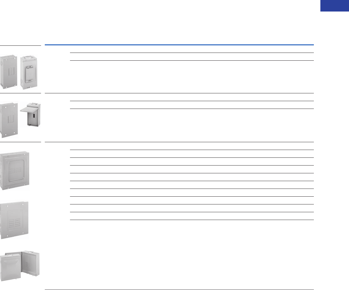
CH Spa Panel
Volume 1—Residential and Light Commercial CA08100002E—June 2014 www.eaton.com V1-T1-15
1
1
1
1
1
1
1
1
1
1
1
1
1
1
1
1
1
1
1
1
1
1
1
1
1
1
1
1
1
1
1.1
Loadcenters and Circuit Breakers
Type CH Loadcenters and Circuit Breakers
Surge Panel
Contents—CH Specialty Products
Description Page
Overview. . . . . . . . . . . . . . . . . . . . . . . . . . . . . . . . V1-T1-2
CH Specialty Products
Spa Panels . . . . . . . . . . . . . . . . . . . . . . . . . . . . V1-T1-14
Surge Panel
Plug-On Neutral Loadcenter. . . . . . . . . . . . . . . V1-T1-17
Type CH Renovation Loadcenter . . . . . . . . . . . V1-T1-18
Type CH Retrofit Interior Kits . . . . . . . . . . . . . . V1-T1-19
CH Loadcenter Options and Accessories . . . . . . . V1-T1-22
CH Circuit Breakers. . . . . . . . . . . . . . . . . . . . . . . . V1-T1-31
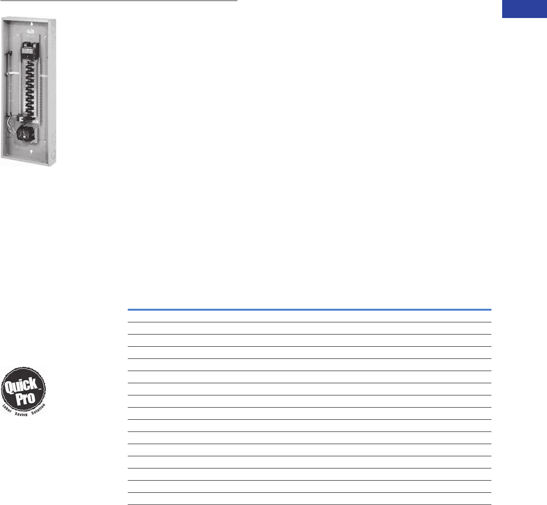
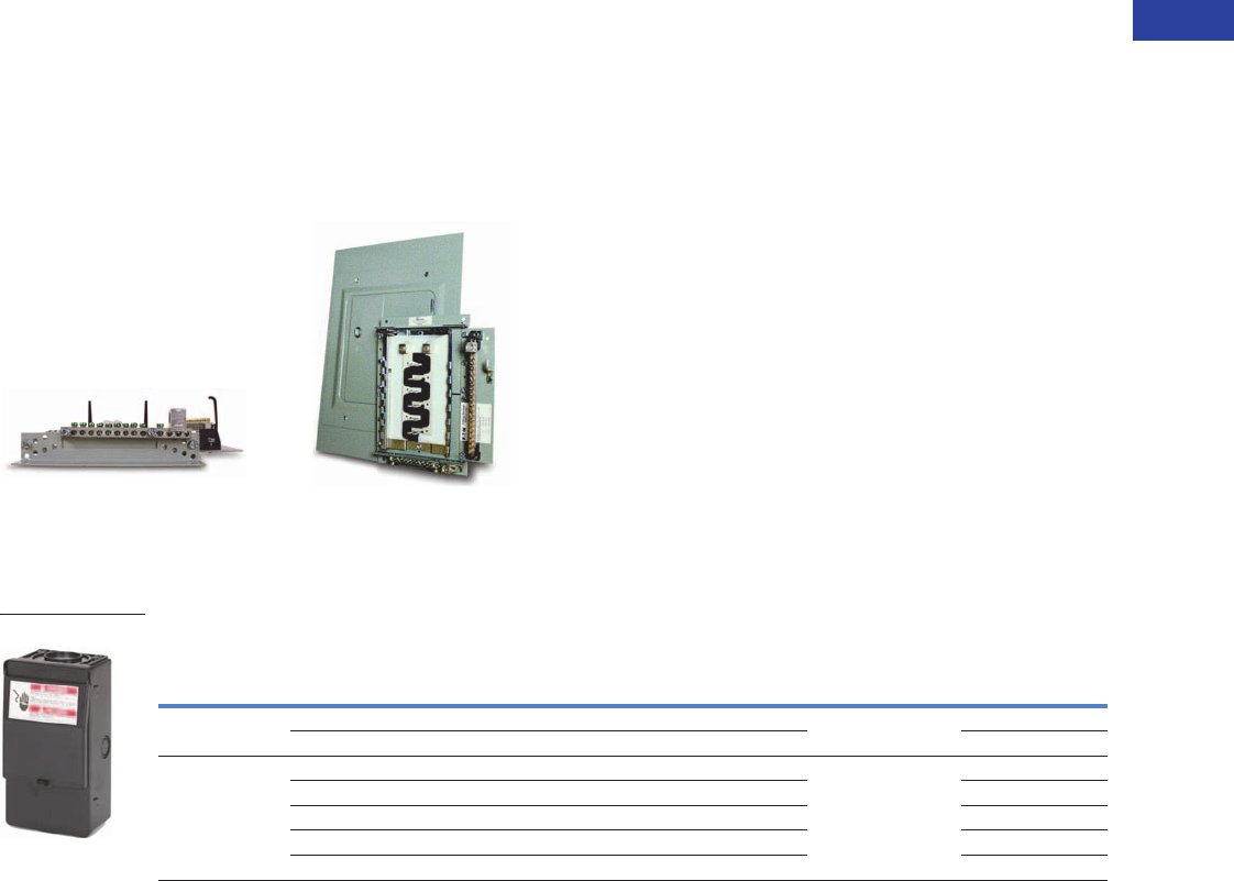
Surge Panel
Product Description
Eaton’s Type CH Surge
Loadcenter includes a factory-
mounted and wired surge
suppressor device. There is
a knockout in the cover that
allows the user to view the
status indication lights on
the surge suppressor. The
CH Surge Loadcenter reduces
the surge current, helping
protect sensitive home
electronic equipment.
Save labor
by installing
a factory-
mounted surge
protective
device.
Factory-Installed
Surge Protection
●Includes a CHSPT2ULTRA
and a two-pole 50A
circuit breaker
●Increases the
effectiveness of
surge protection due
to reduced lead length
●A modified deadfront
allows for easy viewing
of indicating lights
Surge Ready
●Provides a mounting
provision for
CHSPT2ULTRA
●A modified deadfront
allows for easy viewing
of indicating lights
Product Selection
Surge Installed Loadcenters
Notes
1Order cover separately.
2With main lugs installed.
Ampere
Rating Type
Number
of Circuits
Loadcenter
Catalog Number
Loadcenter Cover
Catalog Number
Combination Surface
225 Convertible 42 CHSUR42N225L 1CHSUR8LF CHSUR8LS
225 Convertible 242 CHSUR42L225L2 1CHSUR8LF CHSUR8LS
200 Main breaker 42 CHSUR42B200L2 1CHSUR8LF CHSUR8LS
225 Convertible 32 CHSUR32N225K 1CHSUR8KF CHSUR8KS
225 Convertible 232 CHSUR32L225K 1CHSUR8KF CHSUR8KS
200 Main breaker 32 CHSUR32B200K 1CHSUR8KF CHSUR8KS
150 Main breaker 32 CHSUR32B150K 1CHSUR8KF CHSUR8KS
100 Main breaker 32 CHSUR32B100K 1CHSUR8KF CHSUR8KS
125 Convertible 224 CHSUR24L125E 1CHSUR8EF CHSUR8ES
100 Main breaker 24 CHSUR24B100E 1CHSUR8EF CHSUR8ES
200 Convertible 40/40 BRSUR4040N200 Cover included
200 Main lug 40/40 BRSUR4040L200 Cover included
200 Main breaker 40/40 BRSUR4040B200 Cover included
200 Convertible 30/40 BRSUR3040N200 Cover included
200 Main lug 30/40 BRSUR3040L200 Cover included
200 Main breaker 30/40 BRSUR3040B200 Cover included

V1-T1-16 Volume 1—Residential and Light Commercial CA08100002E—June 2014 www.eaton.com
1
1
1
1
1
1
1
1
1
1
1
1
1
1
1
1
1
1
1
1
1
1
1
1
1
1
1
1
1
1
1.1
Loadcenters and Circuit Breakers
Type CH Loadcenters and Circuit Breakers
Surge Ready Loadcenters (provision only, CHSPT2ULTRA and breaker not included)
Main Breaker Kits Main Lug Kits
Technical Data and Specifications
Ratings
●Loadcenter
●25 kAIC main breaker, main lug only, and convertible
main breaker/main lug
●Factory installed or provision for field-installed
surge suppressor
●Top or bottom feed
●Surge protective device (CHSPT2ULTRA)
●Nominal discharge current: 20 kA (In)
●Surge current capacity per phase: 108 kA
●Warranty: $75,000 connected equipment 4
●For further product ratings, see Volume 1, Tab 2.1
Surge Protection
Notes
1Order cover separately.
2With main lugs installed.
3Rainproof loadcenters are furnished with hub closure plates. For rainproof hubs,
refer to Page V1-T1-25.
4For warranty details, visit www.eaton.com/surgetrap.
Ampere
Rating Type
Number
of Circuits
Loadcenter
Catalog Number 1
Loadcenter Cover Catalog Number
Combination Surface
225 Convertible 42 CHEC42N225L CHSUR8LF CHSUR8LS
225 Convertible 242 CHEC42L225L CHSUR8LF CHSUR8LS
200 Main breaker 42 CHEC42B200L CHSUR8LF CHSUR8LS
225 Convertible 232 CHEC32L225K CHSUR8KF CHSUR8KS
225 Convertible 32 CHEC32N225K CHSUR8KF CHSUR8KS
225 Convertible 32 CHEC32N225R 3——
200 Main breaker 32 CHEC32B200K CHSUR8KF CHSUR8KS
150 Main breaker 32 CHEC32B150K CHSUR8KF CHSUR8KS
100 Main breaker 32 CHEC32B100K CHSUR8KF CHSUR8KS
125 Convertible 224 CHEC24L125E CHSUR8EF CHSUR8ES
100 Main breaker 24 CHEC24B100E CHSUR8EF CHSUR8ES
Maximum Main Ampere Rating
Catalog Number
25 kAIC 35 kAIC
100 CSR2100N CSH2100N
150 CSR2150N CSH2150N
200 CSR2200N CSH2200N
225 CSR2225N CSH2225N
Maximum Main Ampere Rating Catalog Number
125 CHL125N
225 CHL225N
Volume 1—Residential and Light Commercial CA08100002E—June 2014 www.eaton.com V1-T1-17
1
1
1
1
1
1
1
1
1
1
1
1
1
1
1
1
1
1
1
1
1
1
1
1
1
1
1
1
1
1
1.1
Loadcenters and Circuit Breakers
Type CH Loadcenters and Circuit Breakers
60-Circuit Plug-On Neutral Loadcenter
Contents—CH Specialty Products
Description Page
Overview. . . . . . . . . . . . . . . . . . . . . . . . . . . . . . . . V1-T1-2
CH Specialty Products
Spa Panels . . . . . . . . . . . . . . . . . . . . . . . . . . . . V1-T1-14
Surge Panel . . . . . . . . . . . . . . . . . . . . . . . . . . . V1-T1-15
Plug-On Neutral Loadcenter
Type CH Renovation Loadcenter . . . . . . . . . . . V1-T1-18
Type CH Retrofit Interior Kits . . . . . . . . . . . . . . V1-T1-19
CH Loadcenter Options and Accessories . . . . . . . V1-T1-22
CH Circuit Breakers. . . . . . . . . . . . . . . . . . . . . . . . V1-T1-31
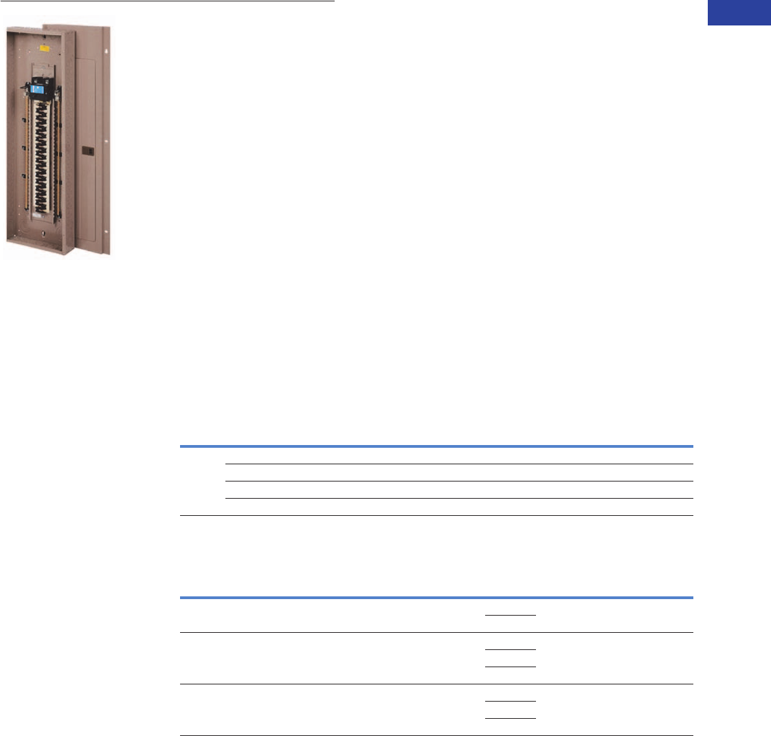
Plug-On Neutral
Loadcenter
Product Description
Code changes and higher
safety standards are leading
to more arc fault and ground
fault circuit interrupter
installations. Eaton offers a
unique product solution that
enables a direct connection of
the breaker to the neutral bar,
eliminating the need for
wiring a pigtail.
Features and Benefits
●Time savings up to 25%
per AFCI/GFCI installation
●Eliminates nuisance
tripping due to loose pigtail
connections
●Clean gutter space
●Easier troubleshooting
due to less wiring
●Backed by a limited
lifetime warranty
Product Selection
Main Breaker Plug-On Neutral Loadcenters
Main Lug Only/Convertible Plug-On Neutral Loadcenters—With Factory Installed Main Lugs
Notes
1Requires the use of type CHNT breakers.
2If 35 kAIC is required, use CSH breaker equivalent.
Main
Breaker
Type
Main
Ampere
Rating
Max.
Number
3/4-Inch
Circuits
Max.
Number
of Poles
Enclosure
Type
Box
Size
Wire Size
Range
Cu/Al
Catalog
Number
Cover Catalog
Number
Combination Surface
CSR 25
kAIC
100 24 24 Indoor E #2–300 kcmil CH24BPN100E CH8EF CH8ES
200 32 32 Indoor J #2–300 kcmil CH32BPN200J CH8JF CH8JS
200 42 42 Indoor K #2–300 kcmil CH42BPN200K CH8KF CH8KS
200 60 120 1Indoor N #2–300 kcmil CH60BPN200N CH8NF —
Max.
Ampere
Rating
Max.
Number
3/4-Inch
Poles
Enclosure
Type
Box
Size
Catalog
Number
Wire Size
Range
for Main Lug
Main
Breaker
Kit 2
Wire Size
Range
For Main
Breaker
Cover Catalog
Number
Combination Surface
125 24 Indoor E CH24NLPN125E #6–300 kcmil CSR2100N #2–300 kcmil CH8NLEF CH8NLES
CSR2125N
225 32 Indoor J CH32NLPN225J #6–300 kcmil CSR2125N #2–300 kcmil CH8NLJF CH8NLJS
CSR2200N
CSR2100N
225 42 Indoor K CH42NLPN225K #6–300 kcmil CSR2125N #2–300 kcmil CH8NLKF CH8NLKS
CSR2150N
CSR2200N
V1-T1-18 Volume 1—Residential and Light Commercial CA08100002E—June 2014 www.eaton.com
1
1
1
1
1
1
1
1
1
1
1
1
1
1
1
1
1
1
1
1
1
1
1
1
1
1
1
1
1
1
1.1
Loadcenters and Circuit Breakers
Type CH Loadcenters and Circuit Breakers
Renovation Panel
Contents—CH Specialty Products
Description Page
Overview . . . . . . . . . . . . . . . . . . . . . . . . . . . . . . . . V1-T1-2
CH Specialty Products
Spa Panels. . . . . . . . . . . . . . . . . . . . . . . . . . . . . V1-T1-14
Surge Panel . . . . . . . . . . . . . . . . . . . . . . . . . . . . V1-T1-15
Plug-On Neutral Loadcenter . . . . . . . . . . . . . . . V1-T1-17
Type CH Renovation Loadcenter
Type CH Retrofit Interior Kits . . . . . . . . . . . . . . V1-T1-19
CH Loadcenter Options and Accessories. . . . . . . . V1-T1-22
CH Circuit Breakers . . . . . . . . . . . . . . . . . . . . . . . . V1-T1-31
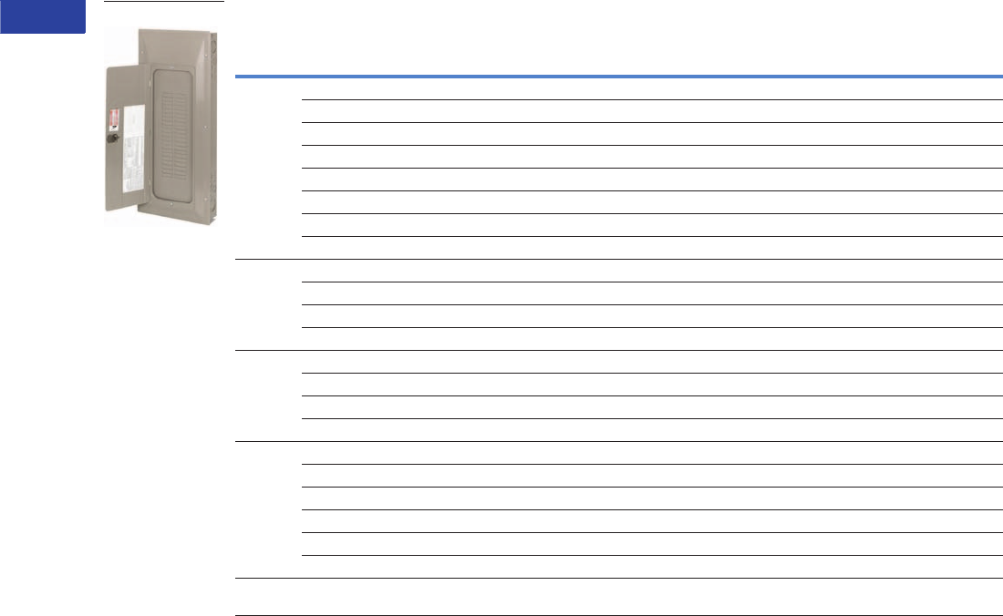
Type CH Renovation
Loadcenter
Product Description
Eaton’s Renovation
Loadcenter is designed
for the service contractor.
With the addition of a five-
circuit terminal block factory
mounted in the top left corner
of the loadcenter, the service
contractor can terminate
short-circuit wires instead of
having to use expensive wire
nuts. Also, the Renovation
Loadcenter incorporates a
twin-stacked neutral design
that places the neutral and
ground terminations higher in
the loadcenter. Both of these
features were added without
increasing any size from a
standard loadcenter. These
features will eliminate the
need for wire nuts and make
for a much neater installation.
There is a provision to field
mount a second five-circuit
terminal block (RN5TB) in
the top right corner of the
loadcenter. Choose amongst
Eaton’s Type CH breaker
family for use in the
Renovation Panel.
Product Selection
Single-Phase—Main Circuit Breaker Loadcenters 25 kAIC 1
Single-Phase, Three-Wire—120/240 Vac—Stacked Split Neutral
Branch Circuit Breakers (CH)
See Pages V1-T1-2–V1-T1-13.
Renovation Loadcenter
Notes
1100A main breaker is rated 10 kAIC.
2Combination style covers may be used in surface or flush applications.
All main circuit breaker loadcenters are listed for use as service entrance equipment. Loadcenters
are factory-bonded for service entrance applications. Remove bonding strap for separate neutral
and ground bars for sub-feed applications.
Main
Breaker
Type
Main
Ampere
Rating
Max.
Number
3/4-Inch
(19.1 mm)
of Poles
Enclosure
Type
Box
Size
Wire Size
Range
Cu/Al
60 or 70ºC
for Main
Breakers
Loadcenter
Catalog
Number
Cover Catalog
Number 2
Combination Surface
CH 100 20 Indoor C #6–1/0 CH22B100CRN CH8CFF CH8CS
CSR 150 32 Indoor J #2–300 kcmil CH32B150JRN CH8JF CH8JS
CSR 200 32 Indoor J #2–300 kcmil CH32B200JRN CH8J CH8JS
CSR 200 42 Indoor K #2–300 kcmil CH42B200KRN CH8KF CH8KS
Description Catalog Number
Five-circuit terminal block kit
Ground bar kits (two maximum per panel)
RN5TB
(See Page V1-T1-25)

Volume 1—Residential and Light Commercial CA08100002E—June 2014 www.eaton.com V1-T1-19
1
1
1
1
1
1
1
1
1
1
1
1
1
1
1
1
1
1
1
1
1
1
1
1
1
1
1
1
1
1
1.1
Loadcenters and Circuit Breakers
Type CH Loadcenters and Circuit Breakers
Type CH Retrofit Type CH Retrofit Interior Collar
Adjustable Interior and Assembly with Trim
Type CH Retrofit Interior
Contents—CH Specialty Products
Description Page
Overview . . . . . . . . . . . . . . . . . . . . . . . . . . . . . . . . V1-T1-2
CH Specialty Products
Spa Panels . . . . . . . . . . . . . . . . . . . . . . . . . . . . V1-T1-14
Surge Panel . . . . . . . . . . . . . . . . . . . . . . . . . . . V1-T1-15
Plug-On Neutral Loadcenter. . . . . . . . . . . . . . . V1-T1-17
Type CH Renovation Loadcenter . . . . . . . . . . . V1-T1-18
Type CH Retrofit Interior Kits
CH Loadcenter Options and Accessories . . . . . . . V1-T1-22
CH Circuit Breakers . . . . . . . . . . . . . . . . . . . . . . . . V1-T1-31
Type CH Retrofit Interior Kits
Product Description
Eaton’s unique Retrofit
Interior allows the customer
to cost-effectively and safely
upgrade an electrical service
without removing the existing
enclosure from the wall.
Application Description
The Retrofit Interior is
designed and tested
specifically for renovating
an outdated electrical panel in
an apartment, a condominium
or a single family home.
These outdated panels are
being recognized by local
inspectors and other
authorities as a possible
hazard.
Opportunities to Retrofit
●Single- or three-phase
●Main lug only or main
breaker
●Up to 42 circuits
●Up to 225A interiors,
400A available upon
request
●Available with CH breakers
(3/4-inch) with copper bus
or BR breakers (1-inch) with
aluminum bus
●The minimum lifetime
warranty for residential
breakers shall be as
follows:
●Limited lifetime
warranty on all CH
branch breakers and
loadcenters
●Refer to Eaton for
complete warranty
details
Features and Benefits
Upgrading Existing Electrical
Infrastructure Is Simple
●Replaces vintage brands
that have hard to find,
expensive replacement
breakers
●Safely upgrade to arc fault
and ground fault breakers
to meet current electrical
codes
●Maximizes number of
circuits available with
compact design
●Eco-friendly in asbestos-
filled environments
●Exclusive design
Save Time and Money
Throughout the Installation
●Uses existing panel
box and wires
●Eliminates expensive and
time-consuming drywall/
paint repair
●Saves 2–3 hours of
installation time compared
to a complete panel
changeout
●Eliminates precise
measurements with field-
adjustable kit
Detailed Product Guide
For questions about retrofit
solutions, contact the Lincoln
Flex Center at 800-330-6479 or
flexcenterlincoln@eaton.com.
Be sure to provide width,
height and depth of panel.
Standards and Certifications
Meets 2008/2011/2014 NEC
wire bending requirements.

V1-T1-20 Volume 1—Residential and Light Commercial CA08100002E—June 2014 www.eaton.com
1
1
1
1
1
1
1
1
1
1
1
1
1
1
1
1
1
1
1
1
1
1
1
1
1
1
1
1
1
1
1.1
Loadcenters and Circuit Breakers
Type CH Loadcenters and Circuit Breakers
CH Specialty Product Selection
To select the retrofit kit:
1. From the existing box
size determine which
retrofit groups are
suitable (may be more
than one).
2. Use type of interior,
number of phases, and
type of main to find the
selection chart.
3. Select part number from
chart (if main breaker,
replace XXX with specific
amp rating).
4. Note that the overlap
of the existing wall is
the retro cover size
minus the existing
box size. If specific
measurements are
needed, communicate
that you need a custom
trim size.
5. Contact the Lincoln Flex
Center at 800-330-6479
for pricing, lead-times,
and order entry
instructions.
How to Order:
1. Measure the existing
panel enclosure to
determine appropriate
kits for your project.
2. Match the existing
dimensions with the
table below to obtain the
correct catalog number.
3. Order your retrofit kit
from a local Eaton
authorized distributor.
Need assistance or can’t find
retrofit to fit existing
enclosure?
Email or call Eaton’s
Residential Flex Center at
1-800-330-6479 for all your
retrofit needs. Go to
www.eaton.com/eccn to
locate an Eaton Certified
Contractor.
Retrofit Interior Kit Specifications
Five recommended groups: existing box height determines retro group size. Approximate Dimensions in Inches (mm).
Notes
1Catalog numbers shown with "_" at the end need one of the following suffixes to denote depth:
J = 3.75–4.25
K = 4.25–5.00
L = 5.00–6.00
Example: RBCH24B200J would signify an interior set with a depth range of 3.75 to 4.25 inches.
2****Denotes characters in the catalog number that relate to overall cover size.
Example: CRWCH6ML2620 would signify a cover 26.00 inches H x 20.00 inches W, or CRBCH24CS3324 would be 33.00 inches H x 24.00 inches W.
3Amperes for MB panels is maximum; catalog number will reflect actual amperage of breaker included.
For UL applications, maximum cover sizes may apply.
Existing Enclosure Parameters—Inches (mm)
Catalog
Number 1Cover 2
Minimum
Depth
Maximum
Depth
Minimum
Width
Minimum
Height Phase Main Bus Amperes
3
Spaces /
Circuits
UL 67
Listed
CH Retrofit Interiors and Covers
RWCH6L125N CRWCH6ML**** 3.13 (79.5) 4.13 (104.9) 7.00 (177.8) 8.50 (215.9) Single MLO CH 125 6 No
RSCH10B125N CRWCH12ML**** 3.50 (88.9) 4.50 (114.3) 8.50 (215.9) 16.50 (419.1) Single MCB CH 125 10 No
RSCH12L125N CRWCH12ML**** 3.50 (88.9) 4.50 (114.3) 8.50 (215.9) 16.50 (419.1) Single MLO CH 125 12 No
RACH22B125J CRACH24ML**** 3.75 (95.3) 4.25 (108.0) 13.00 (330.2) 21.00 (533.4) Single MCB CH 125 22 No
RACH24L125J CRACH24ML**** 3.75 (95.3) 4.25 (108.0) 13.00 (330.2) 21.00 (533.4) Single MLO CH 125 24 No
RBCH24B200_ CRBCH24CS**** 3.75 (95.3) 6.00 (152.4) 13.00 (330.2) 29.00 (736.6) Single MCB CH 200 24 No
RBCH32L200_ CRBCH32ML**** 3.75 (95.3) 6.00 (152.4) 13.00 (330.2) 29.00 (736.6) Single MLO CH 200 32 No
RCCH32B200_ CRBCH32CS**** 3.75 (95.3) 6.00 (152.4) 13.00 (330.2) 34.00 (863.6) Single MCB CH 200 32 No
Volume 1—Residential and Light Commercial CA08100002E—June 2014 www.eaton.com V1-T1-21
1
1
1
1
1
1
1
1
1
1
1
1
1
1
1
1
1
1
1
1
1
1
1
1
1
1
1
1
1
1
1.1
Loadcenters and Circuit Breakers
Type CH Loadcenters and Circuit Breakers
Complete Assembly
Note: For complete assembly,
interior and cover need to be
ordered separately.
Adjustable Interior
●Factory installed ground
and neutral bars positioned
to accept existing wires
●Field adjustable depth
matches existing panel box
●Adjustable height enables
optional placement of the
interior
●Field bondable for service
entrance options
Adjustable Interior
Standard Trim and Collar
●Standard trim matches
new interior
●New circuit directory for
updated labeling
●Oversized collar eliminates
expensive wall/paint repair
Collar and Assembly with Trim
Single-Phase—Main Lug Loadcenters, Non-Metallic
Single-Phase Three-Wire—120/240 Vac—Insulated/Bondable Neutral
Notes
1 Suitable for use as service equipment when not more than six main disconnecting means are provided and when not used as a lighting and appliance panelboard
(see Article 408.34 of the NEC).
2 This device has no main lugs. A Type BR or BD breaker is required to be backfed to supply power to branch breakers. This device is single-phase 120 Vac only.
With the use of three Type BR breakers, there are two branch circuits available. With the use of three Type BD breakers, there are five branch circuits available.
3 Includes GB4NM ground bar.
4 Includes a GFCB240 breaker, factory installed.
Main
Ampere Rating
Maximum Number
1-Inch (25.4 mm) Enclosure
Type Trim Type
Box
Size
Wire Size Range
Cu/Al 60°C or 75°C
for Main Lugs
Loadcenter
Catalog NumberSpaces Circuits
40 144 Indoor Flush (no door) 2 2TT120FLGNM 23
44 Indoor Surface (no door) 2 TT120SLGNM 23
60 2 4 Indoor Flush (no door) 2 #14–2 2460FNM
2 4 Indoor Surface (no door) 2 2460SNM
2 4 Indoor Flush (no door) 2 2460FGNM 3
2 4 Indoor Surface (no door) 2 2460SGNM 3
2 4 Outdoor — 42460RNM
2460SNM
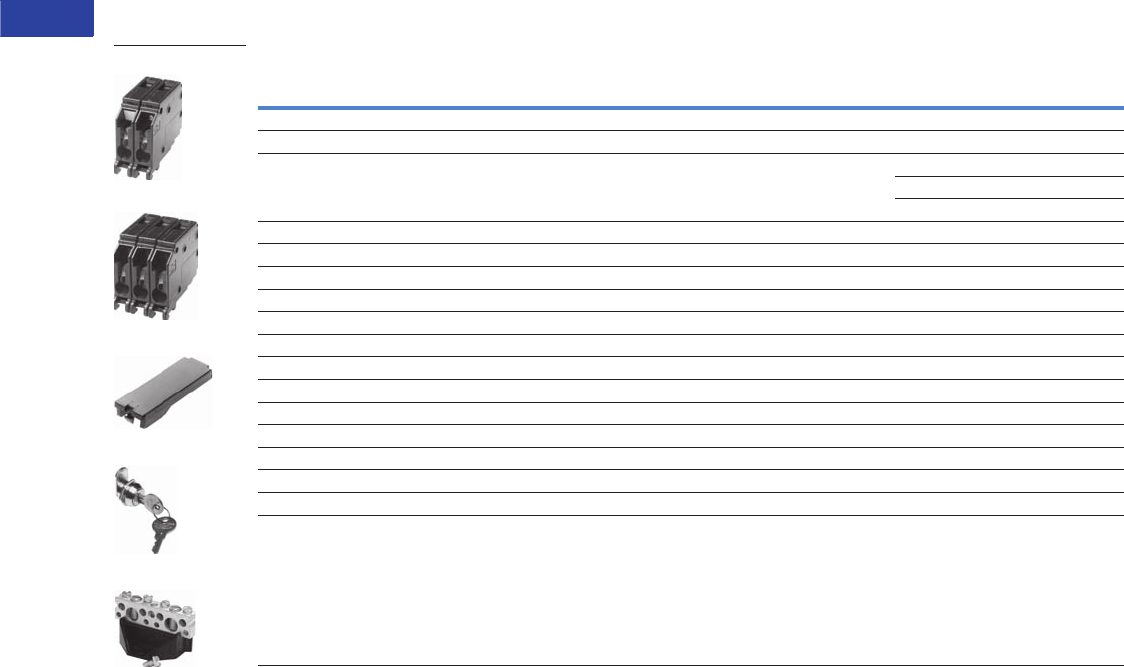
V1-T1-22 Volume 1—Residential and Light Commercial CA08100002E—June 2014 www.eaton.com
1
1
1
1
1
1
1
1
1
1
1
1
1
1
1
1
1
1
1
1
1
1
1
1
1
1
1
1
1
1
1.1
Loadcenters and Circuit Breakers
Type CH Loadcenters and Circuit Breakers
CH Loadcenter Options and Accessories
Field Installation and Parts
Note
1 Must be purchased in multiples of ordering quantities indicated.
Description
Ordering
Quantity 1
Catalog
Number
Sub-feed lug blocks—two-pole, 125A, 3/4-inch (19.1 mm) spaces needed 1 CHSF2125
Sub-feed lug blocks—three-pole, 125A, 3/4-inch (19.1 mm) spaces needed 1 CHSF3125
Neutral/ground lug—add-on neutral or ground lug 1 NL20
1NL30
1NL300
Filler plates—3/4-inch (19.1 mm) space circuit breaker space 25 CHFP
CSR main circuit breaker filler plate (with hardware) 1 CSRFP
Door lock—12–42 circuits, and 100–225A 1 TDL
Sandlewood spray paint 1SPCSW
ANSI-61 light gray touchup paint for outdoor loadcenters 1 SPC61
Isolated neutral assembly (computer circuits) 1 BINA
Circuit directory—adhesive backed 10 TCD
Cover screws 25 LCCS
Cover replacement latch 14-5/16 inch (363.55 mm) wide loadcenters only 1 CHRLS
Circuit marking strip (next to breakers) 10 CHMS
Circuit identification label (preprinted breaker labels next to breakers) 25 CHBL
Series rated caution label 25 SRL
Branch circuit numbering strip 20 CHNS
Bonding strap with screw 1BSSUSE
CHSF2125
CHSF3125
CHFP
TDL
BINA
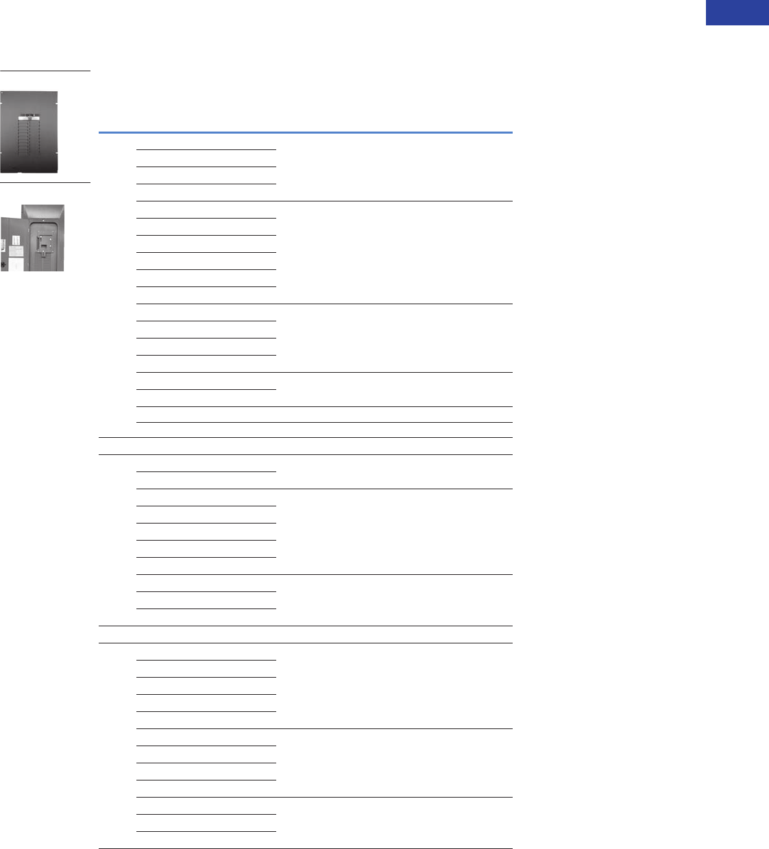
Volume 1—Residential and Light Commercial CA08100002E—June 2014 www.eaton.com V1-T1-23
1
1
1
1
1
1
1
1
1
1
1
1
1
1
1
1
1
1
1
1
1
1
1
1
1
1
1
1
1
1
1.1
Loadcenters and Circuit Breakers
Type CH Loadcenters and Circuit Breakers
Mechanical Interlock Covers
Covers mechanically interlock two breakers. Type A covers
interlock two CH breakers mounted across from one another.
Type B covers interlock a main Type CSR breaker with a Type CH.
Mechanical Interlocks
Mechanical Interlock Trim/Deadfront Catalog Numbers
Type
Fits Loadcenter
Catalog Numbers Flush Surface
ACH12L125B CH8BFM CH8BSM
CH16L125B
CH12L3125B
CH14B100B
CH20L125C CH8CFM CH8CSM
CH24L125C
CH18L3125C
CH24L3125C
CH22B100C
CH22N100C
CH24L150D CH8DFM CH8DSM
CH32L150D
CH24L3225D
CH30L3150D
CH42L225G CH8GFM CH8GSM
CH42L3225G
Inner cover of Box B raintight — CH8BRM
Inner cover of Box C raintight — CH8CRM
Indoor
BCH24B150E CHEFM CHESM
CH24B200E
CH32B150J CH8JFM CH8JSM
CH32B200J
CH3242B200J
CH32N200J
CH32B225J
CH42B200K CH8KFM CH8KSM
CH42N200K
CH42B225K
Outoor
BCH8B150RF CH3RDF7M —
CH8B200RF
CH8N200RF
CH24B150R
CH24B200R
CH32B150R CH3RDF9M —
CH32B200R
CH32N200R
CH32B225R
CH42B200R CH3RDF10M —
CH42N200R
CH42B225R
CH8BRM Type A
CH8EFM Type B
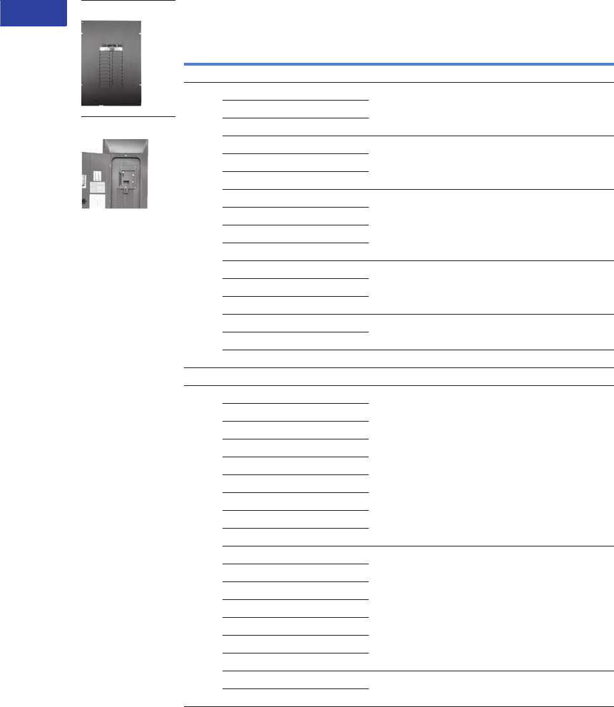
V1-T1-24 Volume 1—Residential and Light Commercial CA08100002E—June 2014 www.eaton.com
1
1
1
1
1
1
1
1
1
1
1
1
1
1
1
1
1
1
1
1
1
1
1
1
1
1
1
1
1
1
1.1
Loadcenters and Circuit Breakers
Type CH Loadcenters and Circuit Breakers
Mechanical Interlocks, contiuned
Note
1 If vintage part number does not match exactly, the cover may not fit. Simple variations such as an “N” at the end of
the part number contain minor design variations that will prevent our cover from working with that particular loadcenter.
Mechanical Interlock Trim/Deadfront Catalog Numbers
Type
Fits Loadcenter
Catalog Numbers Flush Surface
Next Generation Power Center
BCHPC32B150L CHPC8B32LFM —
CHPC32B200L
CHPC32N200L
CHPC42B150L CHPC8B42LFM —
CHPC42B200L
CHPC42N200L
CHPC32B125TR CH3RDF15M —
CHPC32B150TR
CHPC32B200TR
CHPC32N200TR
CHPC42B150TR CH3RDF16M —
CHPC42B200TR
CHPC42N200TR
CHPC32B150TR CH3RDF17M —
CHPC32B200TR
CHPC42B200BR CH3RDF18M —
Vintage 1
CH20JJM200 CH7JJFREPLM —
CH24JJM150
CH30JJM150
CH30JJM200
CH30JJM150H
CH3040JJMM200
CH304JJM150
CH304JJM200
CH304JJM200H
CH30KKM225 CH7KKFREPLM —
CH40KKM200H
CH40KKM225
CH40KKM200H
CH40KKM225H
CH304KKM200
CH304KKM200H
CH304LLM225 CH7LLFREPLM —
CH424LLM225H
CH8BRM Type A
CH8EFM Type B
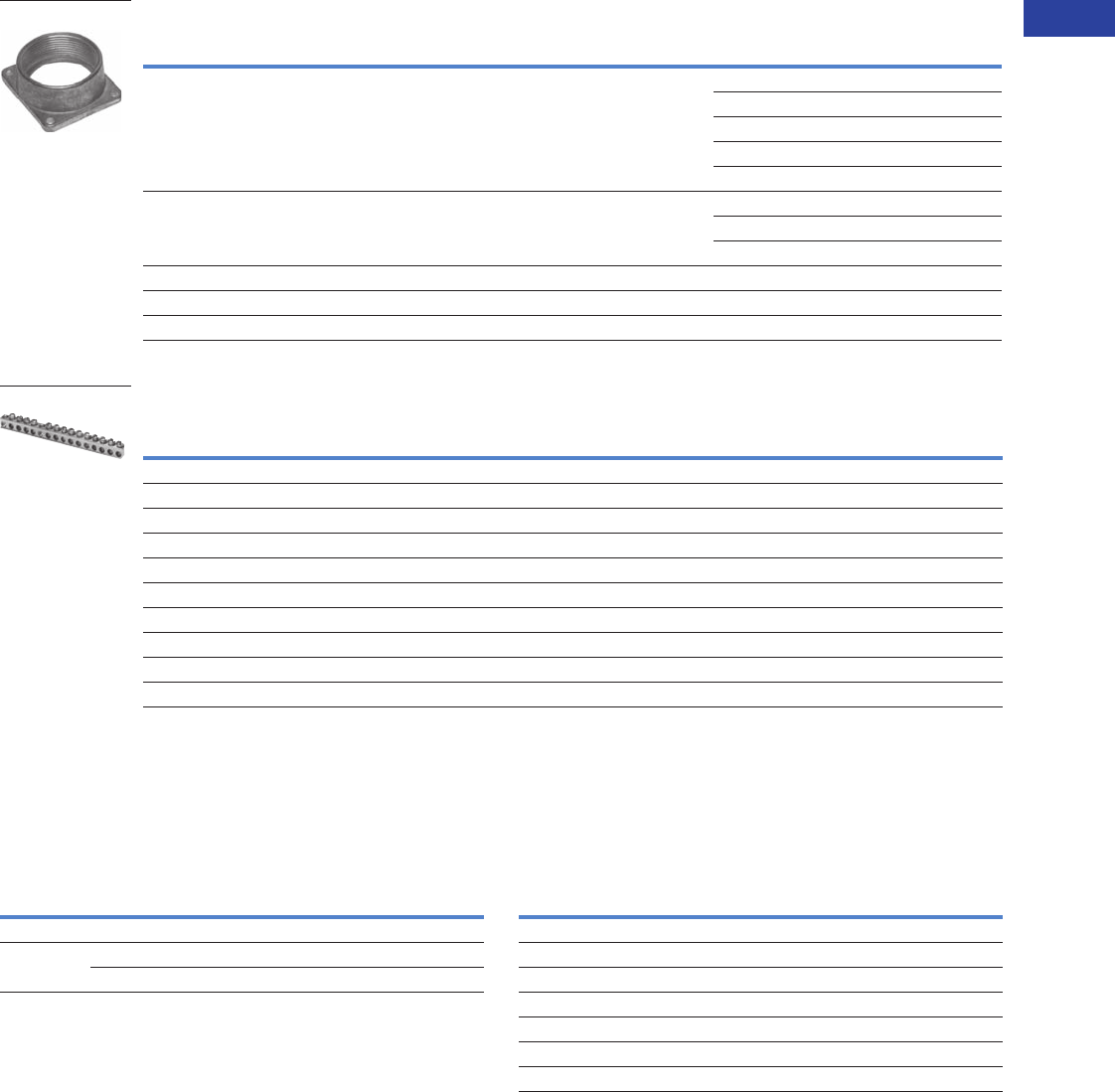
Volume 1—Residential and Light Commercial CA08100002E—June 2014 www.eaton.com V1-T1-25
1
1
1
1
1
1
1
1
1
1
1
1
1
1
1
1
1
1
1
1
1
1
1
1
1
1
1
1
1
1
1.1
Loadcenters and Circuit Breakers
Type CH Loadcenters and Circuit Breakers
Field Installation Rainproof Conduit Hubs
Ground Bar Kits
Ground Bar Legend
Grounded “B” Phase Adapters Neutral Bar Accessories
Notes
1Must be purchased in multiples of ordering quantities indicated.
2Distance between mounting holes is 1-3/4 inches (44.5 mm).
3For single- and three-phase 400A loadcenters.
4Distance between mounting holes is 2-13/32 inches.
5Cannot be used in Safety Breaker Panels. Classic Plus Panels only.
Description
Conduit Size Ordering
Quantity 1
Catalog
NumberInches (mm)
Group 1—for use with 70, 100 and 125A MLO and MCB loadcenters and circuit breaker enclosures 0.75 (19.1) 1 DS075H1
1.00 (25.4) 1 DS100H1
1.25 (31.8) 1 DS125H1
1.50 (38.1) 1 DS150H1
2.00 (50.8) 1 DS200H1
Group 2—for use with 150, 200 and 225A MLO and MCB loadcenters and circuit breaker enclosures 2.00 (50.8) 1 DS200H2
2.50 (63.5) 1 DS250H2
3.00 (76.2) 1 DS300H2
Adapter kit—allows installing a Group 1 hub on devices arranged for Group 2 hubs — 1 DS900AP
Group 1—small blank hub closure plate — 1 DS900CP1
Group 2 —large blank hub closure plate — 1 DS900CP2
Description (See Legend)
Length Ordering
Quantity 2
Catalog
NumberInches (mm)
dssssds 2.54 (64.5) 1 GBK5 2
dssssdsj 3.59 (91.2) 1 GBK520 2
dssssdssssss 4.29 (109.0) 1 GBK10 2
dssssdssssssj 5.34 (135.6) 1 GBK1020 2
4.61 (117.1) 1 GBK13 2
dssssdssssssssss 5.69 (144.5) 1 GBK14 2
dssssdssssssssssj 6.74 (171.2) 1 GBK1420 2
dssssdsssssssssssssssss 8.14 (206.8) 1 GBK21 2
dssssdsssssssssssssssssj 9.19 (233.4) 1 GBK2120 2
ssssssssdssssssdsssssss 7.94 (201.7) 1 CH9GP21 34
DS100H1
GBK14
f
d
f
f
f
k
f
d
f
k
f
f
f
s
j
d
= (3) #14–#10 Cu/Al or (1) #14–#4 Cu/Al
= (1) #6–2/0 Cu/Al
= (1) 1/0–14 or (3) #10–12 Cu/Al
= (1) #14–1/0 Cu/Al or (3) #14–#10 Cu/Al
= Mounting hole
f k
Maximum
Amperes
Three-Phase Loadcenter
Types of Panels
Kit Catalog
Number 5
125 12–32 circuit main lug CHGRD1
225 Main lug and CHH main breaker panels CHGRD2
CC main CB panels CHGRD3
Description
Catalog
Number 5
Split neutral kit for 22-circuit 125A maximum CHSN125C
Split neutral kit for 32-circuit 200A maximum CHSN225J
Split neutral kit for 42-circuit 200A maximum CHSN225K
Replacement neutral for all C type boxes CHN125C
Replacement neutral for all D type boxes CHN125D
Replacement neutral for all L type boxes CHN225L
Isolated Neutral Assembly (computer circuits) BINA
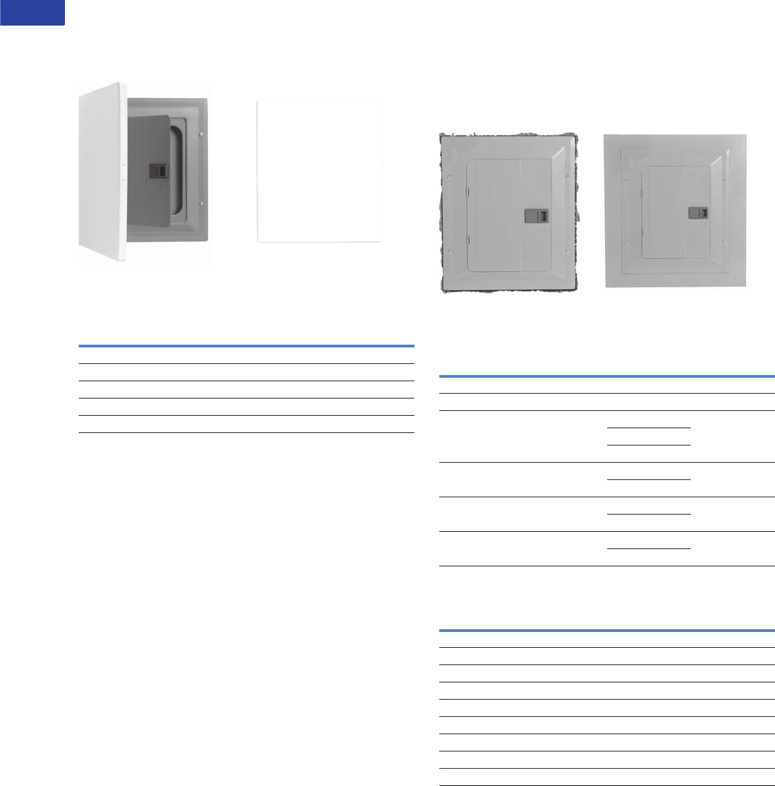
V1-T1-26 Volume 1—Residential and Light Commercial CA08100002E—June 2014 www.eaton.com
1
1
1
1
1
1
1
1
1
1
1
1
1
1
1
1
1
1
1
1
1
1
1
1
1
1
1
1
1
1
1.1
Loadcenters and Circuit Breakers
Type CH Loadcenters and Circuit Breakers
Decorator Cover Accessory
●For easy use with CH loadcenters mounted in living space
●Easily wallpapered or painted to match any decor
●Loadcenter accessory—exclusively from Eaton
Now you see it … … Now you don’t.
Decorator Cover Accessory 1
Loadcenter Goof Collars
Don’t let an ugly drywall problem ruin a beautiful
electrical installation.
Eaton’s Goof Collar is designed to cover gaps between the
finished drywall and loadcenter enclosure. This is often
necessary when upgrading the electrical service and the drywall
surrounding the panel is damaged. The collar allows 2 inches of
overhang beyond the standard flush trim.
Before After
CH Goof Collars
BR Goof Collars
Note
1For goof collars not listed in the table, please contact the Lincoln Flex Center at
1-800-330-6479.
Catalog Number
Corresponding Cover Existing CH Loadcenter Cover
CH8BF CH8KDNB
CH8CF CH8KDNC
CH8DF/EF CH8KDND
CH8GF/JF CH8KDNJ
CH8KF CH8KDNK
Inches (mm) Catalog Number
Height Width Loadcenter Cover Goof Collar
21.00 (533.4) 19.00 (482.6) CH8BF CH8BFC1921
26.00 (660.4) 19.00 (482.6) CH8CF CH8CFC1926
34.00 (863.6) 19.00 (482.6) CH8DF CH8DFC1934
CH8EF
CHSUR8EF
39.00 (990.6) 19.00 (482.6) CH8GF CH8JFC1939
CH8JF
42.00 (1066.8) 19.00 (482.6) CH8KF CH8KFC1942
CHSUR8KF
44.00 (1117.6) 19.00 (482.6) CH8LF CH8LFC1944
CHSUR8LF
Inches (mm) Catalog Number
Height Width BR Box Size Goof Collar
21.00 (533.4) 19.00 (482.6) B1 BRB2GC2319
23.00 (584.2) 19.00 (482.6) B2 BRB1GC2119
25.00 (635.0) 19.00 (482.6) C1 BRC1GC2519
27.00 (685.8) 19.00 (482.6) C2 BRC2GC2719
31.00 (787.4) 19.00 (482.6) C4 BRC4GC3119
34.00 (863.6) 19.00 (482.6) D1 BRD1GC3419
38.00 (965.2) 19.00 (482.6) G1 BRG1GC3819
43.00 (1092.2) 19.00 (482.6) L1 BRL1G4319
48.00 (1219.2) 19.00 (482.6) L2 BRL2GC4819
SCOTT
HAS
PHOTO
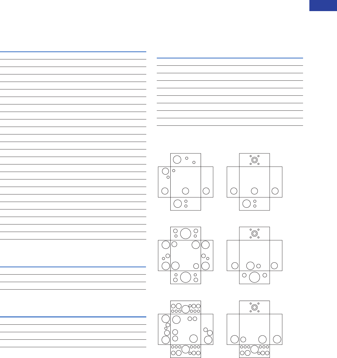
Volume 1—Residential and Light Commercial CA08100002E—June 2014 www.eaton.com V1-T1-27
1
1
1
1
1
1
1
1
1
1
1
1
1
1
1
1
1
1
1
1
1
1
1
1
1
1
1
1
1
1
1.1
Loadcenters and Circuit Breakers
Type CH Loadcenters and Circuit Breakers
Dimensions
Approximate Dimensions in Inches (mm)
Residential/Commercial/Unit Enclosure—Box Sizes
Note: Box sizes do not include covers/fronts.
Residential Loadcenters
Commercial Loadcenters
Types ECB and ECC Unit Enclosures
Residential Loadcenter Knockout
Residential NEMA Type 1 Indoor and NEMA Type 3R
Outdoor Enclosures.
Knockouts for Box Sizes 5, 6, 7, 5R, 6R, 7R
Knockout Positions
Box Size Height Width Depth
NEMA Type 1 Indoor
5 9.50 (241.3) 4.50 (114.3) 3.13 (79.4)
6 11.38 (288.9) 6.88 (174.6) 3.39 (86.1)
7 13.00 (330.2) 11.00 (279.4) 3.69 (93.7)
B 16.75 (425.5) 14.31 (363.5) 3.88 (98.4)
C 21.00 (533.4) 14.31 (363.5) 3.88 (98.4)
D 29.13 (739.8) 14.31 (363.5) 3.88 (98.4)
E 29.13 (739.8) 14.31 (363.5) 3.88 (98.4)
G 34.13 (866.8) 14.31 (363.5) 3.88 (98.4)
J 34.13 (866.8) 14.31 (363.5) 3.88 (98.4)
K 37.00 (939.8) 14.31 (363.5) 3.88 (98.4)
L 39.00 (990.6) 14.31 (363.5) 3.88 (98.4)
N 45.00 (1143.0) 14.31 (363.5) 3.88 (98.4)
NEMA Type 3R Outdoor
5R 9.50 (241.3) 4.50 (114.3) 3.13 (79.4)
6R 11.75 (298.5) 6.50 (165.1) 4.50 (114.3)
7R 13.00 (330.2) 11.00 (279.4) 3.69 (93.7)
B 16.75 (425.5) 14.31 (363.5) 5.19 (131.8)
C 21.00 (533.4) 14.31 (363.5) 5.19 (131.8)
D 29.13 (739.8) 14.31 (363.5) 5.19 (131.8)
E 29.13 (739.8) 14.31 (363.5) 5.19 (131.8)
G 34.13 (866.8) 14.31 (363.5) 5.19 (131.8)
J 34.13 (866.8) 14.31 (363.5) 5.19 (131.8)
K 37.00 (939.8) 14.31 (363.5) 5.19 (131.8)
L 39.00 (990.6) 14.31 (363.5) 5.19 (131.8)
Box Size Height Width Depth
NEMA Type 1 Indoor
P 54.38 (1381.1) 21.00 (533.4) 6.00 (152.4)
PM 62.63 (1590.7) 21.00 (533.4) 6.00 (152.4)
Height Width Depth
NEMA Type 1 Indoor
23.25 (590.6) 8.88 (225.4) 4.50 (114.3)
NEMA Type 3R Outdoor
23.69 (601.7) 9.31 (236.5) 5.44 (138.1)
Code Diameter
A 0.50 (12.7) — — —
B 0.50 (12.7) 0.75 (19.1) — —
C 0.50 (12.7) 0.75 (19.1) 1.00 (25.4) —
D 0.50 (12.7) 0.75 (19.1) 1.00 (25.4) 1.25 (31.8)
E 0.75 (19.1) 1.00 (25.4) 1.25 (31.8) —
F 0.75 (19.1) 1.00 (25.4) 1.25 (31.8) 1.50 (38.1)
G 1.00 (25.4) 1.25 (31.8) 1.50 (38.1) —
H 1.00 (25.4) 1.25 (31.8) 1.50 (38.1) 2.00 (50.8)
I 1.25 (31.8) 1.50 (38.1) 2.00 (50.8) —
Box 6R
Box 7 Box 7R
Box 5 Box 5R
Box 6
A
A
D D D
F
Hub
A
A
B
A
B
B
C
C
FF
F
F
A
B
F
F
H
A
B
A
B
H
F
B B
B
H
Hub
D D
A
A
AA
A
AAA
AAA AAA
B B B
AB B
B
B
B
B
C C
C
C
C
BC
G
G
G
G
G G
F
AAA AAA
AB B
BC
C
G
G G
F
Hub
A
A
A
A
A
A
D D D
D
F
F
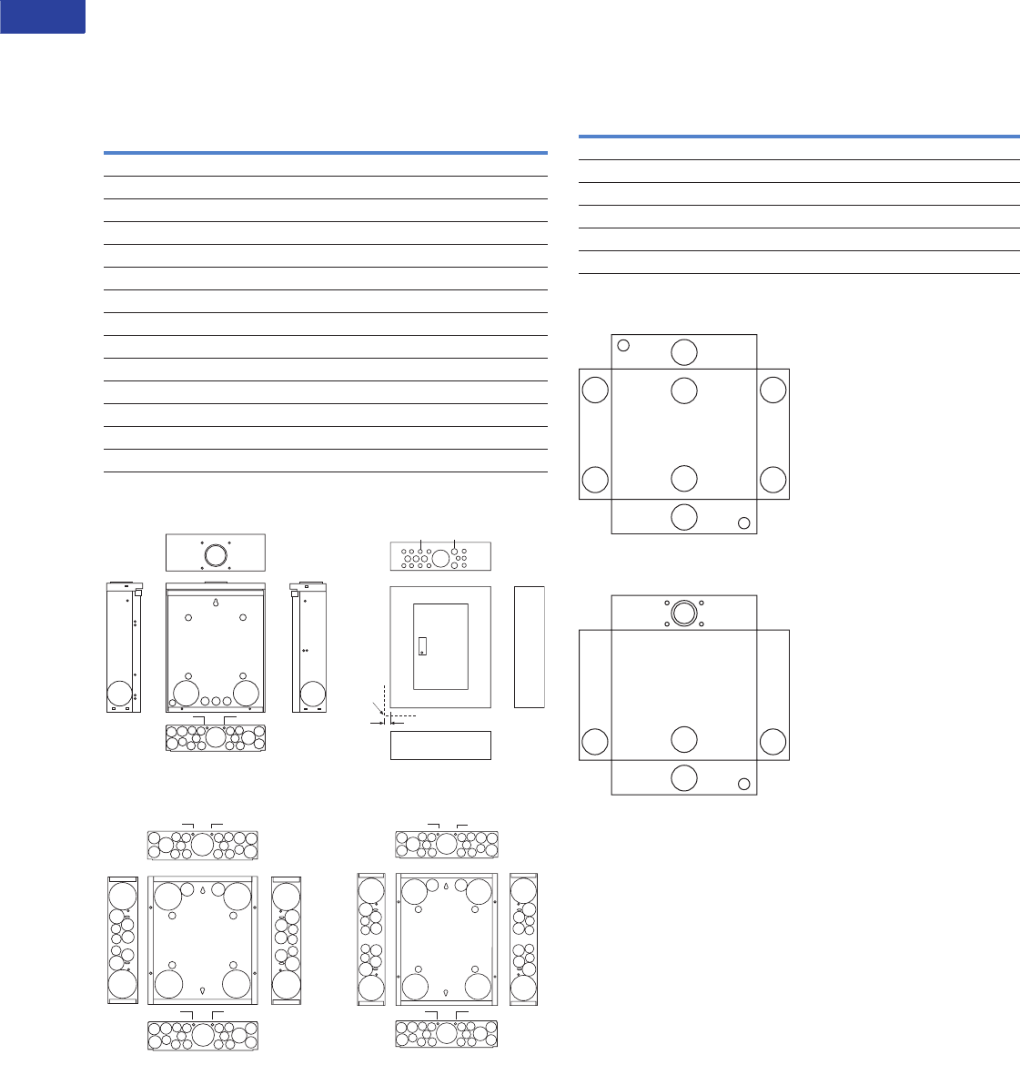
V1-T1-28 Volume 1—Residential and Light Commercial CA08100002E—June 2014 www.eaton.com
1
1
1
1
1
1
1
1
1
1
1
1
1
1
1
1
1
1
1
1
1
1
1
1
1
1
1
1
1
1
1.1
Loadcenters and Circuit Breakers
Type CH Loadcenters and Circuit Breakers
Approximate Dimensions in Inches (mm)
Residential and Commercial Loadcenter Knockout
Residential NEMA Type 1 indoor and NEMA Type 3R outdoor enclosures.
Knockouts for Box Sizes 8, 8R, P, PM, B, C, D, E, G, J, K, L, N
and Outdoor Boxes 12–60 Circuits
Knockout Diagram
Type ECB and ECC Unit Enclosure Knockout
NEMA Type 1—Indoor
NEMA Type 3R—Outdoor
Code Diameter
a 0.75 (19.1) — — — —
b 0.50 (12.7) 0.75 (19.1) — — —
c 0.50 (12.7) — — — —
d 1.00 (25.4) 1.25 (31.8) 1.50 (38.1) 2.00 (50.8) 2.50 (63.5)
e 1.25 (31.8) 1.50 (38.1) 2.00 (50.8) 2.50 (63.5) —
f 0.75 (19.1) 1.25 (31.8) 1.50 (38.1) 2.00 (50.8) —
g 0.50 (12.7) 0.75 (19.1) 1.00 (25.4) — —
h 1.50 (38.1) 2.00 (50.8) 2.50 (63.5) — —
i 0.50 (12.7) 0.75 (19.1) 1.00 (25.4) 1.25 (31.8) 1.50 (38.1)
j 1.00 (25.4) 1.25 (31.8) 1.50 (38.1) — —
k 1.25 (31.8) 1.50 (38.1) 2.00 (50.8) — —
m 0.75 (19.1) 1.00 (25.4) 1.25 (31.8) 1.50 (38.1) 2.00 (50.8)
n 0.75 (19.1) 1.00 (25.4) 1.25 (31.8) 1.50 (38.1) —
p 2.00 (50.8) 2.50 (63.5) — — —
eeee
d
c
c
c
cc
b
b
i
c
c
c
cc
b
g
b
c
c c c
a
Flush
Trim
3/4
c
h
b
b
e
g
b
b
c
c
c
g
e
b
e
g
b
b
c
c
c
g
e
ee
e
e
gg
d
cc
c
c
c
b
bi
cc
c
c
c
b
g
b
c
d
c
c
c
c c
b
b
i
c
c
c
cc
b
g
b
c
0.45 Dia.0.45 Dia.
0.45 Dia.0.45 Dia.
b
e
g
b
b
c
c
g
e
ee
e
e
gg
b
c
c
b
e
g
b
b
c
c
c
g
e
bc
d
cc
c
c
c
b
bi
cc
c
c
c
b
g
b
c
d
c
c
c
c c
b
b
i
c
c
c
cc
b
g
b
c
0.45 Dia.0.45 Dia.
Box P, PM
Outdoor Boxes
12–42 Circuits 225A Maximum
Box B Box C, D, E, G, J, K, L, N
0.45 Dia.0.45 Dia.
0.45 Dia.0.45 Dia.
Code Diameter
NEMA Type 1 Indoor (Flush and Surface Trims)
A 0.50 (12.7) — — — —
B 1.25 (31.8) 1.50 (38.1) 1.75 (44.5) 2.00 (50.8) 2.50 (63.5)
NEMA Type 3R Outdoor
A 0.50 (12.7) — — — —
B 1.25 (31.8) 1.50 (38.1) 1.75 (44.5) 2.00 (50.8) 2.50 (63.5)
B
B
B
B
A
A
B
B
B
B
B
B
A
B B
HUB

Volume 1—Residential and Light Commercial CA08100002E—June 2014 www.eaton.com V1-T1-29
1
1
1
1
1
1
1
1
1
1
1
1
1
1
1
1
1
1
1
1
1
1
1
1
1
1
1
1
1
1
1.1
Loadcenters and Circuit Breakers
Type CH Loadcenters and Circuit Breakers
Technical Data and Specifications
General
A. The Contractor shall
furnish and install
loadcenters incorporating
circuit breakers of the
number, rating and type
as specified herein and
as shown on the
contract drawings.
B. The loadcenter and all
components shall be
designed, manufactured
and tested in accordance
with the latest applicable
standards of UL and
NEMA including:
1. UL 67—standards for
panelboards
2. UL 50—standards for
cabinets and boxes
3. UL 489—standards for
molded case circuit
breakers
4. Federal Spec
Classification W-C 375
5. UL 1699—all fault
interrupting
Qualifications
A. The manufacturer of the
loadcenter shall be the
manufacturer of the
circuit breaker within the
load center. All breakers
shall be full size.
B. For the equipment
specified herein, the
manufacturer shall be
ISO® 9000 certified.
C. The manufacturer of
this equipment shall have
produced similar
electrical equipment
for a minimum period
of seven (7) years.
Manufacturers
A. Eaton
Ratings
A. Loadcenters shall be
rated for 240 Vac and
shall have short-circuit
ratings as shown on the
drawings or as herein
scheduled, but not less
than 10,000 amperes
rms symmetrical.
B. Breakers shall be full
size and a minimum of
125A frame. Breakers
10 –125A trip size shall
take up the same pole
spacing.
C. Loadcenters shall be
labeled with a UL short-
circuit rating. When
series ratings are applied
with integral or remote
devices, a label shall be
provided. Series ratings
shall cover all trip ratings
of installed frames. It
shall state the conditions
of the UL series ratings
including:
1. Size and type of
upstream device.
2. Branch devices that
can be used.
3. UL series short-circuit
rating.
Construction
A. All interiors, with the
exception of the branch
circuit breakers shall be
completely factory
assembled with main
breakers, main lugs or
no main device.
B. Interiors shall be so
designed that circuit
breakers can be replaced
without disturbing
adjacent units and
without removing the
main bus connectors and
shall be so designed that
circuits may be changed
without machining,
drilling or tapping.
C. Physical means must
be provided to prevent
the installation of more
overcurrent devices than
that number for which
the enclosure was
designed. Full size
breakers are required.
Bus
A. Busbars for the main and
cross connectors shall be
of silver flash plated
copper construction in
accordance with UL
standards. Bussing shall
be braced to 65 kAIC.
B. Neutral bussing shall
have a suitable lug for
each outgoing feeder
requiring a neutral
connection of same
ampacity as branch.
Wiring/Termination
A. All wire connectors and
terminals shall be of the
anti-turn solderless type
and suitable for copper
or aluminum wire of the
sizes indicated. All
connectors shall meet
the “Requirements
for Wire Connectors
and Soldering Lugs”
UL 486B.
B. All loadcenters where
marked shall be suitable
for use with 60/75°C
rated wire.
Circuit Breakers
A. Circuit breakers shall
be molded case type,
3/4-inch (19.1 mm) wide
per pole. Multipole circuit
breakers shall be of a
stack pole design to
provide electrical phase
isolation and have an
internal common trip.
B. Each pole of the circuit
breaker will have inverse
time delay overload and
instantaneous short-
circuit protection by
means of both thermal
and magnetic sensors.
Circuit breakers shall be
quick-make/quick-break.
C. The circuit breaker
calibration shall not be
affected by environmental
changes in relative
humidity. Breakers
shall be calibrated
after assembly.
D. All circuit breakers shall
be operated by a toggle-
type handle and multipole
circuit breakers shall have
an internal common trip
mechanism. The circuit
breakers shall incorporate
trip mechanisms that are
mechanically trip-free
from the handle. The
handle position shall
provide good visual
trip indication.
E. Contacts shall be of non-
welding silver alloy.
F. All branch breaker
handles shall be of a
different color than the
case of the breaker.
G. All terminals shall be
listed for use with copper
or aluminum conductors.
Terminals shall be of the
box lug design. The
terminals shall meet
UL 486B requirements
and shall be suitable for
use with either 60° or
75°C wire.
H. Breakers shall be SWD
rated and/or HACR rated
as required.
I. Arc fault interrupting
circuit breakers, (AFC),
shall be provided on all
15 and 20A single-phase
120/240 Vac circuits
except those indicated as
remote controlled
breakers. AFI breakers
shall be “Classified for
mitigating the effects of
arcing faults,” or
conforming to UL
Standard 1699 and as
defined by per Article
210.12 Section A of the
NEC Code.

V1-T1-30 Volume 1—Residential and Light Commercial CA08100002E—June 2014 www.eaton.com
1
1
1
1
1
1
1
1
1
1
1
1
1
1
1
1
1
1
1
1
1
1
1
1
1
1
1
1
1
1
1.1
Loadcenters and Circuit Breakers
Type CH Loadcenters and Circuit Breakers
Enclosures
A. Loadcenters shall have
NEMA 1 general purpose
or NEMA 3R rainproof
enclosures as indicated
on the drawings and
shall be surface or flush
mounted except where
noted.
B. For indoor applications,
enclosures shall be rated
NEMA 1. Enclosures
shall be manufactured
from cold-rolled code-
gauge sheet steel having
multiple knockouts
and painted per paint
specification. For outdoor
applications, enclosures
shall be rated NEMA 3R.
Enclosures shall be
manufactured from
galvanized steel which
shall be painted per the
painted as specified.
Enclosures shall be of
sufficient size to meet
or exceed NEC wire
bending space.
C. The cover shall have an
easy adjustment feature
for flush applications.
D. Boxes shall be factory
assembled into a single
rigid structure.
E. Provide circuit breaker
marking labels and
directories.
Finish
A. Boxes and trims shall
be finished with a
high scratch-resistant
aesthetically pleasing
finish. The finish shall
be polyurethane coating
electrostatically applied
to a thickness of 1.8 to
2 mils.
All loadcenters shall be
provided with provisions for
accepting a paintable or wall
paperable decorator accessory
cover. Where loadcenters are
installed in living areas, provide
manufacturer designed and
tested decorator cover kits.
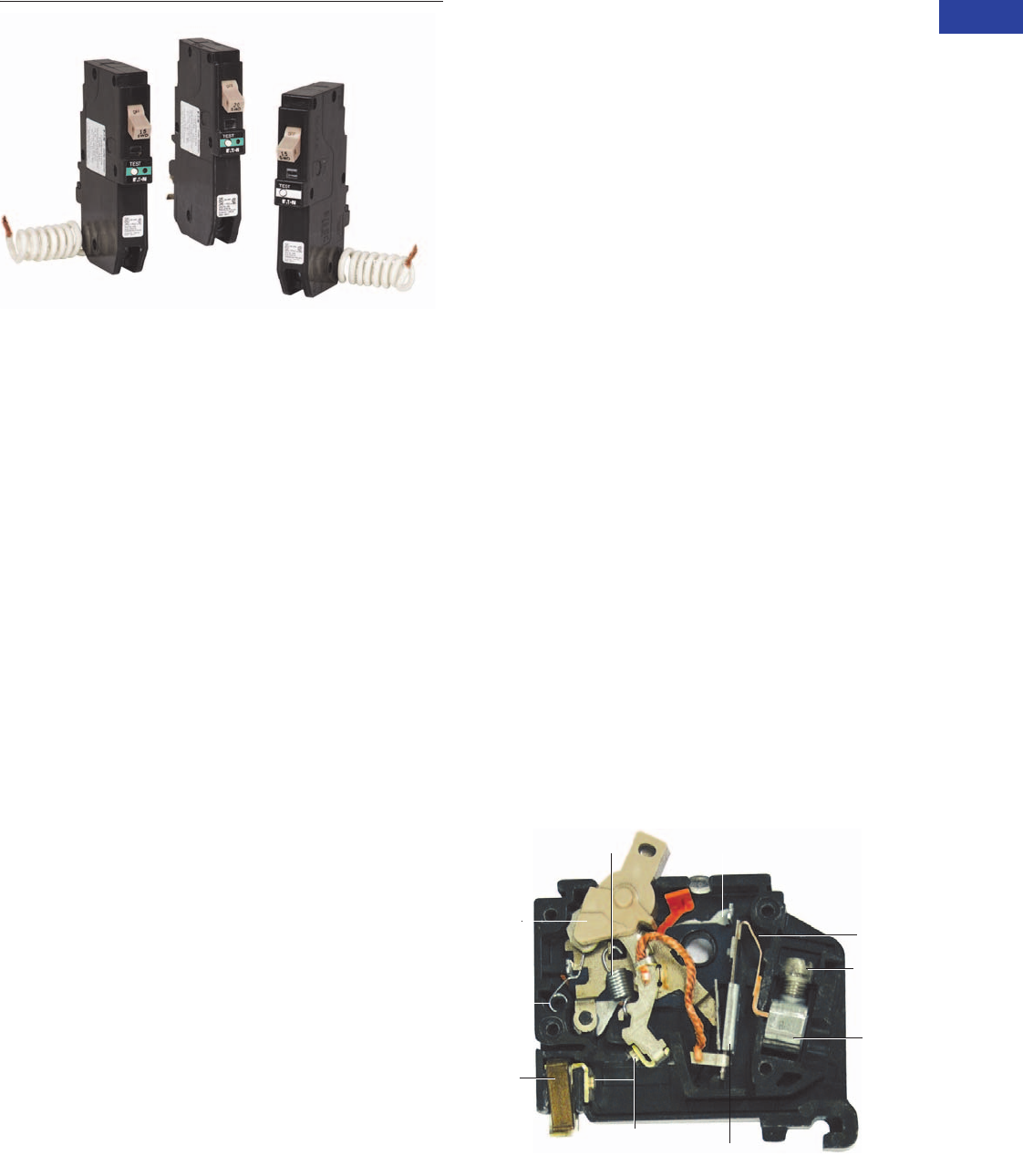
Volume 1—Residential and Light Commercial CA08100002E—June 2014 www.eaton.com V1-T1-31
1
1
1
1
1
1
1
1
1
1
1
1
1
1
1
1
1
1
1
1
1
1
1
1
1
1
1
1
1
1
1.1
Loadcenters and Circuit Breakers
Type CH Loadcenters and Circuit Breakers
Plug-On Circuit Breakers
Contents
Description Page
Overview . . . . . . . . . . . . . . . . . . . . . . . . . . . . . . . . V1-T1-2
CH Specialty Products. . . . . . . . . . . . . . . . . . . . . . V1-T1-14
CH Loadcenter Options and Accessories . . . . . . . V1-T1-22
CH Circuit Breakers
Product Selection . . . . . . . . . . . . . . . . . . . . . . . V1-T1-32
Options and Accessories . . . . . . . . . . . . . . . . . V1-T1-38
Technical Data and Specifications . . . . . . . . . . V1-T1-40
Wiring Diagrams. . . . . . . . . . . . . . . . . . . . . . . . V1-T1-40
CH Circuit Breakers
Product Description
Quick-make, quick-break
switch mechanism combined
with inverse time element
tripping operation and trip-
free handle design. Type CH
circuit breakers trip to the
OFF position, eliminating
nuisance callbacks. The CHF
family also includes a trip flag
to differentiate between a trip
and the breaker being turned
off. The thermal-magnetic trip
curve avoids nuisance tripping
on mild overloads while
reacting almost instantaneously
to severe short-circuit
conditions. Multipole breakers
have internal common trip
connection to operate all
poles simultaneously. Handles
are marked with ON-OFF
indication and ampere rating
of the breaker.
Special Application Plug-On
Circuit Breakers—Type CH
10 kAIC 120 Vac and 120/240 Vac
Branch Feeder Type Arc
Fault Circuit Breakers
A branch feeder type arc fault
circuit interrupter is a device
intended to mitigate high
current arcing faults in the
complete circuit, including
connected cords. High
current arcing faults can
occur from line to neutral or
line to ground. These arcing
faults are in parallel with the
load and produce the most
energy of all arcing faults.
The branch feeder type AFCI
is required in the 1999 and
2002 National Electrical Code.
The Combination Type AFCI
is required in all subsequent
editions of the National
Electrical Code.
Combination Type Arc
Fault Circuit Breakers
A combination type arc fault
circuit interrupter is a device
that offers mitigation of high
current arcing faults in the
complete circuit, including
connected cords. In addition it
provides direct detection of
persistent low current arcing
faults down to 5 amps with
associated mitigation of
fire hazards in the cords
connected to the outlets. High
current arcing faults can occur
from line to neutral or line to
ground. These arcing faults
are in parallel with the load
and produce the most energy
of all arcing faults. The current
level of low current arcing
faults is limited by the load.
Ground Fault Circuit
Breakers—Ground Fault
Application Notes
Single-pole Type CHGFIs are
designed for use in two-wire,
120 Vac circuits. The diagram
on Page V1-T1-40 shows a
typical wiring configuration.
Two-pole Type CHGFIs are
designed for use in three-
wire, 120/240 Vac circuits,
120 Vac multiwire circuits
employing common, neutral
and two-wire, 240 Vac
circuits obtained from a
120/240 Vac source.
Diagrams on Page V1-T1-40
illustrate typical wiring
configurations for 120/240 Vac
multiwire circuits.
The diagram on Page
V1-T1-40 depicts a 240 Vac,
two-wire circuit. Note the
“panel neutral” conductor
connects to the neutral bar,
even though the neutral is not
included in the load circuit.
This connection is necessary
to supply a 120 Vac power
source to the ground fault
sensing circuit.
The figures are shown with
a 120/240 Vac, single-phase,
three-wire power source,
but are also applicable to a
120/208 Vac, three-phase,
four-wire power supply.
For all figures, the electrical
operation of the Type CHGFI
is not affected by the
equipment ground.
Features
Latch
Spring
Over-Center
Tog g l e S pr i n g
Latch
Lever
Magnetic
Armature
Current
Bi-Metal
Lug
Screw
Load
Te r m i n a l
Magnetic
Pole Piece
Contact
Line
Contact
Clip
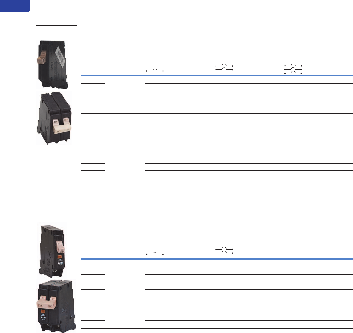
V1-T1-32 Volume 1—Residential and Light Commercial CA08100002E—June 2014 www.eaton.com
1
1
1
1
1
1
1
1
1
1
1
1
1
1
1
1
1
1
1
1
1
1
1
1
1
1
1
1
1
1
1.1
Loadcenters and Circuit Breakers
Type CH Loadcenters and Circuit Breakers
Product Selection
10 kAIC, 120 Vac, 120/240 Vac and 240 Vac
Type CH Breakers, 3/4-Inch (19.1 mm) per Pole 120, 120/240 or 240 Vac, 10 kAIC
CHF Breakers with Mechanical Trip Flag
Notes
1 For single- and two-pole breakers.
2 Solid and stranded wire can be used together.
3 For three-pole breakers.
4 Single-pole 60–70A, two-pole 80–125A, three-pole 40–100A.
5 Single-pole 40–50A, two-pole 40–70A.
6 Two-pole 150A.
7 Switching duty rated.
8 HACR rated.
For factory-installed options, refer to Page V1-T1-39.
Ampere
Rating
Wire Size
Range Cu/Al
60ºC or 75°C
Catalog Number
Single-Pole 120/240 Vac
Requires One
3/4-Inch (19.1 mm) Space
10 per Shelf Carton
Two-Pole 120/240 Vac
Common Trip Requires Two
3/4-Inch (19.1 mm) Spaces
5 per Shelf Carton
Three-Pole 240 Vac
Common Trip Requires Three
3/4-Inch (19.1 mm) Spaces
5 per Shelf Carton
10 (1) #14–8 1
(2) #14–10 12
(1) #14–6 3
CH110 CH210 CH310
15 CH115 78 CH215 8CH315 8
20 CH120 78 CH220 8CH320 8
25 CH125 8CH225 8CH325 8
30 CH130 8CH230 8CH330 8
35 #14–2 1
#14–6 3
CH135 8CH235 8CH335 8
40 #10–1/0 4
#14–2 5
#3/0 6
CH140 8CH240 8CH340 8
45 CH145 8CH245 8CH345 8
50 CH150 8CH250 8CH350 8
60 CH160 CH260 CH360
70 CH170 CH270 CH370
80 — CH280 CH3080
90 — CH290 CH3090
100 — CH2100 CH3100
110 — CH2110 —
125 — CH2125 —
Ampere
Rating
Wire Size
Range Cu/Al
60ºC or 75°C
Catalog Number
Single-Pole 120/240 Vac
Requires One
3/4-Inch (19.1 mm) Space
10 per Shelf Carton
Two-Pole 120/240 Vac
Common Trip Requires Two
3/4-Inch (19.1 mm) Spaces
5 per Shelf Carton
10 (1) #14–8 1
(2) #14–10 12
CHF110 CHF210
15 CHF115 78 CHF215 8
20 CHF120 78 CHF220 8
25 CHF125 8CHF225 8
30 CHF130 8CHF230 8
35 #14–2 1CHF135 8CHF235 8
40 #10–1/0 4
#14–2 5
CHF140 8CHF240 8
45 CHF145 8CHF245 8
50 CHF150 8CHF250 8
Type CH Plug-On
Circuit Breakers
Type CH Plug-On
Circuit Breakers
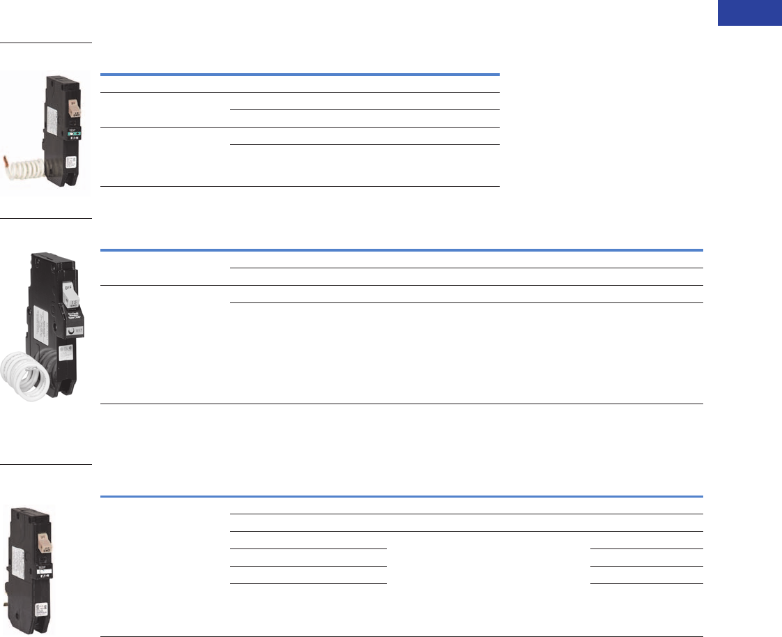
Volume 1—Residential and Light Commercial CA08100002E—June 2014 www.eaton.com V1-T1-33
1
1
1
1
1
1
1
1
1
1
1
1
1
1
1
1
1
1
1
1
1
1
1
1
1
1
1
1
1
1
1.1
Loadcenters and Circuit Breakers
Type CH Loadcenters and Circuit Breakers
Plug-On Branch Feeder Type Arc Fault Circuit Breakers, Type CH 10 kAIC, 120 Vac and 120/240 Vac
Combination Type CH AFCI 3/4-Inch (19.1 mm) Wide Circuit Breakers
Branch Type CH AFCI 3/4-Inch (19.1 mm) Wide FIRE-GUARD® Circuit Breakers
Plug-On Combination Type Arc Fault Circuit Breakers and Ground Fault, Type CH 10 kAIC, 120 Vac and 120/240 Vac 4
Combination Type CH AFCI 3/4-Inch (19.1 mm) and CHGFCI Circuit Breakers
Notes
1 Clamshell packaging available with CS modification code on the end of catalog number.
2 Common trip refers to two-pole 240V load application sourced by 120/240 Vac (see diagram on Page V1-T1-40).
3 Independent trip refers to two-pole multi-wire, home run or shared neutral circuits (see diagrams on Page V1-T1-40).
4 Requires plug-on neutral loadcenter.
Poles Ampere Rating Catalog Number
Standard Pigtail
Single-pole
10 kAIC
15 CHFCAF115
20 CHFCAF120
Two-pole
10 kAIC
15 CHCAF215
20 CHCAF220
Poles Ampere Rating Configuration Catalog Number
Single-pole
10 kAIC
15 AFCI CH115AF 1
20 AFCI CH120AF 1
Two-pole
10 kAIC 23
15 AFCI common trip CH215AF
20 AFCI common trip CH220AF
Poles Ampere Rating Configuration Catalog Number
Single-pole
10 kAIC
15 AFCI plug-on neutral CHFCAF115PN
20 AFCI plug-on neutral CHFCAF120PN
15 GFCI plug-on neutral CHFGF115PN
20 CHFGF120PN
25 CHFGF125PN
30 CHFGF130PN
Type CH AFCI Single-
Pole Circuit Breaker
Type CH AFCI Single-
Pole Circuit Breaker
Type CH AFCI Single-
Pole PON Combo
Circuit Breaker
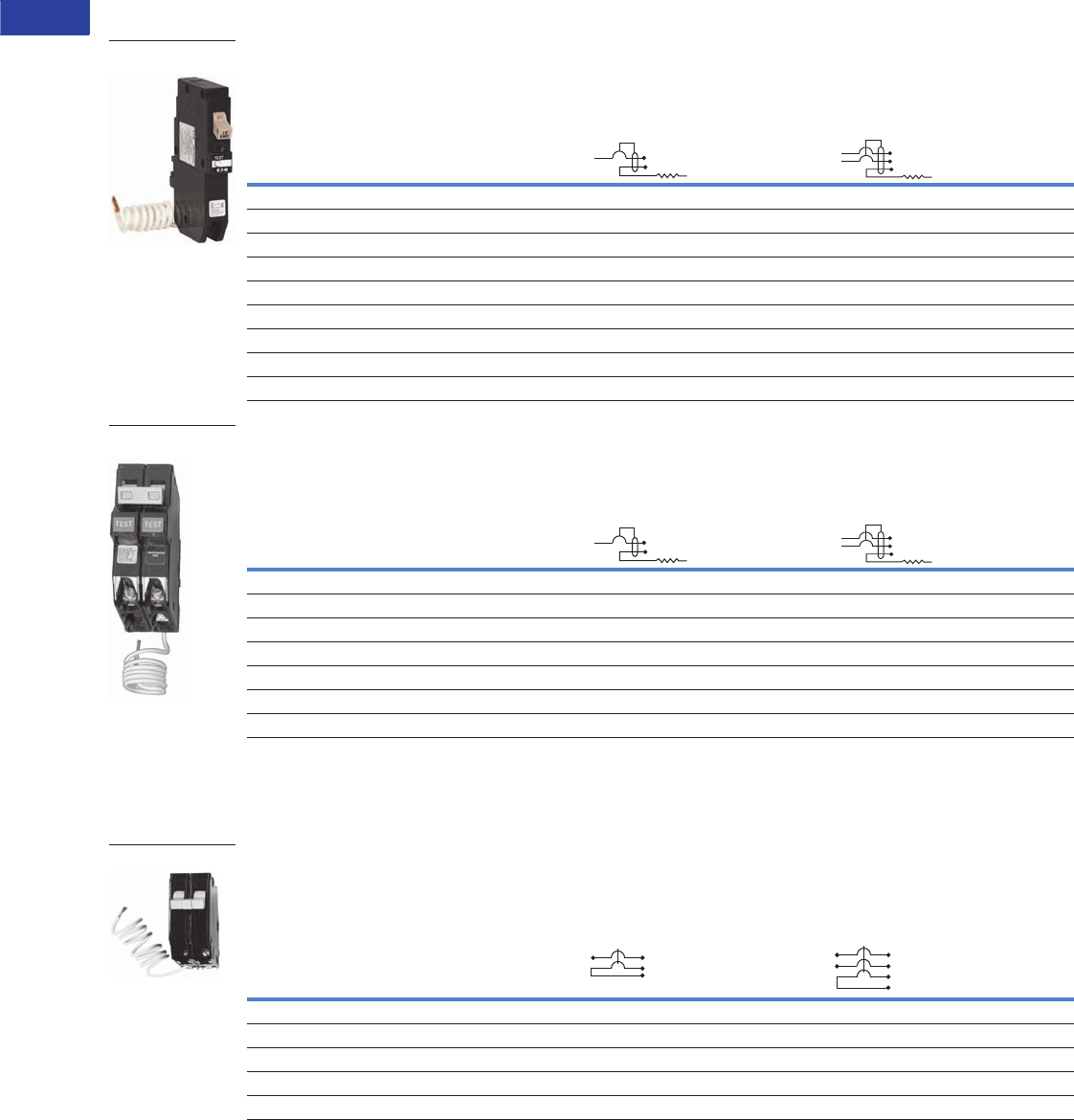
V1-T1-34 Volume 1—Residential and Light Commercial CA08100002E—June 2014 www.eaton.com
1
1
1
1
1
1
1
1
1
1
1
1
1
1
1
1
1
1
1
1
1
1
1
1
1
1
1
1
1
1
1.1
Loadcenters and Circuit Breakers
Type CH Loadcenters and Circuit Breakers
Plug-On Ground Fault Circuit Breakers, Type CH 10 kAIC, 120 Vac and 120/240 Vac
Type CH Ground Fault Circuit Breakers (5 Milliampere) 3/4-Inch (19.1 mm) per Pole 120 Vac or
120/240 Vac,10 kAIC
Type CH Ground Fault Equipment Protectors (30 Milliampere) 3/4-Inch (19.1 mm) per Pole 120 Vac or
120/240 Vac, 10 kAIC
Type CH Switching Neutral Breakers—10 kAIC, 120 Vac and 120/240 Vac
Used to open the neutral along power line(s) for applications of gas pumps.
3/4-Inch (19.1 mm) per Pole 120/240 or 240 Vac, 10 kAIC
Notes
1 60A breaker listed for 75°C Cu wire only.
2 For circuit breakers with shunt trip, add ST suffix. Shunt trip requires one additional pole space.
3 Switching duty rated.
Ampere
Rating
Wire Size Range
Cu/Al 60ºC or 75°C 1
Catalog Number—1 per Shelf Carton
Single-Pole 120 Vac Requires
One 3/4-Inch (19.1 mm) Space
Two-Pole 120/240 Vac Common Trip
Requires Two 3/4-Inch (19.1 mm) Spaces
15 #14–6 CHFGF115 CH215GF
20 #14–6 CHFGF120 CH220GF
25 #14–6 CHFGF125 CH225GF
30 #14–6 CHFGF130 CH230GF
35 #14–6 — CH235GF
40 #14–6 — CH240GF
45 #14–6 — CH245GF
50 #14–6 — CH250GF
60 #14–6 1— CH260GF
Ampere
Rating
Wire Size Range
Cu/Al 60ºC or 75°C 1
Catalog Number—1 per Shelf Carton
Single-Pole 120 Vac Requires
One 3/4-Inch (19.1 mm) Space
Two-Pole 120/240 Vac Common Trip
Requires Two 3/4-Inch (19.1 mm) Spaces
15 #14–6 CHFEP115 CH215EPD
20 #14–6 CHFEP120 CH220EPD
25 #14–6 CHFEP125 —
30 #14–6 CHFEP130 CH230EPD
40 #14–6 — CH240EPD
50 #14–6 — CH250EPD
60 #14–6 1— CH260EPD
Ampere
Rating
Wire Size Range
Cu/Al 60ºC or 75°C
Catalog Number—1 per Shelf Carton
Two-Pole 120 Vac
Common Trip Requires
Two 3/4-Inch (19.1 mm) Spaces
Three-Pole 120/240 Vac
Common Trip Requires
Three 3/4-Inch (19.1 mm) Spaces
15 #14–8 CH215SW 2CH315SW 3
20 #14–8 CH220SW 2CH320SW 3
30 #14–8 CH230SW 2CH330SW 3
40 #14–8 CH240SW 2CH340SW 3
50 #14–8 CH250SW 2CH350SW 3
Type CH Single-Pole
Type CH Two-Pole
CH220SW
Neutral In
Neutral Out
(Hot leg)
Neutral In
Neutral Out
Phase
Phase
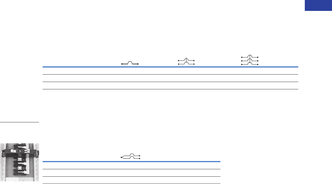
Volume 1—Residential and Light Commercial CA08100002E—June 2014 www.eaton.com V1-T1-35
1
1
1
1
1
1
1
1
1
1
1
1
1
1
1
1
1
1
1
1
1
1
1
1
1
1
1
1
1
1
1.1
Loadcenters and Circuit Breakers
Type CH Loadcenters and Circuit Breakers
Type CH-HID Circuit Breakers—10 kAIC, 120 Vac, 120/240 and 240 Vac
Suitable for use in circuits for fluorescent and high intensity discharge lighting. Also suitable for HACR applications.
3/4-Inch (19.1 mm) per Pole 120 Vac, 120/240 and 240 Vac, 10 kAIC
Type CHT Twin 10 kAIC, 120/240 Vac, Universal CTL and Non-CTL Plug-On Circuit Breakers
Suitable for CTL and Non-CTL CH loadcenters.
Twin (CTL) 3/4-Inch (19.1 mm) per Pole 120 Vac Class CTL 10 kAIC
Notes
1 CH215HID is rated for 120/240V.
2 Switching duty rated.
3 HACR rated.
Ampere
Rating
Wire Size Range
Cu/Al 60ºC or 75°
Single-Pole 120/240 Vac
Requires One
3/4-Inch (19.1 mm) Space
Two-Pole 240 Vac
Common Trip Requires
Two 3/4-Inch (19.1 mm) Spaces
Three-Pole 240 Vac
Common Trip Requires
Three 3/4-Inch (19.1 mm) Spaces
10 per Shelf Carton
Catalog Number
5 per Shelf Carton
Catalog Number
5 per Shelf Carton
Catalog Number
15 #14–8 CH115HID CH215HID 1CH315HID
20 #14–8 CH120HID CH220HID CH320HID
30 #14–8 CH130HID CH230HID CH330HID
Ampere
Rating
Wire Size Range
Cu/Al 60ºC or 75°C
Single-Pole Requires
One 3/4-Inch (19.1 mm) Space
10 per Shelf Carton
Catalog Number
15–15 #14–8 CHT1515 23
15–20 #14–8 CHT1520 23
20–20 #14–8 CHT2020 23
Type CH and CHT
Circuit Breakers
Mounted in Twin
Breaker Panel
120/240 Vac
120/240 Vac
V1-T1-36 Volume 1—Residential and Light Commercial CA08100002E—June 2014 www.eaton.com
1
1
1
1
1
1
1
1
1
1
1
1
1
1
1
1
1
1
1
1
1
1
1
1
1
1
1
1
1
1
1.1
Loadcenters and Circuit Breakers
Type CH Loadcenters and Circuit Breakers
Type CHP Commercial Breakers—10 kAIC, 120 Vac, 120/240 Vac and 240 Vac
Note: CHP breakers feature on-off and trip positions for commercial applications.
3/4-Inch (19.1 mm) per Pole 120, 120/240 or 240 Vac, 10 kAIC
Type CHP-GFCI Circuit Breakers—10 kAIC, 120 Vac and 120/240 Vac
Note: CHP breakers offer on-off and trip positions for commercial applications.
5 Milliampere—3/4-Inch (19.1 mm) per Pole
120V and 120/240 Vac, 10 kAIC
Notes
1For single- and two-pole breakers.
2Solid and stranded wire can be used together.
3For three-pole breakers.
4Single-pole 60–70A, two-pole 80–125A, three-pole 40–100A.
5Single-pole 40–50A, two-pole 40–70A.
6Switching duty rated.
7HACR rated.
CHP breakers offer on-off and trip positions for commercial applications.
Ampere
Rating
Wire Size Range
Cu/Al 60ºC or 75°C
Single-Pole 120/240 Vac
Requires One 3/4-Inch
(19.1 mm) Space
Two-Pole 120/240 Vac
Common Trip
Requires Two 3/4-Inch
(19.1 mm) Spaces
Three-Pole 240 Vac
Common Trip
Requires Three 3/4-Inch
(19.1 mm) Spaces
10 per Shelf Carton
Catalog Number
5 per Shelf Carton
Catalog Number
5 per Shelf Carton
Catalog Number
10 (1) #14–8 1
(2) #14–10 12
(1) #14–6 3
CHP110 CHP210 CHP310
15 CHP115 67 CHP215 7CHP315 7
20 CHP120 67 CHP220 7CHP320 7
25 CHP125 7CHP225 7CHP325 7
30 CHP130 7CHP230 7CHP330 7
35 #14–2 1
#14–6 3
CHP135 7CHP235 7CHP335 7
40 #10–1/0 4
#14–2 5
CHP140 7CHP240 7CHP340 7
45 CHP145 7CHP245 7CHP345 7
50 CHP150 7CHP250 7CHP350 7
60 CHP160 7CHP260 7CHP360 7
70 CHP170 CHP270 CHP370
80 — CHP280 —
90 — CHP290 —
100 — CHP2100 CHP3100
110 — CHP2110 —
125 — CHP2125 —
Ampere
Rating
Wire Size Range
Cu/Al 60ºC or 75°C
Single-Pole 120 Vac Requires
One 3/4-Inch (19.1 mm) Space
1 per Individual Carton
Catalog Number
15 #14–6 CHP115GF
20 #14–6 CHP120GF
30 #14–6 CHP130GF
Volume 1—Residential and Light Commercial CA08100002E—June 2014 www.eaton.com V1-T1-37
1
1
1
1
1
1
1
1
1
1
1
1
1
1
1
1
1
1
1
1
1
1
1
1
1
1
1
1
1
1
1.1
Loadcenters and Circuit Breakers
Type CH Loadcenters and Circuit Breakers
Type CHP Neutral Switching Breakers—10 kAIC, 120 Vac and 120/240 Vac
Used to open the neutral along power line(s) for applications of gas pumps.
3/4-Inch (19.1 mm) per Pole 120 or 120/240 Vac, 10 kAIC
Type CH-M50 High Ambient Breaker
3/4-Inch (19.1 mm) per Pole 120 or 120/240 Vac, 10 kAIC
Type CH-HM and CHP-HM High Magnetic Breakers
3/4-Inch (19.1 mm) per Pole 120 or 120/240 Vac, 10 kAIC
Note
1For circuit breakers with shunt trip, add ST suffix. Shunt trip requires one additional pole space, obtain pricing from Page V1-T1-39.
Ampere
Rating
Wire Size Range
Cu/Al 60ºC or 75°C
Two-Pole 120 Vac Common Trip
Requires Two 3/4-Inch (19.1 mm) Spaces
Three-Pole 120/240 Vac Common Trip
Requires Three 3/4-Inch (19.1 mm) Spaces
1 per Shelf Carton
Catalog Number
1 per Shelf Carton
Catalog Number
15 #14–8 CHP215SW 1CHP315SW 1
20 #14–8 CHP220SW 1CHP320SW 1
Ampere
Rating
Wire Size Range
Cu/Al 60ºC or 75°C
Single-Pole 120/240 Vac
Requires One 3/4-Inch (19.1 mm) Space
Two-Pole 120/240 Vac Common Trip
Requires Two 3/4-Inch (19.1 mm) Spaces
10 per Shelf Carton
Catalog Number
5 per Shelf Carton
Catalog Number
15 (1) #14–8
(2) #14–10
CH115M50 CH215M50
20 CH120M50 CH220M50
25 CH125M50 CH225M50
30 CH130M50 CH230M50
35 CH135M50 CH235M50
40 CH140M50 CH240M50
45 CH145M50 CH245M50
50 CH150M50 CH250M50
60 — CH260M50
70 — CH270M50
Ampere
Rating
Wire Size Range
Cu/Al 60ºC or 75°C
Single-Pole 120/240 Vac
Requires One 3/4-Inch (19.1 mm) Space
Two-Pole 120/240 Vac Common Trip
Requires Two 3/4-Inch (19.1 mm) Spaces
10 per Shelf Carton
Catalog Number
5 per Shelf Carton
Catalog Number
15 (1) #14–8
(2) #14–10
CH115HM CH215HM
20 CH120HM CH220HM
15 (1) #14–8
(2) #14–10
CHP115HM CHP215HM
20 CHP120HM CHP220HM
Neutral In
Neutral Out
(Hot leg)
Neutral In
Neutral Out
Phase
Phase
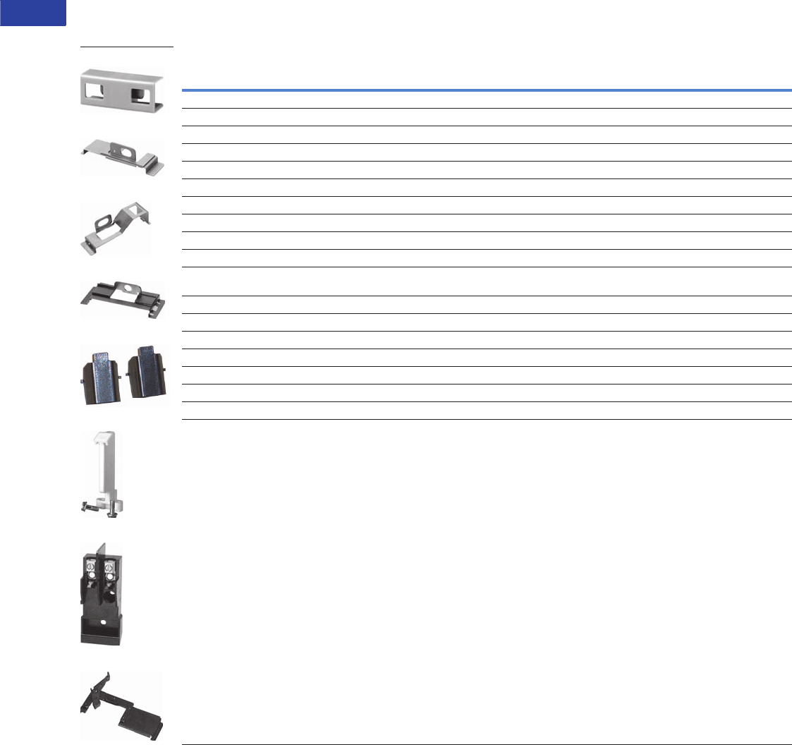
V1-T1-38 Volume 1—Residential and Light Commercial CA08100002E—June 2014 www.eaton.com
1
1
1
1
1
1
1
1
1
1
1
1
1
1
1
1
1
1
1
1
1
1
1
1
1
1
1
1
1
1
1.1
Loadcenters and Circuit Breakers
Type CH Loadcenters and Circuit Breakers
Options and Accessories
Field Installation Kits and Parts
Notes
1 Must be purchased in multiples of ordering quantities indicated.
2 Handle ties: typically used to join two similar independent single-pole breakers to form a two-pole noncommon trip breaker.
3 Handle lockoffs: devices that use a padlock to lock the circuit breaker’s handle in the ON or OFF position.
4 Requires one additional pole space.
5 Escutcheon mounted: device mounted semipermanently to the face of the circuit breaker and secured by the loadcenter deadfront.
6 Screw mounted: device permanently mounted to the face of the circuit breaker by the use of a non-removable screw.
7 Handle lockdogs: devices that are used to secure a circuit breaker’s handle in the ON or OFF position. Handle lockdogs are not padlockable devices.
8 Handle mounted: device mounted above or below handle using spring pressure.
9 Hold-down kits: devices used to secure the circuit breaker to the loadcenter for back-feed main application. See NEC Article 384.16(g).
Description
Ordering
Quantity 1
Catalog
Number
Handle Ties 2
Handle tie bar for physically joining the handles of two adjacent single-pole Type CH circuit breakers (molded plastic handle cover) 25 CHHT
Handle Lockoffs 34
Padlockable device for locking the handle of single-, two- or three-pole Type CH circuit breakers (escutcheon mounted) 5 1 CHPL
Padlockable device for locking the handle of a single-, two- or three-pole Type CHGFI circuit breaker (escutcheon mounted) 51CHPLGF
Padlockable device for locking the handle of main circuit breaker Types CC and CCH into the ON or OFF position.(screw mounted) 61CCPL
Padlockable device for locking the handle of main breaker Types BW and CSR into the ON or OFF position (escutcheon mounted) 51MCBPL
Handle Lockdogs 47
Device used to secure handle in ON or OFF position for single-pole Type CH circuit breakers (handle mounted) 810 CHLO
Hold-Down Kits 9
Hold-down retainer kit for single-, two-, three-pole Type CH circuit breakers. For 6–24 circuit 125A single- and three-phase,
12–42 circuit single-phase 225A and 24–42 circuit three-phase 225A MLO Type CH loadcenters
1CH125RB
Hold-down retainer kit for single-, two-, three-pole Type CH circuit breakers for 2–4 circuit MLO CH loadcenters. 1 CH125RB24
Mounting Bases
Mounting base for two-pole Type CH circuit breaker—70A maximum 1 CH9MB270
Main Breaker Lug Kits
Types CC and CCH main breaker lug kit (2) 300 kcmil 1 CCL300
Type CSR main breaker lug kit (2) 300 kcmil 1MCBL300
Mechanical Interlock
Type CH for two-, three- and four-pole breakers 10 CHML
CHHT
CHPL
CHPLGF
MCBPL
CHLO
CH125RB
CH9MB270
CHML

Volume 1—Residential and Light Commercial CA08100002E—June 2014 www.eaton.com V1-T1-39
1
1
1
1
1
1
1
1
1
1
1
1
1
1
1
1
1
1
1
1
1
1
1
1
1
1
1
1
1
1
1.1
Loadcenters and Circuit Breakers
Type CH Loadcenters and Circuit Breakers
Shunt Trip Options
Handle Position Changeability Chart
Notes
1Add suffix indicated to end of breaker catalog number.
2Requires one additional pole space.
Description Catalog Number
Suffix Adder 1
Type Volts
CSR 12 DC SR12
CSR 24 DC SR24
CSR 120 AC SR01
CH 120 AC ST 2
CC 12 DC SR12
CC 24 DC SR24
CC 120 AC SR01
CC 208 AC SR08
CC 240 AC SR02
Handle Lockoff and
Lockdog Types
To Change Handle Position from
ON to OFF or OFF to ON You Must...
Remove
Padlock
Remove
Device
Remove Loadcenter
Deadfront
Lockoff escutcheon mounted Remove — —
Lockoff screw mounted Remove — —
Lockdog handle mounted N/A Remove —
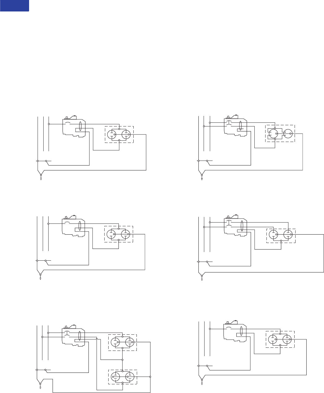
V1-T1-40 Volume 1—Residential and Light Commercial CA08100002E—June 2014 www.eaton.com
1
1
1
1
1
1
1
1
1
1
1
1
1
1
1
1
1
1
1
1
1
1
1
1
1
1
1
1
1
1
1.1
Loadcenters and Circuit Breakers
Type CH Loadcenters and Circuit Breakers
Technical Data and Specifications
Ratings
Single- and two-pole CH breakers rated 15 and 20A have
low instantaneous magnetic trip levels. The 15 and 20A
breakers with “HM” suffix have high magnetic trip settings
recommended for circuits with inherently high inrush currents.
All Type CH breakers are marked for heating, air conditioning
and refrigeration (HACR) equipment application. Single-pole
15–20A breakers are also suitable for switching duty (SWD).
Shunt trip coils operate on 120 Vac and require one additional
pole space per breaker.
Wiring Diagrams
Typical Single-Pole
Single-Pole 120V Load Application Sourced by 120/240 Vac
Two-Pole Shared Neutral with Multi-Duplex
Receptacle Application
Two-Pole 240V Load Application Sourced by 120/240 Vac
Two-Pole Shared Neutral with Duplex Receptacle Application
Single-Pole 120V Duplex
Receptacle Application
NAB
120/240 Vac
Source
120V
Duplex
Receptacle
Single-Pole
Line B
Neutral
Neutral
NAB
120/240 Vac
Source
120V
Duplex
Receptacle
Single-Pole
Line B
Neutral
Neutral
Equipment Ground
NA B
120/240 Vac
Source
Two 120V
Duplex
Receptacles
Two-Pole
Line B
Line A
Neutral
Neutral
Equipment Ground
Line B
NA B
120/240 Vac
Source
Line A 240V
Duplex
Receptacle
Two-Pole
Neutral
Equipment Ground
NAB
120/240 Vac
Source
Line A
120V Duplex
Receptacle
(With Line Side
Jumper Removed)
Two-Pole
Line B
Neutral
Neutral
Equipment Ground
NAB
120/240 Vac
Source
120V
Duplex
Receptacle
Single-Pole
Line B
Neutral
Neutral
Equipment Ground
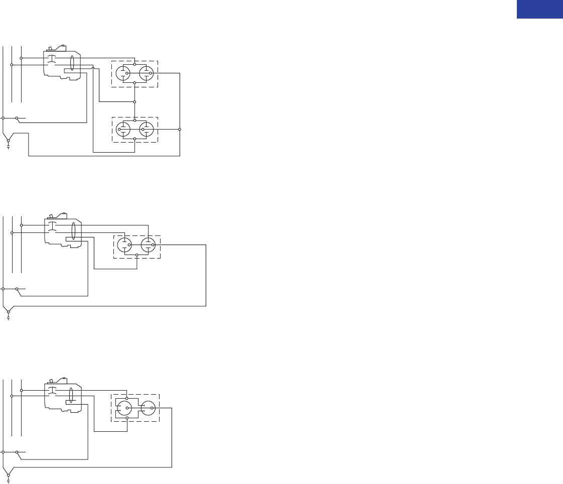
Volume 1—Residential and Light Commercial CA08100002E—June 2014 www.eaton.com V1-T1-41
1
1
1
1
1
1
1
1
1
1
1
1
1
1
1
1
1
1
1
1
1
1
1
1
1
1
1
1
1
1
1.1
Loadcenters and Circuit Breakers
Type CH Loadcenters and Circuit Breakers
Two-Pole 120V Multi-Duplex Receptacle Application
Two-Pole 120V Duplex Receptacle Application
Two-Pole 240V Duplex Receptacle Application
NA B
120/240 Vac
Source
Two 120V
Duplex
Receptacles
Two-Pole
Line B
Line A
Neutral
Neutral
NAB
120/240 Vac
Source
Line A
120V Duplex
Receptacle
(With Line Side
Jumper Removed)
Two-Pole
Line B
Neutral
Neutral
Line B
NA B
120/240 Vac
Source
Line A 240V
Duplex
Receptacle
Two-Pole
Neutral
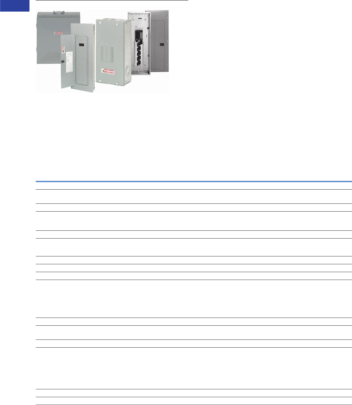
V1-T1-42 Volume 1—Residential and Light Commercial CA08100002E—June 2014 www.eaton.com
1
1
1
1
1
1
1
1
1
1
1
1
1
1
1
1
1
1
1
1
1
1
1
1
1
1
1
1
1
1
1.2
Loadcenters and Circuit Breakers
Type BR Loadcenters and Circuit Breakers
Type BR Loadcenters and Circuit Breakers
Contents
Description Page
Overview
Product Description . . . . . . . . . . . . . . . . . . . . . V1-T1-43
Features, Benefits and Functions . . . . . . . . . . V1-T1-43
Standards and Certifications . . . . . . . . . . . . . . V1-T1-45
Catalog Number Selection . . . . . . . . . . . . . . . . V1-T1-45
Product Selection. . . . . . . . . . . . . . . . . . . . . . . V1-T1-46
BR Specialty Products
Spa Panels . . . . . . . . . . . . . . . . . . . . . . . . . . . . V1-T1-57
Riser Panel. . . . . . . . . . . . . . . . . . . . . . . . . . . . V1-T1-58
Type BR Renovation Loadcenter . . . . . . . . . . . V1-T1-59
Type BR Mechanical Interlock Kits . . . . . . . . . . V1-T1-61
Type BR Retrofit Interior Kits . . . . . . . . . . . . . . V1-T1-72
BR Circuit Breakers. . . . . . . . . . . . . . . . . . . . . . . . V1-T1-75
Overview
Product Selection Guide
BR Loadcenters
Description
Service
Single-phase, three-wire, 120/240 Vac Three-phase, four-wire, 208Y/120 Vac
Three-phase, three-wire, 240 Vac delta
Short-Circuit Current Rating
10 kAIC: All single- and three-phase loadcenters 70–225A, 8 to 42 circuits
22 kAIC: All convertible loadcenters using 125A rated Type BRH main breakers or
selected factory installed 125A rated Type BRH main breaker
25 kAIC: All convertible and factory-installed single-phase loadcenters rated
150 and 200A using Type CSR main breakers
Main Breaker/Main Lug Loadcenters
Single-phase
Main breaker: 100, 125, 150, 200, 225, 400, 600A
Main lugs: 70, 125, 150, 200, 225, 400, 600A
Three-phase
Main breaker: 100, 125, 150, 200, 225, 400, 600A
Main lugs: 100, 125, 150, 200, 225, 400, 600A
Convertible Loadcenters
Main breaker: single-phase up to 200A and three-phase up to 225A Main lugs: single-phase up to 200A and three-phase up to 150A
Branch Breakers
Types BR, BRH and BRHH: 10–150A. single-, two- and three-pole; selected amperage
available in switching duty, HACR, shunt trip and high magnetic setting
Type GFCB: 15–60A
Types BJ and BJH: 125–225A; two- and three-pole
Type BD Twin: 10–50A; two of one-pole; take one 1-inch (25.4 mm) space
Type BQ and BQC Multibreaker: 15–30A. Two of two-pole or one two-pole and
two one-pole; takes two 1-inch (25.4 mm) spaces
Type BRW: 15–30A; two-pole water heater breakers
Type BRSN: 15–30A; two-pole switching neutral breakers
Type BR 15–100A; two-pole, 240 Vac delta breakers
BR-AFCI arc fault circuit interrupter
Enclosures
NEMA Type 1 indoor
NEMA Type 3R outdoor
NEMA 4X
Meets or exceeds UL requirements for indoor or outdoor applications
Loadcenter and Breaker Accessories
Branch circuit breaker:
Auxiliary components Hold-down kits Handle ties
Lockoffs Lockdogs
Complete line of ground bar kits 5, 10, 14 and 21 circuit, some with additional #2/0 lugs;
each terminal will accommodate: (3) #14–#10 Cu/Al or (1) #14–#4 Cu/Al
Main and sub-feed lugs 125, 150, 225A—two- and three-pole
Shunt trips
Surge protection:
Single-phase plug-on surge protector Single-phase bottle type surge protector
Three-phase bottle type surge protector Single-phase whole home surge protector
Universal rainproof conduit hubs
Group One: 3/4, 1, 1-1/4, 1-1/2, 2 inches (19.1, 25.4, 31.8, 38.1, 50.8 mm)
Group Two: 2, 2-1/2, 3 inches (50.8, 63.5, 76.2 mm)
Adapter plate
Bussing
Tin-plated aluminum as standard Limited copper bus panels available

Volume 1—Residential and Light Commercial CA08100002E—June 2014 www.eaton.com V1-T1-43
1
1
1
1
1
1
1
1
1
1
1
1
1
1
1
1
1
1
1
1
1
1
1
1
1
1
1
1
1
1
1.2
Loadcenters and Circuit Breakers
Type BR Loadcenters and Circuit Breakers
Product Description
Loadcenters are enclosures
specifically designed to house
the branch circuit breakers
and wiring required to
distribute power to individual
circuits. They contain either a
main breaker when used at
the service entrance point or
a main lug when used as a
sub-panel to add circuits to
existing service. The main
breaker protects the main
entire panel and can be used
as a service disconnect. The
branch breakers protect the
wires leading to individual
electrical loads such as
fixtures and outlets.
Features, Benefits and
Functions
Loadcenter Construction
Eaton’s Type BR loadcenters
have standard tin-plated
aluminum bus with a limited
availability of copper bus.
The sum of the handle
ratings connected to any stab
is limited to 150A maximum
on the 100 and 125A
loadcenters, and 200A on
loadcenters with 150A or
higher main bus. NEMA
Type 1 boxes or enclosures
are manufactured from
galvanized steel. Raintight
boxes are manufactured
from galvanized steel, then
finished using an electrostatic
powder coat, baked urethane
paint process.
Neutrals
Eaton Type CH loadcenters
feature two types of neutrals:
Insulated/Bondable Split
Neutral
Panels are supplied with split
insulated neutrals with an
insulated cross strap. For
service entrance applications,
the neutral must be bonded
by using the bonding strap
supplied with the panel. For
non-service entrance (sub-
panel) applications, the panel
may be installed with the
bonding strap not connected
to the neutral. Separate
ground bars must be used on
non-service entrance panels.
Insulated/Bondable Single
Neutral
Panels are supplied with a
single insulated neutral. For
service entrance applications,
all that is required to bond the
neutral is to loosen the
bonding screw and the
neutral screw directly beside
it, insert the bonding strap
into the neutral bar, and re-
tighten both connections. The
single neutral can be moved
by the contractor to the other
side of the panel, if desired.
When used as a service
entrance panel, unused
neutral connections may be
used for the termination of
equipment grounds. For non-
service entrance (sub-panel)
applications, the panel may
be installed with the bonding
strap not connected to the
neutral. Separate ground bars
must be used on non-service
entrance panels.
Grounds
In service entrance
applications where the
neutral is bonded, unused
neutral holes may be used
for terminating ground
conductors. In sub-feed
panels, the neutral must be
isolated (non-bonded), and
ground wires must be
terminated on a separate
ground bar.
The insulated/bondable
single/split neutral panels
have sufficient terminations
for both ground and neutral
conductors. The insulated/
bondable single split neutral
panels are supplied with a
separate factory-installed
ground bar if the catalog
number contains a “G.” If
not, a separate ground bar
should be installed. Insulated/
Bondable Single Neutral
panels are supplied without
a ground bar (unless
otherwise noted), and ground
bar kits if needed must be
purchased separately.
Neutral and Ground Terminals
The standard terminals on
grounds and neutrals are
rated to accept (3) #14–#10
Cu/Al or (1) #14–4, provided
the cables terminated are of
the same material. For larger
cables, add-on neutral lugs
may be ordered from the
accessories on Page
V1-T1-65.
Note: NEC allows only one
current-carrying conductor
per hole on neutrals unless
otherwise noted.
Bottom Fed Loadcenters
For single-phase 225A and
below loadcenters that are
bottom fed, a standard panel
can be rotated 180 degrees
to allow straight-in wiring of
power cables to the main
terminals. Because the main
circuit breaker handle
operates horizontally, the
orientation of the main circuit
breaker handle is consistent
with the requirements of NEC
2008 Article 240.81.
Gutter Splicing
Loadcenters are not UL listed
as wiring troughs. Therefore,
gutter splicing of riser cables
to tap off to the main device
is not permitted. Refer to
NEC 2008 Article 312.8.
Fire Rating
Due to the numerous
openings in both loadcenter
boxes and trims, they should
not be mounted in firewalls.
There is no approved method
for sealing the enclosures for
this application.
Date Code
The date of manufacture of
each loadcenter is printed on
the outside of the carton as
well as inside the loadcenter.
On the carton, the date code
is printed on the end carton
label. In the loadcenter, the
date code is located on the
small white label located on
the right side wall (with the
main device on top).
The date code is in the
following format: F # # # &.
The “F” is the numeric
code for the Lincoln, IL
plant, and the three numbers
are the year and week of
manufacturing, e.g., 023. The
“!” sign at the end signifies
the decade of the 2010.
Therefore, the date code
F023& would indicate
that the product was
manufactured in the 23rd
week of 2010. The 1980s
are represented by the “+”
sign and the 1990s are
represented by a “=”
at the end of the code.
Surge Protectors
Complete home surge
protection is available in
multiple options, including
a factory-installed option that
provides the highest level of
surge protection in a
residential design. See Tab 3
for more details.
Circuit Breaker Case
Interrupting Capacity
●10 kAIC
●22 kAIC
●25 kAIC
Warranty Information
●10-year limited
loadcenter warranty
●10-year limited branch
breaker warranty
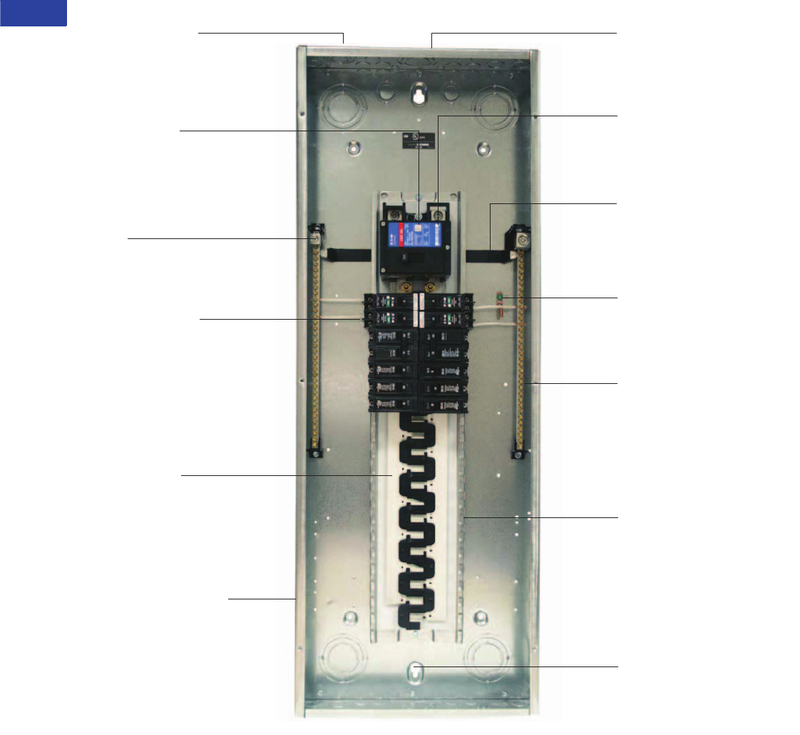
V1-T1-44 Volume 1—Residential and Light Commercial CA08100002E—June 2014 www.eaton.com
1
1
1
1
1
1
1
1
1
1
1
1
1
1
1
1
1
1
1
1
1
1
1
1
1
1
1
1
1
1
1.2
Loadcenters and Circuit Breakers
Type BR Loadcenters and Circuit Breakers
Type BR Loadcenter
Warranty
10-year warranty on all
Type BR loadcenters and
circuit breakers.
Single Keyhole Mounting
One keyhole at the top
and bottom provides easier
mounting and leveling
Neutral Bus (Strap)
Is easily removable for
sub-panel applications
Bonding Z-Strap
Provides easy field
conversion for service
entrance applications
Twin Neutral Bars
Minimum 150% neutral
capacity
Steel Backpan
Provides solid and reliable
breaker mounting—single
piece design for stability and
durability
Extra 1.5 inch Knockout
(38.1 mm)
Larger knockout provides
easier installation and time
savings
“Tangential” Center Knockout
Easier installation for conduit
applications
Commercial Grade Main
Breaker
25 kAIC series rated main
breaker for superior protection
2/0 Lug
Easily removable and can be
installed in any location
on the neutral bar
Drywall Marking on Enclosure
Indicates proper mounting
depth for flush applications
Standard Tin-Plated
Aluminum Bus
Excellent conductivity and
corrosion resistance
Copper bus options
available for select
catalog numbers
Type BR AFCI Breakers
Compact design for easier
wiring and improved
wireway access
Optional LED indicates
one of six trip codes for
circuit diagnostics
Provides a clean gutter space
Top or Bottom Feed
Straight-in wiring saves labor
and material
One panel for either top or
bottom applications
■
■
■
■
■
■
■
■
■
■
■
■
■
■
■
■
■
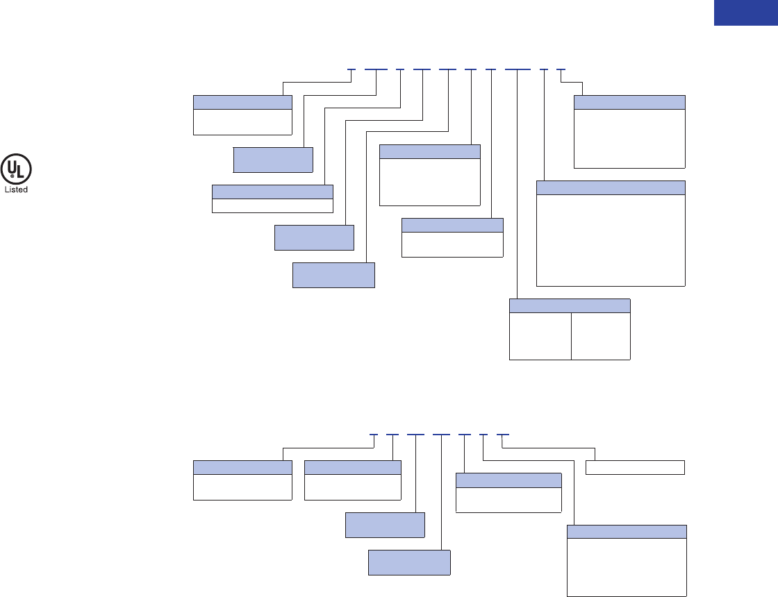
Volume 1—Residential and Light Commercial CA08100002E—June 2014 www.eaton.com V1-T1-45
1
1
1
1
1
1
1
1
1
1
1
1
1
1
1
1
1
1
1
1
1
1
1
1
1
1
1
1
1
1
1.2
Loadcenters and Circuit Breakers
Type BR Loadcenters and Circuit Breakers
Standards and Certifications
UL Listings
All Eaton Type BR loadcenters
are listed under UL File
E52977 except the
2–8 circuit loadcenters,
up through and including
125A, which are listed under
UL File E8741.
Catalog Number Selection
Single- and Three-Phase Through 225A
Single- and Three-Phase 400–600A
Example No. 1: BR1224L125G
Single-phase Type BR
loadcenter rated at 125A with
main lugs, 12 spaces allowing
24 poles, indoor combination
enclosure, aluminum bus and
ground bar.
Example No. 2: BR24L70RP
Single-phase Type BR
loadcenter rated at 70A
with main lugs, two spaces
allowing four poles, rainproof
enclosure with aluminum bus.
Example No. 3: 3B4242EFN
Three-phase Type BR
loadcenter rated at 600A
with main breaker, 42 spaces
allowing 42 poles, indoor
combination enclosure.
Note
1No character space used.
3BR 30 42 B C 200
Phase
Blank = Single-phase 1
3= Three-phase
Construction
Blank = No feed thru lugs 1
F= Feed-through lugs
G= Ground bar
P= Current design
NY = NY City gutter space
Number of 1-Inch
(25.4 mm) Spaces
Factory Options
SUR = Factory integrated surge
Eaton’s Type BR
Loadcenter
Maximum Number
of Circuits
Bus
Blank = Aluminum bus 1
C= Copper bus
Main Device
B= Main breaker
L= Main lug
N= Convertible main
H= Main breaker high AIC
Enclosure
R= NEMA Type 3R rainproof
S= NEMA Type 1 indoor with
surface trim
F= NEMA Type 1 indoor with
flush trim
Blank = NEMA Type 1 indoor with
combination trim 1
RIS = Riser panel
Amperes
50 = 50A
70 = 70A
100 = 100A
125 = 125A
150 = 150A
200 = 200A
225 = 225A
3 B 30 42 D F N
Number of 1-Inch
(25.4 mm) Spaces
Phase
Blank = Single-phase 1
3= Three-phase
N = Current design
Main
Blank = Main lug 1
B= Main breaker
Maximum Number
of Circuits
Amperes
D= 400A
E= 600A
Enclosure
F= NEMA Type 1 indoor with
combination trim
S= NEMA Type 1 indoor with
surface trim
R1 = NEMA Type 3R rainproof
V1-T1-46 Volume 1—Residential and Light Commercial CA08100002E—June 2014 www.eaton.com
1
1
1
1
1
1
1
1
1
1
1
1
1
1
1
1
1
1
1
1
1
1
1
1
1
1
1
1
1
1
1.2
Loadcenters and Circuit Breakers
Type BR Loadcenters and Circuit Breakers
Product Selection
Single-Phase—Main Circuit Breaker Loadcenters—10/25 kAIC
Single-Phase Three-Wire—120/240 Vac—Insulated/Bondable Split Neutral
Notes
1 Combination style covers may be used in surface or flush applications.
2 Wire range size for BR1020B100SP is #6–#1 Cu/Al.
3 Includes through-feed lugs for both phase and neutral conductors.
4 Rainproof panels are furnished with hub closure plates. For rainproof hubs, refer to Page V1-T1-65.
5 See copper bus offering, Page V1-T1-53.
6 22 kAIC series combination rating is obtained when Types BD, BR, BQ, BQC and GFCB 10 kAIC branch breakers are used in series with Type BRH main breaker.
7 25 kAIC series combination rating is obtained when Types BD, BR, BQ, BQC and GFCB 10 kAIC branch circuit breakers are used in series with Type CSR main breaker.
8 Supplied with adapter plate to use DS Group1 hubs on Page V1-T1-65. If 2.50-inch (63.5 mm) hub is needed, remove adapter and use ARP00007CH25 hub.
9 Neutral is bonded—suitable for service entrance only—cannot be converted for sub-feed application.
jAdd G to the end of the catalog number for factory-installed GBK2120 ground bar.
All main circuit breaker loadcenters are listed for use as service entrance equipment and are shipped with neutral bonding strap preattached. The maximum rating of the
panel is the main circuit breaker rating when used as service entrance equipment. Ground bar kits priced separately. See Page V1-T1-65.
Main
Breaker Type
Main
Ampere Rating
Maximum Number
1-Inch (25.4 mm) Enclosure
Type
Box
Size
Wire Size Range
Cu/Al 60°C or 75°C
for Main Breaker
Loadcenter Catalog Number
with Combination 1 or
NEMA Type 3R CoverSpaces Circuits
BR
10 kAIC
100 8 16 Indoor B1 #4–1/0 2BR816B100
10 20 Indoor A1 BR1020B100S11
10 20 Indoor A1 BR1020B100F11
10 20 Outdoor B2R BR1020B100RF 34
12 12 Indoor B2 BR1212B100
12 20 Indoor B2 BR1220B100
12 24 Outdoor B2R BR1224B100R 4
16 16 Indoor C1 BR1616B100
16 20 Indoor C1 BR1620B100
16 24 Outdoor C1R BR1624B100R 4
20 24 Outdoor C3R BR2024B100R 4
20 20 Indoor C2 BR2020B100
16 24 Indoor C1 BR1624B100
30 30 Indoor D1 BR3030B100
125 16 24 Indoor C1 #4–2/0 BR1624B125
20 24 Indoor C1 BR2024B125
20 24 Outdoor C3R BR2024B125R 4
30 30 Indoor D1 BR3030B125
BRH 6
22 kAIC
100 20 24 Indoor C2 #4–1/0 BR2024H100 6
CSR 7
25 kAIC
150 8 16 Outdoor C3R #2–300 kcmil BR816B150RF 34
16 30 Indoor C4 BR1630B150
20 30 Indoor C4 BR2030B150
20 30 Outdoor D1R BR2030B150R 4
20 40 Indoor D1 BR2040B150
20 40 Outdoor D1R BR2040B150R 4
24 30 Indoor G1 BR2430B150
30 30 Outdoor G1R BR3030B150R 4
30 30 Indoor G1 BR3030B150
30 40 Indoor G1 BR3040B150
200 4 8 Outdoor 8R #2–300 kcmil BR48B200RF 389
8 16 Outdoor C3R BR816B200RF 34
16 32 Indoor C4 BR1632B200
20 40 Outdoor D1R BR2040B200R 4
20 40 Indoor D1 BR2040B200
24 40 Indoor G1 BR2440B200
30 40 Outdoor G1R BR3040B200R 4
30 40 Indoor G1 BR3040B200 j
40 40 Outdoor L1R BR4040B200R 4
40 40 Indoor L1 BR4040B200
40 50 Indoor L1 BR4050B200
225 42 42 Indoor L2 #1–250 kcmil BR4242B225
42 42 Outdoor L2R BR4242B225R 4
BR4040B200
Volume 1—Residential and Light Commercial CA08100002E—June 2014 www.eaton.com V1-T1-47
1
1
1
1
1
1
1
1
1
1
1
1
1
1
1
1
1
1
1
1
1
1
1
1
1
1
1
1
1
1
1.2
Loadcenters and Circuit Breakers
Type BR Loadcenters and Circuit Breakers
Main Circuit Breaker Loadcenters—10/22 kAIC
Single-Phase Three-Wire—120/240 Vac—Insulated/Bondable Split Neutral
Notes
1 Ground bar kits priced separately. See Page V1-T1-65.
2 The maximum rating of the panel is the main circuit breaker rating when used as service entrance equipment.
3 Door lock and key included with loadcenter.
4 Type DK main circuit breaker is rated 65 kAIC at 240 Vac and allows a 22 kAIC series rating on the panel when Types BR, BD and BJ branch circuit breakers are used.
5 Rainproof panels are furnished with hub closure plates. For rainproof hubs, refer to Page V1-T1-65.
6 Type HLD main circuit breaker is rated 65 kAIC at 240 Vac. Type HLD circuit breaker is not series rated with Types BR, BD and BJ branch circuit breakers.
Box sizes Pages V1-T1-66 through V1-T1-69.
Main
Breaker
Type
Main
Ampere
Rating
Maximum Number
1-Inch (25.4 mm)
Enclosure
Type
Box
Size
Wire Size Range
Cu/Al 60°C or 75°C
for Main Breaker
Commercial Loadcenter
Catalog Number 123
Spaces Circuits
With Flush or
NEMA Type 3R Cover
With
Surface Cover
DK 4300 42 42 Indoor 24 (2) #3/0–250 kcmil BR304242F BR304242S
400 42 42 Indoor 24 (2) #3/0–250 kcmil B4242DFN B4242DSN
42 42 Outdoor 47 (2) #3/0–250 kcmil B4242DR1N 5—
HLD 6600 42 42 Indoor 24 (2) #3/0–500 kcmil B4242EFN B4242ESN
B4242DFN
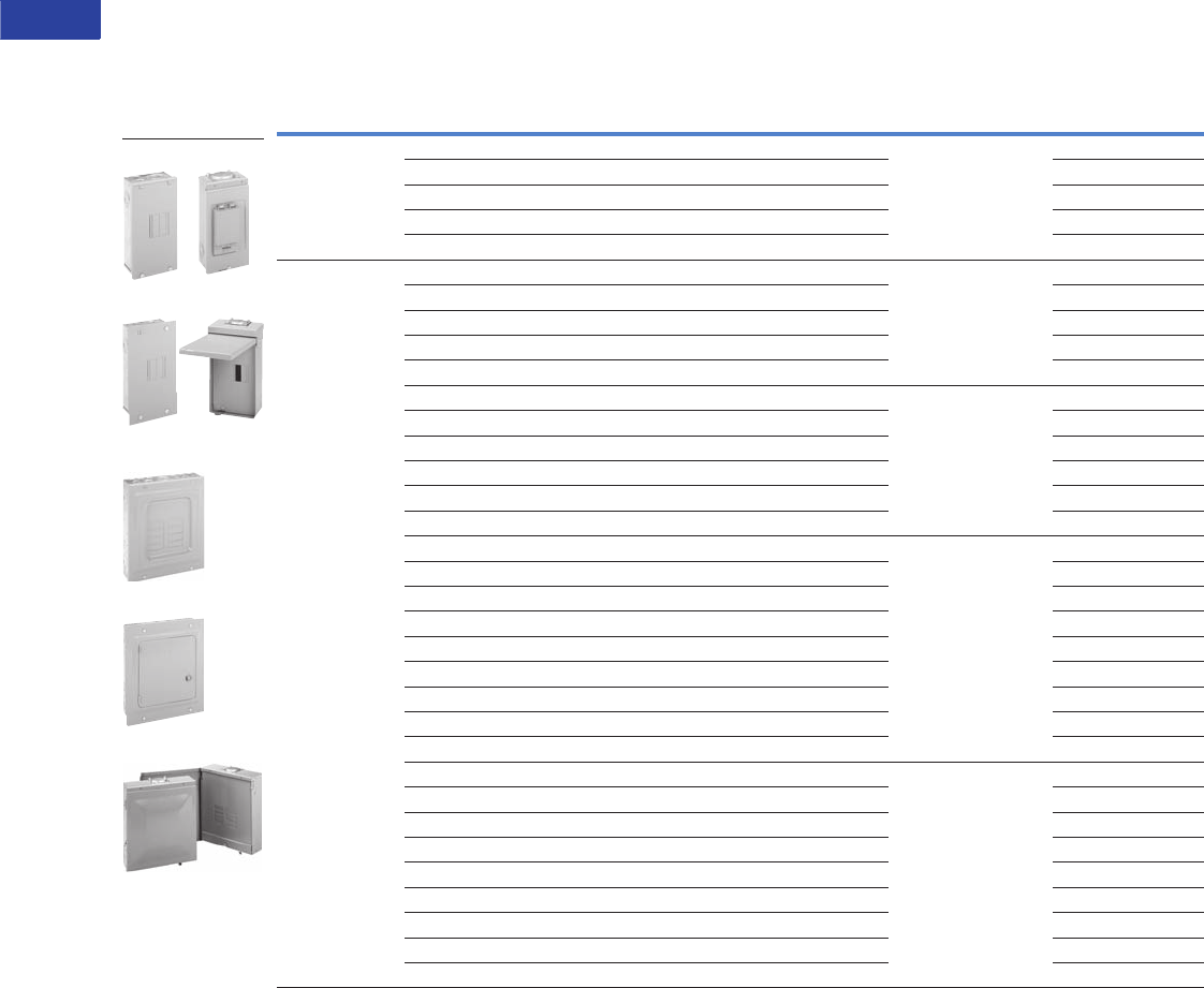
V1-T1-48 Volume 1—Residential and Light Commercial CA08100002E—June 2014 www.eaton.com
1
1
1
1
1
1
1
1
1
1
1
1
1
1
1
1
1
1
1
1
1
1
1
1
1
1
1
1
1
1
1.2
Loadcenters and Circuit Breakers
Type BR Loadcenters and Circuit Breakers
Single-Phase—Main Lug Loadcenters
Single-Phase Three-Wire—120/240 Vac—Insulated/Bondable Split Neutral
Notes
1 Ground bar kits priced separately. See Page V1-T1-65.
– For 2/4 circuit loadcenters, use GBK5 or GBK520 ground bar.
– For 4/8, 6/12 and 8/16 circuit loadcenters, use GBK10 ground bar.
– Ground bars mount to the left side wall of the enclosure for the 4/8, 6/12 and 8/16 circuit loadcenters.
2 Suitable for use as service equipment when not more than two service disconnecting mains are provided or when not used as a lighting and appliance panelboard
(see Article 408.34 of the NEC).
3 Ground bar GBK5 is installed.
4 Rainproof panels are furnished with hub closure plates. For rainproof hubs, refer to Page V1-T1-65.
5 CSA and UL approved.
6 Neutral/ground holes (6) #14–6 and (3) #14–2/0 AWG Cu/Al.
7 For use as service entrance applications only.
8 Neutral/ground holes (6) #14–6 and (3) #14–1/0 AWG Cu/Al.
9
Suitable for use as service equipment when not more than two service disconnecting mains are provided or when not more than six service disconnecting mains are provided and
when not used as a lighting and appliance panelboard (see Article 408.34 of the NEC).
jSuitable for use as service equipment when a main breaker is used or when not more than six service disconnecting mains are provided and when not used
as a lighting and appliance panelboard (see Article 408.34 of the NEC).
kGround bar GBK10 is installed.
lGround bar GBK14 is installed.
Box sizes Pages V1-T1-66 through V1-T1-69.
Main
Ampere Rating
Maximum Number
1-Inch (25.4 mm) Enclosure
Type Trim Type
Box
Size
Wire Size Range
Cu/Al 60°C or 75°C
for Main Lugs
Loadcenter
Catalog NumberSpaces Circuits
70 2 4 Indoor Surface (no door) 5 #8–#2 BR24L70SP 12
2 4 Indoor Surface (no door) 5 BR24L70SGP 23
2 4 Outdoor — 5R BR24L70RP 124
2 4 Indoor Flush (no door) 5 BR24L70FP 12
2 4 Indoor Flush (no door) 5 BR24L70FGP 25
125 2 4 Indoor Surface (no door) 6 #14–1/0 BR24L125SP 12
2 4 Outdoor — 6R BR24L125RP 124
2 4 Outdoor — 6R BR24L125RSEP 278
2 4 Outdoor — 6R BR24L125RSE2P 267
2 4 Indoor Flush (no door) 6 BR24L125FP 12
4 8 Indoor Surface (no door) 7 #14–1/0 BR48L125SP 19
4 8 Indoor Surface (no door) 7 BR48L125SGP 39
4 8 Outdoor — 7R BR48L125RP 149
4 8 Indoor Flush (no door) 7 BR48L125FP 19
4 8 Indoor Flush (with door) 7 BR48L125FDP 19
4 8 Indoor Flush (no door) 7 BR48L125FGP 39
6 12 Indoor Surface (no door) 7 #14–#1 BR612L125SP 1j
6 12 Indoor Surface (no door) 7 BR612L125SGP jk
6 12 Indoor Surface (with door) 7 BR612L125SDP 1j
6 12 Indoor Surface (with door) 7 BR612L125SDGP jk
6 12 Outdoor — 7R BR612L125RP 14j
6 12 Indoor Flush (no door) 7 BR612L125FP 1j
6 12 Indoor Flush (no door) 7 BR612L125FGP 5jk
6 12 Indoor Flush (with door) 7 BR612L125FDP j
6 12 Indoor Flush (with door) 7 BR612L125FDGP 5jk
8 16 Indoor Surface (no door) 7 #14–#1 BR816L125SP 1j
8 16 Indoor Surface (no door) 7 BR816L125SGP jl
8 16 Indoor Surface (with door) 7 BR816L125SDP 1j
8 16 Indoor Surface (with door) 7 BR816L125SDGP jl
8 16 Outdoor — 7R BR816L125RP 14j
8 16 Indoor Flush (no door) 7 BR816L125FP 1j
8 16 Indoor Flush (no door) 7 BR816L125FGP 5jl
8 16 Indoor Flush (with door) 7 BR816L125FDP 1j
8 16 Indoor Flush (with door) 7 BR816L125FDGP 5jl
Surface Outdoor
Flush Outdoor
Surface (No Door)
Flush (No Door)
Outdoor
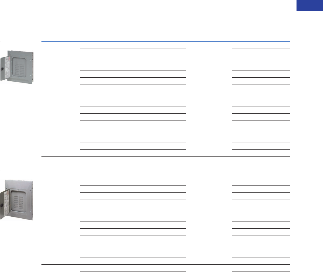
Volume 1—Residential and Light Commercial CA08100002E—June 2014 www.eaton.com V1-T1-49
1
1
1
1
1
1
1
1
1
1
1
1
1
1
1
1
1
1
1
1
1
1
1
1
1
1
1
1
1
1
1.2
Loadcenters and Circuit Breakers
Type BR Loadcenters and Circuit Breakers
Single-Phase—Main Lug Loadcenters
Single-Phase Three-Wire—120/240 Vac—Insulated/Bondable Split Neutral, continued
Notes
1 Ground bar kits priced separately unless otherwise noted. See Page V1-T1-65.
2 Has notch for BREQS125 hold-down kit.
3 Single, movable neutral is provided.
4 Combination cover style.
5 Suitable for use as service equipment when not more than six main disconnecting means are provided and when not used as a lighting and appliance panelboard
(see Article 408.34 of the NEC).
6 Ground bars GBK5 and GBK520 installed.
7 Rainproof panels are furnished with hub closure plates. For rainproof hubs, refer to Page V1-T1-65.
8 Ground bar GBK1220 installed.
9 Has notch for BRHDK125 hold-down kit.
jIncludes through-feed lugs for both phase and neutral conductors.
Main
Ampere Rating
Maximum Number
1-Inch (25.4 mm) Enclosure
Type
Box
Size
Wire Size Range
Cu/Al 60°C or 75°C
for Main Lugs
Loadcenter Catalog Number
with Combination or
NEMA Type 3R Cover 1
Spaces Circuits
125 12 12 Indoor B1 #6–2/0 BR1212L125 2345
12 24 Indoor B1 BR1224L125 245
12 24 Indoor B1 BR1224L125G 245
12 24 Indoor B1 BR1224L125DG 2456
12 24 Outdoor B1R BR1224L125R 257
16 16 Indoor B2 BR1616L125 245
16 24 Indoor B2 BR1624L125 24
16 24 Indoor B2 BR1624L125G 24
16 24 Outdoor B2R BR1624L125R 27
20 20 Indoor C1 BR2020L125 245
20 24 Indoor C1 BR2024L125 24
20 24 Indoor C1 BR2024L125G 248
20 24 Outdoor C1R BR2024L125R 27
24 24 Indoor C2 BR2424L125 24
24 24 Indoor C2 BR2424L125G 248
30 42 Indoor D1 BR3042L125 24
150 16 30 Indoor C2 #1–300 kcmil BR1630L150 49
20 30 Indoor C2 BR2030L150 49
200 8 16 Outdoor B2R #1–300 kcmil BR816L200RF 57j
12 24 Indoor B2 BR1224L200 459
12 24 Outdoor B2R BR1224L200R 579
20 40 Indoor C2 BR2040L200 49
20 40 Indoor C2 BR2040L200G 489
20 40 Outdoor C3R BR2040L200R 79
24 40 Indoor C4 BR2440L200 49
30 40 Indoor D1 BR3040L200 49
30 40 Indoor D1 BR3040L200G 489
30 40 Outdoor D1R BR3040L200R 79
40 40 Indoor G1 BR4040L200 49
40 40 Indoor G1 BR4040L200G 49
40 40 Outdoor G1R BR4040L200R 79
225 42 42 Indoor L1 #1–300 kcmil BR4242L225 4
42 42 Outdoor L1R BR4242L225R 7
BR1224L125
BR1224L200
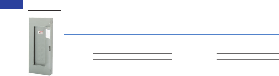
V1-T1-50 Volume 1—Residential and Light Commercial CA08100002E—June 2014 www.eaton.com
1
1
1
1
1
1
1
1
1
1
1
1
1
1
1
1
1
1
1
1
1
1
1
1
1
1
1
1
1
1
1.2
Loadcenters and Circuit Breakers
Type BR Loadcenters and Circuit Breakers
Single-Phase—Main Lug Loadcenters—400 and 600A
Single-Phase Three-Wire—120/240 Vac—Insulated/Bondable Split Neutral
Notes
1 Ground bar kits priced separately unless otherwise noted. See Page V1-T1-65.
2 Has notch for BRHDK125 hold-down kit.
3 Ground bar GBK8 installed.
4 Rainproof panels are furnished with hub closure plates. For rainproof hubs, refer to Page V1-T1-65.
5 Suitable for use as service equipment when not more than six main disconnecting means are provided and when not used as a lighting and appliance panelboard
(see Article 408.34 of the NEC).
Main
Ampere Rating
Maximum Number
1-Inch (25.4 mm)
Enclosure
Type
Box
Size
Wire Size Range
Cu/Al 60°C or 75°C
for Main Lugs
Commercial Loadcenter
Catalog Number 123
Spaces Circuits
With Flush or NEMA
Type 3R Cover
With Surface
Cover
400 12 24 Indoor 19 (1) #4/0–750 kcmil
or
(2) #3/0–400 kcmil
— 1224DSN 5
12 24 Outdoor 42 1224DR1N 45 —
24 42 Indoor 20 — 2442DSN
42 42 Indoor 22 4242DFN 4242DSN
42 42 Outdoor 46 4242DR1N 4—
600 42 42 Indoor 22 (2) #2–500 kcmil — 4242ESN
4242DFN
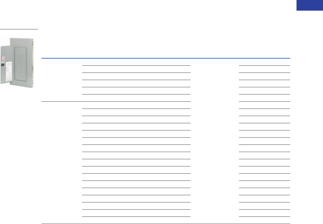
Volume 1—Residential and Light Commercial CA08100002E—June 2014 www.eaton.com V1-T1-51
1
1
1
1
1
1
1
1
1
1
1
1
1
1
1
1
1
1
1
1
1
1
1
1
1
1
1
1
1
1
1.2
Loadcenters and Circuit Breakers
Type BR Loadcenters and Circuit Breakers
Convertible Loadcenters MCB or MLO—Base Units and Main Devices 10/22/25 kAIC,
Complete Assembly Consists of: Loadcenter and Either Main Breaker Kit or Main Lug Kit
Note: Interrupting rating depends on main circuit breaker selected.
Base Units—Single-Phase Three-Wire—120/240 Vac—Insulated/Bondable Split Neutral
(Unless Otherwise Noted)
Notes
1 The maximum rating of the loadcenter is the main circuit breaker rating when used as service entrance equipment.
2 100, 125 and 200A convertible base unit catalog numbers include interior, box and cover only. Main devices and accessories must be ordered separately for field
installation. All convertible base units are listed as suitable for use as service entrance equipment when used per Article 384 of the NEC.
3 Ground bar kits priced separately except as noted, refer to Page V1-T1-65.
4 For main breaker, use Type BR. For main lug use Type BRSF.
5 BREQS125 hold-down screw comes with loadcenter for back-fed Types BR and BRH main circuit breakers.
6 Convertible to maximum of 100A main circuit breaker and 125A main lug.
7 Rainproof loadcenters are furnished with hub closure plates. For rainproof hubs, refer to Page V1-T1-65.
8 For main breaker, use Type BW or CSR. For main lug, use Type BRL.
9 Includes through-feed lugs for both phase and neutral conductors.
jNo hold-down provisions for back-fed Types BR and BRH main circuit breakers.
kInsulated/bondable single neutral.
lIncludes GBK2120 ground bar.
Main
Ampere Rating 1
Maximum Number
1-Inch (25.4 mm) Enclosure
Type
Box
Size
Wire Size Range
Cu/Al 60°C or 75°C
for Main
Loadcenter Catalog Number
With Combination or NEMA
Type 3R Cover 23
Spaces Circuits
125 412 24 Indoor B2 See main breaker and
main lug kit tables
Page V1-T1-54.
BR1224N125 56
12 24 Outdoor B2R BR1224N125R 567
16 24 Indoor C1 BR1624N125 5
16 24 Outdoor C1R BR1624N125R 57
20 24 Indoor C2 BR2024N125 5
20 24 Outdoor C3R BR2024N125R 57
200 8 8 16 Outdoor C3R BR816N200RF 79jk
12 24 Indoor C4 BR1224N200 j
12 24 Outdoor C3R BR1224N200R 7j
16 32 Indoor C4 BR1632N200 j
20 40 Indoor D1 BR2040N200 j
20 40 Indoor D1 BR2040N200G l
20 40 Outdoor D1R BR2040N200R 7j
20 40 Outdoor D1R BR2040N200RG l
24 40 Indoor G1 BR2440N200 7j
30 40 Indoor G1 BR3040N200 j
30 40 Indoor G1 BR3040N200G l
30 40 Outdoor G1R BR3040N200R 7j
30 40 Outdoor G1R BR3040N200RG l
40 40 Indoor L1 BR4040N200 j
40 40 Indoor L1 BR4040N200G l
40 40 Outdoor L1R BR4040N200R 7j
40 40 Outdoor L1R BR4040N200RG l
BR3040N200
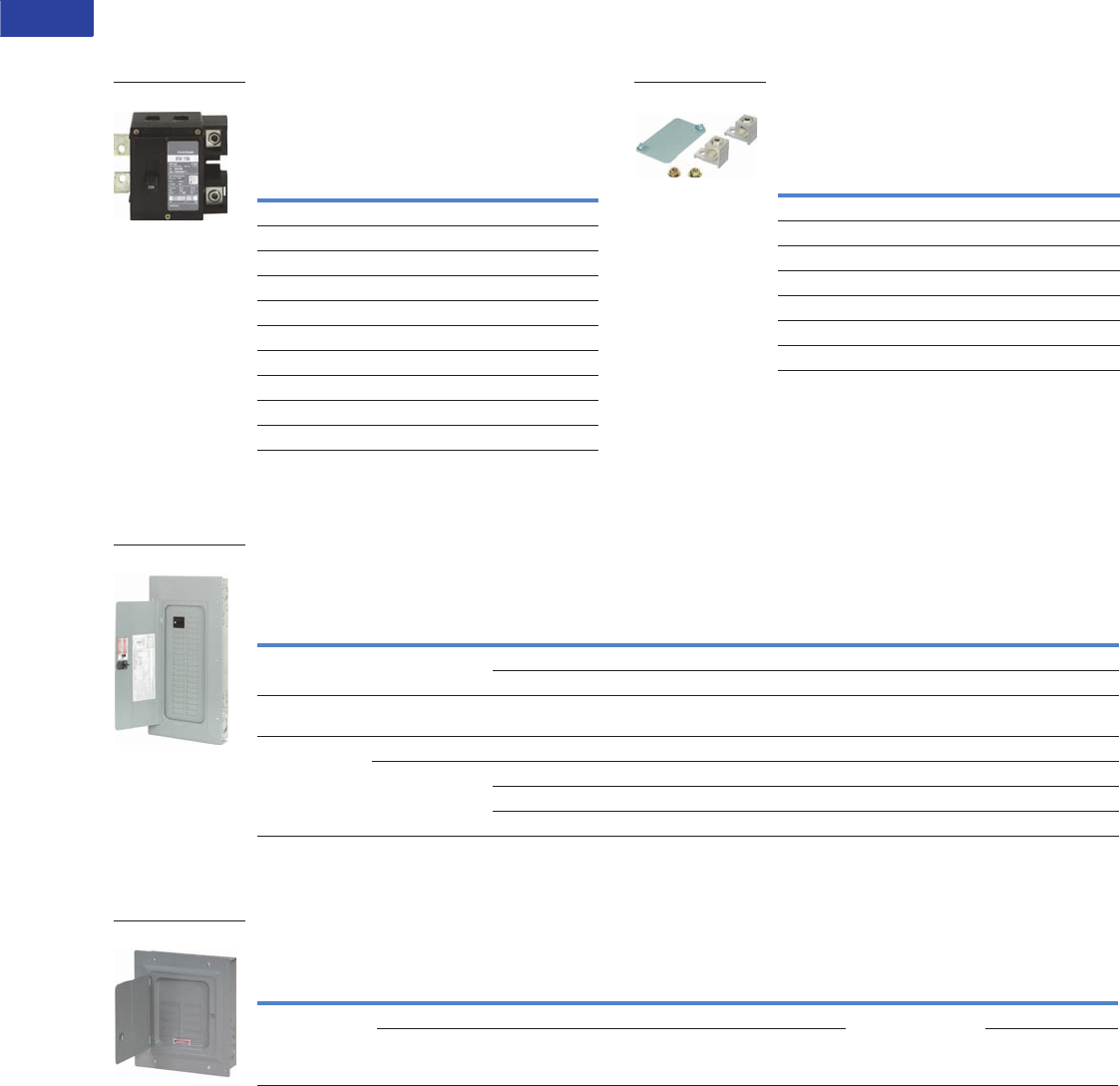
V1-T1-52 Volume 1—Residential and Light Commercial CA08100002E—June 2014 www.eaton.com
1
1
1
1
1
1
1
1
1
1
1
1
1
1
1
1
1
1
1
1
1
1
1
1
1
1
1
1
1
1
1.2
Loadcenters and Circuit Breakers
Type BR Loadcenters and Circuit Breakers
Convertible Loadcenters MCB or MLO—Base Units and Main Devices 10/22/25 kAIC,
Complete Assembly Consists of: Loadcenter and Either Main Breaker Kit or Main Lug Kit
Note: Interrupting rating depends on main circuit breaker selected.
Main Devices—Two- and Three-Pole
Main Circuit Breakers—120/240 Vac or
208Y/120 Vac or 240 Vac
Main Devices—Two- and Three-Pole
Main Lug Kits—120/240 Vac or
208Y/120 Vac or 240 Vac
Main Circuit Breaker with Accessory
Example: BW22005R01 (Put description with catalog number on
order. See Page V1-T1-86.)
Main Circuit Breaker Loadcenters—Copper Bus 10/22/25 kAIC
Main Circuit Breaker Loadcenters—With Copper Bus—Single-Phase Three-Wire—120/240 Vac—
Insulated/Bondable Split Neutral
Main Lug Only Loadcenters—Copper Bus
Single-Phase Three-Wire—120/240 Vac—Insulated/Bondable Single Neutral with Copper Bus
Notes
1 Series combination rating with Types BD, BR, BQ, BQC and GFCB is 22 kAIC with BRH main and 25 kAIC with CSR main.
2 All main circuit breaker loadcenters are listed for use as service entrance equipment and are shipped with neutral bonding strap preattached. The maximum rating of the
panel is the main circuit breaker rating when used as service entrance equipment.
3 Ground bar kits priced separately. See Page V1-T1-65.
4 22 kAIC series combination rating is obtained when Types BD, BR, BQ, BQC and GFCB 10 kAIC branch breakers are used in series with Type BRH main breaker.
Box sizes Pages V1-T1-66 through V1-T1-69.
Ampere
Rating
Wire Size Range
Cu/Al 60°C or 75°C
for Main Breaker
10 kAIC 22/25 kAIC
Catalog
Number
Catalog
Number 1
Tw o - Po l e
100 #4–1/0 BR2100 BRH2100
110 #4–1/0 BR2110 BRH2110
125 #4–2/0 BR2125 BRH2125
125 #2–300 kcmil BW2125 CSR2125N
150 #2–300 kcmil BW2150 CSR2150N
175 #2–300 kcmil BW2175 CSR2175N
200 #2–300 kcmil BW2200 CSR2200N
Three-Pole
100 #1 BR3100 BRH3100
BW2200
Ampere
Rating
Wire Size Range
Cu/Al 60°C or 75°C
for Main Lugs
Catalog
Number
Tw o - P o l e
125 #6–2/0 BRSF125
150 #1–300 kcmil BRL200
175 #1–300 kcmil BRL200
200 #1–300 kcmil BRL200
Three-Pole
150 #6–3/0 3BRSF150
BRL200
Main
Breaker Type
Main
Ampere Rating
Maximum Number
1-Inch (25.4 mm) Enclosure
Type
Box
Size
Wire Size Range
Cu/Al 60°C or 75°C
for Main Breaker
Loadcenter Catalog Number
with Combination Cover 23
Spaces Circuits
BR
10 kAIC
100 20 20 Indoor C2 #4–1/0 BR2020BC100
30 30 Indoor D1 #4–1/0 BR3030BC100
BRH
22 kAIC 4
100 30 30 Indoor D1 #4–1/0 BR3030HC100
CSR
25 kAIC
150 30 30 Indoor G1 #2–300 kcmil BR3030BC150
200 20 40 Indoor D1 #2–300 kcmil BR2040BC200
30 40 Indoor G1 #2–300 kcmil BR3040BC200
40 40 Indoor L1 #2–300 kcmil BR4040BC200
Main
Ampere Rating
Maximum Number
1-Inch (25.4 mm) Enclosure
Type Trim Type
Box
Size
Wire Size Range
Cu/Al 60°C or 75°C
for Main Lugs
Loadcenter
Catalog NumberSpaces Circuits
125 8 16 Indoor Surface (with door) 7 #14–1 BR816LC125SDP
8 16 Indoor Flush (with door) 7 BR816LC125FDP
BR3030BC100
BR816LC125FDP
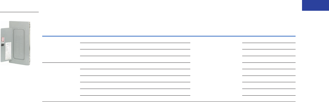
Volume 1—Residential and Light Commercial CA08100002E—June 2014 www.eaton.com V1-T1-53
1
1
1
1
1
1
1
1
1
1
1
1
1
1
1
1
1
1
1
1
1
1
1
1
1
1
1
1
1
1
1.2
Loadcenters and Circuit Breakers
Type BR Loadcenters and Circuit Breakers
Convertible Loadcenters—Copper Bus 10/22/25 kAIC
Convertible—Single-Phase, Three-Wire—120/240 Vac—Insulated/Bondable Split Neutral
Notes
1 100, 125 and 200A convertible base unit catalog numbers include interior, box and cover only. Main devices and accessories must be ordered separately for field
installation. All convertible base units are listed as suitable for use as service entrance equipment when used per Article 384 of the NEC.
2 Ground bar kits priced separately, refer to Page V1-T1-65.
3 All main circuit breaker loadcenters are listed for use as service entrance equipment and are shipped with a neutral bonding strap preattached. The maximum main
rating of the loadcenter is the main breaker rating when used as service entrance equipment.
4 Interrupting rating depends on main circuit breaker selected. See Page V1-T1-65 for mains.
5 For main breaker, use Type BW or CSR. For main lug, use Type BRL.
6 Rainproof loadcenters are furnished with hub closure plates. For rainproof hubs, refer to Page V1-T1-65.
7 Hold-down screw BREQS125 comes with loadcenter for back-fed Types BR and BRH main circuit breakers.
8 For main breaker, use Type BR. For main lug, use Type BRSF.
9 Suitable for use as service equipment when not more than six main disconnecting means are provided and when not used as a lighting and appliance panelboard.
(see Article 408.34 of the NEC).
Main
Ampere Rating
Maximum Number
1-Inch (25.4 mm) Enclosure
Type
Box
Size
Wire Size Range
Cu/Al 60°C or 75°C
for Main
Loadcenter Catalog Number
(With Combination or
NEMA Type 3R Cover) 123
Spaces Circuits
125
10/22 kAIC 45
12 24 Indoor B2 See main breaker
and main lug kit tables
on Page V1-T1-54.
BR1224NC125 67
12 24 Outdoor B2R BR1224NC125R 678
20 24 Indoor C2 BR2024NC125 7
20 24 Outdoor C3R BR2024NC125R 78
200
10/25 kAIC 49
20 40 Indoor D1 BR2040NC200
20 40 Outdoor D1R BR2040NC200R 8
30 40 Indoor G1 BR3040NC200
30 40 Outdoor G1R BR3040NC200R 8
40 40 Indoor L1 BR4040NC200
40 40 Outdoor L1R BR4040NC200R 8
BR3040NC200
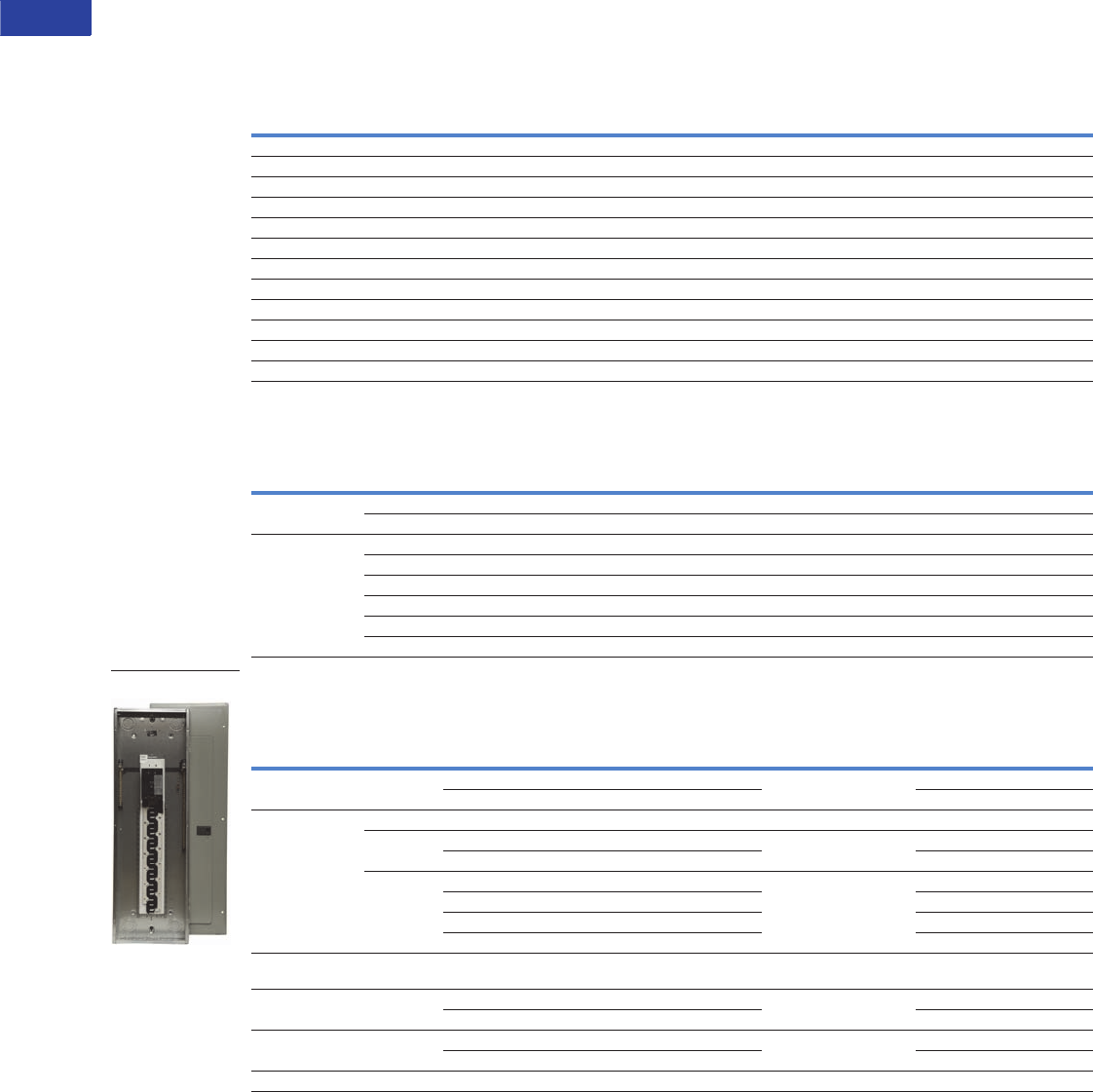
V1-T1-54 Volume 1—Residential and Light Commercial CA08100002E—June 2014 www.eaton.com
1
1
1
1
1
1
1
1
1
1
1
1
1
1
1
1
1
1
1
1
1
1
1
1
1
1
1
1
1
1
1.2
Loadcenters and Circuit Breakers
Type BR Loadcenters and Circuit Breakers
Three-Phase—Type BR Main Circuit Breaker Loadcenters
Three-Phase, Four-Wire—Main Lug Loadcenters—Copper Bus—208Y/120 Vac or 240 Vac,
Insulated/Bondable Split Neutral
Three-Phase, Four-Wire—Main Circuit Breaker Loadcenters—Copper Bus—208Y/120 Vac or 240 Vac,
Insulated/Bondable Split Neutral
Three-Phase, Four-Wire—Main Circuit Breaker Loadcenters—Aluminum Bus—208Y/120 Vac or 240 Vac
Insulated/Bondable Split Neutral
Notes
1 All main circuit breaker loadcenters are listed for use as service entrance equipment and are shipped with a neutral bonding strap pre-attached (commercial loadcenters
do not have a pre-attached bonding strip). The maximum main rating of the panel is the main circuit breaker rating when used as service entrance equipment.
2 Ground bar kits priced separately. See Page V1-T1-65.
3 Rainproof loadcenters are furnished with hub closure plates. For rainproof hubs, refer to Page V1-T1-65.
4 Type DK main circuit breaker is rated 65 kAIC at 240 Vac and allows a 22 kAIC series rating on the loadcenter when Types BR, BD and BJ branch circuit breakers are used.
5 The LD main circuit breaker is rated 65 kAIC at 240 Vac. Type LD circuit breaker is not series rated with Types BR, BD and BJ branch circuit breakers.
6 Includes CHH 100 kAIC rated MCB. 100 kAIC series rating combination is obtained when types BD, BR, BQ, BQC and GFGB branch breakers are used with CHH main.
Main
Ampere Rating
Maximum Number
1-Inch (25.4 mm) Enclosure
Type
Box
Size
Wire Size Range
Cu/Al 60°C or 75°C
for Main
Loadcenter Catalog Number
(With Combination or
NEMA Type 3R Cover)Spaces Circuits
125 12 24 Indoor C1 #6–3/0 3BR1224LC125
125 12 24 Outdoor C1R #6–3/0 3BR1224LC125R
150 24 42 Indoor D1 #4–300 kcmil 3BR2442LC150
150 24 42 Outdoor D1R #4–300 kcmil 3BR2442LC150R
200 12 24 Indoor C4 #4–300 kcmil 3BR1224LC200
200 12 24 Outdoor C3R #4–300 kcmil 3BR1224LC200R
200 30 42 Indoor G1 #4–300 kcmil 3BR3042LC200
200 30 42 Outdoor G1R #4–300 kcmil 3BR3042LC200R
200 42 42 Indoor L1 #4–300 kcmil 3BR4242LC200
200 42 42 Outdoor L1R #4–300 kcmil 3BR4242LC200R
225 30 42 Indoor L1 #4–300 kcmil 3BR3042LC225
225 30 42 Outdoor L1R #4–300 kcmil 3BR3042LC225R
Main
Breaker Type
Main
Ampere
Rating
Maximum Number
1-Inch (25.4 mm) Enclosure
Type
Box
Size
Wire Size Range
Cu/Al 60°C or 75°C
for Main Breaker
Loadcenter Catalog Number
(With Combination or
NEMA Type 3R Cover)Spaces Circuits
BR
10 kAIC
100 12 24 Indoor C1 #14–1/0 3BR1224BC100
100 12 24 Outdoor C1R #14–1/0 3BR1224BC100R
CC
10 kAIC
150 30 42 Indoor L1 #6–4/0 3BR3042BC150
150 30 42 Outdoor L1R #6–4/0 3BR3042BC150R
200 42 42 Indoor L2 2/0–300 kcmil 3BR4242BC200
200 42 42 Outdoor L2R 2/0–300 kcmil 3BR4242BC200R
225 42 42 Indoor L2 2/0–300 kcmil 3BR4242BC225
225 42 42 Outdoor L2R 2/0–300 kcmil 3BR4242BC225R
Main
Breaker Type
Main
Ampere
Rating
Maximum Number
1-Inch (25.4 mm) Enclosure
Type
Box
Size
Wire Size Range
Cu/Al 60°C or 75°C
for Main Breaker
Loadcenter Catalog Number 12
(With Combination or
NEMA Type 3R Cover)Spaces Circuits
BR
10 kAIC
100 12 24 Indoor C1 #14–1/0 3BR1224B100
12 24 Outdoor C1R 3BR1224B100R 3
CC
10 kAIC
125 30 42 Indoor L1 #6–4/0 3BR3042B125
150 30 42 Indoor L1 #6–4/0 3BR3042B150
30 42 Outdoor L1R 3BR3042B150R 3
200 30 42 Indoor L1 #1–250 kcmil 3BR3042B200
30 42 Outdoor L1R 3BR3042B200R 3
42 42 Indoor L2 3BR4242B200
42 42 Outdoor L2R 3BR4242B200R 3
CHH
100 kAIC
200 42 42 Indoor L2 2/0–300 kcmil 3BR4242H200 6
CC
10 kAIC
225 42 42 Indoor L2 2/0–300 kcmil 3BR4242B225
42 42 Outdoor L2R 3BR4242B225R 3
DK 4
22 kAIC
400 42 42 Indoor 24 (2) #3/0–250 kcmil 3B4242DFN
42 42 Outdoor 47 3B4242DR1N 3
LD 5600 42 42 Indoor 24 (2) #3/0–500 kcmil 3B4242EFN
3BR4242B200
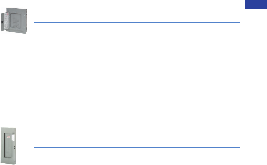
Volume 1—Residential and Light Commercial CA08100002E—June 2014 www.eaton.com V1-T1-55
1
1
1
1
1
1
1
1
1
1
1
1
1
1
1
1
1
1
1
1
1
1
1
1
1
1
1
1
1
1
1.2
Loadcenters and Circuit Breakers
Type BR Loadcenters and Circuit Breakers
Three-Phase, Four-Wire—Main Lug Loadcenters—Aluminum Bus—208Y/120 Vac or 240 Vac,
Insulated/Bondable (Unless Otherwise Noted)
Three-Phase, Four-Wire—Main Lug Loadcenters—Aluminum Bus—208Y/120 Vac or 240 Vac,
Insulated/Bondable Split Neutral
Notes
1 Ground bar kits priced separately. See Page V1-T1-65.
2 Surface cover only.
3 Insulated/bondable single neutral.
4 Rainproof loadcenters are furnished with hub closure plates. For rainproof hubs, refer to Page V1-T1-65.
5 Has notch for BREQS125 hold-down kit.
6 Suitable for use as service equipment when not more than six main disconnecting means are provided and when not used as a lighting and appliance panelboard
(see Article 408.34 of the NEC).
gDoor lock and key included with loadcenter.
Box sizes Pages V1-T1-66 through V1-T1-69.
Main
Ampere Rating
Maximum Number
1-Inch (25.4 mm) Enclosure
Type
Box
Size
Wire Size Range
Cu/Al 60°C or 75°C
for Main Lugs
Loadcenter Catalog Number 1
(With Combination or
NEMA Type 3R Cover)Spaces Circuits
100 3 3 Indoor 9 #6–1/0 3BR3L100S 23
3 3 Outdoor 9R 3BR3L100R 34
125 12 24 Indoor C1 #6–3/0 3BR1224L125 56
12 24 Outdoor C1R 3BR1224L125R 456
150 18 36 Indoor C2 #6–4/0 3BR1836L150
18 36 Outdoor C3R 3BR1836L150R
24 42 Indoor D1 #4–300 kcmil 3BR2442L150
24 42 Outdoor D1R 3BR2442L150R 4
200 12 24 Indoor C4 #4–300 kcmil 3BR1224L200 6
12 24 Outdoor C3R 3BR1224L200R 46
18 36 Indoor C4 #4–300 kcmil 3BR1836L200
18 36 Outdoor C3R 3BR1836L200R
30 42 Indoor G1 #4–300 kcmil 3BR3042L200
30 42 Outdoor G1R 3BR3042L200R 4
42 42 Indoor L1 #4–300 kcmil 3BR4242L200
42 42 Outdoor L1R 3BR4242L200R 4
225 42 42 Indoor L1 #4–300 kcmil 3BR4242L225
42 42 Outdoor L1R 3BR4242L225R 4
Main
Ampere Rating
Maximum Number
1-Inch (25.4 mm)
Enclosure
Type
Box
Size
Wire Size Range
Cu/Al 60°C or 75°C
for Main Lugs
Commercial Loadcenter
Catalog Number g
Spaces Circuits
With Flush or
NEMA Type 3R Cover
With
Surface Cover
400 42 42 Indoor 22 (1) 250–750 kcmil
or
(2) #3/0–250 kcmil
34242DFN 34242DSN
42 42 Outdoor 46 34242DR1N 4—
600 42 42 Indoor 22 (2) #2–500 kcmil — 34242ESN
3BR1224L125
34242DFN
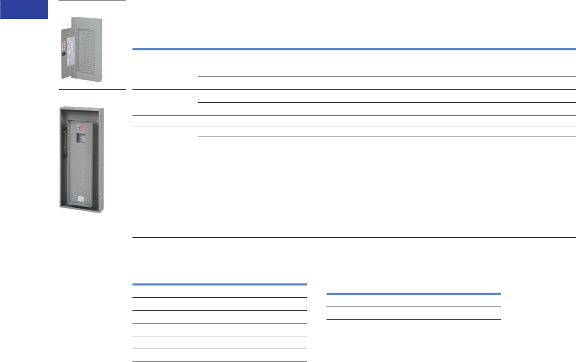
V1-T1-56 Volume 1—Residential and Light Commercial CA08100002E—June 2014 www.eaton.com
1
1
1
1
1
1
1
1
1
1
1
1
1
1
1
1
1
1
1
1
1
1
1
1
1
1
1
1
1
1
1.2
Loadcenters and Circuit Breakers
Type BR Loadcenters and Circuit Breakers
Three-Phase, Four-Wire—Convertible Loadcenters—Aluminum Bus—208Y/120 Vac or 240 Vac,
Insulated/Bondable Split Neutral
Three-Phase Main Breaker Kits—10 kAIC
Notes
1 The maximum rating of the loadcenter is the main circuit breaker
rating when used as service entrance equipment.
2 100, 125 and 200A convertible base unit catalog numbers include
interior, box and cover only. Main devices and accessories must be
ordered separately for field installation.
All convertible base units are listed as suitable for use as service
entrance equipment when used per Article 384 of the NEC.
3 Ground bar kits priced separately. See Page V1-T1-65.
4 For main breaker, use Type BR. For main lug, use Type BRSF.
5 BREQS125 hold-down screw comes with loadcenter for back-fed
Types BR and BRH main circuit breakers.
6 Rainproof loadcenters are furnished with hub closure plates. For
rainproof hubs, refer to Page V1-T1-65.
7 Convertible to maximum of 100A main circuit breaker and 125A
main lug.
8 Suitable for use as service equipment when not more than six
main disconnecting means are provided and when not used as a
lighting and appliance panelboard
(see Article 408.34 of the NEC).
9 Order 3BR42FTNY or 3BR42STNY cover separately.
jFor subfeed.
Box sizes Pages V1-T1-66 through V1-T1-69.
Three-Phase Main Lugs Kit for
Convertible Loadcenters
Main
Ampere Rating 1
Maximum Number
1-Inch (25.4 mm) Enclosure
Type
Box
Size
Wire Size Range
Cu/Al 60°C or 75°C
for Main
Loadcenter Catalog Number 23
(With Combination or
NEMA Type 3R Cover)Spaces Circuits
100 430 30 Indoor D1 See main breaker
and main lug kit tables
below.
3BR3030N100 5
30 30 Outdoor D1R 3BR3030N100R 56
125 412 24 Indoor C1 3BR1224N125 567
12 24 Outdoor C1R 3BR1224N125R 5678
200 30 42 Indoor L1 3BR3042N200
225 42 42 Indoor L2 3BR4242N225
42 42 Indoor B 3BR4242B225NY 9
3BR3030N100
3BR4242N225NY
Ampere
Rating
Wire Size Range
Cu/Al 60°C or 75°C
Catalog
Number
100 #6–4/0 CC3100N
125 #6–4/0 CC3125N
150 #6–4/0 CC3150N
175 #2/0–300 kcmil CC3175N
200 #2/0–300 kcmil CC3200N
225 #2/0–300 kcmil CC3225N
Ampere
Rating
Wire Size Range
Cu/Al 60°C or 75°C
Catalog
Number
225 #1–300 kcmil 3BRL225
225 #1–300 kcmil 3BRS225 j
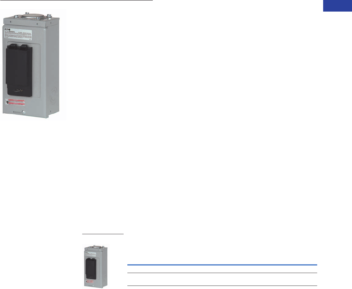
Volume 1—Residential and Light Commercial CA08100002E—June 2014 www.eaton.com V1-T1-57
1
1
1
1
1
1
1
1
1
1
1
1
1
1
1
1
1
1
1
1
1
1
1
1
1
1
1
1
1
1
1.2
Loadcenters and Circuit Breakers
Type BR Loadcenters and Circuit Breakers
Spa Panels
Contents—BR Specialty Products
Description Page
Overview. . . . . . . . . . . . . . . . . . . . . . . . . . . . . . . . V1-T1-42
BR Specialty Products
Spa Panels
Riser Panel . . . . . . . . . . . . . . . . . . . . . . . . . . . . V1-T1-58
Type BR Renovation Loadcenter . . . . . . . . . . . V1-T1-59
Type BR Mechanical Interlock Kits . . . . . . . . . . V1-T1-61
Type BR Retrofit Interior Kits . . . . . . . . . . . . . . V1-T1-72
BR Circuit Breakers . . . . . . . . . . . . . . . . . . . . . . . . V1-T1-75
BR Specialty Products
Spa Panels
Product Description
Eaton’s BR Spa Panels
distribute power to outdoor
loads and provide protection
for people from electric
shock. Save time and money
with streamlined installation
procedures and easy-access
features. Spa panels meet
NEC requirements by
providing a ground fault
circuit interruption device and
a disconnect switch in a
single simple device. Ships
assembled prewired, factory
tested and ready to install.
Features
●10-year warranty
●UL Listed
●Factory-installed
two-pole ground fault
circuit interrupter (GFCI)
Product Selection
Spa Panel—Meets NEC Article 680.40 Through 680.43—
Requirements for GFCI Protection
Notes
1 Includes a GFCB240 breaker, factory installed.
2 Includes a GFCB250 breaker, factory installed.
Main
Ampere
Rating
Maximum Number
1-Inch (25.4 mm) Enclosure
Type
Box
Size
Wire Size Range Cu/Al 60°C
or 75°C for Main Lugs
Catalog
NumberSpace Poles
40 — — Outdoor 5R #8–#2 BR40SPA 1
50 — — Outdoor 5R #8–#2 BR50SPA 2
BR Spa Panel
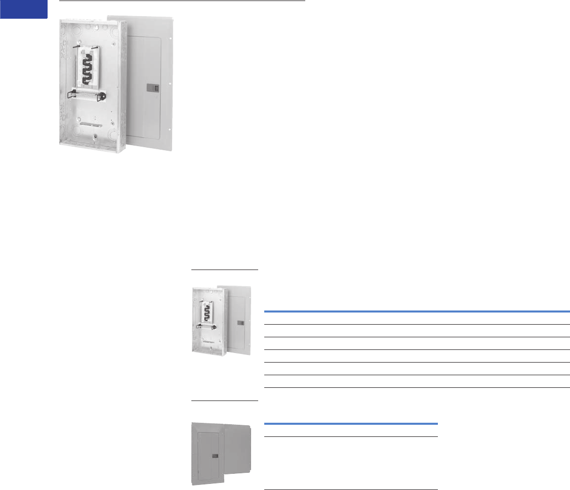
V1-T1-58 Volume 1—Residential and Light Commercial CA08100002E—June 2014 www.eaton.com
1
1
1
1
1
1
1
1
1
1
1
1
1
1
1
1
1
1
1
1
1
1
1
1
1
1
1
1
1
1
1.2
Loadcenters and Circuit Breakers
Type BR Loadcenters and Circuit Breakers
Riser Panel
Contents—BR Specialty Products
Description Page
Overview . . . . . . . . . . . . . . . . . . . . . . . . . . . . . . . . V1-T1-42
BR Specialty Products
Spa Panels. . . . . . . . . . . . . . . . . . . . . . . . . . . . . V1-T1-57
Riser Panel
Type BR Renovation Loadcenter . . . . . . . . . . . . V1-T1-59
Type BR Retrofit Interior Kits. . . . . . . . . . . . . . . V1-T1-72
BR Circuit Breakers . . . . . . . . . . . . . . . . . . . . . . . . V1-T1-75
Riser Panel
Product Description
Eaton’s Riser Panel is a
loadcenter with an offset
interior to allow riser cables
to pass through the enlarged
gutter. By using lay-in tap
lugs, the contractor is able to
simply strip off a length of the
riser cable’s insulation, and
tap off to the riser panel’s
main lugs. These panels are
used in the construction of
assisted living homes,
dormitories, public housing
complexes and apartments.
Product Selection
Riser Panel
Riser Panel Accessories
Notes
1 Bulk-packaged loadcenter without carton. Must be ordered in
multiples of 16.
2 Refer to Page V1-T1-67 for dimensions. BRGUTTER is box
size C2.
Accessories
For riser panels not shown, contact the Flex Center at
1-800-330-6479 for both CH and BR riser panels.
Main Ampere
Rating
Maximum Number
1-Inch (25.4 mm) Enclosure
Type
Box
Size
Wire Size Range
Cu/Al 60°C or 75°C
for Main Lugs
Catalog
NumberSpace Circuits
125 12 24 Indoor C4 #6–2/0 BR1224L125RIS
125 12 24 Indoor C4 #6–2/0 BR1224L125RISBP 1
125 20 24 Indoor C4 #6–2/0 BR2024L125RIS
125 20 24 Indoor C4 #6–2/0 BR2024L125RISBP 1
125 20 30 Indoor C2 #6–2/0 BR2030L125RIS
200 30 40 Indoor D1 #1–300 BR3040L200RIS
Catalog Number
BRGUTTER 2
GTAP250
BR1224L125RIS
BRGUTTER (Shown
with Loadcenter)
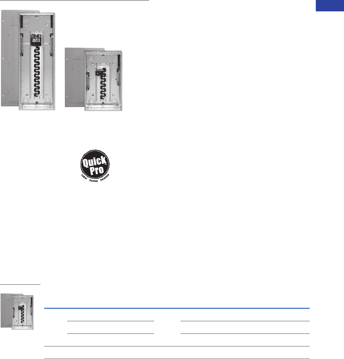
Volume 1—Residential and Light Commercial CA08100002E—June 2014 www.eaton.com V1-T1-59
1
1
1
1
1
1
1
1
1
1
1
1
1
1
1
1
1
1
1
1
1
1
1
1
1
1
1
1
1
1
1.2
Loadcenters and Circuit Breakers
Type BR Loadcenters and Circuit Breakers
BR Renovation Loadcenters
Contents—BR Specialty Products
Description Page
Overview . . . . . . . . . . . . . . . . . . . . . . . . . . . . . . . . V1-T1-42
BR Specialty Products
Spa Panels . . . . . . . . . . . . . . . . . . . . . . . . . . . . V1-T1-57
Riser Panel . . . . . . . . . . . . . . . . . . . . . . . . . . . . V1-T1-58
Type BR Renovation Loadcenter
Options and Accessories . . . . . . . . . . . . . . V1-T1-60
Type BR Retrofit Interior Kits . . . . . . . . . . . . . . V1-T1-72
BR Circuit Breakers . . . . . . . . . . . . . . . . . . . . . . . . V1-T1-75
Type BR Renovation Loadcenter
Product Description
●Available in 10, 20, 30
and 40 circuit main
breaker styles
●Designed to replace
existing loadcenters
and fuse boxes
●Type BR loadcenter
packaged with circuit
breakers
●Factory-installed 5-circuit
terminal block(s)
●Twin-stacked neutral
design
Quick-ProSM
All you need to
know to save
time and make
more money.
Specified on certain Eaton
products, the Quick-Pro
symbol allows for immediate
recognition of products
that are designed for
straightforward installation.
When you see Quick-Pro,
you know you can install
quickly—sometimes up to
50% less than the usual
installation time—and move
on to your next job.
Product Selection
BR Value Packs 1
Note
1 Indoor enclosure type.
Main
Breaker
Type Description
Wire Size
Range
Number of
5-Circuit
Terminal Blocks
Single-Pole
Breakers
Two-Pole
Breakers
Catalog
Number
BR
10 kAIC
Single-phase 100A 10k main breaker 10/20
circuit surface-mount box is 11.75" wide x 13" tall
#6–1/0 0 (2) BR115 (1) BR230 BR1020B100SRNV
Single-phase 100A 10k main breaker 10/20
circuit flush-mount box is 11.75" wide x 13" tall
0 (2) BR115 (1) BR230 BR1020B100FRNV
Single-phase 100A
10 kAIC main breaker 20/20 circuit
1 (5) BR120 (1) BR230 BR2020B100RNV8
CSR
25 kAIC
Single-phase 200A
25 kAIC main breaker 30/40 circuit
#2–300
kcmil
2 (5) BR115
(5) BR120
(1) BR230
(1) BR250
BR3040B100RNV4
BR2020B100RN
Features, Benefits and Functions
●Factory-installed terminal
block(s) allows installer to
terminate existing short
wires without using wire
nuts or junction boxes
●Twin-stacked neutrals are
mounted up high in the
loadcenter, which allows
for all neutral and ground
wires to be terminated in
the top half of the
loadcenter
●Specifically designed for
the service contractor—
this is the ONLY renovation
line in the industry
●Single-pole and two-pole
breakers included
●10-year warranty on
loadcenter and breakers
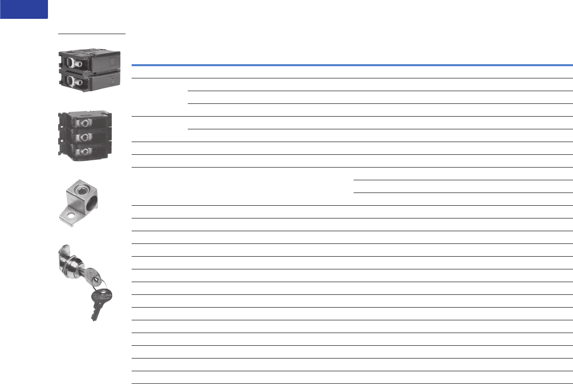
V1-T1-60 Volume 1—Residential and Light Commercial CA08100002E—June 2014 www.eaton.com
1
1
1
1
1
1
1
1
1
1
1
1
1
1
1
1
1
1
1
1
1
1
1
1
1
1
1
1
1
1
1.2
Loadcenters and Circuit Breakers
Type BR Loadcenters and Circuit Breakers
Options and Accessories
Field Installation Kits and Parts
Notes
1 Must be purchased in multiples of ordering quantities indicated.
2 #8–2/0 wire size range is 75°C rated only.
Number
of Poles
Ampere
Rating
Number of 1-Inch (25.4 mm)
Spaces Needed
Wire Size Range
Cu/Al 60°C or 75°C
Ordering
Quantity 1
Catalog
Number
Main and Sub-Feed Lug Blocks
2 125 2 #8–2/0 1 BRSF125
150 2 #8–2/0 1 BRSF150 2
225 4 #2–300 kcmil 1 BRS225
3 150 3 #8–2/0 1 3BRSF150 2
225 6 #2–300 kcmil 1 3BRS225
Main Lugs
Two-pole, 200A stud mounted (includes deadfront filler plate) #1–300 kcmil 1 BRL200
Neutral/ground lug
Add-on neutral or ground lug
#2/0 maximum 1 NL20
#3/0 maximum 1 NL30
300 kcmil maximum 1 NL300
Filler Plates
1-inch (25.4 mm) circuit breaker space 25 BRFP
BW main circuit breaker space (with hardware) 1 BWFP
Door lock —12–42 circuits, and 100–225A 1 TDL
Door lock—4–8 circuits, 125A 1CH9FL
ANSI-61 light gray touchup paint for current loadcenters 1 SPC61
Isolated neutral assembly (computer circuits) 1 BINA
Circuit directory—adhesive backed 10 TCD
Cover screws 25 LCCS
Cover replacement latch (gray) 14-5/16 (363.5 mm) wide loadcenters only 1 BRRL
Circuit marking strip (next to breaker) 10 BRMS
Circuit identification label (preprinted breaker labels) 25 CHBL
Series rated caution label 25 SRL
Bonding strip with screw 1BSSUSE
BRSF125
3BRS225
BRL200
TDL
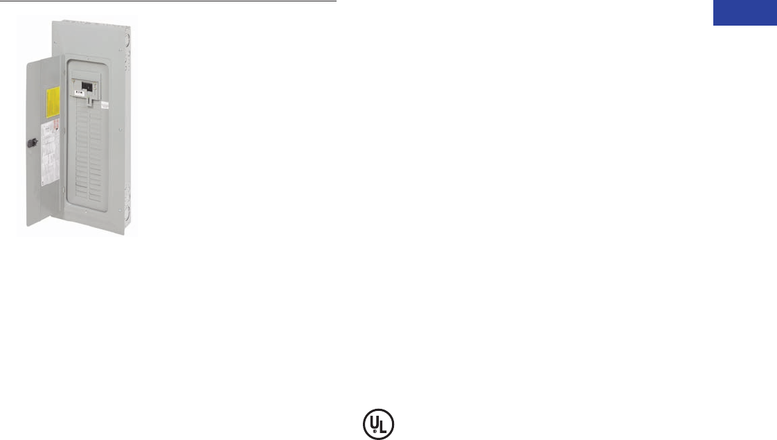
Volume 1—Residential and Light Commercial CA08100002E—June 2014 www.eaton.com V1-T1-61
1
1
1
1
1
1
1
1
1
1
1
1
1
1
1
1
1
1
1
1
1
1
1
1
1
1
1
1
1
1
1.2
Loadcenters and Circuit Breakers
Type BR Loadcenters and Circuit Breakers
Type BR Loadcenter with
Mechanical Interlock Kit
Type BR Mechanical Interlock Kits
Contents
Description Page
Overview . . . . . . . . . . . . . . . . . . . . . . . . . . . . . . . . V1-T1-42
BR Specialty Products
Spa Panels . . . . . . . . . . . . . . . . . . . . . . . . . . . . V1-T1-57
Riser Panel . . . . . . . . . . . . . . . . . . . . . . . . . . . . V1-T1-58
Type BR Renovation Loadcenter . . . . . . . . . . . V1-T1-59
Type BR Retrofit Interior Kits . . . . . . . . . . . . . . V1-T1-72
Type BR Mechanical Interlock Kits
BR Circuit Breakers
Product Selection . . . . . . . . . . . . . . . . . . . . . . . V1-T1-76
Circuit Breaker Accessories . . . . . . . . . . . . . . . V1-T1-84
Wiring Diagrams. . . . . . . . . . . . . . . . . . . . . . . . V1-T1-86
Type BR Mechanical Interlock Kits
Product Description
With the aging electrical
infrastructure and frequent
severe storms, power
outages are becoming more
and more frequent, affecting
thousands of people
nationwide. Eaton mechanical
interlock kit provides an easy
and cost-effective solution
when using backup
emergency power.
This solution expands the
robust line of emergency
power products and
accessories.
Features and Benefits
●Prevents utility and
generator supplies from
being on at the same time
●Protects utility linemen
from dangerous generator
backfeed
●Robust interlock design
●Offered in two unique
styles for almost any BR
loadcenter, which can
reduce inventory levels
●Quick and easy
installation—drill points or
fixtures for pilot holes are
provided on all applicable
BR loadcenters; no
additional assembly is
required
Standards and Certifications
●UL 67 Listed—For use with
BR loadcenters
●Meets NEC® Article 702
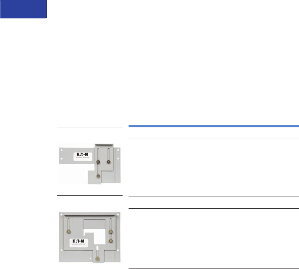
V1-T1-62 Volume 1—Residential and Light Commercial CA08100002E—June 2014 www.eaton.com
1
1
1
1
1
1
1
1
1
1
1
1
1
1
1
1
1
1
1
1
1
1
1
1
1
1
1
1
1
1
1.2
Loadcenters and Circuit Breakers
Type BR Loadcenters and Circuit Breakers
Product Selection
Each mechanical interlock kit
includes:
●Interlock assembly
●Hold down kit 1
●New labels
●Necessary screws
Warranty information:
●10-year warranty on all
Type BR circuit breakers
and loadcenters
●Refer to Eaton for
complete warranty details
Mechanical Interlock Kits 2
Notes
1For breakers under 70A used in backfed applications, add “B” to the end of the catalog string
to get the appropriate “hold-down” version.
2Clamshell packaged.
3Bulk pack contains 10 units, individually packaged.
Description Catalog Number
Single BRMIKBR
Bulk pack 3BRMIKBRBP
Single BRMIKCSR
Bulk pack 3BRMIKCSRBP
BRMIKCSR
BRMIKBR
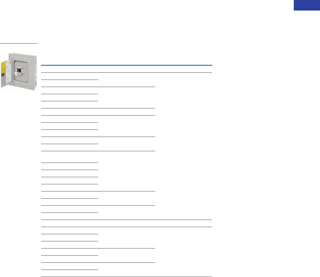
Volume 1—Residential and Light Commercial CA08100002E—June 2014 www.eaton.com V1-T1-63
1
1
1
1
1
1
1
1
1
1
1
1
1
1
1
1
1
1
1
1
1
1
1
1
1
1
1
1
1
1
1.2
Loadcenters and Circuit Breakers
Type BR Loadcenters and Circuit Breakers
Mechanical Interlock Cover
Covers mechanically interlock
two breakers—Type BW
or CSR main breaker with a
Type BR branch breaker.
Mechanical Interlock Cover
Fits Loadcenter
Catalog Numbers
Mechanical Interlock
Trim/Deadfront
Catalog Numbers
Mechanical Interlock Kit
Catalog Numbers
Indoor
BR816B100 BRCOVC10M BRMIKBR
BR816N100
BR1212B100 BRCOVC12M
BR1220B100
BR1220H100
BR1224N125 BRCOVC13M
BR1616B100 BRCOVC16M
BR1620B100
BR1624B100
BR1624B125 BRCOVC17M
BR1624N125
BR2020B100, BR2020BC100
BR2020H100, BR2020HC100
BRCOVC22M
BR2024H100
BR2020HC100
BR2030B100
BR2040B100
BR2024B125 BRCOVC23M
BR2024N125, BR2024NC125
BR3030B100, BR3030BC100 BRCOVC59M
BR3030H100, BR3030HC100
Raintight
BR1020B100R BR3RDF1M Field-installed interlock kits not
available for these catalog numbers.
BR1224B100R
BR1224N125R, BR1224NC125R
BR1624B100R BR3RDF2M
BR1624N125R
BR2024B100R, BR2024B125R BR3RDF4M
BR2024N125R, BR2024NC125R
BR816B100
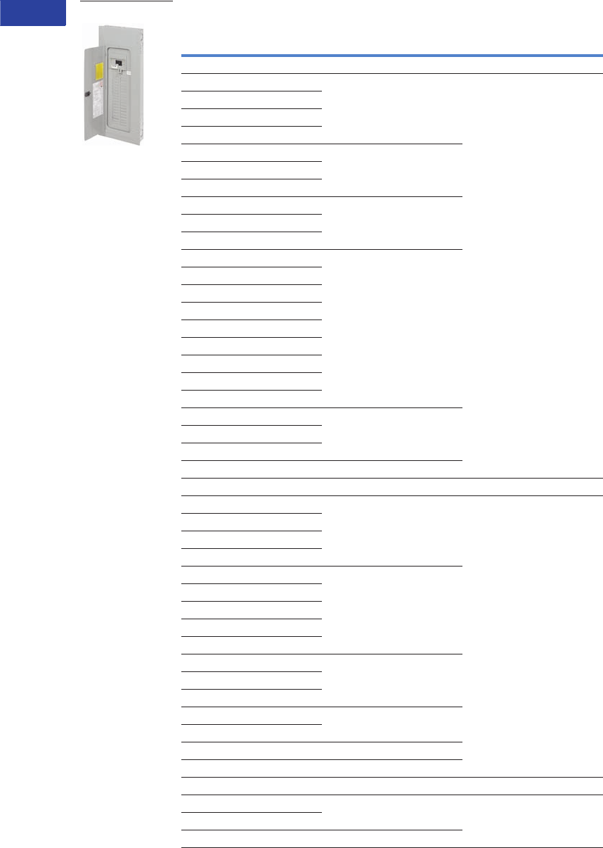
V1-T1-64 Volume 1—Residential and Light Commercial CA08100002E—June 2014 www.eaton.com
1
1
1
1
1
1
1
1
1
1
1
1
1
1
1
1
1
1
1
1
1
1
1
1
1
1
1
1
1
1
1.2
Loadcenters and Circuit Breakers
Type BR Loadcenters and Circuit Breakers
Mechanical Interlock Cover, continued
Notes
1 Deadfront only.
2 Can only be provided as replacement covers for factory-installed mechanically interlock loadcenters.
Fits Loadcenter
Catalog Numbers
Mechanical Interlock
Trim/Deadfront
Catalog Numbers
Mechanical Interlock Kit
Catalog Numbers
Indoor
BR1630B150 BRCOV16C4FM BRMIKCSR
BR1224N200
BR1632B200
BR1632N200
BR2030B150 BRCOV20C4FM
BR2030H150
BR2040B150
BR2040B200, BR2040BC200 BRCOV20D1FM
BR2040H200
BR2040N200, BR2040NC200
BR2430B150, BR2430BC150 BRCOV30G1FM
BR3030B150
BR3030H150
BR3040B150
BR2440B200
BR2440N200
BR3040B200, BR3040BC200
BR3040N200, BR3040NC200
BR3040H200
BR4040B200, BR4040BC200 BRCOV40L1FM
BR4040H200
BR4040N200, BR4040NC200
BR4242B225 BRCOV42L2FM
Raintight
BR816B150RF BR3RDF5M 1
BR816B200RF
BR816N200RF
BR1224N200R
BR2030B150R BR3RDF11M 1
BR2040B150R
BR2040B200R
BR2040B225R
BR2040N200R
BR3030B150R BR3RDF12M 1
BR3040B200R
BR3040N200R
BR4040B200R BR3RDF13M 1
BR4040N200R
BR48B200RF BR3RDF14M
BR4242B225R BR3RDF15M 1
Mechanical Interlock Loadcenter Replacement Covers 2
BR2020B100M, BR2020BC100M BRCOV20C2FM Field-installed interlock kits not
available for these catalog numbers.
BR2024H100M
BR3030BC100M BRCOV30D1FM
BR4040B200
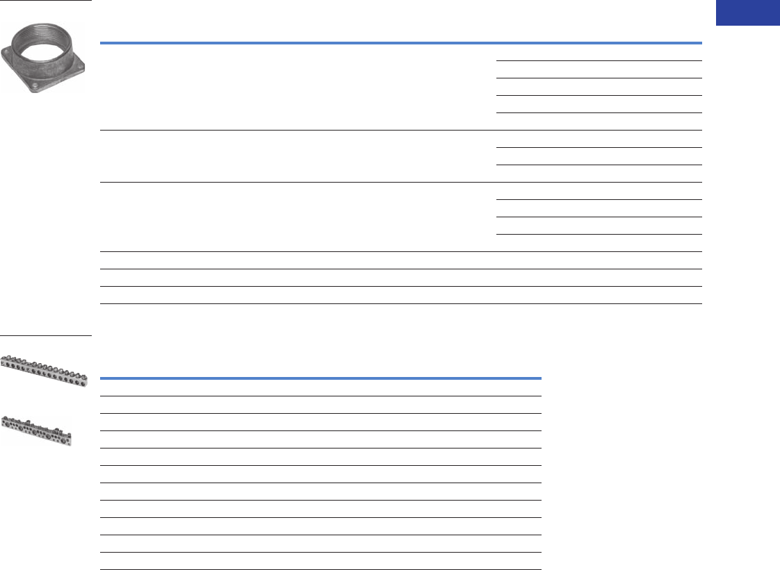
Volume 1—Residential and Light Commercial CA08100002E—June 2014 www.eaton.com V1-T1-65
1
1
1
1
1
1
1
1
1
1
1
1
1
1
1
1
1
1
1
1
1
1
1
1
1
1
1
1
1
1
1.2
Loadcenters and Circuit Breakers
Type BR Loadcenters and Circuit Breakers
Field Installation Rainproof Conduit Hubs
Ground Bar Kits
Ground Bar Legend
Notes
1 Must be purchased in multiples of ordering quantities indicated.
2 Distance between mounting holes is 1.75 inches (44.5 mm).
3 For single- and three-phase 400 and 600A applications.
4 Distance between mounting holes is 2.34 inches (59.5 mm).
5 For non-metallic enclosures. Snaps into molded base.
Description
Conduit Size
Inches (mm)
Ordering
Quantity 1
Catalog
Number
Group 1—for use with 70, 100 and 125A MLO and MCB loadcenters and circuit breaker enclosures and the
following 150 and 200A panels: BR48B200RF
0.75 (19.1) 1 DS075H1
1.00 (25.4) 1 DS100H1
1.25 (31.8) 1 DS125H1
1.50 (38.1) 1 DS150H1
2.00 (50.8) 1 DS200H1
Group 2—for use with 150, 200 and 225A MLO and MCB loadcenters and circuit breaker enclosures except for
the following 200A loadcenters: BR48B200RF. Also for use with 400 and 600A loadcenters and New York City
loadcenters manufactured after November 1, 2005
2.00 (50.8) 1 DS200H2
2.50 (63.5) 1 DS250H2
3.00 (76.2) 1 DS300H2
Type H conduit hubs for loadcenters PL0724R and S3100RN 0.75 (19.1) 1 RH75P
1.00 (25.4) 1 RH100P
1.25 (31.8) 1 RH125P
1.50 (38.1) 1 RH150P
Adapter kit—Allows Installing a Group 1 hub on devices arranged for Group 2 hubs — 1 DS900AP
Group 1 small blank hub plate with bump — 1 DS900CP1
Group 2 Large blank hub plate with bump — 1 DS900CP2
Description
(See Legend)
Length
Inches (mm)
Ordering
Quantity 1
Catalog
Number
dssssds 2.54 (64.5) 1 GBK5 2
dssssdsj 3.59 (91.2) 1 GBK520 2
dssssdssssss 4.29 (109.0) 1 GBK10 2
dssssdssssssj 5.34 (135.6) 1 GBK1020 2
4.61 (117.1) 1 GBK13 2
dssssdssssssssss 5.69 (144.5) 1 GBK14 2
dssssdssssssssssj 6.74 (171.2) 1 GBK1420 2
dssssdsssssssssssssssss 8.14 (206.8) 1 GBK21 2
dssssdsssssssssssssssssj 9.19 (233.4) 1 GBK2120 2
5.78 (146.8) 1 BRGBK39512 34
sssss 1.84 (46.7) 1 GB4NM 5
s
j
d
(3) #14–10 Cu/Al or (1) #14–4 Cu/Al
(1) #6–2/0 Cu/Al
(1) #14–1/0 Cu/Al or (3) #14–10 Cu/Al
(1) #14–6 Cu/Al or (2) #14–12 Cu/Al
Mounting Hole
DS300H2
GBK14
BRGBK39512
f
d
f
f
f
k
f
d
f
k
f
f
f
f
k
f
d
f
k
f
f
f
k
f
d
f
k
f
f
f
k
f
k
f

V1-T1-66 Volume 1—Residential and Light Commercial CA08100002E—June 2014 www.eaton.com
1
1
1
1
1
1
1
1
1
1
1
1
1
1
1
1
1
1
1
1
1
1
1
1
1
1
1
1
1
1
1.2
Loadcenters and Circuit Breakers
Type BR Loadcenters and Circuit Breakers
Dimensions
Approximate Dimensions in Inches (mm)
Residential/Commercial/New York City Loadcenters, Unit Enclosures—Box Sizes
Note: Box sizes do not include covers/fronts.
Residential Loadcenters—NEMA Type 1 Indoor
Residential Loadcenters—NEMA Type 3R Outdoor
Commercial Loadcenters—NEMA Type 1 Indoor
Commercial Loadcenters—NEMA Type 3R Outdoor
New York City Loadcenters—NEMA Type 1 Indoor
Types ECB and ECC Unit Enclosures—NEMA Type 1 Indoor
Types ECB and ECC Unit Enclosures—NEMA Type 3R
Outdoor
Box Size Height Width Depth
A1 15.00 (381.0) 11.25 (285.8) 3.75 (95.3)
B1 16.75 (425.5) 14.31 (363.5) 3.88 (98.4)
B2 18.75 (476.3) 14.31 (363.5) 3.88 (98.4)
C1 21.00 (533.4) 14.31 (363.5) 3.88 (98.4)
C2 23.00 (584.2) 14.31 (363.5) 3.88 (98.4)
C4 27.00 (685.8) 14.31 (363.5) 3.88 (98.4)
D1 29.13 (739.8) 14.31 (363.5) 3.88 (98.4)
G1 34.13 (866.8) 14.31 (363.5) 3.88 (98.4)
L1 39.00 (990.6) 14.31 (363.5) 3.88 (98.4)
L2 45.00 (1143.0) 14.31 (363.5) 3.88 (98.4)
2 8.63 (219.1) 5.00 (127.0) 3.50 (88.9)
3 9.44 (239.7) 4.50 (114.3) 3.00 (76.2)
4 13.00 (330.2) 11.00 (279.4) 3.56 (90.5)
5 9.44 (239.7) 4.50 (114.3) 3.00 (76.2)
6 12.00 (304.8) 6.88 (174.6) 4.50 (114.3)
7 13.00 (330.2) 11.00 (279.4) 3.56 (90.5)
9 14.50 (368.3) 6.50 (165.1) 3.50 (88.9)
Box Size Height Width Depth
B1R 16.75 (425.5) 14.31 (363.5) 5.19 (131.8)
B2R 18.75 (476.3) 14.31 (363.5) 5.19 (131.8)
C3R 25.00 (635.0) 14.31 (363.5) 5.19 (131.8)
D1R 29.13 (739.8) 14.31 (363.5) 5.19 (131.8)
G1R 34.13 (866.8) 14.31 (363.5) 5.19 (131.8)
L1R 39.00 (990.6) 14.31 (363.5) 5.19 (131.8)
L2R 45.00 (1143.0) 14.31 (363.5) 5.19 (131.8)
2R 8.63 (219.1) 5.00 (127.0) 3.50 (88.9)
3R 9.44 (239.7) 4.50 (114.3) 3.00 (76.2)
4R 13.00 (330.2) 11.00 (279.4) 3.56 (90.5)
5R 9.44 (239.7) 4.50 (114.3) 3.00 (76.2)
6R 11.75 (298.5) 6.50 (165.1) 4.50 (114.3)
7R 13.00 (330.2) 11.00 (279.4) 3.56 (90.5)
8R 27.00 (685.8) 10.50 (266.7) 4.75 (120.7)
9R 14.25 (362.0) 6.50 (165.1) 4.00 (101.6)
C1R 21.00 (533.4) 14.31 (363.5) 5.19 (131.8)
Box Size Height Width Depth
19 44.00 (1117.6) 16.16 (410.4) 6.25 (158.8)
20 44.00 (1117.6) 16.16 (410.4) 6.25 (158.8)
22 54.00 (1371.6) 16.22 (412.0) 6.31 (160.3)
24 66.50 (1689.1) 16.22 (412.0) 6.31 (160.3)
Box Size Height Width Depth
42 38.00 (965.2) 16.31 (414.3) 6.38 (161.9)
43 44.00 (1117.6) 16.31 (414.3) 6.38 (161.9)
46 54.00 (1371.6) 16.31 (414.3) 6.38 (161.9)
47 66.56 (1690.7) 16.31 (414.3) 6.38 (161.9)
Box Size Height Width Depth
A 38.00 (965.2) 18.13 (460.4) 5.00 (127.0)
B 44.00 (1117.6) 18.13 (460.4) 5.00 (127.0)
C 66.50 (1689.1) 18.13 (460.4) 6.25 (158.8)
Height Width Depth
23.25 (590.6) 8.88 (225.4) 4.50 (114.3)
Height Width Depth
23.68 (601.7) 9.31 (236.5) 5.44 (138.1)
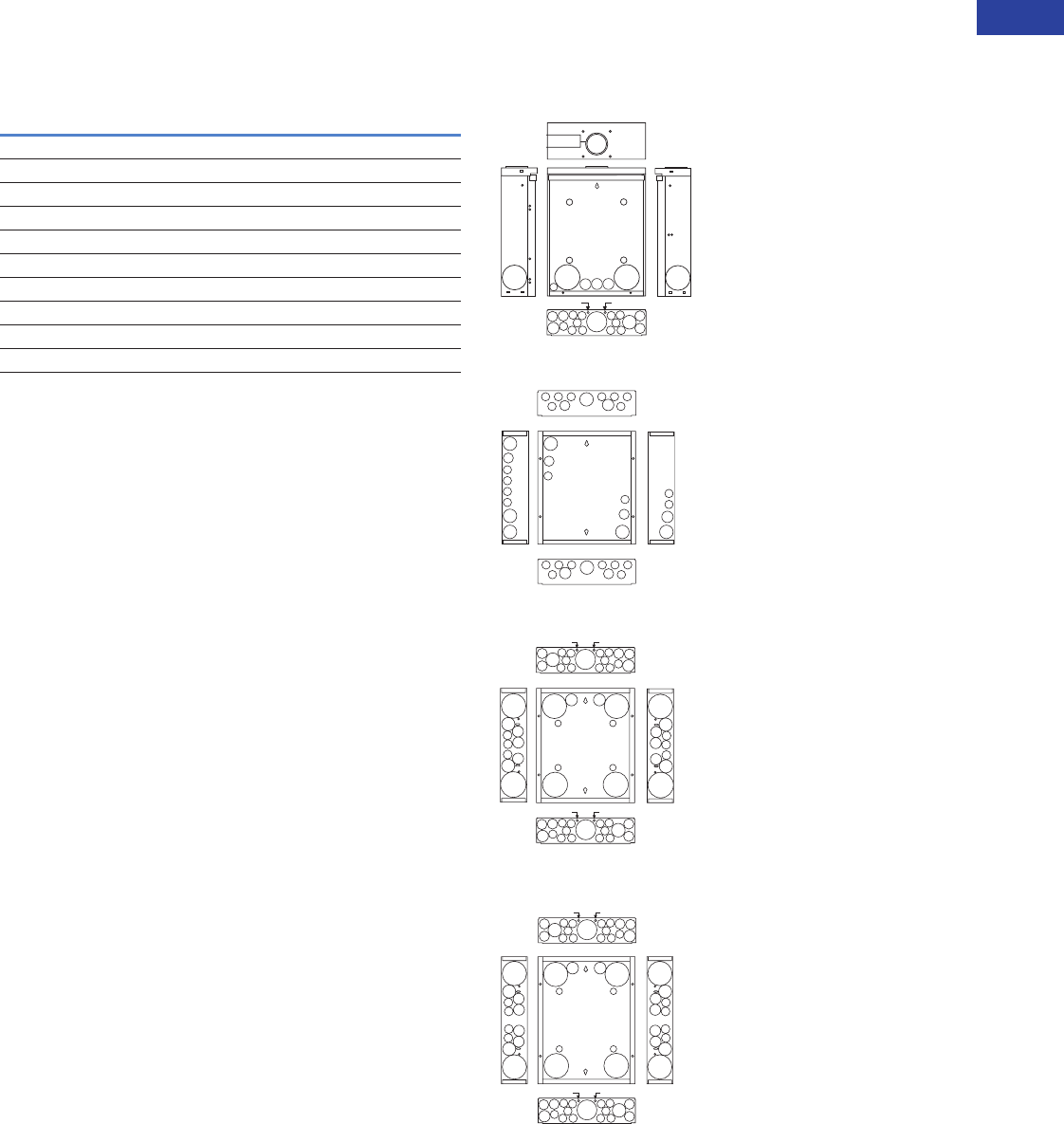
Volume 1—Residential and Light Commercial CA08100002E—June 2014 www.eaton.com V1-T1-67
1
1
1
1
1
1
1
1
1
1
1
1
1
1
1
1
1
1
1
1
1
1
1
1
1
1
1
1
1
1
1.2
Loadcenters and Circuit Breakers
Type BR Loadcenters and Circuit Breakers
Approximate Dimensions in Inches (mm)
Residential Loadcenter Knockouts
Knockouts for Box Sizes A1, B1, B2, C1, C2, C4, D1, G1, L1,
L2, B1R, B2R, C1R, C3R, D1R, G1R, L1R, L2R
Residential NEMA Type 1 Indoor and
NEMA Type 3R Outdoor Enclosures
Code Diameter
A 0.50 (12.7) 0.75 (19.1) — — —
B 0.50 (12.7) — — — —
C 0.50 (12.7) 1.25 (31.8) 1.50 (38.1) 2.00 (50.8) 2.50 (63.5)
D 1.25 (31.8) 1.25 (31.8) 2.00 (50.8) 2.50 (63.5) —
E 0.50 (12.7) 0.75 (19.1) 1.00 (25.4) — —
F 0.50 (12.7) 0.75 (19.1) 1.00 (25.4) 1.50 (38.1) 2.00 (50.8)
G 1.25 (31.8) 1.50 (38.1) 2.00 (50.8) — —
H 0.50 (12.7) 0.75 (19.1) 1.00 (25.4) 1.25 (31.8) 1.50 (38.1)
I 1.00 (25.4) 1.25 (31.8) 1.50 (38.1) 2.00 (50.8) 2.50 (63.5)
J 1.00 (25.4) 1.25 (31.8) 1.50 (38.1) — —
J
E
B B B
A
B
B B B
B
E
J
B B B
A
B
B B B
B
E
J
J
A
B
A
B
J
J
J
A
B
B
B
B
J
B
B
Outdoor Boxes
B1R, B2R, C1R, C3R, D1R,
G1R, L1R, L2R
Indoor Boxes
B1, B2
Indoor Boxes
C1, C2, C4, D1, G1, L1, L2
.45 (11.4) Dia. KO.45 (11.4) Dia. KO
.45 (11.4) Dia. KO
.45 (11.4) Dia. KO
A
D
E
A
A
B
B
B
E
D
A
D
E
A
A
B
B
B
E
D
DD
D
D
EE
I
B
B
B
BB
A
A
H
B
B
B
BB
A
E
A
B
I
BB
B
B
B
A
AH
BB
B
B
B
A
E
A
B
.45 (11.4) Dia. KO
.45 (11.4) Dia. KO
.45 (11.4) Dia. KO.45 (11.4) Dia. KO
A
D
E
A
A
B
B
E
D
DD
D
D
EE
A
B
B
A
D
E
A
A
B
B
B
E
D
AB
I
B
B
B
BB
A
A
H
B
B
B
BB
A
E
A
B
I
BB
B
B
B
A
AH
BB
B
B
B
A
E
A
B
2.06 (52.3) Dia.
(125A Max.)
3.06 (77.7) Dia.
(225A Max.)
Hub
I
B
B
B
BB
A
A
H
B
B
B
BB
A
E
A
B
DDDD
.45 (11.4) Dia. KO
.45 (11.4) Dia. KO
EE E
B
Indoor Boxes
A1
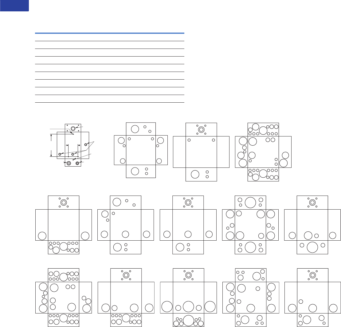
V1-T1-68 Volume 1—Residential and Light Commercial CA08100002E—June 2014 www.eaton.com
1
1
1
1
1
1
1
1
1
1
1
1
1
1
1
1
1
1
1
1
1
1
1
1
1
1
1
1
1
1
1.2
Loadcenters and Circuit Breakers
Type BR Loadcenters and Circuit Breakers
Approximate Dimensions in Inches (mm)
Knockouts for Box Sizes 3, 4, 5, 6, 7, 9, 2R, 3R, 4R, 5R, 6R,
7R, 8R, 9R
Residential NEMA Type 1 Indoor and NEMA Type 3R Outdoor Enclosures
Code Diameter
A 0.50 (12.7) — — —
B 0.50 (12.7) 0.75 (19.1) — —
C 0.50 (12.7) 0.75 (19.1) 1.00 (25.4) —
D 0.50 (12.7) 0.75 (19.1) 1.00 (25.4) 1.25 (31.8)
E 0.75 (19.1) 1.00 (25.4) 1.25 (31.8) —
F 0.75 (19.1) 1.00 (25.4) 1.25 (31.8) 1.50 (38.1)
G 1.00 (25.4) 1.25 (31.8) 1.50 (38.1) —
H 1.00 (25.4) 1.25 (31.8) 1.50 (38.1) 2.00 (50.8)
I 1.25 (31.8) 1.50 (38.1) 2.00 (50.8) —
Box 2, 2R
R1.00–1.25 KO
(25.4–31.8) KO
Mounting
Hole for
5/16 (7.9)
Screw .50–.75
(12.7–19.1)
2.38
(60.3)
.31 (7.9)
.50–.75–1.00
(12.7–19.1–25.4)
.50–1.00–1.25
(12.7–25.4–31.8)
6.38
(161.9)
A
A
A
A
C
E
A
A
C
E
F
A
A
F
Box 3
A
A
A
A
F
Hub
AAA A
A
A A
BB
B
D
G
G G
Hub
A
A
AA
A
A A A
A
A A
BBB
B
B
B
DG
AAA A
A
A A
BB
B
D
D D
G
G
G
D
G
G
Box 3R Box 4
Box 4R Box 5 Box 5R Box 6
A
A
A
A
A
A
D D D
D
F
F
A
A
D D D
F
Hub
A
A
B
A
B
B
C
C
FF
F
F
A
B
F
F
H
A
B
A
B
H
Box 6R
F
B B
B
H
Hub
D D
Box 7 Box 7R
A
A
AA
A
AAA
AAA AAA
B B B
AB B
B
B
B
B
C C
C
C
C
BC
G
G
G
G
G G
F
AAA AAA
AB B
BC
C
G
G G
F
Hub
AA
B
C
C
Hub
I
AA
BC
C
I
I
A A
A
A
A A
B
B
B
B
BB
B
C
C
C
G
GG
G
G
GG
G
A
A
B
B
C
G
G
G
G
Hub
Box 8R Box 9 Box 9R
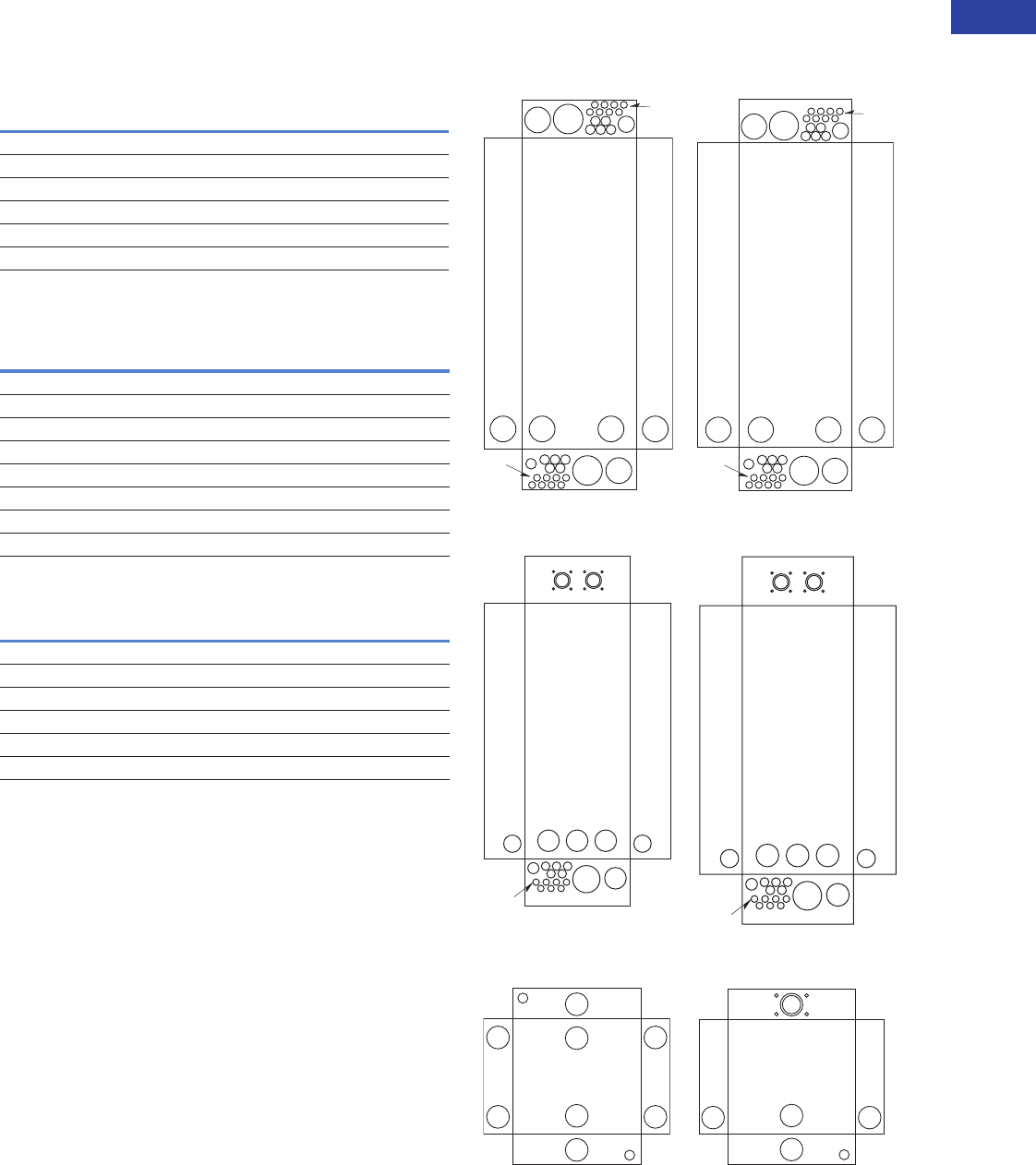
Volume 1—Residential and Light Commercial CA08100002E—June 2014 www.eaton.com V1-T1-69
1
1
1
1
1
1
1
1
1
1
1
1
1
1
1
1
1
1
1
1
1
1
1
1
1
1
1
1
1
1
1.2
Loadcenters and Circuit Breakers
Type BR Loadcenters and Circuit Breakers
Approximate Dimensions in Inches (mm)
Commercial Loadcenter Knockouts
NEMA Type 1 Indoor Commercial Enclosures
Knockouts for Box Sizes 19, 20, 22, 24
NEMA Type 3R Outdoor Commercial Enclosures
Knockouts for Box Sizes 42, 43, 46, 47
Unit Enclosure Knockouts, Types ECB and ECC Knockouts
Indoor Commercial Enclosures
Outdoor Commercial Enclosures
Unit Enclosure Knockouts
Code Diameter
A 0.50 (12.7) — — —
B 0.50 (12.7) 0.75 (19.1) — —
C 0.75 (19.1) 1.00 (25.4) 1.50 (38.1) —
D 1.50 (38.1) 2.00 (50.8) 2.50 (63.5) 3.00 (76.2)
E 2.00 (50.8) 2.50 (63.5) 3.00 (76.2) —
F 2.50 (63.5) 3.00 (76.2) 3.50 (88.9) —
Code Diameter
A 0.50 (12.7) — — —
B 0.50 (12.7) 0.75 (19.1) — —
C 0.75 (19.1) 1.00 (25.4) 1.25 (31.8) —
D 1.50 (38.1) 2.00 (50.8) 2.50 (63.5) —
E 2.00 (50.8) 2.50 (63.5) 3.00 (76.2) —
F 2.50 (63.5) 3.00 (76.2) 3.50 (88.9) —
G 1.25 (31.8) 1.50 (38.1) 2.00 (50.8) 2.50 (63.5)
H 3.25 (82.6) Sq. — — —
Code Diameter
NEMA Type 1 Indoor (Flush and Surface Trims)
A 0.50 (12.7) — — — —
B 1.25 (31.8) 1.50 (38.1) 1.75 (44.5) 2.00 (50.8) 2.50 (63.5)
NEMA Type 3R Outdoor
A 0.50 (12.7) — — — —
B 1.25 (31.8) 1.50 (38.1) 1.75 (44.5) 2.00 (50.8) 2.50 (63.5)
A
H
E
F
A
B B B
B B
C
D D D D
E
C
B
B
B
B
B
A
H
BBB
B B
C
E E E E
E
E
F
A
C
B
B
B
B
B
Box 19, 20 Box 22, 24
GF
E E E
D D
C
B
B
B
B
B
A
HUB HUB
FE
E E E
D D
CB
B
B
B
B
A
HUB HUB
Box 42
Box 43, 46, 47
B
B
B
B
A
A
B
B
B
B
B
B
A
B B
HUB
NEMA Type 1—Indoor NEMA Type 3R—Outdoor

V1-T1-70 Volume 1—Residential and Light Commercial CA08100002E—June 2014 www.eaton.com
1
1
1
1
1
1
1
1
1
1
1
1
1
1
1
1
1
1
1
1
1
1
1
1
1
1
1
1
1
1
1.2
Loadcenters and Circuit Breakers
Type BR Loadcenters and Circuit Breakers
Technical Data and Specifications
General
A. The Contractor shall
furnish and install
deadfront loadcenters
incorporating circuit
breakers of the number,
rating and type as
specified herein and
as shown on the
contract drawings.
B. The loadcenter and all
components shall be
designed, manufactured
and tested in accordance
with the latest applicable
standards of UL, NEMA
and NEC including:
1. UL 67—Standards
for Panelboards.
C. UL 50—Standards for
Cabinets and Boxes.
D. UL 489—Standards for
Molded Case Circuit
Breakers.
E. UL 869—Standards for
Service Equipment.
F. Federal Specification
W-C 375B—Circuit
Breakers.
G. Federal Specification
W-C P115b—Panel
Power Distribution
Type 1, Class 2.
Qualifications
A. The manufacturer of the
loadcenter shall be the
manufacturer of the
circuit breaker within
the loadcenter.
B. For the equipment
specified herein, the
manufacturer shall be
ISO 9000 certified.
C. The manufacturer of
this equipment shall have
produced similar
electrical equipment
for a minimum period
of seven (7) years.
Manufacturers
A. Eaton.
Ratings
A. Loadcenters shall be
rated for 120/240 Vac and
shall have short-circuit
ratings as shown on the
drawings or
as herein scheduled,
but not less than
10,000 amperes rms
symmetrical.
B. Circuit breakers shall be a
minimum of 125A frame.
Circuit breakers 15
through 125A trip size
shall take up the same
pole spacing.
C. Loadcenters shall be
labeled with a UL short-
circuit rating. When
series combination
ratings are applied
with integral or remote
upstream devices, a label
shall be provided. Series
combination ratings shall
cover all trip ratings of
installed frames. It shall
state the conditions of
the UL series ratings
including:
1. Size and type of
upstream device.
2. Branch devices that can
be used.
3. UL series short
circuit rating.
Construction
A. All interiors, with the
exception of the branch
circuit breakers, shall
be completely factory
assembled with main
breakers, main lugs,
or no main device.
B. Interiors shall be
designed so that circuit
breakers can be replaced
without disturbing
adjacent units and
without removing the
main bus connectors and
shall be designed so that
circuits may be changed
without machining,
drilling, or tapping.
C. Physical means shall be
provided to prevent the
installation of more
overcurrent devices than
that number for which
the enclosure was
designed, rated and
approved. Half-size
breakers shall have a
UL listed rejection tab
over the line terminals.
Loadcenter interiors
must have notched stabs
to accept these rejection
tab class CTL breakers, if
required and approved.
Bus
A. Busbars for the main and
cross connectors shall be
[tin-plated aluminum]
[copper] in accordance
with Underwriters
Laboratories standards.
Busing shall be braced
throughout to conform to
industry standard practice
governing short-circuit
stresses in loadcenters.
Note: Note to spec writer—
select one (copper available
in limited ratings).
B. Neutral busing shall
have a suitable lug for
each outgoing feeder
requiring a neutral
connection of same
ampacity as branch.
Wiring/Termination
A. All wire connectors and
terminals shall be of the
anti-turn solderless type
and shall be suitable for
copper or aluminum wire
of the sizes indicated. All
connectors must meet
the “Requirements for
Wire Connectors and
Soldering Lugs” as
stated in UL 486B.
B. All loadcenters where
marked shall be suitable
for use with 60°C or 75°C
rated wire.
Circuit Breakers
A. Circuit breakers shall
be molded case type.
Circuit breakers shall
have four-rivet
construction (GFI Type—
5 rivets). Multipole circuit
breakers shall be of a
stack pole design to
provide electrical
phase isolation.
B. Each pole of the
circuit breaker will
provide inverse time
delay overload and
instantaneous short-
circuit protection by
means of both thermal
and magnetic sensors.
C. The circuit breaker
calibration shall
not be affected by
environmental changes
in relative humidity.
The thermal bimetal
element shall be welded
to the steel frame and
calibration shall be set
independent of the
molded case by computer
controlled equipment.
D. All circuit breakers
shall be operated by
a toggle-type handle
and multipole circuit
breakers shall have an
internal common trip
mechanism. The
circuit breakers shall
incorporate trip
mechanisms that are
mechanically trip-free
from the handle. The
handle position shall
provide visual trip
indication.
E. Contacts shall be of
non-welding silver alloy.
F. All circuit breakers shall
have the trip rating
inscribed on the handle
on each circuit breaker
pole. Also, unique color-
coded cases that indicate
the UL listed 10 kA or
22 kA interrupting
ratings. Breakers shall
be able to be used
as main or branch
disconnect devices.

Volume 1—Residential and Light Commercial CA08100002E—June 2014 www.eaton.com V1-T1-71
1
1
1
1
1
1
1
1
1
1
1
1
1
1
1
1
1
1
1
1
1
1
1
1
1
1
1
1
1
1
1.2
Loadcenters and Circuit Breakers
Type BR Loadcenters and Circuit Breakers
G. Branch circuit breakers
may also be used in
the 1/2-inch (12.7 mm)
per pole ratings that
include two-pole 1-inch
(25.4 mm) wide modules
and four-pole 2-inch
(50.8 mm) wide
modules. Two-pole circuit
breakers must
incorporate a common
trip mechanism. The
exclusive CTL rejection
tab feature shall be
provided to limit the
number of branch
devices for a loadcenter
to 42, in compliance with
NEC Article 384.15.
H. Circuit breakers shall
be completely enclosed
in a molded case of
thermoset material.
No internal aluminum
parts shall be used. All
internal ferrous parts
shall be plated to
prevent corrosion.
I. All terminals shall be
listed for use with copper
or aluminum conductors.
Terminals shall be of the
box lug or clamp type
design. The terminals
shall meet UL 486B
requirements and shall
be suitable for use with
either 60°C or 75°C wire.
J. The calibrated bimetal
assembly shall be
mechanically isolated
from the load terminal
using a flexible braided
copper shunt wire, such
that movement of the
terminals due to twisting
and overtorquing does
not affect breaker
calibration.
K. Breakers shall be SWD
rated and/or HACR rated
as required.
L. Arc Fault Interrupting
circuit breakers, (AFI),
shall be provided on all
15 and 20A single-phase
120/240 Vac circuits
except those indicated as
remote controlled
breakers. AFI breakers
shall be “Classified for
mitigating the effects of
arcing faults,” or
conforming to UL
Standard 1699 and as
defined by Article 210.12
Section A of the 1999
NEC Code.
Surge Protection Devices
See Volume 1, Tab 2 for
complete details on
surge protection.
Enclosures
A. Loadcenter shall have
NEMA Type 1 general
purpose or NEMA Type
3R rainproof enclosures
as indicated on the
drawings and shall be
surface or combination
flush/surface mounted
except where noted.
B. Boxes shall be made
from galvanized sheet
steel having multiple
knockouts. Rainproof
boxes shall use
galvanized steel or
an approved coating
system which meets or
exceeds standards for
outdoor NEMA Type 3R
enclosures. Boxes shall
be of sufficient size to
provide at least a
minimum code gutter
space on all sides.
C. The deadfront shall
have an easy adjustment
feature for flush
applications.
D. Boxes shall be factory
assembled into a single
rigid structure.
E. Unless otherwise noted
on drawings, hinged
doors covering all circuit
breaker handles shall
be included in all trims.
Trim doors shall not
uncover any live parts
in making the circuit
breaker handles
accessible. If key locks
are required, all locks
shall be keyed alike.
F
. Combination trims for
flush and surface panels
shall be flat and shall
overlap the box by at
least 5/8-inch (15.9 mm)
all around. Trims shall
be mounted by a
screwdriver without the
need for special tools.
Finish
A. Trims shall be bonderized
and finished with a light
gray ANSI-61 enamel.
The paint finish shall be
of a type to which field
applied paint will adhere.
Factory Testing
A. The standard factory
tests shall be performed
on the equipment
provided under this
section. All tests shall
be in accordance with
the latest version of UL
and NEMA.
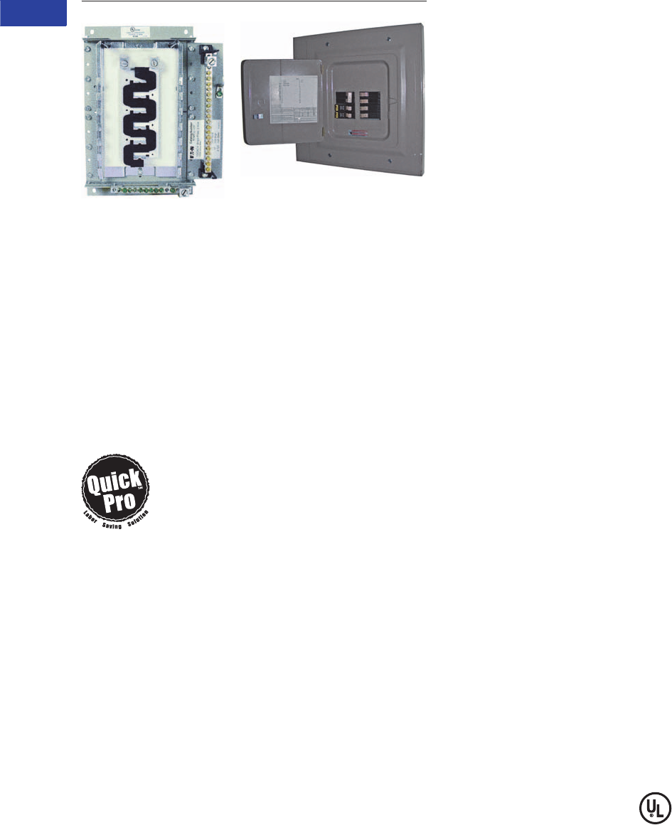
V1-T1-72 Volume 1—Residential and Light Commercial CA08100002E—June 2014 www.eaton.com
1
1
1
1
1
1
1
1
1
1
1
1
1
1
1
1
1
1
1
1
1
1
1
1
1
1
1
1
1
1
1.2
Loadcenters and Circuit Breakers
Type BR Loadcenters and Circuit Breakers
Type BR Retrofit Type BR Retrofit Interior Collar
Adjustable Interior and Assembly with Trim
Type BR Retrofit Interior
Contents—BR Specialty Products
Description Page
Overview . . . . . . . . . . . . . . . . . . . . . . . . . . . . . . . V1-T1-42
BR Specialty Products
Spa Panels . . . . . . . . . . . . . . . . . . . . . . . . . . . . V1-T1-57
Riser Panel. . . . . . . . . . . . . . . . . . . . . . . . . . . . V1-T1-58
Type BR Renovation Loadcenter . . . . . . . . . . . V1-T1-59
Type BR Mechanical Interlock Kits . . . . . . . . . . V1-T1-61
Type BR Retrofit Interior Kits
BR Circuit Breakers. . . . . . . . . . . . . . . . . . . . . . . . V1-T1-75
Type BR Retrofit Interior Kits
Product Description
Eaton’s unique Retrofit
Interior allows the customer
to cost-effectively and safely
upgrade an electrical service
without removing the existing
enclosure from the wall.
Quick-ProSM
All you need to
know to save
time and make
more money.
Specified on certain Eaton
products, the Quick-Pro
symbol allows for immediate
recognition of products
that are designed for
straightforward installation.
When you see Quick-Pro,
you know you can install
quickly—sometimes up to
50% less than the usual
installation time—and move
on to your next job.
Application Description
The Retrofit Interior is
designed and tested
specifically for renovating
an outdated electrical panel in
an apartment, a condominium
or a single family home.
These outdated panels are
being recognized by local
inspectors and other
authorities as a possible
hazard.
Opportunities to Retrofit
●Single- or three-phase
●Main lug only or main
breaker
●Up to 42 circuits
●Up to 225A interiors,
400A available upon
request
●Available with CH breakers
(3/4-inch) with copper bus
or BR breakers (1-inch) with
aluminum bus
●The minimum lifetime
warranty for residential
breakers shall be as
follows:
●10-year warranty on all
BR branch breakers and
loadcenters
●Refer to Eaton for
complete warranty
details
Features and Benefits
Upgrading Existing Electrical
Infrastructure Is Simple
●Replaces vintage brands
that have hard to find,
expensive replacement
breakers
●Safety upgrade to arc fault
and ground fault breakers
to meet current electrical
codes
●Maximizes number of
circuits available with
compact design
●Eco-friendly in asbestos-
filled environments
●Exclusive design
Save Time and Money
Throughout the Installation
●Uses existing panel
box and wires
●Eliminates expensive and
time-consuming drywall/
paint repair
●Saves 2–3 hours of
installation time compared
to a complete panel
changeout
●Eliminates precise
measurements with field-
adjustable kit
Detailed Product Guide
All standard retrofit kits are
suitable for a range of
existing box sizes:
●Box width ranging from
14.50 to 22.00 inches
(368.3 to 558.8 mm)
●Box depth ranging from
4.00 inches (101.6 mm)
for BR
●Box height ranging from
21.00 to 45.00 inches
(533.4 to 1143.0 mm)
For box dimensions outside
of these ranges, contact
the Lincoln Flex Center at
800-330-6479. Be sure to
provide the existing incoming
line wire size.
Standards and Certifications
●Meets 2008/2011/2014
NEC wire bending
requirements
●UL 67 Listed (for UL
listings for specific part
numbers, see the table on
the following page.

Volume 1—Residential and Light Commercial CA08100002E—June 2014 www.eaton.com V1-T1-73
1
1
1
1
1
1
1
1
1
1
1
1
1
1
1
1
1
1
1
1
1
1
1
1
1
1
1
1
1
1
1.2
Loadcenters and Circuit Breakers
Type BR Loadcenters and Circuit Breakers
BR Specialty Product Selection
To select the retrofit kit:
1. From the existing box
size determine which
retrofit groups are
suitable (may be more
than one).
2. Use type of interior,
number of phases, and
type of main to find the
selection chart.
3. Select part number from
chart (if main breaker,
replace XXX with specific
amp rating).
4. Note that the overlap
of the existing wall is
the retro cover size
minus the existing
box size. If specific
measurements are
needed, communicate
that you need a custom
trim size.
5. Contact the Lincoln Flex
Center at 800-330-6479
for pricing, lead-times,
and order entry
instructions.
How to Order:
1. Measure the existing
panel enclosure to
determine appropriate
kits for your project.
2. Match the existing
dimensions with the
table below to obtain the
correct catalog number.
3. Order your retrofit kit
from a local Eaton
authorized distributor.
Need assistance or can’t find
retrofit to fit existing
enclosure?
Call Eaton’s Residential Flex
Center at 1-800-330-6479
or email for all your retrofit
needs. Go to
www.eaton.com/eccn to
locate an Eaton Certified
Contractor.
Retrofit Interior Kit Specifications
Five recommended groups: existing box height determines retro group size. Approximate Dimensions in Inches (mm).
Notes
1Catalog numbers shown with "_" at the end need one of the following suffixes to denote depth:
J = 3.75–4.25
K = 4.25–5.00
L = 5.00–6.00
Example: RTBR12L125J would signify an interior set with a depth range of 3.75 to 4.25 inches.
2****Denotes characters in the catalog number that relate to overall cover size.
Example: CRTBR12ML2620 would signify a cover 26.00 inches H x 20.00 inches W.
3Amperes for MB panels is maximum; catalog number will reflect actual amperage of breaker included.
For UL applications, maximum cover sizes may apply.
Existing Enclosure Parameters—Inches (mm)
Catalog
Number 1Cover 2
Minimum
Depth
Maximum
Depth
Minimum
Width
Minimum
Height Phase Main Bus Amperes
3
Spaces /
Circuits
UL 67
Listed
BR Retrofit Interiors and Covers
RTBR8L100P CRTBR8ML**** 3.13 (79.5) 3.63 (92.2) 10.50 (266.7) 13.00 (330.2) Single MLO BR 100 16 Yes
RUBR8L100_ CRUBR8ML**** 3.75 (95.3) 6.00 (152.4) 10.50 (266.7) 13.00 (330.2) Single MLO BR 100 16 Yes
RTBR12L100P CRTBR12ML**** 3.13 (79.5) 3.63 (92.2) 10.50 (266.7) 14.50 (368.3) Single MLO BR 100 24 Yes
RTBR10B100P CRTBR12ML**** 3.13 (79.5) 3.63 (92.2) 10.50 (266.7) 14.50 (368.3) Single MLO BR 100 20 Yes
RUBR12L100_ CRUBR12ML**** 3.75 (95.3) 6.00 (152.4) 10.50 (266.7) 14.50 (368.3) Single MLO BR 100 24 Yes
RUBR10B100_ CRUBR12ML**** 3.75 (95.3) 6.00 (152.4) 10.50 (266.7) 14.50 (368.3) Single MB BR 100 20 Yes
RTBR12L125P CRTBR12ML**** 3.13 (79.5) 3.63 (92.2) 11.00 (279.4) 17.00 (431.8) Single MLO BR 125 24 Yes
RTBR10B125P CRTBR12ML**** 3.13 (79.5) 3.63 (92.2) 11.00 (279.4) 17.00 (431.8) Single MB BR 125 20 Yes
RUBR12L125_ CRUBR12ML**** 3.75 (95.3) 6.00 (152.4) 11.00 (279.4) 17.00 (431.8) Single MLO BR 125 24 Yes
RUBR10B125_ CRUBR12ML**** 3.75 (95.3) 6.00 (152.4) 11.00 (279.4) 17.00 (431.8) Single MB BR 125 20 Yes
RABR20B125_ CRABR20ML**** 3.75 (95.3) 6.00 (152.4) 13.00 (330.2) 21.00 (533.4) Single MCB BR 125 24 No
RABR20L125_ CRABR20ML**** 3.75 (95.3) 6.00 (152.4) 13.00 (330.2) 21.00 (533.4) Single MLO BR 125 24 No
RBBR20B200_ CRBBR20BW**** 3.75 (95.3) 6.00 (152.4) 13.00 (330.2) 29.00 (736.6) Single MLO BR 200 40 No
RCBR40L200_ CRCBR40ML**** 3.75 (95.3) 6.00 (152.4) 13.00 (330.2) 34.00 (863.6) Single MLO BR 200 40 No
RDBR40B200_ CRDBR40BW**** 3.75 (95.3) 6.00 (152.4) 13.00 (330.2) 37.00 (939.8) Single MLO BR 200 40 No
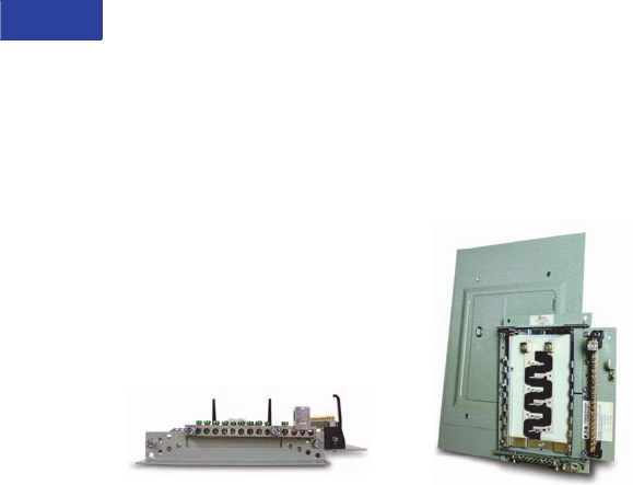
V1-T1-74 Volume 1—Residential and Light Commercial CA08100002E—June 2014 www.eaton.com
1
1
1
1
1
1
1
1
1
1
1
1
1
1
1
1
1
1
1
1
1
1
1
1
1
1
1
1
1
1
1.2
Loadcenters and Circuit Breakers
Type BR Loadcenters and Circuit Breakers
Complete Assembly
Note: For complete assembly,
interior and cover need to be
ordered separately.
Adjustable Interior
●Factory installed ground
and neutral bars positioned
to accept existing wires
●Field adjustable depth
matches existing panel box
●Adjustable height enables
optional placement of the
interior
●Field bondable for service
entrance options
Adjustable Interior
Standard Trim and Collar
●Standard trim matches
new interior
●New circuit directory for
updated labeling
●Oversized collar eliminates
expensive wall/paint repair
Collar and Assembly with Trim
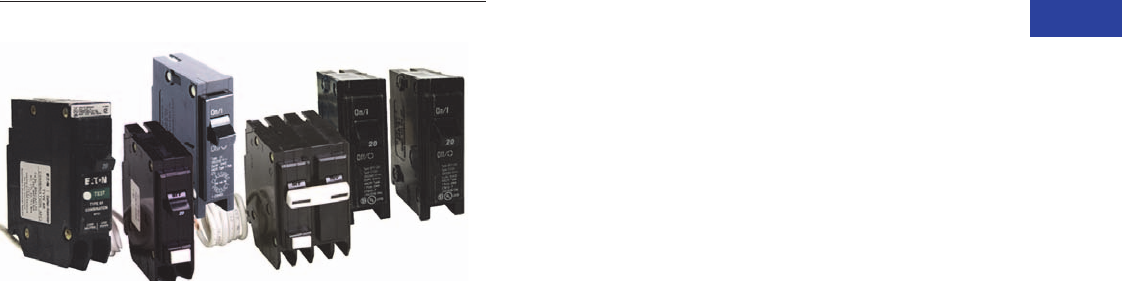
Volume 1—Residential and Light Commercial CA08100002E—June 2014 www.eaton.com V1-T1-75
1
1
1
1
1
1
1
1
1
1
1
1
1
1
1
1
1
1
1
1
1
1
1
1
1
1
1
1
1
1
1.2
Loadcenters and Circuit Breakers
Type BR Loadcenters and Circuit Breakers
BR Circuit Breakers
Contents
Description Page
Overview . . . . . . . . . . . . . . . . . . . . . . . . . . . . . . . . V1-T1-42
BR Specialty Products
Spa Panels . . . . . . . . . . . . . . . . . . . . . . . . . . . . V1-T1-57
Riser Panel . . . . . . . . . . . . . . . . . . . . . . . . . . . . V1-T1-58
Type BR Renovation Loadcenter . . . . . . . . . . . V1-T1-59
Type BR Mechanical Interlock Kits . . . . . . . . . . V1-T1-61
Type BR Retrofit Interior Kits . . . . . . . . . . . . . . V1-T1-72
BR Circuit Breakers
Product Selection . . . . . . . . . . . . . . . . . . . . . . . V1-T1-76
Circuit Breaker Accessories . . . . . . . . . . . . . . . V1-T1-84
Wiring Diagrams. . . . . . . . . . . . . . . . . . . . . . . . V1-T1-86
BR Circuit Breakers
Product Description
Plug-On Branch Feeder Type
Arc Fault Circuit Breakers,
Type BR—10 kAIC, 120 Vac
and 120/240 Vac
A branch feeder type arc fault
circuit interrupter is a device
intended to mitigate high
current arcing faults in the
complete circuit, including
connected cords. High
current arcing faults can
occur from line to neutral or
line to ground. These arcing
faults are in parallel with the
load and produce the most
energy of all arcing faults.
The branch feeder type AFCI
is required in the 1999 and
2002
National Electrical Code.
The
Combination Type AFCI is
required in the 2005, 2008, and
2011 National Electrical Code.
Plug-On Combination Type
Arc Fault Circuit Breakers,
Type BR—10 kAIC, 120 Vac
and 120/240 Vac
A combination type arc
fault circuit interrupter is a
device that includes all of
the protection offered by the
branch feeder AFCI (mitigation
of high current arcing faults in
the complete circuit, including
connected cords). In addition
it provides direct detection of
persistent low current arcing
faults down to 5 amps with
associated mitigation of
fire hazards in the cords
connected to the outlets. High
current arcing faults can occur
from line to neutral or line to
ground. These arcing faults
are in parallel with the load
and produce the most energy
of all arcing faults. The current
level of low current arcing
faults is limited by the load.
Plug-On Ground Fault Circuit
Breakers, Type GFCB and
GFEP—10/22 kAIC, 120 Vac
and 120/240 Vac
Ground Fault
Application Notes
Single-pole GFCBs are
designed for use in two-
wire, 120 Vac circuits. See
Page V1-T1-86 for a typical
wiring configuration.
Two-pole GFCBs are
designed for use in three-
wire, 120/240 Vac circuits,
120 Vac multiwire circuits
employing common, neutral
and two-wire, 240 Vac
circuits obtained from a
120/240 Vac source.
Page V1-T1-86 shows typical
wiring configurations for a
120/240 Vac multiwire
circuits, and a 240 Vac, two-
wire circuit. Note the “panel
neutral” conductor connects
to the neutral bar, even
though the neutral is not
included in the load circuit.
This connection is necessary
to supply a 120 Vac power
source to the ground fault
sensing circuit.
The figures are shown with
a 120/240 Vac, single-phase,
three-wire power source,
but are also applicable to a
120/208 Vac, three-phase,
four-wire power supply.
For all figures, the electrical
operation of the GFCB is
not affected by the
equipment ground.
Non-CTL Plug-On Replacement
—Circuit Breakers, Type BRD—
10 kAIC, 120/240 Vac
Non-CTL 10 kAIC
for Replacement
Purposes Only
For replacement in
enclosures manufactured
prior to 1968 with unnotched
stabs. Circuit breakers do
not have rejection tab.
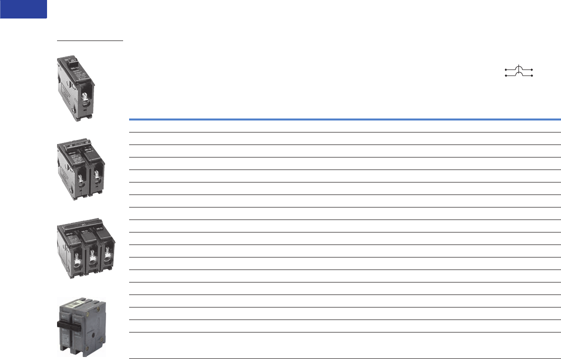
V1-T1-76 Volume 1—Residential and Light Commercial CA08100002E—June 2014 www.eaton.com
1
1
1
1
1
1
1
1
1
1
1
1
1
1
1
1
1
1
1
1
1
1
1
1
1
1
1
1
1
1
1.2
Loadcenters and Circuit Breakers
Type BR Loadcenters and Circuit Breakers
Product Selection
Plug-On Circuit Breakers, Types BR—10/22/42 kAIC, 120 Vac, 120/240 Vac and 240 Vac
Type BR Breakers, 1-Inch (25.4 mm) per Pole 120/240, 10, 22 and 42 kAIC
Notes
1 One pole, 1-inch (25.4 mm) per pole circuit breakers are available with high magnetic setting for switching large tungsten lamp loads. Add suffix H to catalog number.
2 Switching duty rated.
3 On the black handle breaker, add suffix “B” to the catalog number to obtain a tapped molded opening for proper use with hold-down kits.
4 For use as a branch circuit breaker in 400 and 600 ampere panels only.
All Type BR single-, two- and three-pole circuit breakers carry listing for HACR application. For circuit breakers with a shunt trip, add ST suffix.
Ampere
Rating
Wire Size Range
Cu/Al 60°C or 75°C
Single-Pole 120/240 Vac
Requires One 1-Inch (25.4 mm) Space
Two-Pole 120/240 Vac
Common Trip Requires Two
1-Inch (25.4 mm) Spaces
10 per Shelf Carton 5 per Shelf Carton
10 kAIC 22 kAIC 10 kAIC 22 kAIC 42 kAIC
Catalog
Number
Catalog
Number
Catalog
Number
Catalog
Number
Catalog
Number
10 #14–4 BR110 — BR210 — —
15 #14–4 BR115 12 BRH115 BR215 3BRH215 —
20 #14–4 BR120 12 BRH120 BR220 3BRH220 —
25 #14–4 BR125 BRH125 BR225 3BRH225 —
30 #14–4 BR130 BRH130 BR230 3BRH230 —
35 #14–4 BR135 BRH135 BR235 3BRH235 —
40 #14–4 BR140 BRH140 BR240 3BRH240 3—
45 #14–4 — BRH145 BR245 3BRH245 —
50 #14–4 BR150 BRH150 BR250 3BRH250 3—
55 #14–3 BR150 BRH155 BR255 BRH255 —
60 #8–1/0 BR160 BRH160 BR260 BRH260 BRHH260
70 #8–1/0 BR170 BRH170 BR270 BRH270 BRHH270
80 #8–1/0 — — BR280 BRH280 BRHH280
90 #8–1/0 — — BR290 BRH290 BRHH290
100 #8–1/0 — — BR2100 BRH2100 BRHH2100
110 #8–1/0 — — BR2110 BRH2110 BRHH2110
125 #4–2/0 — — BR2125 BRH2125 BRHH2125
150 #4–2/0 — — BR2150 4——
BR120
BR215
BR320
BRH2100
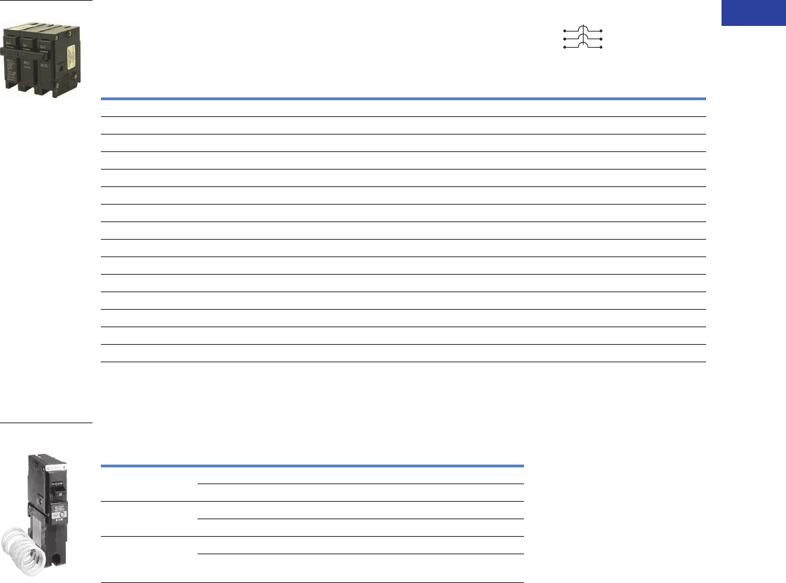
Volume 1—Residential and Light Commercial CA08100002E—June 2014 www.eaton.com V1-T1-77
1
1
1
1
1
1
1
1
1
1
1
1
1
1
1
1
1
1
1
1
1
1
1
1
1
1
1
1
1
1
1.2
Loadcenters and Circuit Breakers
Type BR Loadcenters and Circuit Breakers
Type BR Breakers, 1-Inch (25.4 mm) per Pole 240 Vac, 10, 22 and 42 kAIC
Plug-On Branch Feeder Type Arc Fault Circuit Breakers, Type BR—10 kAIC, 120 Vac and 120/240 Vac
Type BR, 1-Inch (25.4 mm) Wide FIRE-GUARD AFCI Circuit Breakers
Notes
1 One pole, 1-inch (25.4 mm) per pole circuit breakers are available with high magnetic setting for switching large tungsten lamp loads. Add suffix H to catalog number.
2 Clamshell packaging available with CS modification code on the end of catalog number.
3 Common trip refers to two-pole 240V load application sourced by 120/240 Vac (see Page V1-T1-86).
4 Independent trip refers to two-pole multi-wire, home run or shared neutral circuits (see Pages V1-T1-86 and V1-T1-87).
All Type BR single-, two- and three-pole circuit breakers carry listing for HACR application. For circuit breakers with a shunt trip, add ST suffix.
Ampere
Rating
Wire Size Range
Cu/Al 60°C or 75°C
Three-Pole 240 Vac
Common Trip Requires Three
1-Inch (25.4 mm) Spaces
5 per Shelf Carton
10 kAIC 22 kAIC
Catalog Number Catalog Number
10 #14–4 BR310 —
15 #14–4 BR315 1BRH315
20 #14–4 BR320 1BRH320
25 #14–4 BR325 BRH325
30 #14–4 BR330 BRH330
35 #14–4 BR335 BRH335
40 #14–4 BR340 BRH340
45 #14–4 BR345 BRH345
50 #14–4 BR350 BRH350
55 #14–3 BR355 BRH355
60 #4–1/0 BR360 BRH360
70 #4–1/0 BR370 BRH370
80 #4–1/0 BR380 BRH380
90 #4–1/0 BR390 BRH390
100 #4–1/0 BR3100 BRH3100
Poles
Ampere
Rating Configuration
Catalog
Number
Single-pole
10 kAIC
15 AFCI BR115AF 2
20 AFCI BR120AF 2
Single-pole
22 kAIC
15 AFCI BRH115AF
20 AFCI BRH120AF
Two-pole
10 kAIC 34
15 AFCI Common Trip BRL215AF
20 AFCI Common Trip BRL220AF
BR Breakers
Type BR AFCI
Circuit Breaker
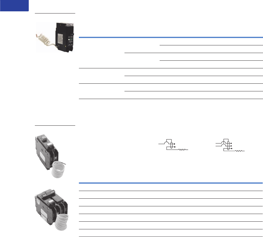
V1-T1-78 Volume 1—Residential and Light Commercial CA08100002E—June 2014 www.eaton.com
1
1
1
1
1
1
1
1
1
1
1
1
1
1
1
1
1
1
1
1
1
1
1
1
1
1
1
1
1
1
1.2
Loadcenters and Circuit Breakers
Type BR Loadcenters and Circuit Breakers
Plug-On Combination Type Arc Fault Circuit Breakers, Type BR—10 kAIC, 120 Vac and 120/240 Vac
Type BR, 1-Inch (25.4 mm) wide FIRE-GUARD Combination Type AFCI
Circuit Breakers
Plug-On Ground Fault Circuit Breakers, Type GFCB and GFEP—10/22 kAIC, 120 Vac and 120/240 Vac
Type GFCB Ground Fault Circuit Breakers—5 Milliampere—
1-Inch (25.4 mm) per Pole 120 Vac or 120/240 Vac, 10 kAIC
Notes
1 Clamshell packaging available with CS modification code on the end of catalog number.
2 Available with bell alarm or auxiliary switch. See circuit breaker accessories on Page V1-T1-84.
3 For use with copper wire only.
Poles
Ampere
Rating Configuration
Catalog
Number
Single-pole
10 kAIC
15 AFCI BRCAF115 1
Diagnostic AFCI BRACAF115
20 AFCI BRCAF120 1
Diagnostic AFCI BRACAF120
Single-pole
22 kAIC
15 AFCI BRHCAF115 1
20 AFCI BRHCAF120 1
Two-pole
10 kAIC
15 AFCI BRL215CAF
20 AFCI BRL220CAF
Ampere
Rating
Wire Size Range
Cu/Al 60°C or 75°C
Single-Pole 120 Vac
Requires One
1-Inch (25.4 mm) Space
Two-Pole 120/240 Vac
Common Trip Requires Two
1-Inch (25.4 mm) Spaces
1 per Shelf Carton 1 per Shelf Carton
Catalog Number 2Catalog Number
15 #14–4 GFCB115 GFCB215
20 #14–4 GFCB120 GFCB220
25 #14–4 GFCB125 GFCB225
30 #14–4 GFCB130 GFCB230
40 #14–4 GFCB140 GFCB240
50 #14–4 — GFCB250 3
60 #14–6 — GFCB260
BRCAF115
Type GFCB Single-Pole
Type GFCB Two-Pole
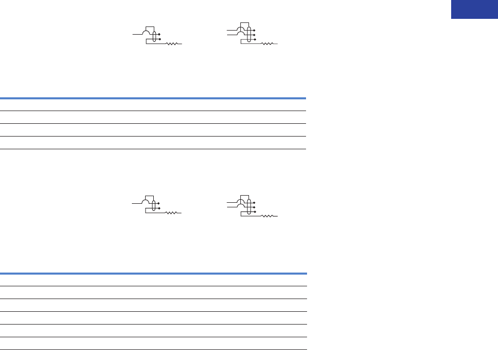
Volume 1—Residential and Light Commercial CA08100002E—June 2014 www.eaton.com V1-T1-79
1
1
1
1
1
1
1
1
1
1
1
1
1
1
1
1
1
1
1
1
1
1
1
1
1
1
1
1
1
1
1.2
Loadcenters and Circuit Breakers
Type BR Loadcenters and Circuit Breakers
Type GFCBH Ground Fault Breakers—5 Milliampere—
1-Inch (25.4 mm) per Pole 120 Vac or 120/240 Vac, 22 kAIC
Type GFEP Ground Fault Equipment Protectors—30 Milliampere—
1-Inch (25.4 mm) per Pole 120 Vac or 120/240 Vac, 10 kAIC
Note
1 For use with copper wire only.
Ampere
Rating
Wire Size Range
Cu/Al 60°C or 75°C
Single-Pole 120 Vac
Requires One
1-Inch (25.4 mm) Space
Two-Pole 120/240 Vac
Common Trip Requires Two
1-Inch (25.4 mm) Spaces
1 per Shelf Carton 1 per Shelf Carton
Catalog Number Catalog Number
15 #14–4 GFCBH115 GFCBH215
20 #14–4 GFCBH120 GFCBH220
25 #14–4 GFCBH125 GFCBH225
30 #14–4 GFCBH130 GFCBH230
Ampere
Rating
Wire Size Range
Cu/Al 60°C or 75°C
Single-Pole 120 Vac
Requires One
1-Inch (25.4 mm) Space
Two-Pole 120/240 Vac
Common Trip Requires Two
1-Inch (25.4 mm) Space
1 per Shelf Carton 1 per Shelf Carton
Catalog Number Catalog Number
15 #14–4 GFEP115 GFEP215
20 #14–4 GFEP120 GFEP220
25 #14–4 GFEP125 GFEP225
30 #14–4 GFEP130 GFEP230
40 #14–4 — GFEP240
50 #14–4 — GFEP250 1
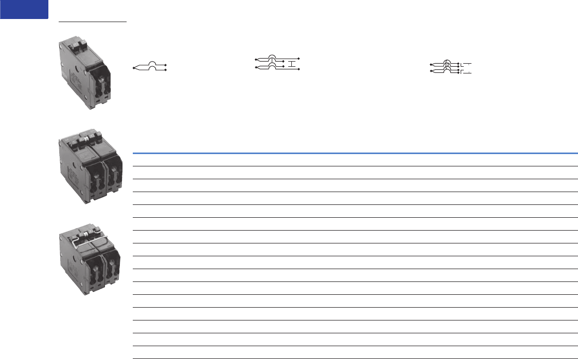
V1-T1-80 Volume 1—Residential and Light Commercial CA08100002E—June 2014 www.eaton.com
1
1
1
1
1
1
1
1
1
1
1
1
1
1
1
1
1
1
1
1
1
1
1
1
1
1
1
1
1
1
1.2
Loadcenters and Circuit Breakers
Type BR Loadcenters and Circuit Breakers
CTL Plug-On Circuit Breakers, Type BD Duplex, BQ and BQC Quadplex—10 kAIC, 120/240 Vac
Class CTL, 1-Inch (25.4 mm) per Pole 10 kAIC—All Circuit Breakers Have Rejection Tab Feature
Notes
1 All 15 and 20A single poles are switch-duty rated.
2 All Type BD duplex and BQ quadplex circuit breakers carry listing for HACR applications.
Type BD Duplex
(UL Type BRD)
Wire Size
Range
Cu/Al
65°C or 75°C
Type BQ Quadplex Independent Trip
(UL Type BRD)
Type BQ Quadplex Independent Trip
(UL Type BRD)
Single-Pole 1
Requires One 1-Inch
(25.4 mm) Space
10 per Shelf Carton
Two-Pole 2 and Single-Pole 1
Requires Two 1-Inch
(25.4 mm) Spaces
5 per Shelf Carton
Two-Pole
Requires Two 1-Inch
(25.4 mm) Spaces
5 per Shelf Carton
Ampere
Rating
120 Vac 120 Vac 120/240 Vac 120 Vac
Catalog
Number
120/240 Vac
Catalog
Number
Catalog
Number
Ampere Rating Ampere Rating
Outer Left
Single-Pole
Center Two-Pole
Independent Trip
Outer Right
Single-Pole
Outer Two-Pole
Independent Trip
Center Two-Pole
Independent Trip
10–10 BD1010 #14–4 15 20 15 BQ2202115 15 15 BQ215215
15–15 BD1515 #14–4 20 20 20 BQ2202120 15 20 BQ215220
15–20 BD1520 #14–4 15 30 15 BQ2302115 15 30 BQ215230
15–30 BD1530 #14–4 20 30 20 BQ2302120 15 40 BQ215240
20–15 BD2015 #14–4 15 40 15 BQ2402115 15 50 BQ215250
20–20 BD2020 #14–4 20 40 20 BQ2402120 20 20 BQ220220
20–30 BD2030 #14–4 15 50 15 BQ2502115 20 30 BQ220230
25–25 BD2525 #14–4 20 50 20 BQ2502120 20 40 BQ220240
30–15 BD3015 #14–4 — — — —20 50 BQ220250
30–20 BD3020 #14–4 — — — —25 25 BQ225225
30–30 BD3030 #14–4 — — — —30 30 BQ230230
30–40 BD3040 #14–4 — — — —30 40 BQ230240
30–50 BD3050 #14–4 — — — —30 50 BQ230250
50–30 BD5030 #14–4 — — — —40 40 BQ240240
50–50 BD5050 #14–4 — — — —40 50 BQ240250
————— ——50 50 BQ250250
BD2020
BQ2302115
BQ230230
120/240 Vac
120/240 Vac
120 Vac
120 Vac
120/240 Vac 120/240 Vac
120/240 Vac
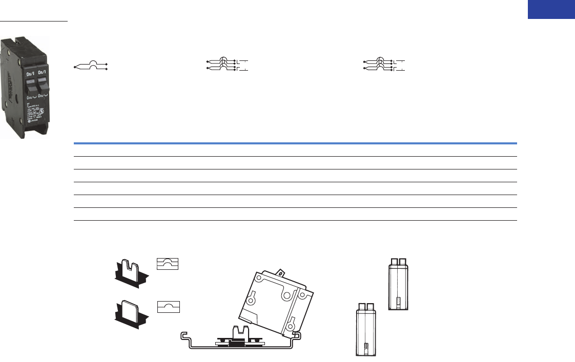
Volume 1—Residential and Light Commercial CA08100002E—June 2014 www.eaton.com V1-T1-81
1
1
1
1
1
1
1
1
1
1
1
1
1
1
1
1
1
1
1
1
1
1
1
1
1
1
1
1
1
1
1.2
Loadcenters and Circuit Breakers
Type BR Loadcenters and Circuit Breakers
Non-CTL Plug-On Replacement—Circuit Breakers, Type BRD—10 kAIC, 120/240 Vac
Class Non-CTL, 1-Inch (25.4 mm) per Pole 10 kAIC—Breakers Do Not Have Rejection Tab Feature
CTL and Non-CTL Breakers
Note
Type BD Duplex, BQ and BQC Quadplex circuit breakers can be installed in Circuit Limiting (CTL) listed BR loadcenters. Type BR twin breakers can be installed in
Non-CTL BR loadcenters.
Type BR Duplex
Wire Size
Range
Cu/Al
65°C or 75°C
Type Brand BRD Quadplex Independent Trip
Type BRD Quadplex Common Trip
Center and Outer Poles
Single-Pole Requires One
1-Inch (25.4 mm) Space
10 per Shelf Carton
Two-Pole Requires Two
1-Inch (25.4 mm) Spaces
5 per Shelf Carton
Two-Pole Requires Two
1-Inch (25.4 mm) Spaces
5 per Shelf Carton
Ampere
Rating
120 Vac 120/240 Vac 120/240 Vac
Catalog
Number
120/240 Vac
Catalog
Number
Catalog
Number
Ampere Rating Ampere Rating
Outer Two-Pole
Independent Trip
Center Two-Pole
Independent Trip
Outer Two-Pole
Common Trip
Center Two-Pole
Common Trip
15–15 BR1515 #14–4 15 15 BR415 15 15 BRDC215215
15–20 BR1520 #14–4 20 20 BR420 30 30 BRDC230230
20–15 BR2015 #14–4 30 30 BR430 30 40 BRDC230240
20–20 BR2020 #14–4 20 30 BRD220230 30 50 BRDC230250
30–30 BR3030 #14–4 30 40 BRD230240 —— —
30–50 BR3050 #14–4 30 50 BRD230250 —— —
BR2020
120/240 Vac
120/240 Vac
120/240 Vac
120/240 Vac
120/240 Vac
120/240 Vac
Notched
Bus Stab
Unnotched
Bus Stab
Type BR or Type BD Duplex, (CTL),
Type BQ and
BQC Quadplex
Type BR Notched
Stab Non-CTL
Non-Circuit
Limiting
Type BR
Type BD
Duplex
Rejection
Tab
CTL Circuit
Limiting
Feature
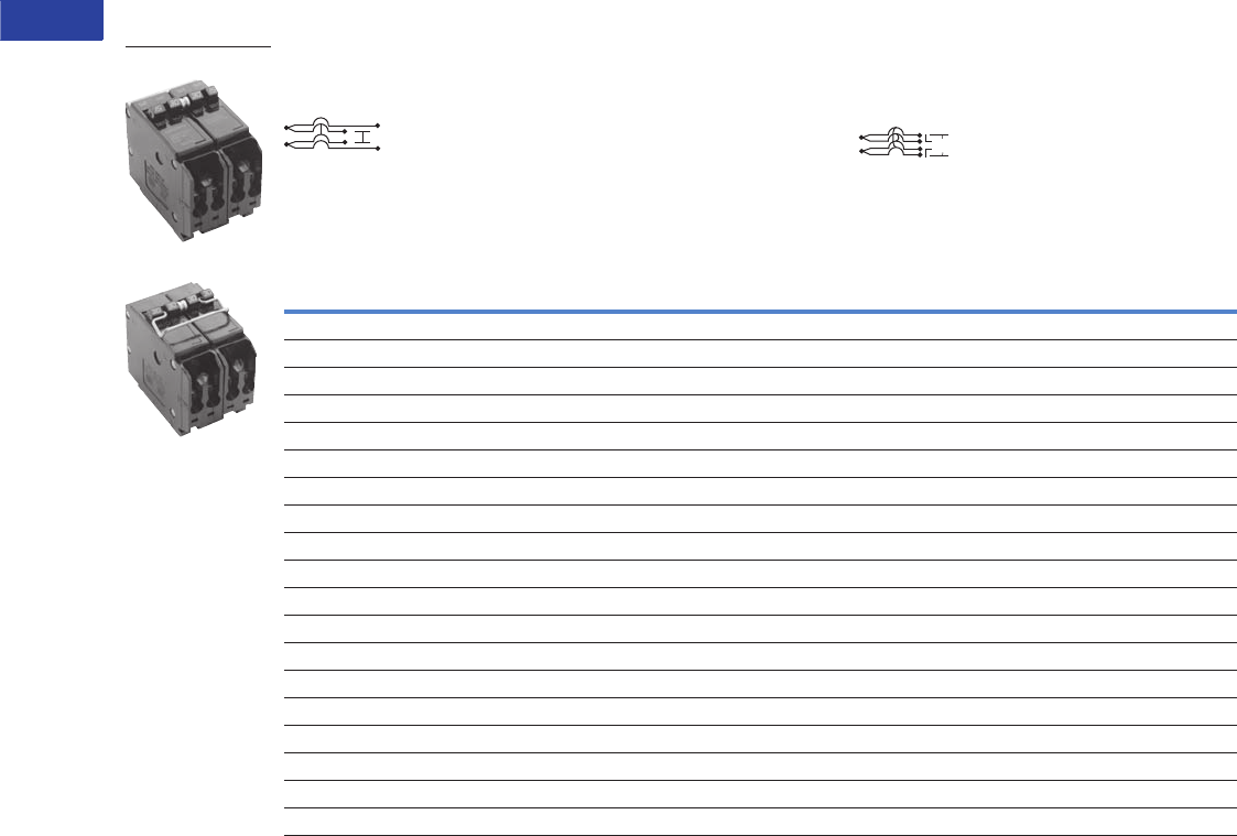
V1-T1-82 Volume 1—Residential and Light Commercial CA08100002E—June 2014 www.eaton.com
1
1
1
1
1
1
1
1
1
1
1
1
1
1
1
1
1
1
1
1
1
1
1
1
1
1
1
1
1
1
1.2
Loadcenters and Circuit Breakers
Type BR Loadcenters and Circuit Breakers
Common Trip Quadplex Breakers
Class CTL, 1-Inch (25.4 mm) per Pole 10 kAIC—All Circuit Breakers Have Rejection Tab Feature
Notes
1 All Type BQC quadplex circuit breakers carry listing for HACR applications.
2 All 15 and 20 ampere single poles are switch-duty rated.
Type BQC Quadplex Common Trip Center Poles
(UL Type BRD)
Wire Size Range
Cu/Al 65°C
or 75°C
Type BQC Quadplex Common Trip Center and Outer Poles
(UL Type BRD)
Two-Pole 1 and Single-Pole 2
Requires Two 1-Inch (25.4 mm) Spaces
5 per Shelf Carton
Two-Pole 1
Requires Two 1-Inch (25.4 mm) Spaces
5 per Shelf Carton
120 Vac 120/240 Vac 120 Vac
Catalog
Number
120/240 Vac
Catalog
Number
Ampere Rating Ampere Rating
Outer Left
Single-Pole
Center Two-Pole
Common Trip
Outer Right
Single-Pole
Outer Two-Pole
Common Trip
Center Two-Pole
Common Trip
15 20 15 BQC2202115 #14–4 15 15 BQC215215
15 25 15 BQC2252115 #14–4 15 20 BQC215220
15 30 15 BQC2302115 #14–4 15 30 BQC215230
15 40 15 BQC2402115 #14–4 20 15 BQC220215
15 50 15 BQC2502115 #14–4 20 20 BQC220220
—— ——#14–4 20 30 BQC220230
—— ——#14–4 20 40 BQC220240
—— ——#14–4 20 50 BQC220250
20 15 20 BQC2152120 #14–4 25 25 BQC225225
20 20 20 BQC2202120 #14–4 25 30 BQC225230
20 25 20 BQC2252120 #14–4 30 15 BQC230215
20 30 20 BQC2302120 #14–4 30 30 BQC230230
20 40 20 BQC2402120 #14–4 30 40 BQC230240
20 50 20 BQC2502120 #14–4 30 50 BQC230250
30 50 20 BQC2502030 #14–4 40 30 BQC240230
—— ——#14–4 40 40 BQC240240
—— ——#14–4 40 50 BQC240250
—— ——#14–4 50 20 BQC250220
—— ——#14–4 50 50 BQC250250
BQC2302115
BQC2302115
120 Vac
120 Vac
120/240 Vac
120/240 Vac
120/240 Vac
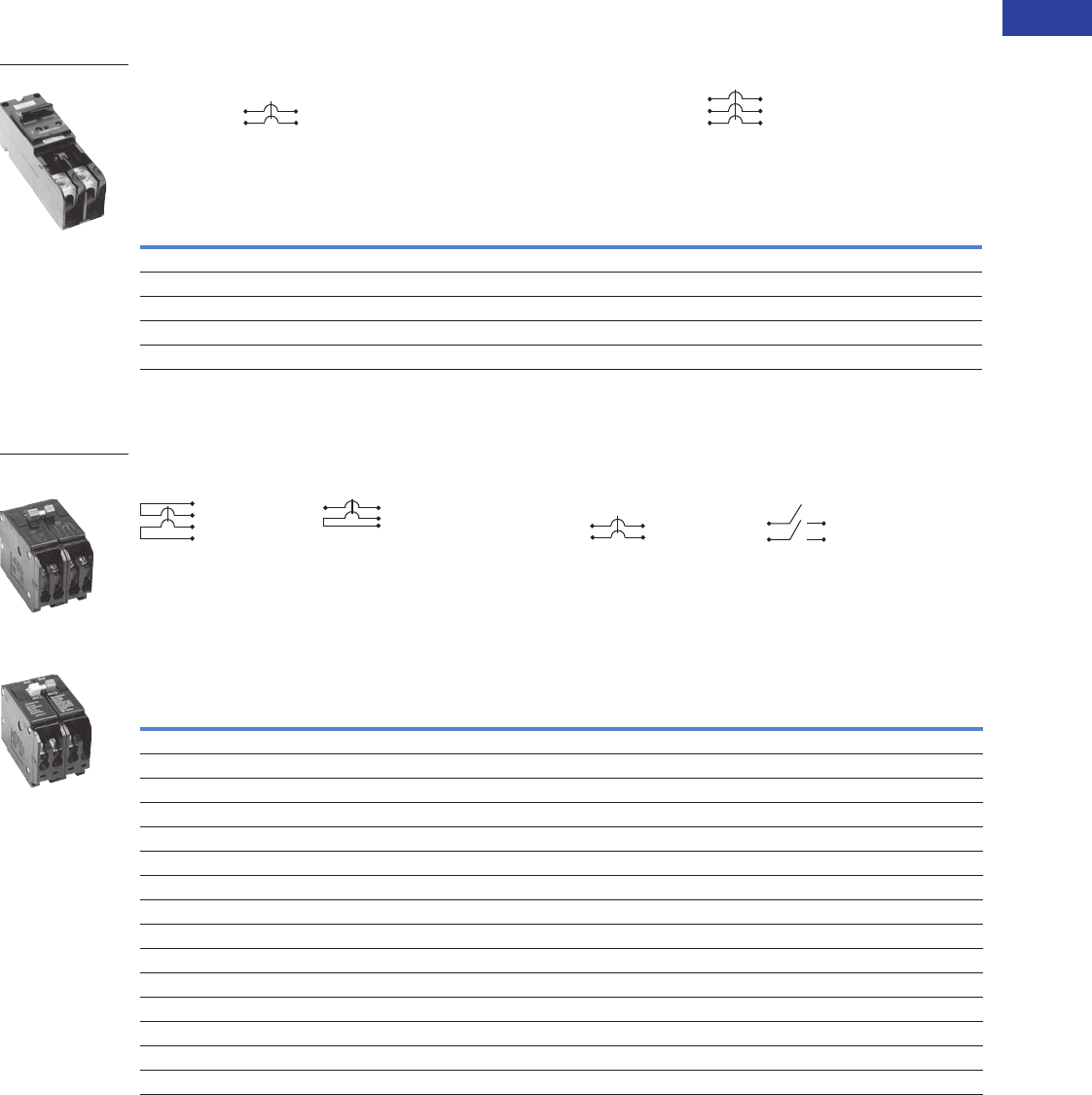
Volume 1—Residential and Light Commercial CA08100002E—June 2014 www.eaton.com V1-T1-83
1
1
1
1
1
1
1
1
1
1
1
1
1
1
1
1
1
1
1
1
1
1
1
1
1
1
1
1
1
1
1.2
Loadcenters and Circuit Breakers
Type BR Loadcenters and Circuit Breakers
Plug-On Circuit Breakers, Types BJ and BJH—10/22 kAIC, 120/240 Vac and 240 Vac
For Use in Single-Phase and Three-Phase Loadcenters—150 Amperes and Above
Types BJ and BJH Breakers, 1-Inch (25.4 mm) per Pole, 120/240 or 240 Vac, 10, 22 kAIC
Plug-On Special Application Circuit Breakers—10 kAIC, 120 Vac, 120/240 Vac and 240 Vac
Special Application Circuit Breakers, 1-Inch (25.4 mm) per Pole
Notes
1 Breaker uses two 1-inch (25.4 mm) pole spaces on left side and two 1-inch (25.4 mm) pole spaces on right side of loadcenter.
2 Breaker uses three 1-inch (25.4 mm) pole spaces on left side and three 1-inch (25.4 mm) pole spaces on right side of loadcenter.
If BJ or BJH breakers are used as a main or a back feed device, a hold-down kit is required. See Page V1-T1-84.
Ampere
Rating
Wire Size Range
Cu/Al 60°C or 75°C
Two-Pole 120/240 Vac
Common Trip Requires Four
1-Inch (25.4 mm) Spaces 1
10 per Shelf Carton
Three-Pole 240 Vac
Common Trip Requires Six
1-Inch (25.4 mm) Spaces 2
5 per Shelf Carton
10 kAIC 22 kAIC 10 kAIC 22 kAIC
Catalog Number Catalog Number Catalog Number Catalog Number
125 BJ2125 BJH2125 #2–300 kcmil BJ3125 BJH3125
150 BJ2150 BJH2150 #2–300 kcmil BJ3150 BJH3150
175 BJ2175 BJH2175 #2–300 kcmil BJ3175 BJH3175
200 BJ2200 BJH2200 #2–300 kcmil BJ3200 BJH3200
225 BJ2225 BJH2225 #2–300 kcmil BJ3225 BJH3225
Water Heater Breakers Switching Neutral Breakers
Wire
Size
Range
Cu/Al
60°C or
75°C
240V Breakers Non-Automatic Molded Case Switches
Two-Pole 120/240 Vac
Common Trip Requires Two
1-Inch (25.4 mm) Spaces
Two-Pole 120 Vac
Common Trip Requires Two
1-Inch (25.4 mm) Spaces
Two-Pole 240 Vac
Common Trip Requires Two
1-Inch (25.4 mm) Spaces
Two-Pole 240 Vac
Requires Two
1-Inch (25.4 mm) Spaces
With Isolated Line Terminals
for Separately Metered
Water Heaters
With Switching Neutral Pole
for Gasoline Pump Applications
Where Voltage to
Ground is 240 Vac
For Use as Disconnect Contains No
Magnetic or Thermal Trip Properties
5 per Shelf Carton 5 per Shelf Carton 5 per Shelf Carton 5 per Shelf Carton
10 kAIC 10 kAIC 10 kAIC 5 kAIC
Ampere
Rating
Catalog
Number
Ampere
Rating
Catalog
Number
Ampere
Rating
Catalog
Number
Ampere
Rating
Catalog
Number
15 BRWH215 15 BRSN215 #14–4 10 BR210H ——
20 BRWH220 20 BRSN220 #14–4 15 BR215H ——
30 BRWH230 25 BRSN225 #14–4 20 BR220H ——
——30 BRSN230 #14–4 25 BR225H ——
————#14–4 30 BR230H——
————#14–4 35 BR235H ——
————#14–4 40 BR240H ——
————#14–4 45 BR245H ——
————#14–4 50 BR250H 50 BR250NA
————#14–4 55 BR255H ——
————#4–1/0 60 BR260H 60 BR260NA
————#4–1/0 70 BR270H ——
————#4–1/0 80 BR280H ——
————#4–1/0 90 BR290H ——
————#4–1/0 100 BR2100H 100 BR2100NA
Type BJ
BRWH215
Water Heater Breaker
BRSN220
Switching Neutral
Breaker
LINE
LOAD
OUT
IN
NEUTRAL
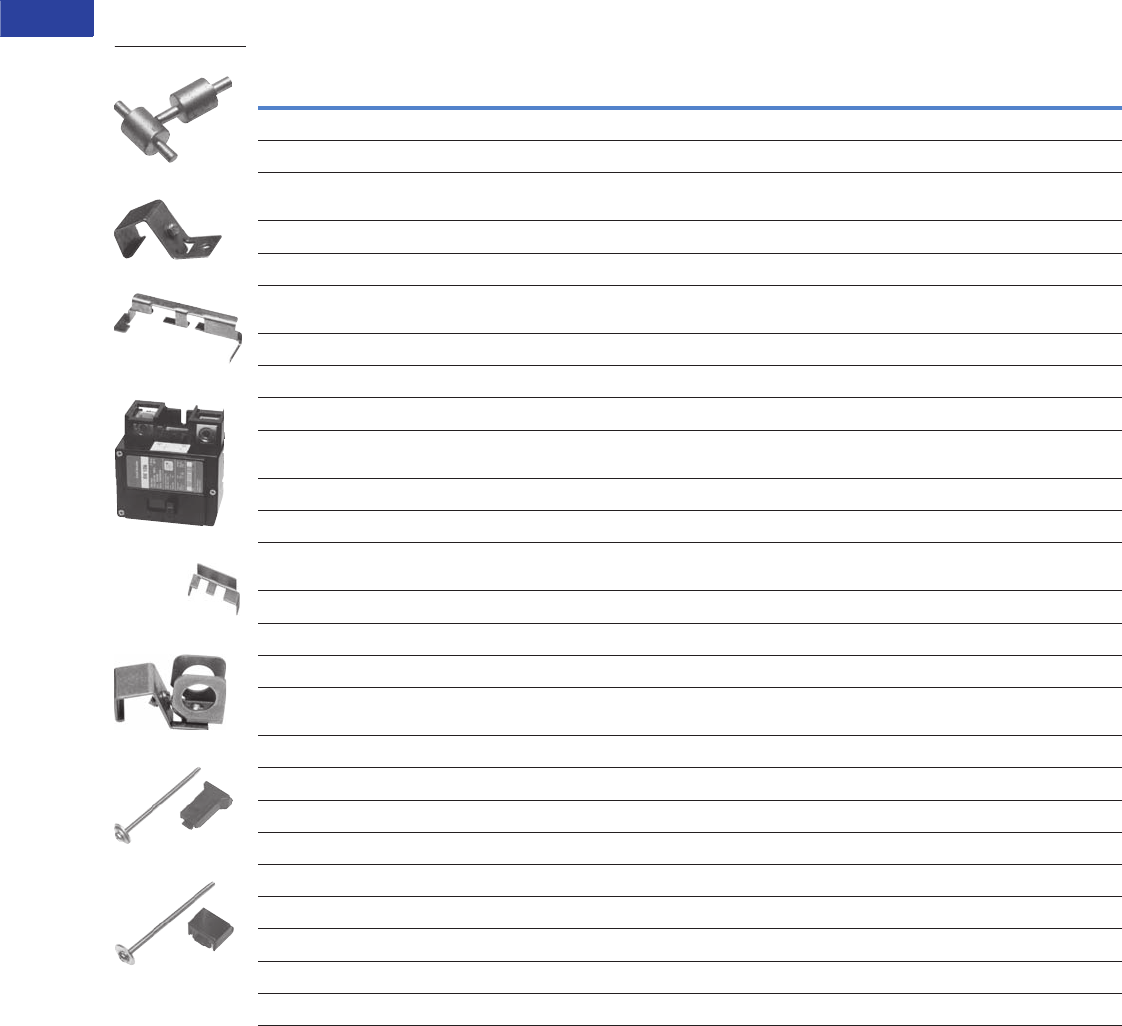
V1-T1-84 Volume 1—Residential and Light Commercial CA08100002E—June 2014 www.eaton.com
1
1
1
1
1
1
1
1
1
1
1
1
1
1
1
1
1
1
1
1
1
1
1
1
1
1
1
1
1
1
1.2
Loadcenters and Circuit Breakers
Type BR Loadcenters and Circuit Breakers
Circuit Breaker Accessories
Field Installation Kits and Parts
Notes
1 Must be purchased in multiples of ordering quantities indicated.
2 Handle ties: typically used to join two similar independent single-pole breakers to form a two-pole noncommon trip breaker.
3 Handle lockoffs: devices that use a padlock to lock the circuit breaker’s handle in the ON or OFF position.
4 See table on Page V1-T1-85 for handle position changeability chart.
5 Escutcheon mounted: device mounted semipermanently to the face of the circuit breaker and secured by the loadcenter deadfront.
6 Handle mounted: device mounted directly to the handle by the use of a set screw.
7 Screw mounted: device permanently mounted to the face of the circuit breaker by the use of a non-removable screw.
8 Hold-down kits: devices used to secure the circuit breaker to the loadcenter for back-feed main application. See NEC Article 384.16(g).
Description
Ordering
Quantity
1
Catalog
Number
Handle Ties 2
Handle tie bar for physically joining the handles of two adjacent single-pole Type BR circuit breakers (metal cylinder pin type)10BHT
Handle tie bar for joining two independent outside poles of Types BQ and BQC Quadplex and outside poles of two Type BD
duplex circuit breakers
10 THOW
Handle tie bar for joining two adjacent outside poles of Types BQ and BQC Quadplex and outside poles of two Type BD duplex circuit breakers 10 THS1
Handle Lockoffs 34
Padlockable device for locking the handle of single-, two- or three-pole Type BR Circuit Breakers and single-pole of a Type BD Duplex
or one independent outside pole of a Type BQ or BQC Quadplex circuit breakers (escutcheon mounted) 5
10 BRLW
Padlockable device for locking the handle of a single-pole Type BR circuit breaker (handle mounted) 610 BRLW1
Padlockable device for locking the handle of a two- and three-pole Type BR circuit breaker (handle mounted) 610 BRLW2
Padlockable device for locking the handle of a single-pole Type BD Duplex, BQ or BQC Quadplex breaker (handle mounted) 610 BRDL1
Padlockable device for locking the handle of the two center poles and the two outer poles of a two-pole Types BQ and BQC quadplex
circuit breakers (escutcheon mounted) 5
10 BRQLW
Padlockable device for locking the handle of main circuit breaker Types CC and CHH into the ON or OFF position (screw mounted) 7 1 CCPL
Padlockable device for locking the handle of main breaker Types BW and CSR into the ON or OFF position (escutcheon Mounted) 51MCBPL
Device used to secure handle in ON or OFF position for single-, two- or three-pole Type BR circuit breakers and single-pole of Type BD
duplex and one independent outside pole of Type BQ or BQC Quadplex circuit breakers (escutcheon mounted) 5
10 BHLW
Device used to secure handle in ON or OFF position for single-pole Type BR circuit breakers (handle mounted) 610 BHLW1
Device used to secure handle in ON or OFF position for two- and three-pole Type BR circuit breakers (handle mounted) 610 BHLW2
Device used to secure handle in ON or OFF position for single-pole Type GFCB ground fault circuit breakers (handle mounted) 610 BHGW
Device used to secure handle in ON or OFF position for one independent outside pole of Types BQ and BQC Quadplex or single-pole
Type BD duplex circuit breakers (handle mounted) 6
10 HLW1
Hold-Down Kits 8
Hold-down retainer kit for three-pole Type BR circuit breakers in S3100 and 3100R loadcenters only 1 BRHDB
Hold-down screw kit for two- and three-pole Type BR circuit breakers in single-phase MLO loadcenters through 100–125A 1 BREQS125
Hold-down screw kit for two- and three-pole Type BR circuit breakers in MLO loadcenters 150–225A 1 BRHDK125
Hold-down screw kit for two-pole Types BJ and BJH circuit breakers in MLO loadcenters 125–225A 1 BJHDS
Hold-down screw kit for three-pole Types BJ and BJH circuit breakers in MLO loadcenters 125–225A 1 BJHDS3P
Main Breaker Lug Kits
Types CC and CHH main breaker lug kit (2) 300 kcmil 1CCL300
Types BW/CSR main breaker lug kit (2) 300 kcmil 1MCBL300
THS1
BHLW2
BRQLW
MCBPL (Installed)
BHLW
BRLW2
BREQS125
BRHDK125
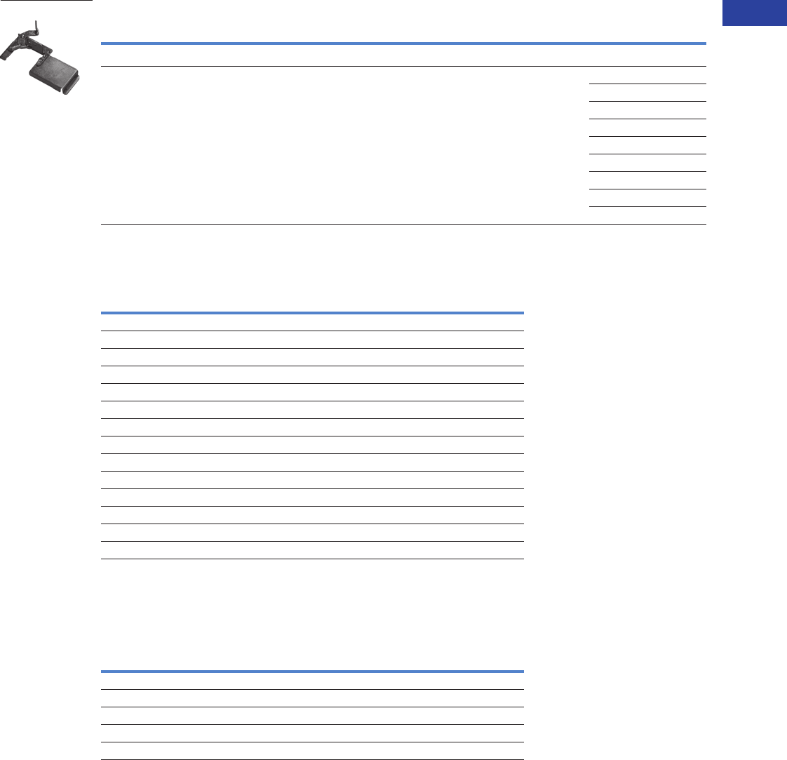
Volume 1—Residential and Light Commercial CA08100002E—June 2014 www.eaton.com V1-T1-85
1
1
1
1
1
1
1
1
1
1
1
1
1
1
1
1
1
1
1
1
1
1
1
1
1
1
1
1
1
1
1.2
Loadcenters and Circuit Breakers
Type BR Loadcenters and Circuit Breakers
Field Installation Kits and Parts, continued
Shunt Trips, Auxiliary and Alarm Contacts
Handle Position Changeability Chart
Notes
1 Must be purchased in multiples of ordering quantities indicated.
2 Add suffix indicated to end of breaker catalog number.
Description
Ordering
Quantity
1
Catalog
Number
Mechanical Interlocks
Types BR for two-, three- and four-pole breakers 10 BRML
10 BRPLOFF
10 BRPLOFF2P
10 BRPLOFF3P
10 BJL2P
10 BJL3P
10 GHQRLOFF2P
10 GHQRLOFF
10 QCD123PLOFF
Description
Catalog Number 2
Suffix Adder
Shunt Trip for Types BW/CSR
12 Volts SR12
24 Volts SR24
120 Volts SR01
Shunt Trip for Types BR
120 Volts ST
Auxiliary Contact for Types BW/CSR
1NO and 1NC AL1
2NO and 2NC AL2
Alarm Contacts for Types BW/CSR
Types BW/CSR CR1
Alarm Contacts for Type GFCB (Single-Pole)
Alarm contact for GFCB (single-pole) W1
1NO and 1NC W2
Handle Lockoff and
Lockdog Types
To Change Handle Position from ON to OFF, or OFF to ON
You Must...
Remove
Padlock
Remove
Device
Remove
Loadcenter
Deadfront
Lockoff escutcheon mounted Remove — —
Lockoff handle mounted Remove Remove —
Lockoff screw mounted Remove — —
Lockdog escutcheon mounted N/A Remove Remove
Lockdog handle mounted N/A Remove —
BRML
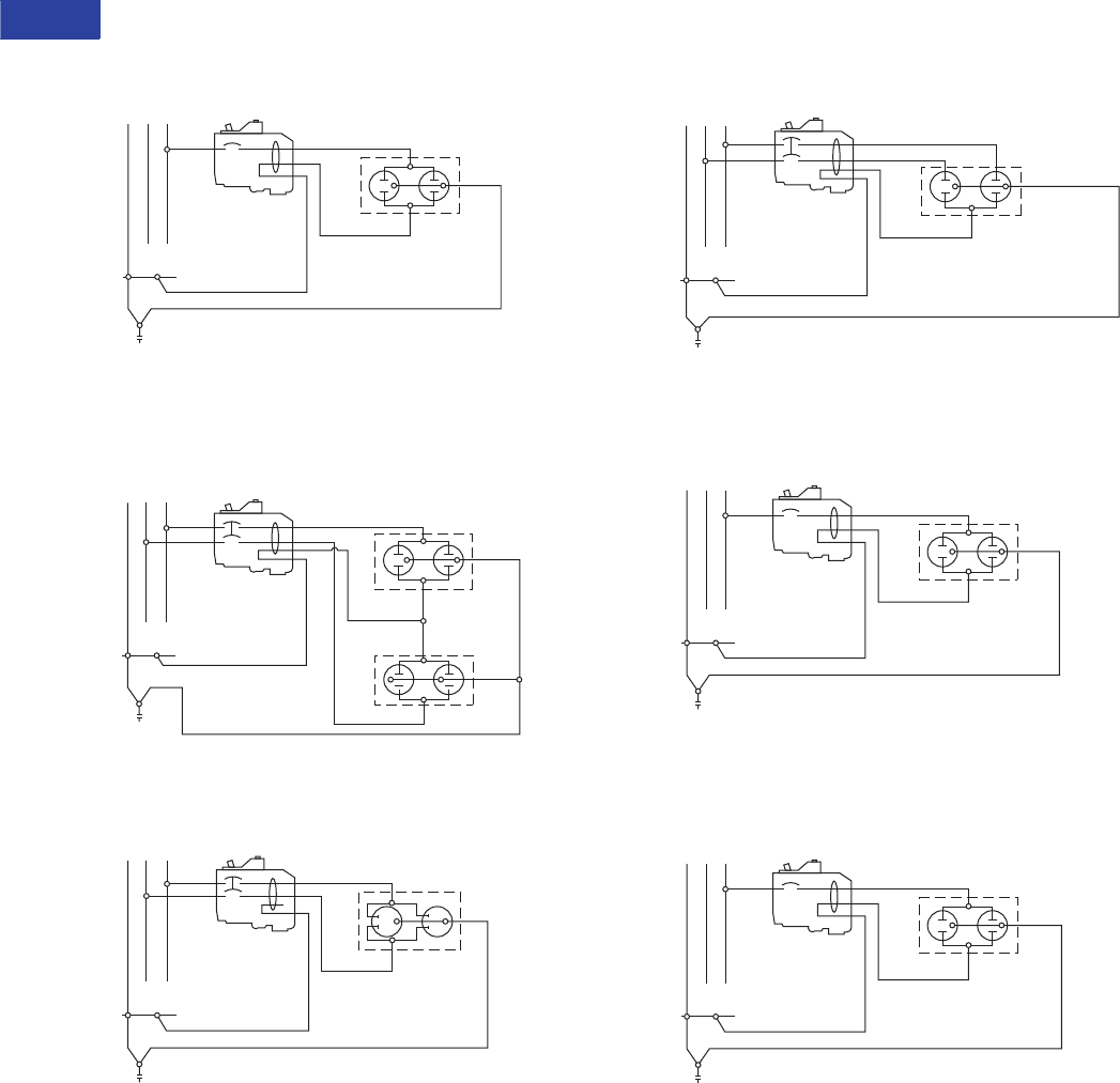
V1-T1-86 Volume 1—Residential and Light Commercial CA08100002E—June 2014 www.eaton.com
1
1
1
1
1
1
1
1
1
1
1
1
1
1
1
1
1
1
1
1
1
1
1
1
1
1
1
1
1
1
1.2
Loadcenters and Circuit Breakers
Type BR Loadcenters and Circuit Breakers
Wiring Diagrams
Single-Pole 120V Load Application Sourced by 120/240 Vac
Two-Pole Shared Neutral with
Multi-Duplex Receptacle Application
Two-Pole 240V Load Application Sourced by 120/240 Vac
Two-Pole Shared Neutral with Duplex Receptacle Application
Single-Pole 120V Load Application Sourced by 120/240 Vac
Single-Pole 120V Duplex Receptacle Application
NAB
120/240 Vac
Source
120V
Duplex
Receptacle
Single-Pole
Line B
Neutral
Neutral
Equipment Ground
NA B
120/240 Vac
Source
Two 120V
Duplex
Receptacles
Two-Pole
Line B
Line A
Neutral
Neutral
Equipment Ground
Line B
NA B
120/240 Vac
Source
Line A 240V
Duplex
Receptacle
Two-Pole
Neutral
Equipment Ground
NAB
120/240 Vac
Source
Line A
120V Duplex
Receptacle
(With Line Side
Jumper Removed)
Two-Pole
Line B
Neutral
Neutral
Equipment Ground
NAB
120/240 Vac
Source
120V
Duplex
Receptacle
Single-Pole
Line B
Neutral
Neutral
Equipment Ground
NAB
120/240 Vac
Source
120V
Duplex
Receptacle
Single-Pole
Line B
Neutral
Neutral
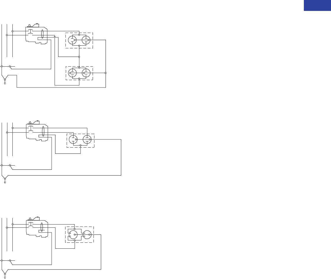
Volume 1—Residential and Light Commercial CA08100002E—June 2014 www.eaton.com V1-T1-87
1
1
1
1
1
1
1
1
1
1
1
1
1
1
1
1
1
1
1
1
1
1
1
1
1
1
1
1
1
1
1.2
Loadcenters and Circuit Breakers
Type BR Loadcenters and Circuit Breakers
Two-Pole 120V Multi-Duplex Receptacle Application
Two-Pole 120V Duplex Receptacle Application
Two-Pole 240V Duplex Receptacle Application
NA B
120/240 Vac
Source
Two 120V
Duplex
Receptacles
Two-Pole
Line B
Line A
Neutral
Neutral
NAB
120/240 Vac
Source
Line A
120V Duplex
Receptacle
(With Line Side
Jumper Removed)
Two-Pole
Line B
Neutral
Neutral
Line B
NA B
120/240 Vac
Source
Line A 240V
Duplex
Receptacle
Two-Pole
Neutral
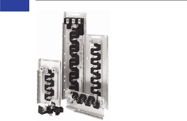
V1-T1-88 Volume 1—Residential and Light Commercial CA08100002E—June 2014 www.eaton.com
1
1
1
1
1
1
1
1
1
1
1
1
1
1
1
1
1
1
1
1
1
1
1
1
1
1
1
1
1
1
1.3
Loadcenters and Circuit Breakers
Loadcenter Interiors/OEM Loadcenters
OEM Loadcenters
Contents
Description Page
Standards and Certifications . . . . . . . . . . . . . . . . . V1-T1-89
Product Selection . . . . . . . . . . . . . . . . . . . . . . . . . V1-T1-89
Product Description
As a leader in the electrical
distribution equipment
business, Eaton has a
unique product offering for
equipment manufacturers,
panel builders and virtually
any OEM that has a need
for power distribution within
their equipment. The OEM
interior offering consists
of a wide variety of power
distribution options utilizing
components from Eaton’s CH
and BR loadcenter product
lines. With high-volume,
standardized products,
OEMs can expect to
receive high-quality products
covering configurations
meeting virtually any power
distribution need.
Coupled with Eaton’s
expertise in circuit breaker
design and manufacturing,
OEM interiors provide solid
power distribution and circuit
protection in a compact,
easy-to-install package.
Interiors are offered from
2 to 42 circuits and from
70 to 225A.
Quality
Built in ISO 9002 certified
manufacturing facilities,
customers can be assured
of the process quality in place
for the manufacture of these
products. Utilizing the latest
in computer-controlled
plating, painting, molding,
stamping and welding
processes, Eaton’s
customers have come to
expect consistent high-quality
from shipment to shipment.
Two Products Offer
Design Flexibility
As a manufacturer of two
lines of loadcenters, Eaton
is in a unique position to
offer the broadest range of
interiors in the market. Each
line has its own unique
characteristics that appeal
to various segments of the
market. OEM interiors are
UL recognized components
and are listed in either of
the following UL files: E8741
or E52977.
The CH interiors feature
100% copper bus and use
the CH 3/4-inch (19.1 mm)
wide circuit breaker, which
minimizes panel space.
Recognized by contractors
for its sturdy design, the
CH interior will appeal to
those customers seeking
an industrial quality bolted
busbar and the space saving
of 3/4-inch (19.1 mm) per
bus stab. With a typical
12 circuit CH interior, this
space savings amounts
to an inch and a half savings
over its 1-inch (25.4 mm)
counterparts. The stab
rating of the CH interiors
is 140A maximum meaning
that the handle rating of
breakers mounted across
from one another may not
exceed 140A.
The BR interiors are
manufactured of formed,
plated aluminum or copper,
and use Eaton’s Type BR
1-inch (25.4 mm) wide circuit
breaker. This design affords
customers the most circuit
flexibility as many of these
interiors allow the installation
of standard single- and
two-pole breakers as well as
duplex (two poles in a 1-inch
(25.4 mm) space) or quadplex
(four poles in a 2-inch
(50.8 mm) space) breakers.
The stab rating of the BR
interiors is 200A maximum,
meaning that the handle
rating of the breakers that
are mounted across from
one another may not
exceed 200A.
The interiors are designed
for either horizontal (single-
row breaker mounting), or
vertical (double-row breaker
mounting). To comply with
National Electrical Code
(NEC) requirements, if
mounted horizontally, when
the breaker is ON, the handle
should be in the UP position.
When mounted vertically, the
handle toggles from left to
right, so this is not a concern.

Volume 1—Residential and Light Commercial CA08100002E—June 2014 www.eaton.com V1-T1-89
1
1
1
1
1
1
1
1
1
1
1
1
1
1
1
1
1
1
1
1
1
1
1
1
1
1
1
1
1
1
1.3
Loadcenters and Circuit Breakers
Loadcenter Interiors/OEM Loadcenters
Standards and Certifications
Class CTL
National Electrical Code
Paragraph 384-15 requires
branch circuit panelboards
to be provided with physical
means to prevent the
installation of more
overcurrent devices than
that number of which the
enclosure was designed,
rated and approved. Class
CTL Duplex, Quadplex and
twin breakers (identified
by a catalog number prefix
BD, BQ, BQC and CHT)
are equipped with a
UL listed rejection tab
over the line terminal.
All OEM interiors have
appropriately notched stabs
to accept these rejection
tab Class CTL breakers.
Duplex, Quadplex and twin
breakers manufactured
without the rejection tab
(identified by a catalog
number prefix BR, BRD
and CHNT) are available
for replacement purposes
in older interiors.
Federal Specifications
All loadcenter enclosures
meet Federal Specifications
W-P-115b, Type 1, Class 2
requirements.
All 120/240V breakers, both
1-inch (25.4 mm), 1/2-inch
(12.7 mm) and 3/4-inch
(19.1 mm) per pole meet
the requirement of Federal
Specifications W-C 375B/
Gen Type 1.
Canadian Standards
Association Listing
All single-pole and two-pole,
120/240V breakers, both
1-inch (25.4 mm), 1/2-inch
(12.7 mm) and 3/4-inch
(19.1 mm) per pole, 225A
maximum, are listed as
Certified by the Canadian
Standards Association, Guide
No. 69-11.19, Class 1432,
File 18328.
Underwriters
Laboratories Listing
All grounding bars
manufactured comply
with Underwriters
Laboratories standards
and are listed under
Guide No. DHJR, File
E31424, Volume W,
Section 17.
All circuit breakers 10A
and larger comply with the
Underwriters Laboratories
“Standard for Branch
Circuit and Service Circuit-
Breakers” UL 489; Guide
No. 60 10.2 File E31424, and
“Requirements for Wire
Connectors and Soldering
Lugs,” UL 486B, Guide
No. 461 10-C File E7830.
All Eaton breakers where
marked, are suitable for use
with 60/75ºC rated wire,
unless otherwise specified.
All devices comply with the
22 kAIC–10 kAIC UL series
connected components File
DKSY2 of the Recognized
Components Index.
Lighting and
Appliance Panelboards
Lighting and appliance
branch circuit panelboards are
defined in NEC (Article 384)
as “One having more than
10 percent of its overcurrent
devices rated 30A or less for
which neutral connections
are provided.” Article 384
also limits the number of
overcurrent devices (branch
circuit poles) to a maximum
of 42 in any one cabinet.
When the 42 poles are
exceeded, two or more
separate panels are required.
For more details and
engineering drawings,
see BR.31.02.S.E.
Product Selection
Type CH Loadcenter Interior Assemblies—Copper Bus
Ampere
Rating
Maximum Number 1-Inch (24.5 mm) UL File
Reference
Main Terminal Size
(Per Phase)
Standard
Package Quantity
Catalog
NumberSpaces Single Poles
Single-Phase Single Row Breaker Mounting—120/240 Vac, Three-Wire
70 2 2 E8741 (1) #8–#2 AWG Cu/Al 1 CH9MB270
125 2 2 E8741 (1) 2/0–#6 AWG Cu/Al 20 CH2L125INT
Single-Phase Double Row Breaker Mounting—120/240 Vac, Three-Wire
125 4 4 E8741 (1) 2/0–#14 AWG Cu/Al 20 CH4L125INT
125 8 8 E8741 (1) 2/0–#6 AWG Cu/Al 20 CH8L125INT
125 12 12 E8741 (1) 2/0–#6 AWG Cu/Al 20 CH12L125INT
125 16 16 E8741 (1) 2/0–#6 AWG Cu/Al 20 CH16L125INT
200 12 12 E8741 (1) 300 kcmil–#4 AWG Cu/Al 20 CH12L200INT
200 16 16 E8741 (1) 300 kcmil–#4 AWG Cu/Al 10 CH16L200INT
225 24 24 E8741 (1) 300 kcmil–#4 AWG Cu/Al 10 CH24L225INT
225 32 32 E8741 (1) 300 kcmil–#4 AWG Cu/Al 10 CH32L225INT
225 42 42 E8741 (1) 300 kcmil–#4 AWG Cu/Al 10 CH42L225INT
Three-Phase Double Row Breaker Mounting—208Y/120 Vac, Four-Wire—240 Vac, Three-Wire—120/240 Vac, Four-Wire Delta
125 12 12 E8741 (1) 2/0–#6 AWG Cu/Al 10 CH12L3125INT
125 18 18 E8741 (1) 2/0–#6 AWG Cu/Al 10 CH18L3125INT
125 24 24 E8741 (1) 2/0–#6 AWG Cu/Al 10 CH24L3125INT
225 24 24 E8741 (1) 300 kcmil–#4 AWG Cu/Al 10 CH24L3225INT
225 30 30 E8741 (1) 300 kcmil–#4 AWG Cu/Al 10 CH30L3225INT
225 42 42 E8741 (1) 300 kcmil–#4 AWG Cu/Al 10 CH42L3225INT

V1-T1-90 Volume 1—Residential and Light Commercial CA08100002E—June 2014 www.eaton.com
1
1
1
1
1
1
1
1
1
1
1
1
1
1
1
1
1
1
1
1
1
1
1
1
1
1
1
1
1
1
1.3
Loadcenters and Circuit Breakers
Loadcenter Interiors/OEM Loadcenters
Type BR Loadcenter Interior Assemblies—Aluminum Bus
Type BR Loadcenter Interior Assemblies—Copper Bus
Ampere
Rating
Maximum Number 1-Inch (24.5 mm) UL File
Reference
Main Terminal Size
(Per Phase)
Standard
Package Quantity
Catalog
NumberSpaces Single Poles
Single-Phase Single Row Breaker Mounting—120/240 Vac, Three-Wire
70 2 4 E8741 (1) #8–#2 AWG Cu/Al 20 24INT70B
125 2 4 E8741 (1) 1/0–#14 AWG Cu
2/0–12 AWG All
20 24INT125B
125 6 12 E52977 (1) 2/0–#14 AWG Cu/Al 20 612INT125SRB
Single-Phase Double Row Breaker Mounting—120/240 Vac, Three-Wire
125 4 8 E8741 (1) 2/0–#14 AWG Cu/Al 20 48INT125B
125 6 12 E8741 (1) 2/0–#14 AWG Cu/Al 20 612INT125B
125 8 16 E8741 (1) 2/0–#14 AWG Cu/Al 20 816INT125B
125 12 12 E52977 (1) 2/0–#14 AWG Cu/Al 20 1212INT125B
125 12 24 E52977 (1) 2/0–#14 AWG Cu/Al 20 1224INT125B
125 16 24 E52977 (1) 2/0–#14 AWG Cu/Al 20 1624INT125B
125 20 24 E52977 (1) 2/0–#14 AWG Cu/Al 10 2024INT125B
125 24 24 E52977 (1) 2/0–#14 AWG Cu/Al 10 2424INT125B
200 8 16 E52977 (1) 300 kcmil–#1 AWG Cu/Al 20 816INT200B
200 12 24 E52977 (1) 300 kcmil–#1 AWG Cu/Al 20 1224INT200B
200 30 40 E52977 (1) 300 kcmil–#1 AWG Cu/Al 10 3040INT200B
225 42 42 E52977 (1) 300 kcmil–#1 AWG Cu/Al 10 4242INT225B
Three-Phase Double Row Breaker Mounting—208Y/120 Vac, Four-Wire—240 Vac, Three-Wire—
120/240 Vac, Four-Wire Delta
125 12 24 E52977 (1) 2/0–#8 AWG Cu/Al 10 1224INT3125B
150 18 36 E52977 (1) 300 kcmil–#2 AWG Cu/Al 10 1836INT3150B
150 24 42 E52977 (1) 300 kcmil–#2 AWG Cu/Al 10 2442INT3150B
200 30 42 E52977 (1) 300 kcmil–#2 AWG Cu/Al 10 3042INT3200B
225 42 42 E52977 (1) 300 kcmil–#2 AWG Cu/Al 10 4242INT3225B
Ampere
Rating
Maximum Number 1-Inch (24.5 mm) UL File
Reference
Main Terminal Size
(Per Phase)
Standard
Package Quantity
Catalog
NumberSpaces Single Poles
Single-Phase Double Row Breaker Mounting—120/240 Vac, Three-Wire
125 8 16 E5297 (1) 2/0–#14 AWG Cu/Al 20 816INT125BC
125 12 12 E5297 (1) 2/0–#14 AWG Cu/Al 20 1212INT125BC
200 12 24 E5297 (1) 300 kcmil–#1 AWG Cu/Al 20 1224INT200BC
Three-Phase Double Row Breaker Mounting—208Y/120 Vac, Four-Wire—240 Vac, Three-Wire—
120/240 Vac, Four-Wire Delta
125 12 24 E52977 (1) 2/0–#8 AWG Cu/Al 10 1224INT3125BC
200 12 24 E52977 (1) 300 kcmil–#2 AWG Cu/Al 10 1224INT3200BC
BR Loadcenter
Interior Assembly
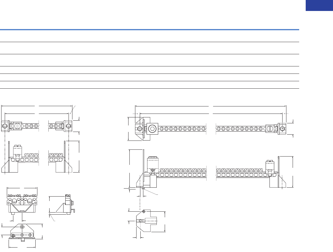
Volume 1—Residential and Light Commercial CA08100002E—June 2014 www.eaton.com V1-T1-91
1
1
1
1
1
1
1
1
1
1
1
1
1
1
1
1
1
1
1
1
1
1
1
1
1
1
1
1
1
1
1.3
Loadcenters and Circuit Breakers
Loadcenter Interiors/OEM Loadcenters
Neutral Assemblies
Ampere
Rating
UL
File
Rating
Main Incoming Terminal
Wire Size Range
60°C or 75°C
Number of Terminals
Standard
Package
Quantity Figure
Dimensions–Inches (mm)
Catalog
Number
#14–4 AWG
Cu/Al
#6–1/0 AWG Cu
#6–2/0 AWG Al
Overall
Length
A
Mounting
B
125 E52977 #6–1/0 AWG Cu
#6–2/0 AWG Al
10 — 20 1 5.938 (150.83) 5.400 (137.16) 10NEU125B
125 E52977 #6–1/0 AWG Cu
#6–2/0 AWG Al
17 — 20 1 8.388 (213.06) 7.850 (199.40) 17NEU125B
125 E52977 #6–1/0 AWG Cu
#6–2/0 AWG Al
20 — 20 1 9.438 (239.73) 8.900 (226.06) 20NEU125B
225 E52977 #1–300 kcmil Cu/Al 24 1 20 2 10.913 (277.19) 10.300 (261.62) 24NEU225B
225 E52977 #1–300 kcmil Cu/Al 35 1 20 2 15.813 (401.65) 15.200 (386.08) 35NEU225B
125 — — 4 2 1 3 2.266 (57.56) 0.594 (15.09) BINA
B
A.269
(6.83)
.844
(21.44)
2.360
(59.94)
C
Lof Mounting Hole C
Lof Mounting Hole
1.187
(30.15)
1.182
(30.02)
B
A
2.000
(50.80)
.156
(3.96)
.688
(17.47)
C
L
of
Mounting
Hole
.269
(6.83)
.344
(8.74)
.844
(21.44)
2.360
(59.94)
1.750
(44.45)
2.860
(72.64)
.250
(6.35) .182 Diameter
(4.62)
.120
(3.05)
1.750
(44.45)
.750
(19.05)
.344
(8.74)
C
Lof Mounting Hole
B
A
Figure 1
Figure 3
Figure 2
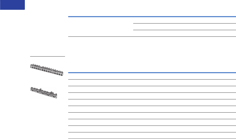
V1-T1-92 Volume 1—Residential and Light Commercial CA08100002E—June 2014 www.eaton.com
1
1
1
1
1
1
1
1
1
1
1
1
1
1
1
1
1
1
1
1
1
1
1
1
1
1
1
1
1
1
1.3
Loadcenters and Circuit Breakers
Loadcenter Interiors/OEM Loadcenters
Add-on Lugs for Neutral Assemblies
Ground Bar Kits
Ground Bar Legend
Notes
1 Must be purchased in multiples of ordering quantities indicated.
2 Distance between mounting holes is 1.75 inches (44.5 mm).
3 For single- and three-phase 400 and 600A applications.
4 Distance between mounting holes is 2.34 inches (59.5 mm).
Description
Wire Size Range
Cu/Al 60°C or 75°C
Ordering
Quantity 1
Catalog
Number
Neutral/ground lug
Add-on neutral or ground lug
#2/0 maximum 1 NL20
#3/0 maximum 1 NL30
300 kcmil maximum 1 NL300
Description
(See Legend)
Length
Inches (mm)
Ordering
Quantity 1
Catalog
Number
dssssds 2.54 (64.5) 1 GBK5 2
dssssdsj 3.59 (91.2) 1 GBK520 2
dssssdssssss 4.29 (109.0) 1 GBK10 2
dssssdssssssj 5.34 (135.6) 1 GBK1020 2
4.61 (117.1) 1 GBK13 2
dssssdssssssssss 5.69 (144.5) 1 GBK14 2
dssssdssssssssssj 6.74 (171.2) 1 GBK1420 2
dssssdsssssssssssssssss 8.14 (206.8) 1 GBK21 2
dssssdsssssssssssssssssj 9.19 (233.4) 1 GBK2120 2
5.78 (146.8) 1 BRGBK39512 34
s
j
d
(3) #14–10 Cu/Al or (1) #14–4 Cu/Al
(1) #6–2/0 Cu/Al
(1) #14–1/0 Cu/Al or (3) #14–10 Cu/Al
(1) #14–6 Cu/Al or (2) #14–12 Cu/Al
Mounting Hole
GBK14
BRGBK39512
f
d
f
f
f
k
f
d
f
k
f
f
f
f
k
f
d
f
k
f
f
f
k
f
d
f
k
f
f
f
k
f
k
f
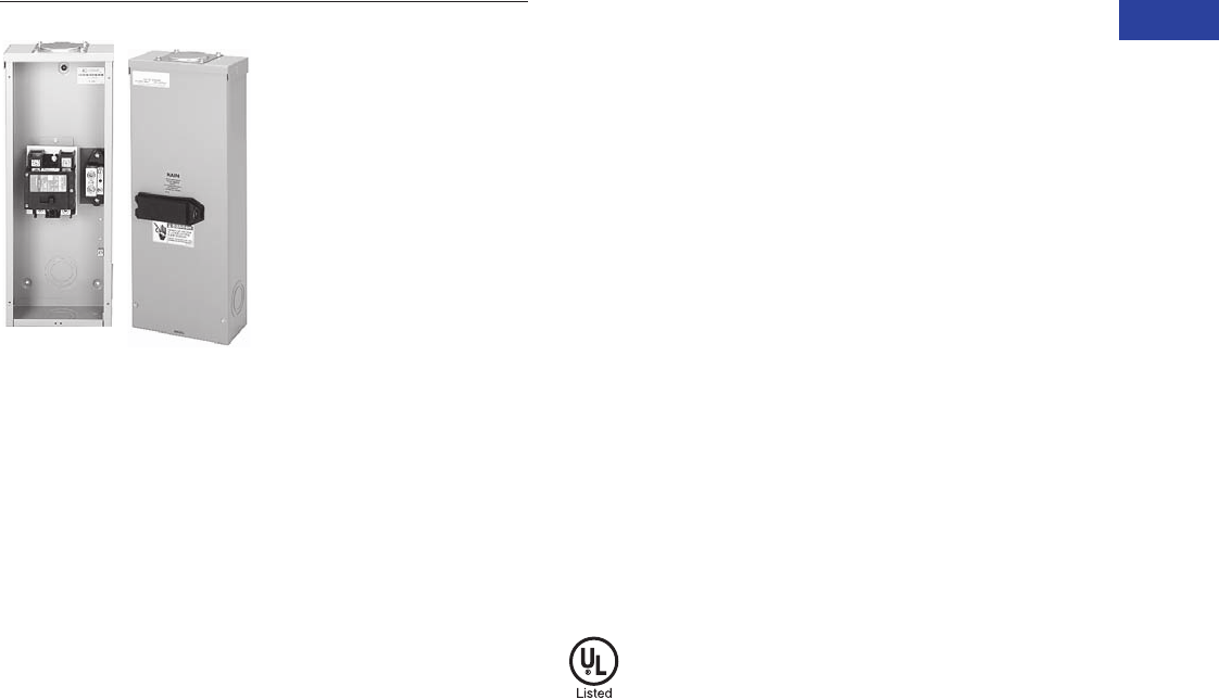
Volume 1—Residential and Light Commercial CA08100002E—June 2014 www.eaton.com V1-T1-93
1
1
1
1
1
1
1
1
1
1
1
1
1
1
1
1
1
1
1
1
1
1
1
1
1
1
1
1
1
1
1.4
Loadcenters and Circuit Breakers
Enclosed Breakers
Enclosed Breakers
Contents
Description Page
Product Selection . . . . . . . . . . . . . . . . . . . . . . . . . V1-T1-94
Product Overview
Eaton enclosed breakers
offer all the advantages of
circuit breakers packed in an
enclosure for 240 Vac
applications and include a
wide range of accessories.
Product Description
●100–225A, 240 Vac
maximum
●
NEMA 1 general purpose—
surface or flush mounting
●NEMA 3R rainproof
surface mounting
Standards and
Certifications
●UL 489
●CSA 22.2
●NEMA 250
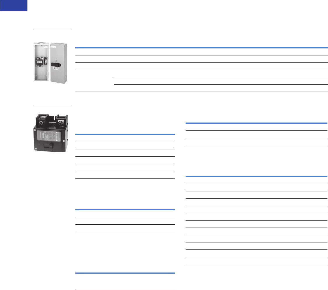
V1-T1-94 Volume 1—Residential and Light Commercial CA08100002E—June 2014 www.eaton.com
1
1
1
1
1
1
1
1
1
1
1
1
1
1
1
1
1
1
1
1
1
1
1
1
1
1
1
1
1
1
1.4
Loadcenters and Circuit Breakers
Enclosed Breakers
Product Selection
Single-Phase Circuit Breaker Enclosures—10/25/35 kAIC
Type ECB Circuit Breaker Enclosure—Includes Lug Kit
Circuit Breakers 120/240 Vac—25 kAIC
For Use in Type ECB Enclosures
Shunt Trips
Lug Kit for Replacement Purposes Only
For Use in Type ECB Enclosures
Wire Data
Shunt Trips, Auxiliary and Alarm Contacts
Notes
1CSR2150N factory-installed circuit breaker.
2CSR2200N factory-installed circuit breaker.
3Order circuit breaker separately.
4Wire size is determined by the circuit breaker installed in enclosure.
Maximum wire size and ampere rating is determined by Wire Data table above.
5Rainproof panels are furnished with hub closures plates. For rainproof hubs,
refer to Page V1-T1-25.
6One ground lug accepting (1) #14 –#2 is factory installed. Also, there are pre-drilled
holes to accept a GBK5 ground bar.
7Approved for service entrance.
8Add suffix indicated to end of breaker catalog number.
Box sizes Pages V1-T1-27 and V1-T1-28.
Main Ampere
Rating
Unit Enclosure
Type Mounting
Type of
Circuit Breaker
Wire Size Range
Cu/Al 60°C or 75°C
Catalog
Number
Single-Phase Three-Wire—240 Vac Maximum
150 Outdoor — CSR (included) 14 ECB150RB 567
200 Outdoor — CSR (included) 24 ECB200RB 567
225 Indoor Flush BW, CSR 3, CSH 4ECB225F 367
Indoor Surface CSR 34 ECB225S 367
Outdoor — CSR 34 ECB225R 3567
Circuit Breaker
Unit Enclosures
Ampere
Rating
Wire Size Range
Cu/Al 60°C or 75°C
for Line Terminals
Two-Pole Breakers
Catalog Number
10 kAIC 25 kAIC
100 #2–300 kcmil — CSR2100N
125 #2–300 kcmil BW2125 CSR2125N
150 #2–300 kcmil BW2150 CSR2150N
175 #2–300 kcmil BW2175 CSR2175N
200 #2–300 kcmil BW2200 CSR2200N
225 #2–300 kcmil BW2225 CSR2225N
Type Volts
Catalog Number
Suffix Adder 8
CSR 12 SR12
CSR 24 SR24
CSR 120 SR01
Ampere
Rating Description
Wire Size Range
Cu/Al 60°C or 75°C
for Line Terminals
Catalog
Number
225 For use on 125,
150, 175, 200 and
225A breakers
#2–300 kcmil MCBK225
CSR2200N
Wire/Application
Maximum
Wire Size
Maximum
Ampere Rating
Aluminum—standard 250 kcmil 200
Aluminum—service entrance 250 kcmil 225
Copper—standard and service entrance 250 kcmil 225
Description
Catalog Number
Suffix Adder 8
Shunt Trip for Types BW/CSR
12V SR12
24V SR24
120V SR01
Auxiliary Contact for Types BW/CSR
1NO and 1NC AL1
2NO and 2NC AL2
Alarm Contacts for Types BW/CSR
Types BW/CSR CR1
Alarm Contacts for Type GFCB (Single-Pole)
Alarm contact for GFCB (single-pole) W1
1NO and 1NC W2
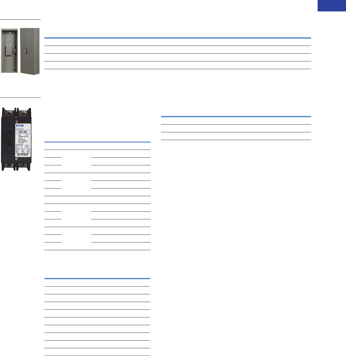
Volume 1—Residential and Light Commercial CA08100002E—June 2014 www.eaton.com V1-T1-95
1
1
1
1
1
1
1
1
1
1
1
1
1
1
1
1
1
1
1
1
1
1
1
1
1
1
1
1
1
1
1.4
Loadcenters and Circuit Breakers
Enclosed Breakers
Single-Phase and Three-Phase Circuit Breaker Enclosures—10/25 kAIC
Type ECC Circuit Breaker Enclosure—Order Type CC Circuit Breaker Separately
Circuit Breaker 240 Vac for Use in
Type ECC Enclosures
Shunt Trips and Auxiliary Contacts 6
Wire/Application Chart
Notes
1Order circuit breaker separately.
2One ground lug accepting (1) #14–#2 is factory installed. Also, there are pre-drilled holes to
accept a GBK5 ground bar.
3Approved for service entrance.
4Rainproof panels are furnished with hub closures plates. For rainproof hubs, refer to
Page V1-T1-65.
5Wire size is determined by the circuit breaker installed in enclosure. Maximum wire size and
ampere rating is determined by the Wire/Application Chart.
6CCV breakers are two-pole only.
7Add suffix indicated to end of breaker catalog number.
8Series ratings are not available for CCH or CCVH breakers.
Box sizes Pages V1-T1-66 through V1-T1-68.
Main Ampere
Rating
Unit Enclosure
Type
Mounting
Type
Circuit
Breaker Type
Wire Size Range
Cu/Al 60°C or 75°C
Catalog
Number
Single- and Three-Phase—240 Vac Maximum
225 Indoor Flush CC/CCV/CCH 5ECC225F 123
225 Indoor Surface CC/CCV/CCH 5ECC225S 123
225 Outdoor — CC/CCV/CCH 5ECC225R 1234
ECC225S
Ampere
Rating
Wire Size
Range
Cu/Al 60°C
or 75°C
for Line
Terminals
Type CCV and
CC 10 kAIC
Catalog
Number
Type
CCVH/CCH
25 kAIC
Catalog
Number 8
Tw o - P o l e
100 #4–4/0 CCV2100 CCVH2100
125 CCV2125 CCVH2125
150 CCV2150 CCVH2150
175 #2/0–300 kcmil CCV2175 CCVH2175
200 CCV2200 CCVH2200
225 CCV2225 CCVH2225
Three-Pole
100 #4–4/0 CC3100 CCH3100
125 CC3125 CCH3125
150 CC3150 CCH3150
175 #2/0–300 kcmil CC3175 CCH3175
200 CC3200 CCH3200
225 CC3225 CCH3225
Description Catalog Number
Suffix Adder 7
Type Volts
Shunt Trip
CC 12 DC SR12
CC 24 DC SR24
CC 120 AC SR01
CC 208 AC SR08
CC 240 AC SR02
CCV 48–127 AC/48–60 DC SR01
CCV 9–24 AC/12–24 DC SR24
Auxiliary Contact
CC 1NO and 1NC — AL1
CCV2200
Wire/Application
Maximum
Wire Size
Maximum
Ampere Rating
Aluminum—standard 250 kcmil 200
Aluminum—service entrance 250 kcmil 225
Copper—standard and service entrance 250 kcmil 225
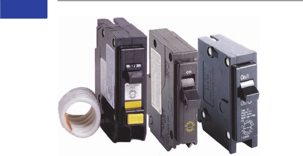
V1-T1-96 Volume 1—Residential and Light Commercial CA08100002E—June 2014 www.eaton.com
1
1
1
1
1
1
1
1
1
1
1
1
1
1
1
1
1
1
1
1
1
1
1
1
1
1
1
1
1
1
1.5
Loadcenters and Circuit Breakers
Classified Circuit Breakers
Classified Breakers
Contents
Description Page
Product Selection . . . . . . . . . . . . . . . . . . . . . . . . . V1-T1-97
Accessories . . . . . . . . . . . . . . . . . . . . . . . . . . . . . V1-T1-99
Technical Data . . . . . . . . . . . . . . . . . . . . . . . . . . . . V1-T1-99
Wiring Diagrams . . . . . . . . . . . . . . . . . . . . . . . . . . V1-T1-100
Product Description
Eaton UL classified
Replacement Circuit Breakers
are available in both 3/4-inch
Type CHQ and 1-inch Type
CL, single- and two-pole
configurations. These
breakers are classified as
direct replacements by
Underwriters Laboratories.
In addition to a UL listing,
they also come with a
15-year warranty.
Specified vs. UL Classified
Specified breakers are listed
by the manufacturer of the
panelboard for use in a
particular panel. This doesn’t
mean that the panelboard
manufacturer produced the
specified breaker; it merely
means that the panelboard
manufacturer has tested the
breaker in the panel. In fact,
through the years, Eaton has
manufactured thousands of
breakers for other panelboard
manufacturers.
UL classified breakers
are produced by one
manufacturer for use in
place of the breakers
specified on the panelboard.
Like specified breakers,
UL classified breakers have
been tested in the panels for
which they are approved.
Testing
Classified breakers are
tested exten
sively in
numerous General Electric
®
,
Siemens
®
, Murray
®
,
Thomas & Betts®, Square D®,
and Crouse-Hinds® panels.
The tests are con
ducted with
witnesses from Underwriters
Laboratories Inc. and involve
short-circuit,
temperature,
and insertion/withdrawal
applications. This level of
testing ensures
that the
breakers meet identified
standards and have been
found suitable by UL for
the specified purpose.
Understanding Classified
Breaker Terminology
Definitions
Specified circuit breaker—
each manufacturer lists
the brands of circuit
breakers that can be used
in their panelboards. Often,
manufacturers will not list
competitors as specified,
even though they are
suitable replacements.
Classified circuit breaker—
a breaker that is considered
suitable, by a qualified third-
party organization, for use
in another manufacturer’s
panelboard.
Listed breaker—the listing
of a circuit breaker is by an
independent third party. Eaton
classified breakers are listed
by UL.
Labeled breaker—a breaker
with a label affixed by an
independent third party.
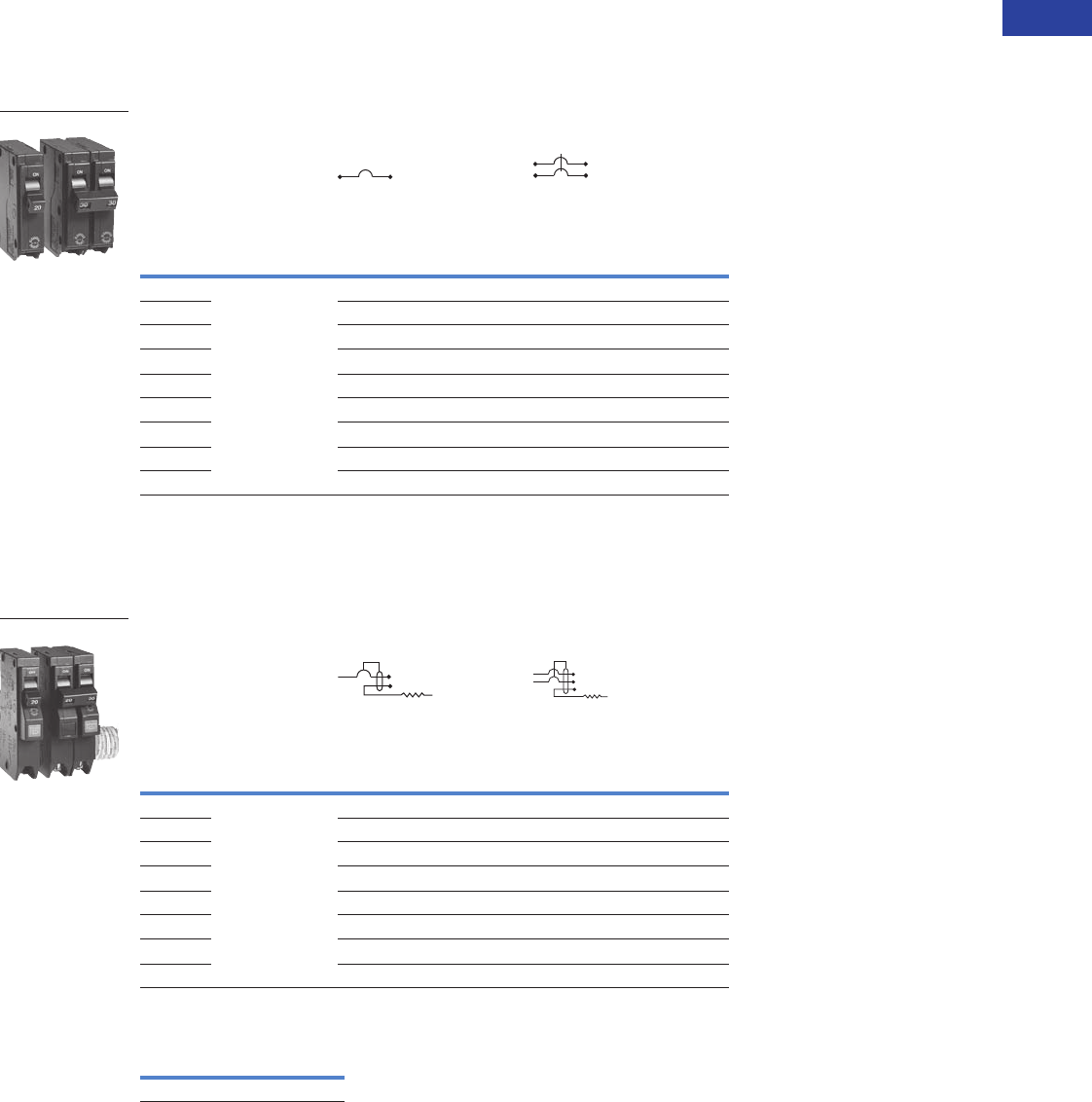
Volume 1—Residential and Light Commercial CA08100002E—June 2014 www.eaton.com V1-T1-97
1
1
1
1
1
1
1
1
1
1
1
1
1
1
1
1
1
1
1
1
1
1
1
1
1
1
1
1
1
1
1.5
Loadcenters and Circuit Breakers
Classified Circuit Breakers
Product Selection
Type CHQ Replacement Breakers for Square D Type QO Loadcenters
10 kAIC, 120 and 120/240 Vac
Type CHQ Classified Breakers 3/4-Inch (19.1 mm) per Pole
120 or 120/240 Vac, 10 kAIC
Type CHQ Ground Fault and Arc Fault Replacement Breakers for Square D Type QO Loadcenters
10 kAIC, 120 and 120/240 Vac
Type CHQ Ground Fault Breakers—5 Milliampere—
3/4-Inch (19.1 mm) per Pole, 10 kAIC
Type CHQ Surge Arrester
Ampere
Rating
Wire Size Range
Cu/Al 60ºC or 75°C
Single-Pole 120/240 Vac
Requires One
3/4-Inch (19.1 mm) Space
10 per Shelf Carton
Two-Pole 120/240 Vac
Common Trip Requires Two
3/4-Inch (19.1 mm) Spaces
5 per Shelf Carton
Catalog Number Catalog Number
15 (1) #14–8
(2) #14–10
CHQ115 CHQ215
20 CHQ120 CHQ220
25 CHQ125 CHQ225
30 CHQ130 CHQ230
35 CHQ135 CHQ235
40 CHQ140 CHQ240
45 CHQ145 CHQ245
50 CHQ150 CHQ250
60 —CHQ260
Ampere
Rating
Wire Size Range
Cu/Al 60ºC or 75°C
Single-Pole 120 Vac
Requires One
3/4-Inch (19.1 mm) Space
10 per Shelf Carton
Two-Pole 120/240 Vac
Common Trip Requires Two
3/4-Inch (19.1 mm) Spaces
5 per Shelf Carton
Catalog Number Catalog Number
15 (1) #14–8
(2) #14–10
CHQ115GF CHQ215GF
20 CHQ120GF CHQ220GF
25 CHQ125GF CHQ225GF
30 CHQ130GF CHQ230GF
35 — CHQ235GF
40 — CHQ240GF
45 — CHQ245GF
50 — CHQ250GF
Catalog Number
CHQSA
CHQ120 CHQ230
CHQ115GF CHQ220GF
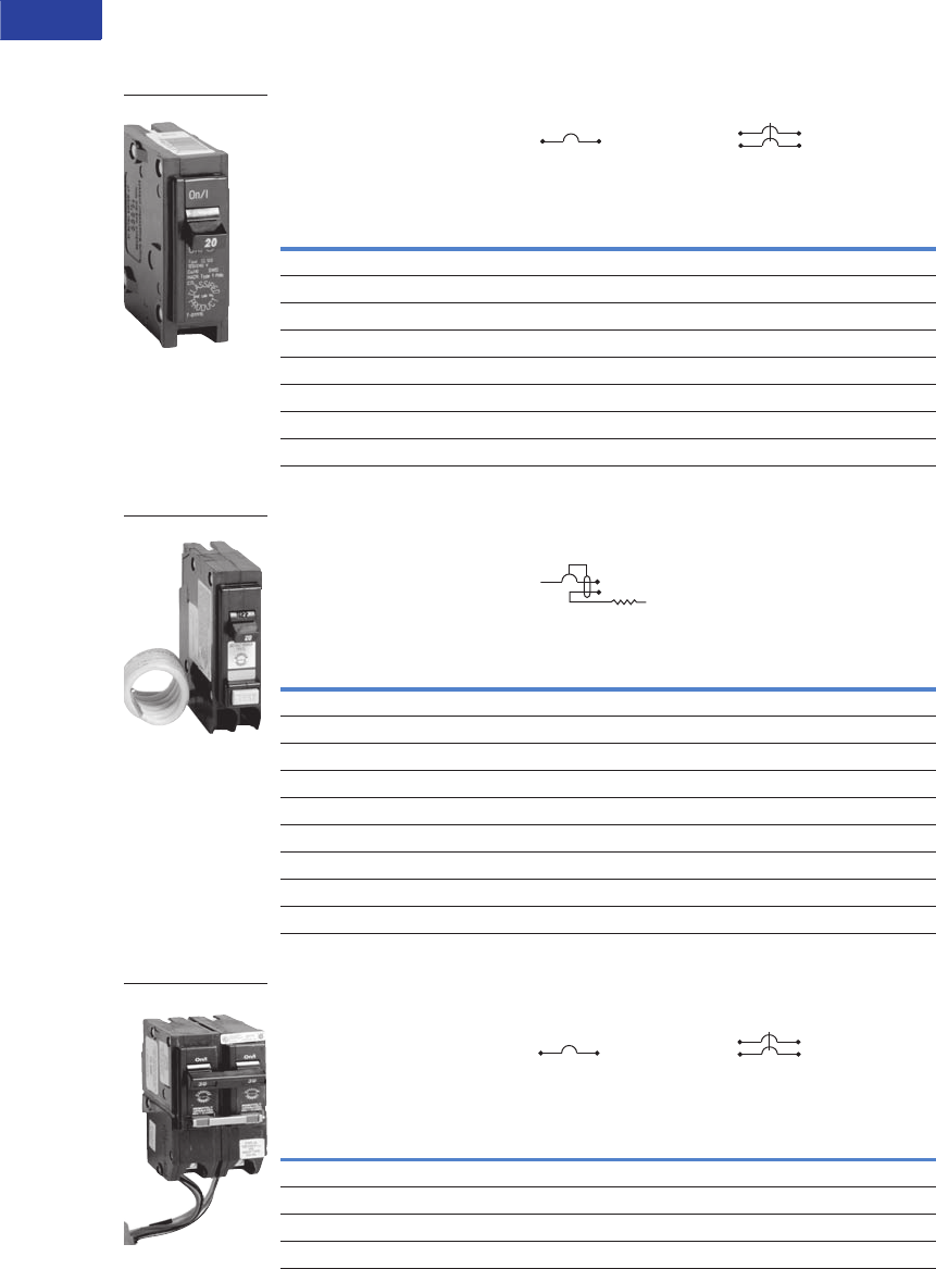
V1-T1-98 Volume 1—Residential and Light Commercial CA08100002E—June 2014 www.eaton.com
1
1
1
1
1
1
1
1
1
1
1
1
1
1
1
1
1
1
1
1
1
1
1
1
1
1
1
1
1
1
1.5
Loadcenters and Circuit Breakers
Classified Circuit Breakers
Type CL Replacement Breakers for Square D HOMELINE, General Electric, Crouse-Hinds,
Thomas & Betts, Murray and ITE®/Siemens Loadcenters
Type CL Breakers, 1-Inch (25.4 mm) per Pole, 10 kAIC
Type CL Classified Arc and Ground Fault Breakers (5 Milliampere),
1-Inch (25.4 mm) per Pole, 10 kAIC
Type CL Classified Latching Remote Control Smart Breakers™,
1-Inch (25.4 mm) per Pole, 10 kAIC
Ampere
Rating
Wire Size
Range Cu/Al
60°C or 75°C
Single-Pole 120/240V
Requires One
1-Inch (25.4 mm) Space
10 per Shelf Carton
Catalog Number
Two-Pole 120/240V
Common Trip Requires Two
1-Inch (25.4 mm) Spaces
5 per Shelf Carton
Catalog Number
15 #14–4 CL115 CL215
20 #14–4 CL120 CL220
25 #14–4 CL125 CL225
30 #14–4 CL130 CL230
35 #14–4 CL135 CL235
40 #14–4 CL140 CL240
45 #14–4 CL145 CL245
50 #14–4 CL150 CL250
Ampere
Rating
Wire Size
Range Cu/Al
60°C or 75°C
Single-Pole 120/240V
Requires One 1-Inch (25.4 mm) Space
1 per Shelf Carton
Catalog Number
Arc Fault Breakers
15 #14–4 CL115AF
20 #14–4 CL115CAF
20 #14–4 CL120AF
20 #14–4 CL120CAF
Ground Fault Breakers
15 #14–4 CL115GF
20 #14–4 CL120GF
30 #14–4 CL130GF
Ampere
Rating
Wire Size
Range Cu/Al
60°C or 75°C
Single-Pole 120V
Requires One
1-Inch (25.4 mm) Space
10 per Shelf Carton
Catalog Number
Two-Pole 120/240V
Common Trip Requires Two
1-Inch (25.4 mm) Spaces
5 per Shelf Carton
Catalog Number
15 (2) #14–10 CLRP115 CLRP215
20 (2) #14–10 CLRP120 CLRP220
25 (1) #8–6 CLRP125 CLRP225
30 (1) #8–6 CLRP130 CLRP230
CL_
CL_AF
CLR_

Volume 1—Residential and Light Commercial CA08100002E—June 2014 www.eaton.com V1-T1-99
1
1
1
1
1
1
1
1
1
1
1
1
1
1
1
1
1
1
1
1
1
1
1
1
1
1
1
1
1
1
1.5
Loadcenters and Circuit Breakers
Classified Circuit Breakers
Accessories
CHQ Breaker Accessories
Description
Catalog
Number
Breaker handle lock CHLO
Technical Data
Arc Fault Application Notes
An arc fault circuit interrupter
is a device intended to
provide protection from
the effects of arc faults by
recognizing characteristics
unique to arcing and by
functioning to de-energize
the circuit when the arc
fault is detected. As of
January 1, 2002, the
National Electrical Code
(NEC) requires all branch
circuits that supply 125V,
single-phase, 15 and 20A
receptacle outlets installed
in dwelling unit bedrooms
shall be protected by an arc
fault circuit interrupter(s).
This includes ceiling lighting
(recessed, ceiling fans, etc.)
as well as smoke detectors
and all other bedroom outlets.
The 2005 NEC introduced the
application of the
Combination Type AFCI for
bedroom circuits required as
of January 1, 2008. The 2008
NEC expands this application
to other living areas.
Ground Fault
Application Notes
Single-pole GFCBs are
designed for use in two-wire,
120 Vac circuits. Drawing
on Page V1-T1-100 shows a
typical wiring configuration.
Two-pole GFCBs are
designed for use in three-
wire, 120/240 Vac circuits,
120 Vac multiwire circuits
employing common, neutral
and two-wire, 240 Vac
circuits obtained from a
120/240 Vac source.
Drawings on Page V1-T1-100
illustrate typical wiring
configurations for
120/240 Vac multiwire
circuits.
Drawing on Page V1-T1-100
depicts a 240 Vac, two-wire
circuit. Note the “panel
neutral” conductor connects
to the neutral bar, even
though the neutral is not
included in the load circuit.
This connection is necessary
to supply a 120 Vac power
source to the ground fault
sensing circuit.
The figures are shown with
a 120/240 Vac, single-phase,
three-wire power source,
ut are also applicable to a
120/208 Vac, three-phase,
four-wire power supply.
For all figures, the electrical
operation of the GFCB
is not affected by the
equipment ground.
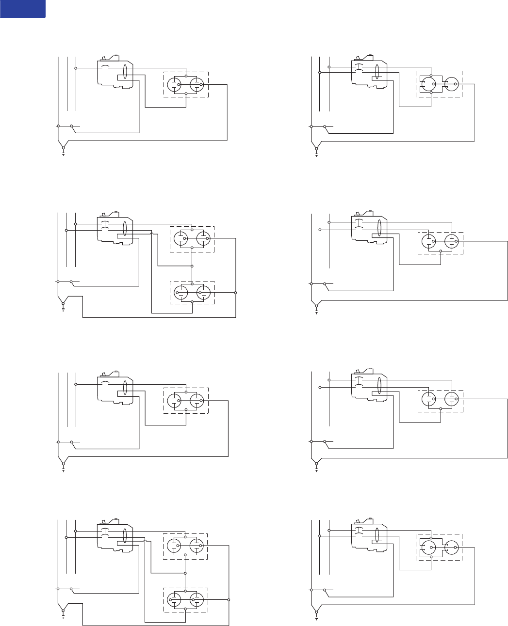
V1-T1-100 Volume 1—Residential and Light Commercial CA08100002E—June 2014 www.eaton.com
1
1
1
1
1
1
1
1
1
1
1
1
1
1
1
1
1
1
1
1
1
1
1
1
1
1
1
1
1
1
1.5
Loadcenters and Circuit Breakers
Classified Circuit Breakers
Wiring Diagrams
Single-Pole 120V Load Application Sourced by 120/240 Vac
Two-Pole Shared Neutral with
Multi-Duplex Receptacle Application
Single-Pole 120V Duplex Receptacle Application
Two-Pole 120V Multi-Duplex Receptacle Application
Two-Pole 240V Load Application Sourced by 120/240 Vac
Two-Pole Shared Neutral with
Duplex Receptacle Application
Two-Pole 120V Duplex Receptacle Application
Two-Pole 240V Duplex Receptacle Application
NAB
120/240 Vac
Source
120V
Duplex
Receptacle
Single-Pole
Line B
Neutral
Neutral
Equipment Ground
NA B
120/240 Vac
Source
Two 120V
Duplex
Receptacles
Two-Pole
Line B
Line A
Neutral
Neutral
Equipment Ground
NAB
120/240 Vac
Source
120V
Duplex
Receptacle
Single-Pole
Line B
Neutral
Neutral
NA B
120/240 Vac
Source
Two 120V
Duplex
Receptacles
Two-Pole
Line B
Line A
Neutral
Neutral
Line B
NA B
120/240 Vac
Source
Line A 240V
Duplex
Receptacle
Two-Pole
Neutral
Equipment Ground
NAB
120/240 Vac
Source
Line A
120V Duplex
Receptacle
(With Line Side
Jumper Removed)
Two-Pole
Line B
Neutral
Neutral
Equipment Ground
NAB
120/240 Vac
Source
Line A
120V Duplex
Receptacle
(With Line Side
Jumper Removed)
Two-Pole
Line B
Neutral
Neutral
Line B
NA B
120/240 Vac
Source
Line A 240V
Duplex
Receptacle
Two-Pole
Neutral

Volume 1—Residential and Light Commercial CA08100002E—September 2012 www.eaton.com V1-T2-1
2
2
2
2
2
2
2
2
2
2
2
2
2
2
2
2
2
2
2
2
2
2
2
2
2
2
2
2
2
2
Surge Protection
Surge Protection Devices
2.1 Surge Protection Devices and Lightning Arresters
Product Description . . . . . . . . . . . . . . . . . . . . . . . . . . . . . . . . . . . . . . V1-T2-2
Application Description . . . . . . . . . . . . . . . . . . . . . . . . . . . . . . . . . . . . V1-T2-2
Standards and Certifications . . . . . . . . . . . . . . . . . . . . . . . . . . . . . . . . V1-T2-3
Product Selection . . . . . . . . . . . . . . . . . . . . . . . . . . . . . . . . . . . . . . . . V1-T2-4
Learn
Online
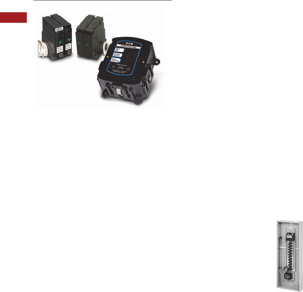
V1-T2-2 Volume 1—Residential and Light Commercial CA08100002E—September 2012 www.eaton.com
2
2
2
2
2
2
2
2
2
2
2
2
2
2
2
2
2
2
2
2
2
2
2
2
2
2
2
2
2
2
2.1
Surge Protection
Surge Protection Devices and Lightning Arresters
Surge Protection Devices
Contents
Description Page
Surge Protection Devices and Lightning Arresters
Standards and Certifications . . . . . . . . . . . . . . . V1-T2-3
Product Selection . . . . . . . . . . . . . . . . . . . . . . . V1-T2-4
Product Description
Due to the evolution
of electronics and
microprocessors in the
home, there is a continuous
challenge to provide quality
(clean) power for electronic
loads such as appliances,
computers/home office and
entertainment systems.
Surges caused by lightning,
utility grid switching and
other sources travel on
current carrying conductors
throughout the home, which
can effect and destroy
sensitive electronic loads.
Eaton offers a comprehensive
family of surge products for
use at service entrance.
These products can help
protect sensitive electronics
against the damaging effects
of surges.
Application Description
Two-Stage Protection
Two stages of surge
suppression are
recommended to provide
the best protection for
electronic equipment.
Two-stage surge suppression
should be provided for all
cables entering a home,
including power, Internet,
coaxial and telephone.
Service Entrance Surge
Protection
Eaton’s service entrance
surge protection units
provide premier surge
protection for AC power
at the service entrance.
These products provide
protection for residential
electrical equipment by
reducing power surges
to an acceptable level for
surge strips to handle at
the point of use.
UL 1449 3rd Edition Type 1 and
Type 2 Surge Protection
●Type 1 Surge Protective
Device (SPD)—
Permanently connected
Type 1 SPDs are intended
for installation between the
secondary of the service
transformer and the line
side of the service
equipment overcurrent
device, as well as the load
side, including watt-hour
meter socket enclosures
and are intended to be
installed without an
external overcurrent
protective device.
Type 1 devices are
dual-rated for Type 2
applications as well,
providing the highest
ratings available for
installation at the service
entrance
●Eaton’s CHSPT1
products provide Type 1
surge protection in
accordance with UL®
1449 3rd Edition. These
units can be universally
mounted outside any
manufacturer’s primary
service equipment
●Type 2 Surge Protective
Device—Permanently
connected Type 2 SPDs
are intended for installation
on the load side of the
service equipment
overcurrent device,
including SPDs located at
the branch panel
●
CHSPT2 products provide
Type 2 surge protection in
accordance with UL 1449
3rd Edition. These units
can be mounted outside
of any manufacturer’s
loadcenter or inside an
Eaton Surge/Surge Ready
loadcenter. Eaton also
offers accessories to the
CHSPT2 line for
telephone and cable
protection.
●Factory-Installed Surge
Protection—Eaton’s
loadcenters with factory-
installed surge protection
include a CHSPT2ULTRA
and a two-pole 50A circuit
breaker. These loadcenters
increase the effectiveness
of surge protection due
to reduced lead length.
A modified deadfront
allows for easy viewing
of indicating lights for
status indication
Surge Panel
●Surge Ready
Loadcenter—The Surge-
Ready loadcenter provides
a mounting provision for
the CHSPT2ULTRA. This
loadcenter has a modified
deadfront to allow for
viewing of indicating lights.
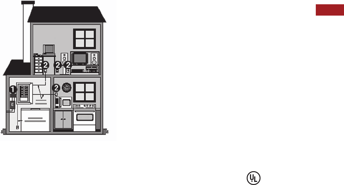
Volume 1—Residential and Light Commercial CA08100002E—September 2012 www.eaton.com V1-T2-3
2
2
2
2
2
2
2
2
2
2
2
2
2
2
2
2
2
2
2
2
2
2
2
2
2
2
2
2
2
2
2.1
Surge Protection
Surge Protection Devices and Lightning Arresters
Two-Stage Protection
Plug-On Surge Protection
●Ty p e C H S A —For use on
single-phase 120/240 Vac
systems. The CHSA easily
plugs into a single-phase
Type CH loadcenter and
occupies two 3/4-inch
(19.1 mm) pole spaces,
similar to a two-pole Type
CH breaker. When installed
properly, it provides surge
protection for the entire
loadcenter. If internal
components are damaged,
the CHSA LED visual
indicators will signal the
need for a replacement.
This device is suitable for
service entry locations
when installed in
accordance with NEC®
guidelines.
●Ty p e B R S U R G E —For use
on single-phase 120/240
Vac systems. This easily
plugs into a single-phase
Type BR loadcenter and
occupies two 1-inch (25.4
mm) pole spaces similar to
a two-pole Type BR
breaker. When installed
properly, it provides surge
protection for the entire
loadcenter. If internal
components are damaged,
the BRSURGE LED visual
indicators will signal the
need for replacement.
This device is suitable
for service entry locations
when installed in
accordance with NEC
guidelines. This unit is
also classified by UL for
use in select GE, ITE/
Siemens, and Crouse-
Hinds Panels. (Refer to
Pub No. 5655B65H01 for
additional details.)
1CHSP installed at the service entrance panel.
2SurgeTrap™ surge traps and strips located where sensitive electronics are plugged in.
●Ty p e C H Q S A —For use
on single-phase, 120/240 Vac
systems. This unit easily
plugs into a
Square D
single-phase loadcenter
Type QO® and occupies
two 3/4-inch (19.1 mm)
pole spaces similar to a
two-pole Type QO breaker.
When installed properly, it
provides surge protection
for the entire loadcenter. If
internal components are
damaged, the CHQSA LED
visual indicators will signal
the need for a replacement.
This device is suitable for
service entrance locations
installed in accordance
with NEC guidelines. This
device is UL classified to
be used in place of Square D
Type QO surge arresters
(refer to Pub-23974).
●Type BRSURGECSA—
For use on single-phase
120/240 Vac systems. This
easily plugs into a single-
phase Type BR loadcenter
and occupies two 1-inch
(25.4 mm) pole spaces
similar to a two-pole Type
BR breaker. When installed
properly, it provides surge
protection for the entire
loadcenter. If internal
components are damaged,
the BRSURGECSA LED
visual indicators will signal
the need for replacement.
This device is suitable
for service entry locations
when installed in
accordance with Canadian
Electrical Code. This device
is CSA® listed to be used in
a Type BR loadcenter.
Type 3 Point-of-Use Surge
Protection
Point-of-use surge strips are
designed to offer premium
surge protection for specific
electronics while providing
innovative features to
enhance user convenience.
Standards and
Certifications
●CHSPT1 Products: UL
1449 3rd Edition Type 1
●CHSPT2 Products:
UL/cUL® 1449 3rd Edition
Type 2
●CHSPTELE: UL 497A, cUL
●CHSPCABLE: UL 6500, cUL
●NEMA® 3R Enclosure for
CHSPTELE and
CHSPCABLE: UL 50
Enclosure
●BRSURGE, CHSA,
BRSURGECSA, CHQSA:
UL 1449 3rd Edition plug-in
type; Type 2 SPD
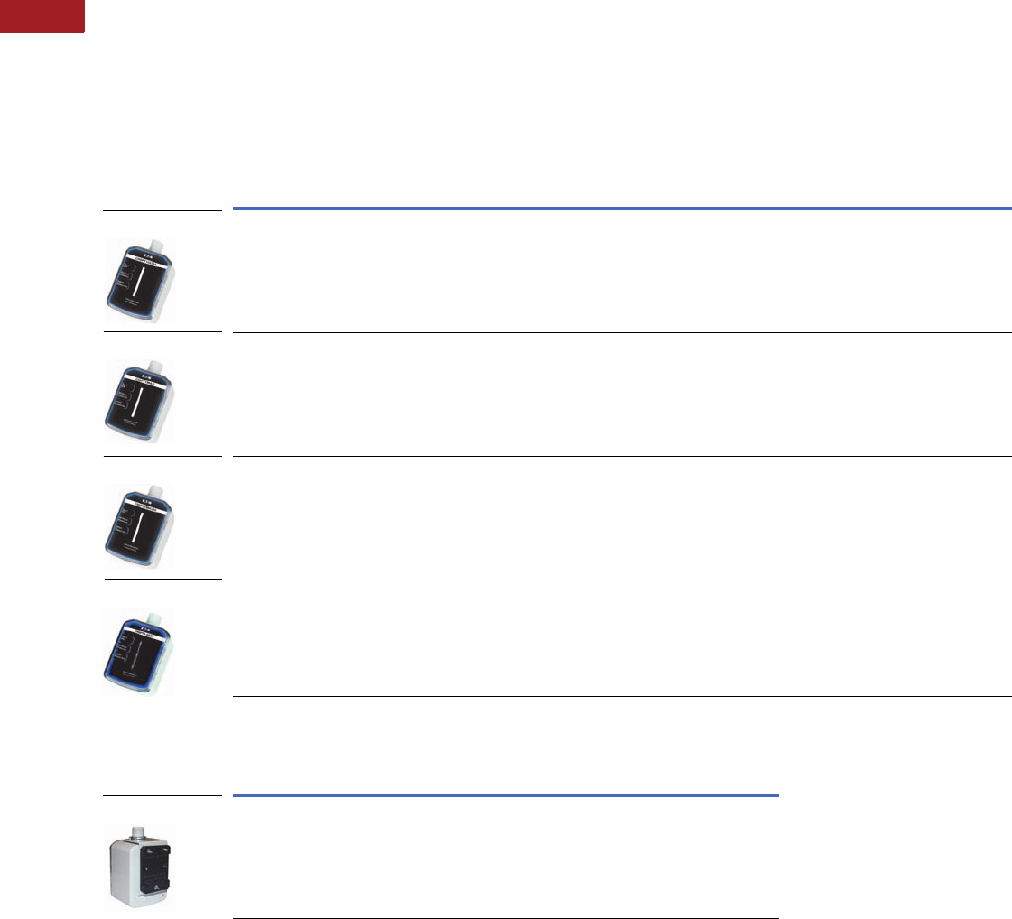
V1-T2-4 Volume 1—Residential and Light Commercial CA08100002E—September 2012 www.eaton.com
2
2
2
2
2
2
2
2
2
2
2
2
2
2
2
2
2
2
2
2
2
2
2
2
2
2
2
2
2
2
2.1
Surge Protection
Surge Protection Devices and Lightning Arresters
Product Selection
SPD Type 1 CHSP Service Entrance Surge Protection—UL 1449 3rd Edition
Product Features
●Commercial grade AC power protection
●Type 1 surge device for installation before or after the main service disconnect
●Convenient mounting options—universal fit to any manufacturer’s equipment
●Clear, visible LED indication displaying status of the surge protector
Accessory for Type 1 CHSP Service Entrance Surge Protection
Notes
1 MCOV: Maximum Continuous Operating Voltage that may be applied to the device per mode.
2 VPR: Voltage Protection Rating is the measured limiting voltage after a surge event.
3 In: Nominal Discharge Current is the current that the device can withstand for 15 impulses.
4 SCCR: The amount of current the product can withstand under short-circuit conditions.
5 Surge Current Capacity: The maximum one time surge current rating per phase.
For warranty details, go to www.eaton.com/surgetrap.
Catalog
Number Connection Enclosure Voltage Phase
Frequency
(Hz) MCOV 1VPR 2In 3SCCR 4
Surge Current
Capacity, Per
Phase Rating 5
CHSPT1ULTRA Permanently connected device
installed before or after the service
disconnect overcurrent device.
NEMA 4 100/200,
110/220,
120/240
Single 50/60 L-L 300,
L-N 150
L-L 1000,
L-N 600
20 kA 200 kA 50 kA
CHSPT1MAX Permanently connected device
installed before or after the service
disconnect overcurrent device.
NEMA 4 100/200,
110/220,
120/240
Single 50/60 L-L 300,
L-N 150
L-L 1000,
L-N 600
20 kA 200 kA 45 kA
CHSPT1MICRO Permanently connected device
installed before or after the service
disconnect overcurrent device.
NEMA 4 100/200,
110/220,
120/240
Single 50/60 L-L 300,
L-N 150
L-L 1000,
L-N 600
20 kA 200 kA 36 kA
CHSPT1-208Y Permanently connected device
installed before or after the service
disconnect overcurrent device.
NEMA 4 120/208 Three-
phase
wye
50/60 L-L 300,
L-N 150
L-L 1000,
L-N 600
20 kA 200 kA 50 kA
Catalog
Number Description
SP1DINRAILKIT Mounting kit for wall or DIN rail installation.
CHSPT1ULTRA
CHSPT1MICRO
CHSPT1MAX
CHSPT1-208Y
SP1DINRAILKIT

Volume 1—Residential and Light Commercial CA08100002E—September 2012 www.eaton.com V1-T2-5
2
2
2
2
2
2
2
2
2
2
2
2
2
2
2
2
2
2
2
2
2
2
2
2
2
2
2
2
2
2
2.1
Surge Protection
Surge Protection Devices and Lightning Arresters
SPD Type 2 CHSP Service Entrance Surge Protection—UL 1449 3rd Edition; cUL
Product Features
●AC power protection
●Universally connects to any manufacturer’s loadcenter (breaker box)
●Quick connect design—easy to mount telephone and cable protection modules
●LED status indication
Notes
1 MCOV: Maximum Continuous Operating Voltage that may be applied to the device per mode.
2 VPR: Voltage Protection Rating is the measured limiting voltage after a surge event.
3 In: Nominal Discharge Current is the current that the device can withstand for 15 impulses.
4 SCCR: The amount of current the product can withstand under short-circuit conditions.
5 Surge Current Capacity: The maximum one time surge current rating per phase.
6 When used with a 50A two-pole circuit breaker, 10 kA when used with a 15A two-pole circuit breaker.
For warranty details, go to www.eaton.com/surgetrap.
Catalog
Number Connection Enclosure Voltage Phase
Frequency
(Hz) MCOV 1VPR 2In 3SCCR 4
Surge Current
Capacity, Per
Phase Rating 5
CHSPT2ULTRA Can be attached to the outside of
any manufacturer’s loadcenter
(breaker box). This product should
be connected on the load side of
the loadcenter main service
disconnect through a dedicated
circuit breaker (follow NEC
Guidelines).
NEMA 4 120/240
Vac rated
line voltage
Single 60 150V L-N,
300V L-L
600V L-N,
1000V L-L,
800V N-G,
600V L-G
20 kA 622 kA 108 kA
(L1-N 54 kA, L1-G
54 kA, L2-N 54
kA, L2-G 54 kA)
CHSPT2MAX Can be attached to the outside of
any manufacturer’s loadcenter
(breaker box). This product should
be connected on the load side of
the loadcenter main service
disconnect through a dedicated
circuit breaker (follow NEC
Guidelines).
NEMA 4 120/240
Vac rated
line voltage
Single 60 150V L-N,
300V L-L
600V L-N,
1000V L-L,
800V N-G,
600V L-G
10 kA 22 kA 72 kA
(L1-N 36 kA, L1-G
36 kA, L2-N 36
kA, L2-G 36 kA)
CHSPT2MICRO Can be attached to the outside of
any manufacturer’s loadcenter
(breaker box). This product should
be connected on the load side of
the loadcenter main service
disconnect through a dedicated
circuit breaker (follow NEC
Guidelines).
NEMA 4 120/240
Vac rated
line voltage
Single 60 150V L-N,
300V L-L
600V L-N,
1000V L-L,
800V N-G,
600V L-G
5 kA 22 kA 36 kA
(L1-N 18 kA, L1-G
18 kA, L2-N 18
kA, L2-G 18 kA)
CHSPT2ULTRA
CHSPT2MICRO
CHSPT2MAX
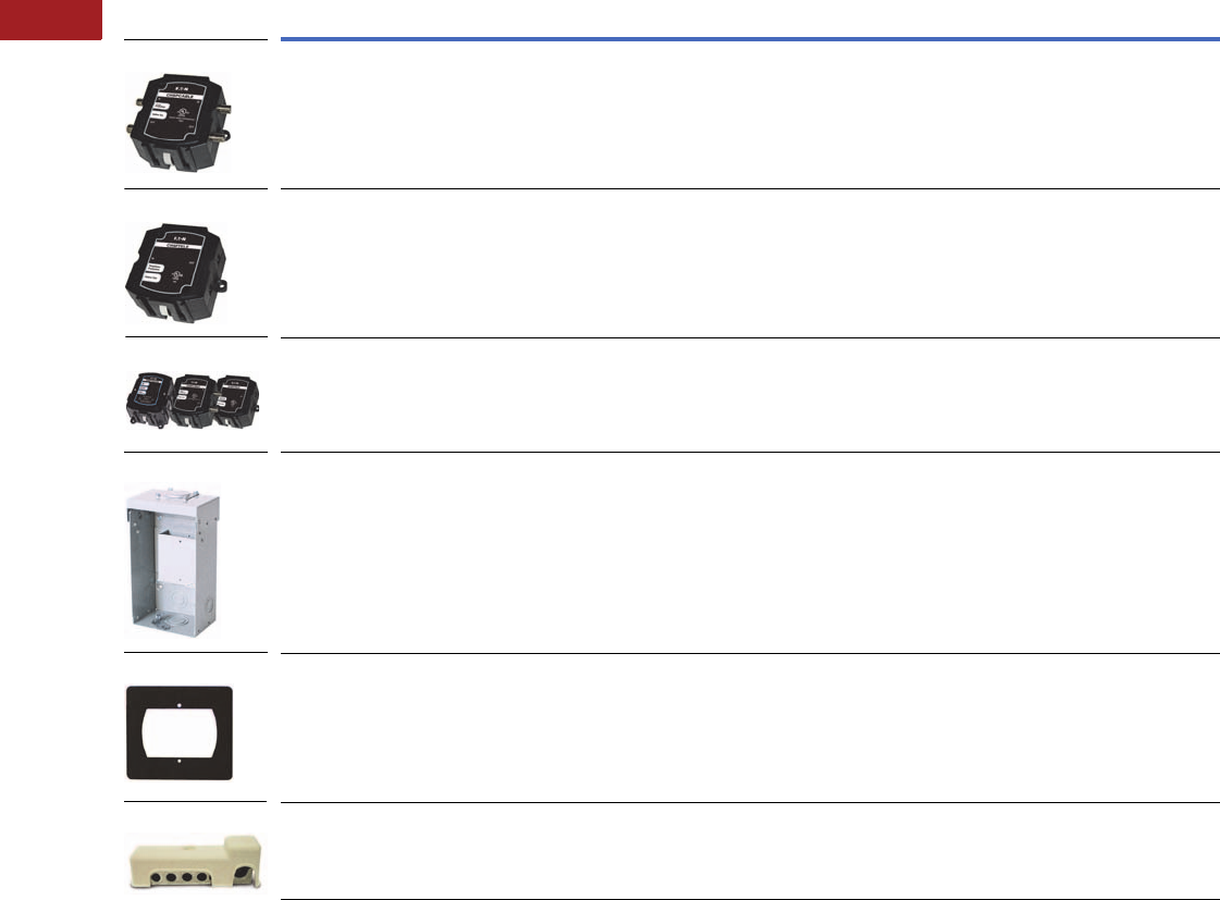
V1-T2-6 Volume 1—Residential and Light Commercial CA08100002E—September 2012 www.eaton.com
2
2
2
2
2
2
2
2
2
2
2
2
2
2
2
2
2
2
2
2
2
2
2
2
2
2
2
2
2
2
2.1
Surge Protection
Surge Protection Devices and Lightning Arresters
Accessories for CHSP Type 2 Service Entrance Protection
Note
For warranty details, go to www.eaton.com/surgetrap.
Catalog
Number Description Installation
Surge Current
Capacity
DC
Breakdown
Voltage Voltage
CHSPCABLE Quick Connect design—add additional
telephone and AC protection modules;
protects two quad shield cables;
bi-directional
Indoor installation; or rain-tight when
used with recommended enclosure
10 kA per line 145V
CHSPTELE Quick Connect design—add additional AC
and cable protection modules; protects four
telephone lines
Indoor installation; or rain-tight when
used with recommended enclosure
20 kA per line 230V Ring 90–120 Vac/
Tone 48–52 Vdc
CHSPT23PACK 3-Pack:
CHSPT2ULTRA+CHSPTELE+CHSPCABLE;
Surge protection for AC power,
telephone and cable—see individual product
features
See individual
product ratings
CHSP3RTELCABLE Raintight enclosure for CHSPTELE and
CHSPCABLE; top or bottom feed; enclosure
only, surge not included; accommodates up to
two devices
CHSPFMKIT Flushmount kit for: CHSPT2ULTRA,
CHSPT2MAX, CHSPT2MICRO, CHSPTELE,
CHSPCABLE
MSEGR2 Outdoor communication grounding device;
meets 2008 NEC requirements for
intersystem bonding termination
CHSP3RTELCABLE
CHSPFMKIT
MSEGR2
CHSPTELE
CHSPT23PACK
CHSPCABLE
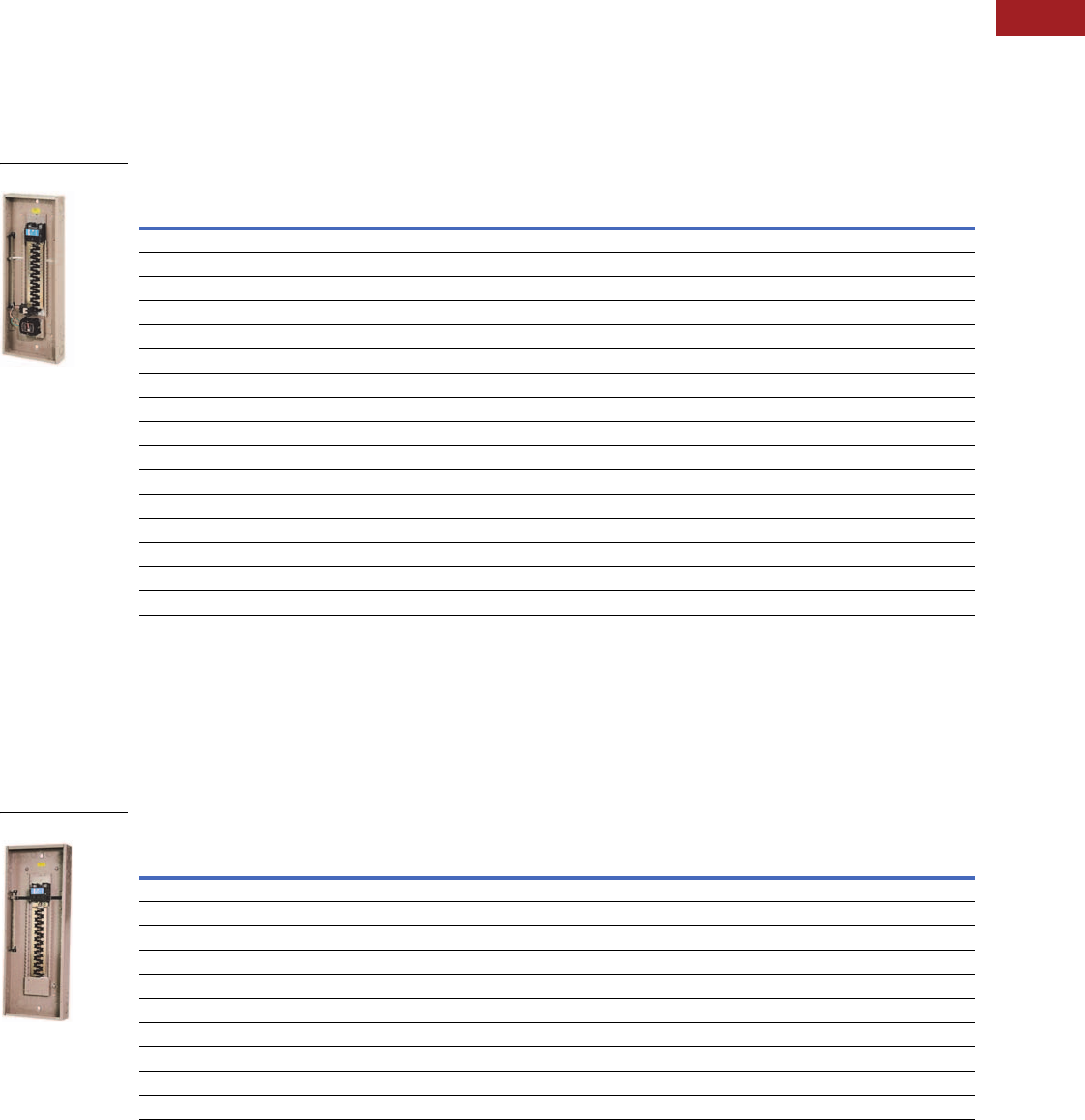
Volume 1—Residential and Light Commercial CA08100002E—September 2012 www.eaton.com V1-T2-7
2
2
2
2
2
2
2
2
2
2
2
2
2
2
2
2
2
2
2
2
2
2
2
2
2
2
2
2
2
2
2.1
Surge Protection
Surge Protection Devices and Lightning Arresters
Factory-Installed Surge Protection
●Includes a CHSPT2ULTRA
and a two-pole 50A circuit
breaker
●Increases the
effectiveness of surge
protection due to reduced
lead length
●A modified deadfront
allows for easy viewing
of indicating lights for
status indication
Surge Installed Loadcenters
Surge Ready Loadcenters
●Provides a mounting
provision for
CHSPT2ULTRA
●A modified deadfront
allows for easy viewing of
indicating lights
Surge Ready Loadcenters (Provision Only, CHSPT2ULTRA and Breaker Not Included)
Notes
1 Order cover separately.
2 With main lugs installed.
Cover Catalog Number
Catalog Number Description Combination Surface
CHSUR42N225L 142 ckt, 225A, convertible CHSUR8LF CHSUR8LS
CHSUR42L225L2 142 ckt, 225A, convertible 2CHSUR8LF CHSUR8LS
CHSUR42B200L2 142 ckt, 200A, main breaker CHSUR8LF CHSUR8LS
CHSUR32N225K 132 ckt, 225A, convertible CHSUR8KF CHSUR8KS
CHSUR32L225K 132 ckt, 225A, convertible 2CHSUR8KF CHSUR8KS
CHSUR32B200K 132 ckt, 200A, main breaker CHSUR8KF CHSUR8KS
CHSUR32B150K 132 ckt, 150A, main breaker CHSUR8KF CHSUR8KS
CHSUR32B100K 132 ckt, 100A, main breaker CHSUR8KF CHSUR8KS
CHSUR24L125E 124 ckt, 125A, convertible 2CHSUR8EF CHSUR8ES
CHSUR24B100E 124 ckt, 100A, main breaker CHSUR8EF CHSUR8ES
BRSUR4040N200 40/40 ckt, 200A, convertible Cover included
BRSUR4040L200 40/40 ckt, 200A, main lug Cover included
BRSUR4040B200 40/40 ckt, 200A, main breaker Cover included
BRSUR3040N200 30/40 ckt, 200A, convertible Cover included
BRSUR3040L200 30/40 ckt, 200A, main lug Cover included
BRSUR3040B200 30/40 ckt, 200A, main breaker Cover included
Surge Installed
Cover Catalog Number
Catalog Number Description Combination Surface
CHEC42N225L 142 ckt, 225A, convertible CHSUR8LF CHSUR8LS
CHEC42L225L 142 ckt, 225A, convertible 2CHSUR8LF CHSUR8LS
CHEC42B200L 142 ckt, 200A, main breaker CHSUR8LF CHSUR8LS
CHEC32L225K 132 ckt, 225A, convertible 2CHSUR8KF CHSUR8KS
CHEC32N225K 132 ckt, 225A, convertible CHSUR8KF CHSUR8KS
CHEC32B200K 132 ckt, 200A, main breaker CHSUR8KF CHSUR8KS
CHEC32B150K 132 ckt, 150A, main breaker CHSUR8KF CHSUR8KS
CHEC32B100K 132 ckt, 100A, main breaker CHSUR8KF CHSUR8KS
CHEC24L125E 124 ckt, 125A, convertible 2CHSUR8EF CHSUR8ES
CHEC24B100E 124 ckt, 100A, main breaker CHSUR8EF CHSUR8ES
Surge Ready
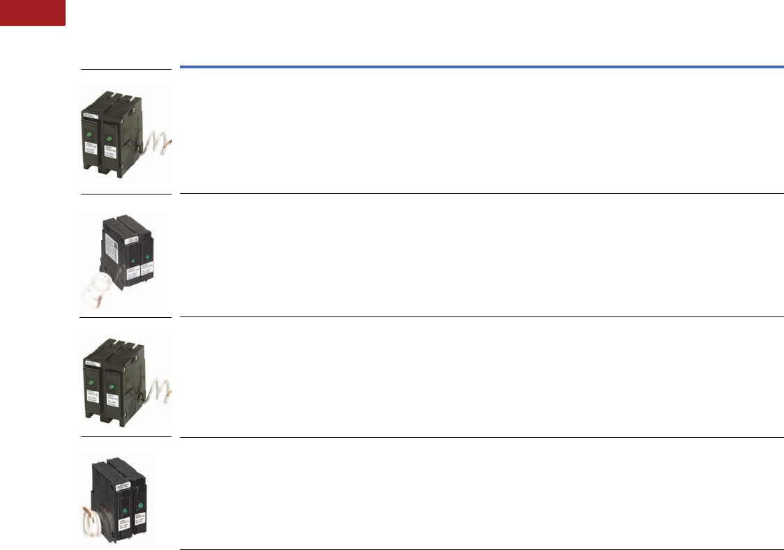
V1-T2-8 Volume 1—Residential and Light Commercial CA08100002E—September 2012 www.eaton.com
2
2
2
2
2
2
2
2
2
2
2
2
2
2
2
2
2
2
2
2
2
2
2
2
2
2
2
2
2
2
2.1
Surge Protection
Surge Protection Devices and Lightning Arresters
SPD Type 2 Plug-On Surge Protection—UL 1449 3rd Edition
Product Features
●Convenient surge protection for the loadcenter
Notes
1 MCOV: Maximum Continuous Operating Voltage that may be applied to the device per mode.
2 VPR: Voltage Protection Rating is the measured limiting voltage after a surge event.
3 In: Nominal Discharge Current is the current that the device can withstand for 15 impulses.
4 SCCR: The amount of current the product can withstand under short-circuit conditions.
5 Surge Current Capacity: The maximum one-time surge current rating per phase.
For warranty details, go to www.eaton.com/surgetrap.
Catalog
Number Description Connection Voltage Phase
Frequency
(Hz) MCOV 1VPR 2In 3SCCR 4
Surge Current
Capacity, Per
Phase Rating 5
BRSURGE UL for use in a single-phase Type BR
loadcenter. This unit is classified by UL
for use in select GE, ITE/Siemens and
Crouse-Hinds panels (refer to Pub. No.
5655B65H01 for additional details).
Plug on to the
loadcenter bus;
see instructions.
120/240 Single 60 L1-N 150V,
L-L 300V
L1-N 600V,
L-L 1000V
3k 10k 18 kA
CHSA UL and CSA for use in a
Type CH loadcenter.
Plug on to the
loadcenter bus;
see instructions.
120/240 Single 60 L1-N 150V,
L-L 300V
L1-N 600V,
L-L 1000V
3k 10k 18 kA
BRSURGECSA CSA for use in an Eaton
Type BR loadcenter.
Plug on to the
loadcenter bus;
see instructions.
120/240 Single 60 L1-N 150V,
L-L 300V
L1-N 600V,
L-L 1000V
3k 10k 18 kA
CHQSA This device is UL classified to be used
in place of Square D Type QO surge
arresters (refer to Pub-23974).
Plug on to the
loadcenter bus;
see instructions.
120/240 Single 60 L1-N 150V,
L-L 300V
L1-N 600V,
L-L 1000V
3k 10k 18 kA
CHSA
BRSURGE
CHQSA
BRSURGECSA

Volume 1—Residential and Light Commercial CA08100002E—February 2014 www.eaton.com V1-T3-1
3
3
3
3
3
3
3
3
3
3
3
3
3
3
3
3
3
3
3
3
3
3
3
3
3
3
3
3
3
3
Residential Standby Backup Power Solutions
3.1 Standby Generators
Product Description . . . . . . . . . . . . . . . . . . . . . . . . . . . . . . . . . . . . . . V1-T3-2
Application Description . . . . . . . . . . . . . . . . . . . . . . . . . . . . . . . . . . . . V1-T3-2
Features, Benefits and Functions . . . . . . . . . . . . . . . . . . . . . . . . . . . . V1-T3-2
Standards and Certifications . . . . . . . . . . . . . . . . . . . . . . . . . . . . . . . . V1-T3-2
Catalog Number Selection . . . . . . . . . . . . . . . . . . . . . . . . . . . . . . . . . V1-T3-3
Product Selection . . . . . . . . . . . . . . . . . . . . . . . . . . . . . . . . . . . . . . . . V1-T3-3
Air-Cooled Generators. . . . . . . . . . . . . . . . . . . . . . . . . . . . . . . . . . . V1-T3-3
Liquid-Cooled Generators . . . . . . . . . . . . . . . . . . . . . . . . . . . . . . . . V1-T3-4
Accessories . . . . . . . . . . . . . . . . . . . . . . . . . . . . . . . . . . . . . . . . . . . . . V1-T3-5
Sizing Guidelines . . . . . . . . . . . . . . . . . . . . . . . . . . . . . . . . . . . . . . . . V1-T3-6
Dimensions . . . . . . . . . . . . . . . . . . . . . . . . . . . . . . . . . . . . . . . . . . . . V1-T3-6
3.2 Portable Generators
Product Selection . . . . . . . . . . . . . . . . . . . . . . . . . . . . . . . . . . . . . . . . V1-T3-8
Dimensions . . . . . . . . . . . . . . . . . . . . . . . . . . . . . . . . . . . . . . . . . . . . V1-T3-10
3.3 Automatic Transfer Switches
Product Description . . . . . . . . . . . . . . . . . . . . . . . . . . . . . . . . . . . . . . V1-T3-11
Application Description . . . . . . . . . . . . . . . . . . . . . . . . . . . . . . . . . . . . V1-T3-11
Standards and Certifications . . . . . . . . . . . . . . . . . . . . . . . . . . . . . . . . V1-T3-12
Product Selection . . . . . . . . . . . . . . . . . . . . . . . . . . . . . . . . . . . . . . . . V1-T3-13
Standard Automatic Transfer Switches. . . . . . . . . . . . . . . . . . . . . . V1-T3-13
Green Automatic Transfer Switches—
Featuring Active Load Management Technology . . . . . . . . . . . . . V1-T3-13
ATS Ready Loadcenter . . . . . . . . . . . . . . . . . . . . . . . . . . . . . . . . . . V1-T3-14
Dimensions . . . . . . . . . . . . . . . . . . . . . . . . . . . . . . . . . . . . . . . . . . . . V1-T3-15
3.4 Manual Transfer Switches
Product Description . . . . . . . . . . . . . . . . . . . . . . . . . . . . . . . . . . . . . . V1-T3-16
Application Description . . . . . . . . . . . . . . . . . . . . . . . . . . . . . . . . . . . . V1-T3-16
Features, Benefits and Functions . . . . . . . . . . . . . . . . . . . . . . . . . . . . V1-T3-16
Standards and Certifications . . . . . . . . . . . . . . . . . . . . . . . . . . . . . . . . V1-T3-17
Reference Information . . . . . . . . . . . . . . . . . . . . . . . . . . . . . . . . . . . . V1-T3-17
Product Selection . . . . . . . . . . . . . . . . . . . . . . . . . . . . . . . . . . . . . . . . V1-T3-18
Manual Transfer Switches and Generator Panels Selection . . . . . . V1-T3-18
Power Inlet Boxes. . . . . . . . . . . . . . . . . . . . . . . . . . . . . . . . . . . . . . V1-T3-18
Technical Data and Specifications . . . . . . . . . . . . . . . . . . . . . . . . . . . . V1-T3-19
Dimensions . . . . . . . . . . . . . . . . . . . . . . . . . . . . . . . . . . . . . . . . . . . . V1-T3-19
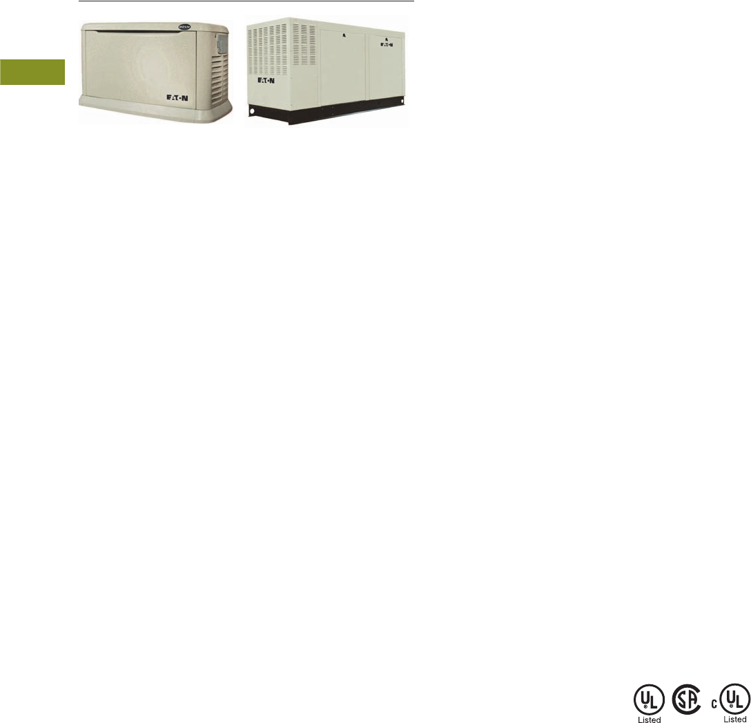
V1-T3-2 Volume 1—Residential and Light Commercial CA08100002E—February 2014 www.eaton.com
3
3
3
3
3
3
3
3
3
3
3
3
3
3
3
3
3
3
3
3
3
3
3
3
3
3
3
3
3
3
3.1
Residential Standby Backup Power Solutions
Standby Generators
EGENX20A EGEN70
Standby Generator Systems
Contents
Description Page
Standby Generators
Catalog Number Selection . . . . . . . . . . . . . . . . V1-T3-3
Product Selection. . . . . . . . . . . . . . . . . . . . . . . V1-T3-3
Accessories . . . . . . . . . . . . . . . . . . . . . . . . . . . V1-T3-5
Sizing Guidelines . . . . . . . . . . . . . . . . . . . . . . . V1-T3-6
Dimensions . . . . . . . . . . . . . . . . . . . . . . . . . . . V1-T3-6
Product Description
A standby generator system
is a package of equipment
specifically designed to
provide substitute electrical
power to a residence in the
event of a utility power
outage. These systems are
comprised of a generator,
transfer switch and the
connections necessary for
installation. Eaton’s standby
generator line consists of
air-cooled and liquid-cooled
models ranging from 8000
watts up to 150,000 watts.
Air-Cooled Standby
Eaton’s air-cooled generators
range from 8 to 20 kW and
these units are perfect for
automatically backing up
every circuit within a home
such as air
conditioner units,
refrigerators,
lighting, furnace
fans, sump pumps and water
pumps.
Eaton’s 14, 17 and 20 kW air-
cooled standby generators
offer fully automatic
operation and provide most
homeowners with enough
power for complete whole
house comfort. These units
all operate at ultra quiet
66 dB, or less, sound level.
Liquid-Cooled Standby
Eaton’s liquid-cooled
generators feature automotive
style engines that range from
22 to 150 kW of power
output. These units run so
quietly that you’ll forget that
you own a generator until you
need it. These units are
available in steel or aluminum
enclosures and are available in
single- and three-phase in four
voltages: 120/240V, single-
phase; 120/208V, three-phase;
240V, three-phase; and 277/
480V, three-phase.
Application Description
Standby generator systems
are most often used in
residential, agricultural
and light commercial
applications. Comfort and
safety are key concerns
of many homeowners
who are dependent on
an uninterrupted supply
of electricity.
The increase in our
dependence on power is
due in part to the popularity of
home offices and in-home
health care. Many regions of
the United States experience
periodic power outages
due to extreme weather
conditions such as ice and
snowstorms, heat waves,
tornadoes or hurricanes.
Eaton highly recommends
that any generator system
be installed by a qualified
electrician and/or generator
installer.
Features, Benefits
and Functions
Eaton’s generator systems
offer a wide range of
features. All systems feature:
●Powerful engines
●Reliable Eaton transfer
switches and control
systems using switching
duty rated circuit breakers
●Weekly exercise function
●Automatic transfer
systems feature automatic
start/stop
Standards and
Certifications
●CSA, cUL® and UL 2200
listed and approved
●All transfer switches are
UL 67 and UL 1008 listed
as “Transfer Switches”
●All generators are
UL 2200 listed
Volume 1—Residential and Light Commercial CA08100002E—February 2014 www.eaton.com V1-T3-3
3
3
3
3
3
3
3
3
3
3
3
3
3
3
3
3
3
3
3
3
3
3
3
3
3
3
3
3
3
3
3.1
Residential Standby Backup Power Solutions
Standby Generators
Catalog Number Selection
Air-Cooled Generators
Liquid-Cooled Generators
Product Selection
Air-Cooled Generators
Note
1Includes No. EGENFASCIA as standard.
Type
Eaton generator
EGENX Series
Rated Power
(LP/NG)
8= 8/7 kW
11 = 11/10 kW
14 = 14/14 kW
17 = 17/16 kW
20 = 20/18 kW
EGENX 20 A
Enclosure
A= Aluminum
Blank = Steel
kW Rating
22
25
27
30
36
45
48
60
70
80
100
130
150
Voltage Required
A = Single-phase 120/240V
G = Three-phase 208V
J = Three-phase 240V
K = Three-phase 480V
Enclosure
A= Aluminum
S= Steel
Fuel Type
N= Natural gas
L= Liquid propane
SCAQMD Compliance
N= No
Y= Yes
EGEN 22 A L A N
Rated
Power kW
(LP/NG)
Maximum Rated
Amperes
at 240 Vac
(LP/NG)
Main Line
Circuit Breaker
Amperes
Enclosure
Material
Engine
Size
Number of
Cylinders Fuel Type
GFI
Receptacle
SCAQMD
Compliant
Sound
Emissions
(dB at 7m)
Limited
Warranty (yrs)
Catalog
Number
8/7 33.3/29.2 35 Steel 410 cc 1 Liquid propane/
natural gas
No Yes 62 5 EGENX8
11/10 45.8/41.7 50 Steel 530 cc 2 Liquid propane/
natural gas
No Yes 63 5 EGENX11
14/14 58.3/58.3 60 Steel 990 cc 2 Liquid propane/
natural gas
No Yes 66 5 EGENX14
17/16 70.8/66.6 65 Steel 990 cc 2 Liquid propane/
natural gas
Yes Yes 66 5 EGENX17
17/16 70.8/66.6 65 Aluminum 990 cc 2 Liquid propane/
natural gas
Yes Yes 66 5 EGENX17A
20/18 83.3/75.0 90 Aluminum 990 cc 2 Liquid propane/
natural gas
Yes Yes 66 5 EGENX20A 1
V1-T3-4 Volume 1—Residential and Light Commercial CA08100002E—February 2014 www.eaton.com
3
3
3
3
3
3
3
3
3
3
3
3
3
3
3
3
3
3
3
3
3
3
3
3
3
3
3
3
3
3
3.1
Residential Standby Backup Power Solutions
Standby Generators
Liquid-Cooled Generators 12
Notes
1 All liquid-cooled models suitable for “optional” standby backup power only, as dictated by NEC Article 702/NFPA 70. Not suitable for legally required
“emergency” applications as required by NEC Article 700/NFPA 110.
2 Models 70–150 kW include battery. For all other liquid-cooled models, battery must be furnished by others.
Catalog
Number
Prefix
kW
Rating
Voltages
Available Fuel Type Enclosure
SCAQMD
Compliance
EGEN22 22 A—120/240V, single-phase N—NG/LP field convertible
(Default set up for NG)
A—Aluminum Y—Yes
(Default Compliant)
G—208V, three-phase
J—240V, three-phase
EGEN25 25 A—120/240V, single-phase N—NG/LP field convertible
(Default set up for NG)
S—Steel Y—Yes
(Default Compliant)
G—208V, three-phase
J—240V, three-phase
EGEN27 27 A—120/240V, single-phase N—NG/LP field convertible
(Default set up for NG)
A—Aluminum Y—Yes
(Default Compliant)
G—208V, three-phase
J—240V, three-phase
EGEN30 30 A—120/240V, single-phase N—NG/LP field convertible
(Default set up for NG)
S—Steel Y—Yes
(Default Compliant)
G—208V, three-phase
J—240V, three-phase
EGEN36 36 A—120/240V, single-phase N—NG/LP field convertible
(Default set up for NG)
A—Aluminum Y—Yes
G—208V, three-phase
J—240V, three-phase N—No
K—480V, three-phase
EGEN45 45 A—120/240V, single-phase N—NG/LP field convertible
(Default set up for NG)
S—Steel Y—Yes
G—208V, three-phase
J—240V, three-phase N—No
K—480V, three-phase
EGEN48 48 A—120/240V, single-phase N—NG/LP field convertible
(Default set up for NG)
A—Aluminum Y—Yes
G—208V, three-phase
J—240V, three-phase N—No
K—480V, three-phase
EGEN60 60 A—120/240V, single-phase N—Natural gas A—Aluminum Y—Yes
G—208V, three-phase
J—240V, three-phase L—Liquid propane S—Steel N—No
K—480V, three-phase
EGEN70 70 A—120/240V, single-phase N—Natural gas A—Aluminum Y—Yes
G—208V, three-phase
J—240V, three-phase L—Liquid propane N—No
K—480V, three-phase
EGEN80 80 A—120/240V, single-phase N—Natural gas A—Aluminum Y—Yes
G—208V, three-phase
J—240V, three-phase L—Liquid propane N—No
K—480V, three-phase
EGEN100 100 A—120/240V, single-phase N—Natural gas A—Aluminum Y—Yes
G—208V, three-phase
J—240V, three-phase L—Liquid propane N—No
K—480V, three-phase
EGEN130 130 A—120/240V, single-phase N—Natural gas A—Aluminum Y—Yes
G—208V, three-phase
J—240V, three-phase L—Liquid propane N—No
K—480V, three-phase
EGEN150 150 A—120/240V, single-phase N—Natural gas A—Aluminum Y—Yes
G—208V, three-phase
J—240V, three-phase L—Liquid propane N—No
K—480V, three-phase
EGEN48ANAN
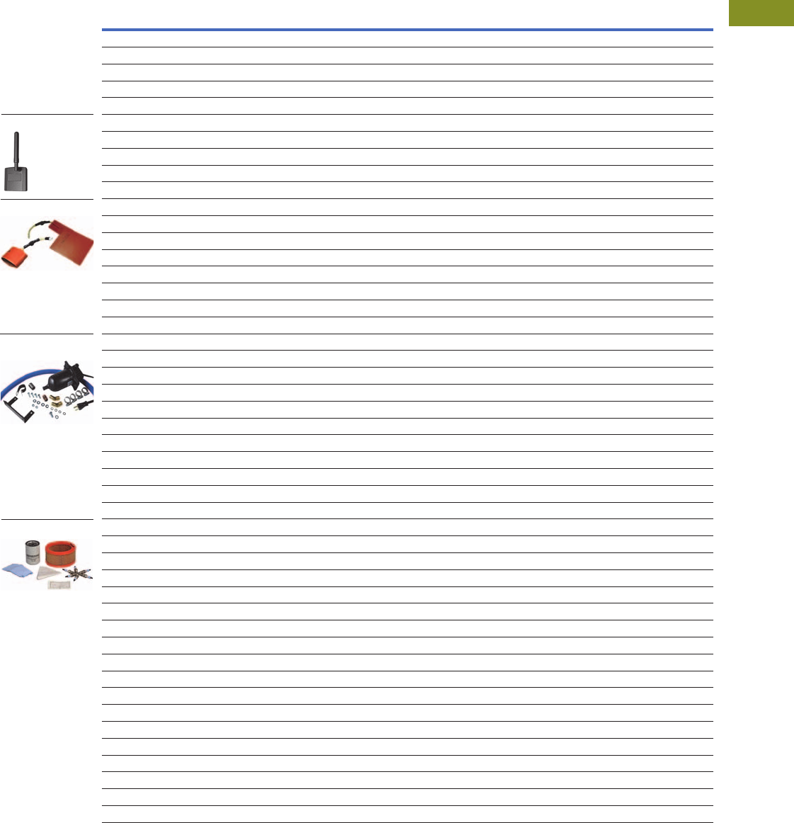
Volume 1—Residential and Light Commercial CA08100002E—February 2014 www.eaton.com V1-T3-5
3
3
3
3
3
3
3
3
3
3
3
3
3
3
3
3
3
3
3
3
3
3
3
3
3
3
3
3
3
3
3.1
Residential Standby Backup Power Solutions
Standby Generators
Accessories
Generator Accessories—Air and Liquid-Cooled Generators
Description
Catalog
Number
General Accessories
Air-cooled transportation cart EGENCART
Bisque paint kit for 2008 model lineup EGENPAINT
Display shell—bisque color EGENSHELL
Generator fascia for air-cooled models. Bisque color (included as standard on EGENX20A models) EGENFASCIA
Wireless Remote Monitoring
Wireless remote monitor for air-cooled and liquid-cooled generators. Compatible with 2008 models or newer. USA only EGENMOBILE
EGENMOBILE adapter wire harness kit required for liquid-cooled generators only. 2008 models or newer. USA only EGENKIT
Basic remote wireless monitor. Compatible with air/liquid-cooled models 8–150 kW. 2008 models or newer 5928CH
Remote monitor adapter kit for liquid-cooled units only—must be ordered w/5928CH basic remote monitor. 2008 models or newer 5958CH
Cold Weather Kits
Cold weather kit for all air-cooled generator models (8–20 kW). Battery and crankcase warmer 6212CH
22, 27, 36, 45 and 60 kW (2.4L) cold weather kit 5630CH
25 and 30 kW (1.5L) cold weather kit 6175CH
100 and 130 kW (6.8L) cold weather kit 5633CH
48 (5.4L), 80 (4.6L) and 70 and 150 kW (6.8L) cold weather kit 5632CH
25 and 30 kW (1.6L) cold weather kit for models prior to February 2012 5629CH
48 kW (4.2L) cold weather kit for models prior to February 2012 5631CH
Extreme Cold Weather Kits
25 and 30 kW extreme cold weather kit 1.5L engine 6174CH
25 and 30 kW extreme cold weather kit 1.6L engine (prior to February 2012) 5615CH
22, 27, 36, 45 and 60 kW extreme cold weather kit for 2.4L engine 5616CH
48 kW extreme cold weather kit for 5.4L engine 6204CH
48 kW extreme cold weather kit for 4.2L engine (prior to February 2012) 5618CH
70, 100 and 130 kW generator extreme cold weather kit for 6.8L engine gear drive 5620CH
80 kW extreme cold weather kit for 4.6L engine 5619CH
150 kW generator extreme cold weather kit for 6.8L engine direct drive 5667CH
Extreme cold weather kit (engine warmer) for air-cooled 8–10 kW, 410/530 cc engines (after April 2010) 5863CH
Extreme cold weather kit (engine warmer) for air-cooled 14–20 kW, 760/992/999 cc engines (after April 2010) 5864CH
Maintenance Kits
8 kW generator maintenance kit 410 cc engine. For #EGENX8 model only 6482CH
11 kW generator maintenance kit 530 cc engine. For #EGENX11 model only 6483CH
14 and 17 kW generator maintenance kit, 760/990 cc engine. For #EGENX14 & #EGENX17-17A models only 6484CH
20 kW generator maintenance kit, 999 cc engine. For #EGENX20A model only 6485CH
8 kW generator maintenance kit 410 cc engine. #EGEN8 vintage model only 5662CH
10 kW generator maintenance kit 530 cc engine. #EGEN10 vintage model only 5663CH
14 and 17 kW generator maintenance kit, 760/990 cc engine. #EGEN14 & EGEN17-17A vintage models only 5664CH
20 kW generator maintenance kit, 999 cc engine. #EGEN20A vintage model only 5665CH
22 and 27 kW generator maintenance kit, 2.4L engine 5656CH
25 and 30 kW generator maintenance kit, 1.5L engine 6176CH
25 and 30 kW generator maintenance kit, 1.6L engine (prior to February 2012) 5655CH
36 kW generator maintenance kit, 2.4L engine 5984CH
45 kW generator maintenance kit, 2.4L engine 6172CH
48 kW generator maintenance kit, 4.2L engine 5658CH
60 kW generator maintenance kit, 2.4L engine 6171CH
80 kW generator maintenance kit, 4.6L engine 5985CH
70, 100, 130 and 150 kW generator maintenance kit, 6.8L engine 5660CH
EGENMOBILE
Maintenance Kits
Cold Weather Kits
Extreme Cold Weather
Kits

V1-T3-6 Volume 1—Residential and Light Commercial CA08100002E—February 2014 www.eaton.com
3
3
3
3
3
3
3
3
3
3
3
3
3
3
3
3
3
3
3
3
3
3
3
3
3
3
3
3
3
3
3.1
Residential Standby Backup Power Solutions
Standby Generators
Sizing Guidelines
When selecting the essential circuits that will be switched to
“Backup Power,” it is important that the sum of the combined
circuit loads does not exceed the wattage/amperage capacity
of the generator. To help you with your selection of essential
circuits, please add up the total wattage of all electrical devices
to be connected at one time. This total should NOT be greater
than the generator’s wattage capacity.
Refer to Eaton Generator Sizing Guide Publication Number
TD00405018E and consult with a trained professional.
Circuit Selection 123
Dimensions
Approximate Dimension in Inches (mm)
Air-Cooled Standby
Liquid-Cooled Standby
Notes
1The rated wattage of lights can be taken from light bulbs. The rated wattage of tools,
appliances and motors can usually be found on a data plate or decal affixed to the device.
2If the appliance, tool or motor does not give wattage, multiply 120 volts times the ampere
rating to determine watts (volts x amps = watts) for single-phase only.
3Some electric motors (induction types) require about three times more watts of power for
starting than for running. This surge lasts for only a few seconds. Be sure you allow for this
high starting wattage when selecting electrical devices that will be energized by the backup
power system:
Figure the watts required to start the largest motor.
Add that to the total running watts of all other connected loads.
4All weights provided for steel enclosures only.
Device
Common
Running Watts
Air conditioner (12,000 btu) 1700
Air conditioner (24,000 btu) 3800
Air Conditioner (40,000 btu) 6000
Battery charger (20 amp) 500
Circular saw (6-1/2-inch) 800–1000
Clothes dryer (electric) 5750
Clothes dryer (gas) 700
Clothes washer 1150
Coffee maker 1750
Compressor (1 hp) 2000
Compressor (1/2 hp) 1400
Compressor (3/4 hp) 1800
Curling iron 700
Dehumidifier 650
Electric blanket 400
Electric range (per element) 1500
Electric skillet 1250
Freezer 700
Furnace fan (3/5 hp) 875
Garage door opener 500–750
Hair dryer 1200
Hand drill 250–1100
Iron 1200
Jet pump 800
Light bulb 100
Microwave oven 700–1000
Milk cooler 1100
Oil burner on furnace 300
Oil fired space heater (140,000 btu) 400
Oil fired space heater (30,000 btu) 150
Oil fired space heater (85,000 btu) 225
Radio 50–200
Refrigerator 700
Slow cooker 200
Submersible pump (1 hp) 2000
Submersible pump (1/2 hp) 1500
Submersible pump (1-1/2 hp) 2800
Sump pump 800–1050
Table saw (10-inch) 1750–2000
Television 200–500
Toaster 1000–1650
Catalog
Number Length Width Height
Weight in
Lbs (kg)
EGENX8 48.00 (1219.2) 25.00 (635.0) 29.00 (736.6) 340 (154.4)
EGENX11 48.00 (1219.2) 25.00 (635.0) 29.00 (736.6) 387 (175.7)
EGENX14 48.00 (1219.2) 25.00 (635.0) 29.00 (736.6) 439 (199.3)
EGENX17 48.00 (1219.2) 25.00 (635.0) 29.00 (736.6) 455 (206.6)
EGENX17A 48.00 (1219.2) 25.00 (635.0) 29.00 (736.6) 421 (191.1)
EGENX20A 48.00 (1219.2) 25.00 (635.0) 29.00 (736.6) 451 (204.8)
Catalog
Number Length Width Height
Weight in
Lbs (kg)
EGEN22 62.00 (1574.8) 29.00 (736.6) 34.00 (863.6) 895 (406.3)
EGEN25 63.00 (1600.2) 30.00 (762.0) 35.00 (889.0) 875 (397.3)
EGEN27 64.00 (1625.6) 31.00 (787.4) 36.00 (914.4) 891 (404.5)
EGEN30 60.00 (1651.0) 32.00 (812.8) 37.00 (939.8) 935 (424.5)
EGEN36 77.00 (1955.8) 34.00 (863.6) 45.00 (1143.0) 1683 (764.1)
EGEN45 78.00 (1981.2) 35.00 (889.0) 46.00 (1168.4) 1414 (642.0)
EGEN48 79.00 (2006.6) 36.00 (914.4) 47.00 (1193.8) 1703 (773.2)
EGEN60 480.00 (2032.0) 37.00 (939.8) 48.00 (1219.2) 1650 (749.1)
EGEN70 497.00 (2463.8) 37.00 (939.8) 48.00 (1219.2) 2185 (992.0)
EGEN80 4115.00 (2921.0) 36.80 (934.7) 79.00 (2006.6) 2010 (912.5)
EGEN100 4116.00 (2946.4) 36.80 (934.7) 80.00 (2032.0) 2705 (1228.1)
EGEN130 4117.00 (2971.8) 36.80 (934.7) 81.00 (2057.4) 2873 (1304.3)
EGEN150 4118.00 (2997.2) 36.80 (934.7) 82.00 (2082.8) 2666 (1210.4)
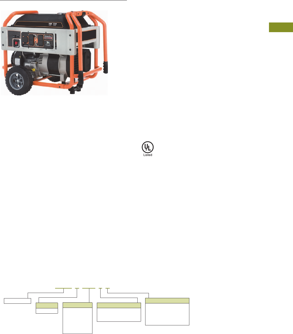
Volume 1—Residential and Light Commercial CA08100002E—February 2014 www.eaton.com V1-T3-7
3
3
3
3
3
3
3
3
3
3
3
3
3
3
3
3
3
3
3
3
3
3
3
3
3
3
3
3
3
3
3.2
Residential Standby Backup Power Solutions
Portable Generators
EGENP8000EX
Contents
Description Page
Portable Generators
Product Selection . . . . . . . . . . . . . . . . . . . . . . . V1-T3-8
Dimensions . . . . . . . . . . . . . . . . . . . . . . . . . . . V1-T3-10
Product Description
Whereas permanently
installed standby systems are
designed for larger homes,
small businesses or
secondary residences,
portable generators are
primarily used for smaller
homes, essential loads,
construction sites, camping,
tailgating and wherever
portable temporary power
is required.
Application Description
Portable generator systems
are primarily used for smaller
homes or for construction
sites where temporary power
is required. Permanently
installed standby systems
are designed for larger
homes, small businesses
or secondary residences,
such as vacation homes
and cabins, that require
uninterrupted power for
critical loads.
As the name indicates and
due to physical size and
weight, portable generators
can easily be transported
from one location to another.
Designed for outdoor use
only, common applications
vary from homes to camping
to construction sites,
providing backup power
everywhere electrical power
is needed.
Standards and
Certifications
●UL Listed
Catalog Number Selection
Portable Generators
Power Output
5500 = 5.5 kW
6500 = 6.5 kW
7000 = 7.5 kW
8000 = 8 kW
15000 = 15 kW
17500 = 17.5 kW
Eaton generator Model
Blank = General purpose
CA = General purpose
“CARB” compliant
(CA only)
X= XG Series
Type
P= Portable
EGEN P8000 E X
Startup Method
Blank = Manual/recoil only
E= Electric and/or
manual/recoil

V1-T3-8 Volume 1—Residential and Light Commercial CA08100002E—February 2014 www.eaton.com
3
3
3
3
3
3
3
3
3
3
3
3
3
3
3
3
3
3
3
3
3
3
3
3
3
3
3
3
3
3
3.2
Residential Standby Backup Power Solutions
Portable Generators
Product Selection
Portable Generators
Notes
1 Requires gasoline as fuel to operate.
All 120/240V. Required gasoline as fuel.
Running
Watts
Starting
Watts
Engine
Displacement/
Type
Startup
Method
Fuel
Tank
Capacity
(gal) 1
Approx.
Running
Time at
1/2 load
(hrs)
Battery
Included
Outlets
Configuration
Warranty
Residential/
Commercial
(yrs)
Catalog
Number
General Purpose (49-State)
5500 6875 389 cc/OHV Manual 7.2 10 No
1 x 30A L14-30R (twist lock), 2 x 20A 5-20R duplex
2/1 Ltd EGENP5500
6500 8125 389 cc/OHV Manual 7.2 10 No
1 x 30A L14-30R (twist lock), 2 x 20A 5-20R duplex
2/1 Ltd EGENP6500
6500 8125 389 cc/OHV Manual/
electric
7.2 10 Yes
1 x 30A L14-30R (twist lock), 2 x 120A 5-20R duplex
2/1 Ltd EGENP6500E
7500 9375 420 cc/OHV Manual/
electric
8.0 12 Yes
1 x 30A L14-30R (twist lock), 2 x 20A 5-20R duplex
2/1 Ltd EGENP7500E
15000 22500 992 cc/OHVI Manual/
electric
16.0 12 Yes
1 x 50A 14-50R, 1 x 30A L14-30R (twist lock),
2 x 30A L5-30R (twist lock), 1 x 20A 5-20R duplex,
1 x 20A GFCI 5-20R duplex
2/1 Ltd EGENP15000E
17500 26250 992 cc/OHVI Manual/
electric
16.0 10 Yes
1 x 50A 14-50R, 1 x 30A L14-30R (twist lock),
1 x 30A L5-30R (twist lock),1 x 20A 5-20R duplex,
1 x 20A 5-20R GFCI duplex
2/1 Ltd EGENP17500E
EGENP6500
EGENP6500E
EGENP7500E
EGENP15000E
EGENP5500
EGENP17500E

Volume 1—Residential and Light Commercial CA08100002E—February 2014 www.eaton.com V1-T3-9
3
3
3
3
3
3
3
3
3
3
3
3
3
3
3
3
3
3
3
3
3
3
3
3
3
3
3
3
3
3
3.2
Residential Standby Backup Power Solutions
Portable Generators
Portable Generators, continued
Notes
1 Requires gasoline as fuel to operate.
All 120/240V. Required gasoline as fuel.
Running
Watts
Starting
Watts
Engine
Displacement/
Type
Startup
Method
Fuel
Tank
Capacity
(gal) 1
Approx.
Running
Time at
1/2 load
(hrs)
Battery
Included
Outlets
Configuration
Warranty
Residential/
Commercial
(yrs)
Catalog
Number
XG Series
7000 8750 407 cc/OHVI Manual/
electric
910Yes
1 x 30A L14-30R (twist lock), 2 x 20A GFCI 5-20R duplex
2/1 Ltd EGENP7000EX
8000 10000 407 cc/OHVI Manual/
electric
10 10 Yes
1 x 30A L14-30R (twist lock), 2 x 20A GFCI 5-20R duplex
2/1 Ltd EGENP8000EX
10000 12500 530 cc/OHVI Manual/
electric
10 10 Yes
1 x 50A 14-50R, 1 x 30A L14-30R (twist lock),
1 x 30A L5-30R (twist Lock), 2 x 20A GFCI 5-20R duplex
2/1 Ltd EGENP10000EX
CARB Compliant (Required in California Only)
5500 6875 389 cc/OHV Manual 7.2 10 No
1 x 30A L14-30R (twist lock), 2 x 20A GFCI 5-20R duplex
2/1 Ltd EGENP5500CA
6500 8125 389 cc/OHV Manual 7.2 10 No
1 x 30A L14-30R (twist lock), 2 x 120A 5-20R duplex
2/1 Ltd EGENP6500CA
EGENP7000EX
EGENP8000EX
EGENP10000EX
EGENP6500CA
EGENP5500CA

V1-T3-10 Volume 1—Residential and Light Commercial CA08100002E—February 2014 www.eaton.com
3
3
3
3
3
3
3
3
3
3
3
3
3
3
3
3
3
3
3
3
3
3
3
3
3
3
3
3
3
3
3.2
Residential Standby Backup Power Solutions
Portable Generators
Dimensions
Approximate Dimension in Inches (mm)
Portable Generators
Catalog
Number Length Width Height
Weight
Lbs (kg)
EGENP5500 27.25 (692.2) 27.00 (685.8) 25.00 (635.0) 171.0 (77.6)
EGENP6500 27.25 (692.2) 27.00 (685.8) 25.00 (635.0) 175.0 (79.5)
EGENP6500E 27.25 (692.2) 27.00 (685.8) 25.00 (635.0) 186.0 (84.4)
EGENP7500E 27.25 (692.2) 27.00 (685.8) 25.00 (635.0) 191.5 (86.9)
EGENP15000E 48.50 (1231.9) 31.00 (787.4) 39.50 (1003.3) 363.0 (164.8)
EGENP17500E 48.50 (1231.9) 31.00 (787.4) 39.50 (1003.3) 390.0 (177.1)
EGENP7000EX 31.00 (787.4) 25.50 (647.7) 28.00 (711.2) 245.0 (111.2)
EGENP8000EX 31.00 (787.4) 25.50 (647.7) 28.00 (711.2) 235.0 (106.7)
EGENP10000EX 30.00 (762.0) 29.50 (749.3) 31.00 (787.4) 300.0 (136.2)
EGENP5500CA 27.25 (692.2) 27.00 (685.8) 25.00 (635.0) 170.9 (77.6)
EGENP6500CA 27.25 (692.2) 27.00 (685.8) 25.00 (635.0) 177.0 (80.3)
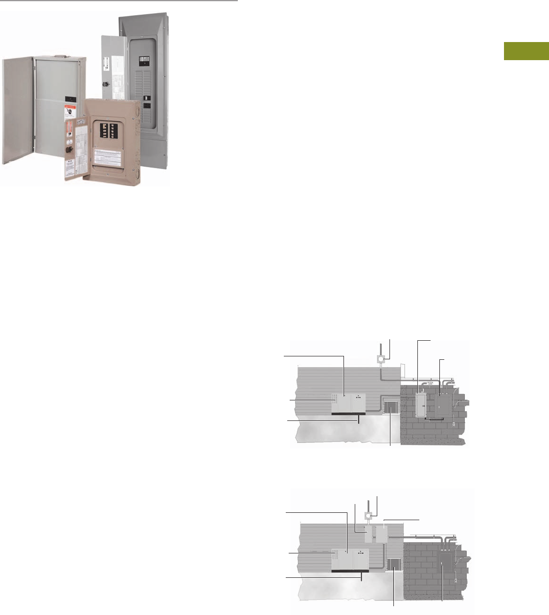
Volume 1—Residential and Light Commercial CA08100002E—February 2014 www.eaton.com V1-T3-11
3
3
3
3
3
3
3
3
3
3
3
3
3
3
3
3
3
3
3
3
3
3
3
3
3
3
3
3
3
3
3.3
Residential Standby Backup Power Solutions
Automatic Transfer Switches
Residential Automatic Transfer Switches
Contents
Description Page
Automatic Transfer Switches
Standards and Certifications . . . . . . . . . . . . . . V1-T3-12
Catalog Number Selection . . . . . . . . . . . . . . . . V1-T3-12
Product Selection . . . . . . . . . . . . . . . . . . . . . . . V1-T3-13
ATS Ready Loadcenter . . . . . . . . . . . . . . . . V1-T3-14
Dimensions . . . . . . . . . . . . . . . . . . . . . . . . . . . V1-T3-15
Product Description
50, 100, 150, 200 and 400A
Fully Automatic
All Eaton automatic transfer
switches (ATS) monitor utility
and generator voltages and
will automatically connect to
the appropriate source of
power. Eaton offers two
types of automatic transfer
switches to suit your personal
backup power needs—the
standard ATS EGSX series
with load shedding
capabilities and the Green
ATS EGSU series that
provides a truly active load
management solution.
Green Line of Automatic
Transfer Switches
With the rising cost of
commodities and fuel
in today’s economy,
consumers are concerned
with maximizing the value
of their purchases.
Electrical loads are now
intelligently managed with
Eaton’s Green Line of
automatic transfer switches.
The active load management
inside each Green ATS allows
the consumer to use 100% of
the power rated output of the
generator and/or use a
smaller generator, reducing
upfront installation costs and
saving on ongoing fuel
consumption costs.
As a part of Eaton’s
commitment to quality,
every Green ATS, at no
extra cost, will ship with a
CHSPT2ULTRA whole surge
protector, which will help
prevent potential damage
to valued electronics caused
by power surges in the
utility line.
Application Description
50, 100, 150, 200 and 400A
Switches
100, 200 and 400A switches
are capable of “whole house”
power transfer in residential/
small business applications.
50A—Indoor Installation—Selected Load Pre-Wired
100/200A—Outdoor Installation—Whole House Pre-Wired
Standby
Generator
Sound
Attenuated
Enclosure
Fuel Supply
(NG or LP)
Air Conditioner
50A
Indoor Transfer
Switch
100/200A
Service Panel
Meter
Low Voltage
Disconnect
Service
Disconnect
100/200A
Outdoor Transfer Switch
Meter
Low Voltage
Disconnect
Air Conditioner
Standby
Generator
Fuel Supply
(NG or LP)
100/200A
Service Panel
Sound
Attenuated
Enclosure
V1-T3-12 Volume 1—Residential and Light Commercial CA08100002E—February 2014 www.eaton.com
3
3
3
3
3
3
3
3
3
3
3
3
3
3
3
3
3
3
3
3
3
3
3
3
3
3
3
3
3
3
3.3
Residential Standby Backup Power Solutions
Automatic Transfer Switches
Standards and
Certifications
●UL 1008 listed
Catalog Number Selection
Standard Automatic Transfer Switches—EGSX Series
Green Automatic Transfer Switches—EGSU Series
EGSX 200 NSEA
Manufacturer
Eaton Type
Generator
transfer switch
EGSX Series
Loadcenter
(CH Type, Integral)
Blank = None
L12 = 12 circuits N1
L12R = 12 circuits N3R
L24R = 24 circuits N3R
Service Entrance Rated
NSEA = Service entrance
(normal source only)
A= Non-service entrance
Ampere
Rating
50 = 50A
100 = 100A
150 = 150A
200 = 200A
400 = 400A
EGSU 200 NSE ACA
Manufacturer
Eaton Type
Generator
universal transfer
switch EGSU
“Green” Series
Service Entrance Rated
NSE = Service entrance
(normal source only)
Blank = Non-service entrance
Ampere
Rating
100 = 100A
150 = 150A
200 = 200A
400 = 400A
Loadcenter
(CH Type, Integral)
Blank = None
L24 = 24 circuits
Load Management
ACA = Active load management
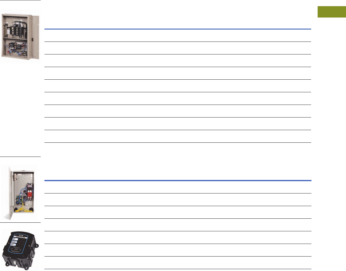
Volume 1—Residential and Light Commercial CA08100002E—February 2014 www.eaton.com V1-T3-13
3
3
3
3
3
3
3
3
3
3
3
3
3
3
3
3
3
3
3
3
3
3
3
3
3
3
3
3
3
3
3.3
Residential Standby Backup Power Solutions
Automatic Transfer Switches
Product Selection
Standard Automatic Transfer Switches 1
Green Automatic Transfer Switches 4—Featuring Active Load Management Technology
Notes
1 Standard ATS “EGSX” Series compatible with Eaton generators only.
2 Uses CH type circuit breakers.
3 For reference only. Generator size must be determined with proper/actual load calculations.
4 UNIVERSAL ATS: compatible with any single-phase, 120/240V generator brand.
5 Whole house surge Cat. No. CHSPT2ULTRA included in every Green ATS “EGSU” Series.
Ampere
Rating Voltage
Service
Entrance
Rated
No. of
Load
Shed
Contacts
Contactor
Wire Size
Range(s)
No. of
Cables
per Phase
Withstand
Current (rms)
at 240 Vac
No. of
Circuits
Included 2
Frequency
(Hz)
Enclosure
Type
Recommended
Generator
Sizes (kW) 3
Catalog
Number
50 120/240 No 2 #14–#6 1 5000 12 50/60 NEMA 1
(indoor)
8, 11 EGSX50L12
50 120/240 No 2 #14–#6 1 5000 12 50/60 NEMA 3R
(outdoor)
8, 11 EGSX50L12R
100 120/240 No 2 #14–#2/0 1 10,000 — 50/60 NEMA 3R
(outdoor)
8, 11, 14 EGSX100A
100 120/240 Yes 2 #14–#2/0 1 10,000 — 50/60 NEMA 3R
(outdoor)
8, 11, 14 EGSX100NSEA
100 120/240 No 2 #14–#2/0 1 25,000 24 50/60 NEMA 3R
(outdoor)
8, 11, 14 EGSX100L24RA
150 120/240 Yes 2 #4–300 kcmil 1 25,000 — 50/60 NEMA 3R
(outdoor)
14, 17, 20 EGSX150NSEA
200 120/240 No 2 #4–300 kcmil 1 25,000 — 50/60 NEMA 3R
(outdoor)
14, 17, 20 EGSX200A
200 120/240 Yes 2 #4–300 kcmil 1 25,000 — 50/60 NEMA 3R
(outdoor)
14, 17, 20 EGSX200NSEA
400 120/240 Yes 2 750 kcmil–2
300 kcmil–1/0
1/2 35,000 — 50/60 NEMA 3R
(outdoor)
>20 EGSX400NSEA
Ampere
Rating Voltage
Service
Entrance
Rated
Contactor
Wire Size
Range(s)
No. of
Cables
per Phase
Withstand
Current (rms)
at 240 Vac
No. of
Circuits
Included 2
Frequency
(Hz)
Enclosure
Type
Recommended
Generator
Sizes (kW) 3
Catalog
Number
100 120/240 No #14–#2/0 1 10,000 — 50/60 NEMA 3R
(outdoor)
8, 11, 14 EGSU100ACA
100 120/240 Yes #14–#2/0 1 10,000 — 50/60 NEMA 3R
(outdoor)
8, 11, 14 EGSU100NSEACA
100 120/240 No #14–#2/0 1 10,000 24 50/60 NEMA 3R
(outdoor)
8, 11, 14 EGSU100L24RACA
150 120/240 Yes #4–300 kcmil 1 25,000 — 50/60 NEMA 3R
(outdoor)
14, 17, 20 EGSU150NSEACA
200 120/240 No #4–300 kcmil 1 25,000 — 50/60 NEMA 3R
(outdoor)
14, 17, 20 EGSU200ACA
200 120/240 Yes #4–300 kcmil 1 25,000 — 50/60 NEMA 3R
(outdoor)
14, 17, 20 EGSU200NSEACA
400 120/240 Yes 750 kcmil–2
300 kcmil–1/0
1/2 35,000 — 50/60 NEMA 3R
(outdoor)
>20 EGSU400NSEACA
EGSX50L12R
EGSU200NSEACA
CHSPT2ULTRA 5
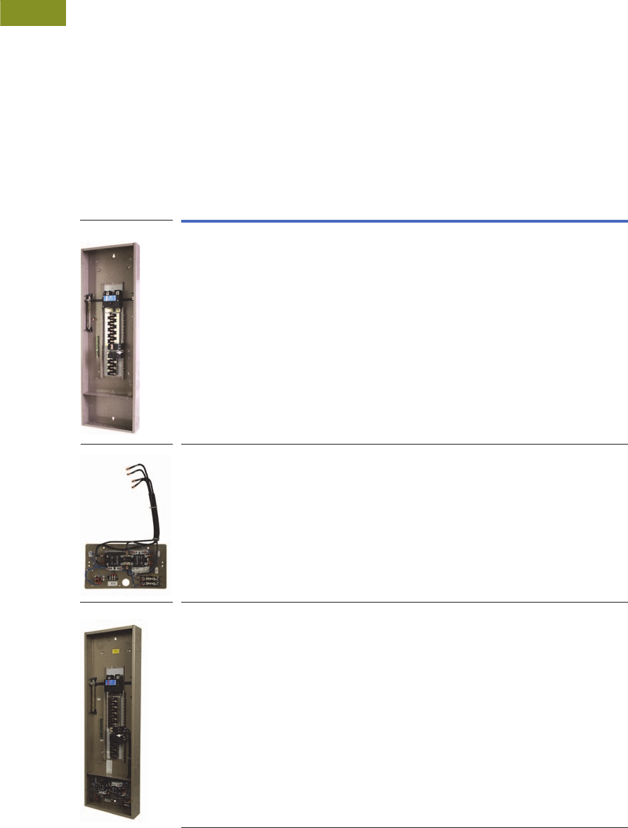
V1-T3-14 Volume 1—Residential and Light Commercial CA08100002E—February 2014 www.eaton.com
3
3
3
3
3
3
3
3
3
3
3
3
3
3
3
3
3
3
3
3
3
3
3
3
3
3
3
3
3
3
3.3
Residential Standby Backup Power Solutions
Automatic Transfer Switches
ATS Ready Loadcenter
From the far-reaching power
failures brought on by
hurricanes and snow/ice
storms, to the increasing
power outage concerns and
an aging electrical
infrastructure, backup power
is more important than ever.
Eaton’s ATS Ready loadcenter
addresses future backup
power needs by enabling a
fast, efficient installation of an
automatic transfer switch kit
to convert from utility power
to generator power. The ATS
Ready loadcenter gives
homebuilders and electrical
contractors the flexibility to
install a generator ready
system or to install a
loadcenter and easily add an
ATS in the future. Backup
power had never been that
versatile before.
ATS Ready Loadcenter Features
●CH Premium Type 200A
single-phase MCB
36-circuit loadcenter
●50A ATS “EGSX” type kit
for factory or field
installation (compatible
with Eaton generators only)
●22 circuits for non-
essential loads and
14 circuits for essential
backup power loads
●Versatile, space-saving
design
●For use with 8 or 11 kW
air-cooled generators
●CH cover included
●Lifetime warranty on CH
loadcenter and breakers
●NEMA 1 design
●UL Listed
ATS Ready Loadcenter
Description Catalog Number
ATS Ready loadcenter
Kit CHEGSX50KIT must be ordered separately
Loadcenter only. Includes provision for ATS kit
CH36B200EGP
ATS “EGSX” kit for ATS Ready loadcenter
Field-installable automatic transfer switch kit
ATS Ready loadcenter CH36B200EGP must be ordered separately
Intuitive, easy installation
Compatible with Eaton generators only
CHEGSX50KIT
ATS Ready LC with factory-installed ATS kit
Factory assembled
Compatible with Eaton generator only. Generator needed to complete backup power system
Recommended Eaton generators models:
8/7 kW–Catalog #EGENX8
11/10 kW–Catalog #EGENX11
CH36B200EGPK
CH36B200EGP
CHEGSX50KIT
CH36B200EGPK

Volume 1—Residential and Light Commercial CA08100002E—February 2014 www.eaton.com V1-T3-15
3
3
3
3
3
3
3
3
3
3
3
3
3
3
3
3
3
3
3
3
3
3
3
3
3
3
3
3
3
3
3.3
Residential Standby Backup Power Solutions
Automatic Transfer Switches
Dimensions
Approximate Dimension in Inches (mm)
Automatic Transfer Switches
Catalog Number Width Height Depth
Weight
Lbs (kg)
EGSX50L12 14.25 (362.0) 21.00 (533.4) 4.00 (101.6) 25 (11.33)
EGSX50L12R 14.25 (362.0) 21.00 (533.4) 6.00 (152.4) 29 (13.15)
EGSX100A 14.46 (367.3) 16.87 (428.5) 5.32 (135.1) 25 (11.33)
EGSX100NSEA 14.46 (367.3) 16.87 (428.5) 5.32 (135.1) 28 (12.70)
EGSX100L24RA 14.46 (367.3) 29.33 (744.0) 5.32 (135.1) 38 (17.24)
EGSX200A 14.46 (367.3) 25.08 (637.0) 5.25 (133.4) 35 (15.87)
EGSX150NSEA 14.46 (367.3) 29.20 (741.7) 5.32 (135.1) 45 (20.41)
EGSX200NSEA 14.46 (367.3) 29.20 (741.7) 5.32 (135.1) 45 (20.41)
EGSU100L24RACA 14.46 (367.3) 29.33 (745.0) 5.32 (135.1) 38 (17.24)
EGSU100ACA 14.46 (367.3) 16.87 (428.5) 5.32 (135.1) 25 (11.33)
EGSU100NSEACA 14.46 (367.3) 16.87 (428.5) 5.32 (135.1) 28 (12.70)
EGSU150NSEACA 14.46 (367.3) 29.20 (741.7) 5.32 (135.1) 45 (20.41)
EGSU200ACA 14.46 (367.3) 25.08 (637.0) 5.25 (133.4) 35 (15.88)
EGSU200NSEACA 14.46 (367.3) 29.20 (741.7) 5.32 (135.1) 45 (20.41)
EGSU400NSEACA 23.14 (587.8) 35.55 (903.0) 10.00 (254.0) 120 (54.43)
CH36B200EGPK 14.31 (363.5) 47.50 (1206.5) 3.88 (98.6) 40 (18.14)
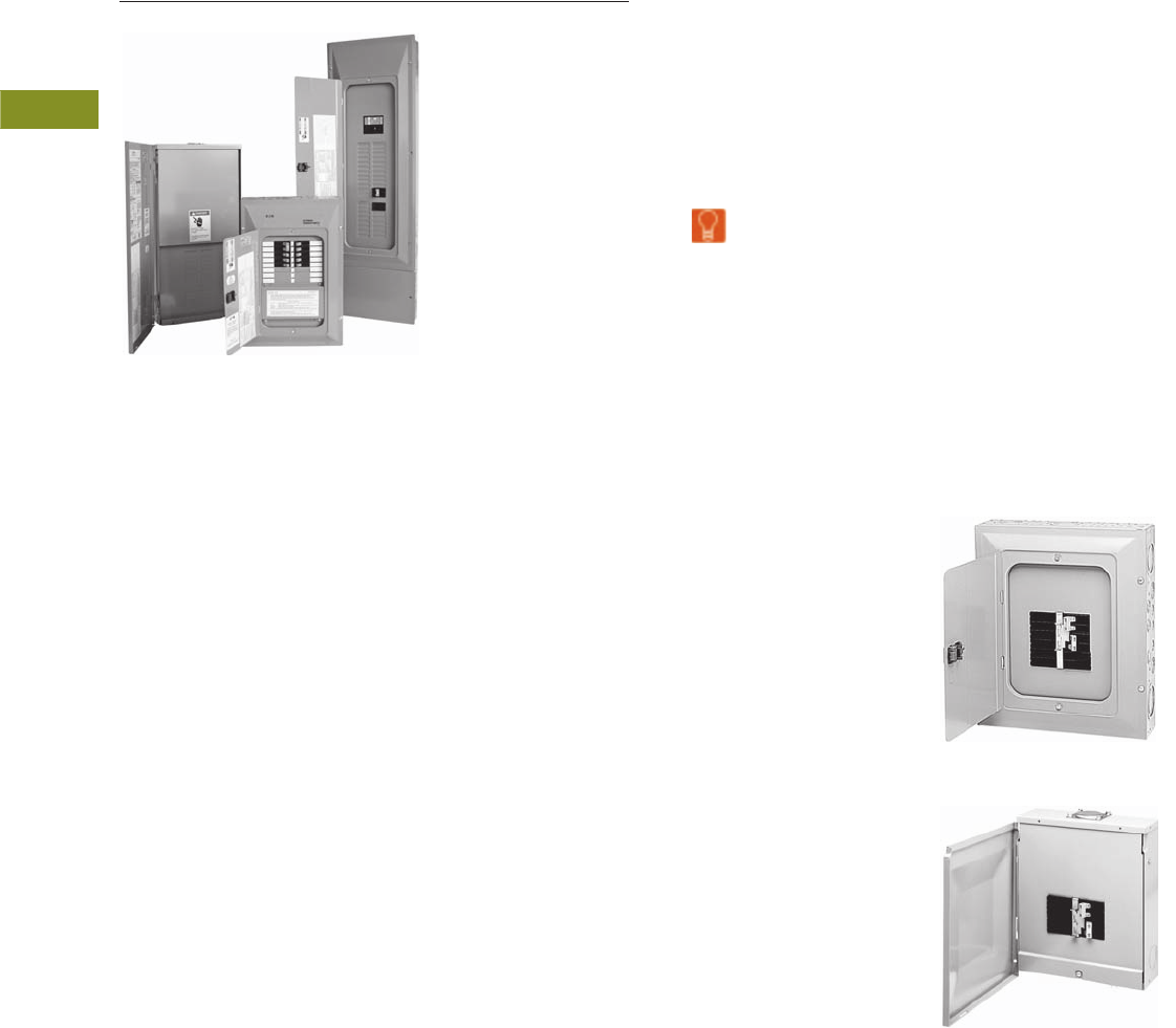
V1-T3-16 Volume 1—Residential and Light Commercial CA08100002E—February 2014 www.eaton.com
3
3
3
3
3
3
3
3
3
3
3
3
3
3
3
3
3
3
3
3
3
3
3
3
3
3
3
3
3
3
3.4
Residential Standby Backup Power Solutions
Manual Transfer Switches
All Panels are Manufactured in the USA and Meet UL 1008
Contents
Description Page
Manual Transfer Switches
Standards and Certifications . . . . . . . . . . . . . . V1-T3-17
Reference Information . . . . . . . . . . . . . . . . . . V1-T3-17
Product Selection . . . . . . . . . . . . . . . . . . . . . . V1-T3-18
Technical Data and Specifications . . . . . . . . . . V1-T3-19
Dimensions . . . . . . . . . . . . . . . . . . . . . . . . . . . V1-T3-19
Learn
Online
Product Description
A manual transfer switch is a
device that is mounted next
to the loadcenter (distribution
panel) in the home or small
business. The manual
transfer switch is used in
conjunction with a portable
backup power generator and
serves the purpose of turning
selected circuits on and off
during a power outage. The
transfer switch panel allows
the owner to start up a
generator to restore power to
critical circuits when utility
power is not available.
The owner designates which
circuits are critical, such as
the refrigerator and certain
lights. Sometimes called
emergency power panels or
emergency generator panels,
manual transfer switch
panels provide the
homeowner or small
business owner with a safe
and easy way to continue
using electrical appliances
when the utility power
is unavailable temporarily.
Application Description
Manual transfer switches
are most often used in
residential, agricultural
and light commercial
applications. Comfort and
safety are key concerns
of many homeowners
who are dependent on
an uninterrupted supply
of electricity.
The increase in our
dependence on power is
due in part to the popularity
of home offices and in-home
health care. Various heavily
populated regions of the
United States experience
periodic power outages
due to extreme weather
conditions, such as ice and
snowstorms, heat waves,
tornadoes or hurricanes.
These regions that include
the Pacific Northwest,
Atlantic Coast and the Gulf
Coast are the strongest
markets for portable
generators and manual
transfer switches.
Features, Benefits and Functions
Eaton offers two manual
transfer switch backup power
solutions:
●Manual transfer switches
●Generator panels
Manual Transfer Switches
●Panel and components
sold separately
●Hardwired generator
connection
●Ideal for new construction/
larger loads
●Sturdy copper bus
construction
●Uses CH and CHNT circuit
breaker types (sold
separately)
●Mechanically interlocked
main disconnects to
prevent paralleling of
normal and emergency
power source
●Indoor and outdoor
designs available
Manual Transfer Switch
Indoor Design
Manual Transfer Switch
Indoor/Outdoor Design
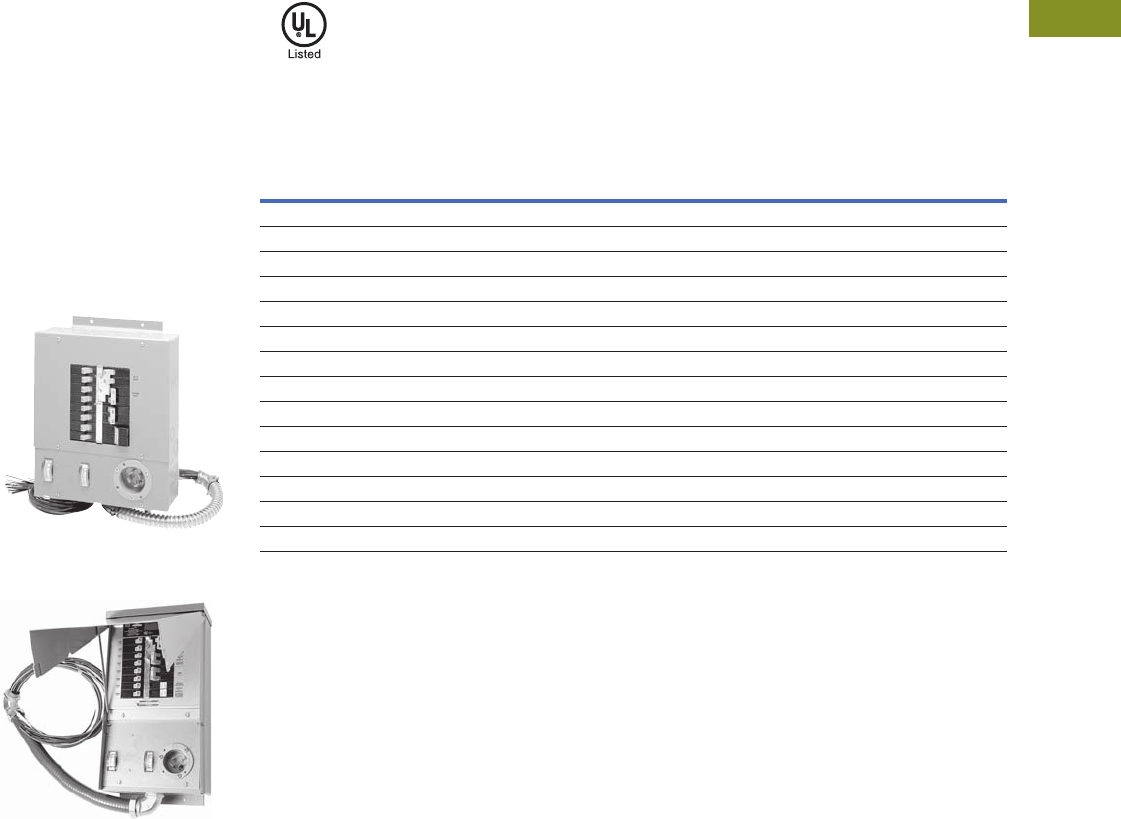
Volume 1—Residential and Light Commercial CA08100002E—February 2014 www.eaton.com V1-T3-17
3
3
3
3
3
3
3
3
3
3
3
3
3
3
3
3
3
3
3
3
3
3
3
3
3
3
3
3
3
3
3.4
Residential Standby Backup Power Solutions
Manual Transfer Switches
Generator Panels
●Mechanically interlocked
main disconnects prevent
paralleling of normal and
emergency power source
●Panel and components
sold separately
●Integral plug-in generator
connection (power inlet
box)
●All circuit breakers are
included—switching
duty rated
●Includes dual wattmeters
for load balancing
●Indoor and outdoor
designs available
Generator Panel
Indoor Design
Generator Panel
Outdoor Design
Standards and Certifications
●UL 67 listed
●UL 1008 listed
Reference Information
Cross-Reference
Notes
1Gen/Trans device is not supplied with a power cord.
2Generac device is 7200 maximum watts on six-circuit device and 12,000 maximum watts on 10-circuit device.
Watts
Number
of Circuits
Ampere
Rating
Catalog Number
Eaton Gen/Tran 1EmerGen 1Square D Generac 1
5000 4–8 30 CH48GEN3060R — — QO48M30DSGP —
15,000 8–16 60 CH816GEN6060 — — QO48M60DSGP —
5000 6 20 CH6EGEN2060 20216 6-5000 — —
5000 6 20 CH6EGEN2060R R20216 6-5000 + RTE657 — —
5000 6 20 CH6EGEN2060SU —— — —
5000 6 20 CH6EGEN2060RSU —— — —
7500 10 30 CH10EGEN3060 302110-20 10-7500 — —
7500 10 30 CH10EGEN3060R R30211-20 10-7500 + RTE1075 — —
7500 10 30 CH10EGEN3060SUR —— — —
7500 10 30 CH10EGEN3060RSU —— — —
7500 10 30 CH10GEN5030SN —— — —
7500 10 30 CH10GEN5030RSN —— — —
12,000 10 50 CH10GEN5050SN —— — —
12,000 10 50 CH10GEN5050RSN —— — —
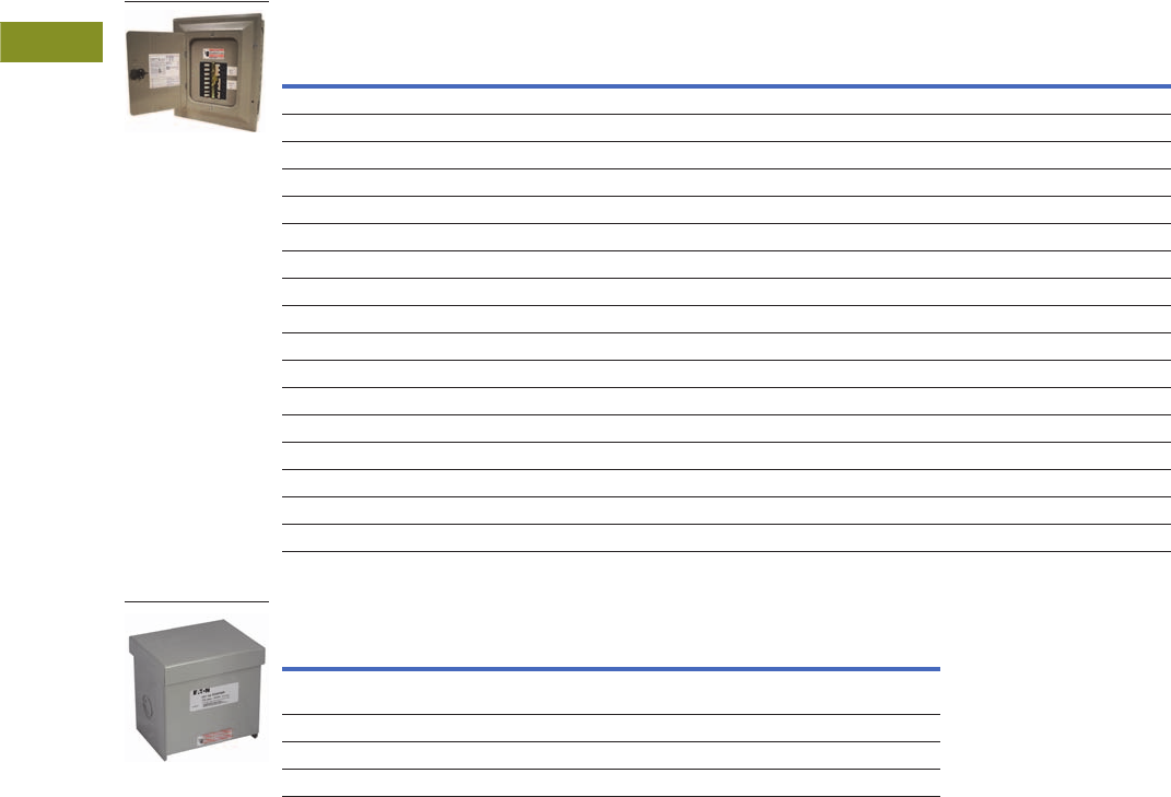
V1-T3-18 Volume 1—Residential and Light Commercial CA08100002E—February 2014 www.eaton.com
3
3
3
3
3
3
3
3
3
3
3
3
3
3
3
3
3
3
3
3
3
3
3
3
3
3
3
3
3
3
3.4
Residential Standby Backup Power Solutions
Manual Transfer Switches
Product Selection
Manual Transfer Switches and Generator Panels Selection
Power Inlet Boxes
Warranty
Manual Transfer Switch
●15-year loadcenter
warranty
●Lifetime branch breaker
warranty
Generator Panel
●15-year loadcenter
warranty
●Lifetime branch breaker
warranty
Enclosure
Type Watts
Number
of Circuits
Ampere
Rating
Main/
Emergency
Ampere Rating
Feeder
Breakers
Included
Accessories
Catalog
Number
Standard Manual Transfer Switch
NEMA 3R 5000 4–8 30 Provision Provision None CH48GEN3060R
NEMA 1 10,000 8–16 60 Provision Provision None CH816GEN6060
Generator Panel
NEMA 1 5000 6 20 60/20 5–1P151–1P20 None CH6EGEN2060
NEMA 3R 5000 6 20 60/20 5–1P151–1P20 None CH6EGEN2060R
NEMA 1 5000 6 20 60/20 5–1P151–1P20 Two-pole surge protector CH6EGEN2060SUR
NEMA 3R 5000 6 20 60/20 5–1P151–1P20 Two-pole surge protector CH6EGEN2060RSU
NEMA 1 7500 10 30 60/30 6–1P152–1P2012P30 None CH10EGEN3060
NEMA 3R 7500 10 30 60/30 6–1P152–1P2012P30 None CH10EGEN3060R
NEMA 1 7500 10 30 60/30 7–1P152–1P2012P30 Two-pole surge protector CH10EGEN3060SUR
NEMA 3R 7500 10 30 60/30 7–1P152–1P2012P30 Two-pole surge protector CH10EGEN3060RSU
Switched Neutral Manual Transfer Switch
NEMA 1 7500 10 30 50/30 6–1P15, 2–1P20, 1–2P30 None CH10GEN5030SN
NEMA 3R 7500 10 30 50/30 6–1P15, 2–1P20, 1–2P30 None CH10GEN5030RSN
NEMA 1 12,000 10 50 50/50 6–1P15, 2–1P20, 1–2P30 None CH10GEN5050SN
NEMA 3R 12,000 10 50 50/50 6–1P15, 2–1P20, 1–2P30 None CH10GEN5050RSN
Description
Ampere
Rating Voltage
Catalog
Number
Flush flange kit (for use with
generator panel only)
— 120/240V CHEGENFKIT
Power inlet box 20 120/240V EGSPIB20
Power inlet box 30 120/240V EGSPIB30
Power inlet box 50 120/240V EGSPIB50
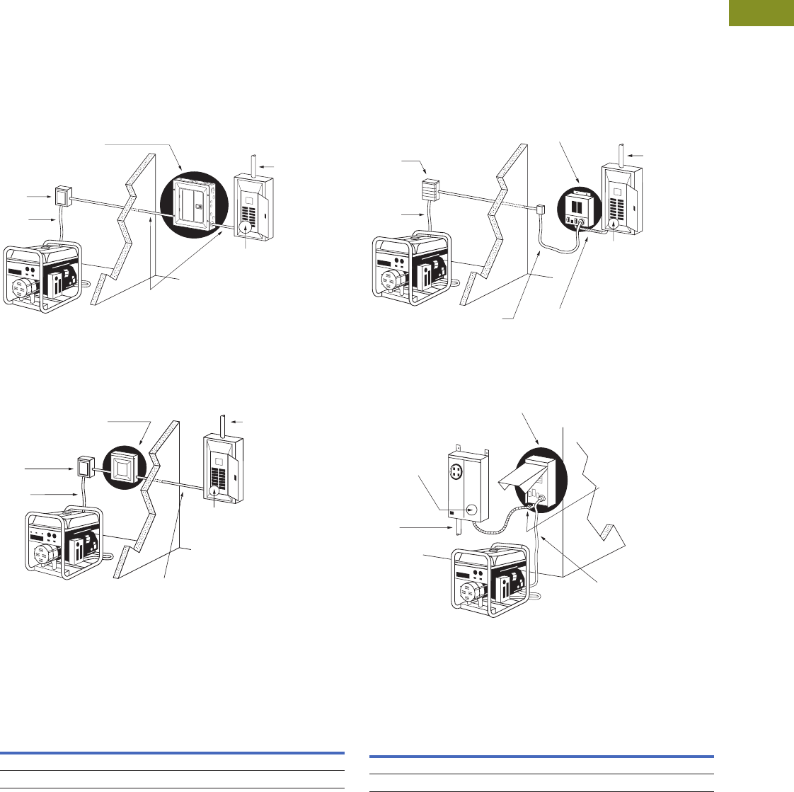
Volume 1—Residential and Light Commercial CA08100002E—February 2014 www.eaton.com V1-T3-19
3
3
3
3
3
3
3
3
3
3
3
3
3
3
3
3
3
3
3
3
3
3
3
3
3
3
3
3
3
3
3.4
Residential Standby Backup Power Solutions
Manual Transfer Switches
Technical Data and Specifications
●10,000 AIC rating
●Switching devices must be circuit breakers
●Manual transfer switch must be supplied with neutral
and ground
●Power inlet box must be connected to a circuit breaker for
generator protection
Installation Diagrams
Manual Transfer Switches—Indoor Installation Diagram
Manual Transfer Switches—Outdoor Installation Diagram
Generator Panels—Indoor Installation Diagram
Generator Panels—Outdoor Installation Diagram
Dimensions
Approximate Dimensions in Inches (mm)
Manual Transfer Switch Generator Panel
Two-Pole, 60A Breaker*
to Feed the Emergency
Power Panel From Your
Existing Main Power Panel
(Loadcenter)
Hardwired
Electrical
Connection*
Eaton
Manual Transfer Switch
Generator*
Not Included
*
Existing
Main
Power
Panel
(Loadcenter)
Power
Inlet
Box*
Power
Cord*
Utility
Power
Feed
Eaton
Manual Transfer Switch
Power
Inlet
Box*
Power
Cord*
Generator*
Hardwired Electrical Connection*
Utility
Power Feed
Two-Pole, 60A Breaker*
to Feed the Emergency
Power Panel From Your
Existing Main Power Panel
(Loadcenter)
Existing
Main
Power
Panel
(Loadcenter)
* Not Included
Power
Inlet
Box*
Power
Cord*
Generator
Utility
Power
Feed
Two-Pole, 60A Breaker*
to Feed the Emergency
Generator Panel From
Your Existing Main
Power Panel (Loadcenter)
Prewired Connector
for Faster Installation
-
Included
Electrical Wiring
or Power Cord*
Generator Panel
*
Existing
Main
Power
Panel
(Loadcenter)
* Not Included
Power Cord*
Generator*
Two-Pole, 60A
Breaker* to Feed
the Emergency
Generator Panel
From Your
Existing Main
Power Panel Prewired
Connector
for Faster
Installation -
Included
*Not Included
Generator Panel
Utility
Power
Feed
Enclosure
Type Height Width Depth
Weight
Lbs (kg)
NEMA 1 16.75 (425.5) 14.31 (363.5) 3.88 (98.5) 25 (11)
NEMA 3R 13.00 (330.2) 11.00 (279.4) 3.56 (90.4) 14 (6)
Enclosure
Type Height Width Depth
Weight Lbs (kg)
Six-Circuit 10-Circuit
NEMA 1 13.23 (336.0) 11.41 (289.8) 4.10 (104.1) 24 (11) 26 (12)
NEMA 3R 17.12 (434.8) 9.45 (240.0) 7.16 (181.9) 29 (13) 31 (14)

Volume 1—Residential and Light Commercial CA08100002E—June 2013 www.eaton.com V1-T4-1
4
4
4
4
4
4
4
4
4
4
4
4
4
4
4
4
4
4
4
4
4
4
4
4
4
4
4
4
4
4
Structured Wiring
Intercom System
4.1 StructuredWiringSolutions™
Product Description . . . . . . . . . . . . . . . . . . . . . . . . . . . . . . . . . . . . . . V1-T4-2
Application Description . . . . . . . . . . . . . . . . . . . . . . . . . . . . . . . . . . . . V1-T4-2
Product Selection . . . . . . . . . . . . . . . . . . . . . . . . . . . . . . . . . . . . . . . . V1-T4-4
Accessories . . . . . . . . . . . . . . . . . . . . . . . . . . . . . . . . . . . . . . . . . . . . V1-T4-21
Learn
Online
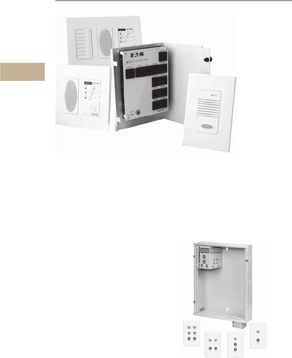
V1-T4-2 Volume 1—Residential and Light Commercial CA08100002E—June 2013 www.eaton.com
4
4
4
4
4
4
4
4
4
4
4
4
4
4
4
4
4
4
4
4
4
4
4
4
4
4
4
4
4
4
4.1
Structured Wiring
StructuredWiringSolutions
Intercom System
Contents
Description Page
StructuredWiringSolutions
Product Selection. . . . . . . . . . . . . . . . . . . . . . . V1-T4-4
Accessories . . . . . . . . . . . . . . . . . . . . . . . . . . . V1-T4-21
Product Description
Structured wiring is a
simple, affordable way
to wire a home for state-of-
the-art communications,
entertainment and security
now and for many years
to come.
The basic concept is that
all telephone, television,
satellite, coaxial, audio and
data communications cables
are wired in a star topology
(home run) to each room in
the home and terminate
at a central distribution
panel. This distribution
panel allows flexibility for
future modifications and/or
additions to keep pace with
a homeowner’s lifestyle
and needs.
Structured wiring can also
be used as a central hub
to interconnect a security
system, home automation,
HVAC and load control,
providing a complete system
to increase the security,
comfort and convenience
for a homeowner.
Wall Outlets and Basic Package
Application Description
●Telephone
●High-speed Internet
●Computer networks
●Web-safe Internet router
●Whole-house sound
●Satellite/cable TV
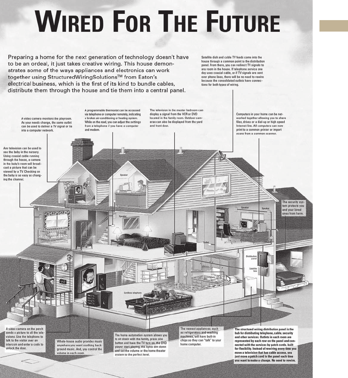
Volume 1—Residential and Light Commercial CA08100002E—June 2013 www.eaton.com V1-T4-3
4
4
4
4
4
4
4
4
4
4
4
4
4
4
4
4
4
4
4
4
4
4
4
4
4
4
4
4
4
4
4.1
Structured Wiring
StructuredWiringSolutions
A Home with StructuredWiringSolutions Gives You Ready Control of the Latest in Computing, Audio, Video and
Communications. With the Right Components, Your Dream Home is Ready for Today’s World and Tomorrow’s Advancements.
Your Value is Ensured...and so is Your Peace of Mind
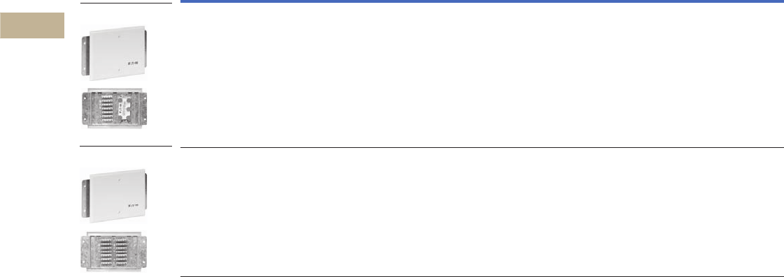
V1-T4-4 Volume 1—Residential and Light Commercial CA08100002E—June 2013 www.eaton.com
4
4
4
4
4
4
4
4
4
4
4
4
4
4
4
4
4
4
4
4
4
4
4
4
4
4
4
4
4
4
4.1
Structured Wiring
StructuredWiringSolutions
Product Selection
Packaged Products
Product Description UPC Code Catalog Number
Perfect for apartments, condos or even entry level homes. This distribution panel distributes four incoming telephone
lines to six locations, punchdown, and one incoming coax signal to four locations, passive. Installation is easy and a stylish
three-gang wall plate cover provides a professional looking finish.
782116895359 ESWB100
Same as ESWB100, except punchdown for telephone is doubled for 11 locations and there is no coax distribution.
Perfect for commercial and resi applications for phone only, or for six phone locations and/or six computer locations.
782116895366 ESWB100P
ESWB100
ESWB100P

Volume 1—Residential and Light Commercial CA08100002E—June 2013 www.eaton.com V1-T4-5
4
4
4
4
4
4
4
4
4
4
4
4
4
4
4
4
4
4
4
4
4
4
4
4
4
4
4
4
4
4
4.1
Structured Wiring
StructuredWiringSolutions
Video Modules
Product Description UPC Code Catalog Number
1 x 4 coax module. 1 in, 4 out coax module with four pass-through connectors. 6-inch form factor. 1.0 lb. 782116895502 ESWV10400
1 x 8 coax module. 1 in, 8 out coax module with two pass-through connectors. 6-inch form factor. 1.3 lbs. 782116895496 ESWV10800
1 x 8 amplified coax module. 1 in, 8 out coax module with 12 dB bi-directional amplifier and two pass-through
connectors. 6" form factor. 2.4 lbs.
782116895519 ESWV10800A
5 x 8 coax module. 5 in, 8 out coax module with 20 dB bi-directional amplifier, surge protection, and four pass-through
connectors, and four inputs for modulated signals. 12-inch form factor. 3 lbs.
782116895526 ESWV50800A
5 x 12 coax module. 5 in, 12 out coax module with 20 dB bi-directional amplifier, surge protection, and four pass-through
connectors, and four inputs for modulated signals. 12-inch form factor. 3.5 lbs.
782116895533 ESWV51200A
5 x 16 coax module. 5 in, 16 out coax module with 20 dB bi-directional amplifier, surge protection, with one direct and four
inputs for modulated signals. 12-inch form factor. 3.6 lbs.
782116895557 ESWV51600A
110 Volt video amplifier power supply. Power supply for all amplified video modules. 782116009671 ESWV110
ESWV10400
ESWV10800
ESWV10800A
ESWV50800A
ESWV51200A
ESWV51600A
V1-T4-6 Volume 1—Residential and Light Commercial CA08100002E—June 2013 www.eaton.com
4
4
4
4
4
4
4
4
4
4
4
4
4
4
4
4
4
4
4
4
4
4
4
4
4
4
4
4
4
4
4.1
Structured Wiring
StructuredWiringSolutions
Telephone Modules
Product Description UPC Code Catalog Number
12-port, four-line punchdown telephone module. The 12/4 punchdown telephone module has 12 110 punchdown blocks
that distribute four incoming lines to 12 locations. 6-inch form factor. 1 lb.
782116895434 ESWT41200P
Eight-port, four-line telephone module. Eight RJ-45 ports support four incoming phone lines. One RJ31X port for security.
6-inch form factor. 1.0 lb.
782116895441 ESWT40800
16-port, four-line telephone module. 16 RJ-45 ports support four incoming phone lines. One RJ31X port for security.
6-inch form factor. 1.25 lbs.
782116895458 ESWT41600
4 x 8 telephone breakout module. Distributes four incoming telephone lines to eight locations, RJ-45 style,
eight breakout ports, four-line pass-through. Breakout configurations: 1-2, 2-1, 3-4, 4-3.
782116894499 ESWTB48800
Eight location non-bridged phone module. Eight RJ-45 jacks connected directly to eight 110 punchdown connectors,
(one-to-one) can be bridged together, great for Ethernet switches and routers.
786685255859 ESWTB801
Telephone line breakout module. This module can be hung from an RJ-45 wall plate to break out and put lines 1–4
on individual center pairs so that all four lines in the RJ-45 jack are connectable to a standard RJ11 wired device.
782116895465 ESWTB00
ESWT41200P
ESWT40800
ESWT41600
ESWTB48800
ESWTB801
ESWTB00

Volume 1—Residential and Light Commercial CA08100002E—June 2013 www.eaton.com V1-T4-7
4
4
4
4
4
4
4
4
4
4
4
4
4
4
4
4
4
4
4
4
4
4
4
4
4
4
4
4
4
4
4.1
Structured Wiring
StructuredWiringSolutions
Combination Modules
Product Description UPC Code Catalog Number
Combo 4 x 8 coax/phone distribution module (with RJ-45 patch connectors). Distributes one incoming coax TV line
to four locations (plus two pass-through) and four telephone lines to eight locations. Includes an RJ31X connection.
6-inch form factor. 1.1 lbs.
782116895472 ESWD40800
Combo 4 x 8 coax/phone distribution module (with 110 punchdown connectors). Distributes one incoming coax
TV line to four locations (plus two pass-through) and four telephone lines to eight locations. 6-inch form factor. 1.2 lbs.
782116895489 ESWD40800P
Combo 8 x 8 passive coax/phone distribution module (with RJ-45 patch connectors). Distributes one incoming coax
TV line to eight locations (plus two pass-through) and four telephone lines to eight locations. Includes an RJ31X connection.
6-inch form factor. 1.2 lbs.
782116895380 ESWD80800
Combo 8 x 8 active coax/phone distribution module (with RJ-45 patch connectors). Distributes one incoming coax
TV line to eight locations with built-in amplification (plus two pass-throughs) and four telephone lines to eight locations.
Includes an RJ31X connection. 6-inch form factor. 1.2 lbs.
782116895397 ESWD80800A
Combo 8 x 8 passive coax/phone distribution module (with 110 punchdown connectors). Distributes one incoming
coax TV line to eight locations (plus two pass-through) and four telephone lines to eight locations. 6-inch form factor. 1.2 lbs.
782116895373 ESWD80800P
Combo 8 x 8 active coax/phone distribution module (with 110 punchdown connectors). Distributes one incoming
coax TV line to eight locations with built-in amplification (plus two pass-throughs) and four telephone lines to eight locations.
Includes an RJ31X connection. 6-inch form factor.
782116895403 ESWD80800AP
ESWD40800
ESWD40800P
ESWD80800
ESWD80800A
ESWD80800P
ESWD80800AP
V1-T4-8 Volume 1—Residential and Light Commercial CA08100002E—June 2013 www.eaton.com
4
4
4
4
4
4
4
4
4
4
4
4
4
4
4
4
4
4
4
4
4
4
4
4
4
4
4
4
4
4
4.1
Structured Wiring
StructuredWiringSolutions
Modules
Product Description UPC Code Catalog Number
Blank filler module. Use this blank filler module to hide cables in the panel. 782116031467 ESWF001
Blank patch module. Use this blank patch module to custom design a zone. The blank patch module accepts any
configuration of CAT5e, RG6 coax or fiber optic inserts. Labeling areas allow you to identify the connections and what
rooms they represent. 6-inch form factor.
782116895427 ESWP100
Three-zone patch module. 12 connection ports (two CAT5 and two coax per zone). 6-inch form factor. 0.8 lbs.
Allows for many room locations (wall plates) to be terminated cleanly and professionally without having to add
expensive service modules. Active wall plates can be patch corded to data, voice or video modules as needed
without complication or added expense. Outlet locations can be permanently labeled for easy consumer plug n’ play,
and changing applications and life styles.
782116895410 ESWMP300
Triple channel modulator module. Used for creating in-home television channels for viewing from any TV in the home.
Signals from three different audio/video sources such as TV, VCR, DVD, DBS, satellite TV and security cameras may be
identified and displayed by any television. 6-inch form factor. 2.1 lbs.
782116895557 ESWM300
One-channel standalone modulator. Distributes one video signal (camera, DVD, SATV, CATV) to any television
in the house.
782116895564 ESWMOD1
Three-channel standalone modulator. Distributes three video signals (camera, DVD, SATV, CATV) to any television
in the house.
782116895571 ESWMOD1
Four-port 10/100 wireless firewall router. Distributes DSL/Broadband service up to four computer locations.
Also provides wireless connectivity.
782116895342 ESWN100
ESWF001
ESWP100
ESWMP300
ESWM300
ESWMOD1
ESWMOD1
ESWN100
Volume 1—Residential and Light Commercial CA08100002E—June 2013 www.eaton.com V1-T4-9
4
4
4
4
4
4
4
4
4
4
4
4
4
4
4
4
4
4
4
4
4
4
4
4
4
4
4
4
4
4
4.1
Structured Wiring
StructuredWiringSolutions
Modules, continued
Product Description UPC Code Catalog Number
DSL or cable router with four-port 10/100M fast ethernet switch. Built-in NAT Firewall. 6-inch form factor. 782116895588 ESWN400
Eight-port 10/100M DSL or cable router. Built-in NAT and parental controls. 786685245768 ESWN800
Product shelf 14 x 4 inches. Can be mounted anywhere in the panel. Allows for third-party products to be mounted
in the panel. (Modems, power strip, etc.)
782116894437 ESWMS100
Service shelf 14 x 8 inches. Can be mounted anywhere in the panel. Designed as a work shelf for the installer. 782116977192 ESWMS200
12-inch blank mounting shelf. Stand-off hole placements for Ademco, First Alert, Caddx, DSC,
and Electronics Line security panels.
782116049318 ESWMS300
12-inch blank mounting shelf cover. Designed to fit over the ESWMS300. 782116049325 ESWMSC300
Camera with IR emitters. 1/4-inch color camera with IR emitters for night-time viewing. Includes mounting bracket.
Does not include power supply.
782116977178 ESWV100
Dome camera. 3.6 mm color dome camera. Can be flush or surface mounted. Does not include the power supply. 782116977185 ESWV200
Four-position video processor. Allows viewing of four cameras on one channel. Includes remote for easy access. 786685245775 ESWVQ4
20-pack of molly rivets and plungers. Use for connecting individual modules to the install can. 782116103126 ESWVRIV
ESWMSC300
ESWV100
ESWV200
ESWN400
ESWMS100
ESWMS200
ESWMS300
ESWN800
ESWVQ4
V1-T4-10 Volume 1—Residential and Light Commercial CA08100002E—June 2013 www.eaton.com
4
4
4
4
4
4
4
4
4
4
4
4
4
4
4
4
4
4
4
4
4
4
4
4
4
4
4
4
4
4
4.1
Structured Wiring
StructuredWiringSolutions
Audio System Components
Product Description UPC Code Catalog Number
75-watt volume control. For analog audio systems.
White 782116895328 ESWA75W
Almond 782116895335 ESWA75A
6.5-inch standard round ceiling speaker. 3/4-inch Mylar swivel tweeter, 80 watts. 782116894413 ESWA6500SC
6.5-inch high-end round ceiling speaker (set of two). In-ceiling, 6.5-inch poly woofer, 1-inch swivel tweeter.
Surround sound capable. Suitable for all audio systems.
782116895304 ESWA6550SC
8-inch round ceiling speaker. 1-inch cloth swivel tweeter, 120 watts. 782116894420 ESWA0800SC
6.5-inch in-wall speakers (set of two). In-wall, 6.5-inch poly woofer, 0.75-inch tweeter. Surround sound capable.
Suitable for all audio systems.
782116895311 ESWA6500SW
5.5-inch outdoor speakers (set of two). Outdoor, 5.5-inch poly woofer, 0.75-inch tweeter. Surround sound capable.
Suitable for all audio systems.
White 782113965918 ESWA5500OW
Black 782113965925 ESWA5500OB
6.5-inch round dual voice coil speaker. Dual 1/2-inch Mylar tweeters, 80 watts. Suitable for small room installations. 786685271491 ESWA65DVC
6.5-inch round A-BUS direct ceiling speaker. Built-in A-BUS amplification. Shipped with multi-function multi-source
remote with cradle.
786685285092 ESWA65ABD
5.5-inch A-BUS direct outdoor speakers. Weather resistant, UV protected. Outdoor speakers with built-in
Class D A-BUS amplifier.
786685366401 ESWA55OABDW
6.5-inch rough-in ring. Designed to fit models ESWA6500SC, ESWA6550SC, ESWA65DVC and ESWA65DVC. 786685366425 ESWA6R
8-inch rough-in ring. Designed to fit model ESWA800SC. 786685366418 ESWA8R
ESWA6550SC
ESWA0800SC
ESWA6500SW
ESWA75W
ESWA6500SC
ESWA5500OW
ESWA65DVC
ESWA65ABD
ESWA6R
ESWA8R
ESWA55OABDW
Volume 1—Residential and Light Commercial CA08100002E—June 2013 www.eaton.com V1-T4-11
4
4
4
4
4
4
4
4
4
4
4
4
4
4
4
4
4
4
4
4
4
4
4
4
4
4
4
4
4
4
4.1
Structured Wiring
StructuredWiringSolutions
A-BUS Products
Product Description UPC Code Catalog Number
A-BUS audio distribution module (6-inch form factor). The Zone 6 audio distribution module distributes CAT5 audio to six
locations. Can be cascaded to one or two additional modules for 12 or 18 locations.
782116153084 ESWAM600C
Eight-location audio distribution module. Distributes one signal to eight stereo locations via traditional speaker
wire up to 16 gauge.
786685015194 ESWAM800
4 Source, 8 zone A-BUS audio kit. Kit includes power supply, (4) source input plates (ESWA7500CW)
and (1) ESWA300 remote.
786685401331 ESWAMK4801C
4 Source, 8 zone A-BUS audio module. Audio module only with power supply. 786685401317 ESWAM4801C
A-BUS volume control. The volume control is the down line amplifier that converts the distributed audio signal back to an
analog signal that is then distributed over speaker wire to in-wall/ceiling speakers.
White 786685017297 ESWA200CW
Almond 786685017280 ESWA200CA
A-BUS volume control with “IR” input option. The IR allows the entertainment center's wireless remote to be used in
rooms that have this feature. Decora faceplate not included.
White 782116153121 ESWA300CW
Almond 782116153138 ESWA300CA
A-BUS two-button volume control with “IR” input option. Decora faceplate not included.
White. 782116978038 ESWA400CW
Almond 782116978045 ESWA400CA
A-BUS four-position backlit multi-source volume control with “IR” input option. Specifically designed for use
with the ESWAM4800 multi-source module. Decora faceplate not included.
White. 782116894444 ESWA4500CW
Almond 782116894451 ESWA4500CA
A-BUS local input plate. Overrides the whole house music and allows a local source such as MP3 player and TVs
to play in the zone or room.
White 786685359197 ESWA701CW
Almond 786685359205 ESWA701CA
ESWAM800
ESWAM600C
ESWAMK4801C
ESWA200CW
ESWA300CW
ESWA400CW
ESWA4500CW
ESWA701CW
ESWAM4801C
V1-T4-12 Volume 1—Residential and Light Commercial CA08100002E—June 2013 www.eaton.com
4
4
4
4
4
4
4
4
4
4
4
4
4
4
4
4
4
4
4
4
4
4
4
4
4
4
4
4
4
4
4.1
Structured Wiring
StructuredWiringSolutions
A-BUS Products, continued
Product Description UPC Code Catalog Number
Source input plate for multi-source A-BUS audio A-BUS. Provides one input and pass-through for audio equipment.
Input for one IR emitter and one relay output.
786685401324 ESWA7500CW
A-BUS modules power supply 782116978021 ESWAP
A-BUS four-button remote control. For use with all A-BUS volume controls with IR inputs.
Controls volume and source inputs.
782116894475 ESWA100CR
A-BUS IR remote control. For use with all A-BUS volume controls. Single and multi-source operation. Shipped with
mounting cradle.
786685362175 ESWA300CR
A-BUS component interface unit. The ESWA500C is used when the customer’s amplifier does not have an A-BUS CAT5e
output built in. RCA connectors are run from the amplifier to the ESWA500C, and then a CAT5e homerun is made to the
ESWAM600C in the main distribution panel.
782116153145 ESWA500C
A-BUS single lead “IR” emitter.782116940189 ESWEM100
A-BUS dual lead “IR” emitter.782116940196 ESWEM200
A-BUS two-door intercom module. This module is the core of the incom system. Includes two-door station outputs
and eight room locations.
782116940202 ESWABI100
A-BUS mini master room keypad.
White 782116940219 ESWABI200
Almond 786685138572 ESWABI200A
A-BUS control center (master keypad).
White 782116940226 ESWABI300
Almond 786685138589 ESWABI300A
ESWAP
ESWA100CR
ESWA300CR
ESWA500C
ESWEM100
ESWEM200
ESWABI100
ESWABI200
ESWABI300
Volume 1—Residential and Light Commercial CA08100002E—June 2013 www.eaton.com V1-T4-13
4
4
4
4
4
4
4
4
4
4
4
4
4
4
4
4
4
4
4
4
4
4
4
4
4
4
4
4
4
4
4.1
Structured Wiring
StructuredWiringSolutions
A-BUS Products, continued
Product Description UPC Code Catalog Number
Intercom outdoor keypad. Weather resistant UV protected, aluminum color. 786685242262 ESWABI200PA
Intercom outdoor keypad. Weather resistant UV protected, brushed brass color. 786685242279 ESWABI200PB
A-BUS door station.
White 782116940233 ESWABI400
Front door cover plate. Weather resistant UV protected, aluminum color. 786685242262 ESWABI500A
Front door cover plate. Weather resistant UV protected, brushed brass color. 786685242279 ESWABI500B
Intercom kit. Kit includes one master keypad, three mini master keypads, one door station and one intercom module.
White keypad 782116940240 ESWABIK311
Almond keypad 786685138725 ESWABIK311A
ESWABI200PA
ESWABI500A
ESWABI500B
ESWABIK311
ESWABI200PB
ESWABI400

V1-T4-14 Volume 1—Residential and Light Commercial CA08100002E—June 2013 www.eaton.com
4
4
4
4
4
4
4
4
4
4
4
4
4
4
4
4
4
4
4
4
4
4
4
4
4
4
4
4
4
4
4.1
Structured Wiring
StructuredWiringSolutions
Enclosures
Product Description UPC Code Catalog Number
12 x 14.5 x 4 inch install can. Allows room for three 6-inch modules. Panel includes a
power receptacle and grounding bar.
782116469185 ESWI1200
18 x 14.5 x 4 inch install can with 110V power. Allows room for five 6-inch modules.
Panel includes a power receptacle and grounding bar.
782116904808 ESWI1800
24 x 14.5 x 4 inch install can with 110V power. Allows room for seven 6-inch modules.
Panel includes a power receptacle and grounding bar.
782116904822 ESWI2400
36 x 14.5 x 4 inch install can with 110V power. Allows room for (11) 6-inch modules.
Panel includes a power receptacle and grounding bar.
782116904846 ESWI3600
54 x 14.5 x 4 inch install can with 110V power. Allows room for (17) 6-inch modules.
Panel includes a power receptacle and grounding bar.
78211649284 ESWI5400
ESWI3600
ESWI1200
ESWI1800
ESWI2400
ESWI5400

Volume 1—Residential and Light Commercial CA08100002E—June 2013 www.eaton.com V1-T4-15
4
4
4
4
4
4
4
4
4
4
4
4
4
4
4
4
4
4
4
4
4
4
4
4
4
4
4
4
4
4
4.1
Structured Wiring
StructuredWiringSolutions
Enclosures, continued
Covers
Product Description UPC Code Catalog Number
24-inch NEMA-3R D-marc box with plywood back. Meets the new SBC and Verizon specifications
for outdoor fiber optic installations. Includes a power receptacle and grounding bar.
782116906581 ESWFDB24
32-inch NEMA-3R D-marc box with plywood back. Meets the new SBC and Verizon specifications
for outdoor fiber optic installations. Includes a power receptacle and grounding bar.
782116906598 ESWFDB32
Product Description UPC Code Catalog Number
17 x 14 inch metal cover for install can ESWI1200. Includes venting for protection
of installed electronic equipment.
782116469192 ESWC1200
17 x 20 inch metal cover for install can ESWI1800. Includes venting for protection
of installed electronic equipment.
782116904815 ESWC1800
17 x 26 inch metal cover for install can ESWI2400. Includes venting for protection
of installed electronic equipment.
782116904839 ESWC2400
17 x 38 inch metal cover for install can ESWI3600. Includes venting for protection
of installed electronic equipment.
782116904853 ESWC3600
ESWFDB24
ESWFDB32
ESWC1200
ESWC1800
ESWC2400
ESWC3600

V1-T4-16 Volume 1—Residential and Light Commercial CA08100002E—June 2013 www.eaton.com
4
4
4
4
4
4
4
4
4
4
4
4
4
4
4
4
4
4
4
4
4
4
4
4
4
4
4
4
4
4
4.1
Structured Wiring
StructuredWiringSolutions
Covers, continued
Product Description UPC Code Catalog Number
17 x 56 inch metal cover for install can ESWI5400. Includes venting for protection
of installed electronic equipment.
782116469291 ESWC5400
17 x 20 inch hinged cover for install can ESWI1800. One cover to a carton. 786685015163 ESWC1800H
17 x 26 inch hinged cover for install can ESWI2400. One cover to a carton. 786685015170 ESWC2400H
17 x 38 inch hinged cover for install can ESWI3600. One cover to a carton. 786685015187 ESWC3600H
17 x 56 inch hinged cover for install can ESWI5400. One cover to a carton. 786685015132 ESWC5400H
ESWC5400
ESWC1800H
ESWC3600H
ESWC2400H
ESWC5400H

Volume 1—Residential and Light Commercial CA08100002E—June 2013 www.eaton.com V1-T4-17
4
4
4
4
4
4
4
4
4
4
4
4
4
4
4
4
4
4
4
4
4
4
4
4
4
4
4
4
4
4
4.1
Structured Wiring
StructuredWiringSolutions
Covers, continued
Product Description UPC Code Catalog Number
17 x 14 inch clear plastic cover for install can ESWI1200. Includes venting for protection of installed electronic
equipment.
782116469208 ESWC1200P
17 x 20 inch clear plastic cover for install can ESWI1800. Includes venting for protection of installed electronic
equipment.
782116630103 ESWC1800P
17 x 26 inch clear plastic cover for install can ESWI2400. Includes venting for protection of installed electronic
equipment.
782116630110 ESWC2400P
17 x 38 inch clear plastic cover for install can ESWI3600. Includes venting for protection of installed electronic
equipment.
782116630127 ESWC3600P
17 x 56 inch clear plastic cover for install can ESWI5400. Includes venting for protection of installed electronic
equipment.
782116630134 ESWC5400P
ESWC1200P
ESWC1800P
ESWC2400P
ESWC3600P
ESWC3600P

V1-T4-18 Volume 1—Residential and Light Commercial CA08100002E—June 2013 www.eaton.com
4
4
4
4
4
4
4
4
4
4
4
4
4
4
4
4
4
4
4
4
4
4
4
4
4
4
4
4
4
4
4.1
Structured Wiring
StructuredWiringSolutions
Wall Plates
Product Description UPC Code Catalog Number
One-port wall outlet. One coax TV connection (RG6).
White 782116894703 ESWR100CW
Almond 782116894680 ESWR100CA
Ivory 782116894697 ESWR100CI
Wall hanging telephone wall plate. One CAT5e telephone/data connector.
White 782116894383 ESWR100TW5W
Almond 782116894369 ESWR100TW5A
Ivory 782116894376 ESWR100TW5I
One-port wall outlet. One RJ11 telephone connection (CAT3 rated).
White 782116894765 ESWR100TW
Almond 782116894741 ESWR100TA
Ivory 782116894758 ESWR100TI
One-port wall hanging outlet. One RJ11 telephone connection (CAT3 rated).
White 782116894796 ESWR100TWW
Almond 782116894772 ESWR100TWA
Ivory 782116894789 ESWR100TWI
One-port wall outlet. One RJ45 telephone/data connection (CAT5e rated).
White 782116894734 ESWR100T5W
Almond 782116894710 ESWR100T5A
Ivory 782116894727 ESWR100T5I
Two-port multimedia wall outlet. Telephone/data connection (CAT5e), one coax TV connection (RG6).
White 782116894826 ESWR200W
Almond 782116894802 ESWR200A
Ivory 782116894819 ESWR200I
Three-port multimedia wall outlet. One telephone/data connection (CAT5e), two coax TV connections (RG6).
White 782116894857 ESWR300W
Almond 782116894833 ESWR300A
Ivory 782116894840 ESWR300I
Four-port multimedia wall outlet. Two telephone/data connections (CAT5e), two coax TV connections (RG6).
White 782116894888 ESWR400W
Almond 782116894864 ESWR400A
Ivory 782116894871 ESWR400I
ESWR100CW
ESWR100TW5W
ESWR100TW
ESWR100TWW
ESWR100T5W
ESWR200W
ESWR300W
ESWR400W

Volume 1—Residential and Light Commercial CA08100002E—June 2013 www.eaton.com V1-T4-19
4
4
4
4
4
4
4
4
4
4
4
4
4
4
4
4
4
4
4
4
4
4
4
4
4
4
4
4
4
4
4.1
Structured Wiring
StructuredWiringSolutions
Wall Plates, continued
Product Description UPC Code Catalog Number
Six-port multimedia wall outlet. Two telephone/data connections (CAT5e), two blanks
(may be populated with CAT5e, coax, or fiber optic connectors), two coax TV connections (RG6),
White 782116894918 ESWR600W
Almond 782116894895 ESWR600A
Ivory 782116894901 ESWR600I
One-port blank receptacle. (Blank face plates.)
White 782116961924 ESWR110W
Almond 782116894925 ESWR110A
Ivory 782116894932 ESWR110I
One-port blank oversized plate.
White 786685242224 ESWRO110W
Almond 786685242231 ESWRO110A
Two-port blank receptacle. (Blank face plates.)
White 782116894970 ESWR210W
Almond 782116894956 ESWR210A
Ivory 782116894963 ESWR210I
Two-port blank oversized plate.
White 786685242248 ESWRO210W
Almond 786685242255 ESWRO210A
Three-port blank receptacle. (Blank face plates.)
White 782116895007 ESWR310W
Almond 782116894987 ESWR310A
Ivory 782116894994 ESWR310I
Four-port blank receptacle. (Blank face plates.)
White 782116895038 ESWR410W
Almond 782116895014 ESWR410A
Ivory 782116895021 ESWR410I
Six-port blank receptacle. (Blank face plates.)
White 782116895069 ESWR610W
Almond 782116895045 ESWR610A
Ivory 782116895052 ESWR610I
ESWR600W
ESWR110W
ESWR210W
ESWR310W
ESWR410W
ESWR610W
ESWR210W
ESWR110W
V1-T4-20 Volume 1—Residential and Light Commercial CA08100002E—June 2013 www.eaton.com
4
4
4
4
4
4
4
4
4
4
4
4
4
4
4
4
4
4
4
4
4
4
4
4
4
4
4
4
4
4
4.1
Structured Wiring
StructuredWiringSolutions
Inserts
Product Description UPC Code Catalog Number
Blank inserts for distribution panel. Sold in 12 pack.
Yellow 782116895106 ESWBLY
Red 782116895083 ESWBLR
Blue 782116895076 ESWBLB
White 782116895090 ESWBLW
RG6 coax connectors for distribution panel. Sold in 12 pack.
Yellow 782116895229 ESWMLC
RJ45, CAT5e rated connectors for distribution panel. Sold in 12 pack.
Blue 782116895212 ESWML5B
CAT5e bezels for distribution panel. Sold in 12 pack.
Orange 782116469215 ESWML5O
CAT5e bezels for distribution panel. Sold in 12 pack.
Blue 782116895113 ESWBZ5
Blank insert for receptacles. Sold in 12 pack.
White 782116895144 ESWINSBLW
Almond 782116895120 ESWINSBLA
Ivory 782116895137 ESWINSBLI
RJ11 wall plate insert. Sold in 12 pack.
White 782116981335 ESWINS11W
Almond 782116981328 ESWINS11A
Ivory 782116981311 ESWINS11I
CAT5e insert for receptacles. Sold in 12 pack.
White 782116895175 ESWINS5W
Almond 782116895151 ESWINS5A
Ivory 782116895168 ESWINS5I
Blue 782116981342 ESWINS5B
Orange 782116981359 ESWINS5O
CAT6 insert for receptacles and patch modules. Sold in 12 pack.
White 786685410609 ESWINS6W
Almond 786685410593 ESWINS6A
Ivory 786685410616 ESWINS6I
RG6 coax inserts for receptacles. Sold in 12 pack.
White 782116895205 ESWINSCW
Almond 782116895182 ESWINSCA
Ivory 782116895199 ESWINSCI
ESWBLY
ESWMLC
ESWML5B
ESWML5O
ESWBZ5
ESWINSBLW

Volume 1—Residential and Light Commercial CA08100002E—June 2013 www.eaton.com V1-T4-21
4
4
4
4
4
4
4
4
4
4
4
4
4
4
4
4
4
4
4
4
4
4
4
4
4
4
4
4
4
4
4.1
Structured Wiring
StructuredWiringSolutions
Accessories
Patch Cords
Product Description UPC Code Catalog Number
Two pair, CAT3 telephone patch cord. Blue
8 inches 782116895267 ESWPT308B
24 inches 782116895274 ESWPT324B
36 inches 782116894390 ESWPT336B
48 inches 782116469239 ESWPT348B
Four pair, CAT5e telephone patch cord. Blue
8 inches 782116895281 ESWPT508B
24 inches 782116895298 ESWPT524B
36 inches 782116894406 ESWPT536B
48 inches 782116469246 ESWPT548B
CAT5e telephone patch cord. Orange
24 inches 782116469253 ESWPT524O
36 inches 782116469260 ESWPT536O
48 inches 782116469277 ESWPT548O
RG6-rated mini digital cable. Yellow
8 inches 782116895236 ESWPC08
24 inches 782116895243 ESWPC24
36 inches 782116895250 ESWPC36
48 inches 782116469222 ESWPC48
ESWPT308B
ESWPT508B
ESWPT524O
ESWPC08
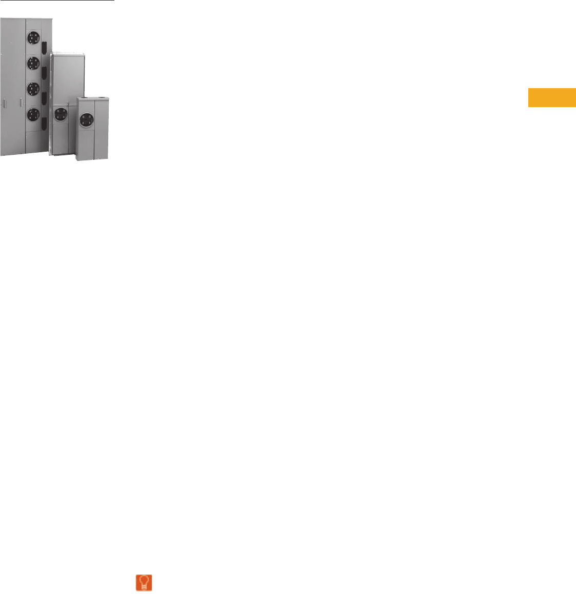
Volume 1—Residential and Light Commercial CA08100002E—February 2014 www.eaton.com V1-T5-1
5
5
5
5
5
5
5
5
5
5
5
5
5
5
5
5
5
5
5
5
5
5
5
5
5
5
5
5
5
5
Metering Products
Group Metering and
Meter Breaker Family
5.1 Single Meter Sockets
Product Description. . . . . . . . . . . . . . . . . . . . . . . . . . . . . . . . . . . . . . . V1-T5-2
5.2 Commercial Lever Bypass Sockets
Product Description. . . . . . . . . . . . . . . . . . . . . . . . . . . . . . . . . . . . . . . V1-T5-10
5.3 Multiple Position Horizontal Ganged Sockets
Product Description. . . . . . . . . . . . . . . . . . . . . . . . . . . . . . . . . . . . . . . V1-T5-18
5.4 Instrument Rated Sockets
Product Description. . . . . . . . . . . . . . . . . . . . . . . . . . . . . . . . . . . . . . . V1-T5-25
5.5 Residential Pedestals
Product Description. . . . . . . . . . . . . . . . . . . . . . . . . . . . . . . . . . . . . . . V1-T5-27
5.6 Accessories and Cross-Reference
Product Description. . . . . . . . . . . . . . . . . . . . . . . . . . . . . . . . . . . . . . . V1-T5-29
5.7 Mechanical Lugs
Product Description. . . . . . . . . . . . . . . . . . . . . . . . . . . . . . . . . . . . . . . V1-T5-34
5.8 Communications Grounding Device (NEC 250.94)
Product Description. . . . . . . . . . . . . . . . . . . . . . . . . . . . . . . . . . . . . . . V1-T5-35
5.9 Meter Breakers
Residential Meter Breakers . . . . . . . . . . . . . . . . . . . . . . . . . . . . . . . . . V1-T5-37
Non-EUSERC Combination Service Entrance Devices 100–200A Styles V1-T5-39
Meets EUSERC Requirements Service Entrance Devices 100–225A. V1-T5-48
West Coast All-In-One Design. . . . . . . . . . . . . . . . . . . . . . . . . . . . . . . V1-T5-59
Mechanical Interlock Cover . . . . . . . . . . . . . . . . . . . . . . . . . . . . . . . . . V1-T5-65
House Panels . . . . . . . . . . . . . . . . . . . . . . . . . . . . . . . . . . . . . . . . . . . V1-T5-75
Commercial Safety Sockets. . . . . . . . . . . . . . . . . . . . . . . . . . . . . . . . . V1-T5-83
CH Style Renovation Solutions . . . . . . . . . . . . . . . . . . . . . . . . . . . . . . V1-T5-86
Aluminum Meter Breakers . . . . . . . . . . . . . . . . . . . . . . . . . . . . . . . . . V1-T5-87
5.10 Group Metering
Systems for Residential and Commercial Applications . . . . . . . . . . . . V1-T5-88
Meter Packs . . . . . . . . . . . . . . . . . . . . . . . . . . . . . . . . . . . . . . . . . . . . V1-T5-90
Type CCV 120/240V Tenant Main Circuit Breaker . . . . . . . . . . . . . . . . V1-T5-95
Type CV 120/240V Tenant Main Circuit Breaker . . . . . . . . . . . . . . . . . V1-T5-96
Meter Packs—1MP, 1MM and 3MM Main Tenant Circuit Breakers . . V1-T5-98
Main Service Modules . . . . . . . . . . . . . . . . . . . . . . . . . . . . . . . . . . . . V1-T5-101
Surge Metering . . . . . . . . . . . . . . . . . . . . . . . . . . . . . . . . . . . . . . . . . . V1-T5-115
Residential Meter Stacks. . . . . . . . . . . . . . . . . . . . . . . . . . . . . . . . . . . V1-T5-116
1MP, 1MM and 3MM Main Tenant Circuit Breakers . . . . . . . . . . . . . . V1-T5-125
Phase Balanced Stack . . . . . . . . . . . . . . . . . . . . . . . . . . . . . . . . . . . . . V1-T5-126
Commercial Meter Stack Modules . . . . . . . . . . . . . . . . . . . . . . . . . . . V1-T5-127
35MM, 37MM, 35SS and 37SS Main Tenant Circuit Breakers . . . . . . V1-T5-134
Learn
Online
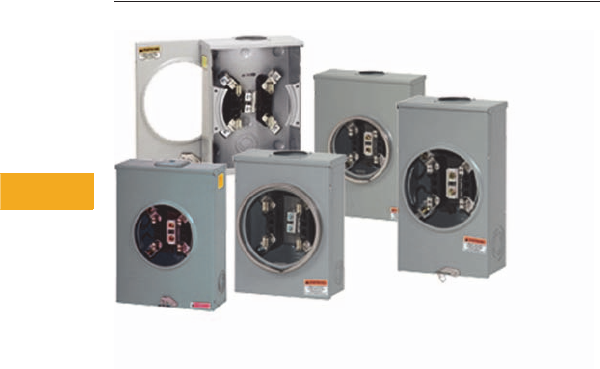
V1-T5-2 Volume 1—Residential and Light Commercial CA08100002E—February 2014 www.eaton.com
5
5
5
5
5
5
5
5
5
5
5
5
5
5
5
5
5
5
5
5
5
5
5
5
5
5
5
5
5
5
5.1
Metering Products
Single Meter Sockets
Single Meter Sockets
Contents
Description Page
Features and Benefits . . . . . . . . . . . . . . . . . . . . . . V1-T5-3
Catalog Number Selection . . . . . . . . . . . . . . . . . . V1-T5-3
Product Selection . . . . . . . . . . . . . . . . . . . . . . . . . V1-T5-4
Dimensions. . . . . . . . . . . . . . . . . . . . . . . . . . . . . . V1-T5-8
Product Description
Single-Phase Three-Wire and Three-Phase Four-Wire 600 Vac
Single Meter Sockets
All Eaton sockets are rated
600 Vac maximum and either
100, 200 or 320A continuous.
All have a minimum short-
circuit rating of 10,000 rms
symmetrical amperes
(watthour meter is not
included in rating).
All single meter sockets are
UL labeled and are supplied in
surface mounted outdoor
enclosures. Confirm local
utility acceptance prior to
order entry.
Volume 1—Residential and Light Commercial CA08100002E—February 2014 www.eaton.com V1-T5-3
5
5
5
5
5
5
5
5
5
5
5
5
5
5
5
5
5
5
5
5
5
5
5
5
5
5
5
5
5
5
5.1
Metering Products
Single Meter Sockets
Features and Benefits
Single Meter Sockets
Catalog Number Selection
Single Meter Sockets RS Group
Features Benefits
Block assembly base exceeds 400 in-lbs of torque Provides durability under the most extreme installation circumstances
One-piece, die-run enclosure Eliminates tampering and extends product life
High visibility Eaton name embossed on cover Company identity and brand preference
Knockouts are installer friendly Labor savings, less time needed for removing knockouts
Oversized 7/8-inch diameter, heavy-duty, steel lug screws Stronger connection component facilitates a reliable wire termination
Slide-nuts are captive Allow for ease in installation of conductors and eliminates lost components
Horn bypass kit is field installable by changing out slide nut Less inventory required and field modifications are simple
Integral triplex or quadplex ground extruded in neutral lug One piece for terminating incoming/outgoing neutral conductors, which increases integrity of connections
100% plated bridge with 4-point mounting Zinc chromate plated to provide superior corrosion resistance
kAIC rating Tested and UL listed up to 200 kAIC rating with specified overcurrent protection devices
Provides a complete Eaton residential solution Adding meter sockets to the already existing (loadcenter, surge, breakers, generators and AC disconnect) product lines that we already
provide, makes Eaton a one-stop shop for our customers residential and light commercial needs
Copper-plated alloy jaws with reinforcing spring Steel reinforcing springs used in all socket jaws to maintain electrical connections
Standard Prefixes
A= Aluminum enclosure
B= Barrel lock provision, for an exposed INNER-TITE® or Brooks barrel lock;
unit includes an internal lock receiver bracket
F= Barrel Lock with guard provision, for a lock guard INNER-TITE or Brooks
barrel lock; unit includes an internal lock receiver bracket
G= Grounded fifth terminal (9 o’clock position)
H= Horn bypass
I= Inhibitor installed in wire connectors
M= Temporary meter cover (waxed cardboard)
N= No sealing ring (applies only to ring style sockets)
R= Ring style socket
S= Aluminum screw type sealing ring (applies only to ring style sockets)
T= Grounding connector (#14–#2 Cu) for triplex ground
TT = Two grounding connectors (#14–#2 Cu) for quadplex ground
U= UL Underwriters Laboratories label
Z= 5/16-inch hex head connector screw in place of slotted (100A only)
Standard Suffixes
A= Solid top
B= Small hub opening
C= Small hub closing plate mounted
L= 1.25-inch (31.8 mm) hub mounted
M= 1.50-inch (38.1 mm) hub mounted
N= 2.00-inch (50.8 mm) hub mounted
P= 2.50-inch (63.5 mm) hub mounted
T= Large hub opening hub
U= Large hub cover plate hub mounted
V= 2.50-inch (63.5 mm) large hub mounted
Q= 3.00-inch (76.2 mm) large hub mounted
R= 3.50-inch (88.9 mm) large hub mounted
S= 4.00-inch (101.6 mm) large hub mounted
Z= Large to small hub adapter mounted
Maximum Conductor (Line and Load)
0 = 0.38-inch stud connectors
1 = #2/0 connectors
2 = #250 kcmil connectors
3 = #350 kcmil connectors
Service Design
0 = Overhead
1 = Combination overhead/underground
2 = Underground, side wired
3 = Combination overhead/underground, side wired
Ampere Rating
1 = 100A
2 = 200A
5 = 150A
Product Group
RS = Residential service, single position
2R-6R = Residential service, multiple position
2H-6H = Commercial or residential service, multiple position
H= Commercial or residential service, single position
UT RS 2 0 2 B CH
Note: The “U” prefix is always used first followed by
other prefixes required in alphabetical order.
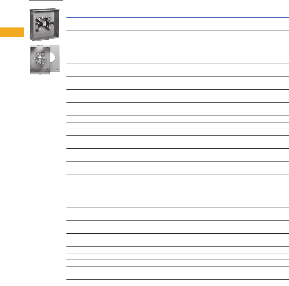
V1-T5-4 Volume 1—Residential and Light Commercial CA08100002E—February 2014 www.eaton.com
5
5
5
5
5
5
5
5
5
5
5
5
5
5
5
5
5
5
5
5
5
5
5
5
5
5
5
5
5
5
5.1
Metering Products
Single Meter Sockets
Product Selection
Residential Ringless Type Cover
Notes
1 Aluminum enclosure.
2 Barrel lock.
3 PEC approved.
For dimensions, see Pages V1-T5-8 and V1-T5-9.
Ampere
Rating Jaws Service Bypass
Connections Opening, Hub or
Closure Plate Catalog NumberLine Load
200 4 UG — 3/8-inch studs 3/8-inch studs Solid top UTRS240ACH
200 4 OH/UG — 3/8-inch studs 3/8-inch studs 3-5/16 hub cover plate UTRS2303CCH
200 4 UG — #8–350 kcmil #8–350 kcmil Solid top UTRS223ACH
200 4 UG — 3/8-inch studs 3/8-inch studs Solid top UTRS220ACH
200 4 OH/UG — #8–350 kcmil #8–350 kcmil 3-5/16 cover plate UTRS213CFLCH
200 4 OH/UG — #8–350 kcmil #8–350 kcmil 3-5/16 hub cover plate UTRS213CEPCH
200 4 OH/UG — #6–350 kcmil #6–350 kcmil 3-5/16 hub cover plate UGTRS213CE
200 4 OH/UG — #6–350 kcmil #6–350 kcmil 3-5/16 hub cover plate UTRS213CE
200 4 OH/UG — #6–350 kcmil #6–350 kcmil 3-5/16 hub opening UATRS213BCH
200 4 OH/UG — #6–350 kcmil #6–350 kcmil 3-5/16 hub opening URS213BCH
200 4 OH/UG — #6–350 kcmil #6–350 kcmil 3-5/16 hub opening UTRS213BE
200 4 UG — #8–350 kcmil #8–350 kcmil Solid top UTRS213AFLCH
200 4 UG — #8–350 kcmil #8–350 kcmil Solid top UTRS213ACH
200 4 OH/UG Horn #8–350 kcmil #8–350 kcmil 3-5/16 hub opening UTRS2138BCH
200 4 OH/UG — #8–250 kcmil #8–250 kcmil Solid top UTRS212ACH
200 4 OH/UG — #8–250 kcmil #8–250 kcmil 3-5/16 cover plate UTRS212CCH
200 4 OH/UG — #8–250 kcmil #8–250 kcmil 3-5/16 cover plate UTRS212CFLCH
200 4 OH/UG — #8–250 kcmil #8–250 kcmil 3-5/16 hub opening UTRS212BCH
200 4 OH — #8–250 kcmil #8–250 kcmil 2-inch bolt-on hub UTRS202NCH
200 4 OH — #8–250 kcmil #8–250 kcmil Small hub opening UATRS202BFLCH 1
200 4 OH/UG — #8–250 kcmil #8–250 kcmil 3-5/16 cover plate UTRS232CCH
200 4 OH — #8–2/0 cu/al #8–2/0 cu/al 3-5/16 hub opening UTRS202BCH
200 4 OH/UG — #8–250 kcmil #8–250 kcmil Solid top URS212ACH
200 4 OH — #8–250 kcmil #8–250 kcmil 2-inch bolt-on hub URS202NCH
200 5 OH Horn #8–250 kcmil #8–250 kcmil 3-5/16 hub opening URS202BDQCH
200 4 OH/UG Horn #8–350 kcmil #8–350 kcmil 3-5/16 hub cover plate UFHTRS213CCH 2
200 4 OH/UG Horn #8–350 kcmil #8–350 kcmil 3-5/16 hub opening UHTTRS213BCH
200 4 OH/UG Horn #8–350 kcmil #8–350 kcmil 3-5/16 hub cover plate UHTTRS213CCH
200 4 OH Horn #8–250 kcmil #8–250 kcmil 3-5/16 hub opening UHTTRS202BCH
200 5 OH/UG Horn #8–350 kcmil #8–350 kcmil 3-5/16 hub cover plate UHTRS233CCH
200 4 UG Horn #8–350 kcmil #8–350 kcmil Solid top UHTRS223ARHCH
200 4 UG Horn #8–350 kcmil #8–350 kcmil Solid top UFHTRS223ACH
200 5 UG Horn #8–350 kcmil #8–350 kcmil Solid top UGHTRS223ACH
200 4 UG Horn #8–350 kcmil #8–350 kcmil Solid top UHTTRS223ACH
200 4 UG Horn #8–350 kcmil #8–350 kcmil Solid top UHTRS223ACH
200 4 OH/UG Horn #6–350 kcmil #6–350 kcmil 3-5/16 hub opening UHTRS213CE
200 4 OH/UG Horn #6–350 kcmil #6–350 kcmil 3-5/16 hub opening UHTRS213BE
200 4 OH/UG Horn #8–350 kcmil #8–350 kcmil Solid top UHTRS213AE
200 4 OH Horn #8–350 kcmil #8–350 kcmil 3-5/16 hub opening UHTRS203BCH
200 4 OH Horn #8–250 kcmil #8–250 kcmil 3-5/16 hub opening UHTRS202BCH
200 4 OH/UG None #8–250 kcmil #8–250 kcmil 2-inch bolt-on hub URS202NPECCH 3
URS212ACH

Volume 1—Residential and Light Commercial CA08100002E—February 2014 www.eaton.com V1-T5-5
5
5
5
5
5
5
5
5
5
5
5
5
5
5
5
5
5
5
5
5
5
5
5
5
5
5
5
5
5
5
5.1
Metering Products
Single Meter Sockets
Residential Ringless Type Cover, continued
Notes
1Right hand incoming.
2Austin Energy approved.
For dimensions, see Pages V1-T5-8 and V1-T5-9.
Ampere
Rating Jaws Service Bypass
Connections Opening, Hub or
Closure Plate Catalog NumberLine Load
200 4 OH/UG Horn #8–350 kcmil #8–350 kcmil Solid top UHIRS223ACVCH
200 4 OH/UG Horn #8–350 kcmil #8–350 kcmil 3-5/16 hub opening UHIRS213BCVCH
200 5 OH/UG — #6–350 kcmil #6–350 kcmil Closure plate UGTRS213CE
200 5 OH/UG — #6–350 kcmil #6–350 kcmil Hub opening UGTRS213BE
200 5 OH/UG Horn #6–350 kcmil #6–350 kcmil Closure plate 786685217918
200 5 OH/UG Horn #6–350 kcmil #6–350 kcmil 3-5/16 hub opening UGHTRS213BE
200 5 OH/UG Horn #8–250 kcmil #8–250 kcmil 3-5/16 hub cover plate UGHRS212CKCCH
200 4 OH — #8–250 kcmil #8–250 kcmil 3-5/16 hub opening UFTRS202BCH
200 4 OH Horn #8–250 kcmil #8–250 kcmil 3-5/16 hub opening UFHTRS202BCH
200 4 UG Horn #8–350 kcmil #8–350 kcmil Solid top UBHTRS223ARHCH
200 4 UG Horn #8–350 kcmil #8–350 kcmil Solid top UBHRS223ACH
200 4 OH Horn #8–250 kcmil #8–250 kcmil 3-5/16 hub cover plate UBHRS202BCH
200 4 OH/UG — #8–350 kcmil #8–350 kcmil 3-5/16 hub opening UATRS213CFLCH
200 4 OH/UG Horn #8–350 kcmil #8–350 kcmil 3-5/16 hub cover plate UAHTRS233CSHCH
200 4 UG Horn #8–350 kcmil #8–350 kcmil Solid top UAHTRS223AFLCH
200 4 OH Horn #8–250 kcmil #8–250 kcmil 3-5/16 hub opening UAHTRS202BFLCH
200 4 OH/UG — #8–350 kcmil #8–350 kcmil 3-5/16 hub closure plate U92197CCCPLCH
200 4 OH/UG — #8–350 kcmil #8–350 kcmil 3-5/16 hub closure plate 1009928CH
200 4 OH/UG Horn #8–250 kcmil #8–250 kcmil Solid top 1009874ACH
200 4 UG — 3/8-inch studs 3/8-inch studs Solid top 1009046CH
200 4 UG Horn #8–350 kcmil #8–350 kcmil Solid top 1008941CH
200 4 UG Horn #8–350 kcmil #8–350 kcmil Solid top 1008940CH
200 4 UG Horn #8–350 kcmil #8–350 kcmil Solid top 1008827CH
200 4 UG Horn #8–350 kcmil #8–350 kcmil Solid top 1008819CH
200 4 UG Horn #8–350 kcmil #8–350 kcmil Solid top 1008717CH
200 4 UG — #8–350 kcmil #8–350 kcmil Solid top 1008617CH
200 4 OH/UG Horn #8–350 kcmil #8–350 kcmil 3-5/16 hub opening 1007817CH
200 4 OH Horn #8–250 kcmil #8–250 kcmil 3-5/16 hub opening 1007699CH
200 4 OH Horn #8–250 kcmil #8–250 kcmil 3-5/16 hub opening 1007665CH
200 4 UG Horn #8–350 kcmil #8–350 kcmil Solid top 1007588CH
200 4 OH/UG — 3/8-inch studs 3/8-inch studs 3-5/16 hub opening 1007448ACH
200 4 UG Horn #8–350 kcmil #8–350 kcmil Solid top 1004884ARHCH 1
200 4 UG Horn #8–350 kcmil #8–350 kcmil Solid top 1004884ACH
200 4 OH/UG — #8–#250 kcmil #8–#250 kcmil 3-5/16 hub cover plate 1004710ECH
200 4 OH — N/A N/A N/A 1004709DCH
200 4 OH Horn #8–#250 kcmil #8–#250 kcmil 2-inch bolt-on hubs 1004455BCH
200 4 OH Horn #8–250 kcmil #8–250 kcmil 3-5/16 hub opening 1004161ACH
200 4 OH/UG Horn #8–350 kcmil #8–350 kcmil 3-5/16 hub opening 1004159ACH
200 4 OH/UG — #8–350 kcmil #8–350 kcmil Hub closure plate 1008826ACH 2
200 4 OH/UG Lever #6–350 kcmil #6–350 kcmil Hub closure plate 1006352CCH 2
200 5 OH Horn #8–250 kcmil #8–250 kcmil 3-5/16 hub opening 1003879ACH
200 5 OH/UG Horn #8–350 kcmil #8–350 kcmil 3-5/16 hub opening 1003878ACH
V1-T5-6 Volume 1—Residential and Light Commercial CA08100002E—February 2014 www.eaton.com
5
5
5
5
5
5
5
5
5
5
5
5
5
5
5
5
5
5
5
5
5
5
5
5
5
5
5
5
5
5
5.1
Metering Products
Single Meter Sockets
Residential Ringless Type Cover, continued
Notes
1 Austin Energy approved.
2 PSE&G approved.
For dimensions, see Pages V1-T5-8 and V1-T5-9.
Ampere
Rating Jaws Service Bypass
Connections Opening, Hub or
Closure Plate Catalog NumberLine Load
150 4 OH/UG — #8–2/0 AWG #8–2/0 AWG Hub closure plate 1004326DCH 1
150 4 OH/UG — #8–250 kcmil #8–250 kcmil Hub opening UTRS502BCH
150 4 OH — #8–250 kcmil #8–250 kcmil 3-5/16 hub opening UTRS502BCH
150 4 OH — #8–250 kcmil #8–250 kcmil 3-5/16 hub cover plate UTRS502CCH
125 4 UG — N/A N/A N/A 1006385BCH
125 4 OH/UG — #8–2/0 cu/al #8–2/0 cu/al 3-5/16 hub opening UTRS111BCH
125 4 OH — #8–2/0 cu/al #8–2/0 cu/al 3-5/16 hub opening UBTRS101BCH
125 4 OH — #8–2/0 cu/al #8–2/0 cu/al 1-1/4-inch bolt-on hub UTRS101LCH
125 4 OH — #8–2/0 cu/al #8–2/0 cu/al 3-5/16 hub cover plate UTRS101CE
125 4 OH — #8–2/0 cu/al #8–2/0 cu/al 3-5/16 hub opening UTRS101BE
125 4 OH — #8–2/0 #8–2/0 3-5/16 hub cover plate URS101CCPLCH
125 4 OH Horn cu/al with
1/2-inch hex
head wire
clamping screw
cu/al with
1/2-inch hex
head wire
clamping screw
3-5/16 hub cover plate URS101BDQCH
125 4 OH — #8–2/0 #8–2/0 3-5/16 hub opening URS101BCPLCH
125 4 OH — #8–2/0 #8–2/0 3-5/16 hub opening URS101BCH
125 4 OH Horn #8–2/0 #8–2/0 3-5/16 hub opening UHTTRS101BCH
125 4 OH/UG Horn #8–250 kcmil #8–250 kcmil 3-5/16 hub opening UHTRS111BCH
125 4 OH Horn #8–2/0 #8–2/0 1.25-inch hub mounted UHTRS101LCH
125 4 OH Horn #8–2/0 #8–2/0 Closure plate UHTRS101CE
125 4 OH Horn #8–2/0 #8–2/0 3-5/16 hub opening UHTRS101BE
125 5 OH/UG — #8–2/0 #8–2/0 3-5/16 hub cover plate UGRS10101CKCCH
125 5 OH/UG — #8–2/0 #8–2/0 3-5/16 hub cover plate UGHTRS111CCH
125 5 OH — #8–2/0 #8–2/0 3-5/16 hub opening UGHTRS101BCH
125 4 OH — #8–2/0 #8–2/0 3-5/16 hub cover plate UBHRS101BCH
125 4 OH/UG — #8–2/0 #8–2/0 3-5/16 hub cover plate UATZRS101CFLCH
125 4 OH — #8–2/0 #8–2/0 3-5/16 hub cover plate UATRS101CCH
125 4 OH — #8–2/0 #8–2/0 3-5/16 hub opening 1008947CH
125 4 UG N/A N/A N/A N/A 1005826ACH
125 4 OH — #8–2/0 #8–2/0 1-1/4-inch bolt-on hub 1004931BCH
125 4 OH — #8–2/0 #8–2/0 3-5/16 hub opening 1004162ACH
125 5 OH — #8–2/0 #8–2/0 3-5/16 hub opening 1003880ACH
125 4 OH — #8–2/0 #8–2/0 3-5/16 hub opening UTZRS101BFLCH
125 4 OH — #8–2/0 #8–2/0 3-5/16 hub closure plate UTZRS101CFLCH
125 5 OH Horn #8–2/0 #8–2/0 Hub opening UTRS101CEPSEG 2
100 4 OH — #8–2/0 #8–2/0 3-5/16 hub opening 1009079CH
200 5 OH/UG Horn #8–350 kcmil #8–350 kcmil Hub closure plate UTRS213CEPSEG 2
URS101BCH

Volume 1—Residential and Light Commercial CA08100002E—February 2014 www.eaton.com V1-T5-7
5
5
5
5
5
5
5
5
5
5
5
5
5
5
5
5
5
5
5
5
5
5
5
5
5
5
5
5
5
5
5.1
Metering Products
Single Meter Sockets
Residential Ring Type Cover
Note
For dimensions, see Pages V1-T5-8 and V1-T5-9.
Ampere
Rating Jaws Service
Connections
Load
Opening, Hub or
Closure Plate Catalog NumberLine
200 4 UG #8–350 kcmil #8–350 kcmil Solid top URTRS223ACH
200 4 OH/UG #8–350 kcmil #8–350 kcmil 3-5/16 hub cover plate URRS213CCH
200 4 OH/UG #8–350 kcmil #8–350 kcmil 2 inch hub mounted URTRS213NEUSCH
200 4 OH/UG #8–350 kcmil #8–350 kcmil 3-5/16 hub cover plate URTRS213CEUSCH
200 4 OH/UG #8–350 kcmil #8–350 kcmil 3-5/16 hub cover plate 1009424CH
200 4 OH/UG #8–350 kcmil #8–350 kcmil Knockouts 1009449CH
200 4 OH #8–350 kcmil #8–350 kcmil 3-5/16 hub opening URSTRS203BCH
200 4 OH #8–250 kcmil #8–250 kcmil 3-5/16 hub cover plate URS212BCRCH
200 4 OH/UG #8–250 kcmil #8–250 kcmil 3-5/16 hub cover plate URTRS202BCH
200 4 OH #8–250 kcmil #8–250 kcmil 3-5/16 hub opening URTRS213BE
200 4 OH/UG #6–350 kcmil #6–350 kcmil Hub opening URTRS202BCH
200 4 OH/UG #6–350 kcmil #6–350 kcmil Closure plate URTRS213CE
200 4 UG #6–350 kcmil #6–350 kcmil 3-5/16 hub opening URTRS213BEUSCH
200 4 OH #8–250 kcmil #8–250 kcmil 2-inch hub mounted URTRS202NEUSCH
200 4 OH #8–250 kcmil #8–250 kcmil 3-5/16 hub opening UNRRS202BEUSCH
200 4 OH/UG #6–350 kcmil #6–350 kcmil Closure plate UNRRS213CEUSE
200 4 OH #8–250 kcmil #8–250 kcmil Hub opening UNRRS213BEUSE
200 4 UG #6–350 kcmil #6–350 kcmil Solid top UNRRS213AEUSE
200 4 OH/UG #6–250 kcmil #6–250 kcmil 5x5 hub opening 3-5/16 adapter plate 1009097CH
125 4 OH #8–2/0 cu/al #8–2/0 cu/al 3-5/16 hub opening URS101BCRCH
125 4 OH #8–2/0 cu/al #8–2/0 cu/al 1-1/4-inch bolt-on hub URRS101LCH
125 4 OH #8–2/0 cu/al #8–2/0 cu/al Hub cover plate URTRS101BE
125 4 OH #8–2/0 cu/al #8–2/0 cu/al Hub cover plate URTRS101CE
125 4 OH #8–2/0 cu/al #8–2/0 cu/al 3-5/16 hub cover plate UNRRS101BEUSE
125 4 OH #8–2/0 cu/al #8–2/0 cu/al Closure plate UNRRS101CEUSE
125 4 OH/UG #8–2/0 cu/al #8–2/0 cu/al 3-5/16 hub cover plate UNRRS111BEUSE
125 4 UG #8–2/0 cu/al #8–2/0 cu/al Solid top UNRRS111AEUSE
125 4 OH #8–2/0 cu/al #8–2/0 cu/al 3-5/16 hub opening URSTRS101BCH

V1-T5-8 Volume 1—Residential and Light Commercial CA08100002E—February 2014 www.eaton.com
5
5
5
5
5
5
5
5
5
5
5
5
5
5
5
5
5
5
5
5
5
5
5
5
5
5
5
5
5
5
5.1
Metering Products
Single Meter Sockets
Dimensions
Approximate Dimensions in Inches (mm)
Residential Ringless Type Cover
Catalog Number Height Width Depth
UTRS240ACH 18.63 (473.2) 13.00 (330.2) 4.94 (125.5)
UTRS2303CCH 20.00 (508.0) 13.00 (330.2) 4.94 (125.5)
UTRS223ACH 13.00 (330.2) 13.00 (330.2) 4.94 (125.5)
UTRS220ACH 15.13 (384.3) 13.00 (330.2) 4.94 (125.5)
UTRS213CFLCH 15.00 (381.0) 11.00 (279.4) 4.37 (111.0)
UTRS213CEPCH 15.00 (381.0) 11.00 (279.4) 4.37 (111.0)
UGTRS213CE 15.13 (384.3) 11.25 (285.8) 4.50 (114.3)
UTRS213CE 15.13 (384.3) 11.25 (285.8) 4.50 (114.3)
UATRS213BCH 15.13 (384.3) 11.25 (285.8) 4.50 (114.3)
URS213BCH 15.00 (381.0) 11.00 (279.4) 4.36 (110.7)
UTRS213BE 15.13 (384.3) 11.25 (285.8) 4.50 (114.3)
UTRS213AFLCH 15.00 (381.0) 11.00 (279.4) 4.37 (111.0)
UTRS213ACH 15.00 (381.0) 11.00 (279.4) 4.36 (110.7)
UTRS2138BCH 20.00 (508.0) 13.00 (330.2) 4.94 (125.5)
UTRS212ACH 14.00 (355.6) 11.00 (279.4) 4.37 (111.0)
UTRS212CCH 14.00 (355.6) 11.00 (279.4) 4.36 (110.7)
UTRS212CFLCH 14.00 (355.6) 11.00 (279.4) 4.36 (110.7)
UTRS212BCH 14.00 (355.6) 11.00 (279.4) 4.36 (110.7)
UTRS202NCH 14.00 (355.6) 8.00 (203.2) 4.36 (110.7)
UATRS202BFLCH 114.00 (355.6) 8.00 (203.2) 4.36 (110.7)
UTRS232CCH 17.12 (434.8) 13.00 (330.2) 4.93 (125.2)
UTRS202BCH 14.00 (355.6) 8.00 (203.2) 4.36 (110.7)
URS212ACH 14.00 (355.6) 11.00 (279.4) 4.38 (111.3)
URS202NCH 14.00 (355.6) 8.00 (203.2) 4.38 (111.3)
URS202BDQCH 14.00 (355.6) 8.00 (203.2) 4.38 (111.3)
UFHTRS213CCH 215.00 (381.0) 11.00 (279.4) 4.38 (111.3)
UHTTRS213BCH 15.00 (381.0) 11.00 (279.4) 4.38 (111.3)
UHTTRS213CCH 15.00 (381.0) 11.00 (279.4) 4.38 (111.3)
UHTTRS202BCH 14.00 (355.6) 8.00 (203.2) 4.38 (111.3)
UHTRS233CCH 17.13 (435.1) 13.00 (330.2) 4.94 (125.5)
UHTRS223ARHCH 13.00 (330.2) 13.00 (330.2) 4.94 (125.5)
UFHTRS223ACH 13.00 (330.2) 13.00 (330.2) 4.94 (125.5)
UGHTRS223ACH 13.00 (330.2) 13.00 (330.2) 4.94 (125.5)
UHTTRS223ACH 13.00 (330.2) 13.00 (330.2) 4.94 (125.5)
UHTRS223ACH 13.00 (330.2) 13.00 (330.2) 4.94 (125.5)
UHTRS213CE 15.00 (381.0) 11.00 (279.4) 4.38 (111.3)
UHTRS213BE 15.00 (381.0) 11.00 (279.4) 4.38 (111.3)
UHTRS213AE 15.00 (381.0) 11.00 (279.4) 4.38 (111.3)
UHTRS203BCH 15.00 (381.0) 8.00 (203.2) 4.38 (111.3)
UHTRS202BCH 14.00 (355.6) 8.00 (203.2) 4.38 (111.3)
UHIRS223ACVCH 13.00 (330.2) 13.00 (330.2) 4.94 (125.5)
Residential Ringless Type Cover, continued
Notes
1Aluminum enclosure.
2Barrel lock.
3Right hand incoming.
Catalog Number Height Width Depth
UHIRS213BCVCH 15.00 (381.0) 11.00 (279.4) 4.38 (111.3)
UGTRS213CE 15.13 (384.3) 11.25 (285.8) 4.50 (114.3)
UGTRS213BE 15.13 (384.3) 11.25 (285.8) 4.50 (114.3)
786685217918 15.13 (384.3) 11.25 (285.8) 4.50 (114.3)
UGHTRS213BE 15.13 (384.3) 11.25 (285.8) 4.50 (114.3)
UGHRS212CKCCH 14.00 (355.6) 11.00 (279.4) 4.38 (111.3)
UFTRS202BCH 14.00 (355.6) 8.00 (203.2) 4.38 (111.3)
UFHTRS202BCH 14.00 (355.6) 8.00 (203.2) 4.38 (111.3)
UBHTRS223ARHCH 13.00 (330.2) 13.00 (330.2) 4.94 (125.5)
UBHRS223ACH 13.00 (330.2) 13.00 (330.2) 4.94 (125.5)
UBHRS202BCH 14.00 (355.6) 8.00 (203.2) 4.38 (111.3)
UATRS213CFLCH 15.00 (381.0) 11.00 (279.4) 4.38 (111.3)
UAHTRS233CSHCH 17.13 (435.1) 13.00 (330.2) 4.94 (125.5)
UAHTRS223AFLCH 13.00 (330.2) 13.00 (330.2) 4.94 (125.5)
UAHTRS202BFLCH 14.00 (355.6) 8.00 (203.2) 4.38 (111.3)
U92197CCCPLCH 14.13 (358.9) 13.00 (330.2) 4.94 (125.5)
1009928CH 15.00 (381.0) 11.00 (279.4) 4.38 (111.3)
1009874ACH 15.00 (381.0) 13.00 (330.2) 4.94 (125.5)
1009046CH 20.75 (527.1) 9.00 (228.6) 4.94 (125.5)
1008941CH 17.13 (435.1) 13.00 (330.2) 4.94 (125.5)
1008940CH 17.13 (435.1) 13.00 (330.2) 4.94 (125.5)
1008827CH 13.00 (330.2) 13.00 (330.2) 4.94 (125.5)
1008819CH 13.00 (330.2) 13.00 (330.2) 4.94 (125.5)
1008717CH 15.00 (381.0) 13.00 (330.2) 4.94 (125.5)
1008617CH 15.00 (381.0) 13.00 (330.2) 4.94 (125.5)
1007817CH 15.00 (381.0) 11.00 (279.4) 4.38 (111.3)
1007699CH 14.00 (355.6) 8.00 (203.2) 4.38 (111.3)
1007665CH 14.00 (355.6) 8.00 (203.2) 4.38 (111.3)
1007588CH 13.00 (330.2) 13.00 (330.2) 4.94 (125.5)
1007448ACH 19.00 (482.6) 11.00 (279.4) 4.38 (111.3)
1004884ARHCH 313.00 (330.2) 13.00 (330.2) 4.93 (125.2)
1004884ACH 13.00 (330.2) 13.00 (330.2) 4.93 (125.2)
1004710ECH 14.00 (355.6) 11.00 (279.4) 4.38 (111.3)
1004709DCH N/A N/A N/A
1004455BCH 15.00 (381.0) 8.00 (203.2) 4.38 (111.3)
1004161ACH 14.00 (355.6) 8.00 (203.2) 4.38 (111.3)
1004159ACH 15.00 (381.0) 11.00 (279.4) 4.38 (111.3)
1003879ACH 15.00 (381.0) 8.00 (203.2) 4.38 (111.3)
1003878ACH 15.00 (381.0) 11.00 (279.4) 4.38 (111.3)
UTRS502BCH 14.00 (355.6) 8.00 (203.2) 4.38 (111.3)

Volume 1—Residential and Light Commercial CA08100002E—February 2014 www.eaton.com V1-T5-9
5
5
5
5
5
5
5
5
5
5
5
5
5
5
5
5
5
5
5
5
5
5
5
5
5
5
5
5
5
5
5.1
Metering Products
Single Meter Sockets
Approximate Dimensions in Inches (mm)
Residential Ringless Type Cover, continued
Catalog Number Height Width Depth
UTRS502BCH 14.00 (355.6) 8.00 (203.2) 4.36 (110.7)
UTRS502CCH 14.00 (355.6) 8.00 (203.2) 4.36 (110.7)
1006385BCH N/A N/A N/A
UTRS111BCH 14.00 (355.6) 11.00 (279.4) 4.36 (110.7)
UBTRS101BCH 10.88 (276.4) 8.00 (203.2) 3.50 (88.9)
UTRS101LCH 10.88 (276.4) 8.00 (203.2) 3.50 (88.9)
UTRS101CE 11.05 (280.7) 8.22 (208.8) 3.61 (91.7)
UTRS101BE 11.05 (280.7) 8.22 (208.8) 3.61 (91.7)
URS101CCPLCH 10.88 (276.4) 8.00 (203.2) 3.50 (88.9)
URS101BDQCH 10.88 (276.4) 8.00 (203.2) 3.50 (88.9)
URS101BCPLCH 10.88 (276.4) 8.00 (203.2) 3.50 (88.9)
URS101BCH 10.88 (276.4) 8.00 (203.2) 3.50 (88.9)
UHTTRS101BCH 10.88 (276.4) 8.00 (203.2) 3.50 (88.9)
UHTRS111BCH 14.00 (355.6) 11.00 (279.4) 4.38 (111.3)
UHTRS101LCH 10.88 (276.4) 8.00 (203.2) 3.50 (88.9)
UHTRS101CE 11.05 (280.7) 8.22 (208.8) 3.61 (91.7)
UHTRS101BE 11.05 (280.7) 8.22 (208.8) 3.61 (91.7)
UGRS10101CKCCH 12.00 (304.8) 8.00 (203.2) 3.50 (88.9)
UGHTRS111CCH 14.00 (355.6) 11.00 (279.4) 4.36 (110.7)
UGHTRS101BCH 10.88 (276.4) 8.00 (203.2) 3.50 (88.9)
UBHRS101BCH 10.88 (276.4) 8.00 (203.2) 3.50 (88.9)
UATZRS101CFLCH 10.88 (276.4) 8.00 (203.2) 3.50 (88.9)
UATRS101CCH 10.87 (276.1) 8.00 (203.2) 3.50 (88.9)
1008947CH 10.89 (276.6) 8.00 (203.2) 3.50 (88.9)
1005826ACH N/A N/A N/A
1004931BCH 10.88 (276.4) 8.00 (203.2) 3.50 (88.9)
1004162ACH 10.89 (276.6) 8.00 (203.2) 3.50 (88.9)
1003880ACH 10.89 (276.6) 8.00 (203.2) 3.50 (88.9)
UTZRS101BFLCH N/A N/A N/A
UTZRS101CFLCH N/A N/A N/A
1009079CH 23.75 (603.3) 8.00 (203.2) 3.48 (88.4)
Residential Ring Type Cover
Catalog Number Height Width Depth
URTRS223ACH 13.00 (330.2) 13.00 (330.2) 4.93 (125.2)
URRS213CCH 15.00 (381.0) 11.00 (279.4) 4.38 (111.3)
URTRS213NEUSCH 15.00 (381.0) 11.00 (279.4) 4.38 (111.3)
URTRS213CEUSCH 15.00 (381.0) 11.00 (279.4) 4.38 (111.3)
1009424CH 15.00 (381.0) 11.00 (279.4) 4.38 (111.3)
1009449CH 18.31 (465.1) 14.19 (360.4) 5.13 (130.3)
URSTRS203BCH N/A N/A N/A
URS212BCRCH 14.00 (355.6) 8.00 (203.2) 4.38 (111.3)
URTRS202BCH 14.00 (355.6) 11.00 (279.4) 4.38 (111.3)
URTRS213BE 14.00 (355.6) 8.00 (203.2) 4.50 (114.3)
URTRS202BCH 15.13 (384.3) 11.25 (285.8) 4.50 (114.3)
URTRS213CE 15.13 (384.3) 11.25 (285.8) 4.50 (114.3)
URTRS213BEUSCH 15.13 (384.3) 11.25 (285.8) 4.50 (114.3)
URTRS202NEUSCH 14.00 (355.6) 8.00 (203.2) 4.38 (111.3)
UNRRS202BEUSCH 14.00 (355.6) 8.00 (203.2) 4.38 (111.3)
UNRRS213CEUSE 15.13 (384.3) 11.25 (285.8) 4.50 (114.3)
UNRRS213BEUSE 15.13 (384.3) 11.25 (285.8) 4.50 (114.3)
UNRRS213AEUSE 15.13 (384.3) 11.25 (285.8) 4.50 (114.3)
1009097CH 19.00 (482.6) 13.00 (330.2) 5.25 (133.4)
URS101BCRCH 10.88 (276.4) 8.00 (203.2) 3.50 (88.9)
URRS101LCH 10.88 (276.4) 8.00 (203.2) 3.50 (88.9)
URTRS101BE 11.00 (279.4) 8.25 (209.6) 3.63 (92.2)
URTRS101CE 11.00 (279.4) 8.25 (209.6) 3.63 (92.2)
UNRRS101BEUSE 10.88 (276.4) 8.00 (203.2) 3.50 (88.9)
UNRRS101CEUSE 10.88 (276.4) 8.00 (203.2) 3.50 (88.9)
UNRRS111BEUSE 14.00 (355.6) 11.00 (279.4) 4.38 (111.3)
URSTRS101BCH 10.88 (276.4) 8.00 (203.2) 3.50 (88.9)
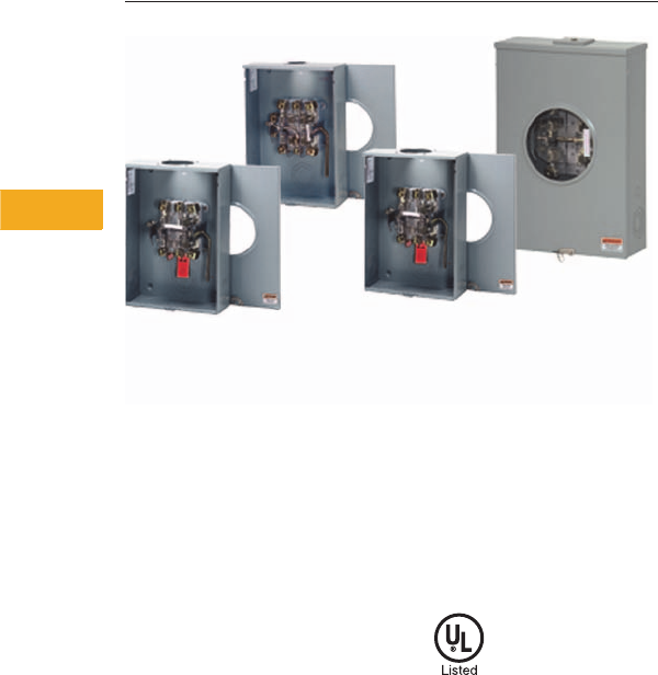
V1-T5-10 Volume 1—Residential and Light Commercial CA08100002E—February 2014 www.eaton.com
5
5
5
5
5
5
5
5
5
5
5
5
5
5
5
5
5
5
5
5
5
5
5
5
5
5
5
5
5
5
5.2
Metering Products
Commercial Lever Bypass Sockets
Commercial Lever Bypass Sockets
Contents
Description Page
Catalog Number Selection . . . . . . . . . . . . . . . . . . V1-T5-11
Product Selection . . . . . . . . . . . . . . . . . . . . . . . . . V1-T5-12
Dimensions. . . . . . . . . . . . . . . . . . . . . . . . . . . . . . V1-T5-16
Product Description
●Heavy-duty, lever bypass,
jaw clamping ringless
meter socket design
●200A and 320A
styles available
●Single-phase or
three-phase
●4, 5 or 7 terminal available
●600 Vac maximum rating
●Multiple service
design offerings
Standards and
Certifications
●UL 414 listed and
recognized
Volume 1—Residential and Light Commercial CA08100002E—February 2014 www.eaton.com V1-T5-11
5
5
5
5
5
5
5
5
5
5
5
5
5
5
5
5
5
5
5
5
5
5
5
5
5
5
5
5
5
5
5.2
Metering Products
Commercial Lever Bypass Sockets
Catalog Number Selection
Single Meter Sockets H Group
Standard Prefixes
A = Aluminum enclosure
B = Barrel lock provision, for an exposed INNER-TITE or Brooks barrel lock;
unit includes an internal lock receiver bracket
F = Barrel Lock with guard provision, for a lock guard INNER-TITE or
Brooks barrel lock; unit includes an internal lock receiver bracket
G = Grounded fifth terminal (9 o’clock position)
H = Horn bypass
I= Inhibitor installed in wire connectors
M = Temporary meter cover (waxed cardboard)
N = No sealing ring (applies only to ring style sockets)
R = Ring style socket
S = Aluminum screw type sealing ring (applies only to ring style sockets)
T = Grounding connector (#14–#2 Cu) for triplex ground
TT = Two grounding connectors (#14–#2 Cu) for quadplex ground
U = UL label
Z = 5/16-inch hex head connector screw in place of slotted (100A only)
Standard Suffixes
A= Solid top
B= Small hub opening
C= Small hub closing plate mounted
L= 1.25-inch (31.8 mm) hub mounted
M= 1.50-inch (38.1 mm) hub mounted
N= 2.00-inch (50.8 mm) hub mounted
P= 2.50-inch (63.5 mm) hub mounted
T= Large hub opening hub
U= Large hub cover plate hub mounted
V= 2.50-inch (63.5 mm) large hub mounted
Q= 3.00-inch (76.2 mm) large hub mounted
R= 3.50-inch (88.9 mm) large hub mounted
S= 4.00-inch (101.6 mm) large hub mounted
Z= Large to small hub adapter mounted
Product Group
RS = Residential service, single position
2R-6R = Residential service, multiple position
2H-6H = Commercial or residential service, multiple position
H = Commercial or residential service, single position
Jaw Quantity
4 = 4 terminals
5 = 5 terminals
7 = 7 terminals
Maximum Conductor (Line & Load)
0 = 0.38-inch stud connectors
3 = #350 kcmil connectors
5 = #500 kcmil connectors
6 = #600 kcmil connectors
7 = #750 kcmil connectors
8 = Dual #250 kcmil connectors
9 = Dual #350 kcmil connectors
Service Design
0 = Overhead
1 = Combination overhead/underground
2 = Underground, side wired
3 = Combination overhead/underground, side wired
Ampere Rating
2 = 200A
3 = 320A
UT H 4 2 0 3 B CH
Note: The “U” prefix is always used first followed by
other prefixes required in alphabetical order.

V1-T5-12 Volume 1—Residential and Light Commercial CA08100002E—February 2014 www.eaton.com
5
5
5
5
5
5
5
5
5
5
5
5
5
5
5
5
5
5
5
5
5
5
5
5
5
5
5
5
5
5
5.2
Metering Products
Commercial Lever Bypass Sockets
Product Selection
Commercial Lever Bypass
Notes
1Aluminum enclosure.
2Austin Energy approved.
For dimensions, see Pages V1-T5-16 and V1-T5-17.
Ampere
Rating Jaws Service Bypass
Connections Opening, Hub or
Closure Plate Catalog NumberLine Load
320 7 OH/UG Lever #4-600 kcmil #4–600 kcmil 5x5 hub opening UTTH7336TCH
320 7 OH Lever #600 kcmil Dual #6–350 5x5 hub opening UTH73069THLCH
320 7 OH/UG Lever #14–1/0 cu/al #6–350 kcmil 5x5 hub cover plate UTH73369UHLCH
320 7 OH/UG Lever #14–1/0 cu/al #6–350 kcmil 5x5 hub opening UTH73369THLCH
320 7 OH/UG Lever 3/8-inch studs 3/8-inch studs 5x5 hub cover plate UFTH7330UCH
320 7 OH/UG Lever #600 kcmil #600 kcmil 5x5 hub opening UTH7336TCH
320 7 OH/UG Lever 3/8-inch studs 3/8-inch studs 5x5 hub cover plate UTH7330UCH
320 7 OH/UG Lever 3/8-inch studs 3/8-inch studs 5x5 hub cover plate UTH7330UFLCH
320 7 OH/UG Lever 3/8-inch studs 3/8-inch studs 5x5 hub cover plate UATH7330UFLCH 1
320 7 OH/UG Lever 3/8-inch studs 3/8-inch studs 5x5 hub opening UH7330TCPLCH
320 7 OH/UG Lever 3/8-inch studs 3/8-inch studs 5x5 hub opening UTH7330TCH
320 7 OH/UG Lever 3/8-inch studs 3/8-inch studs 5x5 hub-inch opening UTTH7330TCH
320 7 OH/UG Lever 3/8-inch studs 3/8-inch studs 5x5 hub cover plate UH7300UCPLCH
320 7 OH/UG Lever 3/8-inch studs 3/8-inch studs 5x5 hub cover plate UTH7300UCH
320 7 OH/UG Lever 3/8-inch studs 3/8-inch studs 5x5 hub opening UTH7300TCH
320 7 OH/UG Lever #6–350 kcmil #6–350 kcmil Hub closure plate 1006353CCH 2
320 5 OH/UG Lever 3/8-inch studs 3/8-inch studs 5x5 hub cover plate UTH5330UFLCH
320 5 OH/UG Lever 3/8-inch studs 3/8-inch studs 5x5 hub cover plate UTH5330UCH
320 5 OH Lever 3/8-inch studs 3/8-inch studs 5x5 hub opening UTH5300TCH
320 5 OH/UG Lever 3/8-inch studs 3/8-inch studs 5x5 hub cover plate UATH5330UFLCH
320 4 OH/UG lever #4–600 kcmil #4–600 kcmil Hub closure plate 1010468CH 2
320 4 UG Lever 3/8-inch studs 3/8-inch studs Solid top UTH4320ACH
320 4 UG Lever 3/8-inch studs Dual #6–350 Solid top UTH43209ACH
320 4 OH/UG Lever #6–350 kcmil #6–350 kcmil 5x5 hub cover plate UTH4339UCH
320 4 OH/UG Lever #6–250 kcmil #6–250 kcmil 5x5 hub cover plate UTH4338UCH
320 4 OH/UG Lever #4–600 kcmil #4–600 kcmil 5x5 hub cover plate UTH4336UCH
320 4 OH/UG Lever #4–600 kcmil #4–600 kcmil 5x5 hub opening UTH4336TCH
320 4 OH/UG Lever #4–600 kcmil #6–350 kcmil 5x5 hub cover plate UTH43369UCH
320 4 OH/UG Lever #4–600 kcmil #6–350 kcmil 5x5 hub opening UTH43369TCH
320 4 OH/UG Lever 3/8-inch studs 3/8-inch studs 3-5/16 hub cover plate UTTH4330UCH
320 4 OH/UG Lever 3/8-inch studs 3/8-inch studs 3-5/16 hub cover plate UTH4330UCH
320 4 OH/UG Lever 3/8-inch studs 3/8-inch studs 5x5 hub opening UBTH4330TCH
320 4 OH/UG Lever 3/8-inch studs 3/8-inch studs 5x5 hub opening UTH4330TCH
320 4 OH/UG Lever 3/8-inch studs 3/8-inch studs 5x5 cover plate UTH4300UCH
320 4 OH/UG Lever 3/8-inch studs 3/8-inch studs 5x5 hub opening UTH4300TCH
320 5 OH/UG Lever 3/8-inch studs 3/8-inch studs 5x5 hub cover plate UH5300UKCCH
320 4 OH/UG Lever #6–250 kcmil #4–600 kcmil 5x5 hub cover plate UH43168UCPLCH
320 4 OH/UG Lever #4–600 kcmil #6–250 kcmil 5x5 hub cover plate UH43068TCPLCH
320 5 OH/UG Lever 3/8-inch studs 3/8-inch studs 5x5 hub cover plate UGTH4330UCH
320 5 OH/UG Lever 3/8-inch studs 3/8-inch studs 5x5 hub opening UGTH4330TCH
320 7 OH/UG Lever 3/8-inch studs 3/8-inch studs 5x5 hub opening UFTH7330TCH
320 4 OH/UG Lever 3/8-inch studs 3/8-inch studs 5x5 hub opening UFTH4330TCH

Volume 1—Residential and Light Commercial CA08100002E—February 2014 www.eaton.com V1-T5-13
5
5
5
5
5
5
5
5
5
5
5
5
5
5
5
5
5
5
5
5
5
5
5
5
5
5
5
5
5
5
5.2
Metering Products
Commercial Lever Bypass Sockets
Commercial Lever Bypass, continued
Notes
1Bolted in shield.
For dimensions, see Pages V1-T5-16 and V1-T5-17.
Ampere
Rating Jaws Service Bypass
Connections Opening, Hub or
Closure Plate Catalog NumberLine Load
320 7 OH/UG Lever #4–600 kcmil #4–600 kcmil 5x5 hub opening UATH7336TCH
320 5 OH/UG Lever 3/8-inch studs 3/8-inch studs 5x5 hub cover plate UATH5330UFLCH
320 4 OH/UG Lever #4–600 kcmil #4–600 kcmil 5x5 hub opening UATH4336TCH
320 4 OH/UG Lever 3/8-inch studs 3/8-inch studs 5x5 hub opening UATH4330TCH
320 4 OH/UG Lever 3/8-inch studs 3/8-inch studs 5x5 hub cover plate 1009788CH
320 4 OH/UG Lever 3/8-inch studs 3/8-inch studs 5x5 hub cover plate 1009788ACH 1
320 4 OH/UG Lever Dual #6–350 Dual #6–350 (2) 5x5 hub cover plates 1009760ACH
320 4 OH/UG Lever Dual #6–350 Dual #6–350 5x5 hub cover plate 1009722CH
320 4 OH/UG Lever 3/8-inch studs 3/8-inch studs 5x5 hub cover plate 782116975945
320 4 OH/UG Lever 3/8-inch studs 3/8-inch studs 5x5 hub cover plate 1009260CH
320 7 OH/UG Lever #4–600 kcmil/Dual 1/0–250
kcmil cu/al
#4–600 kcmil/Dual 1/0–250
kcmil cu/al
5x5 hub opening 1009181CH
320 4 UG Lever #6–350 kcmil #6–350 kcmil Solid top 1009018CH
320 4 OH/UG Lever 3/8-inch studs 3/8-inch studs 5x5 hub opening 1008950CH
320 4 OH/UG Lever 3/8-inch studs 3/8-inch studs 5x5 hub opening 1008948CH
320 4 UG Lever 3/8-inch studs 3/8-inch studs Solid top 1008848CH
320 4 OH/UG Lever 3/8-inch studs 3/8-inch studs 5x5 hub opening 1008837CH
320 4 OH/UG Lever 3/8-inch studs 3/8-inch studs 5x5 hub opening 1008836CH
320 7 OH/UG Lever 3/8-inch studs 3/8-inch studs 5x5 hub opening 1008798CH
320 4 OH/UG Lever 3/8-inch studs 3/8-inch studs 5x5 hub opening 1008793CH
320 5 OH/UG Lever 3/8-inch studs 3/8-inch studs 5x5 hub opening 1008792CH
320 7 OH/UG Lever #4–600 kcmil/Dual 1/0–250
kcmil cu/al
#4–600 kcmil/Dual 1/0–250
kcmil cu/al
5x5 hub opening 1008543CH
320 4 OH/UG Lever #4–600 kcmil cu/al #4–600 kcmil cu/al 5x5 hub opening 1008541CH
320 4 UG Lever N/A N/A Solid top 1008540CH
320 4 OH/UG Lever #4–600 kcmil cu/al #4–600 kcmil cu/al Solid top 1008435CH
320 4 OH/UG Lever 3/8-inch studs 3/8-inch studs 5x5 hub opening 1008191CH
320 4 OH/UG Lever #6–350 kcmil #6–350 kcmil 5x5 hub opening 1008068CH
320 4 OH/UG Lever N/A N/A N/A 1007818CH
320 4 OH/UG Lever 3/8-inch studs 3/8-inch studs 5x5 hub opening 1007801CH
320 4 OH/UG Lever 3/8-inch studs 3/8-inch studs 5x5 hub opening 1007672CH
320 4 OH/UG Lever #6–350 kcmil #6–350 kcmil 5x5 hub opening 1006344ACH
320 4 OH/UG Lever TBD TBD 5x5 hub opening 1004984ACH
320 4 OH/UG N/A #4–600 kcmil #4–600 kcmil 3-inch bolt-on hub 1004771BCH
200 7 OH/UG Lever 3/8-inch studs 3/8-inch studs N/A UBTH7230ACH
200 7 OH/UG Lever #6–350 kcmil #6–350 kcmil 5x5 hub cover plate UTH7233UCH

V1-T5-14 Volume 1—Residential and Light Commercial CA08100002E—February 2014 www.eaton.com
5
5
5
5
5
5
5
5
5
5
5
5
5
5
5
5
5
5
5
5
5
5
5
5
5
5
5
5
5
5
5.2
Metering Products
Commercial Lever Bypass Sockets
Commercial Lever Bypass, continued
Notes
1Barrel lock.
2TT = quadplex ground.
For dimensions, see Pages V1-T5-16 and V1-T5-17.
Ampere
Rating Jaws Service Bypass
Connections Opening, Hub or
Closure Plate Catalog NumberLine Load
200 7 OH/UG Lever #6–350 kcmil #6–350 kcmil 5x5 hub cover plate UTE7213UFLCH
200 7 OH/UG Lever #6–350 kcmil #6–350 kcmil 3-5/16 hub cover plate UETH72137UCH
200 7 OH/UG Lever #6–350 kcmil #6–350 kcmil 3-5/16 hub cover plate UTE7213UCH
200 7 OH/UG Lever #6–350 kcmil #6–350 kcmil 5x5 hub opening UTE7213THLCH
200 7 OH/UG Lever #6–350 kcmil #6–350 kcmil 5x5 hub opening UBHRS212BCH
200 7 OH/UG Lever #6–350 kcmil #6–350 kcmil 5x5 hub opening UBEH7213TCH
200 7 OH/UG Lever #6–350 kcmil #6–350 kcmil 5x5 hub opening UFTE7213TCH 1
200 7 OH/UG Lever #6–350 kcmil #6–350 kcmil Large to small hub adapter UTE7213ZCH
200 7 OH/UG Lever #6–350 kcmil #6–350 kcmil 5x5 hub opening UTE7213TCH
200 7 OH/UG Lever #6–350 kcmil #6–350 kcmil 3-5/16 hub cover plate UTE7213CFLCH
200 7 OH/UG Lever #6–350 kcmil #6–350 kcmil 3-5/16 hub cover plate UTE7213CCH
200 7 OH/UG Lever #6–350 kcmil #6–350 kcmil 3-5/16 hub opening UBTE7213BCH
200 7 OH/UG Lever #6–350 kcmil #6–350 kcmil 3-5/16 hub opening UTE7213BCH
200 7 OH/UG Lever 3/8-inch studs 3/8-inch studs 5x5 hub cover plate UTE7210UCH
200 7 OH Lever #6–350 kcmil #6–350 kcmil 5x5 hub opening UTE7203TCH
200 7 OH Lever #6–350 kcmil #6–350 kcmil 3-5/16 hub opening UTE7203BCH
200 5 OH/UG Lever #6–350 kcmil #6–350 kcmil 5x5 hub cover plate UETH5213UCH
200 5 OH/UG Lever #6–350 kcmil #6–350 kcmil 5x5 hub opening UTE5213TCH
200 5 OH/UG Lever #6–350 kcmil #6–350 kcmil 5x5 hub opening UTTE5213TCH
200 5 OH/UG Lever #6–350 kcmil #6–350 kcmil 3-5/16 hub cover plate UTE5213CCH
200 5 OH/UG Lever #6–350 kcmil #6–350 kcmil 3-5/16 hub opening UTE5213BNDCH
200 5 OH/UG Lever #6–350 kcmil #6–350 kcmil Large to small hub adapter UTE5213ZCH
200 5 OH/UG Lever #6–350 kcmil #6–350 kcmil 5x5 hub cover plate UTE5213UFLCH
200 5 OH/UG Lever #6–350 kcmil #6–350 kcmil 3-5/16 hub cover plate UTE5213CFLCH
200 5 OH/UG Lever #6–350 kcmil #6–350 kcmil 3-5/16 hub opening UTE5213BCH
200 5 OH/UG Lever 3/8-inch studs 3/8-inch studs 3-5/16 hub cover plate UTE5210CCH
200 5 OH Lever #6–350 kcmil #6–350 kcmil 3-5/16 hub opening UTE5203BCH
200 4 OH/UG Lever #6–350 kcmil #6–350 kcmil 5x5 hub opening with adapter plate UTE4213ZCH
200 5 OH/UG Lever #6–350 kcmil #6–350 kcmil 5x5 hub cover plate UGTE4213CCH
200 4 OH/UG Lever #6–350 kcmil #6–350 kcmil 5x5 hub opening UTE4213TCH
200 4 OH/UG Lever #6–350 kcmil #6–350 kcmil 5x5 hub cover plate UTTE4213UCH 2
200 4 OH/UG Lever #6–350 kcmil #6–350 kcmil 5x5 hub cover plate UTE4213CCH
200 4 OH/UG Lever #6–350 kcmil #6–350 kcmil 3-5/16 hub opening UTE4213BCH
200 4 OH Lever #6–350 kcmil #6–350 kcmil 3-5/16 hub opening UTE4203BCH
200 7 OH/UG Lever #6–350 kcmil #6–350 kcmil 5x5 hub cover plate UIH7213UCVCH
200 7 OH/UG Lever #6–350 kcmil #6–350 kcmil 3-5/16 hub cover plate UE7213CCCCH
200 7 OH/UG Lever #6–350 kcmil #6–350 kcmil 3-5/16 hub cover plate UE7213CCPLCH
200 7 OH/UG Lever #6–350 kcmil #6–350 kcmil 3-5/16 hub opening UE7213BCPLCH

Volume 1—Residential and Light Commercial CA08100002E—February 2014 www.eaton.com V1-T5-15
5
5
5
5
5
5
5
5
5
5
5
5
5
5
5
5
5
5
5
5
5
5
5
5
5
5
5
5
5
5
5.2
Metering Products
Commercial Lever Bypass Sockets
Commercial Lever Bypass, continued
Note
For dimensions, see Pages V1-T5-16 and V1-T5-17.
Ampere
Rating Jaws Service Bypass
Connections Opening, Hub or
Closure Plate Catalog NumberLine Load
200 5 OH/UG Lever #6–350 kcmil #6–350 kcmil 3-5/16 hub opening UGTE4213BCH
200 4 OH/UG Lever #6–350 kcmil #6–350 kcmil 3-5/16 hub cover plate UGE4213CCCCH
200 7 OH/UG Lever #6–350 kcmil #6–350 kcmil 3-5/16 hub opening UFTE7213BCH
200 7 OH/UG Lever #6–350 kcmil #6–350 kcmil 5x5 hub opening UATE7213TCH
200 5 OH/UG Lever #6–350 kcmil #6–350 kcmil 3-5/16 hub cover plate UATE5213CCH
200 4 OH/UG Lever #6–350 kcmil #6–350 kcmil 5x5 hub cover plate UATE4213UFLCH
200 5 OH Lever #6–350 kcmil #6–350 kcmil 3-5/16 hub opening UBGTE4203BCH
200 7 UG Lever 4/0 compression line #6–350 kcmil cu/al load Solid top 1009845ECH
200 5 OH/UG Lever #6–350 kcmil #6–350 kcmil 3-5/16 hub cover plate 1008801ECH
200 5 OH/UG Lever 3/8-inch studs 3/8-inch studs 3-5/16 hub cover plate 1008832ECH
200 4 UG Lever #6–350 kcmil #6–350 kcmil Solid top 1007944ECH
200 7 OH/UG Lever #6–350 kcmil cu/al #6–350 kcmil cu/al 5x5 hub opening 1007670ECH
200 7 OH/UG Lever #6–350 kcmil #6–350 kcmil 5x5 hub opening UTTE7213TCH

V1-T5-16 Volume 1—Residential and Light Commercial CA08100002E—February 2014 www.eaton.com
5
5
5
5
5
5
5
5
5
5
5
5
5
5
5
5
5
5
5
5
5
5
5
5
5
5
5
5
5
5
5.2
Metering Products
Commercial Lever Bypass Sockets
Dimensions
Approximate Dimensions in Inches (mm)
Commercial Lever Bypass
Catalog Number Height Width Depth
UTTH7336TCH 39.89 (1013.2) 20.00 (508.0) 6.50 (165.1)
UTH73069THLCH N/A N/A N/A
UTH73369UHLCH 39.89 (1013.2) 20.00 (508.0) 6.50 (165.1)
UTH73369THLCH 39.89 (1013.2) 20.00 (508.0) 6.50 (165.1)
UFTH7330UCH 39.89 (1013.2) 20.00 (508.0) 6.50 (165.1)
UTH7336TCH 39.89 (1013.2) 20.00 (508.0) 6.50 (165.1)
UTH7330UCH 39.89 (1013.2) 20.00 (508.0) 6.50 (165.1)
UTH7330UFLCH 39.89 (1013.2) 20.00 (508.0) 6.50 (165.1)
UATH7330UFLCH 139.89 (1013.2) 20.00 (508.0) 6.50 (165.1)
UH7330TCPLCH 39.89 (1013.2) 20.00 (508.0) 6.50 (165.1)
UTH7330TCH 39.89 (1013.2) 20.00 (508.0) 6.50 (165.1)
UTTH7330TCH 39.89 (1013.2) 20.00 (508.0) 6.50 (165.1)
UH7300UCPLCH 39.89 (1013.2) 20.00 (508.0) 6.50 (165.1)
UTH7300UCH 39.89 (1013.2) 20.00 (508.0) 6.50 (165.1)
UTH7300TCH 34.50 (876.3) 15.00 (381.0) 5.63 (143.0)
UTH5330UFLCH 39.88 (1013.0) 20.00 (508.0) 6.50 (165.1)
UTH5330UCH 39.88 (1013.0) 20.00 (508.0) 6.50 (165.1)
UTH5300TCH 39.88 (1013.0) 20.00 (508.0) 6.50 (165.1)
UATH5330UFLCH 39.88 (1013.0) 20.00 (508.0) 6.50 (165.1)
UTH4320ACH 26.00 (660.4) 15.00 (381.0) 5.68 (144.3)
UTH43209ACH N/A N/A N/A
UTH4339UCH 36.63 (930.4) 15.00 (381.0) 5.69 (144.5)
UTH4338UCH 29.00 (736.6) 15.00 (381.0) 5.69 (144.5)
UTH4336UCH 36.63 (930.4) 15.00 (381.0) 5.69 (144.5)
UTH4336TCH 36.63 (930.4) 15.00 (381.0) 5.69 (144.5)
UTH43369UCH 36.63 (930.4) 15.00 (381.0) 5.69 (144.5)
UTH43369TCH 36.63 (930.4) 15.00 (381.0) 5.69 (144.5)
UTTH4330UCH 36.63 (930.4) 15.00 (381.0) 5.69 (144.5)
UTH4330UCH 36.63 (930.4) 15.00 (381.0) 5.69 (144.5)
UBTH4330TCH 36.63 (930.4) 15.00 (381.0) 5.69 (144.5)
UTH4330TCH 36.63 (930.4) 15.00 (381.0) 5.69 (144.5)
UTH4300UCH 34.50 (876.3) 13.00 (330.2) 4.94 (125.5)
UTH4300TCH 34.50 (876.3) 13.00 (330.2) 4.94 (125.5)
UH5300UKCCH 34.50 (876.3) 13.00 (330.2) 4.94 (125.5)
UH43168UCPLCH 34.50 (876.3) 15.00 (381.0) 5.69 (144.5)
UH43068TCPLCH 34.50 (876.3) 13.00 (330.2) 4.94 (125.5)
UGTH4330UCH 36.63 (930.4) 15.00 (381.0) 5.69 (144.5)
UGTH4330TCH 36.63 (930.4) 15.00 (381.0) 5.69 (144.5)
UFTH7330TCH 39.88 (1013.0) 20.00 (508.0) 6.50 (165.1)
UFTH4330TCH 36.63 (930.4) 15.00 (381.0) 5.69 (144.5)
Commercial Lever Bypass, continued
Notes
1Aluminum enclosure.
2Bolted in shield.
Catalog Number Height Width Depth
UATH7336TCH 39.88 (1013.0) 20.00 (508.0) 6.50 (165.1)
UATH5330UFLCH 39.88 (1013.0) 20.00 (508.0) 6.50 (165.1)
UATH4336TCH 36.63 (930.4) 15.00 (381.0) 5.69 (144.5)
UATH4330TCH 36.63 (930.4) 15.00 (381.0) 5.69 (144.5)
1009788CH 34.50 (876.3) 13.00 (330.2) 4.94 (125.5)
1009788ACH 234.50 (876.3) 13.00 (330.2) 4.94 (125.5)
1009760ACH 36.63 (930.4) 15.00 (381.0) 5.68 (144.3)
1009722CH 36.63 (930.4) 15.00 (381.0) 5.68 (144.3)
782116975945 36.63 (930.4) 15.00 (381.0) 5.69 (144.5)
1009260CH 36.63 (930.4) 15.00 (381.0) 5.69 (144.5)
1009181CH 34.50 (876.3) 15.00 (381.0) 5.69 (144.5)
1009018CH 63.00 (1600.2) 12.97 (329.4) 4.94 (125.5)
1008950CH 39.88 (1013.0) 20.00 (508.0) 6.50 (165.1)
1008948CH 36.63 (930.4) 15.00 (381.0) 5.69 (144.5)
1008848CH 58.00 (1473.2) 12.97 (329.4) 4.94 (125.5)
1008837CH 36.63 (930.4) 15.00 (381.0) 6.50 (165.1)
1008836CH 36.63 (930.4) 15.00 (381.0) 6.50 (165.1)
1008798CH 34.50 (876.3) 15.00 (381.0) 5.69 (144.5)
1008793CH 34.50 (876.3) 13.00 (330.2) 4.94 (125.5)
1008792CH 34.50 (876.3) 13.00 (330.2) 4.94 (125.5)
1008543CH 39.89 (1013.2) 20.00 (508.0) 6.60 (167.6)
1008541CH 36.63 (930.4) 15.00 (381.0) 5.69 (144.5)
1008540CH N/A N/A N/A
1008435CH 26.00 (660.4) 15.00 (381.0) 5.69 (144.5)
1008191CH 36.63 (930.4) 15.00 (381.0) 5.69 (144.5)
1008068CH 34.50 (876.3) 16.44 (417.6) 6.50 (165.1)
1007818CH N/A N/A N/A
1007801CH 28.50 (723.9) 18.00 (457.2) 5.69 (144.5)
1007672CH 36.63 (930.4) 15.00 (381.0) 5.69 (144.5)
1006344ACH 28.50 (723.9) 18.00 (457.2) 5.69 (144.5)
1004984ACH 36.63 (930.4) 15.00 (381.0) 5.69 (144.5)
1004771BCH 36.62 (930.1) 15.00 (381.0) 5.68 (144.3)
UBTH7230ACH N/A N/A N/A
UTH7233UCH 27.00 (685.8) 16.00 (406.4) 5.63 (143.0)

Volume 1—Residential and Light Commercial CA08100002E—February 2014 www.eaton.com V1-T5-17
5
5
5
5
5
5
5
5
5
5
5
5
5
5
5
5
5
5
5
5
5
5
5
5
5
5
5
5
5
5
5.2
Metering Products
Commercial Lever Bypass Sockets
Approximate Dimensions in Inches (mm)
Commercial Lever Bypass, continued
Catalog Number Height Width Depth
UTE7213UFLCH 19.00 (482.6) 13.00 (330.2) 4.94 (125.5)
UETH72137UCH 19.00 (482.6) 13.00 (330.2) 4.94 (125.5)
UTE7213UCH 19.00 (482.6) 13.00 (330.2) 4.94 (125.5)
UTE7213THLCH 19.00 (482.6) 13.00 (330.2) 4.94 (125.5)
UBHRS212BCH 19.00 (482.6) 13.00 (330.2) 4.94 (125.5)
UBEH7213TCH 19.00 (482.6) 13.00 (330.2) 4.94 (125.5)
UFTE7213TCH 119.00 (482.6) 13.00 (330.2) 4.94 (125.5)
UTE7213ZCH 19.00 (482.6) 13.00 (330.2) 4.94 (125.5)
UTE7213TCH 19.00 (482.6) 13.00 (330.2) 4.94 (125.5)
UTE7213CFLCH 19.00 (482.6) 13.00 (330.2) 4.94 (125.5)
UTE7213CCH 19.00 (482.6) 13.00 (330.2) 4.94 (125.5)
UBTE7213BCH 19.00 (482.6) 13.00 (330.2) 4.94 (125.5)
UTE7213BCH 19.00 (482.6) 13.00 (330.2) 4.94 (125.5)
UTE7210UCH 24.69 (627.1) 13.00 (330.2) 4.94 (125.5)
UTE7203TCH 19.00 (482.6) 10.50 (266.7) 4.94 (125.5)
UTE7203BCH 19.00 (482.6) 10.50 (266.7) 4.94 (125.5)
UETH5213UCH 19.00 (482.6) 13.00 (330.2) 4.94 (125.5)
UTE5213TCH 19.00 (482.6) 13.00 (330.2) 4.94 (125.5)
UTTE5213TCH 19.00 (482.6) 13.00 (330.2) 4.94 (125.5)
UTE5213CCH 19.00 (482.6) 13.00 (330.2) 4.94 (125.5)
UTE5213BNDCH 19.00 (482.6) 13.00 (330.2) 4.94 (125.5)
UTE5213ZCH 19.00 (482.6) 13.00 (330.2) 4.94 (125.5)
UTE5213UFLCH 19.00 (482.6) 13.00 (330.2) 4.94 (125.5)
UTE5213CFLCH 19.00 (482.6) 13.00 (330.2) 4.94 (125.5)
UTE5213BCH 19.00 (482.6) 13.00 (330.2) 4.94 (125.5)
UTE5210CCH 20.13 (511.3) 13.00 (330.2) 4.94 (125.5)
UTE5203BCH 19.00 (482.6) 10.50 (266.7) 4.94 (125.5)
UTE4213ZCH 19.00 (482.6) 13.00 (330.2) 4.94 (125.5)
UGTE4213CCH 19.00 (482.6) 13.00 (330.2) 4.94 (125.5)
UTE4213TCH 19.00 (482.6) 13.00 (330.2) 4.94 (125.5)
UTTE4213UCH 219.00 (482.6) 13.00 (330.2) 4.94 (125.5)
UTE4213CCH 19.00 (482.6) 13.00 (330.2) 4.94 (125.5)
UTE4213BCH 19.00 (482.6) 13.00 (330.2) 4.94 (125.5)
UTE4203BCH 19.00 (482.6) 10.50 (266.7) 4.94 (125.5)
UIH7213UCVCH 19.00 (482.6) 13.00 (330.2) 4.94 (125.5)
UE7213CCCCH 19.00 (482.6) 13.00 (330.2) 4.94 (125.5)
UE7213CCPLCH 19.00 (482.6) 13.00 (330.2) 4.94 (125.5)
UE7213BCPLCH 19.00 (482.6) 13.00 (330.2) 4.94 (125.5)
Commercial Lever Bypass, continued
Notes
1Barrel lock.
2TT = quadplex ground.
Catalog Number Height Width Depth
UGTE4213BCH 19.00 (482.6) 13.00 (330.2) 4.94 (125.5)
UGE4213CCCCH 19.00 (482.6) 13.00 (330.2) 4.94 (125.5)
UFTE7213BCH 19.00 (482.6) 13.00 (330.2) 4.94 (125.5)
UATE7213TCH 19.00 (482.6) 13.00 (330.2) 4.94 (125.5)
UATE5213CCH 19.00 (482.6) 13.00 (330.2) 4.94 (125.5)
UATE4213UFLCH 19.00 (482.6) 13.00 (330.2) 4.94 (125.5)
UBGTE4203BCH 19.00 (482.6) 10.50 (266.7) 4.94 (125.5)
1009845ECH 64.00 (1625.6) 11.00 (279.4) 6.00 (152.4)
1008801ECH 19.00 (482.6) 13.00 (330.2) 4.94 (125.5)
1008832ECH 24.69 (627.1) 13.00 (330.2) 4.94 (125.5)
1007944ECH 22.00 (558.8) 16.00 (406.4) 5.69 (144.5)
1007670ECH 19.00 (482.6) 13.00 (330.2) 4.94 (125.5)
UTTE7213TCH 19.00 (482.6) 13.00 (330.2) 4.94 (125.5)
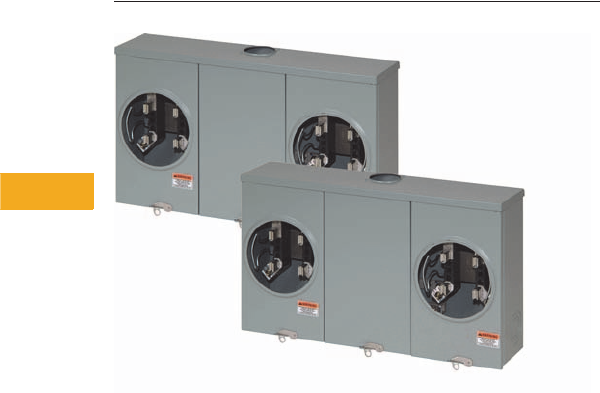
V1-T5-18 Volume 1—Residential and Light Commercial CA08100002E—February 2014 www.eaton.com
5
5
5
5
5
5
5
5
5
5
5
5
5
5
5
5
5
5
5
5
5
5
5
5
5
5
5
5
5
5
5.3
Metering Products
Multiple Position Horizontal Ganged Sockets
Multiple Position Horizontal Ganged Sockets
Contents
Description Page
Catalog Number Selection . . . . . . . . . . . . . . . . . . V1-T5-19
Product Selection . . . . . . . . . . . . . . . . . . . . . . . . . V1-T5-20
Dimensions. . . . . . . . . . . . . . . . . . . . . . . . . . . . . . V1-T5-23
Product Description
●Available in 100A and
200A designs
●Available in 2-position
through 6-position designs
●Multiple service
design offerings
●Multiple line/load
lug configurations
●Residential or lever
bypass socket designs
●Multiple hub opening
and closure plate
sizes available
Volume 1—Residential and Light Commercial CA08100002E—February 2014 www.eaton.com V1-T5-19
5
5
5
5
5
5
5
5
5
5
5
5
5
5
5
5
5
5
5
5
5
5
5
5
5
5
5
5
5
5
5.3
Metering Products
Multiple Position Horizontal Ganged Sockets
Catalog Number Selection
Single Meter Sockets 2R-6R and 2H-6H Group
Standard Prefixes
A = Aluminum enclosure
B = Barrel lock provision, for an exposed INNER-TITE or Brooks barrel lock;
unit includes an internal lock receiver bracket
F = Barrel lock with guard provision, for a lock guard INNER-TITE or
Brooks barrel lock; unit includes an internal lock receiver bracket
G = Grounded fifth terminal (9 o’clock position)
H = Horn bypass
I = Inhibitor installed in wire connectors
M = Temporary meter cover (waxed cardboard)
N = No sealing ring (applies only to ring style sockets)
R = Ring style socket
S = Aluminum screw type sealing ring (applies only to ring style sockets)
T = Grounding connector (#14–#2 Cu) for triplex ground
TT = Two grounding connectors (#14–#2 Cu) for quadplex ground
U = UL label
Z = 5/16-inch hex head connector screw in place of slotted (100A only)
Standard Suffixes
A = Solid top
B = Small hub opening
C = Small hub closing plate mounted
L = 1.25-inch (31.8 mm) hub mounted
M = 1.50-inch (38.1 mm) hub mounted
N = 2.00-inch (50.8 mm) hub mounted
P = 2.50-inch (63.5 mm) hub mounted
T = Large hub opening hub
U = Large hub cover plate hub mounted
V = 2.50-inch (63.5 mm) large hub mounted
Q = 3.00-inch (76.2 mm) large hub mounted
R = 3.50-inch (88.9 mm) large hub mounted
S = 4.00-inch (101.6 mm) large hub mounted
Z = Large to small hub adapter mounted
Maximum Line Conductor
0 = 0.38-inch stud connectors
1 = #2/0 connectors
2 = #250 kcmil connectors
3 = #350 kcmil connectors
5 = #500 kcmil connectors
6 = #600 kcmil connectors
7 = #750 kcmil connectors
8 = Dual #500 kcmil connectors
Service Design
0 = Overhead
1 = Combination overhead/underground
2 = Underground, side wired
3 = Combination overhead/underground, side wired
4 = End feed
Ampere Rating
1 = 100A
2 = 200A
Maximum Load Conductor
0 = 0.38-inch stud connectors
1 = #2/0 connectors
2 = #250 kcmil connectors
3 = #350 kcmil connectors
5 = #500 kcmil connectors
6 = #600 kcmil connectors
7 = #750 kcmil connectors
8 = Dual #500 kcmil connectors
Product Group
RS = Residential service, single position
2R-6R = Residential service, multiple position
2H-6H = Commercial or residential service, multiple position
H = Commercial or residential service, single position
UT 2R 1 1 2 1 B CH
Note: The “U” prefix is always used first followed by
other prefixes required in alphabetical order.
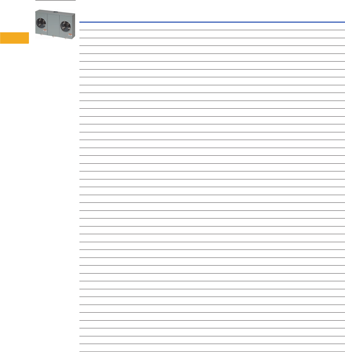
V1-T5-20 Volume 1—Residential and Light Commercial CA08100002E—February 2014 www.eaton.com
5
5
5
5
5
5
5
5
5
5
5
5
5
5
5
5
5
5
5
5
5
5
5
5
5
5
5
5
5
5
5.3
Metering Products
Multiple Position Horizontal Ganged Sockets
Product Selection
Horizontal Design—Multi Position Ringless
Notes
1 Aluminum enclosure.
For dimensions, see Pages V1-T5-23 and V1-T5-24.
Ampere
Rating Jaws Position Service Bypass
Connections Opening, Hub or
Closure Plate Catalog NumberLine Load
200 4 2 OH/UG Horn #6–350 kcmil #8–250 kcmil 5x5 hub opening 1004401BCH
200 4 3 OH/UG Horn #6–350 kcmil #8–250 kcmil 5x5 hub opening 1004404BCH
200 5 2 OH/UG Horn #6–350 kcmil #8–250 kcmil 5x5 hub opening 1004418ACH
200 4 2 OH/UG — 3/8-inch stud #8–250 kcmil 5x5 hub cover plate 1006737BCH
200 4 2 OH/UG Horn 3/8-inch stud #8–250 kcmil 5x5 hub opening 1007700CH
200 4 3 OH/UG Horn 3/8-inch stud #8–250 kcmil Hub opening 1007701CH
200 4 2 OH/UG Horn #6–350 kcmil #8–250 kcmil 5x5 hub cover plate 1008842CH
200 4 3 OH/UG Horn 1/0–500 kcmil cu/al #8–250 kcmil 5x5 hub cover plate 1008843CH
200 4 4 OH/UG Horn 1/0–500 kcmil cu/al #8–250 kcmil 5x5 hub cover plate 1008844CH
200 4 2 OH/UG Horn #6–350 kcmil #8–250 kcmil 5x5 hub cover plate 1008958CH
200 4 3 OH/UG Horn 1/0–500 kcmil cu/al #8–250 kcmil 5x5 hub cover plate 1008959CH
200 4 4 OH/UG Horn 1/0–500 kcmil cu/al #8–250 kcmil 5x5 hub cover plate 1008960CH
200 4 5 OH/UG Horn (2) 1/0–500 kcmil cu/al #8–250 kcmil (2) 5x5 hub cover plate 1009579ACH
200 4 4 OH/UG Horn 1/0–500 kcmil cu/al #8–250 kcmil 5x5 hub opening U4R2352TDQCH
200 4 5 OH/UG Horn (2) 1/0–500 kcmil cu/al #8–250 kcmil (2) 5x5 hub opening U5R2392TTDQCH
200 4 6 OH/UG Horn (2) 1/0–500 kcmil cu/al #8–250 kcmil 5x5 hub opening (2) places U6R2392TTDQCH
200 4 4 OH/UG Horn 1/0–500 kcmil cu/al #8–250 kcmil 5x5 hub opening UBH4R2352TCH
200 4 2 OH/UG Horn #6–350 kcmil #8–250 kcmil 5x5 hub opening UBH2R2332TCH
200 4 3 OH/UG Horn #6–350 kcmil #8–250 kcmil 5x5 hub opening UBH3R2332TCH
200 4 4 OH/UG Horn 3/8-inch stud #8–250 kcmil 5x5 hub cover plate UEHT4R2302UCH
200 4 3 OH/UG Horn 3/8-inch stud #8–250 kcmil 5x5 hub cover plate UEHT3R2302UCH
200 4 2 OH/UG Horn 3/8-inch stud #8–250 kcmil 5x5 hub cover plate UEHT2R2302UCH
200 4 2 UG Horn #6–350 kcmil #8–250 kcmil Solid top UHI2R2332ACVCH
200 4 2 OH/UG Horn #6–350 kcmil #8–250 kcmil Hub opening UHI2R2332TCVCH
200 4 4 UG Horn 1/0–500 kcmil cu/al #8–250 kcmil Solid top UHI4R2352ACVCH
200 4 2 OH/UG Horn #6–350 kcmil #8–250 kcmil 5x5 hub cover plate UHTT2R2332UCH
200 4 2 OH/UG Horn #6–350 kcmil #8–250 kcmil 5x5 hub opening UHT2R2332TCH
200 4 3 OH/UG Horn #6–350 kcmil #8–250 kcmil 5x5 hub opening UHT3R2332TCH
200 4 3 OH/UG Horn 1/0–500 kcmil cu/al #8–250 kcmil 5x5 hub cover plate UHT3R2352UCH
200 4 4 OH/UG Horn 1/0–500 kcmil cu/al #8–250 kcmil 5x5 hub opening UHT4R2352TCH
200 4 4 OH/UG — 1/0–500 kcmil cu/al #8–250 kcmil 5x5 hub cover plate UT4R2352UFLCH
200 4 4 OH/UG Horn 1/0–500 kcmil cu/al #8–250 kcmil 5x5 hub cover plate UHT4R2352UCH
200 5 2 OH/UG Lever 1/0–500 kcmil cu/al #6–350 kcmil 5x5 hub opening UT2H52353TCH
200 4 2 OH/UG Horn #6–350 kcmil #8–250 kcmil 5x5 hub cover plate UHT2R2332UCH
200 4 2 OH/UG — #6–350 kcmil #8–250 kcmil 3-5/16 hub opening UT2R2332BCH
200 4 2 OH/UG — #6–350 kcmil #8–250 kcmil 5x5 hub opening UAT2R2332TCH 1
200 4 2 OH/UG — #6–350 kcmil #8–250 kcmil 5x5 hub opening UT2R2332TCH
200 4 2 OH/UG — #6–350 kcmil #8–250 kcmil 5x5 hub opening U2R2332TCPLCH
200 4 2 OH/UG — #6–350 kcmil #8–250 kcmil 5x5 hub cover plate U2R2332UCPLCH
200 4 2 OH/UG Horn #6–350 kcmil #8–250 kcmil 5x5 hub opening U2R2332TDQCH
200 4 2 OH/UG — #6–350 kcmil #8–250 kcmil 5x5 hub cover plate UT2R2332UCH
200 4 3 OH/UG Horn #6–350 kcmil #8–250 kcmil Large 5X5 hub opening U3R2332TDQCH
UT2R2332BCH
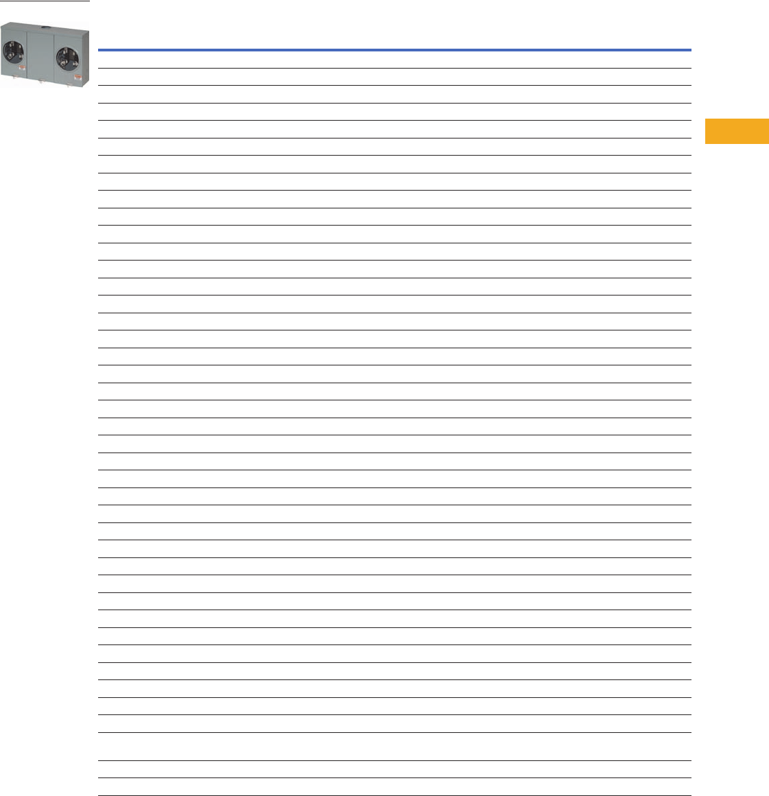
Volume 1—Residential and Light Commercial CA08100002E—February 2014 www.eaton.com V1-T5-21
5
5
5
5
5
5
5
5
5
5
5
5
5
5
5
5
5
5
5
5
5
5
5
5
5
5
5
5
5
5
5.3
Metering Products
Multiple Position Horizontal Ganged Sockets
Horizontal Design—Multi Position Ringless, continued
Notes
1 Aluminum enclosure.
For dimensions, see Pages V1-T5-23 and V1-T5-24.
Ampere
Rating Jaws Position Service Bypass
Connections Opening, Hub or
Closure Plate Catalog NumberLine Load
200 4 3 OH/UG Lever 1/0–500 kcmil cu/al #6–350 kcmil 5x5 hub opening UT3H42353TCH
200 5 3 OH/UG Lever 1/0–500 kcmil cu/al #6–350 kcmil 5x5 hub opening UT3H52353TCH
200 7 3 OH/UG Lever 1/0–500 kcmil cu/al #6–350 kcmil 5x5 hub cover plate UT3H72353UHLCH
200 4 3 OH/UG — #6–350 kcmil #8–250 kcmil 5x5 hub opening UT3R2332TCH
200 4 3 OH/UG — #6–350 kcmil #8–250 kcmil 5x5 hub cover plate UT3R2332UCH
200 4 3 OH/UG — 1/0–500 kcmil cu/al #8–250 kcmil 5x5 hub opening UT3R2352TCH
200 4 4 OH/UG — 1/0–500 kcmil cu/al #8–250 kcmil 5x5 hub opening UT4R2352TCH
200 4 5 OH/UG Horn (2) 1/0–500 kcmil cu/al #8–250 kcmil 5x5 hub opening (in two places) UHT5R2392TTCH
200 4 5 OH/UG — (2) 1/0–500 kcmil cu/al #8–250 kcmil 5x5 hub opening (in two places) UT5R2392TTCH
200 7 5 OH/UG Lever Dual 1/0–500 kcmil #6–350 kcmil (2) 5X5 hub closure plates UT5H72393UUHLCH
200 4 6 OH/UG Horn (2) 1/0–500 kcmil cu/al #8–250 kcmil 5x5 hub opening (in two places) UHT6R2392TTCH
200 4 6 OH/UG — (2) 1/0–500 kcmil cu/al #8–250 kcmil 5x5 hub opening (in two places) UT6R2392TTCH
200 4 6 OH/UG — (2) 1/0–500 kcmil cu/al #8–250 kcmil 5x5 closure plate (in two places) UT6R2392UUFLCH
200 7 6 OH/UG Lever Dual 1/0–500 kcmil #6–350 kcmil 5x5 closure plate (in two places) UT6H72393UUHLCH
200 4 6 OH/UG Horn (2) 1/0–500 kcmil cu/al #8–250 kcmil 5x5 hub opening (in two places) UHT6R2392TTCH
150 4 2 OH/UG Horn #6–350 kcmil #8–250 kcmil 3-5/16 hub opening U2R5432BDQCH
150 4 5 OH/UG — #6–350 kcmil #8–250 kcmil 3-5/16 hub opening (in two places) UT5R5632BCH
100 4 6 OH/UG — #6–350 kcmil #8–2/0 cu/al 3-5/16 hub opening UT6R1131BCH
100 4 2 OH/UG Horn #6–250 kcmil #8–2/0 cu/al 5x5 hub opening 1004426ACH
100 4 2 OH/UG Horn #6–250 kcmil #8–2/0 cu/al 3-5/16 hub opening 1008951CH
100 4 3 OH/UG Horn #6–250 kcmil #8–2/0 cu/al 3-5/16 hub opening 1008952CH
100 4 2 OH/UG Horn #6–250 kcmil #8–2/0 cu/al 3-5/16 hub cover plate 1009693CH
100 4 3 OH/UG Horn #6–250 kcmil #8–2/0 cu/al 3-5/16 hub cover plate 1009694CH
100 4 4 OH/UG Horn #6–250 kcmil #8–2/0 cu/al 3-5/16 hub cover plate 1009695CH
100 4 5 OH/UG Horn #6–250 kcmil #8–2/0 cu/al 3-5/16 hub cover plate 1009696CH
100 4 6 OH/UG — #6–350 kcmil #8–2/0 cu/al 3-5/16 hub cover plate UATZ6R1131CFLCH 1
100 4 2 OH/UG Horn #6–250 kcmil #8–2/0 cu/al 3-5/16 hub opening UBH2R1121BCH
100 4 3 OH/UG Horn #6–250 kcmil #8–2/0 cu/al 3-5/16 hub opening UBH3R1121BCH
100 4 4 OH/UG Horn #6–250 kcmil #8–2/0 cu/al 3-5/16 hub opening UBH4R1121BCH
100 4 2 OH/UG Horn #6–250 kcmil #8–2/0 cu/al 3-5/16 hub opening UHT2R1121BCH
100 4 4 OH/UG — #6–250 kcmil #8–2/0 cu/al 3-5/16 hub opening UT4R1121BCH
100 4 4 OH/UG — #6–250 kcmil #8–2/0 cu/al 3-5/16 closure plate UT4R1121CCH
100 4 4 OH/UG Horn #6–250 kcmil #8–2/0 cu/al 3-5/16 hub opening UHT4R1121BCH
100 4 5 OH/UG Horn #6–250 kcmil #8–2/0 cu/al 3-5/16 hub opening UHT5R1121BCH
100 4 5 OH/UG — #6–250 kcmil #8–2/0 cu/al 3-5/16 hub opening UT5R1121BCH
100 4 5 OH/UG — #6–250 kcmil #8–2/0 cu/al 3-5/16 closure plate UT5R1121CCH
100 4 2 OH/UG — #6–250 kcmil #8–2/0 cu/al 3-5/16 hub opening UT2R1121BCH
100 4 2 OH/UG — #6–250 kcmil #8–2/0 cu/al 3-5/16 closure plate UT2R1121CCH
100 4 2 OH/UG Horn #6–250 kcmil #8–2/0 cu/al 3-5/16 closure plate UHT2R1421CCH
100 4 2 OH/UG — #6–250 kcmil #8–2/0 cu/al 3-5/16 hub opening
3-5/16 hub cover plate
UT2R1421BCH
100 4 3 OH/UG Horn #6–250 kcmil #8–2/0 cu/al 3-5/16 hub opening UHT3R1121BCH
100 4 3 OH/UG — #6–250 kcmil #8–2/0 cu/al 3-5/16 hub opening UT3R1121BCH
UT2R1121BCH

V1-T5-22 Volume 1—Residential and Light Commercial CA08100002E—February 2014 www.eaton.com
5
5
5
5
5
5
5
5
5
5
5
5
5
5
5
5
5
5
5
5
5
5
5
5
5
5
5
5
5
5
5.3
Metering Products
Multiple Position Horizontal Ganged Sockets
Horizontal Design—Multi Position Ring Type
Notes
1 Vertical gang.
For dimensions, see Pages V1-T5-23 and V1-T5-24.
Ampere
Rating Jaws Position Service Bypass
Connections Opening, Hub or
Closure Plate Catalog NumberLine Load
200 4 2 OH/UG — 1/0–500 kcmil cu/al #8–250 kcmil 5x5 hub opening U2R2352TCRCH
200 4 2 OH/UG — #6–350 kcmil #8–250 kcmil 5x5 hub cover plate URT2R2332UCH
200 5 4 OH/UG — 1/0–500 kcmil cu/al #8–250 kcmil Large 5x5 hub opening U4R2352TCRCH
125 5 2 OH — #8–350 kcmil #8–2/0 cu/al Hub opening U2V1031BCRCH 1
125 5 3 OH — #8–350 kcmil #8–2/0 cu/al Hub opening U3V1031BCRCH 1
100 5 2 OH/UG — #6–250 kcmil #8–2/0 cu/al 3-5/16 opening U2R1121BCRCH
100 5 3 OH/UG — #6–250 kcmil #8–2/0 cu/al 3-5/16 opening U3R1121BCRCH
100 5 4 OH/UG — #6–250 kcmil #8–2/0 cu/al 3-5/16 opening U4R1121BCRCH
100 5 5 OH/UG — #6–250 kcmil #8–2/0 cu/al 3-5/16 opening U5R1121BCRCH

Volume 1—Residential and Light Commercial CA08100002E—February 2014 www.eaton.com V1-T5-23
5
5
5
5
5
5
5
5
5
5
5
5
5
5
5
5
5
5
5
5
5
5
5
5
5
5
5
5
5
5
5.3
Metering Products
Multiple Position Horizontal Ganged Sockets
Dimensions
Approximate Dimensions in Inches (mm)
Horizontal Design—Multi Position Ringless
Catalog Number Height Width Depth
1004401BCH 14.13 (358.9) 24.31 (617.5) 5.38 (136.7)
1004404BCH 14.13 (358.9) 32.47 (824.7) 5.38 (136.7)
1004418ACH 14.13 (358.9) 24.31 (617.5) 5.38 (136.7)
1006737BCH 14.13 (358.9) 24.31 (617.5) 5.38 (136.7)
1007700CH 14.13 (358.9) 24.31 (617.5) 5.38 (136.7)
1007701CH 14.13 (358.9) 32.47 (824.7) 5.38 (136.7)
1008842CH 14.13 (358.9) 24.31 (617.5) 5.38 (136.7)
1008843CH 14.13 (358.9) 32.47 (824.7) 5.38 (136.7)
1008844CH 14.13 (358.9) 40.63 (1032.0) 5.38 (136.7)
1008958CH 14.13 (358.9) 24.31 (617.5) 5.38 (136.7)
1008959CH 14.13 (358.9) 32.47 (824.7) 5.38 (136.7)
1008960CH 14.13 (358.9) 40.63 (1032.0) 5.38 (136.7)
1009579ACH 14.13 (358.9) 54.78 (1391.4) 5.38 (136.7)
U4R2352TDQCH 14.13 (358.9) 40.63 (1032.0) 5.38 (136.7)
U5R2392TTDQCH 14.13 (358.9) 62.94 (1598.7) 5.38 (136.7)
U6R2392TTDQCH 14.13 (358.9) 62.94 (1598.7) 5.38 (136.7)
UBH4R2352TCH 14.13 (358.9) 40.63 (1032.0) 5.38 (136.7)
UBH2R2332TCH 14.13 (358.9) 24.31 (617.5) 5.38 (136.7)
UBH3R2332TCH 14.13 (358.9) 32.47 (824.7) 5.38 (136.7)
UEHT4R2302UCH 14.13 (358.9) 40.63 (1032.0) 5.38 (136.7)
UEHT3R2302UCH 14.13 (358.9) 32.47 (824.7) 5.38 (136.7)
UEHT2R2302UCH 14.13 (358.9) 24.31 (617.5) 5.38 (136.7)
UHI2R2332ACVCH 14.13 (358.9) 24.31 (617.5) 5.38 (136.7)
UHI2R2332TCVCH 14.13 (358.9) 24.31 (617.5) 5.38 (136.7)
UHI4R2352ACVCH 14.13 (358.9) 40.63 (1032.0) 5.38 (136.7)
UHTT2R2332UCH 14.13 (358.9) 24.31 (617.5) 5.38 (136.7)
UHT2R2332TCH 14.13 (358.9) 24.31 (617.5) 5.38 (136.7)
UHT3R2332TCH 14.13 (358.9) 32.94 (836.7) 5.38 (136.7)
UHT3R2352UCH 14.13 (358.9) 32.47 (824.7) 5.38 (136.7)
UHT4R2352TCH 14.13 (358.9) 40.63 (1032.0) 5.38 (136.7)
UT4R2352UFLCH 14.13 (358.9) 40.63 (1032.0) 5.38 (136.7)
UHT4R2352UCH 14.13 (358.9) 40.63 (1032.0) 5.38 (136.7)
UT2H52353TCH 23.56 (598.4) 32.78 (832.6) 6.00 (152.4)
UHT2R2332UCH 14.13 (358.9) 24.31 (617.5) 5.38 (136.7)
UT2R2332BCH 14.13 (358.9) 24.31 (617.5) 5.38 (136.7)
UAT2R2332TCH 114.13 (358.9) 24.31 (617.5) 5.38 (136.7)
UT2R2332TCH 14.13 (358.9) 24.31 (617.5) 5.38 (136.7)
U2R2332TCPLCH 14.13 (358.9) 24.31 (617.5) 5.38 (136.7)
U2R2332UCPLCH 14.13 (358.9) 24.31 (617.5) 5.38 (136.7)
U2R2332TDQCH 14.13 (358.9) 24.31 (617.5) 5.38 (136.7)
UT2R2332UCH 14.13 (358.9) 24.31 (617.5) 5.38 (136.7)
U3R2332TDQCH 14.13 (358.9) 32.47 (824.7) 5.38 (136.7)
UT3H42353TCH 23.56 (598.4) 43.91 (1115.3) 6.00 (152.4)
UT3H52353TCH 23.56 (598.4) 43.91 (1115.3) 6.00 (152.4)
UT3H72353UHLCH 23.56 (598.4) 43.91 (1115.3) 5.38 (136.7)
Horizontal Design—Multi Position Ringless, continued
Note
1Aluminum enclosure.
Catalog Number Height Width Depth
UT3R2332TCH 14.13 (358.9) 32.47 (824.7) 5.38 (136.7)
UT3R2332UCH 14.13 (358.9) 32.47 (824.7) 5.38 (136.7)
UT3R2352TCH 14.13 (358.9) 40.63 (1032.0) 5.38 (136.7)
UT4R2352TCH 14.13 (358.9) 40.63 (1032.0) 5.38 (136.7)
UHT5R2392TTCH 14.13 (358.9) 54.78 (1391.4) 5.38 (136.7)
UT5R2392TTCH 14.13 (358.9) 54.78 (1391.4) 5.38 (136.7)
UT5H72393UUHLCH 29.56 (750.8) 72.15 (1832.6) 6.00 (152.4)
UHT6R2392TTCH 14.13 (358.9) 62.94 (1598.7) 5.38 (136.7)
UT6R2392TTCH 14.13 (358.9) 62.94 (1598.7) 5.38 (136.7)
UT6R2392UUFLCH 14.13 (358.9) 62.94 (1598.7) 5.38 (136.7)
UT6H72393UUHLCH 23.56 (598.4) 83.28 (2115.3) 6.00 (152.4)
UHT6R2392TTCH 14.13 (358.9) 62.94 (1598.7) 5.38 (136.7)
U2R5432BDQCH 14.13 (358.9) 20.16 (512.1) 5.38 (136.7)
UT5R5632BCH 14.13 (358.9) 48.63 (1235.2) 5.38 (136.7)
UT6R1131BCH 14.13 (358.9) 56.93 (1446.0) 4.50 (114.3)
1004426ACH 14.13 (358.9) 24.31 (617.5) 4.50 (114.3)
1008951CH 14.13 (358.9) 24.31 (617.5) 4.50 (114.3)
1008952CH 14.13 (358.9) 32.47 (824.7) 4.50 (114.3)
1009693CH 14.13 (358.9) 24.16 (613.7) 5.38 (136.7)
1009694CH 14.13 (358.9) 32.31 (820.7) 5.38 (136.7)
1009695CH 14.13 (358.9) 49.94 (1268.5) 5.38 (136.7)
1009696CH 14.13 (358.9) 48.63 (1235.2) 5.38 (136.7)
UATZ6R1131CFLCH 14.13 (358.9) 56.94 (1446.3) 4.50 (114.3)
UBH2R1121BCH 14.13 (358.9) 24.94 (633.5) 4.50 (114.3)
UBH3R1121BCH 14.13 (358.9) 32.47 (824.7) 4.50 (114.3)
UBH4R1121BCH 14.13 (358.9) 40.63 (1032.0) 4.50 (114.3)
UHT2R1121BCH 14.13 (358.9) 24.31 (617.5) 4.50 (114.3)
UT4R1121BCH 14.13 (358.9) 40.63 (1032.0) 4.50 (114.3)
UT4R1121CCH 14.13 (358.9) 40.63 (1032.0) 4.50 (114.3)
UHT4R1121BCH 14.13 (358.9) 40.63 (1032.0) 4.50 (114.3)
UHT5R1121BCH 14.13 (358.9) 48.78 (1239.0) 4.50 (114.3)
UT5R1121BCH 14.13 (358.9) 48.78 (1239.0) 4.50 (114.3)
UT5R1121CCH 14.13 (358.9) 48.78 (1239.0) 4.50 (114.3)
UT2R1121BCH 14.13 (358.9) 24.31 (617.5) 4.50 (114.3)
UT2R1121CCH 14.13 (358.9) 24.31 (617.5) 4.50 (114.3)
UHT2R1421CCH 14.13 (358.9) 20.16 (512.1) 5.38 (136.7)
UT2R1421BCH 14.13 (358.9) 20.16 (512.1) 5.38 (136.7)
UHT3R1121BCH 14.13 (358.9) 32.47 (824.7) 4.50 (114.3)
UT3R1121BCH 14.13 (358.9) 32.47 (824.7) 4.50 (114.3)

V1-T5-24 Volume 1—Residential and Light Commercial CA08100002E—February 2014 www.eaton.com
5
5
5
5
5
5
5
5
5
5
5
5
5
5
5
5
5
5
5
5
5
5
5
5
5
5
5
5
5
5
5.3
Metering Products
Multiple Position Horizontal Ganged Sockets
Approximate Dimensions in Inches (mm)
Horizontal Design—Multi Position Ring Type
Note
1Vertical gang.
Catalog Number Height Width Depth
U2R2352TCRCH 14.13 (358.9) 24.31 (617.5) 5.38 (136.7)
URT2R2332UCH 14.13 (358.9) 24.31 (617.5) 5.38 (136.7)
U4R2352TCRCH 14.13 (358.9) 48.00 (1219.2) 5.38 (136.7)
U2V1031BCRCH 18.00 (203.2) 25.63 (650.9) 4.38 (111.1)
U3V1031BCRCH 18.00 (203.2) 35.88 (911.2) 4.38 (111.1)
U2R1121BCRCH 14.13 (358.9) 28.00 (711.2) 4.50 (114.3)
U3R1121BCRCH 14.13 (358.9) 38.00 (965.2) 4.50 (114.3)
U4R1121BCRCH 14.13 (358.9) 48.00 (1219.2) 4.50 (114.3)
U5R1121BCRCH 14.13 (358.9) 58.00 (1473.2) 4.50 (114.3)
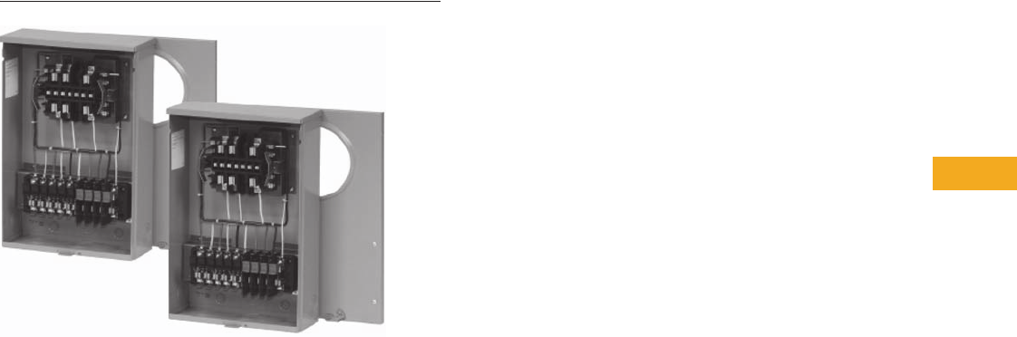
Volume 1—Residential and Light Commercial CA08100002E—February 2014 www.eaton.com V1-T5-25
5
5
5
5
5
5
5
5
5
5
5
5
5
5
5
5
5
5
5
5
5
5
5
5
5
5
5
5
5
5
5.4
Metering Products
Instrument Rated Sockets
Instrument Rated Sockets
Contents
Description Page
Product Selection . . . . . . . . . . . . . . . . . . . . . . . . . V1-T5-26
Dimensions . . . . . . . . . . . . . . . . . . . . . . . . . . . . . . V1-T5-26
Product Description
●Available in 6, 7, 8 and
13 terminal designs
●20A ratings standard
●Multiple service designs
available (overhead,
underground, overhead/
underground)
●Multiple hub opening
and closure plate
sizes available
●600 Vac rated
●Single cover/dual
cover availability
●Provisional test switches
and factory-installed test
switch designs available
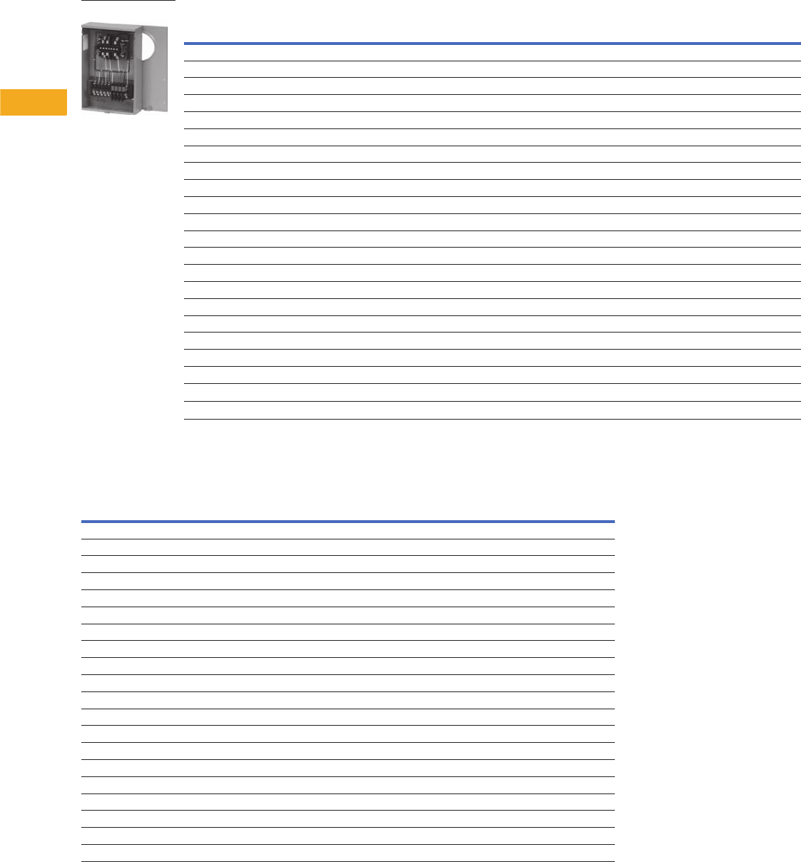
V1-T5-26 Volume 1—Residential and Light Commercial CA08100002E—February 2014 www.eaton.com
5
5
5
5
5
5
5
5
5
5
5
5
5
5
5
5
5
5
5
5
5
5
5
5
5
5
5
5
5
5
5.4
Metering Products
Instrument Rated Sockets
Product Selection
Instrument Rated Sockets
Dimensions
Approximate Dimensions in Inches (mm)
Instrument Rated Sockets
Ampere
Rating Jaws Service
Opening, Hub
or Closure Plate
Catalog
Number
20 13 terminal UG Solid top USTH131A123CH
20 13 terminal OH/UG 3-5/16 hub cover plate USTS131B102CH
20 13 terminal OH/UG 3-5/16 hub cover plate USTS132B101CH
20 13 terminal OH/UG 3-5/16 hub cover plate USTS132CCH
20 13 terminal OH/UG 1-inch bolt-on hub 1008694ACH
20 8 terminal OH/UG 1-inch bolt-on hub 1008695ACH
20 13 terminal N/A N/A 1007003BCH
20 13 terminal Solid top and bottom Solid top 1007003CCH
20 13 terminal OH/UG 3-5/16 hub cover plate USTL131C207CH
20 13 terminal OH/UG Hub opening USTS131BCH
20 13 terminal OH/UG 1-1/4-inch bolt-on hub USTS131L143CH
20 13 terminal N/A N/A USTS132BCH
20 6 terminal OH/UG Hub opening USTS61B138CH
20 6 terminal OH/UG Hub opening UST61BCH
20 8 terminal OH/UG Hub opening USTS82B166CH
20 8 terminal N/A Solid top and bottom 1007361BCH
N/A N/A N/A N/A 1008539CH
20 13 terminal OH/UG 3-5/16 hub cover plate UASTS131C226CH
20 13 terminal OH 3-5/16 hub cover plate 1004671CH
20 7 terminal OH 3-5/16 hub cover plate ULTS131CCH
20 6 terminal UG Solid top STL61A433CH
20 13 terminal UG Solid top STL131A120CH
USTS132CCH
Catalog Number Height Width Depth
USTH131A123CH 20.00 (304.8) 12.00 (304.8) 4.36 (110.7)
USTS131B102CH 20.00 (304.8) 12.00 (304.8) 4.36 (110.7)
USTS132B101CH 20.00 (304.8) 12.00 (304.8) 4.36 (110.7)
USTS132CCH 20.00 (304.8) 12.00 (304.8) 4.36 (110.7)
1008694ACH 20.00 (304.8) 12.00 (304.8) 4.36 (110.7)
1008695ACH 20.00 (304.8) 12.00 (304.8) 4.36 (110.7)
1007003BCH N/A N/A N/A
1007003CCH 16.50 (419.1) 14.00 (355.6) 3.50 (88.9)
USTL131207CH 20.00 (304.8) 12.00 (304.8) 4.35 (110.5)
USTS131BCH 20.00 (304.8) 12.00 (304.8) 4.35 (110.5)
USTS131L143CH 20.00 (304.8) 12.00 (304.8) 4.35 (110.5)
USTS132BCH N/A N/A N/A
USTS61B138CH 20.00 (304.8) 12.00 (304.8) 4.35 (110.5)
UST61BCH 20.00 (304.8) 12.00 (304.8) 4.35 (110.5)
USTS82B166CH 20.00 (304.8) 12.00 (304.8) 4.35 (110.5)
1007361BCH 16.50 (419.1) 14.00 (355.6) 3.50 (88.9)
1008539CH N/A N/A N/A
UASTS131C226CH 20.00 (304.8) 12.00 (304.8) 4.35 (110.5)
1004671CH 17.00 (431.8) 10.00 (254.0) 5.00 (127.0)
ULTS131CCH 22.00 (558.8) 12.00 (304.8) 4.94 (125.5)
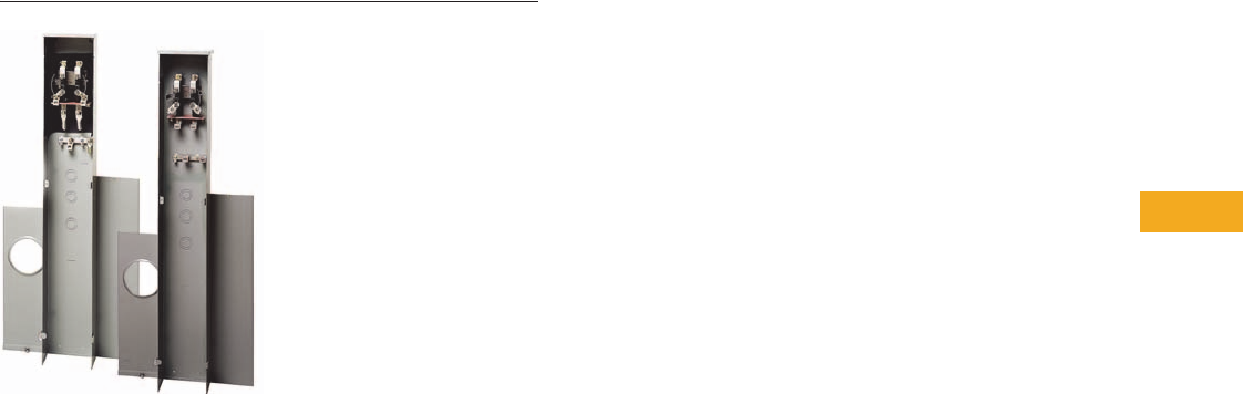
Volume 1—Residential and Light Commercial CA08100002E—February 2014 www.eaton.com V1-T5-27
5
5
5
5
5
5
5
5
5
5
5
5
5
5
5
5
5
5
5
5
5
5
5
5
5
5
5
5
5
5
5.5
Metering Products
Residential Pedestals
Residential Pedestals
Contents
Description Page
Product Selection . . . . . . . . . . . . . . . . . . . . . . . . . V1-T5-28
Dimensions . . . . . . . . . . . . . . . . . . . . . . . . . . . . . . V1-T5-28
Product Description
●Available in 100A, 200A,
300A and 320A designs
●Available in 4- or 5-jaw
configurations
●Underground service
design is standard
●Bypass options (lever,
horn) are available
●Solid top designs
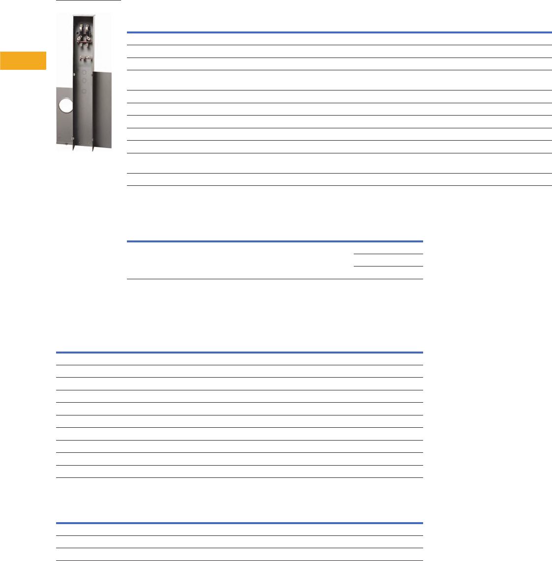
V1-T5-28 Volume 1—Residential and Light Commercial CA08100002E—February 2014 www.eaton.com
5
5
5
5
5
5
5
5
5
5
5
5
5
5
5
5
5
5
5
5
5
5
5
5
5
5
5
5
5
5
5.5
Metering Products
Residential Pedestals
Product Selection
Residential Pedestals
Pedestal Extension Kits
Dimensions
Approximate Dimensions in Inches (mm)
Residential Pedestals
Pedestal Extension Kits
Note
1200A breakers.
Ampere
Rating Jaws Service Bypass
Connections Opening, Hub or
Closure Plate Catalog NumberLine Load
320 4 UG — 3/8-inch studs 3/8-inch studs Solid top 1008847CH
320 4 UG Lever #6–350 kcmil line and line neutral 2/0–250 kcmil load and load neutral Solid top 1009017CH 1
300 4 UG Lever #6–350 kcmil line and line neutral 2/0–250 kcmil load and load neutral Solid top
200 4 UG Horn 4/0 compression (line) 2/0
compression (neutral)
#6–250 kcmil load and load neutral Solid top 1006388CH
200 4 UG Horn #8–350 kcmil #8–350 kcmil Solid top UHTRP242363CH
200 4 UG Horn #6–350 kcmil line and line neutral #6–250 kcmil load neutral Solid top 1008846CH
200 4 UG Horn #6–350 kcmil line and line neutral #6–250 kcmil load neutral N/A 1008961CH
200 5 N/A N/A N/A N/A N/A 1008966CH
200 4 UG — #6–350 kcmil line and line neutral #6–350 kcmil load and load neutral Solid top 1009264CH
200 4 UG — 4/0 compression (line) 2/0
compression (neutral)
#6–350 kcmil load and load neutral Solid top 1009265CH
100 4 UG — #6–350 kcmil line and line neutral #6–250 kcmil load neutral Solid top 1009078CH
Connections
Catalog NumberLine Load
Pedestal extension kit for 1008846CH Pedestal extension kit for 1008846CH 1009021CH
1009022CH
1009026CH
UHTRP242363CH
Catalog Number Height Width Depth
1008847CH 58.00 (1473.2) 12.97 (329.4) 4.93 (125.2)
1009017CH 163.00 (1600.2) 12.96 (329.2) 4.93 (125.2)
1006388CH 61.00 (1549.4) 8.96 (227.6) 4.93 (125.2)
UHTRP242363CH 62.63 (1590.8) 8.97 (227.8) 4.94 (125.5)
1008846CH 70.00 (1778.0) 11.00 (279.4) 6.00 (152.4)
1008961CH 69.93 (1776.2) N/A 6.00 (152.4)
1008966CH N/A N/A N/A
1009264CH 74.00 (1879.6) 8.96 (227.6) 4.93 (125.2)
1009265CH 74.00 (1879.6) 8.97 (227.8) 4.94 (125.5)
1009078CH 69.93 (1776.2) 11.00 (279.4) 6.00 (152.4)
Catalog Number Height Width Depth
1009021CH 18.00 (457.2) 11.00 (279.4) 6.00 (152.4)
1009022CH 18.00 (457.2) 12.96 (329.2) 4.93 (125.2)
1009026CH 30.00 (762.0) 12.96 (329.2) 4.93 (125.2)
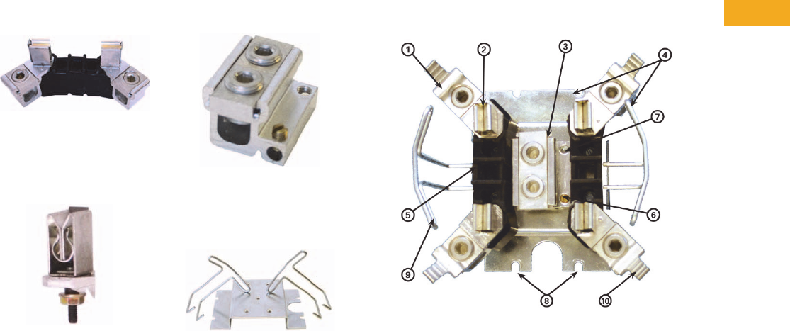
Volume 1—Residential and Light Commercial CA08100002E—February 2014 www.eaton.com V1-T5-29
5
5
5
5
5
5
5
5
5
5
5
5
5
5
5
5
5
5
5
5
5
5
5
5
5
5
5
5
5
5
5.6
Metering Products
Accessories and Cross-Reference
Product Description
This section will help you
better understand the
features and benefits of the
125A and 200A Eaton
designed meter socket.
Features and Benefits
Construction Features
1. High strength, glass-filled
meter block assembly,
lay-in connectors with
captive slide nut and
screw.
2. 100% plated copper
alloy meter jaw with
reinforcing spring clip
and meter guide.
3. Extruded neutral lug
with integral triplex
ground and quadplex
ground provision.
4. Bridge and meter
supports are 100%
zinc chromate plated.
200A Ringless Block Assembly With Horn Bypass
5. Fifth terminal locating
hole in 9 o’clock position.
6. Triplex ground is a
standard feature.
7. Quadplex ground
provision.
8. Durable “four-point”
bridge mounting
(2 top, 2 bottom).
9. Extra rigid meter support
for ringless sockets.
10. Optional, integral horn
bypass extruded on slide
nut. Horn is ribbed for
secure attachment to
utility bypass jumpers.
Field-installable horn
bypass kit available.

V1-T5-30 Volume 1—Residential and Light Commercial CA08100002E—February 2014 www.eaton.com
5
5
5
5
5
5
5
5
5
5
5
5
5
5
5
5
5
5
5
5
5
5
5
5
5
5
5
5
5
5
5.6
Metering Products
Accessories and Cross-Reference
Product Selection
Meter Socket Accessories
Description Part Number
Hub closure plate meter socket accessories ARP00002CHB
Clam shell hub closure plate meter socket accessories ARP00002CHBCS
1-inch hub closure plate meter socket accessories ARP00003CH1
Clam shell 1-inch hub closure plate—small opening ARP00003CH1CS
1-1/4-inch hub closure plate meter socket accessories ARP00004CH12
Clam shell 1-1/4-inch hub closure plate—small opening ARP00004CH12CS
1-1/2-inch hub closure plate meter socket accessories ARP00005CH15
Clam shell 1-1/2-inch hub closure plate—small opening ARP00005CH15CS
2-inch hub closure plate meter socket accessories ARP00006CH2
2-1/2-inch hub for meter socket accessories ARP00007CH25
Clam shell 2-1/2-inch hub for meter socket accessories ARP00007CH25CS
Aluminum hub closure plate for single sockets ARP00008CH
Hub adapter from large opening to small opening ARP00015CHAP
Large hub cover plate ARP00016CHB
2-inch hub with large diameter opening ARP00017CH2
2.5-inch hub with large diameter opening ARP00018CH25
3-inch hub ARP00019CH3
3-1/2-inch hub for meter sockets ARP00020CH35
4-inch hub ARP00021CH4
Screw sealing ring for single meter sockets ARP00027CH
Fifth jaw kit ARP00035CHJ
#6–350 kcmil lug kit for single sockets—3/8-inch stud ARP00119CH
#4–600 kcmil connector for single position meter sockets ARP00129CH
Fifth jaw for bolt on meter ARP00326CH
#6–350 kcmil double barrel lug kit ARP00427CH
Neutral Insulating Kit ARP00759CH
100A meter socket horn cap assembly kit ARP00777CH
Fifth jaw kit for 320A offset socket ARP00862CH
HQ anti-inversion clip for single meter sockets ARP00984CH
Fifth jaw for Chicago and Wisconsin pedestal ARP01085CH
350 kcmil BNS cap assembly kit for meter sockets ARP01226CH
Right hand block assembly with Z Bar ARP01258CH
Left hand block assembly with Z Bar ARP01414CH
Meter pack trough closure plate kit ARP01565CH
2/0 connector kit for MBB and MBP socket breaker ARP01612CH

Volume 1—Residential and Light Commercial CA08100002E—February 2014 www.eaton.com V1-T5-31
5
5
5
5
5
5
5
5
5
5
5
5
5
5
5
5
5
5
5
5
5
5
5
5
5
5
5
5
5
5
5.6
Metering Products
Accessories and Cross-Reference
Cross-Reference
Meter Sockets
Description
Manufacturer
Eaton Milbank
Part Number Part Number
125A, OH/UG, ringless, triplex ground, hub opening UTRS101BE U7487-RL-TG
125A, OH/UG, ringless, triplex ground, hub cover plate UTRS101CE U7487-XL-TG
125A, OH/UG, ringless, triplex ground, hub opening, horn bypass UHTRS101BE U7487-RL-TG-KK
125A, OH/UG, ringless, triplex ground, hub cover plate, horn bypass UHTRS101CE U7487-XL-TG-KK
125A, OH/UG, ringless, triplex ground, hub opening, fifth terminal UTRS101BCH + MSR5TK U7487-RL-TG-5T
125A, OH/UG, ringless, triplex ground, hub cover plate, fifth terminal UTRS101CE + MSR5TK U7487-XL-TG-5T
125A, OH/UG, ringless, triplex ground, hub opening, horn bypass, fifth terminal UHTRS101BCH + MSR5TK U7487-RL-TG-KK-5T
125A, OH/UG, ringless, triplex ground, hub cover plate, horn bypass, fifth terminal UGHTRS101CE + MSR5TK U7487-XL-TG-KK-5T
200A, OH, ringless, triplex ground, hub opening UTRS202BCH U7021-RL-TG
200A, OH, ringless, triplex ground, hub cover plate UTRS202CCH U7021-XL-TG
200A, OH, ringless, triplex ground, hub opening, horn bypass UHTRS202BCH U7021-RL-TG-KK
200A, OH, ringless, triplex ground, hub cover plate, horn bypass UHTRS202CCH U7021-RL-TG-KK
200A, OH, ringless, triplex ground, hub opening, fifth terminal UGTRS202BCH U7021-RL-TG-5T
200A, OH, ringless, triplex ground, hub cover plate, fifth terminal UGTRS202CCH U7021-XL-TG-5T
200A, OH, ringless, triplex ground, hub opening, horn bypass, fifth terminal UGHTRS202BCH U7021-RL-TG-KK-5T
200A, OH, ringless, triplex ground, hub cover plate, horn bypass, fifth terminal UGHTRS202CCH U7021-RL-TG-KK-5T
200A, OH/UG, ringless, triplex ground, hub opening, 250 kcmil lugs UTRS212BCH No cross (no 250 kcmil lugs)
200A, OH/UG, ringless, triplex ground, hub cover plate, 250 kcmil lugs UTRS212CCH No cross (no 250 kcmil lugs)
200A, OH/UG, ringless, triplex ground, hub opening, horn bypass, 250 kcmil lugs UHTRS212BCH No cross (no 250 kcmil lugs)
200A, OH/UG, ringless, triplex ground, hub cover plate, horn bypass, 250 kcmil lugs UHTRS212CCH No cross (no 250 kcmil lugs)
200A, OH/UG, ringless, triplex ground, hub opening, fifth terminal, 250 kcmil lugs UGTRS212BCH No cross (no 250 kcmil lugs)
200A, OH/UG, ringless, triplex ground, hub cover plate, fifth terminal, 250 kcmil lugs UGTRS212CCH No cross (no 250 kcmil lugs)
200A, OH/ UG, ringless, triplex ground, hub opening, horn bypass, fifth terminal, 250 kcmil lugs UGHTRS212BCH No cross (no 250 kcmil lugs)
200A, OH/UG, ringless, triplex ground, hub cover plate, horn bypass, fifth terminal, 250 kcmil lugs UGHTRS212CCH No cross (no 250 kcmil lugs)
200A, OH/UG, ringless, triplex ground, hub opening, 350 kcmil lugs UTRS213BE U7040-RL-TG
200A, OH/UG, ringless, triplex ground, hub cover plate, 350 kcmil lugs UTRS213CE U7040-XL-TG
200A, OH/UG, ringless, triplex ground, hub opening, horn bypass, 350 kcmil lugs UHTRS213BE U7040-RL-TG-KK
200A, OH/UG, ringless, triplex ground, hub cover plate, horn bypass, 350 kcmil lugs UHTRS213CE U7040-XL-TG-KK
200A, OH/UG, ringless, triplex ground, hub opening, fifth terminal, 350 kcmil lugs UGTRS213BE U7040-RL-TG-5T
200A, OH/UG, ringless, triplex ground, hub cover plate, fifth terminal, 350 kcmil lugs UGTRS213CE U7040-XL-TG-5T
200A, OH/ UG, ringless, triplex ground, hub opening, horn bypass, fifth terminal, 350 kcmil lugs UGHTRS213BE U7040-RL-TG-KK-5T
200A, OH/UG, ringless, triplex ground, hub cover plate, horn bypass, fifth terminal, 350 kcmil lugs UGHTRS213CE U7040-XL-TG-KK-5T
200A, UG, ringless, triplex ground, solid top UTRS223ACH U1980-0-TG
200A, UG, ringless, triplex ground, solid top, horn bypass UHTRS223ACH U1980-0-TG-KK
200A, UG, ringless, triplex ground, solid top, fifth terminal UGTRS223ACH U1980-O-TG-5T
200A, UG, ringless, triplex ground, solid top, horn bypass, fifth terminal UGHTRS223ACH U1980-O-TG-KK-5T

V1-T5-32 Volume 1—Residential and Light Commercial CA08100002E—February 2014 www.eaton.com
5
5
5
5
5
5
5
5
5
5
5
5
5
5
5
5
5
5
5
5
5
5
5
5
5
5
5
5
5
5
5.6
Metering Products
Accessories and Cross-Reference
Lever Bypass
Description
Manufacturer
Eaton Milbank
Part Number Part Number
200A, OH, lever bypass, 4 terminal, small hub opening UTE4203BCH U9800-RL
200A, OH, lever bypass, 4 terminal, hub cover plate UTH4203CCH U9800-XL
200A, OH, lever bypass, 4 terminal, large hub opening UTH4203TCH U9800-R
200A, OH, lever bypass, 4 terminal, large hub cover plate UTH4203UCH U9800-X
200A, OH, lever bypass, 5 terminal, small hub opening UTE5203BCH U4550-RL
200A, OH, lever bypass, 5 terminal, hub cover plate UTH5203CCH U4550-XL
200A, OH, lever bypass, 5 terminal, large hub opening UTH5203TCH U9559-R
200A, OH, lever bypass, 5 terminal, large hub cover plate UTH5203UCH U9550-X
200A, OH, lever bypass, 7 terminal, small hub opening UTE7203BCH U4701-RL
200A, OH, lever bypass, 7 terminal, hub cover plate UTH7203CCH U4701-XL
200A, OH, lever bypass, 7 terminal, large hub opening UTE7203TCH U4701-R
200A, OH, lever bypass, 7 terminal, large hub cover plate UTH7203UCH U4701-X
200A, OH/UG, lever bypass, 4 terminal, small hub opening UTE4213BCH U9801-RL
200A, OH/UG, lever bypass, 4 terminal, hub cover plate UTE4213CCH U9801-XL
200A, OH/UG, lever bypass, 4 terminal, large hub opening UTE4213TCH U9801-R
200A, OH/UG, lever bypass, 4 terminal, large hub cover plate UTH4213UCH U9801-XL
200A, OH/UG, lever bypass, 4 terminal, large hub opening with adapter plate UTE4213ZCH U9801-RRL
200A, OH/UG, lever bypass, 4 terminal, large hub opening with adapter and cover plate UTH4213YCH U9801-RXL
200A, OH/UG, lever bypass, 5 terminal, small hub opening UTE5213BCH U4551-RL
200A, OH/UG, lever bypass, 5 terminal, hub cover plate UTE5213CCH U4551-XL
200A, OH/UG, lever bypass, 5 terminal, large hub opening UTE5213TCH U9551-R
200A, OH/UG, lever bypass, 5 terminal, large hub cover plate UTH5213UCH U9551-X
200A, OH/UG, lever bypass, 5 terminal, large hub opening with adapter plate UTE5213ZCH U9551-RRL or U4551-RRL
200A, OH/UG, lever bypass, 5 terminal, large hub opening with adapter and cover plate UTH5213YCH U9551-RXL or U4551-RXL
200A, OH/UG, lever bypass, 7 terminal, small hub opening UTE7213BCH U9701-RL or U4701-RL
200A, OH/UG, lever bypass, 7 terminal, hub cover plate UTE7213CCH U9701-XL or U4701-XL
200A, OH/UG, lever bypass, 7 terminal, large hub opening UTE7213TCH U9701-R or U4701-R
200A, OH/UG, lever bypass, 7 terminal, large hub cover plate UTE7213UCH U9701-RX or U4701-RX
200A, OH/UG, lever bypass, 7 terminal, large hub opening with adapter plate UTE7213ZCH U9701-RRL or U4701-RRL
200A, OH/UG, lever bypass, 7 terminal, large hub opening with adapter and cover plate UTH7213YCH U9701-RXL or U4701-RXL
320A, OH, lever bypass, 4 terminal, large hub opening UTH4300TCH U1079-R or U1797-R
320A, OH, lever bypass, 4 terminal, large hub cover plate UTH4300UCH U1079-X or U1797X
320A, OH/UG, lever bypass, 4 terminal, large hub opening UTH4330TCH U2448-R or U2124-R
320A, OH/UG, lever bypass, 4 terminal, large hub cover plate UTH4330UCH U2448-RX or U2124-RX
320A, OH, lever bypass, 7 terminal, large hub opening UTH7300TCH —
320A, OH, lever bypass, 7 terminal, large hub cover plate UTH7300UCH —
320A, OH/UG, lever bypass, 7 terminal, large hub opening UTH7330TCH U2120-R
320A, OH/UG, lever bypass, 7 terminal, large hub cover plate UTH7330UCH U2120-X

Volume 1—Residential and Light Commercial CA08100002E—February 2014 www.eaton.com V1-T5-33
5
5
5
5
5
5
5
5
5
5
5
5
5
5
5
5
5
5
5
5
5
5
5
5
5
5
5
5
5
5
5.6
Metering Products
Accessories and Cross-Reference
Accessories
Description
Manufacturer
Eaton Milbank
Part Number Part Number
Small hub cover plate ARP00002CHB A7551
1-inch hub ARP00003CH1 A7514
1-1/4-inch hub ARP00004CH12 A7515
1-1/2-inch hub ARP00005CH15 A7516
2-inch hub ARP00006CH2 A7517
2-1/2-inch hub ARP00007CH25 A7518
3-inch hub ARP00019CH3 A8110
3-1/2-inch hub ARP00020CH35 A8111
4-inch hub ARP00021CH4 A8112
Large to small hub opening adapter plate ARP00015CHAP S8324
Large hub cover plate ARP00016CHB S9064
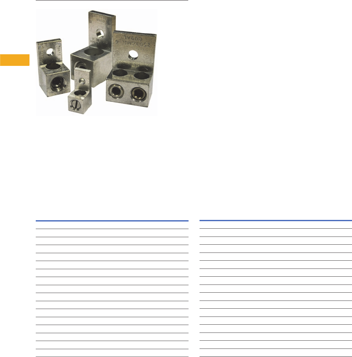
V1-T5-34 Volume 1—Residential and Light Commercial CA08100002E—February 2014 www.eaton.com
5
5
5
5
5
5
5
5
5
5
5
5
5
5
5
5
5
5
5
5
5
5
5
5
5
5
5
5
5
5
5.7
Metering Products
Mechanical Lugs
Mechanical Lugs
Contents
Description
Mechanical Lugs
Product Description
●Single lug
●Extended tang single lug
●Extended tang triple lug
●Double lug
●Extended tang double lug
●Extended tang quadruple
lug
Product Selection
Mechanical Lugs
Description Style Number
Single #14–#6 mechanical lug ESL146
Single #14–2/0 mechanical lug ESL1420
Single #6–250 kcmil mechanical lug ESL6250
Single #4–500 kcmil mechanical lug ESL4500
Double #14–2/0 mechanical lug EDL1420
Double #6–250 kcmil mechanical lug EDL6250
Extended tang single lug #6–350 kcmil EPBSL6350
Extended tang single lug 300–800 kcmil EPBSL300800
Extended tang double lug #6–350 kcmil EPBDL6350
Extended tang double lug 300–800 kcmil EPBDL300800
Extended tang triple lug #6–350 kcmil EPBTL6350
Extended tang triple lug 300–800 kcmil EPBTL300800
Extended tang quadruple lug #6–350 kcmil EPBQL6350
Extended tang quadruple lug 300–750 kcmil EPBQL300800
Extended tang single lug #2–600 kcmil EPBSL2600
Extended tang single lug 500–1000 kcmil EPBSL5001000
Extended tang triple lug #2–600 kcmil EPBTL2600
Dimensions
Approximate Dimensions in Inches (mm)
Mechanical Lugs
Style Number Height Width Length
ESL146 2.50 (63.5) 8.25 (82.6) 3.50 (88.9)
ESL1420 2.50 (63.5) 10.50 (266.7) 3.50 (88.9)
ESL6250 2.50 (63.5) 10.50 (266.7) 3.50 (88.9)
ESL4500 2.50 (63.5) 10.50 (266.7) 3.50 (88.9)
EDL1420 3.50 (88.9) 4.00 (101.6) 3.50 (88.9)
EDL6250 3.50 (88.9) 3.75 (95.3) 4.50 (114.3)
EPBSL6350 2.50 (63.5) 8.25 (82.6) 3.50 (88.9)
EPBSL300800 2.50 (63.5) 10.50 (266.7) 3.50 (88.9)
EPBDL6350 3.50 (88.9) 4.50 (114.3) 5.50 (139.7)
EPBDL300800 3.00 (76.2) 10.50 (266.7) 5.50 (139.7)
EPBTL6350 3.50 (88.9) 4.50 (114.3) 5.50 (139.7)
EPBTL300800 2.50 (63.5) 10.00 (254.0) 5.75 (146.0)
EPBQL6350 2.25 (57.2) 6.50 (165.1) 6.00 (152.4)
EPBQL300800 4.25 (108.0) 8.50 (215.9) 8.50 (215.9)
EPBSL2600 2.50 (63.5) 8.25 (82.6) 3.50 (88.9)
EPBSL5001000 2.50 (63.5) 10.50 (266.7) 3.50 (88.9)
EPBTL2600 2.25 (57.2) 6.50 (165.1) 6.00 (152.4)
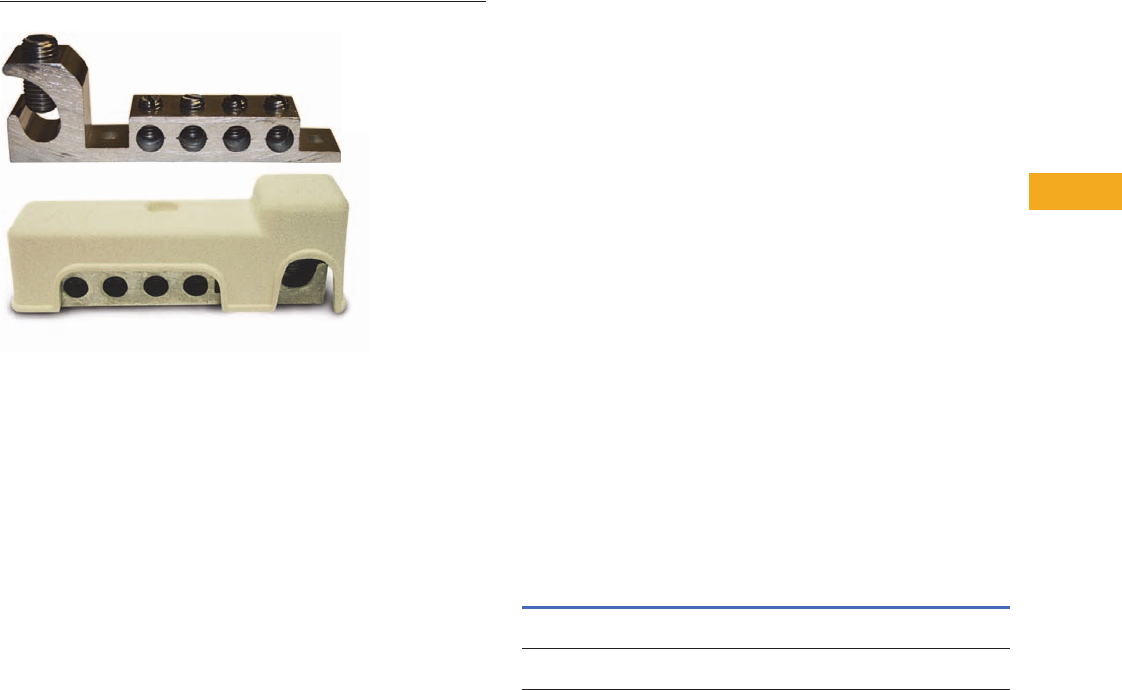
Volume 1—Residential and Light Commercial CA08100002E—February 2014 www.eaton.com V1-T5-35
5
5
5
5
5
5
5
5
5
5
5
5
5
5
5
5
5
5
5
5
5
5
5
5
5
5
5
5
5
5
5.8
Metering Products
Communications Grounding Device (NEC 250.94)
Communication Grounding Device
Contents
Description Page
Wiring Diagram . . . . . . . . . . . . . . . . . . . . . . . . . . . V1-T5-36
Dimensions . . . . . . . . . . . . . . . . . . . . . . . . . . . . . . V1-T5-36
Product Description
This product is required per
the 2008 NEC Article 250.94
“Bonding for Other Systems.”
This product is applied
externally to residential
homes, so that
communications systems
devices such as satellite,
TV, cable and CATV can be
properly bonded at a single
point. This device has two
mounting holes that can be
used for easy installation.
Features, Benefits
and Functions
Communication Grounding
Device Features
●Lay-in lug for ease
of installation
●Four bonding terminals
●Heavy-duty zinc-plated
steel screws included
●Two mounting holes to
securely hold device
into place
●For use with copper and
aluminum conductors
Cover Features
●Outdoor rated reinforced
glass polyester compound
●Suitable for UV exposure
●Paintable exterior, allowing
for matching of exterior of
home
Standards and
Certifications
●ETL listed
Product Selection
Communication Grounding Device
Wire Range
Bonding
Conductor
Ground
Electrode Quantity
Catalog
Number
#14–#2–STR–SOL–CU
#12–#2–SRT–SOL–AL
#8–1/0–STR–SOL–CU/AL (1) Clamshell MSEGR2CS
#14–#2–STR–SOL–CU
#12–#2–SRT–SOL–AL
#8–1/0–STR–SOL–CU/AL (10) Bulk pack MSEGR2
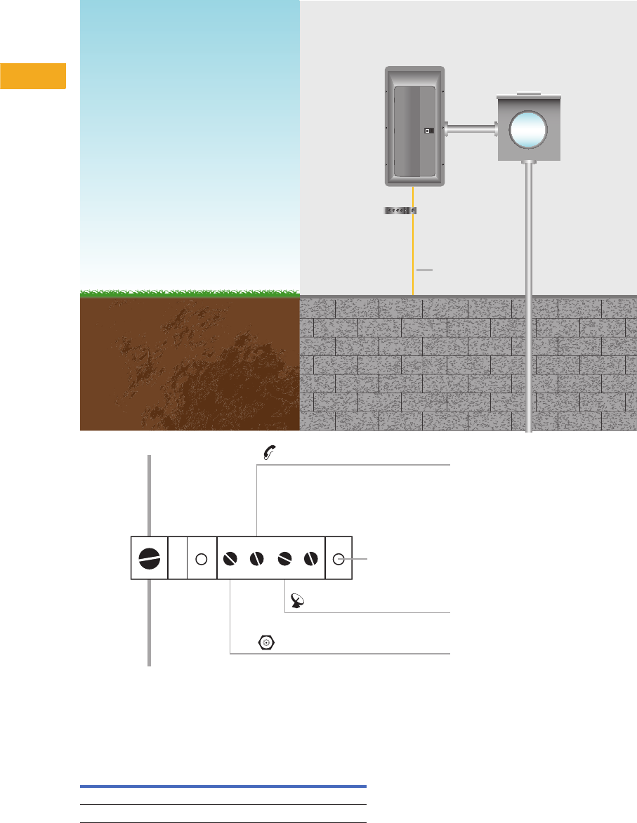
V1-T5-36 Volume 1—Residential and Light Commercial CA08100002E—February 2014 www.eaton.com
5
5
5
5
5
5
5
5
5
5
5
5
5
5
5
5
5
5
5
5
5
5
5
5
5
5
5
5
5
5
5.8
Metering Products
Communications Grounding Device (NEC 250.94)
Wiring Diagram
Installation and Configuration
Dimensions
Approximate Dimensions in Inches (mm)
Communication Grounding Device
Service Entrance Panel
Single Meter Socket
Communication
Grounding Device
(Top View)
Grounding Electrode
Conductor
Phone System Ground
Grounding
Electrode
Conductor
Communication Grounding Device
(Top view)
Satellite TV Ground
Coax Cable Ground
Mounting Holes
(Typical)
Catalog Number Length Width Height
MSEGR2CS 0.75 (19.1) 3.90 (99.1) 1.20 (30.5)
MSEGR2 0.75 (19.1) 3.90 (99.1) 1.20 (30.5)

Volume 1—Residential and Light Commercial CA08100002E—February 2014 www.eaton.com V1-T5-37
5
5
5
5
5
5
5
5
5
5
5
5
5
5
5
5
5
5
5
5
5
5
5
5
5
5
5
5
5
5
5.9
Metering Products
Meter Breakers
Residential Meter Breakers
Contents
Description Page
Residential Meter Breakers
Non-EUSERC Combination Service Entrance
Devices 100–200A Styles . . . . . . . . . . . . . . . . . . V1-T5-39
Meets EUSERC Requirements Service Entrance
Devices 100–225A . . . . . . . . . . . . . . . . . . . . . . . V1-T5-48
West Coast All-In-One Design. . . . . . . . . . . . . . . . V1-T5-59
Mechanical Interlock Cover . . . . . . . . . . . . . . . . . . V1-T5-65
House Panels . . . . . . . . . . . . . . . . . . . . . . . . . . . . V1-T5-75
Commercial Safety Sockets. . . . . . . . . . . . . . . . . . V1-T5-83
CH Style Renovation Solutions . . . . . . . . . . . . . . . V1-T5-86
Aluminum Meter Breakers . . . . . . . . . . . . . . . . . . V1-T5-87
Residential Meter Breakers
Product Description
A meter breaker is service
entrance equipment that
consists of a single meter
socket and loadcenter (circuit
breaker distribution section)
or meter socket and main
breaker combined in one
enclosure. Sometimes called
Combos, All-in-Ones, Meter
Centers or Meter Mains,
these units are increasing in
popularity as the socket and
loadcenter or main breaker
are located in one location,
thus providing the contractor
with a labor and material
savings when installing.
Application Description
In addition to residential
installations, meter breakers
are equally applicable for rural
service entrance, mobile
homes and construction site
temporary power. Meter
breakers are most often sold
in the western, southwestern
and southeastern United
States. The popularity of
meter breakers is continuing
to increase as more utilities
deregulate and pass the
responsibility of supplying
watthour meter sockets on
to the electrical contractor.
Application Considerations
Eaton has the meter breaker
to meet your application,
offering:
●Non-EUSERC
●EUSERC/West Coast
●House panels
●Commercial safety socket
Non-EUSERC
(Page V1-T5-39)
Eaton’s line of non-EUSERC
meter breakers are designed
for customers served by
utilities that are not members
of EUSERC.
EUSERC/West Coast
(Page V1-T5-59)
Eaton’s line of EUSERC
required devices adhere to
the agreed upon standards.
EUSERC utilities are
predominately located in
the western United States,
but some eastern and
midwestern utilities are
also members. These units
can also be used in many
Non-EUSERC areas.
House Panels
(Page V1-T5-75)
CH and BR Styles
(Page V1-T5-76).
Meter breaker device rated
at 300–400A. Applied in
EUSERC and non-EUSERC
areas.
Commercial Safety Sockets
(Page V1-T5-83)
Applied in EUSERC and
non-EUSERC service areas
and used in commercial
applications.
Features, Benefits
and Functions
●Both Type BR and CH
branch circuit breaker
styles available
●Meets latest NEC
wire bending space
requirements
●Slotted sealing screws
at hub with sealing
provision provided
●Surface units are supplied
with mounting tabs
●Semi-flush units are
supplied with stucco flange
●Meter socket ring
landing will accept
locking security rings
●Overhead or underground
service
●Fifth jaw can be installed in
the 3 o’clock or 9 o’clock
position
●Semi-flush with nail flange
or surface mounting
●Meter mounting and
underground pull sections
are utility sealable
●Units are rated a minimum
of 10 kAIC; some units
are 22 kAIC
●Numerous units supplied
with center keyhole for
ease of mounting
●NEMA 3R rainproof
construction

V1-T5-38 Volume 1—Residential and Light Commercial CA08100002E—February 2014 www.eaton.com
5
5
5
5
5
5
5
5
5
5
5
5
5
5
5
5
5
5
5
5
5
5
5
5
5
5
5
5
5
5
5.9
Metering Products
Meter Breakers
Standards and Certifications
●UL Specification 414
(socket)
●UL File Number E52977
●AEIC-EEI-NEMA Standards
(MSJ-7)
●Meet EUSERC utility
requirements where noted
●Documented seismic
qualified—UBC® and
CBC Title 24
●UL Specification 67 (panel)
Technical Data
and Specifications
●Ratings single-phase,
three-wire, 120/240 Vac
●100–225A main breaker
and main lug types
●10,000A rms symmetrical
short-circuit rating
●Available kAIC ratings:
10k with BW breaker,
22k with CSR breaker
and 35k with CSH breaker
Consult TD.31F.01.T.E for
dimensions, wiring diagrams
and knockouts.
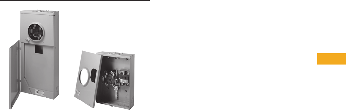
Volume 1—Residential and Light Commercial CA08100002E—February 2014 www.eaton.com V1-T5-39
5
5
5
5
5
5
5
5
5
5
5
5
5
5
5
5
5
5
5
5
5
5
5
5
5
5
5
5
5
5
5.9
Metering Products
Meter Breakers
Standard Design Non-EUSERC Panel Compact Design
Residential Meter Breakers
Contents
Description Page
Residential Meter Breakers. . . . . . . . . . . . . . . . . . V1-T5-37
Non-EUSERC Combination Service Entrance
Devices 100–200A Styles
Meets EUSERC Requirements Service Entrance
Devices 100–225A . . . . . . . . . . . . . . . . . . . . . . . V1-T5-48
West Coast All-In-One Design. . . . . . . . . . . . . . . . V1-T5-59
Mechanical Interlock Cover . . . . . . . . . . . . . . . . . . V1-T5-65
House Panels . . . . . . . . . . . . . . . . . . . . . . . . . . . . V1-T5-75
Commercial Safety Sockets . . . . . . . . . . . . . . . . . V1-T5-83
CH Style Renovation Solutions . . . . . . . . . . . . . . . V1-T5-86
Aluminum Meter Breakers . . . . . . . . . . . . . . . . . . V1-T5-87
Non-EUSERC Combination Service Entrance Devices
100–200A Styles
Product Description
A device that may include a
meter socket, main breaker
and loadcenter section within
the same enclosure.
●Meter main = meter socket
and main breaker
●Meter breaker = meter
socket, main breaker and
loadcenter section
Application Description
Eaton’s line of non-EUSERC
meter breakers are designed
for customers served by
utilities that are not members
of EUSERC.
Features, Benefits and Functions
Meter Mains and All-in-Ones
●Single-phase, three-wire,
120/240 Vac,10 kAIC
●Larger lay-in lugs and 3-inch
(76.2 mm) knockouts for
ease of installation
●Box-type main lugs
included
●Factory-installed neutral
●Hub provisions on top
endwall. If hubs are
required, order “DS” style
●Ring, ringless and ringless
with horn bypass styles
available
●Ringless style, provided
with embossed covers and
security latch for utility
company lock
●Padlockable device covers
provide additional measure
of safety and help prevent
tampering
●NEMA 3R rainproof
construction
Meter Mains
●Meter socket and
main breaker
●Stainless steel latches on
meter compartments in
MBP types
●No distribution section
included
All-in-Ones
●Meter socket and
loadcenter distribution
section
●Stainless steel latches on
meter compartments
●Several designs with horn
bypass and fifth jaw
●Center-fed main breaker,
lugs or provision
●Uses Type BR 1-inch
(25.4 mm) wide branch
breakers
●Special channel for top exit
V1-T5-40 Volume 1—Residential and Light Commercial CA08100002E—February 2014 www.eaton.com
5
5
5
5
5
5
5
5
5
5
5
5
5
5
5
5
5
5
5
5
5
5
5
5
5
5
5
5
5
5
5.9
Metering Products
Meter Breakers
Catalog Number Selection
Spacing
Number of spaces
Accessories/Modifications
D = 5th jaw and horn bypass
CU = Copper
C = Single cover compact design
CR = Two cover compact design
Amperes
Amperage of unit
Main
B= Main breaker included
P= Provision for main
L= Main lug
Poles
Maximum number of poles
Breaker Feed
BT = Bottom and top
B = Bottom only
T = Top only
Mounting
S= Surface
F= Flush/stucco
MB 20 40 B 200 BT S
Meter Breaker Type
MB = 1-inch BR Type
MBE = 1-inch BR Type—EUSERC
CMB = 3/4-Inch (19.1 mm) CH Type
CMBE = 3/4-inch (19.1 mm) CH Type—
EUSERC
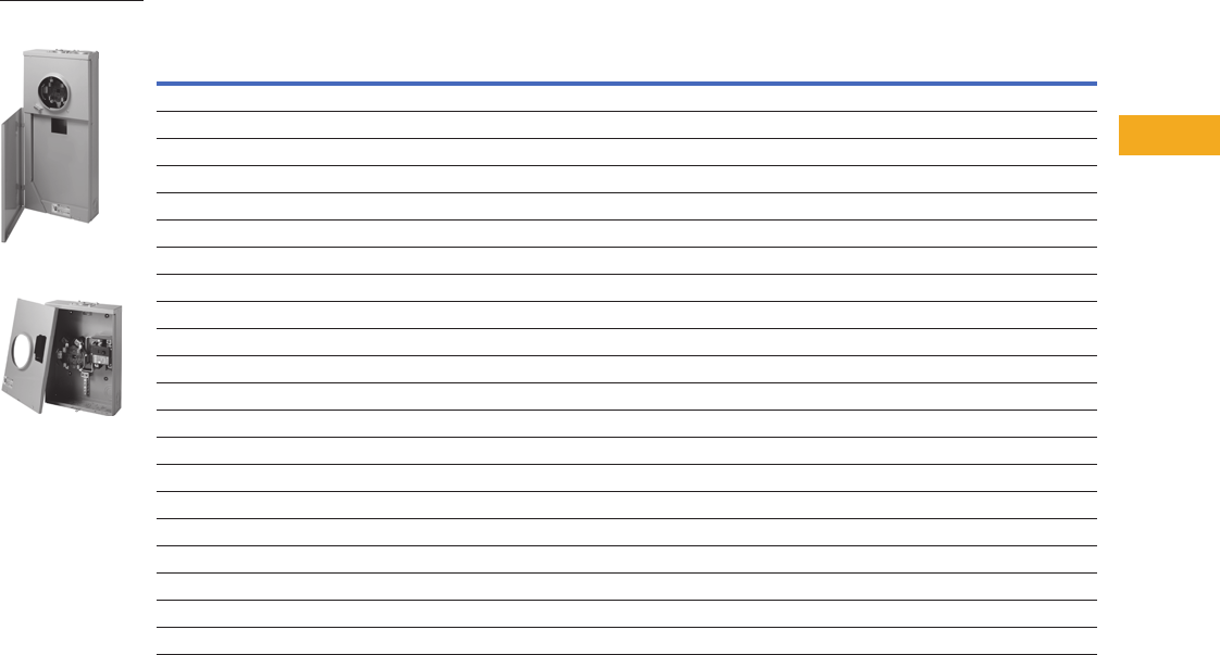
Volume 1—Residential and Light Commercial CA08100002E—February 2014 www.eaton.com V1-T5-41
5
5
5
5
5
5
5
5
5
5
5
5
5
5
5
5
5
5
5
5
5
5
5
5
5
5
5
5
5
5
5.9
Metering Products
Meter Breakers
Product Selection
Note: See knockout drawings on Pages V1-T5-68 through V1-T5-74 for hub information.
Combination Service Entrance Devices—Non-EUSERC
Notes
1 See Page V1-T5-68 for box details.
2 Per installed main breaker rating.
3 When a provision for main is provided, order one of the main breakers listed in Page V1-T5-43. Panels are dual labeled to accept
Types BW, CSR or CSH Main Breakers.
4 MCBK225 lug kit is needed for load side cable connection for Meter Mains. Please order separately.
5 When a provision for main is provided, order one of the main breakers listed in this table. Panels are labeled to accept Type CSR Main Breakers.
6 Copper bus.
7 One-piece cover on utility side, Florida approved.
8 Single cover design.
9 Xcel approved.
Ampere
Rating Bypass Service kAIC Jaws Distribution Main
Branch
Breaker
Type
Dimensions
and Enclosure
Shape 1
Page Numbers
Catalog
NumberWiring Knockout 1
Ring Style Meter Mains (no distribution section included)
150 None OH/UG 10 4 None CSH2150 None 13 V1-T5-46 V1-T5-74 MBB150BTSCR
150 None OH/UG 22 4 None CSH2150 None 3 V1-T5-43 V1-T5-70 CMBB150BTS 67
200 None OH/UG 10 4 None CSH2200 None 13 V1-T5-46 V1-T5-74 MBB200BTSCR
200 None OH/UG 24 None Provision 45 None 3 V1-T5-43 V1-T5-70 CMBP200BTS 67
200 None OH/UG 22 4 None CSH2200 None 3 — V1-T5-70 CMBB200BTS 67
Ringless Meter Mains (no distribution section included)
150 None OH/UG 10 4 None CSH2150 None 13 V1-T5-46 V1-T5-74 MBB150BTSC 7
200 None OH/UG 10 4 None CSH2200 None 9 V1-T5-47 V1-T5-74 MBB200BTS 8
200 None OH/UG 10 4 None CSH2200 None 13 V1-T5-46 V1-T5-74 MBB200BTSC 7
150 None OH/UG 10 4 None CSH2125 None 9 V1-T5-47 V1-T5-74 MBB150BTS
200 None OH/UG 24 None Provision 3None 9 V1-T5-47 V1-T5-74 MBP200BTS 7
200 Horn OH/UG 25 None Provision 34 None 11 V1-T5-45 V1-T5-74 MBP200SD
200 Horn OH/UG 25 None Provision 34 None 9 V1-T5-47 V1-T5-74 MBP200BTSD
100 Horn OH/UG 10 5 None Provision None 15 — V1-T5-74 CHMMB100BTS
150 Horn OH/UG 10 5 None CSR2150 None 16 — V1-T5-74 CHMMB150BTS
200 Horn OH/UG 10 5 None CSR2200 None 16 — V1-T5-74 CHMMB200BTS
150 None OH/UG 10 4 4/8 CSR BR — — — MB48B150TSG
200 None OH/UG 10 4 4/8 CSR BR — — — MB48B200BTSG
200 Lever OH/UG 22 4 8/16 CSR BR — — — MBX816B200BTS
200 Lever OH/UG 22 4 20/40 CSR BR — — — MBX2040B200BTS
Standard Design
Non-EUSERC Panel
Compact Design

V1-T5-42 Volume 1—Residential and Light Commercial CA08100002E—February 2014 www.eaton.com
5
5
5
5
5
5
5
5
5
5
5
5
5
5
5
5
5
5
5
5
5
5
5
5
5
5
5
5
5
5
5.9
Metering Products
Meter Breakers
Note: See knockout drawings on Pages V1-T5-68 through V1-T5-74 for hub information.
Combination Service Entrance Devices—Non-EUSERC, continued
Notes
1See Page V1-T5-68 for box details.
2Per installed main breaker rating.
3Will accept maximum four single-pole, two-pole, or two quad breakers.
4
When a provision for main is provided, order one of the main breakers listed on
Page V1-T5-43
. All panels are dual labeled to accept Types BW, CSR, CSH Main Breakers.
5Copper bus.
6One-piece cover on utility side, Florida approved.
7Units come with feed-through lugs.
8Xcel approved.
Ampere
Rating Bypass Service kAIC Jaws Distribution Main
Branch
Breaker
Type
Dimensions
and Enclosure
Shape 1
Page Numbers
Catalog
NumberWiring Knockout 1
Ring Style All-in-Ones (includes distribution section)
125 None OH/UG 24 2/4 None—refer
to Distribution
CSH2150
CH 2 V1-T5-43 V1-T5-70 CMB24L125BTS 56
150 None OH/UG 22 4 8 CH 3 V1-T5-44 V1-T5-70 CMB88B150BTS 56
200 None OH/UG 10 4 4/8 CSR2200 BR 3 V1-T5-44 V1-T5-70 MB48B200BTS 67
200 None OH/UG 22 4 8 CSH2200 CH 3 V1-T5-44 V1-T5-70 CMB88B200BTS 567
200 None UG 22 4 32/42 CSH2200 CH 7 V1-T5-43 V1-T5-69 CMB3242B200BS 56
200 None OH/UG 22 — 42/42 — CH — — — CMB4242B200BTS 5
Ringless All-in-Ones (includes distribution section)
125 None OH/UG 22 4 4/8 CSR2125 BR 21 — V1-T5-73 MBT48B125BTS
150 None OH/UG 22 4 4/8 CSR2150 BR 21 V1-T5-46 V1-T5-73 MBT48B150BTS
150 Horn OH/UG 10 5 8/16 BW2150 BR 11 — — MB816B150STD 8
150 Horn OH/UG 10 5 20/40 BW2150 BR 11 V1-T5-47 V1-T5-74 MB2040B150SD 8
200 None OH/UG 10 4 8/16 CSR2200 BR 10 V1-T5-46 V1-T5-74 MB816B200BTS 67
200 None OH/UG 10 4 8/16 CSR2200 BR 10 V1-T5-46 V1-T5-74 MB816B200BTSCU 567
200 Horn OH/UG 10 5 8/16 BW2200 BR 11 — — MB816B200STD 8
200 None OH/UG 248/16 Provision
4BR 10 V1-T5-46 V1-T5-74 MB816P200BTS 67
200 None OH/UG 248/16 Provision
4BR 10 V1-T5-46 V1-T5-74 MB816P200BTSCU 567
200 Horn OH/UG 258/16 Provision
4BR 11 V1-T5-46 V1-T5-74 MB816P200STD 78
200 Horn OH/UG 258/16 Provision
4BR 10 V1-T5-46 V1-T5-74 MB816P200BTSD 7
200 None OH/UG 10 4 12/12 CSH2200 CH 10 V1-T5-44 V1-T5-70 CMB1212B200BTS 567
200 None OH/UG 24 6–2 Pole Main lugs CH 9 V1-T5-45 V1-T5-71 CMB1212L200BTS 57
200 None OH/UG 24 12/12 Provision 4CH 10 V1-T5-45 V1-T5-71 CMB1212P200BTS 567
200 None OH/UG 24 6–2 Pole Main lugs BR 9 V1-T5-44 V1-T5-71 MB1212L200BTS 7
200 None OH/UG 22 4 24/24 CSH2200 CH 10 V1-T5-44 V1-T5-74 CMB2424B200BTS 56
200 None OH/UG 22 4 24/36 CSH2200 CH 10 V1-T5-45 V1-T5-74 CMB2436B200BTS 5
200 None OH/UG 10 4 20/40 CSR2200 BR 10 V1-T5-47 V1-T5-74 MB2040B200BTS 6
200 None OH/UG 24 20/40 Provision 4BR 10 V1-T5-47 V1-T5-74 MB2040P200BTS 6
200 Horn OH/UG 25 20/40 Provision 4BR 11 V1-T5-47 V1-T5-74 MB2040P200SD 8
200 Horn OH/UG 10 5 20/40 CSR2200 BR 10 V1-T5-47 V1-T5-74 MB2040B200SD 8
200 Lever OH/UG 10 5 None CSH2200 None 14 V1-T5-45 V1-T5-73 CMBXB200BTS 5
200 Lever OH/UG 10 5 12/12 CSH2200 CH 14 V1-T5-45 V1-T5-73 CMBX1212B200BTS 57
200 Lever OH/UG 10 5 32/42 CSH2200 CH 14 V1-T5-46 V1-T5-73 CMBX3242B200BTS 5
200 Lever OH/UG 10 5 None Provision None 14 V1-T5-45 V1-T5-73 CMBXP200BTS 5
200 Lever OH/UG 10 5 12/12 Provision CH 14 V1-T5-45 V1-T5-73 CMBX1212P200BTS 57
200 Lever OH/UG 10 5 32/42 Provision CH 14 V1-T5-46 V1-T5-73 CMBX3242P200BTS 5
200 None OH/UG 24 4/8 Provision BR 21 V1-T5-46 V1-T5-73 MBT48P200BTS 7
200 None OH/UG 22 4 4/8 CSR2200 BR 21 V1-T5-46 V1-T5-73 MBT48B200BTS 7
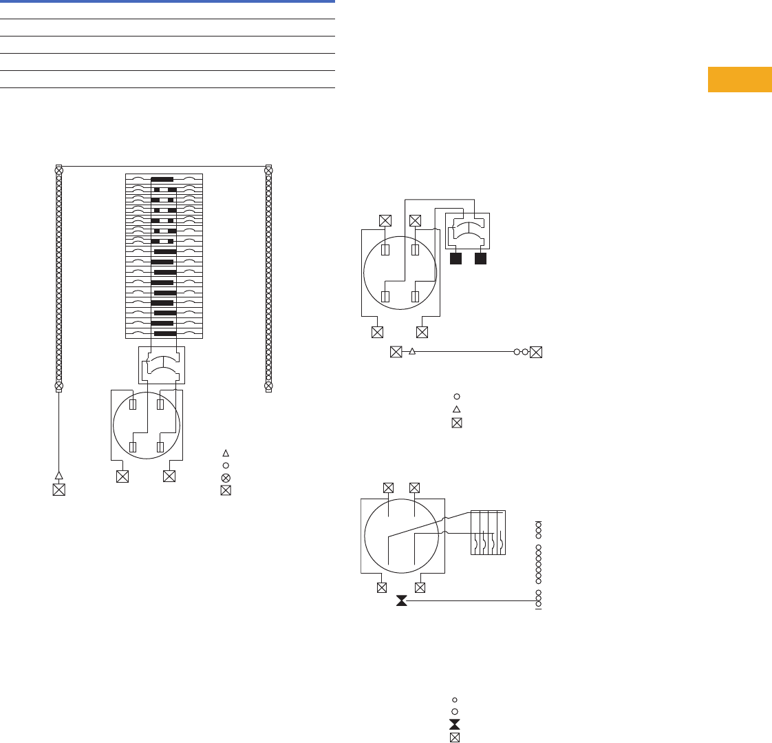
Volume 1—Residential and Light Commercial CA08100002E—February 2014 www.eaton.com V1-T5-43
5
5
5
5
5
5
5
5
5
5
5
5
5
5
5
5
5
5
5
5
5
5
5
5
5
5
5
5
5
5
5.9
Metering Products
Meter Breakers
Main Breaker Selection Chart
Wiring Diagrams
Catalog Number—CMB3242B200BS 47a. Catalog Numbers—CMBP200BTS, CMBB150BTS 47c.
Catalog Number—CMB24L125BTS 47d.
Notes
1When a provision for main is provided, order one of the main breakers listed in this table.
All panels are dual labeled to accept Types BW, CSR and CSR Main Breakers.
2Factory-installed MCBK225 Kit for C/B load lugs.
Maximum
Ampere
Rating
Two-Pole Breaker Catalog Numbers
10 kAIC 25 kAIC 25 kAIC 35 kAIC
100 BW2100 CSR2100 CSR2100N CSH2100N
125 BW2125 CSR2125 CSR2125N CSH2125N
150 BW2150 CSR2150 CSR2150N CSH2150N
200 BW2200 CSR2200 CSR2200N CSH2200N
Load Side Lug Kit for BW and CSR Breakers 1MCBK225
#14-2 AWG
#14-4 AWG
#6-2/0 AWG
#6-250 AWG
Wiring Diagram Key
Service Disconnect
Type CSR
N
Bonded
Neutral
Bonded
Neutral
1
2
3
4
5
6
7
8
9
10
11
12
13
14
15
16
17
18
19
20
21
22
23
24
25
26
27
28
29
30
31
32
33
34
35
36
37
38
39
40
41
42
Line
AB
AB
Bonded
Neutral
Line
N
AB
Install 200 Ampere Maximum
Service Disconnect Type CSR 2
Wiring Diagram Key
#14-2/0 AWG
#14-2 AWG
#6-250 AWG
AB
Bonded
Neutral
Line
N
AB
#14-1/0 AWG
#14-6 AWG
#14-1/0 AWG
#6-250 AWG
1234
Wiring Diagram Key
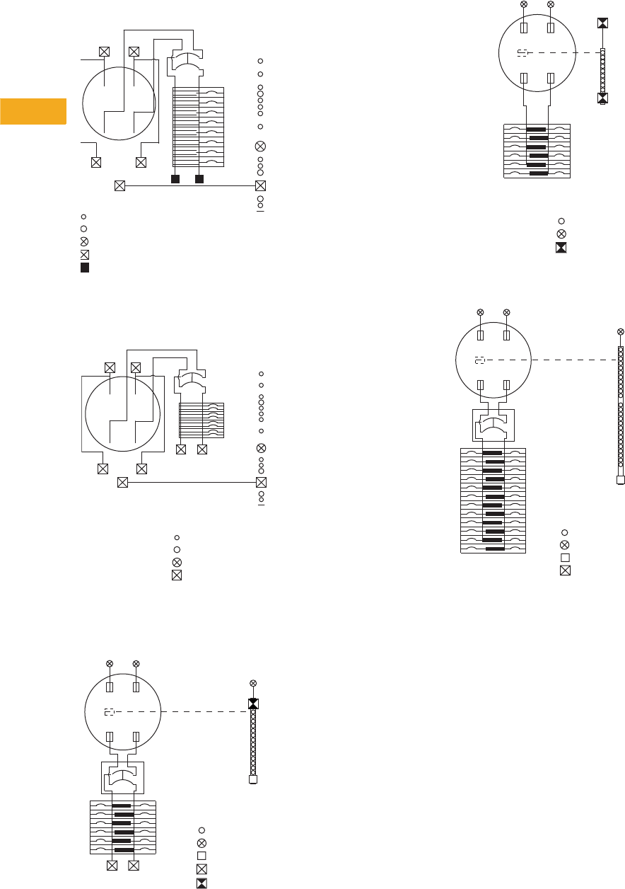
V1-T5-44 Volume 1—Residential and Light Commercial CA08100002E—February 2014 www.eaton.com
5
5
5
5
5
5
5
5
5
5
5
5
5
5
5
5
5
5
5
5
5
5
5
5
5
5
5
5
5
5
5.9
Group Metering and Meter Breakers
Meter Breakers
Catalog Numbers—CMB88B200BTS, CMB88B150BTS 48a.
Catalog Number—MB48B200BTS 48c.
Catalog Number—CMB1212B200BTS 48d.
Catalog Number—MB1212L200BTS 48e.
Catalog Number—CMB2424B200BTS 48f.
AB
1
2
3
4
AB
5
6
7
8
Wiring Diagram Key
#14-1/0 AWG
#14-6 AWG
#6-2/0 AWG
#6-250 AWG
#4-300 AWG
Service Disconnect
Type CSR 200 Ampere Maximum
Bonded Neutral
Line
N
AB
200A Maximum
Service Disconnect
Type BW or CSR
4
6
8
AB
3
5
7
1
2
L2
L1 Bonded
Neutral
Line
N
#14-1/0 AWG
#14-6 AWG
#6-2/0 AWG
#6-250 AWG
Wiring Diagram Key
5th Jaw Factory Installed
on CMB1212B200BTSD and
CMB1212P200BTSD Only
1
3
5
7
9
11
200 Ampere
Maximum
Service Disconnect
Type CSR or CSH
Bonded
Neutral
Line
N
AB
2
4
6
8
10
12
#14-4 AWG
#6-350 kcmil
#6-2/0 AWG
#4-300 kcmil
#6-300 kcmil
Wiring
Diagram Key
1
3
5
7
9
11
Bonded
Neutral N
AB
Ground Bar
#14-2/0 AWG
#6-350 kcmil
#6-300 kcmil
2
4
6
8
10
12
Wiring
Diagram Key
1
3
5
7
9
11
13
15
17
19
21
23
#14-4 AWG
#6-350 kcmil
#6-2/0 AWG
#4-300 kcmil
200 Ampere
Maximum
Service Disconnect
Type CSR
Bonded
Neutral
Line
N
AB
2
4
6
8
10
12
14
16
18
20
22
24
Wiring
Diagram Key
Volume 1—Residential and Light Commercial CA08100002E—February 2014 www.eaton.com V1-T5-45
5
5
5
5
5
5
5
5
5
5
5
5
5
5
5
5
5
5
5
5
5
5
5
5
5
5
5
5
5
5
5.9
Group Metering and Meter Breakers
Meter Breakers
Catalog Number—CMB1212L200BTS 49a.
Catalog Number—CMB2436B200BTS 49b.
Catalog Numbers—MBP200SD, CMBXB200BTS,
CMBXP200BTS 49c.
Catalog Numbers—CMB1212B150BTS, CMBX1212B200BTS,
CMB1212B200BTS, CMB1212P200BTS, CMBX1212P200BTS 49d.
1
3
5
7
9
11
N
Bonded
Neutral
AB
#14-4 AWG
#6-350 kcmil
#6-2/0 AWG
#6-300 kcmil
5th Jaw Factory Installed
on CMB1212L200BTSD Only
2
4
6
8
10
12
Wiring
Diagram Key
200A Max.
Service Disconnect
Type CSR or CSH
Bonded
Neutral
ABLine
N
20
19
21
22
23
1
2
3
4
6
5
2425
27
26
29
28
31
30
33
32
35
34
36
7
98
11
10
1312
1514
17
16
18
Maximum of 12 twin
Breakers as Shown
#14-4 AWG
#6-350 kcmil
#6-2/0 AWG
#4-300 kcmil
Wiring
Diagram Key
#6-2/0 AWG
#6-350 kcmil
#1-300 kcmil
#6-300 kcmil
Wiring
CMBXB200BTS
factory installed
200A Max Service
Disconnect type CSR
MBP200SD
install 200A Max
Service Disconnect
Type BW or CSR
CMBXB200BTS &
CMBXP200BTS
included lever by
pass meter socket
Line N
AB
Diagram Key
5th Jaw Factory Installed
CMBX1212B200BTS &
CMBX1212P200BTS include
lever bypass meter socket
on CMB1212B200BTSD and
CMB1212P200BTSD Only
1
3
5
7
9
11
200 Ampere
Maximum
Service Disconnect
Type CSR or CSH
Bonded
Neutral
Line
N
AB
2
4
6
8
10
12
#14-4 AWG
#6-350 kcmil
#6-2/0 AWG
#4-300 kcmil
#6-300 kcmil
Wiring
Diagram Key
V1-T5-46 Volume 1—Residential and Light Commercial CA08100002E—February 2014 www.eaton.com
5
5
5
5
5
5
5
5
5
5
5
5
5
5
5
5
5
5
5
5
5
5
5
5
5
5
5
5
5
5
5.9
Group Metering and Meter Breakers
Meter Breakers
Catalog Numbers—MBT48B200BTS, MBT48P200BTS,
MBT48B150BTS, MBT48P150BTS 50a.
Catalog Numbers—CMBX3242P200BTS,
CMBX3242B200BTS 50b.
Catalog Numbers—MBB150BTSC, MBB150BTSCR,
MBB200BTSCR and MBB200BTSC 50c.
Catalog Numbers—MB816P200STD, MB816B200BTS,
MB816B200BTSCU, MB816P200BTS, MB816P200BTSCU
and MB816P200BTSD 50d.
12345678#6-2/0 AWG
#6-350 kcmil
#1-300 kcmil
#6-300 kcmil
Wiring
Factory or Field
installed. 15A or
200A Max. Service
Disconnect
Line N
AB
Diagram Key
1
3
5
7
9
11
13
15
17
19
21
23
25
27
2931
3335
39
37
2
4
6
8
10
12
14
16
18
20
24
28
22
32
26
3638
34
30
40
42
41
#14-4 AWG
#6-350 kcmil
#6-2/0 AWG
#6-300 kcmil
Wiring
Line N
Bonded/
Neutral
CMBX3242P200BTS
200 A Max.
Service Disconnect
Type CSR or CSH
(not included)
CMBX3242B200BTS
200 A Max.
Service Disconnect
Factory Installed
Type CSR or CSH
Maximum of
10 Twin Breakers
as shown
AB
Diagram Key
Includes Lever
Bypass Meter
Socket
AB
200A
Maximum
Service Disconnect
Type CSR
Bonded
Neutral
Line N
#6-2/0 AWG
#6-350 kcmil
#6-250 kcmil
#1-300 kcmil
Included in
MBB150BTSCR
Wiring Diagram Key
AB
1
3
2
4
5
7
6
8
9
11
10
12
13
15
14
16
#14-4 AWG
#6-350 kcmil
#6-2/0 AWG
#6-300 kcmil
#6-300 kcmil
Line
N
Bonded
Neutral
200A
Maximum
Service
Disconnect
Type BW or CSR
Wiring Diagram Key
Volume 1—Residential and Light Commercial CA08100002E—February 2014 www.eaton.com V1-T5-47
5
5
5
5
5
5
5
5
5
5
5
5
5
5
5
5
5
5
5
5
5
5
5
5
5
5
5
5
5
5
5.9
Group Metering and Meter Breakers
Meter Breakers
Catalog Numbers—MBB150BTS, MBP200SD, MBB200BTS,
MBP200BTS, MBP200BTSD, CMBXB200BTS and
CMBXP200BTS 51a.
Catalog Numbers—MB2040P200SD, MB2040B200BTS,
MB2040P200BTS, MB2040B150SD and MB2040B200SD 51b.
AB
#6-2/0 AWG
#6-350 kcmil
#1-300 kcmil
#6-300 kcmil
Line
N
Bonded
Neutral
200A Maximum
Service Disconnect
Type BW or CSR 1
Wiring Diagram Key
AB
1
3
2
4
5
7
6
8
9
11
10
12
13
15
14
16
17
19
18
20
21
23
22
24
25
27
26
28
29 30
33
35
34
36
37
39
38
40
31 32
Line
N
Bonded
Neutral
200A
Maximum
Service
Disconnect
Type BW or CSR
#14-4 AWG
#6-350 kcmil
#6-2/0 AWG
Wiring
Diagram Key
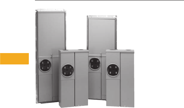
V1-T5-48 Volume 1—Residential and Light Commercial CA08100002E—February 2014 www.eaton.com
5
5
5
5
5
5
5
5
5
5
5
5
5
5
5
5
5
5
5
5
5
5
5
5
5
5
5
5
5
5
5.9
Metering Products
Meter Breakers
Meets EUSERC Requirements Service Entrance Devices 100–225A
Residential Meter Breakers
Contents
Description Page
Residential Meter Breakers . . . . . . . . . . . . . . . . . V1-T5-37
Non-EUSERC Combination Service Entrance
Devices 100–200A Styles. . . . . . . . . . . . . . . . . . V1-T5-39
Meets EUSERC Requirements Service Entrance
Devices 100–225A
West Coast All-In-One Design . . . . . . . . . . . . . . . V1-T5-59
Mechanical Interlock Cover . . . . . . . . . . . . . . . . . . V1-T5-65
House Panels . . . . . . . . . . . . . . . . . . . . . . . . . . . . V1-T5-75
Commercial Safety Sockets . . . . . . . . . . . . . . . . . V1-T5-83
CH Style Renovation Solutions . . . . . . . . . . . . . . . V1-T5-86
Aluminum Meter Breakers . . . . . . . . . . . . . . . . . . V1-T5-87
Meets EUSERC Requirements Service Entrance Devices
100–225A
Product Description
Eaton is proud to introduce
a new line of West Coast/
EUSERC Meter Breaker units.
The new EUSERC devices
complement the existing
standard meter breaker
devices. Customers who are
interested in the complete
meter breaker line of products
can refer to Technical Data
TD.31F.01.T.E.
Application Description
Eaton’s line of EUSERC
required devices adhere
to the agreed upon standards.
EUSERC utilities are
predominately located in the
western United States, but
some eastern and
midwestern utilities are
also members. These units
can also be used in many
Non-EUSERC areas.
Features, Benefits
and Functions
●Single-phase, three-wire,
120/240V, 10 kAIC
●Larger 250 kcmil lugs and
additional knockouts for
ease of installation
●Box type main lugs
are included
●Factory-installed neutrals
●Hub provisions on top
endwall. If hubs are
required, order “DS”
type hubs
●Ring type sockets are
provided with a sealing ring
●Padlockable device covers
provide an additional
measure of security and
help prevent tampering
●Most units have center
keyhole for easy one-
person installation
●NEMA 3R rainproof
construction
Volume 1—Residential and Light Commercial CA08100002E—February 2014 www.eaton.com V1-T5-49
5
5
5
5
5
5
5
5
5
5
5
5
5
5
5
5
5
5
5
5
5
5
5
5
5
5
5
5
5
5
5.9
Metering Products
Meter Breakers
Catalog Number Selection
Note
1Not available in CR.
Meter Breaker Type
MB = 1-inch (25.4 mm) BR Type
MBE = 1-inch (25.4 mm) BR Type—EUSERC
CMB = 0.75-inch (19.1 mm) CH Type
CMBE = 0.75-inch (19.1 mm) CH Type—EUSERC
MBED = 7-inch (177.8 mm) deep
MBER = 1-inch (25.4 mm) BR Type—EUSERC ranch
CMBER = 0.75-inch (19.1 mm) CH Type—EUSERC ranch
MBEB = 1-inch (25.4 mm) BR Type back-to-back
MBX = Xcel approved lever bypass meter breaker
MBE 20 40 B 200 B S
Amperes
Amperage of unit
Main
B = Main breaker included
P = Provision for main
L = Main lug
Poles
Maximum number of poles
Breaker Feed
BT = Bottom and top
B= Bottom only
T= Top only
Mounting
S = Surface
F = Flush/stucco
Last Digits
G= Suffix = GA PWE spec
R 1= Suffix = ECCN renovation
PV = Suffix = PV rated units
6= 2 x 6 construction
A= Aluminum enclosure
Spacing
Number of spaces
Accessories/Modifications
D = 5th jaw and horn bypass
CU = Copper
C = Single cover compact design
CR = Two cover compact design

V1-T5-50 Volume 1—Residential and Light Commercial CA08100002E—February 2014 www.eaton.com
5
5
5
5
5
5
5
5
5
5
5
5
5
5
5
5
5
5
5
5
5
5
5
5
5
5
5
5
5
5
5.9
Metering Products
Meter Breakers
Product Selection
Note: See knockout drawings on Pages V1-T5-68 through V1-T5-74 for hub information.
Combination Service Entrance Devices—EUSERC
Notes
1See Page V1-T5-68 for box details.
2Interrupting rating is dependent on the main breaker that is installed.
3Unit has copper bus.
4Units come with feed-through lugs.
5Please use RH-Type hubs on top end wall for overhead feed.
6Includes factory-mounted 2.50-inch hub on bottom endwall. UG feed only.
7Semi flush flange, not full stucco flange.
8Units include a two-pole provision for secondary main 70A max. Type BR, BRH, BRHH.
Ampere
Rating By-pass Service kAIC Jaws Distribution Main
Branch
Breaker
Type
Dimensions
and Enclosure
Shape
1
Page Numbers
Catalog
Number—Surface
Catalog
Number—Flush
Wiring Knockout
1
Ring Style Meter Mains (no distribution section included)
125 None OH/UG
2
42/4 MLO BR 2
V1-T5-55 V1-T5-70
MBE24L125BTS
MBE24L125BTF
125 None OH/UG
2
42/4 MLO CH 2
V1-T5-53 V1-T5-70
CMBE24L125BTS
3—
150 None OH/UG 22 4 None CSH2150N None 3
V1-T5-52 V1-T5-70
CMBEB150BTS
3—
200 None OH/UG 10 4 None CSR2200 None 3
V1-T5-56 V1-T5-70
MBEB200BTS
MBEB200BTF
200 None OH/UG 22 4 None CSH2200N None 3
V1-T5-52 V1-T5-70
CMBEB200BTS
3—
200 None OH/UG
2
42/4 MLO BR 3
V1-T5-56 V1-T5-70
MBE24L200BTS
MBE24L200BTF
200 None OH/UG
2
42/4 MLO CH 3
V1-T5-53 V1-T5-70
CMBE24L200BTS
3—
Ring Style All-in-Ones (includes distribution section)
100
None
OH/UG 10 4 12/24 BR2100 BR 2
V1-T5-53 V1-T5-70
MBE1224B100BTS
MBE1224B100BTF
100
None
UG 10 4 14/28 BR2100 BR 4
V1-T5-55 V1-T5-69
MBE1428B100BS
MBE1428B100BF
100
None
OH 10 4 12/24 BR2100 BR 9
V1-T5-58 V1-T5-71
MBE1224B100TS
—
125
None
OH/UG 10 4 12/24 BR2125 BR 2
V1-T5-53 V1-T5-70
MBE1224B125BTS
MBE1224B125BTF
125
None
OH 10 4 12/24 BR2125 BR 9
V1-T5-58 V1-T5-71
MBE1224B125TS
—
125
None
UG 10 4 18/36 BR2125 BR 5
V1-T5-54 V1-T5-69
— MBE1836B125BF
150
None
OH/UG
10 4 4/8 CSR2150 BR 19 ——
MBER48B150BTS
48 —
150
None
OH/UG
22 4 8/8 CSH2150N CH 19 ——
CMBER88B150BTS
348 —
150
None
OH/UG 22 4 8 CSH2150N CH 3
V1-T5-53 V1-T5-70
CMBE88B150BTS
34 CMBE88B150BTF 34
150
None
UG 22 4 32/42 CSH2150N CH 7
V1-T5-52 V1-T5-69
CMBE3242B150BS
3—
150
None
UG 10 4 20/40 CSR2150 BR 6
V1-T5-54 V1-T5-69
— MBE2040B150BF 5

Volume 1—Residential and Light Commercial CA08100002E—February 2014 www.eaton.com V1-T5-51
5
5
5
5
5
5
5
5
5
5
5
5
5
5
5
5
5
5
5
5
5
5
5
5
5
5
5
5
5
5
5.9
Metering Products
Meter Breakers
Note: See knockout drawings on Pages V1-T5-68 through V1-T5-74 for hub information.
Combination Service Entrance Devices—EUSERC, continued
Notes
1See Page V1-T5-68 for box details.
2Interrupting rating is dependent on the main breaker that is installed.
3Unit has copper bus.
4Units come with feed-through lugs.
5When a provision for main is provided, order one of the main breakers listed on Page V1-T5-68. All panels are dual labeled to accept Types BW or CSR Main Breakers.
6Please use RH-Type hubs on top end wall for overhead feed.
7Includes factory-mounted 2.50-inch hub on bottom endwall. UG feed only.
8Semi-flush flange, not full stucco flange.
9Units include a two-pole provision for secondary main 70A max. Type BR, BRH, BRHH.
Ampere
Rating
By-
pass Service kAIC Jaws Distribution Main
Branch
Breaker
Type
Dimensions
and
Enclosure
Shape
1
Page Numbers
Catalog
Number—Surface
Catalog
Number—Flush
Wiring Knockout
1
Ring Style All-in-Ones (includes distribution section), continued
150
None
OH/UG 22 4 20/40 CSR2150 BR —
V1-T5-55
—
MBE2040B150BTS
6—
150
None
OH/UG 10 4 4/8 CSR2150 BR 3
V1-T5-56 V1-T5-70
MBE48B150BTS
—
200
None
OH/UG 10 4 4/8 CSR2200 BR 3
V1-T5-56 V1-T5-70
MBE48B200BTS
4MBE48B200BTF 4
200
None
OH/UG 22 4 8 CSH2200N CH 3
V1-T5-53 V1-T5-70
CMBE88B200BTS
34 CMBE88B200BTF 34
200
None
OH/UG 10 4 8 CSR2200 BR 3
V1-T5-56 V1-T5-70
MBE88B200BTS
—
200
None
OH/UG
10 4 4/8 CSR2200 BR 19 V1-T5-58 V1-T5-73
MBER48B200BTS
48 —
200
None
OH/UG
10 4 4/8 CSR2200 BR 19 V1-T5-58 V1-T5-73
MBER48B200BTS
48 —
200
None
OH/UG
2
4 8/16 Provision BR 10
V1-T5-57 V1-T5-71
MBE816P200TSCU
36 —
200
None
OH
2
4 8/16 Provision BR 10
V1-T5-57 V1-T5-71
MBE816P200TS
46 —
200
None
UG
2
4
6–2 Pole
Main Lug CH 5
V1-T5-52 V1-T5-69
CMBE1212L200BS
3MBE1212L200BTF
200
None
OH/UG
2
4
6–2 Pole
Main Lug BR 9
V1-T5-57 V1-T5-69
MBE1212L200BTS
—
200
None
OH 10 4 20/40 CSR2200 BR 10
V1-T5-57 V1-T5-71
MBE2040B200TS
6MBE2040B200TF 5
200
None
UG 10 4 20/40 CSR2200 BR 6
V1-T5-54 V1-T5-69
MBE2040B200BS
6MBE2040B200BF 5
200
None
OH/UG 22 4 20/40 CSR2200 BR —
V1-T5-55
—
MBE2040BH200BTS
6—
200
None
OH/UG 22 4 20/40 CSR2200 BR —
V1-T5-55
—
MBE2040BH200BTF
6—
200
None
UG 22 4 30/42 CSR2200 BR 7
V1-T5-54
—— MBE3042B200BF
200
None
UG 22 4 32/42 CSH2200N CH 7
V1-T5-52 V1-T5-69
CMBE3242B200BS
3CMBE3242B200BF 3
200
None
UG 22 4 40 CSR2200 BR 12
V1-T5-58
—
MBE4040B200BSH
6—
200
None
OH/UG 22 4 40 CSR2200 BR 12
V1-T5-58
—
MBE4040B200BTS
MBE4040B200BTF 7
200
None
OH/UG 22 4 42 CSH2200N CH 12
V1-T5-57
—
CMBE4242B200BTS
3—
200
None
OH/UG 10 4 20/40 CSR2200 BR 18
V1-T5-55 V1-T5-73
MBE2040B200BTS
6MBE2040B200BTF 6
225
None
OH/UG 10 4 20/40 CSR2225 BR 18
V1-T5-58 V1-T5-73
MBE2040B225BTS
6MBE2040B225BTF 6
225
None
UG 22 4 30/42 CSR2225 BR 7
V1-T5-55
—— MBE3042B225BF
225
None
UG 22 4 32/42 CSH2225N CH 7
V1-T5-52 V1-T5-69
CMBE3242B225BS
3CMBE3242B225BF 3
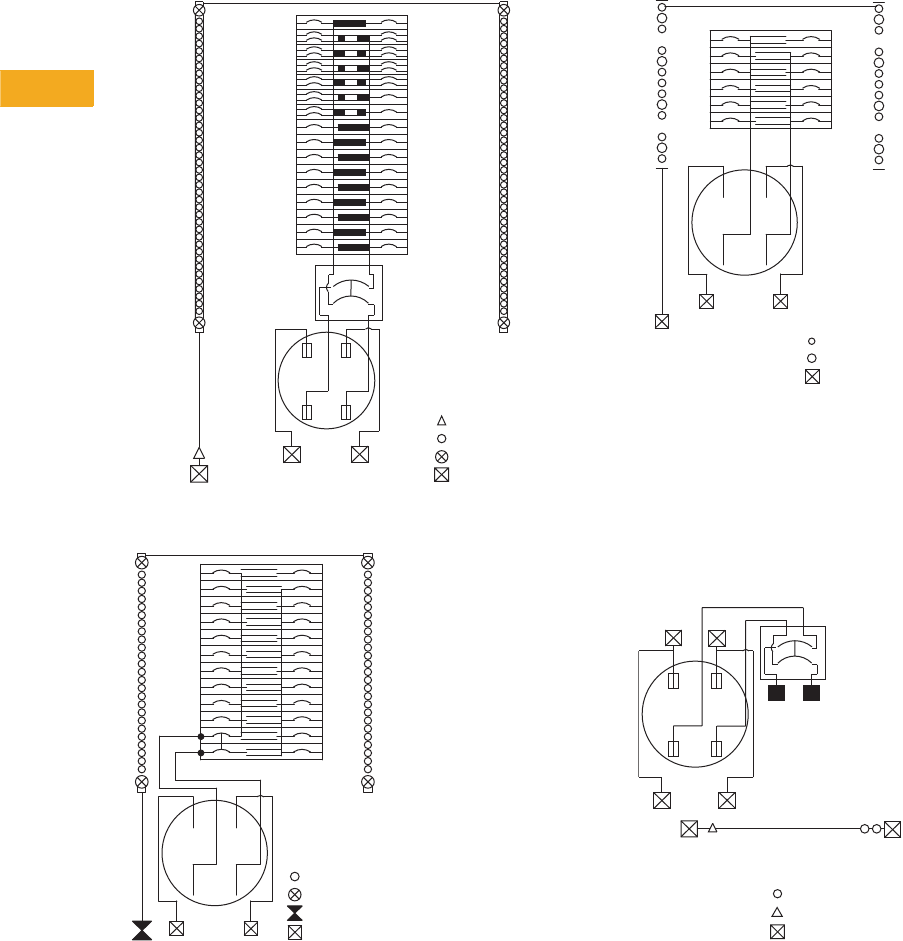
V1-T5-52 Volume 1—Residential and Light Commercial CA08100002E—February 2014 www.eaton.com
5
5
5
5
5
5
5
5
5
5
5
5
5
5
5
5
5
5
5
5
5
5
5
5
5
5
5
5
5
5
5.9
Group Metering and Meter Breakers
Meter Breakers
Wiring Diagrams
Catalog Numbers—CMBE3242B150BS, CMBE3242B200BS,
CMBE3242B200BF, CMBE3242B225BS and
CMBE3242B225BF 56a.
Catalog Numbers—CMBE2222P125BF and CMBE2222P125BS
Catalog Number—CMBE1212L200BS 56c.
Catalog Numbers—CMBEB150BTS and CMBEB200BTS 56d.
Note
1
Factory-installed
MCBK225
kit for C/B load lugs.
#14-2 AWG
#14-4 AWG
#6-2/0 AWG
#6-250 AWG
Wiring Diagram Key
Service Disconnect
Type CSR
N
Bonded
Neutral
Bonded
Neutral
1
2
3
4
5
6
7
8
9
10
11
12
13
14
15
16
17
18
19
20
21
22
23
24
25
26
27
28
29
30
31
32
33
34
35
36
37
38
39
40
41
42
Line
AB
12
14
16
21
22
9
11
13
15
10
4
6
8
1
3
5
7
2
18
20
17
19
N
AB
Service Disconnect
Line
Bonded Neutral
Bonded Neutral
#14-4 AWG
#6-2/0 AWG
#14-2/0 AWG
#6-250 AWG
Wiring
Diagram Key
4
6
8
10
12
1
3
5
7
9
11
2
AB
N Line
Bonded Neutral
Bonded Neutral
#14-4 AWG
#6-1/0 AWG
#6-250 AWG
Wiring
Diagram Key
AB
Bonded
Neutral
Line
N
AB
Install 200 Ampere Maximum
Service Disconnect Type CSR 2
Wiring Diagram Key
#14-2/0 AWG
#14-2 AWG
#6-250 AWG
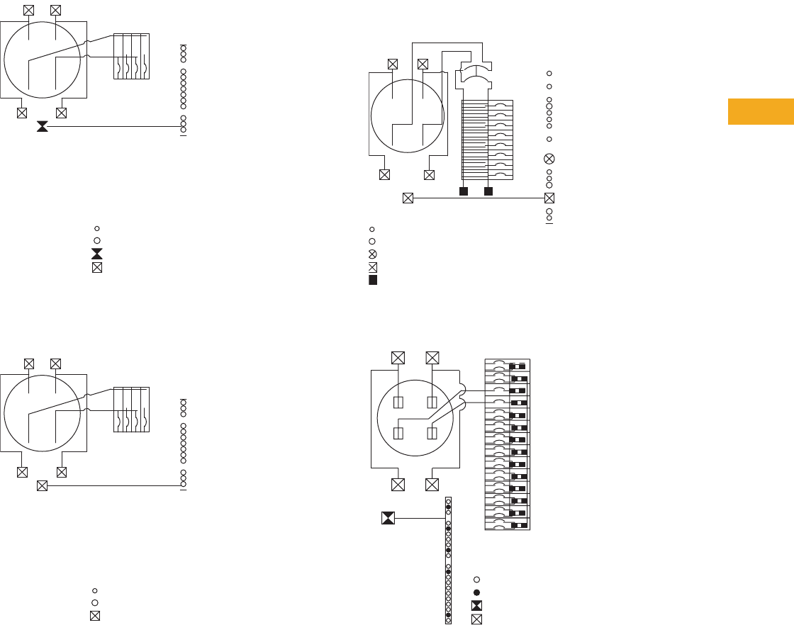
Volume 1—Residential and Light Commercial CA08100002E—February 2014 www.eaton.com V1-T5-53
5
5
5
5
5
5
5
5
5
5
5
5
5
5
5
5
5
5
5
5
5
5
5
5
5
5
5
5
5
5
5.9
Group Metering and Meter Breakers
Meter Breakers
Catalog Number—CMBE24L125BTS 57a.
Catalog Number—CMBE24L200BTS 57b.
Catalog Numbers—CMBE88B200BTS, CMBE88B200BTF,
CMBE88B150BTS and CMBE88B150BTF 57c.
Catalog Numbers—MBE1224B100BTS, MBE1224B100BTF,
MBE1224B125BTS and MBE1224B125BTF 57d.
AB
Bonded
Neutral
Line
N
AB
#14-1/0 AWG
#14-6 AWG
#14-1/0 AWG
#6-250 AWG
1234
Wiring Diagram Key
AB
Bonded
Neutral
Line
N
AB
#14-6 AWG
#14-1/0 AWG
#6-250 AWG
1234
Wiring Diagram Key
AB
1
2
3
4
AB
5
6
7
8
Wiring Diagram Key
#14-1/0 AWG
#14-6 AWG
#6-2/0 AWG
#6-250 AWG
#4-300 AWG
Service Disconnect
Type CSR 200 Ampere Maximum
Bonded Neutral
Line
N
1
2
3
4
#14-6 AWG
#14-1/0 AWG
#14-2/0 AWG
#6-250 AWG
Wiring
Diagram Key
A
Bonded
Neutral
B
Main
5
6
7
8
9
10
11
12
13
14
15
16
17
18
19
20
21
22
23
24
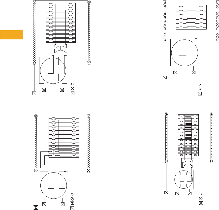
V1-T5-54 Volume 1—Residential and Light Commercial CA08100002E—February 2014 www.eaton.com
5
5
5
5
5
5
5
5
5
5
5
5
5
5
5
5
5
5
5
5
5
5
5
5
5
5
5
5
5
5
5.9
Group Metering and Meter Breakers
Meter Breakers
Catalog Numbers—MBE2040B150BF, MBE2040B200BS
and MBE2040B200BF 58a.
Catalog Number—MBE1836B125BF 58b.
Catalog Numbers—MBE1212L200BF and
MBE1212L200BS
Catalog Number—MBE3042B200BF 58d.
N
AB
14
2
3
58
6
7
912
10
11
13 16
14
15
17 20
18
19
21 24
22
23
25 28
26
27
29 32
30
31
33 36
34
35
37 40
38
39
Service
Disconnect
Type BW
or CSR
Line
Bonded Neutral
Bonded Neutral
#14-4 AWG
#6-2/0 AWG
#6-250 AWG
Wiring
Diagram Key
1
4
2
3
5
8
6
7
9
12
10
11
13
16
14
15
17
20
18
19
21
24
22
23
34
33
36
35
25
28
26
27
29
32
30
31
NLine
AB
Service Disconnect
Bonded Neutral
Bonded Neutral
Wiring
Diagram Key
#14-4 AWG
#6-2/0 AWG
#14-2/0 AWG
#6-250 AWG
4
6
8
10
12
1
3
5
7
9
11
2
Line
AB
N
Bonded Neutral
#14-6 AWG
#6-1/0 AWG
#6-250 AWG
Bonded Neutral
Wiring
Diagram Key
Bonded Neutral
LINE
NAB
41 40
42
39
37 36
38
35
33 32
34
31
29 28
30
27
25 24
26
23
18
17
15
14
16
13
11
10
12
9
7
6
8
5
3
2
4
1
Service
Disconnect
Type BW
or CSR
Bonded Neutral
21 20
22
19
Wiring
Diagram Key
#14-4 AWG
#6-2/0 AWG
#6-250 AWG
Volume 1—Residential and Light Commercial CA08100002E—February 2014 www.eaton.com V1-T5-55
5
5
5
5
5
5
5
5
5
5
5
5
5
5
5
5
5
5
5
5
5
5
5
5
5
5
5
5
5
5
5.9
Group Metering and Meter Breakers
Meter Breakers
Catalog Numbers—MBE1428B100BS and MBE1428B100BF 59a.
Catalog Numbers—MBE2040B200BTS, MBE2040B150BTS,
MBE2040BH200BTS and MBE2040BH200BTF 59b.
Catalog Number—MBE3042B225BF 59c.
Catalog Numbers—MBE24L125BTS and MBE24L125BTF 59d.
1
4
2
3
5
8
6
7
9
12
10
11
13
16
14
15
17
20
18
19
21
24
22
23
26
25
28
27
N
Line
AB
Service Disconnect
Bonded Neutral
Bonded Neutral
Wiring
Diagram Key
#14-4 AWG
#6-2/0 AWG
#14-2/0 AWG
#6-250 AWG
Bonded
Neutral
15
16
17
18
19
20
21
22
13
14
23
24
11
12
9
10
3
4
1
2
7
8
5
6
N
27
28
29
30
31
32
33
34
25
26
35
36
37
38
39
40
AB
AB
200A Max.
Service
Disconnect
Wiring
Diagram Key
#14-6 AWG
#14-1/0 AWG
#6-250 AWG
Bonded Neutral
Service
Disconnect
Type BW
or CSR
Bonded Neutral
LINE
NAB
41 40
42
39
37 36
38
35
33 32
34
31
29 28
30
27
25 24
26
23
18
17
15
14
16
13
11
10
12
9
7
6
8
5
3
2
4
1
21 20
22
19
Wiring
Diagram Key
#14-4 AWG
#6-2/0 AWG
#6-250 AWG
AB
1
Bonded
Neutral
Line
N
AB
23456
#14-1/0 AWG
#14-6 AWG
#14-2/0 AWG
#6-250 AWG
Wiring Diagram Key
V1-T5-56 Volume 1—Residential and Light Commercial CA08100002E—February 2014 www.eaton.com
5
5
5
5
5
5
5
5
5
5
5
5
5
5
5
5
5
5
5
5
5
5
5
5
5
5
5
5
5
5
5.9
Group Metering and Meter Breakers
Meter Breakers
Catalog Numbers—MBE48B150BTS, MBE48B200BTS,
MBE48B200BTF 60a.
Catalog Numbers—MBEB200BTS and MBEB200BTF 60b.
Catalog Numbers—MBE24L200BTS and MBE24L200BTF 60c.
Catalog Number—MBE88B200BTS 60d.
AB
200A Maximum
Service Disconnect
Type BW or CSR
4
6
8
AB
3
5
7
1
2
L2
L1 Bonded
Neutral
Line
N
#14-1/0 AWG
#14-6 AWG
#6-2/0 AWG
#6-250 AWG
Wiring Diagram Key
AB
AB
MCBK225 Kit for
C/B Load Lugs
Wiring Diagram Key
#14-2/0 AWG
#6-2/0 AWG
#6-250 AWG
200A Maximum
Service Disconnect
Type BW or CSR
Bonded
Neutral
Line
N
AB
1
Bonded
Neutral
Line
N
AB
23456
#14-1/0 AWG
#14-6 AWG
#14-2/0 AWG
#6-250 AWG
Wiring Diagram Key
1
2
3
4
5
6
7
8
AB
200A Maximum
Service Disconnect
Type BW or CSR
AB
Bonded Neutral
Line
N
Wiring Diagram Key
#14-1/0 AWG
#14-6 AWG
#6-2/0 AWG
#6-250 AWG
Volume 1—Residential and Light Commercial CA08100002E—February 2014 www.eaton.com V1-T5-57
5
5
5
5
5
5
5
5
5
5
5
5
5
5
5
5
5
5
5
5
5
5
5
5
5
5
5
5
5
5
5.9
Group Metering and Meter Breakers
Meter Breakers
Catalog Numbers—MBE816P200TS and MBE816P200TSCU 61a.
Catalog Numbers— MBE2040B200TS and MBE2040B200TF 61b.
Catalog Number—MBE1212L200BTS 61c.
Catalog Number—MBE1212L200BTS 61d.
Catalog Number—CMBE1212L200TS 61e.
Catalog Number—CMBE4242B200BTS 61f.
AB
1
3
2
4
5
7
6
8
9
11
10
12
13
15
14
16
#14-4 AWG
#6-350 kcmil
#6-2/0 AWG
#6-300 kcmil
#6-300 kcmil
Line
N
Bonded
Neutral
200A
Maximum
Service
Disconnect
Type BW
or CSR
Wiring Diagram Key
AB
Line N
Bonded
Neutral
200A
Maximum
Service
Disconnect
Type BW
or CSR
1
3
2
4
5
7
6
8
9
11
10
12
13
15
14
16
17
19
18
20
21
23
22
24
25
27
26
28
29 30
33
35
34
36
37
39
38
40
31 32
#14-4 AWG
#6-350 kcmil
#6-2/0 AWG
Wiring
Diagram Key
AB
1
2
3
LINE
N
AB4
5
6
Bonded
Neutral
#14-4 AWG
#6-350 kcmil
#6-2/0 AWG
Wiring
Diagram Key
1
3
5
7
9
11
Bonded
Neutral
N
AB
#14-4 AWG
#6-350 kcmil
#6-2/0 AWG
#6-300 kcmil
2
4
6
8
10
12
Wiring Diagram Key
1
3
5
7
9
11
#14-4 AWG
#6-350 kcmil
#6-2/0 AWG
#6-300 kcmil
Bonded
Neutral
ABN
2
4
6
8
10
12
Wiring Diagram Key
1
3
5
7
9
11
13
15
17
19
21
23
25
27
29
31
33
35
37
39
41
AB
AB
Bonded
Neutral
2
4
6
8
10
12
14
16
18
20
22
24
26
28
30
32
34
36
38
40
42
#14-6 AWG
Wiring
Diagram Key
Factory Installed
Service Disconnect
Type CSR
#14-1/0 AWG
#6 AWG-250 kcmil
N
V1-T5-58 Volume 1—Residential and Light Commercial CA08100002E—February 2014 www.eaton.com
5
5
5
5
5
5
5
5
5
5
5
5
5
5
5
5
5
5
5
5
5
5
5
5
5
5
5
5
5
5
5.9
Group Metering and Meter Breakers
Meter Breakers
Catalog Numbers—CMBER88B200BTS and
CMBER88B200BTF 62a.
Catalog Numbers—MBE4040B200BTS and
MBE4040B200BSH 62b.
Catalog Numbers—MBER48B200BTS and MER48B200BTF 62c.
Catalog Numbers—MBE2040B225BTS, MBE2040B225BTF 62d.
Catalog Numbers—MBE1224B125TS and MBE1224B100TS 62e.
Line
N
BA
B
Service
Disconnect Type CSR
or CSH Max 200A
1
2
3
4
5
6
7
8
Secondary
Service
Disconnect
70A Max
Bonded
Neutral
Wire Range
#14-1/0
#14-6 AWG
#5-2/0 AWG
#5-250 AWG
#4-300 AWG
A
1
3
5
7
9
11
13
15
17
19
21
23
25
27
29
31
33
35
37
39
N
AB
AB
Bonded
Neutral
2
4
6
8
10
12
14
16
18
20
22
24
26
28
30
32
34
36
38
40
#14-6 AWG
Wiring
Diagram Key
#14-1/0 AWG
#6 AWG-250 kcmil
Factory Installed
Service Disconnect
Type BW
Line
N
BA
B
Service
Disconnect Type CSR
or CSH Max 200A
1
2
3
4
5
6
7
8
Secondary
Service
Disconnect
70A Max
Bonded
Neutral
Wire Range
#14-1/0
#14-6 AWG
#5-2/0 AWG
#5-250 AWG
#4-300 AWG
A
#14-6 AWG
#14-1/0 AWG
#6-250 AWG
Wiring
Diagram Key
225A Max.
Service
Disconnect
AB
A
N
Bonded
Neutral
B
#14-4 AWG
#14-1/0 AWG
#6-350 kcmil
Wiring
Diagram Key
1
3
5
7
9
11
13
15
17
19
21
23
125A
Maximum
Service Disconnect
Type BR, or BRH
Bonded
Neutral
Line
N
AB
Equipment
Ground
2
4
6
8
10
12
14
16
18
20
22
24
Volume 1—Residential and Light Commercial CA08100002E—February 2014 www.eaton.com V1-T5-59
5
5
5
5
5
5
5
5
5
5
5
5
5
5
5
5
5
5
5
5
5
5
5
5
5
5
5
5
5
5
5.9
Metering Products
Meter Breakers
West Coast All-In-One Design
Contents
Description Page
Residential Meter Breakers. . . . . . . . . . . . . . . . . . V1-T5-37
Non-EUSERC Combination Service Entrance
Devices 100–200A Styles . . . . . . . . . . . . . . . . . . V1-T5-39
Meets EUSERC Requirements Service Entrance
Devices 100–225A . . . . . . . . . . . . . . . . . . . . . . . V1-T5-48
West Coast All-In-One Design
Mechanical Interlock Cover . . . . . . . . . . . . . . . . . . V1-T5-65
House Panels . . . . . . . . . . . . . . . . . . . . . . . . . . . . V1-T5-75
Commercial Safety Sockets. . . . . . . . . . . . . . . . . . V1-T5-83
CH Style Renovation Solutions . . . . . . . . . . . . . . . V1-T5-86
Aluminum Meter Breakers . . . . . . . . . . . . . . . . . . V1-T5-87
West Coast All-In-One Design
Product Description
A metering device that
may contain a meter
socket, main breaker and
distribution section within
the same enclosure.
Features, Benefits
and Functions
●Semi-flush mounting.
7-inch design ideal for
stucco homes
●Endwall knockouts are
easily accessible for
future wiring without
damaging stucco
●Knockout in back of case
for mounting car-charging
receptacle in garage
(meets future electric
car requirements)
●Outboard split neutral
for easy wiring
●Commercial grade
main breaker
●Value-added kits available:
Hub adapter plate

V1-T5-60 Volume 1—Residential and Light Commercial CA08100002E—February 2014 www.eaton.com
5
5
5
5
5
5
5
5
5
5
5
5
5
5
5
5
5
5
5
5
5
5
5
5
5
5
5
5
5
5
5.9
Metering Products
Meter Breakers
Product Selection
7-Inch Deep Meter Breaker—Standard Design OH/NG
Accessories
Hub Adapter Plate
Note
1 Main Breaker Bus connected to 20/40 distribution. Main and Disconnect in same compartment.
Ampere
Rating Bypass Service kAIC Jaws Distribution Main
Branch
Breaker
Type
Catalog Number—
Flush
Factory-
Installed
Kits
100 None UG 10 4 18/36 BW2100 BR
MBED1836B100BF
—
125 None UG 10 4 18/36 BW2125 BR
MBED1836B125BF
—
200 None UG 10 4 20/40 BW2200 BR
MBED2040B200BF
—
200
1
None UG 10 4 20/40 BW2200 BR
MBED2040B200BFN
—
200 None UG 10 4 30/42 BW2200 BR
MBED3042B200BF
—
225 None UG 10 4 20/40 BW2225 BR
MBED2040B225BF
—
225
1
None UG 10 4 20/40 BW2225 BR
MBED2040B225BFN
—
225 None UG 10 4 30/42 BW2225 BR
MBED3042B225BF
—
Description
Catalog
Number
Hub adapter plate MBEDADPT
MBED3042B200BF
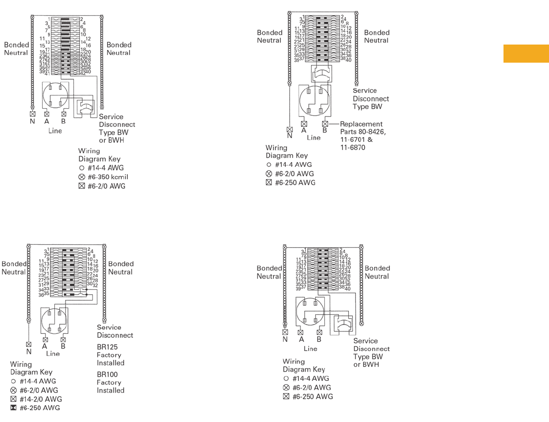
Volume 1—Residential and Light Commercial CA08100002E—February 2014 www.eaton.com V1-T5-61
5
5
5
5
5
5
5
5
5
5
5
5
5
5
5
5
5
5
5
5
5
5
5
5
5
5
5
5
5
5
5.9
Metering Products
Meter Breakers
Wiring Diagrams
Typical Wiring Diagram for Catalog Numbers
MBED3042B200BF, MBED3042B225BF, MBED3042BH200BF
Typical Wiring Diagram for Catalog Numbers
MBED1836B100BF, MBED1836B125BF
Typical Wiring Diagram for Catalog Numbers
MBED2040B200BFN, MBED2040B225BFN
Typical Wiring Diagram for Catalog Numbers
MBED2040B200BF, MBED2040B225BF, MBED2040BH200BF,
MBED2040BH225BF
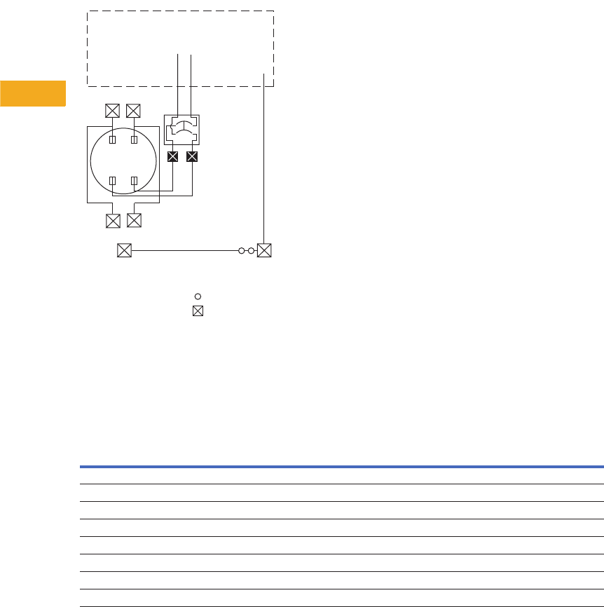
V1-T5-62 Volume 1—Residential and Light Commercial CA08100002E—February 2014 www.eaton.com
5
5
5
5
5
5
5
5
5
5
5
5
5
5
5
5
5
5
5
5
5
5
5
5
5
5
5
5
5
5
5.9
Metering Products
Meter Breakers
Typical Wiring Diagram for Catalog Numbers
MBEB2003040BB and MBEB2253040BB
Dimensions and Knockouts
Approximate Dimensions in Inches (mm)
7-Inch Deep Meter Breaker
#14-2/0 AWG
#6-250 AWG
Wiring
Diagram Key
200A or
225A Max.
Service
Disconnect
Type BW
or CSR
Loadcenter
Main Lugs
Loadcenter
Neutral
AB
AB
N
A
Line N
Factory
Bonded
Neutral
B
Catalog Number—
Flush
Height Width Depth
MBED1836B100BF
38.00 (965.2) 14.19 (360.4) 7.00 (177.8)
MBED1836B125BF
38.00 (965.2) 14.19 (360.4) 7.00 (177.8)
MBED2040B200BF
38.00 (965.2) 14.19 (360.4) 7.00 (177.8)
MBED2040B200BFN
42.50 (1079.5) 14.19 (360.4) 7.00 (177.8)
MBED3042B200BF
42.50 (1079.5) 14.19 (360.4) 7.00 (177.8)
MBED2040B225BF
38.00 (965.2) 14.19 (360.4) 7.00 (177.8)
MBED2040B225BFN
42.50 (1079.5) 14.19 (360.4) 7.00 (177.8)
MBED3042B225BF
42.50 (1079.5) 14.19 (360.4) 7.00 (177.8)
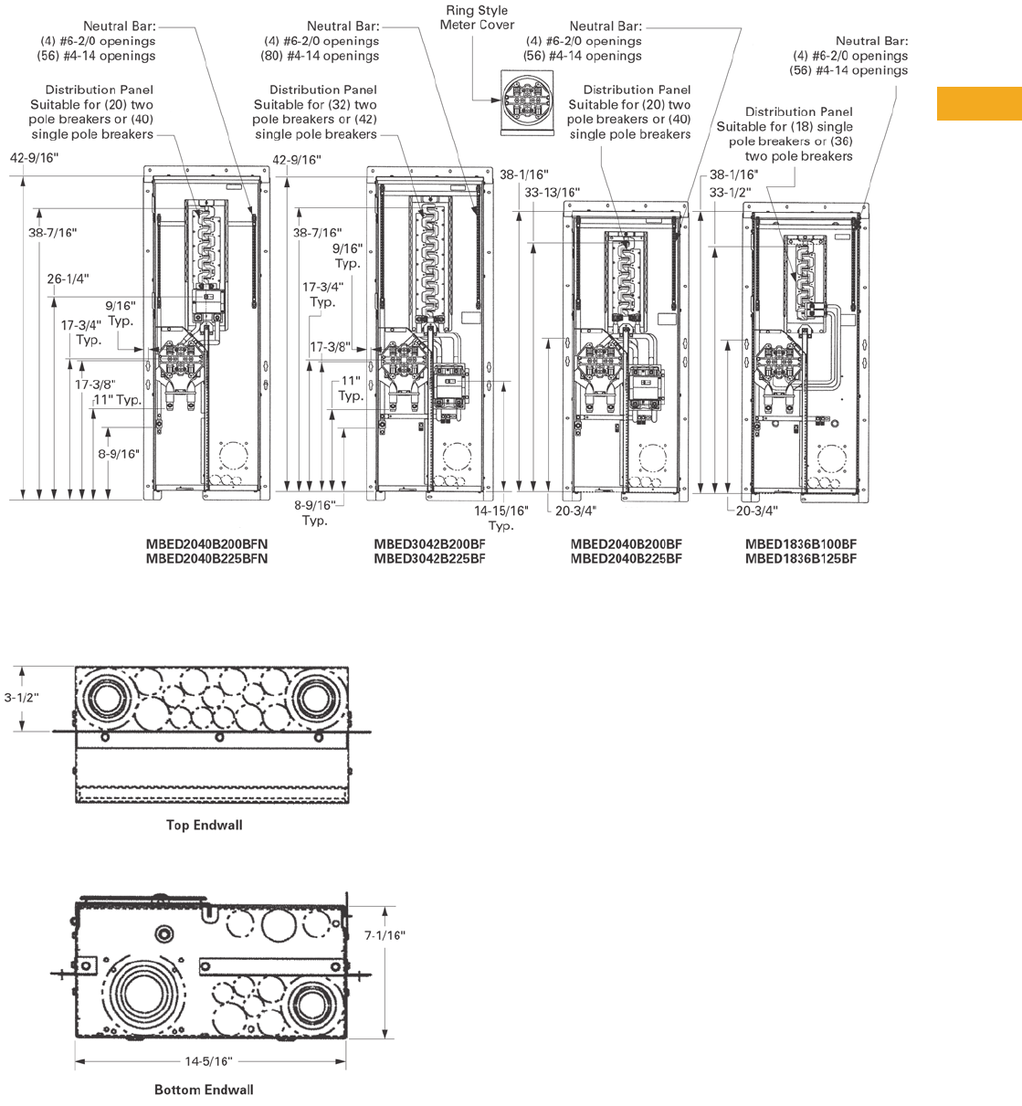
Volume 1—Residential and Light Commercial CA08100002E—February 2014 www.eaton.com V1-T5-63
5
5
5
5
5
5
5
5
5
5
5
5
5
5
5
5
5
5
5
5
5
5
5
5
5
5
5
5
5
5
5.9
Metering Products
Meter Breakers
Approximate Dimensions in Inches (mm)
Catalog Numbers MBED2040B200BFN, MBED20408225BFN, MBED3042B200BF, MBED3042B225BF, MBED2040B200BF,
MBED2040B225BF, MBED1836B100BF, MBED1836B125BF
Knockout Configurations and Dimensions for
MBED2040B200BFN, MBED20408225BFN,
MBED3042B200BF, MBED3042B225BF, MBED2040B200BF,
MBED2040B225BF,MBED1836B100BF, MBED1836B125BF
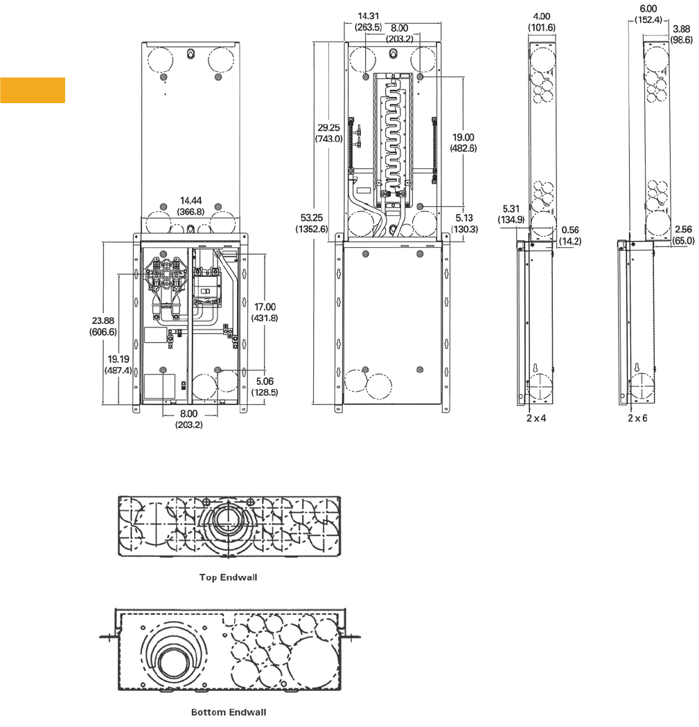
V1-T5-64 Volume 1—Residential and Light Commercial CA08100002E—February 2014 www.eaton.com
5
5
5
5
5
5
5
5
5
5
5
5
5
5
5
5
5
5
5
5
5
5
5
5
5
5
5
5
5
5
5.9
Metering Products
Meter Breakers
Approximate Dimensions in Inches (mm)
Catalog Numbers MBEB2003040BB, MBEB2253040BB
Knockout Configurations for MBEB2003040BB,
MBEB2253040BB

Volume 1—Residential and Light Commercial CA08100002E—February 2014 www.eaton.com V1-T5-65
5
5
5
5
5
5
5
5
5
5
5
5
5
5
5
5
5
5
5
5
5
5
5
5
5
5
5
5
5
5
5.9
Metering Products
Meter Breakers
Meter Breaker with Interlock Cover
Mechanical Interlock Cover
Contents
Description Page
Residential Meter Breakers. . . . . . . . . . . . . . . . . . V1-T5-37
Non-EUSERC Combination Service Entrance
Devices 100–200A Styles . . . . . . . . . . . . . . . . . . V1-T5-39
Meets EUSERC Requirements Service Entrance
Devices 100–225A . . . . . . . . . . . . . . . . . . . . . . . V1-T5-48
West Coast All-In-One Design. . . . . . . . . . . . . . . . V1-T5-59
Mechanical Interlock Cover
House Panels . . . . . . . . . . . . . . . . . . . . . . . . . . . . V1-T5-75
Commercial Safety Sockets. . . . . . . . . . . . . . . . . . V1-T5-83
CH Style Renovation Solutions . . . . . . . . . . . . . . . V1-T5-86
Aluminum Meter Breakers . . . . . . . . . . . . . . . . . . V1-T5-87
Mechanical Interlock Cover
Product Description
Covers mechanically interlock
two breakers. Covers
interlock main breaker with
two-pole breaker mounted in
the distribution section of the
meter breakers.
V1-T5-66 Volume 1—Residential and Light Commercial CA08100002E—February 2014 www.eaton.com
5
5
5
5
5
5
5
5
5
5
5
5
5
5
5
5
5
5
5
5
5
5
5
5
5
5
5
5
5
5
5.9
Metering Products
Meter Breakers
Product Selection
Mechanical Interlock Cover
Mechanical Interlock
Deadfront
Meter Breaker
Catalog Number
MBDF1M CMB1212B200BTS
CMB1212B200BTSD
CMB1212P200BTS
CMB1212P200BTSD
MBDF2M MB816B200BTS
MB816B200BTSCU
MB816P200BTS
MB816P200BTSCU
MB816P200STD
MBDF3M MB2040B200BTS
MB2040P200BTS
MB2040P200SD
MBDF4M MBE816P200TS
MBE816P200TSCU
MBDF5M MBE2040B150BF
MBE2040B150BS
MBE2040B200BF
MBE2040B200BS
MBDF6M MBE2040B200TF
MBE2040B200TS
MBE2040P200TF
MBE2040P200TS
MBDF7M CMBE3242B150BF
CMBE3242B150BS
CMBE3242B200BF
CMBE3242B200BS
CMB3242B150BS
CMB3242B200BS
MBDF8M CMBE4242B200BSH
CMBE4242B200BTF
CMBE4242B200BTS
MBDF9M MBE4040B200BSH
MBE4040B200BSHH
MBE4040B200BTF
MBE4040B200BTS
Meter Breaker with
Interlock Cover
Mechanical Interlock
Deadfront
Meter Breaker
Catalog Number
MBDF1AM CMB2424M200BTS
MBDF10M CMB24B200TFR
CMB24B200TSR
MBDF11M CMBXB200BTS
CMBXP200BTS
MBDF12M CMBX3242B200BTS
CMBX3242P200BTS
MBDF13M MBE3042B200BF
MBE3042B225BF
MBDF14M CMBE88B150BTF
CMBE88B150BTS
CMBE88B200BTF
CMBE88B200BTS
CMB88B150BTS
CMB88B200BTS
MBDF15M MBE48B150BTF
MBE48B150BTS
MBE48B200BTF
MBE48B200BTS
MBDF16M MBE88B150BTF
MBE88B150BTS
MBE88B200BTF
MBE88B200BTS
MBDF17M MBE2040BC200BTS
MBE2040BH200BTF
MBE2040BH200BTS
MBE2040B150BTF
MBE2040B150BTS
MBE2040B200BTF
MBE2040B200BTS
MBE2040B200BTSV
MBE2040B225BTF
MBE2040B225BTS

Volume 1—Residential and Light Commercial CA08100002E—February 2014 www.eaton.com V1-T5-67
5
5
5
5
5
5
5
5
5
5
5
5
5
5
5
5
5
5
5
5
5
5
5
5
5
5
5
5
5
5
5.9
Metering Products
Meter Breakers
Meter Breaker Parts 1
Hub Selection Chart
Top Endwall (Surface)
Description
Catalog
Number
5th Jaw Kits
Compact and standard styles (MB and CMB) MB5JAWKIT
EUSERC style IMM5JKOP
Horn Bypass Kits
Ringless Style units only (MB and CMB) MBHBPKIT
Hub Size
Dimensions in Inches (mm)
Catalog
Number
1.00 (25.4) DS100H2
1.25 (31.8) DS125H2
1.50 (38.1) DS150H2
2.00 (50.8) DS200H2
2.50 (63.5) DS250H2
3.00 (76.2) DS300H2
Hub Provision
Catalog Number
DS100H2
DS125H2
DS150H2
DS200H2
DS250H2
DS300H2
DS900AP (Adapter Plate if using DS___H1 hubs only) 2
Technical Data and Specifications
Wire Size Chart
Wire Size is Determined by the Circuit Breaker Installed
in the Enclosure
Notes
1For breakers under 70A used in backfed applications, add “B” to the end of the catalog string
to get the appropriate “hold-down” version.
2Use when DS H1 Type 1, 1.25 and 1.50-inch hubs are needed.
Use DS...H2 hubs for bottom endwalls (for all units). Use RH hubs for top endwalls on semi-flush
units. Use DS...H2 hubs for top endwalls on surface devices.
Main
Wire Size Range Cu/Al 60ºC
or 75ºC for Line Terminals
BR250 #14–4 kcmil
BR260 #4–1/0 kcmil
BR270 #4–1/0 kcmil
BR280 #4–1/0 kcmil
BR290 #4–1/0 kcmil
BR2100 #4–1/0 kcmil
BW2125 #2–300 kcmil
BW2150 #2–300 kcmil
BW2200 #2–300 kcmil
CSR2125 #2–300 kcmil
CSR2150 #2–300 kcmil
CSR2200 #2–300 kcmil
CSR2125N #1/0–250 kcmil
CSR2150N #1/0–250 kcmil
CSR2200N #1/0–250 kcmil
125A main lugs —
200A main lugs —
MCBK225 #2–300 kcmil
Wire/Application
Maximum
Wire Size
Ampere
Rating
Aluminum—Standard 250 kcmil 200
Aluminum—Service Entrance 250 kcmil 225
Copper—Standard and Service Entrance 250 kcmil 225
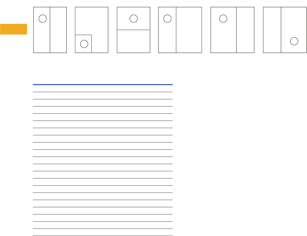
V1-T5-68 Volume 1—Residential and Light Commercial CA08100002E—February 2014 www.eaton.com
5
5
5
5
5
5
5
5
5
5
5
5
5
5
5
5
5
5
5
5
5
5
5
5
5
5
5
5
5
5
5.9
Metering Products
Meter Breakers
Dimensions and Knockouts
Approximate Dimensions in Inches (mm)
Box Styles—Five Different Styles (Shapes) of Product
Box Dimensions
Box
Number Height Width Depth
Box
Style
1 12.50 (317.5) 14.44 (366.7) 4.00 (101.6) A
2 23.88 (606.4) 14.44 (366.7) 5.38 (136.5) A
3 28.38 (720.7) 14.44 (366.7) 5.38 (136.5) A
4 34.13 (866.8) 14.44 (366.7) 5.38 (136.5) B
5 36.13 (917.6) 14.44 (366.7) 5.38 (136.5) B
6 43.38 (1101.7) 14.44 (366.7) 5.38 (136.5) B
7 46.88 (1190.6) 14.44 (366.7) 5.38 (136.5) B
8 19.75 (501.7) 7.50 (190.5) 4.00 (101.6) C
9 25.00 (635.0) 14.44 (366.7) 5.38 (136.5) C
10 32.38 (822.3) 14.44 (366.7) 5.38 (136.5) C
11 36.63 (930.3) 14.44 (366.7) 5.38 (136.5) C
12 34.38 (873.1) 22.00 (558.8) 5.38 (136.5) D
13 19.75 (501.7) 14.44 (366.7) 5.38 (136.5) E
14 39.91 (1013.7) 14.44 (366.7) 5.38 (136.5) C
15 23.88 (606.6) 13.00 (330.2) 4.94 (125.5) F
16 28.38 (720.9) 13.00 (330.2) 4.94 (125.5) F
17 34.19 (868.4) 22.13 (562.1) 5.00 (127.0) D
18 36.06 (915.9) 16.63 (422.4) 5.50 (139.7) A
19 28.38 (720.9) 14.44 (366.8) 4.94 (125.5) A
20 32.06 (814.3) 14.44 (366.8) 4.94 (125.5) C
21 25.50 (647.7) 14.44 (366.8) 4.94 (125.5) C
ABCDE F
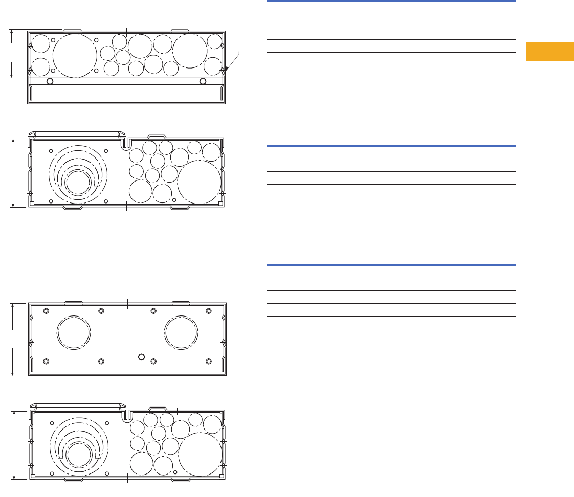
Volume 1—Residential and Light Commercial CA08100002E—February 2014 www.eaton.com V1-T5-69
5
5
5
5
5
5
5
5
5
5
5
5
5
5
5
5
5
5
5
5
5
5
5
5
5
5
5
5
5
5
5.9
Metering Products
Meter Breakers
Approximate Dimensions in Inches (mm)
Knockouts for Stucco and Surface Units Catalog Numbers—
CMBE3242B200BF, CMBE3242B225BF, MBE2040B200BF,
MBE2040B150BF, MBE1428B100BF, MBE1212L200BTF,
MBE1836B125BF and MBE1212L200BTS 62a.
Knockouts for Stucco and Surface Units Catalog Numbers—
CMBE3242B150BS, CMBE3242B200BS, CMBE3242B225BS,
CMBE1212L200BS, MBE2040B200BS, MBE1428B100BS,
MBE1212L200BTS, CMB3242B150BS and
CMB3242B200BS 62b.
Top Endwall (Surface)
Top Endwall (Stucco) 3
Bottom Endwall
Notes
1For details regarding quantities, please contact the Technical Resource Center (TRC)
at 1-877-ETN-CARE.
2Use when DS H1 Type 1, 1.25 and 1.50-inch hubs are needed.
3RH hubs are to be used for Top Endwall (Stucco) endwalls.
3-1/2
3
-1/
2
(88.9)
8
8.9
3-1/2
(88.9)
K
eyhole Knockouts on Sides for Stucco Units Only.
Keyhole Knockouts on Sides for Stucco Units Only.
T
op Stucco
TT
Top Stucco
4-15/16
(125.4)
Bottom
5-5/16
(134.9)
Top Surface
Bottom
4-15/16
(125.4)
Hub Provision
Catalog Number Quantity
DS100H2 1
DS125H2 1
DS150H2 1
DS200H2 1
DS250H2 1
DS300H2 1
DS900AP (Adapter Plate if using DS___H1 hubs only) 21
Knockout Size
Dimensions in Inches (mm) Quantity
1.25, 1.50, 2.00, 2.50 (31.8, 38.1, 50.8, 63.5) 1
1.00, 1.25, 1.50 (25.4, 31.8, 38.1) 1
0.50, 0.75, 1.00 (12.7, 19.1, 25.4) 1
0.50, 0.75 (12.7, 19.1) 3
0.50 (12.7) 3
Knockout Size
Dimensions in Inches (mm) Quantity
0.50 (12.7) 7
0.50, 0.75 (12.7, 19.1) 4
0.50, 0.75, 1.00 (12.7, 19.1, 25.4) 1
1.00, 1.25, 1.50, 2.00 (25.4, 31.8, 38.1, 50.8) 1
1.25, 1.50, 2.00, 2.50, 3.00 (31.8, 38.1, 50.8, 63.5, 76.2) 1
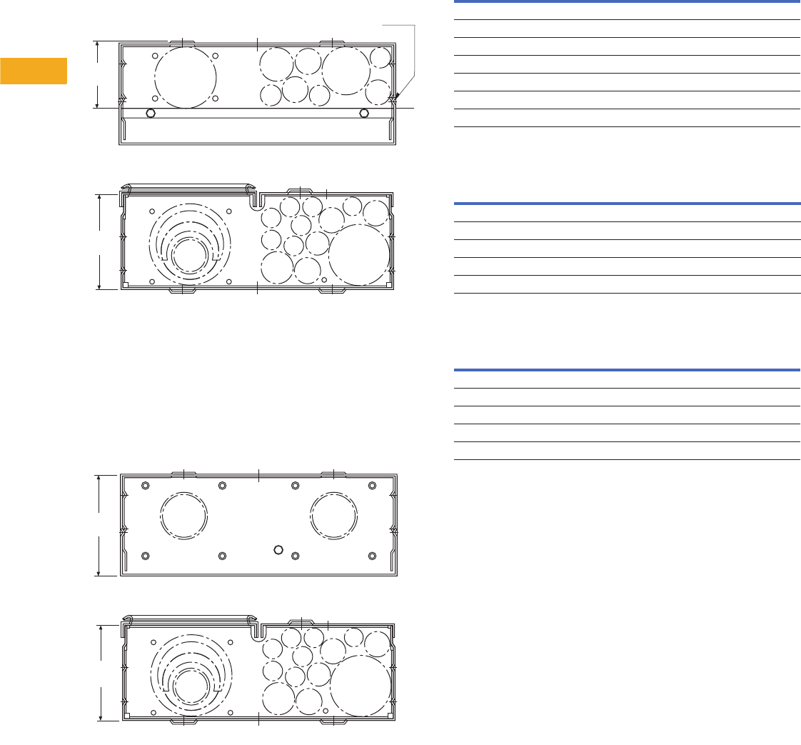
V1-T5-70 Volume 1—Residential and Light Commercial CA08100002E—February 2014 www.eaton.com
5
5
5
5
5
5
5
5
5
5
5
5
5
5
5
5
5
5
5
5
5
5
5
5
5
5
5
5
5
5
5.9
Metering Products
Meter Breakers
Approximate Dimensions in Inches (mm)
Knockouts for Stucco and Surface Units Catalog Numbers—
CMBE88B150BTF, CMBE88B200BTF, MBE24L125BTF,
MBE24L200BTF, MBE48B200BTF, MBEB200BTF,
MBE1224B100BTF and MBE1224B125BTF 63a.
Knockouts for Stucco and Surface Units Catalog Numbers—
CMBB150BTS, CMBB200BTS, CMBP200BTS,
CMBE24L125BTS, CMB24L125BTS, CMBE24L200BTS,
CMBEB200BTS, CMBEB150BTS, CMBE88B150BTS,
CMBP200BTS, CMBE88B200BTS, MBE24L125BTS,
MBE24L200BTS, MBE48B150BTS, MBE48B200BTS,
MBE88B200BTS, MBEB200BTS, MBE1224B100BTS,
MBE1224B125BTS, CMB88B150BTS, CMB88B200BTS
and MB48B200BTS 63b.
Top Endwall (Surface)
Top Endwall (Stucco) 3
Bottom Endwall
Notes
1For details regarding quantities, please contact the Technical Resource Center (TRC)
at 1-877-ETN-CARE.
2Use when DS H1 Type 1, 1.25 and 1.50-inch hubs are needed.
3RH hubs are to be used for Top Endwall (Stucco) endwalls.
Keyhole Knockouts on Sides for Stucco Units Only.
Top Stucco
Bottom
3-1/2
(88.9)
4-15/16
(125.4)
Top Surface
Bottom
5-5/16
(134.9)
4-15/16
(125.4)
Hub Provision
Catalog Number Quantity
DS100H2 1
DS125H2 1
DS150H2 1
DS200H2 1
DS250H2 1
DS300H2 1
DS900AP (Adapter Plate if using DS___H1 hubs only) 21
Knockout Size
Dimensions in Inches (mm) Quantity
1.25, 1.50, 2.00, 2.50 (31.8, 38.1, 50.8, 63.5) 1
1.00, 1.25, 1.50 (25.4, 31.8, 38.1) 1
0.50, 0.75, 1.00 (12.7, 19.1, 25.4) 1
0.50, 0.75 (12.7, 19.1) 3
0.50 (12.7) 3
Knockout Size
Dimensions in Inches (mm) Quantity
0.50 (12.7) 7
0.50, 0.75 (12.7, 19.1) 4
0.50, 0.75, 1.00 (12.7, 19.1, 25.4) 1
1.00, 1.25, 1.50, 2.00 (25.4, 31.8, 38.1, 50.8) 1
1.25, 1.50, 2.00, 2.50, 3.00 (31.8, 38.1, 50.8, 63.5, 76.2) 1
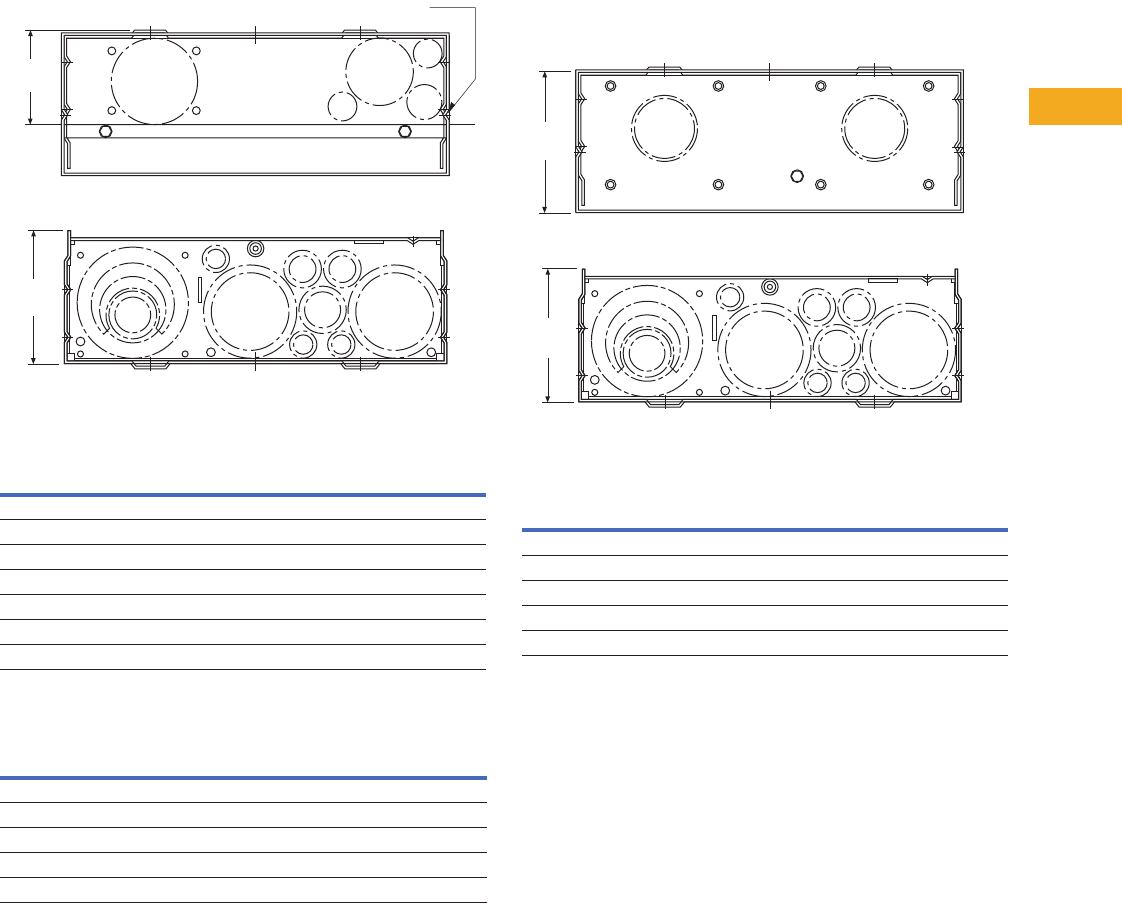
Volume 1—Residential and Light Commercial CA08100002E—February 2014 www.eaton.com V1-T5-71
5
5
5
5
5
5
5
5
5
5
5
5
5
5
5
5
5
5
5
5
5
5
5
5
5
5
5
5
5
5
5.9
Metering Products
Meter Breakers
Approximate Dimensions in Inches (mm)
Knockouts for Stucco and Surface Units Catalog Number—
MMBE2040B200TF 64a.
Top Endwall (Surface)
Top Endwall (Stucco) 3
Knockouts for Stucco and Surface Units Catalog Numbers—
MBE1224B100TS, MBE1224B125TS, MBE816P200TS,
MBE816P200TSCU, MBE2040B200TS, CMB1212P200BTS,
CMB1212P200BTSD, CMB1212B200BTS, MB1212L200BTS
and CMB1212L200BTS 64b.
Bottom Endwall
Notes
1For details regarding quantities, please contact the Technical Resource Center (TRC)
at 1-877-ETN-CARE.
2Use when DS H1 Type 1, 1.25 and 1.50-inch hubs are needed.
3RH hubs are to be used for Top Endwall (Stucco) endwalls.
Hub Provision
Catalog Number Quantity
DS100H2 1
DS125H2 1
DS150H2 1
DS200H2 1
DS250H2 1
DS300H2 1
DS900AP (Adapter Plate) 21
Knockout Size
Dimensions in Inches (mm) Quantity
1.25, 1.50, 2.00, 2.50 (31.8, 38.1, 50.8, 63.5) 1
1.00, 1.25, 1.50 (25.4, 31.8, 38.1) 1
0.50, 0.75, 1.00 (12.7, 19.1, 25.4) 1
0.50, 0.75 (12.7, 19.1) 3
0.50 (12.7) 3
Keyhole Knockouts on Sides for Stucco Units Only.
Top Stucco
Bottom
3.50
(88.9)
4.94
(125.4)
Knockout Size
Dimensions in Inches (mm) Quantity
0.50 (12.7) 7
0.50, 0.75 (12.7, 19.1) 4
0.50, 0.75, 1.00 (12.7, 19.1, 25.4) 1
1.00, 1.25, 1.50, 2.00 (25.4, 31.8, 38.1, 50.8) 1
1.25, 1.50, 2.00, 2.50, 3.00 (31.8, 38.1, 50.8, 63.5, 76.2) 1
Top Surface
Bottom
5.31
(134.9)
4.94
(125.4)
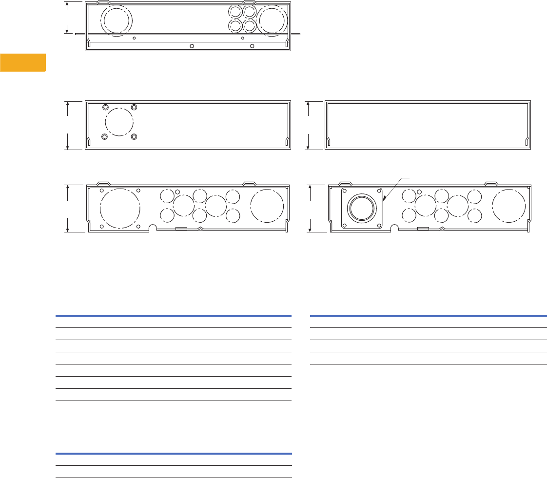
V1-T5-72 Volume 1—Residential and Light Commercial CA08100002E—February 2014 www.eaton.com
5
5
5
5
5
5
5
5
5
5
5
5
5
5
5
5
5
5
5
5
5
5
5
5
5
5
5
5
5
5
5.9
Metering Products
Meter Breakers
Approximate Dimensions in Inches (mm)
Knockouts for Stucco and Surface Units
Top Endwall (Surface)
Top Endwall (Stucco) 3
Bottom Endwall
Notes
1For details regarding quantities, please contact the Technical Resource Center (TRC)
at 1-877-ETN-CARE.
2Use when DS H1 Type 1, 1.25 and 1.50-inch hubs are needed.
3RH hubs are to be used for Top Endwall (Stucco) endwalls.
3.44
(87.3)
Top Surface
Top Flush
MBE4040B200BTF
Top Surface
Bottom Bottom
2-1/2-inch Hub
CMBE4242B200BTS
MBE4040B200BTS
MBE4040B200BSH
5.31
(134.9)
4.94
(125.4)
5.31
(134.9)
4.94
(125.4)
Hub Provision
Catalog Number Quantity
DS100H2 1
DS125H2 1
DS150H2 1
DS200H2 1
DS250H2 1
DS300H2 1
DS900AP (Adapter Plate) 21
Knockout Size
Dimensions in Inches (mm) Quantity
1.25, 1.50, 2.00, 2.50 (31.8, 38.1, 50.8, 63.5) 2
0.50, 0.75 (12.7, 19.1) 3
Knockout Size
Dimensions in Inches (mm) Quantity
0.50, 0.75 (12.7, 19.1) 6
0.50, 0.75, 1, 1.25 (12.7, 19.1, 25.4, 31.8) 2
1.00, 1.25, 1.50, 2.00, 2.50 (25.4, 31.8, 38.1, 50.8, 63.5) 1
1.00, 1.25, 1.50, 2.00, 2.50, 3.00 (25.4, 31.8, 38.1, 50.8, 63.5, 76.2) 1
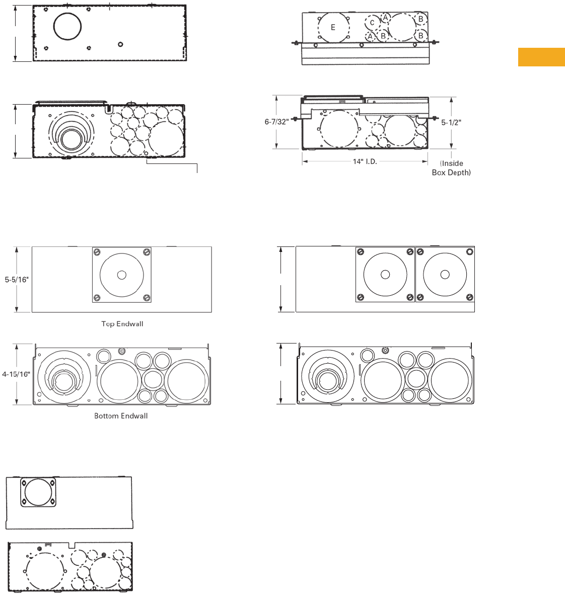
Volume 1—Residential and Light Commercial CA08100002E—February 2014 www.eaton.com V1-T5-73
5
5
5
5
5
5
5
5
5
5
5
5
5
5
5
5
5
5
5
5
5
5
5
5
5
5
5
5
5
5
5.9
Metering Products
Meter Breakers
Approximate Dimensions in Inches (mm)
Knockout Configurations and Dimensions for Catalog
Numbers MBER48B200BTS and CMBER88B200BTS 66a.
Knockout Configurations and Dimensions for
Catalog Numbers CMBXP200BTS, CMBXB200BTS,
CMBX1212P200BTS and CMBX3242P200BTS,
CMBX3242B200BTS, CMBX1212B200BTS 66b.
Surface Unit Knockout Configurations and Dimensions for
MBE2040B200BTS, MBE2040B225BTS, MBE2040B200BTF
and MBE2040B225BTF 66c.
Semi-Flush Stucco Unit Knockout Configurations and
Dimensions for MBE2040B200BTS, MBE2040B225BTS,
MBE2040B200BTF and MBE2040B225BTF 66d.
Knockout Configurations and Dimensions for Catalog
Numbers MBT48B125BTS, MBT48B150BTS, MBT48B200BTS
and MBT48P200BTS 66e.
4-15/16"
Top Surface
Bottom End
Mounting Surface
5-5/16"
Bottom
Top Surface
4-15/16"
5-5/16"
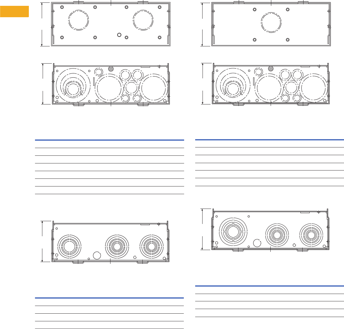
V1-T5-74 Volume 1—Residential and Light Commercial CA08100002E—February 2014 www.eaton.com
5
5
5
5
5
5
5
5
5
5
5
5
5
5
5
5
5
5
5
5
5
5
5
5
5
5
5
5
5
5
5.9
Metering Products
Meter Breakers
Approximate Dimensions in Inches (mm)
Knockouts for Non-EUSERC Units Catalog Numbers—
MBB150BTS, MBB200BTS, MBP200BTS, MB816P200BTS,
MB816P200BTSCU, MB816P200BTSD, MB816B200BTS,
MB816B200BTSCU, MB2040P200BTS, MB2040B200BTS,
MBP200BTSD, MBP200SD, MB816P200STD,
MB2040B150SD, MB2040B200SD and MB2040P200SD 67a.
Top Endwall (Surface)
Knockouts for Non-EUSERC Units Catalog Number—
CHMMB100BTS 67b.
Bottom Endwall
Knockouts for Non-EUSERC Units Catalog Numbers—
CMB2424B200BTS, MBB150BTSCR, MBB200BTSCR,
MBB150BTSC, MBB200BTSC and CMB2436B200BTS 67c.
Bottom Endwall
Knockouts for Non-EUSERC Units Catalog Numbers—
CHMMB150BTS and CHMMB200BTS 67d.
Bottom Endwall
Notes
1For details regarding quantities, please contact the Technical Resource Center (TRC)
at 1-877-ETN-CARE.
2Use when DS H1 Type 1, 1.25 and 1.50-inch hubs are needed.
Hub Provision
Catalog Number Quantity
DS100H2 1
DS125H2 1
DS150H2 1
DS200H2 1
DS250H2 1
DS300H2 1
DS900AP (Adapter Plate) 21
Knockout Size
Dimensions in Inches (mm) Quantity
0.31 (7.9) 1
0.50 (12.7) 1
0.50, 0.75, 1.00, 1.25, 1.50, 2.00, 2.50 (12.7, 19.1, 25.4, 31.8, 38.1, 50.8, 63.5) 2
1,00, 1.25, 1.50, 2.00, 2.50 (25.4, 31.8, 38.1, 50.8, 63.5) 1
Top Surface
Bottom
5.31
(134.9)
4.94
(125.4)
Bottom
4.94
(125.4)
Knockout Size
Dimensions in Inches (mm) Quantity
0.31 (7.9) 3
0.50 (12.7) 3
0.50, 0.75 (12.7, 19.1) 2
0.75, 1.00 (12.7, 25.4) 1
1.25, 1.50, 2.00, 2.50 (19.1, 38.1, 50.8, 63.5) 2
1.50, 2.00, 2.50, 3.00 (38.1, 50.8, 63.5, 76.2) 1
Knockout Size
Dimensions in Inches (mm) Quantity
0.31 (7.9) 1
0.50 (12.7) 1
0.50, 0.75, 1.00, 1.25, 1.50, 2.00, 2.50 (12.7, 19.1, 25.4, 31.8, 38.1, 50.8, 63.5) 2
1.00, 1.25, 1.50, 2.00, 2.50, 3.00 (25.4, 31.8, 38.1, 50.8, 63.5, 76.2) 1
Bottom
4.94
(125.4)
5.31
(134.9)
Top Surface (Catalog Numbers with SC and SCR Sufx Only)
Bottom
4.94
(125.4)
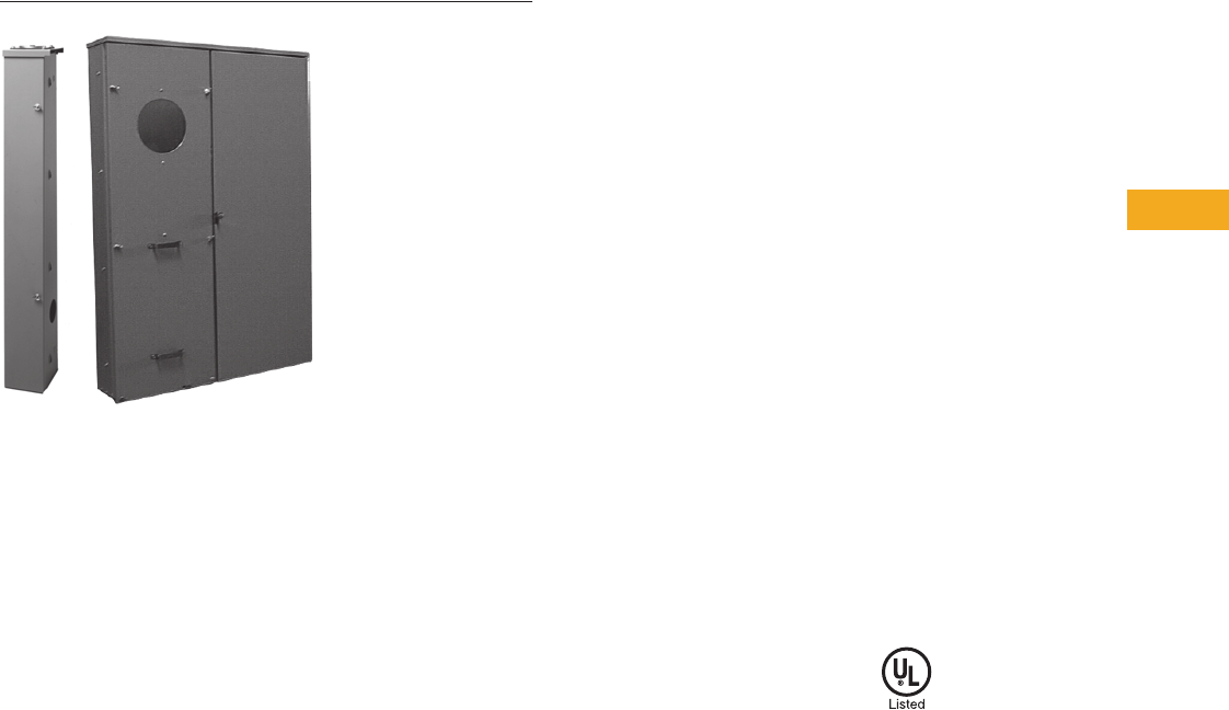
Volume 1—Residential and Light Commercial CA08100002E—February 2014 www.eaton.com V1-T5-75
5
5
5
5
5
5
5
5
5
5
5
5
5
5
5
5
5
5
5
5
5
5
5
5
5
5
5
5
5
5
5.9
Metering Products
Meter Breakers
House Panels
Contents
Description Page
Residential Meter Breakers. . . . . . . . . . . . . . . . . . V1-T5-37
Non-EUSERC Combination Service Entrance
Devices 100–200A Styles . . . . . . . . . . . . . . . . . . V1-T5-39
Meets EUSERC Requirements Service Entrance
Devices 100–225A . . . . . . . . . . . . . . . . . . . . . . . V1-T5-48
West Coast All-In-One Design. . . . . . . . . . . . . . . . V1-T5-59
Mechanical Interlock Cover . . . . . . . . . . . . . . . . . . V1-T5-65
House Panels
Commercial Safety Sockets. . . . . . . . . . . . . . . . . . V1-T5-83
CH Style Renovation Solutions . . . . . . . . . . . . . . . V1-T5-86
Aluminum Meter Breakers . . . . . . . . . . . . . . . . . . V1-T5-87
House Panels
Product Description
Eaton’s House Panels offer
a faster, easier and safer
installation.These 400A units
are ideal for larger homes in
North America that require
meter breakers. Available in
both CH and BR styles, these
service entrance devices
consist of a meter socket
and a distribution section.
In response to contractor
feedback, these panels
have been redesigned with a
focus on flexibility, simplified
wiring, and an overall ease of
installation. All units come
standard with a 22 kAIC main
breaker.The load conductors
can exit the top, bottom, side
or back for greater application
and installation flexibility.
Application Description
Additionally, Eaton’s House
Panels can be used for
apartments, condominiums,
clubhouses or common
areas.
Features, Benefits
and Functions
●NEMA 3R rainproof
●Rated for service entrance
equipment
●Lever bypass socket
available on certain
catalog numbers
●Pin type door hinges
●Socket to distribution
section is connected via
insulated cable for safety
●Second main space can
accept 100–200A BW, CSR
or CSR breakers
Standards and Certifications
●Ring style units meet
EUSERC requirements
●UL listed

V1-T5-76 Volume 1—Residential and Light Commercial CA08100002E—February 2014 www.eaton.com
5
5
5
5
5
5
5
5
5
5
5
5
5
5
5
5
5
5
5
5
5
5
5
5
5
5
5
5
5
5
5.9
Metering Products
Meter Breakers
Product Selection
400A “House Panels”
Notes
1 Confirm security type for individual EUSERC utility requirements.
2 Included in all of the following devices.
3 If unit needs to be semi-flush, order accessory item catalog number HPPR to convert all surface mounting devices to semi-flush mounting.
4 Secondary sub-main installed in panel.
5 Feed-through lugs included.
6 Includes manual bypass and additional ground lug to meet Nevada Power requirements.
7 Bolt-on meter socket.
8 For 10 kAIC, use BR or BW breakers as secondary main.
9 Georgia Power approved.
j Xcel approved.
Ampere
Rating Security 1Bypass 2
Main
Breaker
Optional
Secondary
Main
Breaker
(Not
Included)
Service
Type kAIC Dist.
Line Side
Main Lugs
and Neutral
(Lugs Not
Included)
Semi-
Flush
Catalog
Number 3
Surface
Catalog
Number
300 Ringless Lever CSR2150 BW/CSR OH/UG 22 8/16 Lug
landings for
compression
— HP816P400BSL
300 Ringless Lever CSR2150 BW/CSR UG 22 None — HPC30SHL
400 Ring None CSH2200N CSR UG 22 32/42 — CG403242SH
400 Ring None CSH2200N CSR UG 22 12/12 — CG1212P400BS 5
400 Ring Manual CSR2200 BRH/CSR UG 22 None — HP40SHA 8
400 Ring Manual CSR2200 BRH/CSR UG 22 40/40 — HP404040SHA 68
400 Ringless None DK2400 None UG 22 24/40 — HP402440B 7
400 Ringless None CSR2200 BRH/CSR UG 22 24/40 — HP402440SBH 78
400 Ring None DK2400 None UG 22 None — HP40
400 Ring None CSR2200 BRH/CSR UG 22 None — HP40SH 8
400 Ring None DK2400 None UG 22 24/42 — HP402442
400 Ring None CSR220 BRH/CSR UG 22 40/40 HP404040SHF HP404040SH 8
400 Ring Manual CSR2200 BRH/CSR UG 22 40/40 HP404040SHFA 6—
400 Ring None CSR2200 BRH/CSR UG 22 8/16 — HP816P400BS 58
400 Ringless Lever CSH2200N CSR UG 22 12/12 — CG1212P400BSL 5
400 Ringless Lever CSH2200N CSR UG 22 42/42 — CG404242SHL
400 Ringless Lever CSR2200 BRH/CSR UG 22 None — HP40SHL 8
400 Ringless Lever CSR2200 BRH/CSR OH/UG 22 None — HPC40SHL 8
400 Ringless Lever CSR2200 BRH/CSR UG 22 40/40 — HP404040SHL 8
400 Ringless Lever CSR2200 BRH/CSR UG 22 8/16 — HP816P400BSL 58
400 Ringless Lever CSR2200 BRH/CSR OH/UG 22 4/6 — HPC4046SHLG 9
400 Ringless Lever CSR2200 BRH/CSR OH/UG 22 4/6 — HPC4046SHLX j
House Panels
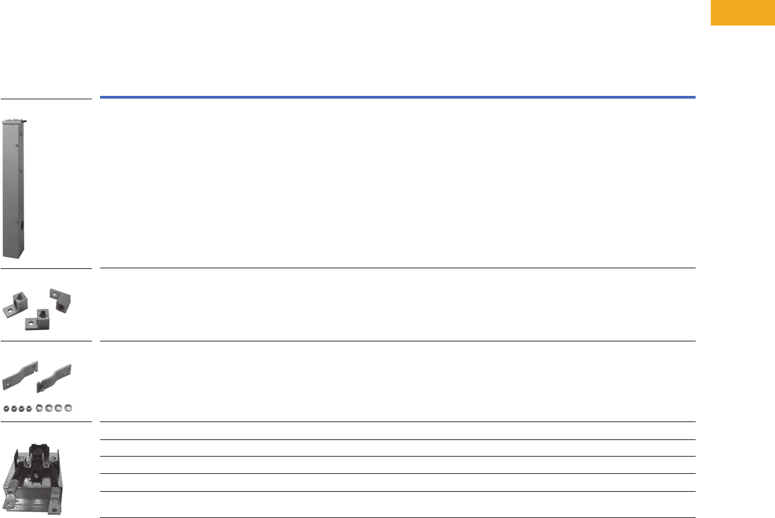
Volume 1—Residential and Light Commercial CA08100002E—February 2014 www.eaton.com V1-T5-77
5
5
5
5
5
5
5
5
5
5
5
5
5
5
5
5
5
5
5
5
5
5
5
5
5
5
5
5
5
5
5.9
Metering Products
Meter Breakers
Accessories
●Top-feed gutter kit to ease
top-fed installation
●Re-engineered, adjustable
flush mount kit for a
cleaner installation
●100A second main
breaker kit
●New 750 kcmil box type
lug kit
Accessories
Description
Catalog
Number
Top feed kit to convert surface mount house panel for overhead service HP40TFKIT
750 kcmil lug kit HPBLK750
Manual bypass kit HPBPK
Flushmount kit HPPR
100A 2nd main kit (Type BR branch) HP2NDMNKIT
100A 2nd main kit (Type CH branch) CH2NDMNKIT
5th jaw for lever bypass house panels ARP00326CH
Locates 3-inch (only) incoming conduit to back of can by utilizing the 4-inch knockout useful in semi-flush applications HP40HUBPLATE
HP40TFKIT
HPBLK750
HPBPK
HP2NDMNKIT
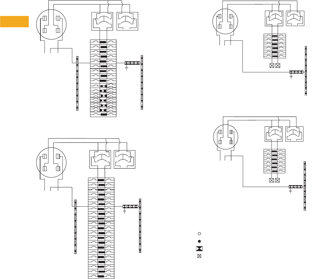
V1-T5-78 Volume 1—Residential and Light Commercial CA08100002E—February 2014 www.eaton.com
5
5
5
5
5
5
5
5
5
5
5
5
5
5
5
5
5
5
5
5
5
5
5
5
5
5
5
5
5
5
5.9
Metering Products
Meter Breakers
Wiring Diagrams
Type CH Style House Panels
Type CH Wiring—Catalog Number CG403242SH
Type CH Wiring—Catalog Number CG404242SHL
12
34
56
11
9
7
12
10
8
13 14
15 16
17 18
19 20
23
21
25
22
27
24
29
26
31
28
33
30
35
32
37
34
39
36
41
38
40
42
A
BONDED
NEUTRAL
EQUIPMENT
GROUNDING
TERMINALS
400 AMPERES
(320 AMPERES
CONTINUOUS)
FACTORY
INSTALLED
200 A
SERVICE
DISCONNECT
NB
LINE
FACTORY/FIELD
INSTALLED
200 A MAXIMUM
SERVICE
DISCONNECT
TYPE CSR
(OPTIONAL)
FACTORY/FIELD
INSTALLED
100 A MAXIMUM
SERVICE
DISCONNECT
TYPE CH
12
34
56
11
9
7
12
10
8
13 14
15 16
17 18
19 20
21 22
23 24
25 26
27 28
29 30
31 32
33 34
35 36
37 38
39 40
41 42
A
BONDED
NEUTRAL
EQUIPMENT
GROUNDING
TERMINALS
400 AMPERES
(320 AMPERES
CONTINUOUS)
FACTORY
INSTALLED
200 A
SERVICE
DISCONNECT
TYPE CSR
NB
LINE
(OPTIONAL)
FACTORY/FIELD
INSTALLED
200 A MAXIMUM
SERVICE
DISCONNECT
FACTORY/FIELD
INSTALLED
100 A MAXIMUM
SERVICE
DISCONNECT
TYPE CH
Type CH Wiring—Catalog Number CG1212P400BS
Type CH Wiring—Catalog Number CG1212P400BSL
Ty p e C H W i ri n g D i a g r a m K e y
A
BONDED
NEUTRAL
AMPERES
200 A MAXIMUM
SERVICE
DISCONNECT
TYPE BW
OR CSR
NB
LINE
200 A MAX.
SERVICE
DISCONNECT
TYPE CSR
12
34
56
11
9
7
12
10
8
OPTIONAL
OPTIONAL
100 A MAX.
SERVICE
DISCONNECT
TYPE CH
(CONTINUOUS)
A
BONDED
NEUTRAL
NB
LINE
12
34
56
11
9
7
12
10
8
200 A MAXIMUM
SERVICE
DISCONNECT
TYPE BW
OR CSR
OPTIONAL
200 A MAX.
SERVICE
DISCONNECT
TYPE CSR
OPTIONAL
100 A MAX.
SERVICE
DISCONNECT
TYPE CH
400 AMPERES
(320 AMPERES
CONTINUOUS)
#14-6 AWG
#14-1/0 AWG
1/0
–
300 kcmil
#4 AWG
–
300 kcmil
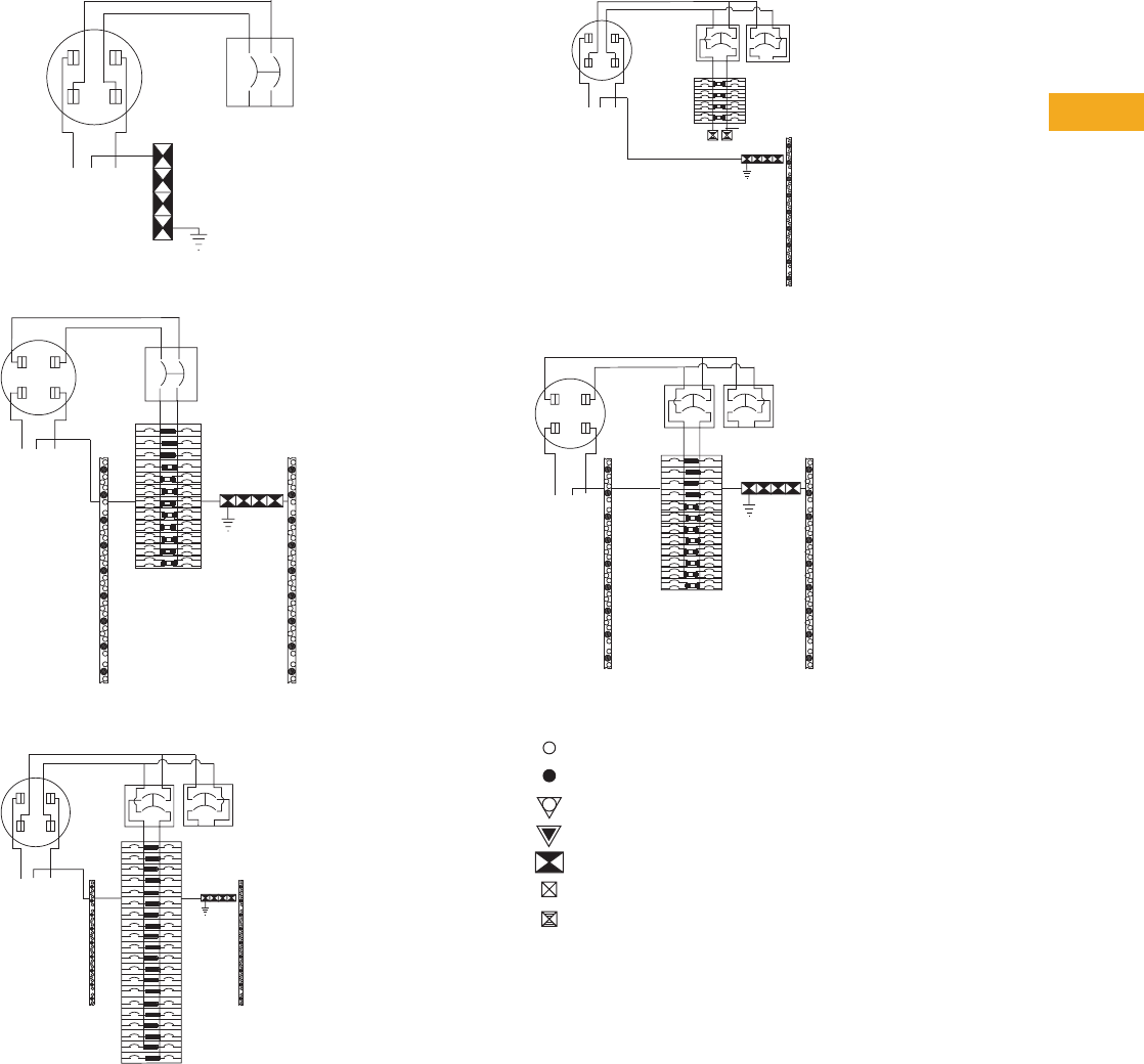
Volume 1—Residential and Light Commercial CA08100002E—February 2014 www.eaton.com V1-T5-79
5
5
5
5
5
5
5
5
5
5
5
5
5
5
5
5
5
5
5
5
5
5
5
5
5
5
5
5
5
5
5.9
Metering Products
Meter Breakers
Type BR Style House Panels
Type BR Wiring—Catalog Number HP40
Type BR Wiring—Catalog Number HP402440B
Type BR Wiring—Catalog Number HP404040SH
A
BONDED
NEUTRAL
400 AMPERES
(320 AMPERES
CONTINUOUS)
F ACT ORY
INSTALLED
400 A
SER VICE
DISCONNECT
TYPE DK
NB
LINE
A
BONDED
NEUTRAL
400 AMPS
(320 AMPS
CONTINUOUS)
FACTORY
INSTALLED
400 A
SERVICE
DISCONNECT
TYPE DK
NB
LINE
12
34
56
11
9
7
12
10
8
13 14
15 16
17 18
19 20
21 22
23 24
25 26
27 28
29 30
31 32
33 34
35 36
37 38
39 40
A
BONDED
NEUTRAL
EQUIPMENT
GROUNDING
TERMINALS
400 AMPERES
(320 AMPERES
CONTINUOUS)
FACTORY
INSTALLED
200 A
SERVICE
DISCONNECT
TYPE CSR
NB
LINE
FACTORY/FIELD
INSTALLED
200 A MAXIMUM
SERVICE
DISCONNECT
TYPE CSR
OR BW
100 A MAXIMUM
SERVICE
DISCONNECT
TYPE BRH OR BR
12
34
56
78
9
11
13
15
10
12
14
16
17
19
21
23
18
20
22
24
25
27
29
31
33
35
37
26
28
30
32
34
36
38
40
39
(OPTIONAL)
Type BR Wiring—Catalog Number HP816P400BS
Type BR Wiring—Catalog Number HP402440SBH
Type BR Wiring Diagram Key
BONDED
NEUTRAL
A
EQUIPMENT
GROUNDING
TERMINALS
400 AMPS
(320 AMPS
CONTINUOUS)
FACTORY
INSTALLED
200 A MAX.
SERVICE
DISCONNECT
TYPE CSR
NB
LINE
1
(OPTIONAL)
32
4
5
76
8
9
11 10
12
13
15 14
16
200 A MAX.
SERVICE
DISCONNECT
TYPE BW OR
CSR
100 A MAX.
SERVICE
DISCONNECT
BONDED
NEUTRAL
400 AMPS
(320 AMPS
CONTINUOUS)
FACTORY/FIELD
INSTALLED
200 A MAX.
SERVICE
DISCONNECT
TYPE CSR OR
BW
FACTORY
INSTALLED
200 A
SERVICE
DISCONNECT
TYPE CSR
(OPTIONAL)
ANB
LINE
1
3
5
11
9
7
13
15
17
19
21
23
25
27
29
31
33
35
37
39
2
4
6
12
10
8
14
16
18
20
22
24
26
28
30
32
34
36
38
40
100 A MAX.
SERVICE
DISCONNECT
TYPE BRH OR
BR
#14-6 AWG
#14-1/0 AWG
#6 AWG
–
250 kcmil
#1 AWG
–
300 kcmil
1/0
–
300 kcmil
#4 AWG
–
300 kcmil
#6 AWG
–
300 kcmil
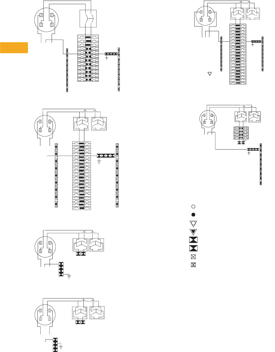
V1-T5-80 Volume 1—Residential and Light Commercial CA08100002E—February 2014 www.eaton.com
5
5
5
5
5
5
5
5
5
5
5
5
5
5
5
5
5
5
5
5
5
5
5
5
5
5
5
5
5
5
5.9
Metering Products
Meter Breakers
Type BR Wiring—Catalog Number HP402442
Type BR Wiring—Catalog Number HP404040SHL
Type BR Wiring—Catalog Number HP40SH
Type BR Wiring—Catalog Number HP40SHL
A
BONDED
NEUTRAL
400 AMPERES
(320 AMPERES
CONTINUOUS)
FACTORY
INSTALLED
400 A
SERVICE
DISCONNECT
TYPE DK
NB
LINE
12
34
56
11
9
7
12
10
8
13 14
15 16
17 18
19 20
21 22
23 24
25 26
27 28
29 30
31 32
33 34
35 36
37 38
39 40
41 42
1
12
34
56
11
9
7
12
10
8
13 14
15 16
17 18
19 20
21 22
23 24
25 26
27 28
29 30
31 32
33 34
35 36
37 38
39 40
ABONDED
NEUTRAL
FACTORY
INSTALLED
200 A
SERVICE
DISCONNECT
TYPE CSR
400 AMPS
(320 AMPS
CONTINUOUS)
N
B
LINE
(OPTIONAL)
FACTORY/FIELD
INSTALLED
200 A MAX.
SERVICE
DISCONNECT
TYPE BW OR
CSR
100 A MAX.
SERVICE
DISCONNECT
TYPE BR OR
BHR
(OPTIONAL)
A
BONDED
NEUTRAL
400 AMPS
(320 AMPS
CONTINUOUS)
FACTORY
INSTALLED
200 A
SERVICE
DISCONNECT
TYPE CSR
NB
LINE
FACTORY/FIELD
INSTALLED
200A MAX.
SERVICE
DISCONNECT
TYPE CSR OR
BW
100A MAX.
SERVICE
DISCONNECT
TYPE BRH OR
BR
A
BONDED
NEUTRAL
400 AMPS
(320 AMPS
CONTINUOUS)
FACTORY
INSTALLED
200 A
SERVICE
DISCONNECT
TYPE CSR
N
B
LINE
FACTORY/FIELD
INSTALLED
200 A MAX.
SERVICE
DISCONNECT
TYPE BW OR
CSR
(OPTIONAL)
100 A MAX.
SERVICE
DISCONNECT
TYPE BR OR
BRH
Type BR Wiring—Catalog Number HP404040SHA
Type BR Wiring—Catalog Number HP816P400BSL
Ty p e B R W i r i n g D i a g r a m K e y
A
EQUIPMENT
GROUNDING
TERMINALS
400 AMPS
(320 AMPS
CONTINUOUS)
FACTORY
INSTALLED
200 A
SERVICE
DISCONNECT
TYPE CSR
NB
LINE
12
34
56
9
7
10
8
FACTORY
INSTALLED
BY-PASS.
FACTORY/FIELD
INSTALLED
200 A MAX.
SERVICE
DISCONNECT
TYPE CSR
OR BW
20
28
36
40
34
38
24
32
26
30
22
16
18
12
14
27
35
39
33
37
23
31
25
29
21
15
11
13
19
17
GROUNDING
LUG
100 A MAX.
SERVICE
DISCONNECT
TYPE BRH
OR BR
(OPTIONAL)
BONDED
NEUTRAL
A
EQUIPMENT
GROUNDING
TERMINALS
400 AMPS
(320 AMPS
CONTINUOUS)
FACTORY
INSTALLED
200 A MAX.
SERVICE
DISCONNECT
NB
LINE
200 A MAX.
SERVICE
DISCONNECT
TYPE CSR
1
OPTIONAL
32
4
5
76
8
9
11 10
12
13
15 14
16
100 A MAX.
SERVICE
DISCONNECT
#14-6 AWG
#14-1/0 AWG
#6 AWG
–
250 kcmil
#1 AWG
–
300 kcmil
1/0
–
300 kcmil
1/3
–
300 kcmil
#4 AWG
–
300 kcmil
#6 AWG
–
300 kcmil
1
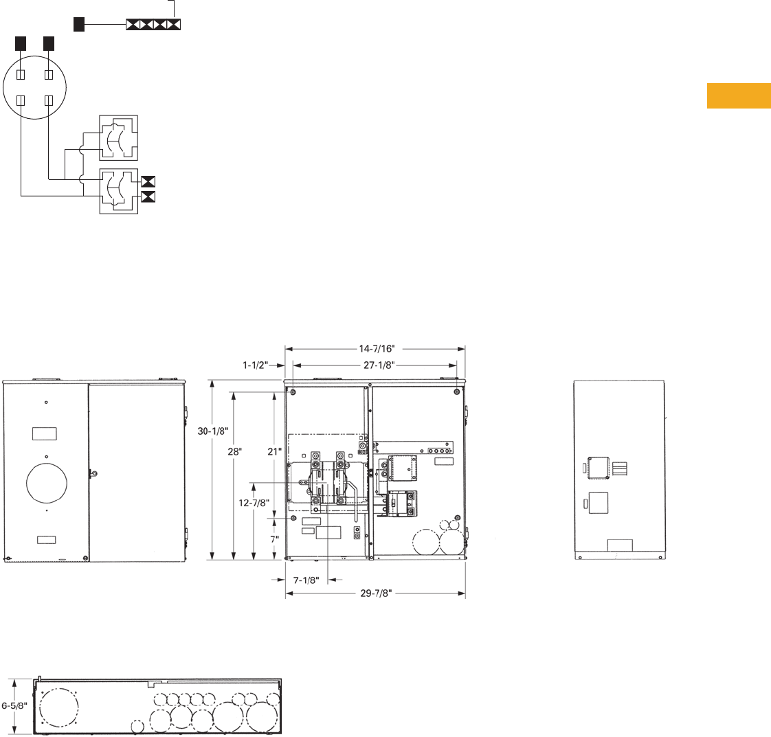
Volume 1—Residential and Light Commercial CA08100002E—February 2014 www.eaton.com V1-T5-81
5
5
5
5
5
5
5
5
5
5
5
5
5
5
5
5
5
5
5
5
5
5
5
5
5
5
5
5
5
5
5.9
Metering Products
Meter Breakers
Catalog Numbers HPC40SHL and HPC30SHL
Dimensions and Knockouts
Approximate Dimensions in Inches (mm)
Catalog Numbers HPC40SHL and HPC30SHL
Knockout Configurations and Dimensions for
HPC40SHL and HPC30SHL
N
Bonded
Neutral
(Optional)
Factory/Field Installed
150 A Max. - HPC30SHL
200 A Max. - HPC40SHL
Service Disconnect
Type BW or CSR
Factory Installed
150 A or 200 A
Service Disconnect
Type CSR
(Optional)
100 A Max.
Service
Disconnect
Type BR or
BRH
400 Amps
(320 Amps
Continuous)
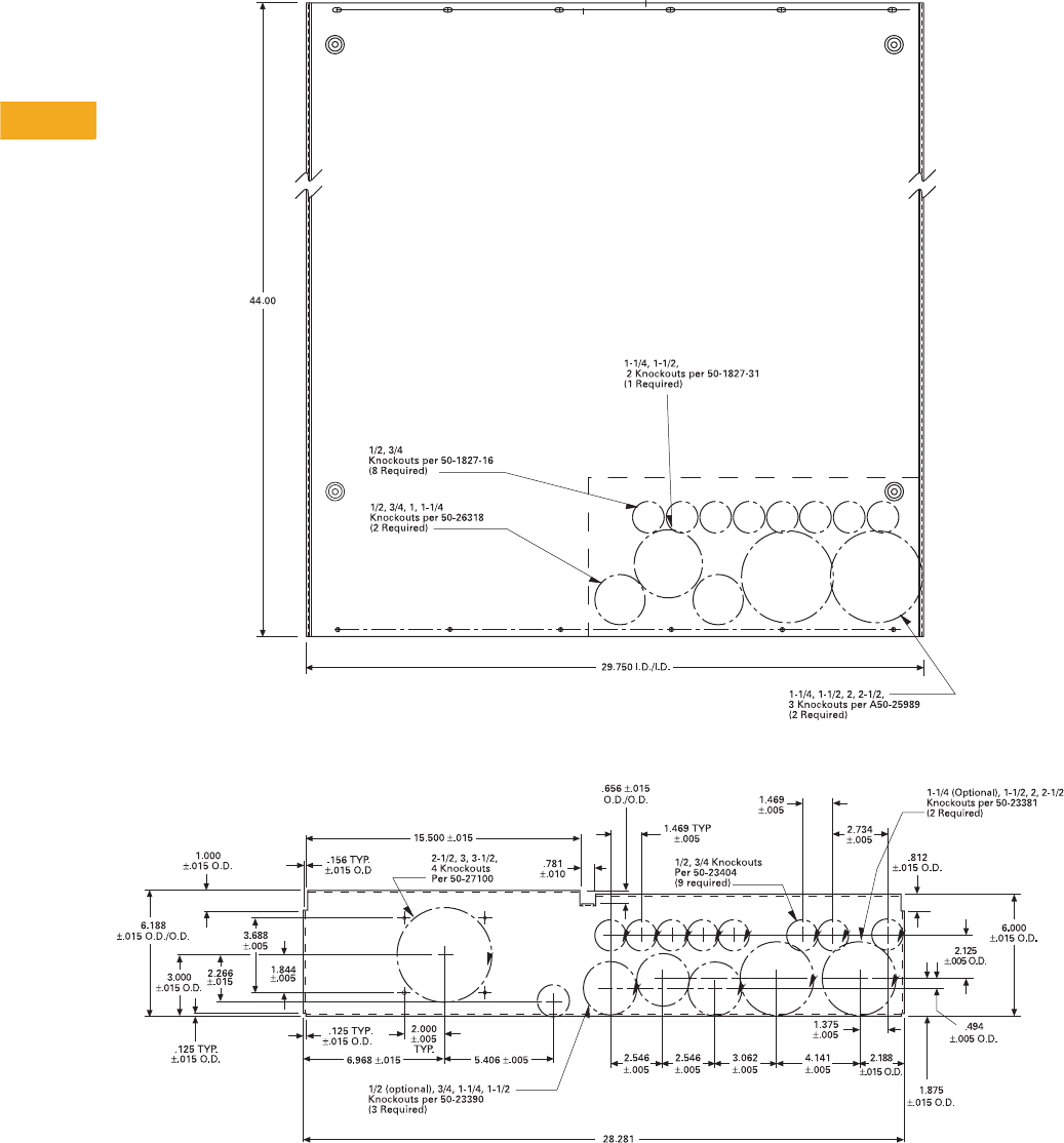
V1-T5-82 Volume 1—Residential and Light Commercial CA08100002E—February 2014 www.eaton.com
5
5
5
5
5
5
5
5
5
5
5
5
5
5
5
5
5
5
5
5
5
5
5
5
5
5
5
5
5
5
5.9
Metering Products
Meter Breakers
Approximate Dimensions in Inches (mm)
House Panel Dimensions and Knockouts—For All House Panels Except Those With HPCPREFIX
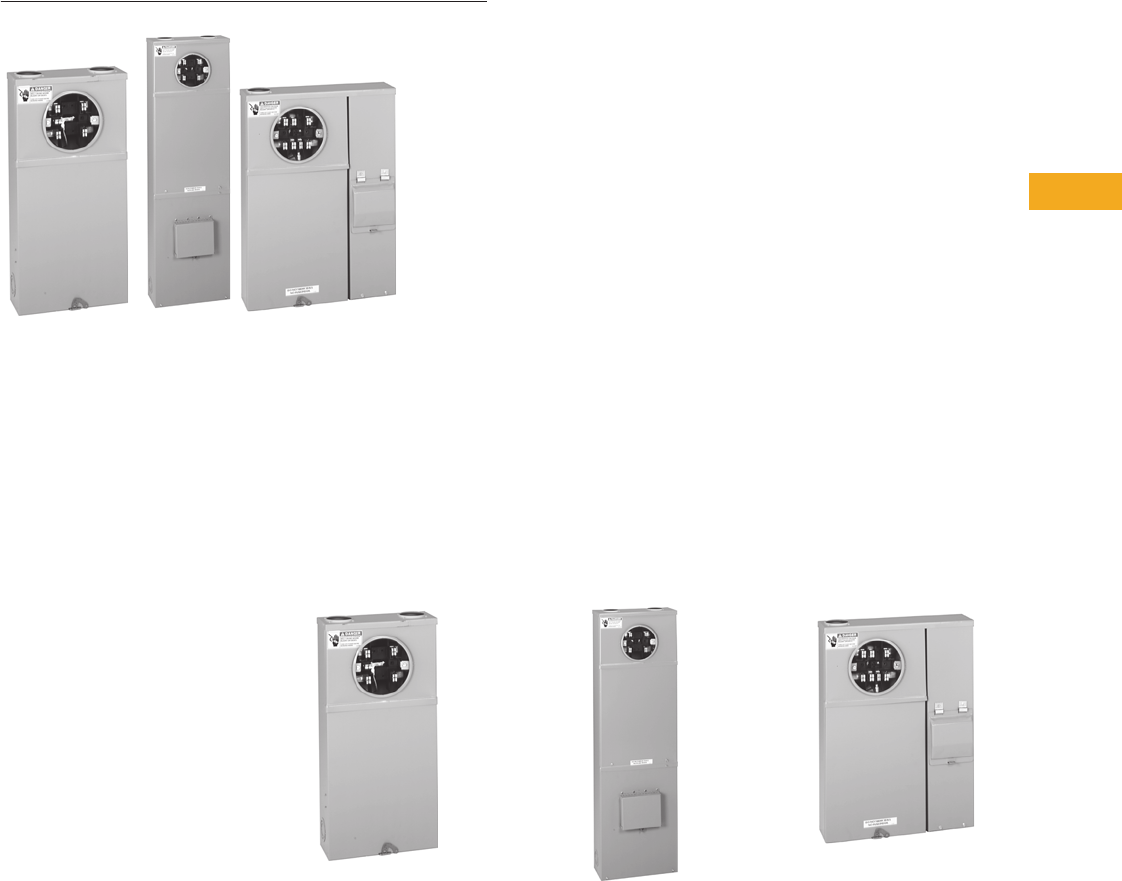
Volume 1—Residential and Light Commercial CA08100002E—February 2014 www.eaton.com V1-T5-83
5
5
5
5
5
5
5
5
5
5
5
5
5
5
5
5
5
5
5
5
5
5
5
5
5
5
5
5
5
5
5.9
Metering Products
Meter Breakers
Residential Meter Breakers
Contents
Description Page
Residential Meter Breakers. . . . . . . . . . . . . . . . . . V1-T5-37
Non-EUSERC Combination Service Entrance
Devices 100–200A Styles . . . . . . . . . . . . . . . . . . V1-T5-39
Meets EUSERC Requirements Service Entrance
Devices 100–225A . . . . . . . . . . . . . . . . . . . . . . . V1-T5-48
West Coast All-In-One Design. . . . . . . . . . . . . . . . V1-T5-59
Mechanical Interlock Cover . . . . . . . . . . . . . . . . . . V1-T5-65
House Panels . . . . . . . . . . . . . . . . . . . . . . . . . . . . V1-T5-75
Commercial Safety Sockets
CH Style Renovation Solutions . . . . . . . . . . . . . . . V1-T5-86
Aluminum Meter Breakers . . . . . . . . . . . . . . . . . . V1-T5-87
Commercial Safety
Sockets
Product Description
A Commercial Safety
Socket is service entrance
equipment that consists of
a commercial meter socket
with a test block, and may
come with or without a
loadcenter type distribution
section.
Application Description
Eaton’s Commercial Safety
Sockets are typically used
where a single meter socket
or single meter socket with
a distribution section are
needed. These areas could
include a commercial
business, commercial office
building, individual retail
facilities and signs and street
lighting. Commercial Safety
Sockets are typically used in
EUSERC utility regions.
Features, Benefits and Functions
Commercial Safety Sockets with
No Secondary Feeder
●Ring type continuous duty
meter socket. 600 Vac
maximum, single- or
three-phase
●100 and 200A units
●Bussed connection from
meter socket to test block
●For use with self-contained
watthour meter
●Conform with EUSERC
standards
●NEMA 3R construction for
indoor/outdoor applications
●Units can be individually
mounted with provisions
for hub kits and pole
mounting
Overhead Combination Units
●NEMA 3R construction for
indoor/outdoor applications
●T-fuse protection, 480 Vac
maximum
●Line at top, load at bottom
●100 and 200A units
available up to 480 Vac
maximum
●Circuit breaker protection
to 480 Vac maximum in
10, 22, 42 and 100 kAIC
ratings
●Factory-cabled connection
from test block to line side
of tenant main
Underground Combination Units
●100 and 200A units
●480 Vac maximum
●NEMA 3R construction for
indoor/outdoor applications
●Underground or overhead
feed
●Provisions for self-
contained watthour meter
●Bussed connection from
meter socket to test block
●Tenant main disconnects
are available with circuit
breakers up to 480 Vac
maximum and T-fuse
mains, 240 Vac maximum
●Load wires can exit top
or bottom
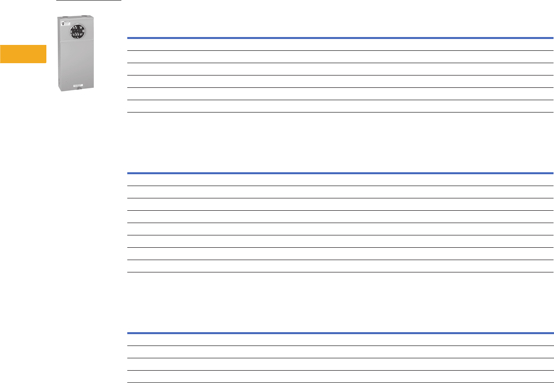
V1-T5-84 Volume 1—Residential and Light Commercial CA08100002E—February 2014 www.eaton.com
5
5
5
5
5
5
5
5
5
5
5
5
5
5
5
5
5
5
5
5
5
5
5
5
5
5
5
5
5
5
5.9
Metering Products
Meter Breakers
Product Selection
Overhead and Underground Combination Units and Individual Units
Individual Safety Sockets—600V Maximum—No Secondary Feeder Devices
Commercial Safety Sockets with Provision for Main Circuit Breaker
Commercial Safety Sockets with Main Circuit Breaker Included
Notes
1 If being protected by a fuse, the interrupting rating of the unit is limited to the fuse AIC rating. If being protected by a single- or three-phase,
600V breaker, the AIC is 14 kA; by a maximum 400A, single-phase, 240V breaker, the AIC is 18 kA; by a maximum 200A, single- or three-phase,
240V breaker, the AIC is 18 kA; by a maximum 125A, single-phase, 240V breaker, the AIC is 22 kA.
2 Order plug-on Type BR, BRH or BRHH circuit breaker separately.
3 Order Type CC breaker or CCH breaker separately.
4 Type BR = 10 kA; Type BRH = 22 kA; Type BRHH = 42 kA.
5 Type CCV = 10 kA; Type CCVH = 25 kA.
Ampere
Rating
No. of
Jaws
AC
Voltage Service Phase, Wire
Maximum
Interrupting
Rating
Wire
Size
Catalog
Number
125 4 600 OH/UG Single-phase, three-wire 1#14–2/0
CH114TB
125 5 600 OH/UG Three-phase, three-wire 1#14–2/0
CH115TB
125 7 600 OH/UG Three-phase, four-wire 1#14–2/0
CH117TB
200 4 600 OH/UG Single-phase, three-wire 1#6–250 kcmil
CH124TB
200 5 600 OH/UG Three-phase, three-wire 1#6–250 kcmil
CH125TB
200 7 600 OH/UG Three-phase, four-wire 1#6–250 kcmil
CH127TB
Ampere
Rating
No. of
Jaws
AC
Voltage Service Phase, Wire
Feeder
Circuit
Breaker
Maximum
Interrupting
Rating
Wire
Size
Catalog
Number
125 4 240 OH Single-phase, three-wire Provision 24 #14–2/0
CH214MTBLB
125 7 208/120 OH Three-phase, four-wire Provision 24 #14–2/0
CH217MTBLB
125 4 240 UG Single-phase, three-wire Provision 24 #14–2/0
CHU214MTBLB
125 7 208/120 UG Three-phase, four-wire Provision 24 #14–2/0
CHU217MTBLB
200 4 120/240 OH Single-phase, three-wire Provision 35 #6–250 kcmil
CH224MTBLB
200 7 208/120 OH Three-phase, four-wire Provision 35 #6–250 kcmil
CH227MTBLB
200 4 120/240 UG Single-phase, three-wire Provision 35 #6–250 kcmil
CHU224MTBLB
200 7 208/120 UG Three-phase, four-wire Provision 35 #6–250 kcmil
CHU227MTBLB
Ampere
Rating
No. of
Jaws
AC
Voltage Service Phase, Wire
Feeder
Circuit
Breaker
Maximum
Interrupting
Rating
Wire
Size
Catalog
Number
100 7 480/277 OH Three-phase, four-wire EHD3100 14 kA #14–2/0
CH217MTBM515
100 7 480/277 UG Three-phase, four-wire EHD3100 14 kA #14–2/0
CHU217MTBMS15
200 7 480/277 OH Three-phase, four-wire JD3200 25 kA #6–250 kcmil
CH227MTBHMS15
200 7 480/277 UG Three-phase, four-wire JD3200 25 kA #6–250 kcmil
CHU227MTBHMS15
CH127TB
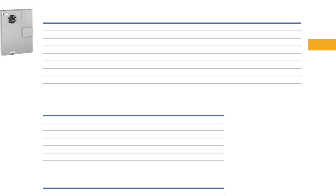
Volume 1—Residential and Light Commercial CA08100002E—February 2014 www.eaton.com V1-T5-85
5
5
5
5
5
5
5
5
5
5
5
5
5
5
5
5
5
5
5
5
5
5
5
5
5
5
5
5
5
5
5.9
Metering Products
Meter Breakers
Underground Combination Units and Safety Socket Accessories
Commercial Safety Sockets with T-Fuse Switch
Hubs
Jaws
Note
Order Type CC or CHH breaker separately.
Ampere
Rating
No. of
Jaws
AC
Voltage Service Phase, Wire
Feeder
Circuit
Breaker
Maximum
Interrupting
Rating
Wire
Size
100 4 120/240 OH Single-phase, three-wire 200 kA #14–2/0 CH214MTBP
100 7 208/120 OH Three-phase, four-wire 200 kA #14–2/0 CH217MTBP
100 4 120/240 UG Single-phase, three-wire 200 kA #14–2/0 CHU214MTBP
100 7 208/120 UG Three-phase, four-wire 200 kA #14–2/0 CHU217MTBP
200 4 120/240 OH Single-phase, three-wire 200 kA #6–250 kcmil CH224MTBP
200 7 208/120 OH Three-phase, four-wire 200 kA #6–250 kcmil CH227MTBP
200 4 120/240 UG Single-phase, three-wire 200 kA #6–250 kcmil CHU224MTBP
200 7 208/120 UG Three-phase, four-wire 200 kA #6–250 kcmil CHU227MTBP
Description
Carton
Weight Lbs (kg)
Catalog
Number
Hub closure plate 3 (1.4) ARP00002CHB
1.00-inch (25.4 mm) hub 3 (1.4) ARP00003CH1
1.25-inch (31.8 mm) hub 3 (1.4) ARP00004CH12
1.50-inch (38.1 mm) hub 3 (1.4) ARP00005CH15
2.00-inch (50.8 mm) hub 3 (1.4) ARP00006CH2
2.50-inch (63.5 mm) hub 3 (1.4) ARP00007CH25
Description Part Number
5th jaw kit CH50371
CHU227MTBP
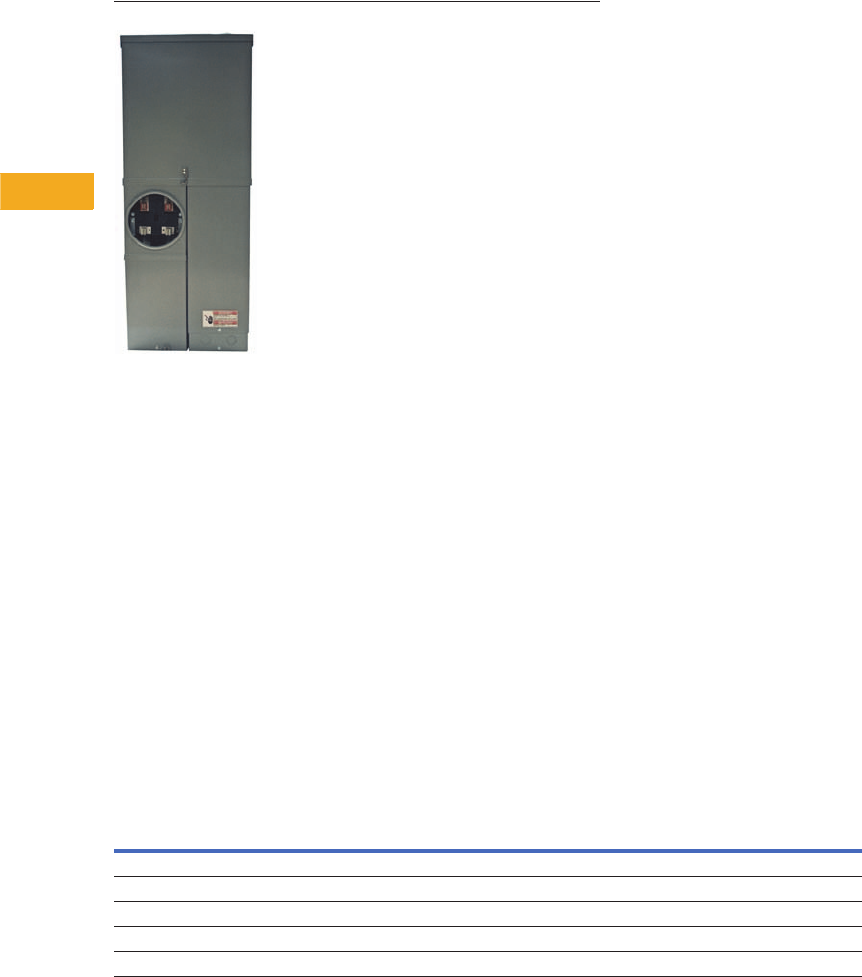
V1-T5-86 Volume 1—Residential and Light Commercial CA08100002E—February 2014 www.eaton.com
5
5
5
5
5
5
5
5
5
5
5
5
5
5
5
5
5
5
5
5
5
5
5
5
5
5
5
5
5
5
5.9
Metering Products
Meter Breakers
CH Style Renovation Solutions
Contents
Description Page
Residential Meter Breakers . . . . . . . . . . . . . . . . . V1-T5-37
Non-EUSERC Combination Service Entrance
Devices 100–200A Styles. . . . . . . . . . . . . . . . . . V1-T5-39
Meets EUSERC Requirements Service Entrance
Devices 100–225A . . . . . . . . . . . . . . . . . . . . . . . V1-T5-48
West Coast All-In-One Design . . . . . . . . . . . . . . . V1-T5-59
Mechanical Interlock Cover . . . . . . . . . . . . . . . . . . V1-T5-65
House Panels . . . . . . . . . . . . . . . . . . . . . . . . . . . . V1-T5-75
Commercial Safety Sockets . . . . . . . . . . . . . . . . . V1-T5-83
CH Style Renovation Solutions
Aluminum Meter Breakers . . . . . . . . . . . . . . . . . . V1-T5-87
CH Style Renovation Solutions
Product Description
●Ring style meter
socket design
●Provisional main breaker
or factory main breaker
available
●Center top feed design
●Exit bottom or top design
●100A, 125A or 200A
ratings available
Product Selection
CH Style Retrofit Solutions
Ampere
Rating Description
Catalog
Number
100 CH, 22 circuit, provision, center top feed, exit top or bottom, flush, OH/UG CMBE22P100BTFR
125 CH, 22 circuit, provision, center top feed, exit top or bottom, surface, OH/UG CMBE22P125BTSR
125 CH, 22 circuit, provision, center top feed, exit top or bottom, flush, OH/UG CMBE22P125BTFR
200 CH, 32/42 circuit, 200A main breaker, center top feed, exit top or bottom, semi-flush, OH/UG CMBE3242B200BTS
200 CH, 32/42 circuit, 200A main breaker, center top feed, exit top or bottom, flush, OH/UG CMBE3242B200BTFR
Volume 1—Residential and Light Commercial CA08100002E—February 2014 www.eaton.com V1-T5-87
5
5
5
5
5
5
5
5
5
5
5
5
5
5
5
5
5
5
5
5
5
5
5
5
5
5
5
5
5
5
5.9
Metering Products
Meter Breakers
Contents
Description Page
Residential Meter Breakers. . . . . . . . . . . . . . . . . . V1-T5-37
Non-EUSERC Combination Service Entrance
Devices 100–200A Styles . . . . . . . . . . . . . . . . . . V1-T5-39
Meets EUSERC Requirements Service Entrance
Devices 100–225A . . . . . . . . . . . . . . . . . . . . . . . V1-T5-48
West Coast All-In-One Design. . . . . . . . . . . . . . . . V1-T5-59
Mechanical Interlock Cover . . . . . . . . . . . . . . . . . . V1-T5-65
House Panels . . . . . . . . . . . . . . . . . . . . . . . . . . . . V1-T5-75
Commercial Safety Sockets. . . . . . . . . . . . . . . . . . V1-T5-83
CH Style Renovation Solutions . . . . . . . . . . . . . . . V1-T5-86
Aluminum Meter Breakers
Aluminum Meter Breakers
Product Description
Eaton’s Aluminum Meter
Breaker enclosure and
external cover offers
excellent corrosion resistance
in the harshest coastal
environments. The meter
breaker’s light weight and
overhead/underground
design offers flexibility and
ease of installation.
Features and Benefits
●Overhead/underground
design provides flexibility
with wiring options
●Steel meter guides are
standard, which provides a
means of easy installation
of the utility glass bulb
meter into the meter’s
jaws
●Main Lug Only design
includes six two-pole
breaker locations, which
complies with National
Electrical Code 225.33
(maximum number of
disconnects)
●Distribution section
accepts BR branch
breakers
●Single-phase, three-wire
120/240 Vac applications
●Hub closure plate is
provided, attached to the
top of the device
●Optional fifth jaw can be
applied to 3 o’clock or
9 o’clock meter socket
position
●10-year warranty
●For customer support,
contact Eaton’s Technical
Resource Center at
1-877-ETN-CARE
●For additional information
or to place an order,
contact your local Eaton
representative or visit us
at www.eaton.com
Catalog Number Selection
Meter Breakers
MB 12 12 L 200 BT S A
Meter Breaker Type
MB = 1-inch (25.4 mm) BR Type
Spacing
Number of spaces
Poles
Maximum number of poles
Main
L = Lug
Amperes
Amperage of unit
Breaker Feed
BT = Bottom and top
Mounting
S = Surface
Material
A = Aluminum
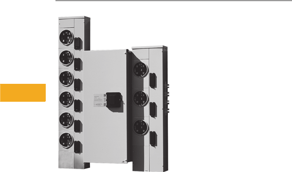
V1-T5-88 Volume 1—Residential and Light Commercial CA08100002E—February 2014 www.eaton.com
5
5
5
5
5
5
5
5
5
5
5
5
5
5
5
5
5
5
5
5
5
5
5
5
5
5
5
5
5
5
5.10
Metering Products
Group Metering
Systems for Residential and Commercial Application
Contents
Description Page
Systems for Residential and Commercial
Applications
Meter Packs . . . . . . . . . . . . . . . . . . . . . . . . . . . . . V1-T5-90
Type CCV 120/240V Tenant Main Circuit Breaker . V1-T5-95
Type CV 120/240V Tenant Main Circuit Breaker . . V1-T5-96
Meter Packs—1MP, 1MM and 3MM Main
Tenant Circuit Breakers . . . . . . . . . . . . . . . . . . . V1-T5-98
Main Service Modules . . . . . . . . . . . . . . . . . . . . . V1-T5-101
Surge Metering. . . . . . . . . . . . . . . . . . . . . . . . . . . V1-T5-115
Residential Meter Stacks . . . . . . . . . . . . . . . . . . . V1-T5-116
1MP, 1MM and 3MM Main Tenant
Circuit Breakers . . . . . . . . . . . . . . . . . . . . . . . . . V1-T5-125
Phase Balanced Stack. . . . . . . . . . . . . . . . . . . . . . V1-T5-126
Commercial Meter Stack Modules . . . . . . . . . . . . V1-T5-127
35MM, 37MM, 35SS and 37SS
Main Tenant Circuit Breakers . . . . . . . . . . . . . . . V1-T5-134
Systems for Residential and Commercial Applications
Product Description
Group metering is a service
entrance product line that
consists of a main device
and multiple meter sockets
in one enclosure or several
connected enclosures.
Group metering allows the
customer to install a multiple
tenant-metering device in
one location while providing
a space and installation
cost savings.
Application Description
Eaton’s Electrical Sector
offers two group metering
designs—Meter Packs and
Gangable Metering. Meter
Packs, also called All-in-Ones,
consist of main lugs and up
to six meter sockets in one
enclosure. Meter Packs are
supplied as one complete
unit and the user cannot
“add” additional meter
sockets to the unit in the
future. The most common
application for Meter Packs
is garden apartments,
small condominiums and
townhouses where six or
less units are metered
through one centrally
located Meter Pack.
Gangable Metering
(Main Service Modules
and Meter Stacks)
The second type of group
metering is Gangable
Metering, which consists of
a Main Service Module used
in conjunction with a Meter
Stack to make a custom
metering lineup. The Main
Service Module can be main
lug, main circuit breaker, main
fusible switch or bolted
pressure switch. The Meter
Stack is offered with various
meter sockets and bus
ratings. This type of custom
lineup allows the owner to
add/remove meter sockets
and main devices to meet
future need. Gangable
Metering is often used in
large condominiums, strip
malls and light commercial
applications where more
than six units are metered,
or there will be a future
need to add more units.
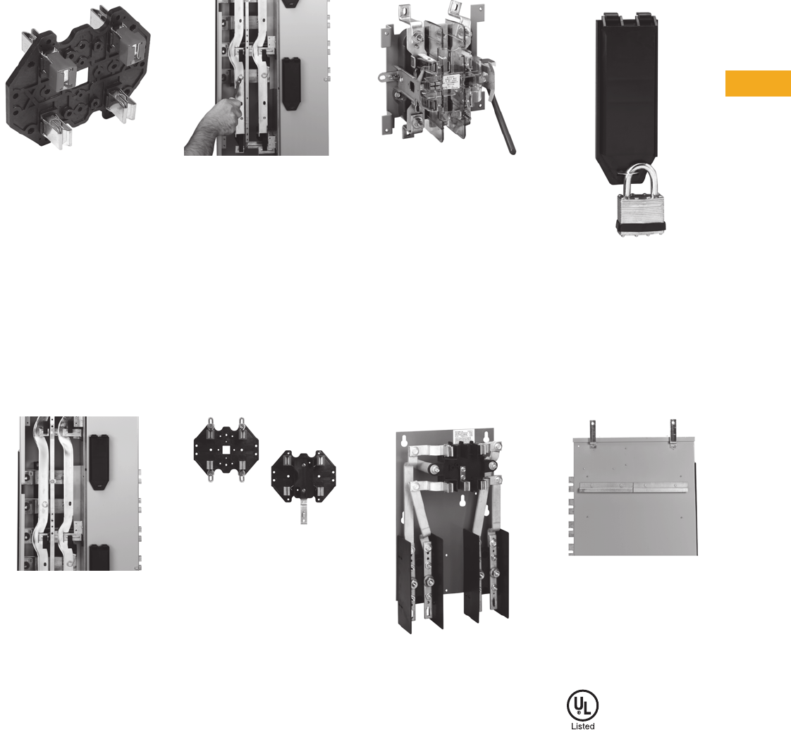
Volume 1—Residential and Light Commercial CA08100002E—February 2014 www.eaton.com V1-T5-89
5
5
5
5
5
5
5
5
5
5
5
5
5
5
5
5
5
5
5
5
5
5
5
5
5
5
5
5
5
5
5.10
Metering Products
Group Metering
Features, Benefits and Functions
Clip-Tight™ Socket
Clip-Tight Socket
Eaton’s series of 1MP, 1MM,
3MM metering devices
incorporate the only socket
base in the industry without
fasteners. This component
uses jaws on both sides of a
thermoplastic polyester glass
fiber reinforced (PBT) base,
eliminating the need
for self-tapping screw
connections to vertical
busbars.
One-Piece Vertical Busbar
One-Piece Vertical Busbar
Eaton’s series of 1MP, 1MM,
3MM meter stacks embody
a one-piece busbar
construction to each socket,
as well as a one-piece cross
bus to each tenant main.
Because the Eaton design
uses the Clip-Tight meter
socket and does not have
busbar joints, the chance of
hot spots occurring is virtually
eliminated.
Field Phase Balancing
Field Phase Balancing
Due to popular incoming
three-phase voltage systems
and single-phase outgoing
loads, installers have the
option to field phase balance
on the individual stack (A-B,
B-C, A-C). This feature
eliminates the chance of
installing an incorrectly
phased device due to its
versatility.
Horn and Manual Bypass
Horn and Manual Bypass
With an increasing demand for
uninterrupted power, Eaton’s
series of 1MP, 1MM and
3MM meter sockets offer
horn (ringless style) and
manual (ring style) field-
installable bypass accessories.
These accessories provide
uninterrupted tenant service
if a meter is pulled for
inspection or replacement.
Lever Bypass
Lever Bypass
Due to commercial
requirements, Eaton offers
a lever bypass (as standard)
on all 35MM and 37MM
devices. Each socket base
consists of a lever bypass,
which also releases the jaws
(when lever is engaged in
bypass position), enabling
utility company mechanics to
easily remove and/or insert
utility meter.
Test Bypass Disconnects
Test Bypass Disconnects
Eaton also provides
commercial meter stacks
with EUSERC required test-
bypass disconnects (35SS
and 37SS). This bypass is
used in the same applications
as the lever bypass and it is
required by EUSERC utilities.
Main Tenant Breaker Cover
Main Tenant Breaker Cover
Each tenant circuit breaker
is protected by a lockable
raintight cover that secures
the breaker against
unauthorized operation. The
tenant breaker cover is a high
impact plastic to resist wear,
rusting and corrosion.
Mounting Features
Mounting Features
A standard mounting rail and
factory-installed swing away
feet speed up and simplify
installation.
Standards and Certifications
●UL listed
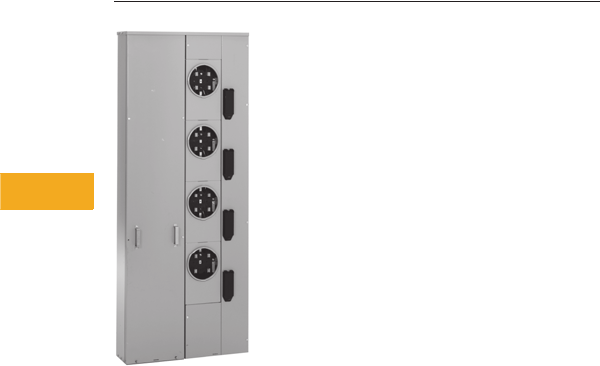
V1-T5-90 Volume 1—Residential and Light Commercial CA08100002E—February 2014 www.eaton.com
5
5
5
5
5
5
5
5
5
5
5
5
5
5
5
5
5
5
5
5
5
5
5
5
5
5
5
5
5
5
5.10
Metering Products
Group Metering
Meter Pack
Contents
Description Page
Systems for Residential and Commercial
Applications . . . . . . . . . . . . . . . . . . . . . . . . . . . . V1-T5-88
Meter Packs
Type CCV 120/240V Tenant Main Circuit Breaker . V1-T5-95
Type CV 120/240V Tenant Main Circuit Breaker . . V1-T5-96
Meter Packs—1MP, 1MM and 3MM Main
Tenant Circuit Breakers . . . . . . . . . . . . . . . . . . . V1-T5-98
Main Service Modules . . . . . . . . . . . . . . . . . . . . . V1-T5-101
Surge Metering. . . . . . . . . . . . . . . . . . . . . . . . . . . V1-T5-115
Residential Meter Stacks . . . . . . . . . . . . . . . . . . . V1-T5-116
1MP, 1MM and 3MM Main Tenant
Circuit Breakers . . . . . . . . . . . . . . . . . . . . . . . . . V1-T5-125
Phase Balanced Stack. . . . . . . . . . . . . . . . . . . . . . V1-T5-126
Commercial Meter Stack Modules . . . . . . . . . . . . V1-T5-127
35MM, 37MM, 35SS and 37SS
Main Tenant Circuit Breakers . . . . . . . . . . . . . . . V1-T5-134
Meter Packs
Product Overview
●Eaton’s 1MP units are
self-contained (main
terminal box included) for
installations requiring up to
six meter socket positions
in a single enclosure
●Units are not gangable
with any other metering
device
●Approved by major power
companies, UL listed,
suitable as service
equipment and meet the
service and electrical
requirements of EUSERC
and CECHA
●Series rating up to
100 kAIC
●All ringless cover
devices include fifth
jaw as standard
●Ring type devices do
not include fifth jaw as
standard. Order 1MM5JK
if needed
●Bondable neutral
●120/240 Vac, single-phase
three-wire metering device
●Up to 600A maximum
horizontal bus rating
●Incoming lugs not included
(phase A, phase B and
neutral)
●Indoor/outdoor
construction
●Provision for two-pole
breaker (plug-on type for
125A sockets and bolt-on
type for 200A sockets)—
circuit breakers not
included
●Underground incoming
feed
●Aluminum or copper bus
Volume 1—Residential and Light Commercial CA08100002E—February 2014 www.eaton.com V1-T5-91
5
5
5
5
5
5
5
5
5
5
5
5
5
5
5
5
5
5
5
5
5
5
5
5
5
5
5
5
5
5
5.10
Metering Products
Group Metering
Catalog Number Selection
When Ordering:
1. Determine catalog number of the basic device.
2. Include Lug Kit for incoming section. See Page V1-T5-94.
3. Find quantity and catalog numbers for tenant circuit breakers. (Order one breaker per socket.) See Page V1-T5-94.
4. Select required accessories. See Page V1-T5-136.
Bus Material
C = Copper bus
Blank = Aluminum bus
Single-Phase Type of Metering
MP = Meter pack
Ampere Rating
12 = 125A
20 = 200A
Blank = Accessory
Number of Meters
2, 3, 4, 5 or 6
Blank = Accessory
Security or Accessory Code
R= Ring
RRL = Ringless
RRLB = Ringless with horn bypass
LK = Lug kit (accessory)
SC = Crimp lug landing pad kit
(accessory)
Bus Ampere Rating
2 = 200A
4 = 400A
6 = 600A
Blank = Accessory
1 M P 4 12 4 R C

V1-T5-92 Volume 1—Residential and Light Commercial CA08100002E—February 2014 www.eaton.com
5
5
5
5
5
5
5
5
5
5
5
5
5
5
5
5
5
5
5
5
5
5
5
5
5
5
5
5
5
5
5.10
Metering Products
Group Metering
Product Selection
Meter Packs
Aluminum Bus—Main Lugs Not Included—See Page V1-T5-94
Notes
1Ring Style Meter Packs do not come with fifth jaw. Order 1MM5JK if needed.
2To change in field from ring to ringless—order 1MMRC125.
3To change in field from ring to ringless—order 1MMRC200.
4To change from ring to ringless covers, the top socket only in 2, 5 and 6 socket designs—order 1MMRC125T. Top socket only.
5Main lugs included. #6–300 kcmil. (Optional lugs are not available.)
6For overhead use, order DS_H2 type hub.
7Fifth jaw factory installed at 9 o’clock position.
8For overhead use, order DS type hub.
9To order with raceway provision in bottom endwall, add “T” suffix to the catalog number. Trough accessory catalog number is 1008934CH.
See Page V1-T5-94 for Main Lug Kit selection and Wire Sizes.
Socket
Ampere
Rating
Number of
Meter
Sockets
Bus
Ampere Rating
Main Tenant
Breaker Type
(See Page V1-T5-94)
Catalog
Number
Semi-Flush
Flange Kit
Catalog Number
Ring Style Meter Socket Covers 1
125 22 4200 Plug-on type
BR2_
BRH2_
BRHH2_
1MP2122R 58 1MPSFK1
125 23 400 1MP3124R 61MPSFK2
125 24 400 1MP4124R 61MPSFK2
125 25 4600 1MP5126R 61MPSFK3
125 26 4600 1MP6126R 61MPSFK3
200 32 400 Bolt-on type
CCV2_X
CCVH2_X
CVS2_XMM
CV2_XMM
CVH2_XMM
1MP2204R 61MPSFK4
200 33 600 1MP3206R 61MPSFK5
200 34 600 1MP4206R 61MPSFK5
200 35 600 1MP5206R 61MPSFK6
200 36 600 1MP6206R 61MPSFK6
Ringless Style Meter Socket Covers 7
125 2 200 Plug-on type
BR2_
BRH2_
BRHH2_
1MP2122RRL 58 1MPSFK1
125 3 400 1MP3124RRL 61MPSFK2
125 4 400 1MP4124RRL 61MPSFK2
125 5 600 1MP5126RRL 61MPSFK3
125 6 600 1MP6126RRL 61MPSFK3
200 2 400 Bolt-on type
CCV2_X
CCVH2_X
CVS2_XMM
CV2_XMM
CVH2_XMM
1MP2204RRL 61MPSFK4
200 3 600 1MP3206RRL 61MPSFK5
200 4 600 1MP4206RRL 61MPSFK5
200 5 600 1MP5206RRL 61MPSFK6
200 6 600 1MP6206RRL 61MPSFK6
Ringless Style Covers with Horn Bypass 7
125 2 200 Plug-on type
BR2_
BRH2_
BRHH2_
1MP2122RRLB 58 1MPSFK1
125 3 400 1MP3124RRLB 69 1MPSFK2
125 4 400 1MP4124RRLB 69 1MPSFK2
125 5 600 1MP5126RRLB 69 1MPSFK3
125 6 600 1MP6126RRLB 69 1MPSFK3
200 2 400 Bolt-on type
CCV2_X
CCVH2_X
CVS2_XMM
CV2_XMM
CVH2_XMM
1MP2204RRLB 69 1MPSFK4
200 3 600 1MP3206RRLB 69 1MPSFK5
200 4 600 1MP4206RRLB 69 1MPSFK5
200 5 600 1MP5206RRLB 69 1MPSFK6
200 6 600 1MP6206RRLB 69 1MPSFK6

Volume 1—Residential and Light Commercial CA08100002E—February 2014 www.eaton.com V1-T5-93
5
5
5
5
5
5
5
5
5
5
5
5
5
5
5
5
5
5
5
5
5
5
5
5
5
5
5
5
5
5
5.10
Metering Products
Group Metering
Copper Bus—Main Lugs Not Included—See Page V1-T5-94
Notes
1Ring Style Meter Packs do not come with fifth jaw. Order 1MM5JK if needed.
2To change in field from ring to ringless—order 1MMRC125.
3To change in field from ring to ringless—order 1MMRC200.
4To change in field from ring to ringless covers, the top socket only in 5 to 6 socket design—order 1MMRC125T.
Top socket only—other sockets see 2.
5Fifth jaw factory installed at 9 o’clock position.
6For overhead use, order DS_H2 type hub.
7For overhead use, order DS_MH type hub.
Socket
Ampere
Rating
Number of
Meter
Sockets
Bus
Ampere Rating
Main Tenant
Breaker Type
(See Page V1-T5-94)
Catalog
Number
Semi-Flush
Flange Kit
Catalog Number
Ring Style Meter Socket Covers 1
125 22 4200 Plug-on type
BR2_
BRH2_
BRHH2_
1MP2122RC 61MPSFK1
125 23400 1MP3124RC 71MPSFK2
125 24400 1MP4124RC 71MPSFK2
125 25 4600 1MP5126RC 71MPSFK3
125 26 4600 1MP6126RC 71MPSFK3
200 32 400 Bolt-on type
CCV2_X
CCVH2_X
CVS2_XMM
CV2_XMM
CVH2_XMM
1MP2204RC 71MPSFK4
200 33600 1MP3206RC 71MPSFK5
200 34600 1MP4206RC 71MPSFK5
200 35600 1MP5206RC 71MPSFK6
200 36600 1MP6206RC 71MPSFK6
Ringless Style Meter Socket Covers 5
125 2 200 Plug-on type
BR2_
BRH2_
BRHH2_
1MP2122RRLC 71MPSFK1
125 3 400 1MP3124RRLC 71MPSFK2
125 4 400 1MP4124RRLC 71MPSFK2
125 5 600 1MP5126RRLC 71MPSFK3
125 6 600 1MP6126RRLC 71MPSFK3
200 2 400 Bolt-on type
CCV2_X
CCVH2_X
CVS2_XMM
CV2_XMM
CVH2_XMM
1MP2204RRLC 71MPSFK4
200 3 600 1MP3206RRLC 71MPSFK5
200 4 600 1MP4206RRLC 71MPSFK5
200 5 600 1MP5206RRLC 71MPSFK6
200 6 600 1MP6206RRLC 71MPSFK6
Ringless Style Covers with Horn Bypass 5
125 2 200 Plug-on type
BR2_
BRH2_
BRHH2_
1MP2122RRLBC 71MPSFK1
125 3 400 1MP3124RRLBC 71MPSFK2
125 4 400 1MP4124RRLBC 71MPSFK2
125 5 600 1MP5126RRLBC 71MPSFK3
125 6 600 1MP6126RRLBC 71MPSFK3
200 2 400 Bolt-on type
CCV2_X
CCVH2_X
CVS2_XMM
CV2_XMM
CVH2_XMM
1MP2204RRLBC 71MPSFK4
200 3 600 1MP3206RRLBC 71MPSFK5
200 4 600 1MP4206RRLBC 71MPSFK5
200 5 600 1MP5206RRLBC 71MPSFK6
200 6 600 1MP6206RRLBC 71MPSFK6
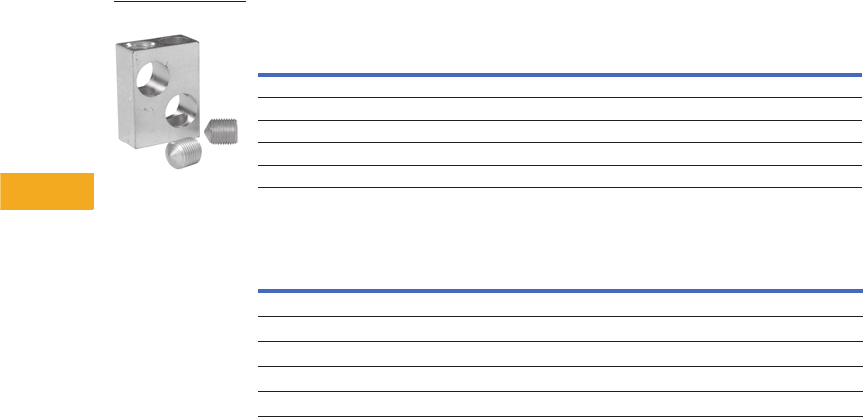
V1-T5-94 Volume 1—Residential and Light Commercial CA08100002E—February 2014 www.eaton.com
5
5
5
5
5
5
5
5
5
5
5
5
5
5
5
5
5
5
5
5
5
5
5
5
5
5
5
5
5
5
5.10
Metering Products
Group Metering
Main Lug Selection—Field-Installed Lugs for 400 or 600A Main Bus
Wire Sizes—Neutral and Ground Lugs
Notes
1 This kit comes with three pads for two lines and neutral. Each pad will accept one or two crimp
lugs. Cannot be used on 1MP2122R, RL, RC and RLB EUSERC underground termination.
2 This lug is not UL listed.
Each stack includes a neutral and ground bar. If an extra ground bar is needed, order 1MMGBK.
Line Lug and Wire Sizes
Order Separately and Field Install
Line Lug Kit Catalog Number
Order Three Kits
(For Two Lines and Neutral)
(1) #6–600 kcmil or (2) 2/0–250 kcmil 1MPLK1
(2) 250–500 kcmil 1MPLK3
(3) #4–300 kcmil 1MPLK4 1
(1) 750 kcmil 1MPLK2 2
Crimp lug landing pad 250–750 kcmil 1MPSC1 1
Description
Wire Size,
Al/Cu
Catalog
Number
Neutral—125A meter pack #6–2/0 —
Neutral—200A meter pack #1/0–300 kcmil —
Equipment ground bar—125A meter pack #14–#2 —
Equipment ground bar—200A meter pack #14–2/0 —
Optional ground bar #6–2/0 1MMGBK
1MPLK3
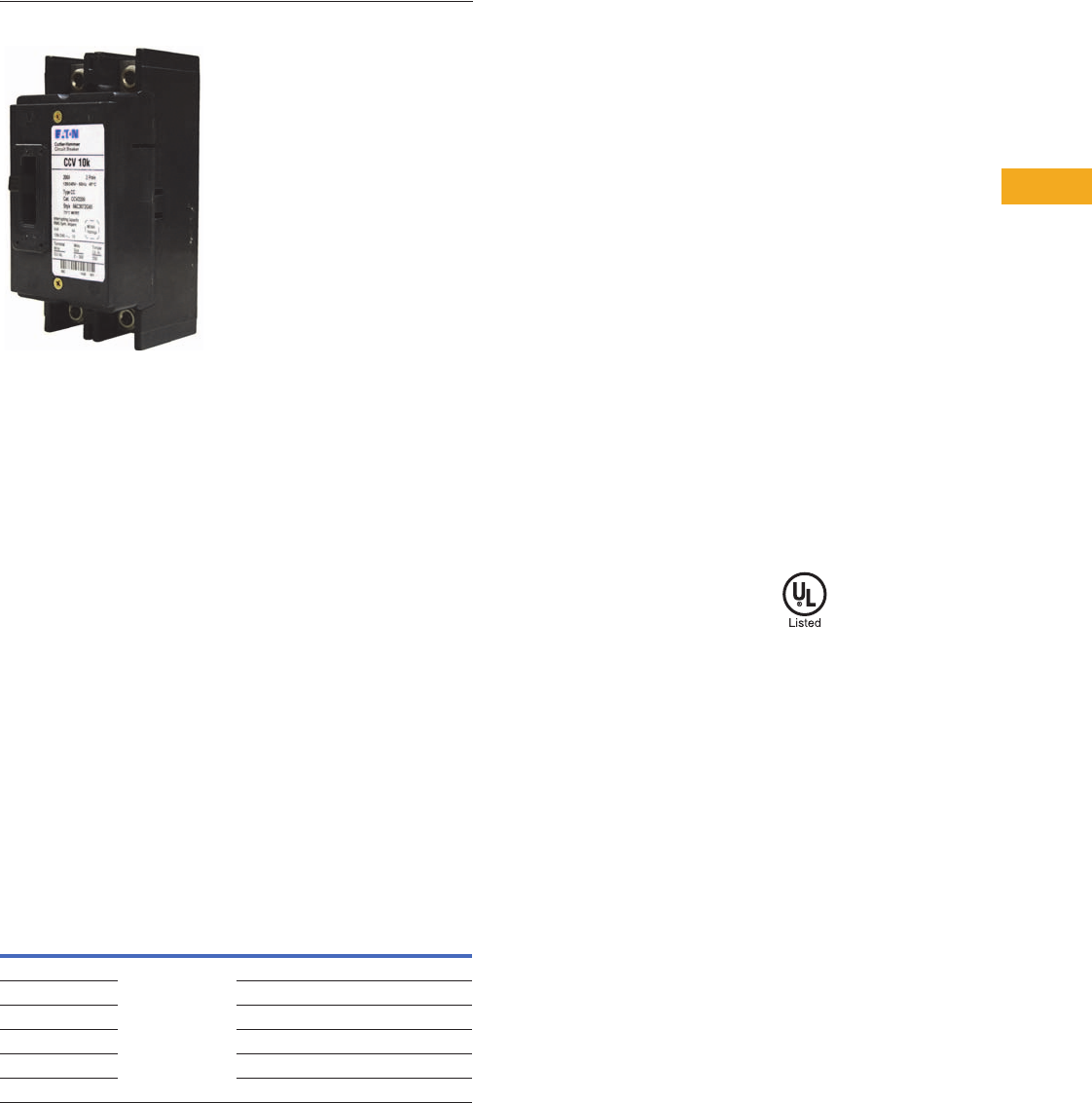
Volume 1—Residential and Light Commercial CA08100002E—February 2014 www.eaton.com V1-T5-95
5
5
5
5
5
5
5
5
5
5
5
5
5
5
5
5
5
5
5
5
5
5
5
5
5
5
5
5
5
5
5.10
Metering Products
Group Metering
Type CCV Tenant Main Circuit Breaker
Contents
Description Page
Systems for Residential and Commercial
Applications . . . . . . . . . . . . . . . . . . . . . . . . . . . . V1-T5-88
Meter Packs . . . . . . . . . . . . . . . . . . . . . . . . . . . . . V1-T5-90
Type CCV 120/240V Tenant Main Circuit Breaker
Type CV 120/240V Tenant Main Circuit Breaker . . V1-T5-96
Meter Packs—1MP, 1MM and 3MM Main
Tenant Circuit Breakers . . . . . . . . . . . . . . . . . . . . V1-T5-98
Main Service Modules . . . . . . . . . . . . . . . . . . . . . V1-T5-101
Surge Metering . . . . . . . . . . . . . . . . . . . . . . . . . . . V1-T5-115
Residential Meter Stacks. . . . . . . . . . . . . . . . . . . . V1-T5-116
1MP, 1MM and 3MM Main Tenant
Circuit Breakers. . . . . . . . . . . . . . . . . . . . . . . . . . V1-T5-125
Phase Balanced Stack . . . . . . . . . . . . . . . . . . . . . . V1-T5-126
Commercial Meter Stack Modules . . . . . . . . . . . . V1-T5-127
35MM, 37MM, 35SS and 37SS
Main Tenant Circuit Breakers . . . . . . . . . . . . . . . V1-T5-134
Type CCV 120/240V Tenant Main Circuit Breaker
Product Overview
Eaton offers Type CCV
(10 and 22 kAIC) and Type CV
(42, 65 and 100 kAIC) family
of circuit breakers as the
primary tenant main breakers
used in most group metering
applications.
Product Description
Eaton’s residential products
Type CCV circuit breaker is
available in two-pole
configurations from 100A to
225A in 10 and 22 kAIC
ratings.
Features
●Ratings—120/240 Vac,
two-pole, through 225
continuous amperes,
calibrated at 40°C
●Tripping characteristics—
thermal-magnetic trip,
calibrated and sealed after
assembly. Indirectly heated
thermal tripping bimetal
elements
●Interrupting capacity at
120/240 Vac. Type CCV—
10 kAIC rms symmetrical.
Type CCVH—25 kAIC rms
symmetrical
●Handles—trip-free with
ON-TRIPPED-OFF
positions. Reset past OFF
is required to latch breaker
contacts after tripping
●Te rm i n a l s —standard
lugs (wire connectors)
suitable for copper or
aluminum wire
●
Backward compatibility
—
Type CCV and CCVH
retains same profile and
footprint as the CC and
CCH breaker, allowing use
in the same applications
Standards and Certifications
●Complies with UL Standard
489. Breakers are listed
under UL File #E7819
Product Selection
Type CCV 120/240V Tenant Main Circuit Breaker
Modification Codes
●X—load side terminals only
Two-Pole Breaker
Ampere
Rating
Wire Size Range,
Al/Cu 10 kAIC 25 kAIC
100 #2–300 kcmil CCV2100X CCVH2100X
125 CCV2125X CCVH2125X
150 CCV2150X CCVH2150X
175 CCV2175X CCVH2175X
200 CCV2200X CCVH2200X
225 CCV2225X CCVH2225X
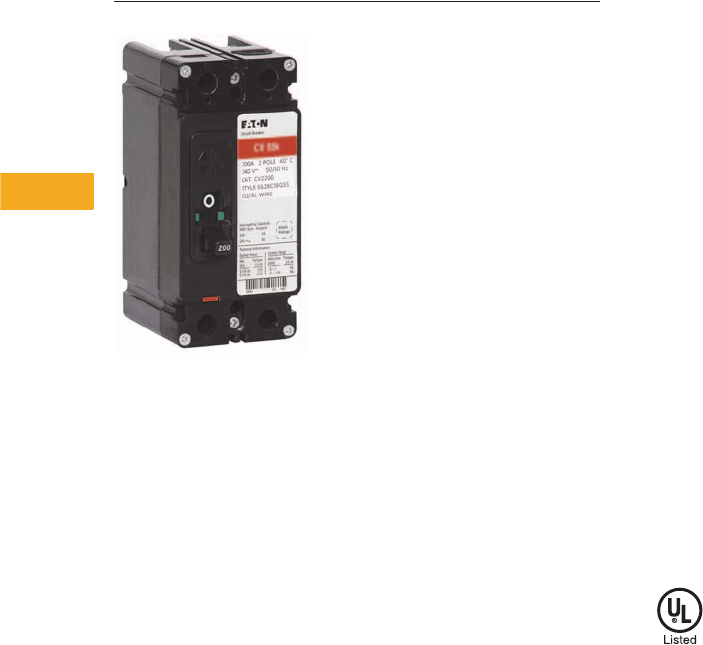
V1-T5-96 Volume 1—Residential and Light Commercial CA08100002E—February 2014 www.eaton.com
5
5
5
5
5
5
5
5
5
5
5
5
5
5
5
5
5
5
5
5
5
5
5
5
5
5
5
5
5
5
5.10
Metering Products
Group Metering
Type CV Tenant Main Circuit Breaker
Contents
Description Page
Systems for Residential and Commercial
Applications . . . . . . . . . . . . . . . . . . . . . . . . . . . . V1-T5-88
Meter Packs . . . . . . . . . . . . . . . . . . . . . . . . . . . . . V1-T5-90
Type CCV 120/240V Tenant Main Circuit Breaker . V1-T5-95
Type CV 120/240V Tenant Main Circuit Breaker . . V1-T5-96
Meter Packs—1MP, 1MM and 3MM Main
Tenant Circuit Breakers . . . . . . . . . . . . . . . . . . . V1-T5-98
Main Service Modules . . . . . . . . . . . . . . . . . . . . . V1-T5-101
Surge Metering. . . . . . . . . . . . . . . . . . . . . . . . . . . V1-T5-115
Residential Meter Stacks . . . . . . . . . . . . . . . . . . . V1-T5-116
1MP, 1MM and 3MM Main Tenant
Circuit Breakers . . . . . . . . . . . . . . . . . . . . . . . . . V1-T5-125
Phase Balanced Stack. . . . . . . . . . . . . . . . . . . . . . V1-T5-126
Commercial Meter Stack Modules . . . . . . . . . . . . V1-T5-127
35MM, 37MM, 35SS and 37SS
Main Tenant Circuit Breakers . . . . . . . . . . . . . . . V1-T5-134
Type CV 120/240V Tenant Main Circuit Breaker
Product Overview
Eaton offers Type CCV
(10 and 22 kAIC) and Type CV
(42, 65 and 100 kAIC) family
of circuit breakers as the
primary tenant main breakers
used in most group metering
applications.
Product Description
Eaton’s residential products
Type CV molded-case circuit
breaker is available in two-
and three-pole configurations
from 60A to 225A in 42, 65
and 100 kAIC ratings.
Features
●Ratings—120/240 Vac,
two- and three-pole,
through 225 continuous
amperes, calibrated
at 40°C
●Tripping characteristics—
thermal-magnetic trip,
calibrated and sealed after
assembly. Indirectly heated
thermal tripping bimetal
elements; includes push-
to-test button for routine
preventive maintenance
●Interrupting capacity at
120/240 Vac
●Type CVS—42,000A rms
symmetrical
●Type CV—65,000A rms
symmetrical
●Type CVH—100,000A
rms symmetrical
●Handles—trip-free with
ON-TRIPPED-OFF
positions. Reset past OFF
is required to latch breaker
contacts after tripping
●Te rm i n a l s —standard
lugs (wire connectors)
suitable for copper or
aluminum wire
Standards and Certifications
●Complies with UL Standard
489. Breakers are listed
under UL File #E7819

Volume 1—Residential and Light Commercial CA08100002E—February 2014 www.eaton.com V1-T5-97
5
5
5
5
5
5
5
5
5
5
5
5
5
5
5
5
5
5
5
5
5
5
5
5
5
5
5
5
5
5
5.10
Metering Products
Group Metering
Product Selection
Type CV Two-Pole Tenant Main Circuit Breakers Type CV Three-Pole Tenant Main Circuit Breakers
Accessories
Field Installable
Number
of Poles
Main Tenant
Circuit Breaker
Ampere Rating
Wire Size
Range,
Al/Cu
42 kAIC 65 kAIC 100 kAIC
Catalog
Number
Catalog
Number
Catalog
Number
2 60 #6–4/0 CVS2060XMM CV2060XMM CVH2060XMM
70 CVS2070XMM CV2070XMM CVH2070XMM
80 CVS2080XMM CV2080XMM CVH2080XMM
90 CVS2090XMM CV2090XMM CVH2090XMM
100 CVS2100XMM CV2100XMM CVH2100XMM
125 CVS2125XMM CV2125XMM CVH2125XMM
150 CVS2150XMM CV2150XMM CVH2150XMM
175 CVS2175XMM CV2175XMM CVH2175XMM
200 CVS2200XMM CV2200XMM CVH2200XMM
225 CVS2225XMM CV2225XMM CVH2225XMM
Number
of Poles
Main Tenant
Circuit Breaker
Ampere Rating
Wire Size
Range,
Al/Cu
42 kAIC 65 kAIC 100 kAIC
Catalog
Number
Catalog
Number
Catalog
Number
3 60 #6–4/0 CVS3060X CV3060X CVH3060X
70 CVS3070X CV3070X CVH3070X
80 CVS3080X CV3080X CVH3080X
90 CVS3090X CV3090X CVH3090X
100 CVS3100X CV3100X CVH3100X
125 CVS3125X CV3125X CVH3125X
150 CVS3150X CV3150X CVH3150X
175 CVS3175X CV3175X CVH3175X
200 CVS3200X CV3200X CVH3200X
225 CVS3225X CV3225X CVH3225X
Description
Catalog
Number
Two-pole 300 kcmil with terminal shield 2TA225CVK
Three-pole 300 kcmil with terminal shield 3TA225CVK
Replacement mounting hardware kit for 200A 1MP, 1MM and 3MM units 1MMCBK
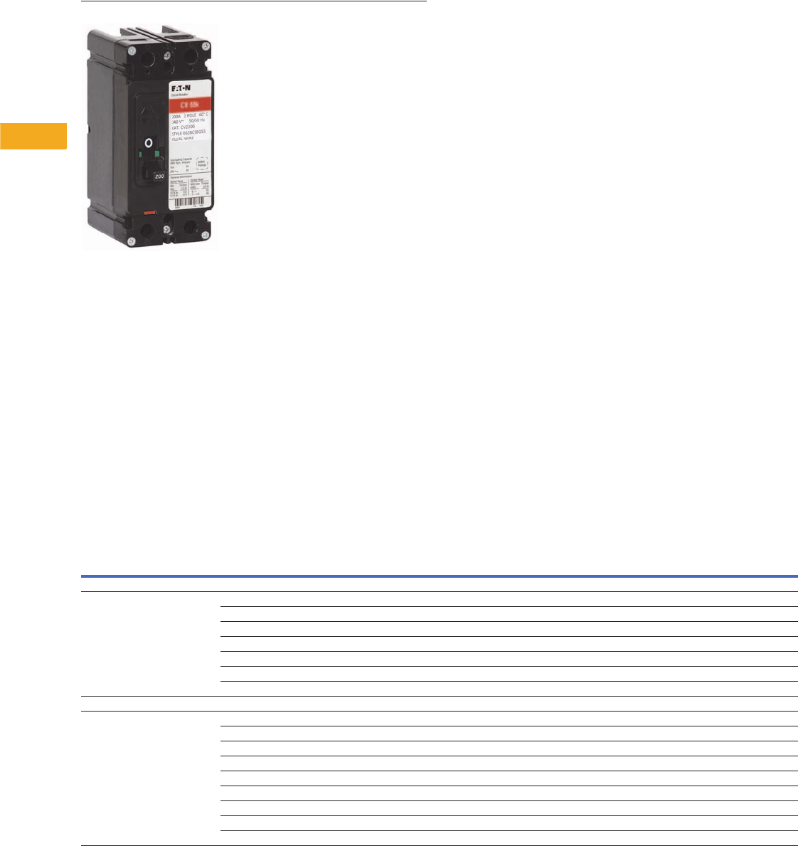
V1-T5-98 Volume 1—Residential and Light Commercial CA08100002E—February 2014 www.eaton.com
5
5
5
5
5
5
5
5
5
5
5
5
5
5
5
5
5
5
5
5
5
5
5
5
5
5
5
5
5
5
5.10
Metering Products
Group Metering
Main Tenant Circuit Breakers
Contents
Description Page
Systems for Residential and Commercial
Applications . . . . . . . . . . . . . . . . . . . . . . . . . . . . V1-T5-88
Meter Packs . . . . . . . . . . . . . . . . . . . . . . . . . . . . . V1-T5-90
Type CCV 120/240V Tenant Main Circuit Breaker . V1-T5-95
Type CV 120/240V Tenant Main Circuit Breaker . . V1-T5-96
Meter Packs—1MP, 1MM and 3MM Main
Tenant Circuit Breakers
Main Service Modules . . . . . . . . . . . . . . . . . . . . . V1-T5-101
Surge Metering. . . . . . . . . . . . . . . . . . . . . . . . . . . V1-T5-115
Residential Meter Stacks . . . . . . . . . . . . . . . . . . . V1-T5-116
1MP, 1MM and 3MM Main Tenant
Circuit Breakers . . . . . . . . . . . . . . . . . . . . . . . . . V1-T5-125
Phase Balanced Stack. . . . . . . . . . . . . . . . . . . . . . V1-T5-126
Commercial Meter Stack Modules . . . . . . . . . . . . V1-T5-127
35MM, 37MM, 35SS and 37SS
Main Tenant Circuit Breakers . . . . . . . . . . . . . . . V1-T5-134
Meter Packs—1MP, 1MM and 3MM Main Tenant Circuit Breakers
Product Description
Specific main tenant circuit
breakers that are to be
used in meter packs (1MP),
residential meter stacks
(1MM) and three-phase in
single-phase out meter
stacks (3MM).
Product Selection
Notes
1#2–300 kcmil wire size range for CCV and CCVH tenant main circuit breakers.
2“MM” suffix indicates mounting hardware kit is included as standard with tenant main breaker.
31MMCBK replacement mounting hardware kit. One kit is needed per breaker. Mounting hardware kit ships standard with breaker “MM” suffix offering.
4#6–4/0 kcmil wire size range for CVS, CV and CVH tenant main circuit breakers. If #2–300 kcmil is needed, order 2TA225CVK. One kit needed per breaker.
Description
Number
of Poles
Main Tenant
Circuit Breaker
Ampere Rating
10 kAIC 22 kAIC 25 kAIC 42 kAIC 65 kAIC 100 kAIC
Catalog
Number 1
Catalog
Number
Catalog
Number 1234
Catalog
Number 234
Catalog
Number 234
Catalog
Number 234
Plug-On Type
Plug-on type circuit breakers used
with 1MP, 1MM, and 3MM 125A
modular metering stacks
260BR260 BRH260 — BRHH260 — —
270BR270 BRH270 — BRHH270 — —
280BR280 BRH280 — BRHH280 — —
290BR290 BRH290 — BRHH290 — —
2 100 BR2100 BRH2100 — BRHH2100 — —
2 110 BR2110 BRH2110 — BRHH2110 — —
2 125 BR2125 BRH2125 — BRHH2125 — —
Bolt-On Type
Bolt-on type circuit breakers used
with 1MP, 1MM, and 3MM 200A
modular metering stacks
260— — CVS2060XMM CVS2060XMM CV2060XMM CVH2060XMM
270— — CVS2070XMM CVS2070XMM CV2070XMM CVH2070XMM
280— — CVS2080XMM CVS2080XMM CV2080XMM CVH2080XMM
290— — CVS2090XMM CVS2090XMM CV2090XMM CVH2090XMM
2 100 CCV2100X — CCVH2100X CVS2100XMM CV2100XMM CVH2100XMM
2 125 CCV2125X — CCVH2125X CVS2125XMM CV2125XMM CVH2125XMM
2 150 CCV2150X — CCVH2150X CVS2150XMM CV2150XMM CVH2150XMM
2 175 CCV2175X — CCVH2175X CVS2175XMM CV2175XMM CVH2175XMM
2 200 CCV2200X — CCVH2200X CVS2200XMM CV2200XMM CVH2200XMM
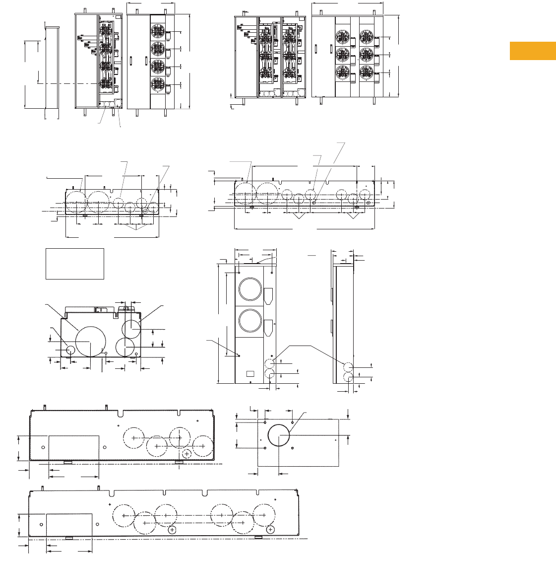
Volume 1—Residential and Light Commercial CA08100002E—February 2014 www.eaton.com V1-T5-99
5
5
5
5
5
5
5
5
5
5
5
5
5
5
5
5
5
5
5
5
5
5
5
5
5
5
5
5
5
5
5.10
Metering Products
Group Metering
Dimensions and Knockouts
Approximate Dimensions in Inches (mm)
1MP, 125 Ampere Meter Packs—Aluminum and Copper Bus
3, 4 Meter Device
12.552 9.000 9.000 9.000
48.290
24.260
To of Wall Mtg. Screw
C
L
Meter To Rail Mtg. Screw
C
L
C
L
21.699
7. 0 1 5 (3) Knockout
for 1, 1-1/4, 1-1/2
Conduit
(1) Knockout
for 1-1/2, 2,
2-1/2 Conduit
34.250
2.025
3.140 5, 6 Meter Device
12.550 9.000 9.000
41.600
36.280
3.00 (76.2)
.450
"Z" "Y"
"X""W"
Concentric Knockouts
2-1/2", 3", 3-1/2", 4 " Knockout
Concentric Knockouts
1", 1-1/4", 1-1/2", Knockout
Concentric
Knockouts
1/2" Knockout
4.555
14.460
7. 0 0 5
4.690
3.615
24.08 (611.6)
5.125
5.610
of 1/2" Ring
of 1-1/2" Ring
of 1-1/2" Ring
of 4" Ring
C
L
C
L
C
L
C
L
"Z" =
"Y" =
"X" =
"W" =
3.625
7. 0 1 5
Concentric
Knockouts
2-1/2", 3", 3-1/2", 4 "
Knockout
Concentric Knockouts
1", 1-1/4", 1-1/2", Knockout
Concentric
Knockouts
1/2" Knockout
.450
4.565
8.000
3.000 3.000
36.130
6.560
"Z"
"Y"
"X"
"W"
.695
27.000
4.690
5.610 5.125
2.560
5.0009.380
11.880
Mtn. for 2, 2-1/2, 3"
C-H Conduit Hubs
1, 1-1/4, 1-1/2" KO
6 Places
2.750
2.880
57 Mtg Holes
4 Places
34.180
23.750
1.806
6.380
5.900 .060
2.250
2.750
1.440
1.880
3.250
2.563
6.500
3.250
2.563
6.500
3.063 Dia.
Hub Opening
2.277
4.000
1.063
.438
3.688
3.063
.875 1", 1-1/4", 1-1/2"
Knockouts
(6 Required)
2.625
1.500
1-1/2", 2",
2-1/2", 3"
Knockouts
1/2" Knockout
4.389
2.313
2.313
1.438
4.375
Bottom Endwall Knockouts for Units with "T" Sufx
3, 4 Meter Device
Bottom Endwall Knockouts for Units with "T" Sufx
5, 6 Meter Device
Top View
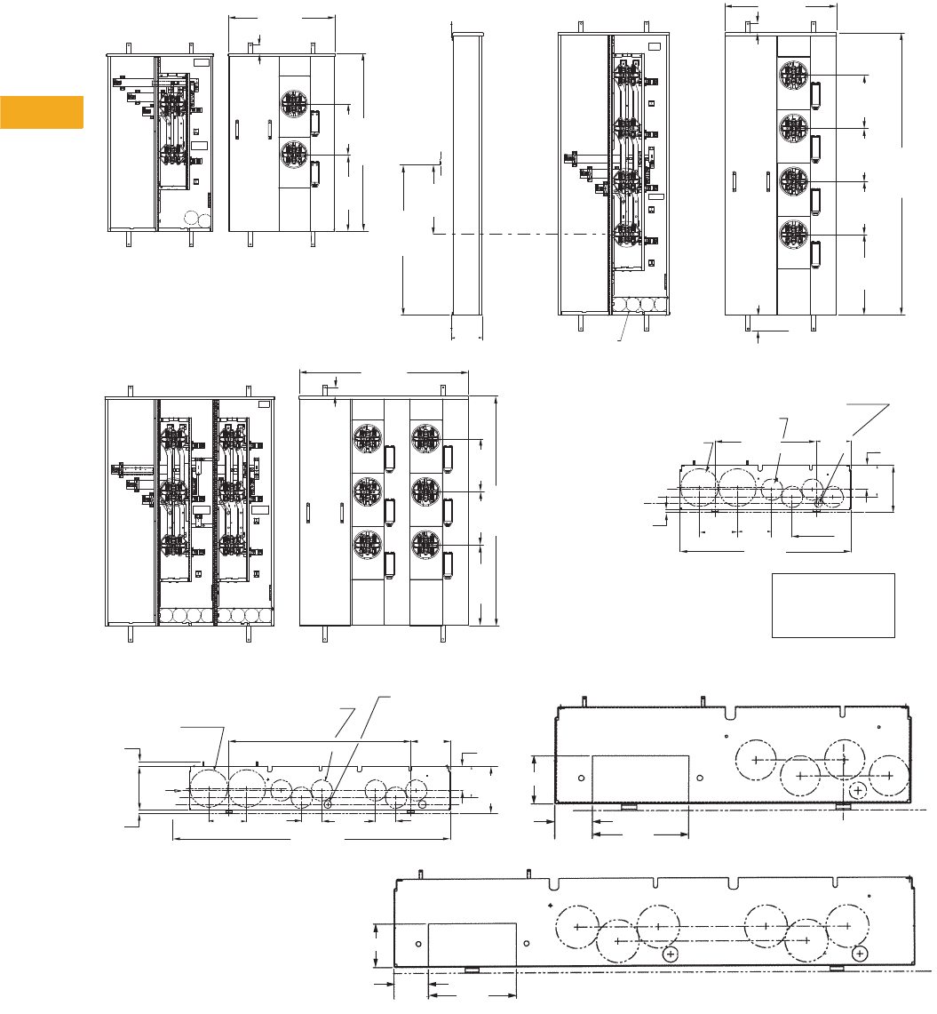
V1-T5-100 Volume 1—Residential and Light Commercial CA08100002E—February 2014 www.eaton.com
5
5
5
5
5
5
5
5
5
5
5
5
5
5
5
5
5
5
5
5
5
5
5
5
5
5
5
5
5
5
5.10
Metering Products
Group Metering
Approximate Dimensions in Inches (mm)
1MP, 200 Ampere Meter Packs—Aluminum and Copper Bus
4.690
7. 0 0 5
Concentric Knockouts
2-1/2", 3", 3-1/2", 4 " Knockout
Concentric Knockouts
1", 1-1/4", 1-1/2", 2" Knockout
Concentric Knockouts
1/2" Knockout
5.610
.450
4.555
3.000
5.125
"Z"
"Y"
"X"
"W"
3.615
Typ.
15.000
24.080
of 1/2" Ring
of 1-1/2" Ring
of 1-1/2" Ring
of 4" Ring
C
L
C
L
C
L
C
L
"Z" =
"Y" =
"X" =
"W" =
7. 0 1 5
(4) Knock Out
For 1", 1-1/4", 1-1/2", 2"
Conduit 3, 4 Meter Device
15.826
2.015
25.480
3.125
18.425
12.125 12.125 12.125
64.535
To of Wall Mtg. Screw
C
L
Meter To Rail Mtg. Screw
C
L
C
L
34.250
2 Meter Device
25.480
2.015
42.685
12.155
18.400
38.755
2.015
12.125
12.125
18.425
52.415
5, 6 Meter Device
2, 3 & 4 Meter Endwall
3.0003.000
.450
"Z"
"Y"
"X""W"
Concentric
Knockouts
2-1/2", 3", 3-1/2",
4 " Knockout
Concentric
Knockouts
1", 1-1/4", 1-1/2",
2" Knockout
Concentric Knockouts
1/2" Knockout
4.565
4.690
6.555
.695
3.625
38.635
27.000
7. 0 1 5
8.000
5.610
3.250
2.563
6.500
3.250
2.563
6.500
Bottom Endwall Knockouts
for Units with "T" Sufx
2, 3, 4 Meter Device
Bottom Endwall Knockouts for Units with "T" Sufx
5, 6 Meter Device

Volume 1—Residential and Light Commercial CA08100002E—February 2014 www.eaton.com V1-T5-101
5
5
5
5
5
5
5
5
5
5
5
5
5
5
5
5
5
5
5
5
5
5
5
5
5
5
5
5
5
5
5.10
Metering Products
Group Metering
Contents
Description Page
Systems for Residential and Commercial
Applications . . . . . . . . . . . . . . . . . . . . . . . . . . . . V1-T5-88
Meter Packs . . . . . . . . . . . . . . . . . . . . . . . . . . . . . V1-T5-90
Type CCV 120/240V Tenant Main Circuit Breaker . V1-T5-95
Type CV 120/240V Tenant Main Circuit Breaker . . V1-T5-96
Meter Packs—1MP, 1MM and 3MM Main
Tenant Circuit Breakers. . . . . . . . . . . . . . . . . . . . V1-T5-98
Main Service Modules
Surge Metering . . . . . . . . . . . . . . . . . . . . . . . . . . . V1-T5-115
Residential Meter Stacks . . . . . . . . . . . . . . . . . . . V1-T5-116
1MP, 1MM and 3MM Main Tenant
Circuit Breakers . . . . . . . . . . . . . . . . . . . . . . . . . V1-T5-125
Phase Balanced Stack . . . . . . . . . . . . . . . . . . . . . . V1-T5-126
Commercial Meter Stack Modules . . . . . . . . . . . . V1-T5-127
35MM, 37MM, 35SS and 37SS
Main Tenant Circuit Breakers . . . . . . . . . . . . . . . V1-T5-134
Main Service Modules
Product Description
●Main terminal box
●Main circuit breaker
●Main bolted pressure
switch
●Main fusible switch
●Main fusible switch with
pull box
●Underground pull box
Application Description
Main Circuit Breakers with
Busway Connections
The Service Entrance Product
Team announces the
availability of both main
fusible switch and main
circuit breaker group
metering mains with busway
connections. This offering
provides us with the ability
to offer multiple tenant
metering in high rise
apartment buildings where
riser busway is used.
Features, Benefits and Functions
Eaton’s Main Service Module
●Offering: main terminal/lug
compartment, main circuit
breaker, main fusible
switch, main bolted
pressure switch, main
fusible switch with pull
box (meets EUSERC
electrical requirements),
underground pull box
termination compartment
without cross bus (meets
EUSERC electrical
requirements)
●Mechanically and
electrically built for use
with 1MM, 3MM, 35MM,
37MM, 35SS and 37SS
modular metering stacks
●For integrated system
short-circuit ratings with
main devices, see series
ratings on Page V1-T5-142
●All main service modules
include both left and right
horizontal bus closure
plates
●Two-pole devices are
applied to single-phase,
three-wire, 120/240V or
208Y/120V systems, three-
pole devices to 208Y/240V
or 120/240V delta systems
●Single-phase mains couple
to any modular metering
stack (1MM, 3MM, 35MM,
37MM, 35SS and 37SS)
●Three-phase mains require
three-phase bussed stacks.
These modular metering
stacks are 3MM, 35MM,
37MM, 35SS and 37SS
●If the ampere rating of the
main service module is
greater than the horizontal
bus rating of the meter
stack (residential or
commercial), the main
service module must be
center fed. Examples:
1200A Main Circuit Breaker
(1MCB1200R) with an
800A residential stack
(1MM512R). 1600A Main
Terminal Box
(3MTB1600R) with a
1200A residential stack
(3MM212R12)
●Most main service
modules are available with
aluminum or copper bus
Main Circuit Breakers with
Busway Connections
●Three-phase, 400–200A
main circuit breakers
●Three-phase, 400–800A
main fusible switches
●Simple bridge joint
connection
●Variety of options:
●Right or left mounting
●Internal ground or
housing ground
●The MFS/MCB and busway
connector are supplied
completely assembled
V1-T5-102 Volume 1—Residential and Light Commercial CA08100002E—February 2014 www.eaton.com
5
5
5
5
5
5
5
5
5
5
5
5
5
5
5
5
5
5
5
5
5
5
5
5
5
5
5
5
5
5
5.10
Metering Products
Group Metering
Catalog Number Selection
When Ordering:
1. Determine catalog number of Main Service Module.
2. Determine catalog number of Meter Stack (Residential or Commercial).
3. Find quantity and catalog numbers for tenant circuit breakers (found on Page V1-T5-125 or V1-T5-135).
Order one breaker per socket.
4. If any accessories are needed, order from Pages V1-T5-136 and V1-T5-137.
Phase
1 = Single-phase
3 = Three-phase
Ampere Rating
400A
600A
800A
1000A
1200A
1400A
1600A
2000A
Bus Material
C= Copper bus
Blank= Aluminum bus
Type of Metering
BTB = Main terminal box
MCB = Main circuit breaker
BPS = Bolted pressure switch
MFS = Main fusible switch
UGPB = Underground pull box
MTBE = Main terminal box with utility
pull box
MCBE = Main circuit breaker with utility
pull box
Accessories and Additional Options
BLK= Box lug kit (accessory)
CLK= Compression lug (accessory)
B= Bottom feed
T= Top feed
UG= Pull box
Blank= No options
Enclosure
R = NEMA 3R
3 MTB 400 R C
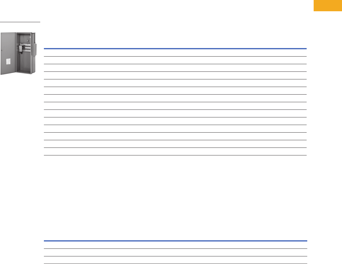
Volume 1—Residential and Light Commercial CA08100002E—February 2014 www.eaton.com V1-T5-103
5
5
5
5
5
5
5
5
5
5
5
5
5
5
5
5
5
5
5
5
5
5
5
5
5
5
5
5
5
5
5.10
Metering Products
Group Metering
Product Selection
Main Terminal Box
●Phase and neutral lugs
are included
●Top or bottom feed:
●For top feed, use
Myer type hub
●Indoor or outdoor
●Terminal box UL listed
short-circuit rating is the
least AIC rating of any
installed main tenant
breaker—to a maximum
of 100,000 rms
symmetrical amperes
Main Terminal Box
Main Terminal Box Riser Panel
Eaton’s Main Terminal Box
Riser Panel is a main terminal
box with offset lugs on each
phase to allow riser cables to
pass through the main
service module.
These panels are used in the
construction of assisted living
homes, dormitories, public
housing complexes and
apartments.
Main Terminal Box Riser Panel
Notes
1 1200A main devices must be center fed when installing 800A residential meter stacks.
1600A main devices must be center fed when installing 800–1200A residential and commercial meter stacks.
2 For 400A units, to obtain (4) 750 kcmil cables per phase—order quantity 4 1MPLK2. Kit contains one lug.
3 For compression lug landing kits for 600A units, order 3MTB600CLK. Kit includes lug landings for three phases and neutral.
4 For 800A units, to obtain (4) 1/0–300 kcmil or (2) 1/0–750 kcmil cables per phase—order catalog number 3MTB800BLK,
one lug kit per main terminal box ordered (neutral and ground included in kit).
5 For 800A and 1200A units, for compression lug landing kits, order 3MTB1200CLK. Kit includes lug landings for three-phase and neutral.
6 For 1200A units, to obtain (6) 1/0–300 kcmil or (3) 750 kcmil cables per phase—order catalog number 3MTB1200BLK,
one lug kit per main terminal box ordered (neutral and ground included in kit).
7 Meets EUSERC electrical requirements and eliminates the need to add additional pull box section.
8 For 1600A units, to obtain (4) 750 kcmil cables per phase—order catalog number 3MTB1600BLK, one lug kit per main terminal box ordered.
For a 1600A compression lug landing kit, order catalog number 3MTB1600CLK.
9 Quantity (10) lugs per phase—quantity (5) lugs incoming and quantity (5) lugs outgoing per phase.
Ampere
Rating Line Side Lug and Wire Sizes—Included
System Voltage
120/240 Vac Single-Phase, Three-Wire 120/208 Vac Three-Phase, Four-Wire
Catalog Number Catalog Number
Aluminum Bus (Standard Offering)
400 (1) #6–600 or (2) 1/0–250 kcmil 2Use three-phase 3MTB400R
600 (2) 250–500 kcmil 3Use three-phase 3MTB600R
800 (4) 250–500 kcmil 45 1MTB800R 3MTB800R
1200 1(4) 250–500 kcmil 56 1MTB1200R 3MTB1200R
Aluminum Bus (EUSERC)
400 Crimp lug landing pads (no lugs included) 1MTBE400R 73MTBE400R 7
800 Crimp lug landing pads (no lugs included) 1MTBE800R 73MTBE800R 7
Copper Bus (Premium Offering)
400 (1) #6–600 or (2) 1/0–250 kcmil 2Use three-phase 3MTB400RC
600 (2) 250–500 kcmil 3Use three-phase 3MTB600RC
800 (4) 250–500 kcmil 45 1MTB800RC 3MTB800RC
1200 1(4) 250–500 kcmil 56 1MTB1200RC 3MTB1200RC
1600 1(6) 500 kcmil 81MTB1600RC 3MTB1600RC
Main Terminal Box
System Voltage
Ampere
Rating
Line and Load Side Lug and
Wire Sizes Included
120/240 Vac Single-Phase,
Three-Wire Catalog Number
120/208 Vac Three-Phase,
Four-Wire Catalog Number
Copper Bus (Standard Offering)
1200 #2 AWG–750 kcmil 19 Use three-phase 3MTB1200RCRIS
1600 #2 AWG–750 kcmil 19 Use three-phase 3MTB1600RCRIS
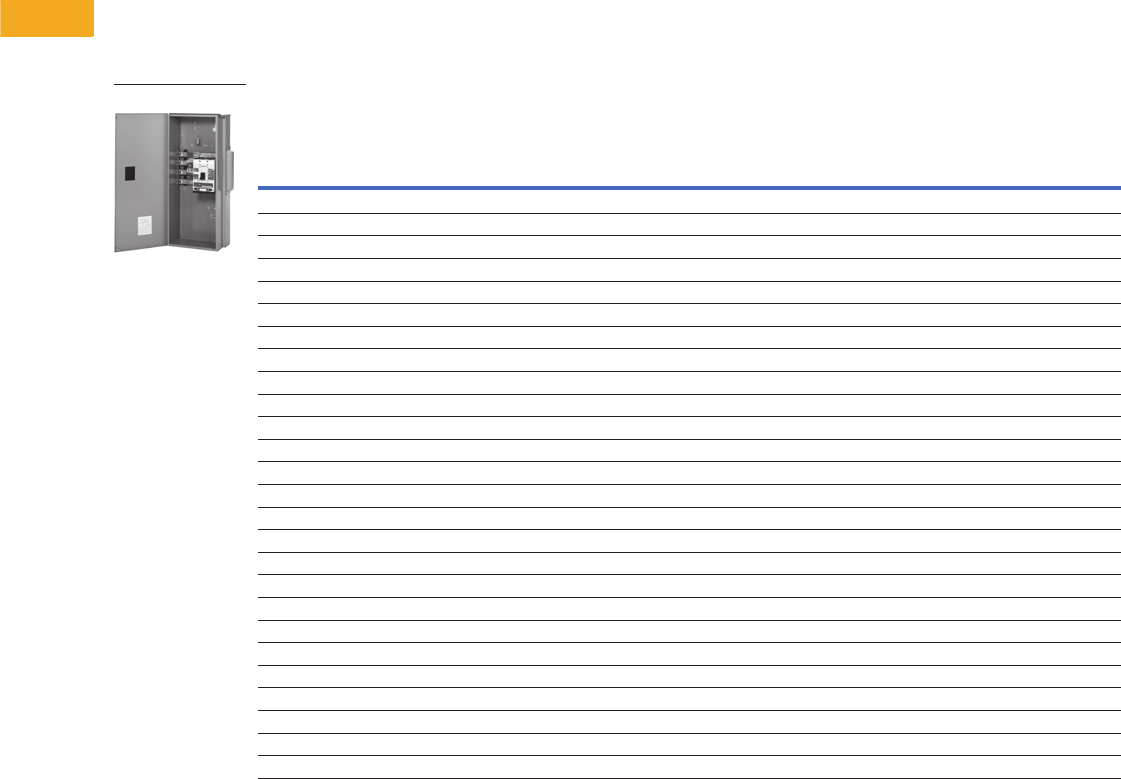
V1-T5-104 Volume 1—Residential and Light Commercial CA08100002E—February 2014 www.eaton.com
5
5
5
5
5
5
5
5
5
5
5
5
5
5
5
5
5
5
5
5
5
5
5
5
5
5
5
5
5
5
5.10
Metering Products
Group Metering
Main Circuit Breaker
●Phase and neutral lugs
included. If additional
neutral lugs are needed,
order 1MCB1200NLK
for (3) 1/0–750 or
(6) 1/0–300 kcmil
●For shunt trip mains, order
the field-installable shunt
trip kit in this volume,
Tab 1, secti on 1.1
●For overhead feed, use
Myer type hub. Verify local
utility approval
●For compression lugs on
400, 600, 800, 1000 and
1200A units, add CL to the
end of the part number
(includes copper lug pads
for lines and neutral)
●1200A or greater main
devices must be center
fed when installing 800A
residential meter stacks
●1400, 1600 and 2000A
main devices must be
center fed when installing
800 and 1200A residential
and commercial meter
stacks
Main Circuit Breaker
Notes
1 If additional neutral lugs are needed, order 1MCB1200NLK [(3) 1/0–750 kcmil or (6) 1/0–300 kcmil].
2 Add CL to end of catalog number for compression lug pads (includes lug pads for lines and neutral).
3 If (3) 500–750 kcmil are needed, order TA1201NB1. Order one kit per pole.
4 Main devices with a rating greater than 800A can be used with 800A residential modular stacks, but only as a center fed main.
Main
Ampere
Rating
Main
Circuit
Breaker
Type Feed kAIC
Line Side Lug and Wire Sizes
(Lugs Included with Main Breaker) 1
System Voltage
120/240 Vac
Single-Phase, Three-Wire
120/208 Vac
Three-Phase, Four-Wire
Catalog Number Catalog Number
Aluminum Bus (Standard Offering)
250 KD Bottom/top 65 (2) 3/0–250 kcmil or (1) 2/0–500 kcmil 1MCB250R 3MCB250R
250 HKD Bottom/top 100 (2) 3/0–250 kcmil or (1) 2/0–500 kcmil 1MHCB250R 3MHCB250R
300 KD Bottom/top 65 (2) 3/0–250 kcmil or (1) 2/0–500 kcmil 1MCB300R 3MCB300R
300 HKD Bottom/top 100 (2) 3/0–250 kcmil or (1) 2/0–500 kcmil 1MHCB300R 3MHCB300R
350 KD Bottom/top 65 (2) 3/0–250 kcmil or (1) 2/0–500 kcmil 1MCB350R 3MCB350R
350 HKD Bottom/top 100 (2) 3/0–250 kcmil or (1) 2/0–500 kcmil 1MHCB350R 3MHCB350R
400 KD Bottom/top 65 (2) 3/0–250 kcmil or (1) 2/0–500 kcmil 1MCB400R 23MCB400R 2
400 HKD Bottom/top 100 (2) 3/0–250 kcmil or (1) 2/0–500 kcmil 1MHCB400R 23MHCB400R 2
500 LD Bottom/top 65 (2) 400–500 kcmil 1MCB500R 3MCB500R
500 HLD Bottom/top 100 (2) 400–500 kcmil 1MHCB500R 3MHCB500R
600 LD Bottom/top 65 (2) 400–500 kcmil 1MCB600R 23MCB600R 2
600 HLD Bottom/top 100 (2) 400–500 kcmil 1MHCB600R 23MHCB600R 2
700 HMDL Bottom/top 100 (3) 3/0–400 kcmil 1MHCB700R 3MHCB700R
700 MDL Bottom/top 65 (3) 3/0–400 kcmil 1MCB700R 3MCB700R
800 MDL Bottom/top 65 (3) 3/0–400 kcmil 1MCB800R 23MCB800R 2
800 MDL Bottom/top 65 (2) 500–750 kcmil 1MCB800R750 3MCB800R750
800 HMDL Bottom/top 100 (3) 3/0–400 kcmil 1MHCB800R 23MHCB800R 2
900 NGS Bottom/top 65 (4) 4/0–500 kcmil 31MCB900R 43MCB900R 4
900 NGH Bottom/top 100 (4) 4/0–500 kcmil 31MHCB900R 43MHCB900R 4
1000 NGS Bottom/top 65 (4) 4/0–500 kcmil 31MCB1000R 24 3MCB1000R 24
1000 NGS Bottom/top 65 (2) 500–750 kcmil 1MCB1000R750 3MCB1000R750
1000 NGH Bottom/top 100 (4) 4/0–500 kcmil 31MHCB1000R 24 3MHCB1000R 24
1200 NGS Bottom 65 (4) 4/0–500 kcmil 31MCB1200R 24 3MCB1200R 24
1200 NGH Bottom 100 (4) 4/0–500 kcmil 31MHCB1200R 24 3MHCB1200R 24
1200 NGS Bottom 65 (2) 500–750 kcmil Use three-phase 3MCB1200R750
Main Circuit Breaker
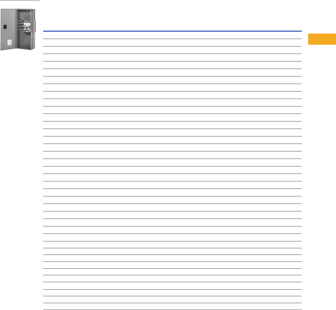
Volume 1—Residential and Light Commercial CA08100002E—February 2014 www.eaton.com V1-T5-105
5
5
5
5
5
5
5
5
5
5
5
5
5
5
5
5
5
5
5
5
5
5
5
5
5
5
5
5
5
5
5.10
Metering Products
Group Metering
Main Circuit Breaker
Main Circuit Breaker, continued
Notes
1 If additional neutral lugs are needed, order 1MCB1200NLK [(3) 1/0–750 kcmil or (6) 1/0–300 kcmil].
2 Add CL to end of catalog number for compression lug pads (includes lug pads for lines and neutral).
3 If (3) 500–750 kcmil are needed, order TA1201NB1. Order one kit per pole.
4 Main devices with a rating greater than 800A can be used with 800A residential modular stacks but only as a center fed main.
5 If (6) #2–600 kcmil lugs are needed, order TA2000RD. Catalog number includes terminals and hardware for three poles. If neutral is needed, order TA2000N.
6 Copper bus.
7 Main devices with a rating greater than 1200A can be used with residential and commercial modular metering stacks but only as a center fed main.
8 Only to be used in center feed applications with 1200A meter stacks. Not to be used with 800A stacks.
Main
Ampere
Rating
Main
Circuit
Breaker
Type Feed kAIC
Line Side Lug and Wire Sizes
(Lugs Included with Main Breaker) 1
System Voltage
120/240 Vac
Single-Phase, Three-Wire
120/208 Vac
Three-Phase, Four-Wire
Catalog Number Catalog Number
Aluminum Bus (EUSERC)
300 KD Bottom/top 65 Crimp lug landing pads (no lugs included) 1MCBE300R 3MCBE300R
350 KD Bottom/top 65 Crimp lug landing pads (no lugs included) 1MCBE350R 3MCBE350R
400 KD Bottom/top 65 Crimp lug landing pads (no lugs included) 1MCBE400R 3MCBE400R
400 HKD Bottom/top 100 Crimp lug landing pads (no lugs included) 1MHCBE400R 3MHCBE400R
500 LD Bottom/top 65 Crimp lug landing pads (no lugs included) 1MCBE500R 3MCBE500R
600 LD Bottom/top 65 Crimp lug landing pads (no lugs included) 1MCBE600R 3MCBE600R
600 HLD Bottom/top 100 Crimp lug landing pads (no lugs included) 1MHCBE600R 3MHCBE600R
800 MDL Bottom/top 65 Crimp lug landing pads (no lugs included) 1MCBE800R 3MCBE800R
800 HMDL Bottom/top 100 Crimp lug landing pads (no lugs included) 1MHCBE800R 3MHCBE800R
1000 NGS Bottom/top 65 Crimp lug landing pads (no lugs included) 1MCBE1000R 3MCBE1000R
1200 NGS Bottom 65 Crimp lug landing pads (no lugs included) 1MCBE1200R 3MCBE1200R
1200 NGH Bottom 100 Crimp lug landing pads (no lugs included) 1MHCBE1200R 3MHCBE1200R
Copper Bus (Premium Offering)
400 KD Bottom/top 65 (2) 3/0–250 kcmil or (1) 2/0-500 kcmil 1MCB400RC 23MCB400RC 2
400 HKD Bottom/top 100 2/0–500 kcmil 1MHCB400RC 23MHCB400RC 2
600 LD Bottom/top 65 (2) 300–500 kcmil 1MCB600RC 23MCB600RC 2
600 HLD Bottom/top 100 (2) 300–500 kcmil 1MHCB600RC 23MHCB600RC 2
800 MDL Bottom/top 65 (3) 3/0–400 kcmil 1MCB800RC 23MCB800RC 2
800 HMDL Bottom/top 100 (3) 3/0–400 kcmil 1MHCB800RC 23MHCB800RC 2
900 NGS Bottom/top 65 (4) 4/0–500 kcmil 31MCB900RC 43MCB900RC 4
900 NGH Bottom/top 100 (4) 4/0–500 kcmil 31MHCB900RC 43MHCB900RC 4
1000 NGS Bottom/top 65 (2) 500–750 kcmil 1MCB1000R750C 3MCB1000R750C
1000 NGS Bottom/top 65 (4) 4/0–500 kcmil 31MCB1000RC 24 3MCB1000RC 24
1000 NGH Bottom/top 100 (4) 4/0–500 kcmil 31MHCB1000RC 24 3MHCB1000RC 24
1200 NGS Bottom 65 (2) 500–750 kcmil Use three-phase 3MCB1200R750C
1200 NGS Bottom 65 (4) 4/0–500 kcmil 31MCB1200RC 24 3MCB1200RC 24
1200 NGH Bottom 100 (4) 4/0–500 kcmil 31MHCB1200RC 24 3MHCB1200RC 24
1400 RGH Bottom 100 (4) 500–1000 kcmil 51MCB1400RBC 46 3MCB1400RBC 46
1400 RGH Top 100 (4) 500–1000 kcmil 51MCB1400RT 73MCB1400RT 7
1600 RGH Bottom 100 (4) 500–1000 kcmil 51MCB1600RBC 67 3MCB1600RBC 67
1600 RGH Top 100 (4) 500–1000 kcmil 51MCB1600RT 73MCB1600RT 7
2000 RGH Bottom 100 (6) #2–600 kcmil 1MCB2000RBC 68 3MCB2000RBC 68
2000 RGH Top 100 (6) #2–600 kcmil 1MCB2000RT 83MCB2000RT 8
Copper Bus (EUSERC)
1000 NGH Bottom 100 Crimp lug landing pads (no lugs included) 1MCBE1000RC 3MCBE1000RC
1200 NGS Bottom 65 Crimp lug landing pads (no lugs included) 1MCBE1200RC 3MCBE1200RC
1200 NGH Bottom 100 Crimp lug landing pads (no lugs included) 1MHCBE1200RC 3MHCBE1200RC
Main Circuit Breaker
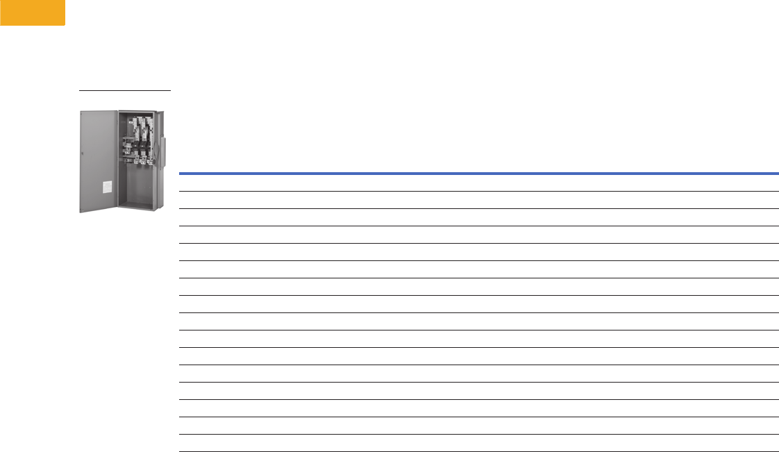
V1-T5-106 Volume 1—Residential and Light Commercial CA08100002E—February 2014 www.eaton.com
5
5
5
5
5
5
5
5
5
5
5
5
5
5
5
5
5
5
5
5
5
5
5
5
5
5
5
5
5
5
5.10
Metering Products
Group Metering
Main Fusible Switches
●Fuses not included
●Main lugs and neutral
included with device
●100 kAIC rating on
switches with Class T
fuses installed. If
converting to Class H, the
kAIC rating is 10 and if
converted to Class R, the
kAIC rating is 200
Note: This is the fuse rating,
switch still rated at 100 kAIC.
●800A top and bottom fed
units are supplied with
Class T fuse clips as
standard. The Class T fuse
clips are field convertible to
Class L by repositioning.
No kit is needed
●Barrier kits available
for 400A–800A
fusible switches:
Bottom feed—3MFSBBK,
Top feed—3MFSTBK
Main Fusible Switches
Notes
1 If Class H fuse clips are needed, use catalog number WCG3HK400 (order (1) per phase).
If Class R fuse clips are needed, order catalog number DS56FK in addition to WCG3HK400.
In order to go from T to R, the device must first be converted to H.
All kits are field installable and each DS56FK kit will convert three poles.
2 If Class H fuse clips are needed, use catalog number WCG3HK600 (order (1) per phase).
If Class R fuse clips are needed, order catalog number DS66FK in addition to WCG3HK600.
In order to go from T to R, the device must first be converted to H.
All kits are field installable and each DS66FK kit will convert three poles.
3 Class T fuse clips provided are field convertible to Class L by repositioning. No kit is needed.
4 If compression lugs are being used, order 3MFS800CLK. This compression lug kit includes four pads (three poles and neutral).
5 1MFS600BLK (4) 3/0–750 kcmil/phase (one kit/phase and one kit/neutral).
6 If compression lugs are being used, order 3MFS800CLKT. This compression lug kit includes four pads (three poles and neutral).
7 IMFS1200LK (3) 750 kcmil/phase (one kit/phase). IMFS1200LKN (3) 750 kcmil (neutral).
Ampere
Rating Feed
Class Fuse
Clips (Fuses
Not Included)
Line Side Box Lugs and Wire Sizes
(Included with Switch)
System Voltage
120/240 Vac
Single-Phase,
Three-Wire
120/208 Vac
Three-Phase,
Four-Wire
Catalog Number Catalog Number
Aluminum Bus (Standard Offering)
400 Bottom T 1(2) 1/0–300 kcmil or (1) 750 kcmil 45 1MFS400RB 3MFS400RB
400 Top T 1(2) 1/0–300 kcmil or (1) 750 kcmil 56 1MFS400RT 3MFS400RT
600 Bottom T 2(2) #2–600 kcmil 45 1MFS600RB 3MFS600RB
600 Top T 2(2) #2–600 kcmil 56 1MFS600RT 3MFS600RT
800 Bottom T, L 3(4) 3/0–750 kcmil 41MFS800RB 3MFS800RB
800 Top T, L 3(4) 3/0–750 kcmil 61MFS800RT 3MFS800RT
1200 Bottom T, L 3(4) #2–600 kcmil 71MFS1200RB 3MFS1200RB
Copper Bus (Premium Offering)
400 Bottom T 1(2) 1/0–300 kcmil or (1) 750 kcmil 45 1MFS400RBC 3MFS400RBC
400 Top T 1(2) 1/0–300 kcmil or (1) 750 kcmil 56 1MFS400RTC 3MFS400RTC
600 Bottom T 2(2) #2–600 kcmil 45 1MFS600RBC 3MFS600RBC
600 Top T 2(2) #2–600 kcmil 56 1MFS600RTC 3MFS600RTC
800 Bottom T, L 3(4) 3/0–750 kcmil 41MFS800RBC 3MFS800RBC
800 Top T, L 3(4) 3/0–750 kcmil 61MFS800RTC 3MFS800RTC
1200 Bottom T, L 3(4) #2–600 kcmil 71MFS1200RBC 3MFS1200RBC
Main Fusible Switches
Volume 1—Residential and Light Commercial CA08100002E—February 2014 www.eaton.com V1-T5-107
5
5
5
5
5
5
5
5
5
5
5
5
5
5
5
5
5
5
5
5
5
5
5
5
5
5
5
5
5
5
5.10
Metering Products
Group Metering
Main Fusible Switch with
Utility Pull Box
●Fuses not included
●Includes lug landing pads
on line side and neutral
●Spacer kit 3MMBSK
required when stacks are
mounted on right-hand
side in EUSERC areas
●100 kAIC rating on
switches with Class T
fuse clips installed
Main Fusible Switch with Utility Pull Box
Utility Pull Box
●Includes lug landing pads
on line side and neutral
●Requires cable connection
in field to main device;
does not include horizontal
cross bus
Pull Box
Note
1 Pull box section includes landing studs for line side compression lugs. Wire sizes refer to load side connection.
Ampere
Rating Feed
Class Fuse Clips
(Fuses Not Included)
Line Side Box Lugs
and Wire Sizes
(Included with Switch)
System Voltage
120/240 Vac
Single-Phase, Three-Wire
120/208 Vac
Three-Phase, Four-Wire
Catalog Number Catalog Number
Aluminum Bus (Standard Offering)
400 Bottom T
11MFS400RUG 3MFS400RUG
600 Bottom T
11MFS600RUG 3MFS600RUG
800 Bottom T, L 11MFS800RUG 3MFS800RUG
1200 Bottom T 11MFS1200RUG 3MFS1200RUG
Copper Bus (Premium Offering)
400 Bottom T
11MFS400RUGC 3MFS400RUGC
600 Bottom T
11MFS600RUGC 3MFS600RUGC
800 Bottom T, L 11MFS800RUGC 3MFS800RUGC
1200 Bottom T 11MFS1200RUGC 3MFS1200RUGC
Main Fusible Switch
with Utility Pull Box
Ampere
Rating Feed
Line Side
Lug Information
Load Side Lug Information
for Cable Connection
to Main Disconnect
System Voltage
120/240 Vac
Single-Phase, Three-Wire
120/208 Vac
Three-Phase, Four-Wire
Catalog Number Catalog Number
Aluminum Bus (Standard Offering)
400 Bottom 11/0–750 kcmil or (2) 1/0–300 kcmil 1UGPB400R 3UGPB400R
800 Bottom 1(2) 1/0–750 kcmil or (4) 1/0–300 kcmil 1UGPB800R 3UGPB800R
1200 Bottom 1(4) #2–600 kcmil 1UGPB1200R 3UGPB1200R
Copper Bus (Premium Offering)
400 Bottom 11/0–750 kcmil or (2) 1/0–300 kcmil 1UGPB400RC 3UGPB400RC
800 Bottom 1(2) 1/0–750 kcmil or (4) 1/0–300 kcmil 1UGPB800RC 3UGPB800RC
1200 Bottom 1(4) #2–600 kcmil 1UGPB1200RC 3UGPB1200RC

V1-T5-108 Volume 1—Residential and Light Commercial CA08100002E—February 2014 www.eaton.com
5
5
5
5
5
5
5
5
5
5
5
5
5
5
5
5
5
5
5
5
5
5
5
5
5
5
5
5
5
5
5.10
Metering Products
Group Metering
Main Bolted Pressure
Contact Switches
●Add suffix ST to catalog
number for shunt trip
●Fuses not included
●100 kAIC rating on
switches with Class L
fuses installed
Main Bolted Pressure Contact Switches
Ampere
Rating Feed
Class Fuse Clips
(Fuses Not Included)
System Voltage
Line Side Box Lugs
and Wire Sizes
(Included)
120/240 Vac
Single-Phase, Three-Wire
120/208 Vac
Three-Phase, Four-Wire
Catalog Number Catalog Number
Copper Bus
1200 Bottom L 1BPS1200RB 3BPS1200RB (4) #4–600 kcmil
1200 Top L 1BPS1200RT 3BPS1200RT (4) #4–600 kcmil
1600 Bottom L Use three-phase 3BPS1600RB (6) #4–600 kcmil
1600 Top L Use three-phase 3BPS1600RT (6) #4–600 kcmil
2000 Bottom L Use three-phase 3BPS2000RB (8) #4–600 kcmil
2000 Top L Use three-phase 3BPS2000RT (8) #4–600 kcmil

Volume 1—Residential and Light Commercial CA08100002E—February 2014 www.eaton.com V1-T5-109
5
5
5
5
5
5
5
5
5
5
5
5
5
5
5
5
5
5
5
5
5
5
5
5
5
5
5
5
5
5
5.10
Metering Products
Group Metering
Main Circuit Breaker with Busway Connection
Verify proper left/right–bus/main phasing.
Note: “Right” means that the bus duct is to the right of the main and
“left” means that the bus duct is to the left of the main. (See Dimension/
Layout section for clarification.)
Main Circuit Breaker with Busway Connection
Ampere
Rating Feed
System Voltage
120/208 Vac
Three-Phase, Four-Wire
Catalog Number
Internal
Ground or
Housing
Ground
Standard T
or TO
Opposite
Phasing
Right
or Left
Side
400 Bottom 3MFS400BCRGTO Internal TO Right
600 Bottom 3MFS600BCRGTO Internal TO Right
800 Bottom 3MFS800BCRGTO Internal TO Right
400 Bottom 3MFS400BCLGTO Internal TO Left
600 Bottom 3MFS600BCLGTO Internal TO Left
800 Bottom 3MFS800BCLGTO Internal TO Left
400 Bottom 3MFS400BCRGT Internal T Right
600 Bottom 3MFS600BCRGT Internal T Right
800 Bottom 3MFS800BCRGT Internal T Right
400 Bottom 3MFS400BCLGT Internal T Left
600 Bottom 3MFS600BCLGT Internal T Left
800 Bottom 3MFS800BCLGT Internal T Left
400 Bottom 3MFS400BCRNTO Housing TO Right
600 Bottom 3MFS600BCRNTO Housing TO Right
800 Bottom 3MFS800BCRNTO Housing TO Right
400 Bottom 3MFS400BCLNTO Housing TO Left
600 Bottom 3MFS600BCLNTO Housing TO Left
800 Bottom 3MFS800BCLNTO Housing TO Left
400 Bottom 3MFS400BCRNT Housing T Right
600 Bottom 3MFS600BCRNT Housing T Right
800 Bottom 3MFS800BCRNT Housing T Right
400 Bottom 3MFS400BCLNT Housing T Left
600 Bottom 3MFS600BCLNT Housing T Left
800 Bottom 3MFS800BCLNT Housing T Left
400 Bottom 3MCB400BCRGT Internal T Right
400 Bottom 3HMCB400BCRGT Internal T Right
600 Bottom 3MCB600BCRGT Internal T Right
600 Bottom 3HMCB600BCRGT Internal T Right
800 Bottom 3MCB800BCRGT Internal T Right
800 Bottom 3HMCB800BCRGT Internal T Right
1000 Bottom 3MCB1000BCRGT Internal T Right
1000 Bottom 3HMCB1000BCRGT Internal T Right
1200 Bottom 3MCB1200BCRGT Internal T Right
1200 Bottom 3HMCB1200BCRGT Internal T Right
400 Bottom 3MCB400BCLGT Internal T Left
400 Bottom 3HMCB400BCLGT Internal T Left
600 Bottom 3MCB600BCLGT Internal T Left
600 Bottom 3HMCB600BCLGT Internal T Left
800 Bottom 3MCB800BCLGT Internal T Left
800 Bottom 3HMCB800BCLGT Internal T Left
1000 Bottom 3MCB1000BCLGT Internal T Left
1000 Bottom 3HMCB1000BCLGT Internal T Left
1200 Bottom 3MCB1200BCLGT Internal T Left
1200 Bottom 3HMCB1200BCLGT Internal T Left
400 Bottom 3MCB400BCRNT Housing T Right
400 Bottom 3HMCB400BCRNT Housing T Right
600 Bottom 3MCB600BCRNT Housing T Right
600 Bottom 3HMCB600BCRNT Housing T Right
800 Bottom 3MCB800BCRNT Housing T Right
800 Bottom 3HMCB800BCRNT Housing T Right
1000 Bottom 3MBC1000BCRNT Housing T Right
1000 Bottom 3HMBC1000BCRNT Housing T Right
Using this information, select the correct main device catalog
number per the selection chart.
Main Circuit Breaker with Busway Connection, continued
Ampere
Rating Feed
System Voltage
120/208 Vac
Three-Phase, Four-Wire
Catalog Number
Internal
Ground or
Housing
Ground
Standard T
or TO
Opposite
Phasing
Right
or Left
Side
1200 Bottom 3MCB1200BCRNT Housing T Right
1200 Bottom 3HMCB1200BCRNT Housing T Right
400 Bottom 3MCB400BCLNT Housing T Left
400 Bottom 3HMCB400BCLNT Housing T Left
600 Bottom 3MCB600BCLNT Housing T Left
600 Bottom 3HMCB600BCLNT Housing T Left
800 Bottom 3MCB800BCLNT Housing T Left
800 Bottom 3HMCB800BCLNT Housing T Left
1000 Bottom 3MCB1000BCLNT Housing T Left
1000 Bottom 3HMCB1000BCLNT Housing T Left
1200 Bottom 3MCB1200BCLNT Housing T Left
1200 Bottom 3HMCB1200BCLNT Housing T Left
400 Bottom 3MCB400BCRGTO Internal TO Right
400 Bottom 3HMCB400BCRGTO Internal TO Right
600 Bottom 3MCB600BCRGTO Internal TO Right
600 Bottom 3HMCB600BCRGTO Internal TO Right
800 Bottom 3MCB800BCRGTO Internal TO Right
800 Bottom 3HMCB800BCRGTO Internal TO Right
1000 Bottom 3MCB1000BCRGTO Internal TO Right
1000 Bottom 3HMCB1000BCRGTO Internal TO Right
1200 Bottom 3MCB1200BCRGTO Internal TO Right
1200 Bottom 3HMCB1200BCRGTO Internal TO Right
400 Bottom 3MCB400BCLGTO Internal TO Left
400 Bottom 3HMCB400BCLGTO Internal TO Left
600 Bottom 3MCB600BCLGTO Internal TO Left
600 Bottom 3HMCB600BCLGTO Internal TO Left
800 Bottom 3MCB800BCLGTO Internal TO Left
800 Bottom 3HMCB800BCLGTO Internal TO Left
1000 Bottom 3MCB1000BCLGTO Internal TO Left
1000 Bottom 3HMCB1000BCLGTO Internal TO Left
1200 Bottom 3MCB1200BCLGTO Internal TO Left
1200 Bottom 3HMCB1200BCLGTO Internal TO Left
400 Bottom 3MCB400BCRNTO Housing TO Right
400 Bottom 3HMCB400BCRNTO Housing TO Right
600 Bottom 3MCB600BCRNTO Housing TO Right
600 Bottom 3HMCB600BCRNTO Housing TO Right
800 Bottom 3MCB800BCRNTO Housing TO Right
800 Bottom 3HMCB800BCRNTO Housing TO Right
1000 Bottom 3MCB1000BCRNTO Housing TO Right
1000 Bottom 3HMCB1000BCRNTO Housing TO Right
1200 Bottom 3MCB1200BCRNTO Housing TO Right
1200 Bottom 3HMCB1200BCRNTO Housing TO Right
400 Bottom 3MCB400BCLNTO Housing TO Left
400 Bottom 3HMCB400BCLNTO Housing TO Left
600 Bottom 3MCB600BCLNTO Housing TO Left
600 Bottom 3HMCB600BCLNTO Housing TO Left
800 Bottom 3HMCB800BCLNTO Housing TO Left
800 Bottom 3HMCB800BCLNTO Housing TO Left
1000 Bottom 3MCB1000BCLNTO Housing TO Left
1000 Bottom 3HMCB1000BCLNTO Housing TO Left
1200 Bottom 3MCB1200BCLNTO Housing TO Left
1200 Bottom 3HMCB1200BCLNTO Housing TO Left

V1-T5-110 Volume 1—Residential and Light Commercial CA08100002E—February 2014 www.eaton.com
5
5
5
5
5
5
5
5
5
5
5
5
5
5
5
5
5
5
5
5
5
5
5
5
5
5
5
5
5
5
5.10
Metering Products
Group Metering
Dimensions
Approximate Dimensions in Inches (mm)
Dimensions (Not to be Used for Construction Purposes)
Main Device
Width Height Depth Mounting
Center Line of
Wall Mounting
Bracket
Knockouts in Bottom Endwalls Except No
KOs for Top Feed Switch or Bolted Pressure
Switch Conduit Diameter KO
Dwg.ABCDE F Inches mm
Terminal Box
400 and 600A 13.50 (342.9) 48.75 (1238.3) 7.00 (177.8) — 54.00 (1371.6) 30.63 (777.9)
(1) 2.50, 3.00, 3.50, 4.00
(1) 0.50
(1) 63.5, 76.2, 88.9, 101.6
(1) 12.7
1
800 and 1200A 20.00 (508.0) 47.63 (1209.8) 11.75 (298.5) 12.00 (304.8) 51.50 (1308.1) 30.63 (777.9)
(2) 0.50, 0.75, 1.00
(4) 2.00, 2.50, 3.00, 3.50, 4.00
(2) 12.1, 19.1, 25.4
(4) 50.8, 63.5, 76.2, 88.9, 101.6
2
1600A 32.88 (835.2) 60.13 (1527.3) 11.44 (290.6) 16.00 (406.4) 64.13 (1628.9) 38.59 (980.2)
(1) 0.75, 1.00, 1.25, 1.50
(5) 3.00, 3.50, 4.00, 5.00
(1) 19.1, 25.4, 31.8, 38.1
(5)
76.2, 88.9, 101.6, 127.0
3
Main Circuit Breaker with Box Lugs
400–1200A 20.00 (508.0) 47.63 (1209.8) 11.75 (298.5) 12.00 (304.8) 51.50 (1308.1) 30.63 (777.9)
(2) 0.50, 0.75, 1.00
(4) 2.00, 2.50, 3.00,3.50, 4.00
(2) 12.7, 19.1, 25.4
(4) 50.8, 63.5, 76.2, 88.9, 101.6
2
1400–2000A 24.88 (632.0) 57.13 (1451.0) 14.88 (378.0) 16.00 (406.4) 57.13 (1451.0) 44.00 (1117.6)
——
—
Main Circuit Breaker with Compression Lugs
400–1200A 20.00 (508.0) 61.00 (1549.4) 11.75 (298.5) 12.00 (304.8) 65.00 (1651.0) 44.00 (1117.6)
(2) 0.50, 0.75, 1.00
(4) 2.00, 2.50, 3.00, 3.50, 4.00
(2) 12.7, 19.1, 25.4
(4) 50.8, 63.5, 76.2, 88.9, 101.60
2
Main Fusible Switch
Bottom feed
400–800A
20.00 (508.0) 47.63 (1209.8) 11.75 (298.5) 12.00 (304.8) 51.50 (1308.1) 30.63 (777.9)
(2) 0.50, 0.75, 1.00
(4) 2.00, 2.50, 3.00, 3.50, 4.00
(2) 12.7, 19.1, 25.4
(4) 50.8, 63.5, 76.2, 88.9, 101.6
2
Top feed
400–800A
20.00 (508.0) 47.63 (1209.8) 11.75 (298.5) 12.00 (304.8) 51.50 (1308.1) 18.13 (460.4)
(2) 0.50, 0.75, 1.00
(4) 2.00, 2.50, 3.00, 3.50, 4.00
(2) 12.7, 19.1, 25.4
(4) 50.8, 63.5, 76.2, 88.9, 101.6
2
1200A 33.50 (850.9) 52.75 (1339.9) 11.88 (301.8) 16.00 (406.4) 56.25 (1428.8) 30.75 (781.1)
(5) 3.50, 4.00, 5.00
(1) 0.75, 1.00, 1.25, 1.50
(5) 88.9, 101.6, 127.0
(1) 19.1, 25.4, 31.8, 38.1
4
Bolted Pressure Switch
36.50 (927.1) 66.50 (1689.1) 19.50 (495.3) 28.00 (711.2) 60.00 (1524.0) 30.63 (777.9)
——
—
Main Fusible Switch with Pull Box
400A 20.00 (508.0) 61.00 (1549.4) 11.75 (298.5) 12.00 (304.8) 65.00 (1651.0) 44.00 (1117.6)
(2) 0.50, 0.75, 1.00
(4) 2.00, 2.50, 3.00, 3.50, 4.00
(2) 12.7, 19.1, 25.4
(4) 50.8, 63.5, 76.2, 88.9, 101.6
2
600 and 800A
(single-phase)
20.00 (508.0) 61.00 (1549.4) 11.75 (298.5) 12.00 (304.8) 65.00 (1651.0) 44.00 (1117.6)
(2) 0.50, 0.75, 1.00
(4) 2.00, 2.50, 3.00, 3.50, 4.00
(2) 12.7, 19.1, 25.4
(4) 50.8, 63.5, 76.2, 88.9, 101.6
2
600 and 800A
(three-phase)
25.06 (636.5) 61.00 (1549.4) 11.75 (298.5) 17.00 (431.8) 65.00 (1651.0) 44.00 (1117.6)
(2) 0.50, 0.75, 1.00
(4) 2.00, 2.50, 3.00, 3.50, 4.00
(2) 12.7, 19.1, 25.4
(4) 50.8, 63.5, 76.2, 88.9, 101.6
4
1200A 33.50 (850.9) 61.50 (1562.1) 11.88 (301.8) 16.00 (406.4) 65.25 (1657.4) 48.00 (1219.2)
(5) 3.50, 4.00, 5.00
(1) 0.75, 1.00, 1.25, 1.50
(5) 88.9, 101.6, 127.0
(1) 19.1, 25.4, 31.8, 38.1
4
Main Circuit Breaker with Pull Box (EUSERC)
400A 20.01 (508.2) 60.44 (1535.2) 11.14 (283.0) 12.00 (304.8) 65.11 (1653.8) 39.75 (1009.6)
(4) 2.50, 3.00, 3.50, 4.00 (4) 63.5, 76.2, 88.9, 101.6
2
800A 24.88 (632.0) 60.94 (1547.9) 11.14 (283.0) 17.00 (431.8) 64.88 (1648.0) 39.81 (1011.2)
(4) 2.50, 3.00, 3.50, 4.00 (4) 63.5, 76.2, 88.9, 101.6
2
1200A 33.00 (838.2) 61.14 (1553.0) 11.32 (287.5) 16.00 (406.4) 65.25 (1657.4) 43.56 (1106.4)
(4) 2.50, 3.00, 3.50, 4.00 (4) 63.5, 76.2, 88.9, 101.6
4
Pull Box
400A 16.38 (416.1) 44.88 (1140.0) 7.88 (200.2) 8.00 (203.2) 45.75 (1162.1) 28.63 (727.2)
(2) 4.00 101.6
5
800A 24.38 (619.3) 46.88 (1190.8) 11.88 (301.8) 12.00 (304.8) 47.75 (1212.9) 32.25 (819.2)
(3) 4.00 101.6
6
1200A 32.50 (825.5) 56.88 (1444.8) 12.00 (304.8) 17.75 (450.9) 57.75 (1466.9) 42.25 (1073.2)
(4) 5.00 127.0
7
EUSERC Bussed Pull Section
Single-phase
400 and 800A
20.13 (511.3) 61.00 (1549.4) 11.25 (285.8) 12.00 (304.8) 64.88 (1648.0) 44.00 (1117.6)
(4) 2.50, 3.00, 3.50, 4.00 (4) 63.5, 76.2, 88.9, 101.6
5
Three-phase
400 and 800A
25.13 (638.3) 61.00 (1549.4) 11.88 (301.8) 17.00 (431.8) 64.88 (1648.0) 44.00 (1117.6)
(4) 2.50, 3.00, 3.50, 4.00 (4) 63.5, 76.2, 88.9, 101.6
6
EUSERC Main Terminal Box
Single-phase
400 and 800A
20.13 (511.3) 61.00 (1549.4) 11.88 (301.8) 12.00 (304.8) 64.88 (1648.0) 44.00 (1117.6)
(2) 0.50, 0.75, 1.00 (2) 12.7, 19.1, 25.4
2
Three-phase
400A
20.13 (511.3) 61.00 (1549.4) 11.88 (301.8) 12.00 (304.8) 64.88 (1648.0) 44.00 (1117.6)
(4) 2.00, 2.50, 3.00, 3.50, 4.00 (4) 50.8, 63.5, 76.2, 88.9, 101.6
2
Three-phase
800A
25.13 (638.3) 61.00 (1549.4) 11.88 (301.8) 17.00 (431.8) 64.88 (1648.0) 44.00 (1117.6)
(4) 2.00, 2.50, 3.00, 3.50, 4.00 (4) 50.8, 63.5, 76.2, 88.9, 101.6
2
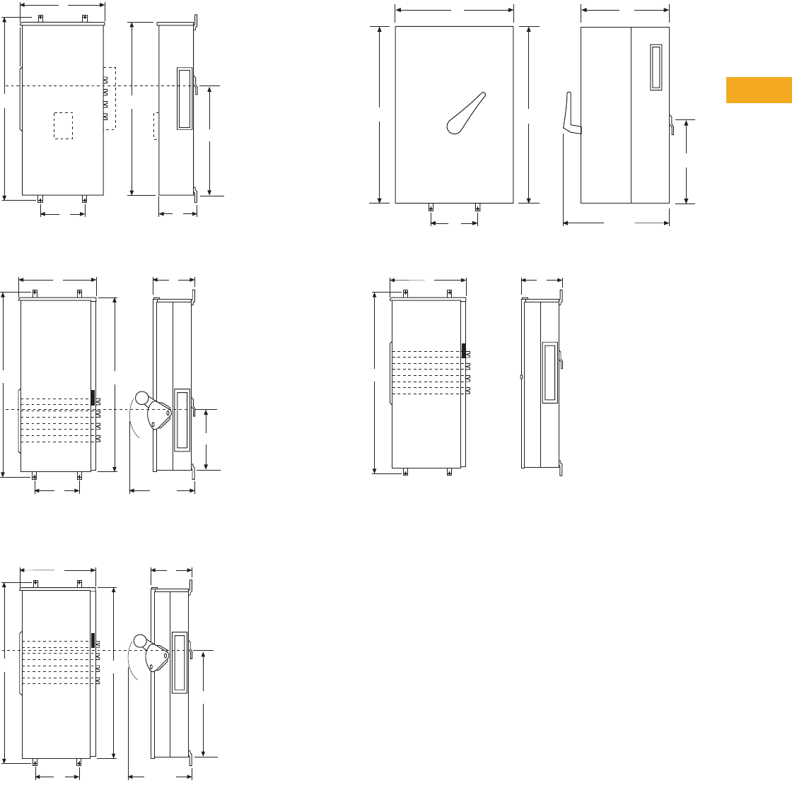
Volume 1—Residential and Light Commercial CA08100002E—February 2014 www.eaton.com V1-T5-111
5
5
5
5
5
5
5
5
5
5
5
5
5
5
5
5
5
5
5
5
5
5
5
5
5
5
5
5
5
5
5.10
Metering Products
Group Metering
Approximate Dimensions in Inches (mm)
Main Circuit Breakers, Terminal Boxes and Pull Boxes
Top Feed Fusible Switch
Bottom Feed Fusible Switch and Combination Fusible
Switch with Pull Box
Bolted Pressure Switch
EUSERC Main Terminal Box
C
B
A
E
D
Main CB, Non-Euserc Terminal Box and Pullboxes
F
C
17.00
(431.8)
A
EB
D
Top Feed Switch (No Knockouts)
F
Bottom Feed Switch and Combination Switch/Pullbox
A
EB
D
C
17.00
(431.8)
F
D
B
E
A
25.00
(635.0)
F
C
A
B
C

V1-T5-112 Volume 1—Residential and Light Commercial CA08100002E—February 2014 www.eaton.com
5
5
5
5
5
5
5
5
5
5
5
5
5
5
5
5
5
5
5
5
5
5
5
5
5
5
5
5
5
5
5.10
Metering Products
Group Metering
Approximate Dimensions in Inches (mm)
Knockout 1
Knockout 2
Knockout 3
Knockout 4
.875
.020
.169+.003
–.000 Diameter 5 Hole
.175
.010
Stamped
ID Mark
5.375
.010 3.500
.010
2.880
.010
KO (44)
KO (1)
12.375 .010
3.010
.010
2.880
.030
2-1/2”, 3”, 3-1/2”, 4” KO
1 Knockout Required
1/2”Knockout
1 Required
Per 50-1827-1 .080
.020
2.500
.020
.310 .030 Diameter
Paint Hole
.080
.020
.438
.010
.800
.030
.625
.010
6.500 Outside .010
C
L
8.00
2 Knockouts for 1/2”,
3/4” or 1” Conduit
4 Knockouts for 2-1/2”,
3”, 3-1/2” or 4” Conduit
.281 Diameter Knockout
1 Required
A
.45
3.25 2.50 1.75
4.25
.16
22.54
11.62
10.38
2.50 3.75
1.93
.61
19.40
8.00 4.00
11.19
2.125
.020
6.000
.010
6.000
.010
6.000
.010
6.000
.010
6.000
.010
6.000
.010 6.000
.010
6.000
.010 6.000
.010
3/4”, 1”, 1-1/4”, 1-1/2” Knockout
Per A50-26319 1 Knockout Required
32.120 .020
3”, 3-1/2”, 4”, 5”
Knockout Per A50-26327
5 Knockouts Required
.380
.020
2.750
.010
2.750
.010
2.750
.010
4.000
.020
7.500
.020
2.125
.020
1.440
.020
.169 .002 Diameter
5 Holes Required at ”X”
1.500
.020
.130
.030
.125
.030
4.440
.020
8.00
22.54
11.62
10.38
2.50
19.40
8.00 4.00
3.75
1.93
.61
11.19
.45
3.25 2.50 1.75
4.25
2 Knockouts for 1/2”,
3/4” or 1” Conduit
4 Knockouts for 2-1/2”,
3”, 3-1/2” or 4” Conduit
.281 Diameter Knockout
1 Required
.16
B
Knockout 5
Knockout 6
Knockout 7
Knockout 8
6.000
.020
KO (10)
KO (10)
5.000
.020
.150 .020
Typ.
3.250
.020
3.000
.020
.150 .020 Typ.
6.120
.020
6.850
.020
7.000
+.000
–.030
.780 .020 Typ.
.200
.020
Typ.
KO (10)
.150 .020
Typ.
KO (10)
KO (10)
6.000
.020
6.000
.020
6.000
.020
.250
Ref.
.150
.020
Typ.
4.000
.020
4.250
.020
.250
Ref.
.220
Dia.
Paint
Hole
10.120
.020
10.850
.020
11.000
+.000 -.030
.200 .020
Typ.
.780 .020
Typ.
7.250
.020 7.250
.020
7.250
.020
5.125
.020
.350
Ref.
.150
.020
Typ.
4.000
.020
4.250
.020
.350
Ref.
.220
Dia.
Paint
Hole
.150 .020
Typ.
KO (11)
KO (11)
KO (11)
KO (11)
10.140
.020
10.850
.020
11.000
+.000
–.030
.120
.020
Typ.
.685 .020
Typ.
4 Knockouts for 2-1/2",
3", 3-1/2" or 4" Conduit
8.00 4.00
8.00
24.38
11.25
1.75
2.13
15.38 3.75
16.63
27.13
2.50
3.63
0.50
4.75 3.13 2.50
1.50
4.25 1.75
.281 Dia. Knockout 1 Required
2 Knockouts for
1/2", 3/4", or 1" Conduit
2 Knockouts for
1/2", 3/4", or 1" Conduit
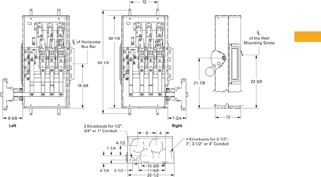
Volume 1—Residential and Light Commercial CA08100002E—February 2014 www.eaton.com V1-T5-113
5
5
5
5
5
5
5
5
5
5
5
5
5
5
5
5
5
5
5
5
5
5
5
5
5
5
5
5
5
5
5.10
Metering Products
Group Metering
Approximate Dimensions in Inches (mm)
Layout—Main Fusible Switch
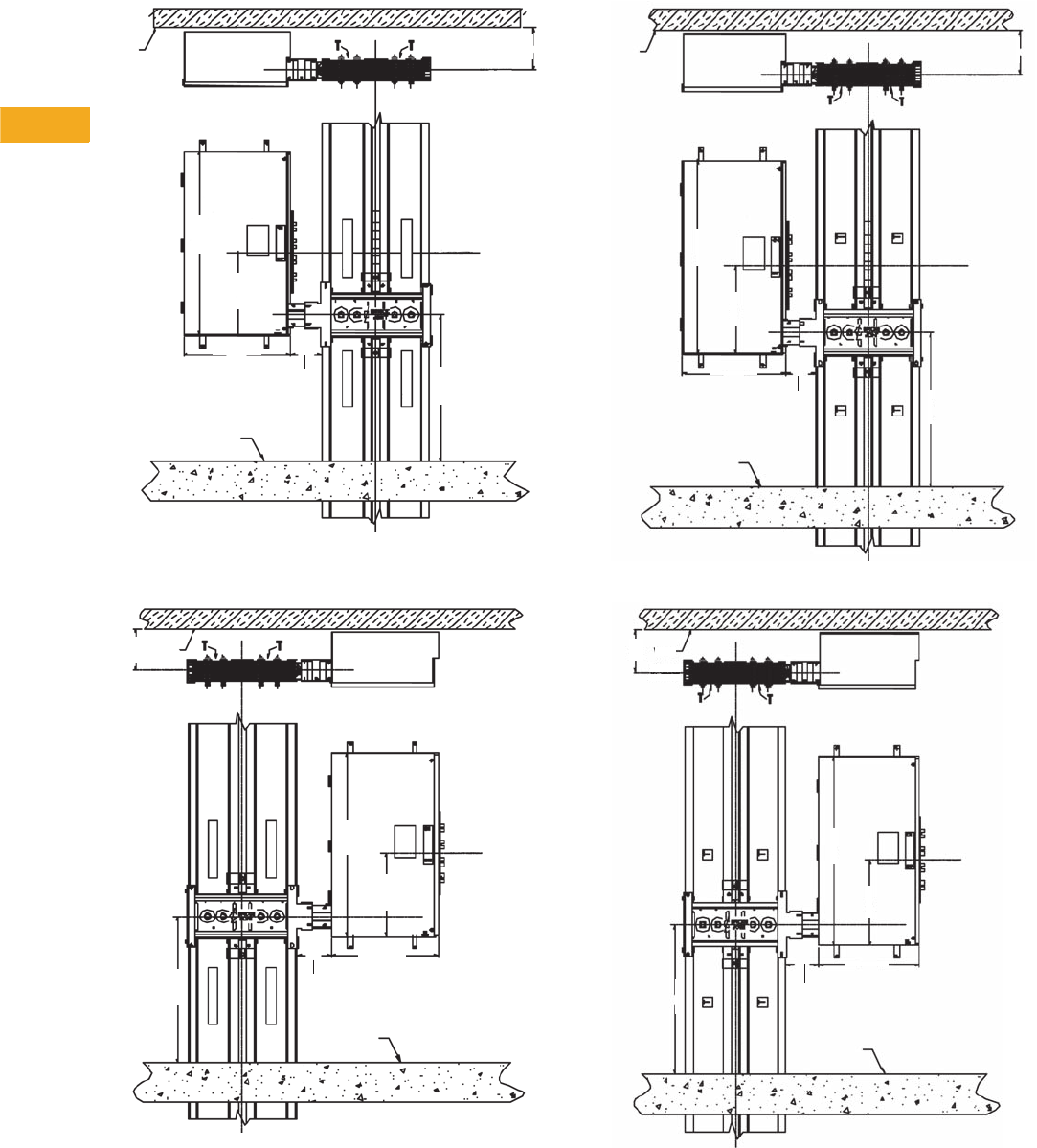
V1-T5-114 Volume 1—Residential and Light Commercial CA08100002E—February 2014 www.eaton.com
5
5
5
5
5
5
5
5
5
5
5
5
5
5
5
5
5
5
5
5
5
5
5
5
5
5
5
5
5
5
5.10
Metering Products
Group Metering
Approximate Dimensions in Inches (mm)
Main Circuit Breaker—“T-Opposite” Phasing Right
Main Circuit Breaker—“T-Opposite” Phasing Left
Main Circuit Breaker—“Standard T” Phasing Right
Main Circuit Breaker—“Standard T” Phasing Left
Meter
Center
Front
C
LHorizontal
C
L
Floor
Wall
Vertical
8.48
(215.4)
38.76
(984.5)
18.17
(461.5)
20.00
(508.0)
30.08
(764.0)
T-Opposite
T-Opposite
T-Opposite
T-Opposite
6.00
(152.4)
Meter
Center
Front
C
LHorizontal
20.00
(508.0)
Floor
Wall
C
LVertical
38.76
(984.5)
18.17
(461.5)
30.08
(764.0)
8.48
(215.4)
T-Opposite
T-Opposite
T-Opposite
T-Opposite
6.00
(152.4)
Meter
Center
Front
C
LHorizontal
C
L
20.00
(508.0)
Floor
Wall
Vertical
8.48
(215.4)
38.76
(984.5)
18.17
(461.5)
30.08
(764.0)
6.00
(152.4)
Meter
Center
Front
C
LHorizontal
C
L
38.76
(984.5)
18.17
(461.5)
20.00
(508.0)
30.08
(764.0)
Floor
8.48
(215.4)Wall
Vertical
6.00
(152.4)
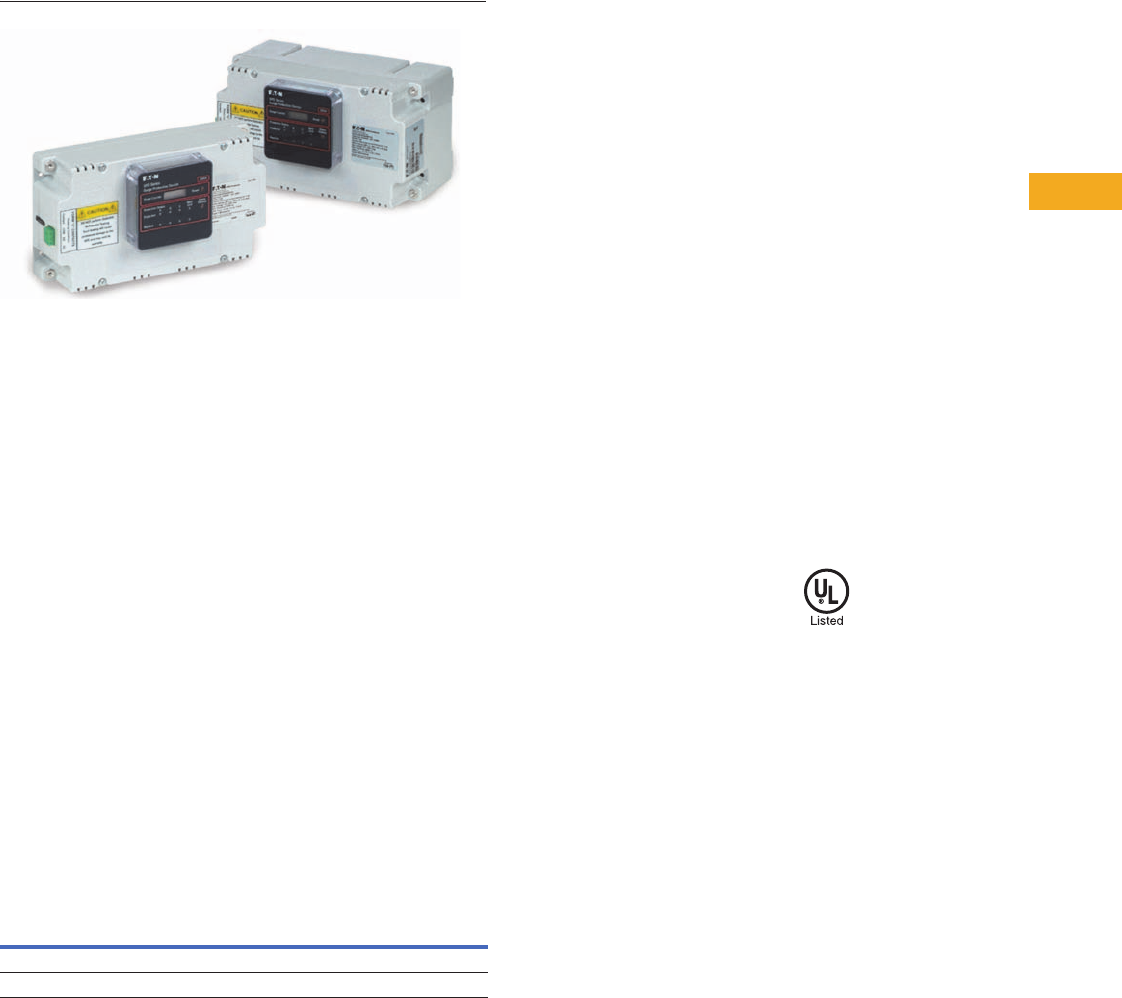
Volume 1—Residential and Light Commercial CA08100002E—February 2014 www.eaton.com V1-T5-115
5
5
5
5
5
5
5
5
5
5
5
5
5
5
5
5
5
5
5
5
5
5
5
5
5
5
5
5
5
5
5.10
Metering Products
Group Metering
Surge suppression devices shown are factory mounted in
Group Metering Enclosure.
Surge Metering
Contents
Description Page
Systems for Residential and Commercial
Applications . . . . . . . . . . . . . . . . . . . . . . . . . . . . V1-T5-88
Meter Packs . . . . . . . . . . . . . . . . . . . . . . . . . . . . . V1-T5-90
Type CCV 120/240V Tenant Main Circuit Breaker . V1-T5-95
Type CV 120/240V Tenant Main Circuit Breaker . . V1-T5-96
Meter Packs—1MP, 1MM and 3MM Main
Tenant Circuit Breakers . . . . . . . . . . . . . . . . . . . . V1-T5-98
Main Service Modules . . . . . . . . . . . . . . . . . . . . . V1-T5-101
Surge Metering
Residential Meter Stacks. . . . . . . . . . . . . . . . . . . . V1-T5-116
1MP, 1MM and 3MM Main Tenant
Circuit Breakers. . . . . . . . . . . . . . . . . . . . . . . . . . V1-T5-125
Phase Balanced Stack . . . . . . . . . . . . . . . . . . . . . . V1-T5-126
Commercial Meter Stack Modules . . . . . . . . . . . . V1-T5-127
35MM, 37MM, 35SS and 37SS
Main Tenant Circuit Breakers . . . . . . . . . . . . . . . V1-T5-134
Surge Metering
Product Description
Eaton’s multiple metering
product family is proud to
announce the availability of
main surge devices. The new
main surge is mounted
between the main service
module and the meter stacks
and serves the purpose of
providing surge protection
for downstream multiple
metering products. The main
surge is compatible with
all meter stacks currently
manufactured (1MM, 3MM,
35MM and 37MM).
Features, Benefits
and Functions
●Uses thermally protected
metal oxide varistor (MOV)
technology
●Compatible with 37MM
enclosure accessories
●Protection status indicator
lights EMI/RFI filtering and
audible alarms
●Offers surge protection for
all units fed from a main
service module
●Benefit for building/complex
owners who want to offer
surge protection to their
tenants. Owner can market
their apartment complex as
being surge friendly to
appliances and electronics
●Attain local utility
company approval. Not
for use in EUSERC area
Standards and Certifications
●UL 1449 3rd Edition
recognized component
Product Selection
Surge Metering
Voltage
Surge Current
per Phase (kA) Diagnostics
Catalog
Number
120/240V single-phase 100 Standard 1MMSURGE
208Y/120V three-phase 100 Standard 3MMSURGE
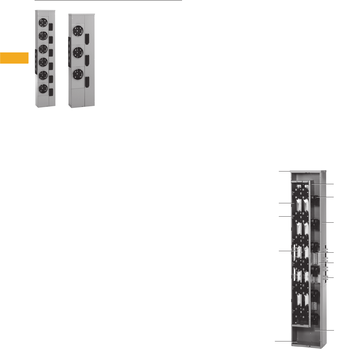
V1-T5-116 Volume 1—Residential and Light Commercial CA08100002E—February 2014 www.eaton.com
5
5
5
5
5
5
5
5
5
5
5
5
5
5
5
5
5
5
5
5
5
5
5
5
5
5
5
5
5
5
5.10
Metering Products
Group Metering
1MM and 3MM Metering Stack Modules
Contents
Description Page
Systems for Residential and Commercial
Applications . . . . . . . . . . . . . . . . . . . . . . . . . . . . V1-T5-88
Meter Packs . . . . . . . . . . . . . . . . . . . . . . . . . . . . . V1-T5-90
Type CCV 120/240V Tenant Main Circuit Breaker . V1-T5-95
Type CV 120/240V Tenant Main Circuit Breaker . . V1-T5-96
Meter Packs—1MP, 1MM and 3MM Main
Tenant Circuit Breakers . . . . . . . . . . . . . . . . . . . V1-T5-98
Main Service Modules . . . . . . . . . . . . . . . . . . . . . V1-T5-101
Surge Metering. . . . . . . . . . . . . . . . . . . . . . . . . . . V1-T5-115
Residential Meter Stacks
1MP, 1MM and 3MM Main Tenant
Circuit Breakers . . . . . . . . . . . . . . . . . . . . . . . . . V1-T5-125
Phase Balanced Stack. . . . . . . . . . . . . . . . . . . . . . V1-T5-126
Commercial Meter Stack Modules . . . . . . . . . . . . V1-T5-127
35MM, 37MM, 35SS and 37SS
Main Tenant Circuit Breakers . . . . . . . . . . . . . . . V1-T5-134
Residential Meter Stacks
Features, Benefits and Functions
A. Barrier
Meter socket and tenant
main breaker/wireway
sections are separated by a
solid metal barrier to guard
unmetered bus against
power theft.
B. Tenant Breaker
Reliable busbar–to–busbar
connection. 200A modules
accept bolt-on breakers 60–
200A. 125A modules accept
15–125A plug-on breakers.
C. Moveable Phase Connector
Four-wire horizontal bus lets
you use any 3MM module
for single- or three-phase
incoming service. Shipped
with A and B phase
connection, phase balancing
is easily accomplished in the
field by moving one, front-
accessible phase connector
post per module.
D. Neutral Assembly
A convenient termination for
neutral conductors is in the
wireway of each module.
E. Enclosed Horizontal Bus
Added security because a
non-removable barrier
encloses the 800 or 1200A
horizontal bus passing
through tenant breaker
section.
F. Equipment Ground Bar
Factory installed in side
gutter, a standard feature
that’s moveable to the top or
bottom gutter.
G. Raintight Cap
Shipped on each outdoor
meter module and main
device.
H. Knockouts
Tangential in bottom endwall.
I. Superior Finish
Rust inhibiting phosphate
primer and gray baked
enamel is standard. All
outdoor enclosures are of
galvanized steel construction.
J. Meter Socket
Our unique meter socket
base is installed without any
fasteners—reducing chances
for hot spots, easily
replaceable, and improves
connection to vertical bus.
K. Bus Connection
Mains and modules slip
together quickly and
smoothly with front-
accessible captive bolts
securing the juncture without
removing socket interiors or
bus access plate. Main bus
joint bolts torque to 25 foot
pounds.
L. Separate Wireway Cover
Separate covers allow easy
access to tenant breaker and
wireway section, permit work
on breakers or in wireway
without disturbing meters or
meter covers. (Not shown.)
M. Vertical Busbar
One-piece vertical busbar
from phase balancing joints to
meter socket eliminating any
chance for hot spots.
1MM Meter Stack Module
K
F
E
A
B
G
M
J
C
H
D
I
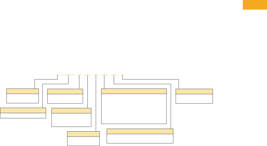
Volume 1—Residential and Light Commercial CA08100002E—February 2014 www.eaton.com V1-T5-117
5
5
5
5
5
5
5
5
5
5
5
5
5
5
5
5
5
5
5
5
5
5
5
5
5
5
5
5
5
5
5.10
Metering Products
Group Metering
●Eaton’s
1MM stacks are
single-
phase in, single-
phase out design
●Eaton’s 3MM stacks are
three-phase in, single-
phase out design
●Stacks with single-phase
horizontal bus are rated
240/120V, single-phase,
three-wire. Stacks with
three-phase horizontal bus
are rated 208Y/120V, three-
phase, four-wire, but can
be used on 240/120V,
three-phase, four-wire
delta systems
●All three-phase horizontal
bus modules have four-
wire cross bus, connected
A-B phase to vertical bus,
readily reconnectable for
phase balance on
installation
Note: Individual sockets cannot be
phase balanced, only each stack.
●Short-circuit ratings up to
100,000A
rms symmetrical
depending
upon AIC rating
of installed main tenant
circuit breakers and
main device
●Main tenant feeders can
exit bottom or back.
Knockouts are available
at all exit locations
●If being used in outdoor
application and exiting the
top, mount Myer type hubs
on rainproof cap
●Provision for two-pole
breaker (plug-on type for
125A sockets and bolt-on
type for 200A sockets)—
circuit breakers not
included
●Mechanically and
electrically built to bolt-up
with main service modules
and commercial modular
metering stacks
●Aluminum or copper bus
●800 or 1200A horizontal
bus
●All 3MM stacks include
fifth jaw at 9 o’clock
position
●All 1MM stacks do not
include fifth jaw. Order
1MM5JK if needed
Catalog Number Selection
When Ordering:
1. Determine catalog number of Main Service Module.
2. Determine catalog number of Meter Stack (Residential or Commercial).
3. Find quantity and catalog numbers for tenant circuit breakers (found on Page V1-T5-125 or V1-T5-135).
Order one breaker per socket.
4. If any accessories are needed, order from Pages V1-T5-136 and V1-T5-137.
Phases
1 = Single-phase
3 = Three-phase
Options
Blank = Ring
RL = Ringless
RLB = Ringless with horn bypass
WB = Wall bracket (accessory)
BSK = Bussed spacer (accessory)
EB12 = 12-inch (304.8 mm) elbow (accessory)
EB16 = 16-inch (406.4 mm) elbow (accessory)
Number of Meters
2, 3, 4, 5 or 6
Blank = Accessory
Bus Type
Blank = Aluminum
C= Copper
Type of Metering
MM = Multiple metering
Ampere Rating
12 = 125A
20 = 200A
Blank = Accessory
Enclosure
R= Outdoor
Blank = Indoor
Bus Amperes
12 = 200A horizontal bus (3MM units only)
Blank = Standard 800A bus
1 MM 4 12 R 12 C
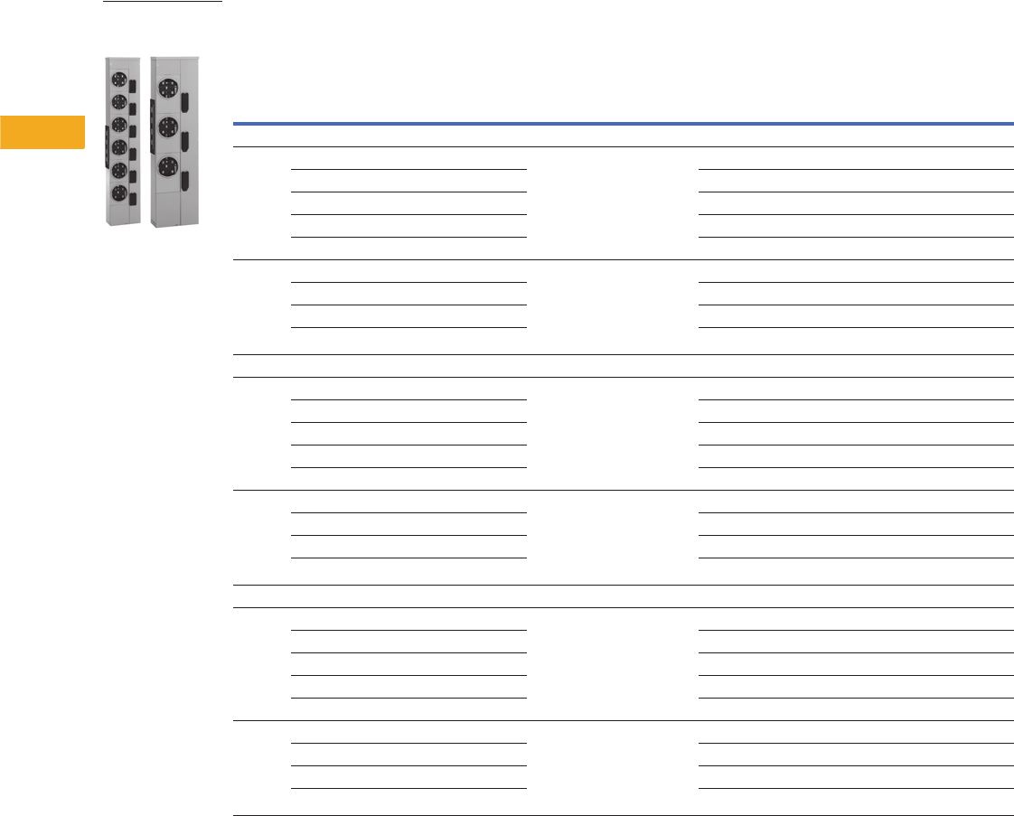
V1-T5-118 Volume 1—Residential and Light Commercial CA08100002E—February 2014 www.eaton.com
5
5
5
5
5
5
5
5
5
5
5
5
5
5
5
5
5
5
5
5
5
5
5
5
5
5
5
5
5
5
5.10
Metering Products
Group Metering
Product Selection
800A Horizontal Aluminum Bus—Standard Offering
Notes
1 For indoor applications where a top endwall with knockouts is needed, order one of part number MM12N1WLK for each 125A stack
or MM20N1WLK for each 200A stack.
2 1MM units do not come with 5th jaw.
3 To change in field from ring to ringless—order 1MMRC125.
4 To change in field from ring to ringless, the top socket in 125A, two- and three-high stacks use 1MMRC125T. Top socket only—other sockets see 3.
5 To change in field from ring to ringless—order 1MMRC200.
6 Check with local utility for height requirements or restrictions.
Amperes
Per
Meter
Socket
Number of
Meter
Sockets
Bus
Ampacity
Enclosure
Type 1
Main Tenant Breaker Type
(For Specific Catalog Numbers,
Refer to Page V1-T5-125)
Single-Phase In,
Single-Phase Out
Three-Phase In,
Single-Phase Out
Single-Phase Horizontal Bus
(Three Horizontal Busbars—
A, B and Neutral) 2
Three-Phase Horizontal Bus
(Four Horizontal Busbars—
A, B, C and Neutral)
Catalog Number Catalog Number
Ring Style Meter Socket Covers
125 32 4800 Indoor/outdoor Plug-on type
BR2_
BRH2_
BRHH2_
Use three-phase 3MM212R
3 4800 Indoor/outdoor 1MM312R 3MM312R
4 800 Indoor/outdoor 1MM412R 3MM412R
5 800 Indoor/outdoor 1MM512R 3MM512R
6 800 Indoor/outdoor 1MM612R 3MM612R
200 52 800 Outdoor Bolt-on type
CCV2_X
CCVH2_X
CVS2_XMM
CV2_XMM
CVH2_XMM
Use three-phase 3MM220R
3 800 Outdoor 1MM320R 3MM320R
4 800 Outdoor 1MM420R 3MM420R
5 800 Outdoor 1MM520R 63MM520R 5
Ringless Style Meter Socket Covers
125 2 800 Outdoor Plug-on type
BR2_
BRH2_
BRHH2_
Use three-phase 3MM212RRL
3 800 Outdoor 1MM312RRL 3MM312RRL
4 800 Outdoor 1MM412RRL 3MM412RRL
5 800 Outdoor 1MM512RRL 3MM512RRL
6 800 Outdoor 1MM612RRL 3MM612RRL
200 2 800 Outdoor Bolt-on type
CCV2_X
CCVH2_X
CVS2_XMM
CV2_XMM
CVH2_XMM
Use three-phase 3MM220RRL
3 800 Outdoor 1MM320RRL 3MM320RRL
4 800 Outdoor 1MM420RRL 3MM420RRL
5 800 Outdoor 1MM520RRL 63MM520RRL 5
Ringless Style Covers with Horn Bypass
125 2 800 Outdoor Plug-on type
BR2_
BRH2_
BRHH2_
Use three-phase 3MM212RRLB
3 800 Outdoor 1MM312RRLB 3MM312RRLB
4 800 Outdoor 1MM412RRLB 3MM412RRLB
5 800 Outdoor 1MM512RRLB 3MM512RRLB
6 800 Outdoor 1MM612RRLB 3MM612RRLB
200 2 800 Outdoor Bolt-on type
CCV2_X
CCVH2_X
CVS2_XMM
CV2_XMM
CVH2_XMM
Use three-phase 3MM220RRLB
3 800 Outdoor 1MM320RRLB 3MM320RRLB
4 800 Outdoor 1MM420RRLB 3MM420RRLB
5 800 Outdoor 1MM520RRLB 63MM520RRLB 5
1MM and 3MM
Metering Stack
Modules
Volume 1—Residential and Light Commercial CA08100002E—February 2014 www.eaton.com V1-T5-119
5
5
5
5
5
5
5
5
5
5
5
5
5
5
5
5
5
5
5
5
5
5
5
5
5
5
5
5
5
5
5.10
Metering Products
Group Metering
800A Horizontal Copper Bus—Premium Offering
Notes
1 For indoor applications where a top endwall with knockouts is needed, order (1) of part number MM12N1WLK for each 125A stack
or MM20N1WLK for each 200A stack.
2 1MM units do not come with 5th jaw.
3 To change in field from ring to ringless—order 1MMRC125.
4 To change in field from ring to ringless, the top socket in 125A, two- and three-high stacks use 1MMRC125T. Top socket only—other sockets see 3.
5 To change in field from ring to ringless—order 1MMRC200.
6 Check with local utility for height requirements or restrictions.
Single-Phase In,
Single-Phase Out
Three-Phase In,
Single-Phase Out
Amperes
Per
Meter
Socket
Number of
Meter
Sockets
Bus
Ampacity
Enclosure
Type 1
Main Tenant Breaker Type
(For Specific Catalog Numbers,
Refer to Page V1-T5-125)
Single-Phase Horizontal Bus
(Three Horizontal Busbars—
A, B, C and Neutral) 2
Three-Phase Horizontal Bus
(Four Horizontal Busbars—
A, B, C and Neutral)
Catalog Number Catalog Number
Ring Style Meter Socket Covers
125 32 4800 Outdoor Plug-on type
BR2_
BRH2_
BRHH2_
Use three-phase 3MM212RC
3 4800 Outdoor 1MM312RC 3MM312RC
4 800 Outdoor 1MM412RC 3MM412RC
5 800 Outdoor 1MM512RC 3MM512RC
6 800 Outdoor 1MM612RC 3MM612RC
200 52 800 Outdoor Bolt-on type
CCV2_X
CCVH2_X
CVS2_XMM
CV2_XMM
CVH2_XMM
Use three-phase 3MM220RC
3 800 Outdoor 1MM320RC 3MM320RC
4 800 Outdoor 1MM420RC 3MM420RC
5 800 Outdoor 1MM520RC 63MM520RC 5
Ringless Style Meter Socket Covers
125 2 800 Outdoor Plug-on type
BR2_
BRH2_
BRHH2_
Use three-phase 3MM212RRLC
3 800 Outdoor 1MM312RRLC 3MM312RRLC
4 800 Outdoor 1MM412RRLC 3MM412RRLC
5 800 Outdoor 1MM512RRLC 3MM512RRLC
6 800 Outdoor 1MM612RRLC 3MM612RRLC
200 2 800 Outdoor Bolt-on type
CCV2_X
CCVH2_X
CVS2_XMM
CV2_XMM
CVH2_XMM
Use three-phase 3MM220RRLC
3 800 Outdoor 1MM320RRLC 3MM320RRLC
4 800 Outdoor 1MM420RRLC 3MM420RRLC
5 800 Outdoor 1MM520RRLC 63MM520RRLC 5
Ringless Style Covers with Horn Bypass
125 2 800 Outdoor Plug-on type
BR2_
BRH2_
BRHH2_
Use three-phase 3MM212RRLBC
3 800 Outdoor 1MM312RRLBC 3MM312RRLBC
4 800 Outdoor 1MM412RRLBC 3MM412RRLBC
5 800 Outdoor 1MM512RRLBC 3MM512RRLBC
6 800 Outdoor 1MM612RRLBC 3MM612RRLBC
200 2 800 Outdoor Bolt-on type
CCV2_X
CCVH2_X
CVS2_XMM
CV2_XMM
CVH2_XMM
Use three-phase 3MM220RRLBC
3 800 Outdoor 1MM320RRLBC 3MM320RRLBC
4 800 Outdoor 1MM420RRLBC 3MM420RRLBC
5 800 Outdoor 1MM520RRLBC 63MM520RRLBC 5
1MM and 3MM
Metering Stack
Modules
V1-T5-120 Volume 1—Residential and Light Commercial CA08100002E—February 2014 www.eaton.com
5
5
5
5
5
5
5
5
5
5
5
5
5
5
5
5
5
5
5
5
5
5
5
5
5
5
5
5
5
5
5.10
Metering Products
Group Metering
1200A Horizontal Aluminum Bus—Standard Offering
Notes
1 For indoor applications where a top endwall with knockouts is needed, order (one) of part number MM12N1WLK for each 125A stack or
MM20N1WLK for each 200A stack.
2 To change in field from ring to ringless—order 1MMRC125.
3 To change in field from ring to ringless, the top socket in 125A, two- and three-high stacks use 1MMRC125T. Top socket only—other sockets see 2.
4 To change in field from ring to ringless—order 1MMRC200.
Three-Phase In, Single-Phase Out
Amperes
Per
Meter
Socket
Number of
Meter
Sockets
Bus
Ampacity
Enclosure
Type 1
Main Tenant Breaker Type
(For Specific Catalog Numbers,
Refer to Page V1-T5-116)
Three-Phase Horizontal Bus
(Four Horizontal Busbars—
A, B, C and Neutral)
Catalog Number
Ring Style Meter Socket Covers
125 22 31200 Indoor/outdoor Plug-on type
BR2_
BRH2_
BRHH2_
3MM212R12
3 31200 Indoor/outdoor 3MM312R12
4 1200 Indoor/outdoor 3MM412R12
5 1200 Indoor/outdoor 3MM512R12
6 1200 Indoor/outdoor 3MM612R12
200 42 1200 Outdoor Bolt-on type
CCV2_X
CCVH2_X
CVS2_XMM
CV2_XMM
CVH2_XMM
3MM220R12
3 1200 Outdoor 3MM320R12
4 1200 Outdoor 3MM420R12
5 1200 Indoor/outdoor 3MM520R12
Ringless Style Meter Socket Covers (5th Jaw at 9 o’Clock Standard—Field Adjustable to 3 or 6 o’Clock)
125 2 1200 Outdoor Plug-on type
BR2_
BRH2_
BRHH2_
3MM212R12RL
3 1200 Outdoor 3MM312R12RL
4 1200 Outdoor 3MM412R12RL
5 1200 Outdoor 3MM512R12RL
6 1200 Outdoor 3MM612R12RL
200 2 1200 Outdoor Bolt-on type
CCV2_X
CCVH2_X
CVS2_XMM
CV2_XMM
CVH2_XMM
3MM220R12RL
3 1200 Outdoor 3MM320R12RL
4 1200 Outdoor 3MM420R12RL
5 1200 Outdoor 3MM520R12RL
Ringless Style Covers with Horn Bypass (5th Jaw at 9 o’Clock Standard—Field Adjustable to 3 or 6 o’Clock)
125 2 1200 Outdoor Plug-on type
BR2_
BRH2_
BRHH2_
3MM212R12RLB
3 1200 Outdoor 3MM312R12RLB
4 1200 Outdoor 3MM412R12RLB
5 1200 Outdoor 3MM512R12RLB
6 1200 Outdoor 3MM612R12RLB
200 2 1200 Outdoor Bolt-on type
CCV2_X
CCVH2_X
CVS2_XMM
CV2_XMM
CVH2_XMM
3MM220R12RLB
3 1200 Outdoor 3MM320R12RLB
4 1200 Outdoor 3MM420R12RLB
5 1200 Outdoor 3MM520R12RLB
1MM and 3MM
Metering Stack
Modules
Volume 1—Residential and Light Commercial CA08100002E—February 2014 www.eaton.com V1-T5-121
5
5
5
5
5
5
5
5
5
5
5
5
5
5
5
5
5
5
5
5
5
5
5
5
5
5
5
5
5
5
5.10
Metering Products
Group Metering
1200A Horizontal Copper Bus—Premium Offering
Technical Data and Specifications
Wire Sizes—Neutral and Ground Lugs
●Each stack includes a neutral and ground bar
●If an extra ground bar is needed, order 1MMGBK
Wire Sizes—Neutral and Ground Lugs
Notes
1For indoor applications where a top endwall with knockouts is needed, order (one) of
part number MM12N1WLK for each 125A stack
or MM20N1WLK for each 200A stack.
2To change in field from ring to ringless—order 1MMRC125.
3To change in field from ring to ringless, the top socket in 125A, two- and three-high
stacks use 1MMRC125T. Top socket only—other sockets see 2.
4To change in field from ring to ringless—order 1MMRC200.
Three-Phase In, Single-Phase Out
Amperes
Per
Meter
Socket
Number of
Meter
Sockets
Bus
Ampacity
Enclosure
Type 1
Main Tenant Breaker Type
(For Specific Catalog Numbers,
Refer to Page V1-T5-116)
Three-Phase Horizontal Bus
(Four Horizontal Busbars—
A, B, C and Neutral)
Catalog Number
Ring Style Meter Socket Covers
125 22 31200 Indoor/outdoor Plug-on type
BR2_
BRH2_
BRHH2_
3MM212R12C
3 31200 Indoor/outdoor 3MM312R12C
4 1200 Indoor/outdoor 3MM412R12C
5 1200 Indoor/outdoor 3MM512R12C
6 1200 Indoor/outdoor 3MM612R12C
200 42 1200 Outdoor Bolt-on type
CCV2_X
CCVH2_X
CVS2_XMM
CV2_XMM
CVH2_XMM
3MM220R12C
3 1200 Outdoor 3MM320R12C
4 1200 Outdoor 3MM420R12C
5 1200 Outdoor 3MM520R12C
Ringless Style Meter Socket Covers (5th Jaw at 9 o’Clock Standard—Field Adjustable to 3 or 6 o’Clock)
125 2 1200 Outdoor Plug-on type
BR2_
BRH2_
BRHH2_
3MM212R12RLC
3 1200 Outdoor 3MM312R12RLC
4 1200 Outdoor 3MM412R12RLC
5 1200 Outdoor 3MM512R12RLC
6 1200 Outdoor 3MM612R12RLC
200 2 1200 Outdoor Bolt-on type
CCV2_X
CCVH2_X
CVS2_XMM
CV2_XMM
CVH2_XMM
3MM220R12RLC
3 1200 Outdoor 3MM320R12RLC
4 1200 Outdoor 3MM420R12RLC
5 1200 Outdoor 3MM520R12RLC
Ringless Style Covers with Horn Bypass (5th Jaw at 9 o’Clock Standard—Field Adjustable to 3 or 6 o’Clock)
125 2 1200 Outdoor Plug-on type
BR2_
BRH2_
BRHH2_
3MM212R12RLBC
3 1200 Outdoor 3MM312R12RLBC
4 1200 Outdoor 3MM412R12RLBC
5 1200 Outdoor 3MM512R12RLBC
6 1200 Outdoor 3MM612R12RLBC
200 2 1200 Outdoor Bolt-on type
CCV2_X
CCVH2_X
CVS2_XMM
CV2_XMM
CVH2_XMM
3MM220R12RLBC
3 1200 Outdoor 3MM320R12RLBC
4 1200 Outdoor 3MM420R12RLBC
5 1200 Outdoor 3MM520R12RLBC
Lugs in Meter
Socket Modules
Wire Size,
Al/Cu
Branch neutral—125A socket module #6–2/0 kcmil
Branch neutral—200A socket module #1/0–300 kcmil
Equipment ground bar—125A socket module #14–#2 kcmil
Equipment ground bar—200A socket module #14–2/0 kcmil
Optional ground bar (1MMGBK) #6–2/0 kcmil
1MM and 3MM
Metering Stack
Modules
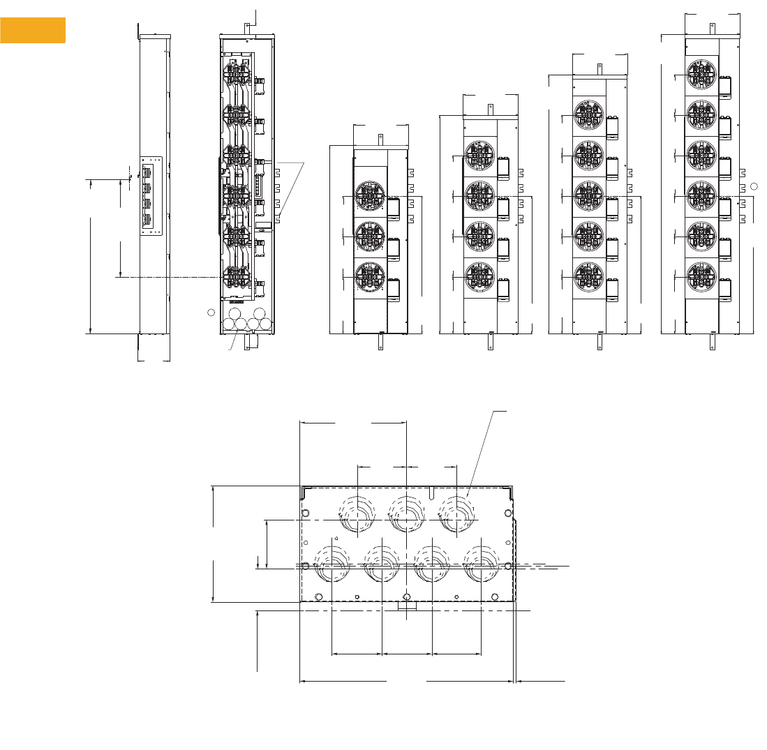
V1-T5-122 Volume 1—Residential and Light Commercial CA08100002E—February 2014 www.eaton.com
5
5
5
5
5
5
5
5
5
5
5
5
5
5
5
5
5
5
5
5
5
5
5
5
5
5
5
5
5
5
5.10
Metering Products
Group Metering
Dimensions
Approximate Dimensions in Inches (mm)
Modular Metering Stacks—Aluminum and Copper
1MM, 3MM, 125 Amperes
Note: Dimensions Apply to 800 and 1200 Ampere Horizontal Bus.
This Bus
Omitted
On 1 —
PH Units
41.80
(1061.7)
9.00
(228.6)
9.00
(228.6)
12.61
(320.2)
3.07
(78.0)
(6) KO for
1, 1-2/4 1-1/2
Conduit
A
7. 0 1
(178.0)
34.25
(870.0)
To of Wall Mtg. Screw
C
L
21.65
(550.0)
C Meter to C Rail Mounting Screw
LL
2.00
(50.8) TYP.
2, 3 Meter Device 4 Meter Device
30.0
(777.2) To C of Main Busbar
L48.50
(1231.9)
12.60
(320.3)
9.00
(228.6)
9.00
(228.6)
9.00
(228.6)
30.60
(777.2)
To C of Main Busbar
L
57.50
(1460.5)
9.00
(228.6)
9.00
(228.6)
9.00
(228.6)
12.60
(320.0)
To C of Main Busbar
L
30.60
(777.2)
5 Meter Device 6 Meter Device
12.60
(320.0)
9.00
(228.6)
9.00
(228.6)
9.00
(228.6)
9.00
(228.6)
9.00
(228.6)
66.50
(1689.1)
A
30.60
(777.2)
To C of Main Busbar
L
Top End & Bottom End View for NEMA 1;
Bottom End View for NEMA 3R
Tangential K.O.'s
3/4, 1, 1-1/4, 1-1/2
"Z" = C OF 1-1/2" Ring
"Y" = C OF 1-1/4" Ring
"X" = C OF 3/4" & 1" Ring
L
L
L
0.125
(3.2)
12.13
(308.1)
2.83
(71.9)
2.83
(71.9)
2.83
(71.9)
2.33
(59.1)
6.62
(168.1)
2.83
(71.9)
6.06
(153.9)
2.83
(71.9)
2.83
(71.9)
12.26
(311.4)
12.26
(311.4)
12.26
(311.4)
12.26
(311.4)
"X""Y"
"Z"
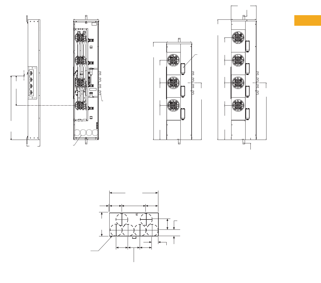
Volume 1—Residential and Light Commercial CA08100002E—February 2014 www.eaton.com V1-T5-123
5
5
5
5
5
5
5
5
5
5
5
5
5
5
5
5
5
5
5
5
5
5
5
5
5
5
5
5
5
5
5.10
Metering Products
Group Metering
Approximate Dimensions in Inches (mm)
Modular Metering Stacks—Aluminum and Copper
1MM, 3MM, 200 Amperes
Note: Dimensions Apply to 800 and 1200 Ampere Horizontal Bus.
4 Meter Device
2, 3 Meter Device
34.25
(870.0)
To C of Wall Rail Mtg. Screw
L
15.82
(401.8)
C Meter to C Rail Mtg. Screw
LL
7. 0 1
(178.1)
(4) KO For
1, 1-1/4, 1-1/2, 2
Conduit
This Bus Omitted on
1-PH Devices
52.35
(1329.7)
12.12
(307.8)
12.12
(307.8)
18.42
(467.9)
30.55
(776.0)
To C of Main Busbar
L
18.42
(467.9)
12.12
(307.8)
12.12
(307.8)
12.12
(307.8)
64.50
(1638.3)
Circuit
Breaker
Covers
Omitted
On NEMA
1 Devices
13.50
(342.9)
1.70
(43.2) TYP.
30.55
(776.0)
To C of Main Busbar
L
1.75
(44.5)
TYP.
Bottom View
3.29
(83.6)
0.12
(3.0)
6.59
(167.4)
13.36
(339.3)
3.29
(83.6)
3.29
(83.6)
3.38
(85.9)
1.75
(44.5)
6.62
(168.1)
(6) Cocentric K.O.'s
1", 1-1/4", 1-1/2", 2"
1.76
(44.7)
3.00
(76.2)
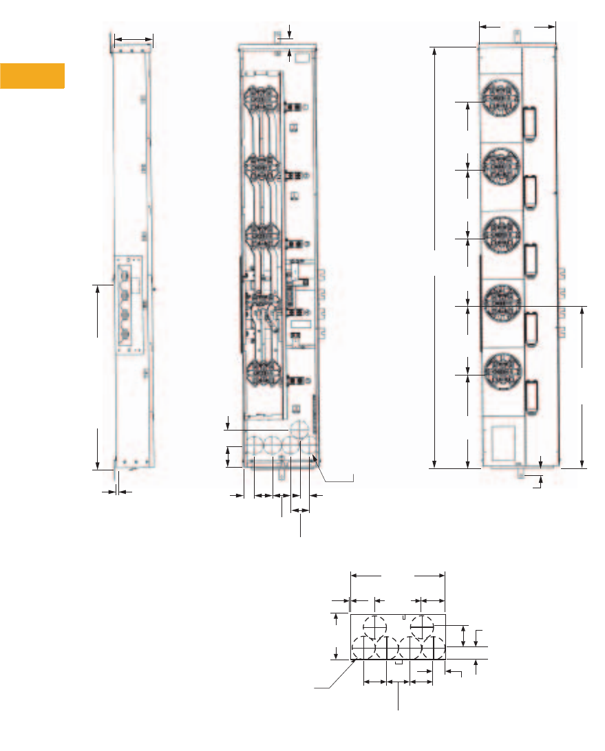
V1-T5-124 Volume 1—Residential and Light Commercial CA08100002E—February 2014 www.eaton.com
5
5
5
5
5
5
5
5
5
5
5
5
5
5
5
5
5
5
5
5
5
5
5
5
5
5
5
5
5
5
5.10
Metering Products
Group Metering
Approximate Dimensions in Inches (mm)
5-High, 200 Amperes, 1MM and 3MM Metering
Note: The Bussed meter stack device shown on the far right of the figure, must be used on Mains with Busway connections, found on Pages V1-T5-109 and V1-T5-113. Please contact factory for
catalog numbers associated with Bussed meter stack devices.
L
33.27
(845.1)
Typ.
to
C
of Wall
Mtg.
Screw
13.50
(342.9)
1.70
(43.2)
0.45
(11.4)
Typ. Residential
Device
6.87
(174.5)
Typ.
16.76
(425.7)
28.88 to
C of Main
Busbar
12.13
(308.1)
12.13
(308.1)
74.96
(1904.0)
12.13
(308.1)
12.13
(308.1)
1.75 (44.5)
3.21
(81.5)
3.21
(81.5)
1.61
(40.9)
(5) Concentric
K.O.'s
1", 1-1/4",
1-1/2", 2"
1.87
(47.5)
2.74
(69.6)
3.85
(97.8)
3.21
(81.5)
L
Bottom View
3.29
(83.6)
0.12
(3.0)
6.59
(167.4)
13.36
(339.3)
3.29
(83.6)
3.29
(83.6)
3.38
(85.9)
1.75
(44.5)
6.62
(168.1)
(6) Cocentric K.O.'s
1", 1-1/4", 1-1/2", 2"
1.76
(44.7)
3.00
(76.2)
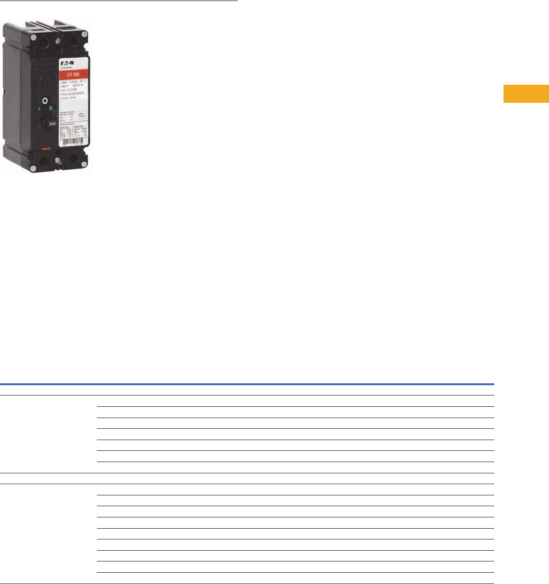
Volume 1—Residential and Light Commercial CA08100002E—February 2014 www.eaton.com V1-T5-125
5
5
5
5
5
5
5
5
5
5
5
5
5
5
5
5
5
5
5
5
5
5
5
5
5
5
5
5
5
5
5.10
Metering Products
Group Metering
CV2200
1MM and 3MM Metering Circuit Breakers
Contents
Description Page
Systems for Residential and Commercial
Applications . . . . . . . . . . . . . . . . . . . . . . . . . . . . V1-T5-88
Meter Packs . . . . . . . . . . . . . . . . . . . . . . . . . . . . . V1-T5-90
Type CCV 120/240V Tenant Main Circuit Breaker . V1-T5-95
Type CV 120/240V Tenant Main Circuit Breaker . . V1-T5-96
Meter Packs—1MP, 1MM and 3MM Main
Tenant Circuit Breakers . . . . . . . . . . . . . . . . . . . . V1-T5-98
Main Service Modules . . . . . . . . . . . . . . . . . . . . . V1-T5-101
Surge Metering . . . . . . . . . . . . . . . . . . . . . . . . . . . V1-T5-115
Residential Meter Stacks. . . . . . . . . . . . . . . . . . . . V1-T5-116
1MP, 1MM and 3MM Main Tenant
Circuit Breakers
Phase Balanced Stack . . . . . . . . . . . . . . . . . . . . . . V1-T5-126
Commercial Meter Stack Modules . . . . . . . . . . . . V1-T5-127
35MM, 37MM, 35SS and 37SS
Main Tenant Circuit Breakers . . . . . . . . . . . . . . . V1-T5-134
1MP, 1MM and 3MM Main Tenant Circuit Breakers
Product Description
Specific main tenant circuit
breakers that are to be
used in meter packs (1MP),
residential meter stacks
(1MM) and three-phase in
single-phase out meter
stacks (3MM).
Product Selection
Notes
1#2–300 kcmil wire size range for CCV and CCVH tenant main circuit breakers.
2“MM” suffix indicates mounting hardware kit is included as standard with tenant main breaker.
31MMCBK replacement mounting hardware kit. One kit is needed per breaker. Mounting hardware kit ships standard with breaker “MM” suffix offering.
4#6–4/0 kcmil wire size range for CVS, CV and CVH tenant main circuit breakers. If #2–300 kcmil is needed, order 2TA225CVK. One kit needed per breaker.
Description
Number
of Poles
Main Tenant
Circuit Breaker
Ampere Rating
10 kAIC 22 kAIC 25 kAIC 42 kAIC 65 kAIC 100 kAIC
Catalog
Number 1
Catalog
Number
Catalog
Number 1234
Catalog
Number 234
Catalog
Number 234
Catalog
Number 234
Plug-On Type
Plug-on type circuit breakers used
with 1MP, 1MM, and 3MM 125A
modular metering stacks
260BR260 BRH260 — BRHH260 — —
270BR270 BRH270 — BRHH270 — —
280BR280 BRH280 — BRHH280 — —
290BR290 BRH290 — BRHH290 — —
2 100 BR2100 BRH2100 — BRHH2100 — —
2 110 BR2110 BRH2110 — BRHH2110 — —
2 125 BR2125 BRH2125 — BRHH2125 — —
Bolt-On Type
Bolt-on type circuit breakers used with
1MP, 1MM, and 3MM 200A modular
metering stacks
260— — CVS2060XMM CVS2060XMM CV2060XMM CVH2060XMM
270— — CVS2070XMM CVS2070XMM CV2070XMM CVH2070XMM
280— — CVS2080XMM CVS2080XMM CV2080XMM CVH2080XMM
290— — CVS2090XMM CVS2090XMM CV2090XMM CVH2090XMM
2 100 CCV2100X — CCVH2100X CVS2100XMM CV2100XMM CVH2100XMM
2 125 CCV2125X — CCVH2125X CVS2125XMM CV2125XMM CVH2125XMM
2 150 CCV2150X — CCVH2150X CVS2150XMM CV2150XMM CVH2150XMM
2 175 CCV2175X — CCVH2175X CVS2175XMM CV2175XMM CVH2175XMM
2 200 CCV2200X — CCVH2200X CVS2200XMM CV2200XMM CVH2200XMM

V1-T5-126 Volume 1—Residential and Light Commercial CA08100002E—February 2014 www.eaton.com
5
5
5
5
5
5
5
5
5
5
5
5
5
5
5
5
5
5
5
5
5
5
5
5
5
5
5
5
5
5
5.10
Metering Products
Group Metering
Contents
Description Page
Systems for Residential and Commercial
Applications . . . . . . . . . . . . . . . . . . . . . . . . . . . . V1-T5-88
Meter Packs . . . . . . . . . . . . . . . . . . . . . . . . . . . . . V1-T5-90
Type CCV 120/240V Tenant Main Circuit Breaker . V1-T5-95
Type CV 120/240V Tenant Main Circuit Breaker . . V1-T5-96
Meter Packs—1MP, 1MM and 3MM Main
Tenant Circuit Breakers . . . . . . . . . . . . . . . . . . . V1-T5-98
Main Service Modules . . . . . . . . . . . . . . . . . . . . . V1-T5-101
Surge Metering. . . . . . . . . . . . . . . . . . . . . . . . . . . V1-T5-115
Residential Meter Stacks . . . . . . . . . . . . . . . . . . . V1-T5-116
1MP, 1MM and 3MM Main Tenant
Circuit Breakers . . . . . . . . . . . . . . . . . . . . . . . . . V1-T5-125
Phase Balanced Stack
Commercial Meter Stack Modules . . . . . . . . . . . . V1-T5-127
35MM, 37MM, 35SS and 37SS
Main Tenant Circuit Breakers . . . . . . . . . . . . . . . V1-T5-134
Phase Balanced Stack
Product Description
Eaton’s Phase Balanced
Stack allows for a complete
phase balanced metering line-
up using fewer stacks. With
today’s electrical rooms
becoming smaller, the need
is greater than ever to offer
space-saving metering
products while providing a
fully phase balanced system.
The new phase balanced
stack is the answer.
Today, achieving a phase
balanced system when
connected to a 208Y/120 Vac
three-phase, four-wire
system may require one or
two additional 3MM meter
modules. Standard 3MM
meter stacks come factory
connected to phases A and B.
The new phase balanced
stacks connect the two
bottom meters to phases
B and C and the top two or
three meters to phases
A and C. Using these new
stacks with the AB phased
3MM metering, phase
balancing is accomplished,
and more compact than
before.
Features
●Available in four- and
five-high configurations
at 125A
●200A stacks available
●Available with 800A
aluminum bus and
1200A copper bus
●Ring, ringless, ringless
with horn bypass available
●Outdoor enclosure
●Dimensions same as
existing 125A, three-phase
meter stacks
Product Selection
Ordering Information
●Check with local utility
for height restrictions
●Items loaded in VISTA
●If you have questions,
please contact the
Technical Resource Center
1-800-356-1243, option 3
Phase Balanced Stack
Note: Local codes and utility requirements still apply. The phase balance stacks are not
suitable for changing in the field.
Amperes Per
Meter Socket Bus Ampacity Meter Socket Cover Catalog Number
125 800 Ring 3MM412RACBC
125 800 Ring 3MM512RACBC
125 800 Ringless 3MM412RRLACBC
125 800 Ringless 3MM512RRLACBC
125 800 Ringless horn bypass 3MM412RRLBACBC
125 800 Ringless horn bypass 3MM512RRLBACBC
125 1200 Ring 3MM412R2ACBC
125 1200 Ring 3MM512R2ACBC
125 1200 Ringless 3MM412R2RLACBC
125 1200 Ringless 3MM512R2RLACBC
125 1200 Ringless horn bypass 3MM412R2RLBACBC
125 1200 Ringless horn bypass 3MM512R2RLBACBC
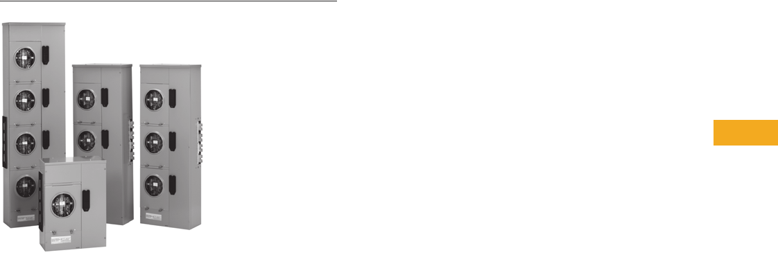
Volume 1—Residential and Light Commercial CA08100002E—February 2014 www.eaton.com V1-T5-127
5
5
5
5
5
5
5
5
5
5
5
5
5
5
5
5
5
5
5
5
5
5
5
5
5
5
5
5
5
5
5.10
Metering Products
Group Metering
35MM, 37MM, 35SS and 37SS
Commercial Meter Stack Modules (35MM, 37MM, 35SS and 37SS)
Contents
Description Page
Systems for Residential and Commercial
Applications . . . . . . . . . . . . . . . . . . . . . . . . . . . . V1-T5-88
Meter Packs . . . . . . . . . . . . . . . . . . . . . . . . . . . . . V1-T5-90
Type CCV 120/240V Tenant Main Circuit Breaker . V1-T5-95
Type CV 120/240V Tenant Main Circuit Breaker . . V1-T5-96
Meter Packs—1MP, 1MM and 3MM Main
Tenant Circuit Breakers . . . . . . . . . . . . . . . . . . . . V1-T5-98
Main Service Modules . . . . . . . . . . . . . . . . . . . . . V1-T5-101
Surge Metering . . . . . . . . . . . . . . . . . . . . . . . . . . . V1-T5-115
Residential Meter Stacks. . . . . . . . . . . . . . . . . . . . V1-T5-116
1MP, 1MM and 3MM Main Tenant
Circuit Breakers. . . . . . . . . . . . . . . . . . . . . . . . . . V1-T5-125
Phase Balanced Stack . . . . . . . . . . . . . . . . . . . . . . V1-T5-126
Commercial Meter Stack Modules
35MM, 37MM, 35SS and 37SS
Main Tenant Circuit Breakers . . . . . . . . . . . . . . . V1-T5-134
Commercial Meter Stack Modules
Product Description
●Heavy-duty lever bypass
socket design
●Single-phase or three-
phase designs (35 = single-
phase, 37 = three-phase)
●Provision for two-pole or
three-pole main tenant
breakers
●Phase balance kits are
included with three-high
and four-high modules
Features, Benefits
and Functions
A. End Walls
The top cap is removable and
does not contain knockouts,
so contractors can position
and punch holes where they
need them. There are
numerous KOs in the back
and bottom for flexibility.
B. Ground Bars
The factory-installed
equipment ground bars are
provided in both the top and
bottom gutters.
C. Meter Socket
The 5-jaw meter socket and
7-jaw meter socket includes a
built-in manual bypass and jaw
release. The ground wire is
factory connected in both
35MM and 37MM modules.
D. Separate Wireway Cover
If work on the breakers or
cables is necessary, it can
be accomplished without
disturbing the meters or
meter covers, thanks to a
separate cover that allows
easy access to the module’s
main tenant breaker and
wireway section.
(Not shown.)
E. Barrier
A solid metal barrier
separates the meter socket
section from the tenant
breaker in the wireway
section. The unmetered
vertical bus is enclosed to
guard against power theft.
F. Neutral Assembly
Located in the wireway of
each module, the assembly
permits convenient
termination of the neutral
conductors.
G. Enclosed Horizontal Bus
Non-removable metal barrier
encloses 1200A horizontal
bus when passing through
the tenant breaker section
for added security.
H. Tenant Breaker Range
All modules accept 15–225A
bolt-on breakers in various
AIC ratings. The CHH_X
breaker carries a UL listed
series rating of 100,000A,
which allows you to use
standard 10 kAIC breakers in
downstream loadcenters and
panelboards by Eaton.
I. Indoor/Outdoor Construction
Raintight caps, meter covers
and lockable raintight tenant
breaker covers make it
convenient for you to use
any of our modules on either
NEMA 1 or NEMA 3R
applications.
J. Mounting Rail
Rear mounting rail and wall
hanger speed and simplify
installation. (Mounting rail
not shown.)
K. Nameplate and Ratings
The nameplate gives you full
rating data: 208Y/120, three-
phase, four-wire; 240/120,
three-phase, four-wire delta
(high leg on B-phase); and
240/120 single-phase.
(Not shown.)
L. Mains and Modules
Slip together quickly,
smoothly with front-
accessible captive bolts
securing the juncture without
removing socket interiors or
bus access plate. Main bus
joint bolts torque to 25 foot
pounds.
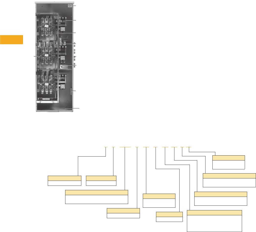
V1-T5-128 Volume 1—Residential and Light Commercial CA08100002E—February 2014 www.eaton.com
5
5
5
5
5
5
5
5
5
5
5
5
5
5
5
5
5
5
5
5
5
5
5
5
5
5
5
5
5
5
5.10
Metering Products
Group Metering
37MM Meter Stack Module ●Eaton’s 35MM and 37MM
modular metering stacks
contain meter sockets with
built-in manual
bypass and
jaw release (Non-EUSERC
areas)
●Eaton’s 35SS and 37SS
stacks use meter sockets
with test bypass feature
(meets EUSERC electrical
requirements)
●All commercial modular
metering stacks contain
four horizontal cross buses
●Mechanically and
electrically built to bolt-up
with main service modules
and residential modular
metering stacks
Catalog Number Selection
Commercial Meter Stack Modules
When Ordering:
1. Determine catalog number of Main Service Module.
2. Determine catalog number of Meter Stack (Residential or Commercial).
3. Find quantity and catalog numbers for tenant circuit breakers (found on Page V1-T5-134). Order one breaker per socket.
4. If any accessories are needed, order from Pages V1-T5-136 and V1-T5-137.
L
B
G
F
E
H
C
I
A
Phases
Three-phase only
Number of Jaws
5 or 7
Socket Amperage
20 = 200A
40 = 400A
Number of Meters
1, 2, 3 or 4
Socket Type
K = K Base bolt-on socket
Blank = Plug-in type socket
Type of Metering
MM = Commercial metering module
SS = Safety socket—EUSERC
Bus
12 = 1200A main bus ampacity
AB = Phases A&B—EUSERC
AC = Phases A&C—EUSERC
BC = Phases B&C—EUSERC
Enclosure
R = NEMA 3R
Tenant Breakers
40 = 400A included
Blank = Ordered separately
Bus
C = Copper
Blank = Aluminum
3 7 MM 1 40 R 12 40 K C

Volume 1—Residential and Light Commercial CA08100002E—February 2014 www.eaton.com V1-T5-129
5
5
5
5
5
5
5
5
5
5
5
5
5
5
5
5
5
5
5
5
5
5
5
5
5
5
5
5
5
5
5.10
Metering Products
Group Metering
Product Selection
35MM
●Each socket is a 5 terminal
block with lever bypass and
jaw release
●Ringless covers
●Provision for two-pole main
tenant breakers (circuit
breakers not included).
For circuit breaker
catalog numbers, refer
to Page V1-T5-134
●Phase balancing kits are
included with three-high
and four-high modules.
Each individual socket can
be phase balanced in the
field to the desired lines
(A-B, B-C or A-C). Comes
from factory as A-B
●Indoor/outdoor
construction
●Main tenant feeders can
exit top, bottom or back
●If being used in outdoor
application and exiting the
top, mount Myer type hubs
on rainproof cap
●Short-circuit ratings up
to 100A rms symmetrical
depending upon the kAIC
rating of installed main
tenant circuit breakers
and main device
●Non-EUSERC areas
35MM—Single-Phase Commercial Meter Stack Modules (Three-Phase In, Single-Phase Out)
Notes
1Retrofit tenant circuit breaker mounting kit (37MMRCBK) for installation of Type EHD and CV breakers. Needed only for stacks manufactured prior to February 2013. Order one kit per breaker.
2Unit is bottom exit only.
3Rated at 100 kAIC.
4Rated at 35 kAIC.
System
Voltage
Ampere Rating
Per Meter Socket
Number
of Meter
Sockets
Horizontal
Bus
Ampacity/
Material
Number of
Jaws Per
Meter Socket
Main Tenant
Breaker Type
(Page V1-T5-134) 1
Catalog
Number
120/240V, single-phase, three-wire systems and
208Y/120V network metering (Not suitable for use
on three-phase, four-wire delta systems)
225 1 1200 Al 5 Bolt-on type
EHD2_
CCV2_X
CCVH2_X
CVS2_XMM
CV2_XMM
CVH2_XMM
35MM120R12
1 1200 Cu 5 35MM120R12C
2 1200 Al 5 35MM220R12
2 1200 Cu 5 35MM220R12C
3 1200 Al 5 35MM320R12
3 1200 Cu 5 35MM320R12C
4 1200 Al 5 35MM420R12
4 1200 Cu 5 35MM420R12C
400 1 1200 Al 5 400A
K-Frame included
35MM140R1240 2
1 1200 Cu 5 35MM140R1240C 2
400 1 1200 Al 5 400A
K-Frame included
35MM140HR1240 3
1 1200 Cu 5 35MM140HR1240C 3
400 2 1200 Al 5 400A
K-Frame included
35MM240R1240
2 1200 Cu 5 35MM240R1240C
400 continuous 1 1200 Cu 5 400A
L-Frame included
35MM140R1240K
400 continuous 1 1200 Cu 5 400A
L-Frame included
35MM140HR1240KC 4

V1-T5-130 Volume 1—Residential and Light Commercial CA08100002E—February 2014 www.eaton.com
5
5
5
5
5
5
5
5
5
5
5
5
5
5
5
5
5
5
5
5
5
5
5
5
5
5
5
5
5
5
5.10
Metering Products
Group Metering
37MM
●Each socket is a 7 terminal
block with lever bypass and
jaw release
●Ringless covers
●Provision for three-pole
main tenant breakers
(circuit breakers not
included). For circuit
breaker catalog numbers,
refer to Page V1-T5-134
●Indoor/outdoor
construction
●Main tenant breakers can
exit top, bottom or back
●If being used in outdoor
application and exiting the
top, mount Myer type hubs
on rainproof cap
●Short-circuit ratings up to
100A rms symmetrical
depending upon the kAIC
rating of installed main
tenant circuit breakers
and main device
●Non-EUSERC areas
37MM—Three-Phase Commercial Meter Stack Modules (Three-Phase In, Three-Phase Out)
Notes
1If a socket in a 37MM meter stack module needs to be single-phase, order 37MM1CK. This will convert the three-phase socket to single-phase.
2Retrofit tenant circuit breaker mounting kit (37MMRCBK) for installation of Type EHD and CV breakers. Needed only for stacks manufactured prior to February 2013. Order one kit per breaker.
3320A continuous rated socket with provisions for two main tenant breakers.
4Unit is bottom exit only.
5Rated at 100 kAIC.
6Rated at 25 kAIC.
7Rated at 35 kAIC.
System
Voltage
Ampere Rating
Per Meter Socket
Number
of Meter
Sockets
Horizontal
Bus
Ampacity/
Material
Number of
Jaws Per
Meter Socket 1
Main Tenant
Breaker Type 2
(Page V1-T5-134)
Catalog
Number
208Y/120V, three-phase, four-wire
240/120V, three-phase, four-wire delta
(B-phase is high leg)
225 1 1200 Al 7 Bolt-on type
EHD3_
CC3_X
CVS3_X
CV3_X
CVH3_X
37MM120R12
1 1200 Cu 7 37MM120R12C
2 1200 Al 7 37MM220R12
2 1200 Cu 7 37MM220R12C
3 1200 Al 7 37MM320R12
3 1200 Cu 7 37MM320R12C
4 1200 Al 7 37MM420R12
4 1200 Cu 7 37MM420R12C
400 1 1200 Al 7 400A
K-Frame included
37MM140R12 3
1 1200 Cu 7 37MM140R12C 3
400 1 1200 Al 7 400A
K-Frame included
37MM140R1240 4
1 1200 Cu 7 37MM140R1240C 4
400 1 1200 Al 7 400A
K-Frame included
37MM140HR1240 5
1 1200 Cu 7 37MM140HR1240C 5
400 2 1200 Al 7 400A
K-Frame included
37MM240R1240
2 1200 Cu 7 37MM240R1240C
400 continuous 1 1200 Cu 7 400A
L-Frame included
37MM140R1240KC 6
400 continuous 1 1200 Cu 7 400A
L-Frame included
37MM140HR1240KC 7
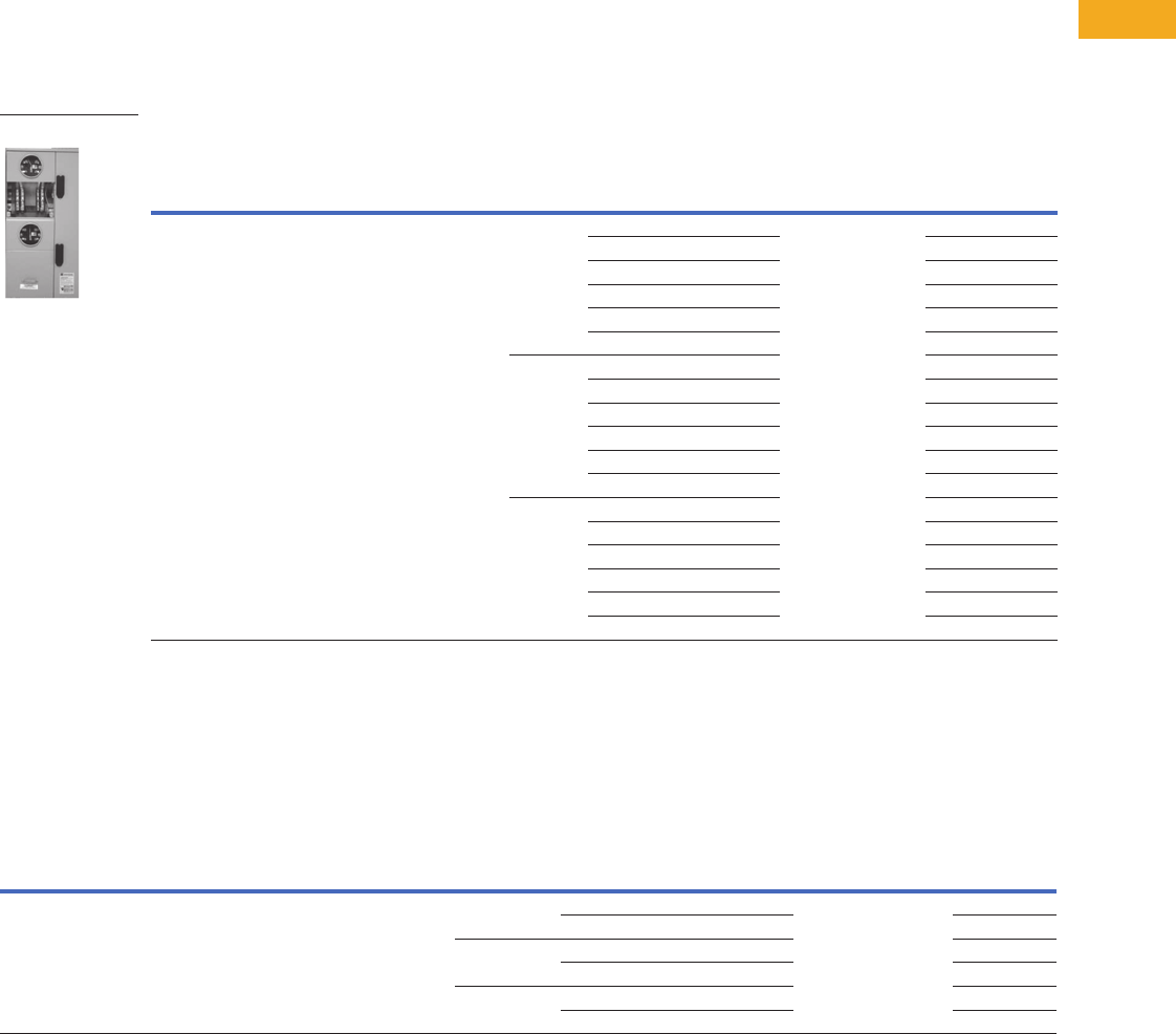
Volume 1—Residential and Light Commercial CA08100002E—February 2014 www.eaton.com V1-T5-131
5
5
5
5
5
5
5
5
5
5
5
5
5
5
5
5
5
5
5
5
5
5
5
5
5
5
5
5
5
5
5.10
Metering Products
Group Metering
35SS
●Sockets include EUSERC
required test-bypass-
disconnect feature
●Ring type covers
●Single-phase units have
provisions for two-pole
main tenant breakers
●When applying 35SS
(single-phase) stacks on
208Y/120V, three-phase,
four-wire and 240/120V,
three-phase, four-wire
delta systems, refer to
suffixes for proper phase
balancing. Each meter
stack module is phase
balanced at the plant
(A-B, B-C or A-C) and
cannot be field modified
●Indoor/outdoor
construction
●Main tenant breakers can
exit top, bottom or back.
If being used in outdoor
application and exiting the
top, mount Myer type hubs
on rainproof cap
●Short-circuit ratings up to
100A rms symmetrical
depending upon the kAIC
rating of installed main
tenant circuit breakers
and main device
35SS—Three-Phase Commercial Meter Stack Modules
37SS
●Sockets include EUSERC
required test-bypass-
disconnect feature
●Ring type covers
●Three-phase units have
provisions for three-pole
main tenant breaker
●Aluminum horizontal bus
supplied as standard
37SS—Three-Phase Commercial Meter Stack Modules
Notes
1Retrofit tenant circuit breaker mounting kit (37MMRCBK) for installation of Type EHD and CV breakers. Needed only for stacks manufactured prior to February 2013. Order one kit per breaker.
2Last two digits of catalog number indicate phase balancing (AB indicates all sockets in this stack are connected to phases A and B only).
System
Voltage
Ampere Rating
Per Meter Socket
Number
of Meter
Sockets
Horizontal
Bus
Ampacity/
Material
Number of
Jaws Per
Meter Socket
Main Tenant
Breaker Type 1
(Page V1-T5-134)
Catalog
Number
120/240V, single-phase,
three-wire systems and
208Y/120V network metering
(Not suitable for use on three-phase,
four-wire delta systems)
225 1 1200 Al 5 Bolt-on type
EHD2_
CCV2_X
CCVH2_X
CVS2_X
CV2_X
CVH2_X
35SS120RAB 2
1200 Cu 5 35SS120RABC 2
1200 Al 5 35SS120RAC 2
1200 Cu 5 35SS120RACC 2
1200 Al 5 35SS120RBC 2
1200 Cu 5 35SS120RBCC 2
2 1200 Al 5 35SS220RAB 2
1200 Cu 5 35SS220RABC 2
1200 Al 5 35SS220RAC 2
1200 Cu 5 35SS220RACC 2
1200 Al 5 35SS220RBC 2
1200 Cu 5 35SS220RBCC 2
3 1200 Al 5 35SS320RAB 2
1200 Cu 5 35SS320RABC 2
1200 Al 5 35SS320RAC 2
1200 Cu 5 35SS320RACC 2
1200 Al 5 35SS320RBC 2
1200 Cu 5 35SS320RBCC 2
35SS_
System
Voltage
Ampere Rating
Per Meter Socket
Number
of Meter
Sockets
Horizontal
Bus
Ampacity/
Material
Number of
Jaws Per
Meter Socket
Main Tenant
Breaker Type 1
(Page V1-T5-134)
Catalog
Number
208Y/120V, three-phase, four-wire
240/120V, three-phase, four-wire delta
(B-phase is high leg)
225 1 1200 Al 7 Bolt-on type
EHD3_
CC3_X
CVS3_X
CV3_X
CVH3_X
37SS120R
1200 Cu 7 37SS120RC
2 1200 Al 7 37SS220R
1200 Cu 7 37SS220RC
3 1200 Al 7 37SS320R
1200 Cu 7 37SS320RC
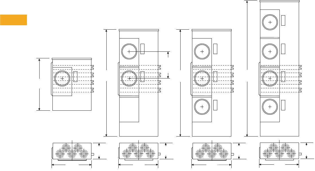
V1-T5-132 Volume 1—Residential and Light Commercial CA08100002E—February 2014 www.eaton.com
5
5
5
5
5
5
5
5
5
5
5
5
5
5
5
5
5
5
5
5
5
5
5
5
5
5
5
5
5
5
5.10
Metering Products
Group Metering
Approximate Dimensions in Inches (mm)
Commercial Stacks (35MM and 37MM)
35MM and 37MM
19.25
(489.0)
66.63
(1692.3)
25.38
(644.5)
14.00
(355.6)
Typ.
52.63
(1336.7)
52.63
(1336.7)
8.75
(222.3)
35MM140R1240
37MM140R1240
same as below
except eliminate
top socket.
18.25
(463.6)
8.75
(222.3)
18.25
(463.6)
8.75
(222.3)
18.25
(463.6)
8.75
(222.3)
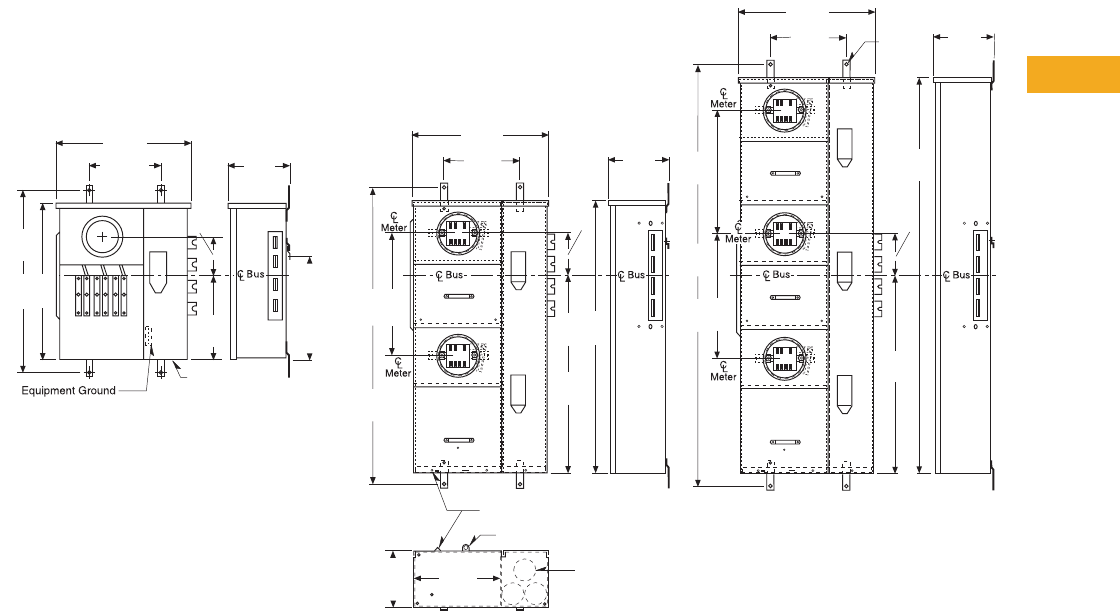
Volume 1—Residential and Light Commercial CA08100002E—February 2014 www.eaton.com V1-T5-133
5
5
5
5
5
5
5
5
5
5
5
5
5
5
5
5
5
5
5
5
5
5
5
5
5
5
5
5
5
5
5.10
Metering Products
Group Metering
Approximate Dimensions in Inches (mm)
Commercial Stacks (35SS and 37SS)
35SS and 37SS
3 KOs 1.50 (38.1),
2.00 (50.8), 2.50 (63.5)
Bottom (Typ.)
13.56
(344.5)
8.75
(222.3)
Inside
Wire Seal Slot and Sealing Screw
Ribbon Seal or Barrel Lock Hasp
21.38
(542.9)
12.00
(304.8)
29.38
(746.1)
25.00
(635.0)
13.50
(342.9)
6.50
(165.1)
KO 1.50 (38.1)
2.00 (50.8),
2.50 (63.5)
9.50
(241.3)
17.75
(450.9)
Centerline
of Wall
Mounting
Screws
47.38
(1203.3)
19.50
(495.3)
21.38
(542.9)
12.00
(304.8)
6.50
(165.1)
31.50
(800.1)
43.00
(1092.2)
9.56
(242.9)
19.50
(495.3)
19.50
(495.3)
68.88
(1749.4)
6.50
(165.1)
62.44
(1585.9)
31.50
(800.1)
0.41 Dia.
(10.3)
4-Holes
9.56
(242.9)
12.00
(304.8)
21.38
(542.9)
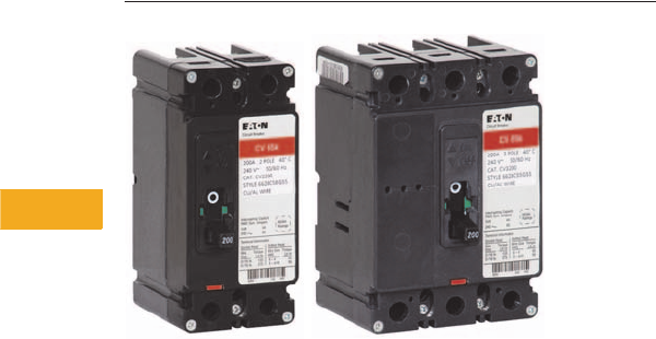
V1-T5-134 Volume 1—Residential and Light Commercial CA08100002E—February 2014 www.eaton.com
5
5
5
5
5
5
5
5
5
5
5
5
5
5
5
5
5
5
5
5
5
5
5
5
5
5
5
5
5
5
5.10
Metering Products
Group Metering
CV2200/CV3200
35MM, 37MM, 35SS and 37SS Main Tenant Circuit Breakers
Contents
Description Page
Systems for Residential and Commercial
Applications . . . . . . . . . . . . . . . . . . . . . . . . . . . . V1-T5-88
Meter Packs . . . . . . . . . . . . . . . . . . . . . . . . . . . . . V1-T5-90
Type CCV 120/240V Tenant Main Circuit Breaker . V1-T5-95
Type CV 120/240V Tenant Main Circuit Breaker . . V1-T5-96
Meter Packs—1MP, 1MM and 3MM Main
Tenant Circuit Breakers . . . . . . . . . . . . . . . . . . . V1-T5-98
Main Service Modules . . . . . . . . . . . . . . . . . . . . . V1-T5-101
Surge Metering. . . . . . . . . . . . . . . . . . . . . . . . . . . V1-T5-115
Residential Meter Stacks . . . . . . . . . . . . . . . . . . . V1-T5-116
1MP, 1MM and 3MM Main Tenant
Circuit Breakers . . . . . . . . . . . . . . . . . . . . . . . . . V1-T5-125
Phase Balanced Stack. . . . . . . . . . . . . . . . . . . . . . V1-T5-126
Commercial Meter Stack Modules . . . . . . . . . . . . V1-T5-127
35MM, 37MM, 35SS and 37SS
Main Tenant Circuit Breakers
35MM, 37MM, 35SS
and 37SS Main Tenant
Circuit Breakers
Product Description
●The following breakers
are to be used on 35MM,
37MM, 35SS and 37SS
modular metering stacks
●Series rating information
available on Pages V1-T5-
142 through V1-T5-145
●Two-pole breakers are
120/240 Vac, field installed
●Three-pole breakers are
208Y/120 Vac, field
installed

Volume 1—Residential and Light Commercial CA08100002E—February 2014 www.eaton.com V1-T5-135
5
5
5
5
5
5
5
5
5
5
5
5
5
5
5
5
5
5
5
5
5
5
5
5
5
5
5
5
5
5
5.10
Metering Products
Group Metering
Product Selection
35MM, 37MM, 35SS and 37SS Main Tenant Circuit Breakers
Notes
1#6–4/0 kcmil wire size range for CVS, CV and CVH tenant main circuit breakers. If #2–300 kcmil is needed, order 2TA225CVK (two-pole) 3TA225CVK (three-pole). One kit is needed per breaker.
2“MM” suffix provides mounting hardware needed for 1MP, 1MM and 3MM modular metering stacks only. Mounting hardware is not needed for use in 35MM and 35SS modular metering stacks, but
is included as standard with breakers.
3Retrofit tenant circuit breaker mounting kit (37MMRCBK) for installation of Type EHD and CV breakers. Needed only for stacks manufactured prior to February 2013.
Order one kit per breaker.
4Type EHD main tenant circuit breakers are also available from 15 to 50A.
10 kAIC 25 kAIC 42 kAIC 65 kAIC 100 kAIC
Description
Number
of Poles
Main Tenant
Circuit Breaker
Ampere Rating
Catalog
Number
Catalog
Number 12
Catalog
Number 12
Catalog
Number 12
Catalog
Number 12
Bolt-On Type
Bolt-on type circuit breakers used
with 35MM and 35SS (single-phase
modular metering stacks) 34
260 EHD2060 CVS2060XMM CVS2060XMM CV2060XMM CVH2060XMM
270 EHD2070 CVS2070XMM CVS2070XMM CV2070XMM CVH2070XMM
280 EHD2080 CVS2080XMM CVS2080XMM CV2080XMM CVH2080XMM
290 EHD2090 CVS2090XMM CVS2090XMM CV2090XMM CVH2090XMM
2100 CCV2100X CCVH2100X CVS2100XMM CV2100XMM CVH2100XMM
2125 CCV2125X CCVH2125X CVS2125XMM CV2125XMM CVH2125XMM
2150 CCV2150X CCVH2150X CVS2150XMM CV2150XMM CVH2150XMM
2175 CCV2175X CCVH2175X CVS2175XMM CV2175XMM CVH2175XMM
2200 CCV2200X CCVH2200X CVS2200XMM CV2200XMM CVH2200XMM
2225 CCV2225X CCVH2225X CVS2225XMM CV2225XMM CVH2225XMM
Bolt-On Type
Bolt-on type circuit breakers used
with 37MM and 37SS (three-phase
modular metering stacks) 34
360 EHD3060 CVS3060X CVS3060X CV3060X CVH3060X
370 EHD3070 CVS3070X CVS3070X CV3070X CVH3070X
380 EHD3080 CVS3080X CVS3080X CV3080X CVH3080X
390 EHD3090 CVS3090X CVS3090X CV3090X CVH3090X
3100 CC3100X CVS3100X CVS3100X CV3100X CVH3100X
3125 CC3125X CVS3125X CVS3125X CV3125X CVH3125X
3150 CC3150X CVS3150X CVS3150X CV3150X CVH3150X
3175 CC3175X CVS3175X CVS3175X CV3175X CVH3175X
3200 CC3200X CVS3200X CVS3200X CV3200X CVH3200X
3225 CC3225X CVS3225X CVS3225X CV3225X CVH3225X
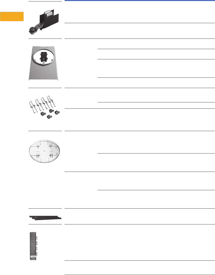
V1-T5-136 Volume 1—Residential and Light Commercial CA08100002E—February 2014 www.eaton.com
5
5
5
5
5
5
5
5
5
5
5
5
5
5
5
5
5
5
5
5
5
5
5
5
5
5
5
5
5
5
5.10
Metering Products
Group Metering
Accessories
1MP, 1MM and 3MM Modular Metering Stacks
Notes
1 WCG8HB only applies to meter packs built prior to 1998. Current meter packs use 1MMBPH.
2 Must be used when mounting MCB main next to an MTB main or another MCB main device.
Description Application
Catalog
Number
Fifth jaw kit Bolted onto neutral in the 3, 6 or
9 o’clock position. Typically used on
network metering systems (three-phase
in/single-phase out) or when specified
by utility company.
1MM5JK
Isolated
fifth jaw kit
Connects to the neutral
with an insolated wire.
1MM5JKOP
Manual
bypass kit
(ring style
socket only)
For use with 125A sockets only.
(Not top socket.)
1MMBPM125
For use with 200A sockets only.
(Not top socket.)
1MMBPM200
This kit only to be used for top
position of two- and three-high 125A 1MM
and 3MM stacks and of 2, 5 and
six-position 125A 1MP packs.
1MMBPM125T
This kit only to be used for top position of 200A
two-position 1MP packs.
1MMBPM200T
Horn bypass Used only on ringless cover stacks,
kits can be installed on 125A or
200A sockets.
1MMBPH
Note: For 1MP2122RRL use: WCG8HB 1
Meter bypass
jumper
Installed on 125A or 200A
sockets. Jumpers are plugged into jaws.
Order Lexan® cover plate with
bypass jumpers to prevent access
to meter socket once energized. (Not UL listed.)
1MMBPJ
Lexan blank
cover
Circular cover mounted on ring or
ringless devices preventing access
to meter socket while meter is not in
place. Includes four plastic tabs
that plug into each jaw.
1MMPCP
Same as 1MMPCP minus the tabs
located in the back to plug into jaws.
This device to be used while meter
bypass jumpers are in place (1MMBPJ).
1MMACP
Blank meter
socket cover
Used for 125A stacks. Fits bottom
socket only. Kit replaces existing meter
cover preventing access to meter socket.
Includes hasp for seal.
1MMBC125B
Used on 200A stacks. Fits bottom
socket only. Kit replaces existing meter
cover preventing access to meter socket.
Includes hasp for seal.
1MMBC200B
Wall mounting rail Rails are 4 feet (1.2m) in length.
Bolted on wall for stacks, packs
and mains to be hung.
1MMWB
Bussed spacer Bussed spacer 1200A 4-inch
(101.6 mm). Required when stacks
are mounted on right-hand side in
EUSERC areas. (copper)
3MMBSK 2
Bus duct riser/
meter center
connection
Available in 400, 600, 800A
main fusible units only.
Contact product line for details.
—
Fifth Jaw Kit
Manual Bypass Kit
Horn Bypass Kit
Lexan Blank Cover
Wall Mounting Rail
Bussed Spacer
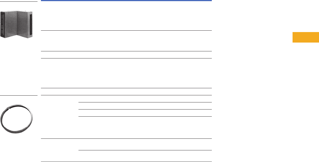
Volume 1—Residential and Light Commercial CA08100002E—February 2014 www.eaton.com V1-T5-137
5
5
5
5
5
5
5
5
5
5
5
5
5
5
5
5
5
5
5
5
5
5
5
5
5
5
5
5
5
5
5.10
Metering Products
Group Metering
Accessories for 1MP, 1MM and 3MM Modular Metering Stacks, continued
Note
1 Aluminum Snap Type.
Description Application
Catalog
Number
Indoor corner elbow
(copper)
12-inch (304.8 mm) indoor corner
elbow, 1200A, three-phase, four-wire
for use with 1MM and 3MM only.
Do not use with 35MM, 37MM,
35SS or 37SS stacks.
12-inch corner elbow not EUSERC approved.
3MMEB12
Indoor corner elbow
(copper)
16-inch (406.4 mm) indoor corner
elbow, 1200A, three-phase, four-wire
for use with 1MM, 3MM, 35MM,
37MM, 35SS and 37SS.
3MMEB16
Barrier Barrier for individual sockets 1MMBK
Meter jumper
and cover
Combination meter jumper and
cover (200A maximum).
Used to jumper line and load
jaws as well as cover meter
socket preventing exposure to
current carrying parts.
1MMJCK
Lug block 125A two-pole lug block assembly. BRSF125
Sealing ring Stainless steel screw type with brass screw 1MMSR1
Standard (included with packs and stacks) 11MMSR2
Stainless steel screw type with cast zinc screw 1MMSR4
Aluminum screw type with locking provisions 1MMSR5
Top endwall 125A, NEMA 1 top end wall with
knockouts for 1MM, 3MM meter stacks
MM12N1WLK
200A, NEMA 1 top end wall
for 1MM, 3MM meter stacks
MM20N1WLK
Indoor Corner Elbow
Standard Sealing Ring
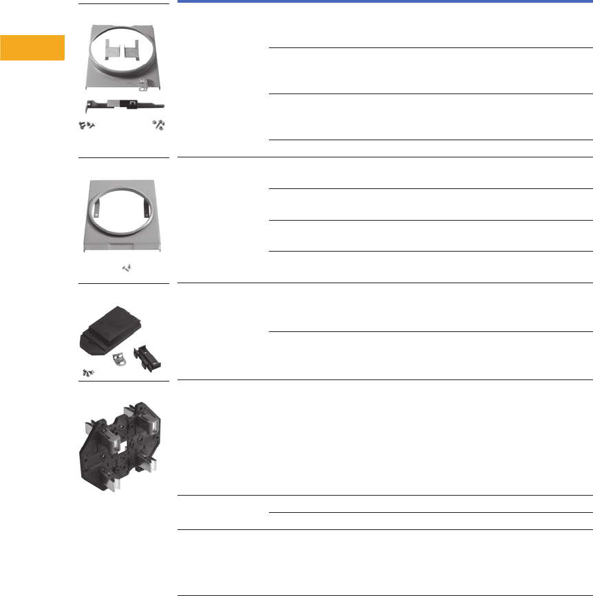
V1-T5-138 Volume 1—Residential and Light Commercial CA08100002E—February 2014 www.eaton.com
5
5
5
5
5
5
5
5
5
5
5
5
5
5
5
5
5
5
5
5
5
5
5
5
5
5
5
5
5
5
5.10
Metering Products
Group Metering
Renewal Parts
1MP, 1MM and 3MM Replacement Parts
Notes
1 Meter Packs 1MP2122RRL and 1MP2122RRLB use different meter sockets.
See Renewal Parts listing RP.32A.01A.T.E for details.
See RP00501001E for a complete Renewal Parts listing.
Description Application
Catalog
Number
Ringless cover
(can install this to go
from ring to ringless)
Installed on 125A socket
for ringless security
1MMRC125
Installed on 200A socket
for ringless security
1MMRC200
For use with top position of 125A,
two- and three-position,1MM and 3MM stacks
and two-, five- and six-position 1MP packs
1MMRC125T
Top-position two position IMP 1MMRC200T
Ring cover Installed on 125A socket
for ring security
1MMCP1
Installed on 200A socket
for ring security
1MMCP2
Top socket ring cover 125A 1MMCP1T
Top socket ring cover 200A 1MMCP2T
Tenant breaker
hinged cover
125A cover 1MMBC1
200A cover 1MMBC2
Meter socket 1125 and 200A 1MMMS
Busbar end cap Flat—left side 47-24139A
Bump—right side 47-28172-2A
Main circuit breaker
cover kit (black)
49-7060
Ringless Cover
Ring Cover
Tenent Breaker Cover
Meter Socket
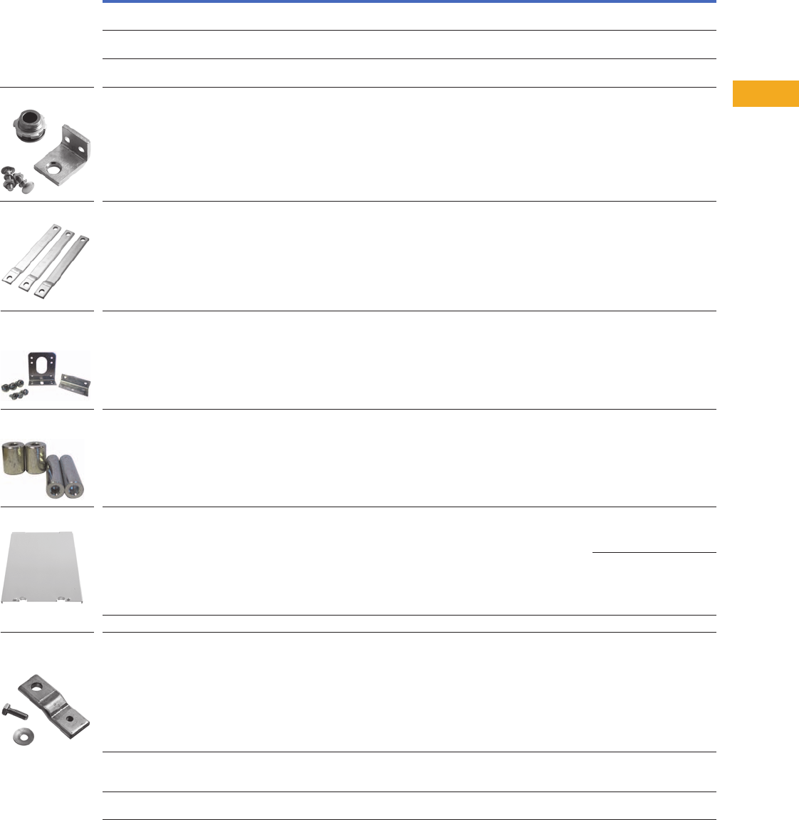
Volume 1—Residential and Light Commercial CA08100002E—February 2014 www.eaton.com V1-T5-139
5
5
5
5
5
5
5
5
5
5
5
5
5
5
5
5
5
5
5
5
5
5
5
5
5
5
5
5
5
5
5.10
Metering Products
Group Metering
Accessories for 35MM and 37MM Modular Metering Stacks
Notes
1 For all units made 10/2002 and earlier.
2 For all units made after 11/2002.
Description Application
Catalog
Number
Wall mounting rail Rails are 4 feet (1.2m) in length. Bolted on wall for stacks,
packs and mains to be hung.
1MMWB
Indoor corner elbow (copper) 16-inch (406.4 mm) indoor corner elbow, 1200A, three-phase,
four-wire for use with 1MM, 3MM, 35MM, 37MM, 35SS and 37SS.
3MMEB16
Handle
insulator
Each meter block includes a lever bypass. This kit includes the sleeve
which slides onto the lever handle.
37MMHC
Barrel lock bracket kit Needed when using barrel lock security. 37MMBLK
Totalizing jumper kit Used if one socket is to meter two tenant feeds. When ordering jumper
kit, should also order a plastic cover plate (1MMPCP + IMMJCK) preventing
access to live parts on unused socket.
37MMTJK
Type EHD and CV breaker retrofit mounting kit Retrofit mounting hardware for installation of Type EHD and CV breakers in
35MM, 37SS, 37MM and 37SS meter stacks manufactured prior to February 2013.
Order one kit per breaker.
37MMRCBK
Type CV breaker mounting kit Replacement Type CV breaker mounting hardware kit. Used in 200A
1MP/1MM/3MM modular metering stacks at 42, 65 and 100 kAIC.
1MMCBK
Blank cover kit Kit replaces meter cover preventing access to socket. 37MMCK 1
37MMCKA 2
Barrier Barrier for individual sockets 37MMBK
Three-Phase to single-phase conversion kit This kit will convert one three-phase meter socket (37MM devices) to a
single-phase socket. Only needed if phasing A-C or C-B. If single-phase socket
is to be phased A-B, kit is not required for field conversion.
(Must use three-phase breaker.)
37MM1CK
Bus duct riser/meter center connection Available in 400, 600, 800A
Main fusible units and 400, 600, 800, 1000,
1200 main circuit breaker. Contact product line for details.
—
Anti-inversion clip This clip should be inserted into upper right hand jaw of a 320A meter socket. The
purpose is prevent a 200A meter from being inserted into a 320A meter socket.
37MMINVCLIP
Barrel Lock Bracket Kit
Totalizing Jumper Kit
Type EHD and CV
Breaker Retrofit
Mounting Kit
Three-Phase to
Single-Phase
Conversion Kit
Blank Cover Kit
Type CV Breaker
Mounting Kit
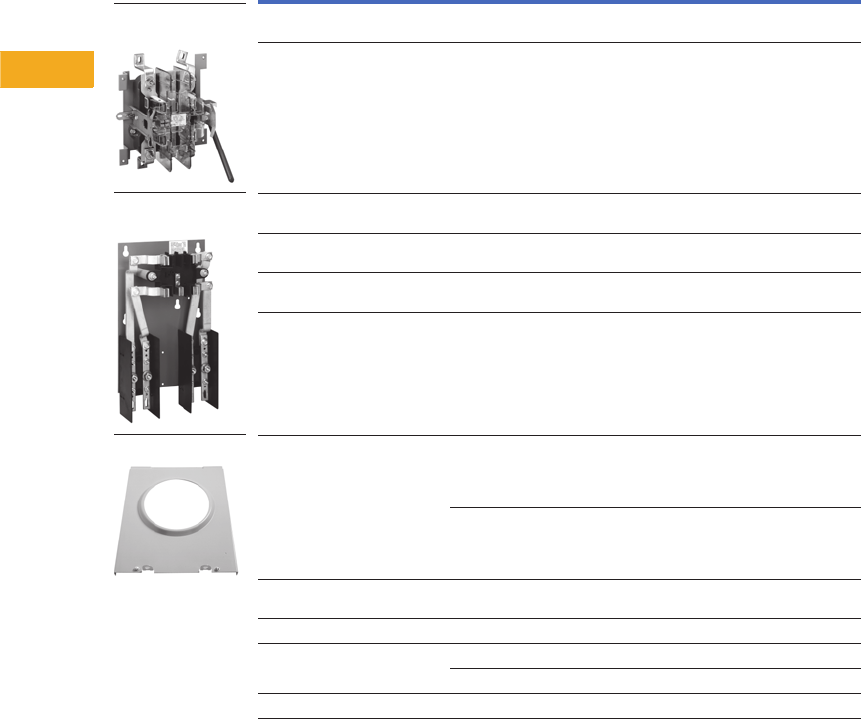
V1-T5-140 Volume 1—Residential and Light Commercial CA08100002E—February 2014 www.eaton.com
5
5
5
5
5
5
5
5
5
5
5
5
5
5
5
5
5
5
5
5
5
5
5
5
5
5
5
5
5
5
5.10
Metering Products
Group Metering
Renewal Parts
35MM and 37MM Modular Metering Stacks
Note
See RP.32A.01.T.E for a complete Renewal Parts listing.
Description Application
Catalog
Number
35MM replacement
meter socket
To replace meter socket
with lever bypass and jaw release.
MSLMSA1
37MM replacement
meter socket
To replace meter socket
with lever bypass and jaw release.
MSLMSA2
35SS replacement
meter socket
To replace meter socket with
test bypass disconnect feature
MSTMSA1
37SS replacement
meter socket
To replace meter socket with
test bypass disconnect feature
MSTMSA2
Safety socket
meter cover assembly
To replace ring type cover over the
meter prior to 7/1/02.
MSTMCVR1
Safety socket
meter cover assembly
To replace ring type cover over the
meter after 7/1/02
MSTMCVR1E
35MM and 37MM
meter cover assembly
Prior to 12/1/02 37MMSK
After 12/1/02 37MMSK1
Meter cover assembly
with NJ latch
To replace ringless cover over the meter.
Includes New Jersey latch requirement.
37MMSKNJ
Tenant breaker hinged cover To replace cover over tenant breakers. 1MMBC2
Busbar end cap Flat—left side 47-24139A
Bump—right side 47-28172-2A
Main circuit breaker cover/CIT (black) 49-7060
35MM Replacement
Meter Socket
37SS Replacement
Meter Socket
Meter Cover Assembly
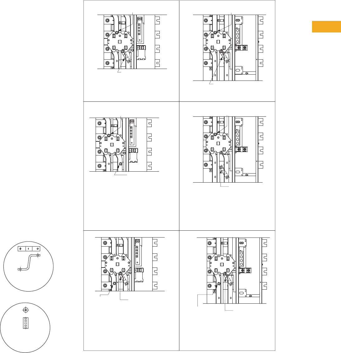
Volume 1—Residential and Light Commercial CA08100002E—February 2014 www.eaton.com V1-T5-141
5
5
5
5
5
5
5
5
5
5
5
5
5
5
5
5
5
5
5
5
5
5
5
5
5
5
5
5
5
5
5.10
Metering Products
Group Metering
Technical Data and
Specifications
Phase Balancing
All 3MM meter modules
come factory connected
to phase A and B, per
Figure A. When connected to
a 208Y/120 Vac three-phase,
four-wire system, field phase
balancing of two out of every
three stacks is required. One
of every three stacks should
be phased AC, per Figure B,
and one of every three stacks
should be phased CB, per
Figure C.
Examples:
Nine Total Positions—use
(three) three-position stacks
and phase one per Figure B
(A-C phasing) and one per
Figure C (C-B phasing).
16 Total Positions—use
(two) five-position and (two)
three-position stacks. Phase
balance (one) five-position
per Figure B (A-C phasing)
and (one) five-position per
Figure C (C-B phasing).
19 Total Positions—where
four-position maximum
height is allowed by utility.
Use (one) four-position and
(five) three-position stacks.
Phase balance (two) three-
position stacks per Figure B
(A-C phasing) and (two)
three-position stacks per
Figure C (C-B phasing).
“Z” Shaped and “Barrel”
Shaped Phase Connector
"Barrel" Shaped
Phase
Connector
"Z" Shaped
Phase
Connector
Phase Balancing
A
C
B
N
A
C
B
N
A
B
A
C
B
C
N
A
A
C
B
N
A
C
B
B
N
C
A
C
B
N
FACTORY 125 A A-B PHASING
125 A STACKS
FIGURE AFIGURE BFIGURE C
200 A STACKS
FIELD 125 A A-C PHASING
FIELD 125 A C-B PHASING
FACTORY 200 A A-B PHASING
FACTORY 200 A A-C PHASING
A
C
B
N
A
C
B
N
A
B
A
C
B
N
A
C
B
N
FACTORY 200 A C-B PHASING
A
C
B
N
A
C
B
N
CB
A
C
Remove "Z" Phase Jumper from "B" Phase
Horizontal Bus
Reattached at "C" Phase Horizontal Bus as Shown.
Torque to 60 lb-in (6.78 N-M)
Remove "Barrel" Phase Jumper from "A" Phase
Horizontal Bus
Reattached at "C" Phase Horizontal Bus as shown.
Torque to 60 lb-in (6.78 N-M)
Remove "Z" Phase Jumper from "B" Phase
Horizontal Bus
Replace with "Barrel" Phase Jumper from
kit 99-4184
Supplied with Meter Stack and attach to "C" Phase
Bus as shown.
Torque to 60 lb-in (6.78 N-M)
Retain "Z" Phase Jumper for future use.
Remove "Barrel" Phase Jumper from "A" Phase
Horizontal Bus
Reattached at "C" Phase Horizontal Bus as shown.
Torque to 60 lb-in (6.78 N-M)
"Barrel" Shaped
Phase Connector
"Barrel" Shaped
Phase Connector
"Z" Shaped
Phase Connector
"Z" Shaped
Phase Connector
"Z" Shaped
Phase Connector
"Barrel" Shaped
Phase Connector
"Barrel" Shaped
Phase Connector
"Barrel" Shaped
Phase Connector
"Barrel" Shaped
Phase Connector
"Z" Shaped
Phase Connector
"Barrel" Shaped
Phase Connector
"Z" Shaped
Phase Connector

V1-T5-142 Volume 1—Residential and Light Commercial CA08100002E—February 2014 www.eaton.com
5
5
5
5
5
5
5
5
5
5
5
5
5
5
5
5
5
5
5
5
5
5
5
5
5
5
5
5
5
5
5.10
Metering Products
Group Metering
Series Combination
Short-Circuit Ratings
When main tenant breakers
are installed in Eaton’s
modular metering stack
per the table on Page
V1-T5-143, the branch
breakers installed in
downstream panel rated 10
kAIC or greater are protected
to the listed series AIC rating.
Refer to the downstream
panel marking for the proper
series combination short-
circuit ratings.
Replacement or additional
breakers shall be of the same
manufacture and type, and
shall have an interrupting
rating equal to or greater than
the interrupting rating of any
main tenant breaker installed.
Series Combination
Short-Circuit Ratings
Modular
Metering
Stack
Main
Service
Module
Load Side
Breakers
Main
Tenant
Breaker
Downstream Panel
(Type CH or BR)
The Watt-Hour Meter is not
Included in the Short-Circuit
Current Rating (Per UL 67).

Volume 1—Residential and Light Commercial CA08100002E—February 2014 www.eaton.com V1-T5-143
5
5
5
5
5
5
5
5
5
5
5
5
5
5
5
5
5
5
5
5
5
5
5
5
5
5
5
5
5
5
5.10
Metering Products
Group Metering
Series Combination Short-Circuit Ratings—240 Vac
Note
1100,000A rating with 100,000A rated main.
Main Module Overcurrent Device
Breaker Type or Class Fuse
System
AIC Rating
120/240 Vac
Maximum
Meter Module
Tenant Feeder Breaker
Type 1MM, 3MM, 35MM,
37MM, 35SS, 37SS
or Loadcenter Main Breaker
Tenant Feeder
Breaker Short-
Circuit Rating
Loadcenter Branch Breaker
(Single-, Two- or Three-Pole)
None 10,000 None — BD, BR, BRD, BQ, BQC, GFCB, CH, CHT, CH3, CH-GFCI
Without main disconnect.
Cable tap box
Type 1MTB_, 3MTB_
10,000 BR_, CC_, BW_, CCV_ 10,000
22,000 BRH_ 22,000
25,000 CSR_, CHH_H2, CCVH_ 25,000
42,000 BRHH_, CHH_H4, CVS_ 42,000
65,000 CV_, KD_, HKD_ 65,000
100,000 CHH_, CVH_, KDC_ 100,000
Main switch module
Type 1MFS_, 3MFS_
with Class T fuse,
400A maximum
42,000 BRH_ 22,000 CH, CHT, CH3, CH-GFCI
Main switch module
Type 1MFS_, 3MFS_
with Class T fuse,
600A maximum
100,000 BRH_ 22,000 BD, BR, BRD, BQ, BQC, GFCB
Main switch module
Type 1MFS_, 3MFS_
with Class T fuse,
1200A maximum
10,000 BR_, CC_, BW_, CCV_ 10,000 BD, BR, BRD, BQ, BQC, GFCB, CH, CHT, CH3, CH-GFCI
22,000 BRH_ 22,000
25,000 CSR_, CHH_H2, CCVH_ 25,000
42,000 BRHH_, CHH_H4, CVS_ 42,000
65,000 CV_, KD_, HKD_ 65,000
100,000 CHH_, CVH_, KDC_ 100,000
Main switch module
Type 1MFS_, 3MFS_
with Class T fuse,
1200A maximum
100,000 BRHH_ 42,000 BD, BR, BRD, BQ, BQC, GFCB, CH, CHT, CH3, CH-GFCI
Main switch module
Type 1BPS_, 3BPS_
with Class L fuse,
1200–2000A
10,000 BR_, CC_, BW_, CCV_ 10,000 BD, BR, BRD, BQ, BQC, GFCB, CH, CHT, CH3, CH-GFCI
22,000 BRH_ 22,000
25,000 CSR_, CHH_H2, CCVH_ 25,000
42,000 BRHH_, CHH_H4, CVS_ 42,000
65,000 CV_, KD_, HKD_ 65,000
100,000 CHH, CVH_, KDC_ 100,000
Main breaker module
Type 1MCB_, 3MCB_ with
KD, HKD (400A maximum)
LD, HLD (600A maximum)
MDL, HMDL (800A maximum)
ND, NGS, HND, NGH (1200A maximum)
RD, RGH (2000A maximum)
10,000 BR_, CC_, BW_, CCV_ 10,000 BD, BR, BRD, BQ, BQC, GFCB, CH, CHT, CH3, CH-GFCI
22,000 BRH_ 22,000
25,000 CSR_, CHH_H2, CCVH_ 25,000
42,000 BRHH_, CHH_H4, CVS_ 42,000
65,000 CV_, KD_, HKD_ 65,000
100,000 1CHH_, CVH_, KDC_ 100,000
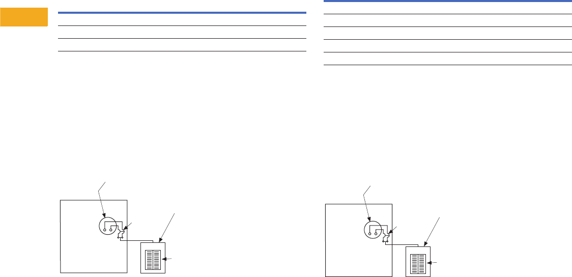
V1-T5-144 Volume 1—Residential and Light Commercial CA08100002E—February 2014 www.eaton.com
5
5
5
5
5
5
5
5
5
5
5
5
5
5
5
5
5
5
5
5
5
5
5
5
5
5
5
5
5
5
5.10
Metering Products
Group Metering
1MP 125A Meter Module
This All-in-One Meter Module is UL listed for the short-circuit
rating at 240 Vac maximum in rms symmetrical amperes per
table below.
1MP 125A Meter Module
When Type BRHH or BRH tenant breakers are installed in this
meter module, then Eaton’s breakers rated 10 kAIC or greater
installed on the load side of this meter module may be protected
for short circuits up to 22 kAIC with Type BRH breakers or
42 kAIC with Type BRHH breakers.
See load side breaker panel marking for proper short-circuit
current rating.
1MP 125A Meter Module
1MP 200A Meter Module
This All-in-One Meter Module is UL listed for the short-circuit
rating at 240 Vac maximum in rms symmetrical amperes per
table below.
1MP 200A Meter Module
When Type CV tenant breakers are installed in this meter
module, then breakers rated 10 kAIC or greater installed on
the load side of this meter module may be protected for short
circuits up to 100 kAIC.
See load side breaker panel marking for proper short-circuit
current rating.
1MP 200A Meter Module
Note: The ratings for both 125 and 200A tenant positions apply to
both Type BR and CH loadcenters and 10 kAIC branch breakers.
Tenant Breaker
Catalog Number
Two-Pole
Maximum
Ampere Rating
UL Listed Series
Short-Circuit
Rating
BRHH_____ 125 42 kAIC
BRH_____ 125 22 kAIC
BR_____ 125 10 kAIC
Load Side
Breakers
Tenant
Breaker
Downstream Panel
(Type CH or BR)
The Watt-Hour Meter is not
Included in the Short-Circuit
Current Rating (Per UL 67).
All-in-One
Meter
Module
Tenant Breaker
Catalog Number
Two- or Three-Pole
Maximum
Ampere Rating
UL Listed Series
Short-Circuit
Rating
CVH_XMM 200 100 kAIC
CV_XMM 200 65 kAIC
CVS_XMM 200 42 kAIC
CCVH_XMM 200 25 kAIC
CCV_X 200 10 kAIC
Load Side
Breakers
Tenant
Breaker
Downstream Panel
(Type CH or BR)
The Watt-Hour Meter is not
Included in the Short-Circuit
Current Rating (Per UL 67).
All-in-One
Meter
Module
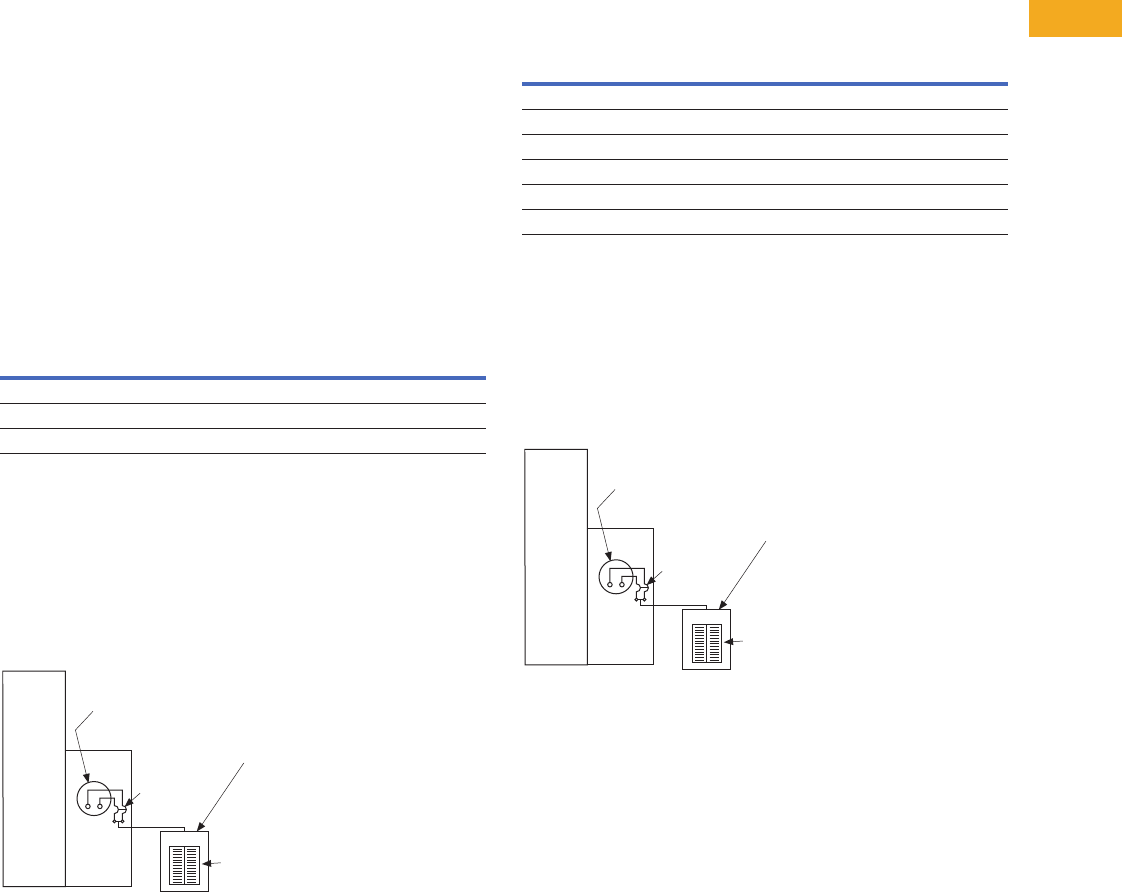
Volume 1—Residential and Light Commercial CA08100002E—February 2014 www.eaton.com V1-T5-145
5
5
5
5
5
5
5
5
5
5
5
5
5
5
5
5
5
5
5
5
5
5
5
5
5
5
5
5
5
5
5.10
Metering Products
Group Metering
General
When tenant breakers are installed in Eaton’s metering
modules per the short-circuit current ratings below, the
branch breakers installed in downstream panel rated 10 kAIC or
greater are protected to the listed series AIC rating. Refer to the
downstream panel marking for the proper series combination
short-circuit ratings. These ratings apply to both loadcenter
Types BR and CH.
The short-circuit rating is limited to the lowest interrupting
rating of any tenant breaker installed or to the lowest marked
interrupting rating of the main switch, main breaker or main
lug modules.
Replacement or additional breakers shall be of the same type
and manufacturer, and shall have an interrupting rating equal
to or greater than the interrupting rating of any tenant breaker
presently installed in the meter module.
1MM, 3MM 125A Meter Module
When used with main switch, main breaker or main lug
modules, this meter module is UL listed for the short-circuit
rating at 240 Vac maximum in rms symmetrical amperes per
table below.
1MM, 3MM 125A Meter Module
When Type BRHH or BRH tenant breakers are installed in this
meter module, then breakers rated 10 kAIC or greater installed
on the load side of this meter module may be protected for short
circuits up to 22 kAIC with Type BRH breakers or 42 kAIC with
Type BRHH breakers.
See load side breaker panel marking for proper short-circuit
current rating.
1MM, 3MM 125A Meter Module
1MM, 3MM, 200A Meter Modules; 35MM, 37MM, 35SS and 37SS 225A
Meter Modules
When used with main switch, main breaker or main lug
modules, these meter modules are UL listed for the short-circuit
rating at 240 Vac maximum in rms symmetrical amperes per
table below.
1MM, 3MM, 200A Meter Modules; 35MM, 37MM, 35SS and
37SS 225A Meter Modules
When Type CV tenant breakers are installed in these meter
modules, then Eaton’s breakers rated 10 kAIC or greater
installed on the load side of these meter modules may be
protected for short circuits up to 100 kAIC.
See load side breaker panel marking for proper short-circuit
current rating.
1MM, 3MM, 200A Meter Modules; 35MM, 37MM, 35SS and
37SS 225A Meter Modules
Tenant Breaker
Catalog Number
Two-Pole
Amperes
Maximum
UL Listed Series
Short-Circuit Rating
BRHH_____ 125 42 kAIC
BRH_____ 125 22 kAIC
BR_____ 125 10 kAIC
Modular
Metering
Stack
Main
Service
Module
Load Side
Breakers
Main
Tenant
Breaker
Downstream Panel
(Type CH or BR)
The Watt-Hour Meter is not
Included in the Short-Circuit
Current Rating (Per UL 67).
Amperes Maximum
Tenant Breaker
Catalog Number
Two- or Three-Pole
1MM
3MM
200A
35MM, 37MM,
35SS, 37SS
225A
UL Listed Series
Short-Circuit Rating
CVH_XMM 200 225 100 kAIC
CV_XMM 200 225 65 kAIC
CVS_XMM 200 225 42 kAIC
CCVH_X 200 225 25 kAIC
CCV_X 200 225 10 kAIC
CC_X 200 225 10 kAIC
Modular
Metering
Stack
Main
Service
Module
Load Side
Breakers
Main
Tenant
Breaker
Downstream Panel
(Type CH or BR)
The Watt-Hour Meter is not
Included in the Short-Circuit
Current Rating (Per UL 67).

V1-T5-146 Volume 1—Residential and Light Commercial CA08100002E—February 2014 www.eaton.com
5
5
5
5
5
5
5
5
5
5
5
5
5
5
5
5
5
5
5
5
5
5
5
5
5
5
5
5
5
5
5.10
Metering Products
Group Metering
Ratings
A. The assembly shall be
rated to withstand
mechanical forces
exerted during short-
circuit conditions when
connected directly to
a power source having
available fault current
[22,000] [42,000]
[65,000] [100,000]
amperes symmetrical
at rated voltage.
Construction
A. The entire assembly shall
be front accessible and
shall include [main lugs]
[a main disconnect
device].
B. Tenant disconnects
shall be wired for cold
sequence and shall be
molded case circuit
breakers.
C. The meter sockets shall
be (ring-) (ringless-) type
rated (125A) (200A) (as
shown on the plans)
and a bypass (shall be)
(shall not be) required.
If required, the bypass
shall be a (slider-) (horn-)
(lever-) (disconnect block-)
type. The meter sockets
and associated branch
protective device
positions shall be
completely prewired
and shipped ready for
installation of the meters
and tenant main breakers.
Meter sockets shall
include covers with
sealing positions.
Bus
A. All busbars shall be [tin-
plated aluminum or
copper]. Main horizontal
busbars shall be
mounted with all three
phases arranged in the
same vertical plane. Bus
sizing shall be based on
UL standard temperature
rise criteria for multiple
metering equipment.
B. Provide a full capacity
neutral bus where a
neutral bus is indicated
on the drawings.
C. All hardware used for
busbar connections shall
be high-tensile strength,
zinc-plated. Provide
Belleville-type spring
washers for all bus joints.
Wiring/Terminations
A. [Mechanical-type
terminals] [Crimp-type
termination provisions]
shall be provided for all
line terminations suitable
for copper or aluminum
cable and rated at 75ºC.
B. Lugs shall be provided in
the incoming line section
for connection of the main
grounding conductor.
Main Circuit Protective Devices
A. Main protective devices
shall be [molded case
circuit breakers] [bolted
pressure switches] [quick-
make/quick-break fusible
switches].
Molded Case Circuit Breakers
A. [Main] [Feeder] [All]
protective devices shall
be molded case circuit
breakers with inverse
time and instantaneous
tripping characteristics.
B. Circuit breakers shall be
operated by a toggle-type
handle and shall have a
quick-make/quick-break
over-center switching
mechanism that is
mechanically trip-free.
Automatic tripping of the
breaker shall be clearly
indicated by the handle
position. Contacts shall
be nonwelding silver
alloy and arc extension
shall be accomplished by
means of DE-ION® arc
chutes.
C. Circuit breakers shall
have a minimum
symmetrical interrupting
capacity as indicated on
the drawings.
D. Circuit breakers [250-]
[400-] [600-] [1200-]
ampere frame and below
shall be manufactured
by Eaton with thermal-
magnetic or electronic
trip units having
inverse time-current
characteristics.
E. Circuit breakers shall be
UL listed for series
application.
Bolted Pressure Switches
A. Main protective devices
shall be bolted pressure
contact type and shall be
UL listed.
B. Fusible switches shall be
furnished with Class L
fuse clips. Switch
contact interrupting
capacity shall be 12 times
the continuous rating
of the switch.
C. Fuse access door s
hall be mechanically
interlocked with the
operating handle and
shall have provisions for
padlocking the switch in
the OPEN position.
D. The switch shall use a
stored energy deadfront
operating mechanism
compressed and
released by the operating
handle, to provide quick
positive switching action,
independent of the
operating handle.
E. Switches shall be
manually operated.
Quick-Make/Quick-Break
Fusible Switches
A. Fusible switches 30A
through 1200A frames
shall be furnished with
300V Class T-type fuse
clips unless otherwise
scheduled.
B. Switches shall
incorporate safety cover
interlocks to prevent
opening the cover with
the switch in the ON
position.
C. Provide defeater for
authorized personnel.
D. Handles shall have
provisions for padlocking
and shall clearly indicate
the ON or OFF position.
E. Front cover doors shall
be padlockable in the
CLOSED position.
F. Main protective devices
shall be quick-make/
quick-break fusible
switches as manufactured
by Eaton.
Tenant Utility Metering
A. For EUSERC serviced
areas, meter centers
shall incorporate
metering sections with
tenant feeder circuits
using ring-type meter
sockets rated [125] [200]
amperes to meet local
utility and/or customer
requirements.
B. The self-contained meter
sockets shall include a
test bypass/disconnect
block per EUSERC
requirements,
– OR–
A. For non-EUSERC
serviced areas, meter
centers shall incorporate
metering sections with
tenant feeder
circuits
using [ring-] [ringless-]
type meter sockets
rated [125] [200] [320]
amperes to meet local
utility or customer
requirements. Provide
meter sockets with
individual covers having
sealing provisions.
B. Meter sockets shall
have manual
bypass and
optional internal barriers.
Enclosures
A. NEMA 1 Enclosure
– OR–
A. Outdoor NEMA 3R
Surface-Mounted
Enclosure
Finish
A. Boxes and trims shall be
bonderized and finished
with ANSI 61 light gray
enamel.
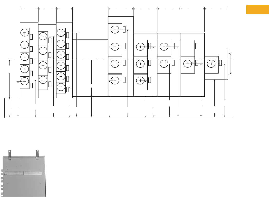
Volume 1—Residential and Light Commercial CA08100002E—February 2014 www.eaton.com V1-T5-147
5
5
5
5
5
5
5
5
5
5
5
5
5
5
5
5
5
5
5
5
5
5
5
5
5
5
5
5
5
5
5.10
Metering Products
Group Metering
Dimensions
Approximate Dimensions in Inches (mm)
General Layout
Mounting Features
Mounting Features
A standard mounting rail and
factory-installed swing away
feet, speed up and simplify
installation.
Notes
1Not a constant value. Dimension changes depending on main device chosen. See Page V1-T5-110 for specific dimensions.
2Residential device.
1MM/3MM
200 A
1MM/3MM
200 A
34.25
(870.0)
13.38
(339.7)
Typical Height
Above Ground
or Floor Level
31.88
(809.6) 68.25
(1733.6)
26.00
(660.4)
30.14
(765.6)
71.00
(1803.4)
30.00
(762.0)
72.00
(1828.8)
58.00
(1473.2)
30.00
(762.0)
44.00
(1117.6)
58.00
(1473.2)
44.00
(1117.6)
31.00
(787.4)
44.00
(1117.6)
13.50
(342.9)
13.50
(342.9)
12.25
(311.2)
19.25
(488.8)
18.25
(463.6)
18.25
(463.6)
18.25
(463.6)
18.25
(463.6)
Wall Hanger Screws
L
C
1MM/3MM
125 A
35MM/37MM
225 A Maximum
35MM/37MM
225 A Maximum
35MM/37MM
225 A Maximum
37MM
400 A
35MM/37MM
Main Device a
b
Minimum and maximum height of single-phase and three-phase
meter sockets above typical ground level.
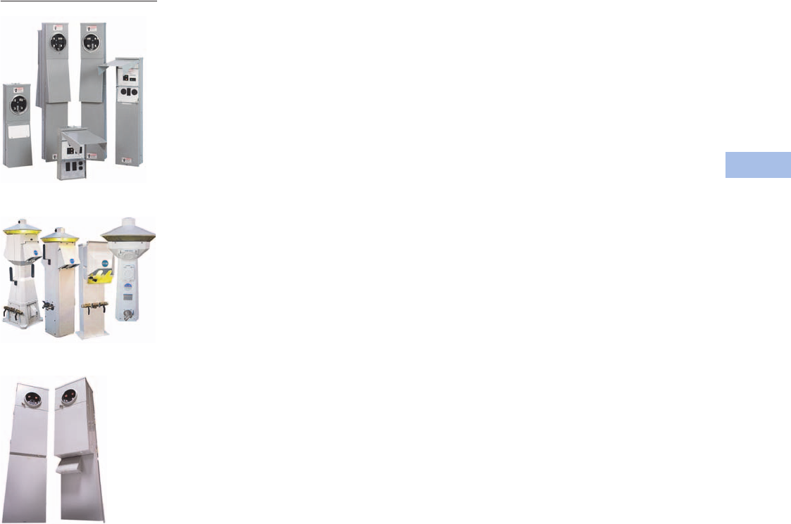
Volume 1—Residential and Light Commercial CA08100002E—February 2014 www.eaton.com V1-T6-1
6
6
6
6
6
6
6
6
6
6
6
6
6
6
6
6
6
6
6
6
6
6
6
6
6
6
6
6
6
6
Power Pedestals
Power Pedestals
Construction Site and RV Parks
Marina Power and Lighting
Mobile Home Panels
6.1 Introduction
Product Description. . . . . . . . . . . . . . . . . . . . . . . . . . . . . . . . . . . . . . . V1-T6-2
Application Description . . . . . . . . . . . . . . . . . . . . . . . . . . . . . . . . . . . . V1-T6-2
Optional Features . . . . . . . . . . . . . . . . . . . . . . . . . . . . . . . . . . . . . . . . V1-T6-2
6.2 Temporary Power/RV Park
Product Overview . . . . . . . . . . . . . . . . . . . . . . . . . . . . . . . . . . . . . . . . V1-T6-3
Product Description . . . . . . . . . . . . . . . . . . . . . . . . . . . . . . . . . . . . V1-T6-3
Application Description. . . . . . . . . . . . . . . . . . . . . . . . . . . . . . . . . . V1-T6-4
Features and Benefits. . . . . . . . . . . . . . . . . . . . . . . . . . . . . . . . . . . V1-T6-4
Standards and Certifications. . . . . . . . . . . . . . . . . . . . . . . . . . . . . . V1-T6-5
Catalog Number Selection . . . . . . . . . . . . . . . . . . . . . . . . . . . . . . . V1-T6-6
Product Selection . . . . . . . . . . . . . . . . . . . . . . . . . . . . . . . . . . . . . . V1-T6-7
Accessories . . . . . . . . . . . . . . . . . . . . . . . . . . . . . . . . . . . . . . . . . . V1-T6-7
Renewal Parts. . . . . . . . . . . . . . . . . . . . . . . . . . . . . . . . . . . . . . . . . V1-T6-8
Surface Units. . . . . . . . . . . . . . . . . . . . . . . . . . . . . . . . . . . . . . . . . . . . V1-T6-10
Product Overview. . . . . . . . . . . . . . . . . . . . . . . . . . . . . . . . . . . . . . V1-T6-10
Product Selection . . . . . . . . . . . . . . . . . . . . . . . . . . . . . . . . . . . . . . V1-T6-10
Dimensions. . . . . . . . . . . . . . . . . . . . . . . . . . . . . . . . . . . . . . . . . . . V1-T6-13
Pedestal Units . . . . . . . . . . . . . . . . . . . . . . . . . . . . . . . . . . . . . . . . . . . V1-T6-16
Product Overview. . . . . . . . . . . . . . . . . . . . . . . . . . . . . . . . . . . . . . V1-T6-16
Product Selection . . . . . . . . . . . . . . . . . . . . . . . . . . . . . . . . . . . . . . V1-T6-16
Dimensions. . . . . . . . . . . . . . . . . . . . . . . . . . . . . . . . . . . . . . . . . . . V1-T6-18
6.3 Mobile Home Panels
Product Overview . . . . . . . . . . . . . . . . . . . . . . . . . . . . . . . . . . . . . . . . V1-T6-21
Features. . . . . . . . . . . . . . . . . . . . . . . . . . . . . . . . . . . . . . . . . . . . . . . . V1-T6-21
Catalog Number Selection . . . . . . . . . . . . . . . . . . . . . . . . . . . . . . . . . V1-T6-22
Product Selection . . . . . . . . . . . . . . . . . . . . . . . . . . . . . . . . . . . . . . . . V1-T6-22
Accessories . . . . . . . . . . . . . . . . . . . . . . . . . . . . . . . . . . . . . . . . . . . . . V1-T6-23
Dimensions . . . . . . . . . . . . . . . . . . . . . . . . . . . . . . . . . . . . . . . . . . . . . V1-T6-24
6.4 RV Park Hook-Ups
Power Pedestals . . . . . . . . . . . . . . . . . . . . . . . . . . . . . . . . . . . . . . . . . V1-T6-28
Powerhouse Power Pedestal. . . . . . . . . . . . . . . . . . . . . . . . . . . . . . . . V1-T6-30
Powerhouse—Stainless Steel (SS) Power Pedestal . . . . . . . . . . . . . . V1-T6-33
Newport Camp Mate Power Pedestal . . . . . . . . . . . . . . . . . . . . . . . . . V1-T6-36
Park Light Power Pedestal. . . . . . . . . . . . . . . . . . . . . . . . . . . . . . . . . . V1-T6-39
Firehouse. . . . . . . . . . . . . . . . . . . . . . . . . . . . . . . . . . . . . . . . . . . . . . . V1-T6-42
Digital Electronic Kilowatthour Meters . . . . . . . . . . . . . . . . . . . . . . . . V1-T6-44
Distribution Equipment—Ground Fault Monitor . . . . . . . . . . . . . . . . . V1-T6-45
Distribution Equipment—Substations . . . . . . . . . . . . . . . . . . . . . . . . . V1-T6-46
Distribution Equipment—Panels . . . . . . . . . . . . . . . . . . . . . . . . . . . . . V1-T6-49
Distribution Equipment—Transformers . . . . . . . . . . . . . . . . . . . . . . . . V1-T6-50
6.5 Marina Power and Lighting Equipment
Power Pedestals . . . . . . . . . . . . . . . . . . . . . . . . . . . . . . . . . . . . . . . . . V1-T6-51
Lighthouse. . . . . . . . . . . . . . . . . . . . . . . . . . . . . . . . . . . . . . . . . . . . . . V1-T6-54
Lighthouse–SS . . . . . . . . . . . . . . . . . . . . . . . . . . . . . . . . . . . . . . . . . . V1-T6-58
Admiral–SS . . . . . . . . . . . . . . . . . . . . . . . . . . . . . . . . . . . . . . . . . . . . . V1-T6-62
Newport Harbor Mate . . . . . . . . . . . . . . . . . . . . . . . . . . . . . . . . . . . . . V1-T6-65
Hatteras Light . . . . . . . . . . . . . . . . . . . . . . . . . . . . . . . . . . . . . . . . . . . V1-T6-69
Firehouse. . . . . . . . . . . . . . . . . . . . . . . . . . . . . . . . . . . . . . . . . . . . . . . V1-T6-73
Smart Start . . . . . . . . . . . . . . . . . . . . . . . . . . . . . . . . . . . . . . . . . . . . . V1-T6-79
Mariner . . . . . . . . . . . . . . . . . . . . . . . . . . . . . . . . . . . . . . . . . . . . . . . . V1-T6-80
Digital Electronic Kilowatthour Meters . . . . . . . . . . . . . . . . . . . . . . . . V1-T6-81
Distribution Equipment—Ground Fault Monitor . . . . . . . . . . . . . . . . . V1-T6-82
Distribution Equipment—Mega Yacht Powerpoint . . . . . . . . . . . . . . . V1-T6-83
Distribution Equipment—Substations . . . . . . . . . . . . . . . . . . . . . . . . . V1-T6-86
Distribution Equipment—Panels . . . . . . . . . . . . . . . . . . . . . . . . . . . . . V1-T6-89
Distribution Equipment—Transformers . . . . . . . . . . . . . . . . . . . . . . . . V1-T6-90
Don’t Give Up!
If you don’t find the product you want in this catalog, try the Flex Center at 1-800-330-6479.
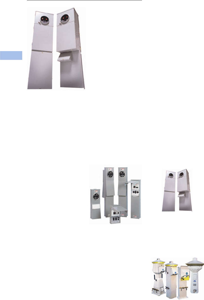
V1-T6-2 Volume 1—Residential and Light Commercial CA08100002E—February 2014 www.eaton.com
6
6
6
6
6
6
6
6
6
6
6
6
6
6
6
6
6
6
6
6
6
6
6
6
6
6
6
6
6
6
6.1
Power Pedestals
Introduction
Power Pedestals
Contents
Description
Introduction
Product Description
A power pedestal is a device
designed for outdoor service
to meet temporary power
requirements at construction
sites, marinas, recreational
vehicle (RV parks, marinas
and mobile home parks).
Power pedestals provide a
safe and reliable means for
users to access electricity
at such locations.
Application Description
Construction Site and
RV Parks
Power outlet panels on
construction sites and in
RV parks provide a safe and
reliable means for users to
access electricity. A wide
range of products are available
with multiple features and
enclosure material options.
Construction Site and RV Parks
Mobile Home Panels
Eaton’s versatile mobile home
panels have a user-friendly
design that allows for a faster,
cleaner installation. Mobile
home panels are designed for
service entrance distribution,
and include a meter and
distribution section with
breaker and receptacle
configuration options.
Mobile Home Panels
Marina Power and Lighting
Park lighting and marina
pedestals offer robust
enclosure options with
premium features to enhance
user convenience at marinas
and campgrounds.
Marina Power and Lighting
Optional Features
●Product can ship from the
factory completely
assembled and prewired
●External light
●TV and telephone jacks
●Ground fault monitors
●Digital electronic
kilowatthour meters
●Water faucet
●Available GFI (ground fault
interrupter) protection
●Weatherproof engineered
resin enclosure (will never
rust or deteriorate)
●Stainless steel to meet
and exceed all applicable
codes, and withstand
harsh inland and coastal
environments
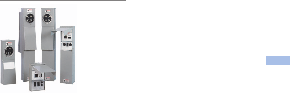
Volume 1—Residential and Light Commercial CA08100002E—February 2014 www.eaton.com V1-T6-3
6
6
6
6
6
6
6
6
6
6
6
6
6
6
6
6
6
6
6
6
6
6
6
6
6
6
6
6
6
6
6.2
Power Pedestals
Temporary Power/RV Park
Power Outlet Panels
Contents
Description Page
Product Overview . . . . . . . . . . . . . . . . . . . . . . . . . V1-T6-3
Application Description . . . . . . . . . . . . . . . . . . V1-T6-4
Features and Benefits . . . . . . . . . . . . . . . . . . . V1-T6-4
Standards and Certifications . . . . . . . . . . . . . . V1-T6-5
Catalog Number Selection . . . . . . . . . . . . . . . . V1-T6-6
Product Selection . . . . . . . . . . . . . . . . . . . . . . . V1-T6-7
Accessories . . . . . . . . . . . . . . . . . . . . . . . . . . . V1-T6-7
Renewal Parts . . . . . . . . . . . . . . . . . . . . . . . . . V1-T6-8
Surface Units. . . . . . . . . . . . . . . . . . . . . . . . . . . . . V1-T6-10
Pedestal Units . . . . . . . . . . . . . . . . . . . . . . . . . . . . V1-T6-16
Product Overview
A power outlet panel (or POP)
is a device designed for
outdoor service to meet
temporary power
requirements at construction
sites and RV parks. POPs
provide a safe and reliable
means for users to access
electricity at such locations.
Product Description
Power outlet panels shall be
designed for outdoor service
to meet temporary power
outlet requirements at
construction sites and provide
high quality, economical
power to individual sites
at RV parks. POPs shall be
provided with means to bond
the neutral for temporary
service entrance applications.
RV panels shall have a factory-
installed insulated neutral bar.
Receptacles and
Circuit Protection
Circuit protection shall be
Eaton’s UL listed full-size
Type BR or half-size Type BD
circuit breakers. The
receptacles shall be NEMA
commercial/industrial grade
devices. Ground fault
protection (GFCB) shall be
provided at the 20A duplex
NEMA 5-20R receptacle or
20A single-pole circuit
breaker when required.
Ground fault protection shall
be provided at the circuit
breaker for receptacles above
20A when required.
Construction
The power outlet panel
pedestal shall be of deadfront
design and constructed of
heavy gauge, 100 percent
galvanized steel. Baked-on
polyester powder coating
shall be used for excellent
mechanical strength, plus
resistance to chalking caused
by the sun’s ultraviolet rays.
The power outlet panel
surface and pedestal units
shall have NEMA Type 3R
rainproof enclosures.
Ease of Installation
Panels shall ship from
the factory completely
assembled, prewired with
100 percent copper wire, and
tested in accordance with
UL Standard 231. The door
shall swing up and open for
user convenience and ease
of access to breakers and
receptacles. When required,
a means for securing the
door in the open position
shall be provided. Panels
shall be bottom fed through
knockouts in endwall or top
fed using a bolt-on raintight
hub. Knockouts shall range
from 1/2-inch (12.7 mm) to
1-1/2 inches (38.1 mm).
Grounding provisions
(#4–14 Cu/Al) shall be
provided on all panels.

V1-T6-4 Volume 1—Residential and Light Commercial CA08100002E—February 2014 www.eaton.com
6
6
6
6
6
6
6
6
6
6
6
6
6
6
6
6
6
6
6
6
6
6
6
6
6
6
6
6
6
6
6.2
Power Pedestals
Temporary Power/RV Park
Application Description
POPs are also sometimes
called temporary power
panels, temporary site
service equipment or
RV panels.
Construction Site Application
When POPs are used at a
construction site, they are
installed on a temporary basis
until permanent electrical
power is available at the
building. The most common
reason for needing a POP
at a construction site is to
provide a power source for
the contractor’s tools.
Construction Site Application
RV Park Applications
When POPs are used at an
RV park, they are installed
for more permanent use
and serve the purpose of
providing power to the
recreational vehicles. Many
RV parks now supply
customers with amenities
such as lighted POPs with TV
and telephone jacks.
RV Park Application
Service Applications
Suitable for use as temporary
Service Entrance Equipment,
temporary power service
equipment and recreational
vehicle site supply.
Features and Benefits
●Designed for outdoor
service to meet power
outlet requirements
●Receptacles conform
to NEMA and/or ANSI
configurations as specified
by the National Electrical
Code® (NEC)
●Includes a factory-installed
insulated neutral bar with
provisions for bonding
when used for temporary
service entrance
applications
●125A rated meter socket
●Temporary power and RV
park POPs are CSA listed.
Compact POP and single
receptacle devices are not
CSA listed
Designed for Easy Installation
and Protection
●Panels come from the
factory completely
assembled, prewired with
100 percent copper wire
and tested...ready for easy
installation
●Door swings up and open
for user convenience and
ease of access to breakers
and receptacles
●Panels can be bottom fed
through knockouts in the
endwall or top fed using a
bolt-on raintight hub
●Two-piece deadfront cover
allows field wiring without
interfering with factory
wiring
●Lower deadfront cover
permits easy field wiring to
circuit protective devices
●Available GFI (ground fault
interrupter) single- and
two-pole protection
through 50A
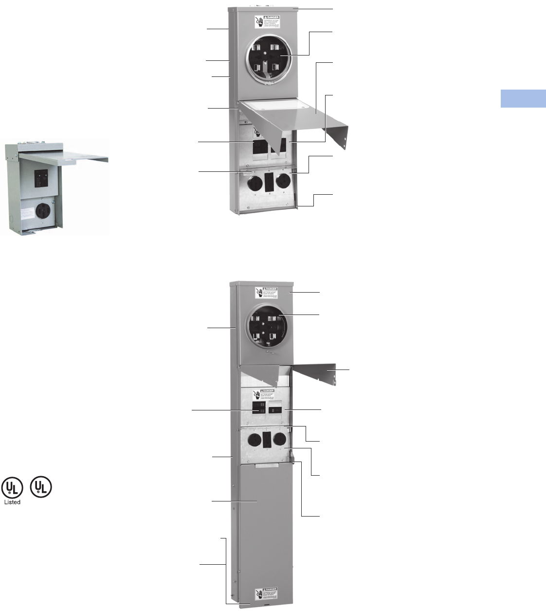
Volume 1—Residential and Light Commercial CA08100002E—February 2014 www.eaton.com V1-T6-5
6
6
6
6
6
6
6
6
6
6
6
6
6
6
6
6
6
6
6
6
6
6
6
6
6
6
6
6
6
6
6.2
Power Pedestals
Tem p ora r y Pow er/ R V Pa r k
Two Styles to Meet Your
Power Outlet Needs
●Surface mount: User
mounts unit to a post
●Pedestal mount:
User mounts with an
underground pedestal
extension or pad-mounting
bracket. (Underground
pedestal extension and
pad-mounting bracket are
sold separately. See
accessories Page V1-T6-7
for part numbers and
options)
Compact Design Available in Certain
Configurations for Added Convenience
Standards and Certifications
●UL Standard 231
●UL File Number E163588
Receptacles conform to
NEMA and/or ANSI
configurations as specified
by the NEC.
Standard Compliance
All power outlet panels for
temporary construction site
power and RV (recreational
vehicle) application shall be
UL listed for the U.S. per UL
Standard 231, File E163588.
Receptacles shall conform
to NEMA and/or ANSI
configurations as specified
by the National Electrical
Code (NEC).
Surface Units
Pedestal Units
Lighted option for site
location and nighttime
panel operations
Three-point mounting
100 percent galvanized
steel with baked-on
polyester powder coating
GFI circuit breakers
available through 50A
One-piece case back for
metered and unmetered
panels
Unique steel barrier
prevents unauthorized
operation of breakers
when door is closed
and padlocked
Lower deadfront cover
can be removed for easy
routing of incoming wires or
receptacle changeouts
Padlock provisions to prevent
unauthorized entry
Utility grade metering available
for construction site or RV park
applications
Removable upper deadfront
cover for easy incoming wire
connections to breaker terminals
• Units are factory wired
and assembled
NEMA 3R construction for
rainproof installation
Door swings up when opening
and allows cords to remain
connected when closed.
• Metered units available with
meter on top or on bottom
• Units are factory wired
and assembled
100 percent galvanized
steel with baked-on
polyester powder coating
GFI circuit breakers
(single- and two-pole)
available through 50A
One-piece case back for
metered and unmetered
panels
Removable upper deadfront cover for
easy incoming wire connections to
breaker terminals
Door swings up when
opening and allows
cords to remain connected
when closed
Unique steel barrier prevents
unauthorized operation of breakers
when door is closed and padlocked
Lower deadfront cover can be
removed for easy routing of
incoming wires or receptacle
changeouts
Padlock provisions to prevent
unauthorized entry
Loop-feed lug assembly
with 350 kcmil lugs
included as standard
Pad-mounted bracket
option also available
Pedestal extension available
for underground services
Utility grade metering
available for construction
site or RV park applications
NEMA 3R construction for
rainproof installation
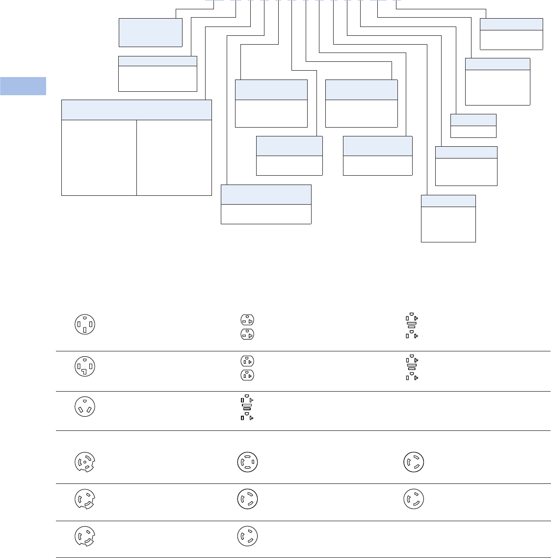
V1-T6-6 Volume 1—Residential and Light Commercial CA08100002E—February 2014 www.eaton.com
6
6
6
6
6
6
6
6
6
6
6
6
6
6
6
6
6
6
6
6
6
6
6
6
6
6
6
6
6
6
6.2
Power Pedestals
Temporary Power/RV Park
Catalog Number Selection
Notes
1For receptacle configurations, see table below.
2Weather-resistant.
3Weather-resistant/tamper resistant.
Receptacle Configuration
Twist-Lock and Custom Receptacle/Breaker Combinations
150A, 125/250V,
three-pole, four-wire, NEMA 14-50R
Two-pole, 50A breaker
520A, 250V,
two-pole, three-wire, NEMA 6-20R2
Two-pole, 20A breaker
820A, 125V,
two-pole, three-wire,
weather-resistant (WR), NEMA 5-20R2GFI
330A, 125/250V,
three-pole, four-wire, NEMA 14-30R
Two-pole, 30A breaker
620A, 125V,
two-pole, three-wire, NEMA 5-20R2
Single-pole, 20A breaker
920A, 125V,
two-pole, three-wire, weather-resistant/
tamper-resistant (WR TR), NEMA 5-20R2GFI
430A, 125V,
two-pole, three-wire, NEMA TT-30R
Single-pole, 30A breaker
720A, 125V,
two-pole, three-wire, NEMA 5-20R2GFI
Single-pole, 20A breaker
A50A, 125/250V,
three-pole, three-wire, NEMA L14-50R
Two-pole, 50A breaker
D30A, 125/250V,
three-pole, four-wire, NEMA L14-30R
Two-pole, 30A breaker
H20A, 250V,
two-pole, three-wire, NEMA L6-20R
Two-pole, 20A breaker
B50A, 250V,
two-pole, three-wire, NEMA L6-50R
Two-pole, 50A breaker
E30A, 250V,
two-pole, three-wire, NEMA L6-30R
Two-pole, 30A breaker
J20A, 125V,
two-pole, three-wire, NEMA L5-20R
Single-pole, 20A breaker
C50A, 125V,
two-pole, three-wire, NEMA L5-50R
Single-pole, 50A breaker
F30A, 125V,
two-pole, three-wire, NEMA L5-30R
Single-pole, 30A breaker
Metering Type
U= Unmetered
M= Metered-ring
R= Metered-ringless
Receptacle Type
Left Position 1
1 = NEMA 14-50R
3 = NEMA 14-30R
4 = NEMA TT-30R
5 = NEMA 6-20R2
6 = NEMA 5-20R2
7 = NEMA 5-20R2GFI
8 = NEMA 5-20R2GFI 2
9 = NEMA 5-20R2GFI 3
A = NEMA L14-50R
B = NEMA L6-50R
C = NEMA L5-50R
D = NEMA L14-30R
E = NEMA L6-30R
F = NEMA L5-30R
H = NEMA L6-20R
J = NEMA L5-20R
Blank = No receptacle
Mounting
S=Surface
P= Pedestal
B= Back-to-back
pedestal
Interior
X = Six circuit
Blank = Standard
Four circuit
Lighting
L=Lighted
Pedestal Extension
TZ= Factory installed
pedestal extension
with lay-in
ground lug
Receptacle Type
Right Position 1
See “Receptacle Type
Left Position” for
code selection
Circuit Breaker Type
Position 2
N = Non-ground fault
G = Ground fault
Feed
U = Bottom fed
Blank =Top fed
Circuit Breaker Type
Position 3
N = Non-ground fault
G = Ground fault
Circuit Breaker Type
Position 1
N = Non-ground fault
G = Ground fault
Eaton’s
Cutler-Hammer®
Series
Receptacle Type
Center Position 1
See “Receptacle Type
Left Position” for
code selection
C H M 1 N 7 N 4 N P X L T Z U
WR
WR
TR
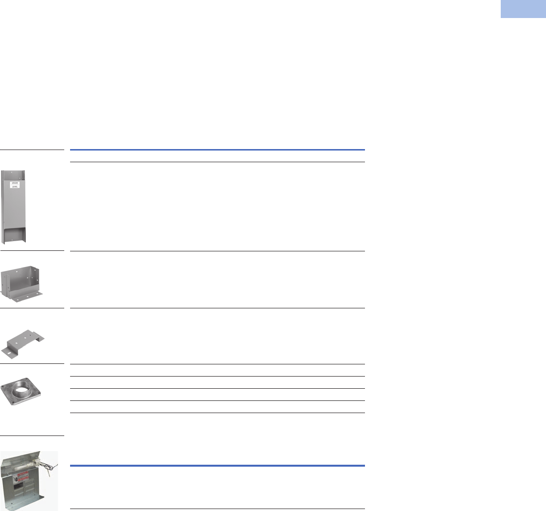
Volume 1—Residential and Light Commercial CA08100002E—February 2014 www.eaton.com V1-T6-7
6
6
6
6
6
6
6
6
6
6
6
6
6
6
6
6
6
6
6
6
6
6
6
6
6
6
6
6
6
6
6.2
Power Pedestals
Temporary Power/RV Park
Product Selection
When quoting or selecting
a power outlet panel, the
following questions should
be answered:
●Unmetered, ring or
ringless style
●Number and types of
receptacles (seven
standard and eight
twist-lock options)
●Standard or ground
fault breakers
●Surface, pedestal or
back-to-back mounting
●Are any factory or field
options required?
Power Outlet Panel Receptacle
Configuration Rules
Four Receptacles/Unit
All receptacles must
be NEMA 5-20R2 or
NEMA 5-20R2GFI,
surface mount only.
Three Receptacles/Unit
●One or more of the
receptacles must be
NEMA 6-20R2,
NEMA 5-20R2 or
NEMA 5-20R2GFI
●NEMA 6-20R2,
NEMA 5-20R2, or
NEMA 5-20R2GFI must
go in the second position
●If two receptacles consist
of types NEMA 14-50R,
NEMA 10-50R,
NEMA 14-30R or
NEMA 6-20R2 a six-circuit
interior must be added
●Example:
CHUIN5N2NSX
Note: Configuration 1 and 2 were
chosen so a six-circuit interior
needs to be added (suffix X) to
the end of the catalog number.
Also, configuration 5 is in the
second position.
Two, One and Zero
Receptacles/Unit
Any configuration.
Accessories
Accessories
Fluorescent Light Kit
Description
Catalog
Number
Underground pedestal extension CHPEDEXT
Stainless steel underground pedestal extension CHPEDEXTSS
Pad-mount bracket CHPADEXT
Cable TV and telephone bracket CHTELTV
Rainproof conduit hub 0.75 inch (19.1 mm) DS075H1
Rainproof conduit hub 1.00 inch (25.4 mm) DS100H1
Rainproof conduit hub 1.25 inch (31.8 mm) DS125H1
Rainproof conduit hub 1.50 inch (38.1 mm) DS150H1
Description
Catalog
Number
Converts power outlet panel to lighted unit, must also order CHOUTCVRL CHFLGTKIT
Underground Pedestal
Extension
Pad-Mount Bracket
DS Hub
Cable TV/Telephone
Bracket
Fluorescent Light Kit
V1-T6-8 Volume 1—Residential and Light Commercial CA08100002E—February 2014 www.eaton.com
6
6
6
6
6
6
6
6
6
6
6
6
6
6
6
6
6
6
6
6
6
6
6
6
6
6
6
6
6
6
6.2
Power Pedestals
Temporary Power/RV Park
Renewal Parts
Renewal Parts
Description
Catalog
Number
See this volume, Tab 1, section 1.2 —
Ring style replacement meter socket CHPOPMSRING
Ringless style replacement meter socket CHPOPMSRL
5th jaw kit ARP00035CHJ
Horn bypass (one lug cap per kit; four kits required per device) ARP00777CH
Bonding strap and mounting hardware CHBONDST
Inner lens for lighted power outlet panels CHINLENS
Loop feed lug assembly for single pedestal CHLOOPFDP
Loop feed lug assembly for back-to-back pedestal CHLOOPFDB
Blank lower deadfront cover CHLDFCVR
Lower deadfront cover with duplex receptacle opening CHLDFCVR1
Lower deadfront cover with duplex, duplex receptacle opening CHLDFCVR2
Lower deadfront cover with duplex, duplex, duplex receptacle opening CHLDFCVR3
Lower deadfront cover with rectangle receptacle opening CHLDFCVR4
Lower deadfront cover with rectangle, rectangle receptacle opening CHLDFCVR5
Lower deadfront cover with rectangle, rectangle, rectangle receptacle opening CHLDFCVR6
Lower deadfront cover with duplex, rectangle receptacle opening CHLDFCVR7
Lower deadfront cover with duplex, rectangle, duplex receptacle opening CHLDFCVR8
Lower deadfront cover with rectangle, rectangle, duplex receptacle opening CHLDFCVR9
Lower deadfront cover with round receptacle opening CHLDFCVR10
Lower deadfront cover with round, round receptacle opening CHLDFCVR11
Lower deadfront cover with round, duplex receptacle opening CHLDFCVR12
Meter Socket
Bonding Strap and
Mounting Hardware
Lower Deadfront Cover
Inner Lens
Circuit Breaker
(BR/GFCB)
Loop Feed
Lug Assembly

Volume 1—Residential and Light Commercial CA08100002E—February 2014 www.eaton.com V1-T6-9
6
6
6
6
6
6
6
6
6
6
6
6
6
6
6
6
6
6
6
6
6
6
6
6
6
6
6
6
6
6
6.2
Power Pedestals
Temporary Power/RV Park
Renewal Parts, continued
Description
Catalog
Number
Lower deadfront cover with round, duplex, duplex receptacle opening CHLDFCVR13
Lower deadfront cover with round, duplex, round receptacle opening CHLDFCVR14
Lower deadfront cover with round, rectangle receptacle opening CHLDFCVR15
Lower deadfront cover with round, rectangle, rectangle receptacle opening CHLDFCVR16
Lower deadfront cover with round, rectangle, round receptacle opening CHLDFCVR17
Lower deadfront cover with round, rectangle, duplex receptacle opening CHLDFCVR18
Upper deadfront cover with six breaker twistouts CHUDFCVR
Upper deadfront cover with provisions for lighted option CHUDFCVRL
Outer door CHOUTCVR
Outer door with lens CHOUTCVRL
Six-hole neutral assembly with 2/0 lug CHNEUT
Seven-hole neutral assembly with 2/0 lug CHNEUT1
Five-hole ground bar kit GBK5
10-hole ground bar kit GBK10
Replacement Meter Cover
Replacement meter cover—ring type CHPOPRMC
Replacement meter cover—ringless CHPOPRLMC
Replacement meter cover—ringless CHPOPRLMCN
Replacement meter cover—ringless CHPOPRLMCN2
Upper Deadfront Cover
Outer Door with Lens
Outer Door
Neutral Assemblies
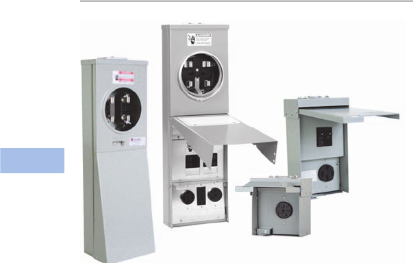
V1-T6-10 Volume 1—Residential and Light Commercial CA08100002E—February 2014 www.eaton.com
6
6
6
6
6
6
6
6
6
6
6
6
6
6
6
6
6
6
6
6
6
6
6
6
6
6
6
6
6
6
6.2
Power Pedestals
Temporary Power/RV Park
Power Outlet Panels
Contents
Description Page
Product Overview. . . . . . . . . . . . . . . . . . . . . . . . . . V1-T6-3
Surface Units
Dimensions . . . . . . . . . . . . . . . . . . . . . . . . . . . . V1-T6-13
Pedestal Units . . . . . . . . . . . . . . . . . . . . . . . . . . . . V1-T6-16
Surface Units
Product Overview
A power outlet panel (or POP)
is a device designed for
outdoor service to meet
temporary power
requirements at construction
sites and recreation vehicle
(RV) parks. POPs provide a
safe and reliable means for
users to access electricity
at such locations.
Product Selection
Power Outlet Panel Receptacle Configuration Rules
See Page V1-T6-8 for
complete list. For 100A Main
Breaker, contact the Flex
Center (1-800-330-6479).
Four Receptacles/Unit
All receptacles must be
NEMA 5-20R2 and/or
NEMA 5-20R2GFI, surface
mount only.
Three Receptacles/Unit
●One or more of the
receptacles must be
NEMA 6-20R2,
NEMA 5-20R2 or
NEMA 5-20R2GFI
●NEMA 6-20R2,
NEMA 5-20R2, or
NEMA 5-20R2GFI must
go in the second position
●If two receptacles consist
of types NEMA 14-50R,
NEMA 10-50R,
NEMA 14-30R or
NEMA 6-20R2 a six-circuit
interior must be added
●Example:
CHUIN5N2NSX
Note: Configuration 1 and 2 were
chosen so a six-circuit interior
needs to be added (suffix X) to
the end of the catalog number.
Also, configuration 5 is in the
second position.
Two, One and Zero
Receptacles/Unit
Any configuration.
Options
●Six-circuit interior
●Factory-mounted
pedestal extension
●Lighted
●Bottom fed
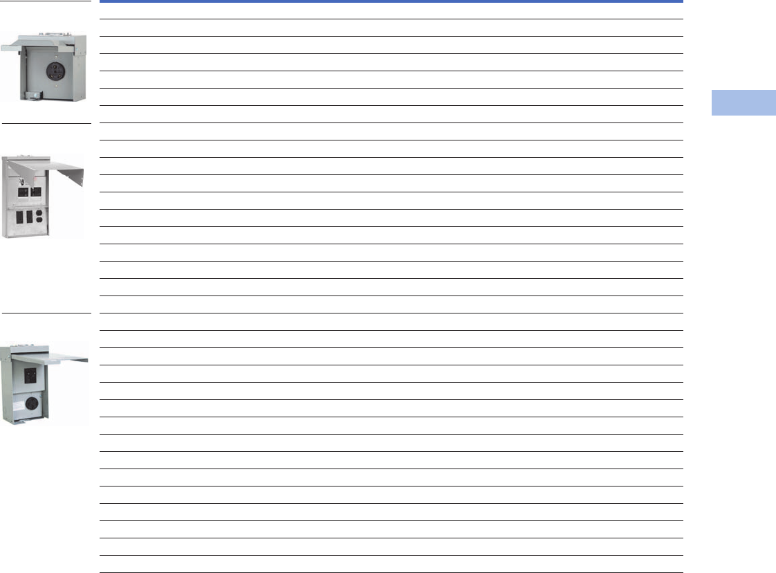
Volume 1—Residential and Light Commercial CA08100002E—February 2014 www.eaton.com V1-T6-11
6
6
6
6
6
6
6
6
6
6
6
6
6
6
6
6
6
6
6
6
6
6
6
6
6
6
6
6
6
6
6.2
Power Pedestals
Temporary Power/RV Park
Surface Type
Notes
1 The “X” suffix indicates that a six circuit interior is provided, instead of the standard four circuit interior.
2 Includes 60A two-pole main breaker for service disconnect ratings.
Contact your local Eaton sales office for configurations not listed.
Ampere
Series
Receptacle Description Breaker Description
Catalog
Number
Position
1st 2nd 3rdLeft Center Right
Unmetered Single Receptacle
50 — 14-50R — No breaker No breaker No breaker CHU1S
30 — 14-30 R — No breaker No breaker No breaker CHU3S
30 — TT-30R — No breaker No breaker No breaker CHU4S
20 — 6-20R2 — No breaker No breaker No breaker CHU5S
20 — 5-20R2 — No breaker No breaker No breaker CHU6S
20 — 5-20R2GFI — No breaker No breaker No breaker CHU7S
Unmetered
20/20/20 5-20R2 5-20R2 6-20R2 GFI GFI GFI CHU6G6G5GS
20/20/20 5-20R2GFI 5-20R2GFI 6-20R2 Non-GFI Non-GFI Non-GFI CHU7N7N5NS
20/20/20 5-20R2GFI 5-20R2GFI 6-20R2 Non-GFI Non-GFI GFI CHU7N7N5GS
50/20/30 14-50R 5-20R2GFI TT-30R Non-GFI Non-GFI Non-GFI CHU1N7N4NS
50/20/30 14-50R 5-20R2GFI 6-20R GFI Non-GFI Non-GFI CHU1G7N7NS
50/20 14-50R 5-20RGFI — GFI Non-GFI — CHU1G7NS
50/20 14-50R 5-20RGFI — Non-GFI Non-GFI — CHU1N7NS
50/20/50 14-50R 5-20R2GFI 14-50R Non-GFI Non-GFI Non-GFI CHU1N7N1NSX 1
30/30/20 TT-30R 5-20R2GFI TT-30R Non-GFI Non-GFI Non-GFI CHU4N7N4NS
20/20/20 5-20R2 5-20R2 6-20R2 GFI GFI GFI CHU6G6G5GS6OM 2
Unmetered (Compact Version)
50 14-50R — — Non-GFI — — CHU1NS
20 5-20R2 — — Non-GFI — — CHU2NS
30 TT-30R — — GFI — — CHU4GS
30/30 TT-30R TT-30R — Non-GFI Non-GFI — CHU4N4NS
30/20 TT-30R 5-20R2 — Non-GFI Non-GFI — CHU4N6NS
30/20 TT-30R 5-20R2GFI — Non-GFI Non-GFI — CHU4N7NS
30 TT-30R — — Non-GFI — — CHU4NS
20 6-20R2 — — GFI — — CHU5GS
20/20 5-20R2 5-20R2 — GFI GFI — CHU6G6GS
20 5-20R2 — — GFI — — CHU6GS
20/20 5-20R2 5-20R2 — Non-GFI Non-GFI — CHU6N6NS
20 5-20R2 — — Non-GFI — — CHU6NS
20/20 5-20R2GFI 5-20R2GFI — Non-GFI Non-GFI — CHU7N7NS
20 5-20R2GFI — — Non-GFI — — CHU7NS
Single Receptacle
CHU4S
Unmetered Type
CHU1N7N4NS
Unmetered
(Compact Version)
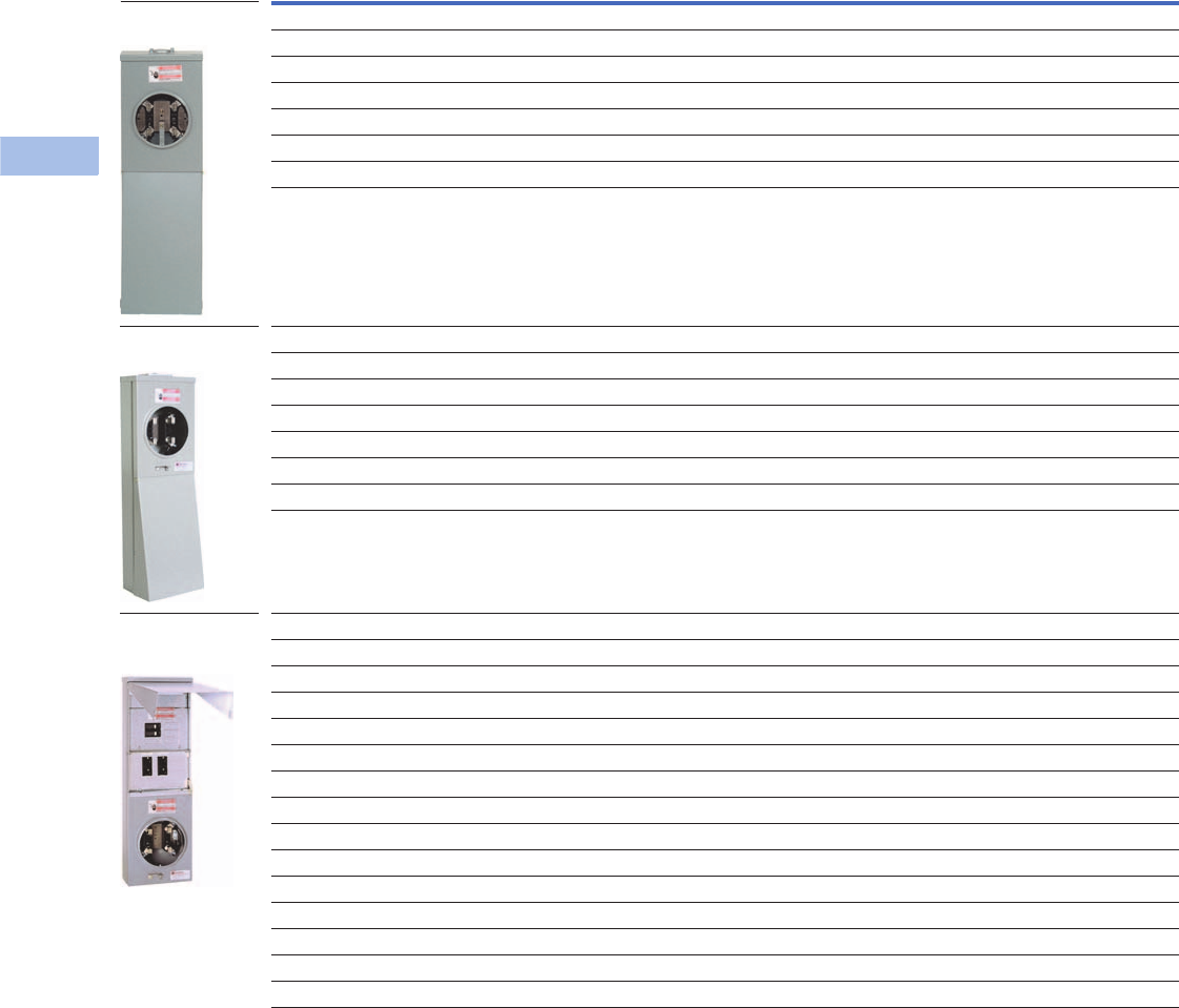
V1-T6-12 Volume 1—Residential and Light Commercial CA08100002E—February 2014 www.eaton.com
6
6
6
6
6
6
6
6
6
6
6
6
6
6
6
6
6
6
6
6
6
6
6
6
6
6
6
6
6
6
6.2
Power Pedestals
Temporary Power/RV Park
Surface Type, continued
Accessories
See Page V1-T6-7.
Ampere
Series
Receptacle Description Breaker Description
Catalog
Number
Position
1st 2nd 3rdLeft Center Right
Metered—Ring
50/20/20 14-50R 5-20R2GFI 5-20R2GFI GFI Non-GFI Non-GFI CHM1G7N7NS
20/20 5-20R2GFI 5-20R2GFI — Non-GFI Non-GFI — CHM7N7NS
20/20/20 5-20R2GFI 5-20R2GFI 6-20R2 Non-GFI Non-GFI GFI CHM7N7N5GS
20/20/20 5-20R2GFI 5-20R2GFI 6-20R2 Non-GFI Non-GFI Non-GFI CHM7N7N5NS
50/30/20 14-50R 5-20R2GFI TT-30R Non-GFI Non-GFI Non-GFI CHM1N7N4NS
50/20 14-50R 5-20R2GFI — Non-GFI Non-GFI — CHM1N7NS
20/20 6-20R2 5-20R2GFI — Non-GFI Non-GFI Non-GFI CHM5N7NS
Metered—Ringless
50/20 14-50R 5-20R2GFI — GFI Non-GFI — CHR1G7NS
20/20 5-20R2GFI 5-20R2GFI — Non-GFI Non-GFI — CHR7N7NS
50/20/20 14-50R 5-20R2GFI 5-20R2GFI GFI Non-GFI Non-GFI CHR1G7N7NS
50/20 14-50R 5-20R2GFI — Non-GFI Non-GFI — CHR1N7NS
20/20/20 5-20R2GFI 5-20R2GFI 5-20R2GFI Non-GFI Non-GFI Non-GFI CHR7N7N7NS
30/20/20 14-30R 5-20R2GFI 5-20R2GFI Non-GFI Non-GFI Non-GFI CHR3N7N7NS
50/30/20 14-50R 5-20R2GFI TT-30R Non-GFI Non-GFI Non-GFI CHR1N7N4NS
Metered—Ring—Bottom Fed
20/20 5-20R2GFI 5-20R2GFI — Non-GFI Non-GFI — CHM7N7NSU
20/20/20 5-20R2GFI 5-20R2GFI 6-20R2 Non-GFI Non-GFI GFI CHM7N7N5GSU
50/20/20 14-50R 5-20R2GFI 5-20R2GFI GFI Non-GFI Non-GFI CHM1G7N7NSU
Metered—Ringless—Bottom Fed
20/20 5-20R2GFI 5-20R2GFI — Non-GFI Non-GFI — CHR7N7NSU
50/20 14-50R 5-20R2GFI — GFI Non-GFI — CHR1G7NSU
50/20 10-50R 5-20R2GFI — GFI Non-GFI — CHR2G7NSU
20/20/20 5-20R2GFI 5-20R2GFI 6-20R2 Non-GFI Non-GFI GFI CHR7N7N5GSU
20/20/20 5-20R2GFI 5-20R2GFI 6-20R2 Non-GFI Non-GFI Non-GFI CHR7N7N5NSU
20/20/20 5-20R2GFI 5-20R2GFI 5-20R2GFI Non-GFI Non-GFI Non-GFI CHR7N7N7NSU
30/20/20 14-30R 5-20R2GFI 5-20R2GFI Non-GFI Non-GFI Non-GFI CHR3N7N7NSU
30/20/20 14-30R 5-20R2GFI 5-20R2GFI GFI Non-GFI Non-GFI CHR3G7N7NSU
50/20/20 14-50R 5-20R2GFI 5-20R2GFI GFI Non-GFI Non-GFI CHR1G7N7NSU
50/20/30 14-50R 5-20R2GFI TT-30R Non-GFI Non-GFI Non-GFI CHR1N7N4NSU
Metered Ringless Type
CHR4N7NS
Metered Ring or
Ringless Type
Bottom Feed
Metered Ring
CHM1G7NS
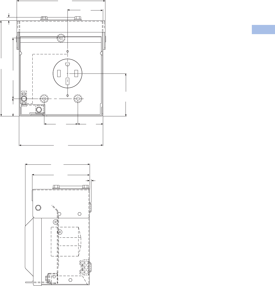
Volume 1—Residential and Light Commercial CA08100002E—February 2014 www.eaton.com V1-T6-13
6
6
6
6
6
6
6
6
6
6
6
6
6
6
6
6
6
6
6
6
6
6
6
6
6
6
6
6
6
6
6.2
Power Pedestals
Temporary Power/RV Park
Dimensions
Approximate Dimensions in Inches (mm)
Single Receptacle
6.58
(167.1)
2.63
(66.8)
0.24
(6.1)
7. 1 0
(108.3)
4.50
(114.3)
1.30
(33.0)
6.23
(158.2)
2.50
(63.5)
1.87
(47.5 )
3.18
(80.8)
4.79
(121.7)
4.27
(108.5) 0.13
(3.3)
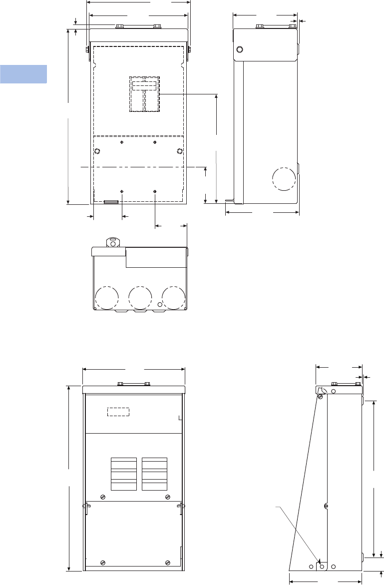
V1-T6-14 Volume 1—Residential and Light Commercial CA08100002E—February 2014 www.eaton.com
6
6
6
6
6
6
6
6
6
6
6
6
6
6
6
6
6
6
6
6
6
6
6
6
6
6
6
6
6
6
6.2
Power Pedestals
Temporary Power/RV Park
Approximate Dimensions in Inches (mm)
Compact Design Option
Unmetered Units
Unmetered Surface Type
6.94
(176.3)
6.58
(167.1)
11.66
(296.2)
0.30
(7.62)
Center Line
for Receptacle
4.27
(108.5) 0.13
(3.3)
7.26
(184.4)
2.43
(61.7)
4.89
(124.2)
1.89
(48.0) 2.14
(54.4)
Locking
Provision
9.50
(241.3)
17.10
(434.3)
6.70
(170.2) 1.30
(33.0)
14.50
(368.3)
4.30
(109.2) 0.07
(1.7)
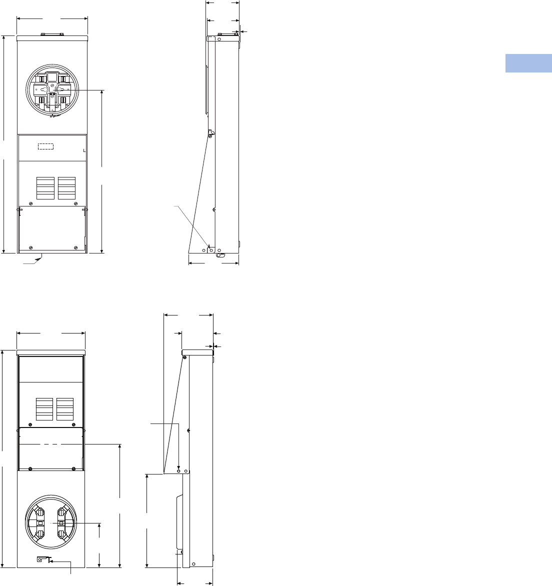
Volume 1—Residential and Light Commercial CA08100002E—February 2014 www.eaton.com V1-T6-15
6
6
6
6
6
6
6
6
6
6
6
6
6
6
6
6
6
6
6
6
6
6
6
6
6
6
6
6
6
6
6.2
Power Pedestals
Temporary Power/RV Park
Approximate Dimensions in Inches (mm)
Metered Units (Ring and Ringless)
Metered Surface Type
Bottom Fed Type
Sealing
Provision
Locking
Provision
9.50
(241.3)
22.50
(571.5)
30.00
(762.0)
4.50
(114.3)
0.07
(1.7)
4.30
(109.2)
6.70
(170.1)
9.49
(241.1)
30.10
(764.6)
Sealing
Provision
6.15
(156.2)
17.11
(434.7) 12.97
(329.4)
4.93
(125.2)
Locking
Provision
6.80
(172.8)
4.31
(109.5) 0.06
(1.6)
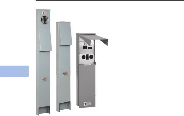
V1-T6-16 Volume 1—Residential and Light Commercial CA08100002E—February 2014 www.eaton.com
6
6
6
6
6
6
6
6
6
6
6
6
6
6
6
6
6
6
6
6
6
6
6
6
6
6
6
6
6
6
6.2
Power Pedestals
Temporary Power/RV Park
Power Outlet Panels
Contents
Description Page
Product Overview. . . . . . . . . . . . . . . . . . . . . . . . . . V1-T6-3
Surface Units . . . . . . . . . . . . . . . . . . . . . . . . . . . . . V1-T6-10
Pedestal Units . . . . . . . . . . . . . . . . . . . . . . . . . . . . V1-T6-16
Dimensions . . . . . . . . . . . . . . . . . . . . . . . . . . . . V1-T6-18
Pedestal Units
Product Overview
A power outlet panel (or POP)
is a device designed for
outdoor service to meet
temporary power
requirements at construction
sites and recreation vehicle
(RV) parks. POPs provide a
safe and reliable means for
users to access electricity
at such locations.
Product Selection
Power Outlet Panel Receptacle Configuration Rules
See Page V1-T6-8 for
complete list. For 100A Main
Breaker, contact the Flex
Center (1-800-330-6479).
Four Receptacles/Unit
All receptacles must be
NEMA 5-20R2 and/or
NEMA 5-20R2GFI, surface
mount only.
Three Receptacles/Unit
●One or more of the
receptacles must be
NEMA 6-20R2,
NEMA 5-20R2 or
NEMA 5-20R2GFI
●NEMA 6-20R2,
NEMA 5-20R2, or
NEMA 5-20R2GFI must
go in the second position
●If two receptacles consist
of types NEMA 14-50R,
NEMA 10-50R,
NEMA 14-30R or
NEMA 6-20R2 a six-circuit
interior must be added
●Example:
CHUIN5N2NSX
Note: Configuration 1 and 2 were
chosen so a six-circuit interior
needs to be added (suffix X) to
the end of the catalog number.
Also, configuration 5 is in the
second position.
Two, One and Zero
Receptacles/Unit
Any configuration.
Options
●Six-circuit interior
●Factory-mounted
pedestal extension
●Lighted
●Bottom fed
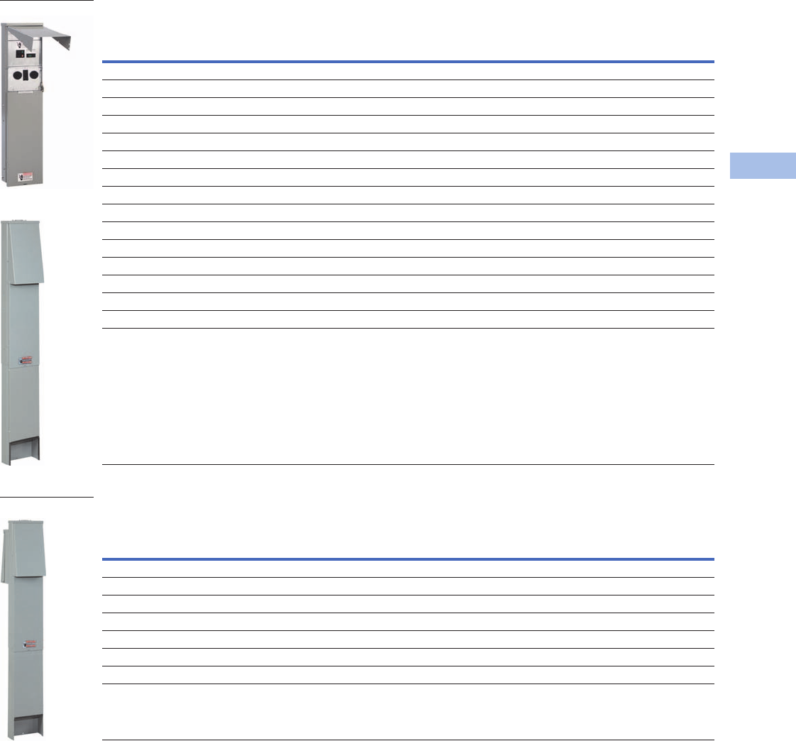
Volume 1—Residential and Light Commercial CA08100002E—February 2014 www.eaton.com V1-T6-17
6
6
6
6
6
6
6
6
6
6
6
6
6
6
6
6
6
6
6
6
6
6
6
6
6
6
6
6
6
6
6.2
Power Pedestals
Temporary Power/RV Park
Pedestal Type
Back-to-Back Pedestal Type
Notes
1 The pedestal back-to-back units have receptacles and circuit breakers as shown for each panel and share one common pedestal with loop feed lugs.
Contact your local Eaton sales office for configurations not listed.
Accessories
See Page V1-T6-7.
Ampere
Series
Receptacle Description Breaker Description
Catalog
Number
Position
1st 2nd 3rdLeft Center Right
Unmetered
50/30/20 14-50R 5-20R2GFI TT-30R Non-GFI Non-GFI Non-GFI CHU1N7N4NP
30/20 TT-30R 5-20R2GFI — Non-GFI Non-GFI — CHU4N7NP
50/30/20 14-50R 5-20R2GFI TT-30R Non-GFI Non-GFI Non-GFI CHU1N7N4NPTZ
30/30/20 TT-30R 5-20R2GFI TT-30R Non-GFI Non-GFI Non-GFI CHU4N7N4NP
30/20 TT-30R 5-20R2GFI — Non-GFI Non-GFI — CHU4N7NPTZ
Metered—Ring
50/30/20 14-50R 5-20R2GFI TT-30R Non-GFI Non-GFI Non-GFI CHM1N7N4NP
50/20 14-50R 5-20R2GFI — Non-GFI Non-GFI — CHM1N7NP
50/30/20 14-50R 5-20R2GFI TT-30R Non-GFI Non-GFI Non-GFI CHM1N7N4NPTZ
30/20 TT-30R 5-20R2GFI — Non-GFI Non-GFI — CHM4N7NPTZ
Metered—Ringless
50/30/20 14-50R 5-20R2GFI TT-30R Non-GFI Non-GFI Non-GFI CHR1N7N4NP
50/20/50 14-50R 5-20R2GFI 14-50R Non-GFI Non-GFI Non-GFI CHR1N7N1NPX
50/20/30 14-50R 5-20R2GFI 14-30R Non-GFI Non-GFI Non-GFI CHR1N7N3NPX
50/20/30 14-50R 5-20R2 14-30R Non-GFI Ground fault Non-GFI CHR1N6G3NPX
Ampere
Series
Receptacle Description Breaker Description
Catalog
Number
Position
1st 2nd 3rdLeft Center Right
Unmetered 1
30/30/20 TT-30R 5-20R2GFI TT-30R Non-GFI Non-GFI Non-GFI CHU4N7N4NB
50/30/20 14-50R 5-20R2GFI TT-30R Non-GFI Non-GFI Non-GFI CHU1N7N4NBTZ
Metered—Ring 1
30/20 TT-30R 5-20R2GFI — Non-GFI Non-GFI — CHM4N7NB
50/30/20 14-50R 5-20R2GFI TT-30R Non-GFI Non-GFI Non-GFI CHM1N7N4NB
Metered—Ringless 1
50/30/20 14-50R 5-20R2GFI TT-30R Non-GFI Non-GFI Non-GFI CHR1N7N4NBTZ
Unmetered Type
CHM1N7N4NPTZ
CHU1N7N4NBTZ
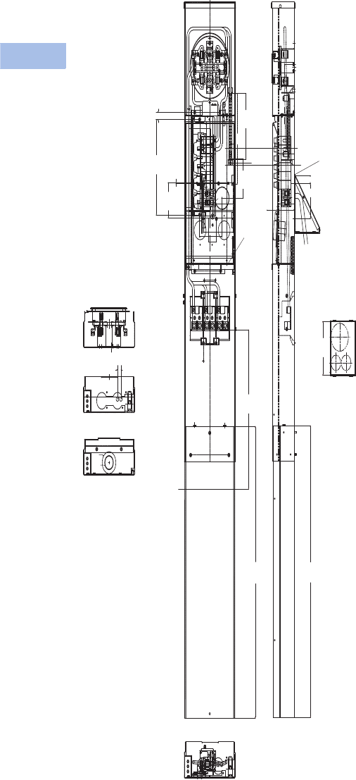
V1-T6-18 Volume 1—Residential and Light Commercial CA08100002E—February 2014 www.eaton.com
6
6
6
6
6
6
6
6
6
6
6
6
6
6
6
6
6
6
6
6
6
6
6
6
6
6
6
6
6
6
6.2
Power Pedestals
Temporary Power/RV Park
Dimensions
Approximate Dimensions in Inches (mm)
Metered Units
100A Pedestal
ÿ2.50
(63.5)
Gasket
CURRENT INTERRUPTING RATING
AT 120/240 VOLTS AC
10,000
MAX. RMS SYM. AMPERES
STRIP
.438
100A
1"
100A 100A
100A 100A
1"1"
1"1"
100A
1"
.63
(15.9)
100A 100A
Ringless
U.G. Feed Pedestal-Mount
Sections Through at
Meter Socket
6.10
(154.9)
33.00
(838.2)
18.02
(457.7)
Secondary
Hit Exit
Hole B/B
Only
A N B
7.44
(188.9)
ÿ1.50
10.24
(260.0)
3.077
4.108
4.00
(101.6)
.12
(3.1)
10.78
(273.7)
.904
4.46
(113.3)
ÿ2.500
Sections Through
At Upper Barrier
Sections Through
At Lower Barrier
.79
(20.1)
4.00
(101.6)
.92 (23.4)
33.00
(838.2)
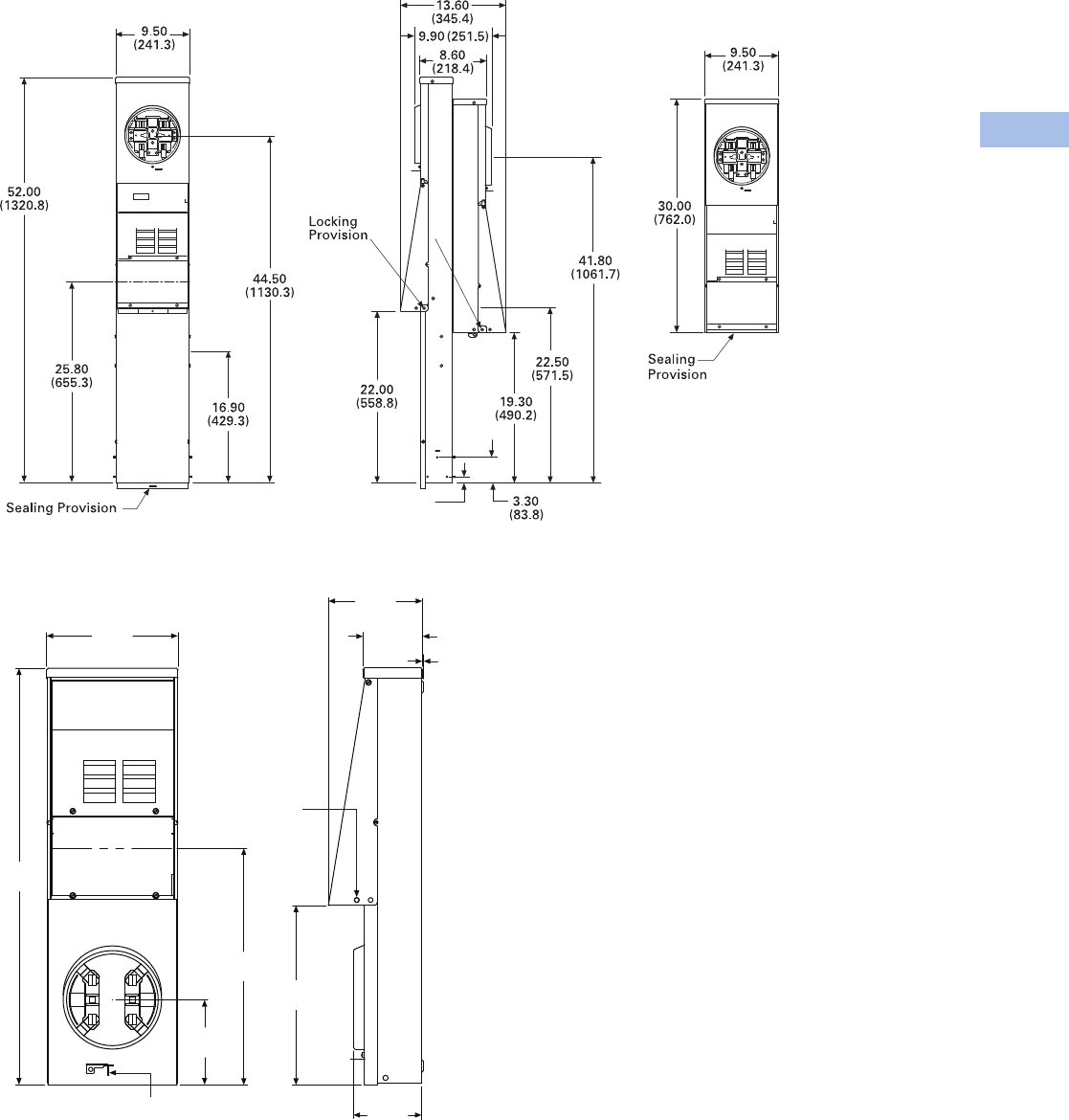
Volume 1—Residential and Light Commercial CA08100002E—February 2014 www.eaton.com V1-T6-19
6
6
6
6
6
6
6
6
6
6
6
6
6
6
6
6
6
6
6
6
6
6
6
6
6
6
6
6
6
6
6.2
Power Pedestals
Temporary Power/RV Park
Approximate Dimensions in Inches (mm)
Metered Units (Ring and Ringless)
Metered Back-to-Back Pedestal Type
Bottom Fed Type
0.75
(19.1)
9.49
(241.1)
30.10
(764.6)
Sealing
Provision
6.15
(156.2)
17.11
(434.7) 12.97
(329.4)
4.93
(125.2)
Locking
Provision
6.80
(172.8)
4.31
(109.5) 0.06
(1.6)
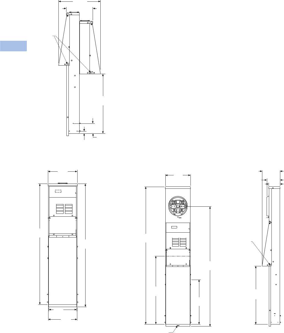
V1-T6-20 Volume 1—Residential and Light Commercial CA08100002E—February 2014 www.eaton.com
6
6
6
6
6
6
6
6
6
6
6
6
6
6
6
6
6
6
6
6
6
6
6
6
6
6
6
6
6
6
6.2
Power Pedestals
Te m po ra ry Pow er/ R V Pa r k
Approximate Dimensions in Inches (mm)
Unmetered Back-to-Back Pedestal Type
Unmetered Pedestal Type Metered Pedestal Type
Locking
Provision
13.60
(345.4)
8.60 (218.4)
19.20
(487.7)
3.30
(83.8)
0.75
(19.1)
9.50
(241.3)
39.90
(1013.5)
39.10
(993.1)
9.40
(238.8)
9.20
(233.7)
Sealing
Provision
Locking
Provision
9.50
(241.3)
52.00
(1320.8)
25.80
(655.3)
16.90
(429.3)
44.50
(1130.3)
22.00
(558.8)
6.80
(172.7)
5.00
(127.0) 4.30
(109.2)

Volume 1—Residential and Light Commercial CA08100002E—February 2014 www.eaton.com V1-T6-21
6
6
6
6
6
6
6
6
6
6
6
6
6
6
6
6
6
6
6
6
6
6
6
6
6
6
6
6
6
6
6.3
Power Pedestals
Mobile Home Panels
Power Outlet Panels
Contents
Description Page
Mobile Home Panels
Catalog Number Selection . . . . . . . . . . . . . . . . V1-T6-22
Product Selection . . . . . . . . . . . . . . . . . . . . . . . V1-T6-22
Accessories . . . . . . . . . . . . . . . . . . . . . . . . . . . V1-T6-23
Dimensions . . . . . . . . . . . . . . . . . . . . . . . . . . . V1-T6-24
Product Overview
Eaton’s versatile Mobile
Home Panels have a user-
friendly design that allows for
a faster, cleaner installation.
100 and 200A panels come
complete with the main
breaker and a 4/8 or 8/16
interior, respectively. The
200A units are designed with
ample width to ensure plenty
of room for wire bending and
an easier installation.
Receptacle Deadfront Kits
Optional receptacle
deadfront kits enable the
field installation of contractor
supplied receptacles and
breakers that can supply
power for a variety of
applications including:
●Visiting RVs
●Temporary power
●Lawn equipment
●Air compressors
●Anything else that requires
cord-connected power
Features
Fastenerless Socket Design
●Eliminates overheating
caused by loose socket
connections
Pedestal Unit
●Convenient and sturdy
ground mounting
●Loop feed feature allows
several units to be
connected in series
Easier, Better and
Faster Installation
●More wire bending and
viewing room
●Additional circuits mean
more flexibility
V1-T6-22 Volume 1—Residential and Light Commercial CA08100002E—February 2014 www.eaton.com
6
6
6
6
6
6
6
6
6
6
6
6
6
6
6
6
6
6
6
6
6
6
6
6
6
6
6
6
6
6
6.3
Power Pedestals
Mobile Home Panels
Catalog Number Selection
Mobile Home Panels
Product Selection
Mobile Home Panels 1
Note
1 Pedestal Extension included with Mobile Home Panels.
Amperes Security Interior Main
Branch
Breakers Mounting Receptacles
Catalog
Number
100 Ring 4/8 BR2100 BR Pedestal None MHM100P
100 Ring 4/8 BR2100 BR Back-to-back None MHM100B
100 Ringless 4/8 BR2100 BR Pedestal None MHR100P
100 Ringless 4/8 BR2100 BR Back-to-back None MHR100B
150 Ring 8/16 CSR2150 BR Pedestal None MHM150P
150 Ring 8/16 CSR2150 BR Back-to-back None MHM150B
150 Ringless 8/16 CSR2150 BR Pedestal None MHR150P
150 Ringless 8/16 CSR2150 BR Back-to-back None MHR150B
200 Ring 8/16 CSR2200 BR Pedestal None MHM200P
200 Ring 8/16 CSR2200 BR Back-to-back None MHM200B
200 Ringless 8/16 CSR2200 BR Pedestal None MHR200P
200 Ringless 8/16 CSR2200 BR Back-to-back None MHR200B
200 Ringless 8/16 CSR2200 BR Pedestal Qty 1 14-50R
Qty 2 TT-30R
MHM200P1N4N4N
Amperes
100
150
200
Type
MH = Mobile Home Panel
Metering Type
M= Metered-ring
R= Metered-ringless
Mounting
P= Pedestal
B= Back-to-back
Optional Receptacle Type
Position 1
1 = NEMA 14-50R
3 = NEMA 14-30R
4 = NEMA TT-30R
5 = NEMA 6-20R2
6 = NEMA 5-20R2
7 = NEMA 5-20R2GFI
8 = NEMA 5-20R2GFI (WR)
9 = NEMA 5-20R2GFI (WR/TR)
Blank = No receptacle
Circuit Breaker Type
Position 1
N = Non-ground fault
G = Ground fault Optional Receptacle Type
Position 2
1 = NEMA 14-50R
3 = NEMA 14-30R
4 = NEMA TT-30R
5 = NEMA 6-20R2
6 = NEMA 5-20R2
7 = NEMA 5-20R2GFI
8 = NEMA 5-20R2GFI (WR)
9 = NEMA 5-20R2GFI (WR/TR)
Blank = No receptacle
Circuit Breaker Type
Position 2
N = Non-ground fault
G = Ground fault
MH M100 P 1 N 4 N
Mobile Home Panel
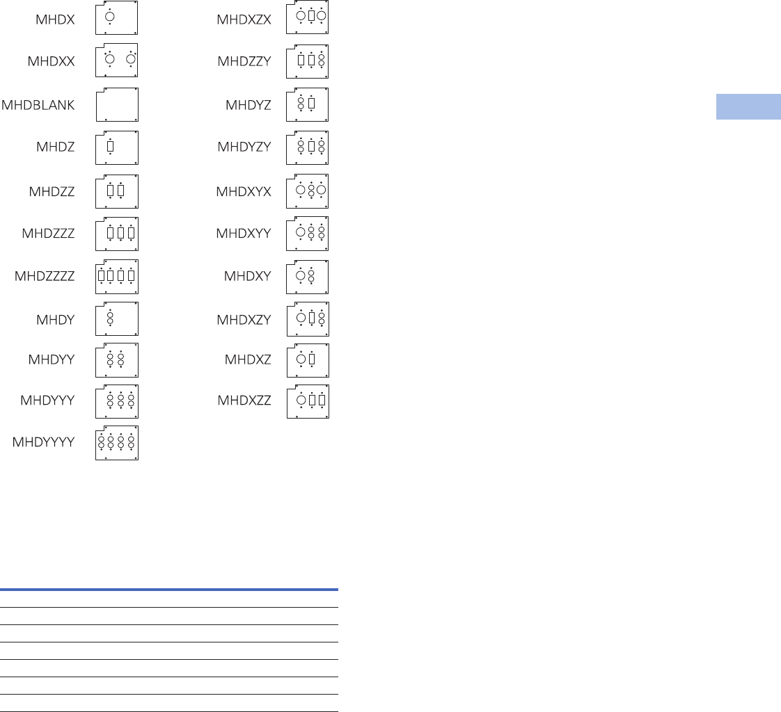
Volume 1—Residential and Light Commercial CA08100002E—February 2014 www.eaton.com V1-T6-23
6
6
6
6
6
6
6
6
6
6
6
6
6
6
6
6
6
6
6
6
6
6
6
6
6
6
6
6
6
6
6.3
Power Pedestals
Mobile Home Panels
Mobile Home Panel Deadfronts for 200A Units 1
Available Receptacle Deadfront Kits—Receptacles and
Breakers Not Included
Accessories
Mobile Home Panels
Hubs not used on mobile home panels.
Note
1For 100A units, the accessory Catalog Number would be MHD1___. For example, to order
a deadfront to accept one 30A receptacle (round) in a 100 ampere device, the Catalog
Number would be MHD1X.
Description Amperes
Catalog
Number
Direct feed kit — MHDFK
Pedestal extension 200 MHPEDEXT
Stainless steel pedestal extension 200 MHPEDEXTSS
Padmount adapter 200 MHPADEXT
Pedestal extension 100 CHPEDEXT100
Stainless steel pedestal extension 100 CHPEDESTSS100
Padmount adapter 100 CHPADEXT100
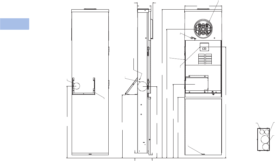
V1-T6-24 Volume 1—Residential and Light Commercial CA08100002E—February 2014 www.eaton.com
6
6
6
6
6
6
6
6
6
6
6
6
6
6
6
6
6
6
6
6
6
6
6
6
6
6
6
6
6
6
6.3
Power Pedestals
Mobile Home Panels
Dimensions
Approximate Dimensions in Inches (mm)
Mobile Home Panel—Ringless—Pedestal Mounting
ON
OFF
ON
OFF
Grade Level
5.31
(134.8)
5.98
(152.0) 14.45
(367.0)
27.87
(708.0)
28.01
(711.5) 23.69
(601.8)
50.08
(1272.1)
Ringless
Socket
Rated 200 A
Continuous
200A
Main
Breaker
57.81
(1468.3)
Sealing
Provision
1-1/4, 1-1/2,
2, 2-1/2
(31.8, 38.1,
50.8, 63.5)
Knockout
1, 1-1/4, 1-1/2, 2
(25.4, 31.8, 38.1, 50.8)
Knockout
5/16 (7.9)
Diameter KO
Opposite
Side Only
43.20
(1097.4)
28.70
(729.0)
1.21
(30.7)
2.00
(50.8)
24.65
(626.1)
Optional Direct
Feed Kit
Shown Installed
(Cover Not Shown)
Door Not
Shown
Bottom Endwall
Direct Feed Kit
1/2, 3/4,1
(12.7, 19.1, 25.4)
KO (2 Required)
1, 1-1/4, 1-1/2, 2
(25.4, 31.8, 38.1,
50.8) KO
1/2, 3/4, 1, 1-1/4,
1-1/2 (12.7, 19.1,
25.4, 31.8, 38.1) KO
Sealing Provision
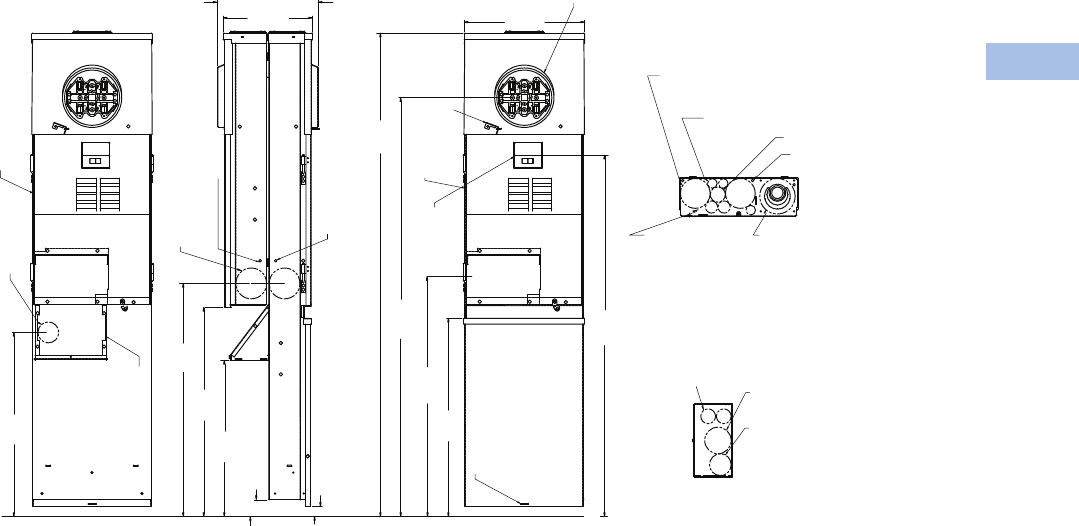
Volume 1—Residential and Light Commercial CA08100002E—February 2014 www.eaton.com V1-T6-25
6
6
6
6
6
6
6
6
6
6
6
6
6
6
6
6
6
6
6
6
6
6
6
6
6
6
6
6
6
6
6.3
Power Pedestals
Mobile Home Panels
Approximate Dimensions in Inches (mm)
Mobile Home Panel—Ringless—Back-to-Back Mounting
Sealing
Provision
Door
Not
Shown
ON
OFF
ON
OFF
ON
OFF
ON
OFF
12.09
(307.2) 10.75
(272.9)
27.87
(708.0)
22.01
(711.5) 18.69
(474.6)
25.00
(635.0)
Front View
Optional Direct
Feed Kit Shown
Installed
(Cover Not
Shown)
200A
Main
Breaker
Sealing
Provision
1-1/4, 1-1/2,
2, 2-1/2
(31.8, 38.1,
50.8, 63.5)
Knockout
5/16 (7.9)
Diameter
KO Opposite
Side Only 5/16 (7.9)
Diameter
KO
Opposite
Side Only
1,1-1/4,
1-1/2, 2
(25.4, 31.8,
38.1, 50.8)
Knockout
Grade Level
Door Not
Shown
23.69
(601.8)
50.08
(1272.1)
57.81
(1468.3)
43.20
(1097.4)
28.70
(729.0)
1.21
(30.7)
2.00
(50.8)
14.45
(367.0)
Bottom Endwall Direct Feed Kit
1/2, 3/4, 1 (12.7,
19.1, 25.4) KO
(2) Required
1/2, 3/4, 1, 1-1/4, 1-1/2
(12.7, 19.1, 25.4, 31.8,
38.1) KO
1, 1-1/4, 1-1/2, 2
(25.4, 31.8, 38.1, 50.8) KO
Bottom Endwall Back Unit
1-1/2, 2, 2-1/2, 3
(38.1, 50.8, 63.5, 76.2) KO
5/16 (7.9) Diameter
KO (3) Required
1/2 (12.7) KO
(3) Required
3/4, 1 (19.1, 25.4) KO
1-1/4, 1-1/2, 2, 2-1/2
(31.8, 38.1, 50.8, 63.5) KO
(2) Required
1/2, 3/4 (12.7, 19.1)
KO (2) Required
Ringless
Socket
Rated 200 A
Continuous
Back View
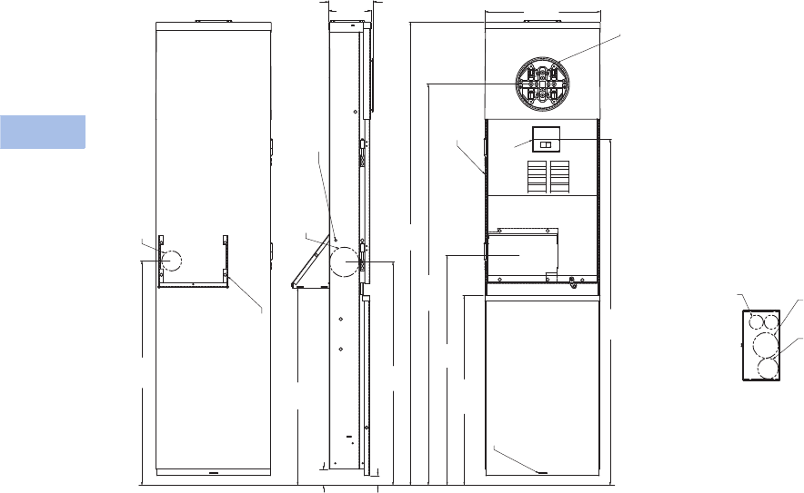
V1-T6-26 Volume 1—Residential and Light Commercial CA08100002E—February 2014 www.eaton.com
6
6
6
6
6
6
6
6
6
6
6
6
6
6
6
6
6
6
6
6
6
6
6
6
6
6
6
6
6
6
6.3
Power Pedestals
Mobile Home Panels
Approximate Dimensions in Inches (mm)
Mobile Home Panel—Ring—Pedestal Mounting
ON
OFF
ON
OFF
Ring Type Socket
Rated 200 A Continuous
200A
Main
Breaker
Door
Not
Shown
5/16 (7.9)
Diameter
KO
Opposite
Side Only
1-1/4,
1-1/2, 2,
2-1/2
(31.8, 38.1,
50.8, 63.5)
Knockout
Sealing
Provision
24.64
(626.0)
Optional Direct Feed Kit
Shown Installed
(Cover Not Shown)
28.01
(711.5)
1, 1-1/4,
1-1/2, 2
(25.4,
31.8, 38.1,
50.8) KO
1/2, 3/4, 1 (12.7,
19.1, 25.4) KO
(2 Required)
Bottom Endwall
Direct Feed Kit
1/2, 3/4, 1, 1-1/4,
1-1/2 (12.7, 19.1,
25.4, 31.8, 38.1) KO
1, 1-1/4, 1-1/2,
2 (25.4, 31.8,
38.1, 50.8) KO
Grade Level
27.87
(708.0) 23.69
(601.8)
50.08
(1272.1)
57.81
(1468.3)
28.70
(729.0)
1.21
(30.7)
2.00
(50.8)
5.56
(141.3) 5.31
(134.8)
43.20
(1097.4)
14.45
(367.0)
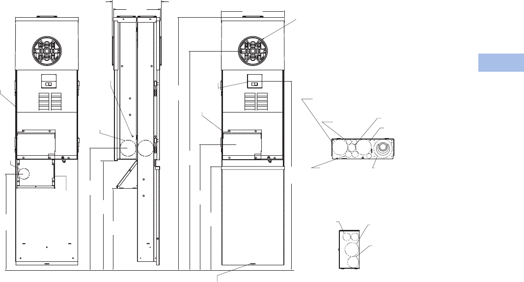
Volume 1—Residential and Light Commercial CA08100002E—February 2014 www.eaton.com V1-T6-27
6
6
6
6
6
6
6
6
6
6
6
6
6
6
6
6
6
6
6
6
6
6
6
6
6
6
6
6
6
6
6.3
Power Pedestals
Mobile Home Panels
Approximate Dimensions in Inches (mm)
Mobile Home Panel—Ring—Back-to-Back Mounting
ON
OFF
ON
OFF
Grade Level
1-1/4,
1-1/2, 2,
2-1/2
(31.8,
38.1, 50.8,
63.5)
Knockout
1, 1-1/4, 1-1/2, 2
(25.4, 31.8,
38.1, 50.8)
Knockout
Sealing Provision
5/16 (7.9)
Diameter KO
Back View Front View
1-1/4, 1-1/2, 2, 2-1/2
(31.8, 38.1, 50.8, 63.5)
KO (2) Required
Bottom Endwall
Back Unit
Bottom Endwall
Direct Feed Kit
1/2, 3/4, 1 (12.7,
19.1, 25.4) KO
(2) Required
1/2, 3/4, 1, 1-1/4,
1-1/2 (12.7, 19.1,
25.4, 31.8, 38.1) KO
1, 1-1/4, 1-1/2, 2 (25.4,
31.8, 38.1, 50.8) KO
1-1/2, 2, 2-1/2, 3 (38.1,
50.8, 63.5, 76.2) KO
3/4, 1 (19.1, 25.4) KO
Optional Direct
Feed Kit
Shown Installed
(Cover Not
Shown)
Door Not
Shown
200A
Main
Breaker
Door
Not
Shown
23.69
(601.8)
50.08
(1272.1)
57.81
(1468.3)
43.20
(1097.4)
28.70
(729.0)
11.25
(285.8) 10.75
(273.0) 14.45
(367.0) Ring Type Socket
Rated 200 A Continuous
27.87
(708.0)
18.69
(474.6)
25.00
(635.0)
22.01
(711.5)
5/16 (7.9) Diameter
KO (3) Required
1/2 (12.7) KO
(3) Required
1/2, 3/4 (12.7, 19.1)
KO (2) Required

V1-T6-28 Volume 1—Residential and Light Commercial CA08100002E—February 2014 www.eaton.com
6
6
6
6
6
6
6
6
6
6
6
6
6
6
6
6
6
6
6
6
6
6
6
6
6
6
6
6
6
6
6.4
Power Pedestals
RV Park Hook-Ups
High-Quality, Weatherproof Electrical Equipment
Recreational Vehicle/Campground Products
Contents
Description
Power Pedestals
Product Selection Guide . . . . . . . . . . . . . . . . . V1-T6-29
Powerhouse Power Pedestal . . . . . . . . . . . . . . . . V1-T6-30
Powerhouse—Stainless Steel (SS) Power Pedestal V1-T6-33
Newport Camp Mate Power Pedestal . . . . . . . . . V1-T6-36
Park Light Power Pedestal . . . . . . . . . . . . . . . . . . V1-T6-39
Firehouse . . . . . . . . . . . . . . . . . . . . . . . . . . . . . . . V1-T6-42
Digital Electronic Kilowatthour Meters . . . . . . . . . V1-T6-44
Distribution Equipment—Ground Fault Monitor . . V1-T6-45
Distribution Equipment—Substations. . . . . . . . . . V1-T6-46
Distribution Equipment—Panels. . . . . . . . . . . . . . V1-T6-49
Distribution Equipment—Transformers. . . . . . . . . V1-T6-50
Power Pedestals
Product Overview
On March 24, 2006, RV Park
Hook-Ups® joined together
with Eaton to provide
unmatched products and
services in the recreational
vehicle industry, as well as
the marina industry. Known
as the leader in electrical
control, power distribution,
and industrial automation
products and services, Eaton
is a quality driven company
that constantly looks for ways
to provide enhanced products
and service solutions for their
customers. Eaton will be able
to provide RV park developers
a complete electrical solution.
For more information on the
other products available from
Eaton, visit us online at
www.eaton.com or
www.rvparkhookups.com
What Eaton has to Offer
●Complementary
comprehensive in-house
electrical designs for your
complete RV or marina
development
●RV and marina power
pedestals
●Custom substations
●Tr a n s fo r m e r s
●Panels
●Wire
●Digital electronic meters
●Receptacles and breakers
●Specialized electrical parts
and equipment
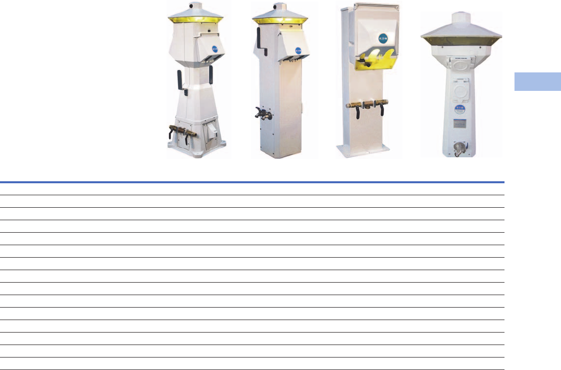
Volume 1—Residential and Light Commercial CA08100002E—February 2014 www.eaton.com V1-T6-29
6
6
6
6
6
6
6
6
6
6
6
6
6
6
6
6
6
6
6
6
6
6
6
6
6
6
6
6
6
6
6.4
Power Pedestals
RV Park Hook-Ups
Product Selection Guide
Power Receptacles
Power Outlets Maximum GFI
Side One Side Two Phase Powerhouse Powerhouse–SS Newport Camp Mate Park Light
NoneNone1 2 2 2 2
30–20 00 1 2 2 1 1
30–20 30–20 1 2 2 — —
30–30–20 30–30–20 1 2 2 — —
30–20 50–20 1 2 2 — —
30–30–20 50–20 1 2 2 — —
30–30–20 30–50–20 1 2 2 — —
30–30–20 50–50–20 1 2 2 — —
30–50–20 30–50–20 1 2 2 — —
30–50–20 50–50–20 1 2 2 — —
50–20 None 1 2 2 — —
50–20 50–20 1 2 2 — —
50–50–20 50–20 1 2 2 — —
50–50–20 50–50–20 1 2 2 — —
30–50–20 None 1 2 2 0 —

V1-T6-30 Volume 1—Residential and Light Commercial CA08100002E—February 2014 www.eaton.com
6
6
6
6
6
6
6
6
6
6
6
6
6
6
6
6
6
6
6
6
6
6
6
6
6
6
6
6
6
6
6.4
Power Pedestals
RV Park Hook-Ups
Powerhouse Power Pedestal
Contents
Description Page
Power Pedestals . . . . . . . . . . . . . . . . . . . . . . . . . . V1-T6-28
Powerhouse Power Pedestal
Standards and Certifications . . . . . . . . . . . . . . V1-T6-31
Catalog Number Selection . . . . . . . . . . . . . . . . V1-T6-31
Accessories . . . . . . . . . . . . . . . . . . . . . . . . . . . V1-T6-32
Dimensions . . . . . . . . . . . . . . . . . . . . . . . . . . . V1-T6-32
Powerhouse—Stainless Steel (SS) Power Pedestal V1-T6-33
Newport Camp Mate Power Pedestal . . . . . . . . . V1-T6-36
Park Light Power Pedestal . . . . . . . . . . . . . . . . . . V1-T6-39
Firehouse . . . . . . . . . . . . . . . . . . . . . . . . . . . . . . . V1-T6-42
Digital Electronic Kilowatthour Meters . . . . . . . . . V1-T6-44
Distribution Equipment—Ground Fault Monitor . . V1-T6-45
Distribution Equipment—Substations. . . . . . . . . . V1-T6-46
Distribution Equipment—Panels. . . . . . . . . . . . . . V1-T6-49
Distribution Equipment—Transformers. . . . . . . . . V1-T6-50
Powerhouse Power Pedestal
Product Description
The Powerhouse® RV utility
center is our most popular
pedestal for single or double
RV sites because of its full
complement of standard
features and available option
packages able to meet any
user requirement. The
housing is made of durable
weatherproof engineered
resin and will never rust or
deteriorate.
That’s why it comes with a
limited lifetime warranty.
Since the Powerhouse can
accommodate two RV sites,
it’s an economical pedestal
for double site installation.
This unit is ideal for new, or
when retrofitting, full-service
RV parks.
Features
●Photocell controlled
13 watt fluorescent light
with amber lens
●Lockable weatherproof
doors that protect
receptacles and breakers
●Hose and cable brackets
●Engineered resin
housing with a two-part
polyurethane coating for a
UV-resistant, long-lasting
finish
●Limited lifetime warranty
on the housing
●Loop-feed mechanical
busbars that can accept up
to 250 kcmil wire
●Hinged pedestal base
providing easy access
for installation and
maintenance
Surge Protection
SurgeTrap is designed
to protect electrical and
electronic loads from
transients and surge
disturbances on your AC
power line, such as voltage
surges, spikes and lighting.
The SurgeTrap has a lifetime
warranty where Eaton will
replace the SurgeTrap device
at no charge.
●175 kA maximum
surge current
●3500 joules
●Type 3R enclosure
●Comes with a protection
working indicator light
●Factory installed integral
to pedestal or available
for retrofit
Available Options
●Clear lens
●Photocell controlled single
or dual 7 watt or 13 watt
fluorescent light
●Telephone (RJ-11) for
each side
●Cable TV for each side
●High-speed Internet
connector (RJ-45) for
each side
●Water—single or dual
1/4-turn brass ball valves
(brass “T” connection)
with 3/4-inch hose bibs
●Water meters with remote
capability
●Water—anti-siphon faucet
●Loop-feed 3/8-inch stud
lug copper busbar for
up to 250 kcmil wire
(recommended for salt
water environments)
●Single-feed mechanical
busbars for up to
250 kcmil wire
●Digital electronic meter
for each side
●Wireless remote reading of
electronic kilowatt meters
●Meter socket for each side
powered (to accept glass
style meter)
●Direct burial ground
mounting stand stainless
or galvanized
●Custom paint color
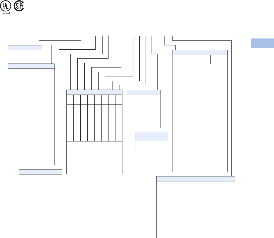
Volume 1—Residential and Light Commercial CA08100002E—February 2014 www.eaton.com V1-T6-31
6
6
6
6
6
6
6
6
6
6
6
6
6
6
6
6
6
6
6
6
6
6
6
6
6
6
6
6
6
6
6.4
Power Pedestals
RV Park Hook-Ups
Standards and Certifications
●UL/CSA listed
Catalog Number Selection
Receptacle: R1S1 = Receptacle 1, Side 1
R2S1 = Receptacle 2, Side 1
R3S1 = Receptacle 3, Side 1
R1S2 = Receptacle 1, Side 2
R2S2 = Receptacle 2, Side 2
R3S2 = Receptacle 3, Side 2
Notes
1Number represents the quantity of 1/4-turn ball valves with 3/4-inch hose bibs.
Internet option also available. Contact factory for details.
Type
P= Powerhouse
Z=PHSS
Metering Type
U= Unmetered
D= Digital electronic meters
(side one)
T= Digital electronic meters
(side two)
B= Digital electronic meters
(both sides)
R= Receptacles metered
individually
M= One meter socket
(100A)
N= Two meter socket
(100A each)
Lighting and Lens Color
A = 7W light Amber
B= Dual 7W light Amber
C= 9W light Amber
D= 13W light Amber
E= Dual 13W light Amber
F= No lighting Amber
G= 7W light Clear
H= Dual 7W light Clear
I= 9W light Clear
J= 13W light Clear
K= Dual 13W light Clear
L= No lighting Clear
M= 7W light Special
N= Dual 7W light Special
O= 9W light Special
P= 13W light Special
Q= Dual 13W light Special
R= No lighting Special
S=350 MA LED Amber
T=700 MA LED Amber
U= 350 MA LED Clear
V= 700 MA LED Clear
W= 350 MA LED Special
Y= 700 MA LED Special
Phone Cable TV and Internet Options
Phone
Jack
Cable TV
Jack
Internet
Option
A=1 0 0
B=1 0 1
C=1 0 2
D=1 1 0
E=1 1 1
F=1 1 2
G=1 2 0
H=1 2 1
I=1 2 2
J=2 0 0
K=2 0 1
L=2 0 2
M=2 1 0
N=2 1 1
O=2 1 2
P=2 2 0
Q=2 2 1
R=2 2 2
S=0 2 2
T=0 0 1
U=0 0 2
V=0 1 0
W=0 1 1
X=0 1 2
Y=0 2 0
Z=0 2 1
0=0 0 0
P D U 4 7 0 0 0 0 0 0 1 2 K M
Sides and Receptacles
R1S1
R2S1
R3S1
R4S1
R1S2
R2S2
R3S2
R4S2
0
1
2
3
4
5
6
7
8
0
1
2
3
4
5
6
7
8
0
1
2
3
4
5
6
7
8
0
1
2
3
4
5
6
7
8
0
1
2
3
4
5
6
7
8
0
1
2
3
4
5
6
7
8
0
1
2
3
4
5
6
7
8
0
1
2
3
4
5
6
7
8
0=None
1= 20A GFI duplex
2= 30A, 125V
4= 50A, 125/250V
5= 100A, 208V
6= 100A, 250V
7= 100A, 277/480V
8= 100A, 480V
Water Option 1
0=0
1=1
2=2
3= Single water meter
4= Dual water meter
5= Single meter, 2V
6= 1 frost free
7= 2 frost free
Extra Unmetered GFI
Receptacles
0= None
1=1
2=2
Bus
S= Single-phase 3/8-inch copper busbar
F= Three-phase 3/8-inch copper busbar
C= Single-phase 3/8-inch Canadian busbar
T= Three-phase 3/8-inch Canadian busbar
M= Single-phase 300 kcmil mechanical lug bus
Z= Three-phase 300 kcmil mechanical lug bus
L= Single-phase 350 kcmil mechanical lug bus
P= Three-phase 350 kcmil mechanical lug bus
N= Single-phase 1/4-inch copper busbar
Q= Single-phase 1/4-inch split mechanical busbar
A= Single-phase 300 kcmil mechanical lug Canadian bus
B= Three-phase 300 kcmil mechanical lug Canadian bus
D= Single-phase 350 kcmil mechanical lug Canadian bus
E= Three-phase 350 kcmil mechanical lug Canadian bus
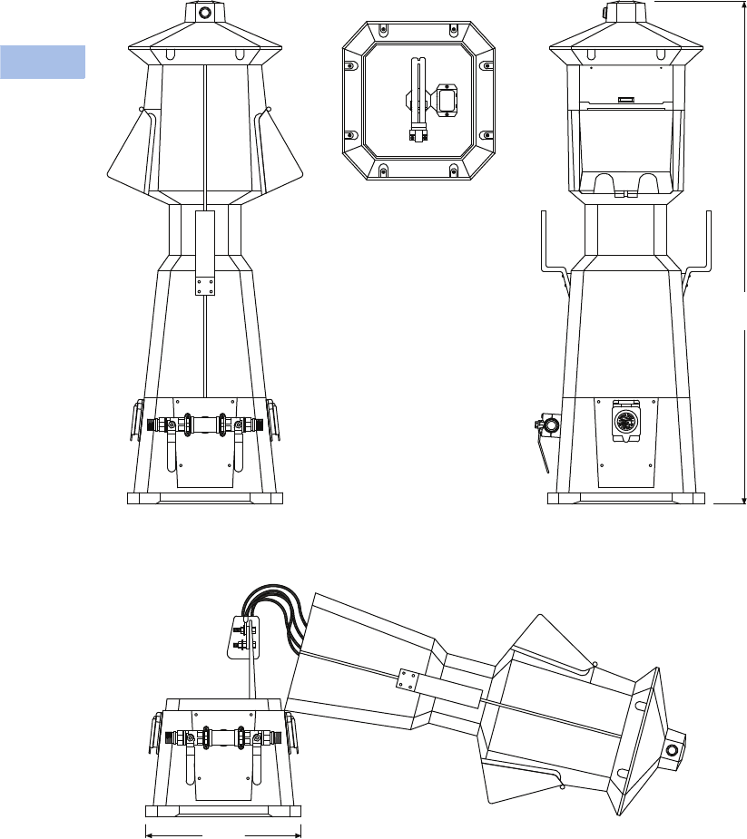
V1-T6-32 Volume 1—Residential and Light Commercial CA08100002E—February 2014 www.eaton.com
6
6
6
6
6
6
6
6
6
6
6
6
6
6
6
6
6
6
6
6
6
6
6
6
6
6
6
6
6
6
6.4
Power Pedestals
RV Park Hook-Ups
Accessories
See Page V1-T6-75.
Dimensions
Approximate Dimensions in Inches (mm)
Powerhouse
To p
Front ViewSide View
Broken View
44.00
(1117.6)
13.75
(349.2)

Volume 1—Residential and Light Commercial CA08100002E—February 2014 www.eaton.com V1-T6-33
6
6
6
6
6
6
6
6
6
6
6
6
6
6
6
6
6
6
6
6
6
6
6
6
6
6
6
6
6
6
6.4
Power Pedestals
RV Park Hook-Ups
Powerhouse—Stainless Steel (SS) Power Pedestal
Contents
Description Page
Power Pedestals . . . . . . . . . . . . . . . . . . . . . . . . . . V1-T6-28
Powerhouse Power Pedestal. . . . . . . . . . . . . . . . . V1-T6-30
Powerhouse—Stainless Steel (SS) Power Pedestal
Catalog Number Selection . . . . . . . . . . . . . . . . V1-T6-34
Accessories . . . . . . . . . . . . . . . . . . . . . . . . . . . V1-T6-35
Dimensions . . . . . . . . . . . . . . . . . . . . . . . . . . . V1-T6-35
Newport Camp Mate Power Pedestal . . . . . . . . . . V1-T6-36
Park Light Power Pedestal. . . . . . . . . . . . . . . . . . . V1-T6-39
Firehouse. . . . . . . . . . . . . . . . . . . . . . . . . . . . . . . . V1-T6-42
Digital Electronic Kilowatthour Meters . . . . . . . . . V1-T6-44
Distribution Equipment—Ground Fault Monitor . . V1-T6-45
Distribution Equipment—Substations . . . . . . . . . . V1-T6-46
Distribution Equipment—Panels . . . . . . . . . . . . . . V1-T6-49
Distribution Equipment—Transformers . . . . . . . . . V1-T6-50
Powerhouse—Stainless Steel (SS) Power Pedestal
Product Description
For long-lasting durability
and low maintenance,
the new stainless steel
Powerhouse–SS pedestal
is the most resilient power
center offered.
We have designed a stainless
steel pedestal that will meet
and exceed all applicable
codes and withstand harsh
inland and coastal
environments.
Features
●Stainless steel housing
with a limited lifetime
warranty
●Photocell controlled
13 watt fluorescent light
with amber lens
●Large removable access
panel for easy installation
and maintenance
●Weatherproof doors
that protect receptacles
and breakers
●Backlit faceplate to aid in
hooking up at night
●Hose and cable brackets
●Powder-coated finish
●Loop-feed mechanical
busbars that can accept up
to 350 kcmil wire
Available Options
●Clear lens
●Photocell controlled single
or dual 7 watt or 13 watt
fluorescent light
●Telephone (RJ-11) for
each side
●Cable TV for each side
●High-speed Internet
connection (RJ-45) for each
side
●Water–single or dual
1/4-turn brass ball valves
(brass “T” connection)
with 3/4-inch hose bibs
●Water meters with
remote capability
●Water—anti-siphon faucet
●Direct burial stainless steel
ground mounting stand
●Lockable doors
●Loop-feed 3/8-inch stud
lug copper busbar for
up to 350 kcmil wire
(recommended for salt
water environments)
●Single-feed mechanical
busbars for up to
350 kcmil wire
●Digital electronic metering
for each side
●Wireless remote reading of
electronic kilowatt meters
●Meter socket for each side
powered (to accept glass
style meter)
●Four door design to add
more outlets per pedestal
V1-T6-34 Volume 1—Residential and Light Commercial CA08100002E—February 2014 www.eaton.com
6
6
6
6
6
6
6
6
6
6
6
6
6
6
6
6
6
6
6
6
6
6
6
6
6
6
6
6
6
6
6.4
Power Pedestals
RV Park Hook-Ups
Catalog Number Selection
Receptacle: R1S1 = Receptacle 1, Side 1
R2S1 = Receptacle 2, Side 1
R3S1 = Receptacle 3, Side 1
R1S2 = Receptacle 1, Side 2
R2S2 = Receptacle 2, Side 2
R3S2 = Receptacle 3, Side 2
Notes
1Number represents the quantity of 1/4-turn ball valves with 3/4-inch hose bibs.
Internet option also available. Contact factory for details.
Extra Unmetered GFI
Receptacles
0= None
1=1
2=2
Water Option 1
0=0
1=1
2=2
3= Single water meter
4= Dual water meter
5= Single meter, 2V
6= 1 frost free
7= 2 frost free
Type
P= Powerhouse
Z= PHSS
Metering Type
U= Unmetered
D= Digital electronic meters
(side one)
T= Digital electronic meters
(side two)
B= Digital electronic meters
(both sides)
R= Receptacles metered
individually
M= One meter socket
(100A)
N= Two meter socket
(100A each)
Lighting and Lens Color
A = 7W light Amber
B= Dual 7W light Amber
C= 9W light Amber
D= 13W light Amber
E= Dual 13W light Amber
F= No lighting Amber
G= 7W light Clear
H= Dual 7W light Clear
I= 9W light Clear
J= 13W light Clear
K= Dual 13W light Clear
L= No lighting Clear
M= 7W light Special
N= Dual 7W light Special
O= 9W light Special
P= 13W light Special
Q= Dual 13W light Special
R= No lighting Special
S= 350 MA LED Amber
T= 700 MA LED Amber
U= 350 MA LED Clear
V= 700 MA LED Clear
W= 350 MA LED Special
Y= 700 MA LED Special
Bus
S= Single-phase 3/8-inch copper busbar
F= Three-phase 3/8-inch copper busbar
C= Single-phase 3/8-inch Canadian busbar
T= Three-phase 3/8-inch Canadian busbar
M= Single-phase 300 kcmil mechanical lug bus
Z= Three-phase 300 kcmil mechanical lug bus
L= Single-phase 350 kcmil mechanical lug bus
P= Three-phase 350 kcmil mechanical lug bus
N= Single-phase 1/4-inch copper busbar
Q= Single-phase 1/4-inch split mechanical busbar
A= Single-phase 300 kcmil mechanical lug Canadian bus
B= Three-phase 300 kcmil mechanical lug Canadian bus
D= Single-phase 350 kcmil mechanical lug Canadian bus
E= Three-phase 350 kcmil mechanical lug Canadian bus
Phone Cable TV and Internet Options
Phone
Jack
Cable TV
Jack
Internet
Option
A=1 0 0
B=1 0 1
C=1 0 2
D=1 1 0
E=1 1 1
F=1 1 2
G=1 2 0
H=1 2 1
I=1 2 2
J=2 0 0
K=2 0 1
L=2 0 2
M=2 1 0
N=2 1 1
O=2 1 2
P=2 2 0
Q=2 2 1
R=2 2 2
S=0 2 2
T=0 0 1
U=0 0 2
V=0 1 0
W=0 1 1
X=0 1 2
Y=0 2 0
Z=0 2 1
0=0 0 0
Z D U 4 7 0 0 0 0 0 0 1 2 K M
Sides and Receptacles
R1S1
R2S1
R3S1
R4S1
R1S2
R2S2
R3S2
R4S2
0
1
2
3
4
5
6
7
8
0
1
2
3
4
5
6
7
8
0
1
2
3
4
5
6
7
8
0
1
2
3
4
5
6
7
8
0
1
2
3
4
5
6
7
8
0
1
2
3
4
5
6
7
8
0
1
2
3
4
5
6
7
8
0
1
2
3
4
5
6
7
8
0=None
1= 20A GFI duplex
2= 30A, 125V
4= 50A, 125/250V
5= 100A, 208V
6= 100A, 250V
7= 100A, 277/480V
8= 100A, 480V
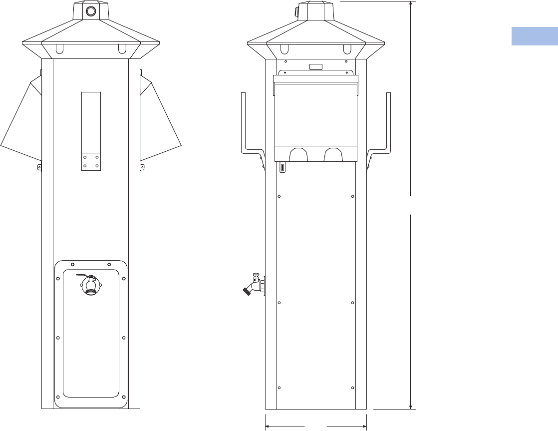
Volume 1—Residential and Light Commercial CA08100002E—February 2014 www.eaton.com V1-T6-35
6
6
6
6
6
6
6
6
6
6
6
6
6
6
6
6
6
6
6
6
6
6
6
6
6
6
6
6
6
6
6.4
Power Pedestals
RV Park Hook-Ups
Accessories
See Page V1-T6-75.
Dimensions
Approximate Dimensions in Inches (mm)
Powerhouse—Stainless Steel (SS)
9.88
(251.0)
40.00
(1016.0)

V1-T6-36 Volume 1—Residential and Light Commercial CA08100002E—February 2014 www.eaton.com
6
6
6
6
6
6
6
6
6
6
6
6
6
6
6
6
6
6
6
6
6
6
6
6
6
6
6
6
6
6
6.4
Power Pedestals
RV Park Hook-Ups
Newport Camp Mate Power Pedestal
Contents
Description Page
Power Pedestals . . . . . . . . . . . . . . . . . . . . . . . . . . V1-T6-28
Powerhouse Power Pedestal . . . . . . . . . . . . . . . . V1-T6-30
Powerhouse—Stainless Steel (SS) Power Pedestal V1-T6-33
Newport Camp Mate Power Pedestal
Catalog Number Selection . . . . . . . . . . . . . . . . V1-T6-37
Accessories . . . . . . . . . . . . . . . . . . . . . . . . . . . V1-T6-38
Dimensions . . . . . . . . . . . . . . . . . . . . . . . . . . . V1-T6-38
Park Light Power Pedestal . . . . . . . . . . . . . . . . . . V1-T6-39
Firehouse . . . . . . . . . . . . . . . . . . . . . . . . . . . . . . . V1-T6-42
Digital Electronic Kilowatthour Meters . . . . . . . . . V1-T6-44
Distribution Equipment—Ground Fault Monitor . . V1-T6-45
Distribution Equipment—Substations. . . . . . . . . . V1-T6-46
Distribution Equipment—Panels. . . . . . . . . . . . . . V1-T6-49
Distribution Equipment—Transformers. . . . . . . . . V1-T6-50
Newport Camp Mate Power Pedestal
Product Description
The Newport Camp Mate
provides many of the features
and options of our other full-
size pedestals, but in a
compact self-contained unit.
This model provides more
mounting options to RV park
owners than any other model.
It can be mounted to our
stainless steel stand either
flanged or direct burial, a
post or any wall.
It comes standard with a resin
housing that will never rust or
deteriorate and provides area
lighting as well as aiding in
hooking up at night. This unit
is especially suitable to many
RV park renovation projects
as well as new RV parks.
Features
●Photocell controlled 7 watt
fluorescent light with
amber lens
●Lockable weatherproof
door that protects
receptacles and breakers
●Engineered resin housing
●Limited lifetime warranty
on the housing
●Designed to mount on a
post, wall or an optional
custom stand
●Loop-feed 1/4-inch copper
stud lug
busbars that can
accept 2/0 AWG wire
for
Camp Mate without
optional stand
●Loop-feed mechanical
busbars that can accept up
to
2/0 AWG
wire for Camp
Mate on optional stand
Available Options
●36-inch stainless
steel stand
●40-inch stainless steel
pad-mounted stand
●60-inch direct burial
stainless steel stand
●Telephone (RJ-11)
●Cable TV
●High-speed Internet
connector (RJ-45)
●Water—single or dual
1/4-turn brass ball valves
(brass “T” connection)
with 3/4-inch hose bibs
mounted on optional stand
●Water—anti-siphon
backflow preventer
●Loop feed 3/8-inch stud lug
copper busbar for up to
350 kcmil wire with stand
(recommended for salt
water environments)
●Single-feed mechanical
busbars for up to 350 kcmil
wire available with stand
●Digital electronic meter
●Wireless remote reading of
electronic kilowatt meter
●
Meter socket available with
aluminum
stands (to accept
glass style meter)
Standards and Certifications
The Newport Camp Mate is
UL listed and comes with a
limited lifetime warranty on
the housing.
Volume 1—Residential and Light Commercial CA08100002E—February 2014 www.eaton.com V1-T6-37
6
6
6
6
6
6
6
6
6
6
6
6
6
6
6
6
6
6
6
6
6
6
6
6
6
6
6
6
6
6
6.4
Power Pedestals
RV Park Hook-Ups
Catalog Number Selection
Receptacle: R1 = Receptacle 1
R2 = Receptacle 2
R3 = Receptacle 3
Notes
120A GFIs not metered.
2Number represents the quantity of 1/4-turn ball valves with 3/4-inch hose bibs (with stand only).
Water
Option 2
0=0
1=1
2=2
Phone Cable TV and Internet Options
Phone Jack Cable TV Jack Internet Option
A=1 0 0
B=1 0 1
C=1 0 2
D=1 1 0
E= 1 1 1 (Camp Mate only)
T=0 0 1
V=0 1 0
W=0 1 1
0=0 0 0
Stand
0=0
1=1
Bus
S= Single-phase 1/4-inch copper busbar
F= Three-phase 1/4-inch copper busbar
C= Single-phase 1/4-inch Canadian busbar
M= Mechanical lug 2/0
Q= Single-phase 1/4-inch split mechanical
busbar (with stand ONLY)
A= 1/4-inch Canadian mechanical
Sides and
Receptacles
R1S1 R2S1 R3S1
0
1
2
3
4
0
1
2
3
4
0
1
0=None
1= 20A GFI duplex
2= 30A, 125V
3= 50A, 125V
4= 50A, 125/250V
Type
N= NP Harbor Mate
C=NP Camp Mate
Lighting and Lens Color
A = 7W light Amber
C= 9W light Amber
F= No lighting Amber
G= 7W light Clear
I= 9W light Clear
L= No lighting Clear
M= 7W light Special
O= 9W light Special
R= No lighting Special
S= 350 MA LED Amber
T= 700 MA LED Amber
U= 350 MA LED Clear
V= 700 MA LED Clear
W= 350 MA LED Special
Y= 700 MA LED Special
Hard Wired
Breakers
S1
0= None
2= 20A, two-pole
3= 30A
Photocell
Y=Yes
N=No
Lighting Protection
B= Breaker protected
F= Fuse protected
Metering Type 1
U= Unmetered
D= Digital electronic meters
R= Receptacles metered
individually
C A Y B U 4 3 0 1 1 2 W M
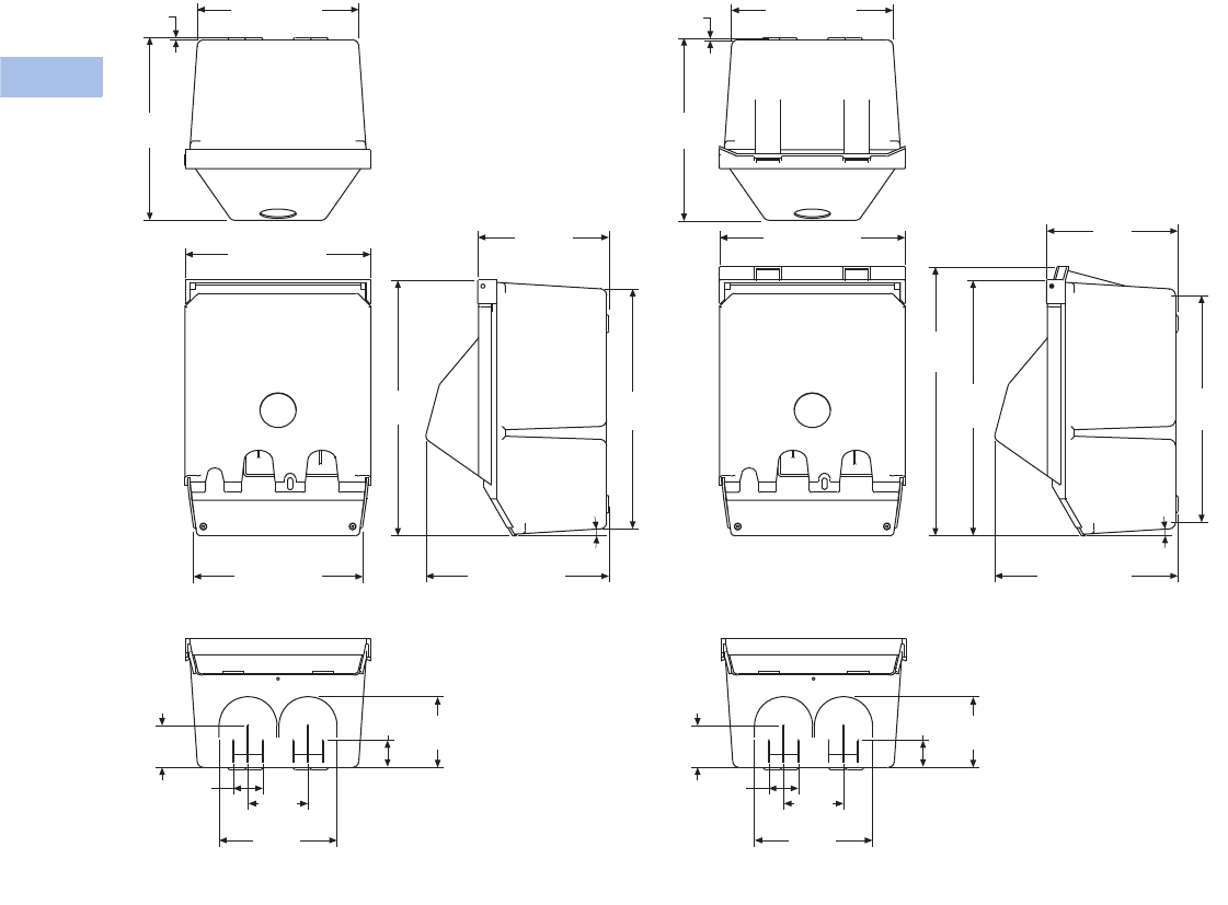
V1-T6-38 Volume 1—Residential and Light Commercial CA08100002E—February 2014 www.eaton.com
6
6
6
6
6
6
6
6
6
6
6
6
6
6
6
6
6
6
6
6
6
6
6
6
6
6
6
6
6
6
6.4
Power Pedestals
RV Park Hook-Ups
Accessories
See Page V1-T6-75.
Dimensions
Approximate Dimensions in Inches (mm)
Newport Camp Mate
9.18 (233.0)
0.12
(3.2)
10.38
(263.7)
Newport Redesign Newport Redesign With Meters
10.52 (267.2)
9.59 (243.6) 10.38 (263.7)
14.53
(369.0)
13.63
(346.2)
7.44
(189.1)
6.70
(170.2)
3.40
(86.4)
1.68
(42.7)
2.37
(60.3)
4.02
(102.2)
1.54
(39.1)
6.70
(170.2)
3.40
(86.4)
1.68
(42.7)
2.37
(60.3)
4.02
(102.2)
1.54
(39.1)
4º
9.18 (233.0)
0.12
(3.2)
10.38
(263.7)
10.52 (267.2) 7.44
(189.1)
14.53
(369.0)
15.28
(388.0)
4º
10.38 (263.7)
12.88
(327.2)
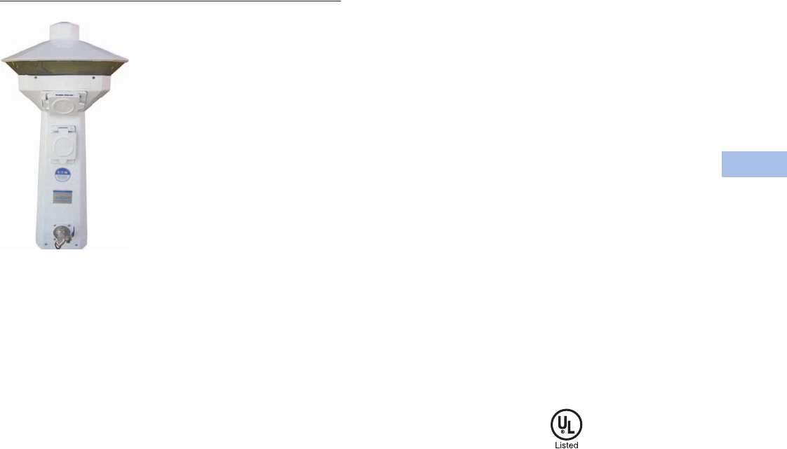
Volume 1—Residential and Light Commercial CA08100002E—February 2014 www.eaton.com V1-T6-39
6
6
6
6
6
6
6
6
6
6
6
6
6
6
6
6
6
6
6
6
6
6
6
6
6
6
6
6
6
6
6.4
Power Pedestals
RV Park Hook-Ups
Park Light Power Pedestal
Contents
Description Page
Power Pedestals . . . . . . . . . . . . . . . . . . . . . . . . . . V1-T6-28
Powerhouse Power Pedestal. . . . . . . . . . . . . . . . . V1-T6-30
Powerhouse—Stainless Steel (SS) Power Pedestal V1-T6-33
Newport Camp Mate Power Pedestal . . . . . . . . . . V1-T6-36
Park Light Power Pedestal
Catalog Number Selection . . . . . . . . . . . . . . . . V1-T6-40
Accessories . . . . . . . . . . . . . . . . . . . . . . . . . . . V1-T6-41
Dimensions . . . . . . . . . . . . . . . . . . . . . . . . . . . V1-T6-41
Firehouse. . . . . . . . . . . . . . . . . . . . . . . . . . . . . . . . V1-T6-42
Digital Electronic Kilowatthour Meters . . . . . . . . . V1-T6-44
Distribution Equipment—Ground Fault Monitor . . V1-T6-45
Distribution Equipment—Substations . . . . . . . . . . V1-T6-46
Distribution Equipment—Panels . . . . . . . . . . . . . . V1-T6-49
Distribution Equipment—Transformers . . . . . . . . . V1-T6-50
Park Light Power Pedestal
Product Description
The elegant design of the
Park Light complements park
landscaping and provides
essential lighting required
for park safety and security
for campground paths,
walkways, recreational areas
and even pools. The Park
Light has the same 360
degree lighting design as
the Powerhouse and a resin
housing that will never rust
or deteriorate.
At 10¢/kWH, it will provide
area lighting at a cost of
less than 50¢/month and
the bulbs will last for about
three years. The Park Light
is a perfect lighting fixture
for any campground and
especially for RV parks with
Powerhouse utility centers.
Features
●Photocell controlled dual
13 watt fluorescent light
with amber lens
●Engineered resin
housing with a two-part
polyurethane coating for a
UV-resistant, long-lasting
finish
●Limited lifetime warranty
on the housing
●Loop-feed 1/4-inch stud lug
copper busbars that can
accept 2/0 AWG wire
Available Options
●Clear lens
●Photocell controlled single
or dual 7 watt or 13 watt
fluorescent light
●Phone (RJ-11)
●Cable TV
●High-speed Internet
(RJ-45)
●Water faucet(s) with
3/4-inch hose bib
●Water—anti-siphon
backflow preventer
●Digital electronic meter
●Wireless remote reading of
electronic kilowatt meter
●Direct burial ground
mounting stand
●Custom paint color
Standards and Certifications
The housing has a limited
lifetime warranty, and the unit
is UL listed.
V1-T6-40 Volume 1—Residential and Light Commercial CA08100002E—February 2014 www.eaton.com
6
6
6
6
6
6
6
6
6
6
6
6
6
6
6
6
6
6
6
6
6
6
6
6
6
6
6
6
6
6
6.4
Power Pedestals
RV Park Hook-Ups
Catalog Number Selection
Receptacle: R1 = Receptacle 1, Side 1
R2 = Receptacle 2, Side 2
Notes
120A GFIs not metered.
2Number represents the quantity of 1/4-turn ball valves with 3/4-inch hose bibs (with stand only).
Bus
S= Single-phase 1/4-inch copper busbar
F= Three-phase 1/4-inch copper busbar
C= Single-phase 1/4-inch Canadian busbar
M= Mechanical lug 2/0
A= 1/4-inch Canadian mechanical
Sides and
Receptacles
R1S1 R2S1 R1S2
0
1
2
3
4
0
1
2
3
4
0
1
2
3
4
0= None
1= 20A GFI duplex
2= 30A, 125V
3= 50A, 125V
4= 50A, 125/250V
Type
H= Hatteras Light
R= Park Light
Hard Wired
Breakers
S1
0=None
2= 20A, two-pole
3=30A
Photocell
Y=Yes
N=No
Lighting and Lens Color
A = 7W light Amber
B= Dual 7W light Amber
C= 9W light Amber
D= 13W light Amber
E= Dual 13W light Amber
F= No lighting Amber
G= 7W light Clear
H= Dual 7W light Clear
I= 9W light Clear
J= 13W light Clear
K= Dual 13W light Clear
L= No lighting Clear
M= 7W light Special
N= Dual 7W light Special
O= 9W light Special
P= 13W light Special
Q= Dual 13W light Special
R= No lighting Special
S= 350 MA LED Amber
T= 700 MA LED Amber
U= 350 MA LED Clear
V= 700 MA LED Clear
W= 350 MA LED Special
Y= 700 MA LED Special
Water Option 2
0=0
1= 1 (1/2-inch)
2= 2 (1/2-inch)
3= 1 (3/4-inch)
4= 2 (3/4-inch)
Phone Cable TV and Internet Options
Phone
Jack
Cable TV
Jack
Internet
Option
A=1 0 0
B=1 0 1
C=1 0 2
D=1 1 0
E=1 1 1
F=1 1 2
G=1 2 0
H=1 2 1
I=1 2 2
J=2 0 0
M=2 1 0
P=2 2 0
S=0 2 2
T=0 0 1
U=0 0 2
V=0 1 0
W=0 1 1
X=0 1 2
Y=0 2 0
Z=0 2 1
Lighting Protection
B= Breaker protected
F= Fuse protected
Metering Type 1
U= Unmetered
D= Digital electronic meters
R= Receptacles metered
individually
H D Y B D 4 7 0 1 2 A M
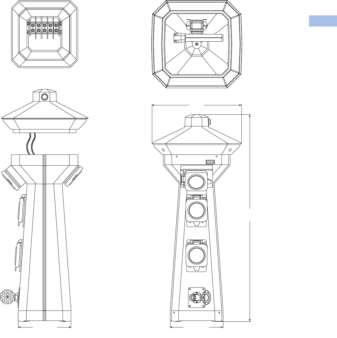
Volume 1—Residential and Light Commercial CA08100002E—February 2014 www.eaton.com V1-T6-41
6
6
6
6
6
6
6
6
6
6
6
6
6
6
6
6
6
6
6
6
6
6
6
6
6
6
6
6
6
6
6.4
Power Pedestals
RV Park Hook-Ups
Accessories
See Page V1-T6-75.
Dimensions
Approximate Dimensions in Inches (mm)
Park Light
Side View Front View
Busbar Access Top Removed
Inside Top
7.90 (200.7) 7.90 (200.7)
30.98
(786.9)
13.39
(340.2)
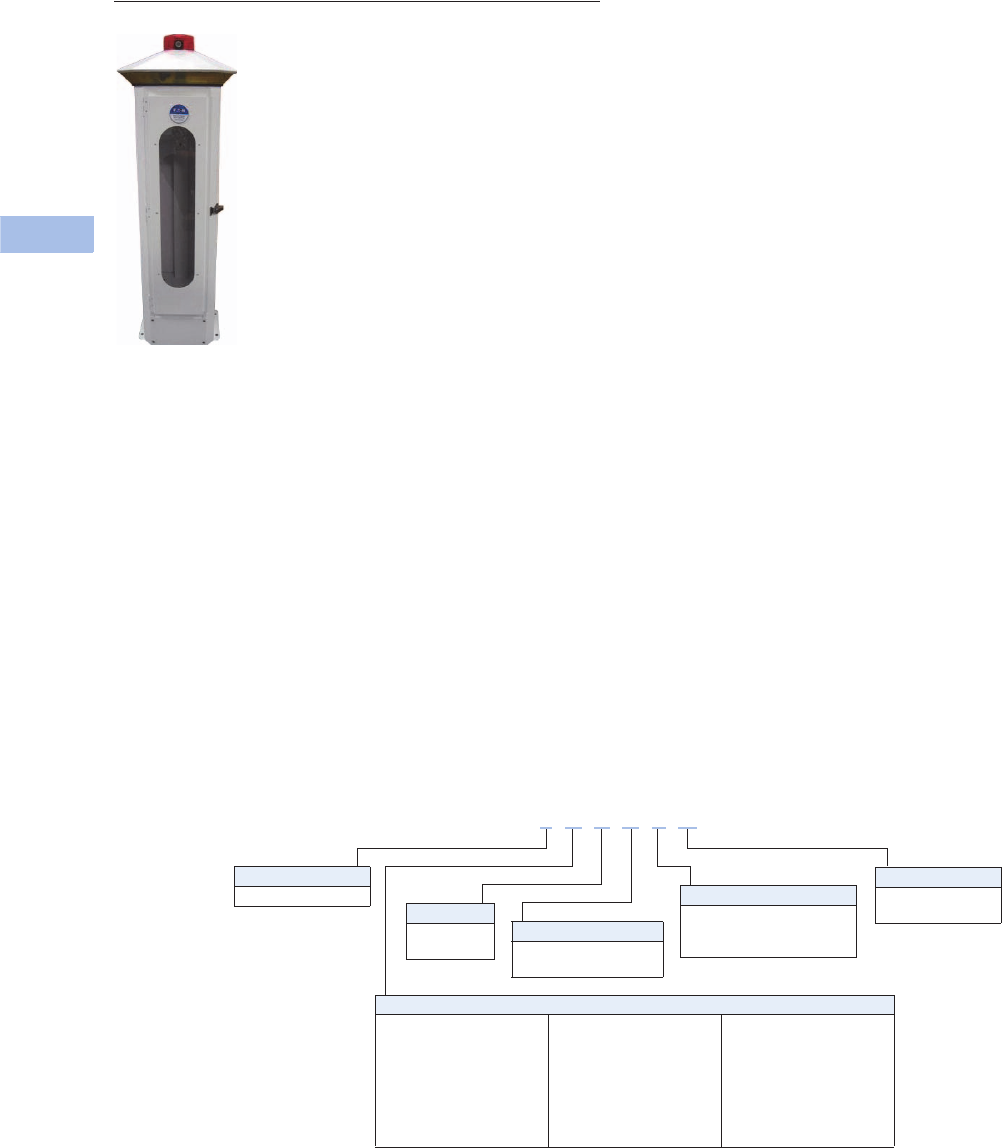
V1-T6-42 Volume 1—Residential and Light Commercial CA08100002E—February 2014 www.eaton.com
6
6
6
6
6
6
6
6
6
6
6
6
6
6
6
6
6
6
6
6
6
6
6
6
6
6
6
6
6
6
6.4
Power Pedestals
RV Park Hook-Ups
Firehouse
Contents
Description Page
Power Pedestals . . . . . . . . . . . . . . . . . . . . . . . . . . V1-T6-28
Powerhouse Power Pedestal . . . . . . . . . . . . . . . . V1-T6-30
Powerhouse—Stainless Steel (SS) Power Pedestal V1-T6-33
Newport Camp Mate Power Pedestal . . . . . . . . . V1-T6-36
Park Light Power Pedestal . . . . . . . . . . . . . . . . . . V1-T6-39
Firehouse
Accessories . . . . . . . . . . . . . . . . . . . . . . . . . . . V1-T6-43
Dimensions . . . . . . . . . . . . . . . . . . . . . . . . . . . V1-T6-43
Digital Electronic Kilowatthour Meters . . . . . . . . . V1-T6-44
Distribution Equipment—Ground Fault Monitor . . V1-T6-45
Distribution Equipment—Substations. . . . . . . . . . V1-T6-46
Distribution Equipment—Panels. . . . . . . . . . . . . . V1-T6-49
Distribution Equipment—Transformers. . . . . . . . . V1-T6-50
Firehouse
Product Description
The Firehouse is designed to
provide added fire safety to
RV parks and campgrounds.
The Firehouse provides a
convenient location and easy
access to fire extinguishers
and to an optional life ring
when installed around pools
and waterfront amenities.
In addition, the Firehouse
provides area lighting for easy
identification during an
emergency and for security
lighting around the unit. The
Firehouse can be equipped
with an alarm strobe light and
siren, which are automatically
activated when the fire
extinguisher cabinet door is
opened or the optional life
ring is removed.
Features
●Photocell controlled
13 watt fluorescent light
●Amber lens for bug
reduction
●10 lb ABC Type fire
extinguisher
●Stainless steel housing
with oven-baked enamel
finish with an engineered
resin base and top
●Limited lifetime warranty
on the housing
Available Options
●Alarm strobe light
and siren
●Optional 24-inch white or
orange life ring for poolside
or dockside installations
●20 lb ABC Type fire
extinguisher
Catalog Number Selection
Fire Extinguisher
E= Include 10 lb extinguisher
N= No extinguisher
X= Include 20 lb extinguisher
Type
F = Firehouse
Photocell
Y=Yes
N=No
Alarm/Strobe
A= Include alarm/strobe
N= No alarm/strobe
24-Inch Life Ring
R= Include life ring
N= No life ring
Lighting and Lens Color
A = 7W light Amber
B= Dual 7W light Amber
C= 9W light Amber
D= 13W light Amber
E= Dual 13W light Amber
F= No lighting Amber
G= 7W light Clear
H= Dual 7W light Clear
I= 9W light Clear
J= 13W light Clear
K= Dual 13W light Clear
L= No lighting Clear
M= 7W light Special
N= Dual 7W light Special
O= 9W light Special
P= 13W light Special
Q= Dual 13W light Special
R= No lighting Special
S= 350 MA LED Amber
T= 700 MA LED Amber
U= 350 MA LED Clear
V= 700 MA LED Clear
W= 350 MA LED Special
Y= 700 MA LED Special
F A Y A E N
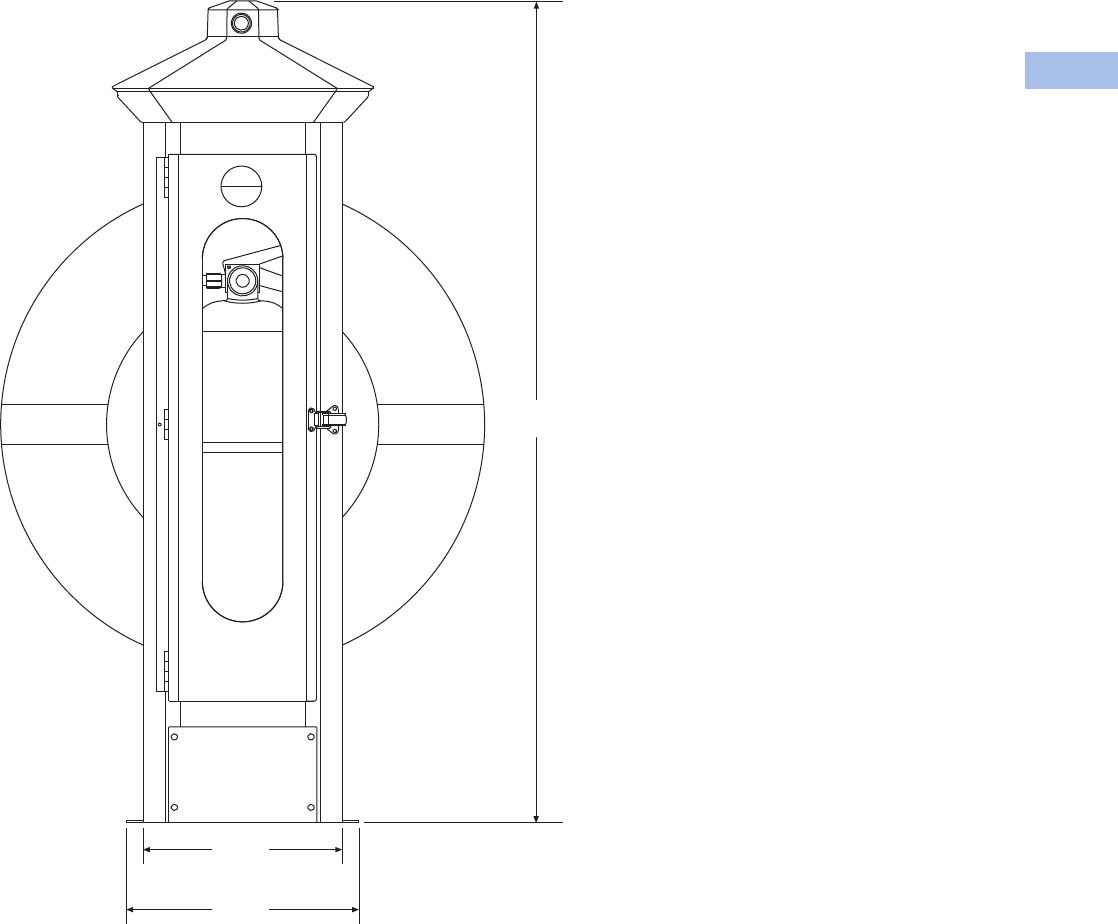
Volume 1—Residential and Light Commercial CA08100002E—February 2014 www.eaton.com V1-T6-43
6
6
6
6
6
6
6
6
6
6
6
6
6
6
6
6
6
6
6
6
6
6
6
6
6
6
6
6
6
6
6.4
Power Pedestals
RV Park Hook-Ups
Accessories
See Page V1-T6-75.
Dimensions
Approximate Dimensions in Inches (mm)
Firehouse–SS
40.74
(1034.9)
9.88
(250.8)
11.54
(293.0)
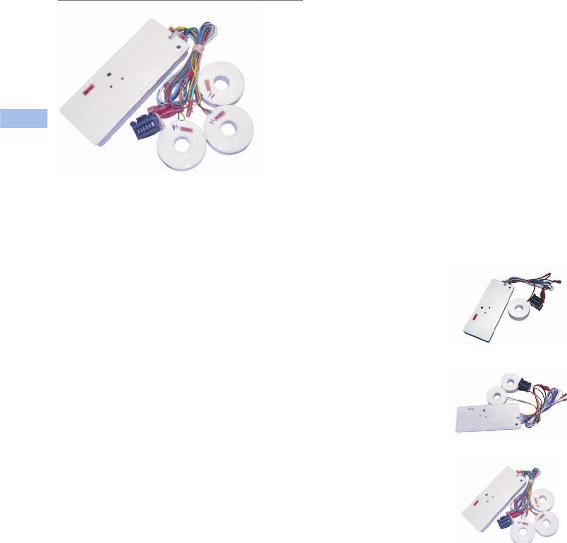
V1-T6-44 Volume 1—Residential and Light Commercial CA08100002E—February 2014 www.eaton.com
6
6
6
6
6
6
6
6
6
6
6
6
6
6
6
6
6
6
6
6
6
6
6
6
6
6
6
6
6
6
6.4
Power Pedestals
RV Park Hook-Ups
Digital Electronic Kilowatthour Meters
Contents
Description Page
Power Pedestals . . . . . . . . . . . . . . . . . . . . . . . . . . V1-T6-28
Powerhouse Power Pedestal . . . . . . . . . . . . . . . . V1-T6-30
Powerhouse—Stainless Steel (SS) Power Pedestal V1-T6-33
Newport Camp Mate Power Pedestal . . . . . . . . . V1-T6-36
Park Light Power Pedestal . . . . . . . . . . . . . . . . . . V1-T6-39
Firehouse . . . . . . . . . . . . . . . . . . . . . . . . . . . . . . . V1-T6-42
Digital Electronic Kilowatthour Meters
Distribution Equipment—Ground Fault Monitor . . V1-T6-45
Distribution Equipment—Substations. . . . . . . . . . V1-T6-46
Distribution Equipment—Panels. . . . . . . . . . . . . . V1-T6-49
Distribution Equipment—Transformers. . . . . . . . . V1-T6-50
Digital Electronic Kilowatthour Meters
Product Description
Using the latest surface
mount technology, Eaton
manufactures a digital
electronic kilowatt hour
meter that exceeds the
+/– 2% accuracy required by
ANSI (American National
Standards Institute) C-12.1
and is approved by the state
of California at +/– 1% over
the full range of 0–100A from
a 0.5 to 1 power factor and is
available for both single- and
three-phase applications.
The meter drives an electro-
mechanical counter that
requires a 12V pulse each
tenth of a kilowatthour,
providing 10 pulses per
kilowatt used. The meter
output can be hard wired or
connected to a transmitter
in the pedestal for wireless
transmission to a receiver
displaying the output on a
PC for direct billing of up to
1,000 individual customers
Features
Our meter is designed to
be user friendly in that all
connections from external
sources and the meter
output are through one
14-pin locking connector.
This feature eliminates many
common problems, such
as reverse line polarity and
improper coil polarity. Simple
LEDs, both red and green,
indicate line and load
condition and the pulsed
LED indicates the rate of
power consumption.
Wireless System
All of our meters are
“wireless capable” to allow
for wireless meter reading.
This technology enables the
marina or RV park to get
meter readings from one
central location rather than
visiting every site to read
the counters.
Meter Socket Capabilities
Meter sockets are available
on the Powerhouse and
Powerhouse–SS.
Standard:
●Four jaw
●Ring-type
●100A
Available Options
●200A (SS only)
●Lockable hasp
●Ringless (SS only)
●Five jaw
●Seven jaw (SS only)
Product Selection
One Element Meter
Two Element Meter
Three Element Meter

Volume 1—Residential and Light Commercial CA08100002E—February 2014 www.eaton.com V1-T6-45
6
6
6
6
6
6
6
6
6
6
6
6
6
6
6
6
6
6
6
6
6
6
6
6
6
6
6
6
6
6
6.4
Power Pedestals
RV Park Hook-Ups
Ground Fault Monitor
Contents
Description Page
Power Pedestals . . . . . . . . . . . . . . . . . . . . . . . . . . V1-T6-28
Powerhouse Power Pedestal. . . . . . . . . . . . . . . . . V1-T6-30
Powerhouse—Stainless Steel (SS) Power Pedestal V1-T6-33
Newport Camp Mate Power Pedestal . . . . . . . . . . V1-T6-36
Park Light Power Pedestal. . . . . . . . . . . . . . . . . . . V1-T6-39
Firehouse. . . . . . . . . . . . . . . . . . . . . . . . . . . . . . . . V1-T6-42
Digital Electronic Kilowatthour Meters . . . . . . . . . V1-T6-44
Distribution Equipment—Ground Fault Monitor
Distribution Equipment—Substations . . . . . . . . . . V1-T6-46
Distribution Equipment—Panels . . . . . . . . . . . . . . V1-T6-49
Distribution Equipment—Transformers . . . . . . . . . V1-T6-50
Distribution Equipment—Ground Fault Monitor
Product Description
New to our product offering
are ground fault monitoring
systems designed to detect
fault currents in the AC shore
power system that are too
low to trip a circuit breaker.
The Ground Fault Monitor
helps reduce the risk of injury
or property damage, which
may result from stray fault
currents. Our ground fault
monitoring system provides
information to the
maintenance staff on the
overall condition of the AC
electrical system. The ground
fault monitoring system
operates 24 hours a day and
can be monitored by non-
technical personnel.
Features
●UL listed current
transformers
●Adjustable trip level
10 mA to 10A
●Current transformers up to
8 1/4-inch diameter
●Visual and/or audible alarm
●Housing of fiberglass or
powder coated stainless
steel available
Power Guard
The ground fault monitor
detects ground fault
currents by means of current
transformers (CT), which are
placed around main or branch
circuits. If a ground fault
occurs, the CT will detect the
amount of fault current and
send a signal to the ground
fault monitoring device where
the amount of fault current
is displayed with the faulty
circuit identified. The
detected fault can either
activate an indicator alarm or
disconnect the faulted circuit.
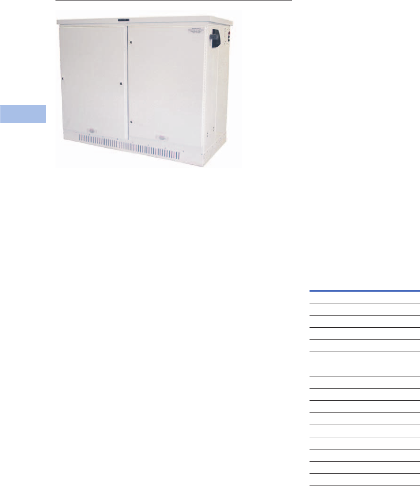
V1-T6-46 Volume 1—Residential and Light Commercial CA08100002E—February 2014 www.eaton.com
6
6
6
6
6
6
6
6
6
6
6
6
6
6
6
6
6
6
6
6
6
6
6
6
6
6
6
6
6
6
6.4
Power Pedestals
RV Park Hook-Ups
Side-by-Side Substation
Substations
Contents
Description Page
Power Pedestals . . . . . . . . . . . . . . . . . . . . . . . . . . V1-T6-28
Powerhouse Power Pedestal . . . . . . . . . . . . . . . . V1-T6-30
Powerhouse—Stainless Steel (SS) Power Pedestal V1-T6-33
Newport Camp Mate Power Pedestal . . . . . . . . . V1-T6-36
Park Light Power Pedestal . . . . . . . . . . . . . . . . . . V1-T6-39
Firehouse . . . . . . . . . . . . . . . . . . . . . . . . . . . . . . . V1-T6-42
Digital Electronic Kilowatthour Meters . . . . . . . . . V1-T6-44
Distribution Equipment—Ground Fault Monitor . . V1-T6-45
Distribution Equipment—Substations
Features, Benefits and Functions . . . . . . . . . . V1-T6-47
Available Options . . . . . . . . . . . . . . . . . . . . . . . V1-T6-48
Standards and Certifications . . . . . . . . . . . . . . V1-T6-48
Dimensions . . . . . . . . . . . . . . . . . . . . . . . . . . . V1-T6-48
Distribution Equipment—Panels. . . . . . . . . . . . . . V1-T6-49
Distribution Equipment—Transformers. . . . . . . . . V1-T6-50
Distribution Equipment—Substations
Product Description
The introduction of
substations into the marina
and recreational vehicle
market allows Eaton to be
your complete marina and
RV park electrical products
supplier. We are able to
assist in the design and
layout of your marina or RV
park electrical system from
the primary service provider
to your power pedestal. Our
substations are designed
for any coastal or inland
environment and are
constructed of powder-
coated stainless steel
NEMA 3R housing cabinets.
All substation cabinets
come with our limited lifetime
warranty. All of our
substations use Eaton’s
panels and circuit breakers,
providing our customers the
utmost in circuit protection
and quality.
Application Description
The aluminum and Galvaneal
cabinets are recommended
for inland applications.
The substations can be
configured with 50 to
330 kVA single-phase or
three-phase copper wound
transformers and up to 20
single-phase or 12 three-
phase branch breakers. An
optional three-sided double-
wall cabinet is available that
provides air flow between the
panels. All substations come
standard with temperature-
controlled cooling fans.
Product Selection Guide
Panel and Transformer
Combinations
Panel Transformer
Single-Phase
200A 50 kVA
300A 75 kVA
400A 100 kVA
600A 150 kVA
700A 167.5 kVA
800A 200 kVA
1000A 250 kVA
1200A 330 kVA
Three-Phase
100A 45 kVA
200A 75 kVA
300A 112.5 kVA
400A 150 kVA
600A 225 kVA
800A 300 kVA

Volume 1—Residential and Light Commercial CA08100002E—February 2014 www.eaton.com V1-T6-47
6
6
6
6
6
6
6
6
6
6
6
6
6
6
6
6
6
6
6
6
6
6
6
6
6
6
6
6
6
6
6.4
Power Pedestals
RV Park Hook-Ups
Features, Benefits
and Functions
●Limited lifetime warranty
on the housing
●All stainless steel
hardware
●Temperature controlled
cooling fans in the
transformer and circuit
breaker compartments
●Lockable door
Ventilation
The substation ventilation
is designed to optimize air
circulation over and around
the transformers and through
the panel compartment so
that the substation operates
at lower temperatures.
Substations come equipped
with temperature-controlled
cooling fans for exhausting
hot air from the cabinet and
solar shield.
In addition, substations are
available with a double-
walled cabinet and solar
shield, which allow for
cooling of both the exterior
surface of the cabinet and
the internal components.
Substations
Stainless steel housing
with polyester
powder coating
Limited
lifetime
warranty
on the
housing
Stainless steel hardware with
locking doors
Temperature-controlled fans
for cooling
Custom made to your specifications:
Single-phase or three-phase copper
wound transformers
50 to 330 kVA
Up to 1200A main circuit breaker with
20 single-phase or 12 three-phase
branch circuit breakers
Sun Heat
Transformers
Air
Cool Air
Double-Walled
Stainless
Double-Walled Construction

V1-T6-48 Volume 1—Residential and Light Commercial CA08100002E—February 2014 www.eaton.com
6
6
6
6
6
6
6
6
6
6
6
6
6
6
6
6
6
6
6
6
6
6
6
6
6
6
6
6
6
6
6.4
Power Pedestals
RV Park Hook-Ups
Available Options
●Powder-coated cabinets
made of stainless steel
or fiberglass
●Limited lifetime warranty
on housing. Transformer
and secondary distribution
panel in a single enclosure
have a one-year limited
warranty
●Stainless steel housing
and hardware with
locking doors
●Single-phase and three-
phase models
●Overload capacity meets
ANSI L57.96–01.250
●Optional double-walled
construction
●Temperature-controlled
fans for cooling
●Custom-made copper
wound single-phase or
three-phase transformers
from 50 to 330 kVA
●Up to 1200A main circuit
breaker with 15 single-
phase branch circuit
breakers or 10 three-phase
branch circuit breakers
●Substations can be
equipped with photocells
to turn on and off lights
●A 20A GFI can be installed
in the cabinet, as well
as a ground fault
monitoring system
Standards and Certifications
●cULus listed
Dimensions
Approximate Dimensions in
Inches (mm)
Substations
Standard Substation
Height 53.00 (1346.2)
Width 51.00 (1295.4)
Depth 33.00 (838.2)
Side-by-Side Substation
Height 53.00 (1346.2)
Width 66.00 (1676.4)
Depth 30.00 (762.0)
Double Panel Substation
Height 53.00 (1346.2)
Width 63.00 (1600.2)
Depth 33.00 (838.2)
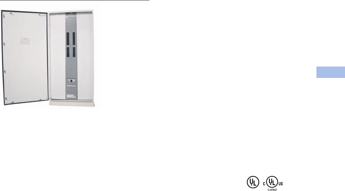
Volume 1—Residential and Light Commercial CA08100002E—February 2014 www.eaton.com V1-T6-49
6
6
6
6
6
6
6
6
6
6
6
6
6
6
6
6
6
6
6
6
6
6
6
6
6
6
6
6
6
6
6.4
Power Pedestals
RV Park Hook-Ups
Panels
Contents
Description Page
Power Pedestals . . . . . . . . . . . . . . . . . . . . . . . . . . V1-T6-28
Powerhouse Power Pedestal. . . . . . . . . . . . . . . . . V1-T6-30
Powerhouse—Stainless Steel (SS) Power Pedestal V1-T6-33
Newport Camp Mate Power Pedestal . . . . . . . . . . V1-T6-36
Park Light Power Pedestal. . . . . . . . . . . . . . . . . . . V1-T6-39
Firehouse. . . . . . . . . . . . . . . . . . . . . . . . . . . . . . . . V1-T6-42
Digital Electronic Kilowatthour Meters . . . . . . . . . V1-T6-44
Distribution Equipment—Ground Fault Monitor . . V1-T6-45
Distribution Equipment—Substations . . . . . . . . . . V1-T6-46
Distribution Equipment—Panels
Distribution Equipment—Transformers . . . . . . . . . V1-T6-50
Distribution Equipment—Panels
Product Description
We now can offer our
customers Eaton’s PRL-3A
and PRL-4 panels as stand-
alone units or in one of our
substations. All of our busses
are made of copper and are
load rated, breakers are bolt-
on type. Distribution panels
can be single-phase or three-
phase based on your system
requirements. Distribution
panels can also have a
main breaker or a main lug.
Branch circuit breakers
are provided based on
customer requirements.
Features
●All internal wiring is
fine stranded 2000V
insulated copper
●Copper busbars
●All exterior hardware is
stainless steel
Available Options
●NEMA 3R or 4X
●Powder-coated
stainless steel
●Main breaker up to
1200A
●Branch breaker 20 to
1200A
●Main lug only
●We also offer 480V
models—single-phase
and three-phase
Single-Phase
●Up to 1200A main
circuit breakers
●Up to 42 branch
circuit breakers
Three-Phase
●Up to 1200A main
circuit breakers
●Up to 42 branch
circuit breakers
Standards and Certifications
●UL listed
●cULus listed
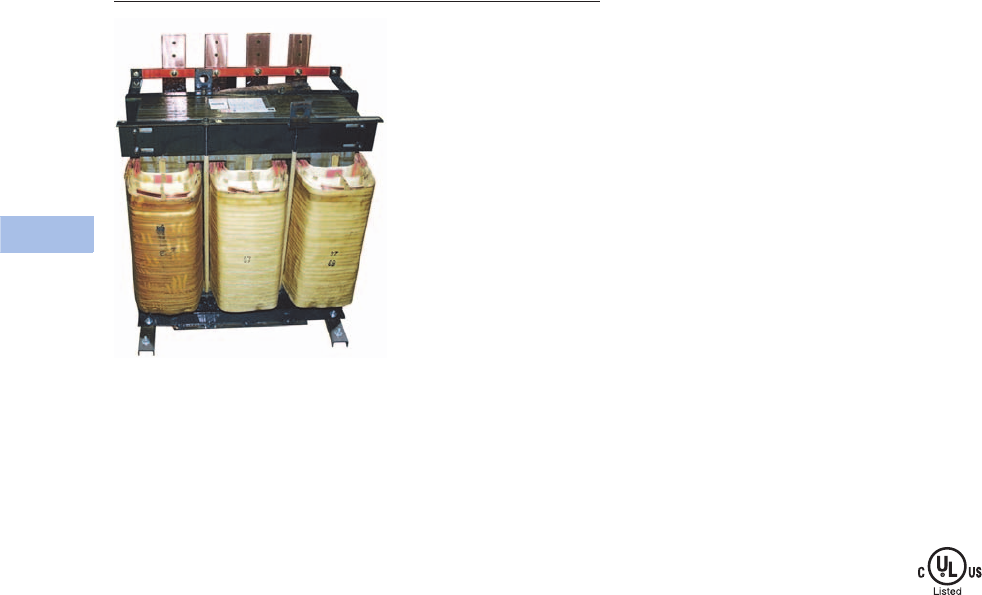
V1-T6-50 Volume 1—Residential and Light Commercial CA08100002E—February 2014 www.eaton.com
6
6
6
6
6
6
6
6
6
6
6
6
6
6
6
6
6
6
6
6
6
6
6
6
6
6
6
6
6
6
6.4
Power Pedestals
RV Park Hook-Ups
Transformers
Contents
Description Page
Power Pedestals . . . . . . . . . . . . . . . . . . . . . . . . . . V1-T6-28
Product Selection Guide . . . . . . . . . . . . . . . . . V1-T6-29
Powerhouse Power Pedestal . . . . . . . . . . . . . . . . V1-T6-30
Powerhouse—Stainless Steel (SS) Power Pedestal V1-T6-33
Newport Camp Mate Power Pedestal . . . . . . . . . V1-T6-36
Park Light Power Pedestal . . . . . . . . . . . . . . . . . . V1-T6-39
Firehouse . . . . . . . . . . . . . . . . . . . . . . . . . . . . . . . V1-T6-42
Digital Electronic Kilowatthour Meters . . . . . . . . . V1-T6-44
Distribution Equipment—Ground Fault Monitor . . V1-T6-45
Distribution Equipment—Substations. . . . . . . . . . V1-T6-46
Distribution Equipment—Panels. . . . . . . . . . . . . . V1-T6-49
Distribution Equipment—Transformers
Distribution Equipment—Transformers
Product Description
Because of the high humidity
and corrosive conditions of
coastal environments, our
transformers are wound with
Class H heavily insulated
copper bar and are double
dipped in tough insulating
varnish that protects the
copper, as well as reduces
the hum that is typical in
a transformer that is not
double dipped. For marine
applications, we provide
a third overcoat of high
temperature epoxy to protect
against the severe saltwater
environment. We can provide
this transformer in single-
phase, from 50–500 kVA,
and three-phase, from
45–300 kVA.
Features
●Copper wound transformer
coils double dipped in high
temperature baking varnish
●Copper terminations
●Marine transformers with
epoxy overcoat
●All copper-to-copper
connections
Available Options
●Single-phase: 50–500 kVA
●Three-phase: 45–300 kVA
●Epoxy overcoat for non-
marine applications
Primary Voltages
●480 wye three-phase
●480V three-phase delta
three-wire + ground
●480V single-phase
two-wire + ground
Secondary Voltages
●127/220V three-phase
wye four-wire
●120/208V three-phase
wye four-wire
●120/240V single-phase
three-wire
Marina Power Distribution
Transformer kVA Availabilities
●Single-phase: 50, 75, 100,
150, 167.5, 200, 250, 330,
500 kVA
●Three-phase: 45, 75, 112.5,
150, 225, 300 kVA
Standards and Certifications
●cULus listed

Volume 1—Residential and Light Commercial CA08100002E—February 2014 www.eaton.com V1-T6-51
6
6
6
6
6
6
6
6
6
6
6
6
6
6
6
6
6
6
6
6
6
6
6
6
6
6
6
6
6
6
6.5
Power Pedestals
Marina Power and Lighting Equipment
High-Quality, Weatherproof Electrical Equipment
Marina Power and Lighting Equipment
Contents
Description Page
Power Pedestals
Product Selection Guide. . . . . . . . . . . . . . . . . . V1-T6-52
Lighthouse . . . . . . . . . . . . . . . . . . . . . . . . . . . . . . V1-T6-54
Lighthouse–SS . . . . . . . . . . . . . . . . . . . . . . . . . . . V1-T6-58
Admiral–SS . . . . . . . . . . . . . . . . . . . . . . . . . . . . . . V1-T6-62
Newport Harbor Mate . . . . . . . . . . . . . . . . . . . . . . V1-T6-65
Hatteras Light . . . . . . . . . . . . . . . . . . . . . . . . . . . . V1-T6-69
Firehouse . . . . . . . . . . . . . . . . . . . . . . . . . . . . . . . V1-T6-73
Smart Start . . . . . . . . . . . . . . . . . . . . . . . . . . . . . . V1-T6-79
Mariner . . . . . . . . . . . . . . . . . . . . . . . . . . . . . . . . . V1-T6-80
Digital Electronic Kilowatthour Meters . . . . . . . . . V1-T6-81
Distribution Equipment—Ground Fault Monitor . . V1-T6-82
Distribution Equipment—Mega Yacht Powerpoint V1-T6-83
Distribution Equipment—Substations . . . . . . . . . . V1-T6-86
Distribution Equipment—Panels . . . . . . . . . . . . . . V1-T6-89
Distribution Equipment—Transformers . . . . . . . . . V1-T6-90
Learn
Online
Power Pedestals
Product Overview
Known as a leader in
electrical control, power
distribution, and industrial
automation products and
services, Eaton is a quality
driven company that
constantly looks for ways to
provide enhanced product
and service solutions for their
customers. Eaton will be able
to provide Marina developers
a complete electrical solution.
For more information on
the other products available
from Eaton, visit us online
at www.eaton.com or
www.marinapower.com.
What Eaton has to Offer
●Eaton has more marina
power outlets in service
than all other suppliers
combined
●We offer complementary
comprehensive in-house
electrical designs for
your complete marina
development using all high
quality Eaton products
●We can provide your
marina development with
complete remote wireless
digital electronic meter
reading
●Not only can Eaton provide
your marina with the
highest quality power
pedestals and marine
distribution equipment, we
can also supply your entire
electrical needs for your
surrounding development
and beyond from safety
switches to loadcenters
and much more

V1-T6-52 Volume 1—Residential and Light Commercial CA08100002E—February 2014 www.eaton.com
6
6
6
6
6
6
6
6
6
6
6
6
6
6
6
6
6
6
6
6
6
6
6
6
6
6
6
6
6
6
6.5
Power Pedestals
Marina Power and Lighting Equipment
Product Selection Guide
Power Pedestal Quick Guide
Lighthouse Lighthouse–SS Hatteras Light
Newport
Harbor Mate Admiral–SS Firehouse Mariner Lookout Power Point
Main housing Engineered resin Stainless steel Engineered resin Engineered resin Stainless steel Stainless steel Engineered resin Stainless steel Stainless steel
Top Engineered resin Engineered resin Engineered resin Engineered resin Stainless steel Engineered resin Engineered resin Stainless steel Stainless steel
Optional stand — — — Stainless steel — — PVC — —
External hardware Stainless steel Stainless steel Stainless steel Stainless steel Stainless steel Stainless steel Stainless steel Stainless steel Stainless steel
Standard lightwattage(s) 13W 13W 13W 7W 13W 13W 5W, 7W & 13W — 13W
LED lighting option Yes Yes Yes No Yes Yes No No Yes
Photocell Yes Yes Yes Yes Yes Yes No No Yes
Lockable doors Yes Yes Yes Yes Yes — — — Yes
Hose hangers Yes Yes No No Yes No No No No
Electric meters Yes—up to 4 Yes—up to 4 Yes—up to 2 Yes—up to 2 Yes—up to 4 No No No Yes—up to 6
Remote meter reading Yes Yes Yes Yes Yes No No No Yes
Water Two 3/4” Two 3/4” Two 1/2” Two 3/4” Two 3/4” None None None One 3/4” or more
Water meters Yes Yes No Yes Yes No No No Yes
Telephone Yes Yes Yes Yes Yes No No No Yes
Cable TV Yes Yes Yes Yes Yes No No No Yes
Internet Yes Yes Yes Yes Yes No No No Yes
Fire extinguisher No No No No No Yes—up to 20 lbs No No No
Life ring No No No No No Yes—24” No No No
Alarm and strobe light No No No No No Yes No No No
20A 110V GFI Yes Yes Yes Yes Yes No No No Yes
30A 125V twist—lock Yes Yes Yes Yes Yes No No No Yes
50A 125/250V twist—lock Yes Yes Yes Yes Yes No No No Yes
100A 120/240V pin and sleeve Yes Yes No No Yes No No No Yes
100A 120/208V pin and sleeve Yes Yes No No Yes No No No Yes
100A 277/480V pin and sleeve Yes Yes No No Yes No No No Yes
100A 480V pin and sleeve Yes Yes No No Yes No No No Yes
200A 480V pin and sleeve No No No No Yes No No No Yes
Hardwire compatible No No No No No No No No Yes
TVSS compatible Yes Yes No No Yes No No No Yes
Card swipe compatible Yes Yes No Yes Yes No No No Yes
Security camera compatible No No No No No No No Yes No
Busbar rating Up to 500A Up to 500A Up to 140A Up to 140A Up to 500A — — — Up to 800A
Maximum wire size—single feed 350 kcmil 350 kcmil #2/0 #2/0 350 kcmil — — — (3) 500 kcmil
Maximum wire size—loop feed #4/0 #4/0 #1 #1 350 kcmil — — — (3) 500 kcmil
Height 44” 40” 30” 36” 48” 43.5” 24” to 72” 72” to 96” 50”
Width 13.75” 9.875” 7.5” 10.5” 14” 9.875” 7” 9” 50”
Depth 13.75” 9.875” 7.5” 14.5” 14” 9.875” 7” 9” 36”
Warranty
Housing Limited lifetime Limited lifetime Limited lifetime Limited lifetime Limited lifetime Limited lifetime Limited lifetime Limited lifetime Limited lifetime
Receptacles and breakers 2 years 2 years 2 years 2 years 2 years — — — 2 years
Lighting assembly 1 year 1 year 1 year 1 year 1 year 1 year 1 year — 1 year

Volume 1—Residential and Light Commercial CA08100002E—February 2014 www.eaton.com V1-T6-53
6
6
6
6
6
6
6
6
6
6
6
6
6
6
6
6
6
6
6
6
6
6
6
6
6
6
6
6
6
6
6.5
Power Pedestals
Marina Power and Lighting Equipment
Receptacles Receptacle Configuration Availability
Note
1Configuration available with no additional GFI receptacles.
Side One Side Two
None None None None
30A None None None
30A 30A None None
30A None 30A None
30A 30A 30A 30A
30A 50A None None
30A None 50A None
30A 50A 30A 50A
50A None None None
50A 50A None None
50A None 50A None
50A 50A 50A 50A
100A 120/240V None None None
100A 120/240V None 50A-50A None
100A 120/240V None 100A 120/240V None
100A 120/240V 50A-50A 100A 120/240V 50A-50A
100A 120/208V None None None
100A 120/208V None 100A 120/240V None
100A 120/240V 100A 120/240V 100A 120/240V 100A 120/240V
100A 120/208V 100A 120/208V 100A 120/208V 100A 120/208V
100A 120/240V 100A 120/240V 100A 120/208V 100A 120/208V
Lighthouse Lighthouse–SS Admiral–SS Hatteras Light
Newport
Harbor Mate
Receptacle Available with GFI Receptacles
Yes Yes Yes Yes Yes
Yes Yes Yes Yes Yes
Yes Yes Yes No Yes
Yes Yes Yes Yes No
Yes Yes Yes No No
Yes Yes Yes No Yes
Yes Yes Yes Yes 1No
Yes Yes Yes No No
Yes Yes Yes Yes Yes
Yes Yes Yes No Yes
Yes Yes Yes No No
Yes Yes Yes No No
Yes Yes Yes No No
Yes Yes Yes No No
Yes Yes Yes No No
No No Yes No No
Yes Yes Yes No No
Yes Yes Yes No No
No No Yes No No
No No Yes No No
No No Yes No No
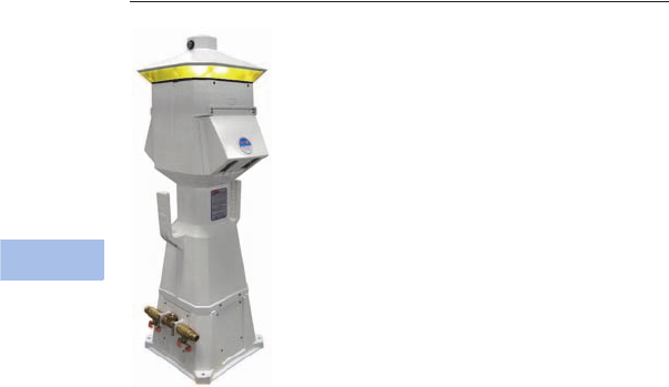
V1-T6-54 Volume 1—Residential and Light Commercial CA08100002E—February 2014 www.eaton.com
6
6
6
6
6
6
6
6
6
6
6
6
6
6
6
6
6
6
6
6
6
6
6
6
6
6
6
6
6
6
6.5
Power Pedestals
Marina Power and Lighting Equipment
Lighthouse
Contents
Description Page
Power Pedestals. . . . . . . . . . . . . . . . . . . . . . . . . . . V1-T6-51
Lighthouse
Available Options. . . . . . . . . . . . . . . . . . . . . . . . V1-T6-55
Catalog Number Selection . . . . . . . . . . . . . . . . V1-T6-56
Accessories. . . . . . . . . . . . . . . . . . . . . . . . . . . . V1-T6-57
Dimensions . . . . . . . . . . . . . . . . . . . . . . . . . . . . V1-T6-57
Lighthouse–SS . . . . . . . . . . . . . . . . . . . . . . . . . . . . V1-T6-58
Admiral–SS. . . . . . . . . . . . . . . . . . . . . . . . . . . . . . . V1-T6-62
Newport Harbor Mate . . . . . . . . . . . . . . . . . . . . . . V1-T6-65
Hatteras Light. . . . . . . . . . . . . . . . . . . . . . . . . . . . . V1-T6-69
Firehouse . . . . . . . . . . . . . . . . . . . . . . . . . . . . . . . . V1-T6-73
Smart Start . . . . . . . . . . . . . . . . . . . . . . . . . . . . . . . V1-T6-79
Mariner. . . . . . . . . . . . . . . . . . . . . . . . . . . . . . . . . . V1-T6-80
Digital Electronic Kilowatthour Meters . . . . . . . . . . V1-T6-81
Distribution Equipment—Ground Fault Monitor. . . V1-T6-82
Distribution Equipment—Mega Yacht Powerpoint . V1-T6-83
Distribution Equipment—Substations . . . . . . . . . . V1-T6-86
Distribution Equipment—Panels . . . . . . . . . . . . . . V1-T6-89
Distribution Equipment—Transformers . . . . . . . . . V1-T6-90
Lighthouse
Product Description
One of our most popular
units, the all-purpose
Lighthouse® pedestal has a
wide range of features. With
units in service around the
world, this stylish power
pedestal is recognized for its
practicality and exceptional
durability.
Engineered to withstand
the most severe weather
conditions, Lighthouse
power pedestals can be
found in marinas from
Alaska to the tropics.
Note: Custom paint color.
Note: Wireless remote reading
of electronic kilowatt meters.
Note: Clear lens.
Features, Benefits
and Functions
●Photocell controlled
13 watt fluorescent light
(clear lens or amber lens
for bug reduction)
●Lockable weatherproof
doors that protect breakers
and receptacles while in
use (a requirement of NFPA
303 and NEC Article 555)
●Hose and cable brackets
●Heavy resin housing with
a two-part polyurethane
coating for a UV-resistant,
long-lasting finish
●Copper busbar with ratings
from 250 to 500A
●New “hingeless” base
providing easy access for
both installation and
maintenance
●Backlit faceplate for easy
receptacle plug-in at night
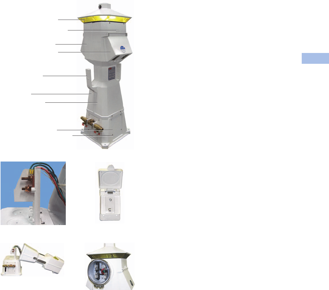
Volume 1—Residential and Light Commercial CA08100002E—February 2014 www.eaton.com V1-T6-55
6
6
6
6
6
6
6
6
6
6
6
6
6
6
6
6
6
6
6
6
6
6
6
6
6
6
6
6
6
6
6.5
Power Pedestals
Marina Power and Lighting Equipment
Lighthouse
Copper Busbar with Ratings
from 250 to 500A
New Hingeless Base
Cable and Internet
Connections
Optional Meter Socket
360° controlled 13 watt fluorescent light
with amber lens for bug reduction
Digital electronic metering for each side
Lockable weatherproof doors that protect
breakers and receptacles
Receptacle configuration available
30A, 50A, 30A/30A, 30A/50A,
50A/50A, 100A, Empty
Note: Custom configurations also available
Hose and cable brackets
1/4-inch Resin housing with a two-part
polyurethane coating for a UV resistant,
long-lasting finish
20A/125V GFI receptacle
Phone and cable TV connections
High-speed Internet connections (RJ45) for
each side
Available Options
●Digital electronic metering
(one, two or three element
meters available)
●Built-in meter socket
●20A/125V GFI receptacle
(max. of two GFI
receptacles per pedestal)
Note: 20A GFI receptacles are
not to be used for shore power.
●High-speed Internet
connections
●Wireless remote metering
for electric and water
●Transient voltage surge
suppressor (TVSS) to
protect from voltage
surges, spikes or lightning
on the AC power line
(extends warranty on
internal parts to three
years)
●Stainless steel door hinge
on receptacle main doors
●Single or dual steel 1/4-turn
ball valves with 3/4-inches
●Hose bibs and stainless
steel handles
●Single or dual phone and/or
cable TV connections
●Base cap
●Base extension
●LED lighting
V1-T6-56 Volume 1—Residential and Light Commercial CA08100002E—February 2014 www.eaton.com
6
6
6
6
6
6
6
6
6
6
6
6
6
6
6
6
6
6
6
6
6
6
6
6
6
6
6
6
6
6
6.5
Power Pedestals
Marina Power and Lighting Equipment
Catalog Number Selection
Receptacle: R1S1 = Receptacle 1, Side 1
R2S1 = Receptacle 2, Side 1
R1S2 = Receptacle 1, Side 2
R2S2 = Receptacle 2, Side 2
Notes
1Number represents the quantity of 1/4-turn ball valves with 3/4-inch hose bibs.
2Quantity of 20A GFI duplex receptacles.
Extra Unmetered GFI
Receptacles 2
0=None
1=1
2=2
Phone Cable TV and Internet Options
Phone
Jack
Cable TV
Jack
Internet
Option
A=1 0 0
B=1 0 1
C=1 0 2
D=1 1 0
E=1 1 1
F=1 1 2
G=1 2 0
H=1 2 1
I=1 2 2
J=2 0 0
K=2 0 1
L=2 0 2
M=2 1 0
N=2 1 1
O=2 1 2
P=2 2 0
Q=2 2 1
R=2 2 2
S=0 2 2
T=0 0 1
U=0 0 2
V=0 1 0
W=0 1 1
X=0 1 2
Y=0 2 0
Z=0 2 1
0=0 0 0
Water Option 1
0=0
1=1
2=2
3= Single water meter
4= Dual water meter
5= Single meter, 2V
6= 1 frost free
7= 2 frost free
Bus
S= Single-phase 3/8-inch copper busbar
F= Three-phase 3/8-inch copper busbar
C= Single-phase 3/8-inch Canadian busbar
T= Three-phase 3/8-inch Canadian busbar
M= Single-phase 300 kcmil mechanical lug bus
Z= Three-phase 300 kcmil mechanical lug bus
L= Single-phase 350 kcmil mechanical lug bus
P= Three-phase 350 kcmil mechanical lug bus
N= Single-phase 1/4-inch copper busbar
Q= Single-phase 1/4-inch split mechanical busbar
Sides and Receptacles
R1S1
R2S1
R3S1
R4S1
R1S2
R2S2
R3S2
R4S2
0
1
2
3
4
5
6
7
8
0
1
2
3
4
5
6
7
8
0
1
2
3
4
5
6
7
8
0
1
2
3
4
5
6
7
8
0
1
2
3
4
5
6
7
8
0
1
2
3
4
5
6
7
8
0
1
2
3
4
5
6
7
8
0
1
2
3
4
5
6
7
8
0=None
1= 20A GFI duplex
2= 30A, 125V
3= 50A, 125V
4= 50A, 125/250V
5= 100A, 208V
6= 100A, 250V
7= 100A, 277/480V
8= 100A, 480V
Type
L= Lighthouse
S=LHSS
Metering Type
U= Unmetered
D= Digital electronic meters
(side one)
T= Digital electronic meters
(side two)
B= Digital electronic meters
(both sides)
R= Receptacles metered
individually
M= One meter socket
(100A)
N= Two meter socket
(100A each)
V= 200A meter socket
Lighting and Lens Color
A = 7W light Amber
B= Dual 7W light Amber
C= 9W light Amber
D= 13W light Amber
E= Dual 13W light Amber
F= No lighting Amber
G= 7W light Clear
H= Dual 7W light Clear
I= 9W light Clear
J= 13W light Clear
K= Dual 13W light Clear
L= No lighting Clear
M= 7W light Special
N= Dual 7W light Special
O= 9W light Special
P= 13W light Special
Q= Dual 13W light Special
R= No lighting Special
S= 350 MA LED Amber
T= 700 MA LED Amber
U= 350 MA LED Clear
V= 700 MA LED Clear
W= 350 MA LED Special
Y= 700 MA LED Special
L D U 4 7 0 0 0 0 0 0 1 2 K M
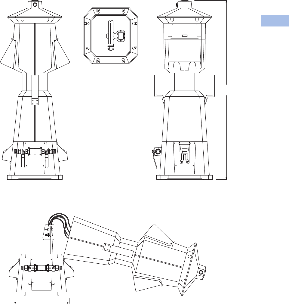
Volume 1—Residential and Light Commercial CA08100002E—February 2014 www.eaton.com V1-T6-57
6
6
6
6
6
6
6
6
6
6
6
6
6
6
6
6
6
6
6
6
6
6
6
6
6
6
6
6
6
6
6.5
Power Pedestals
Marina Power and Lighting Equipment
Accessories
See Page V1-T6-75.
Dimensions
Approximate Dimensions in Inches (mm)
Lighthouse
Side View
To p
Front View
Broken View
13.75
(249.3)
44.00
(1117.6)

V1-T6-58 Volume 1—Residential and Light Commercial CA08100002E—February 2014 www.eaton.com
6
6
6
6
6
6
6
6
6
6
6
6
6
6
6
6
6
6
6
6
6
6
6
6
6
6
6
6
6
6
6.5
Power Pedestals
Marina Power and Lighting Equipment
Lighthouse–SS
Contents
Description Page
Power Pedestals. . . . . . . . . . . . . . . . . . . . . . . . . . . V1-T6-51
Lighthouse . . . . . . . . . . . . . . . . . . . . . . . . . . . . . . . V1-T6-54
Lighthouse–SS
Available Options. . . . . . . . . . . . . . . . . . . . . . . . V1-T6-59
Catalog Number Selection . . . . . . . . . . . . . . . . V1-T6-60
Accessories. . . . . . . . . . . . . . . . . . . . . . . . . . . . V1-T6-61
Dimensions . . . . . . . . . . . . . . . . . . . . . . . . . . . . V1-T6-61
Admiral–SS. . . . . . . . . . . . . . . . . . . . . . . . . . . . . . . V1-T6-62
Newport Harbor Mate . . . . . . . . . . . . . . . . . . . . . . V1-T6-65
Hatteras Light. . . . . . . . . . . . . . . . . . . . . . . . . . . . . V1-T6-69
Firehouse . . . . . . . . . . . . . . . . . . . . . . . . . . . . . . . . V1-T6-73
Smart Start . . . . . . . . . . . . . . . . . . . . . . . . . . . . . . . V1-T6-79
Mariner. . . . . . . . . . . . . . . . . . . . . . . . . . . . . . . . . . V1-T6-80
Digital Electronic Kilowatthour Meters . . . . . . . . . . V1-T6-81
Distribution Equipment—Ground Fault Monitor. . . V1-T6-82
Distribution Equipment—Mega Yacht Powerpoint . V1-T6-83
Distribution Equipment—Substations . . . . . . . . . . V1-T6-86
Distribution Equipment—Panels . . . . . . . . . . . . . . V1-T6-89
Distribution Equipment—Transformers . . . . . . . . . V1-T6-90
Lighthouse–SS
Product Description
The Lighthouse–SS offers
the same standard features
and available options as the
standard Lighthouse. But,
like all of the stainless steel
products manufactured here,
the Lighthouse–SS is made
with high-quality 316L
stainless steel for superior
quality and performance.
Note: 20/125A GFI receptacle.
Note: Wireless remote reading
of electronic kilowatt meters.
Note: Clear lens.
Note: Meter socket for each
side powered (to accept glass
style meter).
Note: Receptacle configurations
available:
30A
30A/30A
30A/50A
50A/50A
100A (single-phase) 120/240V
100A (three-phase) 120/208V
200A (three-phase) 480V
Features, Benefits
and Functions
●Photocell controlled
13 watt fluorescent light
(clear lens or amber lens
for bug reduction)
●Available with lockable
weatherproof doors
●Hose and cable brackets
●Long-lasting maintenance-
free 316L stainless steel
housing with limited
lifetime warranty
●Copper busbar with ratings
from 250 to 500A
●Large removable
access panel for easy
maintenance and
installation
●Backlit faceplate for easy
receptacle plug-in at night
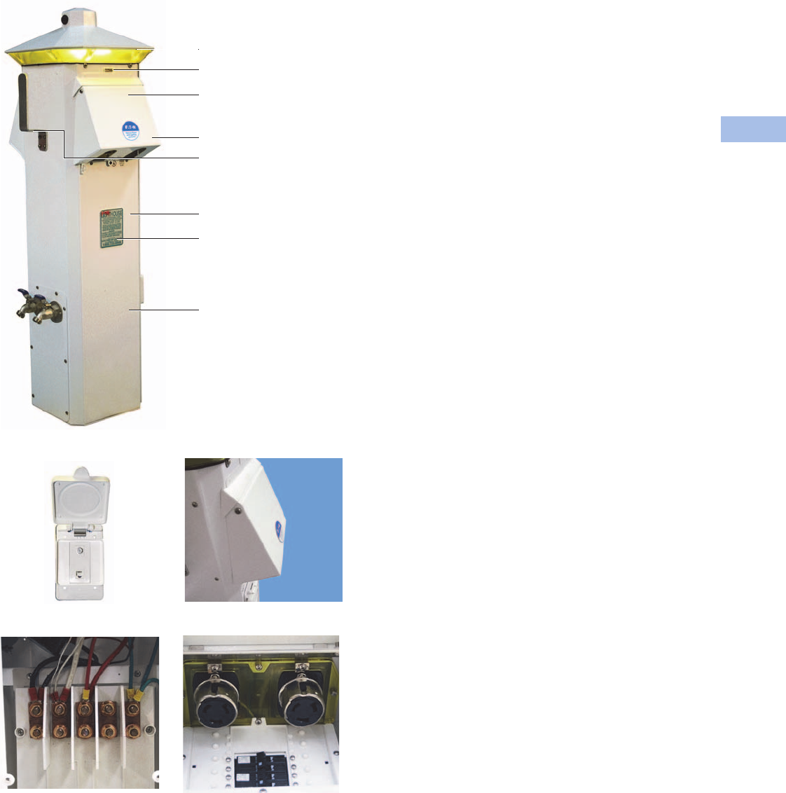
Volume 1—Residential and Light Commercial CA08100002E—February 2014 www.eaton.com V1-T6-59
6
6
6
6
6
6
6
6
6
6
6
6
6
6
6
6
6
6
6
6
6
6
6
6
6
6
6
6
6
6
6.5
Power Pedestals
Marina Power and Lighting Equipment
Lighthouse–SS
Phone and Cable TV Connections
Copper Busbar with Ratings
from 250 to 500A
New Door
Backlit Faceplate to Aid
in Hooking Up at Night
360° controlled 13 watt
fluorescent light with amber
lens for bug reduction
Digital electronic metering
for each side
Powder-coated stainless steel
weatherproof doors that protect
receptacles and breakers
Lockable doors
Long-lasting maintenance-free
powder-coated stainless steel
housing with limited lifetime
warranty
High-speed Internet connection
(RJ-45)
for each side
Large removable access panel
for easy maintenance an d
installation
Hose and cable bracket
Available Options
●Digital electronic metering
(one, two or three element
meters available)
●20A/125V GFI receptacle
(max. of two GFI
receptacles per pedestal)
Note: 20A GFI receptacles are
not to be used for shore power.
●High-speed Internet
connection
●Wireless remote metering
available for water and
electricity
●Transient voltage surge
suppressor (TVSS) to
protect from voltage
surges, spikes or lightning
on the AC power line
(extends warranty on
internal parts to three
years)
●Single or dual phone and/or
cable TV connections
●Single or dual 3/4-inch hose
bibs with stainless steel
●Handles LED lighting
V1-T6-60 Volume 1—Residential and Light Commercial CA08100002E—February 2014 www.eaton.com
6
6
6
6
6
6
6
6
6
6
6
6
6
6
6
6
6
6
6
6
6
6
6
6
6
6
6
6
6
6
6.5
Power Pedestals
Marina Power and Lighting Equipment
Catalog Number Selection
Receptacle: R1S1 = Receptacle 1, Side 1
R2S1 = Receptacle 2, Side 1
R1S2 = Receptacle 1, Side 2
R2S2 = Receptacle 2, Side 2
Notes
1Number represents the quantity of 1/4-turn ball valves with 3/4-inch hose bibs.
2Quantity of 20A GFI duplex receptacles.
Water Option 1
0=0
1=1
2=2
3= Single water meter
4= Dual water meter
5= Single meter, 2V
6= 1 frost free
7= 2 frost free
Bus
S= Single-phase 3/8-inch copper busbar
F= Three-phase 3/8-inch copper busbar
C= Single-phase 3/8-inch Canadian busbar
T= Three-phase 3/8-inch Canadian busbar
M= Single-phase 300 kcmil mechanical lug bus
Z= Three-phase 300 kcmil mechanical lug bus
L= Single-phase 350 kcmil mechanical lug bus
P= Three-phase 350 kcmil mechanical lug bus
N= Single-phase 1/4-inch copper busbar
Q= Single-phase 1/4-inch split mechanical busbar
Metering Type
U= Unmetered
D= Digital electronic meters
(side one)
T= Digital electronic meters
(side two)
B= Digital electronic meters
(both sides)
R= Receptacles metered
individually
M= One meter socket
(100A)
N= Two meter socket
(100A each)
V= 200A meter socket
Lighting and Lens Color
A = 7W light Amber
B= Dual 7W light Amber
C= 9W light Amber
D= 13W light Amber
E= Dual 13W light Amber
F= No lighting Amber
G= 7W light Clear
H= Dual 7W light Clear
I= 9W light Clear
J= 13W light Clear
K= Dual 13W light Clear
L= No lighting Clear
M= 7W light Special
N= Dual 7W light Special
O= 9W light Special
P= 13W light Special
Q= Dual 13W light Special
R= No lighting Special
S= 350 MA LED Amber
T= 700 MA LED Amber
U= 350 MA LED Clear
V= 700 MA LED Clear
W= 350 MA LED Special
Y= 700 MA LED Special
Type
L= Lighthouse
S=LHSS
Extra Unmetered GFI
Receptacles 2
0=None
1=1
2=2
Phone Cable TV and Internet Options
Phone
Jack
Cable TV
Jack
Internet
Option
A=1 0 0
B=1 0 1
C=1 0 2
D=1 1 0
E=1 1 1
F=1 1 2
G=1 2 0
H=1 2 1
I=1 2 2
J=2 0 0
K=2 0 1
L=2 0 2
M=2 1 0
N=2 1 1
O=2 1 2
P=2 2 0
Q=2 2 1
R=2 2 2
S=0 2 2
T=0 0 1
U=0 0 2
V=0 1 0
W=0 1 1
X=0 1 2
Y=0 2 0
Z=0 2 1
0=0 0 0
Sides and Receptacles
R1S1
R2S1
R3S1
R4S1
R1S2
R2S2
R3S2
R4S2
0
1
2
3
4
5
6
7
8
0
1
2
3
4
5
6
7
8
0
1
2
3
4
5
6
7
8
0
1
2
3
4
5
6
7
8
0
1
2
3
4
5
6
7
8
0
1
2
3
4
5
6
7
8
0
1
2
3
4
5
6
7
8
0
1
2
3
4
5
6
7
8
0=None
1= 20A GFI duplex
2= 30A, 125V
3= 50A, 125V
4= 50A, 125/250V
5= 100A, 208V
6= 100A, 250V
7= 100A, 277/480V
8= 100A, 480V
L D U 4 7 0 0 0 0 0 0 1 2 K M
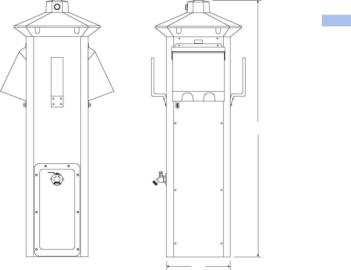
Volume 1—Residential and Light Commercial CA08100002E—February 2014 www.eaton.com V1-T6-61
6
6
6
6
6
6
6
6
6
6
6
6
6
6
6
6
6
6
6
6
6
6
6
6
6
6
6
6
6
6
6.5
Power Pedestals
Marina Power and Lighting Equipment
Accessories
See Page V1-T6-75.
Dimensions
Approximate Dimensions in Inches (mm)
Lighthouse–SS
9.88
(251.0)
40.00
(1016.0)
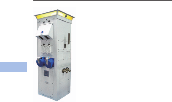
V1-T6-62 Volume 1—Residential and Light Commercial CA08100002E—February 2014 www.eaton.com
6
6
6
6
6
6
6
6
6
6
6
6
6
6
6
6
6
6
6
6
6
6
6
6
6
6
6
6
6
6
6.5
Power Pedestals
Marina Power and Lighting Equipment
Admiral–SS
Contents
Description Page
Power Pedestals. . . . . . . . . . . . . . . . . . . . . . . . . . . V1-T6-51
Lighthouse . . . . . . . . . . . . . . . . . . . . . . . . . . . . . . . V1-T6-54
Lighthouse–SS . . . . . . . . . . . . . . . . . . . . . . . . . . . . V1-T6-58
Admiral–SS
Catalog Number Selection . . . . . . . . . . . . . . . . V1-T6-63
Accessories. . . . . . . . . . . . . . . . . . . . . . . . . . . . V1-T6-64
Dimensions . . . . . . . . . . . . . . . . . . . . . . . . . . . . V1-T6-64
Newport Harbor Mate . . . . . . . . . . . . . . . . . . . . . . V1-T6-65
Hatteras Light. . . . . . . . . . . . . . . . . . . . . . . . . . . . . V1-T6-69
Firehouse . . . . . . . . . . . . . . . . . . . . . . . . . . . . . . . . V1-T6-73
Smart Start . . . . . . . . . . . . . . . . . . . . . . . . . . . . . . . V1-T6-79
Mariner. . . . . . . . . . . . . . . . . . . . . . . . . . . . . . . . . . V1-T6-80
Digital Electronic Kilowatthour Meters . . . . . . . . . . V1-T6-81
Distribution Equipment—Ground Fault Monitor. . . V1-T6-82
Distribution Equipment—Mega Yacht Powerpoint . V1-T6-83
Distribution Equipment—Substations . . . . . . . . . . V1-T6-86
Distribution Equipment—Panels . . . . . . . . . . . . . . V1-T6-89
Distribution Equipment—Transformers . . . . . . . . . V1-T6-90
Admiral–SS
Product Description
Truly the flagship of our
unitized pedestal line, the
Admiral–SS possesses
amperage capabilities up to
500A and voltages of 480/277
three-phase, 120/240 single-
phase and combinations of
these receptacles all in one
unit to serve nearly any size
Mega Yacht.
Features
●Heavy 316L stainless
steel housing that is
powder coated with a
polyester resin
●Photocell controlled
13 watt fluorescent light
with clear lens that
provides 360 degrees
of lighting
Available Options
●Dual phone and/or cable TV
connections
●Four 100A receptacles
of any two voltage
combinations such as
277/480 three-phase,
120/208 three-phase or
120/240 single-phase
●200A/480V receptacles
●when the 100A 120/240V
receptacles are used, two
50A 120/240V receptacles
can also be provided for a
total of 500A
●20A/125V GFI receptacle
(max. of two GFI
receptacles per pedestal)
Note:
20A GFI receptacles are not
to be used for shore power.
●Single or dual Cat5
high-speed Internet
connections
●Single or dual water
1/4-turn ball valves with
3/4-inch hose bibs and
stainless steel handles
●Digital metering available
●Wireless remote metering
available for water and
electricity
●LED lighting
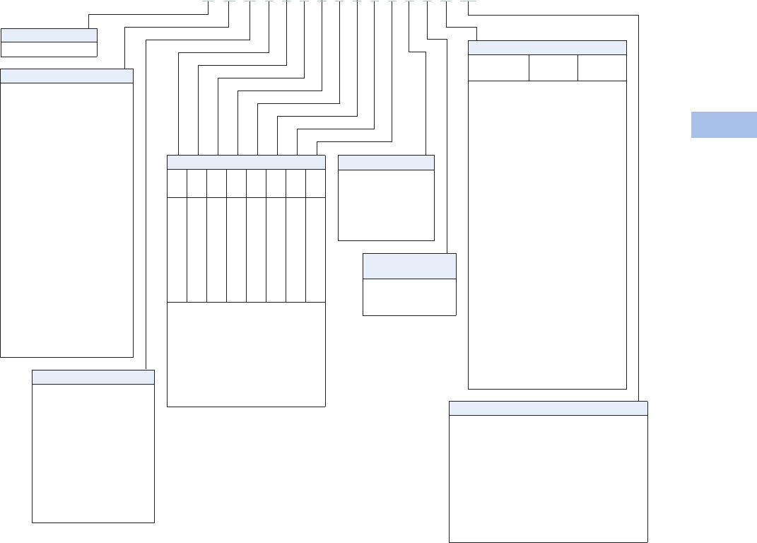
Volume 1—Residential and Light Commercial CA08100002E—February 2014 www.eaton.com V1-T6-63
6
6
6
6
6
6
6
6
6
6
6
6
6
6
6
6
6
6
6
6
6
6
6
6
6
6
6
6
6
6
6.5
Power Pedestals
Marina Power and Lighting Equipment
Catalog Number Selection
Receptacles: R1S1 = Receptacle 1, Side 1
R2S1 = Receptacle 2, Side 1
R3S1 = Receptacle 3, Side 1
R4S1 = Receptacle 3, Side 1
R1S2 = Receptacle 1, Side 2
R2S2 = Receptacle 2, Side 2
R3S2 = Receptacle 3, Side 2
R4S2 = Receptacle 3, Side 2
Notes
1Number represents the quantity of 1/4-turn ball valves with 3/4-inch hose bibs.
2Number represents the quantity of RJ-45 high-speed Internet jacks.
Internet option also available. Contact factory for details.
Extra Unmetered GFI
Receptacles
0=None
1=1
2=2
Phone Cable TV and Internet Options
Phone
Jack
Cable TV
Jack
Internet
Option 2
A=1 0 0
B=1 0 1
C=1 0 2
D=1 1 0
E=1 1 1
F=1 1 2
G=1 2 0
H=1 2 1
I=1 2 2
J=2 0 0
K=2 0 1
L=2 0 2
M=2 1 0
N=2 1 1
O=2 1 2
P=2 2 0
Q=2 2 1
R=2 2 2
S=0 2 2
T=0 0 1
U=0 0 2
V=0 1 0
W=0 1 1
X=0 1 2
Y=0 2 0
Z=0 2 1
0=0 0 0
Water Option 1
0=0
1=1
2=2
3= Single water meter
4= Dual water meter
5= Single meter, 2V
Bus
S= Single-phase 3/8-inch copper busbar
F= Three-phase 3/8-inch copper busbar
C= Single-phase 3/8-inch Canadian busbar
T= Three-phase 3/8-inch Canadian busbar
M= Single-phase 300 kcmil mechanical lug bus
Z= Three-phase 300 kcmil mechanical lug bus
L= Single-phase 350 kcmil mechanical lug bus
P= Three-phase 350 kcmil mechanical lug bus
N= Single-phase 1/4-inch copper busbar
Q= Single-phase 1/4-inch split mechanical busbar
D= Dual-phase busbar
Sides and Receptacles
R1S1
R2S1
R3S1
R4S1
R1S2
R2S2
R3S2
R4S2
0
1
2
3
4
5
6
7
8
0
1
2
3
4
5
6
7
8
0
1
2
3
4
5
6
7
8
0
1
2
3
4
5
6
7
8
0
1
2
3
4
5
6
7
8
0
1
2
3
4
5
6
7
8
0
1
2
3
4
5
6
7
8
0
1
2
3
4
5
6
7
8
0=None
1= 20A GFI duplex
2= 30A, 125V
3= 50A, 125V
4= 50A, 125/250V
5= 100A, 208V
6= 100A, 250V
7= 100A, 277/480V
8= 100A, 480V
Type
A= Admiral–SS
Metering Type
U= Unmetered
D= Digital electronic meters
(side one)
T= Digital electronic meters
(side two)
B= Digital electronic meters
(both sides)
M= One meter socket
(100A)
N= Two meter socket
(100A each)
V= 200A meter socket
Lighting and Lens Color
A = 7W light Amber
B= Dual 7W light Amber
C= 9W light Amber
D= 13W light Amber
E= Dual 13W light Amber
F= No lighting Amber
G= 7W light Clear
H= Dual 7W light Clear
I= 9W light Clear
J= 13W light Clear
K= Dual 13W light Clear
L= No lighting Clear
M= 7W light Special
N= Dual 7W light Special
O= 9W light Special
P= 13W light Special
Q= Dual 13W light Special
R= No lighting Special
S= 350 MA LED Amber
T= 700 MA LED Amber
U= 350 MA LED Clear
V= 700 MA LED Clear
W= 350 MA LED Special
Y= 700 MA LED Special
A D U 4 7 0 0 0 0 0 0 1 2 K M
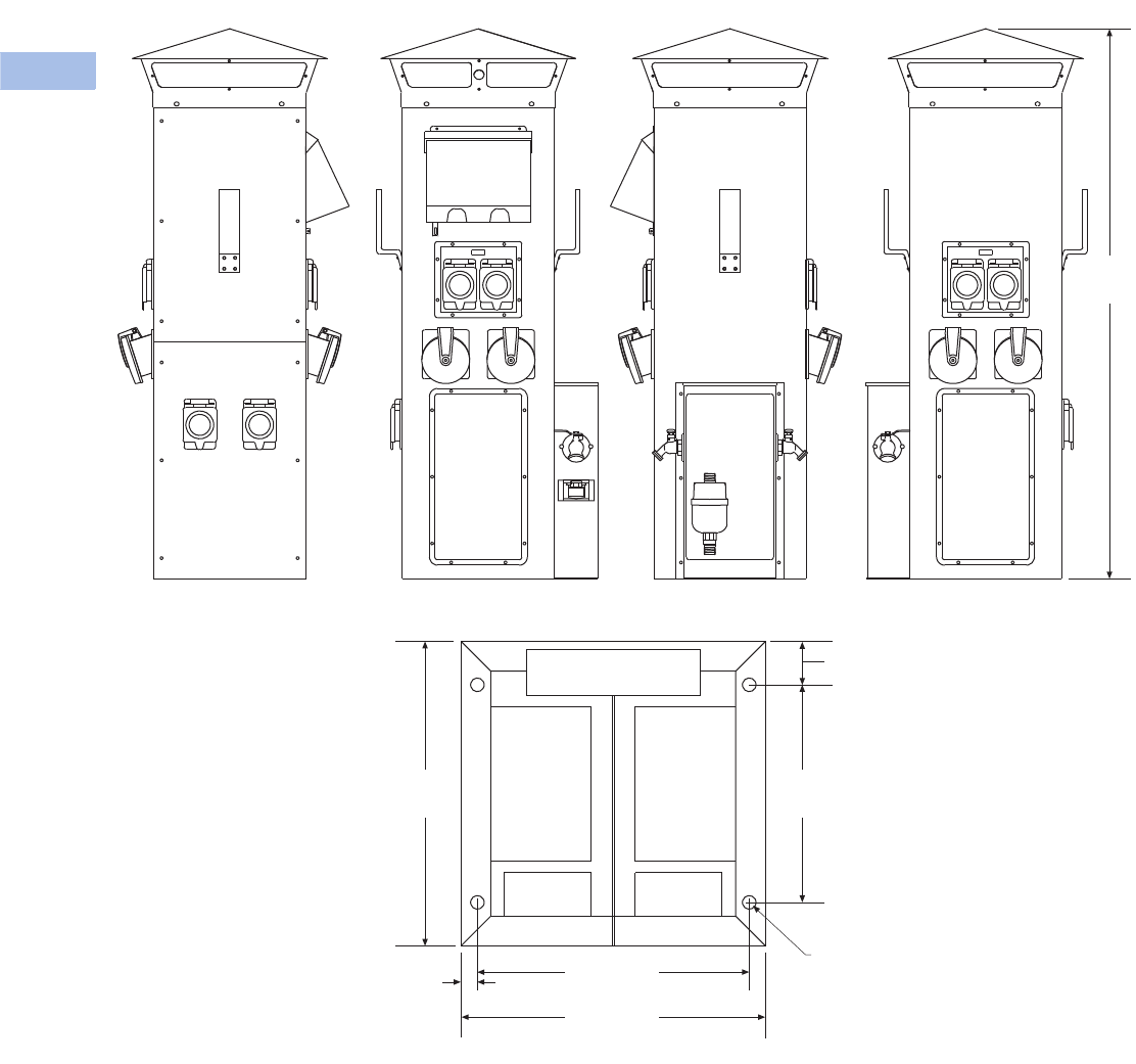
V1-T6-64 Volume 1—Residential and Light Commercial CA08100002E—February 2014 www.eaton.com
6
6
6
6
6
6
6
6
6
6
6
6
6
6
6
6
6
6
6
6
6
6
6
6
6
6
6
6
6
6
6.5
Power Pedestals
Marina Power and Lighting Equipment
Accessories
See Page V1-T6-75.
Dimensions
Approximate Dimensions in Inches (mm)
Admiral–SS
Base Footprint
12.50 (317.5)
14.00 (355.6)
Ø 0.62
(Ø 15.9)
10.00
(254.0)
14.00
(355.6)
0.75
(19.1)
50.54
(1283.8)
Front Side One Back Side Two
2.00
(50.8)
Water
Access
240V
Electrical
Access
280V
Electrical
Access
CATV/INT.
Access
CATV/INT.
Access
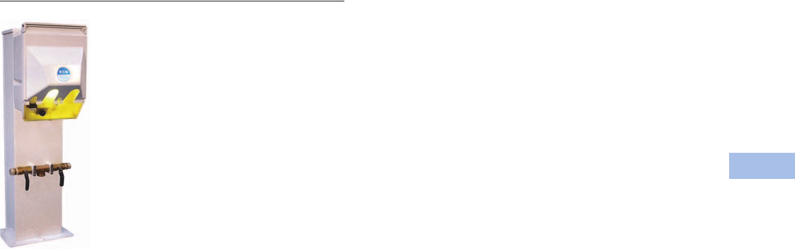
Volume 1—Residential and Light Commercial CA08100002E—February 2014 www.eaton.com V1-T6-65
6
6
6
6
6
6
6
6
6
6
6
6
6
6
6
6
6
6
6
6
6
6
6
6
6
6
6
6
6
6
6.5
Power Pedestals
Marina Power and Lighting Equipment
Newport Harbor Mate
Contents
Description Page
Power Pedestals . . . . . . . . . . . . . . . . . . . . . . . . . . V1-T6-51
Lighthouse . . . . . . . . . . . . . . . . . . . . . . . . . . . . . . V1-T6-54
Lighthouse–SS . . . . . . . . . . . . . . . . . . . . . . . . . . . V1-T6-58
Admiral–SS . . . . . . . . . . . . . . . . . . . . . . . . . . . . . . V1-T6-62
Newport Harbor Mate
Available Options . . . . . . . . . . . . . . . . . . . . . . . V1-T6-66
Catalog Number Selection . . . . . . . . . . . . . . . . V1-T6-67
Accessories . . . . . . . . . . . . . . . . . . . . . . . . . . . V1-T6-68
Dimensions . . . . . . . . . . . . . . . . . . . . . . . . . . . V1-T6-68
Hatteras Light . . . . . . . . . . . . . . . . . . . . . . . . . . . . V1-T6-69
Firehouse . . . . . . . . . . . . . . . . . . . . . . . . . . . . . . . V1-T6-73
Smart Start . . . . . . . . . . . . . . . . . . . . . . . . . . . . . . V1-T6-79
Mariner . . . . . . . . . . . . . . . . . . . . . . . . . . . . . . . . . V1-T6-80
Digital Electronic Kilowatthour Meters . . . . . . . . . V1-T6-81
Distribution Equipment—Ground Fault Monitor . . V1-T6-82
Distribution Equipment—Mega Yacht Powerpoint V1-T6-83
Distribution Equipment—Substations . . . . . . . . . . V1-T6-86
Distribution Equipment—Panels . . . . . . . . . . . . . . V1-T6-89
Distribution Equipment—Transformers . . . . . . . . . V1-T6-90
Newport Harbor Mate
Product Description
Five years of development
and 30 prototype models
have yielded this unit the
most innovative mini-power
center available. Host to a
variety of electrical services,
contained in a compact yet
strong housing, the Newport
Harbor Mate is packed with
features.
Features, Benefits
and Functions
●Tough and durable resin
housing with UV inhibitor
for lasting finish
●Photocell controlled 7 and
9 watt fluorescent light
(clear lens or amber lens
for bug reduction)
●Designed to mount
on a dock box, piling or
stainless steel stand
●Copper busbar with a
maximum rating of 140A
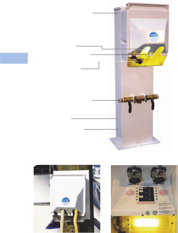
V1-T6-66 Volume 1—Residential and Light Commercial CA08100002E—February 2014 www.eaton.com
6
6
6
6
6
6
6
6
6
6
6
6
6
6
6
6
6
6
6
6
6
6
6
6
6
6
6
6
6
6
6.5
Power Pedestals
Marina Power and Lighting Equipment
Newport Harbor Mate (Shown with Optional Stand)
Mounting Option Backlit Faceplate
Available with single, dual or
combo of 30 or 50A receptacles
20A/125V GFI receptacle
Phone, cable TV, high-speed
Internet connections
Digital electronic meter
Tough and durable resin housing
with UV inhibitor for lasting finish
Lockable weatherproof door that
protects receptacles and breakers
Photocell controlled 7 watt
fluorescent light with amber
lens for bug reduction
Stainless steel stand
Single or dual 1/2-turn brass ball
valve with 3/4-inch hose bibs
Designed to mount on a dock
box, piling, wall or optional
stand (shown in photo)
Available Options
●Available with single, dual
or combination of 30A or
50A receptacles
●20A/125V GFI receptacle
(max. of two GFI
receptacles per pedestal)
Note: 20A GFI receptacles are
not to be used for shore power.
●Single or dual phone, cable
TV, high-speed Internet
connections
●Electronic metering
(one or two element
meters available)
●316L stainless steel stand
●LED lighting
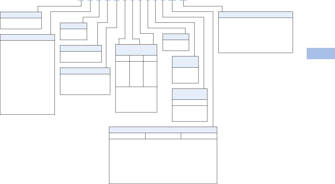
Volume 1—Residential and Light Commercial CA08100002E—February 2014 www.eaton.com V1-T6-67
6
6
6
6
6
6
6
6
6
6
6
6
6
6
6
6
6
6
6
6
6
6
6
6
6
6
6
6
6
6
6.5
Power Pedestals
Marina Power and Lighting Equipment
Catalog Number Selection
Receptacles: R1 = Receptacle 1
R2 = Receptacle 2
Notes
120A GFIs not metered.
2Number represents the quantity of 1/4-turn ball valves with 3/4-inch hose bibs (with stand only).
Water
Option 2
0=0
1=1
2=2
Phone Cable TV and Internet Options
Phone Jack Cable TV Jack Internet Option
A=1 0 0
B=1 0 1
C=1 0 2
D=1 1 0
E= 1 1 1 (Camp Mate only)
T=0 0 1
V=0 1 0
W=0 1 1
0=0 0 0
Stand
0=0
1=1
Bus
S= Single-phase 1/4-inch copper busbar
F= Three-phase 1/4-inch copper busbar
C= Single-phase 1/4-inch Canadian busbar
M= Mechanical lug 2/0
Q= Single-phase 1/4-inch split mechanical
busbar (with stand ONLY)
A= 1/4-inch Canadian mechanical
Sides and
Receptacles
R1S1 R2S1 R3S1
0
1
2
3
4
0
1
2
3
4
0
1
0=None
1= 20A GFI duplex
2= 30A, 125V
3= 50A, 125V
4= 50A, 125/250V
Metering Type 1
U= Unmetered
D= Digital electronic meters
R= Receptacles metered
individually
Lighting and Lens Color
A = 7W light Amber
C= 9W light Amber
F= No lighting Amber
G= 7W light Clear
I= 9W light Clear
L= No lighting Clear
M= 7W light Special
O= 9W light Special
R= No lighting Special
S=350 MA LED Amber
T=700 MA LED Amber
U= 350 MA LED Clear
V= 700 MA LED Clear
W= 350 MA LED Special
Y= 700 MA LED Special
Hard Wired
Breakers
S1
0=None
2= 20A, two-pole
3=30A
Photocell
Y=Yes
N=No
Lighting Protection
B= Breaker protected
F= Fuse protected
Type
N= NP Harbor Mate
C= NP Camp Mate
N A Y B U 4 3 0 1 1 2 W M
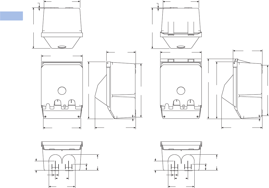
V1-T6-68 Volume 1—Residential and Light Commercial CA08100002E—February 2014 www.eaton.com
6
6
6
6
6
6
6
6
6
6
6
6
6
6
6
6
6
6
6
6
6
6
6
6
6
6
6
6
6
6
6.5
Power Pedestals
Marina Power and Lighting Equipment
Accessories
See Page V1-T6-75.
Dimensions
Approximate Dimensions in Inches (mm)
Newport Harbor Mate
9.18 (233.0)
0.12
(3.2)
10.38
(263.7)
Newport Redesign Newport Redesign With Meters
10.52 (267.2)
9.59 (243.6) 10.38 (263.7)
14.53
(369.0)
13.63
(346.2)
7.44
(189.1)
6.70
(170.2)
3.40
(86.4)
1.68
(42.7)
2.37
(60.3)
4.02
(102.2)
1.54
(39.1)
6.70
(170.2)
3.40
(86.4)
1.68
(42.7)
2.37
(60.3)
4.02
(102.2)
1.54
(39.1)
4º
9.18 (233.0)
0.12
(3.2)
10.38
(263.7)
10.52 (267.2) 7.44
(189.1)
14.53
(369.0)
15.28
(388.0)
4º
10.38 (263.7)
12.88
(327.2)
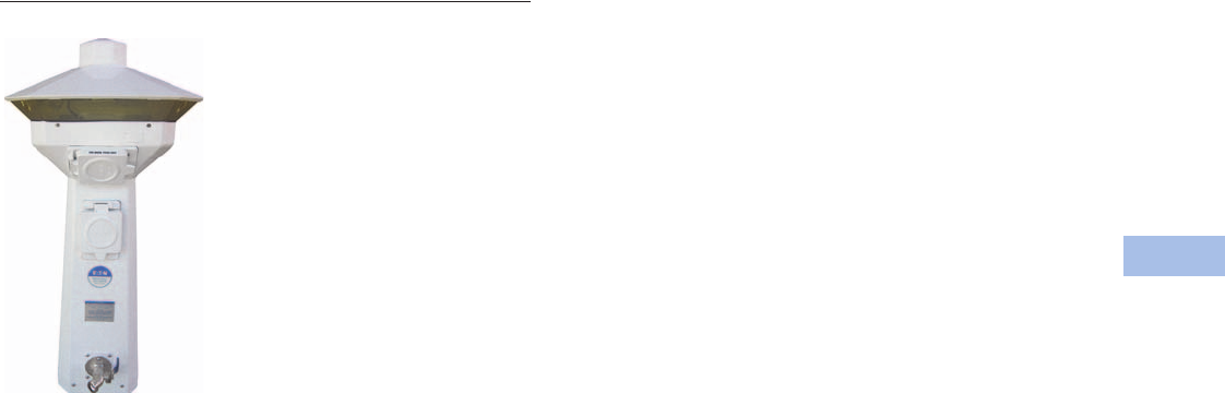
Volume 1—Residential and Light Commercial CA08100002E—February 2014 www.eaton.com V1-T6-69
6
6
6
6
6
6
6
6
6
6
6
6
6
6
6
6
6
6
6
6
6
6
6
6
6
6
6
6
6
6
6.5
Power Pedestals
Marina Power and Lighting Equipment
Hatteras Light
Contents
Description Page
Power Pedestals . . . . . . . . . . . . . . . . . . . . . . . . . . V1-T6-51
Lighthouse . . . . . . . . . . . . . . . . . . . . . . . . . . . . . . V1-T6-54
Lighthouse–SS . . . . . . . . . . . . . . . . . . . . . . . . . . . V1-T6-58
Admiral–SS . . . . . . . . . . . . . . . . . . . . . . . . . . . . . . V1-T6-62
Newport Harbor Mate . . . . . . . . . . . . . . . . . . . . . . V1-T6-65
Hatteras Light
Available Options . . . . . . . . . . . . . . . . . . . . . . . V1-T6-70
Catalog Number Selection . . . . . . . . . . . . . . . . V1-T6-71
Accessories . . . . . . . . . . . . . . . . . . . . . . . . . . . V1-T6-72
Dimensions . . . . . . . . . . . . . . . . . . . . . . . . . . . V1-T6-72
Firehouse . . . . . . . . . . . . . . . . . . . . . . . . . . . . . . . V1-T6-73
Smart Start . . . . . . . . . . . . . . . . . . . . . . . . . . . . . . V1-T6-79
Mariner . . . . . . . . . . . . . . . . . . . . . . . . . . . . . . . . . V1-T6-80
Digital Electronic Kilowatthour Meters . . . . . . . . . V1-T6-81
Distribution Equipment—Ground Fault Monitor . . V1-T6-82
Distribution Equipment—Mega Yacht Powerpoint V1-T6-83
Distribution Equipment—Substations . . . . . . . . . . V1-T6-86
Distribution Equipment—Panels . . . . . . . . . . . . . . V1-T6-89
Distribution Equipment—Transformers . . . . . . . . . V1-T6-90
Hatteras Light
Product Description
The Hatteras® Light is an
elegant and low cost
alternative to the Lighthouse.
It uses the same 360 degree
light assembly as the
Lighthouse, yet is only
30 inches tall. Thousands
of these attractive pedestals
are found not only in marinas,
but also around pools, deck
areas, boardwalks and
landscape areas. The housing
will never rust or corrode and
comes with a limited lifetime
warranty. This unit is popular
for smaller slips at marinas
with the Lighthouse and for
private docks.
Note: Wireless remote reading
of electronic kilowatt meters.
Note: Clear lens.
Note: Custom paint color.
Features, Benefits
and Functions
●Photocell controlled
13 watt fluorescent light
(clear lens or amber lens
for bug reduction)
●Circuit breakers
●Heavy resin housing with
a two-part polyurethane
coating for a UV resistant,
long-lasting finish
●Copper busbar with a
maximum rating of 140A
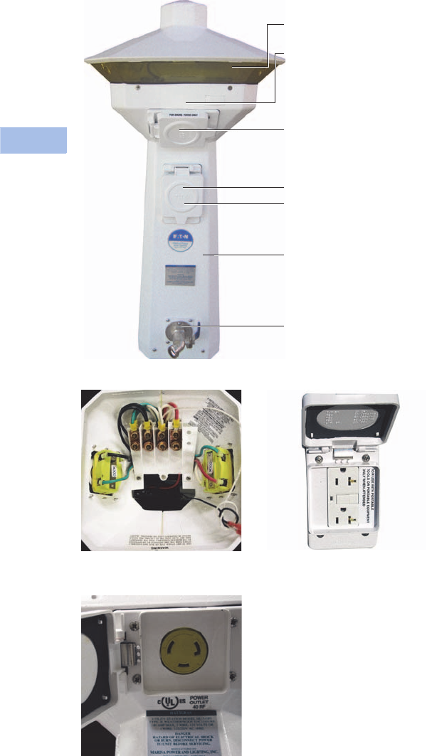
V1-T6-70 Volume 1—Residential and Light Commercial CA08100002E—February 2014 www.eaton.com
6
6
6
6
6
6
6
6
6
6
6
6
6
6
6
6
6
6
6
6
6
6
6
6
6
6
6
6
6
6
6.5
Power Pedestals
Marina Power and Lighting Equipment
Hatteras Light
Copper Busbar with Ratings
up to 140A
Faceplate
20A/125A GFI Receptacle
360° controlled 13 watt
fluorescent light with amber
lens for bug reduction
Receptacle configurations
available:
Side 1: 30A, 50A
Side 2: 30A, N/A
Note: Custom configurations
also available
Digital electronic metering
Circuit breakers
Phone, cable TV,
high-speed Internet
connections
1/4-inch resin housing with a
two-part polyurethane coating
for a UV resistant, long-lasting
finish
1/2-turn brass ball valve and
3/4-inch hose bib
Available Options
●20A/125V GFI receptacle
(max. of two GFI
receptacles per pedestal)
Note: 20A GFI receptacles are
not to be used for shore power.
●Digital electronic metering
(one or two element meter
available)
●Single or dual phone, cable
TV, high-speed Internet
connections
●Single or dual 1/2-inch or
3/4-inch silcock with
stainless steel handles
●LED lighting
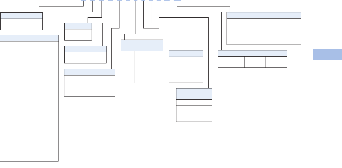
Volume 1—Residential and Light Commercial CA08100002E—February 2014 www.eaton.com V1-T6-71
6
6
6
6
6
6
6
6
6
6
6
6
6
6
6
6
6
6
6
6
6
6
6
6
6
6
6
6
6
6
6.5
Power Pedestals
Marina Power and Lighting Equipment
Catalog Number Selection
Receptacles: R1 = Receptacle 1
R2 = Receptacle 2
Notes
120A GFIs not metered.
2Number represents the quantity of 1/4-turn ball valves with 3/4-inch hose bibs.
3Wire size #2/0 kcmil or less.
Bus
S= Single-phase 1/4-inch copper busbar
F= Three-phase 1/4-inch copper busbar
C= Single-phase 1/4-inch Canadian busbar
M= Mechanical lug 2/0 3
A= 1/4-inch Canadian mechanical
Sides and
Receptacles
R1S1 R2S1 R1S2
0
1
2
3
4
0
1
2
3
4
0
1
2
3
4
0=None
1= 20A GFI duplex
2= 30A, 125V
3= 50A, 125V
4= 50A, 125/250V
Type
H= Hatteras Light
R= Park Light
Hard Wired
Breakers
S1
0= None
2= 20A, two-pole
3=30A
Photocell
Y=Yes
N=No
Lighting Protection
B= Breaker protected
F= Fuse protected
Lighting and Lens Color
A = 7W light Amber
B= Dual 7W light Amber
C= 9W light Amber
D= 13W light Amber
E= Dual 13W light Amber
F= No lighting Amber
G= 7W light Clear
H= Dual 7W light Clear
I= 9W light Clear
J= 13W light Clear
K= Dual 13W light Clear
L= No lighting Clear
M= 7W light Special
N= Dual 7W light Special
O= 9W light Special
P= 13W light Special
Q= Dual 13W light Special
R= No lighting Special
S= 350 MA LED Amber
T= 700 MA LED Amber
U= 350 MA LED Clear
V= 700 MA LED Clear
W= 350 MA LED Special
Y= 700 MA LED Special
Water Option 2
0=0
1=1 (1/2-inch)
2=2 (1/2-inch)
3=1 (3/4-inch)
4=2 (3/4-inch)
Phone Cable TV and Internet Options
Phone
Jack
Cable TV
Jack
Internet
Option
A=1 0 0
B=1 0 1
C=1 0 2
D=1 1 0
E=1 1 1
F=1 1 2
G=1 2 0
H=1 2 1
I=1 2 2
J=2 0 0
M=2 1 0
P=2 2 0
S=0 2 2
T=0 0 1
U=0 0 2
V=0 1 0
W=0 1 1
X=0 1 2
Y=0 2 0
Z=0 2 1
Metering Type 1
U= Unmetered
D= Digital electronic meters
R= Receptacles metered
individually
H D Y B D 4 7 0 1 2 A M
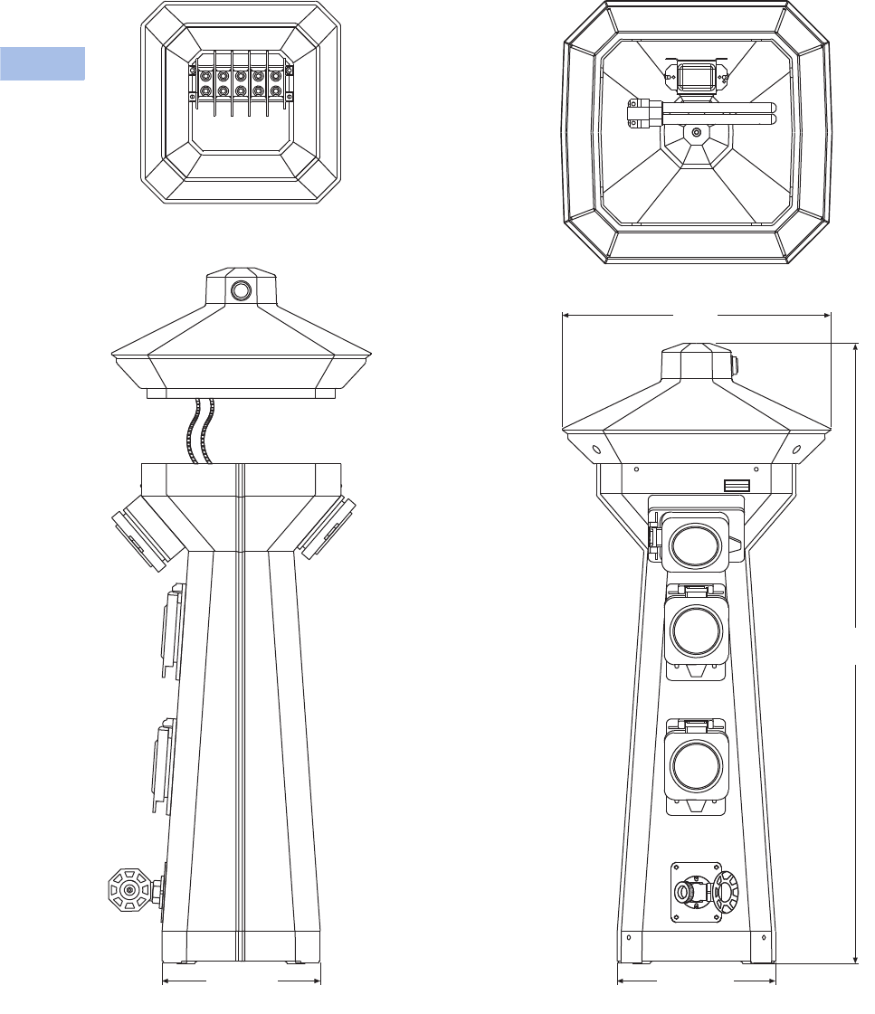
V1-T6-72 Volume 1—Residential and Light Commercial CA08100002E—February 2014 www.eaton.com
6
6
6
6
6
6
6
6
6
6
6
6
6
6
6
6
6
6
6
6
6
6
6
6
6
6
6
6
6
6
6.5
Power Pedestals
Marina Power and Lighting Equipment
Accessories
See Page V1-T6-75.
Dimensions
Approximate Dimensions in Inches (mm)
Hatteras
Side View Front View
Busbar Access Top Removed
Inside Top
7.90 (200.7) 7.90 (200.7)
30.98
(786.9)
13.39
(340.2)

Volume 1—Residential and Light Commercial CA08100002E—February 2014 www.eaton.com V1-T6-73
6
6
6
6
6
6
6
6
6
6
6
6
6
6
6
6
6
6
6
6
6
6
6
6
6
6
6
6
6
6
6.5
Power Pedestals
Marina Power and Lighting Equipment
Firehouse
Contents
Description Page
Power Pedestals . . . . . . . . . . . . . . . . . . . . . . . . . . V1-T6-51
Lighthouse. . . . . . . . . . . . . . . . . . . . . . . . . . . . . . . V1-T6-54
Lighthouse–SS . . . . . . . . . . . . . . . . . . . . . . . . . . . V1-T6-58
Admiral–SS . . . . . . . . . . . . . . . . . . . . . . . . . . . . . . V1-T6-62
Newport Harbor Mate . . . . . . . . . . . . . . . . . . . . . . V1-T6-65
Hatteras Light . . . . . . . . . . . . . . . . . . . . . . . . . . . . V1-T6-69
Firehouse
Available Options . . . . . . . . . . . . . . . . . . . . . . . V1-T6-74
Catalog Number Selection . . . . . . . . . . . . . . . . V1-T6-74
Accessories . . . . . . . . . . . . . . . . . . . . . . . . . . . V1-T6-75
Dimensions . . . . . . . . . . . . . . . . . . . . . . . . . . . V1-T6-78
Smart Start . . . . . . . . . . . . . . . . . . . . . . . . . . . . . . V1-T6-79
Mariner . . . . . . . . . . . . . . . . . . . . . . . . . . . . . . . . . V1-T6-80
Digital Electronic Kilowatthour Meters . . . . . . . . . V1-T6-81
Distribution Equipment—Ground Fault Monitor . . V1-T6-82
Distribution Equipment—Mega Yacht Powerpoint V1-T6-83
Distribution Equipment—Substations . . . . . . . . . . V1-T6-86
Distribution Equipment—Panels . . . . . . . . . . . . . . V1-T6-89
Distribution Equipment—Transformers . . . . . . . . . V1-T6-90
Firehouse
Product Description
Created as a complete
solution for fire and rescue
needs, this pedestal features
fire extinguisher storage and
a mounted alarm strobe light
and siren, as well as an
optional life ring. This unit
is well equipped for any
marina emergency. The alarm
strobe light and siren can be
automatically activated when
the door is open or optional
life ring is removed.
Features, Benefits
and Functions
●Alarm strobe light and
siren: automatically
activated when door is
open or optional life ring
is removed
●Photocell controlled
13 watt fluorescent light
(clear lens or amber lens
for bug reduction)
●10 lb ABC Type fire
extinguisher
●316L stainless steel
polyester powder-coated
housing
●Polycarbonate top
assembly
Firehouse
High-visibility alarm
strobe light and warning
siren
Photocell controlled
energy efficient 13 watt
fluorescent light with
amber lens for bug
reduction
Stainless steel housing with
oven-baked enamel finish
with a polycarbonate base
and top
Remote control unit can
automatically call select
services via a four
channel transmitter:
Medical emergency
Fire emergency
Police emergency
Optional general
emergency
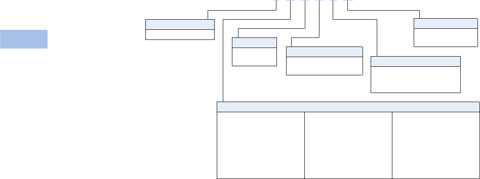
V1-T6-74 Volume 1—Residential and Light Commercial CA08100002E—February 2014 www.eaton.com
6
6
6
6
6
6
6
6
6
6
6
6
6
6
6
6
6
6
6
6
6
6
6
6
6
6
6
6
6
6
6.5
Power Pedestals
Marina Power and Lighting Equipment
Available Options
●24-inch life ring
●20 lb ABC Type fire
extinguisher available
Catalog Number Selection
Fire Extinguisher
E= Include 10 lb extinguisher
N= No extinguisher
X= Include 20 lb extinguisher
Type
F= Firehouse
Photocell
Y=Yes
N=No
Alarm/Strobe
A= Include alarm/strobe
N= No alarm/strobe
24-Inch Life Ring
R= Include life ring
N= No life ring
Lighting and Lens Color
A = 7W light Amber
B= Dual 7W light Amber
C= 9W light Amber
D= 13W light Amber
E= Dual 13W light Amber
F= No lighting Amber
G= 7W light Clear
H= Dual 7W light Clear
I= 9W light Clear
J= 13W light Clear
K= Dual 13W light Clear
L= No lighting Clear
M= 7W light Special
N= Dual 7W light Special
O= 9W light Special
P= 13W light Special
Q= Dual 13W light Special
R= No lighting Special
S= 350 MA LED Amber
T= 700 MA LED Amber
U= 350 MA LED Clear
V= 700 MA LED Clear
W= 350 MA LED Special
Y= 700 MA LED Special
F A Y A E N

Volume 1—Residential and Light Commercial CA08100002E—February 2014 www.eaton.com V1-T6-75
6
6
6
6
6
6
6
6
6
6
6
6
6
6
6
6
6
6
6
6
6
6
6
6
6
6
6
6
6
6
6.5
Power Pedestals
Marina Power and Lighting Equipment
Accessories
Accessories for Custom Design Marina Products, Resin and Stainless Steel Pedestals and Power Products
Replacement Parts Catalog Numbers Replacement Parts Catalog Numbers, continued
Description
Catalog
Number
Receptacles
20A GFCI duplex MPL3038
30A 125V twistlock MPL3039
50A 125V twistlock MPL3040
50A 125/250V twistlock MPL3045
100A 120/240V pin and sleeve MPL4100R12W
100A 120/208V pin and sleeve MPL5100R9W
100A 480V four-wire pin and sleeve MPL4100R7W
100 A 480V five-wire pin and sleeve MPL5100R7W
200A 277/480V pin and sleeve (Russellstoll®)MPL4200R7W
30A 125V RV RV3042
50A 125/250V RV RV3043
Circuit Breakers
20A 125V single-pole QCF1020
20A 125V single-pole GFCI QCGF1020
30A 125V single-pole QCF1030
30A 125V single-pole GFCI QCGF1030
50A 125V single-pole QCF1050
20A 125/250V two-pole QCF2020
20A 125/250V two-pole GFCI QCGF2020
30A 125/250V two-pole QCF2030
30A 125/250V two-pole GFCI QCGF2030
50A 125/250V two-pole QCF2050
50A 125/250V two-pole GFCI QCGF2050
60A 125/250V two-pole QCF2060
100A 125/250V two-pole GHC2100D
100A 120/208V three-pole GHC3100D
200A 277/480V three-pole JT2200FA
Fluorescent Light Assembly
13 watt 120V 60 Hz ballast MPL2400
7 watt 120V 60 Hz ballast MPL2401
13 watt socket MPL3079
7 watt socket MPL3077
13 watt fluorescent bulb MPL3018
7 watt fluorescent bulb MPL3019
Photocell MPL3044
Photocell nuts MPL3034
Lighthouse in-line fuse MPL3026
Lighthouse in-line fuse holder MPL3027
Lighthouse, Lighthouse–SS, Powerhouse,
Powerhouse–SS, Hatteras, Park Light
Top with complete light and lens assembly MPL6003A
Top with complete light and lens assembly—fused MPL6003FA
Top only MPL6003
Amber lens MPL6005
Clear lens MPL6008
Description
Catalog
Number
Lighthouse, Lighthouse–SS, Powerhouse,
Powerhouse–SS, Hatteras, Park Light, continued
20A GFCI receptacle external cover set MPL1101
30A receptacle external cover set MPL1102
50A receptacle external cover set MPL1105
Single-pole external breaker cover set MPL11061
Two-pole external breaker cover set MPL11062
Three-pole external breaker cover set MPL11063
Lighthouse, Lighthouse–SS, Powerhouse,
Powerhouse–SS
Lighthouse/Powerhouse pedestal main housing MPL6006
Lighthouse–SS/Powerhouse–SS pedestal main housing MPL6006S
Lighthouse/Powerhouse main door MPL6007
Lighthouse–SS/Powerhouse–SS main door MPL6007S
Lighthouse/Powerhouse spring closure MPL1099
Lighthouse Powerhouse top isolation plate MPL6012
Lighthouse/Lighthouse–SS breaker plate MPL1141
Powerhouse/Powerhouse–SS breaker plate RV1112
Lighthouse/Lighthouse–SS/Powerhouse/
Powerhouse–SS Hose and cable brackets
MPL1087
Lighthouse/Powerhouse stainless steel hinge MPL1088
Lighthouse/Powerhouse complete pedestal
base with busbar assembly
MPL6004A
Lighthouse/Powerhouse complete pedestal base with three-phase
busbar assembly
MPL6004FA
Lighthouse/Powerhouse pedestal base without busbars MPL6004
Lighthouse/Powerhouse aluminum blank access panel MPL5500
Lighthouse/Lighthouse–SS/Powerhouse/
Powerhouse–SS complete busbar assembly
MPL1140A
Lighthouse/Lighthouse–SS/Powerhouse/Powerhouse–SS complete
three-phase busbar assembly
MPL1140FA
Copper busbar with nuts and washers MPL3471
20A GFCI—00 amber resin faceplate MPL1120
30A—20 GFCI amber resin faceplate MPL1121
30–50A amber resin faceplate MPL1122
30–30A amber resin faceplate MPL1127
30–00A amber resin faceplate MPL1129
50–50A amber resin faceplate MPL1123
50A—20 GFCI amber resin faceplate MPL1124
20 GFCI—20 GFCI amber resin faceplate MPL1125
00–00 amber resin faceplate MPL1126
50A—00 amber resin faceplate MPL1128
100A faceplate MPL1142
20A GFCI—00 amber resin faceplate assembly with breakers MPL1120A
30A—20 GFCI amber resin faceplate assembly with breakers MPL1121A
30–50A amber resin faceplate assembly with breakers MPL1122A

V1-T6-76 Volume 1—Residential and Light Commercial CA08100002E—February 2014 www.eaton.com
6
6
6
6
6
6
6
6
6
6
6
6
6
6
6
6
6
6
6
6
6
6
6
6
6
6
6
6
6
6
6.5
Power Pedestals
Marina Power and Lighting Equipment
Replacement Parts Catalog Numbers, continued Replacement Parts Catalog Numbers, continued
Notes
1Lighthouse, Lighthouse–SS, Powerhouse, Powerhouse–SS.
2Hatteras Light, Park Light, Newport Camp Mate, Newport Harbor Mate.
3Please contact factory to determine configurations for replacement housing.
Description
Catalog
Number
Lighthouse, Lighthouse–SS, Powerhouse,
Powerhouse–SS, continued
30–30A amber resin faceplate assembly with breakers MPL1127A
50–50A amber resin faceplate assembly with breakers MPL1123A
50A—20 GFCI amber resin faceplate assembly with breakers MPL1124A
20 GFCI—20 GFCI amber resin faceplate assembly with breakers MPL1125A
50A—00 amber resin faceplate assembly with breakers MPL1128A
30–00A faceplate assembly with breakers MPL1129A
100A faceplate assembly with breakers MPL1142A
Powerhouse 30–50 receptacle plate RV1143
Powerhouse (30A—00) receptacle plate RV11433
Powerhouse (50A—00) receptacle plate RV11435
Powerhouse breaker plate RV1112
Phone, Cable, Internet Assemblies
Lighthouse/Powerhouse complete phone and cable assembly MPL1114/RV1114
Lighthouse–SS/Powerhouse–SS/Hatteras Light/Park Light complete
phone and cable assembly
MPL1119/RV1119
Hatteras Light/Park Light complete phone and cable assembly MPL1119
Newport Harbor Mate/Camp Mate phone and cable insert assembly MPL1115/RV1115
Lighthouse/Powerhouse access plates with dual Internet jacks MPL5501
Coax cable TV FCF female adpt. with lugnut and washer MPL1086
RJ45 CAT5e high-speed internet jack MPL3059
Marine phone receptacle MPL3037
RJ12 CAT3 phone jack RV3060
Water Assemblies
Lighthouse/Powerhouse complete water manifold assembly
(dual 3/4-inch hose bibs with 1/4-turn ball valves)
MPL11A
Newport Harbor Mate/Newport Camp Mate water manifold
assembly (dual 3/4-inch hose bibs with 1/4-turn ball valves)
MPL11C
3/4-inch hose adapter MPL7030
Lighthouse/Powerhouse water mounting plate
with mounting brackets
MPL1132
Hatteras Light/Park Light aluminum water mounting plate MPL6584
1/2-inch brass silcock (hose bib) MPL7014
3/4-inch stainless steel silcock (hose bib) MPL5271
3/4-inch brass ball valve MPL7021
Watts 3/4-inch backflow preventer MPL7015
Description
Catalog
Number
Digital Electronic Meters
Single element, 14-pin quick disconnect (no CTs) MPL17A1
Single element, 14-pin quick disconnect (with CTs) MPL17A2 1
Single element, 14-pin quick disconnect (with CTs) MPL17A2 2
Dual element, 14-pin quick disconnect (no CTs) MPL17B1
Dual element, 14-pin quick disconnect (with CTs) MPL17B2 1
Dual element, 14-pin quick disconnect (with CTs) MPL17B2 2
Three element, 14-pin quick disconnect (no CTs) MPL17C1
Three element, 14-pin quick disconnect (with CTs) MPL17C2 1
Three element, 14-pin quick disconnect (with CTs) MPL17C2 2
Single element coil transformers (CTs) MPL30321 1
Single element coil transformers (CTs) MPL30321 2
Dual element coil transformers (CTs) MPL30322 1
Dual element coil transformers (CTs) MPL30322 2
Three element coil transformers (CTs) MPL30323 1
Three element coil transformers (CTs) MPL30323 2
Counter (large—old style) MPL3022
Counter (small—new style) MPL3021
Hatteras Light (Marina) and Park Light (RV) 3
Pedestal main housing MPL6002
Copper busbar with nuts and washers MPL3468
Complete busbar assembly MPL1108A
Complete three-phase busbar assembly MPL1108FA
20A GFCI external cover door MPL1101
30A external cover door MPL1102
50A external cover door MPL1105
Light fuse MPL3026
Fuse holder MPL3027
Mounting feet (set of four) MPL7004

Volume 1—Residential and Light Commercial CA08100002E—February 2014 www.eaton.com V1-T6-77
6
6
6
6
6
6
6
6
6
6
6
6
6
6
6
6
6
6
6
6
6
6
6
6
6
6
6
6
6
6
6.5
Power Pedestals
Marina Power and Lighting Equipment
Replacement Parts Catalog Numbers, continued
Note
1For custom faceplates to include phone/cable or other accessories,
please contact Eaton’s Marina Power & Lighting facility at 1-800-723-8009.
Description
Catalog
Number
Newport Harbor Mate (MARINA)
and Camp Mate (RV)
Amber lens—three-piece MPL1117
Clear lens—three-piece MPL1109
Main housing MPL6000
Main door MPL6001
30–30A faceplate 1MPL1135
30–50A faceplate 1MPL1136
50–50A faceplate 1MPL1137
50A–00 faceplate 1MPL1138
30A–00 faceplate 1MPL1139
30–30A faceplate assembly with breakers 1MPL1135A
30–30–20 GFI faceplate assembly 1MPL1135G/RV1135G
30–50A faceplate assembly with breakers 1MPL1136A
30–50–20 GFI faceplate assembly 1MPL1136G/RV1136G
50–50A faceplate assembly with breakers 1MPL1137A
50–50–20 GFI faceplate assembly 1MPL1137G/RV1137G
50A–00 faceplate assembly with breakers 1MPL1138A
50–20 GFI faceplate assembly 1MPL1138G/RV1138G
30A–00 faceplate assembly with breakers 1MPL1139A
30–20 GFI faceplate assembly 1MPL1139G/RV1139G
Mounting brackets MPL7005
36-inch stainless steel stand MPL5506
Copper busbar with nuts and washers MPL3468
Complete busbar assembly MPL1108A
Complete three-phase busbar assembly MPL1108FA
Firehouse (Marina and RV)
Red strobe light/siren MPL3020
Firehouse top with lighting assembly and strobe
MPLFH6003A
Light fuse MPL3029
Fuse holder MPL3028
Door MPL6013
24-inch life ring MPL4201
Life ring bracket MPL4201B
Blank access panel MPL6015
Door/life ring switch (pre-2004) MPL3030
Door/life ring switch (new) MPL3050
Door hasp MPL3950
Busbar (double barrel terminal block) MPL3751
10-lb ABC Type fire extinguisher MPL8025
20-lb ABC Type fire extinguisher MPL8025X
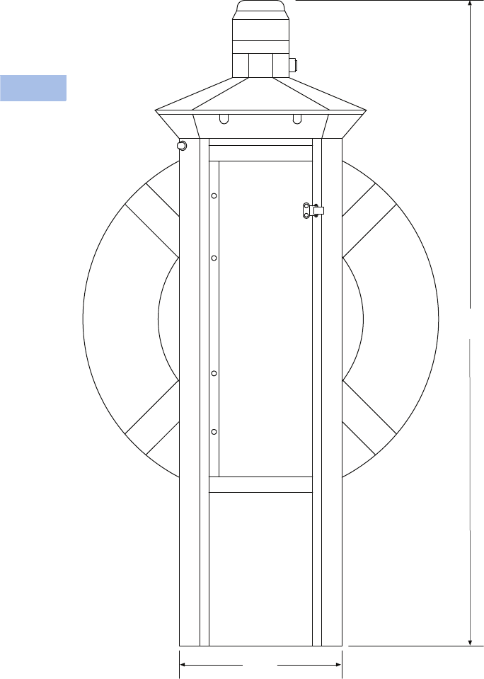
V1-T6-78 Volume 1—Residential and Light Commercial CA08100002E—February 2014 www.eaton.com
6
6
6
6
6
6
6
6
6
6
6
6
6
6
6
6
6
6
6
6
6
6
6
6
6
6
6
6
6
6
6.5
Power Pedestals
Marina Power and Lighting Equipment
Dimensions
Approximate Dimensions in Inches (mm)
Firehouse–SS
43.50
(1104.9)
9.87
(250.6)
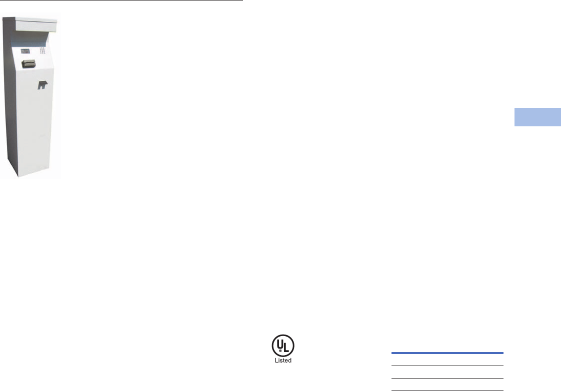
Volume 1—Residential and Light Commercial CA08100002E—February 2014 www.eaton.com V1-T6-79
6
6
6
6
6
6
6
6
6
6
6
6
6
6
6
6
6
6
6
6
6
6
6
6
6
6
6
6
6
6
6.5
Power Pedestals
Marina Power and Lighting Equipment
Smart Start
Contents
Description Page
Power Pedestals . . . . . . . . . . . . . . . . . . . . . . . . . . V1-T6-51
Lighthouse . . . . . . . . . . . . . . . . . . . . . . . . . . . . . . V1-T6-54
Lighthouse–SS . . . . . . . . . . . . . . . . . . . . . . . . . . . V1-T6-58
Admiral–SS . . . . . . . . . . . . . . . . . . . . . . . . . . . . . . V1-T6-62
Newport Harbor Mate . . . . . . . . . . . . . . . . . . . . . . V1-T6-65
Hatteras Light . . . . . . . . . . . . . . . . . . . . . . . . . . . . V1-T6-69
Firehouse . . . . . . . . . . . . . . . . . . . . . . . . . . . . . . . V1-T6-73
Smart Start
Mariner . . . . . . . . . . . . . . . . . . . . . . . . . . . . . . . . . V1-T6-80
Digital Electronic Kilowatthour Meters . . . . . . . . . V1-T6-81
Distribution Equipment—Ground Fault Monitor . . V1-T6-82
Distribution Equipment—Mega Yacht Powerpoint V1-T6-83
Distribution Equipment—Substations . . . . . . . . . . V1-T6-86
Distribution Equipment—Panels . . . . . . . . . . . . . . V1-T6-89
Distribution Equipment—Transformers . . . . . . . . . V1-T6-90
Smart Start
Product Description
If you have transient boat
slips, Eaton Marina Power
and Lighting has developed
their newest product for
your situation.
The new “Smart Start”
pedestal is activated by the
swipe of a credit card. A kiosk
will be centrally located at the
marina and will control up to
32 power pedestals. When a
boater wants to use a slip,
they will enter the slip
number and amount of time
they would like and will then
be asked to swipe a card in
order to activate the pedestal.
Once the chosen time is up,
the pedestal will shut down.
No more free power!
The “Smart Start” pedestal
will not only prevent transient
boaters from stealing power,
but it will also eliminate the
need for 24-hour monitoring
of the slips. Boaters will be
able to come in at any time
of the day and activate a
pedestal.
Features
●Lighted 316L stainless
steel kiosk enclosure
●Programmable slip
time blocks
●Programmable slip rates
printable receipts
Standards and Certifications
●UL listing pending
Dimensions
Approximate Dimensions in
Inches (mm)
Smart Start
Height 60.05 (1525.3)
Width 14.15 (359.4)
Depth 14.24 (361.9)
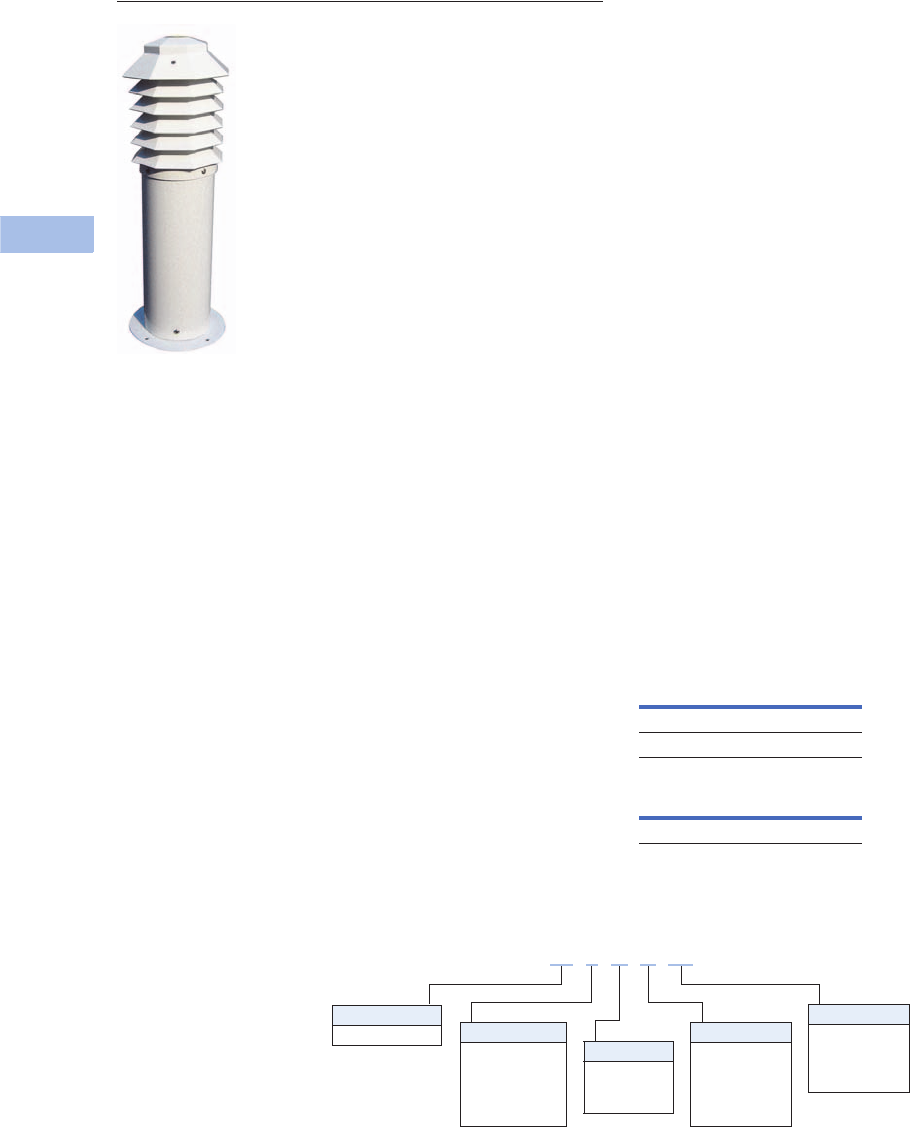
V1-T6-80 Volume 1—Residential and Light Commercial CA08100002E—February 2014 www.eaton.com
6
6
6
6
6
6
6
6
6
6
6
6
6
6
6
6
6
6
6
6
6
6
6
6
6
6
6
6
6
6
6.5
Power Pedestals
Marina Power and Lighting Equipment
Mariner
Marina Power and Lighting Equipment
Contents
Description Page
Power Pedestals. . . . . . . . . . . . . . . . . . . . . . . . . . . V1-T6-51
Lighthouse . . . . . . . . . . . . . . . . . . . . . . . . . . . . . . . V1-T6-54
Lighthouse–SS . . . . . . . . . . . . . . . . . . . . . . . . . . . . V1-T6-58
Admiral–SS. . . . . . . . . . . . . . . . . . . . . . . . . . . . . . . V1-T6-62
Newport Harbor Mate . . . . . . . . . . . . . . . . . . . . . . V1-T6-65
Hatteras Light. . . . . . . . . . . . . . . . . . . . . . . . . . . . . V1-T6-69
Firehouse . . . . . . . . . . . . . . . . . . . . . . . . . . . . . . . . V1-T6-73
Smart Start . . . . . . . . . . . . . . . . . . . . . . . . . . . . . . . V1-T6-79
Mariner
Digital Electronic Kilowatthour Meters . . . . . . . . . . V1-T6-81
Distribution Equipment—Ground Fault Monitor. . . V1-T6-82
Distribution Equipment—Mega Yacht Powerpoint . V1-T6-83
Distribution Equipment—Substations . . . . . . . . . . V1-T6-86
Distribution Equipment—Panels . . . . . . . . . . . . . . V1-T6-89
Distribution Equipment—Transformers . . . . . . . . . V1-T6-90
Mariner
Product Description
The Mariner is a lighting
bollard that can stand from
1.5 to 4 feet tall and can be
used in various applications
from marina docks, to
landscaped areas, golf
courses and beyond. The
Mariner will have a lifetime
warranty on the engineered
resin housing that will
withstand the harsh marine
and land environments from
Alaska to the tropics.
Features
●Can be configured with a
7 watt, 9 watt or 13 watt
fluorescent bulb
●Mounting base and painted
pole supplied for desired
height
●Limited lifetime warranty
on engineered resin
housing
●Custom colors available
●Side-mounted option
Dimensions
Approximate Dimensions in
Inches (mm)
Catalog Number Selection
Mariner
7 watt 14.15 (359.4)
9 watt/13 watt 14.24 (361.9)
Mounting Base and Pole
1.5 feet–4 feet
Bulb Wattage
5 = 5W
7 = 7W
9 = 9W
3 = 13W
1 = 50 MA LED
Color Lens
A = Amber
C = Clear
S = Special
Stand Height
18 = 18-inch
24 = 24-inch
36 = 36-inch
48 = 48-inch
Type
M = Mariner Color
W= White
R= Blue
B= Black
D= Dark green
S= Special
M 5 A R 18
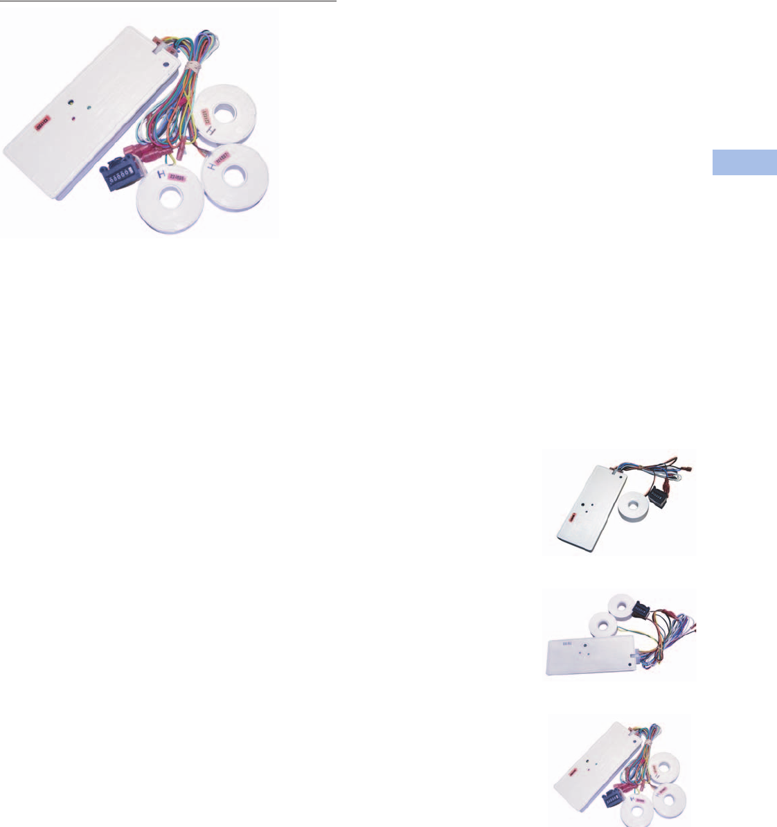
Volume 1—Residential and Light Commercial CA08100002E—February 2014 www.eaton.com V1-T6-81
6
6
6
6
6
6
6
6
6
6
6
6
6
6
6
6
6
6
6
6
6
6
6
6
6
6
6
6
6
6
6.5
Power Pedestals
Marina Power and Lighting Equipment
Digital Electronic Kilowatt Hour Meters
Contents
Description Page
Power Pedestals . . . . . . . . . . . . . . . . . . . . . . . . . . V1-T6-51
Lighthouse . . . . . . . . . . . . . . . . . . . . . . . . . . . . . . V1-T6-54
Lighthouse–SS . . . . . . . . . . . . . . . . . . . . . . . . . . . V1-T6-58
Admiral–SS . . . . . . . . . . . . . . . . . . . . . . . . . . . . . . V1-T6-62
Newport Harbor Mate . . . . . . . . . . . . . . . . . . . . . . V1-T6-65
Hatteras Light . . . . . . . . . . . . . . . . . . . . . . . . . . . . V1-T6-69
Firehouse . . . . . . . . . . . . . . . . . . . . . . . . . . . . . . . V1-T6-73
Smart Start . . . . . . . . . . . . . . . . . . . . . . . . . . . . . . V1-T6-79
Mariner . . . . . . . . . . . . . . . . . . . . . . . . . . . . . . . . . V1-T6-80
Digital Electronic Kilowatthour Meters
Distribution Equipment—Ground Fault Monitor . . V1-T6-82
Distribution Equipment—Mega Yacht Powerpoint V1-T6-83
Distribution Equipment—Substations . . . . . . . . . . V1-T6-86
Distribution Equipment—Panels . . . . . . . . . . . . . . V1-T6-89
Distribution Equipment—Transformers . . . . . . . . . V1-T6-90
Digital Electronic Kilowatthour Meters
Product Description
Using the latest surface
mount technology, Eaton
manufactures a digital
electronic kilowatthour meter
that exceeds the +/– 2%
accuracy required by ANSI
(American National Standards
Institute) C-12.1 and is
approved by the state of
California at +/– 1% over the
full range of 0–100A from a
0.5–1 power factor and is
available for both single- and
three-phase applications.
The meter drives an electro-
mechanical counter that
requires a 12V pulse each
tenth of a kilowatthour,
providing 10 pulses per
kilowatt used. The meter
output can be hard wired or
connected to a transmitter
in the pedestal for wireless
transmission to a receiver
displaying the output on a
PC for direct billing of up to
1,000 individual customers.
Features
Our meter is designed to
be user friendly in that all
connections from external
sources and the meter output
are through one 14-pin locking
connector. This feature
eliminates many common
problems, such as reverse
line polarity and improper coil
polarity. Simple LEDs, both
red and green, indicate line
and load condition and the
pulsed LED indicates the rate
of power consumption.
Wireless System
All of our meters are “wireless
capable” to allow for wireless
meter reading. This technology
enables the marina or RV park
to get meter readings from
one central location rather
than visiting every site to
read the counters.
Meter Socket Capabilities
Meter sockets are available
on the Lighthouse and
Lighthouse–SS.
Standard
●Four jaw
●Ring-type
●100A
Available Options
●200A (SS only)
●Lockable hasp
●Ringless (SS only)
●Five jaw
●Seven jaw (SS only)
Product Selection
One Element Meter
Two Element Meter
Three Element Meter
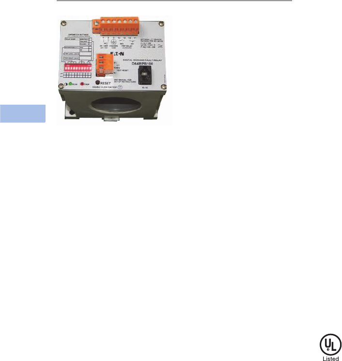
V1-T6-82 Volume 1—Residential and Light Commercial CA08100002E—February 2014 www.eaton.com
6
6
6
6
6
6
6
6
6
6
6
6
6
6
6
6
6
6
6
6
6
6
6
6
6
6
6
6
6
6
6.5
Power Pedestals
Marina Power and Lighting Equipment
Ground Fault Monitor
Contents
Description Page
Power Pedestals. . . . . . . . . . . . . . . . . . . . . . . . . . . V1-T6-51
Lighthouse . . . . . . . . . . . . . . . . . . . . . . . . . . . . . . . V1-T6-54
Lighthouse–SS . . . . . . . . . . . . . . . . . . . . . . . . . . . . V1-T6-58
Admiral–SS. . . . . . . . . . . . . . . . . . . . . . . . . . . . . . . V1-T6-62
Newport Harbor Mate . . . . . . . . . . . . . . . . . . . . . . V1-T6-65
Hatteras Light. . . . . . . . . . . . . . . . . . . . . . . . . . . . . V1-T6-69
Firehouse . . . . . . . . . . . . . . . . . . . . . . . . . . . . . . . . V1-T6-73
Smart Start . . . . . . . . . . . . . . . . . . . . . . . . . . . . . . . V1-T6-79
Mariner. . . . . . . . . . . . . . . . . . . . . . . . . . . . . . . . . . V1-T6-80
Digital Electronic Kilowatthour Meters . . . . . . . . . . V1-T6-81
Distribution Equipment—Ground Fault Monitor
Distribution Equipment—Mega Yacht Powerpoint . V1-T6-83
Distribution Equipment—Substations . . . . . . . . . . V1-T6-86
Distribution Equipment—Panels . . . . . . . . . . . . . . V1-T6-89
Distribution Equipment—Transformers . . . . . . . . . V1-T6-90
Distribution Equipment—Ground Fault Monitor
Product Description
Our ground fault monitoring
systems are designed to
detect fault currents in the
AC shore power system that
are too low to trip a circuit
breaker. The ground fault
monitor helps reduce the risk
of injury or property damage
that may result from stray
fault currents. Our ground
fault monitoring system
provides information to the
maintenance staff on the
overall condition of the AC
electrical system. The ground
fault monitoring system
operates 24 hours a day and
can be monitored by non-
technical personnel.
Features
●Adjustable trip level 10 mA
to 10A
●Current transformers up to
8 1/4-inch diameter
●Visual and/or audible alarm
●Housing of fiberglass or
powder-coated stainless
steel available
Power Guard
The ground fault monitor
detects ground fault currents
by means of current
transformers (CT), which are
placed around main or branch
circuits. If a ground fault
occurs, the CT will detect the
amount of fault current and
send a signal to the ground
fault monitoring device where
the amount of fault current is
displayed with the faulty
circuit identified. The
detected fault can either
activate an indicator alarm or
disconnect the faulted circuit.
Standards and Certifications
●UL listed current
transformers
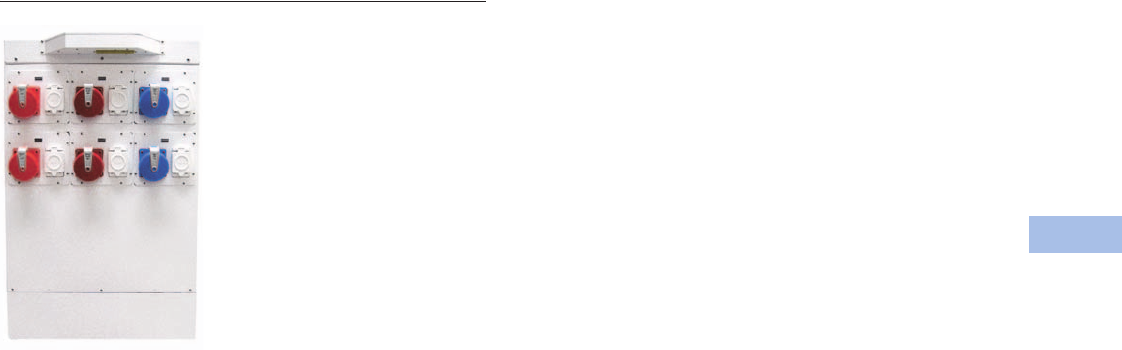
Volume 1—Residential and Light Commercial CA08100002E—February 2014 www.eaton.com V1-T6-83
6
6
6
6
6
6
6
6
6
6
6
6
6
6
6
6
6
6
6
6
6
6
6
6
6
6
6
6
6
6
6.5
Power Pedestals
Marina Power and Lighting Equipment
Marina Power and Lighting Equipment
Contents
Description Page
Power Pedestals . . . . . . . . . . . . . . . . . . . . . . . . . . V1-T6-51
Lighthouse . . . . . . . . . . . . . . . . . . . . . . . . . . . . . . V1-T6-54
Lighthouse–SS . . . . . . . . . . . . . . . . . . . . . . . . . . . V1-T6-58
Admiral–SS . . . . . . . . . . . . . . . . . . . . . . . . . . . . . . V1-T6-62
Newport Harbor Mate . . . . . . . . . . . . . . . . . . . . . . V1-T6-65
Hatteras Light . . . . . . . . . . . . . . . . . . . . . . . . . . . . V1-T6-69
Firehouse . . . . . . . . . . . . . . . . . . . . . . . . . . . . . . . V1-T6-73
Smart Start . . . . . . . . . . . . . . . . . . . . . . . . . . . . . . V1-T6-79
Mariner . . . . . . . . . . . . . . . . . . . . . . . . . . . . . . . . . V1-T6-80
Digital Electronic Kilowatthour Meters . . . . . . . . . V1-T6-81
Distribution Equipment—Ground Fault Monitor . . V1-T6-82
Distribution Equipment—Mega Yacht Powerpoint
Wiring Diagram . . . . . . . . . . . . . . . . . . . . . . . . V1-T6-84
Dimensions . . . . . . . . . . . . . . . . . . . . . . . . . . . V1-T6-85
Distribution Equipment—Substations . . . . . . . . . . V1-T6-86
Distribution Equipment—Panels . . . . . . . . . . . . . . V1-T6-89
Distribution Equipment—Transformers . . . . . . . . . V1-T6-90
Distribution Equipment—Mega Yacht Powerpoint
Product Description
From the company that is
known for its high-quality
innovations, Eaton is the only
company to offer a self-
contained dual-phase mega
yacht unit. Made out of long-
lasting stainless steel, this
mega yacht unit has a
copper-wound, low-noise
transformer that is double
insulated and epoxy
overcoated.The mega yacht
unit delivers both single-
phase and three-phase power
to serve most mega yachts.
Helping to keep your marina
environment tranquil, the
mega yacht unit has a
low-noise, highly efficient
transformer that has isolation
mounts to ensure a very
quiet operation.
Features
●Thermostatically controlled
fans in transformer
compartment for cooling
●Heavy stainless steel
(316L) cabinet with a
polyester powder coating
●Ventilated sun shields to
help unit run cooler in
tropical climates
●Limited lifetime warranty
on housing
●Two or three light 13 watt
photocell controlled
fluorescent lights on
the sun shield for optimal
night lighting
Available Options
●200A–480V three-phase
receptacles
●100% rated breakers
●Hard wiring busbars for
all voltages with breaker
protection
●Two 3/4 inch water outlets
with a water meter
●Two phone, two CATV
and two CAT5 high-speed
Internet connections
●Digital electronic meters
on all receptacles
●Primary breaker
●Two 480V delta or wye
125A three-phase
receptacles (IEC)
●Two 120/208V 100A three-
phase receptacles (IEC)
●Two 120/240V 100A single-
phase receptacles (IEC)
●Up to four 50A 120/240V
locking receptacles
(NEMA)
●Up to four 30A 120V
locking receptacles
(NEMA)
●Wireless remote metering
for electric and water
●20A GFI receptacle
●Primary side 480V
maximum 600A
●Secondary side single-
phase 120/240V maximum
100 kVA
●Secondary side three-
phase 120/208V maximum
125 kVA
●Fire extinguisher—10 or
20 lbs
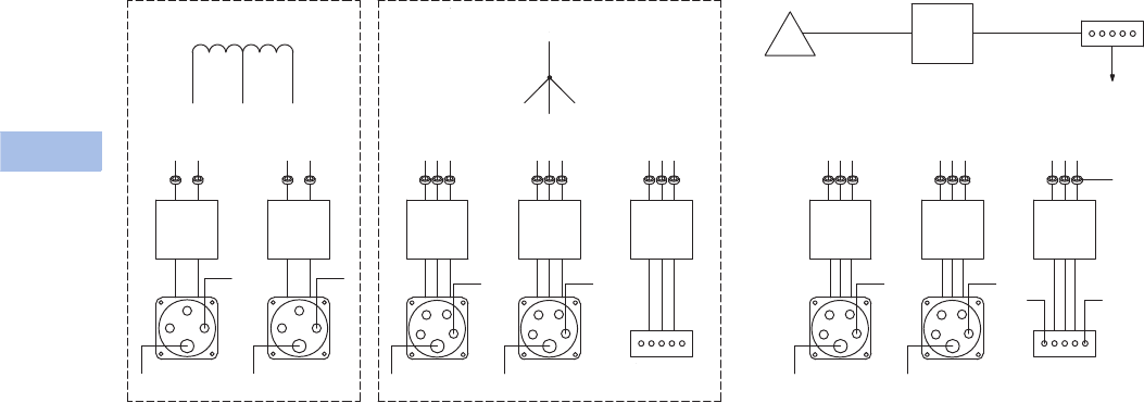
V1-T6-84 Volume 1—Residential and Light Commercial CA08100002E—February 2014 www.eaton.com
6
6
6
6
6
6
6
6
6
6
6
6
6
6
6
6
6
6
6
6
6
6
6
6
6
6
6
6
6
6
6.5
Power Pedestals
Marina Power and Lighting Equipment
Wiring Diagram
Powerpoint
N
120/240V
100A 1Ø
2-Pole
Breaker
120/240V
100A 1Ø
2-Pole
Breaker
120/208V
100A 3Ø
3-Pole
Breaker
120/208V
100A 3Ø
3-Pole
Breaker
120/208V
100A 3Ø
3-Pole
Breaker
480V
100A 3Ø
3-Pole
Breaker
480V
100A 3Ø
3-Pole
Breaker
480V
100A 3Ø
3-Pole
Breaker
G
N
G
N
G
N
G
1 2 3
1 2 3
1 2 3
120/240V Single-Phase Supply 120/240V Three-Phase Supply
3 Ø, 277/480V
Supply from
Main Breaker
3 Ø, 277/480V
Supply from
Main Breaker
3 Ø, 277/480V
Supply from
Main Breaker
480V
3Ø 3-Pole
Main
Breaker
N
G
N
G
NG
Dual-Phase Primary
Transformer 480V
277/480V Supply
from Utility
To 480V
Service
CT for
Electronic
Meter (Typ.)
200A Hard Wire Buss
277/480V
(Ground & Neutral
from Utility Supply)
1
N
32
AB AB
ABO
100A Hard
Wire Buss
120/480V
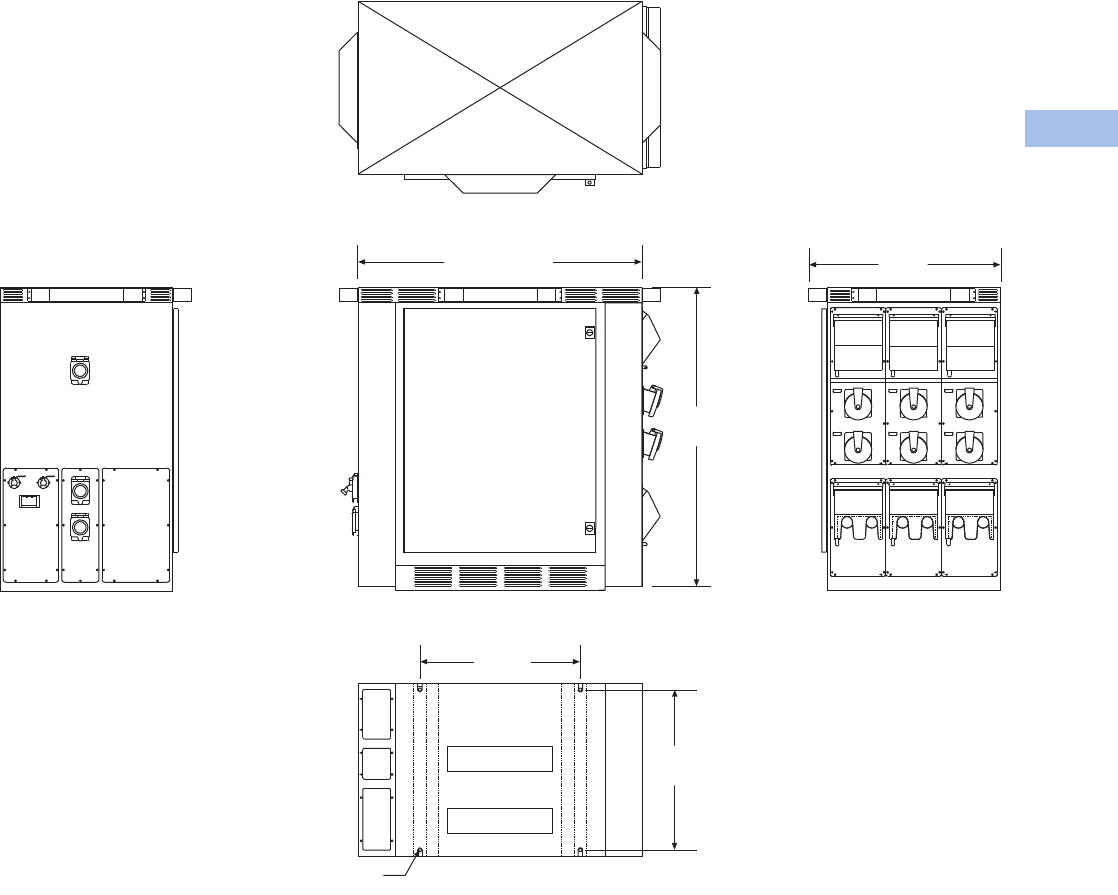
Volume 1—Residential and Light Commercial CA08100002E—February 2014 www.eaton.com V1-T6-85
6
6
6
6
6
6
6
6
6
6
6
6
6
6
6
6
6
6
6
6
6
6
6
6
6
6
6
6
6
6
6.5
Power Pedestals
Marina Power and Lighting Equipment
Dimensions
Approximate Dimensions in Inches (mm)
Powerpoint Unit
Top With Solar Shield
Front
Base
Right SideLeft Side
46.00 (1168.4)
48.54
(1232.9)
31.00
(787.4)
26.00
(660.4)
26.00
(660.4)
Ø 0.50
(Ø 12.7)
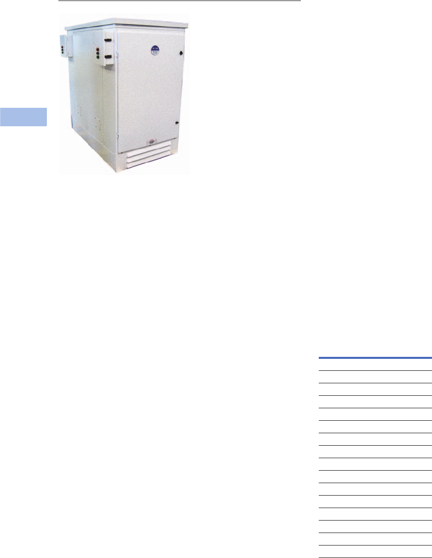
V1-T6-86 Volume 1—Residential and Light Commercial CA08100002E—February 2014 www.eaton.com
6
6
6
6
6
6
6
6
6
6
6
6
6
6
6
6
6
6
6
6
6
6
6
6
6
6
6
6
6
6
6.5
Power Pedestals
Marina Power and Lighting Equipment
Double Panel Substation
Substations
Contents
Description Page
Power Pedestals. . . . . . . . . . . . . . . . . . . . . . . . . . . V1-T6-51
Lighthouse . . . . . . . . . . . . . . . . . . . . . . . . . . . . . . . V1-T6-54
Lighthouse–SS . . . . . . . . . . . . . . . . . . . . . . . . . . . . V1-T6-58
Admiral–SS. . . . . . . . . . . . . . . . . . . . . . . . . . . . . . . V1-T6-62
Newport Harbor Mate . . . . . . . . . . . . . . . . . . . . . . V1-T6-65
Hatteras Light. . . . . . . . . . . . . . . . . . . . . . . . . . . . . V1-T6-69
Firehouse . . . . . . . . . . . . . . . . . . . . . . . . . . . . . . . . V1-T6-73
Smart Start . . . . . . . . . . . . . . . . . . . . . . . . . . . . . . . V1-T6-79
Mariner. . . . . . . . . . . . . . . . . . . . . . . . . . . . . . . . . . V1-T6-80
Digital Electronic Kilowatthour Meters . . . . . . . . . . V1-T6-81
Distribution Equipment—Ground Fault Monitor. . . V1-T6-82
Distribution Equipment—Mega Yacht Powerpoint . V1-T6-83
Distribution Equipment—Substations
Features, Benefits and Functions . . . . . . . . . . . V1-T6-87
Available Options. . . . . . . . . . . . . . . . . . . . . . . . V1-T6-88
Standards and Certifications . . . . . . . . . . . . . . . V1-T6-88
Dimensions . . . . . . . . . . . . . . . . . . . . . . . . . . . . V1-T6-88
Distribution Equipment—Panels . . . . . . . . . . . . . . V1-T6-89
Distribution Equipment—Transformers . . . . . . . . . V1-T6-90
Distribution Equipment—Substations
Product Description
The introduction of
substations into the marina
and recreational vehicle
market allows Eaton to be
your complete marina and RV
park electrical products
supplier. We are able to
assist in the design and
layout of your marina or RV
park electrical system from
the primary service provider,
to your power pedestal.
Our substations are designed
for any coastal or inland
environment and are
constructed of powder-
coated stainless steel NEMA
3R housing cabinets. All
substation cabinets come
with our limited lifetime
warranty. All of our
substations use Eaton’s
panels and circuit breakers
providing our customers the
utmost in circuit protection
and quality.
Application Description
The aluminum and Galvaneal
cabinets are recommended
for inland applications.
The substations can be
configured with 50–330 kVA
single-phase or three-phase
copper wound transformers
and up to 20 single-phase or
12 three-phase branch
breakers. An optional three-
sided double-wall cabinet is
available that provides air
flow between the panels. All
substations come standard
with temperature controlled
cooling fans.
Product Selection Guide
Panel and Transformer
Combinations
Panel Transformer
Single-Phase
200A 50 kVA
300A 75 kVA
400A 100 kVA
600A 150 kVA
700A 167.5 kVA
800A 200 kVA
1000A 250 kVA
1200A 330 kVA
Three-Phase
100A 45 kVA
200A 75 kVA
300A 112.5 kVA
400A 150 kVA
600A 225 kVA
800A 300 kVA
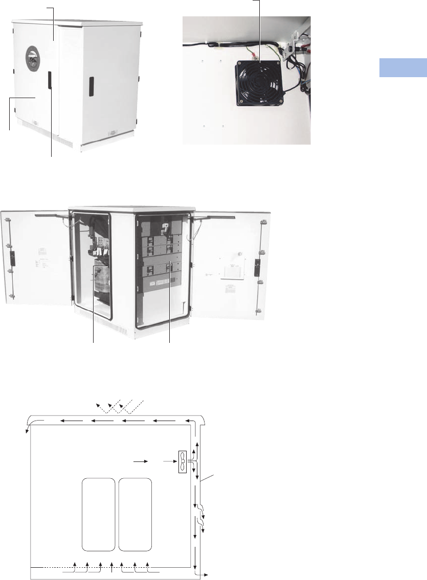
Volume 1—Residential and Light Commercial CA08100002E—February 2014 www.eaton.com V1-T6-87
6
6
6
6
6
6
6
6
6
6
6
6
6
6
6
6
6
6
6
6
6
6
6
6
6
6
6
6
6
6
6.5
Power Pedestals
Marina Power and Lighting Equipment
Features, Benefits
and Functions
●Limited lifetime warranty
on the housing
●All stainless steel
hardware
●Temperature controlled
cooling fans in the
transformer and circuit
breaker compartments
●Lockable door
Ventilation
The substation ventilation
is designed to optimize air
circulation over and around
the transformers and through
the panel compartment so
that the substation operates
at lower temperatures.
Substations come equipped
with temperature controlled
cooling fans for exhausting
hot air from the cabinet and
solar shield.
In addition, substations are
available with a double-
walled cabinet and solar
shield, which allow for
cooling of both the exterior
surface of the cabinet and
the internal components.
Substations
Stainless steel housing
with polyester
powder coating
Limited
lifetime
warranty
on the
housing
Stainless steel hardware
with locking doors
Temperature-controlled
fans for cooli n g
Custom made to your specifications:
Single-phase or three-phase copper
wound transformers
50 to 330 kVA
Up to 1200A main circuit breaker with
20 single-phase or 12 three-phase
branch circuit breakers
Sun Heat
Transformers
Air
Cool Air
Double-Walled
Stainless
Double-Walled Construction

V1-T6-88 Volume 1—Residential and Light Commercial CA08100002E—February 2014 www.eaton.com
6
6
6
6
6
6
6
6
6
6
6
6
6
6
6
6
6
6
6
6
6
6
6
6
6
6
6
6
6
6
6.5
Power Pedestals
Marina Power and Lighting Equipment
Available Options
●Powder-coated cabinets
made of stainless steel
or fiberglass
●Limited lifetime warranty
on housing. Transformer
and secondary distribution
panel in a single enclosure
have a one-year limited
warranty
●Stainless steel housing
and hardware with
locking doors
●Single-phase and three-
phase models
●Overload capacity meets
ANSI L57.96–01.250
●Optional double-walled
construction
●Temperature controlled
fans for cooling
●Custom-made copper
wound single-phase or
three-phase transformers
from 50–330 kVA
●Up to 1200A main circuit
breaker with 15 single-
phase branch circuit
breakers or 10 three-phase
branch circuit breakers
●Substations can be
equipped with photocells
to turn on and off lights
●A 20A GFI can be installed
in the cabinet, as well as
a ground fault monitoring
system
Standards and Certifications
●cULus listed
Dimensions
Approximate Dimensions in
Inches (mm)
Substations
Standard Substation
Height 53.00 (1346.2)
Width 51.00 (1295.4)
Depth 33.00 (838.2)
Side-by-Side Substation
Height 53.00 (1346.2)
Width 66.00 (1676.4)
Depth 30.00 (762.0)
Double Panel Substation
Height 53.00 (1346.2)
Width 63.00 (1600.2)
Depth 33.00 (838.2)
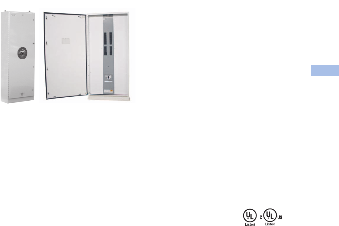
Volume 1—Residential and Light Commercial CA08100002E—February 2014 www.eaton.com V1-T6-89
6
6
6
6
6
6
6
6
6
6
6
6
6
6
6
6
6
6
6
6
6
6
6
6
6
6
6
6
6
6
6.5
Power Pedestals
Marina Power and Lighting Equipment
Panel (Stainless Steel Shown)
Panels
Contents
Description Page
Power Pedestals . . . . . . . . . . . . . . . . . . . . . . . . . . V1-T6-51
Lighthouse . . . . . . . . . . . . . . . . . . . . . . . . . . . . . . V1-T6-54
Lighthouse–SS . . . . . . . . . . . . . . . . . . . . . . . . . . . V1-T6-58
Admiral–SS . . . . . . . . . . . . . . . . . . . . . . . . . . . . . . V1-T6-62
Newport Harbor Mate . . . . . . . . . . . . . . . . . . . . . . V1-T6-65
Hatteras Light . . . . . . . . . . . . . . . . . . . . . . . . . . . . V1-T6-69
Firehouse . . . . . . . . . . . . . . . . . . . . . . . . . . . . . . . V1-T6-73
Smart Start . . . . . . . . . . . . . . . . . . . . . . . . . . . . . . V1-T6-79
Mariner . . . . . . . . . . . . . . . . . . . . . . . . . . . . . . . . . V1-T6-80
Digital Electronic Kilowatthour Meters . . . . . . . . . V1-T6-81
Distribution Equipment—Ground Fault Monitor . . V1-T6-82
Distribution Equipment—Mega Yacht Powerpoint V1-T6-83
Distribution Equipment—Substations . . . . . . . . . . V1-T6-86
Distribution Equipment—Panels
Distribution Equipment—Transformers . . . . . . . . . V1-T6-90
Distribution Equipment—Panels
Product Description
Two of the many products
we can offer our customers
are Eaton’s PRL-3A and
PRL-4 panels as standalone
units or in one of our
substations. All of our busses
are made of copper and are
load rated; breakers are
bolt-on type. Distribution
panels can be 120/240V
single-phase, 120/208V three-
phase, 277/480V three-phase
or 220Y/127V three-phase
based on your system
requirements. Distribution
panels can also have a main
breaker or a main lug. Branch
circuit breakers are provided
based on customer
requirements.
Features
●All internal wiring is
fine stranded 1000V
insulated copper
●Copper busbars
●All exterior hardware
is stainless steel
Available Options
●NEMA 3R or 4X
●Powder-coated
stainless steel
●Main breaker up to 1200A
●Branch breaker 20–1200A
●Main lug only
●We also offer 480V
models—single-phase
and three-phase
Single-Phase
●Up to 1200A main
circuit breakers
●Up to 42 branch
circuit breakers
Three-Phase
●Up to 1200A main
circuit breakers
●Up to 42 branch
circuit breakers
Standards and Certifications
●UL listed
●cULus listed
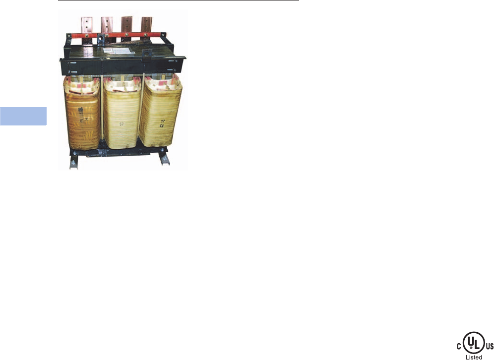
V1-T6-90 Volume 1—Residential and Light Commercial CA08100002E—February 2014 www.eaton.com
6
6
6
6
6
6
6
6
6
6
6
6
6
6
6
6
6
6
6
6
6
6
6
6
6
6
6
6
6
6
6.5
Power Pedestals
Marina Power and Lighting Equipment
Three-Phase Transformer
Transformers
Contents
Description Page
Power Pedestals. . . . . . . . . . . . . . . . . . . . . . . . . . . V1-T6-51
Lighthouse . . . . . . . . . . . . . . . . . . . . . . . . . . . . . . . V1-T6-54
Lighthouse–SS . . . . . . . . . . . . . . . . . . . . . . . . . . . . V1-T6-58
Admiral–SS. . . . . . . . . . . . . . . . . . . . . . . . . . . . . . . V1-T6-62
Newport Harbor Mate . . . . . . . . . . . . . . . . . . . . . . V1-T6-65
Hatteras Light. . . . . . . . . . . . . . . . . . . . . . . . . . . . . V1-T6-69
Firehouse . . . . . . . . . . . . . . . . . . . . . . . . . . . . . . . . V1-T6-73
Smart Start . . . . . . . . . . . . . . . . . . . . . . . . . . . . . . . V1-T6-79
Mariner. . . . . . . . . . . . . . . . . . . . . . . . . . . . . . . . . . V1-T6-80
Digital Electronic Kilowatthour Meters . . . . . . . . . . V1-T6-81
Distribution Equipment—Ground Fault Monitor. . . V1-T6-82
Distribution Equipment—Mega Yacht Powerpoint . V1-T6-83
Distribution Equipment—Substations . . . . . . . . . . V1-T6-86
Distribution Equipment—Panels . . . . . . . . . . . . . . V1-T6-89
Distribution Equipment—Transformers
Distribution Equipment—Transformers
Product Description
Because of the high humidity
and corrosive conditions of
coastal environments, our
transformers are wound with
Class H heavily insulated
copper bar and are double
dipped in tough insulating
varnish that protects the
copper, as well as reduces
the hum that is typical in
a transformer that is not
double dipped. We provide
a second overcoat of high
temperature epoxy to protect
against the severe saltwater
environment. We can provide
this transformer in single-
phase, from 50–500 kVA,
and three-phase, from
45–300 kVA.
Features
●Copper wound transformer
coils double dipped in high
temperature baking varnish
●All internal wiring is
fine stranded 2000V
insulated copper
●Copper busbars
●Marine transformers
with epoxy overcoat
●All copper-to-copper
connections
Available Options
●Single-phase: 50–500 kVA
●Three-phase: 45–300 kVA
●Epoxy overcoat for non-
marine applications
Primary Voltages
●480 wye three-phase
●480V three-phase delta
three-wire + ground
●480V single-phase
two-wire + ground
Secondary Voltages
●127/220V three-phase
wye four-wire
●120/208V three-phase
wye four-wire
●120/240V single-phase
three-wire
Marina Power Distribution
Transformer kVA Availabilities
●Single-phase: 50, 75, 100,
150, 167.5, 200, 250, 330,
500 kVA
●Three-phase: 45, 75, 112.5,
150, 225, 300 kVA
Standards and Certifications
●cULus listed

Volume 1—Residential and Light Commercial CA08100002E—August 2012 www.eaton.com V1-T7-1
7
7
7
7
7
7
7
7
7
7
7
7
7
7
7
7
7
7
7
7
7
7
7
7
7
7
7
7
7
7
Air Conditioning Disconnects
Air Conditioning Disconnects
7.1 Air Conditioning Disconnects
Product Description . . . . . . . . . . . . . . . . . . . . . . . . . . . . . . . . . . . . . . . V1-T7-2
Application Description. . . . . . . . . . . . . . . . . . . . . . . . . . . . . . . . . . . . . V1-T7-2
Features, Benefits and Functions . . . . . . . . . . . . . . . . . . . . . . . . . . . . . V1-T7-3
Standards and Certifications. . . . . . . . . . . . . . . . . . . . . . . . . . . . . . . . . V1-T7-3
Product Selection . . . . . . . . . . . . . . . . . . . . . . . . . . . . . . . . . . . . . . . . . V1-T7-4
Cross-Reference . . . . . . . . . . . . . . . . . . . . . . . . . . . . . . . . . . . . . . . . . . V1-T7-6
Technical Data and Specifications. . . . . . . . . . . . . . . . . . . . . . . . . . . . . V1-T7-7
Dimensions. . . . . . . . . . . . . . . . . . . . . . . . . . . . . . . . . . . . . . . . . . . . . . V1-T7-7
Learn
Online
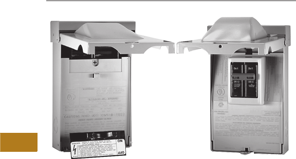
V1-T7-2 Volume 1—Residential and Light Commercial CA08100002E—August 2012 www.eaton.com
7
7
7
7
7
7
7
7
7
7
7
7
7
7
7
7
7
7
7
7
7
7
7
7
7
7
7
7
7
7
7.1
Air Conditioning Disconnects
Fused, Unfused and Molded Case Switch
Complete Line of Fused, Unfused and Molded
Case Switch Type Air Conditioning Disconnects
Air Conditioning Disconnects
Contents
Description Page
Features, Benefits and Functions. . . . . . . . . . . . . . V1-T7-3
Standards and Certifications . . . . . . . . . . . . . . . . . V1-T7-3
Product Selection . . . . . . . . . . . . . . . . . . . . . . . . . . V1-T7-4
Cross-Reference . . . . . . . . . . . . . . . . . . . . . . . . . . V1-T7-6
Technical Data and Specifications . . . . . . . . . . . . . V1-T7-7
Dimensions . . . . . . . . . . . . . . . . . . . . . . . . . . . . . . V1-T7-7
Product Description
An air conditioning
disconnect (ACD) is a
disconnect located between
a loadcenter (distribution
panel) and air conditioner.
Eaton’s ACD product line
provides an installer or repair
personnel with a visible
disconnecting means when
performing maintenance.
ACDs are also known as
disconnects, pullouts or air
conditioning switches.
Non-fused pullout and
molded case switch devices
provide personnel with a
visible ON-OFF disconnecting
means. While fused pullout
units also perform this
function, they also provide an
additional level of protection
for the air conditioner.
Fused and non-fused devices
are of a pullout design, where
the user physically removes
or “pulls out” a tab to break
the electrical connection.
A molded case switch is
similar to a light switch where
the user “switches” the
unit to the indicated
ON-OFF position.
Fused and Non-Fused
Pullouts
●ON/OFF control provided
by a pullout handle
●Pullout handle can be
conveniently stored in the
compartment in the OFF
position, helping to prevent
the handle from being
misplaced
●Protective shield cannot be
removed until the pullout
handle is removed,
disconnecting the power
Molded Case Switch
●Rugged molded case
construction in a
disconnect switch that
looks like a circuit breaker
but operates like an
ordinary household
light switch
●Plug-in molded case switch
(included) eliminates the
need for pullout handles
●No need for replacement
pullout handles due to loss
or theft
Application Description
The most widely used
application for ACDs is for
residential and light
commercial air conditioning
units. An ACD is installed
outdoors, in visible proximity
to the air conditioner
condensing unit. ACDs are
also found in use with heat
pumps, swimming pools,
spas, whirlpools and pump
houses, and meet 2008
NEC Article 422.31 (B)
requirements for servicing
electric water heaters.
Metallic enclosures are
galvanized steel and are
installed in various locations.
Non-metallic enclosures are a
plastic (polycarbonate)
enclosure commonly used in
coastal or salt-water areas.

Volume 1—Residential and Light Commercial CA08100002E—August 2012 www.eaton.com V1-T7-3
7
7
7
7
7
7
7
7
7
7
7
7
7
7
7
7
7
7
7
7
7
7
7
7
7
7
7
7
7
7
7.1
Air Conditioning Disconnects
Fused, Unfused and Molded Case Switch
Features, Benefits and Functions
●Single-phase, two-wire,
240 Vac and three-phase,
three-wire, 240 Vac
●NEMA 3R outdoor
enclosures offered in
metallic and
non-metallic versions
●Easy-to-remove high-
strength protective
shield for easier wiring
and mounting
●Easy-to-remove front cover
(no screws or fasteners to
remove)
●1-inch knockouts on the
bottom, back and side
of unit
●Copper-rated line and load
lugs that are easily
accessible
●Ample wiring space for
mounting with a stud gun
(single keyhole, two- or
three-point mounting)
●Fused devices are service
entrance rated
Note: Fused non-metallic units
require the addition of GB4NM
ground bar to obtain a Service
Entrance rating.
●Horsepower rated (10 hp
maximum at 240 Vac)
●Padlockable door provision
for safety and reduction of
tampering
●Metallic enclosures are
bottom entry and exit only
●Non-metallic enclosures
have knockouts and a hub
provision for top access
●Non-metallic enclosures
have a single unit door and
protective shield for
installer convenience
●Non-metallic enclosures
are durable and provide
excellent resistance to
climate changes
●Factory-installed tamper-
resistant/weather-resistant
receptacles are available as
an option on some products
Standards and
Certifications
●UL listed File No. E132354,
E143893, E196365
Contact Eaton for details
and part numbers for CSA
approved units.
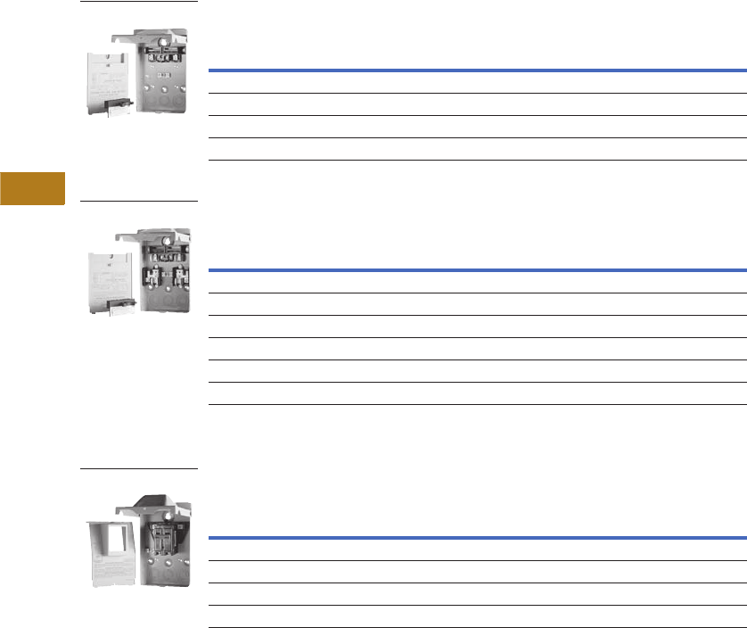
V1-T7-4 Volume 1—Residential and Light Commercial CA08100002E—August 2012 www.eaton.com
7
7
7
7
7
7
7
7
7
7
7
7
7
7
7
7
7
7
7
7
7
7
7
7
7
7
7
7
7
7
7.1
Air Conditioning Disconnects
Fused, Unfused and Molded Case Switch
Product Selection
Non-Fused Pullouts
Fused Pullouts
For Service Entrance applications, see footnotes below.
Molded Case Switch
Notes
1 For replacement pullout head, order part number 96-3258-4.
2 To obtain a Service Entrance Rating, the addition of a DPFG (ground bar kit) is required.
3 For replacement molded case switch, order part number BR260NA.
Main
Ampere
Rating
Maximum hp Rating Wire Size
Range Cu/Al
60ºC or 75ºC
Catalog
Number120V 240V
Galvanized Steel
60 — 10 #14–3 DPU222R 1
Non-Metallic/Polycarbonate Enclosure
60 — 10 #14–2 ACD222URNM-A2 1
Main
Ampere
Rating
Maximum hp Rating Wire Size
Range Cu/Al
60ºC or 75ºC
Catalog
Number120V 240V
Galvanized Steel
30 22 3 #14–3 DPF221R 1
60 23 10 #14–3 DPF222R 1
Non-Metallic
30 2 3 #14–2 ACD221RNM-A2 1
60 3 10 #14–2 ACD222RNM-A2 1
Main
Ampere
Rating
Maximum hp Rating Wire Size
Range Cu/Al
60ºC or 75ºC
Catalog
Number120V 240V
Galvanized Steel
60 — 10 #14–3 DPB222R 3
Non-Metallic/Polycarbonate Enclosure
60 — 10 #14–2 B60NARNM-A2 3
DPU222R
DPF222R
DPB222R
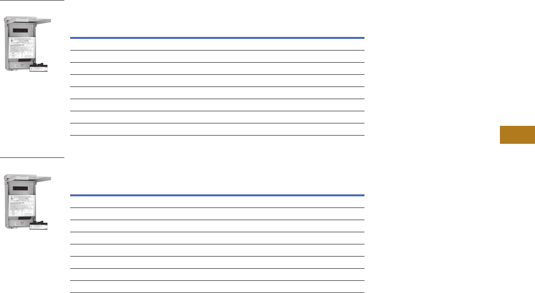
Volume 1—Residential and Light Commercial CA08100002E—August 2012 www.eaton.com V1-T7-5
7
7
7
7
7
7
7
7
7
7
7
7
7
7
7
7
7
7
7
7
7
7
7
7
7
7
7
7
7
7
7.1
Air Conditioning Disconnects
Fused, Unfused and Molded Case Switch
ACD with 20 Ampere Ground Fault Receptacle 1
ACD with 15 Ampere Ground Fault Receptacle 13
Notes
1 Factory-installed GFCI receptacle.
2 Includes weather-resistant/tamper-resistant receptacles to meet 2008 NEC Article 406.8 (A) and 406.11 requirements.
3 NEC permits the maximum receptacle rating of a 15A circuit to be 15A.
Main
Ampere
Rating
Maximum hp Rating Wire Size
Range Cu/Al
60ºC or 75ºC
Catalog
Number120V 240V
Non-Fused Pullouts
60 — 10 #14–3 DPU222RGF20WRTR 2
60 — 10 #14–3 DPU222RGF20
Fused Pullouts
30 2 3 #14–3 DPF221RGF20WRTR 2
30 2 3 #14–3 DPF221RGF20
60 3 10 #14–3 DPF222RGF20WRTR 2
60 3 10 #14–3 DPF222RGF20
Main
Ampere
Rating
Maximum hp Rating Wire Size
Range Cu/Al
60ºC or 75ºC
Catalog
Number120V 240V
Non-Fused Pullouts
60 — 10 #14–3 DPU222RGF15
60 — 10 #14–3 DPU222RGF15WRTR 2
Fused Pullouts
30 2 3 #14–3 DPF221RGF15
30 2 3 #14–3 DPF221RGF15WRTR 2
60 3 10 #14–3 DPF222RGF15
60 3 10 #14–3 DPF222RGF15WRTR 2
DPU222RGF20
DPU222RGF15
V1-T7-6 Volume 1—Residential and Light Commercial CA08100002E—August 2012 www.eaton.com
7
7
7
7
7
7
7
7
7
7
7
7
7
7
7
7
7
7
7
7
7
7
7
7
7
7
7
7
7
7
7.1
Air Conditioning Disconnects
Fused, Unfused and Molded Case Switch
Three-Phase Non-Fused ACD
Cross-Reference
Cross-Reference
Note
1Eaton Quick ProSM designated item.
Main
Ampere
Rating
Maximum hp Rating
Wire Size
Range Cu 75ºC
Catalog
Number240V 480V
60 15 30 #14–4 DPU362RA
DPU362A
Description
Catalog Number
Eaton Square D®GE®Siemens®
(Murray®) Milbank Midwest
Metallic/Galvanized Steel Enclosure
30A fused DPF221R — TF30R WF2030 U3830 U035F2
60A fused DPF222R — TF60R WF2060 U3860 U065F1
60A non-fused DPU222R — TFN60R — U3800 U065P010
60A non-fused compact design DPU222R — — WNFC2060 — —
60A molded case switch DPB222R QO200TR TNA60R1 WNAS2060 — U065NA1
60A non-fused with ground fault receptacle DPU222RGF — TFN60RGFR WN2060GFCI U3822-20GR U065P010
30A fused with ground fault receptacle DPF221RGF — — WF2030GFCI — U035F010
60A fused with ground fault receptacle DPF222RGF — — WF2060GFCI — U065F010
60A non-fused with 1/2-inch wire harness DPU222R12W —————
60A non-fused with 3/4-inch wire harness DPU222R34W —————
60A three-phase 600V molded case switch DPU362RA — — — — U0653F
Non-Metallic/Polycarbonate Enclosure
30A fused ACD221RNM-A2 TPF30R WF2030PL — P035F
60A fused ACD222RNM-A2 TPF60R WF2060PL — P065F
60A non-fused ACD222URNM-A2 TPN60R1 WN2060PL — P065P1
60A molded case switch B60NARNM-A2 QO200TRNM TPNA60R1 WNAS2060PL — P065NA1
30A fused with 15A ground fault receptacle DPF221RGF15WRTR —————
30A fused with 20A ground fault receptacle DPF221RGF20WRTR —————
60A fused with 15A ground fault receptacle DPF222RGF15WRTR —————
60A fused with 20A ground fault receptacle DPF222RGF20WRTR —————
60A non-fused with 15A ground fault receptacle DPU222RGF15WRTR —————
60A non-fused with 20A ground fault receptacle DPU222RGF20WRTR — — — U3822-20GWR —

Volume 1—Residential and Light Commercial CA08100002E—August 2012 www.eaton.com V1-T7-7
7
7
7
7
7
7
7
7
7
7
7
7
7
7
7
7
7
7
7
7
7
7
7
7
7
7
7
7
7
7
7.1
Air Conditioning Disconnects
Fused, Unfused and Molded Case Switch
Technical Data and Specifications
●10,000 amperes rms
symmetrical interrupting
rating
●Horsepower rated
●Fusible and non-fusible
pullout and molded case
switch designs
●30 and 60 amperes
available in fusible
●60 amperes available in
non-fusible and molded
case switch
●Class H fuse clips provided
on fusible pullout design
●WRTR (weather-resistant/
tamper-resistant)
receptacle options
available
Dimensions
Approximate Dimensions in Inches (mm)
Dimensions and Shipping Carton Information
Note
1Eaton Quick Pro designated item.
Catalog Number
Carton
Quantity
Dimensions in Inches (mm)
Weight Lbs (kg)Height Width Depth
Metallic/Galvanized Steel Enclosure
DPF221R 10 8.70 (220.9) 5.40 (137.2) 3.15 (80.0) 27 (12)
DPF222R 10 8.70 (220.9) 5.40 (137.2) 3.15 (80.0) 27 (12)
DPU222R 10 8.70 (220.9) 5.40 (137.2) 3.15 (80.0) 27 (12)
DPB222R 10 8.60 (218.4) 5.30 (134.6) 3.74 (95.0) 34 (15)
DPU222R12W 11 14.75 (374.6) 12.50 (317.5) 4.00 (101.6) 6 (3)
DPU222R34W 11 14.75 (374.6) 12.50 (317.5) 4.00 (101.7) 6 (3)
DPU222RGF20 1 13.00 (330.2) 7.50 (190.5) 4.75 (120.7) 8 (4)
DPF221RGF20 1 13.00 (330.2) 7.50 (190.5) 4.75 (120.7) 8 (4)
DPF222RGF20 1 13.00 (330.2) 7.50 (190.5) 4.75 (120.7) 8 (4)
DPU222RGF15 1 13.00 (330.2) 7.50 (190.5) 4.75 (120.7) 8 (4)
DPF221RGF15 1 13.00 (330.2) 7.50 (190.5) 4.75 (120.7) 8 (4)
DPF222RGF15 1 13.00 (330.2) 7.50 (190.5) 4.75 (120.7) 8 (4)
DPF221RGF15WRTR 1 13.00 (330.2) 7.50 (190.5) 4.75 (120.7) 8 (4)
DPF221RGF20WRTR 1 13.00 (330.2) 7.50 (190.5) 4.75 (120.7) 8 (4)
DPF222RGF15WRTR 1 13.00 (330.2) 7.50 (190.5) 4.75 (120.7) 8 (4)
DPF222RGF20WRTR 1 13.00 (330.2) 7.50 (190.5) 4.75 (120.7) 8 (4)
DPU222RGF15WRTR 1 13.00 (330.2) 7.50 (190.5) 4.75 (120.7) 8 (4)
DPU222RGF20WRTR 1 13.00 (330.2) 7.50 (190.5) 4.75 (120.7) 8 (4)
DPU362R 1 8.60 (218.4) 5.30 (134.6) 3.74 (94.9) 4 (2)
Non-Metallic/Polycarbonate Enclosure
ACD221RNM-A2 10 8.63 (219.0) 6.26 (159.0) 4.33 (109.9) 15 (7)
ACD222RNM-A2 10 8.63 (219.0) 6.26 (159.0) 4.33 (109.9) 15 (7)
ACD222URNM-A2 10 8.63 (219.0) 6.26 (159.0) 4.33 (109.9) 15 (7)
B60NARNM-A2 10 8.63 (219.0) 6.26 (159.0) 4.33 (109.9) 18 (8)
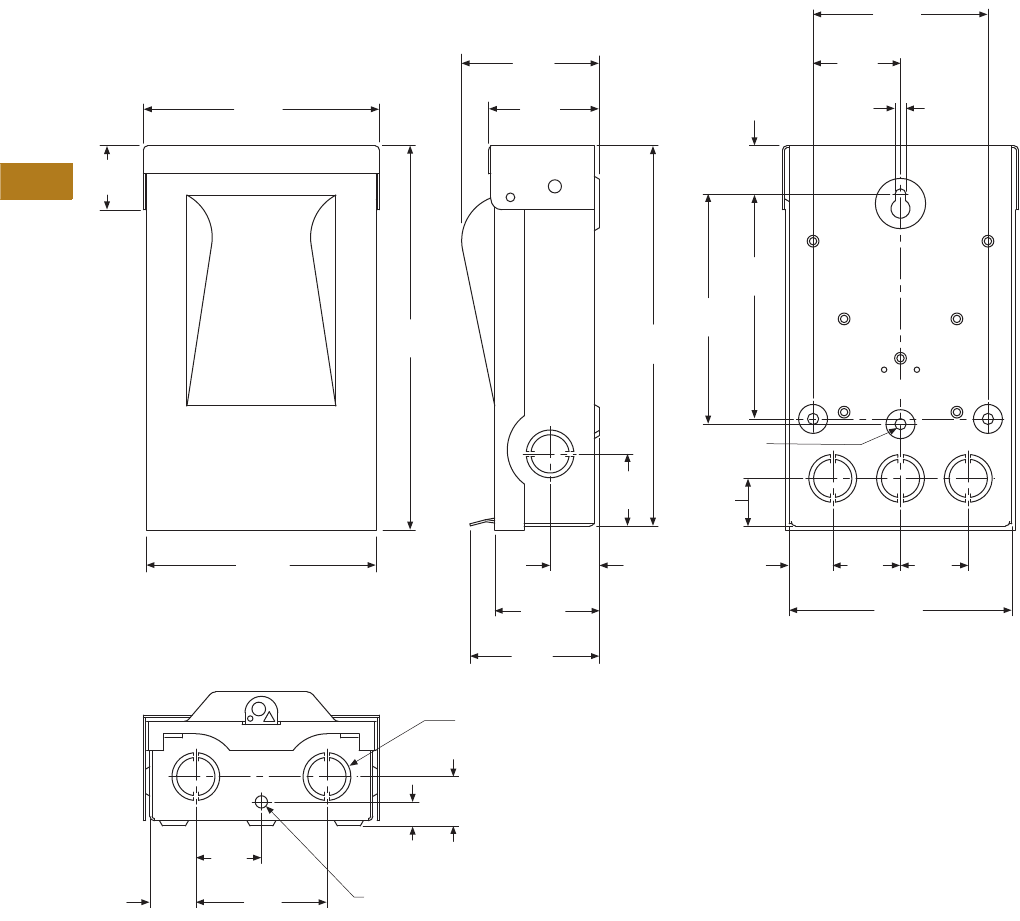
V1-T7-8 Volume 1—Residential and Light Commercial CA08100002E—August 2012 www.eaton.com
7
7
7
7
7
7
7
7
7
7
7
7
7
7
7
7
7
7
7
7
7
7
7
7
7
7
7
7
7
7
7.1
Air Conditioning Disconnects
Fused, Unfused and Molded Case Switch
Approximate Dimensions in Inches (mm)
DPF221R, DPF222R, DPU222R, DPU222R12W and DPU222R34W
5.40
(137.2)
8.79
(223.4)
2.54
(64.4)
3.15
(80.1)
7 Knockouts for 1/2 (12.7),
3/4 (19.1) or 1 (25.4) Conduit
0.28 (7.1) Diameter
Knockout—1 Req‘d.
0.26 (6.5) Dia.
3 Holes Req’d.
0.25
(6.4)
2.00
(50.8)
4.00
(101.6)
1.47
(37.2)
8.70
(221.0)
5.26
(133.6)
5.14
(130.6)
1.11
(28.2)
5.25
(133.5)
1.05
(26.7)
1.50
(38.1)
3.00
(76.2)
0.55
(14.0)
1.13
(28.7)
2.97
(75.3)
2.39
(60.8)
1.13
(28.7)
1.65
(41.9) 1.09
(27.7)
1.0 0
(25.4)
1.55
(39.4)
5.10
(129.5)
1.55
(39.4)
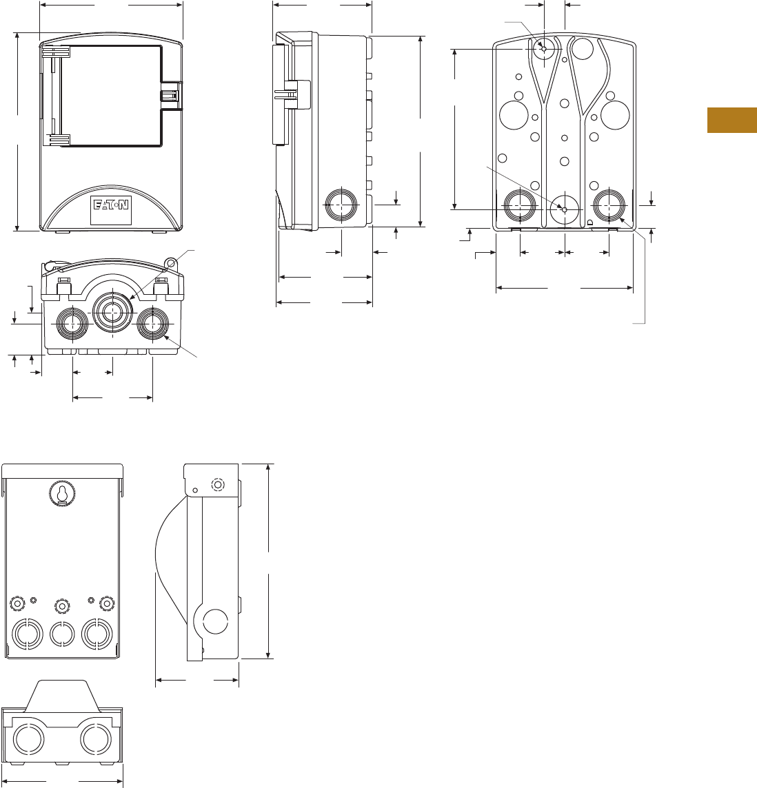
Volume 1—Residential and Light Commercial CA08100002E—August 2012 www.eaton.com V1-T7-9
7
7
7
7
7
7
7
7
7
7
7
7
7
7
7
7
7
7
7
7
7
7
7
7
7
7
7
7
7
7
7.1
Air Conditioning Disconnects
Fused, Unfused and Molded Case Switch
Approximate Dimensions in Inches (mm)
ACD221RNM-A2, ACD222RNM-A2, ACD222URNM-A2 and B60NARNM-A2
DPB222R and DPU362A
1.36
(34.5)
1.0 0
(25.4)
6.26
(159.0)
1.76
(44.7)
3.52
(89.3)
1.35
(34.3)
1.83
(46.4)
0.96
(24.4)
1.35
(34.3)
4.08
(103.6)
4.20
(106.6)
4.33
(110.2)
7.03
(178.7)
0.81
(20.6)
1.05
(26.5)
1.95
(49.5)
0.90
(22.9)
0.20
(5.1) DIA.
0.21
(5.3)
DIA.
4 Knockouts
for 0.75 (19.1)
or 1.00 (25.4)
Conduit
2 Knockouts
for 0.50 (12.7),
0.75 (19.1)
or 1.00 (25.4)
Conduit
1 Knockout
for 0.50 (12.7),
1.00 (25.4),
1.25 (31.8)
Conduit
8.36
(212.2)
6.00
(152.4)
8.69
(220.8)
1.95
(49.5)
5.30
(134.6)
3.74
(94.9)
8.60
(218.4)
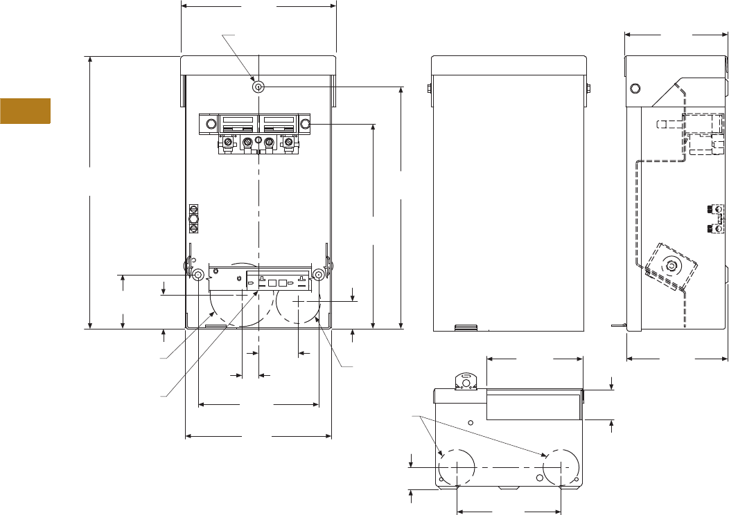
V1-T7-10 Volume 1—Residential and Light Commercial CA08100002E—August 2012 www.eaton.com
7
7
7
7
7
7
7
7
7
7
7
7
7
7
7
7
7
7
7
7
7
7
7
7
7
7
7
7
7
7
7.1
Air Conditioning Disconnects
Fused, Unfused and Molded Case Switch
Approximate Dimensions in Inches (mm)
DPU222RGF20, DPF221RGF20, DPF222RGF20, DPU222RGF15, DPF221RGF15, DPF222RGF15, DPF221RGF15WRTR,
DPF221RGF20WRTR, DPF222RGF15WRTR, DPF222RGF20WRTR, DPU222RGF15WRTR and DPU222RGF20WRTR
6.63
(168.4)
11.63
(295.4)
8.75
(222.3)
2.31
(58.7)
0.69
(17.5)
5.13
(130.3)
6.25
(158.8)
4.44
(112.8)
0.94
(23.9)
1.25
(31.8)
4.06
(103.1)
4.31
(109.5)
4.44
(112.8)
1.69
(42.9)
1.44
(36.6)
0.75, 1.00, 1.25, 1.50
(19.1, 25.4, 31.8, 38.1)
Knockouts
0.50, 0.75, 1.00
(12.7, 19.1, 25.4)
Knockouts
0.50, 0.75
(12.7, 19.1)
Knockouts
20A GFCI
Receptacle
LINE LINE
0.25 (6.4) Dia.
Hole 3 Places
10.25
(260.4)
1.18
(30.0)

Volume 1—Residential and Light Commercial CA08100002E—June 2013 www.eaton.com V1-A1-1
Appendix 1—Eaton Terms & Conditions
Effective Date: November 1, 2008
Eaton Terms & Conditions
Contents
Description Page
Terms and Conditions of Sale. . . . . . . . . . . . . . . . . V1-A1-1
Terms of Payment . . . . . . . . . . . . . . . . . . . . . . . . . V1-A1-2
Freight . . . . . . . . . . . . . . . . . . . . . . . . . . . . . . . . . . V1-A1-3
Warranty . . . . . . . . . . . . . . . . . . . . . . . . . . . . . . . . . V1-A1-3
Selling Policy (Supersedes Selling Policy 25-000, dated February 20, 2006)
Terms and Conditions of Sale
The Terms and Conditions of
Sale set forth herein, and any
supplements which may be
attached hereto, constitute
the full and final expression
of the contract for the sale
of products or services
(hereinafter referred to as
Product(s) or Services by
Eaton Corporation
(hereinafter referred to as
Seller) to the Buyer, and
supersedes all prior
quotations, purchase orders,
correspondence or
communications whether
written or oral between the
Seller and the Buyer.
Notwithstanding any contrary
language in the Buyer’s
purchase order,
correspondence or other
form of acknowledgment,
Buyer shall be bound by
these Terms and Conditions
of Sale when it sends a
purchase order or otherwise
indicates acceptance of this
contract, or when it accepts
delivery from Seller of the
Products or Services.
THE CONTRACT FOR SALE
OF THE PRODUCTS OR
SERVICES IS EXPRESSLY
LIMITED TO THE TERMS
AND CONDITIONS OF SALE
STATED HEREIN. ANY
ADDITIONAL OR DIFFERENT
TERMS PROPOSED BY
BUYER ARE REJECTED
UNLESS EXPRESSLY
AGREED TO IN WRITING BY
SELLER. No contract shall
exist except as herein
provided.
Complete Agreement
No amendment or
modification hereto nor any
statement, representation or
warranty not contained herein
shall be binding on the Seller
unless made in writing by an
authorized representative of
the Seller. Prior dealings,
usage of the trade or a course
of performance shall not be
relevant to determine the
meaning of this contract even
though the accepting or
acquiescing party had
knowledge of the nature
of the performance and
opportunity for objection.
Quotations
Written quotations are valid
for 30 days from its date
unless otherwise stated in
the quotation or terminated
sooner by notice.
Verbal quotations, unless
accepted, expire the same
day they are made.
A complete signed order
must be received by Seller
within 20 calendar days of
notification of award,
otherwise the price and
shipment will be subject to
re-negotiation.
Termination and Cancellation
Any order may be terminated
by the Buyer only by written
notice and upon payment
of reasonable termination
charges, including all costs
plus profit.
Seller shall have the right to
cancel any order at any time
by written notice if Buyer
breaches any of the terms
hereof, becomes the subject
of any proceeding under state
or federal law for the relief
of debtors, or otherwise
becomes insolvent or
bankrupt, generally does not
pay its debts as they become
due or makes an assignment
for the benefit of creditors.
V1-A1-2 Volume 1—Residential and Light Commercial CA08100002E—June 2013 www.eaton.com
Appendix 1—Eaton Terms & Conditions
Effective Date: November 1, 2008
Prices
All prices are subject to
change without notice. In the
event of a price change, the
effective date of the change
will be the date of the new
price or discount sheet, letter
or telegram. All quotations
made or orders accepted
after the effective date will be
on the new basis. For existing
orders, the price of the
unshipped portion of an order
will be the price in effect at
time of shipment.
Price Policy—Products and
Services
When prices are quoted as
firm for quoted shipment, they
are firm provided the following
conditions are met:
1. The order is released
with complete
engineering details.
2. Shipment of Products are
made, and Services
purchased are provided
within the quoted
lead time.
3. When drawings for
approval are required
for any Products, the
drawings applicable to
those Products must be
returned within 30*
calendar days from the
date of the original
mailing of the drawings
by Seller. The return
drawings must be
released for manufacture
and shipment and must
be marked “APPROVED”
or “APPROVED AS
NOTED.” Drawing
re-submittals which are
required for any other
reason than to correct
Seller errors will not
extend the 30-day period.
* 60 days for orders
through contractors
to allow time for their
review and approval
before and after
transmitting them
to their customers.
If the Buyer initiates or in
any way causes delays
in shipment, provision of
Services or return of approval
drawings beyond the periods
stated above, the price of the
Products or Services will be
increased 1% per month
or fraction thereof up to a
maximum of 18 months from
the date of the Buyer’s order.
For delays resulting in
shipment or provision of
Services beyond 18 months
from the date of the Buyer’s
order, the price must be
renegotiated.
Price Policy—BLS
Refer to Price Policy 25-050.
Minimum Billing
Orders less than $1,000 will
be assessed a shipping and
handling charge of 5% of the
price of the order, with a
minimum charge of $25.00
unless noted differently on
Product discount sheets.
Taxes
The price does not include
any taxes. Buyer shall be
responsible for the payment
of all taxes applicable to, or
arising from the transaction,
the Products, its sale, value,
or use, or any Services
performed in connection
therewith regardless of
the person or entity
actually taxed.
Terms of Payment
Products
Acceptance of all orders is
subject to the Buyer meeting
Seller’s credit requirements.
Terms of payment are subject
to change for failure to meet
such requirements. Seller
reserves the right at any time
to demand full or partial
payment before proceeding
with a contract of sale as a
result of changes in the
financial condition of the
Buyer. Terms of Payment are
either Net 30 days from the
date of invoice of each
shipment or carry a cash
discount based on Product
type. Specific payment terms
for Products are outlined in
the applicable Product
discount schedules.
Services
Terms of payment are net
within 30 days from date of
invoice for orders amounting
to less than $50,000.00.
Terms of payment for orders
exceeding $50,000.00 shall
be made according to the
following:
1. Twenty percent (20%) of
order value with the
purchase order payable
30 days from date of
invoice.
2. Eighty percent (80%) of
order value in equal
monthly payments over
the performance period
payable 30 days from
date of invoice.
Except for work performed (i)
under a firm fixed price basis
or (ii) pursuant to terms of a
previously priced existing
contract between Seller and
Buyer, invoices for work
performed by Seller shall
have added and noted on
each invoice a charge of 3%
(over and above the price of
the work) which is related
to Seller compliance with
present and proposed
environmental, health, and
safety regulations associated
with prescribed requirements
covering hazardous materials
management and employee
training, communications,
personal protective
equipment, documentation
and record keeping
associated therewith.
Adequate Assurances
If, in the judgment of Seller,
the financial condition of the
Buyer, at any time during the
period of the contract, does
not justify the terms of
payment specified, Seller
may require full or partial
payment in advance.
Delayed Payment
If payments are not made in
accordance with these terms,
a service charge will, without
prejudice to the right of Seller
to immediate payment, be
added in an amount equal to
the lower of 1.5% per month
or fraction thereof or the
highest legal rate on the
unpaid balance.
Volume 1—Residential and Light Commercial CA08100002E—June 2013 www.eaton.com V1-A1-3
Appendix 1—Eaton Terms & Conditions
Effective Date: November 1, 2008
Freight
Freight policy will be listed on
the Product discount sheets,
or at option of Seller one of
the following freight terms
will be quoted.
F.O.B.—P/S—Frt./Ppd. and
Invoiced
Products are sold F.O.B. point
of shipment freight prepaid
and invoiced to the Buyer.
F.O.B.—P/S—Frt./Ppd.
and Allowed
Products sold are delivered
F.O.B. point of shipment,
freight prepaid and included
in the price.
F.O.B. Destination—Frt./Ppd.
and Allowed
At Buyer’s option, Seller will
deliver the Products F.O.B.
destination freight prepaid
and 2% will be added to the
net price.
The term “freight prepaid”
means that freight charges
will be prepaid to the
accessible common carrier
delivery point nearest the
destination for shipments
within the United States and
Puerto Rico unless noted
differently on the Product
discount sheets. For any
other destination contact
Seller’s representative.
Shipment and Routing
Seller shall select the point of
origin of shipment, the
method of transportation, the
type of carrier equipment and
the routing of the shipment.
If the Buyer specifies a
special method of
transportation, type of carrier
equipment, routing, or
delivery requirement, Buyer
shall pay all special freight
and handling charges.
When freight is included in
the price, no allowance will
be made in lieu of
transportation if the Buyer
accepts shipment at factory,
warehouse, or freight station
or otherwise supplies its own
transportation.
Risk of Loss
Risk of loss or damage to the
Products shall pass to Buyer
at the F.O.B. point.
Concealed Damage
Except in the event of F.O.B.
destination shipments, Seller
will not participate in any
settlement of claims for
concealed damage.
When shipment has been
made on an F.O.B. destination
basis, the Buyer must unpack
immediately and, if damage is
discovered must:
1. Not move the Products
from the point of
examination.
2. Retain shipping container
and packing material.
3. Notify the carrier in
writing of any apparent
damage.
4. Notify Seller
representative within
72 hours of delivery.
5. Send Seller a copy of
the carrier’s inspection
report.
Witness Tests/Customer
Inspection
Standard factory tests may be
witnessed by the Buyer
at Seller’s factory for an
additional charge calculated
at the rate of $2,500 per day
(not to exceed eight (8) hours)
per Product type. Buyer may
final inspect Products at the
Seller’s factory for $500 per
day per Product type.
Witness tests will add one (1)
week to the scheduled
shipping date. Seller will
notify Buyer fourteen (14)
calendar days prior to
scheduled witness testing
or inspection. In the event
Buyer is unable to attend, the
Parties shall mutually agree
on a rescheduled date.
However, Seller reserves
the right to deem the witness
tests waived with the right to
ship and invoice Products.
Held Orders
For any order held, delayed
or rescheduled at the request
of the Buyer, Seller may, at
its sole option (1) require
payment to be based on any
reasonable basis, including
but not limited to the contract
price, and any additional
expenses, or cost resulting
from such a delay; (2) store
Products at the sole cost and
risk of loss of the Buyer; and/
or (3) charge to the Buyer
those prices under the
applicable price policy.
Payment for such price,
expenses and costs, in any
such event, shall be due by
Buyer within thirty (30) days
from date of Seller’s invoice.
Any order so held delayed or
rescheduled beyond six (6)
months will be treated as a
Buyer termination.
Drawing Approval
Seller will design the
Products in line with, in
Seller’s judgment, good
commercial practice. If at
drawing approval Buyer
makes changes outside of
the design as covered in their
specifications, Seller will then
be paid reasonable charges
and allowed a commensurate
delay in shipping date based
on the changes made.
Drawing Re-Submittal
When Seller agrees to do so
in its quotation, Seller shall
provide Buyer with the first
set of factory customer
approval drawing(s) at Seller’s
expense. The customer
approval drawing(s) will be
delivered at the quoted
delivery date. If Buyer
requests drawing changes
or additions after the initial
factory customer approval
drawing(s) have been
submitted by Seller, the
Seller, at its option, may
assess Buyer drawing
charges. Factory customer
approval drawing changes
required due to
misinterpretation by Seller
will be at Seller’s expense.
Approval drawings generated
by Bid Manager are excluded
from this provision.
Warranty
Warranty for Products
Seller warrants that the
Products manufactured by
it will conform to Seller’s
applicable specifications and
be free from failure due to
defects in workmanship and
material for one (1) year from
the date of installation of
the Product or eighteen (18)
months from the date of
shipment of the Product,
whichever occurs first.
In the event any Product fails
to comply with the foregoing
warranty Seller will, at its
option, either (a) repair or
replace the defective
Product, or defective part or
component thereof, F.O.B.
Seller’s facility freight
prepaid, or (b) credit Buyer
for the purchase price of the
Product. All warranty claims
shall be made in writing.
Seller requires all non-
conforming Products be
returned at Seller’s expense
for evaluation unless
specifically stated otherwise
in writing by Seller.
This warranty does not
cover failure or damage
due to storage, installation,
operation or maintenance not
in conformance with Seller’s
recommendations and
industry standard practice
or due to accident, misuse,
abuse or negligence. This
warranty does not cover
reimbursement for labor,
gaining access, removal,
installation, temporary power
or any other expenses, which
may be incurred in connection
with repair or replacement.
This warranty does not
apply to equipment not
manufactured by Seller.
Seller limits itself to
extending the same warranty
it receives from the supplier.
V1-A1-4 Volume 1—Residential and Light Commercial CA08100002E—June 2013 www.eaton.com
Appendix 1—Eaton Terms & Conditions
Effective Date: November 1, 2008
Extended Warranty for Products
If requested by the Buyer and
specifically accepted in
writing by Seller, the
foregoing standard warranty
for Products will be extended
from the date of shipment for
the period and price indicated
below:
●24 months—2% of
Contract Price
●30 months—3% of
Contract Price
●36 months—4% of
Contract Price
Special Warranty (In and Out)
for Products
If requested by the Buyer
and specifically accepted in
writing by Seller, Seller will,
during the warranty period
for Products, at an additional
cost of 2% of the contract
price, be responsible for the
direct cost of:
1. Removing the Product
from the installed
location.
2. Transportation to the
repair facility and return
to the site.
3. Reinstallation on site.
The total liability of Seller for
this Special Warranty for
Products is limited to 50%
of the contract price of the
particular Product being
repaired and excludes
expenses for removing
adjacent apparatus, walls,
piping, structures, temporary
service, etc.
Warranty for Services
Seller warrants that the
Services performed by it
hereunder will be performed
in accordance with generally
accepted professional
standards.
The Services, which do not
so conform, shall be
corrected by Seller upon
notification in writing by the
Buyer within one (1) year
after completion of the
Services.
Unless otherwise agreed to in
writing by Seller, Seller
assumes no responsibility
with respect to the suitability
of the Buyer’s, or its
customer’s, equipment or
with respect to any latent
defects in equipment not
supplied by Seller. This
warranty does not cover
damage to Buyer’s, or its
customer’s, equipment,
components or parts
resulting in whole or in part
from improper maintenance
or operation or from their
deteriorated condition. Buyer
will, at its cost, provide Seller
with unobstructed access
to the defective Services,
as well as adequate free
working space in the
immediate vicinity of the
defective Services and such
facilities and systems,
including, without limitation,
docks, cranes and utility
disconnects and connects,
as may be necessary in order
that Seller may perform its
warranty obligations. The
conducting of any tests shall
be mutually agreed upon and
Seller shall be notified of, and
may be present at, all tests
that may be made.
Warranty for Power Systems
Studies
Seller warrants that any
power systems studies
performed by it will conform
to generally accepted
professional standards. Any
portion of the study, which
does not so conform, shall
be corrected by Seller upon
notification in writing by the
Buyer within six (6) months
after completion of the study.
All warranty work shall be
performed in a single shift
straight time basis Monday
through Friday. In the event
that the study requires
correction of warranty items
on an overtime schedule,
the premium portion of such
overtime shall be for the
Buyer’s account.
Limitation on Warranties for
Products, Services and Power
Systems Studies
THE FOREGOING
WARRANTIES ARE
EXCLUSIVE EXCEPT FOR
WARRANTY OF TITLE.
SELLER DISCLAIMS ALL
OTHER WARRANTIES
INCLUDING ANY IMPLIED
WARRANTIES OF
MERCHANTABILITY
AND FITNESS FOR A
PARTICULAR PURPOSE.
CORRECTION OF NON-
CONFORMITIES IN THE
MANNER AND FOR THE
PERIOD OF TIME PROVIDED
ABOVE SHALL CONSTITUTE
SELLER’S SOLE LIABILITY
AND BUYER’S EXCLUSIVE
REMEDY FOR FAILURE OF
SELLER TO MEET ITS
WARRANTY OBLIGATIONS,
WHETHER CLAIMS OF
THE BUYER ARE BASED
IN CONTRACT, IN TORT
(INCLUDING NEGLIGENCE
OR STRICT LIABILITY), OR
OTHERWISE.
Asbestos
Federal Law requires that
building or facility owners
identify the presence,
location and quantity of
asbestos containing material
(hereinafter “ACM”) at work
sites. Seller is not licensed to
abate ACM. Accordingly, for
any contract which includes
the provision of Services,
prior to (i) commencement of
work at any site under a
specific Purchase Order, (ii) a
change in the work scope of
any Purchase Order, the
Buyer will certify that the
work area associated with the
Seller’s scope of work
includes the handling of Class
II ACM, including but not
limited to generator wedges
and high temperature gaskets
which include asbestos
materials. The Buyer shall, at
its expense, conduct
abatement should the
removal, handling,
modification or reinstallation,
or some or all of them, of said
Class II ACM be likely to
generate airborne asbestos
fibers; and should such
abatement affect the cost
of or time of performance
of the work then Seller shall
be entitled to an equitable
adjustment in the schedule,
price and other pertinent
affected provisions of
the contract.
Compliance with Nuclear
Regulation
Seller’s Products are sold as
commercial grade Products
not intended for application in
facilities or activities licensed
by the United States Nuclear
Regulatory Commission for
atomic purposes. Further
certification will be required
for use of the Products in any
safety-related application in
any nuclear facility licensed
by the U.S. Nuclear
Regulatory Commission.
Volume 1—Residential and Light Commercial CA08100002E—June 2013 www.eaton.com V1-A1-5
Appendix 1—Eaton Terms & Conditions
Effective Date: November 1, 2008
Returning Products
Authorization and shipping
instructions for the return
of any Products must be
obtained from Seller before
returning the Products.
When return is occasioned
due to Seller error, full credit
including all transportation
charges will be allowed.
Product Notices
Buyer shall provide the user
(including its employees) of
the Products with all Seller
supplied Product notices,
warnings, instructions,
recommendations, and
similar materials.
Force Majeure
Seller shall not be liable for
failure to perform or delay
in performance due to fire,
flood, strike or other labor
difficulty, act of God, act of
any governmental authority or
of the Buyer, riot, embargo,
fuel or energy shortage, car
shortage, wrecks or delays in
transportation, or due to any
other cause beyond Seller’s
reasonable control. In the
event of delay in performance
due to any such cause, the
date of delivery or time for
completion will be extended
by a period of time reasonably
necessary
to overcome the
effect of such delay.
Liquidated Damages
Contracts which include
liquidated damage clauses for
failure to meet shipping or job
completion promises are not
acceptable or binding on
Seller, unless such clauses
are specifically accepted in
writing by an authorized
representative of the Seller at
its headquarters office.
Patent Infringement
Seller will defend or, at its
option, settle any suit or
proceeding brought against
Buyer, or Buyer’s customers,
to the extent it is based upon
a claim that any Product or
part thereof, manufactured by
Seller or its subsidiaries and
furnished hereunder,
infringes any United States
patent, other than a claim of
infringement based upon use
of a Product or part thereof in
a process, provided Seller is
notified in reasonable time
and given authority,
information and assistance
(at Seller’s expense) for the
defense of same. Seller shall
pay all legal and court costs
and expenses and court-
assessed damages awarded
therein against Buyer
resulting from or incident to
such suit or proceeding. In
addition to the foregoing, if at
any time Seller determines
there is a substantial question
of infringement of any United
States patent, and the use of
such Product is or may be
enjoined, Seller may, at its
option and expense: either (a)
procure for Buyer the right to
continue using and selling the
Product; (b) replace the
Product with non-infringing
apparatus; (c) modify the
Product so it becomes non-
infringing; or (d) as a last
resort, remove the Product
and refund the purchase
price, equitably adjusted for
use and obsolescence. In no
case does Seller agree to pay
any recovery based upon its
Buyer’s savings or profit
through use of Seller’s
Products whether the use be
special or ordinary. The
foregoing states the entire
liability of Seller for patent
infringement.
The preceding paragraph
does not apply to any claim of
infringement based upon: (a)
any modification made to a
Product other than by Seller;
(b) any design and/or
specifications of Buyer to
which a Product was
manufactured; or (c) the use
or combination of Product
with other products where
the Product does not itself
infringe. As to the above-
identified claim situations
where the preceding
paragraph does not apply,
Buyer shall defend and hold
Seller harmless in the same
manner and to the extent as
Seller’s obligations described
in the preceding paragraph.
Buyer shall be responsible for
obtaining (at Buyer’s
expense) all license rights
required for Seller to be able
to use software products in
the possession of Buyer
where such use is required in
order to perform any Service
for Buyer.
With respect to a Product or
part thereof not manufactured
by Seller or its subsidiaries,
Seller will attempt to obtain
for Buyer, from the supplier(s),
the patent indemnification
protection normally provided
by the supplier(s) to
customers.
Limitation of Liability
THE REMEDIES OF THE
BUYER SET FORTH IN THIS
CONTRACT ARE EXCLUSIVE
AND ARE ITS SOLE
REMEDIES FOR ANY
FAILURE OF SELLER
TO COMPLY WITH ITS
OBLIGATIONS HEREUNDER.
NOTWITHSTANDING
ANY PROVISION IN THIS
CONTRACT TO THE
CONTRARY, IN NO EVENT
SHALL SELLER BE LIABLE
IN CONTRACT, IN TORT
(INCLUDING NEGLIGENCE
OR STRICT LIABILITY) OR
OTHERWISE FOR DAMAGE
TO PROPERTY OR
EQUIPMENT OTHER THAN
PRODUCTS SOLD
HEREUNDER, LOSS OF
PROFITS OR REVENUE,
LOSS OF USE OF
PRODUCTS, COST OF
CAPITAL, CLAIMS OF
CUSTOMERS OF THE
BUYER OR ANY SPECIAL,
INDIRECT, INCIDENTAL OR
CONSEQUENTIAL
DAMAGES WHATSOEVER,
REGARDLESS OF WHETHER
SUCH POTENTIAL
DAMAGES ARE
FORESEEABLE OR IF
SELLER HAS BEEN ADVISED
OF THE POSSIBILITY OF
SUCH DAMAGES.
THE TOTAL CUMULATIVE
LIABILITY OF SELLER
ARISING FROM OR
RELATED TO THIS
CONTRACT WHETHER
THE CLAIMS ARE BASED
IN CONTRACT, IN TORT
(INCLUDING NEGLIGENCE
OR STRICT LIABILITY) OR
OTHERWISE, SHALL NOT
EXCEED THE PRICE OF THE
PRODUCT OR SERVICES
ON WHICH SUCH LIABILITY
IS BASED.
Volume 1—Residential and Light Commercial CA08100002E—April 2014 www.eaton.com V1-A2-1
Appendix 2—Catalog Parent Number Index
A
ACD. . . . . . . . . . . V1-T7-4, V1-T7-6
ACD2. . . . . . . . . . V1-T7-4, V1-T7-6
ARP . . . . . . . . . . . V1-T5-77, V1-T6-8
ARP0 . . . . . . . . . . V1-T5-30, V1-T5-33, V1-T5-85
B
BD . . . . . . . . . . . . V1-T1-80
BH . . . . . . . . . . . . V1-T1-84
BHG. . . . . . . . . . . V1-T1-84
BHL . . . . . . . . . . . V1-T1-84
BHT . . . . . . . . . . . V1-T1-84
BIN . . . . . . . . . . . V1-T1-25
BINA . . . . . . . . . . V1-T1-22, V1-T1-25, V1-T1-60, V1-T1-91
BJ . . . . . . . . . . . . V1-T1-83, V1-T1-84
BJH . . . . . . . . . . . V1-T1-83, V1-T1-84
BJL . . . . . . . . . . . V1-T1-85
BQ . . . . . . . . . . . . V1-T1-80
BQC. . . . . . . . . . . V1-T1-82
BR . . . . . . . . . . . . V1-T2-8
BRB . . . . . . . . . . . V1-T1-26
BRC . . . . . . . . . . . V1-T1-26
BRD. . . . . . . . . . . V1-T1-26, V1-T1-81, V1-T1-84
BRE . . . . . . . . . . . V1-T1-84
BRF . . . . . . . . . . . V1-T1-60
BRG. . . . . . . . . . . V1-T1-26, V1-T1-58, V1-T1-65, V1-T1-92
BRH. . . . . . . . . . . V1-T1-52, V1-T1-76, V1-T1-77, V1-T1-84,
V1-T5-98, V1-T5-125
BRHH . . . . . . . . . V1-T1-76, V1-T5-98, V1-T5-125
BRL . . . . . . . . . . . V1-T1-26, V1-T1-52, V1-T1-60, V1-T1-77,
V1-T1-84
BRL2 . . . . . . . . . . V1-T1-78
BRM . . . . . . . . . . V1-T1-60, V1-T1-85
BRP . . . . . . . . . . . V1-T1-85
BRQ. . . . . . . . . . . V1-T1-84
BRR . . . . . . . . . . . V1-T1-60
BRS . . . . . . . . . . . V1-T1-15, V1-T1-52, V1-T1-60, V1-T1-83,
V1-T5-137
BRSF . . . . . . . . . . V1-T5-137
BRSUR . . . . . . . . V1-T1-15, V1-T2-7
BRW . . . . . . . . . . V1-T1-83
BR1 . . . . . . . . . . . V1-T1-46–V1-T1-49, V1-T1-51, V1-T1-53, V1-T1-
58, V1-T1-59, V1-T1-76, V1-T1-77, V1-T1-81
BR2 . . . . . . . . . . . V1-T1-46–V1-T1-49, V1-T1-51–V1-T1-52, V1-T1-
58, V1-T1-59, V1-T1-76, V1-T1-81, V1-T1-83, V1-
T5-98, V1-T5-125, V1-T6-22
BR3 . . . . . . . . . . . V1-T1-46–V1-T1-47, V1-T1-49, V1-T1-51–V1-T1-
52, V1-T1-58, V1-T1-59, V1-T1-77, V1-T1-81
BR4 . . . . . . . . . . . V1-T1-46–V1-T1-49, V1-T1-51–V1-T1-53,
V1-T1-81
BR5 . . . . . . . . . . . V1-T1-57
BR6 . . . . . . . . . . . V1-T1-48
BR8 . . . . . . . . . . . V1-T1-46, V1-T1-48, V1-T1-49, V1-T1-51,
V1-T1-52
BSS . . . . . . . . . . . V1-T1-22, V1-T1-60
BW . . . . . . . . . . . V1-T1-60, V1-T1-94, V1-T5-43
BWFP . . . . . . . . . V1-T1-60
B424 . . . . . . . . . . V1-T1-47
B60N . . . . . . . . . . V1-T7-4, V1-T7-6
C
CC . . . . . . . . . . . V1-T1-38, V1-T1-56, V1-T1-84, V1-T1-95
CCH . . . . . . . . . . V1-T1-95
CCL . . . . . . . . . . V1-T1-38, V1-T1-84
CCV . . . . . . . . . . V1-T1-95, V1-T5-95
CCVH . . . . . . . . . V1-T1-95, V1-T5-95, V1-T5-98, V1-T5-135
CCV2 . . . . . . . . . V1-T5-95, V1-T5-98, V1-T5-125, V1-T5-135
CC3 . . . . . . . . . . V1-T1-95, V1-T5-135
CG . . . . . . . . . . . V1-T5-76
CH . . . . . . . . . . . V1-T1-89
CHB . . . . . . . . . . V1-T1-22, V1-T1-60, V1-T6-8
CHE . . . . . . . . . . V1-T1-16, V1-T1-23
CHEC . . . . . . . . . V1-T2-7
CHEG . . . . . . . . . V1-T3-14, V1-T3-18
CHF . . . . . . . . . . V1-T1-22, V1-T1-32, V1-T1-33
CHFL . . . . . . . . . V1-T6-7
CHG . . . . . . . . . . V1-T1-25
CHH . . . . . . . . . . V1-T1-38
CHI. . . . . . . . . . . V1-T6-8
CHL . . . . . . . . . . V1-T1-11, V1-T1-16, V1-T1-38, V1-T6-8
CHLD . . . . . . . . . V1-T6-8
CHLDF . . . . . . . . V1-T6-8, V1-T6-9
CHM . . . . . . . . . V1-T1-22, V1-T1-38, V1-T5-41, V1-T6-12,
V1-T6-17
CHMM . . . . . . . . V1-T5-41
CHM1 . . . . . . . . V1-T6-12, V1-T6-17
CHM4 . . . . . . . . V1-T6-17
CHM5 . . . . . . . . V1-T6-12
CHM7 . . . . . . . . V1-T6-12
CHN . . . . . . . . . . V1-T1-22, V1-T1-25, V1-T6-9
CHOU . . . . . . . . V1-T6-9
CHP . . . . . . . . . . V1-T1-24, V1-T1-36–V1-T1-38, V1-T6-23
CHPA . . . . . . . . . V1-T6-7, V1-T6-23
CHPE . . . . . . . . . V1-T6-7, V1-T6-23
CHPO. . . . . . . . . V1-T6-8, V1-T6-9
CHQ . . . . . . . . . . V1-T2-8
CHR . . . . . . . . . . V1-T1-22, V1-T6-12, V1-T6-17
CHR1 . . . . . . . . . V1-T6-12, V1-T6-17
CHR3 . . . . . . . . . V1-T6-12
CHR7 . . . . . . . . . V1-T6-12
CHS . . . . . . . . . . V1-T1-15, V1-T1-16, V1-T1-22, V1-T1-25
CHSA . . . . . . . . . V1-T2-8
CHSPC . . . . . . . . V1-T2-6
CHSPF . . . . . . . . V1-T2-6
CHSPT . . . . . . . . V1-T2-4–V1-T2-6
CHSP3 . . . . . . . . V1-T2-6
CHSUR. . . . . . . . V1-T2-7
CHT . . . . . . . . . . V1-T1-35
CHTE . . . . . . . . . V1-T6-7
CHU . . . . . . . . . . V1-T5-84, V1-T5-85, V1-T6-11, V1-T6-17
CHUD. . . . . . . . . V1-T6-9
CHU1 . . . . . . . . . V1-T6-11, V1-T6-17
CHU2 . . . . . . . . . V1-T5-84, V1-T6-11
CHU3 . . . . . . . . . V1-T6-11
CHU4 . . . . . . . . . V1-T6-11, V1-T6-17
CHU5 . . . . . . . . . V1-T6-11
CHU6 . . . . . . . . . V1-T6-11
CHU7 . . . . . . . . . V1-T6-11
V1-A2-2 Volume 1—Residential and Light Commercial CA08100002E—April 2014 www.eaton.com
Appendix 2—Catalog Parent Number Index
CHVH . . . . . . . . . V1-T5-125
CH1 . . . . . . . . . . . V1-T1-7, V1-T1-10, V1-T1-13, V1-T1-32–V1-T1-
35, V1-T1-37, V1-T1-38, V1-T3-17, V1-T3-18,
V1-T5-84
CH2 . . . . . . . . . . . V1-T1-7–V1-T1-10, V1-T1-11, V1-T1-13, V1-T1-
17, V1-T1-18, V1-T1-32–V1-T1-35, V1-T1-37,
V1-T5-77, V1-T5-84, V1-T5-85
CH2L . . . . . . . . . . V1-T1-9
CH3 . . . . . . . . . . . V1-T1-7, V1-T1-8, V1-T1-10–V1-T1-14, V1-T1-17,
V1-T1-18, V1-T1-23, V1-T1-32–V1-T1-35,
V1-T3-14
CH4 . . . . . . . . . . . V1-T1-7–V1-T1-14, V1-T1-17, V1-T1-18,
V1-T3-17, V1-T3-18
CH4L . . . . . . . . . . V1-T1-9
CH5 . . . . . . . . . . . V1-T1-14, V1-T5-85
CH6 . . . . . . . . . . . V1-T1-13, V1-T1-14, V1-T1-17, V1-T3-17,
V1-T3-18
CH7 . . . . . . . . . . . V1-T1-7, V1-T1-10–V1-T1-13, V1-T1-24
CH8 . . . . . . . . . . . V1-T1-7–V1-T1-11, V1-T1-17, V1-T1-18,
V1-T1-23, V1-T1-26, V1-T3-17, V1-T3-18
CH8L . . . . . . . . . . V1-T1-9
CH9 . . . . . . . . . . . V1-T1-25, V1-T1-38, V1-T1-60
CMB . . . . . . . . . . V1-T5-41, V1-T5-42, V1-T5-66
CMBB . . . . . . . . . V1-T5-41
CMBE . . . . . . . . . V1-T5-50, V1-T5-51, V1-T5-66, V1-T5-86
CMBX . . . . . . . . . V1-T5-42
CSH . . . . . . . . . . . V1-T1-11, V1-T1-16
CSH2 . . . . . . . . . . V1-T1-11, V1-T5-43
CSR . . . . . . . . . . . V1-T1-11, V1-T1-16, V1-T1-22, V1-T1-52, V1-T1-
94, V1-T5-43, V1-T6-22
CSR2 . . . . . . . . . . V1-T1-11, V1-T1-17, V1-T1-94, V1-T5-43
CVH . . . . . . . . . . . V1-T5-135
CVH2 . . . . . . . . . . V1-T5-97, V1-T5-98, V1-T5-125
CVS . . . . . . . . . . . V1-T5-135
CVS2 . . . . . . . . . . V1-T5-97, V1-T5-98, V1-T5-125
CV2 . . . . . . . . . . . V1-T5-97, V1-T5-98, V1-T5-125, V1-T5-135
CV3 . . . . . . . . . . . V1-T5-135
D
DPB . . . . . . . . . . . V1-T7-4, V1-T7-6
DPB2 . . . . . . . . . . V1-T7-4, V1-T7-6
DPF . . . . . . . . . . . V1-T7-4–V1-T7-6
DPF2 . . . . . . . . . . V1-T7-4–V1-T7-6
DPU. . . . . . . . . . . V1-T7-4–V1-T7-6
DPU2. . . . . . . . . . V1-T7-4–V1-T7-5
DS . . . . . . . . . . . . V1-T1-25, V1-T1-65, V1-T6-7
DS1 . . . . . . . . . . . V1-T5-67
DS2 . . . . . . . . . . . V1-T5-67
DS3 . . . . . . . . . . . V1-T5-67
DS9 . . . . . . . . . . . V1-T5-67
E
ECB . . . . . . . . . . . V1-T1-94
ECC . . . . . . . . . . . V1-T1-95
EDL . . . . . . . . . . . V1-T5-34
EGEN. . . . . . . . . . V1-T3-3, V1-T3-4
EGS . . . . . . . . . . . V1-T3-18
EHD. . . . . . . . . . . V1-T5-135
EPBD. . . . . . . . . . V1-T5-34
EPBQ . . . . . . . . . V1-T5-34
EPBS . . . . . . . . . V1-T5-34
EPBT . . . . . . . . . V1-T5-34
ESL . . . . . . . . . . V1-T5-34
ESWA . . . . . . . . V1-T4-10–V1-T4-13
ESWB . . . . . . . . V1-T4-4, V1-T4-20
ESWC . . . . . . . . V1-T4-15–V1-T4-17
ESWD . . . . . . . . V1-T4-7
ESWE. . . . . . . . . V1-T4-12
ESWF. . . . . . . . . V1-T4-8, V1-T4-15
ESWI . . . . . . . . . V1-T4-14, V1-T4-20
ESWM . . . . . . . . V1-T4-8, V1-T4-9, V1-T4-20
ESWN . . . . . . . . V1-T4-8, V1-T4-9
ESWP. . . . . . . . . V1-T4-8, V1-T4-21
ESWR . . . . . . . . V1-T4-18, V1-T4-19
ESWT. . . . . . . . . V1-T4-6
ESWV. . . . . . . . . V1-T4-5, V1-T4-9
G
GB . . . . . . . . . . . V1-T1-25, V1-T1-65, V1-T1-92
GBK . . . . . . . . . . V1-T6-9
GFC . . . . . . . . . . V1-T1-78, V1-T1-79
GFE . . . . . . . . . . V1-T1-79
GHC . . . . . . . . . . V1-T6-75
GHQ. . . . . . . . . . V1-T1-85
GTAP . . . . . . . . . V1-T1-58
H
HL . . . . . . . . . . . V1-T1-84
HPB . . . . . . . . . . V1-T5-77
HPC . . . . . . . . . . V1-T5-76
HPP . . . . . . . . . . V1-T5-77
HP2 . . . . . . . . . . V1-T5-77
HP4 . . . . . . . . . . V1-T5-76, V1-T5-77
HP8 . . . . . . . . . . V1-T5-76
I
IMM . . . . . . . . . . V1-T5-67
J
JT . . . . . . . . . . . . V1-T6-75
L
LC . . . . . . . . . . . V1-T1-22, V1-T1-60
M
MBB. . . . . . . . . . V1-T5-41
MBE. . . . . . . . . . V1-T5-50, V1-T5-66
MBED . . . . . . . . V1-T5-60
MBER . . . . . . . . V1-T5-51
MBE1. . . . . . . . . V1-T5-50, V1-T5-51
MBE2. . . . . . . . . V1-T5-50, V1-T5-51
MBE3. . . . . . . . . V1-T5-51
MBE4. . . . . . . . . V1-T5-51
MBE8. . . . . . . . . V1-T5-51
MBH . . . . . . . . . V1-T5-67
MBP. . . . . . . . . . V1-T5-41
MBT . . . . . . . . . . V1-T5-42
Volume 1—Residential and Light Commercial CA08100002E—April 2014 www.eaton.com V1-A2-3
Appendix 2—Catalog Parent Number Index
MBX . . . . . . . . . . V1-T5-41
MB1 . . . . . . . . . . V1-T5-42
MB2 . . . . . . . . . . V1-T5-66
MB20 . . . . . . . . . V1-T5-42
MB4 . . . . . . . . . . V1-T5-42
MB5 . . . . . . . . . . V1-T5-67
MB8 . . . . . . . . . . V1-T5-42, V1-T5-66
MCB . . . . . . . . . . V1-T1-38, V1-T1-84, V1-T1-94, V1-T5-43
MCBK . . . . . . . . . V1-T1-94, V1-T5-43
MHD . . . . . . . . . . V1-T6-23
MHM. . . . . . . . . . V1-T6-22
MHP . . . . . . . . . . V1-T6-23
MHR . . . . . . . . . . V1-T6-22
MM . . . . . . . . . . . V1-T5-137
MPL. . . . . . . . . . . V1-T6-75–V1-T6-77
MPLFH . . . . . . . . V1-T6-77
MSEG . . . . . . . . . V1-T2-6, V1-T5-35
MSL. . . . . . . . . . . V1-T5-140
MST. . . . . . . . . . . V1-T5-140
N
NL . . . . . . . . . . . . V1-T1-22, V1-T1-60
Q
QCD . . . . . . . . . . V1-T1-85
QCF . . . . . . . . . . . V1-T6-75
QCGF . . . . . . . . . V1-T6-75
R
RH . . . . . . . . . . . . V1-T1-65
RN . . . . . . . . . . . . V1-T1-18
RV . . . . . . . . . . . . V1-T6-75, V1-T6-77
S
SPC . . . . . . . . . . . V1-T1-22, V1-T1-60
SP1 . . . . . . . . . . . V1-T2-4
SR . . . . . . . . . . . . V1-T1-39, V1-T1-85, V1-T1-94
SRL . . . . . . . . . . . V1-T1-22, V1-T1-60
ST . . . . . . . . . . . . V1-T1-39
STL . . . . . . . . . . . V1-T5-26
T
TCD . . . . . . . . . . . V1-T1-22, V1-T1-60
TDL . . . . . . . . . . . V1-T1-22, V1-T1-60
TH . . . . . . . . . . . . V1-T1-84
TT120 . . . . . . . . . V1-T1-21
U
UAHT. . . . . . . . . . V1-T5-5
UAST . . . . . . . . . . V1-T5-26
UAT . . . . . . . . . . . V1-T5-20
UATE . . . . . . . . . . V1-T5-15
UATH. . . . . . . . . . V1-T5-12, V1-T5-13
UATR. . . . . . . . . . V1-T5-4–V1-T5-6
UATZ . . . . . . . . . . V1-T5-6, V1-T5-21
UBEH . . . . . . . . . V1-T5-14
UBGT. . . . . . . . . . V1-T5-15
UBH. . . . . . . . . . . V1-T5-20, V1-T5-21
UBHR. . . . . . . . . V1-T5-5, V1-T5-6, V1-T5-14
UBHT . . . . . . . . . V1-T5-5
UBTE . . . . . . . . . V1-T5-14
UBTH . . . . . . . . . V1-T5-12, V1-T5-13
UBTR . . . . . . . . . V1-T5-6
UEHT . . . . . . . . . V1-T5-20
UETH . . . . . . . . . V1-T5-14
UE7 . . . . . . . . . . V1-T5-14
UFHT . . . . . . . . . V1-T5-4–V1-T5-5
UFT . . . . . . . . . . V1-T5-12, V1-T5-15
UFTE . . . . . . . . . V1-T5-14
UFTH . . . . . . . . . V1-T5-12
UFTR . . . . . . . . . V1-T5-5
UGE . . . . . . . . . . V1-T5-15
UGHR. . . . . . . . . V1-T5-5
UGHT . . . . . . . . . V1-T5-4–V1-T5-6, V1-T5-31
UGRS . . . . . . . . . V1-T5-6
UGTE . . . . . . . . . V1-T5-14, V1-T5-15
UGTH . . . . . . . . . V1-T5-12
UGTR . . . . . . . . . V1-T5-4, V1-T5-5, V1-T5-31
UHI. . . . . . . . . . . V1-T5-20
UHIR . . . . . . . . . V1-T5-5
UHT . . . . . . . . . . V1-T5-20, V1-T5-21
UHTR . . . . . . . . . V1-T5-4–V1-T5-6, V1-T5-28, V1-T5-31
UHTT . . . . . . . . . V1-T5-4, V1-T5-6, V1-T5-20
UH4 . . . . . . . . . . V1-T5-12
UH5 . . . . . . . . . . V1-T5-12
UH7 . . . . . . . . . . V1-T5-12
UIH. . . . . . . . . . . V1-T5-14
ULTS . . . . . . . . . V1-T5-26
UNRR. . . . . . . . . V1-T5-7
URRS . . . . . . . . . V1-T5-7
URS . . . . . . . . . . V1-T5-4, V1-T5-6, V1-T5-7
URT . . . . . . . . . . V1-T5-22
URTR . . . . . . . . . V1-T5-7
USTH . . . . . . . . . V1-T5-26
USTL . . . . . . . . . V1-T5-26
USTS . . . . . . . . . V1-T5-26
UST6 . . . . . . . . . V1-T5-26
UTE . . . . . . . . . . V1-T5-14, V1-T5-32
UTH . . . . . . . . . . V1-T5-12, V1-T5-13, V1-T5-32
UTRS . . . . . . . . . V1-T5-4–V1-T5-7, V1-T5-31
UTTE . . . . . . . . . V1-T5-14, V1-T5-15
UTTH . . . . . . . . . V1-T5-12
UTZR . . . . . . . . . V1-T5-6
UT2 . . . . . . . . . . V1-T5-20, V1-T5-21
UT3 . . . . . . . . . . V1-T5-21
UT4 . . . . . . . . . . V1-T5-20, V1-T5-21
UT5 . . . . . . . . . . V1-T5-21
UT6 . . . . . . . . . . V1-T5-21
U2R . . . . . . . . . . V1-T5-22
U2V . . . . . . . . . . V1-T5-22
U3R . . . . . . . . . . V1-T5-20, V1-T5-22
U3V . . . . . . . . . . V1-T5-22
U4R . . . . . . . . . . V1-T5-20–V1-T5-22
U5R . . . . . . . . . . V1-T5-20–V1-T5-22
U6R . . . . . . . . . . V1-T5-20
U921 . . . . . . . . . V1-T5-5
V1-A2-4 Volume 1—Residential and Light Commercial CA08100002E—April 2014 www.eaton.com
Appendix 2—Catalog Parent Number Index
W
WCG . . . . . . . . . . V1-T5-136
Numerics
1BPS . . . . . . . . . . V1-T5-108
1MCB . . . . . . . . . V1-T5-104, V1-T5-105
1MFS. . . . . . . . . . V1-T5-106, V1-T5-107
1MHC . . . . . . . . . V1-T5-104, V1-T5-105
1MM . . . . . . . . . . V1-T5-115, V1-T5-119, V1-T5-136, V1-T5-137,
V1-T5-139
1MMA . . . . . . . . . V1-T5-136
1MMB . . . . . . . . . V1-T5-136–V1-T5-140
1MMC . . . . . . . . . V1-T5-138
1MMG. . . . . . . . . V1-T5-94
1MMJ . . . . . . . . . V1-T5-137
1MMM . . . . . . . . V1-T5-138
1MMP . . . . . . . . . V1-T5-136
1MMR . . . . . . . . . V1-T5-138
1MMS . . . . . . . . . V1-T5-137
1MMW . . . . . . . . V1-T5-136, V1-T5-139
1MM3 . . . . . . . . . V1-T5-118, V1-T5-119
1MM4 . . . . . . . . . V1-T5-118, V1-T5-119
1MM5 . . . . . . . . . V1-T5-118, V1-T5-119, V1-T5-136
1MM6 . . . . . . . . . V1-T5-118, V1-T5-119
1MPL. . . . . . . . . . V1-T5-94
1MPS . . . . . . . . . V1-T5-92–V1-T5-94
1MP2. . . . . . . . . . V1-T5-92, V1-T5-93
1MP3. . . . . . . . . . V1-T5-92, V1-T5-93
1MP4. . . . . . . . . . V1-T5-92, V1-T5-93
1MP5. . . . . . . . . . V1-T5-92, V1-T5-93
1MP6. . . . . . . . . . V1-T5-92, V1-T5-93
1MTB . . . . . . . . . V1-T5-103
1UGP. . . . . . . . . . V1-T5-107
1003 . . . . . . . . . . V1-T5-5, V1-T5-6
1004 . . . . . . . . . . V1-T5-5, V1-T5-6, V1-T5-13, V1-T5-20, V1-T5-21,
V1-T5-26
1005 . . . . . . . . . . V1-T5-6
1006 . . . . . . . . . . V1-T5-6, V1-T5-13, V1-T5-20, V1-T5-28
1007 . . . . . . . . . . V1-T5-5, V1-T5-13, V1-T5-15, V1-T5-20,
V1-T5-26
1008 . . . . . . . . . . V1-T5-5, V1-T5-6, V1-T5-13, V1-T5-15, V1-T5-20,
V1-T5-21, V1-T5-26, V1-T5-28
1009 . . . . . . . . . . V1-T5-5–V1-T5-7, V1-T5-13–V1-T5-15, V1-T5-20,
V1-T5-21, V1-T5-28
1010 . . . . . . . . . . V1-T5-12
1212 . . . . . . . . . . V1-T1-90
1224 . . . . . . . . . . V1-T1-50, V1-T1-90
1624 . . . . . . . . . . V1-T1-90
17NE . . . . . . . . . . V1-T1-91
1836 . . . . . . . . . . V1-T1-90
20NE . . . . . . . . . . V1-T1-91
2024 . . . . . . . . . . V1-T1-90
24IN. . . . . . . . . . . V1-T1-90
24NE . . . . . . . . . . V1-T1-91
2424 . . . . . . . . . . V1-T1-90
2442 . . . . . . . . . . V1-T1-50, V1-T1-90
2460 . . . . . . . . . . V1-T1-21
3BPS . . . . . . . . . . V1-T5-108
3BR . . . . . . . . . . . V1-T1-54–V1-T1-56, V1-T1-60
3B42 . . . . . . . . . V1-T1-54
3HM. . . . . . . . . . V1-T5-109
3MC . . . . . . . . . . V1-T5-109
3MCB. . . . . . . . . V1-T5-104, V1-T5-105, V1-T5-109
3MF . . . . . . . . . . V1-T5-109
3MFS . . . . . . . . . V1-T5-106, V1-T5-107, V1-T5-109
3MHC . . . . . . . . V1-T5-104, V1-T5-105
3MM . . . . . . . . . V1-T5-115, V1-T5-136, V1-T5-137
3MMB . . . . . . . . V1-T5-136
3MME . . . . . . . . V1-T5-137, V1-T5-139
3MM2 . . . . . . . . V1-T5-118–V1-T5-121
3MM3 . . . . . . . . V1-T5-118–V1-T5-121
3MM4 . . . . . . . . V1-T5-118–V1-T5-121, V1-T5-126
3MM5 . . . . . . . . V1-T5-118–V1-T5-121, V1-T5-126
3MM6 . . . . . . . . V1-T5-118–V1-T5-121
3MTB . . . . . . . . . V1-T5-103
3UGP . . . . . . . . . V1-T5-107
304. . . . . . . . . . . V1-T1-90
3424. . . . . . . . . . V1-T1-55
35MM . . . . . . . . V1-T5-129
35NE . . . . . . . . . V1-T1-91
35SS . . . . . . . . . V1-T5-131
37M . . . . . . . . . . V1-T5-139
37MM . . . . . . . . V1-T5-130, V1-T5-139, V1-T5-140
37SS . . . . . . . . . V1-T5-131
4242. . . . . . . . . . V1-T1-50, V1-T1-90
47. . . . . . . . . . . . V1-T5-138, V1-T5-140
48IN . . . . . . . . . . V1-T1-90
49. . . . . . . . . . . . V1-T5-138, V1-T5-140
612I . . . . . . . . . . V1-T1-90
7821. . . . . . . . . . V1-T5-13
7866. . . . . . . . . . V1-T5-5
816I . . . . . . . . . . V1-T1-90
Volume 1—Residential and Light Commercial CA08100002E—April 2014 www.eaton.com V1-A3-1
Appendix 3—Alphabetical Product Index
A
A-BUS Products
StructuredWiringSolutions
“IR” Emitter . . . . . . . . . . . . . . . . . . . . . . . . . . . . . . . V1-T4-12
Audio Distribution Module . . . . . . . . . . . . . . . . . . . . V1-T4-11
Audio Kit . . . . . . . . . . . . . . . . . . . . . . . . . . . . . . . . . . V1-T4-11
Audio Module . . . . . . . . . . . . . . . . . . . . . . . . . . . . . . V1-T4-11
Cover Plate . . . . . . . . . . . . . . . . . . . . . . . . . . . . . . . . V1-T4-13
Door Station . . . . . . . . . . . . . . . . . . . . . . . . . . . . . . . V1-T4-13
Intercom Kit . . . . . . . . . . . . . . . . . . . . . . . . . . . . . . . V1-T4-13
Intercom Module . . . . . . . . . . . . . . . . . . . . . . . . . . . V1-T4-12
Interface Unit . . . . . . . . . . . . . . . . . . . . . . . . . . . . . . V1-T4-12
Keypad . . . . . . . . . . . . . . . . . . . . . . . . . . . . . . . . . . . V1-T4-12
Local Input Plate. . . . . . . . . . . . . . . . . . . . . . . . . . . . V1-T4-11
Remote Control . . . . . . . . . . . . . . . . . . . . . . . . . . . . V1-T4-12
Volume Control. . . . . . . . . . . . . . . . . . . . . . . . . . . . . V1-T4-11
Access Panel
Marina Power and Lighting Equipment/RV Park Hook-Ups
Accessories . . . . . . . . . . . . . . . . . . . . . . . . . . . . . . . V1-T6-77
Accessories
Manual Transfer Switches
Flush Flange Kit . . . . . . . . . . . . . . . . . . . . . . . . . . . . V1-T3-18
Power Inlet Box . . . . . . . . . . . . . . . . . . . . . . . . . . . . V1-T3-18
Marina Power and Lighting Equipment/RV Park Hook-Ups
Access Panel . . . . . . . . . . . . . . . . . . . . . . . . . . . . . . V1-T6-77
Breaker Plate . . . . . . . . . . . . . . . . . . . . . . . . . . . . . . V1-T6-75
Bus Bar Assembly . . . . . . . . . . . . . . . . . . V1-T6-76, V1-T6-77
Circuit Breakers . . . . . . . . . . . . . . . . . . . . . . . . . . . . V1-T6-75
Cover Set . . . . . . . . . . . . . . . . . . . . . . . . . . . . . . . . . V1-T6-75
Digital Electronic Meters . . . . . . . . . . . . . . . . . . . . . V1-T6-76
Door Hasp . . . . . . . . . . . . . . . . . . . . . . . . . . . . . . . . V1-T6-77
External Cover . . . . . . . . . . . . . . . . . . . . . . . . . . . . . V1-T6-76
Faceplate . . . . . . . . . . . . . . . . . . . . . . . . . V1-T6-75–V1-T6-77
Fire Extinguisher. . . . . . . . . . . . . . . . . . . . . . . . . . . . V1-T6-77
Fluorescent Light Assembly. . . . . . . . . . . . . . . . . . . V1-T6-75
Fuse Holder . . . . . . . . . . . . . . . . . . . . . . . . . . . . . . . V1-T6-76
Hose and Cable Brackets . . . . . . . . . . . . . . . . . . . . . V1-T6-75
Isolation Plate . . . . . . . . . . . . . . . . . . . . . . . . . . . . . . V1-T6-75
Lens . . . . . . . . . . . . . . . . . . . . . . . . . . . . . . . . . . . . . V1-T6-77
Life Ring . . . . . . . . . . . . . . . . . . . . . . . . . . . . . . . . . . V1-T6-77
Light and Lens Assembly . . . . . . . . . . . . . . . . . . . . . V1-T6-75
Light Fuse. . . . . . . . . . . . . . . . . . . . . . . . . V1-T6-76, V1-T6-77
Light Holder . . . . . . . . . . . . . . . . . . . . . . . . . . . . . . . V1-T6-77
Main Door. . . . . . . . . . . . . . . . . . . . . . . . . V1-T6-75, V1-T6-77
Main Housing . . . . . . . . . . . . . . . . . . . . . . V1-T6-75–V1-T6-77
Mounting Brackets . . . . . . . . . . . . . . . . . . . . . . . . . . V1-T6-77
Mounting Feet . . . . . . . . . . . . . . . . . . . . . . . . . . . . . V1-T6-76
Phone, Cable, Internet Assemblies . . . . . . . . . . . . . V1-T6-76
Receptacles . . . . . . . . . . . . . . . . . . . . . . . . . . . . . . . V1-T6-75
Spring Closure . . . . . . . . . . . . . . . . . . . . . . . . . . . . . V1-T6-75
Strobe Light . . . . . . . . . . . . . . . . . . . . . . . . . . . . . . . V1-T6-77
Water Assemblies . . . . . . . . . . . . . . . . . . . . . . . . . . V1-T6-76
Metering Products
House Panel Accessories. . . . . . . . . . . . . . . . . . . . . V1-T5-77
Meter Socket Accessories . . . . . . . . . . . . . . . . . . . . V1-T5-30
Metering Stack Accessories,
Group Metering . . . . . . . . V1-T5-136, V1-T5-137, V1-T5-139
West Coast All-In-One Design Accessories,
Meter Breakers . . . . . . . . . . . . . . . . . . . . . . . . . . . V1-T5-60
Mobile Home Panels. . . . . . . . . . . . . . . . . . . . . . . . . . V1-T6-23
Direct Feed Kit . . . . . . . . . . . . . . . . . . . . . . . . . . . . . V1-T6-23
Padmount Adapter . . . . . . . . . . . . . . . . . . . . . . . . . . V1-T6-23
Pedestal Extension . . . . . . . . . . . . . . . . . . . . . . . . . . V1-T6-23
StructuredWiringSolutions
Patch Cords. . . . . . . . . . . . . . . . . . . . . . . . . . . . . . . . V1-T4-21
Surge Protection Devices and Lightning Arresters
3-Pack . . . . . . . . . . . . . . . . . . . . . . . . . . . . . . . . . . . . . V1-T2-6
Flushmount Kit . . . . . . . . . . . . . . . . . . . . . . . . . . . . . . V1-T2-6
Outdoor Communication Grounding Device . . . . . . . . V1-T2-6
Quick Connect Design . . . . . . . . . . . . . . . . . . . . . . . . V1-T2-6
Raintight Enclosure . . . . . . . . . . . . . . . . . . . . . . . . . . . V1-T2-6
Temporary Power/RV Park
Cable TV and Telephone Bracket . . . . . . . . . . . . . . . . V1-T6-7
Fluorescent Light Kit . . . . . . . . . . . . . . . . . . . . . . . . . . V1-T6-7
Pad-Mount Bracket . . . . . . . . . . . . . . . . . . . . . . . . . . . V1-T6-7
Pedestal Extension . . . . . . . . . . . . . . . . . . . . . . . . . . . V1-T6-7
Rainproof Conduit Hub . . . . . . . . . . . . . . . . . . . . . . . . V1-T6-7
Renewal Parts. . . . . . . . . . . . . . . . . . . . . . . . . . . . . . . V1-T6-8
Type BR Loadcenters and Circuit Breakers . . . . . . . . . V1-T1-60
Alarm Contacts . . . . . . . . . . . . . . . . . . . . . . . . . . . . . V1-T1-85
Auxiliary Contact . . . . . . . . . . . . . . . . . . . . . . . . . . . . V1-T1-85
Field Installation and Parts . . . . . . . . . . . . . . . . . . . . V1-T1-60
Filler Plates . . . . . . . . . . . . . . . . . . . . . . . . . . . . . . . . V1-T1-60
Ground Bar Kits. . . . . . . . . . . . . . . . . . . . . V1-T1-65, V1-T1-92
Handle Lockoffs . . . . . . . . . . . . . . . . . . . . . . . . . . . . V1-T1-84
Handle Ties . . . . . . . . . . . . . . . . . . . . . . . . . . . . . . . . V1-T1-84
Hold-Down Kits . . . . . . . . . . . . . . . . . . . . . . . . . . . . . V1-T1-84
Main and Sub-Feed Lug Blocks . . . . . . . . . . . . . . . . V1-T1-60
Main Breaker Lug Kits. . . . . . . . . . . . . . . . . . . . . . . . V1-T1-84
Main Lugs . . . . . . . . . . . . . . . . . . . . . . . . . . . . . . . . . V1-T1-60
Mechanical Interlock Covers. . . . . . . . . . . . . . . . . . . V1-T1-63
Mechanical Interlocks . . . . . . . . . . . . . . . . . . . . . . . . V1-T1-85
Rainproof Conduit Hubs . . . . . . . . . . . . . . . . . . . . . . V1-T1-65
Shunt Trip . . . . . . . . . . . . . . . . . . . . . . . . . . . . . . . . . V1-T1-85
Type CH Loadcenters and Circuit Breakers . . . . . . . . . V1-T1-22
Decorator Cover . . . . . . . . . . . . . . . . . . . . . . . . . . . . V1-T1-26
Field Installation and Parts . . . . . . . . . . . . . . . . . . . . V1-T1-22
Goof Collars . . . . . . . . . . . . . . . . . . . . . . . . . . . . . . . V1-T1-26
Ground Bar Kits. . . . . . . . . . . . . . . . . . . . . . . . . . . . . V1-T1-25
Handle Lockdogs . . . . . . . . . . . . . . . . . . . . . . . . . . . V1-T1-38
Handle Lockoffs . . . . . . . . . . . . . . . . . . . . . . . . . . . . V1-T1-38
Handle Ties . . . . . . . . . . . . . . . . . . . . . . . . . . . . . . . . V1-T1-38
Hold-Down Kits . . . . . . . . . . . . . . . . . . . . . . . . . . . . . V1-T1-38
Main Breaker Lug Kits. . . . . . . . . . . . . . . . . . . . . . . . V1-T1-38
Mechanical Interlock Covers. . . . . . . . . . . . . . . . . . . V1-T1-23
Mechanical Interlocks . . . . . . . . . . . . . . . . V1-T1-23, V1-T1-38
Mounting Bases . . . . . . . . . . . . . . . . . . . . . . . . . . . . V1-T1-38
Neutral Bar Accessories . . . . . . . . . . . . . . . . . . . . . . V1-T1-25
Phase Adapters. . . . . . . . . . . . . . . . . . . . . . . . . . . . . V1-T1-25
Rainproof Conduit Hubs . . . . . . . . . . . . . . . . . . . . . . V1-T1-25
Shunt Trip . . . . . . . . . . . . . . . . . . . . . . . . . . . . . . . . . V1-T1-39
Admiral—SS
Marina Power and Lighting Equipment
Power Pedestals . . . . . . . . . . . . . . . . . . . . . . . . . . . . V1-T6-62
Air Conditioning Disconnects. . . . . . . . . . . . . . . . . V1-T7-1–V1-T7-10
Cross-Reference . . . . . . . . . . . . . . . . . . . . . . . . . . . . . . V1-T7-6
Ground Fault Receptacle . . . . . . . . . . . . . . . . . . . . . . . . V1-T7-5
Molded Case Switch . . . . . . . . . . . . . . . . . . . . V1-T7-2, V1-T7-4
Pullouts
Fused . . . . . . . . . . . . . . . . . . . . . . . . . . . . . . V1-T7-2, V1-T7-4
V1-A3-2 Volume 1—Residential and Light Commercial CA08100002E—April 2014 www.eaton.com
Appendix 3—Alphabetical Product Index
Non-Fused . . . . . . . . . . . . . . . . . . . . . . . . . . V1-T7-2, V1-T7-4
Air Cooled Generators
Standby Generator . . . . . . . . . . . . . . . . . . . . . . . . . . . . V1-T3-3
Air Cooled Standby
Standby Generator System . . . . . . . . . . . . . . . . . . . . . . V1-T3-2
Alarm Contacts
Type BR Loadcenters and Circuit Breakers
Accessories . . . . . . . . . . . . . . . . . . . . . . . . . . . . . . . V1-T1-85
Aluminum Meter Breakers
Metering Products
Meter Breakers . . . . . . . . . . . . . . . . . . . . . . . . . . . . V1-T5-87
ATS Kit
Automatic Transfer Switches . . . . . . . . . . . . . . . . . . . V1-T3-14
ATS Ready LC with factory-installed ATS kit
Automatic Transfer Switches . . . . . . . . . . . . . . . . . . . V1-T3-14
ATS Ready Loadcenter
Automatic Transfer Switches . . . . . . . . . . . . . . . . . . . V1-T3-14
Audio Distribution Module, A-BUS Products
StructuredWiringSolutions . . . . . . . . . . . . . . . . . . . . . V1-T4-11
Audio Kit, A-BUS Products
StructuredWiringSolutions . . . . . . . . . . . . . . . . . . . . . V1-T4-11
Audio Module, A-BUS Products
StructuredWiringSolutions . . . . . . . . . . . . . . . . . . . . . V1-T4-11
Audio System Components
StructuredWiringSolutions
Dual Voice Coil Speaker . . . . . . . . . . . . . . . . . . . . . . V1-T4-10
In-Wall Speakers. . . . . . . . . . . . . . . . . . . . . . . . . . . . V1-T4-10
Outdoor Speakers . . . . . . . . . . . . . . . . . . . . . . . . . . V1-T4-10
Rough-In Ring. . . . . . . . . . . . . . . . . . . . . . . . . . . . . . V1-T4-10
Round Ceiling Speakers . . . . . . . . . . . . . . . . . . . . . . V1-T4-10
Volume Control. . . . . . . . . . . . . . . . . . . . . . . . . . . . . V1-T4-10
Automatic Transfer Switches . . . . . . . . . . . . . . . V1-T3-11–V1-T3-15
ATS Ready LC with factory-installed ATS kit. . . . . . . . V1-T3-14
ATS Ready Loadcenter . . . . . . . . . . . . . . . . . . . . . . . . V1-T3-14
ATS Kit . . . . . . . . . . . . . . . . . . . . . . . . . . . . . . . . . . . V1-T3-14
Eaton’s Green Line . . . . . . . . . . . . . . . . . . . . . . . . . . . V1-T3-11
Fully Automatic Transfer Switches . . . . . . . . . . . . . . . V1-T3-11
Auxiliary Contact
Type BR Loadcenters and Circuit Breakers
Accessories . . . . . . . . . . . . . . . . . . . . . . . . . . . . . . . V1-T1-85
B
Blank Filler Modules
StructuredWiringSolutions . . . . . . . . . . . . . . . . . . . . . . V1-T4-8
Blank Inserts
StructuredWiringSolutions . . . . . . . . . . . . . . . . . . . . . V1-T4-20
Blank Oversized Wall Plates
StructuredWiringSolutions . . . . . . . . . . . . . . . . . . . . . V1-T4-19
Blank Receptacle Wall Plates
StructuredWiringSolutions . . . . . . . . . . . . . . . . . . . . . V1-T4-19
BR Circuit Breakers
BR Specialty Products
Type BR
Loadcenters and Circuit Breakers . . . . . . . . . . . . . V1-T1-75
Breaker Plate
Marina Power and Lighting Equipment/RV Park Hook-Ups
Accessories. . . . . . . . . . . . . . . . . . . . . . . . . . . . . . . . V1-T6-75
Bus Bar Assembly
Marina Power and Lighting Equipment/RV Park Hook-Ups
Accessories. . . . . . . . . . . . . . . . . . . . . . . . V1-T6-76, V1-T6-77
C
Cable TV and Telephone Bracket
Temporary Power/RV Park
Accessories. . . . . . . . . . . . . . . . . . . . . . . . . . . . . . . . . V1-T6-7
Camera with IR Emitters
StructuredWiringSolutions. . . . . . . . . . . . . . . . . . . . . . . V1-T4-9
CAT6 Inserts
StructuredWiringSolutions. . . . . . . . . . . . . . . . . . . . . . V1-T4-20
CH Circuit Breakers
Type CH
Loadcenters and Circuit Breakers . . . . . . . . . . . . . . . V1-T1-31
CH Specialty Products
Non-Metallic Loadcenter . . . . . . . . . . . . . . . . . . . . . . . V1-T1-21
CH Style Renovation Solutions
Metering Products
Meter Breakers . . . . . . . . . . . . . . . . . . . . . . . . . . . . . V1-T5-86
Circuit Breaker Unit Enclosures
Type CH
Loadcenters and Circuit Breakers . . . . . . . . . . . . . . . V1-T1-94
Circuit Breakers
Marina Power and Lighting Equipment/RV Park Hook-Ups
Accessories. . . . . . . . . . . . . . . . . . . . . . . . . . . . . . . . V1-T6-75
Clear Plastic Covers
StructuredWiringSolutions. . . . . . . . . . . . . . . . . . . . . . V1-T4-17
Coax Video Modules
StructuredWiringSolutions. . . . . . . . . . . . . . . . . . . . . . . V1-T4-5
Combination Modules
StructuredWiringSolutions. . . . . . . . . . . . . . . . . . . . . . . V1-T4-7
Commercial Lever Bypass Sockets
Metering Products . . . . . . . . . . . . . . . . . . . . V1-T5-10–V1-T5-17
Commercial Meter Stack Modules
Group Metering
Metering Products . . . . . . . . . . . . . . . . . . . . . . . . . V1-T5-127
Commercial Safety Sockets
Meter Breakers
Metering Products . . . . . . . . . . . . . . . . . . . . . . . . . . V1-T5-83
Common Trip Quadplex Breakers
Type BR
Loadcenters and Circuit Breakers . . . . . . . . . . . . . . . V1-T1-82
Communications Grounding Device
Metering Products . . . . . . . . . . . . . . . . . . . . V1-T5-35, V1-T5-36
Convertible Loadcenters MCB
Type BR
Loadcenters and Circuit Breakers . . . . . . . . . . . . . . . V1-T1-51
Type CH
Loadcenters and Circuit Breakers . . . . . . . . . . . . . . . V1-T1-11
Convertible Loadcenters MLO
Type BR
Volume 1—Residential and Light Commercial CA08100002E—April 2014 www.eaton.com V1-A3-3
Appendix 3—Alphabetical Product Index
Loadcenters and Circuit Breakers . . . . . . . . . . . . . . V1-T1-51
Type CH
Loadcenters and Circuit Breakers . . . . . . . . . . . . . . V1-T1-11
Cover Plate, A-BUS Products
StructuredWiringSolutions . . . . . . . . . . . . . . . . . . . . . V1-T4-13
Cover Set
Marina Power and Lighting Equipment/RV Park Hook-Ups
Accessories . . . . . . . . . . . . . . . . . . . . . . . . . . . . . . . V1-T6-75
Covers
StructuredWiringSolutions
Clear Plastic . . . . . . . . . . . . . . . . . . . . . . . . . . . . . . . V1-T4-17
Hinged . . . . . . . . . . . . . . . . . . . . . . . . . . . . . . . . . . . V1-T4-16
Metal . . . . . . . . . . . . . . . . . . . . . . . . . . . . . . . . . . . . V1-T4-15
Cross-Reference
Metering Products . . . . . . . . . . . . . . . . . . . . . . . . . . . V1-T5-31
D
Decorator Cover
Type CH Loadcenters and Circuit Breakers
Accessories . . . . . . . . . . . . . . . . . . . . . . . . . . . . . . . V1-T1-26
Digital Electronic Kilowatthour Meters
Marina Power and Lighting Equipment
Power Pedestals . . . . . . . . . . . . . . . . . . . . . . . . . . . V1-T6-81
RV Park Hook-Ups
Power Pedestals . . . . . . . . . . . . . . . . . . . . . . . . . . . V1-T6-44
Digital Electronic Meters
Marina Power and Lighting Equipment/RV Park Hook-Ups
Accessories . . . . . . . . . . . . . . . . . . . . . . . . . . . . . . . V1-T6-76
Direct Feed Kit
Mobile Home Panels
Accessories . . . . . . . . . . . . . . . . . . . . . . . . . . . . . . . V1-T6-23
Distribution Equipment—Ground Fault Monitor
Marina Power and Lighting Equipment
Power Pedestals . . . . . . . . . . . . . . . . . . . . . . . . . . . V1-T6-82
Distribution Equipment—MegaYacht Powerpoint
Marina Power and Lighting Equipment
Power Pedestals . . . . . . . . . . . . . . . . . . . . . . . . . . . V1-T6-83
Distribution Equipment—Panels
Marina Power and Lighting Equipment
Power Pedestals . . . . . . . . . . . . . . . . . . . . . . . . . . . V1-T6-89
Power Pedestals
RV Park Hook-Ups . . . . . . . . . . . . . . . . . . . . . . . . . . V1-T6-49
Distribution Equipment—Substations
Marina Power and Lighting Equipment
Power Pedestals . . . . . . . . . . . . . . . . . . . . . . . . . . . V1-T6-86
Distribution Equipment—Transformers
Marina Power and Lighting Equipment
Power Pedestals . . . . . . . . . . . . . . . . . . . . . . . . . . . V1-T6-90
Distribution—Ground Fault Monitor
RV Park Hook-Ups
Power Pedestals . . . . . . . . . . . . . . . . . . . . . . . . . . . V1-T6-45
Distribution—Substations
RV Park Hook-Ups
Power Pedestals . . . . . . . . . . . . . . . . . . . . . . . . . . . V1-T6-46
Distribution—Transformers
RV Park Hook-Ups
Power Pedestals . . . . . . . . . . . . . . . . . . . . . . . . . . . . V1-T6-50
D-Marc Box Enclosures
StructuredWiringSolutions. . . . . . . . . . . . . . . . . . . . . . V1-T4-15
Dome Camera
StructuredWiringSolutions. . . . . . . . . . . . . . . . . . . . . . . V1-T4-9
Door Hasp
Marina Power and Lighting Equipment/RV Park Hook-Ups
Accessories. . . . . . . . . . . . . . . . . . . . . . . . . . . . . . . . V1-T6-77
Door Station, A-BUS Products
StructuredWiringSolutions. . . . . . . . . . . . . . . . . . . . . . V1-T4-13
DSL or Cable Router
StructuredWiringSolutions. . . . . . . . . . . . . . . . . . . . . . . V1-T4-9
Dual Voice Coil Speaker
StructuredWiringSolutions. . . . . . . . . . . . . . . . . . . . . . V1-T4-10
E
Eaton Terms & Conditions. . . . . . . . . . . . . . . . . . . . . . . . . . . V1-T1-1
Freight . . . . . . . . . . . . . . . . . . . . . . . . . . . . . . . . . . . . . . V1-T1-3
Limitation of Liability . . . . . . . . . . . . . . . . . . . . . . . . . . . V1-T1-5
Terms and Conditions of Sale . . . . . . . . . . . . . . . . . . . . V1-T1-1
Terms of Payment . . . . . . . . . . . . . . . . . . . . . . . . . . . . . V1-T1-2
Warranty . . . . . . . . . . . . . . . . . . . . . . . . . . . . . . . . . . . . V1-T1-3
Eaton’s Green Line
Automatic Transfer Switches . . . . . . . . . . . . . . . . . . . V1-T3-11
Emergency Generator Panels
Manual Transfer Switches. . . . . . . . . . . . . . V1-T3-16–V1-T3-18
Emergency Power Panels
Manual Transfer Switches. . . . . . . . . . . . . . . . . . . . . . V1-T3-16
Enclosed Breakers
Loadcenters and Circuit Breakers . . . . . . . . V1-T1-93–V1-T1-95
Enclosures
StructuredWiringSolutions
D-Marc Box . . . . . . . . . . . . . . . . . . . . . . . . . . . . . . . . V1-T4-15
Install Can . . . . . . . . . . . . . . . . . . . . . . . . . . . . . . . . . V1-T4-14
EUSERC Requirements Service Entrance Devices
Meter Breakers
Metering Products . . . . . . . . . . . . . . . . . . . . . . . . . . V1-T5-48
External Cover
Marina Power and Lighting Equipment/RV Park Hook-Ups
Accessories. . . . . . . . . . . . . . . . . . . . . . . . . . . . . . . . V1-T6-76
F
Faceplate
Marina Power and Lighting Equipment/RV Park Hook-Ups
Accessories. . . . . . . . . . . . . . . . . . . . . . . . V1-T6-75–V1-T6-77
Factory-Installed Surge Protection
Surge Protection Devices and
Lightning Arresters . . . . . . . . . . . . . . . . . . . . V1-T2-2, V1-T2-7
Field Installation and Parts
Type BR Loadcenters and Circuit Breakers
Accessories. . . . . . . . . . . . . . . . . . . . . . . . . . . . . . . . V1-T1-60
Type CH Loadcenters and Circuit Breakers
Accessories. . . . . . . . . . . . . . . . . . . . . . . . . . . . . . . . V1-T1-22
Filler Plates
Type BR Loadcenters and Circuit Breakers
V1-A3-4 Volume 1—Residential and Light Commercial CA08100002E—April 2014 www.eaton.com
Appendix 3—Alphabetical Product Index
Accessories . . . . . . . . . . . . . . . . . . . . . . . . . . . . . . . V1-T1-60
Fire Extinguisher
Marina Power and Lighting Equipment/RV Park Hook-Ups
Accessories . . . . . . . . . . . . . . . . . . . . . . . . . . . . . . . V1-T6-77
Firehouse
Marina Power and Lighting Equipment
Power Pedestals . . . . . . . . . . . . . . . . . . . . . . . . . . . V1-T6-73
RV Park Hook-Ups
Power Pedestals . . . . . . . . . . . . . . . . . . . . . . . . . . . V1-T6-42
Firewall Router Modules
StructuredWiringSolutions . . . . . . . . . . . . . . . . . . . . . . V1-T4-8
Fluorescent Light Assembly
Marina Power and Lighting Equipment/RV Park Hook-Ups
Accessories . . . . . . . . . . . . . . . . . . . . . . . . . . . . . . . V1-T6-75
Fluorescent Light Kit
Temporary Power/RV Park
Accessories . . . . . . . . . . . . . . . . . . . . . . . . . . . . . . . . V1-T6-7
Flush Flange Kit
Manual Transfer Switches . . . . . . . . . . . . . . . . . . . . . V1-T3-18
Flushmount Kit
Surge Protection Devices and Lightning Arresters . . . . V1-T2-6
Fully Automatic Transfer Switches
Automatic Transfer Switches . . . . . . . . . . . . . . . . . . . V1-T3-11
Fuse Holder
Marina Power and Lighting Equipment/RV Park Hook-Ups
Accessories . . . . . . . . . . . . . . . . . . . . . . . . . . . . . . . V1-T6-76
Fused, Unfused and Molded Case Switch
Air Conditioning Disconnects . . . . . . . . . . . . V1-T7-2–V1-T7-10
G
Goof Collars
Type CH Loadcenters and Circuit Breakers
Accessories . . . . . . . . . . . . . . . . . . . . . . . . . . . . . . . V1-T1-26
Ground Bar Kits
Type BR Loadcenters and Circuit Breakers
Accessories . . . . . . . . . . . . . . . . . . . . . . . V1-T1-65, V1-T1-92
Type CH Loadcenters and Circuit Breakers
Accessories . . . . . . . . . . . . . . . . . . . . . . . . . . . . . . . V1-T1-25
Ground Fault Receptacle
Air Conditioning Disconnects . . . . . . . . . . . . . . . . . . . . V1-T7-5
Group Metering
Metering Products . . . . . . . . . . . . . . . . . . V1-T5-88–V1-T5-147
Accessories . . . . . . . . . . . . . . . . . . . . . V1-T5-136, V1-T5-139
Commercial Meter Stack Modules. . . . . . . . . . . . . V1-T5-127
Main Service Modules . . . . . . . . . . . . . . . . . . . . . . V1-T5-101
Main Tenant Circuit
Breaker . . . . . . V1-T5-96, V1-T5-98, V1-T5-125, V1-T5-134
Meter Packs . . . . . . . . . . . . . . . . . . . . . . . . . . . . . . . V1-T5-90
Phase Balanced Stack . . . . . . . . . . . . . . . . . . . . . . V1-T5-126
Renewal Parts . . . . . . . . . . . . . . . . . . . V1-T5-138, V1-T5-140
Residential and Commercial Applications . . . . . . . . V1-T5-88
Residential Meter Stacks . . . . . . . . . . . . . . . . . . . . V1-T5-116
Surge Metering . . . . . . . . . . . . . . . . . . . . . . . . . . . V1-T5-115
Type CCV Tenant Main Circuit Breaker . . . . . . . . . . V1-T5-95
H
Handle Lockdogs
Type CH Loadcenters and Circuit Breakers
Accessories. . . . . . . . . . . . . . . . . . . . . . . . . . . . . . . . V1-T1-38
Handle Lockoffs
Type BR Loadcenters and Circuit Breakers
Accessories. . . . . . . . . . . . . . . . . . . . . . . . . . . . . . . . V1-T1-84
Type CH Loadcenters and Circuit Breakers
Accessories. . . . . . . . . . . . . . . . . . . . . . . . . . . . . . . . V1-T1-38
Handle Ties
Accessories
Type CH Loadcenters and Circuit Breakers . . . . . . . V1-T1-38
Type BR Loadcenters and Circuit Breakers
Accessories. . . . . . . . . . . . . . . . . . . . . . . . . . . . . . . . V1-T1-84
Hatteras Light
Marina Power and Lighting Equipment
Power Pedestals . . . . . . . . . . . . . . . . . . . . . . . . . . . . V1-T6-69
Hinged Covers
StructuredWiringSolutions. . . . . . . . . . . . . . . . . . . . . . V1-T4-16
Hold-Down Kits
Type BR Loadcenters and Circuit Breakers
Accessories. . . . . . . . . . . . . . . . . . . . . . . . . . . . . . . . V1-T1-84
Hose and Cable Brackets
Marina Power and Lighting Equipment/RV Park Hook-Ups
Accessories. . . . . . . . . . . . . . . . . . . . . . . . . . . . . . . . V1-T6-75
House Panels
Meter Breakers
Accessories. . . . . . . . . . . . . . . . . . . . . . . . . . . . . . . . V1-T5-77
Metering Products . . . . . . . . . . . . . . . . . . . . . . . . . . V1-T5-75
I
Inserts
StructuredWiringSolutions
Blank . . . . . . . . . . . . . . . . . . . . . . . . . . . . . . . . . . . . . V1-T4-20
CAT5e . . . . . . . . . . . . . . . . . . . . . . . . . . . . . . . . . . . . V1-T4-20
CAT6 . . . . . . . . . . . . . . . . . . . . . . . . . . . . . . . . . . . . . V1-T4-20
RG6 . . . . . . . . . . . . . . . . . . . . . . . . . . . . . . . . . . . . . . V1-T4-20
RJ11 . . . . . . . . . . . . . . . . . . . . . . . . . . . . . . . . . . . . . V1-T4-20
RJ45, CAT5e . . . . . . . . . . . . . . . . . . . . . . . . . . . . . . . V1-T4-20
Install Can Enclosures
StructuredWiringSolutions. . . . . . . . . . . . . . . . . . . . . . V1-T4-14
Instrument Rated Sockets
Metering Products . . . . . . . . . . . . . . . . . . . . V1-T5-25, V1-T5-26
Intercom Kit, A-BUS Products
StructuredWiringSolutions. . . . . . . . . . . . . . . . . . . . . . V1-T4-13
Intercom Module, A-BUS Products
StructuredWiringSolutions. . . . . . . . . . . . . . . . . . . . . . V1-T4-12
Interface Unit, A-BUS Products
StructuredWiringSolutions. . . . . . . . . . . . . . . . . . . . . . V1-T4-12
In-Wall Speakers
StructuredWiringSolutions. . . . . . . . . . . . . . . . . . . . . . V1-T4-10
IR Emitter, A-BUS Products
StructuredWiringSolutions. . . . . . . . . . . . . . . . . . . . . . V1-T4-12
Volume 1—Residential and Light Commercial CA08100002E—April 2014 www.eaton.com V1-A3-5
Appendix 3—Alphabetical Product Index
Isolation Plate
Marina Power and Lighting Equipment/RV Park Hook-Ups
Accessories . . . . . . . . . . . . . . . . . . . . . . . . . . . . . . . V1-T6-75
K
Keypad, A-BUS Products
StructuredWiringSolutions . . . . . . . . . . . . . . . . . . . . . V1-T4-12
L
Lens
Marina Power and Lighting Equipment/RV Park Hook-Ups
Accessories . . . . . . . . . . . . . . . . . . . . . . . . . . . . . . . V1-T6-77
Life Ring
Marina Power and Lighting Equipment/RV Park Hook-Ups
Accessories . . . . . . . . . . . . . . . . . . . . . . . . . . . . . . . V1-T6-77
Light and Lens Assembly
Marina Power and Lighting Equipment/RV Park Hook-Ups
Accessories . . . . . . . . . . . . . . . . . . . . . . . . . . . . . . . V1-T6-75
Light Fuse
Marina Power and Lighting Equipment/RV Park Hook-Ups
Accessories . . . . . . . . . . . . . . . . . . . . . . . V1-T6-76, V1-T6-77
Light Holder
Marina Power and Lighting Equipment/RV Park Hook-Ups
Accessories . . . . . . . . . . . . . . . . . . . . . . . . . . . . . . . V1-T6-77
Lighthouse
Marina Power and Lighting Equipment
Power Pedestals . . . . . . . . . . . . . . . . . . . . . . . . . . . V1-T6-54
Lighthouse—SS
Marina Power and Lighting Equipment
Power Pedestals . . . . . . . . . . . . . . . . . . . . . . . . . . . V1-T6-58
Liquid Cooled Generator
Standby Generator . . . . . . . . . . . . . . . . . . . . . . . . . . . . V1-T3-4
Liquid Cooled Standby
Standby Generator System. . . . . . . . . . . . . . . . . . . . . . V1-T3-2
Loadcenter Interiors/OEM Loadcenters
Loadcenters and Circuit Breakers . . . . . . . . V1-T1-88–V1-T1-92
Loadcenters and Circuit Breakers . . . . . . . . . . . . . V1-T1-1–V1-T1-95
Enclosed Breakers . . . . . . . . . . . . . . . . . . . V1-T1-93–V1-T1-95
Loadcenter Interiors/OEM Loadcenters . . . V1-T1-88–V1-T1-92
Type BR . . . . . . . . . . . . . . . . . . . . . . . . . . . V1-T1-42–V1-T1-69
Accessories . . . . . . . . . . . . . . . . . . . . . . . . . . . . . . . V1-T1-60
BR Specialty Products
BR Circuit Breakers . . . . . . . . . . . . . . . . . . . . . . . . V1-T1-75
Riser Panel. . . . . . . . . . . . . . . . . . . . . . . . . . . . . . . V1-T1-58
Spa Panels . . . . . . . . . . . . . . . . . . . . . . . . . . . . . . . V1-T1-57
Type BR Renovation Loadcenter . . . . . . . . . . . . . . V1-T1-59
Type BR Retrofit Interior Kits. . . . . . . . . . . . . . . . . V1-T1-72
Common Trip Quadplex Breakers . . . . . . . . . . . . . . V1-T1-82
Convertible Loadcenters MCB . . . . . . . . . . . . . . . . . V1-T1-51
Convertible Loadcenters MLO . . . . . . . . . . . . . . . . . V1-T1-51
Plug-On Circuit Breakers . . . . . . . . . . . . . . . . . . . . . V1-T1-75
Quick-Pro . . . . . . . . . . . . . . . . . . . . . . . . . . . . . . . . . V1-T1-59
Single-Phase. . . . . . . . . . . . . . . . . . . . . . . . . . . . . . . V1-T1-48
Three-Phase . . . . . . . . . . . . . . . . . . . . . . . . . . . . . . . V1-T1-54
Type CH . . . . . . . . . . . . . . . . . . . . . . . . . . . . V1-T1-2–V1-T1-28
Accessories . . . . . . . . . . . . . . . . . . . . . . . . . . . . . . . V1-T1-22
CH Circuit Breakers . . . . . . . . . . . . . . . . . . . . . . . . . V1-T1-31
CH Specialty Products
Non-Metallic Loadcenter . . . . . . . . . . . . . . . . . . . . V1-T1-21
Plug-On Neutral Loadcenter . . . . . . . . . . . . . . . . . . V1-T1-17
Spa Panels . . . . . . . . . . . . . . . . . . . . . . . . . . . . . . . V1-T1-14
Surge Panel . . . . . . . . . . . . . . . . . . . . . . . . . . . . . . V1-T1-15
Type CH Renovation Loadcenter . . . . . . . . . . . . . . V1-T1-18
Type CH Retrofit Interior Kits . . . . . . . . . . . . . . . . . V1-T1-19
Circuit Breaker Unit Enclosures . . . . . . . . . . . . . . . . V1-T1-94
Convertible Loadcenters MCB . . . . . . . . . . . . . . . . . V1-T1-11
Convertible Loadcenters MLO . . . . . . . . . . . . . . . . . V1-T1-11
Single-Phase . . . . . . . . . . . . . . . . . . . . . . . . . . . . . . . . V1-T1-7
Three-Phase . . . . . . . . . . . . . . . . . . . . . . . . . . . . . . . V1-T1-12
Local Input Plate, A-BUS Products
StructuredWiringSolutions. . . . . . . . . . . . . . . . . . . . . . V1-T4-11
M
Main and Sub-Feed Lug Blocks
Type BR Loadcenters and Circuit Breakers
Accessories. . . . . . . . . . . . . . . . . . . . . . . . . . . . . . . . V1-T1-60
Main Breaker Lug Kits
Type BR Loadcenters and Circuit Breakers
Accessories. . . . . . . . . . . . . . . . . . . . . . . . . . . . . . . . V1-T1-84
Type CH Loadcenters and Circuit Breakers
Accessories. . . . . . . . . . . . . . . . . . . . . . . . . . . . . . . . V1-T1-38
Main Door
Marina Power and Lighting Equipment/RV Park Hook-Ups
Accessories. . . . . . . . . . . . . . . . . . . . . . . . V1-T6-75, V1-T6-77
Main Housing
Marina Power and Lighting Equipment/RV Park Hook-Ups
Accessories. . . . . . . . . . . . . . . . . . . . . . . . V1-T6-75–V1-T6-77
Main Lugs
Type BR Loadcenters and Circuit Breakers
Accessories. . . . . . . . . . . . . . . . . . . . . . . . . . . . . . . . V1-T1-60
Main Service Modules
Group Metering
Metering Products . . . . . . . . . . . . . . . . . . . . . . . . . V1-T5-101
Main Tenant Circuit Breaker
Group Metering
Metering
Products . . . . . . V1-T5-96, V1-T5-98, V1-T5-125, V1-T5-134
Manual Transfer Switches . . . . . . . . . . . . . . . . . . V1-T3-16–V1-T3-19
Emergency Generator Panels . . . . . . . . . . . . . . . . . . . V1-T3-16
Emergency Power Panels . . . . . . . . . . . . . . . . . . . . . . V1-T3-16
Generator Panels . . . . . . . . . . . . . . . . . . . . . . . . . . . . . V1-T3-18
Indoor and Outdoor Designs. . . . . . . . . . . . . . . . . . . V1-T3-17
Indoor and Outdoor Designs . . . . . . . . . . . . . . . . . . . . V1-T3-16
Standard Manual Transfer Switch . . . . . . . . . . . . . . . . V1-T3-18
Switched Neutral Manual Transfer Switch . . . . . . . . . V1-T3-18
Marina Power and Lighting Equipment
Power Pedestals . . . . . . . . . . . . . . V1-T6-2, V1-T6-51–V1-T6-90
Admiral—SS . . . . . . . . . . . . . . . . . . . . . . . . . . . . . . . V1-T6-62
Digital Electronic Kilowatthour Meters . . . . . . . . . . . V1-T6-81
Distribution Equipment—Ground Fault Monitor . . . . V1-T6-82
Distribution Equipment—MegaYacht Powerpoint . . V1-T6-83
Distribution Equipment—Panels . . . . . . . . . . . . . . . . V1-T6-89
Distribution Equipment—Substations. . . . . . . . . . . . V1-T6-86
Distribution Equipment—Transformers . . . . . . . . . . V1-T6-90
Firehouse . . . . . . . . . . . . . . . . . . . . . . . . . . . . . . . . . V1-T6-73
V1-A3-6 Volume 1—Residential and Light Commercial CA08100002E—April 2014 www.eaton.com
Appendix 3—Alphabetical Product Index
Hatteras Light. . . . . . . . . . . . . . . . . . . . . . . . . . . . . . V1-T6-69
Lighthouse . . . . . . . . . . . . . . . . . . . . . . . . . . . . . . . . V1-T6-54
Lighthouse—SS . . . . . . . . . . . . . . . . . . . . . . . . . . . . V1-T6-58
Mariner . . . . . . . . . . . . . . . . . . . . . . . . . . . . . . . . . . . V1-T6-80
Newport Harbor Mate . . . . . . . . . . . . . . . . . . . . . . . V1-T6-65
Smart Start . . . . . . . . . . . . . . . . . . . . . . . . . . . . . . . . V1-T6-79
Marina Power and Lighting Equipment/RV Park Hook-Ups
Power Pedestals
Accessories . . . . . . . . . . . . . . . . . . . . . . . . . . . . . . . V1-T6-75
Mariner
Marina Power and Lighting Equipment
Power Pedestals . . . . . . . . . . . . . . . . . . . . . . . . . . . V1-T6-80
Mechanical Interlock Cover
Metering Products
Meter Breakers . . . . . . . . . . . . . . . . . . . . . . . . . . . . V1-T5-65
Mechanical Interlock Covers
Type BR Loadcenters and Circuit Breakers
Accessories . . . . . . . . . . . . . . . . . . . . . . . . . . . . . . . V1-T1-63
Type CH Loadcenters and Circuit Breakers
Accessories . . . . . . . . . . . . . . . . . . . . . . . . . . . . . . . V1-T1-23
Mechanical Interlocks
Type BR Loadcenters and Circuit Breakers
Accessories . . . . . . . . . . . . . . . . . . . . . . . . . . . . . . . V1-T1-85
Type CH Loadcenters and Circuit Breakers
Accessories . . . . . . . . . . . . . . . . . . . . . . . V1-T1-23, V1-T1-38
Mechanical Lugs
Metering Products . . . . . . . . . . . . . . . . . . . . . . . . . . . V1-T5-34
Metal Covers
StructuredWiringSolutions . . . . . . . . . . . . . . . . . . . . . V1-T4-15
Meter Breakers
Metering Products . . . . . . . . . . . . . . . . . . . V1-T5-37–V1-T5-87
Accessories . . . . . . . . . . . . . . . . . . . . . . . . . . . . . . . V1-T5-77
Aluminum Meter Breakers . . . . . . . . . . . . . . . . . . . . V1-T5-87
CH Style Renovation Solutions. . . . . . . . . . . . . . . . . V1-T5-86
Commercial Safety Sockets . . . . . . . . . . . . . . . . . . . V1-T5-83
EUSERC Requirements Service Entrance Devices . V1-T5-48
House Panels . . . . . . . . . . . . . . . . . . . . . . . . . . . . . . V1-T5-75
Mechanical Interlock Cover . . . . . . . . . . . . . . . . . . . V1-T5-65
Non-EUSERC Combination Service
Entrance Devices. . . . . . . . . . . . . . . . . . . . . . . . . . V1-T5-39
Residential Meter Breakers . . . . . . . . . . . . . . . . . . . V1-T5-37
West Coast All-In-One Design . . . . . . . . . . . . . . . . . V1-T5-59
Meter Packs
Group Metering
Metering Products . . . . . . . . . . . . . . . . . . . . . . . . . . V1-T5-90
Metering Products . . . . . . . . . . . . . . . . . . . . . . . V1-T5-1–V1-T5-147
Commercial Lever Bypass Sockets. . . . . . . V1-T5-10–V1-T5-17
Communications Grounding Device . . . . . . V1-T5-35, V1-T5-36
Cross-Reference . . . . . . . . . . . . . . . . . . . . . . . . . . . . . V1-T5-31
Group Metering. . . . . . . . . . . . . . . . . . . . . V1-T5-88–V1-T5-147
Accessories . . . . . . . . . . . . V1-T5-136, V1-T5-137, V1-T5-139
Commercial Meter Stack Modules. . . . . . . . . . . . . V1-T5-127
Main Service Modules . . . . . . . . . . . . . . . . . . . . . . V1-T5-101
Main Tenant Circuit
Breaker . . . . . . V1-T5-96, V1-T5-98, V1-T5-125, V1-T5-134
Meter Packs . . . . . . . . . . . . . . . . . . . . . . . . . . . . . . . V1-T5-90
Phase Balanced Stack . . . . . . . . . . . . . . . . . . . . . . V1-T5-126
Renewal Parts . . . . . . . . . . . . . . . . . . . V1-T5-138, V1-T5-140
Residential and Commercial Applications . . . . . . . . . V1-T5-88
Residential Meter Stacks . . . . . . . . . . . . . . . . . . . . V1-T5-116
Surge Metering . . . . . . . . . . . . . . . . . . . . . . . . . . . . V1-T5-115
Type CCV Tenant Main Circuit Breaker. . . . . . . . . . . V1-T5-95
Instrument Rated Sockets . . . . . . . . . . . . . . V1-T5-25, V1-T5-26
Mechanical Lugs . . . . . . . . . . . . . . . . . . . . . . . . . . . . . V1-T5-34
Meter Breakers . . . . . . . . . . . . . . . . . . . . . . V1-T5-37–V1-T5-87
Accessories. . . . . . . . . . . . . . . . . . . . . . . . . . . . . . . . V1-T5-77
Aluminum Meter Breakers . . . . . . . . . . . . . . . . . . . . V1-T5-87
CH Style Renovation Solutions . . . . . . . . . . . . . . . . . V1-T5-86
Commercial Safety Sockets . . . . . . . . . . . . . . . . . . . V1-T5-83
EUSERC Requirements Service Entrance Devices. . V1-T5-48
House Panels . . . . . . . . . . . . . . . . . . . . . . . . . . . . . . V1-T5-75
Mechanical Interlock Cover. . . . . . . . . . . . . . . . . . . . V1-T5-65
Non-EUSERC Combination Service
Entrance Devices . . . . . . . . . . . . . . . . . . . . . . . . . . V1-T5-39
Residential Meter Breakers . . . . . . . . . . . . . . . . . . . V1-T5-37
West Coast All-In-One Design . . . . . . . . . . . . . . . . . V1-T5-59
Meter Socket Accessories
Accessories. . . . . . . . . . . . . . . . . . . . . . . . . . . . . . . . V1-T5-30
Multiple Position Horizontal Ganged
Sockets . . . . . . . . . . . . . . . . . . . . . . . . . . . V1-T5-18–V1-T5-24
Residential Pedestals. . . . . . . . . . . . . . . . . . V1-T5-27, V1-T5-28
Single Meter Sockets . . . . . . . . . . . . . . . . . . . V1-T5-2–V1-T5-9
Residential Ringless Type Cover. . . . . . . . . . . . . . . . . V1-T5-4
Mini Digital Cable, Patch Cords
StructuredWiringSolutions. . . . . . . . . . . . . . . . . . . . . . V1-T4-21
Mobile Home Panels
Accessories
Power Pedestals . . . . . . . . . . . . . . . . . . . . . . . . . . . . V1-T6-23
Power Pedestals . . . . . . . . . . . . . . V1-T6-2, V1-T6-21–V1-T6-27
Modulator Modules
StructuredWiringSolutions. . . . . . . . . . . . . . . . . . . . . . . V1-T4-8
Modules
StructuredWiringSolutions
Blank Filler. . . . . . . . . . . . . . . . . . . . . . . . . . . . . . . . . . V1-T4-8
Camera with IR Emitters. . . . . . . . . . . . . . . . . . . . . . . V1-T4-9
Dome Camera. . . . . . . . . . . . . . . . . . . . . . . . . . . . . . . V1-T4-9
DSL or Cable Router . . . . . . . . . . . . . . . . . . . . . . . . . . V1-T4-9
Firewall Router . . . . . . . . . . . . . . . . . . . . . . . . . . . . . . V1-T4-8
Modulator . . . . . . . . . . . . . . . . . . . . . . . . . . . . . . . . . . V1-T4-8
Mounting Shelf . . . . . . . . . . . . . . . . . . . . . . . . . . . . . . V1-T4-9
Mounting Shelf Cover . . . . . . . . . . . . . . . . . . . . . . . . . V1-T4-9
Patch . . . . . . . . . . . . . . . . . . . . . . . . . . . . . . . . . . . . . . V1-T4-8
Product Shelf . . . . . . . . . . . . . . . . . . . . . . . . . . . . . . . V1-T4-9
Service Shelf . . . . . . . . . . . . . . . . . . . . . . . . . . . . . . . . V1-T4-9
Standalone . . . . . . . . . . . . . . . . . . . . . . . . . . . . . . . . . V1-T4-8
Video Processor . . . . . . . . . . . . . . . . . . . . . . . . . . . . . V1-T4-9
Molded Case Switch
Air Conditioning Disconnects. . . . . . . . . . . . . . V1-T7-2, V1-T7-4
Mounting Bases
Type CH Loadcenters and Circuit Breakers
Accessories. . . . . . . . . . . . . . . . . . . . . . . . . . . . . . . . V1-T1-38
Mounting Brackets
Marina Power and Lighting Equipment/RV Park Hook-Ups
Accessories. . . . . . . . . . . . . . . . . . . . . . . . . . . . . . . . V1-T6-77
Volume 1—Residential and Light Commercial CA08100002E—April 2014 www.eaton.com V1-A3-7
Appendix 3—Alphabetical Product Index
Mounting Feet
Marina Power and Lighting Equipment/RV Park Hook-Ups
Accessories . . . . . . . . . . . . . . . . . . . . . . . . . . . . . . . V1-T6-76
Mounting Shelf
StructuredWiringSolutions . . . . . . . . . . . . . . . . . . . . . . V1-T4-9
Mounting Shelf Cover
StructuredWiringSolutions . . . . . . . . . . . . . . . . . . . . . . V1-T4-9
Multiple Position Horizontal Ganged Sockets
Metering Products . . . . . . . . . . . . . . . . . . . V1-T5-18–V1-T5-24
N
Neutral Bar Accessories
Type CH Loadcenters and Circuit Breakers
Accessories . . . . . . . . . . . . . . . . . . . . . . . . . . . . . . . V1-T1-25
Newport Camp Mate Power Pedestal
RV Park Hook-Ups
Power Pedestals . . . . . . . . . . . . . . . . . . . . . . . . . . . V1-T6-36
Newport Harbor Mate
Marina Power and Lighting Equipment
Power Pedestals . . . . . . . . . . . . . . . . . . . . . . . . . . . V1-T6-65
Non-EUSERC Combination Service Entrance Devices
Metering Products
Meter Breakers . . . . . . . . . . . . . . . . . . . . . . . . . . . . V1-T5-39
Non-Metallic Loadcenter
CH Specialty Products
Type CH
Loadcenters and Circuit Breakers . . . . . . . . . . . . . V1-T1-21
O
Outdoor Communication Grounding Device
Surge Protection Devices and Lightning Arresters . . . . V1-T2-6
Outdoor Speakers
StructuredWiringSolutions . . . . . . . . . . . . . . . . . . . . . V1-T4-10
P
Packaged Products
StructuredWiringSolutions . . . . . . . . . . . . . . . . . . . . . . V1-T4-4
Padmount Adapter
Mobile Home Panels
Accessories . . . . . . . . . . . . . . . . . . . . . . . . . . . . . . . V1-T6-23
Pad-Mount Bracket
Temporary Power/RV Park
Accessories . . . . . . . . . . . . . . . . . . . . . . . . . . . . . . . . V1-T6-7
Park Light Power Pedestal
RV Park Hook-Ups
Power Pedestals . . . . . . . . . . . . . . . . . . . . . . . . . . . V1-T6-39
Patch Cords
StructuredWiringSolutions
Mini Digital Cable . . . . . . . . . . . . . . . . . . . . . . . . . . . V1-T4-21
Telephone. . . . . . . . . . . . . . . . . . . . . . . . . . . . . . . . . V1-T4-21
Patch Modules
StructuredWiringSolutions . . . . . . . . . . . . . . . . . . . . . . V1-T4-8
Pedestal Extension
Mobile Home Panels
Accessories . . . . . . . . . . . . . . . . . . . . . . . . . . . . . . . V1-T6-23
Temporary Power/RV Park
Accessories. . . . . . . . . . . . . . . . . . . . . . . . . . . . . . . . . V1-T6-7
Pedestal Units
Temporary Power/RV Park
Power Pedestals . . . . . . . . . . . . . . . . . . . . . . . . . . . . V1-T6-16
Phase Adapters
Type CH Loadcenters and Circuit Breakers
Accessories. . . . . . . . . . . . . . . . . . . . . . . . . . . . . . . . V1-T1-25
Phase Balanced Stack
Group Metering
Metering Products . . . . . . . . . . . . . . . . . . . . . . . . . V1-T5-126
Phone, Cable, Internet Assemblies
Marina Power and Lighting Equipment/RV Park Hook-Ups
Accessories. . . . . . . . . . . . . . . . . . . . . . . . . . . . . . . . V1-T6-76
Plug-On Circuit Breakers
Type BR
Loadcenters and Circuit Breakers . . . . . . . . . . . . . . . V1-T1-75
Plug-On Neutral Loadcenter
CH Specialty Products
Type CH
Loadcenters and Circuit Breakers . . . . . . . . . . . . . V1-T1-17
Plug-On Surge Protection
Surge Protection Devices and Lightning Arrester . . . . . V1-T2-3
Portable Generators
Residential Standby Backup
Power Solutions . . . . . . . . . . . . . . . . . . . . . V1-T3-7–V1-T3-10
Power Inlet Box
Manual Transfer Switches. . . . . . . . . . . . . . . . . . . . . . V1-T3-18
Power Outlet Panels
Power Pedestals . . . . . . . . . . . . . . . . . . . . . . . . . . . . . . V1-T6-2
Power Pedestals . . . . . . . . . . . . . . . . . . . . . . . . . . V1-T6-1–V1-T6-90
Marina Power and Lighting
Equipment. . . . . . . . . . . . . . . . . . V1-T6-2, V1-T6-51–V1-T6-90
Admiral—SS . . . . . . . . . . . . . . . . . . . . . . . . . . . . . . . V1-T6-62
Digital Electronic Kilowatthour Meters . . . . . . . . . . . V1-T6-81
Distribution Equipment—Ground Fault Monitor . . . . V1-T6-82
Distribution Equipment—MegaYacht Powerpoint . . V1-T6-83
Distribution Equipment—Panels . . . . . . . . . . . . . . . . V1-T6-89
Distribution Equipment—Substations. . . . . . . . . . . . V1-T6-86
Distribution Equipment—Transformers . . . . . . . . . . V1-T6-90
Firehouse . . . . . . . . . . . . . . . . . . . . . . . . . . . . . . . . . V1-T6-73
Hatteras Light . . . . . . . . . . . . . . . . . . . . . . . . . . . . . . V1-T6-69
Lighthouse . . . . . . . . . . . . . . . . . . . . . . . . . . . . . . . . V1-T6-54
Lighthouse—SS . . . . . . . . . . . . . . . . . . . . . . . . . . . . V1-T6-58
Mariner . . . . . . . . . . . . . . . . . . . . . . . . . . . . . . . . . . . V1-T6-80
Newport Harbor Mate. . . . . . . . . . . . . . . . . . . . . . . . V1-T6-65
Smart Start . . . . . . . . . . . . . . . . . . . . . . . . . . . . . . . . V1-T6-79
Marina Power and Lighting Equipment/RV Park Hook-Ups
Accessories. . . . . . . . . . . . . . . . . . . . . . . . . . . . . . . . V1-T6-75
Mobile Home Panels . . . . . . . . . . . V1-T6-2, V1-T6-21–V1-T6-27
Accessories. . . . . . . . . . . . . . . . . . . . . . . . . . . . . . . . V1-T6-23
Power Outlet Panels . . . . . . . . . . . . . . . . . . . . . . . . . . . V1-T6-2
RV Park Hook-Ups . . . . . . . . . . . . . . . . . . . . V1-T6-28–V1-T6-50
Digital Electronic Kilowatthour Meters . . . . . . . . . . . V1-T6-44
Distribution Equipment—Panels . . . . . . . . . . . . . . . . V1-T6-49
Distribution—Ground Fault Monitor . . . . . . . . . . . . . V1-T6-45
Distribution—Substations . . . . . . . . . . . . . . . . . . . . . V1-T6-46
Distribution—Transformers. . . . . . . . . . . . . . . . . . . . V1-T6-50
V1-A3-8 Volume 1—Residential and Light Commercial CA08100002E—April 2014 www.eaton.com
Appendix 3—Alphabetical Product Index
Firehouse . . . . . . . . . . . . . . . . . . . . . . . . . . . . . . . . . V1-T6-42
Newport Camp Mate Power Pedestal . . . . . . . . . . . V1-T6-36
Park Light Power Pedestal . . . . . . . . . . . . . . . . . . . . V1-T6-39
Powerhouse Power Pedestal . . . . . . . . . . . . . . . . . . V1-T6-30
Powerhouse Stainless Steel Power Pedestal. . . . . . V1-T6-33
Temporary Power/RV Park . . . . . . . . . . . . . . V1-T6-3–V1-T6-20
Accessories . . . . . . . . . . . . . . . . . . . . . . . . . . . . . . . . V1-T6-7
Pedestal Units . . . . . . . . . . . . . . . . . . . . . . . . . . . . . V1-T6-16
Surface Units . . . . . . . . . . . . . . . . . . . . . . . . . . . . . . V1-T6-10
Powerhouse Power Pedestal
RV Park Hook-Ups
Power Pedestals . . . . . . . . . . . . . . . . . . . . . . . . . . . V1-T6-30
Powerhouse Stainless Steel Power Pedestal
RV Park Hook-Ups
Power Pedestals . . . . . . . . . . . . . . . . . . . . . . . . . . . V1-T6-33
Product Shelf
StructuredWiringSolutions . . . . . . . . . . . . . . . . . . . . . . V1-T4-9
Pullouts, Fused and Non-Fused
Air Conditioning Disconnects . . . . . . . . . . . . . V1-T7-2, V1-T7-4
Q
Quick Connect Design
Surge Protection Devices and Lightning Arresters . . . . V1-T2-6
Quick-Pro
Type BR
Loadcenters and Circuit Breakers . . . . . . . . . . . . . . V1-T1-59
R
Rainproof Conduit Hub
Temporary Power/RV Park
Accessories . . . . . . . . . . . . . . . . . . . . . . . . . . . . . . . . V1-T6-7
Rainproof Conduit Hubs
Type BR Loadcenters and Circuit Breakers
Accessories . . . . . . . . . . . . . . . . . . . . . . . . . . . . . . . V1-T1-65
Type CH Loadcenters and Circuit Breakers
Accessories . . . . . . . . . . . . . . . . . . . . . . . . . . . . . . . V1-T1-25
Raintight Enclosure
Surge Protection Devices and Lightning Arresters . . . . V1-T2-6
Receptacles
Marina Power and Lighting Equipment/RV Park Hook-Ups
Accessories . . . . . . . . . . . . . . . . . . . . . . . . . . . . . . . V1-T6-75
Remote Controls, A-BUS Products
StructuredWiringSolutions . . . . . . . . . . . . . . . . . . . . . V1-T4-12
Renewal Parts
Group Metering
Metering Products . . . . . . . . . . . . . . . . V1-T5-138, V1-T5-140
Temporary Power/RV Park
Accessories . . . . . . . . . . . . . . . . . . . . . . . . . . . . . . . . V1-T6-8
Residential and Commercial Applications
Group Metering
Metering Products . . . . . . . . . . . . . . . . . . . . . . . . . . V1-T5-88
Residential Meter Breakers
Meter Breakers
Metering Products . . . . . . . . . . . . . . . . . . . . . . . . . . V1-T5-37
Residential Meter Stacks
Group Metering
Metering Products . . . . . . . . . . . . . . . . . . . . . . . . . V1-T5-116
Residential Pedestals
Metering Products . . . . . . . . . . . . . . . . . . . . V1-T5-27, V1-T5-28
Residential Ringless Type Cover
Single Meter Sockets
Metering Products . . . . . . . . . . . . . . . . . . . . . . . . . . . V1-T5-4
Residential Standby Backup Power Solutions . . . . V1-T3-1–V1-T3-15
Automatic Transfer Switches . . . . . . . . . . . V1-T3-11–V1-T3-15
Manual Transfer Switches . . . . . . . . . . . . . . V1-T3-16–V1-T3-19
Portable Generators. . . . . . . . . . . . . . . . . . . . V1-T3-7–V1-T3-10
Standby Generator. . . . . . . . . . . . . . . . . . . . . . V1-T3-2–V1-T3-6
RG6 Inserts
StructuredWiringSolutions. . . . . . . . . . . . . . . . . . . . . . V1-T4-20
Riser Panel
BR Specialty Products
Type BR
Loadcenters and Circuit Breakers . . . . . . . . . . . . . V1-T1-58
RJ11 Inserts
StructuredWiringSolutions. . . . . . . . . . . . . . . . . . . . . . V1-T4-20
RJ45, CAT5e Inserts
StructuredWiringSolutions. . . . . . . . . . . . . . . . . . . . . . V1-T4-20
Rough-In Ring
StructuredWiringSolutions. . . . . . . . . . . . . . . . . . . . . . V1-T4-10
Round Ceiling Speakers
StructuredWiringSolutions. . . . . . . . . . . . . . . . . . . . . . V1-T4-10
RV Park Hook-Ups
Power Pedestals . . . . . . . . . . . . . . . . . . . . . V1-T6-28–V1-T6-50
Digital Electronic Kilowatthour Meters . . . . . . . . . . . V1-T6-44
Distribution Equipment—Panels . . . . . . . . . . . . . . . . V1-T6-49
Distribution—Ground Fault Monitor . . . . . . . . . . . . . V1-T6-45
Distribution—Substations . . . . . . . . . . . . . . . . . . . . . V1-T6-46
Distribution—Transformers. . . . . . . . . . . . . . . . . . . . V1-T6-50
Firehouse . . . . . . . . . . . . . . . . . . . . . . . . . . . . . . . . . V1-T6-42
Newport Camp Mate Power Pedestal . . . . . . . . . . . V1-T6-36
Park Light Power Pedestal . . . . . . . . . . . . . . . . . . . . V1-T6-39
Powerhouse Power Pedestal . . . . . . . . . . . . . . . . . . V1-T6-30
Powerhouse Stainless Steel Power Pedestal . . . . . . V1-T6-33
S
Safety Sockets, Commercial
Meter Breakers
Metering Products . . . . . . . . . . . . . . . . . . . . . . . . . . V1-T5-83
Service Entrance Surge Protection
Surge Protection Devices and Lightning Arresters . . . . V1-T2-2
Service Shelf
StructuredWiringSolutions. . . . . . . . . . . . . . . . . . . . . . . V1-T4-9
Shunt Trip
Type BR Loadcenters and Circuit Breakers
Accessories. . . . . . . . . . . . . . . . . . . . . . . . . . . . . . . . V1-T1-85
Type CH Loadcenters and Circuit Breakers
Accessories. . . . . . . . . . . . . . . . . . . . . . . . . . . . . . . . V1-T1-39
Single Meter Sockets
Metering Products . . . . . . . . . . . . . . . . . . . . . . V1-T5-2–V1-T5-9
Residential Ringless Type Cover. . . . . . . . . . . . . . . . . V1-T5-4
Single-Phase
Type BR
Volume 1—Residential and Light Commercial CA08100002E—April 2014 www.eaton.com V1-A3-9
Appendix 3—Alphabetical Product Index
Loadcenters and Circuit Breakers . . . . . . . . . . . . . . V1-T1-48
Type CH
Loadcenters and Circuit Breakers . . . . . . . . . . . . . . . V1-T1-7
Smart Start
Marina Power and Lighting Equipment
Power Pedestals . . . . . . . . . . . . . . . . . . . . . . . . . . . V1-T6-79
Spa Panels
BR Specialty Products
Type BR
Loadcenters and Circuit Breakers . . . . . . . . . . . . . V1-T1-57
CH Specialty Products
Type CH
Loadcenters and Circuit Breakers . . . . . . . . . . . . . V1-T1-14
Type BR . . . . . . . . . . . . . . . . . . . . . . . . . . . . . . . . . . . V1-T1-57
Spring Closure
Marina Power and Lighting Equipment/RV Park Hook-Ups
Accessories . . . . . . . . . . . . . . . . . . . . . . . . . . . . . . . V1-T6-75
Standalone Modules
StructuredWiringSolutions . . . . . . . . . . . . . . . . . . . . . . V1-T4-8
Standard Manual Transfer Switch
Manual Transfer Switches . . . . . . . . . . . . . . . . . . . . . V1-T3-18
Standby Generator . . . . . . . . . . . . . . . . . . . . . . . . . V1-T3-2–V1-T3-6
Air Cooled Generators. . . . . . . . . . . . . . . . . . . . . . . . . . V1-T3-3
Liquid Cooled Generators . . . . . . . . . . . . . . . . . . . . . . . V1-T3-4
Standby Generator System
Air Cooled Standby . . . . . . . . . . . . . . . . . . . . . . . . . . . . V1-T3-2
Liquid Cooled Standby . . . . . . . . . . . . . . . . . . . . . . . . . V1-T3-2
Strobe Light
Marina Power and Lighting Equipment/RV Park Hook-Ups
Accessories . . . . . . . . . . . . . . . . . . . . . . . . . . . . . . . V1-T6-77
Structured Wiring . . . . . . . . . . . . . . . . . . . . . . . . . V1-T4-1–V1-T4-22
StructuredWiringSolutions . . . . . . . . . . . . . . . . . . V1-T4-2–V1-T4-22
A-BUS Products . . . . . . . . . . . . . . . . . . . . . V1-T4-11–V1-T4-13
Audio System Components . . . . . . . . . . . . . . . . . . . . V1-T4-10
Combination Modules. . . . . . . . . . . . . . . . . . . . . . . . . . V1-T4-7
Covers. . . . . . . . . . . . . . . . . . . . . . . . . . . . . V1-T4-15–V1-T4-17
Enclosures . . . . . . . . . . . . . . . . . . . . . . . . . V1-T4-14, V1-T4-15
Inserts . . . . . . . . . . . . . . . . . . . . . . . . . . . . . . . . . . . . . V1-T4-20
Modules . . . . . . . . . . . . . . . . . . . . . . . . . . . . . V1-T4-8, V1-T4-9
Packaged Products . . . . . . . . . . . . . . . . . . . . . . . . . . . . V1-T4-4
Patch Cords. . . . . . . . . . . . . . . . . . . . . . . . . . . . . . . . . V1-T4-21
Telephone Modules . . . . . . . . . . . . . . . . . . . . . . . . . . . V1-T4-6
Video Modules . . . . . . . . . . . . . . . . . . . . . . . . . . . . . . . V1-T4-5
Wall Plates . . . . . . . . . . . . . . . . . . . . . . . . . V1-T4-18, V1-T4-19
Surface Units
Temporary Power/RV Park
Power Pedestals . . . . . . . . . . . . . . . . . . . . . . . . . . . V1-T6-10
Surge Installed Loadcenters
Surge Protection Devices and Lightning Arrester. . . . . V1-T2-7
Surge Metering
Group Metering
Metering Products . . . . . . . . . . . . . . . . . . . . . . . . . V1-T5-115
Surge Panel
CH Specialty Products
Type CH
Loadcenters and Circuit Breakers . . . . . . . . . . . . . V1-T1-15
Surge Protection . . . . . . . . . . . . . . . . . . . . . . . . . . . V1-T2-1–V1-T2-8
Factory-Installed Surge Protection. . . . . . . . . . V1-T2-2, V1-T2-7
Plug-On Surge Protection . . . . . . . . . . . . . . . . . . . . . . . V1-T2-3
Type 3 Point-of-Use Surge Protection. . . . . . . . . . . . . V1-T2-3
Type BRSURGE . . . . . . . . . . . . . . . . . . . . . . . . . . . . . V1-T2-3
Type BRSURGECSA . . . . . . . . . . . . . . . . . . . . . . . . . . V1-T2-3
Type CHQSA. . . . . . . . . . . . . . . . . . . . . . . . . . . . . . . . V1-T2-3
Type CHSA . . . . . . . . . . . . . . . . . . . . . . . . . . . . . . . . . V1-T2-3
Service Entrance . . . . . . . . . . . . . . . . . . . . . . . . . . . . . . V1-T2-2
Surge Installed Loadcenters . . . . . . . . . . . . . . . . . . . . . V1-T2-7
Surge Protection Devices and
Lightning Arresters . . . . . . . . . . . . . . . . . . . . V1-T2-2–V1-T2-8
Surge Ready Loadcenter . . . . . . . . . . . . . . . . . V1-T2-2, V1-T2-7
Two-Stage Protection . . . . . . . . . . . . . . . . . . . V1-T2-2, V1-T2-3
UL 1449 3rd Edition Surge Protection
Type 1 . . . . . . . . . . . . . . . . . . . . . . . . . . . . . . . . . . . . . V1-T2-2
Type 1 CHSP. . . . . . . . . . . . . . . . . . . . . . . . . . . . . . . . V1-T2-4
Type 2 . . . . . . . . . . . . . . . . . . . . . . . . . . . . . . . . . . . . . V1-T2-2
Type 2 Plug-On . . . . . . . . . . . . . . . . . . . . . . . . . . . . . . V1-T2-8
UL 1449 3rd Edition, cUL
Type 2 CHSP Service Entrance. . . . . . . . . . . . . . . . . . V1-T2-5
Surge Protection Devices and
Lightning Arresters . . . . . . . . . . . . . . . . . . . . . . . . V1-T2-2–V1-T2-8
Surge Ready
Type CH
Loadcenters and Circuit Breakers . . . . . . . . . . . . . . . V1-T1-16
Surge Ready Loadcenter . . . . . . . . . . . . . . . . . . . . . . . . . . . . V1-T2-7
Surge Protection Devices and Lightning Arresters . . . . V1-T2-2
Switched Neutral Manual Transfer Switch
Manual Transfer Switches. . . . . . . . . . . . . . . . . . . . . . V1-T3-18
T
Telephone Modules
StructuredWiringSolutions. . . . . . . . . . . . . . . . . . . . . . . V1-T4-6
Telephone Patch Cords
StructuredWiringSolutions. . . . . . . . . . . . . . . . . . . . . . V1-T4-21
Temporary Power/RV Park
Power Pedestals . . . . . . . . . . . . . . . . . . . . . . V1-T6-3–V1-T6-20
Accessories. . . . . . . . . . . . . . . . . . . . . . . . . . . . . . . . . V1-T6-7
Pedestal Units. . . . . . . . . . . . . . . . . . . . . . . . . . . . . . V1-T6-16
Surface Units . . . . . . . . . . . . . . . . . . . . . . . . . . . . . . V1-T6-10
Three-Phase
Type BR
Loadcenters and Circuit Breakers . . . . . . . . . . . . . . . V1-T1-54
Type CH
Loadcenters and Circuit Breakers . . . . . . . . . . . . . . . V1-T1-12
Transfer Panels
Manual Transfer Switches. . . . . . . . . . . . . . . . . . . . . . V1-T3-16
Two-Stage Protection
Surge Protection Devices and
Lightning Arresters . . . . . . . . . . . . . . . . . . . . V1-T2-2, V1-T2-3
Type 1 Surge Protective Device
Surge Protection Devices and Lightning Arresters . . . . V1-T2-2
Type 2 Surge Protective Device
Surge Protection Devices and Lightning Arresters . . . . V1-T2-2
Type 3 Point-of-Use Surge Protection
Surge Protection Devices and Lightning Arresters . . . . V1-T2-3
V1-A3-10 Volume 1—Residential and Light Commercial CA08100002E—April 2014 www.eaton.com
Appendix 3—Alphabetical Product Index
Type BR
Loadcenters and Circuit Breakers . . . . . . . . V1-T1-42–V1-T1-69
Accessories . . . . . . . . . . . . . . . . . . . . . . . . . . . . . . . V1-T1-60
BR Specialty Products
BR Circuit Breakers . . . . . . . . . . . . . . . . . . . . . . . . V1-T1-75
Riser Panel. . . . . . . . . . . . . . . . . . . . . . . . . . . . . . . V1-T1-58
Spa Panels . . . . . . . . . . . . . . . . . . . . . . . . . . . . . . . V1-T1-57
Type BR Renovation Loadcenter . . . . . . . . . . . . . . V1-T1-59
Type BR Retrofit Interior Kits. . . . . . . . . . . . . . . . . V1-T1-72
Common Trip Quadplex Breakers . . . . . . . . . . . . . . V1-T1-82
Convertible Loadcenters MCB . . . . . . . . . . . . . . . . . V1-T1-51
Convertible Loadcenters MLO . . . . . . . . . . . . . . . . . V1-T1-51
Plug-On Circuit Breakers . . . . . . . . . . . . . . . . . . . . . V1-T1-75
Quick-Pro . . . . . . . . . . . . . . . . . . . . . . . . . . . . . . . . . V1-T1-59
Single-Phase. . . . . . . . . . . . . . . . . . . . . . . . . . . . . . . V1-T1-48
Spa Panels . . . . . . . . . . . . . . . . . . . . . . . . . . . . . . . . V1-T1-57
Three-Phase . . . . . . . . . . . . . . . . . . . . . . . . . . . . . . . V1-T1-54
Type BR Renovation Loadcenter
BR Specialty Products
Type BR
Loadcenters and Circuit Breakers . . . . . . . . . . . . . V1-T1-59
Type BR Retrofit Interior Kits
BR Specialty Products
Type BR
Loadcenters and Circuit Breakers . . . . . . . . . . . . . V1-T1-72
Type BRSURGE Surge Protection
Surge Protection Devices and Lightning Arresters . . . . V1-T2-3
Type CCV Tenant Main Circuit Breaker
Group Metering
Metering Products . . . . . . . . . . . . . . . . . . . . . . . . . . V1-T5-95
Type CH . . . . . . . . . . . . . . . . . . . . . . . . . . . . . . . . . . . . . . . V1-T1-16
Loadcenters and Circuit Breakers . . . . . . . . . V1-T1-2–V1-T1-28
Accessories . . . . . . . . . . . . . . . . . . . . . . . . . . . . . . . V1-T1-22
CH Circuit Breakers . . . . . . . . . . . . . . . . . . . . . . . . . V1-T1-31
CH Specialty Products
Non-Metallic Loadcenter . . . . . . . . . . . . . . . . . . . . V1-T1-21
Plug-On Neutral Loadcenter . . . . . . . . . . . . . . . . . V1-T1-17
Spa Panels . . . . . . . . . . . . . . . . . . . . . . . . . . . . . . . V1-T1-14
Surge Panel . . . . . . . . . . . . . . . . . . . . . . . . . . . . . . V1-T1-15
Type CH Renovation Loadcenter . . . . . . . . . . . . . . V1-T1-18
Circuit Breaker Unit Enclosures . . . . . . . . . . . . . . . . V1-T1-94
Convertible Loadcenters MCB . . . . . . . . . . . . . . . . . V1-T1-11
Convertible Loadcenters MLO . . . . . . . . . . . . . . . . . V1-T1-11
Single-Phase. . . . . . . . . . . . . . . . . . . . . . . . . . . . . . . . V1-T1-7
Surge Ready . . . . . . . . . . . . . . . . . . . . . . . . . . . . . . . V1-T1-16
Three-Phase . . . . . . . . . . . . . . . . . . . . . . . . . . . . . . . V1-T1-12
Type CH Renovation Loadcenter
CH Specialty Products
Type CH
Loadcenters and Circuit Breakers . . . . . . . . . . . . . V1-T1-18
Type CH Retrofit Interior Kits
CH Specialty Products
Type CH
Loadcenters and Circuit Breakers . . . . . . . . . . . . . V1-T1-19
Type CHQSA Surge Protection
Surge Protection Devices and Lightning Arresters . . . . V1-T2-3
Type CHSA Surge Protection
Surge Protection Devices and Lightning Arresters . . . . V1-T2-3
U
UL 1449 3rd Edition
Surge Protection Devices and Lightning Arrester . . . . . V1-T2-2
V
Video Amplifier Power Supply, 110 Volt
StructuredWiringSolutions. . . . . . . . . . . . . . . . . . . . . . . V1-T4-5
Video Modules
StructuredWiringSolutions
Coax Module. . . . . . . . . . . . . . . . . . . . . . . . . . . . . . . . V1-T4-5
Video Amplifier Power Supply, 110 Volt . . . . . . . . . . . V1-T4-5
Video Processor
StructuredWiringSolutions. . . . . . . . . . . . . . . . . . . . . . . V1-T4-9
Volume Control
StructuredWiringSolutions. . . . . . . . . . . . . . V1-T4-10, V1-T4-11
W
Wall Hanging Outlet Plates
StructuredWiringSolutions. . . . . . . . . . . . . . . . . . . . . . V1-T4-18
Wall Outlet Plates
StructuredWiringSolutions. . . . . . . . . . . . . . . . . . . . . . V1-T4-18
Wall Plates
StructuredWiringSolutions
Blank Oversized Plate . . . . . . . . . . . . . . . . . . . . . . . . V1-T4-19
Blank Receptacle . . . . . . . . . . . . . . . . . . . . . . . . . . . V1-T4-19
Wall Hanging Outlet . . . . . . . . . . . . . . . . . . . . . . . . . V1-T4-18
Wall Outlet . . . . . . . . . . . . . . . . . . . . . . . . . . . . . . . . V1-T4-18
Water Assemblies
Marina Power and Lighting Equipment/RV Park Hook-Ups
Accessories. . . . . . . . . . . . . . . . . . . . . . . . . . . . . . . . V1-T6-76
West Coast All-In-One Design
Meter Breakers
Accessories. . . . . . . . . . . . . . . . . . . . . . . . . . . . . . . . V1-T5-60
Metering Products . . . . . . . . . . . . . . . . . . . . . . . . . . V1-T5-59
Numerics
3-Pack
Surge Protection Devices and Lightning Arresters . . . . V1-T2-6
