Product Detail Manual
104280-Catalog 104280-Catalog 104280-Catalog 783510 Batch7 unilog cesco-content
2014-09-05
: Pdf 102202-Attachment 102202-Attachment 783510 Batch7 unilog
Open the PDF directly: View PDF ![]() .
.
Page Count: 328 [warning: Documents this large are best viewed by clicking the View PDF Link!]
- Overview
- Why Cool Electronics in the First Place?
- Sealed Enclosure Cooling
- Sealed Enclosure Cooling Overview
- Air Conditioner Cooling Capacity Overview
- Part A: Determine Internal Heat Load
- Part B: Determining Heat Transfer Load Overview
- Simple Chart Method
- Determine Total Heat Load
- Equation Method
- Heat Exchanger Cooling Capacity Overview
- Determine Internal Heat Load
- Determine Heat Transfer
- Determine Heat Exchanger Capacity
- Fresh Air Enclosure Cooling Overview
- Introduction
- What Is Airflow?
- What Is Static Pressure?
- How is Performance Characterized?
- What Are the Capabilities of Each Air Mover?
- Airflow Design Options
- Choosing an Air Mover
- Power Input
- Enclosure Protection
- Airflow
- Step 1. Determine Delta-T (ΔT)
- Step 2. Determine Internal Heat Load
- Step 3. Determine Free Airflow
- Step 4. Estimate System Impedance
- Step 5. Select Your Air Mover
- Friendly Reminder
- UL, CE, GOST Certification Benefits
- Air Conditioners
- SPECTRACOOL™ Indoor/Outdoor
- SPECTRACOOL™ Narrow Indoor/Outdoor
- SPECTRACOOL™ Compact Indoor
- EASY SWAP Adaptor Plenums For Air Conditioners
- T-SERIES Compact Outdoor
- T-SERIES Mid-size Outdoor
- T-SERIES Large Capacity Outdoor
- GENESIS™ Top-Mount Indoor
- PROAIR Harsh Environment
- Water-Cooled Indoor
- Water-Cooled Indoor/Outdoor
- Water-Cooled Rack-Mount
- Heat Exchangers
- Thermoelectric Coolers
- Vortex Coolers
- SPECTRACOOL™ Indoor/Outdoor
- Direct Air Cooling Systems (DACS)
- Condensation Management

SPECIFIER’S GUIDE
EQUIPMENT PROTECTION MCLEAN IS NOW HOFFMAN COOLING VOLUME 3
COOLING
COOLING SUBJECT TO CHANGE WITHOUT NOTICE EQUIPMENT PROTECTION
763.422.2211
763.576.3200
ADVANCING A HERITAGE OF LEADERSHIP
Pentair Equipment Protection is a global leader in safeguarding industrial controls, electrical components, and
communications hardware. Its premier brand, Hoffman®, provides a comprehensive range of standard, modified and
custom engineered solutions. For more information, visit www.hoffmanonline.com
Hoffman is a leading designer and manufacturer of systems to safely and
reliably protect the electronic controls and mission critical electrical systems
in industrial, data communications, commercial construction and government
applications. Our product catalog features the wide array of enclosures,
accessories and thermal management products.
We have developed significant vertical market expertise to help us understand
and develop industry solutions to address your particular circumstances. Our
extensive network of North American distributors and our global sales channel
can help you obtain the products you need.
In addition to our broad line of standard enclosures, Hoffman has the expertise to
deliver modified standard enclosures quickly and reliably as well as complicated
co-developed and custom solutions.
Hoffman maintains a high standard of quality and operates under a global ISO
9000 certificate. We design and test our products in our in-house UL laboratory
to ensure they meet stringent quality standards. Hoffman products comply with
UL, NEMA, CSA and other international standards.
Hoffman Cooling helps create optimal conditions for the reliable operation
of electronic and electrical components in manufacturing controls, telecom
equipment, data networks, and other vital systems. From standard fan
assemblies to air conditioners, to heat exchangers, to integrated cooling
enclosures for a variety of applications, Hoffman assures maximum productivity
and uptime while protecting the life cycles of controls and equipment. Flawless
operation is the expectation of OEM s, engineers, and end-users alike. That’s why
choosing the most qualified cooling technology provider reaches far beyond the
implications of product performance to include service and support benchmarks.
As a premier global provider with decades of experience in cooling industrial
automation and electrical components, Hoffman remains unrivaled with an
industry-leading portfolio of proven products, pre- and post-sale support, and
comprehensive engineering and testing services.
For more information about Hoffman Cooling products visit hoffmanonline.com.
Pentair (www.pentair.com) delivers industry-leading products, services and solutions for its customers in diverse
needs in water and other fluids, thermal management and equipment protection. With 2012 pro forma revenues of
approximately $8 billion, Pentair employs more than 30,000 people worldwide.
About Pentair Ltd.

I
COOLINGPH 763.422.2211 • FAX 763.576.3200 • HOFFMANONLINE.COMEQUIPMENT PROTECTION
1
TABLE OF CONTENTS
SELECTING A COOLING SOLUTION
OVERVIEW
Why Cool Electronics in the First Place? ...........4
Heat Ruins Electronics .........................4
Sources of Heat ..............................4
Trend Toward More Damaging Heat ...............4
The Consequences of Damaging Heat .............4
Conductive Enclosure Cooling ...................5
Fresh Air Enclosure Cooling .....................5
Sealed Enclosure Cooling ......................5
Sealed vs. Fresh Air Enclosure Cooling ............6
SEALED ENCLOSURE COOLING
Introduction .................................7
SEALED ENCLOSURE COOLING OVERVIEW
Air Conditioner Cooling Capacity Overview .........8
Part A: Determine Internal Heat Load .............8
Part B: Determining Heat Transfer Load Overview ....9
Simple Chart Method ..........................9
Determine Total Heat Load .....................10
Equation Method ............................10
Heat Exchanger Cooling Capacity Overview ........11
Determine Internal Heat Load ..................11
Determine Heat Transfer ......................11
Determine Heat Exchanger Capacity .............12
FRESH AIR ENCLOSURE COOLING OVERVIEW
Introduction ................................13
What Is Airflow? ............................13
What Is Static Pressure? ......................13
How is Performance Characterized? .............14
What Are the Capabilities of Each Air Mover? ......14
Airflow Design Options. . . . . . . . . . . . . . . . . . . . . . . .15
Choosing an Air Mover ........................16
Power Input ................................16
Enclosure Protection .........................16
Airflow ....................................16
Step 1. Determine Delta-T (ΔT) ..................17
Step 2. Determine Internal Heat Load ............17
Step 3. Determine Free Airflow .................18
Step 4. Estimate System Impedance .............19
Step 5. Select Your Air Mover ...................19
Friendly Reminder ...........................19
TECHNICAL INFORMATION
UL, CE, GOST CERTIFICATION BENEFITS
Standards Organization Summary and Directory
Overview ..................................22
CE. . . . . . . . . . . . . . . . . . . . . . . . . . . . . . . . . . . . . . . .22
GOST .....................................22
UL AND IP DEFINITIONS
Protection Levels ............................23
SCCR Requirements per UL (Condensed version) ....24
SEALED ENCLOSURE COOLING
AIR CONDITIONERS
SPECTRACOOL™ Indoor/Outdoor ................28
SPECTRACOOL™ Narrow Indoor/Outdoor ..........52
SPECTRACOOL™ Compact Indoor ................70
EASY SWAP Adaptor Plenums For Air Conditioners ..78
T-SERIES Compact Outdoor ....................80
T-SERIES Mid-size Outdoor ....................88
T-SERIES Large Capacity Outdoor ..............106
GENESIS™ Top-Mount Indoor ..................116
PROAIR Harsh Environment ...................122
Water-Cooled Indoor ........................132
Water-Cooled Indoor/Outdoor .................136
Water-Cooled Rack-Mount ....................140
HEAT EXCHANGERS
CLIMAGUARD™ Air-to-Air Indoor ...............144
CLIMAGUARD™ Air-to-Air Outdoor ..............160
CLIMAGUARD™ Air-to-Water Indoor .............174
THERMOELECTRIC COOLERS
Thermoelectric Coolers Indoor/Outdoor ..........184
Thermoelectric Temperature Controller ..........192
Thermoelectric Condensate Manager. . . . . . . . . . . .193
VORTEX COOLERS
Vortex Coolers Indoor/Outdoor .................194
Quiet Vortex A/C Enclosure Coolers, Type 4/4X/12 ..198
Vortex A/C Enclosure Coolers, Hazardous Location .202
FRESH AIR ENCLOSURE COOLING
DIRECT AIR COOLING SYSTEMS (DACS)
DACS Outdoor. . . . . . . . . . . . . . . . . . . . . . . . . . . . . .206
FILTER FANS
SF Side-Mount .............................212
ST Thin Side-Mount .........................230
SR Top-Mount .............................236
Filter Fan Shrouds ..........................240
SF/ST Replacement Filters ...................241
TFP Side-Mount ............................242
TFP Exhaust Grilles .........................246
TFP Optional Grilles and Replacement Filters .....246
TFP EMC Upgrade Kit ........................247
Outdoor Filter Fan and Exhaust Package .........248
AXIAL FANS AND ACCESSORIES
Compact Axial Fans .........................250
Fan Cords .................................254
Fan Cords With Inline Thermostat ..............254
Fan Filter and Finger Guard Kit ................254
Fan Brackets ..............................255
Finger Guards ..............................255
FAN TRAYS
Rack-Mountable Assemblies ..................256
19-in. Rack-Mountable Tray ...................258
Rack-Mount Fan Speed Control ................259
PACKAGED BLOWERS
Rack-Mountable Blowers .....................260
AIR MOVERS
Rack-Mountable Fan Package .................266
Exhaust Grilles and Replacement Filters .........267
Filter Box Fans .............................268
BLOWERS
Centrifugal Blowers .........................270
MOTORIZED IMPELLERS
AC Motorized Impellers ......................274
DC Motorized Impellers ......................282
ACCESSORIES
Filter Grille Panel ...........................290
Louver Plate Kits ...........................291
Louver Plate Kit Filters ......................291
Vent Kit ..................................292
Ventilator .................................292
Filter Adhesive .............................293
ACCESSORIES
CONDENSATION MANAGEMENT
H2OMIT™ Vent Drains .......................296
H2OMIT™ Thermoelectric Dehumidifier ..........298
ENCLOSURE HEATERS
Touch-Safe Heaters .........................300
Semiconductor Heaters ......................301
Electric Heaters ............................303
Hazardous Location Heater ...................307
CONTROLLERS
Thermostat Controller .......................308
Dual Thermostat ...........................309
Electronic Hygrotherm .......................310
Mechanical Hygrostat .......................311
Temperature Control Switch ..................312
Panel-Mount Fan Speed Controls ...............313
Hazardous Location Thermostat. . . . . . . . . . . . . . . .314
PRESSURE COMPENSATION
Stainless Steel Pressure Compensation .........316
Pressure Compensation ......................317
INDEX
Catalog Number Index .......................318
Product Index ..............................324
II COOLING SUBJECT TO CHANGE WITHOUT NOTICE EQUIPMENT PROTECTION
1
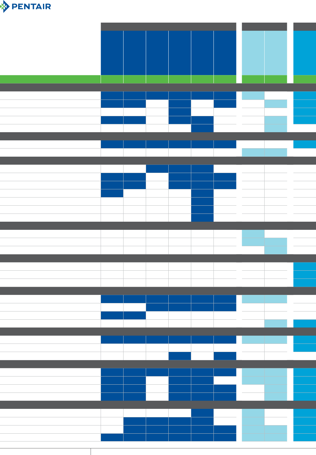
QUICK REFERENCE
Use this handy table to match your
electronic cooling requirements with
the most effective Hoffman protective
cooling solution.
Air Conditioners Heat Exchangers TEC
SPECTRACOOL™
SPECTRACOOL™
Narrow
SPECTRACOOL™
Compact
PROAIR™
T-SERIES™
Water-Cooled
CLIMAGUARD™
Indoor
CLIMAGUARD™
Outdoor
Thermoelectric
PAGE NUMBER 28 52 70 122 80 132 144 160 184
SYSTEM APPLICATION
For indoor industrial
For harsh / corrosive environments
For washdown applications
For outdoor enclosures
For telecommunications shelters
TEMPERATURE OF THE ELECTRONICS
Cooler than outside the enclosure
Warmer than outside the enclosure
AIR CONDITIONER COOLING CAPACITY
1000-2000 BTU/Hr (300-700 Watts)
4000-6000 BTU/Hr (1200-1800 Watts)
8000-12000 BTU/Hr (2300-3500 Watts)
20000 BTU/Hr (5900 Watts)
2-ton 23500 BTU/Hr (6900 Watts)
3-ton 42000 BTU/Hr (12300 Watts)
5-ton 59000 BTU/Hr (17300 Watts)
HEAT EXCHANGER COOLING CAPACITY
Less than 20 Watts/°F (30 Watts/°C)
20-60 Watts/°F (30-100 Watts/°C)
More than 60 Watts/°F (100 Watts/°C)
THERMOELECTRIC COOLING CAPACITY
60 Watts (178 BTU/Hr.)
100 Watts (321 BTU/Hr.)
200 Watts (567 BTU/Hr.)
POWER INPUT
115 & 230 AVC 50/60 Hz
400 / 460 AVC 50/60 Hz 1-phase
400 / 460 AVC 50/60 Hz 3-phase
24 & 48 VAC
MOUNTING
Side
Top
Rack
CABINET PROTECTION
Type 12
Type 3R
Type 4
Type 4X
CABINET DIMENSION
Fits 8” / 203 mm
Fits 12” / 305 mm
Fits 16” / 406 mm
Fits 20” / 508 mm or larger
III
COOLINGPH 763.422.2211 • FAX 763.576.3200 • HOFFMANONLINE.COMEQUIPMENT PROTECTION
1
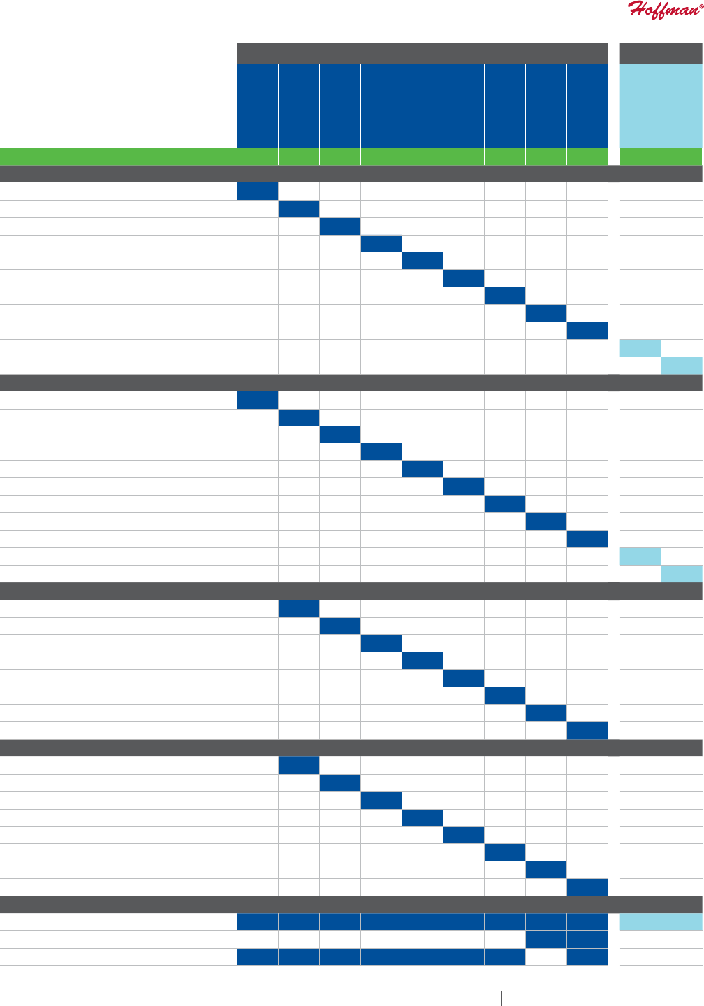
QUICK REFERENCE
Use this handy table to match your
electronics cooling requirements with
the most effective Hoffman Filter Fan.
Side Mount Roof Mount
SF04
SF05
SF09
ST10
SF10
ST13
SF13 376
CFM
SF13 473
CFM
SF13 571
CFM
SR16 280
CFM
SR16 459
CFM
PAGE NUMBER 213 216 218 231 220 233 222 224 227 236 238
18 F/10 C ∆T COOLING CAPACITY TYPE 12/IP54 60 Hz 2 Exhaust Grilles
133 BTU’s (39 Watts) .05" Static Pressure
304 BTU’s (89 Watts) .10" Static Pressure
646 BTU’s (198 Watts) .10" Static Pressure
776 BTU’s (315 Watts) .10" Static Pressure
1,437 BTU’s (421 Watts) .15" Static Pressure
2,305 BTU’s (676 Watts) .20" Static Pressure
2,422 BTU’s (710 Watts) .20" Static Pressure
3,931 BTU’s (1,152 Watts) .35" Static Pressure
3,945 BTU’s (1,156 Watts) .45" Static Pressure
1,929 BTU’s (565 Watts) .55" Static Pressure
4,151 BTU’s (1,216 Watts) .85" Static Pressure
36 F/20 C ∆T COOLING CAPACITY TYPE 12/IP54 60 Hz 2 Exhaust Grilles
267 BTU’s (78 Watts) .05" Static Pressure
609 BTU’s (178 Watts) .10" Static Pressure
1,292 BTU’s (379 Watts) .10" Static Pressure
1,552 BTU’s (632 Watts) .10" Static Pressure
2,874 BTU’s (842 Watts) .15" Static Pressure
4,606 BTU’s (1,350 Watts) .20" Static Pressure
4,845 BTU’s (1,420 Watts) .20" Static Pressure
7,862 BTU’s (2,304 Watts) .35" Static Pressure
7,886 BTU’s (2,311 Watts) .45" Static Pressure
3,859 BTU’s (1,131 Watts) .55" Static Pressure
8,302 BTU’s (2,432 Watts) .85" Static Pressure
18 F/10 C ΔT COOLING CAPACITY TYPE 12/IP55 60 Hz 2 Exhaust Grilles
283 BTU’s (83 Watts) .10" Static Pressure
545 BTU’s (220 Watts) .10" Static Pressure
646 BTU’s (290 Watts) .10" Static Pressure
1,195 BTU’s (350 Watts) .15" Static Pressure
2,064 BTU’s (605 Watts) .20" Static Pressure
2,414 BTU’s (707 Watts) .20" Static Pressure
3,300 BTU’s (967 Watts) .35" Static Pressure
3,273 BTU’s (959 Watts) .45" Static Pressure
36 F/20 C ΔT COOLING CAPACITY TYPE 12/IP55 60 Hz 2 Exhaust Grilles
565 BTU’s (165 Watts) .10" Static Pressure
1,090 BTU’s (442 Watts) .10" Static Pressure
1,292 BTU’s (580 Watts) .10" Static Pressure
2,390 BTU’s (940 Watts) .15" Static Pressure
4,128 BTU’s (1,209 Watts) .20" Static Pressure
4,828 BTU’s (1,415 Watts) .20" Static Pressure
6,600 BTU’s (1,934 Watts) .35" Static Pressure
6,547 BTU’s (1,918 Watts) .45" Static Pressure
POWER INPUT
115 & 230 AC Volt
400 / 460 AC Volt 3-Phase
24 & 48 DC Volt
* NOTE: Roof mount filter fan capacities assume two air intake grille kits.

EQUIPMENT PROTECTIONSUBJECT TO CHANGE WITHOUT NOTICECOOLING2
1
763.422.2211
763.576.3200
COOLING
SELECTING A CO OLING SOLUTIO N
Intro Page
CHAPTER 1
SELECTING
A COOLING SOLUTION
OVERVIEW
Keeping your electronics cool is
essential to extending their life and
keeping your business running. Heat
can have a significant impact on
electronics, causing damage and voiding
manufacturers’ warranties. Cooling
sensitive electronics increases service
life and reduces capital expenses.
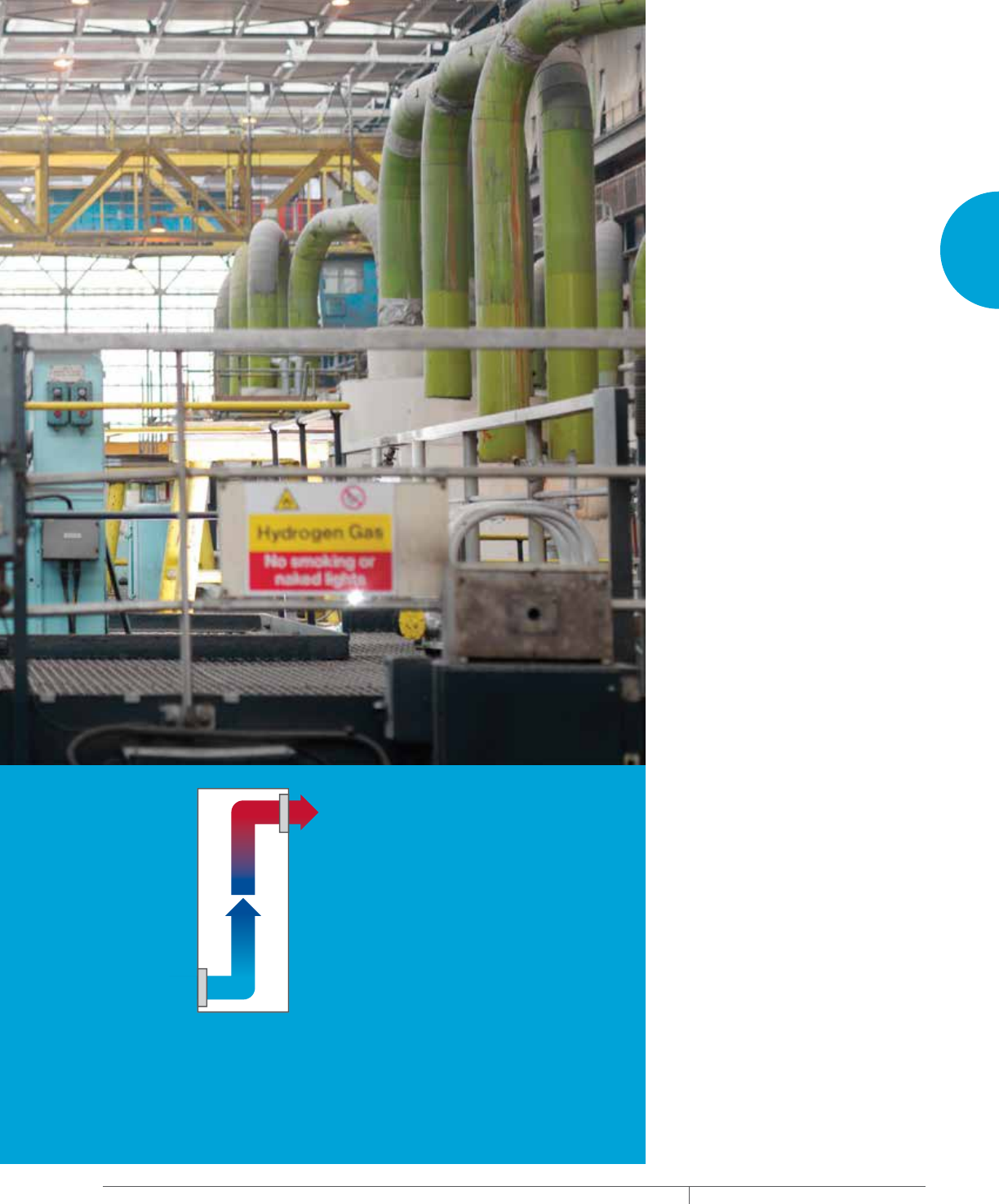
SEALED ENCLOSURE COOLING
Sealed enclosure cooling, also known
as a “closed-loop system”, allows no
outside elements inside the enclosure.
It is generally required for applications
operating in high temperatures—
typically over 35°C/95°F—or when
the enclosure is deployed in harsh
environments, such as an outdoor
telecom base, wastewater treatment
plant, metal working, oil rig, paper mill,
foundry and/or generates high heat from
its own components.
PH 763.422.2211 • FAX 763.576.3200 • HOFFMANONLINE.COMEQUIPMENT PROTECTION COOLING 3
Intro Page
1
FRESH AIR ENCLOSURE COOLING
Fresh air cooling, referred to as an
“open-loop system”, ventilates fresh air
through the cabinet, exhausting heat away
from hot electronics. Fresh air cooling
is optimal when the electronics system
is deployed in a relatively clean and cool
environment, such as an office building,
data networking center or light-duty
factory.
CHAPTER CONTENTS
OVERVIEW
Why Cool Electronics in the First Place? ..............4
Heat Ruins Electronics ............................4
Sources of Heat .................................4
Trend Toward More Damaging Heat ...................4
The Consequences of Damaging Heat .................4
Conductive Enclosure Cooling ......................5
Fresh Air Enclosure Cooling ........................5
Sealed Enclosure Cooling ..........................5
Sealed vs. Fresh Air Enclosure Cooling ................6
SEALED ENCLOSURE COOLING
Introduction ....................................7
SEALED ENCLOSURE COOLING OVERVIEW
Air Conditioner Cooling Capacity Overview .............8
Part A: Determine Internal Heat Load .................8
Part B: Determining Heat Transfer Load Overview .......9
Simple Chart Method .............................9
Determine Total Heat Load ........................10
Equation Method ................................10
Heat Exchanger Cooling Capacity Overview ...........11
Determine Internal Heat Load ......................11
Determine Heat Transfer ..........................11
Determine Heat Exchanger Capacity .................12
FRESH AIR ENCLOSURE COOLING OVERVIEW
Introduction ...................................13
What Is Airflow? ................................13
What Is Static Pressure? .........................13
How is Performance Characterized? .................14
What Are the Capabilities of Each Air Mover? ..........14
Airflow Design Options ...........................15
Choosing an Air Mover ...........................16
Power Input. . . . . . . . . . . . . . . . . . . . . . . . . . . . . . . . . . . .16
Enclosure Protection ............................16
Airflow .......................................16
Step 1. Determine Delta-T (ΔT) .....................17
Step 2. Determine Internal Heat Load ................17
Step 3. Determine Free Airflow .....................18
Step 4. Estimate System Impedance ................19
Step 5. Select Your Air Mover ......................19
Friendly Reminder ...............................19
EQUIPMENT PROTECTIONSUBJECT TO CHANGE WITHOUT NOTICECOOLING4
1
SELECTING A COOLING SOLUTION OVERVIEW
OVERVIEW
WHY COOL ELECTRONICS IN THE FIRST PLACE?
Keeping your electronics cool is essential to extending their life and keeping your business running.
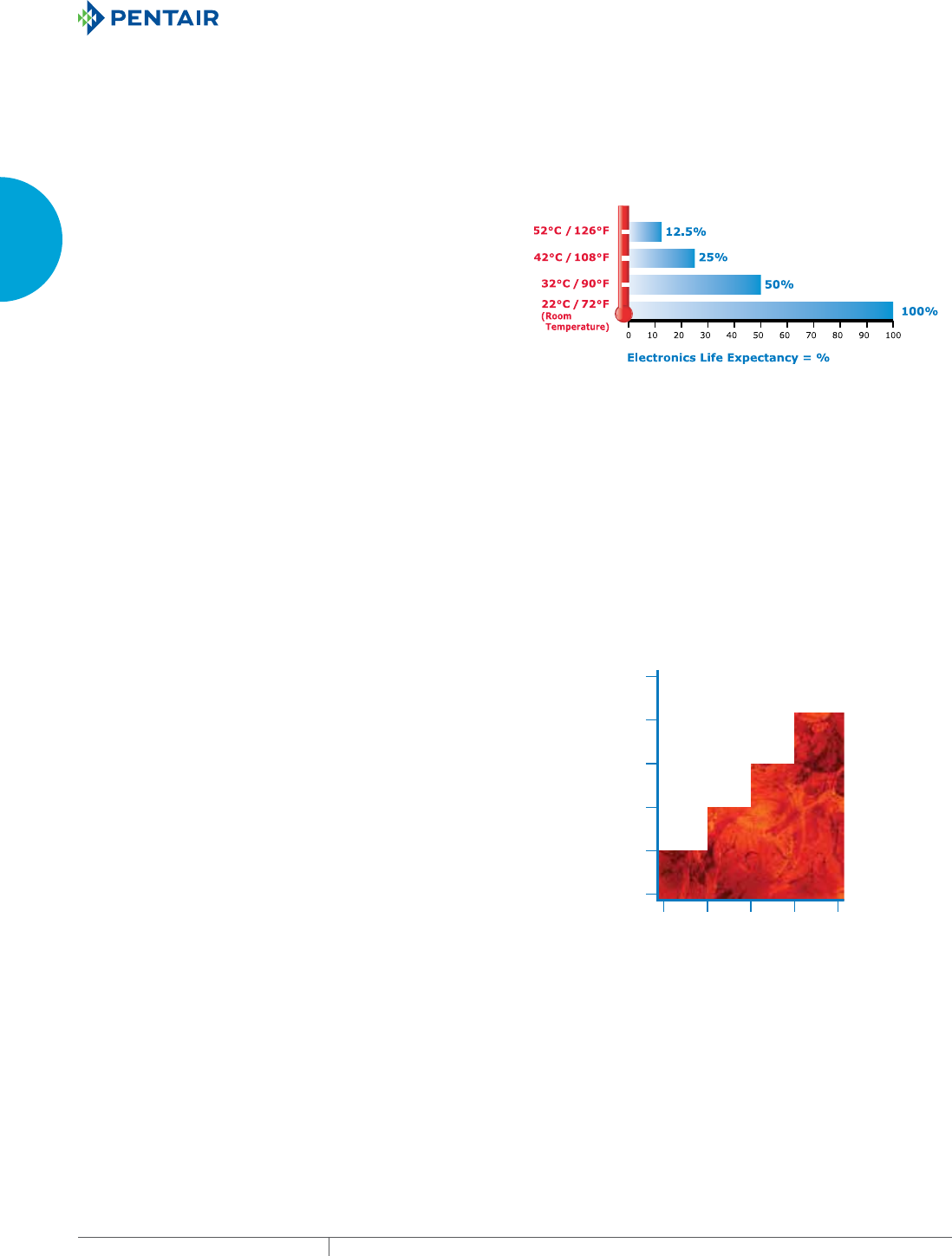
HEAT RUINS ELECTRONICS
The life expectancy of electronics is cut in half every 10 C / 18 F
they operate above room temperature. Operating electronics above
certain temperatures can void manufacturers’ warranties, making
proper cooling essential. Cooling vital electronics increases service
life and reduces capital expenses over the long-term.
Electronics Life Expectancy with
Every 10° C Rise over Room Temperature
SOURCES OF HEAT
Damaging heat can come from a variety of sources. Inside the
cabinet, heat can come from:
• AC power supplies
• Controllers, drives and servos
• Transformers and rectifiers
• Processors and server racks
• Radio equipment
• And other electronic components
Heat also comes from sources outside the enclosure such as:
• Solar heat gain
• Welding processes
• Paint oven
• Blast furnace
• Foundry equipment
TREND TOWARD MORE DAMAGING HEAT
For the foreseeable future, the trend is toward increasing levels of
heat in electronics, not less, because the market’s thirst for more
information processing capacity and speed continues to grow. This
trend is known as “Moore’s Law.”
More powerful data-processing electronics generate extra heat
with virtually every new system that is designed. There is no
guarantee that an application which did not require much, if any,
cooling in the past will not need cooling in the future. The new
system likely has more functionality and will probably require some
form of cooling as a result.
Moore’s Law
Named after the founder of Intel
Wa
tts
Watts +2 +2 +2 +2
Processor Heat Dissipation
Performance = Heat
100
80
60
40
20
0
THE CONSEQUENCES OF DAMAGING HEAT
Heat build-up can adversely affect industrial controls and sensitive
electronic systems as follows:
• De-rated drive performance
• I/C-based devices experience intermittent fluctuations
• MTBF decreases exponentially
• Catastrophic failure
The costs when a factory line or electronic system fails can include:
• Productivity losses
• Component replacement costs
• Late shipments
• Customer dissatisfaction
• Lost revenue
• Cell phone tower outage
• Breach in homeland security
Direct costs to a business can be as much as $50,000 per hour of
system downtime.
PH 763.422.2211 • FAX 763.576.3200 • HOFFMANONLINE.COMEQUIPMENT PROTECTION COOLING 5
1
SELECTING A COOLING SOLUTION OVERVIEW
CONDUCTIVE ENCLOSURE COOLING
This is a passive way to cool electronics. It simply allows the heat to
radiate through the cabinet walls.
Conductive enclosure cooling works well with electronics systems
that have small heat loads (<50 W) and cool air around the enclosure
(<78 F/25 C).
If heat is an issue, one option within this type of cooling is to
increase cabinet size to create more surface area to speed the
transfer of heat. However, growing cabinet size is often not a
practical solution because of space limitations and the greater heat
loads associated with today’s high-power electronics.
FRESH AIR ENCLOSURE COOLING
This is an active way to manage heat in electronics applications.
This type of cooling ventilates fresh air through the cabinet,
exhausting heat away from the hot components.
Fresh air enclosure cooling may be used when the electronics
system is deployed in a relatively clean and cool environment such
as an office building, data networking center or light-duty factory.
Options for cooling electronic enclosures with fresh air include
filter fans, fan trays, motorized impellers and packaged blowers.
Fresh air enclosure cooling is known as an “open-loop system”
because no significant seal is maintained to protect electronic
components from harmful elements such as dirt, water, metal
filings and corrosive fumes.
SEALED ENCLOSURE COOLING
This is another active way to cool electrical components. This
type of cooling maintains the seal of the enclosure—using an air
conditioner or heat exchanger as examples—to remove heat from
inside the electronics cabinet.
Protective cooling is generally required when the electronics
application:
(1) operates in high temperatures, typically over 95 F/35 C,
(2) is deployed in a harsh environment such as an outdoor telecom
base station, wastewater treatment plant, metal working operation,
oil rig platform, paper mill, foundry and/or
(3) generates a high heat load from its own components, usually
more than 500 W.
Options for sealed enclosure cooling include air conditioners,
air-to-air heat exchangers, air-to-water heat exchangers,
thermoelectric coolers and vortex coolers.
Sealed enclosure cooling is known as a “closed-loop system”
because the seal of the electrical cabinet is maintained, allowing no
elements which can damage the electronics inside the enclosure.
EQUIPMENT PROTECTIONSUBJECT TO CHANGE WITHOUT NOTICECOOLING6
1
SELECTING A COOLING SOLUTION OVERVIEW
SEALED VS. FRESH AIR ENCLOSURE COOLING
Since heat dissipation is often not a solution, we will limit our choices to sealed vs. fresh air enclosure cooling.
Use the environmental and electronic system criteria in the table below to determine whether sealed or fresh air enclosure cooling is
most appropriate for your application.
Choosing Sealed vs. Fresh Air Enclosure Cooling
Specifying protective cooling that keeps your electronics components sealed from the outside environment versus using fresh
air cooling to remove damaging heat depends on the following prole of your system application (check one side or the
other for each of the six criteria):
If most of your assessments fell on the fresh air side, then a lter fan, fan tray, motorized impeller or blower is probably the
correct cooling solution for your application. However, if most of your assessments were on the protective side, then an
air conditioner or heat exchanger is likely the right cooling solution for your electronics system.
SEALEDFRESH AIR CRITERIA
Dirty / Wet / Metal Filings /
Outdoors / Corrosive Fumes
Hot
(typically over 35 C / 95 F)
Below to Somewhat Above
Ambient Temperature
High Relative Humidity
Narrow / Precise
Moderate to High
(typically over 3000 Watts)
SYSTEM OPERATING
ENVIRONMENT
TEMPERATURE OUTSIDE
OF THE ENCLOSURE
TEMPERATURE RATING
OF THE ELECTRONICS
HUMIDITY OUTSIDE
OF THE ENCLOSURE
TEMPERATURE RANGE
FOR THE ELECTRONICS
SYSTEM POWER DRAW /
HEAT LOAD
Clean Air / Some Dust /
Dripping Water
Moderate to Low
(typically under 35 C / 95 F)
Somewhat to Well-Above
Ambient Temperature
Moderate to Low
Wide
Moderate to Low
(typically under 3000 Watts)
PH 763.422.2211 • FAX 763.576.3200 • HOFFMANONLINE.COMEQUIPMENT PROTECTION COOLING 7
1
SELECTING A COOLING SOLUTION SEALED ENCLOSURE COOLING
SEALED ENCLO SURE COOLIN G
INTRODUCTION
Assuming that sealed enclosure cooling is needed for the
application, there are two basic choices—air conditioners or heat
exchangers.
An air conditioner should be specified when:
• The temperature inside the enclosure must be maintained at or
below the ambient temperature
• Humidity must be removed
• A moderate to high heat load is being produced by the electronic
system
A heat exchanger can be used to transfer heat from inside the
enclosure to the outside atmosphere when:
• The electronic components can operate at a temperature above
the ambient air temperature
• Humidity is not a factor
• A low to moderate heat load is being produced by the electronic
system
Heat ExchangerAir Conditioner

EQUIPMENT PROTECTIONSUBJECT TO CHANGE WITHOUT NOTICECOOLING8
1
SELECTING A COOLING SOLUTION SEALED ENCLOSURE COOLING OVERVIEW
SEALED ENCLO SURE COOLIN G OVERVIEW
AIR CONDITIONER COOLING CAPACITY OVERVIEW
The cooling capacity of an air conditioner needs to match or exceed the amount of total heat load generated by the electronic system.
Total heat load comes from two sources:
(a) the electronic components themselves which is called “internal heat load” and
(b) the ambient heat outside the enclosure which is known as the “heat transfer load.”
Most engineers and cooling suppliers determine internal heat load. However, the impact from the heat transfer load is easily overlooked.
Heat transfer load can significantly add to the total heat load of the system, especially if the outside air temperature is high and/or the
enclosure is located in the sun.
Thus, the total heat load to be removed from the electrical enclosure by the air conditioner is the sum of the internal heat load and the
heat transfer load.
TOTAL HEAT LOAD = INTERNAL HEAT LOAD + HEAT TRANSFER LOAD
PART A: DETERMINE INTERNAL HEAT LOAD
The internal heat load comes from the amount of waste heat generated inside the enclosure by the electronic components and is
expressed in Watts (W).
There are several methods to determine internal heat load, depending on data availability.
Method 1. Heat Load Data from Each Electronics Component Manufacturer
One way to estimate internal load is to gather heat load data from the manufacturers of the electronics components inside the cabinet.
They may know the amount of heat their equipment is generating. If more than one control or other electronics components are inside the
enclosure, it will be necessary to add together all the estimates of heat load to determine total internal heat load.
Method 2. Component Power – Component Efficiency
A second method is to establish the Watts of power used by each electronic component. Derive Watts of power by multiplying the amp
draw of each device by its voltage. Then subtract the efficiency of each component from its estimated power use. Add up the outcomes to
get the total internal heat load.
INTERNAL HEAT LOAD = COMPONENT POWER (W) - COMPONENT EFFICIENCY (for each electrical device)
For example:
An electronic system uses two components that draw 115 VAC at 15 amps. Each has a rated efficiency of 90%. Put another way, 10% of
each device is inefficient. Unused power becomes generated heat. Thus the estimated internal heat load is:
Device Power = 115 x 15 = 1725 W
Total Power = 2 x 1725 = 3450
Less Efficiency = 3450 x (1 - .90)
Total Heat Load = 345 W
Method 3. Incoming – Outgoing Power
A third approach is to estimate the power going into the enclosure and the power coming out of it. The difference becomes the estimated
amount of internal heat load. The amps and volts of each electrical line going in are multiplied to determine Watts, then they’re added
together. The same is done for the electrical line(s) coming out of the application. The outgoing Watts are then subtracted from the
incoming Watts.
INTERNAL HEAT LOAD = INCOMING POWER (W) – OUTGOING POWER (W)
For example:
An enclosure has three input lines of 230 VAC at 11, 6 and 4 A. It has one output control line of 115 VAC at 9 A.
Incoming Power = (230 x 11) + (230 x 6) + (230 x 4) = 4830 W
Outgoing Power = 115 x 9 = 1035 W
Total Heat Load = 4830 – 1035 = 3795 W
Method 4. Automated Equipment Horsepower
This fourth method applies only to industrial automation equipment that operates with horsepower (hp) such as variable frequency drives
(VFDs). 1 hp = 745.6 W. Thus, the internal heat load from a 3-hp VFD is 2237 W, less its efficiency which is typically 93-95%.
For example:
A cabinet has three 5-hp VFDs with 95% efficiency.
VFD Watts = 5 hp x 745.6 x 3 = 11184
Adjusted Watts = 11184 x (1 - .95) = 559
Total Heat Load = 559 x 1.25 = 699 W
1.25 is an assumed “safety” margin for other minor heat-producing components.
PH 763.422.2211 • FAX 763.576.3200 • HOFFMANONLINE.COMEQUIPMENT PROTECTION COOLING 9
1
SELECTING A COOLING SOLUTION SEALED ENCLOSURE COOLING OVERVIEW
PART B: DETERMINING HEAT TRANSFER LOAD OVERVIEW
Heat transfer load is the ambient heat outside the enclosure conducting itself through the cabinet walls toward the electronics (heat
energy travels from the hottest to coldest location).
When an air conditioner cools the enclosure temperature lower than the ambient air outside, additional heat load is drawn into the cabinet
which the air conditioner needs to remove. The higher the ambient temperature and/or the presence of solar heat gain (the “greenhouse
effect”) on the enclosure, the more cooling capacity is required.
Determining heat transfer load requires that you know the total surface area of the cabinet, less any non-conductive surface area such
as the enclosure side mounted to a wall. It also requires that you determine T, which is the difference between maximum ambient
temperature and the maximum temperature rating of the electronics components.
There are two methods for determining heat transfer load—the simple chart method and the equation method.
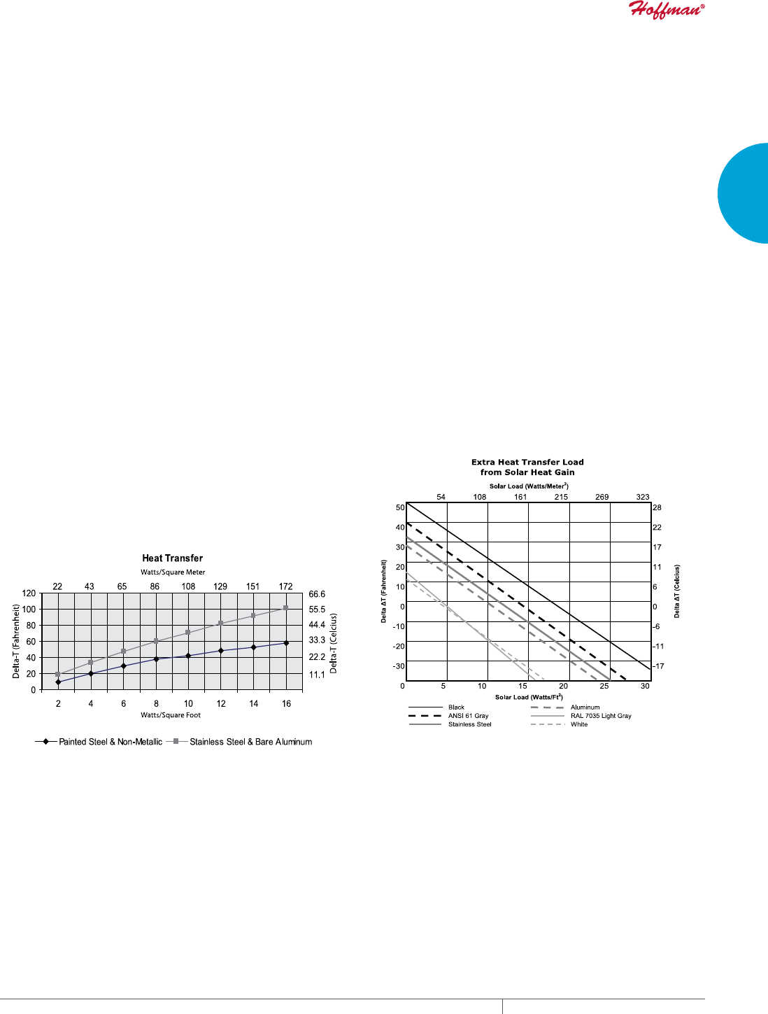
SIMPLE CHART METHOD
This method is reasonably accurate for most indoor industrial
systems where there is no unusual air movement and insulation is
not typically used inside the enclosure. The process also provides
a ballpark result for outside plant and telecommunications
applications, taking into account solar heat gain. However, it does
not incorporate the impact of wind or cabinet insulation. If either is
present, then the equation method is more precise.
Step A. Determine ΔT in °F or °C.
Step B. Find the heat transfer per ft.2 or m2 on the chart below,
using ΔT and the proper cabinet material curve.
Step C. Multiply the heat transfer per ft.2 or m2 by the total surface
area of the enclosure that will conduct heat. (Remember to exclude
surfaces such as a side mounted to a wall.)
SURFACE AREA (ft.2) = [2AB (in.) + 2BC (in.) + 2AC (in.)] ÷ 144
SURFACE AREA (m2) =
[2AB (mm) + 2BC (mm) + 2AC (mm)] ÷ 1000000
Total Heat Transfer Load =
Heat Transfer per ft.2 or m2 x Cabinet Surface Area
For example:
A painted steel cabinet has 80 ft.2 of surface area and will be located
in a maximum ambient temperature of 95 F. The rated temperature
of the electronics is 75 F.
ΔT = 95 - 75 = 20 F
Heat Transfer = 4 W/ft.2 (from chart)
Total Heat Transfer Load = 80 x 4 = 320 W
The estimate for heat transfer load ends here, unless the electronic
system will be deployed outdoors. Then solar heat gain needs to be
added to the total heat transfer load calculated above. Solar heat
gain is determined much the same way as heat transfer per ft.2 or
m2, using a similar chart.
For example: The painted cabinet above is in ANSI 61 gray. Thus, 7
W/ft.2 need to be added to the heat transfer load which is 560 W (7 x
80 ft.2). Total Heat Transfer Load consequently becomes 720 W.
The result does not include insulation which can significantly reduce
heat transfer load.

EQUIPMENT PROTECTIONSUBJECT TO CHANGE WITHOUT NOTICECOOLING10
1
SELECTING A COOLING SOLUTION SEALED ENCLOSURE COOLING OVERVIEW
EQUATION METHOD
Heat transfer load may also be determined by equation. This
method should be used when at least one of the following criteria
are found in the electronic system:
• Moderate to high airflow within the cabinet
• Outdoor applications that involve breezes or gusty winds
• Insulation used within the cabinet to offset the impact of solar
heat gain
The governing equations for heat transfer load are:
English System (°F, inches and feet):
q = (To - Ti) ÷ [(1/ho) + (1/hi) + R]
Metric System (°C, millimeters and meters):
(q = (To - Ti) ÷ [(1/ho) + (1/hi) + R] x 5.67
Definition of Variables—
q = Heat transfer load per unit of surface area
To = Maximum ambient temperature outside the enclosure
Ti = Maximum rated temperature of the electronics components
ho = Convective heat transfer coefficient outside the cabinet
Still air: h = 1.6
Relatively calm day: h = 2.5
Windy day (approx. 15 mph): h = 6.0
hi = Convective heat transfer coefficient inside the cabinet
Still air: h = 1.6
Moderate air movement: h = 2.0
Blower (approx. 8 ft.3/sec.): h = 3.0
R = Value of insulation lining the interior of the enclosure walls
No insulation: R = 0.0
1/2 in. or 12 mm: R = 2.0
1 in. or 25 mm: R = 4.0
1-1/2 in. or 38 mm: R = 6.0
2 in. or 51 mm: R = 8.0
q = (125 - 75) ÷ [(1/6) + (1/2) + 4]
q = (50) ÷ (.16 + .5 + 4)
q = 50 ÷ 4.66
q = 10.7 BTU/hr./ft.2
Total Heat Transfer Load
10.7 x 72 = 770 BTU/hr. or 770 ÷ 3.413 = 226 W
Since the cabinet is outdoors, and assuming it is painted ANSI 61
gray and located in the sun, extra solar load needs to be added to
the outcome above which is 504 Watts (7 W per ft.2 x 72 ft.2).
Total Heat Transfer Load with Extra from Solar Heat Gain
226 + 504 = 730 W
DETERMINE TOTAL HEAT LOAD
Total heat load to be removed from the electrical enclosure by the air conditioner is the sum of internal heat load plus heat transfer load.
TOTAL HEAT LOAD (C) = INTERNAL HEAT LOAD (A) + HEAT TRANSFER LOAD (B)
Thus, one adds together the result from Part A to the outcome from Part B.
For example:
The internal heat load from one of the examples above was 3795 Watts. The heat transfer load from the other example above was 730 W.
Therefore, total heat load is 3795 + 730 = 4525 W.
To convert Watts into BTU/hr. to determine air conditioner capacity in the English system, multiply by 3.413.
4525 W is then 15444 BTU/hr.
Power input, protection level and dimensions of the air conditioner also need to fit system requirements.
Caution! Do not simply match the nominal cooling capacity of the air conditioner model with the total heat load result above. Be sure to
know the maximum ambient temperature outside the enclosure as well as the rated temperature of the electronic components. Apply
these temperatures to the performance curves provided by the cooling manufacturer to select an appropriately sized air conditioner.
Failure to do so may under-size your air conditioner as much as 20% - 25%, thereby under-cooling the electronics and making the
application vulnerable to potential over-heating issues.

PH 763.422.2211 • FAX 763.576.3200 • HOFFMANONLINE.COMEQUIPMENT PROTECTION COOLING 11
1
SELECTING A COOLING SOLUTION SEALED ENCLOSURE COOLING OVERVIEW
HEAT EXCHANGER COOLING CAPACITY OVERVIEW
Cooling with an air-to-air heat exchanger assumes the electronic components in your system are able to operate above the ambient
temperature outside the enclosure. If this is not the case, then an air conditioner must be used.
Selecting a heat exchanger is similar to specifying an air conditioner in that the cooling capacity of the unit must remove the internal heat
load from the electrical enclosure.
However, since the conductive cooling nature of the cabinet itself removes some of the heat from the system, heat transfer should be
subtracted from internal heat load (versus added in the case of air conditioners).
Because the cooling capacity of heat exchangers is expressed in terms of Watts/°F or Watts/°C, an extra step is necessary to convert net
heat load into a result used to select the appropriate heat exchanger. Divide the net heat load by the T which is the difference between the
maximum ambient temperature outside the enclosure and the maximum temperature rating of the electronic components.
HEAT EXCHANGER CAPACITY (C) = [INTERNAL HEAT LOAD (A) – HEAT TRANSFER (B)] / ΔT
DETERMINE INTERNAL HEAT LOAD
Internal heat load stems from the amount of waste heat generated inside the enclosure by the electronic components and is expressed in
Watts.
To determine internal heat load, follow one of the four options outlined in the air conditioner “Determine Internal Heat Load” section
on page 8.
DETERMINE HEAT TRANSFER
In air-to-air heat exchangers, heat transfer is actually cabinet heat loss because the heat inside the enclosure is conducting itself through
the cabinet walls toward the cooler temperature outside the enclosure. That is why heat transfer is subtracted from internal heat load to
arrive at total net heat load.
To determine heat transfer you need to know the total surface area of the cabinet, less any non-conductive surface area such as the
enclosure side mounted to a wall. You must also determine T which is the difference between maximum ambient temperature and the
maximum temperature rating of the electronic components.
There are two methods to determine heat transfer—the simple chart method and the equation method. The simple chart method may be
used for nearly all indoor heat exchanger applications. The equation method needs to be applied when air movement outside or inside the
electrical enclosure is high, or for outdoor applications.
Here are the steps for the simple chart method:
Step A. Determine ΔT in °F or °C.
Step B. Find the heat transfer per ft.2 or m2 from the Heat Transfer graph on page 9, using ΔT and the proper cabinet material curve.
Step C. Multiply the heat transfer per ft.2 or m2 by the total surface area of the enclosure that will conduct heat. (Remember to exclude
surfaces such as a side mounted to a wall.)
SURFACE AREA (ft.2) = [2AB (in.) + 2BC (in.) + 2AC (in.)] ÷ 144
SURFACE AREA (m2) = [2AB (mm) + 2BC (mm) + 2AC (mm)] ÷ 1,000,000
Heat Transfer (Cabinet Heat Loss) = Heat Transfer per ft.2 or m2 x Enclosure Surface Area
The estimate for heat transfer ends here, unless the electronic system will be deployed outdoors, or airflow inside or outside the
enclosure is high. Then the equation method needs to be used to determine heat transfer (cabinet heat loss).
For the equation method, follow the steps on page 9 in the air conditioner selection section. The result will be a negative number; the
negative sign should be ignored when deducting heat transfer from internal heat load.
Caution! If the result of the equation method is a positive number, then this means that you want the electronics temperature inside the
cabinet to be lower than the temperature outside the enclosure. In this case, an air conditioner should be specified for the electronics
system.

EQUIPMENT PROTECTIONSUBJECT TO CHANGE WITHOUT NOTICECOOLING12
1
SELECTING A COOLING SOLUTION SEALED ENCLOSURE COOLING OVERVIEW
DETERMINE HEAT EXCHANGER CAPACITY
Air-to-air heat exchanger capacities are not provided in terms of
Watts or BTUs/hr. of cooling like air conditioners. Instead, they are
expressed in terms of Watts/°F or Watts/°C. Thus, the final step in
determining heat exchanger capacity is to divide the total net heat
load by ΔT. Then select the heat exchanger with the same or higher
Watts/°F or Watts/°C as the outcome of this process.
—Indoor Industrial Example—
An electronic system uses two components that draw 230 VAC
at 7.5 A. Each has a rated efficiency of 90%. They are protected
in a painted steel cabinet that is 60 in. (1524 mm) tall, 36 in. (914
mm) wide and 18 in. (457 mm) deep. The system will be located
in a maximum ambient temperature of 80 F (27 C). The rated
temperature of the electronics is 95 F (35 C).
HEAT EXCHANGER CAPACITY (C) =
[INTERNAL HEAT LOAD (A) – HEAT TRANSFER (B)] ÷ ΔT
Internal heat load (A) may be determined using the “Component
Power – Component Efficiency” method on page 8, given the
available information. In this example, the estimated heat load is:
Device Power = 230 x 7.5 = 1725 W
Total Power = 2 x 1725 = 3450
Less Efficiency = 3450 x (1 - .90)
Internal Heat Load = 345 W
Heat transfer (B) is derived using the simple chart method, since
this is an indoor industrial application. Both cabinet surface area
and ΔT are needed to determine heat transfer. Cabinet surface area
is 54 ft.2 or 5.02 m2 (from surface area formula on page 9). ΔT
is 15 F (8 C)—the difference between ambient temperature and the
rated temperature of the electronics.
Heat Transfer (Cabinet Heat Loss) =
Heat Transfer per ft.2 or m2 x Enclosure Surface Area
Using the painted steel curve on the Heat Transfer chart on page
9, heat transfer per ft.2 or m2 is 3 W/ft.2 or 32.5 W/m2.
Heat Transfer = 3 W/ft.2 x 54 ft.2 = 162 W
Now that we know internal heat load, heat transfer and ΔT, we can
determine heat exchanger capacity as follows:
HEAT EXCHANGER CAPACITY (C) =
[345 WATTS (A) – 162 WATTS (B)] ÷ 15 F (or 8 C)
HEAT EXCHANGER CAPACITY (C) = 12 W/°F or 22 W/°C
The result is minimum heat exchanger capacity. If no heat
exchanger model is similar to the result, choose the next largest
size to ensure adequate electronics cooling.
Power input, protection level and dimensions of the heat exchanger
also need to fit the system.
—Outdoor Example—
A telecom system draws a total of 5,000 W; its efficiency is 85%. It
is protected in a steel cabinet that is 72 ft.2 (6.69 m2) and painted
with RAL 7035 light-gray paint. The enclosure walls are lined inside
with 1 in. (25 mm) of insulation. The application will be deployed
in a maximum ambient outdoor temperature of 104 F (40 C) with
occasional winds reaching 15+ mph. The rated temperature of
the electronics is 114 F (46 C). Air circulation inside the cabinet is
moderate.
HEAT EXCHANGER CAPACITY (C) =
[INTERNAL HEAT LOAD (A) – HEAT TRANSFER (B)] ÷ DELTA ΔT
Internal heat load (A) is determined using the “Component Power
– Component Efficiency” method on page 8. In this example, the
estimated heat load is as follows:
Total System Power = 5000 W
Less Efficiency = 5000 x (1 - .85)
Internal Heat Load = 750 W
Heat transfer (B) is derived using the equation method, since this
is an outdoor application. For brevity, we will assume the English
system (°F, inches and feet).
q = (To - Ti) ÷ [(1/ho) + (1/hi) + R]
“q” is heat transfer per surface area. For an explanation of the other
variables, see “Equation Method” on page 10.
q = (104 - 114) ÷ [(1/6) + (1/2) + 4]
q = -2.14 W/ft.2
Total Heat Transfer = 2.14 x 72 ft.2 = 154 W
(negative sign is ignored)
T is 10 F — the difference between ambient temperature and the
rated temperature of the electronics.
HEAT EXCHANGER CAPACITY (C) =
[750 W (A) – 154 W (B)] ÷ 10 F
HEAT EXCHANGER CAPACITY (C) = 60 W/°F
As in the indoor industrial example, the above result is minimum
heat exchanger capacity. If no heat exchanger model is similar
to the result, choose the next largest size to ensure adequate
electronics cooling.
Power input, protection level and dimensions of the heat exchanger
also need to fit the system.
PH 763.422.2211 • FAX 763.576.3200 • HOFFMANONLINE.COMEQUIPMENT PROTECTION COOLING 13
1
SELECTING A COOLING SOLUTION FRESH AIR ENCLOSURE COOLING OVERVIEW
FRESH AIR ENCL OSURE COOLI NG OVERVIEW
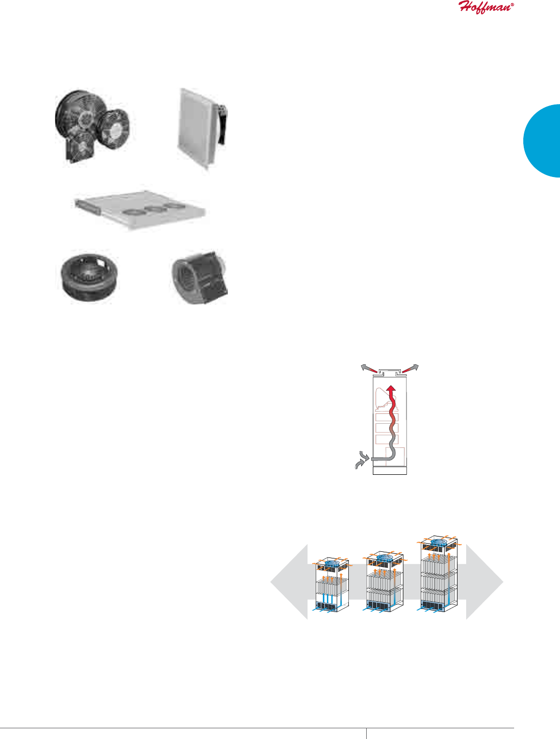
INTRODUCTION
There are many standard air movers for electronics cooling on the
market today. Common options include:
Compact
Axial
Fans Filter Fan
Server Rack
Fan Tray
Mo
torized
Impeller
Centrifugal
Blower
As one may conclude by looking at the products, each fresh air
cooling solution can vary in terms of:
• General vs. concentrated airflow
• Amount of air volume (CFM or M3/Hr.)
• Ability to overcome airflow restriction caused by electronics
components (static pressure—Inches of H2O or Pascals)
• Component price
• Power input (AC or DC volt)
• Ability to protect the electronics from dust and water
However, before we begin to briefly review the advantages and
disadvantages of each air mover, we first need to understand two
important concepts, airflow and static pressure, because each
fresh air cooling solution can be quite different with these factors.
WHAT IS AIRFLOW?
Airflow is the volume of air that a fan, impeller or blower can move.
In the English system, airflow is measured in cubic feet per minute
or CFM. In the Metric system, airflow is defined as cubic meters
per hour or M3/Hr. Electronic systems with low heat loads (100 to
1000 Watts) require less airflow to cool the components. Cabinets
with moderate to high heat loads (more than 1000 Watts) need more
airflow.
WHAT IS STATIC PRESSURE?
Static pressure is air restriction created by the components inside
the enclosure. In the English system, static pressure is expressed
in Inches of Water or In. H2O. In the Metric system, static pressure
is Pascals or Pa. Systems with loosely packed components have
low static pressure (0.24 to 0.50 In. H2O) and use a smaller, less
powerful air mover such as a tube axial fan or filter fan for cooling.
However, cabinets that are moderately to densely packed with
electronics (0.75 In. H2O or more) require a larger, more powerful
air mover or multiple air movers.
Low
Static
Pressure
High
Static
Pressure
Lightly Packed
Electronics
Under 0.75 In. H2O
(187 Pa)
Moderately Packed
Electronics
0.75 - 1.75 In. H2O
(187 - 436 Pa)
Densely Packed
Electronics
Over 1.75 In. H2O
(436 Pa)
EQUIPMENT PROTECTIONSUBJECT TO CHANGE WITHOUT NOTICECOOLING14
1
SELECTING A COOLING SOLUTION FRESH AIR ENCLOSURE COOLING OVERVIEW
HOW IS PERFORMANCE CHARACTERIZED?
Each air mover is commonly rated based on its airflow and static
pressure capability known as a “performance curve.”
In a 0 static pressure electronics system, the air mover provides
325 CFM of airflow. Conversely, at 1.6 In. of H2O static pressure (a
moderately packed cabinet), the air mover provides 0 airflow.
Air mover manufacturers determine the performance curve for
each of their products by placing the unit in a test chamber to
determine its precise airflow and static pressure.
$LU0RYHU
3HUIRUPDQFH&XUYH
$LU
&)0
6WDWLF3UHVVXUH
LQRI+
$LU
0
+U
6WDWLF3UHVVXUH
3D
$LUIORZ
6WDWLF3UHVVXUH
LQRI+
$LUIORZ
$LU0RYHU3HUIRUPDQFH&XUYH([DPSOH
0
+U
6WDWLF3UHVVXUH
3D
WHAT ARE THE CAPABILITIES OF EACH AIR MOVER?
Each air mover such as a tube axial fan, filter fan, fan tray, motorized impeller and centrifugal blower performs in a different way. A
summary of the characteristics and applications for each of these popular fresh air cooling products is outlined in the table below.
Axial fans, filter fans and fan trays generally provide low to moderate airflow in electronic systems with low static pressure. Most are
used with VAC applications. Filter fans provide an extra level of enclosure protection against dust infiltration (Type 12 or IP54) and water
infiltration (Type 3R or IP55). With the exception of fan trays, tube axial fans and filter fans are relatively inexpensive.
Motorized impellers offer moderate to high airflow and work well in electronics cabinets with moderate to high static pressure. They
often provide general cooling throughout an enclosure. Motorized impellers are available in VAC and VDC inputs and are reasonably priced
Centrifugal blowers deliver moderate to high airflow and overcome the system impedance that builds up in electronic cabinets with
moderate to high static pressure. They’re primarily available for VAC power input and are relatively higher priced.
Characteristics of Popular Air Movers
Characteristics Axial Fans Filter Fans Fan Trays Motorized Impellers Centrifugal Blowers
Airflow Low Low - Moderate Low - Moderate Moderate - High Moderate - High
Static Pressure Low Low Low Moderate - High Moderate - High
Voltage Input AC (some DC) AC and DC AC (some DC) AC and DC AC
Protection None Type 12 & 3R None None None
Per Piece Price Low Moderate High Moderate High
Typical
Application
Spot
electronics
cooling
Industrial
electrical cabinet
cooling
Datacom card
and server
rack cooling
General cooling
of moderate to high
static pressure
cabinets
Concentrated or
general cooling
of high static
pressure systems
PH 763.422.2211 • FAX 763.576.3200 • HOFFMANONLINE.COMEQUIPMENT PROTECTION COOLING 15
1
SELECTING A COOLING SOLUTION FRESH AIR ENCLOSURE COOLING OVERVIEW
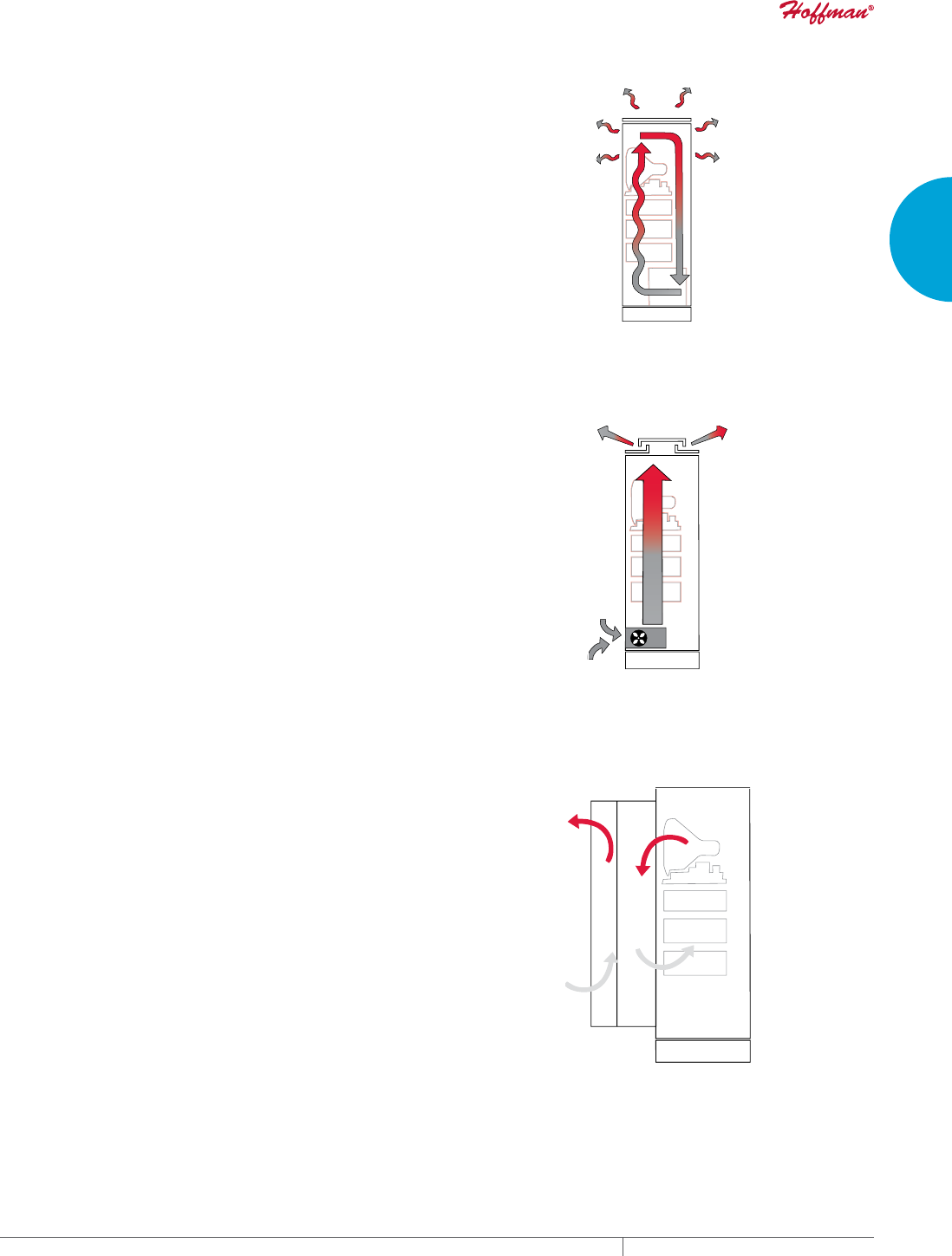
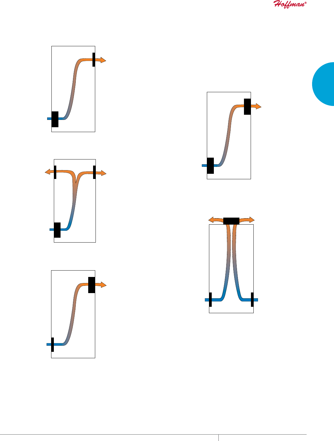
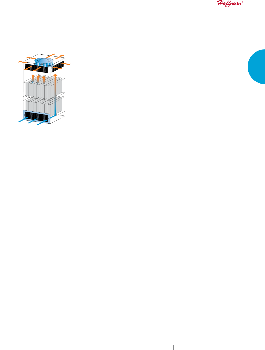
AIRFLOW DESIGN OPTIONS
A typical air mover system design “pushes” cool air into the bottom
of the electronics cabinet and exhausts the warm air out the top
“Push”
Design
C
ool air in
through
lter fan
Warm air
out the
exhaust
grille
To reduce exhaust grille static pressure and improve cool airflow,
some engineers use two exhaust grilles in their airflow design.
“Push”
Design
with Dual
Exhaust
Cool air in
through
lter fan
Warm air
out the
exhaust
grille
Warm air
out the
exhaust
grille
Another option is to use a reverse airflow fan and mount it high in
the enclosure to “pull” cool air through the enclosure.
“Pull”
Design
Cool air in
through
grille
Warm air
out the
lter fan
The “pull” approach is less desirable because it de-pressurizes
the enclosure. If poor seals are in the cabinet at a door or modular
panel, for example, damaging dust could be sucked inside and
onto the electrical components. However, space constraints at the
bottom of the enclosure may force the engineer to design a “pull”
system.
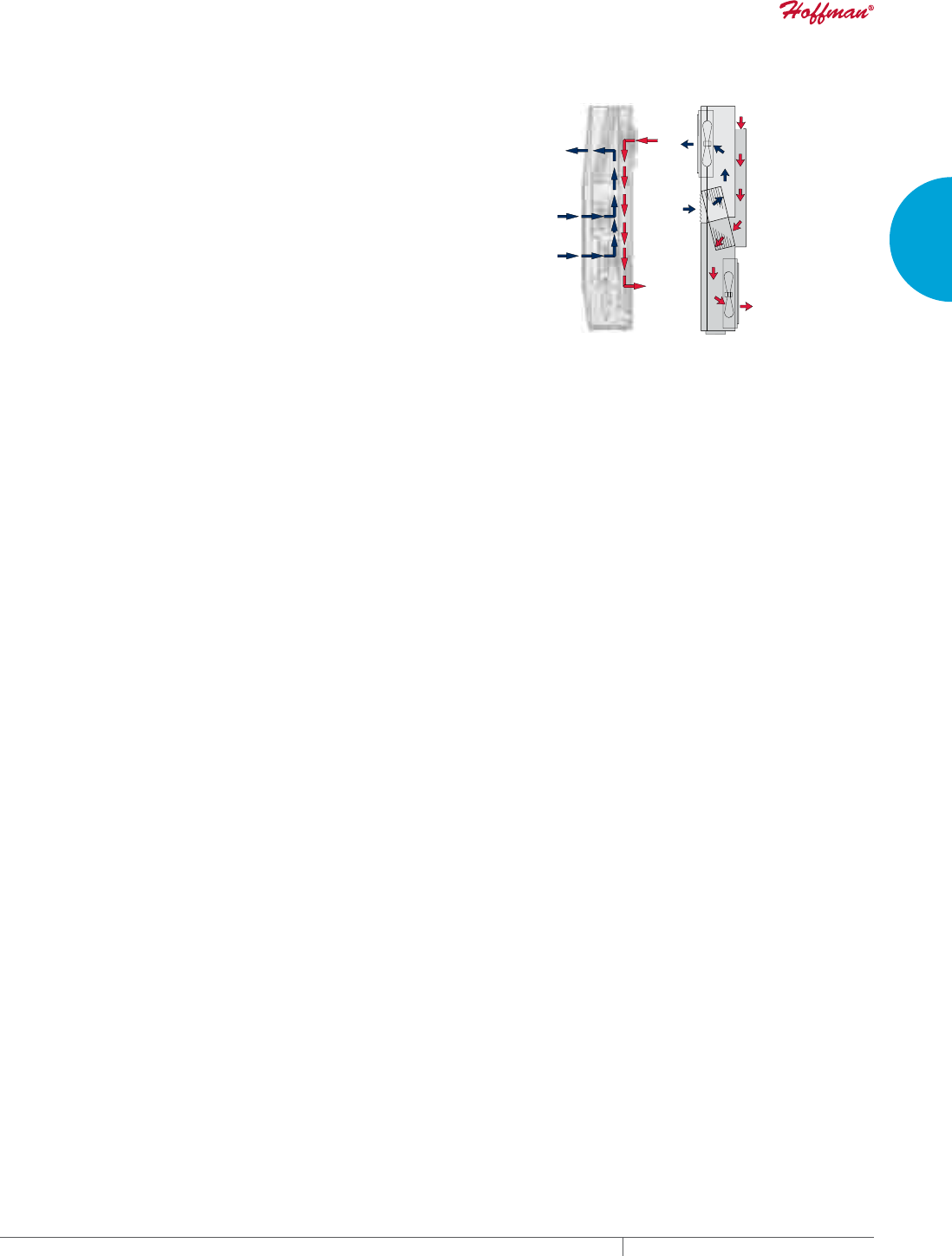
For electrical systems with higher static pressure, filter fans are
sometimes used in a “push/pull” approach. The reason is that two
filter fans designed in “series” overcome twice the static pressure
compared to one filter fan working alone with an exhaust grille.
“Push/Pull”
Design
Cool air in
through
lter fan
Warm air
out with
lter fan
Roof-mount air movers are also available. Engineers occasionally
employ them due to space constraints lower in the enclosure or for
other reasons. Two exhaust grilles are recommended to ensure
adequate airflow through the enclosure.
Roof-Mount
Design
Cool air in
through
grille
Cool air in
through
grille
Warm air
out through
roof-mount
lter fan
Warm air
out through
roof-mount
lter fan
Roof-mount air mover designs also pose the risk of pulling dust into
the enclosure through poor seals.

EQUIPMENT PROTECTIONSUBJECT TO CHANGE WITHOUT NOTICECOOLING16
1
SELECTING A COOLING SOLUTION FRESH AIR ENCLOSURE COOLING OVERVIEW
CHOOSING AN AIR MOVER
Three overall considerations are applied when selecting a filter fan: voltage input, enclosure protection and airflow requirement.
POWER INPUT
Narrowing the choice of filter fans based on voltage input is quite simple. If the voltage available in the electronics system to power the
filter fan is AC, then an VAC filter fan is chosen. If the voltage for the application is DC, then a VDC filter fan is specified.
The voltage level of the filter fan’s power input also needs to be taken into consideration. For example, if the voltage input is 115 VAC,
then a 115 VAC filter fan should be specified. If the voltage input is 24 VDC, then a 24 VDC impeller is required. Filter fans are commonly
available in 115, 230 and 460 3-phase 50/60 Hz VAC as well as 24 VDC. Some manufacturers such as Pentair Technical Products offer 48
VDC due to the trend toward using this power input in some electronic systems.
ENCLOSURE PROTECTION
Another important consideration is selecting an air mover that maintains the protection level of the electrical enclosure.
U.S. standards of protection generally include:
Type 1 – For indoor use to protect against contact with the enclosed equipment
Type 12 - For indoor use to protect against dust, falling dirt and dripping non-corrosive liquid such as water
Type 3R – For outdoor use to protect against rain and sleet
Type 4 – For outdoor or indoor use to protect against windblown dust and rain, splashing water and hose-directed water
Type 4X – For outdoor or indoor use to protect against corrosion, windblown dust and rain, splashing water and hose-directed water
European standards of protection include:
IP54 – Dust must not enter in sufficient quantity to interfere with the satisfactory operation of the equipment; complete protection against
contact; water splashing against the enclosure from any direction shall have no harmful effect.
IP55 – Dust must not enter in sufficient quantity to interfere with the satisfactory operation of the equipment; complete protection against
contact; and water projected by a nozzle against enclosure from any direction shall have no harmful effects.
IP65 – No ingress of dust; complete protection against contact; and water projected by a nozzle against enclosure from any direction shall
have no harmful effects.
AIRFLOW
Choosing a filter fan with the right airflow or cooling capacity is as important as voltage input and enclosure protection. However, the
process is a little more involved.
Generally, smaller heat loads in the electronics system will require a filter fan with a lower airflow rate (CFM or M3/Hr.). Moderate to high
heat loads will need a larger, more powerful filter fan or multiple filter fans to move enough air to cool the electronics components.
The following 5-step process results in a filter fan specification that should generally work in your electronics system.
1. Determine Delta-T
2. Determine Internal Heat Load
3. Determine Free Airflow
4. Estimate System Impedance
5. Select Your Filter Fan
These five steps yield a ballpark result. A filter fan sample should always be tested in the actual electrical system itself to confirm that its
performance provides adequate airflow.
The next section outlines the 5-step filter fan selection process in more detail.
PH 763.422.2211 • FAX 763.576.3200 • HOFFMANONLINE.COMEQUIPMENT PROTECTION COOLING 17
1
SELECTING A COOLING SOLUTION FRESH AIR ENCLOSURE COOLING OVERVIEW
STEP 1. DETERMINE DELTAT (T)
Delta-T is the difference between maximum desired temperature
for the electronics and maximum temperature outside the
enclosure. It is important to determine ΔT because cooler air will
usually require less filter fan airflow whereas warmer air will
typically require more airflow.
Maximum
Electronics
Temperature
Maximum
Ambient
Temperature
Maximum desired temperature for the electronics is identified by
reviewing the component manufacturer’s specifications. They will
often indicate that the equipment should not operate above a certain
temperature such as 35 C (95 F).
Maximum temperature outside the enclosure is determined by
forecasting the highest potential temperature of the air around the
electronics cabinet. If the application is in an indoor environment
such as an air conditioned factory, the maximum temperature
outside the enclosure is the temperature of the facility, such as
25 C (77 F). If the electronics system is outdoors, the maximum
temperature around the cabinet is the hottest weather that the
application experiences, which may be 45 C (116 F) if it’s deployed on
a roof top for example.
ΔT =
maximum temperature desired for the electronics -
maximum expected ambient temperature
For example:
ΔT =
35 C (95 F) [maximum electronics temperature] -
25 C [maximum ambient temperature]
ΔT = 10 C (18 F)
STEP 2. DETERMINE INTERNAL HEAT LOAD
Heat load stems from the amount of waste heat generated inside the enclosure by the electronic components and is expressed in Watts.
There are several methods to determine internal heat load, depending on data availability.
A. Heat Load Data from Each Electronics Component Manufacturer
One way to estimate internal load is to gather heat load data from the manufacturers of the electronics components inside the cabinet. If
more than one control or other components are inside the enclosure, it will be necessary to add together the multiple estimates of heat
load to determine total internal heat load.
B. Component Power – Component Efficiency
A second method is to establish the Watts of power used by each electronic component. Derive Watts by multiplying the amp draw of each
device with its voltage. Then subtract the efficiency of each component from its estimated power use, adding up the outcomes for total
internal heat load.
INTERNAL HEAT LOAD = COMPONENT POWER (Watts) - COMPONENT EFFICIENCY (for each electrical device)
For example:
An electronic system uses two components that draw 115 VAC at 9.5 amps. Each has a rated efficiency of 90 percent (10 percent of each
device is inefficient). Unused amounts of power become generated heat. Thus, the estimated internal heat load is:
Device Power = 115 x 9.5 = 1100 Watts
Total Power = 2 x 1100 = 2200
Less Efficiency = 2200 x (1 - .90)
Total Heat Load = 220 Watts
C. Incoming – Outgoing Power
A third approach is to estimate the power going into the enclosure and the power coming out of it. The difference is the estimated amount
of internal heat load. Multiply the amps and volts of each electrical line going in to determine Watts and then add them together. Do the
same for the electrical line(s) coming out of the application. The outgoing watts are subsequently subtracted from the incoming watts.
INTERNAL HEAT LOAD = INCOMING POWER (Watts) – OUTGOING POWER (Watts)
For example:
An enclosure has three input lines of 230 VAC at 11, 6 and 4 amps. It has one output control line of 115 VAC at 9 amps.
Incoming Power = (230 x 11) + (230 x 6) + (230 x 4) = 4830 Watts
Outgoing Power = (115 x 9) = 1035 Watts
Total Heat Load = 4830 – 1035 = 3795 Watts
D. Automated Equipment Horsepower
The fourth method applies only to industrial automation equipment that operates with horsepower such as variable frequency drives
(VFDs). 1 horsepower = 745.6 Watts. Thus, the internal heat load from a 3 horsepower VFD is 2237 Watts, less its efficiency which is
typically 93 – 95 percent.
For example:
A cabinet has three 5 Hp VFDs with 95% efficiency.
VFD Watts = 5 Hp x 745.6 x 3 = 11184
Adjusted Watts = 11184 x (1 - .95) = 559
Total Heat Load = 559 x 1.25 = 699 Watts
Note: 1.25 is an assumed “safety” margin for other minor heat-producing components.
EQUIPMENT PROTECTIONSUBJECT TO CHANGE WITHOUT NOTICECOOLING18
1
SELECTING A COOLING SOLUTION FRESH AIR ENCLOSURE COOLING OVERVIEW
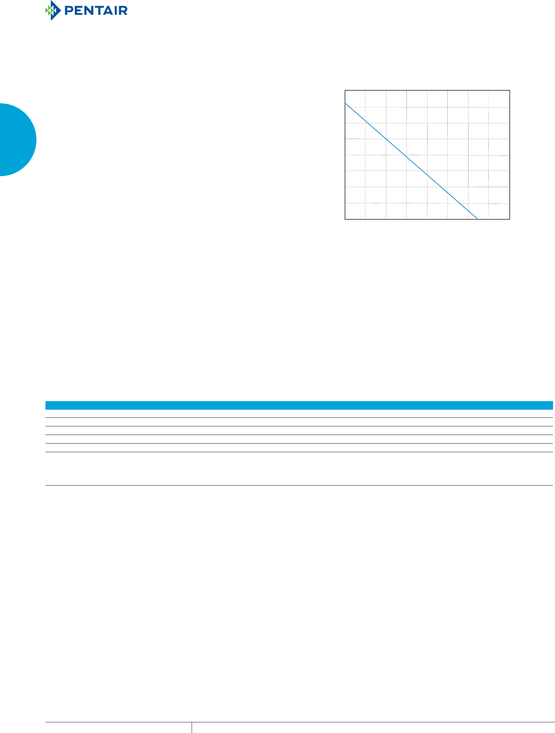
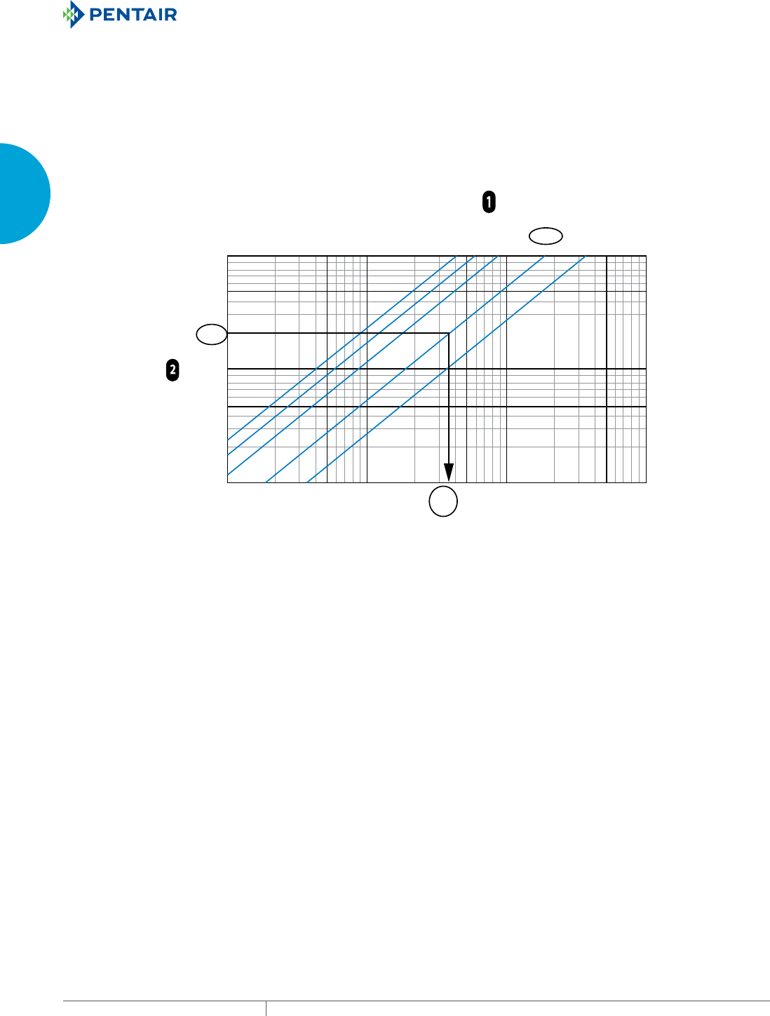
STEP 3. DETERMINE FREE AIRFLOW
Determining free airflow applies the results from steps 1 and 2 to the chart below. Recall that free airflow is the unimpeded airflow
through the enclosure without any interference from electronics components or filter fan exhaust grilles.
Select the diagonal ΔT line that closely matches the ΔT of your electronics system. Using the example from step 1, ΔT is 10 C (18 F).
Then find your cabinet’s heat load along the Y-axis of the chart. In the example from step 2, heat load is 2000 Watts.
Find where heat load intersects with ΔT to determine free airflow on the X-axis. Continuing the example, free airflow in this case is 360
CFM or 611 M3/Hr.
10000
5000
1000
500
100
50
85
40°C
72°F
30°C
54°F
20°C
36°F
10°C
18°F
5°C
9°F
100
170
500
849
1000
1698
5000
8489
10000
16978
FREE AIRFLOW WITHOUT SYSTEM IMPEDANCE
(Dierence between Ambient & Enclosure Temperature)
360
611
CFM 10
M/Hr 17
2000
DELTA-T
HEAT LOAD (Watts)
Now we need to account for system impedance, i.e., the amount of airflow interference created by the electronic components inside the
cabinet. A filter fan with more than 360 CFM or 611 M3/Hr. of free airflow will actually be needed for this system’s design.
PH 763.422.2211 • FAX 763.576.3200 • HOFFMANONLINE.COMEQUIPMENT PROTECTION COOLING 19
1
SELECTING A COOLING SOLUTION FRESH AIR ENCLOSURE COOLING OVERVIEW
STEP 4. ESTIMATE SYSTEM IMPEDANCE
Static pressure or system impedance can impact the cooling
performance of an air mover. Filter fans work well in electrical
cabinets with low static pressure such as a large enclosure with
a bare drive and few other components. They do not have enough
force to push air through a cabinet with a moderate or high system
impedance.
Low
Static
Pressure
High
Static
Pressure
Lightly Packed
Electronics
Under 0.75 In. H2O
(187 Pa)
Moderately Packed
Electronics
0.75 - 1.75 In. H2O
(187 - 436 Pa)
Densely Packed
Electronics
Over 1.75 In. H2O
(436 Pa)
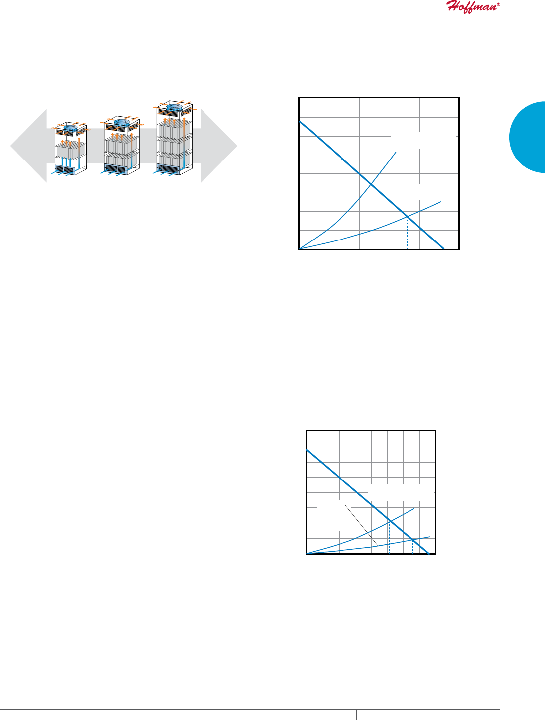
If your system design appears like the middle or right hand
example, then a motorized impeller or blower is probably a better
solution for the application than a filter fan.
Assuming a filter fan can cool your application, the exhaust grille
and electrical components inside the enclosure will reduce airflow
through the system. Filter fan manufacturers will show the effect
of the exhaust grille on the performance curve. However, they
do not indicate the impedance curve of the electronics system
because filter fan makers do not know this information. Only the
specifying electronics engineer or system designer can determine
this. If it is not possible to measure the exact static pressure inside
an electronics cabinet, you must make an estimate and draw an
approximation.
Estimated Electronic
Component Impedance
Exhaust Grille
System Impedance
1.00
100 180 200 265 300 400
.75
.50
.25
249
187
124
62
00
170 306 340 450 510 680
0
Airflow (CFM)
Airflow (CFM)
Impact of System Impedance on Free Airflow
of a 376 CFM (638 M3/Hr.) Filter Fan
Static Pressure (Inches of Water)
Static Pressure (Inches of Water)
In the example shown, the free airflow of a 376 CFM (638 M3/Hr.) air
mover decreases to 265 CFM with the exhaust grille kit and down to
180 CFM when used in an actual application. Thus, a model with a
performance curve similar to the one in the next graph would be too
small to keep our electrical system cool because our actual target
airflow is 360 CFM.
STEP 5. SELECT YOUR AIR MOVER
In this final step, we bring together the results of free airflow (step
3) and system impedance (step 4), using the air mover performance
charts. Applying the example, we need to select a motorized
impeller that delivers a minimum of 360 CFM (611 M3/Hr.).
Identify alternative air mover models with free airflow ratings
that are greater than the step 3 outcome of 360 CFM (611 M3/Hr.)
to compensate for airflow losses created by static pressure in the
system. A judgmental system impedance curve is overlaid onto
the performance charts of each of the optional models, and then
the model with the CFM or M3/Hr. closest to the target airflow is
selected.
In the performance curve shown here, 571 CFM is commonly the
largest filter fan in the electronics cooling industry. Based on
the estimated electronic component impedance overlaid by our
imaginary engineer, it should deliver the cooling performance
required by the system.
Estimated Electronic
Component Impedance
Exhaust
Grille
System
Impedance
1.00
150 180 300 450 510 600
255 306 510 765 866 1019
.75
.50
.25
249
187
124
62
0
0
Airflow(CFM)
Airflow (M/Hr.)
Performance Curve of a 571 CFM (969 M3/Hr.) Filter
Fan with Exhaust Grille and System Impedance
Static Pressure
(Inches of Water)
Static Pressure
(Pascals)
FRIENDLY REMINDER
This 5-step process for selecting an air mover yields a ballpark result. Be sure to test a sample of the air mover in the electrical system
prototype at maximum ambient and heat load conditions to verify adequate cool airflow.
EQUIPMENT PROTECTIONSUBJECT TO CHANGE WITHOUT NOTICECOOLING20
2
763.422.2211
763.576.3200
COOLING
TECHNICAL INFORMATION
Intro Page
STANDARDS SUMMARY
To standardize enclosure performance,
organizations like NEMA, UL, CSA, IEC
and VDE use rating systems to identify
an enclosure’s ability to resist external
environmental influences. CE
For industrial control equipment, the
CE Mark is not intended to be applied
to empty enclosures because they are
inactive components of a final assembly.
With the CE marking, the manufacturer
declares that the product conforms
with the essential requirements of the
applicable EU directives.
GOST
The GOST Standard, approved by ISO as
a local standard in Russian Federation
and CIS countries, covers general and
technical specifications as well as safety
requirements.
CHAPTER 2
TECHNICAL INFORMATION

PH 763.422.2211 • FAX 763.576.3200 • HOFFMANONLINE.COMEQUIPMENT PROTECTION COOLING 21
Intro Page
UL
The UL Listing Mark means that
the product has met UL’s safety
requirements and is suitable for factory
and field installation.
2
CHAPTER CONTENTS
UL, CE, GOST CERTIFICATION BENEFITS
Standards Organization Summary and Directory Overview 22
CE ...........................................22
GOST .........................................22
UL AND IP DEFINITIONS
Protection Levels ...............................23
SCCR Requirements per UL (Condensed version) .......24

EQUIPMENT PROTECTIONSUBJECT TO CHANGE WITHOUT NOTICECOOLING22
2
TECHNICAL INFORMATION UL, CE, GOST CERTIFICATION BENEFITS
UL, CE, GOST CERTIFICATION BENEFITS
STANDARDS ORGANIZATION SUMMARY AND DIRECTORY OVERVIEW
What’s in a Rating?
As a way of standardizing enclosure performance, organizations
like NEMA, UL, CSA, IEC and VDE use rating systems to identify
an enclosure’s ability to resist external environmental influences.
Resistance to everything from dripping liquid to hose-down to total
submersion is defined by the ratings systems. While these ratings
are all intended to provide information to help you make a safer,
more-informed product choice, there are differences among them.
North American Standards Organizations
In North America, NEMA, UL and CSA are the commonly recognized
standards organizations. Their ratings are based on similar
application descriptions and expected performance. UL and CSA
both require enclosure testing by qualified evaluators in their
certified labs. They also send site inspectors to make sure a
manufacturer adheres to prescribed manufacturing methods and
material specifications. NEMA, on the other hand, does not require
independent testing and leaves compliance completely up to the
manufacturer.
North American enclosure rating systems also include a rating
that indicates corrosion resistance. This rating is based on the
enclosure’s ability to withstand prolonged exposure to salt water
spray.
While the corrosion resistance rating is a good indicator that an
enclosure can resist corrosion, it does not provide information
on how a specific corrosive agent will affect a given enclosure
material. It is best to conduct a full analysis of the specific
application and environment to determine the best enclosure
choice.
International Standards Organizations
Like NEMA, IEC does not require independent testing and leaves
compliance completely up to the manufacturer. Nevertheless, there
are differences in how enclosure performance is interpreted. For
example, UL and CSA test requirements specify that an enclosure
fails the water-tight test if even a single drop of water enters the
enclosure. In the IEC standards for each level of ingress protection
(IP), a certain amount of water is allowed to enter the enclosure.
IEC 60529 IP ratings do not specify construction requirements
or degrees of protection against corrosive atmospheres, risk of
explosion or conditions such as moisture or corrosive vapors.
NEMA Type ratings, on the other hand, do specify construction and
performance requirements for most environmental conditions.
For this reason, and because the tests and evaluations for other
characteristics are not identical, the IEC enclosure classification
designations cannot be exactly equated with NEMA enclosure Type
numbers.
CE
For industrial control equipment, the CE Mark is not intended to be applied to empty enclosures because such enclosures are inactive
components of a final assembly. The responsibility of ensuring compliance with all applicable EU directives and harmonized standards
belongs with the final equipment manufacturer.
GOST
GOST Standard has been approved by ISO as a local standard in Russian Federation and CIS countries and is quite similar to the EN/CE
standards. The GOST collection of standards covers general and technical specifications as well as safety requirements.
At the time of this printing, the following countries use GOST Standard with some individual additions: Russia, Belarus, Ukraine, Moldova,
Kazakhstan, Azerbaijan, Armenia, Kyrgyzstan, Uzbekistan, Tajikistan, Georgia, Turkmenistan
GOST-R certification is required in order to gain customs clearance for products at the Russian borders. The GOST-R certificate indicates
compliance with the Russian standards. GOST-R is valid only for Russian Federation and may not be accepted in CIS countries. There are
similar, but independent regulations in each CIS country.
PH 763.422.2211 • FAX 763.576.3200 • HOFFMANONLINE.COMEQUIPMENT PROTECTION COOLING 23
2
TECHNICAL INFORMATION UL AND IP DEFINITIONS
UL AND IP DEFIN ITIONS
PROTECTION LEVELS
NEMA, UL and CSA Ratings Enclosure Type Descriptions for Non-Hazardous Locations
Type NEMA UL CSA
Indoor Type 1 Enclosures are intended for indoor
use primarily to provide a degree of
protection against contact with the
enclosed equipment or locations where
unusual service conditions do not exist.
Indoor use primarily to
provide protection against
contact with the enclosed
equipment and against
a limited amount of falling dirt.
General purpose enclosure.
Protects against accidental
contact with live parts.
Indoor Type 12 Enclosures are intended for indoor use
primarily to provide a degree of
protection against dust, falling dirt and
dripping noncorrosive liquids.
Indoor use to provide a degree
of protection against dust, dirt, fiber
flyings, dripping water and external
condensation of noncorrosive liquids.
Indoor use; provides a degree of
protection against circulating dust,
lint, fibers and flyings; dripping and
light splashing of non-corrosive
liquids; not provided with knockouts.
Indoor Type 12K Enclosures with knockouts are intended
for indoor use primarily to provide a
degree of protection against dust, falling
dirt and dripping noncorrosive liquids.
Indoor use to provide a degree of
protection against dust, dirt, fiber
flyings, dripping water and external
condensation of noncorrosive liquids.
Indoor use; provides a degree of
protection against circulating
dust, lint, fibers and flyings; dripping
and light splashing of noncorrosive
liquids; not provided with knockouts.
Indoor Type 13 Enclosures are intended for indoor
use primarily to provide a degree of
protection against dust, spraying of water,
oil and noncorrosive coolant.
Indoor use to provide a degree
of protection against lint, dust
seepage, external condensation
and spraying of water, oil and
noncorrosive liquids.
Indoor use; provides a degree of
protection against circulating dust,
lint, fibers and flyings; seepage and
spraying of non-corrosive liquids,
including oils and coolants.
Outdoor Type 3 Enclosures are intended for outdoor
use primarily to provide a degree of
protection against windblown dust, rain
and sleet; undamaged by the
formation of ice on the enclosure.
Outdoor use to provide a
degree of protection against
windblown dust and windblown
rain; undamaged by the
formation of ice on the enclosure.
Indoor or outdoor use; provides a
degree of protection against
rain, snow and windblown dust;
undamaged by the external
formation of ice on the enclosure.
Outdoor Type 3R Enclosures are intended for outdoor
use primarily to provide a degree of
protection against falling rain and sleet;
undamaged by the formation
of ice on the enclosure.
Outdoor use to provide a
degree of protection against
falling rain; undamaged by the
formation of ice on the enclosure.
Indoor or outdoor use; provides
a degree of protection against
rain and snow; undamaged by the
external formation of ice
on the enclosure.
Outdoor Type 3RX Enclosures are intended for outdoor
use primarily to provide a degree of
protection against corrosion, falling
rain and sleet; undamaged by the
formation of ice on the enclosure.
Not specifically defined. Not specifically defined.
Outdoor Type 4 Enclosures are intended for indoor or
outdoor use primarily to provide a
degree of protection against windblown
dust and rain, splashing water and hose
directed water; undamaged by the
formation of ice on the enclosure.
Either indoor or outdoor use to
provide a degree of protection
against falling rain, splashing
water and hose-directed water;
undamaged by the formation
of ice on the enclosure.
Indoor or outdoor use; provides a
degree of protection against
rain, snow, windblown dust,
splashing and hose-directed
water; undamaged by the external
formation of ice on the enclosure.
Outdoor Type 4X Enclosures are intended for indoor
or outdoor use primarily to provide a
degree of protection against corrosion,
windblown dust and rain, splashing water
and hose-directed water; undamaged by
the formation of ice on the enclosure.
Either indoor or outdoor use to
provide a degree of protection
against falling rain, splashing
water and hose-directed water;
undamaged by the formation of ice
on the enclosure; resists corrosion.
Indoor or outdoor use; provides a
degree of protection against rain,
snow, windblown dust, splashing and
hose-directed water; undamaged by
the external formation of ice on the
enclosure; resists corrosion.
Outdoor Type 6 Enclosures are intended for use indoors or
outdoors where occasional submersion is
encountered; limited depth; undamaged
by the formation of ice on the enclosure.
Indoor or outdoor use to provide a
degree of protection against entry of
water during temporary submersion
at a limited depth; undamaged
by the external formation
of ice on the enclosure.
Indoor or outdoor use; provides a
degree of protection against the
entry of water during temporary
submersion at a limited depth.
Undamaged by the external
formation of ice on the
enclosure; resists corrosion.
• This material is reproduced with permission from NEMA. The preceding descriptions, however, are not intended to be complete
representations of National Electrical Manufacturers Association standards for enclosures nor those of the Electrical and Electronic
Manufacturers Association of Canada.
• This material is reproduced with permission from Underwriters Laboratories Inc. Enclosures for Electrical Equipment, UL 50, 50E
and Industrial Control Panels, UL 508A.
• This material is reproduced with permission from the Canadian Standards Association.
• Underwriters Laboratories Inc. (UL) shall not be responsible for the use of or reliance upon a UL Standard by anyone. UL shall
not incur any obligation or liability for damages, including consequential damages, arising out of or in connection with the use,
interpretation of, or reliance upon a UL Standard.
• Some enclosures may have multiple ratings. For instance: 4, 12—Outdoor use; able to be used indoors with modifications; 4X, 3RX—
Outdoor use; able to be used indoors with modifications; 4, 9—Can be used in both hazardous and non-hazardous locations
EQUIPMENT PROTECTIONSUBJECT TO CHANGE WITHOUT NOTICECOOLING24
2
TECHNICAL INFORMATION UL AND IP DEFINITIONS
IP Rating Descriptions Example Rating
If 1st IP number is... and the 2nd IP number is... Then the IP rating is
2 3 IP23
(protection against solid objects) (protection against liquids) An enclosure with this designation provides protection against touch with a
finger, penetration of solid objects greater than 12 mm and spraying water.
First Numeral (Solid Objects and Dust)
IP Protection of Persons Protection of Equipment
0No Protection No Protection
1Protected against contact with large areas of the body (back of hand) Protected against objects over 50 mm in diameter
2Protected against contact with fingers Protected against solid objects over 12 mm in diameter
3Protected against tools and wires over 2.5 mm in diameter Protected against solid objects over 2.5 mm in diameter
4Protected against tools and wires over 1 mm in diameter Protected against solid objects over 1 mm in diameter
5Protected against tools and wires over 1 mm in diameter Protected against dust (limited ingress, no harmful deposit)
6Protected against tools and wires over 1 mm in diameter Totally protected against dust
Second Numeral (Liquid)
IP Protection of Equipment
0No Protection
1Protected against vertically falling drops of water, e.g. condensation
2Protected against direct sprays of water up to 15 degrees from vertical
3Protected against sprays up to 60 degrees from vertical
4Protected against water sprayed from all directions (limited ingress permitted)
5Protected against low-pressure jets of water from all directions (limited ingress permitted)
6Protected against strong jets of water
7Protected against the effects of immersion between 15 cm and 1 m
8Protected against long periods of immersion under pressure
SCCR REQUIREMENTS PER UL (CONDENSED VERSION)
Article 409 of the 2008 National Electric Code (NFPA 70) requires industrial control panels to be marked with a short circuit current
rating. As specified in the National Electric Code, UL508A-2001 Supplement SB, the Standard of Safety for Industrial Control Equipment,
provides an accepted method for determining the short-circuit current rating of the control panel.
The SCCR rating for our air conditioners and heat exchangers has a default value of 5 kA.
You may use a 5 or 10 kVA isolation transformer between the customer’s panel and our air conditioner and not have an effect on the
customer’s 65 kA rating.
You may use a fuse or circuit breaker with a 5 kA short circuit rating on the line side of the ACU and its branch circuit protective device and
not have an effect on the customer’s 65 kA rating.
The current limiting fuse or circuit breaker used on the line side of the branch circuit protection for the ACU must have a SCCR equal to
or greater than that of the panel rating. Additionally, for a current limiting fuse, the customer would need to verify that the let-through
current (Ip * 10^3) of the fuse is less than or equal to 5KA by referencing table SB4.2 of UL 508A. If a circuit breaker is used as feeder
protection, it must be marked Current Limiting type from the manufacturer, and the panel builder would need to verify based on the
manufacturers published curves that the let-through current is less than or equal to 5kA. Examples of these curves are included in UL
508A supplement SB.
You can run separate circuits for the panel and the air conditioner as long as each is labeled with their individual SCCR ratings.
(5 kA and 65 kA)
If the customer does not implement one of the options above, then the resulting SCCR rating would be the 5 kA rating of the ACU, if that is
the lowest rated component in the panel.
Testing represents another option; however, if the customer does not implement these options, then the resulting short circuit rating of
the panel is based on the lowest short circuit current rating of all power circuit components installed in the panel.

PH 763.422.2211 • FAX 763.576.3200 • HOFFMANONLINE.COMEQUIPMENT PROTECTION COOLING 25
2
TECHNICAL INFORMATION UL AND IP DEFINITIONS
Notes
EQUIPMENT PROTECTIONSUBJECT TO CHANGE WITHOUT NOTICECOOLING26
3
763.422.2211
763.576.3200
COOLING
SEALED ENCLO SURE COOLIN G
Intro Page
SPECTRACOOL™ AIR
CONDITIONERS
Designed to deliver vital cooling to
sensitive electronics within enclosures,
SPECTRACOOL™ air conditioners
provide energy-efficient, reliable
cooling in rugged indoor and
outdoor environments. With a
variety of cooling capacities and
sizes, air conditioners
are ideal for
applications ranging
from low-profile
cabinet cooling
to large cabinet
cooling.
CLIMAGUARD™
HEAT
EXCHANGERS
CLIMAGUARD™
heat exchangers
are an efficient,
maintenance-
free and low-noise solution for cooling
enclosures in industrial applications.
With a unique, double-seal design and
small to large cooling capacities, heat
exchangers protect vital electronics
by effectively transferring heat and
preventing damaging dirt and dust.
CHAPTER 3
SEALED ENCLOSURE
COOLING
FEATURED PRODUCTS
PH 763.422.2211 • FAX 763.576.3200 • HOFFMANONLINE.COMEQUIPMENT PROTECTION COOLING 27
Intro Page
EASY SWAP ADAPTOR PLENUMS
When existing air conditioners are
damaged or have reached end-of-life,
Easy Swap Adaptor
Plenums provide
a quick and easy
means for attaching
new SPECTRACOOL
air conditioners to
the enclosure with
no modifications
required.
THERMOELECTRIC
COOLERS
A compact design,
with no refrigerant,
compressors or
filters required,
Thermoelectric
Coolers provide
reliable cooling
for small indoor and outdoor
enclosures. With Peltier effect
cooling capacities, Thermoelectric
Coolers efficiently remove heat
around critical electronics within an
enclosure.
3
CHAPTER CONTENTS
AIR CONDITIONERS
SPECTRACOOL™ Indoor/Outdoor ....................28
SPECTRACOOL™ Narrow Indoor/Outdoor ..............52
SPECTRACOOL™ Compact Indoor ...................70
EASY SWAP Adaptor Plenums For Air Conditioners ......78
T-SERIES Compact Outdoor ........................80
T-SERIES Mid-size Outdoor ........................88
T-SERIES Large Capacity Outdoor ..................106
GENESIS™ Top-Mount Indoor .....................116
PROAIR Harsh Environment. . . . . . . . . . . . . . . . . . . . . . .122
Water-Cooled Indoor ............................132
Water-Cooled Indoor/Outdoor .....................136
Water-Cooled Rack-Mount .......................140
HEAT EXCHANGERS
CLIMAGUARD™ Air-to-Air Indoor ...................144
CLIMAGUARD™ Air-to-Air Outdoor .................160
CLIMAGUARD™ Air-to-Water Indoor ................174
THERMOELECTRIC COOLERS
Thermoelectric Coolers Indoor/Outdoor .............184
Thermoelectric Temperature Controller .............192
Thermoelectric Condensate Manager ...............193
VORTEX COOLERS
Vortex Coolers Indoor/Outdoor ....................194
Quiet Vortex A/C Enclosure Coolers, Type 4/4X/12 .....198
Vortex A/C Enclosure Coolers, Hazardous Location ....202
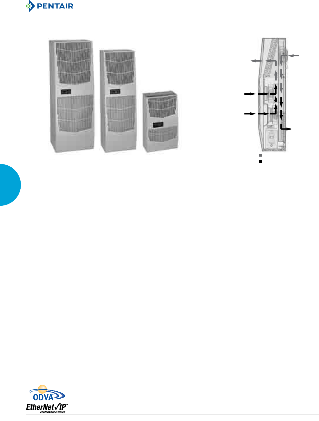
EQUIPMENT PROTECTIONSUBJECT TO CHANGE WITHOUT NOTICECOOLING28
3
SEALED ENCLOSURE COOLING AIR CONDITIONERS
AIR CONDITIONERS
SPECTRACOOL™ INDOOR/OUTDOOR
G28
4000/6000 BTU/Hr.
1172/1758 Watt
G52
8000/12000 BTU/Hr.
2300/3500 Watt
G57
20000 BTU/Hr.
5861 Watt
G28
G52
G57
Ambient AirFlow
Clean AirFlow
INDUSTRY STANDARDS
UL/cUL Listed; Type 12, 3R, 4; 4X optional; File No. SA6453
CE
GOST
IP 56 Internal Loop
IP 34 on External Loop
Telcordia GR-487 capable (Outdoor)
APPLICATION
• Industrial automation
• Telecommunications equipment
• Waste water treatment systems
• Package handling equipment
• Security and defense systems
• And more
FEATURES
• Energy-efficient rotary compressor on most models
• R407c and R134a earth-friendly refrigerants
• 115, 230 and 400/460 VAC 3-phase power input on most models
• UL Listed to save customers time and money with agency
approvals
• Outdoor model operating temperature range from -40 F/-40 C to
131 F/55 C
• Exterior and partially recessed mounting options
• Attractive industrial design with minimal use of visible fasteners
• Reliable mechanical thermostat on enclosure side of the unit;
indoor air conditioner models include digital display on ambient
side
• Dual condenser-side air movers for performance redundancy on
G52 and G57 models
• Galvanized sheet-metal cover for rugged factory and outdoor
environments
• Easy-mount flanges for simple installation
• Cut-out adapter options for enclosures with GENESIS™ and
T-Series air conditioners, enable users to easily transition to the
new unit
• Dust-resistant condenser coil allows the unit to be run filterless
in most applications
• Cleanable, reusable aluminum mesh filter protects coils for
maximum cooling performance
• Mounting hardware, gaskets and user manual furnished with the
unit
• Every unit functionally tested before shipping
• Standard Indoor Air Conditioner models also include:
- Active condensate management with heater strip
- Power-off relay for door switch and other system
requirements
- Malfunction switch
• Standard Outdoor Air Conditioner models also include:
- Telcordia GR-487 capable
- Corrosion-resistant components
- Malfunction switch
- Compressor heater
- Head pressure control
- Up to 2000 Watt (G28, G52) and 3000 Watt (G57) enclosure
heater
SPECIFICATIONS
• Nominal cooling capacity:
G28 4000 & 6000 BTU/Hr. (1172 and 1758 W)
G52 8000 & 12000 BTU/Hr. (2344 and 3516 W)
G57 20000 BTU/Hr. (5861 W)
• Outdoor model operating temperature range from -40 F/-40 C to
131 F/55 C
FINISH
• RAL 7035 light-gray, semi-textured powder-coat paint
• Other colors and textures available
NOTES
Visit www.HoffmanOnline.com to download 2D and 3D CAD
drawings into the overall design of your electronic system.
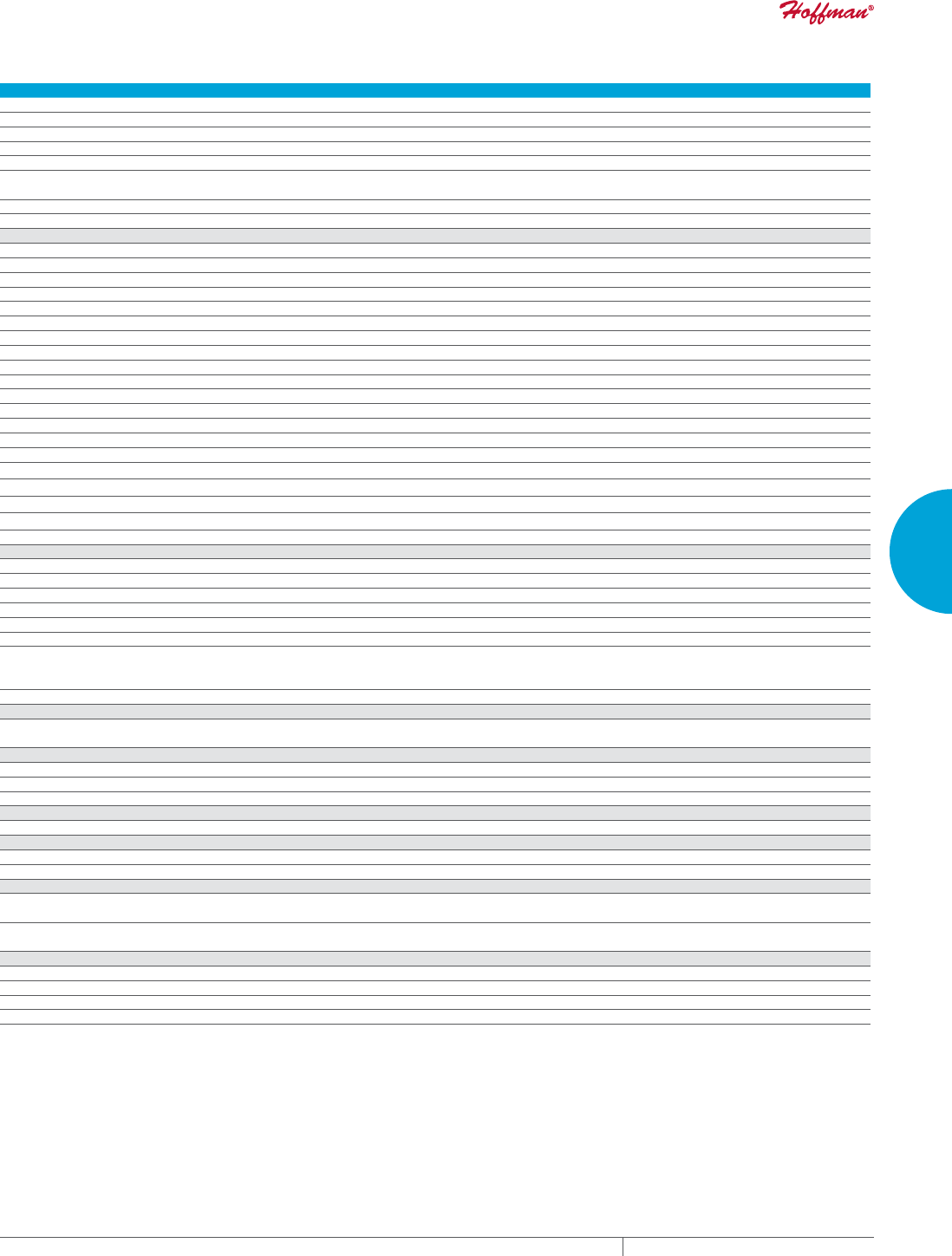
PH 763.422.2211 • FAX 763.576.3200 • HOFFMANONLINE.COMEQUIPMENT PROTECTION COOLING 29
3
SEALED ENCLOSURE COOLING AIR CONDITIONERS
Performance Data G28 Models 4000/6000 BTU/Hr. (1172/1758 Watt)
CATALOG NUMBER
Indoor Model G280416G050 G280426G050 G280446G050 G280616G050 G280626G050 G280646G050
Indoor Model Stainless Steel Type 4X G280416G051 G280426G051 G280446G051 G280616G051 G280626G051 G280646G051
Indoor Model with Remote Access Control* G280416G060 G280426G060 G280446G060 G280616G060 G280626G060 G280646G060
Outdoor Model without Heat Pkg. G280416G100 G280426G100 G280446G100 G280616G100 G280626G100 G280646G100
Outdoor Model Partial Recessed Mount G280416G101 G280426G101 G280446G101 G280616G101 G280626G101 G280646G101
Outdoor Model without Heat Pkg.
Stainless Steel Type 4X
G280416G102 G280426G102 G280446G102 G280616G102 G280626G102 G280646G102
Outdoor Model with Heat Pkg. G280416G150 G280426G150 —G280616G150 G280626G150 —
Outdoor Model with Heat Pkg. Stainless Steel Type 4X G280416G151 G280426G151 —G280616G151 G280626G151 —
COOLING PERFORMANCE
Nominal:
BTU/Hr. 4600/4900 4600/4900 4600/4900 6000/6400 6000/6400 5400/6000
Watts 1347/1435 1347/1435 1347/1435 1757/1874 1757/1874 1581/1757
At 131 F/131 F (55 C/55 C):
BTU/Hr. (50/60 Hz) 4600/4900 4600/4900 4600/4900 6000/6400 6000/6400 5400/6000
W (50/60 Hz) 1347/1435 1347/1435 1347/1435 1757/1874 1757/1874 1581/1757
At 95 F/95 F (35 C/35 C):
BTU/Hr. (50/60 Hz) 4300/4600 4300/4600 4324/4655 5600/6000 5600/6000 5054/5685
W (50/60 Hz) 1260/1364 1260/1364 1267/1364 1641/1758 1641/1758 1481/1666
Refrigerant R407C R407C R134A R407C R407C R134A
Refrigerant Charge (ounces/grams) 20/567 20/567 16/454 20/567 20/567 16/454
Operating Temperature Range:
Maximum (°F/°C) 131 F/55 C 131 F/55 C 131 F/55 C 131 F/55 C 131 F/55 C 131 F/55 C
Minimum (°F/°C) -40 F/-40 C -40 F/-40 C -40 F/-40 C -40 F/-40 C -40 F/-40 C -40 F/-40 C
Air Flow at 0 Static Pressure:
Internal loop 50 Hz (CFM / m3/hr.) 189/321 189/321 189/321 189/321 189/321 189/321
External loop 50 Hz (CFM / m3/hr.) 291/494 291/494 291/494 291/494 291/494 291/494
Internal loop 60 Hz (CFM / m3/hr.) 221/375 221/375 221/375 221/375 221/375 221/375
External loop 60 Hz (CFM / m3/hr.) 300/509 300/509 300/509 300/509 300/509 300/509
Max. Heater W (Outdoor Models) 2000 2000 2000 2000
ELECTRICAL DATA
Rated Voltage 115 230 400/460 3~ 115 230 400/460 3~
Frequency (Hz) 50/60 50/60 50/60 50/60 50/60 50/60
Operating Range +/- 10% +/- 10% +/- 10% +/- 10% +/- 10% +/- 10%
Max. Power Consumption (W at 50/60 Hz) 1138.5/1311 1058/1334 680/874 1138.5/1311 1058/1334 680/874
Max. Nominal Current (A at 50/60 Hz) 9.9/11.4 4.6/5.8 1.7/1.9 9.9/11.4 4.6/5.8 1.7/1.9
Starting Current (A) 36.2 17.7 7.7 36.2 17.7 7.7
Agency Approvals cUL Listed
CE
GOST
Power Input Description Terminal Block
ENCLOSURE PROTECTION
UL Type Type 12, 3R, 4 Standard
Type 4X Stainless Steel Optional
CONTROLLER
Description Basic Mechanical Thermostat
Thermostat Location Enclosure Side on All Base Models
Factory Thermostat Setting (°F/°C) 80/27 80/27 80/27 80/27 80/27 80/27
SOUND LEVEL
At 1.5 Meters 68dB(A)
UNIT CONSTRUCTION
Material Galvanized Sheet Metal Standard (Optional: Stainless Steel)
Finish Powder Coat RAL 7035 Light Gray Standard
ACCESSORIES
EASYSWAP Adaptor Plenum (GENESIS™ M28) Enables SPECTRACOOL to be mounted to GENESIS M28 air conditioner cutout
Catalog Number PLM28G28
EASYSWAP Adaptor Plenum (T-Series T29) Enables SPECTRACOOL to be mounted to T-Series T29 air conditioner cutout
Catalog Number PLT29G28
UNIT DIMENSIONS
Height (in./mm) 28.55/725.1
Width (in./mm) 16.97/431.1
Depth (in./mm) 10.10/256.6
Weight (lb./kg) 84/38 84/38 84/38 84/38 84/38 84/38
*Units with Remote Access Control utilize a digital controller and communicate via EtherNet/IP, Modbus TCP/IP and SNMP over ethernet or modbus RTU
over USB.
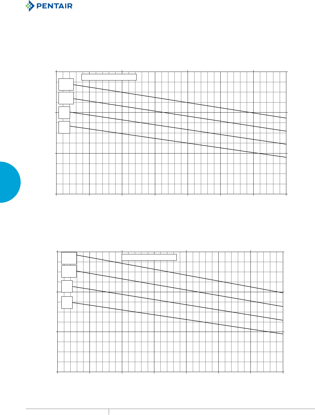
EQUIPMENT PROTECTIONSUBJECT TO CHANGE WITHOUT NOTICECOOLING30
3
SEALED ENCLOSURE COOLING AIR CONDITIONERS
Enclosure Air Temperature
25 C
77 F
35 C
95 F
45 C
113 F
55 C
131 F
G28-0416-GXXX Capacity Curves at 60 Hz
0
2000
4000
6000
68 77 86 95 104113 122 131
Ambient Air In (°F)
Cooling Capacity (BTU/Hr.)
0
586
1172
1758
20 30 40 50
Ambient Air In (°C)
Cooling Capacity (W)
Enclosure Air Temperature
25 C
77 F
35 C
95 F
45 C
113 F
55 C
131 F
G28-0416-GXXX Capacity Curves at 50 Hz
0
2000
4000
6000
68 77 86 95 104 113 122 131
Ambient Air In (°F)
Cooling Capacity (BTU/Hr.)
0
586
1172
1758
20 30 40 50
Ambient Air In (°C)
Cooling Capacity (W)
Performance Curves for G28 Models 4000 BTU/Hr. (1347/1435 Watt)

PH 763.422.2211 • FAX 763.576.3200 • HOFFMANONLINE.COMEQUIPMENT PROTECTION COOLING 31
3
SEALED ENCLOSURE COOLING AIR CONDITIONERS
Enclosure Air Temperature
25 C
77 F
35 C
95 F
45 C
113 F
55 C
131 F
G28-0426-GXXX Capacity Curves at 60 Hz Without Air Filter
0
2000
4000
6000
8000
68 77 86 95 104113 122131
Ambient Air In (°F)
Cooling Capacity (BTU/Hr.)
0
586
1172
1758
2344
20 30 40 50
Ambient Air In (°C)
Cooling Capacity (W)
Enclosure Air Temperature
25 C
77 F
35 C
95 F
45 C
113 F
55 C
131 F
G28-0426-GXXX Capacity Curves at 50 Hz Without Air Filter
0
2000
4000
6000
8000
68 77 86 95 104 113 122 131
Ambient Air In (°F)
Cooling Capacity (BTU/Hr.)
0
586
1172
1758
2344
20 30 40 50
Ambient Air In (°C)
Cooling Capacity (W)
Performance Curves for G28 Models 4000 BTU/Hr. (1347/1435 Watt)
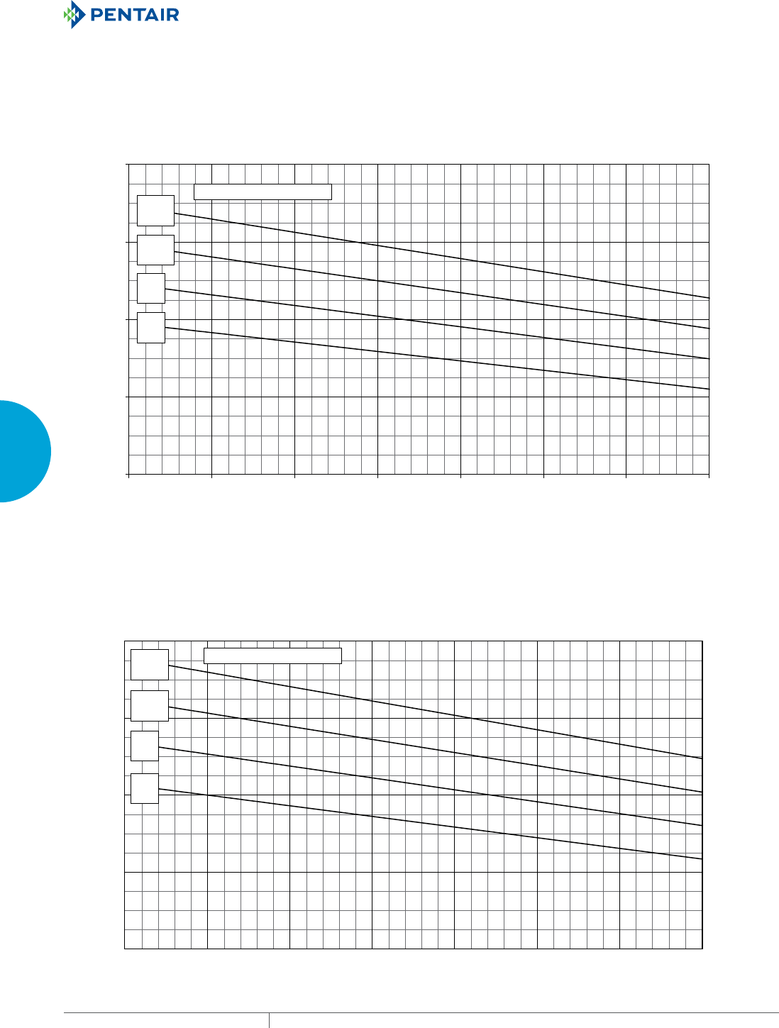
EQUIPMENT PROTECTIONSUBJECT TO CHANGE WITHOUT NOTICECOOLING32
3
SEALED ENCLOSURE COOLING AIR CONDITIONERS
Enclosure Air Temperature
25 C
77 F
35 C
95 F
45 C
113 F
55 C
131 F
0
2000
4000
6000
8000
68 77 86 95 104 113 122 131
Ambient Air In (°F)
Cooling Capacity (BTU/Hr.)
0
586
1172
1758
2344
20 30 40 50
Ambient Air In (°C)
Cooling Capacity (W)
G28-0446-GXXX- Capacity Curves at 60 Hz; Without Filter
Enclosure Air Temperature
25 C
77 F
35 C
95 F
45 C
113 F
55 C
131 F
0
2000
4000
6000
8000
68 77 86 95 104 113122 131
Ambient Air In (°F)
Cooling Capacity (BTU/Hr.)
0
586
1172
1758
2344
20 30 40 50
Ambient Air In (°C)
Cooling Capacity (W)
G28-0446-GXXX- Capacity Curves at 50 Hz; Without Filter
Performance Curves for G28 Models 4000 BTU/Hr. (1347/1435 Watt)
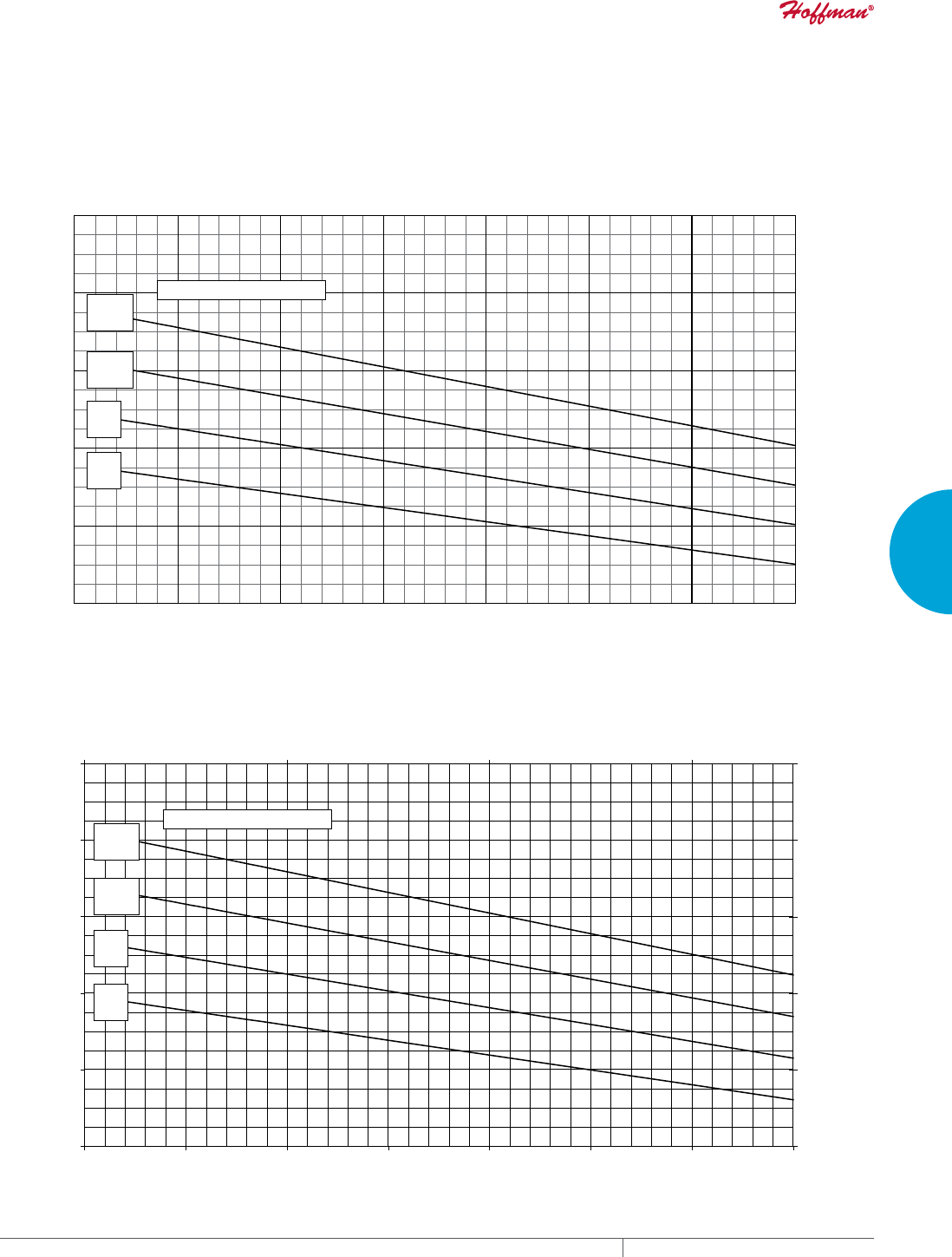
PH 763.422.2211 • FAX 763.576.3200 • HOFFMANONLINE.COMEQUIPMENT PROTECTION COOLING 33
3
SEALED ENCLOSURE COOLING AIR CONDITIONERS
Enclosure Air Temperature
25 C
77 F
35 C
95 F
45 C
113 F
55 C
131 F
2000
4000
6000
8000
10000
12000
68 77 86 95 104 113 122 131
Ambient Air In (°F)
Cooling Capacity (BTU/Hr.)
586
1172
1758
2344
2930
3516
20 30 40 50
Ambient Air In (°C)
Cooling Capacity (W)
G28-06(1/2)6-G002-P#2 Capacity Curves at 60 Hz Without Filter
Enclosure Air Temperature
25 C
77 F
35 C
95 F
45 C
113 F
55 C
131 F
2000
4000
6000
8000
10000
12000
68 77 86 95 104 113 122 131
Ambient Air In (°F)
Cooling Capacity (BTU/Hr.)
586
1172
1758
2344
2930
3516
20 30 40 50
Ambient Air In (°C)
Cooling Capacity (W)
G28-06(1/2)6-GXXX Capacity Curves at 50 Hz Without Filter
Performance Curves for G28 Models 4000/6000 BTU/Hr. (1172/1758 Watt)

EQUIPMENT PROTECTIONSUBJECT TO CHANGE WITHOUT NOTICECOOLING34
3
SEALED ENCLOSURE COOLING AIR CONDITIONERS
Enclosure Air Temperature
25 C
77 F
35 C
95 F
45 C
113 F
55 C
131 F
G28-0646-GXXX Performance Curve 460VAC/60Hz Without Air Filter
2000
4000
6000
8000
10000
68 77 86 95 104 113 122 131
Ambient Air In (°F)
Cooling Capacity (BTU/Hr.)
586
1172
1758
2344
2930
20 30 40 50
Ambient Air In (°C)
Cooling Capacity (W)
Enclosure Air Temperature
25 C
77 F
35 C
95 F
45 C
113 F
55 C
131 F
G28-0646-GXXX Performance Curve 400VAC/50Hz Without Air Filter
2000
4000
6000
8000
10000
68 77 86 95 104 113 122 131
Ambient Air In (°F)
Cooling Capacity (BTU/Hr.)
586
1172
1758
2344
2930
20 30 40 50
Ambient Air In (°C)
Cooling Capacity (W)
Performance Curves for G28 Models 6000 BTU/Hr. (1758 Watt)
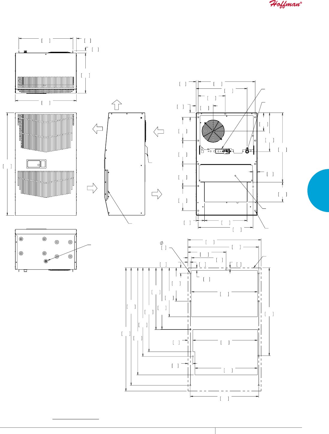
PH 763.422.2211 • FAX 763.576.3200 • HOFFMANONLINE.COMEQUIPMENT PROTECTION COOLING 35
3
SEALED ENCLOSURE COOLING AIR CONDITIONERS
:$50
$,5287
&22/
$,5287
(1&/2685(
$,5287
5(029$%/(
+$1*,1*
7$%6
$0%,(17
$,5,1
&/($1$%/(5(86$%/(
$/80,180,1/(7),/7(5
$&&(66+2/(72>@
2876,'(',$0(7(5'5$,1678%
&22/,1*+($7,1*
7+(50267$76
32:(5
,1/(7
237,21$/
$&&(663$1(/
21/<)2581,76
:,7++($7(5
81&
02817,1*
+2/(6
;
;
;
[
;
;
;
$&287/,1(
&XWRXW'LPHQVLRQV
127(
02817,1**$6.(76833/,('1276+2:1
81,76LQ>PP@
*0RGHOV%78+U9:DWW
Visit www
.HoffmanOnline.com to download 2D and 3D CAD drawings into the overall design of your electr
onic system.
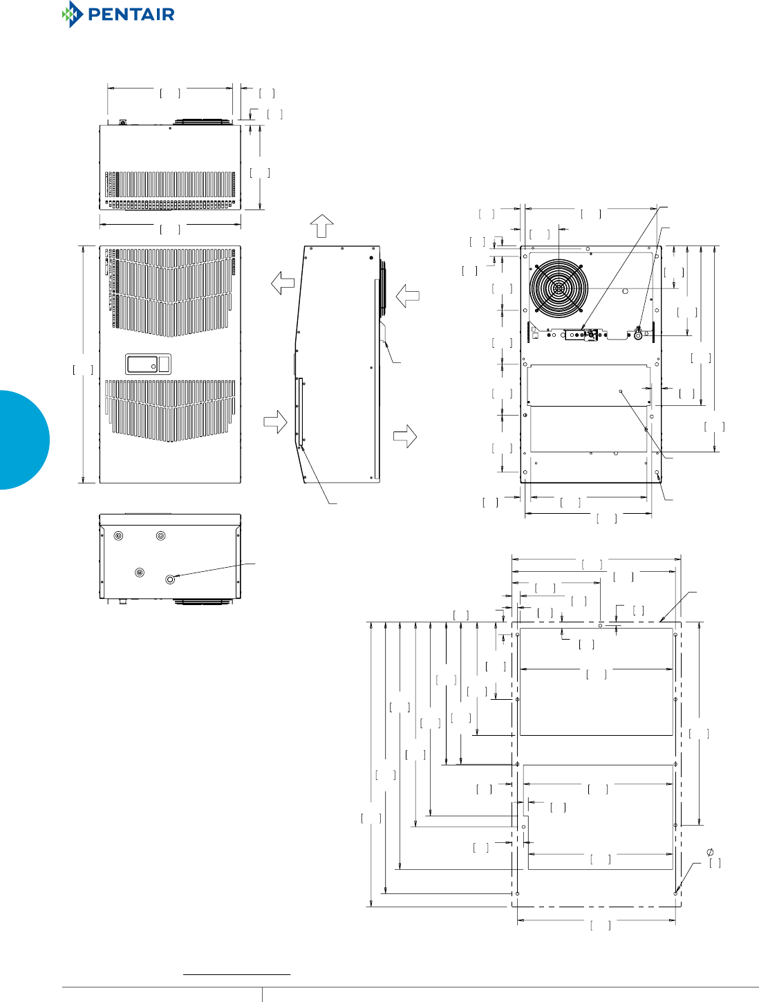
EQUIPMENT PROTECTIONSUBJECT TO CHANGE WITHOUT NOTICECOOLING36
3
SEALED ENCLOSURE COOLING AIR CONDITIONERS
:$50
$,5287
$0%,(17
$,5,1
&22/
$,5287
(1&/2685(
$,5287
5(029$%/(
+$1*,1*
7$%6
&/($1$%/(5(86$%/(
$/80,180,1/(7),/7(5
$&&(66+2/(72>@
2876,'(',$0(7(5'5$,1678%
81&
02817,1*
+2/(6
237,21$/
$&&(663$1(/
21/<)2581,76
:,7++($7(5
32:(5
,1/(7
&22/,1*+($7,1*
7+(50267$76
;
;
;
;
;
$&287/,1(
&XWRXW'LPHQVLRQV
127(
02817,1**$6.(76833/,('1276+2:1
81,76LQ>PP@
*0RGHOV%78+U9%78+U9:DWW
Visit www
.HoffmanOnline.com to download 2D and 3D CAD drawings into the overall design of your electr
onic system.
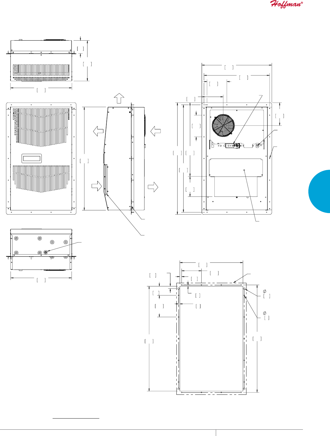
PH 763.422.2211 • FAX 763.576.3200 • HOFFMANONLINE.COMEQUIPMENT PROTECTION COOLING 37
3
SEALED ENCLOSURE COOLING AIR CONDITIONERS
,1&/8'('02817,1**$6.(7.,772%($'+(5('
727+,66,'(2)7+(02817,1*5$,/6%()25(
,167$//,1*$,5&21',7,21(572&$%,1(7
$0%,(17
$,5287
$0%,(17
$,5,1
(1&/2685(
$,5,1
(1&/2685(
$,5287
&/($1$%/(5(86$%/(
$/80,180,1/(7),/7(5
$&&(66+2/(72>@
2876,'(',$0(7(5
'5$,1678%
;
;
32:(5
,1387
&22/,1*+($7,1*
7+(50267$7
02817,1*
678'6
237,21$/
$&&(663$1(/
21/<)2581,76
:,7++($7(5
7<3
7<3
;
;
;
;
;
;
02817,1*
5$,/287/,1(
&XWRXW'LPHQVLRQV
*0RGHOV%78+U9:DWW3DUWLDO5HFHVV
Visit www
.HoffmanOnline.com to download 2D and 3D CAD drawings into the overall design of your electr
onic system.
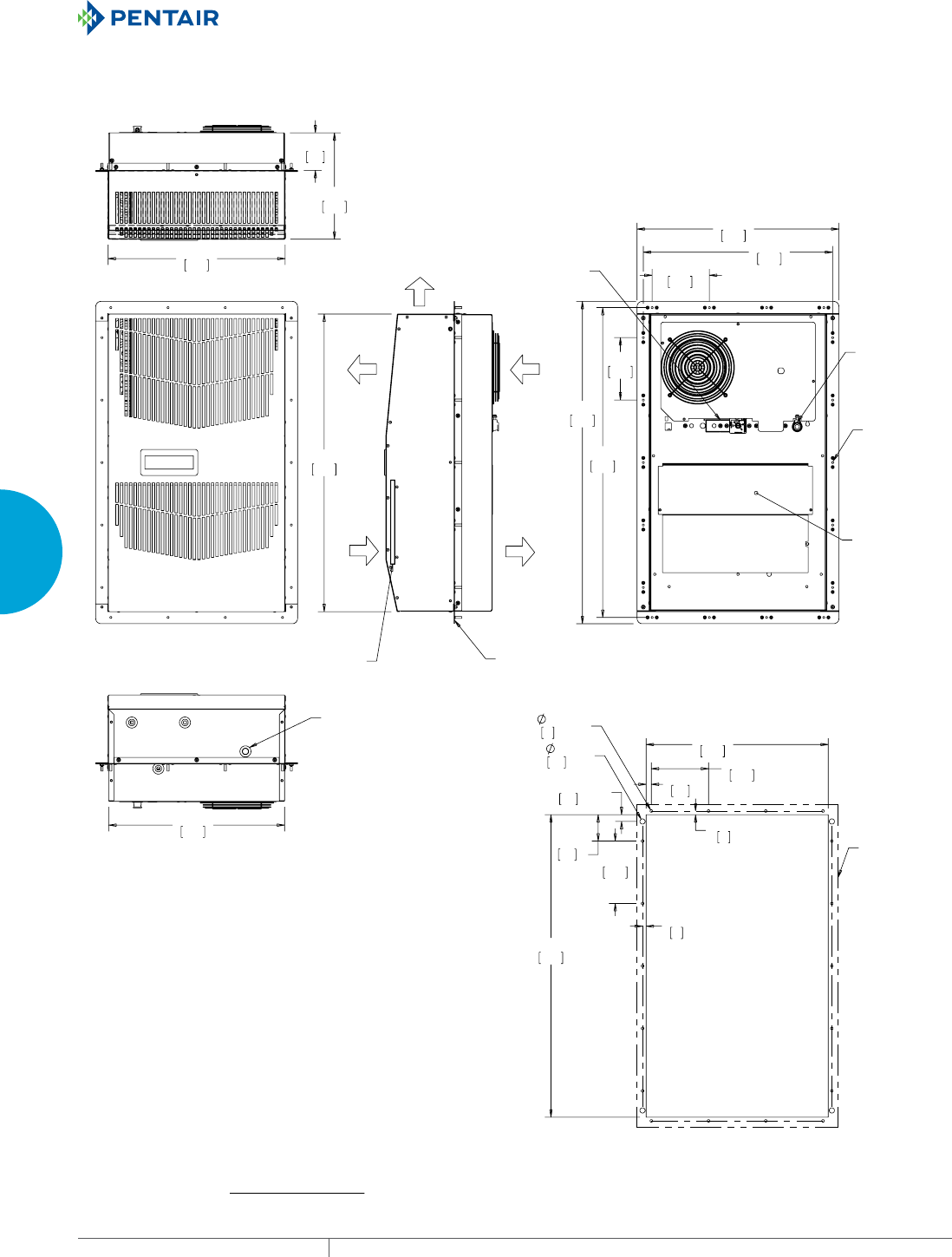
EQUIPMENT PROTECTIONSUBJECT TO CHANGE WITHOUT NOTICECOOLING38
3
SEALED ENCLOSURE COOLING AIR CONDITIONERS
$0%,(17
$,5287
(1&/2685(
$,5,1
$0%,(17
$,5,1
(1&/2685(
$,5287
&/($1$%/(5(86$%/(
$/80,180,1/(7),/7(5
,1&/8'('02817,1**$6.(7.,772%($'+(5('
727+,66,'(2)7+(02817,1*5$,/6%()25(
,167$//,1*$,5&21',7,21(572&$%,1(7
237,21$/
$&&(663$1(/
21/<)25
81,76:,7+
+($7(5
02817,1*
678'6;
32:(5
,1/(7
&22/,1*+($7,1*
7+(50267$7
$&&(66+2/(72>@
2876,'(',$0(7(5'5$,1678%
;
;
;
;
;
;
7<3
7<3
&XWRXW'LPHQVLRQV
02817,1*
5$,/
287/,1(
*0RGHO%78+U9%78+U9:DWW3DUWLDO5HFHVV
127(
02817,1**$6.(76833/,('1276+2:1
81,76LQ>PP@
Visit www
.HoffmanOnline.com to download 2D and 3D CAD drawings into the overall design of your electr
onic system.
PH 763.422.2211 • FAX 763.576.3200 • HOFFMANONLINE.COMEQUIPMENT PROTECTION COOLING 39
3
SEALED ENCLOSURE COOLING AIR CONDITIONERS
Performance Data G52 Models 8000/12000 BTU/Hr. (2300/3500 Watt)
CATALOG NUMBER
Indoor Model G520816G050 G520826G050 G520846G050 G521216G050 G521226G050 G521246G050
Indoor Model Stainless Steel Type 4X G520816G051 G520826G051 G520846G051 G521216G051 G521226G051 G521246G051
Indoor Model with Remote Access Control* G520816G060 G520826G060 G520846G060 G521216G060 G521226G060 G521246G060
Outdoor Model without Heat Pkg. G520816G100 G520826G100 G520846G100 G521216G100 G521226G100 G521246G100
Outdoor Model Partial Recessed Mount G520816G101 G520826G101 G520846G101 G521216G101 G521226G101 G521246G101
Outdoor Model without Heat Pkg. Stainless Steel Type 4X G520816G102 G520826G102 G520846G102 G521216G102 G521226G102 G521246G102
Outdoor Model with Heat Pkg. G520816G150 G520826G150 G520846G150 G521216G150 G521226G150 G521246G150
Outdoor Model with Heat Pkg. Stainless Steel Type 4X G520816G151 G520826G151 G520846G151 G521216G151 G521226G151 G521246G151
COOLING PERFORMANCE
Nominal:
BTU/Hr. 8000 8000 8000 12000 12000 12000
Watts 2300 2300 2300 3500 3500 3500
At 131 F/131 F (55 C/55 C):
BTU/Hr. 7300/8200 7300/8200 8800/9800 12000/12500 12000/12500 11100/12000
Watts 2139/2403 2139/2403 2578/2871 3516/3662 3516/3662 3252/3516
At 95 F/95 F (35 C/35 C):
BTU/Hr. 6000/6800 6000/6800 7400/8200 9900/10700 9900/10700 9900/10700
Watts 1758/1992 1758/1992 2168/2402 2900/3135 2900/3135 2900/3135
Refrigerant R134a R134a R134a R134a R134a R134a
Refrigerant Charge (ounces/grams) 24/680 24/680 24/680 38/1077 38/1077 38/1077
Operating Temperature Range:
Maximum (ºF/ºC) 131/55 131/55 131/55 131/55 131/55 131/55
Indoor Minimum (ºF/ºC) 50/10 50/10 50/10 50/10 50/10 50/10
Outdoor Minimum (ºF/ºC) -40/-40 -40/-40 -40/-40 -40/-40 -40/-40 -40/-40
Airflow at 0 Static Pressure:
Internal loop 50 Hz (CFM / m3/hr.) 285/484 285/484 285/484 287/487 287/487 287/487
External loop 50 Hz (CFM / m3/hr.) 650/1104 650/1104 650/1104 635/1078 635/1078 635/1078
Internal loop 60 Hz (CFM / m3/hr.) 310/527 310/527 310/527 305/518 305/518 305/518
External loop 60 Hz (CFM / m3/hr.) 700/1189 700/1189 700/1189 650/1104 650/1104 650/1104
Max. Heater W (Outdoor Models): 2000 2000 NA 2000 2000 NA
ELECTRICAL DATA
Rated Voltage 115 230/208-230 400/460 3~ 115 230/208-230 400/460 3~
Frequency (Hz) 50/60 50/60 50/60 50/60 50/60 50/60
Operating Range +/- 10% +/- 10% +/- 10% +/- 10% +/- 10% +/- 10%
Max. Power Consumption (W) 1250/1415 1250/1415 806/957** 2100/2427 1830/2130 910/1106**
Max. Nominal Current (A) 11.2/12.3 5.6/7.0-6.2 3.1/3.2 16.1/21.0 9.1/10.6-9.5 3.6/3.5
Starting Current (A) 48 27 16 57 38 16
Agency Approvals cUL Listed
CE
GOST
Others available upon request
Power Input Description Terminal Block
ENCLOSURE PROTECTION
UL Type Type 12, 3R, 4 standard
Type 4X Stainless steel optional
International Rating IP56 internal loop
IP34 external loop
CONTROLLER
Description Basic mechanical thermostat with digital display
Thermostat Location Enclosure side on all base models
Digital Display Location:
Indoor Models Ambient side
Outdoor Models Enclosure side
Factory Thermostat Setting (F/C) 80/27
SOUND LEVEL
At 1.5 Meters 68 dB(A)
UNIT CONSTRUCTION
Material Galvanized sheet metal standard
Stainless steel optional
Finish RAL 7035 light-gray, semi-textured powder-coat paint standard
Other colors available
ACCESSORIES
Cleanable Re-usable Filter Aluminum mesh Part #101000103
EASYSWAP Adaptor Plenum (GENESIS™ M52) Enables SPECTRACOOL to be mounted to a GENESIS M52 air conditioner cutout
Catalog Number PLM52G52
UNIT DIMENSIONS
Height (in./mm) 52.69/1338
Width (in./mm) 17.12/435
Depth (in./mm) 11.66/296
Weight (lb./kg) 128/58.1 128/58.1 138/62.6 131/59.4 131/59.4 141/64.0
*Units with Remote Access Control utilize a digital controller and communicate via EtherNet/IP, Modbus TCP/IP and SNMP over ethernet or modbus RTU
over USB.
**Watts based on .65 power factor.

EQUIPMENT PROTECTIONSUBJECT TO CHANGE WITHOUT NOTICECOOLING40
3
SEALED ENCLOSURE COOLING AIR CONDITIONERS
Enclosure Air Temperature
25 C
77 F
35 C
95 F
45 C
113 F
55 C
131 F
0
3000
6000
9000
12000
15000
68 77 86 95 104 113 122 131
Ambient Air In (°F)
Cooling Capacity (BTU/Hr.)
0
879
1758
2637
3516
4395
20 30 40 50
Ambient Air In (°C)
Cooling Capacity (W)
G52-08(1/2)6-GXXX Capacity Curves at 60 Hz
Enclosure Air Temperature
25 C
77 F
35 C
95 F
45 C
113 F
55 C
131 F
0
3000
6000
9000
12000
15000
68 77 86 95 104 113 122 131
Ambient Air In (°F)
Cooling Capacity (BTU/Hr.)
0
879
1758
2637
3516
4395
20 30 40 50
Ambient Air In (°C)
Cooling Capacity (W)
G52-08(1/2)6-GXXX Capacity Curves at 50 Hz
Performance Curves for G52 Models 8000 BTU/Hr. (23 Watt)

PH 763.422.2211 • FAX 763.576.3200 • HOFFMANONLINE.COMEQUIPMENT PROTECTION COOLING 41
3
SEALED ENCLOSURE COOLING AIR CONDITIONERS
Enclosure Air Temperature
25 C
77 F
35 C
95 F
45 C
113 F
55 C
131 F
0
3000
6000
9000
12000
15000
68 77 86 95 104 113 122 131
Ambient Air In (°F)
Cooling Capacity (BTU/Hr.)
0
879
1758
2637
3516
4395
20 30 40 50
Ambient Air In (°C)
Cooling Capacity (W)
G52-0846-GXXX Capacity Curves at 60 Hz
Enclosure Air Temperature
25 C
77 F
35 C
95 F
45 C
113 F
55 C
131 F
0
3000
6000
9000
12000
15000
68 77 86 95 104 113 122 131
Ambient Air In (°F)
Cooling Capacity (BTU/Hr.)
0
879
1758
2637
3516
4395
20 30 40 50
Ambient Air In (°C)
Cooling Capacity (W)
G52-0846-GXXX Capacity Curves at 50 Hz
Performance Curves for G52 Models 8000 BTU/Hr. (2300 Watt)
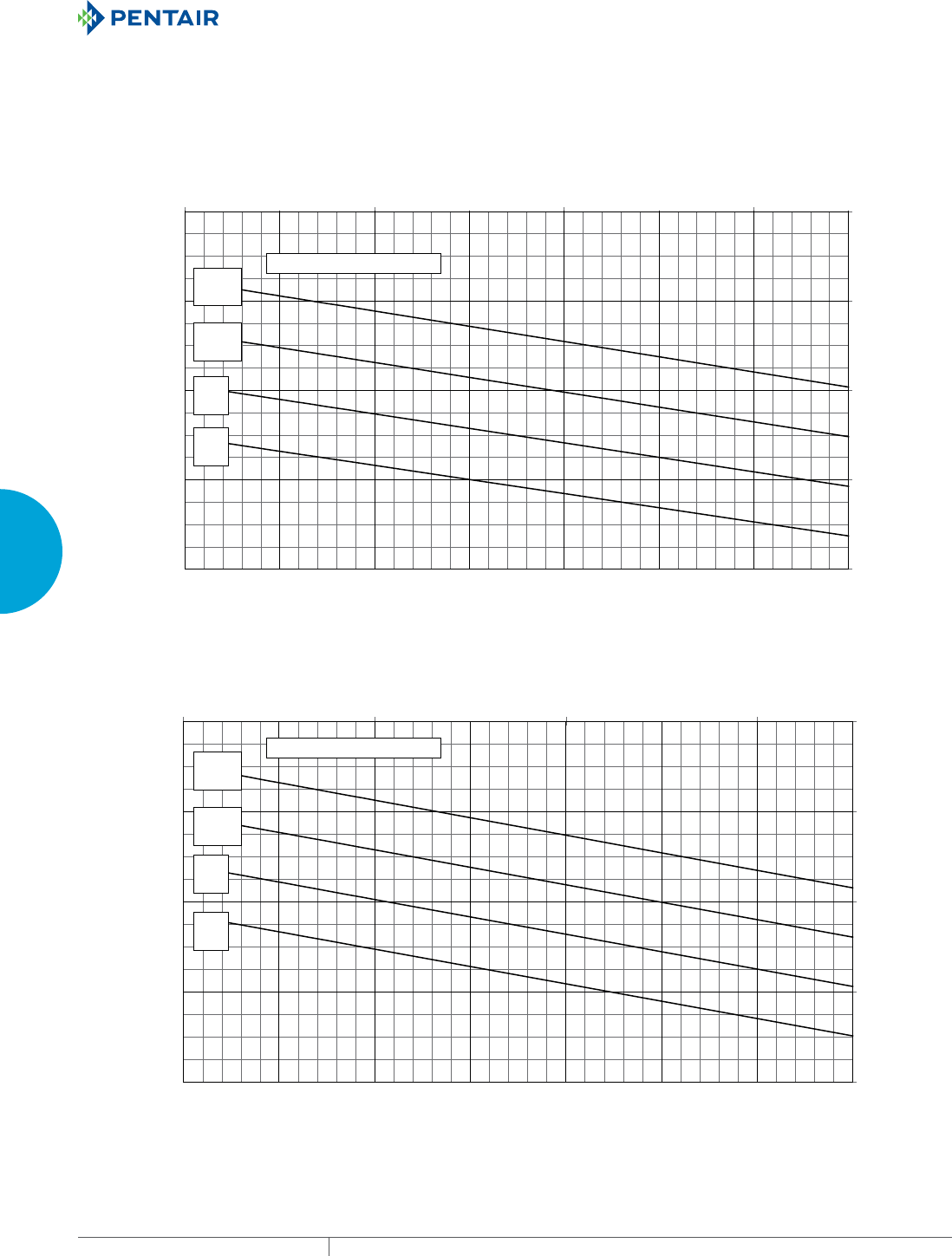
EQUIPMENT PROTECTIONSUBJECT TO CHANGE WITHOUT NOTICECOOLING42
3
SEALED ENCLOSURE COOLING AIR CONDITIONERS
Enclosure Air Temperature
25 C
77 F
35 C
95 F
45 C
113 F
55 C
131 F
4000
8000
12000
16000
20000
68 77 86 95 104113 122131
Ambient Air In (°F)
Cooling Capacity (BTU/Hr.)
1172
2344
3516
4688
5860
20 30 40 50
Ambient Air In (°C)
Cooling Capacity (W)
G52-12(1/2)6-GXXX Capacity Curve 60 Hz
Enclosure Air Temperature
25 C
77 F
35 C
95 F
45 C
113 F
55 C
131 F
4000
8000
12000
16000
20000
68 77 86 95 104113 122131
Ambient Air In (°F)
Cooling Capacity (BTU/Hr.)
1172
2344
3516
4688
5860
20 30 40 50
Ambient Air In (°C)
Cooling Capacity (W)
G52-12(1/2)6-GXXX Capacity Curve 50 Hz
Performance Curves for G52 Models 12000 BTU/Hr. (3500 Watt)

PH 763.422.2211 • FAX 763.576.3200 • HOFFMANONLINE.COMEQUIPMENT PROTECTION COOLING 43
3
SEALED ENCLOSURE COOLING AIR CONDITIONERS
Enclosure Air Temperature
25 C
77 F
35 C
95 F
45 C
113 F
55 C
131 F
2000
6000
10000
14000
18000
68 77 86 95 104113 122131
Ambient Air In (°F)
Cooling Capacity (BTU/Hr.)
586
1758
2930
4102
5274
20 30 40 50
Ambient Air In (°C)
Cooling Capacity (W)
G52-1246-GXXX Capacity Curve 60 Hz
Enclosure Air Temperature
25 C
77 F
35 C
95 F
45 C
113 F
55 C
131 F
2000
6000
10000
14000
18000
68 77 86 95 104113 122131
Ambient Air In (°F)
Cooling Capacity (BTU/Hr.)
586
1758
2930
4102
5274
20 30 40 50
Ambient Air In (°C)
Cooling Capacity (W)
G52-1246-GXXX Capacity Curve 50 Hz
Performance Curves for G52 Models 12000 BTU/Hr. (3516 Watt)
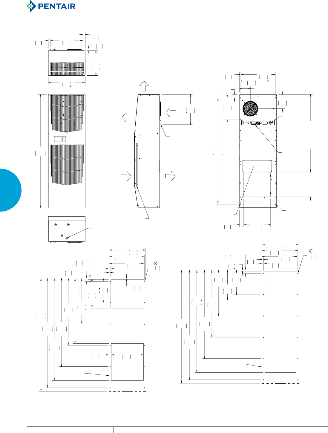
EQUIPMENT PROTECTIONSUBJECT TO CHANGE WITHOUT NOTICECOOLING44
3
SEALED ENCLOSURE COOLING AIR CONDITIONERS
$0%,(17
$,5287
$0%,(17
$,5,1
(1&/2685(
$,5,1
(1&/2685(
$,5287
5(029$%/(
+$1*,1*
7$%6
&/($1$%/(5(86$%/(
$/80,180,1/(7),/7(5
$&&(66+2/(>@
2876,'(',$0(7(5
'5$,1678%
7<3
%78
>@
%78
>@
%78
>@
%78
>@
&22/,1*
+($7,1*
7+(50267$7
32:(5
,1/(7
02817,1*
+2/(6;
237,21$/$&&(663$1(/
21/<)2581,76:,7++($7(5
;
;
;
;
;
;
;
;
$&287/,1(
&XWRXW'LPHQVLRQV
6WDQGDUG
;
;
;
;
;
;
;
&XWRXW'LPHQVLRQV
****
****RQO\
$&287/,1(
*0RGHOV%78+U:DWW
127(
02817,1**$6.(76833/,('1276+2:1
81,76LQ>PP@
Visit www
.HoffmanOnline.com to download 2D and 3D CAD drawings into the overall design of your electr
onic system.
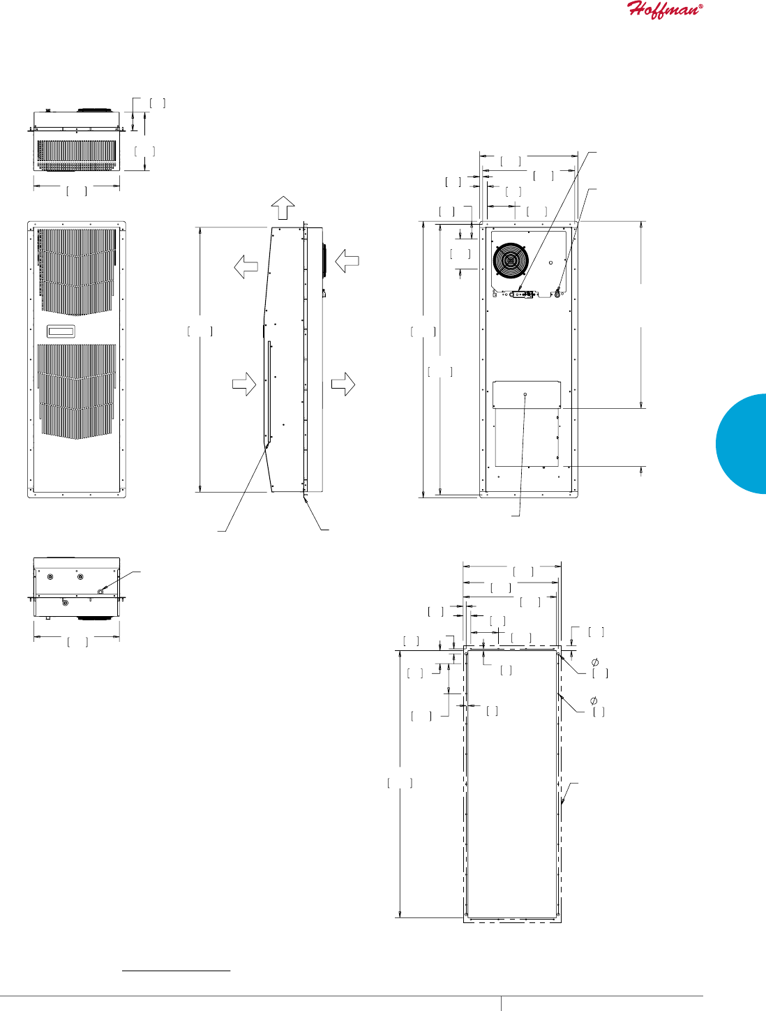
PH 763.422.2211 • FAX 763.576.3200 • HOFFMANONLINE.COMEQUIPMENT PROTECTION COOLING 45
3
SEALED ENCLOSURE COOLING AIR CONDITIONERS
(1&/2685(
$,5,1
(1&/2685(
$,5287
$0%,(17
$,5,1
$0%,(17
$,5287
&/($1$%/(5(86$%/(
$/80,180,1/(7),/7(5
,1&/8'('02817,1**$6.(7.,772%($'+(5('727+,66,'(2)
02817,1*5$,/6%()25(,167$//,1*$,5&21',7,21(572&$%,1(7
7<3
7<3
%78
>@
%78
>@
%78
>@
%78
>@
&22/,1*+($7,1*
7+(50267$7
32:(5
,1/(7
237,21$/$&&(663$1(/
21/<)2581,76:,7++($7(5
$&&(66+2/(72>@
2876,'(',$0(7(5
'5$,1678%
;
;
;
;
;
;
&XWRXW'LPHQVLRQV
02817,1*
5$,/
287/,1(
*0RGHOV%78+U:DWWZLWK3DUWLDO5HFHVV
127(
02817,1**$6.(76833/,('1276+2:1
81,76LQ>PP@
Visit www
.HoffmanOnline.com to download 2D and 3D CAD drawings into the overall design of your electr
onic system.
EQUIPMENT PROTECTIONSUBJECT TO CHANGE WITHOUT NOTICECOOLING46
3
SEALED ENCLOSURE COOLING AIR CONDITIONERS
Performance Data G57 Models 20000 BTU/Hr. (5861 Watt)
CATALOG NUMBER
Indoor Model G572026G050 G572046G050
Indoor Model Stainless Steel Type 4X G572026G051 G572046G051
Indoor Model with Remote Access Control* G572026G060 G572046G060
Outdoor Model without Heat Pkg. G572026G100 G572046G100
Outdoor Model Partial Recessed Mount G572026G101 G572046G101
Outdoor Model with Heat Pkg. G572026G150 G572046G150
Outdoor Model without Heat Pkg. Stainless Steel Type 4X G572026G102 G572046G102
Outdoor Model with Heat Pkg. Stainless Steel Type 4X G572026G151 G572046G151
COOLING PERFORMANCE
Nominal:
BTU/Hr. 20000 20000
Watts 5861 5861
At 131 F/131 F (55 C/55 C):
BTU/Hr. (50/60 Hz) 17500/19600 21400/23400
W (50/60 Hz) 5129/5744 6272/6857
At 95 F/95 F (35 C/35 C):
BTU/Hr. (50/60 Hz) 16000/18000 19300/21400
W (50/60 Hz) 4689/5275 5656/6272
Refrigerant R407c R407c
Refrigerant Charge (ounces/grams) 50/1417 48/1361
Operating Temperature Range:
Maximum (ºF/ºC) 131/55 131/55
Indoor Minimum (ºF/ºC) 50/10 50/10
Outdoor Minimum (ºF/ºC) -40/-40 -40/-40
Airflow at 0 Static Pressure:
Internal loop 50 Hz (CFM / m3/hr.) 513/872 513/872
External loop 50 Hz (CFM / m3/hr.) 919/1562 919/1562
Internal loop 60 Hz (CFM / m3/hr.) 587/998 587/998
External loop 60 Hz (CFM / m3/hr.) 1055/1794 1055/1794
Max. Heater W (Outdoor Models) 3000 3000
ELECTRICAL DATA
Rated Voltage 230/230 400/460 3~
Frequency (Hz) 50/60 50/60
Operating Range +/- 10% +/- 10%
Max. Power Consuption (W at 50/60 Hz) 4508/5106 2400/3128
Max. Nominal Current (A at 50/60 Hz) 19.6/22.2 6.0/6.8
Starting Current (A) 63 27
Agency Approvals cUL Listed
CE
GOST
Others available upon request
Power Input Description Terminal Block
ENCLOSURE PROTECTION
UL Type Type 12, 3R, 4 standard
Type 4X stainless steel optional
International Rating IP56 internal loop
IP34 external loop
CONTROLLER
Description Basic mechanical thermostat with digital display
Thermostat Location Enclosure side on all base models
Digital Display Location:
Indoor Models Ambient side
Outdoor Models Enclosure side
Factory Thermostat Setting (ºF/ºC) 80/27
SOUND LEVEL
At 1.5 Meters 74.1 dB(A)
UNIT CONSTRUCTION
Material Galvanized sheet metal standard
Stainless steel optional
Finish RAL 7035 light-gray, semi-textured powder-coat paint standard
ACCESSORIES
Cleanable Re-usable Filter Aluminum mesh part #101000103 BA
EASYSWAP Adaptor Plenum (T-Series T53) Enables SPECTRACOOL to be mounted to a T-Series
T53 air conditioner cutout part #57721601SP
UNIT DIMENSIONS
Height (in./mm) 57.69/1465.4
Width (in./mm) 20.87/530.1
Depth (in./mm) 15.28/388.1
Weight (lb./kg) 197/89
*Units with Remote Access Control utilize a digital controller and communicate via EtherNet/IP, Modbus TCP/IP and SNMP over ethernet or modbus RTU
over USB.
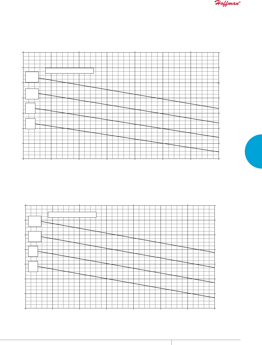
PH 763.422.2211 • FAX 763.576.3200 • HOFFMANONLINE.COMEQUIPMENT PROTECTION COOLING 47
3
SEALED ENCLOSURE COOLING AIR CONDITIONERS
Enclosure Air Temperature
25 C
77 F
35 C
95 F
45 C
113 F
55 C
131 F
G57-2026-GXXX Capacity Curves at 60 Hz
8000
12000
16000
20000
24000
28000
32000
36000
68 77 86 95 104113 122 131
Ambient Air In (°F)
Cooling Capacity (BTU/Hr.)
2345
3517
4689
5861
7033
8205
9377
10549
20 30 40 50
Ambient Air In (°C)
Cooling Capacity (W)
Enclosure Air Temperature
25 C
77 F
35 C
95 F
45 C
113 F
55 C
131 F
G57-2026-GXXX Capacity Curves at 50 Hz
8000
12000
16000
20000
24000
28000
32000
36000
68 77 86 95 104 113 122 131
Ambient Air In (°F)
Cooling Capacity (BTU/Hr.)
2345
3517
4689
5861
7033
8205
9377
10549
20 30 40 50
Ambient Air In (°C)
Cooling Capacity (W)
Performance Curves for G57 Models 20000 BTU/Hr.

EQUIPMENT PROTECTIONSUBJECT TO CHANGE WITHOUT NOTICECOOLING48
3
SEALED ENCLOSURE COOLING AIR CONDITIONERS
Enclosure Air Temperature
25 C
77 F
35 C
95 F
45 C
113 F
55 C
131 F
G57-2046-GXXX Capacity Curves at 60 Hz
8000
12000
16000
20000
24000
28000
32000
36000
68 77 86 95 104 113 122 131
Ambient Air In (°F)
Cooling Capacity (BTU/Hr.)
2345
3517
4689
5861
7033
8205
9377
10549
20 30 40 50
Ambient Air In (°C)
Cooling Capacity (W)
Enclosure Air Temperature
25 C
77 F
35 C
95 F
45 C
113 F
55 C
131 F
G57-2046-GXXX Capacity Curves at 50 Hz
8000
12000
16000
20000
24000
28000
32000
36000
68 77 86 95 104113 122 131
Ambient Air In (°F)
Cooling Capacity (BTU/Hr.)
2345
3517
4689
5861
7033
8205
9377
10549
20 30 40 50
Ambient Air In (°C)
Cooling Capacity (W)
Performance Curves for G57 Models 20000 BTU/Hr.
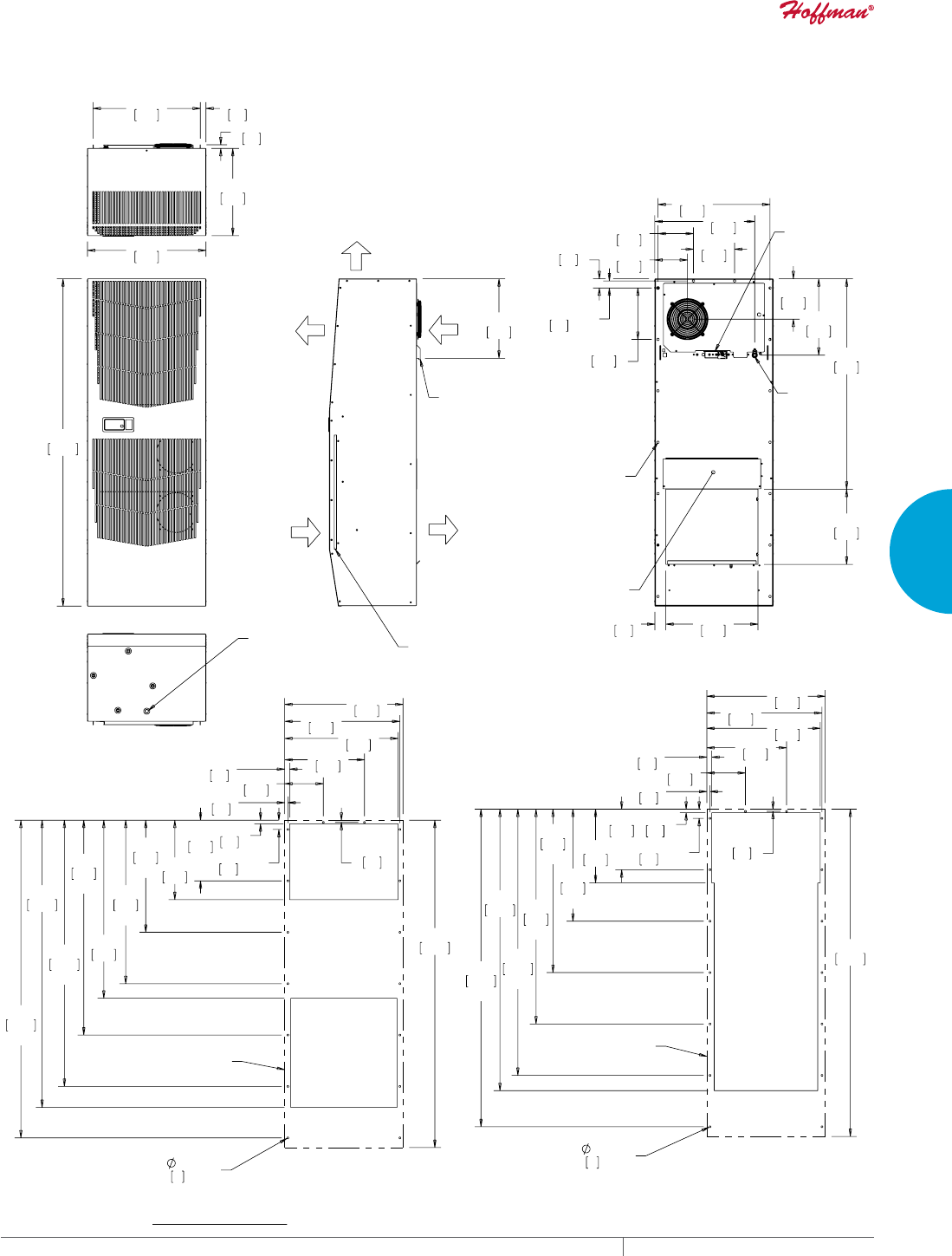
PH 763.422.2211 • FAX 763.576.3200 • HOFFMANONLINE.COMEQUIPMENT PROTECTION COOLING 49
3
SEALED ENCLOSURE COOLING AIR CONDITIONERS
:$50
$,5287
$0%,(17
$,5,1
(1&/2685(
$,5,1
&22/
$,5287
5(029$%/(
+$1*,1*
7$%6
&/($1$%/(5(86$%/(
$/80,180,1/(7),/7(5
$&&(66+2/(72>@
2876,'(',$0(7(5
'5$,1678%
;
;
7<3
&22/,1*
+($7,1*
7+(50267$7
32:(5
,1/(7
02817,1*
+2/(6;
237,21$/$&&(663$1(/
21/<)2581,76:,7++($7(5
;
;
;
;
;
;
;
;
;
&XWRXW'LPHQVLRQ
6WDQGDUG
$&287/,1(
;
;
;
;
;
;
;
;
;
&XWRXW'LPHQVLRQV
****2QO\
$&287/,1(
*0RGHOV%78+U:DWW
127(
02817,1**$6.(76833/,('1276+2:1
81,76LQ>PP@
Visit www
.HoffmanOnline.com to download 2D and 3D CAD drawings into the overall design of your electr
onic system.
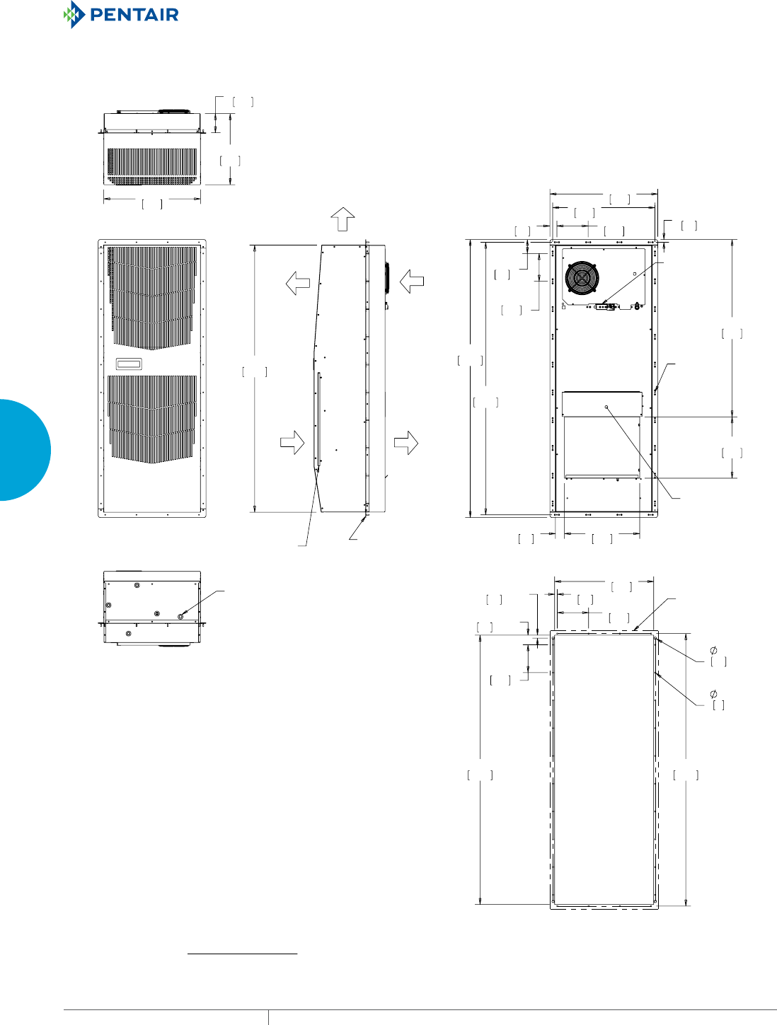
EQUIPMENT PROTECTIONSUBJECT TO CHANGE WITHOUT NOTICECOOLING50
3
SEALED ENCLOSURE COOLING AIR CONDITIONERS
(1&/2685(
$,5,1
&22/
$,5287
$0%,(17
$,5,1
:$50
$,5287
&/($1$%/(5(86$%/(
$/80,180,1/(7),/7(5
,1&/8'('02817,1**$6.(7.,7
72%($'+(5('727+,66,'(2)
02817,1*5$,/6%()25(,167$//,1*
$,5&21',7,21(572&$%,1(7
7<3
7<3
&22/,1*
+($7,1*
7+(50267$7
02817,1*
+2/(6
237,21$/
$&&(663$1(/
21/<)25
81,76:,7+
+($7(5
$&&(66+2/(72
>@2876,'(
',$0(7(5'5$,1
678%
;
;
;
;
;
;
02817,1*
5$,/287/,1(
&XWRXW'LPHQVLRQV
*0RGHOV%78+U:DWW:LWK3DUWLDO5HFHVV
127(
02817,1**$6.(76833/,('1276+2:1
81,76LQ>PP@
Visit www
.HoffmanOnline.com to download 2D and 3D CAD drawings into the overall design of your electr
onic system.

PH 763.422.2211 • FAX 763.576.3200 • HOFFMANONLINE.COMEQUIPMENT PROTECTION COOLING 51
3
SEALED ENCLOSURE COOLING AIR CONDITIONERS
Notes
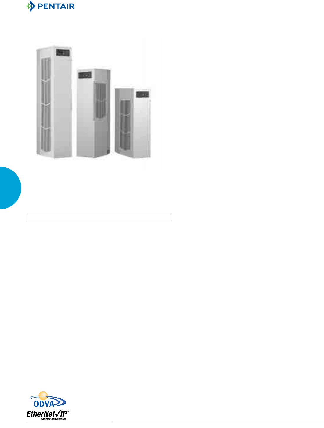
EQUIPMENT PROTECTIONSUBJECT TO CHANGE WITHOUT NOTICECOOLING52
3
SEALED ENCLOSURE COOLING AIR CONDITIONERS
SPECTRACOOL™ NARROW INDOOR/OUTDOOR
N43
11000 BTU/Hr.
3223 Watt
N36
6000/8000 BTU/Hr.
1758/2344 Watt
N28
4000 BTU/Hr.
1172 Watt
N
43
N
3
6
N
2
8
INDUSTRY STANDARDS
UL/cUL Listed; Type 12, 3R, 4; 4X optional; File No. SA6453
CE
IP 56 Internal Loop
IP 34 on External Loop
Telcordia GR-487 capable (Outdoor)
APPLICATION
• Industrial automation
• Waste water treatment systems
• Package handling equipment
• Security and defense systems
FEATURES
• Narrow design accommodates 12-in. (300-mm) deep cabinets
• Energy efficient rotary compressor
• R407c and R134a earth-friendly refrigerants
• Models for 115, 230 and 400/460 3-phase VAC power input
• UL Listed to save customers time and money with agency
approvals
• Outdoor model operating temperature range from -40 F/-40 C to
131 F/55 C (125 F/52 C on N28 Series)
• Attractive industrial design with minimal use of visible fasteners
• Reliable mechanical thermostat on enclosure side of the unit;
indoor Air Conditioner models include digital display on ambient
side
• Galvanized sheet-metal cover for rugged factory and outdoor
environments
• Easy-mount flanges for simple installation
• Cut-out adapter options for enclosures with GENESIS® air
conditioners enable users to easily transition to the new unit
• Dust-resistant condenser coil allows the unit to be run filterless
in most applications
• Cleanable, reusable aluminum mesh filter protects coils for
maximum cooling performance
• Mounting hardware, gaskets and user manual furnished with the
unit
• Every unit functionally tested before shipping
• Standard Indoor Air Conditioner models also include:
- Active condensate management with heater strip
- Power-off relay for door switch and other system
requirements
- Malfunction switch
• Standard Outdoor Air Conditioner models also include:
- Telcordia GR-487 capable
- Corrosion-resistant components
- Malfunction switch
- Compressor heater
- Head pressure control
- 1300 W enclosure heater
SPECIFICATIONS
• Nominal cooling capacity:
N28 4000 BTU/Hr. (1172 W)
N36 6000 & 8000 BTU/Hr. (1758 and 2344 W)
N43 11000 BTU/Hr. (3223 W)
• Outdoor model operating temperature range from -40 F/-40 C to
131 F/55 C (125 F/52 C on N28 Series)
FINISH
• RAL 7035 light-gray, semi-textured powder-coat paint
• Other colors and textures available
NOTES
Visit www.HoffmanOnline.com to download 2D and 3D CAD
drawings into the overall design of your electronic system.
PH 763.422.2211 • FAX 763.576.3200 • HOFFMANONLINE.COMEQUIPMENT PROTECTION COOLING 53
3
SEALED ENCLOSURE COOLING AIR CONDITIONERS
Performance Data N28 4000 BTU/Hr. (1172 Watt)
CATALOG NUMBER
Indoor Model N280416G050 N280426G050 N280425G050 N280446G050
Indoor Model Stainless Steel Type 4X N280416G051 N280426G051 N280425G051 N280446G051
Indoor Model with Remote Access Control* N280416G060 N280426G060 N280425G060 N280446G060
Outdoor Model without Heat Pkg. N280416G100 N280426G100 N280425G100 N280446G100
Outdoor Model without Heat Pkg. Stainless Steel Type 4X N280416G102 N280426G102 N280425G102 N280446G102
Outdoor Model with Heat Pkg. N280416G150 N280426G150 N280425G150 N280446G150
Outdoor Model with Heat Pkg. Stainless Steel Type 4X N280416G151 N280426G151 N280425G151 N280446G151
COOLING PERFORMANCE
Nominal:
BTUs/Hr. 3800 / 4000 4000 3800 4000
Watts 1114 / 1172 1172 1114 1172
At 125 F / 125 F (50 C / 50 C):
BTU/Hr. (50 / 60 Hz) 3805 / 4162 4394 3818 4394
Watts (50 / 60 Hz) 1115 / 1220 1288 1119 1288
At 95 F / 95 F (35 C / 35 C):
BTU/Hr. (50 /60 Hz) 3589 / 3974 3690 3298 3690
Watts (50 / 60 Hz) 1052 / 1165 1081 967 1081
Refrigerant R134a R134a R134a R134a
Refrigerant Charge (ounces/grams) 11 / 312 11 / 312 11 / 312 11 / 312
Operating Temperature Range:
Maximum (°F / °C) 125/52 125/52 125/52 125/52
Minimum (°F / °C) -40/-40 -40/-40 -40/-40 -40/-40
Air Flow at 0 Static Pressure:
Internal loop 50 Hz (CFM / M3/Hr) 138 / 234 N/A 138 / 234 N/A
External loop 50 Hz (CFM / M3/Hr) 268 / 455 N/A 268 / 455 N/A
Internal loop 60 Hz (CFM / M3/Hr) 143 / 362 143 / 243 N/A 143 / 243
External loop 60 Hz (CFM / M3/Hr) 288 / 728 288 / 489 N/A 288 / 489
Max. Heater W (Outdoor Models) 1300 1300 1300 1300
ELECTRICAL DATA
Rated Voltage 110 / 115 230 230 460
Frequency (Hz) 50 / 60 60 50 60
Operating Range +/-10% +/-10% +/-10% +/-10%
Max. Power Consumption (Watts at 50 / 60 Hz) 1039 / 1191 1250 1111 1250
Max. Nominal Current (Amps at 50 / 60 Hz) 11.6-11.2 6.5 5.8 3.3
Starting Current (Amps) 40 24.5 24.5 12.5
Agency Approvals cUL Listed
CE
Others available upon request
Power Input Description Terminal Block
ENCLOSURE PROTECTION
UL Type Type 12, 3R, 4 Standard
Type 4X Stainless Steel Optional
CONTROLLER
Description Basic Mechanical Thermostat
Thermostat Location Enclosure Side
Factory Thermostat Setting (°F / °C) 80 / 27
SOUND LEVEL
At 1.5 Meters 66.1 dBA 65.5 dBA 65.5 dBA 65.5 dBA
UNIT CONSTRUCTION
Material Galvanized sheet metal standard
Stainless steel optional
Finish RAL 7035 light-gray, semi-textured powder-coat paint standard
Other colors available
ACCESSORIES
EASYSWAP Adaptor Plenum (GENESIS™ M33) Enables SPECTRACOOL to be mounted to a GENESIS M33
air conditioner cutout Catalog Number PLM33N28
UNIT DIMENSIONS
Height (in / mm) 28 / 711.2
Width (in / mm) 11.50 / 292.1
Depth (in / mm) 14.00 / 355.6
Weight (lb / kg) 84/38 84/38 92/41.7 92/41.7
*Units with Remote Access Control utilize a digital controller and communicate via EtherNet/IP, Modbus TCP/IP and SNMP over ethernet or modbus RTU
over USB.
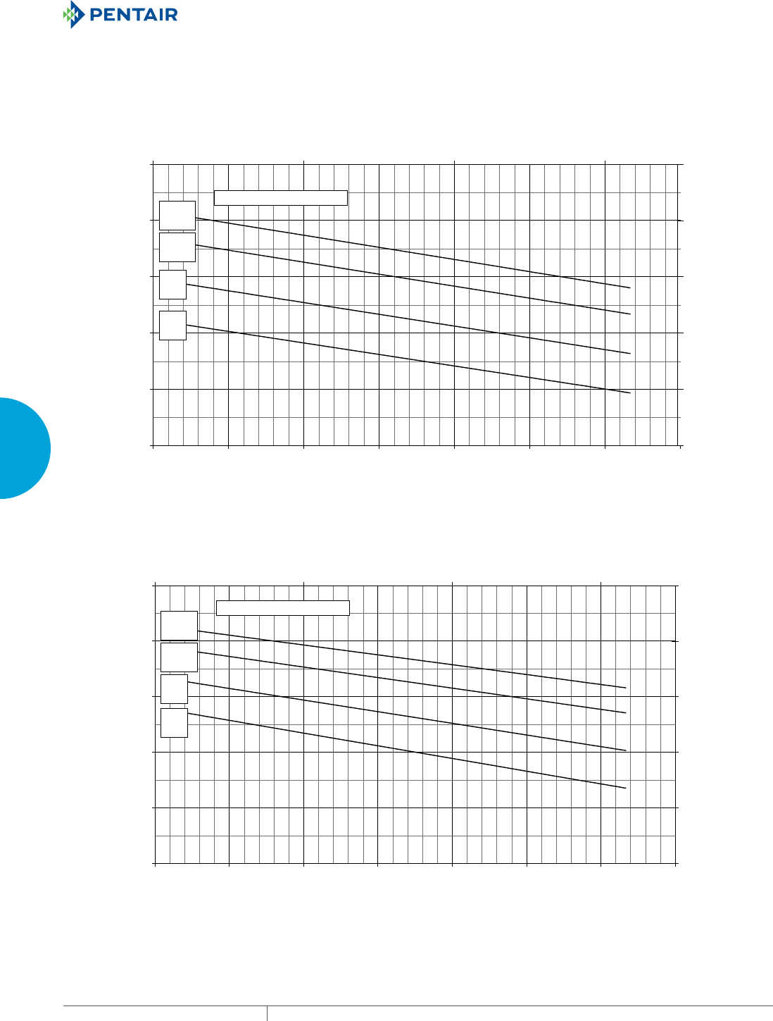
EQUIPMENT PROTECTIONSUBJECT TO CHANGE WITHOUT NOTICECOOLING54
3
SEALED ENCLOSURE COOLING AIR CONDITIONERS
Enclosure Air Temperature
25 C
77 F
35 C
95 F
45 C
113 F
51 C
124 F
N28-0416-GXXX Capacity Curves at 60 Hz
1000
2000
3000
4000
5000
6000
68 77 86 95 104 113 122 131
Ambient Air In (°F)
Cooling Capacity (BTU/Hr.)
293
586
879
1172
1465
1758
20 30 40 50
Ambient Air In (°C)
Cooling Capacity (W)
Enclosure Air Temperature
25 C
77 F
35 C
95 F
45 C
113 F
51 C
124 F
1000
2000
3000
4000
5000
6000
68 77 86 95 104 113 122 131
Ambient Air In (°F)
Cooling Capacity (BTU/Hr.)
293
586
879
1172
1465
1758
20 30 40 50
Ambient Air In (°C)
Cooling Capacity (W)
N28-0416-GXXX Capacity Curves at 50 Hz
Performance Curves for N28 Models 4000 BTU/Hr. (1172 Watt)
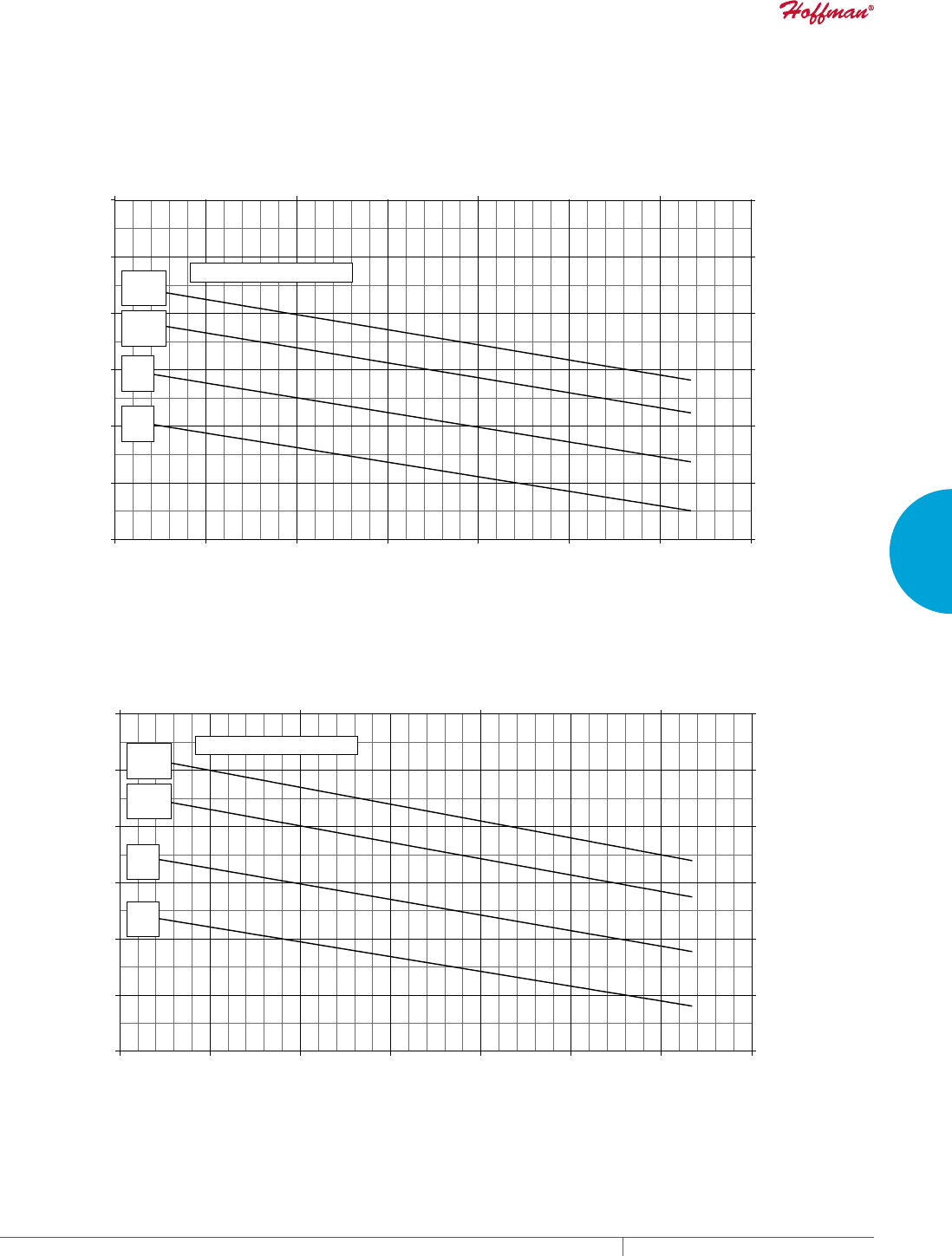
PH 763.422.2211 • FAX 763.576.3200 • HOFFMANONLINE.COMEQUIPMENT PROTECTION COOLING 55
3
SEALED ENCLOSURE COOLING AIR CONDITIONERS
Enclosure Air Temperature
25 C
77 F
35 C
95 F
45 C
113 F
51 C
124 F
N28-0426-GXXX Capacity Curves at 60 Hz
1000
2000
3000
4000
5000
6000
7000
68 77 86 95 104 113 122131
Ambient Air In (°F)
Cooling Capacity (BTU/Hr.)
293
586
879
1172
1465
1758
2051
20 30 40 50
Ambient Air In (°C)
Cooling Capacity (W)
Enclosure Air Temperature
25 C
77 F
35 C
95 F
45 C
113 F
51 C
124 F
N28-0426-GXXX Capacity Curves at 50 Hz
1000
2000
3000
4000
5000
6000
7000
68 77 86 95 104 113 122 131
Ambient Air In (°F)
Cooling Capacity (BTU/Hr.)
293
586
879
1172
1465
1758
2051
20 30 40 50
Ambient Air In (°C)
Cooling Capacity (W)
Performance Curves for N28 Models 4000 BTU/Hr. (1172 Watt)
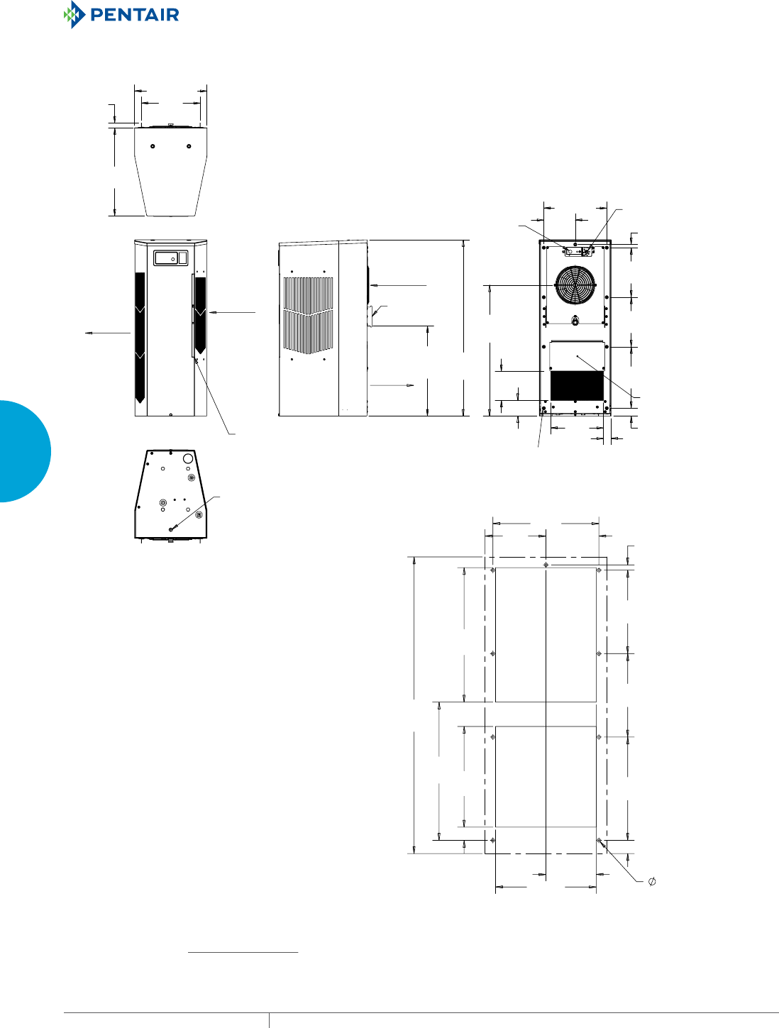
EQUIPMENT PROTECTIONSUBJECT TO CHANGE WITHOUT NOTICECOOLING56
3
SEALED ENCLOSURE COOLING AIR CONDITIONERS
&/($1$%/(5(86$%/(
$/80,180,1/(7$,5),/7(5
38//6287)5217
>@
>@
>@
>@
>@
>@
&22/
$,5287
(1&/2685(
$,5,1
5(029$%/(
+$1*,1*7$%6
>@
>@
>@
>@
>@
>@
>@
>@
>@
>@
>@
>@
81&
02817,1*
+2/(6
&22/,1*767$7
+($7,1*767$7
237,21$/
237,21$/$&&(663$1(/
21/<)2581,76
:,7++($7(5
$&&(66+2/(72
>@2876,'(
',$0(7(5'5$,1678%
$0%,(17
$,5,1
:$50
$,5287
>@
>@
>@
>@
>@
>@
>@
>@
>@
>@
>@
>@
>@
>@
>@
>@
N28 Models 4000 BTU/Hr. (1172 Watt)
Cutout Dimensions
Visit www
.HoffmanOnline.com to download 2D and 3D CAD drawings into the overall design of your electr
onic system.
PH 763.422.2211 • FAX 763.576.3200 • HOFFMANONLINE.COMEQUIPMENT PROTECTION COOLING 57
3
SEALED ENCLOSURE COOLING AIR CONDITIONERS
Performance Data N36 6000/8000 BTU/Hr. (1758/2344 Watt)
CATALOG NUMBER
Indoor Model N360616G050 N360626G050 N360646G050 N360816G050 N360826G050 N360846G050
Indoor Model Stainless Steel Type 4X N360616G051 N360626G051 N360646G051 N360816G051 N360826G051 N360846G051
Indoor Model with Remote Access Control* N360616G060 N360626G060 N360646G060 N360816G060 N360826G060 N360846G060
Outdoor Model without Heat Pkg. N360616G100 N360626G100 N360646G100 N360816G100 N360826G100 N360846G100
Outdoor Model without Heat Pkg.
Stainless Steel Type 4X
N360616G102 N360626G102 N360646G102 N360816G102 N360826G102 N360846G102
Outdoor Model with Heat Pkg. N360616G150 N360626G150 N360646G150 N360816G150 N360826G150 N360846G150
Outdoor Model with Heat Pkg.
Stainless Steel Type 4X
N360616G151 N360626G151 N360646G151 N360816G151 N360826G151 N360846G151
COOLING PERFORMANCE
Nominal:
BTU/Hr. 5400 / 6000 5400 / 6000 5400 / 6000 8250 / 8500 8250 / 8500 8250 / 8500
Watts 1581 / 1757 1581 / 1757 1581 / 1757 2416 / 2489 2313 / 2635 2284 / 2401
At 131 F / 131 F (55 C / 55 C):
BTU/Hr. (50 / 60 Hz) 5585 / 6180 5469 / 5965 5300 / 6089 8213 / 8453 7874 / 8063 7777 / 8166
Watts (50 / 60 Hz) 1637 / 1811 1603 / 1748 1553 / 1785 2405 / 2475 2306 / 2361 2277 / 2391
At 95 F / 95 F (35 C / 35 C):
BTU/Hr. (50 /60 Hz) 4909 / 5485 5159 / 5621 5572 / 6026 7028 / 7626 6660 / 7411 6877 / 7525
Watts (50 / 60 Hz) 1439 / 1607 1512 / 1647 1633 / 1766 2058 / 2233 1950 / 2170 2014 / 2203
Refrigerant R134a R134a R134a R134a R134a R134a
Refrigerant Charge (ounces/grams) 20 / 567 22 / 624 16 / 454 36 / 1021 36 / 1021 36 / 1021
Operating Temperature Range:
Maximum (°F / °C) 131 / 55 131 / 55 131 / 55 131 / 55 131 / 55 131 / 55
Minimum (°F / °C) -40 / -40 -40 / -40 -40 / -40 -40 / -40 -40 / -40 -40 / -40
Air Flow at 0 Static Pressure:
Internal loop 50 Hz (CFM / M3/Hr.) 251 / 426 250 / 425 250 / 425 250 / 425 245 / 416 243 / 413
External loop 50 Hz (CFM / M3/Hr.) 284 / 483 338 / 574 338 / 574 313 / 532 347 / 589 365 / 620
Internal loop 60 Hz (CFM / M3/Hr.) 261 / 443 261 / 443 261 / 443 263 / 447 258 / 439 254 / 432
External loop 60 Hz (CFM / M3/Hr.) 311 / 528 356 / 605 356 / 605 338 / 574 382 / 648 394 / 669
Max. Heater W (Outdoor Models) 1300 1300 1300 1300 1300 1300
ELECTRICAL DATA
Rated Voltage 115 230 400 / 460 3~ 115 230 400 / 460 3~
Frequency (Hz) 50 / 60 50 / 60 50 / 60 50 / 60 50 / 60 50 / 60
Operating Range +/-10% +/-10% +/-10% +/-10% +/-10% +/-10%
Max. Power Consumption (Watts at 50 / 60 Hz) 911 / 1108 908 / 1073 697 / 895 1334 / 1530 1265 / 1403 572 / 628
Max. Nominal Current (Amps at 50 / 60 Hz) 9.1 / 10.1 4.5 / 4.7 1.59 / 1.69 11.6 / 13.3 5.5/6.1 2.9/3.0
Starting Current (Amps) 39.2 23 8.1 48.3 27 16
Agency Approvals cUL Listed
CE
Others available upon request
Power Input Description Terminal Block
ENCLOSURE PROTECTION
UL Type Type 12, 3R, 4 Standard
Type 4X Stainless Steel Optional
CONTROLLER
Description Basic Mechanical Thermostat
Thermostat Location Enclosure Side
Factory Thermostat Setting (°F / °C) 80 / 27
SOUND LEVEL
At 1.5 Meters 66.9 dBA 66.7 dBA 68.2 dBA 66.0 dBA 66.0 dBA 66.0 dBA
UNIT CONSTRUCTION
Material Galvanized sheet metal standard
Stainless steel optional
Finish RAL 7035 light-gray, semi-textured powder-coat paint standard
Other colors available
ACCESSORIES
EASYSWAP Adaptor Plenum (GENESIS™ M36) Enables SPECTRACOOL to be mounted to a GENESIS M36 air conditioner cutout
Catalog Number PLM36N36
UNIT DIMENSIONS
Height (in. / mm) 36.00 / 914.4
Width (in. / mm) 11.50 / 292.1
Depth (in. / mm) 14.00 / 355.6
Weight (lb. / kg) 100 / 45 100 / 45 104 / 47 106 / 48 106 / 48 114 / 52
*Units with Remote Access Control utilize a digital controller and communicate via EtherNet/IP, Modbus TCP/IP and SNMP over ethernet or modbus RTU
over USB.

EQUIPMENT PROTECTIONSUBJECT TO CHANGE WITHOUT NOTICECOOLING58
3
SEALED ENCLOSURE COOLING AIR CONDITIONERS
Enclosure Air Temperat
25 C
77 F
35 C
95 F
45 C
113 F
55 C
131 F
2000
4000
6000
8000
10000
68 77 86 95 104113 122 131
Ambient Air In (°F)
Cooling Capacity (BTU/Hr.)
586
1172
1758
2344
2930
20 30 40 50
Ambient Air In (°C)
Cooling Capacity (W)
N36-0616-GXXX Capacity Curves at 60 Hz
Enclosure Air Temperat
25 C
77 F
35 C
95 F
45 C
113 F
55 C
131 F
2000
4000
6000
8000
10000
68 77 86 95 104 113 122 131
Ambient Air In (°F)
Cooling Capacity (BTU/Hr.)
586
1172
1758
2344
2930
20 30 40 50
Ambient Air In (°C)
Cooling Capacity (W)
N36-0616-GXXX Capacity Curves at 50 Hz
Performance Curves for N36 Models 6000 BTU/Hr. (1758 Watt)
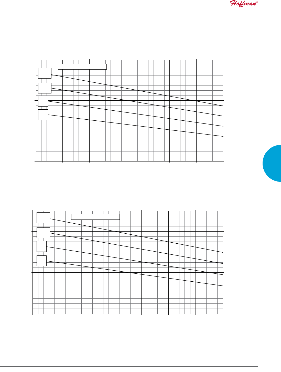
PH 763.422.2211 • FAX 763.576.3200 • HOFFMANONLINE.COMEQUIPMENT PROTECTION COOLING 59
3
SEALED ENCLOSURE COOLING AIR CONDITIONERS
Enclosure Air Temperature
25 C
77 F
35 C
95 F
45 C
113 F
55 C
131 F
0
2000
4000
6000
8000
10000
68 77 86 95 104 113122 131
Ambient Air In (°F)
Cooling Capacity (BTU/Hr.)
0
586
1172
1758
2344
2930
20 30 40 50
Ambient Air In (°C)
Cooling Capacity (W)
N36-0626-GXXX Capacity Curves at 60 Hz
Enclosure Air Temperature
25 C
77 F
35 C
95 F
45 C
113 F
55 C
131 F
0
2000
4000
6000
8000
10000
68 77 86 95 104 113 122 131
Ambient Air In (°F)
Cooling Capacity (BTU/Hr.)
0
586
1172
1758
2344
2930
20 30 40 50
Ambient Air In (°C)
Cooling Capacity (W)
N36-0626-GXXX Capacity Curves at 50 Hz
Performance Curves for N36 Models 6000 BTU/Hr. (1758 Watt)
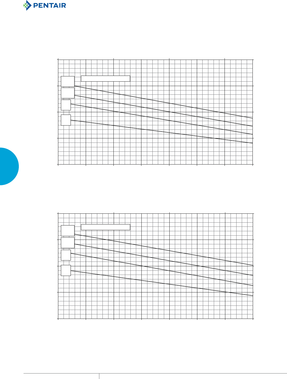
EQUIPMENT PROTECTIONSUBJECT TO CHANGE WITHOUT NOTICECOOLING60
3
SEALED ENCLOSURE COOLING AIR CONDITIONERS
Enclosure Air Temperature
25 C
77 F
35 C
95 F
45 C
113 F
55 C
131 F
0
3000
6000
9000
12000
68 77 86 95 104 113 122 131
Ambient Air In (°F)
Cooling Capacity (BTU/Hr.)
0
879
1758
2637
3516
20 30 40 50
Ambient Air In (°C)
Cooling Capacity (W)
N36-0646-GXXX Capacity Curves at 60 Hz
Enclosure Air Temperature
25 C
77 F
35 C
95 F
45 C
113 F
55 C
131 F
0
3000
6000
9000
12000
68 77 86 95 104 113 122 131
Ambient Air In (°F)
Cooling Capacity (BTU/Hr.)
0
879
1758
2637
3516
20 30 40 50
Ambient Air In (°C)
Cooling Capacity (W)
N36-0646-GXXX Capacity Curves at 50 Hz
Performance Curves for N36 Models 6000 BTU/Hr. (1758 Watt)
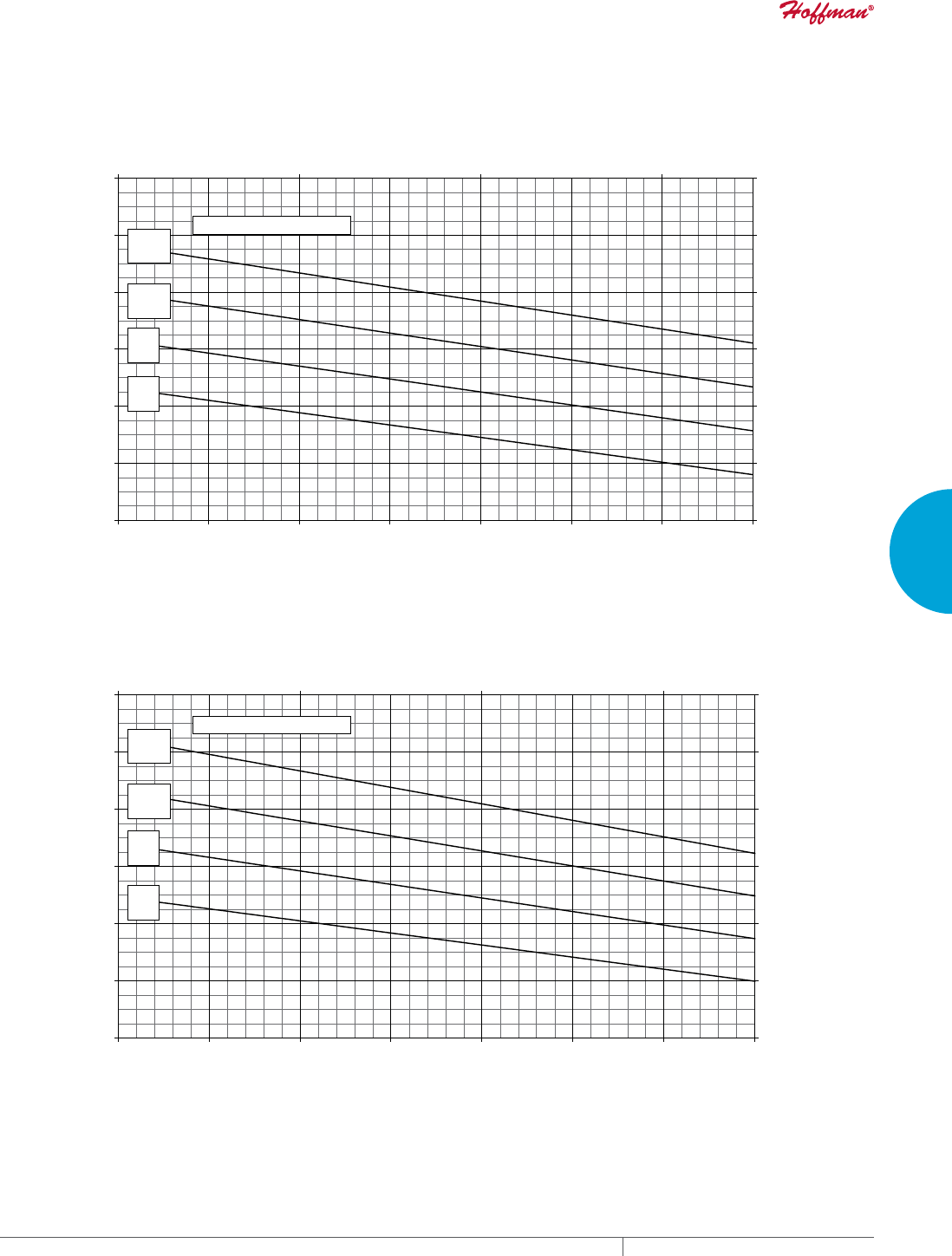
PH 763.422.2211 • FAX 763.576.3200 • HOFFMANONLINE.COMEQUIPMENT PROTECTION COOLING 61
3
SEALED ENCLOSURE COOLING AIR CONDITIONERS
Enclosure Air Temperature
25 C
77 F
35 C
95 F
45 C
113 F
55 C
131 F
2000
4000
6000
8000
10000
12000
14000
68 77 86 95 104 113 122 131
Ambient Air In (°F)
Cooling Capacity (BTU/Hr.)
586
1172
1758
2344
2930
3516
4102
20 30 40 50
Ambient Air In (°C)
Cooling Capacity (W)
N36-0816-GXXX Capacity Curves at 60 Hz
Enclosure Air Temperature
25 C
77 F
35 C
95 F
45 C
113 F
55 C
131 F
2000
4000
6000
8000
10000
12000
14000
68 77 86 95 104 113 122 131
Ambient Air In (°F)
Cooling Capacity (BTU/Hr.)
586
1172
1758
2344
2930
3516
4102
20 30 40 50
Ambient Air In (°C)
Cooling Capacity (W)
N36-0816-GXXX Capacity Curves at 50 Hz
Performance Curves for N36 Models 8000 BTU/Hr. (2344 Watt)

EQUIPMENT PROTECTIONSUBJECT TO CHANGE WITHOUT NOTICECOOLING62
3
SEALED ENCLOSURE COOLING AIR CONDITIONERS
Enclosure Air Temperature
25 C
77 F
35 C
95 F
45 C
113 F
55 C
131 F
2000
4000
6000
8000
10000
12000
14000
68 77 86 95 104113 122131
Ambient Air In (°F)
Cooling Capacity (BTU/Hr.)
586
1172
1758
2344
2930
3516
4102
20 30 40 50
Ambient Air In (°C)
Cooling Capacity (W)
N36-0826-GXXX Capacity Curves at 60 Hz
Enclosure Air Temperature
25 C
77 F
35 C
95 F
45 C
113 F
55 C
131 F
2000
4000
6000
8000
10000
12000
14000
68 77 86 95 104113 122 131
Ambient Air In (°F)
Cooling Capacity (BTU/Hr.)
586
1172
1758
2344
2930
3516
4102
20 30 40 50
Ambient Air In (°C)
Cooling Capacity (W)
N36-0826-GXXX Capacity Curves at 50 Hz
Performance Curves for N36 Models 8000 BTU/Hr. (2344 Watt)

PH 763.422.2211 • FAX 763.576.3200 • HOFFMANONLINE.COMEQUIPMENT PROTECTION COOLING 63
3
SEALED ENCLOSURE COOLING AIR CONDITIONERS
Enclosure Air Temperature
25 C
77 F
35 C
95 F
45 C
113 F
55 C
131 F
2000
4000
6000
8000
10000
12000
68 77 86 95 104 113 122131
Ambient Air In (°F)
Cooling Capacity (BTU/Hr.)
586
1172
1758
2344
2930
3516
20 30 40 50
Ambient Air In (°C)
Cooling Capacity (W)
N36-0846-GXXX Capacity Curves at 60 Hz
Enclosure Air Temperature
25 C
77 F
35 C
95 F
45 C
113 F
55 C
131 F
2000
4000
6000
8000
10000
12000
68 77 86 95 104113 122131
Ambient Air In (°F)
Cooling Capacity (BTU/Hr.)
586
1172
1758
2344
2930
3516
20 30 40 50
Ambient Air In (°C)
Cooling Capacity (W)
N36-0846-GXXX Capacity Curves at 50 Hz
Performance Curves for N36 Models 8000 BTU/Hr. (2344 Watt)
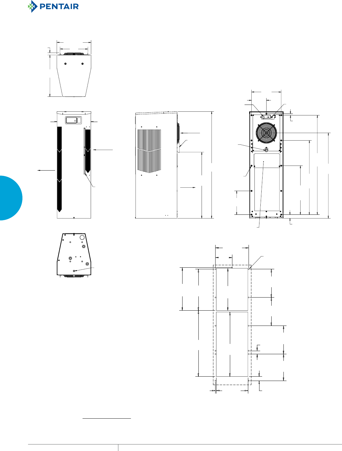
EQUIPMENT PROTECTIONSUBJECT TO CHANGE WITHOUT NOTICECOOLING64
3
SEALED ENCLOSURE COOLING AIR CONDITIONERS
$0%,(17
$,5,1
&/($1$%/(5(86$%/(
$/80,180,1/(7),/7(5
38//6287)5217
:$50
$,5287
>@
>@
>@
>@
>@
>@
(1&/65
$,5,1
&22/
$,5287
5(029$%/(
+$1*,1*
7$%6
;
>@
>@
;
>@
;
>@
;
>@
>@
>@
>@
>@
81&
02817,1*
+2/(6;
32:(5
,1387
&22/7+(50267$7
+($7
7+(50267$7
237,21$/
237,21$/$&&(663$1(/
21/<)2581,76:,7++($7(5
$&&(66+2/(72
>@2876,'(
',$0(7(5'5$,1678%
>@
>@
;
>@
>@
;
>@
;
>@
>@
>@
>@
>@
;
>@
;
>@
;
>@
;
>@
;
>@
;
>@
>@
;
;
N36 6000/8000 BTU/Hr. (1758/2344 Watt)
Cutout Dimensions
Visit www
.HoffmanOnline.com to download 2D and 3D CAD drawings into the overall design of your electr
onic system.
PH 763.422.2211 • FAX 763.576.3200 • HOFFMANONLINE.COMEQUIPMENT PROTECTION COOLING 65
3
SEALED ENCLOSURE COOLING AIR CONDITIONERS
Performance Data N43 11000 BTU/Hr. (3223 Watt)
CATALOG NUMBER
Indoor Model N431216G050 N431226G050 N431246G050
Indoor Model Stainless Steel Type 4X N431216G051 N431226G051 N431246G051
Indoor Model with Remote Access Control* N431216G060 N431226G060 N431246G060
Outdoor Model without Heat Pkg. N431216G100 N431226G100 N431246G100
Outdoor Model without Heat Pkg. Stainless Steel Type 4X N431216G102 N431226G102 N431246G102
Outdoor Model with Heat Pkg. N431216G150 N431226G150 N431246G150
Outdoor Model with Heat Pkg. Stainless Steel Type 4X N431216G151 N431226G151 N431246G151
COOLING PERFORMANCE
Nominal:
BTU/Hr. 10400 / 11000 10400 / 11000 10400 / 11000
Watts 3047 / 3223 2900 / 3223 2900 / 3223
At 131 F / 131 F (55 C / 55 C):
BTU/Hr. (50 / 60 Hz) 10588 / 11180 9946 / 11052 10048 / 10797
Watts (50 / 60 Hz) 3103 / 3277 2915 / 3239 2945 / 3164
At 95 F / 95 F (35 C / 35 C):
BTU/Hr. (50 /60 Hz) 9475 / 10023 8967 / 9644 8587 / 9559
Watts (50 / 60 Hz) 2777 / 2937 2628 / 2826 2517 / 2801
Refrigerant R134a R134a R134a
Refrigerant Charge (ounces/grams) 36 / 1021 38 / 1077 41 / 1162
Operating Temperature Range:
Maximum (°F / °C) 131 / 55 131 / 55 131 / 55
Minimum (°F / °C) -40 / -40 -40 / -40 -40 / -40
Air Flow at 0 Static Pressure:
Internal loop 50 Hz (CFM / M3/Hr) 239 / 406 259 / 440 254 / 432
External loop 50 Hz (CFM / M3/Hr) 494 / 839 489 / 831 341 / 579
Internal loop 60 Hz (CFM / M3/Hr) 250 / 425 267 / 454 260 / 442
External loop 60 Hz (CFM / M3/Hr) 528 / 897 525 / 892 564 / 958
Max. Heater W (Outdoor Models) 1300 1300 1300
ELECTRICAL DATA
Rated Voltage 115 230 400 / 460 3~
Frequency (Hz) 50 / 60 50 / 60 50 / 60
Operating Range +/-10% +/-10% +/-10%
Max. Power Consumption (Watts at 50 / 60 Hz) 1802 / 2446 1802 / 2446 1283 / 1644
Max. Nominal Current (Amps at 50 / 60 Hz) 16.6 / 22.0 8.7 / 9.1 3.1 / 3.3
Starting Current (Amps) 57 38 16
Agency Approvals cUL Listed
CE
Others available upon request
Power Input Description Terminal Block
ENCLOSURE PROTECTION
UL Type Type 12, 3R, 4 Standard
Type 4X Stainless Steel Optional
CONTROLLER
Description Basic Mechanical Thermostat
Thermostat Location Enclosure Side
Factory Thermostat Setting (°F / °C) 80 / 27
SOUND LEVEL
At 1.5 Meters 68.4 dBA 68.4 dBA 69.6 dBA
UNIT CONSTRUCTION
Material Galvanized sheet metal standard
Stainless steel optional
Finish RAL 7035 light-gray, semi-textured powder-coat paint standard
Other colors available
UNIT DIMENSIONS
Height (in / mm) 43.00 / 1092.2
Width (in / mm) 11.50 / 292.1
Depth (in / mm) 14.00 / 355.6
Weight (lb / kg) 127/57.6 127/57.6 138/62.6
*Units with Remote Access Control utilize a digital controller and communicate via EtherNet/IP, Modbus TCP/IP and SNMP over ethernet or modbus RTU
over USB.
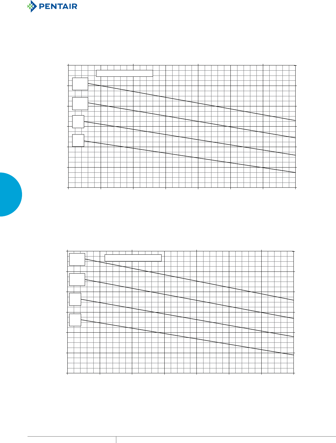
EQUIPMENT PROTECTIONSUBJECT TO CHANGE WITHOUT NOTICECOOLING66
3
SEALED ENCLOSURE COOLING AIR CONDITIONERS
Enclosure Air Temperature
25 C
77 F
35 C
95 F
45 C
113 F
55 C
131 F
4000
6000
8000
10000
12000
14000
16000
68 77 86 95 104 113 122131
Ambient Air In (°F)
Cooling Capacity (BTU/Hr.)
1172
1758
2344
2930
3516
4102
4688
20 30 40 50
Ambient Air In (°C)
Cooling Capacity (W)
N43-1216-GXXX Capacity Curves at 60 Hz
Enclosure Air Temperature
25 C
77 F
35 C
95 F
45 C
113 F
55 C
131 F
4000
6000
8000
10000
12000
14000
16000
68 77 86 95 104 113 122 131
Ambient Air In (°F)
Cooling Capacity (BTU/Hr.)
1172
1758
2344
2930
3516
4102
4688
20 30 40 50
Ambient Air In (°C)
Cooling Capacity (W)
N43-1216-GXXX Capacity Curves at 50 Hz
Performance Curves for N43 Models 11000 BTU/Hr. (3223 Watt)

PH 763.422.2211 • FAX 763.576.3200 • HOFFMANONLINE.COMEQUIPMENT PROTECTION COOLING 67
3
SEALED ENCLOSURE COOLING AIR CONDITIONERS
Enclosure Air Temperature
25 C
77 F
35 C
95 F
45 C
113 F
55 C
131 F
4000
6000
8000
10000
12000
14000
16000
68 77 86 95 104113 122 131
Ambient Air In (°F)
Cooling Capacity (BTU/Hr.)
1172
1758
2344
2930
3516
4102
4688
20 30 40 50
Ambient Air In (°C)
Cooling Capacity (W)
N43-1226-GXXX Capacity Curves at 60 Hz
Enclosure Air Temperature
25 C
77 F
35 C
95 F
45 C
113 F
55 C
131 F
4000
6000
8000
10000
12000
14000
16000
68 77 86 95 104 113 122 131
Ambient Air In (°F)
Cooling Capacity (BTU/Hr.)
1172
1758
2344
2930
3516
4102
4688
20 30 40 50
Ambient Air In (°C)
Cooling Capacity (W)
N43-1226-GXXX Capacity Curves at 50 Hz
Performance Curves for N43 Models 11000 BTU/Hr. (3223 Watt)
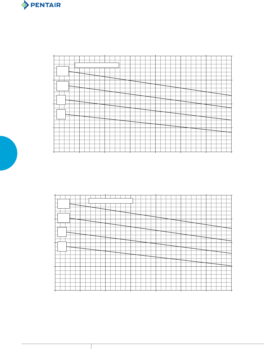
EQUIPMENT PROTECTIONSUBJECT TO CHANGE WITHOUT NOTICECOOLING68
3
SEALED ENCLOSURE COOLING AIR CONDITIONERS
Enclosure Air Temperature
25 C
77 F
35 C
95 F
45 C
113 F
55 C
131 F
3000
6000
9000
12000
15000
68 77 86 95 104 113 122 131
Ambient Air In (°F)
Cooling Capacity (BTU/Hr.)
879
1758
2637
3516
4395
20 30 40 50
Ambient Air In (°C)
Cooling Capacity (W)
N43-1246-GXXX Capacity Curves at 60 Hz
Enclosure Air Temperature
25 C
77 F
35 C
95 F
45 C
113 F
55 C
131 F
3000
6000
9000
12000
15000
68 77 86 95 104 113 122 131
Ambient Air In (°F)
Cooling Capacity (BTU/Hr.)
879
1758
2637
3516
4395
20 30 40 50
Ambient Air In (°C)
Cooling Capacity (W)
N43-1246-GXXX Capacity Curves at 50 Hz
Performance Curves for N43 Models 11000 BTU/Hr. (3223 Watt)
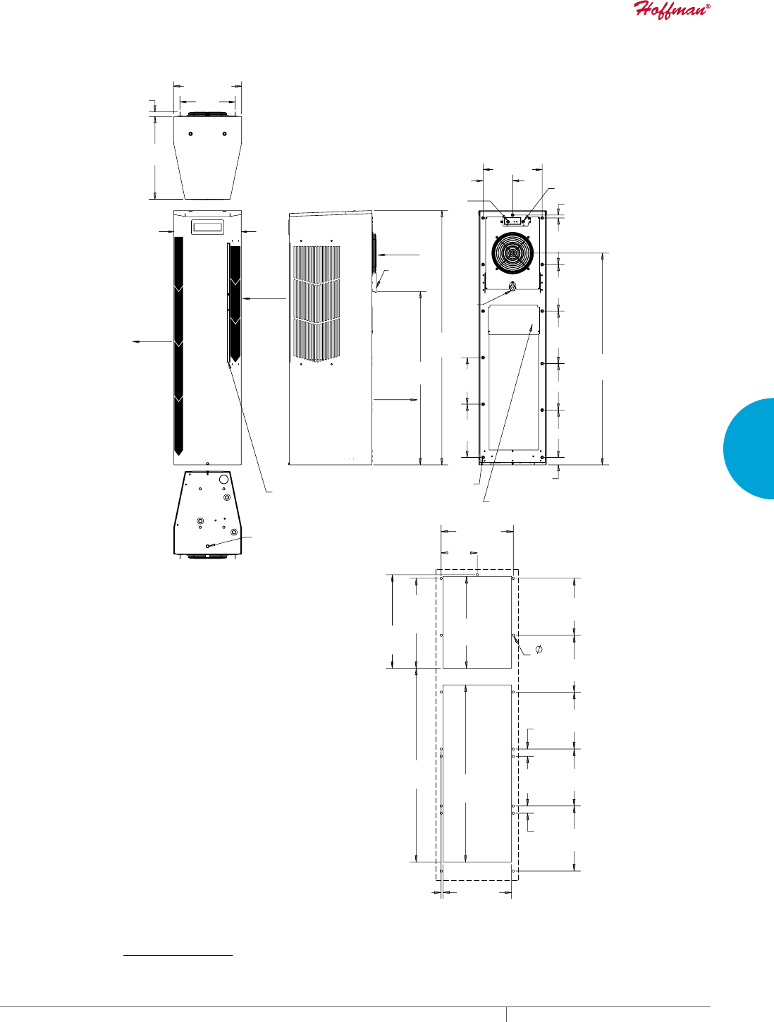
PH 763.422.2211 • FAX 763.576.3200 • HOFFMANONLINE.COMEQUIPMENT PROTECTION COOLING 69
3
SEALED ENCLOSURE COOLING AIR CONDITIONERS
$0%,(17
$,5,1
&/($1$%/(5(86$%/(
$/80,180,1/(7),/7(5
38//6287)5217
>@
>@
>@
>@
>@
>@
(1&/65
$,5,1
&22/
$,5287
5(029$%/(
+$1*,1*
7$%6
>@
>@
>@
>@
;
>@
;
>@
;
>@
>@
>@
;
>@
>@
>@
81&
02817,1*
+2/(6;
32:(5
,1387
237,21$/$&&(663$1(/
21/<)2581,76:,7++($7(5
&22/767$7
+($7767$7
237,21$/
$&&(66+2/(72
>@2''5$,1678%
:$50
$,5287
>@
>@
;
>@
;
>@
;
>@
;
>@
>@
;
>@
;
>@
>@
;
>@
;
>@
;
>@
;
>@
>@
>@
;
>@
;
>@
N43 12000 BTU/Hr. (3516 Watt)
CUTOUT INSTRUCTIONS
Visit www
.HoffmanOnline.com to download 2D and 3D CAD drawings into the overall design of your electr
onic system.
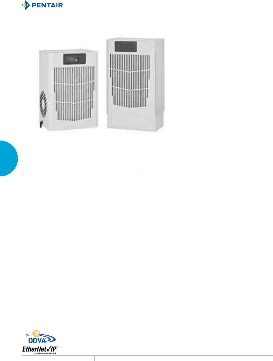
EQUIPMENT PROTECTIONSUBJECT TO CHANGE WITHOUT NOTICECOOLING70
3
SEALED ENCLOSURE COOLING AIR CONDITIONERS
SPECTRACOOL™ COMPACT INDOOR
N17 115/230 Volt
1000 BTU/Hr.
293 Watt
N17 460 Volt
1800 BTU/Hr.
527 Watt
N1
7
11
5/
23
0
V
l
N1
7
46
0
V
l
INDUSTRY STANDARDS
UL/cUL Listed; Type 12; File No. SA6453
CE
IP 54 Internal Loop
IP 34 on External Loop
APPLICATION
• Industrial automation
• Package handling equipment
• Security and defense systems
FEATURES
• Narrow design accommodates 12-in. deep cabinets
• R134a earth-friendly refrigerants
• Models for 115, 230 and 400/460 VAC power input
• UL Listed to save customers time and money with agency
approvals
• Attractive industrial design with minimal use of visible fasteners
• Reliable mechanical thermostat is located behind the cover of the
unit; Air Conditioner models include digital display on ambient
side
• Galvanized sheet-metal cover for rugged factory environments
• Easy-mount flanges for simple installation
• Cut-out adapter options for enclosures with GENESIS® air
conditioners enable users to easily transition to the new unit
•
Dust-resistant condenser coil allows the unit to be run filterless
in most applications
• Cleanable, reusable aluminum mesh filter protects coils for
maximum cooling performance
• Mounting hardware, gaskets and user manual furnished with the
unit
• Every unit functionally tested before shipping
• Standard Indoor Air Conditioner models also include:
- Active condensate management
- Power-off relay for door switch and other system
requirements
- Malfunction switch
SPECIFICATIONS
• Nominal cooling capacity:
N17 1000 BTU/Hr. (293 W)
N17 1800 BTU/Hr. (527 W)
• Operating temperature range from 50 F/10 C to 125 F/52 C
FINISH
• RAL 7035 light-gray, semi-textured powder-coat paint
• Other colors and textures available
NOTES
Visit www.HoffmanOnline.com to download 2D and 3D CAD
drawings into the overall design of your electronic system.
PH 763.422.2211 • FAX 763.576.3200 • HOFFMANONLINE.COMEQUIPMENT PROTECTION COOLING 71
3
SEALED ENCLOSURE COOLING AIR CONDITIONERS
Performance Data N17 Models 1000/1800 BTU/Hr. (300/527 Watt)
CATALOG NUMBER
Indoor Model N170116G010 N170126G010 N170146G010 N170216G010 N170226G010 N170246G010
Indoor Model with Remote Access Control* N170116G020 N170126G020 N170146G020 N170216G020 N170226G020 N170246G020
COOLING PERFORMANCE
Nominal:
BTU/Hr. 908/1025 908/1025 908/1025 1500/1800 1500/1800 1500/1800
Watts 266/300 266/300 266/300 440/527 440/527 440/527
Refrigerant R-134a R-134a R-134a R-134a R-134a R-134a
Refrigerant Charge (ounces/grams) 5/142 5/142 5/142 5.5/156 5.5/156 5.5/156
Operating Temperature Range:
Maximum (°F/°C) 125/52 125/52 125/52 125/52 125/52 125/52
Minimum (°F/°C) 50/10 50/10 50/10 50/10 50/10 50/10
Airflow at 0 Static Pressure:
Internal loop 50 Hz (CFM / m3/hr.) 57/97 57/97 57/97 61/104 61/104 61/104
External loop 50 Hz (CFM / m3/hr.) 96/163 96/163 96/163 98/167 98/167 98/167
Internal loop 60 Hz (CFM / m3/hr.) 67/114 67/114 67/114 72/122 72/122 72/122
External loop 60 Hz (CFM / m3/hr.) 114/194 114/194 114/194 118/200 118/200 118/200
ELECTRICAL DATA
Rated Voltage 110/115 220/208-230 400/460 110/115 220/208-230 400/460
Frequency (Hz) 50/60 50/60 50/60 50/60 50/60 50/60
Operating Range +/- 10% +/- 10% +/- 10% +/- 10% +/- 10% +/- 10%
Max. Power Consumption (W at 50/60 Hz) 337/356 375/407 345/376 642/728 639/667 543/603
Max. Nominal Current (A at 50/60 Hz) 4.4/3.9 2.3/2.1 1.2/1.2 7.0/7.1 4.0/3.5 2.0/2.0
Starting Current (A) 18 8.5 4.25 28 14.4 7.2
Agency Approvals UL/cUL Listed
CE
Power Input Description Terminal Block
ENCLOSURE PROTECTION
UL Type Type 12
IP IP 54
CONTROLLER (...G010 Models)
Thermostat Location Behind Cover, Right Side
Factory Thermostat Setting (°F/°C) 80/27
CONTROLLER (...G020 Models)
Thermostat Location Ambient Side
Factory Thermostat Setting (°F/°C) 80/27
SOUND LEVEL
At 1.5 Meters 65.0 dBA
UNIT CONSTRUCTION
Material Galvanized sheet metal standard
Finish RAL 7035 light-gray, semi-textured powder-coat paint standard
Other colors available
ACCESSORIES
EASYSWAP Adaptor Plenum (GENESIS™ M13) Enables SPECTRACOOL to be mounted to a GENESIS M13 air conditioner cutout
Catalog Number PLM13N17
NOTE: EASYSWAP adaptor plenum not required for M17. It is the same cutout as N17.
UNIT DIMENSIONS
Height (in./mm) 17.64/448.1 17.64/448.1 22.14/562.4 17.64/448.1 17.64/4 48.1 22.14/562.4
Width (in./mm) 12.0/304.8 12.0/304.8 12.0/304.8 12.0/304.8 12.0/304.8 12.0/304.8
Depth (in./mm) 8.4/213.4 8.4/213.4 8.4/213.4 8.4/213.4 8.4/213.4 8.4/213.4
Weight (lb./kg) 50/23 50/23 66/30 54/25 54/25 73/33
*Units with Remote Access Control utilize a digital controller and communicate via EtherNet/IP, Modbus TCP/IP and SNMP over ethernet or modbus RTU
over USB.
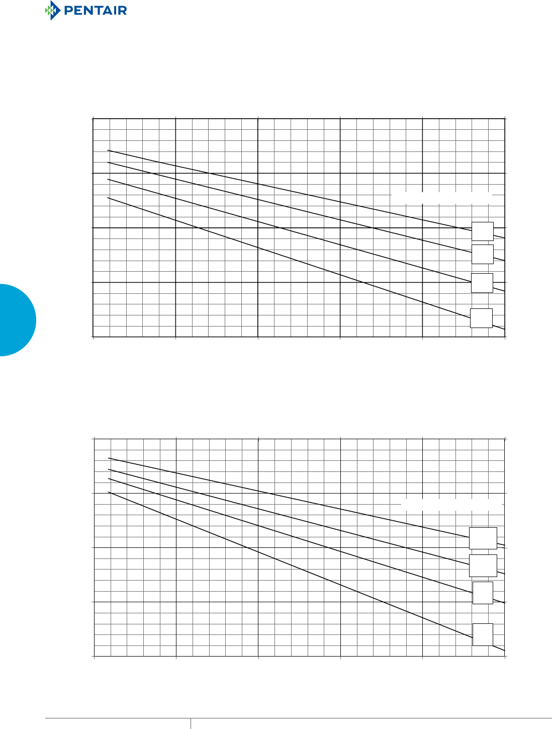
EQUIPMENT PROTECTIONSUBJECT TO CHANGE WITHOUT NOTICECOOLING72
3
SEALED ENCLOSURE COOLING AIR CONDITIONERS
25 C
77 F
35 C
95 F
45 C
113 F
52 C
126 F
Enclosure Air Temperature
N17-0116-GXXX Capacity Curves at 60 Hz
0
500
1000
1500
2000
68 79 91 102 114 125
Ambient Air In (°F)
Cooling Capacity (BTU/Hr)
0
146
293
439
586
20 26 33 39 45 52
Ambient Air In (°C)
Cooling Capacity (W)
52 C
125 F
45 C
113 F
35 C
95 F
25 C
77 F
Enclosure Air Temperature
N17-0116-GXXX Capacity Curves at 50 Hz
0
500
1000
1500
2000
68 79 91 102114 125
Ambient Air In (°F)
Cooling Capacity (BTU/Hr.)
0
146
293
439
586
20 26 33 39 45 52
Ambient Air In (°C)
Cooling Capacity (W)
Performance Curves for N17 Models 1000 BTU/Hr. (293 Watt)
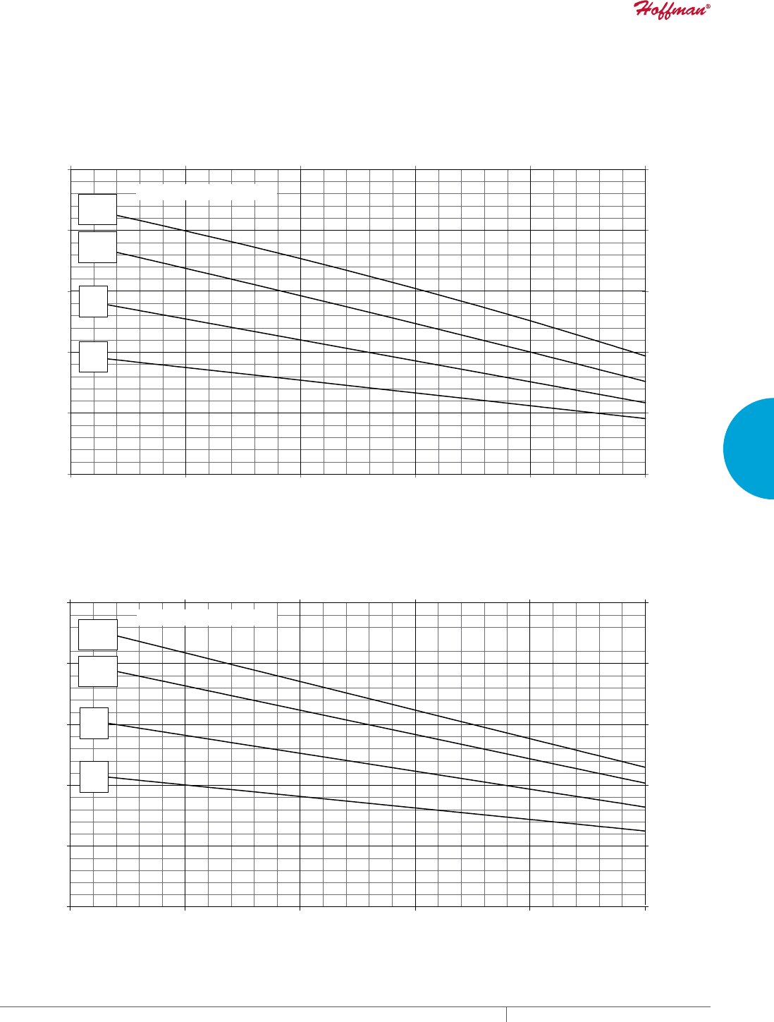
PH 763.422.2211 • FAX 763.576.3200 • HOFFMANONLINE.COMEQUIPMENT PROTECTION COOLING 73
3
SEALED ENCLOSURE COOLING AIR CONDITIONERS
25 C
77 F
35 C
95 F
45 C
113 F
52 C
126 F
Enclosure Air Temperature
N17-01(2/4)6-GXXX Capacity Curves at 60 Hz
0
500
1000
1500
2000
2500
68 79 91 102 114 125
Ambient Air In (°F)
Cooling Capacity (BTU/Hr)
0
146
293
439
586
732
20 26 33 39 45 52
Ambient Air In (°C)
Cooling Capacity (W)
25 C
77 F
35 C
95 F
45 C
113 F
52 C
126 F
Enclosure Air Temperature
N17-01(2/4)6-GXXX Capacity Curves at 50 Hz
0
500
1000
1500
2000
2500
68 79 91 102 11
41
25
Ambient Air In (°F)
Cooling Capacity (BTU/Hr)
0
146
293
439
586
732
20 26 33 39 45 52
Ambient Air In (°C)
Cooling Capacity (W)
Performance Curves for N17 Models 1000/2000 BTU/Hr. (293/585 Watt)
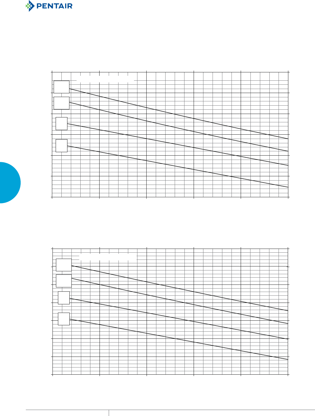
EQUIPMENT PROTECTIONSUBJECT TO CHANGE WITHOUT NOTICECOOLING74
3
SEALED ENCLOSURE COOLING AIR CONDITIONERS
25 C
77 F
35 C
95 F
45 C
113 F
52 C
126 F
Enclosure Air Temperature
N17-0216-GXXX Capacity Curves at 60 Hz
0
500
1000
1500
2000
2500
3000
3500
68 79 91 102 11
41
25
Ambient Air In (°F)
Cooling Capacity (BTU/Hr)
0
146
293
439
586
732
878
1025
20 26 33 39 45 52
Ambient Air In (°C)
Cooling Capacity (W)
25 C
77 F
35 C
95 F
45 C
113 F
52 C
126 F
Enclosure Air Temperature
N17-0216-GXXX Capacity Curves at 50 Hz
0
500
1000
1500
2000
2500
3000
68 79 91 102 114 125
Ambient Air In (°F)
Cooling Capacity (BTU/Hr)
0
146
293
439
586
732
878
20 26 33 39 45 52
Ambient Air In (°C)
Cooling Capacity (W)
Performance Curves for N17 Models 1000 BTU/Hr. (293 Watt)
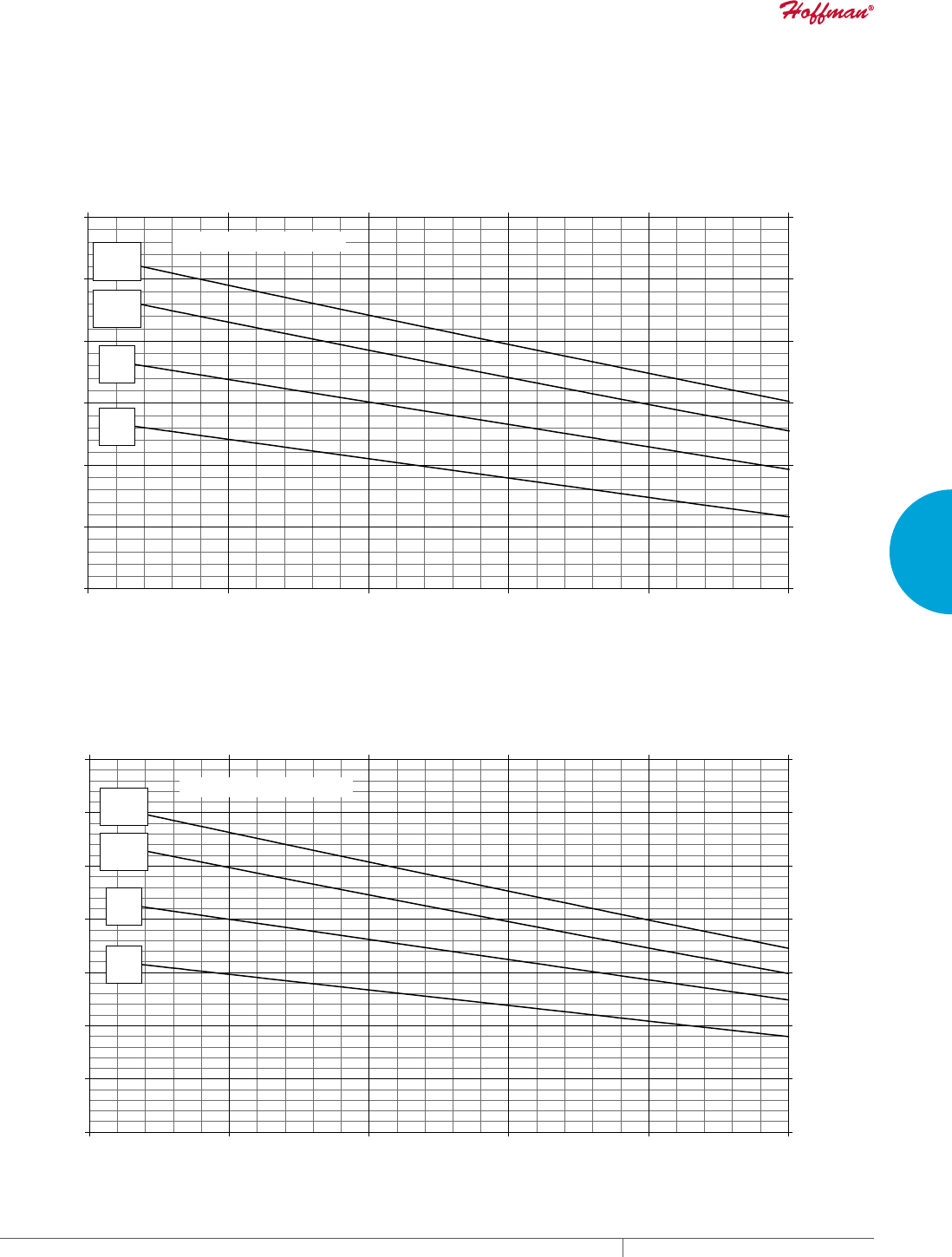
PH 763.422.2211 • FAX 763.576.3200 • HOFFMANONLINE.COMEQUIPMENT PROTECTION COOLING 75
3
SEALED ENCLOSURE COOLING AIR CONDITIONERS
25 C
77 F
35 C
95 F
45 C
113 F
52 C
126 F
Enclosure Air Temperature
N17-02(2/4)6-GXXX Capacity Curves at 60 Hz
0
500
1000
1500
2000
2500
3000
3500
68 79 91 102 114 125
Ambient Air In (°F)
Cooling Capacity (BTU/Hr)
0
146
293
439
586
732
878
1025
20 26 33 39 45 52
Ambient Air In (°C)
Cooling Capacity (W)
25 C
77 F
35 C
95 F
45 C
113 F
52 C
126 F
Enclosure Air Temperature
N17-02(2/4)6-GXXX Capacity Curves at 50 Hz
0
500
1000
1500
2000
2500
3000
68 79 91 102 114 125
Ambient Air In (°F)
Cooling Capacity (BTU/Hr)
0
146
293
439
586
732
878
20 26 33 39 45 52
Ambient Air In (°C)
Cooling Capacity (W)
Performance Curves for N17 Models 1000/2000 BTU/Hr. (293/585 Watt)
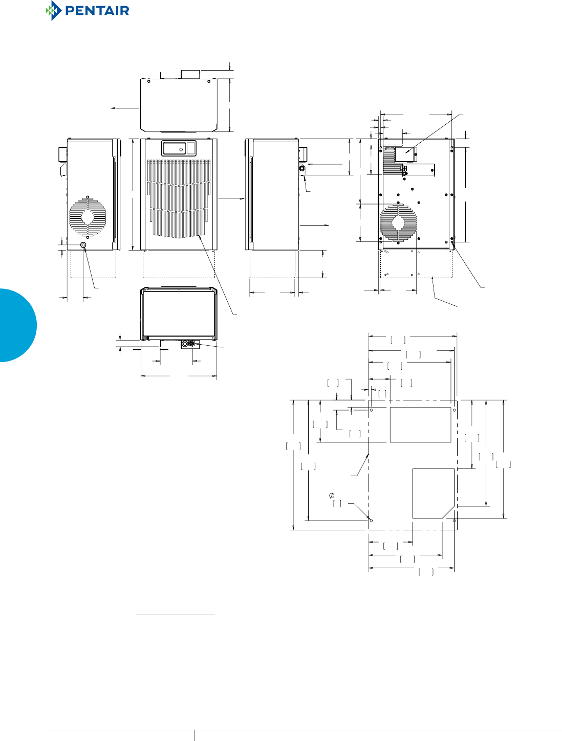
EQUIPMENT PROTECTIONSUBJECT TO CHANGE WITHOUT NOTICECOOLING76
3
SEALED ENCLOSURE COOLING AIR CONDITIONERS
&/($1$%/(5(86$%/(
$/80,180,1/(7),/7(5
6/,'(62876,'(
-%2;
;)05%2;
&22/
$,5287
(1&/2685(
$,5,1
5(029$%/(
+$1*,1*
%5$&.(7
-%2;32:(5&211(&7,216
%(+,1'5(029$%/(&29(5
81&
02817,1*
+$1*,1*
7$%6
675$,15(/,())25
32:(5:,5,1*
&21'(16$7(
'5$,1
$0%,(17
$,5,1
:$50
$,5287
75$16)250(5
921/<
;
;
&XWRXW'LPHQVLRQV
$&
287/,1(
N17 Models 1000/1800 BTU/Hr. (300/527 Watt)
89089862
Visit www
.HoffmanOnline.com to download 2D and 3D CAD drawings into the overall design of your electr
onic system.

PH 763.422.2211 • FAX 763.576.3200 • HOFFMANONLINE.COMEQUIPMENT PROTECTION COOLING 77
3
SEALED ENCLOSURE COOLING AIR CONDITIONERS
Notes
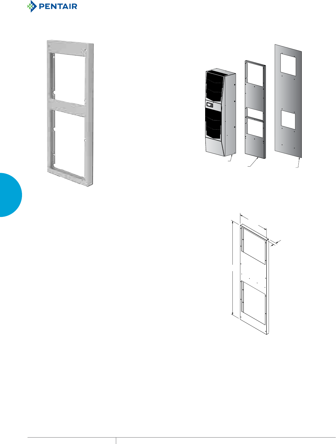
EQUIPMENT PROTECTIONSUBJECT TO CHANGE WITHOUT NOTICECOOLING78
3
SEALED ENCLOSURE COOLING AIR CONDITIONERS
EASY SWAP ADAPTOR PLENUMS FOR AIR CONDITIONERS
$LU&RQGLWLRQHU
$GDSWHU
3OHQXP
(QFORVXUH&DELQHW
6XUIDFH
INDUSTRY STANDARDS
Maintains NEMA Type 12 rating when properly installed on a Type 12
enclosure.
NEMA Type 12
IP 54
APPLICATION
When existing air conditioners are damaged or have reached
end-of-life, EASY SWAP Adaptor Plenums provide a quick and easy
means for attaching newer Hoffman® air conditioners to the cut-out
left on the enclosure.
FEATURES
• No modification of the enclosure required - designed to match the
enclosure cut-out and mounting holes of the air conditioner being
replaced
• Plenum design allows for optimum air flow (vs. a flat plate that
can block the air intake and air outtake left by the older air
conditioner)
• Gasket included
SPECIFICATIONS
• 18 gauge steel
FINISH
• Painted to match the standard Hoffman air conditioner color
(light gray)
• Other colors available upon request
$
%
&
PH 763.422.2211 • FAX 763.576.3200 • HOFFMANONLINE.COMEQUIPMENT PROTECTION COOLING 79
3
SEALED ENCLOSURE COOLING AIR CONDITIONERS
EASY SWAP Adaptor Plenum Cross Reference
Air Conditioner
Manufacturer
To Replace
Air Conditioner
Series
To Replace
Air Conditioner
Part Number
To Replace
Use This Hoffman
Air Conditioner
Catalog Number
With This
Adaptor Plenum
Catalog Number
Adaptor Plenum
Dimensions
AxBxC* (in./mm)
Hoffman Genesis M130116G014 N170116G010 PLM13N17 17.65x14.25x1.50
448x362x38
Hoffman Genesis M130126G1008 N170126G010 PLM13N17 17.65x14.25x1.50
448x362x38
Hoffman Genesis M130146G1400 N170146G010 PLM13N17 17.65x14.25x1.50
448x362x38
Hoffman Genesis M170216G009 N170216G010 Not Required ---
Hoffman Genesis M170226G004 N170226G010 Not Required ---
Hoffman Genesis M170246G400 N170246G010 Not Required ---
Hoffman Genesis M280216G013 N170216G010 PLM28N17 28.50x17.00x1.50
724x432x38
Hoffman Genesis M280226G004 N170226G010 PLM28N17 28.50x17.00x1.50
724x432x38
Hoffman Genesis M280246G400 N170246G010 PLM28N17 28.50x17.00x1.50
724x432x38
Hoffman Genesis M280416G007 G280416G050 PLM28G28 28.50x17.00x1.50
724x432x38
Hoffman Genesis M280426G032 G280426G050 PLM28G28 28.50x17.00x1.50
724x432x38
Hoffman Genesis M280446G400 G280446G050 PLM28G28 28.50x17.00x1.50
724x432x38
Hoffman Genesis M280616G005 G280616G050 PLM28G28 28.50x17.00x1.50
724x432x38
Hoffman Genesis M280626G005 G280626G050 PLM28G28 28.50x17.00x1.50
724x432x38
Hoffman Genesis M280646G400 G280646G050 PLM28G28 28.50x17.00x1.50
724x432x38
Hoffman Genesis M330416G010 N280416G050 PLM33N28 34.31x12.00x1.50
871x305x38
Hoffman Genesis M330426G009 N280426G050 PLM33N28 34.31x12.00x1.50
871x305x38
Hoffman Genesis M330446G400 N280446G050 PLM33N28 34.31x12.00x1.50
871x305x38
Hoffman Genesis M360616G307 N360616G050 PLM36N36 38.75x15.00x1.50
984x381x38
Hoffman Genesis M360626G306 N360626G050 PLM36N36 38.75x15.00x1.50
984x381x38
Hoffman Genesis M360646G400 N360646G050 PLM36N36 38.75x15.00x1.50
984x381x38
Hoffman Genesis M520816032 G520816G050 PLM52G52 52.56x17.03x1.50
1335x433x38
Hoffman Genesis M520826015 G520826G050 PLM52G52 52.56x17.03x1.50
1335x433x38
Hoffman Genesis M520846G002 G520846G050 PLM52G52 52.56x17.03x1.50
1335x433x38
Hoffman Genesis M521046G002 G521246G050 PLM52G52 52.56x17.03x1.50
1335x433x38
Hoffman Genesis M521216017 G521216G050 PLM52G52 52.56x17.03x1.50
1335x433x38
Hoffman Genesis M521226034 G521226G050 PLM52G52 52.56x17.03x1.50
1335x433x38
Hoffman T-Series T290416G100 G280416G050 PLT29G28 28.50x17.00x1.50
724x432x38
Hoffman T-Series T290416G150 G280416G150 PLT29G28 28.50x17.00x1.50
724x432x38
Hoffman T-Series T290426G100 G280426G050 PLT29G28 28.50x17.00x1.50
724x432x38
Hoffman T-Series T290426G150 G280426G150 PLT29G28 28.50x17.00x1.50
724x432x38
Hoffman T-Series T290446G400 G280446G050 PLT29G28 28.50x17.00x1.50
724x432x38
Hoffman HC52 HC52 SERIES G57XXXXXXXX PLHC52G57 57.60x22.97x1.50
1463x583x38
Hoffman HC52 HC52 SERIES T53XXXXXXXX PLHC52T53 52.85x23.00x1.50
1342x584x38
*Prior to ordering, ensure Adaptor Plenum dimensions do not exceed available space on the enclosure mounting surface.
Please contact Customer Service for support in finding an appropriate cross for older models not shown above.
For a list of EASY SWAP Adaptor Plenums to fit other manufacturers’ air conditioners, please visit www.hoffmanonline.com
EQUIPMENT PROTECTIONSUBJECT TO CHANGE WITHOUT NOTICECOOLING80
3
SEALED ENCLOSURE COOLING AIR CONDITIONERS
TSERIES COMPACT OUTDOOR
T15
800 BTU/Hr.
234 Watts
T20
2000 BTU/Hr.
586 Watts
INDUSTRY STANDARDS
UL/cUL Listed; Type 12, 3R, 4; 4X optional; File No. SA6453
UR/cUR Recognized
UR/cUR Recognized on select models, reference performance data
tables.
CE
GOST
Telcordia GR-487 capable
APPLICATION
• Industrial automation
• Telecommunications equipment
• Package handling equipment
• Security and defense systems
• And more
FEATURES
• Stock models equipped with head pressure control for low-
ambient operation, compressor heater, coated condenser coil,
malfunction switch, thermostat and heater package
• R134A earth-friendly refrigerant
• Models for 115, 230 and 460 VAC power input
• UL Listed to save customers time and money with agency
approvals (some models UL recognized)
• Outdoor model operating temperature range from -40 F/-40 C to
131 F/55 C
• Exterior and fully recessed mounting options on many models
• Compact footprint to minimize real estate and maximize capacity
• Reliable mechanical thermostat on enclosure side of the unit
• Dual condenser-side air movers for performance redundancy
• Painted galvanized sheet-metal cover for rugged factory and
outdoor environments
• Easy-mount flanges for simple installation
• Cleanable, reusable aluminum mesh filter protects coils for
maximum cooling performance
• Mounting hardware, gaskets and user manual furnished with the
unit
• Every unit functionally tested before shipping
• Standard Outdoor Air Conditioner models also include:
- Telcordia GR-487 capable
- Thermostat
- Corrosion-resistant components
- Malfunction switch
- Compressor heater
- Head pressure control
- Enclosure heater
FINISH
• RAL 7035 light-gray, semi-textured powder-coat paint
• Other colors and textures available
OPTIONS
• Thermostat Malfunction Package
• Special Voltage Package
• Outdoor Package
• Harsh Environment Package*
• Stainless Steel Package*
• Heater Package
* PROAIR A/C may be more appropriate. Refer to PROAIR
A/C Chapter. Consult the Factory for availability and catalog
number.
NOTES
Visit www.HoffmanOnline.com to download 2D and 3D CAD
drawings into the overall design of your electronic system.
PH 763.422.2211 • FAX 763.576.3200 • HOFFMANONLINE.COMEQUIPMENT PROTECTION COOLING 81
3
SEALED ENCLOSURE COOLING AIR CONDITIONERS
Performance Data T15 800 BTU/Hr. (234 Watt) Models
CATALOG NUMBER
Indoor Model T150116G120 T150126G120
Outdoor Model without Heat Pkg. T150116G100 T150126G100
Outdoor Model with Heat Pkg. T150116G150 T150126G150
Outdoor Model/SST/Corrosion/4X T150116G152 T150126G104
Outdoor Model/SST/Corrosion/4X/Heater T150116G151 —
COOLING PERFORMANCE
Nominal:
BTU/Hr. 800/800 800/900
Watts 235/235 235/264
At 131 F/131 F (55 C/55 C):
BTU/Hr. (50/60 Hz) 819 920/960
W (50/60 Hz) 240 270/281
At 95 F/95 F (35 C/35 C):
BTU/Hr. (50 /60 Hz) 948 810/955
W (50/60 Hz) 278 237/280
Refrigerant R-134A R-134A
Refrigerant Charge (ounces/grams) 4/113 3.8/107
Operating Temperature Range:
Maximum (ºF/ºC) 131/55 125/131/52/55
Minimum (ºF/ºC) -40/-40 -40/-40
Airflow at 0 Static Pressure:
Internal loop 50 Hz (CFM / m3/hr.) 25/42 25/42
External loop 50 Hz (CFM / m3/hr.) 48/82 48/82
Internal loop 60 Hz (CFM / m3/hr.) 30/51 30/51
External loop 60 Hz (CFM / m3/hr.) 53/90 53/90
Max. Heater W (Outdoor Models) 150 150
ELECTRICAL DATA
Rated Voltage 100/115 220/230
Frequency (Hz) 50/60 50/60
Operating Range +/- 10% +/- 10%
Max. Power Consumption (W at 50/60 Hz) 360/403 330/345
Max. Nominal Current (A at 50/60 Hz) 3.6/3.5 1.5/1.5
Starting Current (A) 8.0/9.2 3.3/3.1
Agency Approvals cUL Listed
CE
GOST
Others available upon request
Power Input Description 6-ft. cord with NEMA 5-15 plug 6-ft. cord with NEMA 6-15 plug
ENCLOSURE PROTECTION
UL Type Type 12, 3R, 4 standard
Type 4X Stainless steel optional
CONTROLLER
Description Basic mechanical thermostat
Thermostat Location Enclosure behind front panel
Factory Thermostat Setting (ºF/ºC) 80/27
SOUND LEVEL
At 1.5 Meters 63 dB(A)
UNIT CONSTRUCTION
Material Galvanized sheet metal standard
Stainless steel optional
Finish RAL 7035 light-gray, semi-textured powder-coat paint standard
UNIT DIMENSIONS
Height (in./mm) 15.75/400
Width (in./mm) 7.5/191
Depth (in./mm) 6.3/160
Weight (lb./kg) 27/12
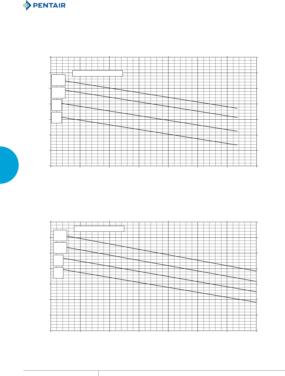
EQUIPMENT PROTECTIONSUBJECT TO CHANGE WITHOUT NOTICECOOLING82
3
SEALED ENCLOSURE COOLING AIR CONDITIONERS
Enclosure Air Temperature
25 C
77 F
35 C
95 F
45 C
113 F
55 C
131 F
0
250
500
750
1000
1250
1500
1750
68 77 86 95 104 113 122 131
Ambient Air In (°F)
Cooling Capacity (BTU/Hr.)
0
73
147
220
293
366
440
513
20 30 40 50
Ambient Air In (°C)
Cooling Capacity (W)
T15-01x6-Gxxx Capacity Curves 60 Hz
Enclosure Air Temperature
25 C
77 F
35 C
95 F
45 C
113 F
55 C
131 F
0
250
500
750
1000
1250
1500
1750
68 77 86 95 104 113122
20 30 40 50
131
Ambient Air In (°F)
Cooling Capacity (BTU/Hr.)
0
73
147
220
293
366
440
513
Ambient Air In (°C)
Cooling Capacity (W)
T15-01x6-Gxxx Capacity Curves 50 Hz
Performance Curves for T15 Models 800 BTU/Hr. (234 Watt)
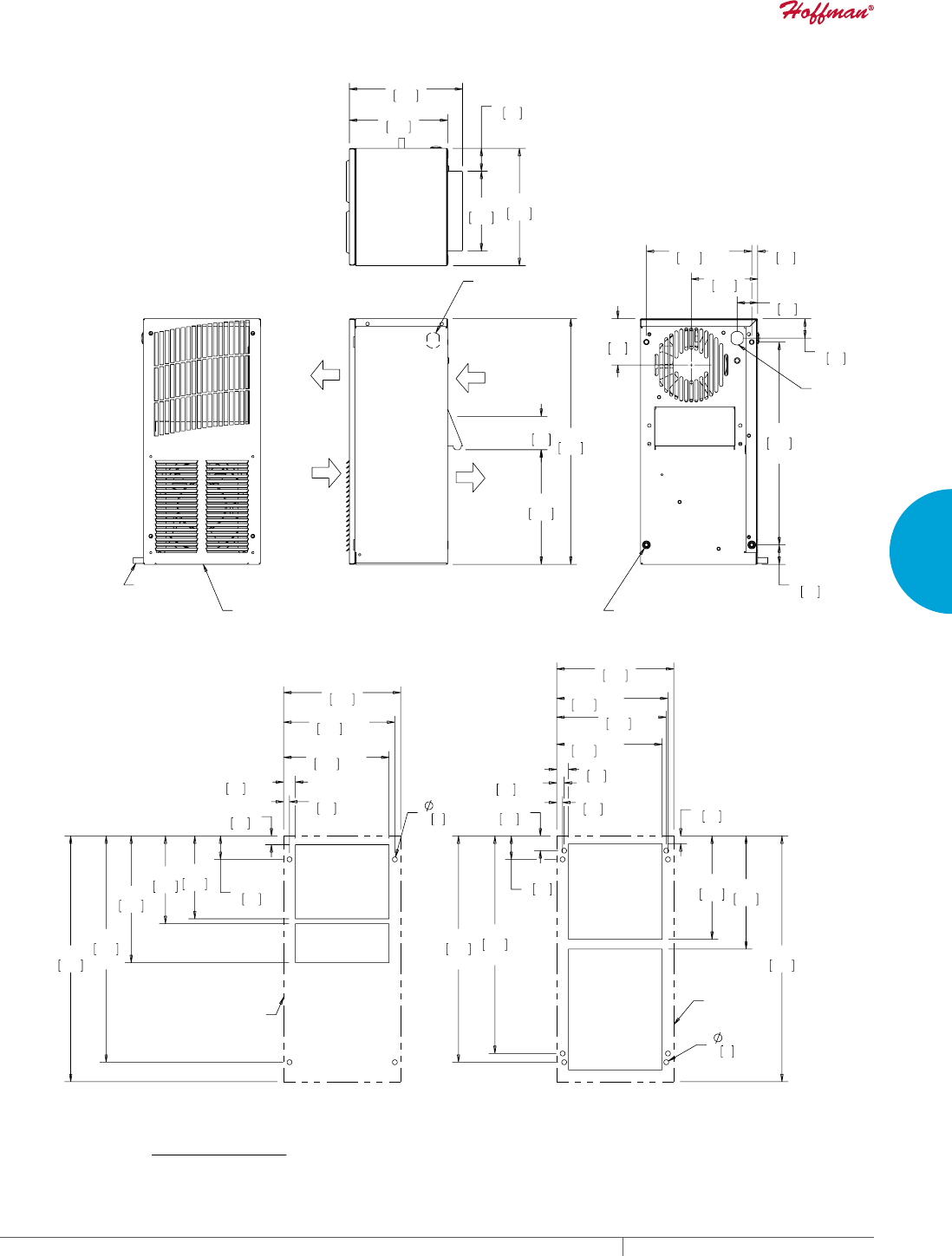
PH 763.422.2211 • FAX 763.576.3200 • HOFFMANONLINE.COMEQUIPMENT PROTECTION COOLING 83
3
SEALED ENCLOSURE COOLING AIR CONDITIONERS
$0%,(17
$,5287
(1&/2685(
$,5,1
$0%,(17
$,5,1
(1&/2685(
$,5287
),(/'&+$1*($%/(
32:(5&25'/2&$7,21
23326,7(6,'(2)81,7
;
;
;
;
32:(5
&25'
(;,7
02817,1*+2/(6;
21%$&.)$&(%(+,1')5217&29(5
,1&+
'5$,1678%
02817,1*+$5':$5()25)8//<5(&(66('
02817,1*,6%(+,1'5(029$%/()5217&29(5
&/($1$%/(5(86$%/($/80,180,1/(7),/7(5
6/,'(62876/27,1%277202))5217&29(5
;
;
;
;
;
;
;
;
;
;
;
;
;
;
;
;
;
$&287/,1(
$&287/,1(
&XWRXW'LPHQVLRQV
,QWHUQDOO\0RXQWHG
&XWRXW'LPHQVLRQV
([WHUQDOO\0RXQWHG
70RGHOV%78+U:DWW
127(
02817,1**$6.(76833/,('1276+2:1
81,76LQ>PP@
Visit www
.HoffmanOnline.com to download 2D and 3D CAD drawings into the overall design of your electr
onic system.

EQUIPMENT PROTECTIONSUBJECT TO CHANGE WITHOUT NOTICECOOLING84
3
SEALED ENCLOSURE COOLING AIR CONDITIONERS
Performance Data T20 2000 BTU/Hr. (586 Watt) Models
CATALOG NUMBER
Outdoor Model without Heat Pkg. T200216G100 T200226G100 T200246G400
Outdoor Model with Heat Pkg. T200216G150 T200226G150 —
Outdoor Model/SST/Corrosion/4X T200216G155 T200226G103 T200246G401
Outdoor Model/SST/Corrosion/4X/Heater T200216G157 T200226G158 —
COOLING PERFORMANCE
Nominal:
BTU/Hr. 1800/2000 1800/2000 1800/2000
Watts 528/586 528/586 528/586
At 131 F/131 F (55 C/55 C):
BTU/Hr. (50/60 Hz) 2000/2175 2000/2175 2000/2175
W (50/60 Hz) 586/637 586/637 586/637
At 95 F/95 F (35 C/35 C):
BTU/Hr. (50/60 Hz) 1950/2200 1950/2200 1950/2200
W (50/60 Hz) 571/645 571/645 571/645
Refrigerant R-134A R-134A R-134A
Refrigerant Charge (ounces/grams) 6.7/190 6.7/190 6.7/190
Operating Temperature Range:
Maximum (°F/°C) 131/55 131/55 131/55
Minimum (°F/°C) -40/-40 -40/-40 -40/-40
Airflow at 0 Static Pressure:
Internal loop 50 Hz (CFM / m3/hr.) 77/131 77/131 77/131
External loop 50 Hz (CFM / m3/hr.) 150/255 150/255 150/255
Internal loop 60 Hz (CFM / m3/hr.) 91/155 91/155 91/155
External loop 60 Hz (CFM / m3/hr.) 165/280 165/280 165/280
Max. Heater W (Outdoor Models) 500 500 500
ELECTRICAL DATA
Rated Voltage 115 230 460V 1PH
Frequency (Hz) 50/60 50/60 50/60
Operating Range +/- 10% +/- 10% +/- 10%
Max. Power Consumption (W at 50/60 Hz) 700/805 805 874
Max. Nominal Current (A at 50/60 Hz) 7.0/7.0 3.5/3.5 1.9
Starting Current (A) 28 14.4 7.2
Agency Approvals cUL Listed
CE
GOST
Others available upon request
cUR Recognized
CE
GOST
Power Input Description 6-ft. cord with NEMA 5-15 plug 6-ft. cord with NEMA 6-15 plug 6-ft. cord with wire leads
ENCLOSURE PROTECTION
UL Type Type 12, 3R, 4 standard
Type 4X Stainless steel optional
CONTROLLER
Description Basic mechanical thermostat
Thermostat Location Enclosure side on all base models
Factory Thermostat Setting (°F/°C) 80/27
SOUND LEVEL
At 1.5 Meters 66 dB(A)
UNIT CONSTRUCTION
Material Galvanized sheet metal standard
Stainless steel optional
Finish RAL 7035 light-gray, semi-textured powder-coat paint standard
UNIT DIMENSIONS
Height (in./mm) 20/508 20/508 24.25/615.95
Width (in./mm) 10/254 10/254 10/254
Depth (in./mm) 9.9/251 9.9/251 9.9/251
Weight (lb./kg) 56/25 56/25 66/30
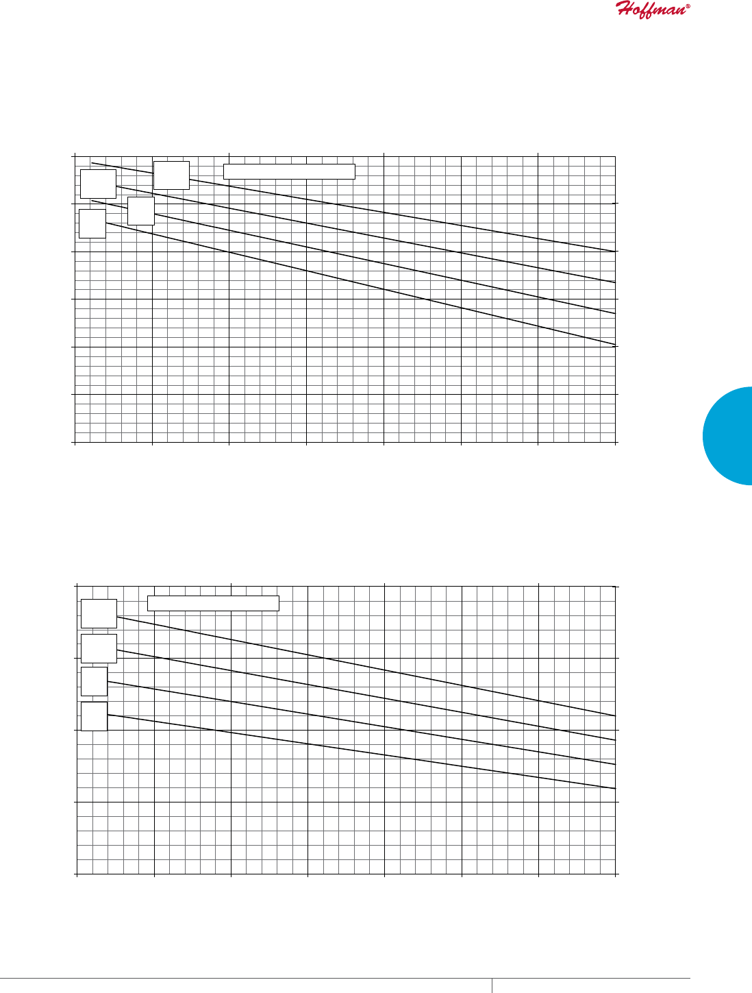
PH 763.422.2211 • FAX 763.576.3200 • HOFFMANONLINE.COMEQUIPMENT PROTECTION COOLING 85
3
SEALED ENCLOSURE COOLING AIR CONDITIONERS
Enclosure Air Temperature
25 C
77 F
35 C
95 F
45 C
113 F
55 C
131 F
0
1000
2000
3000
4000
68 77 86 95 104 113122 131
Ambient Air In (°F)
Cooling Capacity (BTU/Hr.)
0
293
586
879
1172
20 30 40 50
Ambient Air In (°C)
Cooling Capacity (W)
T20-02x6-Gxxx Capacity Curves 60 Hz
Enclosure Air Temperature
25 C
77 F
35 C
95 F
45 C
113 F
55 C
131 F
0
500
1000
1500
2000
2500
3000
68 77 86 95 104 113122 131
Ambient Air In (°F)
Cooling Capacity (BTU/Hr.)
0
147
294
441
588
735
20 30 40 50
Ambient Air In (°C)
Cooling Capacity (W)
T20-02x6-Gxxx Capacity Curves 50 Hz
Performance Curves for T20 Models 2000 BTU/Hr. (586 Watt)
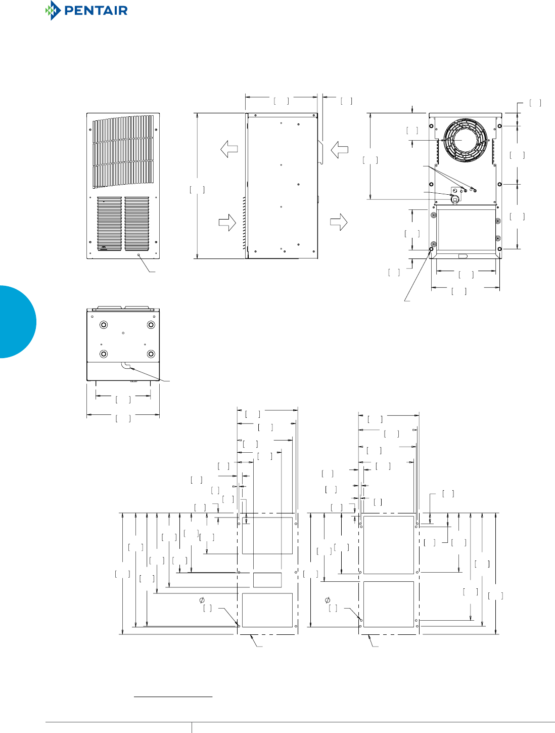
EQUIPMENT PROTECTIONSUBJECT TO CHANGE WITHOUT NOTICECOOLING86
3
SEALED ENCLOSURE COOLING AIR CONDITIONERS
02817,1*+$5':$5()25)8//<5(&(66('
02817,1*,6%(+,1'5(029$%/()5217&29(5
&/($1$%/(5(86$%/($/80,180,1/(7),/7(5
6/,'(62876/27,1%277202))5217&29(5
$0%,(17
$,5287
$0%,(17
$,5,1
(1&/2685(
$,5,1
(1&/2685(
$,5287
5(029$%/(
+$1*,1*
7$%6
,1&+'5$,1678%
;
;
;
;
7+(50267$7
$'-8670(17
32:(5
&25'
$'-8670(17
02817,1*+2/(6;
21%$&.)$&(
%(+,1')5217&29(5
;
;
;
;
;
;
;
;
;
;
;
;
;
;
;
;
;
;
;
;
$&287/,1( $&287/,1(
70RGHOV%78+U:DWW
&XWRXW'LPHQVLRQV
([WHUQDOO\0RXQWHG
&XWRXW'LPHQVLRQV
,QWHUQDOO\0RXQWHG
127(
02817,1**$6.(76833/,('1276+2:1
81,76LQ>PP@
Visit www
.HoffmanOnline.com to download 2D and 3D CAD drawings into the overall design of your electr
onic system.

PH 763.422.2211 • FAX 763.576.3200 • HOFFMANONLINE.COMEQUIPMENT PROTECTION COOLING 87
3
SEALED ENCLOSURE COOLING AIR CONDITIONERS
Notes
EQUIPMENT PROTECTIONSUBJECT TO CHANGE WITHOUT NOTICECOOLING88
3
SEALED ENCLOSURE COOLING AIR CONDITIONERS
TSERIES MIDSIZE OUTDOOR
T29
4000 BTU/Hr.
1173 Watts
T43
6000, 8000, 10000 BTU/Hr.
1758, 2344, 2930 Watts
T50
12000 BTU/Hr.
3516 Watts
T53
19000 BTU/Hr.
5567 Watts
INDUSTRY STANDARDS
UL/cUL Listed; Type 12, 3R, 4; 4X optional; File No. SA6453
UR/cUR Recognized
UR/cUR Recognized on select models, reference performance data
tables.
CE
GOST
Telcordia GR-487 capable
APPLICATION
• Industrial automation
• Telecommunications equipment
• Package handling equipment
• Security and defense systems
• And more
FEATURES
• Stock models equipped with head pressure control for low-
ambient operation, compressor heater, coated condenser coil,
malfunction switch, thermostat and heater package
• R134A or R-407C earth-friendly refrigerant
• Models for 115, 230 and 460 VAC power input
• UL Listed to save customers time and money with agency
approvals (some models UL recognized)
• Outdoor model operating temperature range from -40 F/-40 C to
131 F/55 C
• Exterior and fully recessed mounting options on many models
• Compact footprint to minimize real estate and maximize capacity
• Reliable mechanical thermostat on enclosure side of the unit
• Dual condenser-side air movers for performance redundancy
• Painted galvanized sheet-metal cover for rugged factory and
outdoor environments
• Easy-mount flanges for simple installation
• Cleanable, reusable aluminum mesh filter protects coils for
maximum cooling performance
• Mounting hardware, gaskets and user manual furnished with the
unit
• Every unit functionally tested before shipping
• Standard Outdoor Air Conditioner models also include:
- Telcordia GR-487 capable
- Thermostat
- Corrosion-resistant components
- Malfunction switch
- Compressor heater
- Head pressure control
- Enclosure heater
FINISH
• RAL 7035 light-gray, semi-textured powder-coat paint
• Other colors and textures available
OPTIONS
• Thermostat Malfunction Package
• Special Voltage Package
• Outdoor Package
• Harsh Environment Package*
• Stainless Steel Package*
• Heater Package
* PROAIR Harsh Environment air conditioner may be more
appropriate. Refer to PROAIR Harsh Environment air
conditioner catalog section. Consult the Factory for availability
and catalog number.
NOTES
Visit www.HoffmanOnline.com to download 2D and 3D CAD
drawings into the overall design of your electronic system.

PH 763.422.2211 • FAX 763.576.3200 • HOFFMANONLINE.COMEQUIPMENT PROTECTION COOLING 89
3
SEALED ENCLOSURE COOLING AIR CONDITIONERS
Performance Data T29 4000 BTU/Hr. (1173 Watt) Models
CATALOG NUMBER
Outdoor Model without Heat Pkg. T290416G100 T290426G100 T290446G400
Outdoor Model with Heat Pkg. T290416G150 T290426G150 —
Outdoor Model/SST/Corrosion/4X T290416G159 T290426G161 —
Outdoor Model/SST/Corrosion/4X/Heater T290416G156 T290426G160 T290446G403
COOLING PERFORMANCE
Nominal:
BTU/Hr. 3600/4000 3600/4000 3600/4000
Watts 1055/1172 1055/1172 1055/1172
At 131 F/131 F (55 C/55 C):
BTU/Hr. (50/60 Hz) 3950/4250 3950/4250 3950/4250
W (50/60 Hz) 1157/1245 1157/1245 1157/1245
At 95 F/95 F (35 C/35 C):
BTU/Hr. (50 /60 Hz) 3500/3900 3500/3900 3500/3900
W (50/60 Hz) 1025/1143 1025/1143 1025/1143
Refrigerant R-134A R-134A R-134A
Refrigerant Charge (ounces/grams) 12.5/354 14.3/404 14.3/404
Operating Temperature Range:
Maximum (°F/°C) 131/55 131/55 131/55
Minimum (°F/°C) -40/-40 -40/-40 -40/-40
Airflow at 0 Static Pressure:
Internal loop 50 Hz (CFM / m3/hr.) 172/292 172/292 172/292
External loop 50 Hz (CFM / m3/hr.) 195/331 195/331 195/331
Internal loop 60 Hz (CFM / m3/hr.) 205/348 205/348 205/348
External loop 60 Hz (CFM / m3/hr.) 235/399 235/399 235/399
Max. Heater W (Outdoor Models) 1000 1000
ELECTRICAL DATA
Rated Voltage 115 230 460V 1PH
Frequency (Hz) 50/60 50/60 50/60
Operating Range +/- 10% +/- 10% +/- 10%
Max. Power Consumption (W at 50/60 Hz) 1163/1222 1587/1564 1748
Max. Nominal Current (A at 50/60 Hz) 13.8/12.8 6.9/6.8 3.8
Starting Current () 48 23 12
Agency Approvals cUL Listed
CE
GOST
Others available upon request
cUR Recognized
CE
GOST
Power Input Description 6-ft. cord with NEMA 5-20 plug 6-ft. cord with NEMA 6-15 plug 6-ft. cord with wire leads
ENCLOSURE PROTECTION
UL Type Type 12, 3R, 4 standard
Type 4X Stainless steel optional
CONTROLLER
Description Basic mechanical thermostat
Thermostat Location Enclosure side on all base models
Factory Thermostat Setting (°F/°C) 80/27
SOUND LEVEL
At 1.5 Meters 67 dB(A)
UNIT CONSTRUCTION
Material Galvanized sheet metal standard
Stainless steel optional
Finish RAL 7035 light-gray, semi-textured powder-coat paint standard
UNIT DIMENSIONS
Height (in./mm) 29/737 29/737
Width (in./mm) 17/432 17/432
Depth (in./mm) 11.3/287 11.3/287
Weight (lb./kg) 107/48.6 127/58
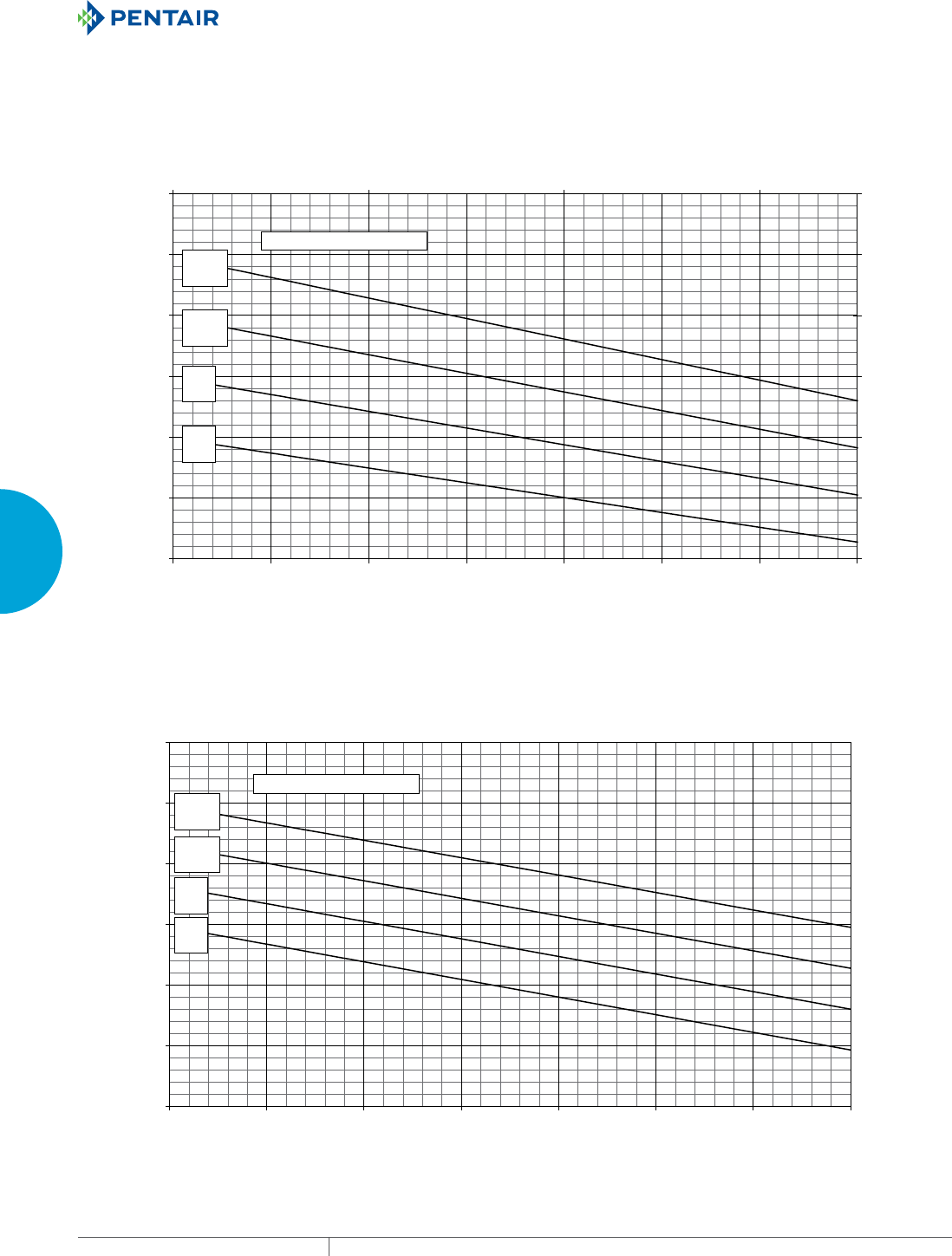
EQUIPMENT PROTECTIONSUBJECT TO CHANGE WITHOUT NOTICECOOLING90
3
SEALED ENCLOSURE COOLING AIR CONDITIONERS
Enclosure Air Temperature
25 C
77 F
35 C
95 F
45 C
113 F
55 C
131 F
1000
2000
3000
4000
5000
6000
7000
68 77 86 95 104 113122 131
Ambient Air In (°F)
Cooling Capacity (BTU/Hr.)
293
586
879
1172
1465
1758
2051
20 30 40 50
Ambient Air In (°C)
Cooling Capacity (W)
T29-04x6-Gxx Capacity Curves 60 Hz
Enclosure Air Temperature
25 C
77 F
35 C
95 F
45 C
113 F
55 C
131 F
1000
2000
3000
4000
5000
6000
7000
68 77 86 95 104 113 122 131
Ambient Air In (°F)
Cooling Capacity (BTU/Hr.)
293
586
879
1172
1465
1758
2051
20 30 40 50
Ambient Air In (°C)
Cooling Capacity (W)
T29-04x6-Gxxx Capacity Curves 50 Hz
Performance Curves for T29 Models 4000 BTU/Hr. (1173 Watt)
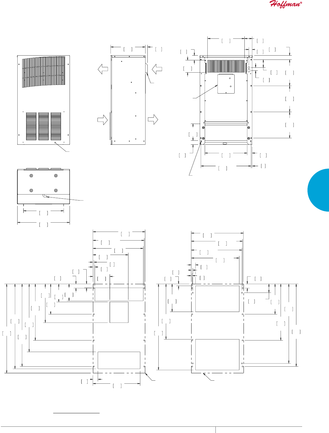
PH 763.422.2211 • FAX 763.576.3200 • HOFFMANONLINE.COMEQUIPMENT PROTECTION COOLING 91
3
SEALED ENCLOSURE COOLING AIR CONDITIONERS
02817,1*+$5':$5()25)8//<5(&(66('
02817,1*,6%(+,1'5(029$%/()5217&29(5
&/($1$%/(5(86$%/($/80,180,1/(7),/7(5
6/,'(62876/27,1%277202))5217&29(5
$0%,(17
$,5287
$0%,(17
$,5,1
(1&/2685(
$,5287
(1&/2685(
$,5,1
5(029$%/(
+$1*,1*
7$%6
'5$,1
678%
;
;
;
;
;
;
&21752/6
$&&(66
3/$7(
02817,1*+2/(6;
21%$&.)$&(
%(+,1')5217&29(5
;
;
;
;
;
;
;
;
;
;
;
;
;
;
;
;
;
;
$&287/,1($&287/,1(
70RGHOV%78+U:DWW
&XWRXW'LPHQVLRQV
([WHUQDOO\0RXQWHG
&XWRXW'LPHQVLRQV
,QWHUQDOO\0RXQWHG
127(
02817,1**$6.(76833/,('1276+2:1
81,76LQ>PP@
Visit www
.HoffmanOnline.com to download 2D and 3D CAD drawings into the overall design of your electr
onic system.

EQUIPMENT PROTECTIONSUBJECT TO CHANGE WITHOUT NOTICECOOLING92
3
SEALED ENCLOSURE COOLING AIR CONDITIONERS
Performance Data T43 6000 BTU/Hr. (1758 Watt) Models
CATALOG NUMBER
Outdoor Model without Heat Pkg. T430616G100 T430626G100 T430646G400
Outdoor Model with Heat Pkg. T430616G150 T430626G150 T430646G153
Outdoor Model/SST/Corrosion/4X T430616G102 T430626G159 —
Outdoor Model/SST/Corrosion/4X/Heater — — —
COOLING PERFORMANCE
Nominal:
BTU/Hr. 6310/6680 6520/6770 6520/6770
Watts 1848/1958 1910/1985 1910/1985
At 131 F/131 F (55 C/55 C):
BTU/Hr. (50/60 Hz) 6400/6680 6520/6774 6520/6774
W (50/60 Hz) 1875/1957 1910/1985 1910/1985
At 95 F/95 F (35 C/35 C):
BTU/Hr. (50 /60 Hz) 5500/5900 5461/5846 5461/5846
W (50/60 Hz) 1611/1729 1600/1713 1600/1713
Refrigerant R-134A R-134A R-134A
Refrigerant Charge (ounces/grams) 30/850 30/850 30/850
Operating Temperature Range:
Maximum (°F/°C) 131/55 131/55 131/55
Minimum (°F/°C) -40/-40 -40/-40 -40/-40
Airflow at 0 Static Pressure:
Internal loop 50 Hz (CFM / m3/hr.) 310/527 310/527 310/527
External loop 50 Hz (CFM / m3/hr.) 345/586 345/586 345/586
Internal loop 60 Hz (CFM / m3/hr.) 320/544 320/544 320/544
External loop 60 Hz (CFM / m3/hr.) 355/603 355/603 355/603
Max. Heater W (Outdoor Models) 1000 1000 N/A
ELECTRICAL DATA
Rated Voltage 115 230 460V 1PH
Frequency (Hz) 50/60 50/60 50/60
Operating Range +/- 10% +/- 10% +/- 10%
Max. Power Consumption (W at 50/60 Hz) 1058/989 1012/874 1104/966
Max. Nominal Current (A at 50/60 Hz) 9.2/8.6 4.4/3.8 2.4/2.1
Starting Current (A) 57.2 27 14
Agency Approvals cUL Listed
CE
GOST
Others available upon request
cUR Recognized
CE
GOST
Power Input Description 6-ft. cord with NEMA 5-20 plug 6-ft. cord with NEMA 6-15 plug 6-ft. cord with wire leads
ENCLOSURE PROTECTION
UL Type Type 12, 3R, 4 standard
Type 4X Stainless steel optional
International Rating IP56 on the internal loop; IP34 on the external loop
CONTROLLER
Description Basic mechanical thermostat
Thermostat Location Enclosure side on all base models
Factory Thermostat Setting (°F/°C) 80/27
SOUND LEVEL
At 1.5 Meters 65.7 dB(A)
UNIT CONSTRUCTION
Material Galvanized sheet metal standard
Stainless steel optional
Finish RAL 7035 light-gray, semi-textured powder-coat paint standard
UNIT DIMENSIONS
Height (in./mm) 43/1092
Width (in./mm) 15.75/400
Depth (in./mm) 10.9/279
Weight (lb./kg) 125/57
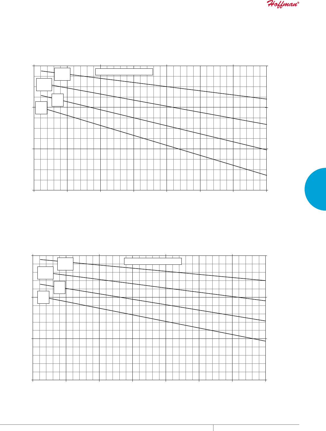
PH 763.422.2211 • FAX 763.576.3200 • HOFFMANONLINE.COMEQUIPMENT PROTECTION COOLING 93
3
SEALED ENCLOSURE COOLING AIR CONDITIONERS
Enclosure Air Temperature
25 C
77 F
35 C
95 F
45 C
113 F
55 C
131 F
2000
4000
6000
8000
68 77 86 95 104113 122131
Ambient Air In (°F)
Cooling Capacity (BTU/Hr.)
1172
1758
2344
20 30 40 50
Ambient Air In (°C)
Cooling Capacity (W)
T43-06X6-G150 Capacity Curves 60 Hz
Enclosure Air Temperature
25 C
77 F
35 C
95 F
45 C
113 F
55 C
131 F
2000
4000
6000
8000
68 77 86 95 104 113 122 131
Ambient Air In (°F)
Cooling Capacity (BTU/Hr.)
586
1172
1758
2344
20 30 40 50
Ambient Air In (°C)
Cooling Capacity (W)
T43-06X6-G150 Capacity Curves 50 Hz
Performance Curves for T43 Models 6000 BTU/Hr. (1758 Watt)

EQUIPMENT PROTECTIONSUBJECT TO CHANGE WITHOUT NOTICECOOLING94
3
SEALED ENCLOSURE COOLING AIR CONDITIONERS
Performance Data T43 8000 BTU/Hr. (2344 Watt) Models
CATALOG NUMBER
Outdoor Model without Heat Pkg. T430816G100 T430826G100 T430846G400
Outdoor Model with Heat Pkg. T430816G150 T430826G150 T430846G403
Outdoor Model/SST/Corrosion/4X T430816G153 T430826G108 T430846G402
Outdoor Model/SST/Corrosion/4X/Heater — — —
COOLING PERFORMANCE
Nominal:
BTU/Hr. 7900/8600 7400/8200 7400/8200
Watts 2310/2500 2160/2400 2160/2400
At 131 F/131 F (55 C/55 C):
BTU/Hr. (50/60 Hz) 7937/8629 7484/8215 7484/8215
W (50/60 Hz) 2326/2528 2193/2407 2193/2407
At 95 F/95 F (35 C/35 C):
BTU/Hr. (50 /60 Hz) 6401/7100 5940/6705 5940/6705
W (50/60 Hz) 1875/2080 1740/1965 1740/1965
Refrigerant R-134A R-134A R-134A
Refrigerant Charge (ounces/grams) 36/1022 36/1022 36/1022
Operating Temperature Range:
Maximum (°F/°C) 131/55 131/55 131/55
Minimum (°F/°C) -40/-40 -40/-40 -40/-40
Airflow at 0 Static Pressure:
Internal loop 50 Hz (CFM / m3/hr.) 273/464 273/464 273/464
External loop 50 Hz (CFM / m3/hr.) 310/527 310/527 310/527
Internal loop 60 Hz (CFM / m3/hr.) 290/493 290/493 290/493
External loop 60 Hz (CFM / m3/hr.) 315/535 315/535 315/535
Max. Heater W (Outdoor Models) 1000 1000 N/A
ELECTRICAL DATA
Rated Voltage 115 230 460V 1PH
Frequency (Hz) 50/60 50/60 50/60
Operating Range +/- 10% +/- 10% +/- 10%
Max. Power Consumption (W at 50/60 Hz) 1196/1288 1196/1242 1334/1380
Max. Nominal Current (A at 50/60 Hz) 10.4/11.2 5.2/5.4 2.9/3.0
Starting Current (A) 48.3 27 14
Agency Approvals cUL Listed
CE
GOST
Others available upon request
cUR Recognized
CE
GOST
Power Input Description 6-ft. cord with NEMA 5-20 plug 6-ft. cord with NEMA 6-15 plug 6-ft. cord with wire leads
ENCLOSURE PROTECTION
UL Type Type 12, 3R, 4 standard
Type 4X Stainless steel optional
International Rating IP56 on the internal loop; IP34 on the external loop
CONTROLLER
Description Basic mechanical thermostat
Thermostat Location Enclosure side on all base models
Factory Thermostat Setting (°F/°C) 80/27
SOUND LEVEL
At 1.5 Meters 65.7 dB(A)
UNIT CONSTRUCTION
Material Galvanized sheet metal standard
Stainless steel optional
Finish RAL 7035 light-gray, semi-textured powder-coat paint standard
UNIT DIMENSIONS
Height (in./mm) 43/1092
Width (in./mm) 15.75/400
Depth (in./mm) 10.9/279
Weight (lb./kg) 125/57

PH 763.422.2211 • FAX 763.576.3200 • HOFFMANONLINE.COMEQUIPMENT PROTECTION COOLING 95
3
SEALED ENCLOSURE COOLING AIR CONDITIONERS
Enclosure Air Temperature
25 C
77 F
35 C
95 F
45 C
113 F
55 C
131 F
2000
4000
6000
8000
10000
12000
68 77 86 95 104 113 122 131
Ambient Air In (°F)
Cooling Capacity (BTU/Hr.)
586
1172
1758
2344
2930
3516
Ambient Air In (°C)
Cooling Capacity (W)
20 30 40 50
T43-08X6-G150 Capacity Curves 60 Hz
Enclosure Air Temperature
25 C
77 F
35 C
95 F
45 C
113 F
55 C
131 F
2000
4000
6000
8000
10000
12000
68 77 86 95 104 113 122131
Ambient Air In (°F)
Cooling Capacity (BTU/Hr.)
586
1172
1758
2344
2930
3516
20 30 40 50
Ambient Air In (°C)
Cooling Capacity (W)
T43-08X6-G150 Capacity Curves 50 Hz
Performance Curves for T43 Models 8000 BTU/Hr. (2344 Watt)
EQUIPMENT PROTECTIONSUBJECT TO CHANGE WITHOUT NOTICECOOLING96
3
SEALED ENCLOSURE COOLING AIR CONDITIONERS
Performance Data T43 10000 BTU/Hr. (2930 Watt) Models
CATALOG NUMBER
Outdoor Model without Heat Pkg. T431016G100 T431026G100 T431046G400
Outdoor Model with Heat Pkg. T431016G150 T431026G150 —
Outdoor Model/SST/Corrosion/4X T431016G102 T431026G104 T431046G406
Outdoor Model/SST/Corrosion/4X/Heater T431016G153 T431026G152 —
COOLING PERFORMANCE
Nominal:
BTU/Hr. 9670/10300 10100/10500 10100/10500
Watts 2831/3016 2957/3075 2957/3075
At 131 F/131 F (55 C/55 C):
BTU/Hr. (50/60 Hz) 9667/10290 10039/10669 10039/10669
W (50/60 Hz) 2832/3015 2941/3126 2941/3126
At 95 F/95 F (35 C/35 C):
BTU/Hr. (50/60 Hz) 7663/8397 8458/8837 8458/8837
W (50/60 Hz) 2245/2460 2478/2589 2478/2589
Refrigerant R-134A R-134 A R-134A
Refrigerant Charge (ounces/grams) 32/907 32/907 32/907
Operating Temperature Range:
Maximum (°F/°C) 131/55 131/55 131/55
Minimum (°F/°C) -40/-40 -40/-40 -40/-40
Airflow at 0 Static Pressure:
Internal loop 50 Hz (CFM / m3/hr.) 272/462 320/544 320/544
External loop 50 Hz (CFM / m3/hr.) 510/866 568/965 568/965
Internal loop 60 Hz (CFM / m3/hr.) 290/493 330/561 330/561
External loop 60 Hz (CFM / m3/hr.) 565/960 636/1081 636/1081
Max. Heater W (Outdoor Models) 1000 1000 N/A
ELECTRICAL DATA
Rated Voltage 115 230 460V 1PH
Frequency (Hz) 50/60 50/60 50/60
Operating Range +/- 10% +/- 10% +/- 10%
Max. Power Consumption (W at 50/60 Hz) 1828.5/2288.5 2070 1334/1380
Max. Nominal Current (A at 50/60 Hz) 15.9/19.9 9 5
Starting Current (A) 57 38 20
Agency Approvals cUL Listed
CE
GOST
Others available upon request
cUR Recognized
CE
GOST
Power Input Description 6-ft. cord with NEMA 5-30 plug 6-ft. cord with NEMA 6-15 plug 6-ft. cord with wire leads
ENCLOSURE PROTECTION
UL Type Type 12, 3R, 4 standard
Type 4X Stainless steel optional
International Rating IP56 on the internal loop; IP34 on the external loop
CONTROLLER
Description Basic mechanical thermostat
Thermostat Location Enclosure side on all base models
Factory Thermostat Setting (°F/°C) 80/27
SOUND LEVEL
At 1.5 Meters 73.3 dB(A)
UNIT CONSTRUCTION
Material Galvanized sheet metal standard
Stainless steel optional
Finish RAL 7035 light-gray, semi-textured powder-coat paint standard
UNIT DIMENSIONS
Height (in./mm) 43/1092
Width (in./mm) 15.75/400
Depth (in./mm) 10.9/279
Weight (lb./kg) 125/57
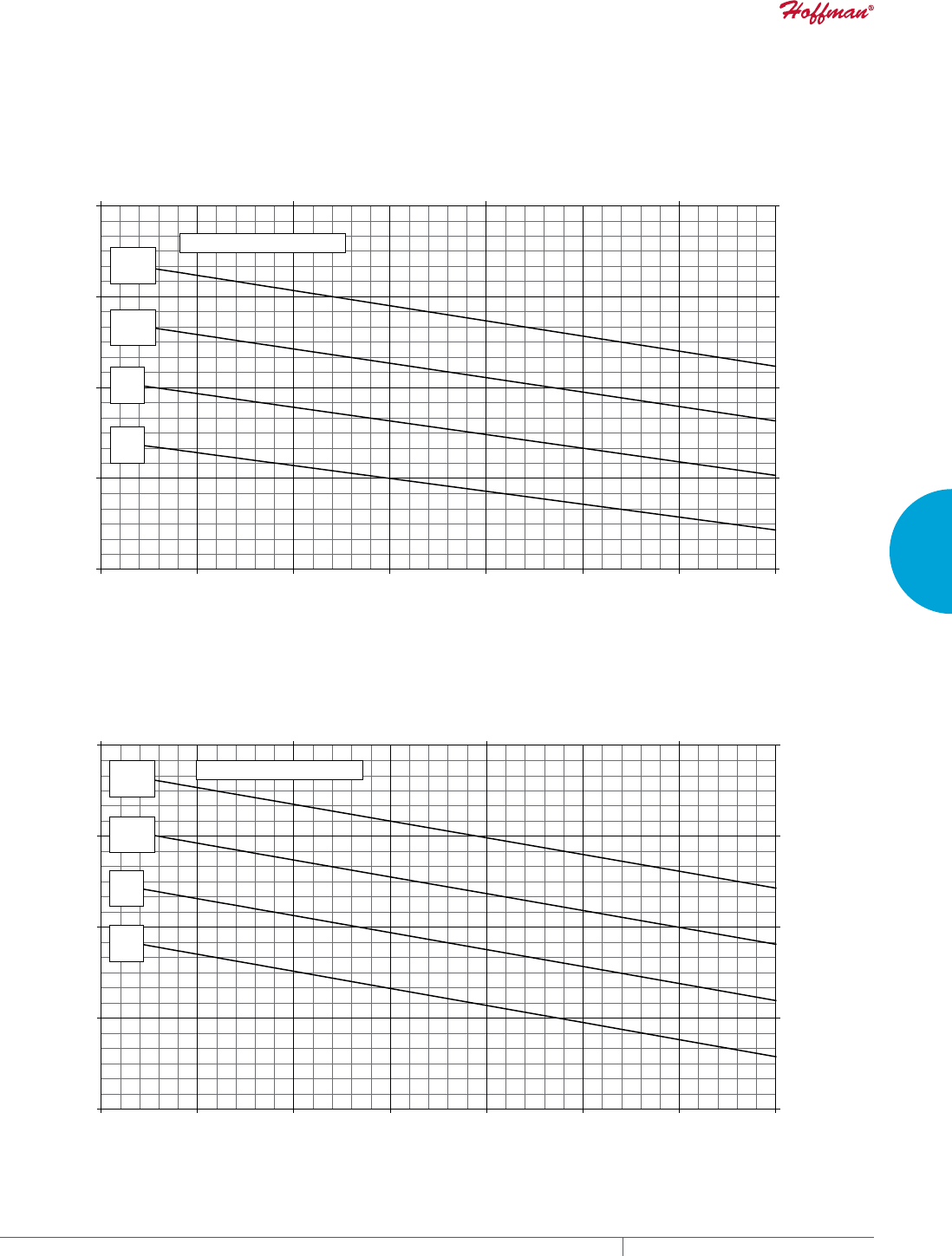
PH 763.422.2211 • FAX 763.576.3200 • HOFFMANONLINE.COMEQUIPMENT PROTECTION COOLING 97
3
SEALED ENCLOSURE COOLING AIR CONDITIONERS
Enclosure Air Temperature
25 C
77 F
35 C
95 F
45 C
113 F
55 C
131 F
3000
6000
9000
12000
15000
68 77 86 95 104 113122 131
Ambient Air In (°F)
Cooling Capacity (BTU/Hr.)
879
1758
2637
3516
4395
20 30 40 50
Ambient Air In (°C)
Cooling Capacity (W)
T43-10X6-G150 Capacity Curves 60 Hz
Enclosure Air Temperature
25 C
77 F
35 C
95 F
45 C
113 F
55 C
131 F
3000
6000
9000
12000
15000
68 77 86 95 104 113 122 131
Ambient Air In (°F)
Cooling Capacity (BTU/Hr.)
879
1758
2637
3516
4395
20 30 40 50
Ambient Air In (°C)
Cooling Capacity (W)
T43-10X6-G150 Capacity Curves 50 Hz
Performance Curves for T43 Models 10000 BTU/Hr. (2930 Watt)
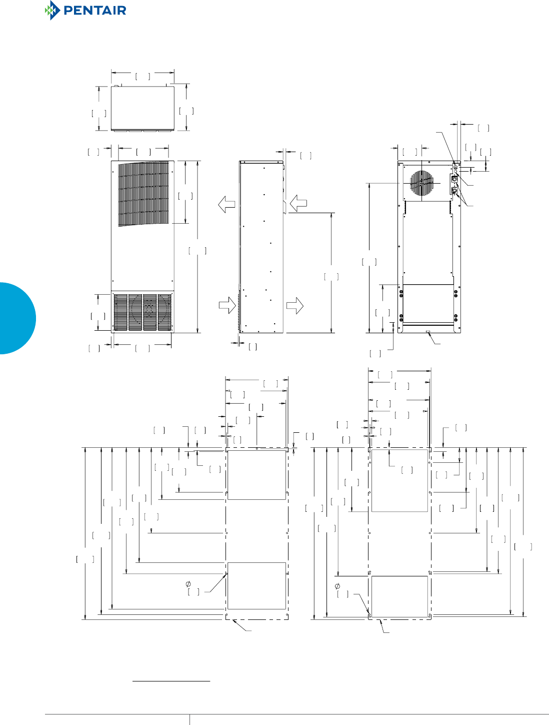
EQUIPMENT PROTECTIONSUBJECT TO CHANGE WITHOUT NOTICECOOLING98
3
SEALED ENCLOSURE COOLING AIR CONDITIONERS
$0%,(17
$,5287
$0%,(17
$,5,1
(1&/2685(
$,5,1
(1&/2685(
$,5287
;
32:(5&25'
7+(50267$7
$'-8670(17
$/$50:,5(6
'5$,1
/2&$7,21
;
;
;
;
;
;
;
;
;
;
;
;
;
;
;
;
;
;
;
;
;
;
;
;
;
$&287/,1( $&287/,1(
70RGHOV%78+5:DWW
&XWRXW'LPHQVLRQV
([WHUQDOO\0RXQWHG
&XWRXW'LPHQVLRQV
,QWHUQDOO\0RXQWHG
127(
02817,1**$6.(76833/,('1276+2:1
81,76LQ>PP@
Visit www
.HoffmanOnline.com to download 2D and 3D CAD drawings into the overall design of your electr
onic system.

PH 763.422.2211 • FAX 763.576.3200 • HOFFMANONLINE.COMEQUIPMENT PROTECTION COOLING 99
3
SEALED ENCLOSURE COOLING AIR CONDITIONERS
Performance Data T50 12000 BTU/Hr. (3516 Watt) Models
CATALOG NUMBER
Outdoor Model without Heat Pkg. T501226G100 T501246G400
Outdoor Model with Heat Pkg. T501226G150 —
Outdoor Model/SST/Corrosion/4X T501226G125 T501246G401
Outdoor Model/SST/Corrosion/4X/Heater T501226G156 —
COOLING PERFORMANCE
Nominal:
BTU/Hr. 11000/12000 11000/12000
Watts 3223/3516 3223/3516
At 131 F/131 F (55 C/55 C):
BTU/Hr. (50/60 Hz) 10030/12000 10030/12000
W (50/60 Hz) 2939/3516 2939/3516
At 95 F/95 F (35 C/35 C):
BTU/Hr. (50 /60 Hz) 9300/10050 9300/10050
W (50/60 Hz) 2725/2945 2725/2945
Refrigerant R-134A R-134A
Refrigerant Charge (ounces/grams) 46/1300 46/1300
Operating Temperature Range:
Maximum (°F/°C) 131/55 131/55
Minimum (°F/°C) -40/-40 -40/-40
Airflow at 0 Static Pressure:
Internal loop 50 Hz (CFM / m3/hr.) 300/510 300/510
External loop 50 Hz (CFM / m3/hr.) 520/883 520/883
Internal loop 60 Hz (CFM / m3/hr.) 368/626 368/626
External loop 60 Hz (CFM / m3/hr.) 625/1062 625/1062
Max. Heater W (Outdoor Models) 1500 1500
ELECTRICAL DATA
Rated Voltage 220/230 460V 1PH
Frequency (Hz) 50/60 50/60
Operating Range +/- 10% +/- 10%
Max. Power Consumption (W at 50/60 Hz) 1804/2139 2070/2346
Max. Nominal Current (A at 50/60 Hz) 8.2/9.3 4.5/5.1
Starting Current (A) 38 20
Agency Approvals cUL Listed
CE
GOST
cUR Recognized
CE
GOST
Power Input Description 6-ft. cord with NEMA 6-15 plug 6-ft. cord with wire leads
ENCLOSURE PROTECTION
UL Type Type 12, 3R, 4 standard
Type 4X Stainless steel optional
CONTROLLER
Description Basic mechanical thermostat
Thermostat Location Enclosure side on all base models
Factory Thermostat Setting (°F/°C) 80/27
SOUND LEVEL
At 1.5 Meters 68 dB(A)
UNIT CONSTRUCTION
Material Galvanized sheet metal standard
Stainless steel optional
Finish RAL 7035 light-gray, semi-textured powder-coat paint standard
UNIT DIMENSIONS
Height (in./mm) 50/1270
Width (in./mm) 19/483
Depth (in./mm) 11.05/281
Weight (lb./kg) 164/75
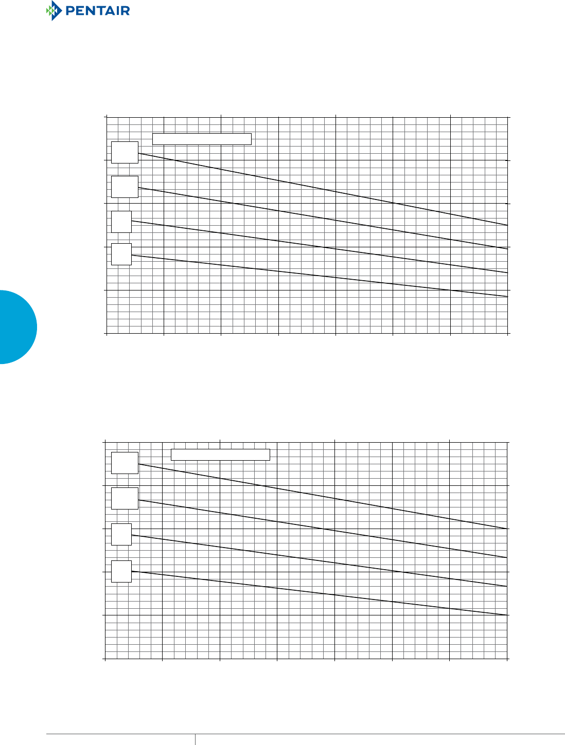
EQUIPMENT PROTECTIONSUBJECT TO CHANGE WITHOUT NOTICECOOLING100
3
SEALED ENCLOSURE COOLING AIR CONDITIONERS
Enclosure Air Temperature
25 C
77 F
35 C
95 F
45 C
113 F
55 C
131 F
3000
6000
9000
12000
15000
18000
68 77 86 95 104 113122 131
Ambient Air In (°F)
Cooling Capacity (BTU/Hr.)
879
1758
2637
3516
4395
5274
20 30 40 50
Ambient Air In (°C)
Cooling Capacity (W)
T50-12x6-GXXX Capacity Curves 60 Hz
Enclosure Air Temperature
25 C
77 F
35 C
95 F
45 C
113 F
55 C
131 F
3000
6000
9000
12000
15000
18000
68 77 86 95 104113 122 131
Ambient Air In (°F)
Cooling Capacity (BTU/Hr.)
879
1758
2637
3516
4395
5274
20 30 40 50
Ambient Air In (°C)
Cooling Capacity (W)
T50-12x6-GXXX Capacity Curves 50 Hz
Performance Curves for T50 Models 12000 BTU/Hr. (3516 Watt)
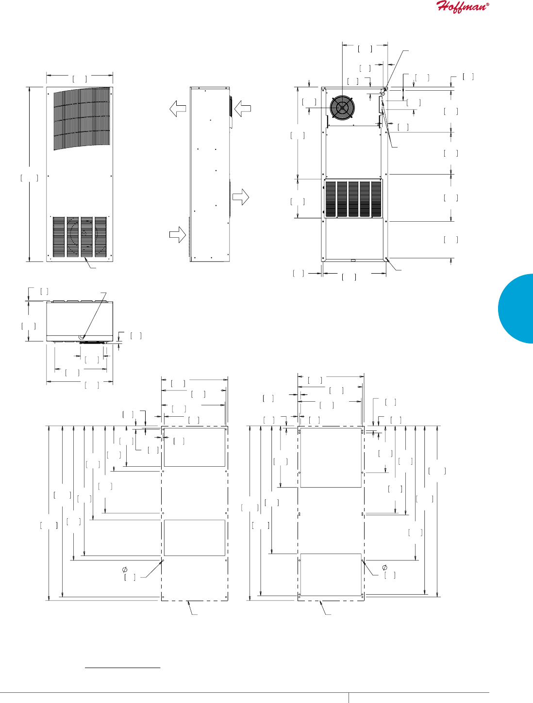
PH 763.422.2211 • FAX 763.576.3200 • HOFFMANONLINE.COMEQUIPMENT PROTECTION COOLING 101
3
SEALED ENCLOSURE COOLING AIR CONDITIONERS
&/($1$%/(5(86$%/(
$/80,180,1/(7),/7(5
%(+,1'5(029$%/(/289(56
(1&/2685(
$,5,1
(1&/2685(
$,5287
$0%,(17
$,5,1
'5$,1678%
;
;
;
;
;
;
;
32:(5&25'
(175$1&(
7+(50267$7
$'-8670(17
02817,1*+2/(6;
;
;
;
;
;
;
;
;
;
;
;
;
;
;
;
;
;
;
;
;
;
;
;
&XWRXW'LPHQVLRQV
([WHUQDOO\0RXQWHG
&XWRXW'LPHQVLRQV
,QWHUQDOO\0RXQWHG
$&287/,1( $&287/,1(
70RGHOV%78+U:DWW
$0%,(17
$,5287
127(
02817,1**$6.(76833/,('1276+2:1
81,76LQ>PP@
Visit www
.HoffmanOnline.com to download 2D and 3D CAD drawings into the overall design of your electr
onic system.
EQUIPMENT PROTECTIONSUBJECT TO CHANGE WITHOUT NOTICECOOLING102
3
SEALED ENCLOSURE COOLING AIR CONDITIONERS
Performance Data T53 19000 BTU/Hr. (5567 Watt) Models
CATALOG NUMBER
Outdoor Model without Heat Pkg. T531926G100 T531946G400
Outdoor Model with Heat Pkg. T531926G150 —
Outdoor Model/SST/Corrosion/4X T531926G109 —
Outdoor Model/SST/Corrosion/4X/Heater — —
COOLING PERFORMANCE
Nominal:
BTU/Hr. 16800/19000 16800/19000
Watts 4922/5567 4922/5567
At 131 F/131 F (55 C/55 C):
BTU/Hr. (50/60 Hz) 16854/19081 16854/19081
W (50/60 Hz) 4939/5592 4939/5592
At 95 F/95 F (35 C/35 C):
BTU/Hr. (50 /60 Hz) 15240/19815 15240/19815
W (50/60 Hz) 4466/5807 4466/5807
Refrigerant 410A 410A
Refrigerant Charge (ounces/grams) 40/1132 40/1132
Operating Temperature Range:
Maximum (°F/°C) 131/55 131/55
Minimum (°F/°C) -40/-40 -40/-40
Airflow at 0 Static Pressure:
Internal loop 50 Hz (CFM / m3/hr.) 449/763 449/763
External loop 50 Hz (CFM / m3/hr.) 1204/2046 1204/2046
Internal loop 60 Hz (CFM / m3/hr.) 519/882 519/882
External loop 60 Hz (CFM / m3/hr.) 1300/2209 1300/2209
Max. Heater W (Outdoor Models) 3000
ELECTRICAL DATA
Rated Voltage 230 460V 1PH
Frequency (Hz) 50/60 50/60
Operating Range +/- 10% +/- 10%
Max. Power Consumption (W at 50/60 Hz) 3979/4669 4370/5152
Max. Nominal Current (A at 50/60 Hz) 17.3/20.3 9.5/11.2
Starting Current (A) 54 28
Agency Approvals cUL Listed
CE
GOST
cUR Recognized
CE
GOST
Power Input Description Terminal block
ENCLOSURE PROTECTION
UL Type Type 12, 3R, 4 standard
Type 4X Stainless steel optional
CONTROLLER
Description Basic mechanical thermostat
Thermostat Location Enclosure side on all base models
Factory Thermostat Setting (°F/°C) 80/27
SOUND LEVEL
At 1.5 Meters 76 dB(A)
UNIT CONSTRUCTION
Material Galvanized sheet metal standard
Stainless steel optional
Finish RAL 7035 light-gray, semi-textured powder-coat paint standard
UNIT DIMENSIONS
Height (in./mm) 53.0/1346.2
Width (in./mm) 21.0/533.4
Depth (in./mm) 13.0/330.2
Weight (lb./kg) 197/90 237/108
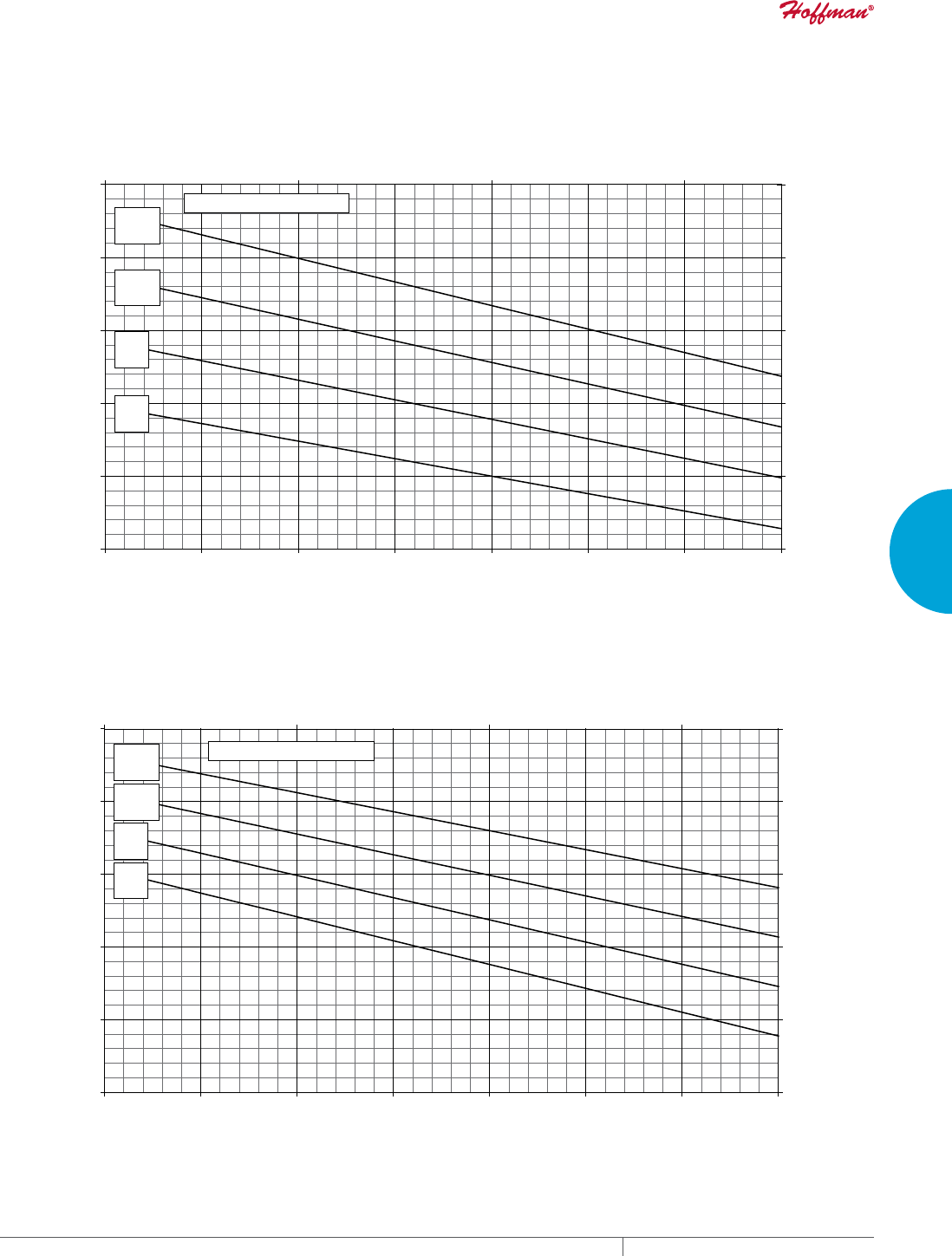
PH 763.422.2211 • FAX 763.576.3200 • HOFFMANONLINE.COMEQUIPMENT PROTECTION COOLING 103
3
SEALED ENCLOSURE COOLING AIR CONDITIONERS
Enclosure Air Temperature
25 C
77 F
35 C
95 F
45 C
113 F
55 C
131 F
5000
10000
15000
20000
25000
30000
68 77 86 95 104 113 122 131
Ambient Air In (°F)
Cooling Capacity (BTU/Hr.)
1465
2930
4395
5860
7325
8790
20 30 40 50
Ambient Air In (°C)
Cooling Capacity (W)
T53-19x6-GXXX Capacity Curve 60 Hz
Enclosure Air Temperature
25 C
77 F
35 C
95 F
45 C
113 F
55 C
131 F
5000
10000
15000
20000
25000
30000
68 77 86 95 104 113 122 131
Ambient Air In (°F)
Cooling Capacity (BTU/Hr.)
1465
2930
4395
5860
7325
8790
20 30 40 50
Ambient Air In (°C)
Cooling Capacity (W)
T53-19x6-GXXX Capacity Curve 50 Hz
Performance Curves for T53 Models 19000 BTU/Hr. (5567 Watt)
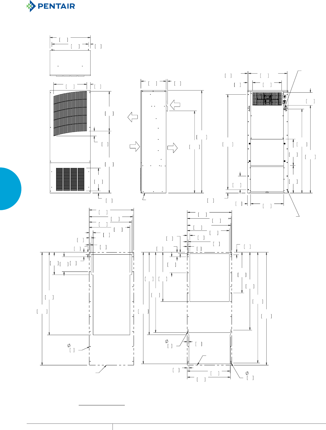
EQUIPMENT PROTECTIONSUBJECT TO CHANGE WITHOUT NOTICECOOLING104
3
SEALED ENCLOSURE COOLING AIR CONDITIONERS
$0%,(17
$,5287
$0%,(17
$,5,1
(1&/2685(
$,5287
(1&/2685(
$,5,1
'5$,1
23(1,1*
;
;
;
;
;
32:(5
&25'
,1/(7
02817,1*
+$5':$5(;
;
;
;
;
;
;
;
;
;
;
;
$&287/,1(
&XWRXW'LPHQVLRQV
([WHUQDOO\0RXQWHG
&XWRXW'LPHQVLRQV
,QWHUQDOO\0RXQWHG
$&287/,1(
70RGHOV%78+U:DWW
127(
02817,1**$6.(76833/,('1276+2:1
81,76LQ>PP@
Visit www
.HoffmanOnline.com to download 2D and 3D CAD drawings into the overall design of your electr
onic system.

PH 763.422.2211 • FAX 763.576.3200 • HOFFMANONLINE.COMEQUIPMENT PROTECTION COOLING 105
3
SEALED ENCLOSURE COOLING AIR CONDITIONERS
Notes
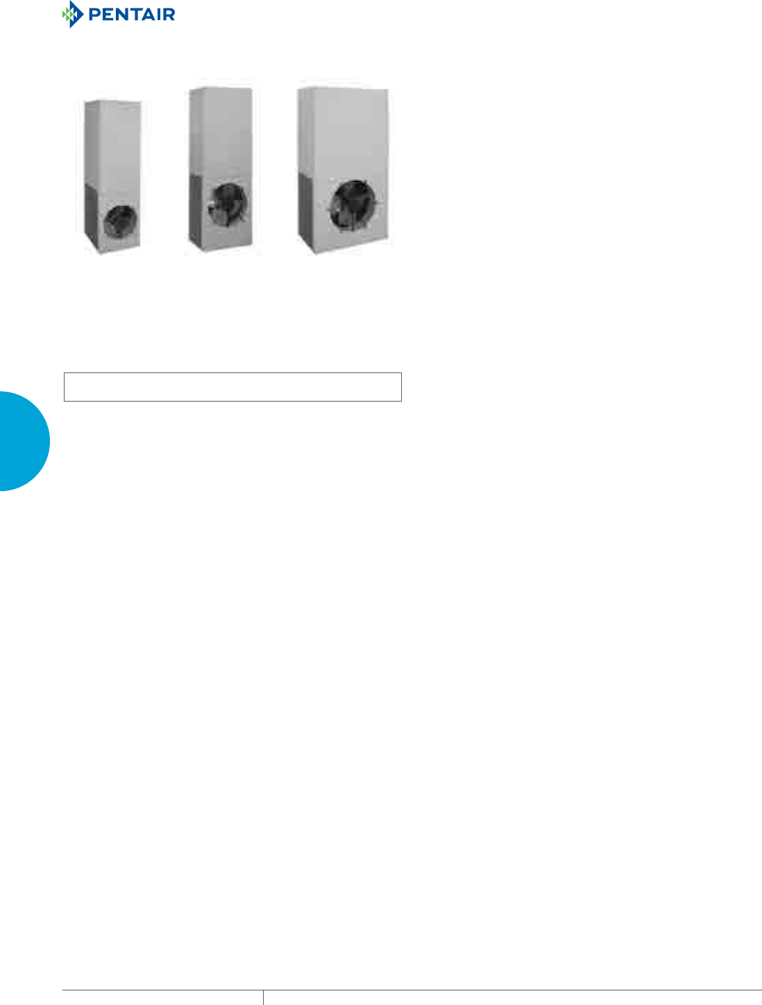
EQUIPMENT PROTECTIONSUBJECT TO CHANGE WITHOUT NOTICECOOLING106
3
SEALED ENCLOSURE COOLING AIR CONDITIONERS
TSERIES LARGE CAPACITY OUTDOOR
T62
20000 BTU/Hr.
5860 Watts
T70-36
36000 BTU/Hr.
10548 Watts
T70-60
59000 BTU/Hr.
17287 Watts
INDUSTRY STANDARDS
UL/cUL Listed; Type 12, 3R, 4; 4X optional; File No. SA6453
UR/cUR Recognized
UR/cUR Recognized on select models, reference performance data
tables.
CE
GOST
Telcordia GR-487 capable
APPLICATION
• Industrial automation
• Telecommunications equipment
• Package handling equipment
• Security and defense systems
• And more
FEATURES
• Stock models equipped with head pressure control for low-
ambient operation, compressor heater, coated condenser coil,
malfunction switch, thermostat and heater package
• R-407C earth-friendly refrigerant
• Models for 230 and 460 VAC power input
• UL Listed to save customers time and money with agency
approvals (some models UL recognized)
• Outdoor model operating temperature range from -40 F/-40 C to
131 F/55 C
• Exterior and fully recessed mounting options on many models
• Compact footprint to minimize real estate and maximize capacity
• Reliable mechanical thermostat on enclosure side of the unit
• Dual condenser-side air movers for performance redundancy
• Painted galvanized sheet-metal cover for rugged factory and
outdoor environments
• Easy-mount flanges for simple installation
• Cleanable, reusable aluminum mesh filter protects coils for
maximum cooling performance
• Mounting hardware, gaskets and user manual furnished with the
unit
• Every unit functionally tested before shipping
• Standard Outdoor Air Conditioner models also include:
- Telcordia GR-487 capable
- Thermostat
- Corrosion-resistant components
- Malfunction switch
- Compressor heater
- Head pressure control
- Enclosure heater
FINISH
• RAL 7035 light-gray, semi-textured powder-coat paint
• Other colors and textures available
OPTIONS
• Thermostat Malfunction Package
• Special Voltage Package
• Outdoor Package
• Harsh Environment Package*
• Stainless Steel Package*
• Heater Package
* PROAIR A/C may be more appropriate. Refer to PROAIR
A/C Chapter. Consult the Factory for availability and catalog
number.
NOTES
Visit www.HoffmanOnline.com to download 2D and 3D CAD
drawings into the overall design of your electronic system.
PH 763.422.2211 • FAX 763.576.3200 • HOFFMANONLINE.COMEQUIPMENT PROTECTION COOLING 107
3
SEALED ENCLOSURE COOLING AIR CONDITIONERS
Performance Data T62 20000 BTU/Hr. (5860 Watt) Models
CATALOG NUMBER
T622226G150 T622246G400
COOLING PERFORMANCE
Nominal:
BTU/Hr. 20500/23500 20500/23500
Watts 6007/6886 6007/6886
At 131 F/131 F (55 C/55 C):
BTU/Hr. (50/60 Hz) 20860/23927 20860/23927
W (50/60 Hz) 6113/7012 6113/7012
At 95 F/95 F (35 C/35 C):
BTU/Hr. (50 /60 Hz) 18258/20256 18258/20256
W (50/60 Hz) 5351/5936 5351/5936
Refrigerant R-407C
Refrigerant Charge (ounces/grams) 42/1300 42/1300
Operating Temperature Range:
Maximum (°F/°C) 131/55 131/55
Minimum (°F/°C) -40/-40 -40/-40
Airflow at 0 Static Pressure:
Internal loop 50 Hz (CFM / m3/hr.) 570/968 570/968
External loop 50 Hz (CFM / m3/hr.) 1443/2452 1443/2452
Internal loop 60 Hz (CFM / m3/hr.) 673/1143 673/1143
External loop 60 Hz (CFM / m3/hr.) 1797/3053 1797/3053
Max. Heater W (Outdoor Models) 2000 Up to 3000 (Optional)
ELECTRICAL DATA
Rated Voltage 230 460V 1PH
Frequency (Hz) 50/60 50/60
Operating Range +/- 10% +/- 10%
Max. Power Consumption (W at 50/60 Hz) 4370/5060 7000/9200
Max. Nominal Current (A at 50/60 Hz) 19/22 10.5/12
Starting Current (A) 60 30
Agency Approvals cUL Listed
CE
GOST
cUR Recognized
CE
GOST
Power Input Description Terminal block Terminal block
ENCLOSURE PROTECTION
UL Type Type 12, 3R, 4 standard
Type 4X Stainless steel optional
CONTROLLER
Description Basic mechanical thermostat
Thermostat Location Enclosure ide on all base models
Factory Thermostat Setting (°F/°C) 80/27
SOUND LEVEL
At 1.5 Meters 71 dB(A)
UNIT CONSTRUCTION
Material Galvanized sheet metal standard
Stainless steel optional
Finish RAL 7035 light-gray, semi-textured powder-coat paint standard
UNIT DIMENSIONS
Height (in./mm) 61.77/1568.96 61.77/1568.96
Width (in./mm) 19.91/505.71 19.91/505.71
Depth (in./mm) 17.36/440.94 17.36/440.94
Weight (lb./kg) 218/99.1 258/117

EQUIPMENT PROTECTIONSUBJECT TO CHANGE WITHOUT NOTICECOOLING108
3
SEALED ENCLOSURE COOLING AIR CONDITIONERS
Enclosure Air Temperature
25 C
77 F
35 C
95 F
45 C
113 F
55 C
131 F
0
10000
20000
30000
40000
68 77 86 95 104 113 122 131
Ambient Air In (°F)
Cooling Capacity (BTU/Hr.)
0
2931
5862
8793
20 30 40 50
Ambient Air In (°C)
Cooling Capacity (W)
T62-22x6-GXXX R-407c Capacity Curves 60 Hz
Enclosure Air Temperature
25 C
77 F
35 C
95 F
45 C
113 F
55 C
131 F
0
10000
20000
30000
40000
68 77 86 95 104 113 122 131
Ambient Air In (°F)
Cooling Capacity (BTU/Hr.)
0
2931
5862
8793
20 30 40 50
Ambient Air In (°C)
Cooling Capacity (W)
T62-22x6-GXXX R-407c Capacity Curves 50 Hz
Performance Curves for T62 Models 20000 BTU/Hr. (5860 Watt)
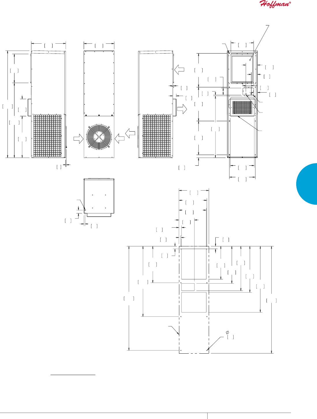
PH 763.422.2211 • FAX 763.576.3200 • HOFFMANONLINE.COMEQUIPMENT PROTECTION COOLING 109
3
SEALED ENCLOSURE COOLING AIR CONDITIONERS
$0%,(17
$,5,1
$0%,(17
$,5,1
$0%,(17
$,5287
(1&/2685(
$,5287
(1&/2685(
$,5,1
&21'(16$7(
'5$,1
;
;
;
;
02817,1*;
&/($1$%/(5(86$%/(
$/80,180,1/(7),/7(5
237,21$/
-81&7,21
%2;
/,1(92/7$*(
(/(&75,&$/
(175$1&(
$'-867$%/(
$,5',9(57(5
237,21$/
;
;
;
;
;
;
;
;
;
$&287/,1(
70RGHOV%78+U:DWW
&XWRXW'LPHQVLRQV
127(
02817,1**$6.(76833/,('1276+2:1
81,76LQ>PP@
Visit www
.HoffmanOnline.com to download 2D and 3D CAD drawings into the overall design of your electr
onic system.
EQUIPMENT PROTECTIONSUBJECT TO CHANGE WITHOUT NOTICECOOLING110
3
SEALED ENCLOSURE COOLING AIR CONDITIONERS
Performance Data T70-36 36000 BTU/Hr. (10548 Watt) Models
CATALOG NUMBER
T703626G150 T703646G400
COOLING PERFORMANCE
Nominal:
BTU/Hr. 39000/43000
Watts 11430/12602
At 131 F/131 F (55 C/55 C):
BTU/Hr. (50/60 Hz) 38613/42930
W (50/60 Hz) 11316/12570
At 95 F/95 F (35 C/35 C):
BTU/Hr. (50 /60 Hz) 31364/36130
W (50/60 Hz) 9192/10579
Refrigerant R-407C
Refrigerant Charge (ounces/grams) 110/3118
Operating Temperature Range:
Maximum (°F/°C) 131/55
Minimum (°F/°C)Minimum (°F/°C) -40/-40
Airflow at 0 Static Pressure:
Internal loop 50 Hz (CFM / m3/hr.) 1085/1843
External loop 50 Hz (CFM / m3/hr.) 2176/3697
Internal loop 60 Hz (CFM / m3/hr.) 1171/1989
External loop 60 Hz (CFM / m3/hr.) 2347/3987
Max. Heater W (Outdoor Models) 2000 Standard (5000 Optional)
ELECTRICAL DATA
Rated Voltage 230 460
Frequency (Hz) 50/60 60
Operating Range +/- 10% +/- 10%
Max. Power Consumption (W at 50/60 Hz) 8280 8280
Max. Nominal Current (A at 50/60 Hz) 36 18
Starting Current (A) 104 52
Agency Approvals cUL Listed
CE
GOST
Others available upon request
Power Input Description Terminal block
ENCLOSURE PROTECTION
UL Type Type 12, 3R, 4 standard
Type 4X Stainless steel optional
International Rating UL/cUL Listed
CONTROLLER
Description Basic mechanical thermostat
Thermostat Location Enclosure side on all base models
Factory Thermostat Setting (°F/°C) 80/27
SOUND LEVEL
At 1.5 Meters 66 dB(A)
UNIT CONSTRUCTION
Material Galvanized sheet metal standard
Stainless steel optional
Finish RAL 7035 light-gray, semi-textured powder-coat paint standard
UNIT DIMENSIONS
Height (in./mm) 69.8/1772
Width (in./mm) 22.8/578
Depth (in./mm) 20.94/532
Weight (lb./kg) 260/118

PH 763.422.2211 • FAX 763.576.3200 • HOFFMANONLINE.COMEQUIPMENT PROTECTION COOLING 111
3
SEALED ENCLOSURE COOLING AIR CONDITIONERS
Enclosure Air Temperature
25 C
77 F
35 C
95 F
45 C
113 F
55 C
131 F
10000
20000
30000
40000
50000
60000
68 77 86 95 104 113 122 131
Ambient Air In (°F)
Cooling Capacity (BTU/Hr.)
2931
5862
8793
11724
14655
20 30 40 50
Ambient Air In (°C)
Cooling Capacity (W)
T70-36X6-GXXX R-407c Capacity Curves 60 Hz
Enclosure Air Temperature
25 C
77 F
35 C
95 F
45 C
113 F
55 C
131 F
10000
20000
30000
40000
50000
60000
68 77 86 95 104 113 122 131
Ambient Air In (°F)
Cooling Capacity (BTU/Hr.)
2931
5862
8793
11724
14655
20 30 40 50
Ambient Air In (°C)
Cooling Capacity (W)
T70-36X6-GXXX R-407c Capacity Curves 50 Hz
Performance Curves for T70 Models 36000 BTU/Hr. (10548 Watt)
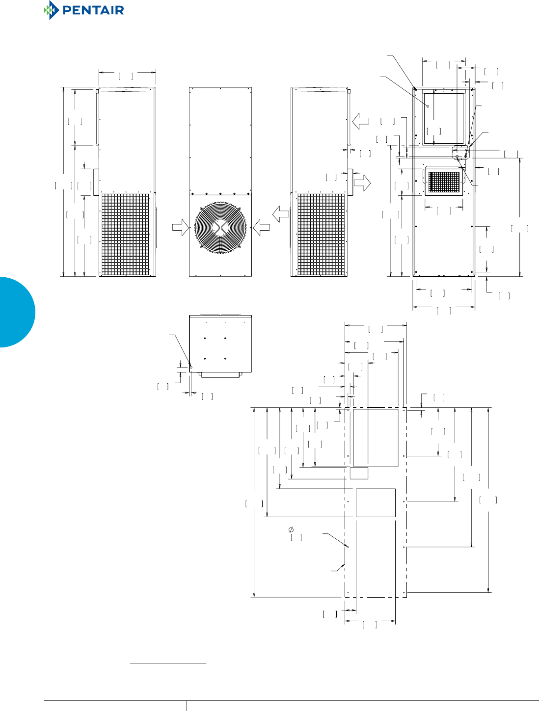
EQUIPMENT PROTECTIONSUBJECT TO CHANGE WITHOUT NOTICECOOLING112
3
SEALED ENCLOSURE COOLING AIR CONDITIONERS
$0%,(17
$,5,1
$0%,(17
$,5,1
$0%,(17
$,5287
(1&/2685(
$,5287
(1&/2685(
$,5,1
&21'(16$7(
'5$,1
;
;
;
&/($1$%/(5(86$%/(
$/80,180$,5),/7(5
02817,1*;
-81&7,21
%2;
/,1(
92/7$*(
(/(&75,&$/
(175$1&(
/2:92/7$*(
(/(&75,&$/
(175$1&(
;
;
;
;
;
;
;
;
;
$&287/,1(
&XWRXW'LPHQVLRQV
70RGHOV%78+U:DWW
127(
02817,1**$6.(76833/,('1276+2:1
81,76LQ>PP@
Visit www
.HoffmanOnline.com to download 2D and 3D CAD drawings into the overall design of your electr
onic system.
PH 763.422.2211 • FAX 763.576.3200 • HOFFMANONLINE.COMEQUIPMENT PROTECTION COOLING 113
3
SEALED ENCLOSURE COOLING AIR CONDITIONERS
Performance Data T70-60 59000 BTU/Hr. (17287 Watt) Models
CATALOG NUMBER
T706026G150 T706046G400
COOLING PERFORMANCE
Nominal:
BTU/Hr. 51900/60000
Watts 15210/17584
At 122 F/122 F (50 C/50 C):
BTU/Hr. (50/60 Hz) 51900/60000
W (50/60 Hz) 15210/17584
At 95 F/95 F (35 C/35 C):
BTU/Hr. (50 /60 Hz) 47122/54500
W (50/60 Hz) 13810/15972
Refrigerant R-407C
Refrigerant Charge (ounces/grams) 150/4252
Operating Temperature Range:
Maximum (°F/°C) 122/50
Minimum (°F/°C) -40/-40
Airflow at 0 Static Pressure:
Internal loop 50 Hz (CFM / m3/hr.) 1510/2565
External loop 50 Hz (CFM / m3/hr.) 2716/4614
Internal loop 60 Hz (CFM / m3/hr.) 1629/2767
External loop 60 Hz (CFM / m3/hr.) 2931/4979
Max. Heater W (Outdoor Models)
ELECTRICAL DATA
Rated Voltage 200/230 420/460
Frequency (Hz) 50/60 50/60
Operating Range +/- 10% +/- 10%
Max. Power Consumption (W at 50/60 Hz) 7000/9200 6426/7038
Max. Nominal Current (A at 50/60 Hz) 35/40 15.3
Starting Current (A) 144 144
Agency Approvals cUL Listed
CE
GOST
Others available upon request
Power Input Description Terminal block
ENCLOSURE PROTECTION
UL Type Type 12, 3R, 4 standard
Type 4X Stainless steel optional
International Rating IP56 on the internal loop; IP34 on the external loop
Description Basic mechanical thermostat
CONTROLLER
Thermostat Location Enclosure side on all base models
Factory Thermostat Setting (°F/°C) 80/27
SOUND LEVEL
At 1.5 Meters 66 dB(A)
UNIT CONSTRUCTION
Material Galvanized sheet metal standard
Stainless steel optional
Finish RAL 7035 light-gray, semi-textured powder-coat paint standard
UNIT DIMENSIONS
Height (in./mm) 69.77/1772
Width (in./mm) 35.86/911
Depth (in./mm) 22.94/583
Weight (lb./kg) 419/190.5
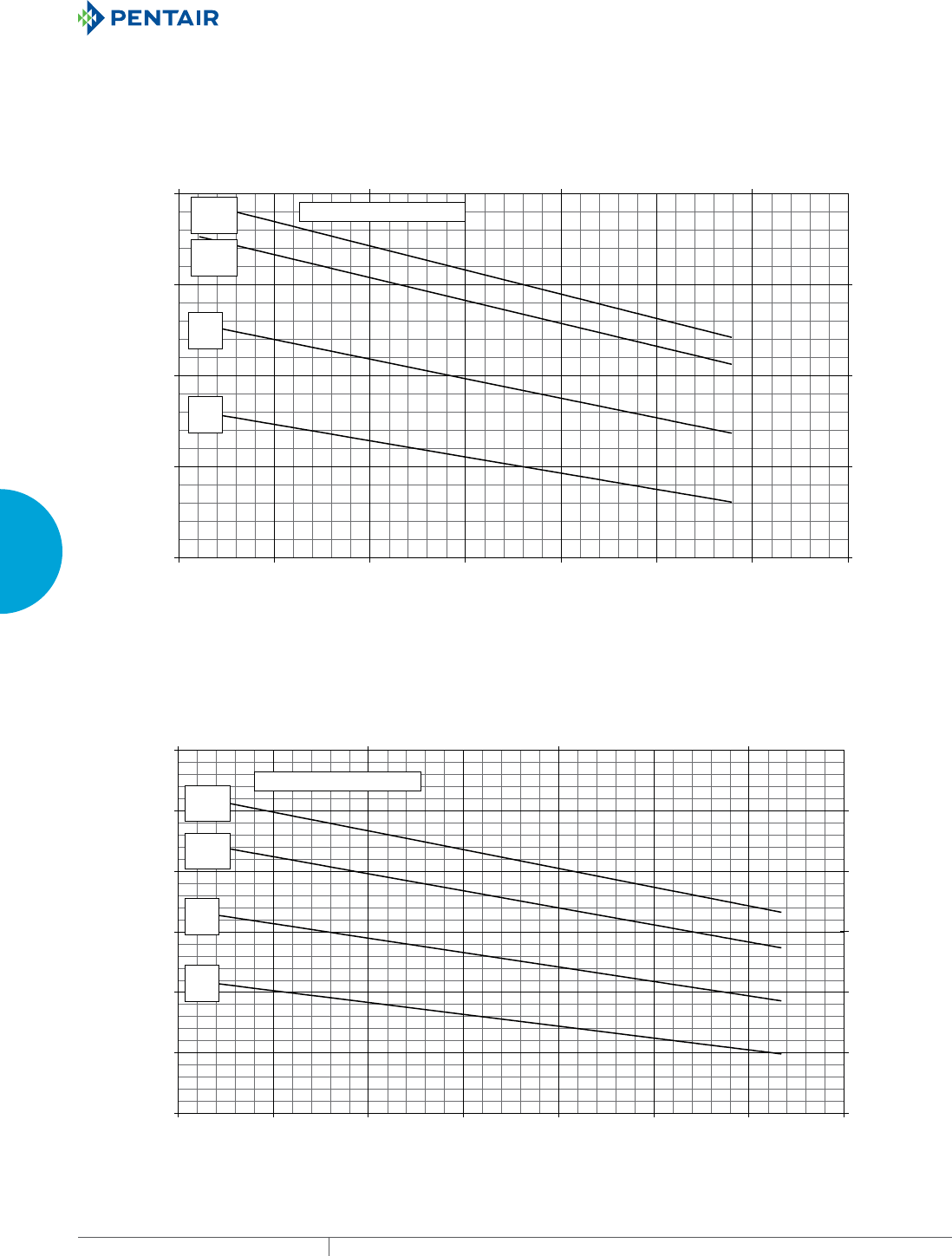
EQUIPMENT PROTECTIONSUBJECT TO CHANGE WITHOUT NOTICECOOLING114
3
SEALED ENCLOSURE COOLING AIR CONDITIONERS
Enclosure Air Temperature
25 C
77 F
35 C
95 F
45 C
113 F
55 C
131 F
25000
35000
45000
55000
65000
75000
85000
68 77 86 95 104113 122 131
Ambient Air In (°F)
Cooling Capacity (BTU/Hr.)
7327
10258
13189
16120
19051
21982
20 30 40 50
Ambient Air In (°C)
Cooling Capacity (W)
T70-60X6-GXXX R-407c Capacity Curves 60 Hz
Enclosure Air Temperature
25 C
77 F
35 C
95 F
45 C
113 F
55 C
131 F
25000
35000
45000
55000
65000
68 77 86 95 104 113122 131
Ambient Air In (°F)
Cooling Capacity (BTU/Hr.)
7327
10258
13189
16120
20 30 40 50
Ambient Air In (°C)
Cooling Capacity (W)
T70-60X6-GXXX R-407c Capacity Curves 50 Hz
Performance Curves for T70 Models 59000 BTU/Hr. (17287 Watt)
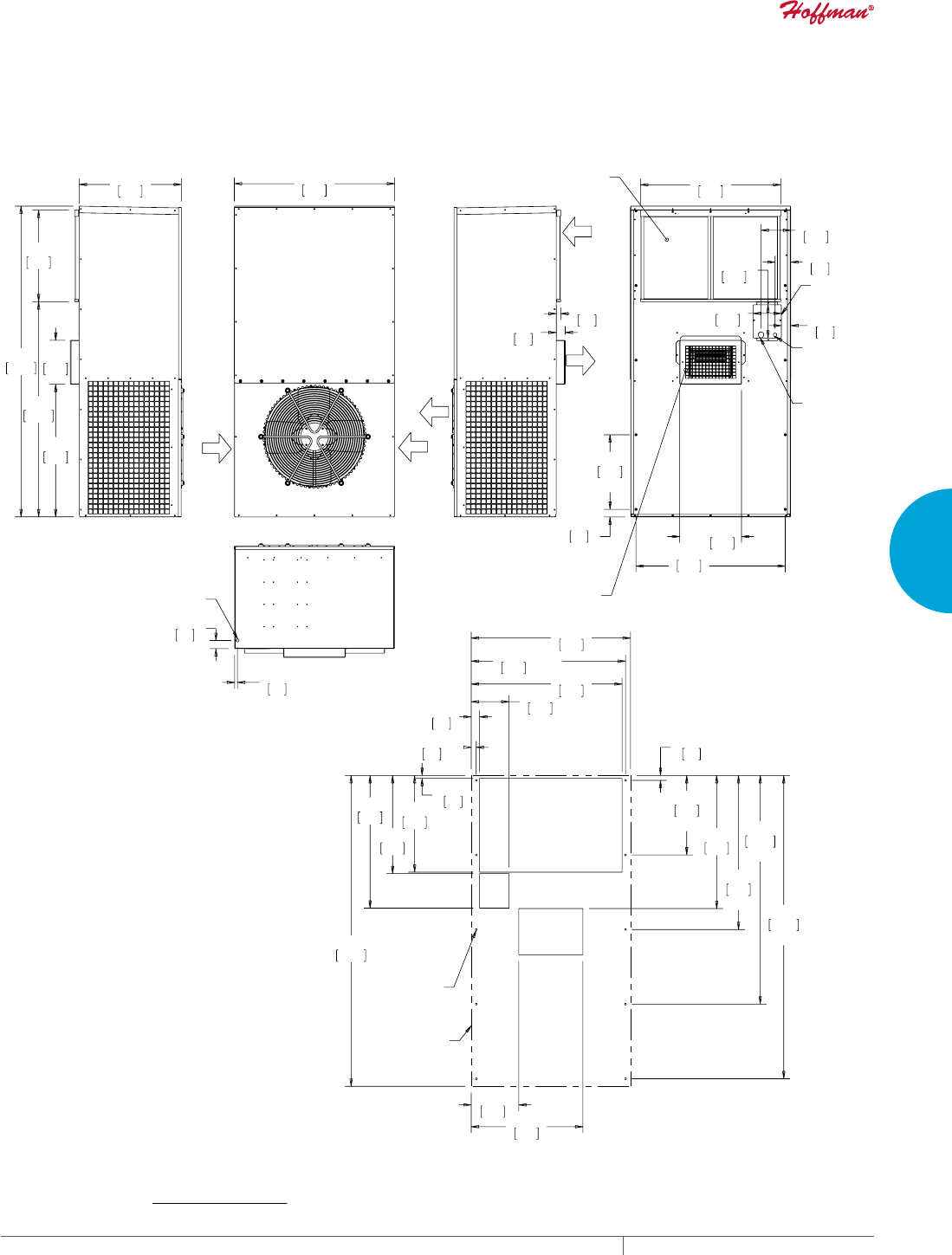
PH 763.422.2211 • FAX 763.576.3200 • HOFFMANONLINE.COMEQUIPMENT PROTECTION COOLING 115
3
SEALED ENCLOSURE COOLING AIR CONDITIONERS
$0%,(17
$,5,1
$0%,(17
$,5,1
(1&/2685(
$,5287
(1&/2685(
$,5,1
$0%,(17
$,5287
&21'(16$7(
'5$,1
;
;
;
$'-867$%/(
$,5
',9(57(5
/,1(
92/7$*(
(/(&75,&$/
(175$1&(
-81&7,21
%2;
&/($1$%/(5(86$%/(
$/80,180$,5),/7(5
/2:
92/7$*(
(/(&75,&$/
(175$1&(
;
;
;
;
;
;
;
&XWRXW'LPHQVLRQV
02817,1*
;
$&287/,1(
70RGHOV%78+U:DWW
127(
02817,1**$6.(76833/,('1276+2:1
81,76LQ>PP@
Visit www
.HoffmanOnline.com to download 2D and 3D CAD drawings into the overall design of your electr
onic system.
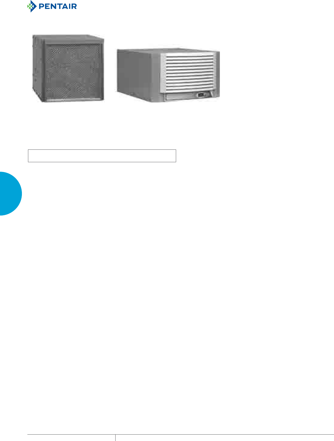
EQUIPMENT PROTECTIONSUBJECT TO CHANGE WITHOUT NOTICECOOLING116
3
SEALED ENCLOSURE COOLING AIR CONDITIONERS
GENESIS™ TOPMOUNT INDOOR
HB16
8000 BTU/Hr.
2051 Watt
MHB11
2200-4000 BTU/Hr.
645-1172 Watt
INDUSTRY STANDARDS
UL/cUL Listed; Type 12; File No. SA6453
UR/cUR Recognized
Maintains U/cUL Type 12 rating when properly installed on a UL/cUL
Type 12 enclosure.
UR/cUR Recognized on select models, reference performance data
tables.
CE
GOST
APPLICATION
• Industrial automation
• Package handling equipment
• Security and defense systems
• Ideal for use where there is little or no clearance around the
enclosure
FEATURES
• Robust reciprocating compressor
• R134a and R407c earth-friendly refrigerant
• Models for 115, 230 and 460 single-phase VAC power input
• UL Listed or Recognized to save customers time and money with
agency approvals
• Operating temperature range from 50 F/10 C to 125 F/52 C
• Attractive industrial design with minimal use of visible fasteners
• Reliable mechanical thermostat located behind the filter of the
unit
• Low-carbon mild-steel sheet-metal cover for rugged factory
environments
• Cleanable, reusable aluminum mesh filter protects coils for
maximum cooling performance
• Mounting hardware, gaskets and user manual furnished with the
unit
• Every unit functionally tested before shipping
• Standard Indoor Air Conditioner models also include:
- Electro-Mechanical Thermostat
- Surge Suppressor
- Condensate Management System On MHB11 models
FINISH
• RAL 7042 gray, semi-gloss powder-coat paint standard
• Other colors and textures available
OPTIONS
• Thermostat Malfunction Package
• Special Voltage Package
* Consult the factory for availability and catalog number
NOTES
Visit www.HoffmanOnline.com to download 2D and 3D CAD
drawings into the overall design of your electronic system.

PH 763.422.2211 • FAX 763.576.3200 • HOFFMANONLINE.COMEQUIPMENT PROTECTION COOLING 117
3
SEALED ENCLOSURE COOLING AIR CONDITIONERS
Performance DataMHB11 Models 2200 BTU/Hr. (645 Watt)
CATALOG NUMBER
MHB110216G306 MHB110226G306 MHB110246G400
COOLING PERFORMANCE
Nominal:
BTU/Hr. 2200/2200 2200/2200 2200/2200
Watts 645/645 645/645 645/645
Refrigerant R-134A R-134A R-134A
Refrigerant Charge (ounces/grams) 11/312 11/312 11/312
Operating Temperature Range:
Maximum (°F/°C) 125/52 125/52 125/52
Minimum (°F/°C) 50/10 50/10 50/10
Airflow at 0 Static Pressure:
Internal loop 50 Hz (CFM / m3/hr.) 158/268 170/289 170/289
External loop 50 Hz (CFM / m3/hr.) 222/377 218/370 218/370
Internal loop 60 Hz (CFM / m3/hr.) 177/301 192/326 192/326
External loop 60 Hz (CFM / m3/hr.) 252/428 245/416 245/416
ELECTRICAL DATA
Rated Voltage 115 220/230 440/460V 1PH
Frequency (Hz) 50/60 50/60 50/60
Operating Range +/- 10% +/- 10% +/- 10%
Max. Power Consumption (W at 50/60 Hz) 1127/1035 1210/1058 1320/1150
Max. Nominal Current (A at 50/60 Hz) 9.8/9.0 5.5/4.6 3.0/2.5
Starting Current (A) 28 14.4 7.4
Agency Approvals cUL Listed
CE
GOST
Others available upon request
cUR Recognized
CE
GOST
Power Input Description 6-ft. cord with NEMA 5-15 plug 6-ft. cord with NEMA 6-15 plug 6-ft. cord with wire leads
ENCLOSURE PROTECTION
UL Type Type 12 standard
CONTROLLER
Description Basic mechanical thermostat
Thermostat Location Behind filter
Factory Thermostat Setting (°F/°C) 80/27
SOUND LEVEL
At 1.5 Meters 62 dB(A)
UNIT CONSTRUCTION
Material Mild steel sheet metal standard
Stainless steel optional
Finish RAL 7042 gray, semi-gloss powder-coat paint standard
UNIT DIMENSIONS
Height (in./mm) 10.25/260 10.25/260 10.25/260
Width (in./mm) 17/432 17/432 17/432
Depth (in./mm) 21.08/535 21.08/535 21.08/535
Weight (lb./kg) 90/41 90/41 110/50
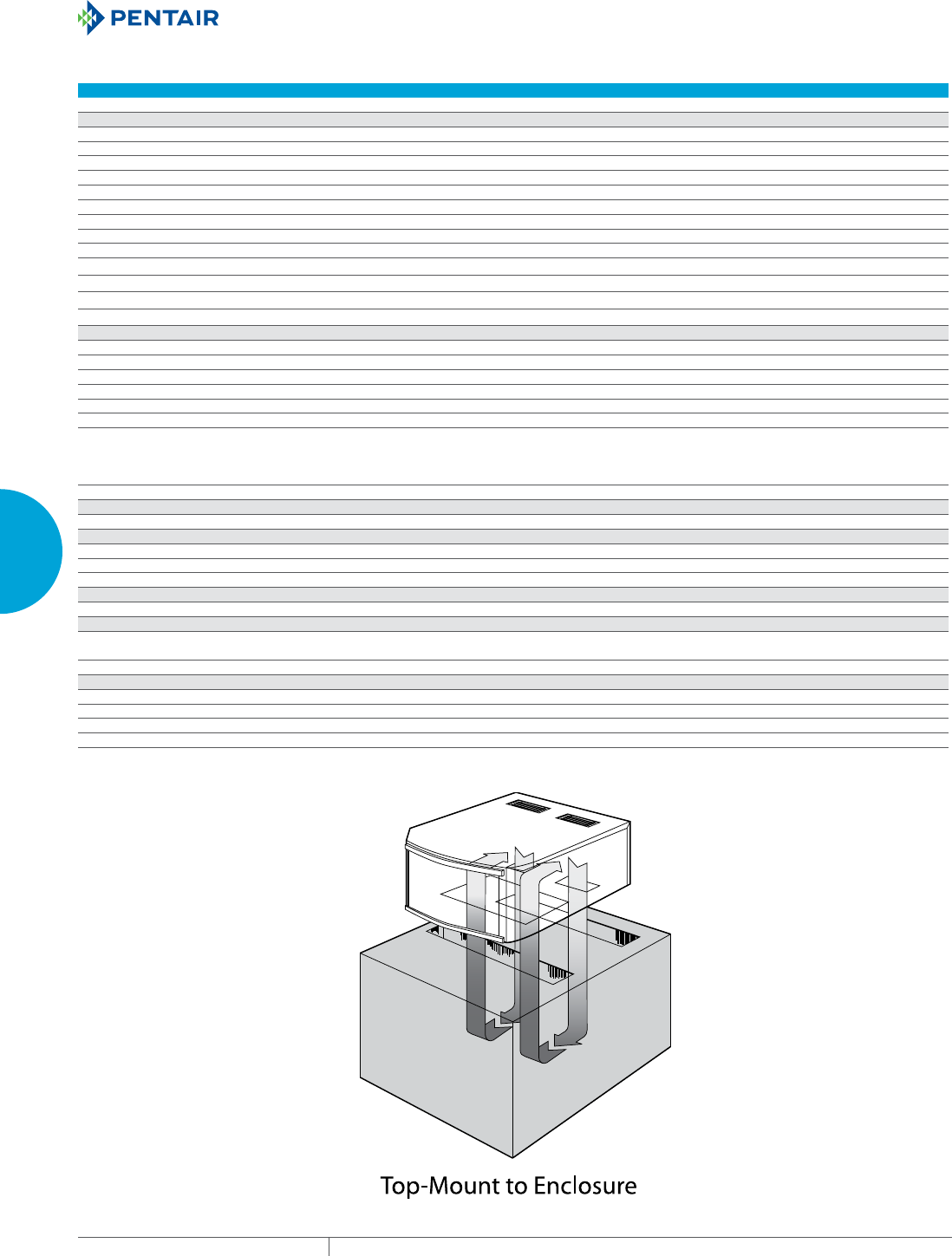
EQUIPMENT PROTECTIONSUBJECT TO CHANGE WITHOUT NOTICECOOLING118
3
SEALED ENCLOSURE COOLING AIR CONDITIONERS
Performance DataMHB11 Models 4000 BTU/Hr. (1172 Watt)
CATALOG NUMBER
MHB110416G307 MHB110426G306 MHB110446G400
COOLING PERFORMANCE
Nominal:
BTU/Hr. 3300/4000 3300/4000 3300/4000
Watts 967/1172 967/1172 967/1172
Refrigerant R-134A R-134A R-134A
Refrigerant Charge (ounces/grams) 13/369 13/369 13/369
Operating Temperature Range:
Maximum (°F/°C) 125/52 125/52 125/52
Minimum (°F/°C) 50/10 50/10 50/10
Airflow at 0 Static Pressure:
Internal loop 50 Hz (CFM / m3/hr.) 158/268 170/289 170/289
External loop 50 Hz (CFM / m3/hr.) 222/377 218/370 218/370
Internal loop 60 Hz (CFM / m3/hr.) 177/301 192/326 192/326
External loop 60 Hz (CFM / m3/hr.) 252/428 245/416 245/416
ELECTRICAL DATA
Rated Voltage 110/115 220/230 440/460V 1PH
Frequency (Hz) 50/60 50/60 50/60
Operating Range +/- 10% +/- 10% +/- 10%
Max. Power Consumption (W at 50/60 Hz) 1617/1564 1760/1725 1936/1886
Max. Nominal Current (A at 50/60 Hz) 14.7/13.6 8.0/7.5 4.4/4.1
Starting Current (A) 48 23 12
Agency Approvals cUL Listed
CE
GOST
Others available upon request
cUR Recognized
CE
GOST
Power Input Description 6-ft. cord with NEMA 5-20 plug 6-ft. cord with NEMA 6-15 plug 6-ft. cord with wire leads
ENCLOSURE PROTECTION
UL Type Type 12 standard
CONTROLLER
Description Basic mechanical thermostat
Thermostat Location Behind filter
Factory Thermostat Setting (°F/°C) 80/27
SOUND LEVEL
At 1.5 Meters 62 dB(A)
UNIT CONSTRUCTION
Material Mild steel sheet metal standard
Stainless steel optional
Finish RAL 7042 gray, semi-gloss powder-coat paint standard
UNIT DIMENSIONS
Height (in./mm) 10.25/260 10.25/260 10.25/260
Width (in./mm) 17/432 17/432 17/432
Depth (in./mm) 21.08/535 21.08/535 21.08/535
Weight (lb./kg) 108/49 108/49 128/58
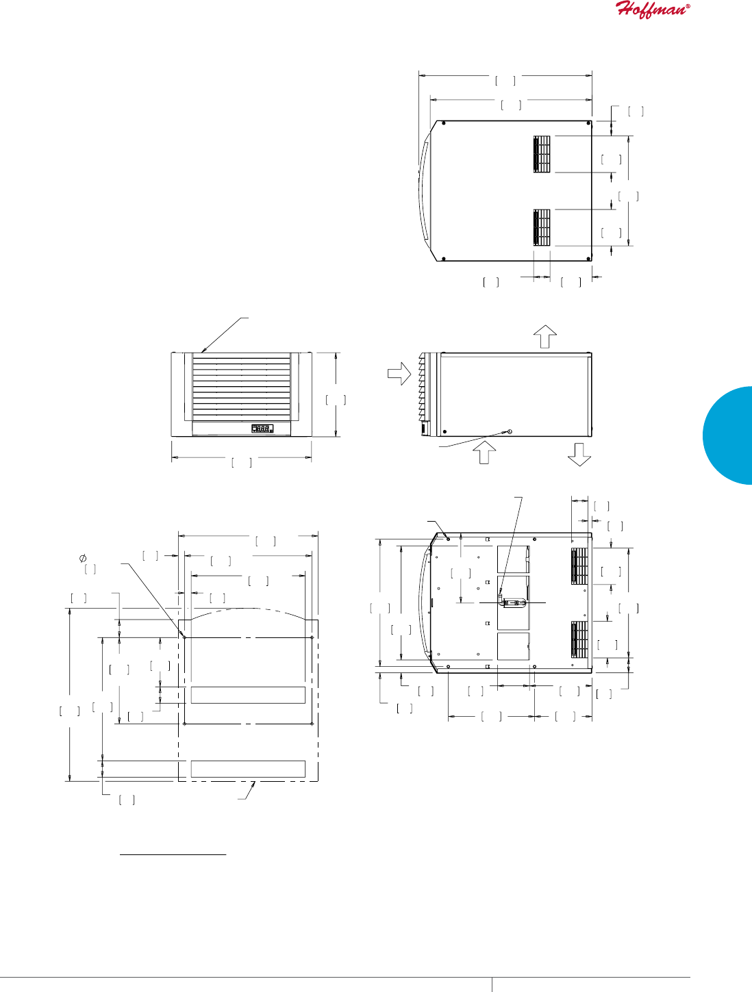
PH 763.422.2211 • FAX 763.576.3200 • HOFFMANONLINE.COMEQUIPMENT PROTECTION COOLING 119
3
SEALED ENCLOSURE COOLING AIR CONDITIONERS
$0%,(17
$,5287
&22/
$,5287
(1&/2685(
$,5,1
$/7(51$7(
29(5)/2:'5$,1
(,7+(56,'(
;
;
;
;
;
67$1'$5'&21'(16$7(
'5$,1/2&$7,21
81&;
$0%,(17
$,5,1
&/($1$%/(5(86$%/(
$/80,180,1/(7),/7(5
%(+,1'*5,//(
5()
5()
;
5()
;
;
;
5()
;
$&287/,1(
&XWRXW'LPHQVLRQV
0+%0RGHOV%78+U:DWW
127(
02817,1**$6.(76833/,('1276+2:1
81,76LQ>PP@
&87287',0(16,216)2567$1'$5'81,7621/<
Visit www
.HoffmanOnline.com to download 2D and 3D CAD drawings into the overall design of your electr
onic system.

EQUIPMENT PROTECTIONSUBJECT TO CHANGE WITHOUT NOTICECOOLING120
3
SEALED ENCLOSURE COOLING AIR CONDITIONERS
Performance Data HB16 Models 8000 BTU/Hr. (2051 Watt)
MODEL NUMBER
Indoor Model HB160816G040 HB160826G040 HB160846G040
COOLING PERFORMANCE
Nominal:
BTU/Hr. 7000/8000 7000/8000 7000/8000
Watts 2051/2344 2051/2344 2051/2344
At 125 F/125 F (52 C/52 C):
BTU/Hr. (50/60 Hz) 6975/8137 7075/8133 7075/8133
Watts (50/60 Hz) 2044/2385 2073/2384 2073/2384
At 95 F/95 F (35 C/35 C):
BTU/Hr. (50/60 Hz) 6959/8236 6958/7774 6958/7774
W (50/60 Hz) 2039/2414 2039/2278 2039/2278
Refrigerant R-407C R-407C R-407C
Refrigerant Charge (ounces/grams) 24/680 24/680 24/680
Operating Temperature Range:
Maximum (°F/°C) 125/52 125/52 125/52
Minimum (°F/°C) 50/10 50/10 50/10
ELECTRICAL DATA
Rated Voltage 115 230 460
Frequency (Hz) 50/60 50/60 50/60
Operating Range +/- 10% +/- 10% +/- 10%
Max. Power Consumption (W at 50/60 Hz) 1822/2223 1785/2105 2162
Max. Nominal Current (A at 50/60 Hz) 18.7/20.4 8.5/9.3 4.3/4.7
Starting Current (A) 67 29 15
Agency Approvals cUL Listed
CE
GOST
Power Input Description 6-ft. cord with NEMA 5-20 plug 6-ft. cord with NEMA 5-20 plug 6-ft. cord with NEMA L8-20 plug
ENCLOSURE PROTECTION
UL Type Type 12 Standard
CONTROLLER
Description Basic Mechanical Thermostat
Thermostat Location Enclosure Side on All Base Models
Factory Thermostat Setting (°F/°C) 80/27 80/27 80/27
UNIT CONSTRUCTION
Material Galvanized Sheet Metal Standard (Optional: Stainless Steel)
Finish RAL 7042 gray, semi-gloss powder-coat paint standard
Other colors and textures available
UNIT DIMENSIONS
Height (in./mm) 15.25/387.35 15.25/387.35 15.25/387.35
Width (in./mm) 17.00/431.80 17.00/4 31.80 17.00/4 31.80
Depth (in./mm) 25.19/639.76 25.19/639.76 25.19/639.76
Weight (lb./kg) 145.00/69.78 145.00/69.78 170.00/77.00
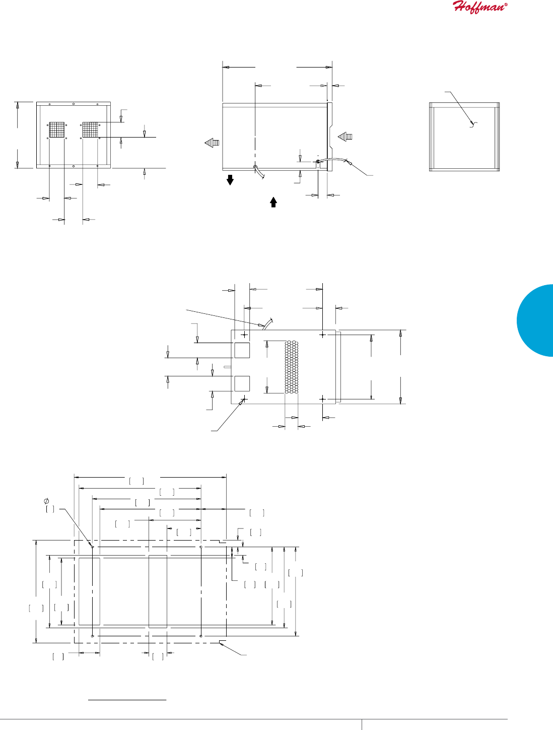
PH 763.422.2211 • FAX 763.576.3200 • HOFFMANONLINE.COMEQUIPMENT PROTECTION COOLING 121
3
SEALED ENCLOSURE COOLING AIR CONDITIONERS
>@
>@
>@
>@
>@
>@
>@
>@
$,55(7851
(1&/2685(
&22/$,5
287
$,5287
$0%,(17
$0%,(17
$,5,1
6(59,&(
&25'
>@
>@
>@
)URQW9LHZ
6LGH9LHZ
5HDU9LHZ
&/($1$%/(
5(86$%/(
$/80,180
,1/(7),/7(5
>@
81&%
>@
>@
>@
>@ >@
>@
>@
>@
>@
>@
>@
,''5$,1+26(
>@
%RWWRP9LHZ
5()
5()
;
5()
5()
$,5&21',7,21(5287/,1(
&XWRXW
+%0RGHOV%78V+U:DWWV
Visit www
.HoffmanOnline.com to download 2D and 3D CAD drawings into the overall design of your electr
onic system.
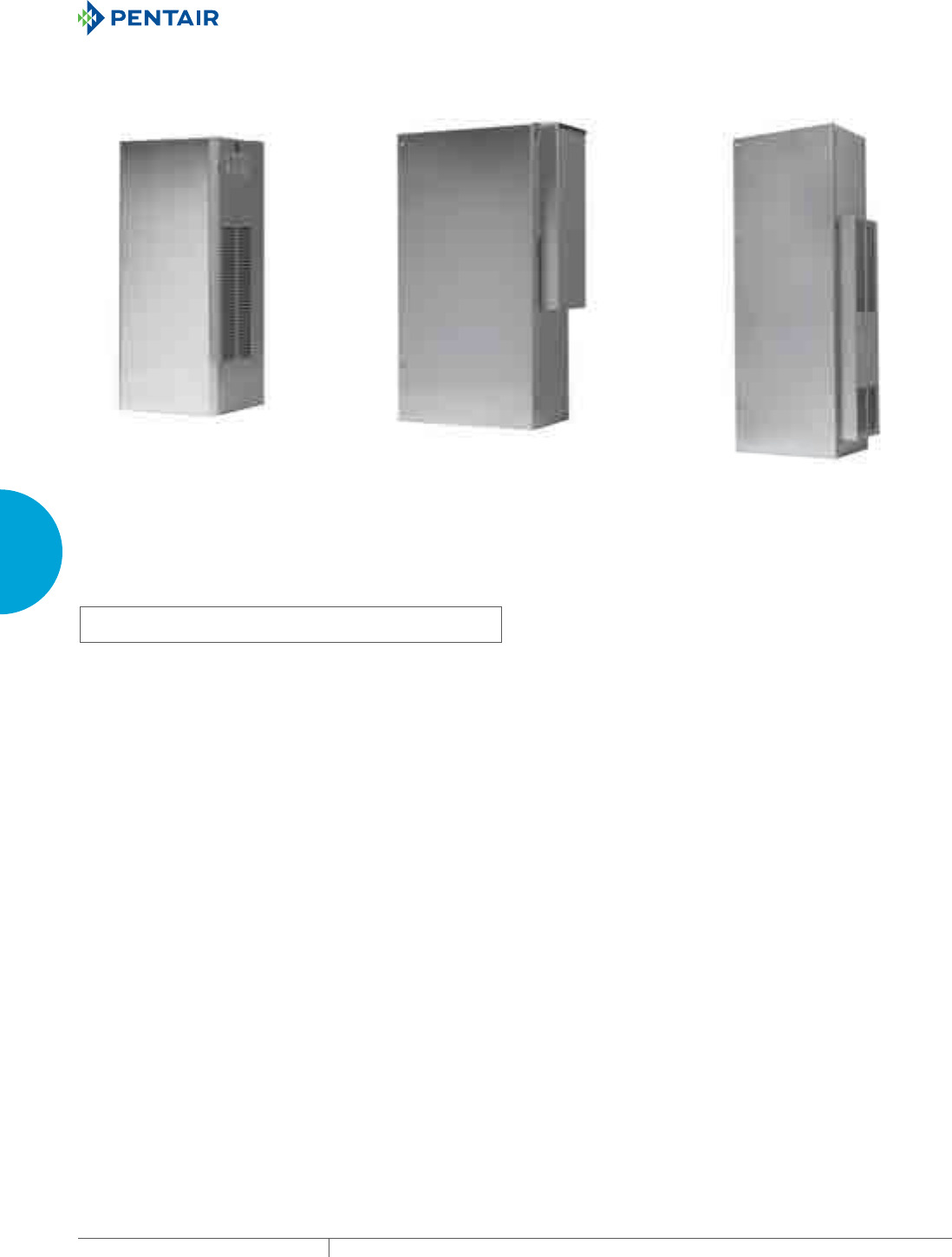
EQUIPMENT PROTECTIONSUBJECT TO CHANGE WITHOUT NOTICECOOLING122
3
SEALED ENCLOSURE COOLING AIR CONDITIONERS
PROAIR HARSH ENVIRONMENT
CR23
1600 BTU/Hr.
469 Watts
CR29
2200 and 4000 BTU/Hr.
645 and 1172 Watts CR43
6000 & 8000 BTU/Hr.
1758 and 2344 Watts
INDUSTRY STANDARDS
UL/cUL Listed; Type 12, 3R, 4; 4X optional; File No. SA6453
UR/cUR Recognized
UR/cUR Recognized on select models, reference performance data
tables.
CE
GOST
APPLICATION
• Industrial automation
• Package handling equipment
• Food and beverage
• Wastewater treatment
• Security and defense systems
• And more
FEATURES
• Robust reciprocating compressor
• Easy maintenance: hinged front cover allows quick access to all
components; condenser coil can be cleaned while unit is still
mounted to the cabinet
• R134a or R407c earth-friendly refrigerant
• Models for 115, 230 and 460 single phase VAC power input
• UL Listed or Recognized to save customers time and money with
agency approvals
• Operating temperature range from -40 F/-40 C to 131 F/55 C (with
optional low-ambient package)
• Attractive industrial design with minimal use of visible fasteners
• Reliable mechanical thermostat located behind the filter of the
unit
• Low-carbon mild-steel sheet-metal cover for rugged factory and
outdoor environments
• Easy-mount flanges for simple installation
• Cleanable reusable aluminum mesh filter protects coils for
maximum cooling performance
• Mounting hardware, gaskets and user manual furnished with the
unit
• Every unit functionally tested before shipping
• High-performance fans and blowers designed for densely packed
enclosures
• Standard Indoor Air Conditioner models also include:
- Electro-Mechanical Thermostat
- Surge Suppressor
FINISH
• RAL 7035 light-gray, semi-textured powder-coat paint standard
• Stainless steel Type 304 or 316 finishes available on Type 4X
models
• Other colors and textures available
OPTIONS
• Thermostat Malfunction Package
• Special Voltage Package
• Outdoor Package*
• Harsh Environment Package*
• Stainless Steel Package*
• Heater Package*
* T-Series may be more appropriate. Refer to T-Series A/C
section. Consult the factory for availability and catalog
number.
NOTES
Visit www.HoffmanOnline.com to download 2D and 3D CAD
drawings into the overall design of your electronic system.
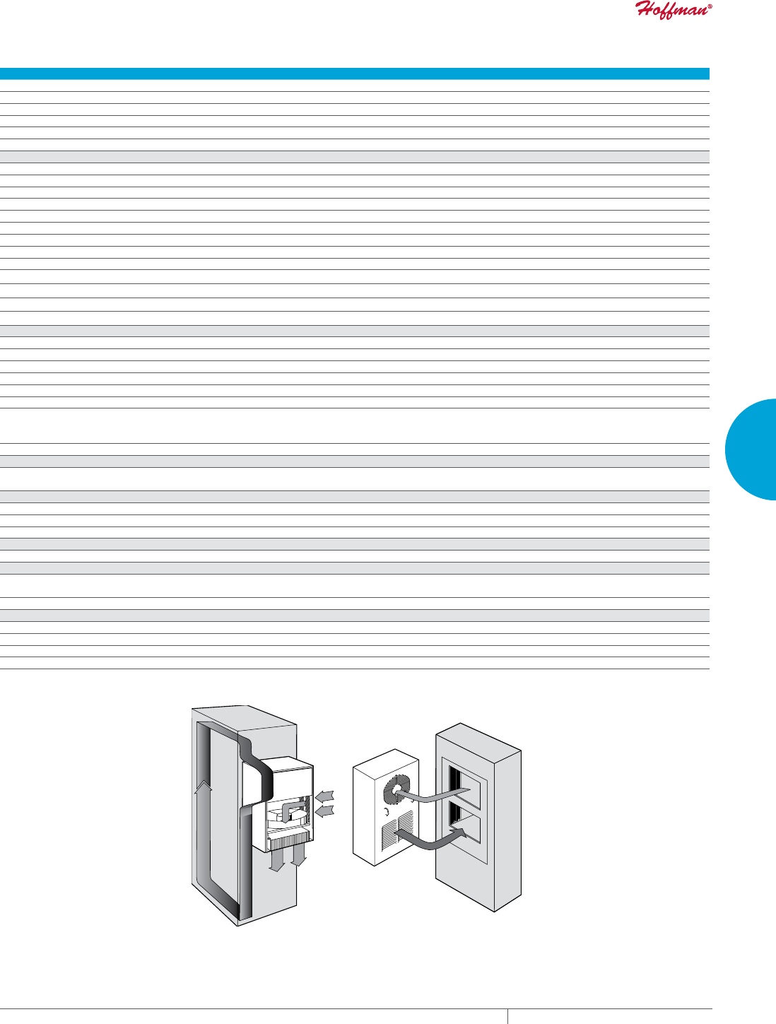
PH 763.422.2211 • FAX 763.576.3200 • HOFFMANONLINE.COMEQUIPMENT PROTECTION COOLING 123
3
SEALED ENCLOSURE COOLING AIR CONDITIONERS
Performance Data CR23 Models 1600 BTU/Hr. (469 Watt)
CATALOG NUMBER
Indoor Model CR230216G002 CR230226G002 CR230246G400
Indoor Level 2 Controller CR230216G016 — —
Outdoor Type 3R CR230216G013 CR230226G030 —
Outdoor/SST/Corrosion Type 3R CR230216G007 CR230226G009 —
Outdoor/SST/Level 2 Type 3R CR230216G017 CR230226G016 —
Indoor/Outdoor/SST/Corrosion Type 4X CR230216G015 CR230226G014 CR230226G037
COOLING PERFORMANCE
Nominal:
BTU/Hr. 1400/1600 1400/1600 1400/1600
Watts 410/469 410/469 410/469
Refrigerant R-134A R-134A R-134A
Refrigerant Charge (ounces/grams) 10/284 10/284 10/284
Operating Temperature Range:
Maximum (°F/°C) 131/55 131/55 131/55
Minimum (°F/°C) (Low Ambient Pkg) -40/-40 -40/-40 -40/-40
Airflow at 0 Static Pressure:
Internal loop 50 Hz (CFM / m3/hr.) 117/199 117/199 117/199
External loop 50 Hz (CFM / m3/hr.) 86/146 86/146 86/146
Internal loop 60 Hz (CFM / m3/hr.) 130/221 130/221 130/221
External loop 60 Hz (CFM / m3/hr.) 95/161 95/161 95/161
ELECTRICAL DATA
Rated Voltage 115 230 460V 1PH
Frequency (Hz) 50/60 50/60 50/60
Operating Range +/- 10% +/- 10% +/- 10%
Max. Power Consumption (W at 50/60 Hz) 471.5/517.5 506 552
Max. Nominal Current (A at 50/60 Hz) 4.1/4.5 2.2 1.2
Starting Current (A) 18 8.5 5
Agency Approvals cUL Listed
CE
GOST
cUR Recognized
CE
GOST
Power Input Description 6-ft. cord with NEMA 5-15 plug 6-ft. cord with NEMA 6-15 plug 6-ft. cord with wire leads
ENCLOSURE PROTECTION
UL Type Type 12, 3R standard
Type 4, 4X Stainless steel optional
CONTROLLER
Description Basic mechanical thermostat
Thermostat Location Behind cover
Factory Thermostat Setting (°F/°C) 80/27
SOUND LEVEL
At 1.5 Meters 62 dB(A)
UNIT CONSTRUCTION
Material Mild steel sheet metal standard
Stainless steel optional
Finish RAL 7035 light-gray, semi-textured powder-coat paint standard
UNIT DIMENSIONS
Height (in./mm) 23/584 23/584
Width (in./mm) 10/254 10/254
Depth (in./mm) 8.75/222 8.75/222
Weight (lb./kg) 57/26 67/30
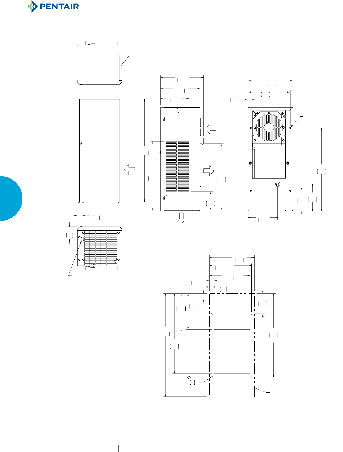
EQUIPMENT PROTECTIONSUBJECT TO CHANGE WITHOUT NOTICECOOLING124
3
SEALED ENCLOSURE COOLING AIR CONDITIONERS
$0%,(17
$,5,1
&/($1$%/(5(86$%/(
$/80,180,1/(7),/7(5
(1&/2685(
$,5,1
&22/
$,5287
$0%,(17
$,5287
67$1'$5'
&21'(16$7(
'5$,1
/2&$7,21
;
;
;
;
81&
;
;
;
;
;
;
;
&XWRXW'LPHQVLRQV
$&287/,1(
&50RGHOV%78+U:DWW
127(
02817,1**$6.(76833/,('1276+2:1
81,76LQ>PP@
Visit www
.HoffmanOnline.com to download 2D and 3D CAD drawings into the overall design of your electr
onic system.
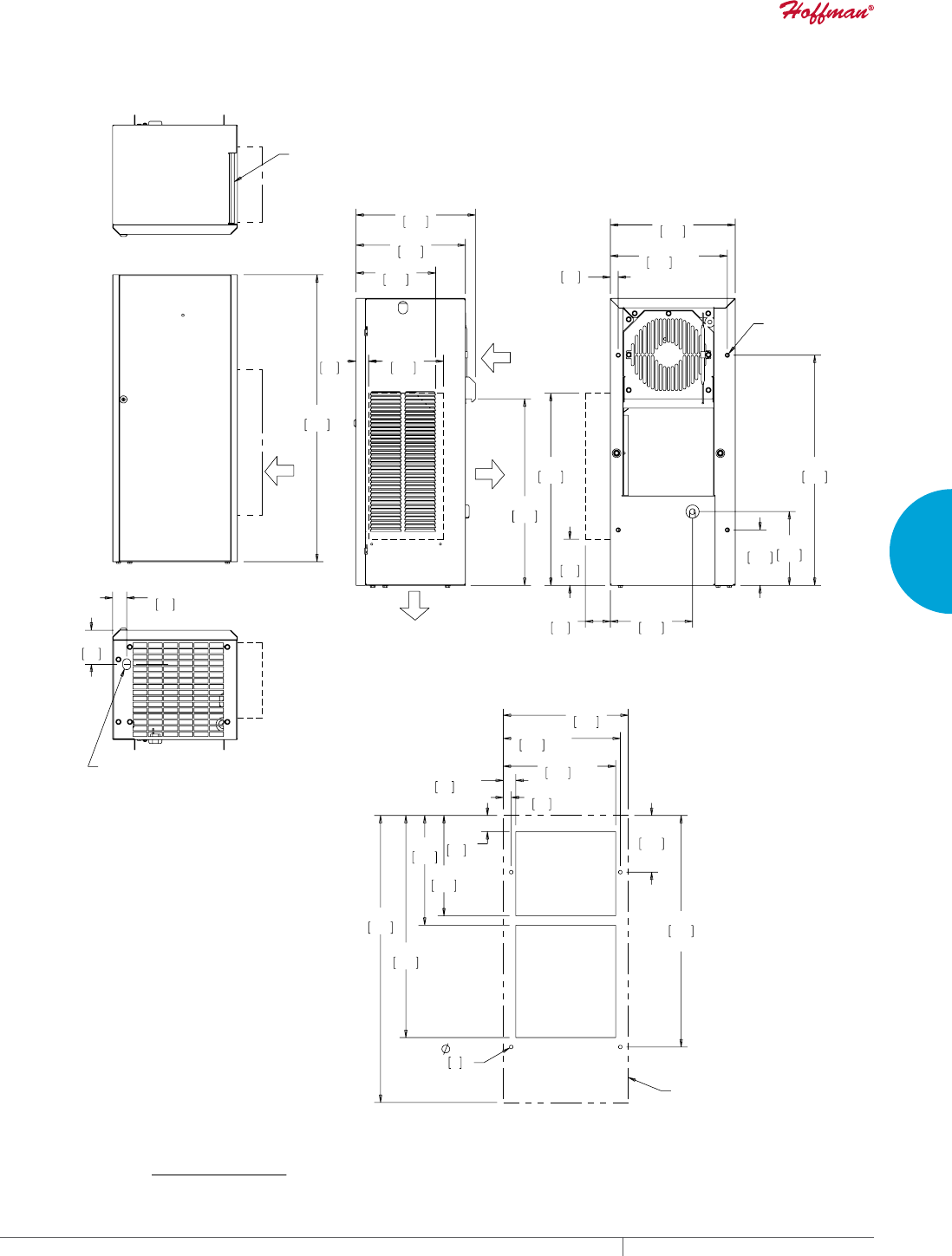
PH 763.422.2211 • FAX 763.576.3200 • HOFFMANONLINE.COMEQUIPMENT PROTECTION COOLING 125
3
SEALED ENCLOSURE COOLING AIR CONDITIONERS
$0%,(17
$,5,1
&/($1$%/(5(86$%/(
$/80,180,1/(7),/7(5
(1&/2685(
$,5,1
&22/
$,5287
$0%,(17
$,5287
67$1'$5'
&21'(16$7(
'5$,1
/2&$7,21
;
;
;
;
81&
;
;
;
;
;
;
;
&XWRXW'LPHQVLRQV
$&287/,1(
&50RGHOV%78+U:DWW:LWK7\SH;+RRG
127(
02817,1**$6.(76833/,('1276+2:1
81,76LQ>PP@
Visit www
.HoffmanOnline.com to download 2D and 3D CAD drawings into the overall design of your electr
onic system.
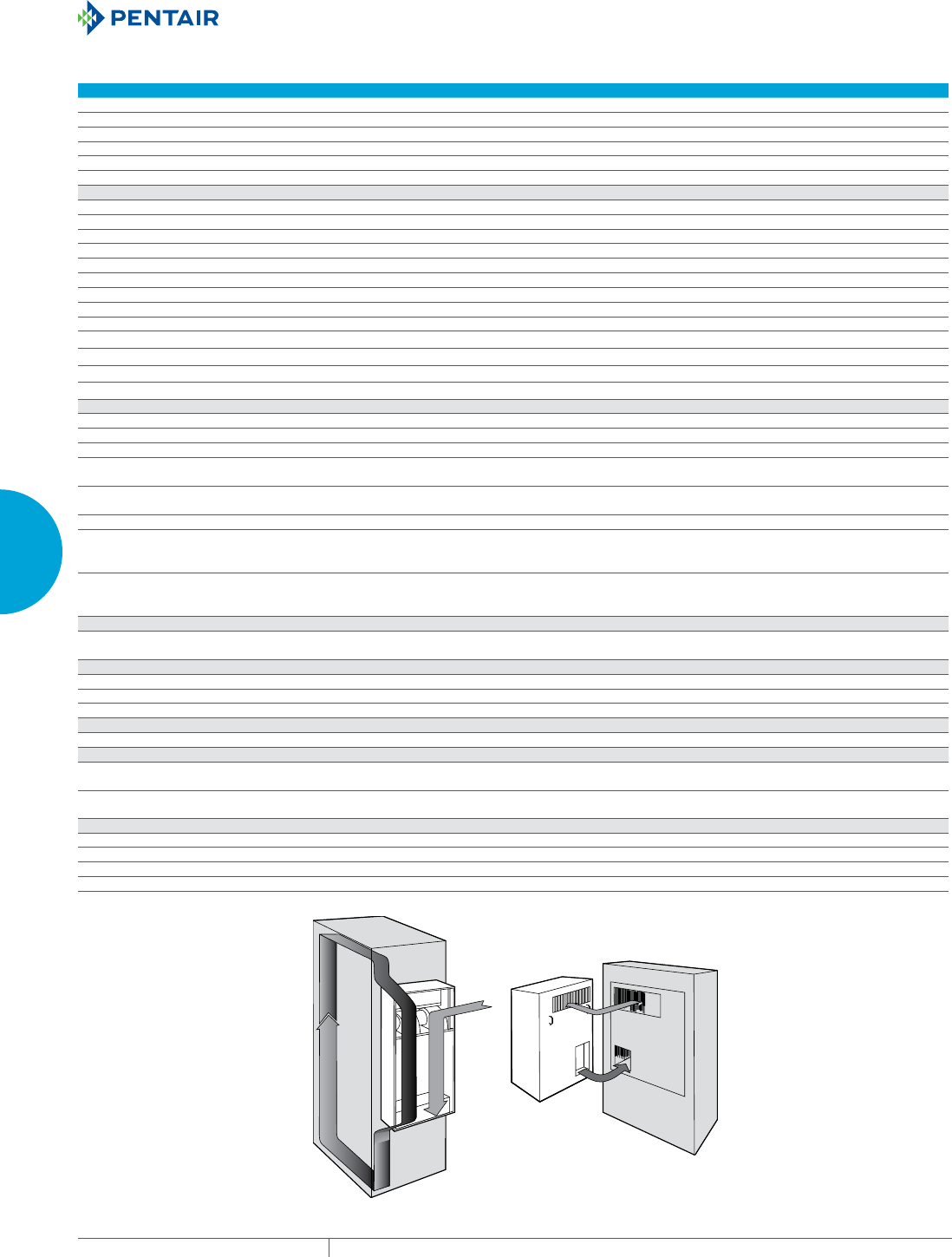
EQUIPMENT PROTECTIONSUBJECT TO CHANGE WITHOUT NOTICECOOLING126
3
SEALED ENCLOSURE COOLING AIR CONDITIONERS
Performance Data CR29 Models 2200/4000 BTU/Hr. (645/1172 Watt)
CATALOG NUMBER
Indoor Model CR290216G002 CR290226G002 CR290246G400 CR290416G002 CR290426G002 CR290446G400
Indoor Level 2 Controller CR290216G030 CR290226G030 CR290226G041 CR290416G047 CR290426G027 —
Outdoor Type 3R CR290216G035 CR290226G020 CR290226G046 CR290416G045 CR290426G022 CR290426G067
Outdoor/SST/Corrosion Type 3R CR290216G013 CR290226G010 CR290246G401 CR290416G030 CR290426G017 —
Outdoor/SST/Level 2 Type 3R — CR290226G031 CR290226G058 CR290416G052 —CR290426G101
Indoor/Outdoor/SST/Corrosion Type 4X CR290216G036 CR290226G037 CR290226G045 CR290416G068 CR290426G054 CR290426G061
COOLING PERFORMANCE
Nominal:
BTU/Hr. 2000/2200 2500/2700 2500/2700 3500/4000 3500/4000 3500/4000
Watts 586/645 732/791 732/791 1025/1172 1025/1172 1026/1172
Refrigerant R-134A R-134A R-134A R-134A R-134A R-134A
Refrigerant Charge (ounces/grams) 11/312 11/312 11/312 11/312 12/341 12/341
Operating Temperature Range:
Maximum (°F/°C) 131/55 131/55 131/55 131/55 131/55 131/55
Minimum (°F/°C) (Low Ambient Pkg) -40/-40 -40/-40 -40/-40 -40/-40 -40/-40 -40/-40
Airflow at 0 Static Pressure:
Internal loop 50 Hz (CFM / m3/hr.) 141/239 141/239 141/239 141/239 141/239 141/239
External loop 50 Hz (CFM / m3/hr.) 235/399 235/399 235/399 235/399 235/399 235/399
Internal loop 60 Hz (CFM / m3/hr.) 157/266 157/266 157/266 157/266 157/266 157/266
External loop 60 Hz (CFM / m3/hr.) 261/443 261/4 43 261/443 261/443 261/4 43 261/443
ELECTRICAL DATA
Rated Voltage 115 230 460V 1PH 115 230 460V 1PH
Frequency (Hz) 50/60 50/60 50/60 50/60 50/60 50/60
Operating Range +/- 10% +/- 10% +/- 10% +/- 10% +/- 10% +/- 10%
Max. Power Consumption
(W at 50/60 Hz)
851/517.5 1058/877 1150/996 1116/1253 1541/1518 1702/1656
Max. Nominal Current
(A at 50/60 Hz)
7.4 4.6/3.9 2.5/2.1 12.7/12.1 6.7/6.6 3.7/3.6
Starting Current (A) 28 14.4 7.4 44.5 23 12
Agency Approvals cUL Listed
CE
GOST
cUR Recognized
CE
GOST
cUL Listed
CE
GOST
cUR Recognized
CE
GOST
Power Input Description 6-ft. cord
with NEMA
5-15 plug
6-ft. cord
with NEMA
6-15 plug
6-ft. cord
with wire
leads
6-ft. cord
with NEMA
5-20 plug
6-ft. cord
with NEMA
6-15 plug
6-ft. cord
with wire
leads
ENCLOSURE PROTECTION
UL Type Type 12, 3R standard
Type 4, 4X Stainless steel optional
Type 12, 3R standard
4, 4X Stainless steel optional
CONTROLLER
Description Basic mechanical thermostat Basic mechanical thermostat
Thermostat Location Behind cover Behind cover
Factory Thermostat Setting (°F/°C) 80/27 80/27
SOUND LEVEL
At 1.5 Meters 68 dB(A) 68 dB(A)
UNIT CONSTRUCTION
Material Mild steel sheet metal standard
Stainless steel optional
Mild steel sheet metal standard
Stainless steel optional
Finish RAL 7035 light-gray, semi-textured powder-coat
paint standard RAL 7035 light-gray, semi-textured powder-coat
paint standard
UNIT DIMENSIONS
Height (in./mm) 29.5/749 29.5/749
Width (in./mm) 15.75/400 15.75/400
Depth (in./mm) 8.63/219 8.63/219
Weight (lb./kg) 98/44 98/44 108/49 118/54 118/54 128/58
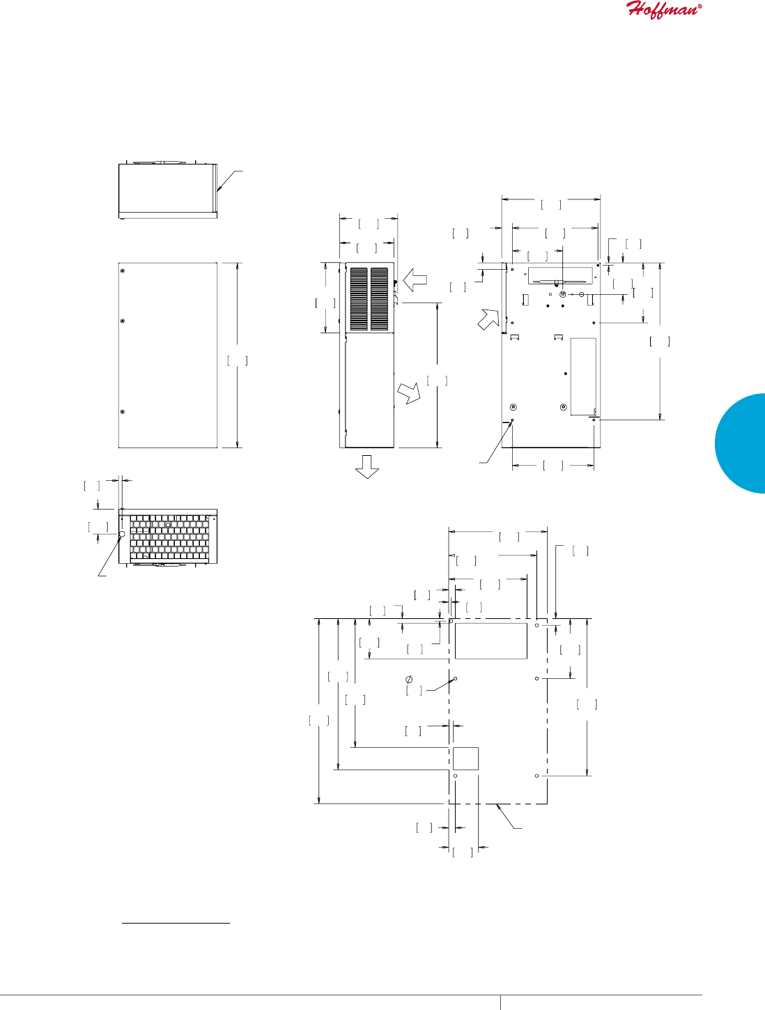
PH 763.422.2211 • FAX 763.576.3200 • HOFFMANONLINE.COMEQUIPMENT PROTECTION COOLING 127
3
SEALED ENCLOSURE COOLING AIR CONDITIONERS
&/($1$%/(5(86$%/(
$/80,180,1/(7),/7(5
67$1'$5'
&21'(16$7(
'5$,1/2&$7,21
&22/
$,5287
$0%,(17
$,5287
(1&/2685(
$,5,1
;
;
;
;
$0%,(17
$,5,1
81&;
;
;
;
;
;
&XWRXW'LPHQVLRQV
$&287/,1(
&50RGHOV%78+U:DWW
127(
02817,1**$6.(76833/,('1276+2:1
81,76LQ>PP@
Visit www
.HoffmanOnline.com to download 2D and 3D CAD drawings into the overall design of your electr
onic system.
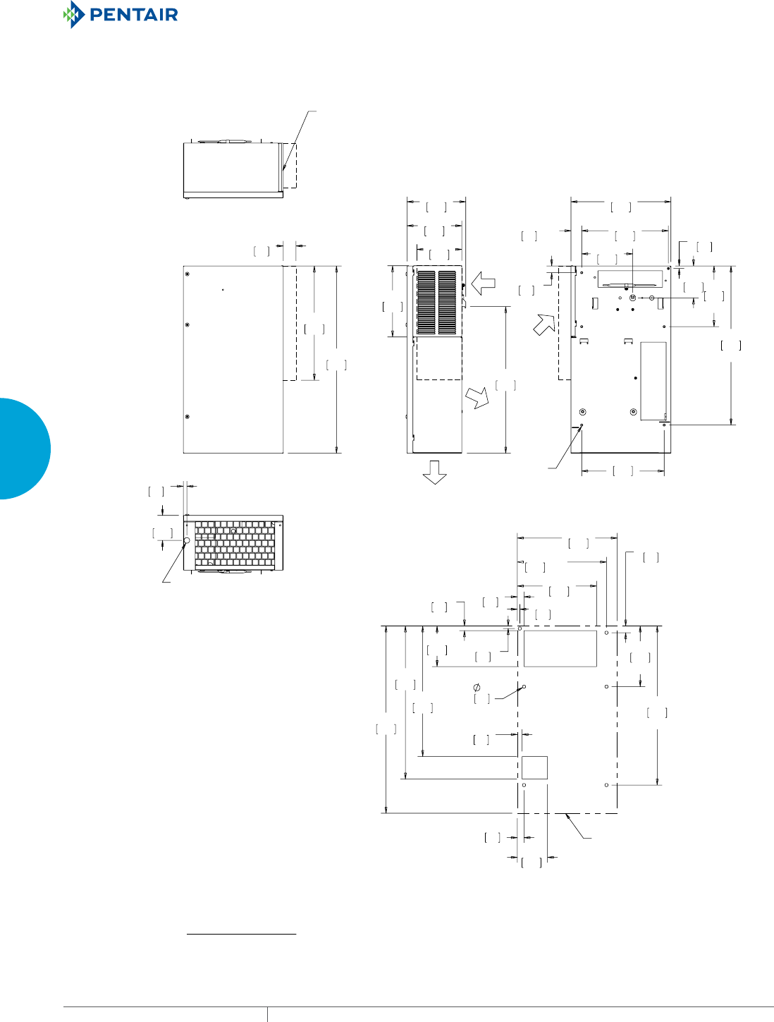
EQUIPMENT PROTECTIONSUBJECT TO CHANGE WITHOUT NOTICECOOLING128
3
SEALED ENCLOSURE COOLING AIR CONDITIONERS
&/($1$%/(5(86$%/(
$/80,180,1/(7),/7(5
67$1'$5'
&21'(16$7(
'5$,1/2&$7,21
&22/
$,5287
$0%,(17
$,5287
(1&/2685(
$,5,1
;
;
;
;
$0%,(17
$,5,1
81&;
;
;
;
;
;
&XWRXW'LPHQVLRQV
$&287/,1(
&50RGHOV%78+U:DWW:LWK7\SH;+RRG
127(
02817,1**$6.(76833/,('1276+2:1
81,76LQ>PP@
Visit www
.HoffmanOnline.com to download 2D and 3D CAD drawings into the overall design of your electr
onic system.
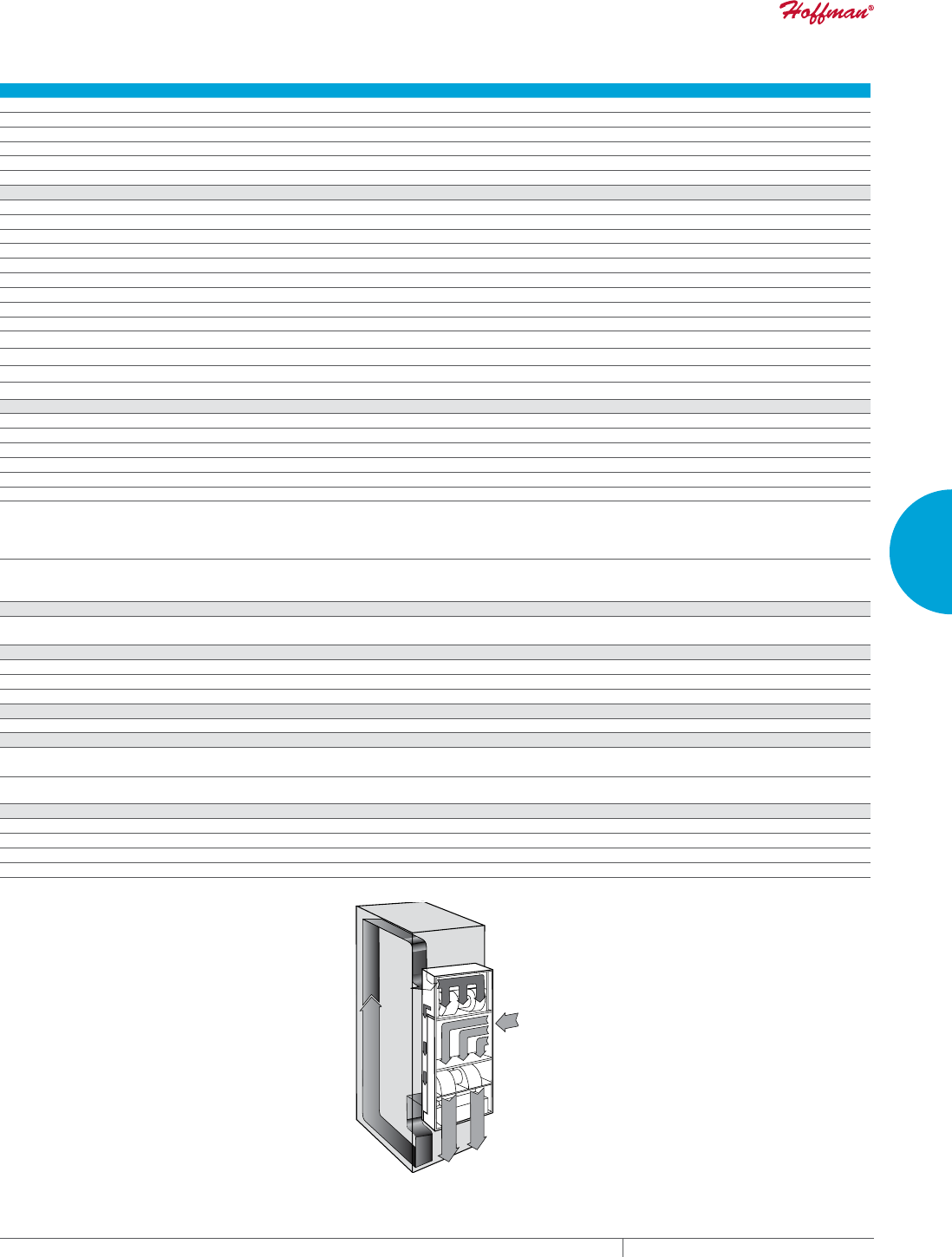
PH 763.422.2211 • FAX 763.576.3200 • HOFFMANONLINE.COMEQUIPMENT PROTECTION COOLING 129
3
SEALED ENCLOSURE COOLING AIR CONDITIONERS
Performance Data CR43 Models 6000/8000 BTU/Hr. (1758/2344 Watt)
CATALOG NUMBER
Indoor Model CR430616G002 CR430626G002 CR430646G004 CR430816G002 CR430826G002 CR430826G089
Indoor Level 2 Controller CR430616G016 CR430626G018 CR430626G030 CR430816G021 CR430826G026 —
Outdoor Type 3R CR430616G013 CR430626G014 —CR430816G038 CR430826G007 —
Outdoor/SST/Corrosion Type 3R CR430616G004 — — CR430816G010 CR430826G037 —
Outdoor/SST/Level 2 Type 3R — CR430626G020 —CR430816G023 CR430826G024 —
Indoor/Outdoor/SST/Corrosion Type 4X CR430616G031 CR430626G034 CR430626G074 CR430816G036 CR430826G038 CR430846G401
COOLING PERFORMANCE
Nominal:
BTU/Hr. 5500/6000 5500/6000 5500/6000 7100/8000 7100/8000 7100/8000
Watts 1611/1758 1611/1758 1611/1758 2080/2344 2080/2344 2080/2344
Refrigerant R-134A R-134A R-134A R-134A R-134A R-134A
Refrigerant Charge (ounces/grams) 19/538 19/538 19/538 19/538 19/538 19/538
Operating Temperature Range:
Maximum (°F/°C) 131/55 131/55 131/55 131/55 131/55 131/55
Minimum (°F/°C) (Low Ambient Pkg.) -40/-40 -40/-40 -40/-40 -40/-40 -40/-40 -40/-40
Airflow at 0 Static Pressure:
Internal loop 50 Hz (CFM / m3/hr.) 320/543 226/384 226/384 320/543 226/384 226/384
External loop 50 Hz (CFM / m3/hr.) 480/815 470/798 470/798 480/815 470/798 470/798
Internal loop 60 Hz (CFM / m3/hr.) 368/625 255/433 255/433 368/625 255/433 255/433
External loop 60 Hz (CFM / m3/hr.) 544/924 540/917 540/917 544/924 540/917 540/917
ELECTRICAL DATA
Rated Voltage 115 230 460V 1PH 115 230 460V 1PH
Frequency (Hz) 50/60 50/60 50/60 50/60 50/60 50/60
Operating Range +/- 10% +/- 10% +/- 10% +/- 10% +/- 10% +/- 10%
Max. Power Consumption (W at 50/60 Hz) 1460 1403/1518 1564/1656 1460 1403/1518 1564/1656
Max. Nominal Current (A at 50/60 Hz) 12.7 6.1/6.6 3.4/3.6 12.7 6.1/6.6 3.4/3.6
Starting Current (A) 48.3 27 14 48.3 27 14
Agency Approvals cUL Listed
CE
GOST
Others available upon request
cUR Recognized
CE
GOST
cUL Listed
CE
GOST
Others available upon request
cUR Recognized
CE
GOST
Power Input Description 6-ft. cord
with NEMA
5-20 plug
6-ft. cord
with NEMA
6-15 plug
6-ft. cord
with wire leads
6-ft. cord
with NEMA
5-20 plug
6-ft. cord
with NEMA
6-15 plug
6-ft. cord
with wire leads
ENCLOSURE PROTECTION
UL Type Type 12, 3R standard
Type 4, 4X Stainless steel optional
Type 12, 3R standard
4, 4X Stainless steel optional
CONTROLLER
Description Basic mechanical thermostat Basic mechanical thermostat
Thermostat Location Enclosure side on all base models Enclosure side on all base models
Factory Thermostat Setting (°F/°C) 80/27 80/27
SOUND LEVEL
At 1.5 Meters 71 dB(A) 71 dB(A)
UNIT CONSTRUCTION
Material Galvanized sheet metal standard
Stainless steel optional
Galvanized sheet metal standard
Stainless steel optional
Finish RAL 7035 light-gray, semi-textured powder-coat
paint standard RAL 7035 light-gray, semi-textured powder-coat
paint standard
UNIT DIMENSIONS
Height (in./mm) 4 3.31/1100 43.31/1100
Width (in./mm) 15.75/400 15.75/400
Depth (in./mm) 10.25/260 10.25/260
Weight (lb./kg) 125/57 125/57 155/70 125/57 125/57 155/70
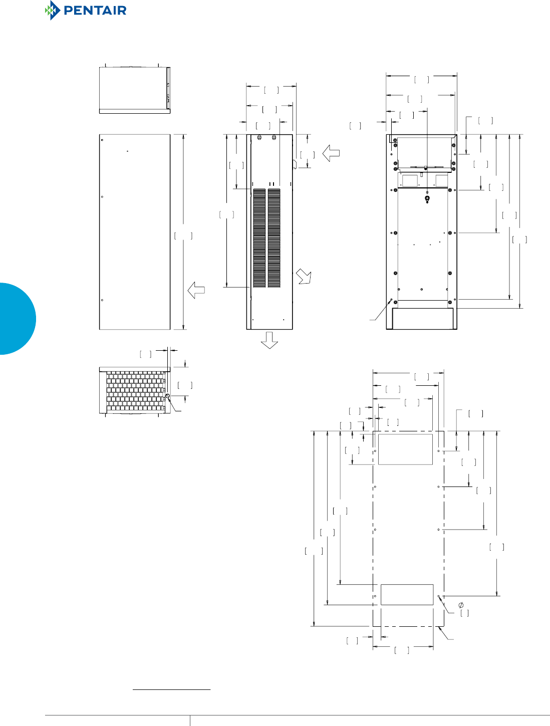
EQUIPMENT PROTECTIONSUBJECT TO CHANGE WITHOUT NOTICECOOLING130
3
SEALED ENCLOSURE COOLING AIR CONDITIONERS
$0%,(17
$,5,1
67$1'$5'&21'(16$7(
'5$,1/2&$7,21
&22/
$,5287
$0%,(17
$,5287
(1&/2685(
$,5,1
;
;
;
;
;
;
81&;
;
;
;
;
;
;
;
&XWRXW'LPHQVLRQV
$&287/,1(
&50RGHOV%78+U:DWW
127(
02817,1**$6.(76833/,('1276+2:1
81,76LQ>PP@
Visit www
.HoffmanOnline.com to download 2D and 3D CAD drawings into the overall design of your electr
onic system.
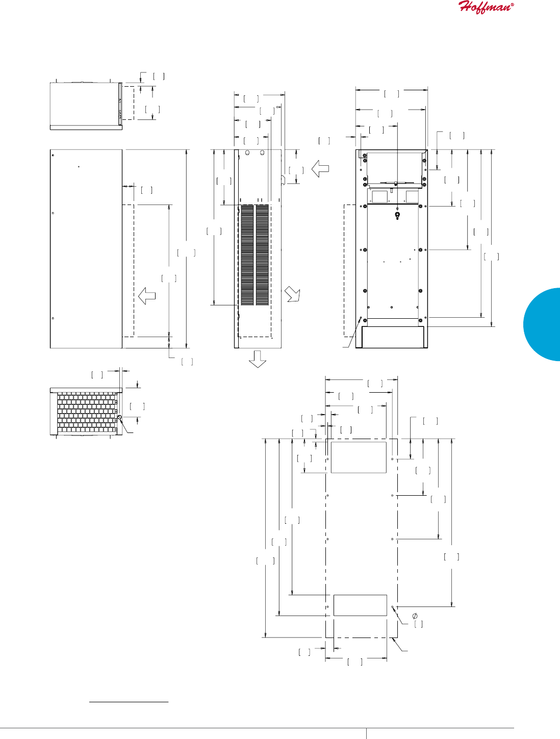
PH 763.422.2211 • FAX 763.576.3200 • HOFFMANONLINE.COMEQUIPMENT PROTECTION COOLING 131
3
SEALED ENCLOSURE COOLING AIR CONDITIONERS
$0%,(17
$,5,1
67$1'$5'&21'(16$7(
'5$,1/2&$7,21
&22/
$,5287
$0%,(17
$,5287
(1&/2685(
$,5,1
;
;
;
;
;
;
81&;
;
;
;
;
;
;
;
&XWRXW'LPHQVLRQV
$&287/,1(
&50RGHOV%78+U:DWW:LWK7\SH;+RRG
127(
02817,1**$6.(76833/,('1276+2:1
81,76LQ>PP@
Visit www
.HoffmanOnline.com to download 2D and 3D CAD drawings into the overall design of your electr
onic system.
EQUIPMENT PROTECTIONSUBJECT TO CHANGE WITHOUT NOTICECOOLING132
3
SEALED ENCLOSURE COOLING AIR CONDITIONERS
WATERCOOLED INDOOR
33WC
4000 BTU/Hr.
1172 Watt
INDUSTRY STANDARDS
UL/cUL Listed; Type 12; File No. SA6453
UR/cUR Recognized
UR/cUR Recognized on select models, reference performance data
tables.
CE
GOST
APPLICATION
• Industrial automation
• Package handling equipment
• Food and beverage
• Wastewater treatment
• Security and defense systems
• Pulp and paper
• And more
FEATURES
• Robust reciprocating compressor
• R134a earth-friendly refrigerant
• Models for 115 VAC, 230 VAC and 460 V 1-phase power input
• UL Listed or Recognized to save customers time and money with
agency approvals
• Operating temperature range from 50 F/10 C to 125 F/52 C
• Attractive industrial design with minimal use of visible fasteners
• Reliable mechanical thermostat located behind the front panel of
the unit
• Low-carbon mild-steel sheet-metal cover for rugged factory and
outdoor environments
• Easy-mount flanges for simple installation
• Mounting hardware, gaskets and user manual furnished with the
unit
• Every unit functionally tested before shipping
• Heat is removed from the system by means of the water cooling
the refrigerant; no external air movers or condenser coils to get
clogged
• Maximum water usage of 2 GPM at 90 F water intake temperature
• Standard Indoor Air Conditioner models also include:
- Electro-Mechanical Thermostat
- Surge Suppressor
FINISH
• RAL 7042 gray, semi-gloss powder-coat paint standard
• Stainless steel Type 304 or 316 finishes available on Type 4X
models
• Other colors and textures available
OPTIONS
• Thermostat Malfunction Package
• Special Voltage Package
• Active Condensate Evaporator Package
• Harsh Environment Package*
• Stainless Steel Package*
* Consult the factory for availability and catalog number.
NOTES
Visit www.HoffmanOnline.com to download 2D and 3D CAD
drawings into the overall design of your electronic system.
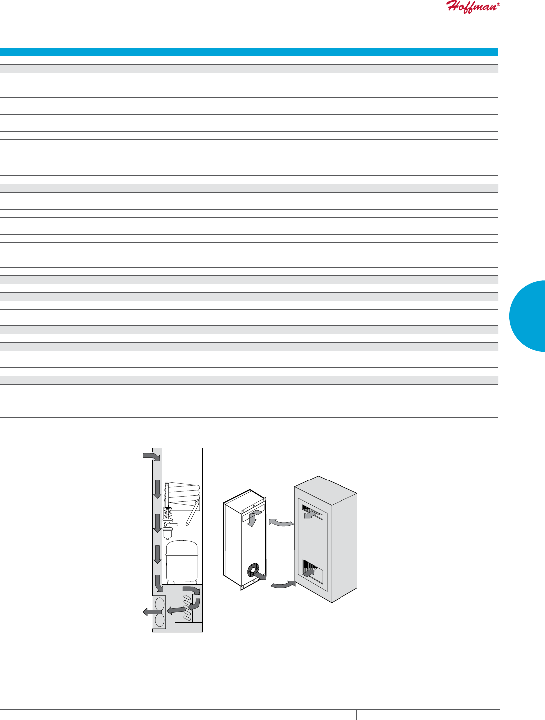
PH 763.422.2211 • FAX 763.576.3200 • HOFFMANONLINE.COMEQUIPMENT PROTECTION COOLING 133
3
SEALED ENCLOSURE COOLING AIR CONDITIONERS
Performance Data 33WC Models 4000 BTU/Hr. (1172 Watt)
CATALOG NUMBER
330416GW010 330426GW014 330426GW012
COOLING PERFORMANCE
Nominal:
BTU/Hr. 3800/4000 3800/4000 3800/4000
Watts 1113/1172 1113/1172 1113/1172
Refrigerant R-134A R-134A R-134A
Refrigerant Charge (ounces/grams) 7/198 7/198 7/198
Operating Temperature Range:
Maximum (°F/°C) 125/52 125/52 125/52
Minimum (°F/°C) 50/10 50/10 50/10
Airflow at 0 Static Pressure:
Internal loop 50 Hz (CFM / m3/hr.) 135/229 100/170 100/170
External loop 50 Hz Waterflow: 0.5 GPM @ 90 F Waterflow: 0.5 GPM @ 90 F Waterflow: 0.5 GPM @ 90 F
Internal loop 60 Hz (CFM / m3/hr.) 145/246 110/187 110/187
External loop 60 Hz Waterflow: 0.5 GPM @ 90 F Waterflow: 0.5 GPM @ 90 F Waterflow: 0.5 GPM @ 90 F
ELECTRICAL DATA
Rated Voltage 115 220/230 460V 1PH
Frequency (Hz) 50/60 50/60 50/60
Operating Range +/- 10% +/- 10% +/- 10%
Max. Power Consumption (W at 50/60 Hz) 690/667 726/736 828/782
Max. Nominal Current (A at 50/60 Hz) 6.0/5.8 3.3/3.2 1.8/1.7
Starting Current (A) 28 14.4 7.4
Agency Approvals cUL Listed
CE
GOST
cUR Recognized
CE
GOST
Power Input Description 6-ft. cord with NEMA 5-15 plug 6-ft. cord with NEMA 6-15 plug 6-ft. cord with wire leads
ENCLOSURE PROTECTION
UL Type Type 12 standard
CONTROLLER
Description Basic mechanical thermostat
Thermostat Location Behind front cover
Factory Thermostat Setting (°F/°C) 80/27
SOUND LEVEL
At 1.5 Meters 61 dB(A)
UNIT CONSTRUCTION
Material Mild steel sheet metal standard
Stainless steel optional
Finish RAL 7042 gray, semi-gloss powder-coat paint standard
UNIT DIMENSIONS
Height (in./mm) 34.13/867 38.63/981.2
Width (in./mm) 12.38/314 12.38/314
Depth (in./mm) 8.75/222 8.75/222
Weight (lb./kg) 86/39 106/48
33WC
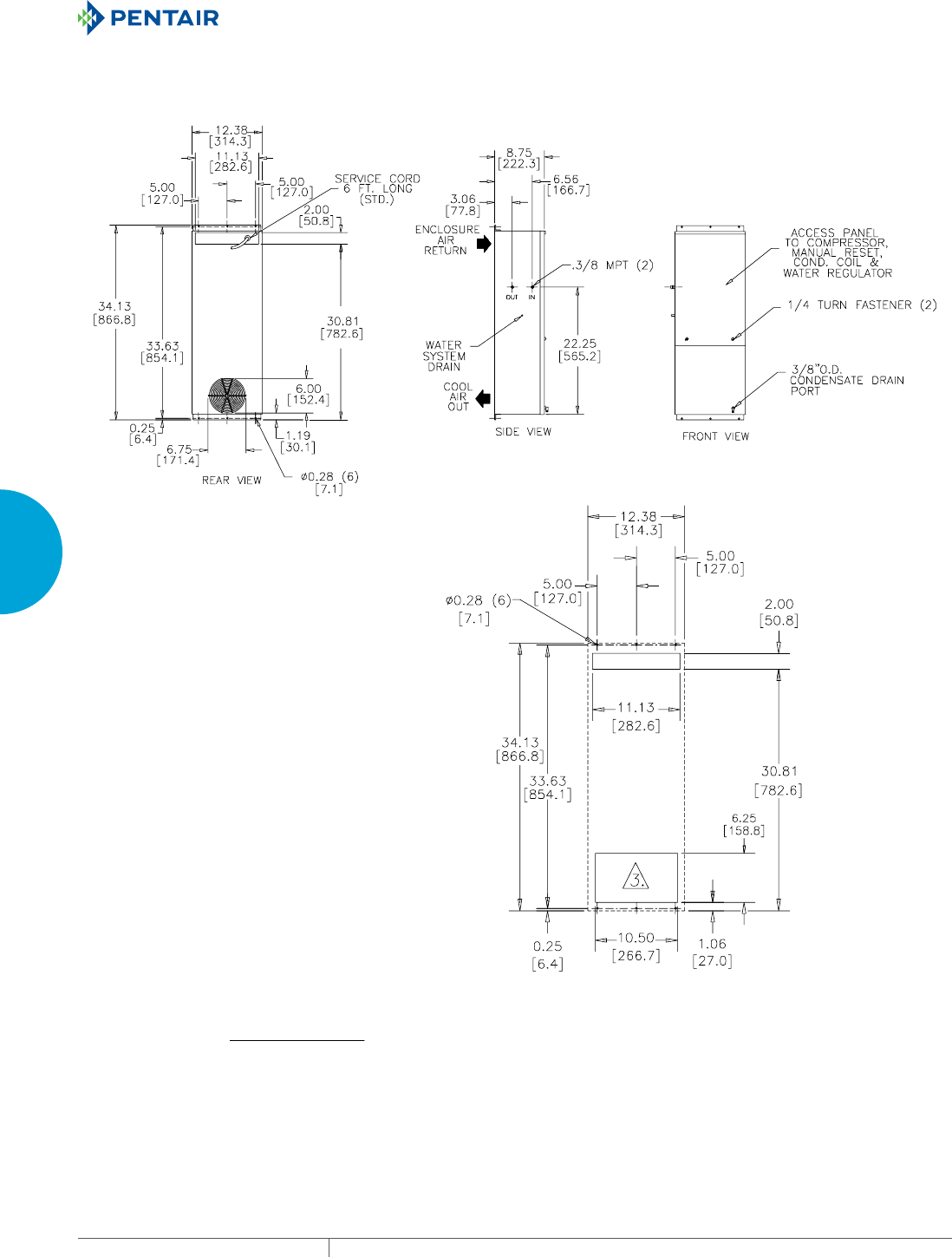
EQUIPMENT PROTECTIONSUBJECT TO CHANGE WITHOUT NOTICECOOLING134
3
SEALED ENCLOSURE COOLING AIR CONDITIONERS
Cutout Dimensions
89045090
33WC Models 4000 BTU/Hr. (1172 Watt)
Visit www
.HoffmanOnline.com to download 2D and 3D CAD drawings into the overall design of your electr
onic system.

PH 763.422.2211 • FAX 763.576.3200 • HOFFMANONLINE.COMEQUIPMENT PROTECTION COOLING 135
3
SEALED ENCLOSURE COOLING AIR CONDITIONERS
Notes
EQUIPMENT PROTECTIONSUBJECT TO CHANGE WITHOUT NOTICECOOLING136
3
SEALED ENCLOSURE COOLING AIR CONDITIONERS
WATERCOOLED INDOOR/OUTDOOR
CR43WC
8000 BTU/Hr.
2345 Watt
INDUSTRY STANDARDS
UL/cUL Listed; Type 4; 4X optional; File No. SA6453
UR/cUR Recognized
UR/cUR Recognized on select models, reference performance data
tables.
CE
GOST
APPLICATION
• Industrial automation
• Package handling equipment
• Food and beverage
• Wastewater treatment
• Security and defense systems
• Pulp and paper
• And more
FEATURES
• Robust reciprocating compressor
• R134a earth-friendly refrigerant
• Models for 115 and 230 VAC power input
• UL Listed or Recognized to save customers time and money with
agency approvals
• Operating temperature range from 50 F/10 C to 125 F/52 C
• Attractive industrial design with minimal use of visible fasteners
• Reliable mechanical thermostat located behind the front panel of
the unit
• Low-carbon mild-steel sheet-metal cover for rugged factory and
outdoor environments
• Easy-mount flanges for simple installation
• Mounting hardware, gaskets and user manual furnished with the
unit
• Every unit functionally tested before shipping
• Heat is removed from the system by means of the water cooling
the refrigerant; no external air movers or condenser coils to get
clogged
• Maximum water usage of 2 GPM at 90 F water intake temperature
• Standard Indoor Air Conditioner models also include:
- Electro-Mechanical Thermostat
- Surge Suppressor
FINISH
• RAL 7035 light-gray, semi-textured powder-coat paint standard
• Stainless steel Type 304 or 316 finishes available on Type 4X
models
• Other colors and textures available
OPTIONS
• Thermostat Malfunction Package
• Special Voltage Package
• Active Condensate Evaporator Package
• Harsh Environment Package*
• Stainless Steel Package*
* Consult the factory for availability and catalog number.
NOTES
Visit www.HoffmanOnline.com to download 2D and 3D CAD
drawings into the overall design of your electronic system.
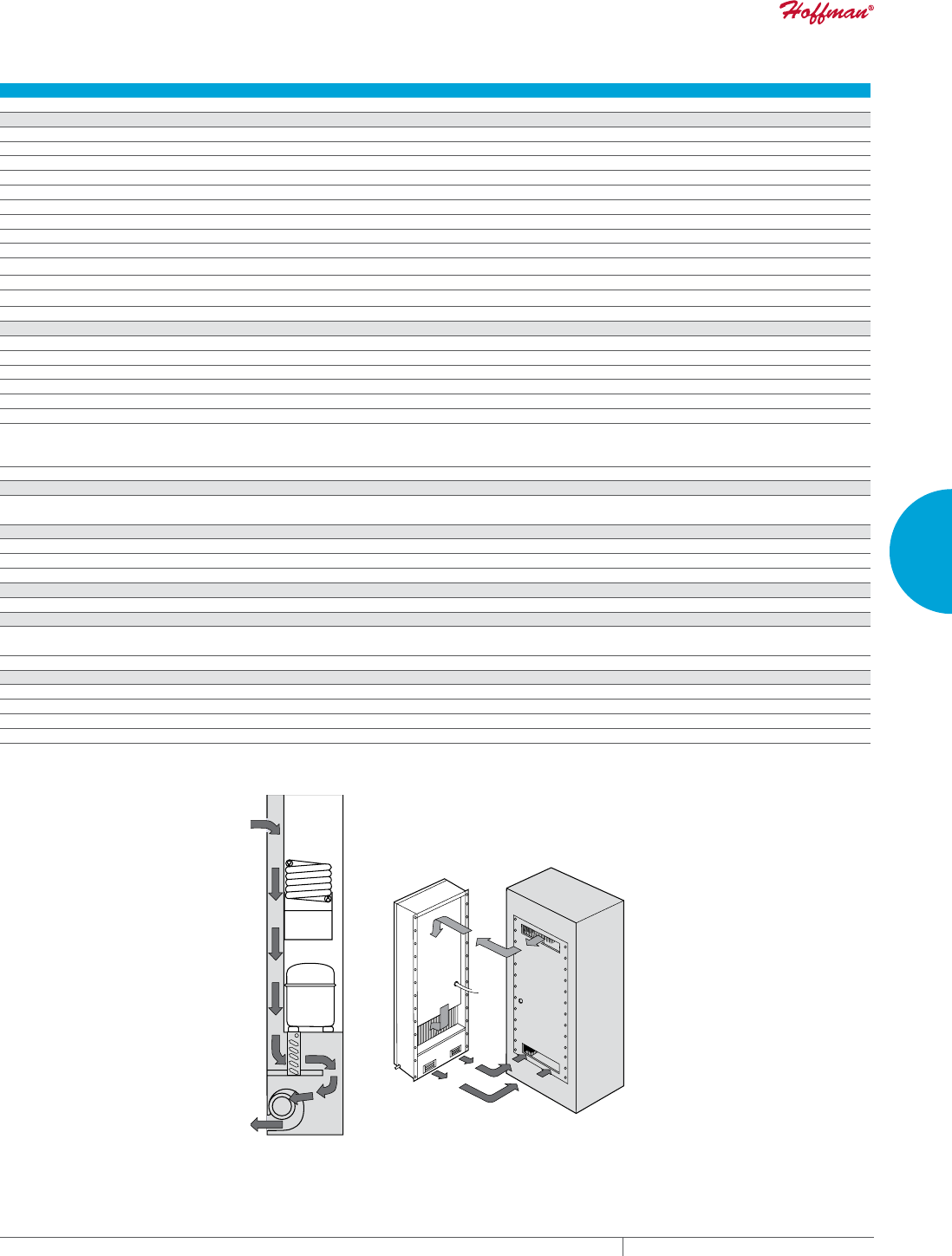
PH 763.422.2211 • FAX 763.576.3200 • HOFFMANONLINE.COMEQUIPMENT PROTECTION COOLING 137
3
SEALED ENCLOSURE COOLING AIR CONDITIONERS
Performance Data CR43WC Models 8000 BTU/Hr. (2345 Watt)
CATALOG NUMBER
CR430816GW010 CR430826GWXXX
COOLING PERFORMANCE
Nominal:
BTU/Hr. 8500 8500
Watts 2490 2490
Refrigerant R-134A R-134A
Refrigerant Charge (ounces/grams) 12/341 12/341
Operating Temperature Range:
Maximum (°F/°C) 131/55 131/55
Minimum (°F/°C) 50/10 50/10
Airflow at 0 Static Pressure:
Internal loop 50 Hz (CFM / m3/hr.) 135/229 100/170
External loop 50 Hz Waterflow: 1.5 GPM @ 90F Waterflow: 1.5 GPM @ 90F
Internal loop 60 Hz (CFM / m3/hr.) 145/246 110/187
External loop 60 Hz Waterflow: 1.5 GPM @ 90F Waterflow: 1.5 GPM @ 90F
ELECTRICAL DATA
Rated Voltage 115 230
Frequency (Hz) 50/60 50/60
Operating Range +/- 10% +/- 10%
Max. Power Consumption (W at 50 / 60 Hz) 1518/1495 1518/1495
Max. Nominal Current (A at 50 / 60 Hz) 13.2/13 6.6/6.5
Starting Current (A) 48.3 27
Agency Approvals cUL Listed
CE
GOST
Power Input Description 6-ft. cord with NEMA 5-15 plug 6-ft. cord with NEMA 6-15 plug
ENCLOSURE PROTECTION
UL Type Type 4 standard
Type 4X Stainless steel optional
CONTROLLER
Description Basic mechanical thermostat
Thermostat Location Behind front cover
Factory Thermostat Setting (°F/°C) 80/27
SOUND LEVEL
At 1.5 Meters 61 dB(A)
UNIT CONSTRUCTION
Material Mild steel sheet metal standard
Stainless steel optional
Finish RAL 7035 light-gray, semi-textured powder-coat paint standard
UNIT DIMENSIONS
Height (in./mm) 43.31/1100
Width (in./mm) 15.75/400
Depth (in./mm) 10.25/260.4
Weight (lb./kg) 86/39
CR43WC
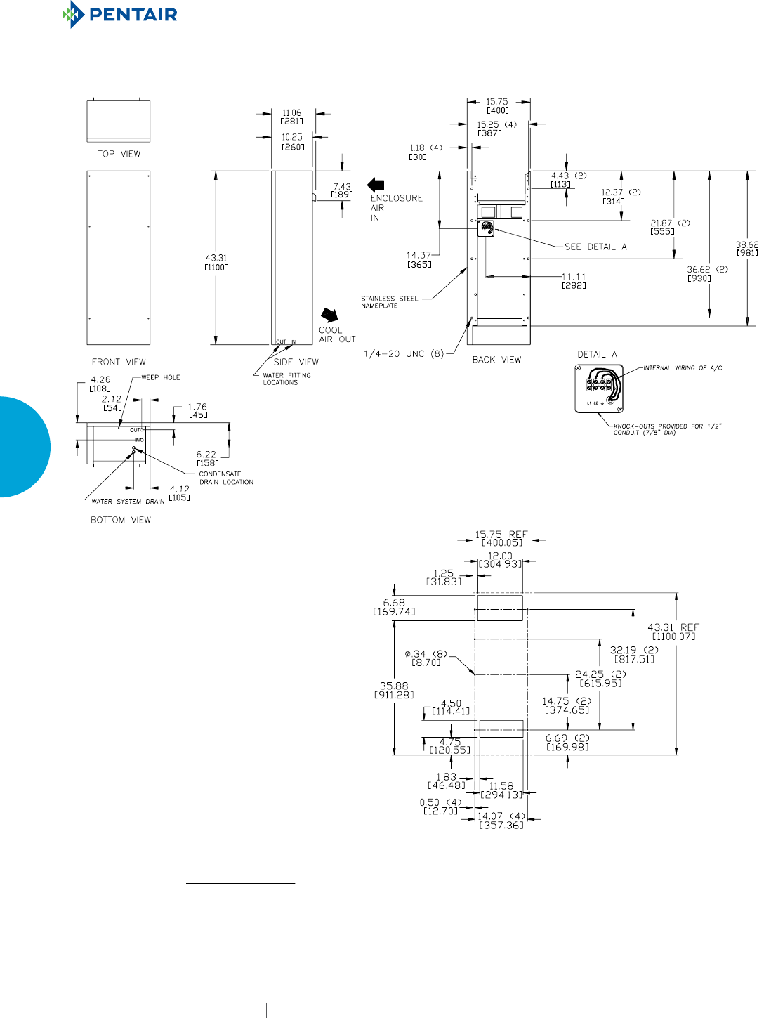
EQUIPMENT PROTECTIONSUBJECT TO CHANGE WITHOUT NOTICECOOLING138
3
SEALED ENCLOSURE COOLING AIR CONDITIONERS
Cutout Dimensions
CR43WC Models 8000 BTU/Hr. (2345 Watt)
89045091
Visit www
.HoffmanOnline.com to download 2D and 3D CAD drawings into the overall design of your electr
onic system.

PH 763.422.2211 • FAX 763.576.3200 • HOFFMANONLINE.COMEQUIPMENT PROTECTION COOLING 139
3
SEALED ENCLOSURE COOLING AIR CONDITIONERS
Notes
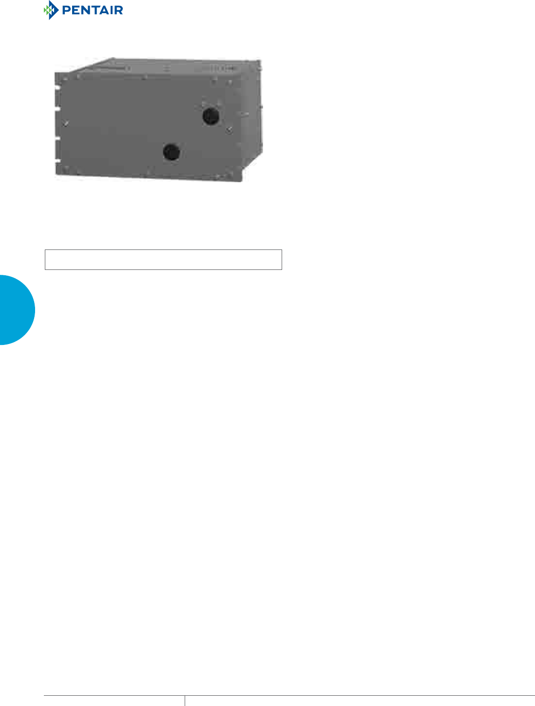
EQUIPMENT PROTECTIONSUBJECT TO CHANGE WITHOUT NOTICECOOLING140
3
SEALED ENCLOSURE COOLING AIR CONDITIONERS
WATERCOOLED RACKMOUNT
LB11WC
4000 BTU/Hr.
1172 Watt
INDUSTRY STANDARDS
UL/cUL Listed; Type 12; File No. SA6453
UR/cUR Recognized
UR/cUR Recognized on select models, reference performance data
tables.
CE
GOST
APPLICATION
• Industrial automation
• Package handling equipment
• Food and beverage
• Wastewater treatment
• Security and defense systems
• Pulp and paper
• And more
FEATURES
• Robust reciprocating compressor
• R134a earth-friendly refrigerant
• Models for 115 and 230 VAC power input
• UL Listed or Recognized to save customers time and money with
agency approvals
• Operating temperature range from 50 F/10 C to 125 F/52 C
• Reliable mechanical thermostat located behind the front panel of
the unit
• Low-carbon mild-steel sheet-metal cover for rugged factory and
outdoor environments
• Easy-mount flanges for simple installation
• Mounting hardware, gaskets and user manual furnished with the
unit
• Every unit functionally tested before shipping
• Heat is removed from the system by means of the water cooling
the refrigerant; no external air movers or condenser coils to get
clogged
• Maximum water usage of 2 GPM at 90 F water intake temperature
• Standard Indoor Air Conditioner models also include:
- Electro-Mechanical Thermostat
- Surge Suppressor
FINISH
• RAL 7042 gray, semi-gloss powder-coat paint standard
• Stainless steel Type 304 or 316 finishes available on Type 4X
models
• Other colors and textures available
OPTIONS
• Thermostat Malfunction Package
• Special Voltage Package
• Active Condensate Evaporator Package
• Harsh Environment Package*
• Stainless Steel Package*
* Consult the factory for availability and catalog number.
NOTES
Visit www.HoffmanOnline.com to download 2D and 3D CAD
drawings into the overall design of your electronic system.
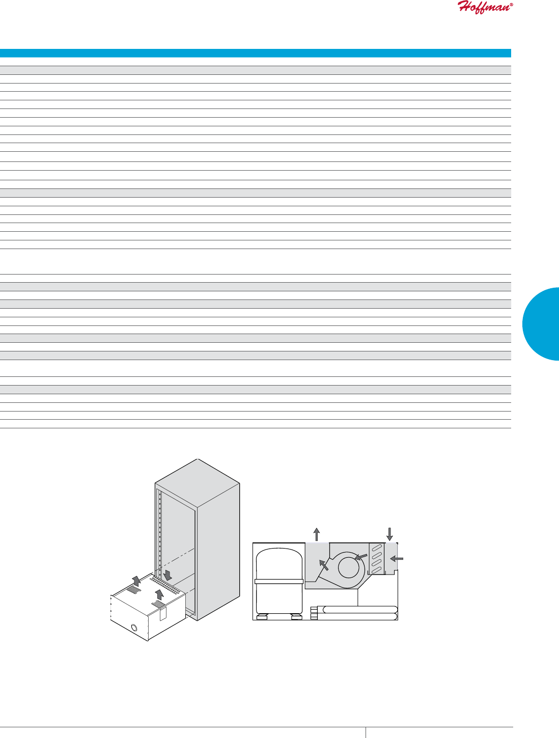
PH 763.422.2211 • FAX 763.576.3200 • HOFFMANONLINE.COMEQUIPMENT PROTECTION COOLING 141
3
SEALED ENCLOSURE COOLING AIR CONDITIONERS
Performance Data LB11WC Models 4000 BTU/Hr. (1172 Watt)
CATALOG NUMBER
LB110416GW008 LB110426GW010
COOLING PERFORMANCE
Nominal:
BTU/Hr. 3900/4000 3900/4000
Watts 1142/1172 1142/1172
Refrigerant R-134A R-134A
Refrigerant Charge (ounces/grams) 12/340 12/340
Operating Temperature Range:
Maximum (°F/°C) 125/52 125/52
Minimum (°F/°C) 50/10 50/10
Airflow at 0 Static Pressure:
Internal loop 50 Hz (CFM / m3/hr.) 135/229 100/170
External loop 50 Hz Waterflow: 1.0 GPM @ 90 F Waterflow: 1.0 GPM @ 90 F
Internal loop 60 Hz (CFM / m3/hr.) 145/246 110/187
External loop 60 Hz Waterflow: 1.0 GPM @ 90 F Waterflow: 1.0 GPM @ 90 F
ELECTRICAL DATA
Rated Voltage 115 230
Frequency (Hz) 50/60 50/60
Operating Range +/- 10% +/- 10%
Max. Power Consumption (W at 50/60 Hz) 885.5/828 897/792
Max. Nominal Current (A at 50/60 Hz) 7.7/7.2 3.9/3.6
Starting Current (A) 28 14.4
Agency Approvals Not listed cUL Listed
CE
GOST
Power Input Description 6-ft. cord with NEMA 5-15 plug 6-ft. cord with NEMA 6-15 plug
ENCLOSURE PROTECTION
UL Type Type 12 standard
CONTROLLER
Description Basic mechanical thermostat
Thermostat Location Behind front cover
Factory Thermostat Setting (°F/°C) 80/27
SOUND LEVEL
At 1.5 Meters 61 dB(A)
UNIT CONSTRUCTION
Material Mild steel sheet metal standard
Stainless steel optional
Finish RAL 7042 gray, semi-gloss powder-coat paint standard
UNIT DIMENSIONS
Height (in./mm) 10.47/266
Width (in./mm) 19/483
Depth (in./mm) 19.63/499
Weight (lb./kg) 110/50
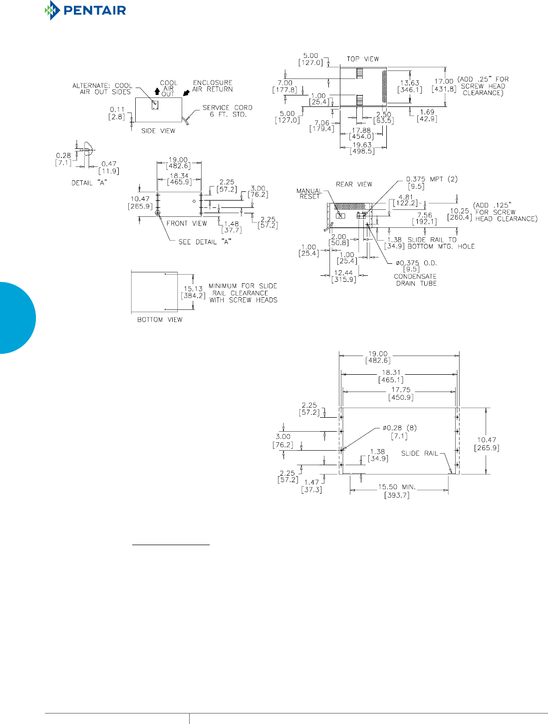
EQUIPMENT PROTECTIONSUBJECT TO CHANGE WITHOUT NOTICECOOLING142
3
SEALED ENCLOSURE COOLING AIR CONDITIONERS
Cutout Dimensions
LB11WC Models 4000 BTU/Hr. (1172 Watt)
89045092
Visit www
.HoffmanOnline.com to download 2D and 3D CAD drawings into the overall design of your electr
onic system.

PH 763.422.2211 • FAX 763.576.3200 • HOFFMANONLINE.COMEQUIPMENT PROTECTION COOLING 143
3
SEALED ENCLOSURE COOLING AIR CONDITIONERS
Notes
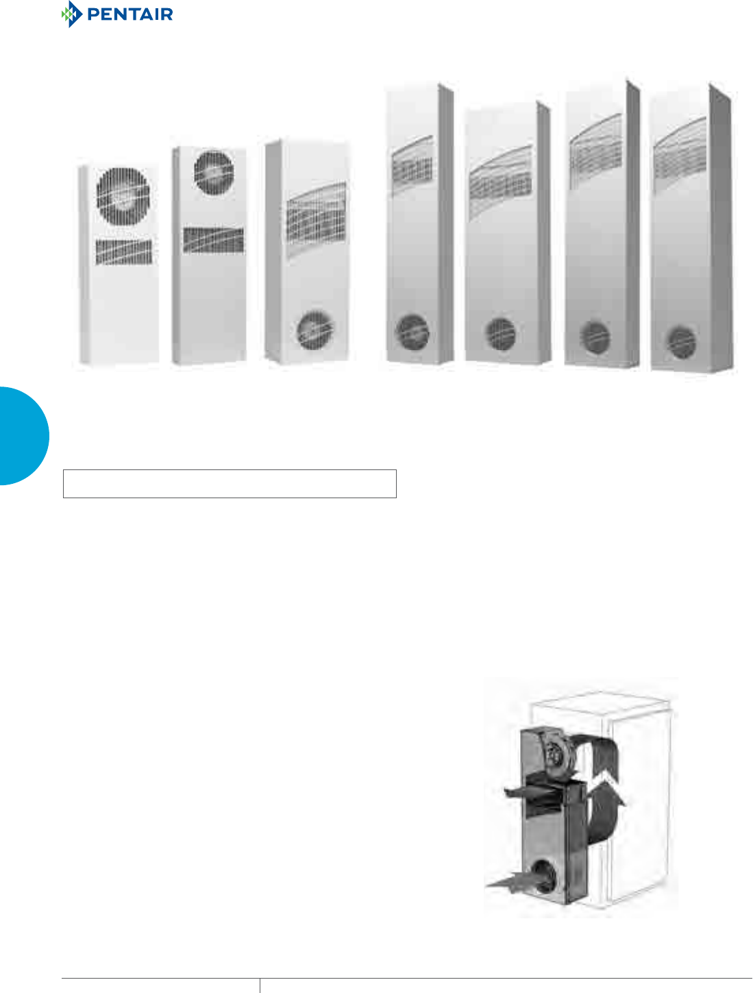
EQUIPMENT PROTECTIONSUBJECT TO CHANGE WITHOUT NOTICECOOLING144
3
SEALED ENCLOSURE COOLING HEAT EXCHANGERS
HEAT E XCHA NGER S
CLIMAGUARD™ AIRTOAIR INDOOR
XR20
Models
4 W/°F (7 W/°C)
XR29-08
Models
8 W/°F (14 W/°C)
XR29-18
Models
18 W/°F (32 W/°C)
XR47-24
Models
24 W/°F (43 W/°C)
XR47-35
Models
35 W/°F (63 W/°C)
XR60-55
Models
55 W/°F (99 W/°C)
XR60-84
Models
84 W/°F (151 W/°C)
INDUSTRY STANDARDS
UL/cUL Listed; Type 12, 3R; File No. SA7402
UR/cUR Recognized
Type 12 on XR20 and XR29-08 models
Type 3R on XR29-18 and larger models when surface mounted
vertically on an enclosure
CE
GOST
APPLICATION
• Industrial automation
• Package handling equipment
• Security and defense systems
• And more
FEATURES
• Unique counterflow aluminum core for high-efficiency and high-
performance heat transfer, except for the XR20 and XR29-08
which use a modified heat pipe core
• Models for 115 and 230 VAC power input
• UL Listed or Recognized to save customers time and money with
agency approvals
• Operating temperature range from -20 F/-29 C to 140 F/60 C
• Streamlined aesthetics with no visible mounting rails; Slim
design allows for mounting to narrow or shallow enclosures
• Reliable top-quality bearing fans and impellers make these units
run quietly and with increased reliability
• Low-carbon mild-steel sheet-metal cover for rugged factory
environments
• Easy-mount flanges for simple installation
• Mounting hardware, gaskets and user manual furnished with the
unit
• Every unit functionally tested before shipping
• Filterless design for low maintenance and easy cleaning
• Four fasteners allow simple removal of front cover for easy
access
FINISH
• RAL 7035 light-gray, semi-textured powder-coat paint standard
• Stainless steel Type 304 or 316 finishes available on Type 4X
models
• Other colors and textures available
OPTIONS
• Special Voltage Package
• Outdoor Package*
• Harsh Environment Package*
• Stainless Steel Package*
* CLIMAGUARD™ may be more appropriate. Refer to
CLIMAGUARD Air-to-Air Outdoor chapter. Consult the factory
for availability and catalog number.
NOTES
Visit www.hoffmanonline.com to download 2D and 3D CAD drawings
into the overall design of your electronic system

PH 763.422.2211 • FAX 763.576.3200 • HOFFMANONLINE.COMEQUIPMENT PROTECTION COOLING 145
3
SEALED ENCLOSURE COOLING HEAT EXCHANGERS
Performance Data XR20 Models 4 W/°F (7 W/°C)
CATALOG NUMBER
XR200416012 XR200426012
COOLING PERFORMANCE
Nominal:
W per °F 4 4
W per °C 7 7
Refrigerant R-134A R-134A
Refrigerant Charge (ounces/grams) 4/113 4/113
Operating Temperature Range:
Maximum (°F/°C) 140/60 140/60
Minimum (°F/°C) -20/-29 -20/-29
Airflow at 0 Static Pressure:
Internal loop 50 Hz (CFM / m3/hr.) 71/121 71/121
External loop 50 Hz (CFM / m3/hr.) 75/127 75/127
Internal loop 60 Hz (CFM / m3/hr.) 74/126 74/126
External loop 60 Hz (CFM / m3/hr.) 78/132 78/132
ELECTRICAL DATA
Rated Voltage 115 230
Frequency (Hz) 50/60 50/60
Operating Range +/- 10% +/- 10%
Max. Power Consumption (W at 50/60 Hz) 69 69
Max. Nominal Current (A at 50/60 Hz) 0.6 0.3
Agency Approvals cUL Listed
CE
GOST
Power Input Description 6-ft. cord with NEMA 5-15 plug 6-ft. cord with NEMA 6-15 plug
ENCLOSURE PROTECTION
UL Type Type 12 standard
SOUND LEVEL
At 1.5 Meters 56 dBA
UNIT CONSTRUCTION
Material Mild steel sheet metal standard
Stainless steel optional
Finish RAL 7035 light-gray, semi-textured powder-coat paint standard
UNIT DIMENSIONS
Height (in./mm) 20/508 20/508
Width (in./mm) 7.5/190.5 7.5/190.5
Depth (in./mm) 3/76.2 3/76.2
Weight (lb./kg) 12/5.4 12/5.4
Mounting Options
External
Top-Mount
Internal
Top-Mount
External
Vertical-Mount
Internal
Vertical-Mount
Note:
Internal
mounting
requires
inverting
the heat
exchanger
as shown.
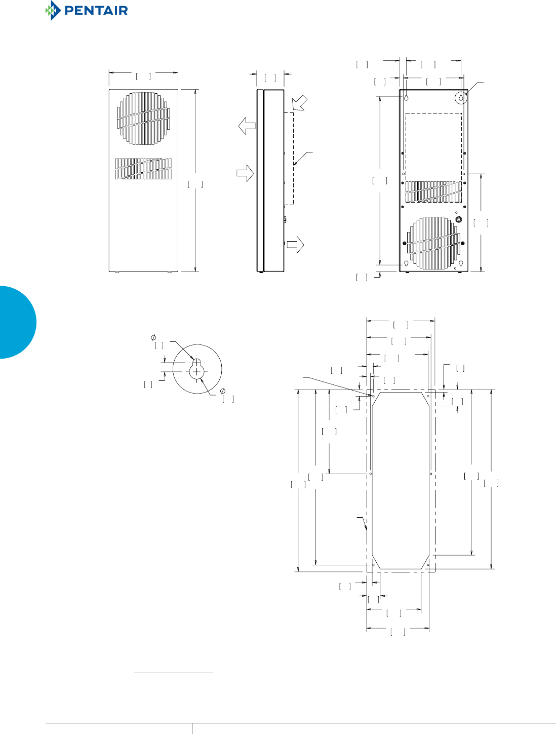
EQUIPMENT PROTECTIONSUBJECT TO CHANGE WITHOUT NOTICECOOLING146
3
SEALED ENCLOSURE COOLING HEAT EXCHANGERS
(1&/2685(
$,5287
(1&/2685(
$,5,1
6((127(
;
;
;
;
;
6(('(7$,/$
;
;
;
;
;
+(287/,1(
81&
;
'(7$,/$
;
;50RGHOV:r):r&
127(
02817,1**$6.(76833/,('1276+2:1
81,76LQ>PP@
6(59,&(&25'7(50,1$7(':,7+$335235,$7(3/8*
1(0$3)25981,76
1(0$3)25981,76
'(7$&+$%/($,5)/2:3/(1800$<%(86(':+(1
02817,1*7+(+($7(;&+$1*(5,16,'(252876,'(
2)7+((1&/2685(
$0%,(17
$,5,1
$0%,(17
$,5287
&XWRXW'LPHQVLRQV
Visit www
.HoffmanOnline.com to download 2D and 3D CAD drawings into the overall design of your electr
onic system.

PH 763.422.2211 • FAX 763.576.3200 • HOFFMANONLINE.COMEQUIPMENT PROTECTION COOLING 147
3
SEALED ENCLOSURE COOLING HEAT EXCHANGERS
Performance Data XR29 Models 8 W/°F (14 W/°C)
CATALOG NUMBER
XR290816012 XR290826012
COOLING PERFORMANCE
Nominal:
W per °F 8 8
W per °C 14 14
Refrigerant R-134A R-134A
Refrigerant Charge (ounces/grams) 5.5/156 5.5/156
Operating Temperature Range:
Maximum (°F/°C) 140/60 140/60
Minimum (°F/°C) -20/-29 -20/-29
Airflow at 0 Static Pressure:
Internal loop 50 Hz (CFM / m3/hr.) 71/121 71/121
External loop 50 Hz (CFM / m3/hr.) 75/127 75/127
Internal loop 60 Hz (CFM / m3/hr.) 74/126 74/126
External loop 60 Hz (CFM / m3/hr.) 78/132 78/132
ELECTRICAL DATA
Rated Voltage 115 230
Frequency (Hz) 50/60 50/60
Operating Range +/- 10% +/- 10%
Max. Power Consumption (W at 50/60 Hz) 69 69
Max. Nominal Current (A at 50/60 Hz) 0.6 0.3
Agency Approvals cUL Listed
CE
GOST
Power Input Description 6-ft. cord with NEMA 5-15 plug 6-ft. cord with NEMA 6-15 plug
ENCLOSURE PROTECTION
UL Type Type 12 standard
SOUND LEVEL
At 1.5 Meters 56 dBA
UNIT CONSTRUCTION
Material Mild steel sheet metal standard
Stainless steel optional
Finish RAL 7035 light-gray, semi-textured powder-coat paint standard
UNIT DIMENSIONS
Height (in./mm) 29.5/749.3 29.5/749.3
Width (in./mm) 10/254 10/254
Depth (in./mm) 3.09/78.5 3.09/78.5
Weight (lb./kg) 21/9.5 21/9.5
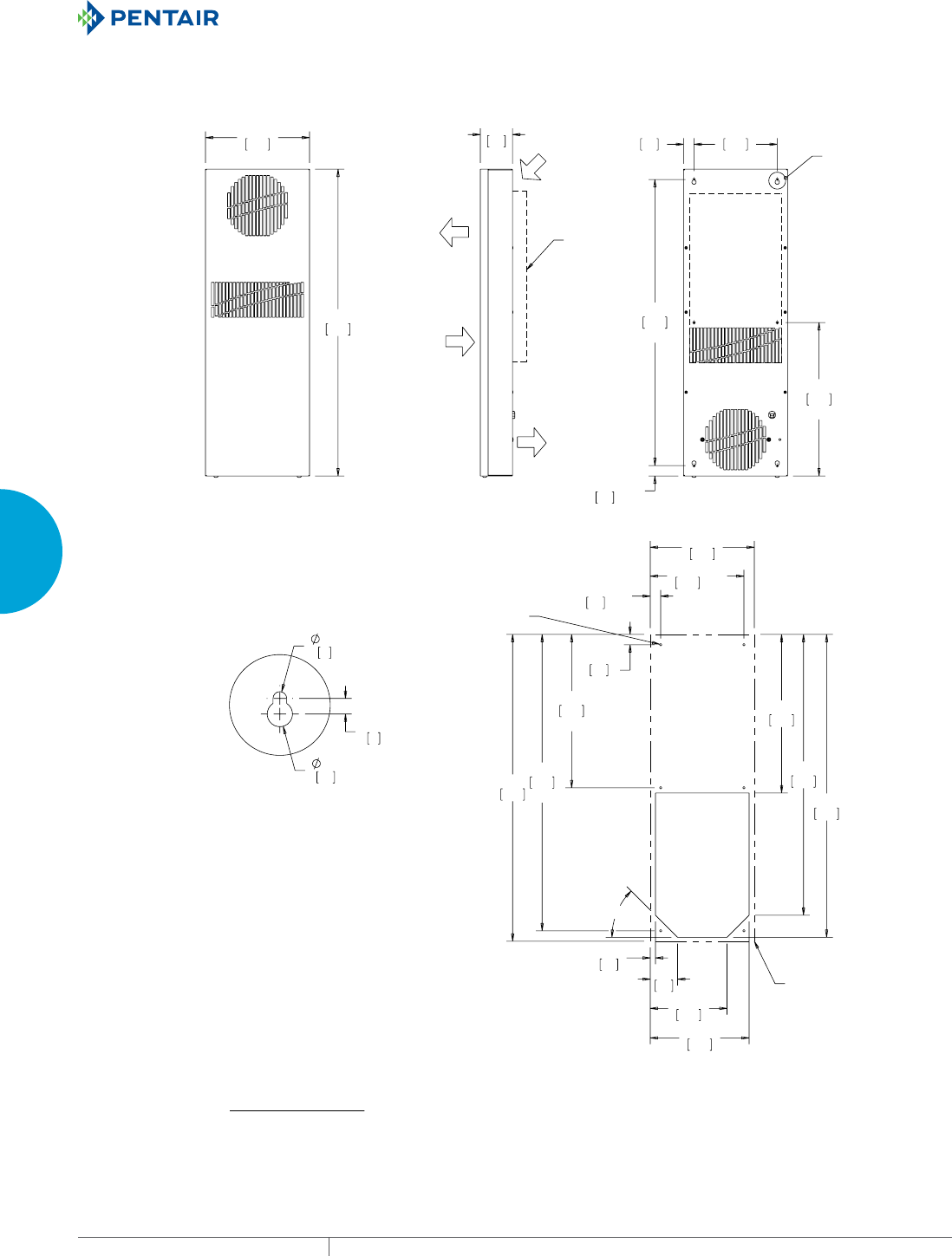
EQUIPMENT PROTECTIONSUBJECT TO CHANGE WITHOUT NOTICECOOLING148
3
SEALED ENCLOSURE COOLING HEAT EXCHANGERS
$0%,(17
$,5287
$0%,(17
$,5,1
(1&/2685(
$,5,1
(1&/2685(
$,5287
6((127(
;
;
;
;
;
6(('(7$,/
$
;
;
;
;
;
r
;
&XWRXW'LPHQVLRQV
+(287/,1(
81&
;
'(7$,/$
;
;50RGHOV:r):r&
127(
02817,1**$6.(76833/,('1276+2:1
81,76LQ>PP@
6(59,&(&25'7(50,1$7(':,7+$335235,$7(3/8*
1(0$S)25981,76
1(0$3)25981,76
'(7$&+$%/($,5)/2:3/(1800$<%(86(':+(1
02817,1*7+(+($7(;&+$1*(5,16,'(252876,'(
2)7+((1&/2685(
Visit www
.HoffmanOnline.com to download 2D and 3D CAD drawings into the overall design of your electr
onic system.

PH 763.422.2211 • FAX 763.576.3200 • HOFFMANONLINE.COMEQUIPMENT PROTECTION COOLING 149
3
SEALED ENCLOSURE COOLING HEAT EXCHANGERS
Performance Data XR29 Models 18 W/°F (32 W/°C)
CATALOG NUMBER
XR291816012 XR291826012
COOLING PERFORMANCE
Nominal:
W per °F 18 18
W per °C 32 32
Refrigerant N/A N/A
Refrigerant Charge (ounces/grams) N/A N/A
Operating Temperature Range:
Maximum (°F/°C) 140/60 140/60
Minimum (°F/°C) -20/-29 -20/-29
Airflow at 0 Static Pressure:
Internal loop 50 Hz (CFM / m3/hr.) 126/214 126/214
External loop 50 Hz (CFM / m3/hr.) 120/204 120/204
Internal loop 60 Hz (CFM / m3/hr.) 140/237 140/237
External loop 60 Hz (CFM / m3/hr.) 133/226 133/226
ELECTRICAL DATA
Rated Voltage 115 230
Frequency (Hz) 50/60 50/60
Operating Range +/- 10% +/- 10%
Max. Power Consumption (W at 50/60 Hz) 207 207
Max. Nominal Current (A at 50/60 Hz) 1.8 0.9
Agency Approvals cUL Listed
CE
GOST
Power Input Description 6-ft. cord with NEMA 5-15 plug 6-ft. cord with NEMA 6-15 plug
ENCLOSURE PROTECTION
UL Type Type 12 standard
Type 3R, 4, 4X optional
SOUND LEVEL
At 1.5 Meters 64 dBA
UNIT CONSTRUCTION
Material Mild steel sheet metal standard
Stainless steel optional
Finish RAL 7035 light-gray, semi-textured powder-coat paint standard
UNIT DIMENSIONS
Height (in./mm) 29.66/753.3 29.66/753.3
Width (in./mm) 10.24/260.1 10.24/260.1
Depth (in./mm) 5.92/150.4 5.92/150.4
Weight (lb./kg) 32/15 32/15
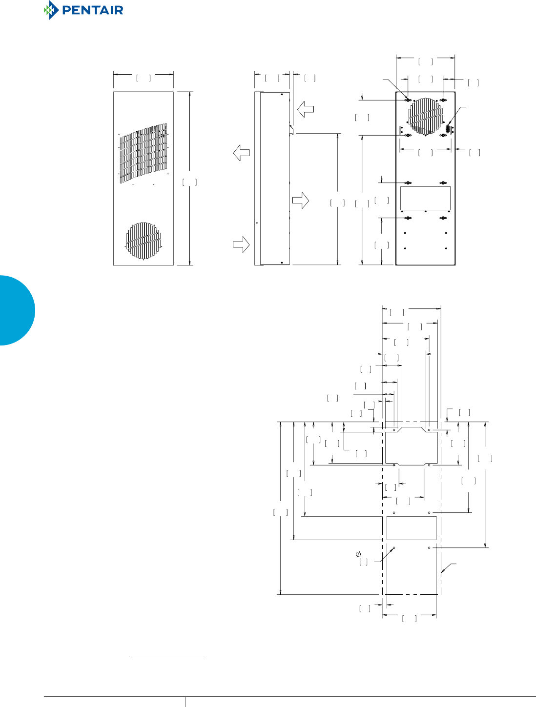
EQUIPMENT PROTECTIONSUBJECT TO CHANGE WITHOUT NOTICECOOLING150
3
SEALED ENCLOSURE COOLING HEAT EXCHANGERS
(1&/2685(
$,5,1
(1&/2685(
$,5287
$0%,(17
$,5287
$0%,(17
$,5,1
;
;
;
;
02817,1*
+$5':$5(
,(&&
32:(5
,1/(7
;
;
;
;
;
;
;
;
;
;
;
+(287/,1(
;50RGHOV:r):r&
127(
02817,1**$6.(76833/,('1276+2:1
81,76LQ>PP@
&XWRXW'LPHQVLRQV
Visit www
.HoffmanOnline.com to download 2D and 3D CAD drawings into the overall design of your electr
onic system.
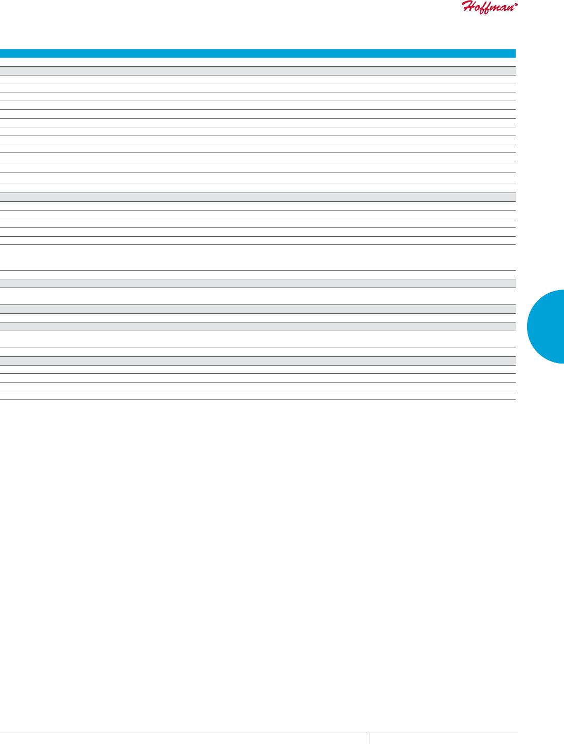
PH 763.422.2211 • FAX 763.576.3200 • HOFFMANONLINE.COMEQUIPMENT PROTECTION COOLING 151
3
SEALED ENCLOSURE COOLING HEAT EXCHANGERS
Performance Data XR47 Models 24 W/°F (43 W/°C)
CATALOG NUMBER
XR472416012 XR472426012
COOLING PERFORMANCE
Nominal:
W per °F 24 24
W per °C 43 43
Refrigerant N/A N/A
Refrigerant Charge (ounces/grams) N/A N/A
Operating Temperature Range:
Maximum (°F/°C) 140/60 140/60
Minimum (°F/°C) -20/-29 -20/-29
Airflow at 0 Static Pressure:
Internal loop 50 Hz (CFM / m3/hr.) 140/238 140/238
External loop 50 Hz (CFM / m3/hr.) 118/200 118/200
Internal loop 60 Hz (CFM / m3/hr.) 156/265 156/265
External loop 60 Hz (CFM / m3/hr.) 131/222 131/222
ELECTRICAL DATA
Rated Voltage 115 230
Frequency (Hz) 50/60 50/60
Operating Range +/- 10% +/- 10%
Max. Power Consumption (W at 50/60 Hz) 207 207
Max. Nominal Current (A at 50/60 Hz) 1.8 0.9
Agency Approvals cUL Listed
CE
GOST
Power Input Description 6-ft. cord with NEMA 5-15 plug 6-ft. cord with NEMA 6-15 plug
ENCLOSURE PROTECTION
UL Type Type 12 standard
Type 3R, 4, 4X optional
SOUND LEVEL
At 1.5 Meters 68 dBA
UNIT CONSTRUCTION
Material Mild steel sheet metal standard
Stainless steel optional
Finish RAL 7035 light-gray, semi-textured powder-coat paint standard
UNIT DIMENSIONS
Height (in./mm) 47.16/1197.9 47.16/1197.9
Width (in./mm) 10.24/260.1 10.24/260.1
Depth (in./mm) 5.92/150.4 5.92/150.4
Weight (lb./kg) 51/23 51/23
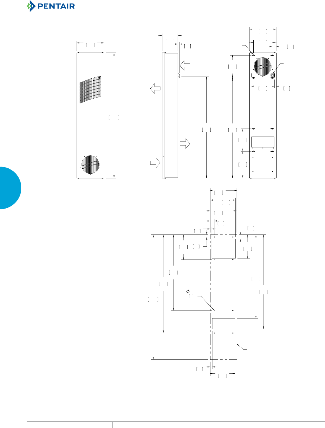
EQUIPMENT PROTECTIONSUBJECT TO CHANGE WITHOUT NOTICECOOLING152
3
SEALED ENCLOSURE COOLING HEAT EXCHANGERS
$0%,(17
$,5287
$0%,(17
$,5,1
(1&/2685(
$,5,1
(1&/2685(
$,5287
;
;
;
;
;
,(&&
32:(5
,1/(7
;
02817,1*
+$5':$5(
;
;
;
;
;
;
;
&XWRXW'LPHQVLRQV
+(287/,1(
;50RGHOV:r):r&
Visit www
.HoffmanOnline.com to download 2D and 3D CAD drawings into the overall design of your electr
onic system.

PH 763.422.2211 • FAX 763.576.3200 • HOFFMANONLINE.COMEQUIPMENT PROTECTION COOLING 153
3
SEALED ENCLOSURE COOLING HEAT EXCHANGERS
Performance Data XR47 Models 35 W/°F (63 W/°C)
CATALOG NUMBER
XR473516012 XR473526012
COOLING PERFORMANCE
Nominal:
W per °F 35 35
W per °C 63 63
Refrigerant N/A N/A
Refrigerant Charge (ounces/grams) N/A N/A
Operating Temperature Range:
Maximum (°F/°C) 140/60 140/60
Minimum (°F/°C) -20/-29 -20/-29
Airflow at 0 Static Pressure:
Internal loop 50 Hz (CFM / m3/hr.) 120/204 120/204
External loop 50 Hz (CFM / m3/hr.) 131/222 131/222
Internal loop 60 Hz (CFM / m3/hr.) 133/226 133/226
External loop 60 Hz (CFM / m3/hr.) 146/248 146/248
ELECTRICAL DATA
Rated Voltage 115 230
Frequency (Hz) 50/60 50/60
Operating Range +/- 10% +/- 10%
Max. Power Consumption (W at 50/60 Hz) 207 207
Max. Nominal Current (A at 50/60 Hz) 1.8 0.9
Agency Approvals cUL Listed
CE
GOST
Power Input Description 6-ft. cord with NEMA 5-15 plug 6-ft. cord with NEMA 6-15 plug
ENCLOSURE PROTECTION
UL Type Type 12 standard
Type 3R, 4, 4X optional
SOUND LEVEL
At 1.5 Meters 68 dBA
UNIT CONSTRUCTION
Material Mild steel sheet metal standard
Stainless steel optional
Finish RAL 7035 light-gray, semi-textured powder-coat paint standard
UNIT DIMENSIONS
Height (in./mm) 47.16/1197.8 47.16/1197.8
Width (in./mm) 15.24/387.1 15.24/387.1
Depth (in./mm) 5.92/150.4 5.92/150.4
Weight (lb./kg) 59/27 59/27
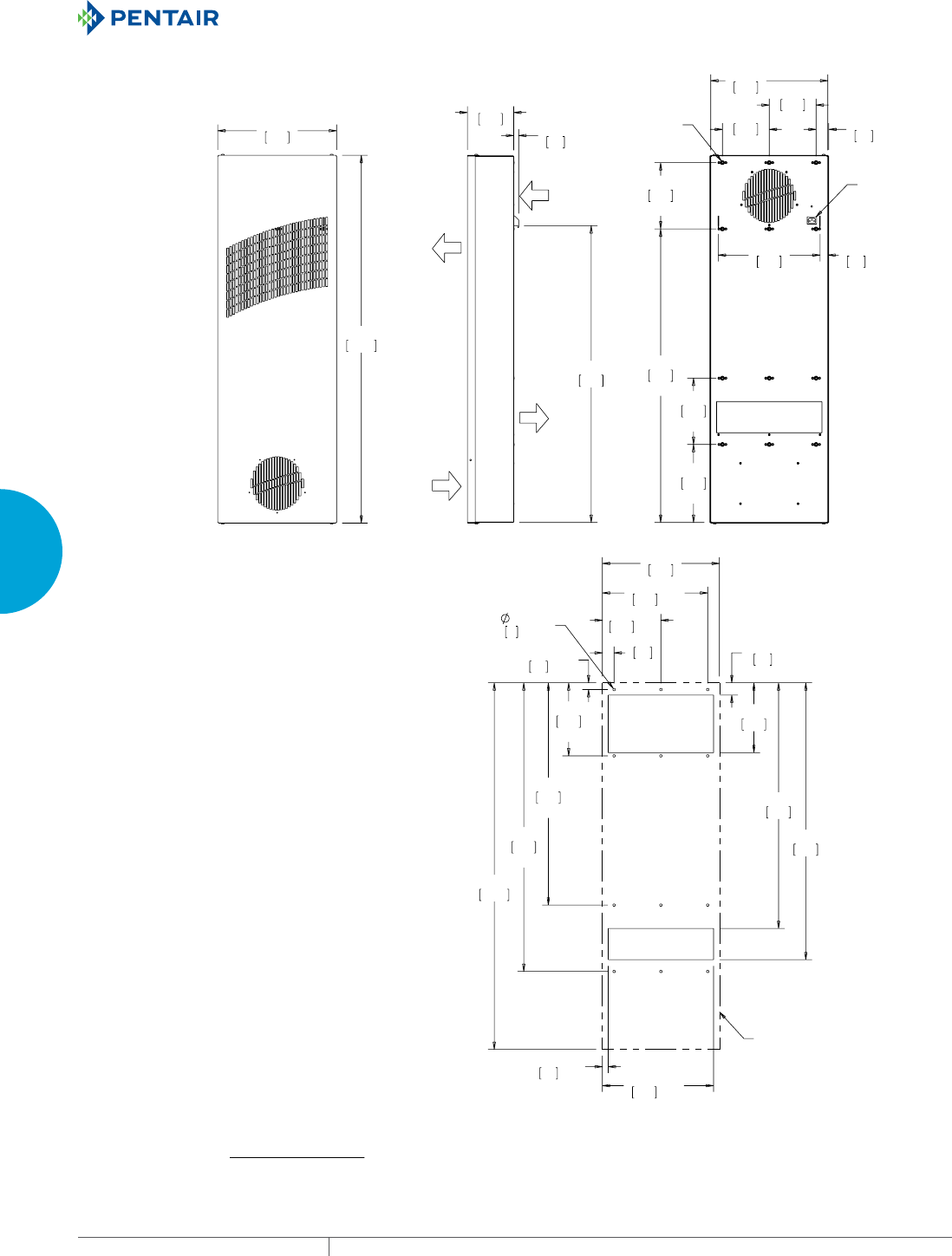
EQUIPMENT PROTECTIONSUBJECT TO CHANGE WITHOUT NOTICECOOLING154
3
SEALED ENCLOSURE COOLING HEAT EXCHANGERS
(1&/2685(
$,5,1
(1&/2685(
$,5287
$0%,(17
$,5287
$0%,(17
$,5,1
;
;
;
;
;
;
;
,(&
32:(5
,1/(7
;
02817,1*
+$5':$5(
;
;
;
;
;
;
;
;
;
;
+(287/,1(
;50RGHOV:r):r&
127(
02817,1**$6.(76833/,('1276+2:1
81,76LQ>PP@
0(7(5/21*6(59,&(&25'7(50,1$7('
:,7+$335235,$7(3/8*
1(0$3)25981,76
1(0$3)25981,76
&XWRXW'LPHQVLRQV
Visit www
.HoffmanOnline.com to download 2D and 3D CAD drawings into the overall design of your electr
onic system.

PH 763.422.2211 • FAX 763.576.3200 • HOFFMANONLINE.COMEQUIPMENT PROTECTION COOLING 155
3
SEALED ENCLOSURE COOLING HEAT EXCHANGERS
Performance Data XR60 Models 55 W/°F (99 W/°C)
CATALOG NUMBER
XR605516012 XR605526012
COOLING PERFORMANCE
Nominal:
W per °F 55 55
W per °C 99 99
Refrigerant N/A N/A
Refrigerant Charge (ounces/grams) N/A N/A
Operating Temperature Range:
Maximum (°F/°C) 140/60 140/60
Minimum (°F/°C) -20/-29 -20/-29
Airflow at 0 Static Pressure:
Internal loop 50 Hz (CFM / m3/hr.) 398/676 398/676
External loop 50 Hz (CFM / m3/hr.) 429/729 429/729
Internal loop 60 Hz (CFM / m3/hr.) 442/751 442/751
External loop 60 Hz (CFM / m3/hr.) 477/810 477/810
ELECTRICAL DATA
Rated Voltage 115 230
Frequency (Hz) 50/60 50/60
Operating Range +/- 10% +/- 10%
Max. Power Consumption (W at 50/60 Hz) 759 759
Max. Nominal Current (A at 50/60 Hz) 6.6 3.3
Agency Approvals cUL Listed
CE
GOST
Power Input Description 6-ft. cord with NEMA 5-15 plug 6-ft. cord with NEMA 6-15 plug
ENCLOSURE PROTECTION
UL Type Type 12 standard
Type 3R, 4, 4X optional
SOUND LEVEL
At 1.5 Meters 73 dBA
UNIT CONSTRUCTION
Material Mild steel sheet metal standard
Stainless steel optional
Finish RAL 7035 light-gray, semi-textured powder-coat paint standard
UNIT DIMENSIONS
Height (in./mm) 59.66/1515.3 59.66/1515.3
Width (in./mm) 15.24/387.1 15.24/387.1
Depth (in./mm) 5.92/150.4 5.92/150.4
Weight (lb./kg) 86/39 86/39

EQUIPMENT PROTECTIONSUBJECT TO CHANGE WITHOUT NOTICECOOLING156
3
SEALED ENCLOSURE COOLING HEAT EXCHANGERS
(1&/2685(
$,5,1
(1&/2685(
$,5287
$0%,(17
$,5287
$0%,(17
$,5,1
;
;
;
;
;
;
;
,(&
32:(5
,1/(7
;
02817,1*
+$5':$5(
;
;
;
;
;
;
;
;
&XWRXW'LPHQVLRQV
+(287/,1(
;50RGHOV:r):r&
127(
02817,1**$6.(76833/,('
1276+2:1
81,76LQ>PP@
0(7(5/21*6(59,&(&25'
6833/,(':,7+$335235,$7(3/8*
1(0$3)25981,76
1(0$3)25981,76
Visit www
.HoffmanOnline.com to download 2D and 3D CAD drawings into the overall design of your electr
onic system.

PH 763.422.2211 • FAX 763.576.3200 • HOFFMANONLINE.COMEQUIPMENT PROTECTION COOLING 157
3
SEALED ENCLOSURE COOLING HEAT EXCHANGERS
Performance Data XR60 Models 84 W/°F (151 W/°C)
CATALOG NUMBER
XR608416012 XR608426012
COOLING PERFORMANCE
Nominal:
W per °F 84 84
W per °C 151 151
Refrigerant N/A N/A
Refrigerant Charge (ounces/grams) N/A N/A
Operating Temperature Range:
Maximum (°F/°C) 140/60 140/60
Minimum (°F/°C) -20/-29 -20/-29
Airflow at 0 Static Pressure:
Internal loop 50 Hz (CFM / m3/hr.) 497/844 497/844
External loop 50 Hz (CFM / m3/hr.) 434/737 434/737
Internal loop 60 Hz (CFM / m3/hr.) 552/938 552/938
External loop 60 Hz (CFM / m3/hr.) 482/819 482/819
ELECTRICAL DATA
Rated Voltage 115 230
Frequency (Hz) 50/60 50/60
Operating Range +/- 10% +/- 10%
Max. Power Consumption (W at 50/60 Hz) 759 759
Max. Nominal Current (A at 50/60 Hz) 6.6 3.3
Agency Approvals cUL Listed
CE
GOST
Power Input Description 6-ft. cord with NEMA 5-15 plug 6-ft. cord with NEMA 6-15 plug
ENCLOSURE PROTECTION
UL Type Type 12 standard
Type 3R, 4, 4X optional
SOUND LEVEL
At 1.5 Meters 73 dBA
UNIT CONSTRUCTION
Material Mild steel sheet metal standard
Stainless steel optional
Finish RAL 7035 light-gray, semi-textured powder-coat paint standard
UNIT DIMENSIONS
Height (in./mm) 59.66/1515.3 59.66/1515.3
Width (in./mm) 15.24/387.1 15.24/387.1
Depth (in./mm) 9.92/252 9.92/252
Weight (lb./kg) 106/48 106/48
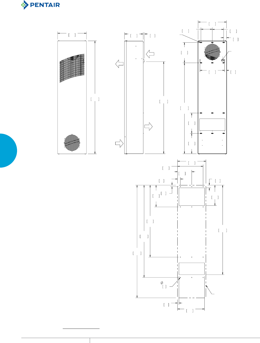
EQUIPMENT PROTECTIONSUBJECT TO CHANGE WITHOUT NOTICECOOLING158
3
SEALED ENCLOSURE COOLING HEAT EXCHANGERS
(1&/2685(
$,5,1
(1&/2685(
$,5287
$0%,(17
$,5,1
$0%,(17
$,5287
;
;
;
;
;
;
;
,(&
32:(5
,1/(7
;
02817,1*
+$5':$5(
;
;
;
;
;
;
;
+(287/,1(
;50RGHOV:r):r&
127(
02817,1**$6.(76833/,('1276+2:1
81,76LQ>PP@
0(7(5/21*6(59,&(&25'6833/,('
:,7+$335235,$7(3/8*
1(0$3)25981,76
1(0$3)25981,76
&XWRXW'LPHQVLRQV
Visit www
.HoffmanOnline.com to download 2D and 3D CAD drawings into the overall design of your electr
onic system.

PH 763.422.2211 • FAX 763.576.3200 • HOFFMANONLINE.COMEQUIPMENT PROTECTION COOLING 159
3
SEALED ENCLOSURE COOLING HEAT EXCHANGERS
Notes
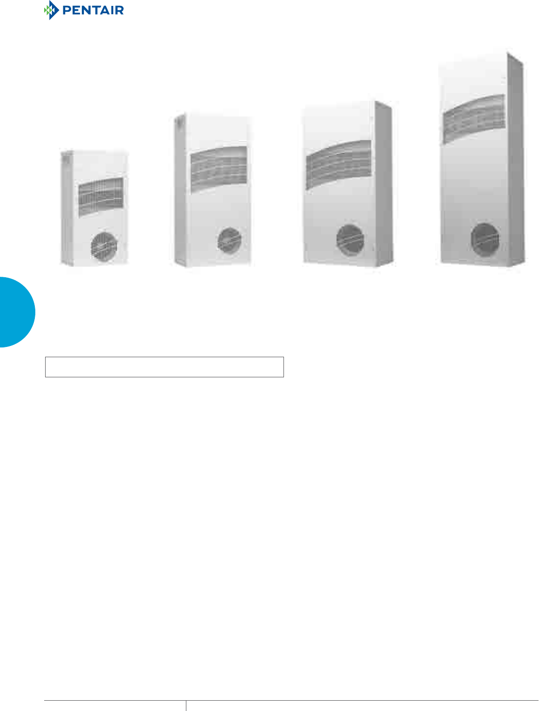
EQUIPMENT PROTECTIONSUBJECT TO CHANGE WITHOUT NOTICECOOLING160
3
SEALED ENCLOSURE COOLING HEAT EXCHANGERS
CLIMAGUARD™ AIRTOAIR OUTDOOR
TX23
Models
14 W/°F (25 W/°C)
TX33
Models
28 W/°F (50 W/°C)
TX38
Models
56 W/°F (100 W/°C)
TX52
Models
83 W/°F (150 W/°C)
INDUSTRY STANDARDS
UL/cUL Listed; Type 12, 3R, 4; 4X optional; File No. SA7402
UR/cUR Recognized
UR/cUR Recognized on select models, reference performance data
tables.
CE
GOST
Telcordia GR-487 capable
APPLICATION
• Telecom shelters
• Outdoor cabinets
• Equipment buildings
• Instrument enclosures
• And more
FEATURES
• Unique counterflow aluminum core for high efficiency and high
performance heat transfer
• Models for 24 VDC, 48 VDC, 115 VAC and 230 VAC power supplies
• UL Listed or Recognized to save customers time and money with
agency approvals
• Operating temperature range from -40 F/-40 C to 149 F/65 C
• Variable speed blowers standard on DC powered units for quiet
running
• Surface or recessed mount capable
• Low-carbon mild-steel sheet-metal cover for rugged factory
environments
• Easy-mount flanges for simple installation
• Mounting hardware, gaskets and user manual furnished with the
unit
• Every unit functionally tested before shipping
• Filterless design for low maintenance and easy cleaning
• Engineered for temperature extremes, corrosive environments
and wind driven rain
FINISH
• RAL 7035 light-gray, semi-textured powder-coat paint standard
• Stainless steel Type 304 or 316 finishes available on Type 4X
models
• Other colors and textures available
OPTIONS
• Thermostat Package
• Special Voltage Package
• Outdoor Package
• Harsh Environment Package*
• Stainless Steel Package*
• Heater Package*
* Consult the factory for availability and catalog number.
NOTES
Visit www.HoffmanCoolingTech.com to download 2D and 3D CAD
drawings into the overall design of your electronic system

PH 763.422.2211 • FAX 763.576.3200 • HOFFMANONLINE.COMEQUIPMENT PROTECTION COOLING 161
3
SEALED ENCLOSURE COOLING HEAT EXCHANGERS
Performance Data TX23 Models 14 W/°F (25 W/°C)
CATALOG NUMBER
TX231416100 TX231426100 TX231424100 TX231448100
COOLING PERFORMANCE
Nominal:
W per °F 14 14 14 14
W per °C 25 25 25 25
Refrigerant N/A N/A N/A N/A
Refrigerant Charge (ounces/grams) N/A N/A N/A N/A
Operating Temperature Range
Maximum (°F/°C) 149/65 149/65 149/65 149/65
Minimum (°F/°C) -40/-40 -40/-40 -40/-40 -40/-40
Airflow at 0 Static Pressure:
Internal loop 50 Hz (CFM / m3/hr.) 69/117 69/117 N/A N/A
External loop 50 Hz (CFM / m3/hr.) 58/98 58/98 N/A N/A
Internal loop 60 Hz (CFM / m3/hr.) 84/142 84/142 175/268 175/268
External loop 60 Hz (CFM / m3/hr.) 69/117 69/117 158/297 158/297
ELECTRICAL DATA
Rated Voltage 115 VAC 230 VAC 24 VDC 48 VDC
Frequency (Hz) 50/60 50/60 50/60 50/60
Operating Range +/- 10% +/- 10% +/- 10% +/- 10%
Max. Power Consumption (W at 50/60 Hz) 69 23 82 87
Max. Nominal Current (A at 50/60 Hz) 0.6 0.1 3.4 1.8
Agency Approvals cUL Listed
CE
GOST
cUL Listed
CE
GOST
Power Input Description 6-ft. cord with
NEMA 5-15 plug
6-ft. cord with
NEMA 6-15 plug
Terminal block Terminal block
ENCLOSURE PROTECTION
UL Type Type 12, 3R, 4 standard
Type 4X optional
Type 12, 3R, 4 standard
Type 4X optional
SOUND LEVEL
At 1.5 Meters 56 dBA 56 dBA
UNIT CONSTRUCTION
Material Mild steel sheet metal standard
Stainless steel optional
Mild steel sheet metal standard
Stainless steel optional
Finish RAL 7035 light-gray, semi-textured
powder-coat paint standard
RAL 7035 light-gray, semi-textured
powder-coat paint standard
UNIT DIMENSIONS
Height (in./mm) 23/584.2 23/584.2 23/584.2 23/584.2
Width (in./mm) 12/304.8 12/304.8 12/304.8 12/304.8
Depth (in./mm) 7.1/180.3 7.1/180.3 7.1/180.3 7.1/180.3
Weight (lb./kg) 30/13.6 30/13.6 30/13.6 30/13.6
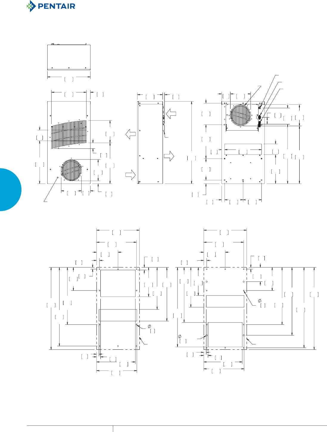
EQUIPMENT PROTECTIONSUBJECT TO CHANGE WITHOUT NOTICECOOLING162
3
SEALED ENCLOSURE COOLING HEAT EXCHANGERS
02817,1*+$5':$5()25,17(51$//02817('
02817,1*,6%(+,1'5(029$%/(&29(5
;
$0%,(17
$,5287
$0%,(17
$,5,1
(1&/2685(
$,5287
(1&/2685(
$,5,1
5(029$%/(
+$1*,1*
7$%6;
;
;
;
;
,03(//(532:(5
$1'$/$50
,17(5)$&(
$&+($7(532:(5
&21752//(5/('6
02817,1*;
21%$&.)$&(
%(+,1')5217&29(5
;
;
;
;
;
;
;
;
;
;
;
;
;
;
;
;
;
;
;
&87287',0(16,216
(;7(51$/02817
&87287',0(16,216
,17(51$/02817
+(287/,1( +(287/,1(
7;'&0RGHOV:r)r&
127(
02817,1**$6.(76833/,('1276+2:1
81,76LQ>PP@
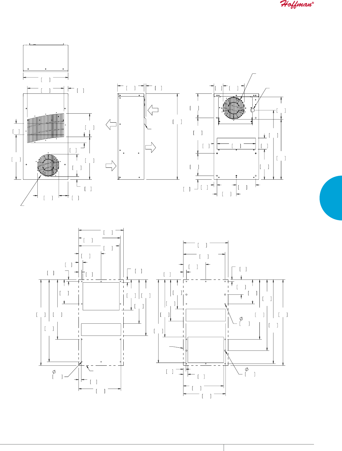
PH 763.422.2211 • FAX 763.576.3200 • HOFFMANONLINE.COMEQUIPMENT PROTECTION COOLING 163
3
SEALED ENCLOSURE COOLING HEAT EXCHANGERS
02817,1*+$5':$5()25
,17(51$//<02817('
02817,1*,6%(+,1'
5(029$%/()5217&29(5
5(029$%/(
+$1*,1*
7$%6;
(1&/2685(
$,5,1
(1&/2685(
$,5287
$0%,(17
$,5287
$0%,(17
$,5,1
;
;
;
;
;
;
32:(5&25'
(175$1&(
02817,1*;
21%$&.)$&(
%(+,1')5217&29(5
;
;
;
;
;
;
;
;
;
;
;
;
;
;
;
;
;
;
;
+(287/,1(
+(
287/,1(
7;$&0RGHOV:r):r&
127(
02817,1**$6.(76833/,('1276+2:1
81,76LQ>PP@
&87287',0(16,216
,17(51$/02817
&87287',0(16,216
(;7(51$/02817
EQUIPMENT PROTECTIONSUBJECT TO CHANGE WITHOUT NOTICECOOLING164
3
SEALED ENCLOSURE COOLING HEAT EXCHANGERS
Performance Data TX33 Models 28 W/°F (50 W/°C)
CATALOG NUMBER
TX332816100 TX332826100 TX332824100 TX332848100
COOLING PERFORMANCE
Nominal:
W per °F 28 28 28 28
W per °C 50 50 50 50
Refrigerant N/A N/A N/A N/A
Refrigerant Charge (ounces/grams) N/A N/A N/A N/A
Operating Temperature Range:
Maximum (°F/°C) 149/65 149/65 149/65 149/65
Minimum (°F/°C) -40/-40 -40/-40 -40/-40 -40/-40
Airflow at 0 Static Pressure:
Internal loop 50 Hz (CFM / m3/hr.) 212/360 212/360 N/A N/A
External loop 50 Hz (CFM / m3/hr.) 238/404 238/404 N/A N/A
Internal loop 60 Hz (CFM / m3/hr.) 228/387 228/387 228/387 228/387
External loop 60 Hz (CFM / m3/hr.) 263/447 263/447 166/282 166/282
ELECTRICAL DATA
Rated Voltage 115 VAC 230 VAC 24 VDC 48 VDC
Frequency (Hz) 50/60 50/60 50/60 50/60
Operating Range +/- 10% +/- 10% +/- 10% +/- 10%
Max. Power Consumption (W at 50/60 Hz) 161 92 82 87
Max. Nominal Current (A at 50/60 Hz) 1.4 0.4 3.4 1.8
Agency Approvals cUL Listed
CE
GOST
cUL Listed
CE
GOST
Power Input Description 6-ft. cord with
NEMA 5-15 plug
6-ft. cord with
NEMA 6-15 plug
Terminal block Terminal block
ENCLOSURE PROTECTION
UL Type Type 12, 3R, 4 standard
Type 4X optional
Type 12, 3R, 4 standard
Type 4X optional
SOUND LEVEL
At 1.5 Meters 56 dBA 56 dBA
UNIT CONSTRUCTION
Material Mild steel sheet metal standard
Stainless steel optional
Mild steel sheet metal standard
Stainless steel optional
Finish RAL 7035 light-gray, semi-textured
powder-coat paint standard
RAL 7035 light-gray, semi-textured
powder-coat paint standard
UNIT DIMENSIONS
Height (in./mm) 33/838.2 33/838.2 33/838.2 33/838.2
Width (in./mm) 15.7/398.8 15.7/398.8 15.7/398.8 15.7/398.8
Depth (in./mm) 8.1/205.7 8.1/205.7 8.1/205.7 8.1/205.7
Weight (lb./kg) 45/20.4 45/20.4 45/20.4 45/20.4
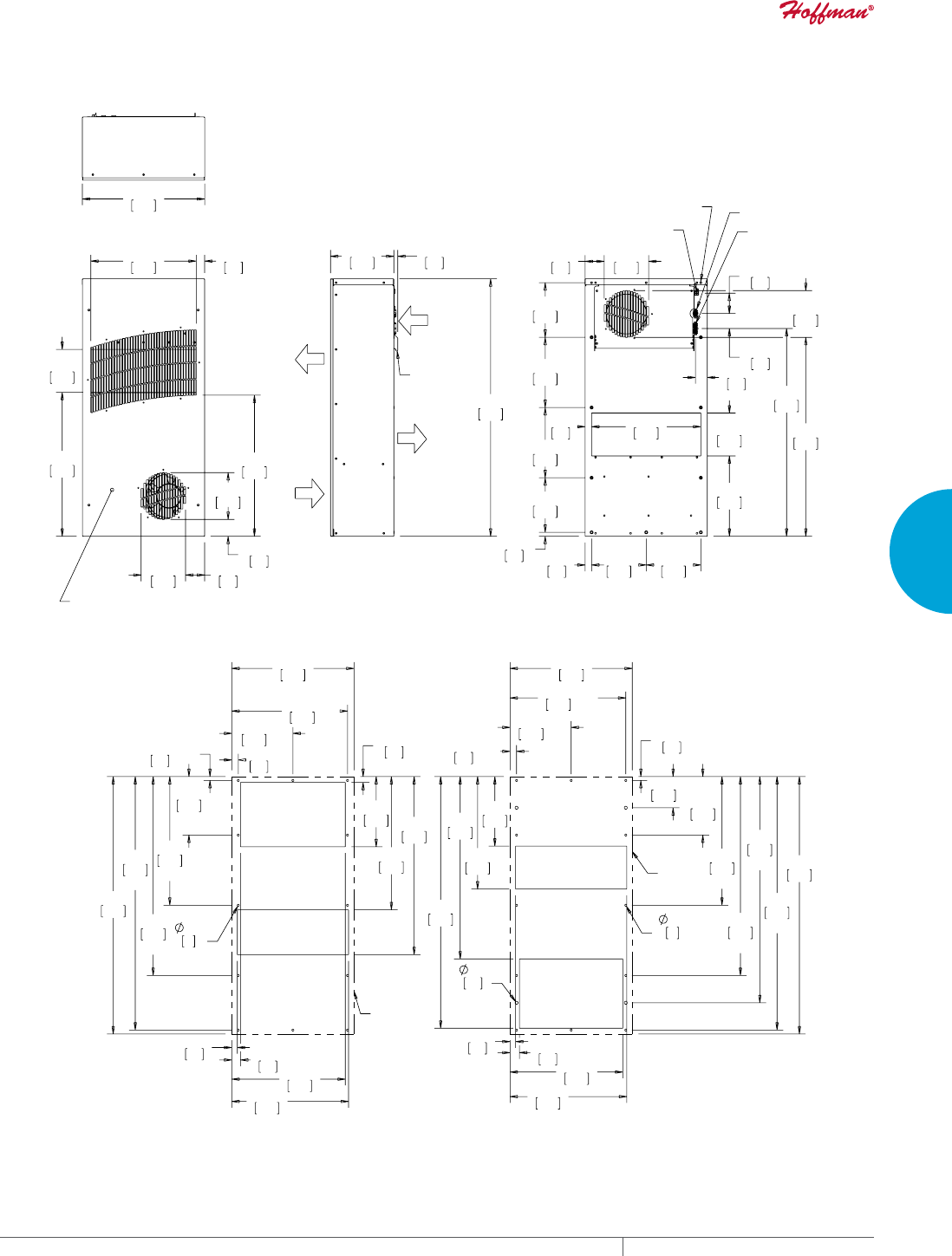
PH 763.422.2211 • FAX 763.576.3200 • HOFFMANONLINE.COMEQUIPMENT PROTECTION COOLING 165
3
SEALED ENCLOSURE COOLING HEAT EXCHANGERS
02817,1*+$5':$5()25,17(5$//<02817('
02817,1*,6%(+,1'5(029$%/()5217&29(5
5(029$%/(
+$1*,1*
7$%6;
(1&/2685(
$,5,1
(1&/2685(
$,5287
$0%,(17
$,5287
$0%,(17
$,5,1
,03(//(532:(5
$1'$/$50
,17(5)$&(
$&+($7(532:(5
&21752//(5
/('6
02817,1*;
21%$&.)$&(
%(+,1')5217&29(5
;
;
;
;
;
;
;
;
;
;
;
;
;
;
;
;
;
;
;
;
;
+(287/,1(
+(
287/,1(
7;'&0RGHOV:r):r&
127(
02817,1**$6.(76833/,('1276+2:1
81,76LQ>PP@
&XWRXW'LPHQVLRQV
([WHUQDO0RXQW
&XWRXW'LPHQVLRQV
,QWHUQDO0RXQW
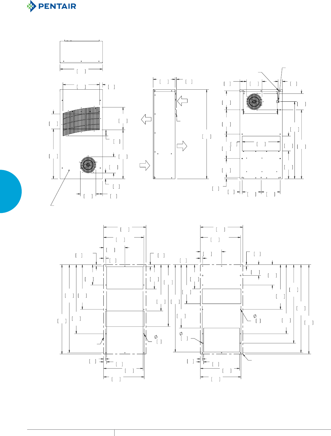
EQUIPMENT PROTECTIONSUBJECT TO CHANGE WITHOUT NOTICECOOLING166
3
SEALED ENCLOSURE COOLING HEAT EXCHANGERS
02817,1*+$5':$5()25,17(51$//<02817('
02817,1*,6%(+,1'5(029$%/()5217&29(5
5(029$%/(
+$1*,1*
7$%6;
(1&/2685(
$,5,1
(1&/2685(
$,5287
$0%,(17
$,5287
$0%,(17
$,5,1
;
32:(5&25'
(175$1&(
02817,1*;
21%$&.)$&(
%(+,1')5217&29(5
;
;
;
;
;
;
;
;
;
;
;
;
;
;
;
;
;
;
;
;
;
+(287/,1(
+(287/,1(
7;$&0RGHOV:r):r&
&XWRXW'LPHQVLRQV
([WHUQDO0RXQW
&XWRXW'LPHQVLRQV
,QWHUQDO0RXQW

PH 763.422.2211 • FAX 763.576.3200 • HOFFMANONLINE.COMEQUIPMENT PROTECTION COOLING 167
3
SEALED ENCLOSURE COOLING HEAT EXCHANGERS
Performance Data TX38 Models 56 W/°F (100 W/°C)
CATALOG NUMBER
TX385616100 TX385626100 TX385624100 TX385648100
COOLING PERFORMANCE
Nominal:
W per °F 56 56 56 56
W per °C 100 100 100 100
Refrigerant N/A N/A N/A N/A
Refrigerant Charge (ounces/grams) N/A N/A N/A N/A
Operating Temperature Range:
Maximum (°F/°C) 149/65 149/65 149/65 149/65
Minimum (°F/°C) -40/-40 -40/-40 -40/-40 -40/-40
Airflow at 0 Static Pressure:
Internal loop 50 Hz (CFM / m3/hr.) 425/722 425/722 N/A N/A
External loop 50 Hz (CFM / m3/hr.) 461/738 461/738 N/A N/A
Internal loop 60 Hz (CFM / m3/hr.) 477/810 477/810 368/625 368/625
External loop 60 Hz (CFM / m3/hr.) 517/878 517/878 422/717 422/717
ELECTRICAL DATA
Rated Voltage 115 VAC 230 VAC 24 VDC 48 VDC
Frequency (Hz) 50/60 50/60 50/60 50/60
Operating Range +/- 10% +/- 10% +/- 10% +/- 10%
Max. Power Consumption (W at 50/60 Hz) 368 276 207 279
Max. Nominal Current (A at 50/60 Hz) 2.3/3.2 0.7/1.2 8.6 5.8
Agency Approvals cUL Listed
CE
GOST
cUL Listed
CE
GOST
Power Input Description 6-ft. cord with
NEMA 5-15 plug
6-ft. cord with
NEMA 6-15 plug
Terminal block Terminal block
ENCLOSURE PROTECTION
UL Type Type 12, 3R, 4 standard
Type 4X optional
Type 12, 3R, 4 standard
Type 4X optional
SOUND LEVEL
At 1.5 Meters 64 dBA 64 dBA
UNIT CONSTRUCTION
Material Mild Mild steel sheet metal standard Mild Mild steel sheet metal standard
Finish RAL 7035 light-gray, semi-textured
powder-coat paint standard
RAL 7035 light-gray, semi-textured
powder-coat paint standard
UNIT DIMENSIONS
Height (in./mm) 38/965.2 38/965.2 38/965.2 38/965.2
Width (in./mm) 19.7/500.4 19.7/500.4 19.7/500.4 19.7/500.4
Depth (in./mm) 10.1/256.5 10.1/256.5 10.1/256.5 10.1/256.5
Weight (lb./kg) 66/30 66/30 66/30 66/30
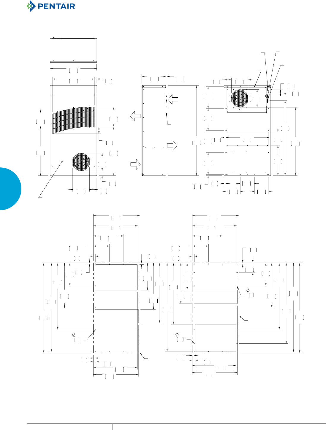
EQUIPMENT PROTECTIONSUBJECT TO CHANGE WITHOUT NOTICECOOLING168
3
SEALED ENCLOSURE COOLING HEAT EXCHANGERS
02817,1*+$5':$5()25,17(51$//<02817('
02817,1*,6%(+,1'5(029$%/()5217&29(5
$0%,(17
$,5,1
(1&/2685(
$,5287
5(029$%/(
+$1*,1*
7$%6;
(1&/2685(
$,5,1
;
;
;
;
;
;
;
;
,03(//(532:(5
$1'$/$50
,17(5)$&(
$&+($7(5
32:(5
&21752//(5
/('6
02817,1*;
21%$&.)$&(
%(+,1')5217&29(5
;
;
;
;
;
;
;
;
;
;
;
;
;
;
;
;
;
;
;
;
;
;
;
&XWRXW'LPHQVLRQV
,QWHUQDO0RXQW
&XWRXW'LPHQVLRQV
([WHUQDO0RXQW
+(287/,1(
+(287/,1(
7;'&0RGHOV:r):r&
$0%,(17
$,5287
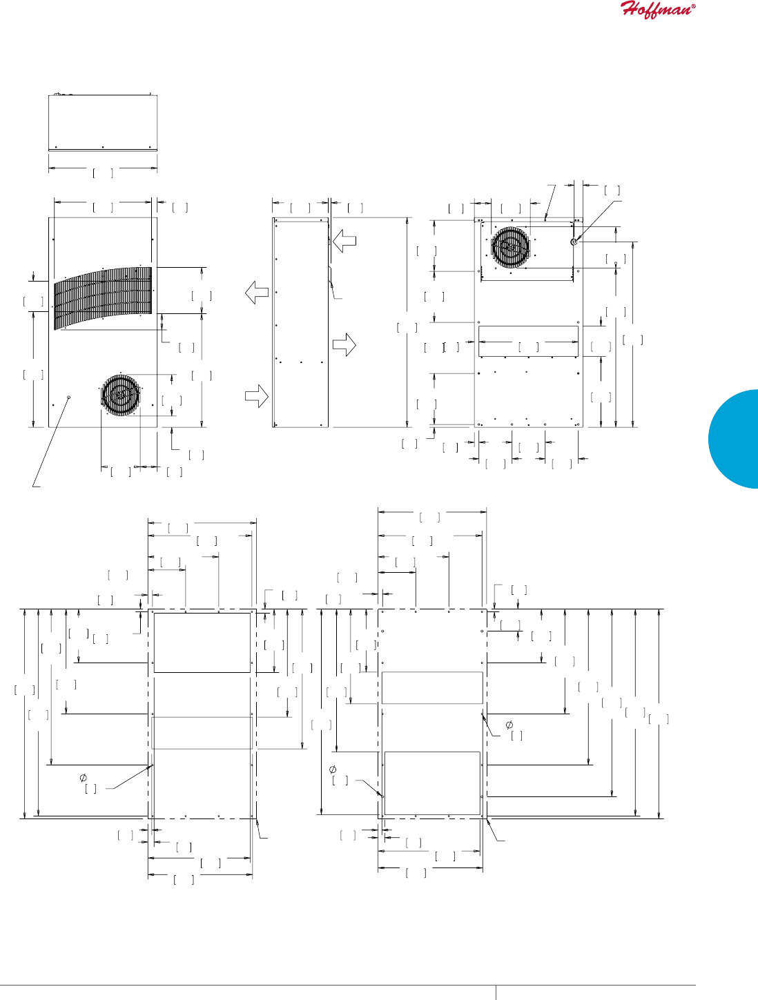
PH 763.422.2211 • FAX 763.576.3200 • HOFFMANONLINE.COMEQUIPMENT PROTECTION COOLING 169
3
SEALED ENCLOSURE COOLING HEAT EXCHANGERS
02817,1*+$5':$5()25,17(51$//<02817('
02817,1*,6%(+,1'5(029$%/()5217&29(5
5(029$%/(
+$1*,1*
7$%6;
(1&/2685(
$,5,1
(1&/2685(
$,5287
$0%,(17
$,5287
$0%,(17
$,5,1
;
;
;
;
02817,1*;
21%$&.)$&(
%(+,1')5217&29(5
32:(5&25'
(175$1&(
;
;
;
;
;
;
;
;
;
;
;
;
;
;
;
;
;
;
;
;
;
6;
;
&XWRXW'LPHQVLRQV
([WHUQDO0RXQW
&XWRXW'LPHQVLRQV
,QWHUQDO0RXQW
+(287/,1(
+(287/,1(
7;$&0RGHOV:r):r&
127(
02817,1**$6.(76833/,('1276+2:1
81,76LQ>PP@

EQUIPMENT PROTECTIONSUBJECT TO CHANGE WITHOUT NOTICECOOLING170
3
SEALED ENCLOSURE COOLING HEAT EXCHANGERS
Performance Data TX52 Models 83 W/°F (150 W/°C)
CATALOG NUMBER
TX528316100 TX528326100 TX528324100 TX528348100
COOLING PERFORMANCE
Nominal:
W per °F 83 83 83 83
W per °C 150 150 150 150
Refrigerant N/A N/A N/A N/A
Refrigerant Charge (ounces/grams) N/A N/A N/A N/A
Operating Temperature Range:
Maximum (°F/°C) 149/65 149/65 149/65 149/65
Minimum (°F/°C) -40/-40 -40/-40 -40/-40 -40/-40
Airflow at 0 Static Pressure:
Internal loop 50 Hz (CFM / m3/hr.) 495/841 495/841 N/A N/A
External loop 50 Hz (CFM / m3/hr.) 540/917 540/917 N/A N/A
Internal loop 60 Hz (CFM / m3/hr.) 533/905 533/905 466/792 466/792
External loop 60 Hz (CFM / m3/hr.) 605/1028 605/1028 547/929 547/929
ELECTRICAL DATA
Rated Voltage 115 VAC 230 VAC 24 VDC 48 VDC
Frequency (Hz) 50/60 50/60 50/60 50/60
Operating Range +/- 10% +/- 10% +/- 10% +/- 10%
Max. Power Consumption (W at 50/60 Hz) 782 771 507 375
Max. Nominal Current (A at 50/60 Hz) 4.3/6.7 2.2/3.4 21.1 7.8
Agency Approvals cUL Listed
CE
GOST
cUL Listed
CE
GOST
Power Input Description 6-ft. cord with
NEMA 5-15 plug
6-ft. cord with
NEMA 6-15 plug
Terminal block Terminal block
ENCLOSURE PROTECTION
UL Type Type 12, 3R, 4 standard
Type 4X optional
Type 12, 3R, 4 standard
Type 4X optional
SOUND LEVEL
At 1.5 Meters 68 dBA 68 dBA
UNIT CONSTRUCTION
Material Mild steel sheet metal standard
Stainless steel optional
Mild steel sheet metal standard
Stainless steel optional
Finish RAL 7035 light-gray, semi-textured
powder-coat paint standard
RAL 7035 light-gray, semi-textured
powder-coat paint standard
UNIT DIMENSIONS
Height (in./mm) 52/1320.8 52/1320.8 52/1320.8 52/1320.8
Width (in./mm) 19.7/500.4 19.7/500.4 19.7/500.4 19.7/500.4
Depth (in./mm) 10.1/256.5 10.1/256.5 10.1/256.5 10.1/256.5
Weight (lb./kg) 100/45.3 100/45.3 100/45.3 100/45.3
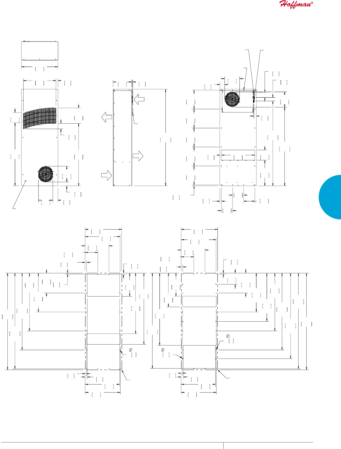
PH 763.422.2211 • FAX 763.576.3200 • HOFFMANONLINE.COMEQUIPMENT PROTECTION COOLING 171
3
SEALED ENCLOSURE COOLING HEAT EXCHANGERS
02817,1*+$5':$5()25,17(51$//<02817('
02817,1*,6%(+,1'5(029$%/()5217&29(5
5(029$%/(
+$1*,1*
7$%6;
$0%,(17
$,5287
$0%,(17
$,5,1
(1&/2685(
$,5,1
(1&/2685(
$,5287
;
;
;
;
;
;
;
;
;
;
,03(//(532:(5
$1'$/$50
,17(5)$&(
$&+($7(5
32:(5
02817,1*;
21%$&.)$&(
%(+,1')5217&29(5
;
;
;
;
;
;
;
;
;
;
;
;
;
;
;
;
;
;
;
;
;
;
;
;
;
+(287/,1(
+(287/,1(
7;'&0RGHOV:r):r&
127(
02817,1**$6.(76833/,('1276+2:1
81,76LQ>PP@
&XWRXW'LPHQVLRQV
([WHUQDO0RXQW
&XWRXW'LPHQVLRQV
,QWHUQDO0RXQW
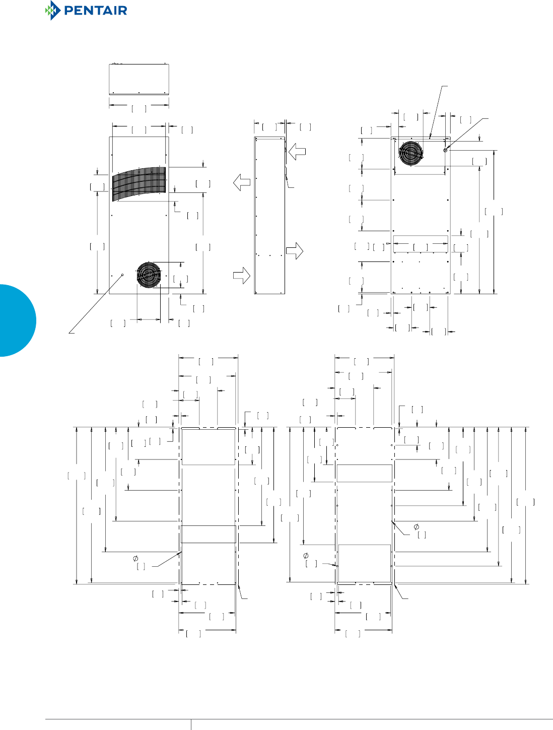
EQUIPMENT PROTECTIONSUBJECT TO CHANGE WITHOUT NOTICECOOLING172
3
SEALED ENCLOSURE COOLING HEAT EXCHANGERS
02817,1*+$5':$5()25,17(51$//<02817('
02817,1*,6%(+,1'5(029$%/()5217&29(5
5(029$%/(
+$1*,1*
7$%6;
(1&/2685(
$,5,1
(1&/2685(
$,5287
$0%,(17
$,5,1
$0%,(17
$,5287
;
;
;
;
;
;
;
;
;
32:(5
&25'
(175$1&(
02817,1*;
21%$&.)$&(
%(+,1')5217&29(5
;
;
;
;
;
;
;
;
;
;
;
;
;
;
;
;
;
;
;
;
;
;
;
;
;
;
+(287/,1( +(287/,1(
7;$&0RGHOV:r):r&
127(
02817,1**$6.(76833/,('12:6+2:1
81,76LQ>PP@
&XWRXW'LPHQVLRQV
([WHUQDO0RXQW
&XWRXW'LPHQVLRQV
,QWHUQDO0RXQW

PH 763.422.2211 • FAX 763.576.3200 • HOFFMANONLINE.COMEQUIPMENT PROTECTION COOLING 173
3
SEALED ENCLOSURE COOLING HEAT EXCHANGERS
Notes
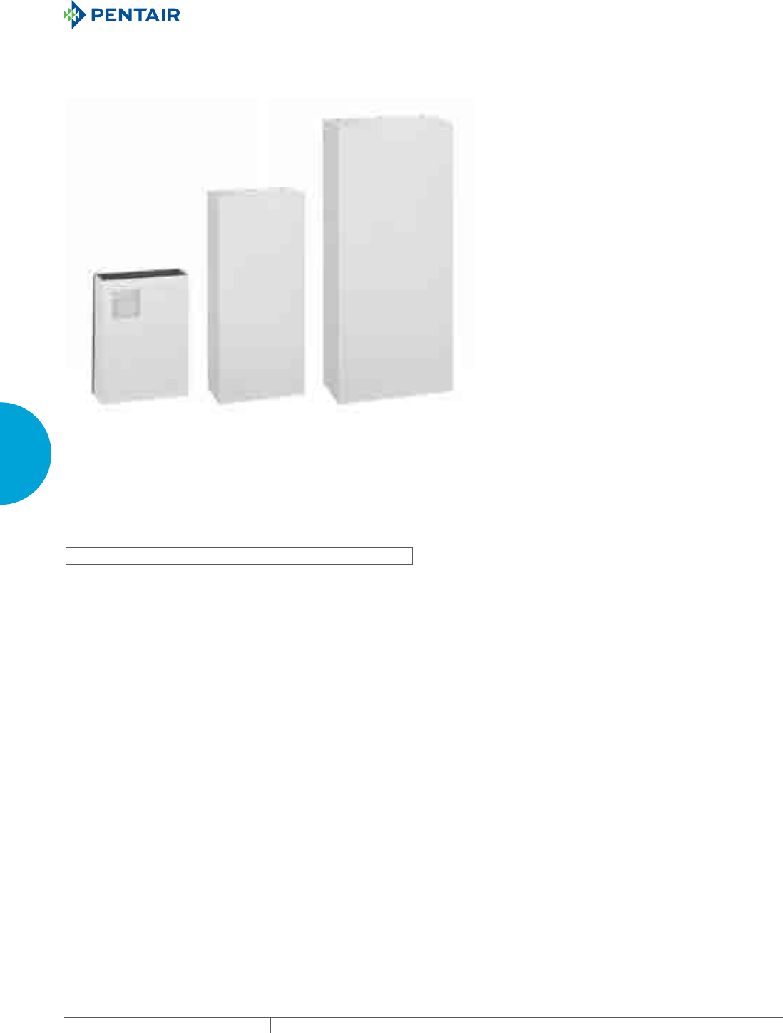
EQUIPMENT PROTECTIONSUBJECT TO CHANGE WITHOUT NOTICECOOLING174
3
SEALED ENCLOSURE COOLING HEAT EXCHANGERS
CLIMAGUARD™ AIRTOWATER INDOOR
WCHE01
2968 BTU/Hr.
870 Watts
WCHE04/WCHE06
7506/10577 BTU/Hr.
2200/3100 Watts
WCHE14
22861 BTU/Hr.
6700 Watts
INDUSTRY STANDARDS
UL/cUL Listed; Type 12; File No. SA33866
CE
IP55
APPLICATION
• Industrial process controls
• Industrial robotics controls
• Electronic cabinets in harsh environments
• Conveyor systems
FEATURES
• Capacities ranging from 870 watts to 6700 watts
• Filterless design
• NEMA power cord connection standard
• Copper pipe and aluminum fins heat exchanger core
• Air movers with thermal protection
• Regulating mechanical thermostat set at 35 C (95 F), differential
of 4 C (7 F)
• Operating temperature from 10-50 C (50-122 F)
• Solenoid water valve
• UL Listed to save customers time and money with agency
approvals
• Recovery of condensation system and condensation discharge
pipe
• Requires an available cooled water source
FINISH
• Standard models constructed of rugged steel
• RAL 7035 light-gray, powder-coat polyester paint
NOTES
Visit www.HoffmanOnline.com to download 2D and 3D CAD
drawings into the overall design of your electronic system.
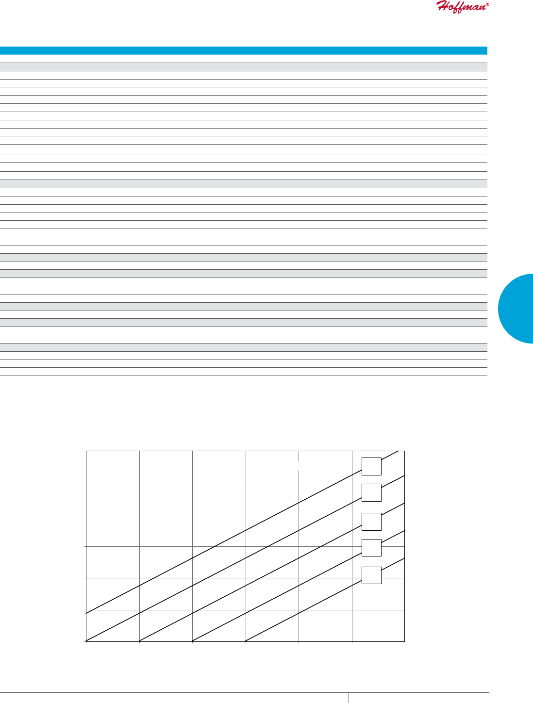
PH 763.422.2211 • FAX 763.576.3200 • HOFFMANONLINE.COMEQUIPMENT PROTECTION COOLING 175
3
SEALED ENCLOSURE COOLING HEAT EXCHANGERS
Performance DataWCHE01 Models 870 Watt
CATALOG NUMBER
WCHE01916002 WCHE01926002
COOLING PERFORMANCE
Nominal:
BTU/Hr. @ t 25 C 2968 2968
Watts @ t 25 C 870 870
Refrigerant NA NA
Refrigerant Charge (ounces/grams) NA NA
Operating Temperature Range:
Maximum (°F/°C) 122/50 122/50
Minimum (°F/°C) 50/10 50/10
Flow at 0 Static Pressure:
Internal loop 50 Hz (Airflow: CFM / m3/hr.) 194/330 194/330
External loop 50 Hz (Waterflow: GPM @ 95 F) 0.66 0.66
Internal loop 60 Hz (Airflow: CFM / m3/hr.) 194/330 194/330
External loop 60 Hz (Waterflow: GPM @ 95 F) 0.66 0.66
ELECTRICAL DATA
Rated Voltage 115 230
Frequency (Hz) 50/60 50/60
Operating Range +/- 10% +/- 10%
Max. Power Consumption (W at 50/60 Hz) 28 28
Max. Nominal Current (A at 50/60 Hz) 0.5 0.5
Starting Current (Amps) 0.7 0.7
Agency Approvals UL/cUL Listed
Power Input Description Cord with NEMA 5-15 plug Cord with NEMA 6-15 plug
ENCLOSURE PROTECTION
UL Type Type 12/IP55 Type 12/IP55
CONTROLLER
Description Basic Mechanical Thermostat
Thermostat Location Behind front cover, near the fan
Factory Thermostat Setting (°F/°C) 95/35 95/35
SOUND LEVEL
At 1.0 Meters 58 dBA 58 dBA
UNIT CONSTRUCTION
Material Mild Steel Sheet Metal Standard
Finish RAL 7035 light-gray, semi-textured powder-coat paint standard
UNIT DIMENSIONS
Height (in./mm) 15.9/404 15.9/404
Width (in./mm) 12.12/308 12.12/308
Depth (in./mm) 4.49/114 4.49/114
Weight (lb./kg) 19.84/9 19.84/9
10 C
50 F
15 C
59 F
20 C
68 F
25 C
77 F
30 C
86 F
Water Temperature
580
1262
1945
2627
3310
3992
4675
170
370
570
770
970
1170
1370
68 77 86 95 104 113 122
20 25 30 35 40 45 50
Cabinet Te mperature (°F)
Cabinet Te mperature (°C)
Cooling Capacity (BTU/Hr.)
Cooling Capacity (W)
Performance Curves for WCHE01 Models 870 Watt
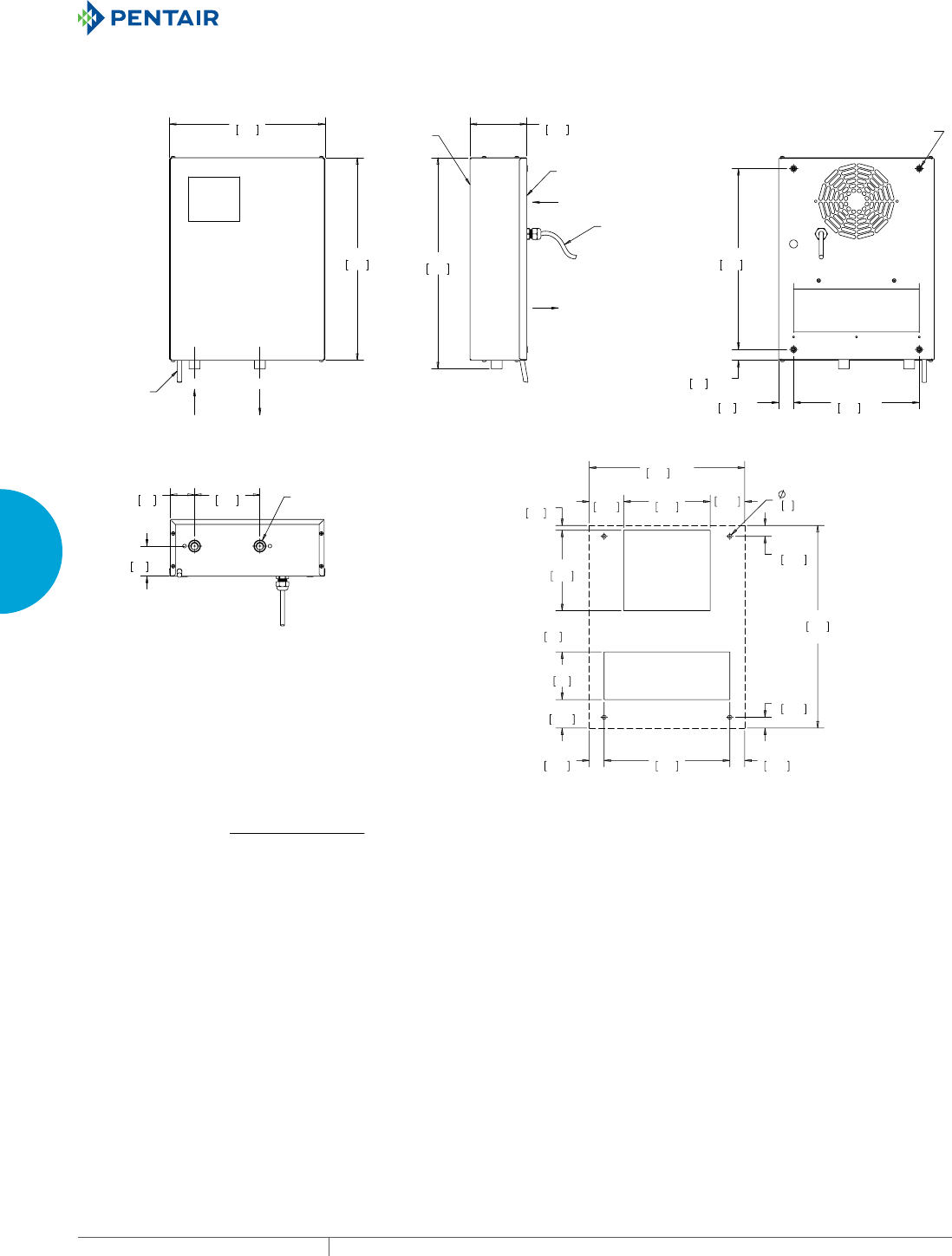
EQUIPMENT PROTECTIONSUBJECT TO CHANGE WITHOUT NOTICECOOLING176
3
SEALED ENCLOSURE COOLING HEAT EXCHANGERS
89091145
:$7(5
,1
:$7(5
287
&21'(16$7(
'5$,178%(
(1&/2685(
$,5,1
(1&/2685(
$,5287
)5217
%$&.
)705()
32:(5&25':,7+3/8*
002817,1*+2/(6
%336*)(0$/(
:$7(5&211(&7,21
5()
5()
5()
5()
&87287',0(16,216
WCHE01 Models 870 Watt
Visit www
.HoffmanOnline.com to download 2D and 3D CAD drawings into the overall design of your electr
onic system.
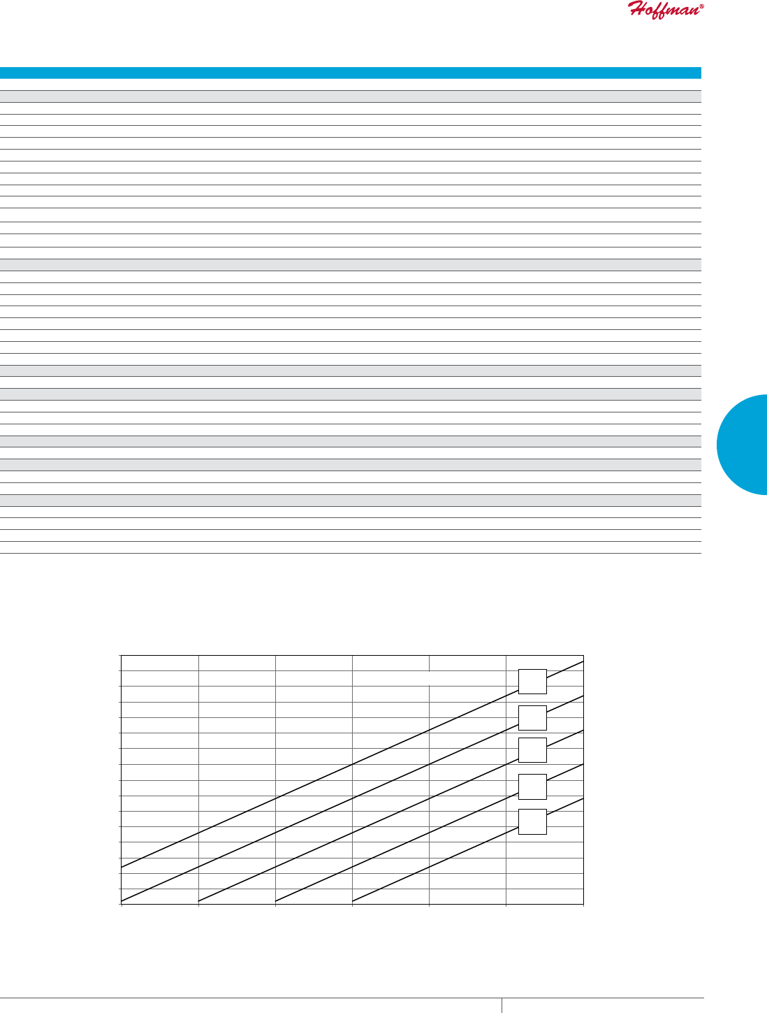
PH 763.422.2211 • FAX 763.576.3200 • HOFFMANONLINE.COMEQUIPMENT PROTECTION COOLING 177
3
SEALED ENCLOSURE COOLING HEAT EXCHANGERS
Performance DataWCHE04 Models 2200 Watt
CATALOG NUMBER
WCHE04916002 WCHE04926002
COOLING PERFORMANCE
Nominal:
BTU/Hr. @ t 25 C 7506 7506
Watts @ t 25 C 2200 2200
Refrigerant NA NA
Refrigerant Charge (ounces/grams) NA NA
Operating Temperature Range:
Maximum (°F/°C) 122/50 122/50
Minimum (°F/°C) 50/10 50/10
Flow at 0 Static Pressure:
Internal loop 50 Hz (Airflow: CFM / m3/hr.) 339/575 339/575
External loop 50 Hz (Waterflow: GPM @ 95 F) 0.66 0.66
Internal loop 60 Hz (Airflow: CFM / m3/hr.) 339/575 339/575
External loop 60 Hz (Waterflow: GPM @ 95 F) 0.66 0.66
ELECTRICAL DATA
Rated Voltage 115 230
Frequency (Hz) 50/60 50/60
Operating Range +/- 10% +/- 10%
Max. Power Consumption (W at 50/60 Hz) 90 90
Max. Nominal Current (A at 50/60 Hz) 0.8 0.8
Starting Current (Amps) 1 1
Agency Approvals UL/cUL Listed
Power Input Description Cord with NEMA 5-15 plug Cord with NEMA 6-15 plug
ENCLOSURE PROTECTION
UL Type Type 12/IP55 Type 12/IP55
CONTROLLER
Description Basic Mechanical Thermostat
Thermostat Location Behind front cover, near the fan
Factory Thermostat Setting (°F/°C) 95/35 95/35
SOUND LEVEL
At 1.0 Meters 58 dBA 58 dBA
UNIT CONSTRUCTION
Material Mild Steel Sheet Metal Standard
Finish RAL 7035 light-gray, semi-textured powder-coat paint standard
UNIT DIMENSIONS
Height (in./mm) 36.41/925 36.41/925
Width (in./mm) 15.75/400 15.75/400
Depth (in./mm) 8.07/205 8.07/205
Weight (lb./kg) 44.1/20 44.1/20
10 C
50 F
15 C
59 F
20 C
68 F
25 C
77 F
30 C
86 F
Water Temperature
1365
2047
2730
3412
4095
4777
5459
6142
6824
7507
8189
8872
9554
10236
10919
11601
12284
400
600
800
1000
1200
1400
1600
1800
2000
2200
2400
2600
2800
3000
3200
3400
3600
68 77 86 95 104 113 122
20 25 30 35 40 45 50
Cabinet Te mperature (°F)
Cabinet Te mperature (°C)
Cooling Capacity (BTU/Hr.)
Cooling Capacity (W)
Performance Curves for WCHE04 Models 2200 Watt
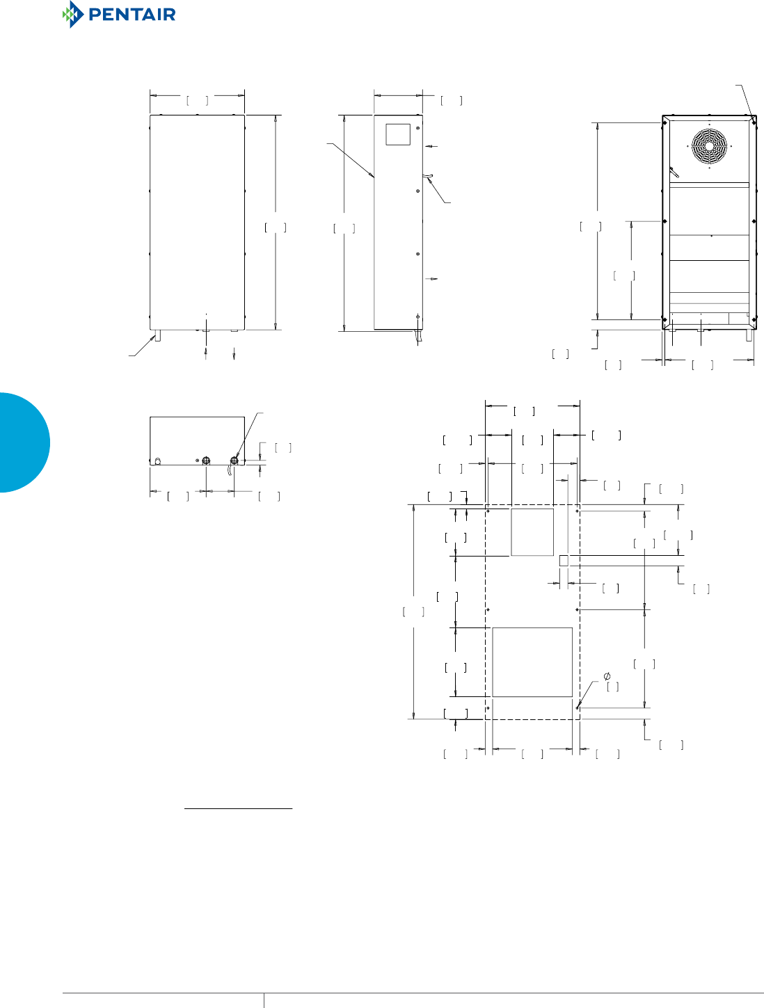
EQUIPMENT PROTECTIONSUBJECT TO CHANGE WITHOUT NOTICECOOLING178
3
SEALED ENCLOSURE COOLING HEAT EXCHANGERS
89091146
5()
5()
5()
5()
5()
&87287',0(16,216
:$7(5
,1
:$7(5
287
&21'(16$7(
'5$,178%(
(1&/2685(
$,5,1
(1&/2685(
$,5287
)5217
)705()
32:(5&25':,7+3/8*
002817,1*+2/(6
%336*)(0$/(
:$7(5&211(&7,21
WCHE04 Models 2200 Watt
Visit www
.HoffmanOnline.com to download 2D and 3D CAD drawings into the overall design of your electr
onic system.
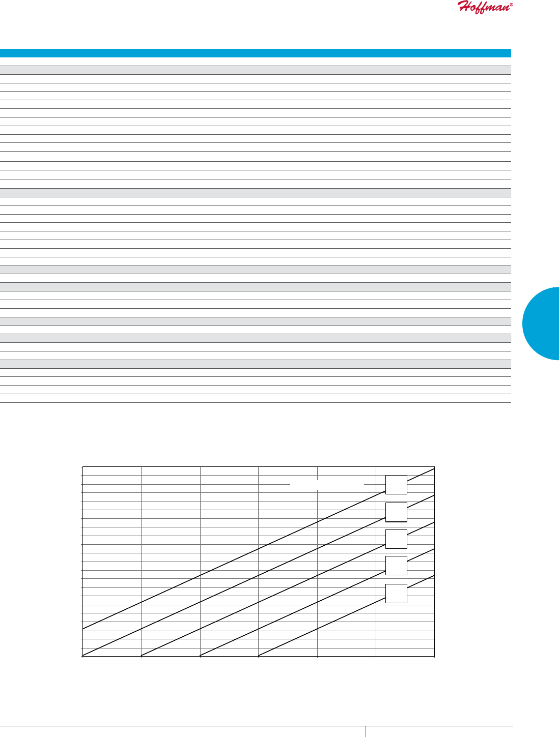
PH 763.422.2211 • FAX 763.576.3200 • HOFFMANONLINE.COMEQUIPMENT PROTECTION COOLING 179
3
SEALED ENCLOSURE COOLING HEAT EXCHANGERS
Performance DataWCHE06 Models 3100 Watt
CATALOG NUMBER
WCHE06916002 WCHE06926002
COOLING PERFORMANCE
Nominal:
BTU/Hr. @ t 25 C 10577 10577
Watts @ t 25 C 3100 3100
Refrigerant NA NA
Refrigerant Charge (ounces/grams) NA NA
Operating Temperature Range:
Maximum (°F/°C) 122/50 122/50
Minimum (°F/°C) 50/10 50/10
Flow at 0 Static Pressure:
Internal loop 50 Hz (Airflow: CFM / m3/hr.) 507/860 507/860
External loop 50 Hz (Waterflow: GPM @ 95 F) 2.2 2.2
Internal loop 60 Hz (Airflow: CFM / m3/hr.) 507/860 507/860
External loop 60 Hz (Waterflow: GPM @ 95 F) 2.2 2.2
ELECTRICAL DATA
Rated Voltage 115 230
Frequency (Hz) 50/60 50/60
Operating Range +/- 10% +/- 10%
Max. Power Consumption (W at 50/60 Hz) 110 115
Max. Nominal Current (A at 50/60 Hz) 2 1
Starting Current (Amps) 2.4 1.2
Agency Approvals UL/cUL Listed
Power Input Description Cord with NEMA 5-15 plug Cord with NEMA 6-15 plug
ENCLOSURE PROTECTION
UL Type Type 12/IP55 Type 12/IP55
CONTROLLER
Description Basic Mechanical Thermostat
Thermostat Location Behind front cover, near the fan
Factory Thermostat Setting (°F/°C) 95/35 95/35
SOUND LEVEL
At 1.0 Meters 58 dBA 58 dBA
UNIT CONSTRUCTION
Material Mild Steel Sheet Metal Standard
Finish RAL 7035 light-gray, semi-textured powder-coat paint standard
UNIT DIMENSIONS
Height (in./mm) 36.41/925 36.41/925
Width (in./mm) 15.75/400 15.75/400
Depth (in./mm) 8.07/205 8.07/205
Weight (lb./kg) 46.3/21 46.3/21
10 C
50 F
15 C
59 F
20 C
68 F
25 C
77 F
30 C
86 F
Water Temperature
600
800
1000
1200
1400
1600
1800
2000
2200
2400
2600
2800
3000
3200
3400
3600
3800
4000
4200
4400
4600
4800
5000
68 77 86 95 104 113 122
20 25 30 35 40 45 50
Cabinet Te mperature (°F)
Cabinet Te mperature (°C)
Cooling Capacity (BTU/Hr.)
Cooling Capacity (W)
2047
2730
3412
4095
4777
5459
6142
6824
7507
8189
8872
9554
10236
10919
11601
12284
12966
13649
14331
15013
15696
16378
17061
Performance Curves for WCHE06 Models 3100 Watt
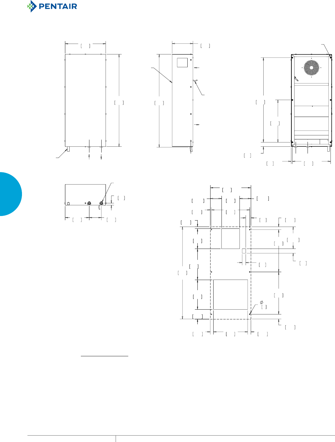
EQUIPMENT PROTECTIONSUBJECT TO CHANGE WITHOUT NOTICECOOLING180
3
SEALED ENCLOSURE COOLING HEAT EXCHANGERS
89091147
5()
5()
5()
5()
5()
&87287',0(16,216
:$7(5
,1
:$7(5
287
&21'(16$7(
'5$,178%(
(1&/2685(
$,5,1
(1&/2685(
$,5287
)5217
)705()
32:(5&25':,7+3/8*
002817,1*+2/(6
%336*)(0$/(
:$7(5&211(&7,21
WCHE06 Models 3100 Watt
Visit www
.HoffmanOnline.com to download 2D and 3D CAD drawings into the overall design of your electr
onic system.
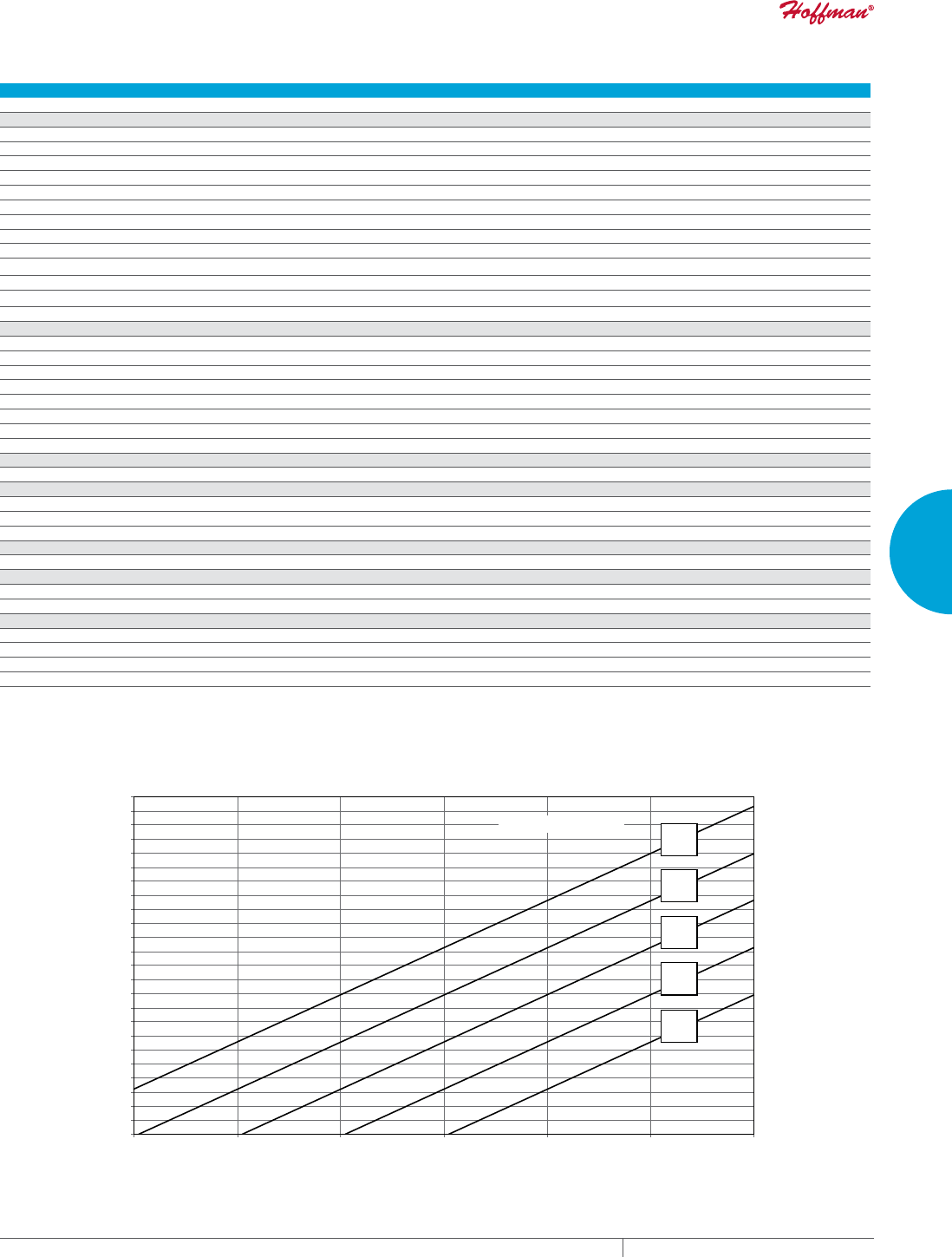
PH 763.422.2211 • FAX 763.576.3200 • HOFFMANONLINE.COMEQUIPMENT PROTECTION COOLING 181
3
SEALED ENCLOSURE COOLING HEAT EXCHANGERS
Performance DataWCHE14 Models 6700 Watt
CATALOG NUMBER
WCHE14916002 WCHE14926002
COOLING PERFORMANCE
Nominal:
BTU/Hr. @ t 25 C 22861 22861
Watts @ t 25 C 6700 6700
Refrigerant NA NA
Refrigerant Charge (ounces/grams) NA NA
Operating Temperature Range:
Maximum (°F/°C) 122/50 122/50
Minimum (°F/°C) 50/10 50/10
Flow at 0 Static Pressure:
Internal loop 50 Hz (Airflow: CFM / m3/hr.) 855/1450 855/1450
External loop 50 Hz (Waterflow: GPM @ 95 F) 3.78 3.78
Internal loop 60 Hz (Airflow: CFM / m3/hr.) 855/1450 855/1450
External loop 60 Hz (Waterflow: GPM @ 95 F) 3.78 3.78
ELECTRICAL DATA
Rated Voltage 115 230
Frequency (Hz) 50/60 50/60
Operating Range +/- 10% +/- 10%
Max. Power Consumption (W at 50/60 Hz) 200 245
Max. Nominal Current (A at 50/60 Hz) 2 1.3
Starting Current (Amps) 2.4 1.4
Agency Approvals UL/cUL Listed
Power Input Description Cord with NEMA 5-15 plug Cord with NEMA 6-15 plug
ENCLOSURE PROTECTION
UL Type Type 12/IP55 Type 12/IP55
CONTROLLER
Description Basic Mechanical Thermostat
Thermostat Location Behind front cover, near the fan
Factory Thermostat Setting (°F/°C) 95/35 95/35
SOUND LEVEL
At 1.0 Meters 58 dBA 58 dBA
UNIT CONSTRUCTION
Material Mild Steel Sheet Metal Standard
Finish RAL 7035 light-gray, semi-textured powder-coat paint standard
UNIT DIMENSIONS
Height (in./mm) 43.34/1101 4 3.34/1101
Width (in./mm) 19.72/501 19.72/501
Depth (in./mm) 11.81/300 11.81/300
Weight (lb./kg) 86/39 86/39
10 C
50 F
15 C
59 F
20 C
68 F
25 C
77 F
30 C
86 F
Water Temperature
4777
6142
7507
8872
10236
11601
12966
14331
15696
17061
18426
19790
21155
22520
23885
25250
26615
27980
29344
30709
32074
33439
34804
36169
37534
1400
1800
2200
2600
3000
3400
3800
4200
4600
5000
5400
5800
6200
6600
7000
7400
7800
8200
8600
9000
9400
9800
10200
10600
11000
68 77 86 95 104 113 122
20 25 30 35 40 45 50
Cabinet Te mperature (°F)
Cabinet Te mperature (°C)
Cooling Capacity (BTU/Hr.)
Cooling Capacity (W)
Performance Curves for WCHE14 Models 6700 Watt
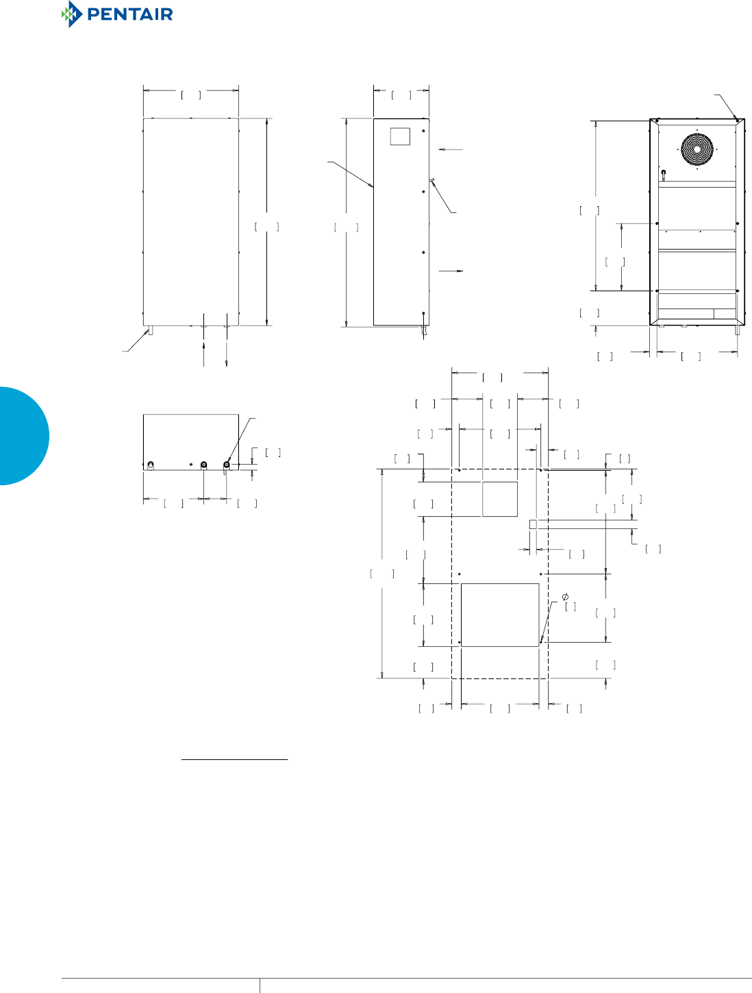
EQUIPMENT PROTECTIONSUBJECT TO CHANGE WITHOUT NOTICECOOLING182
3
SEALED ENCLOSURE COOLING HEAT EXCHANGERS
89091148
5()
5()
5()
5()
5()
5()
&87287',0(16,216
&21'(16$7(
'5$,178%(
:$7(5
,1
:$7(5
287
(1&/2685(
$,5,1
(1&/2685(
$,5287
)5217
)705()
32:(5&25':,7+3/8*
002817,1*+2/(6
%336*)(0$/(
:$7(5&211(&7,21
WCHE14 Models 6700 Watt
Visit www
.HoffmanOnline.com to download 2D and 3D CAD drawings into the overall design of your electr
onic system.

PH 763.422.2211 • FAX 763.576.3200 • HOFFMANONLINE.COMEQUIPMENT PROTECTION COOLING 183
3
SEALED ENCLOSURE COOLING HEAT EXCHANGERS
Notes
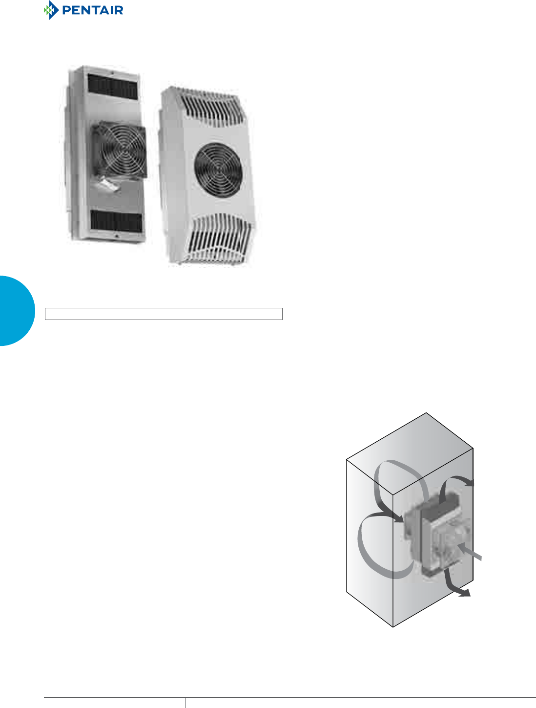
EQUIPMENT PROTECTIONSUBJECT TO CHANGE WITHOUT NOTICECOOLING184
3
SEALED ENCLOSURE COOLING THERMOELECTRIC COOLERS
THERMOELECTRIC COOLERS
THERMOELECTRIC COOLERS INDOOR/OUTDOOR
Unshrouded
60, 100 and 200 Watts
Shrouded
60, 100 and 200 Watts
INDUSTRY STANDARDS
UR, cUR Recognized; Type 12, 3R, 4, 4X; File No. SA6453
CE
IP 65
APPLICATION
Thermoelectric Coolers minimize downtime and component loss
by removing heat around critical components within an enclosure.
These compact, low-profile coolers using the Peltier effect allow
for cooling of small indoor and outdoor enclosures. No condensers,
compressors or filters are required making it a reliable solution for
demanding low-maintenance environments.
FEATURES
• DC Powered operation for 24V and 48V applications
• Low profile design allows for mounting vertically and horizontally
on any enclosure to avoid interference with internal components
• Filterless design reduces maintenance requirements
• Contains no refrigerant, making it earth friendly
• Prewired with simple terminal block for easy wiring connections
• Operates on the Peltier effect for cooling or heating
• Compressor-free air conditioning for demanding indoor and
outdoor applications
• Shrouded and unshrouded models included in standard packages
• Operating temperature range -40 C (-40 F) to 55 C (131 F)
• Partial recess mount
SPECIFICATIONS
• Models
60 Watt, 24 Volt
100 Watt, 24/48 Volt
200 Watt, 24/48 Volt
FINISH
• Shrouded finish includes both powder coat paint RAL 7035 light
gray standard and stainless steel 304
ACCESSORIES
• Optional thermolelectric temperature controller regulates
cooling and heating automatically
• Optional thermoelectric condenser manager helps direct
condensation to the bottom of the enclosure
NOTES
Visit www.HoffmanOnline.com to download 2D and 3D CAD
drawings into the overall design of your electronic system.

PH 763.422.2211 • FAX 763.576.3200 • HOFFMANONLINE.COMEQUIPMENT PROTECTION COOLING 185
3
SEALED ENCLOSURE COOLING THERMOELECTRIC COOLERS
Performance Data TE09 60W 204 BTU/Hr. (24 V)
CATALOG NUMBERS
Description 24V w/o shroud 24V w/ painted shroud 24V w/ SS shroud
Catalog Number TE090624020 TE090624010 TE090624011
COOLING PERFORMANCE
BTU/Hr. 178 178 178
Watts 52 52 52
Operating Temperature Range:
Maximum (°C / °F) 55 / 131 55 / 131 55 / 131
Minimum (°C / °F) -40 / -40 -40 / -40 -40 / -40
Air Flow at 0 Static Pressure:
Internal loop (CFM / M3/Hr.) 24 / 41 24 / 41 24 / 41
External loop (CFM / M3/Hr.) 80 / 136 80 / 136 80 / 136
Nominal Heating Watts 64 64 64
ELECTRICAL DATA
Input DC Voltage
Nominal (VDC) 24 24 24
Minimum (VDC) 18 18 18
Maximum (VDC) 27.6 27.6 27.6
Power Consumption 95 F / 95 F (35 C / 35 C) 89 89 89
Max Current (Amps) 4.4 4.4 4.4
Agency Approvals UR, cUR Recognized
CE
UR, cUR Recognized
CE
UR, cUR Recognized
CE
Power Input Description Terminal Block Terminal Block Terminal Block
ENCLOSURE PROTECTION
UL Type / IP Rating Type 12,3R,4,4X / IP 65 Type 12,3R,4 / IP 65 Type 12,3R,4,4X / IP 65
SOUND LEVEL
At 1.5 Meters 65 dBA 65 dBA 65 dBA
UNIT CONSTRUCTION
Heat Sink Material Anodized Aluminum Anodized Aluminum Anodized Aluminum
Shroud Material N/A Galvanized Steel Stainless Steel
Shroud Finish N/A RAL 7035 light-gray,
semi-textured
powder-coat
paint standard
No. 4 Brushed Finish
UNIT DIMENSIONS
Height (in. / mm) 9.06/230 9.29/236 9.29/236
Width (in. / mm) 4.84/123 5.02/128 5.02/128
Depth (in. / mm) 6.91/176 6.94/176 6.94/176
Weight (lb. / kg) 6.00/2.70 7.80/3.60 7.80/3.60
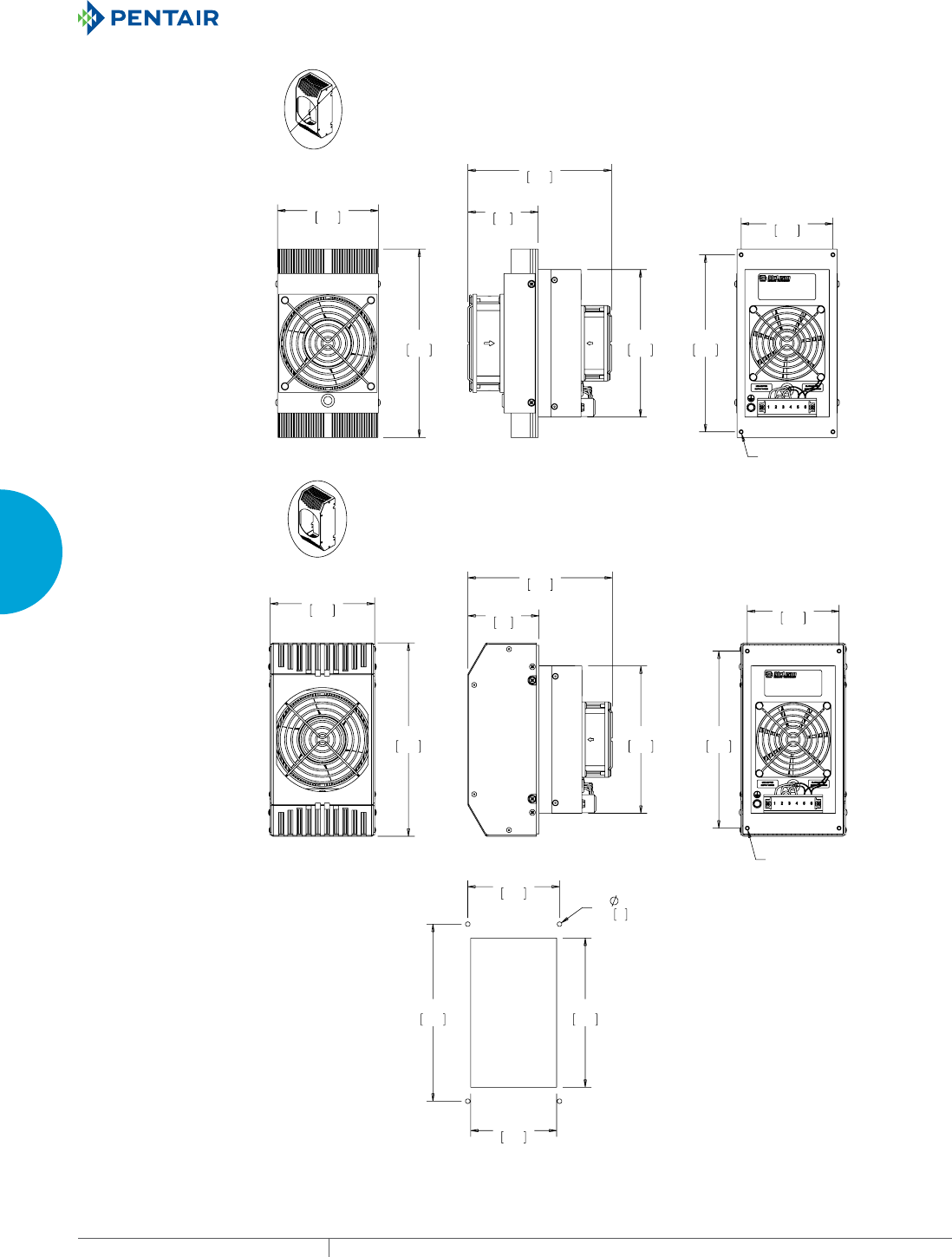
EQUIPMENT PROTECTIONSUBJECT TO CHANGE WITHOUT NOTICECOOLING186
3
SEALED ENCLOSURE COOLING THERMOELECTRIC COOLERS
0;;
[
&XWRXW'LPHQVLRQV
0;;
:9
:9

PH 763.422.2211 • FAX 763.576.3200 • HOFFMANONLINE.COMEQUIPMENT PROTECTION COOLING 187
3
SEALED ENCLOSURE COOLING THERMOELECTRIC COOLERS
Performance Data TE12 100W 341 BTU/Hr. (24/48 V)
CATALOG NUMBERS
Description 24V w/o shroud 24V w/ painted shroud 24V w/ SS shroud 48V w/o shroud 48V w/ painted shroud
Catalog Number TE121024020 TE121024010 TE121024011 TE121048020 TE121048010
COOLING PERFORMANCE
BTU/Hr. 321 321 321 321 321
Watts 94 94 94 94 94
Operating Temperature Range:
Maximum (°C / °F) 55 / 131 55 / 131 55 / 131 55 / 131 55 / 131
Minimum (°C / °F) -40 /-40 -40 /-40 -40 /-40 -40 /-40 -40 /-40
Air Flow at 0 Static Pressure:
Internal loop (CFM / M3/Hr.) 62 / 105 62 / 105 62 / 105 62 / 105 62 / 105
External loop (CFM / M3/Hr.) 86 / 146 86 / 146 86 / 146 86 / 146 86 / 146
Nominal Heating Watts 94 94 94 94 94
ELECTRICAL DATA
Input DC Voltage
Nominal (VDC) 24 24 24 48 48
Minimum (VDC) 18 18 18 40 40
Maximum (VDC) 27.6 27.6 27.6 56.7 56.7
Power Consumption
95 F / 95 F (35 C / 35 C)
162 162 162 162 162
Max Current (Amps) 8.5 8.5 8.5 4.4 4.4
Agency Approvals UR, cUR Recognized
CE
GOST
UR, cUR Recognized
CE
GOST
UR, cUR Recognized
CE
GOST
UR, cUR Recognized
CE
GOST
UR, cUR Recognized
CE
GOST
Power Input Description Terminal Block Terminal Block Terminal Block Terminal Block Terminal Block
ENCLOSURE PROTECTION
UL Type / IP Rating Type 12,3R,4,4X / IP 65 Type 12,3R,4 / IP 65 Type 12,3R,4,4X / IP 65 Type 12,3R,4,4X / IP 65 Type 12,3R,4 / IP 65
SOUND LEVEL
At 1.5 Meters 68 dBA 68 dBA 68 dBA 68 dBA 68 dBA
UNIT CONSTRUCTION
Heat Sink Material Anodized Aluminum Anodized Aluminum Anodized Aluminum Anodized Aluminum Anodized Aluminum
Shroud Material N/A Galvanized Steel Stainless Steel N/A Galvanized Steel
Shroud Finish N/A RAL 7035 light-gray,
semi-textured
powder-coat
paint standard
No. 4 Brushed Finish N/A RAL 7035 light-gray,
semi-textured
powder-coat
paint standard
UNIT DIMENSIONS
Height (in. / mm) 11.81/300 12.00/305 12.00/305 11.81/300 12.00/305
Width (in. / mm) 6.02/153 6.18/157 6.18/157 6.02/153 6.18/157
Depth (in. / mm) 7.40/188 7.43/189 7.43/189 7.40/188 7.43/189
Weight (lb. / kg) 8.50/3.90 11.00/5.00 11.00/5.00 8.50/3.90 11.00/5.00
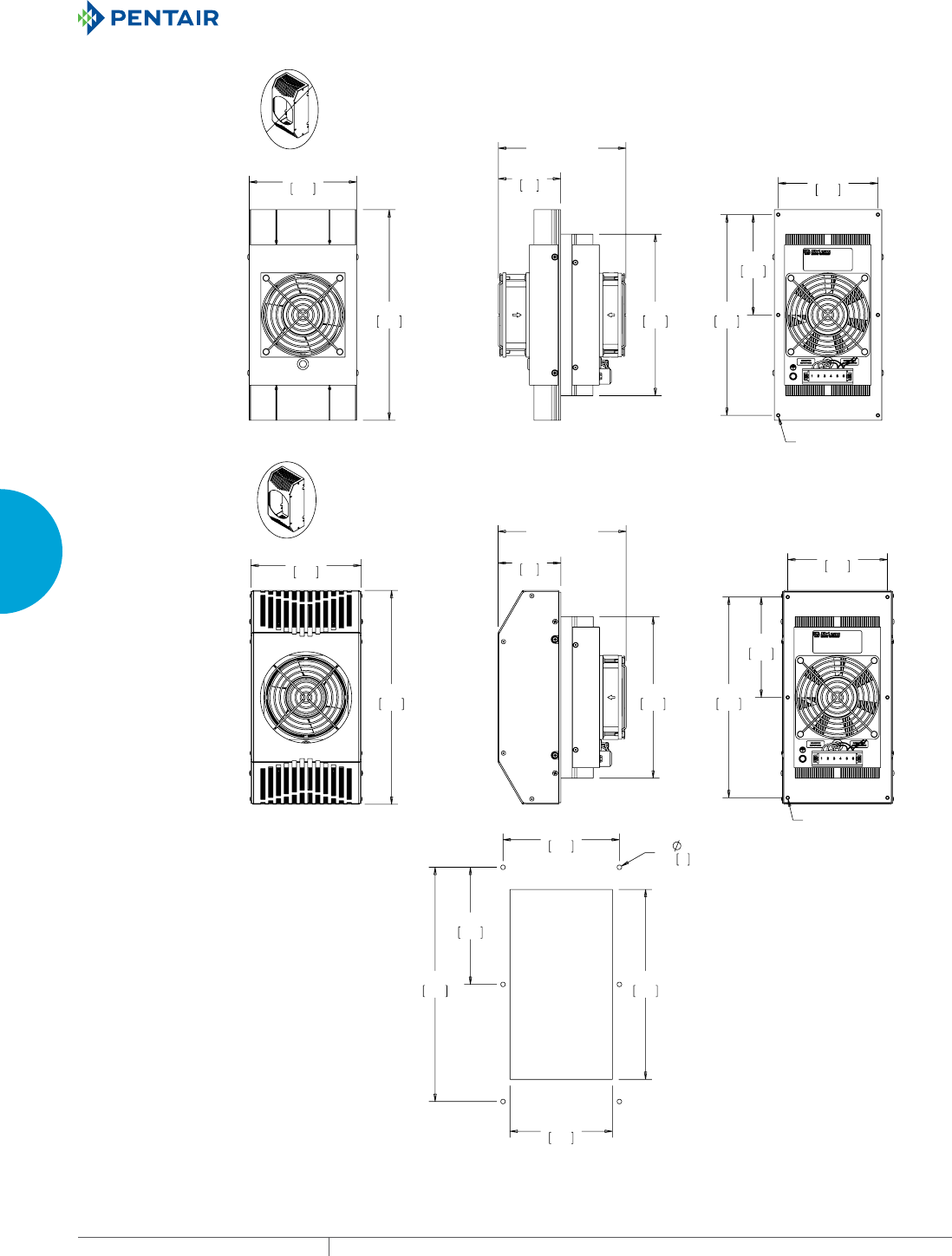
EQUIPMENT PROTECTIONSUBJECT TO CHANGE WITHOUT NOTICECOOLING188
3
SEALED ENCLOSURE COOLING THERMOELECTRIC COOLERS
>@>@
25
0;;
>@>@
25
0;;
[
&XWRXW'LPHQVLRQV
:9
:9

PH 763.422.2211 • FAX 763.576.3200 • HOFFMANONLINE.COMEQUIPMENT PROTECTION COOLING 189
3
SEALED ENCLOSURE COOLING THERMOELECTRIC COOLERS
Performance Data TE16 200W 682 BTU/Hr. (24/48 V)
CATALOG NUMBERS
Description 24V w/o shroud 24V w/ painted shroud 24V w/ SS shroud 48V w/o shroud 48V w/ painted shroud
Catalog Number TE162024020 TE162024010 TE162024011 TE162048020 TE162048010
COOLING PERFORMANCE
BTU/Hr. 567 567 567 567 567
Watts 166 166 166 166 166
Operating Temperature Range:
Maximum (°C / °F) 55 / 131 55 / 131 55 / 131 55 / 131 55 / 131
Minimum (°C / °F) -40 /-40 -40 /-40 -40 /-40 -40 /-40 -40 /-40
Air Flow at 0 Static Pressure:
Internal loop (CFM / M3/Hr.) 62 / 105 62 / 105 62 / 105 62 / 105 62 / 105
External loop (CFM / M3/Hr.) 86 / 146 86 / 146 86 / 146 86 / 146 86 / 146
Nominal Heating Watts 146 146 146 146 146
ELECTRICAL DATA
Input DC Voltage
Nominal (VDC) 24 24 24 48 48
Minimum (VDC) 18 18 18 40 40
Maximum (VDC) 27.6 27.6 27.6 56.7 56.7
Power Consumption
95 F / 95 F (35 C / 35 C)
295 295 295 295 295
Max Current (Amps) 14.7 14.7 14.7 7.6 7.6
Agency Approvals UR, cUR Recognized
CE
GOST
UR, cUR Recognized
CE
GOST
UR, cUR Recognized
CE
GOST
UR, cUR Recognized
CE
GOST
UR, cUR Recognized
CE
GOST
Power Input Description Terminal Block Terminal Block Terminal Block Terminal Block Terminal Block
ENCLOSURE PROTECTION
UL Type / IP Rating Type 12,3R,4,4X / IP 65 Type 12,3R,4 / IP 65 Type 12,3R,4,4X / IP 65 Type 12,3R,4,4X / IP 65 Type 12,3R,4 / IP 65
SOUND LEVEL
At 1.5 Meters 68 dBA 68 dBA 68 dBA 68 dBA 68 dBA
UNIT CONSTRUCTION
Heat Sink Material Anodized Aluminum Anodized Aluminum Anodized Aluminum Anodized Aluminum Anodized Aluminum
Shroud Material N/A Galvanized Steel Stainless Steel N/A Galvanized Steel
Shroud Finish N/A RAL 7035 light-gray,
semi-textured
powder-coat
paint standard
No. 4 Brushed Finish N/A RAL 7035 light-gray,
semi-textured
powder-coat
paint standard
UNIT DIMENSIONS
Height (in. / mm) 15.75/400 15.93/405 15.93/405 15.75/400 15.93/405
Width (in. / mm) 7.09/180 7.35/187 7.35/187 7.09/180 7.35/187
Depth (in. / mm) 7.25/18 4 7.27/185 7.27/185 7.25/184 7.27/185
Weight (lb. / kg) 14.80/6.70 18.60/8.40 18.60/8.40 14.80/6.70 18.60/8.40
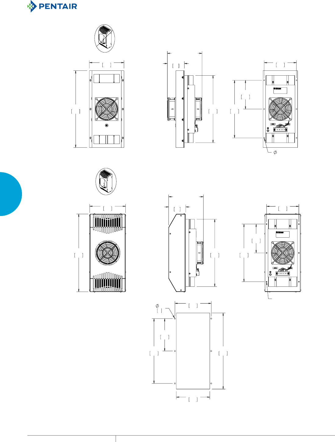
EQUIPMENT PROTECTIONSUBJECT TO CHANGE WITHOUT NOTICECOOLING190
3
SEALED ENCLOSURE COOLING THERMOELECTRIC COOLERS
>@>@
25
7+58+2/(;
>@>@
25
0;
[
&XWRXW'LPHQVLRQV
:9
:9
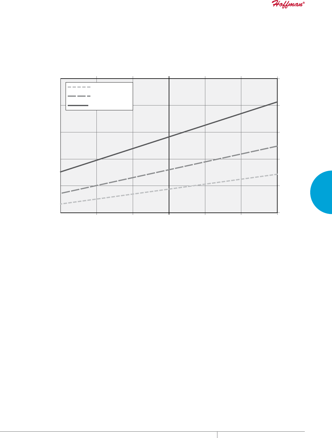
PH 763.422.2211 • FAX 763.576.3200 • HOFFMANONLINE.COMEQUIPMENT PROTECTION COOLING 191
3
SEALED ENCLOSURE COOLING THERMOELECTRIC COOLERS
TE0906XXXXX
TE1210XXXXX
TE1620XXXXX
Temperature Dierence (Inside - Outside)
Cooling Capacity
0 BTU/hr
200 BTU/hr
400 BTU/hr
600 BTU/hr
800 BTU/hr
1000 BTU/hr
-15 C -10 C -5 C0 C5 C 10 C 15 C
0 W
59 W
117 W
176 W
234 W
293 W
-27 F-18 F -9 F0 F9 F 18 F 27 F
Cooling Capacity versus Temperature D at 35 C (95 F) Ambientierence
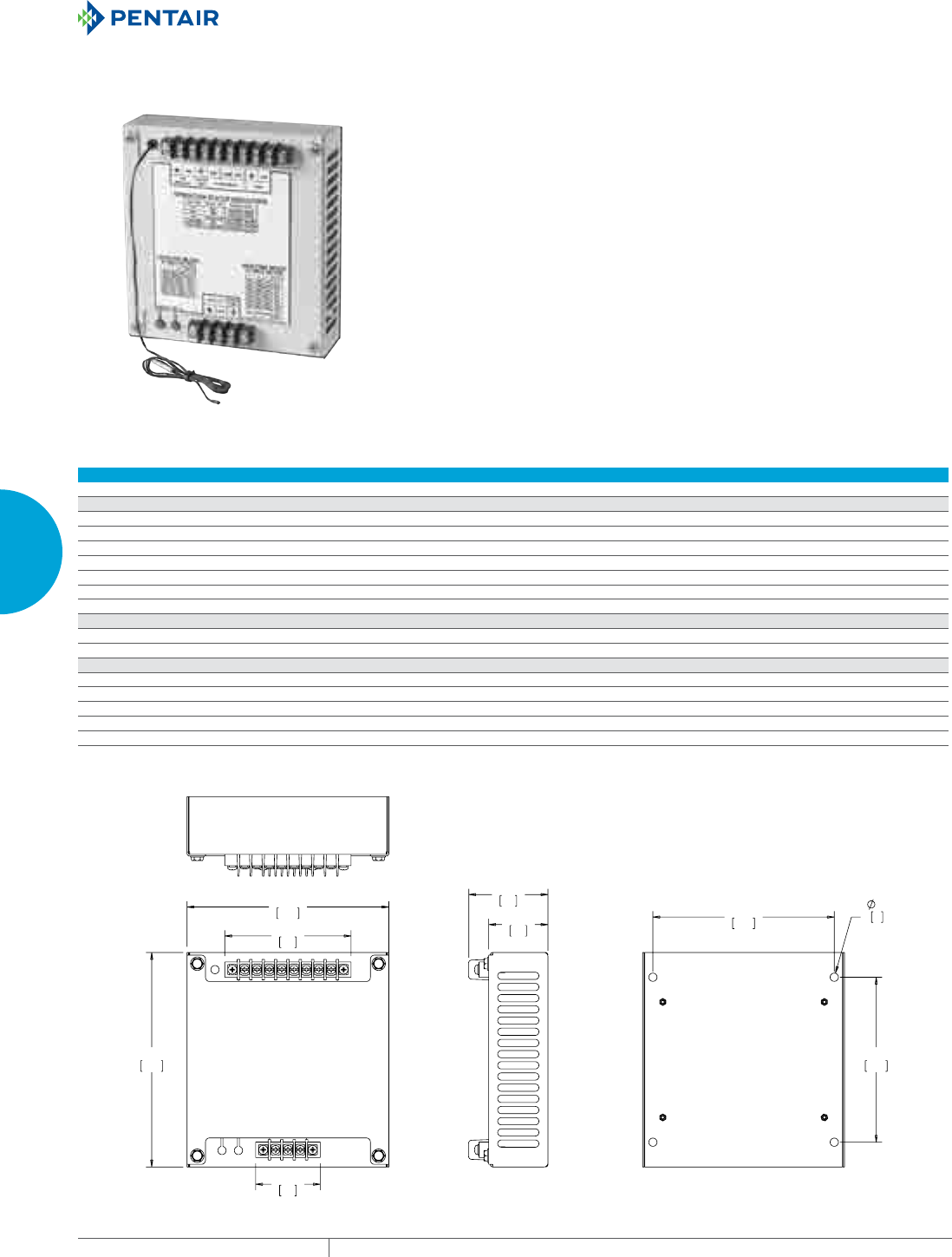
EQUIPMENT PROTECTIONSUBJECT TO CHANGE WITHOUT NOTICECOOLING192
3
SEALED ENCLOSURE COOLING THERMOELECTRIC COOLERS
THERMOELECTRIC TEMPERATURE CONTROLLER
FEATURES
• Provides PWM regulation of cooling and heating output for
Thermoelectric Cooler
• Automatically switches between cooling and heating
• Six cooling temperature set points range from 22.5 C (72.5 F) to
35 C (95 F) (35 C factory setting)
• Seven heating temperature set points range from -15 C (5 F) to 15
C(59 F)(15 C factory setting)
• Heating function can be easily disabled if desired
• LEDs indicate cooling and heating mode, low and high
temperature alarms, and overall system status
• Dry contact relay output provides for external alarm indication
• Can be mounted in a convenient dry location near the
thermoelectric cooler; mounting hardware included
FINISH
• RAL 7035 light-gray powder-coat painted galvanized steel
Performance Data
CATALOG NUMBERS
TEC24VCNTLR TEC48VCNTLR
ELECTRICAL DATA
Rated Voltage (VDC) 24 48
Operating Range (VDC) 18 to 30 40 to 60
Current @ Rated Voltage (Amps) 17.2 8.6
Power (Watts) 410
Operating Temperature Range
Maximum (°F/°C) 149/65
Minimum (°F/°C) -40/-40
UNIT CONSTRUCTION
Material Steel
Finish RAL 7035 light-gray, semi-textured powder-coat paint standard
UNIT DIMENSIONS
Height (in./mm) 6.50/165.0
Width (in./mm) 6.12/155.5
Depth - overall (in./mm) 2.50/63.5
Depth - enclosure (in/mm) 1.75/44.5
Weight (lb./kg) 3.0/1.6
9DQG97(&&RQWUROOHUV
;
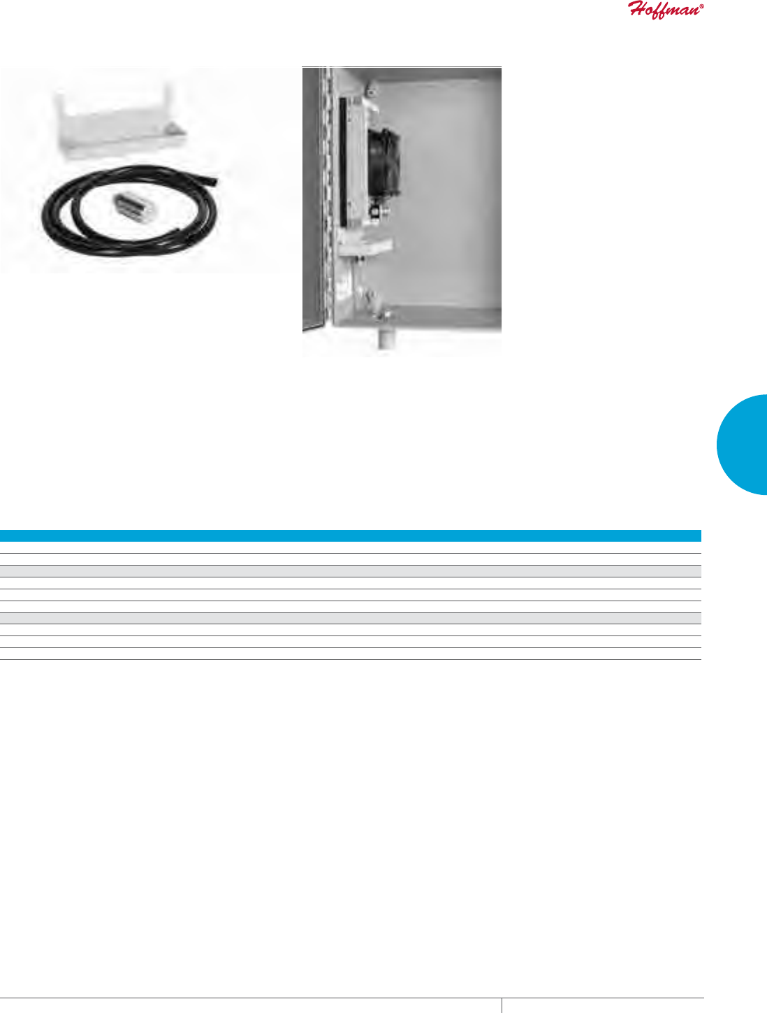
PH 763.422.2211 • FAX 763.576.3200 • HOFFMANONLINE.COMEQUIPMENT PROTECTION COOLING 193
3
SEALED ENCLOSURE COOLING THERMOELECTRIC COOLERS
THERMOELECTRIC CONDENSATE MANAGER
INDUSTRY STANDARDS
Maintains UL/cUL Type 3R, 12, 4 and 4X rating when properly
installed
FEATURES
• Includes all required hardware and vent drain
• Maintains the ingerity of Type 4 or Type 4X enclosure
• Drains condensation to bottom of enclosure via vent drain (vent
drain included with package)
• Utilizes existing mounting holes and fasteners of thermoelectric
cooler that requires no additional mounting
FINISH
• Pan Material Galvanzied steel polyester powder coat paint with
RAL 7035
• Vent drain material options include stainless steel or non-
metallic
Performance Data
CATALOG NUMBERS
TEC60WCMSS4 TEC60WCMNM TEC100WCMSS4 TEC100WCMNM TEC200WCMSS4 TEC200WCMNM
Fits TEC Unit Model All TE09 All TE09 All TE12 All TE12 All TE16 All TE16
UNIT CONSTRUCTION
Pan Material Galvanized Steel
Pan Finish RAL 7035 light-gray, semi-textured powder-coat paint standard
Vent Drain Material Stainless Steel Non-Metallic Stainless Steel Non-Metallic Stainless Steel Non-Metallic
UNIT DIMENSIONS
Height (in./mm) .75/19 .75/19 .75/19 .75/19 .75/19 .75/19
Width (in./mm) 5.50/140 5.50/140 6.25/159 6.25/159 7.4 4/189 7.4 4/189
Depth (in./mm) 2.50/64 2.50/64 2.50/64 2.50/64 2.50/64 2.50/64
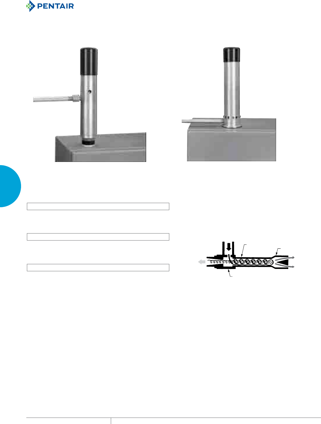
EQUIPMENT PROTECTIONSUBJECT TO CHANGE WITHOUT NOTICECOOLING194
3
SEALED ENCLOSURE COOLING VORTEX COOLERS
VORTEX COOLERS
VORTEX COOLERS INDOOR/OUTDOOR
INDUSTRY STANDARDS
NEMA Type 4 Models:
Maintains UL/cUL Type 4 when properly installed on a UL/cUL Type
4 enclosure.
UL508 Listed; Type 4; File No. E187045
NEMA Type 4X Models:
Maintains UL/cUL Type 4X when properly installed on a UL/cUL
Type 4X enclosure.
UL508 Listed; Type 4X; File No. E187045
NEMA Type 12 Models:
Maintains UL/cUL Type 12 when properly installed on a UL/cUL Type
12 enclosure.
UL508 Listed; Type 12; File No. E187045
APPLICATION
Powered by compressed air, Vortex Cooling Systems generate
chilled air to cool small enclosures without refrigerants or
moving parts. These systems are exceptionally reliable and low
maintenance, even in the harshest and dirtiest environments.
FEATURES
• Five-micron airline filter, 115 V solenoid
• Thermostat
• Ducting kit
• Cooling capacities to 2500 BTU/Hr. (733 W)
FINISH
Brushed satin aluminum or stainless steel
ACCESSORIES
(for the enclosure)
Can be installed on all enclosure product families.
Separate accessories include an in-line oil filter.
Compressed Air In
(70 F/21 C)
Vortex Generation Chamber
Vortex Tube Air Flow Schematic
Vortex Tube Control Valve
Hot
Air
Outlet
Cold
Air
Outlet
PH 763.422.2211 • FAX 763.576.3200 • HOFFMANONLINE.COMEQUIPMENT PROTECTION COOLING 195
3
SEALED ENCLOSURE COOLING VORTEX COOLERS
Performance Data VC Series NEMA Type 12
CATALOG NUMBERS
Aluminum VC0416012 VC0916012 VC1516012 VC2516012
COOLING PERFORMANCE
Cooling Capacity (BTU/Hr.) 400 900 1500 2500
Cooling Capacity (Watts) 117 264 440 733
Compressed Air Consumption (SCFM) 8 15 25 35
Compressed Air Consumption (L3/M) 227 425 708 991
SOUND LEVEL
Noise Level (dB) 69 80 83 90
ENCLOSURE PROTECTION
UL Type Type 12
ELECTRICAL DATA
Rated Voltage 115 115 115 115
Frequency (Hz) 50/60 50/60 50/60 50/60
UNIT DIMENSIONS
Weight (lb./kg) 5/2.27 6/2.72 6/2.72 6/2.72
Performance Data VC Series NEMA Type 4, 4X
CATALOG NUMBERS
Aluminum VC0916004 VC1716004 VC2516004
Stainless Steel VC091604X VC171604X VC251604X
COOLING PERFORMANCE
Cooling Capacity (BTU/Hr.) 900 1700 2500
Cooling Capacity (Watts) 264 498 733
Compressed Air Consumption (SCFM) 15 25 35
Compressed Air Consumption (L3/M) 425 708 991
SOUND LEVEL
Noise Level (dB) 83 86 90
ENCLOSURE PROTECTION
UL Type Type 4, 4X
ELECTRICAL DATA
Rated Voltage 115 115 115
Frequency (Hz) 50/60 50/60 50/60
UNIT DIMENSIONS
Weight (lb./kg) 6/2.72 6/2.72 6/2.72
Vortex Cooling System Accessories
CATALOG NUMBERS
VCOF17 VCOF25
PERFORMANCE
Description Oil Filter
Use with VCool Model Capacity Up to 1700 BTU/Hr. 2500 BTU/Hr.
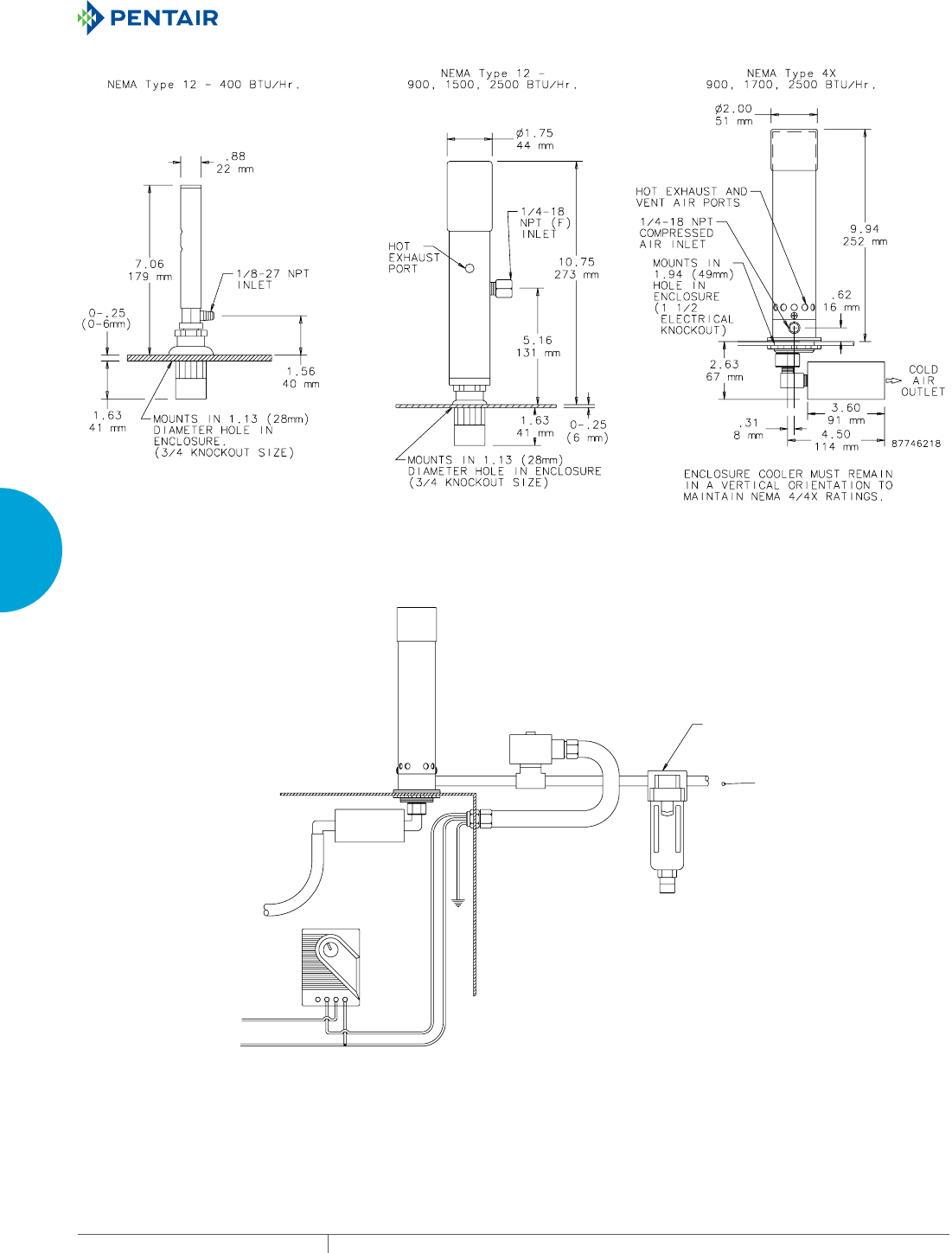
EQUIPMENT PROTECTIONSUBJECT TO CHANGE WITHOUT NOTICECOOLING196
3
SEALED ENCLOSURE COOLING VORTEX COOLERS
1 3
7\SLFDO,QVWDOODWLRQ
9RUWH[&RROHU
6ROHQRLG9DOYH
1371RUPDOO\&ORVHG
1(0$RU;5DWHG
9+]RU9+]
0LFURQ)LOWHU
6XSSOLHG
7KHUPRVWDW
&ROG$LU
'XFWLQJ.LW
$LUIORZ

PH 763.422.2211 • FAX 763.576.3200 • HOFFMANONLINE.COMEQUIPMENT PROTECTION COOLING 197
3
SEALED ENCLOSURE COOLING VORTEX COOLERS
Notes
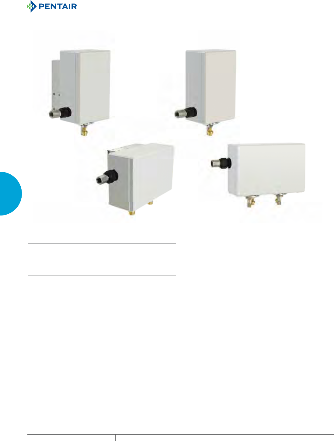
EQUIPMENT PROTECTIONSUBJECT TO CHANGE WITHOUT NOTICECOOLING198
3
SEALED ENCLOSURE COOLING VORTEX COOLERS
QUIET VORTEX A/C ENCLOSURE COOLERS, TYPE 4/4X/12
VA09, VA15, VA25
NEMA Type 12
VA09, VA15, VA25
NEMA Type 4/4X
VA50
NEMA Type 4/4X
VA50
NEMA Type 12
V
A09
,
VA15
,
VA25
NEMA T
y
pe 12
VA09
,
VA15
,
VA2
5
NEMA T
y
pe 4/4X
VA5
0
NEMA Type 4
/
4X
V
A50
NEMA Type 1
2
INDUSTRY STANDARDS
NEMA Type 4,4X Models:
Maintains UL/cUL Type 4, 4X when properly installed on a UL/
cUL Type 4, 4X enclosure.
UL508 Listed; Type 4, 4X; File No. E249700
NEMA Type 12 Models:
Maintains UL/cUL Type 12 when properly installed on a UL/cUL
Type 12 enclosure.
UL508 Listed; Type 12; File No. E249700
APPLICATION
Vortex A/C Enclosure Coolers keep enclosures cool, clean and
protected even in the harshest environments. Offering flexible
installation, these enclosure coolers are ideal in space-restrictive
areas where compressed air is readily available. With almost no
moving parts, these enclosure coolers are highly reliable and
virtually maintenance free.
FEATURES
• Mechanical thermostat reduces energy consumption
• Top, side, and front mount allows for versatile installation in
confined areas
• Quieter operation with noise level of 60-75 dB
• Cooling capacities up to 5000 BTU/Hr. (1465 W)
• Supplied with five-micron, automatic drain compressed air filter,
cold ducting kit, and cold air muffler
• Operates in environments up to 175 F (80 C)
FINISH
• NEMA Type 4,4X models: Polycarbonate and stainless steel
exterior; aluminum and brass internal components
• NEMA Type 12 models: Polycarbonate and aluminum exterior;
aluminum and brass internal components
ACCESSORIES
• Oil Removal Filter
• Generator Kit
• Five-micron Air Filter
• Cold Air Ducting Kit
• Cold Air Muffler
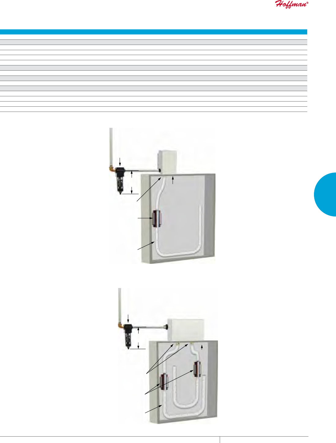
PH 763.422.2211 • FAX 763.576.3200 • HOFFMANONLINE.COMEQUIPMENT PROTECTION COOLING 199
3
SEALED ENCLOSURE COOLING VORTEX COOLERS
Performance Data VA Series NEMA Type 4, 4X
CATALOG NUMBERS
VA091604X VA151604X VA251604X VA501604X
COOLING PERFORMANCE
Cooling Capacity (BTU/Hr.) 900 1500 2500 5000
Cooling Capacity (Watts) 264 440 733 1465
Compressed Air Consumption (SCFM) 15 25 35 70
Compressed Air Consumption (SLPM) 425 708 991 1982
SOUND LEVEL
Noise Level (dB) 60 66 72 75
ENCLOSURE PROTECTION
UL Type Type 4, 4X
UNIT DIMENSIONS
Height (in./mm) 8.00/203 8.00/203 8.00/203 6.44/164
Width (in./mm) 4.75/121 4.75/121 4.75/121 9.44/240
Depth (in./mm) 5.38/137 5.38/137 5.38/137 5.56/141
Weight (lb./kg) 6.3/2.86 6.3/2.86 6.4/2.90 11.0/4.99
Filter (supplied)
Vent Air
Hole 1.94 (49 mm)
Ducting (supplied)
1.75 (44 mm) diameter x 3.59
(91 mm) long muffler and
mounting clamps (supplied)
5.88
149 mm
VA09, VA15, VA25, Type 4/4X
Filter (supplied)
Vent Air
Holes 1.94 (49 mm)
1.75 (44 mm) diameter x 3.59
(91 mm) long muffler and
mounting clamps (supplied)
6.38
162 mm
Ducting (supplied)
VA50, Type 4/4X
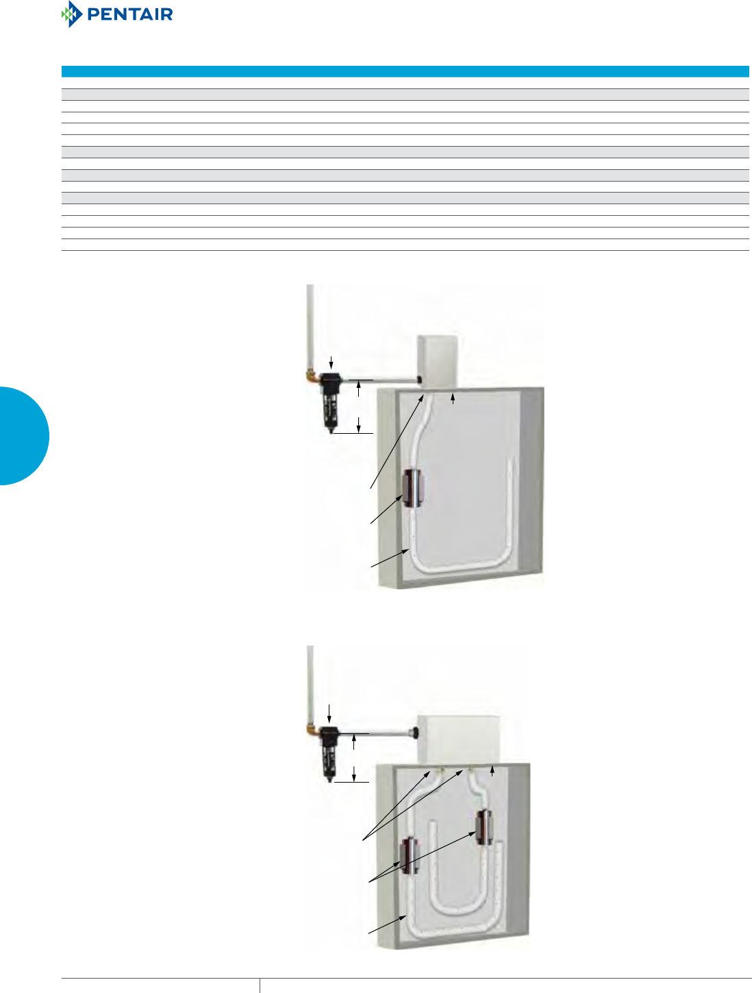
EQUIPMENT PROTECTIONSUBJECT TO CHANGE WITHOUT NOTICECOOLING200
3
SEALED ENCLOSURE COOLING VORTEX COOLERS
Performance Data VA Series NEMA Type 12
CATALOG NUMBERS
VA0916012 VA1516012 VA2516012 VA5016012
COOLING PERFORMANCE
Cooling Capacity (BTU/Hr.) 900 1500 2500 5000
Cooling Capacity (Watts) 264 440 733 1465
Compressed Air Consumption (SCFM) 15 25 35 70
Compressed Air Consumption (SLPM) 425 708 991 1982
SOUND LEVEL
Noise Level (dB) 60 66 72 75
ENCLOSURE PROTECTION
UL Type Type 12
UNIT DIMENSIONS
Height (in./mm) 8.00/203 8.00/203 8.00/203 6.44/164
Width (in./mm) 4.75/121 4.75/121 4.75/121 9.44/240
Depth (in./mm) 3.56/90 3.56/90 3.56/90 4.25/108
Weight (lb./kg) 4.9/2.22 4.9/2.22 5.0/2.27 7.7/3.50
Filter (supplied)
Vent Air
Hole 1.94 (49 mm)
1.75 (44 mm) diameter x 3.59
(91 mm) long muffler and
mounting clamps (supplied)
5.88
149 mm
Ducting (supplied)
VA09, VA15, VA25, Type 12
Filter
(supplied)
Vent Air
Holes 1.94 (49 mm)
1.75 (44 mm) diameter x 3.59
(91 mm) long muffler and
mounting clamps (supplied)
6.38
162 mm
Ducting (supplied)
VA50, Type 12

PH 763.422.2211 • FAX 763.576.3200 • HOFFMANONLINE.COMEQUIPMENT PROTECTION COOLING 201
3
SEALED ENCLOSURE COOLING VORTEX COOLERS
Vortex AC Accessories Type 4/4X/12
CATALOG NUMBERS Description Use with VA Model Capacity
Air Filters
VAAF15 5 micron, automatic drain compressed air filter Up to 1500 BTU/Hr.
VAAF25 5 micron, automatic drain compressed air filter Up to 2500 BTU/Hr.
VAAF50 5 micron, automatic drain compressed air filter Up to 5000 BTU/Hr.
Oil Filters
VCOF17 Oil Filter Up to 1500 BTU/Hr.
VCOF25 Oil Filter Up to 5000 BTU/Hr.
Generators
VAGK09 Generator Kit 900 BTU/Hr. models
VAGK15 Generator Kit 1500 BTU/Hr. models
VAGK25 Generator Kit 2500 and 5000 BTU/Hr. models
Air Ducting
VADK124X Cold Air Ducting Kit All NEMA 12, 4/4X models
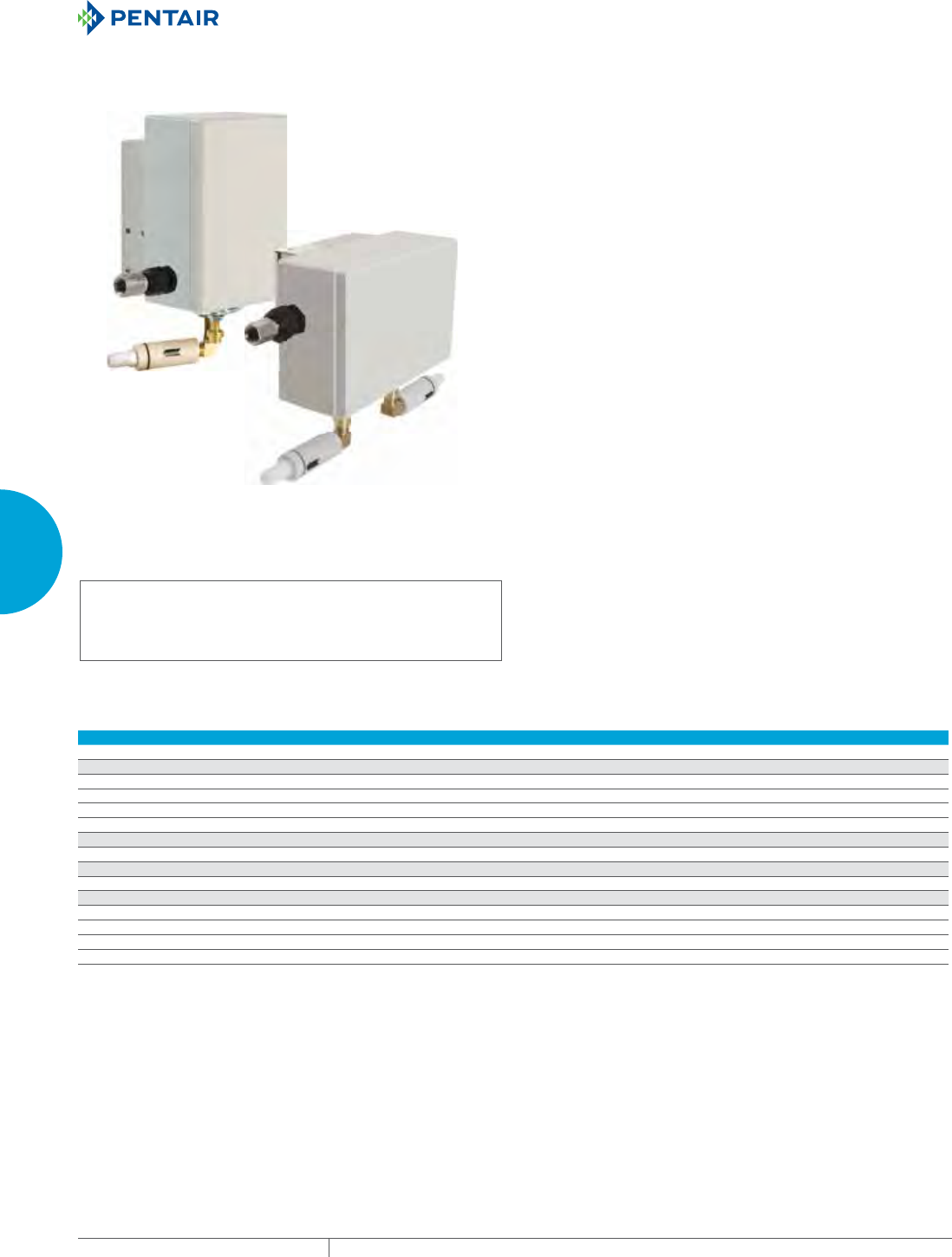
EQUIPMENT PROTECTIONSUBJECT TO CHANGE WITHOUT NOTICECOOLING202
3
SEALED ENCLOSURE COOLING VORTEX COOLERS
VORTEX A/C ENCLOSURE COOLERS, HAZARDOUS LOCATION
VHL09, VHL15, VHL25
VHL50
INDUSTRY STANDARDS
Hazardous Location Models:
UL Classified for Class 1, Div. 2, Groups A through D; Class II,
Div. 2, Groups F & G; and Class III locations (when used with an
approved purge/pressurization system); File No. E364567.
Maintains UL/cUL Type 4, 4X when properly installed on a UL/
cUL Type 4, 4X enclosure.
APPLICATION
Hazardous Location Vortex A/C Enclosure Coolers keep enclosures
cool, clean and protected even in hazardous environments. These
systems are ideal for applications where compressed air is
available in Hazardous Locations. With almost no moving parts,
these systems are highly reliable and virtually maintenance free.
FEATURES
• Approved for a 175 F (80 C) maximum ambient temperature in
Class I, Div. 2; Class II, Div. 2; and Class III areas
• Mechanical thermostat reduces energy consumption
• Top, side, and front mount allows for versatile installation in
confined areas
• Quieter operation with noise level of 60-75 dB
• Supplied with five-micron, automatic drain compressed air filter,
cold ducting kit, cold air muffler, and check valve
• Cooling capacities up to 5000 BTU/Hr. (1465 W)
FINISH
• Polycarbonate and stainless steel exterior with aluminum and
brass internal components
ACCESSORIES
• Oil Removal Filter
• Generator Kit
• 5 micron Air Filter
• Cold Air Ducting Kit
• Cold Air Muffler
• Check Valve
• Purge System
Performance Data VHL Series for Hazardous Locations
CATALOG NUMBERS
VHL09160 VHL15160 VHL25160 VHL50160
COOLING PERFORMANCE
Cooling Capacity (BTU/Hr.) 900 1500 2500 5000
Cooling Capacity (Watts) 264 440 733 1465
Compressed Air Consumption (SCFM) 15 25 35 70
Compressed Air Consumption (SLPM) 425 708 991 1982
SOUND LEVEL
Noise Level (dB) 60 66 72 75
ENCLOSURE PROTECTION
UL Classified Class 1, Div. 2, Groups A-D; Class II, Div. 2, Groups F & G, Class III
UNIT DIMENSIONS
Height (in./mm) 8.00/203 8.00/203 8.00/203 6.44/164
Width (in./mm) 4.75/121 4.75/121 4.75/121 9.44/240
Depth (in./mm) 5.38/137 5.38/137 5.38/137 5.56/141
Weight (lb./kg) 6.70/3.04 6.7/3.04 6.8/3.08 11.4/5.17
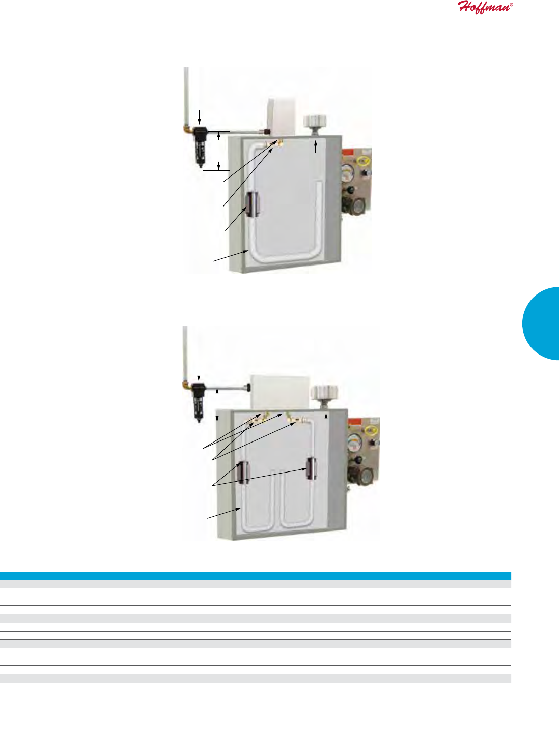
PH 763.422.2211 • FAX 763.576.3200 • HOFFMANONLINE.COMEQUIPMENT PROTECTION COOLING 203
3
SEALED ENCLOSURE COOLING VORTEX COOLERS
Filter (supplied)
Cut 1.94 (49 mm)
hole in enclsoure
to install unit
1.75 (44 mm) diameter x 3.84
(98 mm) long muffler and
mounting clamps (supplied)
1.25 (32 mm) diameter x
3.06 (78 mm) long
check valve assembly
(supplied)
5.44
138 mm
Minimum Vent Air
Purge
System
(order
separatel
y)
Ducting (supplied)
VHL09, VHL15, VHL25 HAZLOC
Holes 1.94 (49 mm)
Ducting (supplied)
1.75 (44 mm) diameter x 3.88
(98 mm) long muffler and
mounting clamps (supplied)
6.38
162 mm
Vent Air
Filter (supplied)
1.25 (32 mm) diameter x
3.06 (78 mm) long
check valve assembly
(supplied)
Purge
System
(order
separately)
VHL50 HAZLOC
Vortex AC Accessories Hazardous Location
CATALOG NUMBERS Description Use with VHL Model Capacity
Air Filters
VAAF15 5 micron, automatic drain compressed air filter Up to 1500 BTU/Hr.
VAAF25 5 micron, automatic drain compressed air filter Up to 2500 BTU/Hr.
VAAF50 5 micron, automatic drain compressed air filter Up to 5000 BTU/Hr.
Oil Filters
VCOF17 Oil Filter Up to 1500 BTU/Hr.
VCOF25 Oil Filter Up to 5000 BTU/Hr.
Generators
VAGK09 Generator Kit 900 BTU/Hr. models
VAGK15 Generator Kit 1500 BTU/Hr. models
VAGK25 Generator Kit 2500 and 5000 BTU/Hr. models
Air Ducting
VHLDK Cold Air Ducting Kit All Hazardous Location models
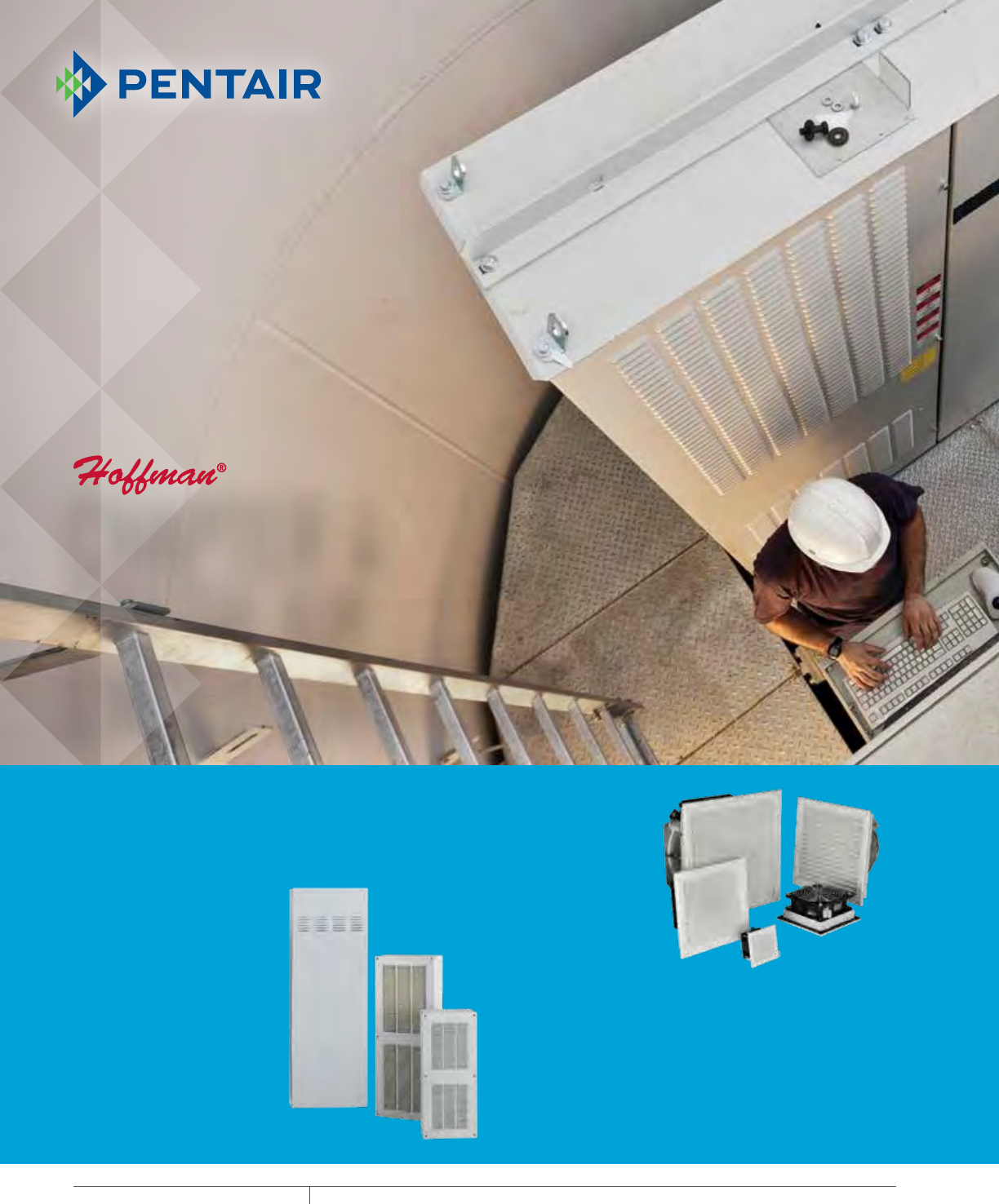
EQUIPMENT PROTECTIONSUBJECT TO CHANGE WITHOUT NOTICECOOLING204
4
763.422.2211
763.576.3200
COOLING
FRESH AIR ENCL OSURE COOLI NG
Intro Page
DIRECT AIR COOLING SYSTEMS
(DACS)
DACS provides flexible, effective heat
removal for outdoor enclosures. A
cost-efficient alternative to closed-loop
cooling solutions, DACS utilizes
quiet, fan-based technology to
draw filtered ambient air into the
enclosure to dissipate heat. Models
include Hydrophobic
Gore™ and MERV 12
filtration styles to
protect against
outdoor elements
such as water,
dust, bugs and
rain.
FILTER FANS
Filter Fans cool a wide range of heat
loads in applications ranging from
industrial drives to process equipment
and controls. With more than 175
models, Type 12, Type 3R and Type
1 options, a wide range of airflow
capabilities and various mounting
options, Filter Fans are available for
diverse environments.
CHAPTER 4
FRESH AIR
ENCLOSURE COOLING
FEATURED PRODUCTS
PH 763.422.2211 • FAX 763.576.3200 • HOFFMANONLINE.COMEQUIPMENT PROTECTION COOLING 205
Intro Page
FAN TRAYS
Fan Trays deliver a versatile solution to
efficiently cool card cages and racks.
Redundant cooling with optional failure
detection ensures reliable cooling for
sensitive electronic equipment. With
a slim, field-adjustable design, these
19-inch rack mountable trays provide
simple installation and easy access.
4
CHAPTER CONTENTS
DIRECT AIR COOLING SYSTEMS (DACS)
DACS Outdoor .................................206
FILTER FANS
SF Side-Mount ................................212
ST Thin Side-Mount. . . . . . . . . . . . . . . . . . . . . . . . . . . . .230
SR Top-Mount .................................236
Filter Fan Shrouds ..............................240
SF/ST Replacement Filters .......................241
TFP Side-Mount ...............................242
TFP Exhaust Grilles. . . . . . . . . . . . . . . . . . . . . . . . . . . . .246
TFP Optional Grilles and Replacement Filters ........246
TFP EMC Upgrade Kit ...........................247
Outdoor Filter Fan and Exhaust Package ............248
AXIAL FANS AND ACCESSORIES
Compact Axial Fans ............................250
Fan Cords ....................................254
Fan Cords With Inline Thermostat .................254
Fan Filter and Finger Guard Kit ....................254
Fan Brackets ..................................255
Finger Guards .................................255
FAN TRAYS
Rack-Mountable Assemblies .....................256
19-in. Rack-Mountable Tray ......................258
Rack-Mount Fan Speed Control ...................259
PACKAGED BLOWERS
Rack-Mountable Blowers ........................260
AIR MOVERS
Rack-Mountable Fan Package ....................266
Exhaust Grilles and Replacement Filters ............267
Filter Box Fans ................................268
BLOWERS
Centrifugal Blowers ............................270
MOTORIZED IMPELLERS
AC Motorized Impellers ..........................274
DC Motorized Impellers. . . . . . . . . . . . . . . . . . . . . . . . . .282
ACCESSORIES
Filter Grille Panel ..............................290
Louver Plate Kits ..............................291
Louver Plate Kit Filters ..........................291
Vent Kit ......................................292
Ventilator ....................................292
Filter Adhesive ................................293
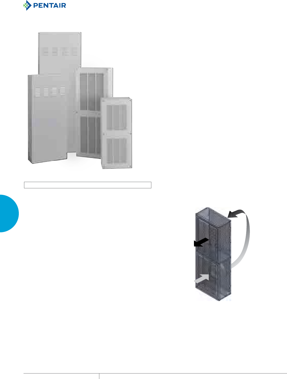
EQUIPMENT PROTECTIONSUBJECT TO CHANGE WITHOUT NOTICECOOLING206
4
FRESH AIR ENCLOSURE COOLING DIRECT AIR COOLING SYSTEMS (DACS)
DIRECT AIR CO OLING SYSTEMS (D ACS)
DACS OUTDOOR
INDUSTRY STANDARDS
UL Recognized
CE
Telcordia GR-487 capable
APPLICATION
• Outdoor telecommunications equipment
• Industrial automation
• Outdoor kiosk
• Outdoor displays
• OSP applications
FEATURES
• Customizable solutions to meet any customer need
• Two models utilizing Hydrophobic GORE® filter
• Two models with MERV 12, pleated filter
• Standard power input: 48 VDC
• UL Listed to save time and money with agency approvals
• Power Cord included
• Easy to replace filters
• Broad operating temperature range -40 C to 55 C
• Every unit functionally tested before shipping
• Hydrophobic GORE® filter protects against salt and other
corrosive agents
• Controller provides soft start and current limiting at start up
• Vibration resistant to withstand over-the-ground transportation
of the telecom system
• Variable speed blowers standard on units for quiet running
• Controller provides fan speed control and temperature alarm
FINISH
• Standard Finish: Galvanized steel with RAL 7035 light-gray semi-
textured powder coat paint
OPTIONS
• Custom Material: Aluminum, Stainless Steel, Mild Steel
• Custom Finish: Paint Color
• Custom Power Input: 24 VDC, 115 VAC, & 230 VAC
• Custom Sizes: Height 29 in. (737 mm) to 56 in. (1422 mm)
NOTES
Visit www.HoffmanOnline.com to download 2D and 3D CAD
drawings into the overall design of your electronic system.
GORE® is a registered trademark of W.L. Gore & Associates, Inc.
PH 763.422.2211 • FAX 763.576.3200 • HOFFMANONLINE.COMEQUIPMENT PROTECTION COOLING 207
4
FRESH AIR ENCLOSURE COOLING DIRECT AIR COOLING SYSTEMS (DACS)
Performance Data DACS
CATALOG NUMBERS
DCG4108548100 DCG2904248100 DCT5615048100 DCT3809448100
COOLING PERFORMANCE
Nominal:
Watts/°F 85 42 50 94
Watts/°C 152 75 270 170
Operating Temperature Range:
Maximum (°F/°C) 131/55 131/55 131/55 131/55
Minimum (°F/°C) -40/-40 -40/-40 -40/-40 -40/-40
Air Flow at 0 Static Pressure: (CFM/ m3/hr.) 265/450 130/221 470/799 300/510
ELECTRICAL DATA
Rated Voltage (VDC) 48
Operating Range (VDC) 40-60
Max. Power Consumption (Watts) 159 159 192 173
Max. Nominal Current (Amps) 3.3 3.3 4.0 3.6
Agency Approvals cUL Listed, CE
ENCLOSURE PROTECTION
UL Type Type 3R
CONTROLLER
Description Fan speed control and temperature alarm
Factory Thermostat Setting (°F/°C) 104/40
SOUND LEVEL
At 1.5 Meters - Full Speed (dBA) 67.1 68.1 65.0 63.4
UNIT CONSTRUCTION
Material Galvanized Steel
Finish RAL 7035 light-gray, semi-textured powder-coat paint standard
Filter Type Hydrophobic GORE®Pleated Filter Merv 12
UNIT DIMENSIONS
Height (in./mm) 40.75/1035 28.75/730 56/1422 38/965
Width (in./mm) 15/381 12/305 20/508 16/406
Depth (in./mm) 7.88/200 7.12/181 7/178 6/152
Weight (lb./kg) 50/22.7 40/18.1 65/29.5 38/17.2
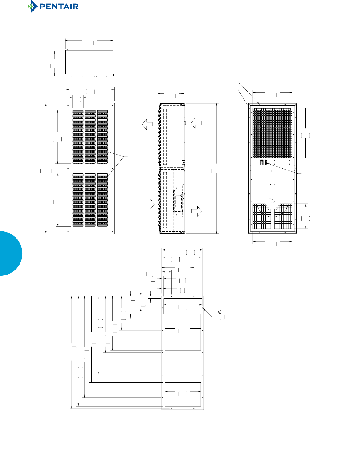
EQUIPMENT PROTECTIONSUBJECT TO CHANGE WITHOUT NOTICECOOLING208
4
FRESH AIR ENCLOSURE COOLING DIRECT AIR COOLING SYSTEMS (DACS)
$0%,(17
$,5287
$0%,(17
$,5,1
(1&/2685(
$,5287
(1&/2685(
$,5,1
),/7(56
'&*
*$6.(7)25
02817,1*
72(1&/2685(
32:(5
$1'$/$50
&211(&7256
02817,1*
;
&87287',0(16,216
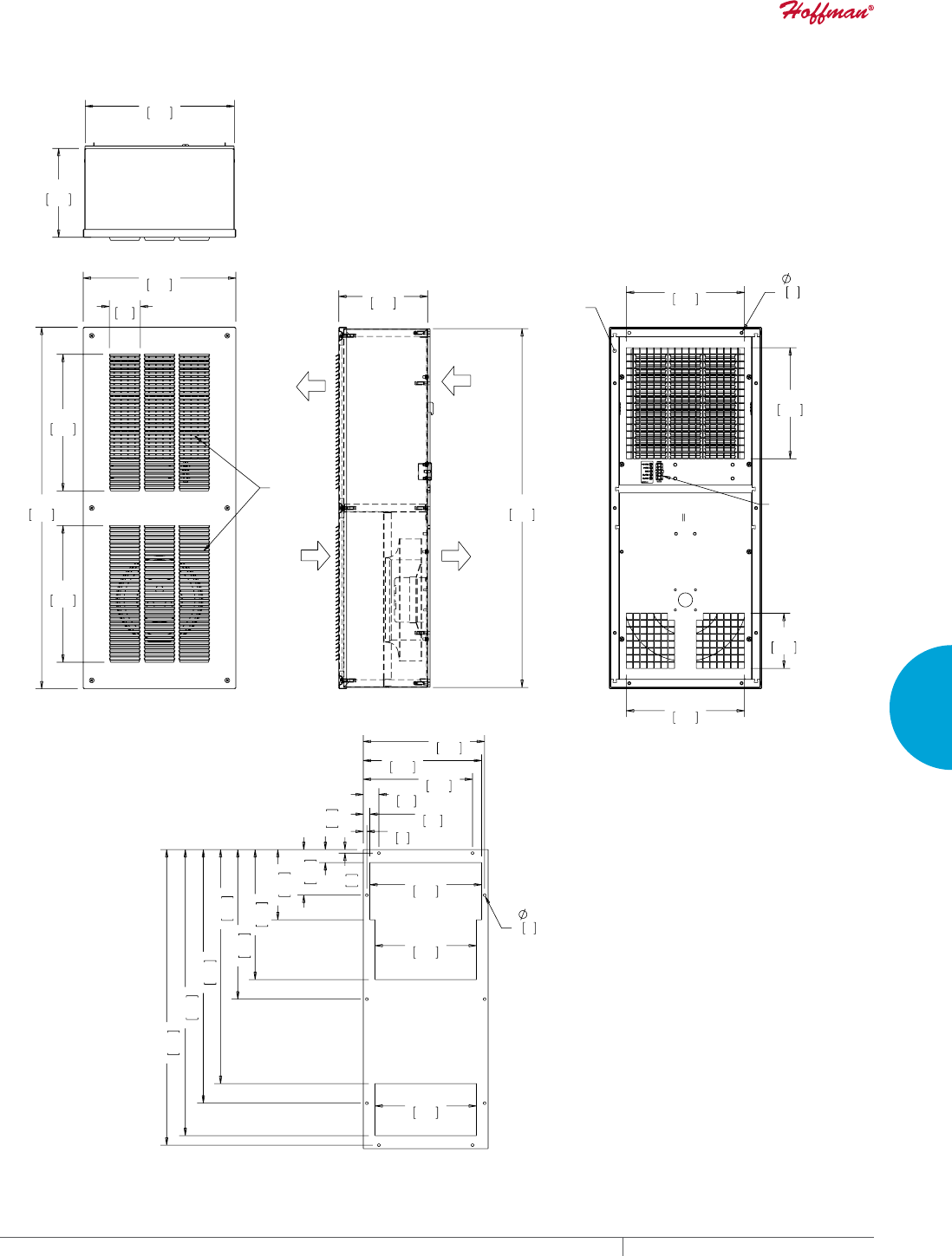
PH 763.422.2211 • FAX 763.576.3200 • HOFFMANONLINE.COMEQUIPMENT PROTECTION COOLING 209
4
FRESH AIR ENCLOSURE COOLING DIRECT AIR COOLING SYSTEMS (DACS)
),/7(56
$0%,(17
$,5287
$0%,(17
$,5,1
(1&/2685(
$,5287
(1&/2685(
$,5,1
;
*$6.(7)25
02817,1*72
(1&/2685(
32:(5
$1'$/$50
&211(&7256
;
&87287',0(16,216
'&*
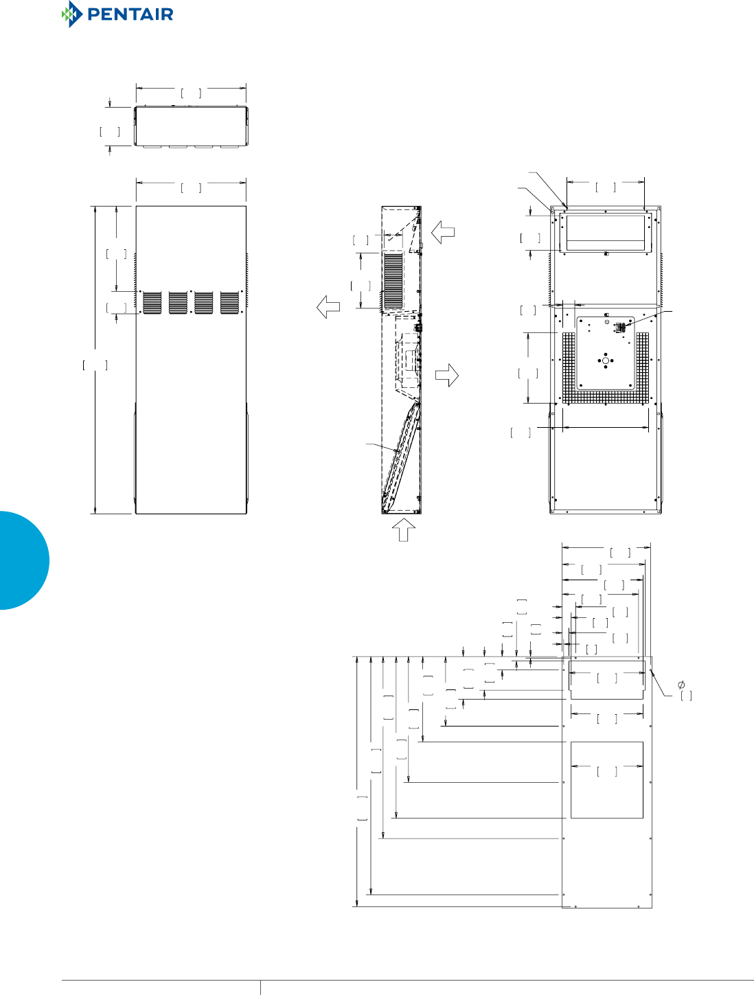
EQUIPMENT PROTECTIONSUBJECT TO CHANGE WITHOUT NOTICECOOLING210
4
FRESH AIR ENCLOSURE COOLING DIRECT AIR COOLING SYSTEMS (DACS)
$0%,(17
$,5287
(1&/2685(
$,5287
$0%,(17
$,5,1
(1&/2685(
$,5,1
),/7(5
32:(5
$1'$/$50
&211(&7256
*$6.(7)25
02817,1*72
(1&/2685(
02817,1*
;
'&7
&87287',0(16,216
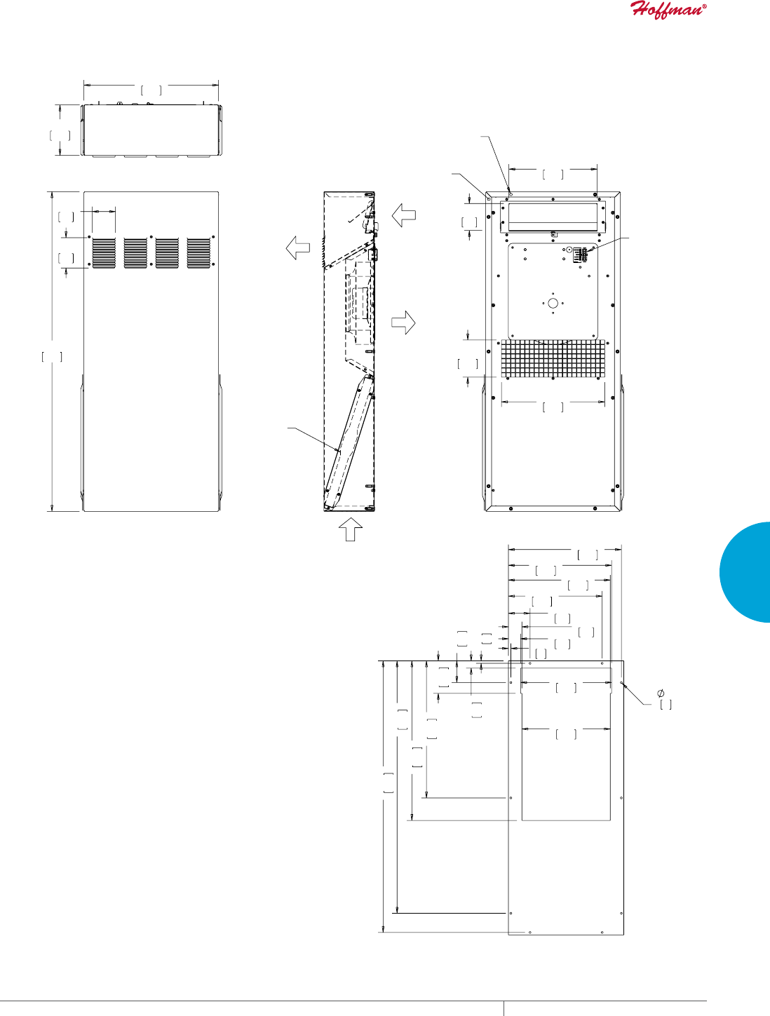
PH 763.422.2211 • FAX 763.576.3200 • HOFFMANONLINE.COMEQUIPMENT PROTECTION COOLING 211
4
FRESH AIR ENCLOSURE COOLING DIRECT AIR COOLING SYSTEMS (DACS)
),/7(5
*$6.(7)25
02817,1*72
(1&/2685(
02817,1*
32:(5
$1'$/$50
&211(&7256
;
'&7
&87287',0(16,216
$0%,(17
$,5,1
$0%,(17
$,5287
(1&/2685(
$,5,1
(1&/2685(
$,5287
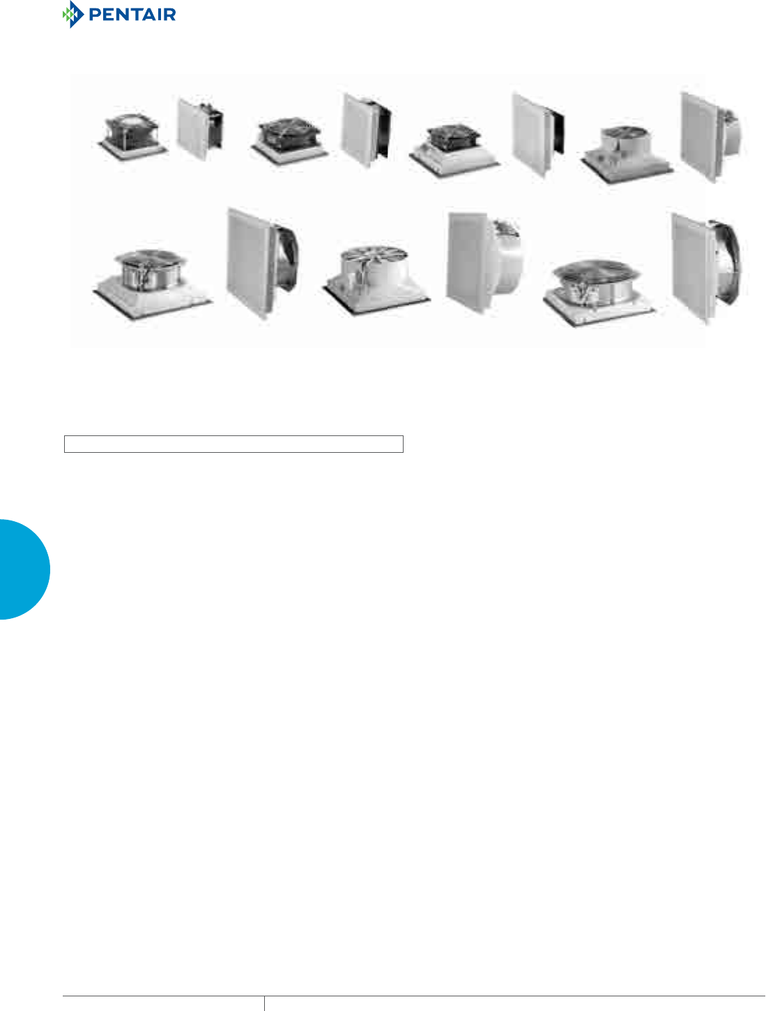
EQUIPMENT PROTECTIONSUBJECT TO CHANGE WITHOUT NOTICECOOLING212
4
FRESH AIR ENCLOSURE COOLING FILTER FANS
FILTE R FAN S
SF SIDEMOUNT
SF04
16 CFM (28 m/hr.)
SF05
39 CFM (66 m/hr.) SF09
75 CFM (127 m/hr.) SF10
162 CFM (275 m/hr.)
SF13
376 CFM (638 m/hr.)
SF13
473 CFM (803 m/hr.)
SF13
571 CFM (970 m/hr.)
INDUSTRY STANDARDS
UL/cUL recognized; File No. 235470
CE, CSA (fan motor only)
Type 12, IP54 standard
Type 12, IP 55 optional
APPLICATION
• Industrial automation
• Automotive assembly
• Package handling equipment
• Food and beverage process controlls
• Wind energy systems
FEATURES
• Click-fit design quickly installs into enclosure wall; no tools or
screws required
• Simple snap-open grille for easy filter replacement
• Enclosure side wall mounting
• Reverse airflow option on SF13 models available to push/pull air
through higher static pressure
• Standard foam-in-place gasket
• Similar cut-out sizes as other filter fan manufacturers
• Terminal wire connections
• Optional thermostat available to save energy and extend service
life
SPECIFICATIONS
• Size rage from 4 in. (102 mm) to 13 in. (325 mm)
• Free air flow from 16 CFM (28 m3/hr.) to 571 CFM (920 m3/hr.)
• Service life hours from 40000 to 70000 hours
• Operating temperature range fo -4 F/-20 C to 149 F/65 C
FINISH
• RAL 7035 light-gray, UV-resistant plastic standard
• RAL 9011 black, UV-resistant plastic optional
ACCESSORIES
• Replacement filters
• Thermostat
• Rain shroud
NOTES
Visit www.HoffmanOnline.com to download 2D and 3D CAD
drawings into the overall design of your electronic system.

PH 763.422.2211 • FAX 763.576.3200 • HOFFMANONLINE.COMEQUIPMENT PROTECTION COOLING 213
4
FRESH AIR ENCLOSURE COOLING FILTER FANS
Performance Data SF04 16 CFM (28 m3/hr.) Side-Mount Filter Fan
ELECTRICAL DATA
Rated Voltage 115 230 24 48
Frequency (Hz) 50 / 60 50 / 60 — —
Nominal Current Maximum (Amps) 1.40/1.20 0.70 1.00 0.54
Power Consumption Maximum (Watts) 12 / 11 12 2.2 2.6
Power Connection Lead Wires
TYPE 12 / IP54 FILTER FANS
RAL 7035 Light Gray:
Catalog Number SF0416414 SF0426414 SF0424414 SF0448414
RAL 9011 Black:
Catalog Number SF0416413 SF0426413 SF0424413 SF0448413
Free Airflow (CFM / m3/hr.) 16 / 28 16 / 28 16 / 28 16 / 28
Airflow with 1 Exhaust Grille (CFM / m3/hr.) 10/17 10/17 10/17 10/17
Airflow with 2 Exhaust Grilles (CFM / m3/hr.) 12/21 12 / 21 12 / 21 12 / 21
FILTER FAN UNIT CONSTRUCTION
Fan RPM 2700 / 3200 2700 / 3200 3300 3300
Sound Pressure (dBA) 30 30 36 36
Operating Temperature Range:
Maximum (°F / °C) 131 / 55 131 / 55 149 / 65 149 / 65
Minimum (°F / °C) 14 / -10 14 / -10 -4 / -20 -4 / -20
Service Life (hours) 37,500 37,500 70,000 70,000
Unit Dimensions - H x W x D (in. / mm) 4.13 x 4.13 x 2.17 / 105 x 105 x 55
Cutout Dimensions - H x W (in. / mm) 3.62 x 3.62 / 92 x 92
Weight (lb. / kg) .73 / .33
TYPE 12 / IP54 EXHAUST GRILLES
RAL 7035 Light Gray:
Catalog Number SG0400404
RAL 9011 Black:
Catalog Number SG0400403
ACCESSORIES
Replacement Filters:
Type 12 / IP54 Catalog Number 10100059H
Thermostat Catalog Number TWR60
Above airflow rates at 60 Hz; see performance curves for airflow at 50 Hz and more details.
Unit depth is from the back edge of the grille to the back of the fan.
Exhaust Grilles sold separately.
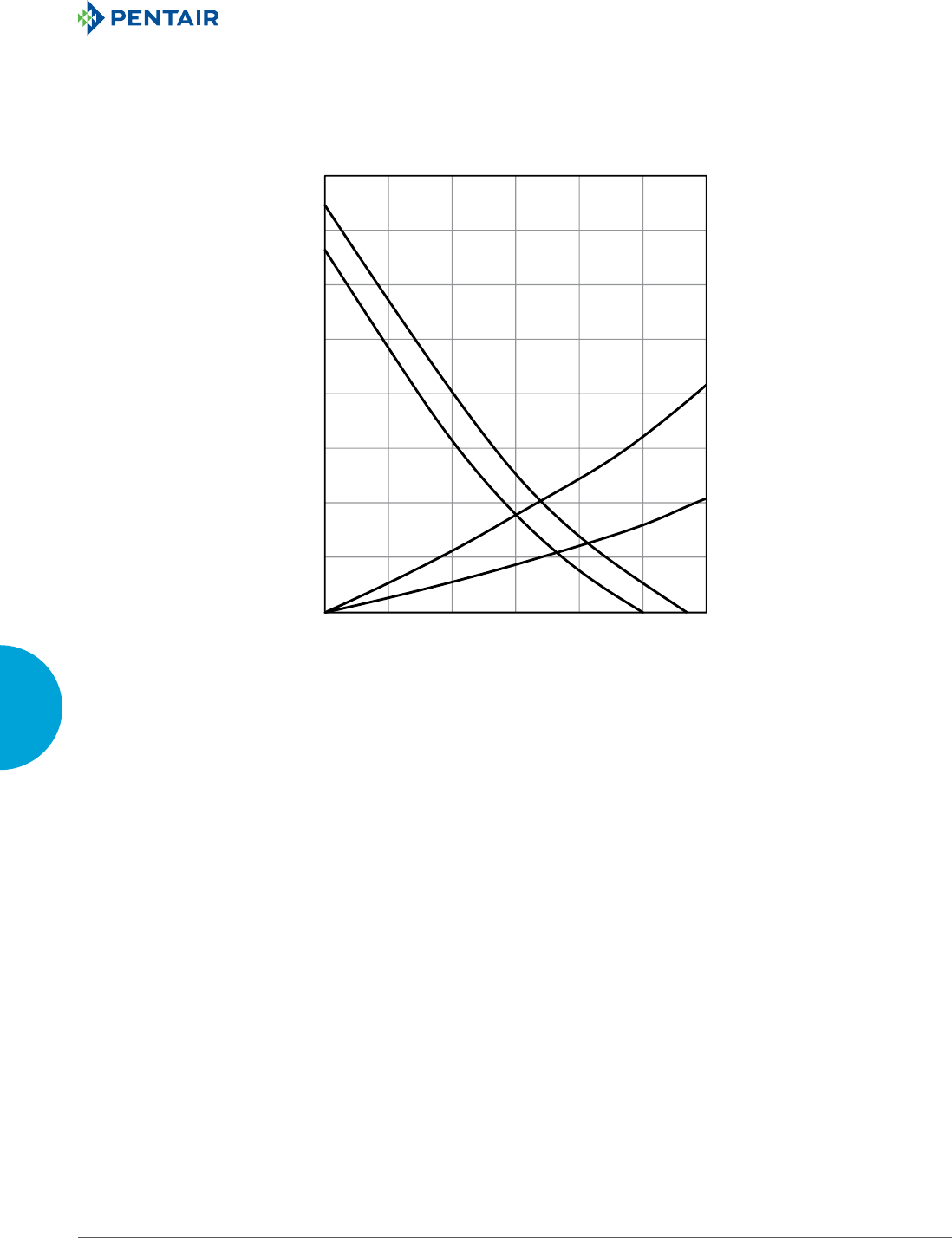
EQUIPMENT PROTECTIONSUBJECT TO CHANGE WITHOUT NOTICECOOLING214
4
FRESH AIR ENCLOSURE COOLING FILTER FANS
SG04 IP 54
SF04 50Hz IP 54
SF04 60Hz IP 54
2 x SG04 IP 54
Static Pressure (Pa)
Static Pressure (in. HO)
0
5 10 15 20 300
Volume Flow (m³/hr.)
Volume Flow (CFM)
25
3 6912 170 15
5
10
15
20
25
30
35
40
0
.02
.04
.06
.08
.10
.12
.14
.16
SF04 16 CFM (28 m/hr.) Side-Mount Filter Fan
Performance Curve
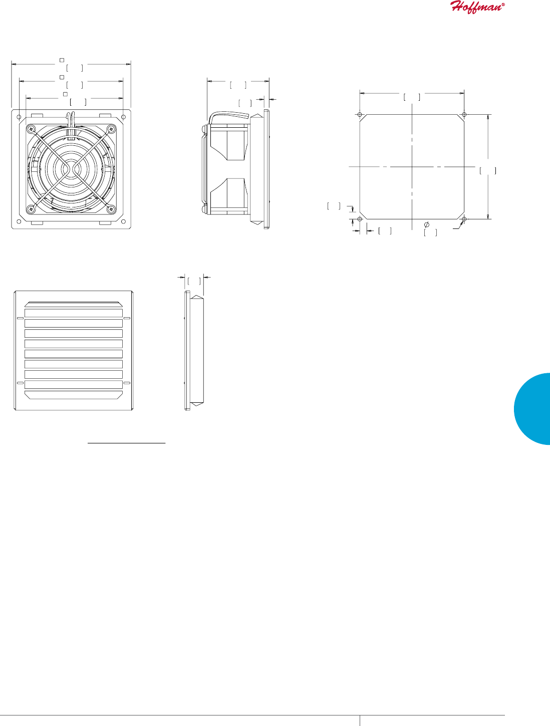
PH 763.422.2211 • FAX 763.576.3200 • HOFFMANONLINE.COMEQUIPMENT PROTECTION COOLING 215
4
FRESH AIR ENCLOSURE COOLING FILTER FANS
;
;
;
%$&.9,(:
&87287',0(16,216
)LOWHU)DQ6)&)0PuKU
6,'(9,(:
(;+$867*5,//(
2UGHU([KDXVW*ULOOH.LWVVHSDUDWHO\
Visit www
.HoffmanOnline.com to download 2D and 3D CAD drawings into the overall design of your electr
onic system.
EQUIPMENT PROTECTIONSUBJECT TO CHANGE WITHOUT NOTICECOOLING216
4
FRESH AIR ENCLOSURE COOLING FILTER FANS
Performance Data SF05 39 CFM (66 m3/hr.) Side-Mount Filter Fan
ELECTRICAL DATA
Rated Voltage 115 230 24 48
Frequency (Hz) 50 / 60 50 / 60 — —
Nominal Current Maximum (Amps) 0.23 0.11 0.17 0.08
Power Consumption Maximum (Watts) 20 20 4.1 3.5
Power Connection Terminal Block
TYPE 12 / IP54 FILTER FANSRAL 7035 Light Gray:
RAL 7035 Light Gray:
Catalog Number SF0516414 SF0526414 SF0524414 SF0548414
RAL 9011 Black:
Catalog Number SF0516413 SF0526413 SF0524413 SF0548413
Free Airflow (CFM / m3/hr.) 39 / 66 39 / 66 39 / 66 39 / 66
Airflow with 1 Exhaust Grille (CFM / m3/hr.) 26 / 44 26 / 44 26 / 44 26 / 44
Airflow with 2 Exhaust Grilles (CFM / m3/hr.) 30 / 51 30 / 51 30 / 51 30 / 51
TYPE 12 / IP55 FILTER FANS
RAL 7035 Light Gray:
Catalog Number SF0516514 SF0526514 SF0524514 SF0548514
RAL 9011 Black:
Catalog Number SF0516513 SF0526513 SF0524513 SF0548513
Free Airflow (CFM / m3/hr.) 36 / 61 36 / 61 36 / 61 36 / 61
Airflow with 1 Exhaust Grille (CFM / m3/hr.) 24 / 40 24 / 40 24 / 40 24 / 40
Airflow with 2 Exhaust Grilles (CFM / m3/hr.) 28 / 47 28 / 47 28 / 47 28 / 47
FILTER FAN UNIT CONSTRUCTION
Fan RPM 2650 / 3100 2650 / 3100 3050 3050
Sound Pressure (dBA) 42 42 42 42
Operating Temperature Range:
Maximum (°F / °C) 131 / 55 131 / 55 149 / 65 149 / 65
Minimum (°F / °C) 14 / -10 14 / -10 -4 / -20 -4 / -20
Service Life (hours) 27,500 27,500 50,000 50,000
Unit Dimensions - H x W x D (in. / mm) 5.83 x 5.83 x 2.56 / 148 x 148 x 65
Cutout Dimensions - H x W (in. / mm) 4.92 x 4.92 / 125 x 125
Weight (lb. / kg) 1.19 / .54
TYPE 12 / IP54 EXHAUST GRILLES
RAL 7035 Light Gray:
Catalog Number SG0500404
RAL 9011 Black:
Catalog Number SG0500403
TYPE 12 / IP55 EXHAUST GRILLES
RAL 7035 Light Gray:
Catalog Number SG0500504
RAL 9011 Black:
Catalog Number SG0500503
ACCESSORIES
Replacement Filters:
Type 12 / IP54 Catalog Number 10100060
Type 12 / IP55 Catalog Number 10100064H
Thermostat Catalog Number TWR60
Stainless Steel Washdown Shroud Catalog Number SH0500005
Above airflow rates at 60 Hz; see performance curves for airflow at 50 Hz and more details.
Unit depth is from the back edge of the grille to the back of the fan.
Exhaust Grilles sold separately.
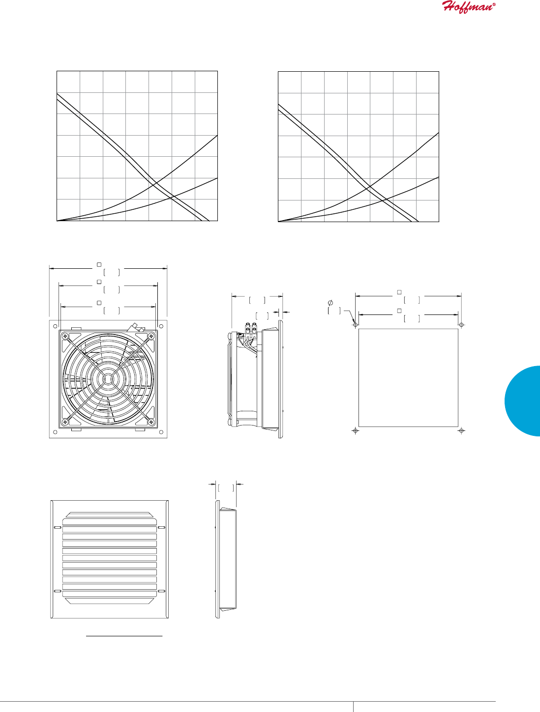
PH 763.422.2211 • FAX 763.576.3200 • HOFFMANONLINE.COMEQUIPMENT PROTECTION COOLING 217
4
FRESH AIR ENCLOSURE COOLING FILTER FANS
SF05 50Hz IP 55
SF05 60Hz IP 55
SG05 IP 55
2 x SG05 IP 55
Static Pressure (Pa)
Static Pressure (in. HO)
0 10 20 30 40 600
Volume Flow (m³/hr.)
Volume Flow (CFM)
70
50
6121824350 41
29
10
20
30
40
50
60
70
0
TYPE 12 / IP 55 Filter Fan
.04
.08
.12
.16
.20
.24
.28
SG05 IP 54
SF05 50Hz IP 54
SF05 60Hz IP 54
2 x SG05 IP 54
Static Pressure (Pa)
Static Pressure (in. HO)
0 10 20 30 40 600
Volume Flow (m³/hr.)
Volume Flow (CFM)
TYPE 12 / IP 54 Filter Fan
70
50
6121824350 41
29
10
20
30
40
50
60
70
0
.04
.08
.12
.16
.20
.24
.28
SF05 39 CFM (66 m/hr.) Side-Mount Filter Fan Performance Curve
;
%$&.9,(:
&87287
),/7(5)$1
6,'(9,(:
(;+$867*5,//(
Visit www
.HoffmanOnline.com to download 2D and 3D CAD drawings into the overall design of your electr
onic system.

EQUIPMENT PROTECTIONSUBJECT TO CHANGE WITHOUT NOTICECOOLING218
4
FRESH AIR ENCLOSURE COOLING FILTER FANS
Performance Data SF09 75 CFM (127 m3/hr.) Side-Mount Filter Fan
ELECTRICAL DATA
Rated Voltage 115 230 24 48
Frequency (Hz) 50 / 60 50 / 60 — —
Nominal Current Maximum (Amps) 0.23 0.11 0.17 0.08
Power Consumption Maximum (Watts) 20 20 4.1 3.5
Power Connection Terminal Block
TYPE 12 / IP54 FILTER FANS
RAL 7035 Light Gray:
Catalog Number SF0916414 SF0926414 SF0924414 SF0948414
RAL 9011 Black:
Catalog Number SF0916413 SF0926413 SF0924413 SF0948413
Free Airflow (CFM / m3/hr.) 75 / 127 75 / 127 75 / 127 75 / 127
Airflow with 1 Exhaust Grille (CFM / m3/hr.) 59 / 100 59 / 100 59 / 100 59 / 100
Airflow with 2 Exhaust Grilles (CFM / m3/hr.) 67 / 114 67 / 114 67 / 114 67 / 114
TYPE 12 / IP55 FILTER FANS
RAL 7035 Light Gray:
Catalog Number SF0916514 SF0926514 SF0924514 SF0948514
RAL 9011 Black:
Catalog Number SF0916513 SF0926513 SF0924513 SF0948513
Free Airflow (CFM / m3/hr.) 70 / 118 70 / 118 70 / 118 70 / 118
Airflow with 1 Exhaust Grille (CFM / m3/hr.) 54 / 92 54 / 92 54 / 92 54 / 92
Airflow with 2 Exhaust Grilles (CFM / m3/hr.) 62 / 106 62 / 106 62 / 106 62 / 106
FILTER FAN UNIT CONSTRUCTION
Fan RPM 2650 / 3100 2650 / 3100 3050 3050
Sound Pressure (dBA) 51 51 51 51
Operating Temperature Range:
Maximum (°F / °C) 131 / 55 131 / 55 149 / 65 149 / 65
Minimum (°F / °C) 14 / -10 14 / -10 -4 / -20 -4 / -20
Service Life (hours) 27,500 27,500 50,000 50,000
Unit Dimensions - H x W x D (in. / mm) 8.03 x 8.03 x 3.54 / 204 x 204 x 90
Cutout Dimensions - H x W (in. / mm) 6.97 x 6.97 / 177 x 177
Weight (lb. / kg) 1.74 / .79
TYPE 12 / IP54 EXHAUST GRILLES
RAL 7035 Light Gray:
Catalog Number SG0900404
RAL 9011 Black:
Catalog Number SG0900403
TYPE 12 / IP55 EXHAUST GRILLES
RAL 7035 Light Gray:
Catalog Number SG0900504
RAL 9011 Black:
Catalog Number SG0900503
ACCESSORIES
Replacement Filters:
Type 12 / IP54 Catalog Number 10100061
Type 12 / IP55 Catalog Number 10100065H
Thermostat Catalog Number TWR60
Stainless Steel Washdown Shroud Catalog Number SH0900005
Above airflow rates at 60 Hz; see performance curves for airflow at 50 Hz and more details.
Unit depth is from the back edge of the grille to the back of the fan.
Exhaust Grilles sold separately.
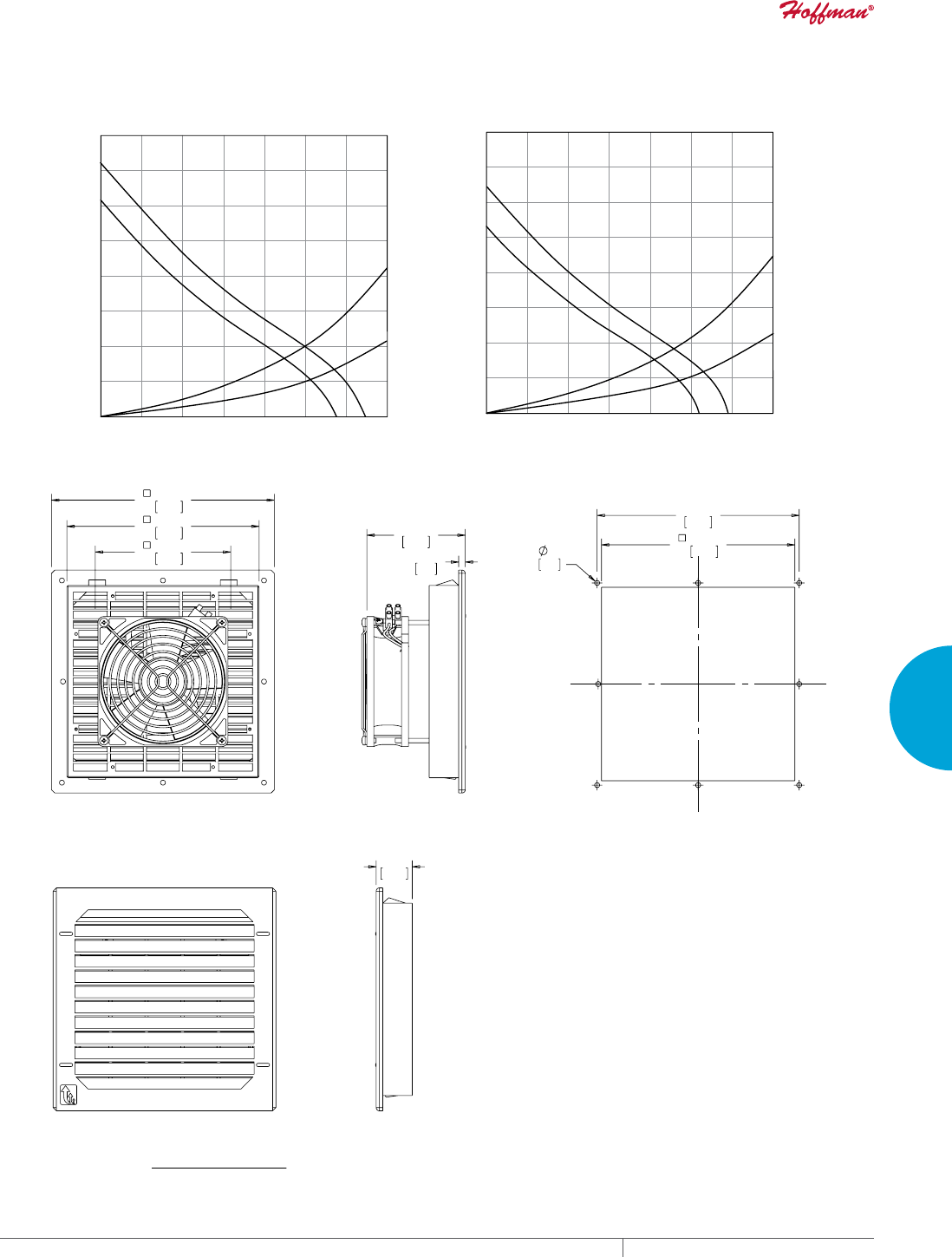
PH 763.422.2211 • FAX 763.576.3200 • HOFFMANONLINE.COMEQUIPMENT PROTECTION COOLING 219
4
FRESH AIR ENCLOSURE COOLING FILTER FANS
6)+],3
6)+],3
6*,3
[6*,3
Static Pressure (Pa)
Static Pressure (in. HO)
0 20 40 60 80 1200
Volume Flow (m³/hr.)
Volume Flow (CFM)
140
100
12 24 35 47 71
08
2
59
10
20
30
40
50
60
70
80
0
.04
.08
.12
.16
.20
.24
.28
.32
TYPE 12 / IP 55 Filter Fan
6*,3
6)+],3
6)+],3
[6*,3
Static Pressure (Pa)
Static Pressure (in. HO)
0 20 40 60 80 1200
Volume Flow (m³/hr.)
Volume Flow (CFM)
140
100
12 24 35 47 71082
59
10
20
30
40
50
60
70
80
0
.04
.08
.12
.16
.20
.24
.28
.32
TYPE 12 / IP 54 Filter Fan
SF09 75 CFM (127 m/hr.) Side-Mount Filter Fan Performance Curve
;
%$&.9,(:
&87287',0(16,216
)LOWHU)DQ6)&)0PuKU
6,'(9,(:
(;+$867*5,//(
2UGHU([KDXVW*ULOOH.LWVVHSDUDWHO\
Visit www
.HoffmanOnline.com to download 2D and 3D CAD drawings into the overall design of your electr
onic system.

EQUIPMENT PROTECTIONSUBJECT TO CHANGE WITHOUT NOTICECOOLING220
4
FRESH AIR ENCLOSURE COOLING FILTER FANS
Performance Data SF10 162 CFM (275 m3/Hr.) Side-Mount Filter Fan
ELECTRICAL DATA
Rated Voltage 115 230 24 48
Frequency (Hz) 50 / 60 50 / 60 — —
Nominal Current Maximum (Amps) .53 / .50 .30 / .25 0.66 0.33
Power Consumption Maximum (Watts) 43 / 40 45 / 39 16 16
Power Connection Terminal Block
TYPE 12 / IP54 FILTER FANS
RAL 7035 Light Gray:
Catalog Number SF1016414 SF1026414 SF1024414 SF1048414
RAL 9011 Black:
Catalog Number SF1016413 SF1026413 SF1024413 SF1048413
Free Airflow (CFM / m3/hr.) 162 / 275 162 / 275 162 / 275 162 / 275
Airflow with 1 Exhaust Grille (CFM / m3/hr.) 133 / 226 133 / 226 133 / 226 133 / 226
Airflow with 2 Exhaust Grilles (CFM / m3/hr.) 149 / 253 149 / 253 149 / 253 149 / 253
TYPE 12 / IP55 FILTER FANS
RAL 7035 Light Gray:
Catalog Number SF1016514 SF1026514 SF1024514 SF1048514
RAL 9011 Black:
Catalog Number SF1016513 SF1026513 SF1024513 SF1048513
Free Airflow (CFM / m3/hr.) 149 / 253 149 / 253 149 / 253 149 / 253
Airflow with 1 Exhaust Grille (CFM / m3/hr.) 122 / 207 122 / 207 122 / 207 122 / 207
Airflow with 2 Exhaust Grilles (CFM / m3/hr.) 137 / 233 137 / 233 137 / 233 137 / 233
FILTER FAN UNIT CONSTRUCTION
Fan RPM 2760 / 3030 2760 / 3030 2950 2950
Sound Pressure (dBA) 52 52 52 52
Operating Temperature Range:
Maximum (°F / °C) 131 / 55 131 / 55 131 / 55 131 / 55
Minimum (°F / °C) 14 / -10 14 / -10 14 / -10 14 / -10
Service Life (hours) 40,000 40,000 40,000 40,000
Unit Dimensions - H x W x D (in. / mm) 9.84 x 9.84 x 4.72 / 250 x 250 x 120
Cutout Dimensions - H x W (in. / mm) 8.78 x 8.78 / 223 x 223
Weight (lb. / kg) 4.19 / 1.9
TYPE 12 / IP54 EXHAUST GRILLES
RAL 7035 Light Gray:
Catalog Number SG1000404
RAL 9011 Black:
Catalog Number SG1000403
TYPE 12 / IP55 EXHAUST GRILLES
RAL 7035 Light Gray:
Catalog Number SG1000504
RAL 9011 Black:
Catalog Number SG1000503
ACCESSORIES
Replacement Filters:
Type 12 / IP54 Catalog Number 10100062
Type 12 / IP55 Catalog Number 10100066H
Thermostat Catalog Number TWR60
Stainless Steel Washdown Shroud Catalog Number SH1000005
Above airflow rates at 60 Hz; see performance curves for airflow at 50 Hz and more details.
Unit depth is from the back edge of the grille to the back of the fan.
Exhaust Grilles sold separately.
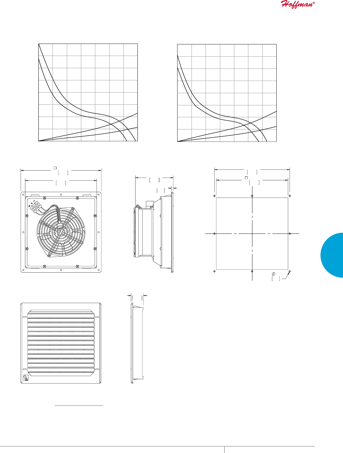
PH 763.422.2211 • FAX 763.576.3200 • HOFFMANONLINE.COMEQUIPMENT PROTECTION COOLING 221
4
FRESH AIR ENCLOSURE COOLING FILTER FANS
6)+],3
6*,3
[6*,3
6)+],3
Static Pressure (Pa)
Static Pressure (in. HO)
0
40 80 120 160 2400
Volume Flow (m³/hr.)
Volume Flow (CFM)
280
200
24 47 71 94 1410 165
118
20
40
60
80
100
120
140
0
.08
.16
.24
.32
.40
.48
.56
TYPE 12 / IP 55 Filter Fan
6*,3
6)+],3
6)+],3
[6*,3
Static Pressure (Pa)
Static Pressure (in. HO)
0
40 80 120 160 2400
Volume Flow (m³/hr.)
Volume Flow (CFM)
280
200
24 47 71 94 1410 165
118
20
40
60
80
100
120
140
0
.08
.16
.24
.32
.40
.48
.56
TYPE 12 / IP 54 Filter Fan
SF10 162 CFM (275 m/hr.) Side-Mount Filter Fan Performance Curve
;
%$&.9,(:
&87287',0(16,216
)LOWHU)DQ6)&)0PuKU
6,'(9,(:
(;+$867*5,//(
2UGHU([KDXVW*ULOOH.LWVHSDUDWHO\
Visit www
.HoffmanOnline.com to download 2D and 3D CAD drawings into the overall design of your electr
onic system.

EQUIPMENT PROTECTIONSUBJECT TO CHANGE WITHOUT NOTICECOOLING222
4
FRESH AIR ENCLOSURE COOLING FILTER FANS
Performance Data SF13 376 CFM (638 m3/hr.) Side-Mount Filter Fan - Standard and Reverse
ELECTRICAL DATA
Rated Voltage 115 230 24 48 115 Rvrs 230 Rvrs
Frequency (Hz) 50 / 60 50 / 60 — — 50 / 60 50 / 60
Nominal Current Maximum (Amps) .58 / .70 .29 / .35 2.60 1.30 .58 / .70 .29 / .35
Power Consumption Maximum (Watts) 64 / 80 64 / 80 55 55 64 / 80 64 / 80
Power Connection Terminal Block
TYPE 12 / IP54 FILTER FANS
RAL 7035 Light Gray:
Catalog Number SF1316414 SF1326414 SF1324414 SF1348414 SF1316414R SF1326414R
RAL 9011 Black:
Catalog Number SF1316413 SF1326413 SF1324413 SF1348413 SF1316413R SF1326413R
Free Airflow (CFM / m3/hr.) 375 / 638 375 / 638 375 / 638 375 / 638 375 / 638 375 / 638
Airflow with 1 Exhaust Grille (CFM / m3/hr.) 249 / 423 249 / 423 249 / 423 249 / 423 249 / 423 249 / 423
Airflow with 2 Exhaust Grilles (CFM / m3/hr.) 333 / 565 333 / 565 333 / 565 333 / 565 333 / 565 333 / 565
TYPE 12 / IP55 FILTER FANS
RAL 7035 Light Gray:
Catalog Number SF1316514 SF1326514 SF1324514 SF1348514 — —
RAL 9011 Black:
Catalog Number SF1316513 SF1326513 SF1324513 SF1348513 — —
Free Airflow (CFM / m3/hr.) 346 / 587 346 / 587 346 / 587 346 / 587 — —
Airflow with 1 Exhaust Grille (CFM / m3/hr.) 228 / 387 228 / 387 228 / 387 228 / 387 — —
Airflow with 2 Exhaust Grilles (CFM / m3/hr.) 301 / 511 301 / 511 301 / 511 301 / 511 — —
FILTER FAN UNIT CONSTRUCTION
Fan RPM 2550 / 2800 2550 / 2800 2950 2950 2550 / 2800 2550 / 2800
Sound Pressure (dBA) 60 60 60 60 60 60
Operating Temperature Range:
Maximum (°F / °C) 131 / 55 131 / 55 140 / 60 140 / 60 131 / 55 131 / 55
Minimum (°F / °C) 14 / -10 14 / -10 -13 / -25 -13 / -25 14 / -10 14 / -10
Service Life (hours) 40,000 40,000 40,000 40,000 40,000 40,000
Unit Dimensions - H x W x D (in. / mm) 12.72 x 12.72 x 5.83 / 323 x 323 x 148
Cutout Dimensions - H x W (in. / mm) 11.5 x 11.5 / 292 x 292
Weight (lb. / kg) 7.5 / 3.4
TYPE 12 / IP54 EXHAUST GRILLES
RAL 7035 Light Gray:
Catalog Number SG1300404
RAL 9011 Black:
Catalog Number SG1300403
TYPE 12 / IP55 EXHAUST GRILLES
RAL 7035 Light Gray:
Catalog Number SG1300504
RAL 9011 Black:
Catalog Number SG1300503
ACCESSORIES
Replacement Filters:
Type 12 / IP54 Catalog Number 10100063
Type 12 / IP55 Catalog Number 10100067H
Thermostat Catalog Number TWR60
Stainless Steel Washdown Shroud Catalog Number SH1300005
Above airflow rates at 60 Hz; see performance curves for airflow at 50 Hz and more details.
Unit depth is from the back edge of the grille to the back of the fan.
Exhaust Grilles sold separately.
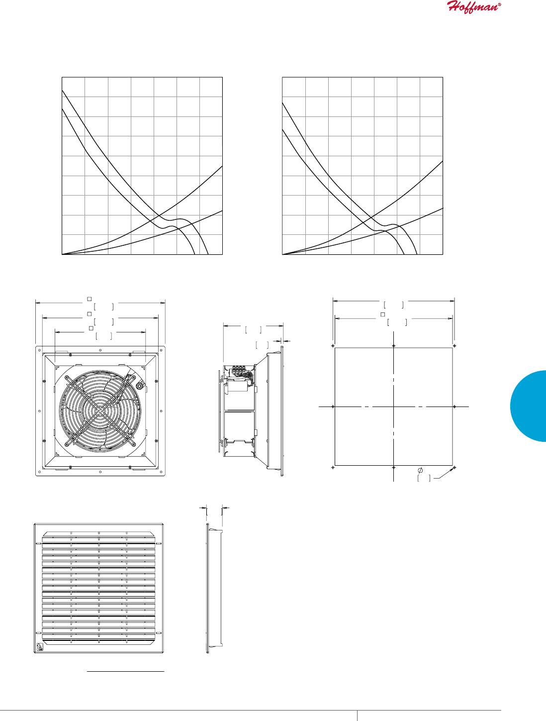
PH 763.422.2211 • FAX 763.576.3200 • HOFFMANONLINE.COMEQUIPMENT PROTECTION COOLING 223
4
FRESH AIR ENCLOSURE COOLING FILTER FANS
6)+],3
6)+],3
6*,3
[6*,3
Static Pressure (Pa)
Static Pressure (in. HO)
0
100 200 300 400 6000
Volume Flow (m³/hr.)
Volume Flow (CFM)
160
700
500
59 118 177 235 3530 412
294
20
40
60
80
100
120
140
180
0
.64
.08
.16
.24
.32
.40
.48
.56
.72
TYPE 12 / IP 55 Filter Fan
6*,3
6)+],3
[6*,3
6)+],3
Static Pressure (Pa)
Static Pressure (in. HO)
0
100 200 300 400 6000
Volume Flow (m³/hr.)
Volume Flow (CFM)
160
700
500
59 118 177 235 3530 412
294
20
40
60
80
100
120
140
180
0
.64
.08
.16
.24
.32
.40
.48
.56
.72
TYPE 12 / IP 54 Filter Fan
SF13 376 CFM (638 m/hr.) Side-Mount Filter Fan Performance Curve
;
%$&.9,(:
&87287',0(16,216
)LOWHU)DQ6)&)0PuKU
6,'(9,(:
(;+$867*5,//(
2UGHU([KDXVW*ULOOH.LWVHSDUDWHO\
Visit www
.HoffmanOnline.com to download 2D and 3D CAD drawings into the overall design of your electr
onic system.

EQUIPMENT PROTECTIONSUBJECT TO CHANGE WITHOUT NOTICECOOLING224
4
FRESH AIR ENCLOSURE COOLING FILTER FANS
Performance Data SF13 473 CFM (803 m3/hr.) Side-Mount Filter Fan - Standard
ELECTRICAL DATA
Rated Voltage 115 230 400
Frequency (Hz) 50 / 60 50 / 60 50 / 60
Nominal Current Maximum (Amps) 1.02 / 1.4 .51 / .74 .22 /. 26
Power Consumption Maximum (Watts) 115 / 166 115 / 175 110 / 150
Power Connection Terminal Block
TYPE 12 / IP54 FILTER FANS
RAL 7035 Light Gray:
Catalog Number SF1316424 SF1326424 SF1340424
RAL 9011 Black:
Catalog Number SF1316423 SF1326423 SF1340423
Free Airflow (CFM / m3/hr.) 473 / 803 473 / 803 473 / 803
Airflow with 1 Exhaust Grille (CFM / m3/hr.) 343 / 583 343 / 583 343 / 583
Airflow with 2 Exhaust Grilles (CFM / m3/hr.) 399 / 677 399 / 677 399 / 677
TYPE 12 / IP55 FILTER FANS
RAL 7035 Light Gray:
Catalog Number SF1316524 SF1326524 SF1340524
RAL 9011 Black:
Catalog Number SF1316523 SF1326523 SF1340523
Free Airflow (CFM / m3/hr.) 436 / 740 436 / 740 436 / 740
Airflow with 1 Exhaust Grille (CFM / m3/hr.) 314 / 533 314 / 533 314 / 533
Airflow with 2 Exhaust Grilles (CFM / m3/hr.) 369 / 627 369 / 627 369 / 627
FILTER FAN UNIT CONSTRUCTION
Fan RPM 2450 / 2650 2550 / 2750 2650 / 2900
Sound Pressure (dBA) 70 70 70
Operating Temperature Range:
Maximum (°F / °C) 131 / 55 131 / 55 131 / 55
Minimum (°F / °C) 14 / -10 14 / -10 14 / -10
Service Life (hours) 40,000 40,000 40,000
Unit Dimensions - H x W x D (in. / mm) 12.72 x 12.72 x 6.38 / 323 x 323 x 162
Cutout Dimensions - H x W (in. / mm) 11.50 x 11.50 / 292 x 292
Weight (lb. / kg) 7.72 / 3.5
TYPE 12 / IP54 EXHAUST GRILLES
RAL 7035 Light Gray:
Catalog Number SG1300404
RAL 9011 Black:
Catalog Number SG1300403
TYPE 12 / IP55 EXHAUST GRILLES
RAL 7035 Light Gray:
Catalog Number SG1300504
RAL 9011 Black:
Catalog Number SG1300503
ACCESSORIES
Replacement Filters:
Type 12 / IP54 Catalog Number 10100063
Type 12 / IP55 Catalog Number 10100067H
Thermostat Catalog Number TWR60
Stainless Steel Washdown Shroud Catalog Number SH1300005
Above airflow rates at 60 Hz; see performance curves for airflow at 50 Hz and more details.
Unit depth is from the back edge of the grille to the back of the fan.
Exhaust Grilles sold separately.
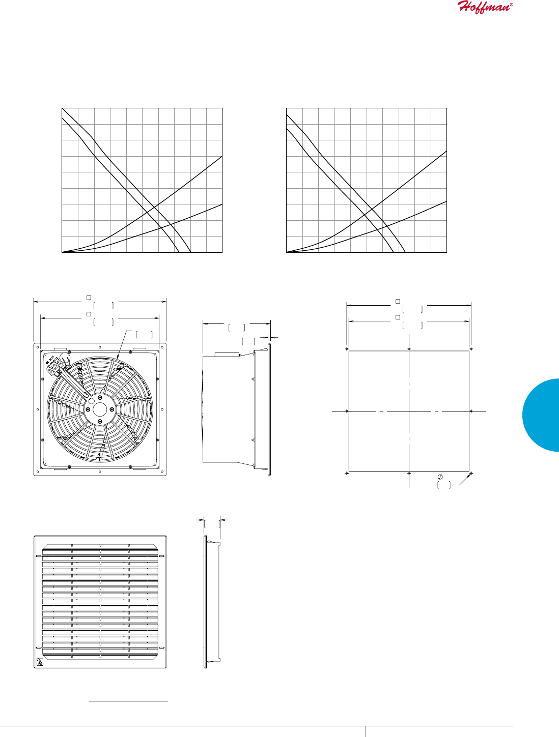
PH 763.422.2211 • FAX 763.576.3200 • HOFFMANONLINE.COMEQUIPMENT PROTECTION COOLING 225
4
FRESH AIR ENCLOSURE COOLING FILTER FANS
6)+],3
6)+],3
6*,3
[6*,3
TYPE 12 / IP 55 Filter Fan
150
125
100
75
50
25
Static Pressure (Pa)
Static Pressure (in. HO)
0
100 200 300 400 500 6000
Volume Flow (m³/hr.)
Volume Flow (CFM)
225
200
175
.60
.50
.40
.30
.20
.10
0
.90
.80
.70
700 800 900 1000
59 118 177 235 294 353
04
12 471 530 589
6)+],3
6*,3
6)+],3
[6*,3
TYPE 12 / IP 54 Filter Fan
150
125
100
75
50
25
Static Pressure (Pa)
Static Pressure (in. HO)
0
100 200 300 400 500 6000
Volume Flow (m³/hr.)
Volume Flow (CFM)
225
200
175
.60
.50
.40
.30
.20
.10
0
.90
.80
.70
700 800 900 1000
59 118 177 235 294 3530412 471 530 589
SF13 473 CFM (803 m/hr.) Side-Mount Filter Fan Performance Curve
5
;
%$&.9,(:
&87287',0(16,216
)LOWHU)DQ6)&)0PuKU
6,'(9,(:
(;+$867*5,//(
2UGHU([KDXVW*ULOOH.LWVHSDUDWHO\
Visit www
.HoffmanOnline.com to download 2D and 3D CAD drawings into the overall design of your electr
onic system.
EQUIPMENT PROTECTIONSUBJECT TO CHANGE WITHOUT NOTICECOOLING226
4
FRESH AIR ENCLOSURE COOLING FILTER FANS
Performance Data SF13 473 CFM (803 m3/hr.) Side-Mount Filter Fan - Reverse
ELECTRICAL DATA
Rated Voltage 115 Rvrs 230 Rvrs 400 Rvrs
Frequency (Hz) 50 / 60 50 / 60 50 / 60
Nominal Current Maximum (Amps) 1.05 / 1.5 .51 / .70 .22 / .26
Power Consumption Maximum (Watts) 120 / 175 115 / 165 110 /1 50
Power Connection Terminal Block
TYPE 12 / IP54 FILTER FANS
RAL 7035 Light Gray:
Catalog Number SF1316424R SF1326424R SF1340424R
RAL 9011 Black:
Catalog Number SF1316423R SF1326423R SF1340423R
Free Airflow (CFM / m3/hr.) 473 / 803 473 / 803 473 / 803
Airflow with 1 Exhaust Grille (CFM / m3/hr.) 343 / 583 343 / 583 343 / 583
Airflow with 2 Exhaust Grilles (CFM / m3/hr.) 399 / 677 399 / 677 399 / 677
FILTER FAN UNIT CONSTRUCTION
Fan RPM 2450 / 2650 2550 / 2750 2650 / 2900
Sound Pressure (dBA) 70 70 70
Operating Temperature Range:
Maximum (°F / °C) 131 / 55 131 / 55 131 / 55
Minimum (°F / °C) 14 / -10 14 / -10 14 / -10
Service Life (hours) 40,000 40,000 40,000
Unit Dimensions - H x W x D (in. / mm) 12.72 x 12.72 x 6.38 / 323 x 323 x 162)
Cutout Dimensions - H x W (in. / mm) 11.50 x 11.50 / 292 x 292)
Weight (lb. / kg) 7.72 / 3.5
TYPE 12 / IP54 EXHAUST GRILLES
RAL 7035 Light Gray:
Catalog Number SG1300404
RAL 9011 Black:
Catalog Number SG1300403
TYPE 12 / IP55 EXHAUST GRILLES
RAL 7035 Light Gray:
Catalog Number SG1300504
RAL 9011 Black:
Catalog Number SG1300503
ACCESSORIES
Replacement Filters:
Type 12/IP54 Catalog Number 10100063
Type 12 / IP55 Catalog Number 10100067H
Thermostat Catalog Number TWR60
Stainless Steel Washdown Shroud Catalog Number SH1300005
Above airflow rates at 60 Hz; see performance curves for airflow at 50 Hz and more details.
Unit depth is from the back edge of the grille to the back of the fan.
Exhaust Grilles sold separately.

PH 763.422.2211 • FAX 763.576.3200 • HOFFMANONLINE.COMEQUIPMENT PROTECTION COOLING 227
4
FRESH AIR ENCLOSURE COOLING FILTER FANS
Performance Data SF13 571 CFM (970 m3/hr.) Side-Mount Filter Fan - Standard
ELECTRICAL DATA
Rated Voltage 115 230 24 48 400/460
Frequency (Hz) 50 / 60 50 / 60 — — 50 / 60
Nominal Current Maximum (Amps) 1.02 / 1.47 .6 / .92 5.00 2.60 .25 / .27
Power Consumption Maximum (Watts) 115 / 175 135 / 215 105 105 113 / 172
Power Connection Terminal Block
TYPE 12 / IP54 FILTER FANS
RAL 7035 Light Gray:
Catalog Number SF1316434 SF1326434 SF1324434 SF1348434 SF1346434
RAL 9011 Black:
Catalog Number SF1316433 SF1326433 SF1324433 SF1348433 SF1346433
Free Airflow (CFM / m3/hr.) 571 / 970 571 / 970 571 / 970 571 / 970 571 / 970
Airflow with 1 Exhaust Grille (CFM / m3/hr.) 377 / 640 377 / 640 377 / 640 377 / 640 377 / 640
Airflow with 2 Exhaust Grilles (CFM / m3/hr.) 454 / 770 454 / 770 454 / 770 454 / 770 454 / 770
TYPE 12 / IP55 FILTER FANS
RAL 7035 Light Gray:
Catalog Number SF1316534 SF1326534 SF1324534 SF1348534 SF1346534
RAL 9011 Black:
Catalog Number SF1316533 SF1326533 SF1324533 SF1348533 SF1346533
Free Airflow (CFM / m3/hr.) 526 / 893 526 / 893 526 / 893 526 / 893 526 / 893
Airflow with 1 Exhaust Grille (CFM / m3/hr.) 345 / 586 345 / 586 345 / 586 345 / 586 345 / 586
Airflow with 2 Exhaust Grilles (CFM / m3/hr.) 415 / 705 415 / 705 415 / 705 415 / 705 415 / 705
FILTER FAN UNIT CONSTRUCTION
Fan RPM 2600 / 2850 2650 / 2950 2750 2750 2650 / 3050
Sound Pressure (dBA) 70 69 70 70 73
Operating Temperature Range:
Maximum (°F / °C) 140 / 60 140 / 60 140 / 60 140 / 60 140 / 60
Minimum (°F / °C) 5 / -15 5 / -15 5 / -15 5 / -15 5 / -15
Service Life (hours) 40,000 40,000 40,000 40,000 40,000
Unit Dimensions - H x W x D (in. / mm) 12.72 x 12.72 x 5.51 / 323 x 323 x 140
Cutout Dimensions - H x W (in. / mm) 11.50 x 11.50 / 292 x 292
Weight (lb. / kg) 10.14 / 4.6
TYPE 12 / IP54 EXHAUST GRILLES
RAL 7035 Light Gray:
Catalog Number SG1300404
RAL 9011 Black:
Catalog Number SG1300403
TYPE 12 / IP55 EXHAUST GRILLES
RAL 7035 Light Gray:
Catalog Number SG1300504
RAL 9011 Black:
Catalog Number SG1300503
ACCESSORIES
Replacement Filters:
Type 12 / IP54 Catalog Number 1010063
Type 12 / IP55 Catalog Number 10100067H
Thermostat Catalog Number TWR60
Stainless Steel Washdown Shroud Catalog Number SH1300005
Unit depth is from the back edge of the grille to the back of the fan.
Exhaust Grilles sold separately.
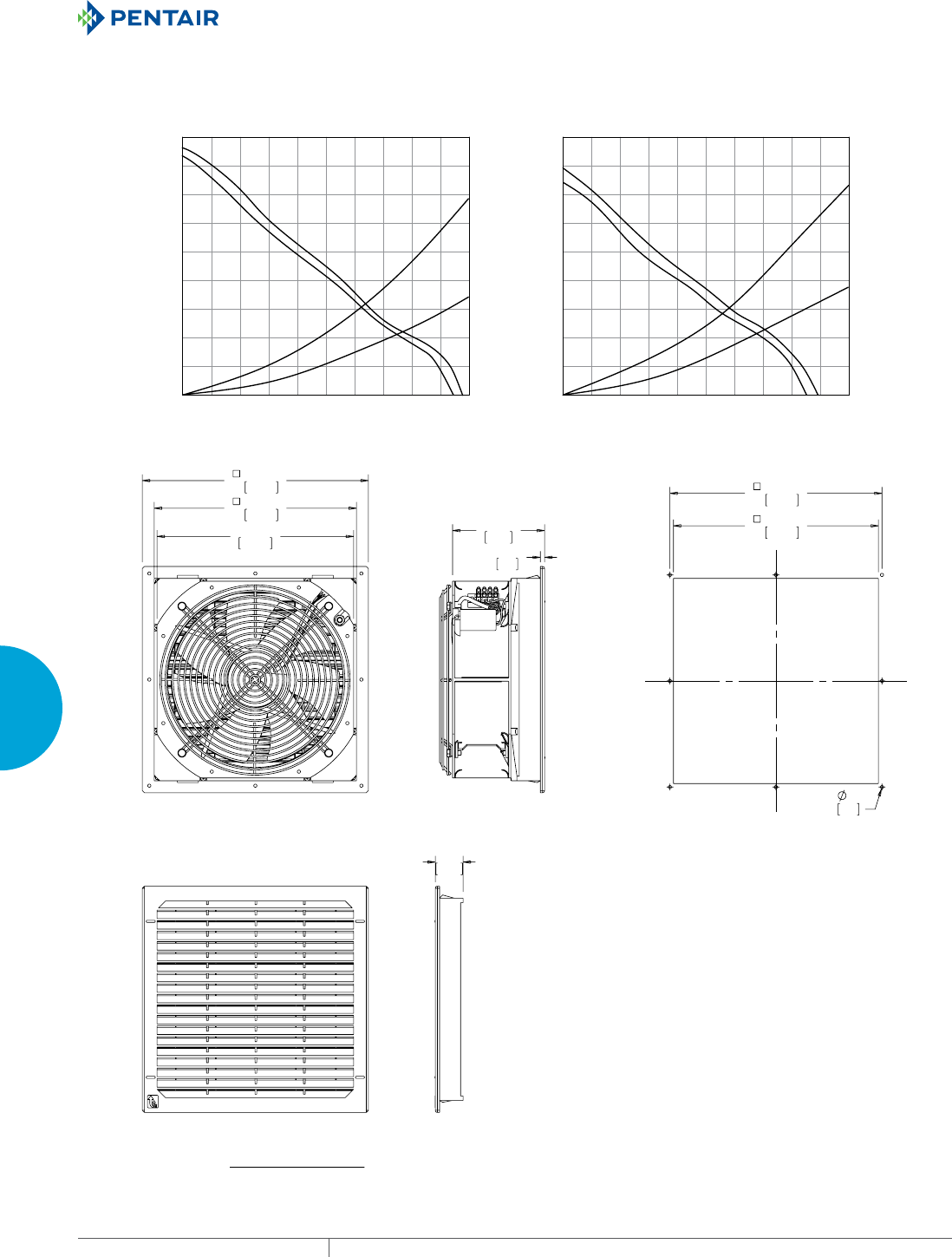
EQUIPMENT PROTECTIONSUBJECT TO CHANGE WITHOUT NOTICECOOLING228
4
FRESH AIR ENCLOSURE COOLING FILTER FANS
6)+],3
6)+],3
[6*,3
[6*,3
150
125
100
75
50
25
Static Pressure (Pa)
Static Pressure (in. HO)
0
100 200 300 400 500 6000
Volume Flow (m³/hr.)
Volume Flow (CFM)
225
200
175
.60
.50
.40
.30
.20
.10
0
.90
.80
.70
700 800 900 1000
59 118 177 235 294 3530 412 471 530 589
TYPE 12 / IP 55 Filter Fan
[6*,3
6)+],3
6)+],3
[6*,3
150
125
100
75
50
25
Static Pressure (Pa)
Static Pressure (in. HO)
0
100 200 300400 500 6000
Volume Flow (m³/hr.)
Volume Flow (CFM)
225
200
175
.60
.50
.40
.30
.20
.10
0
.90
.80
.70
700 800 900 1000
59 118 177235 294 3530412 471 530 589
TYPE 12 / IP 54 Filter Fan
SF13 571 CFM (970 m
/hr.) Side-Mount Filter Fan Performance Curve
;
&87287',0(16,216
%$&.9,(:
)LOWHU)DQ6)&)0PuKU
6,'(9,(:
(;+$867*5,//(
2UGHU([KDXVW*ULOOH.LWVVHSDUDWHO\
Visit www
.HoffmanOnline.com to download 2D and 3D CAD drawings into the overall design of your electr
onic system.
PH 763.422.2211 • FAX 763.576.3200 • HOFFMANONLINE.COMEQUIPMENT PROTECTION COOLING 229
4
FRESH AIR ENCLOSURE COOLING FILTER FANS
Performance Data SF13 571 CFM (970 m3/hr.) Side-Mount Filter Fan - Reverse
ELECTRICAL DATA
Rated Voltage 115 230 400/460
Frequency (Hz) 50 / 60 50 / 60 50 / 60
Nominal Current Maximum (Amps) 1.02 / 1.47 .6 / .92 .25 / .27
Power Consumption Maximum (Watts) 115 / 175 135 / 215 113 / 160
Power Connection Terminal Block
TYPE 12 / IP54 FILTER FANS
RAL 7035 Light Gray:
Catalog Number SF1316434R SF1326434R SF1340434R
RAL 9011 Black:
Catalog Number SF1316433R SF1326433R SF1346433R
Free Airflow (CFM / m3/hr.) 571 / 970 571 / 970 571 / 970
Airflow with 1 Exhaust Grille (CFM / m3/hr.) 377 / 640 377 / 640 377 / 640
Airflow with 2 Exhaust Grilles (CFM / m3/hr.) 454 / 770 454 / 770 454 / 770
FILTER FAN UNIT CONSTRUCTION
Fan RPM 2600 / 2850 2650 / 2950 2650 / 3050
Sound Pressure (dBA) 70 69 73
Operating Temperature Range:
Maximum (°F / °C) 140 / 60 140 / 60 140 / 60
Minimum (°F / °C) 5 / -15 5 / -15 5 / -15
Service Life (hours) 40,000 40,000 40,000
Unit Dimensions - H x W x D (in. / mm) 12.72 x 12.72 x 5.51 / 323 x 323 x 140
Cutout Dimensions - H x W (in. / mm) 11.50 x 11.50 / 292 x 292
Weight (lb. / kg) 10.14 / 4.6
TYPE 12 / IP54 EXHAUST GRILLES
RAL 7035 Light Gray:
Catalog Number SG1300404
RAL 9011 Black:
Catalog Number SG1300403
TYPE 12 / IP55 EXHAUST GRILLES
RAL 7035 Light Gray:
Catalog Number SG1300504
RAL 9011 Black:
Catalog Number SG1300503
ACCESSORIES
Replacement Filters:
Type 12 / IP54 Catalog Number 10100063
Type 12 / IP55 Catalog Number 10100067H
Thermostat Catalog Number TWR60
Stainless Steel Washdown Shroud Catalog Number SH1300005
Above airflow rates at 60 Hz; see performance curves for airflow at 50 Hz and more details.
Unit depth is from the back edge of the grille to the back of the fan.
Exhaust Grilles sold separately.
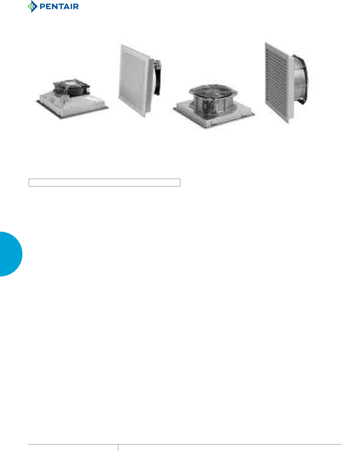
EQUIPMENT PROTECTIONSUBJECT TO CHANGE WITHOUT NOTICECOOLING230
4
FRESH AIR ENCLOSURE COOLING FILTER FANS
ST THIN SIDEMOUNT
ST10
100 CFM (170 m/hr.)
ST13
303 CFM (515 m/hr.)
INDUSTRY STANDARDS
UL/cUL recognized; File no. 235470
CE, CSA (fan motor only)
Type 12, IP54 standard
Type 12, IP55 optional
APPLICATION
• Industrial automation
• Automotive assembly
• Package handling equipment
• Food and beverage process controlls
• Wind energy systems
FEATURES
• ST13 has reverse airflow option available to push/pull air through
higher static pressure
• Click-fit design quickly installs into enclosure wall; no tools or
screws required
• Thin depth to minimize cabinet intrusion
• Enclosure side wall mounting
• Standard foam-in-place gasket
•
Similar cut-out sizes as other filter fan manufacturers
• Terminal wire connections
• Simple snap-open grille for easy filter replacement
• Optional thermostat available to save energy and extend service
life
SPECIFICATIONS
• Free airflow from 100 CFM (170 m3/hr.) to 303 CFM (515 m3/hr.)
• Service life hours range from 40000 to 57500
• Operating temperature range of -4 F / -20 C to 149 F / 65 C
FINISH
• RAL 7035 light-gray UV-resistant plastic standard
• RAL 9011 black UV-resistant plastic optional
ACCESSORIES
• Replacement filters
• Thermostat
• Rain shroud
NOTES
Visit www.HoffmanOnline.com to download 2D and 3D CAD
drawings into the overall design of your electronic system.

PH 763.422.2211 • FAX 763.576.3200 • HOFFMANONLINE.COMEQUIPMENT PROTECTION COOLING 231
4
FRESH AIR ENCLOSURE COOLING FILTER FANS
Performance Data ST10 100 CFM (170 m3/hr.) Thin Side-Mount Filter Fan
ELECTRICAL DATA
Rated Voltage 115 230 24 48
Frequency (Hz) 50 / 60 50 / 60 — —
Nominal Current Maximum (Amps) 0.2 0.10 0.27 0.14
Power Consumption Maximum (Watts) 18 18 6.5 6.5
Power Connection Terminal Block
TYPE 12 / IP54 FILTER FANS
RAL 7035 Light Gray:
Catalog Number ST1016414 ST1026414 ST1024414 ST1048414
RAL 9011 Black:
Catalog Number ST1016413 ST1026413 ST1024413 ST1048413
Free Airflow (CFM / m3/hr.) 100 / 170 100 / 170 100 / 170 100 / 170
Airflow with 1 Exhaust Grille (CFM / m3/hr.) 74 / 125 74 / 125 74 / 125 74 / 125
Airflow with 2 Exhaust Grilles (CFM / m3/hr.) 84 / 143 84 / 143 84 / 143 84 / 143
TYPE 12 / IP55 FILTER FANS
RAL 7035 Light Gray:
Catalog Number ST1016514 ST1026514 ST1024514 ST1048514
RAL 9011 Black:
Catalog Number ST1016513 ST1026513 ST1024513 ST1048513
Free Airflow (CFM / m3/hr.) 92 / 156 92 / 156 92 / 156 92 / 156
Airflow with 1 Exhaust Grille (CFM / m3/hr.) 67 / 114 67 / 114 67 / 114 67 / 114
Airflow with 2 Exhaust Grilles (CFM / m3/hr.) 77 / 130 77 / 130 77 / 130 77 / 130
FILTER FAN UNIT CONSTRUCTION
Fan RPM 2750 / 3100 2750 / 3100 3150 3150
Sound Pressure (dBA) 44 44 46 46
Operating Temperature Range:
Maximum (°F / °C) 131 / 55 131 / 55 149 / 65 149 / 65
Minimum (°F / °C) 14 / -10 14 / -10 -4 / -20 -4 / -20
Service Life (hours) 40,000 40,000 57,500 57,500
Unit Dimensions - H x W x D (in. / mm) 9.84 x 9.84 x 4.02 / 250 x 250 x 102
Cutout Dimensions - H x W (in. / mm) 8.78 x 8.78 / 223 x 223
Weight (lb. / kg) 2.54 / 1.15
TYPE 12 / IP54 EXHAUST GRILLES
RAL 7035 Light Gray:
Catalog Number SG1000404
RAL 9011 Black:
Catalog Number SG1000403
TYPE 12 / IP55 EXHAUST GRILLES
RAL 7035 Light Gray:
Catalog Number SG1000504
RAL 9011 Black:
Catalog Number SG1000503
ACCESSORIES
Replacement Filters:
Type 12 / IP54 Catalog Number 10100062
Type 12 / IP55 Catalog Number 10100066H
Thermostat Catalog Number TWR60
Stainless Steel Washdown Shroud Catalog Number SH1000005
Above airflow rates at 60 Hz; see performance curves for airflow at 50 Hz and more details.
Unit depth is from the back edge of the grille to the back of the fan.
Exhaust Grilles sold separately.
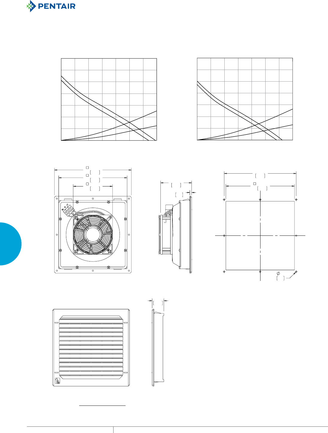
EQUIPMENT PROTECTIONSUBJECT TO CHANGE WITHOUT NOTICECOOLING232
4
FRESH AIR ENCLOSURE COOLING FILTER FANS
67+],3
67+],3
6*,3
[6*,3
Static Pressure (Pa)
0
25 50 75 100 1500
Volume Flow (m³/hr.)
Volume Flow (CFM)
175
125
15 29 44 59 880 103
74
10
20
30
40
50
60
70
Static Pressure (In. HO)
0
.04
.08
.12
.16
.20
.24
.28
TYPE 12 / IP 55 Filter Fan
67+],3
6*,3
67+],3
[6*,3
Static Pressure (Pa)
0
25 50 75 100 1500
Volume Flow (m³/hr.)
Volume Flow (CFM)
175
125
15 29 44 59 880 103
74
10
20
30
40
50
60
70
Static Pressure (In. HO)
0
.04
.08
.12
.16
.20
.24
.28
TYPE 12 / IP 54 Filter Fan
ST10 100 CFM (170 m
/hr.) Thin Side-Mount Filter Fan
Performance Curve
;
%$&.9,(:
)LOWHU)DQ67&)0PuKU
6,'(9,(:
(;+$867*5,//(
2UGHU([KDXVW*ULOOH.LWVVHSDUDWHO\
&87287',0(16,216
Visit www
.HoffmanOnline.com to download 2D and 3D CAD drawings into the overall design of your electr
onic system.
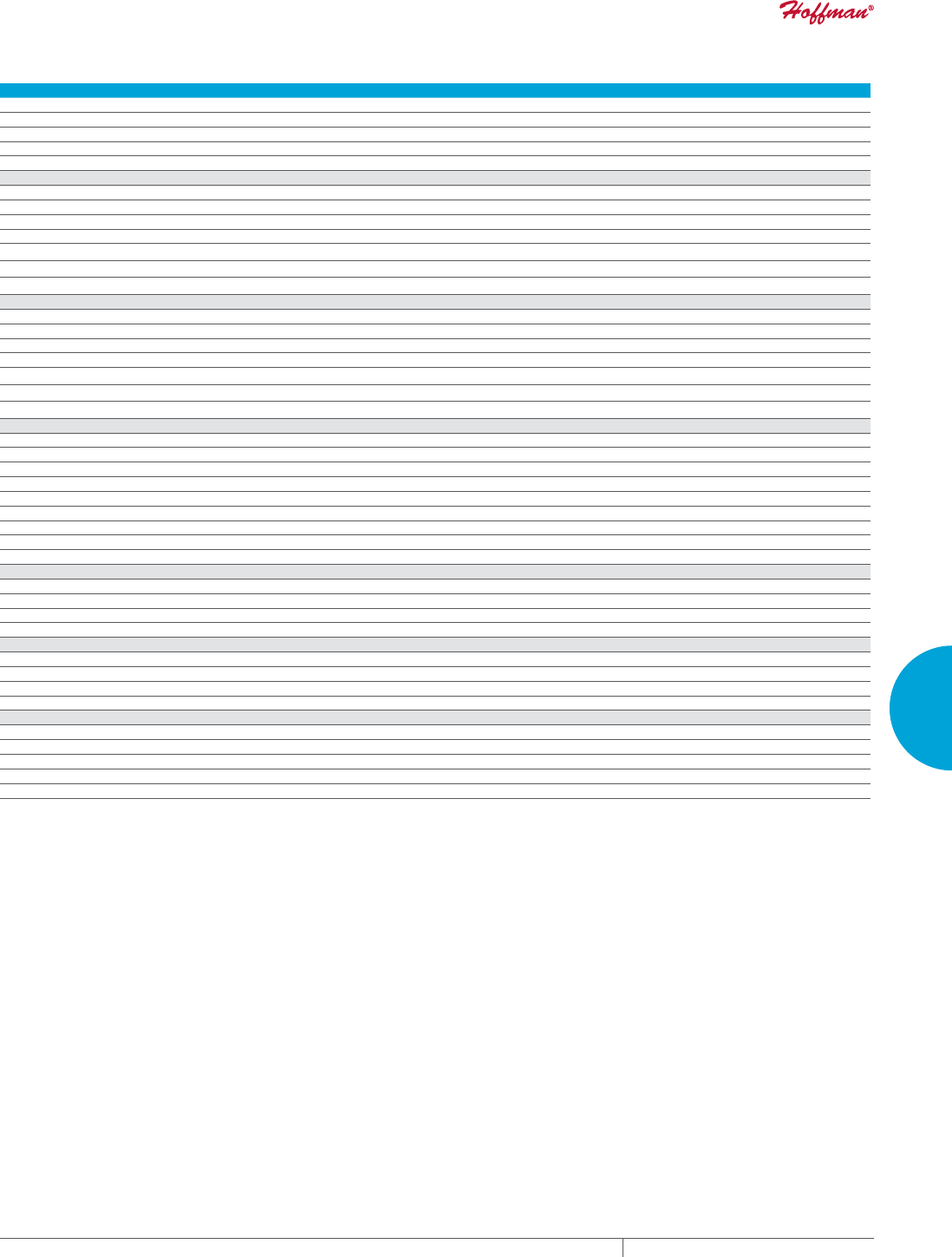
PH 763.422.2211 • FAX 763.576.3200 • HOFFMANONLINE.COMEQUIPMENT PROTECTION COOLING 233
4
FRESH AIR ENCLOSURE COOLING FILTER FANS
Performance Data ST13 303 CFM (515 m3/hr.) Thin Side-Mount Filter Fan - Standard and Reverse
ELECTRICAL DATA
Rated Voltage 115 230 115 230
Frequency (Hz) 50 / 60 50 / 60 50 / 60 50 / 60
Nominal Current Maximum (Amps) .58 / .70 .29 / .35 .58 / .70 .29 / .35
Power Consumption Maximum (Watts) 64 / 80 64 / 80 64 / 80 64 / 80
Power Connection Terminal Block
TYPE 12 / IP54 FILTER FANS
RAL 7035 Light Gray:
Catalog Number ST1316414 ST1326414 ST1316414R ST1326414R
RAL 9011 Black:
Catalog Number ST1316413 ST1326413 ST1316413R ST1326413R
Free Airflow (CFM / m3/hr.) 303 / 515 303 / 515 303 / 515 303 / 515
Airflow with 1 Exhaust Grille (CFM / m3/hr.) 209 / 355 209 / 355 209 / 355 209 / 355
Airflow with 2 Exhaust Grilles (CFM / m3/hr.) 249 / 422 249 / 422 249 / 422 249 / 422
TYPE 12 / IP55 FILTER FANS
RAL 7035 Light Gray:
Catalog Number ST1316514 ST1326514 ST1316514R ST1326514R
RAL 9011 Black:
Catalog Number ST1316513 ST1326513 ST1316513R ST1326513R
Free Airflow (CFM / m3/hr.) 277 / 470 277 / 470 277 / 470 277 / 470
Airflow with 1 Exhaust Grille (CFM / m3/hr.) 191 / 325 191 / 325 191 / 325 191 / 325
Airflow with 2 Exhaust Grilles (CFM / m3/hr.) 219 / 372 219 / 372 219 / 372 219 / 372
FILTER FAN UNIT CONSTRUCTION
Fan RPM 2550 / 2800 2550 / 2800 2550 / 2800 2550 / 2800
Sound Pressure (dBA) 60 60 60 60
Operating Temperature Range:
Maximum (°F / °C) 131 / 55 131 / 55 131 / 55 131 / 55
Minimum (°F / °C) 14 / -10 14 / -10 14 / -10 14 / -10
Service Life (hours) 40,000 40,000 40,000 40,000
Unit Dimensions - H x W x D (in. / mm) 12.72 x 12.72 x 4.8 / 323 x 323 x 122
Cutout Dimensions - H x W (in. / mm) 11.50 x 11.50 / 292 x 292
Weight (lb. / kg) 7.5 / 3.4
TYPE 12 / IP54 EXHAUST GRILLES
RAL 7035 Light Gray:
Catalog Number SG1300404
RAL 9011 Black:
Catalog Number SG1300403
TYPE 12 / IP55 EXHAUST GRILLES
RAL 7035 Light Gray:
Catalog Number SG1300504
RAL 9011 Black:
Catalog Number SG1300503
ACCESSORIES
Replacement Filters:
Type 12 / IP54 Catalog Number 10100063
Type 12 / IP55 Catalog Number 10100067H
Thermostat Catalog Number TWR60
Stainless Steel Washdown Shroud Catalog Number SH1300005
Above airflow rates at 60 Hz; see performance curves for airflow at 50 Hz and more details.
Unit depth is from the back edge of the grille to the back of the fan.
Exhaust Grilles sold separately.
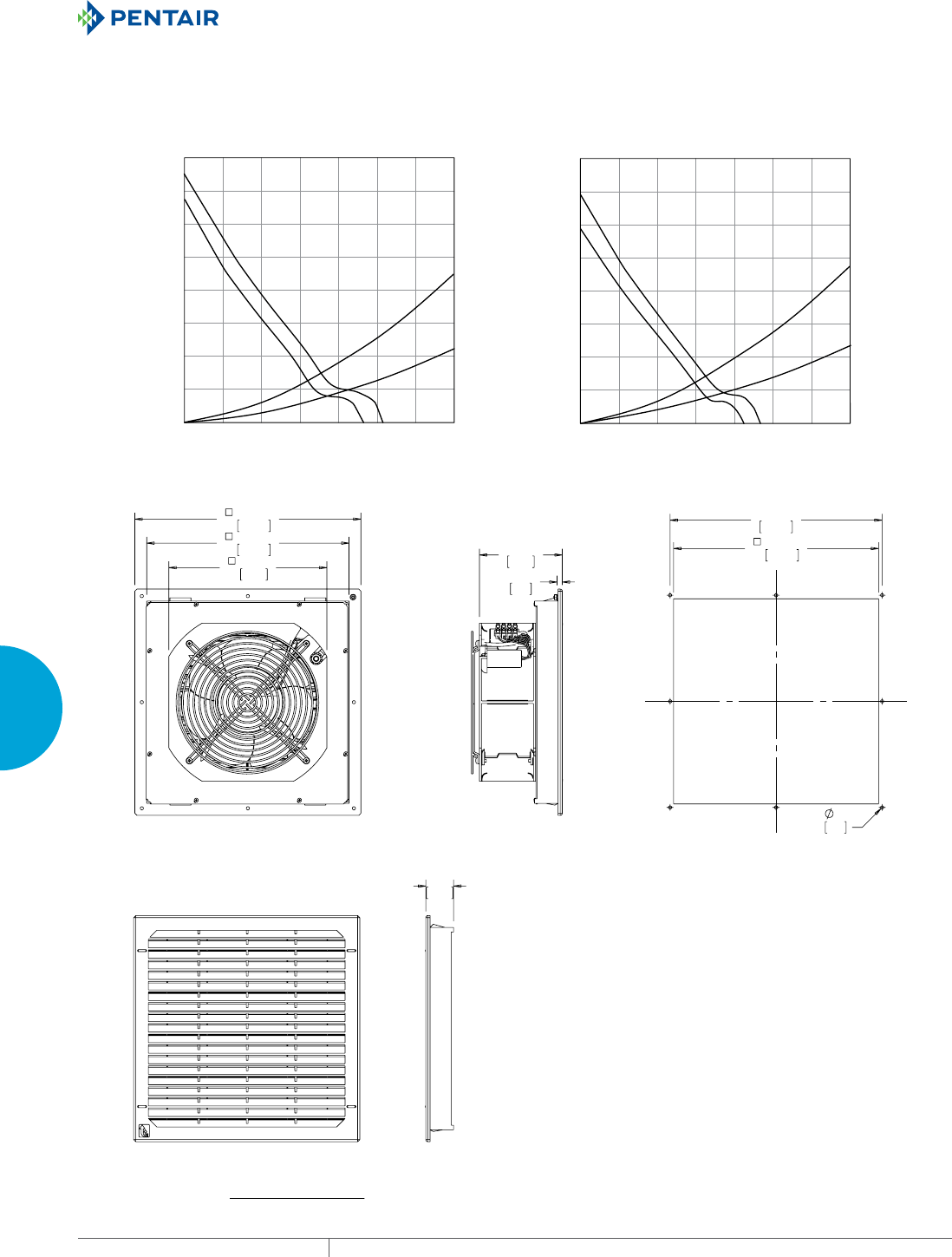
EQUIPMENT PROTECTIONSUBJECT TO CHANGE WITHOUT NOTICECOOLING234
4
FRESH AIR ENCLOSURE COOLING FILTER FANS
67+],3
67+],3
6*,3
[6*,3
Static Pressure (Pa)
Static Pressure (in. HO)
0
100 200 300 400 6000
Volume Flow (m³/hr.)
Volume Flow (CFM)
160
700
500
0
20
40
60
80
100
120
140
TYPE 12 / IP 55 Filter Fan
0
.64
.08
.16
.24
.32
.40
.48
.56
59 118 177 235 353 412294
6*,3
67+],3
[6*,3
67+],3
Static Pressure (Pa)
Static Pressure (in. HO)
0
100 200 300 400 6000
Volume Flow (m³/hr.)
Volume Flow (CFM)
160
700
500
59 118 177 235 3530 412
294
20
40
60
80
100
120
140
0
.64
.08
.16
.24
.32
.40
.48
.56
T
YPE 12 / IP 54 Filter Fan
ST13 303 CFM (515 m
/hr.) Thin Side-Mount Filter Fan
Pe
rformance Curve
;
%$&.9,(:
&87287',0(16,216
)LOWHU)DQ67&)0PuKU
6,'(9,(:
(;+$867*5,//(
2UGHU([KDXVW*ULOOH.LWVHSDUDWHO\
Visit www
.HoffmanOnline.com to download 2D and 3D CAD drawings into the overall design of your electr
onic system.

PH 763.422.2211 • FAX 763.576.3200 • HOFFMANONLINE.COMEQUIPMENT PROTECTION COOLING 235
4
FRESH AIR ENCLOSURE COOLING FILTER FANS
Notes
EQUIPMENT PROTECTIONSUBJECT TO CHANGE WITHOUT NOTICECOOLING236
4
FRESH AIR ENCLOSURE COOLING FILTER FANS
SR TOPMOUNT
INDUSTRY STANDARDS
UL (fan motor only)
CE, CSA (fan motor only)
APPLICATION
• Industrial automation
• Automotive assembly
• Package handling equipment
• Food and beverage process controlls
• Wind energy systems
FEATURES
• Free airflow up to 280 CFM (475 m3/hr.) or 459 CFM (780 m3/hr.)
• Enclosure roof mounting
• Bolt in place to ensure a tight seal
• Terminal wire connections
FINISH
• RAL 7035 light-gray UV-resistant mild steel standard
• RAL 9011 black UV-resistant mild steel optional
NOTES
Visit www.HoffmanOnline.com to download 2D and 3D CAD
drawings into the overall design of your electronic system.
Performance Data SR16 280 CFM (475 m3/hr.) Roof-Mount Filter Fan
ELECTRICAL DATA
Rated Voltage 115 230
Frequency (Hz) 50 / 60 50 / 60
Nominal Current Maximum (Amps) .35 / .40 .20 / .21
Power Consumption Maximum (Watts) 40 / 45 40 / 45
Power Connection Terminal Block
FILTER FANS
RAL 7035 Light Gray:
Catalog Number SR1616414 SR1626414
Free Airflow (CFM / m3/hr.) 227 / 386 227 / 386
Airflow with 1 Exhaust Grille (CFM / m3/hr.) 151 / 257 151 / 257
Airflow with 2 Exhaust Grilles (CFM / m3/hr.) 183 / 311 183 / 311
FILTER FAN UNIT CONSTRUCTION
Fan RPM 1430 / 1700 1430 / 1700
Sound Pressure (dBA) 58 / 62 58 / 62
Operating Temperature Range:
Maximum (°F / °C) 140 / 60 140 / 60
Minimum (°F / °C) 14 / -10 14 / -10
Service Life (hours) 40,000 40,000
Unit Dimensions - H x W x D (in. / mm) 13.52 x 16.27 x 4.19 / 343 x 413 x 107
Cutout Dimensions - H x W (in. / mm) 10.43 x 13.58 / 265 x 345
Weight (lb. / kg) 17.20 / 7.8
EXHAUST GRILLES
RAL 7035 Light Gray:
Catalog Number SG1300404
ACCESSORIES
Replacement Filters:
Catalog Number 10100063
Thermostat Catalog Number TWR60
Above airflow rates at 60 Hz; see performance curves for airflow at 50 Hz and more details.
Unit depth is from the back edge of the grille to the back of the fan.
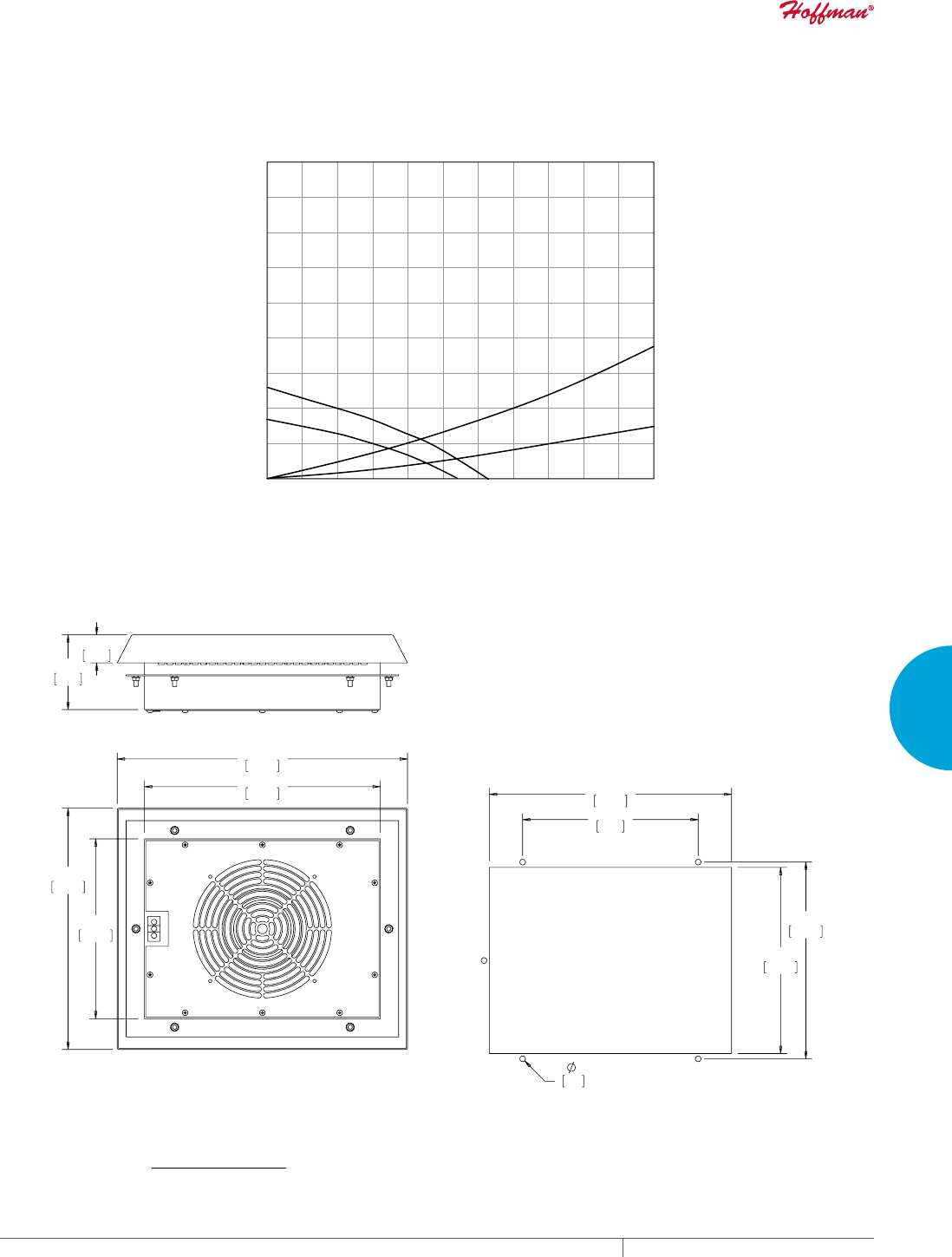
PH 763.422.2211 • FAX 763.576.3200 • HOFFMANONLINE.COMEQUIPMENT PROTECTION COOLING 237
4
FRESH AIR ENCLOSURE COOLING FILTER FANS
SR16 60 Hz
SR16 50 Hz
SG13
2 x SG13
44 88 132 177 221 2650 309 353 397 441 486
Volume Flow (CFM)
450
375
300
225
150
75
Static Pressure (Pa)
0
75 150 225 300 375 4500 Volume Flow (m³/hr.)
675
600
525
525 600 675 750 825
Static Pressure (in. HO)
1.81
1.51
1.21
.90
.60
.30
0
2.71
2.41
2.11
SR16 280 CFM (475 m/hr.) Roof-Mount Filter Fan
Performance Curve
;
)LOWHU)DQ65&)0PuKU
&87287',0(16,216
Visit www
.HoffmanOnline.com to download 2D and 3D CAD drawings into the overall design of your electr
onic system.
EQUIPMENT PROTECTIONSUBJECT TO CHANGE WITHOUT NOTICECOOLING238
4
FRESH AIR ENCLOSURE COOLING FILTER FANS
Performance Data SR16 459 CFM (780 m3/hr.) Roof-Mount Filter Fan
ELECTRICAL DATA
Rated Voltage 115 230
Frequency (Hz) 50 / 60 50 / 60
Nominal Current Maximum (Amps) .60 / .80 .55 / .73
Power Consumption Maximum (Watts) 100 / 130 110 / 150
Power Connection Terminal Block
FILTER FANS
RAL 7035 Light Gray:
Catalog Number SR1616424 SR1626424
Free Airflow (CFM / m3/hr.) 459 / 780 459 / 780
Airflow with 1 Exhaust Grille (CFM / m3/hr.) 347 / 590 347 / 590
Airflow with 2 Exhaust Grilles (CFM / m3/hr.) 400 / 680 400 / 680
FILTER FAN UNIT CONSTRUCTION
Fan RPM 2650 / 2950 2650 / 2950
Sound Pressure (dBA) 73 / 76 73 / 76
Operating Temperature Range:
Maximum (°F / °C) 140 / 60 140 / 60
Minimum (°F / °C) 14 / -10 14 / -10
Service Life (hours) 40,000 40,000
Unit Dimensions - H x W x D (in. / mm) 13.52 x 16.27 x 4.19 / 343 x 413 x 107
Cutout Dimensions - H x W (in. / mm) 10.43 x 13.58 / 265 x 345
Weight (lb. / kg) 17.20 / 7.8
EXHAUST GRILLES
RAL 7035 Light Gray:
Catalog Number SG1300404
ACCESSORIES
Replacement Filters:
Catalog Number 10100063
Thermostat Catalog Number TWR60
Above airflow rates at 60 Hz; see performance curves for airflow at 50 Hz and more details.
Unit depth is from the back edge of the grille to the back of the fan.
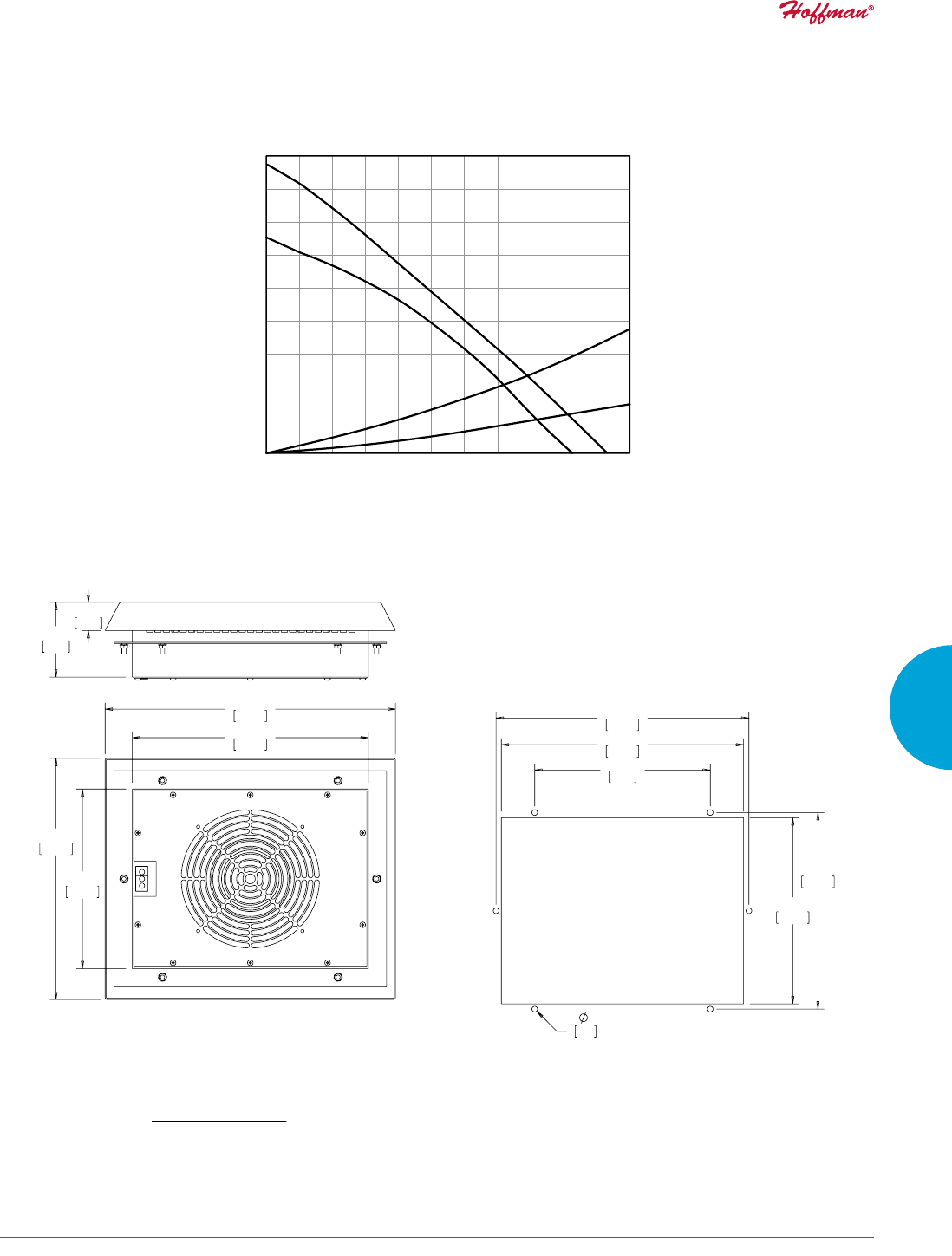
PH 763.422.2211 • FAX 763.576.3200 • HOFFMANONLINE.COMEQUIPMENT PROTECTION COOLING 239
4
FRESH AIR ENCLOSURE COOLING FILTER FANS
SG13
2 x SG13
SR16 50 Hz
SR16 60 Hz
44 88 132 177 221 2650 309 353 397 441 486
Volume Flow (CFM)
450
375
300
225
150
75
Static Pressure (Pa)
0
75 150 225 300 375 4500
Volume Flow (m³/hr.)
675
600
525
525 600 675 750 825
Static Pressure (in. HO)
1.81
1.51
1.21
.90
.60
.30
0
2.71
2.41
2.11
SR16 459 CFM (780 m/hr.) Roof-Mount Filter Fan
Performance Curve
;
)LOWHU)DQ65&)0PuKU
&87287',0(16,216
Visit www
.HoffmanOnline.com to download 2D and 3D CAD drawings into the overall design of your electr
onic system.
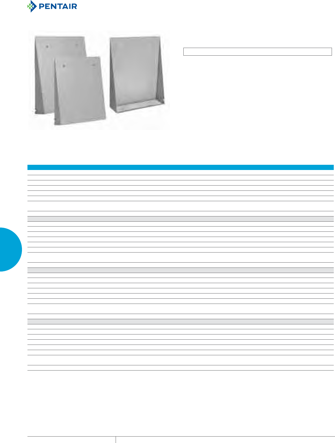
EQUIPMENT PROTECTIONSUBJECT TO CHANGE WITHOUT NOTICECOOLING240
4
FRESH AIR ENCLOSURE COOLING FILTER FANS
FILTER FAN SHROUDS
INDUSTRY STANDARDS
Maintains UR/cUR Type 3R and Type 12 rating when properly
installed on a Type 3R or Type 12 enclosure
UL 508A UR/cUR; Type 3R; File No. 61997
FEATURES
• Protects filter fan and exhaust grill from wind-driven rain and
high-pressure hose water
• Does not impede air flow of filter fan and exhaust grill
• Easy one person installation with simple back panel mounting
• Easily accessed filter simplifies replacement
• Low profile design
• Stainless steel pest screen
• Provides Type 3R protections and maintains a Type 12 rating
when used with an equivalent rated filter kit
FINISH
• RAL 7035 light gray polyester powder coat paint on galvanized
metal
• ANSI 61 gray polyester powder coat paint on galvanized metal
• Stainless Steel #304
Performance Data
SH05 Models
Catalog Number SH05GS35001 SH05GS61001 SH05SS04001
Provides protection for:
Filter Fan Models SF04 and SF05 SF04 and SF05 SF04 and SF05
Exhaust Grille Models SG04 and SG05 SG04 and SG05 SG04 and SG05
Unit Construction
Material Glavanized Glavanized Stainless Steel #304
Finish RAL 7035 polyester
powder coat paint
ANSI 61 polyester
powder coated paint
N/A
Unit Dimensions H x W x D (in./mm) 10.25 x 8.0 x 2.25/260 x 203 x 57 10.25 x 8.0 x 2.25/260 x 203 x 57 10.25 x 8.0 x 2.25/260 x 203 x 57
SH09 Models
Catalog Number SH09GS35001 SH09GS61001 SH09SS04001
Provides protection for:
Filter Fan Models SF09 and TFP4 SF09 and TFP4 SF09 and TFP4
Exhaust Grille Models SG09 and TFP4 SG09 and TFP4 SG09 and TFP4
Unit Construction
Material Glavanized Glavanized Stainless Steel #304
Finish RAL 7035 polyester
powder coat paint
ANSI 61 polyester
powder coated paint
N/A
Unit Dimensions H x W x D (in./mm) 12.75 x 10.0 x 3.0/324 x 254 x 76 12.75 x 10.0 x 3.0/324 x 254 x 76 12.75 x 10.0 x 3.0/324 x 254 x 76
SH10 Models
Catalog Number SH10GS35001 SH10GS61001 SH10SS04001
Provides protection for:
Filter Fan Models SF10, ST10 and TFP6 SF10, ST10 and TFP6 SF10, ST10 and TFP6
Exhaust Grille Models SG10 and TFP6 SG10 and TFP6 SG10 and TFP6
Unit Construction
Material Glavanized Glavanized Stainless Steel #304
Finish RAL 7035 polyester
powder coat paint
ANSI 61 polyester
powder coated paint
N/A
Unit Dimensions H x W x D (in./mm) 14.74 x 12.0 x 3.50/374 x 304 x 89 14.74 x 12.0 x 3.50/374 x 304 x 89 14.74 x 12.0 x 3.50/374 x 304 x 89
SH13 Models
Catalog Number SH13GS35001 SH13GS61001 SH13SS04001
Provides protection for:
Filter Fan Models SF13, ST13 and TFP10 SF13, ST13 and TFP10 SF13, ST13 and TFP10
Exhaust Grille Models SG13 and TFP10 SG13 and TFP10 SG13 and TFP10
Unit Construction
Material Glavanized Glavanized Stainless Steel #304
Finish RAL 7035 polyester
powder coat paint
ANSI 61 polyester
powder coated paint
N/A
Unit Dimensions H x W x D (in./mm) 17.62 x 16.0 x 4.75/447 x 406 x 121 17.62 x 16.0 x 4.75/447 x 406 x 121 17.62 x 16.0 x 4.75/447 x 406 x 121
PH 763.422.2211 • FAX 763.576.3200 • HOFFMANONLINE.COMEQUIPMENT PROTECTION COOLING 241
4
FRESH AIR ENCLOSURE COOLING FILTER FANS
SF/ST REPLACEMENT FILTERS • Type 12 / IP54 filter option provides protection against dust
infiltration (6 filters per package)
• IP55 filter adds additional protection against moisture
• See individual product pages for catalog and item numbers to
order
REPLACEMENT FILTER
CATALOG NUMBERS FITS FAN PACKAGES
10100059H All SF04 Models
10100060 All SF05 IP54 Models
10100064H All SF05 IP55 Models
10100061 All SF09 IP54 Models
10100065H All SF09 IP55 Models
10100062 All SF10 IP54 Models
10100066H All SF10 IP55 Models
10100063 All SF13 IP54 Models
10100067H All SF13 IP55 Models
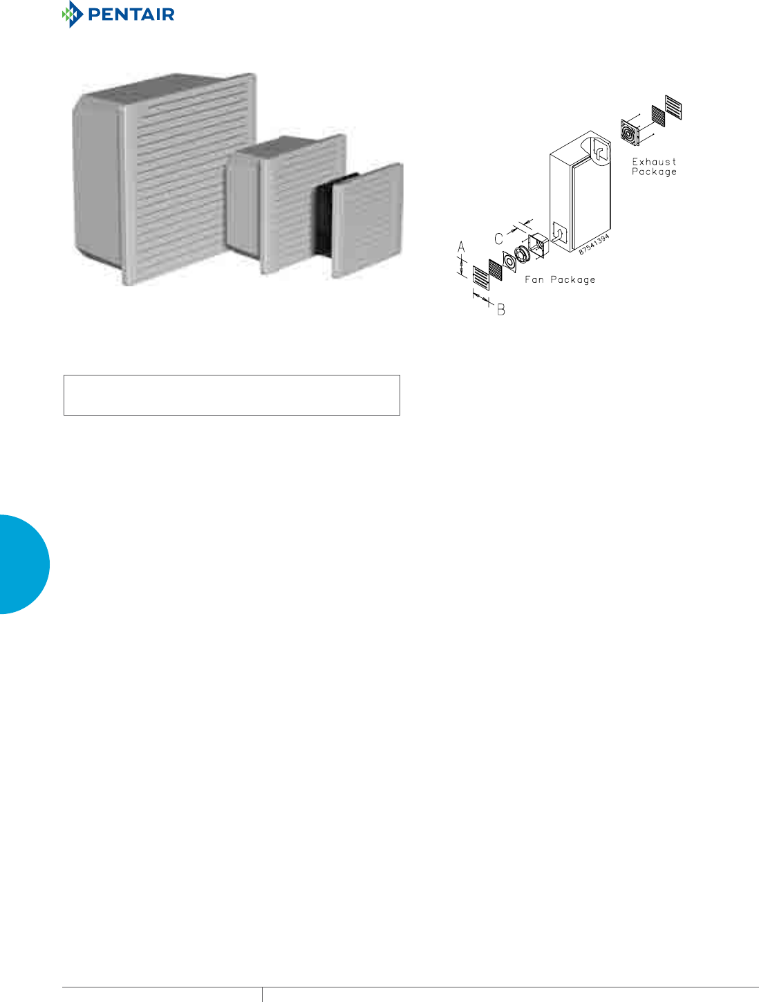
EQUIPMENT PROTECTIONSUBJECT TO CHANGE WITHOUT NOTICECOOLING242
4
FRESH AIR ENCLOSURE COOLING FILTER FANS
TFP SIDEMOUNT
TFP10
215 CFM
(365 m/hr.)
TFP6
140 CFM
(238 m/hr.)
TFP4
55 CFM
(93 m/hr.)
INDUSTRY STANDARDS
UL 508A Component Recognized; File No. E61997
TFP# Models: Type 1
TFP# UL 12 Models: Type 12
CSA certified (fan only)
CE
APPLICATION
• Industrial automation
• Automotive assembly
• Package handling equipment
• Food and beverage process controlls
• Wind energy systems
FEATURES
• Cooling Fan Package includes fan, air filter, composite air
plenum, finger guard and grille
• Exhaust Package includes air filter, filter retainer with integral
finger guard and grille
• EMC Upgrade Kit includes a grille standoff collar and a special
EMC shielding grille
• Reliable cooling for enclosures with limited space requiring
simple filtered airflow for basic cooling
• 24 VDC, 115 VAC and 230 VAC options available
• Washable foam (Type 1) or disposable (Type 12) filter in fan
• Dynamically-balanced fan impellers molded from polycarbonate
material
• 4-in. fan is thermally protected and uses permanently-lubricated
ball bearings
• 6- and 10-in. fans have ball bearing construction and split-
capacitor motors that are thermally protected to avoid premature
failure
• Fans have lead wires for power connection with ends stripped 1/2
in. (12 mm)
• All mounting hardware and installation instructions are
furnished
SPECIFICATIONS
• Free airflow from 45 CFM (76 m3/hr.) to 215 CFM (365 m3/hr.)
• Maximum operating temperature 158 F / 70 C
• Engineered for 50,000 hours of continuous operation without
lubrication or service (a monthly maintenance schedule is
recommended to ensure optimal cooling performance)
FINISH
• Stainless steel grilles have brushed finish.
• ABS composite grille is black.
ACCESSORIES
Aluminum Type 1 and Hi-Density Type 12 Filters
EMC Upgrade Kit
Grille Options:
Stainless Steel
Black ABS Plastic
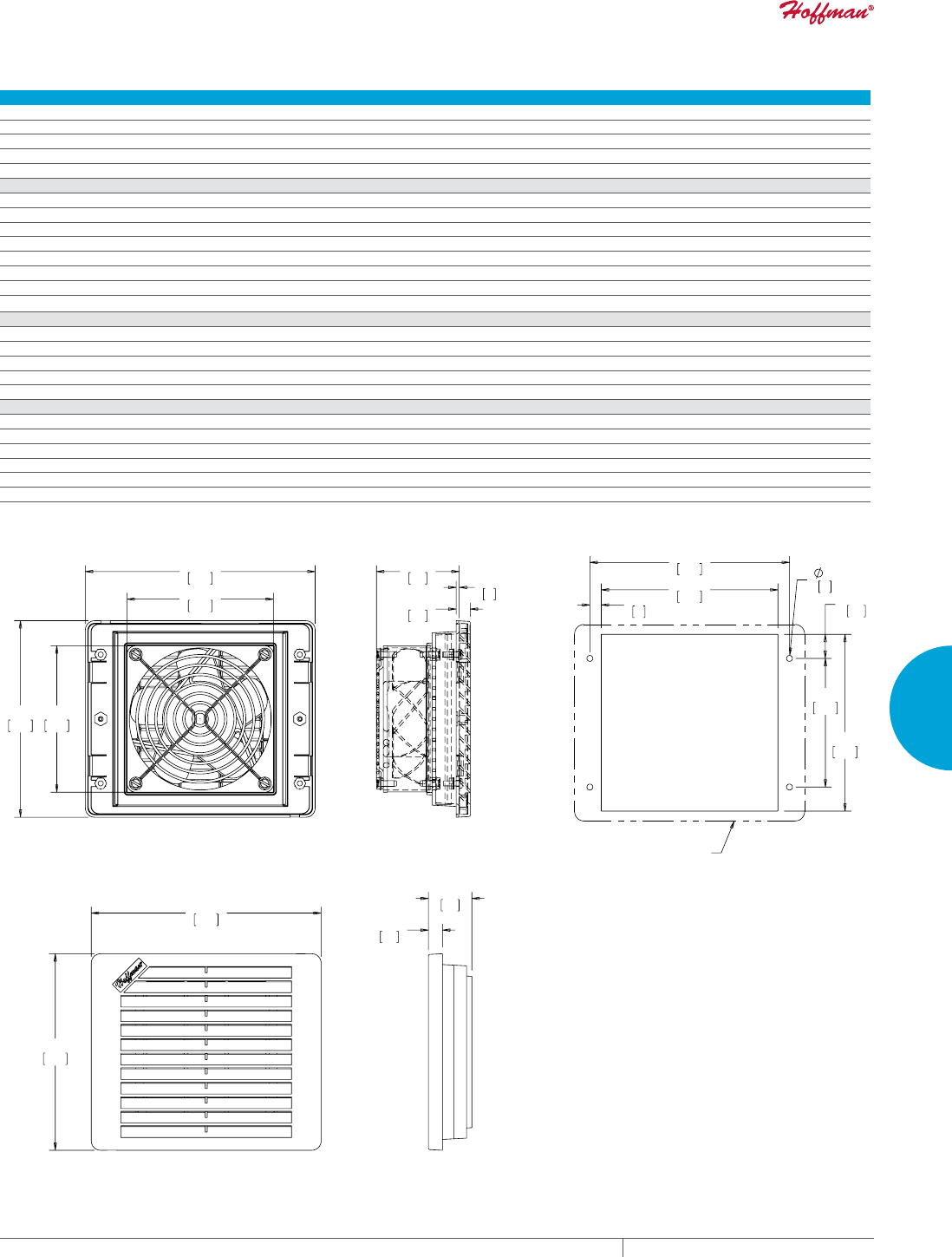
PH 763.422.2211 • FAX 763.576.3200 • HOFFMANONLINE.COMEQUIPMENT PROTECTION COOLING 243
4
FRESH AIR ENCLOSURE COOLING FILTER FANS
Performance Data TFP4 Models
ELECTRICAL DATA
Rated Voltage 24 VDC 115 VAC 230 VAC
Frequency (Hz) 50/60
Nominal Current Maximum @ 50/60 Hz(Amps) .35 .26/.21 .14/.11
Power Consumption Maximum @ 50/60 Hz (Watts) 8.4 17/15 16/14
Power Connection Stripped Leadwires
CATALOG NUMBERS
Composite Type 1
Catalog Number TFP424 TFP41 TFP42
Stainless Steel Type 1
Catalog Number — TFP41SS TFP42SS
Composite Type 12
Catalog Number — TFP41UL12 TFP42UL12
Free Airflow @ 50/60 Hz (CFM)* 55 45/55 45/55
Free Airflow @ 50/60 Hz (m3/hr.)* 93 76/93 76/93
UNIT CONSTRUCTION
Noise SIL @ 50/60 Hz (dBA) 65 37/41 37/41
Maximum Operating Temperature (°F/°C) 158/70
Unit Dimensions - H x W x D (in./mm) 6.29 x 7.37 x 2.65/160 x 187 x 67
Cutout Dimensions - H x W (in./mm) 5.66 x 5.66/144 x 144
Weight (lb./kg) 4.2/1.90 4.2/1.90 4.3/1.95
EXHAUST GRILLE CATALOG NUMBERS
Composite Type 1
Catalog Number TEP4
Stainless Steel Type 1
Catalog Number TEP4SS
Composite Type 12
Catalog Number TEP4UL12
*CFM with single exhaust grille installed.
%$&.9,(:
6,'(9,(:
7(3(;+$867*5,//(
([KDXVWJULOOHLQFOXGHGZLWKIDQSDFNDJH
;
)$1*5,//(
287/,1(
&87287',0(16,216
7)30RGHOV
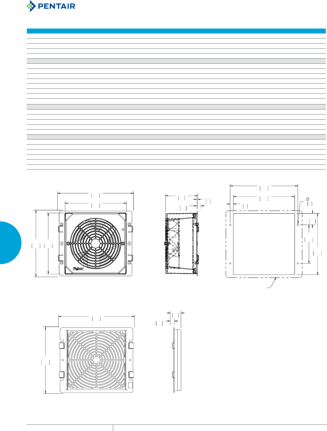
EQUIPMENT PROTECTIONSUBJECT TO CHANGE WITHOUT NOTICECOOLING244
4
FRESH AIR ENCLOSURE COOLING FILTER FANS
Performance Data TFP6 Models
ELECTRICAL DATA
Rated Voltage 24 VDC 115 VAC 230 VAC
Frequency (Hz) 50/60
Nominal Current Maximum @ 50/60 Hz(Amps) .88 .45/.36 .23/.18
Power Consumption Maximum @ 50/60 Hz (Watts) 21.1 36/32 39/35
Power Connection Stripped Leadwires
CATALOG NUMBERS
Composite Type 1
Catalog Number TFP624 TFP61 TFP62
Stainless Steel Type 1
Catalog Number — TFP61SS TFP62SS
Composite Type 12
Catalog Number — TFP61UL12 TFP62UL12
Free Airflow @ 50/60 Hz (CFM)* 140 117/140 117/140
Free Airflow @ 50/60 Hz (m3/hr.)* 238 199/238 199/238
UNIT CONSTRUCTION
Noise SIL @ 50/60 Hz (dBA) 62.5 50/56 50/56
Maximum Operating Temperature (°F/°C) 158/70
Unit Dimensions - H x W x D (in./mm) 7.80 x 8.87 x 3.75/198 x 225 x 95
Cutout Dimensions - H x W (in./mm) 7.16 x 7.16/182 x 182
Weight (lb./kg) 5.3/2.40 5.3/2.40 5.4/2.45
EXHAUST GRILLE CATALOG NUMBERS
Composite Type 1
Catalog Number TEP6
Stainless Steel Type 1
Catalog Number TEP6SS
Composite Type 12
Catalog Number TEP6UL12
*CFM with single exhaust grille installed.
%$&.9,(:
6,'(9,(:
([KDXVWJULOOHLQFOXGHGZLWKIDQSDFNDJH
7(3(;+$867*5,//(
;
)$1*5,//(
287/,1(
7)30RGHOV
&87287',0(16,216
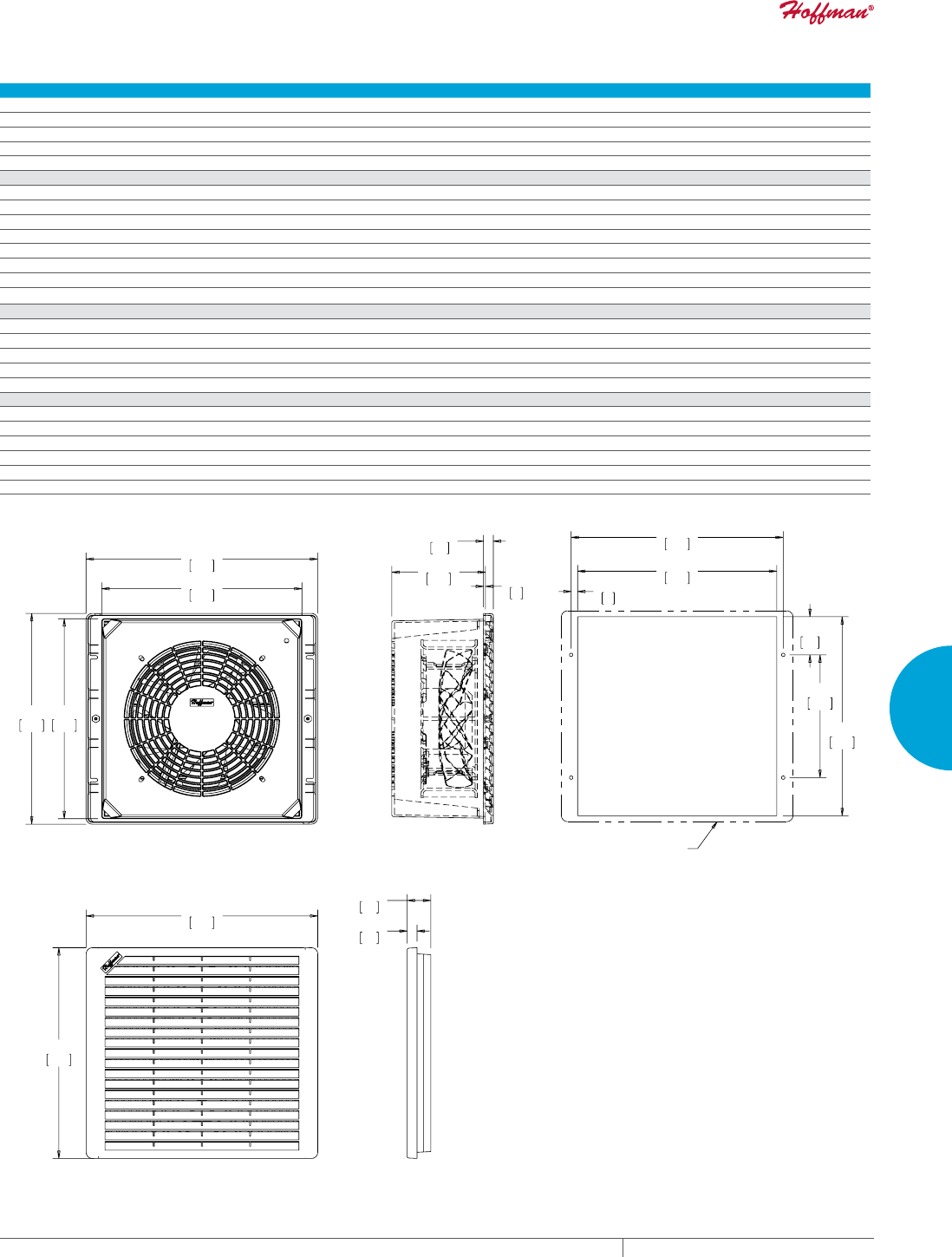
PH 763.422.2211 • FAX 763.576.3200 • HOFFMANONLINE.COMEQUIPMENT PROTECTION COOLING 245
4
FRESH AIR ENCLOSURE COOLING FILTER FANS
Performance Data TFP10 Models
ELECTRICAL DATA
Rated Voltage 115 VAC 230 VAC
Frequency (Hz) 50/60
Nominal Current Maximum @ 50/60 Hz(Amps) .58/.70 .29/.35
Power Consumption Maximum @ 50/60 Hz (Watts) 64/80 64/80
Power Connection Stripped Leadwires
CATALOG NUMBERS
Composite Type 1
Catalog Number TFP101 TFP102
Stainless Steel Type 1
Catalog Number TFP101SS TFP102SS
Composite Type 12
Catalog Number TFP101UL12 TFP102UL12
Free Airflow @ 50/60 Hz (CFM)* 180/215 180/215
Free Airflow @ 50/60 Hz (m3/hr.)* 306/365 306/365
UNIT CONSTRUCTION
Noise SIL @ 50/60 Hz (dBA) 54/61 54/61
Maximum Operating Temperature (°F/°C) 167/75 167/75
Unit Dimensions - H x W x D (in./mm) 11.81 x 12.99 x 5.25/300 x 330 x 133
Cutout Dimensions - H x W (in./mm) 11.16 x 11.16/283 x 283
Weight (lb./kg) 12.0/2.45 11.4/5.17
EXHAUST GRILLE CATALOG NUMBERS
Composite Type 1
Catalog Number TEP10
Stainless Steel Type 1
Catalog Number TEP10SS
Composite Type 12
Catalog Number TEP10UL12
*CFM with single exhaust grille installed.
%$&.9,(:
6,'(9,(:
)$1*5,//(
287/,1(
&87287',0(16,216
7(3(;+$867*5,//(
([KDXVWJULOOHLQFOXGHGZLWKIDQSDFNDJH
7)30RGHOV
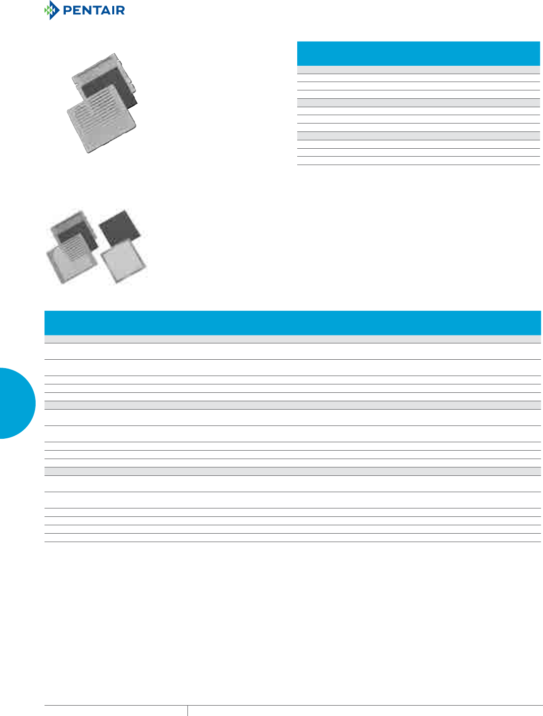
EQUIPMENT PROTECTIONSUBJECT TO CHANGE WITHOUT NOTICECOOLING246
4
FRESH AIR ENCLOSURE COOLING FILTER FANS
TFP EXHAUST GRILLES
CATALOG NUMBERS
Nominal Fan
Size
in./mm
TEP4 Models
TEP4 4
TEP4SS 4
TEP4UL12 4
TEP6 Models
TEP6 6
TEP6SS 6
TEP6UL12 6
TEP10 Models
TEP10 10
TEP10SS 10
TEP10UL12 10
TFP OPTIONAL GRILLES AND REPLACEMENT FILTERS Optional grilles offer the choice of stainless steel or black
ABS plastic. These grilles replace the standard RAL 7035 gray
composite or stainless steel grilles on both fan and exhaust
packages. Standard replacement filters are washable foam (Type
1) or disposable (Type 12). To maintain UL Type 12 rating on the
enclosure, UL Type 12 filters must be used on the fan package inlet.
Washable aluminum filters are also available. Aluminum filters are
compatible with Type 1 systems only.
Type 12 air filters are not washable.
CATALOG NUMBERS Description
Fits Fan
and Exhaust
Nominal Size
Fits Fan
and Exhaust
Grill Size (in./mm)
4-inch Fan Models
TG4SS Brushed stainless steel grille 4 6.29 x 7.31 x .81
160 x 186 x 21
TG4B Black ABS plastic grille 4 6.29 x 7.37 x .81
160 x 187 x 21
AFLTR4 Type 1 filter replacement (5/package) 4 —
AFLTR4AL Aluminum filter replacement (5/package) 4 —
TFLT4UL12 Type 12 filter replacement (5/package) 4 —
6-inch Fan Models
TG6SS Brushed stainless steel grille 6 7.80 x 8.81 x .75
198 x 224 x 19
TG6B Black ABS plastic grille 6 7.80 x 8.87 x .49
198 x 225 x 12
AFLTR6 Foam filter replacement (5/package) 6 —
AFLTR6AL Aluminum filter replacement (5/package) 6 —
TFLT6UL12 UL 12 filter replacement (5/package) 6 —
10-inch Fan Models
TG10SS Brushed stainless steel grille 10 11.81 x 12.92 x .75
300 x 328 x 19
TG10B Black ABS plastic grille 10 11.81 x 12.99 x .75
300 x 330 x 19
AFLTR10 Foam filter replacement (5/package) 10 —
AFLTR10AL Aluminum filter replacement (5/package) 10 —
TFLT10UL12 UL 12 filter replacement (5/package)a 10 —
Replacement filter for Type 12 fan package only (models TFF__UL12). For Type 12 exhaust package use replacement filter AFLTRX.
Filters fit all fan and exhaust packages according to their size.
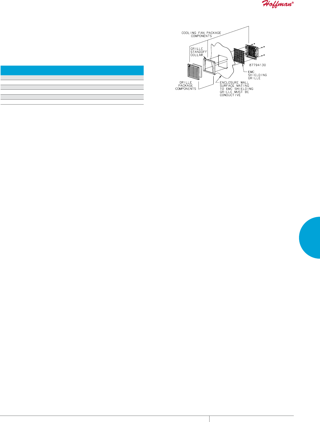
PH 763.422.2211 • FAX 763.576.3200 • HOFFMANONLINE.COMEQUIPMENT PROTECTION COOLING 247
4
FRESH AIR ENCLOSURE COOLING FILTER FANS
TFP EMC UPGRADE KIT
With the addition of this kit, the cooling fan and exhaust packages
are upgraded to provide EMC (electromagnetic compatibility)
protection. Consult Hoffman for shielding effectiveness (dB
attenuation vs. frequency).
Separate kits must be installed on both the inlet and outlet. Cooling fan
and exhaust package must be ordered separately. EMC upgrade kit will
not work with stainless steel grille option.
CATALOG NUMBERS
Fits Cooling
Fan Package
Fits Exhaust
Grille
4-inch Fan Models
T4EMC TFP41/TFP42 TEP4
6-inch Fan Models
T6EMC TFP61/TFP62 TEP6
10-inch Fan Models
T10EMC TFP101/TFP102 TEP10
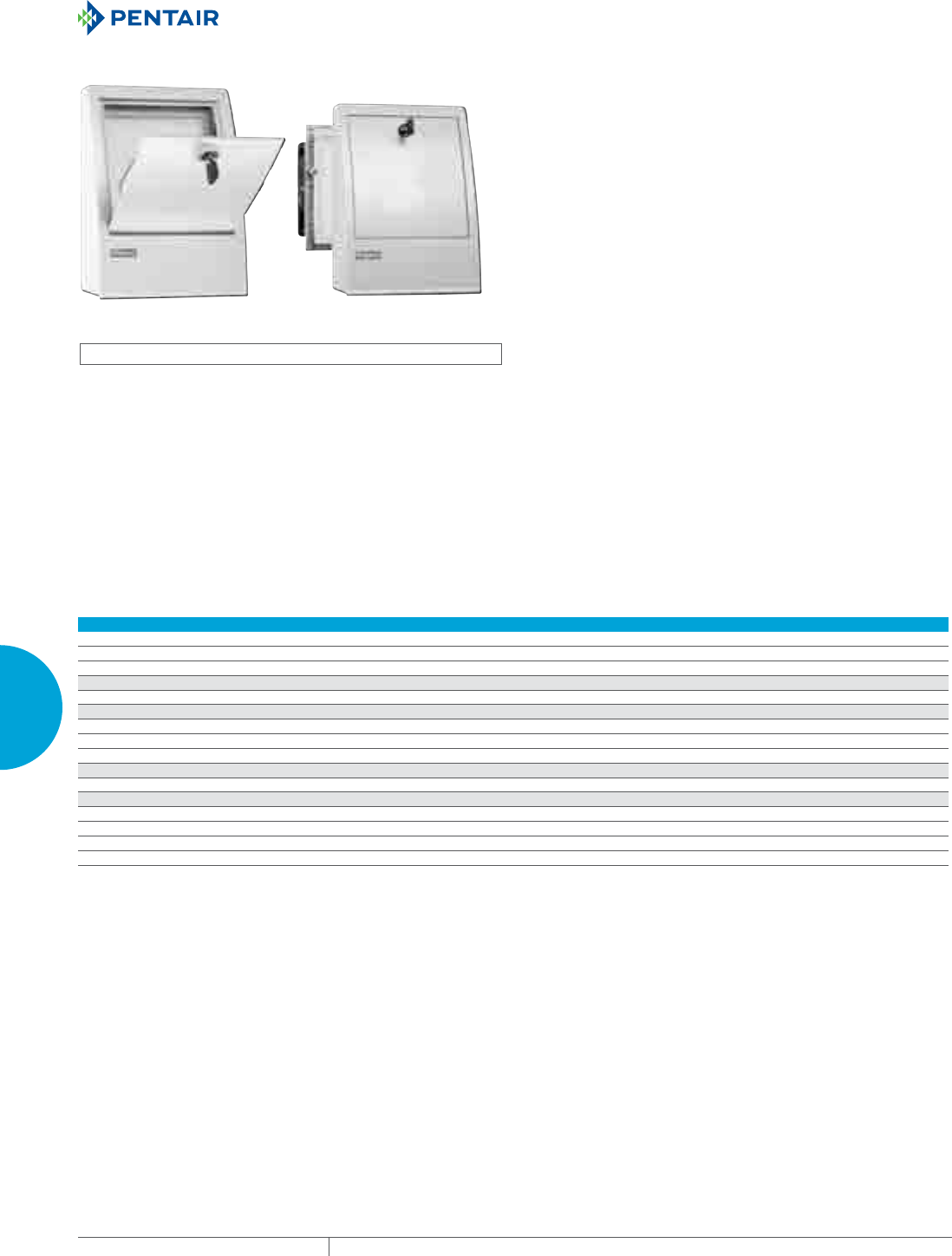
EQUIPMENT PROTECTIONSUBJECT TO CHANGE WITHOUT NOTICECOOLING248
4
FRESH AIR ENCLOSURE COOLING FILTER FANS
OUTDOOR FILTER FAN AND EXHAUST PACKAGE
INDUSTRY STANDARDS
cURus Type 12; File No. E234324
NEMA Type 3R
IEC/EN60529, IP55
CE
FEATURES
• Ball bearing axial fan, service life minimum 50,000 hours at 77 F
(25 C) and 65 percent RH
• Airflow 11.8 CFM (20 cubic meters/hour) free blowing
• High-impact plastic is highly weatherproof and resistant to UV
light
• Removable F5 filter
• Lockable door in hood
• Two-sided tape provided
• Filter hood permanently fixed to enclosure from inside
• 2 lead wires, 3.94-in. (100-mm) long, with pressure clamps, 14
gauge max. (2.5 mm)
• Synthetic filter material, temperature resistant to 212 F (100 C),
self-extinguishing class F1, moisture resistant to 100 percent RH
• Filter mat: Fine grade F5 to DIN EN779 filtering degree: 98
percent of particles larger than 10 µm (10 microns)
SPECIFICATIONS
• Aluminum fan body, plastic impeller
FINISH
• Light gray plastic, UL94H-B
ACCESSORIES
This fan package meets basic requirements for outdoor or indoor
applications that require warm air dissipation.
Performance Data Outdoor Filter Fan
ELECTRICAL DATA
Rated Voltage 120 VAC
Frequency (Hz) 60
Full Load (Amps) 0.3
FILTER FAN
Catalog Number AOFF118
UNIT CONSTRUCTION
External Mounting Depth (in./mm) 2.56/65
Internal Mounting Depth (in./mm) 2.44/62
Enclosure Cutout (in./mm) 4.92 x 4.92 / 125 x 125
EXHAUST GRILLE
Catalog Number AOEFG118
ACCESSORIES
Replacement Filters:
Catalog Number AOFILTER
Description Filter Mat, F5 (3 per package)
Filter Size (in./mm) 4.80 x 4.80 / 122 x 122
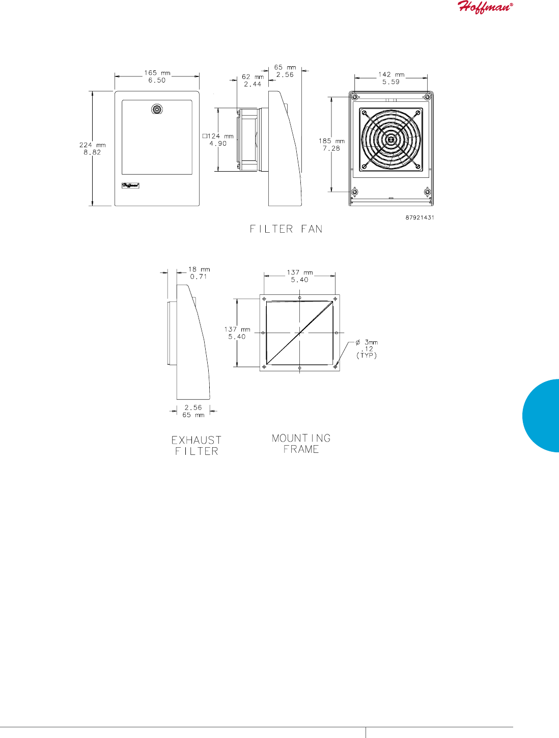
PH 763.422.2211 • FAX 763.576.3200 • HOFFMANONLINE.COMEQUIPMENT PROTECTION COOLING 249
4
FRESH AIR ENCLOSURE COOLING FILTER FANS
Outdoor Filter Fan and Exhaust Package
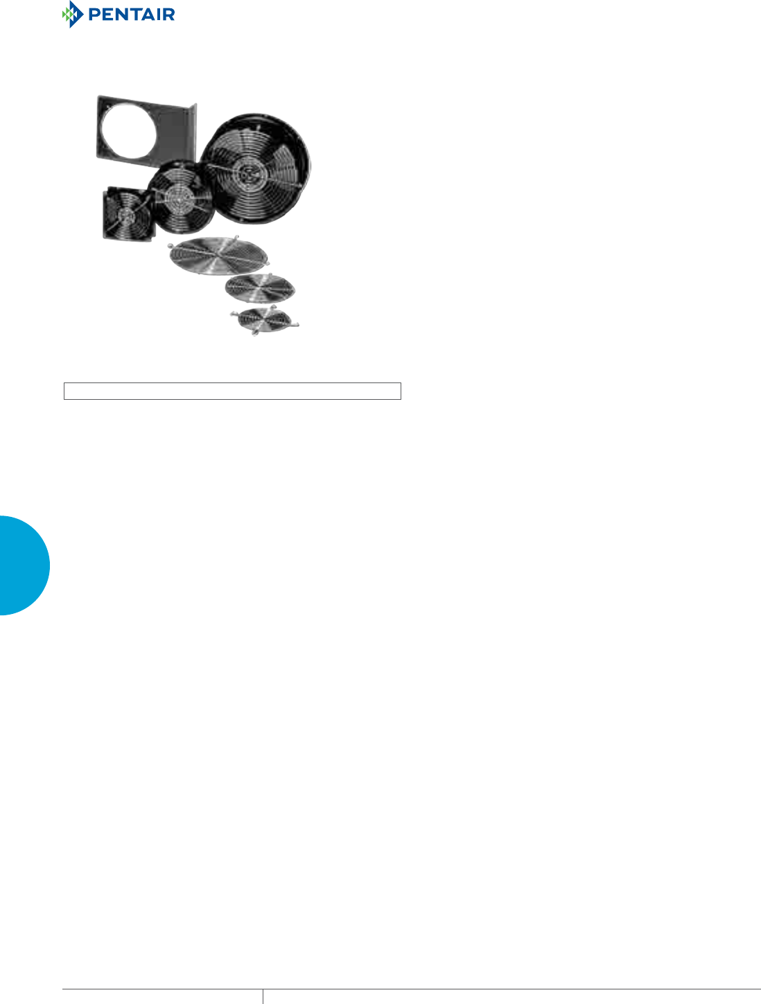
EQUIPMENT PROTECTIONSUBJECT TO CHANGE WITHOUT NOTICECOOLING250
4
FRESH AIR ENCLOSURE COOLING AXIAL FANS AND ACCESSORIES
AXIAL FANS AN D ACCESSORI ES
COMPACT AXIAL FANS
INDUSTRY STANDARDS
UL Component Recognized
CSA certified
APPLICATION
Compact Cooling Fans are ideal for applications where enclosure
space is limited and quiet, reliable cooling is required. Engineered
for 50,000 hours of continuous operation without lubrication or
service.
Installation
Can be installed on any surface of an enclosure. With the addition
of accessory fan brackets, Compact Cooling Fans can also be
installed in any position inside the enclosure for spot cooling or air
circulation.
FEATURES
• Maximum operating temperature is 158 F (70 C)
• 4-in. fan is thermally protected and uses permanently lubricated
ball bearings
• 6- and 10-in. fans have ball-bearing construction and split-
capacitor motors
• Split-capacitor motors are thermally protected to avoid
premature failure
• Dynamically balanced impellers molded from polycarbonate
material
• One finger guard is furnished (additional finger guards are
available)
• All mounting hardware is provided
• 240 and 560 CFM fans have ball bearing construction and split
capacitor motors
• Fans have leadwires with ends stripped 1/2-in. (12-mm) or 6-ft.
(1.8-m) cord with polarized plug for power connections
Fan bracket and additional finger guards must be purchased separately
FINISH
• Fan housing is black.
ACCESSORIES
Fan Power Cords
Fan Brackets
Finger Guards
Temperature Control Switch
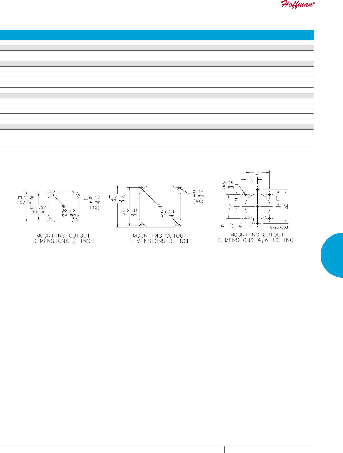
PH 763.422.2211 • FAX 763.576.3200 • HOFFMANONLINE.COMEQUIPMENT PROTECTION COOLING 251
4
FRESH AIR ENCLOSURE COOLING AXIAL FANS AND ACCESSORIES
Design Data Compact Axial Fans
CATALOG NUMBERS
Nominal
Size Voltage
A
in./mm
D
in./mm
E
in./mm
J
in./mm
K
in./mm
L
in./mm
M
in./mm
A2AXFN24 2 24 VDC — 1.97/50 .98/25 1.97/50 .98/25 — —
3-in. Fans
A3AXFN 3 115 VAC —2.81/71 1.40/36 2.81/71 1.40/36 — —
A3AXFN24 3 24 VDC — 2.81/71 1.40/36 2.81/71 1.40/36 — —
4-in. Fans
A4AXFNGQ 4 115 VAC 4.62/117 4.12/105 2.06/52 4.12/105 2.06/52 — —
A4AXFNPG 4 115 VAC 4.62/117 4.12/105 2.06/52 4.12/105 2.06/52 — —
A4AXFN 4 115 VAC 4.62/117 4.12/105 2.06/52 4.12/105 2.06/52 — —
A4AXFN2 4 230 VAC 4.62/117 4.12/105 2.06/52 4.12/105 2.06/52 — —
A4AXFN24 4 24 VDC 4.62/117 4.12/105 2.06/52 4.12/105 2.06/52 — —
6-in. Fans
A6AXFNGQ 6 115 VAC 5.88/149 ————3.19/81 6.38/162
A6AXFNPG 6 115 VAC 5.88/149 ————3.19/81 6.38/162
A6AXFN 6 115 VAC 5.88/149 ————3.19/81 6.38/162
A6AXFN2 6 230 VAC 5.88/149 ————3.19/81 6.38/162
A6AXFN24 6 24 VDC 5.88/149 ————3.19/81 6.38/162
10-in. Fans
A10AXFNPG 10 115 VAC 9.00/229 6.88/175 3.44/87 6.88/175 3.44/87 — —
A10AXFN 10 115 VAC 9.00/229 6.88/175 3.44/87 6.88/175 3.44/87 — —
A10AXFN2 10 230 VAC 9.00/229 6.88/175 3.44/87 6.88/175 3.44/87 — —
EQUIPMENT PROTECTIONSUBJECT TO CHANGE WITHOUT NOTICECOOLING252
4
FRESH AIR ENCLOSURE COOLING AXIAL FANS AND ACCESSORIES
Performance Data Compact Axial Fans
ELECTRICAL DATA
Rated Voltage 24 VDC 115 VAC
Lead Wires
115 VAC
Power Cord
Quiet Fan
115 VAC
Power Cord
230 VAC
Lead Wires
Frequency (Hz) 50/60 50/60 50/60 50/60 50/60
Power Connection Lead Wires Lead Wires Power Cord Power Cord Lead Wires
2 inch Nominal-Size Fans
Catalog Number A2AXFN24 — — — —
Nominal Current Maximum @50/60 Hz (Amps) .09 — — — —
Power Consumption Maximum @ 50/60 Hz (Watts) 2.16 — — — —
Free Airflow @ 50/60 Hz (CFM)* 21.5 — — — —
Free Airflow @ 50/60 Hz (m3/hr.)* 36.5 — — — —
Noise SIL @ 50/60 Hz (dBA) 65 — — — —
Maximum RPM @50/60 Hz (RPM) 4550 — — — —
Fan Size Diameter (in.) 2.36 — — — —
Fan Depth (in.) .98 — — — —
3 inch Nominal-Size Fans
Catalog Number A3AXFN24 A3AXFN — — —
Nominal Current Maximum @50/60 Hz (Amps) .14 .09 — — —
Power Consumption Maximum @ 50/60 Hz (Watts) 3.36 7 — — —
Free Airflow @ 50/60 Hz (CFM)* 40 27 — — —
Free Airflow @ 50/60 Hz (m3/hr.)* 68 46 — — —
Noise SIL @ 50/60 Hz (dBA) 35 40 — — —
Maximum RPM @50/60 Hz (RPM) 3400 2700 — — —
Fan Size Diameter (in.) 3.15 3.15 — — —
Fan Depth (in.) .98 1.50 — — —
4 inch Nominal-Size Fans
Catalog Number A4AXFN24 A4AXFN A4AXFNGQ A4AXFNPG A4AXFN2
Nominal Current Maximum @50/60 Hz (Amps) .35 .26/.21 .09/.08 .26/.21 .14/.11
Power Consumption Maximum @ 50/60 Hz (Watts) 84 17/15 6/5 17/15 16/14
Free Airflow @ 50/60 Hz (CFM)* 118 85/100 46/49 85/100 85/100
Free Airflow @ 50/60 Hz (m3/hr.)* 200 144/170 78/83 144/170 144/170
Noise SIL @ 50/60 Hz (dBA) 46.5 37/41 27/28 37/41 37/41
Maximum RPM @50/60 Hz (RPM) 3200 2415/2900 1350/1450 2415/2900 2415/2900
Fan Size Diameter (in.) 4.69 4.69 4.69 4.69 4.69
Fan Depth (in.) 1.52 1.52 1.52 1.52 1.52
6 inch Nominal-Size Fans
Catalog Number A6AXFN24 A6AXFN A6AXFNGQ A6AXFNPG A6AXFN2
Nominal Current Maximum @50/60 Hz (Amps) .88 .45/.36 .16/.19 .45/.36 .23/.18
Power Consumption Maximum @ 50/60 Hz (Watts) 21.1 36/32 16/18 36/32 39/35
Free Airflow @ 50/60 Hz (CFM)* 280 200/240 85/102 200/240 200/240
Free Airflow @ 50/60 Hz (m3/hr.)* 476 340/408 144/173 340/408 340/408
Noise SIL @ 50/60 Hz (dBA) 62.5 50/56 35/38 50/56 50/56
Maximum RPM @50/60 Hz (RPM) 3750 2670/3200 1400/1650 2670/3200 2670/3200
Fan Size Diameter (in.) 6.77 6.77 6.77 6.77 6.77
Fan Depth (in.) 2.00 1.50 1.50 1.50 1.50
10 inch Nominal-Size Fans
Catalog Number — A10AXFN —A10AXFNPG A10A XFN2
Nominal Current Maximum @50/60 Hz (Amps) — 1.0/.88 —1.0/.88 .47/.43
Power Consumption Maximum @ 50/60 Hz (Watts) — 36/36 —36/36 36/36
Free Airflow @ 50/60 Hz (CFM)* — 480/560 —480/560 480/560
Free Airflow @ 50/60 Hz (m3/hr.)* —816/951 —816/951 816/951
Noise SIL @ 50/60 Hz (dBA) — 46/49 —46/49 46/49
Maximum RPM @50/60 Hz (RPM) — 1350/1650 —1350/1650 1350/1650
Fan Size Diameter (in.) — 10.00 —10.00 10.00
Fan Depth (in.) — 3.50 —3.50 3.50
* CFM without exhaust grille
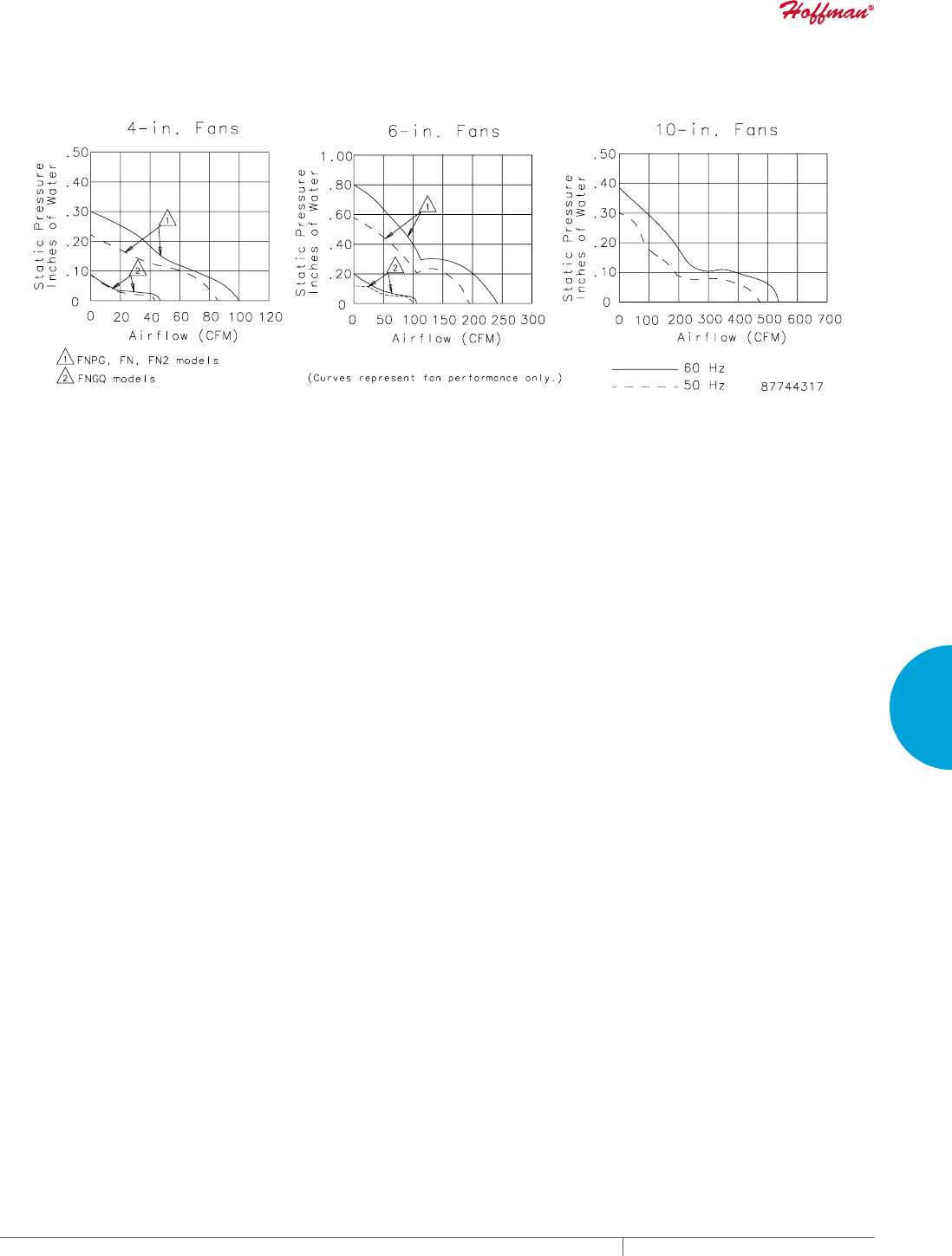
PH 763.422.2211 • FAX 763.576.3200 • HOFFMANONLINE.COMEQUIPMENT PROTECTION COOLING 253
4
FRESH AIR ENCLOSURE COOLING AXIAL FANS AND ACCESSORIES
Performance Curves for Compact Axial Fans
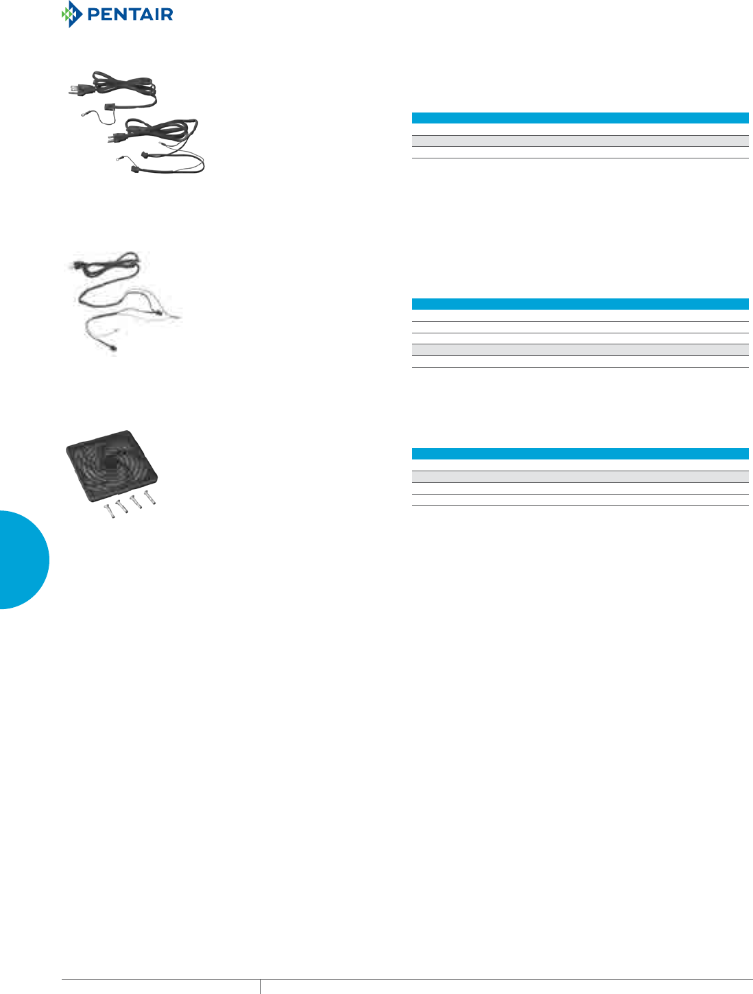
EQUIPMENT PROTECTIONSUBJECT TO CHANGE WITHOUT NOTICECOOLING254
4
FRESH AIR ENCLOSURE COOLING AXIAL FANS AND ACCESSORIES
FAN CORDS Used to power Compact Cooling Fans when positive ground of
the cabinet case is required. Available with connectors for one or
two fans. Five-foot (1.52-meter) cord with grounded three-prong
plug. Fits A4AXFNPG, A6AXFNPG, A10AXFNPG, A4AXFNGQ and
A10AXFNGQ.
CATALOG NUMBERS
ACORD1 ACORD2
DESIGN DATA
Description One connector Two connectors
FAN CORDS WITH INLINE THERMOSTAT Use to power 120 VAC Compact Cooling Fans; replaces existing
supplied power cord. Fan cord includes inline thermostat. The cord
automatically activates up to two fans. Fan(s) will turn on when
the inline thermostat reaches 86F (30C). Fan(s) will run only when
temperature is above 86F (30C). Use with 110-120 VAC fans with
power cords only. One or two fans can be used with power cord.
ELECTRICAL DATA
Rated Voltage 110-120 VAC
Maximum Current (Amps) 10
Fan Activation Temperature (°F/°C) 86/30
CATALOG NUMBERS
ACORD2T
FAN FILTER AND FINGER GUARD KIT Low-density filter kit for 4-in. (102-mm) and 6-in. (152-mm) fans.
Can also be used as vent. Filter is removable and can be cleaned
and reused. Mounting hardware included.
CATALOG NUMBERS
AFLTR4LD AFLTR6LD
DESIGN DATA
Description Fan Filter and Finger Guard Kit
Fits 4-in. fans 6-in. fans
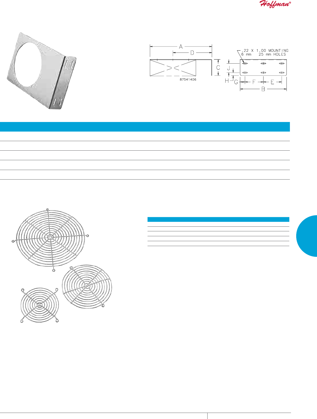
PH 763.422.2211 • FAX 763.576.3200 • HOFFMANONLINE.COMEQUIPMENT PROTECTION COOLING 255
4
FRESH AIR ENCLOSURE COOLING AXIAL FANS AND ACCESSORIES
FAN BRACKETS Designed to provide easy mounting of compact axial fans on
enclosure panels. Brackets can be used for general air circulation
or to direct air at problem areas. All sizes are .100-in. aluminum.
Package quantity of 1 bracket. Fans must be ordered separately.
CATALOG
NUMBERS
AxBxC
in./mm Used with Fan Catalog Number
D
in./mm
E
in./mm
F
in./mm
G
in./mm
H
in./mm
J
in./mm
ABRKT2 3.75x2.75x1.50
95x70x38
A2AXFN24 2.38/60 —1.75/44 .50/13 .37/9 .62/16
ABRKT3 4.50x3.50x1.50
114x89x38
A3AXFN, A3AXFN24 2.75/70 —2.50/64 .50/13 .37/9 .62/16
ABRKT4 6.00x5.00x1.50
152x127x38
A4AXFNPG, A4AXFNGQ, A4AXFN
or A4AXFN2
3.50/89 —3.00/76 1.00/25 .38/10 .62/16
ABRKT6 10.00x6.88x2.00
254x175x51
A6AXFNPG, A6AXFNGQ, A6AXFN
or A6AXFN2
6.50/51 —5.00/127 .94/24 .38/10 1.00/25
ABRKT10 13.50x10.12x3.50
343x257x89
A10AXFNPG, A10A XFNGQ, A10A XFN
or A10AXFN2
8.50/216 4.00/102 4.00/102 1.06/27 .62/16 2.00/51
FINGER GUARDS One finger guard is included with each Compact Axial Fan and
Cooling Fan Package. Additional Finger Guards can be mounted on
either side of the fan for maximum safety. All guards are chrome-
plated and meet UL 507 .25-in. plug gauge test.
CATALOG NUMBERS Use on Compact Axial Fan Catalog Numbers
AGARD2 A2AXFN24
AGARD3 A3AXFN, A3AXFN24
AGARD4 A4AXFNPG, A4XFNGQ, A4AXFN, A4AXFN2
AGARD6 A6AXFNPG, A6AXFNGQ, A6AXFN, A6AXFN2
AGARD10 A10AXFNPG, A10AXFNQR , A10AXFN, A10AXFN2
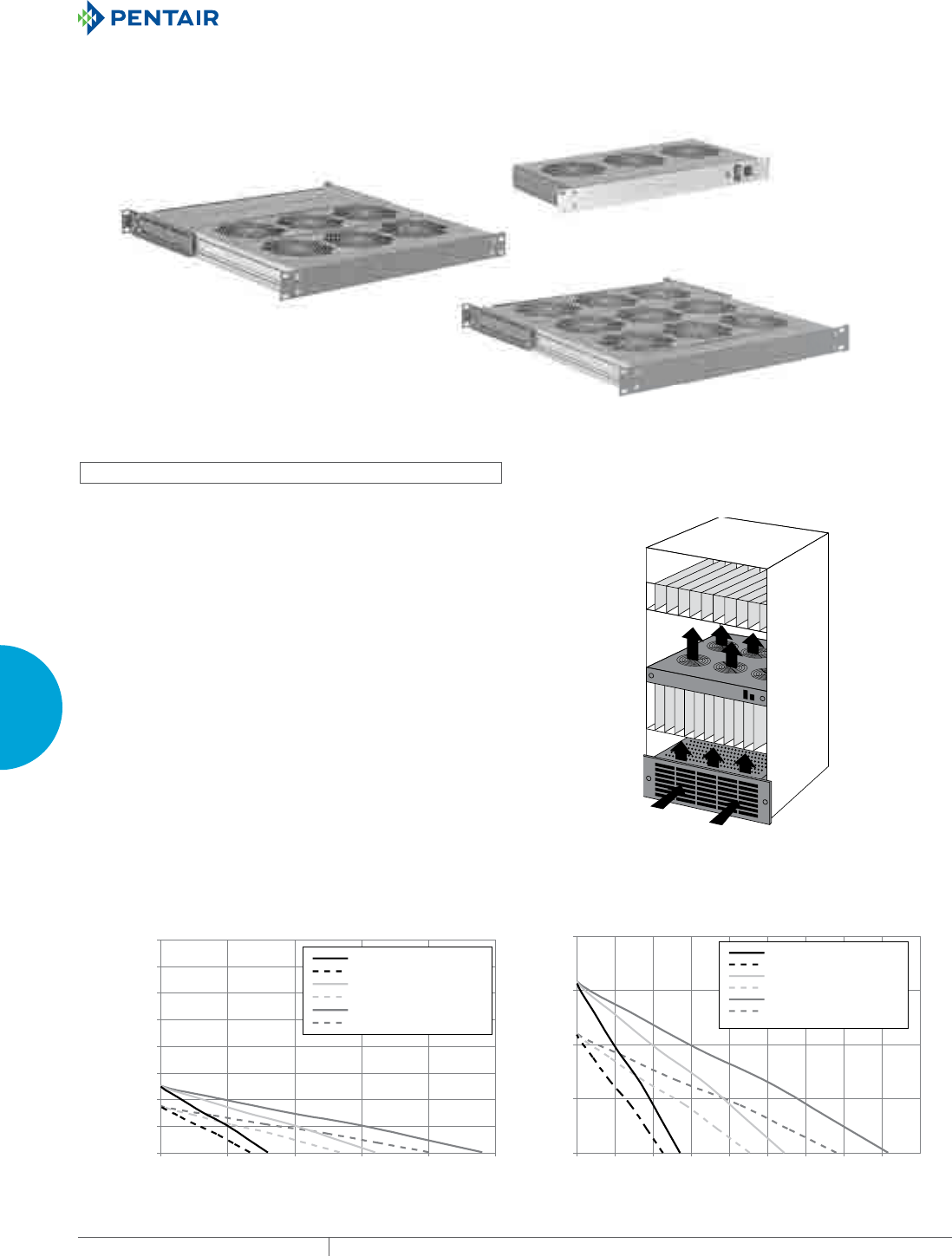
EQUIPMENT PROTECTIONSUBJECT TO CHANGE WITHOUT NOTICECOOLING256
4
FRESH AIR ENCLOSURE COOLING FAN TRAYS
FAN TRAYS
RACKMOUNTABLE ASSEMBLIES
UEB17H
2EB17H
3EB17H
INDUSTRY STANDARDS
UL recognized
• CSA Certified Motors
• CE
APPLICATION
Fan trays are a versatile solution to cooling card cages and racks.
Redundant cooling with optional failure detection makes this
air mover the obvious choice for sensitive equipment. Minimal
rack space and repositionable fans are suited to today’s smaller
enclosures.
FEATURES
• Slim 1.75 in. (44 mm) Panel Height
• 19-in. rack mountable
• Field adjustable fan strips to optimize air flow
• Easy access to fan tray from front and back
• Simplified installation without the need for side access
• Support bracket
• Exhaust Guard
• 6-inch Power Cord AC trays, Terminal block on DC trays
• Permanently lubricated ball bearing motors
• 100% functionally tested
SPECIFICATIONS
• 115/230 VAC
• 24 VDC
• 50/60 Hz
0
20
40
60
80
0 200 400 600 800 1000 1200 1400 1600
m3/hr
Pa
UEB,1EB-17H&T - 60hz
UEB,1EB-17H&T - 50hz
2EB-17H&T - 60hz
2EB-17H&T-50hz
3EB-17H&T-60hz
3EB-17H&T-50hz
Performance Curves (Pa to m3/hr)
0
0.1
0.2
0.3
0.4
0.5
0.6
0.7
0.8
0 200 400 600 800 1000
CFM
Inches of Water
UEB,1EB-17H&T - 60hz
UEB,1EB-17H&T - 50hz
2EB-17H&T - 60hz
2EB-17H&T-50hz
3EB-17H&T-60hz
3EB-17H&T-50hz
Performance Curves (Inches of Water to CFM)
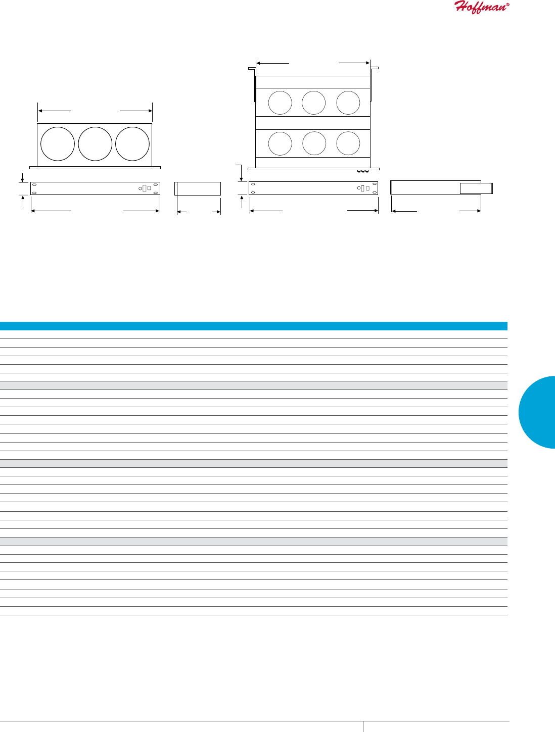
PH 763.422.2211 • FAX 763.576.3200 • HOFFMANONLINE.COMEQUIPMENT PROTECTION COOLING 257
4
FRESH AIR ENCLOSURE COOLING FAN TRAYS
&DVH
'HSWK
>@
&DVH:LGWK
(
7HOHVFRSLQJ5HDU
6XSSRUW%UDFNHWV
LQ0D[LPXP
81,7,=(''(6,*1 02'8/$5'(6,*1
3DQHO:LGWK
(
&DVH:LGWK
(
3DQHO:LGWK
(
&DVH'HSWK
>@
3DQHO+HLJKW
>@
:KHUHRQO\RQH
IDQVWULSLV
UHTXLUHGD
XQLWL]HG8IDQ
WUD\LV
UHFRPPHQGHG
89081542
Performance Data Rack-Mountable Assemblies
ELECTRICAL DATA
Rated Voltage 115 VAC 230 VAC 24 VDC
Frequency (Hz) 50/60 50/60 DC
RPM 3100 3100 3000
Nominal Current Maximum (Amps) 0.4 0.2 0.8
Power Consumption Maximum (Watts) 42 42 21
Maximum Operating Temperature (°F/°C) 158/70
UEB17H
Catalog Numbers UEB17H115 UEB17H230 UEB17H24
Nominal Current Maximum @50/60 Hz (Amps) .4 .2 .8
Power Consumption Maximum @ 50/60 Hz (Watts) 42 42 21
Free Airflow @ 50/60 Hz (CFM)* 315 315 330
Free Airflow @ 50/60 Hz (m3/hr.)* 536 536 561
Number of Fans 3
Unit Dimensions H x W x D (In./mm) 1.75 x 19.00 x 8.00/44 x 482 x 203
Weight (lb./kg) 7.8/3.4 7.8/3.4 7.6/3.3
2EB17H
Catalog Numbers 2EB17H115 2EB17H230 —
Nominal Current Maximum @50/60 Hz (Amps) .9 .5 —
Power Consumption Maximum @ 50/60 Hz (Watts) 84 84 —
Free Airflow @ 50/60 Hz (CFM)* 630 630 —
Free Airflow @ 50/60 Hz (m3/hr.)* 1071 1071 —
Number of Fans 6 —
Unit Dimensions H x W x D (In./mm) 1.75 x 19.00 x 18.75/44 x 482 x 476 —
Weight (lb./kg) 10.2/4.5 10.2/4.5 —
3EB17H
Catalog Numbers 3EB17H115 3EB17H230 —
Nominal Current Maximum @50/60 Hz (Amps) 1.4 .8 —
Power Consumption Maximum @ 50/60 Hz (Watts) 126 126 —
Free Airflow @ 50/60 Hz (CFM)* 945 945 —
Free Airflow @ 50/60 Hz (m3/hr.)* 1607 1607 —
Number of Fans 9 —
Unit Dimensions H x W x D (In./mm) 1.75 x 19.00 x 18.75/44 x 482 x 476 —
Weight (lb./kg) 12.5/5.5 12.5/5.5 —
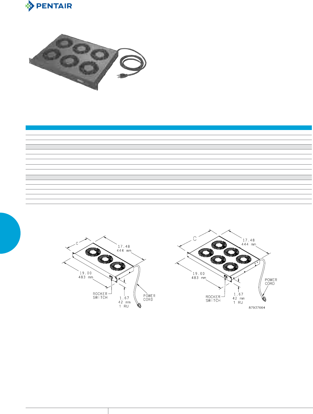
EQUIPMENT PROTECTIONSUBJECT TO CHANGE WITHOUT NOTICECOOLING258
4
FRESH AIR ENCLOSURE COOLING FAN TRAYS
19IN. RACKMOUNTABLE TRAY
APPLICATION
Fan trays enhance the natural convection airflow within a cabinet
when installed with other 19-in. rack-mount equipment.
FEATURES
• Fan trays available with either three or six 4-in. fans
• Includes 72-in. (1829-mm) power cord with IEC 320 standard
power socket
• Power cord plugs into standard 115 VAC outlet
• Lighted rocker switch provides on-off control and indicates when
fans are on
FINISH
• RAL 9005 black, lightly textured polyester powder paint
ACCESSORIES
Rack mounting hardware
Performance Data 19-in. Rack-Mountable Tray
ELECTRICAL DATA
Rated Voltage 115 115
Frequency (Hz) 60 60
Power Consumption (Watts) 45 90
CATALOG NUMBERS
A19FT3B A19FT6B
Maximum Airflow (CFM) 253 506
Maximum Airflow (m3/hr.) 430 860
Nominal Airflow Capacity (CFM) 102 102
Nominal Airflow Capacity (m3/hr.) 173 173
UNIT CONSTRUCTION
Sound Pressure (dBA) 41 41
Maximum Operating Temperature Range (°F/°C) 158/70 158/70
Maximum Static Pressure (in. WC) 0.27 0.27
Number of Fans 3 6
C (in./mm) 8.10/206 12.96/329
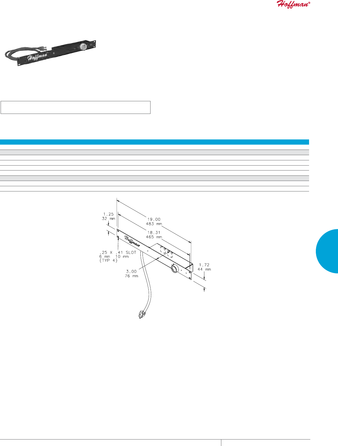
PH 763.422.2211 • FAX 763.576.3200 • HOFFMANONLINE.COMEQUIPMENT PROTECTION COOLING 259
4
FRESH AIR ENCLOSURE COOLING FAN TRAYS
RACKMOUNT FAN SPEED CONTROL
INDUSTRY STANDARDS
UL 508 Listed; File No. E249700
cUL Listed per CSA C22.2 No. 14; File No. E249700
APPLICATION
Perfect for offices, classrooms and other noise-sensitive areas. Fan
Speed Control optimizes airflow in a cabinet or rack, balancing air
volume requirements with noise level and power use.
FEATURES
• Continuously variable fan speed control knob with minimum
speed adjustment
• Uses 1 RU rack space
• Steel construction
• Two NEMA 5-15R outlets provide power to fan
• Six-foot (1.83-m) power cord plugs into standard 120 V 60 Hz
outlet
FINISH
• A19FANSC: RAL 9005 black polyester powder paint
Performance Data Rack-Mount Fan Speed Controls
CATALOG NUMBERS
A19FANSC
ELECTRICAL DATA
Rated Voltage 120 VAC
Maximum Nominal Current (Amps) 4
Temperature Settings (°F) 86, 95, 104, 113
Temperature Settings (°C) 30, 35, 40, 45
DESIGN DATA
Description 19-in. Rack-Mount Fan Speed Control
Application Fan speed adjusted manually
89084921
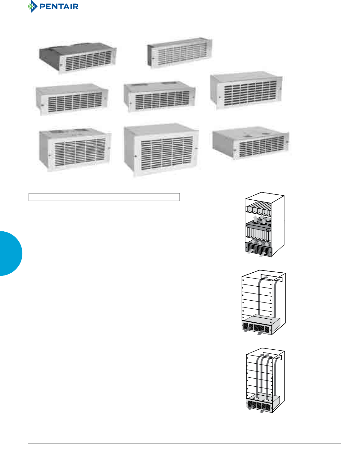
EQUIPMENT PROTECTIONSUBJECT TO CHANGE WITHOUT NOTICECOOLING260
4
FRESH AIR ENCLOSURE COOLING PACKAGED BLOWERS
PACKAGED BLOWERS
RACKMOUNTABLE BLOWERS
1EB52H115A
2EB300 2EB3500
2EB512 2EB612
4EB300
2EB412
1EB52H115B
INDUSTRY STANDARDS
UL recognized
CSA Certified Motors
CE
APPLICATION
Fanpack packaged blowers are filtered inlet redundant fan
packages. The compact size of the “B” models result in minimal
intrusion into the enclosure.
Standard packaged blowers offer reliable rack cooling in a variety
of case styles. Two exhaust styles are available with air flowing out
the rear or out the top. Specify exhaust style (R or T) when ordering.
Multi-exhaust packaged blowers feature top and rear exhausts, for
a wide, deep airflow pattern. Designed with two separate blowers
inside, multi-exhaust blowers also offer redundancy and increased
airflow.
FEATURES
• Permanent, Washable Aluminum Filter
• 19-in. Rack Mountable
• Brushed Aluminum Grille
• Exhaust Guard
• Power Cord
• Permanently lubricated ball bearing motors
• 100% functionally tested
SPECIFICATIONS
• 115/230 VAC
• 50/60 Hz
4EB Models
2EB Models
1EB Models
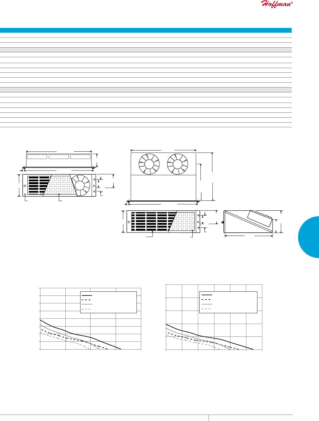
PH 763.422.2211 • FAX 763.576.3200 • HOFFMANONLINE.COMEQUIPMENT PROTECTION COOLING 261
4
FRESH AIR ENCLOSURE COOLING PACKAGED BLOWERS
Performance Data 1EB Models
ELECTRICAL DATA
Rated Voltage 115 230
Frequency (Hz) 50/60 50/60
Maximum Operating Temperatur (°F/°C) 140/60 140/60
”A” Models
Catalog Numbers 1EB52H115A 1EB52H230A
Free Airflow (CFM/M3/hr.) 320/544 320/544
RPM 3300 3300
Nominal Run Current Maximum (Amps) .52 .26
Nominal Start Current Maximum (Amps) 1.00 .50
Power Consumption (Watts) 62 62
Weight (lb./kg) 14/6.3 14/6.3
”B” Models
Catalog Numbers 1EB52H115B 1EB52H230B
Free Airflow (CFM/M3/hr.) 235/400 235/400
RPM 3100 3100
Nominal Run Current Maximum (Amps) .55 .31
Nominal Start Current Maximum (Amps) .80 .40
Power Consumption (Watts) 44 44
Weight (lb./kg) 8/3.6 8/3.6
Brushed
Aluminium Grille
Aluminium Filter
Washable, Replaceable
18 [457]
17 [432]
3.43 [87]
2.25 [57]
1.12 [28]
5.21 [132]
2.60 [66]
0.50 [13]
18 [457]
17 [432]
9.25
[235]
13.70
[348]
Brushed
Aluminium Grille
Aluminium Filter
Washable, Replaceable
1.12 [28]
2.61
[67]
13.70
[348]
3.00
[76]
5.18
[132]
0.50 [13]
5.21 [132]
2.25 [57]
89081701
1EB52HxxxB Models 1EB52HxxxA Models
1EB52HXXXA - 60hz
1EB52HXXXA - 50hz
1EB52HXXXB-60hz
1EB52HXXXB-50hz
1EB52HXXXA - 60hz
1EB52HXXXA - 50hz
1EB52HXXXB-60hz
1EB52HXXXB-50hz
0
0.1
0.2
0.3
0.4
0.5
0.6
0.7
0.8
0 100 200 300 400 0
50
100
150
200
250
0100 200300 400500 600
Inches of Water
Pa
CFM M/hr.
1EB Models
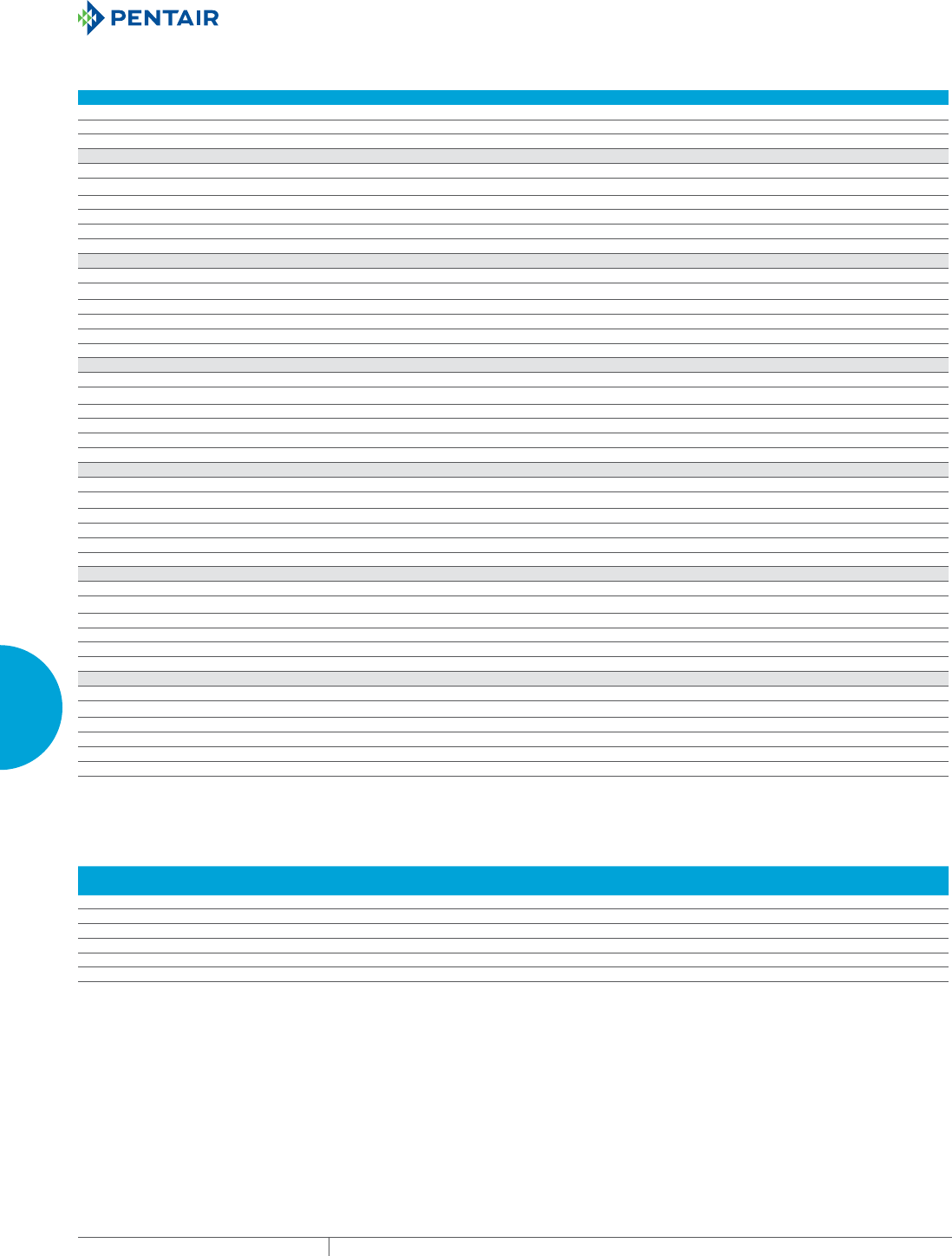
EQUIPMENT PROTECTIONSUBJECT TO CHANGE WITHOUT NOTICECOOLING262
4
FRESH AIR ENCLOSURE COOLING PACKAGED BLOWERS
Performance Data 2EB Models
ELECTRICAL DATA
Rated Voltage 115 230
Frequency (Hz) 50/60 50/60
Maximum Operating Temperatur (°F/°C) 104/40 104/40
2EB300R Models
Catalog Numbers 2EB300R115 2EB300R230
Free Airflow (CFM/M3/hr.) 125/212 125/212
RPM 3000 3000
Nominal Run Current Maximum (Amps) .9 .5
Power Consumption (Watts) 70 70
Weight (lb./kg) 16/17.3 16/17.3
2EB3500R Models
Catalog Numbers 2EB3500R115 2EB3500R230
Free Airflow (CFM/M3/hr.) 290/493 290/493
RPM 3050 3050
Nominal Run Current Maximum (Amps) 1.8 .9
Power Consumption (Watts) 125 125
Weight (lb./kg) 17/7.7 17/7.7
2EB412R Models
Catalog Numbers 2EB412R115 2EB412R230
Free Airflow (CFM/M3/hr.) 375/637 375/637
RPM 3100 3100
Nominal Run Current Maximum (Amps) 1.8 .8
Power Consumption (Watts) 200 200
Weight (lb./kg) 22/10 22/10
2EB512R Models
Catalog Numbers 2EB512R115
Free Airflow (CFM/M3/hr.) 425/722
RPM 1700
Nominal Run Current Maximum (Amps) 1.3
Power Consumption (Watts) 140
Weight (lb./kg) 25/11.3
2EB512T Models
Catalog Numbers 2EB512T115
Free Airflow (CFM/M3/hr.) 425/722
RPM 1700
Nominal Run Current Maximum (Amps) 1.3
Power Consumption (Watts) 140
Weight (lb./kg) 25/11.3
2EB612R Models
Catalog Numbers 2EB612R115 2EB612R230
Free Airflow (CFM/M3/hr.) 800/1359 800/1359
RPM 1650 1650
Nominal Run Current Maximum (Amps) 2.2 1.0
Power Consumption (Watts) 220 220
Weight (lb./kg) 41/18.6 41/18.6
Design Data 2EB Models
CATALOG NUMBERS
PMax
in./mm
A
in./mm
B
in./mm
C
in./mm
D
in./mm
E
in./mm
F
in./mm
2EB300R115 5.25/133 4.30/109 2.05/52 — — 8.22/209 —
2EB3500R115 5.25/133 4.38/111 4.56/116 — — 7.17/182 1.75/44
2EB412R115 7.00/178 4.23/107 3.15/80 — — 8.22/209 —
2EB512R115 8.75/222 4.13/105 3.63/92 — — 8.22/209 —
2EB512T115 8.75/222 4.13/105 3.63/92 .80/20 3.40/86 9.61/244 —
2EB612R115 10.50/267 4.38/111 3.99/101 — — 10.22/620 —
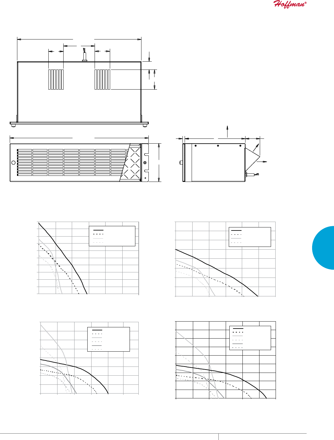
PH 763.422.2211 • FAX 763.576.3200 • HOFFMANONLINE.COMEQUIPMENT PROTECTION COOLING 263
4
FRESH AIR ENCLOSURE COOLING PACKAGED BLOWERS
F (3500 ONLY)
BB
A
P MAX
19.00 [483] .32
[8] E
C
D
AIR EXHAUST
"T" VERSION
AIR EXHAUST
"R" VERSION
17.00 [432]
89081699
2EB Models
2EB612 -60Hz
2EB612 -50hz
2EB412 -60Hz
2EB412 -50Hz
2EB512 -60hz
2EB512 -50hz
0
50
100
150
200
250
300
350
400
450
0500 1000 1500
Pa
M/hr.
2EB612 -60Hz
2EB612 -50hz
2EB412 -60Hz
2EB412 -50Hz
2EB512 -60hz
2EB512 -50hz
0
1.0
0.8
0.6
0.4
0.2
1.2
1.4
1.6
0 200 400 600 800 1000 1200
Inches of Water
CFM
2EB3500 -60hz
2EB3500-50hz
2EB300 -60hz
2EB300 -50hz
0
50
100
150
200
25
5
450
550
0
30
0100 200300 400 50
06
00
Pa
M/hr.
2EB3500-60hz
2EB3500-50hz
2EB300 -60hz
2EB300 -50hz
0
0.1
0.2
0.3
0.4
0.5
0.6
0.7
0.8
0.9
1
0 200 400 600
Inches of Water
CFM
2EB Models
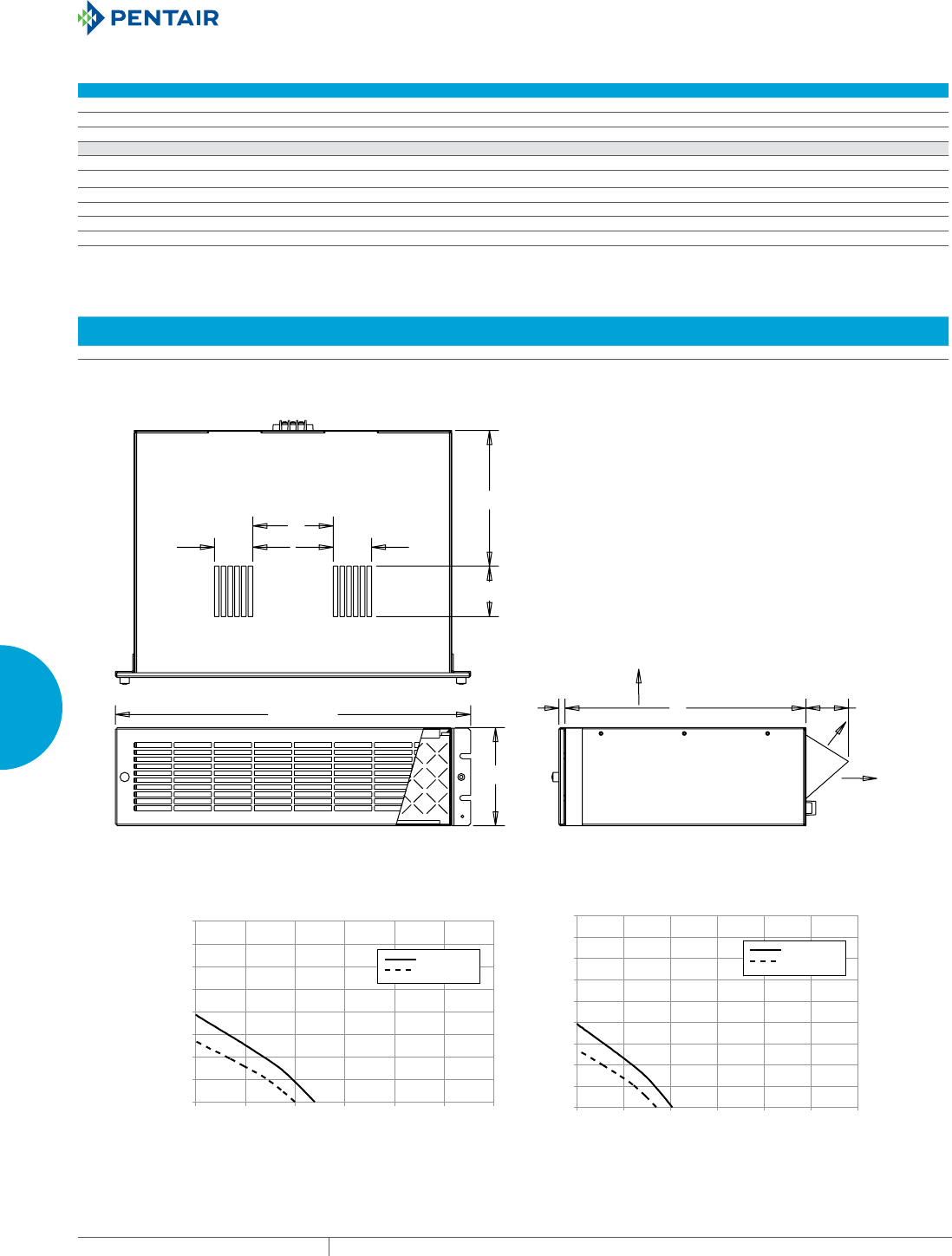
EQUIPMENT PROTECTIONSUBJECT TO CHANGE WITHOUT NOTICECOOLING264
4
FRESH AIR ENCLOSURE COOLING PACKAGED BLOWERS
Performance Data 4EB Models
ELECTRICAL DATA
Rated Voltage 115
Frequency (Hz) 50/60
Maximum Operating Temperatur (°F/°C) 104/40
4EB300RT Models
Catalog Number 4EB300RT115
Free Airflow (CFM/M3/hr.) 225/382
RPM 2900
Nominal Run Current Maximum (Amps) 1.8
Power Consumption (Watts) 130
Weight (lb./kg) 21/9.5
Design Data 4EB Models
CATALOG NUMBERS
PMax
in./mm
A
in./mm
B
in./mm
C
in./mm
D
in./mm
E
in./mm
F
in./mm
4EB300RT115 5.25/133 4.30/109 2.05/52 7.25/184 2.70/69 12.88/327 —
F (3500 ONLY)
C
D
BB
A
19.00 [483]
P MAX
.32
[8]
E
AIR EXHAUST
"T" VERSION
AIR EXHAUST
"R" VERSION
89081700
4EB Models
(%+]
(%K]
(%+]
(%K]
0
0.2
0.4
0.6
0.8
1.0
1.2
1.4
1.6
0 100 200300 400500 600 0
50
100
150
200
250
300
350
400
450
0200 400600 80010001200
Inches of Water
Pa
CFM M/hr.
4EB Models

PH 763.422.2211 • FAX 763.576.3200 • HOFFMANONLINE.COMEQUIPMENT PROTECTION COOLING 265
4
FRESH AIR ENCLOSURE COOLING PACKAGED BLOWERS
Notes
EQUIPMENT PROTECTIONSUBJECT TO CHANGE WITHOUT NOTICECOOLING266
4
FRESH AIR ENCLOSURE COOLING AIR MOVERS
AIR MOVERS
RACKMOUNTABLE FAN PACKAGE
INDUSTRY STANDARDS
UL Component Recognized; File No. E61997
EIA RS-310-D
CSA certified
(blower motor only)
APPLICATION
For enclosure or 19-in. rack applications, the Blower Fan Package
provides the maximum amount of cooling air in the least amount of
space by utilizing 115 volt AC, 60/50 hertz, single-phase input power.
Engineered for 20,000 hours of continuous operation when properly
powered.
FEATURES
• Intake grille is easily removed with two captive thumbnuts
• Washable aluminum filter
• Single phase motor powers the statically balanced blower
• Motor is thermally protected and cooled by incoming forced air
• Direct drive induction motor contains permanently lubricated ball
bearings
• Lubricant protects from -20 F to 298 F (-29 C to 148 C)
• Rotating components are suspended on neoprene shock-mounts
• Three-conductor power cord (five feet long)
• The unit is self-supporting with 16 gauge steel flanges notched
per EIA RS-310-D.
• An exhaust grille and filter package (catalog number AEXGR275)
is required and must be ordered separately
SPECIFICATIONS
• 16 gauge steel housing
FINISH
• Blower housing is black enamel.
• Grille is brushed stainless steel.
ACCESSORIES
Exhaust Grille and Filter
Filter Adhesive
Temperature Control Switch
Performance Data Rack-Mountable Fan Package
CATALOG NUMBERS
ADB275
ELECTRICAL DATA
Rated Voltage 115
Frequency 50/60
Free Airflow (CFM) 230/275
RPM 2580/3100
Nominal Current Maximum (Amps) 1.2
Power Consumption (Watts) 84
SOUND LEVEL
Sound Pressure (dBA) 56
UNIT CONSTRUCTION
Weight (lb./kg) 15/7
EXHAUST GRILLE CATALOG NUMBERS
Catalog Number AEXGR275*
* Exhaust grille sold separately
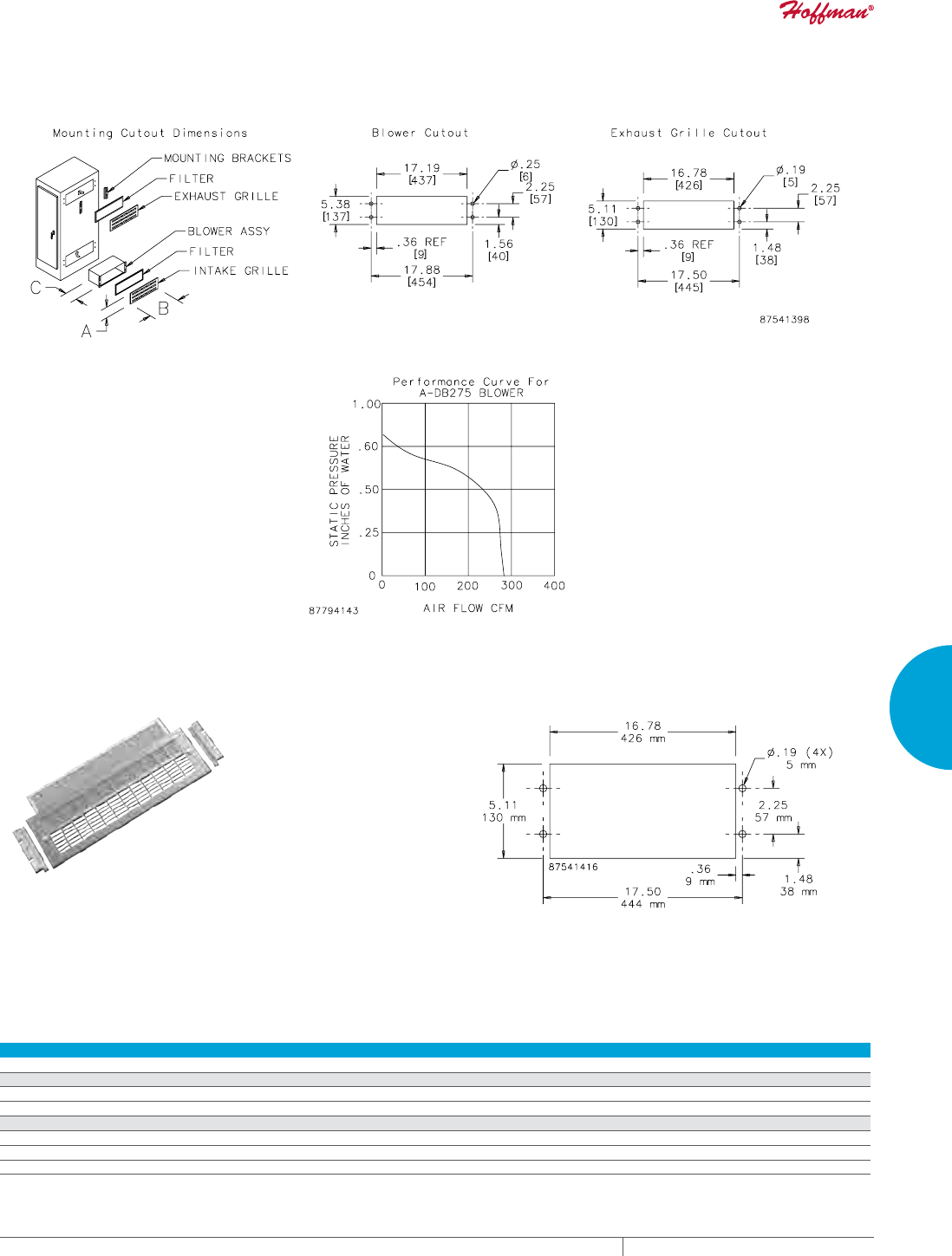
PH 763.422.2211 • FAX 763.576.3200 • HOFFMANONLINE.COMEQUIPMENT PROTECTION COOLING 267
4
FRESH AIR ENCLOSURE COOLING AIR MOVERS
Rack-Mountable Fan Package
EXHAUST GRILLES AND REPLACEMENT FILTERS
Located at air discharge side of an enclosure using Blower Package
ADB275. Polished stainless steel grille is 65 percent open and
offers low resistance to airflow. Expanded aluminum filter (included
with each grille) is easily removed for cleaning from outside the
enclosure. Mounting hardware is furnished.
CUTOUT DIMENSIONS
Performance Data Exhaust Grilles and Replacement Filters for Rack-Mountable Fan Package
CATALOG NUMBERS
AEXGR275
UNIT CONSTRUCTION
Dimensions H x W (in./mm) 5.75/146 x 19.00/483
Filter Size (in./mm) 4.98/126 x 16.56/421
ACCESSORIES
Replacement Filters:
Catalog Number AFLTR275AL
Description Aluminum Filter Replacement (5 per package)
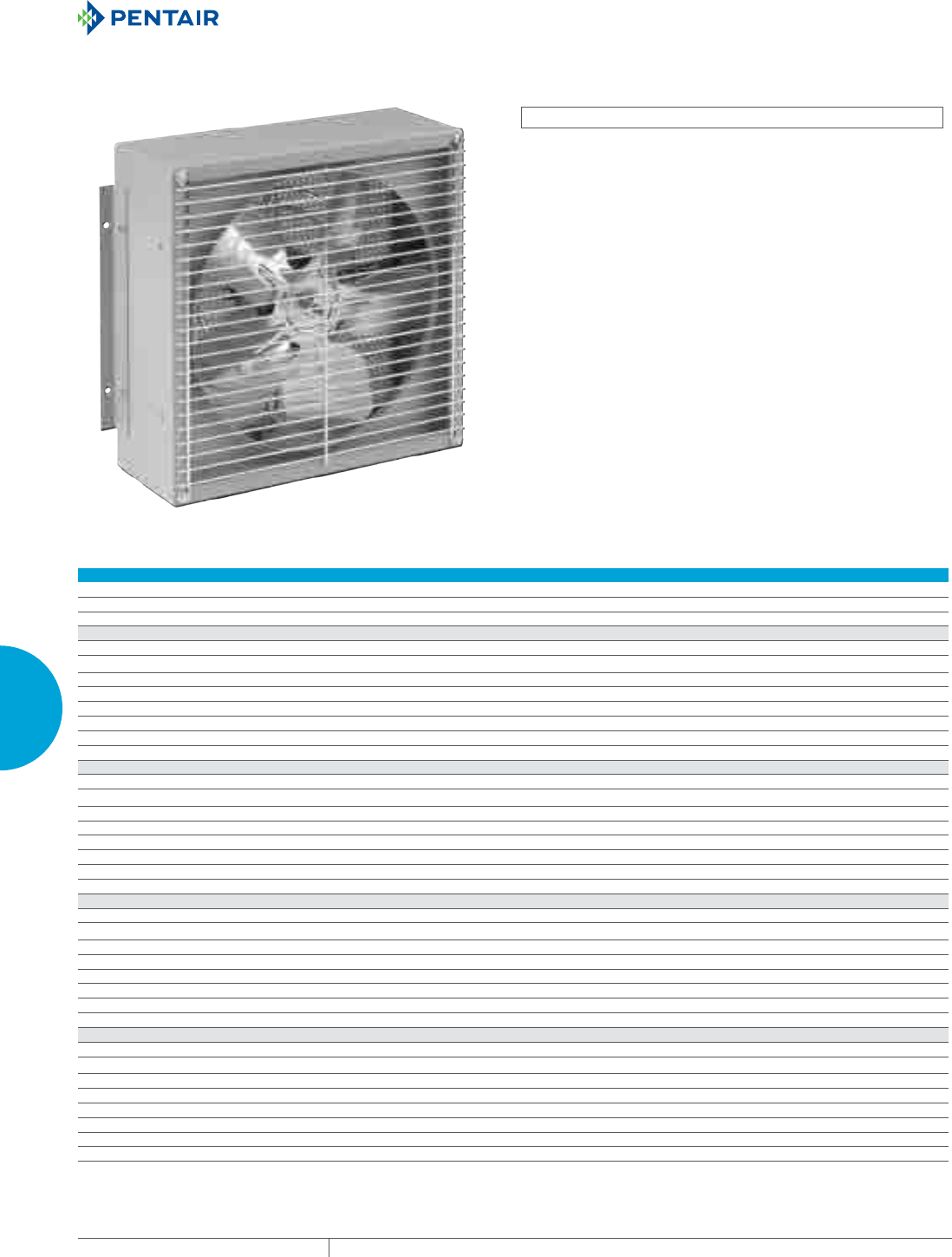
EQUIPMENT PROTECTIONSUBJECT TO CHANGE WITHOUT NOTICECOOLING268
4
FRESH AIR ENCLOSURE COOLING AIR MOVERS
FILTER BOX FANS
INDUSTRY STANDARDS
Motor UL Recognized
Motor CSA
APPLICATION
Thermal filter boxes are high volume air movers that require
minimal enclosure space. Repositionable mounting ears allow the
fans to be mounted internally or externally, and used for either
intake or exhaust.
FEATURES
• Inlet Guard
• Outlet Guard
• Power Cord
• 5-15 plug available on catalog numbers ending with “M” only
• Permanently lubricated ball bearing motors
• 100% functionally tested
SPECIFICATIONS
• 115 VAC
• 50/60Hz
Performance Data Filter Box Fans
ELECTRICAL DATA
Rated Voltage 115 115
Frequency (Hz) 50/60 50/60
Maximum Operating Temperature (°F/°C) 104/40 104/40
1RB65 Models
Catalog Numbers 1RB65 1RB65M
Free Airflow (CFM/M3/hr.) 275/493 275/493
RPM 3000 3000
Nominal Run Current Maximum (Amps) .85 .85
Nominal Start Current Maximum (Amps) 1.2 1.2
Power Consumption (Watts) 70 70
Filter N/A Aluminum
Weight (lb./kg) 8/3.5 8/3.5
1RB80 Models
Catalog Numbers 1RB80 1RB80M
Free Airflow (CFM/M3/hr.) 390/699 390/699
RPM 1600 1600
Nominal Run Current Maximum (Amps) 1.1 1.1
Nominal Start Current Maximum (Amps) 1.5 1.5
Power Consumption (Watts) 80 80
Filter N/A Aluminum
Weight (lb./kg) 10/4.5 10/4.5
1RB100 Models
Catalog Numbers 1RB100 1RB100M
Free Airflow (CFM/M3/hr.) 725/1299 725/1299
RPM 1600 1600
Nominal Run Current Maximum (Amps) 1.2 1.2
Nominal Start Current Maximum (Amps) 1.5 1.5
Power Consumption (Watts) 90 90
Filter N/A Aluminum
Weight (lb./kg) 12/5.4 12/5.4
1RB120 Models
Catalog Numbers 1RB120 1RB120M
Free Airflow (CFM/M3/hr.) 1200/2151 1200/2151
RPM 1500 1500
Nominal Run Current Maximum (Amps) 1.5 1.5
Nominal Start Current Maximum (Amps) 2.5 2.5
Power Consumption (Watts) 160 160
Filter N/A Aluminum
Weight (lb./kg) 24/10.8 24/10.8
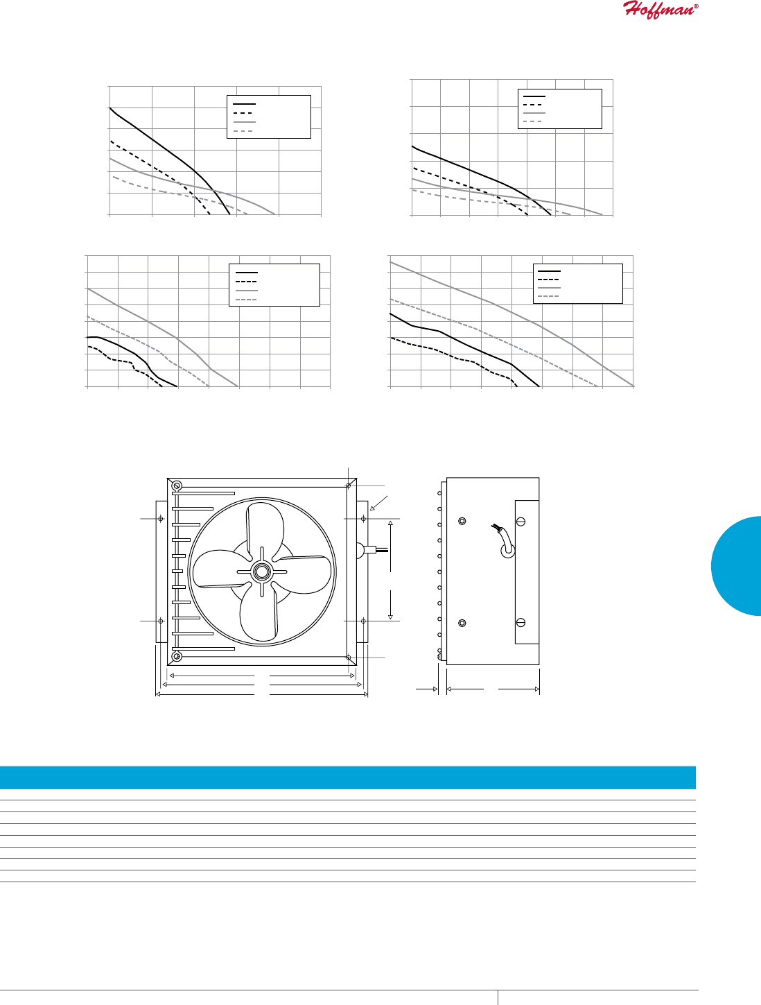
PH 763.422.2211 • FAX 763.576.3200 • HOFFMANONLINE.COMEQUIPMENT PROTECTION COOLING 269
4
FRESH AIR ENCLOSURE COOLING AIR MOVERS
1RB65 60Hz
1RB65 50Hz
1RB80 60Hz
1RB80 50Hz
1RB100 60Hz
1RB100 50Hz
1RB120 60Hz
1RB120 50Hz
1RB65 60Hz
1RB65 50Hz
1RB80 60Hz
1RB80 50Hz
1RB100 60Hz
1RB100 50Hz
1RB120 60Hz
1RB120 50Hz
0
0.1
0.2
0.3
0.4
0.5
0.6
0 100 200 300 400 500 0
50
100
150
200
250
0 100 200 300 400 500 600 700
Inches of Water
CFM
Pa
M/hr.
0
0.10
0.20
0.30
0.40
0.50
0.60
0.70
0.80
0 250 500 750 1000 1250 1500 1750 2000 0
20
40
60
80
100
120
140
160
0 250 500 750 1000 1250 1500 1750 2000
CFM
Inches of Water
Pa
M/hr.
Performance Curves Filter Box
89081776
B
E
A
0.32
[8]
C
D
Ø 0.22
[6]
(4 Holes)
Design Data Filter Box
CATALOG NUMBERS
A
in./mm
B
in./mm
C
in./mm
D
in./mm
E
in./mm
1RB65 4.50/114 8.88/226 9.56/243 10.13/257 4.88/124
1RB65M 4.50/114 8.88/226 9.56/243 10.13/257 4.88/124
1RB80 4.50/114 8.88/226 9.56/243 10.13/257 4.88/124
1RB80M 4.50/114 8.88/226 9.56/243 10.13/257 4.88/124
1RB100 4.50/114 12.13/308 12.81/325 13.38/340 6.13/156
1RB100M 4.50/114 12.13/308 12.81/325 13.38/340 6.13/156
1RB120 7.38/187 15.13/384 15.81/402 16.38/416 9.00/229
1RB120M 7.38/187 15.13/384 15.81/402 16.38/416 9.00/229
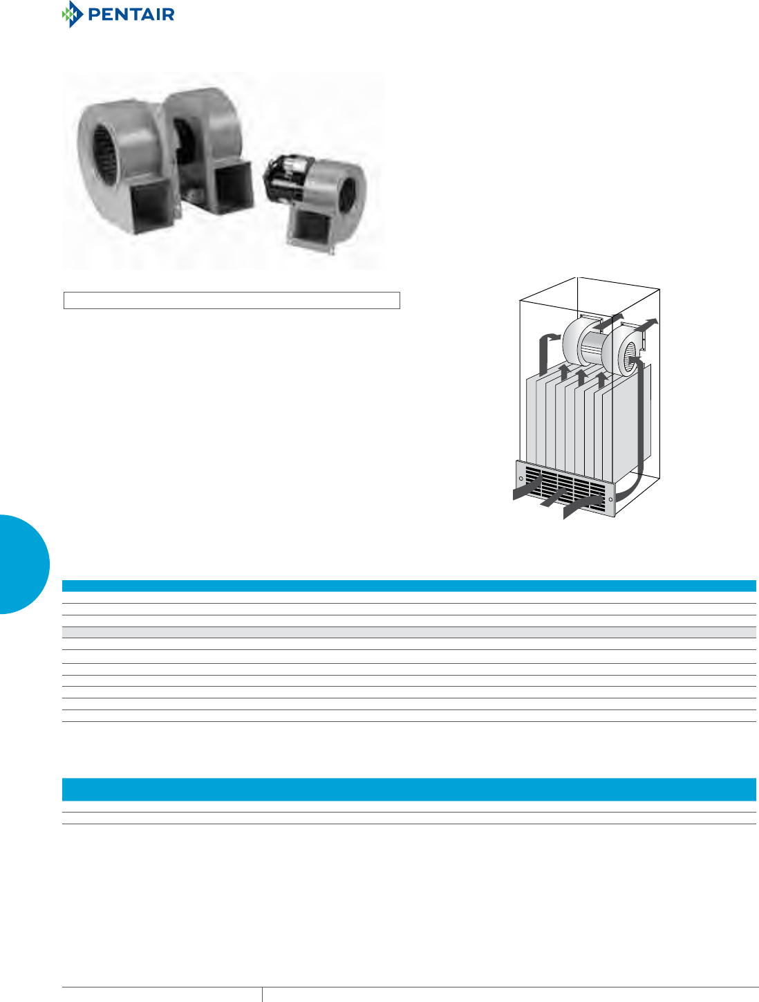
EQUIPMENT PROTECTIONSUBJECT TO CHANGE WITHOUT NOTICECOOLING270
4
FRESH AIR ENCLOSURE COOLING BLOWERS
BLOWERS
CENTRIFUGAL BLOWERS
INDUSTRY STANDARDS
UL Recognized
CSA Certified Motors
APPLICATION
Single Centrifugal Blowers are compact for the maximum in spot
cooling applications. Single centrifugal blowers can be mounted in
any position for effective air movement.
Dual Centrifugal Blowers are designed for applications where space
limitations are a problem. Mountable in any position, these blowers
provide dual blasts from separate housings mounted on a reliable
motor.
FEATURES
• 100% Functionally Tested
SPECIFICATIONS
• 115/230 VAC
• 50/60 Hz
Performance Data 1NB Models
ELECTRICAL DATA
Rated Voltage 115 230
Frequency (Hz) 50/60 50/60
Maximum Operating Temperature (°F/°C) 104/40 104/40
1NB412 Models
Catalog Numbers 1NB412115 1NB412230
Free Airflow (CFM/M3/hr.) 200/340 200/340
RPM 3100 3100
Nominal Run Current Maximum (Amps) 1.2 0.6
Nominal Start Current Maximum (Amps) 2.1 1.5
Power Consumption (Watts) 120 120
Weight (lb./kg) 6/2.7 6/2.7
Design Data 1NB Models
CATALOG
NUMBERS
A
in./mm
B
in./mm
C
in./mm
D
in./mm
F
in./mm
G
in./mm
H
in./mm
I
in./mm
J
in./mm
K
in./mm
L
in./mm
M
in./mm
HD
in./mm
1NB412115 6.81/173 6.14/156 3.84/96 3.29/84 0.31/8 0.62/16 4.66/118 4.03/102 0.31/8 0.72/18 3.22/82 7.47/190 0.28/7
1NB412230 6.81/173 6.14/156 3.84/96 3.29/84 0.31/8 0.62/16 4.66/118 4.03/102 0.31/8 0.72/18 3.22/82 7.47/190 0.28/7
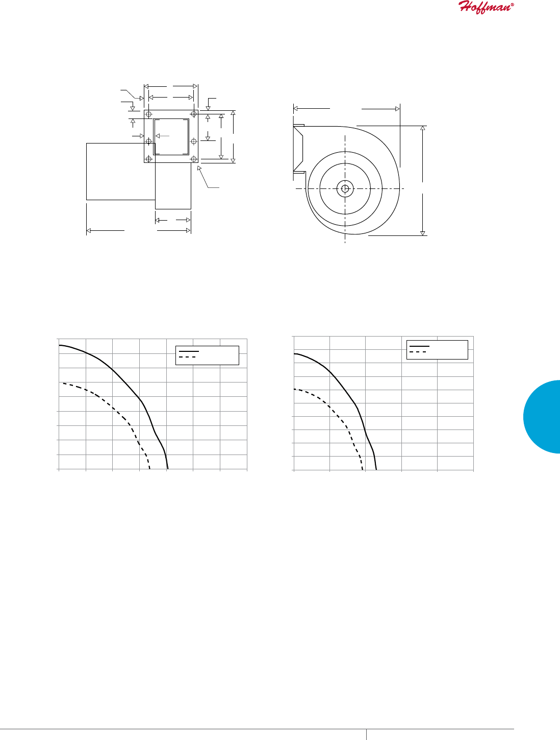
PH 763.422.2211 • FAX 763.576.3200 • HOFFMANONLINE.COMEQUIPMENT PROTECTION COOLING 271
4
FRESH AIR ENCLOSURE COOLING BLOWERS
M ± .13
[3]
H
I
G
J
EDC
L
K
F
HD A ±
B ± .06
[2]
.06
[2]
1NB Models
89081796
1%
1%K]
1%
1%K]
0
0.2
0.4
0.6
0.8
1.0
1.2
1.4
1.6
1.8
050 100 150 200 250 300 350
CFM
Inches of Water
0
50
100
150
200
250
300
350
400
450
500
0 150 300 450 600 750
Pa
M/hr.
Performance Curves 1NB Models
EQUIPMENT PROTECTIONSUBJECT TO CHANGE WITHOUT NOTICECOOLING272
4
FRESH AIR ENCLOSURE COOLING BLOWERS
Performance Data 2NB Models
ELECTRICAL DATA
Rated Voltage 115 230
Frequency (Hz) 50/60 50/60
Maximum Operating Temperature (°F/°C) 104/40 104/40
2NB300 Models
Catalog Numbers 2NB300115 2NB300230
Free Airflow (CFM/M3/hr.) 130/221 130/221
RPM 2900 2900
Nominal Run Current Maximum (Amps) 0.9 0.5
Nominal Start Current Maximum (Amps) 1.2 0.6
Power Consumption (Watts) 70 70
Weight (lb./kg) 6/2.7 6/2.7
2NB3500 Models
Catalog Numbers 2NB3500115 2NB3500230
Free Airflow (CFM/M3/hr.) 300/510 300/510
RPM 3050 3050
Nominal Run Current Maximum (Amps) 1.8 0.9
Nominal Start Current Maximum (Amps) 2.5 1.3
Power Consumption (Watts) 125 125
Weight (lb./kg) 8/3.6 8/3.6
2NB412 Models
Catalog Numbers 2NB412115 2NB412230
Free Airflow (CFM/M3/hr.) 360/612 360/612
RPM 3000 3000
Nominal Run Current Maximum (Amps) 1.6 0.8
Nominal Start Current Maximum (Amps) 4 2
Power Consumption (Watts) 225 225
Weight (lb./kg) 9/4.1 9/4.1
2NB424 Models
Catalog Numbers 2NB424115 2NB424230
Free Airflow (CFM/M3/hr.) 595/1011 595/1011
RPM 3100 3100
Nominal Run Current Maximum (Amps) 4 2
Nominal Start Current Maximum (Amps) 6.8 3.5
Power Consumption (Watts) 400 400
Weight (lb./kg) 12/5.4 12/5.4
2NB512 Models
Catalog Numbers 2NB512115 2NB512230
Free Airflow (CFM/M3/hr.) 500/850 500/850
RPM 1700 1700
Nominal Run Current Maximum (Amps) 1.5 0.8
Nominal Start Current Maximum (Amps) 3.5 1.7
Power Consumption (Watts) 130 130
Weight (lb./kg) 14/6.3 14/6.3
Design Data 2NB Models
CATALOG
NUMBERS
A
in/mm
B
in/mm
C
in/mm
D
in/mm
F
in/mm
G
in/mm
H
in/mm
I
in/mm
J
in/mm
K
in/mm
L
in/mm
M
in/mm
HD
in/mm
2NB300XXX 5.19/132 5.25/133 2.19/56 2.50/64 .28/7 .43/11 2.13/54 2.63/67 .22/6 .42/11 3.87/98 8.69/221 .25/6
2NB3500XXX 5.57/141 5.07/129 2.00/51 2.75/70 .38/10 .78/20 4.37/111 5.25/133 .38/10 .50/13 3.00/76 13.80/350 .22/6
2NB412XXX 6.73/171 6.37/162 2.59/66 2.53/64 .38/10 - / - 3.22/82 4.03/102 .27/7 .68/17 3.31/84 10.62/270 .28/7
2NB424XXX 8.06/205 7.00/178 3.13/80 3.25/83 .63/16 .13/3 3.50/89 4.13/105 .69/18 1.12/28 3.63/92 11.25/286 .25/6
2NB512XXX 8.06/205 7.75/197 3.44/87 4.06/103 .31/8 .63/16 3.66/93 4.25/108 .31/8 .63/16 3.63/92 11.56/294 .28/7
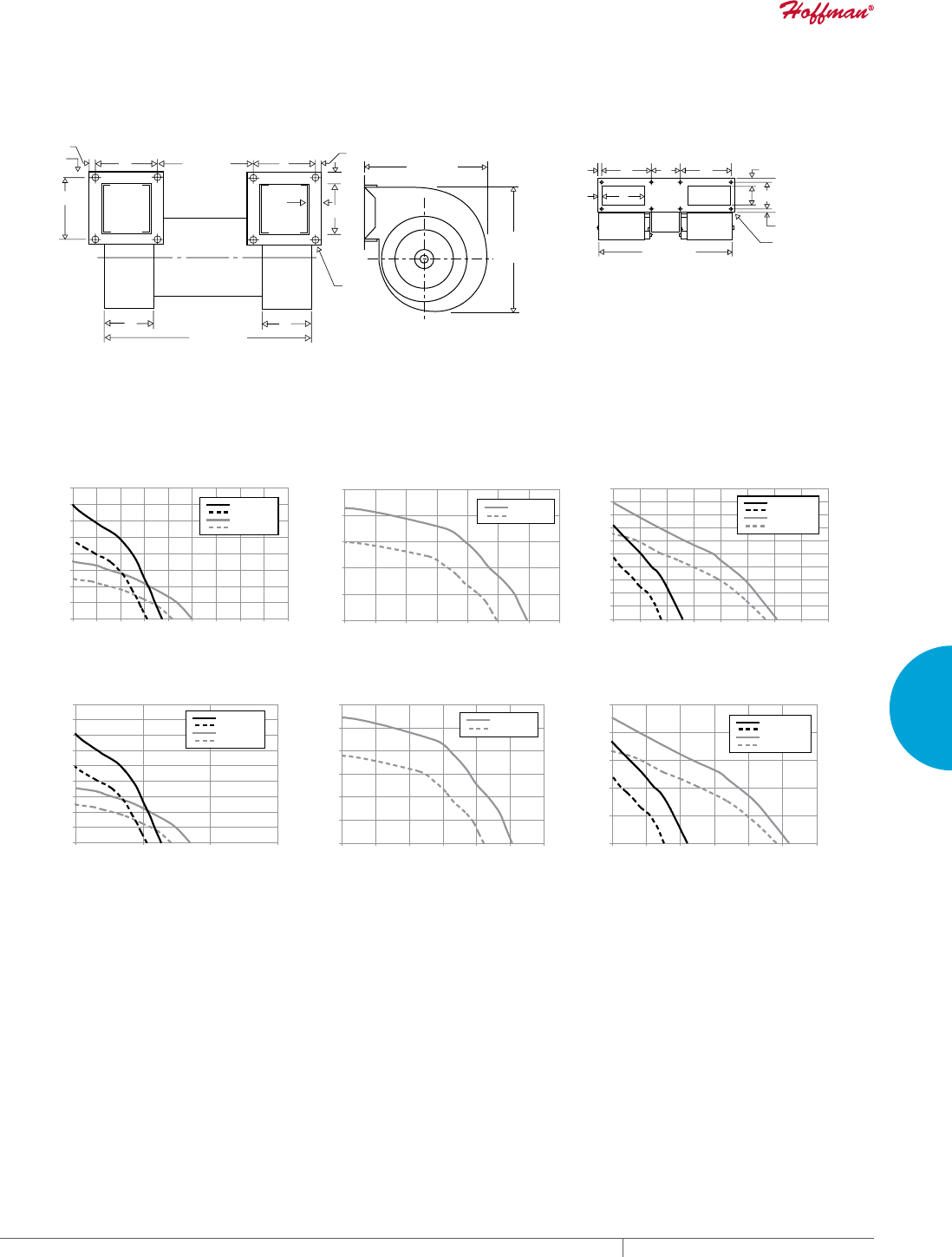
PH 763.422.2211 • FAX 763.576.3200 • HOFFMANONLINE.COMEQUIPMENT PROTECTION COOLING 273
4
FRESH AIR ENCLOSURE COOLING BLOWERS
A ± .06
[2]
B ± .06
[2]
M ± .06
[2]
H
I
H
HD
I
K
D
F
G
C
L ± .06
[2]
J
J
A ± .06
[2]
HD
I
J
KC
F
D
IL G
H
Mounting
Flange for
2NB3500
2NB Models
89081797
1%
1%K]
1%K]
1%+]
1%
1%K]
1%K]
1%+]
1%K]
1%+]
1%K]
1%+]
1%K]
1%K]
1%K]
1%+]
1%K]
1%K]
1%K]
1%+]
0
0.2
0.4
0.6
0.8
1.0
1.2
1.4
1.6
0 100 200 300 400 500 600 700 800 900
CFM
0
50
100
150
200
250
300
350
400
450
0 500 1000 1500
0
0.5
1
1.5
2
2.5
0 100 200 300 400 500 600 700
CFM
0
100
200
300
400
500
600
0 200 400 600 800 1000 1200
0
0.1
0.2
0.3
0.4
0.5
0.6
0.7
0.8
0.9
1.0
050 100 150 200 250 300 350 400
CFM
0
50
100
150
200
250
0 100 200 300 400 500 600
Inches of Water
Inches of Water
Inches of Water
Pa
Pa
M/hr. M/hr. M/hr.
Pa
Performance Curves 2NB Models
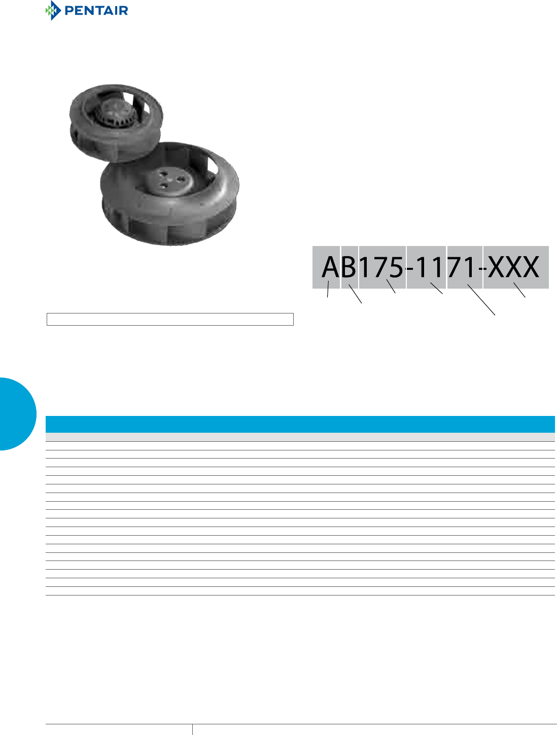
EQUIPMENT PROTECTIONSUBJECT TO CHANGE WITHOUT NOTICECOOLING274
4
FRESH AIR ENCLOSURE COOLING MOTORIZED IMPELLERS
MOTORIZED IMPELLERS
AC MOTORIZED IMPELLERS
INDUSTRY STANDARDS
UL Recognized
CE
APPLICATION
Thermal AC Motorized Impellers offer a quiet, compact cooling
option. Slim space-saving design compared to centrifugal blowers
that allow multiple mounting options.
FEATURES
• Quiet, space-saving fresh air cooling
• Backward curved blades with high efficiency air flow
• Clockwise rotation as viewed from air intake side
• Permanently lubricated double-sealed ball bearings
• Impeller blades made of plastic PA66, galvanized steel or
aluminum
SPECIFICATIONS
• Models that deliver 147– 1558 CFM (250 – 2647 M3/Hr)
• Maximum operating temperature of 140°F (60°C)
• For 115 volt AC 60 hz or 230 volt AC 50/60 hz power input voltage
with +/- 10% tolerance.
• 54 inch (137cm) lead length
• Separate capacitor included
• Optional inlet ring adds 5% air flow
NOTES
Visit www.HoffmanOnline.com to download 2D and 3D CAD
drawings into the overall design of your electronic system.
Internal
Use
Impeller
Height
71=71mm
Specific
Voltage
11=115 AC
23=230 AC
24=24 DC
48=48 DC
Impeller
Diameter
175=175mm
Blade
Design
B=Backward
Curve
Gener
al
V
oltage
A=A
C volt
D=DC
Volt
Performance Data AC Motorized Impellers
CATALOG
NUMBERS Diameter Power Draw Free Air Flow Static Pressure Max. Temp Min. Temp
Shipping
Weight
in./mm VAC Hz Watts CFM M3/Hr. RPM In HO Pa °F/°C °F/°C lb./kg
AB1331196701 5.24/133 115 60 30 173 294 3150 .84 209 140/60 -13/-25 2/.9
AB1332396701 5.24/133 230 50/60 28/30 147/173 250/294 2725/3150 .60/.84 149/209 140/60 -13/-25 2/.9
AB1751171701 6.89/175 115 60 44 294 500 2875 1.08 269 140/60 -13/-25 2/.9
AB1752371701 6.89/175 230 50/60 39/44 255/294 433/500 2515/2875 .83/1.08 207/269 140/60 -13/-25 2/.9
AB1901169901 7.48/190 115 60 109 384 652 2930 1.75 436 104/40 -13/-25 3/1.4
AB1902369901 7.48/190 230 50/60 87/109 343/384 583/652 2600/2930 1.31/1.75 326/436 104/40 -13/-25 3/1.4
AB2201171901 8.78/223 115 60 120 608 1033 2600 1.78 443 140/60 -13/-25 4/1.6
AB2202371901 8.78/223 230 50/60 95/120 564/608 958/1033 2400/2600 1.43/1.78 356/443 104/40 -13/-25 4/1.6
AB2251110901 8.86/225 115 60 195 834 1417 3100 2.67 665 140/60 -13/-25 4/1.6
AB2252310901 8.86/225 230 50/60 147/195 712/834 1210/1417 2800/3100 1.91/2.67 476/665 140/60 -13/-25 4/1.6
AB2501199901 9.88/251 115 60 246 846 1437 2760 2.33 580 140/60 -13/-25 6/2.9
AB2502399901 9.88/251 230 50/60 174/246 794/846 1349/1437 2600/2760 1.98/2.33 493/580 140/60 -13/-25 6/2.9
AB2801193901 11.06/281 115 60 313 1033 1755 2850 2.83 705 140/60 -13/-25 7/3.3
AB2802393901 11.06/281 230 50/60 220/313 939/1033 1595/1755 2600/2850 2.32/2.83 578/705 113/45 -13/-25 7/3.3
AB3201116101 12.52/318 115 60 161 1244 2114 1600 1.48 369 140/60 -13/-25 8/3.8
AB3202316101 12.52/318 230 50/60 117/161 1095/1244 1860/2114 1400/1600 1.08/1.48 269/369 140/60 -13/-25 8/3.8
AB3551117101 14.13/359 115 60 172 1558 2647 1590 1.99 496 104/40 -13/-25 10/4.9
AB3552317101 14.13/359 230 50/60 172/250 1398/1558 2375/2647 1400/1590 1.48/1.99 369/496 104/40 -13/-25 10/4.9
Free air flow and static pressure listed at 60 hz. See Performance Curves for complete details.
UL pending for AB355 models.
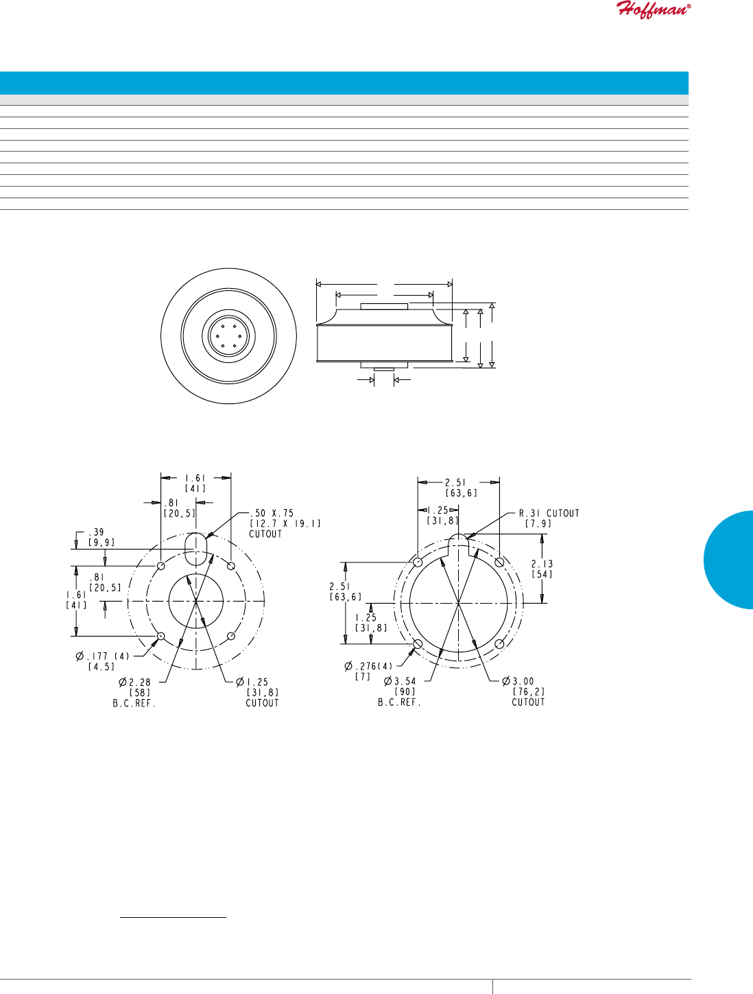
PH 763.422.2211 • FAX 763.576.3200 • HOFFMANONLINE.COMEQUIPMENT PROTECTION COOLING 275
4
FRESH AIR ENCLOSURE COOLING MOTORIZED IMPELLERS
Impeller Dimensions AC Motorized Impellers
CATALOG
NUMBERS Diameter (A) Inside Diameter (B) Height (C) Height (D) Motor Height (E)
in./mm in./mm in./mm in./mm in./mm
AB133 5.24/133 3.67/93 2.36/60 3.78/96 --
AB175 6.89/175 5.16/131 2.44/62 2.80/71 --
AB190 7.48/190 5.16/131 2.44/62 2.70/69 2.80/71
AB220 8.78/223 6.36/162 2.52/64 2.80/71 --
AB225 8.86/225 6.06/154 3.50/89 4.21/107 --
AB250 9.88/251 6.85/174 3.36/85 3.90/99 --
AB280 11.06/281 7.48/190 3.24/82 3.64/93 3.82/97
AB320 12.52/318 8.66/220 5.51/140 6.10/155 --
AB355 14.13/359 9.84/250 5.79/147 6.50/165 --
89059014
See below for
base mounting patterns
AB133-AB280 AB133-AB280
A
B
CDE
Base Mounting Patterns
For models AB133 thru AB280:
4 Holes on 2.28 (58.0 mm) bolt circle diameter.
M4 x 5mm maximum thread depth.
1.25 (31.8 mm) diameter cutout.
For models AB320 and AB355:
4 Holes on 3.54 (90.0 mm) bolt circle diameter.
M6 x 12mm maximum thread depth.
3.00 (76.2 mm) diameter cutout.
Visit www
.HoffmanOnline.com to download 2D and 3D CAD drawings into the overall design of your electr
onic system.
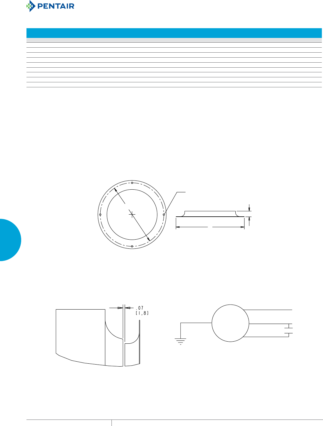
EQUIPMENT PROTECTIONSUBJECT TO CHANGE WITHOUT NOTICECOOLING276
4
FRESH AIR ENCLOSURE COOLING MOTORIZED IMPELLERS
Inlet Ring Dimensions AC Motorized Impellers
CATALOG
NUMBERS Inlet Ring Diameter (A) Height (B) Mounting (C)*
Number of
Mounting Holes
Part No. in./mm in./mm in./mm
AB133 101072120SP 5.08/129 .51/13 4.65/118 4
AB175 101072121SP 6.69/170 .55/14 6.22/158 4
AB190 101072121SP 6.69/170 .55/14 6.22/158 4
AB220 101072123SP 9.92/252 .83/21 9.29/236 3
AB225 101072124SP 8.78/223 1.10/28 8.30/211 4
AB250 101072125SP 10.04/255 1.30/33 9.45/240 4
AB280 101072126SP 11.02/280 1.38/35 10.24/260 4
AB320 101072127SP 11.81/300 1.06/27 11.02/280 4
AB355 101072129SP 13.78/350 1.22/31 12.80/325 6
Order Separately
*Bolt Circle Diameter for equally spaced holes listed:
Holes are .177 (4.5 mm) each.
All inlet rings have 4 holes, except for 101072123SP which has 3 holes and 101072129SP has 6 holes.
89059015
L2
L1
Inlet Ring
Motor Wiring
Green/Yellow
PSC Motor
Blue
Black
Brown
Impeller and Inlet Ring Interface
Wheel/Inlet Ring Recommended Gap
Mounting holes equally
spaced (see table)
Ø.177 (4.5mm)
C
A
B
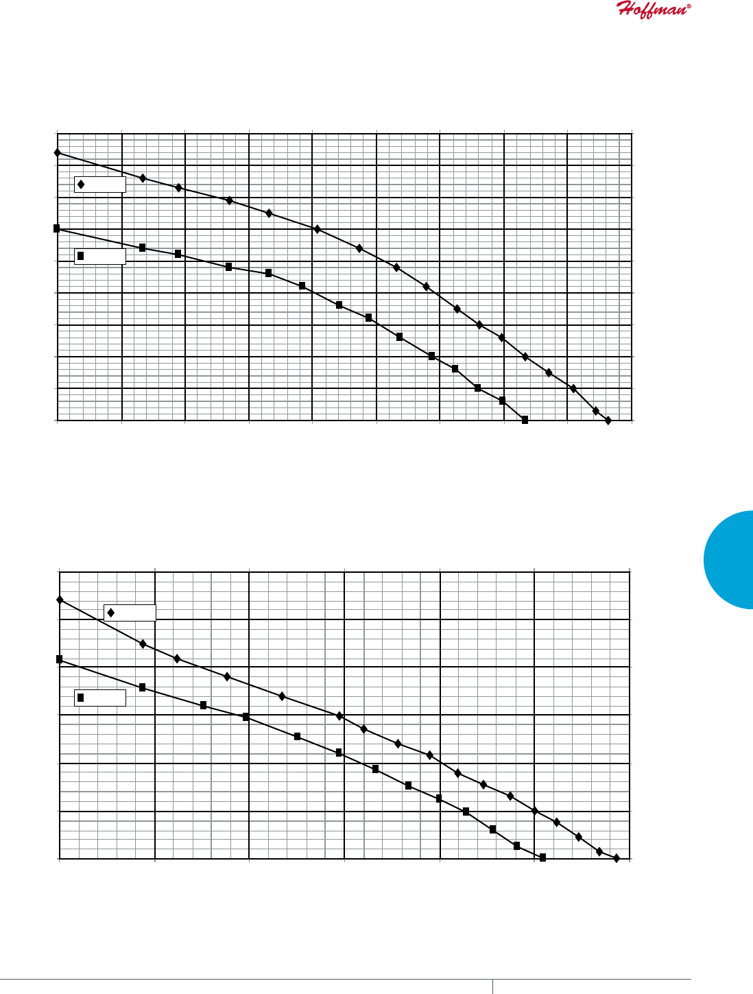
PH 763.422.2211 • FAX 763.576.3200 • HOFFMANONLINE.COMEQUIPMENT PROTECTION COOLING 277
4
FRESH AIR ENCLOSURE COOLING MOTORIZED IMPELLERS
60 Hz
50 Hz
AirFlow (M3/Hr.)
AirFlow (CFM)
Static Pressure (in H2O)
Static Pressure (Pa)
Performance Curve for AB175 (airflow with inlet ring)
050
0
.20
.40
.60
.80
.100
1.20
0
50
100
149
199
249
299
100150 200250 300
085 170 255340 42
55
10
60 Hz
50 Hz
AirFlow (M3/Hr.)
AirFlow (CFM)
Static Pressure (in H2O)
Static Pressure (Pa)
Performance Curve for AB133 (airflow with inlet ring)
020
0
.10
.20
.30
.40
.50
.60
.70
.80
.90
0
25
50
75
100
124
149
174
199
224
40 60 80 100120 140160 180
03468102 136170 204238 272306
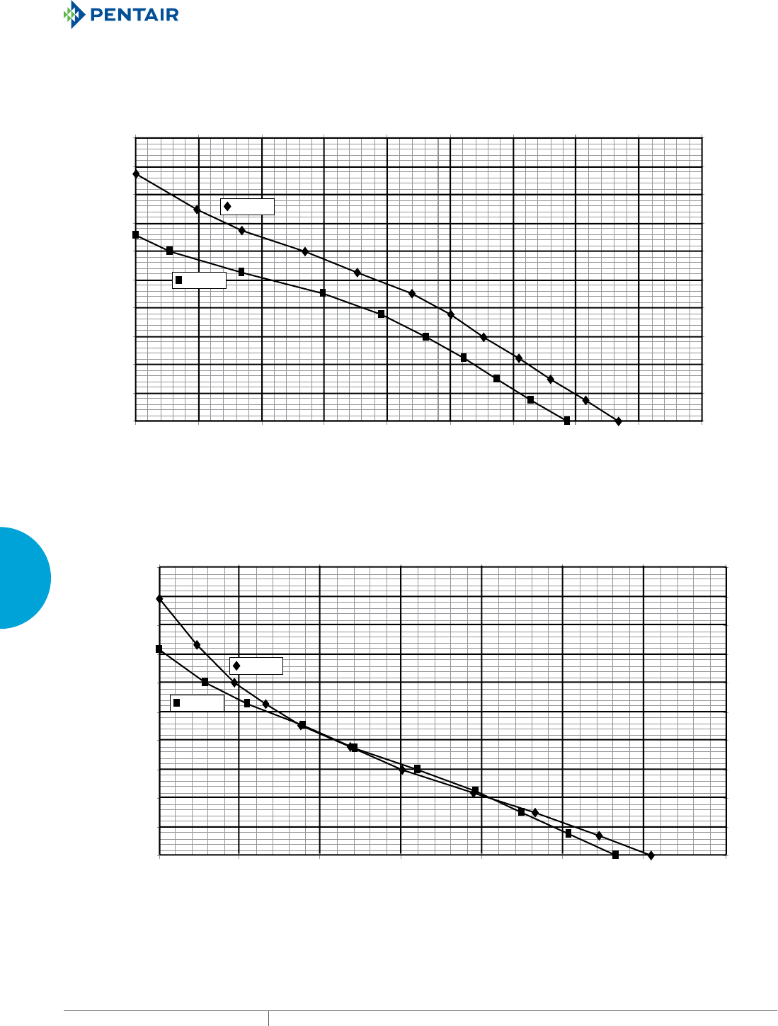
EQUIPMENT PROTECTIONSUBJECT TO CHANGE WITHOUT NOTICECOOLING278
4
FRESH AIR ENCLOSURE COOLING MOTORIZED IMPELLERS
60 Hz
50 Hz
Performance Curve for AB220 (airflow with inlet ring)
AirFlow (M3/Hr.)
AirFlow (CFM)
Static Pressure (in H2O)
Static Pressure (Pa)
0
0
.20
.40
.60
.80
1.00
1.20
1.40
1.60
1.80
2.00
0
50
100
149
249
199
299
349
398
448
498
0170 340 510679 849101
91
189
100200 300 400500 600700
60 Hz
50 Hz
Performance Curve for AB190 (airflow with inlet ring)
AirFlow (M3/Hr.)
AirFlow (CFM)
Static Pressure (in H2O)
Static Pressure (Pa)
050
0
.20
.40
.60
.80
1.00
1.20
1.40
1.60
1.80
2.00
0
50
100
149
249
199
299
349
398
448
498
100 150200 250300 350400 450
085 170 255 340425 510595 680765
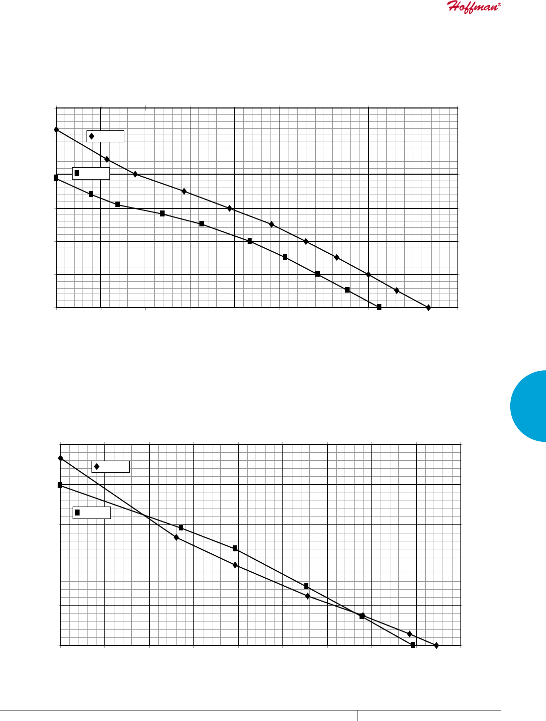
PH 763.422.2211 • FAX 763.576.3200 • HOFFMANONLINE.COMEQUIPMENT PROTECTION COOLING 279
4
FRESH AIR ENCLOSURE COOLING MOTORIZED IMPELLERS
60 Hz
50 Hz
AirFlow (M3/Hr.)
AirFlow (CFM)
Static Pressure (in H2O)
Static Pressure (Pa)
Performance Curve for AB250 (airflow with inlet ring)
0100
0
.50
1.00
1.50
2.50
2.00
125
249
374
623
498
0
200 300 400500 600700 800900
0 170 340 510 680849 1019 1189 1359 1529
60 Hz
50 Hz
Performance Curve for AB225 (airflow with inlet ring)
AirFlow (M3/Hr.)
AirFlow (CFM)
Static Pressure (in H2O)
Static Pressure (Pa)
0 100
0
.50
1.00
1.50
2.50
3.00
2.00
125
249
374
623
747
498
0
200300 400500 600700 800900
0 170 340 510680 8491019118913591529
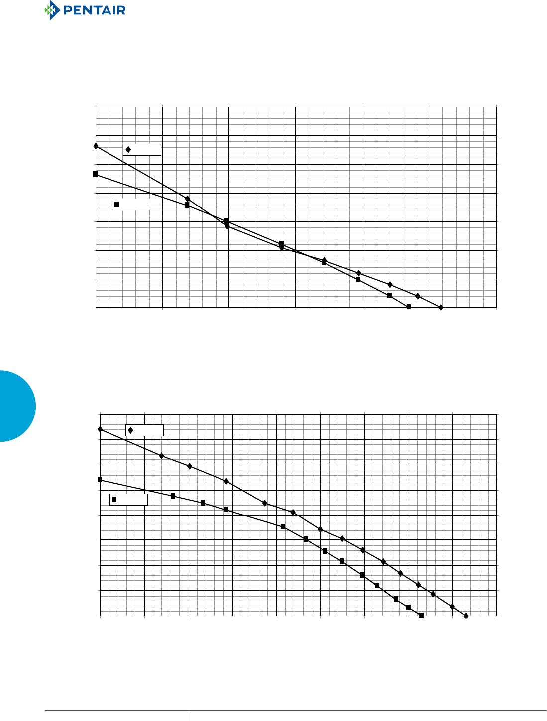
EQUIPMENT PROTECTIONSUBJECT TO CHANGE WITHOUT NOTICECOOLING280
4
FRESH AIR ENCLOSURE COOLING MOTORIZED IMPELLERS
60 Hz
50 Hz
AirFlow (M3/Hr.)
AirFlow (CFM)
Note: Without inlet ring, assume 5% reduction in air flow.
Static Pressure (in H2O)
Static Pressure (Pa)
Performance Curve for AB320 (airflow with inlet ring)
0
0
.20
.40
.60
1.00
.80
1.60
1.40
1.20
150300 450900 1050 1200 1350600750
0255 510765 1020 1274 1529 1784 2039 2294
50
100
149
249
199
299
348
398
0
60 Hz
50 Hz
AirFlow (M3/Hr.)
AirFlow (CFM)
Static Pressure (in H2O)
Static Pressure (Pa)
Performance Curve for AB280 (airflow with inlet ring)
0
0
.50
1.00
1.50
2.50
2.00
3.50
3.00
125
249
374
623
498
747
871
0
200 400600 12008001000
0 340 6801019135916992039

PH 763.422.2211 • FAX 763.576.3200 • HOFFMANONLINE.COMEQUIPMENT PROTECTION COOLING 281
4
FRESH AIR ENCLOSURE COOLING MOTORIZED IMPELLERS
60 Hz
50 Hz
AirFlow (M3/Hr.)
AirFlow (CFM)
Static Pressure (in H2O)
Static Pressure (Pa)
Performance Curve for AB355 (airflow with inlet ring)
0
0
.20
.40
.60
1.00
.80
1.60
1.80
2.00
1.40
1.20
200 400 600 1200 1400 16008001000
0 340 680 1019 1359 1699 2039 2378 2718
50
100
149
249
199
299
349
398
448
498
0
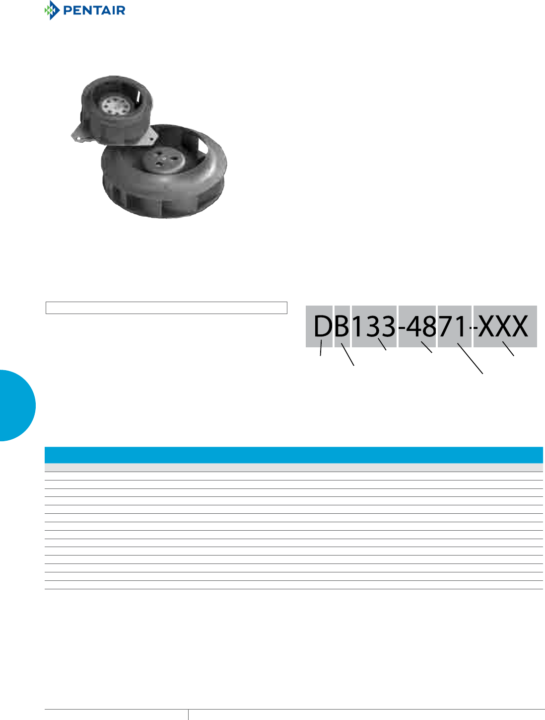
EQUIPMENT PROTECTIONSUBJECT TO CHANGE WITHOUT NOTICECOOLING282
4
FRESH AIR ENCLOSURE COOLING MOTORIZED IMPELLERS
DC MOTORIZED IMPELLERS
INDUSTRY STANDARDS
UL Recognized
CE
APPLICATION
Thermal DC Motorized Impellers offer a quiet, compact cooling
option. Slim space-saving design compared to centrifugal blowers
that allow multiple mounting options.
FEATURES
• Quiet, space-saving fresh air cooling
• Backward curved blades with high efficiency air flow
• Clockwise rotation as viewed from air intake side
• Permanently lubricated double-sealed ball bearings
• Impeller blades made of plastic PA66, galvanized steel or
aluminum
• Brushless DC motor for excellent control
• Reverse polarity protected
• Every unit functionally tested before shipping
SPECIFICATIONS
• Models that deliver 100 – 565 CFM (170 – 960 M3/Hr)
• Maximum operating temperature of 149°F (65°C)
• Input voltage +/- 25% tolerance
• 24 VDC, 48 VDC, select 12 VDC models
• Capable of working with PWM (Pulse Width Modulation) and
linear controls for variable speed operation. 5 volt (2 pulse per
rev) tach output.
OPTIONS
• Optional inlet ring
• Custom solutions available, including additional 12 volt DC
models and custom wire connections
NOTES
Visit www.HoffmanOnline.com to download 2D and 3D CAD
drawings into the overall design of your electronic system.
Internal
Use
Impeller
Height
71=71mm
Specific
Voltage
12=12 DC
24=24 DC
48=48 DC
11=115 AC
23=230 AC
Impeller
Diameter
133=133mm
Blade
Design
B=Backward
Curve
Gener
al
V
oltage
A=A
C volt
D=DC
Volt
Performance Data DC Motorized Impellers
CATALOG
NUMBERS Diameter Power Draw Free Air Flow Static Pressure Max. Temp Min. Temp
Shipping
Weight
in./mm VDC Watts CFM M3/Hr. RPM In HO Pa °F/°C °F/°C lb./kg
DB1021254401 4.02/102 12 28 100 170 6400 1.7 423 149/65 -4/-20 1/.5
DB1022454401 4.02/102 24 27 100 170 6300 1.7 423 149/65 -4/-20 1/.5
DB1024854401 4.02/102 48 29 100 170 6400 1.7 423 149/65 -4/-20 1/.5
DB1331242401 5.24/133 12 27 140 238 4600 1.4 348 149/65 -4/-20 2/.9
DB1332442401 5.24/133 24 32 140 238 4900 1.4 348 149/65 -4/-20 2/.9
DB1334842401 5.24/133 48 39 140 238 5300 1.4 348 149/65 -4/-20 2/.9
DB1332491701 5.24/133 24 68 220 373 4800 1.6 399 149/65 -4/-20 2/.9
DB1334891701 5.24/133 48 72 220 373 4800 1.6 399 149/65 -4/-20 2/.9
DB1752455701 6.89/175 24 68 305 518 4200 2.3 573 149/65 -4/-20 3/1.4
DB1754855701 6.89/175 48 72 305 518 4200 2.3 573 149/65 -4/-20 3/1.4
DB1752469701 6.89/175 24 68 360 611 3900 1.8 448 149/65 -4/-20 3/1.4
DB1754869701 6.89/175 48 72 360 611 3900 1.8 448 149/65 -4/-20 3/1.4
DB2202471701 8.66/220 24 92 565 960 2950 2.0 498 149/65 -4/-20 4/1.8
DB2204871701 8.66/220 48 92 565 960 2950 2.0 498 149/65 -4/-20 4/1.8
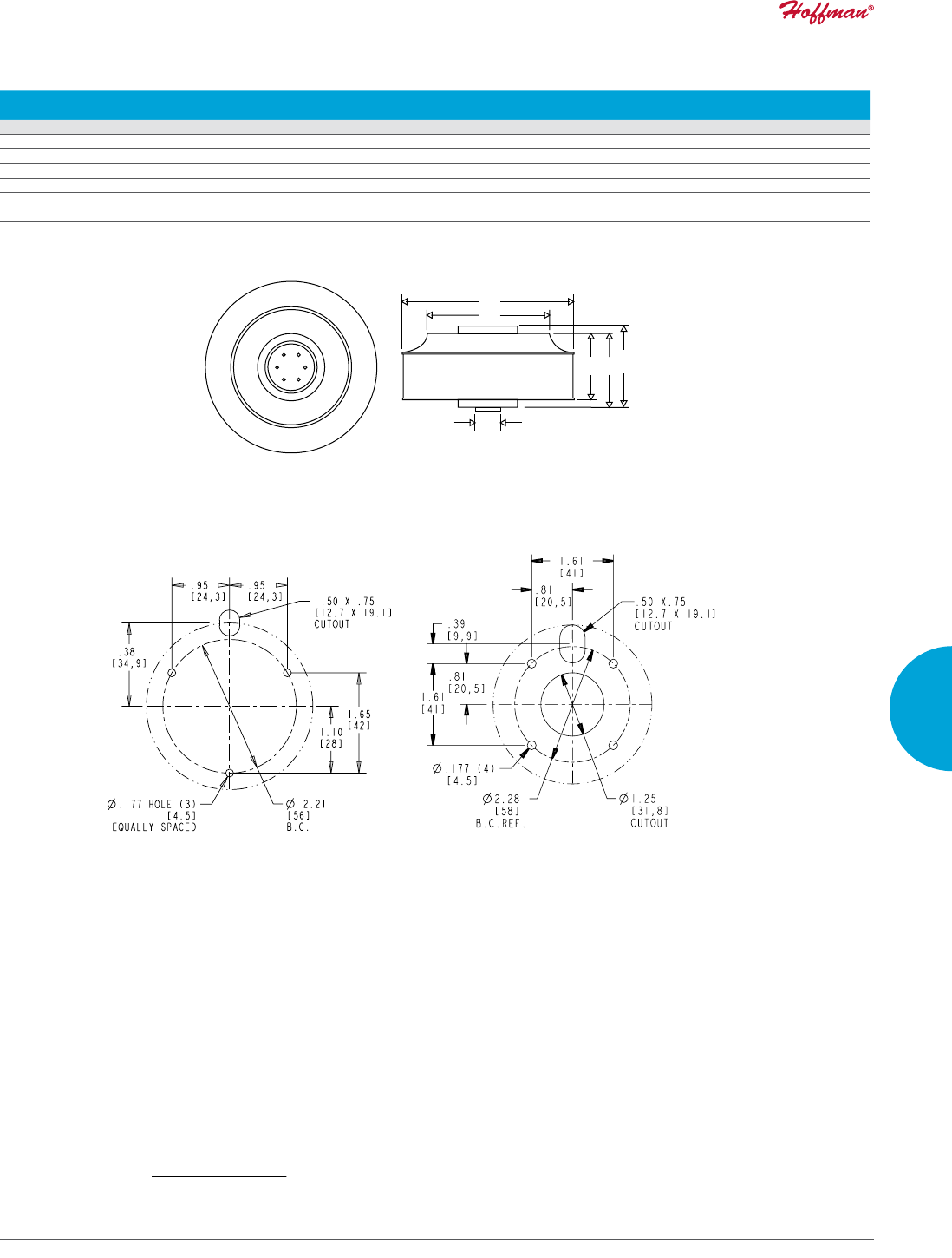
PH 763.422.2211 • FAX 763.576.3200 • HOFFMANONLINE.COMEQUIPMENT PROTECTION COOLING 283
4
FRESH AIR ENCLOSURE COOLING MOTORIZED IMPELLERS
Impeller Dimensions DC Motorized Impellers
CATALOG
NUMBERS Diameter (A) Diameter (B) Height (C) Height (D) Motor Height (E)
in. mm in. mm in. mm in. mm
DB102XX54 4.00 102 2.80 71 1.78 45 2.13 54 -- --
DB133XX42 5.25 133 3.70 94 1.35 34 1.65 42 -- --
DB133XX91 5.25 133 3.70 94 2.35 60 3.58 91 -- --
DB175XX55 6.89 175 5.16 131 1.87 48 2.15 55 2.41 61
DB175XX69 6.89 175 5.16 131 2.46 63 2.70 69 -- --
DB220XX71 8.66 220 6.28 160 2.47 63 2.80 71 -- --
89059016
See below for
base mounting patterns
DB102-DB133-XX42 DB133-XX91-DB220
A
B
CDE
Base Mounting Patterns
For models DB102-XX54 and DB133-XX42:
3 Holes on 2.21 (56 mm) bolt circle diameter.
8-32 x .19 maximum thread depth
For all other models:
4 Holes on 2.28 (58.0 mm) bolt circle diameter.
M4 x 5mm maximum thread depth.
Visit www
.HoffmanOnline.com to download 2D and 3D CAD drawings into the overall design of your electr
onic system.
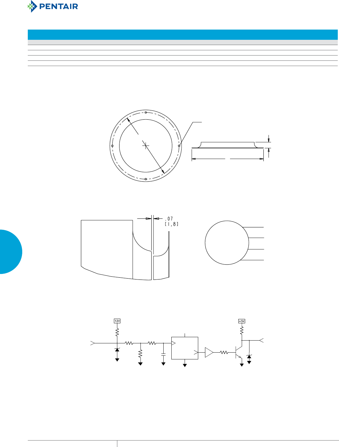
EQUIPMENT PROTECTIONSUBJECT TO CHANGE WITHOUT NOTICECOOLING284
4
FRESH AIR ENCLOSURE COOLING MOTORIZED IMPELLERS
Inlet Ring Dimensions DC Motorized Impellers
CATALOG
NUMBERS Inlet Ring Diameter (A) Height (B) Mounting (C)*
Number of
Mounting Holes
Part No. in. mm in. mm in. mm
DB102 89070536 4.00 102 .25 6.4 3.70 94 3
DB133 101072120SP 5.08 129 .51 13 4.65 118 4
DB175 101072121SP 6.69 170 .55 14 6.22 158 4
DB220 101072123SP 9.92 252 .83 21 9.29 236 3
*Bolt Circle Diameter for equally spaced holes listed:
Holes are .177 (4.5 mm) each.
All inlet rings have 4 holes, except for 10-1072-123 which has 3 holes.
89059017
Inlet Ring
Motor Wiring
Red (VDC
MTR
Black (Return)
Blue (Tach Output)
Yellow (Command Input)
Impeller and Inlet Ring Interface
Wheel/Inlet Ring Recommended Gap
Mounting holes equally
spaced (see table)
Ø.177 (4.5mm)
A
B
C
89059018
PULL-UP
LOGIC
SCALE
VCC
5.62K
24V 20K
7.87K 24V
390 OHMS
LOW-PASS
FILTER
TACH OUT
(BLUE)
COMMAND
INPUT
(YELLOW)
ANALOG
INPUT
DIGITAL
OUTPUT
Impeller Speed Control Interface
DC Impellers can be speed controlled via the yellow input lead in either of two ways:
1. 250 Hz to 4kHz 10 VDC PWM signal.
2. 0 to 10 VDC analog signal (linear control).
Command input (1 - 10 VDC) corresponds linearly from zero to max bus voltage applied
to the motor. Command input must be above 1 VDC before any measurable voltage is
applied to the motor. The applied voltage is roughly proportional to the motor speed.
• With the yellow lead left open, the impeller will run at full speed.
• With the yellow lead connected to the black lead, the impeller will stop.
• The blue lead produces a 5 VDC Tach output, 2 pulses per revolution.
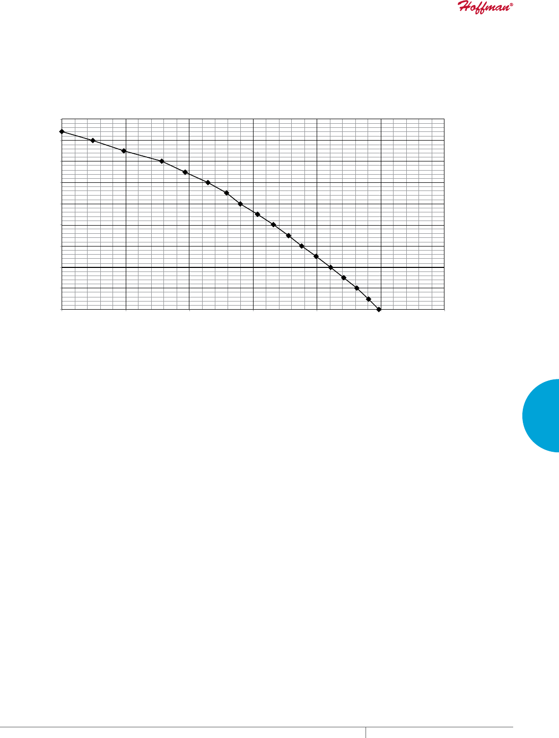
PH 763.422.2211 • FAX 763.576.3200 • HOFFMANONLINE.COMEQUIPMENT PROTECTION COOLING 285
4
FRESH AIR ENCLOSURE COOLING MOTORIZED IMPELLERS
AirFlow (M
3
/Hr.)
Static Pressure (Pa)
Performance Curve for DB102-XX54 (airflow with inlet ring)
0
50
100
149
199
249
299
349
399
448
03468 102 136 170 204
0
.20
.40
.60
.80
1.00
1.20
1.40
1.60
1.80
020406080100 120
Static Pressure (in H2O)
AirFlow (CFM)
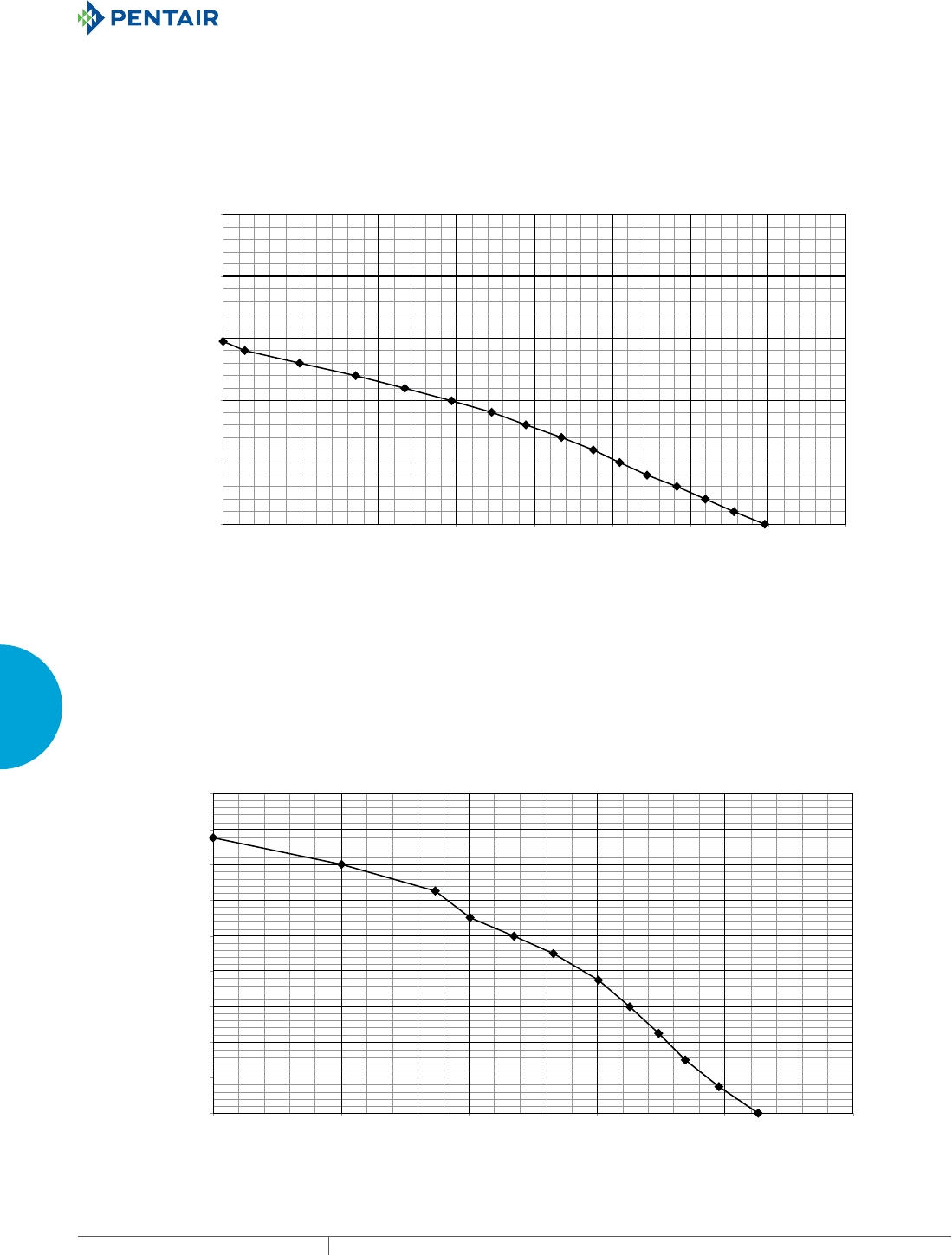
EQUIPMENT PROTECTIONSUBJECT TO CHANGE WITHOUT NOTICECOOLING286
4
FRESH AIR ENCLOSURE COOLING MOTORIZED IMPELLERS
Performance Curve for DB133-XX91 (airflow with inlet ring)
AirFlow (M
3
/Hr.)
Static Pressure (Pa)
0
50
100
149
199
249
299
349
399
448
085 170 255 340 425
AirFlow (CFM)
Static Pressure (in H2O)
0
.20
.40
.60
.80
1. 00
1. 20
1. 40
1. 60
1. 80
050100 150200 250
AirFlow (M
3
/Hr.)
AirFlow (CFM)
Static Pressure (in H2O)
Static Pressure (Pa)
Performance Curve for DB133-XX42 (airflow with inlet ring)
0
124
249
373
498
622
03468 102 136 170 204 238 272
0
.50
1. 00
1. 50
2.00
2.50
020406080100 12 0140 16 0
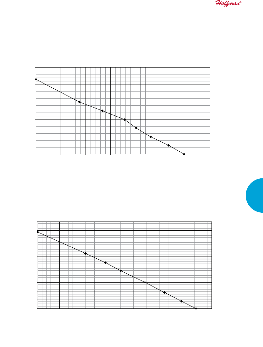
PH 763.422.2211 • FAX 763.576.3200 • HOFFMANONLINE.COMEQUIPMENT PROTECTION COOLING 287
4
FRESH AIR ENCLOSURE COOLING MOTORIZED IMPELLERS
0
.20
.40
.60
.80
1. 00
1. 20
1. 40
1. 60
1. 80
2.00
050100 150200 250300 350400
AirFlow (M
3
/Hr.)
AirFlow (CFM)
Static Pressure (in H2O)
Static Pressure (Pa)
0
50
100
149
199
249
299
349
399
448
498
085 170 255 340 425 510 595 680
Performance Curve for DB175-XX69 (airflow with inlet ring)
Performance Curve for DB175-XX55 (airflow with inlet ring)
AirFlow (M
3
/Hr.)
Static Pressure (Pa)
Static Pressure (in H2O)
0
125
249
374
498
623
085 170 255 340 425 510 595
AirFlow (CFM)
0
.50
1. 00
1. 50
2.00
2.50
050100 15 0200 250300 350
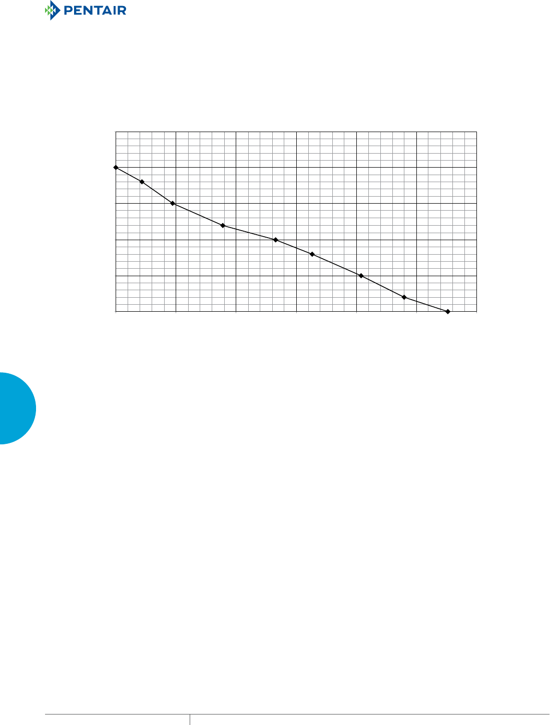
EQUIPMENT PROTECTIONSUBJECT TO CHANGE WITHOUT NOTICECOOLING288
4
FRESH AIR ENCLOSURE COOLING MOTORIZED IMPELLERS
0
.50
1. 00
1. 50
2.00
2.50
0100 200 300 400500 600
AirFlow (M
3
/Hr.)
AirFlow (CFM)
Static Pressure (in H2O)
Static Pressure (Pa)
0
125
249
374
498
623
0 170 340 510 680 850 1019
Performance Curve for DB220-XX71 (airflow with inlet ring)

PH 763.422.2211 • FAX 763.576.3200 • HOFFMANONLINE.COMEQUIPMENT PROTECTION COOLING 289
4
FRESH AIR ENCLOSURE COOLING MOTORIZED IMPELLERS
Notes
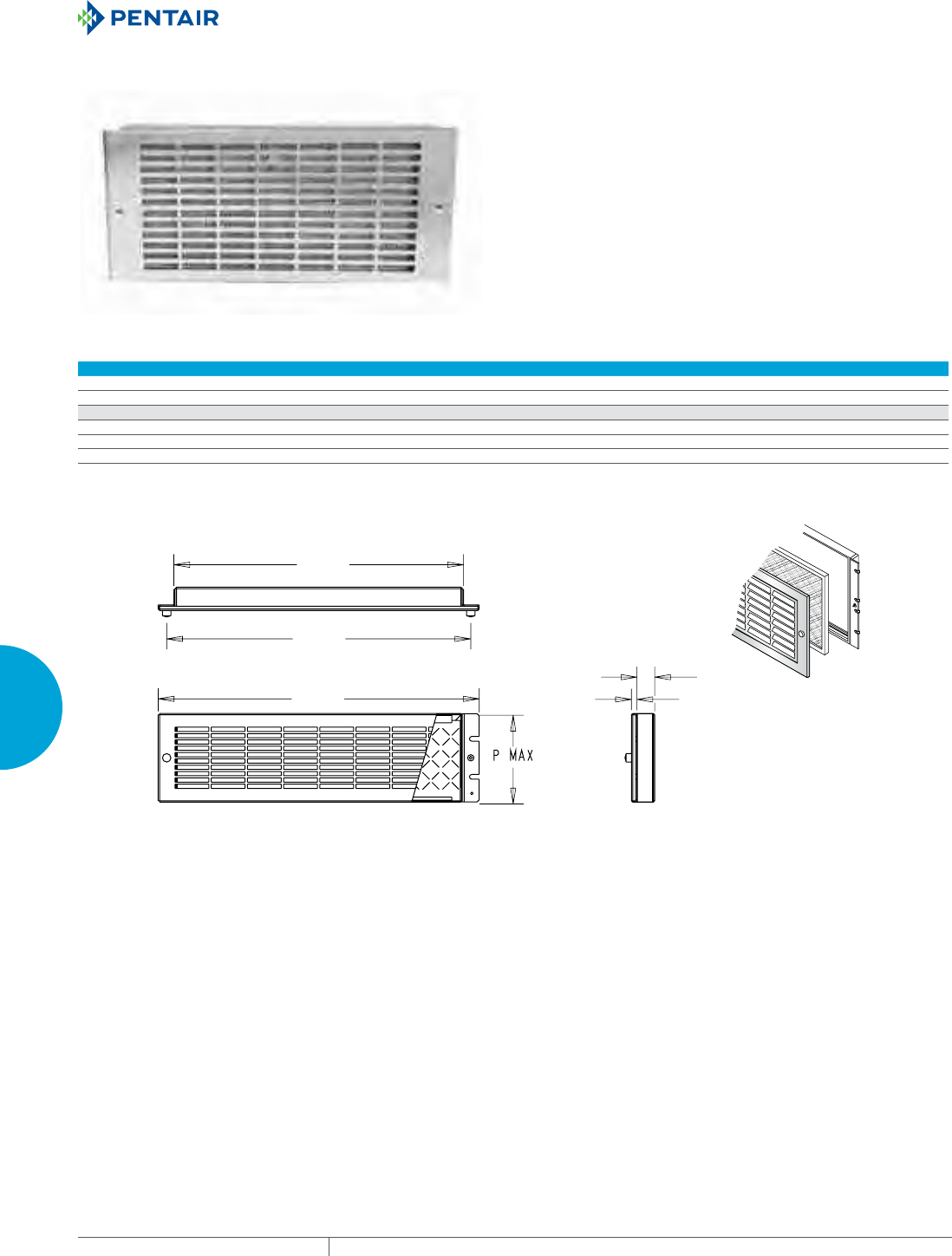
EQUIPMENT PROTECTIONSUBJECT TO CHANGE WITHOUT NOTICECOOLING290
4
FRESH AIR ENCLOSURE COOLING ACCESSORIES
ACCESSORIES
FILTER GRILLE PANEL
APPLICATION
Filter Grille Panels add valuable ventilation to a rack for either inlet
or exhaust air. Used alone, filter grille panels allow adequate air
flow on natural convection applications or in conjunction with an air
moving device to provide filtered air intake.
FEATURES
• Permanent, Washable Aluminum Filter
• 19-inch Rack Mountable
• Brushed Aluminum or Stainless Steel Grilles
Performance Data Filter Grille Panel
CATALOG NUMBERS
Stainless Steel 35G19 525G19 7G19 875G19 105G19
Aluminum 35H19 525H19 7H19 875H19 105H19
UNIT CONSTRUCTION
Height PMax (in./mm) 3.5/89 5.25/133 7.00/178 8.75/222 10.50/267
Width (in./mm) 19/483 19/483 19/483 19/483 19/483
Weight (lb./kg) 2/1.0 3/1.4 5/2.2 5/2.2 5/2.2
17.15
[436]
18.00
[457]
19.00
[483] .32
[8]
1.05
[27]
89081845
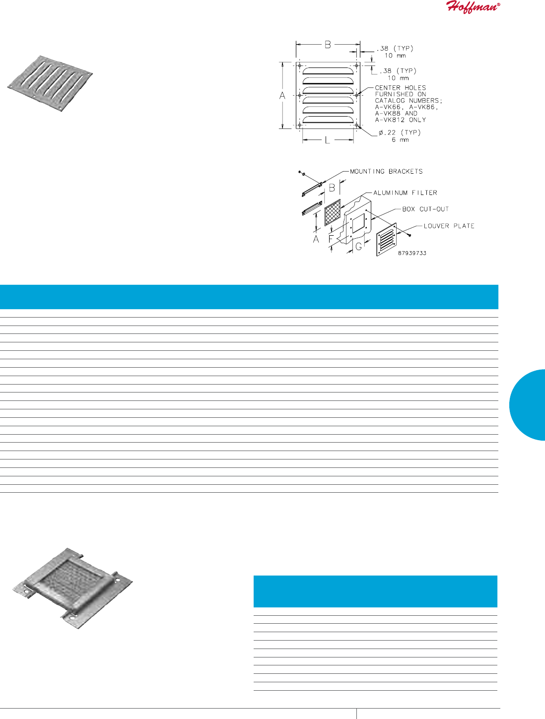
PH 763.422.2211 • FAX 763.576.3200 • HOFFMANONLINE.COMEQUIPMENT PROTECTION COOLING 291
4
FRESH AIR ENCLOSURE COOLING ACCESSORIES
LOUVER PLATE KITS
Designed to provide ventilation in enclosures where excessive
internal heat or excessive moisture is a problem. Although louvers
cannot keep all moisture out of an enclosure, gasketing or sealing
the perimeter of the louver plate reduces problems associated with
moisture intrusion. These kits may be easily installed in the field
by making a cutout of the proper size and attaching the louver plate
in place. Louver plates are made from 14 gauge steel with an ANSI
61 gray polyester powder finish over pretreated surfaces or 316
stainless steel. Hardware is furnished for mounting. Custom sizes,
materials, finishes, etc., can be provided on special order.
Design Data Louver Plate Kits
CATALOG NUMBERS
Dimensions
A x B
in./mm
Number
of Louvers
Thickness
in./mm
Length L
in./mm
Opening Area
in.2/cm2
Cutout
Size, F
in./mm
Cutout
Size, G
in./mm
AVK23 3.25 x 3.25/83 x 83 3 0.19/5 2.00/51 .86/5.54 2.00/51 1.75/44
AVK23SS6 3.25 x 3.25/83 x 83 3 0.19/5 2.00/51 .86/5.54 2.00/51 1.75/44
AVK33 3.88 x 4.50/98 x 114 3 0.25/6 3.00/76 1.32/8.52 2.62/67 3.00/76
AVK33SS6 3.88 x 4.50/98 x 114 3 0.25/6 3.00/76 1.32/8.52 2.62/67 3.00/76
AVK34 4.75 x 4.50/121 x 114 4 0.25/6 3.00/76 1.76/11.35 3.50/89 3.00/76
AVK34SS6 4.75 x 4.50/121 x 114 4 0.25/6 3.00/76 1.76/11.35 3.50/89 3.00/76
AVK43 4.50 x 5.50/114 x 140 3 0.25/6 4.00/102 1.88/12.10 3.25/83 4.00/102
AVK43SS6 4.50 x 5.50/114 x 140 3 0.25/6 4.00/102 1.88/12.10 3.25/83 4.00/102
AVK44 5.62 x 5.50/143 x 140 4 0.25/6 4.00/102 2.50/16.13 4.38/111 4.00/102
AVK44SS6 5.62 x 5.50/143 x 140 4 0.25/6 4.00/102 2.50/16.13 4.38/111 4.00/102
AVK64 5.62 x 7.50/143 x 191 4 0.31/8 6.00/152 5.21/33.61 4.38/111 6.00/152
AVK64SS6 5.62 x 7.50/143 x 191 4 0.31/8 6.00/152 5.21/33.61 4.38/111 6.00/152
AVK66 7.88 x 7.50/200 x 191 6 0.31/8 6.00/152 7.82/50.45 6.62/168 6.00/152
AVK66SS6 7.88 x 7.50/200 x 191 6 0.31/8 6.00/152 7.82/50.45 6.62/168 6.00/152
AVK84 5.81 x 9.50/148 x 241 4 0.31/8 8.00/203 8.08/52.12 4.56/116 8.00/203
AVK84SS6 5.81 x 9.50/148 x 241 4 0.31/8 8.00/203 8.08/52.12 4.56/116 8.00/203
AVK86 8.19 x 9.50/208 x 241 6 0.31/8 8.00/203 12.11/78.13 6.94/176 8.00/203
AVK86SS6 8.19 x 9.50/208 x 241 6 0.31/8 8.00/203 12.11/78.13 6.94/176 8.00/203
AVK88 10.56 x 9.50/268 x 241 8 0.31/8 8.00/203 16.15/104.19 9.31/236 8.00/203
AVK88SS6 10.56 x 9.50/268 x 241 8 0.31/8 8.00/203 16.15/104.19 9.31/236 8.00/203
AVK812 15.31 x 9.50/389 x 241 12 0.31/8 8.00/203 24.22/156.26 14.06/357 8.00/203
AVK812SS6 15.31 x 9.50/389 x 241 12 0.31/8 8.00/203 24.22/156.26 14.06/357 8.00/203
Catalog numbers ending in SS6 indicates 316L stainless steel
LOUVER PLATE KIT FILTERS
Design
Designed for use with Louver Plate Kit. Mounting holes on filter
bracket align with louver mounting holes. Hardware supplied with
louvers also secures filter brackets in place. Aluminum air filters
provide good arrestment of airborne dust and dirt.
Filter Media
Filter media is composed of layers of slit and expanded aluminum
providing hundreds of adhesive coated baffle surfaces for trapping
impurities. Impurities are held throughout the depth of the filter.
Washing with warm water will keep the filter clean. To achieve best
results, Filter Adhesive is recommended.
CATALOG NUMBERS
Dimensions H x W
(in./mm)
Use with
Steel
Louver
Use with
Stainless
Steel
Louver
AFLT33 3.22x 3.25/82 x 83 AVK33 AVK33SS6
AFLT34 4.09 x 3.25/104 x 83 AVK34 AVK34SS6
AFLT43 3.84 x 4.25/98 x 108 AVK43 AVK43SS6
AFLT44 4.97 x 4.25/126 x 108 AVK44 AVK44SS6
AFLT64 4.45 x 6.25/113 x 159 AVK64 AVK64SS6
AFLT66 6.72 x 6.25/171 x 159 AVK66 AVK66SS6
AFLT84 4.64 x 8.25/118 x 210 AVK84 AVK84SS6
AFLT86 7.02 x 8.25/178 x 210 AVK86 AVK86SS6
AFLT88 9.39 x 8.25/239 x 210 AVK88 AVK88SS6
AFLT812 14.14 x 8.25/359 x 210 AVK812 AVK812SS6
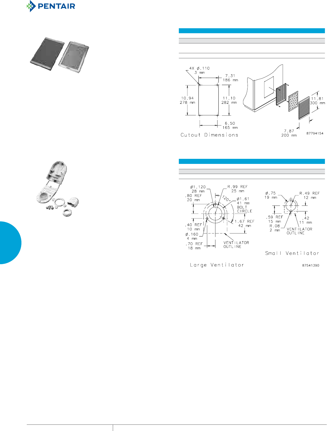
EQUIPMENT PROTECTIONSUBJECT TO CHANGE WITHOUT NOTICECOOLING292
4
FRESH AIR ENCLOSURE COOLING ACCESSORIES
VENT KIT
Includes a stylized louvered cover and filter package. Use as an air
inlet when a cooling fan is mounted in an enclosure or use two vent
kits to allow passive airflow. Mounting hardware included. Vent Kit
requires cutout shown in diagram. Available in gray (RAL 7042) or
black.
CATALOG NUMBERS
XPV32 PPV32B
UNIT CONSTRUCTON
Dimension H x W x D (in./mm) 11.81 x 7.88 x 1.03
300 x 200 x 26
11.81 x 7.88 x 1.03
300 x 200 x 26
Color Gray Black
VENTILATOR
Designed to fit most metallic and non-metallic enclosures. Proper
installation will provide rainproof ventilation but will not meet
Type 4 or 12 requirements. Kit includes mounting hardware, and
instructions.
Supplied screws are 13-mm (.515-inch) long. Some applications may
require longer screws.
CATALOG NUMBERS
ANMV6 ANMV3
DESIGN DATA
Description Large nonmetallic vent Small nonmetallic vent
PH 763.422.2211 • FAX 763.576.3200 • HOFFMANONLINE.COMEQUIPMENT PROTECTION COOLING 293
4
FRESH AIR ENCLOSURE COOLING ACCESSORIES
FILTER ADHESIVE Designed to maximize the efficiency of all expanded aluminum air
filters. Use of Filter Adhesive doubles the dust-retention capacity of
the filter. Adhesive contains a low-viscosity water-soluble oil which
absorbs dirt particles trapped on the surface of the filter. Through
the circulation of the oil, a renewed impurity-absorbing surface is
constantly established. Washing with water will remove dust, dirt
and other impurities. Once the filter is dry, re-coat with adhesive.
CATALOG NUMBERS
AFLTAD
DESIGN DATA
Description Spray Adhesive
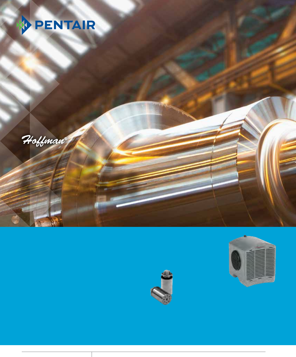
EQUIPMENT PROTECTIONSUBJECT TO CHANGE WITHOUT NOTICECOOLING294
5
763.422.2211
763.576.3200
COOLING
ACCESSORIES
Intro Page
H2OMIT™ VENT DRAINS
UL-approved vent drains allow
accumulated water to drain out the
bottom of an enclosure, while also
functioning as an air pressure equalizer
to prevent water and moisture from
being pulled into the
enclosure. Installs in
the bottom of mild steel,
aluminum, stainless
steel or non-metallic
enclosures.
H2OMIT™
THERMOELECTRIC
DEHUMIDIFIER
Thermoelectric dehumidifiers
remove moisture from the air within
an enclosure and standing liquids,
providing a cost-effective way to protect
sensitive electronics from condensation.
A built-in drain provision with plastic
hose directs collected moisture to the
vent drain (sold separately).
CHAPTER 5
ACCESSORIES
FEATURED PRODUCTS
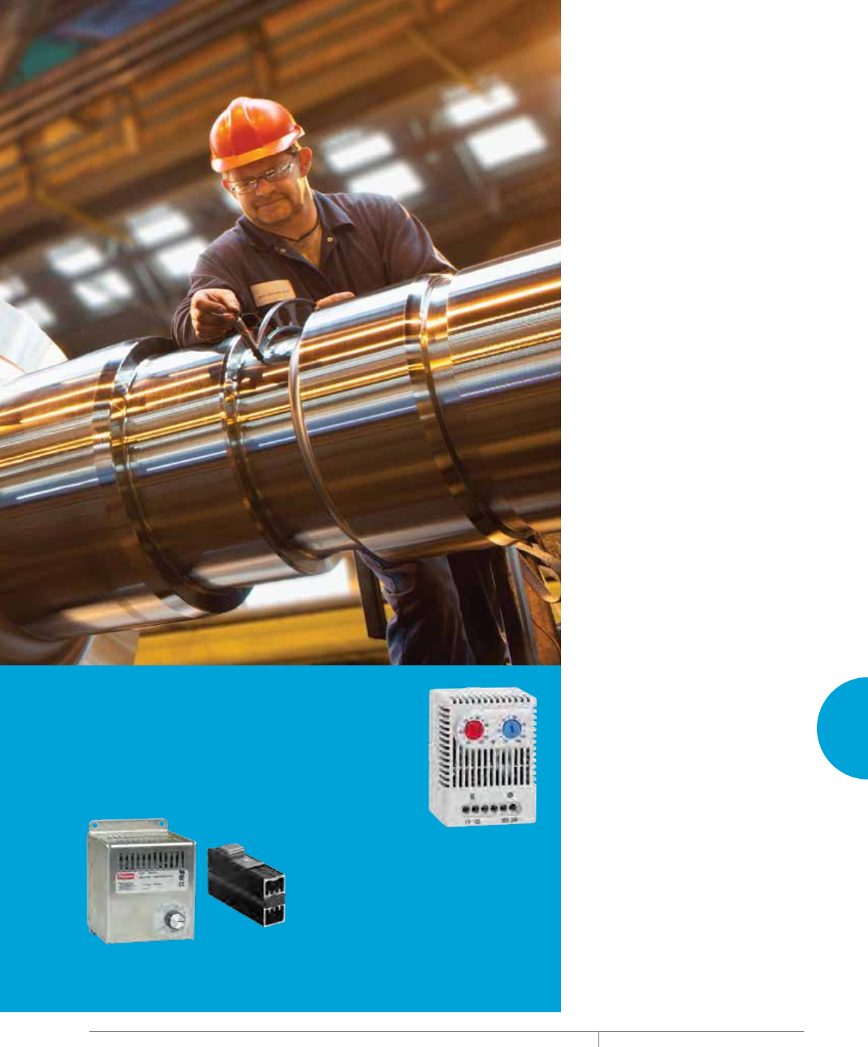
PH 763.422.2211 • FAX 763.576.3200 • HOFFMANONLINE.COMEQUIPMENT PROTECTION COOLING 295
Intro Page
ENCLOSURE HEATERS
Protect electronic, pneumatic, hydraulic
and mechanical equipment from low
temperatures, condensation and
corrosion with Enclosure Heaters. To
accommodate diverse applications,
semiconductor, electric and hazardous
locations are available.
DUAL THERMOSTAT
With two thermostats in one unit,
the Dual Thermostat independently
controls equipment heating and
cooling systems. Temperatures range
from 32 to 140 degrees Fahrenheit.
5
CHAPTER CONTENTS
CONDENSATION MANAGEMENT
H2OMIT™ Vent Drains ...........................296
H2OMIT™ Thermoelectric Dehumidifier .............298
ENCLOSURE HEATERS
Touch-Safe Heaters ............................300
Semiconductor Heaters .........................301
Electric Heaters ...............................303
Hazardous Location Heater .......................307
CONTROLLERS
Thermostat Controller ..........................308
Dual Thermostat ...............................309
Electronic Hygrotherm ..........................310
Mechanical Hygrostat ...........................311
Temperature Control Switch ......................312
Panel-Mount Fan Speed Controls ..................313
Hazardous Location Thermostat ...................314
PRESSURE COMPENSATION
Stainless Steel Pressure Compensation .............316
Pressure Compensation .........................317
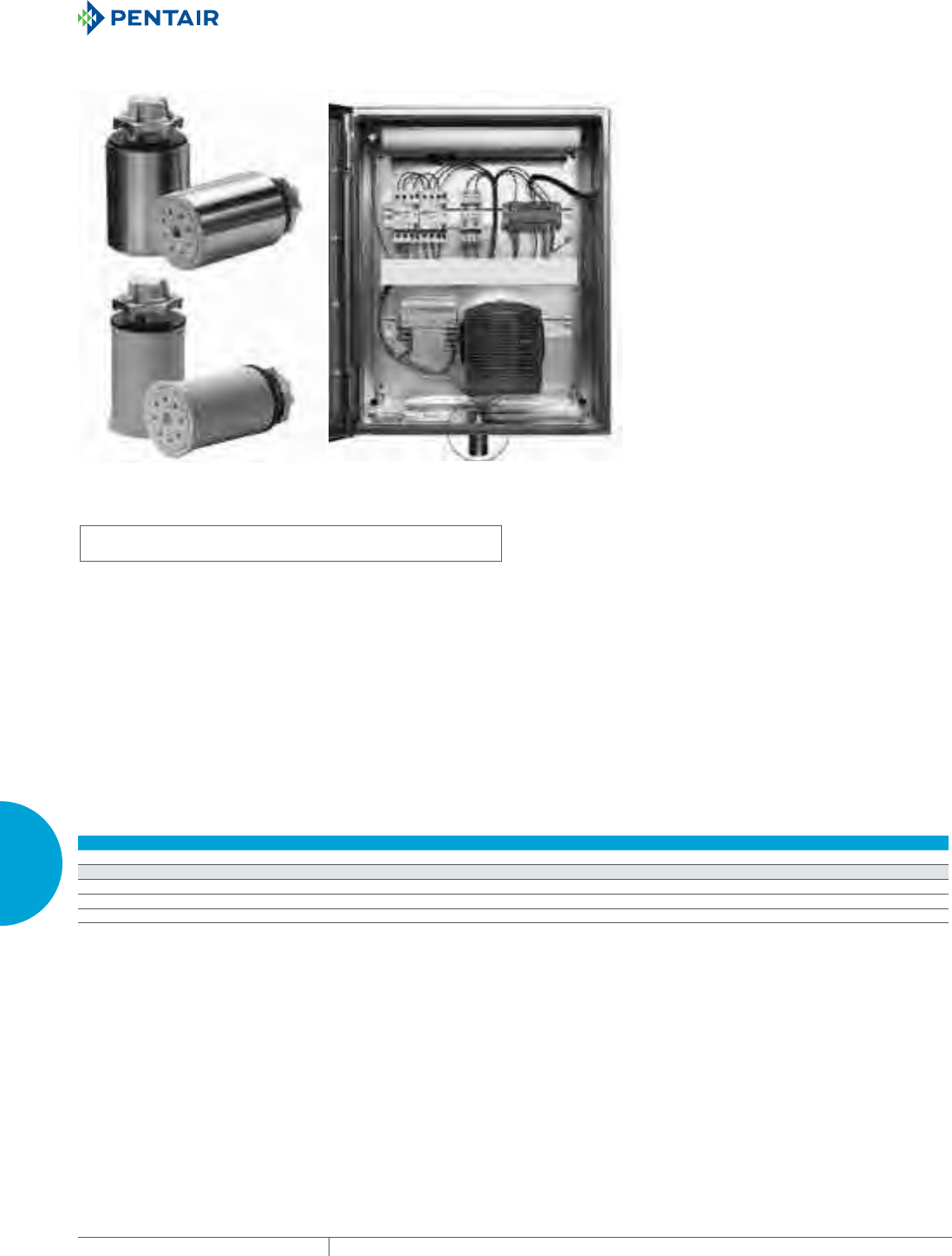
EQUIPMENT PROTECTIONSUBJECT TO CHANGE WITHOUT NOTICECOOLING296
5
ACCESSORIES CONDENSATION MANAGEMENT
CONDENSATION MANAGEMENT
H2OMIT™ VENT DRAINS
INDUSTRY STANDARDS
Maintains UL/cUL Type 4, 4X rating when properly installed on a UL/cUL
Type 4 or 4X enclosure.
UL 508A Listed; Type 4, 4X; File No. E61997
cUL Listed per CSA C22.2 No 94; Type 4, 4X; File No. E61997
NEMA/EEMAC Type 4, 4X
IEC 60529, IP66
APPLICATION
H2OMIT™ Vent Drains allow accumulated water to drain out the
bottom of an enclosure. The UL-approved vent drains also function
as an air pressure equalizer, reducing the harmful effects of
temperature-induced vacuums that could pull water and moisture
into the enclosure.
FEATURES
• Uses gravity to remove collected liquids
• One-way mechanical shut-off when pressure is equalized
prevents water and contaminants from entering the enclosure
• Helps reduce corrosion that can limit the life of internal electrical
and electronic components
• Installs in a 7/8-in. hole in the bottom of enclosure with provided
nut or in a 1/2-in. NPT/NPS threaded conduit hub
• Installs in the bottom of mild steel, aluminum, stainless steel or
non-metallic enclosures
• Maintains enclosure’s UL Type rating when properly installed
SPECIFICATIONS
Stainless Steel Vent Drain
• Corrosion-resistant polyester material with a Type 304 stainless
steel sleeve
• 2.00-in. long x 1.38-in outside diameter
Non-Metallic Drain Vent
• Corrosion-resistant polyester material
• 2.00-in. long x 1.25-in. outside diameter
Performance Data H2OMIT Vent Drains
CATALOG NUMBERS
AVDR4NM AVDR4SS4
UNIT CONSTRUCTION
Description Non-metallic Vent Drain Stainless Steel Vent Drain
D (in./mm) 1.25/32 1.38/35
Quantity 1 1
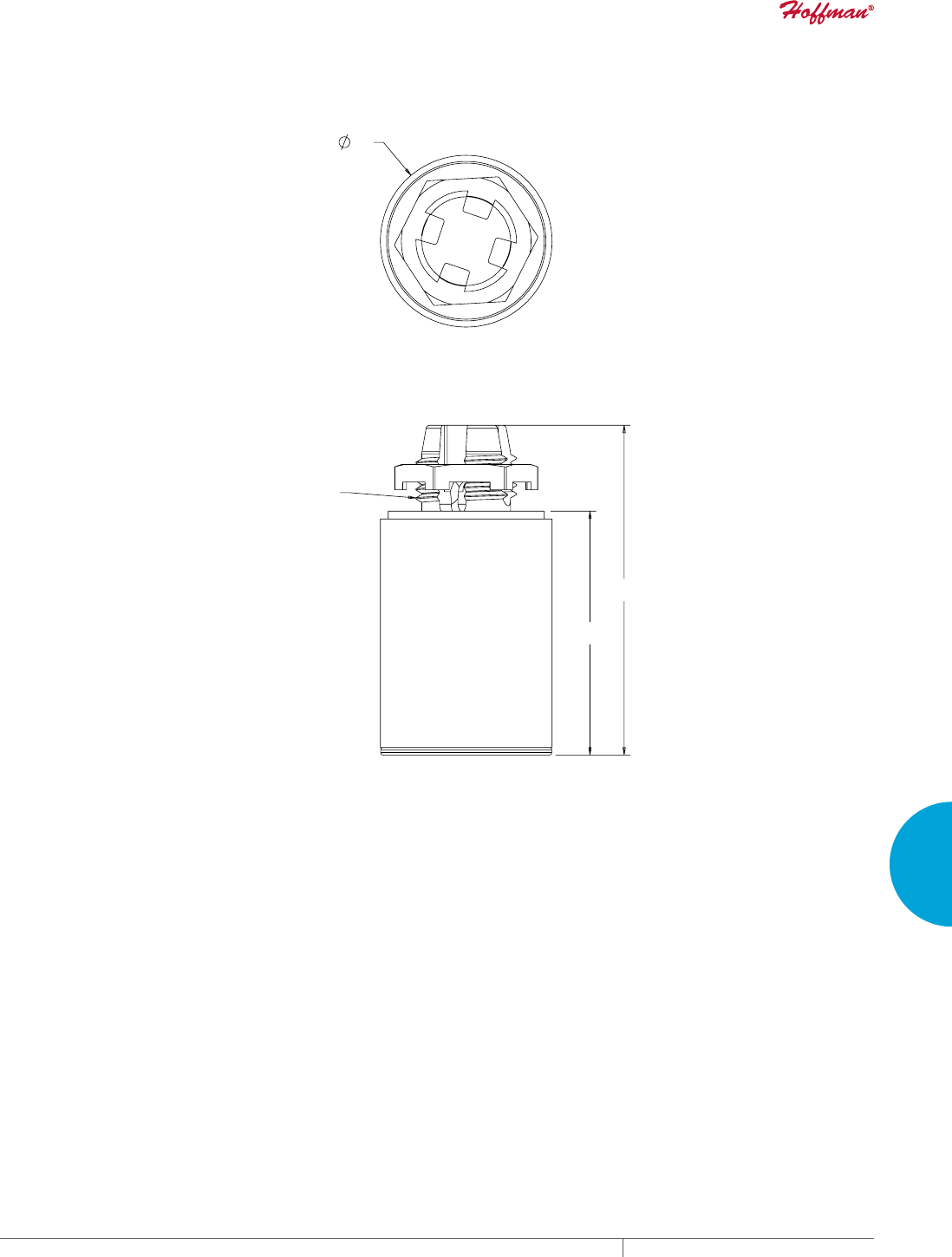
PH 763.422.2211 • FAX 763.576.3200 • HOFFMANONLINE.COMEQUIPMENT PROTECTION COOLING 297
5
ACCESSORIES CONDENSATION MANAGEMENT
PP
PP
LQ137136
'
+20,79HQW'UDLQV

EQUIPMENT PROTECTIONSUBJECT TO CHANGE WITHOUT NOTICECOOLING298
5
ACCESSORIES CONDENSATION MANAGEMENT
H2OMIT™ THERMOELECTRIC DEHUMIDIFIER
INDUSTRY STANDARDS
UL 508A Listed; File No. E61997
cUL Listed per C22.2 No. 14; File No. E61997
CE
APPLICATION
The H2OMIT™ Thermoelectric Dehumidifier removes moisture
from the air within an enclosure, providing an inexpensive yet highly
effective way to protect electronic and electrical components from
condensation.
FEATURES
• Reduces corrosion that can limit the life of internal electrical and
electronic components
• Condenses moisture from internal enclosure air and standing
liquids
• Built-in drain provision with plastic hose directs collected
moisture to the Vent Drain (sold separately)
• Rotating side air vents direct recirculating air away from critical
controls
• Mounts via DIN rail on internal panel or mounts directly onto the
inside bottom of enclosure above the Vent Drain (sold separately)
• Can be used in mild steel, aluminum, stainless steel and non-
metallic enclosures
SPECIFICATIONS
• High-impact ABS shell
• Operates on 24-Volt DC power
• 4.5 A max. (84 W)
• Runs continuously above 32 Fa (power supply not included)
• Removes 8 oz. of moisture in 24 hours
• Compact 6.00-in. x 5.50-in. x 5.75-in. design
• One Thermoelectric Dehumidifier includes:
- Four feet of plastic hose
- Two hose retainers
- One double-ended hose retainer
- Six inches of Velcro®
- Seven-inch strip of DIN rail
- Two mounting screws
Must be used with UL-certified drain to remove pooled liquid from
enclosure.
aIf continual operation is not desired, a Mechanical Hygrostat (AMHUM)
can be wired to the thermoelectric dehumidifier and then set to turn the
dehumidifier on at the desired relative humidity.
VELCRO is a trademark of Velcro Industries B.V.
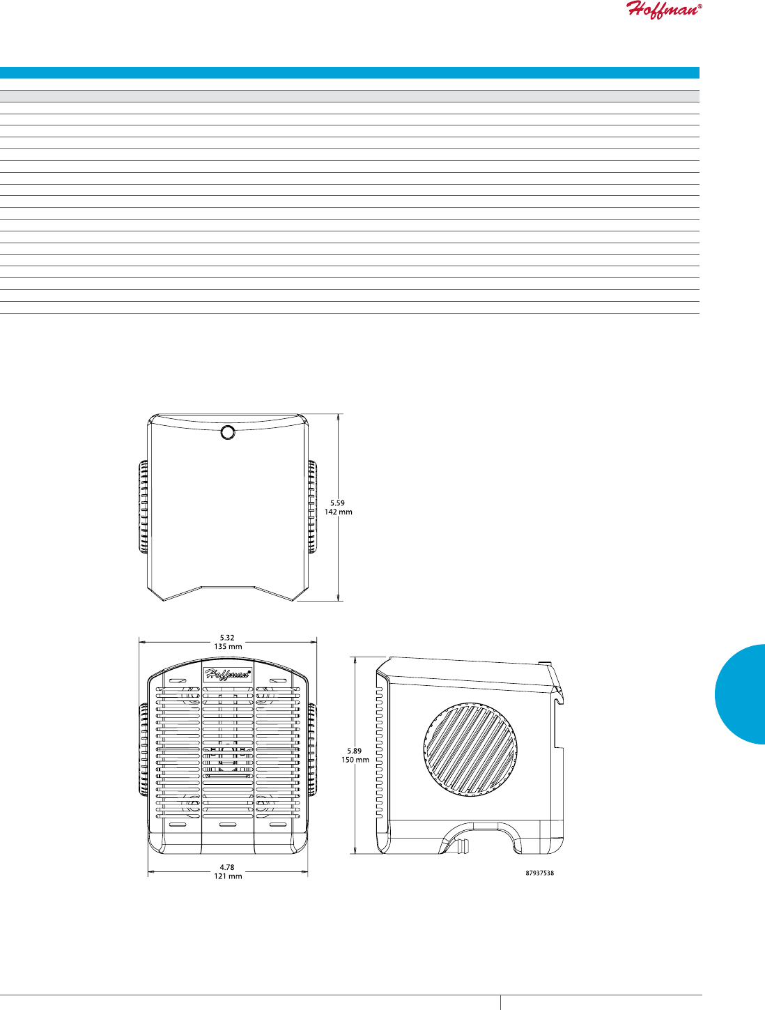
PH 763.422.2211 • FAX 763.576.3200 • HOFFMANONLINE.COMEQUIPMENT PROTECTION COOLING 299
5
ACCESSORIES CONDENSATION MANAGEMENT
Performance Data H2OMIT Thermoelectric Dehumidifier
CATALOG NUMBERS
H2OMITTER
Dew Point Temperature : Percent Relative Humidity
Temp. (° F) 100% 95% 90% 85% 80% 75% 70% 65% 60% 55% 50% 45% 40% 35% 30% 25% 20% 15% 10%
110 110 108 106 104 102 100 98 95 93 90 87 84 80 76 72 65 60 51 41
105 105 103 101 99 97 95 93 91 88 85 83 80 76 72 67 62 55 47 37
100 100 99 97 95 93 91 89 86 84 81 78 75 71 67 63 58 52 44 32
95 95 96 92 90 88 86 87 81 79 76 73 70 67 63 59 54 48 40 32
90 90 88 87 85 83 81 79 79 74 71 68 65 62 59 54 49 43 36 32
85 85 83 81 80 78 76 74 71 69 67 64 61 58 54 50 45 38 32 —
80 80 78 77 75 73 71 69 67 65 62 59 56 53 50 45 40 35 32 —
75 75 73 72 70 68 66 64 62 60 58 55 52 49 45 41 36 32 — —
70 70 68 67 65 63 61 59 58 55 53 50 47 44 40 37 32 — —
65 65 63 62 60 59 57 55 53 50 48 45 42 40 36 62 — — — —
60 60 58 57 55 53 52 50 48 45 43 41 38 35 32 — — — — —
55 55 53 52 50 49 47 45 43 40 38 36 33 32 — — — — — —
50 50 48 46 45 44 42 40 38 36 34 32 — — — — — — — —
45 45 43 42 40 39 37 35 34 32 — — — — — — — — — —
40 40 39 37 35 34 32 — — — — — — — — — — — — —
35 35 34 32 — — — — — — — — — — — — — — — —
32 32 — — — — — — — — — — — — — — — — — —
Definition: Dew Point is the temperature at which condensation forms. If the temperature of the enclosure is 85 F
and the relative humidity is 80 percent, Dew Point is reached at a temperature of 78 F or below.
This means that moisture vapor will condense on any surface that is below the Dew Point temperature of 78 F.
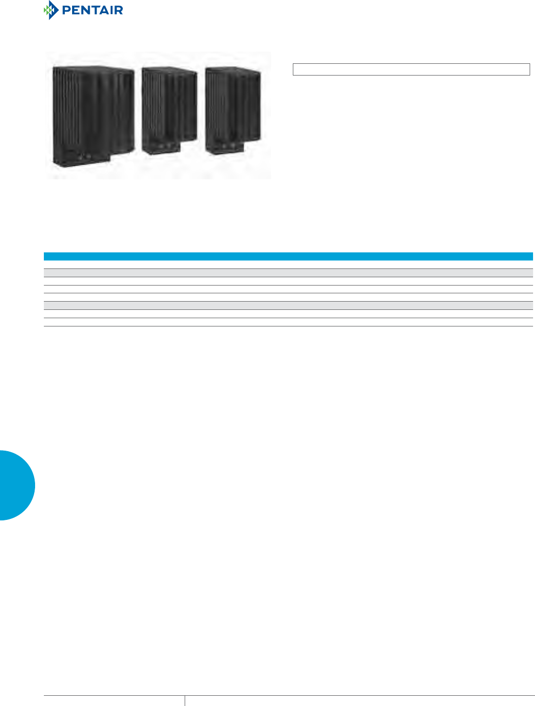
EQUIPMENT PROTECTIONSUBJECT TO CHANGE WITHOUT NOTICECOOLING300
5
ACCESSORIES ENCLOSURE HEATERS
ENCLOSURE HEATERS
TOUCHSAFE HEATERS
INDUSTRY STANDARDS
cURus Component Recognized; File No. E150057
IP 20
CE
APPLICATION
Protect electronic, mechanical equipment from low temperatures,
condensation, and corrosion with this heater, which will maintain
stable enclosure temperatures by using natural convection
resulting in current circulation of warm air.
SPECIFICATIONS
• Heating element PTC resistor - temperature limiting
• Double Insulated Protection
• Mounting clip for 35mm DIN rail, EN 60 715
• Vertical mount
FINISH
• UL 94 V-0 Black Plastic Housing
Performance Data
CATALOG NUMBERS
DAH101TS DAH201TS DAH501TS
Electrical Data
Rated Voltage (AC/DC) 110/120 110/120 110/120
Power Consumption (Watts) 10 20 50
Start Nominal Current (Amps) 2.5 4.5 8
Unit Construction
H x W x D (in./mm) 3.9 X 1.5 X 3.0/98 x 38 x 75 3.9 X 1.5 X 3.0/98 x 38 x 75 4.3 X 2.4 X 3.5/110 x 60 x 90
Weight (oz) 5.0 6.1 10.4
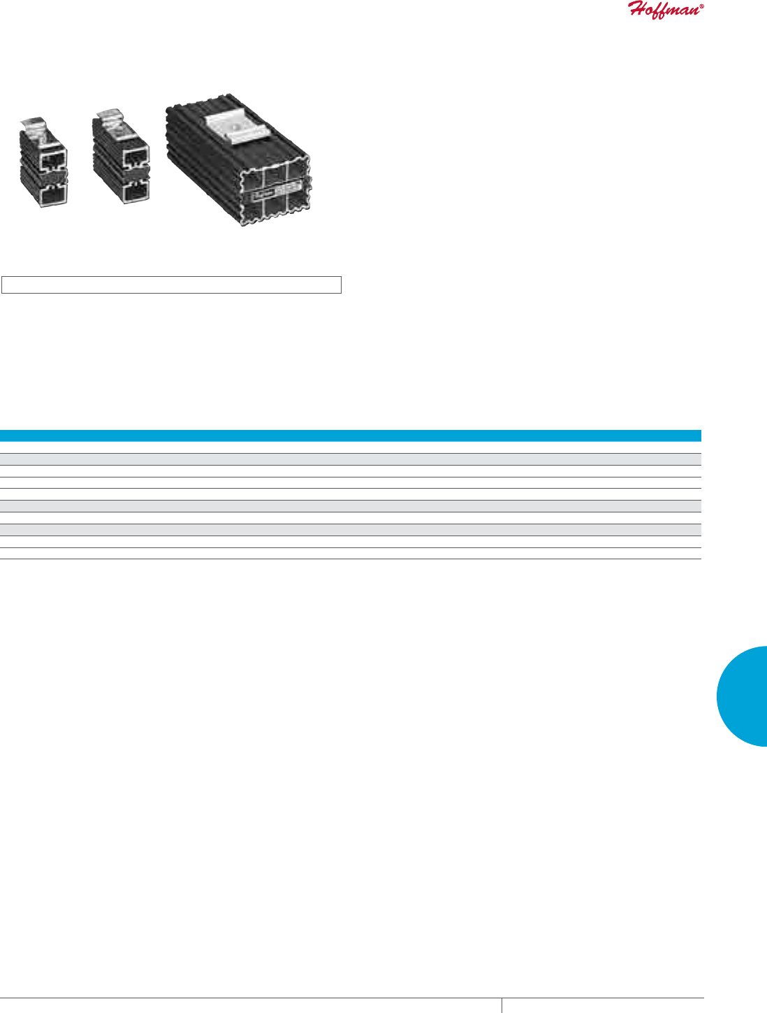
PH 763.422.2211 • FAX 763.576.3200 • HOFFMANONLINE.COMEQUIPMENT PROTECTION COOLING 301
5
ACCESSORIES ENCLOSURE HEATERS
SEMICONDUCTOR HEATERS
INDUSTRY STANDARDS
cURus Component Recognized; File No. E150057
IEC IP54
CE
APPLICATION
Protect electronic, pneumatic, hydraulic and mechanical equipment
from low temperatures, condensation and corrosion with this
heater, which maintains a stable enclosure temperature.
SPECIFICATIONS
• PTC (Positive Temperature Coefficient) heating element
• Mounting clip for 35-mm DIN rails EN 50022
FINISH
• Black anodized, extruded aluminum.
Performance Data Semiconductor Heater
CATALOG NUMBERS
DAH101 DAH301 DAH601
ELECTRICAL DATA
Rated Voltage AC/DC 110/120 AC/DC 110/120 AC/DC 110/250
Power Consumption (Watts) 10 30 60
Start Nominal Current (Amps) 0.8 1.2 2.5
HEATING PERFORMANCE
Watts 10 30 60
UNIT CONSTRUCTION
L (in./mm) 1.97/50 3.93/100 5.5/140
Weight (lb./kg) 0.45/0.20 0.66/0.30 1.10/0.50
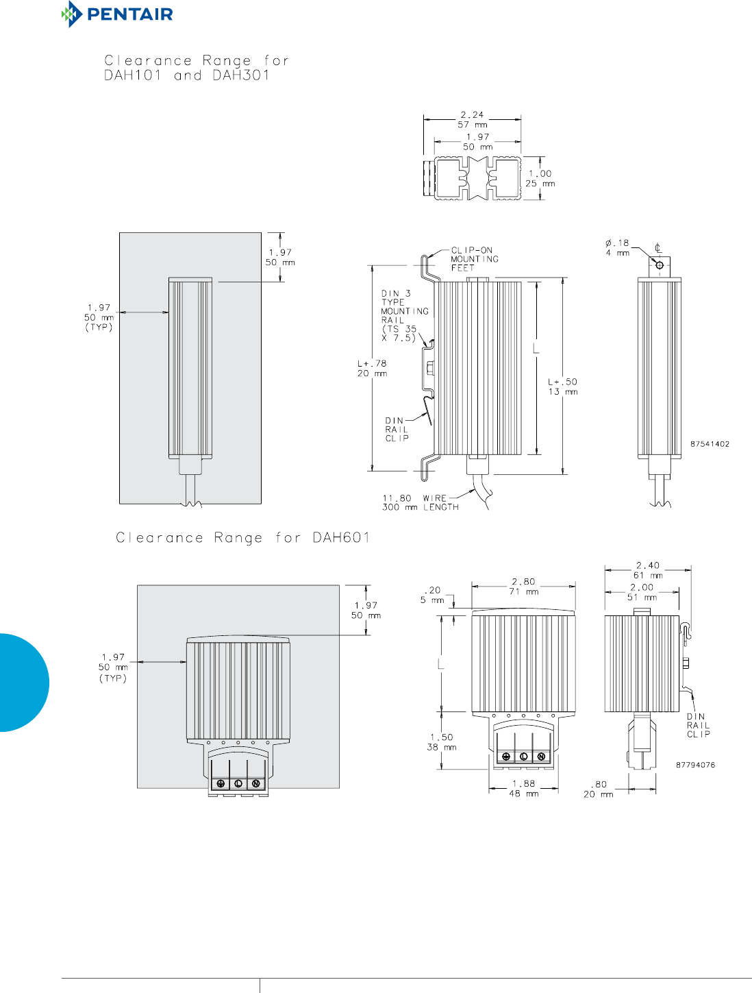
EQUIPMENT PROTECTIONSUBJECT TO CHANGE WITHOUT NOTICECOOLING302
5
ACCESSORIES ENCLOSURE HEATERS
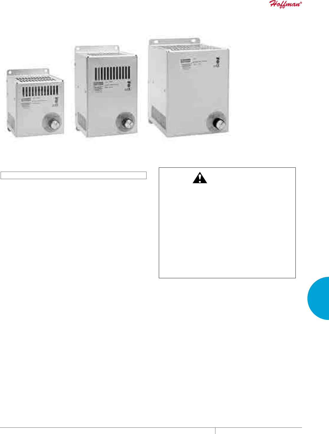
PH 763.422.2211 • FAX 763.576.3200 • HOFFMANONLINE.COMEQUIPMENT PROTECTION COOLING 303
5
ACCESSORIES ENCLOSURE HEATERS
ELECTRIC HEATERS
115/230 Volt
100/200 Watt
115/230 Volt
400/800 Watt
115/230 Volt
1300 Watt
INDUSTRY STANDARDS
UL 508A Component Recognized; File No. E61997
CSA Certified, CSA File No. LR42186
CE
APPLICATION
Protect mechanical, electrical and electronic equipment
from low temperatures, condensation and corrosion with this
thermostatically controlled, fan-driven heater that maintains a
stable enclosure temperature.
Fan draws cool air from the bottom of the enclosure and passes
this air across the thermostat and heating element before being
released into enclosure cavity. Heated air is discharged through the
top of the heater unit.
SPECIFICATIONS
• Aluminum housing
• Thermostat range adjustable from 0 F to 100 F (-18 C to 38 C)
• Four 10-32 x self-tapping screws are included with each heater
• Ball bearing fan
• Terminal strip with clamp connector that accepts both solid and
stranded wire
FINISH
• Brushed aluminum
CAUTION
These electric heaters are not designed for use in dusty,
dirty, corrosive, or hazardous locations. Portions of the
heater can get hot. Adequate protection must be taken
to protect people from potential burns, and to protect
other components from this heat. Pentair Technical
Products recommends this heater only be installed in a
totally-enclosed metal enclosure.
Heat sensitive components should not be placed near the
heater discharge area since this air can be quite warm.
The clearance range denes the space that must be kept
free of these components for proper and safe operation
of the heater.
DO NOT INSTALL HEATERS ON WOOD PANELS.
EQUIPMENT PROTECTIONSUBJECT TO CHANGE WITHOUT NOTICECOOLING304
5
ACCESSORIES ENCLOSURE HEATERS
Performance Data 100 and 200 Watt Heaters
CATALOG NUMBERS
DAH1001A DAH1002A DAH2001A DAH2002A
ELECTRICAL DATA
Rated Voltage 115 230 115 230
Frequency (Hz) 50/60 50/60 50/60 50/60
Power Consumption (Watts) 100 100 200 200
Nominal Current (Amps) 0.98 0.49 1.89 0.95
HEATING PERFORMANCE
Watts 100 100 200 200
UNIT CONSTRUCTION
Weight (lb./kg) 1.6/0.73 1.6/0.73 1.6/0.73 1.6/0.73
X (in./mm) 4.00/102 4.00/102 4.00/102 4.00/102
Performance Data 400 and 800 Watt Heaters
CATALOG NUMBERS
DAH4001B DAH4002B DAH8001B DAH8002B
ELECTRICAL DATA
Rated Voltage 115 230 115 230
Frequency (Hz) 50/60 50/60 50/60 50/60
Power Consumption (Watts) 400 400 800 800
Nominal Current (Amps) 3.72 1.86 7.37 3.69
HEATING PERFORMANCE
Watts 400 400 800 800
UNIT CONSTRUCTION
Weight (lb./kg) 2.2/1.00 2.2/1.00 2.2/1.00 2.2/1.00
X (in./mm) 6.00/152 6.00/152 8.00/203 8.00/203
Performance Data 1300 Watt Heaters
CATALOG NUMBERS
DAH13001C DAH13002C
ELECTRICAL DATA
Rated Voltage 115 230
Frequency (Hz) 50/60 50/60
Power Consumption (Watts) 1300 1300
Nominal Current (Amps) 11.5 5.7
HEATING PERFORMANCE
Watts 1300 1300
UNIT CONSTRUCTION
Weight (lb./kg) 3.4/1.54 3.4/1.54
X (in./mm) 8.00/203 8.00/203
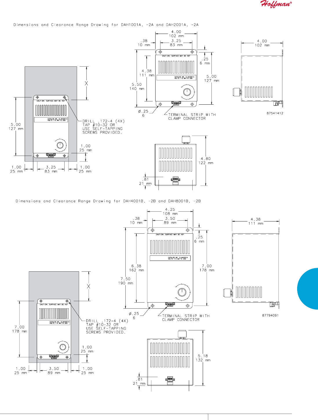
PH 763.422.2211 • FAX 763.576.3200 • HOFFMANONLINE.COMEQUIPMENT PROTECTION COOLING 305
5
ACCESSORIES ENCLOSURE HEATERS
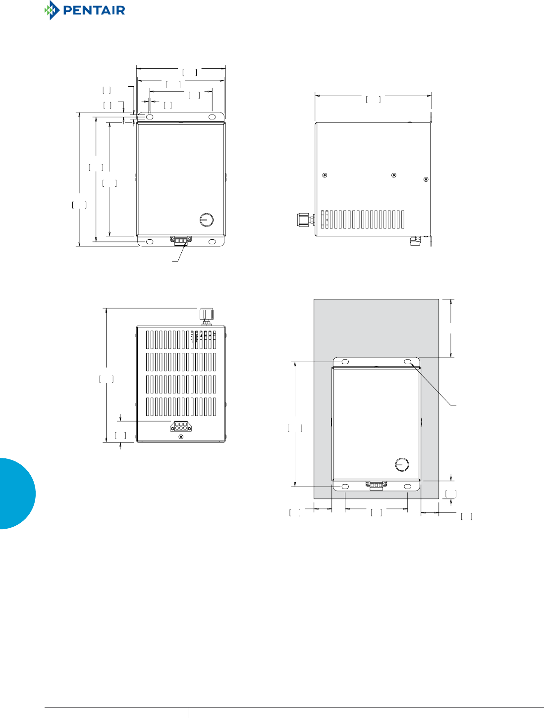
EQUIPMENT PROTECTIONSUBJECT TO CHANGE WITHOUT NOTICECOOLING306
5
ACCESSORIES ENCLOSURE HEATERS
;
;
7(50,1$/675,3:,7+
&/$03&211(&725
;
'5,//;
7$325
86(6(/)7$33,1*
6&5(:63529,'('
'LPHQVLRQVDQG&OHDUDQFH5DQJH'UDZLQJIRU'$+&DQG'$+&
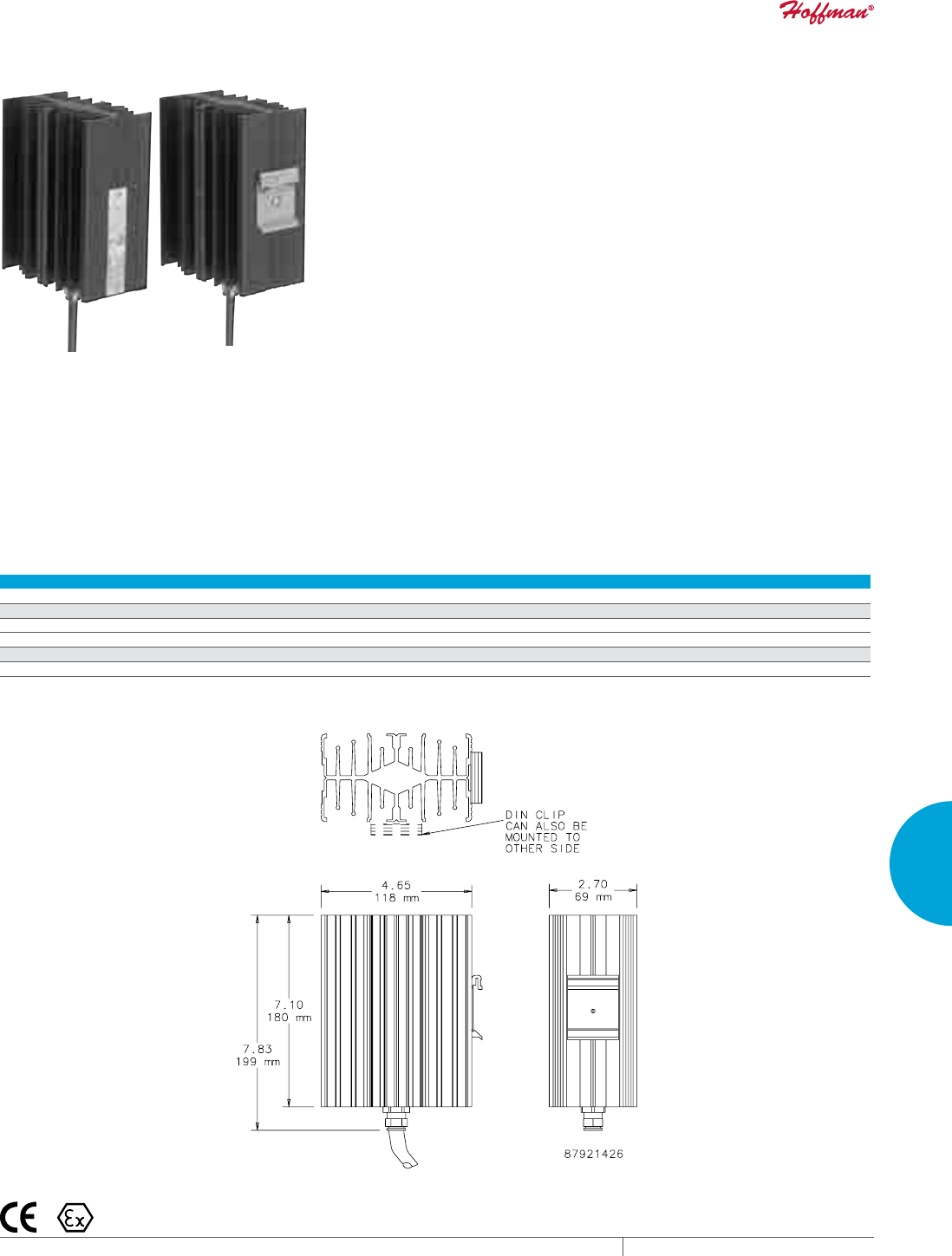
PH 763.422.2211 • FAX 763.576.3200 • HOFFMANONLINE.COMEQUIPMENT PROTECTION COOLING 307
5
ACCESSORIES ENCLOSURE HEATERS
HAZARDOUS LOCATION HEATER
INDUSTRY STANDARDS
CE
Conformity Certificate LCIE (Laboratoire Central des Industries
Electriques) LCIE 01 ATEX 6073
EEx d IIC T4/II 2 GD, IP6x T135°C
IEC 60529, IP65/I (grounded)
APPLICATION
Designed for use in hazardous locations where electronic
components require protection from condensation and corrosion,
sudden temperature drops and low temperatures.
FEATURES
• Maintenance-free
• High-performance heating cartridge (element)
• Large convection surface
• Extruded aluminum heat sink
• DIN clip for mounting
• Connection cable: Si HF-JZ 3 x AWG 18 x 3.3 ft. (0.75 mm² x 1 m)
• Operating voltage 110-120 VAC
FINISH
• Black anodized
Performance Data Hazardous Location Heater
CATALOG NUMBERS
HLHEAT100
DESIGN DATA
Heating Power (Watts) 100
Surface Temperature T4 (°F/°C) * 275/135
UNIT CONSTRUCTION
Unit Dimensions - H x W x D (in. / mm) 7.10/180 x 4.65/118 x 270/69
* Surface temperature when mounted vertically.
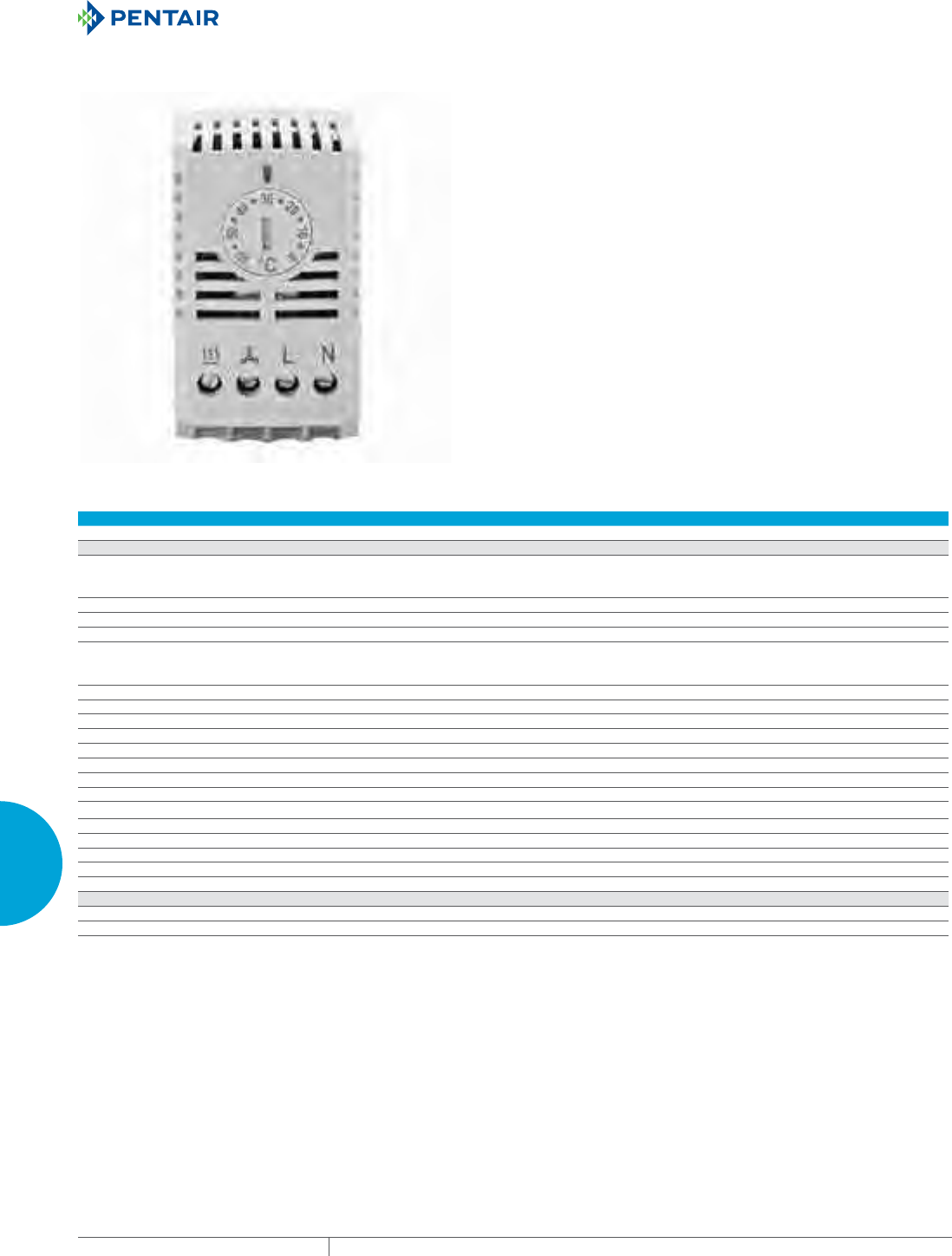
EQUIPMENT PROTECTIONSUBJECT TO CHANGE WITHOUT NOTICECOOLING308
5
ACCESSORIES CONTROLLERS
CONTROLLERS
THERMOSTAT CONTROLLER
FEATURES
• Saves energy, reduces filter replacement frequency and extends
filter fan life
• Terminal block connection
• 38-mm DIN rail mounting bracket (according to EN 60715) and
screws included
FINISH
• RAL7035 light gray
• Plastic housing UL94 V-0
NOTES
Caution: When setting the temperature of the break contact (NC)
and the changeover contact (CO) to use it as a break contact, care
must be taken to add the maximum hysteresis (that consists of the
switching difference and the operating tolerance) to the required
minimum temperature. For instance, if the temperature in the
enclosure may not fall below 5 C, the controller must be set to
5+7+3=15 C (with a switching) difference of 4-7 k and tolerance of
+/- 3 k.
Performance Data Thermostat Controller
CATALOG NUMBERS
TWR60
DESIGN DATA
Control Range (°F / °C) -4 / -20 to 104 / 40 or
32 / 0 to 140 / 60 or
68 / 20 to 176 / 80 (see type plate)
Switching Differences:
Bimetal controllers Approx. 1 k, approx. 3 k, 4-7 k (see type plate)
Capillary controllers less than 7 k
Contact Snap contact as break contact = NC
Make contact = NO
Changeover contact = CO (see type plate)
Switching Capacity:
Break contact/make contact 100V…250V / 10(2)A, at 4 max. 30 W
Changeover contact - heating 100V…250V / 10(2)A, at 4 max. 30 W
Changeover contact - cooling 100V…250V / 15(2)A, at 4 max. 30 W
Supply Voltage Controller (CO) requires 230V
Protection IP20
Switchpoint Tolerance +/- 3k
Sensor Bimetal
Power Connection Terminal screws 0.5 to 2.5 mm2
Bimetal Controller Ambient Temperature:
T40 -4 / -20 to 104 / 40
T60 32 / 0 to 140 / 60
T80 68 / 20 to 176 / 80
Storage Temperature (°F / °C) -4 / -20 to 140 / 60
UNIT CONSTRUCTION
Unit Dimensions - H x W x D (in. / mm) 2.52 x 1.46 x 1.81 / 64 x 37 x 46
Weight (oz / g) 1.8 / 50
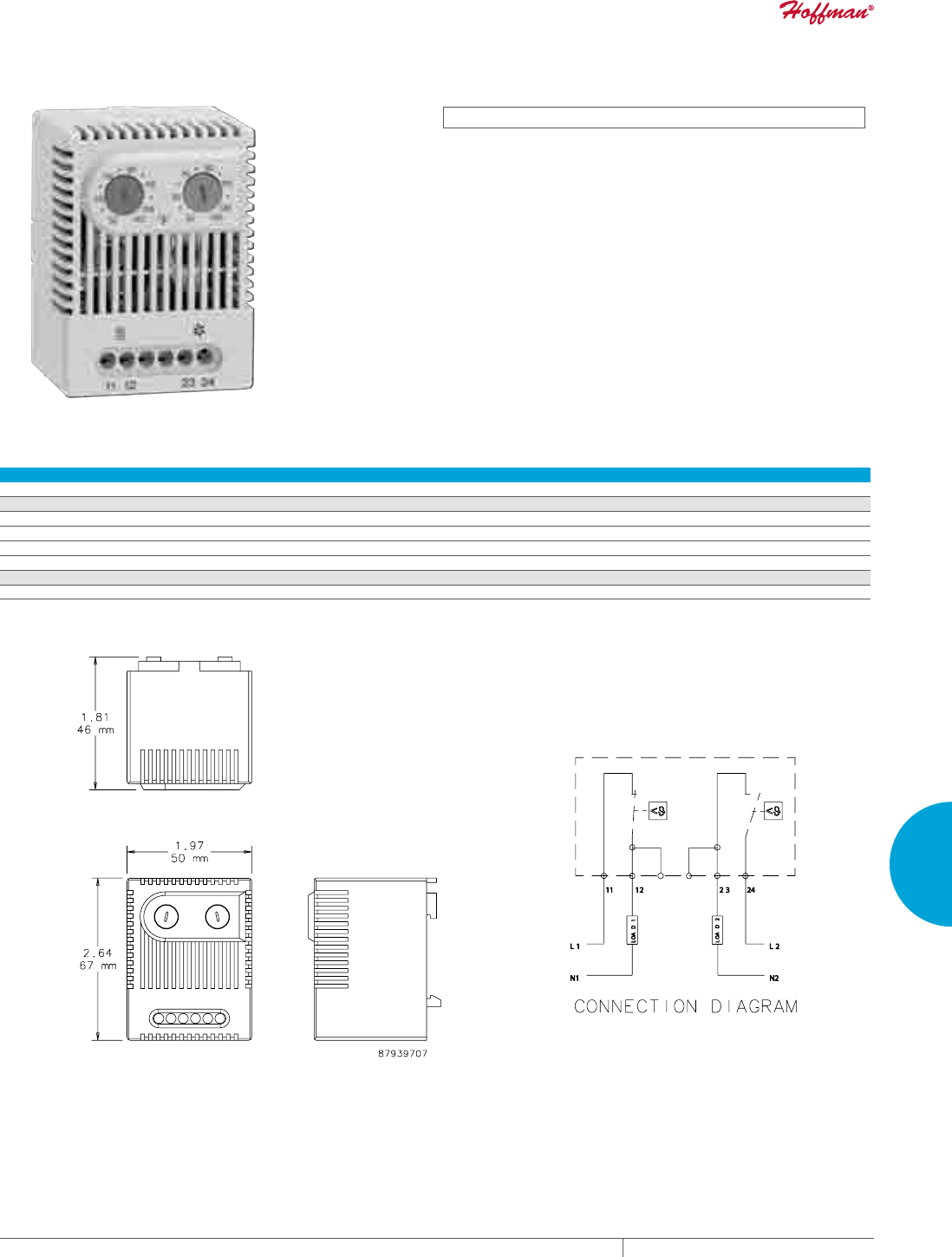
PH 763.422.2211 • FAX 763.576.3200 • HOFFMANONLINE.COMEQUIPMENT PROTECTION COOLING 309
5
ACCESSORIES CONTROLLERS
DUAL THERMOSTAT
INDUSTRY STANDARDS
cURus; File No. E164102
CSA File No. 215952
CE
APPLICATION
Two thermostats in one, the Dual Thermostat independently
controls equipment heating and cooling systems.
FEATURES
• Two thermostats; one normally closed (NC), red, and one
normally open (NO), blue, in one casing
• Wide adjustable temperature range (32 -140 F)
• Thermostatic bimetallic sensor element
• Connection: 4-pole terminal for AWG 14 max (2.5 mm2)
• Mounting clip for 35-mm DIN rail
FINISH
• Light-gray plastic, UL94V-0
Performance Data Dual Thermostat
CATALOG NUMBERS
ADLTEMP
ELECTRICAL DATA
Switching Capacity (Normally Closed) 10 A resistive/2 A inductive @250 VAC, DC 30 W
Switching Capacity - Normally Open 5 A resistive/2 A inductive @250 VAC, DC 30 W
Setting Range - Normally Closed (°F/C°) 32/0 to 140/60
Setting Range - Normally Open (°F/C°) 32/0 to 140/60
UNIT CONSTRUCTION
Unit Dimensions - H x W x D (in./mm) 2.64/67 x 1.97/50 x 1.81/46
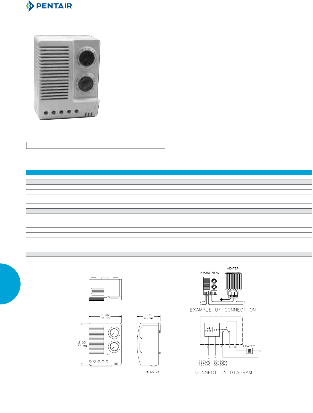
EQUIPMENT PROTECTIONSUBJECT TO CHANGE WITHOUT NOTICECOOLING310
5
ACCESSORIES CONTROLLERS
ELECTRONIC HYGROTHERM
INDUSTRY STANDARDS
cURus; File No. E164102
CE
APPLICATION
The Electronic Hygrotherm senses ambient temperature and
relative air humidity and adjusts a connected device to maintain
temperature and humidity set points.
FEATURES
• Temperature (32-140 F) and humidity (50%-90% RH) adjustment
• High switching capacity
• Optical function displays (LED) in each control
• Mounting clip for 35-mm DIN rail
• Change-over contact (relay)
• Connection: 5-pole terminal for AWG 14 max (2.5-mm square).
Clamping torque .5 Nm (4.4 in-lbs) maximum.
• Plastic housing UL94V-0
• Vertical mounting
• Operating voltage is AC 100-240 V with maximum switching
capacity of 10 A resistive / 1.6 A inductive at AC 240 V
FINISH
• Light-gray plastic UL94V-0
Performance Data Electronic Hygrotherm
CATALOG NUMBERS
ATEMHUM
ELECTRICAL DATA
Hysteresis ~ 3.6 F (2K) ± 1.8 F (1K) tolerance
Humidity Set Point (adjustable) 50-90% RH
Temperature Set Point (adjustable) (°F/°C) 32/0 to 140/60
Operating Temperature Range (°F/°C) -40 to 140/-40 to 60
Storage Temperature (°F/°C) -40 to 140/-40 to 60
CONTACTS
3 and 5
Close at... humidity rise or temperature drop
Open at... humidity drop or temperature rise
Use for... heaters, dehumidifiers, low-temp alarms
4 and 5
Close at... humidity drop or temperature rise
Open at... humidity rise or temperature drop
Use for... cooling, humidifiers, high-temp alarms
UNIT CONSTRUCTION
Unit Dimensions - H x W x D (in./mm) 3.03/77 x 2.36/60 x 1.69/43
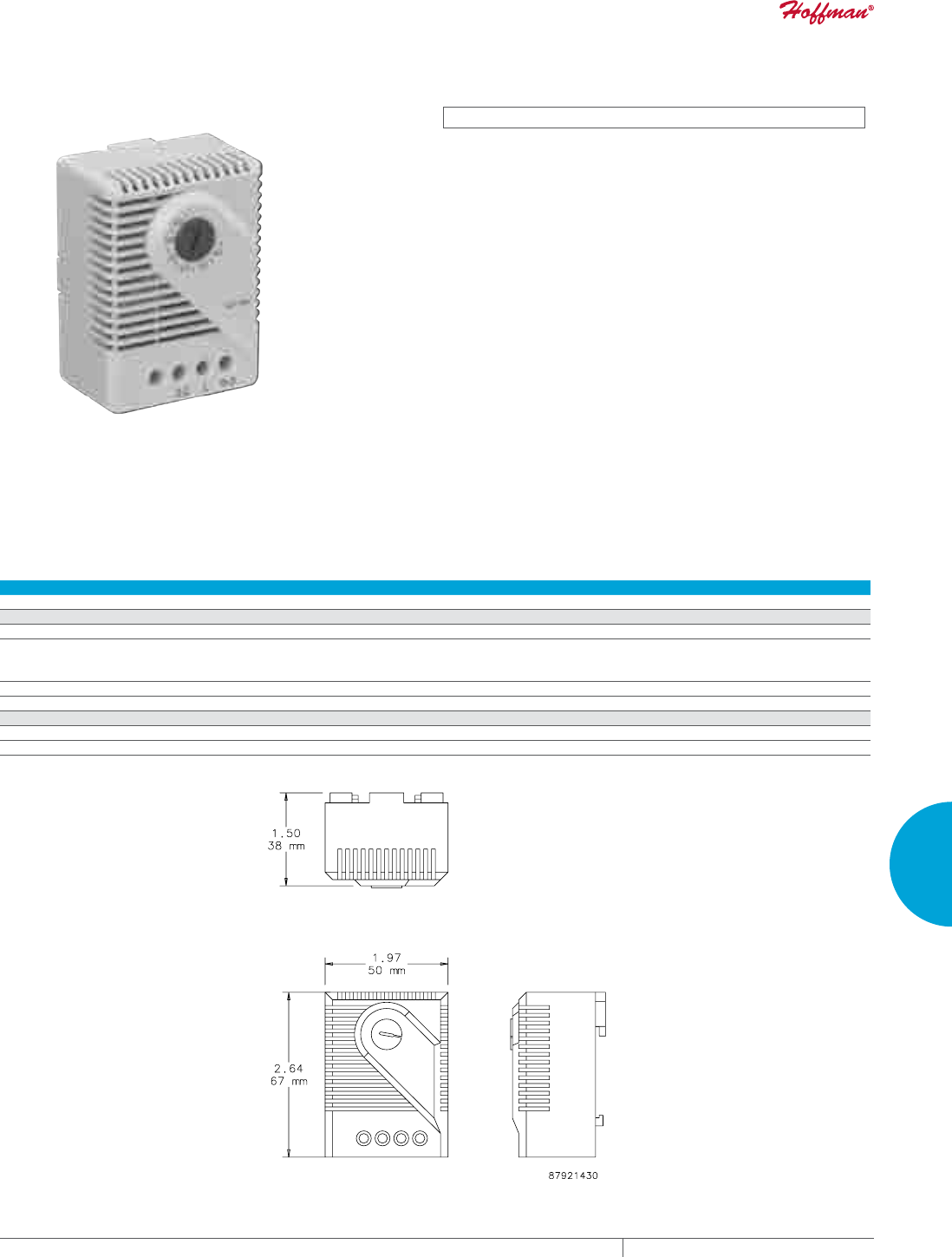
PH 763.422.2211 • FAX 763.576.3200 • HOFFMANONLINE.COMEQUIPMENT PROTECTION COOLING 311
5
ACCESSORIES CONTROLLERS
MECHANICAL HYGROSTAT
INDUSTRY STANDARDS
cURus; File No. E164102
CE
APPLICATION
The Mechanical Hygrostat controls relative air humidity inside an
enclosure to prevent condensation and corrosion that can damage
components. It can also be connected to an enclosure heater,
cooling fans, warning lights or other devices.
The critical relative humidity (RH) level for most components is 65
percent. Above 65 percent RH, condensation can form and cause
electronic equipment to malfunction.
FEATURES
• Adjustable relative humidity range
• High switching capacity
• Long service life (>100,000 cycles)
• Maximum permissible air velocity of 50 ft./sec. (15 m/s)
• Maximum switching voltage = 250 VAC
250 V should be switched only in a non-condensing environment
• Change-over contact
• Mounting clip for 35-mm DIN rail
• Connection: 3-pole terminal for AWG 14 max. (2.5-mm squared)
• Contact resistance less than 10 mΩ
FINISH
• Light-gray plastic, UL94V-0
Performance Data Mechanical Hygrostat
CATALOG NUMBERS
AMHUM
ELECTRICAL DATA
Switching Capacity (Minimum) 100mA @ AC/DC 20 V
Switching Capacity (Maximum) 5A @ AC 250 V (resistive load)
0.2A @ AC 250 V (inductive load at cos O = 0.8)
DC 20W
Operating Temperature Adjustable) (°F/°C) 32/0 to 140/60
Storage Temperature (°F/°C) -40/-40 to 140/60
UNIT CONSTRUCTION
Unit Dimensions - H x W x D (in./mm) 2.64/67 x 1.97/50 x 1.5/38
Weight (oz/g) 2/60
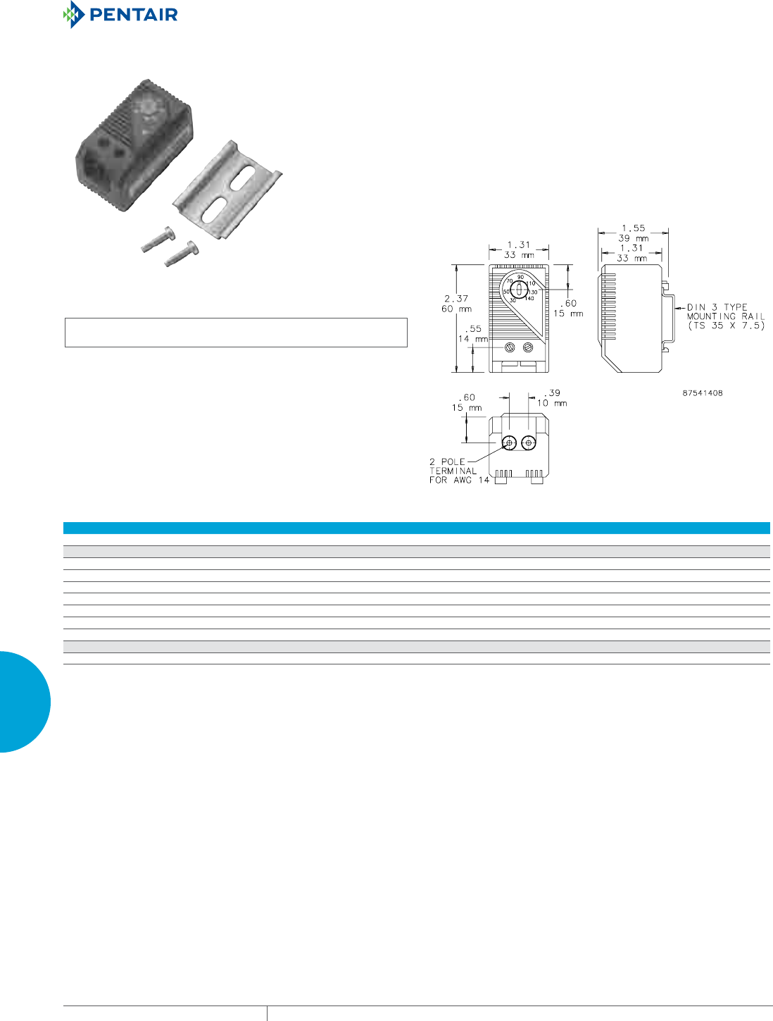
EQUIPMENT PROTECTIONSUBJECT TO CHANGE WITHOUT NOTICECOOLING312
5
ACCESSORIES CONTROLLERS
TEMPERATURE CONTROL SWITCH
INDUSTRY STANDARDS
cURus; File No. E164102
UL94-VO
Protection rating IEC IP30
CSA Certified, File Number 215952
CE
APPLICATION
These easy-to-install thermostats regulate and monitor air
temperature in enclosures that contain heat-emitting equipment.
Thermostats prolong heater and fan life expectancy by controlling
operation time and increase electrical component working
efficiency by exposing them to fewer environmental contaminants.
FEATURES
• Additional label for conversion to Celsius scale and blank label to
cover set point range label when adjustment after initial setting is
not desired are included
• Bimetal temperature sensor
• Plastic housing
• Connections consist of tubular screw terminals for AWG 14
(.04 sq. in.)
• Provision for both panel mounting and DIN rail mounting
FINISH
• Molded plastic housing is black
Performance Data Temperature Control Switch
CATALOG NUMBERS
ATEMNC ATEMNO
ELECTRICAL DATA
Maximum Load (Switching Capacity)
120 VAC 15 A resistive / 2 A inductive @ 120 VAC
250 VAC 10 A resistive / 2 A inductive @ 250 VAC
DC DC 30 W
Minimum load 20 mA (all voltages)
Contact Type NC (normally closed), quick acting NO (normally open), quick acting
Control Application Heater Fan
UNIT CONSTRUCTION
Unit Dimensions - H x W x D (in./mm) 2.37/60 x 1.31/33 x 1.55/39
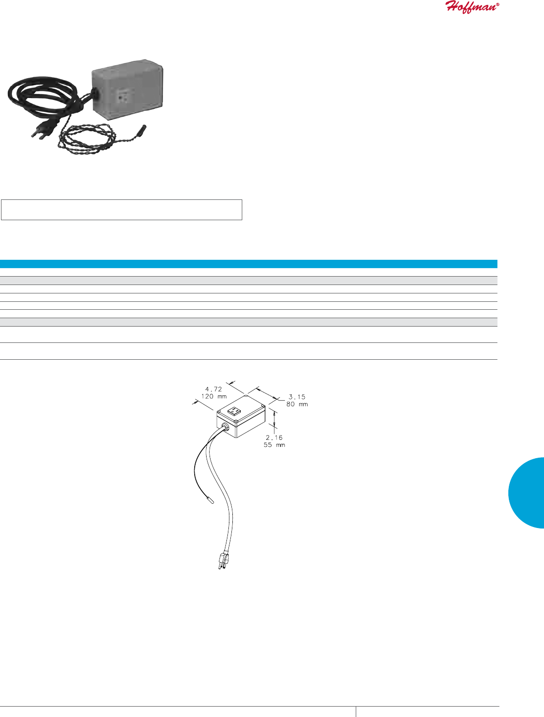
PH 763.422.2211 • FAX 763.576.3200 • HOFFMANONLINE.COMEQUIPMENT PROTECTION COOLING 313
5
ACCESSORIES CONTROLLERS
PANELMOUNT FAN SPEED CONTROLS
INDUSTRY STANDARDS
UL 508 Listed; File No. E249700
cUL Listed per CSA C22.2 No. 14; File No. E249700
APPLICATION
Perfect for offices, classrooms and other noise-sensitive areas. Fan
Speed Control optimizes airflow in a cabinet or rack, balancing air
volume requirements with noise level and power use.
FEATURES
• Automatically adjusts fan speed depending on remote
temperature sensor input
• Temperature set point is field adjustable; preset at 35 C (95 F)
• Idle speed and temperature slope are field-adjustable
• Push-to-reset thermal circuit breaker inside control housing
• Compact polycarbonate control housing can be mounted in any
position
• NEMA 5-15R outlet provides power to fan
• Six-foot (1.83-m) power cord plugs into standard 120 V, 50 or 60
Hz outlet
• Remote temperature sensor with 10-ft. (3.05-m) lead mounts in
airflow
• Mounting brackets included
FINISH
• AFANTSC: Light-gray polycarbonate control housing
Performance Data Panel-Mount Fan Speed Controls
CATALOG NUMBERS
AFANTSC
ELECTRICAL DATA
Rated Voltage 120 VAC
Maximum Nominal Current (Amps) 2
Temperature Settings (°F) 86, 95, 104, 113
Temperature Settings (°C) 30, 35, 40, 45
DESIGN DATA
Description Panel-Mount
Fan Speed Control
Application Fan speed controlled automatically
with remote temperature sensor
89084920
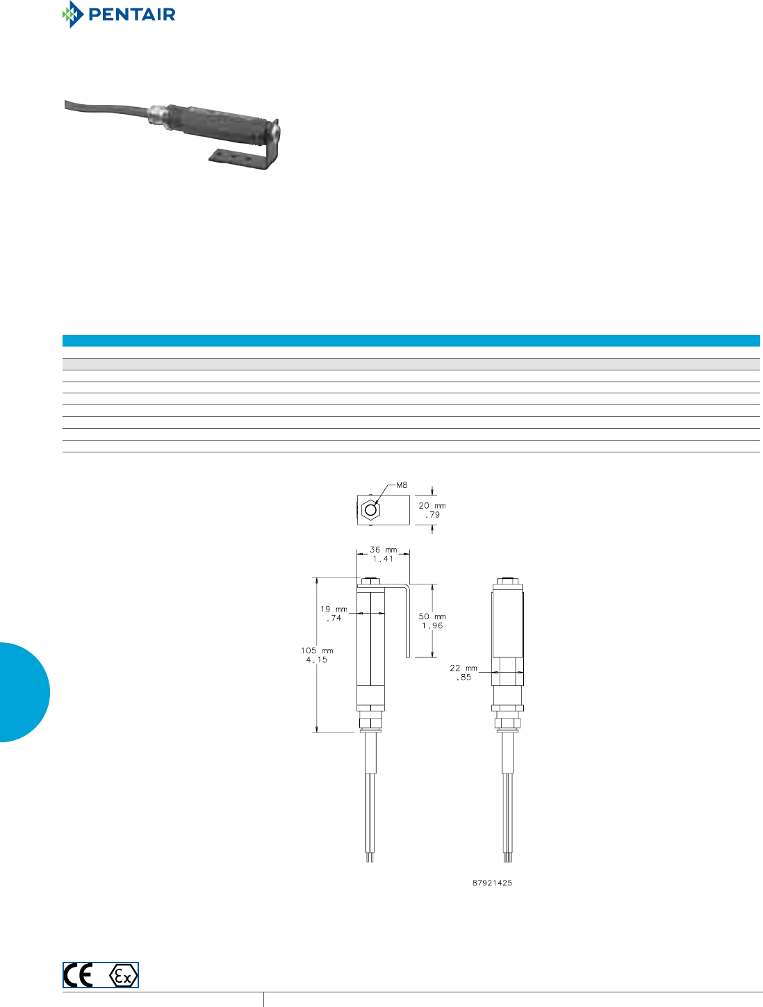
EQUIPMENT PROTECTIONSUBJECT TO CHANGE WITHOUT NOTICECOOLING314
5
ACCESSORIES CONTROLLERS
HAZARDOUS LOCATION THERMOSTAT
INDUSTRY STANDARDS
CE
Conformity Certificate LCIE (Laboratoire Central des Industries
Electriques) LCIE 01 ATEX 6074
EEx d IIC T6/II 2 GD, IP6x T85 °C
IEC 60529, IP65/1 (grounded)
APPLICATION
Compact mechanical thermostat for temperature control of
heaters or low-temperature alarms in enclosures that are used in
explosion-hazardous areas.
FEATURES
• Compact design
• Set temperature
• High switching capacity
• Small hysteresis (switching difference)
• Long service life (greater than 100,000 cycles)
• Can usually be connected directly and switched without the need
for additional relays
• Thermostatic bimetallic sensor element
• One-pole contact opens with rising temperature
• Mounting bracket and DIN clip for mounting
• Connection cable: Si HF - JZ 3 x AWG 18 x 3.3 ft. (0.75 mm² x 1 m)
FINISH
• Black anodized aluminum
Performance Data Hazardous Location Thermostat
CATALOG NUMBERS
HLTHERMNC
DESIGN DATA
Maximum Operating Voltage (AC) 250 V
Maximum Operating Voltage (DC) 100 V
Switching Capacity @ 250 VAC 4A resistive; 1A ind. (cos f = 0.6)
Switch Off (Open) Temperature (°F) 77 +/- 6
Switch Off (Open) Temperature (°C) 25 +/- 3K
Switch On (Closed) Temperature below Switch Off Temperature (°F) 7.2 +/- 2
Switch On (Closed) Temperature below Switch Off Temperature (°C) 4 +/- 1K

PH 763.422.2211 • FAX 763.576.3200 • HOFFMANONLINE.COMEQUIPMENT PROTECTION COOLING 315
5
ACCESSORIES CONTROLLERS
Notes
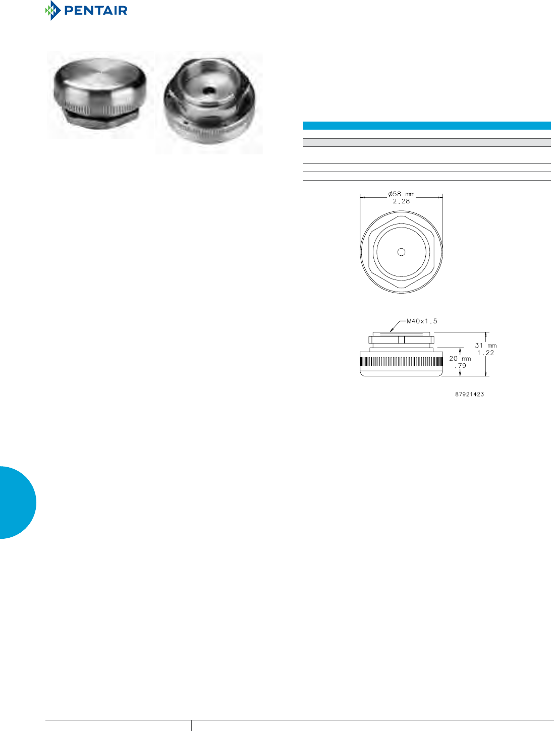
EQUIPMENT PROTECTIONSUBJECT TO CHANGE WITHOUT NOTICECOOLING316
5
ACCESSORIES PRESSURE COMPENSATION
PRESSURE COMPENSATION
STAINLESS STEEL PRESSURE COMPENSATION
INDUSTRY STANDARDS
CE
NEMA Type 4X
IEC/EN 60529, IP66
APPLICATION
Pressure differentials in a tightly sealed enclosure result from
heat generated by electrical and electronic equipment within
the enclosure and fluctuations of outside ambient temperature.
Stainless steel pressure compensation devices provide IP66
protection in corrosive applications requiring slow pressure
equalization. For optimal performance, install two plugs diagonally
to each other.
FEATURES
• Air permeability = 42 cubic feet/hour (1,200 liters/hour) at a
pressure difference of min. 70 mbar
• Easy installation: drill one 1.60-in. (41-mm) diameter hole
• Sealing gasket (Nitrile Buna-N Rubber)
SPECIFICATIONS
• Type 316L stainless steel
• Semipermeable membrane inside the plug filters moisture and
dust
• Mounting thread M40 with union nut
FINISH
• Machined Type 316L stainless steel
CATALOG NUMBERS
APCDSS6
UNIT CONSTRUCTION
Operating/Storage
Temperature (°F/°C)
-40/-40 to 176/80
Unit Dimenstions (in./mm) 2.28/58Ø x 1.22/31
Depth into Enclosure (in./mm) .35/9
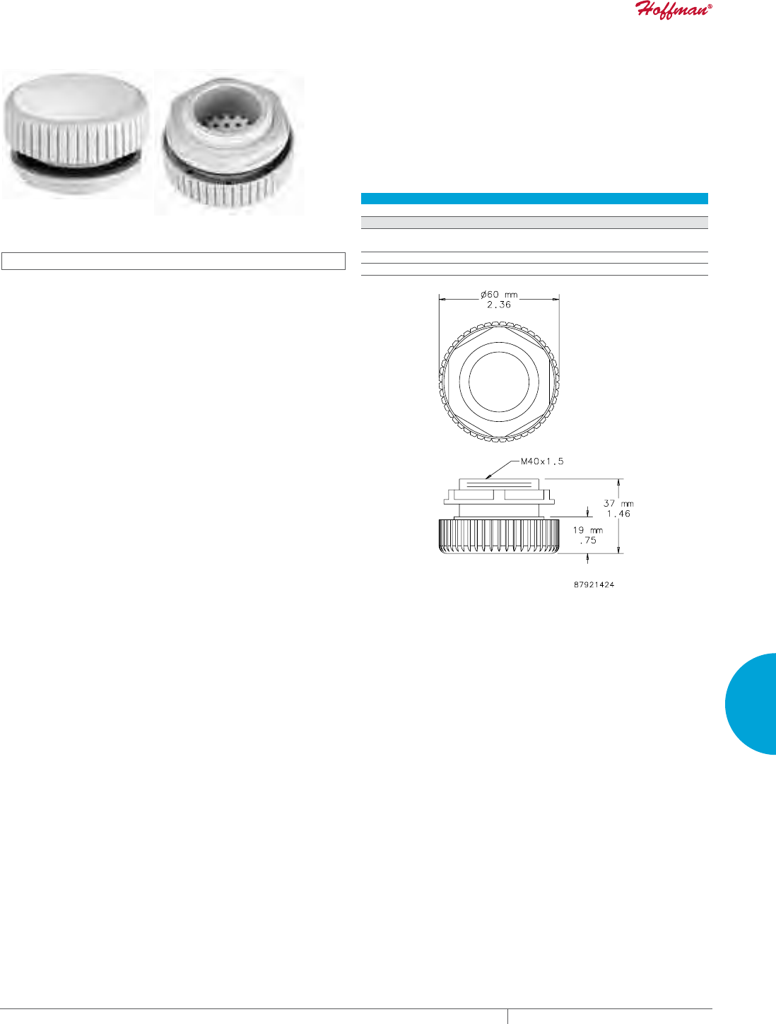
PH 763.422.2211 • FAX 763.576.3200 • HOFFMANONLINE.COMEQUIPMENT PROTECTION COOLING 317
5
ACCESSORIES PRESSURE COMPENSATION
PRESSURE COMPENSATION
INDUSTRY STANDARDS
UL Type 1, 4, 4X; File No. E234324
CE
IEC/EN 60529, IP66
APPLICATION
Pressure differentials in a tightly sealed enclosure result from
heat generated by electrical and electronic equipment within
the enclosure and fluctuations of outside ambient temperature.
Pressure compensation devices provide IP66 protection in
applications requiring slow pressure equalization. For optimal
performance, install two plugs diagonally to each other.
FEATURES
• Air permeability = 42 cubic feet/hour (1,200 liters/hour) at a
pressure difference of min. 70 mbar
• Easy installation: drill one 1.60-in. (41-mm) diameter hole
• Sealing gasket (Nitrile Buna-N Rubber)
SPECIFICATIONS
• Semipermeable membrane inside the plug to filter moisture and
dust
• Mounting thread M40 with union nut
• Plastic PA66
FINISH
• Light-gray plastic. Polymeric material manufactured by
DuPont™ .
DuPont is the trademark of E. I. duPont de Nemours and Company.
CATALOG NUMBERS
APCDABS
UNIT CONSTRUCTION
Operating/Storage
Temperature (°F/°C)
-49/-45 to 158/70
Unit Dimensions (in./mm) 2.36/60Ø x 146/37
Depth into Enclosure (in./mm) .6/15

6
CATALOG NUMBER INDEX
EQUIPMENT PROTECTIONSUBJECT TO CHANGE WITHOUT NOTICEINDEX318
Catalog
Number
Catalog
Page
Catalog
Number
Catalog
Page
Catalog
Number
Catalog
Page
INDEX
INDEX
C
Catalog Number Index
1EB52H115A ..................................... 261
1EB52H115B ..................................... 261
1EB52H230A ..................................... 261
1EB52H230B ..................................... 261
1NB412115 ...................................... 270
1NB412230 ...................................... 270
1RB100 ..................................... 268, 269
1RB100M ................................... 268, 269
1RB120 ..................................... 268, 269
1RB120M ................................... 268, 269
1RB65 ...................................... 268, 269
1RB65M .................................... 268, 269
1RB80 ...................................... 268, 269
1RB80M .................................... 268, 269
10100059H ...................................... 241
10100060 ....................................... 241
10100061 ....................................... 241
10100062 ....................................... 241
10100063 ....................................... 241
10100064H ...................................... 241
10100065H ...................................... 241
10100066H ...................................... 241
10100067H ...................................... 241
105G19 ......................................... 290
105H19 ......................................... 290
2EB17H115 ...................................... 257
2EB17H230 ...................................... 257
2EB300R115 ..................................... 262
2EB300R230 ..................................... 262
2EB3500R115 .................................... 262
2EB3500R230 .................................... 262
2EB412R115 ..................................... 262
2EB412R230 ..................................... 262
2EB512R115 ..................................... 262
2EB512T115 ..................................... 262
2EB612R115 ..................................... 262
2EB612R230 ..................................... 262
2NB300XXX ...................................... 272
2NB300115 ...................................... 272
2NB300230 ...................................... 272
2NB3500XXX ..................................... 272
2NB3500115 ..................................... 272
2NB3500230 ..................................... 272
2NB412XXX ...................................... 272
2NB412115 ...................................... 272
2NB412230 ...................................... 272
2NB424XXX ...................................... 272
2NB424115 ...................................... 272
2NB424230 ...................................... 272
2NB512XXX ...................................... 272
2NB512115 ...................................... 272
2NB512230 ...................................... 272
3EB17H115 ...................................... 257
3EB17H230 ...................................... 257
330416GW010 .................................... 133
330426GW012 .................................... 133
330426GW014 .................................... 133
35G19 .......................................... 290
35H19 .......................................... 290
4EB300RT115 .................................... 264
525G19 ......................................... 290
525H19 ......................................... 290
7G19 ........................................... 290
7H19 ........................................... 290
875G19 ......................................... 290
875H19 ......................................... 290
A10AXFN .................................... 251, 252
A10AXFN2 ................................... 251, 252
A10AXFNPG .................................. 251, 252
A19FANSC ....................................... 259
A19FT3B ........................................ 258
A19FT6B ........................................ 258
A2AXFN24 ....................................... 251
A3AXFN ..................................... 251, 252
A3AXFN24 ................................... 251, 252
A4AXFN ..................................... 251, 252
A4AXFN2 .................................... 251, 252
A4AXFN24 ................................... 251, 252
A4AXFNGQ ................................... 251, 252
A4AXFNPG ................................... 251, 252
A6AXFN ..................................... 251, 252
A6AXFN2 .................................... 251, 252
A6AXFN24 ................................... 251, 252
A6AXFNGQ ................................... 251, 252
A6AXFNPG ................................... 251, 252
AB133 ...................................... 275, 276
AB1331196701 ................................... 274
AB1332396701 ................................... 274
AB175 ...................................... 275, 276
AB1751171701 ................................... 274
AB1752371701 ................................... 274
AB190 ...................................... 275, 276
AB1901169901 ................................... 274
AB1902369901 ................................... 274
AB220 ...................................... 275, 276
AB2201171901 ................................... 274
AB2202371901 ................................... 274
AB225 ...................................... 275, 276
AB2251110901 ................................... 274
AB2252310901 ................................... 274
AB250 ...................................... 275, 276
AB2501199901 ................................... 274
AB2502399901 ................................... 274
AB280 ...................................... 275, 276
AB2801193901 ................................... 274
AB2802393901 ................................... 274
AB320 ...................................... 275, 276
AB3201116101 ................................... 274
AB3202316101 ................................... 274
AB355 ...................................... 275, 276
AB3551117101 ................................... 274
AB3552317101 ................................... 274
ABRKT10 ........................................ 255
ABRKT2 ......................................... 255
ABRKT3 ......................................... 255
ABRKT4 ......................................... 255
ABRKT6 ......................................... 255
ACORD1 ........................................ 254
ACORD2 ........................................ 254
ACORD2T ........................................ 254
ADB275 ......................................... 266
ADLTEMP ....................................... 309
AEXGR275 ....................................... 267
AFANTSC ........................................ 313
AFLT33 ......................................... 291
AFLT34 ......................................... 291
AFLT43 ......................................... 291
AFLT44 ......................................... 291
AFLT64 ......................................... 291
AFLT66 ......................................... 291
AFLT812 ........................................ 291
AFLT84 ......................................... 291
AFLT86 ......................................... 291
AFLT88 ......................................... 291
AFLTAD ......................................... 293
AFLTR10 ........................................ 246
AFLTR10AL ...................................... 246
AFLTR275AL ..................................... 267
AFLTR4 ......................................... 246
AFLTR4AL ....................................... 246
AFLTR4LD ....................................... 254
AFLTR6 ......................................... 246
AFLTR6AL ....................................... 246
AFLTR6LD ....................................... 254
AGARD10. . . . . . . . . . . . . . . . . . . . . . . . . . . . . . . . . . . . . . . . 255
AGARD2 ........................................ 255
AGARD3 ........................................ 255
AGARD4 ........................................ 255
AGARD6 ........................................ 255
AMHUM ......................................... 311
ANMV3 ......................................... 292
ANMV6 ......................................... 292

6
CATALOG NUMBER INDEX
PH 763.422.2211 • FAX 763.576.3200 • MCLEANCOOLINGTECH.COMEQUIPMENT PROTECTION INDEX 319
Catalog
Number
Catalog
Page
Catalog
Number
Catalog
Page
Catalog
Number
Catalog
Page
AOFF118 ........................................ 248
APCDABS ....................................... 317
APCDSS6 ....................................... 316
ATEMHUM ....................................... 310
ATEMNC ........................................ 312
ATEMNO ........................................ 312
AVDR4NM ....................................... 296
AVDR4SS4 ....................................... 296
AVK23 .......................................... 291
AVK23SS6 ....................................... 291
AVK33 .......................................... 291
AVK33SS6 ....................................... 291
AVK34 .......................................... 291
AVK34SS6 ....................................... 291
AVK43 .......................................... 291
AVK43SS6 ....................................... 291
AVK44 .......................................... 291
AVK44SS6 ....................................... 291
AVK64 .......................................... 291
AVK64SS6 ....................................... 291
AVK66 .......................................... 291
AVK66SS6 ....................................... 291
AVK812 ......................................... 291
AVK812SS6 ...................................... 291
AVK84 .......................................... 291
AVK84SS6 ....................................... 291
AVK86 .......................................... 291
AVK86SS6 ....................................... 291
AVK88 .......................................... 291
AVK88SS6 ....................................... 291
CR230216G002 ................................... 123
CR230216G007 ................................... 123
CR230216G013 ................................... 123
CR230216G015 ................................... 123
CR230216G016 ................................... 123
CR230216G017 ................................... 123
CR230226G002 ................................... 123
CR230226G009 ................................... 123
CR230226G014 ................................... 123
CR230226G016 ................................... 123
CR230226G030 ................................... 123
CR230226G037 ................................... 123
CR230246G400 ................................... 123
CR290216G002 ................................... 126
CR290216G013 ................................... 126
CR290216G030 ................................... 126
CR290216G035 ................................... 126
CR290216G036 ................................... 126
CR290226G002 ................................... 126
CR290226G010 ................................... 126
CR290226G020 ................................... 126
CR290226G030 ................................... 126
CR290226G031 ................................... 126
CR290226G037 ................................... 126
CR290226G041 ................................... 126
CR290226G045 ................................... 126
CR290226G046 ................................... 126
CR290226G058 ................................... 126
CR290246G400 ................................... 126
CR290246G401 ................................... 126
CR290416G002 ................................... 126
CR290416G030 ................................... 126
CR290416G045 ................................... 126
CR290416G047 ................................... 126
CR290416G052 ................................... 126
CR290416G068 ................................... 126
CR290426G002 ................................... 126
CR290426G017 ................................... 126
CR290426G022 ................................... 126
CR290426G027 ................................... 126
CR290426G054 ................................... 126
CR290426G061 ................................... 126
CR290426G067 ................................... 126
CR290426G101 ................................... 126
CR290446G400 ................................... 126
CR430616G002 ................................... 129
CR430616G004 ................................... 129
CR430616G013 ................................... 129
CR430616G016 ................................... 129
CR430616G031 ................................... 129
CR430626G002 ................................... 129
CR430626G014 ................................... 129
CR430626G018 ................................... 129
CR430626G020 ................................... 129
CR430626G030 ................................... 129
CR430626G034 ................................... 129
CR430626G074 ................................... 129
CR430646G004 ................................... 129
CR430816G002 ................................... 129
CR430816G010 ................................... 129
CR430816G021 ................................... 129
CR430816G023 ................................... 129
CR430816G036 ................................... 129
CR430816G038 ................................... 129
CR430816GW010 .................................. 137
CR430826G002 ................................... 129
CR430826G007 ................................... 129
CR430826G024 ................................... 129
CR430826G026 ................................... 129
CR430826G037 ................................... 129
CR430826G038 ................................... 129
CR430826G089 ................................... 129
CR430826GWXXX ................................. 137
CR430846G401 ................................... 129
DAH1001A ....................................... 304
DAH1002A ....................................... 304
DAH101 ......................................... 301
DAH101TS ....................................... 300
DAH13001C ...................................... 304
DAH13002C ...................................... 304
DAH2001A ....................................... 304
DAH2002A ....................................... 304
DAH201TS ....................................... 300
DAH301 ......................................... 301
DAH4001B ....................................... 304
DAH4002B ....................................... 304
DAH501TS ....................................... 300
DAH601 ......................................... 301
DAH8001B ....................................... 304
DAH8002B ....................................... 304
DB102 .......................................... 284
DB102XX54 ...................................... 283
DB1021254401 ................................... 282
DB1022454401 ................................... 282
DB1024854401 ................................... 282
DB133 .......................................... 284
DB133XX42 ...................................... 283
DB133XX91 ...................................... 283
DB1331242401 ................................... 282
DB1332442401 ................................... 282
DB1332491701 ................................... 282
DB1334842401 ................................... 282
DB1334891701 ................................... 282
DB175 .......................................... 284
DB175XX55 ...................................... 283
DB175XX69 ...................................... 283
DB1752455701 ................................... 282
DB1752469701 ................................... 282
DB1754855701 ................................... 282
DB1754869701 ................................... 282
DB220 .......................................... 284
DB220XX71 ...................................... 283
DB2202471701 ................................... 282
DB2204871701 ................................... 282
DCG2904248100 .................................. 207
DCG4108548100 .................................. 207
DCT3809448100 .................................. 207
DCT5615048100 .................................. 207
G280416G050 ..................................... 29
G280416G051 ..................................... 29
G280416G060 ..................................... 29
G280416G100 ..................................... 29
G280416G101 ..................................... 29

6
CATALOG NUMBER INDEX
EQUIPMENT PROTECTIONSUBJECT TO CHANGE WITHOUT NOTICEINDEX320
Catalog
Number
Catalog
Page
Catalog
Number
Catalog
Page
Catalog
Number
Catalog
Page
G280416G102 ..................................... 29
G280416G150 ..................................... 29
G280416G151 ..................................... 29
G280426G050 ..................................... 29
G280426G051 ..................................... 29
G280426G060 ..................................... 29
G280426G100 ..................................... 29
G280426G101 ..................................... 29
G280426G102 ..................................... 29
G280426G150 ..................................... 29
G280426G151 ..................................... 29
G280446G050 ..................................... 29
G280446G051 ..................................... 29
G280446G060 ..................................... 29
G280446G100 ..................................... 29
G280446G101 ..................................... 29
G280446G102 ..................................... 29
G280616G050 ..................................... 29
G280616G051 ..................................... 29
G280616G060 ..................................... 29
G280616G100 ..................................... 29
G280616G101 ..................................... 29
G280616G102 ..................................... 29
G280616G150 ..................................... 29
G280616G151 ..................................... 29
G280626G050 ..................................... 29
G280626G051 ..................................... 29
G280626G060 ..................................... 29
G280626G100 ..................................... 29
G280626G101 ..................................... 29
G280626G102 ..................................... 29
G280626G150 ..................................... 29
G280626G151 ..................................... 29
G280646G050 ..................................... 29
G280646G051 ..................................... 29
G280646G060 ..................................... 29
G280646G100 ..................................... 29
G280646G101 ..................................... 29
G280646G102 ..................................... 29
G520816G050 ..................................... 39
G520816G051 ..................................... 39
G520816G060 ..................................... 39
G520816G100 ..................................... 39
G520816G101 ..................................... 39
G520816G102 ..................................... 39
G520816G150 ..................................... 39
G520816G151 ..................................... 39
G520826G050 ..................................... 39
G520826G051 ..................................... 39
G520826G060 ..................................... 39
G520826G100 ..................................... 39
G520826G101 ..................................... 39
G520826G102 ..................................... 39
G520826G150 ..................................... 39
G520826G151 ..................................... 39
G520846G050 ..................................... 39
G520846G051 ..................................... 39
G520846G060 ..................................... 39
G520846G100 ..................................... 39
G520846G101 ..................................... 39
G520846G102 ..................................... 39
G520846G150 ..................................... 39
G520846G151 ..................................... 39
G521216G050 ..................................... 39
G521216G051 ..................................... 39
G521216G060 ..................................... 39
G521216G100 ..................................... 39
G521216G101 ..................................... 39
G521216G102 ..................................... 39
G521216G150 ..................................... 39
G521216G151 ..................................... 39
G521226G050 ..................................... 39
G521226G051 ..................................... 39
G521226G060 ..................................... 39
G521226G100 ..................................... 39
G521226G101 ..................................... 39
G521226G102 ..................................... 39
G521226G150 ..................................... 39
G521226G151 ..................................... 39
G521246G050 ..................................... 39
G521246G051 ..................................... 39
G521246G060 ..................................... 39
G521246G100 ..................................... 39
G521246G101 ..................................... 39
G521246G102 ..................................... 39
G521246G150 ..................................... 39
G521246G151 ..................................... 39
G572026G050 ..................................... 46
G572026G051 ..................................... 46
G572026G060 ..................................... 46
G572026G100 ..................................... 46
G572026G101 ..................................... 46
G572026G102 ..................................... 46
G572026G150 ..................................... 46
G572026G151 ..................................... 46
G572046G050 ..................................... 46
G572046G051 ..................................... 46
G572046G060 ..................................... 46
G572046G100 ..................................... 46
G572046G101 ..................................... 46
G572046G102 ..................................... 46
G572046G150 ..................................... 46
G572046G151 ..................................... 46
H2OMITTER ...................................... 299
HB160816G040 ................................... 120
HB160826G040 ................................... 120
HB160846G040 ................................... 120
HLHEAT100 ...................................... 307
HLTHERMNC ..................................... 314
LB110416GW008 .................................. 141
LB110426GW010 .................................. 141
MHB110216G306 .................................. 117
MHB110226G306 .................................. 117
MHB110246G400 .................................. 117
MHB110416G307 .................................. 118
MHB110426G306 .................................. 118
MHB110446G400 .................................. 118
N170116G010 ..................................... 71
N170116G020 ..................................... 71
N170126G010 ..................................... 71
N170126G020 ..................................... 71
N170146G010 ..................................... 71
N170146G020 ..................................... 71
N170216G010 ..................................... 71
N170216G020 ..................................... 71
N170226G010 ..................................... 71
N170226G020 ..................................... 71
N170246G010 ..................................... 71
N170246G020 ..................................... 71
N280416G050 ..................................... 53
N280416G051 ..................................... 53
N280416G060 ..................................... 53
N280416G100 ..................................... 53
N280416G102 ..................................... 53
N280416G150 ..................................... 53
N280416G151 ..................................... 53
N280425G050 ..................................... 53
N280425G051 ..................................... 53
N280425G060 ..................................... 53
N280425G100 ..................................... 53
N280425G102 ..................................... 53
N280425G150 ..................................... 53
N280425G151 ..................................... 53
N280426G050 ..................................... 53
N280426G051 ..................................... 53
N280426G060 ..................................... 53
N280426G100 ..................................... 53
N280426G102 ..................................... 53
N280426G150 ..................................... 53
N280426G151 ..................................... 53
N280446G050 ..................................... 53
N280446G051 ..................................... 53
N280446G060 ..................................... 53

6
CATALOG NUMBER INDEX
PH 763.422.2211 • FAX 763.576.3200 • MCLEANCOOLINGTECH.COMEQUIPMENT PROTECTION INDEX 321
Catalog
Number
Catalog
Page
Catalog
Number
Catalog
Page
Catalog
Number
Catalog
Page
N280446G100 ..................................... 53
N280446G102 ..................................... 53
N280446G150 ..................................... 53
N280446G151 ..................................... 53
N360616G050 ..................................... 57
N360616G051 ..................................... 57
N360616G060 ..................................... 57
N360616G100 ..................................... 57
N360616G102 ..................................... 57
N360616G150 ..................................... 57
N360616G151 ..................................... 57
N360626G050 ..................................... 57
N360626G051 ..................................... 57
N360626G060 ..................................... 57
N360626G100 ..................................... 57
N360626G102 ..................................... 57
N360626G150 ..................................... 57
N360626G151 ..................................... 57
N360646G050 ..................................... 57
N360646G051 ..................................... 57
N360646G060 ..................................... 57
N360646G100 ..................................... 57
N360646G102 ..................................... 57
N360646G150 ..................................... 57
N360646G151 ..................................... 57
N360816G050 ..................................... 57
N360816G051 ..................................... 57
N360816G060 ..................................... 57
N360816G100 ..................................... 57
N360816G102 ..................................... 57
N360816G150 ..................................... 57
N360816G151 ..................................... 57
N360826G050 ..................................... 57
N360826G051 ..................................... 57
N360826G060 ..................................... 57
N360826G100 ..................................... 57
N360826G102 ..................................... 57
N360826G150 ..................................... 57
N360826G151 ..................................... 57
N360846G050 ..................................... 57
N360846G051 ..................................... 57
N360846G060 ..................................... 57
N360846G100 ..................................... 57
N360846G102 ..................................... 57
N360846G150 ..................................... 57
N360846G151 ..................................... 57
N431216G050 ..................................... 65
N431216G051 ..................................... 65
N431216G060 ..................................... 65
N431216G100 ..................................... 65
N431216G102 ..................................... 65
N431216G150 ..................................... 65
N431216G151 ..................................... 65
N431226G050 ..................................... 65
N431226G051 ..................................... 65
N431226G060 ..................................... 65
N431226G100 ..................................... 65
N431226G102 ..................................... 65
N431226G150 ..................................... 65
N431226G151 ..................................... 65
N431246G050 ..................................... 65
N431246G051 ..................................... 65
N431246G060 ..................................... 65
N431246G100 ..................................... 65
N431246G102 ..................................... 65
N431246G150 ..................................... 65
N431246G151 ..................................... 65
PLHC52G57 ....................................... 79
PLHC52T53 ....................................... 79
PLM13N17 ....................................... 79
PLM28G28 ....................................... 79
PLM28N17 ....................................... 79
PLM33N28 ....................................... 79
PLM36N36 ....................................... 79
PLM52G52 ....................................... 79
PLT29G28 ........................................ 79
PPV32B ......................................... 292
SF0416413 ...................................... 213
SF0416414 ...................................... 213
SF0424413 ...................................... 213
SF0424414 ...................................... 213
SF0426413 ...................................... 213
SF0426414 ...................................... 213
SF0448413 ...................................... 213
SF0448414 ...................................... 213
SF0516413 ...................................... 216
SF0516414 ...................................... 216
SF0516513 ...................................... 216
SF0516514 ...................................... 216
SF0524413 ...................................... 216
SF0524414 ...................................... 216
SF0524513 ...................................... 216
SF0524514 ...................................... 216
SF0526413 ...................................... 216
SF0526414 ...................................... 216
SF0526513 ...................................... 216
SF0526514 ...................................... 216
SF0548413 ...................................... 216
SF0548414 ...................................... 216
SF0548513 ...................................... 216
SF0548514 ...................................... 216
SF0916413 ...................................... 218
SF0916414 ...................................... 218
SF0916513 ...................................... 218
SF0916514 ...................................... 218
SF0924413 ...................................... 218
SF0924414 ...................................... 218
SF0924513 ...................................... 218
SF0924514 ...................................... 218
SF0926413 ...................................... 218
SF0926414 ...................................... 218
SF0926513 ...................................... 218
SF0926514 ...................................... 218
SF0948413 ...................................... 218
SF0948414 ...................................... 218
SF0948513 ...................................... 218
SF0948514 ...................................... 218
SF1016413 ...................................... 220
SF1016414 ...................................... 220
SF1016513 ...................................... 220
SF1016514 ...................................... 220
SF1024413 ...................................... 220
SF1024414 ...................................... 220
SF1024513 ...................................... 220
SF1024514 ...................................... 220
SF1026413 ...................................... 220
SF1026414 ...................................... 220
SF1026513 ...................................... 220
SF1026514 ...................................... 220
SF1048413 ...................................... 220
SF1048414 ...................................... 220
SF1048513 ...................................... 220
SF1048514 ...................................... 220
SF1316413 ...................................... 222
SF1316413R ..................................... 222
SF1316414 ...................................... 222
SF1316414R ..................................... 222
SF1316423 ...................................... 224
SF1316423R ..................................... 226
SF1316424 ...................................... 224
SF1316424R ..................................... 226
SF1316433 ...................................... 227
SF1316433R ..................................... 229
SF1316434 ...................................... 227
SF1316434R ..................................... 229
SF1316513 ...................................... 222
SF1316514 ...................................... 222
SF1316523 ...................................... 224
SF1316524 ...................................... 224
SF1316533 ...................................... 227
SF1316534 ...................................... 227
SF1324413 ...................................... 222
SF1324414 ...................................... 222

6
CATALOG NUMBER INDEX
EQUIPMENT PROTECTIONSUBJECT TO CHANGE WITHOUT NOTICEINDEX322
Catalog
Number
Catalog
Page
Catalog
Number
Catalog
Page
Catalog
Number
Catalog
Page
SF1324433 ...................................... 227
SF1324434 ...................................... 227
SF1324513 ...................................... 222
SF1324514 ...................................... 222
SF1324533 ...................................... 227
SF1324534 ...................................... 227
SF1326413 ...................................... 222
SF1326413R ..................................... 222
SF1326414 ...................................... 222
SF1326414R ..................................... 222
SF1326423 ...................................... 224
SF1326423R ..................................... 226
SF1326424 ...................................... 224
SF1326424R ..................................... 226
SF1326433 ...................................... 227
SF1326433R ..................................... 229
SF1326434 ...................................... 227
SF1326434R ..................................... 229
SF1326513 ...................................... 222
SF1326514 ...................................... 222
SF1326523 ...................................... 224
SF1326524 ...................................... 224
SF1326533 ...................................... 227
SF1326534 ...................................... 227
SF1340423 ...................................... 224
SF1340423R ..................................... 226
SF1340424 ...................................... 224
SF1340424R ..................................... 226
SF1340434R ..................................... 229
SF1340523 ...................................... 224
SF1340524 ...................................... 224
SF1346433 ...................................... 227
SF1346433R ..................................... 229
SF1346434 ...................................... 227
SF1346533 ...................................... 227
SF1346534 ...................................... 227
SF1348413 ...................................... 222
SF1348414 ...................................... 222
SF1348433 ...................................... 227
SF1348434 ...................................... 227
SF1348513 ...................................... 222
SF1348514 ...................................... 222
SF1348533 ...................................... 227
SF1348534 ...................................... 227
SH05GS35001 .................................... 240
SH05GS61001 .................................... 240
SH05SS04001 .................................... 240
SH09GS35001 .................................... 240
SH09GS61001 .................................... 240
SH09SS04001 .................................... 240
SH10GS35001 .................................... 240
SH10GS61001 .................................... 240
SH10SS04001 .................................... 240
SH13GS35001 .................................... 240
SH13GS61001 .................................... 240
SH13SS04001 .................................... 240
SR1616414 ...................................... 236
SR1616424 ...................................... 238
SR1626414 ...................................... 236
SR1626424 ...................................... 238
ST1016413 ...................................... 231
ST1016414 ...................................... 231
ST1016513 ...................................... 231
ST1016514 ...................................... 231
ST1024413 ...................................... 231
ST1024414 ...................................... 231
ST1024513 ...................................... 231
ST1024514 ...................................... 231
ST1026413 ...................................... 231
ST1026414 ...................................... 231
ST1026513 ...................................... 231
ST1026514 ...................................... 231
ST1048413 ...................................... 231
ST1048414 ...................................... 231
ST1048513 ...................................... 231
ST1048514 ...................................... 231
ST1316413 ...................................... 233
ST1316413R ..................................... 233
ST1316414 ...................................... 233
ST1316414R ..................................... 233
ST1316513 ...................................... 233
ST1316513R ..................................... 233
ST1316514 ...................................... 233
ST1316514R ..................................... 233
ST1326413 ...................................... 233
ST1326413R ..................................... 233
ST1326414 ...................................... 233
ST1326414R ..................................... 233
ST1326513 ...................................... 233
ST1326513R ..................................... 233
ST1326514 ...................................... 233
ST1326514R ..................................... 233
T10EMC ........................................ 247
T150116G100 ..................................... 81
T150116G120 ..................................... 81
T150116G150 ..................................... 81
T150116G151 ..................................... 81
T150116G152 ..................................... 81
T150126G100 ..................................... 81
T150126G104 ..................................... 81
T150126G120 ..................................... 81
T150126G150 ..................................... 81
T200216G100 ..................................... 84
T200216G150 ..................................... 84
T200216G155 ..................................... 84
T200216G157 ..................................... 84
T200226G100 ..................................... 84
T200226G103 ..................................... 84
T200226G150 ..................................... 84
T200226G158 ..................................... 84
T200246G400 ..................................... 84
T200246G401 ..................................... 84
T290416G100 ..................................... 89
T290416G150 ..................................... 89
T290416G156 ..................................... 89
T290416G159 ..................................... 89
T290426G100 ..................................... 89
T290426G150 ..................................... 89
T290426G160 ..................................... 89
T290426G161 ..................................... 89
T290446G400 ..................................... 89
T290446G403 ..................................... 89
T4EMC ......................................... 247
T430616G100 ..................................... 92
T430616G102 ..................................... 92
T430616G150 ..................................... 92
T430626G100 ..................................... 92
T430626G150 ..................................... 92
T430626G159 ..................................... 92
T430646G153 ..................................... 92
T430646G400 ..................................... 92
T430816G100 ..................................... 94
T430816G150 ..................................... 94
T430816G153 ..................................... 94
T430826G100 ..................................... 94
T430826G108 ..................................... 94
T430826G150 ..................................... 94
T430846G400 ..................................... 94
T430846G402 ..................................... 94
T430846G403 ..................................... 94
T431016G100 ..................................... 96
T431016G102 ..................................... 96
T431016G150 ..................................... 96
T431016G153 ..................................... 96
T431026G100 ..................................... 96
T431026G104 ..................................... 96
T431026G150 ..................................... 96
T431026G152 ..................................... 96
T431046G400 ..................................... 96
T431046G406 ..................................... 96
T501226G100 ..................................... 99
T501226G125 ..................................... 99
T501226G150 ..................................... 99

6
CATALOG NUMBER INDEX
PH 763.422.2211 • FAX 763.576.3200 • MCLEANCOOLINGTECH.COMEQUIPMENT PROTECTION INDEX 323
Catalog
Number
Catalog
Page
Catalog
Number
Catalog
Page
Catalog
Number
Catalog
Page
T501226G156 ..................................... 99
T501246G400 ..................................... 99
T501246G401 ..................................... 99
T6EMC ......................................... 247
T622226G150 .................................... 107
T622246G400 .................................... 107
T703626G150 .................................... 110
T703646G400 .................................... 110
T706026G150 .................................... 113
T706046G400 .................................... 113
TE090624010 .................................... 185
TE090624011 .................................... 185
TE090624020 .................................... 185
TE121024010 .................................... 187
TE121024011 .................................... 187
TE121024020 .................................... 187
TE121048010 .................................... 187
TE121048020 .................................... 187
TE162024010 .................................... 189
TE162024011 .................................... 189
TE162024020 .................................... 189
TE162048010 .................................... 189
TE162048020 .................................... 189
TEC24VCNTLR .................................... 192
TEC48VCNTLR .................................... 192
TEP10 ...................................... 246, 247
TEP10SS ........................................ 246
TEP10UL12 ...................................... 246
TEP4 ....................................... 246, 247
TEP4SS ......................................... 246
TEP4UL12 ....................................... 246
TEP6 ....................................... 246, 247
TEP6SS ......................................... 246
TEP6UL12 ....................................... 246
TFLT10UL12 ...................................... 246
TFLT4UL12 ...................................... 246
TFLT6UL12 ...................................... 246
TFP101 ..................................... 245, 247
TFP101SS ....................................... 245
TFP101UL12 ..................................... 245
TFP102 ..................................... 245, 247
TFP102SS ....................................... 245
TFP102UL12 ..................................... 245
TFP41 ...................................... 243, 247
TFP41SS ........................................ 243
TFP41UL12 ...................................... 243
TFP42 ...................................... 243, 247
TFP42SS ........................................ 243
TFP42UL12 ...................................... 243
TFP424 ......................................... 243
TFP61 ...................................... 244, 247
TFP61SS ........................................ 244
TFP61UL12 ...................................... 244
TFP62 ...................................... 244, 247
TFP62SS ........................................ 244
TFP62UL12 ...................................... 244
TFP624 ......................................... 244
TG10B .......................................... 246
TG10SS ......................................... 246
TG4B ........................................... 246
TG4SS .......................................... 246
TG6B ........................................... 246
TG6SS .......................................... 246
TWR60 ......................................... 308
TX231416100 .................................... 161
TX231424100 .................................... 161
TX231426100 .................................... 161
TX231448100 .................................... 161
TX332816100 .................................... 164
TX332824100 .................................... 164
TX332826100 .................................... 164
TX332848100 .................................... 164
TX385616100 .................................... 167
TX385624100 .................................... 167
TX385626100 .................................... 167
TX385648100 .................................... 167
TX528316100 .................................... 170
TX528324100 .................................... 170
TX528326100 .................................... 170
TX528348100 .................................... 170
UEB17H115 ...................................... 257
UEB17H230 ...................................... 257
UEB17H24 ....................................... 257
VA0916012 ...................................... 200
VA091604X ...................................... 199
VA1516012 ...................................... 200
VA151604X ...................................... 199
VA2516012 ...................................... 200
VA251604X ...................................... 199
VA5016012 ...................................... 200
VA501604X ...................................... 199
VAAF15 ..................................... 201, 203
VAAF25 ..................................... 201, 203
VAAF50 ..................................... 201, 203
VADK124X ....................................... 201
VAGK09 ..................................... 201, 203
VAGK15 ..................................... 201, 203
VAGK25 ..................................... 201, 203
VC0416012 ...................................... 195
VC0916004 ...................................... 195
VC0916012 ...................................... 195
VC091604X ...................................... 195
VC1516012 ...................................... 195
VC1716004 ...................................... 195
VC171604X ...................................... 195
VC2516004 ...................................... 195
VC2516012 ...................................... 195
VC251604X ...................................... 195
VCOF17 .................................. 195, 201, 203
VCOF25 .................................. 195, 201, 203
VHL09160 ....................................... 202
VHL15160 ....................................... 202
VHL25160 ....................................... 202
VHL50160 ....................................... 202
VHLDK. . . . . . . . . . . . . . . . . . . . . . . . . . . . . . . . . . . . . . . . . . 203
WCHE01916002 ................................... 175
WCHE01926002 ................................... 175
WCHE04916002 ................................... 177
WCHE04926002 ................................... 177
WCHE06916002 ................................... 179
WCHE06926002 ................................... 179
WCHE14916002 ................................... 181
WCHE14926002 ................................... 181
XPV32 .......................................... 292
XR200416012 .................................... 145
XR200426012 .................................... 145
XR290816012 .................................... 147
XR290826012 .................................... 147
XR291816012 .................................... 149
XR291826012 .................................... 149
XR472416012 .................................... 151
XR472426012 .................................... 151
XR473516012 .................................... 153
XR473526012 .................................... 153
XR605516012 .................................... 155
XR605526012 .................................... 155
XR608416012 .................................... 157
XR608426012 .................................... 157

6
PRODUCT INDEX
EQUIPMENT PROTECTIONSUBJECT TO CHANGE WITHOUT NOTICEINDEX324
Product
Description
Catalog
Page
Product
Description
Catalog
Page
Product
Description
Catalog
Page
P
Product Index
19-in. Rack-Mountable Tray .................................................. 258
AC Motorized Impellers ......................................................... 274
Air Conditioner Cooling Capacity Overview ................................ 8
Airflow .................................................................................. 16
Airflow Design Options .......................................................... 15
CE ......................................................................................... 22
Centrifugal Blowers .............................................................. 270
Choosing an Air Mover ........................................................... 16
CLIMAGUARD™ Air-to-Air Indoor ........................................... 144
CLIMAGUARD™ Air-to-Air Outdoor ......................................... 160
CLIMAGUARD™ Air-to-Water Indoor....................................... 174
Compact Axial Fans .............................................................. 250
Conductive Enclosure Cooling .................................................. 5
DACS Outdoor ....................................................................... 206
DC Motorized Impellers......................................................... 282
Determine Heat Exchanger Capacity ....................................... 12
Determine Heat Transfer ........................................................ 11
Determine Internal Heat Load ................................................ 11
Determine Total Heat Load ..................................................... 10
Dual Thermostat ................................................................... 309
Electric Heaters .................................................................... 303
Electronic Hygrotherm .......................................................... 310
Enclosure Protection ............................................................. 16
Equation Method ................................................................... 10
Exhaust Grilles and Replacement Filters ............................... 267
Fan Brackets ........................................................................ 255
Fan Cords ............................................................................. 254
Fan Cords With Inline Thermostat ......................................... 254
Fan Filter and Finger Guard Kit.............................................. 254
Filter Adhesive ..................................................................... 293
Filter Box Fans ..................................................................... 268
Filter Fan Shrouds ................................................................ 240
Filter Grille Panel ................................................................. 290
Finger Guards ....................................................................... 255
Fresh Air Enclosure Cooling ..................................................... 5
Friendly Reminder.................................................................. 19
GENESIS™ Top-Mount Indoor ................................................ 116
GOST ..................................................................................... 22
H2OMIT™ Thermoelectric Dehumidifier ................................. 298
H2OMIT™ Vent Drains ........................................................... 296
Hazardous Location Heater ................................................... 307
Hazardous Location Thermostat ............................................ 314
Heat Exchanger Cooling Capacity Overview ............................. 11
Heat Ruins Electronics ............................................................ 4
How is Performance Characterized? ....................................... 14
Introduction ....................................................................... 7, 13
Louver Plate Kit Filters ......................................................... 291
Louver Plate Kits .................................................................. 291
Mechanical Hygrostat ........................................................... 311
Outdoor Filter Fan and Exhaust Package ............................... 248
Panel-Mount Fan Speed Controls .......................................... 313
Part A: Determine Internal Heat Load ....................................... 8
Part B: Determining Heat Transfer Load Overview ..................... 9
Power Input ........................................................................... 16
Pressure Compensation ........................................................ 317
PROAIR Harsh Environment ................................................... 122
Protection Levels................................................................... 23
Quiet Vortex A/C Enclosure Coolers, Type 4/4X/12 .................. 198
Rack-Mountable Assemblies ................................................. 256
Rack-Mountable Blowers ...................................................... 260
Rack-Mountable Fan Package ............................................... 266
Rack-Mount Fan Speed Control ............................................. 259
SCCR Requirements per UL (Condensed version) ..................... 24
Sealed Enclosure Cooling ........................................................ 5
Sealed vs. Fresh Air Enclosure Cooling ..................................... 6
Semiconductor Heaters ........................................................ 301
SF Side-Mount ..................................................................... 212
SF/ST Replacement Filters .................................................... 241
Simple Chart Method ............................................................... 9
Sources of Heat ....................................................................... 4
SPECTRACOOL™ Compact Indoor ........................................... 70
SPECTRACOOL™ Indoor/Outdoor ............................................ 28
SPECTRACOOL™ Narrow Indoor/Outdoor ................................. 52
SR Top-Mount ...................................................................... 236
Stainless Steel Pressure Compensation ................................ 316
Standards Organization Summary and Directory Overview ....... 22
Step 1. Determine Delta-T (ΔT) ..................................... 17
Step 2. Determine Internal Heat Load ..................................... 17
Step 3. Determine Free Airflow ............................................... 18
Step 4. Estimate System Impedance ...................................... 19
Step 5. Select Your Air Mover ................................................. 19
ST Thin Side-Mount .............................................................. 230
Temperature Control Switch .................................................. 312
TFP EMC Upgrade Kit ............................................................ 247
TFP Exhaust Grilles .............................................................. 246
TFP Optional Grilles and Replacement Filters ........................ 246
TFP Side-Mount ................................................................... 242
The Consequences of Damaging Heat ....................................... 4
Thermoelectric Condensate Manager .................................... 193
Thermoelectric Coolers Indoor/Outdoor ................................. 184
Thermoelectric Temperature Controller ................................. 192
Thermostat Controller .......................................................... 308
Touch-Safe Heaters .............................................................. 300
Trend Toward More Damaging Heat........................................... 4
T-SERIES Compact Outdoor .................................................... 80
T-SERIES Large Capacity Outdoor .......................................... 106
T-SERIES Mid-size Outdoor .................................................... 88
Ventilator ............................................................................. 292
Vent Kit ................................................................................ 292
Vortex A/C Enclosure Coolers, Hazardous Location ................. 202
Vortex Coolers Indoor/Outdoor .............................................. 194
Water-Cooled Indoor ............................................................. 132
Water-Cooled Indoor/Outdoor................................................ 136
Water-Cooled Rack-Mount .................................................... 140
What Are the Capabilities of Each Air Mover? ......................... 14
What Is Airflow? .................................................................... 13
What Is Static Pressure? ....................................................... 13
Why Cool Electronics in the First Place? .................................. 4
