G2 1 32 Updated 102241 Catalog
2014-07-05
: Pdf 102241-Catalog 102241-Catalog 781381 Batch5 unilog
Open the PDF directly: View PDF ![]() .
.
Page Count: 37
- Incandescent Lighting: Explosionproof
- A-51® Incandescent Explosionproof Lighting Fixtures
- Classified Area Suitability and Weights
- Fixture Catalog Numbers
- Mounting Hoods, Fixture Units, Globes, Guards
- Reflectors, Colored Globes, Parts
- Dimensions
- Photometric Data
- A-51® Incandescent Groups A and B Explosionproof Lighting Fixtures
- Mounting Hoods, Fixtures and Parts
- Dimensions
- Photometric Data
- AHL and EHL Incandescent Explosionproof Lighting Fixtures and Handlamp
- Fixture Catalog Numbers
- EDT Incandescent Dust-Ignitionproof Lighting Fixtures and Accessories
- ELS Series Emergency Lighting System
- Catalog Numbering Logic
- Fixture Catalog Numbers
- Accessories, Replacement Parts and Technical Data
- Weights and Dimensions
- Code•Master™ Strobe and Beacon Factory Sealed Lighting Fixtures
- Ordering Information
- Fixture Catalog Numbers
- Mounting Hoods, Fixture Units, Weights
- Strobes For The Hearing Impaired
- Accessories, Replacement Parts, Weights
- Family Tree and Dimensions
- Code•Master™ Incandescent Factory Sealed Lighting Fixtures
- Ordering Information
- Fixtures, Mounting Hoods
- Fixture Unit, Accessories, Replacement Parts, Weights
- Family Tree, Dimensions
Effective September, 2005
Copyright 2005
800-621-1506
www.appletonelec.com
PAGE 1
G2-1
G
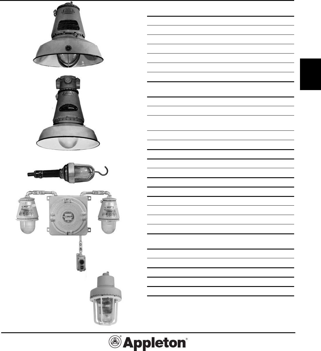
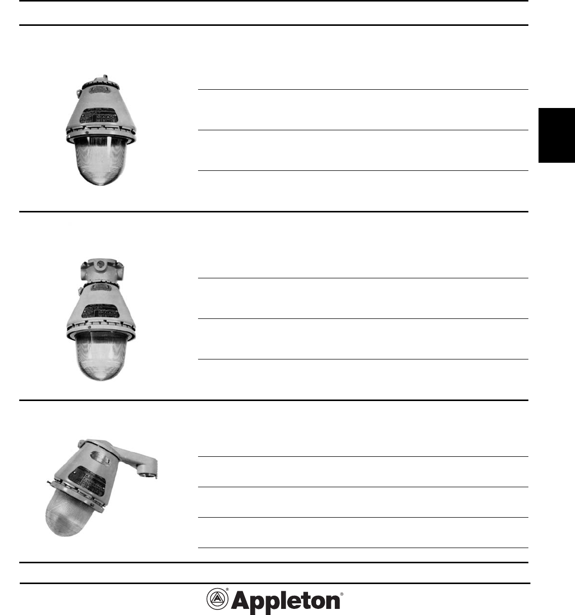
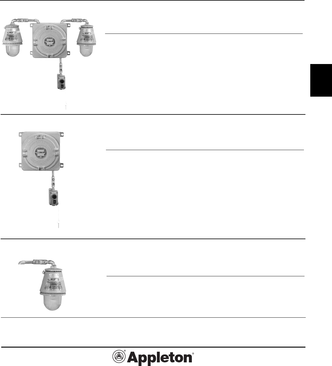
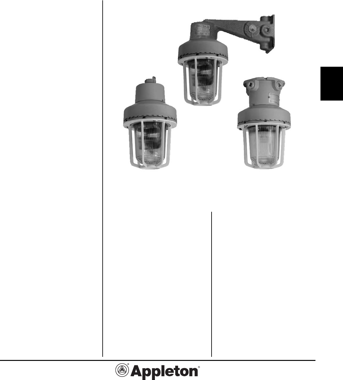
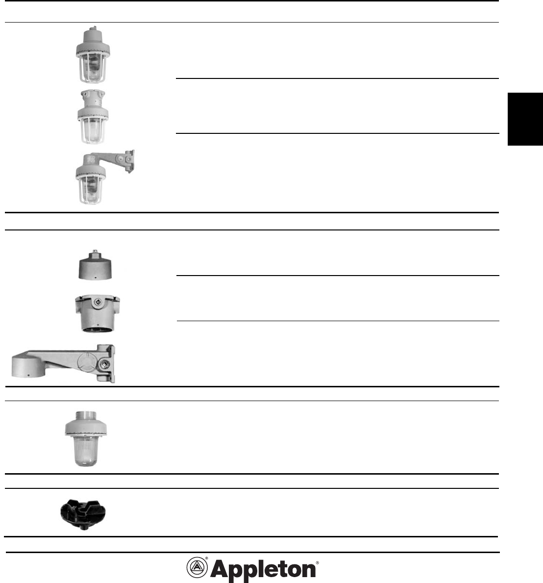
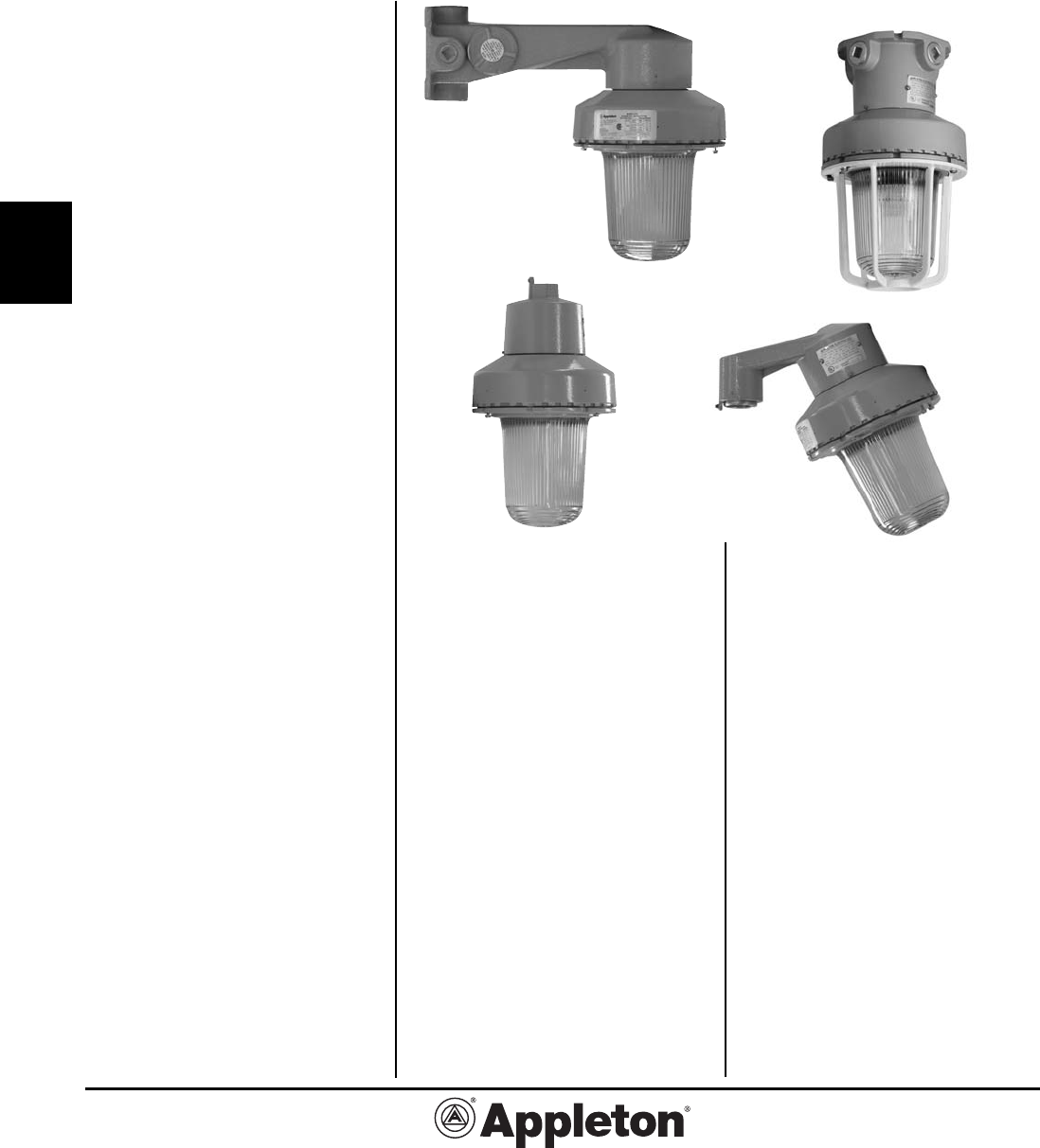
Incandescent Lighting:
Explosionproof
Page Description
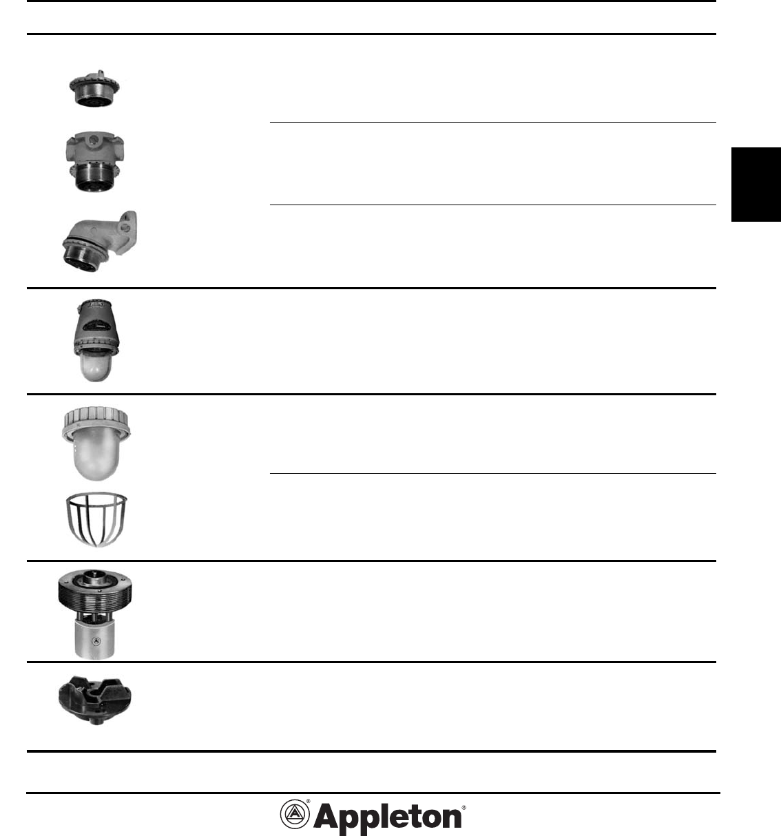
5-11 A-51® Series Lighting Fixtures—
Class I, Groups C and D
2,3 Features
4 Classified Area Suitability, Weights
5,6 Ordering Information
7 Mounting Hoods, Fixture Units, Globes and Guards
8 Reflectors, Colored Globes, and Parts
9 Dimensions
10, 11 Photometrics
12,15 A-51® Series Lighting Fixtures—
Class I, Groups A and B
2,3 Features
12 Ordering Information and Reflectors
13 Mounting Hoods, Fixture Units, Globes, Guards
and Parts
14 Dimensions
15 Photometrics
16 AHL and EHL Portable Handlamps
16 Features
17 Fixtures, Parts and Dimensions
18 EDT Lighting Fixtures and Accessories
19-24 ELS Series Emergency Lighting System
19 Features
20-22 Ordering Information
23 Replacement Parts and Technical Data
24 Weights and Dimensions
25-31 Code-Master™ Strobe and Beacon
Factory Sealed Lighting Fixtures
25 Features
26 Order Information and Technical Data
27-29 Fixtures
30 Optional Guard and Replacement Parts
31 Dimensions
See Section Q for Explosionproof Floodlights.
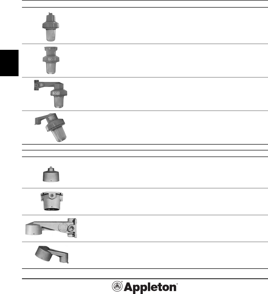
EHL Handlamp
Code•Master™ Strobe
ELS Series
A-51® Groups C & D
A-51® Groups A & B
Effective September, 2005
Copyright 2005
PAGE 2
800-621-1506
www.appletonelec.com
G2-2
G
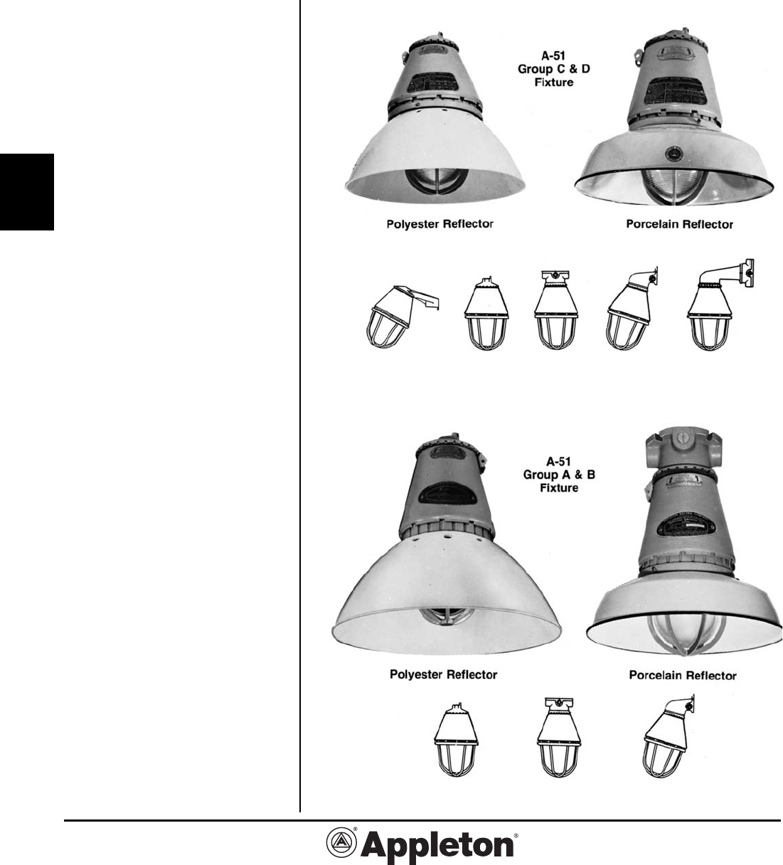
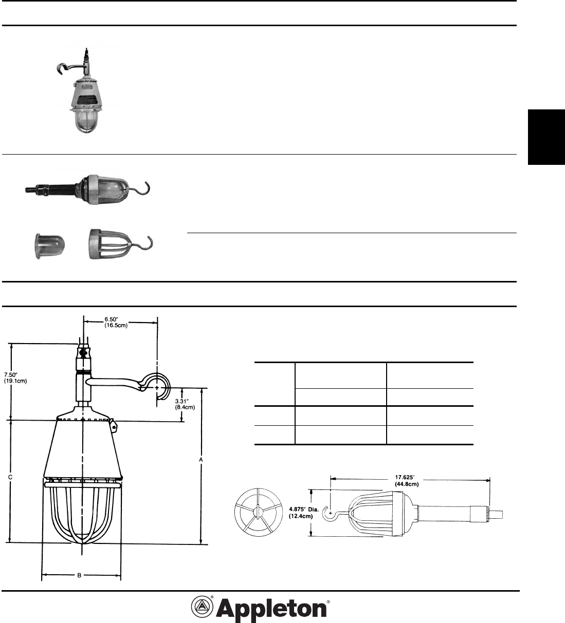
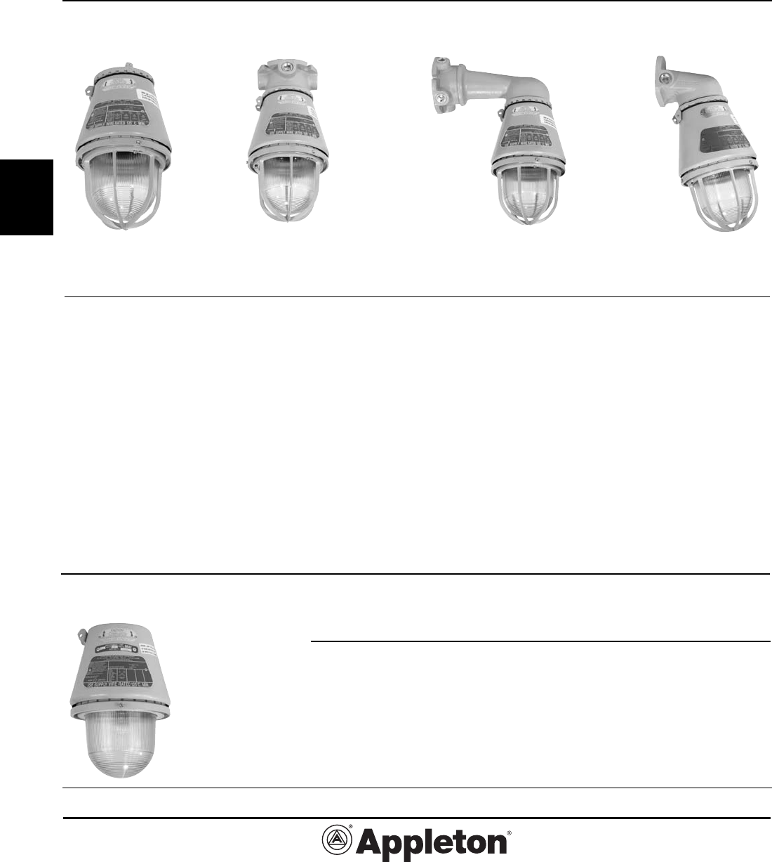
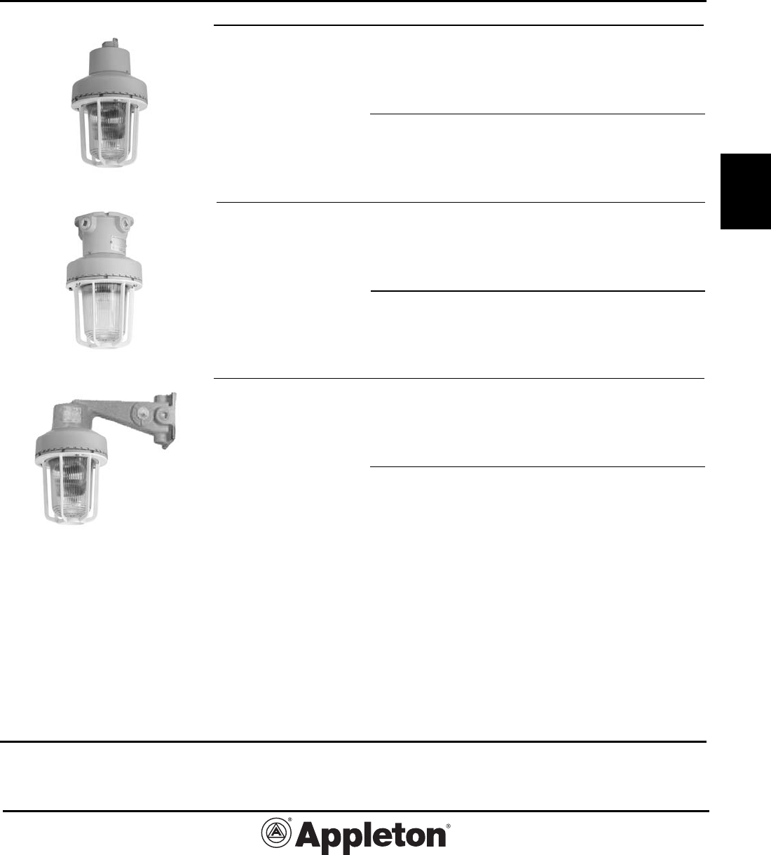
A-51® Incandescent Explosionproof
Lighting Fixtures: Factory Sealed
Suitable for use in Wet Locations.
UNILETS¨ for use with Threaded Metal Conduit.
Applications
• A-51 Series Incandescent Class I,
Groups A, B, C and D; Class II, E, F
and G applications (see listings and
area suitability chart).
• Ideal for use in chemical and
petrochemical plants and in other
heavy process areas where ignitable
vapors, dust, moisture and corrosive
atmospheres may be present.
• Suitable for use in wet locations.
• Wide range of wattages — 60 thru
500 watt incandescent lamps.
• Choice of units with or without
guard as well as choice of porcelain or
polyester reflectors.
• Choice of mountings — pendant,
ceiling, stanchion, long bracket and
short bracket.
• Porcelain reflectors for standard
applications and fiberglass reinforced
polyester reflectors for installations
where fixture is subject to exception-
ally severe corrosive atmospheres.
High bay reflector for installations
where mounting height from work
plane ranges from 20 to 30 feet.
• Class I, Groups A and B fixtures
have special UL approved sintered
metal flame arrester.
Features
• All A-51 fixtures are factory sealed—
no external sealing fittings are re-
quired.
• New high temp phenolic connec-
tion block in mounting hood has
rugged leaf spring contacts—loosen
two screws, rotate and remove for
quick wiring.
• Safe, easy servicing or relamp-
ing without disconnecting any wiring.
“Wireless” fixture unit easily threads
off mounting hood for convenient
servicing or for immediate exchange
with “stand-by” unit.
• All joints are flame tight.
Effective September, 2005
Copyright 2005
800-621-1506
www.appletonelec.com
PAGE 3
G2-3
G
A-51® Incandescent Explosionproof
Lighting Fixtures: Factory Sealed
Suitable for use in Wet Locations.
UNILETS® for use with Threaded Metal Conduit.
• Specially formulated two coat baked
epoxy enamel provides superior
protective finish to resist corrosion.
Applied to all mounting hoods, fixture
units and guards.
• New high temperature glass
reinforced phenolic socket block in
fixture unit has collector ring and pin
which automatically makes electrical
contact as fixture unit is threaded onto
mounting hood.
• Globes in A-51 fixtures are explo-
sion-proof and heat and impact re-
sisting glass. Prismatic configuration
on globe interior provides light control
while allowing smooth exterior surface
for cleaning.
• A-51 fixture units have standardized
threads to fit all A-51 and mounting
hoods.
• All fixtures have Alzak® aluminum
inner reflector for increased lumen
efficiency.
• A-51 fixture guards are of rugged
copper-free aluminum construction and
double epoxy coated—provide protec-
tion to globe. Easily mounts to globe
ring with 3 screws.
Standard Materials
• Fixtures and guards: copper-free
aluminum (4/10 of 1%).
• Pendant mounting hoods: copper-
free aluminum (4/10 of 1%).
• Ceiling and bracket mounting hoods:
malleable iron with aluminum adapt-
ers.
• Reflectors: porcelain enameled
steel, Alzak aluminum or fiberglass
reinforced polyester.
Standard Finishes
• Fixtures, guards and mounting
hoods: two coat epoxy-clad finish.
Epoxy powder coat finish, electrostati-
cally applied for complete, uniform sur-
face protection.
• Steel reflectors: white porcelain
enamel.
• Polyester and Alzak aluminum
reflectors: natural finish.
Compliances
• UL Listed.
• UL 1598 and 844.
• Class I,* Div. 1 and 2, Groups
A,B,C,D. Class II,* Div. 1 and 2, Groups
E,F,G.
*Some models.
• Suitable for use in wet locations.
• Appleton malleable iron products
conform to ASTM A47-77, Grade
32510, which has the following proper-
ties: tensile strength, 50,000 psi; yield,
32,000 psi; and elongation, 10%.
• Appleton aluminum products
are produced from a high strength
copper-free (4/10 of 1% max.) alloy.
Product Cross Reference
• See general introduction to catalog
for information on fixture selection. For
HID fixtures with integral ballasts, see
Code•Master Series in catalog section
G1. Fluorescent fixtures are in section
F3 and G3.
Porcelain
Effective September, 2005
Copyright 2005
PAGE 4
800-621-1506
www.appletonelec.com
G2-4
G
A-51® Incandescent Fixtures
Classified Area Suitability and Weights
Class I Div. 1 and Div. 2 Groups C and D
Fixture Lamp Supply
Unit Watts Without Reflectors Standard Dome 30˚ Angle High Bay Wire
AAU1N 100W A19 T5 T5 T5 _ 125°C
100W A21 T5 T5 T5 _ 125°C
AAU15N 150W A23 T3C T3C T3C _ 125°C
200W A25 T3C T3C T3C _ 125°C
200W PS25 T3C T3C T3C _ 125°C
300W PS25 T3C T3A T3A (D) _ 125°C
AAU2NS 200W PS25 T3C T3C T3C _ 110°C
200W PS30 T3C T3C T3C _ 110°C
300W PS25 T3C T3C T3C _ 110°C
300W PS30 T3C T3C T3C _ 110°C
AAU5NS 500W PS35 T3C T3C T3C _ 135°C
500W PS40 T3C T3C T3C _ 135°C
Class I Div. 1 and Div. 2 Groups A, B, C and D
AAUA15 150W A23 T3C T3C T3C _ 110°C
150W A25 T3C T3C T3C _ 110°C
200W A25 T3C T3C T3C _ 110°C
200W PS25 T3C T3C T3C _ 110°C
AAUA2 200W PS25 T3C T3C T3C _ 110°C
200W PS30 T3C T3C T3C _ 110°C
300W PS25 T3C T3C T3C _ 110°C
300W PS30 T3C T3C T3C _ 110°C
Class II Div. 1 and Div. 2 Groups E, F and G
AAU1N 100W A19 T3C T3C T3C _ 125°C
100W A21 T3C T3C T3C _ 125°C
AAU15N 150W A23 T3C T3C T3C _ 125°C
200W A25 T3C T3C T3C _ 125°C
200W PS25 T3 T3 T3 _ 125°C
300W PS25 T3 _ 125°C
AAU2NS 200W PS25 T3C T3C T3C _ 110°C
200W PS30 T3C T3C T3C _ 110°C
300W PS25 T3C T3C T3A (EF) _ 110°C
300W PS30 T3C T3C T3A (EF) _ 110°C
AAU5NS 500W PS35 T3C T3C T3C _ 135°C
500W PS40 T3C T3C T3C _ 135°C
Group A Pendant Mount only. NOTE: Ambient suitability of these incandescent fixtures: 40° C
Weights
Fixture Units Mounting Hoods Guards Standard Reflectors 30˚ Angle Reflectors High Bay Reflectors
Cat. No. Wt., Lbs. Cat. No. Wt., Lbs. Cat. No. Wt., Lbs. Cat. No. Wt., Lbs. Cat. No. Wt., Lbs. Cat. No. Wt., Lbs.
AAU-1N 7.6 Pendant 1.3 AAGU-1 .4 AARP-2ST 2.8 AARP-2AN 3.3 AARE-2HB 2.9
AAU-15N 7.6 Ceiling 4.8 AAGU-2 .8 AARW-15ST 2.1 AARW-15AN 2.1 AARE-5HB 3.9
AAU-2NS 10.7 Stanchion 1.6 AAGU-5 1.9 AARW-2ST 2.9 AARW-2AN 2.4
AAU-5NS 20.3 Long Bracket 8.9 AAGUA-15 .5 AARW-5ST 4.3 AARW-5AN 7.0
AAUA-15 15.0 Short Bracket 4.8 AARW-15ST 2.1 AARW-15AN 2.1
AAUA-2 18.0
Effective September, 2005
Copyright 2005
800-621-1506
www.appletonelec.com
PAGE 5
G2-5
G
A-51® Incandescent Explosionproof
Lighting Fixtures: Factory Sealed
Suitable for use in Wet Locations.
Class I, Div. 1 and 2
Groups C,D
Class II, Div. 1 and 2
Groups E,F,G*
Class III
UL 1598, UL 844
Hub Size Catalog
Type (Inches) Number
Pendant
One hub, rigid or flexible mounting.
60-100 Watt (AAU-1N) 1/2 AP1050
A-21 3/4 AP1075
1 AP10100
150-300 Watt (AAU-15N) 1/2 AP1550
A-23 PS-25 3/4 AP1575
1 AP15100
200-300 Watt (AAU-2NS) 1/2 AP2050
PS-30 3/4 AP2075
1 AP20100
300-500 Watt (AAU-5NS) 1/2 AP5050
PS-35 3/4 AP5075
1 AP50100
Ceiling
Four hubs and three close-up plugs.
60-100 Watt (AAU-1N) 1/2 AC1050
A-21 3/4 AC1075
1 AC10100
150-300 Watt (AAU-15N) 1/2 AC1550
A-23 PS-25 3/4 AC1575
1 AC15100
200-300 Watt (AAU-2NS) 1/2 AC2050
PS-30 3/4 AC2075
1 AC20100
300-500 Watt (AAU-5NS) 1/2 AC5050
PS-35 3/4 AC5075
1 AC50100
25° Stanchion (Not UL Listed)
One hub
60-100 Watt (AAU-1N)
A-21 1-1/2◆ AN10150
150-300 Watt (AAU-15N)
A-23 PS-25 1-1/2◆ AN15150
200-300 Watt (AAU-2NS)
PS-30 1-1/2◆ AN20150
300-500 Watt (AAU-5NS)
PS-35 1-1/2◆ AN50150
*For specific classified area suitability of each fixture listed, see table on page G2-4. ◆1-1/2” tapped hub furnished with a 1-1/2” to 1-1/4” reducer.
Effective September, 2005
Copyright 2005
PAGE 6
800-621-1506
www.appletonelec.com
G2-6
G
A-51® Incandescent Explosionproof
Lighting Fixtures: Factory Sealed
Suitable for use in Wet Locations.
Class I, Div. 1 and 2
Groups C,D
Class II, Div. 1 and 2
Groups E,F,G*
Class III
UL 1598, UL 844
Hub Size Catalog
Type (Inches) Number
Long Bracket
Four hubs and three close-up plugs
60-100 Watt (AAU-1N) 1/2 ALB1050
A-21 3/4 ALB1075
1 ALB10100
150-300 Watt (AAU-15N) 1/2 ALB1550
A-23 PS-25 3/4 ALB1575
1 ALB15100
200-300 Watt (AAU-2NS) 1/2 ALB2050
PS-30 3/4 ALB2075
1 ALB20100
300-500 Watt (AAU-5NS) 1/2 ALB5050
PS-35 3/4 ALB5075
1 ALB50100
15° Short Bracket
Two hubs and one close-up plug
60-100 Watt (AAU-1N) 1/2 ASB1050
A-21 3/4 ASB1075
150-300 Watt (AAU-15N) 1/2 ASB1550
A-23 PS-25 3/4 ASB1575
200-300 Watt (AAU-2NS) 1/2 ASB2050
PS-30 3/4 ASB2075
Accessories
Add Suffix to Fixture Catalog Number
Suffix
Guard -G
Standard Dome Reflector -ST
30˚ Angle Reflector -AN
High Bay Reflector -HB
*For specific classified area suitability of each fixture listed, see table on page G2-4.
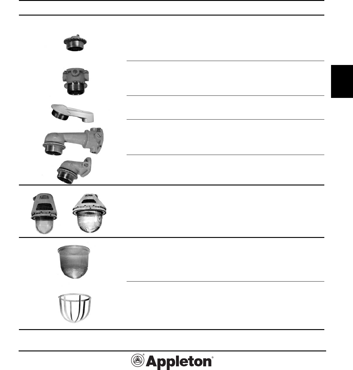
Three-Way Exit Sign
Epoxy enameled steel — 6”-high red lettering CJEXRN
60-200W (Mounts to AAU-1N or AAU-15N fixture units
in place of guard)
Single Sided Exit Sign
Epoxy enameled steel — 6”-high red lettering AEXR-15R
60-200W (Mounts to AAU-1N or AAU-15N fixture units
in place of guard)
(See page G2-24 for dimensions)
Effective September, 2005
Copyright 2005
800-621-1506
www.appletonelec.com
PAGE 7
G2-7
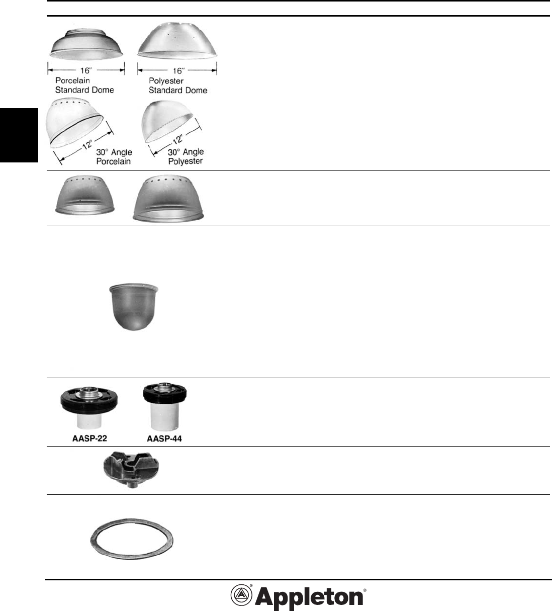
G
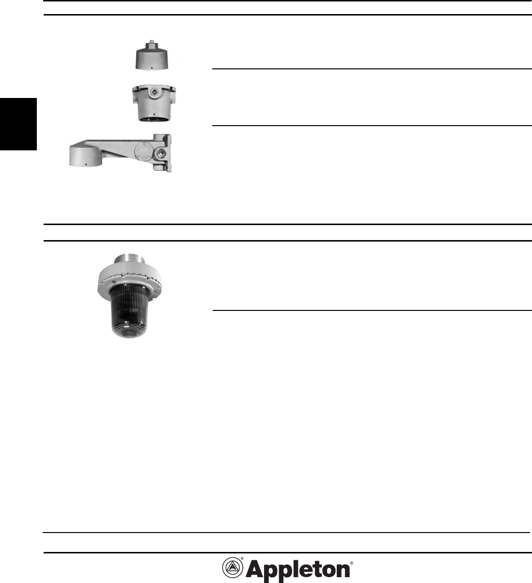
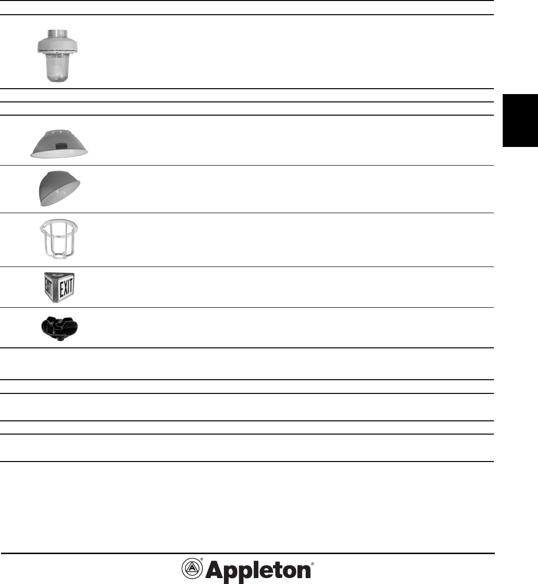
A-51® Incandescent Explosionproof
Lighting Fixtures: Mounting Hoods,
Fixture Units, Globes, Guards
Copper-Free Aluminum Fixture with Gray Epoxy Finish.
Mounting Hoods in Aluminum and Malleable Iron.*
Hub Size Catalog
Type (Inches) Number
Mounting Hoods*
Pendant
One hub, 1/2 AAP-50
rigid or flexible mounting 3/4 AAP-75
1 AAP-100
Ceiling
Four hubs 1/2 AAC-50
and three 3/4 AAC-75
close-up plugs 1 AAC-100
25° Stanchion (Not UL Listed)
One hub 1-1/2 AAN-150†
Long Bracket
Four hubs 1/2 AALB-50
and three 3/4 AALB-75
close-up plugs 1 AALB-100
15° Short Bracket
Two hubs and 1/2 AASB-50
one close-up plug 3/4 AASB-75
Fixture Units
60-100W A-21 AAU-1N
150-300W A-23 & PS-25 AAU-15N
200-300W PS-30 AAU-2NS
300-500W PS-35 AAU-5NS
Prismatic Glass Globes
60-100W (AAU-1N) AAGL-1PR
150-300W (AAU-15N) AAGL-1PR
200-300W (AAU-2NS) AAGL-2PR
300-500W (AAU-5NS) AAGL-5PR
Aluminum Guards
60-100W (AAU-1N) AAGU-1
150-300W (AAU-15N) AAGU-1
200-300W (AAU-2NS) AAGU-2
300-500W (AAU-5NS) AAGU-5
†1-1/2” Tapped hub furnished with a 1-1/2” to 1-1/4” reducer. * Pendant and stanchion mounting hoods are copper-free aluminum. Ceiling and
bracket types are malleable iron with aluminum adapters.
Effective September, 2005
Copyright 2005
PAGE 8
800-621-1506
www.appletonelec.com
G2-8
G
A-51® Incandescent Explosionproof
Lighting Fixtures:
Reflectors, Colored Globes, Parts
Porcelain, Alzak Aluminum or Polyester Reflectors.
Fixture Size Catalog Number
Porcelain and Polyester
Reflectors
Standard Dome Porcelain Polyester
(Not for use with short brackets)
60-100W (AAU-1N) AARW-15ST
150-300W (AAU-15N) AARW-15ST
200-300W (AAU-2NS) AARW-2ST AARP-2ST
300-500W (AAU-5NS) AARW-5ST
30˚ Angle
60-100W (AAU-1N) AARW-15AN
150-300W (AAU-15N) AARW-15AN
200-300W (AAU-2NS) AARW-2AN AARP-2AN
300-500W (AAU-5NS) AARW-5AN
Alzak Aluminum Reflectors
High Bay
200-300W (AAU-2NS) AARE-2HB
300-500W (AAU-5NS) AARE-5HB
Colored Glass Globes
Amber
60-100W (AAU-1N) AAGL-1A
150-300W (AAU-15N) AAGL-1A
200-300W (AAU-2NS) AAGL-2A
Green
60-100W (AAU-1N) AAGL-1G
150-300W (AAU-15N) AAGL-1G
200-300W (AAU-2NS) AAGL-2G
Red
60-100W (AAU-1N) AAGL-1R
150-300W (AAU-15N) AAGL-1R
200-300W (AAU-2NS) AAGL-2R
Replacement Socket
60-100W (AAU-1N)—Medium Base AASP-11
150-300W (AAU-15N)—Medium Base AASP-22
200-300W (AAU-2NS)—Medium Base AASP-22
300-500W (AAU-5NS)—Mogul Base AASP-44
Connection Block
60-500W. Fits A-51
Mounting Hoods VPT-7
Globe Gaskets—Fiber
and Aluminum
Requires one of each
Fiber Aluminum
60-300W (AAU-1N and AAU-15N) AASP-15V AASP-15A
200-300W (AAU-2NS) AASP-2V AASP-2A
300-500W (AAU-NS) AASP-5V AASP-5A
Effective September, 2005
Copyright 2005
800-621-1506
www.appletonelec.com
PAGE 9
G2-9
G
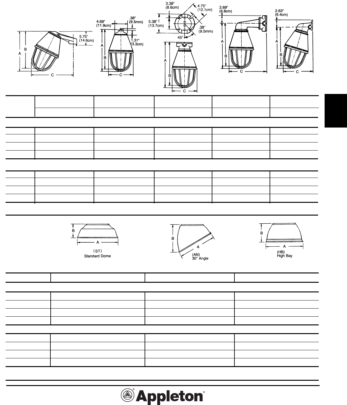
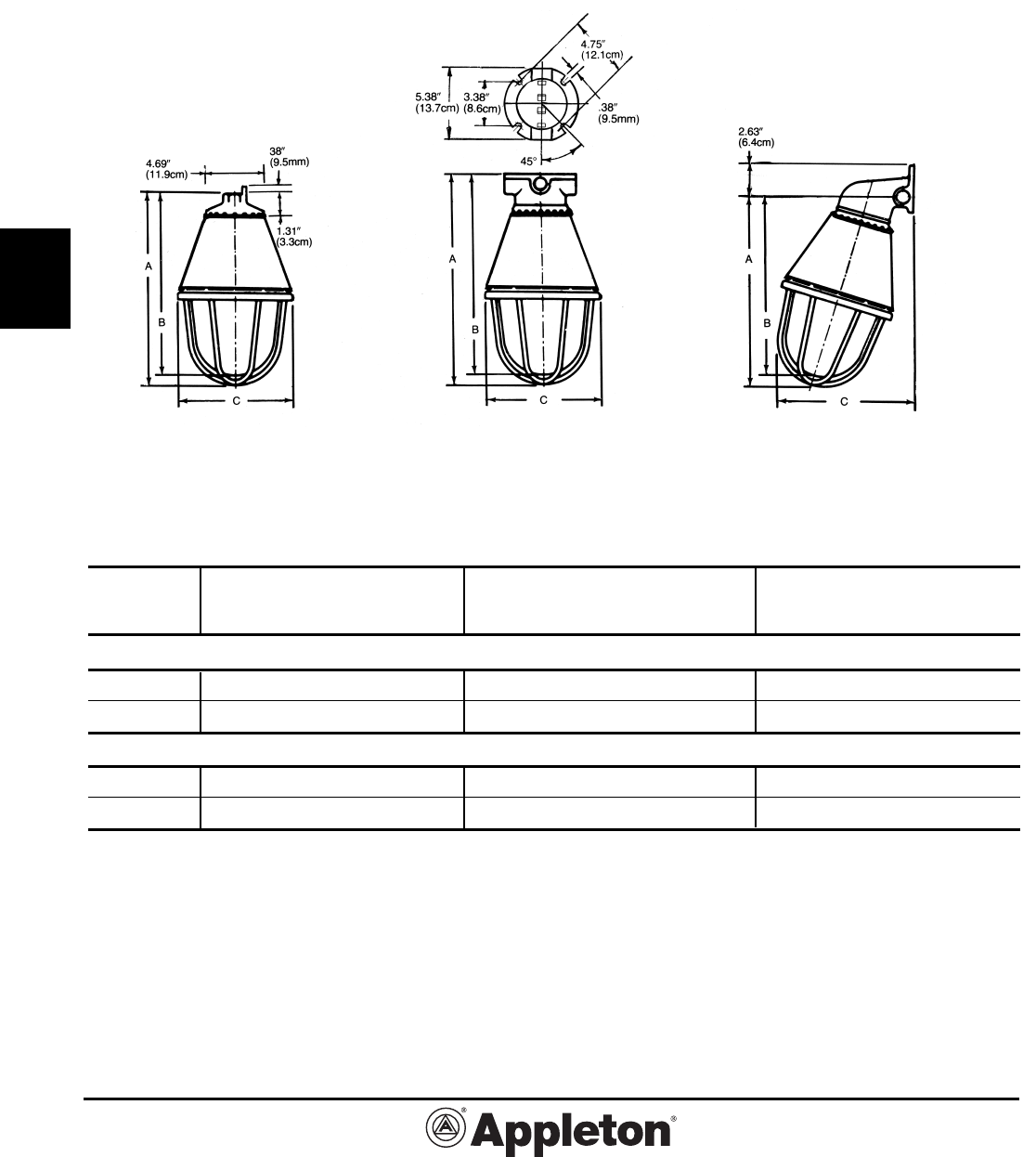
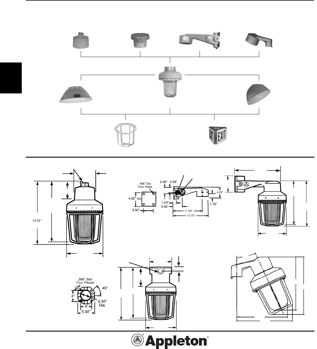
Dimensions: A-51® Incandescent
Lighting Fixtures
Stanchion Pendant◆ Ceiling Long Bracket Short Bracket
Size (Watts) A B C A B C A B C A B C A B C
Dimensions in Inches
60-100 11.47 10.85 11.50 12.25 11.63 7.06 13.75 13.13 7.06 13.75 13.13 12.38 13.56 12.94 9.13
150-300 11.47 10.85 11.50 12.25 11.63 7.06 13.75 13.13 7.06 13.75 13.13 12.38 13.56 12.94 9.13
200-300 13.07 12.38 12.71 13.94 13.25 8.81 15.44 14.75 8.81 15.50 14.75 13.25 15.19 14.50 10.13
300-500 15.09 14.34 14.64 16.00 15.25 12.13 17.50 17.75 12.13 17.50 16.75 14.88 17.25 16.50 11.94
Dimensions in Centimeters
60-100 29.1 27.6 29.2 31.1 29.5 17.9 34.9 33.3 17.9 34.9 33.3 31.4 34.4 32.9 23.2
150-300 29.1 27.6 29.2 31.1 29.5 17.9 34.9 33.3 17.9 34.9 33.3 31.4 34.4 32.9 23.2
200-300 33.2 31.4 32.3 35.4 33.7 22.4 39.2 37.5 22.4 39.4 37.5 33.7 38.6 36.8 25.7
300-500 38.3 36.4 37.2 40.6 38.7 30.8 44.5 45.1 30.8 44.5 42.5 37.8 43.8 41.9 30.3
◆For dimensions of fixture unit only, subtract pendant hood dimension 1.31” (3.3cm) from dimensions A and B as listed.
Size (Watts) A B A B A B
Dimensions in Inches
60-100 12.00 4.50 10.00 7.63 — —
150-200 14.00 4.38 10.00 7.63 — —
200-300 16.00 5.19 12.00 7.88 12.00 6.06
300-500 20.00 6.84 18.00 13.13 18.00 9.13
Dimensions in Centimeters
60-100 30.5 11.4 25.4 19.4 — —
150-200 35.6 11.1 25.4 19.4 — —
200-300 40.6 13.2 30.5 20.0 30.5 15.4
300-500 50.8 17.4 45.7 33.3 45.7 23.2
*Dimensions illustrated are for porcelain steel (dome and angle) and etched Alzak aluminum (high bay). Overall dimensions for fiberglass
reinforced polyester reflectors are: standard dome—16-1/2” dia., 6” high; 30° Angle—14-3/8” dia., 10” high.
A-51 Lighting Fixtures
A-51 Reflectors*
Effective September, 2005
Copyright 2005
PAGE 10
800-621-1506
www.appletonelec.com
G2-10
G
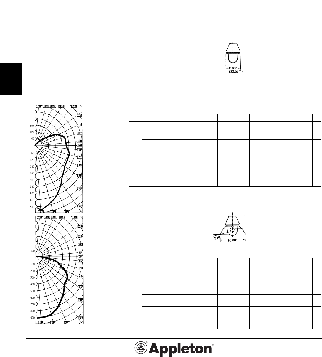
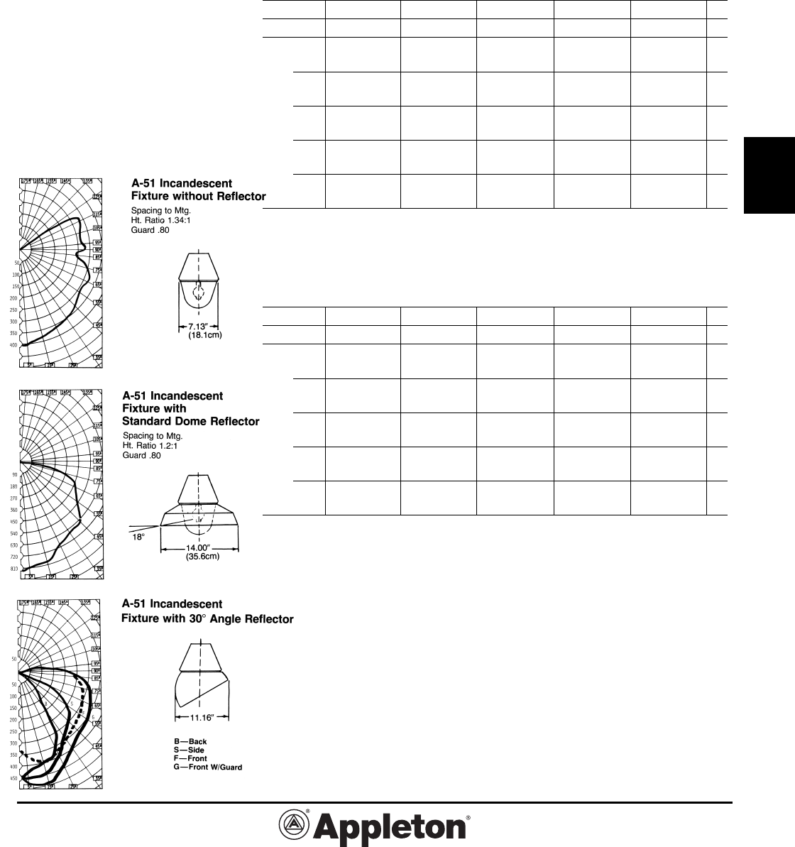
Photometric Data:
A-51® Incandescent Explosionproof
Lighting Fixtures
Class I, Groups C and D Fixtures.
Coefficients of Utilization: Zonal Cavity Method
Photometric data shown here is based on a
200 watt type PS-30 lamp and is representa-
tive of the performance for all A-51 incandes-
cent fixtures using 60 watt to 500 watt lamps.
For candlepower values of fixtures with other
lamps, use the following multipliers: 60 watt
A-19—.23; 100 watt A-19—.47; 150 watt
A-21—.75; 200 watt A-23—1.07; 200 watt
A-25—1.02; 200 watt PS-25—1.03: 300
watt PS-25—1.70; 300 watt PS-30—1.63;
300 watt PS-35—1.55; 500 watt PS-35—
2.95; 500 watt PS-40—2.69. To determine
candlepower values of fixtures with a guard,
multiply by value shown with each curve.
Effective Floor Cavity Reflectance (Rfc) is 20%
% Ceiling Rcc 80 70 50 30 10 0
% Walls Rw 50 30 10 50 30 10 50 30 10 50 30 10 50 30 10 0
1 .735 .690 .651 .695 .655 .618 .622 .590 .561 .554 .530 .506 .493 .473 .454 .422
2 .621 .558 .503 .588 .530 .481 .525 .478 .437 .467 .430 .396 .413 .384 .357 .327
3 .540 .468 .411 .512 .446 .394 .457 .404 .359 .406 .363 .327 .360 .325 .294 .267
4 .474 .400 .342 .450 .381 .328 .402 .346 .301 .359 .312 .274 .318 .280 .248 .223
5 .415 .341 .284 .394 .325 .272 .354 .295 .251 .316 .266 .229 .280 .240 .207 .184
6 .372 .297 .245 .352 .284 .233 .316 .258 .215 .283 .234 .197 .252 .210 .178 .157
7 .334 .262 .213 .317 .249 .203 .285 .227 .187 .255 .207 .170 .228 .187 .155 .136
8 .300 .231 .182 .285 .221 .175 .256 .202 .162 .231 .183 .148 .206 .165 .135 .117
9 .271 .204 .157 .258 .195 .152 .233 .178 .140 .209 .162 .128 .187 .146 .117 .100
10 .246 .181 .139 .234 .175 .135 .212 .160 .124 .191 .145 .113 .172 .132 .102 .087
A-51 Incandescent
Fixture without Reflector
Spacing to Mtg.
Ht. Ratio 1.25:1
Guard .877
ROOM CAVITY RATIOS
Effective Floor Cavity Reflectance (Rfc) is 20%
% Ceiling Rcc 80 70 50 30 10 0
% Walls Rw 50 30 10 50 30 10 50 30 10 50 30 10 50 30 10 0
1 .757 .727 .700 .740 .713 .689 .709 .686 .667 .681 .663 .646 .656 .641 .627 .612
2 .660 .613 .572 .647 .603 .567 .621 .585 .552 .598 .568 .540 .577 .551 .528 .512
3 .580 .524 .478 .570 .516 .475 .549 .504 .466 .529 .490 .458 .511 .478 .449 .434
4 .514 .452 .403 .504 .446 .400 .486 .436 .395 .469 .425 .390 .454 .415 .384 .368
5 .451 .385 .336 .442 .380 .334 .427 .372 .332 .413 .364 .327 .399 .357 .323 .308
6 .402 .336 .291 .394 .333 .286 .381 .326 .285 .369 .319 .282 .358 .313 .279 .264
7 .361 .296 .254 .355 .293 .250 .343 .286 .247 .332 .282 .245 .323 .278 .243 .229
8 .323 .261 .216 .318 .258 .216 .308 .254 .215 .299 .249 .213 .290 .245 .211 .197
9 .291 .230 .187 .287 .227 .187 .278 .223 .186 .269 .219 .184 .262 .216 .182 .169
10 .264 .204 .166 .259 .204 .166 .253 .200 .164 .245 .197 .162 .240 .194 .161 .149
ROOM CAVITY RATIOS
A-51 Incandescent
Fixture with
Standard Dome
Reflector
Spacing to Mtg.
Ht. Ratio 1.25:1
Guard .890
Effective September, 2005
Copyright 2005
800-621-1506
www.appletonelec.com
PAGE 11
G2-11
G
Photometric Data:
A-51® Incandescent Explosionproof
Lighting Fixtures
Class I, Groups C and D Fixtures.
Coefficients of Utilization: Zonal Cavity Method
Photometric data shown here is based on a
200 watt type PS-30 lamp and is representa-
tive of the performance for all A-51 incandes-
cent fixtures using 60 watt to 500 watt lamps.
For candlepower values of fixtures with other
lamps, use the following multipliers: 60 watt
A-19—.23; 100 watt A-19—.47; 150 watt
A-21—.75; 200 watt A-23—1.07; 200 watt
A-25—1.02; 200 watt PS-25—1.03: 300
watt PS-25—1.70; 300 watt PS-30—1.63;
300 watt PS-35—1.55; 500 watt PS-35—
2.95; 500 watt PS-40—2.69. To determine
candlepower values of fixtures with a guard,
multiply by value shown with each curve.
Effective Floor Cavity Reflectance (Rfc) is 20%
% Ceiling Rcc 80 70 50 30 10 0
% Walls Rw 50 30 10 50 30 10 50 30 10 50 30 10 50 30 10 0
1 .686 .644 .645 .671 .651 .634 .644 .628 .614 .620 .607 .595 .598 .588 .577 .566
2 .614 .580 .549 .603 .571 .545 .581 .555 .531 .562 .540 .520 .544 .525 .508 .496
3 .550 .508 .473 .542 .501 .470 .524 .490 .461 .507 .478 .454 .492 .467 .446 .434
4 .493 .445 .408 .486 .441 .404 .470 .431 .400 .456 .422 .395 .443 .413 .389 .377
5 .439 .387 .349 .432 .383 .347 .420 .376 .344 .407 .369 .340 .396 .383 .336 .324
6 .393 .340 .304 .387 .338 .300 .376 .331 .298 .366 .326 .296 .356 .320 .293 .281
7 .352 .299 .264 .347 .296 .261 .337 .290 .258 .327 .287 .256 .320 .283 .254 .242
8 .313 .261 .224 .309 .259 .223 .300 .255 .222 .293 .251 .220 .285 .247 .219 .207
9 .280 .228 .191 .276 .225 .191 .268 .222 .190 .261 .219 .189 .254 .216 .187 .176
10 .252 .201 .168 .248 .201 .168 .242 .197 .167 .236 .195 .165 .231 .192 .164 .153
A-51 Incandescent
Fixture with
High Bay Reflector
Spacing to Mtg.
Ht. Ratio 1.40:1
Guard .865
A-51 Incandescent
Fixture with
30˚ Reflector
B—Back
S—Side
F—Front
G—Front W.Guard
ROOM CAVITY RATIOS
Effective September, 2005
Copyright 2005
PAGE 12
800-621-1506
www.appletonelec.com
G2-12
G
A-51® Incandescent Groups A and B
Explosionproof Lighting Fixtures:
Factory Sealed
Suitable for use in Wet Locations.
Class I, Div. 1 and 2
Groups A◆,B,C,D
Class II, Div. 1 and 2
Groups E,F,G
Class III
UL 1598, UL 844 Listed
Fixture Type and Type Hub Size (Inches) Catalog Number
Pendant
One hub, rigid or flexible mounting.
60-200 Watt (AAUA-15) 1/2 AAPA1550
PS-25 3/4 AAPA1575
200-300 Watt (AAUA-2) 1/2 AAPA2050
PS-30 3/4 AAPA2075
Ceiling
Four hubs and three close-up plugs.
60-200 Watt (AAUA-15) 1/2 AACA1550
PS-25 3/4 AACA1575
200-300 Watt (AAUA-2) 1/2 AACA2050
PS-30 3/4 AACA2075
15˚ Short Bracket
Two hubs and one close-up plug.
60-200 Watt (AAUA-15) 1/2 AASBA1550
PS-25 3/4 AASBA1575
200-300 Watt (AAUA-2) 1/2 AASBA2050
PS-30 3/4 AASBA2075
Accessories
Add suffix to fixture catalog number
Suffix
Guard -G
Standard Dome Reflector -ST
30˚ Angle Reflector -AN
Porcelain Steel and
Polyester Reflectors
Porcelain Polyester
Standard Dome
60-200 Watt (AAUA-15) AARW-15ST
200-300 Watt (AAUA-2) AARW-2ST AARP-2ST
30˚ Angle
60-200 Watt (AAUA-15) AARW-15AN
200-300 Watt (AAUA-2) AARW-2AN AARP-2AN
◆ Shaded area indicates pendant mount is suitable for Class I, Group A in addition to other applicable area suitabilities.
For specific classified area suitability of each fixture, see page G2-4.
Effective September, 2005
Copyright 2005
800-621-1506
www.appletonelec.com
PAGE 13
G2-13
G
Hub Size
Type (Inches) Catalog Number
Mounting Hoods
Pendant
One hub, rigid 1/2 AAP-50†
or flexible mounting 3/4 AAP-75†
Ceiling
Four hubs and
three close-up 1/2 AAC-50
plugs 3/4 AAC-75
15˚ Short Bracket
Two hubs and
one close-up 1/2 AASB-50
plug 3/4 AASB-75
Fixture Units
60-200 Watt
PS-25 AAUA-15
200-300 Watt
PS-30 AAUA-2
Globe and Ring Assembly
60-200 Watt (AAUA-15) AAGLA-15
200-300 Watt (AAUA-2) AAGLA-2
Aluminum Guards
60-200 Watt (AAUA-15) AAGUA-15
200-300 Watt (AAUA-2) AAGU-2
Medium Base Lamp Socket
60-200 Watt (AAUA-15) AASPA-15
200-300 Watt (AAUA-2) AASPA-22
Connection Block
Fits all A-51 and AA-51 mounting hoods
60-300 Watt VPT-7
† Group A pendant mount only. * Pendant mounting hoods are copper-free aluminum. Ceiling and bracket types are malleable iron with aluminum
adapters.
A-51® Incandescent Groups A† and B
Explosionproof Lighting Fixtures:
Mounting Hoods, Fixtures and Parts
Mounting Hoods in Aluminum and Malleable Iron.* Copper-Free
Aluminum Fixture with Gray Epoxy Finish.
Effective September, 2005
Copyright 2005
PAGE 14
800-621-1506
www.appletonelec.com
G2-14
G
Dimensions:
A-51® Groups A and B Incandescent Lighting
Fixtures
Pendant Ceiling Short Bracket
Size (Watts) A B C A B C A B C
Dimensions in Inches
60-200 13.69 13.13 7.06 16.50 15.94 7.06 15.00 14.44 9.50
200-300 14.75 13.69 8.81 17.56 16.50 8.81 16.00 15.44 10.38
Dimensions in Centimeters
60-200 34.8 33.3 17.9 41.9 40.5 17.9 38.1 36.7 24.1
200-300 37.5 34.8 22.4 44.6 41.9 22.4 40.6 39.2 26.4
Pendant Ceiling Short Bracket
Effective September, 2005
Copyright 2005
800-621-1506
www.appletonelec.com
PAGE 15
G2-15
G
Photometric Data:
A-51® Incandescent Explosionproof
Lighting Fixtures
Class I, Groups A and B Fixtures.
Effective Floor Cavity Reflectance (Rfc) is 20% (No Reflector)
% Ceiling Rcc 80 70 50 30 10 0
% Walls Rw 50 30 10 50 30 10 50 30 10 50 30 10 50 30 10 0
1 .711 .669 .630 .669 .631 .595 .590 .560 .533 .518 .495 .473 .452 .434 .417 .383
2 .602 .541 .488 .567 .511 .465 .499 .455 .416 .437 .402 .371 .380 .352 .327 .296
3 .519 .449 .393 .488 .424 .374 .430 .379 .336 .375 .335 .300 .325 .292 .264 .236
4 .456 .384 .328 .430 .364 .312 .379 .325 .282 .332 .288 .252 .288 .252 .223 .197
5 .400 .328 .274 .378 .311 .260 .334 .278 .236 .293 .247 .211 .254 .217 .187 .164
6 .357 .285 .234 .336 .270 .221 .297 .242 .200 .261 .215 .180 .227 .188 .159 .138
7 .318 .248 .200 .300 .234 .190 .265 .209 .171 .233 .187 .153 .204 .165 .135 .116
8 .287 .219 .172 .270 .208 .164 .240 .187 .149 .212 .167 .134 .104 .147 .119 .101
9 .260 .194 .150 .246 .185 .143 .218 .166 .130 .192 .148 .117 .168 .131 .103 .087
10 .236 .173 .132 .222 .166 .126 .199 .149 .114 .175 .133 .102 .154 .117 .090 .075
ROOM CAVITY RATIOS
Effective Floor Cavity Reflectance (Rfc) is 20% (Std. Dome Reflector)
% Ceiling Rcc 80 70 50 30 10 0
% Walls Rw 50 30 10 50 30 10 50 30 10 50 30 10 50 30 10 0
1 .797 .763 .733 .779 .748 .721 .745 .720 .697 .715 .695 .676 .689 .671 .655 .640
2 .687 .633 .586 .673 .622 .581 .645 .603 .566 .620 .585 .553 .597 .567 .541 .524
3 .594 .530 .478 .583 .522 .474 .560 .508 .464 .538 .494 .457 .519 .481 .448 .431
4 .527 .458 .404 .517 .452 .400 .497 .440 .395 .479 .430 .390 .462 .419 .384 .366
5 .466 .393 .340 .456 .388 .337 .440 .379 .335 .424 .371 .330 .410 .364 .326 .310
6 .414 .342 .292 .406 .339 .288 .391 .331 .286 .378 .324 .283 .367 .317 .280 .264
7 .369 .298 .252 .362 .294 .248 .350 .288 .245 .337 .284 .242 .328 .279 .240 .225
8 .333 .265 .217 .327 .262 .216 .316 .257 .215 .307 .252 .213 .297 .248 .211 .196
9 .302 .235 .189 .297 .232 .189 .287 .229 .188 .278 .224 .186 .270 .221 .185 .170
10 .273 .209 .167 .268 .209 .167 .261 .204 .166 .253 .201 .163 .247 .198 .162 .149
ROOM CAVITY RATIOS
Coefficients of Utilization: Zonal Cavity
Method
Photometric data shown here is based
on a 200 watt type PS-25 lamp, and is
representative of the performance for
A-51 incandescent fixtures (Groups A and B).
For candlepower values of fixtures with other
lamps, use the following multipliers: 150 watt
(PS-25), .70; 300 watt (PS-25), 1.6. To de-
termine candlepower values of fixtures with
a guard, multiply by value shown with each
curve.
Effective September, 2005
Copyright 2005
PAGE 16
800-621-1506
www.appletonelec.com
G2-16
G
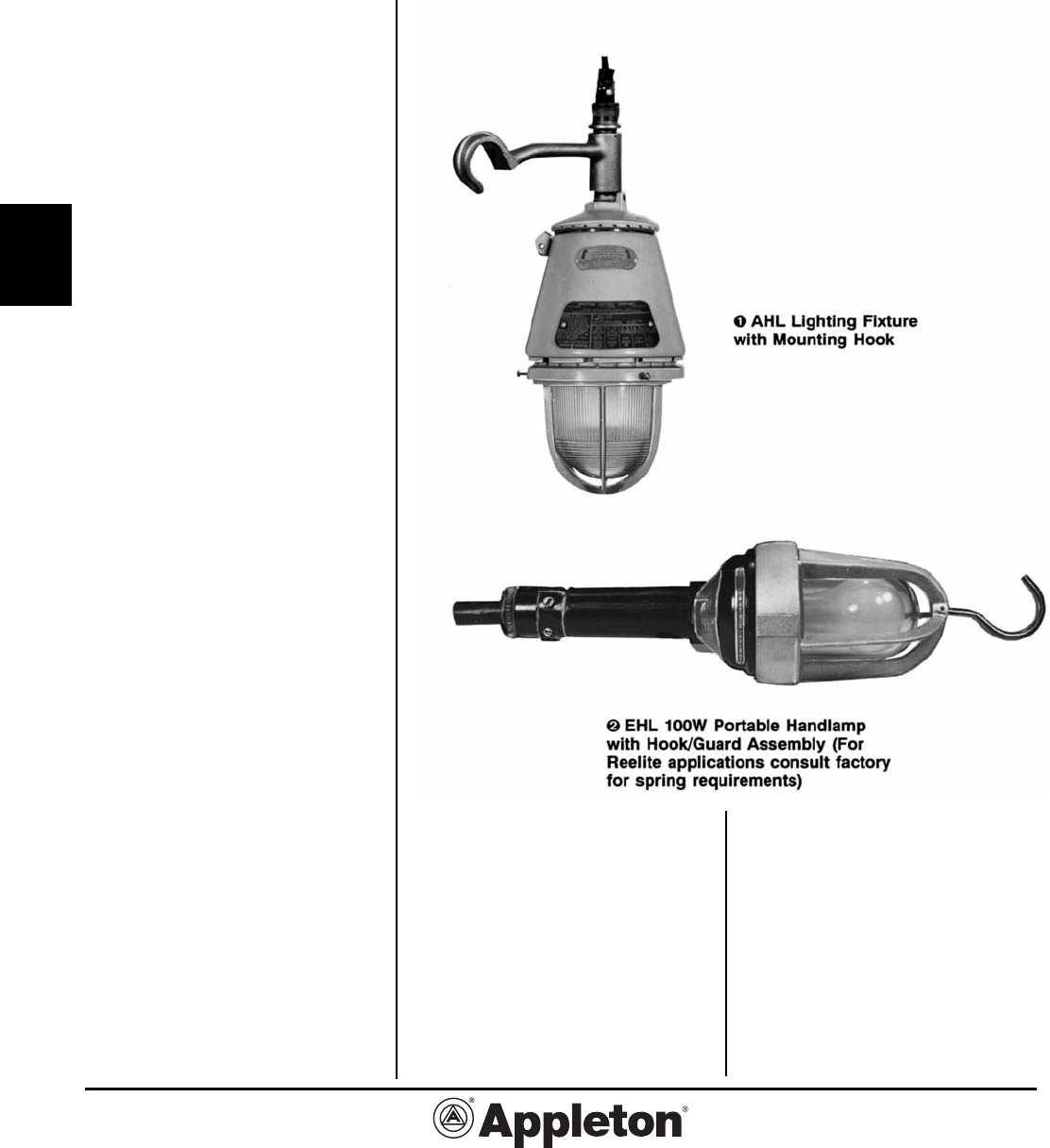
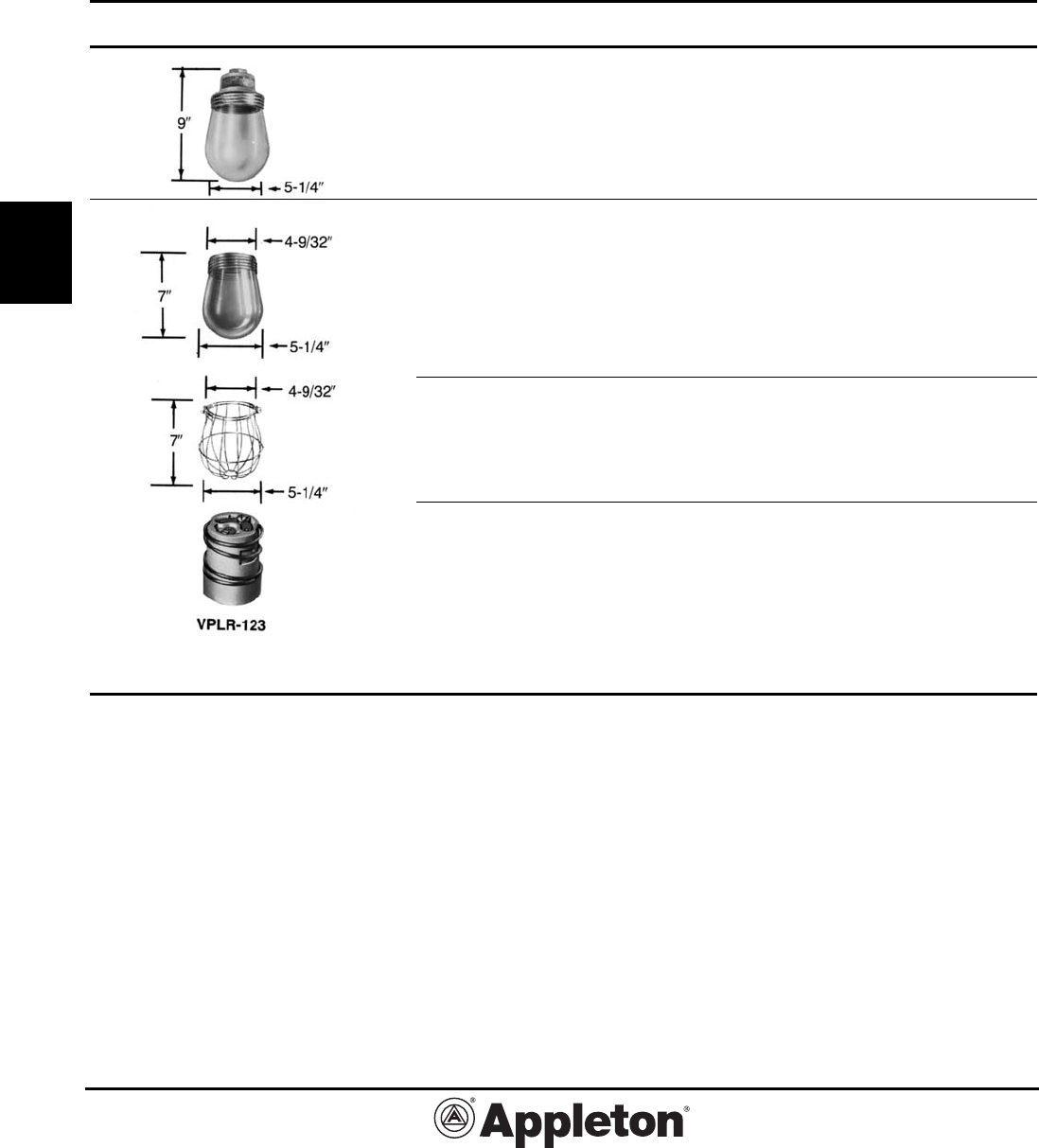
AHL and EHL Incandescent Explosionproof
Lighting Fixtures and Handlamp: Factory Sealed
Suitable for use in Wet Locations.
Applications
• AHL general purpose Explosionproof
lighting fixture - an A-51 fixture with
handle assembly of hook and cable
clamp. CAUTION: For safe opera-
tion, the AHL fixture weight must be
supported by the hanger hook,
not by the flexible cord, per NEC
502-11(a)(3).
• EHL general purpose Explosionproof
portable handlamp. Only 5” in diameter
for ease of movement.
• The EHL handlamp may be used
with AE Automatic Take-Up Reelites
listed in Catalog Subsection W3 and
ECC Cord Connector and Plugs and
Receptacles in Catalog Section L.
Features: AHL and EHL
• Equipped with connection block for
ease of wiring and relamping.
• Cable clamp diameters: AHL— .375”
to .625”. EHL—.406” for 16-3 AWG.
• Heat- and impact-resistant glass
globes.
AHL Features
• Sturdy fixture with rugged hanging
hook.
• Safety grounding — additional termi-
nal furnished to connect to grounding
conductor.
EHL Features
• Portability, with phenolic handle and
non-sparking guard with hook.
• Easy relamping — loosen setscrew,
unscrew guard, remove globe and
insert lamp.
• Safety grounding — remove cable
and clamp and make connections to
terminal (including one ground termi-
nal) then tighten clamp.
Standard Materials
• Globes: heat-and impact-resistant
glass.
• AHL fixture unit, hook and guard:
copper-free aluminum.
• AHL cable clamp: brass.
• EHL fixture body and handle: lami-
nated phenolic.
• EHL handle: laminated phenolic.
• EHL hook: brass.
• EHL guard: copper-free aluminum.
Standard Finishes
• AHL fixture unit, guard, handle and
hook: two-coat epoxy enamel.
• AHL cable clamp: natural finish.
• EHL fixture body: laminated
phenolic.
• EHL handle: phenolic.
• EHL guard and hook: guard — natu-
ral finish, hook — zinc electroplate and
clear chromate.
• EHL cable clamp: laminated
phenolic.
Compliances
• UL Standard 1598 (supersedes UL
57) and 844.
• Suitable for use in wet locations.
• Appleton malleable iron products
conform to ASTM A47-77, Grade
32510, which has the following proper-
ties: tensile strength, 50,000 psi; yield,
32,000 psi; and elongation, 10%.
• Appleton aluminum products
are produced from a high strength
copper-free (4/10 of 1% max.) alloy.
Effective September, 2005
Copyright 2005
800-621-1506
www.appletonelec.com
PAGE 17
G2-17
G
AHL and EHL Incandescent
Explosionproof Lighting Fixtures
and Handlamp: Factory Sealed
Suitable for use in Wet Locations.
Cable Dia. Catalog
U.S. Pat. 3,170,750 Pat. Can. 1968 Description (Inches) T Ratings Number
AHL—Explosionproof
60-300W Lighting Fixtures
Class I, Groups C and D;
Class II, Groups F and G
CAUTION: For safe operation, weight of fixture
must be supported by hanger hook, not by
the flexible cord, per NEC 502-11(a)3.
60-100 Watt, A-21
(AAU-1N) .375 to .625 T4 AHL100
200-300 Watt, PS-30
(AAU-2NS) .375 to .625 T4A AHL200
*EHL—Explosionproof
100W Portable Handlamp
Laminated Phenolic Handle. Wiring Connection
Block takes from #16 to #14 Wire.
Class I, Groups C and D
100 Watt, A-21 .406 T3A EHL100N
EHL Replacement
Globe and Guard
Heat-resistant glass globe XP419
Aluminum guard with hook XP163SA
† To reduce the risk of ignition of hazardous atmospheres, do not use where electrically conductive dusts are present (most coal dusts are
not electrically conductive). *Handlamp accommodates 16-3 SO cable. Consult factory if 14-3 cable is required.
AHL:
Class I, Div. 1 and 2
Groups C,D
Class II, Div. 1 and 2
Groups F
†,G
Class III
EHL:
Class I, Div. 1 and 2
Groups C,D
AHL Dimensions
Dim. in Dim. in
Inches Centimeters
Cat. No., A B C A B C
AHL100 14.25 7.06 10.94 36.2 17.9 27.8
AHL200 15.94 8.81 12.63 40.5 22.4 32.1
EHL Dimensions
Effective September, 2005
Copyright 2005
PAGE 18
800-621-1506
www.appletonelec.com
G2-18
G
EDT Incandescent Dust-Ignitionproof
Lighting Fixtures and Accessories
Suitable for use in Wet Locations.
Class II, Div. 1 and 2
Groups E,F,G
Class III
UL 1598, UL 844
Hub
Watts Size Catalog Number
Pendant Lighting Fixture*
One tapped opening for
rigid or flexible mounting,
with heat resistant clear globe
60-200 Watt 1/2” EDTP2050
Fixture Accessories and Parts
Heat Resistant
Clear Glass Globe
60-200 Watt VSGL-2HR
Globe Guard
60-200 Watt DPGU-2
Replacement Porcelain
Shock-Absorbing Socket
Medium Base
60-200 Watt VPLR-123
* T3C maximum operating temperature. Supply wire 150°C. Maximum ambient temperature 25°C. Vertical mount only (globe down).
Effective September, 2005
Copyright 2005
800-621-1506
www.appletonelec.com
PAGE 19
G2-19
G
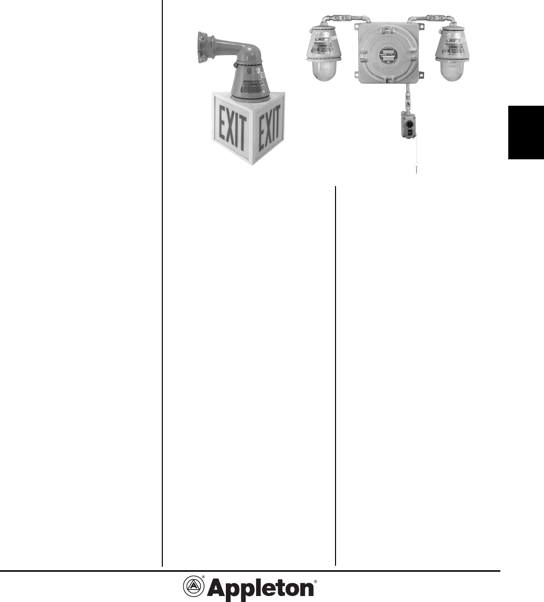
ELS Series Emergency Lighting System:
Explosionproof, Dust-Ignitionproof
Remote and direct mounted fixtures for hazardous location applications
Applications
• ELS Series features an emergency
lighting power unit that is designed to
provide safe operation in the presence
of hazardous gasses, vapors, or dusts,
defined by the National Electrical Code
as Class I, Groups C and D, and Class
II, Groups E,F,G.
• Typical applications include all means
of egress (such as walkways, exit
ramps, stairs and aisles) for hazardous
areas which include oil refineries, petro-
chemical facilities, pulp and paper mills,
chemical storage areas, waste water
treatment facilities and grain elevators.
Features
• The electronics consist of a solid-
state charger, transfer circuit and low
voltage battery disconnect circuit.
• The unit test switch and AC “On”
indicator light are housed in a separate
module that may be attached directly to
the unit housing or mounted remotely
for ease of testing.
• All ELS Series units are rated for
operation in NEC Class I, Divisions 1 or
2 Groups C and D and Class II, Divisions
1 or 2 Groups E, F, and G environment.
•
Housing provisions allow for the
attachment of two optional Explosion-
proof lighting fixtures.
• Unit capacity is sufficient for the
connection of up to four, 6- or 12- volt,
18-watt fixtures
• Units provide 90 minutes of emer-
gency operation.
• The solid-state charger maintains
battery at full charge.
• Upon failure of utility voltage, the DC
emergency lighting load is connected to
the battery.
• During emergency operation,
automatic battery protection from deep
discharge damage is provided by a
low-voltage battery disconnect (LVD)
circuit.
• Upon restoration of normal power,
the charger will begin a recharge cycle.
It will bring the battery to full capacity
within acceptable UL time standards.
•
A pilot light indicates the presence
of AC line voltage, and a test switch is
provided for checking transfer op
eration.
Lock out type guard on push button
accepts locks with up to 1/4” hasp.
• A universal transformer allows opera-
tion on 120 or 277 VAC lines.
• Emergency power source is a main-
tenance-free, sealed, pure-lead battery
suited for harsh temperature environ-
ments for 0° to 40°C.
• Expected life is 10 years
• Compact in design.
• Never necessary to add water.
• Standard illumination is provided
using fixtures specially designed for
emergency lighting in hazardous
environments, supplied with double
contact bayonet base 18 or 28-watt in-
candescent lamps.
• Designed for easy installation.
Provided with 4 mounting holes for
attachment to a wall or other suit-
able surface. Mounting hardware not
included.
• Housing is drilled and tapped for in-
stallation of utility 1/2” NPT conduit.
• Quick access to internal wiring and
components is provided by thread-on
cover.
• All necessary fittings for test switch/
pilot light module supplied standard.
Standard Materials
• Battery Enclosure: Copper Free
Aluminum.
• Fixtures and guards: Copper Free
Aluminum.
• Ceiling and bracket mounts:
Malleable Iron with aluminum adapter.
• Pendant mount: Copper Free
Aluminum.
• Reflectors: Porcelain enameled
steel.
• Test Switch: Copper free Aluminum
with stainless steel hardware.
Standard Finishes
• Enclosure, Fixtures and Test Station:
Epoxy Powder Coat Finish Electrostati-
cally applied for complete and uniform
surface protection
• Steel Reflectors: White Porcelain
Enamel.
Options
• The fixture may be adapted to
serve as an exit sign through use of an
Auxiliary Exit Housing.
• Time Delay Relay (15 min.) available
to permit normal lighting to re-establish
brightness. Add suffix T1 for 120 VAC
or T2 for 277 VAC.
Compliances
• UL 844
• UL 924
• NFPA101 (Life Safety Code)
Effective September, 2005
Copyright 2005
PAGE 20
800-621-1506
www.appletonelec.com
G2-20
G
ELS Series Emergency Lighting System:
Explosionproof, Dust-Ignitionproof
Remote and direct mounted fixtures for hazardous location applications
Class I, Div. 1 and 2
Groups B*,C,D
Class II, Div. 1 and 2
Groups E,F,G
Class III
ELS 2 18 6 T1G
Series
# of direct mounted fixtures
0 - no direct mounted fixtures
1 - 1 direct mounted fixture
2 - 2 direct mounted fixtures
Wattage per lamp
18 - 18 Watt
28 - 28 Watt
Lamp Voltage
6 - 6 VDC
12 - 12 VDC
Options
T1 - Time delay relay, 120 VAC input
T2 - Time delay relay, 277 VAC input
G - Guard installed on fixture
Reflectors and exit signs ordered separately. See accessories page.
Catalog Numbering Logic for Emergency Lighting System
Combination Number of Wattage per Total
Number Fixtures Fixture Wattage
1 1 18 18
2 1 28 28
3 2 18 36
4 2 28 56
5 3 18 54
6 1 28 64
2 18
7 4 18 72
Up to 2 fixtures may be direct mounted.
The remainder must be remote mounted.
Capacity of standard ELS unit (75 Watt for 90 minutes).
* Consult factory for Class I, Group B rating.
Effective September, 2005
Copyright 2005
800-621-1506
www.appletonelec.com
PAGE 21
G2-21
G
ELS Series Emergency Lighting System:
Explosionproof, Dust-Ignitionproof
Remote and direct mounted fixtures for hazardous location applications
Number of Watts per Lamp Input Catalog Number
Fixtures Lamp Voltage Voltage (Lamp(s) Included)
2 18 6 VDC 120/277 VAC ELS2186 ❶❷❸❹
2 28 6 VDC 120/277 VAC ELS2286 ❶❷❸❹
2 18 12 VDC 120/277 VAC ELS21812 ❶❷❸❹
2 28 12 VDC 120/277 VAC ELS22812 ❶❷❸❹
1 18 6 VDC 120/277 VAC ELS1186 ❶❷❸❹
1 28 6 VDC 120/277 VAC ELS1286 ❶❷❸❹
1 18 12 VDC 120/277 VAC ELS11812 ❶❷❸❹
1 28 12 VDC 120/277 VAC ELS12812 ❶❷❸❹
Emergency Lighting System with Direct Mounted Fixtures
Lamp Input Catalog Number with
Voltage Voltage Push-to-Test
(Incl. Fittings)
6 VDC 120/277 VAC ELS06 ❶❷❸
12 VDC 120/277 VAC ELS012 ❶❷❸
Emergency Lighting System Enclosure with Battery and Charger
Watts Lamp Catalog Number
Per Lamp Voltage Lamp Included
18 6 VDC AP1050-186-DM
❹
28 6 VDC AP1050-286-DM
❹
18 12 VDC AP1050-1812-DM ❹
28 12 VDC AP1050-2812-DM ❹
Emergency Lighting System Fixture for Direct Mounting to Enclosure
Includes all necessary fittings and lamp.
Class I, Div. 1 and 2
Groups C,D
Class II, Div. 1 and 2
Groups E,F,G
Class III
❶ 1/2” NPT provided for AC input.
❷ Add suffix T1 for time delay relay for 120 VAC input.
❸ Add suffix T2 for time delay relay for 277 VAC input.
❹ To order fixtures with guard installed add suffix – G. Reflectors and exit signs are ordered separately. See accessories page.
Effective September, 2005
Copyright 2005
PAGE 22
800-621-1506
www.appletonelec.com
G2-22
G
ELS Series Emergency Lighting System:
Explosionproof, Dust-Ignitionproof
Remote and direct mounted fixtures for hazardous location applications
Watts Lamp Catalog Number
Per Lamp Voltage Lamp Included ❶
18 6 VDC AAU1N-186
28 6 VDC AAU1N-286
18 12 VDC AAU1N-1812
28 12 VDC AAU1N-2812
Mounting Watts Lamp Catalog Number
Type Per Lamp Voltage Lamp Included ❶
Pendant 18 6 VDC AP1050-186
One 1/2” Hub 28 6 VDC AP1050-286
18 12 VDC AP1050-1812
28 12 VDC AP1050-2812
Ceiling 18 6 VDC AC1050-186
Four 1/2” Hubs, 28 6 VDC AC1050-286
Three Close-Up Plugs 18 12 VDC AC1050-1812
28 12 VDC AC1050-2812
Long Bracket 18 6 VDC ALB1050-186
Four 1/2” Hubs, 28 6 VDC ALB1050-286
Three Close-Up Plugs 18 12 VDC ALB1050-1812
28 12 VDC ALB1050-2812
Short Bracket (15 degrees) 18 6 VDC ASB1050-186
Two 1/2” Hubs, 28 6 VDC ASB1050-286
One Close-Up Plug 18 12 VDC ASB1050-1812
28 12 VDC ASB1050-2812
Emergency Lighting System Replacement Fixtures
Lamp included. Fits existing mounting hood
Class I, Div. 1 and 2
Groups C,D
Class II, Div. 1 and 2
Groups E,F,G
Class III
Pendant Mount Ceiling Mount Long Bracket Mount Short Bracket Mount
Emergency Lighting System Fixture for Remote Mounting
Lamp included
❶ To order fixtures with guard installed add suffix – G. Reflectors and exit signs are ordered separately. See accessories page.
Effective September, 2005
Copyright 2005
800-621-1506
www.appletonelec.com
PAGE 23
G2-23
G
ELS Series Emergency Lighting System:
Accessories, Replacement Parts and
Technical Data
Description Catalog Number
Guard AAGU1
30° Angle Reflector AARW15AN
Standard Dome Reflector AARW15ST
Push-to-Test Station EFDCB150J1U1-T-A
Cover with Switch and Pilot Light EFKB-J1U1-TEST
Switch Only SPBB-U1-Q
Pilot Light Only SPLNS-RE-B
Lamp, 18 W, 6 VDC 59620527074
Lamp, 28 W, 6 VDC 59620527075
Lamp, 18 W, 12 VDC 59620527076
Lamp, 28 W, 12 VDC 59620527078
Lamp Supply Wire Ambient Temp Class I, Div. 1 & 2 Class II, Division 1 & 2 (Groups E, F & G)
Watts Temp (degrees C) (degrees C) Operating Temperature Operating Temperature
18 125 40 T5 T3C
28 125 40 T5 T3C
Operating temperatures are with and without reflectors and guards
“T”
Number T1 350 325 T2 T2A T2B T2C T2D T3 T3A T3B T3C T4 T4A T5 T6
Temp.
Range 351-450 326-350 301-325 281-300 261-280 231-260 216-230 201-215 181-200 166-180 161-165 136-160 121-135 101-120 86-100 85
(°C)
NOTE: The maximum operating temperature of the fixture must not exceed the ignition temperature of the gas, vapor or dust to be
encountered per NEC 500-2(c).
Technical Data: Operating Temperature
“T” numbers represent the maximum surface temperature for Class I, Div. 1 locations and the maximum surface temperature under dust
blanket for Class II, Div. 1 locations.
Three-Way Exit Sign
Epoxy enameled steel — 6”-high red lettering CJEXRN
Mounts to fixture units in place of guard.
Single Sided Exit Sign
Epoxy enameled steel — 6”-high red lettering AEXR-15R
Mounts to fixture units in place of guard.
Effective September, 2005
Copyright 2005
PAGE 24
800-621-1506
www.appletonelec.com
G2-24
G
ELS Series Emergency Lighting System:
Weights and Dimensions
Weight (lbs.) Catalog Number Weight (lbs.) Catalog Number
52 ELS06, ELS012 7.6 AAU1N-186
11 AP1050-186-DM 0.4 AAGU1
9 AP1050-186 5 AEXR-15R
12.5 AC1050-186 5 CJEXRN
16.6 ALB1050-186 2.1 AARW15AN
12.5 ASB1050-186 2.1 AARW15ST
4 EFDCB150J1U1-T-A
Weights
Dimensions (In Inches)
Battery Enclosure Direct Mount fixture
CJEXRN
ELS with 2 direct mounted fixtures
EFDCB150J1JU1-T-A
14.38
10.75
13.13
12.00
Short Bracket Mount
2.63
13.56 12.94
9.13
Ceiling Mount
13.75
13.13
7.06
4.75
5.38
3.38
.38
45°
12.25 14.12
13.50
AARW15ST
4.38
14.00
12.00
9.25
13.00
5.41
3.00
AEXR-15R
11.75
8.50
6.88
AARW15AN
7.63
10.00
28.67
33.50
Pendant Mount
14.69
7.06
1.31
.38
12.25
11.63
Long Bracket Mount
2.69
12.38
13.75
13.13
Effective September, 2005
Copyright 2005
800-621-1506
www.appletonelec.com
PAGE 25
G2-25
G
Applications
• Code•Master Explosionproof Strobe
and Beacon Fixtures are designed to
provide safe operation in the presence of
hazardous gases, vapors, or dusts, de-
fined by the National Electrical Code as
Class I, Groups C and D, and Class II,
Groups E, F and G.
• For use in hazardous locations such
as plants where plastics, paints, thinners
and petrochemicals are manufactured.
• In areas where audible signals cannot
be heard.
• To warn of unsafe conditions and other
communication needs.
• -25°C minimum operating temperature.
Features
• Fixtures operate safely in high ambient
temperatures.
• Available for fire alarm hearing
impaired.
• Strobe 65 flashes per minute.
• Beacon 75 rotations per minute.
• Fixtures are complete with lamp.
• Patented “wireless” design. Threading of
fixture unit onto mounting hood makes
electrical connection. The only wiring
required is attaching two wires to con-
nection block in mounting hood.
• Connection block is easily wired:
(a) loosen two screws, (b) make wire
connections, (c) re-position connection
block.
• Safe, easy servicing without discon-
necting any wiring. “Wireless” fixture unit
threads off mounting hood for convenient
servicing or for immediate replacement
with a “stand-by” unit.
• Acme double-lead threads speed
installation and fixture removal from
mounting hood only half as many
turns are required as for single-lead
threads. The threads do not stick
or gall, eliminating problems often
encountered with single-lead threads
during fixture unit removal.
• All threaded joints are flame-tight.
• Lens available in five colors: Red,
Amber, Blue, Green and Clear. (Factory
installed).
• Factory sealed. External seals not re-
quired.
• Heat and impact resistant globes
have smooth dust-resistant exterior.
• Superior corrosion-resistance, with
epoxy powder coat finish.
• Fixture is suitable for mounting globe
up or globe down utilizing pendant,
ceiling or wall bracket type mounts.
• Optional guards protect globes from
damage. Secured to fixture with three
stainless steel screws.
Standard Materials
• Fixture housing and guards: copper-
free aluminum (less than 4/10 of 1%
maximum copper content).
• Mounting hoods: copper-free alumi-
num (less than 4/10 of 1%).
• Globes: Prismatic Glass.
Standard Finishes
• Fixture housing, guards and mount-
ing hoods: Epoxy power coat finish,
electrostatically applied for complete,
uniform corrosion protection.
Compliances
• UL and cUL Listed.
• Class I, Div. 1 and 2, Groups C and D.
• Class I, Div. 2, Groups A, B, C and D.
• Class II, Div. 1 and 2, Groups E, F, and G.
• Class III.
• Type 3R and 4X
• Marine Outside Type (Saltwater).
• UL 1203.
• UL 1638 Visual Signaling Appliances.
• UL 1971 Visual Signaling Equipment
has been investigated for fire protec-
tive signaling services to alert hearing
impaired persons. This signaling equip-
ment is intended to be used in conjunc-
tion with Listed compatible units and
devices. Visual signaling equipment
Listed in this category is intended to be
used in the “Public Operating Mode” as
defined in NFPA 72.
Code•Master™ Strobe and Beacon
Factory Sealed Lighting Fixtures:
Explosionproof, Dust-Ignitionproof
Fixtures are suitable for mounting in any position including globe up or globe
down utilizing pendant, ceiling or wall bracket type mounts.
Fixtures shown with optional guard.
Effective September, 2005
Copyright 2005
PAGE 26
800-621-1506
www.appletonelec.com
G2-26
G
CATALOG NUMBERING GUIDE FOR CODE-MASTER STROBE AND BEACON LUMINAIRES
CS S P 75 120AC CL P
Operating Temperatures
Class I, Div. 1 and 2 Class I, Div. 2 Class II, Div. 1 & 2
Ambient Groups C & D Groups A & B Class III
Temp. Strobe Beacon Strobe Beacon Strobe Beacon
40°C T6 T6 T2B 450°C T4A T4A
55°C T6 T5 T2B 450°C T4A T4A
65°C T6 T5 T2A 450°C T4 T4
Code•Master™ Strobe and Beacon
Factory Sealed Lighting Fixtures:
Explosionproof, Dust-Ignitionproof
VOLTAGE CURRENT:
120AC
-
120VAC
240AC
-
240VAC
250DC
-
250VDC
1248DC
-
12-48VDC†
2030DC
-
20-30VDC*
2428DC
-
24-28VDC***††
24DC
-
24VDC***
Technical Data: Thermal Suitability of Code-Master Strobe and Beacon Fixture.
Operating Temperatures: Represent the Maximum Internal Temperature for Class I, Div. 2 Locations and
Maximum Surface Temperature for Class I, Div. 1 Locations, and Maximum Surface Temperature Under Dust
Blanket for Class II, Div. 1.
“T’
Number
T1 350 325 T2 T2A TB T2C T2D T3 T3A T3B T3 T4 T4A T5 T6
Temp
Range
351-450 326-350 301-325 281-300 261-280 231-260 216-230 201-215 181-200 166-180 161-165 136-160 121-135 101-120 86-100 85
(°C)
NOTE: The maximum operating temperature of the fixture must not exceed the ignition temperature of the gas, vapor or dust to be
encountered per NEC 500-5(e, f ).
TYPE:
S - Strobe
B - Beacon
MOUNTING
HOOD:
P - PENDANT
B - WALL BRACKET
C - CEILING
HUB SIZE:
75 - 3/4”
GLOBE:
CL
-
Clear
AM
-
Amber**
BL
-
Blue**
GR
-
Green**
RE - Red**
OPTIONS:
P - Hearing
Impaired
(UL1971)
(Strobe Only)
G - Guard
* UL1971 Strobe Only
** Not for use with UL1971 Strobe
*** Diode Polarized (Current limiter supplied as standard).
†
Strobe Only
††
Beacon Only
Ordering Information:
Order using catalog numbering guide below or select catalog number from pages G2-27 through G2-30.
SERIES:
CS - Code-Master
Signal
Effective September, 2005
Copyright 2005
800-621-1506
www.appletonelec.com
PAGE 27
G2-27
G
Code•Master™ Strobe and Beacon
Factory Sealed Lighting Fixtures:
Explosionproof, Dust-Ignitionproof
Class I, Div. 1 and 2, Groups C,D
Class I, Div. 2, Groups A,B
Class II, Div. 1 and 2
Groups E,F,G
Class III
NEMA 3R, 4X
UL and cUL Listed
Standards UL 1638 and UL1203
Suitable for Wet Locations
Marine Outside Type (Saltwater)
Volts Catalog Number* †
120VAC CSSP75120ACCL
240VAC CSSP75240ACCL
250VDC CSSP75250DCCL
12-48VDC CSSP751248DCCL
24VDC CSSP7524DCCL**
120VAC CSBP75120ACCL
240VAC CSBP75240ACCL
24-28VDC CSBP752428DCCL**
120VAC CSSC75120ACCL
240VAC CSSC75240ACCL
250VDC CSSC75250DCCL
12-48VDC CSSC751248DCCL
24VDC CSSC7524DCCL**
120VAC CSBC75120ACCL
240VAC CSBC75240ACCL
24-28VDC CSBC752428DCCL**
120VAC CSSB75120ACCL
240VAC CSSB75240ACCL
250VDC CSSB75250DCCL
12-48VDC CSSB751248DCCL
24VDC CSSB7524DCCL**
120VAC CSBB75120ACCL
240VAC CSBB75240ACCL
24-28VDC CSBB752428DCCL**
Pendant Strobe
One Hub 3/4” NPT
Rigid Conduit.
Beacon
Ceiling Strobe
Rigid Conduit
Four Hubs 3/4” NPT
Three Close-Up Plugs
Beacon
Wall Bracket Strobe
Rigid Conduit
Four Hubs 3/4” NPT
Three Close-Up Plugs
Beacon
* Catalog numbers shown are supplied with clear lens. Add G suffix for optional Guard.
** Diode Polarized (Current limiter supplied as standard).
†To order colored lens replace last digits of catalog number CL with AM for Amber, BL for Blue, GR for Green, RE for Red.
Effective September, 2005
Copyright 2005
PAGE 28
800-621-1506
www.appletonelec.com
G2-28
G
Code•Master™ Strobe and Beacon
Factory Sealed Lighting Fixtures:
Mounting Hoods, Fixture Units, Weights
Class I, Div. 1 and 2, Groups C,D
Class I, Div. 2, Groups A,B
Class II, Div. 1 and 2
Groups E,F,G
Class III
NEMA 3R, 4X
UL and cUL Listed
Standards UL 1638 and UL1203
Suitable for Wet Locations
Marine Outside Type (Saltwater)
Mounting Hoods: Type Mounting Hub Size (In.) Hood Weight Catalog Number
Pendant 3/4 2 lbs. CAP75
One Hub
Rigid Conduit
Ceiling 3/4 4 lbs. CAC75
Four Hubs
Three Close-Up Plugs
Rigid Conduit
Bracket 3/4 6 lbs. CALB75
Four Hubs
Three Close-Up Plugs
Rigid Conduit
Fixture Unit Only: (not including mounting hood)
Volts Unit Weight Catalog Number*†
Strobe 120VAC 10 lbs. 3 oz. CSST120ACCL
240VAC 10 lbs. 3 oz. CSST240ACCL
250VDC 10 lbs. 3 oz. CSST250DCCL
12-48VDC 10 lbs. 3 oz. CSST1248DCCL
24VDC 10 lbs. 3 oz. CSST24PDCCL**
Beacon 120VAC 10 lbs. 10 oz. CSB120ACCL
240VAC 10 lbs. 10 oz. CSB240ACCL
24-28VDC 10 lbs. 10 oz. CSB2428PDCCL**
† To order colored lens replace last digits of catalog number CL with AM for Amber, BL for Blue, GR for Green, RE for Red.
Effective September, 2005
Copyright 2005
800-621-1506
www.appletonelec.com
PAGE 29
G2-29
G
Hearing Impaired Catalog Number
Strobes:
Type Mounting
Volts UL1971 - Hearing Impaired*
Pendant 20-30VDC CSSP752030DCCLP
One Hub 3/4” NPT
Rigid Conduit
Ceiling 20-30VDC CSSC752030DCCLP
Rigid Conduit,
Four Hubs 3/4”
NPT, Three
Close-Up Plugs
Bracket 20-30VDC CSSB752030DCCLP
Rigid Conduit,
Four Hubs 3/4”
NPT, Three
Close-Up Plugs
Mounting Hoods: Type Mounting Hub Size (Inches)
Hearing Impaired Catalog Number
Pendant 3/4 CAP75-1971
One Hub
Rigid Conduit
Ceiling 3/4 CAC75-1971
Four Hubs
Three Close-up Plugs
Rigid Conduit
Bracket 3/4 CALB75-1971
Four Hubs
Three Close-up Plugs
Fixture Unit Only: (less mounting hood)
Volts Hearing Impaired Catalog Number
20-30VDC CSST2030PDCCL
Connection Block: (replacement part)
Hearing Impaired Catalog Number
For Hearing Impaired VPT-7P
Code-Master Fixtures
Code•Master™ Strobe and Beacon
Factory Sealed Lighting Fixtures:
Explosionproof, Dust-Ignitionproof
Strobes For The Hearing Impaired
Class I, Div. 1 and 2, Groups C,D
Class I, Div. 2, Groups A,B
Class II, Div. 1 and 2
Groups E,F,G
Class III
NEMA 3R, 4X
UL and cUL Listed
Standards UL 1638 and UL1203
Suitable for Wet Locations
Marine Outside Type (Saltwater)
* Only clear globes are available for UL1971 Applications.
Effective September, 2005
Copyright 2005
PAGE 30
800-621-1506
www.appletonelec.com
G2-30
G
Replacement Lamps
For Strobe and Beacon Code-Master Fixtures.
Code•Master™ Strobe and Beacon
Factory Sealed Lighting Fixtures:
Accessories, Replacement Parts, Weights
Catalog
Description Weight Number
Optional Aluminum Guard
Copper-Free Aluminum. 1.0 lbs. CJGU-15
Replacement Connection Block
For Non-Hearing Impaired 0.5 lbs. VPT-7
Code-Master Fixtures.
Fixture Type Lamp Type Voltage Wattage Base Type Catalog Number
Beacon Halogen 120VAC 40W DBL Bayonet Q4OA9-120AC
Beacon Halogen 24-28VDC 18W DBL Bayonet Q20A-24VDC
Beacon Incand. 240VAC 25W DBL Bayonet 125-240AC
Strobe Xenon All -------- Octal Socket S865
Q4OA9-120AC
Q20A-24VDC
125-240AC
S865
Effective September, 2005
Copyright 2005
800-621-1506
www.appletonelec.com
PAGE 31
G2-31
G
Code•Master™ Strobe and Beacon
Factory Sealed Lighting Fixtures:
Family Tree and Dimensions
Pendant Ceiling Bracket
One Hub Four Hubs Four Hubs
— Three Close-Up Plugs Three Close-Up Plugs
3/4” NPT 3/4” NPT 3/4” NPT
CAP75 CAC75 CALB75
CAP75-1971 CAC75-1971 CALB75-1971
Fixture Unit With Globe
Strobe 120AC CSST120ACCL
240AC CSST240ACCL
12-48DC CSST1248DCCL
250DC CSST250DCCL
20-30DC CSST2030PDCCL*
24DC CSST24PDCCL**
Beacon 120AC CSB120ACCL
240AC CSB240ACCL
24-28DC CSB2428PDCCL**
Optional Aluminum Guard
CJGU-15
Pendant Ceiling Wall Bracket
Hub for 3/4” NPT
Conduit Four Sides
Hub for 3/4”
NPT Conduit.
Hub For
3/4” NPT 2” Wiring access
cover both sides.
Dimensions:
* UL1971 (See page G2-25).
** Diode Polarized (Current limiter supplied as standard).
4.50”
13.15”
13.53”
7.80”
.94”
5.95”
13.00”
4”
13.38”
7.80”
4.92”
13.88”
12.38”
13.75”
7.80”
3.75”
Effective January, 2007
Copyright 2007
PAGE 32
800-621-1506
www.appletonelec.com
G2-32
G
Applications
• Code•Master Incandescent
Explosionproof Fixtures are designed to
provide safe operation in the presence
of hazardous gases, vapors, or dusts,
defined by the National Electrical Code
as Class I, Groups C and D,
Class I,
Zone 1, Group IIB
and Class II, Groups
E, F and G.
• For use in hazardous locations such
as plants where plastics, paints, thin-
ners and petrochemicals are manufac-
tured.
• For use in chemical and petrochemi-
cal plants, such as manufacturers of
plastics, paints, and thinners, in refiner-
ies, and in other areas where ignitable
vapors, dust, moisture and corrosive
elements may be present.
• Suitable for outdoor saltwater loca-
tions and for other wet locations.
Features
• Fixtures operate safely in high ambi-
ent temperatures.
• Patented “wireless” design. Threading
of fixture unit onto mounting hood
makes electrical connection. The only
wiring required is attaching two wires
to connection block in mounting hood.
• Connection block is easily wired: (a)
loosen two screws, (b) make wire con-
nections, (c) re-position connection
block.
• Safe, easy servicing without discon-
necting any wiring. “Wireless” fixture
unit threads off mounting hood for con-
venient servicing or for immediate re-
placement with a “stand-by” unit.
• Acme double-lead threads speed
installation and fixture removal from
mounting hood only half as many turns
are required as for single-lead threads.
The threads do not stick or gall, elimi-
nating problems often encountered with
single-lead threads during fixture unit
removal.
• Strategic location of lamp socket, in
combination with interior prism design
of the glass globe, provides optimum
light distribution and control.
• Heat-and impact-resistant globes
have smooth dust-resistant exterior.
• Superior corrosion-resistance, with
epoxy powder coat finish.
• Porcelain socket with nickel plated
phosphor bronze screw shell. Assures
long trouble-free operation in high
ambient areas.
• Choice of mountings: pendant,
ceiling, bracket and stanchion.
• Fiberglass reinforced polyester
reflectors, in standard dome, or 30°
angle styles, are ideal in installations
where luminaire is subject to exception-
ally severe corrosive atmospheres.
• All threaded joints are flame-tight.
• Heat and impact resistant globes
have smooth dust-resistant exterior.
• Superior corrosion-resistance, with
epoxy powder coat finish.
• Optional guards protect globes from
damage. Secured to fixture with three
stainless steel screws.
Standard Materials
• Fixture housing and guards: copper-
free aluminum (less than 4/10 of 1%
maximum copper content).
• Mounting hoods: copper-free alumi-
num (less than 4/10 of 1%).
• Globes: Prismatic Glass.
• Reflectors: fiberglass reinforced polyester.
Standard Finishes
• Fixture housing, guards and mount-
ing hoods: Epoxy power coat finish,
electrostatically applied for complete,
uniform corrosion protection.
Compliances
• UL and cUL Listed.
• Class I, Div. 1, Groups C and D.
• Class I, Zone 1, Group IIB.
• Class II, Div. 1 and 2, Groups E,
F, and G.
• Class III.
• UL 844 Hazardous Locations
• UL 1598A Marine Type Electric
Fixtures Outside Type (Salt Water)
Outdoor Wet Locations
• NEMA 3R and 4X
Code•Master™ Incandescent Factory
Sealed Lighting Fixtures:
Explosionproof, Dust-Ignitionproof
For use with threaded metal conduit.
UL and cUL Listed
Class I, Div. 1, Groups C,D
Class I, Zone 1, Group IIB
Class II, Div. 1 and 2, Groups E,F,G
Class III
UL 844
UL 1598A
NEMA 3R and 4X
Effective January, 2007
Copyright 2007
800-621-1506
www.appletonelec.com
PAGE 33
G2-33
G
Code•Master™ Incandescent Factory
Sealed Lighting Fixtures:
Explosionproof, Dust-Ignitionproof
For use with threaded metal conduit.
Technical Data: Thermal Suitability of Code-Master Incandescent Fixture.
“T” Numbers Represent the Maximum External Temperature for Class I, Div. 1 Locations and
Maximum Surface Temperature Under Dust Blanket for Class II, Div. 1 Locations.
“T”
Number T1 350 325 T2 T2A T2 T2C T2D T3 T3A T3B T3 T4 T4A T5 T6
Temp
Range
(C°)
351-
450
326-
350
301-
325
281-
300
261-
280
231-
260
216-
230
201-
215
181-
200
166-
180
161-
165
136-
160
121-
135
101-
120
86-
100 85
NOTE:
The maximum operating temperature of the fixture must not exceed the ignition temperature of the gas, vapor or dust to be encountered per NEC 500-5(e, f ).
Ordering Information:
Order using catalog numbering guide below or select catalog number from pages G2-34.
CATALOG NUMBERING GUIDE FOR CODE-MASTER INCANDESCENT LUMINAIRES
CI P 30 75 G
SERIES: MOUNTING
HOOD: WATTAGE: HUB SIZE: OPTIONS:
CI – Code•Master
Incandescent
P – Pendant
B – Wall Bracket
C – Ceiling
S – Stanchion
30 – 100W A21
200W A23
300W PS25
75 – 3/4”
100 – 1”
150 – 1-1/4” or
1-1/2”
G – Guard
Blank – No Guard
Lamp Type Lamp Watts
(Max.) Use Wire Supply Ambient
Temperature
Class I, Division 1,
Groups C & D
Class II, Division 1,
Groups E, F & G
Incandescent (A21) 100 75°C 40°C T5 T3C
Incandescent (A23) 200 75°C 40°C T4 T3C
Incandescent (PS25) 300 75°C 40°C T3C T3C
Effective January, 2007
Copyright 2007
PAGE 34
800-621-1506
www.appletonelec.com
G2-34
G
Hub Size (In.) Catalog Number *
Pendant
One Hub 3/4 CIP3075
Rigid Conduit. 1 CIP30100 †
Ceiling
Rigid Conduit 3/4 CIC3075
Four Hubs 1 CIC30100 †
Three Close-Up Plugs
Wall Bracket
Rigid Conduit 3/4 CIB3075
Four Hubs 1 CIB30100 †
Three Close-Up Plugs
25° Stanchion
One Hub 1-1/2 ♦CIS30150
* Catalog numbers shown are supplied with clear lens. Add suffi x G for optional Guard.
Mounting Hoods: Type Mounting Hub Size (In.) Hood Weight Catalog Number
Pendant 3/4 2 lbs. CAP75
One Hub 1 2 lbs. CAP100 †
Rigid Conduit
Ceiling 3/4 4 lbs. CAC75
Four Hubs 1 4 lbs. CAC100 †
Three Close-Up Plugs
Rigid Conduit
Bracket 3/4 6 lbs. CALB75
Four Hubs 1 6 lbs. CALB100 †
Three Close-Up Plugs
Rigid Conduit
25° Stanchion 1-1/4 or 1-1/2 ♦CAS-150 ♦
One Hub
♦ 1-1/2” Tapped hub furnished with 1-1/2” to 1-1/4” reducer.
† 1” Hubs are listed for Group D only.
Code•Master™ Incandescent Factory Sealed
Lighting Fixtures: Fixtures, Mounting Hoods
For use with threaded metal conduit.
UL and cUL Listed
Class I, Div. 1, Groups C,D
Class I, Zone 1, Group IIB
Class II, Div. 1 and 2, Groups E,F,G
Class III
UL 844
UL 1598A
NEMA 3R and 4X
Effective January, 2007
Copyright 2007
800-621-1506
www.appletonelec.com
PAGE 35
G2-35
G
Fixture Unit Only: (not including mounting hood) Catalog Number
CJNC30I
Accessories Description Weight Catalog Number
Optional White Polyester Refl ector
Standard Dome 2.5 lbs. KR2-ST
Optional White Polyester Refl ector
Angled Refl ector 2.5 lbs. KR2-AN
Optional Aluminum Guard
Copper-Free Aluminum. 0.5 lbs. CJGU-15
Optional Three Way Exit Sign
CJEXRN
Replacement Connection Block
0.5 lbs. VPT-7
Fixture and Accessory Weights
Fixture Fixture Weight Refl ector Weight Guard Weight
11 lbs.3 lbs.1 lb.
Mounting Hood Pendant Ceiling Bracket Stanchion
2 lbs.4 lbs.6 lbs.2 lbs.
Code•Master™ Incandescent Factory Sealed
Lighting Fixtures: Fixture Unit, Accessories,
Replacement Parts, Weights
For use with threaded metal conduit.
UL and cUL Listed
Class I, Div. 1, Groups C,D
Class I, Zone 1, Group IIB
Class II, Div. 1 and 2, Groups E,F,G
Class III
UL 844
UL 1598A
NEMA 3R and 4X
Effective January, 2007
Copyright 2007
PAGE 36
800-621-1506
www.appletonelec.com
G2-36
G
Code•Master™ Incandescent Factory Sealed
Lighting Fixtures: Family Tree, Dimensions
For use with threaded metal conduit.
UL and cUL Listed
Class I, Div. 1, Groups C,D
Class I, Zone 1, Group IIB
Class II, Div. 1 and 2, Groups E,F,G
Class III
UL 844
UL 1598A
NEMA 3R and 4X
Dimensions:
Ceiling
Hub for 3/4” NPT
Conduit Four Sides
.94”
5.95”
13.00”
4”
13.38”
7.80”
Wall Bracket Hub For
3/4” NPT 2” Wiring access
cover both sides.
4.92”
13.88”
12.38”
13.75”
7.80”
Pendant Hub for 3/4”
NPT Conduit.
4.50”
13.15”
7.80”
3.75”
Pendant
One Hub
3/4” NPT
CAP75
Ceiling
Four Hubs
Three Close-Up Plugs
3/4” NPT
CAC75
Bracket
Four Hubs
Three Close-Up Plugs
3/4” NPT
CALB75
25° Stanchion
One Hub
1-1/4 or 1-1/2” NPT
CAS150
Code•Master
Incandescent
Fixture Unit
CJNC30I
Standard Dome
KR2-ST
Angle Refl ector
KR2-AN
Optional Aluminum
Guard
CJGU-15
Optional Three Way
Exit Sign
CJEXRN
12.87”
11.93”
12.48”
11.43”
25°
25° Stanchion
Effective September, 2005
Copyright 2005
800-621-1506
www.appletonelec.com
PAGE 37
G2-37
G
®
