Harger 2012 Catalog 102386
97381-Attachment 97381-Attachment 97381-Attachment 808475 Batch12 unilog cesco-content
609382-Catalog 609382-Catalog 609382-Catalog 808475 Batch7 unilog cesco-content
2014-11-11
: Pdf 102386-Catalog 102386-Catalog 808475 Batch12 unilog
Open the PDF directly: View PDF ![]() .
.
Page Count: 420 [warning: Documents this large are best viewed by clicking the View PDF Link!]

H
ar
g
er Li
g
htnin
g
& Groundin
g
•
©
2012 Phone 847-548-8700 • Fax 847-548-8755 • U.S. 800-842-743
7
1
Intr
o
ducti
on
H
ar
g
er Li
g
htnin
g
& Groundin
g
Master Equipment Catalo
g
S
ince its be
g
innin
g
in 1960, Har
g
er Li
g
htnin
g
& Groundin
g
has become a
l
eader in the
g
roundin
g
and li
g
htnin
g
protection industries. Founded on the
principles of honesty, inte
g
rity and technical expertise, Har
g
er has been
able to provide
g
roundin
g
solutions and li
g
htnin
g
protection equipment for
man
y
satisfi ed customers.
H
ar
g
er Li
g
htnin
g
& Groundin
g
has built its reputation on providin
g
a broad line of
q
ualit
y
p
roducts at a com
p
etitive
p
rice, cou
p
led with
extraordinar
y
service.
W
e have experience in all facets of these markets includin
g
en
g
ineerin
g
,
s
ystems desi
g
n, product manufacturin
g
and installation. We have the
s
taff and facilities to handle
y
our s
p
ecial re
q
uirements. Our com
p
lete
en
g
ineerin
g
and manufacturin
g
facilities have the capacity to produce
sp
ecial items as well as modif
y
our standard com
p
onent line. Let us know
the a
pp
lication and we can
p
rovide the necessar
y
e
q
ui
p
ment.
In order to meet the ri
g
orous demands of our markets, Har
g
er maintains
an extensive inventor
y
to ensure
p
rom
p
t deliveries to our customers,
domestically and worldwide. Located near Chica
g
o, Illinois, Har
g
er is
centrall
y
located to serve the needs of customers from coast to coast.
Information chan
g
es after the catalo
g
is printed.
For the most u
p
to date information,
please
g
o to our website at
www.har
g
er.co
m
O
ur catalo
g
drawin
g
s & details are available on our CD version
of this catalo
g
. Please contact us to request a Catalo
g
CD.

H
ar
g
er Li
g
htnin
g
& Groundin
g
•
©
2012 Phone 847-548-8700 • Fax 847-548-8755 • U.S. 800-842-743
7
2
M
i
ss
io
n Statement
M
i
ss
io
n Statement
Our mission is to
p
rovide the
best
grounding and
t
l
i
g
htnin
g
protection equipment in the world. We
w
ill accomplish this by providin
g
the most accurate
en
g
ineerin
g
desi
g
ns available and supplyin
g
the
hi
g
hest quality materials.
W
e will strive t
o
o
ffer the
u
ltim
a
te in c
u
st
o
mer
s
ervice, makin
g
every customer our fi rst priority.
W
e will continue to
g
row our company in a
controlled, res
p
onsible and
p
rofi table manner.
W
e will cre
a
te
a
st
ab
le w
o
rk envir
o
nment f
o
r
ou
r
team members that fosters creativit
y
, rewards
i
nnovation and self-motivation, and
p
romotes a
hi
g
h feelin
g
of self-worth.

H
ar
g
er Li
g
htnin
g
& Groundin
g
•
©
2012 Phone 847-548-8700 • Fax 847-548-8755 • U.S. 800-842-743
7
3
Table
o
f C
o
ntents
Descr
i
pt
i
on Pa
g
e
S
ection 1 – Groundin
g
Components
1.1 Gr
ou
n
d
C
o
n
du
ct
o
r
s
1.1.1 Stranded Co
pp
er Conductor
s
...............................................................................
1
2
1.1.2 Solid Co
pp
er Conductor
s
.....................................................................................
1
3
1.1.3 Solid Tinned Co
pp
er Conductor
s
..........................................................................
1
3
1.1.4 Solid Co
pp
erweld Conductor
s
..............................................................................
14
1.1.5 Co
pp
er Flat Stra
p
Conductor
s
..............................................................................
14
1.1.6 Co
pp
er Flat Stra
p
Clam
ps
....................................................................................
1
5
1.1.7 Tinned Co
pp
er Flat Braid Conductor
s
...................................................................
1
5
1.1.8 Black Insulated Weldin
g
Cable
.............................................................................
1
6
1.2 Gr
ou
n
d
Electr
od
es
&
Access
o
rie
s
1.2.1 Co
pp
er Clad Steel Ground Rod
s
...........................................................................
18
1.2.2 Tie D
o
wn Gr
ou
n
d
R
ods
.......................................................................................
19
1.2.3 Solid Co
pp
er Ground Rod
s
...................................................................................
19
1.2.4 St
a
inless Steel Gr
ou
n
d
R
ods
................................................................................
20
1.2.
5
G
a
lv
a
nize
d
Steel Gr
ou
n
d
R
ods
.............................................................................
20
1.2.
6
Secti
o
n
a
l Gr
ou
n
d
R
ods
........................................................................................
2
1
1.2.7 Ground Rod Cou
p
lers, Drivers, Drive Sleeves & Stud
s
............................................
22
1.2.8 Ground Rod Clam
ps
............................................................................................
2
4
1.2.9 Ground Rece
p
tacles & Brass Ball Stud
s
.................................................................
26
1.2.10 Co
pp
er Ground Plate
s
.........................................................................................
27
1.2.11 Enh
a
nce
d
Gr
ou
n
d
R
od
s
&
Kit
s
.............................................................................
2
9
1.2.12 Ultrafi ll - Earth
(
Ground
)
Enhancement Material
....................................................
36
1.2.13 Irri
g
ation Groundin
g
Kit
s
.....................................................................................
37
1.2.14 M
ob
ile Gr
ou
n
d
St
a
ke Kit
s
....................................................................................
38
1.2.1
5
Gr
ou
n
d
Access Well
s
...........................................................................................
40
1.2.1
6
Gr
ou
n
d
Access Well C
o
ver
s
.................................................................................
45
1.
3
Gr
ou
n
d
B
a
rs
&
Access
o
rie
s
1.3.1 Har
g
er Ground Bar Numberin
g
System
.................................................................
4
8
1.3.2 Ground Bar St
y
le
s
...............................................................................................
4
9
1.
3
.
3
Gr
ou
n
d
B
a
r H
o
le P
a
ttern
s
....................................................................................
5
1
1.3.4 Custom Ground Bars Desi
g
n Sheet
.......................................................................
53
1.
3
.
5
GBI Gr
ou
n
d
B
a
rs
&
Kit
s
.......................................................................................
54
1.
3
.
6
GBIT Gr
ou
n
d
B
a
r
s
..............................................................................................
5
8
1.
3
.7 GBIA Gr
ou
n
d
B
a
r
s
..............................................................................................
5
9
1.3.8 GBIP Ground Bar
s
..............................................................................................
60
1.3.9 Plexi
g
lass Cover
s
................................................................................................
60
1.
3
.1
0
BGB Gr
ou
n
d
B
a
r
s
................................................................................................
6
1
1.3.11 TIA-607 St
y
le Telecommunications Ground Bars & Kit
s
..........................................
62
1.3.12 Telecommunications Equipment Rack Groundin
g
Busbars & Kit
s
.............................
66
1.
3
.1
3
Telc
o
Gr
ou
n
d
B
a
r
s
..............................................................................................
6
9
1.3.14 FAA Style Ground Bars & Plexi
g
lass Cover
s
...........................................................
71
1.3.15 Standoff Insulators & Thread Formin
g
Scre
w
........................................................
7
3
1.3.16 Mountin
g
Bracket
s
..............................................................................................
74
1.3.17 Universal Busbar Mountin
g
Ki
t
.............................................................................
75
1.3.18 Stainless Steel An
g
le Adapter
s
.............................................................................
7
6
1.3.19 "Do Not Disconnect" Ta
g
.....................................................................................
7
6
1.3.20 Network Buildin
g
Ground Ta
g
..............................................................................
7
6
1.3.21 Intersystem Bondin
g
Connection (IBTD
)
...............................................................
77

H
ar
g
er Li
g
htnin
g
& Groundin
g
•
©
2012 Phone 847-548-8700 • Fax 847-548-8755 • U.S. 800-842-743
7
4
1.4 Ground Bus S
y
stem
s
1.4.1 Intr
odu
cti
on
.......................................................................................................
80
1.4.2 Ground Bus Numberin
g
System
...........................................................................
80
1.4.3 Co
pp
er Ground Busbar
s
......................................................................................
81
1.4.4 Gr
ou
n
d
B
u
s Size
s
................................................................................................
81
1.4.5 Elbows & S
p
licers with Kit
s
..................................................................................
8
2
1.4.6 "Sandwich" St
y
le Elbows & S
p
licer
s
......................................................................
8
3
1.4.7 Insulators & Mountin
g
Bracket
s
...........................................................................
84
1.4.8 Static Ground Kit
s
...............................................................................................
85
1.
5
Gr
ou
n
d
B
o
xe
s
1.5.1 NEMA T
yp
e 1 Steel Enclosure
s
.............................................................................
88
1.5.2 NEMA Type 4 Fiber
g
lass Enclosure
s
......................................................................
88
1.6 UL Listed Supplementary Bondin
g
Grids (SRG) & Prefabricated Copper Ground Mes
h
1.6.1 Supplementary Bondin
g
Grids (SRG
)
....................................................................
90
1.6.2 Flat Strip Supplementary Bondin
g
Grids (SRG
)
......................................................
9
1
1.6.3 Supplementary Bondin
g
Grid (SRG) Numberin
g
System
.........................................
9
1
1.6.4 Low Im
p
edance Riser
s
........................................................................................
92
1.
6
.
5
SRG t
o
SRG C
o
nnecti
o
n
s
.....................................................................................
92
1.6.6 SRG Bondin
g
......................................................................................................
93
1.6.7 Round-wire Supplementary Bondin
g
Grids (SRG
)
..................................................
9
4
1.6.8 Ground Pedestal Clamps & Bondin
g
Clamp
s
..........................................................
9
4
1.6.9 Com
p
uter Room Ground Clam
ps
..........................................................................
96
1.6.10 Static Floor Bondin
g
Clamp Kit
.............................................................................
96
1.6.11 UL Listed Prefabricated Co
pp
er Ground Mes
h
.......................................................
97
1.6.12 Co
pp
er Ground Mesh Worksheet
..........................................................................
9
9
1.6.13 Co
pp
er Ground Mes
h
........................................................................................
1
00
1.6.14 Personnel Safet
y
Mat
s
.......................................................................................
1
0
1
1.7 Bondin
g
Straps/Bondin
g
Jumper
s
1.7.1 Bondin
g
Strap Numberin
g
System
......................................................................
1
0
4
1.7.2 One Hole Tinned Flat Braid Copper Bondin
g
Strap
s
.............................................
1
05
1.7.3 Two Hole Tinned Flat Braid Copper Bondin
g
Strap
s
.............................................
1
06
1.7.4 One Hole Bare Copper Braid Bondin
g
Strap & Ki
t
................................................
1
07
1.7.5 Bondin
g
/Groundin
g
Straps Numberin
g
System
....................................................
108
1.7.6 Bondin
g
/Groundin
g
Strap
s
................................................................................
108
1.7.7 Bondin
g
Jumper Numberin
g
System
...................................................................
1
0
9
1.7.8 One Hole Bondin
g
Jumpers & Kit
s
......................................................................
1
0
9
1.7.9 Bondin
g
Jumper Ki
t
..........................................................................................
11
0
1.7.10 Two Hole Insulated Bondin
g
Jumpers & Kit
s
.......................................................
11
0
1.8 Compression Lu
g
s, Connectors & Tool
s
1.8.1 One Hole Compression Lu
gs
..............................................................................
11
2
1.8.2 Specialized Compression Lu
gs
...........................................................................
112
1.8.3 Two Hole Lon
g
Barrel Compression Lu
gs
............................................................
11
3
1.8.4 Slotted Lon
g
Barrel Compression Lu
gs
...............................................................
114
1.8.5 C-T
yp
e Com
p
ression Ta
ps
..................................................................................
114
1.8.6 Mechanical Com
p
ression Tool
s
...........................................................................
11
5
1.8.7 H
y
draulic Com
p
ression Tools & Die
s
...................................................................
11
6
1.9 Mechanicals (Terminal Lu
g
s, Split Bolts & Pipe Clamps
)
1.9.1 Dual Rated Two-Hole Aluminum Lay-In Lu
g
........................................................
118
1.9.2 One-Hole Tinned Copper Lay-In Lu
g
..................................................................
118
1.9.3 Copper Terminal Lu
gs
.......................................................................................
118
1.9.4 Copper Offset Terminal Lu
gs
.............................................................................
119
Descr
i
pt
i
on Pa
g
e
T
able
o
f C
o
ntents

H
ar
g
er Li
g
htnin
g
& Groundin
g
•
©
2012 Phone 847-548-8700 • Fax 847-548-8755 • U.S. 800-842-743
7
5
1.9.5 Co
pp
er S
p
lit Bolt
s
.............................................................................................
119
1.9.
6
C
ab
le C
o
nnect
o
r
s
.............................................................................................
1
20
1.9.7 Bondin
g
Clamp
s
...............................................................................................
1
2
1
1.9.8 Pipe Bondin
g
Strap
s
..........................................................................................
1
22
1.9.9 Cable Tra
y
Clam
ps
............................................................................................
1
22
1.9.10 Rebar & Water Pi
p
e Clam
ps
...............................................................................
1
23
1.9.11 Water Pi
p
e Ground Clam
ps
................................................................................
1
23
1.9.12 Conduit Bondin
g
Clamp
s
...................................................................................
1
23
1.9.13 CPC Pi
p
e Ground Clam
ps
...................................................................................
1
2
4
1.9.14 Universal Pi
p
e Clam
ps
.......................................................................................
1
25
1.10 Swimmin
g
Pool Groundin
g
1.10.1 Typical Pool Groundin
g
Layou
t
...........................................................................
128
1.10.2 Pool Groundin
g
Component
s
.............................................................................
1
2
9
1.10.3 Pool Groundin
g
Technical Note
s
.........................................................................
1
30
1.11 Fence Groundin
g
/Bondin
g
Equipmen
t
1.11.1 Universal Pi
p
e Clam
ps
.......................................................................................
1
3
4
1.11.2 Fence Clam
p
Assemblie
s
...................................................................................
1
35
1.11.3 Fence Fabric Ground Clam
ps
.............................................................................
1
36
1.11.4 Flexible Gate Jum
p
er
s
.......................................................................................
1
37
1.11.
5
Fence G
a
te Assem
b
lie
s
.....................................................................................
138
1.12 H
a
r
d
w
a
re
&
Access
o
rie
s
1.12.1 St
a
inless Steel Screw
s
.......................................................................................
14
2
1.12.2 St
a
inless Steel W
a
shers
&
N
u
t
s
..........................................................................
14
3
1.12.3 Silicon Bronze Screws, Washers & Nut
s
..............................................................
14
5
1.12.4 Thread Formin
g
Scre
w
......................................................................................
14
6
1.12.
5
N
a
il
s
................................................................................................................
14
6
1.12.
6
Sheet Met
a
l Screw
s
..........................................................................................
14
6
1.1
2
.7 TEK
S
S
crew
s
....................................................................................................
14
7
1.12.8 Ex
p
ansion Anchor
s
...........................................................................................
14
7
1.12.9 Abrasive Pad & Cold Galvanizin
g
Spra
y
...............................................................
14
7
1.12.10 Antioxidant Joint Com
p
ound
..............................................................................
148
S
ection 2 – Li
g
htnin
g
Protection Components
2.1 Li
g
htnin
g
Conductors & Accessorie
s
2.1.1 Class I Co
pp
er Conductor
s
................................................................................
1
52
2.1.2 Class II Co
pp
er Conductor
s
...............................................................................
1
53
2.1.
3
Cl
a
ss I Al
u
min
u
m C
o
n
du
ct
o
r
s
............................................................................
1
5
4
2.1.4 Cl
a
ss II Al
u
min
u
m C
o
n
du
ct
o
r
s
...........................................................................
1
55
2.1.5 Bondin
g
Conductor
s
..........................................................................................
1
55
2.1.6 Cable Cli
ps
.......................................................................................................
1
56
2.1.7 Pre-formed Cable Cli
ps
......................................................................................
1
56
2.1.8 Standin
g
Seam Clamp
s
.....................................................................................
1
57
2.1.9 A
d
hesive C
ab
le H
o
l
d
er
s
.....................................................................................
158
2.1.1
0
A
d
hesive
s
........................................................................................................
1
5
9
2.1.11 C
ab
le G
ua
r
ds
...................................................................................................
1
60
2.2 Air Termin
a
ls
&
Access
o
rie
s
2.2.1 Class I Co
pp
er Air Terminal
s
..............................................................................
1
62
2.2.2 Class II Co
pp
er Air Terminal
s
.............................................................................
1
63
2.2.
3
Cl
a
ss I Al
u
min
u
m Air Termin
a
l
s
..........................................................................
1
6
4
2.2.4 Cl
a
ss II Al
u
min
u
m Air Termin
a
l
s
........................................................................
1
6
4
Table
o
f C
o
ntents
Descr
i
pt
i
on Pa
g
e

H
ar
g
er Li
g
htnin
g
& Groundin
g
•
©
2012 Phone 847-548-8700 • Fax 847-548-8755 • U.S. 800-842-743
7
6
2.2.5 Safety Tip Air Terminals - STAT
..........................................................................
T
1
65
2.2.6 Air Terminals with Safet
y
Cabl
e
..........................................................................
1
66
2.2.7 S
p
ecialt
y
Air Terminal
s
......................................................................................
1
67
2.2.8 Air Terminal Assemblie
s
....................................................................................
168
2.2.9 Air Terminal Ada
p
ter
s
........................................................................................
1
6
9
2.2.1
0
Air Termin
a
l Br
a
ce
s
...........................................................................................
17
2
2.2.11 Air Termin
a
l Extensi
o
n
s
.....................................................................................
17
3
2.2.12 Extension Rod Cou
p
ler
s
....................................................................................
174
2.2.1
3
Dec
o
r
a
tive Fini
a
l
s
.............................................................................................
17
5
2.
3
Air Termin
a
l B
a
se
s
2.
3
.1 H
o
riz
o
nt
a
l B
a
se
s
...............................................................................................
178
2.
3
.2
U
nivers
a
l B
a
se
s
................................................................................................
179
2
.
3
.
3
Para
p
et Base Extension
s
...................................................................................
179
2.
3
.4 Swivel B
a
se
s
....................................................................................................
180
2.
3
.
5
Vertic
a
l B
a
se
s
...................................................................................................
180
2.3.6 Rid
g
e Saddle Base
s
..........................................................................................
181
2.3.7 1/2 Rid
g
e Saddle Base
s
.....................................................................................
181
2.3.8 Pipe Railin
g
Base
s
.............................................................................................
18
2
2.
3
.9 C
o
nce
a
le
d
B
a
se
s
..............................................................................................
184
2.3.10 Chimne
y
Flue Base
s
..........................................................................................
185
2
.
3
.11 D
o
me B
a
se
s
.....................................................................................................
186
2.3.12 Standin
g
Seam Base
s
.......................................................................................
186
2.4 Thru-Roof/Wall Connectors, Assemblies & Accessorie
s
2.4.1 Thru-Roof
/
Wall Connector
s
...............................................................................
188
2.4.2 Thru-Roof
/
Wall Assemblie
s
................................................................................
19
0
2.4.
3
Thr
u
-R
oo
f Access
o
rie
s
......................................................................................
19
2
2.4.4 Pitch Pockets & Roof Flashin
gs
..........................................................................
194
2.5 Li
g
htnin
g
Conductor Cable Connectors & Clamp
s
2.5.1 Rebar Groundin
g
Assemblie
s
.............................................................................
19
6
2.
5
.2 2 B
o
lt P
a
r
a
llel C
o
nnect
o
r
s
..................................................................................
19
6
2.
5
.
3
4 B
o
lt C
o
nnect
o
r
s
.............................................................................................
19
7
2.
5
.4 2 B
o
lt C
o
nnect
o
r
s
.............................................................................................
19
7
2.
5
.
5
“T” C
o
nnect
o
r
s
.................................................................................................
19
7
2.5.6 1 Bolt Bondin
g
Connector
s
................................................................................
198
2
.
5
.7 Cr
o
ss R
u
n C
o
nnect
o
r
s
.......................................................................................
198
2.5.8 Bi-Metal Connector
s
..........................................................................................
199
2.
5
.9 1 B
o
lt P
a
r
a
llel C
o
nnect
o
r
s
..................................................................................
200
2.
5
.1
0
P
a
r
a
llel C
ab
le C
o
nnect
o
r
s
..................................................................................
20
1
2.
5
.11 C
ab
le t
o
Fl
a
t Met
a
l C
o
nnect
o
r
s
..........................................................................
20
1
2.
5
.12 Sillc
o
ck Gr
ou
n
d
C
o
nnect
or
.................................................................................
202
2.5.13 Stra
p
T
yp
e Pi
p
e Clam
ps
.....................................................................................
202
2.5.14 CPC & APC Pi
p
e Clam
ps
....................................................................................
203
2.6 Bondin
g
Lu
g
s & Plate
s
2.6.1 Bondin
g
Lu
gs
...................................................................................................
206
2.6.2 Bondin
g
Plate
s
.................................................................................................
208
2.7 Li
g
htnin
g
Warnin
g
System
2.7.1 Strike Guard Li
g
htnin
g
Warnin
g
System
..............................................................
2
1
2
2
.7.
2
WAVE Siren
&
Tr
a
nsmitte
r
.................................................................................
2
1
3
2.7.3 Complete Li
g
htnin
g
Warnin
g
System
..................................................................
2
14
Descr
i
pt
i
on Pa
g
e
T
able
o
f C
o
ntents

H
ar
g
er Li
g
htnin
g
& Groundin
g
•
©
2012 Phone 847-548-8700 • Fax 847-548-8755 • U.S. 800-842-743
7
7
S
ect
i
on 3 – Commun
i
cat
i
ons S
i
te E
q
u
ip
ment
3.1 Wireless Communications E
q
ui
p
men
t
3.1.1 Shelter Groundin
g
Component
s
.........................................................................
2
19
3.1.1.1 Shelter Interior La
y
ou
t
..........................................................................
220
3.1.1.2 Li
g
htnin
g
Arrestor Bracket
s
...................................................................
22
1
3
.1.1.
3
Entr
a
nce P
a
nel Kit
s
...............................................................................
222
3.1.1.4 Bulk Head Entr
y
Panel Kit
s
....................................................................
223
3.1.1.5 Halo Standoff Clam
ps
............................................................................
22
4
3.1.1.6 Rack Isolatin
g
Pad
................................................................................
226
3.1.1.7 Conduit Bondin
g
Clamp
s
.......................................................................
226
3.1.1.8 Door Jum
p
er
s
.......................................................................................
226
3.1.2 Tower Groundin
g
Component
s
...........................................................................
227
3.1.2.1 Exterior Groundin
g
Layout
.....................................................................
228
3
.1.2.2 T
o
wer Air Termin
a
l
s
..............................................................................
230
3.1.2.3 Gu
y
Wire Clam
ps
..................................................................................
23
1
3.1.2.4 Ban
j
o Clamp
.........................................................................................
232
3.1.2.5 Beam Clam
ps
.......................................................................................
232
3
.1.2.
6
T
o
wer St
a
n
do
ff f
o
r R
ou
n
d
Mem
b
er
s
.......................................................
233
3
.1.2.7 Ins
u
l
a
te
d
T
o
wer St
a
n
do
ff f
o
r R
ou
n
d
Mem
b
er
s
.........................................
23
4
3.1.2.8 Tower Standoff for Sna
p
-In
s
..................................................................
235
3.1.2.9 Band Clam
ps
........................................................................................
236
3.1.2.10 Stainless Steel Down Conductor Standoff
...............................................
f
236
3.1.2.11 Stainless Steel Down Conductor An
g
le Adapte
r
.......................................
236
3.1.2.12 Slotted Lon
g
Barrel Compression Lu
g
s (Telecommunications)
..................
237
3.1.2.13 Co
pp
er Flat Stra
p
Clam
p
s
.....................................................................
237
3
.1.
3
Gr
ou
n
d
Kits
&
Access
o
rie
s
.................................................................................
23
9
3.1.3.1 Coax Ground Kits with Ca
p
tive Hardwar
e
................................................
2
4
0
3
.1.
3
.2
U
nivers
a
l Gr
ou
n
d
Kit
s
............................................................................
2
41
3.1.3.3 Weather Proofi n
g
Kit
s
...........................................................................
2
41
3.1.3.4 Li
g
htnin
g
Arrestor Kit
s
..........................................................................
2
4
2
3.2 Premise Wirin
g
/Data-Com
3.2.1 Data-Com Groundin
g
& Bondin
g
Application
s
......................................................
2
44
3.2.2 Data-Com Groundin
g
& Bondin
g
Equipmen
t
.......................................................
2
4
5
S
ection 4 – Ground Testin
g
Equipment
4.1 An Introduction to Ground Testin
g
by Me
gg
e
r
®
.............................................................
250
4.
2
Me
gg
e
r
®
Ground Testin
g
Equipment
............................................................................
255
4.
3
Me
gg
e
r
®
Earth/Ground Resistance & Leaka
g
e Current Clamp Tester
s
.............................
257
4.4 Har
g
er Ground Test Kit
s
..............................................................................................
25
9
S
ecti
o
n 5 – Ultraweld
®
Exothermic Connections
®
5.1
C
onnection T
yp
e
s
.......................................................................................................
262
5
.2 Ex
o
thermic Pr
o
cesse
s
.................................................................................................
2
7
2
5.3 Mold Numberin
g
System
.............................................................................................
2
7
5
5
.4 L
o
w Sm
o
ke M
o
l
ds
......................................................................................................
2
7
6
5
.
5
Co
nnecti
o
ns
...............................................................................................................
2
7
7
5
.
6
U
ni-Sh
o
t
s
..................................................................................................................
3
1
2
5.7 Tinned Copper Lu
g
s (Strai
g
ht, Offset, Bent & Bent J
)
....................................................
3
14
5.8 E
q
ui
p
ment Ground Plates, Molds & Assemblie
s
.............................................................
3
1
6
5.9 Aircraft Ground Rece
p
tacl
e
..........................................................................................
320
Table
o
f C
o
ntents
Descr
i
pt
i
on Pa
g
e

H
ar
g
er Li
g
htnin
g
& Groundin
g
•
©
2012 Phone 847-548-8700 • Fax 847-548-8755 • U.S. 800-842-743
7
8
Descr
i
pt
i
on Pa
g
e
Table
o
f C
o
ntents
5.10 Flexible Gate Jum
p
er
s
................................................................................................
32
1
5.11 Materials, Tools & Accessorie
s
.....................................................................................
322
5
.12 Technic
a
l Inf
o
rm
a
ti
on
.................................................................................................
333
S
ection 6 – Technical Assistance
6.1 Li
g
htnin
g
Risk Assessmen
t
..........................................................................................
338
6.2 Structural Li
g
htnin
g
Protection System Specifi catio
n
.....................................................
3
44
6.3 Underwriters Laboratories Master Label Ins
p
ection Servic
e
............................................
348
6.4 Typical Li
g
htnin
g
Protection Drawin
gs
..........................................................................
3
49
6.5 Li
g
htnin
g
Protection & Groundin
g
Detail
s
.....................................................................
353
6.6 Wireless Communication Site LP & Groundin
g
System Specifi catio
n
................................
36
4
6.7 Wireless Communication Drawin
g
s & Detail
s
................................................................
3
7
0
6.8 Si
g
nal Reference Grid System Specifi catio
n
..................................................................
3
7
5
6.9 Si
g
nal Reference Grid (SRG) Installation Instruction
s
....................................................
3
79
6.10 Groundin
g
& Bondin
g
for Communications System Specifi catio
n
(
ANSI-J-STD-607-A
)
................................................................................................
381
S
ecti
o
n 7 – Indexes
7.1 P
a
rt N
u
m
b
er In
d
e
x
.....................................................................................................
386
7.2 Ke
y
Word Inde
x
.........................................................................................................
405

H
ar
g
er Li
g
htnin
g
& Groundin
g
•
©
2012 Phone 847-548-8700 • Fax 847-548-8755 • U.S. 800-842-743
7
9
9
Section 1
Grounding Components
S
ect
io
n 1
G
roundin
g
Components
In
d
ex
Descr
i
pt
i
on Pa
g
e
1.1 Gr
ou
n
d
C
o
n
du
ct
o
r
s
......................................................................................
11
1.2 Gr
ou
n
d
Electr
od
es
&
Access
o
rie
s
...................................................................
1
7
1.
3
Gr
ou
n
d
B
a
rs
&
Access
o
rie
s
...........................................................................
47
1.4 Ground Bus S
y
stem
s
....................................................................................
79
1.
5
Gr
ou
n
d
B
o
xe
s
..............................................................................................
8
7
1.6 UL Listed Supplementary Bondin
g
Grids & Prefabricated Copper Ground Mes
h
..
89
1.7 Bondin
g
Straps/Bondin
g
Jumper
s
................................................................
1
03
1.8 Compression Lu
g
s, Connectors & Tool
s
........................................................
111
1.9 Mechanicals (Terminal Lu
g
s, Split Bolts & Pipe Clamps
)
.................................
11
7
1.10 Swimmin
g
Pool Groundin
g
..........................................................................
1
27
1.11 Fence Groundin
g
/Bondin
g
Equipmen
t
..........................................................
1
33
1.12 H
a
r
d
w
a
re
&
Access
o
rie
s
..............................................................................
141
S
ect
io
n 1
G
roundin
g
Components
Section 1
Grounding Components
UL Defi niti
o
ns
9
6: UL standard for li
g
htnin
g
protection component
s
5
0H2: Har
g
er's number for li
g
htnin
g
protection (assi
g
ned by UL
)
4
67: UL standard for
g
roundin
g
components. Includes requirements for direct burial.
2S01: Har
g
er's number for
g
roundin
g
(assi
g
ned by UL
)
4
68: UL listin
g
for lu
gs
ZMVV: Har
g
er's listin
g
for lu
g
s (assi
g
ned by UL
)

H
ar
g
er Li
g
htnin
g
& Groundin
g
•
©
2012 Phone 847-548-8700 • Fax 847-548-8755 • U.S. 800-842-743
7
1010
Section 1
Grounding Components
No
tes

H
ar
g
er Li
g
htnin
g
& Groundin
g
•
©
2012 Phone 847-548-8700 • Fax 847-548-8755 • U.S. 800-842-743
7
11
11
Section 1
Grounding Components
S
ect
io
n 1.1
G
r
o
und C
o
nduct
o
rs
In
d
ex
Descr
i
pt
i
on Pa
g
e
1.1.1 Stranded Co
pp
er Conductor
s
...............................................................
1
2
1.1.2 Solid Co
pp
er Conductor
s
.....................................................................
1
3
1.1.3 Solid Tinned Co
pp
er Conductor
s
..........................................................
1
3
1.1.4 Solid Co
pp
erweld Conductor
s
..............................................................
14
1.1.5 Co
pp
er Flat Stra
p
Conductor
s
..............................................................
14
1.1.6 Co
pp
er Flat Stra
p
Clam
ps
....................................................................
1
5
1.1.7 Tinned Co
pp
er Flat Braid Conductor
s
...................................................
1
5
1.1.8 Black Insulated Weldin
g
Cabl
e
.............................................................
1
6
H
ar
g
er Li
g
htnin
g
& Groundin
g
•
©
2012 Phone 847-548-8700 • Fax 847-548-8755 • U.S. 800-842-743
7
1
2
12
Section 1
Grounding Components
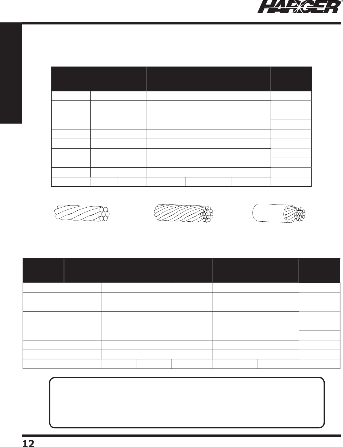
7 Str
a
n
d
C
o
ncentri
c
19 Str
a
n
d
C
o
ncentri
c
19 Str
a
n
d
Ins
u
l
a
te
d
Part No. Size
(AWG)
No. of
Strands CM Area Approx. Wt.
lbs./M ft.
Standard
Reels
Approx.
Wt.
lbs./Reel
8-
7
8
7
16,510
5
1
500'
30
6
-
7
6
7
2
6,
2
40 81
500'
43
4
-
7
4
7
4
1,740 1
27
500'
7
2
2
-
7
2
7
6
6,
3
60
204
2
50'
60
1
/
0-19 1
/
0 19 105,600
325
2
50'
90
2
/
0-
7
2
/
0
7
1
33
,100
4
1
0
2
50'
111
2
/
0-19 2
/
0191
33
,100
4
1
0
2
50'
111
3
/
0-19 3
/
0 19 167,800
5
18 2
00'
11
2
4/
0-
7
4/
0
7
2
11,600
653
2
00'
1
3
9
4/
0-19
4/
019
2
11,600
653
2
00'
1
3
9
Part No. Size
(AWG)
No. of
Strands
Jacket
Type CM Area Approx. Wt.
lbs./M ft.
Standard
Reels
Approx.
Wt.
lbs./Reel
6
7
G
6
7
THW
2
6,
2
40 1
05
500'
6
1
6
-19
G
6
19
THHN
2
6,
2
40
9
8
500'
57
4
7
G
4
7
THW
4
1,740 1
60
500'
88-1
/2
4
-19
G
4
19
THHN
4
1,740 1
57
500'
86-1
/2
2
7
G
2
7
THW
6
6,
3
60
2
4
5
2
50'
7
0
2
-19
G
2
19
THHN
6
6,
3
60
2
4
0
2
50'
6
8
1
/
019
G
1
/
019
THHN
105,600
3
7
2
2
50'
101-1
/2
2
/
019
G
2
/
019
THHN
1
33
,100
462
2
50'
115-1
/2
4/
019
G
4/
019
THHN
2
11,600 71
6
2
00'
14
3
C
oncentric La
y
Soft-Drawn Bare Co
pp
er
G
reen Insulated C
o
nduct
o
rs
N
O
TES
:
• Green Insulated conductor carries a THW or THHN ratin
g
. Other colors available upon request.
• Sizes u
p
to 1000 MCM are available. Please contact the factor
y
for s
p
ecial re
q
uests.
• Har
g
er offers standard reel sizes, however we will cut to specifi ed len
g
ths.
• Bare Stranded conductor shall meet the re
q
uirements of ASTM B-8.
• Stranded co
pp
er conductors available tinned. Please add suffi x T to
p
art number.
S
ect
io
n 1.1.1
S
tranded Co
pp
er Conductors
H
ar
g
er Li
g
htnin
g
& Groundin
g
•
©
2012 Phone 847-548-8700 • Fax 847-548-8755 • U.S. 800-842-743
7
13
13
Section 1
Grounding Components
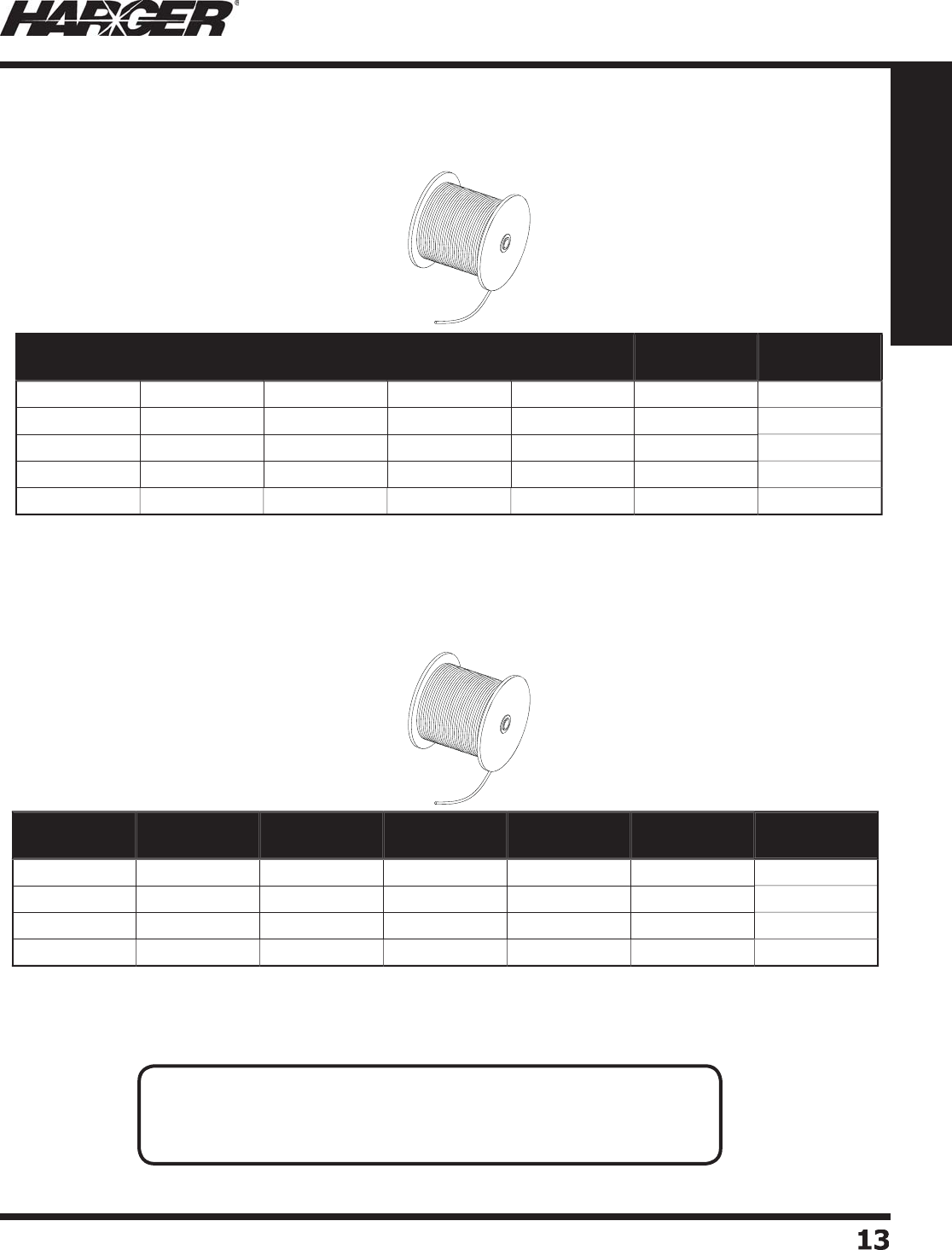
*
2T can be ordered as stock items #2T-250
(
250' standard reel
)
and #2T-500
(
500' standard reel
)
.
S
olid Sin
g
le Soft-Drawn Bare Copper
S
olid Co
pp
er Conductors
S
olid Tinned Co
pp
er Conductors
S
olid Sin
g
le Soft-Drawn Bare Tinned Copper
N
O
TES
:
• Other sizes are available. Please contact factor
y
for s
p
ecial re
q
uests.
• Solid soft-drawn conductors shall meet the re
q
uirements of ASTM B-3.
• Tinned Co
pp
er conductors shall meet the re
q
uirements of ASTM B-33.
Part No. Size
(AWG) Diameter CM Area Approx. Wt.
lbs./M ft.
Standard
Reel
Approx. Wt.
lbs./Reel
1
0
1
0
.
1
0
1 10,380 31-1
/2
500'
18-1
/
4
88
.
128 16,510
50
500'
24-1
/2
6
6
.
1
62
2
6,
2
40 80
500'
4
2-1
/2
4
4
.20
4
4
1,470 1
26
500'
71-1
/2
2
2
.257
6
6,
3
60
20
12
50'
5
8-1
/2
Part No. Size
(AWG) Diameter CM Area Approx. Wt.
lbs./M ft.
Standard
Reel
Approx. Wt.
lbs./Reel
8T 8
.
128 16,510
50
500'
24-1
/2
6
T
6
.
1
62
2
6,
2
40 80
500'
4
2-1
/2
4T
4
.204
4
1,470 1
26
500'
71-1
/2
2T*
2
.257
6
6,
3
60
20
12
50'
5
8-1
/2
S
ect
io
n 1.1.2 & 1.1.3
H
ar
g
er Li
g
htnin
g
& Groundin
g
•
©
2012 Phone 847-548-8700 • Fax 847-548-8755 • U.S. 800-842-743
7
14
14
Section 1
Grounding Components
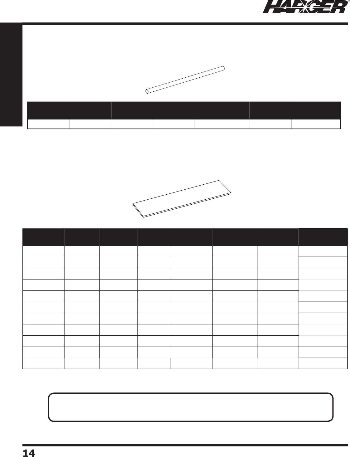
F
lat Stra
p
Part No. Width
(Inches)
Thickness
(Inches)
Actual
Gauge
X-Sectional
Area (in.2)
Approx. Wt.
lbs./M ft.
Standard
Coil
Approx.
Coil Wt. (lbs.)
CUFS5806
4
.625
.064
14
.0
4
00
1
5
41
00'
15-1
/
4
C
U
FS1
032
1
.032
20
.0320
1
2
41
00'
12-1
/
4
C
U
FS1
5
1
6
1.
5
.0
1
6
26
.023
9
93
1
00'
9
-1
/
4
C
U
FS1
5032
1.
5
.032
20
.
0480 185-1
/2
1
00'
18-1
/2
C
U
FS
20
1
6
2
.0
1
6
26
.
0318 123-1
/2
1
00'
12-1
/
4
C
U
FS
2032
2
.032
20
.06
4
0
247-1
/2
1
00'
24-1
/2
C
U
FS
2064
2
.064
14
.
1280
4
9
5
1
00'
4
9-1
/2
C
U
FS
30
1
6
3
.0
1
6
26
.
0478 186 1
00'
18-1
/2
C
U
FS
3032
3
.032
20
.0
9
60
3
71 1
00'
37-1
/
4
C
U
FS4
0
1
6
4
.0
1
6
26
.06
4
0
247-1
/2
1
00'
24-1
/2
C
U
FS
60
1
6
6
.0
1
6
26
.0
9
56
3
7
2
1
00'
37-1
/
4
Part No. Size
(AWG) Diameter CM Area Approx. Wt.
lbs./M ft.
Standard
Reels
Approx. Wt.
lbs./Reel
6
CW
3D
6
.
1
62
2
6,
2
40 80
500'
4
2-1
/2
S
olid Co
pp
erweld Conductors
#6 Solid Co
pp
erweld LC 30% Dead Soft Annealed
C
o
pp
er Flat Stra
p
Conductors
N
O
TES
:
• Most Bare Co
pp
er Flat Stra
p
conductors are available tinned. Please add suffi x T to
p
art number.
• Other sizes of conductors are available. Please contact factor
y
for more information.
S
ect
io
n 1.1.4 & 1.1.5
H
ar
g
er Li
g
htnin
g
& Groundin
g
•
©
2012 Phone 847-548-8700 • Fax 847-548-8755 • U.S. 800-842-743
7
15
15
Section 1
Grounding Components
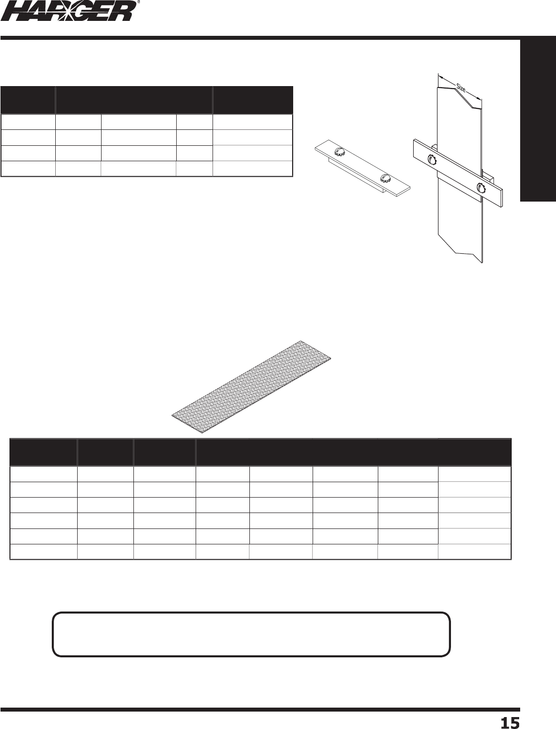
•
Used for makin
g
connection to fl at strap or fl at braid.
•
Co
pp
er "sandwich" clam
p
s com
p
lete with stainless steel
hardware. The to
p
is 1/8" thick and the bottom is 1/4" thick.
•
Ends are desi
g
ned to allow for exothermically weldin
g
conductors
to clam
p
.
F
l
a
t Br
a
i
d
Part No. Strap
Size
Approx. Each
Wt. (lbs.)
Box
Qty.
Approx. Box
Wt. (lbs.)
FSC2
2" 1
/2
1
0
5
F
SC
3
3
"3
/4
1
0
7-1
/2
FSC4
4
"11
0
1
0
F
SC
6
6
" 1-1
/
41
0
12-1
/2
Part No. Width
(Inches)
Thickness
(Inches)
Actual
Gauge
Nominal
Circ. Mils
Approx.
lbs./M ft.
Standard
Coil
Approx. Coil
Wt. (lbs.)
C
U
FB14
030
.25
.030
14
4
,
2
00 1
6
1
00'
2-1
/2
C
U
FB1
20
9
4
.50
.0
94
6
2
4,1
2
084
50'
4
-1
/
4
CUFB5806
2
.625
.062
4
3
6,000 1
2
1
50'
7
C
U
FB
3
4
062
.75
.062
6
2
4,1
2
085
50'
5
-1
/
4
C
U
FB1
062
1
.062
4
38,59
2
1
35
50'
7-1
/2
C
U
FB1
5
1
25
1.
5
.
1
25
2
/
01
2
0,600
420
50'
2
1
C
o
pp
er Flat Stra
p
Clam
p
s
Tinned Co
pp
er Flat Braid Conductors
N
O
TES
:
• Width and thickness on fl at braid items are nominal size
(
not exact
)
.
• Other sizes of conductors are available. Please contact factor
y
for more information.
S
ect
io
n 1.1.6 & 1.1.7
H
ar
g
er Li
g
htnin
g
& Groundin
g
•
©
2012 Phone 847-548-8700 • Fax 847-548-8755 • U.S. 800-842-743
7
1616
Section 1
Grounding Components
Part No. Size
(AWG)
Voltage
Rating
Approx.
lbs./M ft.
Standard
Reel
Reel Wt.
(lbs.)
2
W
C
2
600
V
302
1
00'
3
1
2
/
0WC 2
/
0
600
V
5
78 1
00'
60
4/
0WC
4/
0
600
V 858 1
00'
88
Black Insulated Weldin
g
Cable
N
O
TES
:
• Ro
p
e stranded co
pp
er conductor, vin
y
l se
p
arator, insulated with oil and water resistant
thermo
p
lastic rubber com
p
ound
(
TPE
)
.
• For connections for electrode holder and
g
roundin
g
clamp to arc welder, bus, weldin
g
bo
x
o
r tr
a
nsf
o
rmer.
• Also suitable for certain 600-volt applications such as battery leads and
j
umper cables.
S
ect
io
n 1.1.8

H
ar
g
er Li
g
htnin
g
& Groundin
g
•
©
2012 Phone 847-548-8700 • Fax 847-548-8755 • U.S. 800-842-743
7
1
7
17
Section 1
Grounding Components
S
ect
io
n 1.2
G
r
o
und Electr
o
des & Access
o
ries
In
d
ex
Descr
i
pt
i
on Pa
g
e
1.2.1 Co
pp
er Clad Steel Ground Rod
s
...........................................................
18
1.2.2 Tie D
o
wn Gr
ou
n
d
R
ods
.......................................................................
19
1.2.3 Solid Co
pp
er Ground Rod
s
...................................................................
19
1.2.4 St
a
inless Steel Gr
ou
n
d
R
ods
................................................................
20
1.2.
5
G
a
lv
a
nize
d
Steel Gr
ou
n
d
R
ods
.............................................................
20
1.2.
6
Secti
o
n
a
l Gr
ou
n
d
R
ods
........................................................................
2
1
1.2.7 Ground Rod Cou
p
lers, Drivers, Drive Sleeves & Stud
s
............................
22
1.2.8 Ground Rod Clam
ps
............................................................................
24
1.2.9 Ground Rece
p
tacles & Brass Ball Stud
s
................................................
26
1.2.10 Co
pp
er Ground Plate
s
.........................................................................
27
1.2.11 Enh
a
nce
d
Gr
ou
n
d
R
od
s
&
Kit
s
.............................................................
2
9
Enhanced Ground Rod Numberin
g
System
.......................................
30
Co
pp
er Vertical Enhanced Ground Rod Kit
s
.......................................
3
1
Co
pp
er Horizontal L-sha
p
ed Enhanced Ground Rod Kit
s
.....................
32
St
a
inless Steel Vertic
a
l Enh
a
nce
d
Gr
ou
n
d
R
od
Kit
s
............................
33
Stainless Steel Horizontal L-sha
p
ed Enhanced Ground Rod Kit
s
..........
3
4
Co
pp
er Sectional Enhanced Ground Rod Kit
s
....................................
35
1.2.12 Ultrafi ll - Earth
(
Ground
)
Enhancement Material
....................................
36
1.2.13 Irri
g
ation Groundin
g
Kit
s
.....................................................................
37
1.2.14 M
ob
ile Gr
ou
n
d
St
a
ke Kit
s
....................................................................
38
1.2.1
5
Gr
ou
n
d
Access Well
s
...........................................................................
40
1.2.1
6
Gr
ou
n
d
Access Well C
o
ver
s
.................................................................
45
H
ar
g
er Li
g
htnin
g
& Groundin
g
•
©
2012 Phone 847-548-8700 • Fax 847-548-8755 • U.S. 800-842-743
7
1
8
18
Section 1
Grounding Components
L
iste
d
4
67
Part No. Size Approx. Each
Wt. (lbs.)
Standard
Bundle
Approx. Wt.
lbs./Bundle
UL
Mark
With
UPC Label
1208UPC 1
/
2" x 8
'
6
5
30
Yes
Yes
1
2
1
0
1
/
2" x 10
'
7
5
35
Yes
No
5
88
5/
8" x 8
'
7
5
35
Yes
No
5
88RU
S
5/
8" x 8
'
7
5
35
Yes
No
5
88UPC
5/
8" x 8
'
7
5
35
Yes
Yes
5
810
5/
8" x 10
'
9
5
45
Yes
No
5
810UPC
5/
8" x 10
'
9
5
45
Yes
Yes
348 3
/
4" x 8
'
11
5
55
Yes
No
3
41
0
3
/
4" x 10
'
1
3
5
65
Yes
No
3
41
2
3
/
4" x 12
'
1
5
5
75
Yes
No
11
0
1" x 1
0'
23
3
6
9
Yes
No
C
o
pp
er Clad Steel Ground Rods
•
For more information refer to Ground Rod table on pa
g
e 335.
T
ECHNICAL N
O
TES
:
•NEC 2011 Article 250.53
(
G
)
(
Summarized
)
The electrode shall be installed so that 8' of len
g
th is in contact with the soil. It shall be driven to a
de
p
th of not less than 8' exce
p
t where rock bottom is encountered. In the case of bedrock, the
electrode shall be driven at an an
g
le not to exceed 45 de
g
rees from the vertical or shall be buried in a
trench that is at least 2-1/2' dee
p
.
•
U
L 467 6.9.2.3
(
Summarized
)
A solid rod electrode of co
pp
er or other suitable non-ferrous metal, or a solid rod electrode of iron or
steel with a copper or other suitable non-ferrous metal or stainless steel
j
acket, shall have a diameter
not less than 1
/
2" thick.
•UL 467 6.9.2.6
(
Summarized
)
The copper
j
acket shall not be less than .010" thick at any point.
• R
US
(Rural Utilities Service)
g
round rods have a 13 mil copper platin
g
thickness.
S
ect
io
n 1.2.1
H
ar
g
er Li
g
htnin
g
& Groundin
g
•
©
2012 Phone 847-548-8700 • Fax 847-548-8755 • U.S. 800-842-743
7
19
19
Section 1
Grounding Components
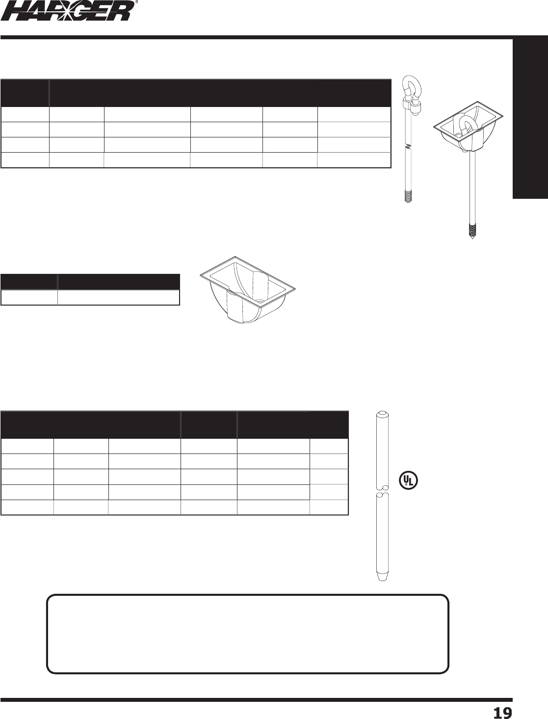
L
iste
d
4
67
•
Copper Clad Aircraft Tie Down Ground Rods are manufactured of hi
g
h stren
g
th C1018
cold drawn steel with 0.010" thick copper platin
g
.
•
Threads are cold-rolled to provide superior stren
g
th.
•
Use plastic mold #TDGRDM (sold separately) durin
g
installation.
•
See pa
g
e 22 for tool for drivin
g
tie down
g
round rods (34TDDRIVER).
Part No. Rod Size Thread Size Approx. Each
Wt. (lbs.)
Standard
Bundle
Approx. Wt.
lbs./Bundle
3
41
0
T
D
3
/
4" x 10
'
3/4-10 (1.5" lon
g)
14
5
7
0
348T
D
3
/
4" x 8
'
3/4-10 (1.5" lon
g)
11
5
55
5
88T
D
5/
8" x 8
'
5
/8-11 (1.5" lon
g)
7-1
/2
5
37-1
/2
5
86T
D
5/
8" x 6
'
5
/8-11 (1.5" lon
g)
6
5
30
Part No. Approx. Each Wt. (lbs.)
T
D
G
RDM 1
/4
Part No. Size Approx. Each
Wt. (lbs.)
Standard
Bundle
Approx. Wt.
lbs./Bundle
UL
Mark
5
88C
5/
8" x 8
'
1
0
5
50
Yes
5
810C
5/
8" x 10
'
1
2
5
60
Yes
348C 3
/
4" x 8
'
1
5
5
75
Yes
3
41
0
C3
/
4" x 10
'
18
5
90
Yes
11
0
C 1" x 1
0'
3
1
3
93
Yes
Tie D
o
wn Gr
o
und R
o
ds
Tie D
o
wn Plastic M
o
ld
S
olid Co
pp
er Ground Rods
•
All r
od
s
a
re f
u
ll
d
i
a
meter.
•
For more information refer to Ground Rod table on pa
g
e 335.
APPLICATI
O
N N
O
TES
:
• Manufactured from alloy 110 electrolytic tou
g
h pitch hard temper copper bar. Meets
ASTM B 133 & ASTM B 187.
• Solid copper
g
round electrodes are used when better conductivity and corrosion
resistance is
p
referred.
• Due to softness of solid copper, care must be taken when drivin
g
electrode.
S
ect
io
n 1.2.2 & 1.2.3
H
ar
g
er Li
g
htnin
g
& Groundin
g
•
©
2012 Phone 847-548-8700 • Fax 847-548-8755 • U.S. 800-842-743
7
20
20
Section 1
Grounding Components
L
iste
d
4
67
Part No. Size Approx. Each
Wt. (lbs.)
Standard
Bundle
Approx. Wt.
lbs./Bundle
With
UPC Label
5
88
G
5/
8" x 8
'
8
5
40
No
5
88GUPC
5/
8" x 8
'
8
5
40
Yes
5
810
G
5/
8" x 10
'
1
0
5
50
No
5
810GUPC
5/
8" x 10
'
1
0
5
50
Yes
348
G
3
/
4" x 8
'
1
2
5
60
No
3
41
0G
3
/
4" x 10
'
1
5
5
75
No
1
26G
1
/
2" x 6
'
4
5
20
No
1
26
G
U
PC 1
/
2" x 6
'
4
5
20
Yes
128
G
1
/
2" x 8
'
6
5
30
No
128GUPC 1
/
2" x 8
'
6
5
30
Yes
Part No. Size Approx. Each
Wt. (lbs.)
Standard
Bundle
Approx. Wt.
lbs./Bundle
UL
Mark
1
2
1
0
SS
3
1
/
2" x 10
'
7
5
35
Yes
5
88SS
3
5/
8" x 8
'
9
5
45
Yes
5
810SS
3
5/
8" x 10
'
11
5
55
Yes
3
41
0
SS
3
3
/
4" x 10
'
1
5
5
75
Yes
S
tainless Steel Gr
o
und R
o
ds
G
alvanized Steel Gr
o
und R
o
ds
•
All r
od
s
a
re f
u
ll
d
i
a
meter.
•
For more information refer to Ground Rod table on pa
g
e 335.
•
All r
od
s
a
re f
u
ll
d
i
a
meter.
•
For more information refer to Ground Rod table on pa
g
e 335.
TECHNICAL N
O
TES
:
•
U
L 467 6.9.2.3
(
Summarized
)
A solid rod electrode of co
pp
er or other suitable non-ferrous metal, or a solid rod electrode of
iron or steel with a copper or other suitable non-ferrous metal or stainless steel
j
acket, shall have
a diameter not less than 1
/
2" thick.
• UL 467 6.9.2.5
(
Summarized
)
The stainless steel
j
acket mentioned in 9.2.3 shall not be less than .015 inches thick at any point.
•
U
L 467 6.9.2.8
(
Summarized
)
The stainless steel
j
acket mentioned above on a stainless steel rod, shall be formed of an
austenitic stainless steel of the 18% chromium, 8% nickel t
yp
e.
• Stainless steel
g
round rods are used in corrosive soil conditions.
N
O
TES
:
• Manufactured from zinc coated hi
g
h stren
g
th steel.
• Meets re
q
uirements of NEMA GR-1.
• Preferred electrode when
p
rimar
y
concern is cathodic
p
rotection to structure.
• N
o
n
U
L liste
d
.
S
ect
io
n 1.2.4 & 1.2.5
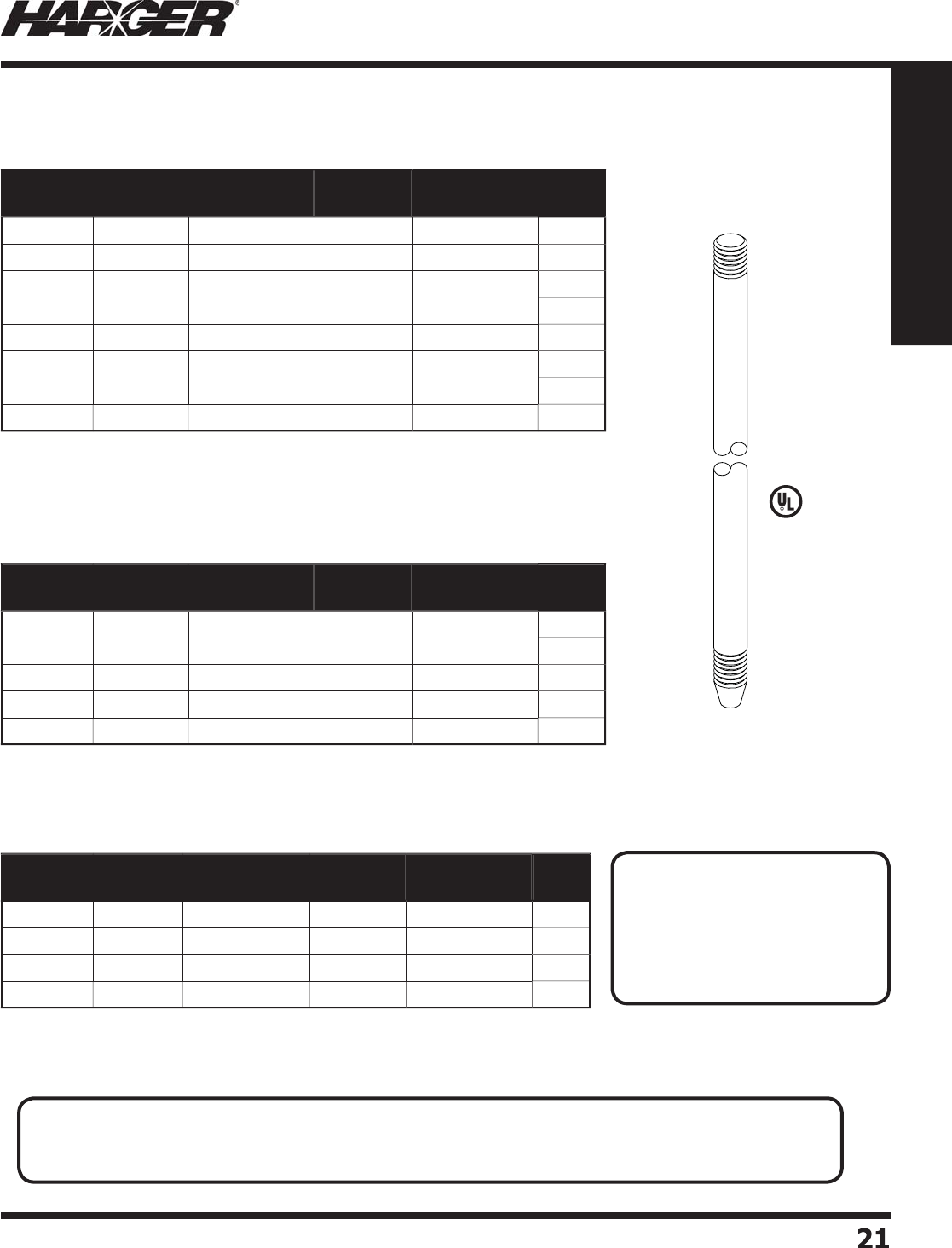
H
ar
g
er Li
g
htnin
g
& Groundin
g
•
©
2012 Phone 847-548-8700 • Fax 847-548-8755 • U.S. 800-842-743
7
2
1
21
Section 1
Grounding Components
L
iste
d
4
67
S
ecti
o
nal Stainless Steel
G
r
o
und R
o
ds N
o
tes
:
S
S-3 = T
yp
e 300 Stainless Steel
-
N
o
n-ferr
ou
s
U
L liste
d
.
O
ther sizes
a
v
a
il
ab
le.
Contact factor
y
for details.
Part No. Size Approx. Each
Wt. (lbs.)
Standard
Bundle
Approx. Wt.
lbs./Bundle
UL
Mark
S
58
2
5/
8" x 2
'
2
5
1
0
No
S
58
3
5/
8" x 3
'
3
5
1
5
No
S
585
5/
8" x 5
'
5
5
25
No
S
588
5/
8" x 8
'
7
5
35
Yes
S
5810
5/
8" x 10
'
9
5
45
Yes
S
348 3
/
4" x 8
'
11
5
55
Yes
S3
41
0
3
/
4" x 10
'
1
3
5
65
Yes
S
11
0
1" x 1
0'
23
3
6
9
Yes
Part No. Size Approx. Each
Wt. (lbs.)
Standard
Bundle
Approx. Wt.
lbs./Bundle
UL
Mark
S
582C
5/
8" x 2
'
3
5
1
5
No
S
583C
5/
8" x 3
'
4
5
20
No
S
585C
5/
8" x 5
'
6
5
30
No
S3
4
5
C3
/
4" x 5
'
9
5
45
No
S
1
5C
1" x
5'
1
6
3
4
8
No
Part No. Size Approx. Each
Wt. (lbs.)
Standard
Bundle
Approx. Wt.
lbs./Bundle
UL
Mark
S
585SS
3
5/
8" x 5
'
6
5
30
No
S
588SS
3
5/
8" x 8
'
9
5
45
Yes
S
5810SS
3
5/
8" x 10
'
11
5
55
Y
es
S3
41
0
SS
3
3
/
4" x 10
'
1
5
5
75
Yes
S
ecti
o
nal Gr
o
und R
o
ds
S
ectional Co
pp
er Clad Steel Ground Rods
S
ectional Solid Co
pp
er Ground Rods
S
ecti
o
nal Stainless Steel Gr
o
und R
o
ds
APPLICATI
O
N N
O
TES
:
• Sectional
g
round rods are used to help reduce
g
round resistance in poor soils such as sand and
g
ravel.
• Doublin
g
g
round rod len
g
th theoretically reduces resistance 40%.
S
ect
io
n 1.2.6
•
All r
od
s
a
re f
u
ll
d
i
a
meter.
•
For more information refer to Ground Rod table on pa
g
e 335.
•
All r
od
s
a
re f
u
ll
d
i
a
meter.
•
All r
od
s
a
re f
u
ll
d
i
a
meter.
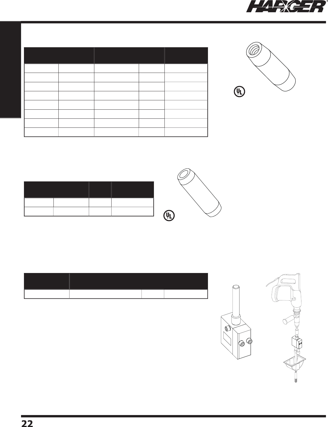
H
ar
g
er Li
g
htnin
g
& Groundin
g
•
©
2012 Phone 847-548-8700 • Fax 847-548-8755 • U.S. 800-842-743
7
2
2
22
Section 1
Grounding Components
•
C
o
rr
o
si
o
n resist
a
nt silic
o
n
b
r
o
nze
threaded
g
round rod coupler for
s
ectional
g
round rods.
•
Als
o
a
v
a
il
ab
le in st
a
inless steel.
S
tainless steel cou
p
lers are not
U
L Liste
d
.
•
Corrosion resistant bronze
g
round
rod com
p
ression cou
p
ler for use
on non-sectional co
pp
er clad
g
round rods.
L
iste
d
4
67
•
For drivin
g
3/4" tie down
g
round rods, #3410TD (see pa
g
e 19),
w
ithout deformin
g
the eye loop.
•
M
a
n
u
f
a
ct
u
re
d
fr
o
m t
oo
l h
a
r
d
ene
d
sh
o
ck resist
a
nt steel.
•
3-piece desi
g
n allows operator to remove tool in case of a
j
am.
•
Drivin
g
hammer and 3/4"
g
round rod drive bit not included.
Part No. Ground
Rod Size Material Box
Qty.
Approx. Box
Wt. (lbs.)
GRC1
2
1
/
2"
B
r
o
nz
e
5
2-1
/2
GRC1
2
S
S
1
/
2"
S
t
a
inless Steel
5
2-1
/2
GRC58
5/
8"
B
r
o
nz
e
5
2-1
/2
GRC58S
S
5/
8"
S
t
a
inless Steel
5
2-1
/2
GRC
3
43
/
4"
B
r
o
nz
e
5
2-1
/2
GRC
3
4S
S
3
/
4"
S
t
a
inless Steel
5
2-1
/2
G
R
C
11"
B
r
o
nz
e
5
5
G
R
C
1
SS
1"
S
t
a
inless Steel
5
5
Part No. Ground
Rod Size
Box
Qty.
Approx. Box
Wt. (lbs.)
GRCC58
5/
8"
5
2-1
/2
GRCC
34
3
/
4"
5
2-1
/2
Part No. Description Qty. Approx. Each
Wt. (lbs.)
3
4TDDRIVER 3
/
4" Ground Rod Drive
r
EA
11
G
round Rod Cou
p
lers
Tie D
o
wn Gr
o
und R
o
d Driver
L
iste
d
4
67
S
ect
io
n 1.2.7
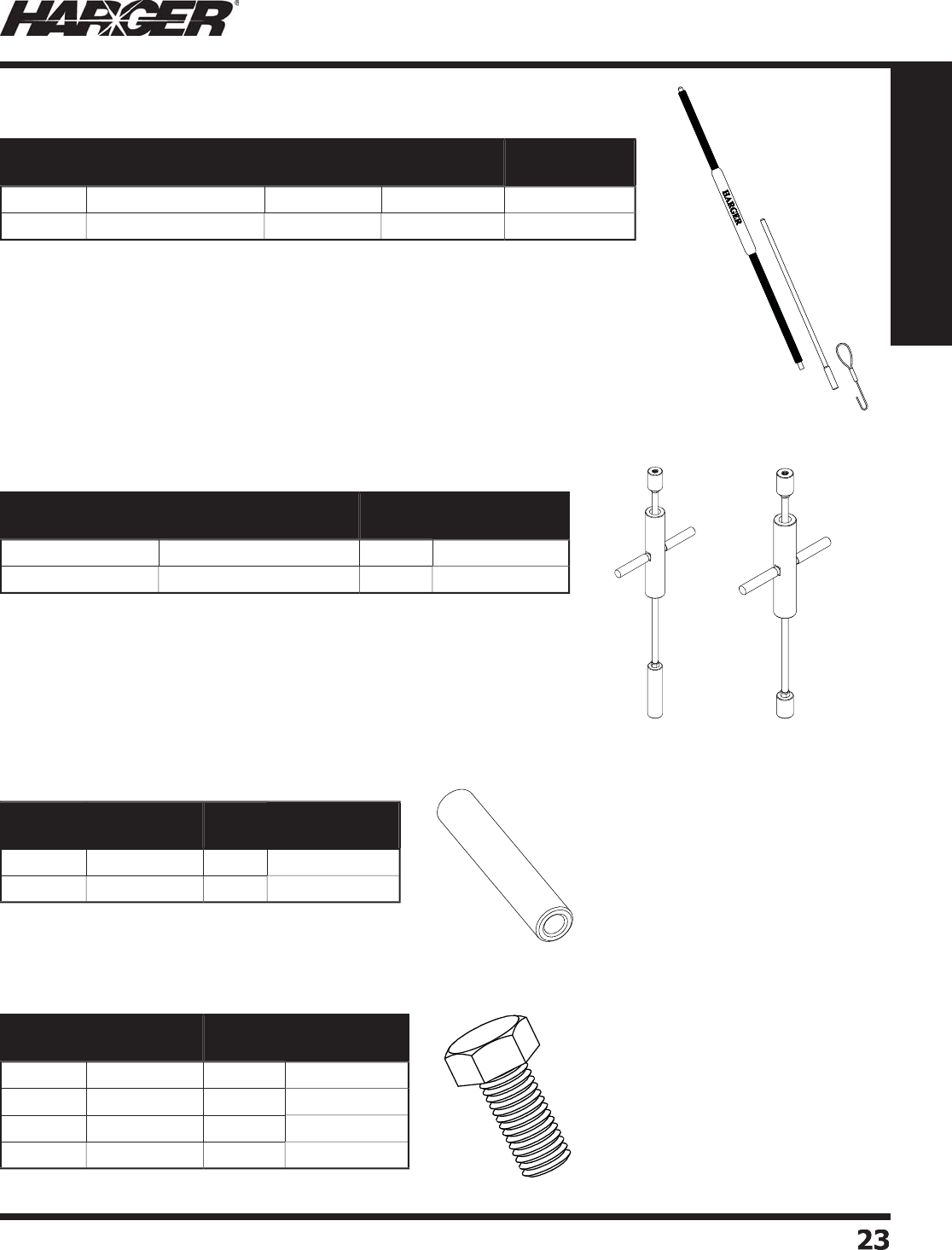
H
ar
g
er Li
g
htnin
g
& Groundin
g
•
©
2012 Phone 847-548-8700 • Fax 847-548-8755 • U.S. 800-842-743
7
23
23
Section 1
Grounding Components
•
Prevents "mushroomin
g
" top o
f
g
round rod while drivin
g
rod.
•
Hi
g
h stren
g
th alloy drivin
g
stud
prevents dama
g
e to the coupler or
g
round rod threads when drivin
g
g
round rods.
•
SMGRD58U - Ground rod driver with slide hammer. One end is
threaded for use with threaded 5/8"
g
round rods and the other end
i
s for use with tapered 5/8" copper clad steel
g
round rods.
•
SMGRD58USHGR - Ground rod driver with slide hammer, connects
to
g
round rods with 5/8" threads on both ends.
- Used to install or remove threaded
g
round rods.
•
Drives
g
round rods from
g
round level without the need for a ladder or sled
g
e
h
a
mmer.
•
3/4" insert is interchan
g
eable with driver body.
•
Insert prevents driver from slippin
g
off
g
round rod near
g
round level.
•
Insert prevents "mushroomin
g
" top of
g
round rod.
S
MGRD58USHGR
S
MGRD58U
Part No. Description Ground Rod
Size Qty. Approx. Each
Wt. (lbs.)
GRD58
D
river & 5
/
8" Inser
t
1
/
2" & 5
/
8"
EA
23
GRD
3
4I
R
e
p
lacement Inser
t
3
/
4"
EA
6
Part No. Description Qty. Approx. Each
Wt. (lbs.)
S
MGRD58U
5/
8" Ground Rod Drive
r
EA
1
6
S
MGRD58USHGR
5/
8" Ground Rod Drive
r
EA
14
Part No. Ground Rod
Size Qty. Approx. Each
Wt. (lbs.)
GRDS58
5/
8"
EA
2
GRDS
34
3
/
4"
EA
3
Part No. Ground Rod
Size
Box
Qty.
Approx. Box
Wt. (lbs.)
GDS1
2
1
/
2"
5
2-1
/2
GDS58
5/
8"
5
2-1
/2
GDS
34
3
/
4"
5
2-1
/2
G
D
S
11"
3
3
G
r
o
und R
o
d Driver
G
r
o
und R
o
d Drivers
Drive Sleeve
s
Drive St
uds
S
ect
io
n 1.2.7
•
For Copper Clad Steel
g
round rods.
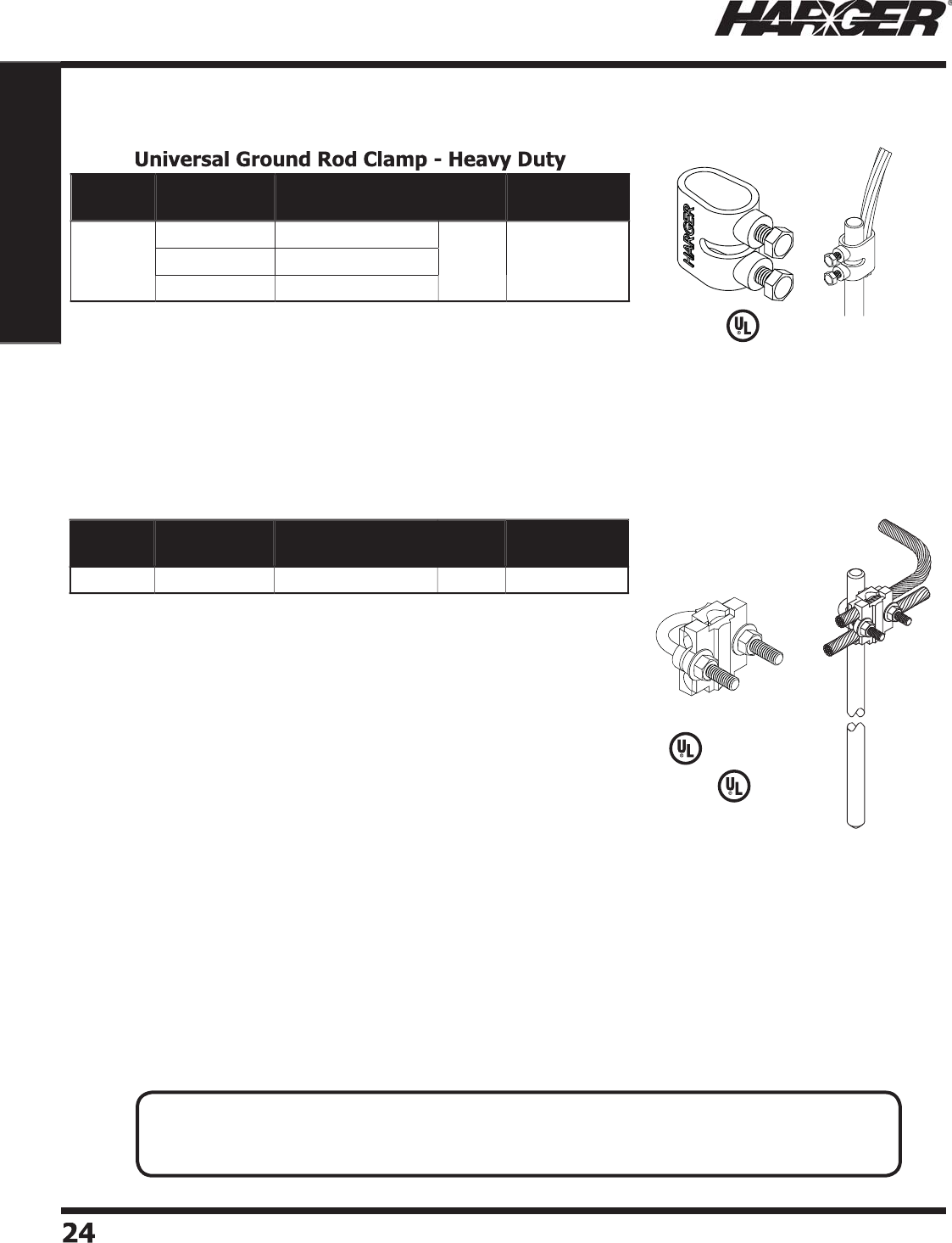
H
ar
g
er Li
g
htnin
g
& Groundin
g
•
©
2012 Phone 847-548-8700 • Fax 847-548-8755 • U.S. 800-842-743
7
24
24
Section 1
Grounding Components
•
Bronze
g
round rod clamp features a stainless steel "U" bolt
for stren
g
th and corrosion resistance.
•
Provides over 1-1/2" of contact between the
g
round
electr
od
e
a
n
d
c
o
n
du
ct
o
rs.
•
Acc
o
mm
oda
tes tw
o
h
o
riz
o
nt
a
l c
o
n
du
ct
o
rs thr
u
2
50
MCM.
•
Accommodates one vertical conductor u
p
to 500 MCM.
•
Fits all
g
round rods throu
g
h 1" diameter. Ideal for connectin
g
down conductors to
g
round loop conductors.
L
iste
d
9
6
L
iste
d
4
67
Part No. Ground Rod
Size
Conductor
Range (AWG)
Box
Qty.
Approx. Box
Wt. (lbs.)
305
Up
thru 1" #
6
-
500
MCM
5
3
G
round Rod Clam
p
s
Part No. Ground Rod
Size
Conductor
Range (AWG)
Box
Qty.
Approx. Box
Wt. (lbs.)
302U
1
/
2" #
6
S
o
l. -
350
MCM
5
5
5/
8" #
6
S
o
l. -
350
MCM
3
/
4" #2 S
o
l. - 2
50
MCM
APPLICATI
O
N N
O
TES
:
• Ground Rod Clamps for li
g
htnin
g
protection systems require 1-1/2" of surface contact between
conductor and
g
round rod.
S
ect
io
n 1.2.8
•
Heavy duty bronze
g
round rod clamps.
•
Provides over 1-1
/
2 inches of contact area with cables and
g
round rod.
•
Two stainless steel cap screws secure the cable to the
g
round
electrode for a
p
ositive electrical connection.
L
iste
d
9
6
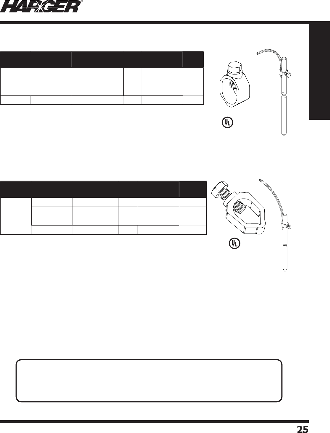
H
ar
g
er Li
g
htnin
g
& Groundin
g
•
©
2012 Phone 847-548-8700 • Fax 847-548-8755 • U.S. 800-842-743
7
25
25
Section 1
Grounding Components
•
Li
g
ht duty
g
round rod clamp.
•
Bronze cap screw secures the cable to the
g
round electrode.
•
Commonl
y
called acorn or tear dro
p
clam
p
.
L
iste
d
4
67
•
Li
g
ht duty
g
round rod clamp for securin
g
cable to
g
round rod.
•
Eliminates the need to inventor
y
assorted different-size clam
p
s.
•
Replaces a wide ran
g
e of products made for economy, standard duty, heavy
dut
y
and extra heav
y
dut
y
a
pp
lications.
•
M
ad
e fr
o
m c
o
rr
o
si
o
n resist
a
nt silic
o
n
b
r
o
nze.
•
Accommodates 3/8" to 3/4"
g
round rods and #10 Solid to 1/0 Stranded
c
o
n
du
ct
o
r.
•
Tested to 300 inch-
p
ounds.
*
U
L
a
n
d
CSA liste
d
f
o
r Direct B
u
ri
a
l.
Part No. Ground Rod
Size
Conductor
Range (AWG)
Box
Qty.
Approx. Box
Wt. (lbs.)
UL
Mark
300
L
D
1
/
2" 1
0
S
o
l. - #2 Str. 1
0
2
Yes
30
1L
D
5/
8" 1
0
S
o
l. - #2 Str. 1
0
2
Yes
302
L
D
3
/
4" 1
0
S
o
l. - #2 Str. 1
0
2
Yes
303
L
D
1" 8 Sol. - 4
/
01
0
6
Yes
Part No. Ground Rod
Size
Conductor
Range (AWG)
Box
Qty.
Approx. Box
Wt. (lbs.)
UL
Listed*
302U
GR
C
3
/
8" 1
/
0 - 10 Sol. 1
0
2
No
1
/
2" 1
/
0 - 10 Sol. 1
0
2
Yes
5/
8" 1
/
0 - 10 Sol. 1
0
2
Yes
3
/
4" 1
/
0 - 8 Sol. 1
0
2
Yes
G
round Rod Clam
p
s
U
niversal Ground Rod Clamp - Li
g
ht Dut
y
L
iste
d
4
67
APPLICATI
O
N N
O
TES
:
• Ground Rod Clamps for li
g
htnin
g
protection systems require 1-1/2" of surface contact between
conductor and
g
round rod.
• Li
g
ht duty series (300LD, 301LD, 302LD & 302UGRC) acceptable for electrical
g
roundin
g
, but not
li
g
htnin
g
protection.
S
ect
io
n 1.2.8

H
ar
g
er Li
g
htnin
g
& Groundin
g
•
©
2012 Phone 847-548-8700 • Fax 847-548-8755 • U.S. 800-842-743
7
26
26
Section 1
Grounding Components
•
350 Series heav
y
dut
y
bronze
fl oor rece
p
tacle features a
fl
u
sh m
ou
nt c
o
ver
a
tt
a
che
d
t
o
the main bod
y
via a stainless
s
teel
ba
ll ch
a
in.
•
Br
a
ss
ba
ll st
ud
l
o
c
a
te
d
insi
d
e
the rece
p
tacle
p
rovides
the termination
p
oint for
g
round clamps.
•
Br
a
ss
ba
ll st
ud
is rem
o
v
ab
le.
U
ses 1
/
2" stud #BBSTUD12.
•
Rece
p
tacle to
p
is 3" in
diameter, hei
g
ht is 3-1/2" tall.
•
Similar to 350 Series exce
p
t
fe
a
t
u
res
a
b
r
o
nze
dua
l
c
ab
le c
o
nnect
o
r.
•
Acce
p
ts all conductors u
p
to 4
/
0.
•
Br
a
ss
ba
ll st
ud
is rem
o
v
ab
le.
U
ses 1
/
2" stud #BBSTUD12.
•
Rece
p
tacle to
p
is 3" in
diameter, hei
g
ht is 3-1/2" tall.
•
Used as re
p
lacement studs
for
g
round receptacles.
•
C
a
n
a
ls
o
b
e m
ou
nte
d
o
n
g
round bars.
•
Brass Ball Stud: 3
/
4" in
diameter, 1-1/2" total
l
en
g
th.
•
Ground receptacle desi
g
ned to be exothermically connected
to a
g
round rod.
S
ee pa
g
e 320 for mold styles.
•
Brass ball stud is removable. Uses 1
/
2" stud #BBSTUD12.
Part No. Ground Rod
Size
Conductor
Type Qty. Approx. Each
Wt. (lbs.)
350
-4S
S
1
/
2"
S
et
S
cre
w
EA
2
350
-
5
S
S
5/
8"
S
et
S
cre
w
EA
2
350
-
6
S
S
3
/
4"
S
et
S
cre
w
EA
2
350
-4T 1
/
2"
T
hre
ad
e
d
EA
2
350
-
5
T
5/
8"
T
hre
ad
e
d
EA
2
350
-
6
T3
/
4"
T
hre
ad
e
d
EA
2
Part No. Ground Rod
Size
Conductor
Type Qty. Approx. Each
Wt. (lbs.)
35
1-4S
S
1
/
2"
S
et
S
cre
w
EA
2
35
1-
5
S
S
5/
8"
S
et
S
cre
w
EA
2
35
1-
6
S
S
3
/
4"
S
et
S
cre
w
EA
2
35
1-4T 1
/
2"
T
hre
ad
e
d
EA
2
35
1-
5
T
5/
8"
T
hre
ad
e
d
EA
2
35
1-
6
T3
/
4"
T
hre
ad
e
d
EA
2
Part No. Qty. Approx. Each
Wt. (lbs.)
SG
RX
EA
1-1
/
4
Part No. Thread
Size Qty. Approx. Each
Wt. (lbs.)
B
B
S
T
U
D1
4
1
/
4"
EA
1
/2
B
BSTUD38 3
/
8"
EA
1
/2
B
BST
U
D1
2
1
/
2"
EA
1
/2
G
round Rece
p
tacles
Bra
ss
Ball St
uds
APPLICATI
O
N N
O
TES
:
• Ground Receptacles are used when temporary
g
rounds must be established.
• Used for
g
roundin
g
aircrafts durin
g
refuelin
g
.
• 351 Series accept
g
round loop conductors; important when establishin
g
an equipotential
g
round plane.
S
ect
io
n 1.2.9
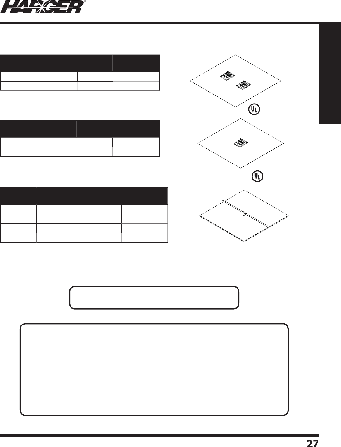
H
ar
g
er Li
g
htnin
g
& Groundin
g
•
©
2012 Phone 847-548-8700 • Fax 847-548-8755 • U.S. 800-842-743
7
2
7
27
Section 1
Grounding Components
O
ther
s
ize
s
an
d
thickne
ss
e
s
are available.
Please contact factor
y
for more information.
•
Co
pp
er Ground Plate features two dual cable connectors
f
o
r
a
sec
u
re electric
a
l c
o
nnecti
o
n.
L
iste
d
9
6
Part No. Ground Plate
Size
Thickness
(Inches)
Approx. Each
Wt. (lbs.)
335
18" x 18"
.032
6
336
24" x 24"
.032
9
•
Same as above except only has a sin
g
le cable connector.
L
iste
d
9
6
Part No. Ground Plate
Size
Thickness
(Inches)
Approx. Each
Wt. (lbs.)
335
-1 18" x 18"
.032
5
336
-1 24" x 24"
.032
8
•
Copper Ground Plate features an 18" or 24" (dependin
g
on the size
o
f the
p
late
)
co
pp
er conductor exothermicall
y
welded to the
p
late.
•
Thickness is .
03
2 inches.
Part No. Ground Plate
Size
Conductor
(AWG)
Approx. Each
Wt. (lbs.)
GP18182T 18" x 18"
2
T
4
GP18184
/
0 18" x 18"
4/
0
4
-1
/2
GP
2
4
2
4
2
T 24" x 24"
2
T
6
-1
/2
GP24244
/
0 24" x 24"
4/
0
7
C
o
pp
er Ground Plates
S
ect
io
n 1.2.10
T
ECHNICAL N
O
TES
:
•NEC 2011 Article 250.52
(
A
)(
7
)
(
Summarized
)
Each
p
late electrode shall ex
p
ose not less than 0.186 m
2
(
2 f
t
2
) of surface to exterior soil. Electrodes
of non-ferrous metal shall be at least 1.5 mm
(
0.06 in.
)
in thickness.
•
NEC 2011 Article 250.53
(
A
)
Rod, Pi
p
e, and Plate Electrodes. Where
p
racticable, rod,
p
i
p
e and
p
late electrodes shall be embedded
below
p
ermanent moisture level. Rod,
p
i
p
e and
p
late electrodes shall be free from nonconductive
coatin
g
s such as paint or enamel.
APPLICATI
O
N N
O
TES
:
• Copper Ground Plates are used in areas havin
g
little or no top soil.
• Can also be used to enhance
g
round
g
rid systems.
• Can be used in con
j
unction with earth enhancement material such as Ultrafi ll.

H
ar
g
er Li
g
htnin
g
& Groundin
g
•
©
2012 Phone 847-548-8700 • Fax 847-548-8755 • U.S. 800-842-743
7
2
8
28
Section 1
Grounding Components
•
1/4" thick bare copper
g
round plate.
•
Field connection re
q
uired.
•
Meets
g
roundin
g
requirements of the National Electrical Code.
•
1/4" x 24" x 24"
g
round plate with zi
g
-za
g
sheared ed
g
es provides 66%
more ed
g
e surface area than conventional
g
round plates.
•
5' lon
g
4/0-7 strand tail exothermically welded to center of plate.
•
Meets
g
roundin
g
requirements of the National Electrical Code.
•
Thickness is .2
5
inches.
L
iste
d
9
6
O
ther
s
ize
s
an
d
thickne
ss
e
s
are available.
Please contact factor
y
for more information.
•
Copper Ground Plate features a 12" or 24" (dependin
g
on the size
o
f the
p
late
)
co
pp
er conductor exothermicall
y
welded to the
p
late.
•
Meets
g
roundin
g
requirements of the National Electrical Code.
•
Thickness is .
06
2 inches.
Part No. Ground Plate
Size
Conductor
(AWG)
Approx. Each
Wt. (lbs.)
GP
062
1
2
1
22
T 12" x 12"
2
T 3-1
/2
GP06212124
/
0 12" x 12"
4/
0 3-1
/2
GP
062
1
22
4
2
T 12" x 24"
2
T
6
-1
/2
GP06212244
/
0 12" x 24"
4/
0
7
Part No. Ground Plate
Size
Thickness
(Inches)
Approx. Each
Wt. (lbs.)
GP141818 18" x 18"
.25
27
GP14
2
4
2
4
N
24" x 24"
.25
47
Part No. Ground Plate
Size
Conductor
(AWG)
Approx. Each
Wt. (lbs.)
GP14
2
4
2
4JD
P
24" x 24"
4/
0
5
2-1
/2
NEC Com
p
liant Co
pp
er Ground Plates
T
ECHNICAL N
O
TES
:
• NEC 2011 Article 250.52
(
A
)(
7
)
(
Summarized
)
Each
p
late electrode shall ex
p
ose not less than 0.186 m
2
(
2 ft
2
)
of surface to exterior soil. Electrodes
of non-ferrous metal shall be at least 1.5 mm
(
0.06 in.
)
in thickness.
•
NEC 2011 Article 250.53
(
A
)
Rod, Pi
p
e, and Plate Electrodes. Where
p
racticable, rod,
p
i
p
e and
p
late electrodes shall be embedded
below
p
ermanent moisture level. Rod,
p
i
p
e and
p
late electrodes shall be free from nonconductive
coatin
g
s such as paint or enamel.
APPLICATI
O
N N
O
TES
:
• Copper Ground Plates are used in areas havin
g
little or no top soil.
• Can also be used to enhance
g
round
g
rid systems.
• Can be used in con
j
unction with earth enhancement material such as Ultrafi ll.
S
ect
io
n 1.2.10
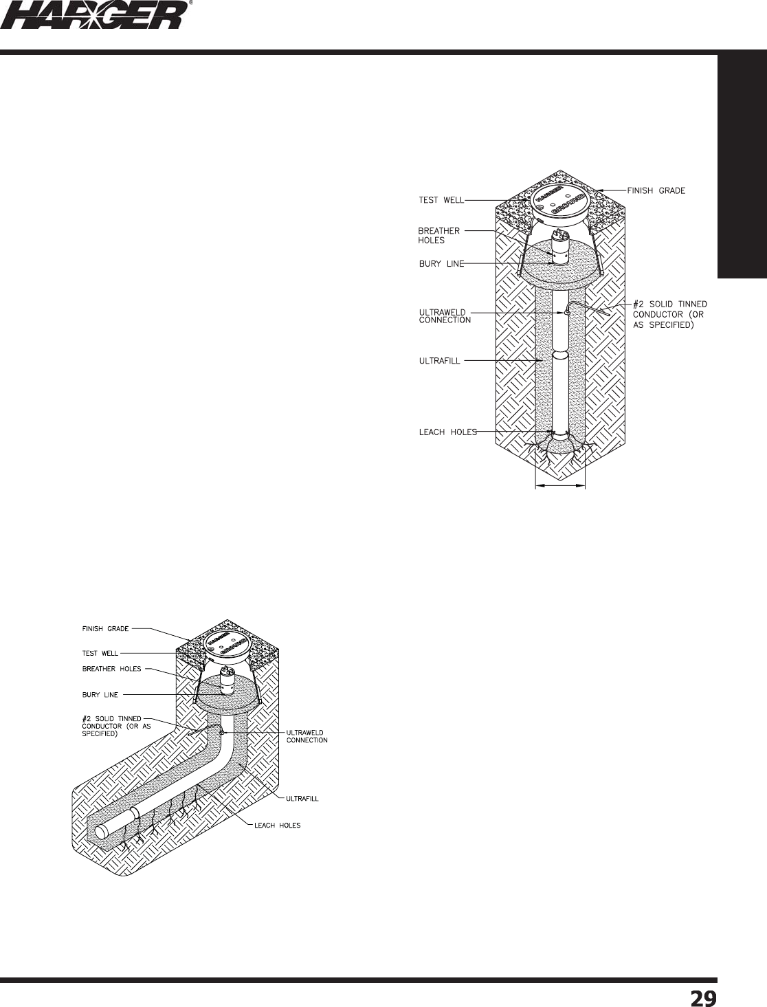
H
ar
g
er Li
g
htnin
g
& Groundin
g
•
©
2012 Phone 847-548-8700 • Fax 847-548-8755 • U.S. 800-842-743
7
29
29
Section 1
Grounding Components
Enhanced Gr
o
und R
o
ds
W
h
a
t is
a
n Enh
a
nce
d
Gr
ou
n
d
R
od?
S
im
p
l
y
p
ut, an Enhanced Ground Rod is a
conductive hollow tube
g
round rod, usually
m
a
n
u
f
a
ct
u
re
d
fr
o
m
300
st
a
inless steel
o
r
copper. They contain special hy
g
roscopic,
electrol
y
tic salts. These salts form a saline
s
olution by absorbin
g
moisture out of the
atmos
p
here. This saline solution leaches out
o
f the bottom of the rod, which
g
radually
l
owers resistivity of the surroundin
g
soil,
formin
g
"electrolytic roots" over time.
T
he salt mixture is critical. Har
g
er utilizes a
s
pecial combination of Ma
g
nesium Sulfate
a
n
d
C
a
lci
u
m Chl
o
ri
d
e. C
a
lci
u
m Chl
o
ri
d
e is
an “active” salt, which continuall
y
draws
m
o
ist
u
re
ou
t
o
f the
a
ir
a
n
d
f
o
rms the
s
olution. Man
y
other
p
roviders of this t
yp
e
o
f electr
od
e
u
tilize s
a
lts s
u
ch
a
s s
od
i
u
m
chloride, some even use common water
s
oftener
p
ellets. These salts do not draw
moisture out of the air, the
y
must be
activated by addin
g
water. This may lower
resistivit
y
initiall
y
, however, unless water
i
s continuall
y
added, the salts dr
y
out over
time and resistivity of the electrode
g
oes
back u
p
.
T
o increase the effi cac
y
of the Enhanced Ground
R
od, a very low resistance
g
round enhancement
material is placed around the rod. Har
g
er proudly
u
ses Ultrafi ll; an ultra-low resistance carbon
ba
se
d
m
a
teri
a
l.
H
ar
g
er exothermically attaches a conductor o
f
y
our choice to the enhanced
g
round rod. This
c
o
n
du
ct
o
r is c
a
lle
d
the t
a
il. The t
a
il
d
irecti
o
n is
v
ery important. Har
g
er provides a desi
g
n which
allows the current, either li
g
htnin
g
or electrical
fault, to maintain a downward slopin
g
path to
g
round. Most manufacturers utilize a desi
g
n
w
hich forces li
g
htnin
g
to
g
o “uphill” before
reachin
g
the
g
round rod. Some manufactures
claim a superior “x” desi
g
n. Althou
g
h at fi rst this
s
ounds
g
ood, it causes the contractor to make
twice as many connections, thus increasin
g
the
c
o
st
o
f inst
a
ll
a
ti
o
n.
6" DIA. MIN.
H
ar
g
er offers two basic styles, vertical and horizontal (L-shaped). We also offer a variety of len
g
ths,
s
ectionals and different kits to meet
y
our s
p
ecifi c re
q
uirements.
Vertica
l
H
o
riz
o
nta
l
S
ect
io
n 1.2.11

H
ar
g
er Li
g
htnin
g
& Groundin
g
•
©
2012 Phone 847-548-8700 • Fax 847-548-8755 • U.S. 800-842-743
7
3030
Section 1
Grounding Components
T
he Enhanced Ground Rod Numberin
g
System allows you to customize the product to meet your specifi c
needs. In the above example, the product specifi ed is a stainless steel, 10' lon
g
, L-shaped
g
round rod that
i
ncludes an inspection well and 2 - 50 pound ba
g
s of Ultrafi ll with a #2 solid tinned 5' tail exothermically
w
elded to the rod. The
p
art number i
s
E
G
RSS1
0
LW
G
2T
.
Vertic
a
l
Ho
riz
o
nt
a
l "L"
E
nh
a
nce
d
Gr
ou
n
d
Rod
L
en
g
t
h
(
ft.
)
S
t
y
l
e
Vertic
a
l - Le
a
ve Bl
a
nk
Ho
riz
o
nt
a
l - A
dd
L
Ins
p
ection Well
Incl
ud
e in Kit - A
dd
W
N
one Re
q
uired - Leave Blank
U
ltr
a
fi ll
Gr
ou
n
d
Ma
teri
a
l
Incl
ud
e in Kit - A
dd
G
N
one Re
q
uired - Leave Blank
C
o
n
du
ct
o
r
Typ
e
T
o s
p
ecif
y
t
yp
e
a
n
d
wire c
od
e
E
GR SS 1
0
L W G
2
T
Ma
teri
a
l
Co
pp
er - Leave Blank
S
t
a
inless Steel - A
dd
S
S
Enhanced Ground Rod Numberin
g
Syste
m
L
iste
d
4
67
TECHNICAL N
O
TES
:
•
U
L 467 6.9.3.1
(
Summarized
)
A hollow-tube, chemically-char
g
ed-rod electrode shall:
a
)
Be constructed of co
pp
er or an e
q
uivalent material resistant to the corrosive effects of moist soil;
b
)
Have an internal diameter not less than 2 inches and a wall thickness not less than .080 inch; and
c
)
If the means of installation is not obvious, be accom
p
anied b
y
ade
q
uate installation instructions.
•
U
L 467 6.9.3.2
(
Summarized
)
The chemical char
g
e within the rod electrode described in 9.3.1 shall be a substance that does not
cause the electrode to corrode at a faster rate than an electrode constructed of 3
/
4 inch trade size
ri
g
id ferrous metal conduit.
•
U
L 467 6.9.3.3
(
Summarized
)
With reference to 9.3.2, a chemical char
g
e of 60 percent sodium chloride and 40 percent calcium
chloride may be used if the total wei
g
ht of the char
g
e is less than 11 pounds.
S
ect
io
n 1.2.11

H
ar
g
er Li
g
htnin
g
& Groundin
g
•
©
2012 Phone 847-548-8700 • Fax 847-548-8755 • U.S. 800-842-743
7
3
1
31
Section 1
Grounding Components
•
Other sizes and conductor t
yp
es available. Contact the factor
y
for details.
*
5' enhanced
g
round rods are not UL listed.
L
Part No. Length Inspection
Well
Ultrafi ll
50# Bag
Tail (Conductor)
Type (AWG)
Approx. Shipping
Wt. (lbs.)
E
GR5WG4
/
0*
5'
Yes
1
5
' - 4
/
0 Stranded 80
E
GR8WG2T 8
'
Yes
2
5
' - #2 S
o
li
d
Tinne
d
1
35
E
GR8WG2
/
08
'
Yes
2
5
' - 2
/
0 Stranded 14
0
E
GR8WG4
/
08
'
Yes
2
5
' - 4
/
0 Stranded 14
5
E
GR1
0
WG
2
T1
0'
Yes
2
5
' - #2 S
o
li
d
Tinne
d
185
E
GR10WG2
/
01
0'
Yes
2
5
' - 2
/
0 Stranded 19
0
E
GR10WG4
/
01
0'
Yes
2
5
' - 4
/
0 Stranded 19
5
E
GR
20
WG
2
T2
0'
Yes
4
5
' - #2 S
o
li
d
Tinne
d
320
E
GR20WG2
/
02
0'
Yes
4
5
' - 2
/
0 Stranded
325
E
GR20WG4
/
02
0'
Yes
4
5
' - 4
/
0 Stranded
330
C
o
pp
er Vertical Enhanced Ground Rod Kits
L
iste
d
4
67
APPLICATI
O
N N
O
TES
:
• Enhanced
g
rounds are used in hi
g
h resistivity soil conditions and when low resistance
g
round
electrode s
y
stems are critical.
• Conductor is welded 18" down from the to
p
.
• Outside diameter of co
pp
er tube is 2-1/8".
S
ect
io
n 1.2.11
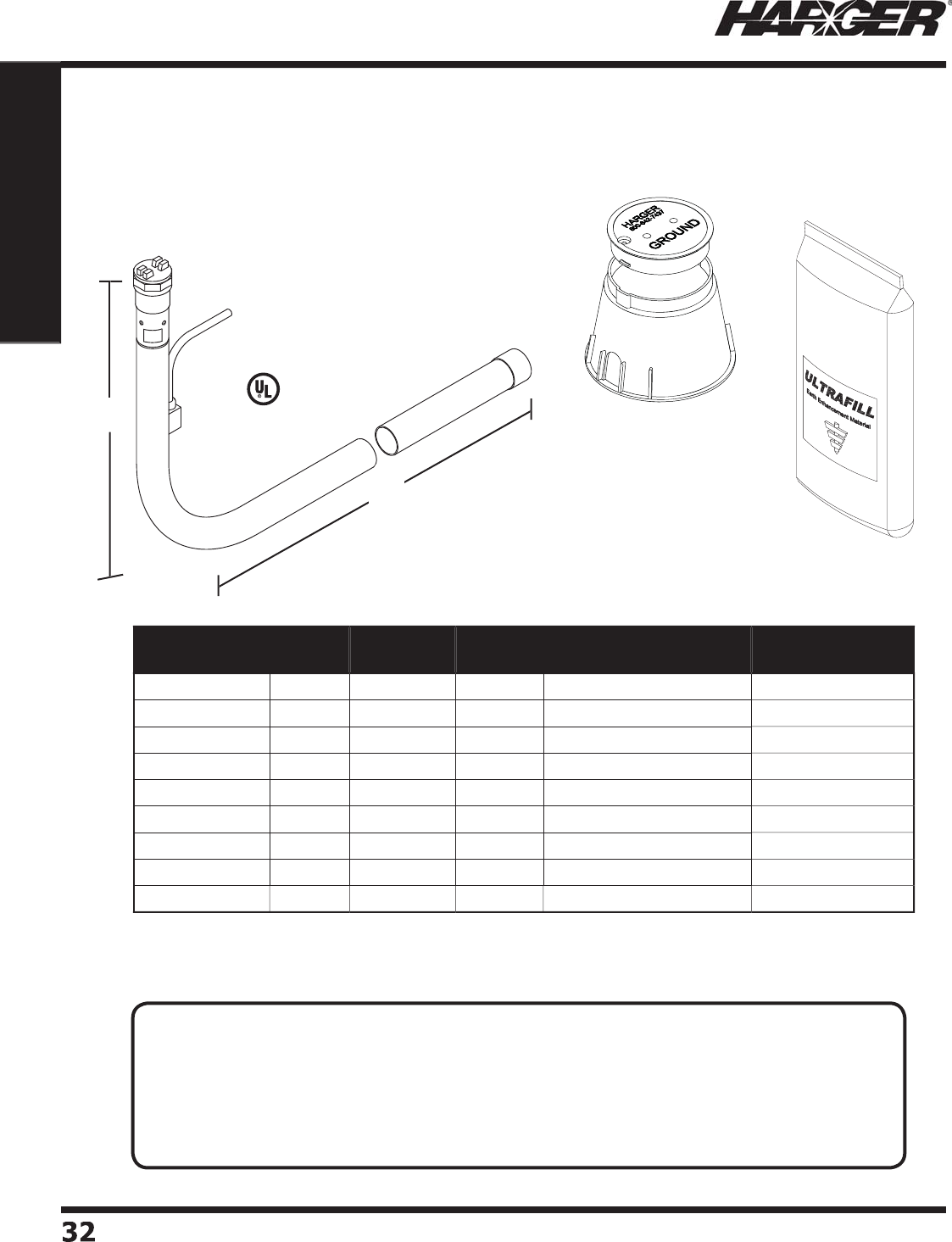
H
ar
g
er Li
g
htnin
g
& Groundin
g
•
©
2012 Phone 847-548-8700 • Fax 847-548-8755 • U.S. 800-842-743
7
3
2
32
Section 1
Grounding Components
L
iste
d
4
67
•
Other sizes and conductor t
yp
es available. Contact the factor
y
for details.
*
N
o
min
a
l
d
imensi
o
ns.
2
6
"
L
Part No. Dims
H* x L*
Inspection
Well
Ultrafi ll
50# Bag
Tail (Conductor)
Type (AWG)
Approx. Shipping
Wt. (lbs.)
E
GR8LWG2T 2' x 8
'
Yes
2
5
' - #2 S
o
li
d
Tinne
d
1
50
E
GR8LWG2
/
0 2' x 8
'
Yes
2
5
' - 2
/
0 Stranded 1
55
E
GR8LWG4
/
0 2' x 8
'
Yes
2
5
' - 4
/
0 Stranded 1
60
E
GR1
0
LWG
2
T 2' x 1
0'
Yes
2
5
' - #2 S
o
li
d
Tinne
d
205
E
GR10LWG2
/
0 2' x 1
0'
Yes
2
5
' - 2
/
0 Stranded
2
1
0
E
GR10LWG4
/
0 2' x 1
0'
Yes
2
5
' - 4
/
0 Stranded
2
1
5
E
GR
20
LWG
2
T 2' x 2
0'
Yes
4
5
' - #2 S
o
li
d
Tinne
d
3
4
0
E
GR20LWG2
/
0 2' x 2
0'
Yes
4
5
' - 2
/
0 Stranded
3
4
5
E
GR20LWG4
/
0 2' x 2
0'
Yes
4
5
' - 4
/
0 Stranded
350
C
o
pp
er Horizontal L-sha
p
ed Enhanced Ground Rod Kits
APPLICATI
O
N N
O
TES
:
• Enhanced
g
rounds are used in hi
g
h resistivity soil conditions and when low resistance
g
round
electrode s
y
stems are critical.
•
L
-shaped enhanced
g
round rods are used when proper depth cannot be achieved due to physical
c
o
n
d
iti
o
ns s
u
ch
a
s
b
e
d
r
o
ck.
• Conductor is welded 11" down from the to
p
.
• Outside diameter of co
pp
er tube is 2-1/8".
S
ect
io
n 1.2.11
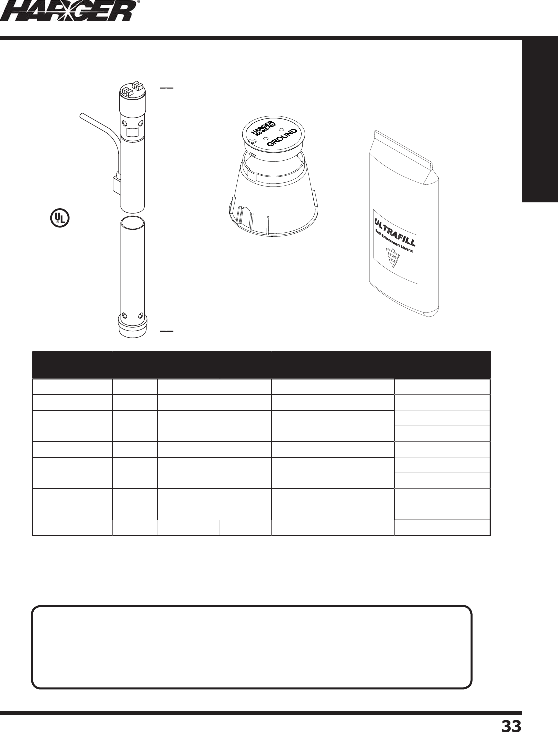
H
ar
g
er Li
g
htnin
g
& Groundin
g
•
©
2012 Phone 847-548-8700 • Fax 847-548-8755 • U.S. 800-842-743
7
33
33
Section 1
Grounding Components
•
M
a
n
u
f
a
ct
u
re
d
fr
o
m c
o
rr
o
si
o
n resist
a
nt
300
series st
a
inless steel.
•
Other sizes and conductor t
yp
es available. Contact the factor
y
for details.
*
5' enhanced
g
round rods are not UL listed.
L
Part No. Length Inspection
Well
Ultrafi ll
50# Bag
Tail (Conductor)
Type (AWG)
Approx. Shipping
Wt. (lbs.)
E
GRSS5WG4
/
0*
5'
Yes
1
5
' - 4
/
0 Stranded 80
E
GRSS8WG2T 8
'
Yes
2
5
' - #2 S
o
li
d
Tinne
d
1
35
E
GRSS8WG2
/
08
'
Yes
2
5
' - 2
/
0 Stranded 14
0
E
GRSS8WG4
/
08
'
Yes
2
5
' - 4
/
0 Stranded 14
5
E
GRSS1
0
WG
2
T1
0'
Yes
2
5
' - #2 S
o
li
d
Tinne
d
185
E
GRSS10WG2
/
01
0'
Yes
2
5
' - 2
/
0 Stranded 19
0
E
GRSS10WG4
/
01
0'
Yes
2
5
' - 4
/
0 Stranded 19
5
E
GRSS
20
WG
2
T2
0'
Yes
4
5
' - #2 S
o
li
d
Tinne
d
320
E
GRSS20WG2
/
02
0'
Yes
4
5
' - 2
/
0 Stranded
325
E
GRSS20WG4
/
02
0'
Yes
4
5
' - 4
/
0 Stranded
330
S
tainless Steel Vertical Enhanced Gr
o
und R
o
d Kits
L
iste
d
4
67
APPLICATI
O
N N
O
TES
:
• Enhanced
g
rounds are used in hi
g
h resistivity soil conditions and when low resistance
g
round
electrode s
y
stems are critical.
• Excellent for corrosive soils or cathodic
p
rotection a
pp
lications.
• Conductor is welded 18" down from the to
p
.
• Outside diameter of stainless steel tube is 2-3
/
8".
S
ect
io
n 1.2.11
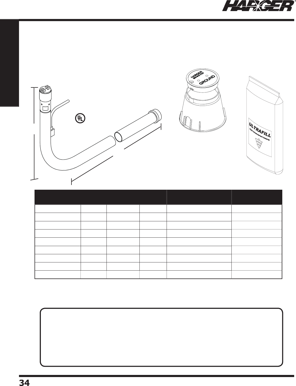
H
ar
g
er Li
g
htnin
g
& Groundin
g
•
©
2012 Phone 847-548-8700 • Fax 847-548-8755 • U.S. 800-842-743
7
34
34
Section 1
Grounding Components
L
iste
d
4
67
•
M
a
n
u
f
a
ct
u
re
d
fr
o
m c
o
rr
o
si
o
n resist
a
nt
300
series st
a
inless steel.
•
Other sizes and conductor t
yp
es available. Contact the factor
y
for details.
*
N
o
min
a
l Dimensi
o
n
s
L
2
6
"
Part No. Dims.
H* x L*
Inspection
Well
Ultrafi ll
50# Bag
Tail (Conductor)
Type (AWG)
Approx. Shipping
Wt. (lbs.)
E
GRSS8LWG2T 2' x 8
'
Yes
2
5
' - #2 S
o
li
d
Tinne
d
1
50
E
GRSS8LWG2
/
0 2' x 8
'
Yes
2
5
' - 2
/
0 Stranded 1
55
E
GRSS8LWG4
/
0 2' x 8
'
Yes
2
5
' - 4
/
0 Stranded 1
60
E
GRSS1
0
LWG
2
T 2' x 1
0'
Yes
2
5
' - #2 S
o
li
d
Tinne
d
205
E
GRSS10LWG2
/
0 2' x 1
0'
Yes
2
5
' - 2
/
0 Stranded
2
1
0
E
GRSS10LWG4
/
0 2' x 1
0'
Yes
2
5
' - 4
/
0 Stranded
2
1
5
E
GRSS
20
LWG
2
T 2' x 2
0'
Yes
4
5
' - #2 S
o
li
d
Tinne
d
3
4
0
E
GRSS20LWG2
/
0 2' x 2
0'
Yes
4
5
' - 2
/
0 Stranded
3
4
5
E
GRSS20LWG4
/
0 2' x 2
0'
Yes
4
5
' - 4
/
0 Stranded
350
S
tainless Steel Horizontal L-sha
p
ed
Enhanced Gr
o
und R
o
d Kits
APPLICATI
O
N N
O
TES
:
• Enhanced
g
rounds are used in hi
g
h resistivity soil conditions and when low resistance
g
round
electrode s
y
stems are critical.
•
L
-shaped enhanced
g
round rods are used when proper depth cannot be achieved due to physical
c
o
n
d
iti
o
ns s
u
ch
a
s
b
e
d
r
o
ck.
• Excellent for corrosive soils or cathodic
p
rotection a
pp
lications.
• Conductor is welded 11" down from the to
p
.
• Outside diameter of stainless steel tube is 2-3
/
8".
S
ect
io
n 1.2.11
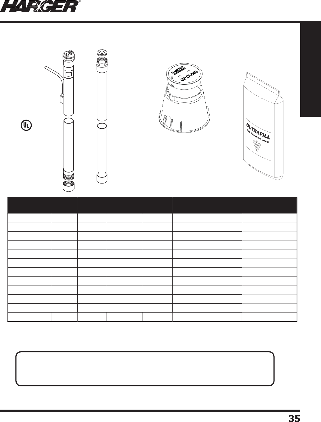
H
ar
g
er Li
g
htnin
g
& Groundin
g
•
©
2012 Phone 847-548-8700 • Fax 847-548-8755 • U.S. 800-842-743
7
35
35
Section 1
Grounding Components
L
iste
d
4
67
•
Other size conductors available. Contact the factor
y
for details.
Part No. Overall
Length
Section
Length
Inspection
Well
Ultrafi ll
50# Bag
Tail (Conductor)
Type (AWG)
Approx. Shipping
Wt. (lbs.)
S
EGR1
0
WG
2
T1
0'
5'
Yes
2
5
' - #2 S
o
li
d
Tinne
d
185
S
EGR10WG2
/
01
0'
5'
Yes
2
5
' - 2
/
0 Stranded 19
0
S
EGR10WG4
/
01
0'
5'
Yes
2
5
' - 4
/
0 Stranded 19
5
S
EGR
20
WG
2
T2
0'
1
0'
Yes
4
5
' - #2 S
o
li
d
Tinne
d
320
S
EGR20WG2
/
02
0'
1
0'
Yes
4
5
' - 2
/
0 Stranded
325
S
EGR20WG4
/
02
0'
1
0'
Yes
4
5
' - 4
/
0 Stranded
330
S
EGR
30
WG
2
T
30'
1
5'
Yes
6
5
' - #2 S
o
li
d
Tinne
d
450
S
EGR30WG2
/
0
30'
1
5'
Yes
6
5
' - 2
/
0 Stranded
455
S
EGR30WG4
/
0
30'
1
5'
Yes
6
5
' - 4
/
0 Stranded
460
S
EGR4
0
WG
2
T
40'
2
0'
Yes
8
5
' - #2 S
o
li
d
Tinne
d
5
85
S
EGR40WG2
/
0
40'
2
0'
Yes
8
5
' - 2
/
0 Stranded
5
9
0
S
EGR40WG4
/
0
40'
2
0'
Yes
8
5
' - 4
/
0 Stranded
5
9
5
C
o
pp
er Sectional Enhanced Ground Rod Kits
APPLICATI
O
N N
O
TES
:
• Used where there are vertical hei
g
ht restrictions or when len
g
ths
g
reater than 20' are desired.
• Conductor is welded 18" down from the to
p
.
• Outside diameter of co
pp
er tube is 2-1/8".
S
ect
io
n 1.2.11
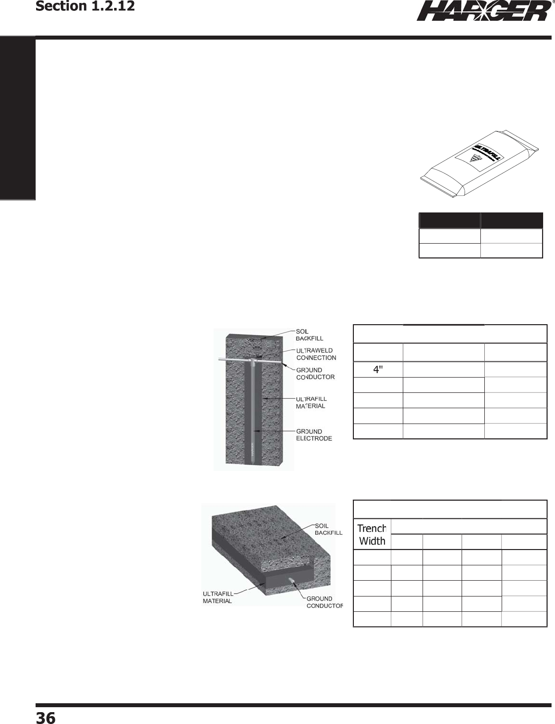
H
ar
g
er Li
g
htnin
g
& Groundin
g
•
©
2012 Phone 847-548-8700 • Fax 847-548-8755 • U.S. 800-842-743
7
3636
Section 1
Grounding Components
Vertical A
pp
lications
:
Au
g
er hole to required depth.
Insert electr
od
e in center
o
f h
o
le.
P
our Ultrafi ll to
p
ro
p
er de
p
th. The
chart located to the ri
g
ht will help
d
etermine h
o
w m
u
ch
U
ltr
a
fi ll will
be re
q
uired.
Horizontal A
pp
lications
:
P
our enou
g
h Ultrafi ll to cover
bo
tt
o
m
o
f trench. Pl
a
ce the
g
round electrode into trench.
Pou
r in
add
iti
o
n
a
l
U
ltr
a
fi ll t
o
c
o
ver
electrode to the desired de
p
th.
F
or example, placin
g
a 5/8" x 10'
g
round rod in
a 4" hole would re
q
uire 30
p
ounds of Ultrafi ll.
(
3.0 x 10 = 30
p
ounds
)
F
or example, usin
g
2" of material in a 6" wide
by 10' lon
g
trench would require 30 pounds o
f
U
ltrafi ll.
(
3.0 x 10 = 30
p
ounds
)
Liquid Mixin
g
Instructions
:
T
o mix Ultrafi ll into a slurry for pumpin
g
applications, use the
followin
g
formula:
6
p
arts wate
r
1
p
art bentonite
1
p
art Ultrafi ll.
Installati
o
n Instructi
o
ns
U
ltrafi ll is a low resistance carbon based backfi ll material, which
dramatically lowers
g
round system resistance in diffi cult soil situations.
U
ltrafi ll contains no bentonite or concrete com
p
onents, which, in ver
y
dry conditions, can cause shrinka
g
e around the
g
round electrode, thus
renderin
g
it ineffective.
U
ltrafi ll is ideal for use in rocky soil, sand,
g
ravel or any other hi
g
h
resist
a
nce s
o
il c
o
n
d
iti
o
ns. It is
a
ls
o
the i
d
e
a
l
ba
ckfi ll m
a
teri
a
l f
o
r
u
se
around enhanced
g
round rods and
g
round
g
rid systems.
U
ltrafi ll is eas
y
to use, safe and effective. Unlike other backfi ll
p
roducts,
U
ltrafi ll is relatively dust free and does not require mixin
g
in water prior
t
o
inst
a
ll
a
ti
o
n.
U
ltrafi ll may be wither used in a horzontal trench or
g
rid, or in vertical
a
pp
lications. Ultrafi ll is available in 25 and 50
p
ound coated woven
polypropylene ba
g
s.
Pounds of Ultrafi ll Required Per FootPounds of Ultrafi ll Required Per Foot
Hole Size
Hole Size
5/
8" Ground Rod 2" EGR
3
.
0
2
.
2
6
"
6
.9
6
.1
8" 1
2
.
3
11.
5
1
0
" 19.
3
18.5
12" 27.8
2
7.
0
Pounds of Ultrafi ll Required Per FootPounds of Ultrafi ll Required Per Foot
T
hickness of Ultrafi ll
(
Inches
)
1
"
2
"
3
"
4
"
4
"1.
0
2
.
0
3
.
0
3
.9
6
"1.
5
3
.
0
4
.
4
5
.9
8
"
2
.
0
3
.9
5
.9 7.9
10
"
2
.
5
4
.9
7
.
4
9
.9
1
2"
3
.
0
5
.9 8.9 11.8
Part No. Approx. Wt.
U
LTRAFILL
25
2
5
l
b
s.
ULTRAFILL
50
l
b
s.
U
ltrafi ll - Earth
(
Ground
)
Enhancement Materia
l
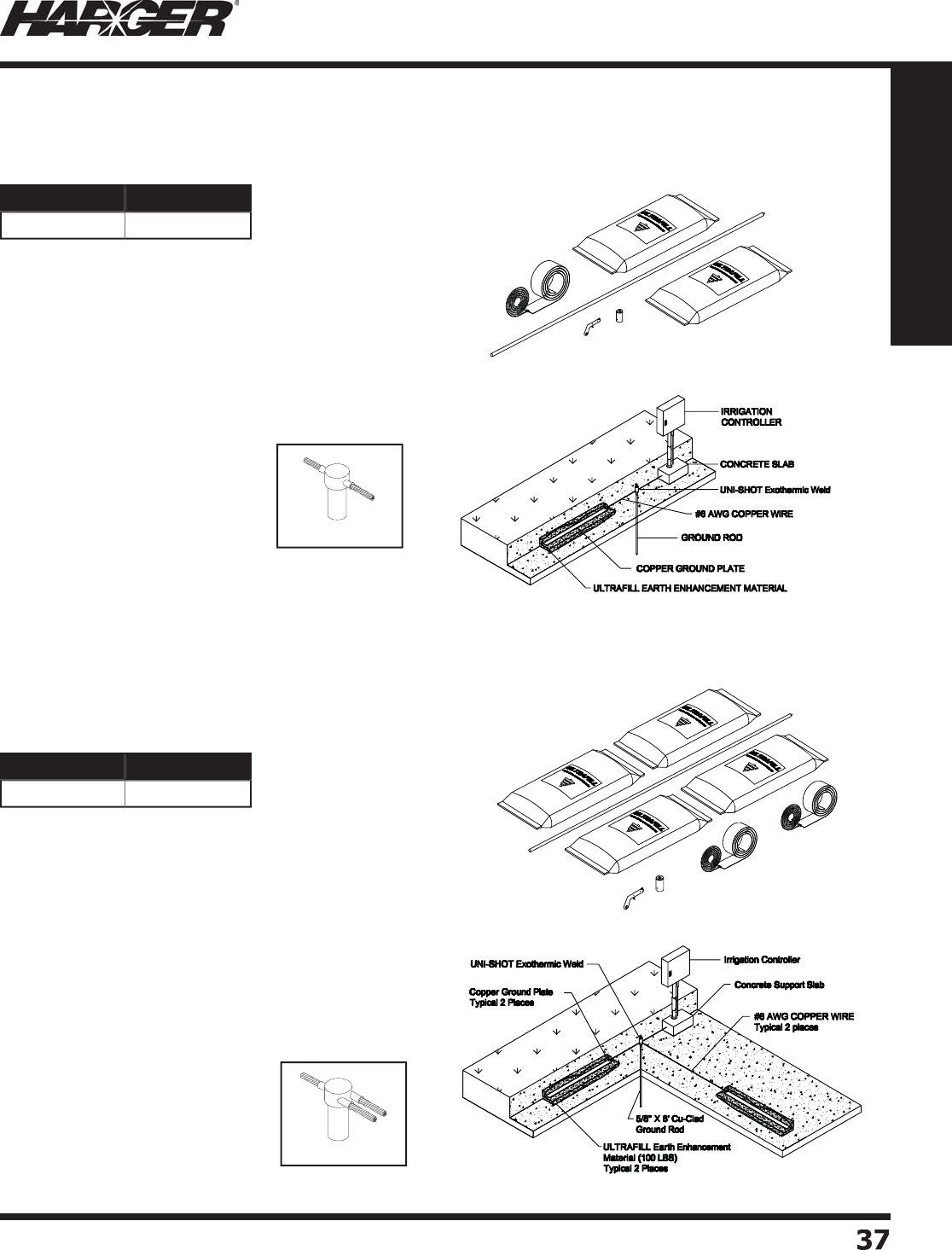
H
ar
g
er Li
g
htnin
g
& Groundin
g
•
©
2012 Phone 847-548-8700 • Fax 847-548-8755 • U.S. 800-842-743
7
3
7
37
Section 1
Grounding Components
•
For
g
roundin
g
and li
g
htnin
g
protection of
g
olf course
i
rri
g
ation systems.
•
Kit incl
ud
e
s:
(1) 5/8" x 8'
g
round rod
(2) 50 lb. ba
g
s of Ultrafi ll earth enhancement material
(1) Flint i
g
nite
r
(
1
)
#G21-588 Uni-shot exothermic weld metal
(
1
)
8' co
pp
er
p
late with a 25' tail of #6 AWG wir
e
•
For
g
roundin
g
and li
g
htnin
g
protection of
g
olf course
i
rri
g
ation systems.
•
Used when connectin
g
two kits to sin
g
le irri
g
ation
c
o
ntr
o
ller.
•
Kit incl
ud
e
s:
(1) 5/8" x 8'
g
round rod
(4) 50 lb. ba
g
s of Ultrafi ll earth enhancemen
t
m
a
teri
a
l
(1) Flint i
g
nite
r
(
1
)
#G31-588 Uni-shot exothermic weld metal
(
2
)
8' co
pp
er
p
late with a 25' tail of #6 AWG wir
e
#G
2
1 C
o
nnecti
on
#G
3
1 C
o
nnecti
on
Part No. Approx. Wt.
IRR
G
RDKIT1 117 l
b
s.
Part No. Approx. Wt.
IRRGRDKIT
2
227 l
b
s.
Irri
g
ation Groundin
g
Kits
S
ect
io
n 1.2.13
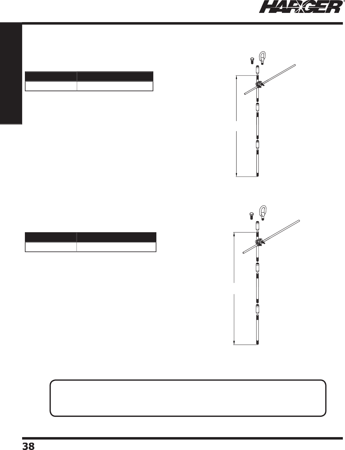
H
ar
g
er Li
g
htnin
g
& Groundin
g
•
©
2012 Phone 847-548-8700 • Fax 847-548-8755 • U.S. 800-842-743
7
38
38
Section 1
Grounding Components
•
Consists of three 5/8" x 2' copper clad sectional
g
round rods,
thus achievin
g
an overall depth of 6'.
•
Also contains three 5/8"
g
round rod couplers, one 5/8" drive
s
tud, one u-bolt
g
round rod clamp and one 5/8" eyelet.
•
Consists of three 5/8" x 3' copper clad sectional
g
round rods,
thus achievin
g
an overall depth of 9'.
•
Also contains three 5/8"
g
round rod couplers, one 5/8" drive
s
tud, one u-bolt
g
round rod clamp and one 5/8" eyelet.
6 FT.
NOM.
9 FT.
NOM.
Part No. Approx. Each Wt. (lbs.)
M
OBGRDSTK58
2
14
Part No. Approx. Each Wt. (lbs.)
M
OBGRDSTK58
3
20
M
o
bile Gr
o
und Stake Kits
APPLICATI
O
N N
O
TES
:
• Mobile
g
round stakes provide temporary
g
rounds for military communications vehicles, tanks,
COWs (Cell-site On Wheels), etc. Usually a
g
round loop is installed around the vehicle to help
provide an equipotential
g
round plane. Eyelet provides for easy means of removal.
S
ect
io
n 1.2.1
4

H
ar
g
er Li
g
htnin
g
& Groundin
g
•
©
2012 Phone 847-548-8700 • Fax 847-548-8755 • U.S. 800-842-743
7
3
9
39
Section 1
Grounding Components
•
NSN 5975-01-497-0438
•
Consists of three 5/8" x 2' copper clad sectional
g
round rods,
thus achievin
g
an overall depth of 6'.
•
Also contains three 5/8"
g
round rod couplers, one 5/8" drive
s
tud and one u-bolt
g
round rod clamp.
•
Bottom rod has tappered end to facilitate drivin
g
.
•
NSN
5
97
5
-
0
1-497-149
6
•
Consists of three 5/8" x 3' copper clad sectional
g
round rods,
thus achievin
g
an overall depth of 9'.
•
Also contains three 5/8"
g
round rod couplers, one 5/8" drive
s
tud and one u-bolt
g
round rod clamp.
•
Bottom rod has tappered end to facilitate drivin
g
.9 FT.
NOM.
Part No. Approx. Each Wt. (lbs.)
5
82GTEKIT 13-1
/
4
Part No. Approx. Each Wt. (lbs.)
5
83GTEKIT 19-1
/
4
M
o
bile Gr
o
und Stake Kits
APPLICATI
O
N N
O
TES
:
• Mobile
g
round stakes provide temporary
g
rounds for military communications vehicles, tanks,
COWs (Cell-site On Wheels), etc. Usually a
g
round loop is installed around the vehicle to help
provide an equipotential
g
round plane. Eyelet provides for easy means of removal.
S
ect
io
n 1.2.1
4
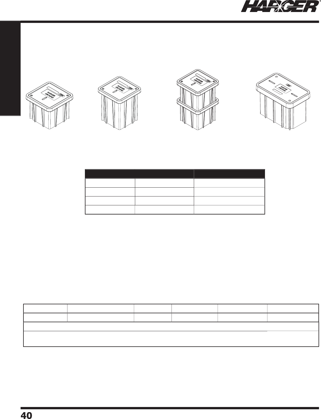
H
ar
g
er Li
g
htnin
g
& Groundin
g
•
©
2012 Phone 847-548-8700 • Fax 847-548-8755 • U.S. 800-842-743
7
40
40
Section 1
Grounding Components
•
Lid & Grade Rin
g
manufactured from 20,000 PSI hi
g
h density
p
ol
y
mer concrete.
•
Body manufactured from sheet moldin
g
compound for
exceptional tou
g
hness and reduced wei
g
ht.
•
Comes with 20,000# rated covers.
•
Suitable for installation and use throu
g
h a temperature ran
g
e
o
f -4
0
°C t
o
+9
0
°C.
•
Gra
y
color.
*
GAW121224HD is a two piece stackable, each 12" hi
g
h.
Li
g
ht Wei
g
ht Polymer Concrete
GAW132418H
D
GAW1
2
1
2
1
2
H
D
GAW121218H
D
GAW121224HD*
Part No. Dimensions Approx. Each Wt. (lbs.)
GAW1
2
1
2
1
2
H
D
12" x 12" x 12" dee
p
52
GAW121218H
D
12" x 12" x 18" dee
p
57
GAW121224HD* 12" x 12" x 24" dee
p
67
GAW132418H
D
13" x 24" x 18" dee
p
9
7-1
/2
G
r
o
und Access Wells
ASTM C-857 S
p
ecifi cations
C
over T
yp
e
C
over Rat
i
n
g
s Live Loa
d
30% Safet
y
Test Loa
d
T
e
s
t
A
rea
H
eav
y
D
ut
y
10 Ton GVW
(
20,000#
)
8,000# 10,400# 22,568# 1
0
" x 1
0
"
20,000# boxes and covers ma
y
be
p
laced in locations that ma
y
see occasional non-deliberate heav
y
vehicles.
Covers exceed their ratin
g
by at least 20% and exceed ASTM test loads. No polymer concrete box or cover
should be
p
laced in a full traffi c, H-20, a
pp
lication. Meets W.U.C. 3.6.
•
GVW = Gross Vehicle Wei
g
h
t
S
ect
io
n 1.2.15
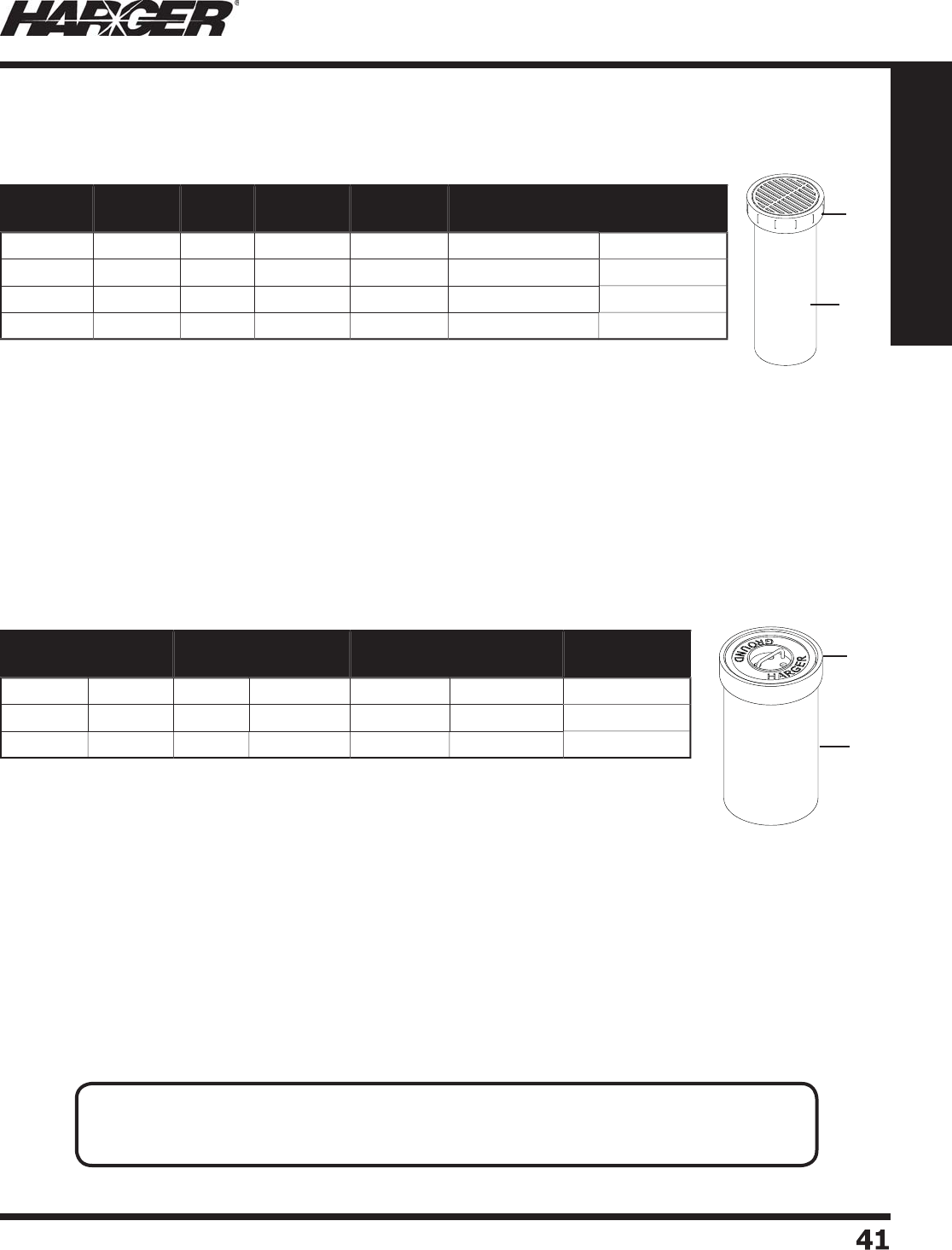
H
ar
g
er Li
g
htnin
g
& Groundin
g
•
©
2012 Phone 847-548-8700 • Fax 847-548-8755 • U.S. 800-842-743
7
41
41
Section 1
Grounding Components
•
Available in 8", 10", 12" and 18" diameters.
•
Di
a
meter is me
a
s
u
re
d
o
n insi
d
e
d
i
a
meter
o
f
a
ccess well
bo
tt
o
m.
•
Must be shi
pp
ed b
y
truck onl
y
.
•
Available in 8", 10" and 12" diameters.
•
Di
a
meter is me
a
s
u
re
d
o
n insi
d
e
d
i
a
meter
o
f
a
ccess well
bo
tt
o
m.
•
Must be shi
pp
ed b
y
truck onl
y
.
Be
ll
P
i
pe
Be
ll
P
i
pe
Part No. Nominal
Size Length Bell I.D.
Minimum
Pipe I.D.
(Approx.) Cover Type Approx. Each
Wt. (lbs.)
358T 8" 24" 10-1
/
2" 8" C
a
st Ir
o
n Gr
a
te
d
57
360
T1
0
" 24" 12-3
/
4" 1
0
"C
a
st Ir
o
n Gr
a
te
d
8
3
362
T 12" 24" 15-1
/
8" 12" C
a
st Ir
o
n Gr
a
te
d
14
0
368T 18" 24" 22-1
/
4" 18" C
a
st Ir
o
n Gr
a
te
d
222
Part No. Nominal
Size Length Bell I.D.
Minimum
Pipe I.D.
(Approx.) Cover Type Approx. Each
Wt. (lbs.)
358TC 8" 24" 10-1
/
2" 8"
Co
ncrete 7
0
360
TC 1
0
" 24" 12-3
/
4" 1
0
"
Co
ncrete
97
362
TC 12" 24" 15-1
/
8" 12"
Co
ncrete 1
5
1
G
r
o
und Access Wells
Tile Well with Grated C
o
ver
Tile Well with C
o
ncrete C
o
ver
S
ect
io
n 1.2.15
APPLICATI
O
N N
O
TES
:
• Provides ready access to
g
round electrode for testin
g
and inspection purposes.
• To prevent displacement by frost, the access well must be lon
g
er than the frost line is deep.
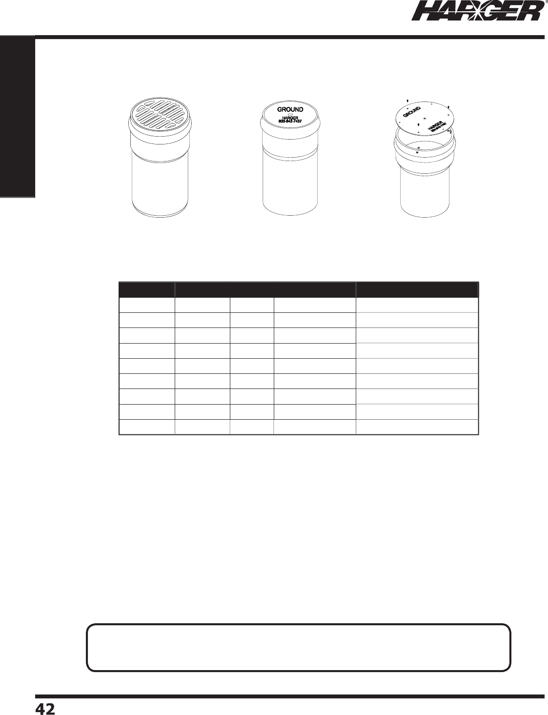
H
ar
g
er Li
g
htnin
g
& Groundin
g
•
©
2012 Phone 847-548-8700 • Fax 847-548-8755 • U.S. 800-842-743
7
4
2
42
Section 1
Grounding Components
•
Available in 10", 12" and 18" diameters.
•
Sche
du
le 4
0
PVC wells fe
a
t
u
re
a
b
elle
d
h
ub
.
•
Flat steel covers are 3/16" thick commercial
g
rade steel with a zinc/ultraseal coatin
g
.
•
Other lids available. See pa
g
e 45.
G
r
o
und Access Wells
PVC Belled Hub Wells with C
o
ver
360
PB
G
360
PB
S
360
PBST
P
Part No. Diameter Length Cover Type Approx. Each Wt. (lbs.)
360
PB
G
1
0
" 24" C
a
st Ir
o
n Gr
a
te
d
20
360
PB
S
1
0
" 24"
F
l
a
t Steel 19
360
PBST
P
1
0
" 24"
T
am
p
er Resistan
t
27
362
PB
G
12" 24" C
a
st Ir
o
n Gr
a
te
d
28
362
PB
S
12" 24"
F
l
a
t Steel
26
362
PBST
P
12" 24"
T
am
p
er Resistan
t
28
368PB
G
18" 24" C
a
st Ir
o
n Gr
a
te
d
71
368PB
S
18" 24"
F
l
a
t Steel
5
8
368PBST
P
18" 24"
T
am
p
er Resistan
t
5
8
APPLICATI
O
N N
O
TES
:
• Provides ready access to
g
round electrode for testin
g
and inspection purposes.
• To prevent displacement by frost, the access well must be lon
g
er than the frost line is deep.
S
ect
io
n 1.2.15
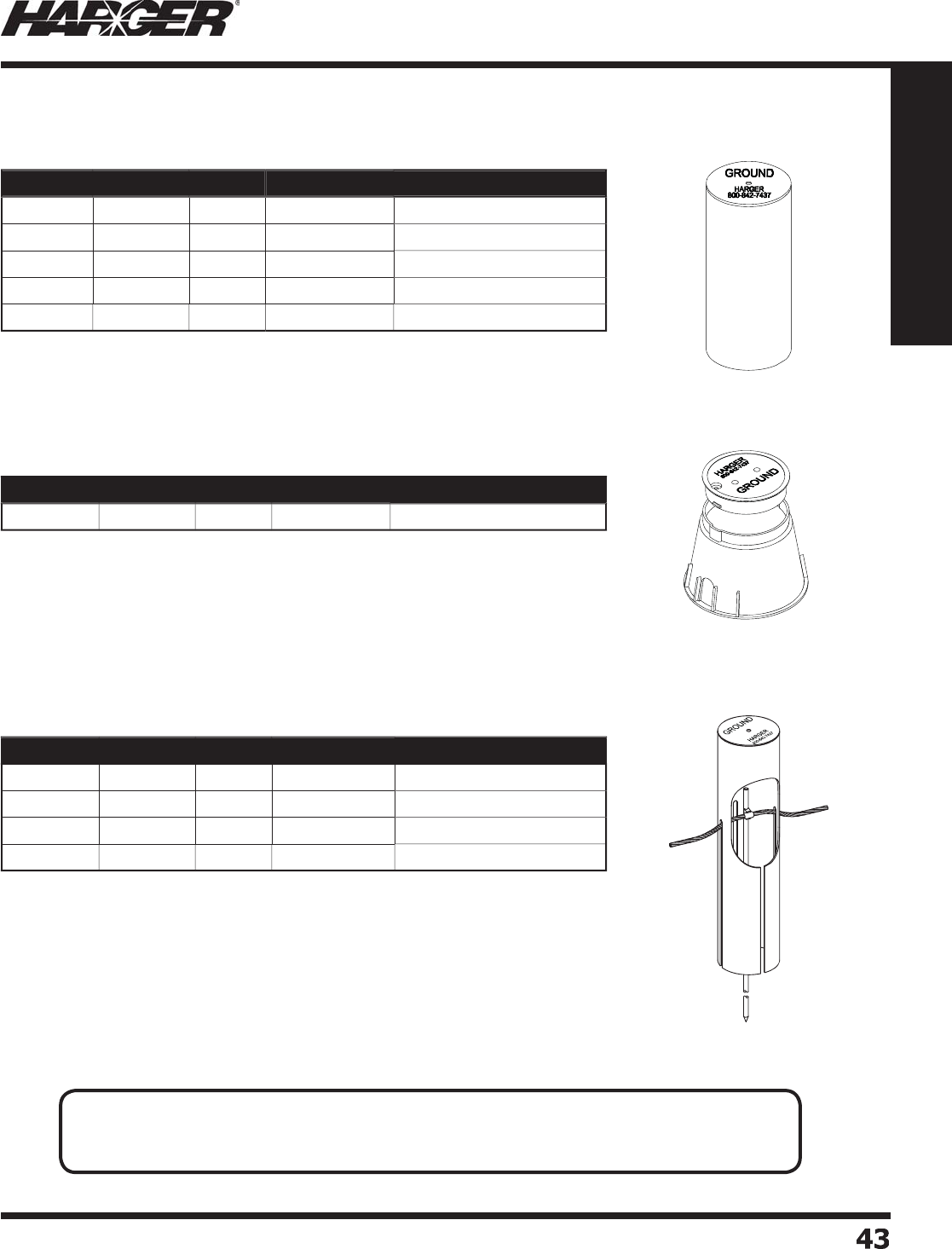
H
ar
g
er Li
g
htnin
g
& Groundin
g
•
©
2012 Phone 847-548-8700 • Fax 847-548-8755 • U.S. 800-842-743
7
43
43
Section 1
Grounding Components
•
Sche
du
le 4
0
PVC well.
•
Steel covers are 3/16" thick commercial
g
rade steel with a zinc/ultraseal coatin
g
.
•
Plastic covers are manufactured from Hi
g
h Density Polyethylene.
•
Molded Hi
g
h Density Polyethylene well features a 9" diameter "twist lock"
cover with lockin
g
bolt.
•
Static vertical load ratin
g
= 350 PSF.
•
2 knock outs (mouse holes) allow for routin
g
conductor to the inside.
•
F
o
r
u
se in n
o
n-vehic
u
l
a
r tr
a
ffi c
a
re
a
s.
Part No. Diameter Length Cover Type Approx. Each Wt. (lbs.)
GAW91
0
9
" 10-1
/
4"
HDPE
4
-1
/2
G
r
o
und Access Wells
PVC Well with C
o
ver
HDPE Well with C
o
ver
•
Sche
du
le 4
0
PVC well.
•
Steel covers are 3/16" thick commercial
g
rade steel with a zinc/ultraseal coatin
g
.
•
Plastic covers are manufactured from Hi
g
h Density Polyethylene.
•
Four 27" slots allow for
g
round electrode connections to be made before
i
nst
a
ll
a
ti
o
n
o
f test well.
PVC Sl
o
tted Well with C
o
ver
Part No. Diameter Length Cover Type Approx. Each Wt. (lbs.)
358P
P
8" 24"
P
l
a
sti
c
1
2
358P
S
8"
24
"
F
l
a
t Steel
14
360
P
P
1
0
" 24"
P
l
a
sti
c
1
5
360
P
S
1
0
"
24
"
F
l
a
t Steel 19
362
P
S
12" 24"
F
l
a
t Steel
22
Part No. Diameter Length Cover Type Approx. Each Wt. (lbs.)
358P4
2
8"
4
2"
F
l
a
t Steel 19
358PP4
2
8"
4
2"
P
l
a
sti
c
1
7
360
P4
2
1
0
"
4
2"
F
l
a
t Steel
30
360
PP4
2
1
0
"
4
2"
P
l
a
sti
c
26
APPLICATI
O
N N
O
TES
:
• Provides ready access to
g
round electrode for testin
g
and inspection purposes.
• To prevent displacement by frost, the access well must be lon
g
er than the frost line is deep.
S
ect
io
n 1.2.15
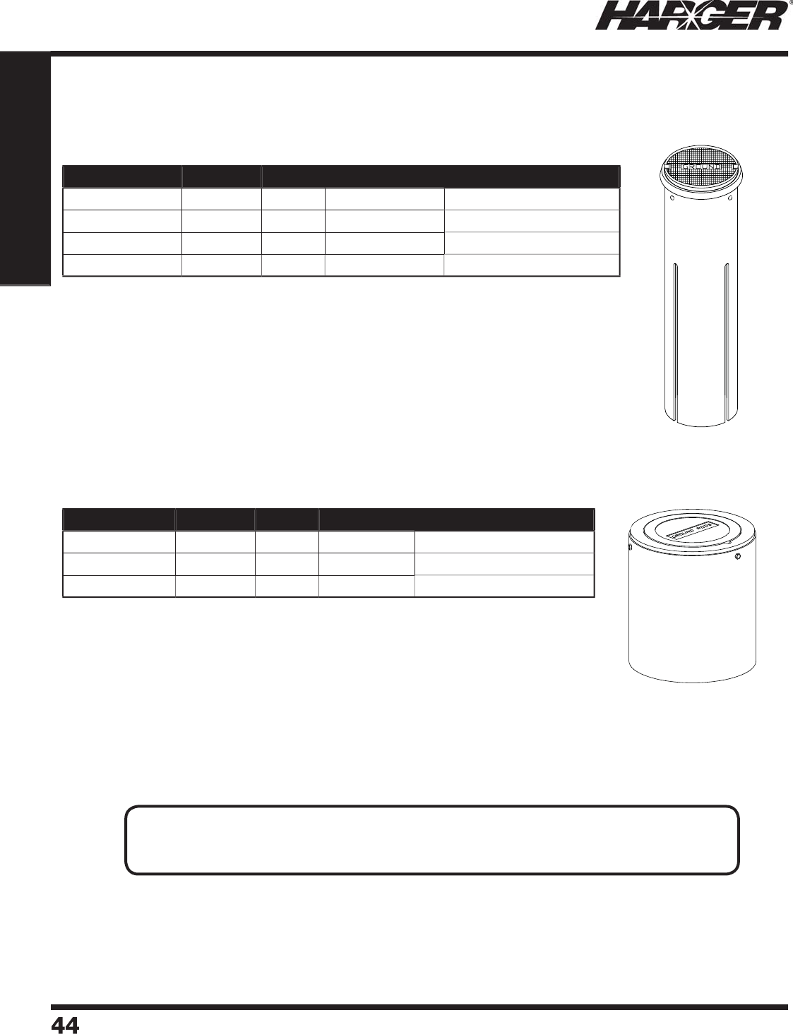
H
ar
g
er Li
g
htnin
g
& Groundin
g
•
©
2012 Phone 847-548-8700 • Fax 847-548-8755 • U.S. 800-842-743
7
44
44
Section 1
Grounding Components
•
10" diameter Schedule 80 PVC well.
•
Available in 36" and 42" len
g
ths.
•
Four 27" slots allow for
g
round electrode connections to be made before
i
nst
a
ll
a
ti
o
n
o
f test well.
•
Cast iron cover fi ts into cast iron rin
g
for extra support.
•
F
o
r
u
se in tr
a
ffi c
a
re
a
s.
•
12" diameter Schedule 80 PVC well.
•
Available in 12", 24" and 30" len
g
ths.
•
Cast iron cover fi ts into cast iron rin
g
for extra support.
•
F
o
r
u
se in tr
a
ffi c
a
re
a
s.
Part No. Diameter Length Cover Type Approx. Each Wt. (lbs.)
360P36CILS80 1
0
"
36
"
Ca
st Ir
on
6
1
360P36CILS80T
P
1
0
"
36
"
T
am
p
er Res
i
stan
t
6
1
360P42CILS80 1
0
"
4
2"
Ca
st Ir
on
67
360P42CILS80T
P
1
0
"
4
2"
T
am
p
er Resistan
t
67
Part No. Diameter Length Cover Type Approx. Each Wt. (lbs.)
362PS12CILS80 12" 12"
Ca
st Ir
on
42
362PS24CILS80 12" 24"
Ca
st Ir
on
6
1
362PS30CILS80 12"
30
"
Ca
st Ir
on
6
8
G
r
o
und Access Wells
Access Well with 10" Cast Ir
o
n C
o
ver
Access Well with 12" Cast Ir
o
n C
o
ver
APPLICATI
O
N N
O
TES
:
• Provides ready access to
g
round electrode for testin
g
and inspection purposes.
• To prevent displacement by frost, the access well must be lon
g
er than the frost line is deep.
S
ect
io
n 1.2.15
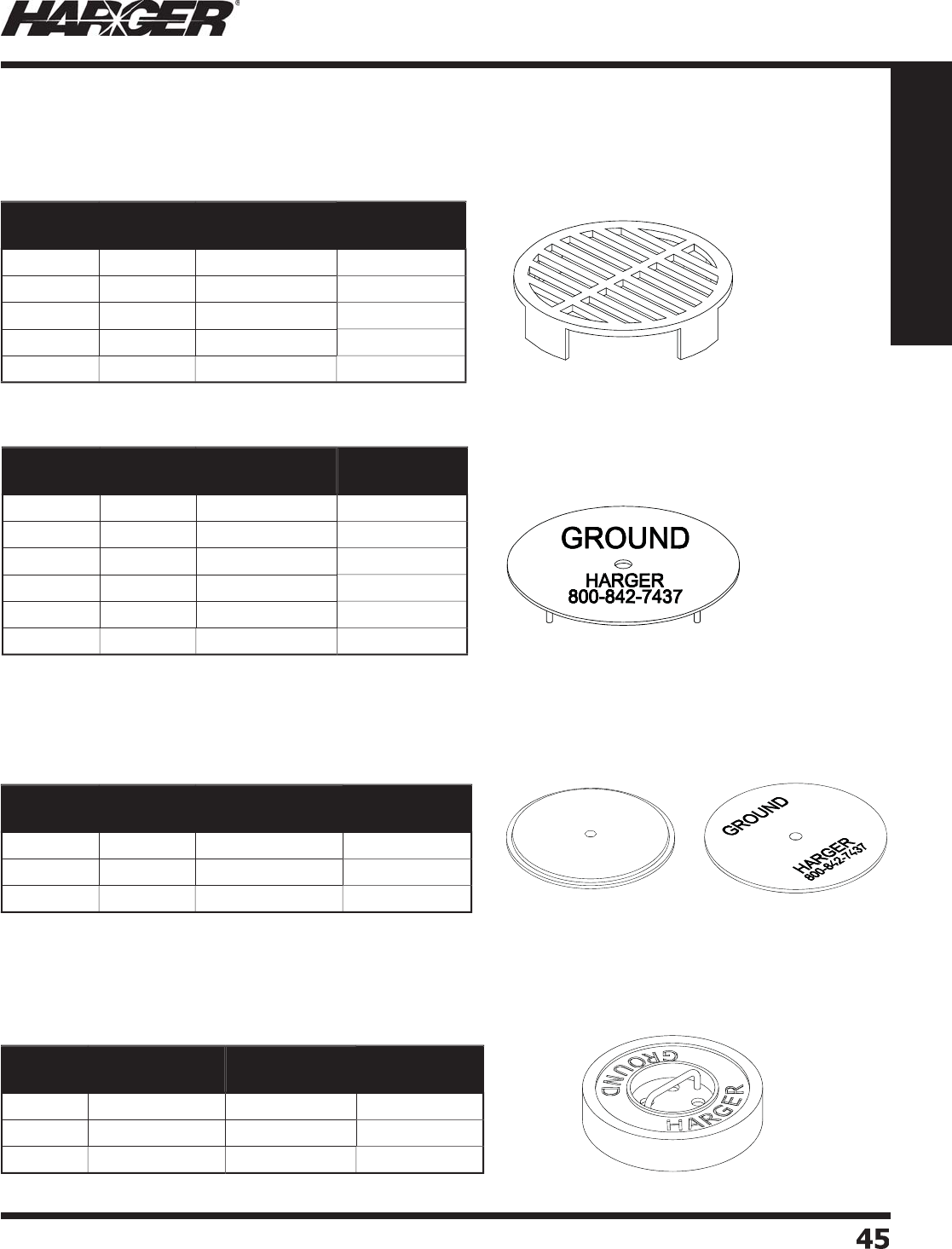
H
ar
g
er Li
g
htnin
g
& Groundin
g
•
©
2012 Phone 847-548-8700 • Fax 847-548-8755 • U.S. 800-842-743
7
45
45
Section 1
Grounding Components
Ground access well covers are available in cast iron
g
rated, fl at steel, plastic and concrete.
•
S
p
ecifi call
y
made for Tile Access Wells.
•
Manufactured from Hi
g
h Density Polyethylene.
T
o
p
View of Cove
r
Inverte
d
View
o
f C
o
ve
r
Part No. Diameter Fits Test Well Approx. Each
Wt. (lbs.)
1
0
PB
G
10-1
/
4" 358T & 360PB
G
7
1
2
PB
G
12-1
/
2"
360
T
&
362
PB
G
1
0
1
2
T
G
14-3
/
4"
362
T18
18PB
G
18-3
/
8" 368PB
G
2
9
18T
G
22" 368T
36
Part No. Diameter Fits Test Well Approx. Each
Wt. (lbs.)
8P
S
8-5
/
8" 358PS & 358P4
2
3
1
0
P
S
10-5
/
8"
360
PS
&
360
P4
2
5
1
0
PB
S
11-1
/
4"
360
PB
S
6
1
2
PB
S
13-1
/
4"
362
PB
S
7
1
2
P
S
12-3
/
4"
362
P
S
8
18PB
S
19-7
/
8" 368PB
S
1
6
Part No. Diameter Fits Test Well Approx. Each
Wt. (lbs.)
6
P
P
6
-5
/
8"
356
P
P
1
8P
P
8-5
/
8" 358PP & 358PP4
2
1
1
0
P
P
10-3
/
4"
360
PP
&
360
PP4
2
2
Part No. Diameter Fits Test Well Approx. Each
Wt. (lbs.)
8CC 10-7
/
8" x 2" 358TC 1
6
1
0
CC 12-1
/
2" x 2"
360
TC
2
4
1
2CC
14-3
/
4" x 2-3
/
4"
362
TC
2
9
G
r
o
und Access Well C
o
vers
C
ast Ir
o
n Grated C
o
vers
Flat Steel C
o
vers
Plastic C
o
vers
Co
ncrete C
o
vers
•
Manufactured from 3/16" commercial
g
rade steel with
a zinc/ultraseal coatin
g
.
S
ect
io
n 1.2.16

H
ar
g
er Li
g
htnin
g
& Groundin
g
•
©
2012 Phone 847-548-8700 • Fax 847-548-8755 • U.S. 800-842-743
7
46
46
Section 1
Grounding Components
No
tes

H
ar
g
er Li
g
htnin
g
& Groundin
g
•
©
2012 Phone 847-548-8700 • Fax 847-548-8755 • U.S. 800-842-743
7
47
47
Section 1
Grounding Components
S
ect
io
n 1.3
G
r
o
und Bars & Access
o
ries
In
d
ex
Descr
i
pt
i
on Pa
g
e
1.3.1 Har
g
er Ground Bar Numberin
g
System
.................................................
4
8
1.3.2 Ground Bar St
y
le
s
...............................................................................
4
9
1.
3
.
3
Gr
ou
n
d
B
a
r H
o
le P
a
ttern
s
....................................................................
5
1
1.3.4 Custom Ground Bars Desi
g
n Shee
t
......................................................
53
1.
3
.
5
GBI Gr
ou
n
d
B
a
rs
&
Kit
s
.......................................................................
54
1.
3
.
6
GBIT Gr
ou
n
d
B
a
r
s
..............................................................................
5
8
1.
3
.7 GBIA Gr
ou
n
d
B
a
r
s
..............................................................................
5
9
1.3.8 GBIP Ground Bar
s
..............................................................................
60
1.3.9 Plexi
g
lass Covers
...............................................................................
60
1.
3
.1
0
BGB Gr
ou
n
d
B
a
r
s
................................................................................
6
1
1.3.11 TIA-607 St
y
le Telecommunications Ground Bars & Kit
s
..........................
62
1.3.12 Telecommunications Equipment Rack Groundin
g
Busbars & Kit
s
.............
66
1.
3
.1
3
Telc
o
Gr
ou
n
d
B
a
r
s
..............................................................................
6
9
1.3.14 FAA Style Ground Bars & Plexi
g
lass Cover
s
...........................................
71
1.3.15 Standoff Insulators & Thread Formin
g
Scre
w
........................................
7
3
1.3.16 Mountin
g
Bracket
s
..............................................................................
74
1.3.17 Universal Busbar Mountin
g
Ki
t
.............................................................
75
1.3.18 Stainless Steel An
g
le Adapter
s
.............................................................
7
6
1.3.19 "Do Not Disconnect" Ta
g
.....................................................................
7
6
1.3.20 Network Buildin
g
Ground Ta
g
..............................................................
7
6
1.3.21 Intersystem Bondin
g
Connection (IBTD
)
..............................................
77

H
ar
g
er Li
g
htnin
g
& Groundin
g
•
©
2012 Phone 847-548-8700 • Fax 847-548-8755 • U.S. 800-842-743
7
4
8
48
Section 1
Grounding Components
1.
S
t
y
le
:
GB - Plain
g
round bar.
GBA - Ground bar with stainless steel an
g
le adapters.
GBI - Ground bar with wall mountin
g
brackets and insulators.
HDGBI - Ground bar with heavy duty wall mountin
g
brackets and insulators.
GBIT - Ground bar with wall mountin
g
brackets, insulators and a 25' exothermically welded tail.
GBT - Ground bar with tail onl
y
.
GBS - Ground bar with standoff insulators onl
y
.
GBB - Ground bar with brackets onl
y
.
BGB - Bent
g
round bar.
GBIP - Ground bar with insulators, wall mountin
g
brackets and plexi
g
lass cover.
GBIA - Ground bar with insulators and stainless steel an
g
le adapters.
GBU - Ground bar with insulators, wall mountin
g
brackets and zinc plated malleable
beam clam
p
s.
2
.
Si
ze
:
Thickness, width, len
g
th in inches.
3
. H
o
le Pattern
:
See Pa
g
es 51-52 to specify hole pattern.
4
.
T
ail
:
Specify American Wire Gau
g
e (AWG) size and strandin
g
required. 25' len
g
th is standard unless
otherwise re
q
uested.
5
.
T:
Prefi x desi
g
nates electro-tin plated
g
round bar.
S
imply follow the steps outlined below to specify the style and size of the
g
round bar you need. The followin
g
example is a
g
round bar with wall mountin
g
brackets, insulators, and an exothermically welded tail. The
g
round
bar is tin plated 1/4" thick, 4" wide and 12" lon
g
. It has a hole pattern "J" with a No. 2 AWG solid tinned tail.
Li
s
te
d
4
6
7
Har
g
er Ground Bar Numberin
g
Syste
m
T
GBIT 14 4 1
2
J
2
T
S
t
y
l
e
T
hi
c
kn
ess
(
inches
)
W
i
d
t
h
(
inches
)
Ho
l
e
Pa
tter
n
Length
(
inches
)
Ta
il
T
in-Pl
a
te
d
S
ect
io
n 1.3.1
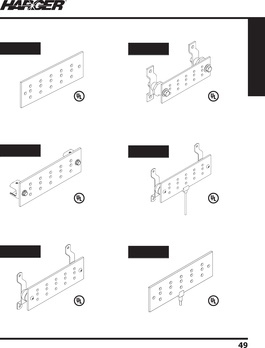
H
ar
g
er Li
g
htnin
g
& Groundin
g
•
©
2012 Phone 847-548-8700 • Fax 847-548-8755 • U.S. 800-842-743
7
49
49
Section 1
Grounding Components
G
round Bar with Wall Mountin
g
B
r
a
ckets
a
n
d
I
ns
u
l
a
t
o
r
s
H
e
av
y
D
uty
G
round Bar with Heav
y
Dut
y
W
all Mountin
g
B
r
a
ckets
a
n
d
I
ns
u
l
a
t
o
r
s
G
round Bar with Wall Mountin
g
B
rackets,
I
ns
u
l
a
t
o
rs
a
n
d
a 25' Exothermicall
y
Welded
T
a
il
G
r
ou
n
d
B
ar with a 25' Exothermicall
y
Welded
T
a
il
P
l
a
in
G
r
ou
n
d
B
ar
G
r
ou
n
d
B
ar with Stainless Steel An
g
le
A
da
p
ter
s
GB Series
GBA Series
GBI Series
GBIT Series
HDGBI Series
GBT Series
G
round Bar St
y
les
S
ect
io
n 1.3.2
L
iste
d
4
67
L
iste
d
4
67
L
iste
d
4
67
L
iste
d
4
67
L
iste
d
4
67
L
iste
d
4
67
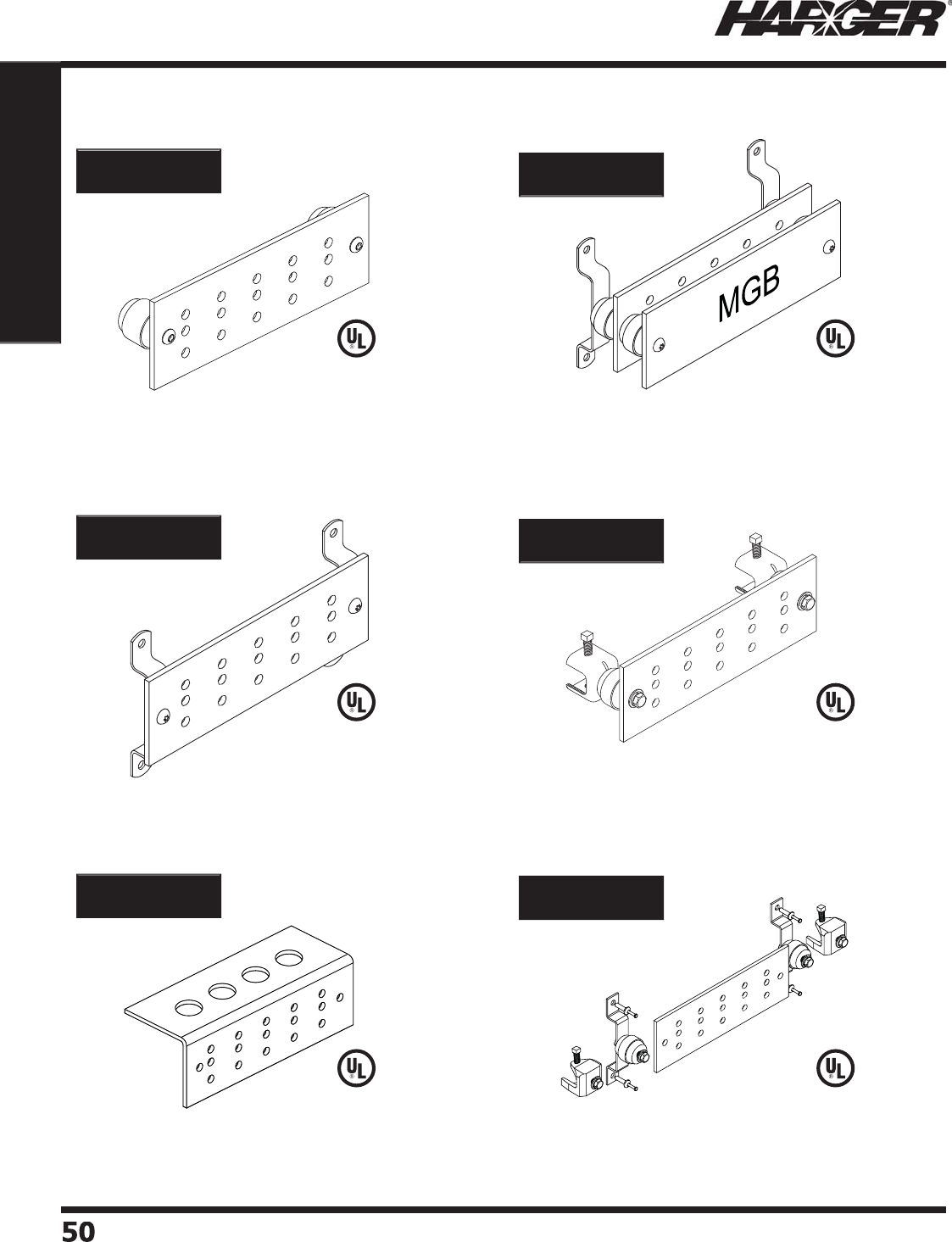
H
ar
g
er Li
g
htnin
g
& Groundin
g
•
©
2012 Phone 847-548-8700 • Fax 847-548-8755 • U.S. 800-842-743
7
50
50
Section 1
Grounding Components
G
r
ou
n
d
B
a
r with
S
tandoff Insulators Onl
y
G
r
ou
n
d
B
a
r with
B
rackets Onl
y
B
e
n
t
G
r
ou
n
d
B
ar
G
r
ou
n
d
B
a
r with
I
nsulators, Wall Mountin
g
Bracket
s
a
n
d
P
l
exi
g
lass Cove
r
G
r
ou
n
d
B
a
r with
I
ns
u
l
a
t
o
rs
a
n
d
S
tainless Steel An
g
le
A
da
p
ter
s
GBS Series
GBB Series GBIA Series
GBIP Series
BGB Series GBU Series
G
r
ou
n
d
B
a
r
U
nivers
a
l
w
ith Insulators, Brackets and
Zinc Plated Malleable Beam Clam
p
G
round Bar St
y
les
S
ect
io
n 1.3.2
L
iste
d
4
67
L
iste
d
4
67
L
iste
d
4
67
L
iste
d
4
67
L
iste
d
4
67
L
iste
d
4
67
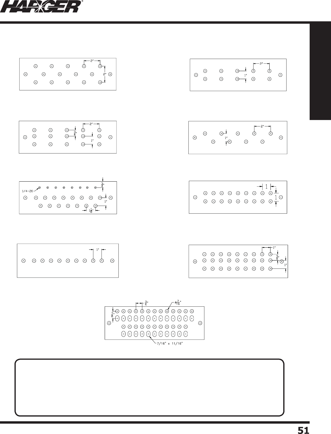
H
ar
g
er Li
g
htnin
g
& Groundin
g
•
©
2012 Phone 847-548-8700 • Fax 847-548-8755 • U.S. 800-842-743
7
51
51
Section 1
Grounding Components
“ B ”“ A ”
“
C
” “ D ”
“ H ”
“
G
”
“ F ”
“
J
”
“ M ”
G
r
o
und Bar H
o
le Patterns
N
O
TES
:
• All holes are 7/16" unless s
p
ecifi ed differentl
y
. To order threaded holes, s
p
ecif
y
hole size.
The standard ta
pp
ed hole size is 1/4-20 unless s
p
ecifi ed differentl
y
. Add suffi x T to
p
art number
for ta
pp
ed hole.
• Slotted hole patterns accommodate "B" and "C" spaced two hole lu
g
s (3/4" and 1" on center).
• Above bar patterns represent a 12"
g
round bar.
• All bars are available with electro-tin platin
g
. Add prefi x T to part number.
S
ect
io
n 1.3.3

H
ar
g
er Li
g
htnin
g
& Groundin
g
•
©
2012 Phone 847-548-8700 • Fax 847-548-8755 • U.S. 800-842-743
7
5
2
52
Section 1
Grounding Components
“ R ”
“ Z ”“ X ”
“ V ” “ W ”
“ T ”
“ N ”
“ P ” “
Q
”
1"
1"
3
4"
13
8"
5
8"
Ø1
4"
G
r
o
und Bar H
o
le Patterns
N
O
TES
:
• All holes are 7/16" unless s
p
ecifi ed differentl
y
. To order threaded holes, s
p
ecif
y
hole size.
The standard ta
pp
ed hole size is 1/4-20 unless s
p
ecifi ed differentl
y
. Add suffi x T to
p
art number
for ta
pp
ed hole.
• Slotted hole patterns accommodate "B" and "C" spaced two hole lu
g
s (3/4" and 1" on center).
• Above bar patterns represent a 12"
g
round bar.
• All bars are available with electro-tin platin
g
. Add prefi x T to part number.

H
ar
g
er Li
g
htnin
g
& Groundin
g
•
©
2012 Phone 847-548-8700 • Fax 847-548-8755 • U.S. 800-842-743
7
53
53
Section 1
Grounding Components
S
ect
io
n 1.3.
4
P
l
a
stic C
o
ver: Y
o
r N
T
hickness:_______ Width:_______ Len
g
th:
________
L
etterin
g
: Y or N Size:_____ Color: ___________
T
ext Sh
a
ll Re
ad
Exactly
y
a
s F
o
ll
o
ws:
____________________________________________
____________________________________________
(
Note: Show Cover La
y
out on a
Separate
p
Sheet.
)
Other O
p
tions:
________________________________
____________________________________________
B
ar En
g
ravin
g
/ Etchin
g
: Y or N
T
ext Sh
a
ll Re
ad
Exactly
y
a
s F
o
ll
o
ws:
____________________________________________
____________________________________________
T
hickness:_______ Width:_______ Len
g
th:
________
T
am
p
er Resistant Hardware: Y or N Part#
______
P
latin
g
: Y or N Type:
_______________________
H
oles: Punched Ta
pp
ed Comb
o
S
ize Punched:________ Size Ta
pp
ed:
____________
E
xothermicall
y
Welded Tail: Y or N Size:
_______
Str
a
n
d
e
d
S
o
li
d
B
a
re Tinne
d
Ins
u
l
a
te
d
L
en
g
th:________ (Show location of weld on bar.
)
S
t
a
n
do
ff: Y
o
r N Dim. B
a
r:
__________________
Typ
e: Insulator_________ N
y
lon All-Thread
________
C
ustom Ground Bar Desi
g
n Sheet
______”
______”
______”
T
hi
c
kn
ess
L
en
g
t
h
W
i
d
t
h
Ins
u
l
a
t
o
rs
&
Br
a
ckets
c
a
n
b
e f
ou
n
d
o
n
pa
g
es 7
3
- 75.
S
im
p
l
y
fi ll out
y
our re
q
uirements,
s
ubmit the sheet to our factor
y
and we will
p
roduce
y
our custom
g
round bar in a timely fashion.
Sp
ecif
y
Brackets:
P
art
#____________
Sp
ecif
y
Insulators:
P
art
#____________
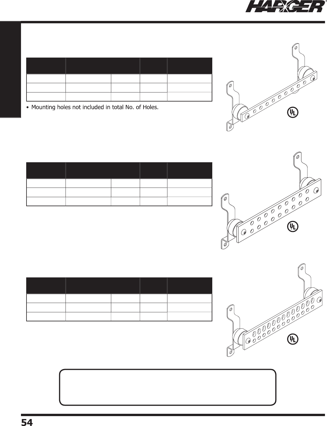
H
ar
g
er Li
g
htnin
g
& Groundin
g
•
©
2012 Phone 847-548-8700 • Fax 847-548-8755 • U.S. 800-842-743
7
54
54
Section 1
Grounding Components
•
Accommodates one hole lu
g
s usin
g
3/8" hardware.
•
12" bar
p
ictured. Holes are 7/16" diameter.
•
Mountin
g
holes not included in total No. of Holes.
•
Accommodates "C" spaced two hole lu
g
s (1" on center).
•
12" bar
p
ictured. Holes are 7/16" diameter.
L
iste
d
4
67
L
iste
d
4
67
•
Mountin
g
holes not included in total No. of Holes.
•
Accommodates "B" and "C" spaced two hole lu
g
s (3/4" and 1" on center).
•
12" bar
p
ictured. Holes are 7/16" diameter and slots are 7/16" x 11/16".
L
iste
d
4
67
Part No. Bar Size Hole
Pattern
No. of
Holes
Approx. Each
Wt. (lbs.)
GBI141
6H
1
/
4" x 1" x 6"
H
3
2
GBI1411
2H
1
/
4" x 1" x 12"
H
9
3
GBI1411
6H
1
/
4" x 1" x 16"
H
1
3
4
Part No. Bar Size Hole
Pattern
No. of
Holes
Approx. Each
Wt. (lbs.)
GBI14
26G
1
/
4" x 2" x 6"
G
6
2
GBI14
2
1
2G
1
/
4" x 2" x 12"
G
18
3
GBI14
2
1
6G
1
/
4" x 2" x 16"
G
26
4
Part No. Bar Size Hole
Pattern
No. of
Holes
Approx. Each
Wt. (lbs.)
GBI14
26P
1
/
4" x 2" x 6"
P
1
0
2
GBI14
2
1
2P
1
/
4" x 2" x 12"
P
26
3
GBI14
2
1
6P
1
/
4" x 2" x 16"
P
3
4
4
G
BI Gr
o
und Bars
"H" Patter
n
"
G
" Patter
n
"P" Patter
n
N
O
TES
:
• Manufactured from electrolytic tou
g
h pitch copper alloy 110.
• Bars available electro-tin plated. When orderin
g
, add prefi x T to part number.
• Other sizes available. Please contact factor
y
for more information.
S
ect
io
n 1.3.5
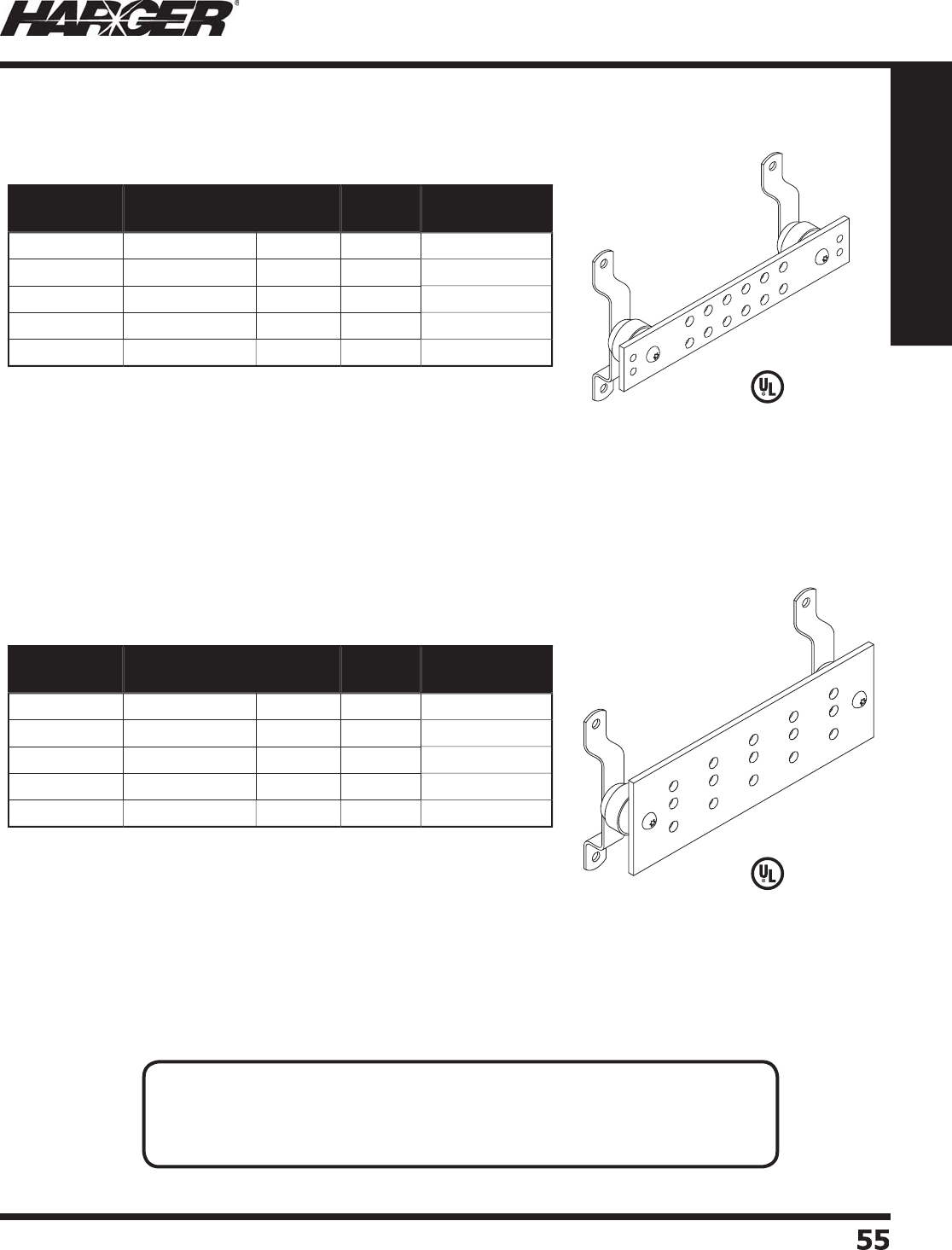
H
ar
g
er Li
g
htnin
g
& Groundin
g
•
©
2012 Phone 847-548-8700 • Fax 847-548-8755 • U.S. 800-842-743
7
55
55
Section 1
Grounding Components
•
Mountin
g
holes not included in total No. of Holes.
•
Accommodates "B", "C" and "D" spaced two hole lu
g
s (3/4", 1" and
1-3/4" on center
)
.
•
12" bar
p
ictured. Holes are 7/16" diameter.
•
Mountin
g
holes not included in total No. of Holes.
•
Accommodates "A" and "C" spaced two hole lu
g
s (5/8" and 1" on center).
•
12" bar
p
ictured. Holes are 5/16" and 7/16" diameter.
L
iste
d
4
67
L
iste
d
4
67
Part No. Bar Size Hole
Pattern
No. of
Holes
Approx. Each
Wt. (lbs.)
GBI14
26
X1
/
4" x 2" x 6"
X
6
2
GBI14
2
1
2
X1
/
4" x 2" x 12"
X
1
6
3
GBI14
2
1
6
X1
/
4" x 2" x 16"
X
2
4
4
GBI14
220
X1
/
4" x 2" x 20"
X
32
5
GBI14
22
4X 1
/
4" x 2" x 24"
X
40
6
Part No. Bar Size Hole
Pattern
No. of
Holes
Approx. Each
Wt. (lbs.)
GBI144
6
C1
/
4" x 4" x 6"
C
6
3
GBI1441
2
C1
/
4" x 4" x 12"
C
1
5
5
GBI1441
6
C1
/
4" x 4" x 16"
C
2
1
7
GBI144
20
C1
/
4" x 4" x 20"
C
27
8
GBI144
2
4C 1
/
4" x 4" x 24"
C
33
9
G
BI Gr
o
und Bars
"X" Patter
n
"C" Patter
n
N
O
TES
:
• Manufactured from electrolytic tou
g
h pitch copper alloy 110.
• Bars available electro-tin plated. When orderin
g
, add prefi x T to part number.
• Other sizes available. Please contact factor
y
for more information.
S
ect
io
n 1.3.5
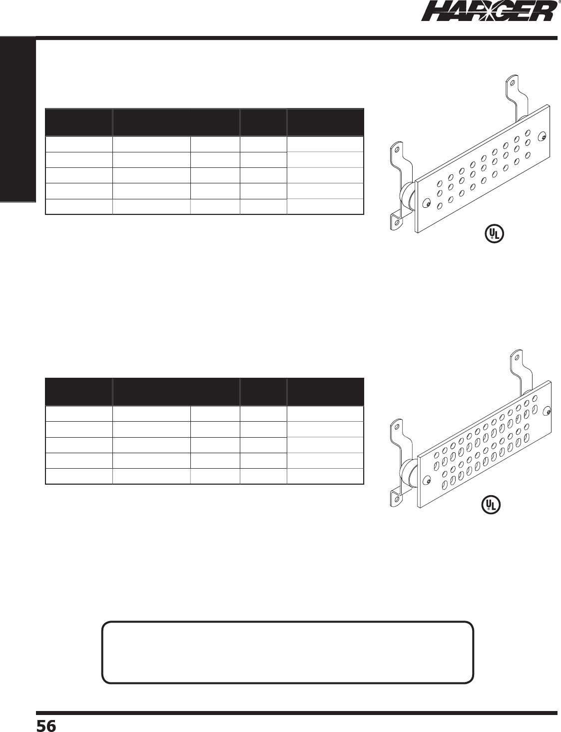
H
ar
g
er Li
g
htnin
g
& Groundin
g
•
©
2012 Phone 847-548-8700 • Fax 847-548-8755 • U.S. 800-842-743
7
56
56
Section 1
Grounding Components
•
Mountin
g
holes not included in total No. of Holes.
•
Accommodates "B", "C" and "D" spaced two hole lu
g
s (3/4", 1" and 1-3/4"
o
n center
)
.
•
12" bar
p
ictured. Holes are 7/16" diameter.
•
Mountin
g
holes not included in total No. of Holes.
•
Accommodates "B" and "C" spaced two hole lu
g
s (3/4" and 1" on center).
•
12" bar
p
ictured. Holes are 7/16" diameter and slots are 7/16" x 11/16".
L
iste
d
4
67
L
iste
d
4
67
Part No. Bar Size Hole
Pattern
No. of
Holes
Approx. Each
Wt. (lbs.)
GBI144
6
J1
/
4" x 4" x 6"
J
9
3
GBI1441
2
J1
/
4" x 4" x 12"
J
27
5
GBI1441
6
J1
/
4" x 4" x 16"
J
3
9
7
GBI144
20
J1
/
4" x 4" x 20"
J
5
18
GBI144
2
4J 1
/
4" x 4" x 24"
J
63
9
Part No. Bar Size Hole
Pattern
No. of
Holes
Approx. Each
Wt. (lbs.)
GBI144
6
M1
/
4" x 4" x 6"
M
1
6
3
GBI1441
2
M1
/
4" x 4" x 12"
M
4
8
5
GBI1441
6
M1
/
4" x 4" x 16"
M
6
8
7
GBI144
20
M1
/
4" x 4" x 20"
M
88 8
GBI144
2
4M 1
/
4" x 4" x 24"
M
11
2
9
"J" Patter
n
"M" Patter
n
N
O
TES
:
• Manufactured from electrolytic tou
g
h pitch copper alloy 110.
• Bars available electro-tin plated. When orderin
g
, add prefi x T to part number.
• Other sizes available. Please contact factor
y
for more information.
S
ect
io
n 1.3.5
G
BI Gr
o
und Bars
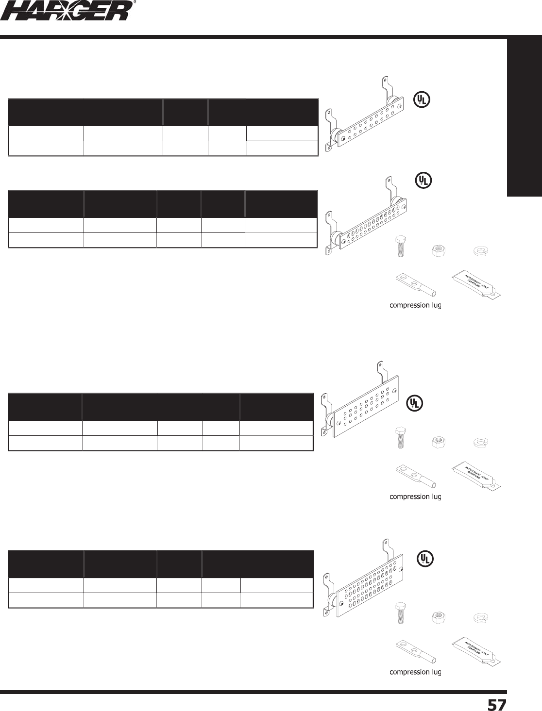
H
ar
g
er Li
g
htnin
g
& Groundin
g
•
©
2012 Phone 847-548-8700 • Fax 847-548-8755 • U.S. 800-842-743
7
57
57
Section 1
Grounding Components
G
BI Gr
o
und Bar Kits
Part No. Bar Size Hole
Pattern
No. of
Holes
Approx. Each
Wt. (lbs.)
GBI1421
0
GKT* 1
/
4” x 2” x 10
”
G
14
5
-1
/2
GBI14212GKT* 1
/
4” x 2” x 12
”
G
18
6
Part No. Bar Size Hole
Pattern
No. of
Holes
Approx. Each
Wt. (lbs.)
GBI1421
0
PKT* 1
/
4” x 2” x 10
”
P
20
5
-1
/2
GBI14212PKT* 1
/
4” x 2” x 12
”
P
26
6
•
Refer to pa
g
e 54.
*Kit Incl
ud
e
s:
(
1) Groundin
g
busbar with brackets & insulators (1) GECLB4/02C: 4/0 compression lu
g
(
3) GECLB62C: #6 compression lu
g
(18) CS68S: 3/8”-16x1” SS hex head cap scre
w
(
2) GECLB22C: #2 compression lu
g
(18) LW6S: 3/8”-16 SS lock washe
r
(
2) GECLB22CS: #2 compression lu
g
(18) N616S: 3/8”-16 SS hex nu
t
(
1) GECLB2/02C: 2/0 compression lu
g
(1) HCAJC1/2: 1/2 oz. tube of antioxidan
t
L
iste
d
4
67
L
iste
d
4
67
ca
p
scr
ew
hex n
ut
lo
ck w
a
she
r
a
nti
o
xi
da
n
t
2
” Kit
s
Part No. Bar Size Hole
Pattern
No. of
Holes
Approx. Each
Wt. (lbs.)
GBI14412JKT* 1
/
4” x 4” x 12
”
J
27
8
GBI1442
0
JKT* 1
/
4” x 4” x 20
”
J
5
11
0
Part No. Bar Size Hole
Pattern
No. of
Holes
Approx. Each
Wt. (lbs.)
GBI14412MKT* 1
/
4” x 4” x 12
”
M
4
88
GBI1442
0
MKT* 1
/
4” x 4” x 20
”
M
88 11
•
Refer to pa
g
e 56.
*Kit Incl
ud
e
s:
(
1) Groundin
g
busbar with brackets & insulators (1) GECLB4/02C: 4/0 compression lu
g
(
8) GECLB62C: #6 compression lu
g
(44) CS68S: 3/8”-16x1” SS hex head cap scre
w
(
6) GECLB22C: #2 compression lu
g
(44) LW6S: 3/8”-16 SS lock washe
r
(
6) GECLB22CS: #2 compression lu
g
(44) N616S: 3/8”-16 SS hex nu
t
(
1) GECLB2/02C: 2/0 compression lu
g
(1) HCAJC1/2: 1/2 oz. tube of antioxidan
t
•
Refer to pa
g
e 56.
*Kit Incl
ud
e
s:
(
1) Groundin
g
busbar with brackets & insulators (1) GECLB4/02C: 4/0 compression lu
g
(
4) GECLB62C: #6 compression lu
g
(24) CS68S: 3/8”-16x1” SS hex head cap scre
w
(
3) GECLB22C: #2 compression lu
g
(24) LW6S: 3/8”-16 SS lock washe
r
(
3) GECLB22CS: #2 compression lu
g
(24) N616S: 3/8”-16 SS hex nu
t
(
1) GECLB2/02C: 2/0 compression lu
g
(1) HCAJC1/2: 1/2 oz. tube of antioxidan
t
L
iste
d
4
67
L
iste
d
4
67
4
” Kit
s
•
Refer to pa
g
e 54.
S
ect
io
n 1.3.5
ca
p
scr
ew
hex n
ut
lo
ck w
a
she
r
a
nti
o
xi
da
n
t
ca
p
scr
ew
hex n
ut
lo
ck w
a
she
r
a
nti
o
xi
da
n
t
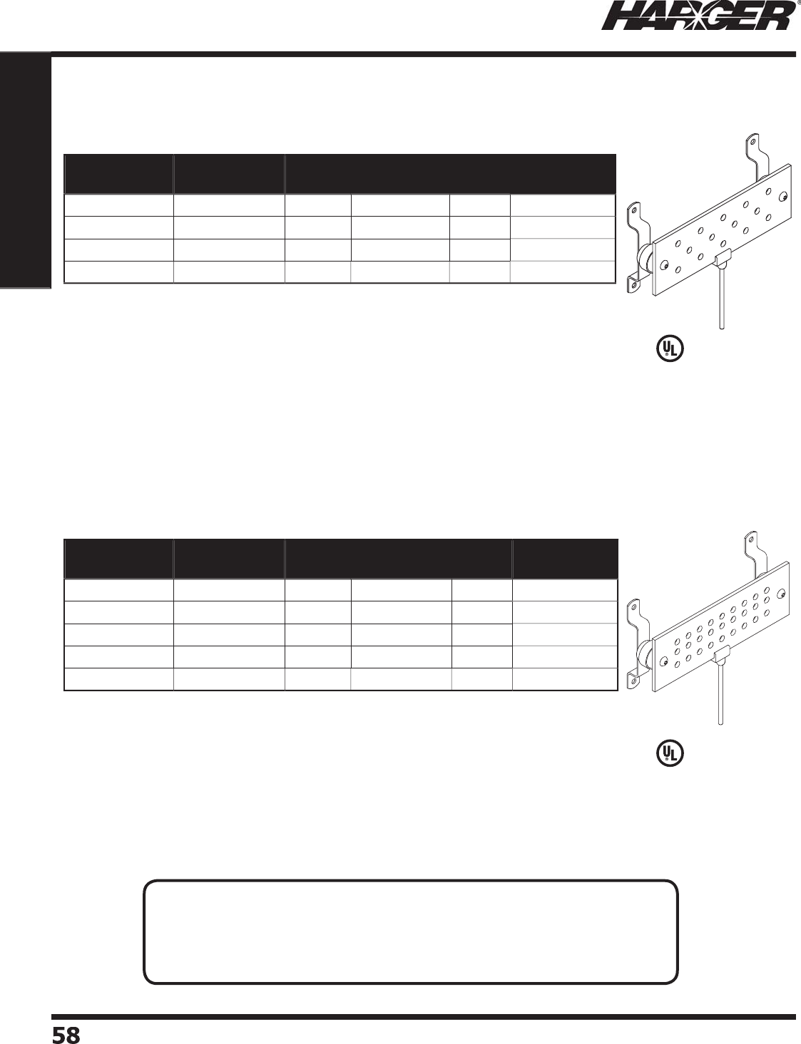
H
ar
g
er Li
g
htnin
g
& Groundin
g
•
©
2012 Phone 847-548-8700 • Fax 847-548-8755 • U.S. 800-842-743
7
5
8
58
Section 1
Grounding Components
•
Mountin
g
holes not included in total No. of Holes.
•
12" bar
p
ictured. Holes are 7/16" diameter.
•
Mountin
g
holes not included in total No. of Holes.
•
Accommodates "B", "C" and "D" spaced two hole lu
g
s (3/4", 1" and 1-3/4" on center).
•
12" bar
p
ictured. Holes are 7/16" diameter.
L
iste
d
4
67
L
iste
d
4
67
Part No. Bar Size Hole
Pattern
Conductor
Type (AWG)
No. of
Holes
Approx. Each
Wt. (lbs.)
GBIT1441
2
A
2
T1
/
4" x 4" x 12"
A
2
T14 1
3
GBIT1441
6
A
2
T1
/
4" x 4" x 16"
A
2
T
20
1
5
GBIT144
20
A
2
T1
/
4" x 4" x 20"
A
2
T
26
1
6
GBIT144
2
4A
2
T1
/
4" x 4" x 24"
A
2
T
32
1
7
Part No. Bar Size Hole
Pattern
Conductor
Type (AWG)
No. of
Holes
Approx. Each
Wt. (lbs.)
GBIT144
6
J
2
T1
/
4" x 4" x 6"
J
2
T
9
11
GBIT1441
2
J
2
T1
/
4" x 4" x 12"
J
2
T
27
1
3
GBIT1441
6
J
2
T1
/
4" x 4" x 16"
J
2
T
3
91
5
GBIT144
20
J
2
T1
/
4" x 4" x 20"
J
2
T
5
11
6
GBIT144
2
4J
2
T1
/
4" x 4" x 24"
J
2
T
63
1
7
G
BIT Gr
o
und Bars
"A" Patter
n
"J" Patter
n
N
O
TES
:
• Manufactured from electrolytic tou
g
h pitch copper alloy 110.
• Comes with a 25' exothermicall
y
welded tail.
• Bars available electro-tin plated. When orderin
g
, add prefi x T to part number.
• Other sizes available. Please contact factor
y
for more information.
S
ect
io
n 1.3.6
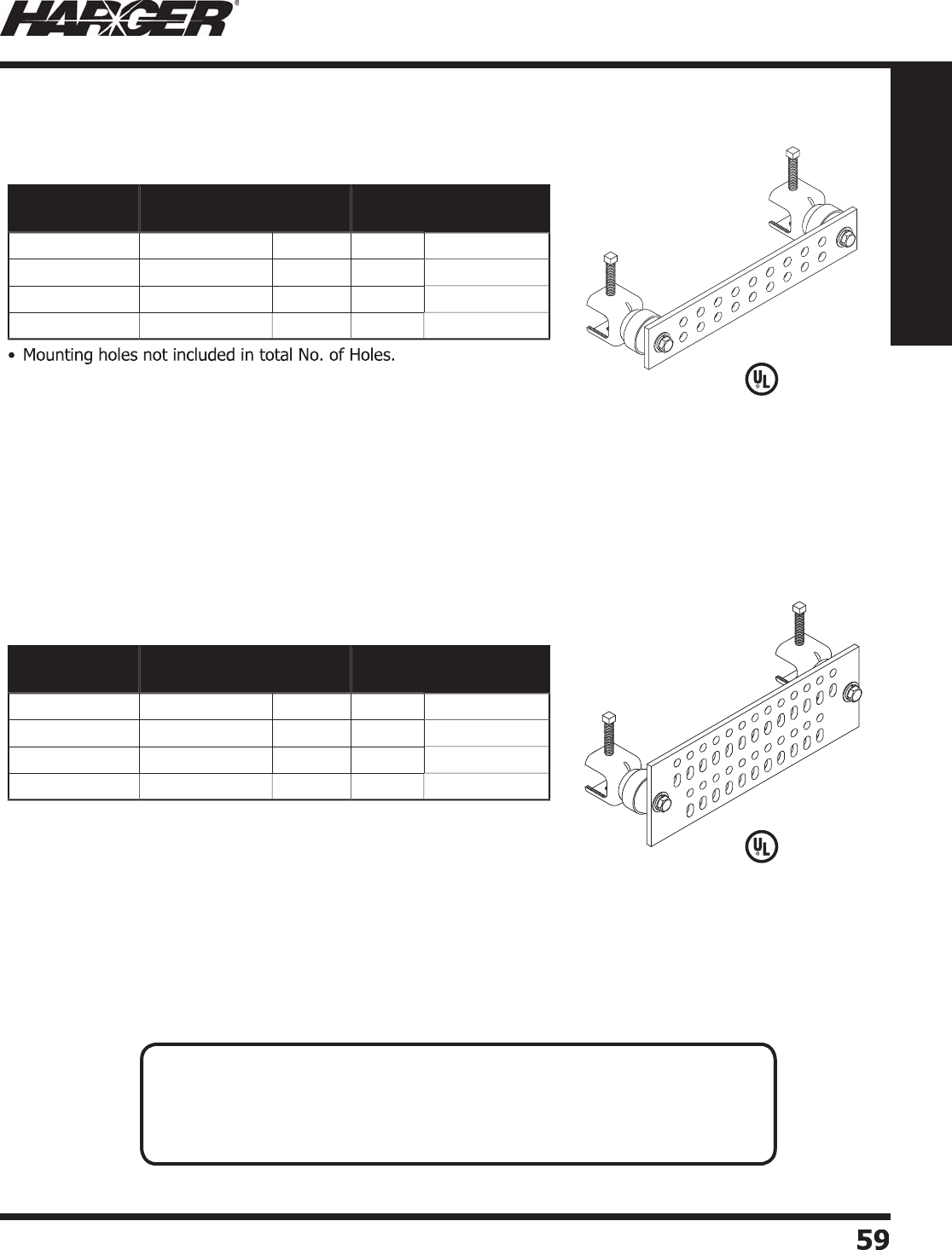
H
ar
g
er Li
g
htnin
g
& Groundin
g
•
©
2012 Phone 847-548-8700 • Fax 847-548-8755 • U.S. 800-842-743
7
5
9
59
Section 1
Grounding Components
•
Accommodates "B" spaced two hole lu
g
s (3/4" on center).
•
12" bar
p
ictured. Holes are 7/16" diameter.
•
Mountin
g
holes not included in total No. of Holes.
•
Accommodates "B" and "C" spaced two hole lu
g
s (3/4" and 1" on center).
•
12" bar
p
ictured. Holes are 7/16" diameter and slots are 7/16" x 11/16".
L
iste
d
4
67
L
iste
d
4
67
Part No. Bar Size Hole
Pattern
No. of
Holes
Approx. Each
Wt. (lbs.)
GBIA14
26Z
1
/
4" x 2" x 6"
Z
6
2
GBIA14
2
1
2Z
1
/
4" x 2" x 12"
Z
18
3
GBIA14
2
1
6Z
1
/
4" x 2" x 16"
Z
26
4
GBIA14
220Z
1
/
4" x 2" x 20"
Z
3
4
5
Part No. Bar Size Hole
Pattern
No. of
Holes
Approx. Each
Wt. (lbs.)
GBIA1441
2
M1
/
4" x 4" x 12"
M
4
8
5
GBIA1441
6
M1
/
4" x 4" x 16"
M
7
0
7
GBIA144
20
M1
/
4" x 4" x 20"
M
88 8
GBIA144
2
4M 1
/
4" x 4" x 24"
M
1
06
9
G
BIA Gr
o
und Bars
"Z" Patter
n
"M" Patter
n
N
O
TES
:
• Manufactured from electrolytic tou
g
h pitch copper alloy 110.
• Bars available electro-tin plated. When orderin
g
, add prefi x T to part number.
• Ground Bar with insulators and stainless steel an
g
le adapters.
• Other sizes available. Please contact factor
y
for more information.
S
ect
io
n 1.3.7

H
ar
g
er Li
g
htnin
g
& Groundin
g
•
©
2012 Phone 847-548-8700 • Fax 847-548-8755 • U.S. 800-842-743
7
60
60
Section 1
Grounding Components
•
Mountin
g
holes not included in total No. of Holes.
•
Accommodates "B", "C" and "D" spaced two hole lu
g
s (3/4", 1" and 1-3/4"
o
n center
)
.
•
12" bar
p
ictured. Holes are 7/16" diameter.
•
Plexi
g
lass cover with MGB letterin
g
. Other letterin
g
available.
L
iste
d
4
67
Part No. Bar Size Hole
Pattern
No. of
Holes
Approx. Each
Wt. (lbs.)
GBIP144
6
JMGB 1
/
4" x 4" x 6"
J
9
5
GBIP1441
2
JMGB 1
/
4" x 4" x 12"
J
27
7
GBIP1441
6
JMGB 1
/
4" x 4" x 16"
J
3
9
9
GBIP144
20
JMGB 1
/
4" x 4" x 20"
J
5
111
G
BIP Gr
o
und Bars
"J" Patter
n
All
g
round bars are available with lettered plexi
g
lass covers.
M
inimum letterin
g
hei
g
ht is 3/8". Letterin
g
available in several different colors.
S
tandard cover thickness is 1
/
4". Other thicknesses available.
P
lease contact our factor
y
with
y
our s
p
ecial needs.
Plexi
g
lass Covers
N
O
TES
:
• Manufactured from electrolytic tou
g
h pitch copper alloy 110.
• Other sizes available. Please contact factor
y
for more information.
S
ect
io
n 1.3.8 & 1.3.9
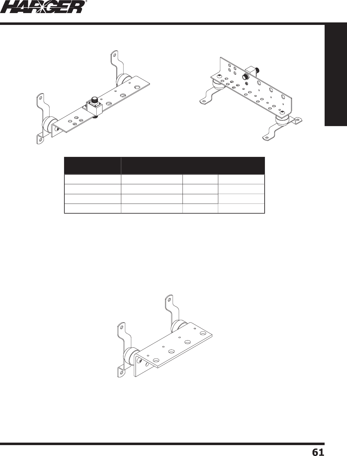
H
ar
g
er Li
g
htnin
g
& Groundin
g
•
©
2012 Phone 847-548-8700 • Fax 847-548-8755 • U.S. 800-842-743
7
6
1
61
Section 1
Grounding Components
•
Manufactured from electrolytic tou
g
h pitch copper alloy 110.
•
Accommodates "B" spaced two hole lu
g
s (3/4" on center).
•
Accepts bulkhead style sur
g
e arrestors with N female connectors.
•
Can be mounted verticall
y
or horizontall
y
.
•
Other sizes/st
y
les available. Please contact factor
y
for more information.
•
Sur
g
e arrestors not included.
T
o
p
Vie
w
Bo
tt
o
m V
i
e
w
BGBI1468ISB4FAA2
•
1/4" x 6" x 8" electrolytic tou
g
h pitch copper alloy 110.
•
Accommodates "C" spaced two hole lu
g
s (1" on center).
•
Accepts 4 bulkhead style sur
g
e arrestors with N female connectors.
•
Can be mounted verticall
y
or horizontall
y
.
•
Other sizes/st
y
les available. Please contact factor
y
for more information.
•
Approximate wei
g
ht is 5 pounds.
Part No. Bar Size No. of
Arrestors
Approx. Each
Wt. (lbs.)
B
GBI1848.75TEL 1
/
8" x 4" x 8-3
/
4"
2
2-1
/2
B
GBI18413.25TEL 1
/
8" x 4" x 13-1
/
4"
4
3-1
/2
B
GBI18417.75TEL 1
/
8" x 4" x 17-3
/
4"
6
4
B
GBI18428TEL 1
/
8" x 4" x 28" 8
5
-1
/2
BGB Gr
o
und Bars
S
ect
io
n 1.3.10

H
ar
g
er Li
g
htnin
g
& Groundin
g
•
©
2012 Phone 847-548-8700 • Fax 847-548-8755 • U.S. 800-842-743
7
6
2
62
Section 1
Grounding Components
L
iste
d
4
67
*
TMGB is standard letterin
g
in black with a minimum letterin
g
hei
g
ht of 3/8". Other sizes available.
Please contact factory for more information. See pa
g
e 60 for plexi
g
lass covers.
•
1/4" thick x 4" wide electrolytic tou
g
h pitch copper alloy 110.
•
Includes 1-1/2" insulators and 1" offset stainless steel mountin
g
brackets.
•
Includes one 1/2 oz. tube of antioxidant
(
#HCAJC1/2
)
.
•
5/16" hole sets 5/8" on centers. Accommodates "A" spaced two hole compression lu
g
s.
•
7/16" holes sets 1" on centers. Accommodates "C" spaced two hole compression lu
g
s.
•
Other sizes available. Please contact factor
y
for more information.
•
Meets "BICSI" and EIA
/
TIA 607 standards.
GBI144
20
TMGB
TIA-607 St
y
le Telecommunications
Main Groundin
g
Busbars
TM
G
B B
us
bar
s
Part No. Bar Size Material Plexiglass
Cover
No. of 5/16"
Hole Sets
No. of 7/16"
Hole Sets
Approx. Each
Wt. (lbs.)
GBI1441
2
TMGB 1
/
4" x 4" x 12"
C
o
pp
e
r
No
1
2
6
6
-1
/2
GBIP14412TMGB* 1
/
4" x 4" x 12"
C
o
pp
e
r
Yes
12
6
7
T
GBI1441
2
TMGB 1
/
4" x 4" x 12"
E
lectr
o
Tin Pl
a
te
d
No
1
2
6
6
-1
/2
T
GBIP14412TMGB* 1
/
4" x 4" x 12"
E
lectr
o
Tin Pl
a
te
d
Y
es
1
2
6
7
GBI144
20
TMGB 1
/
4" x 4" x 20"
C
o
pp
e
r
No
2
4
6
9
GBIP1442
0
TMGB* 1
/
4" x 4" x 20"
C
o
pp
e
r
Yes
2
4
6
9
-1
/2
T
GBI144
20
TMGB 1
/
4" x 4" x 20"
E
lectr
o
Tin Pl
a
te
d
No
2
4
6
9
T
GBIP1442
0
TMGB* 1
/
4" x 4" x 20"
E
lectr
o
Tin Pl
a
te
d
Yes
2
4
6
9
-1
/2
GBI144
2
4TMGB 1
/
4" x 4" x 24"
C
o
pp
e
r
No
28 1
0
10-1
/2
GBIP14424TMGB* 1
/
4" x 4" x 24"
C
o
pp
e
r
Y
es
28 1
0
11
T
GBI144
2
4TMGB 1
/
4" x 4" x 24"
E
lectr
o
Tin Pl
a
te
d
No
28 1
0
10-1
/2
T
GBIP14424TMGB* 1
/
4" x 4" x 24"
E
lectr
o
Tin Pl
a
te
d
Yes
28 1
0
11
GBIP144
20
TMGB
S
ect
io
n 1.3.11
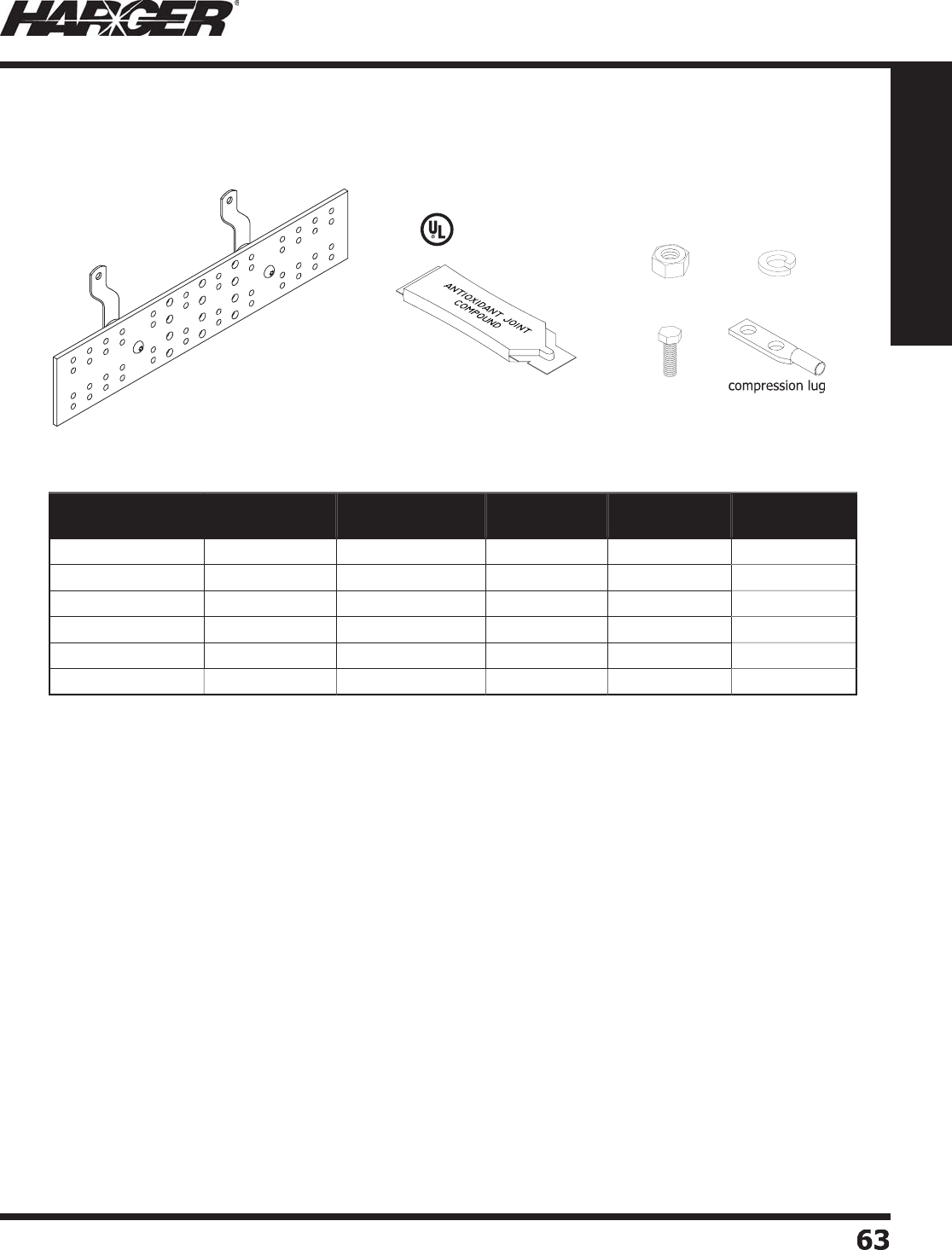
H
ar
g
er Li
g
htnin
g
& Groundin
g
•
©
2012 Phone 847-548-8700 • Fax 847-548-8755 • U.S. 800-842-743
7
63
63
Section 1
Grounding Components
Kit Incl
ud
e
s:
(
1
)
Ground bar with brackets and insulator
s
(6) GECLB62A: #6 compression lu
g
(1) GECLB22C: #2 compression lu
g
(1) GECLB1/02C: 1/0 compression lu
g
(1) GECLB2/02C: 2/0 compression lu
g
(1) GECLB3/02C: 3/0 compression lu
g
(1) GECLB4/02C: 4/0 compression lu
g
(
12
)
CS46S: 1/4"-20 x 3/4" SS hex head ca
p
scre
w
(
12
)
LW4S: 1/4"-20 SS lock washe
r
(
12
)
N420S: 1/4"-20 SS hex nut
(
6
)
CS68S: 3/8"-16 x 1" SS hex head ca
p
scre
w
(
6
)
LW6S: 3/8"-16 SS lock washe
r
(
6
)
N616S: 3/8"-16 SS hex nut
•
Other sizes available. Please contact factor
y
for more information.
•
Includes one 1/2 oz. tube of antioxidant
(
#HCAJC1/2
)
.
•
Meets "BICSI" and EIA
/
TIA 607 standards.
GBI144
20
TMGB ca
p
scr
ew
hex n
u
t
lo
ck w
a
she
r
Part No. Bar Size Material No. of 5/16"
Hole Sets
No. of 7/16"
Hole Sets
Approx. Each
Wt. (lbs.)
GBI1441
2
TMGBKT 1
/
4" x 4" x 12"
C
o
pp
e
r
1
2
6
8
T
GBI1441
2
TMGBKT 1
/
4" x 4" x 12"
E
lectr
o
Tin Pl
a
te
d
1
2
6
8
GBI144
20
TMGBKT 1
/
4" x 4" x 20"
C
o
pp
e
r
24
6
11
T
GBI144
20
TMGBKT 1
/
4" x 4" x 20"
E
lectr
o
Tin Pl
a
te
d
24
6
11
GBI144
2
4TMGBKT 1
/
4" x 4" x 24"
C
o
pp
e
r
28 1
0
1
2
T
GBI144
2
4TMGBKT 1
/
4" x 4" x 24"
E
lectr
o
Tin Pl
a
te
d
28 1
0
1
2
L
iste
d
4
67
TIA-607 St
y
le Telecommunications
Main Groundin
g
Busbar Kits
TM
G
B B
us
bar Kit
s
S
ect
io
n 1.3.11
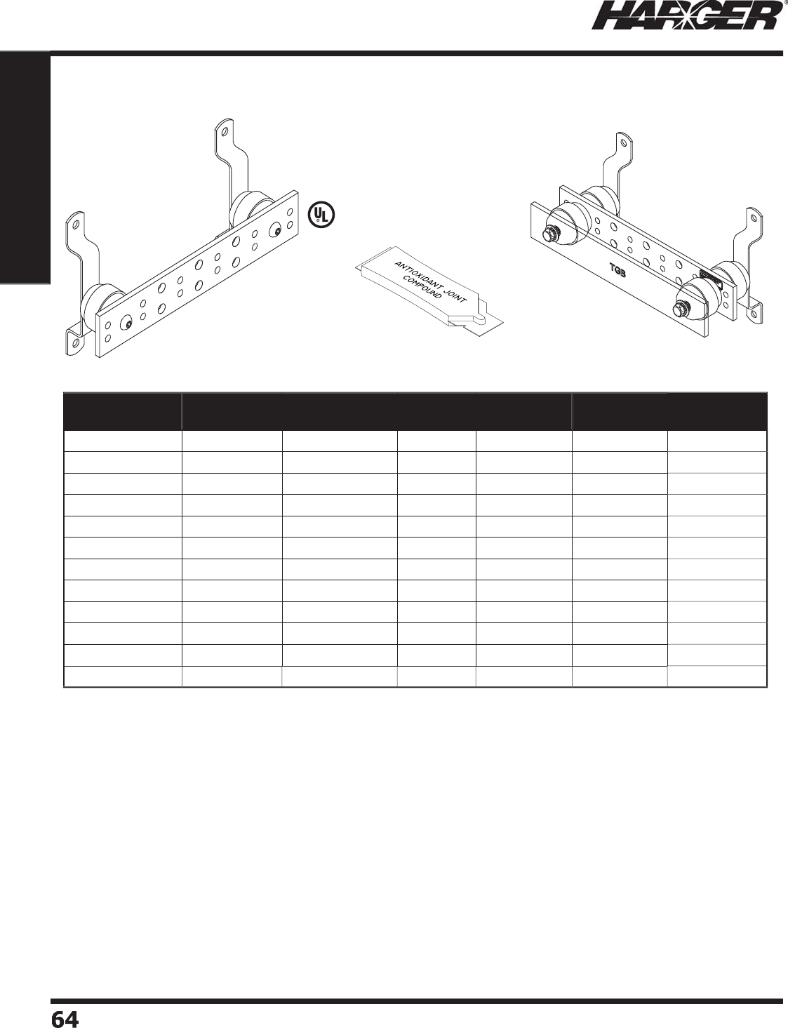
H
ar
g
er Li
g
htnin
g
& Groundin
g
•
©
2012 Phone 847-548-8700 • Fax 847-548-8755 • U.S. 800-842-743
7
64
64
Section 1
Grounding Components
L
iste
d
4
67
GBI14
2
1
2
TGB GBIP14
2
1
2
TGB
TIA-607 St
y
le Telecommunications
G
roundin
g
Busbars
*
TGB is standard letterin
g
in black with a minimum letterin
g
hei
g
ht of 3/8". Other sizes available.
P
lease contact factory for more information. See pa
g
e 60 for plexi
g
lass cover.
•
1/4" thick x 4" wide electrolytic tou
g
h pitch copper alloy 110.
•
Includes 1-1/2" insulators and 1" offset stainless steel mountin
g
brackets.
•
Includes one 1/2 oz. tube of antioxidant
(
#HCAJC1/2
)
.
•
5/16" hole sets 5/8" on centers. Accommodates "A" spaced two hole compression lu
g
s.
•
7/16" hole sets 1" on centers. Accommodates "C" spaced two hole compression lu
g
s.
•
Other sizes available. Please contact factor
y
for more information.
•
Meets "BICSI" and EIA
/
TIA 607 standards.
T
G
B B
us
bar
s
Part No. Bar Size Material Plexiglass
Cover
No. of 5/16"
Hole Sets
No. of 7/16"
Hole Sets
Approx. Each
Wt. (lbs.)
GBI14
26
TGB 1
/
4" x 2" x 6"
C
o
pp
e
r
No
2
2
1-1
/2
GBIP142
6
TGB* 1
/
4" x 2" x 6"
C
o
pp
e
r
Y
es
2
2
2
T
GBI14
26
TGB 1
/
4" x 2" x 6"
E
lectr
o
Tin Pl
a
te
d
No
2
2
1-1
/2
T
GBIP142
6
TGB* 1
/
4" x 2" x 6"
E
lectr
o
Tin Pl
a
te
d
Y
es
2
2
2
GBI14
2
1
0
TGB 1
/
4" x 2" x 10"
C
o
pp
e
r
No
4
3
3
GBIP1421
0
TGB* 1
/
4" x 2" x 10"
C
o
pp
e
r
Yes
4
3
3-1
/2
T
GBI14
2
1
0
TGB 1
/
4" x 2" x 10"
E
lectr
o
Tin Pl
a
te
d
No
4
3
3
T
GBIP1421
0
TGB* 1
/
4" x 2" x 10"
E
lectr
o
Tin Pl
a
te
d
Y
es
4
3
3-1
/2
GBI14
2
1
2
TGB 1
/
4" x 2" x 12"
C
o
pp
e
r
No
6
3
4
GBIP14212TGB* 1
/
4" x 2" x 12"
C
o
pp
e
r
Yes
6
3
4
-1
/2
T
GBI14
2
1
2
TGB 1
/
4" x 2" x 12"
E
lectr
o
Tin Pl
a
te
d
No
6
3
4
T
GBIP14212TGB* 1
/
4" x 2" x 12"
E
lectr
o
Tin Pl
a
te
d
Yes
6
3
4
-1
/2
S
ect
io
n 1.3.11

H
ar
g
er Li
g
htnin
g
& Groundin
g
•
©
2012 Phone 847-548-8700 • Fax 847-548-8755 • U.S. 800-842-743
7
65
65
Section 1
Grounding Components
Kit Incl
ud
e
s:
(
1
)
Ground bar with brackets and insulator
s
(6) GECLB62A: #6 compression lu
g
(1) GECLB22C: #2 compression lu
g
(1) GECLB1/02C: 1/0 compression lu
g
(1) GECLB2/02C: 2/0 compression lu
g
(1) GECLB3/02C: 3/0 compression lu
g
(
12
)
CS46S: 1/4"-20 x 3/4" SS hex head ca
p
scre
w
(
12
)
LW4S: 1/4"-20 SS lock washe
r
(
12
)
N420S: 1/4"-20 SS hex nut
(
6
)
CS68S: 3/8"-16 x 1" SS hex head ca
p
scre
w
(
6
)
LW6S: 3/8"-16 SS lock washe
r
(
6
)
N616S: 3/8"-16 SS hex nut
•
Other sizes available. Please contact factor
y
for more information.
•
Includes one 1/2 oz. tube of antioxidant
(
#HCAJC1/2
)
.
•
Meets "BICSI" and EIA
/
TIA 607 standards.
L
iste
d
4
67
GBI14
2
1
2
TGB
Part No. Bar Size Material No. of 5/16"
Hole Sets
No. of 7/16"
Hole Sets
Approx. Each
Wt. (lbs.)
GBI14
26
TGBKT 1
/
4" x 2" x 6"
C
o
pp
e
r
2
2
3
T
GBI14
26
TGBKT 1
/
4" x 2" x 6"
E
lectr
o
Tin Pl
a
te
d
2
2
3
GBI14
2
1
0
TGBKT 1
/
4" x 2" x 10"
C
o
pp
e
r
4
3
4
-1
/2
T
GBI14
2
1
0
TGBKT 1
/
4" x 2" x 10"
E
lectr
o
Tin Pl
a
te
d
4
3
4
-1
/2
GBI14
2
1
2
TGBKT 1
/
4" x 2" x 12"
C
o
pp
e
r
6
3
5
T
GBI14
2
1
2
TGBKT 1
/
4" x 2" x 12"
E
lectr
o
Tin Pl
a
te
d
6
3
5
TIA-607 St
y
le Telecommunications
G
roundin
g
Busbar Kits
T
G
B B
us
bar Kit
s
S
ect
io
n 1.3.11
ca
p
scr
ew
hex n
ut
lo
ck w
a
she
r
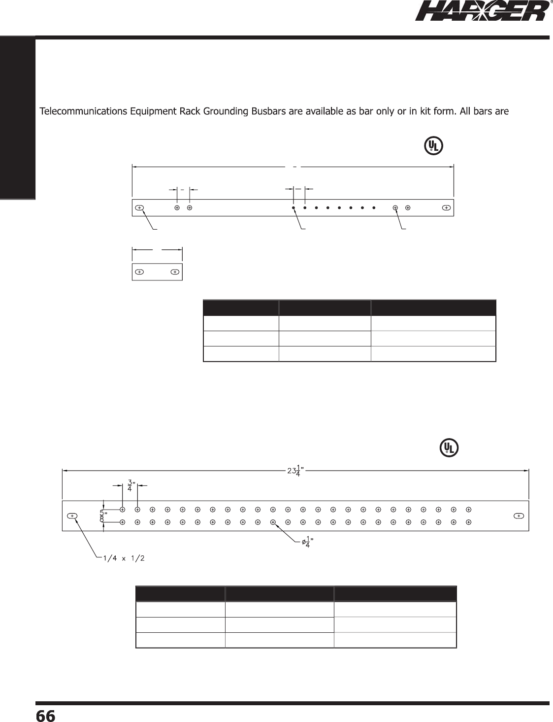
H
ar
g
er Li
g
htnin
g
& Groundin
g
•
©
2012 Phone 847-548-8700 • Fax 847-548-8755 • U.S. 800-842-743
7
66
66
Section 1
Grounding Components
S
ect
io
n 1.3.12
Part No. Bar Size Approx. Each Wt. (lbs.)
R
GBH141.
5
19.
25
A1
/
4" x 1-1
/
2" x 19-1
/
4"
3
R
GBH141.
523
.
25
A1
/
4" x 1-1
/
2" x 23-1
/
4"
4
R
GBH141.
535
.
25
A1
/
4" x 1-1
/
2" x 35-1
/
4"
5
9/32 x 1/2 #6-32
3"
11
16"
Ø9/32"
191
4"
3
4"
manufactured from 1/4" electrolytic tou
g
h pitch copper alloy 110. Desi
g
ned to fi t 19", 23" and 35" equipment racks.
R
G
BH14119.2
5
Pict
u
re
d
•
Above bars include 3" bar s
p
lice
p
late.
R
G
BH141.
5
2
3
.2
5
A Pict
u
re
d
B
ar S
p
lice Plate
•
Accommodates "A" spaced two hole lu
g
s.
L
iste
d
4
67
L
iste
d
4
67
Part No. Bar Size Approx. Each Wt. (lbs.)
R
GBH14119.
25
1
/
4" x 1" x 19-1
/
4"
2
R
GBH141
23
.
25
1
/
4" x 1" x 23-1
/
4"
3
R
GBH141
35
.
25
1
/
4" x 1" x 35-1
/
4"
4
T
elecommunications E
q
ui
p
ment Rack
G
roundin
g
Busbars & Kits
Horizontal Bars Onl
y
Horizontal Bars Onl
y
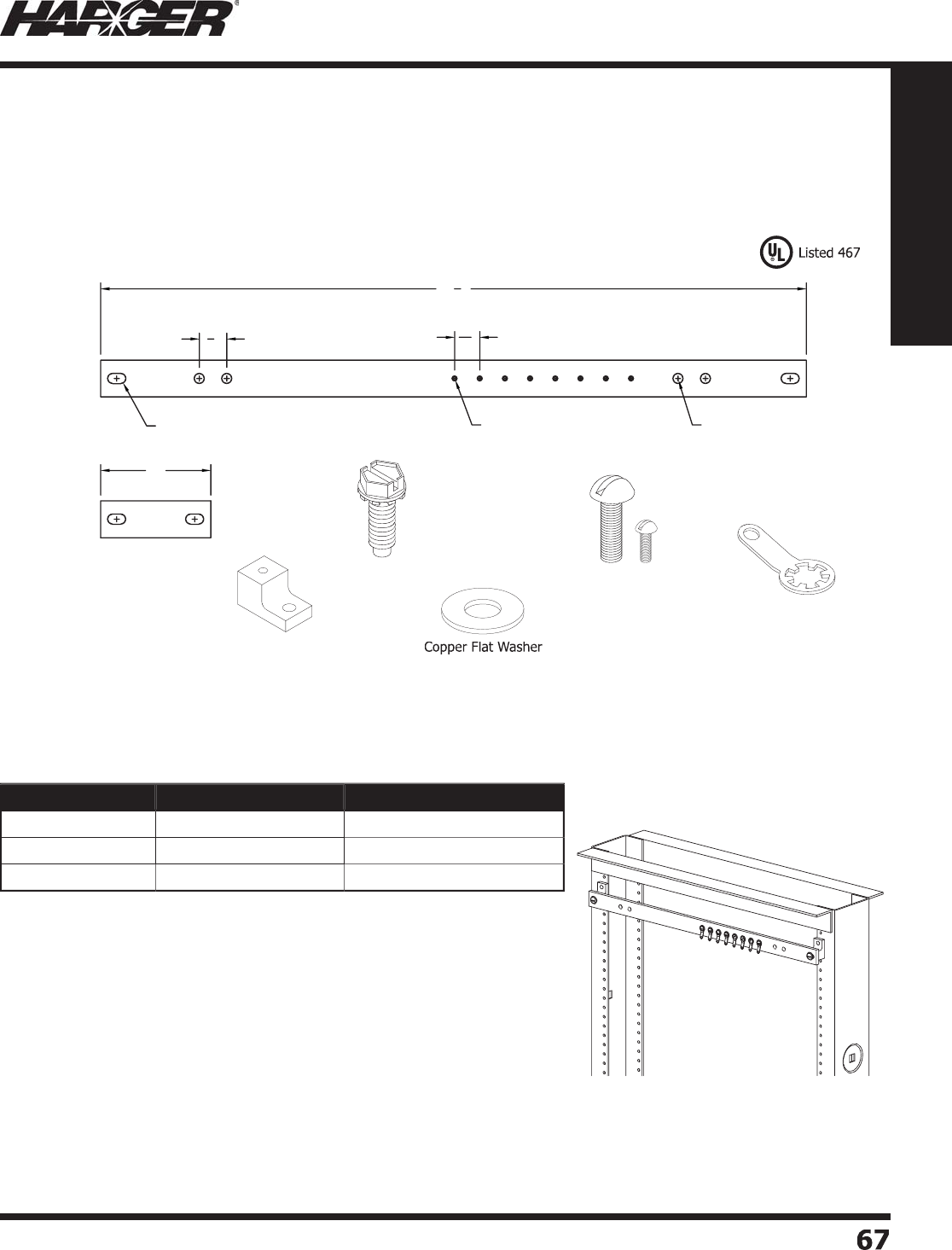
H
ar
g
er Li
g
htnin
g
& Groundin
g
•
©
2012 Phone 847-548-8700 • Fax 847-548-8755 • U.S. 800-842-743
7
6
7
67
Section 1
Grounding Components
R
G
BHKIT14119.2
5
Pict
u
re
d
B
ar S
p
lice Plate
T
elecommunications Equipment Rack Groundin
g
Busbars are available as bar only or in kit form. All bars are
manufactured from 1/4" electrolytic tou
g
h pitch copper alloy 110. Desi
g
ned to fi t 19", 23" and 35" equipment racks.
Kit Incl
ud
e
s:
(1) 1/4" electrolytic tou
g
h pitch copper alloy 110
g
round ba
r
(
1
)
3" bar s
p
lice
p
late with 2 slotted hole
s
(
2
)
11/16WINS: white delrin insulato
r
(2) SMS0126SHWZ: 12-24 x 5/8" hex washer head thread formin
g
scre
w
(
2
)
#12-24 x 3/4" co
pp
er fl ashed brass scre
w
(
2
)
#12 co
pp
er fl at washe
r
(
8
)
#6-32 x 1/4" co
pp
er fl ashed brass scre
w
(8) #6 rin
g
terminal
9/32 x 1/2 #6-32
3"
11
16"
Ø9/32"
191
4"
3
4"
11
/
16WIN
S
S
MS
0
1
26
SHW
Z
Co
pp
er Machine Screw
s
R
in
g
Terminal
Part No. Bar Size Approx. Each Wt. (lbs.)
R
GBHKIT14119.
25
1
/
4" x 1" x 19-1
/
4" 1-3
/
4
R
GBHKIT141
23
.
25
1
/
4" x 1" x 23-1
/
4"
4
R
GBHKIT141
35
.
25
1
/
4" x 1" x 35-1
/
4"
5
H
o
riz
o
ntal Kits
T
elecommunications E
q
ui
p
ment Rack
G
roundin
g
Busbars & Kits
S
ect
io
n 1.3.12
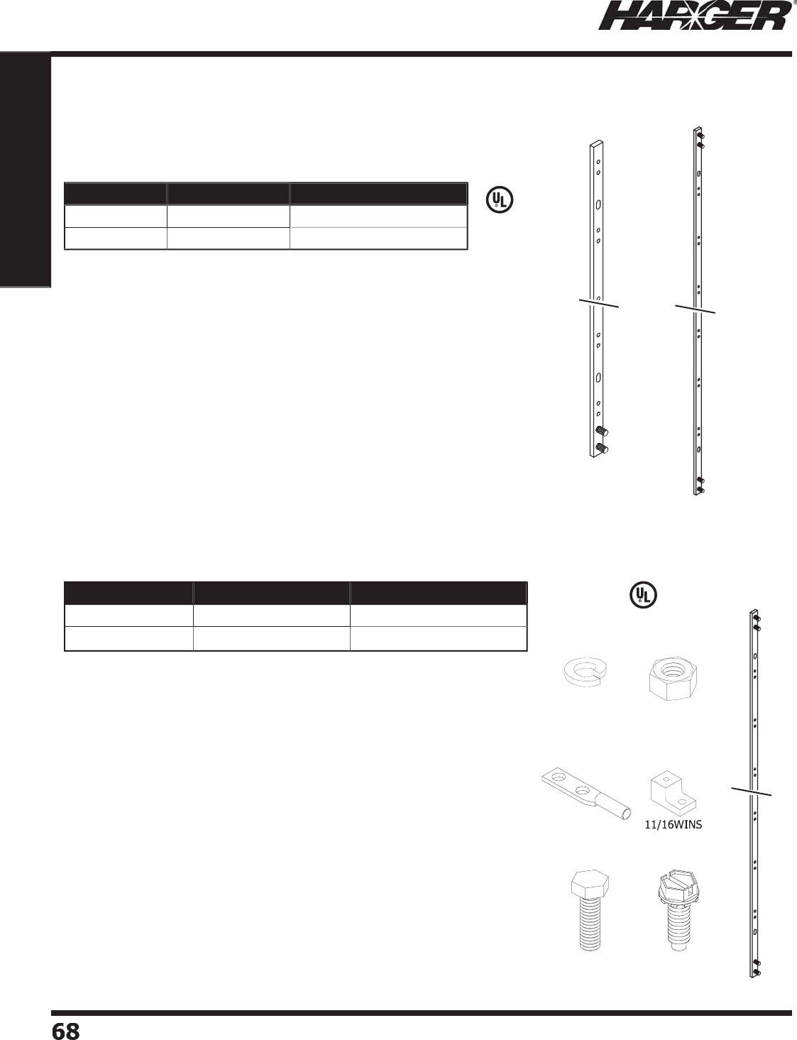
H
ar
g
er Li
g
htnin
g
& Groundin
g
•
©
2012 Phone 847-548-8700 • Fax 847-548-8755 • U.S. 800-842-743
7
6
8
68
Section 1
Grounding Components
S
ect
io
n 1.3.12
•
Manufactured from electrolytic tou
g
h pitch copper alloy 110.
•
Accommodates one hole lu
g
or two hole "A" spaced lu
g
s
(
5/8" on center
)
.
•
Elon
g
ated mountin
g
holes.
•
36" bar has 2 PEM studs 1" on center at one end for
g
round
c
o
n
du
ct
o
r c
o
nnecti
o
n.
•
72" bar has 4 PEM studs
(
two at each end
)
1" on center for
g
round conductor connections.
36
"
72"
•
Manufactured from electrolytic tou
g
h pitch copper alloy 110.
•
Accommodates one or two hole "A" spaced compression lu
g
s
(
5/8" on center
)
.
•
Elon
g
ated mountin
g
holes.
•
36" bar has 2 PEM studs 1" on center at one end for
g
round
c
o
n
du
ct
o
r c
o
nnecti
o
n.
•
72" bar has 4 PEM studs
(
two at each end
)
1" on center for
g
round conductor connections.
GECLB
22C
Kit Incl
ud
e
s:
(1) Vertical Equipment Rack Groundin
g
Busba
r
(
8
)
CS44S: 1/4"-20 x 1/2" stainless steel hex head ca
p
scre
w
(
3
)
11/16WINS: white delrin insulato
r
(
4
)
LW5S: 5/16" stainless steel lock washe
r
(
8
)
LW4S: 1/4" stainless steel lock washe
r
(3) SMS0126SHWZ: #12-24 x 5/8" hex washer head thread formin
g
scre
w
(
4
)
N518S: 5/16"-18 stainless steel hex nu
t
(1) GECLB22C: two hole lon
g
barrel compression lu
g
CS
44
S
L
W
5
S
&
L
W4
S
N
518
S
S
MS
0
1
26
SHW
Z
L
iste
d
4
67
L
iste
d
4
67
Part No. Bar Size Approx. Each Wt. (lbs.)
RGBVKIT145836A 1
/
4" x 5
/
8" x 36" 3-1
/2
R
GBVKIT145872A 1
/
4" x 5
/
8" x 72"
7
Part No. Bar Size Approx. Each Wt. (lbs.)
R
GBV145836A 1
/
4" x 5
/
8" x 36"
2
R
GBV145872A 1
/
4" x 5
/
8" x 72"
4
Vertical Bar
s
Vertical Kit
s
Telecommunications E
q
ui
p
ment Rack
G
roundin
g
Busbars & Kits
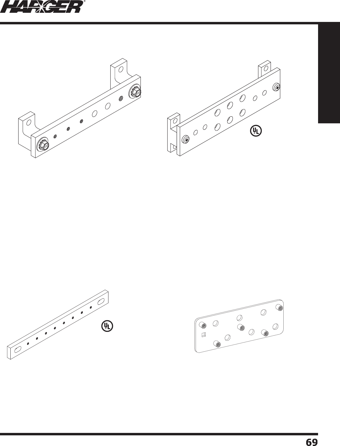
H
ar
g
er Li
g
htnin
g
& Groundin
g
•
©
2012 Phone 847-548-8700 • Fax 847-548-8755 • U.S. 800-842-743
7
6
9
69
Section 1
Grounding Components
G
B14.7
5
7.
5G
BE TGB1825.5CC
S
L
iste
d
4
67
G
BIS1428EE
•
1/4" x 2" x 8" electrolytic tou
g
h pitch copper alloy
11
0
ba
r.
•
(6) .438 punched holes desi
g
ned to fi t two hole lu
g
s
w
ith 1" on center spacin
g
.
•
(4) .313 punched holes desi
g
ned to fi t one hole lu
g
s.
•
Pre-assembled with two #7/8WINS and
p
an head
to
rx screws.
•
Approximate wei
g
ht is 1-1/4 pounds.
•
1/4" x 1" x 6" electrolytic tou
g
h pitch copper alloy
11
0
ba
r.
•
(3) 10-32 tapped holes desi
g
ned to fi t one hole lu
g
s.
•
(2) .281 punched holes desi
g
ned to fi t one hole lu
g
s.
•
(1) 1/4-20 tapped hole desi
g
ned to fi t one hole lu
g
s.
•
Pre-assembled with two #11
/
16WINS insulators and
sc
r
e
w
s
.
•
Approximate wei
g
ht is 1/2 pound.
Telc
o
Gr
o
und Bars
G
BIS141
6
C
G
B
•
1/4" x 3/4" x 7-1/2" electrolytic tou
g
h pitch copper alloy
11
0
ba
r.
•
(8) 6-32 tapped holes desi
g
ned to fit one hole lu
g
s.
•
(2) .281 x 1/2" slots, 6-3/8" on-center for mountin
g
.
•
Approximate wei
g
ht is 1/2 pound.
•
1/8” x 2” x 5-1/2” electrolytic tou
g
h copper alloy
11
0
ba
r.
•
(
6
)
11-32 holes used with 5/16” hardware.
•
(
5
)
10-32 clinch nuts.
•
Approximate wei
g
ht is 1/2 pound.
S
ect
io
n 1.3.13
467
L
iste
d
4
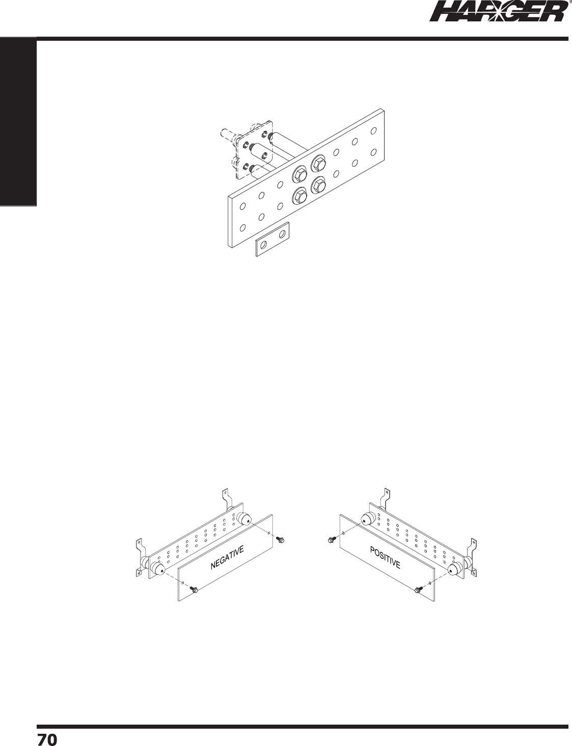
H
ar
g
er Li
g
htnin
g
& Groundin
g
•
©
2012 Phone 847-548-8700 • Fax 847-548-8755 • U.S. 800-842-743
7
7
070
Section 1
Grounding Components
S
ect
io
n 1.3.13
BATTERYC
O
NNKIT
•
(2) 1/4" x 4" x 20" electrolytic tou
g
h pitch copper alloy 110 bars.
•
Each bar has (27) 7/16" punched holes desi
g
ned to accommodate "B" and "C"
s
paced two hole lu
g
s (3/4" and 1" on center).
•
Each bar comes with a 1/4" thick plexi
g
lass cover with 1" hi
g
h red letterin
g
.
•
Approximate wei
g
ht for complete kit is 18 pounds.
Telc
o
Gr
o
und Bars
G
B38414.25TI
•
3/8" x 4" x 14-1/4" electrolytic tou
g
h pitch copper alloy 110 bar.
•
8 sets of 1/2" diameter holes 1-3/4" on center; which accommodates
"
D" spaced two hole compression lu
g
s.
•
Comes with sandwich plate for attachin
g
copper braid or fl at strap.
•
Includes silicon bronze bolts and co
pp
er s
p
acers.
•
Desi
g
ned to be used in con
j
unction with exothermic
g
round plate
X
GP3.25/3.254/0 (not included). See pa
g
e 316 for
g
round plates.
•
Approximate wei
g
ht is 7-1/2 pounds.
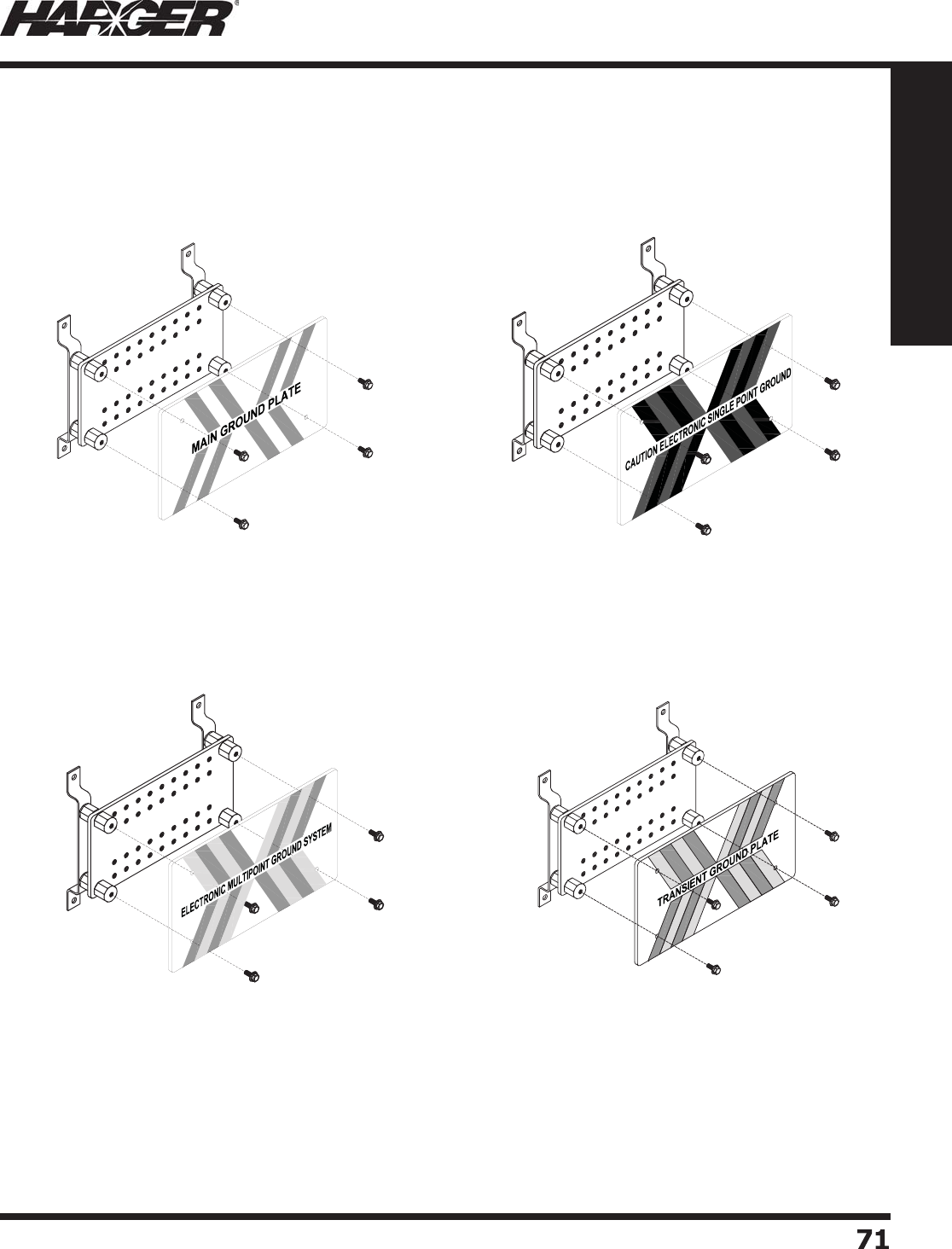
H
ar
g
er Li
g
htnin
g
& Groundin
g
•
©
2012 Phone 847-548-8700 • Fax 847-548-8755 • U.S. 800-842-743
7
7
1
71
Section 1
Grounding Components
G
BIP14
6
12T
G
PFAA
Transient Gr
o
und Plate
1/2" hi
g
h black letterin
g
and
g
reen & red stripin
g
are applied to plexi
g
lass cover.
G
BIP14
6
12CESP
G
FAA
C
aution Electronic Sin
g
le Point Groun
d
1/2" hi
g
h black letterin
g
and
g
reen & yellow stripin
g
are applied to plexi
g
lass cover.
G
BIP14
6
12EM
G
SFAA
Electronic Multi
p
oint Ground S
y
ste
m
1/2" hi
g
h black letterin
g
and
g
reen & oran
g
e stripin
g
are
applied to plexi
g
lass cover.
•
1/4" x 6" x 12" electrolytic tou
g
h pitch copper alloy 110 bar.
•
Includes insulators, mountin
g
brackets and plexi
g
lass covers
(
shi
p
s
p
artiall
y
assembled
)
.
•
18 sets of 3/8-16 ta
pp
ed holes 1" on center.
•
Approximate wei
g
ht is 8 pounds.
FAA St
y
le Ground Bars
G
BIP14
6
12M
G
PFAA
3
Main Gr
o
und Plate
1/2" hi
g
h black letterin
g
and
g
reen & clear
s
tripin
g
are applied to plexi
g
lass cover.
S
ect
io
n 1.3.1
4
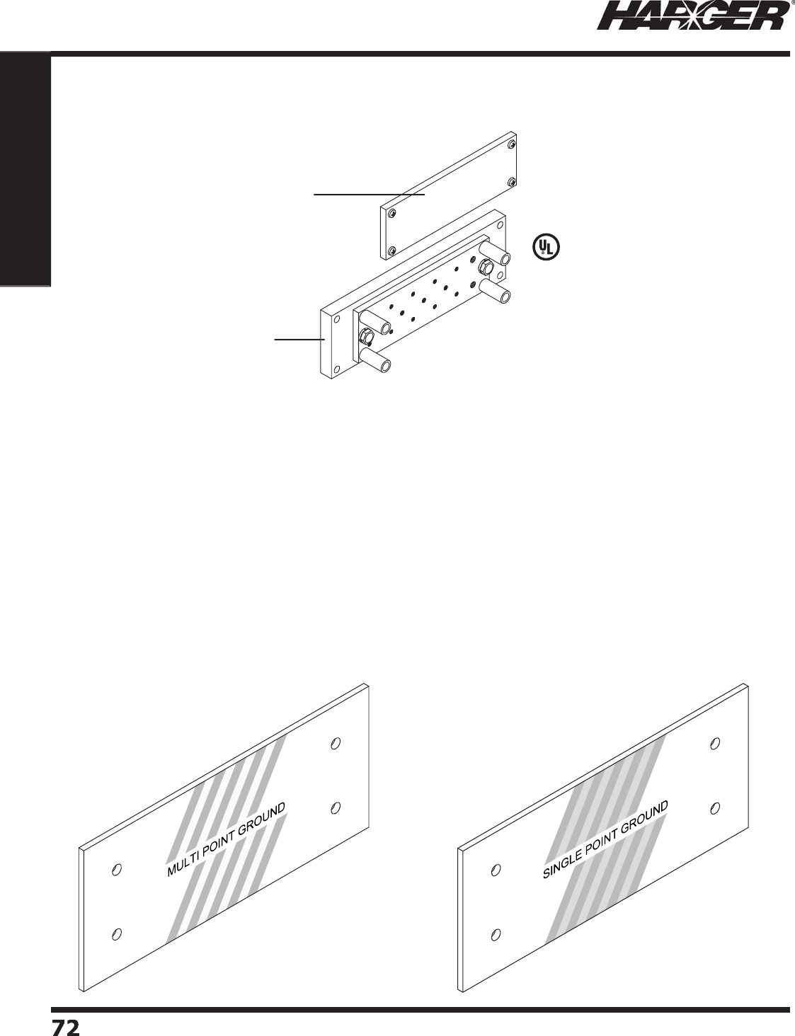
H
ar
g
er Li
g
htnin
g
& Groundin
g
•
©
2012 Phone 847-548-8700 • Fax 847-548-8755 • U.S. 800-842-743
7
72
72
Section 1
Grounding Components
FAA St
y
le Ground Bars
FAA Style Plexi
g
lass Covers
•
1/4" x 2" x 6" electrolytic tou
g
h pitch copper alloy 110 bar.
•
(
10
)
8-32 ta
pp
ed holes,
(
4
)
10-32 ta
pp
ed holes and
(
2
)
1/4-20 ta
pp
ed holes.
•
1/4" thick plexi
g
lass cover.
•
1/2" x 2.5" x 8" HDPE mountin
g
plate.
•
Approximate wei
g
ht is 5 pounds.
L
iste
d
4
67
P
lexi
g
lass cove
r
H
DPE mountin
g
plat
e
G
RDASSHDPER
S
All
g
round bars are available with lettered plexi
g
lass covers.
M
inimum letterin
g
hei
g
ht is 3/8". Letterin
g
available in several different colors.
S
tandard cover thickness is 1
/
4". Other thicknesses available.
P
lease contact our factor
y
with
y
our s
p
ecial needs.
S
ect
io
n 1.3.1
4
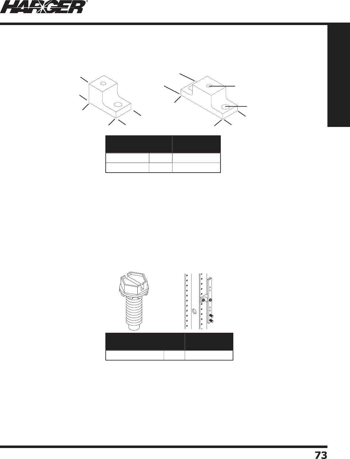
H
ar
g
er Li
g
htnin
g
& Groundin
g
•
©
2012 Phone 847-548-8700 • Fax 847-548-8755 • U.S. 800-842-743
7
7
3
73
Section 1
Grounding Components
Ma
n
u
f
a
ct
u
re
d
fr
o
m Delrin m
a
teri
a
l.
•
For use with 1" wide or less
g
round bars.
•
Surface mountin
g
hole 1/4" in diameter.
•
Ground bar mountin
g
hole 1/8" in diameter (self-tappin
g
).
11
/
16WIN
S
•
#12-24 x 5/8" zinc plated thread formin
g
hex
wa
sher he
ad
screw with extern
a
l w
a
sher.
•
U
se
d
with white st
a
n
do
ff ins
u
l
a
t
o
rs
(
11/16WINS & 7/8WINS
)
.
•
Removes
p
aint on a 12-24 threaded rack hole.
3
/
4"
3/8"
1-1/4"
7
/
8WIN
S
Ground Bar Mountin
g
Hol
e
S
urface Mountin
g
Hol
e
3/8"
2-1/4"
3
/
4"
Part No. Box
Qty.
Approx. Box
Wt. (lbs.)
11
/
16WIN
S
50
1-1
/
4
7
/
8WIN
S
20
1-1
/
4
Part No. Box
Qty.
Approx. Box
Wt. (lbs.)
S
MS
0
1
26
SHWZ-
50
50
1
S
tand
o
ff Insulat
o
rs - White
Thread Formin
g
Screw
S
ect
io
n 1.3.15
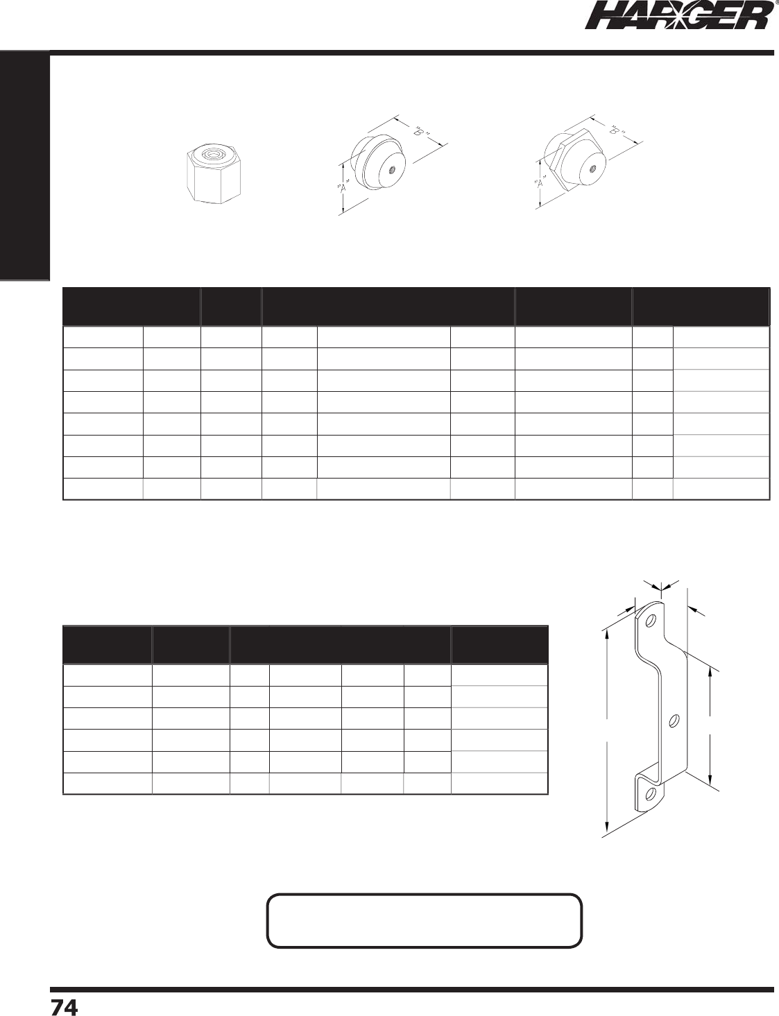
H
ar
g
er Li
g
htnin
g
& Groundin
g
•
©
2012 Phone 847-548-8700 • Fax 847-548-8755 • U.S. 800-842-743
7
74
74
Section 1
Grounding Components
1"
6 3/4" 4"
H
W
BKT1
Other sizes available. Contact our factor
y
for s
p
ecial re
q
uests.
O
cta
g
o
n
H
exa
g
o
n
Rou
n
d
M
anufactured from
g
lass reinforced thermoset polyester.
Part No. "A" "B" Shape Thread Size Voltage
Rating
Tensile
Strength (lbs.)
Box
Qty.
Approx. Box
Wt. (lbs.)
11
00
A1 1" 1"
Hex
1
/
4 - 20 x 1
/
4 AL
600
1
200
25
1-1
/2
4
1
50
S
2
2" 1-1
/
2"
O
ct 1
/
4 - 20 x 1
/
2 STL 1
500
3000
- 4
500
20
4
-1
/2
R
41
50
S
3
1-3
/
4" 1-1
/
2"
Rou
n
d
5/
16 - 18 x 1
/
2 STL 1
500
2500
-
2
7
00
20
5
-1
/2
R
41
50
A
4
1-3
/
4" 1-7
/
8"
Rou
n
d
3
/
8 - 16 x 3
/
8 AL
2000
2500
-
2
7
00
20
5
-1
/2
R
4
200
S
5
1-3
/
4" 2"
Rou
n
d
3
/
8 - 16 x 5
/
8 STL
2500
2500
-
2
7
00
20
6
-3
/
4
4200
S
6
2" 2"
O
ct 1
/
2 - 13 x 5
/
8 STL
2500
3000
- 4
500
20
8
5250
A
5
2-1
/
2" 2-1
/
2"
O
ct 3
/
8 - 16 x 5
/
8 AL
3200
5000
-
5
7
00
1
0
4
-1
/2
5
263A8 2-1
/
2" 2-5
/
8"
O
ct
5/
8 - 11 x 3
/
4 AL
3
4
00
5000
-
5
7
00
1
0
4
-3
/
4
S
tand
o
ff Insulat
o
rs - Red
Part No. Mounting
Hole Size "H" Material Heavy
Duty
Box
Qty.
Approx. Box
Wt. (lbs.)
W
BKT1 7
/
16" 1"
SS
No
1
0
3
W
BKT1H
D
5/
8" 1" Z
/
P Steel
Yes
1
0
8
W
BKT1HD
S
5/
8" 1"
SS
Yes
1
0
8
W
BKT
2
7
/
16" 2"
SS
No
1
0
4
W
BKT
3
7
/
16"
3
"
SS
No
1
0
4
WBKT4
7
/
16"
4
"
SS
No
1
0
5
W
all M
o
unt
•
Manufactured from 304 series stainless steel or zinc
p
lated steel.
•
S
p
ecial brackets available u
p
on re
q
uest.
Mountin
g
Brackets
N
O
TES
:
•
See Section 1.12 on pa
g
e 141 for hardware.
S
ect
io
n 1.3.15 & 1.3.16
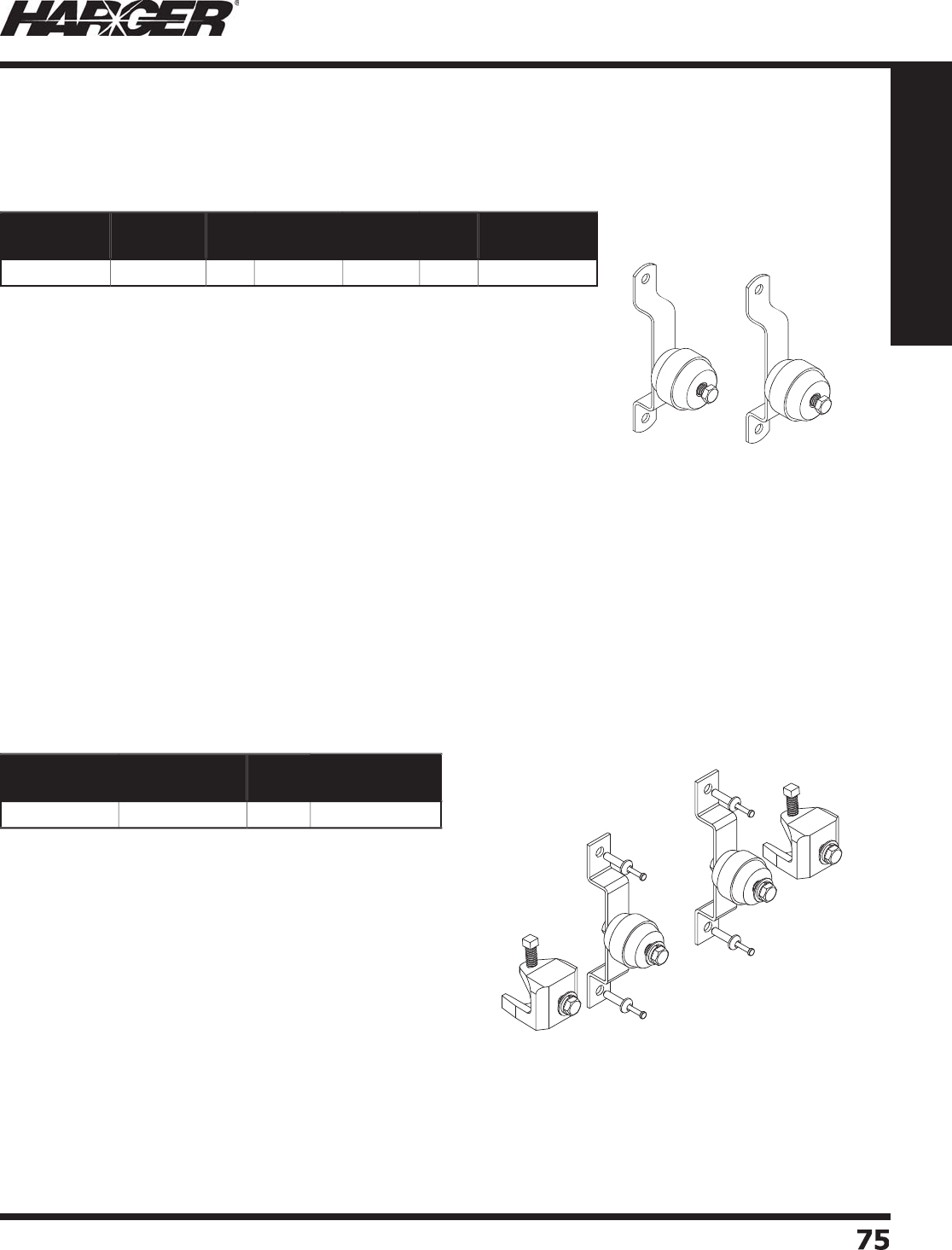
H
ar
g
er Li
g
htnin
g
& Groundin
g
•
©
2012 Phone 847-548-8700 • Fax 847-548-8755 • U.S. 800-842-743
7
75
75
Section 1
Grounding Components
•
Manufactured from 304 series stainless steel or zinc
p
lated steel.
•
S
p
ecial brackets available u
p
on re
q
uest.
Kit Incl
ud
e
s:
(2) WBKT1: stainless steel
g
round bar bracket
(
2
)
R4150A4: round insulato
r
(
2
)
CS66S: 3/8"-16 x 3/4" stainless steel hex head ca
p
scre
w
(
2
)
W6S: 3/8" stainless steel fl at washe
r
(
2
)
LW6S: 3/8" stainless steel s
p
lit lock washe
r
W
BKT1KIT
Part No. Mounting
Hole Size "H" Material Heavy
Duty
Box
Qty.
Approx. Box
Wt. (lbs.)
W
BKT1KIT 7
/
16" 1"
SS
No
5
5
Mountin
g
Brackets
W
all M
o
unt Kit
•
Pr
o
vi
d
es m
a
teri
a
l f
o
r either
a
Shelter
o
r
a
T
o
wer m
ou
nt.
Kit Incl
ud
e
s:
(2) WBKT1: stainless steel
g
round bar bracket (Shelter
)
(2) MBC3816: Malleable iron an
g
le adapters (Tower
)
• Will accommodate u
p
to 7/8" thick material.
(
2
)
R4150A4: round insulato
r
(
4
)
280: 1/4" x 1" drive
p
i
n
(
2
)
CS65S: 3/8"-16 x 5/8" stainless steel hex head ca
p
scre
w
(
2
)
CS66S: 3/8"-16 x 3/4" staniless steel hex head ca
p
scre
w
(
4
)
W6S: 3/8" stainless steel fl at washe
r
(
4
)
LW6S: 3/8" stainless steel s
p
lit lock washe
r
Part No. Approx. Each
Wt. (lbs.)
Box
Qty.
Approx. Box
Wt. (lbs.)
G
B
U
KIT 2-1
/
41
0
22-1
/2
U
niversal Busbar Mountin
g
Kit
S
ect
io
n 1.3.16 & 1.3.17
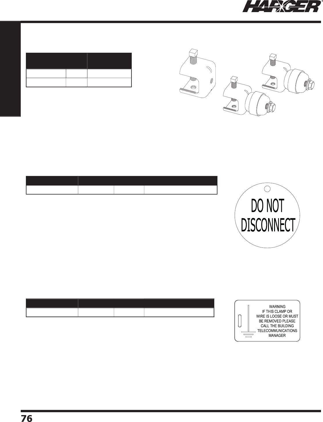
H
ar
g
er Li
g
htnin
g
& Groundin
g
•
©
2012 Phone 847-548-8700 • Fax 847-548-8755 • U.S. 800-842-743
7
7
676
Section 1
Grounding Components
•
Used in Data Center and In-Buildin
g
Telecommunications Groundin
g
Systems
to mark both ends of
g
roundin
g
/bondin
g
conductors.
•
2" diameter brass ta
g
with 1/2" hi
g
h black fi lled letterin
g
.
•
M
ad
e fr
o
m c
o
rr
o
si
o
n resist
a
nt
b
r
a
ss.
•
Has a round hole for mountin
g
, screwin
g
or wire tyin
g
into position.
•
Dimensi
o
ns
a
re 2.12
5
" x
3
.7
5
".
•
Yellow ta
g
with
g
reen text.
•
Ta
g
is UV Resistant.
Part No. Material Box Qty. Approx. Each Wt. (lbs.)
G
RNTA
G
DN
D
B
r
a
s
s
EA
1
/4
Part No. Material Box Qty. Approx. Box Wt. (lbs.)
GRNTAG
60
7PK1
0
P
l
a
sti
c
1
0
1
/2
"Do Not Disconnect" Ta
g
Network Buildin
g
Ground Ta
g
SS
AAKIT
SS
AA
•
M
a
n
u
f
a
ct
u
re
d
fr
o
m
30
4 series st
a
inless steel.
•
SSAAKIT includes two assemblies
(p
ictured
)
. 3/8"
s
tainless steel hardware fastens kit to
g
round bar.
•
SSAAKIT
a
ls
o
incl
ud
es R41
50
A4 ins
u
l
a
t
o
rs.
•
Will accommodate u
p
to 1" thick material.
Part No. Box
Qty.
Approx. Box
Wt. (lbs.)
SS
AA 1
0
5
SS
AAKIT
5
8
S
tainless Steel An
g
le Adapters
S
ect
io
n 1.3.18 - 1.3.20
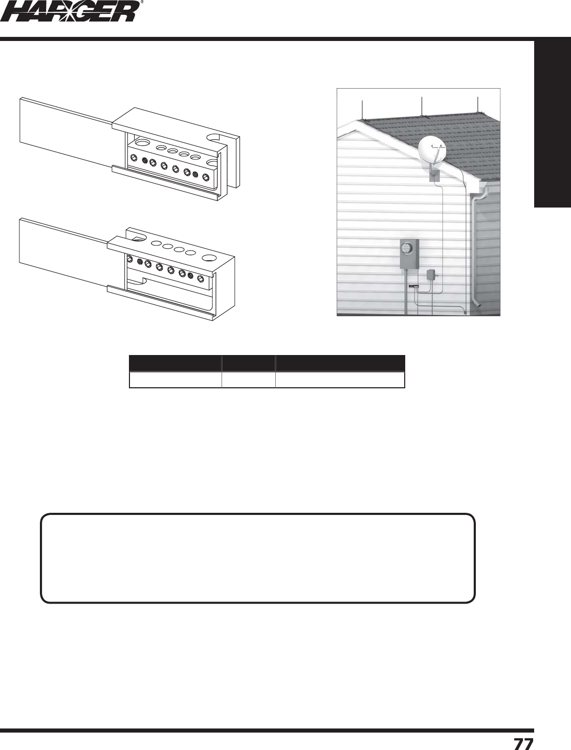
H
ar
g
er Li
g
htnin
g
& Groundin
g
•
©
2012 Phone 847-548-8700 • Fax 847-548-8755 • U.S. 800-842-743
7
77
77
Section 1
Grounding Components
Intersystem Bondin
g
Connectio
n
T
o
p
Vie
w
Bo
tt
o
m Vie
w
Part No. Box Qty. Approx. Each Wt. (lbs.)
IBTD
EA
3
/4
•
I
n
t
ers
y
s
t
em
B
o
ndin
g
T
ermin
a
ti
o
n
D
e
vi
ce
•
Accepts one 6-1 AWG
g
roundin
g
electrode conductor, four
14-4 AWG bondin
g
conductors and one Class I copper
li
g
htnin
g
conductor.
•
Plastic case, brass terminal with stainless steel hardware.
•
Mountin
g
hardware included.
•
Slide in, snap fi t lid desi
g
n for easy installation and inspection.
TECHNICAL NOTES:
(
Summarized
)
An external accessible intersystem bondin
g
termination for connectin
g
intersystem bondin
g
and
g
roundin
g
conductors at the service equipment and at the disconnectin
g
means for
any additional buildin
g
s or structures.*
* NEC 2011 Article 250.94 Bondin
g
For Other System
s
S
ect
io
n 1.3.21

H
ar
g
er Li
g
htnin
g
& Groundin
g
•
©
2012 Phone 847-548-8700 • Fax 847-548-8755 • U.S. 800-842-743
7
78
78
Section 1
Grounding Components
No
tes

H
ar
g
er Li
g
htnin
g
& Groundin
g
•
©
2012 Phone 847-548-8700 • Fax 847-548-8755 • U.S. 800-842-743
7
7
9
79
Section 1
Grounding Components
S
ect
io
n 1.
4
G
round Bus S
y
stems
In
d
ex
Descr
i
pt
i
on Pa
g
e
1.4.1 Intr
odu
cti
on
.......................................................................................
80
1.4.2 Ground Bus Numberin
g
System
...........................................................
80
1.4.3 Co
pp
er Ground Busbar
s
......................................................................
81
1.4.4 Gr
ou
n
d
B
u
s Size
s
...............................................................................
81
1.4.5 Elbows & S
p
licers with Kit
s
..................................................................
8
2
1.4.6 "Sandwich" St
y
le Elbows & S
p
licer
s
......................................................
8
3
1.4.7 Insulators & Mountin
g
Bracket
s
...........................................................
84
1.4.8 Static Ground Kit
s
...............................................................................
85
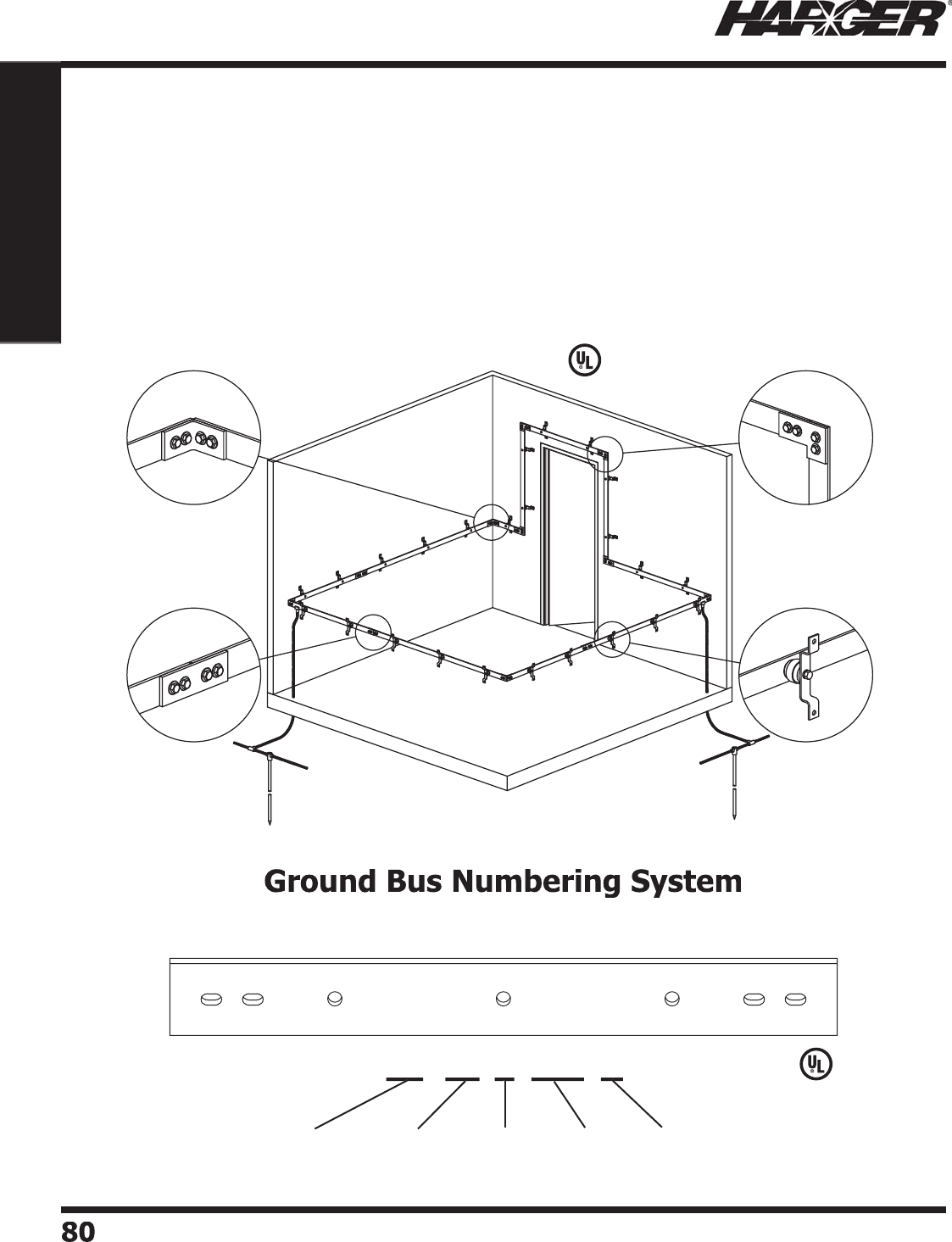
H
ar
g
er Li
g
htnin
g
& Groundin
g
•
©
2012 Phone 847-548-8700 • Fax 847-548-8755 • U.S. 800-842-743
7
8
0
80
Section 1
Grounding Components
C
ustom Ground Bus S
y
stems
H
ar
g
er Ground Bus Systems offer fl exibility, ease of desi
g
n and superior installation characteristics.
A variety of elbows, insulators, splice plates and bars ensure that custom desi
g
n specifi cations are
met. Har
g
er’s technical support staff stands ready to assist you with your desi
g
n criteria.
S
ome examples of Ground Bus System applications are: clean rooms for chemical stora
g
e,
ammunitions, paints & inks, testin
g
laboratories and pharmaceuticals.
L
iste
d
4
67
Intr
o
ducti
on
S
imply follow the example outlined below to specify the type and size of the
g
round bus you need.
T
he followin
g
example is a copper
g
round bus that is 1/4" thick, 2" wide and 12' lon
g
utilizin
g
hole pattern "K".
C
B 14
2
144 K
Ma
teri
a
l
(
CB = co
pp
er ba
r
AB = aluminum bar
)
Thickness
(
in.
)
k
Ho
le
Pa
tter
n
L
en
g
t
h
(
in.
)
W
i
d
t
h
(
in.
)
L
iste
d
4
67
S
ect
io
n 1.4.1 & 1.4.2
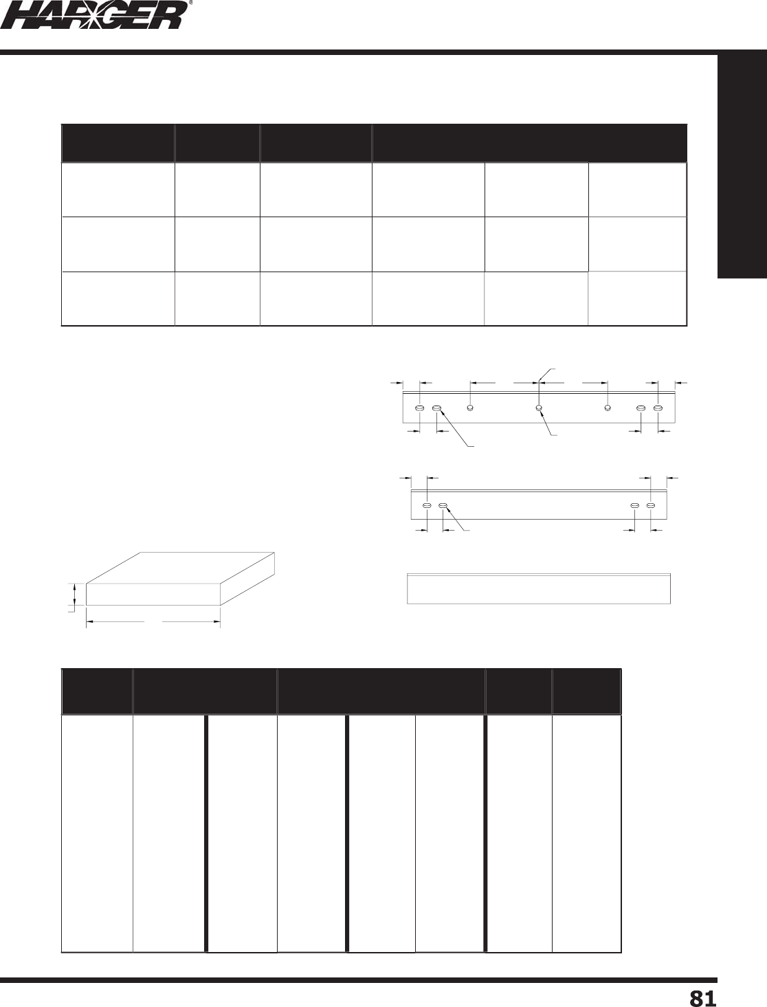
H
ar
g
er Li
g
htnin
g
& Groundin
g
•
©
2012 Phone 847-548-8700 • Fax 847-548-8755 • U.S. 800-842-743
7
8
1
81
Section 1
Grounding Components
"N"
T
hese hole
p
atterns are offered as standard
p
art
numbers. However, Har
g
er stands ready to custom
desi
g
n any hole pattern you require.
M
aximum len
g
th per bar is 12'-0". Bus is available in both copper and aluminum.
"K"
"
S
"
1"1"
1" 1"
12" 12"
CENTERLINE OF BAR
Ø7/16"
Ø3/8" x 5/8" SLOT
1"
1" 1"
1"
Ø3/8" X 5/8" SLOT
"A" "B"
DIMEN.
"A"
INCHES
DIMEN.
"B"
INCHES
DIMEN.
"A"
INCHES
DIMEN.
"B"
INCHES
DIMEN.
"A"
INCHES
DIMEN.
"B"
INCHES
DIMEN.
"A"
INCHES
DIMEN.
"B"
INCHES
1
/
8
1
/
8
1
/
8
1
/
8
1
/
8
1
/
8
1
/
8
1
/
8
1
/
8
1
/
8
1
/
8
1
/
8
1
/
8
1
/
8
1
/
4
1
/
4
1
/
4
3
/
8
1
/2
5/
8
3
/
4
7
/
8
1
1-1
/
4
1-1
/2
1-3
/
4
2
2-1
/2
3
4
6
1
/2
5/
8
3
/
4
1
/
4
1
/
4
1
/
4
1
/
4
1
/
4
1
/
4
1
/
4
1
/
4
1
/
4
1
/
4
1
/
4
1
/
4
3
/
8
3
/
8
3
/
8
3
/
8
3
/
8
1
1-1
/4
1-1
/2
1-3
/4
2
2-1
/2
3
3-1
/2
4
5
6
8
1
/2
5/
8
3
/4
1
1-1
/4
3
/
8
3
/
8
3
/
8
3
/
8
3
/
8
3
/
8
3
/
8
3
/
8
1
/2
1
/2
1
/2
1
/2
1
/2
1
/2
1
/2
1
/2
1
/2
1-1
/2
2
2-1
/2
3
3-1
/2
4
5
6
3
/4
1
1-1
/
4
1-1
/2
1-3
/
4
2
2-1
/2
3
3-1
/2
1
/2
1
/2
1
/2
1
/2
3
/
4
3
/
4
3
/
4
3
/
4
3
/
4
3
/
4
3
/
4
3
/
4
3
/
4
3
/
4
3
/
4
3
/
4
4
5
6
8
1
1-1
/
4
1-1
/2
2
2-1
/2
3
3-1
/2
4
5
6
7-3
/
4
8
G
r
o
und Bus Sizes
Part No. Thickness Width Length Hole Pattern Approx Each
Wt. (lbs.)
C
B141144K
C
B141144
S
C
B141144
N
1
/
4" 1" 144"
K
S
N
1
2
C
B141.
5
144K
C
B141.
5
144
S
C
B141.
5
144
N
1
/
4" 1-1
/
2" 144"
K
S
N
18
C
B14
2
144K
C
B14
2
144
S
C
B14
2
144
N
1
/
4" 2" 144"
K
S
N
2
4
C
o
pp
er Ground Busbars
•
Other sizes available. Please contact factor
y
for more information.
S
ect
io
n 1.4.3 & 1.4.
4
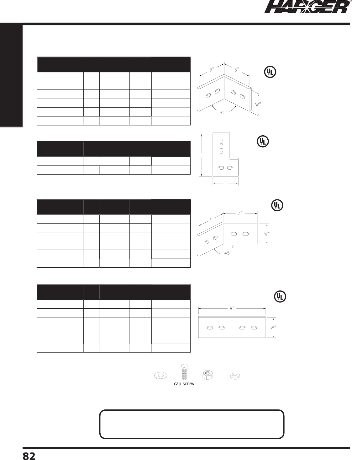
H
ar
g
er Li
g
htnin
g
& Groundin
g
•
©
2012 Phone 847-548-8700 • Fax 847-548-8755 • U.S. 800-842-743
7
8
2
82
Section 1
Grounding Components
L
iste
d
4
67
L
iste
d
4
67
L
iste
d
4
67
L
iste
d
4
67
5"
3"
Part No. Kit* Thickness Width Approx. Each
Wt. (lbs.)
C
U
141EL9
0
No
1
/
4" 1" 1
/2
C
U
141EL9
0
KIT
Yes
1
/
4" 1" 3
/4
C
U
141.
5
EL9
0
No
1
/
4" 1-1
/
2" 3
/4
C
U
141.
5
EL9
0
KIT
Yes
1
/
4" 1-1
/
2" 1
C
U
14
2
EL9
0
No
1
/
4" 2" 1
C
U
14
2
EL9
0
KIT
Yes
1
/
4" 2" 1-1
/4
Part No. Kit* Thickness Dims. Approx. Each
Wt. (lbs.)
C
U
14
35
EL9
0
FL
No
1
/
4"
3
" x
5
"1
C
U
14
35
EL9
0
FLKIT
Yes
1
/
4"
3
" x
5
" 1-1
/4
Part No. Kit* Thickness Width Approx. Each
Wt. (lbs.)
CU
141EL4
5
No
1
/
4" 1" 1
/2
CU
141EL4
5
KIT
Yes
1
/
4" 1" 3
/
4
CU
141.
5
EL4
5
No
1
/
4" 1-1
/
2" 3
/
4
CU
141.
5
EL4
5
KIT
Yes
1
/
4" 1-1
/
2" 1
C
U
14
2
EL4
5
No
1
/
4" 2" 1
C
U
14
2
EL4
5
KIT
Yes
1
/
4" 2" 1-1
/4
Part No. Kit* Thickness Width Approx. Each
Wt. (lbs.)
CU
141
S
PL
No
1
/
4" 1" 1
/2
CU
141
S
PLKIT Y
es
1
/
4" 1" 3
/
4
CU
141.
5S
PL
No
1
/
4" 1-1
/
2" 3
/
4
CU
141.
5S
PLKIT
Yes
1
/
4" 1-1
/
2" 1
C
U
14
2
SPL
No
1
/
4" 2" 1
C
U
14
2
SPLKIT
Yes
1
/
4" 2" 1-1
/4
Elbows & S
p
licers with Kits
90° Elb
o
ws
90° Elb
o
ws
45° Elb
o
ws
Sp
lice Plates
•
Used for 1
/
4" x 2" bar stock.
N
O
TES
:
• Slotted hole size is 3/8" x 5/8" s
p
aced 1" on center.
• Other sizes available. Please contact factor
y
for more information.
S
ect
io
n 1.4.5
*Kit Incl
ud
e
s:
(
1
)
Elbow or S
p
lice Plate
(
4
)
CS68S: 3/8”-16x1” SS hex head ca
p
scre
w
(
8
)
W6S: 3/8”-18 SS flat washe
r
(
4
)
LW6S: 3/8”-16 SS lock washe
r
(
4
)
N616S: 3/8”-16 SS hex nut
hex n
ut
lo
ck w
a
she
r
wa
she
r
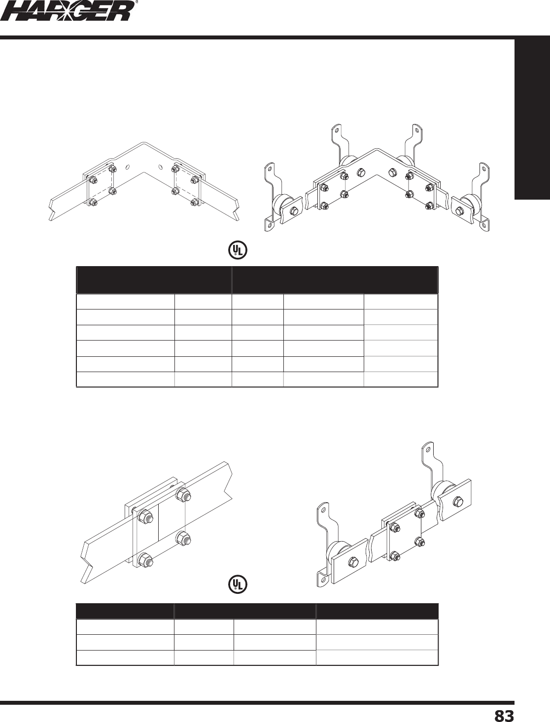
H
ar
g
er Li
g
htnin
g
& Groundin
g
•
©
2012 Phone 847-548-8700 • Fax 847-548-8755 • U.S. 800-842-743
7
8
3
83
Section 1
Grounding Components
Other sizes available. Please contact factor
y
for more information.
L
iste
d
4
67
L
iste
d
4
67
Part No. Thickness Fits Bar
Width
Interior or
Exterior Bend
Approx. Each
Wt. (lbs.)
S
SC
U
EL9
0
141INT 1
/
4" 1" Interi
or
4
S
SC
U
EL9
0
141EXT 1
/
4" 1"
E
xter
ior
4
S
SC
U
EL9
0
141.
5
INT 1
/
4" 1-1
/
2" Interi
or
5
S
SC
U
EL9
0
141.
5
EXT 1
/
4" 1-1
/
2"
E
xteri
or
5
S
SC
U
EL9
0
14
2
INT 1
/
4" 2" Interi
or
6
S
SC
U
EL9
0
14
2
EXT 1
/
4"
2
"
E
xteri
or
6
Part No. Thickness Fits Bar Width Approx. Each Wt. (lbs.)
SSCU
PL141 1
/
4" 1" 1
/2
SSCU
PL141.
5
1
/
4" 1-1
/
2" 1
S
SC
U
PL14
2
1
/
4" 2" 1
"Sandwich" St
y
le Elbow & S
p
licers
No Drillin
g
Required
90° Sandwich S
p
lice
S
andwich S
p
lice
S
ect
io
n 1.4.6
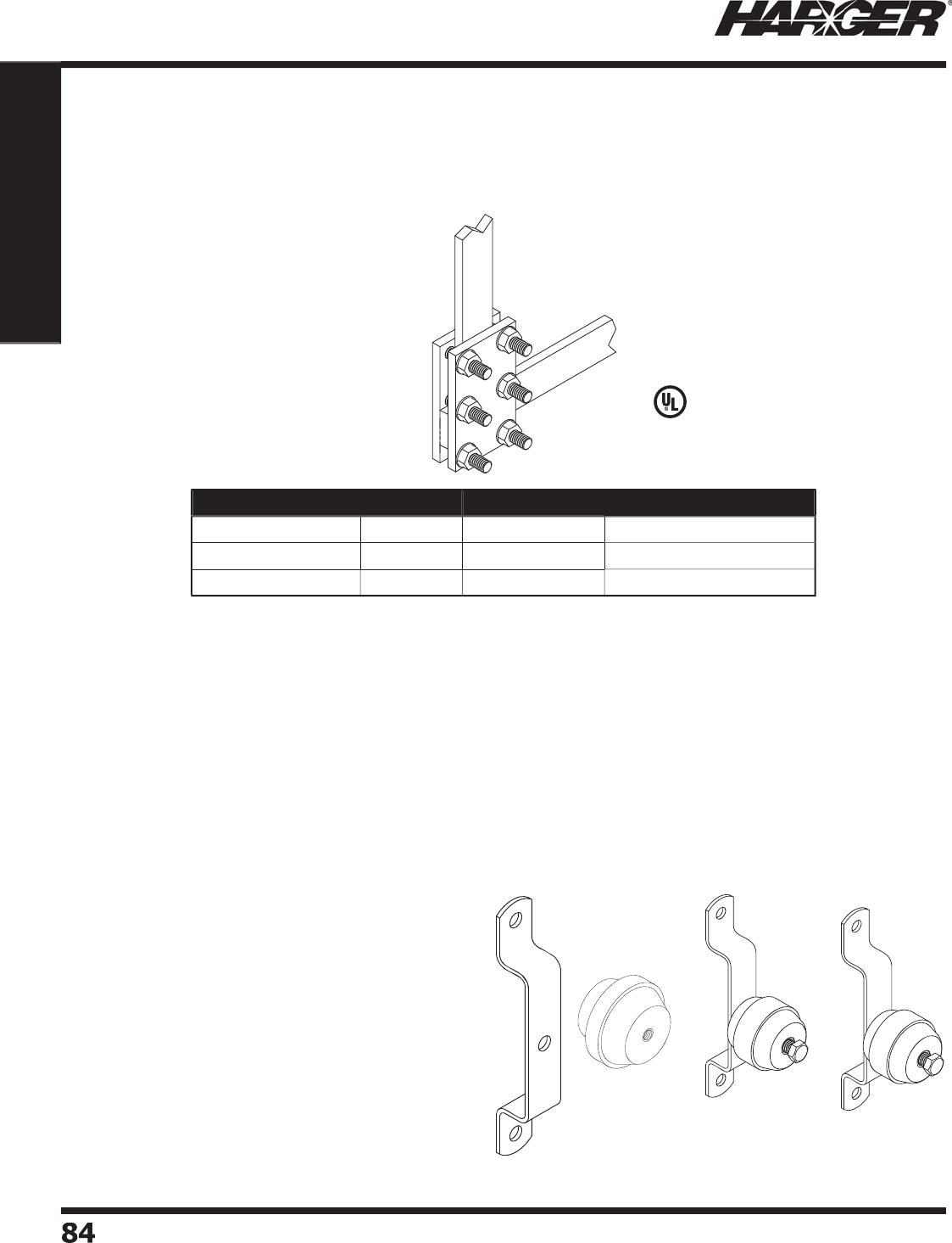
H
ar
g
er Li
g
htnin
g
& Groundin
g
•
©
2012 Phone 847-548-8700 • Fax 847-548-8755 • U.S. 800-842-743
7
84
84
Section 1
Grounding Components
S
tand-off insulators, mountin
g
brackets and hardware
are all provided by Har
g
er. Insulators and mountin
g
brackets are found on pa
g
es 74 & 75.
T
he hardware is in Section 1.12, pa
g
e 141.
T
o
p
rovide
p
ro
p
er su
pp
ort, bars should be mounted
ever
y
2 to 4 feet.
Other sizes available. Please contact factor
y
for more information.
L
iste
d
4
67
W
BKT1KIT
Part No. Thickness Fits Bar Width Approx. Each Wt. (lbs.)
SSCU
PLHV141 1
/
4" 1" 1
/2
SSCU
PLHV141.
5
1
/
4" 1-1
/
2" 1
S
SC
U
PLHV14
2
1
/
4" 2" 1-1
/2
"Sandwich" St
y
le Elbows & S
p
licers
No Drillin
g
Required
Sp
lice Plates
Insulators & Mountin
g
Brackets
S
ect
io
n 1.4.6 & 1.4.7
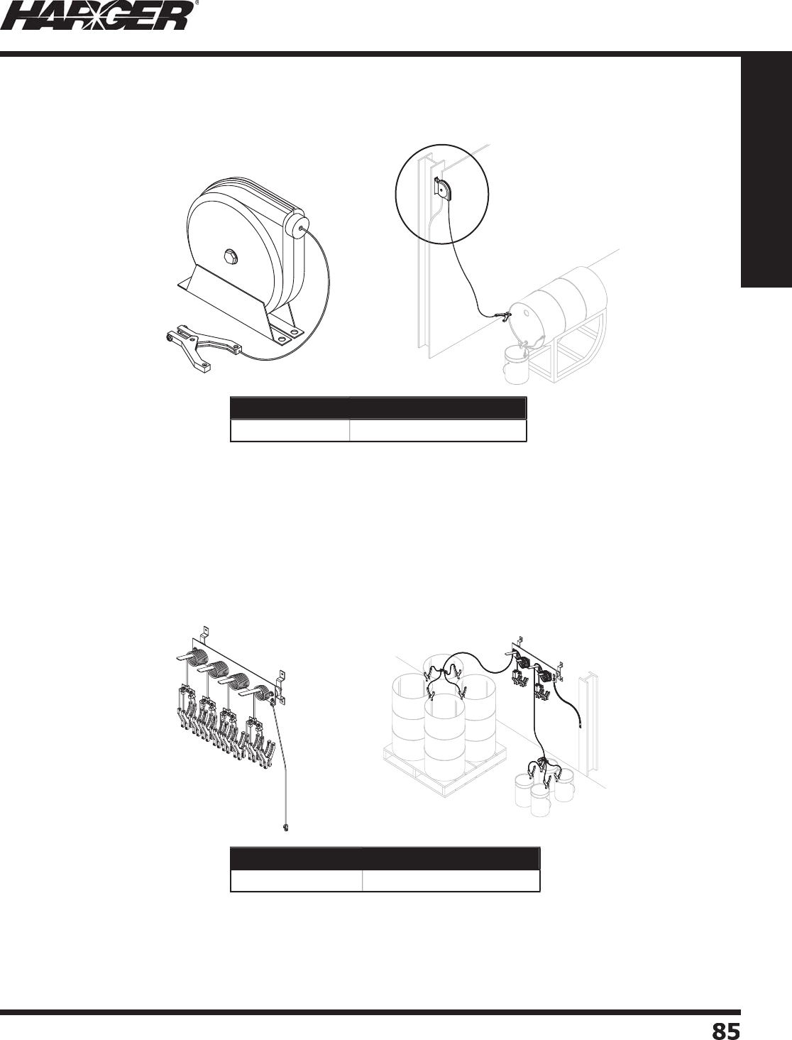
H
ar
g
er Li
g
htnin
g
& Groundin
g
•
©
2012 Phone 847-548-8700 • Fax 847-548-8755 • U.S. 800-842-743
7
8
5
85
Section 1
Grounding Components
•
Static
g
round assembly bonds up to 16 barrels or pails.
•
Comes with 4
Q
uad Leads:
-
3
le
ad
s with 1
0
' c
o
ils.
- 1 le
ad
with
5
' c
o
il.
•
B
a
rs m
a
n
u
f
a
ct
u
re
d
fr
o
m
30
4 st
a
inless steel.
•
Static
g
round reel with 20' retractable 3/32"
diameter
g
alvanized steel bondin
g
conductor.
•
Includes die cast aluminum
p
lier-t
yp
e clam
p
with
two stainless steel
p
oints.
•
Approximate 1" maximum
j
aw openin
g
.
Part No. Approx. Each Wt. (lbs.)
ABB
O
TTB
G
30
Part No. Approx. Each Wt. (lbs.)
S
GR
20
1
5
S
tatic Gr
o
und Kits
Barrel Groundin
g
Assembl
y
S
tatic Ground Reel 20' with Clam
p
S
ect
io
n 1.4.8

H
ar
g
er Li
g
htnin
g
& Groundin
g
•
©
2012 Phone 847-548-8700 • Fax 847-548-8755 • U.S. 800-842-743
7
8
6
86
Section 1
Grounding Components
H
ar
g
er manufactures a variety of static
g
round kits.
P
lease contact factor
y
for more information.
•
10' lon
g
, temporary static bond strap
manufactured from 2/0 su
p
erfl exible,
i
ns
u
l
a
te
d
c
o
n
du
ct
o
r.
•
Comes with a 200 Amp copper
g
round
clamp with 1-5/8" maximum
j
aw openin
g
and a compression lu
g
for 3/8" hardware.
•
36" lon
g
, temporary static bond strap
manufactured from 4/0 su
p
erfl exible,
i
ns
u
l
a
te
d
c
o
n
du
ct
o
r.
•
Comes with two 200 Amp copper
g
round
clamps with 1-5/8" maximum
j
aw openin
g
.
Part No. Approx. Each Wt. (lbs.)
GJ2
/
0WC120BEMA
7
Part No. Approx. Each Wt. (lbs.)
GJ4
/
0WC36CE
5
-1
/
4
S
tatic Gr
o
und Kits
Pail Ground Stra
p
Barrel Bond Stra
p
•
Can be attached to
g
round bar or to steel frame of tank
c
a
rs
o
r tr
u
cks.
•
1-1/4" lon
g
3/8-16 threaded stud with nut and lock washer.
•
Used for static
g
roundin
g
.
Part No. Approx. Each
Wt. (lbs.)
Box
Qty.
Approx. Box
Wt. (lbs.)
GRDSTD1.
25
1
/4
25
6
-1
/
4
Brass Gr
o
und Stud
S
ect
io
n 1.4.8

H
ar
g
er Li
g
htnin
g
& Groundin
g
•
©
2012 Phone 847-548-8700 • Fax 847-548-8755 • U.S. 800-842-743
7
8
7
87
Section 1
Grounding Components
S
ect
io
n 1.5
G
r
o
und B
o
xes
In
d
ex
Descr
i
pt
i
on Pa
g
e
1.5.1 NEMA T
yp
e 1 Steel Enclosures
...........................................................
88
1.5.2 NEMA Type 4 Fiber
g
lass Enclosure
s
.....................................................
88
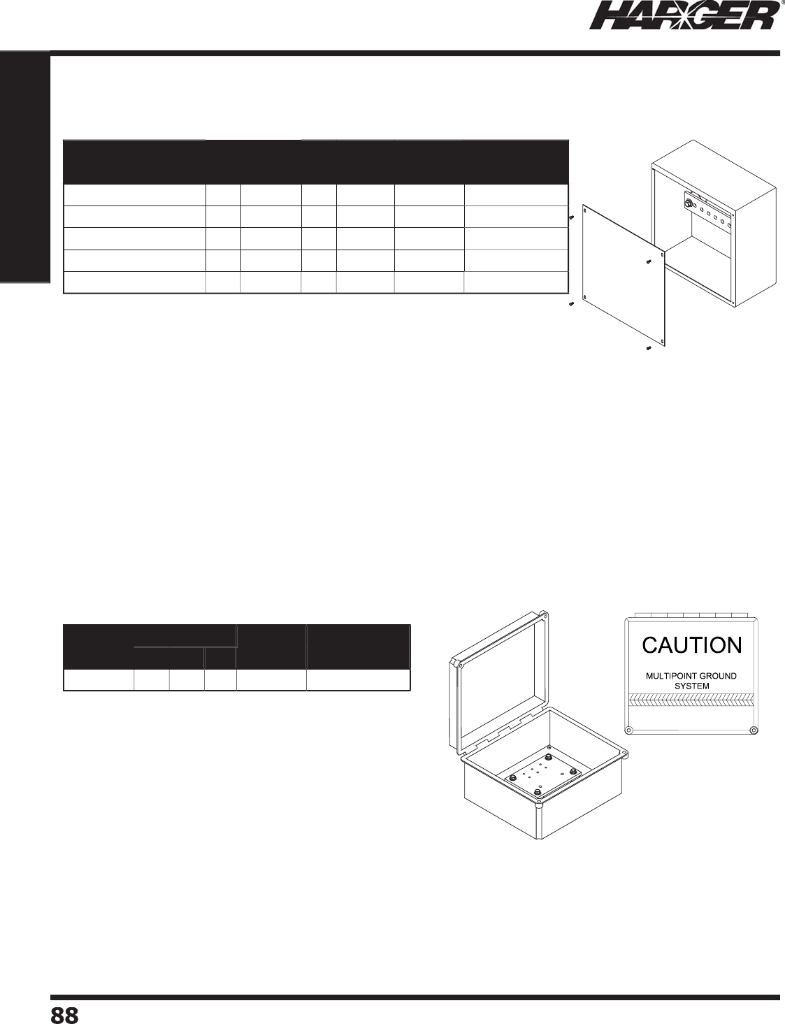
H
ar
g
er Li
g
htnin
g
& Groundin
g
•
©
2012 Phone 847-548-8700 • Fax 847-548-8755 • U.S. 800-842-743
7
8
8
88
Section 1
Grounding Components
•
NEMA Type 1
g
ray steel boxes with screw cover.
•
Standard bar has "H" hole pattern (see pa
g
e 51).
•
"H" hole pattern is a sin
g
le row of 7/16" holes spaced every 1 inch.
•
Two 3
/
8" x 1-7
/
8" insulators.
•
Other sizes and t
yp
es available. Please contact factor
y
for more information.
Part No. Size Bar
Width
Number
of Holes
Approx. Each
Wt. (lbs.)
HWD
GBX886 8" 8"
6
"2"
3
7
GBX1
0
1
06
1
0
"1
0
"
6
"2"
6
1
0
GBX1
2
1
26
12" 12"
6
"2" 8 19
GBX18186 18" 18"
6
"
4
"1
3
20
GBX
2
4
2
4
6
24" 24"
6
"
4
"19
3
4
NEMA T
yp
e 1 Steel Enclosures
NEMA Type 4 Fiber
g
lass Enclosures
Part No. Size Number
of Holes
Approx. Each
Wt. (lbs.)
HWD
E
S
2
4
0
12" 1
0
"
6
"8
22
•
3/8" x 4" x 6" copper
g
round bar with 3 sets of 1/4"
holes s
p
aced 1" on center.
•
3/4" x 9-1/2" x 11-1/2" white plywood backin
g
panel.
•
Four 3
/
8" x 1-1
/
2" insulators.
•
Front cover stenciled with 1" hi
g
h black letters and
3/8" hi
g
h black letters.
•
Stripin
g
is 1/2" hi
g
h
g
reen and oran
g
e.
•
Other sizes and t
yp
es available. Please contact factor
y
f
o
r m
o
re inf
o
rm
a
ti
o
n.
S
ect
io
n 1.5.1 & 1.5.2

H
ar
g
er Li
g
htnin
g
& Groundin
g
•
©
2012 Phone 847-548-8700 • Fax 847-548-8755 • U.S. 800-842-743
7
8
9
89
Section 1
Grounding Components
S
ect
io
n 1.6
U
L Li
s
te
d
S
upplementary Bondin
g
Grids
(
also known as Si
g
nal Reference Grids
)
&
Prefabricated Co
pp
er Ground Mes
h
In
d
ex
Descr
i
pt
i
on Pa
g
e
1.6.1 Supplementary Bondin
g
Grid
s
..............................................................
90
1.6.2 Flat Strip Supplementary Bondin
g
Grid
s
...............................................
9
1
1.6.3 Supplementary Bondin
g
Grid (SRG) Numberin
g
System
.........................
9
1
1.6.4 Low Im
p
edance Riser
s
........................................................................
92
1.
6
.
5
SRG t
o
SRG C
o
nnecti
o
n
s
.....................................................................
92
1.6.6 SRG Bondin
g
......................................................................................
93
1.6.7 Round-wire Supplementary Bondin
g
Grid (SRG
)
....................................
9
4
1.6.8 Ground Pedestal Clamps & Bondin
g
Clamp
s
..........................................
9
4
1.6.9 Com
p
uter Room Ground Clam
ps
..........................................................
96
1.6.10 Static Floor Bondin
g
Clamp Ki
t
.............................................................
96
1.6.11 UL Listed Prefabricated Co
pp
er Ground Mes
h
.......................................
97
1.6.12 Co
pp
er Ground Mesh Workshee
t
..........................................................
9
9
1.6.13 Co
pp
er Ground Mes
h
........................................................................
1
00
1.6.14 Personnel Safet
y
Mat
s
.......................................................................
1
0
1
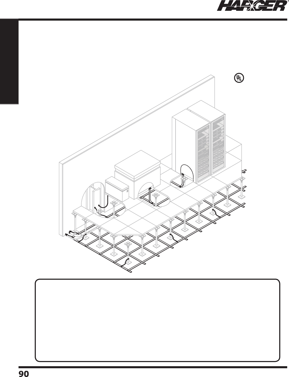
H
ar
g
er Li
g
htnin
g
& Groundin
g
•
©
2012 Phone 847-548-8700 • Fax 847-548-8755 • U.S. 800-842-743
7
9
0
90
Section 1
Grounding Components
T
oday's electronic environments require specialized
g
roundin
g
applications. Understandin
g
hi
g
her frequency
g
rounds, equipotential
g
round planes and supplementary bondin
g
subsystems
are imperative to protectin
g
sophisticated equipment systems. Har
g
er offers the knowled
g
e and
products required to protect these delicate systems. Si
g
nal Reference Grids (SRG) are also known
as Supplementary Bondin
g
Grids.
Note: The SRG acronym will not chan
g
e.
L
iste
d
4
67
S
upplementary Bondin
g
Grids
DEFINITI
O
NS*
:
•E
q
ui
p
otential Plane
:
A
g
rid, sheet, mass, or masses of conductin
g
material which, when bonded
to
g
ether, offers a ne
g
li
g
ible impedance to current fl ow. (Serves as si
g
nal reference subsystem for
new facilities.
)
•Hi
g
her Frequency Ground
:
The interc
o
nnecte
d
met
a
llic netw
o
rk inten
d
e
d
t
o
serve
a
s
a
c
o
mm
o
n
reference for currents and volta
g
es at frequencies above 30 kHz and in some cases above 300 kHz.
Pulse and di
g
ital si
g
nals with rise and fall times of less than 1 microsecond are classifi ed as hi
g
her
frequency si
g
nals.
•
S
i
g
nal Reference Subsystem
:
A conductive sheet or cable network/mesh providin
g
an
e
q
ui
p
otential reference for C-E e
q
ui
p
ments to minimize interference and noise.
*Militar
y
Handbook 419A
S
ect
io
n 1.6.1
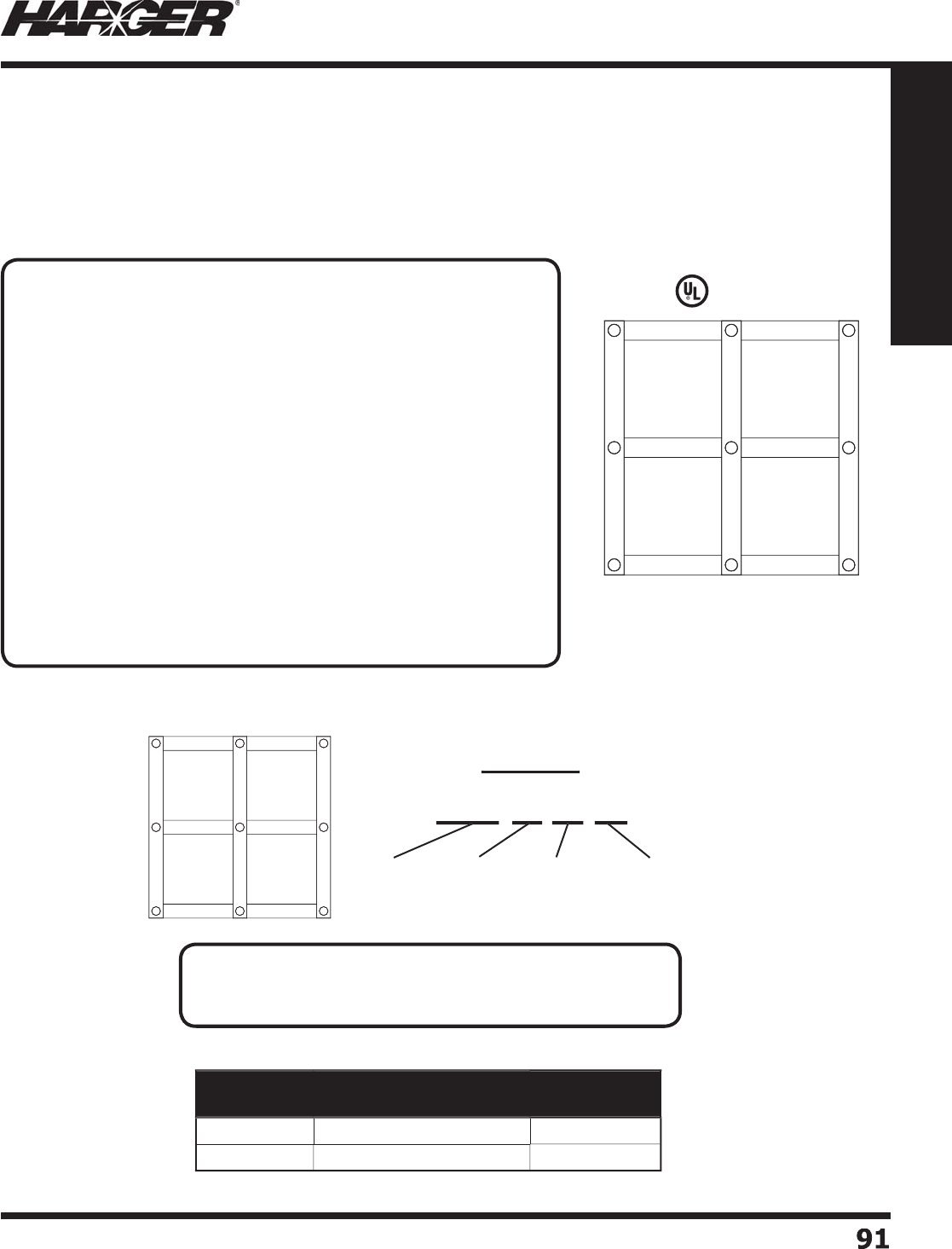
H
ar
g
er Li
g
htnin
g
& Groundin
g
•
©
2012 Phone 847-548-8700 • Fax 847-548-8755 • U.S. 800-842-743
7
9
1
91
Section 1
Grounding Components
H
ar
g
er's Flat Strip Supplementary Bondin
g
Grids are manufactured from 2" wide x 26
g
au
g
e soft copper
s
trip. They are welded to
g
ether formin
g
a 2' x 2' pattern. Rolls of SRG ran
g
e from 2' to 18' wide and the
w
ei
g
ht per roll is usually limited to a maximum of 250 pounds. The followin
g
pa
g
e offers a desi
g
n
g
uide to
help determine what part numbers are required for the fl at strip system. Si
g
nal Reference Grids (SRG) are also
known as Mesh-BN’s, System Reference Potential Planes (SRPP) and Supplementary Bondin
g
Grids.
Note: The SRG acronym will not chan
g
e.
L
iste
d
4
67
•
Commonl
y
stocked.
Part No. Description Approx. Each
Wt. (lbs.)
S
RG1
05024
10' x 50', 24" O.C. Spacin
g
90
S
RG1
25024
12' x 50', 24" O.C. Spacin
g
9
8
Flat Strip Supplementary Bondin
g
Grids
S
upplementary Bondin
g
Grid (SRG) Numberin
g
Syste
m
S
tan
d
ar
d
SR
G
Size
s
Example
p
SRG 12 46 2
4
S
R
G
Mesh
W
i
d
t
h
(
in feet
)
L
en
g
t
h
(
in feet
)
O
.C. Spacin
g
(
in inches
)
APPLICATI
O
N N
O
TES
:
The
g
rid lies directly on the subfl oor that supports the raised
fl oor. It may or may not be
g
lued or fastened down. "Power and
data cables lay on the
g
rid. The advanta
g
e of this
g
eometry is that,
due to decreased open loop area, the couplin
g
of radiated ener
g
y
from far-fi eld
p
henomena into the cables is minimized when the
y
are very close to the copper strips that form the si
g
nal reference
g
rid. The hi
g
her capacitance between the cables and the si
g
nal
reference
g
rid also increases the protected circuit's noise immunity
to electric fi elds. Minimum spacin
g
between the cables and the si
g
nal
reference
g
rid also reduces susceptibility to ma
g
netic fi elds. Both of
these
a
re ne
a
r-fi el
d
effects.
A possible disadvanta
g
e of this form of si
g
nal reference
g
rid is the
requirement for lon
g
er bondin
g
straps as compared to the raised
fl oor-based si
g
nal reference. Two bondin
g
straps (of differen
t
len
g
ths) to each piece of equipment substantially reduces the
im
p
edance of the stra
p
."*
*2
005
IEEE St
d
. 11
00
N
O
TES
:
• 2" x .016" Co
pp
er Stri
p
is used unless s
p
ecifi ed otherwise.
• Meets re
q
uirements of 2005 IEEE Std. 1100.
S
ect
io
n 1.6.2 & 1.6.3
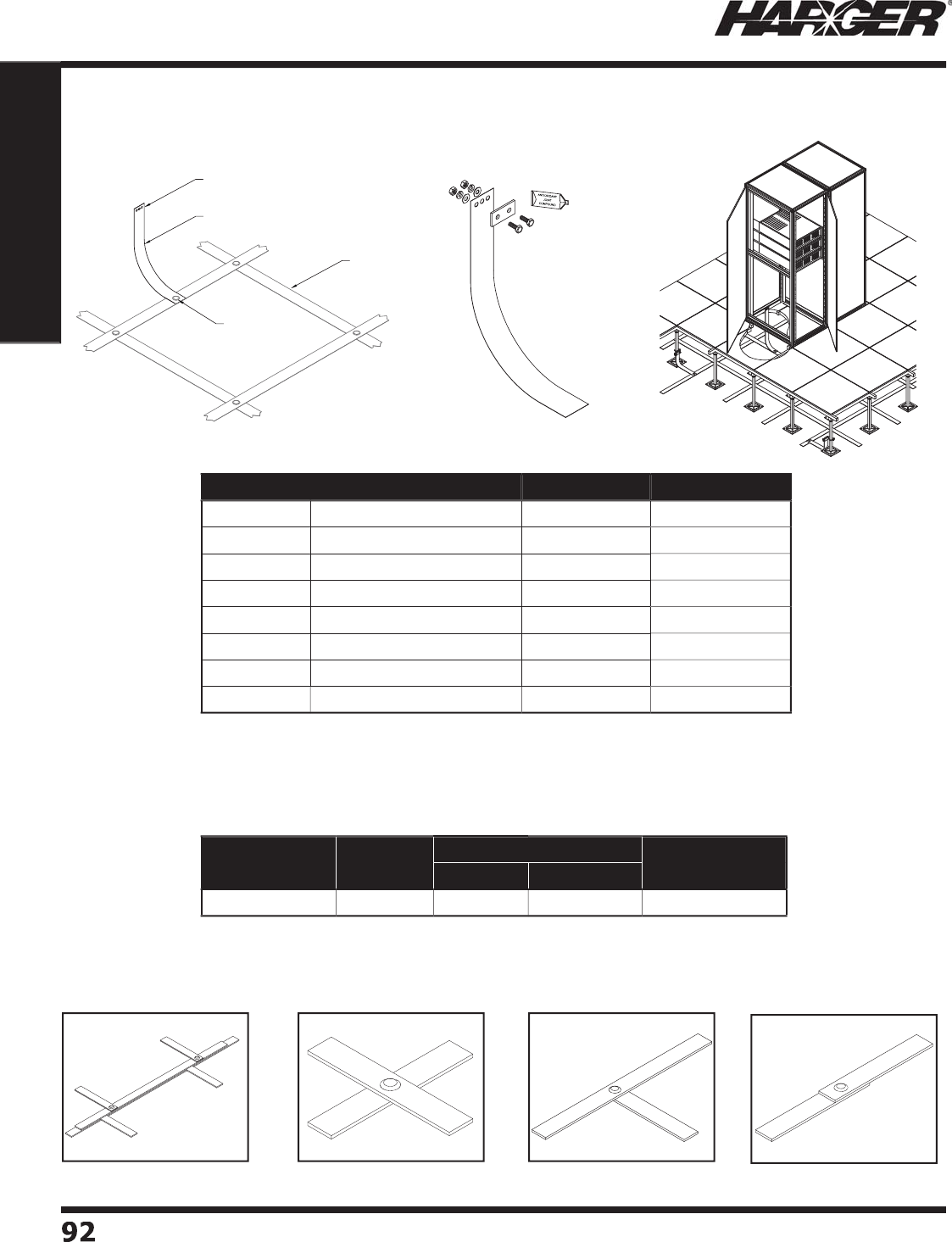
H
ar
g
er Li
g
htnin
g
& Groundin
g
•
©
2012 Phone 847-548-8700 • Fax 847-548-8755 • U.S. 800-842-743
7
9
2
92
Section 1
Grounding Components
•
Kit includes all necessar
y
hardware.
•
U
se m
o
l
d
SRG2
0
1
6
K t
o
wel
d
LIR t
o
SRG.
•
The Ultraweld SRG mold and weld metal are used to exothermically weld ad
j
acent SRG mats to
g
ether in the fi eld.
•
The SRG mold can be used to make all re
q
uired stri
p
to stri
p
connections.
•
Add suffi x SX to mold
p
art number and weld metal
p
art numbers for smokeless s
y
stem
(
exam
p
le: NUWTUBE32SX
)
.
Ad
j
acent SRG Mat
s
W
elded To
g
ethe
r
C
r
o
s
s
Tee
Sp
lice
L
IR K
it
Part No. Material Length Riser or Kit
L
IR18 2" x .016" Flat Co
pp
e
r
18"
R
i
ser
L
IR18KIT 2" x .016" Flat Co
pp
e
r
18"
K
it
L
IR
24
2" x .016" Flat Co
pp
e
r
24"
R
i
ser
L
IR
2
4KIT 2" x .016" Flat Co
pp
e
r
24"
Ki
t
L
IR
36
2" x .016" Flat Co
pp
e
r
36
"
R
i
ser
L
IR
36
KIT 2" x .016" Flat Co
pp
e
r
36
"
K
it
L
IR7
2
2" x .016" Flat Co
pp
e
r
72"
R
i
ser
L
IR7
2
KIT 2" x .016" Flat Co
pp
e
r
72"
K
it
Mold Part No. Flat Strip Weld Metal Handle Clamp
UltraShot NUWTUBE
S
RG
20
1
6
K 2" x .
0
1
6
"
U
S
32
NU
WT
U
BE
32
M
H1
Low Im
p
edance Risers
S
RG t
o
SRG C
o
nnect
io
ns
5/16" Ø
SRG
FIELD MADE
EXOTHERMIC
CONNECTION
LIR18
S
ect
io
n 1.6.4 & 1.6.5
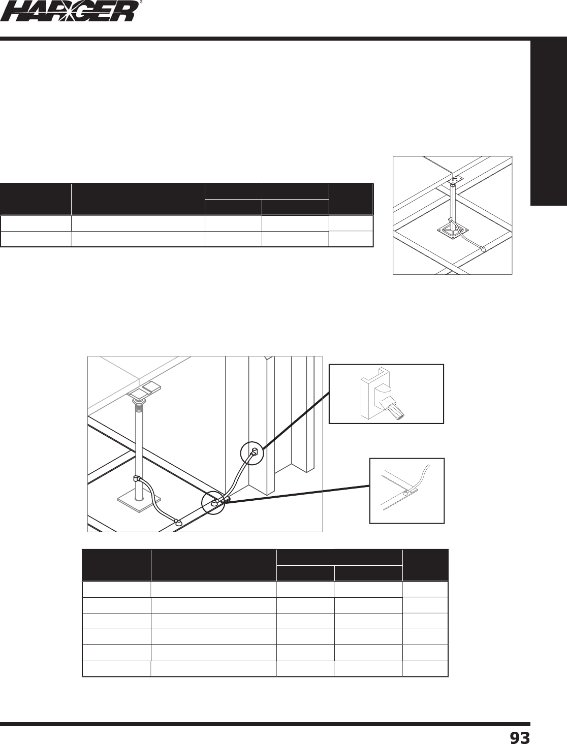
H
ar
g
er Li
g
htnin
g
& Groundin
g
•
©
2012 Phone 847-548-8700 • Fax 847-548-8755 • U.S. 800-842-743
7
9
3
93
Section 1
Grounding Components
Pedestal Bondin
g
to SRG
Connect pedestals per specifi cation, typically every 6th in each direction, to the SRG usin
g
#6 AWG 7 strand
copper cable. The cable should take the shortest path between the pedestal and the SRG. The len
g
th of the wire
s
hould not exceed 2 feet. The bond wire can either be exothermicall
y
welded to the
p
edestal
(p
referred method
)
o
r mechanically attached usin
g
a UL Listed Pedestal Ground Clamp (see pa
g
e 94).
Exothermicall
y
Welded Pedestal Connections
Exothermic Connections for Bondin
g
to Buildin
g
Stee
l
All columns within and at perimeter of the computer room shall be bonded to the SRG usin
g
a concentric stranded
co
pp
er conductor. #6 AWG 7 strand co
pp
er is the most common conductor used for this a
pp
lication. The cable
s
hould take the shortest path between the buildin
g
steel and the Supplementary Bondin
g
Grid.
•
Add suffi x SX to mold
p
art no. and weld metal for smokeless s
y
stem
(
exam
p
le: BCF61.5016BSX and/or NUWTUBE25SX
)
.
•
Add suffi x SX to mold
p
art no. and weld metal for smokeless s
y
stem
(
exam
p
le: BCF41.5016BSX and/or NUWTUBE32SX
)
.
#6
conc to
S
R
G
B
uildin
g
S
teel
V
A
6
B Mol
d
#6
conc
Mold Part
No. Connection Weld Metal Handle
Clamp
UltraShot NUWTUBE
VH
O
61S
Q
MX #6 Conc. to 1" S
q
. Pedestal
U
S
25
NU
WT
U
BE
25
MH4
B
CF
6
1.
50
1
6
B#
6
C
o
nc. t
o
SR
G
U
S
25
NU
WT
U
BE
25
M
H1
Mold Part
No. Connection Weld Metal Handle
Clamp
UltraShot NUWTUBE
VA
6
B #6 Conc. to Buildin
g
Steel
US
4
5
NUWTUBE45
M
H1
VA4B
#4 Conc. to Buildin
g
Steel
US
4
5
NUWTUBE45
M
H1
VA
2
B #2 Conc. to Buildin
g
Steel
US
4
5
NUWTUBE45
M
H1
B
CF
6
1.
50
1
6
B#
6
C
o
nc. t
o
SR
G
U
S
25
NU
WT
U
BE
25
M
H1
B
CF41.
50
1
6
B #4
Co
nc. t
o
S
R
G
U
S
32
NU
WT
U
BE
32
MH1
B
CF
2
1.
50
1
6
B#
2
C
o
nc. t
o
SR
G
U
S
32
NU
WT
U
BE
32
M
H1
S
RG Bondin
g
S
ect
io
n 1.6.6
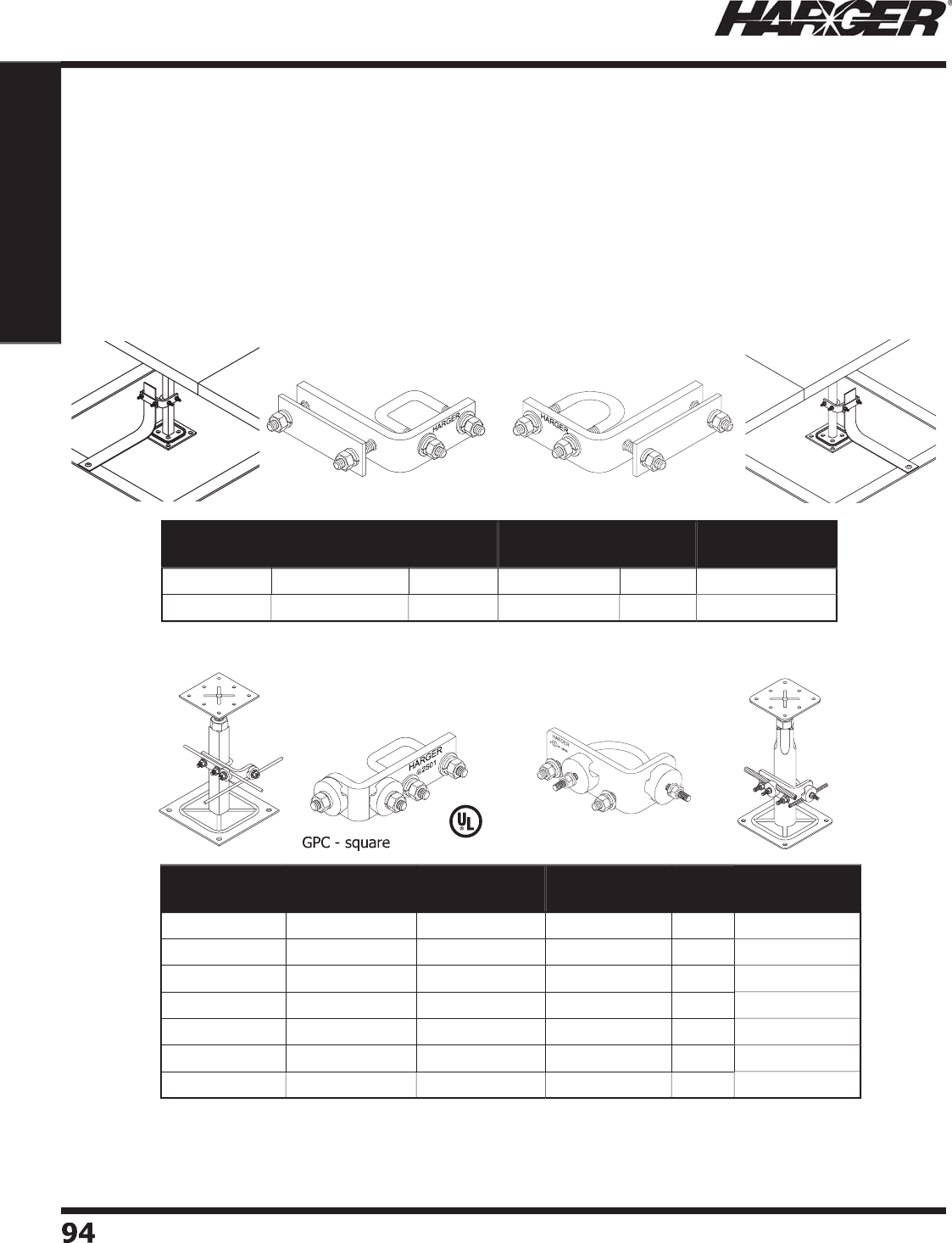
H
ar
g
er Li
g
htnin
g
& Groundin
g
•
©
2012 Phone 847-548-8700 • Fax 847-548-8755 • U.S. 800-842-743
7
94
94
Section 1
Grounding Components
"
A Si
g
nal Reference Grid may also be economically fabricated from standard, bare round-wire
j
oined to
g
ether via weldin
g
, brazin
g
, compression or a suitable
g
roundin
g
clamp arran
g
ement at
each of the crossin
g
points". (2005 IEEE Std. 1100
)
H
ar
g
er offers a variety of
g
round pedestal clamps and conductors to achieve these ob
j
ectives.
Conductors can be found in Section 1.1, pa
g
e 11. Si
g
nal Reference Grids (SRG) are also known as
S
upplementary Bondin
g
Grids.
Note: The SRG acronym will not chan
g
e.
•
Accommodates cross runs without addin
g
an additional connector. Accommodates 4
c
o
n
du
ct
o
rs in t
o
t
a
l.
•
Electro-tin
p
lated co
pp
er.
•
Incl
ud
es st
a
inless steel h
a
r
d
w
a
re.
•
Other sizes available. Please contact factor
y
for more information.
L
iste
d
4
67
Part No. U-Bolt Type Pedestal
Size
Conductor
Size (AWG)
Box
Qty.
Approx. Box
Wt. (lbs.)
GPC6S
Q
Sq
uare 1"
(
1-1/8" OD
)
#
6
5
3-1
/2
GPC
6
R
D
Rou
n
d
1"
(
1-1/8" OD
)
#
6
5
3-1
/2
GPC4S
Q
Sq
uare 1"
(
1-1/8" OD
)
#4
5
3-1
/2
G
P
C
4R
D
Rou
n
d
1"
(
1-1/8" OD
)
#4
5
3-1
/2
GPC
2
S
Q
Sq
uare 1"
(
1-1/8" OD
)
#
2
5
3-1
/2
GPC
2
R
D
Rou
n
d
1"
(
1-1/8" OD
)
#
2
5
3-1
/2
GPC2
/
0RD1.75
Rou
n
d
1-1
/
8" - 1-3
/
4" 2
/
0 & #6
5
7-1
/2
Round-wire Supplementary Bondin
g
Grid
G
round Pedestal Clamps & Bondin
g
Clamps
GPC2
/
0RD1.75
•
Electro-tin
p
lated co
pp
er.
•
Incl
ud
es st
a
inless steel h
a
r
d
w
a
re.
Part No. U-Bolt Type Pedestal
Size
Conductor
Size
Box
Qty.
Approx. Box
Wt. (lbs.)
GPC
2
FSS
Q
Sq
uare 1" 2" Flat Stri
p
5
4
GPC
2
FSR
D
Rou
n
d
1" 2" Flat Stri
p
5
4
G
round Pedestal Clam
p
s for Flat Stri
p
S
ect
io
n 1.6.7 & 1.6.8
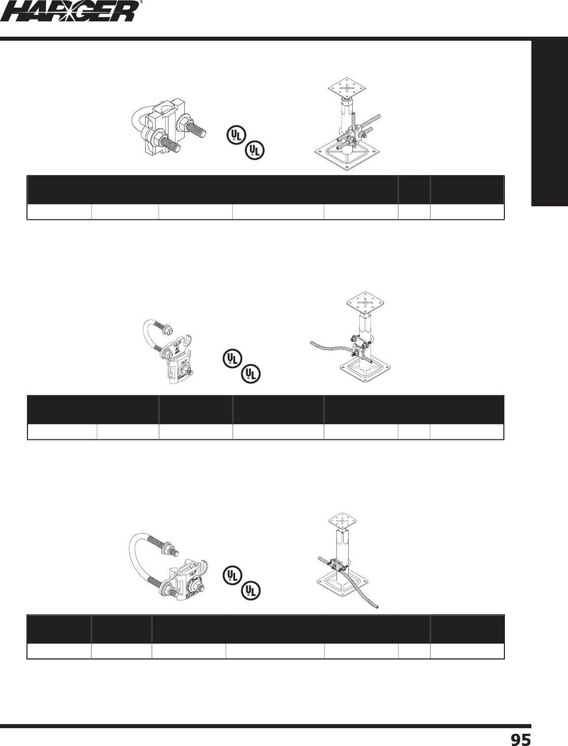
H
ar
g
er Li
g
htnin
g
& Groundin
g
•
©
2012 Phone 847-548-8700 • Fax 847-548-8755 • U.S. 800-842-743
7
9
5
95
Section 1
Grounding Components
•
Electro-tin
p
lated bronze includes stainless steel hardware.
•
Accommodates 3 conductors from #6 AWG u
p
to 4/0, with a maximum
s
in
g
le conductor of 500 MCM or two conductors of 250 MCM.
•
Fits both round and square pedestal le
g
s up to 1" outside diameter.
L
iste
d
9
6
L
iste
d
4
67
L
iste
d
9
6
L
iste
d
4
67
L
iste
d
9
6
L
iste
d
4
67
G
round Pedestal Clamps & Bondin
g
Clamps
•
Electro-tin
p
lated bronze includes stainless steel hardware.
•
Accommodates 2 conductors from #6 AWG u
p
to 250 MCM.
•
Fits round pedestal outside diameter ran
g
e .75" - 1.7".
•
Electro-tin
p
lated bronze includes stainless steel hardware.
•
Accommodates 2 conductors from #6 AWG u
p
to 250 MCM.
•
Fits round pedestal outside diameter ran
g
e 1" - 2.4".
Part No. Tamper
Resistant Material Pedestal
Diameter Range
Pipe Outside
Diameter
Box
Qty.
Approx. Box
Wt. (lbs.)
CPC.5
/
.75
No
T
inne
d
Br
o
nz
e
.5
" - 1"
.3
7
5
" - 1"
5
2-1
/2
Part No. Tamper
Resistant Material Pedestal
Diameter Range
Pipe Outside
Diameter
Box
Qty.
Approx. Box
Wt. (lbs.)
CPC1
/
1.25
No
T
inne
d
Br
o
nz
e
1" - 1.
6
2
5
"
.
7
5
" - 1.7"
5
3
Part No. Tamper
Resistant Material Pedestal
Diameter Range
Pipe Outside
Diameter
Box
Qty.
Approx. Box
Wt. (lbs.)
CPC1.5
/2
No
T
inne
d
Br
o
nze 1.
5
" - 2.
3
7
5
" 1" - 2.4"
5
3-3
/
4
S
ect
io
n 1.6.8
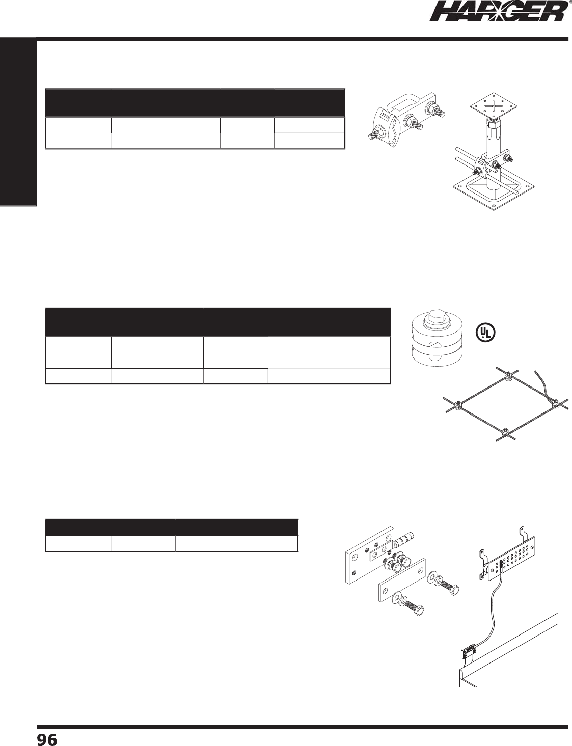
H
ar
g
er Li
g
htnin
g
& Groundin
g
•
©
2012 Phone 847-548-8700 • Fax 847-548-8755 • U.S. 800-842-743
7
9
6
96
Section 1
Grounding Components
G
round Pedestal Clamps & Bondin
g
Clamps
•
U
se
d
when wel
d
e
d
c
o
nnecti
o
ns
a
re n
o
t fe
a
si
b
le.
•
Unique desi
g
n allows clamps to form connections at most any an
g
le.
•
Specifi c uses include fabrication under an existin
g
computer room fl oor.
•
Electro-tin
p
lated brass.
L
iste
d
4
67
Part No. Conductor Size
(AWG) Box Qty. Approx. Box Wt. (lbs.)
CRGC
6
#
6
25
4
C
R
GC
4
#4
1
0
5
CRGC
2
#
2
1
0
5
C
om
p
uter Room Ground Clam
p
s
•
Heav
y
dut
y
bronze clam
p
includes stainless steel hardware.
•
Available electro-tin plated. When orderin
g
, add prefi x T to
p
art number.
•
Fits both round and square pedestal le
g
s up to 1-1/8"
ou
tsi
d
e
d
i
a
meter.
Part No. Conductor
Size (AWG) Box Qty. Approx. Box
Wt. (lbs.)
G
P1M
C
I #6 Sol. thru 2
/
0 Str.
5
2-1
/2
TG
P1M
C
I #6 Sol. thru 2
/
0 Str.
5
2-1
/2
S
ect
io
n 1.6.8 - 1.6.10
Kit Incl
ud
e
s:
(
4
)
CS44S: 1/4"-20 x 1/2" SS hex head ca
p
scre
w
(
4
)
LW4S: 1/4"-20 SS lock washe
r
(
4
)
W4S: 1/4"-20 SS fl at washe
r
(1) GECLB62A: #6 compression lu
g
•
Manufactured from 110 co
pp
er allo
y
.
•
Two piece desi
g
n sandwiches fi rmly secures the
g
round strap.
•
Wall mountin
g
hardware,
g
round bar and conductor not included.
•
Bonds static fl oorin
g
system to the telecommunications bondin
g
and
g
roundin
g
system.
Part No. Box Qty. Approx. Box Wt. (lbs.)
S
FBC
3
KIT 1 1-1
/
4
S
tatic Floor Bondin
g
Clamp Kit
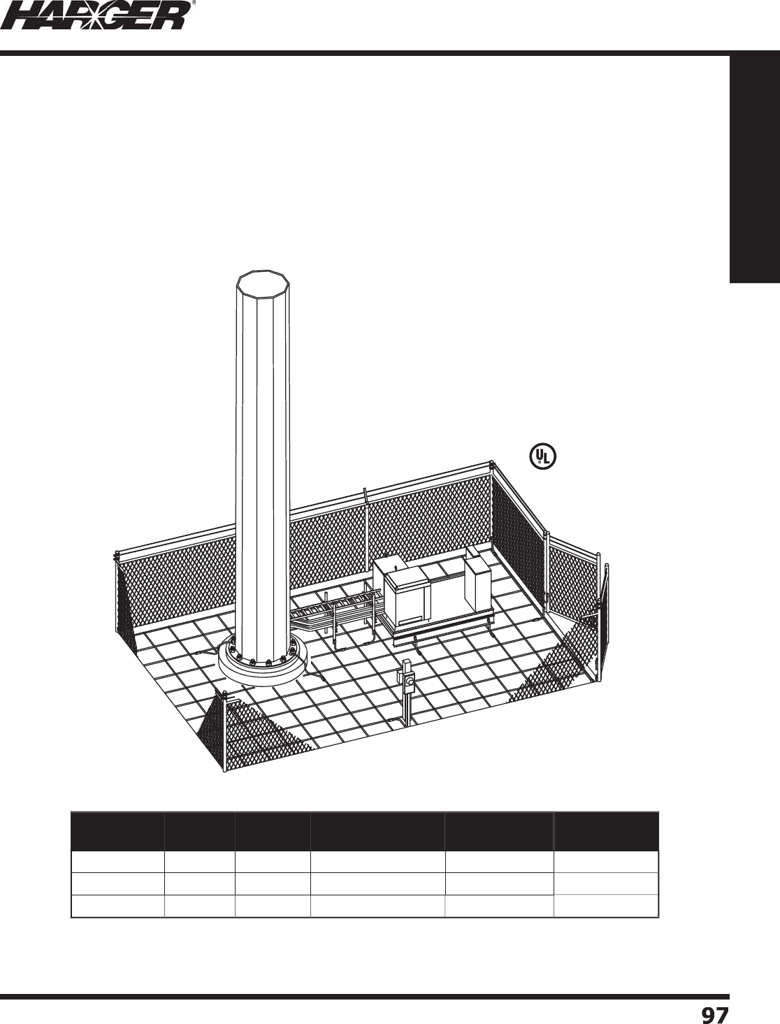
H
ar
g
er Li
g
htnin
g
& Groundin
g
•
©
2012 Phone 847-548-8700 • Fax 847-548-8755 • U.S. 800-842-743
7
9
7
97
Section 1
Grounding Components
P
refabricated wire mesh is a simple cost effective method of enhancin
g
g
round systems.
Applications include improvin
g
the
g
round plane at telecommunications and radio transmittin
g/
receivin
g
facilities and reducin
g
step and touch potentials at power plants and substations. Mesh is
also used where
g
round rods are impossible to drive or are ineffective because of soil conditions.
W
ire mesh is manufactured from solid copper or copper clad steel wire, ran
g
in
g
from #10 AWG
to #4 AWG. Normal spacin
g
between conductors is 4", 6", 8", 12", 24" and 48". All
j
oints are silver
brazed ensurin
g
excellent electrical continuity, corrosion resistance and superior stren
g
th.
S
tan
d
ar
d
Mat Size
s
U
L Listed Prefabricated Co
pp
er Ground Mes
h
•
Other sizes available. Please contact factor
y
for more information.
L
iste
d
4
67
S
ect
io
n 1.6.11
Part No. Width
(ft.)
Length
(ft.)
Conductor
Size/Type (AWG)
Conductor
Spacing (in.)
Approx. Each
Wt. (lbs.)
GM1
25066
1
2
50
6
6
2
14
GM1
2506
1
2
1
2
50
6
1
2
11
7
GM1
25062
4
12
50
6
24
6
9

H
ar
g
er Li
g
htnin
g
& Groundin
g
•
©
2012 Phone 847-548-8700 • Fax 847-548-8755 • U.S. 800-842-743
7
98
98
Section 1
Grounding Components
H
ar
g
er prefabricated wire mesh can be
s
upplied with no overhan
g
, overlappin
g
ends or
butt s
p
lice ends.
N
o Overhan
g
"
Overlappin
g
" end
s
L
iste
d
4
67
L
iste
d
4
67
T
he overlappin
g
end confi
g
uration is desi
g
ned
to allow for side by side connections of ad
j
oinin
g
mats. This t
yp
e of connection
p
rovides the easiest
method of
j
oinin
g
two mesh sections. Addin
g
2"
to one half the conductor spacin
g
provides the
o
verlappin
g
ends. For example, if the mesh size is
6
" square, the overlappin
g
end len
g
th is 5".
You need to fi rst do the calculation for the net wei
g
ht in order to calculate the
g
ross shippin
g
wei
g
ht.
To Calculate Net Weight
g
:
Net Wei
g
ht = Width (ft.) x Len
g
th (ft.) x Table Value (lb/f
t
2
)
To Calculate Gross Shipping Weight
pp g g
:
Gross Wei
g
ht = Net Wei
g
ht + [3.38 x (Mesh Width (ft.) + 1 (ft.))]
Exam
p
le: 10' x 100', #6 Cu Wire T
yp
e, 6" x 6" Cell Size, from table 0.328
(
lb/ft
2
)
Net Wei
g
ht = 10 x 100 x 0.328 = 328 lbs.
Gross Wei
g
ht = 328 + [3.38 x (10 + 1)] = 365 lbs.
Wire TypeWire Type
Mesh Cell Size
Mesh Cell Size
4" x 4"4" x 4"
6" x 6"6" x 6"
8" x 8"8" x 8"
12" x 12"12" x 12"
24" x 24"24" x 24"
24" x 48"24" x 48"
48" x 48"48" x 48"
#1
0
C
u
0
.199
0
.1
32
0
.
0
99
0
.
067
0
.
034
0
.
027
0
.
0
19
8CW3
D
0
.
257
0
.171
0
.1
2
9
0
.08
7
0
.
0
4
5
0
.
035
0
.
024
#8 Cu
0
.
3
1
2
0
.208
0
.1
57
0
.1
06
0
.
055
0
.
0
4
2
0
.
030
6
CW
3D
0
.4
5
1
0
.
30
1
0
.
227
0
.1
53
0
.080
0
.
06
1
0
.
0
4
3
#
6
C
u
0
.491
0
.328
0
.248
0
.1
67
0
.08
7
0
.
067
0
.
0
4
7
#4
Cu
0
.77
5
0
.
5
19
0
.
3
9
2
0
.
265
0
.138
0
.1
06
0
.
0
7
5
U
L Listed Prefabricated Co
pp
er Ground Mes
h
Mesh Net Wei
g
ht in Pounds per Square Foot
S
ect
io
n 1.6.11
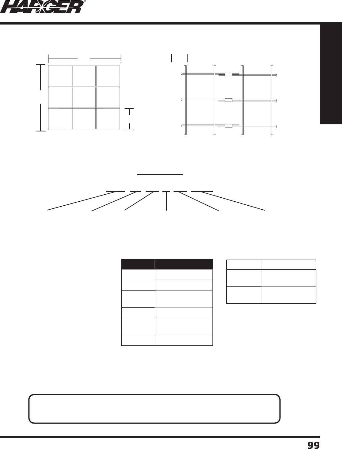
H
ar
g
er Li
g
htnin
g
& Groundin
g
•
©
2012 Phone 847-548-8700 • Fax 847-548-8755 • U.S. 800-842-743
7
99
99
Section 1
Grounding Components
D
ON’T COUNT THE OVERHANG FOR TOTAL LENGTH/WIDT
H
S
tan
d
ar
d
Me
sh
C
onfi
g
urations
W
ire Size: #4, #6, #8, #10 AWG
S
o
li
d
C
o
n
du
ct
or
W
ire T
yp
e: Pure co
pp
er or co
pp
er clad
(
30% conductivit
y)
M
esh Size: 4" square throu
g
h 48" square
in 4"
a
n
d
6
" increment
s
Co
nduct
o
rs
N
o Overhan
g
OC
’’
Overlappin
g
end
s
O
E’’
L
’
W’
Part No. Type
4
S
olid Co
pp
e
r
6
S
olid Co
pp
e
r
6
CW
3D
Co
pp
er Clad
30% Conductivit
y
8
S
olid Co
pp
e
r
8CW3
D
Co
pp
er Clad
30% Conductivit
y
1
0
S
olid Co
pp
e
r
End T
yp
e Descr
ip
t
i
o
n
O
E1 Overlappin
g
End
,
Overhan
g
1 End
O
E
2
Overlappin
g
End
,
Overhan
g
2 End
s
C
o
pp
er Ground Mesh Worksheet
G
M 12 46 6 24 OE
1
Example
p
Gr
ou
n
d
Mes
h
W
i
d
t
h
(
ft.
)
L
en
g
t
h
(
ft.
)
C
o
n
du
ct
or
S
ize/T
yp
e
O
.C. Spacin
g
(
in.
)
E
nd T
yp
e
N
O
TES
:
• Overlappin
g
ends are equal to 1/2 the O.C. spacin
g
plus 2" unless specifi ed otherwise.
• 40% DSA conductor available. Please contact factor
y
for more information.
S
ect
io
n 1.6.12
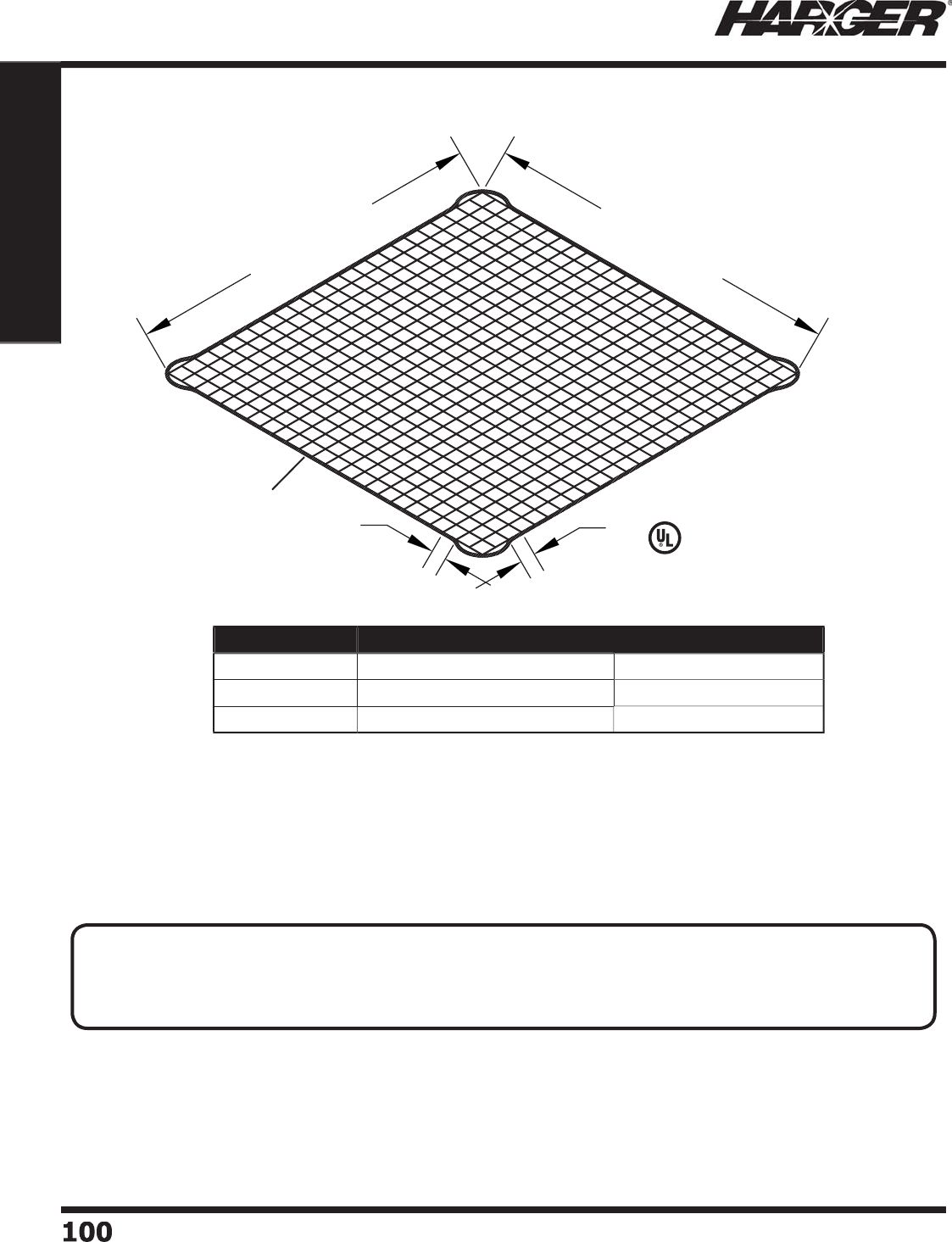
H
ar
g
er Li
g
htnin
g
& Groundin
g
•
©
2012 Phone 847-548-8700 • Fax 847-548-8755 • U.S. 800-842-743
7
100100
Section 1
Grounding Components
12'-0"
12'-0"
6"
6"
•
12' x 12' prefabricated wire
g
roundin
g
mesh with 6" squares made
from #6 AWG solid co
pp
er.
•
Available with a tinned
p
erimeter conductor exothermicall
y
welded
t
o
mesh.
•
Mesh is silver brazed at all crossovers usin
g
a 15% or 35% silver
brazin
g
alloy and a non-corrosive fl ux.
L
iste
d
4
67
Pe
rim
e
t
er
C
o
n
du
ct
or
Part No. Perimeter Conductor (AWG) Approx. Each Wt. (lbs.)
GM1
2
1
266
No
n
e
50
GM1
2
1
266
P
2
T
2
T
60
GM1
2
1
266
SPR1
2
4/
0-19T 81
C
o
pp
er Ground Mes
h
APPLICATI
O
N N
O
TES
:
• For enhancin
g
external
g
roundin
g
systems at radio, pa
g
in
g
, cellular, etc. transmittin
g
/receivin
g
facilities.
• If strate
g
ically placed, mesh can be used as a safety ad
j
unct to reduce dan
g
erous step and touch potentials.
• Perimeter conductor makes for easy attachment to
g
round conductors.
S
ect
io
n 1.6.13
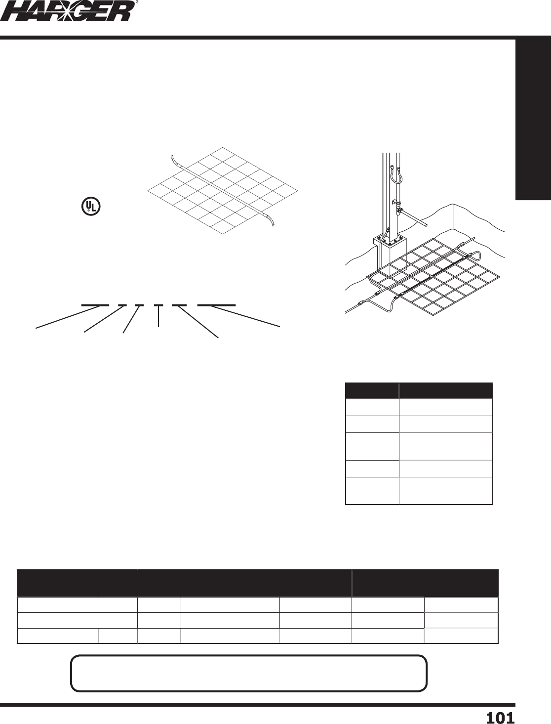
H
ar
g
er Li
g
htnin
g
& Groundin
g
•
©
2012 Phone 847-548-8700 • Fax 847-548-8755 • U.S. 800-842-743
7
10
1
101
Section 1
Grounding Components
H
ar
g
er personnel safety mats are desi
g
ned to protect a
g
ainst "touch potentials" under fault
conditions. Listed below are standard mat confi
g
urations, however mats can be customized by
u
tilizin
g
the personnel safety mat numberin
g
system. The followin
g
example is a safety mat that is
6
' wide x 6' lon
g
made up of #6 solid copper conductor. Conductors are spaced every 12" and the
mat has a 1
/
0 AWG solid center wire.
S
tandard Mat Confi
g
urations
M
at Size: 4' x 4', 4' x 6', 6' x 6', 6' x 8
'
W
ire Size: #4, #6, #8 AWG Solid Conducto
r
W
ire T
yp
e: Pure co
pp
er or co
pp
er clad steel
(
30% conductivit
y)
M
esh Size: 2" square throu
g
h 12" square in 2" increment
s
Center Wire: Optional - See Pa
g
e 11, Section 1.1 for conductors
available. Comes with standard 6" overhan
g
on
bo
th si
d
es
o
f m
a
t.
L
iste
d
4
67
Personnel Safet
y
Mat
Numberin
g
Syste
m
P
SM 6 6 6 12 C1
/
0
S
Conductor Spacin
g
(
in.
)
(
Mesh Size
)
O
p
tional
C
enter Wire
C
o
n
du
ct
o
r
S
ize/T
yp
e
L
en
g
t
h
(
ft.
)
W
i
d
t
h
(
ft.
)
P
ers
o
nnel
S
afet
y
Ma
t
Part No. Type
4
S
olid Co
pp
e
r
6
S
olid Co
pp
e
r
6
CW
3D
Co
pp
er Clad
30% Conductivit
y
8
S
olid Co
pp
e
r
8CW3
D
Co
pp
er Clad
30% Conductivit
y
Part No. Width
(ft.)
Length
(ft.)
Conductor
Size/Type (AWG)
Conductor
Spacing (in.)
Optional
Center Wire
Approx. Each
Wt. (lbs.)
P
SM4666C1
/
0
S
4
6
6
6
1
/
0 Sol. 11
P
SM4644C2
/
0
4
6
4
4
2
/
0
23
P
SM61066C4
/
0
S
6
1
0
6
6
4/
0 Sol.
26
Personnel Safet
y
Mats
Co
nduct
o
rs
S
tan
d
ar
d
Mat Size
s
N
O
TES
:
•
40% DSA conductor available. Please contact factor
y
for more information.
S
ect
io
n 1.6.1
4

H
ar
g
er Li
g
htnin
g
& Groundin
g
•
©
2012 Phone 847-548-8700 • Fax 847-548-8755 • U.S. 800-842-743
7
10
2
102
Section 1
Grounding Components
No
tes

H
ar
g
er Li
g
htnin
g
& Groundin
g
•
©
2012 Phone 847-548-8700 • Fax 847-548-8755 • U.S. 800-842-743
7
103
103
Section 1
Grounding Components
S
ect
io
n 1.7
Bondin
g
Straps/Bondin
g
Jumpers
In
d
ex
Descr
i
pt
i
on Pa
g
e
1.7.1 Bondin
g
Strap Numberin
g
System
......................................................
1
04
1.7.2 One Hole Tinned Flat Braid Copper Bondin
g
Strap
s
.............................
1
05
1.7.3 Two Hole Tinned Flat Braid Copper Bondin
g
Strap
s
.............................
1
06
1.7.4 One Hole Bare Copper Braid Bondin
g
Strap & Ki
t
................................
1
07
1.7.5 Bondin
g
/Groundin
g
Straps Numberin
g
System
....................................
108
1.7.6 Bondin
g
/Groundin
g
Strap
s
................................................................
108
1.7.7 Bondin
g
Jumper Numberin
g
System
...................................................
1
0
9
1.7.8 One Hole Bondin
g
Jumpers & Kit
s
......................................................
1
0
9
1.7.9 Bondin
g
Jumper Ki
t
..........................................................................
11
0
1.7.10 Two Hole Insulated Bondin
g
Jumper & Kit
s
.........................................
11
0
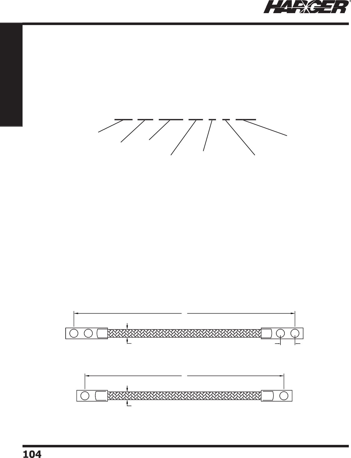
H
ar
g
er Li
g
htnin
g
& Groundin
g
•
©
2012 Phone 847-548-8700 • Fax 847-548-8755 • U.S. 800-842-743
7
104104
Section 1
Grounding Components
B
ondin
g
straps are constructed from fl exible tinned copper fl at braid. Available with one or two
hole compression lu
g
s. Har
g
er offers a variety of len
g
ths and styles. Customizin
g
your own straps
i
s simple with Har
g
er's bondin
g
strap numberin
g
system. To desi
g
n your own custom bondin
g
strap
s
imply follow the steps outlined below. The followin
g
example is a 1/2" wide, .094" thick, 12" lon
g
bondin
g
strap usin
g
2 hole compression lu
g
s with 1" O.C. spacin
g
between 3/8" bolt holes.
1. Width of braid stra
p
2. Thickness of braid stra
p
3. Len
g
th of braid strap (O.C. from lu
g
hole
)
4
. S
p
ecifi es one or two holes
p
er side of stra
p
5
. O.C. Spacin
g
between Bolt Hole on 2 Hole Lu
gs
A=5/8", B=3/4", C=1", D=1-3/4"
6
. B
o
lt h
o
le siz
e
Bondin
g
Strap Numberin
g
Syste
m
L
L
w
wO.C.
SPACING
GS 12 094 12 2 C 3
/
8
W
i
d
t
h
(
in.
)
L
en
g
t
h
(
in.
)
No
.
of
Ho
les
p
er side
O
.C. Spacin
g
b
etween B
o
lt H
o
le
o
n 2 Hole Lu
gs
T
hi
c
kn
ess
(
in.
)
Bo
lt H
a
r
d
w
a
re
S
iz
e
B
ondin
g
S
tra
p
S
ect
io
n 1.7.1
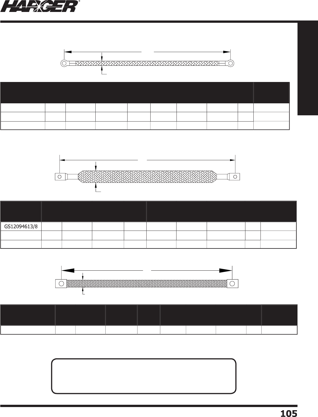
H
ar
g
er Li
g
htnin
g
& Groundin
g
•
©
2012 Phone 847-548-8700 • Fax 847-548-8755 • U.S. 800-842-743
7
105
105
Section 1
Grounding Components
•
"R" indicates Rin
g
Lu
g
.
L
W
L
W
Part No. Braid
Width Thickness
Gauge
Equivalent
(AWG)
Length
No. of
Holes
Per Side
Hardware
Size
Approx.
Each
Wt. (lbs.)
Box
Qty.
Approx. Box
Wt. (lbs.)
GS140306R13
/
81
/
4"
.030
"1
4
6
"1 3
/
8" 1
/2
1
0
5
GS1403012R13
/
81
/
4"
.030
"1
4
12" 1 3
/
8" 1
/2
1
0
5
GS1403024R13
/
81
/
4"
.030
"1
4
24" 1 3
/
8" 1
/2
1
0
5
O
ne Hole Tinned Flat Braid Copper Bondin
g
Straps
Part No. Braid
Width Thickness
Gauge
Equivalent
(AWG)
Length
No. of
Holes
Per Side
Hardware
Size
Approx. Each
Wt. (lbs.)
Box
Qty.
Approx. Box
Wt. (lbs.)
1
/
2"
.0
94"
6
6
"1 3
/
8" 1
/2
1
0
5
GS120941213
/
81
/
2"
.0
94"
6
12" 1 3
/
8" 1
/2
1
0
5
GS120942413
/
81
/
2"
.0
94"
6
24" 1 3
/
8" 1
/2
1
0
5
Part No. Braid
Width Thickness
Gauge
Equivalent
(AWG)
Length
No. of
Holes
Per Side
Hardware
Size
Approx.
Each
Wt. (lbs.)
Box
Qty.
Approx. Box
Wt. (lbs.)
GS5806215.188PTM
W
5/
8"
.062
81
5
.2" 1 7
/
16" 1
/
41
0
2-1
/2
L
W
APPLICATI
O
N N
O
TES
:
• Dimensi
o
ns
a
re n
o
min
a
l sizes.
• See pa
g
e 104 for strap dimensions.
• Other sizes available. Please contact factor
y
for more information.
S
ect
io
n 1.7.2
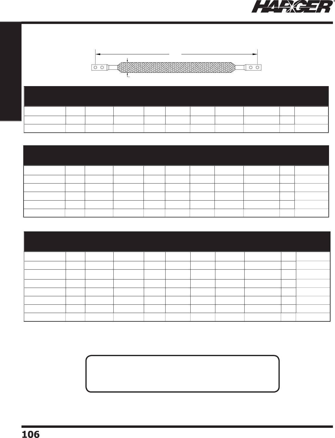
H
ar
g
er Li
g
htnin
g
& Groundin
g
•
©
2012 Phone 847-548-8700 • Fax 847-548-8755 • U.S. 800-842-743
7
106106
Section 1
Grounding Components
L
W
Part No. Braid
Width Thickness
Gauge
Equivalent
(AWG)
Length
No. of
Holes
Per Side
O.C.
Spacing
Hardware
Size
Approx. Each
Wt. (lbs.)
Box
Qty.
Approx. Box
Wt. (lbs.)
GS14030102A1
/
41
/
4"
.030
"1
4
1
0
"
2
5/
8" 1
/
4" 1
/2
1
0
5
GS14030162A1
/
41
/
4"
.030
"1
4
1
6
"
2
5/
8" 1
/
4" 1
/2
1
0
5
GS14030242A1
/
41
/
4"
.030
"1
4
24"
2
5/
8" 1
/
4" 1
/2
1
0
5
Two Hole Tinned Flat Braid Copper Bondin
g
Straps
Part No. Braid
Width Thickness
Gauge
Equivalent
(AWG)
Length
No. of
Holes
Per Side
O.C.
Spacing
Hardware
Size
Approx. Each
Wt. (lbs.)
Box
Qty.
Approx. Box
Wt. (lbs.)
GS34062122A1
/
43
/
4"
.06
2"
6
12"
2
5/
8" 1
/
4" 1
/2
1
0
5
GS34062122C3
/
83
/
4"
.06
2"
6
12"
2
1" 3
/
8" 1
/2
1
0
5
GS34062182A1
/
43
/
4"
.06
2"
6
18"
2
5/
8" 1
/
4" 1
/2
1
0
5
GS34062182C3
/
83
/
4"
.06
2"
6
18"
2
1" 3
/
8" 1
/2
1
0
5
GS34062242A1
/
43
/
4"
.06
2"
6
24"
2
5/
8" 1
/
4" 1
/2
1
0
5
GS34062242C3
/
83
/
4"
.06
2"
6
24"
2
1" 3
/
8" 1
/2
1
0
5
GS34062302A1
/
43
/
4"
.06
2"
6
30
"
2
5/
8" 1
/
4" 1
/2
1
0
5
GS34062302C3
/
83
/
4"
.06
2"
6
30
"
2
1" 3
/
8" 1
/2
1
0
5
Part No. Braid
Width Thickness
Gauge
Equivalent
(AWG)
Length
No. of
Holes
Per Side
O.C.
Spacing
Hardware
Size
Approx. Each
Wt. (lbs.)
Box
Qty.
Approx. Box
Wt. (lbs.)
GS12094122A1
/
41
/
2"
.0
94"
6
12"
2
5/
8" 1
/
4" 1
/2
1
0
5
GS12094122C3
/
81
/
2"
.0
94"
6
12
"
2
1
"3
/
8" 1
/2
1
0
5
GS12094182A1
/
41
/
2"
.0
94"
6
18"
2
5/
8" 1
/
4" 1
/2
1
0
5
GS12094182C3
/
81
/
2"
.0
94"
6
18"
2
1" 3
/
8" 1
/2
1
0
5
GS12094242A1
/
41
/
2"
.0
94"
6
24"
2
5/
8" 1
/
4" 1
/2
1
0
5
GS12094242C3
/
81
/
2"
.0
94"
6
24"
2
1" 3
/
8" 1
/2
1
0
5
APPLICATI
O
N N
O
TES
:
• Dimensi
o
ns
a
re n
o
min
a
l sizes.
• See pa
g
e 104 for strap dimensions.
• Other sizes available. Please contact factor
y
for more information.
S
ect
io
n 1.7.3
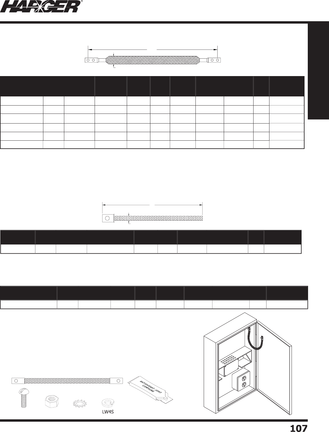
H
ar
g
er Li
g
htnin
g
& Groundin
g
•
©
2012 Phone 847-548-8700 • Fax 847-548-8755 • U.S. 800-842-743
7
10
7
107
Section 1
Grounding Components
•
Dimensi
o
ns
a
re n
o
min
a
l sizes.
•
See pa
g
e 104 for strap dimensions.
•
Other sizes available. Please contact factor
y
for more information.
L
W
Part No. Braid
Width Thickness
Gauge
Equivalent
(AWG)
Length No. of
Holes
O.C.
Spacing
Hardware
Size
Approx.
Each
Wt. (lbs.)
Box
Qty.
Approx. Box
Wt. (lbs.)
GS1062122A1
/4
1"
.06
2"
4
12"
2
5/
8" 1
/
4" 1
/2
1
0
5
GS1062122C3
/
81"
.06
2"
4
12"
2
1" 3
/
8" 1
/2
1
0
5
GS1062182A1
/4
1"
.06
2"
4
18"
2
5/
8" 1
/
4" 1
/2
1
0
5
GS1062182C3
/
81"
.06
2"
4
18"
2
1" 3
/
8" 1
/2
1
0
5
GS1062242A1
/4
1"
.06
2"
4
24"
2
5/
8" 1
/
4" 1
/2
1
0
5
GS1062242C3
/
81"
.06
2"
4
24"
2
1" 3
/
8" 1
/2
1
0
5
Two Hole Tinned Flat Braid Copper Bondin
g
Straps
Part No. Braid
Width Thickness Gauge
Equivalent (AWG) Length No. of
Holes
Hardware
Size
Approx. Each
Wt. (lbs.)
Box
Qty.
Approx. Box
Wt. (lbs.)
GS58101TIE 7
/
16"
.0
7
0
"
7
1
0
"1 7
/
16" 1
/
41
0
2-1
/2
Part No. Braid
Width Thickness Length No. of
Holes
O.C.
Spacing
Hardware
Size
Approx. Each
Wt. (lbs.)
Box
Qty.
Approx. Box
Wt. (lbs.)
GS438070BF1014KIT 7
/
16"
.0
7
0
"1
0
" 1 10-1
/
8" 1
/
4" 1
/4
1
0
2-1
/2
O
ne Hole Bare Copper Braid Bondin
g
Strap Kit
O
ne Hole Bare Copper Braid Bondin
g
Strap
•
Other sizes available. Please contact factor
y
for more information.
Kit Incl
ud
e
s:
(1) GS438070BF1014: copper fl at braid bondin
g
strap
(
1
)
HAAJC1/2: aluminum antioxidant 1/2 oz. tube
(
2
)
N420S: 1/4"-20 x 1/2" stainless steel hex nut scre
w
(
2
)
MS44S: 1/4"-20 x 1/2" stainless steel machine scre
w
(
2
)
LW4S: 1/4" stainless steel s
p
lit lock washe
r
(
2
)
SW4S: 1/4" star lock washe
r
GS438070BF1014
H
AAJC1
/2
N
4
20S
MS
44
S
S
W4
S
L
W
S
ect
io
n 1.7.3 & 1.7.
4

H
ar
g
er Li
g
htnin
g
& Groundin
g
•
©
2012 Phone 847-548-8700 • Fax 847-548-8755 • U.S. 800-842-743
7
1
08
108
Section 1
Grounding Components
C
hart A
S
tan
d
ar
d
Terminal Wi
d
t
h
R
= 3
/
4"
S
= 1"
T
= 1-3
/
8"
U
= 1-1
/
4"
V = 1-1
/
2"
W
= 1-3
/
4"
X
= 2"
Y = 2-3
/
8"
Z =
3
"
C
hart B
Hole O.C. Spacing
pg
A = 1
/
2"
B
= 3
/
4"
C
= 1"
D
= 1-3
/
4"
E
= 1-1
/
4"
F
= 1-1
/
2"
Part No. Number
of Braids
Terminal
Width
Length Terminal
End to End
Hole O.C.
Spacing
Hardware
Size Qty. Approx. Each
Wt. (lbs.)
B
GS1S12D3
/
8 1 1" 12" 1-3
/
4" 3
/
8"
EA
1
/2
B
GS1S24E3
/
8 1 1" 24" 1-1
/
4" 3
/
8"
EA
1
B
GS2S12E1
/2
2
1" 12" 1-1
/
4" 1
/
2"
EA
1
B
GS1V12F1
/2
1 1-1
/
2" 12" 1-1
/
2" 1
/
2"
EA
1
/2
B
GS1V18D1
/2
1 1-1
/
2" 18" 1-3
/
4" 1
/
2"
EA
3
/4
•
Terminal ends come tinned as standard. Bare, silver, nickel are available.
•
Br
a
i
d
c
o
mes tinne
d
a
s
a
st
a
n
da
r
d
.
•
Other sizes are available. Please contact factor
y
for more information.
Bondin
g
/Groundin
g
Straps Numberin
g
Syste
m
BGS 1 S 12 D 3/8
Nu
m
b
er
o
f Br
a
i
ds
T
ermin
a
l Wi
d
t
h
(
in.
)
(
See Chart A Below
)
L
en
g
th
(
in.
)
(
includin
g
terminal
)
/
Ha
r
d
w
a
re
S
ize
B
ondin
g
Groundin
g
S
tra
p
Ho
le
O
.C.
S
pacin
g
(
in.
)
(
See Chart B Below
)
S
ect
io
n 1.7.5 & 1.7.6
Bondin
g
/Groundin
g
Straps
W
B
L
A
L
W
B
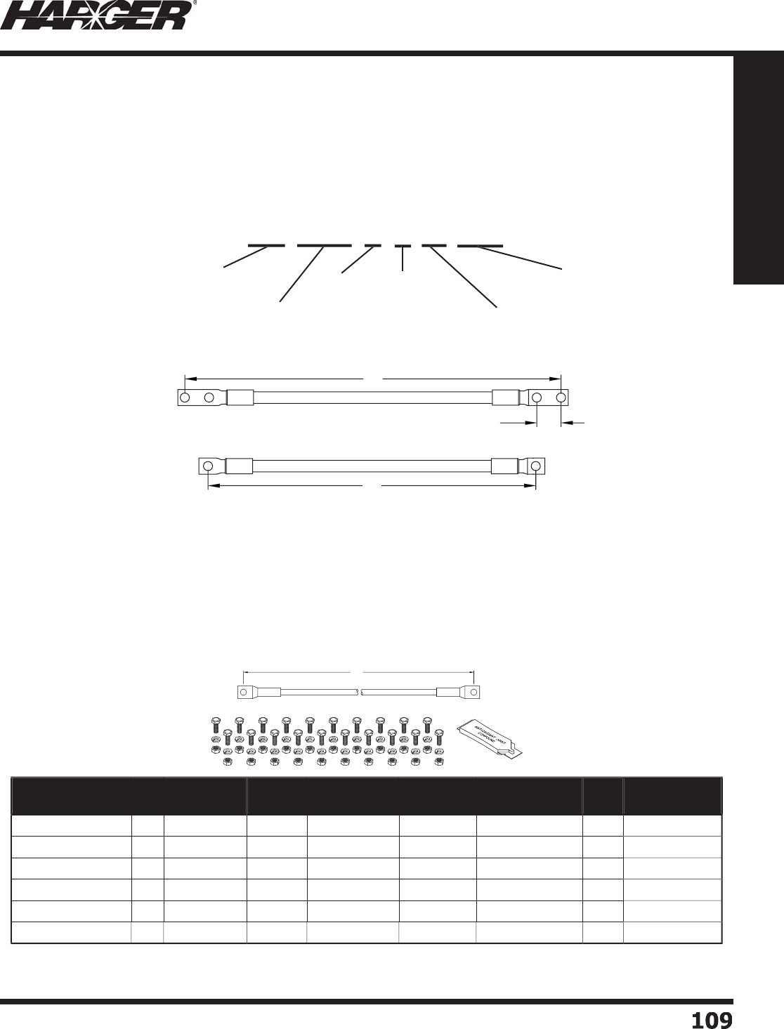
H
ar
g
er Li
g
htnin
g
& Groundin
g
•
©
2012 Phone 847-548-8700 • Fax 847-548-8755 • U.S. 800-842-743
7
10
9
109
Section 1
Grounding Components
B
ondin
g
j
umpers are constructed from round conductors, insulated or bare. Available with one or two
hole compression lu
g
s. Har
g
er offers a variety of len
g
ths and styles. Customizin
g
your own
j
umper is
s
imple with Har
g
er's bondin
g
j
umper numberin
g
system. To desi
g
n your own custom bondin
g
j
umper
s
imply follow the steps outlined below. The followin
g
example is a #6-7 AWG
g
reen conductor, 6"
l
on
g
with 2 hole compression lu
g
s that have 5/8" O.C. spacin
g
between 1/4" bolt holes.
1. Conductor t
ype
2. Len
g
th of bondin
g
j
umpe
r
3. Specifi es one or two holes per side of
j
umpe
r
4
. O.C. Spacin
g
between Bolt Hole on 2 Hole Lu
gs
A=5/8", B=3/4", C=1", D=1-3/4"
5
. B
o
lt h
a
r
d
w
a
re siz
e
GJ 67G 6 2 A 1
/4
L
en
g
t
h
(
in.
)
No
.
of
Ho
les
P
er Si
de
O
.C. Spacin
g
b
etween B
o
lt H
o
le
o
n 2 Hole Lu
gs
Bo
lt H
a
r
d
w
a
re
S
ize
C
o
n
du
ct
o
r
Typ
e
Bondin
g
Jumper Numberin
g
Syste
m
•
#6 AWG x 7 Strand Green THW insulation. Kit includes all necessar
y
hardware.
•
Other sizes and t
yp
es available. Please contact factor
y
for more information.
Part No. Kit Conductor
Type Length No. of Holes
Per Side
Hardware
Size
Approx. Each
Wt. (lbs.)
Box
Qty.
Approx. Box
Wt. (lbs.)
GJ67G1211
/
4
No
6
7
G
12" 1 1
/
4" 1
/
41
0
5
GJ67G1211
/
4KIT5
Yes
6
7
G
12" 1 1
/
4" 1-1
/4
5
6
-1
/
4
GJ67G1811
/
4
No
6
7
G
18" 1 1
/
4" 1
/
41
0
5
GJ67G1811
/
4KIT5
Yes
6
7
G
18" 1 1
/
4" 1-1
/4
5
6
-1
/
4
GJ67G2411
/
4
No
6
7
G
24" 1 1
/
4" 1
/
41
0
5
GJ67G2411
/
4KIT5
Yes
6
7
G
24" 1 1
/
4" 1-1
/4
5
6
-1
/
4
O
ne Hole Bondin
g
Jumpers & Kits
S
ect
io
n 1.7.7 & 1.7.8
B
ondin
g
J
um
p
e
r
L
O.C. Spacing
L
L
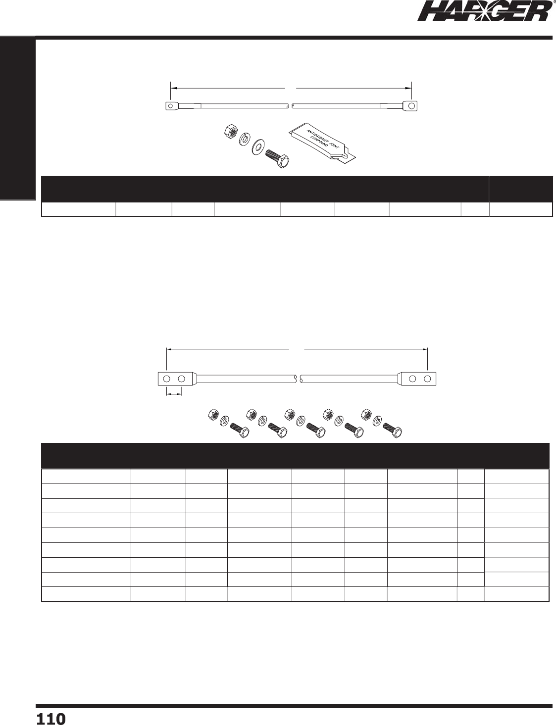
H
ar
g
er Li
g
htnin
g
& Groundin
g
•
©
2012 Phone 847-548-8700 • Fax 847-548-8755 • U.S. 800-842-743
7
1
1
0110
Section 1
Grounding Components
•
#6 AWG x 7 Strand Green THW insulation. Kit includes all necessar
y
hardware.
•
Spacin
g
between bolt holes is 5/8" on center.
•
Other sizes and t
yp
es available. Please contact factor
y
for more information.
Part No. Conductor
Type Length No. of Holes
Per Side
Hardware
Size
Jumper
or Kit
Approx. Each
Wt. (lbs.)
Box
Qty.
Approx. Box
Wt. (lbs.)
GJ67G82A1
/
4
6
7
G
8"
2
1
/
4"
J
um
p
e
r
1
/
81
0
1-1
/
4
GJ67G82A1
/
4KIT
6
7
G
8"
2
1
/
4"
K
i
t
1
/
81
0
1-1
/
4
GJ67G82A1
/
4KIT5
6
7
G
8"
2
1
/
4"
K
i
t
3
/
4
5
3-3
/
4
GJ67G102A1
/
4
6
7
G
1
0
"
2
1
/
4"
J
um
p
e
r
1
/
41
0
2-1
/2
GJ67G102A1
/
4KIT
6
7
G
1
0
"
2
1
/
4"
K
i
t
1
/
41
0
2-1
/2
GJ67G102A1
/
4KIT5
6
7
G
1
0
"
2
1
/
4"
K
i
t
1-1
/
4
5
6
-1
/
4
GJ67G122A1
/
4
6
7
G
12"
2
1
/
4"
J
um
p
e
r
1
/
41
0
2-1
/2
GJ67G122A1
/
4KIT
6
7
G
12"
2
1
/
4"
K
i
t
1
/
41
0
2-1
/2
GJ67G122A1
/
4KIT5
6
7
G
12"
2
1
/
4"
K
i
t
1-1
/
4
5
6
-1
/
4
Two Hole Insulated Bondin
g
Jumpers & Kits
Bondin
g
Jumper Kit
Part No. Conductor
Type Length No. of Holes
Per Side
Hardware
Size A
Hardware
Size B
Approx. Each
Wt. (lbs.)
Box
Qty.
Approx. Box
Wt. (lbs.)
GJ
6
7G7
2
EMSKIT
6
7
G
73-1
/
4" 1 1
/
4" 3
/
8"
2
5
1
0
•
#6 AWG x 7 strand
g
reen THW insulated.
•
Bondin
g
Jumper for 1/4" stud to
g
round bar or
g
round metal body.
•
Includes 1/2 ounce antioxidant
(
HAAJC1/2
)
and 3/8" hardware.
S
ect
io
n 1.7.9 & 1.7.10
L
O.C. Spacing
L
AB

H
ar
g
er Li
g
htnin
g
& Groundin
g
•
©
2012 Phone 847-548-8700 • Fax 847-548-8755 • U.S. 800-842-743
7
111
111
Section 1
Grounding Components
S
ect
io
n 1.8
C
ompress
i
on Lu
g
s, Connectors
&
T
oo
ls
In
d
ex
Descr
i
pt
i
on Pa
g
e
1.8.1 One Hole Compression Lu
gs
..............................................................
112
1.8.2 Specialized Compression Lu
gs
...........................................................
11
2
1.8.3 Two Hole Lon
g
Barrel Compression Lu
gs
............................................
11
3
1.8.4 Slotted Lon
g
Barrel Compression Lu
gs
...............................................
11
4
1.8.5 C-T
yp
e Com
p
ression Ta
ps
..................................................................
114
1.8.6 Mechanical Com
p
ression Tool
s
...........................................................
11
5
1.8.7 H
y
draulic Com
p
ression Tools & Die
s
...................................................
11
6
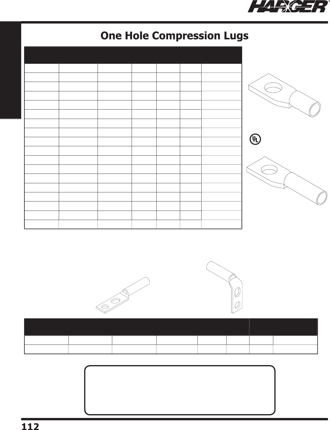
H
ar
g
er Li
g
htnin
g
& Groundin
g
•
©
2012 Phone 847-548-8700 • Fax 847-548-8755 • U.S. 800-842-743
7
1
12
112
Section 1
Grounding Components
L
isted 486
S
pecialized Compression Lu
g
s
Part No. Conductor
Size (AWG)
Hardware
Size
Long
Barrel
Color
Code
Box
Qty.
Approx. Box
Wt. (lbs.)
GECL
6
6
1
/
4"
No
B
l
u
e
50
1
GECLB
6
6
1
/
4"
Yes
B
l
u
e
50
1-1
/2
GECL63
/
8
6
3
/
8"
No
B
l
u
e
50
2
GECLB63
/
8
6
3
/
8"
Yes
B
l
u
e
50
1-1
/2
G
E
C
L4
4
1
/
4"
No
G
ra
y
50
1-1
/2
G
E
C
LB4
4
1
/
4"
Yes
G
ra
y
50
2
GECL
2
2
5/
16"
No
B
r
o
w
n
50
2
GECLB
2
2
5/
16"
Yes
B
r
o
w
n
50
2
GECL23
/
8
2
3
/
8"
No
B
r
o
w
n
50
2
GECLB23
/
8
2
3
/
8"
Yes
B
r
o
w
n
50
2
GECL21
/
4
2
1
/
4"
No
B
r
o
w
n
50
2
GECLB21
/
4
2
1
/
4"
Yes
B
r
o
w
n
50
2
GECL1
/
01
/
03
/
8"
No
P
ink 1
0
1
/2
GECLB1
/
01
/
03
/
8"
Yes
P
ink 1
0
1
GECL2
/
02
/
03
/
8"
No
B
l
a
ck 1
0
1
GECLB2
/
02
/
03
/
8"
Yes
B
l
a
ck 1
0
2
GECL4
/
0
4/
01
/
2"
No
P
ur
p
le 1
0
1
GECLB4
/
0
4/
01
/
2"
Yes
P
ur
p
le 1
0
3
S
t
a
n
da
r
d
B
a
rrel
L
on
g
Barrel
Part No. Conductor
Size (AWG)
Hole Spacing
Range
Hardware
Size
Bend
Angle
Color
Code
Box
Qty.
Approx. Box
Wt. (lbs.)
GECLB
62
EIA #
6
o
r #
6
FLEX
.5
" - .
6
2
5
"1
/
4"
No
Ben
d
B
l
ue
50
1-1
/2
GECLB
62
EIA9
0
#
6
o
r #
6
FLEX
.5
" - .
6
2
5
"1
/
4"
90
˚
B
l
ue
50
1-1
/2
•
Desi
g
ned to fi t standard EIA spacin
g
.
GECLB
62
EIA GECLB
62
EIA9
0
N
O
TES
:
• Manufactured from electro
p
lated tinned co
pp
er.
• For use on co
pp
er or tinned co
pp
er conductors.
• Lu
g
s have inspection ports.
• Other sizes available. Please contact factor
y
for more information.
• See pa
g
e 148 for antioxidants.
S
ect
io
n 1.8.1 & 1.8.2
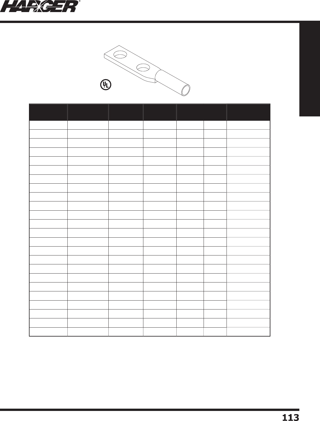
H
ar
g
er Li
g
htnin
g
& Groundin
g
•
©
2012 Phone 847-548-8700 • Fax 847-548-8755 • U.S. 800-842-743
7
1
1
3
113
Section 1
Grounding Components
•
Manufactured from electro
p
lated tinned co
pp
er.
•
For use on co
pp
er or tinned co
pp
er conductors.
•
Lu
g
s have inspection ports.
•
Other sizes available. Please contact factor
y
for more information.
•
For copper exothermic lu
g
s, see pa
g
es 314-315 (SXL, OXL, BXL & JXL
)
•
See pa
g
e 148 for antioxidants.
L
isted 486
Part No. Conductor
Size (AWG)
O.C. Dim.
B/T Holes
Hardware
Size
Color
Code
Box
Qty.
Approx. Box
Wt. (lbs.)
GECLB
62
A
6
.6
2
5
"1
/
4"
B
l
ue
50
1-1
/2
GECLB
62
B
6
.
7
5
"3
/
8"
B
l
ue
50
2
GECLB
62
C
6
1" 3
/
8"
B
l
ue
50
2
GECLB4
2
A
4
.6
2
5
"1
/
4"
G
ra
y
25
1-1
/2
GECLB4
2
B
4
.
7
5
"1
/
4"
G
ra
y
25
1-1
/2
GECLB4
2
C
4
1" 3
/
8"
G
ra
y
25
2
GECLB
22
A
2
.6
2
5
"1
/
4"
B
r
o
w
n
25
1-1
/2
GECLB
22
B
2
.
7
5
"3
/
8"
B
r
o
w
n
25
1-1
/2
GECLB
22
B
S
2 S
o
l.
.
7
5
"3
/
8"
W
hit
e
25
2
GECLB
22
C
2
1" 3
/
8"
B
r
o
w
n
25
2
GECLB
22
C
S
2 S
o
l. 1" 3
/
8"
W
hit
e
25
2-1
/2
GECLB1
/
02
C
1
/
01"3
/
8"
P
ink 1
0
2
GECLB1
/
02
D
1
/
01.7
5
"1
/
2"
P
ink 1
0
2
GECLB2
/
02
C
2
/
01"3
/
8"
B
l
a
ck 1
0
1-1
/2
GECLB2
/
02
D
2
/
01.7
5
"1
/
2"
B
l
a
ck 1
0
1-1
/2
GECLB3
/
02
C
3
/
01"3
/
8"
O
ran
g
e1
0
2
GECLB4
/
02
C
4/
01"3
/
8"
P
ur
p
le 1
0
2
GECLB4
/
02
D
4/
01.7
5
"1
/
2"
P
ur
p
le 1
0
2-1
/2
GECLB
2502
C
250
1" 3
/
8" Yell
ow
1
0
3
GECLB
2502D
250
1.7
5
"1
/
2" Yell
ow
1
0
4
GECLB
5002
C
500
1" 3
/
8"
B
r
o
w
n
1
0
5
GECLB
5002D
500
1.7
5
"1
/
2"
B
r
o
w
n
1
0
8
GECLB7
502
C7
50
1" 3
/
8"
B
l
a
ck 1
0
1
0
GECLB7
502D
7
50
1.7
5
"1
/
2"
B
l
a
ck 1
0
11
Two Hole Lon
g
Barrel Compression Lu
g
s
S
ect
io
n 1.8.3
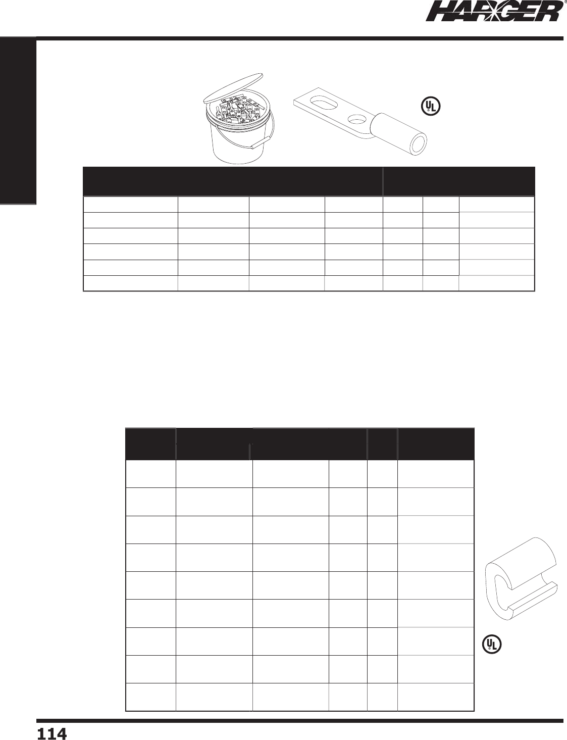
H
ar
g
er Li
g
htnin
g
& Groundin
g
•
©
2012 Phone 847-548-8700 • Fax 847-548-8755 • U.S. 800-842-743
7
114114
Section 1
Grounding Components
Connects two copper conductors to
g
ether with a hydraulic crimp tool.
P
lease refer to the chart for the a
pp
ro
p
riate connector.
Heav
y
Dut
y
C-Ta
p
s
•
Manufactured from electro
p
lated tinned co
pp
er.
•
For use on co
pp
er or tinned co
pp
er conductors.
•
Lu
g
s have inspection ports.
•
250 pack comes in one
g
allon bucket.
Part No. Conductor
Size (AWG)
Hole Spacing
Range
Hardware
Size
Color
Codes
Box
Qty.
Approx. Box
Wt. (lbs.)
GECLB
62
BC #
6
Str.
.
7
5
" t
o
1" 3
/
8"
B
l
ue
50
2
GECLB
62
BC
250
BK #
6
Str.
.
7
5
" t
o
1" 3
/
8"
B
l
ue
250
1
0
GECLB
22
BC
S
#2 S
o
l.
.
7
5
" t
o
1" 3
/
8"
W
hit
e
50
2
GECLB
22
BCS
250
BK #2 S
o
l.
.
7
5
" t
o
1" 3
/
8"
W
hit
e
250
1
3
GECLB
22
BC #
2
S
tr.
.
7
5
" t
o
1" 3
/
8"
B
r
o
w
n
50
2
GECLB
22
BC
250
BK #
2
S
tr.
.
7
5
" t
o
1" 3
/
8"
B
r
o
w
n
250
1
6
Part No. Conductor (AWG) Die
Index
Box
Qty.
Approx. Box
Wt. (lbs.)
Run Tap
CT4
666
#4 Str
a
n
d
e
d
#
6
S
o
li
d
#
6
Str
a
n
d
e
d
#
6
S
o
li
d
BG
50
2-1
/2
CT444
6
#4 Str
a
n
d
e
d
#
6
S
o
li
d
#4 Str
a
n
d
e
d
#4 S
o
li
d
BG
50
2-1
/2
CT2248 #2 Str
a
n
d
e
d
#2 S
o
li
d
#4 Str
a
n
d
e
d
#8 Solid
C
50
6
C
T
2222
#2 Str
a
n
d
e
d
#2 S
o
li
d
#2 Str
a
n
d
e
d
#2 S
o
li
d
C
50
4
CT22
/
02
/
0 Stranded
1
/
0 Solid
#2 Str
a
n
d
e
d
#8 Solid
O
1
0
1
CT24
/
0
4/
0 Stranded
3
/
0 Solid
#2 Str
a
n
d
e
d
#
6
S
o
li
d
D3
1
0
1
CT2
/
02
/
02
/
0 Stranded
1
/
0 Solid
2
/
0 Stranded
1
/
0 Solid
O
1
0
1
CT4
/
02
/
0
4/
0 Stranded
3
/
0 Solid
2
/
0 Stranded
1
/
0 Solid
D3
1
0
2
CT4
/
04
/
0
4/
0 Stranded
3
/
0 Solid
4/
0 Stranded
3
/
0 Solid
D3
1
0
2
S
lotted Lon
g
Barrel Compression Lu
g
s
C
-T
yp
e Com
p
ress
i
on Ta
p
s
L
isted 486
L
isted 486
S
ect
io
n 1.8.4 & 1.8.5
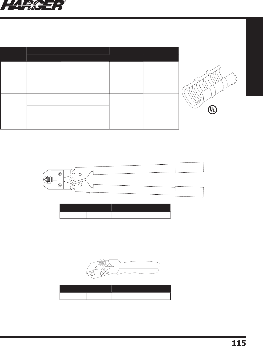
H
ar
g
er Li
g
htnin
g
& Groundin
g
•
©
2012 Phone 847-548-8700 • Fax 847-548-8755 • U.S. 800-842-743
7
115
115
Section 1
Grounding Components
•
Dieless ad
j
ustable compression tool with steel handle.
•
Works with copper conductor sizes #8 AWG throu
g
h
250 MCM and aluminum conductors #8 AWG throu
g
h 4/0.
•
For use with compression lu
g
s and li
g
ht duty compression
t
a
p
s.
•
A
pp
roximatel
y
2 tons of force.
•
Hand
y
com
p
ression tool terminates co
pp
er com
p
ression
connectors in wire sizes #8 AWG throu
g
h 1/0.
•
Handle len
g
th facilitates two-handed crimps when necessary.
•
A
pp
roximatel
y
2 tons of force.
•
Dies incl
ud
e
d
.
•
Other sizes available. Please contact factor
y
for more information.
Part No. Conductor (AWG) Color
Code
Box
Qty.
Approx. Box
Wt. (lbs.)
Run Tap
CT4
666
L
D
#
6
Str
a
n
d
e
d
#5, #4 AW
G
#8-#6 Stranded
#12 - #8 AW
G
B
r
o
w
n
1
00
2
CT2248L
D
#4 Str
a
n
d
e
d
#
3
Str
a
n
d
e
d
#2 Str
a
n
d
e
d
#4 Str
a
n
d
e
d
#
5
Str
a
n
d
e
d
#12-#
6
Str
a
n
d
e
d
P
ink 1
00
4
C
T
2222
L
D
#2 Str
a
n
d
e
d
#2 S
o
li
d
#1 Str
a
n
d
e
d
#1 S
o
li
d
1
/
0 Stranded
1
/
0 Solid
#2 Str. - #2 S
o
l.
#
3
Str. - #
3
S
o
l.
#4 Str. - #4 S
o
l.
#
3
Str. - #
3
S
o
l.
#12 Str. - #12 S
o
l.
#4 Str. - #4 S
o
l.
O
ran
ge
50
5
Part No. Length Approx. Each Wt. (lbs.)
MC
T 24"
5
Part No. Length Approx. Each Wt. (lbs.)
M
CT81
/
0 10-1
/
2"
3
C
-T
yp
e Com
p
ress
i
on Ta
p
s
Li
g
ht Duty C-Taps
Mechanical Com
p
ression Tools
L
isted 486
S
ect
io
n 1.8.5 & 1.8.6

H
ar
g
er Li
g
htnin
g
& Groundin
g
•
©
2012 Phone 847-548-8700 • Fax 847-548-8755 • U.S. 800-842-743
7
1
1
6116
Section 1
Grounding Components
•
Used when crimpin
g
lu
g
s and splices up to 800
M
CM, insulated terminals u
p
to 400 MCM and c-ta
p
s
up
to
3
50 MCM.
•
Hydraulic "C" head tool features a lar
g
e 1.65 inch
j
aw openin
g
allowin
g
for easier insertion/removal o
f
l
ar
g
e size compression terminations and
j
oints.
•
Crimpin
g
head rotates 180 de
g
rees to facilitate
u
sa
g
e in confi ned spaces.
•
Provides 14.6 ton crimpin
g
force.
•
Used with die sets MY-C, ME-C & MC-C.
•
Available in 7 die kit. Contact the factor
y
for details.
•
Used when crimpin
g
lu
g
s and splices up to 500
M
CM, insulated terminals u
p
to 2/0, end sleeves u
p
to 1/0 and c-ta
p
s u
p
to 2/0.
•
Li
g
htwei
g
ht 14.4 volt cordless tool that is balanced
for sin
g
le hand operation.
•
Crimpin
g
head rotates 180 de
g
rees to facilitate
u
sa
g
e in confi ned spaces.
•
Features a double speed action: a fast advancin
g
sp
eed for ra
p
id a
pp
roach of the dies to the
connector and a slower more
p
owerful s
p
eed for
cr
i
mp
i
n
g
.
•
Provides 6 ton crimpin
g
force.
•
Suitable for "W" st
y
le dies.
•
Used with die sets MY, ME & MC.
•
Available in 7 die kit. Contact the factor
y
for details.
•
Used when crimpin
g
lu
g
s and splices up to 800 MCM,
i
nsulated terminals u
p
to 400 MCM and c-ta
p
s u
p
to
350
MCM.
•
Hydraulic "C" head tool features a lar
g
e 1.65 inch
j
aw
o
penin
g
allowin
g
for easier insertion/removal of lar
g
er
s
ize compression terminations and
j
oints.
•
Crimpin
g
head rotates 180 de
g
rees facilitatin
g
usa
g
e in
confi ned s
p
aces.
•
Provides 14.6 ton crimpin
g
force.
•
Will acce
p
t all semicircular slotted dies common to
m
o
st 12 t
o
n t
oo
ls.
•
Available in 7 die kit. Contact the factor
y
for details.
•
Used when crimpin
g
lu
g
s and splices up to 500
M
CM, insulated terminals u
p
to 2/0, end sleeves u
p
to 1/0 and c-ta
p
s u
p
to 2/0.
•
Crimpin
g
head rotates 180 de
g
rees facilitatin
g
usa
g
e
i
n confi ned s
p
aces.
•
Provides 6 tons of crimpin
g
force.
•
Used with die sets MY, ME, MC.
•
U
pp
er and lower ada
p
ters to insert "W" st
y
le dies
fr
o
m
o
ther m
a
n
u
f
a
ct
u
rers.
•
Available in 7 die kit. Contact the factor
y
for details.
Part No. Qty. Approx. Each Wt. (lbs.)
B
1
3
1LCA
EA
11.
55
Part No. Qty. Approx. Each Wt. (lbs.)
H
T
5
1L
EA
6
.
2
Part No. Qty. Approx. Each Wt. (lbs.)
B5
1LA
EA
8.4
7
Part No. Qty. Approx. Each Wt. (lbs.)
H
T1
3
1LC
EA
11.
55
Hydraulic Compression Tools & Dies
S
ect
io
n 1.8.7

H
ar
g
er Li
g
htnin
g
& Groundin
g
•
©
2012 Phone 847-548-8700 • Fax 847-548-8755 • U.S. 800-842-743
7
11
7
117
Section 1
Grounding Components
S
ect
io
n 1.9
Mechanical
s
Terminal Lu
g
s, Split Bolts & Pipe Clamps
In
d
ex
Descr
i
pt
i
on Pa
g
e
1.9.1 Dual Rated Two-Hole Aluminum Lay-In Lu
g
........................................
118
1.9.2 One-Hole Tinned Copper Lay-In Lu
g
..................................................
118
1.9.3 Copper Terminal Lu
gs
.......................................................................
118
1.9.4 Copper Offset Terminal Lu
gs
.............................................................
119
1.9.5 Co
pp
er S
p
lit Bolt
s
.............................................................................
119
1.9.
6
C
ab
le C
o
nnect
o
r
s
.............................................................................
1
20
1.9.7 Bondin
g
Clamp
s
...............................................................................
1
2
1
1.9.8 Rebar & Water Pi
p
e Clam
ps
...............................................................
122
1.9.9 Tinned Bronze Cable Tra
y
Clam
p
........................................................
1
22
1.9.10 Pipe Bondin
g
Strap
s
..........................................................................
1
23
1.9.11 Water Pi
p
e Ground Clam
ps
................................................................
1
23
1.9.12 Conduit Bondin
g
Clamp
s
...................................................................
1
23
1.9.13 CPC Pi
p
e Ground Clam
ps
..................................................................
1
24
1.9.14 Universal Pi
p
e Clam
ps
.......................................................................
1
25
N
O
TE
:
Co
pp
er materials can consist of co
pp
er, bronze or brass. All are co
pp
er allo
y
s.
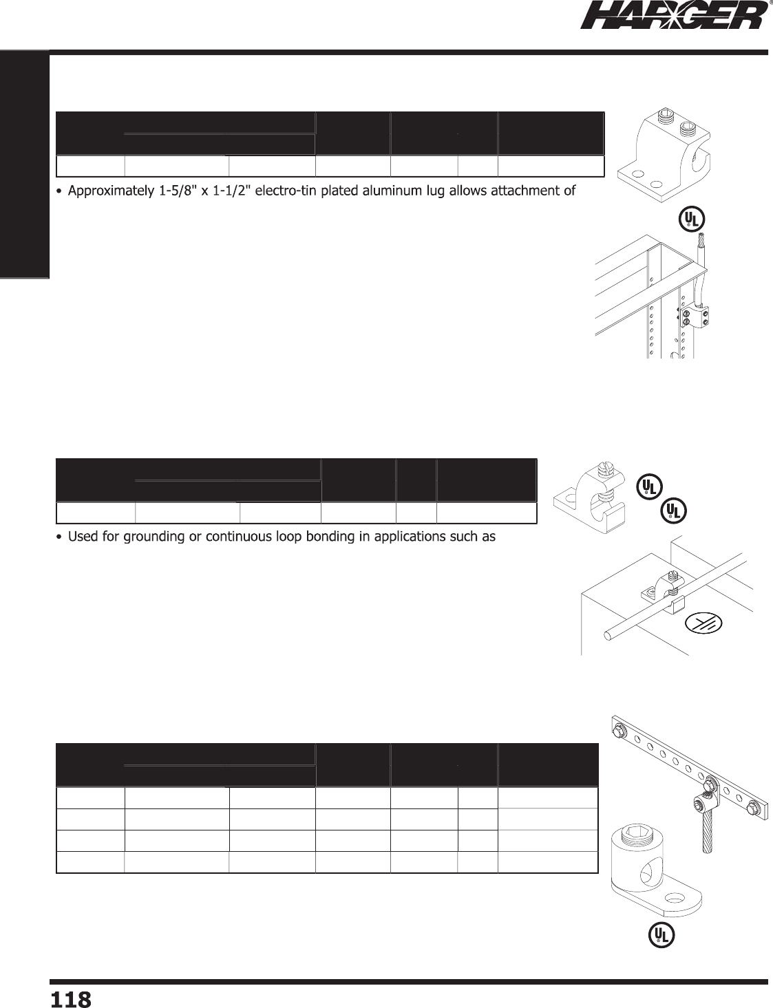
H
ar
g
er Li
g
htnin
g
& Groundin
g
•
©
2012 Phone 847-548-8700 • Fax 847-548-8755 • U.S. 800-842-743
7
1
18
118
Section 1
Grounding Components
L
isted 486
L
isted 486
co
pp
er or aluminum conductors to racks and cabinets.
•
Includes two 3/8" x 1" hex head socket set screws. Re
q
uires a 3/16" Hex Ke
y
(
not
i
ncluded
)
.
•
Meets ANSI J-STD-607-A two-hole mountin
g
recommendations.
•
U
L Liste
d
•
Allows
g
roundin
g
of racks and cabinets utilizin
g
standard EIA/TIA hole spacin
g
.
•
Parallel mountin
g
direction allows for better cable mana
g
ement.
•
When usin
g
copper conductors, apply Har
g
er #HAAJC8 Antioxidant (pa
g
e 148).
pool
g
roundin
g
or PV array frame
g
roundin
g
.
•
Approximately 1-1/8" x 3/8" x 7/8" electro-tin plated copper lu
g
.
•
Incl
ud
es sl
o
tte
d
st
a
inless steel set screw.
•
Ton
g
ue accepts #10 screw.
•
Allows conductor to be laid in without cuttin
g
conductor.
•
Co
rr
o
si
o
n resist
a
nt.
•
S
u
it
ab
le f
o
r
d
irect
bu
ri
a
l.
Part No. Conductor Range (AWG) Bolt Hole
Size
O.C.
Spacing Qty. Approx. Each
Wt. (lbs.)
Maximum Minimum
L
I2
/
014
2
2
/
0141
/
4"
5/
8"
EA
1
/4
Part No. Conductor Range (AWG) Bolt Hole
Size
Box
Qty.
Approx. Box
Wt. (lbs.)
Maximum Minimum
TC
LI414DB
4
14 #1
0
1
0
3
/4
Part No. Conductor Range (AWG) Bolt Hole
Size
Ampere
Rating
Box
Qty.
Approx. Box
Wt. (lbs.)
Maximum Minimum
G
EL1 8 Str. 14 S
o
l. #8
35
1
00
2-1
/
4
GEL
2
4
S
tr. 14 S
o
l. 1
/
4" 7
0
1
00
5
-1
/2
GEL
3
1
/
0 Str. 8 Sol.
5/
16" 1
25
50
5
-1
/
4
G
EL
4
250
MCM
6
S
o
l. 3
/
8"
250
25
5
Dual Rated Two-Hole Aluminum Lay-In Lu
g
O
ne-Hole Tinned Copper Lay-In Lu
g
C
opper Terminal Lu
g
s
S
ect
io
n 1.9.1 - 1.9.3
L
iste
d
4
67
L
isted 486
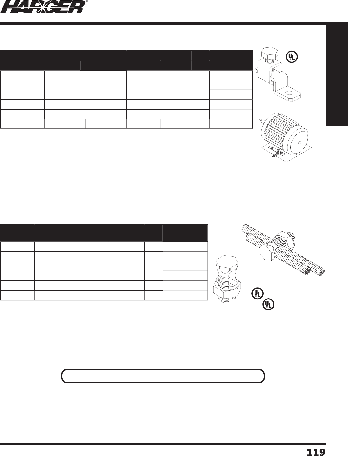
H
ar
g
er Li
g
htnin
g
& Groundin
g
•
©
2012 Phone 847-548-8700 • Fax 847-548-8755 • U.S. 800-842-743
7
1
1
9
119
Section 1
Grounding Components
Part No. Conductor Range (AWG) Bolt Hole
Size
Ampere
Rating
Box
Qty.
Approx. Box
Wt. (lbs.)
Maximum Minimum
GE
O
L1 1
0
Str. 14
S
tr. #8
25
1
00
2-1
/2
GE
O
L
2
6
Str. 14
S
tr. #8
50
1
00
2-1
/
4
GE
O
L
3
2
S
tr. 8 Str. 1
/
4" 7
0
1
00
4
GE
O
L
4
1
/
0 Str. 8 Str. 1
/
4" 1
25
25
3
GE
O
L
5
4/
0 Str.
2
S
tr. 3
/
8"
225
25
6
GE
O
L
500
MCM
500
MCM 1
/
0 Str. 1
/
2"
400
1
0
8
L
isted 486
Other sizes available. Please contact the factor
y
for more information.
Part No. Conductor Range for
Equal Main (AWG)
Minimum
Tap
Box
Qty.
Approx. Box
Wt. (lbs.)
GESB
6
4
Sol. - 8 Sol. 1
6
S
o
l. 1
00
7-1
/4
GESB
2
2 Str. -
6
S
o
l. 14
S
tr.
50
6
GESB1
/
01
/
0 Str. - 4 Sol. 14 S
o
l.
20
3-1
/4
GESB2
/
02
/
0 Str. - 2 Sol. 14
S
tr. 1
5
3-1
/4
GESB4
/
0
4/
0 Str. - 1
/
0 Sol. 1
0
S
o
l. 1
0
3-3
/4
GESB
250
250 MCM - 1
/
0 Str. 1
0
S
o
l. 1
0
3-3
/4
C
opper Offset Terminal Lu
g
s
C
o
pp
er S
p
lit Bolts
•
S
u
it
ab
le f
o
r
d
irect
bu
ri
a
l.
S
ect
io
n 1.9.4 & 1.9.5
L
iste
d
4
67
L
isted 486
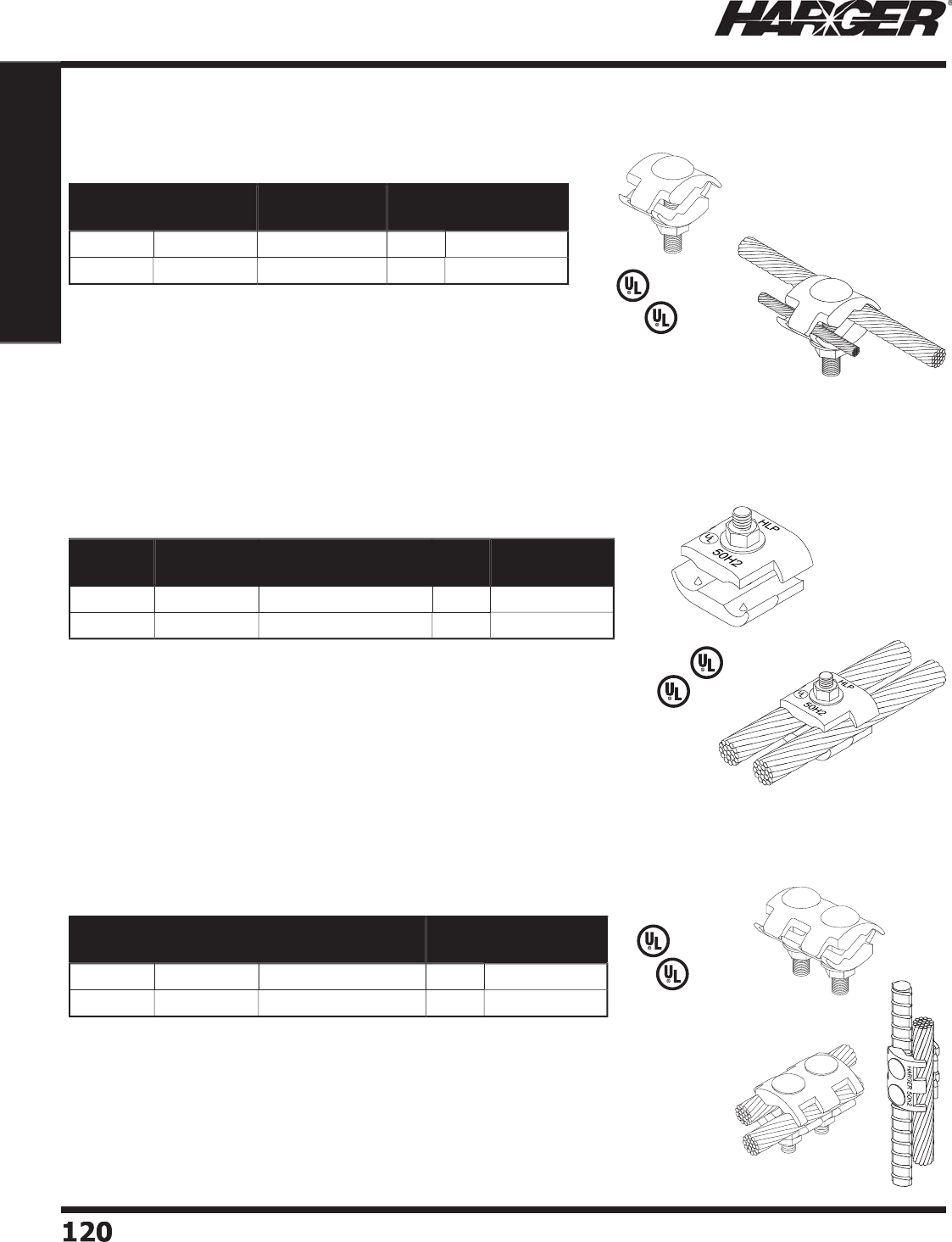
H
ar
g
er Li
g
htnin
g
& Groundin
g
•
©
2012 Phone 847-548-8700 • Fax 847-548-8755 • U.S. 800-842-743
7
1
2
0120
Section 1
Grounding Components
•
Approximately 2" x 1-3/4" two piece connector used for splicin
g
cables and rods.
•
5/16" x 1-7/8" stainless steel carria
g
e bolts, fl at washers and nuts included.
•
Manufactured from hi
g
h conductivity copper alloy.
•
Recommended installation tool - 1/2" dee
p
socket wrench, end wrench or nut driver.
•
S
u
it
ab
le f
o
r
d
irect
bu
ri
a
l.
*
ETPB - Electr
o
Tin Pl
a
te
d
Br
o
nze.
•
A
pp
roximatel
y
7/8" x 1-5/8" one bolt, two
p
iece connector s
p
lices
conductor u
p
to 9/16" diameter.
•
5/16" x 1-7/8" stainless steel carria
g
e bolts, fl at washer and nut included.
•
Manufactured from hi
g
h conductivity copper alloy.
•
Recommended installation tool - 1/2" dee
p
socket wrench, end wrench or
n
u
t
d
river.
•
S
u
it
ab
le f
o
r
d
irect
bu
ri
a
l.
*
ETPB - Electr
o
Tin Pl
a
te
d
Br
o
nze.
L
iste
d
4
67
L
iste
d
4
67
•
A
pp
roximatel
y
2" s
q
uare, two
p
iece connector
p
rovides over 1-1/2" surface
c
o
nt
a
ct
b
etween c
o
n
du
ct
o
rs.
•
5/16" x 1-7/8" stainless steel ca
p
screw with fl at washer and nut included.
•
Manufactured from hi
g
h conductivity copper alloy.
•
Recommended installation tool - 1/2" socket wrench, end wrench or nut driver.
•
S
u
it
ab
le f
o
r
d
irect
bu
ri
a
l.
*
ETPB - Electr
o
Tin Pl
a
te
d
Br
o
nze.
Part No. Material Conductor
Range (AWG)
Box
Qty.
Approx. Box
Wt. (lbs.)
208
C
o
pp
e
r
#6 - 4
/
01
0
2-1
/2
208T
E
TPB* #6 - 4
/
01
0
2-1
/2
Part No. Material Conductor
Range (AWG)
Box
Qty.
Approx. Box
Wt. (lbs.)
B
1B
C
C
o
pp
e
r
#
6
-
250
MCM 1
0
4
T
B1B
C
E
TPB* #
6
-
250
MCM 1
0
4
Part No. Material Conductor
Range (AWG)
Box
Qty.
Approx. Box
Wt. (lbs.)
204
C
o
pp
e
r
#
6
-
250
MCM 1
0
4
-1
/2
20
4T
E
TPB* #
6
-
250
MCM 1
0
4
-1
/2
L
iste
d
9
6
L
iste
d
9
6
L
iste
d
9
6
C
able C
o
nnect
o
rs
1
Bolt Bondin
g
Connectors
1
B
o
lt Parallel C
o
nnect
o
rs
2
B
o
lt Parallel C
o
nnect
o
rs
L
iste
d
4
67
S
ect
io
n 1.9.6
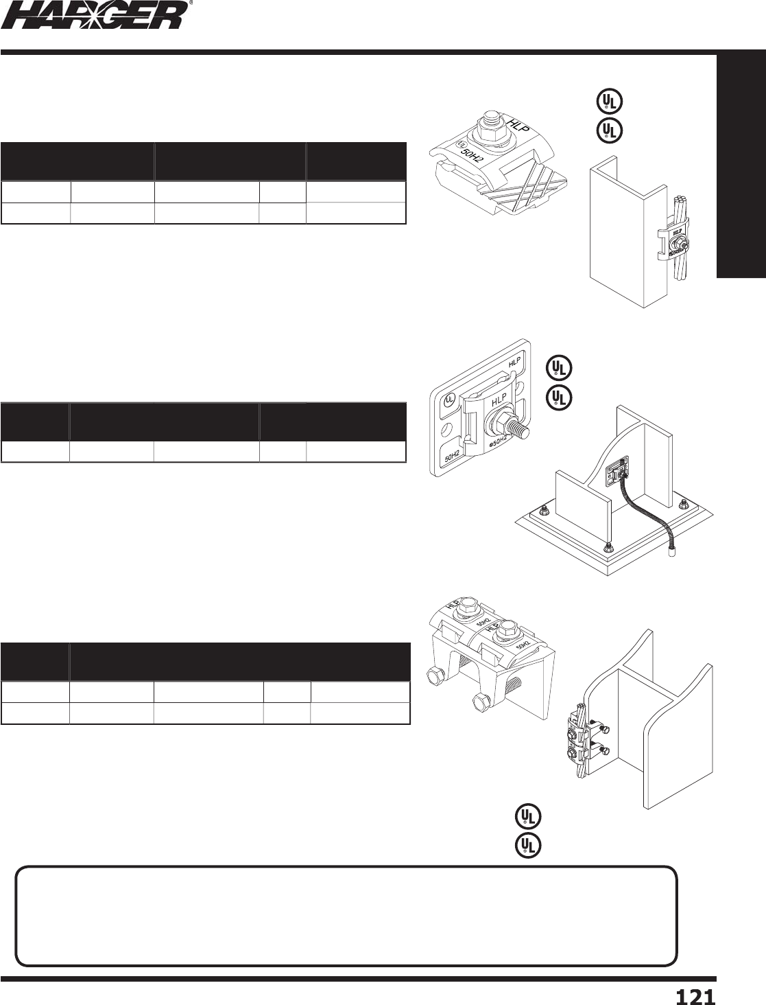
H
ar
g
er Li
g
htnin
g
& Groundin
g
•
©
2012 Phone 847-548-8700 • Fax 847-548-8755 • U.S. 800-842-743
7
1
21
121
Section 1
Grounding Components
•
A
pp
roximatel
y
1-3/4" x 2" two
p
iece, one bolt connector connects conductors
throu
g
h 9/16" diameter to fl at metal ob
j
ects up to 1/2" thickness such as steel
l
adders, small I-beams, channel, etc.
•
5/16" x 1-1/4" stainless steel ca
p
screw with fl at washer included.
•
Manufactured from hi
g
h conductivity copper alloy.
•
Recommended installation tool - 1/2" socket wrench, end wrench or nut driver.
•
S
u
it
ab
le f
o
r
d
irect
bu
ri
a
l.
*
ETPB - Electr
o
Tin Pl
a
te
d
Br
o
nze.
L
iste
d
4
67
L
iste
d
4
67
•
Features a pressed-in stud which ensures a fl at mountin
g
surface.
•
Approximately 2-1/2" x 3-1/4" cast bondin
g
plate provides over
8 square inches of bondin
g
surface.
•
Dual cable
p
ressure connector acce
p
ts conductors u
p
to 9/16" diameter.
•
Two 5/16" mountin
g
holes provide secure mountin
g
.
•
Recommended installation tool - 1/2" socket wrench, end wrench or nut driver.
•
S
u
it
ab
le f
o
r
d
irect
bu
ri
a
l.
*
ETPB - Electr
o
Tin Pl
a
te
d
Br
o
nze.
L
iste
d
4
67
•
Approximately 3-3/4" x 2-1/2" bondin
g
plate provides over 8 square inches o
f
bondin
g
surface.
•
Lar
g
e cable connector offers 3" of contact between the bondin
g
plate and the cable.
•
Accommodates conductors u
p
to 9/16" diameter.
•
Ideal for bondin
g
to steel I-beams up to 1" thick.
•
Recommended installation tool - 1/2" socket wrench, end wrench or nut driver.
•
S
u
it
ab
le f
o
r
d
irect
bu
ri
a
l.
*
ETPB - Electr
o
Tin Pl
a
te
d
Br
o
nze.
Part No. Material Conductor
Range (AWG)
Box
Qty.
Approx. Box
Wt. (lbs.)
2
1
3
C
o
pp
e
r
#6 - 4
/
01
0
4
-1
/2
2
1
3
T
E
TPB* #6 - 4
/
01
0
4
-1
/2
Part No. Material Conductor
Range (AWG)
Box
Qty.
Approx. Box
Wt. (lbs.)
2
1
7
E
TPB* #6 - 4
/
0
5
3-1
/2
Part No. Material Conductor
Range (AWG)
Box
Qty.
Approx. Box
Wt. (lbs.)
223
C
o
pp
e
r
#6 - 4
/
01
0
20
223
T
E
TPB* #6 - 4
/
01
0
20
L
iste
d
9
6
L
iste
d
9
6
L
iste
d
9
6
Bondin
g
Clamps
C
able t
o
Flat Metal C
o
nnect
o
rs
Bondin
g
Plate
Flan
g
e Bondin
g
Clamp
APPLICATI
O
N N
O
TES
:
• It is imperative to properly prepare the bondin
g
surface before applyin
g
the bondin
g
lu
g
or plate. All
paint, rust, moisture and debris must be removed. The use of a rasp (see pa
g
e 326) or
g
rindin
g
tool is
recommended to ensure all surface oxidants have been removed. Generously coat the bondin
g
surface
with the appropriate antioxidant (see pa
g
e 148), then install the bondin
g
lu
g
or plate.
S
ect
io
n 1.9.7
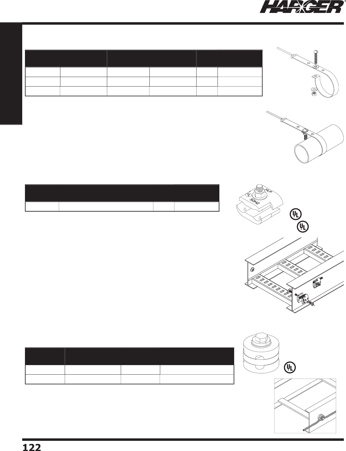
H
ar
g
er Li
g
htnin
g
& Groundin
g
•
©
2012 Phone 847-548-8700 • Fax 847-548-8755 • U.S. 800-842-743
7
1
22
122
Section 1
Grounding Components
•
Used for bondin
g
g
alvanized steel or aluminum cable trays to the
g
roundin
g
electrode system.
•
TBCTC can re
p
lace 3 clam
p
s from other manufacturers due to its su
p
erior
conductor ran
g
e takin
g
desi
g
n.
•
Electro-tin
p
lated cast bronze.
•
Two-
p
iece connector
p
rovides a 1-1/2" linear surface contact between
conductors and the clam
p
.
•
18-8 stainless steel ribbed neck 3/8" bolt with low
p
rofi le #4 Philli
p
s head
can be driven into a 0.44" hole to prevent rotation durin
g
installation.
•
Al
u
min
u
m c
o
n
du
ct
o
rs sh
ou
l
d
b
e wire
b
r
u
she
d
a
n
d
u
se
d
with
a
Zinc
ba
se
d
antioxidant (HAAJC8 pa
g
e 148).
•
Recommended installation tools: 9/16" socket wrench, o
p
en-end wrench
o
r nut driver, 7/16" drill bit, #4 Philli
p
s screw driver and a hammer.
•
Recommended tor
q
ue 15 ft-lbs.
•
S
u
it
ab
le f
o
r
d
irect
bu
ri
a
l.
L
iste
d
4
67
Part No. Conductor Range (AWG) Box
Qty.
Approx. Box
Wt. (lbs.)
T
B
C
T
C
#6 Solid throu
g
h 250 MCM 1
0
5
L
iste
d
9
6
C
able Tra
y
Clam
p
s
•
For use in a
g
ricultural environments such as milkin
g
parlors or ho
g
confi nement facilities.
•
Aids in the establishment of an equipotential
g
round plane thus reducin
g
problems
associated with stray volta
g
e.
•
Stainless steel bondin
g
strap desi
g
ned to fi t 1-1/2" to 2-1/2" outside diameter tubin
g
.
•
Comes with a 5 foot co
pp
er conductor exothermicall
y
welded to the stra
p
.
Part No. OD Tube
Size
Conductor
Size (AWG)
Approx. Each
Wt. (lbs.)
Box
Qty.
Approx. Box
Wt. (lbs.)
23
1S
2
-
2
1-1
/
2" - 2-1
/
2" 2 S
o
li
d
1
/2
25
12-1
/2
23
1S
2
-4 1-1
/
2" - 2-1
/
2"
4
S
o
li
d
1
/2
25
12-1
/2
23
1S
2
-
6
1-1
/
2" - 2-1
/
2"
6
S
o
li
d
1
/2
25
12-1
/2
Pipe Bondin
g
Straps
S
ect
io
n 1.9.8 & 1.9.9
•
Used for bondin
g
g
alvanized steel or aluminum cable trays to the
g
roundin
g
electrode s
y
stem.
•
U
se
d
when wel
d
e
d
c
o
nnecti
o
ns
a
re n
o
t fe
a
si
b
le.
•
Unique desi
g
n allows clamps to form connections at most any an
g
le.
•
Electro-tin
p
lated brass.
L
iste
d
4
67
Part No. Conductor Size
(AWG) Box Qty. Approx. Box Wt. (lbs.)
CRGC
6
#
6
25
4
C
R
GC4
#4
1
0
5
Tinned Bronze Cable Tra
y
Clam
p
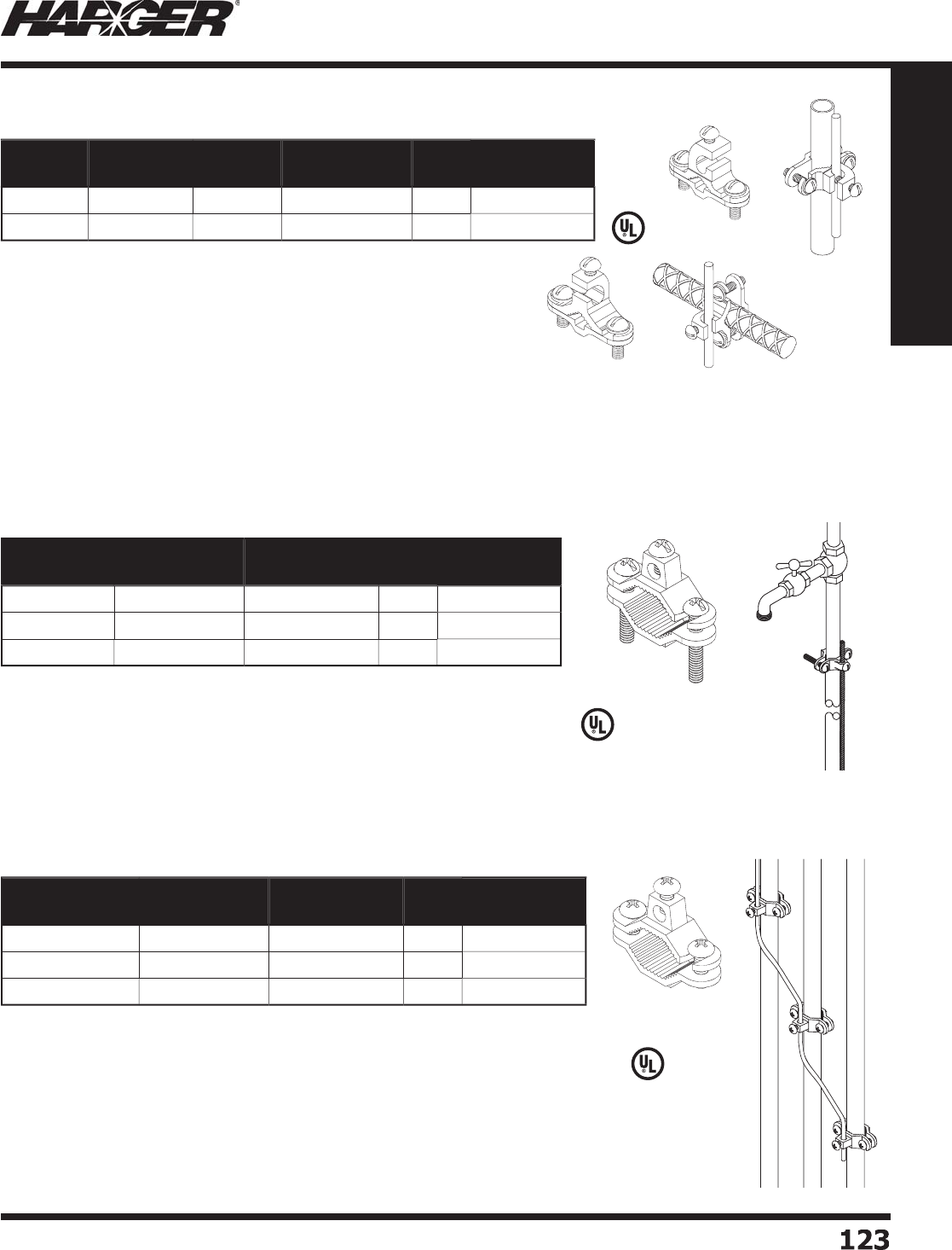
H
ar
g
er Li
g
htnin
g
& Groundin
g
•
©
2012 Phone 847-548-8700 • Fax 847-548-8755 • U.S. 800-842-743
7
1
2
3
123
Section 1
Grounding Components
•
Manufactured from hi
g
h conductivity copper alloy.
•
A
pp
roved for direct burial in earth or concrete.
•
La
y
-in feature s
p
eeds installation.
•
RB12A is for
p
arallel mounted conductors.
•
RB12B is for
p
er
p
endicular mounted conductors.
R
B1
2
A
R
B1
2
B
L
iste
d
4
67
Part No. Rebar
Range
Pipe
Range
Conductor
Range (AWG)
Box
Qty.
Approx. Box
Wt. (lbs.)
R
B1
2
A3
/
8" - 1" 1
/
2" x 1" 1
0
S
o
l. - 2 Str. 1
0
2-1
/2
R
B1
2
B3
/
8" - 1" 1
/
2" x 1" 1
0
S
o
l. - 2 Str. 1
0
2-1
/2
Rebar & Water Pi
p
e Clam
p
s
•
Bronze clamp has many uses such as bondin
g
to
g
round rods or copper
w
ater
p
i
p
es.
•
Bronze clamp for bondin
g
conduits that are fl ush mounted to a surface
s
uch as a wall, fl oor or ceilin
g
.
•
"Low Profi le" desi
g
n utilizes 1/4" diameter lon
g
machine screws.
*
Electro tin
p
lated bronze.
*
* Incl
ud
es st
a
inless steel h
a
r
d
w
a
re. R
a
te
d
f
o
r
d
irect
bu
ri
a
l.
Part No. Ground Rod
or Pipe Size
Conductor
Range (AWG)
Box
Qty.
Approx. Box
Wt. (lbs.)
BGC
41
/
2" - 1" #1
0
- #
2
1
0
3
B
GC41.
25
-
2
1-1
/
4" - 2" #1
0
- #
2
1
0
6
B
GC4
2
.
5
-
4
2-1
/
2" - 4" #1
0
- #
2
1
0
9
W
ater Pi
p
e Ground Clam
p
s
C
onduit Bondin
g
Clamps
L
iste
d
4
67
S
ect
io
n 1.9.10 - 1.9.12
L
iste
d
4
67
Part No. Conduit
Range
Conductor
Range (AWG)
Box
Qty.
Approx. Box
Wt. (lbs.)
BGC
4
SCS
1
/
2" - 3
/
4" #1
0
- #
2
1
0
2-1
/2
T
BGC4SCS* 1
/
2" - 3
/
4" #1
0
- #
2
1
0
2-1
/2
T
BGC4SCSSS** 1
/
2" - 3
/
4" #1
0
- #
2
1
0
2-1
/2
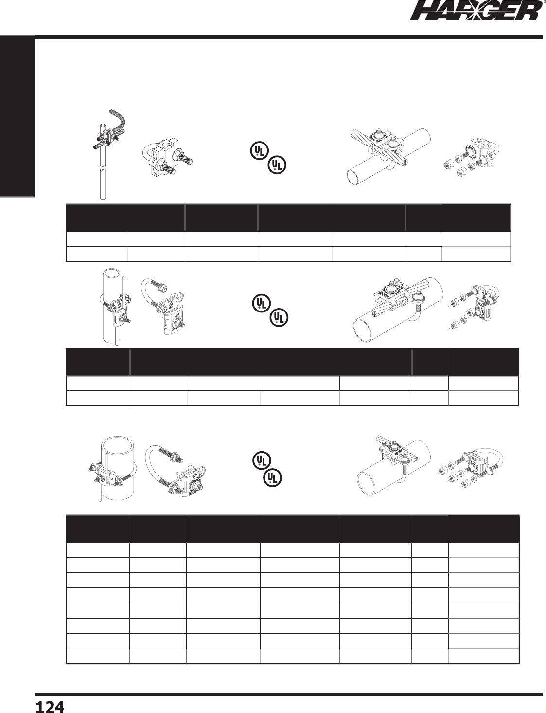
H
ar
g
er Li
g
htnin
g
& Groundin
g
•
©
2012 Phone 847-548-8700 • Fax 847-548-8755 • U.S. 800-842-743
7
1
2
4124
Section 1
Grounding Components
L
iste
d
9
6
L
iste
d
4
67
L
iste
d
9
6
L
iste
d
4
67
L
iste
d
9
6
L
iste
d
4
67
C
PC Pi
p
e Ground Clam
p
s
Pipe Ran
g
e .5/.75
Pipe Ran
g
e 1/1.25
Pipe Ran
g
e 1.5 throu
g
h 6
T
am
p
er Resistan
t
T
am
p
er Resistan
t
T
am
p
er Resistan
t
Part No. Tamper
Resistant Material Nominal Pipe
Size Range
Pipe Outside
Diameter
Box
Qty.
Approx. Box
Wt. (lbs.)
CPC1
/
1.25
No
E
TPB* 1" - 1.2
5
"
.
7
5
" - 1.7"
5
3
CPC1
/
1.25T
P
Yes
E
TPB* 1" - 1.2
5
"
.
7
5
" - 1.7"
5
3
Part No. Tamper
Resistant Material Nominal Pipe
Size Range
Pipe Outside
Diameter
Box
Qty.
Approx. Box
Wt. (lbs.)
CPC.5
/
.75
No
E
TPB*
.5
" - .7
5
"
.3
7
5
" - 1"
5
2-1
/2
CPC.5
/
.75T
P
Yes
E
TPB*
.5
" - .7
5
"
.3
7
5
" - 1"
5
2-1
/2
•
Feature “quick connect”, bi-directional desi
g
n.
•
Pressed stud desi
g
n ensures a fl ush mountin
g
surface.
•
Feature “quick connect”, bi-directional desi
g
n.
•
Pressed stud desi
g
n ensures a fl ush mountin
g
surface.
Part No. Tamper
Resistant Material Nominal Pipe
Size Range
Pipe Outside
Diameter
Box
Qty.
Approx. Box
Wt. (lbs.)
CPC1.5
/2
No
E
TPB* 1.
5
" - 2" 1" - 2.4"
5
3-3
/4
CPC1.5
/
2T
P
Yes
E
TPB* 1.
5
" - 2" 1" - 2.4"
5
3-3
/4
CPC2.5
/3
No
E
TPB* 2.
5
" -
3
" 2.2
5
" -
3
.
5
"
5
5
CPC2.5
/
3T
P
Yes
E
TPB* 2.
5
" -
3
" 2.2
5
" -
3
.
5
"
5
5
CPC3.5
/4
No
E
TPB*
3
.
5
" - 4"
3
.2" - 4.
5
"
5
6
-1
/4
CPC3.5
/
4T
P
Yes
E
TPB*
3
.
5
" - 4"
3
.2" - 4.
5
"
5
6
-1
/4
CPC5
/
6
No
E
TPB*
5
" -
6
"
4
.7
5
" -
6
.
63
"
5
8-3
/4
CPC5
/
6T
P
Yes
E
TPB*
5
" -
6
"
4
.7
5
" -
6
.
63
"
5
8-3
/4
•
Dual UL Listin
g
(UL96 and UL467).
•
Acce
p
table for direct burial.
•
Tam
p
er Resistant comes with break awa
y
nuts.
•
Wide conductor ran
g
e; #6 Solid throu
g
h 250 MCM.
•
Also used for pedestal
g
roundin
g
.
*
Electr
o
Tin Pl
a
te
d
Br
o
nze incl
ud
es st
a
inless steel h
a
r
d
w
a
re.
S
ect
io
n 1.9.13
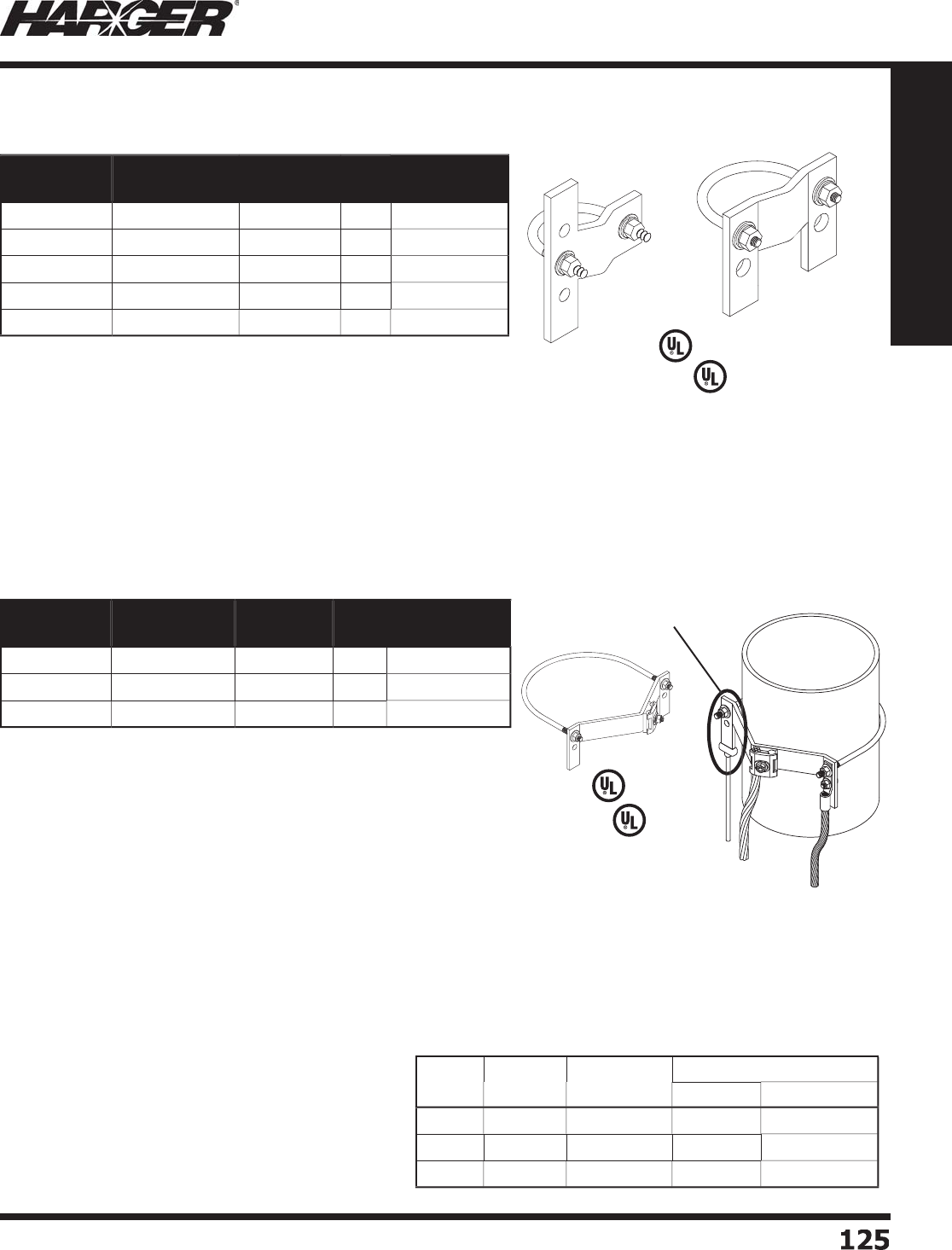
H
ar
g
er Li
g
htnin
g
& Groundin
g
•
©
2012 Phone 847-548-8700 • Fax 847-548-8755 • U.S. 800-842-743
7
1
2
5
125
Section 1
Grounding Components
U
niversal Pi
p
e Clam
p
s
•
Provides bi-directional
g
roundin
g
capabilities makin
g
it the perfect
connection for
g
roundin
g
lar
g
e diameter pipes.
•
Clamps include mechanical connector to connect
g
round conductors
#
6
AWG thr
u
2
50
MCM.
•
Clamps can also be connected to
g
round conductors via exothermic
connections and/or standard compression lu
g
s.
•
Manufactured from hi
g
hly conductive tinned copper; includes
st
a
inless steel h
a
r
d
w
a
re.
•
Provides 1-1
/
2" of contact area to ensure suffi cient electrical contact
for both
g
round fault and li
g
htnin
g
current.
•
Lu
g
ends are 1/4" x 1" and have holes that are 7/16" diameter
1" on center spacin
g
.
•
For conductors lar
g
er than 250 MCM exothermically weld to
the clam
p
.
•
R
a
te
d
f
o
r Direct B
u
ri
a
l.
L
iste
d
9
6
L
iste
d
4
67
Part No. Material Nominal
Pipe Size
Box
Qty.
Approx. Box
Wt. (lbs.)
U
PC8
C
T
inned Co
pp
e
r
8"
5
14
U
PC1
0
C
T
inned Co
pp
e
r
1
0
"
5
15-1
/
4
U
PC1
2
C
T
inned Co
pp
e
r
12"
5
17-3
/
4
•
All clam
p
s
p
rovide 1-1/2" of contact area to ensure suffi cient
electrical contact for both
g
round fault and li
g
htnin
g
current.
•
These clamps can be connected to
g
round conductors via
exothermic connections and/or standard compression lu
g
s.
•
Lu
g
ends are 1/4" x 1" and have holes that are 3/8" diameter
1" on center spacin
g
.
•
The UPC.75/1.25 provides bi-directional
g
roundin
g
capabilities
makin
g
it the perfect connection for
g
roundin
g
fence rail to
fence
p
ost a
pp
lications.
•
All clamps are manufactured from hi
g
hly conductive tinned
co
pp
er and feature stainless steel hardware.
U
P
C
L
iste
d
9
6
U
PC .75
/
1.25
L
iste
d
4
67
Part No. Material Nominal
Pipe Size
Box
Qty.
Approx. Box
Wt. (lbs.)
U
PC.75
/
1.25
T
inned Co
pp
e
r
.
7
5
" - 1.2
5
"1
0
9
U
PC1.5
/2
T
inned Co
pp
e
r
1.
5
" - 2" 1
0
9
-1
/2
U
PC2.5
/3
T
inned Co
pp
e
r
2.
5
" -
3
"
5
6
U
PC3.5
/
4
T
inned Co
pp
e
r
3
.
5
" - 4"
5
7
U
PC5
/
6
T
inned Co
pp
e
r
5
" -
6
"
5
9
C
able
Si
ze
L
u
g
Si
ze
M
o
l
d
P
art
No
.
W
el
d
Meta
l
U
ltraSh
o
t
NUWTUBE
#2 S
o
l. 1
/
4" x 1"
L
E-
2S
141
B
U
S
65
NU
WT
U
BE
65
2
/
01
/
4" x 1"
L
E-2
/
0141
B
U
S
65
NU
WT
U
BE
65
4/
01
/
4" x 1"
L
E-4
/
0141
B
U
S9
0
NU
WT
U
BE9
0
LE Connect
i
on T
yp
e
L
E St
y
le Mold
S
ee pa
g
e
2
9
7
S
ecti
o
n
5
.
5
S
ect
io
n 1.9.1
4

H
ar
g
er Li
g
htnin
g
& Groundin
g
•
©
2012 Phone 847-548-8700 • Fax 847-548-8755 • U.S. 800-842-743
7
1
2
6126
Section 1
Grounding Components
No
tes

H
ar
g
er Li
g
htnin
g
& Groundin
g
•
©
2012 Phone 847-548-8700 • Fax 847-548-8755 • U.S. 800-842-743
7
1
27
127
Section 1
Grounding Components
S
ect
io
n 1.10
S
wimmin
g
Pool Groundin
g
In
d
ex
Descr
i
pt
i
on Pa
g
e
1.10.1 Typical Pool Groundin
g
Layou
t
...........................................................
128
1.10.2 Pool Groundin
g
Component
s
.............................................................
1
2
9
1.10.3 Pool Groundin
g
Technical Note
s
.........................................................
1
30
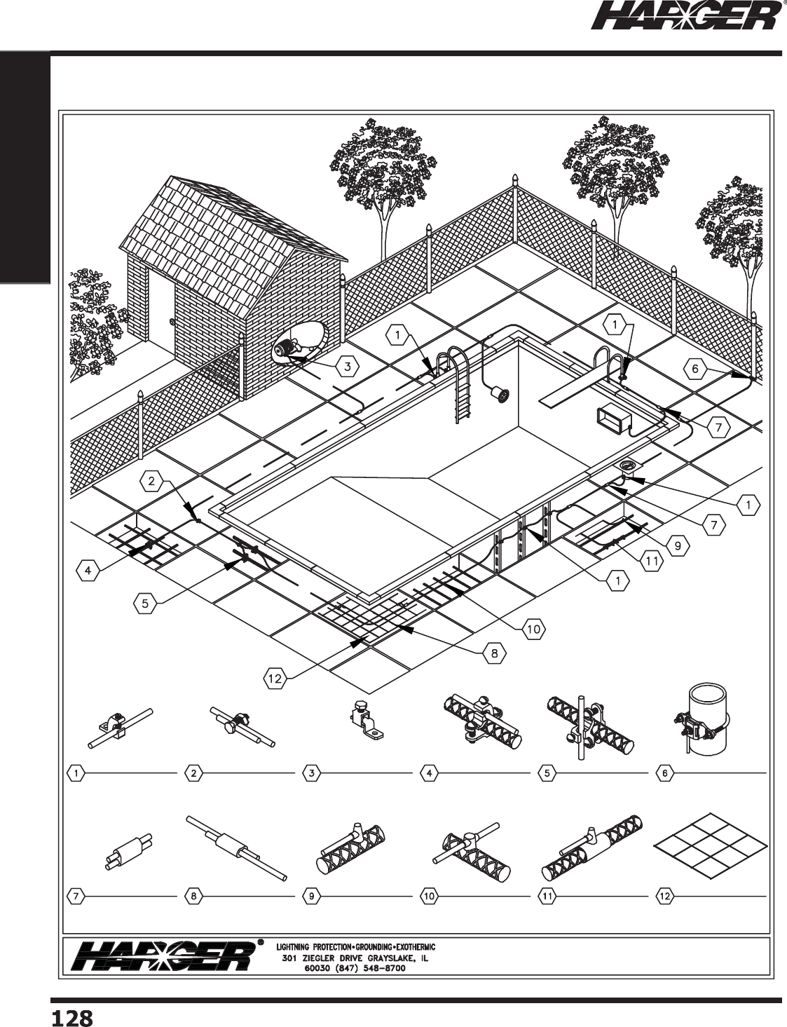
H
ar
g
er Li
g
htnin
g
& Groundin
g
•
©
2012 Phone 847-548-8700 • Fax 847-548-8755 • U.S. 800-842-743
7
1
28
128
Section 1
Grounding Components
Typical Pool Groundin
g
Layout
S
ect
io
n 1.10.1
TYPICAL POOL GROUNDING
NO. TCLI414DB
LAY-IN LUG
PT ULTRAWELD
CONNECTION
NO. GESB6 SPLIT
BOLT CONNECTOR NO. GEOL2 OFFSET
TERMINAL LUG NO. RB12A BONDING
CLAMP NO. RB12B BONDING
CLAMP
PREFABRICATED
GROUND MESH
PS ULTRAWELD
CONNECTION
CPC STYLE PIPE /
POST CLAMP
NO. RB3GA8SX5
REBAR GROUNDING
ASSEMBLY
RP ULTRAWELD
CONNECTION RO ULTRAWELD
CONNECTION
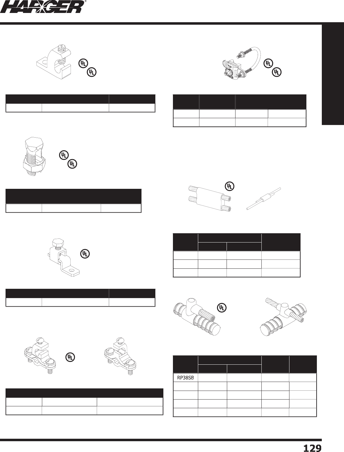
H
ar
g
er Li
g
htnin
g
& Groundin
g
•
©
2012 Phone 847-548-8700 • Fax 847-548-8755 • U.S. 800-842-743
7
1
2
9
129
Section 1
Grounding Components
•
S
u
it
ab
le f
o
r
d
irect
bu
ri
a
l.
•
See Pa
g
e 118 for more information.
•
S
u
it
ab
le f
o
r
d
irect
bu
ri
a
l.
•
See Pa
g
e 119 for more information.
•
See Pa
g
e 119 for more information.
No
t S
u
it
ab
l
e
f
o
r Direct B
u
ri
a
l
•
S
u
it
ab
le f
o
r
d
irect
bu
ri
a
l.
•
See Pa
g
e 123 for more information.
•
S
u
it
ab
le f
o
r
d
irect
bu
ri
a
l.
•
Conductor Ran
g
e #6 - 250 MCM.
•
O
ther sizes
a
v
a
il
ab
le.
•
See Pa
g
es 124 & 203 for more information (Groundin
g
& LP
S
ections
)
.
•
See Pa
g
e 278 for more information.
•
See Pa
g
es 307 & 308 for more information.
L
iste
d
4
67
Part No. Conductor Range (AWG) Bolt Hole Size
TC
LI414DB
4
- 14 #1
0
Part No. Conductor Range for
Equal Main (AWG) Minimum Tap
GESB
6
4
Sol. - 8 Sol. 1
6
S
o
l.
Part No. Conductor Range (AWG) Bolt Hole Size
GE
O
L
2
14 Str. -
6
Str. #8
Part No. Pipe & Rebar Range Conductor Range (AWG)
R
B1
2
A3
/
8" - 1" 1
0
S
o
l. - 2 Str.
R
B1
2
B3
/
8" - 1" 1
0
S
o
l. - 2 Str.
Part No. Material Nom. Pipe
Size Range
Pipe Outside
Diameter
CPC1.5
/2
T
inne
d
Br
o
nze 1.
5
" - 2" 1" - 2.4"
CPC2.5
/3
T
inne
d
Br
o
nze 2.
5
" -
3
" 2.2
5
" -
3
.
5
"
Part
No.
Weld Metal Required
Handle
UltraShot NUWTUBE
P
T8S8SB
U
S
25
NU
WT
U
BE
25
M
H1
P
S8S8SL
U
S
25
NU
WT
U
BE
25
M
H3
(
Included
)
P
S8S6SL
U
S
25
NU
WT
U
BE
25
M
H3
(
Included
)
Part
No.
Weld Metal Required
Handle
Packing
Mat'l No.
UltraShot NUWTUBE
U
S
25
NU
WT
U
BE
25
M
H1
W
RP
S
LV
R
P4L8SA
U
S
25
NU
WT
U
BE
25
Incl
ud
e
d
C
ERPM1
R
O38SB
U
S
65
NU
WT
U
BE
65
M
H1
W
RP
S
LV
R
O48SB
U
S
65
NU
WT
U
BE
65
M
H1
W
RP
S
LV
R
O58SB
U
S
65
NU
WT
U
BE
65
M
H1
W
RP
S
LV
Pool Groundin
g
Components
1
- One-Hole Tinned Copper Lay-In Lu
g
2
- Co
pp
er S
p
lit Bolt
3 - Copper Offset Terminal Lu
g
4
& 5 - Rebar & Water Pi
p
e Ground Clam
p
s
6
- CPC Pi
p
e Clam
p
s
7 & 8 - Cable t
o
Cable Ultraweld
Ex
o
thermic C
o
nnecti
o
n M
o
lds
9 & 10 - Cable t
o
Rebar Ultraweld
Ex
o
thermic C
o
nnecti
o
n M
o
lds
L
isted 486
L
isted 486
L
iste
d
4
67
L
iste
d
4
67
L
iste
d
4
67
S
ect
io
n 1.10.2
R
B1
2
A
R
B1
2
B
L
isted 486
L
iste
d
4
67
L
isted 486
L
iste
d
4
67
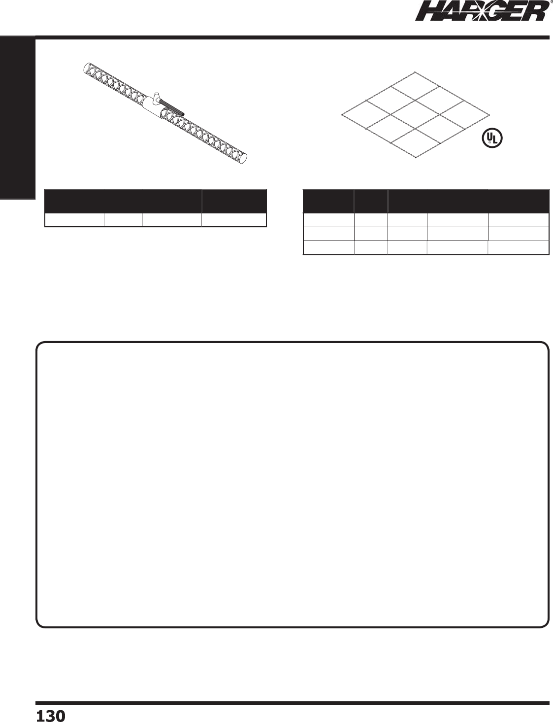
H
ar
g
er Li
g
htnin
g
& Groundin
g
•
©
2012 Phone 847-548-8700 • Fax 847-548-8755 • U.S. 800-842-743
7
130130
Section 1
Grounding Components
Pool Groundin
g
Components
•
Other mesh sizes and wire
g
au
g
es available.
•
See Pa
g
e 98 & 99 for more information.
•
P
refabricated rebar
g
roundin
g
assembly with exothermically
wel
d
e
d
c
o
nnecti
o
n.
•
Standard 24" lon
g
rebar.
•
Can be wire tied or welded to rebar ca
g
e prior to concrete pour.
•
See Pa
g
e 196 for more information.
Part No. Width
(ft.)
Length
(ft.)
Conductor
Spacing (in.)
Approx. Each
Wt. (lbs.)
GM35081
2
3
50
1
2
32
GM37581
2
3
75
12
42
GM310081
2
3
1
00
1
2
5
1
Part No. Rebar
Size
Conductor
Type (AWG)
Conductor
Length (ft.)
R
B3GA8SX5
3
8 Sol.
5
1
1 - Rebar Groundin
g
Assembl
y
1
2 -
U
L Li
s
te
d
Prefabricate
d
#8 Solid Co
pp
er Ground Mes
h
Pool Groundin
g
& Bondin
g
Technical Notes
L
iste
d
4
67
TECHNICAL N
O
TES
:
•680.26 Equipotential Bonding* (Summarized)
(A) Performance. The equipotential bonding required by this section shall be installed to reduce voltage
gradients in the pool area.
(B) Bonded Parts. The parts specifi ed in 680.26(B)(1) through (B)(7) shall be bonded together using solid
copper conductors, insulated covered, or bare, not smaller than 8 AWG or with rigid metal conduit of brass or
other identifi ed corrosion-resistant metal. Connections to bonded parts shall be made in accordance with 250.8. An
8 AWG or larger solid copper bonding conductor provided to reduce voltage gradients in the pool area shall not be
required to be extended or attached to remote panelboards, service equipment, or electrodes.
(1) Conductive Pool Shells. Bonding to conductive pool shells shall be provided as specifi ed in 680.26(B)(1)(a)
or (B)(1)(b). Poured concrete, pneumatically applied or sprayed concrete, and concrete block with painted or
plastered coatings shall all be considered conductive materials due to water permeability and porosity. Vinyl liners
and fi berglass composite shells shall be considered to be nonconductive materials.
(a) Structural Reinforcing Steel. Unencapsulated structural reinforcing steel shall be bonded together by steel
tie wires or the equivalent. Where structural reinforcing steel is encapsulated in a nonconductive compound,
a copper conductor grid shall be installed in accordance with 680.26(B)(1)(b).
(b) Copper Conductor Grid. A copper conductor grid shall be provided and shall comply with (b)(1)
through (b)(4).
(1) Be constructed of minimum 8 AWG bare solid copper conductors bonded to each other at all points of
crossing. The bonding shall be in accordance with 250.89 or approved means.
(2) Conform to the contour of the pool and the pool deck.
(3) Be arranged in a 300 mm (12 in.) by 300 mm (12 in.) network of conductors in a uniformly spaced
perpendicular grid pattern with a tolerance of 100 mm (4 in.).
(4) Be secured within or under the pool no more than 150 mm (6 in.) from the outer contour of the pool shell.
S
ect
io
n 1.10.2 & 1.10.3

H
ar
g
er Li
g
htnin
g
& Groundin
g
•
©
2012 Phone 847-548-8700 • Fax 847-548-8755 • U.S. 800-842-743
7
13
1
131
Section 1
Grounding Components
Pool Groundin
g
& Bondin
g
Technical Notes
(2) Perimeter Surfaces. The perimeter surface shall extend for 1 m (3 ft.) horizontally beyond the inside
walls of the pool and shall include unpaved surfaces as well as poured concrete surfaces and other types
of paving. Perimeter surfaces less than 2 m (3 ft) separated by a permanent wall or building 1.5 m (5 ft) in
height or more shall require equipotential bonding on the pool side of the permanent wall or building. Bonding
to perimeter surfaces shall be provided as specifi ed in 680.26(B)(2)(a) or (2)(b) and shall be attached to the
pool reinforcing steel or copper conductor grid at a minimum of four (4) points uniformly spaced around the
perimeter of the pool. For nonconductive pool shells, bonding at four points shall not be required.
(a) Structural Reinforcing Steel. Structural reinforcing steel shall be bonded in accordance with
680.26(B)(1)(a).
(b) Alternate Means. Where structural reinforcing steel is not available or is encapsulated in a nonconductive
compound, a copper conductor(s) shall be utilized where the following requirements are met:
(1) At least one minimum 8 AWG bare solid copper conductor shall be provided.
(2) The conductors shall follow the contour of the perimeter surface.
(3) Only listed splices shall be permitted.
(4) The required conductor shall be 450 to 600 mm (18 to 24 in.) from the inside walls of the pool.
(5) The required conductor shall be secured within or under the perimeter surface 100 to 150 mm
(4 in. to 6 in.) below the subgrade.
(3) Metallic Components. All metallic parts of the pool structure, including reinforcing metal not addressed
in 680.26(B)(1)(a), shall be bonded. Where reinforcing steel is encapsulated with a nonconductive compound,
the reinforcing steel shall not be required to be bonded.
(4) Underwater Lighting.
(5) Metal Fittings.
(6) Electrical Equipment.
(7) Fixed Metal Parts. All fi xed metal parts shall be bonded including, but not limited to, metal-sheathed
cables and raceways, metal piping, metal awnings, metal fences, and metal door and window frames.
Exception No 1: Those separated from the pool by a permanent barrier that prevents contact by a person
shall not be required to be bonded.
Exception No 2: Those greater than 1.5 m (5 ft.) horizontally of the inside walls of the pool shall not be
required to be bonded.
Exception No 3: Those greater than 3.7 m (12 ft.) measured vertically above the maximum water level
of the pool, or as measured vertically above any observation stands, towers, or platforms, or any diving
structures, shall not be required to be bonded.
(C) Pool Water. An intentional bond of a minimum conductive surface area of 5600 mm2 (9 in.2) shall be
installed in contact with the pool water. This bond shall be permitted to consist of parts that are required to be
bonded in 680.26(B).
• 250.8 Connection of Grounding and Bonding Equipment**
(A) Permitted Methods. Equipment grounding conductors, grounding electrodes conductors, and bonding
jumpers shall be connected by one of the following means:
(1) Listed pressure connectors
(2) Terminal bars
(3) Pressure connectors listed as grounding and bonding equipment
(4) Exothermic welding process
(5) Machine screw-type fasteners that engage not less than two threads or are secured with a nut
(6) Thread-forming machine screws that engage not less than two threads in the enclosure
(7) Connections that are part of a listed assembly
(8) Other listed means
(B) Methods Not Permitted. Connection devices or fi ttings that depend soley on solder shall not be used.
*
NEC 2011 Equipotential Bondin
g
Article 680.26
*
*NEC 2
0
11 Connection of Grounding and Bonding Equipment Article 250.8
S
ect
io
n 1.10.3

H
ar
g
er Li
g
htnin
g
& Groundin
g
•
©
2012 Phone 847-548-8700 • Fax 847-548-8755 • U.S. 800-842-743
7
13
2
132
Section 1
Grounding Components
No
tes

H
ar
g
er Li
g
htnin
g
& Groundin
g
•
©
2012 Phone 847-548-8700 • Fax 847-548-8755 • U.S. 800-842-743
7
133
133
Section 1
Grounding Components
S
ect
io
n 1.11
Fence Groundin
g
/Bondin
g
Equipment
In
d
ex
Descr
i
pt
i
on Pa
g
e
1.11.1 Universal Pi
p
e Clam
ps
.......................................................................
1
34
1.11.2 Fence Clam
p
Assemblie
s
...................................................................
1
35
1.11.3 Fence Fabric Ground Clam
ps
.............................................................
1
36
1.11.4 Flexible Gate Jum
p
er
s
.......................................................................
1
37
1.11.
5
Fence G
a
te Assem
b
lie
s
.....................................................................
138

H
ar
g
er Li
g
htnin
g
& Groundin
g
•
©
2012 Phone 847-548-8700 • Fax 847-548-8755 • U.S. 800-842-743
7
134134
Section 1
Grounding Components
•
All clam
p
s
p
rovide 1-1/2" of contact area to
ens
u
re s
u
ffi cient electric
a
l c
o
nt
a
ct f
o
r
bo
th
g
round fault and li
g
htnin
g
current.
•
These clamps can be connected to
g
round
c
o
n
du
ct
o
rs vi
a
ex
o
thermic c
o
nnecti
o
ns
and/or standard compression lu
g
s.
•
Lu
g
ends are 1/4" x 1" and have holes that
are 3/8" diameter 1" on center spacin
g
.
•
The UPC.75/1.25
p
rovides bi-directional
g
roundin
g
capabilities makin
g
it the perfect
connection for
g
roundin
g
fence rail to fence
p
ost a
pp
lications.
•
All clamps are manufactured from hi
g
hly
conductive tinned co
pp
er and feature
s
t
a
inless steel h
a
r
d
w
a
re.
U
P
C
L
iste
d
9
6
U
PC .75
/
1.25
L
E St
y
le Mold
S
ee pa
g
e
2
9
7
S
ecti
o
n
5
.
5
L
iste
d
4
67
Part No. Material Nominal
Pipe Size
Box
Qty.
Approx. Box
Wt. (lbs.)
U
PC.75
/
1.25
T
inned Co
pp
e
r
.
7
5
" - 1.2
5
"1
0
9
U
PC1.5
/2
T
inned Co
pp
e
r
1.
5
" - 2" 1
0
9
-1
/2
U
PC2.5
/3
T
inned Co
pp
e
r
2.
5
" -
3
"
5
6
U
PC3.5
/
4
T
inned Co
pp
e
r
3
.
5
" - 4"
5
7
U
PC5
/
6
T
inned Co
pp
e
r
5
" -
6
"
5
9
U
niversal Pi
p
e Clam
p
s
S
ect
io
n 1.11.1
C
able
Si
ze
L
u
g
Si
ze
M
o
ld
P
art
No
.
W
el
d
Meta
l
U
ltraSh
o
t
NUWTUBE
#2 S
o
l. 1
/
4" x 1"
L
E-
2S
141
B
U
S
65
NU
WT
U
BE
65
2
/
01
/
4" x 1"
L
E-2
/
0141
B
U
S
65
NU
WT
U
BE
65
4/
01
/
4" x 1"
L
E-4
/
0141
B
U
S9
0
NU
WT
U
BE9
0
LE Connect
i
on T
yp
e
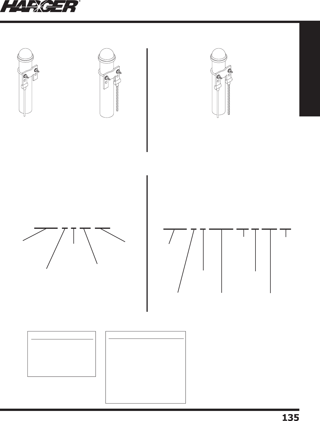
H
ar
g
er Li
g
htnin
g
& Groundin
g
•
©
2012 Phone 847-548-8700 • Fax 847-548-8755 • U.S. 800-842-743
7
135
135
Section 1
Grounding Components
Follow the ste
p
s outlined below to s
p
ecif
y
the Fence Clam
p
Assembl
y
y
ou need.
FCAUBL2T48R4
/
036
1.
5
" P
o
s
t
Left Gr
ou
n
d
C
o
n
du
ct
o
r is
#2 AWG Tinned Solid x 4' lon
g
&
Ri
g
ht Gr
ou
n
d
C
o
n
du
ct
o
r is
4
/0 Concentric x 3' lon
g
FCAUER4
/
048
6
" P
o
s
t
Ri
g
ht Gr
ou
n
d
C
o
n
du
ct
o
r is
4
/0 Concentric x 4' lon
g
No
Left Gr
ou
n
d
C
o
n
du
ct
or
FCA
U
CL2T12
0
3
" P
o
s
t
Left Gr
ou
n
d
C
o
n
du
ct
o
r is
#2 AWG Tinned Solid x 10' lon
g
N
o Ri
g
ht Ground Conducto
r
Gr
ou
n
d
C
o
n
du
ct
o
r Size C
od
e
s
2 = #2 AWG B
a
re S
o
li
d
2T = #2 AWG Tinne
d
S
o
li
d
2-7 = #2 AWG B
a
re Str
a
n
d
e
d
1
/
0 = 1
/
0 Concentri
c
2
/
0 = 2
/
0 Concentri
c
4/
0 = 4
/
0 Concentri
c
25
CM =
250
MCM C
o
ncentri
c
3
CM =
300
MCM C
o
ncentri
c
35
CM =
350
MCM C
o
ncentri
c
No
min
a
l P
o
st Size C
od
e
s
A = .7
5
" - 1.2
5
"
B
= 1.
5
" - 2"
C = 2.
5
" -
3
"
D
=
3
.
5
" - 4"
E
=
5
" -
6
"
No
te: 1/0 - 4/0 are su
pp
lied in
s
t
a
n
da
r
d
19 str
a
n
d
u
nless
o
therwise
requested. 250 MCM and lar
g
er are
s
u
pp
lied in 37 strand.
F
CAU B L 25CM 48 R 4
/
0 36
No
min
a
l P
o
st Siz
e
(
See Chart A Below
)
Fe
n
ce
Clam
p
Assembl
y
U
ltr
a
wel
d
L
eft Si
d
e
C
o
n
du
ct
o
r
D
esi
g
nato
r
L
eft Si
de
Gr
ou
n
d
C
o
n
du
ct
or
S
iz
e
(
See Chart B Below
)
L
eft Si
d
e
Gr
ou
n
d
C
o
n
du
ct
o
r
L
en
g
t
h
(
in.
)
R
i
g
ht Side
C
o
n
du
ct
o
r
D
esi
g
nato
r
R
i
g
ht Side Ground
C
o
n
du
ct
or
S
iz
e
(
See Chart B Below
)
R
i
g
ht Side
Gr
ou
n
d
C
o
n
du
ct
o
r
L
en
g
t
h
(
in.
)
T
he followin
g
D
o
uble Wire exam
p
le is a
F
ence
C
l
am
p
A
s
sembl
y
U
l
traweld with a nominal
p
ost size of 1.5"-2"
w
ith the left side of clam
p
exothermicall
y
welded to 250
M
CM conductor that is 4' (48") lon
g
and the ri
g
ht side o
f
clam
p
exothermicall
y
welded to 4/0 conductor that is 3'
(
36") lon
g
.
T
he followin
g
S
in
g
le Wire Left exam
p
le is a
F
ence
C
l
am
p
A
s
sembl
y
U
l
traweld with a nominal
p
ost size o
f
2.5"-3" with the left side of clam
p
exothermicall
y
welded
to 2T AWG conductor that is 10' (120") lon
g
.
No
min
a
l P
o
st Size
(
See Chart A Below
)
L
eft Si
d
e
C
o
n
du
ct
o
r
D
esi
g
nato
r
L
eft Si
de
Gr
ou
n
d
C
o
n
du
ct
or
S
ize
(
See Chart B Below
)
F
CA
U
C L
2
T 1
20
Fe
n
ce
Clam
p
Assembl
y
U
ltr
a
wel
d
L
eft Si
d
e
Gr
ou
n
d
C
o
n
du
ct
o
r
L
en
g
t
h
(
in.
)
Fence Clam
p
Assemblies
C
hart A
C
hart B
S
ect
io
n 1.11.2
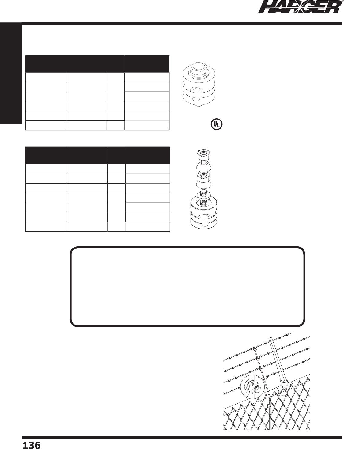
H
ar
g
er Li
g
htnin
g
& Groundin
g
•
©
2012 Phone 847-548-8700 • Fax 847-548-8755 • U.S. 800-842-743
7
136136
Section 1
Grounding Components
L
iste
d
4
67
Part No. Conductor
Size (AWG)
Box
Qty.
Approx. Box
Wt. (lbs.)
F
GC8 #8
25
5
F
GC
6
#
6
25
5
FGC4
#4
25
5
F
GC
2
#
2
25
5
F
GC2
/
02
/
01
0
3
F
GC2-4
/
0* #2 & 4
/
01
0
3
Fence Fabric Groundin
g
Clamps
Fence Ground S
y
ste
m
F
ence
g
roundin
g
systems are desi
g
ned to provide
protection a
g
ainst dan
g
erous “touch” potentials. The
fence fabric
g
round clamp is an inte
g
ral component o
f
this
p
ersonnel safet
y
s
y
stem.
S
ect
io
n 1.11.3
Part No. Conductor
Size (AWG)
Box
Qty.
Approx. Box
Wt. (lbs.)
F
GC8T
P
#8
25
5
F
GC
6
T
P
#
6
25
5
FGC
4T
P
#4
25
5
F
GC
2
T
P
#
2
25
5
F
GC
26
T
P
#
2
&
#
6
25
5
F
GC2
/
0T
P
2
/
01
0
3
F
GC2-4
/
0TP* #2 & 4
/
01
0
3
Tam
p
er Res
i
stant
N
O
TES
:
*Acce
p
ts a #2 AWG and/or 4/0 AWG conductor.
• Unique desi
g
n allows clamp to form connections at most any an
g
le.
• S
p
ecifi c uses include connection to both fence fabric and barbed wire.
• The conductor maintains a direct path to
g
round while connected to an ob
j
ect
that is parallel, perpendicular or in any de
g
ree in between.
• Electro tin
p
lated brass clam
p
comes com
p
lete with stainless steel hardware.
• Allows for use with most metallic surfaces includin
g
g
alvanized.
• Other sizes available. Please contact factor
y
for more information.
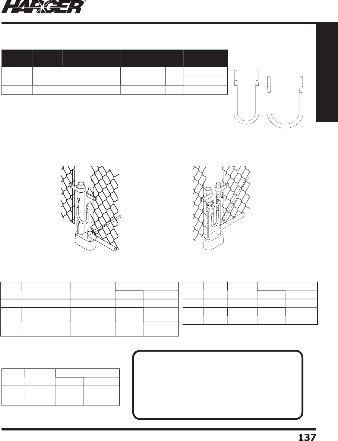
H
ar
g
er Li
g
htnin
g
& Groundin
g
•
©
2012 Phone 847-548-8700 • Fax 847-548-8755 • U.S. 800-842-743
7
13
7
137
Section 1
Grounding Components
•
Can be used with the universal
p
i
p
e clam
p
s or can be exothermicall
y
welded
to the fence/
g
ate post.
•
Three sizes desi
g
ned to fi t either a #2 solid, 2/0 stranded or 4/0 stranded
ex
o
thermic m
o
l
d
.
•
Flex
j
umpers made from weldin
g
cable.
•
Standard len
g
th is 24" lon
g
.
•
Other len
g
ths available. Please contact factory for more information.
**Add Pi
p
e Size of Vertical Pi
p
e to
M
o
ld Part N
o
.
Gate Jum
p
er welded
directl
y
to
p
osts.
Gate Jum
p
er welded to
U
PC clam
p
.
S
ee pa
g
e 134 for UPC's.
*
See pa
g
e 297 for more LE Connection Types.
*
See pa
g
e 292 for more VD (Pipe) Connection Types.
Part No. Jumper
Size
Conductor Size
(AWG)
Approx. Each
Wt. (lbs.)
Box
Qty.
Approx. Box
Wt. (lbs.)
GJX
2
S
2
4
2
AW
G
#2 s
o
li
d
1
/2
1
0
5
GJX2
/
02
4
2
/
0 AW
G
2
/
0 concentri
c
11
0
1
0
GJX4
/
02
4
4/
0 AW
G
4/
0 concentri
c
1-1
/2
1
0
1
5
C
able
Si
ze
N
o
mina
l
P
ip
e S
i
ze
M
o
ld
P
art
No
.
W
el
d
Meta
l
U
ltraSh
o
t
NUWTUBE
#2 S
o
l. 1-1/4" to 4" Pi
pe
VD-
2
SV1.
25
X4
B
U
S
65
NU
WT
U
BE
65
2
/
01-1/4" to 3-1/2" Pi
p
e
2" to 4" Pi
pe
VD-2
/
0V1.25X3.5
B
VD-2
/
0V2X4
B
U
S9
0
U
S9
0
NU
WT
U
BE9
0
NU
WT
U
BE9
0
4/
01-1/4" to 3-1/2" Pi
p
e
2" to 4" Pi
pe
VD-4
/
0V1.25X3.5
B
VD-4
/
0V2X4
B
U
S1
50
U
S1
50
NU
WT
U
BE1
50
NU
WT
U
BE1
50
C
able
Si
ze
L
u
g
Si
ze
M
o
ld
P
art
No
.
W
el
d
Meta
l
U
ltraSh
o
t
NUWTUBE
#2 S
o
l. 1
/
4" x 1"
L
E-
2S
141
B
U
S
65
NU
WT
U
BE
65
2
/
01
/
4" x 1"
L
E-2
/
0141
B
U
S
65
NU
WT
U
BE
65
4/
01
/
4" x 1"
L
E-4
/
0141
B
U
S9
0
NU
WT
U
BE9
0
C
able
Si
ze
M
o
ld
P
art
No
.
W
el
d
Meta
l
U
ltraSh
o
t
NUWTUBE
#2 S
o
l.
2
/
0
4/
0
VD-2
S
V**
B
VD-2
/
0V**
B
VD-4
/
0V**
B
U
S
65
US
11
5
U
S1
50
NU
WT
U
BE
65
NU
WT
U
BE11
5
NU
WT
U
BE1
50
Flexible Gate Jum
p
ers
VD (Pipe) Connection Type (Ran
g
e Takin
g
)LE Connect
i
on T
yp
e
VD
(
Pi
p
e
)
Connection T
yp
e
S
ect
io
n 1.11.
4
N
O
TE
:
T
hin walled
p
i
p
e ma
y
be unsuitable for exothermic connections. I
f
experiencin
g
burn throu
g
h issues with the pipe (typically with 2/0
o
r 4/0 conductors), addin
g
sand inside the fence post well past the
exothermic connection ma
y
solve this
p
roblem. Another solution
w
ould be to use a smaller conductor such as a #2 aw
g
j
umper
w
hich uses a smaller size weld metal. The last solution ma
y
be to
u
se mechanical fence clam
p
assembl
y
such as the ones found in
S
ection 1.11 on pa
g
e 1
33
.
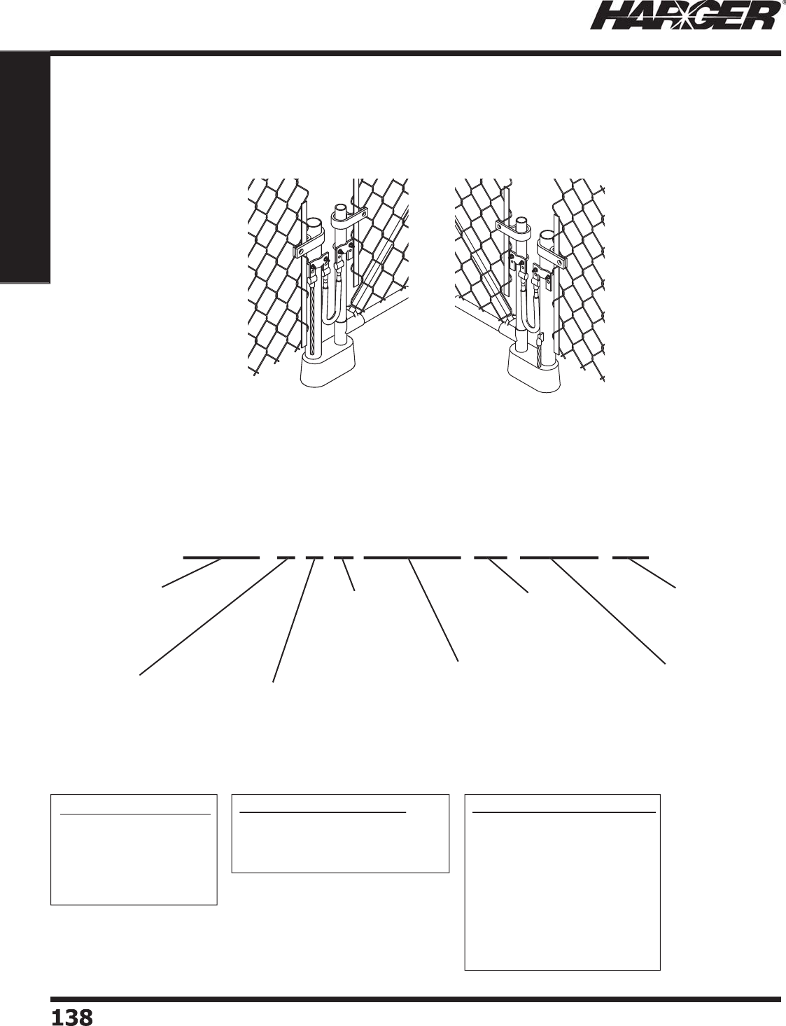
H
ar
g
er Li
g
htnin
g
& Groundin
g
•
©
2012 Phone 847-548-8700 • Fax 847-548-8755 • U.S. 800-842-743
7
1
38
138
Section 1
Grounding Components
F
ollow the steps outlined below to specify the Fence Gate Assembly (Exothermically Welded) you need. The followin
g
exam
p
le is a
F
ence
G
at
e
A
s
sembl
y
U
l
traweld with a nominal fence post size of 2.5"-3" and a nominal
g
ate post
s
ize of 1.5"-2" with the fence post on the left, a 4/0 AWG weldin
g
cable that is 2' (24") lon
g
and a 250 MCM
g
round
conductor that is 4' (48") lon
g
.
FGAUDBR2WC18
4
" Fence P
o
s
t
1.
5
" G
a
te P
o
s
t
F
ence P
o
st is
o
n the Ri
g
ht
#2 AWG Jumper x 1-1/2' lon
g
No
Gr
ou
n
d
C
o
n
du
ct
or
FGAUCBL4
/
0WC2425CM4
8
3
" Fence P
o
s
t
1.
5
" G
a
te P
o
s
t
F
ence P
o
st is
o
n the Left
4
/0 Jumper x 2' lon
g
250 MCM Ground Conductor x 4' lon
g
**If
g
round conductor is not required, then leave
g
round conductor size and len
g
th blank.
Flexible Jumper Size Codes
p
2WC = #2 AWG Weldin
g
Cabl
e
2/0WC = 2/0 AWG Weldin
g
Cabl
e
4
/0WC = 4/0 AWG Weldin
g
Cabl
e
No
min
a
l P
o
st Size C
od
e
s
A = .7
5
" - 1.2
5
"
B
= 1.
5
" - 2"
C = 2.
5
" -
3
"
D
=
3
.
5
" - 4"
E
=
5
" -
6
"
Gr
ou
n
d
C
o
n
du
ct
o
r Size C
od
e
s
2 = #2 AWG B
a
re S
o
li
d
2T = #2 AWG Tinne
d
S
o
li
d
2-7 = #2 AWG B
a
re Str
a
n
d
e
d
1
/
0 = 1
/
0 Concentri
c
2
/
0 = 2
/
0 Concentri
c
4/
0 = 4
/
0 Concentri
c
25
CM =
250
MCM C
o
ncentri
c
3
CM =
300
MCM C
o
ncentri
c
35
CM =
350
MCM C
o
ncentri
c
N
ote: 1
/
0 - 4
/
0
are su
pp
lied
i
n st
a
n
da
r
d
19
s
tr
a
n
d
u
nless
o
therwise
re
q
uested.
2
50
MCM
a
n
d
l
ar
g
er are
s
u
pp
lied in
3
7 str
a
n
d
.
F
GAU C B L 4
/
0WC 24 25CM 48
No
min
a
l Fence P
o
st
S
ize
(
See Chart A Below
)
F
ence
Ga
te
Assembl
y
U
ltr
a
wel
d
F
ence P
o
st Si
de
(
L = Left o
r
R
= Ri
g
ht
)
F
lexible Jum
p
er
S
iz
e
(
See Chart B Below
)
F
lexible Jum
p
er
L
en
g
t
h
(
in.
)
Gr
ou
n
d
**
C
o
n
du
ct
o
r Siz
e
(
See Chart C Below
)
Gr
ou
n
d
**
C
o
n
du
ct
o
r
L
en
g
t
h
(
in.
)
No
min
a
l G
a
te
Po
st
S
iz
e
(
See Chart A Below
)
Fence
G
ate A
ss
emblie
s
(
Exothermicall
y
Welded
)
C
hart A
C
hart B
C
hart
C
S
ect
io
n 1.11.5
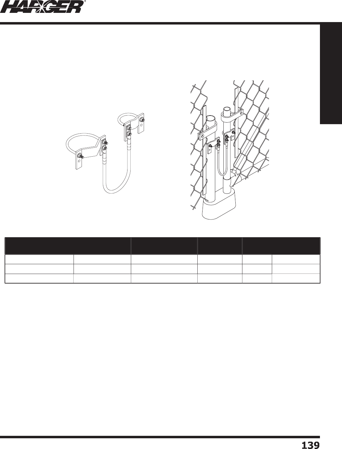
H
ar
g
er Li
g
htnin
g
& Groundin
g
•
©
2012 Phone 847-548-8700 • Fax 847-548-8755 • U.S. 800-842-743
7
13
9
139
Section 1
Grounding Components
•
Inte
g
ral component of a fence
g
roundin
g
system.
•
Helps eliminate dan
g
erous touch potential.
•
Used when it is not feasible to exothermically bond to fence/
g
ate posts.
•
Flex
j
umper assemblies use #2 AWG Weldin
g
Cable.
•
Shi
pp
ed unassembled.
Part No. Nominal Gate
Post Size Range
Nominal Fence Post
Size Range
Jumper
Size (AWG)
Jumper
Length
Approx. Each
Wt. (lbs.)
F
GA1.5
/
2-2.5
/
32WC2
4
1.
5
" - 2" 2.
5
" -
3
"#
2
24" 2-1
/2
F
GA1.5
/
2-3.5
/
42WC2
4
1.
5
" - 2"
3
.
5
" - 4" #
2
24"
3
F
GA1.5
/
2-5
/
62WC2
4
1.
5
" - 2"
5
" -
6
"#
2
24" 3-1
/2
Fence
G
ate A
ss
emblie
s
(
Compression Lu
g
s)
S
ect
io
n 1.11.5

H
ar
g
er Li
g
htnin
g
& Groundin
g
•
©
2012 Phone 847-548-8700 • Fax 847-548-8755 • U.S. 800-842-743
7
1
4
0140
Section 1
Grounding Components
No
tes

H
ar
g
er Li
g
htnin
g
& Groundin
g
•
©
2012 Phone 847-548-8700 • Fax 847-548-8755 • U.S. 800-842-743
7
1
4
1
141
Section 1
Grounding Components
S
ect
io
n 1.12
Hardware & Access
o
ries
In
d
ex
Descr
i
pt
i
on Pa
g
e
1.12.1 St
a
inless Steel Screws
......................................................................
142
1.12.2 St
a
inless Steel W
a
shers
&
N
u
t
s
..........................................................
14
3
1.12.3 Silicon Bronze Screws, Washers & Nut
s
..............................................
14
5
1.12.4 Thread Formin
g
Scre
w
......................................................................
14
6
1.12.
5
N
a
il
s
................................................................................................
14
6
1.12.
6
Sheet Met
a
l Screw
s
..........................................................................
14
6
1.1
2
.7 TEK
S
S
crew
s
....................................................................................
14
7
1.12.8 Ex
p
ansion Anchor
s
...........................................................................
147
1.12.9 Abrasive Pad & Cold Galvanizin
g
Spra
y
...............................................
147
1.12.10 Antioxidant Joint Com
p
ound
..............................................................
148
H
ar
g
er Li
g
htnin
g
& Groundin
g
•
©
2012 Phone 847-548-8700 • Fax 847-548-8755 • U.S. 800-842-743
7
1
42
142
Section 1
Grounding Components
Part No. Thread Size Length Box
Qty.
Approx. Box
Wt. (lbs.)
CS44S-1
00
1
/
4-20 1
/
2" 1
00
1-1
/
4
CS4
6
S-1
00
1
/
4-20 3
/
4" 1
00
1-1
/2
CS48S-100 1
/
4-20 1" 1
00
2
CS
5
4S-1
00
5/
16-18 1
/
2" 1
00
2
CS
5
7S-1
00
5/
16-18 7
/
8" 1
00
3
CS58S-100
5/
16-18
1
"1
00
3
CS
5
1
0
S-1
00
5/
16-18 1-1
/
4" 1
00
4
CS
6
4S-1
00
3
/
8-16 1
/
2" 1
00
3
CS
66
S-1
00
3
/
8-16 3
/
4" 1
00
4
CS68S-100 3
/
8-16 1" 1
00
5
CS
6
1
0
S-1
00
3
/
8-16 1-1
/
4" 1
00
5
CS
6
1
2
S-1
00
3
/
8-16 1-1
/
2" 1
00
6
CS
6
1
6
S-1
00
3
/
8-16 2" 1
00
6
CS88S-100 1
/
2-1
3
1" 1
00
9
CS108S-100
5/
8-11 1" 1
00
15-1
/2
Part No. Thread Size Length Box
Qty.
Approx. Box
Wt. (lbs.)
M
S1
03
S-1
00
1
0
-
2
43
/
8" 1
00
1
/2
M
S1
06
S-1
00
1
0
-
2
43
/
4" 1
00
1
/2
M
S108S-100 1
0
-
2
41"1
00
1
/2
M
S44S-1
00
1
/
4-20 1
/
2" 1
00
1
M
S4
6
S-1
00
1
/
4-20 3
/
4" 1
00
1-1
/
4
M
S48S-100 1
/
4-20 1" 1
00
1-1
/2
M
S41
2
S-1
00
1
/
4-20 1-1
/
2" 1
00
2-1
/
4
S
tainle
ss
Steel Screw
s
Hex Head Ca
p
Screws
S
l
o
tted R
o
und Head Machine Screws
Part No. Thread Size Length Box
Qty.
Approx. Box
Wt. (lbs.)
R
HB
O
B
6
4S-1
0
3
/
8-16 1
/
2" 1
0
1
/3
R
HB
O
B
65
S-1
0
3
/
8-16
5/
8" 1
0
1
/2
Tam
p
er Resistant Bolts
B
ef
o
r
e
Aft
er
N
O
TES
:
• Manufactured from 18-8 stainless steel.
• Other sizes available. Please contact factor
y
for more information.
S
ect
io
n 1.12.1
H
ar
g
er Li
g
htnin
g
& Groundin
g
•
©
2012 Phone 847-548-8700 • Fax 847-548-8755 • U.S. 800-842-743
7
1
4
3
143
Section 1
Grounding Components
Part No. Inside
Diameter
Outside
Diameter
Box
Qty.
Approx. Box
Wt. (lbs.)
W
4S-1
00
1
/
4"
5/
8" 1
00
1
/2
W5
S-1
00
5/
16" 3
/
4" 1
00
1
/2
W6
S-1
00
3
/
8" 1" 1
00
1
W
8S-100 1
/
2" 1-1
/
4" 1
00
2
Part No. Size Box
Qty.
Approx. Box
Wt. (lbs.)
L
W4S-1
00
1
/
4" 1
00
1
/2
L
W
5
S-1
00
5/
16" 1
00
1
/2
L
W
6
S-1
00
3
/
8" 1
00
1
L
W8S-100 1
/
2" 1
00
1-1
/2
Part No. Size Box
Qty.
Approx. Box
Wt. (lbs.)
S
W4S-1
00
1
/
4" 1
00
1
/2
S
W
5
S-1
00
5/
16" 1
00
1
/2
S
W
6
S-1
00
3
/
8" 1
00
1
/2
S
W8S-100 1
/
2" 1
00
1
/2
Part No. Size Box
Qty.
Approx. Box
Wt. (lbs.)
D
TW4-1
00
1
/
4" 1
00
1
/2
D
TW
6
-1
00
3
/
8" 1
00
1
/2
D
TW8-100 1
/
2" 1
00
1
/2
S
tainle
ss
Steel Wa
s
her
s
&
N
u
t
s
Flat Wa
s
her
s
L
o
ck Washers
S
tar Wa
s
her
s
Dra
g
on Tooth Washers
N
O
TES
:
• Manufactured from 18-8 stainless steel.
• Sold in 100 piece packa
g
es.
• Other sizes available. Please contact factor
y
for more information.
S
ect
io
n 1.12.2
H
ar
g
er Li
g
htnin
g
& Groundin
g
•
©
2012 Phone 847-548-8700 • Fax 847-548-8755 • U.S. 800-842-743
7
1
4
4144
Section 1
Grounding Components
•
30
1 St
a
inless Steel
•
Maintains bolt
p
re-load over time.
•
Allows for differential thermal ex
p
ansion without loss of load.
•
Provides even loadin
g
over contact area.
Part No. Bolt Hole
Size
Max.
O.D.
Min.
I.D. Thickness Overall
Height
Load to
Flat (lbs.)
Box
Qty.
Approx. Box
Wt. (lbs.)
B
W4S-1
00
1
/
4"
0
.
500
"
0
.2
55
"
0
.038"
0
.
0
47"
3
7
6
1
00
1
/2
B
W
6
S-1
00
3
/
8"
0
.7
50
"
0
.380"
0
.
0
4
0
"
0
.
05
9"
3
9
2
1
00
1
/2
B
W8S-100
9/
16" 1.12
5
"
0
.
56
7"
0
.038"
0
.
0
7
3
" 268 1
00
1
Part No. Inside
Diameter
Outside
Diameter
Box
Qty.
Approx. Box
Wt. (lbs.)
F
W
6
S-1
00
3
/
8" 1-1
/
4" 1
00
1-1
/2
F
W8S-100 1
/
2" 2" 1
00
2-1
/2
Part No. Thread
Size
Box
Qty.
Approx. Box
Wt. (lbs.)
N
4
20
S-1
00
1
/
4-20 1
00
1
N
518S-100
5/
16-18 1
00
1-1
/2
N6
1
6
S-1
00
3
/
8-16 1
00
1-1
/2
N
813S-50 1
/
2-1
3
50
2
S
tainle
ss
Steel Wa
s
her
s
&
N
u
t
s
Fen
d
er Wa
s
her
s
Belleville Wa
s
her
s
Nu
t
s
Part No. Thread
Size
Box
Qty.
Approx. Box
Wt. (lbs.)
N
518SBON-10
5/
16-18 1
0
1
/3
B
ef
o
r
e
Aft
er
Tam
p
er Res
i
stant Nut
N
O
TES
:
• Manufactured from 18-8 stainless steel.
• Other sizes available. Please contact factor
y
for more information.
S
ect
io
n 1.12.2
H
ar
g
er Li
g
htnin
g
& Groundin
g
•
©
2012 Phone 847-548-8700 • Fax 847-548-8755 • U.S. 800-842-743
7
1
4
5
145
Section 1
Grounding Components
Part No. Thread Size Length Box
Qty.
Approx. Box
Wt. (lbs.)
CS4
6
B-1
00
1
/
4-20 3
/
4" 1
00
1-1
/2
CS58B-100
5/
16-18 1" 1
00
3
CS68B-100 3
/
8-16 1" 1
00
4
-1
/2
Part No. Size Box
Qty.
Approx. Box
Wt. (lbs.)
L
W4B-1
00
1
/
4" 1
00
1
/2
L
W
5
B-1
00
5/
16" 1
00
1
/2
L
W
6
B-1
00
3
/
8" 1
00
3
/4
Part No. Inside
Diameter
Outside
Diameter
Box
Qty.
Approx. Box
Wt. (lbs.)
W
4B-1
00
1
/
4"
5/
8" 1
00
1
/
4
W5
B-1
00
5/
16" 3
/
4" 1
00
1
/2
W6
B-1
00
3
/
8" 1" 1
00
3
/
4
Part No. Thread Size Box
Qty.
Approx. Box
Wt. (lbs.)
N
4
20
B-1
00
1
/
4-20 1
00
1
/2
N
518B-100
5/
16-18 1
00
1-1
/2
N6
1
6
B-1
00
3
/
8-16 1
00
1-1
/2
S
ilicon Bronze Screws, Washers & Nuts
Hex Head Ca
p
Screws
L
o
ck Washers
Flat Wa
s
her
s
Nu
t
s
Part No. Size Box
Qty.
Approx. Box
Wt. (lbs.)
W6
R-
50
3
/
8"
50
3
/4
W6
R-1
00
3
/
8" 1
00
1-1
/2
W
8R-50 1
/
2"
50
3
/4
W
8R-100 1
/
2" 1
00
1-1
/2
Neo
p
rene Washers
N
O
TES
:
• Sold in 100 piece packa
g
es.
• Other sizes available. Please contact factor
y
for more information.
S
ect
io
n 1.12.3
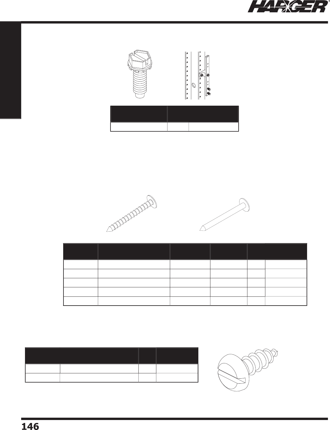
H
ar
g
er Li
g
htnin
g
& Groundin
g
•
©
2012 Phone 847-548-8700 • Fax 847-548-8755 • U.S. 800-842-743
7
1
4
6146
Section 1
Grounding Components
•
#12-24 x 5/8" zinc plated thread formin
g
hex
wa
sher he
ad
screw with extern
a
l w
a
sher.
•
U
se
d
with white st
a
n
do
ff ins
u
l
a
t
o
rs
(
11/16WINS & 7/8WINS
)
.
•
Removes
p
aint on a 12-24 threaded rack hole.
Part No. Box
Qty.
Approx. Box
Wt. (lbs.)
S
MS
0
1
26
SHWZ-
50
50
1
Thread Formin
g
Screw
Nail
s
Part No. Description Length Diameter
Head
Box
Qty.
Approx. Box
Wt. (lbs.)
2
74-1
00
4
d Copper Rin
g
ed 1-1
/
2" 3
/
8" 1
00
3
/4
2
74S-1
00
4
d Stainless Steel Rin
g
ed 1-1
/
2"
5/
16" 1
00
3
/4
A
2
74-1
00
4d
Al
u
min
u
m C
o
mm
on
1-5
/
8" 1
/
4" 1
00
1
/2
2
7
5
-1
00
6
d Co
pp
er Commo
n
2-1
/
8" 1
/
4" 1
00
1-1
/
4
2
77S-1
00
6
d Stainless Steel Rin
g
ed
2
"3
/
8" 1
00
1
R
in
g
ed
Co
mm
on
•
Stainless steel
p
an head sheet metal screw.
•
Use for fastenin
g
cable loops and/or bondin
g
terminals to
thin sheet met
a
l s
u
rf
a
ces.
Part No. Description Box
Qty.
Approx. Box
Wt. (lbs.)
2
9
0
-1
00
N
o. 12 x 5/8" Lon
g
1
00
3
/4
2
91-1
00
N
o. 12 x 1" Lon
g
1
00
1
S
heet Metal Screw
s
S
ect
io
n 1.12.4 - 1.12.6
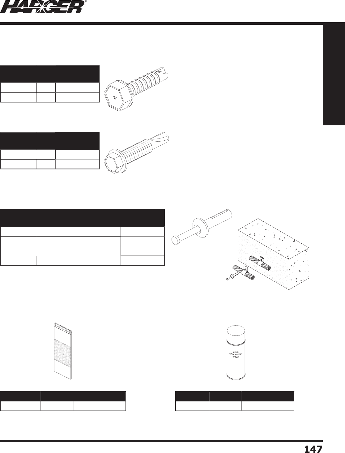
H
ar
g
er Li
g
htnin
g
& Groundin
g
•
©
2012 Phone 847-548-8700 • Fax 847-548-8755 • U.S. 800-842-743
7
1
47
147
Section 1
Grounding Components
•
P
ad
rem
o
ves
o
xi
da
ti
o
n fr
o
m s
u
rf
a
ce when
properly used. Critical step when makin
g
a
l
o
w resist
a
nce c
o
nnecti
o
n.
Part No. Box Qty. Unit Wt. (oz.)
3
MABPA
D
1
2
2
•
Instant cold
g
alvanizin
g
spray provides protection
equal to hot dip
g
alvanizin
g
.
•
Used for touchin
g
up surfaces affected by weldin
g
.
Part No. Qty. Unit Wt. (oz.)
CGS
EA
1
6
Abrasive Pad & Cold Galvanizin
g
Spra
y
•
No. 12-14 x 3/4" lon
g
stainless steel TEKS/3 sel
f
drillin
g
and threadin
g
screw.
•
General purpose screw for use with 12 throu
g
h 26
g
au
g
e steel.
•
No. 12-24 x 1-1
/
4" stainless steel TEKS
/
5 sel
f
drillin
g
and threadin
g
screw.
•
Heavy duty screw for use with 1/4” throu
g
h 26
g
au
g
e steel.
•
Ideal for installin
g
bondin
g
plates.
•
Has stainless steel
p
in and Zamac #7 bod
y
for corrosion
resist
a
nt inst
a
ll
a
ti
o
n.
•
This anchor requires a 5/16" diameter mountin
g
hole.
Part No. Box
Qty.
Approx. Box
Wt. (lbs.)
2
9
5
-
25
25
1
/4
2
9
5
-1
00
1
00
3
/4
Part No. Box
Qty.
Approx. Box
Wt. (lbs.)
2
9
6
-
25
25
1
/2
2
9
6
-1
00
1
00
1-1
/
4
Part No. Description Box
Qty.
Approx. Box
Wt. (lbs.)
280-25 1/4 x 1" Lon
g
25
1
/2
280-100 1/4 x 1" Lon
g
1
00
2-1
/
4
281-25 1/4 x 1-1/2" Lon
g
25
3
/4
281-100 1/4 x 1-1/2" Lon
g
1
00
2-3
/
4
TEK
S
S
crew
s
TEKS
/
3
TEKS
/
5
Ex
p
ansion Anchors
Abra
s
ive Pa
d
C
old Galvanizin
g
Spra
y
S
ect
io
n 1.12.7 - 1.12.9
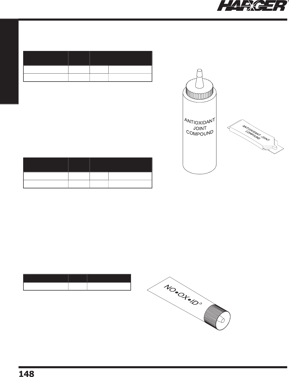
H
ar
g
er Li
g
htnin
g
& Groundin
g
•
©
2012 Phone 847-548-8700 • Fax 847-548-8755 • U.S. 800-842-743
7
1
48
148
Section 1
Grounding Components
•
Oxide inhibitin
g
j
oint compound used to improve
electrical conductivity and enhance the inte
g
rity o
f
the c
o
nnecti
o
n.
•
S
y
nthetic base with sus
p
ended zinc
p
articles.
•
Material is
g
ray in color.
•
Rec
o
mmen
d
e
d
f
o
r
a
l
u
min
u
m t
o
a
l
u
min
u
m
connections, aluminum to co
pp
er connections and
a
l
u
min
u
m c
o
n
du
it thre
ad
s.
N
O
•
O
X•I
D
®
Antioxidant Paste
Cold a
pp
lied clear antioxidant for aluminum
to aluminum, aluminum to co
pp
er and
co
pp
er to co
pp
er connect
i
ons.
•
Oxide inhibitin
g
j
oint compound used to improve
electrical conductivity and enhance the inte
g
rity of the
c
o
nnecti
o
n.
•
S
y
nthetic base with sus
p
ended co
pp
er
p
articles.
•
Material is co
pp
er in color.
•
Recommended for co
pp
er to co
pp
er connections,
copper threads and all
g
roundin
g
applications.
Part No. Size Box
Qty.
Approx. Box
Wt. (lbs.)
H
AAJC1
/2
1
/
2 oz. 1
2
1
/2
H
AAJC8 8 oz. 1
2
6
Part No. Size Box
Qty.
Approx. Box
Wt. (lbs.)
H
CAJC1
/2
1
/
2 oz. 1
2
1
/2
H
CAJC8 8 oz. 1
2
6
Part No. Qty. Unit Wt. (oz.)
NOO
XCLR
EA
8
Al
u
min
um
C
o
pp
er
Antioxidant Joint Com
p
ound
S
ect
io
n 1.12.10

H
ar
g
er Li
g
htnin
g
& Groundin
g
•
©
2012 Phone 847-548-8700 • Fax 847-548-8755 • U.S. 800-842-743
7
1
4
9
149
Section 2
Lightning Protection Components
S
ect
io
n 2
Li
g
htnin
g
Protectio
n
C
om
p
onents
In
d
ex
Descr
i
pt
i
on Pa
g
e
2.1 Li
g
htnin
g
Conductors & Accessorie
s
...................................................
1
5
1
2.2 Air Termin
a
ls
&
Access
o
rie
s
...............................................................
1
6
1
2.
3
Air Termin
a
l B
a
se
s
............................................................................
17
7
2.4 Thru-Roof/Wall Connectors, Assemblies & Accessorie
s
........................
18
7
2.5 Li
g
htnin
g
Conductor Cable Connectors & Clamp
s
................................
19
5
2.6 Bondin
g
Lu
g
s & Plate
s
......................................................................
205
2.7 Li
g
htnin
g
Warnin
g
System
.................................................................
2
11
U
L Defi niti
o
ns
9
6: UL standard for li
g
htnin
g
protection component
s
5
0H2: Har
g
er's number for li
g
htnin
g
protection (assi
g
ned by UL
)
4
67: UL standard for
g
roundin
g
component
s
2S01: Har
g
er's number for
g
roundin
g
(assi
g
ned by UL
)
4
68: UL listin
g
for lu
gs
ZMVV: Har
g
er's listin
g
for lu
g
s (assi
g
ned by UL
)

H
ar
g
er Li
g
htnin
g
& Groundin
g
•
©
2012 Phone 847-548-8700 • Fax 847-548-8755 • U.S. 800-842-743
7
150150
Section 2
Lightning Protection Components
No
tes
Li
g
htnin
g
Protection
Installation Trainin
g
•
Tau
g
ht by an industry exper
t
•
Covers all installation
p
ractice
s
•
Review NFPA 780 re
q
uirement
s
•
Classes available monthl
y
•
View an installed s
y
stem
•
Hands-on learnin
g
•
E
a
rn CEC h
ou
rs*
(
certain states a
pp
l
y)
•
No char
g
e to attend
Sig
n up now
@
http://www.harger.com/training/lptdates.cfm
p// g / g/p

H
ar
g
er Li
g
htnin
g
& Groundin
g
•
©
2012 Phone 847-548-8700 • Fax 847-548-8755 • U.S. 800-842-743
7
151
151
Section 2
Lightning Protection Components
S
ect
io
n 2.1
Li
g
htnin
g
Conductors
&
Access
o
r
i
es
In
d
ex
Descr
i
pt
i
on Pa
g
e
2.1.1 Class I Co
pp
er Conductor
s
................................................................
1
52
2.1.2 Class II Co
pp
er Conductor
s
...............................................................
1
53
2.1.
3
Cl
a
ss I Al
u
min
u
m C
o
n
du
ct
o
r
s
............................................................
1
54
2.1.4 Cl
a
ss II Al
u
min
u
m C
o
n
du
ct
o
r
s
...........................................................
1
55
2.1.5 Bondin
g
Conductor
s
..........................................................................
1
55
2.1.6 Cable Cli
ps
.......................................................................................
1
56
2.1.7 Pre-formed Cable Cli
ps
......................................................................
1
56
2.1.8 Standin
g
Seam Clamp
s
.....................................................................
1
57
2.1.9 A
d
hesive C
ab
le H
o
l
d
er
s
.....................................................................
158
2.1.1
0
A
d
hesive
s
........................................................................................
1
5
9
2.1.11 C
ab
le G
ua
r
ds
...................................................................................
1
60
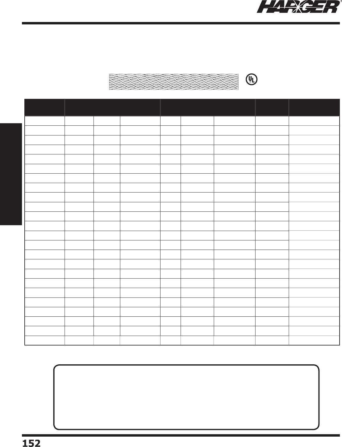
H
ar
g
er Li
g
htnin
g
& Groundin
g
•
©
2012 Phone 847-548-8700 • Fax 847-548-8755 • U.S. 800-842-743
7
15
2
152
Section 2
Lightning Protection Components
Part No. No. of
Strands
Strand
Size
X-Sectional
Area in CM ETP* Approx.
Diameter
Approx. Wt.
lbs./M ft.
Reel/Coil
Size
Approx. Reel/
Coil Wt. (lbs.)
2
4-
25
C
O
IL
2
4 14 AW
G
9
8,600
No
7
/
16"
320
2
5'
8
2
4-
50
C
O
IL
2
4 14 AW
G
9
8,600
No
7
/
16"
320
50'
1
6
2
4-1
00
2
4 14 AW
G
9
8,600
No
7
/
16"
320
1
00'
37
2
4-
250
2
4 14 AW
G
9
8,600
No
7
/
16"
320
2
50'
90
2
9-
25
C
O
IL
2
91
6
AW
G
7
2
,500
No
3
/
8"
203
2
5'
5
-1
/
4
2
9-
50
C
O
IL
2
91
6
AW
G
7
2
,500
No
3
/
8"
203
50'
10-1
/2
2
9-1
00
2
91
6
AW
G
7
2
,500
No
3
/
8"
203
1
00'
2
4
2
9-
250
2
91
6
AW
G
7
2
,500
No
3
/
8"
203
2
50'
55
2
9-
500
2
91
6
AW
G
7
2
,500
No
3
/
8"
203
500'
11
2
29T-2
5
C
O
IL*
2
91
6
AW
G
7
2
,500
Yes
3
/
8"
203
2
5'
5
-1
/
4
29T-
50
C
O
IL*
2
91
6
AW
G
7
2
,500
Yes
3
/
8"
203
50'
10-1
/2
29T-1
00
*
2
91
6
AW
G
7
2
,500
Yes
3
/
8"
203
1
00'
2
4
29T-2
50
*
2
91
6
AW
G
7
2
,500
Yes
3
/
8"
203
2
50'
55
29T-
500
*
2
91
6
AW
G
7
2
,500
Yes
3
/
8"
203
500'
11
2
32
-
25
C
O
IL
32
1
6
AW
G
80,000
No
7
/
16"
2
1
3
2
5'
5
-1
/2
32
-
50
C
O
IL
32
1
6
AW
G
80,000
No
7
/
16"
2
1
3
50'
11
32
-1
00
32
1
6
AW
G
80,000
No
7
/
16"
2
1
3
1
00'
27
32
-
250
32
1
6
AW
G
80,000
No
7
/
16"
2
1
3
2
50'
62
32
-
500
32
1
6
AW
G
80,000
No
7
/
16"
2
1
3
500'
1
22
3
2T-2
5
C
O
IL*
32
1
6
AW
G
80,000
Yes
7
/
16"
2
1
3
2
5'
5
-1
/2
3
2T-
50
C
O
IL*
32
1
6
AW
G
80,000
Yes
7
/
16"
2
1
3
50'
11
3
2T-1
00
*
32
1
6
AW
G
80,000
Yes
7
/
16"
2
1
3
1
00'
27
3
2T-2
50
*
32
1
6
AW
G
80,000
Yes
7
/
16"
2
1
3
2
50'
62
3
2T-
500
*
32
1
6
AW
G
80,000
Yes
7
/
16"
2
1
3
500'
1
22
L
iste
d
9
6
*
ETP - Electr
o
Tin Pl
a
te
d
C
lass I Co
pp
er Conductors
These c
o
nduct
o
rs are intended f
o
r use
o
n structures
up to and includin
g
75' in hei
g
ht.
TECHNICAL N
O
TES
:
• Class I li
g
htnin
g
conductors are manufactured usin
g
a special rope lay process. This process
maximizes the surface area of the conductor while allowin
g
g
reater installation fl exibility.
• Class I Minimum Re
q
uirements:
- 187
p
ounds
p
er 1,000 feet.
- Cross-sectional area of 57,400 circular mils.
- Minim
u
m str
a
n
d
size 17 AWG.
• Conductors are marked every 3' with a
g
reen ink dot for cable fastner spacin
g
.
S
ect
io
n 2.1.1
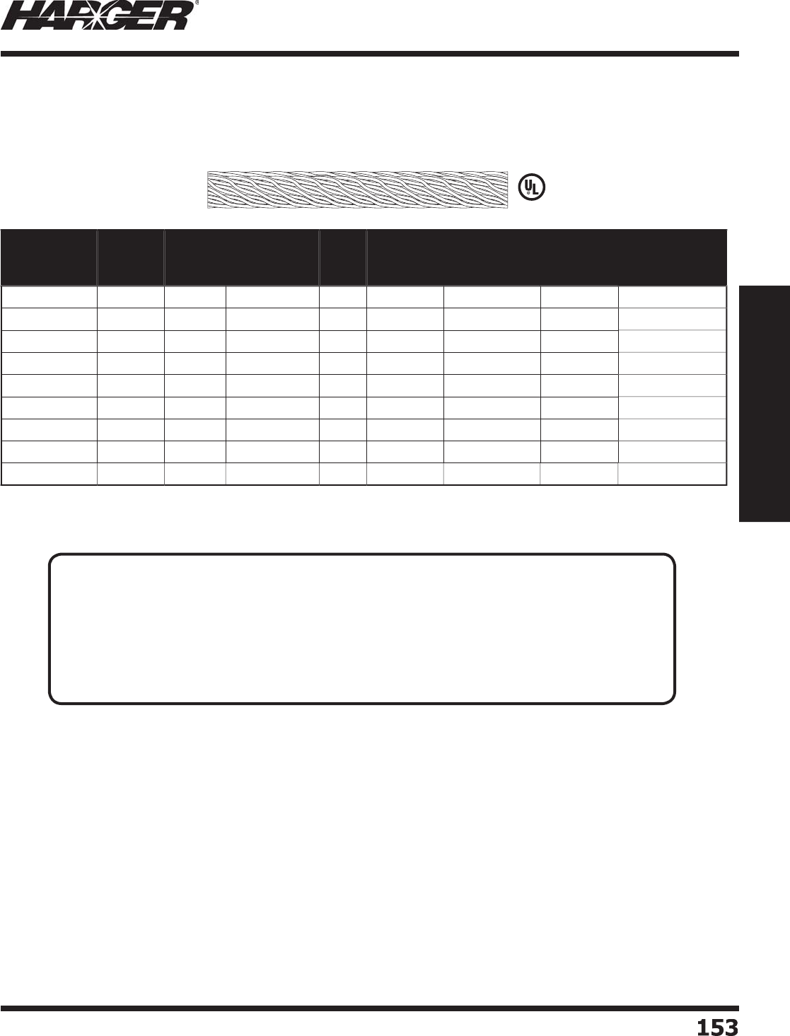
H
ar
g
er Li
g
htnin
g
& Groundin
g
•
©
2012 Phone 847-548-8700 • Fax 847-548-8755 • U.S. 800-842-743
7
153
153
Section 2
Lightning Protection Components
L
iste
d
9
6
*
ETP - Electr
o
Tin Pl
a
te
d
Part No. No. of
Strands
Strand
Size
X-Sectional
Area in CM ETP* Approx.
Diameter
Approx. Wt.
lbs./M ft.
Reel/Coil
Size
Approx.
Reel/Coil Wt.
(lbs.)
28-25COIL 28 14 AW
G
115,000
No
1
/
2"
3
7
5
2
5'
9
-1
/2
28-50COIL 28 14 AW
G
115,000
No
1
/
2"
3
7
5
50'
19
28-100 28 14 AW
G
115,000
No
1
/
2"
3
7
5
1
00'
3
9
28-250 28 14 AW
G
115,000
No
1
/
2"
3
7
5
2
50'
1
03
28T-25COIL* 28 14 AW
G
115,000
Yes
1
/
2"
3
7
5
2
5'
9
-1
/2
28T-50COIL* 28 14 AW
G
115,000
Yes
1
/
2"
3
7
5
50'
19
28T-100* 28 14 AW
G
115,000
Yes
1
/
2"
3
7
5
1
00'
3
9
28T-250* 28 14 AW
G
115,000
Yes
1
/
2"
3
7
5
2
50'
1
03
4
0-28 28
.
0865
2
11,500
No
5/
8"
660
2
50'
17
4
C
lass II Co
pp
er Conductors
These c
o
nduct
o
rs are intended f
o
r use
o
n structures
g
reater than 75' in hei
g
ht.
T
ECHNICAL N
O
TES
:
• Class II li
g
htnin
g
conductors are manufactured usin
g
a special rope lay process. This process
maximizes the surface area of the conductor while allowin
g
g
reater installation fl exibility.
• Class II Minimum Re
q
uirements:
- 375
p
ounds
p
er 1,000 feet.
- Cross-sectional area of 115,000 circular mils.
- Minim
u
m str
a
n
d
size 1
5
AWG.
• Conductors are marked every 3' with a
g
reen ink dot for cable fastner spacin
g
.
S
ect
io
n 2.1.2
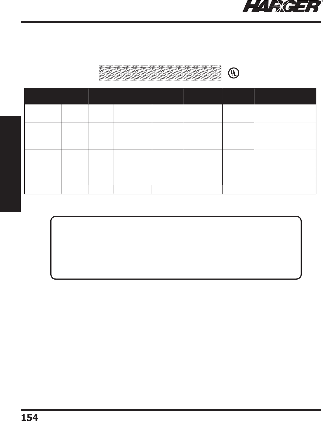
H
ar
g
er Li
g
htnin
g
& Groundin
g
•
©
2012 Phone 847-548-8700 • Fax 847-548-8755 • U.S. 800-842-743
7
154154
Section 2
Lightning Protection Components
L
iste
d
9
6
Part No. No. of
Strands
Strand
Size
X-Sectional
Area in CM
Approx.
Diameter
Approx. Wt.
lbs./M ft.
Reel/Coil
Size
Approx. Reel/Coil
Wt. (lbs.)
A
2
4-
25
C
O
IL
2
4 14 AW
G
9
8,600 7
/
16"
95
2
5'
2-1
/2
A
2
4-
50
C
O
IL
2
4 14 AW
G
9
8,600 7
/
16"
95
50'
5
A
2
4-1
00
2
4 14 AW
G
9
8,600 7
/
16"
95
1
00'
1
3
A
2
4-
250
2
4 14 AW
G
9
8,600 7
/
16"
95
2
50'
28
A
2
4-
500
2
4 14 AW
G
9
8,600 7
/
16"
95
500'
56
A28-25COIL 28 14 AW
G
115,000 1
/
2" 11
2
2
5'
3
A28-50COIL 28 14 AW
G
115,000 1
/
2" 11
2
50'
6
A28-100 28 14 AW
G
115,000 1
/
2" 11
2
1
00'
1
3
A28-250 28 14 AW
G
115,000 1
/
2" 11
2
2
50'
33
A28-500 28 14 AW
G
115,000 1
/
2" 11
2
500'
66
C
lass I Aluminum C
o
nduct
o
rs
These c
o
nduct
o
rs are intended f
o
r use
o
n structures
up to and includin
g
75' in hei
g
ht.
TECHNICAL N
O
TES
:
• Class I li
g
htnin
g
conductors are manufactured usin
g
a special rope lay process. This process
maximizes the surface area of the conductor while allowin
g
g
reater installation fl exibility.
• Class I Minimum Re
q
uirements:
- 95
p
ounds
p
er 1,000 feet.
- Cross-sectional area of 98,600 circular mils.
- Minim
u
m str
a
n
d
size 14 AWG.
• Conductors are marked every 3' with a
g
reen ink dot for cable fastner spacin
g
.
S
ect
io
n 2.1.3
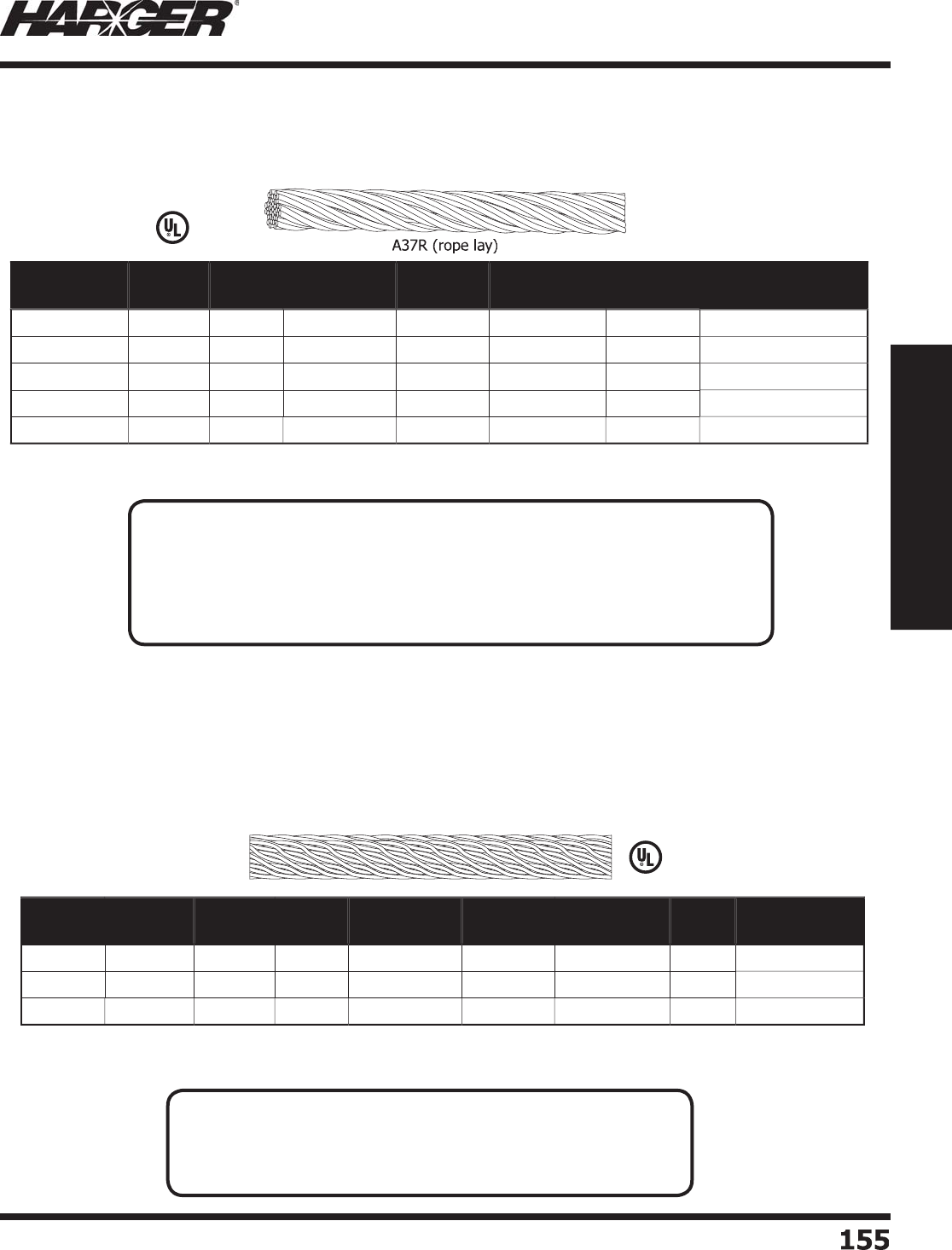
H
ar
g
er Li
g
htnin
g
& Groundin
g
•
©
2012 Phone 847-548-8700 • Fax 847-548-8755 • U.S. 800-842-743
7
155
155
Section 2
Lightning Protection Components
L
iste
d
9
6
Part No. No. of
Strands
Strand
Size
X-Sectional
Area in CM
Approx.
Diameter
Approx. Wt.
lbs./M ft.
Reel/Coil
Size
Approx. Reel/Coil
Wt. (lbs.)
A
3
7R-
25
C
O
IL
37
1
3
AW
G
19
2
,000 19
/
32" 19
0
2
5'
5
A
3
7R-
50
C
O
IL
37
1
3
AW
G
19
2
,000 19
/
32" 19
0
50'
1
0
A
3
7R-1
00
37
1
3
AW
G
19
2
,000 19
/
32" 19
0
1
00'
23
A
3
7R-
250
37
1
3
AW
G
19
2
,000 19
/
32" 19
0
2
50'
56
A
3
7R-
500
37
1
3
AW
G
19
2
,000 19
/
32" 19
0
500'
11
2
Part No. Material No. of
Strands
Strand
Size
X-Sectional
Area in CM
Approx.
Diameter
Approx. Wt.
lbs./M ft.
Reel
Size
Approx. Reel
Wt. (lbs.)
14
C
o
pp
e
r
14 1
6
AW
G
28,000 1
/
4"
92
1
00'
11-1
/
4
A1
0
Al
u
min
u
m1
0
14 AW
G
4
1,100
5/
16"
3
91
00'
6
A4
Al
u
min
u
m1
4
AW
G
4
1,740 13
/
64"
3
91
00'
6
•
A4 is a solid, sin
g
le conductor.
C
lass II Aluminum C
o
nduct
o
rs
These c
o
nduct
o
rs are intended f
o
r use
o
n structures
g
reater than 75' in hei
g
ht.
Bondin
g
Conductors
TECHNICAL N
O
TES
:
• Class II Minimum Re
q
uirements:
- 190
p
ounds
p
er 1,000 feet.
- Cross-sectional area of 192,000 circular mils.
- Minim
u
m str
a
n
d
size 1
3
AWG.
• Conductors are marked every 3' with a
g
reen ink dot for cable fastner spacin
g
.
TECHNICAL N
O
TES
:
• Class I & II Minimum Re
q
uirements:
- Copper bondin
g
conductors: 17 AWG, 26,240 circular mils.
- Aluminum bondin
g
conductors: 14 AWG, 41,100 circular mils.
S
ect
io
n 2.1.4 & 2.1.5
L
iste
d
9
6
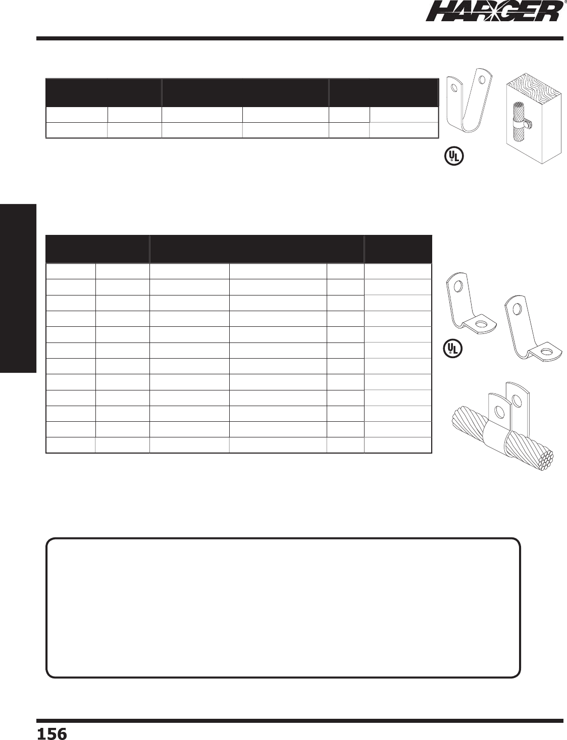
H
ar
g
er Li
g
htnin
g
& Groundin
g
•
©
2012 Phone 847-548-8700 • Fax 847-548-8755 • U.S. 800-842-743
7
156156
Section 2
Lightning Protection Components
•
Co
pp
er cable loo
p
fasteners manufactured from .045" x 5/8" #110 soft drawn
electrolytic tou
g
h pitch copper coil.
•
Aluminum cable fasteners manufactured from .051" x 5
/
8" 3003-0 aluminum.
•
9/32"
(
.280 in.
)
hole to acce
p
t 1/4" hardware.
•
See fasteners on pa
g
e 146.
*
ETPC - Electro Tin Plated Co
pp
e
r
L
iste
d
9
6
•
Hole diameter is 5/32
(
.156 in.
)
•
Use with 277S. See pa
g
e 146.
Part No. Material Fits Lightning
Conductors
Fits Grounding
Conductors
Box
Qty.
Approx Box
Wt. (lbs.)
250
C
o
pp
e
r
28 2
/
01
00
1
A
250
Al
u
min
u
m A28
N/
A1
00
1
/2
Part No. Material Fits Lightning
Conductors
Fits Grounding
Conductors
Box
Qty.
Approx Box
Wt. (lbs.)
A
CC
1Al
u
min
u
mA1
0
N/
A1
00
1
/2
A
CC2
Al
u
min
u
m A28 & A24
N/
A1
00
1
/2
ACC
3
Al
u
min
u
mA
37
N/
A1
00
1
/2
A
CC
4Al
u
min
u
mA
3
7R
N/
A1
00
1
/2
CCC
1
C
o
pp
e
r
#1
4
2 Str., 4 Str., 2 Sol. 1
00
2
CCC
1T
E
TP
C
*#1
4
2 Str., 4 Str., 2 Sol. 1
00
2
CCC2
C
o
pp
e
r
2
9
&
32
1
/
0 Str. & 2
/
0 Str. 1
00
2-1
/4
CCC2
T
E
TP
C
*
2
9
&
32
1
/
0 Str. & 2
/
0 Str. 1
00
2-1
/4
CCC
3
C
o
pp
e
r
28 & 2
4
4/
01
00
2-1
/2
CCC
3
T
E
TP
C
* 28 & 2
4
4/
01
00
2-1
/2
CCC4
C
o
pp
e
r
4
0-28
250
MCM
50
2-3
/4
CCC
4T
E
TP
C
*
4
0-28
250
MCM
50
2-3
/4
C
able Cli
p
s
Pre-formed Cable Cli
p
s
TECHNICAL N
O
TES
:
• Conductors shall be fastened to the structure upon which they are placed at intervals not exceedin
g
0.9 m
(
3 ft
)
.*
• Clips for securin
g
copper conductors shall be cast or made from sheet copper with a minimum
thickness of 0.032 inch
(
0.81 mm
)
and a minimum width of 3/8 inch
(
9.5 mm
)
.**
• Aluminum clips for securin
g
aluminum conductors shall be of cast aluminum or made from sheet
aluminum with a minimum thickness of 0.051 inch
(
1.3 mm
)
thick and a minimum thickness of 1/2
inch
(
12.7 mm
)
wide.**
*
Per NFPA 780 Conductor Fasteners Section 4.10
*
*UL96 Standard for Li
g
htnin
g
Protection Components Sections 15.1 & 15.
2
L
iste
d
9
6
S
ect
io
n 2.1.6 & 2.1.7
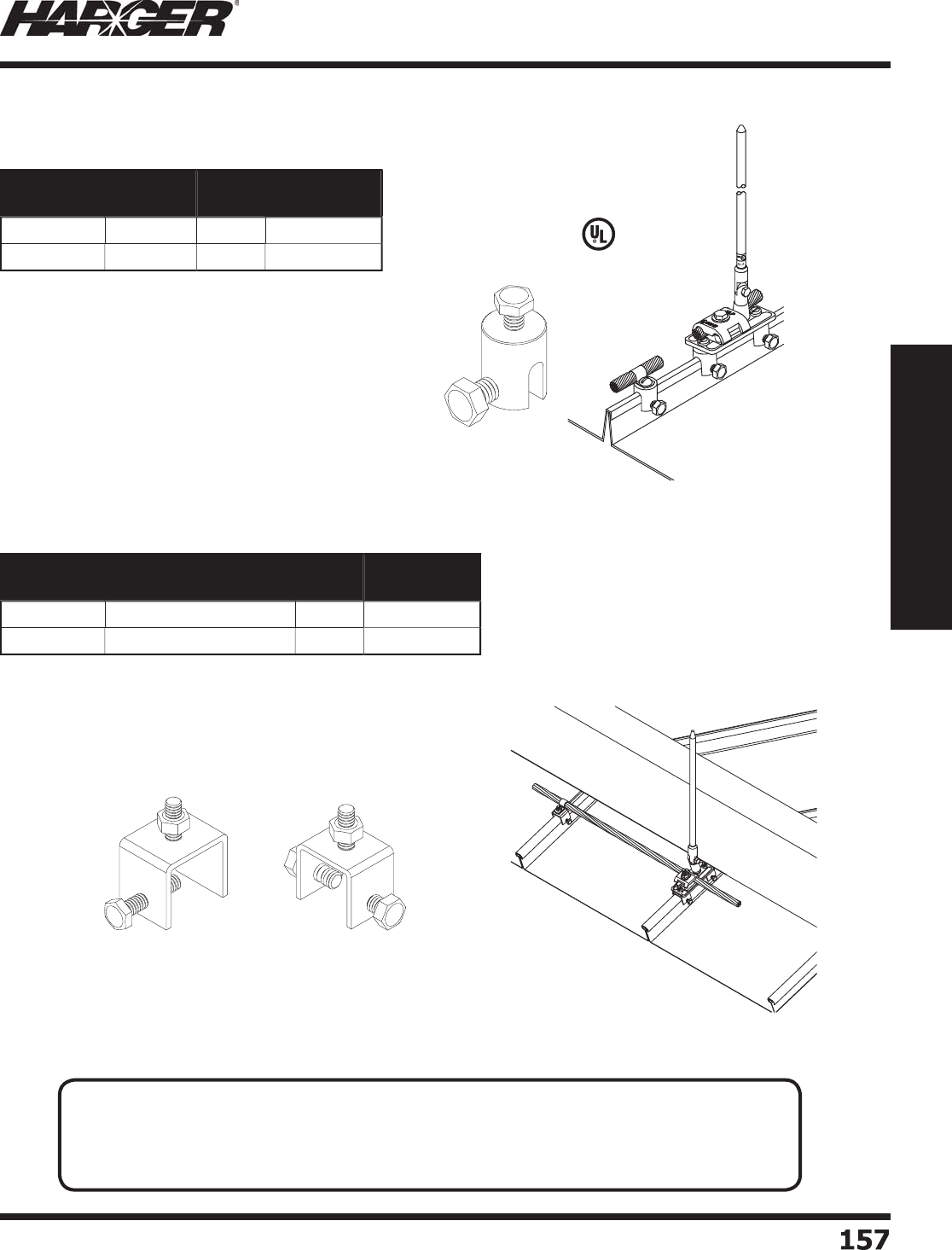
H
ar
g
er Li
g
htnin
g
& Groundin
g
•
©
2012 Phone 847-548-8700 • Fax 847-548-8755 • U.S. 800-842-743
7
15
7
157
Section 2
Lightning Protection Components
•
Desi
g
ned for use on standin
g
seam roof applications.
•
Can be used on seams that have widths of 1
/
4" or less.
•
Cable clips not included. (See pa
g
e 156
)
L
iste
d
9
6
•
Desi
g
ned for use on standin
g
seam roof applications.
•
C
a
n
b
e
u
se
d
o
n se
a
ms th
a
t h
a
ve wi
d
ths
o
f 1"
o
r les
s
•
Maximum clam
p
de
p
th is 5/8".
•
Cable clips not included. (See pa
g
e 156
)
U
se
d
with #1
5
1xxI
s
eries
ba
se
SSSC
1
SSSC2
Part No. Material Box
Qty.
Approx Box
Wt. (lbs.)
CUSC
C
o
pp
e
r
50
6
-1
/2
AL
SC
Al
u
min
u
m
50
3-1
/
4
Part No. Description Box
Qty.
Approx Box
Wt. (lbs.)
SSSC
1
S
t
a
inless Steel - 1 B
o
l
t
1
0
2
SSSC2
S
t
a
inless Steel - 2 B
o
l
t
1
0
2
S
tandin
g
Seam Clamps
N
O
TE
:
• Clamps can be used in con
j
unction with a #CCC/#ACC cable clip (See pa
g
e 156) for cable
fastenin
g
applications or use two clamps to secure either a #15112I or #15138I base (See
pa
g
e 178) to the seam.
S
ect
io
n 2.1.8
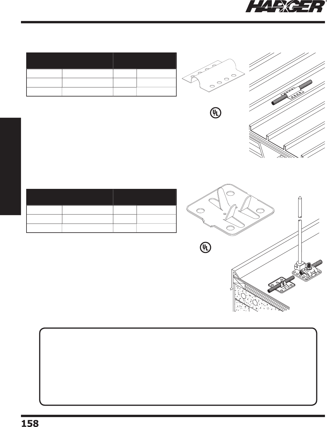
H
ar
g
er Li
g
htnin
g
& Groundin
g
•
©
2012 Phone 847-548-8700 • Fax 847-548-8755 • U.S. 800-842-743
7
1
58
158
Section 2
Lightning Protection Components
•
Economical stam
p
ed co
pp
er adhesive cable holder.
•
Ma
y
be used with all cables thru 3/0 or u
p
to 1/2" diameter.
•
Fast installin
g
cable holder desi
g
ned to permit maximum
movement of thermally expandin
g
or contractin
g
cables.
*
ETPC - Electro Tin Plated Co
pp
e
r
•
Su
p
erior stam
p
ed co
pp
er cable holder secured b
y
a surface
com
p
atible adhesive.
•
Will not "roll-u
p
" or loosen due to cable
p
ull as will the
round t
yp
e.
•
Use on an
y
fl at surface where a fast, secure, adhesive
cable holder is re
q
uired.
•
Desi
g
ned for use with all cables thru 4/0 or up to
9
/
16" diameter.
•
Turned up ed
g
es for reduced puncture hazard and poolin
g
a
re
a
f
o
r incre
a
se
d
ad
hesi
o
n.
*
ETPC - Electro Tin Plated Co
pp
e
r
L
iste
d
9
6
L
iste
d
9
6
Part No. Material Box
Qty.
Approx Box
Wt. (lbs.)
26
1
S
tam
p
ed Co
pp
e
r
1
00
8-1
/
4
A
26
1Al
u
min
u
m1
00
4
26
1T
E
TP
C
*1
00
8-1
/
4
Part No. Material Box
Qty.
Approx Box
Wt. (lbs.)
262
S
tam
p
ed Co
pp
e
r
500
45
A
262
Al
u
min
u
m
500
22
262
T
E
TP
C
*
500
45
Adhesive Cable H
o
lders
TECHNICAL N
O
TES
:
• Conductors shall be fastened to the structure upon which they are placed at intervals not exceedin
g
0.9 m
(
3 ft
)
.*
• Clips for securin
g
copper conductors shall be cast or made from sheet copper with a minimum
thickness of 0.032 inch
(
0.81 mm
)
and a minimum width of 3/8 inch
(
9.5 mm
)
.**
• Aluminum clips for securin
g
aluminum conductors shall be of cast aluminum or made from sheet
aluminum with a minimum thickness of 0.051 inch
(
1.3 mm
)
thick and a minimum thickness of 1/2
inch
(
12.7 mm
)
wide.**
*
Per NFPA 780 Conductor Fasteners Section 4.10
*
*UL96 Standard for Li
g
htnin
g
Protection Components Sections 15.1 & 15.
2
S
ect
io
n 2.1.9
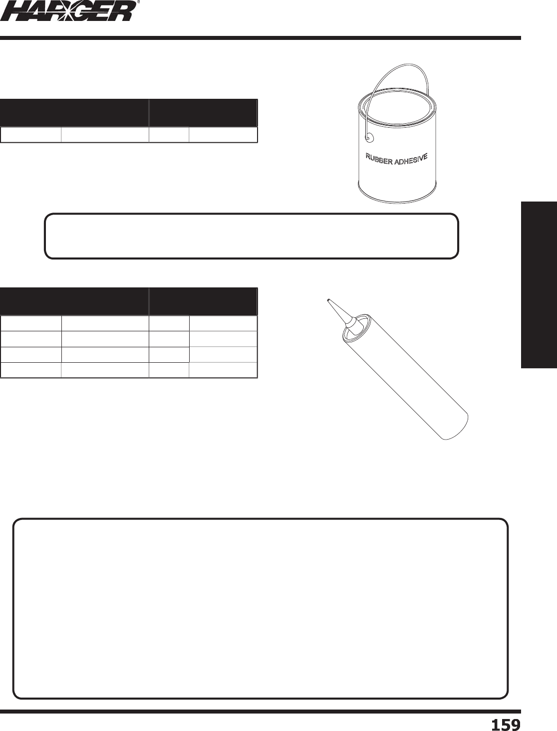
H
ar
g
er Li
g
htnin
g
& Groundin
g
•
©
2012 Phone 847-548-8700 • Fax 847-548-8755 • U.S. 800-842-743
7
15
9
159
Section 2
Lightning Protection Components
•
Fast dryin
g
rubber adhesive for bondin
g
to rubber membrane roofi n
g
.
•
Minimum a
pp
lication tem
p
erature is 40
o
F
.
•
Application covera
g
e (per
g
allon) is 40 #CUBU or #AUBU bases or
100 #262 adhesive cable holders on smooth rubber roofi n
g
.
•
10.1 fl uid oz. cartrid
ge
•
Tou
g
h thermosettin
g
adhesive.
•
Develops 300 PSI shear stren
g
th on metal, masonry and wood. Not for use
o
n TPO or h
yp
olon roofs.
•
Capable of 300% elon
g
ation and can accommodate dimensional chan
g
es in
c
o
nstr
u
cti
o
n m
a
teri
a
ls
do
wn t
o
min
u
s 2
0
°F.
•
Contains no volatile or
g
anic solvents. (No VOC’s
)
•
Can be used in confi ned s
p
aces and also to bond solvent-sensitive materials
s
uch as ex
p
anded
p
ol
y
st
y
rene foam
(
EPS
)
.
•
Service tem
p
erature: -40°F to
2
00°
F
Part No. Approx. Each
Wt. (lbs.)
Box
Qty.
Approx Box
Wt. (lbs.)
26
41
0
2
20
Part No. Color Box
Qty.
Approx Box
Wt. (lbs.)
M
1-1
0O
Z-B
B
l
a
ck
2
4
26
M
1-1
0O
Z-
G
G
ra
y
2
4
26
M
1-1
0O
Z-L
L
imest
o
n
e
2
4
26
M
1-1
0O
Z-
W
W
hit
e
2
4
26
A
d
he
s
ive
s
R
u
bber
M-1 Str
u
ct
u
ral Sealant
TECHNICAL N
O
TE
:
• Contractor must verify adhesive compatibility with roofi n
g
contractor or manufacturer.
APPLICATI
O
N N
O
TES
:
E
xcellent for Emer
g
ency Repairs -
• Multipurpose structural sealant is desi
g
ned for diffi cult bondin
g
and sealin
g
applications such as low slope
commercial roofi n
g
. It bonds a
gg
ressively to EPDM, PVC, BUR, coal tar, SBS mod bit,
g
ranulated APP,
many types of coated metal, metal fl ashin
g
details, and FRP.
• S
o
me G
a
lv
a
l
u
me
®
or K
y
nar coated roofs ma
y
re
q
uire NP1
p
ol
y
urethane sealant.
• Excellent for underwater emer
g
ency repairs.
• Non-slump, self-fi xturin
g
mastic that cures to a durable bond with exposure to atmospheric moisture.
H
eav
y
Dut
y
Construction Adhesive -
• Tou
g
h thermosettin
g
adhesive that can be used to permanently bond structural assemblies such as
copin
g
, metal ed
g
e, skyli
g
hts.
• Capable of bondin
g
steel deck to bar
j
oints and metal sandwich panels to roof and wall purlins.
• Application covera
g
e (per tube) is approximately 15 cable holders or 5 bases.
• Must be installed on a clean, free of dirt surface in tem
p
eratures not below 30
°
F
.
S
ect
io
n 2.1.10
M-1 S
tructural
ealant
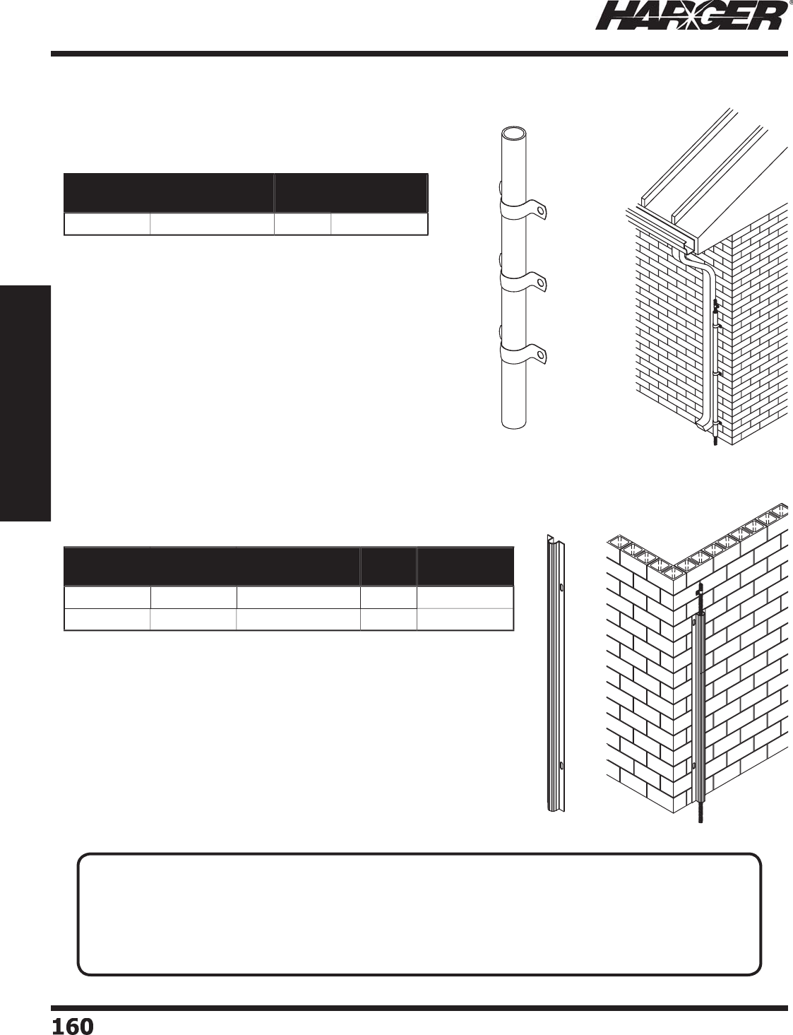
H
ar
g
er Li
g
htnin
g
& Groundin
g
•
©
2012 Phone 847-548-8700 • Fax 847-548-8755 • U.S. 800-842-743
7
160160
Section 2
Lightning Protection Components
•
3/4" O.D. x 8' lon
g
PVC pipe cable
g
uard for protectin
g
all cables thru 4
/
0.
•
Three
g
alvanized fastenin
g
clips furnished for mountin
g
with n
a
ils
o
r screws.
•
1/2" x 8' extruded thermo plastic cable
g
uard with fl an
g
es provides
concealment and
p
rotection for cables and down conductors.
Part No. Approx. Each
Wt. (lbs.)
Box
Qty.
Approx Box
Wt. (lbs.)
320
1-1
/2
3
5
Part No. Color Approx. Each
Wt. (lbs.)
Box
Qty.
Approx Box
Wt. (lbs.)
32
1B
B
l
a
ck 1
5
5
-1
/2
32
1
G
G
ra
y
1
5
5
-1
/2
C
able
Gu
ar
ds
PV
C
Pla
s
ti
c
TECHNICAL N
O
TE
:
• Down conductors located in runways, driveways, school play
g
rounds, cattle yards, public walks, or
other locations sub
j
ect to physical dama
g
e or displacement shall be
g
uarded. Metallic
g
uards shall be
bonded at each end. The down conductor shall be
p
rotected for a minimum distance of 1.8 m
(
6 ft.
)
above
g
rade level.*
*
NFPA 780 Protectin
g
Down Conductors Sections 4.9.11, 4.9.11.1 & 4.9.11.
2
S
ect
io
n 2.1.11

H
ar
g
er Li
g
htnin
g
& Groundin
g
•
©
2012 Phone 847-548-8700 • Fax 847-548-8755 • U.S. 800-842-743
7
16
1
161
Section 2
Lightning Protection Components
S
ect
io
n 2.2
Air Terminals & Access
o
ries
In
d
ex
Descr
i
pt
i
on Pa
g
e
2.2.1 Class I Co
pp
er Air Terminal
s
..............................................................
1
62
2.2.2 Class II Co
pp
er Air Terminal
s
.............................................................
1
63
2.2.
3
Cl
a
ss I Al
u
min
u
m Air Termin
a
l
s
..........................................................
1
64
2.2.4 Cl
a
ss II Al
u
min
u
m Air Termin
a
l
s
........................................................
1
64
2.2.5 Safety Tip Air Terminals - STAT
..........................................................
T
1
65
2.2.6 Air Terminals with Safet
y
Cable
..........................................................
1
66
2.2.7 S
p
ecialt
y
Air Terminal
s
......................................................................
1
67
2.2.8 Air Terminal Assemblie
s
....................................................................
168
2.2.9 Air Terminal Ada
p
ter
s
........................................................................
1
6
9
2.2.1
0
Air Termin
a
l Br
a
ce
s
...........................................................................
17
2
2.2.11 Air Termin
a
l Extensi
o
n
s
.....................................................................
17
3
2.2.12 Extension Rod Cou
p
ler
s
....................................................................
174
2.2.1
3
Dec
o
r
a
tive Fini
a
l
s
.............................................................................
17
5
N
O
TE
:
Air Terminals are also known as Strike Termination Devices
(
STD
)
or
L
i
g
htnin
g
Rods.
N
O
TE
:
Co
pp
er materials can consist of co
pp
er, bronze or brass. All are co
pp
er allo
y
s.
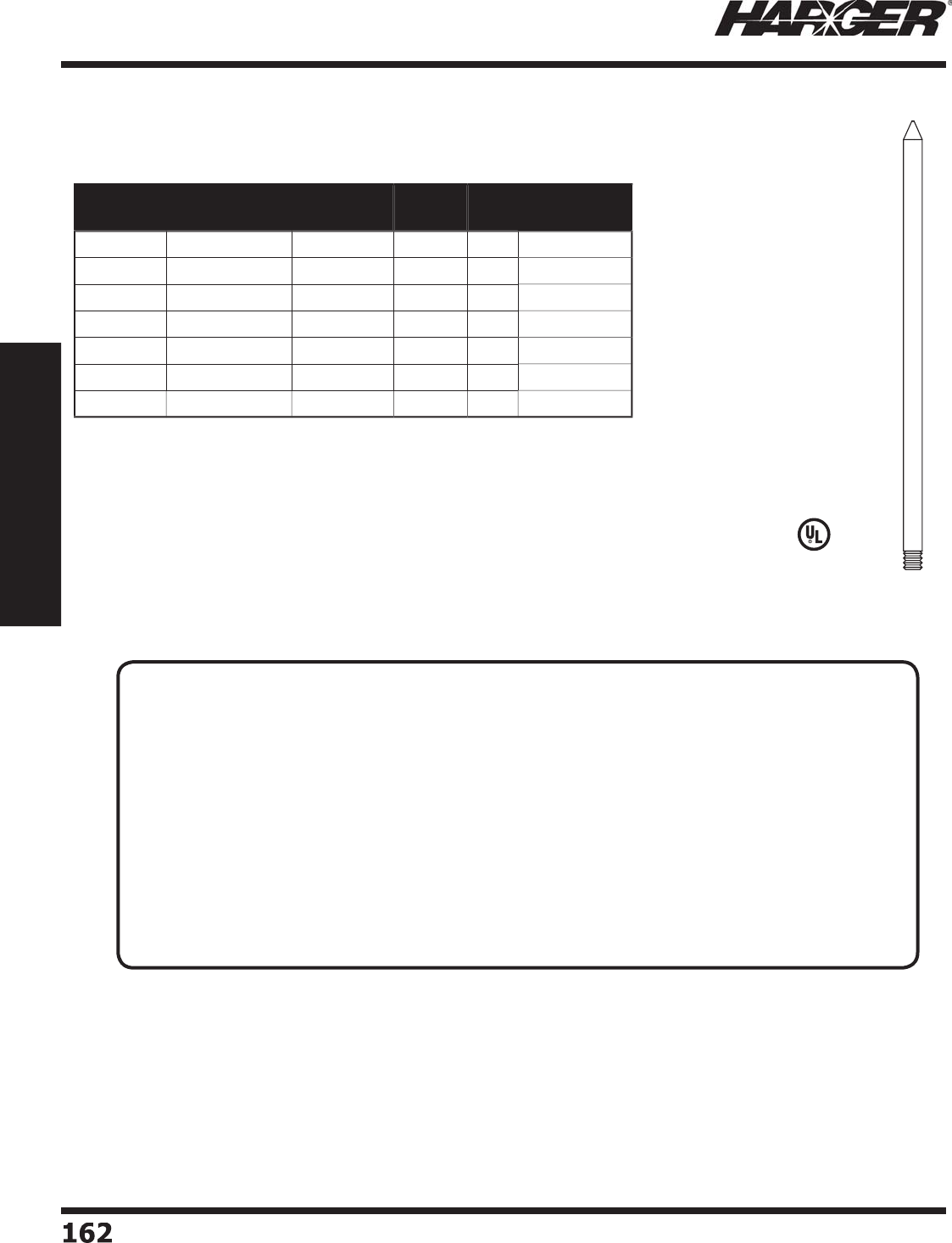
H
ar
g
er Li
g
htnin
g
& Groundin
g
•
©
2012 Phone 847-548-8700 • Fax 847-548-8755 • U.S. 800-842-743
7
16
2
162
Section 2
Lightning Protection Components
•
Manufactured from hi
g
hly
conductive electrolytic tou
g
h
p
itch co
pp
er allo
y
110.
•
Conductivity
g
reater than
9
9% when
a
nne
a
le
d
.
•
Utilizes standard 3
/
8" UNC
thre
ad
s.
•
Ada
p
ters sold se
p
aratel
y
. See
pa
g
es 169-171.
•
Lon
g
er len
g
ths available.
P
lease contact factor
y
for
m
o
re inf
o
rm
a
ti
o
n.
L
iste
d
9
6
Part No.
Copper
Part No.
Nickel Plated
Part No.
Tin Plated Length Box
Qty.
Approx Box
Wt. (lbs.)
3810CUAT 3810CUAT
N
3810CUATT 1
0
"1
0
5
-1
/2
3812CUAT 3812CUAT
N
3812CUATT 12" 1
0
6
-1
/4
3816CUAT 3816CUAT
N
3816CUATT 1
6
"1
0
7-3
/4
3818CUAT 3818CUAT
N
3818CUATT 18" 1
0
9
3824CUAT 3824CUAT
N
3824CUATT 24" 1
0
10-1
/2
3836CUAT 3836CUAT
N
3836CUATT
36
"1
0
18-3
/
4
3848CUAT 3848CUAT
N
3848CUATT
4
8" 1
0
2
1
C
lass I Co
pp
er Air Terminals
3
/
8" Diameter
T
ECHNICAL N
O
TES
:
• Class I air terminals are used on structures up to and includin
g
75' in hei
g
ht.
• For lon
g
er air terminals, select an air terminal and combine with extension rods and couplers on
pa
g
es 17
3
&
174.
• Class I Minimum Re
q
uirements:
- Minimum diameter is 3
/
8" solid.
- The tip of an air terminal shall be not less than 254 mm (10 in.) above the ob
j
ect or area
it is to
p
rotect.*
*
NFPA 780 Air Terminal Hei
g
ht Section 4.6.2.1
• Air terminals shall be secured a
g
ainst overturnin
g
or displacement by one of the followin
g
methods: (1) Attachment to the ob
j
ect to be protected, (2) Braces that are permanently and
ri
g
idly attached to the structure. Air terminals exceedin
g
600 mm (24 in.) in hei
g
ht shall be
supported at a point not less than one-half their hei
g
ht.*
*
NFPA 780 Air Terminal Su
pp
ort Sections 4.6.2.2.1 & 4.6.2.2.
2
S
ect
io
n 2.2.1

H
ar
g
er Li
g
htnin
g
& Groundin
g
•
©
2012 Phone 847-548-8700 • Fax 847-548-8755 • U.S. 800-842-743
7
163
163
Section 2
Lightning Protection Components
•
Manufactured from hi
g
hly
conductive electrolytic tou
g
h
p
itch co
pp
er allo
y
110.
•
Conductivity
g
reater than 99%
w
hen
a
nne
a
le
d
.
•
Utilizes standard 1
/
2" UNC
thre
ad
s.
•
Ada
p
ters sold se
p
aratel
y
. See
pa
g
es 169-171.
•
Lon
g
er len
g
ths available.
P
lease contact factor
y
for more
i
nf
o
rm
a
ti
o
n.
•
Utilizes standard 5
/
8" UNC
thre
ad
s.
•
Lon
g
er len
g
ths available.
P
lease contact factor
y
for
m
o
re inf
o
rm
a
ti
o
n.
Part No.
Copper
Part No.
Nickel Plated
Part No.
Tin Plated Length Box
Qty.
Approx Box
Wt. (lbs.)
1
2
1
0
C
U
AT 1
2
1
0
C
U
AT
N
1
2
1
0
C
U
ATT 1
0
"1
0
6
-1
2
1
2
1
2
C
U
AT 1
2
1
2
C
U
AT
N
1
2
1
2
C
U
ATT 12" 1
0
7-3
/4
1
2
1
6
C
U
AT 1
2
1
6
C
U
AT
N
1
2
1
6
C
U
ATT 1
6
"1
0
10-1
/2
1218CUAT 1218CUAT
N
1218CUATT 18" 1
0
11-3
/
4
1
22
4C
U
AT 1
22
4C
U
AT
N
1
22
4C
U
ATT 24" 1
0
15-1
/2
1
236
C
U
AT 1
236
C
U
AT
N
1
236
C
U
ATT
36
"1
0
23-1
/
4
1248CUAT 1248CUAT
N
1248CUATT
4
8" 1
0
3
1
Part No.
Copper
Part No.
Nickel Plated
Part No.
Tin Plated Length Box
Qty.
Approx Box
Wt. (lbs.)
5
810CUAT
5
810CUAT
N
5
810CUATT 1
0
"1
0
9
-3
/4
5
812CUAT
5
812CUAT
N
5
812CUATT 12" 1
0
11-3
/
4
5
816CUAT
5
816CUAT
N
5
816CUATT 1
6
"1
0
15-3
/
4
5
818CUAT
5
818CUAT
N
5
818CUATT 18" 1
0
17-3
/
4
5
824CUAT
5
824CUAT
N
5
824CUATT 24" 1
0
23-1
/2
5
836CUAT
5
836CUAT
N
5
836CUATT
36
"1
0
35-1
/
4
5
848CUAT
5
848CUAT
N
5
848CUATT
4
8" 1
0
47
C
lass II Co
pp
er Air Terminals
1/
2" Diameter
5/
8" Diameter
TECHNICAL N
O
TES
:
• Class II air terminals are used on structures
g
reater than 75' in hei
g
ht.
• For lon
g
er air terminals, select an air terminal and combine with extension rods and couplers on
pa
g
es 17
3
&
174.
•
Class II Minumum Re
q
uirements:
- Minimum diameter is 1
/
2" solid.
- The tip of an air terminal shall be not less than 254 mm (10 in.) above the ob
j
ect or area
is it to
p
rotect.*
*
NFPA 780 Air Terminal Hei
g
ht Section 4.6.2.1
• Air terminals shall be secured a
g
ainst overturnin
g
or displacement by one of the followin
g
methods: (1) Attachment to the ob
j
ect to be protected, (2) Braces that are permanently and
ri
g
idly attached to the structure. Air terminals exceedin
g
600 mm (24 in.) in hei
g
ht shall be
supported at a point not less than one-half their hei
g
ht.**
*
*NFPA 780 Air Terminal Su
pp
ort Sections 4.6.2.2.1 & 4.6.2.2.
2
S
ect
io
n 2.2.2
L
iste
d
9
6
L
iste
d
9
6
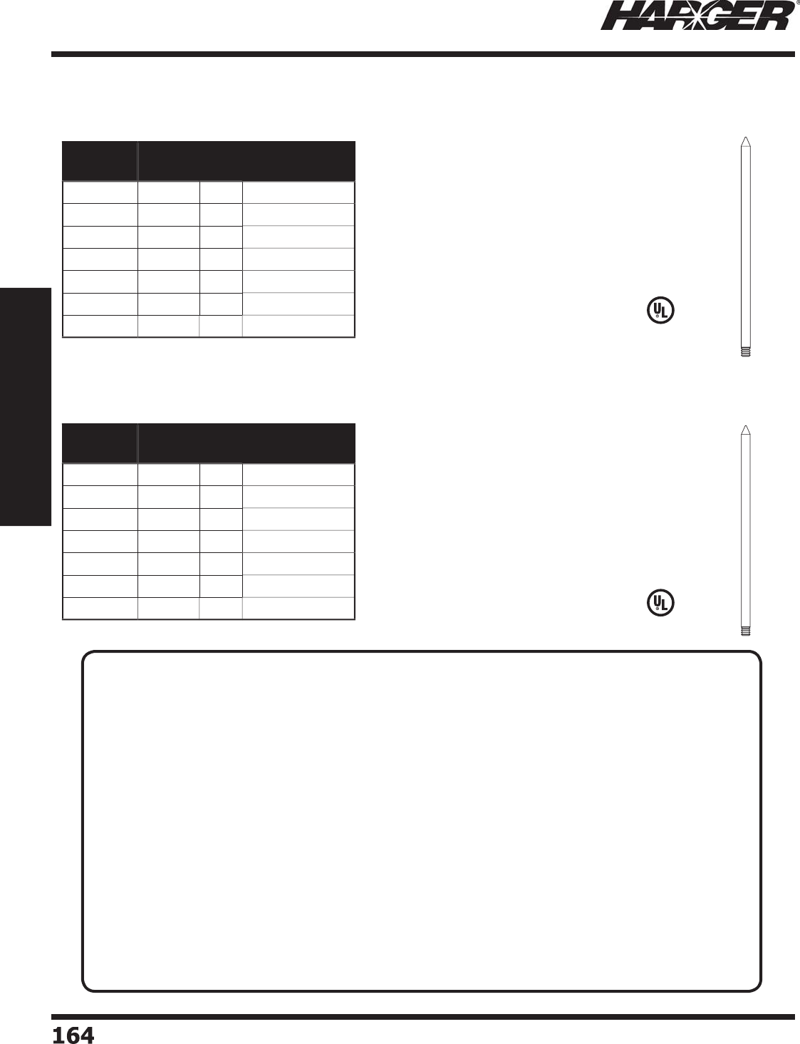
H
ar
g
er Li
g
htnin
g
& Groundin
g
•
©
2012 Phone 847-548-8700 • Fax 847-548-8755 • U.S. 800-842-743
7
164164
Section 2
Lightning Protection Components
•
Manufactured from hi
g
hly conductive
a
l
u
min
u
m.
•
Utilizes standard 1
/
2" UNC threads.
•
Adapters sold separately. See pa
g
es 169-171.
•
Lon
g
er len
g
ths available. Please contact
factor
y
for more information.
L
iste
d
9
6
•
Manufactured from hi
g
hly conductive
a
l
u
min
u
m.
•
Utilizes standard 5
/
8" UNC threads.
•
Adapters sold separately. See pa
g
es 169-171.
•
Lon
g
er len
g
ths available. Please contact
factor
y
for more information.
L
iste
d
9
6
Part No. Length Box
Qty.
Approx. Box
Wt. (lbs.)
1
2
1
0
ALAT 1
0
"1
0
2-1
/2
1
2
1
2
ALAT 12" 1
0
2-3
/
4
1
2
1
6
ALAT 1
6
"1
0
3-1
/2
1218ALAT 18" 1
0
3-3
/
4
1
22
4ALAT 24" 1
0
5
1
236
ALAT
36
"1
0
8-1
/
4
1248ALAT
4
8" 1
0
1
0
Part No. Length Box
Qty.
Approx. Box
Wt. (lbs.)
5
810ALAT 1
0
"1
0
3-1
/2
5
812ALAT 12" 1
0
4
5
816ALAT 1
6
"1
0
5
-1
/
4
5
818ALAT 18" 1
0
6
-3
/
4
5
824ALAT 24" 1
0
8-3
/
4
5
836ALAT
36
"1
0
12-3
/
4
5
848ALAT
4
8" 1
0
17-1
/2
C
la
ss
I Al
u
min
u
m Air Terminal
s
1/
2" Diameter
C
la
ss
II Al
u
min
u
m Air Terminal
s
5/
8" Diameter
TECHNICAL N
O
TES
:
• Class I air terminals are used on structures up to and includin
g
75' in hei
g
ht. Class II air terminals
are used on structures
g
reater than 75' in hei
g
ht.
• For lon
g
er air terminals, select an air terminal and combine with extension rods and couplers on
pa
g
es 17
3
&
174.
• Class I Minimum Re
q
uirements:
- Minimum diameter is 1
/
2" solid.
- The tip of an air terminal shall be not less than 254 mm (10 in.) above the ob
j
ect or area
it is to
p
rotect.*
•
Class II Minumum Re
q
uirements:
- Minimum diameter is 5
/
8" solid.
- The tip of an air terminal shall be not less than 254 mm (10 in.) above the ob
j
ect or area
is it to
p
rotect.*
*
NFPA 780 Air Terminal Hei
g
ht Section 4.6.2.1
• Air terminals shall be secured a
g
ainst overturnin
g
or displacement by one of the followin
g
methods: (1) Attachment to the ob
j
ect to be protected, (2) Braces that are permanently and
ri
g
idly attached to the structure. Air terminals exceedin
g
600 mm (24 in.) in hei
g
ht shall be
supported at a point not less than one-half their hei
g
ht.**
*
*NFPA 780 Air Terminal Su
pp
ort Sections 4.6.2.2.1 & 4.6.2.2.
2
S
ect
io
n 2.2.3 & 2.2.
4

H
ar
g
er Li
g
htnin
g
& Groundin
g
•
©
2012 Phone 847-548-8700 • Fax 847-548-8755 • U.S. 800-842-743
7
165
165
Section 2
Lightning Protection Components
R
evolutionary new air terminal desi
g
ned with safety as well as effi cacy in mind. The
air terminal's ti
p
consists of a s
p
here a
pp
roximatel
y
3/4" in diameter. The rounded
tip helps minimize personnel in
j
uries caused by accidental falls.
•
Co
pp
er safet
y
ti
pp
ed air terminals available in electro
p
lated tin
(
add suffi x T to
p
art
number) or nickel platin
g
(add suffi x N to part number).
•
Lon
g
er len
g
ths available. Please contact factory for more information.
•
5
/
8" diameter STATs have standard 5
/
8" UNC threads.
•
Adapters sold separately. See pa
g
es 169-171.
•
For added safety, use with fl exible adapters. See pa
g
e 170.
L
iste
d
9
6
Part No. Diameter Length Class Copper/
Aluminum
Box
Qty.
Approx. Box
Wt. (lbs.)
3812CSTAT 3
/
8" 12"
I
C
o
pp
e
r
1
0
7
3816CSTAT 3
/
8" 1
6
"
I
C
o
pp
e
r
1
0
8-1
/2
3818CSTAT 3
/
8" 18"
I
C
o
pp
e
r
1
0
9
-3
/
4
3824CSTAT 3
/
8" 24"
I
C
o
pp
e
r
1
0
11-1
/
4
1
2
1
2
A
S
TAT 1
/
2" 12"
I
Al
u
min
u
m1
0
3-1
/
4
1
2
1
2CS
TAT 1
/
2" 12"
II
C
o
pp
e
r
1
0
8-1
/2
1
2
1
6
ASTAT 1
/
2" 1
6
"
I
Al
u
min
u
m1
0
4
1
2
1
6
CSTAT 1
/
2" 1
6
"
II
C
o
pp
e
r
1
0
11-1
/
4
1218ASTAT 1
/
2" 18"
I
Al
u
min
u
m1
0
4
-1
/
4
1218CSTAT 1
/
2" 18"
II
C
o
pp
e
r
1
0
12-1
/2
1
22
4A
S
TAT 1
/
2" 24"
I
Al
u
min
u
m1
0
5
-1
/2
1
22
4
CS
TAT 1
/
2" 24"
II
C
o
pp
e
r
1
0
16-1
/
4
5
812ASTAT
5/
8" 12"
II
Al
u
min
u
m1
0
4
-1
/2
5
812CSTAT
5/
8" 12"
II
C
o
pp
e
r
1
0
12-1
/2
5
816ASTAT
5/
8" 1
6
"
II
Al
u
min
u
m1
0
5
-3
/
4
5
816CSTAT
5/
8" 1
6
"
II
C
o
pp
e
r
1
0
16-1
/2
5
818ASTAT
5/
8" 18"
II
Al
u
min
u
m1
0
7-1
/
4
5
818CSTAT
5/
8" 18"
II
C
o
pp
e
r
1
0
18-1
/2
5
824ASTAT
5/
8" 24"
II
Al
u
min
u
m1
0
9
-1
/
4
5
824CSTAT
5/
8" 24"
II
C
o
pp
e
r
1
0
24-1
/
4
S
afet
y
Ti
p
Air Terminals - STAT
S
ect
io
n 2.2.5
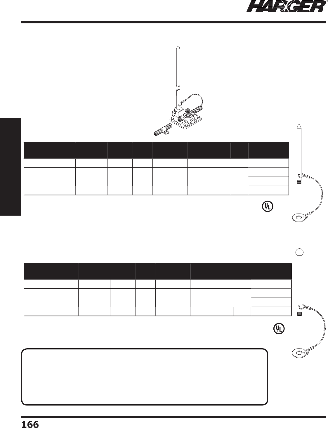
H
ar
g
er Li
g
htnin
g
& Groundin
g
•
©
2012 Phone 847-548-8700 • Fax 847-548-8755 • U.S. 800-842-743
7
166166
Section 2
Lightning Protection Components
L
iste
d
9
6
L
iste
d
9
6
Part No. Diameter Length Class Copper/
Aluminum
Approx. Each
Wt. (lbs.)
Box
Qty.
Approx. Box
Wt. (lbs.)
1
2
1
2
C
U
AT-WSC
36
1
/
2" 12"
II
C
o
pp
e
r
3
/4
1
0
7-1
/2
1
2
1
2
ALAT-WSC
36
1
/
2" 12"
I
Al
u
min
u
m1
/4
1
0
2-1
/2
1
22
4C
U
AT-WSC
36
1
/
2" 24"
II
C
o
pp
e
r
1-1
/2
1
0
1
5
5
812ALAT-WSC36
5/
8" 12"
II
Al
u
min
u
m1
/2
1
0
5
Part No. Diameter Length Class Copper/
Aluminum
Approx. Each
Wt. (lbs.)
Box
Qty.
Approx. Box
Wt. (lbs.)
1
2
1
2
ASTAT-WSC
36
1
/
2" 12"
I
Al
u
min
u
m1
/4
1
0
2-1
/2
1
22
4CSTAT-WSC
36
1
/
2" 24"
II
C
o
pp
e
r
1-1
/2
1
0
1
5
1
22
4ASTAT-WSC
36
1
/
2" 24"
I
Al
u
min
u
m1
/2
1
0
5
3824CSTAT-WSC36 3
/
8" 24"
I
C
o
pp
e
r
1-1
/
41
0
12-1
/2
Air Terminals with Safet
y
Cable
S
afet
y
Ti
p
N
O
TES
:
• Co
pp
er air terminals available in electro
p
lated tin
(
add suffi x T to
p
art number
)
or
nickel platin
g
(add suffi x N to part number).
• Comes with attached 36" safet
y
cable.
• Cable prevents air terminal from fallin
g
off structure if air terminal detaches from base.
• Lon
g
er len
g
ths available. Please contact factory for more information.
• Adapters sold separately. See pa
g
es 169-171.
S
ect
io
n 2.2.6

H
ar
g
er Li
g
htnin
g
& Groundin
g
•
©
2012 Phone 847-548-8700 • Fax 847-548-8755 • U.S. 800-842-743
7
16
7
167
Section 2
Lightning Protection Components
Sp
ecialt
y
Air Terminals
•
For protectin
g
security cameras mounted on poles.
•
Manufactured from 5/8" x 10' copper clad
g
round rod.
•
Thread size is 5/8" in diameter and 6" in len
g
th.
•
Comes with (2) #JN1011S
j
am nuts, (2) LW10S lock washers and
(
2
)
W10S fl at washers.
•
Other sizes available. Please contact factor
y
for more information.
Part No. Diameter Length Class Approx. Each
Wt. (lbs.)
5
810BCCATTSE
5/
8" 7
'
II
9
Bent Co
pp
er Clad Air Terminals
•
For protectin
g
security cameras mounted on poles.
•
Manufactured from 5/8" x 8' copper clad
g
round rod.
•
Other sizes available. Please contact factor
y
for more information.
Part No. Diameter Length Class Approx. Each
Wt. (lbs.)
CCTVCCAT5
/
8
5/
8"
5
'-4"
II
7
C
losed Circuit TV Co
pp
er Clad Air Termina
l
•
Manufactured from 3
/
16" x 2" 304 stainless steel.
•
Includes 3
/
8-16 stainless steel hardware.
•
Can be mounted usin
g
stainless bandin
g
systems such as
BAND
-
IT
®
by others or by weldin
g
.
•
Other sizes available. Please contact factor
y
for
m
o
re inf
o
rm
a
ti
o
n.
Part No. "A" Approx. Each Wt. (lbs.)
L
RCSS3
/
16X8 8" 2-1
/2
L
RCSS3
/
16X1
2
12" 3-1
/2
Li
g
htnin
g
Rod Clamps
S
ect
io
n 2.2.7
30" RADIUS
7 FT.
6"
4"
2"
A
1178"
5'-4"
1812"
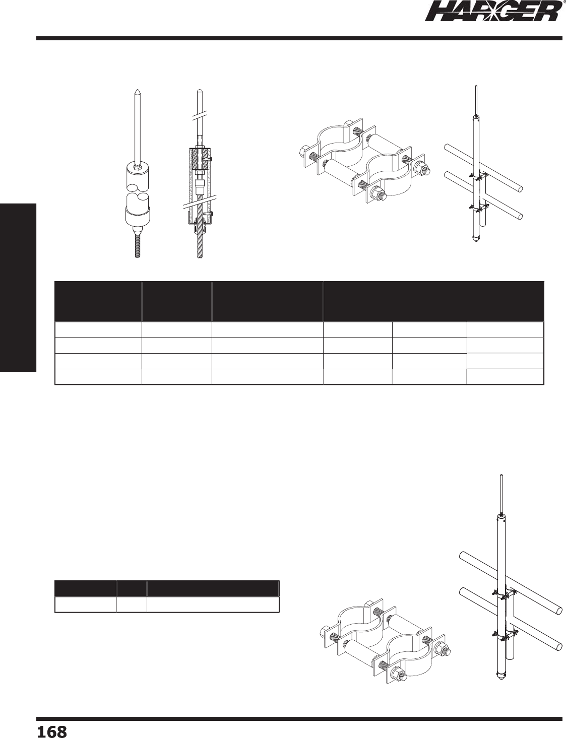
H
ar
g
er Li
g
htnin
g
& Groundin
g
•
©
2012 Phone 847-548-8700 • Fax 847-548-8755 • U.S. 800-842-743
7
1
68
168
Section 2
Lightning Protection Components
•
Desi
g
ned for use with towers or other structures which require lon
g
air terminal extensions.
•
Protects tower li
g
htin
g
, antennas and miscellaneous equipment from direct li
g
htnin
g
strikes.
•
Copper braided li
g
htnin
g
conductor is exothermically attached to the air terminal and extends
past the end of the pole in various len
g
ths.
•
Mast is manufactured from heavy duty, ri
g
id 1/4" thick fi ber
g
lass.
•
Requires separate mountin
g
assembly such as #SSATMSC2.
*
Shi
p
s
p
artiall
y
assembled
SS
ATM
SC2
(
not included
)
•
Mounts CUFATM assembl
y
(
above
)
to vertical
p
ole or tower
p
latform.
•
Mounts 2" mast to 2"
p
i
p
e.
•
M
a
n
u
f
a
ct
u
re
d
fr
o
m st
a
inless steel.
•
Includes 3
/
8" stainless steel hardware.
Part No.
Fiberglass
Pipe Length
(ft.)
Exposed
Air Terminal
Length (in.) (+/-1")
Conductor
Type
Exposed
Conductor
Length (ft.)
Approx. Each
Wt. (lbs.)
C
U
FATM-1
0
14
26
32
1
0
43
C
U
FATM-
50
14
26
32
50
50
C
U
FATM-9
0
14
26
32
90
60
C
U
FATM2
0
-
5
-1
5
*
20
60
28 1
5
45
Part No. Qty. Approx. Each Wt. (lbs.)
SS
ATM
SC2
EA
1-1
/2
Air Terminal A
ss
emblie
s
C
opper Air Terminals with Fiber
g
lass Mast Assembl
y
Air Terminal Mast Mountin
g
Assembl
y
S
ect
io
n 2.2.8
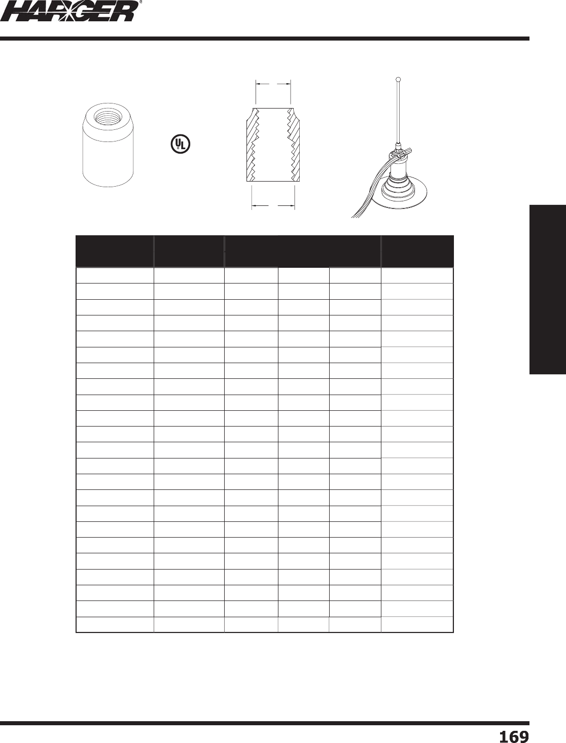
H
ar
g
er Li
g
htnin
g
& Groundin
g
•
©
2012 Phone 847-548-8700 • Fax 847-548-8755 • U.S. 800-842-743
7
16
9
169
Section 2
Lightning Protection Components
•
Used to en
g
a
g
e standard air terminal threads with different thread sizes
f
ou
n
d
in v
a
ri
ou
s
a
ir termin
a
l
ba
se
a
ssem
b
lies. All thre
ad
s
a
re
U
NC.
•
Other sizes available. Please contact factor
y
for more information.
Part No. Material Thread Diameter Box
Qty.
Approx. Box
Wt. (lbs.)
AB
1
20
C
o
pp
e
r
3
/
8"
5/
8"
40
4
1
20N
N
ickel Pl
a
te
d
3
/
8"
5/
8"
40
4
1
20
T
T
in Pl
a
te
d
3
/
8"
5/
8"
40
4
1
2
1
C
o
pp
e
r
1
/
2"
5/
8"
40
4
1
2
1
N
N
ickel Pl
a
te
d
1
/
2"
5/
8"
40
4
1
2
1T
T
in Pl
a
te
d
1
/
2"
5/
8"
40
4
A1
2
1Al
u
min
u
m1
/
2"
5/
8"
40
1-1
/2
1
22
C
o
pp
e
r
5/
8"
5/
8"
40
4
1
22N
N
ickel Pl
a
te
d
5/
8"
5/
8"
40
4
1
22
T
T
in Pl
a
te
d
5/
8"
5/
8"
40
4
122-5
/
8F1
/
2
F
C
o
pp
e
r
5/
8" 1
/
2"
40
4
A1
22
Al
u
min
u
m
5/
8"
5/
8"
40
1-1
/2
A122-5
/
8F1
/
2
F
Al
u
min
u
m
5/
8" 1
/
2"
40
1-1
/2
1
23
C
o
pp
e
r
3
/
8" 3
/
8"
40
5
1
23N
N
ickel Pl
a
te
d
3
/
8" 3
/
8"
40
5
1
23
T
T
in Pl
a
te
d
3
/
8" 3
/
8"
40
5
1
2
4
C
o
pp
e
r
3
/
8" 1
/
2"
40
4
-1
/
4
1
2
4
N
N
ickel Pl
a
te
d
3
/
8" 1
/
2"
40
4
-1
/
4
1
2
4T
T
in Pl
a
te
d
3
/
8" 1
/
2"
40
4
-1
/
4
1
25
C
o
pp
e
r
1
/
2" 1
/
2"
40
4
-1
/
4
1
25N
N
ickel Pl
a
te
d
1
/
2" 1
/
2"
40
4
-1
/
4
1
25
T
T
in Pl
a
te
d
1
/
2" 1
/
2"
40
4
-1
/
4
A1
25
Al
u
min
u
m1
/
2" 1
/
2"
40
1-1
/2
Air Terminal Ada
p
ters
S
tan
d
ar
d
L
iste
d
9
6
S
ect
io
n 2.2.9
A
B
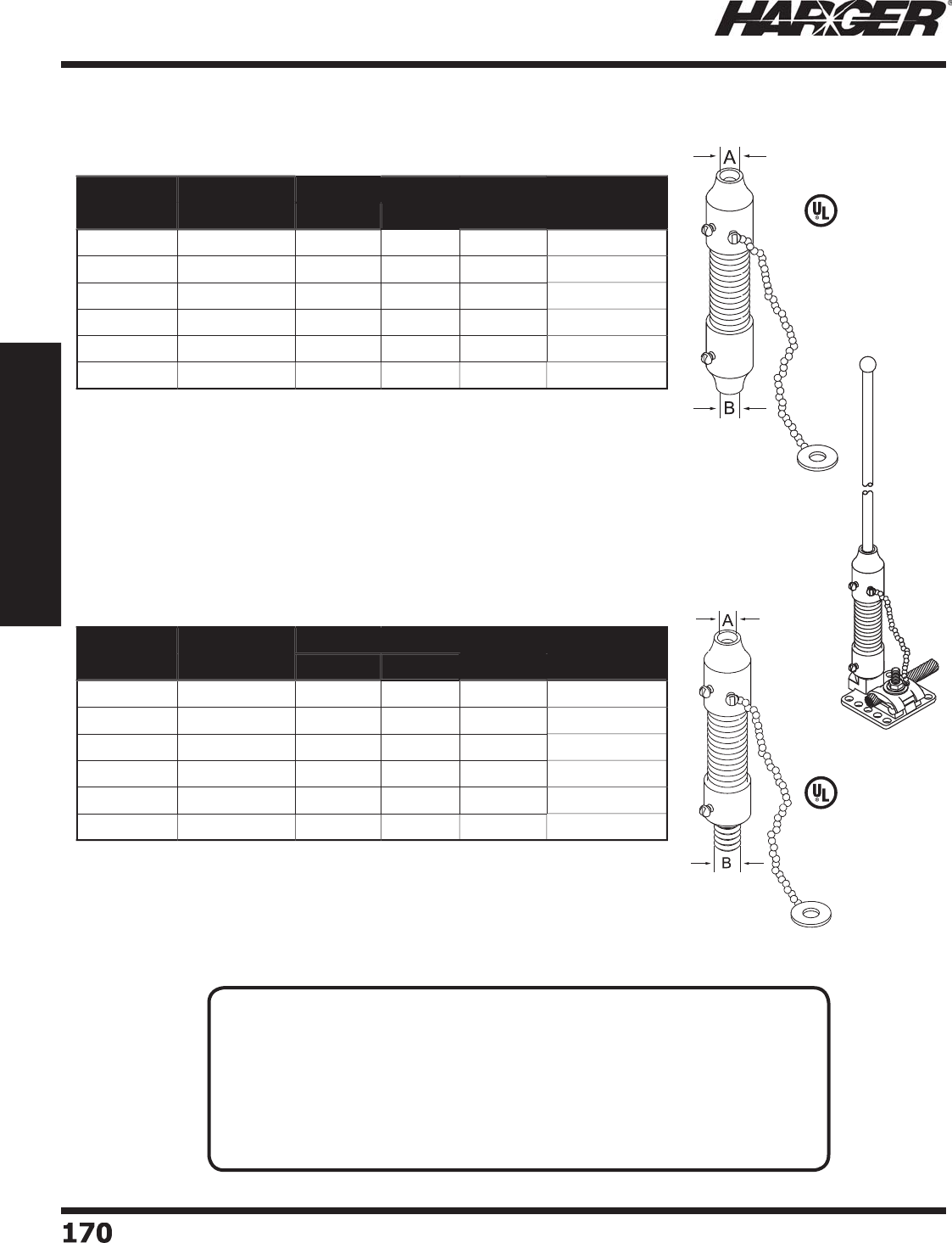
H
ar
g
er Li
g
htnin
g
& Groundin
g
•
©
2012 Phone 847-548-8700 • Fax 847-548-8755 • U.S. 800-842-743
7
1
7
0170
Section 2
Lightning Protection Components
L
iste
d
9
6
L
iste
d
9
6
Ma
le
T
hre
ad
(
M
)
F
em
a
le
T
hre
ad
Air Terminal Ada
p
ters
Part No. Material Thread Diameter Box
Qty.
Approx. Box
Wt. (lbs.)
AB
1
26
C
o
pp
e
r
1
/
2"
5/
8" 1
0
6
-1
/
4
A1
26
Al
u
min
u
m1
/
2"
5/
8" 1
0
4
1
27
C
o
pp
e
r
1
/
2" 1
/
2" 1
0
6
-1
/
4
A1
27
Al
u
min
u
m1
/
2" 1
/
2" 1
0
4
128
C
o
pp
e
r
5/
8"
5/
8" 1
0
6
-1
/
4
A128 Al
u
min
u
m
5/
8"
5/
8" 1
0
4
Part No. Material Thread Diameter Box
Qty.
Approx. Box
Wt. (lbs.)
AB
1
2
7M
C
o
pp
e
r
1
/
2" 1
/
2" 1
0
6
-1
/2
A1
2
7M Al
u
min
u
m1
/
2" 1
/
2" 1
0
4
-1
/
4
128M
C
o
pp
e
r
5/
8"
5/
8" 1
0
6
-1
/2
A128M Al
u
min
u
m
5/
8"
5/
8" 1
0
4
-1
/
4
1
2
9M
C
o
pp
e
r
5/
8" 1
/
2" 1
0
6
-1
/2
A1
2
9M Al
u
min
u
m
5/
8" 1
/
2" 1
0
4
-1
/
4
Flexible Female Threa
ds
Flexible Male Threa
ds
N
O
TES
:
• Flexible air terminal ada
p
ters are used with air terminals located underneath
window washin
g
or other mobile equipment.
• Come complete with stainless steel sprin
g
and safety chain.
• Overall len
g
th of Male thread adapter is 4-3/4".
• Overall len
g
th of Female thread adapter is 4-1/4".
• Can be used in con
j
unction with safety tipped air terminals. See pa
g
e 165.
• Other sizes available. Please contact factor
y
for more information.
S
ect
io
n 2.2.9
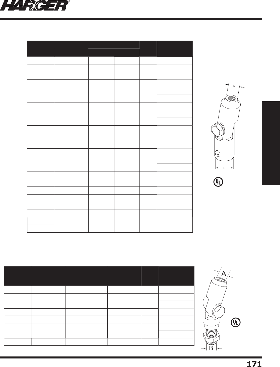
H
ar
g
er Li
g
htnin
g
& Groundin
g
•
©
2012 Phone 847-548-8700 • Fax 847-548-8755 • U.S. 800-842-743
7
1
7
1
171
Section 2
Lightning Protection Components
L
iste
d
9
6
•
U
sed to
p
lumb air terminals to vertical where the bases are mounted on
s
lopin
g
surfaces.
•
Stainless steel screws allow the ada
p
ter to be locked in an
y
p
osition.
Part No. Material Thread Diameter Box
Qty.
Approx. Box
Wt. (lbs.)
AB
1
33
C
o
pp
e
r
3
/
8" 3
/
8" 1
0
4
-1
/4
1
33N
N
ickel Pl
a
te
d
3
/
8" 3
/
8" 1
0
4
-1
/4
1
33
T
T
in Pl
a
te
d
3
/
8" 3
/
8" 1
0
4
-1
/4
1
3
4
C
o
pp
e
r
3
/
8" 1
/
2" 1
0
4
1
3
4
N
N
ickel Pl
a
te
d
3
/
8" 1
/
2" 1
0
4
1
3
4T
T
in Pl
a
te
d
3
/
8" 1
/
2" 1
0
4
1
35
C
o
pp
e
r
3
/
8"
5/
8" 1
0
3-1
/2
1
35N
N
ickel Pl
a
te
d
3
/
8"
5/
8" 1
0
3-1
/2
1
35
T
T
in Pl
a
te
d
3
/
8"
5/
8" 1
0
3-1
/2
1
36
C
o
pp
e
r
1
/
2" 1
/
2" 1
0
3-3
/4
1
36N
N
ickel Pl
a
te
d
1
/
2" 1
/
2" 1
0
3-3
/4
1
36
T
T
in Pl
a
te
d
1
/
2" 1
/
2" 1
0
3-3
/4
A1
36
Al
u
min
u
m1
/
2" 1
/
2" 1
0
1-1
/2
1
37
C
o
pp
e
r
1
/
2"
5/
8" 1
0
3-1
/2
1
3
7
N
N
ickel Pl
a
te
d
1
/
2"
5/
8" 1
0
3-1
/2
1
3
7T
T
in Pl
a
te
d
1
/
2"
5/
8" 1
0
3-1
/2
A1
37
Al
u
min
u
m1
/
2"
5/
8" 1
0
1-1
/2
138
C
o
pp
e
r
5/
8"
5/
8" 1
0
3-1
/2
138
N
N
ickel Pl
a
te
d
5/
8"
5/
8" 1
0
3-1
/2
138T
T
in Pl
a
te
d
5/
8"
5/
8" 1
0
3-1
/2
A138 Al
u
min
u
m
5/
8"
5/
8" 1
0
3-1
/2
1
3
9
C
o
pp
e
r
5/
8" 1
/
2" 1
0
3-1
/2
A1
3
9Al
u
min
u
m
5/
8" 1
/
2" 1
0
3-1
/2
Air Terminal Ada
p
ters
S
wive
l
•
Male thread confi
g
uration desi
g
ned to fi t internally threaded air terminal bases.
L
iste
d
9
6
Part No. Material
Internal
Threaded Top
A
Threaded
Male Stud
B
Box
Qty.
Approx. Box
Wt. (lbs.)
C
U
S1
2
M
C
o
pp
e
r
1
/
2" 1
/
2" 1
0
5
C
U
S1
2
MT
T
in Pl
a
te
d
1
/
2" 1
/
2" 1
0
5
CUS38M
C
o
pp
e
r
3
/
8" 3
/
8" 1
0
5
CUS38MT
T
in Pl
a
te
d
3
/
8" 3
/
8" 1
0
5
CUS58M
C
o
pp
e
r
5/
8"
5/
8" 1
0
2
CUS58MT
T
in Pl
a
te
d
5/
8"
5/
8" 1
0
2
AL
S
1
2
MAl
u
min
u
m1
/
2" 1
/
2" 1
0
2
ALS58M Al
u
min
u
m
5/
8"
5/
8" 1
0
2
S
wivel - C
U
SM
&
ALSM Serie
s
S
ect
io
n 2.2.9
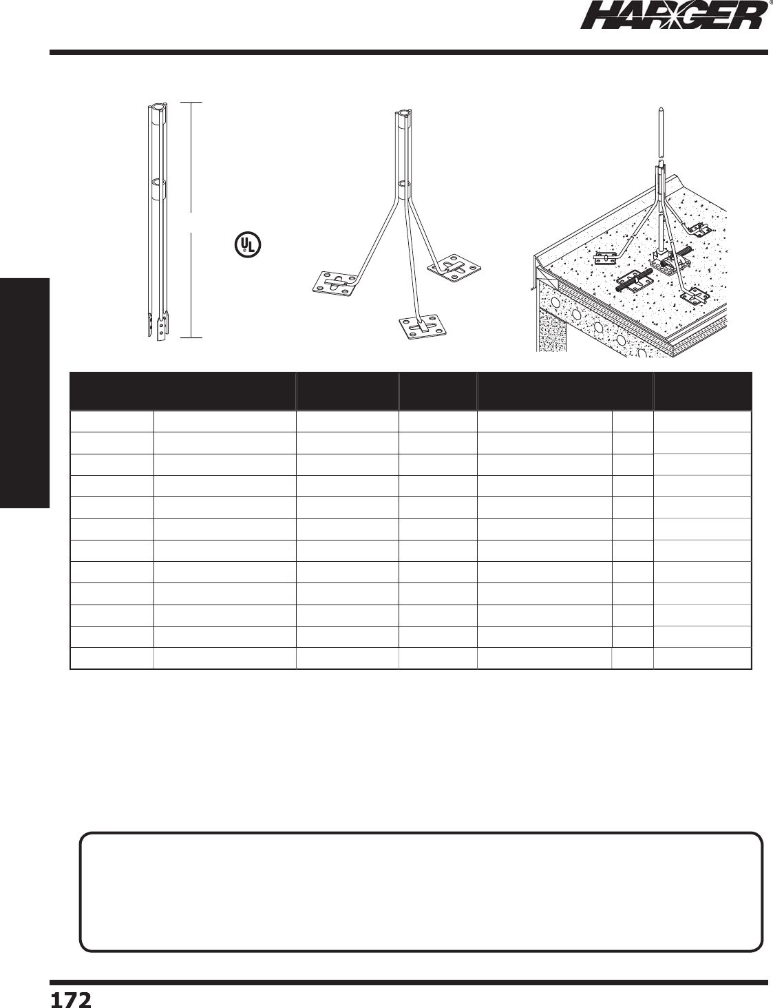
H
ar
g
er Li
g
htnin
g
& Groundin
g
•
©
2012 Phone 847-548-8700 • Fax 847-548-8755 • U.S. 800-842-743
7
1
72
172
Section 2
Lightning Protection Components
•
Galvanized steel tri
p
od brace
s
are used for the support of air terminals that exceed 24" in len
g
th.
•
Constructed of 1/4" steel rod with welded
j
oints and a zinc/ultraseal platin
g
.
•
B
races available with 3/16" holes for anchorin
g
with screws or nails or with adhesive feet when mountin
g
to roofi n
g
membranes or similar surfaces where penetrations cannot be made.
•
Len
g
ths
g
iven are prior to installation. Please take technical notes below into consideration before orderin
g
.
•
Meets UL re
q
uirements.
L
en
g
t
h
Part No. Adhesive Feet
Copper/Aluminum Type Standard
Lengths
Max. Air Terminal
Supported
Box
Qty.
Approx. Box
Wt. (lbs.)
140-18
-----
S
crew H
o
l
e
18" 24" 1
0
12-1
/2
140-18A
D
C
o
pp
e
r
A
d
hesive Fee
t
18" 24" 1
0
12-3
/
4
A140-18A
D
Al
u
min
u
mA
d
hesive Fee
t
18" 24" 1
0
12-3
/
4
14
0
-
24
-----
S
crew H
o
l
e
24"
36
"1
0
1
6
14
0
-
2
4A
D
C
o
pp
e
r
A
d
hesive Fee
t
24"
36
"1
0
16-1
/
4
A14
0
-
2
4A
D
Al
u
min
u
mA
d
hesive Fee
t
24"
36
"1
0
16-1
/
4
14
0
-
36
-----
S
crew H
o
l
e
36
"
60
"1
0
20
14
0
-
36
A
D
C
o
pp
e
r
A
d
hesive Fee
t
36
"
60
"1
0
20-1
/
4
A14
0
-
36
A
D
Al
u
min
u
mA
d
hesive Fee
t
36
"
60
"1
0
20-1
/
4
140-48
-----
S
crew H
o
l
e
4
8" 72" 1
0
22
140-48A
D
C
o
pp
e
r
A
d
hesive Fee
t
4
8" 72" 1
0
22-1
/
4
A140-48A
D
Al
u
min
u
mA
d
hesive Fee
t
4
8" 72" 1
0
22-1
/
4
Air Terminal Brace
s
L
iste
d
9
6
TECHNICAL N
O
TE
:
• Air terminals shall be secured a
g
ainst overturnin
g
or displacement by one of the followin
g
methods:
(1) Attachment to the ob
j
ect to be protected (2) Braces that are permanently and ri
g
idly attached to the
structure. Air terminals exceedin
g
24 in. (600 mm) in hei
g
ht shall be supported at a point not less than
one-half their hei
g
ht.*
*
NFPA 780 Air Terminal Su
pp
ort Sections 4.6.2.2.1 & 4.6.2.2.2
S
ect
io
n 2.2.10
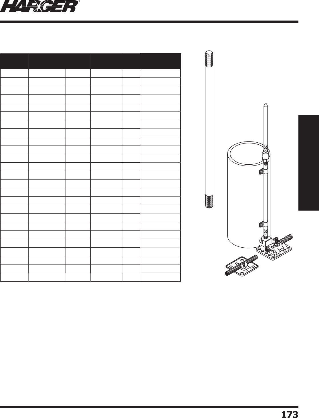
H
ar
g
er Li
g
htnin
g
& Groundin
g
•
©
2012 Phone 847-548-8700 • Fax 847-548-8755 • U.S. 800-842-743
7
1
7
3
173
Section 2
Lightning Protection Components
•
Solid co
pp
er or aluminum extension rods are used to extend
s
tandard air terminals to len
g
ths required.
•
Extension rods are available in len
g
ths up to 12 feet and have
s
t
a
n
da
r
d
U
NC thre
ad
s
a
t e
a
ch en
d
.
•
Meets UL re
q
uirements.
•
Other sizes available. Please contact factor
y
for more information.
Part No. Copper/
Aluminum Length Diameter Box
Qty.
Approx. Box
Wt. (lbs.)
144-1
2
C
o
pp
e
r
12" 3
/
8" 1
0
1
/2
144-
24
C
o
pp
e
r
24" 3
/
8" 1
0
1
144-
36
C
o
pp
e
r
36
"3
/
8" 1
0
1-1
/2
144-48
C
o
pp
e
r
4
8" 3
/
8" 1
0
2
144-
60
C
o
pp
e
r
60
"3
/
8" 1
0
2-1
/2
14
5
-1
2
C
o
pp
e
r
12" 1
/
2" 1
0
3
/4
A14
5
-1
2
Al
u
min
u
m 12" 1
/
2" 1
0
1
/4
14
5
-
24
C
o
pp
e
r
24" 1
/
2" 1
0
1-1
/2
A14
5
-
24
Al
u
min
u
m 24" 1
/
2" 1
0
1
/2
14
5
-
36
C
o
pp
e
r
36
"1
/
2" 1
0
2-1
/
4
A14
5
-
36
Al
u
min
u
m
36
"1
/
2" 1
0
3
/4
145-48
C
o
pp
e
r
4
8" 1
/
2" 1
0
3
A145-48 Al
u
min
u
m
4
8" 1
/
2" 1
0
1
14
5
-
60
C
o
pp
e
r
60
"1
/
2" 1
0
3-3
/
4
A14
5
-
60
Al
u
min
u
m
60
"1
/
2" 1
0
1-1
/
4
14
6
-1
2
C
o
pp
e
r
12"
5/
8" 1
0
1-1
/
4
A14
6
-1
2
Al
u
min
u
m 12"
5/
8" 1
0
1
/2
14
6
-
24
C
o
pp
e
r
24"
5/
8" 1
0
2-1
/2
A14
6
-
24
Al
u
min
u
m 24"
5/
8" 1
0
1
14
6
-
36
C
o
pp
e
r
36
"
5/
8" 1
0
3-3
/
4
A14
6
-
36
Al
u
min
u
m
36
"
5/
8" 1
0
1-1
/2
146-48
C
o
pp
e
r
4
8"
5/
8" 1
0
5
A146-48 Al
u
min
u
m
4
8"
5/
8" 1
0
2
14
6
-
60
C
o
pp
e
r
60
"
5/
8" 1
0
5
-1
/
4
A14
6
-
60
Al
u
min
u
m
60
"
5/
8" 1
0
2-1
/2
Air Terminal Extensi
o
ns
S
ect
io
n 2.2.11
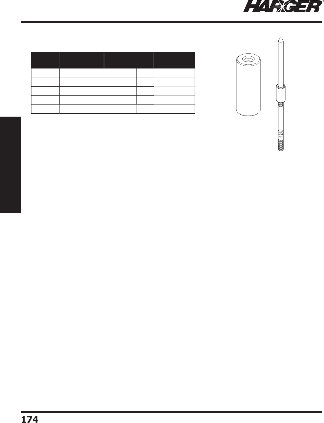
H
ar
g
er Li
g
htnin
g
& Groundin
g
•
©
2012 Phone 847-548-8700 • Fax 847-548-8755 • U.S. 800-842-743
7
1
7
4174
Section 2
Lightning Protection Components
•
13/16" x 2" cou
p
ler connects air terminals to extension rods, or
u
sed to connect sections of rods to
g
ether.
•
All thre
ad
s
a
re
U
NC.
•
Meets UL re
q
uirements.
Part No. Copper/
Aluminum Diameter Box
Qty.
Approx. Box
Wt. (lbs.)
14
7
C
o
pp
e
r
3
/
8" 1
0
2-3
/
4
148
C
o
pp
e
r
1
/
2" 1
0
2-1
/2
A148 Al
u
min
u
m1
/
2" 1
0
1
149
C
o
pp
e
r
5/
8" 1
0
1-3
/
4
A149 Al
u
min
u
m
5/
8" 1
0
1
Extension Rod Cou
p
lers
S
ect
io
n 2.2.12
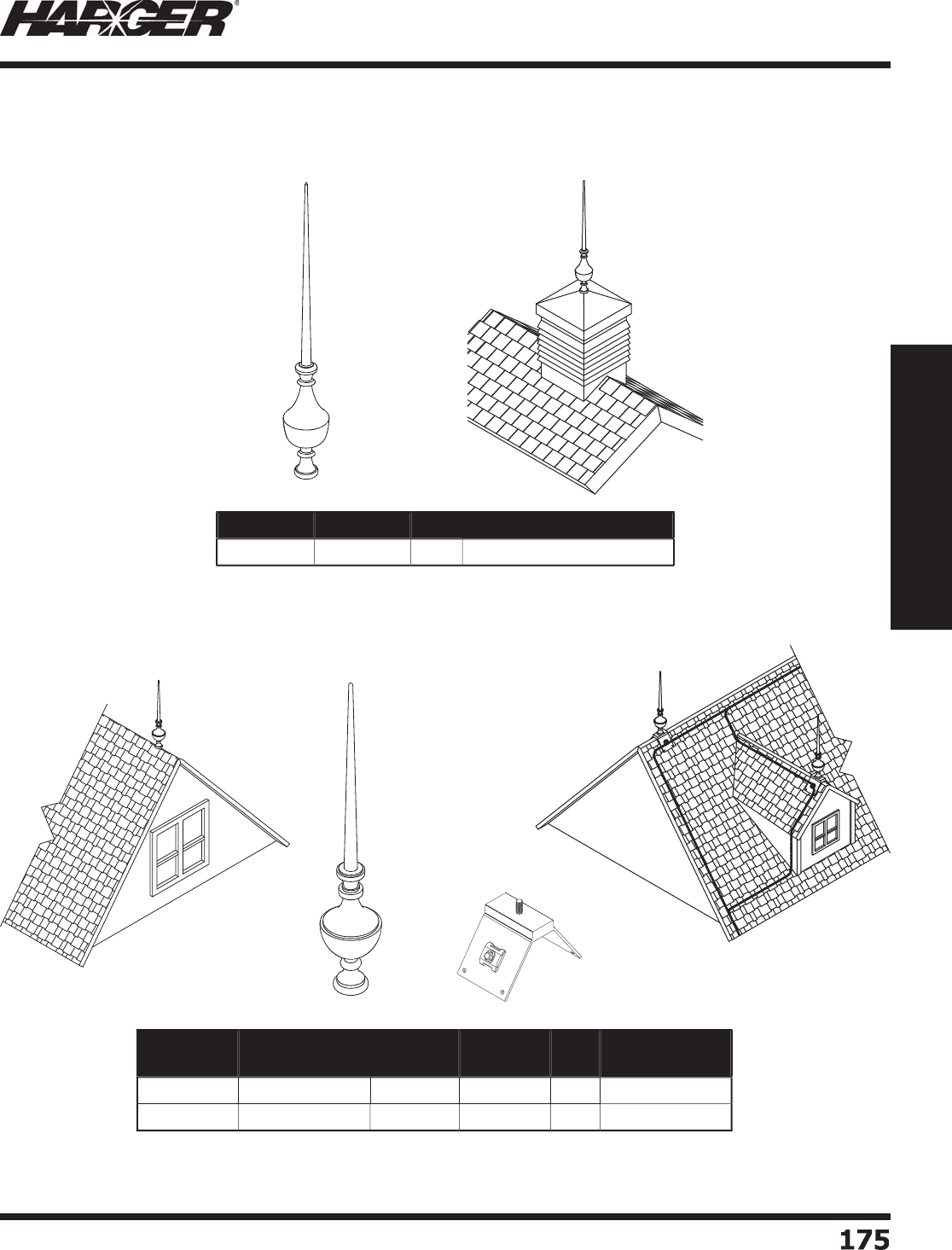
H
ar
g
er Li
g
htnin
g
& Groundin
g
•
©
2012 Phone 847-548-8700 • Fax 847-548-8755 • U.S. 800-842-743
7
1
7
5
175
Section 2
Lightning Protection Components
W
ith B
a
se
D
ecorative fi nial enhances buildin
g
aesthetics while bein
g
part of a functional li
g
htnin
g
protection system.
W
ith
ou
t B
a
s
e
•
16" decorative fi nial with 1
/
2" diameter internal thread.
•
Meets UL re
q
uirements.
Part No. Material Qty. Approx. Each Wt. (lbs.)
B
F16I1
/2
C
o
pp
e
r
EA
3
•
27" decorative fi nial with 1
/
2" diameter internal thread.
•
Meets UL re
q
uirements.
•
Base sold se
p
aratel
y
.
Part No. Description Material Internal
Thread Qty. Approx. Each
Wt. (lbs.)
B
F27I1
/2
F
ini
a
l
C
o
pp
e
r
1
/
2"
EA
2
1
B
F
2
7BA
S
E
Ba
se
C
o
pp
e
r
1
/
2"
EA
19
Dec
o
rative Finials
S
ect
io
n 2.2.13

H
ar
g
er Li
g
htnin
g
& Groundin
g
•
©
2012 Phone 847-548-8700 • Fax 847-548-8755 • U.S. 800-842-743
7
1
7
6176
Section 2
Lightning Protection Components
No
tes

H
ar
g
er Li
g
htnin
g
& Groundin
g
•
©
2012 Phone 847-548-8700 • Fax 847-548-8755 • U.S. 800-842-743
7
1
77
177
Section 2
Lightning Protection Components
S
ect
io
n 2.3
Air Terminal Ba
s
e
s
In
d
ex
Descr
i
pt
i
on Pa
g
e
2.
3
.1 H
o
riz
o
nt
a
l B
a
se
s
...............................................................................
178
2.
3
.2
U
nivers
a
l B
a
se
s
................................................................................
179
2
.
3
.
3
Para
p
et Base Extension
s
...................................................................
179
2.
3
.4 Swivel B
a
se
s
....................................................................................
180
2.
3
.
5
Vertic
a
l B
a
se
s
...................................................................................
180
2.3.6 Rid
g
e Saddle Base
s
..........................................................................
181
2.3.7 1/2 Rid
g
e Saddle Base
s
....................................................................
181
2.3.8 Pipe Railin
g
Base
s
............................................................................
18
2
2.
3
.9 C
o
nce
a
le
d
B
a
se
s
..............................................................................
18
4
2.3.10 Chimne
y
Flue Base
s
..........................................................................
185
2
.
3
.11 D
o
me B
a
se
s
.....................................................................................
186
2.3.12 Standin
g
Seam Base
s
.......................................................................
186
N
O
TE
:
Co
pp
er materials can consist of co
pp
er, bronze or brass. All are co
pp
er allo
y
s.
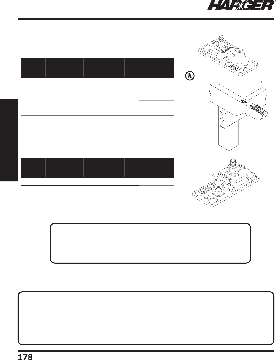
H
ar
g
er Li
g
htnin
g
& Groundin
g
•
©
2012 Phone 847-548-8700 • Fax 847-548-8755 • U.S. 800-842-743
7
1
78
178
Section 2
Lightning Protection Components
L
iste
d
9
6
Part No. Material
Internally
Threaded Hub
Diameter
Box
Qty.
Approx. Box
Wt. (lbs.)
15138I
C
o
pp
e
r
3
/
8"
5
3-3
/
4
15138IT
E
TPB* 3
/
8"
5
3-3
/
4
1
5
11
2
I
C
o
pp
e
r
1
/
2"
5
3-3
/
4
1
5
11
2
IT
E
TPB* 1
/
2"
5
3-3
/
4
A1
5
11
2
IAl
u
min
u
m1
/
2"
5
1-1
/
4
H
o
riz
o
ntal Bases
Internall
y
Threaded Hub Bases
•
Adapter needed. See pa
g
e 169.
Part No. Material
Externally
Threaded Hub
Diameter
Box
Qty.
Approx. Box
Wt. (lbs.)
1
5
1
C
o
pp
e
r
5/
8"
5
3-1
/
4
A1
5
1Al
u
min
u
m
5/
8"
5
3-1
/
4
1
5
1T
E
TPB*
5/
8"
5
3-1
/
4
Externall
y
Threaded Hub Bases
TECHNICAL N
O
TES
:
• A threaded hub
p
rovided for the attachment of the air terminal shall have at least fi ve full threads and, if internall
y
threaded,
shall have a wall thickness of not less than 1/16 inch
(
1.6 mm
)
measured at the base of the threads.*
• Each base support shall incorporate a connector fi ttin
g
for connection to the li
g
htnin
g
conductor. The conductin
g
cross-sectional area of the base support, between the connector and the base of the air terminal, shall be equal to or
g
reater
than that of the conductor. The conductor shall contact the base for not less than 1-1/2 inches
(
38 mm
)
on all sides of the cable.*
• At least two mountin
g
holes that will accept a No. 10 - 24 or lar
g
er bolt or screw shall be provided in the support so that it can
be permanently and ri
g
idly fastened.*
*
UL 96 Standard for Li
g
htnin
g
Protection Components Sections 7.2, 7.4 & 7.5
N
O
TES
:
• 1-3/4" x 4" base is ideal for use where mountin
g
area is very small such as on skyli
g
ht frames
or narrow extruded sha
p
es.
• Acce
p
ts all Class I & Class II conductors.
•
T
wo mountin
g
holes are provided for secure mountin
g
usin
g
machine or self tappin
g
screws.
*ETPB - Electr
o
Tin Pl
a
te
d
Br
o
nz
e
S
ect
io
n 2.3.1
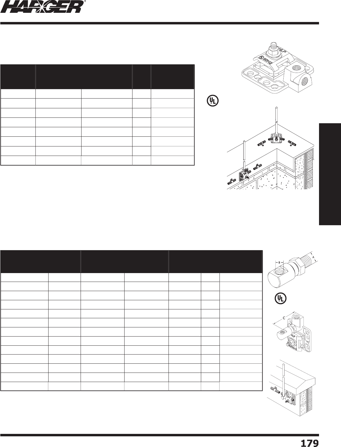
H
ar
g
er Li
g
htnin
g
& Groundin
g
•
©
2012 Phone 847-548-8700 • Fax 847-548-8755 • U.S. 800-842-743
7
1
7
9
179
Section 2
Lightning Protection Components
L
iste
d
9
6
•
2-5/8" x 3" base features a universal mountin
g
desi
g
n allowin
g
it to be
i
nstalled either horizontall
y
or verticall
y
.
•
Utilizes a variety of mountin
g
applications such as self tappin
g
screws, nails
o
r
ad
hesives.
•
Acce
p
ts all Class I & Class II conductors.
*
ETPB - Electr
o
Tin Pl
a
te
d
Br
o
nz
e
Part No. Material
Internally
Threaded Hub
Diameter
Box
Qty.
Approx. Box
Wt. (lbs.)
CUBU38I
C
o
pp
e
r
3
/
8"
5
4
-1
/4
T
CUBU38I
E
TPB* 3
/
8"
5
4
-1
/4
C
U
B
U
1
2
I
C
o
pp
e
r
1
/
2"
5
4
-1
/4
T
C
U
B
U
1
2
I
E
TPB* 1
/
2"
5
4
-1
/4
A
U
B
U
1
2
IAl
u
min
u
m1
/
2"
5
1-1
/2
CUBU58I
C
o
pp
e
r
5/
8"
5
4
-1
/4
T
CUBU58I
E
TPB*
5/
8"
5
4
-1
/4
AUBU58I Al
u
min
u
m
5/
8"
5
1-1
/2
U
niver
s
al Ba
s
e
s
U
BU Series - H
o
riz
o
ntal & Vertical Bases
L
iste
d
9
6
Part No. Material
Base
Thread
Diameter A
Air Terminal
Threaded
Diameter B
Offset
Clearance
C
Box
Qty.
Approx. Box
Wt. (lbs.)
B
PBE
2
C
o
pp
e
r
1
/
2" 1
/
2" 2" 1
0
5
B
PBE2-3
/
8
C
o
pp
e
r
1
/
2" 3
/
8"
2
"1
0
5
B
PBE2-3
/
8X3
/
8
C
o
pp
e
r
3
/
8" 3
/
8" 2" 1
0
5
B
PBE2-5
/
8X5
/
8
C
o
pp
e
r
5/
8"
5/
8" 2" 1
0
5
B
PBE
3
C
o
pp
e
r
1
/
2" 1
/
2"
3
"1
0
7-1
/2
B
PBE3-3
/
8
C
o
pp
e
r
1
/
2" 3
/
8"
3
"1
0
7-1
/2
B
PBE3-3
/
8X3
/
8
C
o
pp
e
r
3
/
8" 3
/
8"
3
"1
0
7-1
/2
B
PBE3-5
/
8X5
/
8
C
o
pp
e
r
5/
8"
5/
8"
3
"1
0
7-1
/2
APBE
2
Al
u
min
u
m1
/
2" 1
/
2" 2" 1
0
2-1
/2
APBE2-5
/
8Al
u
min
u
m1
/
2"
5/
8" 2" 1
0
2-1
/2
APBE2-5
/
8X5
/
8Al
u
min
u
m
5/
8"
5/
8" 2" 1
0
2-1
/2
APBE
3
Al
u
min
u
m1
/
2" 1
/
2"
3
"1
0
5
APBE3-5
/
8X5
/
8Al
u
min
u
m
5/
8"
5/
8"
3
"1
0
5
Para
p
et Base Extens
i
ons
•
Used when mountin
g
air terminal bases under copin
g
s that have up to a 2" or 3" overhan
g
.
•
Provides a 2" or 3" extension
(
measured from inside of air terminal to
p
ara
p
et wall
)
.
•
Manufactured from hi
g
hly conductive copper or aluminum alloys.
•
Stainless steel
j
am nut provides for proper positionin
g
of air terminal.
•
Available electro-tin plated. When orderin
g
, add prefi x T to part number.
S
ect
io
n 2.3.2 & 2.3.3
HLP
50H2
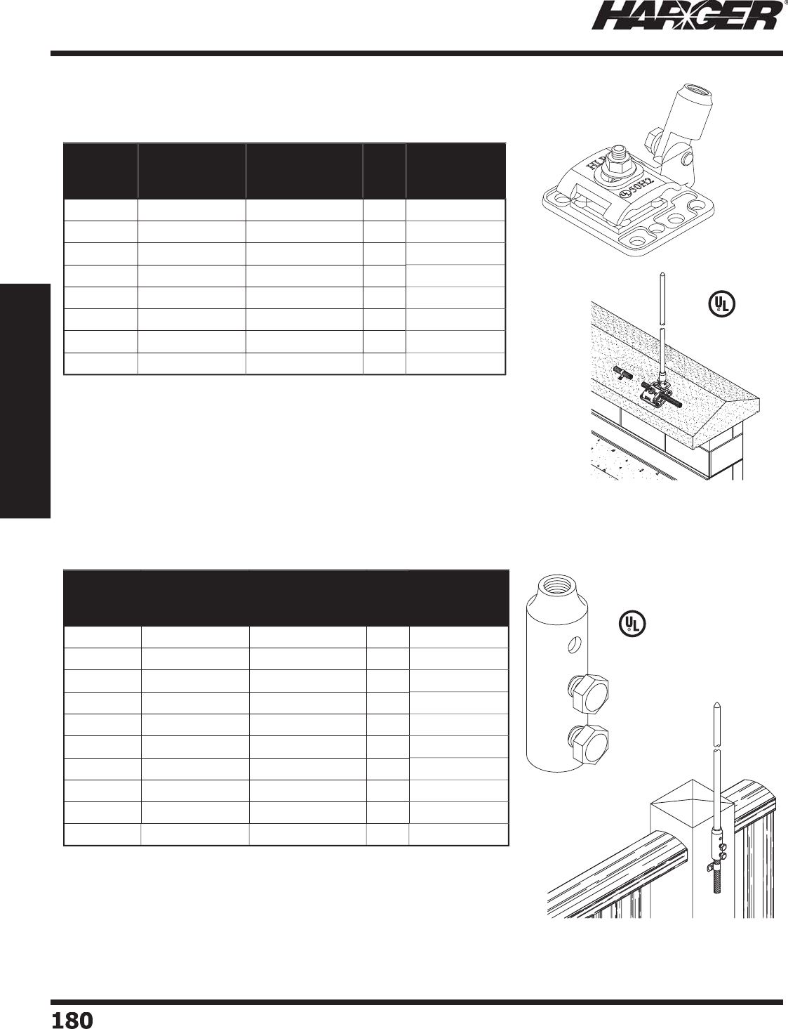
H
ar
g
er Li
g
htnin
g
& Groundin
g
•
©
2012 Phone 847-548-8700 • Fax 847-548-8755 • U.S. 800-842-743
7
1
80
180
Section 2
Lightning Protection Components
•
2-5/8" x 3" base features a swivel ada
p
ter intended for installation on
an
g
led surfaces.
•
U
tilizes a variety of mountin
g
applications such as self tappin
g
screws,
n
a
ils
o
r
ad
hesives.
•
Acce
p
ts all Class I & Class II conductors.
*
ETPB - Electr
o
Tin Pl
a
te
d
Br
o
nze.
Part No. Material
Internally
Thread Hub
Diameter
Box
Qty.
Approx. Box
Wt. (lbs.)
CUBS38
C
o
pp
e
r
3
/
8"
5
4
-1
/2
T
CUBS38
E
TPB* 3
/
8"
5
4
-1
/2
C
U
BS1
2
C
o
pp
e
r
1
/
2"
5
5
-1
/2
T
C
U
BS1
2
E
TPB* 1
/
2"
5
5
-1
/2
A
U
BS1
2
Al
u
min
u
m1
/
2"
5
1-1
/2
CUBS58
C
o
pp
e
r
5/
8"
5
5
T
CUBS58
E
TPB*
5/
8"
5
5
AUBS58 Al
u
min
u
m
5/
8"
5
5
S
wivel Ba
s
e
s
U
BS Series with Swivel Ada
p
ter
•
2-1/2" lon
g
, vertical base connector features 1/4" mountin
g
hole and
two stainless steel cap screws to assure a
g
ood electrical connection.
•
For all standard cables u
p
to 1/2" in diameter.
•
#A158R and #A158R-5/8 fi ts aluminum cables u
p
to 19/32" diameter.
*
Electr
o
Tin Pl
a
te
d
L
iste
d
9
6
Part No. Material
Internally
Threaded Hub
Diameter
Box
Qty.
Approx. Box
Wt. (lbs.)
1
57
C
o
pp
e
r
3
/
8" 1
0
2-1
/2
1
5
7T Co
pp
er* 3
/
8" 1
0
2-1
/2
158
C
o
pp
e
r
1
/
2" 1
0
2-1
/2
158T Co
pp
er* 1
/
2" 1
0
2-1
/2
A158 Al
u
min
u
m1
/
2" 1
0
1-1
/4
A158R Al
u
min
u
m1
/
2" 1
0
1-1
/4
158-5
/
8
C
o
pp
e
r
5/
8" 1
0
2-1
/2
158-5
/
8T Co
pp
er*
5/
8" 1
0
2-1
/2
A158-5
/
8Al
u
min
u
m
5/
8" 1
0
1-1
/4
A158R-5
/
8Al
u
min
u
m
5/
8" 1
0
1-1
/4
Vertical Ba
s
e
s
L
iste
d
9
6
S
ect
io
n 2.3.4 & 2.3.5
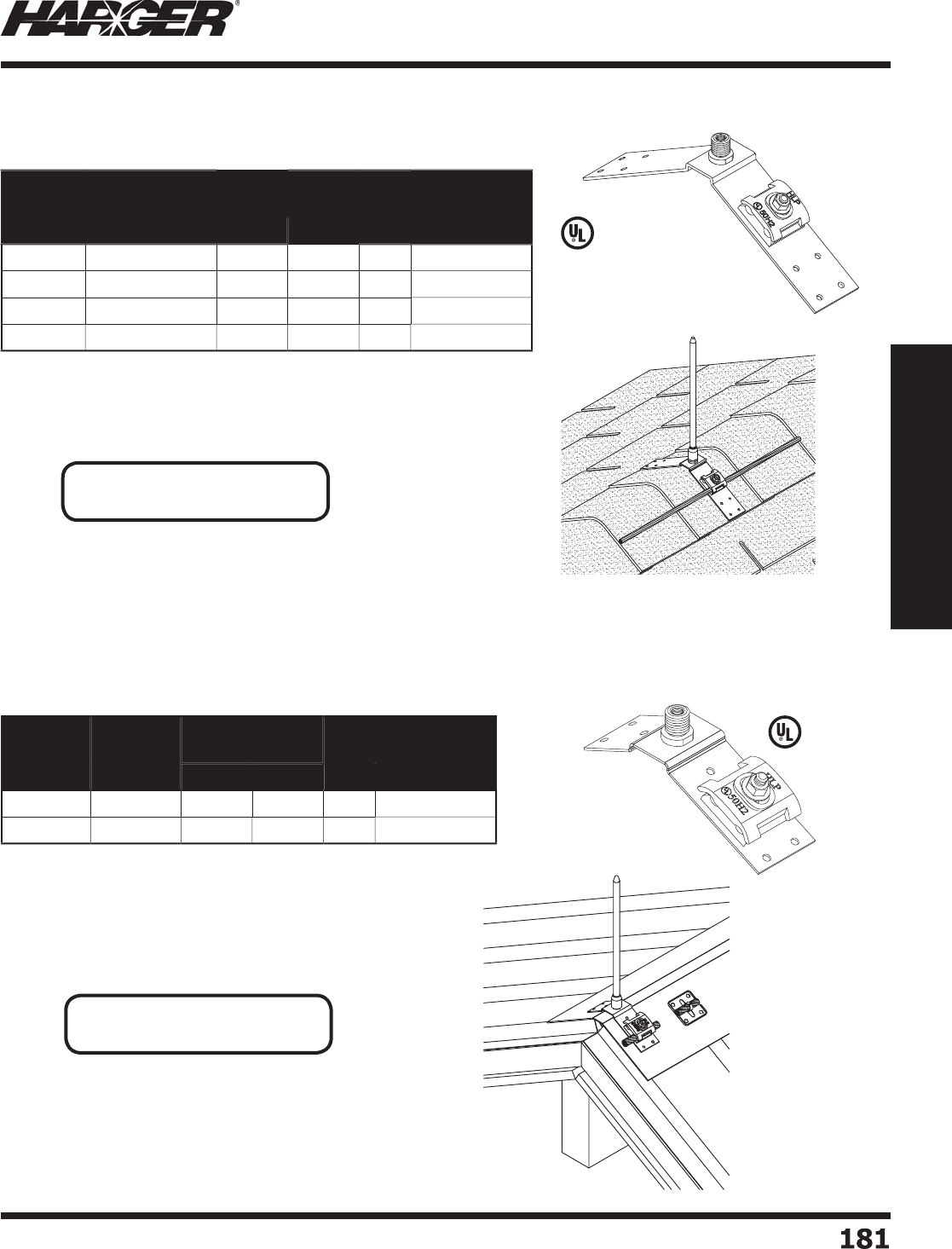
H
ar
g
er Li
g
htnin
g
& Groundin
g
•
©
2012 Phone 847-548-8700 • Fax 847-548-8755 • U.S. 800-842-743
7
1
81
181
Section 2
Lightning Protection Components
•
2" x 12" base fi ts easil
y
to most an
y
surface.
•
Acce
p
ts all Class I & Class II conductors.
*
Electr
o
Tin Pl
a
te
d
L
iste
d
9
6
Part No. Material
Threaded Hub
Diameter Box
Qty.
Approx. Box
Wt. (lbs.)
Int. Ext.
1
60
C
o
pp
e
r
3
/
8"
5/
8" 1
0
1
0
1
60
TCo
pp
er* 3
/
8"
5/
8" 1
0
1
0
A1
60
Al
u
min
u
m1
/
2"
N/
A1
0
4
-1
/2
A160-5
/
8Al
u
min
u
m
5/
8"
N/
A1
0
4
-1
/2
Rid
g
e Saddle Bases
•
2" x 6-3/4" base fi ts easil
y
to most an
y
surface.
•
Acce
p
ts all Class I & Class II conductors.
L
iste
d
9
6
Part No. Material
Threaded Hub
Diameter Box
Qty.
Approx. Box
Wt. (lbs.)
Int. Ext.
C
U
RS
6
.7
5
C
o
pp
e
r
3
/
8"
5/
8" 1
0
1
0
ALRS
6
.7
5
Al
u
min
u
m1
/
2"
N/
A1
0
5
1
/2 Rid
g
e Saddle Bases
N
O
TE
:
•
See pa
g
e 169 for adapters.
N
O
TE
:
•
See pa
g
e 169 for adapters.
S
ect
io
n 2.3.6 & 2.3.7
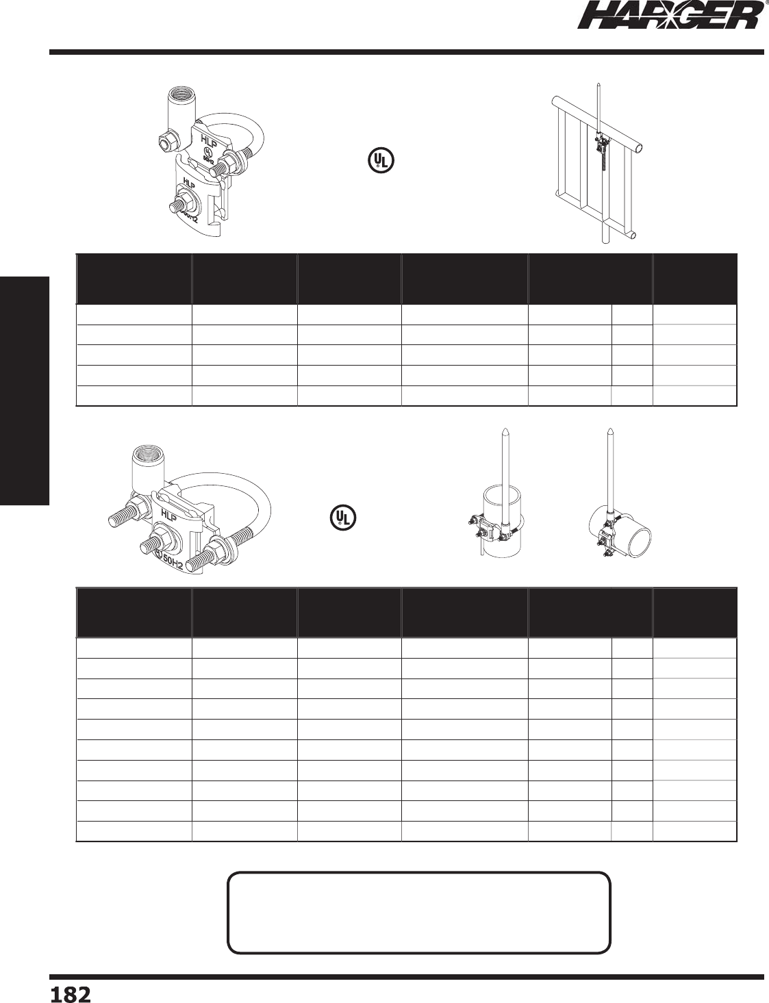
H
ar
g
er Li
g
htnin
g
& Groundin
g
•
©
2012 Phone 847-548-8700 • Fax 847-548-8755 • U.S. 800-842-743
7
1
82
182
Section 2
Lightning Protection Components
L
iste
d
9
6
V
e
rti
ca
l
Ho
riz
o
nt
a
l
Pipe Railin
g
Bases
Part No. Material Nominal Pipe
Size Range
Outside Diameter
Pipe Size Range
Air
Terminal
Diameter
Box
Qty.
Approx.
Box Wt.
(lbs.)
CPRB.5
/
1AT38
E
TPB*
.5
" - 1"
0
.84" - 1.315" 3
/
8"
5
3-3
/4
CPRB.5
/
1AT1
2
E
TPB*
.5
" - 1"
0
.84" - 1.315" 1
/
2"
5
3-3
/4
CPRB.5
/
1AT58
E
TPB*
.5
" - 1"
0
.84" - 1.315"
5/
8"
5
3-3
/4
APRB.5
/
1AT1
2
Al
u
min
u
m
.5
" - 1"
0
.84" - 1.315" 1
/
2"
5
2-1
/2
APRB.5
/
1AT58 Al
u
min
u
m
.5
" - 1"
0
.84" - 1.315"
5/
8"
5
2-1
/2
Part No. Material Nominal Pipe
Size Range
Outside Diameter
Pipe Size Range
Air
Terminal
Diameter
Box
Qty.
Approx.
Box Wt.
(lbs.)
CPRB1.5
/
2AT38
E
TPB* 1.2
5
" - 2" 1.
3
1
5
" - 2.4" 3
/
8"
5
5
CPRB1.5
/
2AT1
2
E
TPB* 1.2
5
" - 2" 1.
3
1
5
" - 2.4" 1
/
2"
5
5
CPRB1.5
/
2AT58
E
TPB* 1.2
5
" - 2" 1.
3
1
5
" - 2.4"
5/
8"
5
5
APRB1.5
/
2AT1
2
Al
u
min
u
m 1.2
5
" - 2" 1.
3
1
5
" - 2.4" 1
/
2"
5
2-1
/2
APRB1.5
/
2AT58 Al
u
min
u
m 1.2
5
" - 2" 1.
3
1
5
" - 2.4"
5/
8"
5
2-1
/2
CPRB2.5
/
3AT38
E
TPB* 2.
5
" -
3
" 2.2
5
" -
3
.
5
"3
/
8"
5
7-1
/2
CPRB2.5
/
3AT1
2
E
TPB* 2.
5
" -
3
" 2.2
5
" -
3
.
5
"1
/
2"
5
7-1
/2
CPRB2.5
/
3AT58
E
TPB* 2.
5
" -
3
" 2.2
5
" -
3
.
5
"
5/
8"
5
7-1
/2
APRB2.5
/
3AT1
2
Al
u
min
u
m2.
5
" -
3
" 2.2
5
" -
3
.
5
"1
/
2"
5
2-1
/2
APRB2.5
/
3AT58 Al
u
min
u
m2.
5
" -
3
" 2.2
5
" -
3
.
5
"
5/
8"
5
3
L
iste
d
9
6
N
O
TES
:
• Swivel adapter desi
g
n allows for mountin
g
at any an
g
le.
• Fits all main size conductors u
p
to 9/16" diameter.
• Air termin
a
l n
o
t incl
ud
e
d
.
S
ect
io
n 2.3.8
*
Electr
o
Tin Pl
a
te
d
Br
o
nze
*
Electr
o
Tin Pl
a
te
d
Br
o
nze
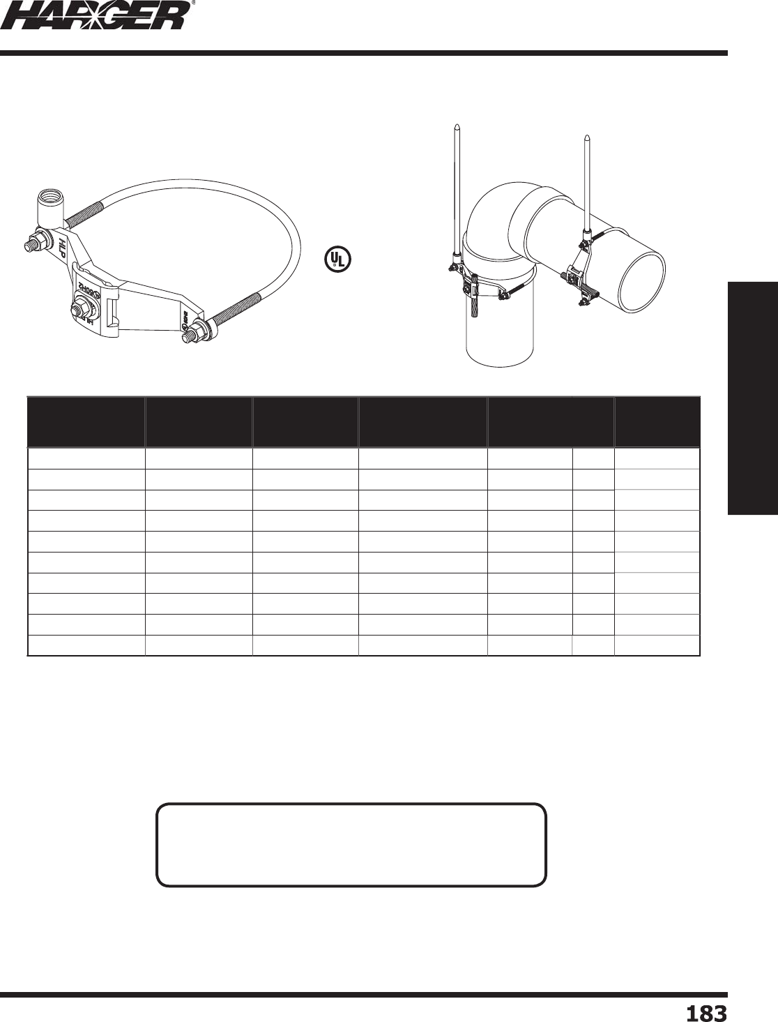
H
ar
g
er Li
g
htnin
g
& Groundin
g
•
©
2012 Phone 847-548-8700 • Fax 847-548-8755 • U.S. 800-842-743
7
1
83
183
Section 2
Lightning Protection Components
Part No. Material Nominal Pipe
Size Range
Outside Diameter
Pipe Size Range
Air
Terminal
Diameter
Box
Qty.
Approx.
Box Wt.
(lbs.)
CPRB3.5
/
4AT38
ETPB
*
3
.
5
" - 4"
3
.2" - 4.
5
"3
/
8"
5
8-3
/4
CPRB3.5
/
4AT1
2
E
TPB*
3
.
5
" - 4"
3
.2" - 4.
5
"1
/
2"
5
8-3
/4
CPRB3.5
/
4AT58
E
TPB*
3
.
5
" - 4"
3
.2" - 4.
5
"
5/
8"
5
8-3
/4
APRB3.5
/
4AT1
2
Al
u
min
u
m
3
.
5
" - 4"
3
.2" - 4.
5
"1
/
2"
5
3-3
/4
APRB3.5
/
4AT58 Al
u
min
u
m
3
.
5
" - 4"
3
.2" - 4.
5
"
5/
8"
5
4
CPRB5
/
6AT38
E
TPB*
5
" -
6
"
5
.
63
" -
6
.
63
"3
/
8"
3
6
CPRB5
/
6AT1
2
ETPB
*
5
" -
6
"
5
.
63
" -
6
.
63
"1
/
2"
3
6
CPRB5
/
6AT58
E
TPB*
5
" -
6
"
5
.
63
" -
6
.
63
"
5/
8"
3
6
APRB5
/
6AT1
2
Al
u
min
u
m
5
" -
6
"
5
.
63
" -
6
.
63
"1
/
2"
3
3-3
/
4
APRB5
/
6AT58 Al
u
min
u
m
5
" -
6
"
5
.
63
" -
6
.
63
"
5/
8"
3
3-3
/
4
Pipe Railin
g
Bases
L
iste
d
9
6
N
O
TES
:
• Swivel adapter desi
g
n allows for mountin
g
at any an
g
le.
• Fits all main size conductors u
p
to 9/16" diameter.
• Air termin
a
l n
o
t incl
ud
e
d
.
S
ect
io
n 2.3.8
*
Electr
o
Tin Pl
a
te
d
Br
o
nze
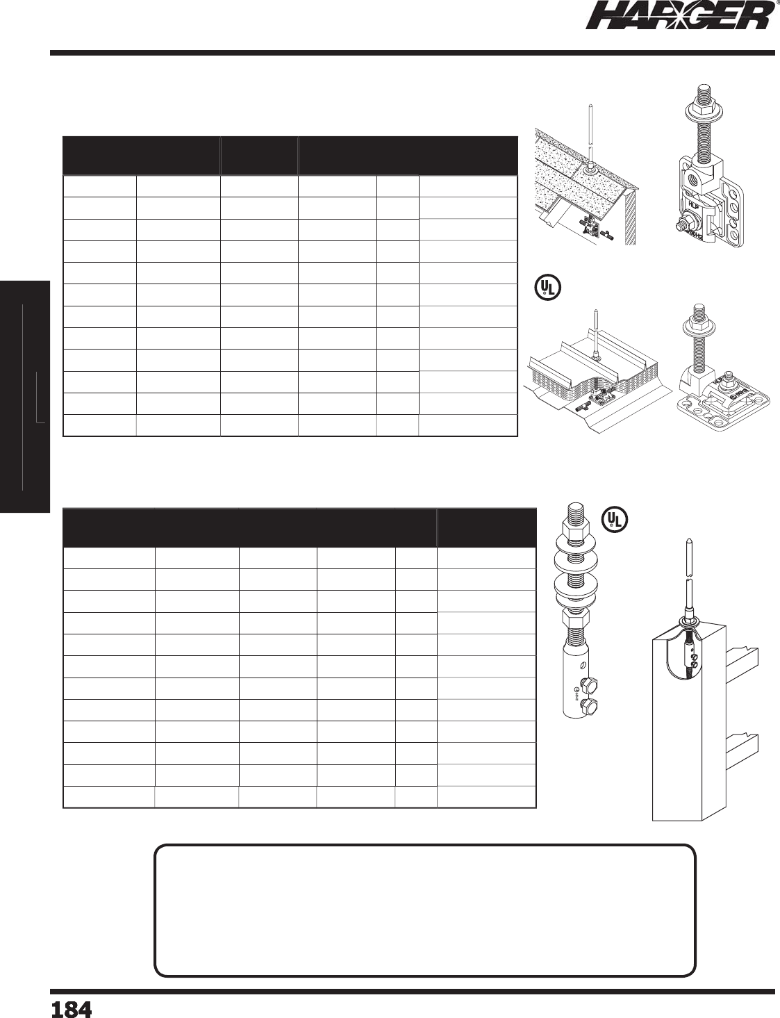
H
ar
g
er Li
g
htnin
g
& Groundin
g
•
©
2012 Phone 847-548-8700 • Fax 847-548-8755 • U.S. 800-842-743
7
Section 2
Lightning Protection Components
1
8
4184184184184184184184
S
ect
io
n 2
Li
g
htnin
g
Protection Components
Section 2
Lightning Protection Components
•
Vertical concealed base assembly desi
g
ned to be mounted on rid
g
e boards or roof trusses.
•
Horizontal concealed base assembly is desi
g
ned for use on fl at roof decks or other fl at surfaces.
•
Al
u
min
u
m c
o
nce
a
le
d
ba
se
a
ssem
b
lies
u
tilize st
a
inless steel riser
ba
rs.
L
iste
d
9
6
Part No. Material Riser Bar
Length
Riser Bar
Diameter
Box
Qty.
Approx. Box
Wt. (lbs.)
1
5
7-
6
C
o
pp
e
r
6
"3
/
8" 1
0
5
1
5
7-1
2
C
o
pp
e
r
12" 3
/
8" 1
0
6
157-18
C
o
pp
e
r
18" 3
/
8" 1
0
8
158-6
C
o
pp
e
r
6
"1
/
2" 1
0
6
158BM-6
B
i-Met
a
l
6
"1
/
2" 1
0
6
158-1
2
C
o
pp
e
r
12" 1
/
2" 1
0
9
158BM-1
2
B
i-Met
a
l
12
"1
/
2" 1
0
1
0
158-18
C
o
pp
e
r
18" 1
/
2" 1
0
1
2
158BM-18
B
i-Met
a
l 18" 1
/
2" 1
0
1
2
A158-6 Al
u
min
u
m
6
"1
/
2" 1
0
3
A158-1
2
Al
u
min
u
m 12" 1
/
2" 1
0
4
A158-18 Al
u
min
u
m 18" 1
/
2" 1
0
6
Co
ncealed Bases
Co
ncealed Base Assemblies
L
iste
d
9
6
Part No. Material Riser Bar
Length
Riser Bar
Diameter
Box
Qty.
Approx. Box
Wt. (lbs.)
1
55
-
6
C
o
pp
e
r
6
"3
/
8" 1
0
6
-1
/
4
1
55
-1
2
C
o
pp
e
r
12" 3
/
8" 1
0
12-1
/2
155-18
C
o
pp
e
r
18" 3
/
8" 1
0
18-3
/
4
1
56
-
6
C
o
pp
e
r
6
"1
/
2" 1
0
5
-1
/
4
A1
56
-
6
Al
u
min
u
m
6
"1
/
2" 1
0
4
-1
/
4
1
56
BM-
6
B
i-Met
a
l
6
"1
/
2" 1
0
7-1
/2
1
56
-1
2
C
o
pp
e
r
12" 1
/
2" 1
0
10-1
/
4
A1
56
-1
2
Al
u
min
u
m 12" 1
/
2" 1
0
8-1
/
4
1
56
BM-1
2
B
i-Met
a
l 12" 1
/
2" 1
0
14-3
/
4
156-18
C
o
pp
e
r
18" 1
/
2" 1
0
15-1
/2
A156-18 Al
u
min
u
m 18" 1
/
2" 1
0
12-1
/
4
156BM-18
B
i-Met
a
l 18" 1
/
2" 1
0
22
Co
ncealed Base Assemblies
N
O
TES
:
• Acce
p
ts all Class I and Class II conductors.
• Stainless steel
j
am nut and washer are provided alon
g
with a special neoprene
sealin
g
washer to assure a waterti
g
ht installation.
• Bi-met
a
l c
o
nsists
o
f st
a
inless steel riser
ba
r
a
n
d
b
r
o
nze
ba
se.
• Air terminal adapters needed for these type of bases. See pa
g
e 169 for adapters.
• Other len
g
ths available. Please contact factory for more information.
S
ect
io
n 2.3.9
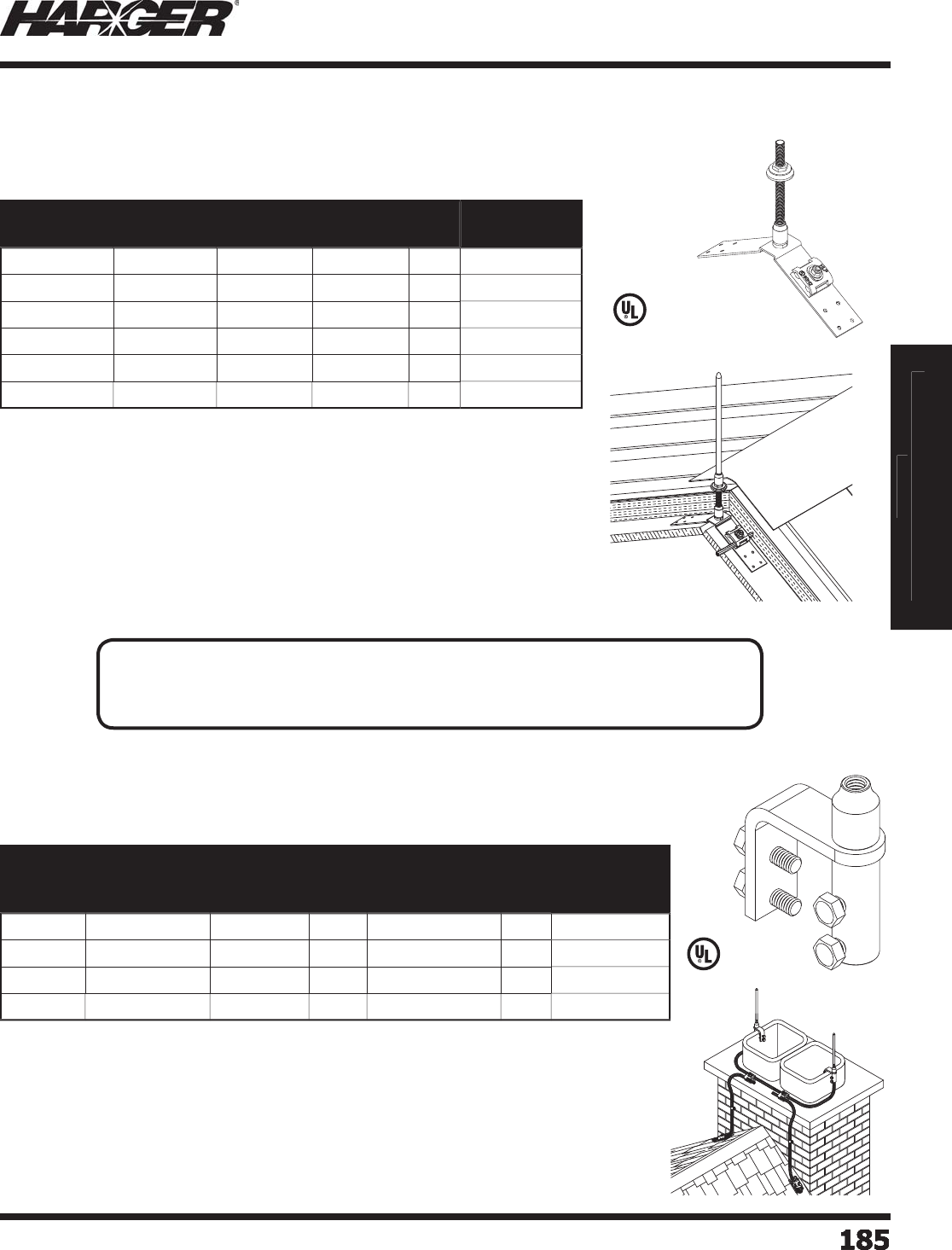
H
ar
g
er Li
g
htnin
g
& Groundin
g
•
©
2012 Phone 847-548-8700 • Fax 847-548-8755 • U.S. 800-842-743
7
Section 2
Lightning Protection Components
1
85
185185185185185185185
S
ect
io
n 2
Li
g
htnin
g
Protection Components
Section 2
Lightning Protection Components
•
2" x 12" concealed base assembly desi
g
ned for use on pitched roo
f
decks in the insulation s
p
ace.
•
Permits concealment of roof conductors where the
y
otherwise ma
y
not
be concealed because the under side of the deck is ex
p
osed.
•
Acce
p
ts all Class I & Class II conductors.
•
Furnished with a stainless steel washer and
j
am nut, as well as a
neoprene washer for a complete waterti
g
ht installation.
L
iste
d
9
6
•
Acce
p
ts all Class I & Class II conductors.
•
Used when protectin
g
chimneys from direct li
g
htnin
g
strikes.
•
Other sizes available. Please contact factor
y
for more information.
L
iste
d
9
6
Part No. Material Riser Bar
Length
Riser Bar
Diameter
Box
Qty.
Approx. Box
Wt. (lbs.)
1
62
-
6
C
o
pp
e
r
6
"1
/
2" 1
0
12-1
/2
A1
62
-
6
Al
u
min
u
m
6
"1
/
2" 1
0
8-1
/2
1
62
-1
2
C
o
pp
e
r
12" 1
/
2" 1
0
5
A1
62
-1
2
Al
u
min
u
m 12" 1
/
2" 1
0
11-1
/2
162-18
C
o
pp
e
r
18" 1
/
2" 1
0
18
A162-18 Al
u
min
u
m 18" 1
/
2" 1
0
14-1
/
4
Part No. Material
Maximum
Material
Thickness
Class
Internally
Threaded Hub
Diameter
Box
Qty.
Approx. Box
Wt. (lbs.)
C
FB1.
5
T
inned Co
pp
e
r
1-1
/
2"
I
3
/
8"
5
5
CFB
2
.
25
T
inned Co
pp
e
r
2-1
/
4"
I
3
/
8"
5
6
-1
/
4
AFB1-1
/2
Al
u
min
u
m1"
I
1
/
2"
5
2
AFB1-5
/
8Al
u
min
u
m1"
II
5/
8"
5
2
Co
ncealed Bases
C
oncealed Rid
g
e Saddle Assemblies
C
himne
y
Flue Bases
N
O
TES
:
• Air terminal adapters needed for these type of bases. See pa
g
e 169 for adapters.
• For other available riser bar len
g
ths, please contact factory for more information.
S
ect
io
n 2.3.9 & 2.3.10
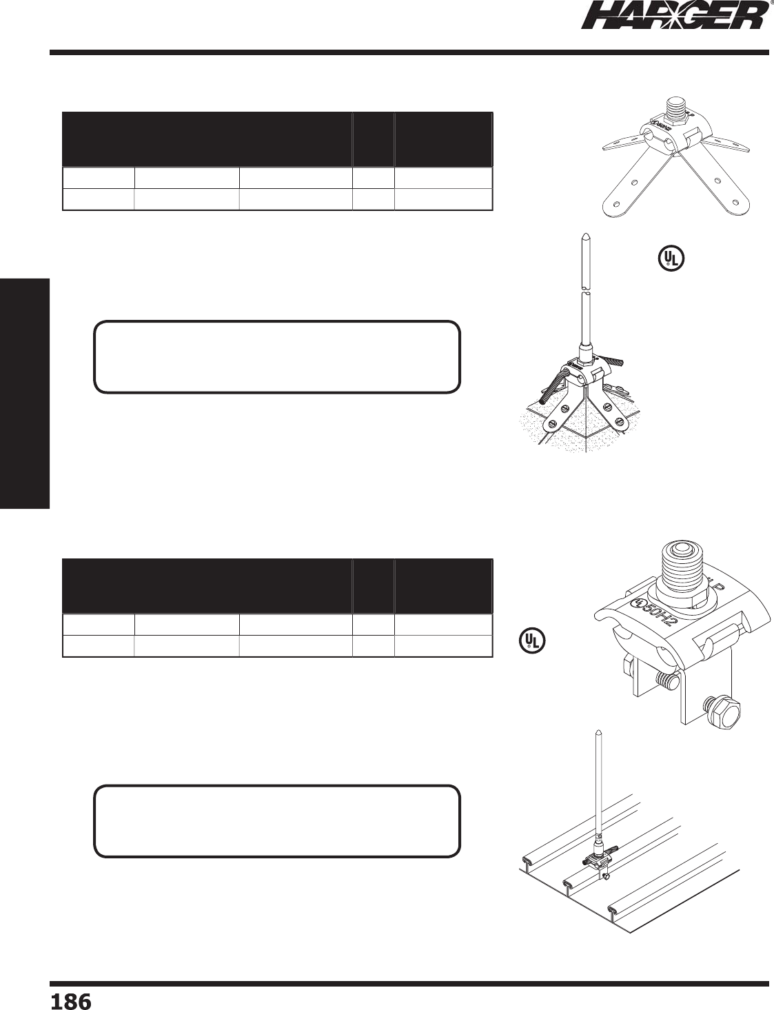
H
ar
g
er Li
g
htnin
g
& Groundin
g
•
©
2012 Phone 847-548-8700 • Fax 847-548-8755 • U.S. 800-842-743
7
1
86
186
Section 2
Lightning Protection Components
S
ect
io
n 2.3.11 & 2.3.12
•
Base features four 4" straps with two 3/16" mountin
g
holes per strap.
•
Stra
p
s manufactured from 1" wide soft tem
p
er co
pp
er or aluminum
w
hich easil
y
forms to fi t all conical sha
p
es.
•
Acce
p
ts all Class I & Class II conductors.
L
iste
d
9
6
•
U
se
d
t
o
c
o
nnect
a
ir termin
a
l
a
n
d
c
o
n
du
ct
o
r t
o
a
se
a
m.
•
Fits u
p
to 1" wide seam.
•
Omni directional base desi
g
n allows conductor to be coursed parallel or
p
er
p
endicular to seam.
•
Acce
p
ts all Class I & Class II conductors.
L
iste
d
9
6
Part No. Material
Externally
Threaded Hub
Diameter
Box
Qty.
Approx. Box
Wt. (lbs.)
1
64
C
o
pp
e
r
5/
8"
5
7-1
/2
A1
64
Al
u
min
u
m
5/
8"
5
6
Part No. Material
Externally
Threaded Hub
Diameter
Box
Qty.
Approx. Box
Wt. (lbs.)
BS
B
C
o
pp
e
r
5/
8"
5
3-3
/
4
AL
S
BAl
u
min
u
m
5/
8"
5
2-1
/2
Do
me
B
ases
S
tandin
g
Seam Bases
N
O
TES
:
• Air terminal ada
p
ters needed for these t
yp
e of bases.
See pa
g
e 169 for adapters.
N
O
TES
:
• Air terminal ada
p
ters needed for these t
yp
e of bases.
See pa
g
e 169 & 171 for adapters.

H
ar
g
er Li
g
htnin
g
& Groundin
g
•
©
2012 Phone 847-548-8700 • Fax 847-548-8755 • U.S. 800-842-743
7
1
87
187
Section 2
Lightning Protection Components
S
ect
io
n 2.
4
Thru-Roof/Wall Connectors,
Assemblies & Access
o
ries
In
d
ex
Descr
i
pt
i
on Pa
g
e
2.4.1 Thru-Roof
/
Wall Connector
s
...............................................................
188
2.4.2 Thru-Roof
/
Wall Assemblie
s
................................................................
19
0
2.4.
3
Thr
u
-R
oo
f Access
o
rie
s
......................................................................
19
2
2.4.4 Pitch Pockets & Roof Flashin
gs
..........................................................
194
N
O
TE
:
Co
pp
er materials can consist of co
pp
er, bronze or brass. All are co
pp
er allo
y
s.
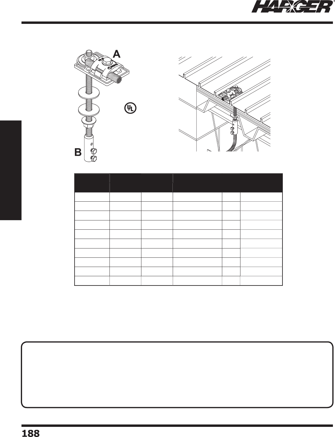
H
ar
g
er Li
g
htnin
g
& Groundin
g
•
©
2012 Phone 847-548-8700 • Fax 847-548-8755 • U.S. 800-842-743
7
1
88
188
Section 2
Lightning Protection Components
•
Thru-roof or thru-wall connectors are used when makin
g
roof or wall penetrations
because of the diffi culty of sealin
g
stranded li
g
htnin
g
conductor cables.
•
Features include 1/2" diameter threaded rod, neoprene sealin
g
washers and
s
tainless steel
j
am nuts to assure a waterti
g
ht installation.
•
Fits all main size conductors u
p
to 9/16" diameter.
•
Other confi
g
urations available. Please contact factory for more information.
L
iste
d
9
6
Thru-Roof
/
Wall Connectors
Ri
g
ht An
g
le to Strai
g
ht Connectio
n
Part No. Type of Material Threaded Bar
Length
Box
Qty.
Approx. Box
Wt. (lbs.)
AB
225
-
6
C
o
pp
e
r
C
o
pp
e
r
6
"1
0
12-3
/
4
A
225
-
6
Al
u
min
u
mAl
u
min
u
m
6
"1
0
7-1
/
4
225
BM-
6
Al
u
min
u
m
C
o
pp
e
r
6
"1
0
11-1
/
4
225
-1
2
C
o
pp
e
r
C
o
pp
e
r
12" 1
0
15-3
/
4
A
225
-1
2
Al
u
min
u
mAl
u
min
u
m 12" 1
0
8-1
/2
225
BM-1
2
Al
u
min
u
m
C
o
pp
e
r
12" 1
0
13-3
/
4
225-18
C
o
pp
e
r
C
o
pp
e
r
18" 1
0
18-3
/
4
A225-18 Al
u
min
u
mAl
u
min
u
m 18" 1
0
9
-3
/
4
225BM-18 Al
u
min
u
m
C
o
pp
e
r
18" 1
0
16-1
/
4
A225BM-18
C
o
pp
e
r
Al
u
min
u
m 18" 1
0
16-1
/
4
TECHNICAL N
O
TES
:
• Requirements coverin
g
exposed systems also shall apply to concealed systems, except conductors shall be
permitted to be coursed under roofi n
g
materials, under roof framin
g
, behind exterior wall facin
g
, between wall
studdin
g
, in conduit chases, or embedded directly in concrete or masonry construction.*
• Where a conductor is run in metal conduit, it shall be bonded to the conduit at the
p
oint where it enters
the conduit, at the point where it emer
g
es from the conduit, and at all locations where the conduit is not
electricall
y
continuous.*
*
NFPA 780 Concealed S
y
stems, General Sections 4.15.1.1 & 4.15.1.2
S
ect
io
n 2.4.1
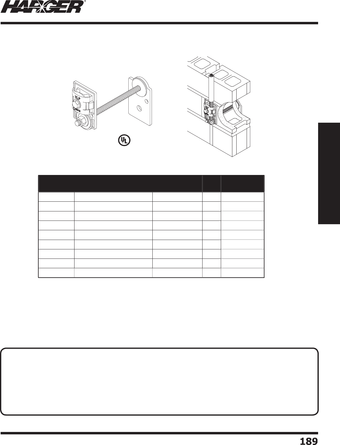
H
ar
g
er Li
g
htnin
g
& Groundin
g
•
©
2012 Phone 847-548-8700 • Fax 847-548-8755 • U.S. 800-842-743
7
1
89
189
Section 2
Lightning Protection Components
L
iste
d
9
6
•
Thru-roof or thru-wall connectors are used when makin
g
roof or wall penetrations
because of the diffi culty of sealin
g
stranded li
g
htnin
g
conductor cables.
•
Features include 1/2" diameter threaded rod, neoprene sealin
g
washers and stainless
s
teel
j
am nuts to assure a waterti
g
ht installation.
•
Fits all main size conductors u
p
to 9/16" diameter.
•
Other confi
g
urations available. Please contact factory for more information.
Part No. Type of Material
Connection
Threaded Bar
Length
Box
Qty.
Approx. Box
Wt. (lbs.)
226
-
6
C
o
pp
er to
C
o
pp
e
r
6
"
5
9
A
226
-
6
Al
u
min
u
m t
o
Al
u
min
u
m
6
"
5
4
-3
/4
226
BM-
6
Co
pp
er to Aluminum
6
"
5
6
-3
/4
226
-1
2
C
o
pp
er to
C
o
pp
e
r
12"
5
10-1
/
4
A
226
-1
2
Al
u
min
u
m t
o
Al
u
min
u
m 12"
5
6
226
BM-1
2
Co
pp
er to Aluminum 12"
5
8
226-18
C
o
pp
er to
C
o
pp
e
r
18"
5
11-1
/2
A226-18 Al
u
min
u
m t
o
Al
u
min
u
m 18"
5
7-1
/4
226BM-18 Co
pp
er to Aluminum 18"
5
9
-1
/4
Thru-Roof
/
Wall Connectors
Ri
g
ht An
g
le to Ri
g
ht An
g
le Connectio
n
TECHNICAL N
O
TES
:
• Requirements coverin
g
exposed systems also shall apply to concealed systems, except conductors shall be
permitted to be coursed under roofi n
g
materials, under roof framin
g
, behind exterior wall facin
g
, between wall
studdin
g
, in conduit chases, or embedded directly in concrete or masonry construction.*
• Where a conductor is run in metal conduit, it shall be bonded to the conduit at the
p
oint where it enters
the conduit, at the point where it emer
g
es from the conduit, and at all locations where the conduit is not
electricall
y
continuous.*
*
NFPA 780 Concealed S
y
stems, General Sections 4.15.1.1 & 4.15.1.2
S
ect
io
n 2.4.1
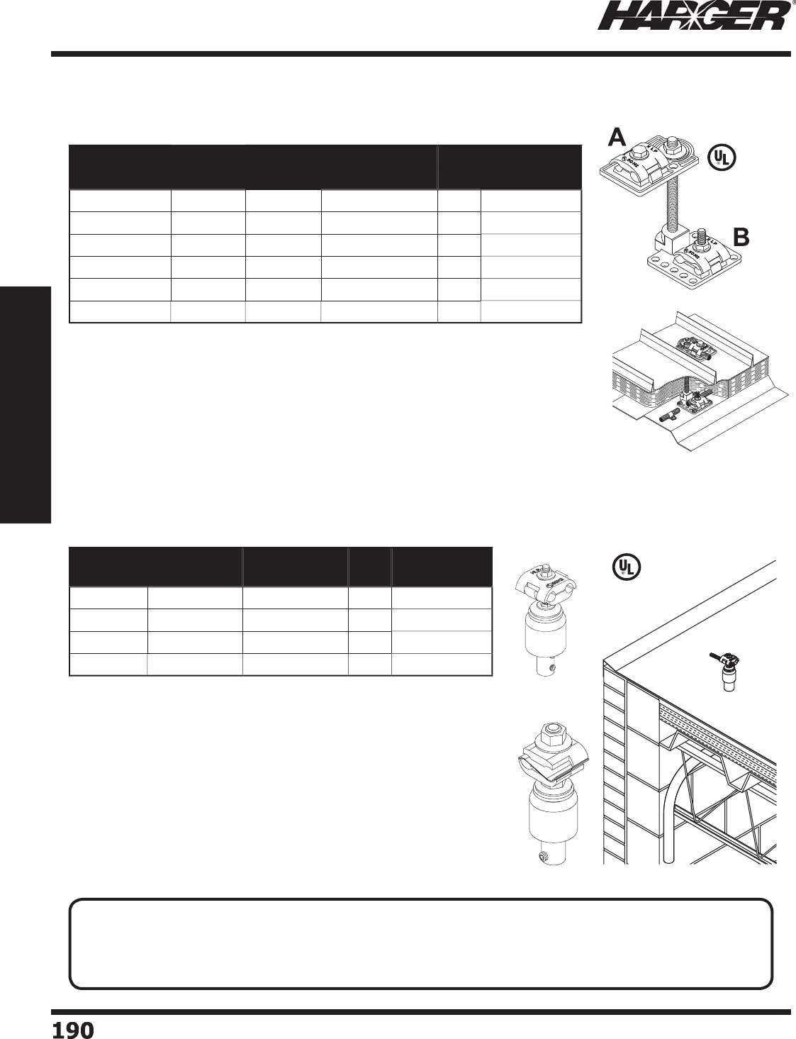
H
ar
g
er Li
g
htnin
g
& Groundin
g
•
©
2012 Phone 847-548-8700 • Fax 847-548-8755 • U.S. 800-842-743
7
1
9
0190
Section 2
Lightning Protection Components
•
Thru-roof or thru-wall connectors are used when makin
g
roof or wall
penetrations because of the diffi culty of sealin
g
stranded li
g
htnin
g
conductor
c
ab
les.
•
Features include 1/2" diameter threaded rod, neoprene sealin
g
washers and
s
tainless steel
j
am nuts to assure a waterti
g
ht installation.
•
Fits all main size conductors u
p
to 9/16" diameter.
•
Other sizes available. Please contact factor
y
for more information.
L
iste
d
9
6
•
Economical, low profi le assembly provides a water ti
g
ht mechanical
connection throu
g
h the roof when 1" PVC conduit is used.
•
Used throu
g
h fi nished roof surfaces or when exitin
g
above the
fi nished roof, such as in or on to
p
of a
p
ara
p
et wall.
•
U
se
d
when 2
30
series thr
u
-r
oo
f
u
nits
a
re n
o
t fe
a
si
b
le.
•
#BMTRC1 thru-roof connectors
p
rovide a bi-metal connection
between aluminum roof com
p
onents and co
pp
er down conductors.
•
#BMTRC1U thru-roof connector
p
rovides a universal connection
for one aluminum and/or one co
pp
er roof com
p
onent and a co
pp
er
do
wn c
o
n
du
ct
o
r.
•
Fits all main size conductors u
p
to 9/16" diameter.
•
#ATRC1 fi ts all main size conductors u
p
to 19/32" diameter.
L
iste
d
9
6
B
MTR
C
1
U
Part No. Description Approx. Each
Wt. (lbs.)
Box
Qty.
Approx. Box
Wt. (lbs.)
ATR
C
1Al
u
min
u
m3
/4
1
0
7-1
/2
C
TR
C
1
C
o
pp
e
r
11
0
1
0
B
MTR
C
1
B
i-Met
a
l3
/4
1
0
7-3
/
4
B
MTR
C
1
U
B
i-Met
a
l3
/4
1
0
7-3
/
4
Thru-Roof
/
Wall Connectors
Bondin
g
Plate to Flat Surface Base Connectio
n
Thru-Roof
/
Wall Assemblies
Thru-R
oo
f C
o
nnect
o
rs
Part No. Type of Material Threaded Bar
Length
Box
Qty.
Approx. Box
Wt. (lbs.)
AB
U2
19ATR-
6
Al
u
min
u
mAl
u
min
u
m
6
"
5
5
U2
19BMTR-
6
C
o
pp
e
r
Al
u
min
u
m
6
"
5
8
U2
19TR-
6
C
o
pp
e
r
C
o
pp
e
r
6
"
5
9
-1
/2
U2
19ATR-1
2
Al
u
min
u
mAl
u
min
u
m 12"
5
6
U2
19BMTR-1
2
C
o
pp
e
r
Al
u
min
u
m 12"
5
9
U2
19TR-1
2
C
o
pp
e
r
C
o
pp
e
r
12"
5
10-1
/2
TECHNICAL N
O
TE
:
• No bend of a conductor shall form an included an
g
le of less than 90 de
g
rees, nor shall it have a radius o
f
bend less than 203 mm
(
8 in.
)
.*
*
NFPA 780 Conductor Bends Section 4.9.5
S
ect
io
n 2.4.1 & 2.4.2

H
ar
g
er Li
g
htnin
g
& Groundin
g
•
©
2012 Phone 847-548-8700 • Fax 847-548-8755 • U.S. 800-842-743
7
19
1
191
Section 2
Lightning Protection Components
L
iste
d
9
6
L
iste
d
9
6
Part No. Description Riser
Length
Approx. Each
Wt. (lbs.)
Box
Qty.
Approx. Box
Wt. (lbs.)
230
H-1
2
Co
pp
er roo
f
c
o
n
du
ct
o
r
t
o co
pp
er
do
wnle
ad
c
ab
le
w
ith h
o
riz
o
nt
a
l
ba
se c
o
nnect
o
r.
12" 2-1
/2
1
0
25
230H-18 18" 3-1
/
41
0
32-1
/2
230
H-
2
4 24" 3-1
/2
1
0
35
230
HBM-1
2
Al
u
min
u
m
r
oo
f c
o
n
du
ct
o
r
t
o co
pp
er
do
wnle
ad
c
ab
le
w
ith h
o
riz
o
nt
a
l
ba
se c
o
nnect
o
r.
12"
2
1
0
20
230HBM-18 18" 2-1
/
41
0
22-1
/2
230
HBM-
24
24"
3
1
0
30
Part No. Description Riser
Length
Approx. Each
Wt. (lbs.)
Box
Qty.
Approx. Box
Wt. (lbs.)
230
V-1
2
Co
pp
er roo
f
c
o
n
du
ct
o
r
t
o co
pp
er
do
wnle
ad
c
ab
le
w
ith vertic
a
l
ba
se c
o
nnect
o
r.
12" 2-1
/2
1
0
25
230V-18 18" 3-1
/
41
0
32-1
/2
230
V-
24
24" 3-1
/2
1
0
35
230
VBM-1
2
Al
u
min
u
m
r
oo
f c
o
n
du
ct
o
r
t
o co
pp
er
do
wnle
ad
c
ab
le
w
ith vertic
a
l
ba
se c
o
nnect
o
r.
12" 1-1
/2
1
0
1
5
230VBM-18 18" 2-1
/
41
0
22-1
/2
230
VBM-
24
24" 2-1
/2
1
0
25
T
hru-Roof
/
Wall Assemblies
H
o
riz
o
ntal Base C
o
nnect
o
rs
Vertical Base C
o
nnect
o
rs
N
O
TES
:
• No. 230 series thru-roof assemblies offer superior stren
g
th and are compatible with a wide ran
g
e
of roofi n
g
systems.
• Assemblies feature a 2-3/8" O.D. PVC tubin
g
support.
• The support not only provides additional stren
g
th to protect a
g
ainst breaka
g
e, but also presents a smooth,
ri
g
id surface for the installation of various types of membrane boot fl ashin
g
s.
• Assemblies are available in various standard len
g
ths with vertical connector (V) or horizontal base connector
(
H
)
for co
pp
er down conductors.
• Dual cable connector accommodates two main size conductors u
p
to 9/16" diameter.
• Also available in aluminum and other len
g
ths are available on special order. Please contact factory for more
inf
o
rm
a
ti
o
n.
S
ect
io
n 2.4.2

H
ar
g
er Li
g
htnin
g
& Groundin
g
•
©
2012 Phone 847-548-8700 • Fax 847-548-8755 • U.S. 800-842-743
7
19
2
192
Section 2
Lightning Protection Components
•
Hi
g
h quality threaded riser bar can be furnished in any len
g
th up to 6 feet.
•
Other len
g
ths available. Please contact factory for more information.
Part No. Size Box
Qty.
Approx. Box
Wt. (lbs.)
W6
R-
50
3
/
8"
50
3
/4
W6
R-1
00
3
/
8" 1
00
1-1
/2
W
8R-50 1
/
2"
50
3
/4
W
8R-100 1
/
2" 1
00
1-1
/2
Thru-R
oo
f Access
o
ries
Threa
d
e
d
Ri
s
er Bar
Neo
p
rene Washers
Part No. Material "A" "B" Box
Qty.
Approx. Box
Wt. (lbs.)
2
4
0
-
6
C
o
pp
e
r
3
/
8"
6
"1
0
1-3
/
4
2
4
0
-1
2
C
o
pp
e
r
3
/
8" 12" 1
0
3-1
/
4
2
4
0
-
24
C
o
pp
e
r
3
/
8" 24" 1
0
6
-1
/2
2
41-
6
C
o
pp
e
r
1
/
2"
6
"1
0
3-1
/
4
2
41S
6
S
t
a
inless Steel 1
/
2"
6
"1
0
2-3
/
4
2
41-1
2
C
o
pp
e
r
1
/
2" 12" 1
0
6
-1
/2
2
41
S
1
2
S
t
a
inless Steel 1
/
2" 12" 1
0
5
-3
/
4
2
41-
24
C
o
pp
e
r
1
/
2" 24" 1
0
1
3
2
41
S24
S
t
a
inless Steel 1
/
2" 24" 1
0
11-1
/2
Part No. Description Riser
Length
Approx. Each
Wt. (lbs.)
Box
Qty.
Approx. Box
Wt. (lbs.)
230H18BM
Ho
riz
o
nt
a
l 18"
2
1
0
20
230V18BM Vertic
a
l 18" 2-1
/2
1
0
25
Thru-Roof
/
Wall Assemblies
•
Aluminum or co
pp
er roof conductor to co
pp
er downlead cable with horizontal or
vertic
a
l
ba
se c
o
nnect
o
r.
•
For more information see Notes on Pa
g
e 191.
Ho
riz
o
nt
a
l
V
ertic
a
l
S
ect
io
n 2.4.2 & 2.4.3
Bi-Meta
l
L
iste
d
9
6
ALUMINUM
CONDUCTOR
(TOP)
COPPER
CONDUCTOR
(BOTTOM)
A
B
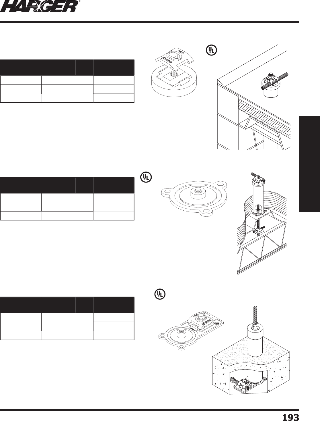
H
ar
g
er Li
g
htnin
g
& Groundin
g
•
©
2012 Phone 847-548-8700 • Fax 847-548-8755 • U.S. 800-842-743
7
1
9
3
193
Section 2
Lightning Protection Components
•
H
eavy duty base plate desi
g
ned for use with standard 2" schedule 40 PVC pipe.
•
T
hree mountin
g
holes permit secure mountin
g
to roof decks.
•
Ma
y
be used on to
p
of or below concrete or metal roof decks.
•
Center hub is threaded for 1
/
2" x 13 standard riser bar.
•
Recessed rin
g
is provided to seat PVC pipe and to assure a ri
g
id assembly.
•
1/4" mountin
g
holes.
*
ETPB - Electr
o
Tin Pl
a
te
d
Br
o
nz
e
•
Combination base plate and cable connector en
g
ineered
to provide easy, secure mountin
g
to any roof deck.
•
D
ua
l c
ab
le c
o
nnect
o
r
a
cc
o
mm
oda
tes tw
o
m
a
in size
conductors u
p
to 9/16" diameter.
•
Three mountin
g
holes assure secure mountin
g
.
*
ETPB - Electr
o
Tin Pl
a
te
d
Br
o
nz
e
L
iste
d
9
6
•
Special fi ttin
g
desi
g
ned to fi t standard 2" schedule 40 PVC pipe.
•
Assures a waterti
g
ht
j
oint when appropriate sealant is used
(See pa
g
e 159).
•
Ru
gg
ed cable clamp accepts up to two Class II conductors.
•
Center hub has 1
/
2" x 13 thread to fi t standard 1
/
2" riser bars.
*
ETPB - Electr
o
Tin Pl
a
te
d
Br
o
nz
e
L
iste
d
9
6
L
iste
d
9
6
Part No. Material Box
Qty.
Approx. Box
Wt. (lbs.)
2
44
C
o
pp
e
r
5
4
A
2
44 Al
u
min
u
m
5
1-1
/2
2
44T
E
TPB*
5
4
Part No. Material Box
Qty.
Approx. Box
Wt. (lbs.)
2
4
5
C
o
pp
e
r
1
0
3-1
/2
A
2
4
5
Al
u
min
u
m1
0
1-1
/4
2
4
5
T
E
TPB* 1
0
3-1
/2
Part No. Material Box
Qty.
Approx. Box
Wt. (lbs.)
2
4
6
C
o
pp
e
r
1
0
8-1
/2
A
2
4
6
Al
u
min
u
m1
0
3-1
/4
2
4
6
T
E
TPB* 1
0
8-1
/2
Thru-R
oo
f Access
o
ries
C
a
p
& Cable Connectors
Ba
s
e Plate
s
Base Plates
/
Cable Connectors
S
ect
io
n 2.4.3
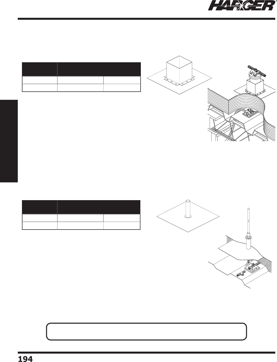
H
ar
g
er Li
g
htnin
g
& Groundin
g
•
©
2012 Phone 847-548-8700 • Fax 847-548-8755 • U.S. 800-842-743
7
194194
Section 2
Lightning Protection Components
•
Galvanized steel
p
itch
p
ocket used on built-u
p
roofs.
•
10" x 10" - 22
g
au
g
e fl ashin
g
has a 4" square pitch
reservoir 4" hi
g
h.
•
Pitch
p
ocket ma
y
be used with the 230 series
thru-roof assemblies or with conduits u
p
to 4" in diameter.
F
or 230 series thru-roof assemblies, see pa
g
e 191.
•
Galvanized steel roof fl ashin
g
desi
g
ned for use with the 225
o
r 226 thru-roof assemblies or 155, 156 or 162 concealed air
terminal assemblies when penetratin
g
fl at built-up roofs.
For 225 series thru-roof assemblies, see pa
g
e 188.
For 226 series thru-roof assemblies, see pa
g
e 189.
For 155 & 156 concealed air terminal assemblies, see pa
g
e 184.
For 162 concealed air terminal assemblies, see pa
g
e 185.
•
Flashin
g
is fabricated from 22
g
au
g
e
g
alvanized steel and is
10" x 10" with a 7/8" riser tube 4" lon
g
.
Part No. Material Approx. Each
Wt. (lbs.)
22
7
G
G
a
lv
a
nize
d
Steel 1-3
/4
22
7
C
C
o
pp
e
r
1-3
/4
Part No. Material Approx. Each
Wt. (lbs.)
228
G
G
a
lv
a
nize
d
Steel 1-1
/
4
228C
C
o
pp
e
r
1-1
/
4
Pitch Pockets & Roof Flashin
g
s
Pitch P
o
ckets
Roof Flashin
g
s
N
O
TE
:
• Other len
g
ths available on special order. Please contact factory for more information.
S
ect
io
n 2.4.
4

H
ar
g
er Li
g
htnin
g
& Groundin
g
•
©
2012 Phone 847-548-8700 • Fax 847-548-8755 • U.S. 800-842-743
7
1
9
5
195
Section 2
Lightning Protection Components
S
ect
io
n 2.5
Li
g
htnin
g
Conductor Cable
C
onnectors & Clam
p
s
In
d
ex
Descr
i
pt
i
on Pa
g
e
2.5.1 Rebar Groundin
g
Assemblie
s
.............................................................
19
6
2.
5
.2 2 B
o
lt P
a
r
a
llel C
o
nnect
o
r
s
..................................................................
19
6
2.
5
.
3
4 B
o
lt C
o
nnect
o
r
s
.............................................................................
19
7
2.
5
.4 2 B
o
lt C
o
nnect
o
r
s
.............................................................................
19
7
2.
5
.
5
"T" C
o
nnect
o
r
s
.................................................................................
19
7
2.5.6 1 Bolt Bondin
g
Connector
s
................................................................
198
2
.
5
.7 Cr
o
ss R
u
n C
o
nnect
o
r
s
.......................................................................
198
2.5.8 Bi-Metal Connector
s
..........................................................................
199
2.
5
.9 1 B
o
lt P
a
r
a
llel C
o
nnect
o
r
s
..................................................................
200
2.
5
.1
0
P
a
r
a
llel C
ab
le C
o
nnect
o
r
s
..................................................................
20
1
2.
5
.11 C
ab
le t
o
Fl
a
t Met
a
l C
o
nnect
o
r
s
..........................................................
20
1
2.
5
.12 Sillc
o
ck Gr
ou
n
d
C
o
nnect
or
.................................................................
202
2.5.13 Stra
p
T
yp
e Pi
p
e Clam
ps
....................................................................
202
2.5.14 CPC & APC Pi
p
e Clam
ps
....................................................................
203
N
O
TE
:
Co
pp
er materials can consist of co
pp
er, bronze or brass. All are co
pp
er allo
y
s.
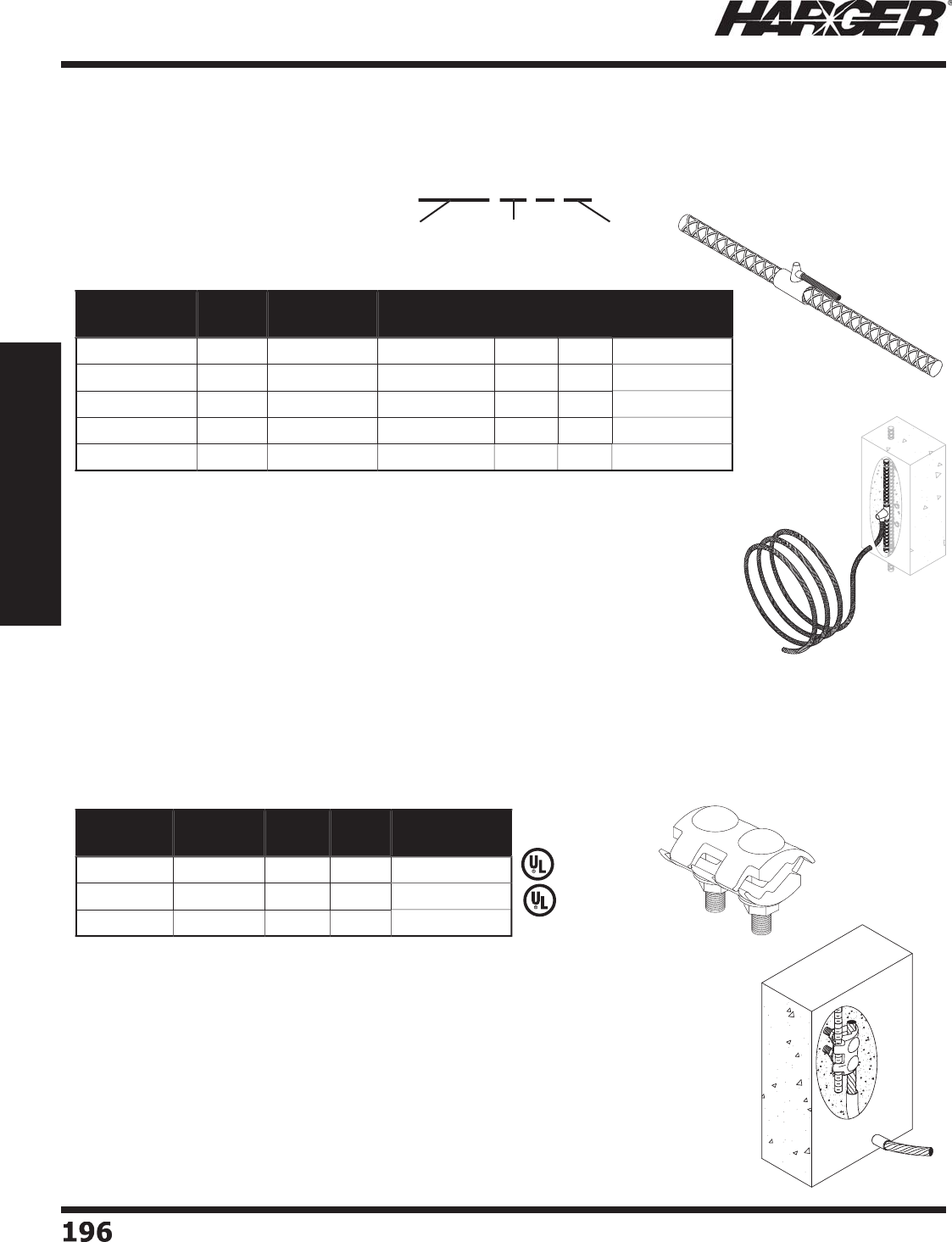
H
ar
g
er Li
g
htnin
g
& Groundin
g
•
©
2012 Phone 847-548-8700 • Fax 847-548-8755 • U.S. 800-842-743
7
1
9
6196
Section 2
Lightning Protection Components
•
Approximately 2" x 1-3/4" two piece connector used for splicin
g
c
ab
les
a
n
d
r
od
s.
•
Acc
o
mm
oda
tes
a
ll st
a
n
da
r
d
size Cl
a
ss I
a
n
d
Cl
a
ss II c
o
n
du
ct
o
rs
u
p
to 17/32" diameter.
•
Accommodates
g
round cable sizes ran
g
in
g
from #6 AWG up to 250 MCM.
•
5/16" x 1-3/4" stainless steel carria
g
e bolts, fl at washers and nuts included.
•
#204 manufactured from hi
g
h conductivity copper alloy.
•
#A204 manufactured from hi
g
h conductivity aluminum alloy.
•
Recommended installation tool - 1/2" dee
p
socket wrench, end wrench
o
r n
u
t
d
river.
•
#2
0
4 is s
u
it
ab
le f
o
r
d
irect
bu
ri
a
l.
*
ETPB - Electr
o
Tin Pl
a
te
d
Br
o
nz
e
L
iste
d
4
67
•
Prefabricated rebar
g
roundin
g
assembly.
•
Standard 24" lon
g
rebar.
•
Exothermicall
y
welded connection.
•
Can be wire tied or welded to rebar ca
g
e prior to concrete pour.
•
Conductor can be stubbed out for connection to a downlead or
g
round
g
rid.
•
Other sizes available. Please contact factor
y
for more information.
Part No. Rebar
Size
Conductor
Type
Conductor
Length (ft.) Class Box
Qty.
Approx. Box
Wt. (lbs.)
R
B3GA8SX5
3
8 Sol.
5
N/
A1 1
R
B4GA
32
X
5
4
32
5
I
1 2-1
/2
R
B
5
GA
2
TX
5
5
2
T
5
N/
A 1 2-1
/2
R
B5GA28X10
5
28 1
0
II
1
6
-1
/4
R
B6GA4
/
0X15
6
4/
01
5
N/
A 1 13-1
/2
Part No. Material Class Box
Qty.
Approx. Box
Wt. (lbs.)
204
C
o
pp
e
r
II
1
0
4
-1
/2
A
20
4Al
u
min
u
m
II
1
0
2-1
/2
20
4T
E
TPB*
II
1
0
4
-1
/2
L
iste
d
9
6
Rebar Groundin
g
Assemblies
Rebar Groundin
g
Assemblies Numberin
g
Syste
m
2
B
o
lt Parallel C
o
nnect
o
rs
RB5GA
A
28
X
10
R
e
ba
r Size C
o
n
du
ct
o
r
Type
L
en
g
th o
f
C
o
n
du
ct
or
(
ft.
)
S
ect
io
n 2.5.1 & 2.5.2
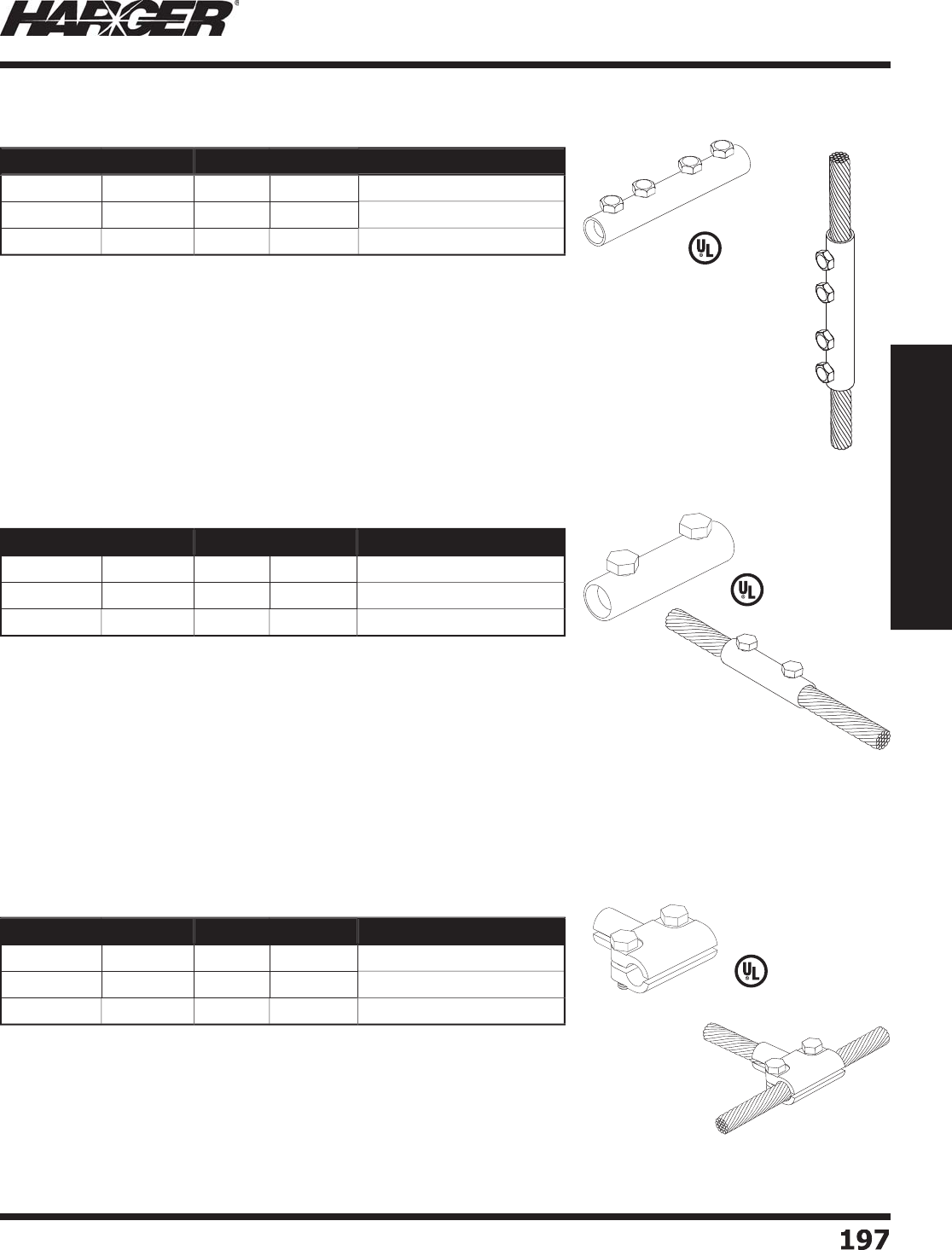
H
ar
g
er Li
g
htnin
g
& Groundin
g
•
©
2012 Phone 847-548-8700 • Fax 847-548-8755 • U.S. 800-842-743
7
19
7
197
Section 2
Lightning Protection Components
•
2" x 2-1/4" - "T" connector s
p
lices two
p
er
p
endicular conductors.
•
Accommodates all standard size Class I and Class II conductors u
p
to 9/16" diameter.
•
Two 5/16" x 7/8" hex head stainless steel ca
p
screws assure a
p
ositive electrical connection.
•
#207 manufactured from hi
g
h conductivity copper alloy.
•
#A207 manufactured from hi
g
h conductivity aluminum alloy.
•
Recommended installation tool - 1/2" socket wrench, end wrench or nut driver.
*
ETPB - Electr
o
Tin Pl
a
te
d
Br
o
nze
L
iste
d
9
6
L
iste
d
9
6
•
3" lon
g
connector provides 1-1/2" of surface contact between conductors.
•
Accommodates all standard size Class I and Class II conductors u
p
to 17/32" diameter.
•
#A206R accommodates all standard size Class I and Class II conductors u
p
to 19/32" diameter.
•
Two 5/16" hex head stainless steel ca
p
screws assure a
p
ositive electrical connection.
•
#206 manufactured from hi
g
h conductivity brass alloy.
•
#A206 and #A206R manufactured from hi
g
h conductivity aluminum alloy.
•
Recommended installation tool - 1/2" socket wrench, end wrench or nut driver.
*
Electr
o
Tin Pl
a
te
d
•
A
pp
roximatel
y
4
" lon
g
connector provides 2" of surface contact between conductors.
•
Accommodates all standard size Class I and Class II conductors u
p
to 17/32" diameter.
•
#A205R accommodates all standard size Class I and Class II conductors u
p
to 19/32" diameter.
•
Four 5/16" hex head stainless steel ca
p
screws assure a
p
ositive electrical connection.
•
#205 manufactured from hi
g
h conductivity brass alloy.
•
#A205 and #A205R manufactured from hi
g
h conductivity aluminum alloy.
•
Recommended installation tool - 1/2" socket wrench, end wrench or nut driver.
*
Electr
o
Tin Pl
a
te
d
L
iste
d
9
6
Part No. Material Class Box Qty. Approx. Box Wt. (lbs.)
205
C
o
pp
e
r
II
1
0
4
-3
/4
A
205
RAl
u
min
u
m
II
1
0
2
205
TCo
pp
er*
II
1
0
4
-3
/4
Part No. Material Class Box Qty. Approx. Box Wt. (lbs.)
206
C
o
pp
e
r
II
1
0
2-3
/4
A
206
RAl
u
min
u
m
II
1
0
1-1
/4
206
TCo
pp
er*
II
1
0
2-3
/4
Part No. Material Class Box Qty. Approx. Box Wt. (lbs.)
207
C
o
pp
e
r
II
1
0
5
A
207
Al
u
min
u
m
II
1
0
2
20
7T
E
TPB*
II
1
0
5
4 B
o
lt C
o
nnect
o
rs
2
B
o
lt C
o
nnect
o
rs
"T" C
o
nnect
o
rs
S
ect
io
n 2.5.3 - 2.5.5
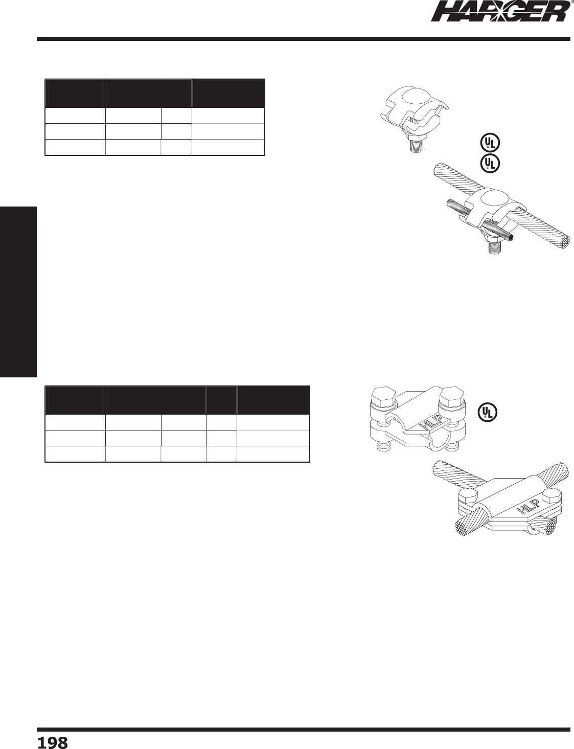
H
ar
g
er Li
g
htnin
g
& Groundin
g
•
©
2012 Phone 847-548-8700 • Fax 847-548-8755 • U.S. 800-842-743
7
1
98
198
Section 2
Lightning Protection Components
•
1-1/2" x 1-1/2" two bolt, two
p
iece connector s
p
lices
p
er
p
endicular
intersectin
g
standard Class I and Class II conductors up to 9/16" diameter.
•
Two 5/16" hex head stainless steel ca
p
screws assure a
p
ositive
electric
a
l c
o
nnecti
o
n.
•
#210 manufactured from hi
g
h conductivity copper alloy.
•
#A210 manufactured from hi
g
h conductivity aluminum alloy.
•
Recommended installation tool - 1/2" socket wrench, end wrench
o
r n
u
t
d
river.
*
ETPB - Electr
o
Tin Pl
a
te
d
Br
o
nz
e
L
iste
d
9
6
•
A
pp
roximatel
y
7/8" x 1-5/8" one bolt, two
p
iece connector s
p
lices
bondin
g
conductor to all standard size Class I and Class II conductors
u
p
to 9/16" diameter.
•
Accommodates
g
round cable sizes ran
g
in
g
from #6 AWG throu
g
h 4/0.
•
5/16" x 1-3/4" stainless steel carria
g
e bolt, fl at washer and nut included.
•
#208 manufactured from hi
g
h conductivity copper alloy.
•
#A208 manufactured from hi
g
h conductivity aluminum alloy.
•
Recommended installation tool - 1/2" dee
p
socket wrench, end wrench
o
r n
u
t
d
river.
•
Suitable for direct burial, exce
p
t Aluminum.
*
ETPB - Electr
o
Tin Pl
a
te
d
Br
o
nz
e
L
iste
d
4
67
Part No. Material Box
Qty.
Approx. Box
Wt. (lbs.)
208
C
o
pp
e
r
1
0
2-1
/2
A208 Al
u
min
u
m1
0
1-1
/
4
208T
E
TPB* 1
0
2-1
/2
Part No. Material Class Box
Qty.
Approx. Box
Wt. (lbs.)
2
1
0
C
o
pp
e
r
II
1
0
4
-1
/2
A
2
1
0
Al
u
min
u
m
II
1
0
2
2
1
0
T
E
TPB*
II
1
0
4
-1
/2
L
iste
d
9
6
1
Bolt Bondin
g
Connectors
C
r
o
ss Run C
o
nnect
o
rs
S
ect
io
n 2.5.6 & 2.5.7

H
ar
g
er Li
g
htnin
g
& Groundin
g
•
©
2012 Phone 847-548-8700 • Fax 847-548-8755 • U.S. 800-842-743
7
199
199
Section 2
Lightning Protection Components
•
A
pp
roximatel
y
4
" lon
g
, four bolt bi-metal connector provides a
non-electrol
y
tic connection between co
pp
er and aluminum conductors.
•
Brass side acce
p
ts all main size conductors u
p
to 17/32” diameter.
•
Aluminum side acce
p
ts all main size conductors u
p
to 19/32” diameter.
•
Four 5/16" hex head stainless steel ca
p
screws assure a
p
ositive
electric
a
l c
o
nnecti
o
n.
•
Manufactured from hi
g
h conductivity brass and aluminum alloys.
•
Recommended installation tool - 1/2" socket wrench, end wrench or nut driver.
•
6
" lon
g
, four bolt bi-metal connector provides a non-electrolytic
connection between co
pp
er and aluminum conductors.
•
Accepts all main size li
g
htnin
g
conductors up to 3/4" diameter.
•
Four 5/16" x 1/2" hex head stainless steel ca
p
screws assure a
p
ositive
electric
a
l c
o
nnecti
o
n.
•
Manufactured from hi
g
h conductivity brass and aluminum alloys.
•
Recommended installation tool - 1/2" socket wrench, end wrench or nut driver.
L
iste
d
9
6
L
iste
d
9
6
L
iste
d
9
6
Part No. Material Class Box Qty. Approx. Box Wt. (lbs.)
2
1
0
BM
B
i-Met
a
l
II
1
0
2-1
/2
Part No. Material Class Box
Qty.
Approx. Box
Wt. (lbs.)
2
11R
B
i-Met
a
l
II
1
0
4
-1
/
4
Part No. Material Class Box Qty. Approx. Box Wt. (lbs.)
2
11XL
B
i-Met
a
l
II
1
0
7
Bi-Metal C
o
nnect
o
rs
Bi-Metal 2 B
o
lt 2 Piece
Bi-Metal 4" Lon
g
4 Bolt
Bi-Metal 6" Lon
g
4 Bolt
•
1-1/2" x 1-1/2" two bolt, two-piece, bi-metal connector allows splicin
g
o
f
aluminum and co
pp
er conductors.
•
Ideal when splicin
g
aluminum conductor off vents to main copper conductor run.
•
Accepts all main size li
g
htnin
g
conductors up to 9/16" diameter.
•
Two 5/16" stainless steel carria
g
e bolts assure a positive electrical connection.
•
Manufactured from hi
g
h conductivity copper and aluminum alloys.
T
ECHNICAL N
O
TE
:
• Aluminum materials shall not be used within 460 mm (18 in.) of the point where the li
g
htnin
g
protection
system conductor comes into contact with the earth. Fittin
g
s used for the connection of aluminum down
conductors to copper or copper-clad
g
roundin
g
equipment shall be of the bimetallic type. Bimetallic
connectors shall be installed not less than 460 mm
(
18 in.
)
above earth level.*
*
NFPA 780 Use of Aluminum Sections 4.5.2, 4.5.2.1 & 4.5.2.2
S
ect
io
n 2.5.8
B
r
a
s
s
Al
u
min
u
m
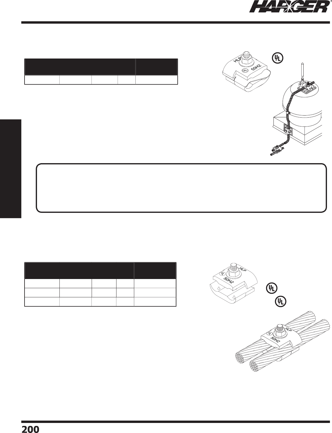
H
ar
g
er Li
g
htnin
g
& Groundin
g
•
©
2012 Phone 847-548-8700 • Fax 847-548-8755 • U.S. 800-842-743
7
200
200
Section 2
Lightning Protection Components
L
iste
d
4
67
•
Innovative pressed bolt desi
g
n ensures a smooth fl at surface; no dama
g
e when
u
sed on membrane roofs and provides
g
reater ease of installation.
•
A
pp
roximatel
y
2" s
q
uare, two
p
iece connector
p
rovides over 1-1/2" surface
c
o
nt
a
ct
b
etween c
o
n
du
ct
o
rs.
•
Accepts all li
g
htnin
g
conductors and rods up to 5/8" diameter and
g
roundin
g
conductors ran
g
in
g
from #6 AWG up to 250 MCM.
•
5/16" x 1-1/4" stainless steel ca
p
screw with fl at washer included.
•
#B1BC manufactured from hi
g
h conductivity copper alloy.
•
#A1BC manufactured from hi
g
h conductivity aluminum alloy.
•
Recommended installation tool - 1/2" socket wrench, end wrench or nut driver.
•
Suitable for direct burial, exce
p
t Aluminum.
*
ETPB - Electr
o
Tin Pl
a
te
d
Br
o
nz
e
•
2" x 1-1/2" one bolt, three piece, bi-metal connector allows splicin
g
o
f
aluminum conductors to co
pp
er conductors.
•
Ideal when splicin
g
aluminum conductor off vents to main copper conductor run.
•
Elimin
a
tes the nee
d
f
o
r
a
n
add
iti
o
n
a
l c
o
nnect
o
r.
•
One 5/16" x 1-1/4" stainless steel
p
ressed bolt assures a
p
ositive electrical connection
and a dama
g
e free installation when properly installed on a membrane roof.
•
Bi-metal materials manufactured from co
pp
er and aluminum allo
y
s.
•
Recommended installation tool - 1/2" socket wrench, end wrench or nut driver.
L
iste
d
9
6
Part No. Material Class Box
Qty.
Approx. Box
Wt. (lbs.)
B
M1B
C
B
i-Met
a
l
II
1
0
5
-1
/
4
Part No. Material Class Box
Qty.
Approx. Box
Wt. (lbs.)
B
1B
C
C
o
pp
e
r
II
1
0
4
A1B
C
Al
u
min
u
m
II
1
0
1-1
/2
T
B1B
C
E
TPB*
II
1
0
4
L
iste
d
9
6
Bi-Metal C
o
nnect
o
rs
Bi-Metal 1 B
o
lt Parallel C
o
nnect
o
r
1
B
o
lt Parallel C
o
nnect
o
rs
TECHNICAL N
O
TE
:
• Aluminum materials shall not be used within 460 mm (18 in.) of the point where the li
g
htnin
g
protection
system conductor comes into contact with the earth. Fittin
g
s used for the connection of aluminum down
conductors to copper or copper-clad
g
roundin
g
equipment shall be of the bimetallic type. Bimetallic
connectors shall be installed not less than 460 mm
(
18 in.
)
above earth level.*
*
NFPA 780 Use of Aluminum Sections 4.5.2, 4.5.2.1 & 4.5.2.2
S
ect
io
n 2.5.8 & 2.5.9
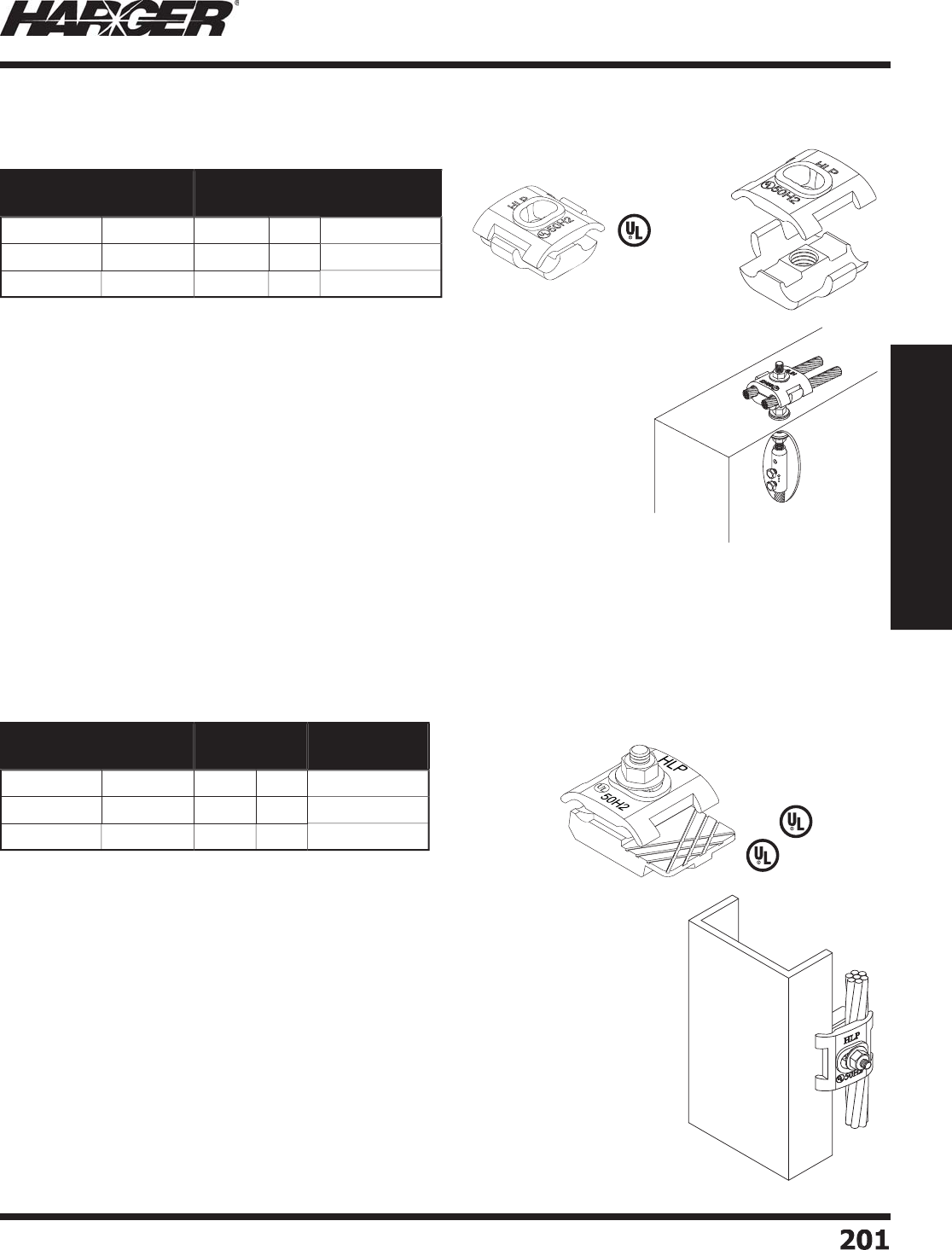
H
ar
g
er Li
g
htnin
g
& Groundin
g
•
©
2012 Phone 847-548-8700 • Fax 847-548-8755 • U.S. 800-842-743
7
20
1
201
Section 2
Lightning Protection Components
•
A
pp
roximatel
y
1-3/4" x 2" two
p
iece, one bolt connector connects
all li
g
htnin
g
conductor cables throu
g
h 9/16" diameter to fl at metal ob
j
ects
u
p
to 1/2" thickness such as steel ladders, small I-beams, channel, etc.
•
5/16" x 1-1/4" stainless steel ca
p
screw with fl at washer included.
•
#213 manufactured from hi
g
h conductivity copper alloy.
•
#A213 manufactured from hi
g
h conductivity aluminum alloy.
•
Recommended installation tool - 1/2" socket wrench, end wrench
o
r n
u
t
d
river.
•
Suitable for direct burial, exce
p
t Aluminum.
*
ETPB - Electr
o
Tin Pl
a
te
d
Br
o
nz
e
L
iste
d
4
67
L
iste
d
9
6
•
2" s
q
uare, two
p
iece connector
p
rovides 1-1/2" surface contact between conductors.
•
Accepts all li
g
htnin
g
conductors and rods up to 5/8" in diameter and
g
roundin
g
conductors ran
g
in
g
from #6 AWG throu
g
h 4/0.
•
Bottom castin
g
is drilled and tapped 1/2-13 UNC coarse thread.
•
To
p
p
iece is bored out to acce
p
t 1/2" threaded rod.
•
Primary use is attachin
g
conductors to allthread.
•
No hardware
p
rovided.
•
#212-1/2 manufactured from hi
g
h conductivity copper alloy.
•
#A212-1/2 manufactured from hi
g
h conductivity aluminum alloy.
•
Recommended installation tool - 1/2" socket wrench, end wrench or nut driver.
*
ETPB - Electr
o
Tin Pl
a
te
d
Br
o
nz
e
Part No. Material Class Box
Qty.
Approx. Box
Wt. (lbs.)
212-1
/2
C
o
pp
e
r
II
1
0
4
A212-1
/2
Al
u
min
u
m
II
1
0
1-1
/2
212-1
/
2T
E
TPB*
II
1
0
4
Part No. Material Class Box
Qty.
Approx. Box
Wt. (lbs.)
2
1
3
C
o
pp
e
r
II
1
0
4
-1
/2
A
2
1
3
Al
u
min
u
m
II
1
0
1-3
/
4
2
1
3
T
E
TPB*
II
1
0
4
-1
/2
L
iste
d
9
6
Parallel Cable C
o
nnect
o
rs
C
able t
o
Flat Metal C
o
nnect
o
rs
S
ect
io
n 2.5.10 & 2.5.11
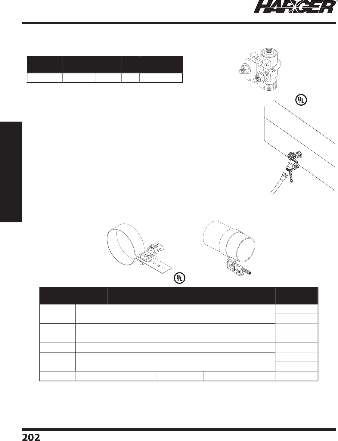
H
ar
g
er Li
g
htnin
g
& Groundin
g
•
©
2012 Phone 847-548-8700 • Fax 847-548-8755 • U.S. 800-842-743
7
20
2
202
Section 2
Lightning Protection Components
•
Manufactured from cast bronze, brass and stainless steel.
•
Acce
p
ts all Class I and Class II co
pp
er conductors u
p
to 9/16" diameter.
•
Allows for required bondin
g
of water pipe system to li
g
htnin
g
protection system.
•
Mounts directl
y
on sill cock threads.
•
Recommended installation tool - channel locks, 1/2" socket wrench, end wrench
o
r n
u
t
d
river.
L
iste
d
9
6
•
2" wide electro plated tin copper strap with heavy duty bondin
g
lu
g
for use with all cables
#6 AWG throu
g
h 4/0.
L
iste
d
9
6
Part No. Material Class Box
Qty.
Approx. Box
Wt. (lbs.)
SCGC
C
o
pp
e
r
II
5
4
-3
/
4
Part No. Material Nominal Pipe
Size Range
Outside
Diameter
Approx. Each
Wt. (lbs.)
Box
Qty.
Approx. Box
Wt. (lbs.)
23
1-
4
C
o
pp
e
r
3
" - 4"
3
.
5
" - 4.
5
"
2
1
0
20
A
23
14 Al
u
min
u
m
3
" - 4"
3
.
5
" - 4.
5
"11
0
1
0
23
1-
6
C
o
pp
e
r
4
" -
6
"
4
.
5
" -
6
.
6
2
5
"
2
1
0
20
A
23
1
6
Al
u
min
u
m
4
" -
6
"
4
.
5
" -
6
.
6
2
5
"11
0
1
0
231-8
C
o
pp
e
r
6
" - 8"
6
.625" - 8.625"
3
1
0
30
A2318 Al
u
min
u
m
6
" - 8"
6
.625" - 8.625"
2
1
0
20
23
1-1
2
C
o
pp
e
r
8" - 12" 8.625" - 12.75"
3
1
0
30
A
23
11
2
Al
u
min
u
m 8" - 12" 8.625" - 12.75"
2
1
0
20
S
illc
o
ck Gr
o
und C
o
nnect
o
r
S
tra
p
T
yp
e Pi
p
e Clam
p
s
S
ect
io
n 2.5.12 & 2.5.13
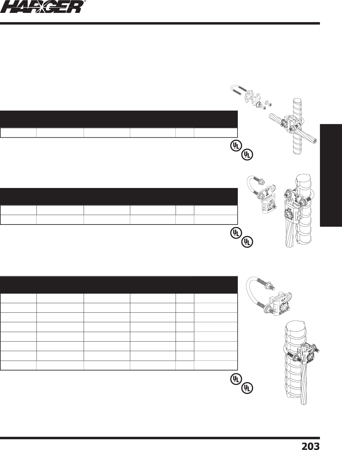
H
ar
g
er Li
g
htnin
g
& Groundin
g
•
©
2012 Phone 847-548-8700 • Fax 847-548-8755 • U.S. 800-842-743
7
203
203
Section 2
Lightning Protection Components
L
iste
d
9
6
L
iste
d
4
67
L
iste
d
9
6
L
iste
d
4
67
L
iste
d
9
6
L
iste
d
4
67
Part No. Material Nominal Pipe
Size Range
Pipe Outside
Diameter
Box
Qty.
Approx. Box
Wt. (lbs.)
CPC.5
/
.75
E
TPB*
.5
" - .7
5
"
.3
7
5
" - 1"
5
2-1
/2
Part No. Material Nominal Pipe
Size Range
Pipe Outside
Diameter
Box
Qty.
Approx. Box
Wt. (lbs.)
CPC1
/
1.25
E
TPB* 1" - 1.2
5
"
.
7
5
" - 1.7"
5
3
APC1
/
1.25 Al
u
min
u
m 1" - 1.2
5
"
.
7
5
" - 1.7"
5
2
Part No. Material Nominal Pipe
Size Range
Pipe Outside
Diameter
Box
Qty.
Approx. Box
Wt. (lbs.)
CPC1.5
/2
E
TPB* 1.
5
" - 2" 1" - 2.4"
5
3-3
/4
APC1.5
/2
Al
u
min
u
m1.
5
" - 2" 1" - 2.4"
5
2
CPC2.5
/3
E
TPB* 2.
5
" -
3
" 2.2
5
" -
3
.
5
"
5
5
APC2.5
/3
Al
u
min
u
m2.
5
" -
3
" 2.2
5
" -
3
.
5
"
5
2-1
/2
CPC3.5
/4
E
TPB*
3
.
5
" - 4"
3
.2" - 4.
5
"
5
6
-1
/4
APC3.5
/4
Al
u
min
u
m
3
.
5
" - 4"
3
.2" - 4.
5
"
5
3
CPC5
/
6
E
TPB*
5
" -
6
"
4
.7
5
" -
6
.
63
"
5
8-3
/4
APC5
/
6Al
u
min
u
m
5
" -
6
"
4
.7
5
" -
6
.
63
"
5
5
C
PC & APC Pi
p
e Clam
p
s
Pipe Ran
g
e .5/.75
Pipe Ran
g
e 1/1.25
Pipe Ran
g
e 1.5/2 - 5/6
•
CPC series only Dual UL Listin
g
(UL96 and UL467).
•
CPC series onl
y
acce
p
table for direct burial.
•
Wide conductor ran
g
e; #6 Solid throu
g
h 250 MCM.
*
Electr
o
Tin Pl
a
te
d
Br
o
nze incl
ud
es st
a
inless steel
h
a
r
d
w
a
re.
•
Feature “quick connect”, bi-directional desi
g
n.
•
Pressed stud desi
g
n ensures a fl ush mountin
g
surface.
•
Feature “quick connect”, bi-directional desi
g
n.
•
Pressed stud desi
g
n ensures a fl ush mountin
g
surface.
S
ect
io
n 2.5.1
4

H
ar
g
er Li
g
htnin
g
& Groundin
g
•
©
2012 Phone 847-548-8700 • Fax 847-548-8755 • U.S. 800-842-743
7
204
204
Section 2
Lightning Protection Components
No
tes

H
ar
g
er Li
g
htnin
g
& Groundin
g
•
©
2012 Phone 847-548-8700 • Fax 847-548-8755 • U.S. 800-842-743
7
205
205
Section 2
Lightning Protection Components
S
ect
io
n 2.6
Bondin
g
Lu
g
s & Plates
In
d
ex
Descr
i
pt
i
on Pa
g
e
2.6.1 Bondin
g
Lu
gs
...................................................................................
206
2.6.2 Bondin
g
Plate
s
.................................................................................
208
N
O
TE
:
Co
pp
er materials can consist of co
pp
er, bronze or brass. All are co
pp
er allo
y
s.
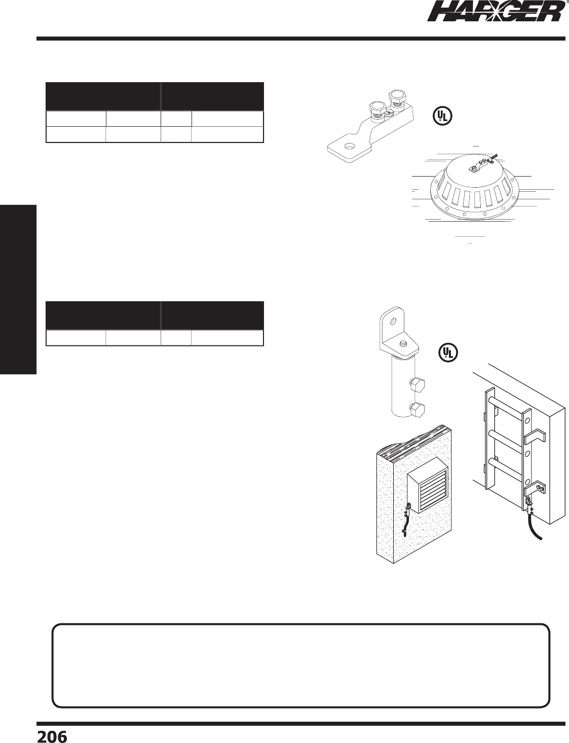
H
ar
g
er Li
g
htnin
g
& Groundin
g
•
©
2012 Phone 847-548-8700 • Fax 847-548-8755 • U.S. 800-842-743
7
206
206
Section 2
Lightning Protection Components
L
iste
d
9
6
•
2-7/8" lon
g
cast lu
g
for use with bondin
g
conductors siz
e
#6 AWG throu
g
h #4 AWG.
•
1" x 1" tan
g
features a 5/16" mountin
g
hole.
•
Two stainless steel bolts
p
rovide a secure connection.
•
Lu
g
has 1-1/2" of surface contact to conductor.
•
Recommended installation tool - 7/16" socket wrench,
en
d
wrench
o
r n
u
t
d
river.
*
ETPB - Electr
o
Tin Pl
a
te
d
Br
o
nz
e
•
13/16" x 3-1/4" bi-metal secondary bondin
g
lu
g
allows bondin
g
to aluminum or steel surfaces from co
pp
er cable runs.
•
For secondary bondin
g
of small metallic bodies that require an
aluminum connection for compatibility such as
g
utters, ladders,
mech
a
nic
a
l
u
nits
a
n
d
d
r
a
in vents.
•
Two 5/16" x 3/4" stainless steel bolts assure a
p
ositive electrical
c
o
nnect
io
n.
•
Will accommodate bondin
g
or main size li
g
htnin
g
conductors or
#6 solid to 4
/
0 concentric conductors.
•
Elimin
a
tes nee
d
f
o
r
a
n
add
iti
o
n
a
l c
o
nnect
o
r.
•
Recommended installation tool - 1/2" socket wrench, end
w
rench
o
r n
u
t
d
river.
L
iste
d
9
6
Part No. Material Box
Qty.
Approx. Box
Wt. (lbs.)
2
1
6
E
TPB* 1
0
1-3
/
4
A
2
1
6
Al
u
min
u
m1
0
1-1
/2
Part No. Material Box
Qty.
Approx. Box
Wt. (lbs.)
2
1
6
BM
B
i-Met
a
l1
0
2-1
/2
Bondin
g
Lu
g
s
Bi-Meta
l
TECHNICAL N
O
TES
:
• A connector fi ttin
g
shall be constructed so that a minimum of 1-1/2 inches (38 mm) of each conductor
c
a
n
b
e sec
u
re
d
within the c
o
nnect
o
r. *
• The fi ttin
g
shall be provided with at least two 1/8 inch (3.2 mm) hi
g
h pro
j
ections on an interior surface
that embed in the conductor when the connector is com
p
ressed around the conductor.*
*
UL 96 Standard for Li
g
htnin
g
Protection Components Sections 10.3 & 10.
4
S
ect
io
n 2.6.1
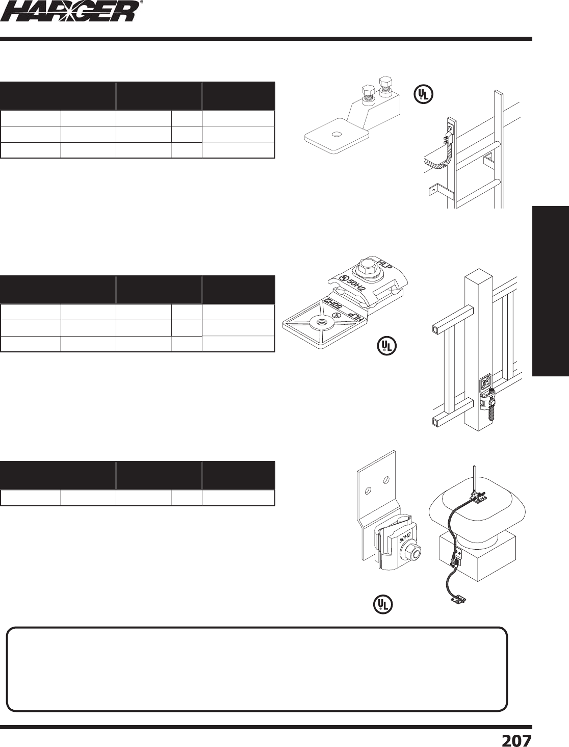
H
ar
g
er Li
g
htnin
g
& Groundin
g
•
©
2012 Phone 847-548-8700 • Fax 847-548-8755 • U.S. 800-842-743
7
20
7
207
Section 2
Lightning Protection Components
•
3-1/2" x 1-3/4" cast lu
g
provides over 3-1/2 square inches of bondin
g
surface.
•
Dual
p
ressure t
yp
e cable connector will acce
p
t all main size conductors u
p
to 9/16"
in
d
i
a
meter.
•
Tan
g
features a 3/8" mountin
g
hole.
•
Recommended installation tool - 1/2" socket wrench, end wrench or nut driver.
*
ETPB - Electr
o
Tin Pl
a
te
d
Br
o
nz
e
L
iste
d
9
6
•
4
-1/4" lon
g
cast lu
g
for use with main size conductors up to 9/16" diameter.
•
#
A218 accommodates main size conductors u
p
to 19/32" diameter.
•
2" x 1-3/4" tan
g
features a 7/16" diameter mountin
g
hole.
•
Two standard steel hex head ca
p
screws
p
rovide a secure connection.
•
Lu
g
has 1-1/2" of surface contact to conductor.
•
Recommended installation tool - 1/2" socket wrench, end wrench or nut driver.
*
ETPB - Electr
o
Tin Pl
a
te
d
Br
o
nz
e
L
iste
d
9
6
•
For bondin
g
of lar
g
er metallic bodies that require an aluminum connection
for compatibility such as mechanical units, copin
g
s, rooftop cable tray and
antenna frames. Recommended for vertical mountin
g
applications.
•
2" x 4-3/16" x 0.10" aluminum base
p
late has over 4 s
q
uare inches o
f
su
rf
a
ce c
o
nt
a
ct.
•
Bi-metallic mechanical connector provides 1-1/2" of contact len
g
th with
c
o
n
du
ct
o
rs.
•
18-8 Stainless Steel Ribbed Neck 3/8" Bolt with low
p
rofi le No. 4 Philli
p
s
head is pre-driven into the lu
g
to prevent rotation durin
g
installation.
L
iste
d
9
6
Part No. Material Class Box
Qty.
Approx. Box
Wt. (lbs.)
218
C
o
pp
e
r
II
5
3
A218 Al
u
min
u
m
II
5
2-1
/4
218T
E
TPB*
II
5
3
Part No. Material Class Box
Qty.
Approx. Box
Wt. (lbs.)
222
C
o
pp
e
r
II
1
0
5
-1
/4
A
222
Al
u
min
u
m
II
1
0
2
222
T
E
TPB*
II
1
0
5
-1
/4
Part No. Material Class Box
Qty.
Approx. Box
Wt. (lbs.)
BMBL
B
i-Met
a
l
II
1
0
4
-1
/4
Bondin
g
Lu
g
s
H
eav
y
D
ut
y
Bi-Meta
l
T
ECHNICAL N
O
TES
:
• A connector fi ttin
g
shall be constructed so that a minimum of 1-1/2 inches (38 mm) of each conductor
c
a
n
b
e sec
u
re
d
within the c
o
nnect
o
r. *
• The fi ttin
g
shall be provided with at least two 1/8 inch (3.2 mm) hi
g
h pro
j
ections on an interior surface
that embed in the conductor when the connector is com
p
ressed around the conductor.*
*
UL 96 Standard for Li
g
htnin
g
Protection Components Sections 10.3 & 10.
4
S
ect
io
n 2.6.1
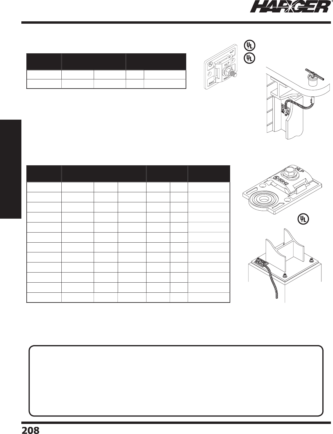
H
ar
g
er Li
g
htnin
g
& Groundin
g
•
©
2012 Phone 847-548-8700 • Fax 847-548-8755 • U.S. 800-842-743
7
2
08
208
Section 2
Lightning Protection Components
L
iste
d
4
67
•
Features a pressed-in stud; ensures fl at mountin
g
surface.
•
Approximately 2-1/2" x 3-1/4" cast bondin
g
plate provides over 8 square inches o
f
bondin
g
surface.
•
Dual cable
p
ressure connector acce
p
ts all main size conductors u
p
to 9/16" diameter.
•
Two 5/16" mountin
g
holes provide secure mountin
g
.
•
Recommended installation tool - 1/2" socket wrench, end wrench or nut driver.
•
S
u
it
ab
le f
o
r
d
irect
bu
ri
a
l.
*
ETPB - Electr
o
Tin Pl
a
te
d
Br
o
nz
e
•
2-1/2" x 4" cast bondin
g
plate provides over 8 square inches of bondin
g
surface.
•
Dual cable
p
ressure connector acce
p
ts all main sized conductor u
p
to 9/16" diameter.
•
Used over anchor bolts to
g
round steel columns.
•
Recommended installation tool - 1/2" socket wrench, end wrench or nut driver.
*
ETPB - Electr
o
Tin Pl
a
te
d
Br
o
nz
e
L
iste
d
9
6
Part No. Material Class Box
Qty.
Approx. Box
Wt. (lbs.)
2
1
7
E
TPB*
II
5
3-1
/2
A
2
1
7
Al
u
min
u
m
II
5
1-1
/2
Part No. Material Hole
Size
Hole
Type Class Box
Qty.
Approx. Box
Wt. (lbs.)
219-3
/
8
C
o
pp
e
r
3
/
8"
T
a
pp
ed
II
5
3-1
/2
A219-3
/
8Al
u
min
u
m3
/
8"
T
a
pp
ed
II
5
1-1
/2
219-3
/
8T
E
TPB* 3
/
8"
T
a
pp
ed
II
5
3-1
/2
219-1
/2
C
o
pp
e
r
1
/
2"
T
a
pp
ed
II
5
3-1
/2
A219-1
/2
Al
u
min
u
m1
/
2"
T
a
pp
ed
II
5
1-1
/2
219-1
/
2T
E
TPB* 1
/
2"
T
a
pp
ed
II
5
3-1
/2
219-5
/
8
C
o
pp
e
r
5/
8"
T
hr
u
II
5
3-1
/2
A219-5
/
8Al
u
min
u
m
5/
8"
T
hr
u
II
5
1-1
/2
219-5
/
8T
E
TPB*
5/
8"
T
hr
u
II
5
3-1
/2
2
19-1
C
o
pp
e
r
1"
T
hr
u
II
5
3-1
/2
A
2
19-1 Al
u
min
u
m1"
T
hr
u
II
5
1-1
/2
2
19-1T
E
TPB* 1"
T
hr
u
II
5
3-1
/2
L
iste
d
9
6
Bondin
g
Plates
B
o
lt H
o
le
TECHNICAL N
O
TES
:
• A bondin
g
plate shall have a minimum thickness of not less than 3/32 inch (2.4 mm). The thickness shall
not be less than 5/16 inch
(
7.9 mm
)
for bosses for screw threads.*
• A Class I bondin
g
plate shall have a minimum surface contact area of 3 square inches (19.4 cm
2
)
.*
• A Class II bondin
g
plate shall comply with the material and dimensional requirements for Class I bondin
g
p
lates.
• A bondin
g
plate for utilizin
g
the steel framework as a conductor shall have a surface contact area of not
less than 8 s
q
uare inches
(
52 cm
2
)
.*
*
UL 96 Standard for Li
g
htnin
g
Protection Components Sections 14.1, 14.2, 20.1 & 20.
2
S
ect
io
n 2.6.2
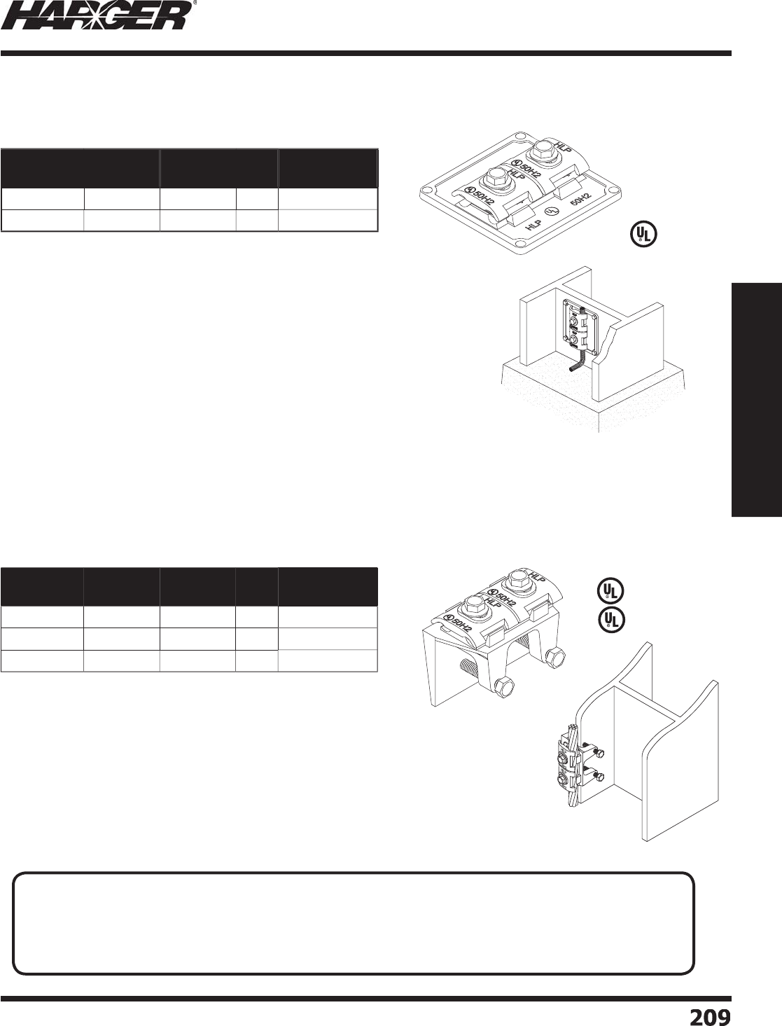
H
ar
g
er Li
g
htnin
g
& Groundin
g
•
©
2012 Phone 847-548-8700 • Fax 847-548-8755 • U.S. 800-842-743
7
20
9
209
Section 2
Lightning Protection Components
•
3-3/4" x 3-3/4" heavy duty bondin
g
plate provides over 14
s
quare inches of bondin
g
surface.
•
Lar
g
e cable connector offers 3" of contact between the
bondin
g
plate and the cable.
•
Accommodates all main size conductors u
p
to 9/16" diameter.
•
Will acce
p
t u
p
to four cables.
•
Four 5/16" mountin
g
holes.
•
Recommended installation tool - 1/2" socket wrench, end
w
rench
o
r n
u
t
d
river.
*
ETPB - Electr
o
Tin Pl
a
te
d
Br
o
nz
e
L
iste
d
9
6
L
iste
d
4
67
•
3-3/4" x 2-1/2" bondin
g
plate provides over 8 square inches o
f
bondin
g
surface.
•
Lar
g
e cable connector offers 3" of contact between the
bondin
g
plate and the cable.
•
Accommodates all main size conductors u
p
to 9/16" diameter.
•
Ideal for bondin
g
to steel I-beams up to 1" thick.
•
Recommended installation tool - 1/2" socket wrench, end
w
rench
o
r n
u
t
d
river.
•
S
u
it
ab
le f
o
r
d
irect
bu
ri
a
l.
*
ETPB - Electr
o
Tin Pl
a
te
d
Br
o
nz
e
Part No. Material Class Box
Qty.
Approx. Box
Wt. (lbs.)
220
C
o
pp
e
r
II
1
0
12-1
/2
220
T
E
TPB*
II
1
0
12-1
/2
Part No. Material Class Box
Qty.
Approx. Box
Wt. (lbs.)
223
C
o
pp
e
r
II
1
0
20
A
223
Al
u
min
u
m
II
1
0
8
223
T
E
TPB*
II
1
0
20
L
iste
d
9
6
Bondin
g
Plates
H
eav
y
D
ut
y
Flan
g
e
APPLICATI
O
N N
O
TE
:
• It is imperative to properly prepare the bondin
g
surface before applyin
g
the bondin
g
lu
g
or plate. All
paint, rust, moisture and debris must be removed. The use of a rasp (see pa
g
e 327) or
g
rindin
g
tool is
recommended to ensure all surface oxidants have been removed. Generously coat the bondin
g
surface
with the appropriate antioxidant (see pa
g
e 148), then install the bondin
g
lu
g
or plate.
S
ect
io
n 2.6.2
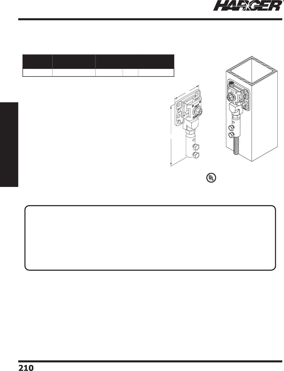
H
ar
g
er Li
g
htnin
g
& Groundin
g
•
©
2012 Phone 847-548-8700 • Fax 847-548-8755 • U.S. 800-842-743
7
2
1
0
210
Section 2
Lightning Protection Components
•
Allows co
pp
er conductors to be bonded to aluminum surfaces.
•
Provides over 8 square inches of bondin
g
surface.
•
Aluminum - Dual cable
p
ressure connector acce
p
ts all
aluminum main size conductors u
p
to 9/16" diameter.
•
Co
pp
er - Dual bolt connector acce
p
ts all co
pp
er main size
conductors u
p
to 1/2" in diameter.
•
Recommended installation tool - 1/2" socket wrench, end
w
rench
o
r n
u
t
d
river.
L
iste
d
9
6
Part No. Material Class Box
Qty.
Approx. Box
Wt. (lbs.)
BMBP
B
i-Met
a
l
II
5
3-3
/
4
Bondin
g
Plates
T
ECHNICAL N
O
TES
:
• A bondin
g
plate shall have a minimum thickness of not less than 3/32 inch (2.4 mm). The thickness shall
not be less than 5/16 inch
(
7.9 mm
)
for bosses for screw threads.*
• A Class I bondin
g
plate shall have a minimum surface contact area of 3 square inches (19.4 cm
2
)
.*
• A Class II bondin
g
plate shall comply with the material and dimensional requirements for Class I bondin
g
p
lates.
• A bondin
g
plate for utilizin
g
the steel framework as a conductor shall have a surface contact area of not
less than 8 s
q
uare inches
(
52 cm
2
)
.*
*
UL 96 Standard for Li
g
htnin
g
Protection Components Sections 14.1, 14.2, 20.1 & 20.
2
S
ect
io
n 2.6.2
3"
6 1/4"
Aluminum
Copper

H
ar
g
er Li
g
htnin
g
& Groundin
g
•
©
2012 Phone 847-548-8700 • Fax 847-548-8755 • U.S. 800-842-743
7
2
11
211
Section 2
Lightning Protection Components
S
ect
io
n 2.7
Li
g
htnin
g
Warnin
g
Syste
m
In
d
ex
Descr
i
pt
i
on Pa
g
e
2.7.1 Strike Guard Li
g
htnin
g
Warnin
g
System
..............................................
2
1
2
2
.7.
2
WAVE Siren
&
Tr
a
nsmitte
r
.................................................................
2
1
3
2.7.3 Complete Li
g
htnin
g
Warnin
g
System
..................................................
2
1
4
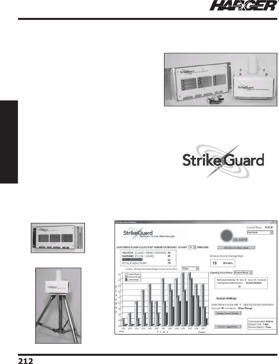
H
ar
g
er Li
g
htnin
g
& Groundin
g
•
©
2012 Phone 847-548-8700 • Fax 847-548-8755 • U.S. 800-842-743
7
2
12
212
Section 2
Lightning Protection Components
S
trike Guard employs state-of-the-art technolo
g
y to address
the most demandin
g
li
g
htnin
g
safety and equipment
p
rotection a
pp
lications.
D
esi
g
ned for critical industrial applications, Strike Guard
monitors cloud and cloud-to-
g
round li
g
htnin
g
within a user
-
s
et radius and provides relay-contact si
g
nalin
g
at user-set
l
i
g
htnin
g
activity thresholds. Patented optical si
g
nal processin
g
and proprietary optical-coincidence technolo
g
y prevents false
a
l
a
rms.
S
trike Guard sensor data are communicated via li
g
htnin
g
-proo
f
fi ber-optic cable to an independent Li
g
htnin
g
Data Receiver with
sy
stem status and Alarm Mode indicators, rela
y
s, and PC out
p
ut.
S
trike G
ua
r
d
Delivers:
•
Fully automatic alarm tri
gg
erin
g
in selectable ran
g
e
•
2
0
mile
d
etecti
o
n r
ad
i
us
•
No false alarms! Patented technolo
gy
•
Sens
o
r
a
n
d
c
o
mm
u
nic
a
ti
o
n self-test
•
Sensor is batter
y
p
owered for eas
y
installatio
n
•
Durable fi ber-optic communication with connector-less technolo
gy
•
NEMA 4X encl
o
s
u
re
•
Li
g
htnin
g
Data Receiver with battery-back-up
•
O
p
tional, Strike View, Windows-based dis
p
la
y
softwar
e
•
Strike Guard Simulation Software for trainin
g
and testin
g
S
trike Guard patented technolo
g
y provides si
g
nifi cant improvement over fi rst-
g
eneration li
g
htnin
g
sensors to enable
automated
g
enerator activation, data back-up, and li
g
htnin
g
evacuation plans with utmost confi dence.
L
i
g
htnin
g
Data Receive
r
L
i
g
htnin
g
Warnin
g
System
Part N
o
. SG002
T
he o
p
tional Strike View Software for Window
s
®
o
ffers
P
C-based audible and visual alarm functions, data lo
gg
in
g
, and system
monitorin
g
.
Part N
o
. SG001
S
trike Guard Com
p
onent
s
S
trike Guard Li
g
htnin
g
Warnin
g
Syste
m
S
ect
io
n 2.7.1
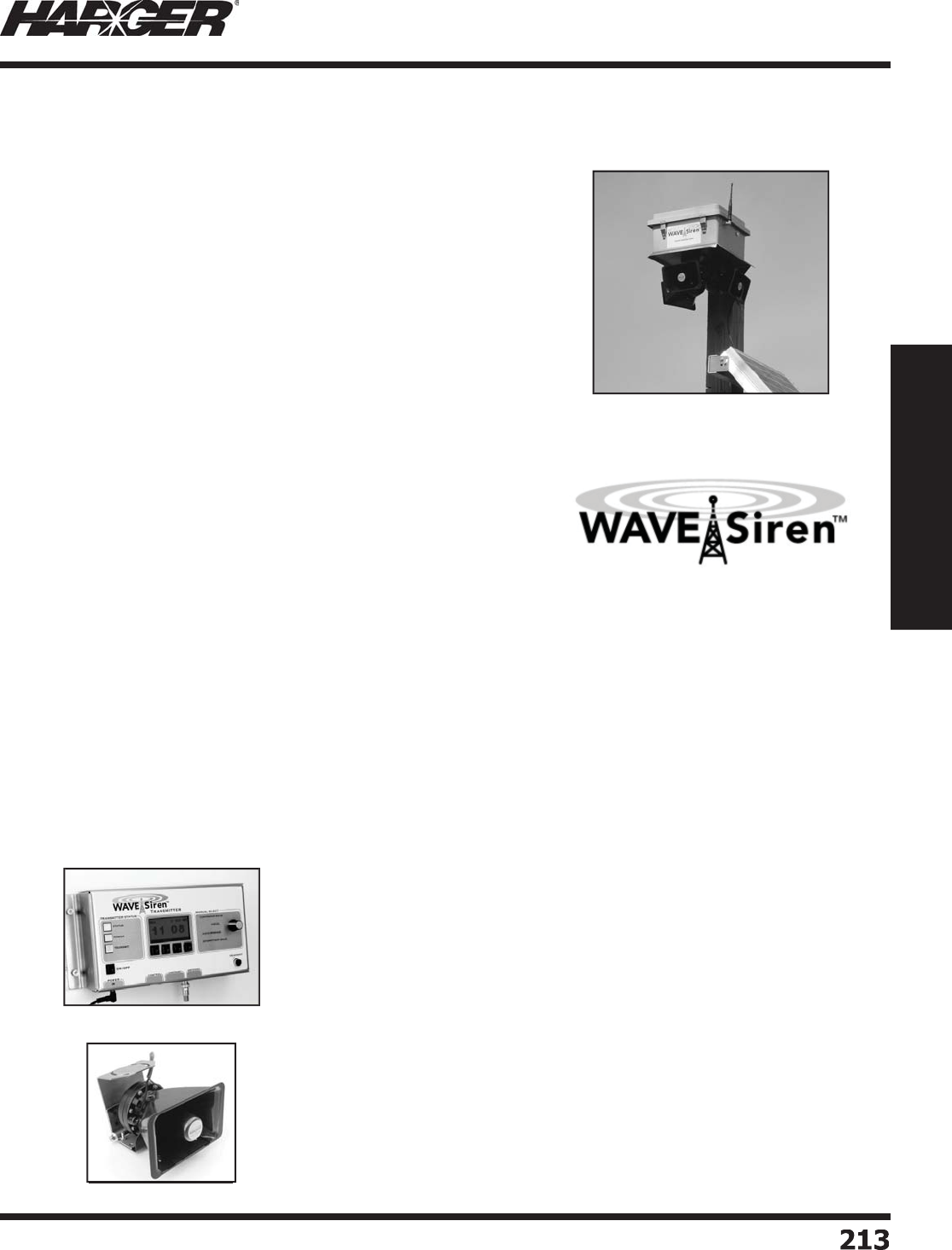
H
ar
g
er Li
g
htnin
g
& Groundin
g
•
©
2012 Phone 847-548-8700 • Fax 847-548-8755 • U.S. 800-842-743
7
2
1
3
213
Section 2
Lightning Protection Components
WAVE employs state-of-the-art technology to address the most demanding
audible and visual notifi cation and warning applications over areas of less
than an acre to hundreds of acres.
Designed for critical safety applications, the WAVE Transmitter broadcasts
digitally encrypted messages to activate WAVE Siren Stations within a
three mile radius. The Transmitter accepts contact-closure signaling for
automated triggering during programmable hours of operation. WAVE
relies on low-frequency RF communication to operate in noisy environments
and over challenging terrain.
WAVE Siren Station horns are modular in design to provide audible
notifi cation specifi c to the desired coverage area and application. Based on
coverage area and sound pressure level requirements, Siren Stations can
be ordered with up to four 100 W re-entrant horn, high effi ciency
compression-drivers.
WAVE SIREN DELIVERS:
• Automatic or manual wireless siren actuation within a three mile radius
• Secure encoded communications
• Comprehensive, automatic self-test for RF communication and system status
• Multiple compression driver mounting for greatest fl exibility
• Siren Station NEMA 4X enclosure
• RF transmission test signal for Siren Station site selection
• Manual key operation or automated operation with contact-closure signal
• Programmable hours of operation for automated external control
• Solar- or AC-powered Siren Station available Part N
o
. S
O
LAR-S
S
• High capacity, battery back-up for uninterrupted operation in a lightning environment
WAVE Siren and Strike Guard combine to provide a fully automated lightning warning system. Strike Guard easily
connects to the WAVE Transmitter to trigger the WAVE Siren Stations and WAVE Power Sequencers for audible
lightning hazard notifi cation and equipment protection across the golf course.
The WAVE Transmitter sends secure codes to activate an
unlimited number of Siren Stations and Power Sequencers
within a three mile radius.
The WAVE Transmitter offers:
1. Easy programming through front panel switches and LCD
2. Comprehensive, automatic system status monitoring
3. Manual control or automated activation from external contact-closure
4. Manual selection of desired transmission via front panel quick-select knob
The WAVE Siren Station offers:
1. Simplifi ed installation and fl exibility through modular design
2. Solar or AC power input
3. Optional strobe light to provide visual indication of conditions
4. External indicators of system status
5. Super-high sound pressure level – directional or omni-directional
W
AVE Tr
a
nsmitte
r
W
AVE
S
ire
n
Part No. WAVE-SS0
3
Other confi
g
urations available.
Contact the factor
y
for details.
Part N
o
. WAVE-TR01
W
AVE S
i
ren
&
Tran
s
m
i
tter
S
ect
io
n 2.7.2
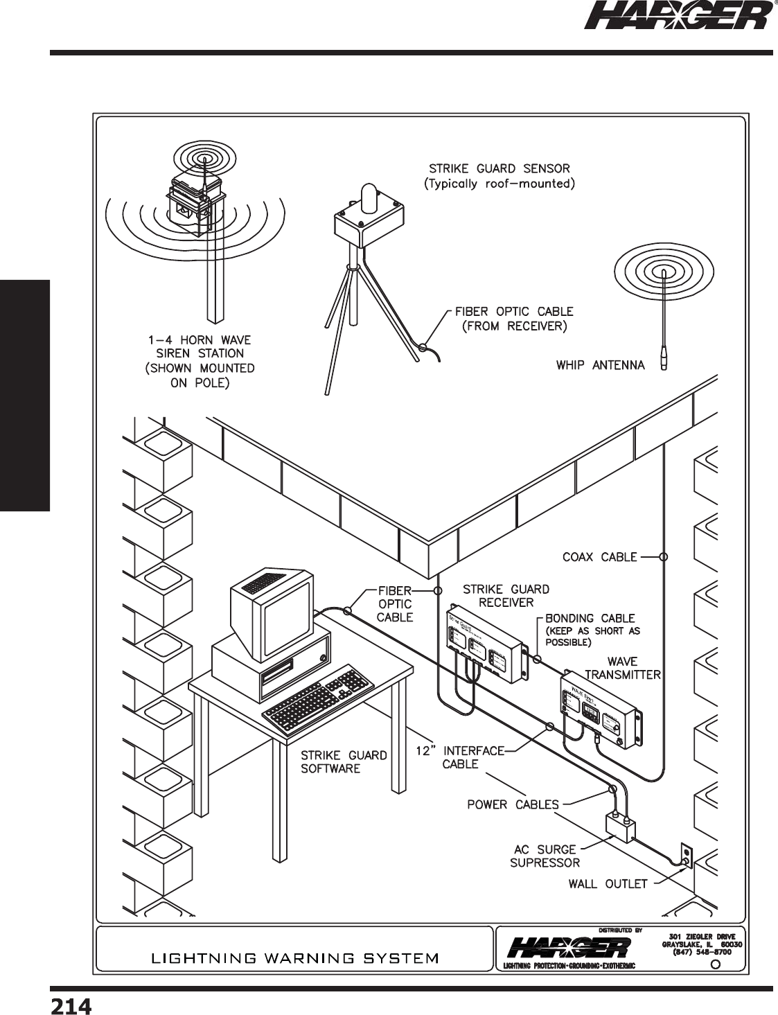
H
ar
g
er Li
g
htnin
g
& Groundin
g
•
©
2012 Phone 847-548-8700 • Fax 847-548-8755 • U.S. 800-842-743
7
2
1
4
214
Section 2
Lightning Protection Components
C
omplete Li
g
htnin
g
Warnin
g
Syste
m
S
ect
io
n 2.7.3
Strike Guard / WAVE SIREN ®
c2009

H
ar
g
er Li
g
htnin
g
& Groundin
g
•
©
2012 Phone 847-548-8700 • Fax 847-548-8755 • U.S. 800-842-743
7
Section 3
Communications Site Equipment
2
1
5
215
S
ect
io
n 3
Co
mmun
i
cat
io
ns S
i
te
E
q
u
ip
ment
In
d
ex
Descr
i
pt
i
on Pa
g
e
3.1 Wireless Communications E
q
ui
p
ment
..............................................
2
1
7
3.1.1 Shelter Groundin
g
Component
s
.................................................
2
19
3.1.2 Tower Groundin
g
Component
s
...................................................
227
3
.1.
3
Gr
ou
n
d
Kits
&
Access
o
rie
s
.........................................................
23
9
3.2 Premise Wirin
g
/Data-Com
..............................................................
2
4
3

H
ar
g
er Li
g
htnin
g
& Groundin
g
•
©
2012 Phone 847-548-8700 • Fax 847-548-8755 • U.S. 800-842-743
7
2
1
6
216216216
Section 3
Communications Site Equipment
No
tes

H
ar
g
er Li
g
htnin
g
& Groundin
g
•
©
2012 Phone 847-548-8700 • Fax 847-548-8755 • U.S. 800-842-743
7
Section 3
Communications Site Equipment
2
17
217
S
ect
io
n 3.1
W
ireless Communications E
q
ui
p
ment
In
d
ex
Descr
i
pt
i
on Pa
g
e
3.1.1 Shelter Groundin
g
Component
s
.........................................................
2
19
3.1.2 Tower Groundin
g
Component
s
...........................................................
227
3
.1.
3
Gr
ou
n
d
Kits
&
Access
o
rie
s
.................................................................
23
9

H
ar
g
er Li
g
htnin
g
& Groundin
g
•
©
2012 Phone 847-548-8700 • Fax 847-548-8755 • U.S. 800-842-743
7
2
18
218218218
Section 3
Communications Site Equipment
No
tes

H
ar
g
er Li
g
htnin
g
& Groundin
g
•
©
2012 Phone 847-548-8700 • Fax 847-548-8755 • U.S. 800-842-743
7
Section 3
Communications Site Equipment
2
1
9
219
S
ect
io
n 3.1.1
S
helter Groundin
g
Components
In
d
ex
Descr
i
pt
i
on Pa
g
e
3.1.1.1 Shelter Interior La
y
out
......................................................................
220
3.1.1.2 Li
g
htnin
g
Arrestor Bracket
s
...............................................................
22
1
3
.1.1.
3
Entr
a
nce P
a
nel Kit
s
...........................................................................
222
3.1.1.4 Bulk Head Entr
y
Panel Kit
s
................................................................
223
3.1.1.5 Halo Standoff Clam
ps
.......................................................................
224
3.1.1.6 Rack Isolatin
g
Pad
............................................................................
226
3.1.1.7 Conduit Bondin
g
Clamp
s
...................................................................
226
3.1.1.8 Door Jum
p
er
s
..................................................................................
226
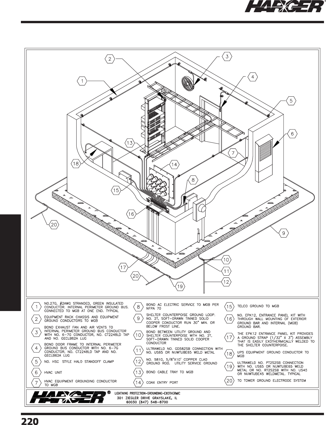
H
ar
g
er Li
g
htnin
g
& Groundin
g
•
©
2012 Phone 847-548-8700 • Fax 847-548-8755 • U.S. 800-842-743
7
2
2
0
220220220
Section 3
Communications Site Equipment
S
helter Interior La
y
out
S
ect
io
n 3.1.1.1
INTERIOR SHELTER LAYOUT
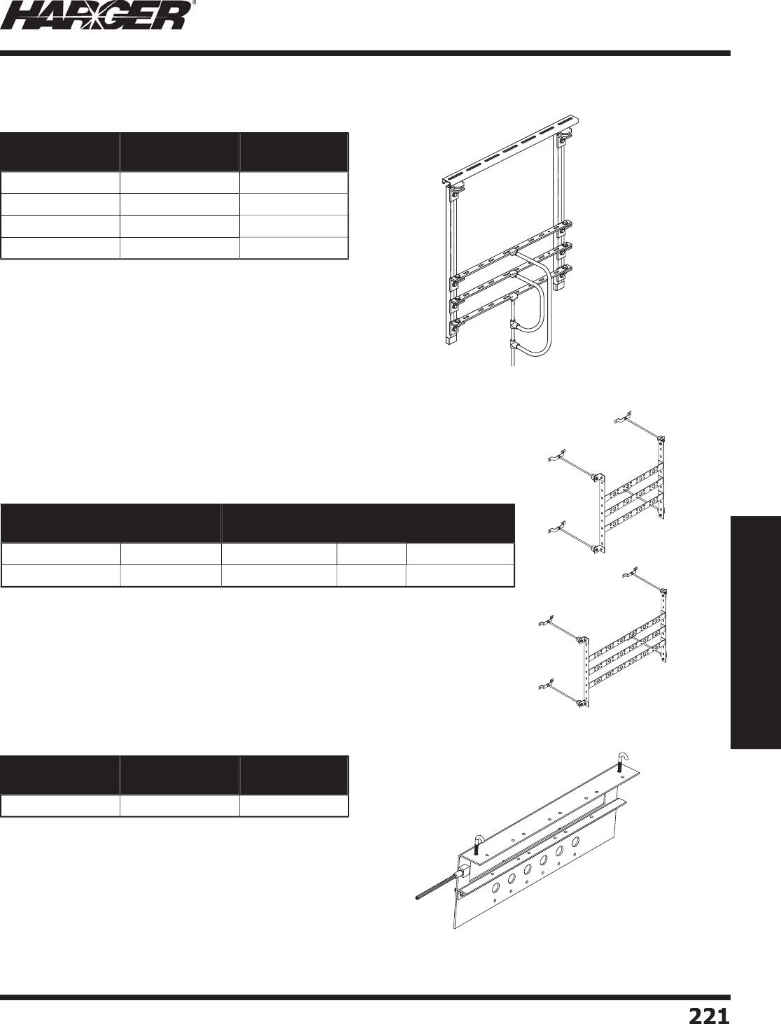
H
ar
g
er Li
g
htnin
g
& Groundin
g
•
©
2012 Phone 847-548-8700 • Fax 847-548-8755 • U.S. 800-842-743
7
Section 3
Communications Site Equipment
2
21
221
•
Manufactured from 110 allo
y
co
pp
er bar.
•
Arrestor bracket is desi
g
ned to be mounted to the ceilin
g
o
f a communication buildin
g
where communication lines
enter the buildin
g
throu
g
h the side wall.
•
Bracket can hold 4 lar
g
e fl an
g
e mount li
g
htnin
g
arrestors
a
n
d
c
o
mes with
a
2
5
' t
a
il
o
f #2 AWG s
o
li
d
tinne
d
conductor for connection to an exterior
g
round loop.
•
Bars are connected with tinned #2 AWG fl exible co
pp
er
c
o
n
du
ct
o
r.
•
Shi
p
s assembled.
CGARRBKT1
2
Part No. Description Approx. Each
Wt. (lbs.)
CGARRBKT
04
4
U
ni
t
18
CGARRBKT08 8 Uni
t
2
1
CGARRBKT1
2
1
2
U
ni
t
2
4
CGARRBKT1
6
1
6
U
ni
t
28
Li
g
htnin
g
Arrestor Brackets
C
eilin
g
Mount
•
Manufactured from 1/8" thick 110 allo
y
co
pp
er bar.
•
Acc
o
mm
oda
tes
bu
lkhe
ad
a
rrest
o
rs with DIN
o
r N fem
a
le c
o
nnect
o
rs.
•
Premounted self clinchin
g
nuts speed installation.
•
Can be ceilin
g
or wall mounted.
•
Shi
p
s unassembled.
•
Manufactured from 110 allo
y
co
pp
er bar.
•
Arrestor bracket mounts to cable tra
y
.
•
Arrestor bar holds 6 li
g
htnin
g
arrestors.
•
Hole diameter is 7
/
8".
•
#2 AWG 7 strand bare conductor tail exothermicall
y
welded
to arrestor bracket for attachment to
g
round system.
•
Shi
p
s assembled.
L
ABKT1
2U
GBA
S
L
ABKT18UGBA
S
Part No. Description Confi guration Width Approx. Each
Wt. (lbs.)
L
ABKT1
2U
GBA
S
1
2
U
ni
t
4
x
3
27" 1
7
L
ABKT18UGBA
S
18 Uni
t
6
x
3
3
9"
25
Part No. Description Approx. Each
Wt. (lbs.)
CGARRBKT
07
6
U
ni
t
18
C
eilin
g
/Wall Mounts
C
able Tra
y
Mount
S
ect
io
n 3.1.1.2
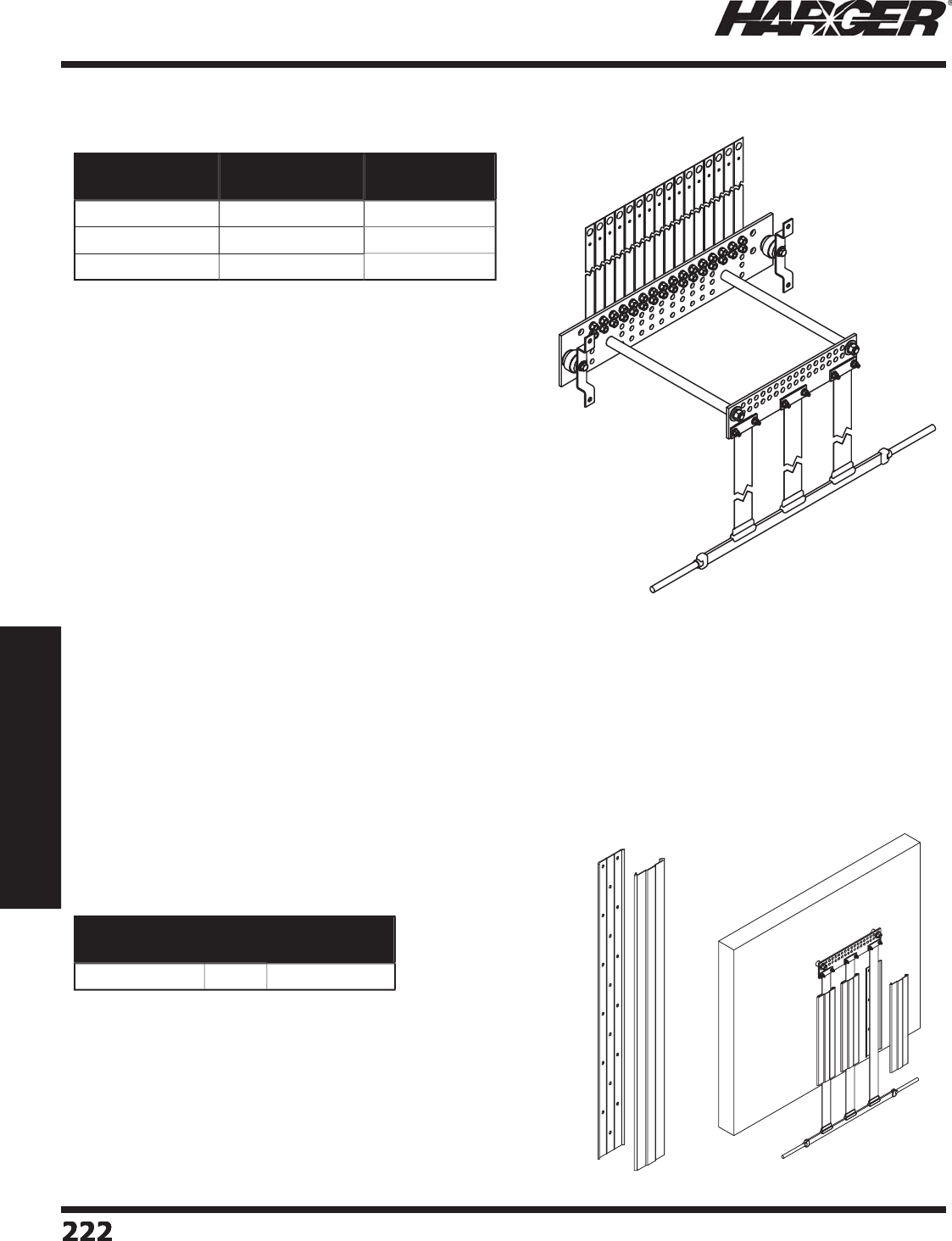
H
ar
g
er Li
g
htnin
g
& Groundin
g
•
©
2012 Phone 847-548-8700 • Fax 847-548-8755 • U.S. 800-842-743
7
2
22
222222222
Section 3
Communications Site Equipment
•
Complete 12, 16 and 24 unit entrance panel
g
round kits
provide the lowest possible impedance to
g
round for
coaxial
g
round shields and arrestors by utilizin
g
robust
fl at
g
round straps.
•
Unique fl at
g
round strap assembly incorporates 3
l
ow im
p
edance
(
1/32" x 3"
)
co
pp
er stra
p
s that are
exothermicall
y
welded to a 1/4" x 1" co
pp
er bar that has
#2 AWG solid tinned conductor exothermicall
y
welded at
either end for easy attachment to
g
round rin
g
.
•
Ground strap assembly attaches to the exterior
g
round
bar via 3 inte
g
rated sandwich type
g
round clamps.
•
Exterior
g
round bar has landin
g
s (3/8" bolt holes on
3/4" centers
)
to accommodate u
p
to 16 coaxial
g
round leads.
•
M
a
xim
u
m w
a
ll thickness
o
f 9".
•
Lon
g
er extension bars are available.
•
Shi
p
s unassembled.
EPK12 Kit Incl
ud
e
s:
(1) Interior
g
round ba
r
(1) Exterior
g
round ba
r
(2) Throu
g
h wall mountin
g
bar
s
(1) Flat
g
round strap assembl
y
(12) Sur
g
e suppression
g
round strap
s
(1) HCAJC1/2
j
oint compound
(
24
)
Sets stainless steel fastener
s
EPK1
6
Kit Incl
ud
e
s:
(1) Interior
g
round ba
r
(1) Exterior
g
round ba
r
(2) Throu
g
h wall mountin
g
bar
s
(1) Flat
g
round strap assembl
y
(16) Sur
g
e suppression
g
round strap
s
(1) HCAJC1/2
j
oint compound
(
32
)
Sets stainless steel fastener
s
E
PK1
6
EPK24 Kit Incl
ud
e
s:
(1) Interior
g
round ba
r
(1) Exterior
g
round ba
r
(2) Throu
g
h wall mountin
g
bar
s
(1) Flat
g
round strap assembl
y
(24) Sur
g
e suppression
g
round strap
s
(1) HCAJC1/2
j
oint compound
(
48
)
Sets stainless steel fastener
s
•
5'
p
lastic
p
rotective channel su
pp
orts
(
includes a front & back
)
.
•
Fastens fl at
g
round strap to shelter surface and protects strap
from dama
g
e.
Part No. Description Approx. Each
Wt. (lbs.)
E
PK1
2
1
2
U
ni
t
52
E
PK1
6
1
6
U
ni
t
53
E
PK
2
4
2
4
U
ni
t
71-1
/2
Part No. Qty. Approx. Each
Wt. (lbs.)
E
PKPP
CS
T
5
EA
5
Entrance Panel Kit
s
C
hannel Su
pp
ort
S
ect
io
n 3.1.1.3
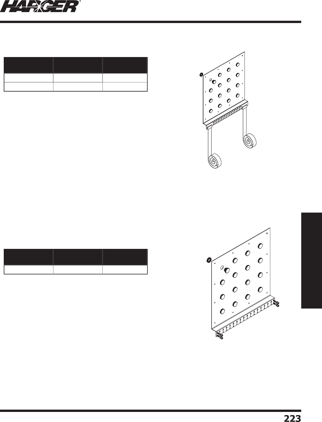
H
ar
g
er Li
g
htnin
g
& Groundin
g
•
©
2012 Phone 847-548-8700 • Fax 847-548-8755 • U.S. 800-842-743
7
Section 3
Communications Site Equipment
2
2
3
223
•
Entrance
p
anels can accommodate either 12 or 16 coaxial entries.
•
5/8" diameter holes accept sur
g
e arrestors.
•
The entrance panel and
g
round bar are inte
g
ral to the unit bein
g
fabricated from a sin
g
le copper plate ensurin
g
the lowest possible
i
mpedance between the entrance panel and
g
round bar.
•
Entrance
p
anels are made from tinned
p
lated 110 co
pp
er allo
y
.
•
Respectively, the panel
g
round bus have 12 and 16 sets of hole
/
s
lots to accommodate lu
g
s with 3/8" holes on 3/4" to 1" centers.
•
Weatherproof plu
g
s are included to seal unused ports.
•
The panel has two robust fl at copper
g
round straps (0.032" x 2" x
10' lon
g
) exothermically welded to
g
round bus to provide a low
impedance path to the
g
round
g
rid.
•
The
g
round straps are exothermically welded in the fi eld to the
g
round
g
rid.
TC
EP4X4
•
Entrance
p
anels can accommodate either 12 or 16 coaxial entries
and DIN arrestors. Contact factor
y
for s
p
ecifi cations.
•
The entrance panel and
g
round bar are inte
g
ral to the unit bein
g
fabricated from a sin
g
le copper plate ensurin
g
the lowest possible
i
mpedance between the entrance panel and
g
round bar.
•
Entrance
p
anels are made from tinned
p
lated 110 co
pp
er allo
y
.
•
Respectively, the panel
g
round bus have 12 and 16 sets of hole
/
s
lots to accommodate lu
g
s with 3/8" holes on 3/4" to 1" centers.
S
ee pa
g
e 113 for lu
g
s.
•
Weatherproof plu
g
s are included to seal unused ports.
Part No. Description Approx. Each
Wt. (lbs.)
T
CEP4X
3
1
2
U
ni
t
60
TC
EP4X
4
1
6
U
ni
t
60
Part No. Description Approx. Each
Wt. (lbs.)
TC
EP4X4H
S
1
6
U
ni
t
4
3-1
/2
Bulk Head Entr
y
Panel Kits
S
ect
io
n 3.1.1.
4
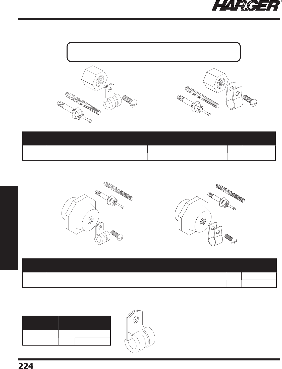
H
ar
g
er Li
g
htnin
g
& Groundin
g
•
©
2012 Phone 847-548-8700 • Fax 847-548-8755 • U.S. 800-842-743
7
2
2
4
224224224
Section 3
Communications Site Equipment
•
Will h
o
l
d
the h
a
l
o
1"
o
ff
o
f the w
a
ll.
•
Supplied with two anchors for mountin
g
to both masonry and stud walls.
•
Will hold the halo 1-1
/
2" off of the wall.
•
Supplied with two anchors for mountin
g
to both masonry and stud walls.
•
304 SS clip with insulatin
g
rubber
g
rommet.
•
CC5 fi ts conductors #6 AWG insulated throu
g
h
#2 AWG
ba
re.
•
CC7 fi ts conductors #2 AWG insulated throu
g
h
2
/
0 AWG bare.
•
CC5 and CC7 have .265" mountin
g
hole.
H
SC1
00
H
SC1
00
C
H
SC1
50
H
SC1
50
C
Part No. Clip Style Conductor Range Box
Qty.
Approx. Box
Wt. (lbs.)
H
SC1
00
S
tainless Steel w/ Insulatin
g
Rubber Grommet #
6
AWG Ins
u
l
a
te
d
t
o
#2 AWG B
a
r
e
11
/4
H
SC1
00
C
B
are
C
o
pp
e
r
#6 AWG Insulated to 2
/
0 AWG Bar
e
11
/4
Part No. Clip Style Conductor Range Box
Qty.
Approx. Box
Wt. (lbs.)
H
SC1
50
S
tainless Steel w/ Insulatin
g
Rubber Gromme
t
#
6
AWG Ins
u
l
a
te
d
t
o
#2 AWG B
a
r
e
11
/4
H
SC1
50
C
B
are
C
o
pp
e
r
#6 AWG Insulated to 2
/
0 AWG Bare
1
1
/4
Part No. Box
Qty.
Approx. Box
Wt. (lbs.)
CC5
1
00
1-1
/2
CC7
1
00
1-1
/2
Halo Standoff Clam
p
s
APPLICATI
O
N N
O
TE
:
• Halo Standoff Clamps are used for mountin
g
interior halo
g
round rin
g
s.
S
ect
io
n 3.1.1.5
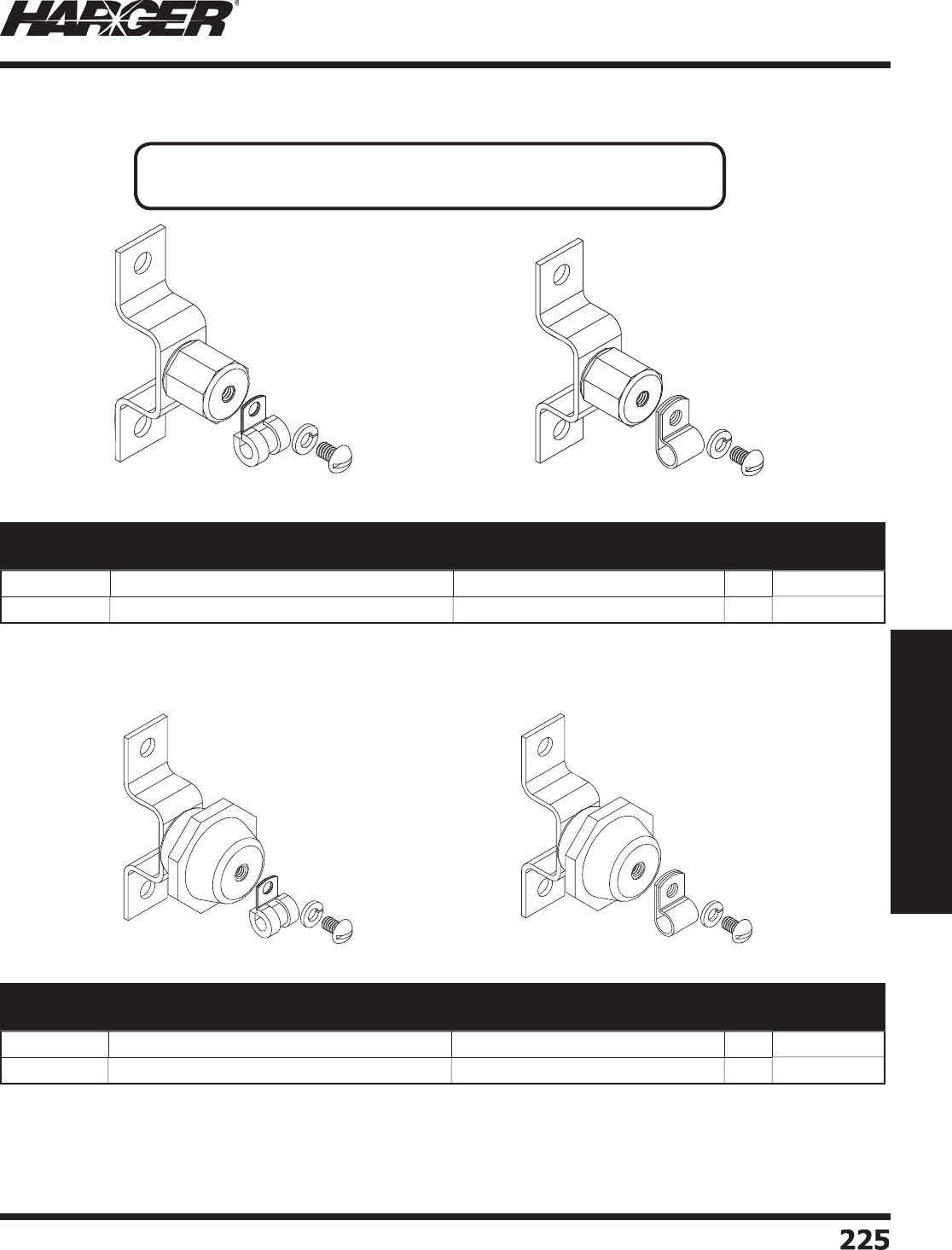
H
ar
g
er Li
g
htnin
g
& Groundin
g
•
©
2012 Phone 847-548-8700 • Fax 847-548-8755 • U.S. 800-842-743
7
Section 3
Communications Site Equipment
2
2
5
225
•
Will h
o
l
d
the h
a
l
o
2"
o
ff
o
f the w
a
ll.
•
Will hold the halo 2-1
/
2" off of the wall.
H
SC1
00
R
56
H
SC1
00
CR
56
H
SC1
50
R
56
H
SC1
50
CR
56
*
R56 is Motorola, Inc. Standards and Guidelines for Communication Site
s
Part No. Clip Style Conductor Range Box
Qty.
Approx. Box
Wt. (lbs.)
H
SC1
00
R
56
S
tainless Steel w/ Insulatin
g
Rubber Gromme
t
#
6
AWG Ins
u
l
a
te
d
t
o
#2 AWG B
a
r
e
11
/
4
H
SC1
00
CR
56
B
are
C
o
pp
e
r
#6 AWG Insulated to 2
/
0 AWG Bar
e
11
/
4
Part No. Clip Style Conductor Range Box
Qty.
Approx. Box
Wt. (lbs.)
H
SC1
50
R
56
S
tainless Steel w/ Insulatin
g
Rubber Gromme
t
#
6
AWG Ins
u
l
a
te
d
t
o
#2 AWG B
a
re 1 1
/4
H
SC1
50
CR
56
B
are
C
o
pp
e
r
#6 AWG Insulated to 2
/
0 AWG Bare 1 1
/4
Halo Standoff Clam
p
s - R56* Com
p
liant
APPLICATI
O
N N
O
TE
:
• Halo Standoff Clamps are used for mountin
g
interior halo
g
round rin
g
s.
S
ect
io
n 3.1.1.5
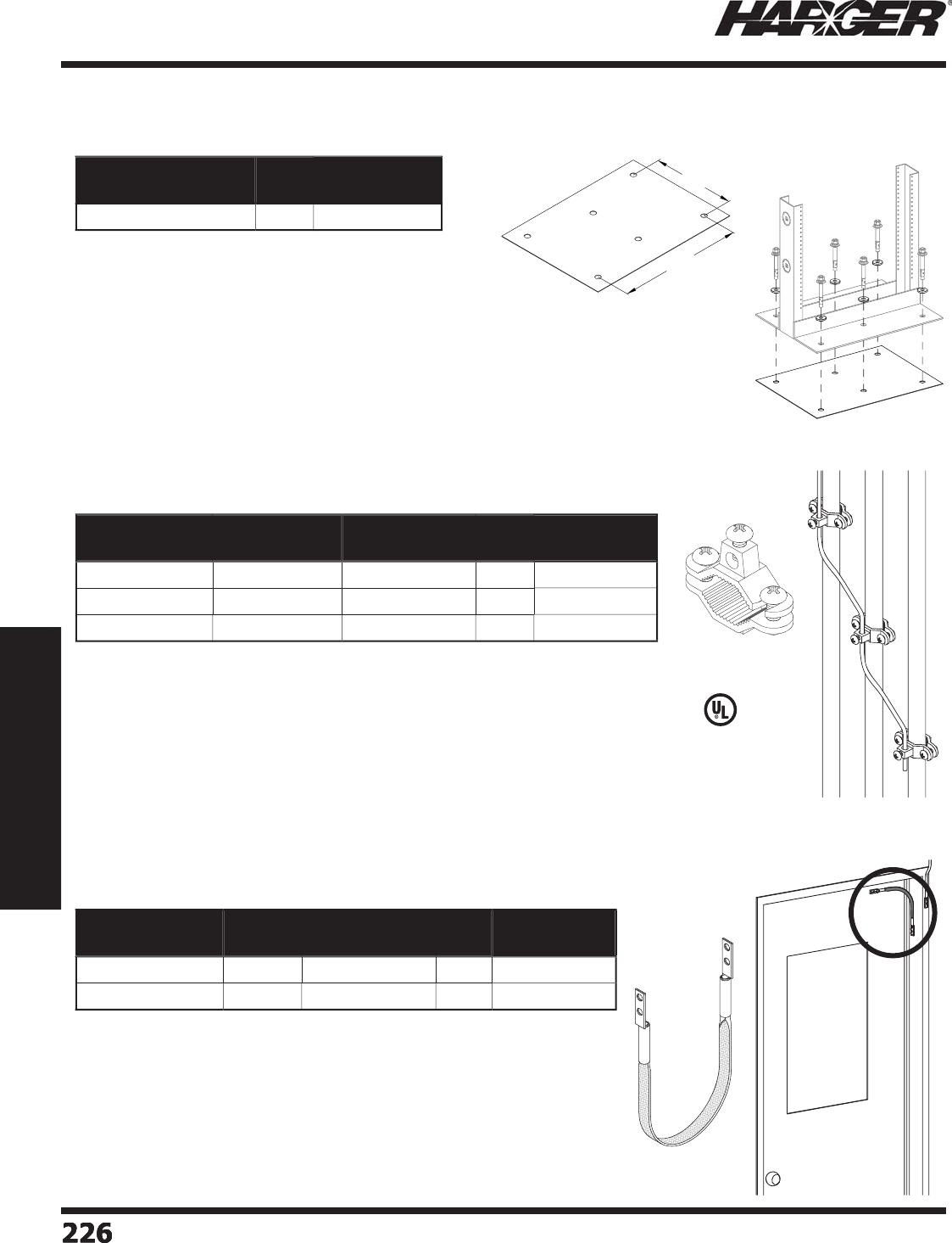
H
ar
g
er Li
g
htnin
g
& Groundin
g
•
©
2012 Phone 847-548-8700 • Fax 847-548-8755 • U.S. 800-842-743
7
2
2
6
226226226
Section 3
Communications Site Equipment
•
Door
j
umpers made from 1/2" x .094 fl exible tinned copper fl at braid.
•
Two holes s
p
aced 5/8" on center
p
er each end.
•
Braid is 4
g
ua
g
e equivalent.
•
Dimensi
o
ns
a
re n
o
min
a
l size.
•
Hole size is 1
/
4".
•
Used to isolate racks from conductive fl oorin
g
such
as concrete and prevent multiple
g
round paths.
•
.062” x 15” x 20-1
/
2” GPO-3 Phenolic Isolation Pad
desi
g
ned to fi t Motorola equipment racks.
•
Includes six isolatin
g
shoulder washers desi
g
ned to
accommodate 1
/
2” anchors.
•
Other sizes and confi
g
urations available. Please
contact factor
y
for more information.
Part No. Qty. Approx. Each
Wt. (lbs.)
IP
062
1
520
.
5
M
O
T
O
EA
1-1
/
4
Part No. Length Approx. Each
Wt. (lbs.)
Box
Qty.
Approx. Box
Wt. (lbs.)
GS12094122A1
/
4 12" 1
/2
1
0
5
GS12094182A1
/
4 18" 1
/2
1
0
5
Rack Isolatin
g
Pad
D
oor
J
um
p
ers
S
ect
io
n 3.1.1.6 - 3.1.1.8
11"
16 1/2"
•
Bronze clamp for bondin
g
conduits that are fl ush mounted to a surface
s
uch as a wall, fl oor or ceilin
g
.
•
"Low Profi le" desi
g
n utilizes 1/4" diameter lon
g
machine screws.
*
Electro tin
p
lated bronze.
*
* Incl
ud
es st
a
inless steel h
a
r
d
w
a
re. R
a
te
d
f
o
r
d
irect
bu
ri
a
l.
C
onduit Bondin
g
Clamps
L
iste
d
4
67
Part No. Conduit
Range
Conductor
Range (AWG)
Box
Qty.
Approx. Box
Wt. (lbs.)
BGC
4
SCS
1
/
2" - 3
/
4" #1
0
- #
2
1
0
2-1
/2
T
BGC4SCS* 1
/
2" - 3
/
4" #1
0
- #
2
1
0
2-1
/2
T
BGC4SCSSS** 1
/
2" - 3
/
4" #1
0
- #
2
1
0
2-1
/2

H
ar
g
er Li
g
htnin
g
& Groundin
g
•
©
2012 Phone 847-548-8700 • Fax 847-548-8755 • U.S. 800-842-743
7
Section 3
Communications Site Equipment
2
27
227
S
ect
io
n 3.1.2
Tower Groundin
g
Components
In
d
ex
Descr
i
pt
i
on Pa
g
e
3.1.2.1 Exterior Groundin
g
Layout
.................................................................
228
3
.1.2.2 T
o
wer Air Termin
a
l
s
..........................................................................
230
3.1.2.3 Gu
y
Wire Clam
ps
..............................................................................
23
1
3.1.2.4 Ban
j
o Clamp
....................................................................................
232
3.1.2.5 Beam Clam
ps
...................................................................................
232
3
.1.2.
6
T
o
wer St
a
n
do
ff f
o
r R
ou
n
d
Mem
b
er
s
...................................................
233
3
.1.2.7 Ins
u
l
a
te
d
T
o
wer St
a
n
do
ff f
o
r R
ou
n
d
Mem
b
er
s
....................................
234
3.1.2.8 Tower Standoff for Sna
p
-In
s
..............................................................
235
3.1.2.9 Band Clam
ps
....................................................................................
236
3.1.2.10 Stainless Steel Down Conductor Standoff
...........................................
f
236
3.1.2.11 Stainless Steel Down Conductor An
g
le Adapte
r
...................................
236
3.1.2.12 Slotted Lon
g
Barrel Compression Lu
g
s (Telecommunications
)
..............
237
3.1.2.13 Co
pp
er Flat Stra
p
Clam
ps
..................................................................
237
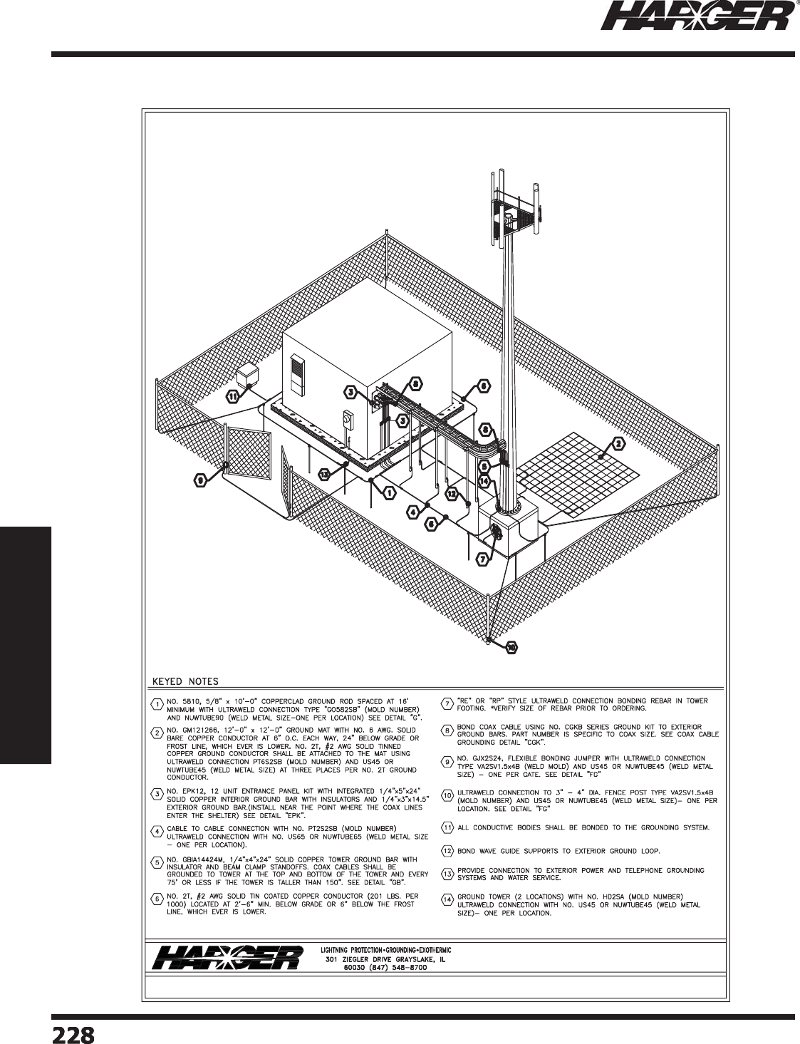
H
ar
g
er Li
g
htnin
g
& Groundin
g
•
©
2012 Phone 847-548-8700 • Fax 847-548-8755 • U.S. 800-842-743
7
2
28
228228228
Section 3
Communications Site Equipment
Exterior Groundin
g
Layout
S
ect
io
n 3.1.2.1
TYPICAL WIRELESS COMMUNICATION SITE
EXTERIOR GROUNDING PLAN
NTS
HARGER LIGHTNING & GROUNDING
847-548-8700 800-842-7437 www.harger.com
2009
9
®
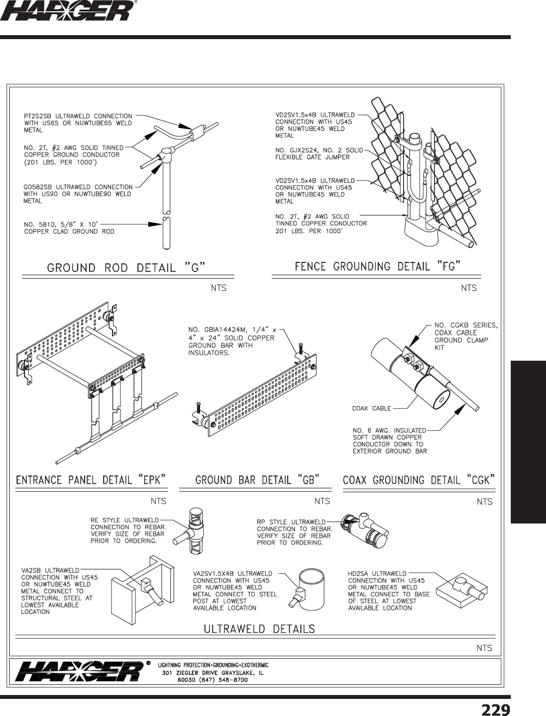
H
ar
g
er Li
g
htnin
g
& Groundin
g
•
©
2012 Phone 847-548-8700 • Fax 847-548-8755 • U.S. 800-842-743
7
Section 3
Communications Site Equipment
2
2
9
229
Exterior Groundin
g
Layout
S
ect
io
n 3.1.2.1
TYPICAL WIRELESS COMMUNICATION SITE
EXTERIOR GROUNDING PLAN
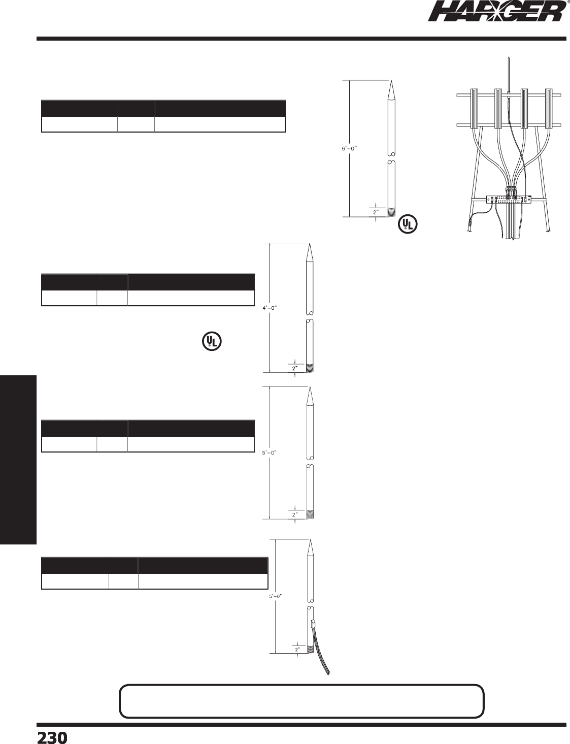
H
ar
g
er Li
g
htnin
g
& Groundin
g
•
©
2012 Phone 847-548-8700 • Fax 847-548-8755 • U.S. 800-842-743
7
230
230230230
Section 3
Communications Site Equipment
•
Tower air terminals are mounted on to
p
of and on the sides
o
f towers to help protect tower li
g
htin
g
, antennas, dishes,
etc. from direct li
g
htnin
g
strikes.
•
5/8" diameter x 6' lon
g
air terminal made from 304 stainless
s
t
ee
l.
•
Air terminal features 2" of 5
/
8"-11 UNC coarse threads and
comes complete with 2 each of stainless steel
j
am nuts, lock
wa
shers
a
n
d
fl
a
t w
a
shers.
•
5/8" diameter x 5' lon
g
air terminal made from
co
pp
er clad steel
(
10 mil
)
.
•
Air terminal features 2" of 5
/
8"-11 UNC coarse
threads and comes com
p
lete with 2 each o
f
s
tainless steel
j
am nuts, lock washers and fl at
wa
shers.
•
Copper clad steel provides superior stren
g
th and
is less susce
p
tible to wind shear than solid co
pp
er
a
ir termin
a
ls.
•
Used where solid co
pp
er air terminals are
p
referred.
•
1/2" diameter x 4' lon
g
solid copper air terminal.
•
Air terminal features 2" of 1
/
2"-13 UNC coarse
threads and comes com
p
lete with 2 each o
f
s
tainless steel
j
am nuts, lock washers and fl at
wa
shers.
•
5/8" diameter x 5' lon
g
air terminal made from
co
pp
er clad steel
(
10 mil
)
.
•
Air terminal features 2" of 5
/
8"-11 UNC coarse
threads and comes com
p
lete with 2 each o
f
s
tainless steel
j
am nuts, lock washers and fl at
wa
shers.
•
25' of 2/0 AWG 19 strand co
pp
er conductor
exothermicall
y
welded to air terminal.
•
Tail can be exothermicall
y
welded to steel tower,
g
round bar or connected to a down conductor.
N
O
TE
:
• Other sizes are available. Please contact factor
y
for more information.
Part No. Qty. Approx. Each Wt. (lbs.)
5
86SS3AT
EA
6
-1
/
4
Part No. Qty. Approx. Each Wt. (lbs.)
1248SCAT
EA
3-1
/2
Part No. Qty. Approx. Each Wt. (lbs.)
5
85CCAT
EA
4
-1
/
4
Part No. Qty. Approx. Each Wt. (lbs.)
5
85CCAT-2
/
0
EA
14-1
/2
T
o
wer Air Terminals
S
tainle
ss
Stee
l
S
olid Co
pp
er
C
o
pp
er Clad Stee
l
C
o
pp
er Clad Stee
l
S
ect
io
n 3.1.2.2
L
iste
d
9
6
L
iste
d
9
6
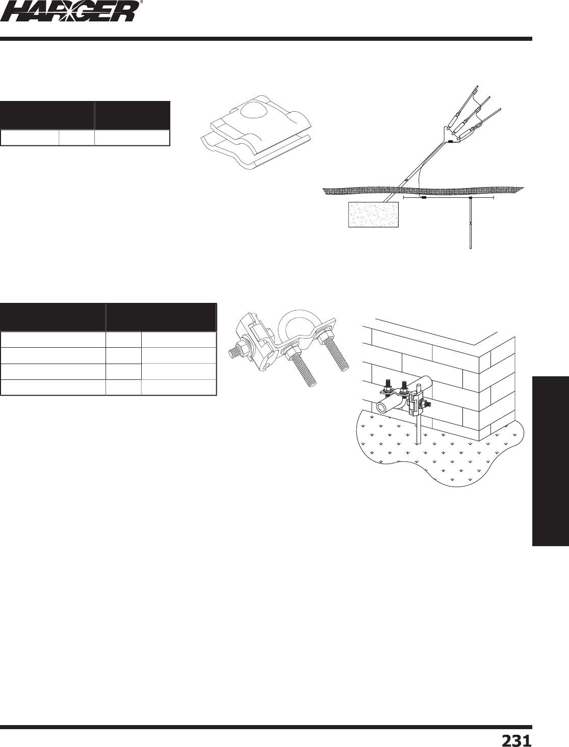
H
ar
g
er Li
g
htnin
g
& Groundin
g
•
©
2012 Phone 847-548-8700 • Fax 847-548-8755 • U.S. 800-842-743
7
Section 3
Communications Site Equipment
23
1
231
•
Can be used for connectin
g
2 dissimilar
conductors such as co
pp
er and
g
alvanized steel.
•
One bolt stainless steel clam
p
comes
w
ith st
a
inless steel h
a
r
d
w
a
re.
•
Accommodates up to 7/8"
g
uy wire
and 4
/
0 AWG conductor.
•
Can be used for connectin
g
2 dissimilar
conductors such as co
pp
er and
g
alvanized steel.
•
One bolt stainless steel clam
p
comes with
s
t
a
inless steel h
a
r
d
w
a
re.
•
Accommodates up to 1"
g
uy wire and
4
/
0 AWG conductor.
Part No. Box
Qty.
Approx. Box
Wt. (lbs.)
S
SC25
/
875 1
0
3-1
/
4
Part No. Box
Qty.
Approx. Box
Wt. (lbs.)
S
SGC.75
/
1-O
D
5
3-3
/
4
S
SGC1.00
/
1.625-O
D
5
4
S
SGC1.625
/
2.375-O
D
5
5
S
SGC2.375
/
3.5-O
D
5
5
-1
/2
G
u
y
Wire Clam
p
s
C
onductor to Gu
y
Wire
C
onductor to Pi
p
e or Gu
y
Wire
S
ect
io
n 3.1.2.3
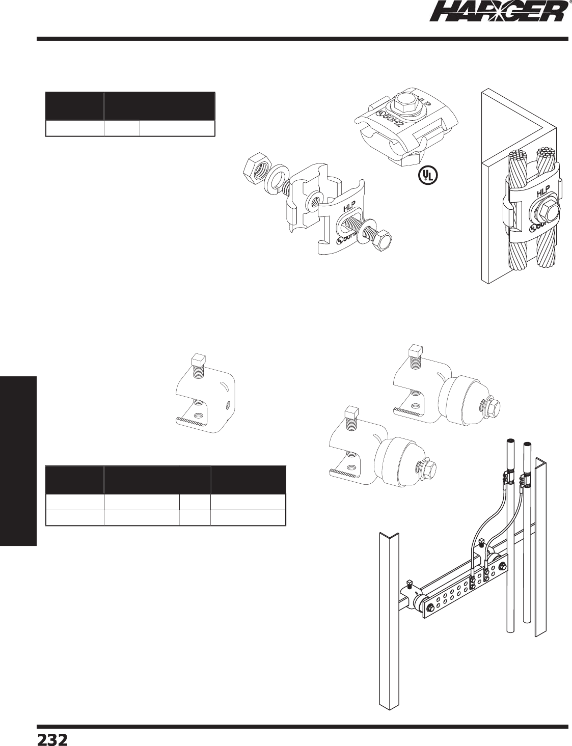
H
ar
g
er Li
g
htnin
g
& Groundin
g
•
©
2012 Phone 847-548-8700 • Fax 847-548-8755 • U.S. 800-842-743
7
23
2
232232232
Section 3
Communications Site Equipment
•
Tinned bronze clamp attaches li
g
htnin
g
c
o
n
du
ct
o
r c
ab
le t
o
l
a
ttice t
o
wers.
•
Acce
p
ts u
p
to 4/0 AWG conductor.
•
1/2" external hub fi ts into most ban
j
o
b
r
a
ckets.
SS
AA
SS
AAKIT
Part No. Box
Qty.
Approx. Box
Wt. (lbs.)
B
J
C
1
0
4
-1
/
4
Part No. Approx. Each
Wt. (lbs.)
Box
Qty.
Approx. Box
Wt. (lbs.)
SS
AA 1
/2
1
0
5
SS
AAKIT 1
/2
5
8
Ban
j
o Clamp
Beam Clam
p
s
L
iste
d
9
6
S
ect
io
n 3.1.2.4 & 3.1.2.5
•
M
a
n
u
f
a
ct
u
re
d
fr
o
m
30
4 series st
a
inless steel.
•
SSAAKIT includes two assemblies
(p
ictured
)
. 3/8"
s
tainless steel hardware fastens kit to
g
round bar.
•
SSAAKIT
a
ls
o
incl
ud
es R41
50
A4 ins
u
l
a
t
o
rs.
•
Will accommodate u
p
to 1" thick material.
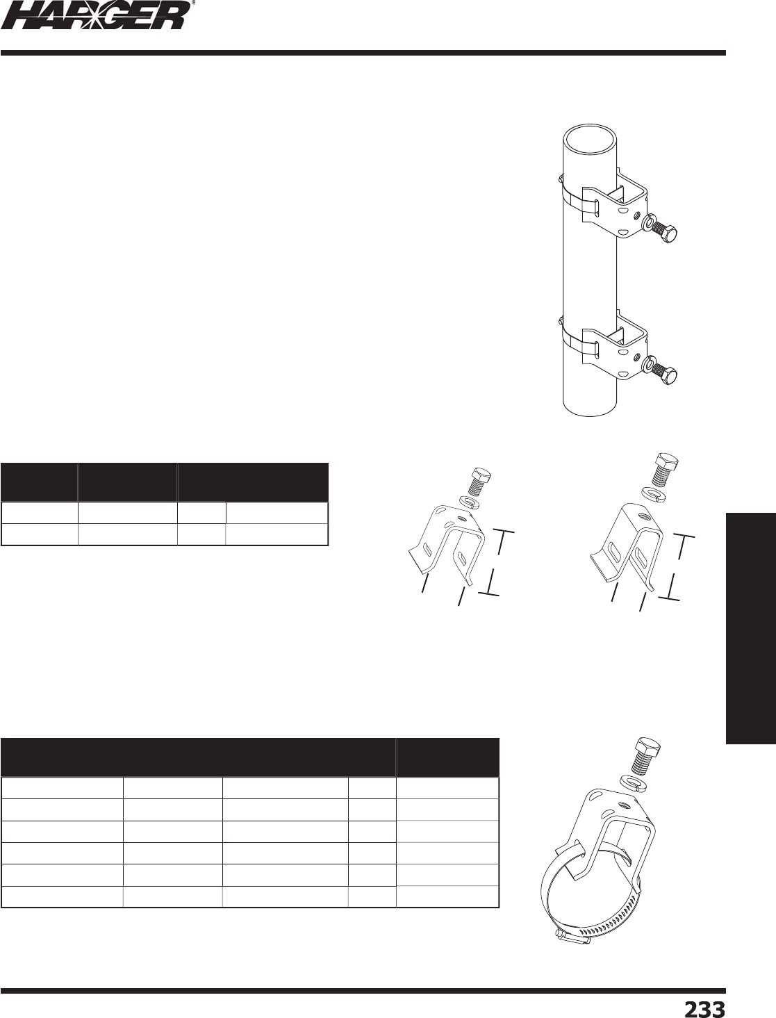
H
ar
g
er Li
g
htnin
g
& Groundin
g
•
©
2012 Phone 847-548-8700 • Fax 847-548-8755 • U.S. 800-842-743
7
Section 3
Communications Site Equipment
233
233
•
The fast, easy and economical way to make quality attachments of
g
round
bars and other com
p
onents to round tower members.
•
Manufactured from 300 series stainless steel for o
p
timum com
p
atibilit
y
.
•
3/8-16 x 5/8" stainless steel hex head ca
p
screw and lock washer included.
•
Available with or without stainless steel hose clam
p
s in a variet
y
of sizes.
•
Sold as 10
p
ack.
T
S
O
T
S
O
M
Part No. Band Clamp
Included
Pack
Qty.
Approx. Box
Wt. (lbs.)
T
S
O
No
1
0
2-1
/2
T
S
O
M
No
1
0
2
Part No. Band Clamp
Included
Round Member
Size O.D.
Pack
Qty.
Approx. Box
Wt. (lbs.)
T
SOC.75
/
1.75
Yes
.
7
5
" - 1.7
5
"1
0
2-1
/2
T
SOC2
/
2.75
Yes
2" - 2.7
5
"1
0
3-1
/2
T
SOC3
/
3.75
Yes
3
" -
3
.7
5
"1
0
3-1
/2
T
SOC4
/
4.75
Yes
4
" - 4.7
5
"1
0
4
T
SOC5
/
5.75
Yes
5
" -
5
.7
5
"1
0
4
T
SOC6
/
6.75
Yes
6
" -
6
.7
5
"1
0
4
T
o
wer Stand
o
ff f
o
r R
o
und Members
T
S
O
Ser
i
e
s
To
wer Stand
o
ffs
Tower Standoff with Hose Clam
p
S
ect
io
n 3.1.2.6
1-3/16"
1-15/16"
15/16"
1-15/16"
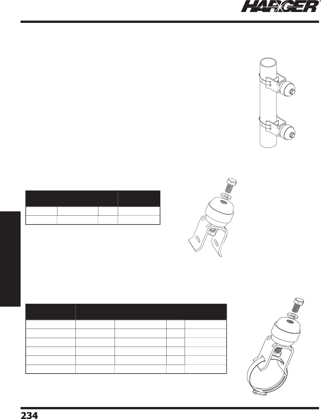
H
ar
g
er Li
g
htnin
g
& Groundin
g
•
©
2012 Phone 847-548-8700 • Fax 847-548-8755 • U.S. 800-842-743
7
234
234234234
Section 3
Communications Site Equipment
•
The fast, easy and economical way to make a quality isolated coaxial
g
round
ba
r m
ou
nt t
o
r
ou
n
d
t
o
wer mem
b
ers.
•
Manufactured from 300 series stainless steel for o
p
timum com
p
atibilit
y
.
•
3/8" x 1-1/2" insulator with 3/8-16 x 5/8" stainless steel hex head ca
p
screw
a
n
d
l
o
ck w
a
sher incl
ud
e
d
.
•
Available with or without stainless steel hose clam
p
s in a variet
y
of sizes.
•
Sold as 10
p
ack.
•
TS
O
INS
u
ses T
o
wer St
a
n
do
ff TS
O
.
•
TS
O
MINS
u
ses T
o
wer St
a
n
do
ff TS
O
M.
Part No. Band Clamp
Included
Pack
Qty.
Approx. Box
Wt. (lbs.)
T
S
O
IN
S
No
1
0
4
-3
/
4
T
S
O
MIN
S
No
1
0
5
Part No. Band Clamp
Included
Round Member
Size O.D.
Pack
Qty.
Approx. Box
Wt. (lbs.)
T
SOCINS.75
/
1.75
Yes
.
7
5
" - 1.7
5
"1
0
6
-1
/
4
T
SOCINS2
/
2.75
Yes
2" - 2.7
5
1
0
6
-1
/
4
T
SOCINS3
/
3.75
Yes
3
" -
3
.7
5
"1
0
6
-1
/
4
T
SOCINS4
/
4.75
Yes
4
" - 4.7
5
"1
0
6
-1
/2
T
SOCINS5
/
5.75
Yes
5
" -
5
.7
5
"1
0
6
-1
/2
T
SOCINS6
/
6.75
Yes
6
" -
6
.7
5
"1
0
6
-1
/2
Insulated T
o
wer Stand
o
ff f
o
r R
o
und Members
TS
O
INS Ser
i
e
s
Insulated T
o
wer Stand
o
ffs
Insulated Tower Standoffs with Hose Clam
p
S
ect
io
n 3.1.2.7
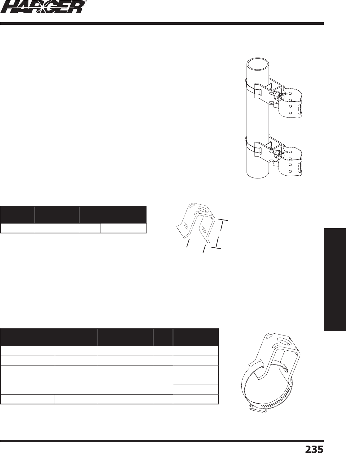
H
ar
g
er Li
g
htnin
g
& Groundin
g
•
©
2012 Phone 847-548-8700 • Fax 847-548-8755 • U.S. 800-842-743
7
Section 3
Communications Site Equipment
235
235
•
The fast, easy and economical way to provide snap-in mountin
g
of coaxial
c
ab
les t
o
r
ou
n
d
t
o
wer mem
b
ers.
•
Manufactured from 300 series stainless steel for o
p
timum com
p
atibilit
y
.
•
3/4" hole for sna
p
-in. Sna
p
-In not included.
•
Available with or without stainless steel hose clam
p
s in a variet
y
of sizes.
•
Sold as 10
p
ack.
•
Sna
p
-In not included.
•
Sna
p
-In not included.
Part No. Band Clamp
Included
Pack
Qty.
Approx. Box
Wt. (lbs.)
T
S
O
SI
No
1
0
2-3
/
4
Part No. Band Clamp
Included
Round Member
Size O.D.
Pack
Qty.
Approx. Box
Wt. (lbs.)
T
SOCSI1.25
/
1.75
Yes
1.2
5
" - 1.7
5
"1
0
3-1
/
4
T
SOCSI2
/
2.75
Yes
2" - 2.7
5
"1
0
3-1
/2
T
SOCSI3
/
3.75
Yes
3
" -
3
.7
5
"1
0
3-1
/2
T
SOCSI4
/
4.75
Yes
4
" - 4.7
5
"1
0
3-3
/
4
T
SOCSI5
/
5.75
Yes
5
" -
5
.7
5
"1
0
3-3
/
4
T
SOCSI6
/
6.75
Yes
6
" -
6
.7
5
"1
0
4
Tower Standoff for Sna
p
-Ins
TS
O
SI Ser
i
e
s
T
ower Standoff for Sna
p
-Ins
T
ower Standoffs for Sna
p
-Ins with Hose Clam
p
S
ect
io
n 3.1.2.8
1-3/16"
1-15/16"
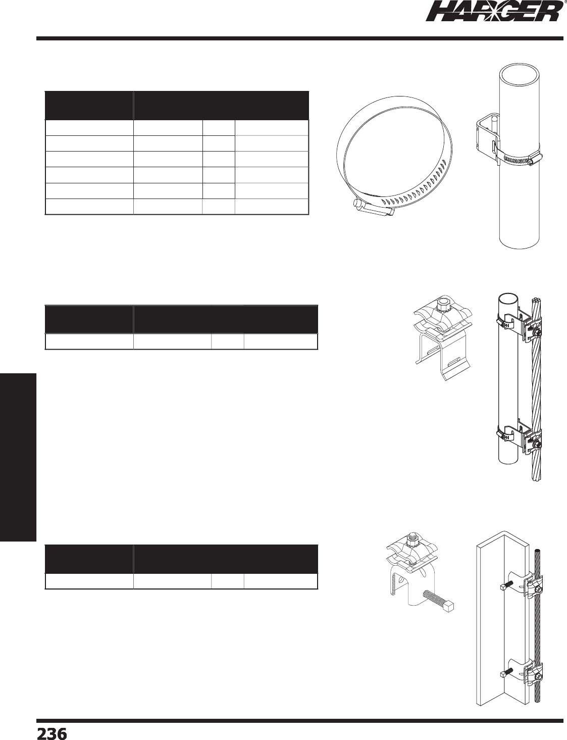
H
ar
g
er Li
g
htnin
g
& Groundin
g
•
©
2012 Phone 847-548-8700 • Fax 847-548-8755 • U.S. 800-842-743
7
236
236236236
Section 3
Communications Site Equipment
•
Stainless steel band clamps attach han
g
ers to round
mem
b
ers.
•
Sold as 50
p
ack.
•
Ran
g
e takin
g
down conductor cable clamp with tower standoff.
•
Fast, eas
y
and economical wa
y
to attach down conductors to round tower
mem
b
ers.
•
The small side of the clam
p
accommodates bare stranded conductors from
#6 up to 2/0 AWG while the lar
g
e side accommodates from 2/0 to 4/0 AWG.
•
The small side of the clam
p
accommodates insulated conductors from #8 u
p
to 2/0 AWG while the lar
g
e side accommodates from #1 up to 4/0 AWG.
•
Manufactured from stainless steel to allow use with an
y
t
yp
e of wire.
•
Available with stainless steel band clam
p
. See above for sizes.
•
Sold as 5
p
ack.
•
Ran
g
e takin
g
down conductor cable clamp with tower standoff.
•
Desi
g
ned to attach to fl at steel tower members.
•
Fast, eas
y
and economical wa
y
to attach down conductors to fl at tower
mem
b
ers.
•
The small side of the clam
p
accommodates bare stranded conductors from
#6 up to 2/0 AWG while the lar
g
e side accommodates from 2/0 to 4/0 AWG.
•
The small side of the clam
p
accommodates insulated conductors from #8 u
p
to 2/0 AWG while the lar
g
e side accommodates from #1 up to 4/0 AWG.
•
Manufactured from stainless steel to allow use with an
y
t
yp
e of wire.
•
Sold as 5
p
ack.
Part No. Band Clamp
Size Range
Pack
Qty.
Approx. Box
Wt. (lbs.)
S
SBC1
2
-
50
1.
06
" - 2"
50
3
S
SBC
23
-
50
2.
06
" -
3
"
50
3-1
/2
S
SBC
3
4-
50
3
.
06
" - 4"
50
4
-1
/4
S
SBC4
5
-
50
4
.
06
" -
5
"
50
5
S
SBC
56
-
50
5
.
06
" -
6
"
50
6
S
SBC
6
7-
50
6
.
06
" - 7"
50
6
-3
/4
Part No. Approx. Each
Wt. (lbs.)
Pack
Qty.
Approx. Box
Wt. (lbs.)
S
SDCS
O
1
/2
5
3-1
/2
Part No. Approx. Each
Wt. (lbs.)
Pack
Qty.
Approx. Box
Wt. (lbs.)
SS
D
C
AA 1
/2
5
4
Band Clam
p
s
S
tainless Steel D
o
wn C
o
nduct
o
r Stand
o
f
f
S
tainless Steel Down Conductor An
g
le Adapter
S
ect
io
n 3.1.2.9 - 3.1.2.11
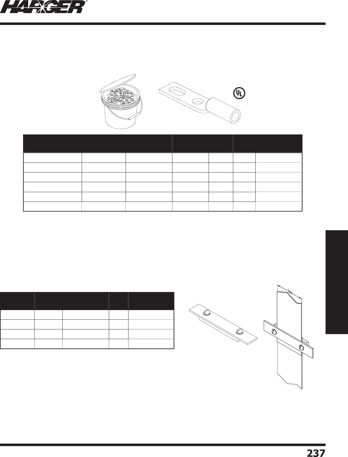
H
ar
g
er Li
g
htnin
g
& Groundin
g
•
©
2012 Phone 847-548-8700 • Fax 847-548-8755 • U.S. 800-842-743
7
Section 3
Communications Site Equipment
23
7
237
Part No. Strap
Size
Approx. Each
Wt. (lbs.)
Box
Qty.
Approx. Box
Wt. (lbs.)
FSC2
2" 1
/2
1
0
5
F
SC
3
3
"3
/4
1
0
7-1
/2
FSC4
4
"11
0
1
0
F
SC
6
6
" 1-1
/
41
0
12-1
/2
S
lotted Lon
g
Barrel Compression Lu
g
s
(
Telecommunications
)
C
o
pp
er Flat Stra
p
Clam
p
s
•
Manufactured from electro
p
lated tinned co
pp
er.
•
For use on co
pp
er or tinned co
pp
er conductors.
•
Lu
g
s have inspection ports.
•
250 pack comes in one
g
allon bucket.
Part No. Conductor
Size (AWG)
Hole Spacing
Range
Hardware
Size
Color
Codes
Box
Qty.
Approx. Box
Wt. (lbs.)
GECLB
62
BC #
6
Str.
.
7
5
" t
o
1" 3
/
8"
B
l
u
e
50
2
GECLB
62
BC
250
BK #
6
Str.
.
7
5
" t
o
1" 3
/
8"
B
l
u
e
250
1
0
GECLB
22
BC
S
#2 S
o
l.
.
7
5
" t
o
1" 3
/
8"
W
hit
e
50
2
GECLB
22
BCS
250
BK #2 S
o
l.
.
7
5
" t
o
1" 3
/
8"
W
hit
e
250
1
3
GECLB
22
BC #
2
S
tr.
.
7
5
" t
o
1" 3
/
8"
B
r
o
w
n
50
2
GECLB
22
BC
250
BK #
2
S
tr.
.
7
5
" t
o
1" 3
/
8"
B
r
o
w
n
250
1
6
L
isted 486
•
Used for makin
g
connection to fl at strap or fl at braid.
•
Co
pp
er "sandwich" clam
p
s com
p
lete with stainless steel
hardware. The to
p
is 1/8" thick and the bottom is 1/4" thick.
•
Ends are desi
g
ned to allow for exothermically weldin
g
conductors
to clam
p
.
S
ect
io
n 3.1.2.12 & 3.1.2.13

H
ar
g
er Li
g
htnin
g
& Groundin
g
•
©
2012 Phone 847-548-8700 • Fax 847-548-8755 • U.S. 800-842-743
7
2
38
238238238
Section 3
Communications Site Equipment
No
tes

H
ar
g
er Li
g
htnin
g
& Groundin
g
•
©
2012 Phone 847-548-8700 • Fax 847-548-8755 • U.S. 800-842-743
7
Section 3
Communications Site Equipment
23
9
239
S
ect
io
n 3.1.3
G
r
o
und Kits & Access
o
ries
In
d
ex
Descr
i
pt
i
on Pa
g
e
3.1.3.1 Coax Ground Kits with Ca
p
tive Hardwar
e
............................................
2
4
0
3
.1.
3
.2
U
nivers
a
l Gr
ou
n
d
Kit
s
.......................................................................
2
41
3.1.3.3 Weather Proofi n
g
Kit
s
.......................................................................
2
41
3
.1.
3
.4
L
i
g
htnin
g
Arrestor Kit
s
......................................................................
242

H
ar
g
er Li
g
htnin
g
& Groundin
g
•
©
2012 Phone 847-548-8700 • Fax 847-548-8755 • U.S. 800-842-743
7
2
4
0
240240240
Section 3
Communications Site Equipment
•
2-bolt coax
g
round kit featurin
g
captive hardware desi
g
n
allows
g
reater ease of installation while providin
g
a
functional, hi
g
h quality
g
round.
•
Desi
g
ned to eliminate over ti
g
htenin
g
and dama
g
in
g
the
c
oa
x shiel
d
.
•
5'
g
round conductor available in Green or Black.
•
Com
p
lies with MIL-STD-188-124B.
Kit Incl
ud
e
s:
(1) Preformed copper
g
round strap complete with "captive"
h
a
r
d
w
a
re
(1) 5' of #6-7 strand AWG THW
g
round conducto
r
(1) "Universal" style
g
round lu
g
which accommodates 3/4"
to 1" s
p
aced hole
s
(2) Sets of stainless steel hardware to attach
g
round lu
g
to
g
round ba
r
(
1
)
But
y
l Mastic
(
2-1/2" x 24"
)
(
1
)
Black electrical ta
p
e
(
2" x 20'
)
Part No.
Green
Part No.
Black
Coax
Size
Approx. Each
Wt. (lbs.)
N/
A CGKBB1
/
4-3
/
81
/
4 to 3
/
8 1-1
/2
CGKB3
/
8-5 CGKBB3
/
8-5 3/8 Corru
g
ated 1-1
/2
CGKB1
/
2-5 CGKBB1
/
2-5 1/2 Corru
g
ated 1-1
/2
CGKB5
/
8-5 CGKBB5
/
8-5
5
/8 Corru
g
ated 1-1
/2
CGKB7
/
8-5 CGKBB7
/
8-5 7/8 Corru
g
ated 1-1
/2
CGKB1-1
/
4-5 CGKBB1-1
/
4-5 1-1/4 Corru
g
ated 1-1
/2
CGKB1-5
/
8-5 CGKBB1-5
/
8-5 1-5/8 Corru
g
ated 1-1
/2
CGKB2-1
/
4-5 CGKBB2-1
/
4-5 2-1/4 Corru
g
ated 1-1
/2
C
oax Ground Kits with Ca
p
tive Hardware
CGKBB1
/
4-3
/
8
N
O
TE
:
• Other sizes and confi
g
urations available. Please contact factory for more information.
S
ect
io
n 3.1.3.1
P
atented Desi
gn
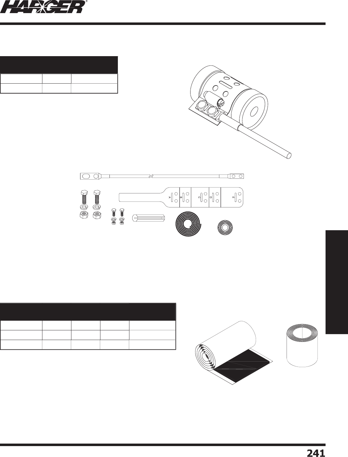
H
ar
g
er Li
g
htnin
g
& Groundin
g
•
©
2012 Phone 847-548-8700 • Fax 847-548-8755 • U.S. 800-842-743
7
Section 3
Communications Site Equipment
2
41
241
•
Accommodates transmission line sizes 1/2" throu
g
h 2-1/4".
•
5' of Black #6 AWG
g
round lead provided with special
factory attached
g
round lu
g
s.
•
"Universal" style
g
round lu
g
accommodates 3/4" to 1"
s
paced holes on
g
round bar.
•
Stainless steel hardware and waterproofi n
g
materials
i
ncl
ud
e
d
.
•
UGKB-5X does not have the factory lu
g
attached.
•
Com
p
lies with MIL-STD-188-124B.
F
actory
L
u
g
•
Used to weatherproof electrical connector
j
unctions and
g
rounds.
•
Includes 2" x 20’
p
remium all weather vin
y
l electrical ta
p
e.
•
Includes 2-1/2" x 2’ But
y
l Mastic.
Part No. Qty. Approx. Each
Wt. (lbs.)
UG
KB-
5
EA
1-3
/4
UG
KB-
5
X
EA
1-3
/4
Part No. Rolls of
Mastic
Rolls of
Tape Qty. Approx. Each
Wt. (lbs.)
W
P1KIT 1 1
EA
1
/2
W
P
3
KIT
3
2
EA
1-1
/2
WP5KIT
5
3
EA
2-1
/2
U
niversal Gr
o
und Kits
W
eather Proofi n
g
Kits
S
ect
io
n 3.1.3.2 & 3.1.3.3
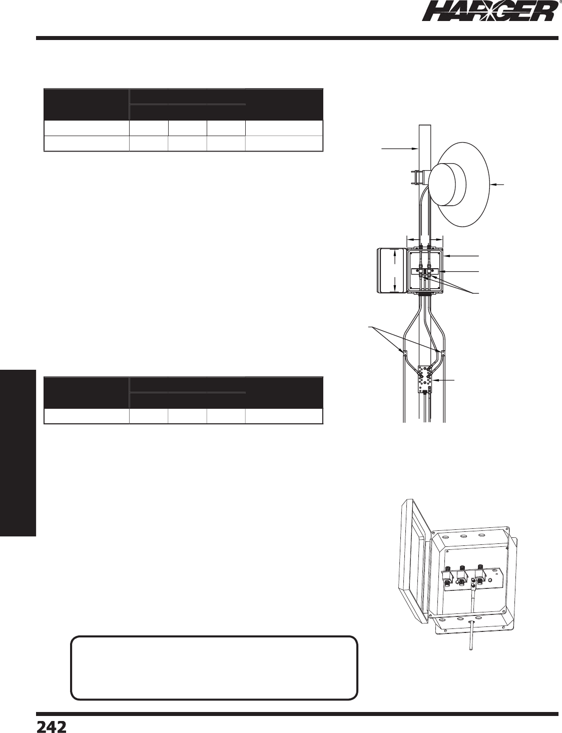
H
ar
g
er Li
g
htnin
g
& Groundin
g
•
©
2012 Phone 847-548-8700 • Fax 847-548-8755 • U.S. 800-842-743
7
2
42
242242242
Section 3
Communications Site Equipment
S
ect
io
n 3.1.3.
4
•
Enclosure provides water ti
g
ht environment for both
s
ur
g
e arrestors and connectors.
•
Sur
g
e arrestors protect a
g
ainst li
g
htnin
g
induced sur
g
e
c
u
rren
t
s.
•
Li
g
htnin
g
arrestor
g
round bar desi
g
n allows the
add
iti
o
n
o
f 2 m
o
re
a
rrest
o
rs.
•
Coax
g
round kits provide low impedance
g
round path.
•
Coax
g
round bar provides
g
round point for coax lines
a
s well
a
s
a
ntenn
a
m
ou
nt.
Kit Incl
ud
e
s:
(1) NEMA 4X molded fi ber
g
lass reinforced polyester
encl
o
s
u
re
(2) Premounted bi-directional sur
g
e arrestors
(1) Li
g
htnin
g
arrestor
g
round ba
r
(2) Coax
g
round kit
s
(1) Coax
g
round ba
r
NEMA 4X
e
n
c
l
osu
r
e
•
Enclosure provides water ti
g
ht environment for both
s
ur
g
e arrestors and connectors.
•
Sur
g
e arrestors protect a
g
ainst li
g
htnin
g
induced sur
g
e
c
u
rren
t
s.
•
Li
g
htnin
g
arrestor
g
round bar desi
g
n allows the
add
iti
o
n
o
f 1 m
o
re
a
rrest
o
r.
•
Coax
g
round kits provide low impedance
g
round path.
•
Coax
g
round bar provides
g
round point for coax lines
a
s well
a
s
a
ntenn
a
m
ou
nt.
Kit Incl
ud
e
s:
(1) NEMA 4X molded fi ber
g
lass reinforced polyester
encl
o
s
u
re
(3) Premounted bi-directional sur
g
e arrestors
(1) Li
g
htnin
g
arrestor
g
round ba
r
(3) Coax
g
round kit
s
(1) Coax
g
round ba
r
W
H
Antenna
(not included)
Antenna Mast
(not included)
NEMA 4X enclosure
Arrestor ground bar
Arrestors
Coaxial collection ground bar
Coax grounding kit
Part No. Size Approx. Each
Wt. (lbs.)
HWD
L
ABA4
2
A
2
GKCGB 12" 1
0
"
5
"
20
L
ABB4
2
A
2
GKCGB 1
6
" 14"
6
"
20
Part No. Size Approx. Each
Wt. (lbs.)
HWD
L
AB1
2
1
06
X
O
12" 1
0
"
6
"
20
Li
g
htnin
g
Arrestor Kits
APPLICATI
O
N N
O
TE
:
• Li
g
htnin
g
arrestor box kits are used in wireless rooftop
communication a
pp
lications such as broadband
p
oint to
p
oint,
p
oint to multi-
p
oint and other similar t
yp
e s
y
stems.

H
ar
g
er Li
g
htnin
g
& Groundin
g
•
©
2012 Phone 847-548-8700 • Fax 847-548-8755 • U.S. 800-842-743
7
Section 3
Communications Site Equipment
2
4
3
243
S
ect
io
n 3.2
Premise Wirin
g
/Data-Co
m
In
d
ex
Descr
i
pt
i
on Pa
g
e
3.2.1 Data-Com Groundin
g
& Bondin
g
Application
s
......................................
244
3.2.2 Data-Com Groundin
g
& Bondin
g
Equipment
.......................................
2
4
5
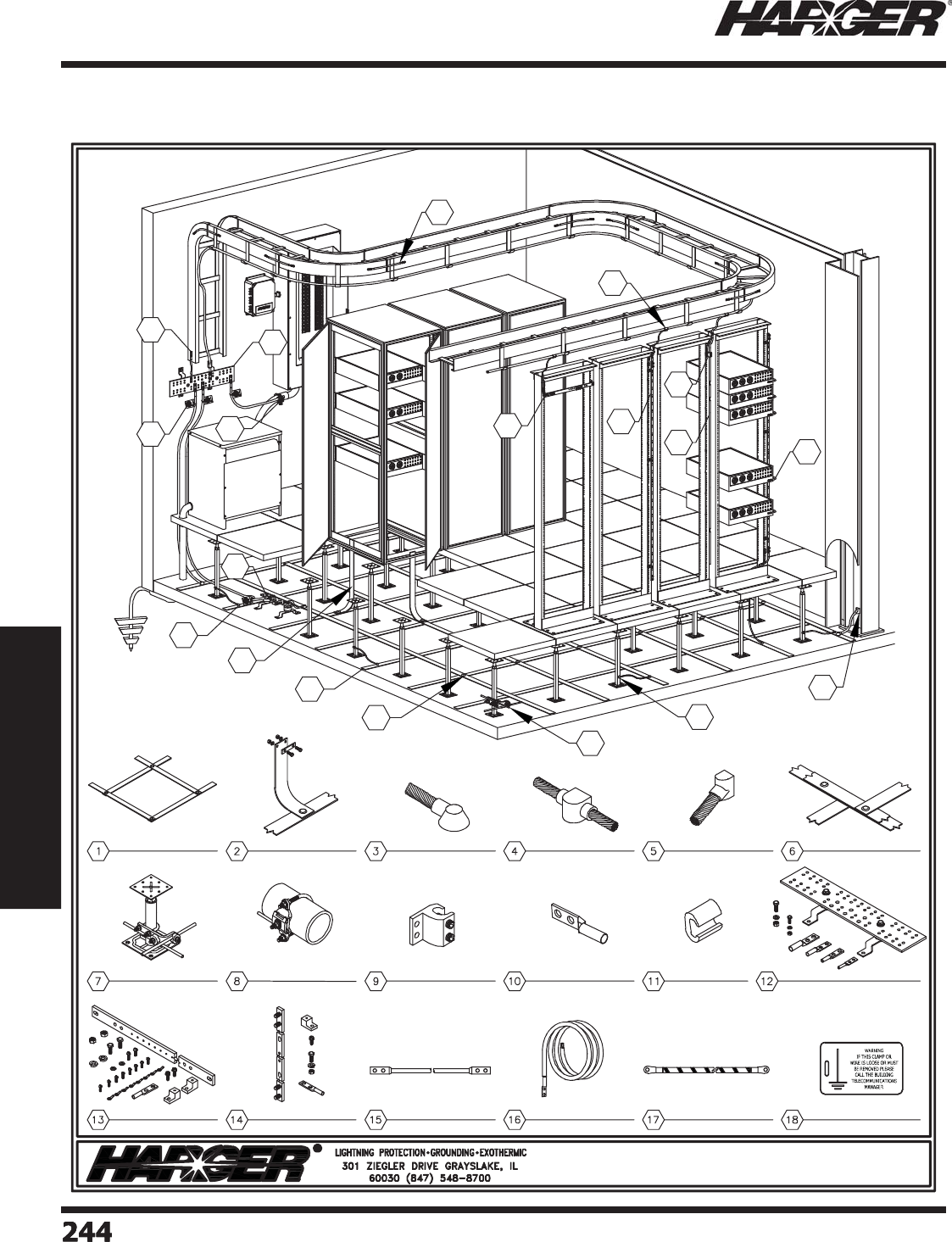
H
ar
g
er Li
g
htnin
g
& Groundin
g
•
©
2012 Phone 847-548-8700 • Fax 847-548-8755 • U.S. 800-842-743
7
2
4
4
244244244
Section 3
Communications Site Equipment
Data-Com Groundin
g
& Bondin
g
Applications
S
ect
io
n 3.2.1
CT C-Tap
CPC Pipe Clamp
RGBHKIT Horizontal
Rack Ground Bar
RGBVKIT Vertical
Rack Ground Bar
RGJ Rack
Ground Jumper
VHO ULTRAWELD
Connection
VA ULTRAWELD
Connection
BCF ULTRAWELD
Connection SRG ULTRAWELD
Connection
Telecommunication
Ground Bar
Low Impedance
Riser
Insulated
Ground Jumper
LI2/0142 Dual
Rated Lay-In Lug
GECLB
Compression Lug
Signal Reference
Grid
GPC Pedestal
Clamp
Data-Com Grounding & Bonding Applications
1
2
3
4
5
7
6
8
9
14
13
11
15
18
10 12
12
16 17
Unit Bonding
Conductor
Network Building
Ground Tag
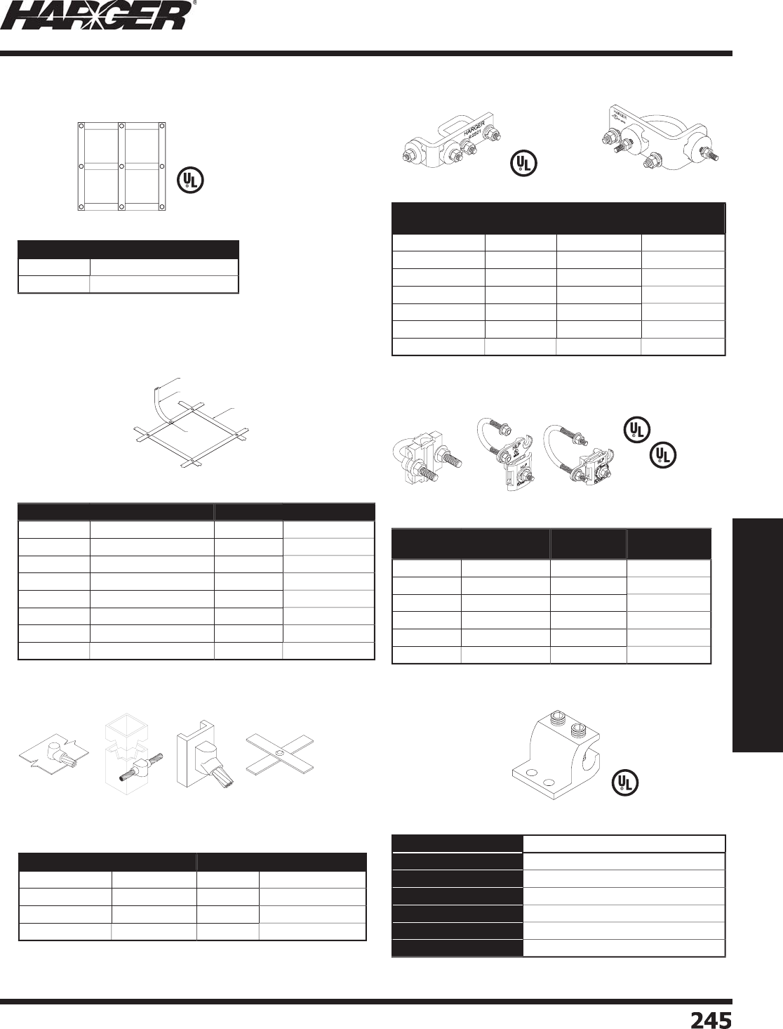
H
ar
g
er Li
g
htnin
g
& Groundin
g
•
©
2012 Phone 847-548-8700 • Fax 847-548-8755 • U.S. 800-842-743
7
Section 3
Communications Site Equipment
2
4
5
245
•
2” x .016” fl at co
pp
er conducto
r
•
See Pa
g
es 90 & 91 for more information.
•
All Smokeless Molds Re
q
uire USCONTROLLER.
•
See Pa
g
e 276 for more information.
•
See Pa
g
e 94 for more information.
•
See Pa
g
e 92 for more information.
•
See Pa
g
e 124 & 203 for more information.
•
See Pa
g
e 118 for more information.
Part No. Description
S
RG1
05024
10' x 50', 24" O.C. Spacin
g
S
RG1
25024
12' x 50', 24" O.C. Spacin
g
Part No. U-Bolt
Type
Pedestal
Size
Conductor
Size
GPC6S
Q
Sq
uare 1"
(
1-1/8" OD
)
#
6
AW
G
GPC
6
R
D
Rou
n
d
1"
(
1-1/8" OD
)
#
6
AW
G
GPC4S
Q
Sq
uare 1"
(
1-1/8" OD
)
#4 AW
G
G
P
C
4R
D
Rou
n
d
1"
(
1-1/8" OD
)
#4 AW
G
GPC
2
S
Q
Sq
uare 1"
(
1-1/8" OD
)
#
2
AW
G
GPC
2
R
D
Rou
n
d
1"
(
1-1/8" OD
)
#
2
AW
G
GPC2
/
0RD1.75
Rou
n
d
1-1
/
8” - 1-3
/
4
”
2
/
0 & #6 AW
G
Part No. Material Length Riser or Kit
L
IR18 2" x .016" Flat Co
pp
e
r
18"
R
i
ser
L
IR18KIT 2" x .016" Flat Co
pp
e
r
18"
K
it
L
IR
2
4 2" x .016" Flat Co
pp
e
r
24"
R
i
ser
L
IR
2
4KIT 2" x .016" Flat Co
pp
e
r
24"
K
it
L
IR
36
2" x .016" Flat Co
pp
e
r
36
"
R
i
ser
L
IR
36
KIT 2" x .016" Flat Co
pp
e
r
36
"
K
it
L
IR7
2
2" x .016" Flat Co
pp
e
r
72"
R
i
ser
L
IR7
2
KIT 2" x .016" Flat Co
pp
e
r
72"
K
it
Part No. Material Nom. Pipe
Size Range
Pipe Outside
Diameter
CPC.5
/
.75
T
inne
d
Br
o
nz
e
.5
" - .7
5
"
.3
7
5
" - 1"
CPC1
/
1.25
T
inne
d
Br
o
nz
e
1" - 1.2
5
"
.
7
5
" - 1.7"
CPC1.5
/2
T
inne
d
Br
o
nz
e
1.
5
" - 2" 1" - 2.4"
CPC2.5
/3
T
inne
d
Br
o
nz
e
2.
5
" -
3
" 2.2
5
" -
3
.
5
"
CPC3.5
/
4
T
inne
d
Br
o
nz
e
3
.
5
" - 4"
3
.2" - 4.
5
"
CPC5
/
6
T
inne
d
Br
o
nz
e
5
" -
6
"
4
.7
5
" -
6
.
63
"
Part No. Weld Metal Fliter Required Handle
B
CF
6
1.
50
1
6
BSX
U
S
25
U
SSXFLR
2
M
H1
VH
O
61S
Q
MXSX
U
S
25
USS
XFLR1
MH4
VA
6
BSX
US
4
5
U
SSXFLR
2
M
H1
S
RG
20
1
6
KSX
U
S
32
USS
XFLR1
M
H1
Part No.
L
I2
/
014
2
Size 1-5
/
8" x 1-1
/
2"
Material
E
lectro-tin Plated Aluminum
(
6061-T6
)
Accepts Conductors 2
/
0 to #14 AW
G
Includes
(
2
)
3/8" x 1" Hex Socket Set Screw
s
Requires 3/16" Hex Ke
y
(
not included
)
Features
D
ual Rated, UL486B Listed
Data-Com Groundin
g
& Bondin
g
Equipment
1
- Supplementary Bondin
g
Grids
2
- Low Im
p
edance Risers & Kits
3, 4, 5, 6 - Ultraweld Connections
S
m
o
keless Ex
o
thermic M
o
lds
7 - GPC Pedestal Clam
p
s
8
- Pi
p
e Clam
p
s
9 - Lay-In Lu
g
L
iste
d
4
67
L
iste
d
4
67
L
iste
d
4
67
L
iste
d
9
6
L
isted 486
S
ect
io
n 3.2.2
5/16" Ø
SRG
FIELD MADE
EXOTHERMIC
CONNECTION
LIR18
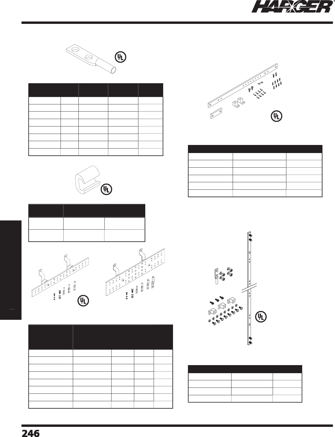
H
ar
g
er Li
g
htnin
g
& Groundin
g
•
©
2012 Phone 847-548-8700 • Fax 847-548-8755 • U.S. 800-842-743
7
Section 3
Communications Site Equipment
2
4
6
246246246246246246246246246246246246246246246246246246246246246246246246246246246
S
ect
io
n 3
C
ommun
i
cat
i
ons S
i
te E
q
u
ip
ment
Section 3
Communications Site Equipment
•
Kit includes lu
g
and all necessary hardware.
•
Bar includes s
p
lice
p
late. Kit includes s
p
lice
p
late,
mountin
g
hardware and rin
g
terminals.
•
See Pa
g
es 66-67 for more information.
•
Kit includes lu
g
s and hardware.
•
See Pa
g
es 62-65 for more information.
•
See Pa
g
e 113 for more information.
•
See Pa
g
e 114 for more information.
•
See Pa
g
e 68 for more information.
Part No. Cable
Size
O.C. Dim.
B/T Holes
Hardware
Size
Color
Code
GECLB
62
A
6
5/
8" 1
/
4"
B
l
u
e
GECLB
62
C
6
1" 3
/
8"
B
l
u
e
GECLB
22
A
2
5/
8" 1
/
4"
B
r
o
w
n
GECLB
22
C
2
1" 3
/
8"
B
r
o
w
n
GECLB1
/
02C 1
/
01" 3
/
8"
P
ink
GECLB2
/
02C 2
/
01" 3
/
8"
B
l
a
ck
GECLB3
/
02C 3
/
01" 3
/
8"
O
ran
g
e
GECLB4
/
02C
4/
01" 3
/
8"
P
ur
p
l
e
Part No. Conductor
Run
Conductor
Tap
CT2248 #2 Str
a
n
d
e
d
#2 S
o
li
d
#4 Str
a
n
d
e
d
#8 Solid
C
T
2222
#2 Str
a
n
d
e
d
#2 S
o
li
d
#2 Str
a
n
d
e
d
#2 S
o
li
d
Part No. Bar Size
No. of
5/16"
Hole
Sets
No. of
7/16"
Hole
Sets
Bar
or
Kit
GBI14
26
TGB 1
/
4" x 2" x 6"
2
2
Bar
GBI14
26
TGBKT 1
/
4" x 2" x 6"
2
2
K
i
t
GBI14
2
1
2
TGB 1
/
4" x 2" x 12"
6
3
Bar
GBI14
2
1
2
TGBKT 1
/
4" x 2" x 12"
6
3
K
i
t
GBI1441
2
TMGB 1
/
4" x 4" x 12" 1
2
6
Bar
GBI1441
2
TMGBKT 1
/
4" x 4" x 12" 1
2
6
K
i
t
GBI144
20
TMGB 1
/
4" x 4" x 20"
24
6
Bar
GBI144
20
TMGBKT 1
/
4" x 4" x 20"
24
6
K
i
t
Part No. Bar Size Bar or Kit
R
GBV145836A 1
/
4" x 5
/
8" x 36"
Bar
R
GBVKIT145836A 1
/
4" x 5
/
8" x 36"
K
i
t
R
GBV145872A 1
/
4" x 5
/
8" x 72"
Bar
R
GBVKIT145872A 1
/
4" x 5
/
8" x 72"
K
i
t
Part No. Bar Size Bar or Kit
R
GBH14119.
25
1
/
4" x 1" x 19-1
/
4"
Bar
R
GBHKIT14119.
25
1
/
4" x 1" x 19-1
/
4"
K
it
R
GBH141
23
.
25
1
/
4" x 1" x 23-1
/
4"
Bar
R
GBHKIT141
23
.
25
1
/
4" x 1" x 23-1
/
4"
K
it
R
GBH141
35
.
25
1
/
4" x 1" x 35-1
/
4"
Bar
R
GBHKIT141
35
.
25
1
/
4" x 1" x 35-1
/
4"
K
it
Data-Com Groundin
g
& Bondin
g
Equipment
1
0 - GECLB Compress
i
on Lu
g
s
1
1 - Heav
y
Dut
y
C-Ta
p
s
1
2 - Telec
o
mmunicati
o
n Gr
o
und Bars
&
K
i
t
s
1
3 - H
o
riz
o
ntal Rack Gr
o
und Bars & Kits
1
4 - Vertical Rack Gr
o
und Bars
&
K
i
t
s
L
isted 486
L
iste
d
4
67
L
iste
d
4
67
S
ect
io
n 3.2.2
L
iste
d
4
67
L
isted 486
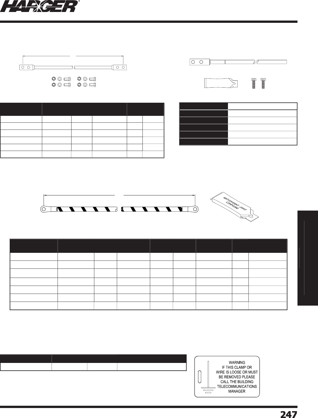
H
ar
g
er Li
g
htnin
g
& Groundin
g
•
©
2012 Phone 847-548-8700 • Fax 847-548-8755 • U.S. 800-842-743
7
Section 3
Communications Site Equipment
S
ect
io
n 3
C
ommun
i
cat
i
ons S
i
te E
q
u
ip
ment
Section 3
Communications Site Equipment
2
47
247247247247247247247
•
#
6
AWG x 7 Str
a
n
d
Green THW ins
u
l
a
ti
o
n.
•
Kit includes all necessar
y
hardware.
•
See Pa
g
es 110 for more information.
•
Kit includes all necessar
y
hardware.
Part No. Conductor
Type Length No. of Holes
Per Side
Hole
Size
Jumper
or Kit
GJ67G82A1
/4
6
7
G
8"
2
1
/
4"
J
um
p
e
r
GJ67G82A1
/
4KIT
6
7
G
8"
2
1
/
4"
K
it
GJ67G102A1
/4
6
7
G
1
0
"
2
1
/
4"
J
um
p
e
r
GJ67G102A1
/
4KIT
6
7
G
1
0
"
2
1
/
4"
K
it
GJ67G122A1
/4
6
7
G
12"
2
1
/
4" Jum
p
e
r
GJ67G122A1
/
4KIT
6
7
G
12"
2
1
/
4"
K
it
Part No.
R
GJ67G1082AKIT
Conductor Type #
6
AWG x 7 Str
a
n
d
THW Gree
n
Conductor Length
9
ft.
No. of Holes
2
Hole Size 1
/
4"
On Center Spacing
5/
8"
Data-Com Groundin
g
& Bondin
g
Equipment
1
5 - Insulated Ground Jum
p
ers & Kits
1
6 - Rack Ground Jum
p
er Kit
•
Dimensi
o
ns
a
re 2.12
5
" x
3
.7
5
".
•
Yellow ta
g
with
g
reen text.
•
Ta
g
is UV Resistant.
Part No. Material Box Qty. Approx. Box Wt. (lbs.)
GRNTAG
60
7PK1
0
P
l
a
sti
c
1
0
1
/2
1
8 - Network Buildin
g
Ground Ta
g
Part No. Conductor
Type Length No. of Holes
Per Side
Hole
Size A
Hole
Size B
Approx. Each
Wt. (lbs.)
Box
Qty.
Approx. Box
Wt. (lbs.)
U
BC61411
/
4KIT5
6
MTWG
/
Y
S
1
4
11
/
4" 1
/
4" 1-1
/2
5
7-1
/2
U
BC61411
/
410KIT5
6
MTWG
/
Y
S
1
4
11
/
4" #1
0
1-1
/2
5
7-1
/2
U
BC61811
/
4KIT5
6
MTWG
/
Y
S
18 1 1
/
4" 1
/
4" 2-1
/2
5
12-1
/2
U
BC61811
/
410KIT5
6
MTWG
/
Y
S
18 1 1
/
4" #1
0
2-1
/2
5
12-1
/2
U
BC63211
/
4KIT5
6
MTWG
/
Y
S
32
1
1
/
4" 1
/
4"
3
5
1
5
U
BC63211
/
410KIT5
6
MTWG
/
Y
S
32
11
/
4" #1
0
3
5
1
5
U
BC63811
/
410KIT5
6
MTWG
/
Y
S
38 1 1
/
4" #1
0
3
5
1
5
•
Conductor t
yp
e is #6 MTW wire with Green insulation and
y
ellow s
p
iral stri
p
e.
•
Kit includes 5
j
umpers and 1 antioxidant (HAAJC1/2).
1
7 - One Hole Unit Bondin
g
Conductor Kits
S
ect
io
n 3.2.2
L
L
AB

H
ar
g
er Li
g
htnin
g
& Groundin
g
•
©
2012 Phone 847-548-8700 • Fax 847-548-8755 • U.S. 800-842-743
7
2
48
248248248
Section 3
Communications Site Equipment
No
tes

H
ar
g
er Li
g
htnin
g
& Groundin
g
•
©
2012 Phone 847-548-8700 • Fax 847-548-8755 • U.S. 800-842-743
7
2
4
9
249
Section 4
Ground Testing Equipment
S
ect
io
n
4
G
round Testin
g
Equipment
In
d
ex
Descr
i
pt
i
on Pa
g
e
4
.1 An Introduction to Ground Testin
g
by Me
gg
e
r
®
...................................
250
4
.
2
Me
gg
e
r
®
Ground Testin
g
Equipmen
t
..................................................
255
4
.
3
Me
gg
e
r
®
Earth/Ground Resistance & Leaka
g
e Current Clamp Tester
s
...
257
4
.4 Har
g
er Ground Test Kit
s
....................................................................
25
9
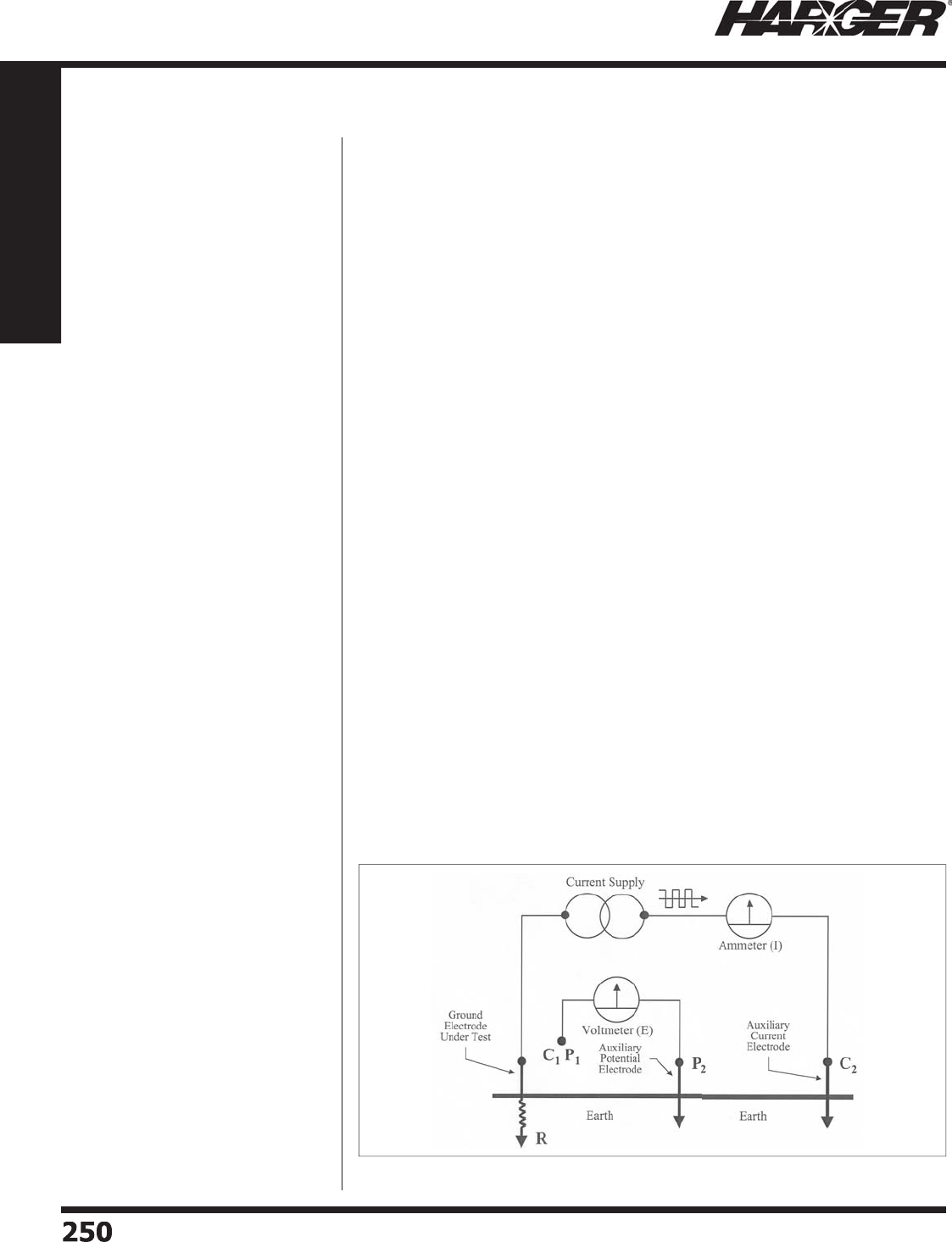
H
ar
g
er Li
g
htnin
g
& Groundin
g
•
©
2012 Phone 847-548-8700 • Fax 847-548-8755 • U.S. 800-842-743
7
250
250
Section 4
Ground Testing Equipment
F
i
g
ure 1: Simplifi ed schematic of four-terminal instruments
B
efore performin
g
a
g
round test, it
i
s advisable to develop a workin
g
familiarit
y
with two im
p
ortant conce
p
ts:
how the tester accom
p
lishes the
measurement and what the o
p
erator
must do to assure a
p
ro
p
er test.
C
hoose the Pro
p
er Instruments
T
he fi rst consideration is hel
p
ful in
the selecti
o
n
o
f
a
n instr
u
ment
a
n
d
the
fundamental a
pp
lication of the test.
Ground tests are fre
q
uentl
y
attem
p
ted
w
ith a variet
y
of ohmmeters that
ha
pp
en to be convenientl
y
at hand.
T
his practice is doubly dama
g
in
g
because it ma
y
result in an incorrect
measurement that is acce
p
ted b
y
the
op
era
t
or.
T
wo-
p
oint measurement with a
multimeter will
g
ive a loop resistance
o
f the circuit that is defi ned b
y
the
arbitrar
y
p
oints of connection, and
this will include in its
p
ath the soil
between those
p
oints. But, so what?
T
his is not necessaril
y
an indication
o
f the electric
a
l c
o
n
d
iti
o
n th
a
t the
g
round electrode has established with
the surroundin
g
soil. Furthermore,
the me
a
s
u
rement itself c
a
n
b
e m
ad
e
i
naccurate b
y
the infl uence of transient
c
u
rrents th
a
t tr
a
vel in the s
o
il fr
o
m
a
v
ariet
y
of sources.
U
n
d
er
s
tan
d
the Te
s
t
T
o perform a
g
round test, a dedicated
g
round tester, not a
g
eneralized
o
hmmeter or multimeter, is re
q
uisite.
T
he manner in which the
g
round tester
u
ni
q
uel
y
accom
p
lishes its
p
ur
p
ose
i
s dia
g
rammed in the accompanyin
g
s
im
p
lifi ed schematic. Its o
p
eration is
s
imilar to, but in a sense o
pp
osite,
that of the familiar Me
gg
e
r
®
Ins
u
l
a
ti
o
n
Tes
t
e
r.
T
he instrument uses two
p
recise
measurin
g
circuits (volta
g
e and
current
)
, and combines the values
throu
g
h Ohm’s Law to
g
ive the desired
measurement
(
resistance
)
.
T
he tw
o
test circ
u
its
a
re est
ab
lishe
d
throu
g
h the soil by strate
g
ic placement
o
f
p
robes, attached via leads to their
res
p
ective terminals. The current
terminal, lead, and
p
robe set u
p
a
test current of a uni
q
ue, s
q
uare wave
fre
q
uenc
y
, a
p
art from the harmonics
o
f utility power, throu
g
h the soil to the
g
round under test. It is only this current that
contributes to the measurement, leavin
g
interferin
g
transients out. Likewise, the volta
g
e
p
robe enables measurement of the dro
p
over the soil to its critical
p
oint of
p
lacement.
B
oth circuits are com
p
leted b
y
connection of a second
p
air of terminals
(
or a common in
the case of three-terminal testers) to the
g
round under test. (See Fi
g
ure 1.
)
U
nderstand the Test Envir
o
nment
P
rovidin
g
the most applicable and hi
g
hest quality tester, however, is only the fi rst part o
f
the operator’s responsibility. No
g
round tester can perform a successful test all by itsel
f
s
ince a
g
round test is never routine. The operator’s knowled
g
e and skill must always be
an essential element of a
p
ro
p
er test.
T
he
p
ro
p
er
p
lacement of the
p
robes is critical and defi es standardization of
p
rocedure.
A de
g
ree of trial and error cannot be avoided, because the earth is not a defi ned circuit,
l
ike a
p
iece of e
q
ui
p
ment. The ex
p
erience and abilit
y
of the o
p
erator are valuable in
reducin
g
this process to an effi cient level, and no instrument can substitute for this
f
a
ct
o
r.
T
he resistance environment with which the
g
round electrode is surrounded, whether it
be a sin
g
le rod or complex
g
rid, is determined by a critical volume of soil. This volume
may be thou
g
ht of as an area of electrical fi eld infl uence around the electrode. It has at
the same time both a fi xed nature, determined b
y
soil t
yp
e, structure of the electrode,
electrical demands u
p
on it and other factors, and a variable com
p
onent, determined b
y
transient factors like moisture and tem
p
erature.
P
ut sim
p
l
y
, this entire critical volume must be measured, for it is what infl uences the
fl ow of fault current from the
g
round electrode into the earth. For the proper volume
to be measured, probes must be suffi ciently spaced. Only the operator’s knowled
g
e
can accom
p
lish this
p
lacement
p
ro
p
erl
y
and effi cientl
y
. Because soil conditions are
never precisely the same, there is no set method to predict spacin
g
in advance, and no
i
nstrument desi
g
n can eliminate the operator.
Sp
ace the Probes Pro
p
erl
y
If the
p
otential
p
robe is too close, measurements are taken within the electrode’s s
p
here
o
f infl uence, and different readin
g
s would be obtained with other placements. Indeed,
a quality tester will
g
ive an accurate measurement to that point, but it is not takin
g
into
a
cc
ou
nt
a
ll the resist
a
nce th
a
t
a
f
au
lt c
u
rrent will meet.
An Introduction to Ground Testin
g
by Me
gg
er
®
S
ect
io
n 4.1
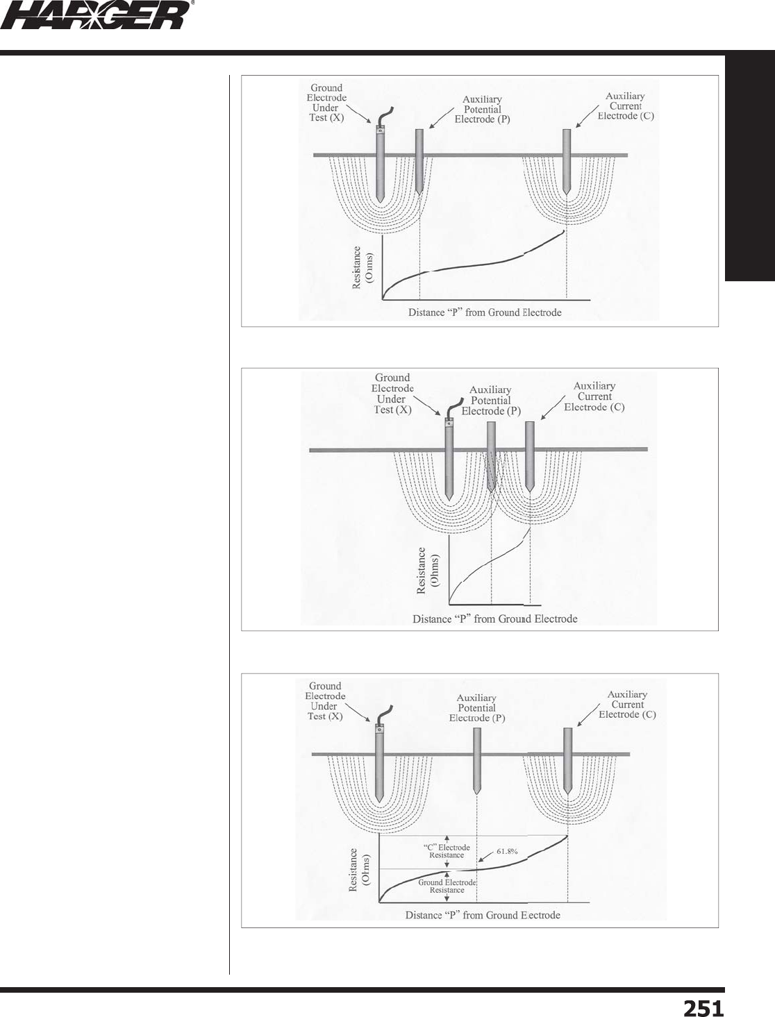
H
ar
g
er Li
g
htnin
g
& Groundin
g
•
©
2012 Phone 847-548-8700 • Fax 847-548-8755 • U.S. 800-842-743
7
25
1
251
Section 4
Ground Testing Equipment
T
his is what ha
pp
ens when shortcut
two-
p
oint tests are made.
(
See
F
i
g
ure 2.) If the current probe is too
close, its electrical fi eld will overla
p
that of the
g
round electrode, and
the
p
otential
p
robe will fi nd itsel
f
makin
g
measurements in an electrical
environment of confl ictin
g
infl uences.
(
See Fi
g
ure 3.
)
W
ith adequate spacin
g
, however,
the
p
otential
p
robe will make its
measurement be
y
ond the boundar
y
o
f maximum resistance exerted b
y
the
fi eld infl uence of the
g
round electrode,
i
n
a
n
a
re
a
where
add
iti
o
n
a
l
d
ist
a
nce
does not contribute si
g
nifi cantly to
the tested electrode’s resistance, and
measurements will be reasonabl
y
s
table. This uniformit
y
of measurement
w
ill persist with increasin
g
distance until
the s
p
here of infl uence of the current
p
robe is entered. This is the method
th
a
t is referre
d
t
o
a
s F
a
ll
o
f P
o
tenti
a
l
(
also called the “three-
p
oint method,
”
i
n reference to the three
p
oints of soil
contact established b
y
the electrode
u
nder test and the two
p
robes
)
. It is
the method described b
y
IEEE Standard
#81 as the reco
g
nized basis for earth
testin
g
in the U.S. (See Fi
g
ure 4.
)
Co
nclusi
on
S
im
p
lifi ed methods have been
develo
p
ed from the full Fall of Potential
conce
p
t, and their descri
p
tions are
readil
y
available in the literature. These
v
arious methods take advanta
g
e o
f
s
im
p
lifi cations of the calculus associated
w
ith a typical Fall of Potential
g
raph to
p
rovide
q
uick and eas
y
mathematical
tests th
a
t will thr
o
w
ou
t the res
u
lts
of
tests made with inade
q
uate setu
p
s,
and acce
p
t onl
y
those results that are
a
cc
u
r
a
te
a
n
d
reli
ab
le me
a
s
u
rements.
F
amiliarization is necessar
y
for the
p
ro
p
er conduct of earth tests, and with
this familiarization, the knowled
g
eable
op
erator can reduce trial and error, and
i
ndeed the work itself, to minimal levels.
F
i
g
ure 4: Correct probe spacin
g
F
i
g
ure 3: Insuffi cient spacin
g
of current prob
e
F
i
g
ure 2: Insuffi cient spacin
g
of potential prob
e
S
ect
io
n 4.1

H
ar
g
er Li
g
htnin
g
& Groundin
g
•
©
2012 Phone 847-548-8700 • Fax 847-548-8755 • U.S. 800-842-743
7
25
2
252
Section 4
Ground Testing Equipment
T
ESTIN
G
LAR
G
E SYSTEMS
L
ar
g
e
g
round systems are an
i
m
p
ortant
p
art of the
p
rotection o
f
the electricit
y
su
pp
l
y
network. The
y
ens
u
re th
a
t f
au
lt c
u
rrent will en
ab
le
p
rotective devices to o
p
erate correctl
y
.
A substation must have a low
g
round
resist
a
nce t
o
re
du
ce excessive
v
olta
g
es developin
g
durin
g
a fault
w
hich could endan
g
er safety of nearby
p
eo
p
le or animals.
In order to obtain a low enou
g
h value
o
f
g
round resistance,
g
round systems
may consist of an earth mat coverin
g
a lar
g
e area or many interconnected
rods. Suitable test techni
q
ues must
be used for lar
g
e systems to ensure
that valid readin
g
s are obtained. This
i
s unlike a small sin
g
le electrode (i.e.,
a li
g
htnin
g
conductor or domestic
g
round) which can be simple to test.
Fall of Potential Testin
g
F
or sin
g
le electrode
g
rounds, such
as domestic
g
rounds and li
g
htnin
g
conductors, the infl uence on the
s
urroundin
g
soil is limited and current
test s
p
ikes can be
q
uite close
(
t
yp
icall
y
30 to 60 ft.
)
to the electrode under
test. It is usuall
y
q
uite eas
y
to fi nd a
fl at portion of the
g
round resistance
c
u
rve which sh
ou
l
d
b
e cl
o
se t
o
the
resist
a
nce
o
f the electr
od
e.
T
estin
g
several points or drawin
g
up
a curve will help the understandin
g
o
f the
a
re
a
a
r
ou
n
d
the electr
od
e. It is
always best to check results by usin
g
a
different direction or a lon
g
er distance
to the test s
p
ikes. This will hel
p
to
eliminate errors caused b
y
nearb
y
buried conductors and other
p
arts o
f
the electrical system interferin
g
with
the res
u
lts.
T
he Slo
p
e Method
T
his meth
od
en
ab
les me
a
s
u
rement
o
f a lar
g
e
g
round system with
o
ut
fi ndin
g
the fl at portion of the
ch
a
r
a
cteristic c
u
rve. This c
a
n re
du
ce
the test distances and, in addition, the
electrical center of the
g
round system
i
s not re
q
uired for measurement, few
calculations are necessar
y
and the
result can easily be checked
g
ivin
g
add
e
d
c
o
nfi
d
ence t
o
the test.
T
he Slope Method involves takin
g
three readin
g
s at 20%, 40% and 60% to the
current spike distance. The differences between these readin
g
s are used to fi t to a
mathematical model of the resistance characteristic. The coeffi cient of slo
p
e,
, is
c
a
lc
u
l
a
te
d
fr
o
m:
=
(
R
60
- R
40
R
) / (R
40
R
-
R
20
)
As with all
g
round testin
g
, it is best to check the results by plottin
g
the full
characteristic and repeatin
g
the test usin
g
a different direction for the test spikes or a
l
ar
g
er distance to the current electrode.
Lar
g
e Ground Systems
T
he physically lar
g
e areas used by
g
round systems such as those in substations and
power stations result in lar
g
e “resistance areas” and consequently lar
g
e distances to
the test spikes. This can typically
g
ive a value of resistance to earth of less than 0.5 Ω
allowin
g
a
g
ood path for the lar
g
e prospective fault current.
T
he
d
ist
a
nce t
o
the c
u
rrent electr
od
e sh
ou
l
d
b
e ten times the m
a
xim
u
m
d
imensi
o
n
of
the
g
round system. For a sin
g
le, 6 ft. lon
g
electrode this is not usually a problem with
a remote test s
p
ike at 60 ft. However, this ma
y
be im
p
ractical for a substation with a
300 ft. square
g
round mat. A current electrode is required approximately 3,000 ft. from
the site. In cases like these, a measurin
g
technique such as the slope method can be
u
sed. This reduces the len
g
th of cable runs and is less likely to overlap with other local
g
round systems which may interfere with the result.
Increase the Res
o
luti
o
n
T
he Me
gg
e
r
®
DET2/2 is ideal for measurin
g
lar
g
e
g
round systems includin
g
substation
g
round mats, power station
g
roundin
g
and communication systems. When measurin
g
g
round resistance of less than 1
, the 1 m
resolution allows real readin
g
s to be
made without instrument errors overwhelmin
g
the results.
U
sin
g
either the Fall of Potential Method or the Slope Method on lar
g
e systems, means
that small differences between low readin
g
s are required. The extra di
g
it of resolution
m
a
kes these v
a
ri
a
ti
o
ns m
o
re
a
cc
u
r
a
te
a
n
d
s
u
it
ab
le f
o
r
u
se with the reference t
ab
les
commonly available in en
g
ineerin
g
manuals.
N
o
ise Interference
H
i
g
h noise interference re
j
ection allows
g
round resistance readin
g
s to be made even
i
n the presence of induced noise. A small test si
g
nal has to be retrieved from a much
l
ar
g
er total si
g
nal.
T
o remove the effect of noise from a
g
round test, a frequency of 128 Hz is often
u
sed. This is close enou
g
h to line frequency to
g
ive a result that can be used to make
calculations of
g
round fault current. This frequency avoids harmonics of the standard
l
ine frequencies to allow fi lterin
g
of the test si
g
nal. A fi lter can then remove the 50 or
6
0 Hz interference from the total si
g
nal.
M
any
g
round testers can only re
j
ect noise of a sin
g
le frequency. This may be
acce
p
table in a laborator
y
but is inade
q
uate for most real situations. Electrical networks
contain noise consistin
g
of the fundamental frequency of the supply and its harmonics
plus hi
g
h frequency noise from switchin
g
etc., and induced si
g
nals from other sources.
In
g
eneric
g
round testers, this type of interference can cause si
g
nifi cant measurement
errors without alertin
g
the user. Such instruments cannot re
j
ect the noise even thou
g
h
i
t is insuffi cient to tri
gg
er a hi
g
h noise indicator.
S
ometimes electrical noise may be short term and testin
g
can be delayed until the
noise has decreased, for example, a passin
g
train when testin
g
a railway system.
H
owever, in most cases back
g
round noise cannot be removed and so a suitable
i
nstrument s
p
ecifi cation is re
q
uired.
S
ect
io
n 4.1

H
ar
g
er Li
g
htnin
g
& Groundin
g
•
©
2012 Phone 847-548-8700 • Fax 847-548-8755 • U.S. 800-842-743
7
253
253
Section 4
Ground Testing Equipment
T
he Me
gg
e
r
®
DET2
/
2 uses a
s
ophisticated fi lterin
g
system that
can re
j
ect more noise than any
o
ther e
a
rth tester
a
v
a
il
ab
le. Test
frequency ad
j
ustment and selectable
l
evels of noise fi lterin
g
also help to
remove stra
y
noise that could affect
the readin
g
. A hi
g
h current ran
g
e
i
ncreases the test si
g
nal stren
g
th in
com
p
arison with the noise.
In extreme cases it ma
y
still be
necessar
y
to carr
y
out the test when
the noise has decreased. However,
the DET2/2 can keep
g
oin
g
at hi
g
her
resolutions lon
g
after other earth
testers have
g
iven up.
Co
nclusi
on
T
he latest
g
eneration of di
g
ital
g
round
testers
g
reatly simplify the testin
g
o
f
electrical
g
round systems. However,
care is still needed interpretin
g
the
res
u
lts. Err
o
r in
d
ic
a
t
o
rs c
a
n
a
lert
the
u
ser t
o
misc
o
nnecte
d
le
ad
s
o
r
conditions that ma
y
lead to an invalid
readin
g
but simply takin
g
one readin
g
i
s n
o
t s
u
ffi cient t
o
me
a
s
u
re the
resistance of any
g
round electrode.
It is always best to repeat a
g
round
test usin
g
a different direction or
distance to verif
y
the results. This
ma
y
remove an
y
errors from hidden
d
ifferences in the s
o
il
a
n
d
incre
a
se
c
o
nfi
d
ence in the res
u
lts.
W
hen selectin
g
a
g
round tester, ensure
that the resolution and accurac
y
are
s
uitable for the a
pp
lication. Instrument
errors can lead to unnecessar
y
expense in the desi
g
n or maintenance
o
f
g
round systems or, worse still,
u
ns
a
fe inst
a
ll
a
ti
o
ns.
U
se a
M
e
gg
e
r
®
DET2/2 if testin
g
low
v
alues
(
<1
)
, or in the
p
resence o
f
i
nduced noise. A hi
g
h level of noise
fi lterin
g
is required for accurate results
i
n re
a
l life sit
ua
ti
o
ns.
L
AZY SPIKE METH
OD
Certain fi eld conditions such as asphalt preclude the use of driven
g
round rods when
attemptin
g
to test a
g
round system. In the past, the operator would have been
u
nable to make the required test. New technolo
g
y has led to the development of the
“
lazy spike” method of
g
round testin
g
, an approach that allows for effective testin
g
even under these t
yp
es of adverse conditions.
L
azy spike takes advanta
g
e of the exceptional resistance tolerances built into
the Me
gg
e
r
®
Ground Testers’ current and volta
g
e circuits in order to provide the
o
perator with a means of dealin
g
with the oft-encountered problem of no available
s
oil to make contact. The “s
p
ike”
(
contact
p
robe
)
doesn’t have to break the surface
i
n order to take a valid measurement. Suppose the test is bein
g
performed in a
con
g
ested urban area, a sprawlin
g
parkin
g
lot, or an airport. Older-technolo
g
y
testers used to require fairly hi
g
h volta
g
es and currents in order to operate. Contact
resistance with the surroundin
g
soil posed a problem, and mandated a solidly driven
probe. With recent technolo
g
y, however, sensitivities have improved so that mere
s
urface contact is frequently suffi cient. And as could be expected, Me
gg
er models
o
ffer the best ca
p
abilities on the market.
W
hen makin
g
a measurement usin
g
the lazy spike method, simply lay the probes
o
n the surface at the normal distances. Pourin
g
water on the probes will improve
the contact. Hook the leads to the probes and measure the resistance of the
g
round
electr
od
e
u
n
d
er test.
N
ow, suppose you have set up to test, say, li
g
htin
g
g
rounds on an expansive mall
parkin
g
lot. There is no soil surface nearby, so the contact probes are laid on the
s
urface and wetted down. Oops! The Me
gg
er Ground Tester’s convenient and
i
ndispensable warnin
g
indicators li
g
ht, informin
g
the operator that insuffi cient
contact has been made. Is the o
pp
ortunit
y
lost? No!
S
im
p
l
y
substitute a coiled
metal chain for the strai
g
ht spike, clip on the lead, and wet down the area.
Coiled metal chain
p
rovides an excellent surface contact for the conductance o
f
electrical current, and even better, it can be infi nitely varied. Just add more len
g
th,
u
ntil contact resistance is brou
g
ht within the tester’s already broad ran
g
e, and the
w
arnin
g
indicators extin
g
uish.
P
roceed with the test! Me
gg
er’s top-of-the-line capabilities are amenable to the kind
o
f variety and fl exibility that will keep you operatin
g
.
S
ect
io
n 4.1
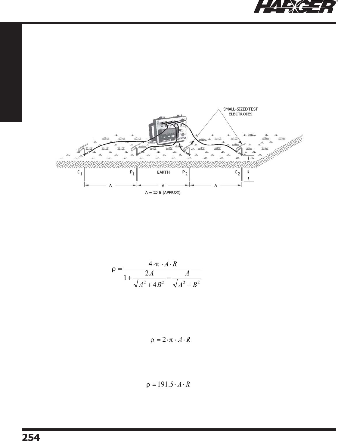
H
ar
g
er Li
g
htnin
g
& Groundin
g
•
©
2012 Phone 847-548-8700 • Fax 847-548-8755 • U.S. 800-842-743
7
254
254
Section 4
Ground Testing Equipment
S
OIL RESISTIVITY TESTING
(
4
p
oint method
)
T
he most common method utilized for measurin
g
soil resistivity is the Four Point Method usin
g
the equally spaced Wenner
Arran
g
ement. This method is commonly referred to as the Four Pin Method. This method is the most accurate method in
practice for measurin
g
the avera
g
e soil resistivity of lar
g
e volumes of earth. This method utilizes a specialized
g
round test
i
nstrument that has a four-terminal arran
g
ement. Small electrodes are driven into the earth, all at depth B and spaced (in a
s
trai
g
ht line) at equal distance intervals A. The test current (I) is passed between the two outer electrodes (C1 and C2) and
the volta
g
e (V) is measured between the two inner electrodes (P1 and P2). The instrument knowin
g
the volta
g
e and current
calculates the resistance from Ohms law (V/I) and
g
ives the resistance (R) in ohms.
F
our Point Method usin
g
Equally Spaced Pin Arran
g
ement
T
he avera
g
e soil resistivity
(
ohm•cm) is calculated by the followin
g
formula where R is the resistance measured in ohms,
(
A) is the pin spacin
g
expressed in centimeters and (B) is the depth that the pins are inserted into the soil also expressed in
centimeters
a
n
d
π
is the c
o
nst
a
nt
3
.141
6
.
(
A and B in cm
)
T
his soil resistivit
y
(
) value is an indication of the avera
g
e soil resistivity to a depth which is equal to the pin separation
distance
(
A
)
. If the condition whereb
y
the
p
in se
p
aration distance
(
A
)
is more than 20 times the
p
in de
p
th
(
B
)
then the formula
for resistivity above can be simplifi ed to the followin
g
:
(
A in cm
)
In practice pin separation distance A is measured in feet, so the followin
g
formula can be used to calculate the avera
g
e soil
resistivit
y
when A is ex
p
ressed in feet. The constant takes into account the conversion from feet to centimeters.
(
A in feet
)
S
ect
io
n 4.1
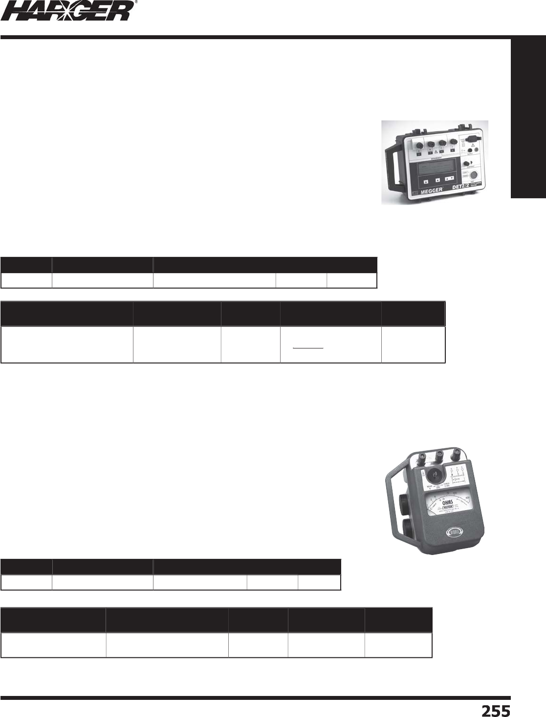
H
ar
g
er Li
g
htnin
g
& Groundin
g
•
©
2012 Phone 847-548-8700 • Fax 847-548-8755 • U.S. 800-842-743
7
255
255
Section 4
Ground Testing Equipment
T
he DET2/2 is ideal for testin
g
complex
s
ystems such as encountered in lar
g
er
sub
st
a
ti
o
ns
o
r telec
o
mm
u
nic
a
ti
o
ns
g
roundin
g
systems.
Hi
g
h Sensitivity Ground Resistance Tester
T
h
e
M
e
gg
e
r
®
DET2
/
2 remains the line leader with its remarkable 40 V tolerance feature
and .001 resolution readin
g
s. In addition, the DET2/2 has matchless added capabilities
that make it virtually undefeatable in fi eld testin
g
in the worst electrical environments.
T
he features of the DET2/2 include an interference fi lter
(
on/off
)
and test current
control (hi
g
h/low). But above all, the test current frequency is ad
j
ustable in half-Hertz
i
ncrements over the full ran
g
e from 105 to 160 Hz. If soil transients are affectin
g
the
measurement, a dis
p
la
y
annunciator alerts the user. The o
p
erator need onl
y
dial to a
different test frequency, away from the troublesome harmonic, while observin
g
the
annunciator disappear and the readin
g
stabilize.
W
hen testin
g
in extreme electrical environments around utility substations or heavy
i
ndustrials, the extra ca
p
abilities of the DET2/2 will
q
uickl
y
p
rove indis
p
ensable.
Part No. Range Resistance Power Source Display Wt.
D
ET2
/2
0
.
0
1
0
- 19.99 k
R
echar
g
eable Batter
y
D
i
g
ital 11 l
b
s.
M
e
gg
er
®
Ground Testin
g
Equipment
Testing Application Application
Examples Resistivity Testing
Requirements
Instrument
Type
L
ar
g
e, complex
g
roundin
g
sy
s
t
ems; ex
t
reme ac
i
nterference volta
g
e presen
t
L
ar
g
e substations;
s
witch
y
ard
Yes
H
i
g
hest accuracy and
precise
p
res
o
l
u
ti
o
n
re
q
uired
4
-termin
a
l
hi
gh
s
ensitivit
y
•
See pa
g
e 259 for Ground Test Kits.
Part No. Range Resistance Power Source Display Wt.
250260
0
.
5
-
500
4C
B
a
tterie
s
Analo
g
3
l
b
s.
Testing Application Application
Examples Resistivity Testing
Requirements
Instrument
Type
S
imple
g
round system
P
ole
g
rounds;
residential wirin
g
system
s
No
H
i
g
h resolutio
n
re
q
uired
3
-termin
a
l
Three Terminal Gr
o
und Resistance Tester
T
he Three-Termin
a
l Gr
ou
n
d
Resist
a
nce Tester is the ec
o
n
o
mic
a
l ch
o
ice f
o
r electric
a
l
contractors, plant electricians, telephone and CATV technicians makin
g
routine
g
round resistance tests on sin
g
le electrodes and other simple
g
roundin
g
systems. The
i
nstrument is eas
y
to use for
q
uick measurement of resistances from 0.5 to 500 ohms.
D
esi
g
ned for simplicity of use, the instrument is operated by a sin
g
le three-position
s
witch to read the measurement, check the
p
robe resistance and turn the instrument
o
ff. Measurements are displayed directly in ohms; ran
g
e chan
g
in
g
, multipliers or
calibration ad
j
ustments are not necessary.
S
ect
io
n 4.2
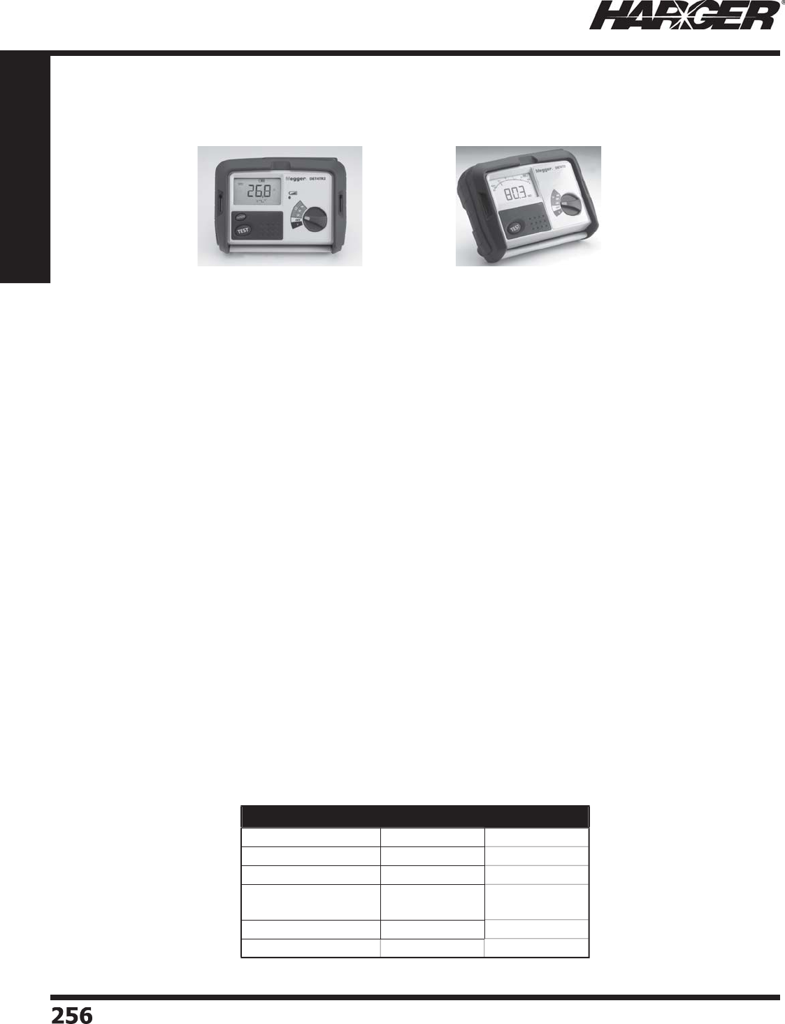
H
ar
g
er Li
g
htnin
g
& Groundin
g
•
©
2012 Phone 847-548-8700 • Fax 847-548-8755 • U.S. 800-842-743
7
256
256
Section 4
Ground Testing Equipment
DET4TR2
R
echar
g
eable batter
y
DET4TD2
D
r
y
cell batter
y
All models have a ru
gg
ed, fi eld-ready case desi
g
n that
assures tou
g
hness and facilitates easy use. The lar
g
e selector
s
witch and LCD promote ease of operation and viewin
g
, to
reduce error and enhance effi cienc
y
in the fi eld. Automatic
i
ndicators warn the o
p
erator of insuffi cient
p
robe contact.
T
he uniquely desi
g
ned selector permits two-, three-, and
four-terminal tests to be
p
erformed b
y
selection alone.
All models are rated IP54 a
g
ainst moisture and dirt
penetration, makin
g
them a match for fi eld weather and
environmental conditions that would
q
uickl
y
render a lesser
i
nstrument out of service. They come provided with carryin
g
case, leads and stakes, so as to be full
y
read
y
for fi eld use
up
on
p
urchase. A variet
y
of extra leads are available to meet
u
nusual fi eld challen
g
es.
"
Grounds" are considered normall
y
"dead", when in fact
the
y
are often "live", a situation that invites accident and
i
n
j
ury. These new instruments are provided with an additional
100 V check to enable the o
p
erator to verif
y
safet
y
before
proceedin
g
. For protection a
g
ainst arc fl ash/arc blast, the
u
nits
a
re r
a
te
d
t
o
IEC1
0
1
0
-1 CAT IV 1
00
V.
M
easurement ran
g
e is from 0.01
t
o
2
0
k
a
t
2
%
accurac
y
. Noise
p
rotection of 40 V
p
eak-to-
p
eak is the best on
the m
a
rket.
Selection Guide DET4TR2 DET4TD2
2
-wire Resist
a
nc
e
•
•
3
-wire Resist
a
nc
e
•
•
4
-w
i
re Res
i
st
a
nc
e
•
•
R
esistance Ran
g
e
&
Accurac
y
0
.
0
1 t
o
2000
Ω
2% ± 3 di
g
it
s
0
.
0
1 t
o
2000
Ω
2% ± 3 di
g
it
s
E
arth Volta
g
e Ran
g
e
0
t
o
1
00
V
0
t
o
1
00
V
D
is
p
la
y
D
i
g
ital
D
i
g
ital
M
e
gg
er
®
Ground Testin
g
Equipment
DET4 C
o
ntract
o
r Ser
i
es
S
ect
io
n 4.2
T
he four-terminal model adds soil resisitivity measurement to
g
round
resistance and bondin
g
. With this added function, the tester has
full capability for all measurements necessary for location, desi
g
n,
i
nstallation, and maintenance of a
g
roundin
g
system.
F
eat
u
re
s:
•
IP
5
4 r
a
te
d
•
2, 3 and 4 point testin
g
•
Resistance measurement ran
g
e to
2
00,000
Ω
•
Selectable 25 V or 50 V out
p
u
t
•
Sim
p
le one button o
p
eratio
n
•
Hardwearin
g
carry cas
e
•
Delivere
d
with FREE c
a
li
b
r
a
ti
o
n certifi c
a
t
e
Kit incl
ud
e
s:
•
Le
ad
a
n
d
st
a
ke ki
t
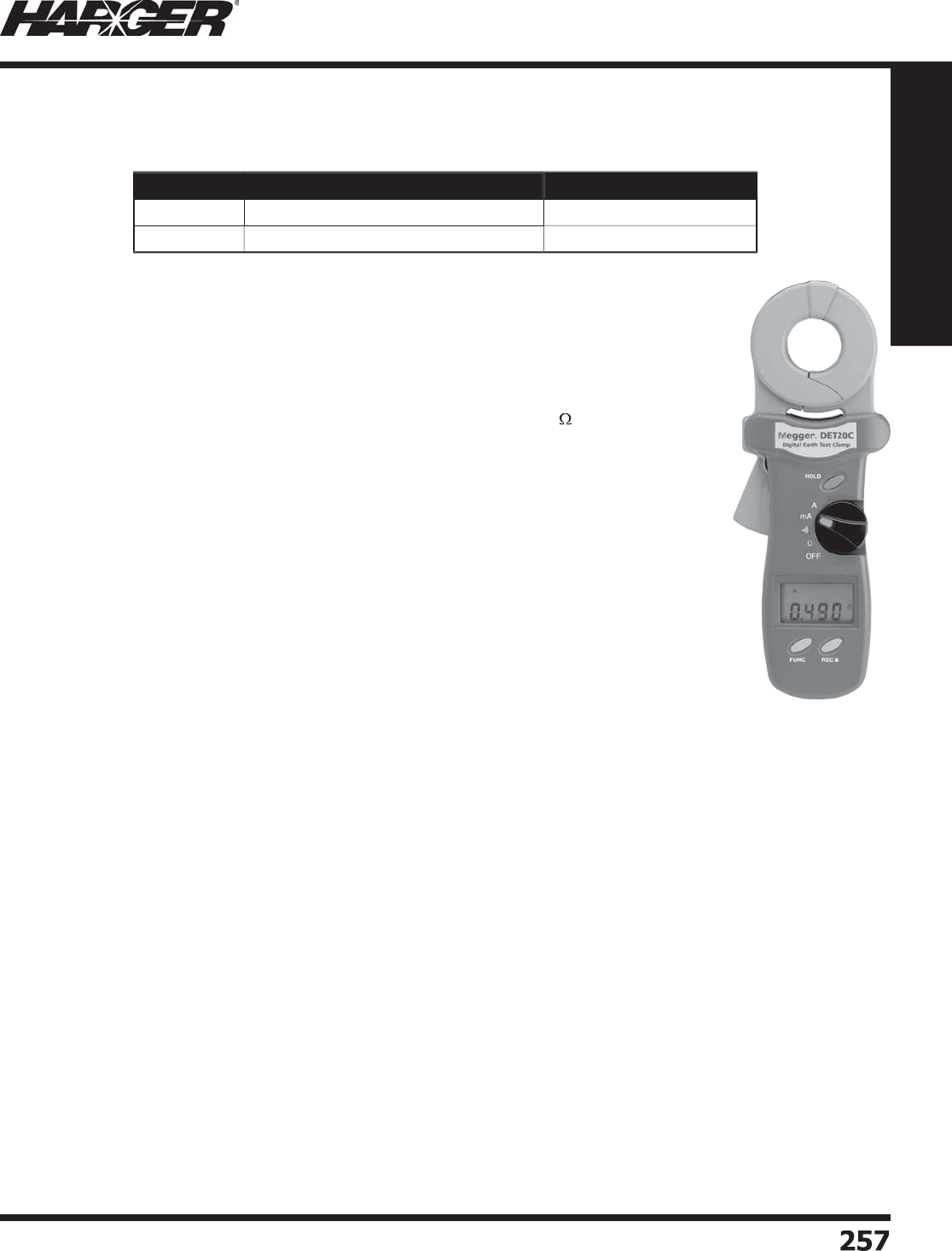
H
ar
g
er Li
g
htnin
g
& Groundin
g
•
©
2012 Phone 847-548-8700 • Fax 847-548-8755 • U.S. 800-842-743
7
25
7
257
Section 4
Ground Testing Equipment
Included Access
o
ries
:
(1) Carryin
g
case (DET10C & DET20C
)
(
1
)
Calibration loo
p
(
DET10C & DET20C
)
(
1
)
Batter
y
(
fi tted
)
(
DET10C & DET20C
)
(
1
)
USB interface cable
(
DET20C
)
(1) Download Mana
g
er Software (DET20C
)
Description
The Megger models DET10C and 20C measure earth/
ground resistance and current fl ow using clamp-on
technology. The instruments induce a test current
into the system without the need to disturb existing
connections. Either unit is a useful addition to the more
traditional methods of earth/ground resistance testing
that may require disconnection and the use of stakes
or ground rods. Simply clamp around the conductor or
stake/rod and measure the resistance to ground fast
and accurately.
The DET10C and 20C can also be used to measure
earth/ground resistance in multiple loop installations
without disconnecting the earth or ground. This allows
the user to perform the test quickly and easily in
total safety, with the added convenience of having a
single point of measurement to read the earth/ground
resistance.
Each instrument also provides a true RMS current
measurement reading to better indicate potential
measurement problems and provide a useful overview
of the dynamics of the general earth/ground system.
The units are rugged, compact and have confi gurable
audible alarms. They also feature auto shutdown
(which is also confi gurable), data storage and self
calibration on power-up, and are supplied with a
calibration loop – all contained in a rugged carry case.
The DET20C also comes with a USB interface cable and
is compatible with Megger Download Manager Software
(included) allowing further analysis and storage of data.
Application
The DET10C and 20C have a variety of applications
including:
• Use to measure resistance and continuity of
grounding loops around pads and buildings.
• Use on multi-grounded systems without disconnecting
the ground rod/stake under test.
• Use to measure leakage current fl owing to ground or
circulating in ground systems.
• Use on cell towers, RF transmitters and
telecommunications sites.
• Use to inspect and verify lightning protection
systems.
• Use on a variety of consumer installations, including
pools, spas, etc.
Features & Benefi ts
• Easy and fast clamp-on
operation. No need for cables
or auxiliary rods/stakes.
• Large LCD display screen that
can be read in bright sunlight.
• Measures ground resistance
from 0.025 to 1550
.
• Direct reading of continuity
and ground loop resistance.
• Measures ground leakage or
phase current from 0.2mA to
35A.
• Large jaw opening to
accommodate a variety of
conductors.
• Indication of high noise
content that may affect
readings.
• Lightweight; only 750g
(1.65lbs), yet exceptionally
rugged for regular fi eld use.
• Hold function for diffi cult to
reach installations.
• Auto-off to save on battery power.
• Confi gure high and low alarms with audible indication
for fast fi eld checks.
• On board storage of test results (up to 8180 records).
• Calibration check loop to insure proper operation.
• Rugged, yet lightweight storage case contains
complete testing kit.
• USB interface for download of test data for later
analysis (DET20C).
Part No. Description Approx. Each Wt. (lbs.)
D
ET1
0C
Clam
p
-On Ground Resistance Teste
r
1-1
/2
D
ET
20C
Clam
p
-On Ground Resistance Teste
r
1-1
/2
M
e
gg
er
®
Earth
/
Ground Resistance
&
Leaka
g
e Current Clamp Testers
S
ect
io
n 4.3
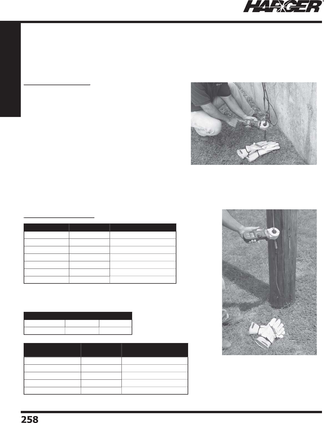
H
ar
g
er Li
g
htnin
g
& Groundin
g
•
©
2012 Phone 847-548-8700 • Fax 847-548-8755 • U.S. 800-842-743
7
2
58
258
Section 4
Ground Testing Equipment
(
1
)
Loo
p
resistance non-inductive, external fi eld <50 A/m
,
external electrical fi eld <1 V/m, conductor centered in
j
aws.
(
2
)
Resistance measurement fre
q
uenc
y
: 1.667 KH
z
Sp
ecifi cations
General Specifi cations:
p
C
o
n
du
ct
o
r size:
35
mm
a
pp
r
o
x.
B
atter
y
t
yp
e: 9V IEC 6 LR61 alkalin
e
D
isplay type: 4 di
g
its 9999 counts LC
D
R
an
g
e selection: Automatic within functio
n
Overload indication: "OL" on dis
p
la
y
P
ower consum
p
tion: 40 mA
B
atter
y
life: 3000 measurements a
pp
rox.
Auto
p
ower down: 5 minutes a
pp
rox.
S
amplin
g
time: 0.5 second
s
O
peratin
g
temperature: 0 to 50°
C
S
tora
g
e temperature: -
2
0° C to 60° C
Operatin
g
humidity: Less than 85% R
H
S
tora
g
e humidity: Less than 75% R
H
D
imensions: 10.8" L x 3.9" W x 1.9"
H
2
7
6
mm L x 1
00
mm W x 47mm
H
D
ata lo
gg
in
g
capacity DET10C: 116 record
s
D
ata lo
gg
in
g
capacity DET20C: 8180 record
s
Electrical Specifi cations:
p
(
3) Auto ran
g
e, 50/60Hz, true RMS to crest factor <3.5
T
he DET20C bein
g
used to test a facility
g
round.
T
he DET20C bein
g
used to test a pole
g
round.
Range (2) Resolution Accuracy (1)
0
.
025
-
0
.
250
Ω
0
.
002
Ω
± 1.
5
% ±
0
.
05
Ω
0
.
25
- 9.999
Ω
0
.
02
Ω
± 1.
5
% ±
0
.1
Ω
1
0
- 99.99
Ω
0
.
0
4
Ω
±
2
.
0
% ±
0
.
3
Ω
1
00
- 199.9
Ω
0
.4
Ω
±
3
.
0
% ± 1.
0
Ω
200
- 4
00
Ω
2
Ω
±
5
.
0
% ±
5
Ω
400
-
600
Ω
5
Ω
± 1
0
% ± 1
0
Ω
600
- 1
500
Ω
20
Ω
±
20%
Alarm Type Range Resolution
H
i
g
h Alarm
0
- 1
550
Ω
1
Ω
Lo
w Al
a
rm
0
- 1
550
Ω
1
Ω
Leakage Current
Range (3) Resolution Accuracy
0
.
200
- 1.
000
mA
0
.
00
1 mA ±
2
.
0
% ±
0
.
05
mA
1.
00
- 1
0
.
00
mA
0
.
0
1 mA ±
2
.
0
% ±
0
.
03
mA
1
0
.
0
- 1
00
.
0
mA
0
.1 mA ±
2
.
0
% ±
0
.
3
mA
1
00
- 1
000
mA 1 mA ±
2
.
0
% ±
3
mA
0
.
20
-
35
A
0
.
0
1 A ±
2
.
0
% ±
0
.
03
A
M
e
gg
er
®
Earth
/
Ground Resistance
&
Leaka
g
e Current Clamp Testers
S
ect
io
n 4.3
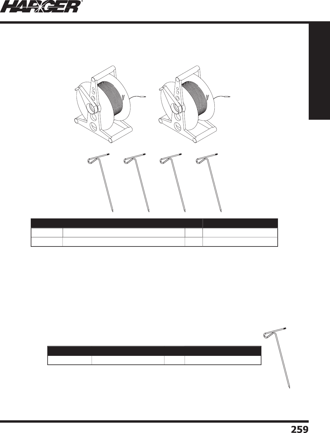
H
ar
g
er Li
g
htnin
g
& Groundin
g
•
©
2012 Phone 847-548-8700 • Fax 847-548-8755 • U.S. 800-842-743
7
25
9
259
Section 4
Ground Testing Equipment
Accessory test kits are desi
g
ned for doin
g
three point measurements on lar
g
er sites.
G
TKIT Incl
ud
e
s:
(2) 300' or 500' lon
g
test lead reels. Durable reel with leads made from #18 AWG
(
65/36
)
test lead wire.
(12) Test spikes. Spikes are 24" lon
g
and made of steel with a dipped zinc ultra-seal
fi ni
s
h.
Part No. Description Qty. Approx. Each Wt. (lbs.)
GTKIT
300
T
est Kit with 300' lon
g
test leads & 12 spike
s
EA
20
GTKIT
500
T
est Kit with 500' lon
g
test leads & 12 spike
s
EA
25
Part No. Description Qty. Approx. Each Wt. (lbs.)
G
RDTE
S
TPI
N
24" Ground Test S
p
ike
EA
1
Har
g
er Ground Test Kits
S
ect
io
n 4.
4

H
ar
g
er Li
g
htnin
g
& Groundin
g
•
©
2012 Phone 847-548-8700 • Fax 847-548-8755 • U.S. 800-842-743
7
260
260
Section 4
Ground Testing Equipment
No
tes

H
ar
g
er Li
g
htnin
g
& Groundin
g
•
©
2012 Phone 847-548-8700 • Fax 847-548-8755 • U.S. 800-842-743
7
26
1
261
Section 5
Ultraweld® Exothermic Connections
S
ect
io
n 5
Ex
o
thermic C
o
nnecti
o
ns
In
d
ex
Descr
i
pt
i
on Pa
g
e
5
.1
C
onnection T
yp
e
s
.............................................................................
262
5
.2 Ex
o
thermic Pr
o
cesse
s
.......................................................................
2
7
2
5
.3 Mold Numberin
g
System
...................................................................
2
7
5
5
.4 L
o
w Sm
o
ke M
o
l
ds
.............................................................................
2
7
6
5
.
5
C
o
nnecti
o
ns: C
ab
le t
o
C
ab
l
e
.............................................................
2
7
7
C
ab
le t
o
Gr
ou
n
d
R
od
...................................................
28
2
Gr
ou
n
d
R
od
t
o
Gr
ou
n
d
R
od
..........................................
286
Cable to Steel Surface / Pi
pe
........................................
28
7
Cable to Lu
g
or Busba
r
................................................
2
9
7
C
ab
le t
o
B
u
s
bar
...........................................................
2
99
B
u
s
ba
r t
o
B
u
s
bar
.........................................................
302
C
ab
le t
o
Re
bar
............................................................
304
C
ab
le t
o
R
a
il
...............................................................
3
1
0
5
.
6
U
ni-Sh
o
t
s
.........................................................................................
3
1
2
5
.7 Tinned Copper Lu
g
s (Strai
g
ht, Offset, Bent & Bent J
)
..........................
3
1
4
5
.8 E
q
ui
p
ment Ground Plates, Molds & Assemblie
s
...................................
3
1
6
5
.9 Aircraft Ground Rece
p
tacle
................................................................
320
5
.10 Flexible Gate Jum
p
er
s
.......................................................................
32
1
5
.11 Materials, Tools & Accessorie
s
...........................................................
322
5
.12 Technic
a
l Inf
o
rm
a
ti
on
.......................................................................
333

H
ar
g
er Li
g
htnin
g
& Groundin
g
•
©
2012 Phone 847-548-8700 • Fax 847-548-8755 • U.S. 800-842-743
7
26
2
262
Section 5
Ultraweld® Exothermic Connections
Connection Catalo
g
Ty
pe Item Pa
ge
Connection Catalo
g
Ty
pe Item Pa
ge
C
onnect
i
on T
yp
es
AD N
o
AH No
B
A Yes
302
B
A
U
N
o
B
B Yes
302
B
B
C
N
o
B
BDEH
S
N
o
B
BDV
S
N
o
B
BE N
o
B
BHTV
S
N
o
B
BT N
o
B
BTH
S
N
o
B
B
U
V
S
N
o
B
BVTV
S
N
o
BC
N
o
BC
B N
o
BC
E N
o
BC
F N
o
BCU
N
o
BC
X N
o
B
D Yes
299
B
DELV
S
N
o
B
DERV
S
N
o
B
DW N
o
B
E Yes
300
B
H Yes
300
S
ect
io
n 5.1

H
ar
g
er Li
g
htnin
g
& Groundin
g
•
©
2012 Phone 847-548-8700 • Fax 847-548-8755 • U.S. 800-842-743
7
263
263
Section 5
Ultraweld® Exothermic Connections
Connection Catalo
g
Ty
pe Item Pa
ge
Connection Catalo
g
Ty
pe Item Pa
ge
C
onnect
i
on T
yp
es
B
HBBVTD N
o
B
HEBHBT N
o
B
HEBHT N
o
B
HEBVTD N
o
B
HEBVTT N
o
B
HEBVT
U
N
o
B
HEX
C
N
o
B
HFA N
o
B
HFBHF N
o
B
HFBHT N
o
B
HFBHX N
o
B
HFBHX
C
N
o
B
L N
o
B
LDV
S
N
o
B
LH
S
N
o
B
LLV
S
N
o
B
LRV
S
N
o
B
MB N
o
B
N N
o
BO
N
o
B
P N
o
BS
Yes 27
7
B
T Yes
303
B
TE N
o
BU
Yes
301
BU
W N
o
S
ect
io
n 5.1
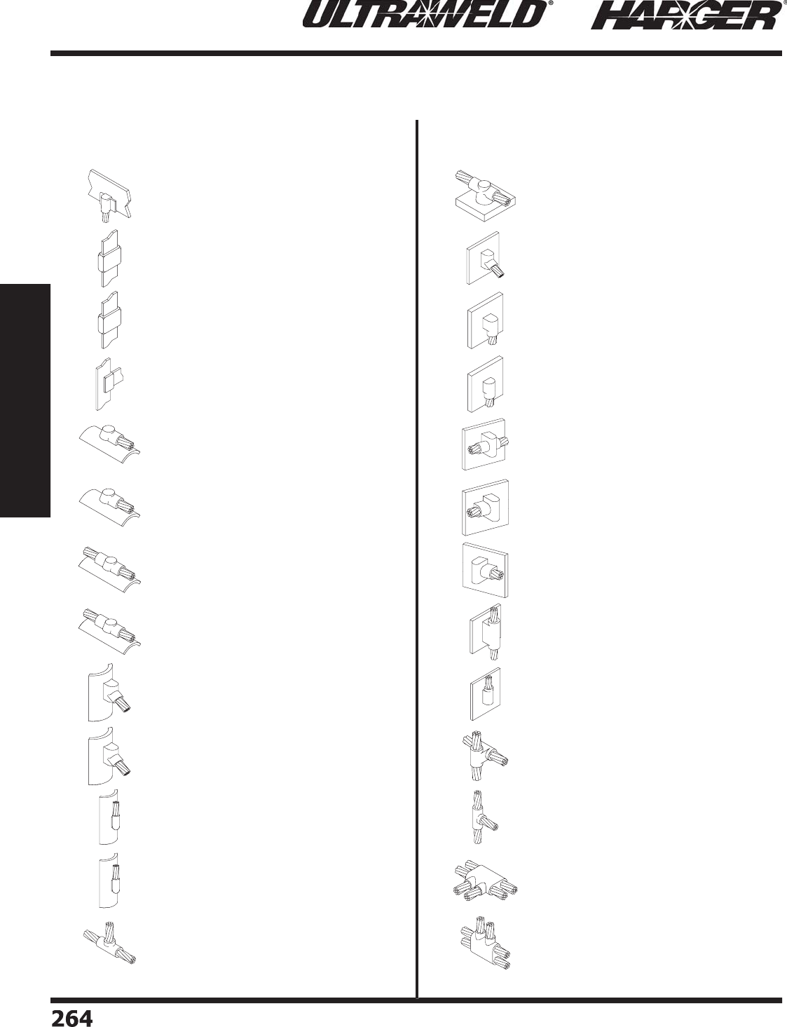
H
ar
g
er Li
g
htnin
g
& Groundin
g
•
©
2012 Phone 847-548-8700 • Fax 847-548-8755 • U.S. 800-842-743
7
264
264
Section 5
Ultraweld® Exothermic Connections
Connection Catalo
g
Ty
pe Item Pa
ge
Connection Catalo
g
Ty
pe Item Pa
ge
C
onnect
i
on T
yp
es
B
V N
o
B
VFBVF N
o
B
VFBVFT N
o
B
VFBVT N
o
C
AHD N
o
C
A
C
IHD N
o
C
AHT N
o
C
A
C
IHT N
o
C
AVA N
o
C
A
C
IVA N
o
C
AV
U
N
o
C
A
C
IV
U
N
o
C
H N
o
C
IH
U
N
o
C
IVA N
o
C
IVD N
o
C
IVD
O
N
o
C
IVH N
o
C
IVL N
o
C
IVR N
o
C
IVT N
o
C
IV
U
N
o
CS
N
o
C
T N
o
DPRDT N
o
DPRDVT N
o
S
ect
io
n 5.1

H
ar
g
er Li
g
htnin
g
& Groundin
g
•
©
2012 Phone 847-548-8700 • Fax 847-548-8755 • U.S. 800-842-743
7
265
265
Section 5
Ultraweld® Exothermic Connections
Connection Catalo
g
Ty
pe Item Pa
ge
Connection Catalo
g
Ty
pe Item Pa
ge
C
onnect
i
on T
yp
es
DPRT N
o
DX N
o
DX1
C
N
o
E
G
PB
S
N
o
E
G
P
C
B Yes
3
1
7
E
G
P
C
T Yes
3
1
7
E
G
P
C
VD N
o
E
G
P
C
V
U
N
o
E
G
P
G
RT N
o
E
G
PHB N
o
E
G
PID Yes
3
1
7
E
G
PI
O
Yes
3
1
7
E
G
P
SG
N
o
E
G
PVB
S
N
o
FG
RB
S
Yes
3
2
0
FG
R
G
D Yes
3
2
0
FG
R
GO
Yes
3
2
0
FG
RI
G
D Yes
3
2
0
FG
RI
GO
Yes
3
2
0
G
11 Yes
3
1
2
G
21 Yes
3
1
2
G3
1 Yes
3
1
2
G
41 Yes
3
1
2
G
A
SO
N
o
G
B N
o
GC
B N
o
S
ect
io
n 5.1

H
ar
g
er Li
g
htnin
g
& Groundin
g
•
©
2012 Phone 847-548-8700 • Fax 847-548-8755 • U.S. 800-842-743
7
266
266
Section 5
Ultraweld® Exothermic Connections
Connection Catalo
g
Ty
pe Item Pa
ge
Connection Catalo
g
Ty
pe Item Pa
ge
C
onnect
i
on T
yp
es
GC
BA N
o
GC
D N
o
GC
H N
o
GC
T N
o
GCU
N
o
GC
V N
o
G
D Yes 2
82
G
E N
o
G
F Yes 2
83
GG
Yes 2
86
GG
H N
o
G
H N
o
G
HLE N
o
G
H
S
D N
o
G
H
SO
N
o
G
H
S
RT N
o
G
HV
S
X N
o
G
LA N
o
G
LV N
o
GO
Yes 2
84
GOC
N
o
GO
T N
o
GO
X
O
N
o
GO
XX N
o
G
P N
o
G
PH
S
D N
o
S
ect
io
n 5.1

H
ar
g
er Li
g
htnin
g
& Groundin
g
•
©
2012 Phone 847-548-8700 • Fax 847-548-8755 • U.S. 800-842-743
7
26
7
267
Section 5
Ultraweld® Exothermic Connections
Connection Catalo
g
Ty
pe Item Pa
ge
Connection Catalo
g
Ty
pe Item Pa
ge
C
onnect
i
on T
yp
es
G
PT N
o
G
RH
90
B N
o
G
RHT N
o
G
R
O
T N
o
G
R
S
N
o
G
R
S
T N
o
G
RT N
o
G
RX
O
N
o
GS
Yes 2
85
GSC
N
o
GSS
D N
o
G
T Yes 2
86
G
T
C
N
o
GU
N
o
GU
BV N
o
GUC
N
o
G
V N
o
G
V
S
A
S
N
o
G
V
S
D N
o
G
V
SO
N
o
G
V
S
P N
o
G
V
SS
N
o
HB Yes
287
HB
C
P N
o
HB
U
V
S
N
o
HBV
S
N
o
S
ect
io
n 5.1

H
ar
g
er Li
g
htnin
g
& Groundin
g
•
©
2012 Phone 847-548-8700 • Fax 847-548-8755 • U.S. 800-842-743
7
2
68
268
Section 5
Ultraweld® Exothermic Connections
Connection Catalo
g
Ty
pe Item Pa
ge
Connection Catalo
g
Ty
pe Item Pa
ge
C
onnect
i
on T
yp
es
H
C
HP N
o
H
C
LV
S
4
5
N
o
H
C
TV
S
4
5
N
o
HD Yes
287
HPH
C
X N
o
HR
C
T N
o
HRDHT N
o
HRH
90
B N
o
HRH
C
X N
o
HRPHT N
o
HRT N
o
HRV
30
TL N
o
HRV
30
TR N
o
HRV
90
B N
o
H
S
VB N
o
H
S
V
C
N
o
HT Yes
289
HT
C
P N
o
H
U
Yes
289
HVBB N
o
HVBM N
o
HVBT N
o
LB
J
Yes
298
LE Yes
297
L
U
N
o
LV N
o
S
ect
io
n 5.1

H
ar
g
er Li
g
htnin
g
& Groundin
g
•
©
2012 Phone 847-548-8700 • Fax 847-548-8755 • U.S. 800-842-743
7
26
9
269
Section 5
Ultraweld® Exothermic Connections
Connection Catalo
g
Ty
pe Item Pa
ge
Connection Catalo
g
Ty
pe Item Pa
ge
C
onnect
i
on T
yp
es
P
B Yes
2
7
7
P
D N
o
P
HD N
o
P
RLE N
o
P
RPT N
o
PS
Yes 27
8
P
T Yes
2
7
8
PU
N
o
P
V N
o
P
VD N
o
P
VDD N
o
P
VD
U
N
o
RATD N
o
RAT
U
N
o
RB Yes
305
R
C
B N
o
R
C
D N
o
R
CU
N
o
RE Yes
306
RH
C
VT N
o
RMFPL N
o
RMFPLB N
o
RMFPR N
o
RMFPRB N
o
RMFT N
o
RMFTB N
o
S
ect
io
n 5.1
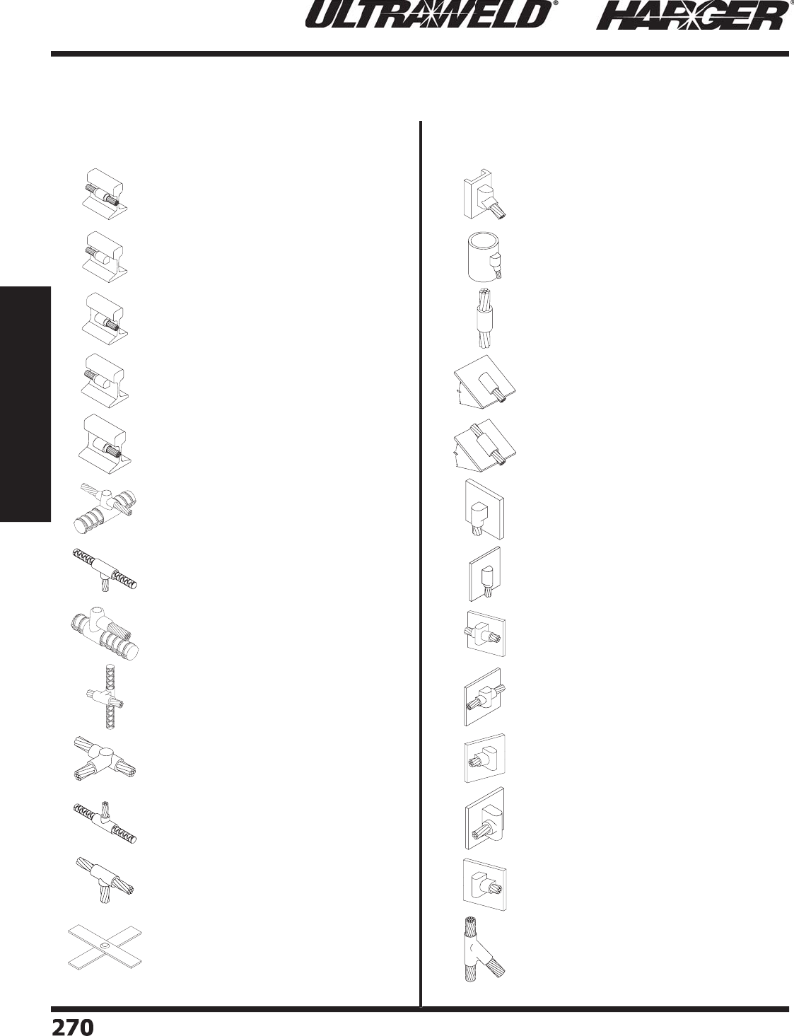
H
ar
g
er Li
g
htnin
g
& Groundin
g
•
©
2012 Phone 847-548-8700 • Fax 847-548-8755 • U.S. 800-842-743
7
2
7
0
270
Section 5
Ultraweld® Exothermic Connections
Connection Catalo
g
Ty
pe Item Pa
ge
Connection Catalo
g
Ty
pe Item Pa
ge
C
onnect
i
on T
yp
es
RMVH Yes
310
RMVL Yes
311
RMVR Yes
311
RMVLB N
o
RMVRB N
o
R
O
Yes
307
R
OC
N
o
RP Yes
308
R
S
Yes
309
RT Yes
2
7
9
R
UC
N
o
RVT N
o
S
R
G
N
o
VA Yes
290
VA
C
P N
o
VB
S
N
o
V
C
DV
S
4
5
N
o
V
C
TV
S
4
5
N
o
VD Yes
290
VD
O
N
o
VH Yes
293
VH
O
N
o
VL Yes
293
VL
O
N
o
VR Yes
293
VR
45
DT N
o
S
ect
io
n 5.1
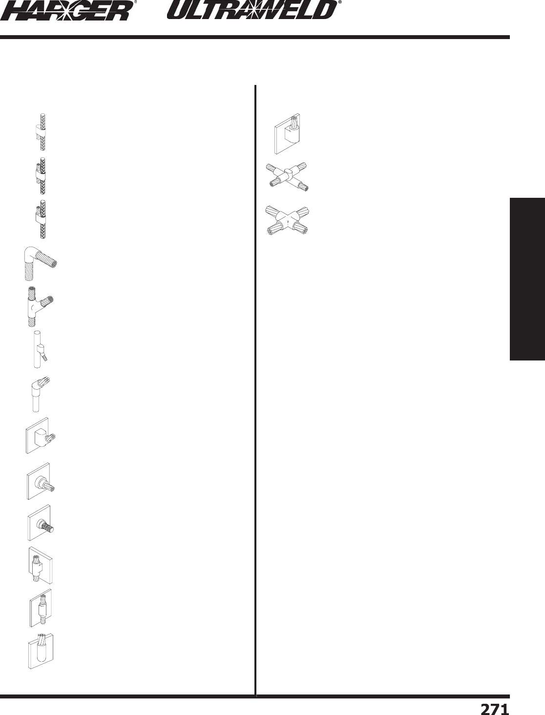
H
ar
g
er Li
g
htnin
g
& Groundin
g
•
©
2012 Phone 847-548-8700 • Fax 847-548-8755 • U.S. 800-842-743
7
2
71
271
Section 5
Ultraweld® Exothermic Connections
Connection Catalo
g
Ty
pe Item Pa
ge
C
onnect
i
on T
yp
es
VR
C
D N
o
VR
C
T N
o
VR
CU
N
o
VRH
90
B N
o
VRV
45
T N
o
VRV
C
AD N
o
VRV
C
A
U
N
o
V
S
A
U
N
o
V
S
HB N
o
V
S
HB
S
N
o
VT Yes
295
VT
O
N
o
V
U
Yes
295
V
UO
N
o
X
O
Yes 2
80
XX Yes
281
S
ect
io
n 5.1
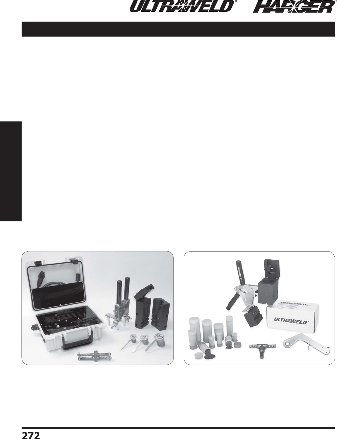
H
ar
g
er Li
g
htnin
g
& Groundin
g
•
©
2012 Phone 847-548-8700 • Fax 847-548-8755 • U.S. 800-842-743
7
2
72
272
Section 5
Ultraweld® Exothermic Connections
Exothermic Process
S
ect
io
n 5.2
Ex
o
thermic Pr
o
cess
The Exothermic Process is an effective and safe method of weldin
g
copper to copper or
copper to steel for the purpose of producin
g
permanent electrical connections. Exothermically
w
elded connections are produced from the ener
g
y and molten copper metal liberated from an
exothermic reaction between
p
owdered co
pp
er oxide and aluminum. The exothermic reaction
takes
p
lace at a theoretical tem
p
erature of 4600°F and as a result, molten co
pp
er allo
y
is
cre
a
te
d
a
n
d
u
se
d
t
o
melt the c
o
n
du
ct
o
rs
a
n
d
c
a
st the fi nishe
d
c
o
nnecti
o
n. The ex
o
thermic
reaction takes place in a semi-permanent
g
raphite mold that will last 50 or more welds i
f
properly cared for. The process is simple and easy to implement providin
g
an on-site means to
make welded electrical connections without requirin
g
external power, equipment or the special
trainin
g
usually required for brazin
g
and weldin
g
. The process will provide a fi nished connection
that will never corrode, loosen or increase in resistance. The fi nished connection also
p
rovides
an ampacity that exceeds that of the conductors bein
g
j
oined.
U
ltr
a
Sh
o
t
®
(
Dro
p
-In
)
NU
WT
ube
™
(
Pour & Shoot
)
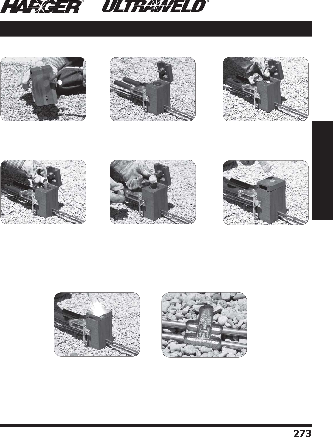
H
ar
g
er Li
g
htnin
g
& Groundin
g
•
©
2012 Phone 847-548-8700 • Fax 847-548-8755 • U.S. 800-842-743
7
2
7
3
273
Section 5
Ultraweld® Exothermic Connections
N
ote: When exothermic weldin
g
, always wear proper clothin
g
, safety
g
lasses and
g
loves.
H
ar
g
er offers Ultraweld trainin
g
. Please contact the factory for more information.
NUWTube P
o
ur & Sh
oo
t Pr
o
cess
Exothermic Process
S
ect
io
n 5.2
S
te
p
1
:
•
Torch dr
y
the mold before
makin
g
the fi rst connectio
n
S
te
p
2
:
•
Clean and dr
y
conductor
s
•
Insert c
o
n
du
ct
o
r int
o
m
o
l
d
•
Close handle clam
p
and lock
m
o
l
d
S
te
p
4
:
•
Remove Clear
p
lastic ca
p
from
N
U
WT
ub
e
•
P
ou
r wel
d
met
a
l int
o
m
o
l
d
S
te
p
6
:
•
I
g
nite material located on top
of the lid usin
g
a fl int i
g
niter
(
FLTIG
)
S
te
p
7
:
•
After the c
o
nnecti
o
n is
com
p
lete, o
p
en the mold and
rem
o
ve the c
o
nnecti
on
•
Remove sla
g
and clean
mold before makin
g
the next
c
o
nnecti
on
Com
p
lete NUWTUBE connectio
n
S
te
p
5
:
•
Remove Oran
g
e cap from
N
U
WT
ub
e
•
Pour 2/3 of the startin
g
material on to
p
of weld metal
•
Cl
o
se li
d
•
Sprinkle remainin
g
startin
g
powder in the lid's i
g
nition
p
ocket
S
te
p
3:
•
Insert
d
isk int
o
m
o
l
d

H
ar
g
er Li
g
htnin
g
& Groundin
g
•
©
2012 Phone 847-548-8700 • Fax 847-548-8755 • U.S. 800-842-743
7
2
7
4
274
Section 5
Ultraweld® Exothermic Connections
UltraShot® Exothermic Process
N
ote: When exothermic weldin
g
, always wear proper clothin
g
, safety
g
lasses and
g
loves.
H
ar
g
er offers UltraShot trainin
g
. Please contact the factory for more information.
U
ltraShot Dro
p
-In Process
S
te
p
1:
•
Clean and dr
y
conductors
a
n
d
m
o
l
d
•
Insert c
o
n
du
ct
o
rs int
o
m
o
l
d
S
te
p
2
:
•
Close handle clam
p
and
l
o
ck m
o
l
d
•
Insert UltraShot dro
p
-in
int
o
m
o
l
d
S
te
p
3
:
•
Att
a
ch c
o
r
d
t
o
U
ltr
a
Sh
o
t
i
g
nite
r
S
te
p
4:
•
Push and hold both i
g
niter
bu
tt
o
ns
a
t the s
a
me time
S
te
p
5:
•
Re
a
cti
o
n is m
ade
•
O
p
en mold and remove
c
o
nnecti
on
•
Remove sla
g
before next
c
o
nnecti
on
A com
p
leted UltraShot connectio
n
S
ect
io
n 5.2
H
ar
g
er Li
g
htnin
g
& Groundin
g
•
©
2012 Phone 847-548-8700 • Fax 847-548-8755 • U.S. 800-842-743
7
2
7
5
275
Section 5
Ultraweld® Exothermic Connections
Mold Numberin
g
Syste
m
T
he Part Number
g
ives, in code, the complete information of the mold.
•
T
yp
e of connection, conductor size
(
s
)
and mold
p
rice ke
y
.
•
Some connection t
yp
es have more than 2 characters.
•
A
dd
s
u
ffi x SX f
o
r L
o
w Sm
o
ke m
o
l
d
s.
RT 4
/
0 2
/
0 B
Typ
e
4/
0
S
tr
a
n
d
e
d
Run
2
/
0
S
tr
a
n
d
e
d
T
a
p
Typ
e
3
/
4"
Gr
ou
n
d
Rod
1
/
0
S
tr
a
n
d
e
d
T
a
p
Type
3
/
0
C
ab
l
e
Typ
e
Vertic
a
l
Pipe
3
"
P
i
pe
P
ri
ce
K
e
y
B
P
ri
ce
K
e
y
B
P
ri
ce
K
e
y
B
P
ri
ce
K
e
y
B
#2 S
o
li
d
C
o
n
du
ct
or
G
O 34 1
/
0 B B
S
2
S
B VA 3
/
0 V 3 B
S
R
G
2
0
1
6
K SX
Typ
e
2" x
0
.
0
1
6
"
C
o
pp
er
S
tri
p
Run
&
Ta
p
Lo
w Sm
o
k
e
P
ri
ce
K
e
y
K
FGRGO 34 4
/
0
F
Type
3
/
4"
Gr
ou
n
d
Rod
4/
0
Co
ncentric
T
a
p
P
ri
ce
K
e
y
F
Mold Numbering System
S
ect
io
n 5.3
Mo
l
d
Pric
e
K
e
y
C
od
e f
or
S
econdar
y
C
o
n
du
ct
or
Co
nnecti
on
Typ
e
C
od
e f
or
P
rimar
y
C
o
n
du
ct
or
XX-XX XX X -
S
X
Lo
w Sm
o
k
e
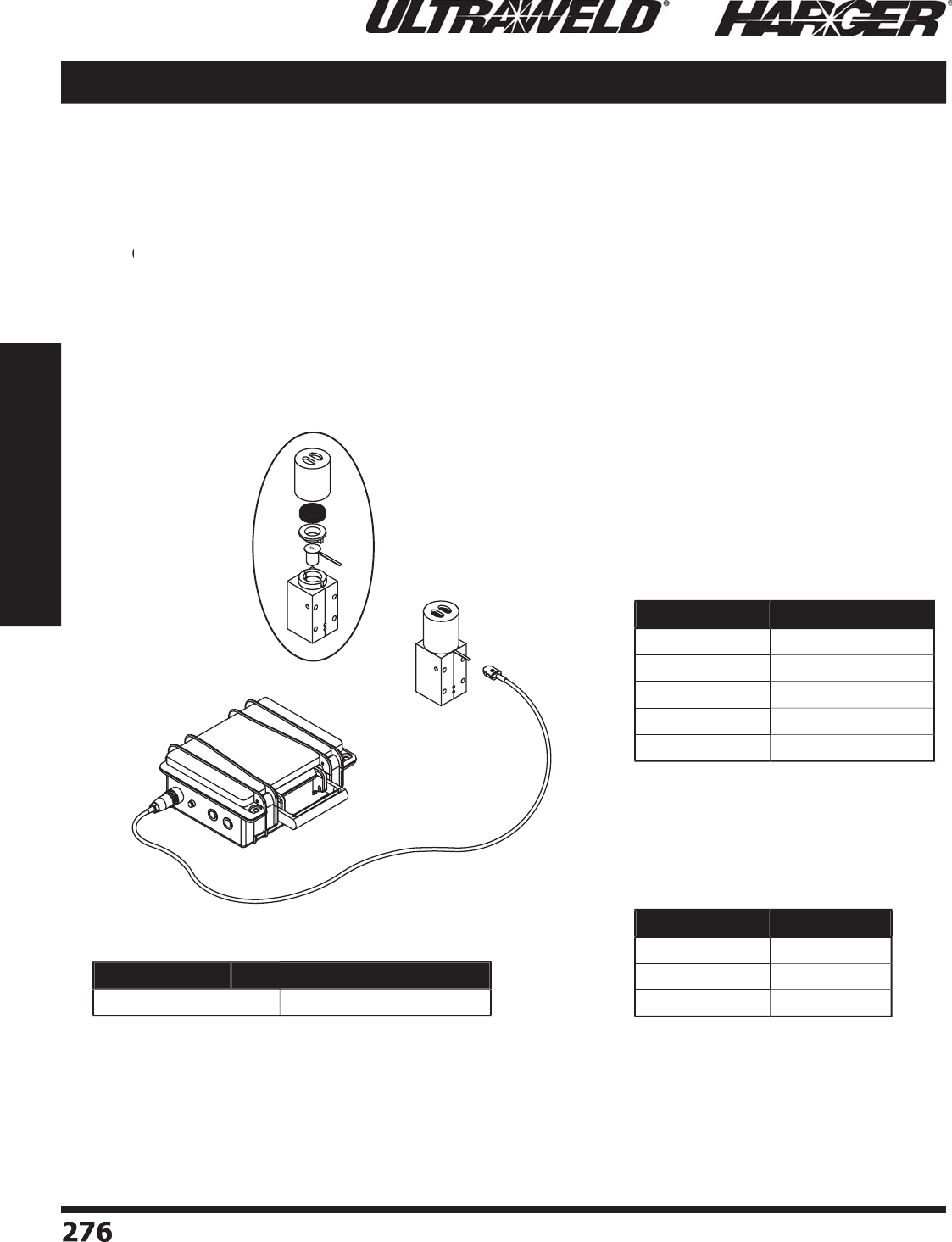
H
ar
g
er Li
g
htnin
g
& Groundin
g
•
©
2012 Phone 847-548-8700 • Fax 847-548-8755 • U.S. 800-842-743
7
2
7
6
276
Section 5
Ultraweld® Exothermic Connections
Low Smoke Molds
Har
g
er Li
gh
tnin
g
& Groundin
g
offers a line of Low Smoke Ultraweld molds for indoor use or
confi ned spaces. The process uses an inte
g
rated fi lter system alon
g
with a specially desi
g
ned
mold. Standard UltraShot weld metal is used in the s
p
ecial mold to
p
roduce a fi nished
c
o
nnecti
o
n with minim
a
l sm
o
ke emissi
o
n.
•
T
o order Low Smoke Ultraweld molds, add the suffi x "SX" to the desired mold part numbers.
T
T
Exam
p
le: Ultraweld mold GD584/0B becomes GD584/0B
S
X
Please N
o
te
:
Molds usin
g
US150 weld metal & lar
g
er will chan
g
e the mold price
ke
y
. Exam
p
le: Ultraweld mold RT4/04/0
B
S
X becomes RT4
/
04
/
0
C
S
X. See ch
a
rt
b
el
o
w.
• The fi lter should be chan
g
ed every connection to ensure the best performance.
S
ect
io
n 5.
4
Part No. Qty. Approx. Each Wt. (lbs.)
U
SC
O
NTR
O
LLER
EA
11
Filter Part No. Mold Size
USS
XFLR1 A, L, M,
&
R
U
SSXFLR
2
B
, E, K, P
&
Q
U
SSXFLR
3
C, D, F, Y
&
Z
L
o
w Sm
o
ke Filters
•
Sold as 10
p
ack.
Regular Mold Low Smoke Mold
B
C
K
D
E
F
P
Y
Q
Z
Price Key Chan
g
es for
L
o
w Sm
o
ke M
o
ld Weld Meta
l
Si
zes US150 & Lar
g
er
Lo
w Sm
o
ke
Mo
l
d
U
SC
O
NTR
O
LLER

H
ar
g
er Li
g
htnin
g
& Groundin
g
•
©
2012 Phone 847-548-8700 • Fax 847-548-8755 • U.S. 800-842-743
7
2
77
277
Section 5
Ultraweld® Exothermic Connections
PB
Mold Information
:
•
M
o
l
d
s liste
d
a
re f
o
r str
a
n
d
e
d
c
ab
le. F
o
r s
o
li
d
conductor, add suffi x "S" after conductor number.
i.e. 4S = 4 AWG s
o
li
d
c
o
n
du
ct
o
r.
•
Price Ke
y
is the
Bold Letter
in the M
o
l
d
P
a
rt N
o
.
r
•
Molds with Price Ke
y
"
L
"
S
O
LD WITH HANDLES.
•
If Handles not re
q
uired, add suffi x "-X" after the
Mo
l
d
P
a
rt N
o
.
•
H
a
n
d
les f
o
r "
L
"
Price Ke
y
molds
DO
N
O
T INCL
U
DE
F
lint I
g
niters.
•
For mold Wear Plates, add suffi x "WP" to the end o
f
the Mold Part No. See pa
g
e 324 for details.
Re
q
uired Tools & Accessories
:
MH1 - H
a
n
d
le f
o
r "
B
"
Price Ke
y
Mold
s
MH2 - H
a
n
d
le f
o
r "
C
"
Price Ke
y
Mold
s
FLTIG - Flint I
g
niter when Price Key is "
L
"
Recommended Tools & Accessories
:
CCBRSH1 - C
a
r
d
Cl
o
th Br
u
s
h
MCBRSH1 - Mold Cleanin
g
Brus
h
(
Parallel Ta
p
o
f
H
orizontal Cables
)
BS / PB Cable to Cable
C
able
Si
ze
M
o
ld
P
art
No
.
W
el
d
Meta
l
U
ltraSh
o
t
NUWTUBE
#4
#2 S
o
l
#
2
1
/
0
2
/
0
3
/
0
4/
0
250
MCM
300
MCM
350
MCM
500
MCM
7
50
MCM
1
000
MCM
BS
-
4
L
BS
-
2S
L
BS
-
2
L
B
S-1
/
0
B
B
S-2
/
0
B
B
S-3
/
0
B
B
S-4
/
0
B
B
S-
25
CM
B
B
S-
3
CM
B
B
S-
35
CM
B
BS
-
5C
M
B
BS
-7
5C
M
C
BS
-1MM
C
U
S
25
U
S
32
U
S
32
US
4
5
U
S
65
U
S9
0
U
S9
0
US
11
5
US
11
5
U
S1
50
U
S
200
U
S
300
U
S4
00
NU
WT
U
BE
25
NU
WT
U
BE
32
NU
WT
U
BE
32
NUWTUBE45
NU
WT
U
BE
65
NU
WT
U
BE9
0
NU
WT
U
BE9
0
NU
WT
U
BE11
5
NU
WT
U
BE11
5
NU
WT
U
BE1
50
NU
WT
U
BE
200
2
-N
U
WT
U
BE1
50
2
-N
U
WT
U
BE
200
C
able Size M
o
ld
P
art
No
.
W
el
d
Meta
l
Run
T
a
p
U
ltraSh
o
t
NUWTUBE
#
6
#
6
P
B-
66
B
U
S
25
NU
WT
U
BE
25
#4
#8 Sol
#
6
S
o
l
#
6
#4
P
B-48
S
B
P
B-4
6S
B
P
B-4
6
B
PB
-
44
B
U
S
32
U
S
32
U
S
32
U
S
32
NU
WT
U
BE
32
NU
WT
U
BE
32
NU
WT
U
BE
32
NU
WT
U
BE
32
#2 S
o
l #2 S
o
l
P
B-
2S2S
B
U
S
65
NU
WT
U
BE
65
#
2
#8 Sol
#
6
S
o
l
#
6
#4
#
2
P
B-28
S
B
P
B-
26S
B
P
B-
26
B
P
B-
2
4
B
P
B-
22
B
U
S
32
U
S
32
U
S
32
US
4
5
U
S
65
NU
WT
U
BE
32
NU
WT
U
BE
32
NU
WT
U
BE
32
NUWTUBE45
NU
WT
U
BE
65
1
/
0
#8 Sol
#
6
S
o
l
#
6
#4
#2 S
o
l
#
2
1
/
0
P
B-1
/
08
S
B
P
B-1
/
06
S
B
P
B-1
/
06
B
P
B-1
/
0
4
B
P
B-1
/
02
S
B
P
B-1
/
0
2
B
P
B-1
/
01
/
0
B
US
4
5
US
4
5
US
4
5
U
S
65
U
S
65
U
S
65
U
S9
0
NUWTUBE45
NUWTUBE45
NUWTUBE45
NU
WT
U
BE
65
NU
WT
U
BE
65
NU
WT
U
BE
65
NU
WT
U
BE9
0
2
/
0
#8 Sol
#
6
S
o
l
#
6
#4
#2 S
o
l
#
2
1
/
0
2
/
0
P
B-2
/
08
S
B
P
B-2
/
06
S
B
P
B-2
/
06
B
P
B-2
/
0
4
B
P
B-2
/
02
S
B
P
B-2
/
0
2
B
P
B-2
/
01
/
0
B
P
B-2
/
02
/
0
B
U
S
65
U
S
65
U
S
65
U
S
65
U
S9
0
U
S9
0
US
11
5
US
11
5
NU
WT
U
BE
65
NU
WT
U
BE
65
NU
WT
U
BE
65
NU
WT
U
BE
65
NU
WT
U
BE9
0
NU
WT
U
BE9
0
NU
WT
U
BE11
5
NU
WT
U
BE11
5
4/
0
#8 Sol
#
6
S
o
l
#
6
#4
#2 S
o
l
#
2
1
/
0
2
/
0
4/
0
P
B-4
/
08
S
B
P
B-4
/
06
S
B
P
B-4
/
06
B
P
B-4
/
0
4
B
P
B-4
/
02
S
B
P
B-4
/
0
2
B
P
B-4
/
01
/
0
B
P
B-4
/
02
/
0
B
P
B-4
/
04
/
0
B
U
S9
0
U
S9
0
U
S9
0
U
S9
0
US
11
5
US
11
5
US
11
5
US
11
5
U
S1
50
NU
WT
U
BE9
0
NU
WT
U
BE9
0
NU
WT
U
BE9
0
NU
WT
U
BE9
0
NU
WT
U
BE11
5
NU
WT
U
BE11
5
NU
WT
U
BE11
5
NU
WT
U
BE11
5
NU
WT
U
BE1
50
BS Connect
i
on T
yp
e
PB Connect
i
on T
yp
e
B
S
(
Butt End S
p
lice o
f
H
orizontal Cables
)
L
iste
d
4
67
L
iste
d
4
67
S
ect
io
n 5.5

H
ar
g
er Li
g
htnin
g
& Groundin
g
•
©
2012 Phone 847-548-8700 • Fax 847-548-8755 • U.S. 800-842-743
7
2
78
278
Section 5
Ultraweld® Exothermic Connections
Cable to Cable PS / PT
PT
P
S
M
o
ld Inf
o
rmati
o
n
:
•
P
S
m
o
l
d
s liste
d
a
re f
o
r s
o
li
d
o
r c
o
ncentric str
a
n
d
e
d
co
pp
er conductors.
•
PT
molds listed are for stranded cable. For solid
T
conductor, add suffi x "S" after conductor number.
i.e. 4S = 4 AWG s
o
li
d
c
o
n
du
ct
o
r.
•
Price Ke
y
is the
Bold Letter
in the M
o
l
d
P
a
rt N
o
.
r
•
Molds with Price Ke
y
"
L
"
&
"
M
"
S
O
LD WITH HANDLES.
•
If Handles not re
q
uired, add suffi x "-X" after the Mold
Pa
rt
No
.
•
H
a
n
d
les f
o
r "
L
"
&
"
M
"
Price Ke
y
molds
DO
N
O
T INCL
U
DE
F
lint I
g
niters.
•
For mold Wear Plates, add suffi x "WP" to the end of the
M
old Part No. See pa
g
e 324 for details.
Re
q
uired Tools & Accessories
:
MH1 - H
a
n
d
le f
o
r "
B
"
Price Ke
y
Mold
s
FLTIG - Flint I
g
niter when Price Key is "
L
"
&
"
M
"
Rec
o
mmended T
oo
ls & Access
o
ries
:
CCBRSH1 - C
a
r
d
Cl
o
th Br
u
s
h
MCBRSH1 - Mold Cleanin
g
Brus
h
(
Parallel Thru S
p
lice o
f
H
orizontal Cables
)
(
Parallel Thru S
p
lice o
f
H
orizontal Cables, Ta
p
Conductor Over Run
)
C
able Size M
o
ld
P
art
No
.
W
el
d
Meta
l
Run
T
a
p
U
ltraSh
o
t
U
ltrawel
d
#2 S
o
l #2 S
o
l
P
T-
2S2S
B
U
S
65
NU
WT
U
BE
65
#
2
#8 Sol
#8
#
6
S
o
l
#
6
#4
#2 S
o
l
#
2
P
T-28
S
B
P
T-28
B
P
T-
26S
B
P
T-
26
B
P
T-
2
4
B
P
T-
22S
B
P
T-
22
B
US
4
5
US
4
5
US
4
5
US
4
5
U
S
65
U
S
65
U
S
65
NUWTUBE45
NUWTUBE45
NUWTUBE45
NUWTUBE45
NU
WT
U
BE
65
NU
WT
U
BE
65
NU
WT
U
BE
65
1
/
0
#8 Sol
#8
#
6
S
o
l
#
6
#4
#2 S
o
l
#
2
1
/
0
P
T-1
/
08
S
B
P
T-1
/
08
B
P
T-1
/
06
S
B
P
T-1
/
06
B
P
T-1
/
0
4
B
P
T-1
/
02
S
B
P
T-1
/
0
2
B
P
T-1
/
01
/
0
B
U
S
65
U
S
65
U
S
65
U
S
65
U
S
65
U
S
65
U
S
65
U
S9
0
NU
WT
U
BE
65
NU
WT
U
BE
65
NU
WT
U
BE
65
NU
WT
U
BE
65
NU
WT
U
BE
65
NU
WT
U
BE
65
NU
WT
U
BE
65
NU
WT
U
BE9
0
2
/
0
#8 Sol
#8
#
6
S
o
l
#
6
#4
#2 S
o
l
#
2
1
/
0
2
/
0
P
T-2
/
08
S
B
P
T-2
/
08
B
P
T-2
/
06
S
B
P
T-2
/
06
B
P
T-2
/
0
4
B
P
T-2
/
02
S
B
P
T-2
/
0
2
B
P
T-2
/
01
/
0
B
P
T-2
/
02
/
0
B
U
S
65
U
S
65
U
S9
0
U
S9
0
U
S9
0
U
S9
0
U
S9
0
US
11
5
US
11
5
NU
WT
U
BE
65
NU
WT
U
BE
65
NU
WT
U
BE9
0
NU
WT
U
BE9
0
NU
WT
U
BE9
0
NU
WT
U
BE9
0
NU
WT
U
BE9
0
NU
WT
U
BE11
5
NU
WT
U
BE11
5
3
/
0
#8 Sol
#8
#
6
S
o
l
#
6
#4
#2 S
o
l
#
2
1
/
0
2
/
0
3
/
0
P
T-3
/
08
S
B
P
T-3
/
08
B
P
T-3
/
06
S
B
P
T-3
/
06
B
P
T-3
/
0
4
B
P
T-3
/
02
S
B
P
T-3
/
0
2
B
P
T-3
/
01
/
0
B
P
T-3
/
02
/
0
B
P
T-3
/
03
/
0
B
U
S9
0
U
S9
0
U
S9
0
U
S9
0
US
11
5
US
11
5
US
11
5
US
11
5
U
S1
50
U
S1
50
NU
WT
U
BE9
0
NU
WT
U
BE9
0
NU
WT
U
BE9
0
NU
WT
U
BE9
0
NU
WT
U
BE11
5
NU
WT
U
BE11
5
NU
WT
U
BE11
5
NU
WT
U
BE11
5
NU
WT
U
BE1
50
NU
WT
U
BE1
50
4/
0
#8 Sol
#8
#
6
S
o
l
#
6
#4
#2 S
o
l
#
2
1
/
0
2
/
0
3
/
0
4/
0
P
T-4
/
08
S
B
P
T-4
/
08
B
P
T-4
/
06
S
B
P
T-4
/
06
B
P
T-4
/
0
4
B
P
T-4
/
02
S
B
P
T-4
/
0
2
B
P
T-4
/
01
/
0
B
P
T-4
/
02
/
0
B
P
T-4
/
03
/
0
B
P
T-4
/
04
/
0
B
U
S9
0
U
S9
0
U
S9
0
U
S9
0
U
S1
50
U
S1
50
U
S1
50
U
S1
50
U
S1
50
U
S
200
U
S
200
NU
WT
U
BE9
0
NU
WT
U
BE9
0
NU
WT
U
BE9
0
NU
WT
U
BE9
0
NU
WT
U
BE1
50
NU
WT
U
BE1
50
NU
WT
U
BE1
50
NU
WT
U
BE1
50
NU
WT
U
BE1
50
NU
WT
U
BE
200
NU
WT
U
BE
200
C
able Size M
o
ld
P
art
No
.
W
el
d
Meta
l
Run
T
a
p
U
ltraSh
o
t
NUWTUBE
#8 Sol
#8
#
6
S
o
l
#
6
#4 S
o
l
#4
#2 S
o
l
#8 Sol
#8
#
6
S
o
l
#
6
#4 S
o
l
#4
#2 S
o
l
P
S-8S8
S
L
P
S-88
L
P
S-
6
S
6S
L
P
S-
66
L
PS
-4
S
4
S
M
PS
-44
M
PS
-
2S2S
M
U
S
25
U
S
25
U
S
25
U
S
25
U
S
32
U
S
32
US
4
5
NU
WT
U
BE
25
NU
WT
U
BE
25
NU
WT
U
BE
25
NU
WT
U
BE
25
NU
WT
U
BE
32
NU
WT
U
BE
32
NUWTUBE45
PT Connection T
yp
e continued
PS Connect
i
on T
yp
e
PT Connect
i
on T
yp
e
L
iste
d
4
67
S
ect
io
n 5.5
C
able Size M
o
ld
P
art
No
.
W
el
d
Meta
l
Run
T
a
p
U
ltraSh
o
t
NUWTUBE
#
6
#
6
P
T-
66
B
U
S
25
NU
WT
U
BE
25
#4
#8 Sol
#8
#
6
S
o
l
#
6
#4
P
T-48
S
B
P
T-48
B
P
T-4
6S
B
P
T-4
6
B
PT
-
44
B
U
S
32
U
S
32
U
S
32
U
S
32
U
S
32
NU
WT
U
BE
32
NU
WT
U
BE
32
NU
WT
U
BE
32
NU
WT
U
BE
32
NU
WT
U
BE
32

H
ar
g
er Li
g
htnin
g
& Groundin
g
•
©
2012 Phone 847-548-8700 • Fax 847-548-8755 • U.S. 800-842-743
7
2
7
9
279
Section 5
Ultraweld® Exothermic Connections
RT Cable to Cable
RT
Mold Information
:
•
M
o
l
d
s liste
d
a
re f
o
r str
a
n
d
e
d
c
ab
le. F
o
r s
o
li
d
conductor, add suffi x "S" after conductor number.
i.e. 4S = 4 AWG s
o
li
d
c
o
n
du
ct
o
r.
•
Price Ke
y
is the
Bold Letter
in the M
o
l
d
P
a
rt N
o
.
r
•
For mold Wear Plates, add suffi x "WP" to the end
o
f the Mold Part No. See pa
g
e 324 for details.
Re
q
uired Tools & Accessories
:
MH1 - H
a
n
d
le f
o
r "
B
"
Price Ke
y
Mold
s
MH2 - H
a
n
d
le f
o
r "
C
"
Price Ke
y
Mold
s
Recommended Tools & Accessories
:
CCBRSH1 - C
a
r
d
Cl
o
th Br
u
s
h
MCBRSH1 - Mold Cleanin
g
Brus
h
(
Tee of Horizontal
R
un & Ta
p
Cables
)
C
able Size M
o
ld
P
art
No
.
W
el
d
Meta
l
Run
T
a
p
UltraSh
o
t
NUWTUBE
#
6
#
6
R
T-
66
B
U
S
32
NU
WT
U
BE
32
#4
#4
RT
-
44
B
U
S
32
NU
WT
U
BE
32
#2 S
o
l #2 S
o
l
R
T-
2S2S
B
US
4
5
NUWTUBE45
#
2
#
6
#4
#2 S
o
l
#
2
R
T-
26
B
R
T-
2
4
B
R
T-
22S
B
R
T-
22
B
US
4
5
US
4
5
US
4
5
US
4
5
NUWTUBE45
NUWTUBE45
NUWTUBE45
NUWTUBE45
1
/
0
#
6
#4
#2 S
o
l
#
2
1
/
0
R
T-1
/
06
B
R
T-1
/
04
B
R
T-1
/
02
S
B
R
T-1
/
0
2
B
R
T-1
/
01
/
0
B
US
4
5
US
4
5
US
4
5
US
4
5
U
S9
0
NUWTUBE45
NUWTUBE45
NUWTUBE45
NUWTUBE45
NU
WT
U
BE9
0
2
/
0
#
6
#4
#2 S
o
l
#
2
1
/
0
2
/
0
R
T-2
/
06
B
R
T-2
/
04
B
R
T-2
/
02
S
B
R
T-2
/
0
2
B
R
T-2
/
01
/
0
B
R
T-2
/
02
/
0
B
US
4
5
US
4
5
US
4
5
US
4
5
U
S9
0
U
S9
0
NUWTUBE45
NUWTUBE45
NUWTUBE45
NUWTUBE45
NU
WT
U
BE9
0
NU
WT
U
BE9
0
3
/
0
#
6
#4
#2 S
o
l
#
2
1
/
0
2
/
0
3
/
0
R
T-3
/
06
B
R
T-3
/
04
B
R
T-3
/
02
S
B
R
T-3
/
0
2
B
R
T-3
/
01
/
0
B
R
T-3
/
02
/
0
B
R
T-3
/
03
/
0
B
US
4
5
US
4
5
US
4
5
US
4
5
U
S9
0
U
S9
0
US
11
5
NUWTUBE45
NUWTUBE45
NUWTUBE45
NUWTUBE45
NU
WT
U
BE9
0
NU
WT
U
BE9
0
NU
WT
U
BE11
5
4/
0
#
6
#
4
#2 S
o
l
#
2
1
/
0
2
/
0
3
/
0
4/
0
R
T-4
/
06
B
R
T-4
/
04
B
R
T-4
/
02
S
B
R
T-4
/
0
2
B
R
T-4
/
01
/
0
B
R
T-4
/
02
/
0
B
R
T-4
/
03
/
0
B
R
T-4
/
04
/
0
B
U
S9
0
U
S9
0
U
S9
0
U
S9
0
U
S9
0
U
S9
0
US
11
5
U
S1
50
NU
WT
U
BE9
0
NU
WT
U
BE9
0
NU
WT
U
BE9
0
NU
WT
U
BE9
0
NU
WT
U
BE9
0
NU
WT
U
BE9
0
NU
WT
U
BE11
5
NU
WT
U
BE1
50
250
MC
M
#
2
1
/
0
2
/
0
3
/
0
4/
0
250
MCM
R
T-
25
CM
2
B
R
T-25CM1
/
0
B
R
T-25CM2
/
0
B
R
T-25CM3
/
0
B
R
T-25CM4
/
0
B
R
T-
25
CM
25
CM
B
U
S9
0
U
S9
0
U
S9
0
U
S1
50
U
S1
50
U
S1
50
NU
WT
U
BE9
0
NU
WT
U
BE9
0
NU
WT
U
BE9
0
NU
WT
U
BE1
50
NU
WT
U
BE1
50
NU
WT
U
BE1
50
C
able Size M
o
ld
P
art
No
.
W
el
d
Meta
l
Run
T
a
p
U
ltraSh
o
t
NUWTUBE
300
MC
M
#
2
1
/
0
2
/
0
3
/
0
4/
0
250
MCM
300
MCM
R
T-
3
CM
2
B
R
T-3CM1
/
0
B
R
T-3CM2
/
0
B
R
T-3CM3
/
0B
R
T-3CM4
/
0
B
R
T-
3
CM
25
CM
B
R
T-
3
CM
3
CM
B
U
S9
0
U
S9
0
U
S9
0
U
S1
50
U
S1
50
U
S1
50
U
S
200
NU
WT
U
BE9
0
NU
WT
U
BE9
0
NU
WT
U
BE9
0
NU
WT
U
BE1
50
NU
WT
U
BE1
50
NU
WT
U
BE1
50
NU
WT
U
BE
200
350
MC
M
#2
1
/
0
2
/
0
3
/
0
4/
0
250
MCM
300
MCM
350
MCM
R
T-
35
CM
2
B
R
T-35CM1
/
0
B
R
T-35CM2
/
0
B
R
T-35CM3
/
0
B
R
T-35CM4
/
0
B
R
T-
35
CM
25
CM
B
R
T-
35
CM
3
CM
B
R
T-
35
CM
35
CM
B
U
S9
0
U
S9
0
U
S9
0
U
S1
50
U
S1
50
U
S
200
U
S
200
U
S
200
NU
WT
U
BE9
0
NU
WT
U
BE9
0
NU
WT
U
BE9
0
NU
WT
U
BE1
50
NU
WT
U
BE1
50
NU
WT
U
BE
200
NU
WT
U
BE
200
NU
WT
U
BE
200
500
MC
M
#
2
1
/
0
2
/
0
4/
0
250
MCM
300
MCM
350
MCM
500
MCM
R
T-
5
CM
2
B
R
T-5CM1
/
0
B
R
T-5CM2
/
0
B
R
T-5CM4
/
0
B
R
T-
5
CM
25
CM
B
R
T-
5
CM
3
CM
B
R
T-
5
CM
35
CM
B
R
T-
5C
M
5C
M
B
U
S9
0
U
S9
0
U
S9
0
U
S1
50
U
S
200
U
S
200
U
S
200
U
S
300
NU
WT
U
BE9
0
NU
WT
U
BE9
0
NU
WT
U
BE9
0
NU
WT
U
BE1
50
NU
WT
U
BE
200
NU
WT
U
BE
200
NU
WT
U
BE
200
2
-N
U
WT
U
BE1
50
7
50
MC
M
1
/
0
2
/
0
4/
0
250
MCM
300
MCM
350
MCM
500
MCM
7
50
MCM
R
T-75CM1
/
0
B
R
T-75CM2
/
0
B
R
T-75CM4
/
0
B
R
T-7
5
CM
25
CM
B
R
T-7
5
CM
3
CM
B
R
T-7
5
CM
35
CM
B
R
T-7
5C
M
5C
M
C
R
T-7
5C
M7
5C
M
C
U
S1
50
U
S1
50
U
S1
50
U
S
200
U
S
200
U
S
250
U
S4
00
U
S
500
NU
WT
U
BE1
50
NU
WT
U
BE1
50
NU
WT
U
BE1
50
NU
WT
U
BE
200
NU
WT
U
BE
200
NU
WT
U
BE
250
2
-N
U
WT
U
BE
200
2
-N
U
WT
U
BE
250
1
000
MC
M
1
/
0
2
/
0
4/
0
250
MCM
300
MCM
350
MCM
500
MCM
7
50
MCM
1
000
MCM
R
T-1MM1
/
0
B
R
T-1MM2
/
0
B
R
T-1MM4
/
0
B
R
T-1MM
25
CM
B
R
T-1MM
3
CM
B
R
T-1MM
35
CM
B
R
T-1MM
5C
M
C
R
T-1MM7
5C
M
C
R
T-1MM1MM
C
U
S1
50
U
S1
50
U
S1
50
U
S
200
U
S
200
U
S
250
U
S4
00
U
S
500
U
S
500
NU
WT
U
BE1
50
NU
WT
U
BE1
50
NU
WT
U
BE1
50
NU
WT
U
BE
200
NU
WT
U
BE
200
NU
WT
U
BE
250
2
-N
U
WT
U
BE
200
2
-N
U
WT
U
BE
250
2
-N
U
WT
U
BE
250
RT Connect
i
on T
yp
e RT Connection T
yp
e continue
d
L
iste
d
4
67
S
ect
io
n 5.5
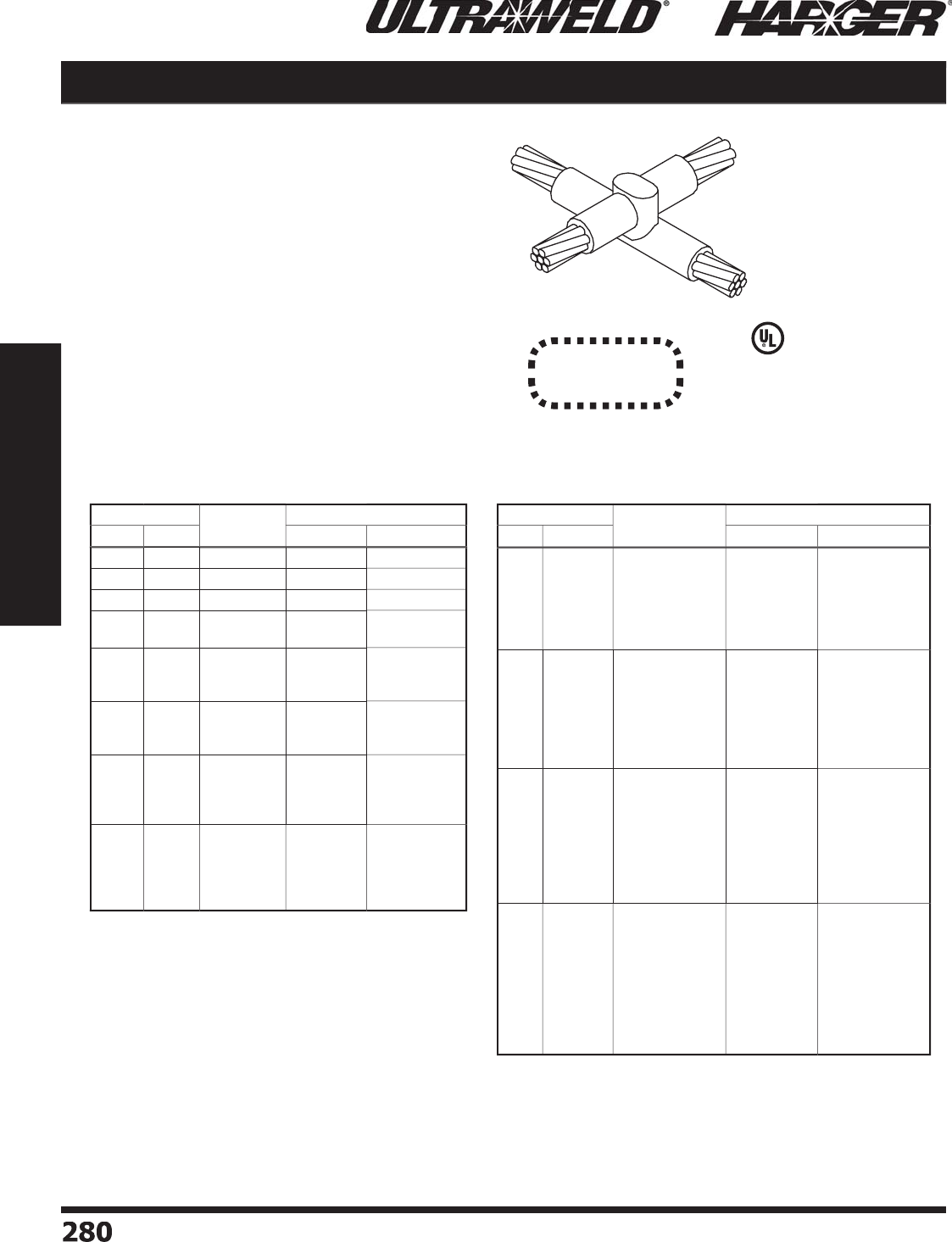
H
ar
g
er Li
g
htnin
g
& Groundin
g
•
©
2012 Phone 847-548-8700 • Fax 847-548-8755 • U.S. 800-842-743
7
2
80
280
Section 5
Ultraweld® Exothermic Connections
Cable to Cable XO
X
O
(
Cross of Horizontal Cables,
L
a
pp
ed & Not Cut
)
M
o
ld Inf
o
rmati
o
n
:
•
M
o
l
d
s liste
d
a
re f
o
r str
a
n
d
e
d
c
ab
le. F
o
r s
o
li
d
conductor, add suffi x "S" after conductor number.
i.e. 4S = 4 AWG s
o
li
d
c
o
n
du
ct
o
r.
•
Price Ke
y
is the
Bold Letter
in the M
o
l
d
P
a
rt N
o
.
r
•
For mold Wear Plates, add suffi x "WP" to the end
of the Mold Part No. See pa
g
e 324 for details.
Re
q
uired Tools & Accessories
:
MH1 - H
a
n
d
le f
o
r "
B
"
&
"
Q
"
Price Ke
y
Mold
s
MH2 - H
a
n
d
le f
o
r "
Z
"
Price Ke
y
Mold
s
Rec
o
mmended T
oo
ls & Access
o
ries
:
CCBRSH1 - C
a
r
d
Cl
o
th Br
u
s
h
MCBRSH1 - Mold Cleanin
g
Brus
h
Co
st Effective
2
-P
i
ece Des
ign
C
able Size M
o
ld
P
art
No
.
W
el
d
Meta
l
Run
T
a
p
U
ltraSh
o
t
NUWTUBE
#
6
#
6
XO
-
66
B
US
4
5
NUWTUBE45
#4
#4
XO
-4
4
B
U
S
65
NU
WT
U
BE
65
#2 S
o
l #2 S
o
l
XO
-
2
S
2S
B
U
S9
0
NU
WT
U
BE9
0
#2
#4
#2
XO
-
24
B
XO
-
22
B
U
S
65
U
S9
0
NU
WT
U
BE
65
NU
WT
U
BE9
0
1
/
0
#4
#
2
1
/
0
X
O-1
/
04
Q
X
O-1
/
0
2
Q
X
O-1
/
01
/
0
Q
US
11
5
US
11
5
U
S1
50
NU
WT
U
BE11
5
NU
WT
U
BE11
5
NU
WT
U
BE1
50
2
/
0
#
2
1
/
0
2
/
0
X
O-2
/
0
2
Q
X
O-2
/
01
/
0
Q
X
O-2
/
02
/
0
Q
U
S1
50
U
S
200
U
S
200
NU
WT
U
BE1
50
NU
WT
U
BE
200
NU
WT
U
BE
200
3
/
0
#
2
1
/
0
2
/
0
3
/
0
X
O-3
/
0
2
Q
X
O-3
/
01
/
0
Q
X
O-3
/
02
/
0
Q
X
O-3
/
03
/
0
Q
U
S1
50
U
S
200
U
S
200
U
S
250
NU
WT
U
BE1
50
NU
WT
U
BE
200
NU
WT
U
BE
200
NU
WT
U
BE
250
4/
0
#
2
1
/
0
2
/
0
3
/
0
4/
0
X
O-4
/
0
2
Q
X
O-4
/
01
/
0
Q
X
O-4
/
02
/
0
Q
X
O-4
/
03
/
0
Q
X
O-4
/
04
/
0
Q
U
S1
50
U
S
200
U
S
200
U
S
250
U
S
250
NU
WT
U
BE1
50
NU
WT
U
BE
200
NU
WT
U
BE
200
NU
WT
U
BE
250
NU
WT
U
BE
250
C
able Size M
o
ld
P
art
No
.
W
el
d
Meta
l
Run
T
a
p
U
ltraSh
o
t
NUWTUBE
250
MC
M
#
2
1
/
0
2
/
0
3
/
0
4/
0
250
MCM
XO
-
25
CM
2
Q
X
O-25CM1
/
0
Q
X
O-25CM2
/
0
Q
X
O-25CM3
/
0
Q
X
O-25CM4
/
0
Q
XO
-
25
CM
25
CM
Q
U
S1
50
U
S
250
U
S
250
U
S
300
U
S
300
U
S
300
NU
WT
U
BE1
50
NU
WT
U
BE
250
NU
WT
U
BE
250
2
-N
U
WT
U
BE1
50
2
-N
U
WT
U
BE1
50
2
-N
U
WT
U
BE1
50
300
MC
M
#
2
1
/
0
2
/
0
3
/
0
4/
0
250
MCM
300
MCM
XO
-
3
CM
2
Q
X
O-3CM1
/
0
Q
X
O-3CM2
/
0
Q
X
O-3CM3
/
0
Q
X
O-3CM4
/
0
Q
XO
-
3
CM
25
CM
Z
XO
-
3
CM
3
CM
Z
U
S1
50
U
S
250
U
S
250
U
S
300
U
S
300
U
S4
00
U
S4
00
NU
WT
U
BE1
50
NU
WT
U
BE
250
NU
WT
U
BE
250
2
-N
U
WT
U
BE1
50
2
-N
U
WT
U
BE1
50
2
-N
U
WT
U
BE
200
2
-N
U
WT
U
BE
200
350
MC
M
#
2
1
/
0
2
/
0
3
/
0
4/
0
250
MCM
300
MCM
350
MCM
XO
-
35
CM
2
Q
X
O-35CM1
/
0
Q
X
O-35CM2
/
0
Q
X
O-35CM3
/
0
Z
X
O-35CM4
/
0
Z
XO
-
35
CM
25
CM
Z
XO
-
35
CM
3
CM
Z
XO
-
35
CM
35
CM
Z
U
S
200
U
S
250
U
S
300
U
S4
00
U
S4
00
U
S
500
U
S
500
U
S
500
NU
WT
U
BE
200
NU
WT
U
BE
250
2
-N
U
WT
U
BE1
50
2
-N
U
WT
U
BE
200
2
-N
U
WT
U
BE
200
2
-N
U
WT
U
BE
250
2
-N
U
WT
U
BE
250
2
-N
U
WT
U
BE
250
500
MC
M
#
2
1
/
0
2
/
0
3
/
0
4/
0
250
MCM
300
MCM
350
MCM
500
MCM
XO
-
5
CM
2
Q
X
O-5CM1
/
0
Q
X
O-5CM2
/
0
Z
X
O-5CM3
/
0
Z
X
O-5CM4
/
0
Z
XO
-
5
CM
25
CM
Z
XO
-
5
CM
3
CM
Z
XO
-
5
CM
35
CM
Z
XO
-
5
CM
5
CM
Z
U
S
250
U
S
300
U
S4
00
U
S
500
U
S
500
U
S
500
U
S7
50
U
S7
50
U
S7
50
NU
WT
U
BE
250
2
-N
U
WT
U
BE1
50
2
-N
U
WT
U
BE
200
2
-N
U
WT
U
BE
250
2
-N
U
WT
U
BE
250
2
-N
U
WT
U
BE
250
3
-N
U
WT
U
BE
250
3
-N
U
WT
U
BE
250
3
-N
U
WT
U
BE
250
XO Connect
i
on T
yp
e XO Connection T
yp
e continued
L
iste
d
4
67
S
ect
io
n 5.5
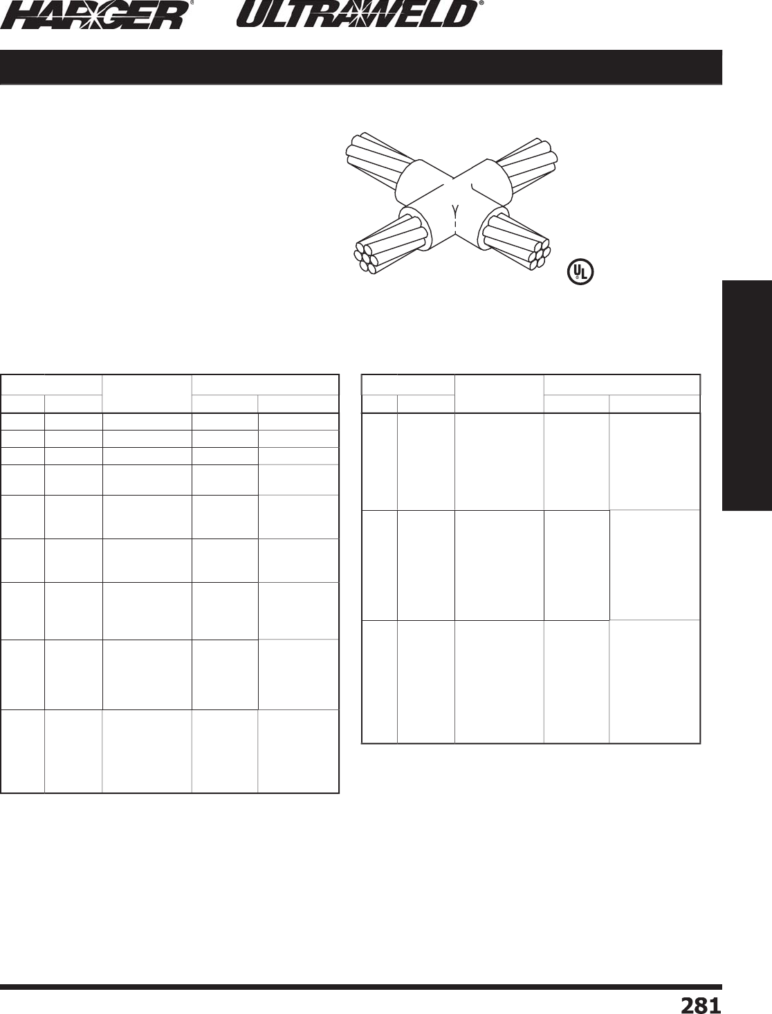
H
ar
g
er Li
g
htnin
g
& Groundin
g
•
©
2012 Phone 847-548-8700 • Fax 847-548-8755 • U.S. 800-842-743
7
2
81
281
Section 5
Ultraweld® Exothermic Connections
XX Cable to Cable
XX
Mold Information
:
•
M
o
l
d
s liste
d
a
re f
o
r str
a
n
d
e
d
c
ab
le. F
o
r s
o
li
d
conductor, add suffi x "S" after conductor number.
i.e. 4S = 4 AWG s
o
li
d
c
o
n
du
ct
o
r.
•
Price Ke
y
is the
Bold Letter
in the M
o
l
d
P
a
rt N
o
.
r
Re
q
uired Tools & Accessories
:
MH1 - H
a
n
d
le f
o
r "
B
"
Price Ke
y
Mold
s
MH2 - H
a
n
d
le f
o
r "
C
"
Price Ke
y
Mold
s
Recommended Tools & Accessories
:
CCBRSH1 - C
a
r
d
Cl
o
th Br
u
s
h
MCBRSH1 - Mold Cleanin
g
Brus
h
(
Cross of Horizontal Cables,
T
a
p
Cable Cut, Cables in
S
ame Plane
)
C
able Size M
o
ld
P
art
No
.
W
el
d
Meta
l
Run
T
a
p
U
ltraSh
o
t
NUWTUBE
#
6
#
6
X
X-
66
B
U
S
32
NU
WT
U
BE
32
#4
#4
XX
-
44
B
US
4
5
NUWTUBE45
#2 S
o
l #2 S
o
l
X
X-
2S2S
B
U
S
65
NU
WT
U
BE
65
#
2
#4
#
2
X
X-
2
4
B
X
X-
22
B
U
S
65
U
S
65
NU
WT
U
BE
65
NU
WT
U
BE
65
1
/
0
#4
#
2
1
/
0
X
X-1
/
04
B
X
X-1
/
0
2
B
X
X-1
/
01
/
0
B
U
S9
0
U
S9
0
U
S9
0
NU
WT
U
BE9
0
NU
WT
U
BE9
0
NU
WT
U
BE9
0
2
/
0
#
2
1
/
0
2
/
0
X
X-2
/
0
2
B
X
X-2
/
01
/
0
B
X
X-2
/
02
/
0
B
US
11
5
US
11
5
US
11
5
NU
WT
U
BE11
5
NU
WT
U
BE11
5
NU
WT
U
BE11
5
3
/
0
#
2
1
/
0
2
/
0
3
/
0
X
X-3
/
0
2
B
X
X-3
/
01
/
0
B
X
X-3
/
02
/
0
B
X
X-3
/
03
/
0
B
US
11
5
US
11
5
U
S1
50
U
S1
50
NU
WT
U
BE11
5
NU
WT
U
BE11
5
NU
WT
U
BE1
50
NU
WT
U
BE1
50
4/
0
#
2
1
/
0
2
/
0
3
/
0
4/
0
X
X-4
/
0
2
B
X
X-4
/
01
/
0
B
X
X-4
/
02
/
0
B
X
X-4
/
03
/
0
B
X
X-4
/
04
/
0
B
US
11
5
U
S1
50
U
S1
50
U
S
200
U
S
200
NU
WT
U
BE11
5
NU
WT
U
BE1
50
NU
WT
U
BE1
50
NU
WT
U
BE
200
NU
WT
U
BE
200
250
MC
M
#
2
1
/
0
2
/
0
3
/
0
4/
0
250
MCM
X
X-
25
CM
2
B
X
X-25CM1
/
0
B
X
X-25CM2
/
0
B
X
X-25CM3
/
0
B
X
X-25CM4
/
0
B
X
X-
25
CM
25
CM
B
US
11
5
U
S1
50
U
S1
50
U
S
200
U
S
200
U
S
200
NU
WT
U
BE11
5
NU
WT
U
BE1
50
NU
WT
U
BE1
50
NU
WT
U
BE
200
NU
WT
U
BE
200
NU
WT
U
BE
200
C
able Size M
o
ld
P
art
No
.
W
el
d
Meta
l
Run
T
a
p
U
ltraSh
o
t
NUWTUBE
300
MC
M
#
2
1
/
0
2
/
0
3
/
0
4/
0
250
MCM
300
MCM
X
X-
3
CM
2
B
X
X-3CM1
/
0
B
X
X-3CM2
/
0
B
X
X-3CM3
/
0
B
X
X-3CM4
/
0
B
X
X-
3
CM
25
CM
B
X
X-
3
CM
3
CM
B
US
11
5
U
S1
50
U
S1
50
U
S
200
U
S
200
U
S
250
U
S
250
NU
WT
U
BE11
5
NU
WT
U
BE1
50
NU
WT
U
BE1
50
NU
WT
U
BE
200
NU
WT
U
BE
200
NU
WT
U
BE
250
NU
WT
U
BE
250
350
MC
M
#
2
1
/
0
2
/
0
3
/
0
4/
0
250
MCM
300
MCM
350
MCM
X
X-
35
CM
2
B
X
X-35CM1
/
0
B
X
X-35CM2
/
0
B
X
X-35CM3
/
0
B
X
X-35CM4
/
0
B
X
X-
35
CM
25
CM
B
X
X-
35
CM
3
CM
B
X
X-
35
CM
35
CM
B
U
S1
50
U
S
200
U
S
200
U
S
200
U
S
200
U
S
250
U
S
250
U
S
250
NU
WT
U
BE1
50
NU
WT
U
BE
200
NU
WT
U
BE
200
NU
WT
U
BE
200
NU
WT
U
BE
200
NU
WT
U
BE
250
NU
WT
U
BE
250
NU
WT
U
BE
250
500
MC
M
#
2
1
/
0
2
/
0
3
/
0
4/
0
250
MCM
300
MCM
350
MCM
500
MCM
X
X-
5
CM
2
B
X
X-5CM1
/
0
B
X
X-5CM2
/
0
B
X
X-5CM3
/
0
C
X
X-5CM4
/
0
C
X
X-
5
CM
25
CM
C
X
X-
5
CM
3
CM
C
X
X-
5
CM
35
CM
C
X
X-
5C
M
5C
M
C
U
S
200
U
S
250
U
S
250
U
S
300
U
S
300
U
S
300
U
S4
00
U
S4
00
U
S
500
NU
WT
U
BE
200
NU
WT
U
BE
250
NU
WT
U
BE
250
2
-N
U
WT
U
BE1
50
2
-N
U
WT
U
BE1
50
2
-N
U
WT
U
BE1
50
2
-N
U
WT
U
BE
200
2
-N
U
WT
U
BE
200
2
-N
U
WT
U
BE
250
XX Connect
i
on T
yp
e XX Connection T
yp
e continue
d
L
iste
d
4
67
S
ect
io
n 5.5

H
ar
g
er Li
g
htnin
g
& Groundin
g
•
©
2012 Phone 847-548-8700 • Fax 847-548-8755 • U.S. 800-842-743
7
2
82
282
Section 5
Ultraweld® Exothermic Connections
Cable to Ground Rod GD
M
o
ld Inf
o
rmati
o
n
:
•
Molds listed are for stranded cable. For solid conductor, add suffi x "S" after
c
o
n
du
ct
o
r n
u
m
b
er. i.e. 4S = 4 AWG s
o
li
d
c
o
n
du
ct
o
r.
•
Molds listed are for tappered
g
round rods. For threaded sectional rods, add
s
uffi x "S" after the
g
round rod number. i.e. 58S = 5/8" sectional
g
round rod.
•
Molds with Price Ke
y
"
L
"
S
O
LD WITH HANDLES.
•
If Handles not re
q
uired, add suffi x "-X" after the Mold Part No.
•
H
a
n
d
les f
o
r "
L
"
Price Key Molds DO NOT INCLUDE Flint I
g
niters.
•
Price Ke
y
is the
Bold Letter
in the M
o
l
d
P
a
rt N
o
.
r
•
For mold Wear Plates, add suffi x "WP" to the end of the Mold Part No.
See pa
g
e 324 for details.
Re
q
uired Tools & Accessories
:
MH1 - H
a
n
d
le f
o
r "
B
"
Price Ke
y
Mold
s
MH2 - H
a
n
d
le f
o
r "
C
"
Price Ke
y
Mold
s
FLTIG - Flint I
g
niter when Price Key is "
L
"
Rec
o
mmended T
oo
ls & Access
o
ries
:
CCBRSH1 - C
a
r
d
Cl
o
th Br
u
s
h
MCBRSH1 - Mold Cleanin
g
Brus
h
GD
(
Sin
g
le Cable Dead Ended to
T
o
p
of Ground Rod
)
G
r
o
und
R
o
d
Si
ze
C
able
Si
ze
M
o
ld
P
art
No
.
W
el
d
Meta
l
U
ltraSh
o
t
NUWTUBE
1
/
2"
#
6
#4
#2 S
o
l
#
2
1
/
0
2
/
0
3
/
0
4/
0
250
MCM
300
MCM
GD-1
26
L
GD-1
24
L
GD-1
22S
B
GD-1
22
B
GD-121
/
0
B
GD-122
/
0
B
GD-123
/
0
B
GD-124
/
0
B
GD-1
225
CM
B
GD-1
23
CM
B
U
S
25
U
S
25
U
S
65
U
S
65
U
S9
0
U
S9
0
U
S9
0
U
S9
0
U
S9
0
U
S9
0
NU
WT
U
BE
25
NU
WT
U
BE
25
NU
WT
U
BE
65
NU
WT
U
BE
65
NU
WT
U
BE9
0
NU
WT
U
BE9
0
NU
WT
U
BE9
0
NU
WT
U
BE9
0
NU
WT
U
BE9
0
NU
WT
U
BE9
0
5/
8"
#
6
#4
#2 S
o
l
#
2
1
/
0
2
/
0
3
/
0
4/
0
250
MCM
300
MCM
350
MCM
500
MCM
GD-586
L
GD-58
4
L
GD-582
S
B
GD-58
2
B
GD-581
/
0
B
GD-582
/
0
B
GD-583
/
0
B
GD-584
/
0
B
GD-5825CM
B
GD-583CM
B
GD-5835CM
B
GD-585CM
B
U
S
32
U
S
32
U
S
65
U
S
65
U
S9
0
U
S9
0
U
S9
0
U
S9
0
U
S9
0
US
11
5
US
11
5
U
S1
50
NU
WT
U
BE
32
NU
WT
U
BE
32
NU
WT
U
BE
65
NU
WT
U
BE
65
NU
WT
U
BE9
0
NU
WT
U
BE9
0
NU
WT
U
BE9
0
NU
WT
U
BE9
0
NU
WT
U
BE9
0
NU
WT
U
BE11
5
NU
WT
U
BE11
5
NU
WT
U
BE1
50
G
r
o
un
d
R
o
d
Si
ze
C
able
Si
ze
M
o
ld
P
art
No
.
W
el
d
Meta
l
U
ltraSh
o
t
NUWTUBE
3
/
4"
#
6
#4
#2 S
o
l
#
2
1
/
0
2
/
0
3
/
0
4/
0
250
MCM
300
MCM
350
MCM
500
MCM
7
50
MCM
GD-
3
4
6
L
GD-
3
44
L
GD-
3
4
2S
B
GD-
3
4
2
B
GD-341
/
0
B
GD-342
/
0
B
GD-343
/
0
B
GD-344
/
0
B
GD-
3
4
25
CM
B
GD-
3
4
3
CM
B
GD-
3
4
35
CM
B
GD-
3
4
5
CM
B
GD-
3
47
5
CM
B
U
S
32
US
4
5
U
S9
0
U
S9
0
U
S9
0
U
S9
0
U
S9
0
U
S9
0
U
S9
0
US
11
5
US
11
5
U
S1
50
U
S
250
NU
WT
U
BE
32
NUWTUBE45
NU
WT
U
BE9
0
NU
WT
U
BE9
0
NU
WT
U
BE9
0
NU
WT
U
BE9
0
NU
WT
U
BE9
0
NU
WT
U
BE9
0
NU
WT
U
BE9
0
NU
WT
U
BE11
5
NU
WT
U
BE11
5
NU
WT
U
BE1
50
NU
WT
U
BE
250
1"
1
/
0
2
/
0
3
/
0
4/
0
250
MCM
300
MCM
350
MCM
500
MCM
7
50
MCM
1
000
MCM
GD-101
/
0
B
GD-102
/
0
B
GD-103
/
0
B
GD-104
/
0
B
GD-1
025
CM
B
GD-1
03
CM
B
GD-1
035
CM
B
GD-1
05
CM
B
GD-1
0
7
5
CM
B
GD-1
0
1MM
C
U
S1
50
U
S1
50
U
S1
50
U
S1
50
U
S1
50
U
S
200
U
S
200
U
S
200
U
S
250
U
S
300
NU
WT
U
BE1
50
NU
WT
U
BE1
50
NU
WT
U
BE1
50
NU
WT
U
BE1
50
NU
WT
U
BE1
50
NU
WT
U
BE
200
NU
WT
U
BE
200
NU
WT
U
BE
200
NU
WT
U
BE
250
2
-N
U
WT
U
BE1
50
G
D Connect
i
on T
yp
e
G
D Connection T
yp
e continued
L
iste
d
4
67
N
O
TES
:
• Molds listed are for copper-clad steel
g
round rods.
• For weldin
g
to full size copper-clad steel, stainless steel,
g
alvanized steel or solid copper
g
round rods, add letter "F" to
g
round rod size. For sectional
g
round rods, add letter "S"
to
g
round rod size. See chart on pa
g
e 335 for details.
S
ect
io
n 5.5
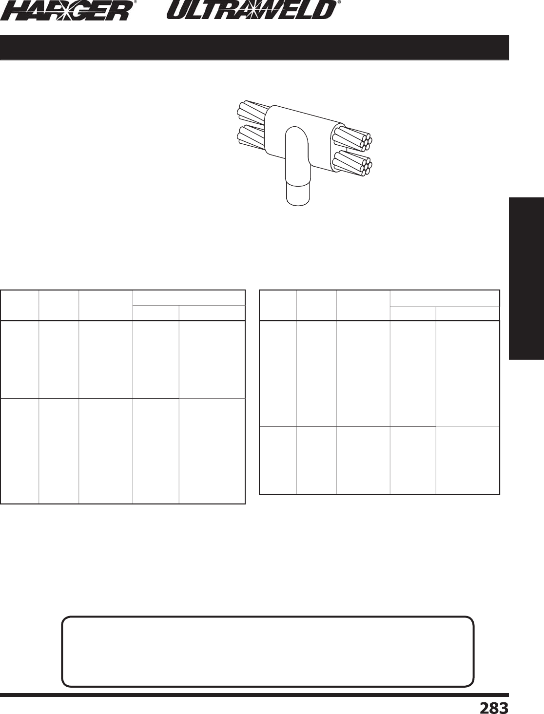
H
ar
g
er Li
g
htnin
g
& Groundin
g
•
©
2012 Phone 847-548-8700 • Fax 847-548-8755 • U.S. 800-842-743
7
2
83
283
Section 5
Ultraweld® Exothermic Connections
GF Cable to Ground Rod
GF
(
Parallel Thru Horizontal Cables
(
Ta
p
Over Run
)
to To
p
o
f
Ground Rod
)
M
o
ld Inf
o
rmati
o
n
:
•
M
o
l
d
s liste
d
a
re f
o
r str
a
n
d
e
d
c
ab
le. F
o
r s
o
li
d
conductor, add suffi x "S" after conductor number.
i.e. 4S = 4 AWG s
o
li
d
c
o
n
du
ct
o
r.
•
Molds listed are for tappered
g
round rods. For
threaded sectional rods, add suffi x "S" after the
g
round rod number. i.e. 58S = 5/8" sectional
g
round rod.
•
Price Ke
y
is the
Bold Letter
in the M
o
l
d
P
a
rt N
o
.
r
Re
q
uired Tools & Accessories
:
MH1 - H
a
n
d
le f
o
r "
K
"
Price Ke
y
Mold
s
MH2 - H
a
n
d
le f
o
r "
D
"
Price Ke
y
Mold
s
Rec
o
mmended T
oo
ls & Access
o
ries
:
CCBRSH1 - C
a
r
d
Cl
o
th Br
u
s
h
MCBRSH1 - Mold Cleanin
g
Brus
h
G
r
o
und
R
o
d
Si
ze
C
able
Si
ze
M
o
ld
P
art
No
.
W
el
d
Meta
l
U
ltraSh
o
t
NUWTUBE
1
/
2"
#
6
#4
#2 S
o
l
#
2
1
/
0
2
/
0
3
/
0
4/
0
GF-1
26
K
GF-1
24
K
GF-1
22S
K
GF-1
22
K
GF-121
/
0
K
GF-122
/
0
K
GF-123
/
0
K
GF-124
/
0
K
U
S9
0
US
11
5
US
11
5
US
11
5
U
S1
50
U
S
200
U
S
250
U
S
250
NU
WT
U
BE9
0
NU
WT
U
BE11
5
NU
WT
U
BE11
5
NU
WT
U
BE11
5
NU
WT
U
BE1
50
NU
WT
U
BE
200
NU
WT
U
BE
250
NU
WT
U
BE
250
5/
8"
#
6
#4
#2 S
o
l
#
2
1
/
0
2
/
0
3
/
0
4/
0
250
MCM
300
MCM
350
MCM
GF-586
K
GF-58
4
K
GF-582
S
K
GF-58
2
K
GF-581
/
0
K
GF-582
/
0
K
GF-583
/
0
D
GF-584
/
0
D
GF-5825CM
D
GF-583CM
D
GF-5835CM
D
U
S9
0
US
11
5
U
S1
50
U
S1
50
U
S
200
U
S
250
U
S
300
U
S
300
U
S4
00
U
S
500
U
S
500
NU
WT
U
BE9
0
NU
WT
U
BE11
5
NU
WT
U
BE1
50
NU
WT
U
BE1
50
NU
WT
U
BE
200
NU
WT
U
BE
250
2
-N
U
WT
U
BE1
50
2
-N
U
WT
U
BE1
50
2
-N
U
WT
U
BE
200
2
-N
U
WT
U
BE
250
2
-N
U
WT
U
BE
250
G
r
o
un
d
R
o
d
Si
ze
C
able
Si
ze
M
o
ld
P
art
No
.
W
el
d
Meta
l
U
ltraSh
o
t
NUWTUBE
3
/
4"
#
6
#4
#2 S
o
l
#
2
1
/
0
2
/
0
3
/
0
4/
0
250
MCM
300
MCM
350
MCM
GF-
3
4
6
K
GF-
3
4
4
K
GF-
3
4
2S
K
GF-
3
4
2
K
GF-341
/
0
K
GF-342
/
0
K
GF-343
/
0
D
GF-344
/
0
D
GF-
3
4
25
CM
D
GF-
3
4
3
CM
D
GF-
3
4
35
CM
D
U
S9
0
US
11
5
U
S1
50
U
S1
50
U
S
200
U
S
250
U
S
300
U
S
300
U
S4
00
U
S
500
U
S
500
NU
WT
U
BE9
0
NU
WT
U
BE11
5
NU
WT
U
BE1
50
NU
WT
U
BE1
50
NU
WT
U
BE
200
NU
WT
U
BE
250
2
-N
U
WT
U
BE1
50
2
-N
U
WT
U
BE1
50
2
-N
U
WT
U
BE
200
2
-N
U
WT
U
BE
250
2
-N
U
WT
U
BE
250
1"
#4
#
2
1
/
0
2
/
0
3
/
0
4/
0
250
MCM
GF-1
04
K
GF-1
02
K
GF-101
/
0
K
GF-102
/
0
D
GF-103
/
0
D
GF-104
/
0
D
GF-1
025
CM
D
U
S1
50
U
S
200
U
S
250
U
S
300
U
S4
00
U
S4
00
U
S
500
NU
WT
U
BE1
50
NU
WT
U
BE
200
NU
WT
U
BE
250
2
-N
U
WT
U
BE1
50
2
-N
U
WT
U
BE
200
2
-N
U
WT
U
BE
200
2
-N
U
WT
U
BE
250
G
F Connect
i
on T
yp
e
G
F Connection T
yp
e continue
d
N
O
TES
:
• Molds listed are for copper-clad steel
g
round rods.
• For weldin
g
to full size copper-clad steel, stainless steel,
g
alvanized steel or solid copper
g
round rods, add letter "F" to
g
round rod size. For sectional
g
round rods, add letter "S"
to
g
round rod size. See chart on pa
g
e 335 for details.
S
ect
io
n 5.5
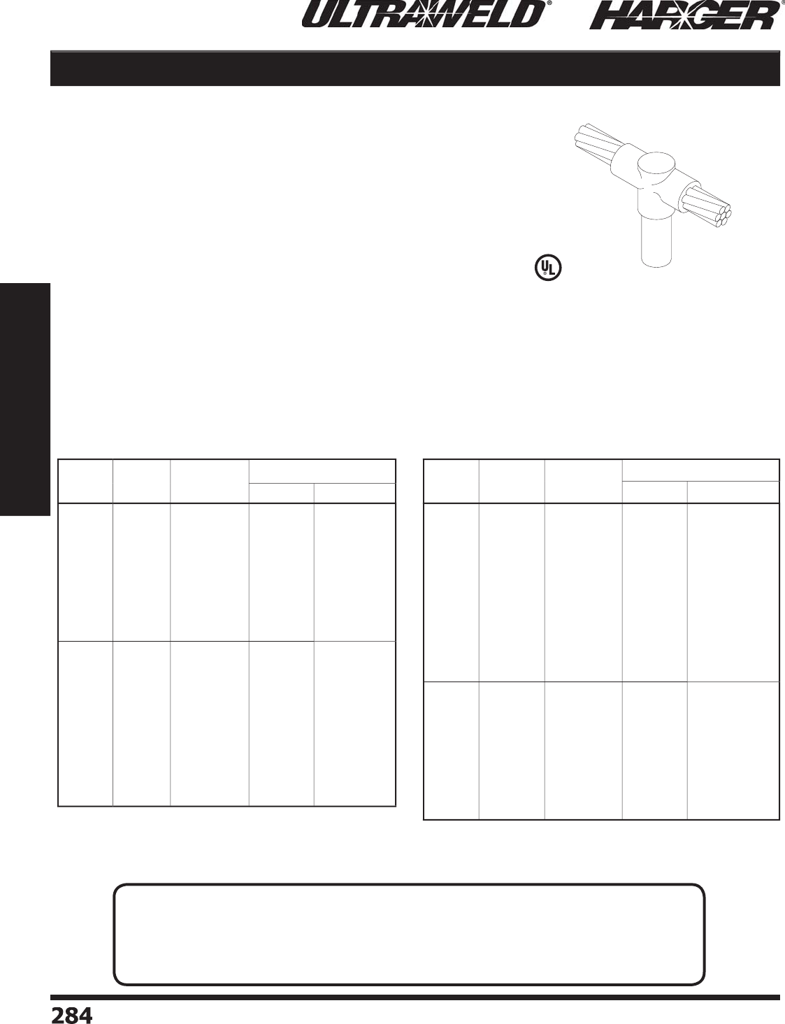
H
ar
g
er Li
g
htnin
g
& Groundin
g
•
©
2012 Phone 847-548-8700 • Fax 847-548-8755 • U.S. 800-842-743
7
2
8
4
284
Section 5
Ultraweld® Exothermic Connections
Cable to Ground Rod GO
M
o
ld Inf
o
rmati
o
n
:
•
Molds listed are for stranded cable. For solid conductor, add suffi x "S" after
c
o
n
du
ct
o
r n
u
m
b
er. i.e. 4S = 4 AWG s
o
li
d
c
o
n
du
ct
o
r.
•
Molds listed are for tappered
g
round rods. For threaded sectional rods,
add suffi x "S" after the
g
round rod number. i.e. 58S = 5/8" sectional
g
round rod.
•
Molds with Price Ke
y
"
L
"
a
n
d
"
M
"
S
O
LD WITH HANDLES.
•
H
a
n
d
les f
o
r "
L
"
a
n
d
"
M
"
Price Key Molds DO NOT INCLUDE Flint I
g
niters.
•
If Handles not re
q
uired, add suffi x "-X" after the Mold Part No.
•
Price Ke
y
is the
Bold Letter
in the M
o
l
d
P
a
rt N
o
.
r
•
For mold Wear Plates, add suffi x "WP" to the end of the Mold Part No.
See pa
g
e 324 for details.
Re
q
uired Tools & Accessories
:
MH1 - H
a
n
d
le f
o
r "
B
"
Price Ke
y
Mold
s
MH2 - H
a
n
d
le f
o
r "
C
"
Price Ke
y
Mold
s
FLTIG - Flint I
g
niter when Price Key is "
L
"
o
r "
M
"
Rec
o
mmended T
oo
ls & Access
o
ries
:
CCBRSH1 - C
a
r
d
Cl
o
th Br
u
s
h
MCBRSH1 - Mold Cleanin
g
Brus
h
GO
(
Horizontal Thru Cable to
T
o
p
of Ground Rod
)
G
r
o
und
R
o
d
Si
ze
C
able
Si
ze
M
o
ld
P
art
No
.
W
el
d
Meta
l
U
ltraSh
o
t
NUWTUBE
1
/
2"
#
6
#4
#2 S
o
l
#
2
1
/
0
2
/
0
3
/
0
4/
0
250
MCM
300
MCM
G
O
-1
26
L
G
O
-1
2
4
L
G
O
-1
22S
B
G
O
-1
22
B
GO-121
/
0
B
GO-122
/
0
B
GO-123
/
0
B
GO-124
/
0
B
G
O
-1
225
CM
B
G
O
-1
23
CM
B
U
S
32
U
S
32
U
S9
0
U
S9
0
U
S9
0
U
S9
0
US
11
5
US
11
5
U
S1
50
U
S
200
NU
WT
U
BE
32
NU
WT
U
BE
32
NU
WT
U
BE9
0
NU
WT
U
BE9
0
NU
WT
U
BE9
0
NU
WT
U
BE9
0
NU
WT
U
BE11
5
NU
WT
U
BE11
5
NU
WT
U
BE1
50
NU
WT
U
BE
200
5/
8"
#
6
#4
#2 S
o
l
#
2
1
/
0
2
/
0
3
/
0
4/
0
250
MCM
300
MCM
350
MCM
500
MCM
GO-586
L
GO-584
L
GO-582
S
B
GO-58
2
B
GO-581
/
0
B
GO-582
/
0
B
GO-583
/
0
B
GO-584
/
0
B
GO-5825CM
B
GO-583CM
B
GO-5835CM
B
GO-585CM
B
U
S
32
U
S
32
U
S9
0
U
S9
0
U
S9
0
US
11
5
US
11
5
US
11
5
U
S1
50
U
S
200
U
S
200
U
S
250
NU
WT
U
BE
32
NU
WT
U
BE
32
NU
WT
U
BE9
0
NU
WT
U
BE9
0
NU
WT
U
BE9
0
NU
WT
U
BE11
5
NU
WT
U
BE11
5
NU
WT
U
BE11
5
NU
WT
U
BE1
50
NU
WT
U
BE
200
NU
WT
U
BE
200
NU
WT
U
BE
250
G
r
o
un
d
R
o
d
Si
ze
C
able
Si
ze
M
o
ld
P
art
No
.
W
el
d
Meta
l
U
ltraSh
o
t
NUWTUBE
3
/
4"
#
6
#4
#2 S
o
l
#
2
1
/
0
2
/
0
3
/
0
4/
0
250
MCM
300
MCM
350
MCM
500
MCM
7
50
MCM
G
O
-
3
4
6
L
G
O
-
3
4
4
M
G
O
-
3
4
2S
B
G
O
-
3
4
2
B
GO-341
/
0
B
GO-342
/
0
B
GO-343
/
0
B
GO-344
/
0
B
G
O
-
3
4
25
CM
B
G
O
-
3
4
3
CM
B
G
O
-
3
4
35
CM
B
G
O
-
3
4
5
CM
B
G
O
-
3
47
5
CM
C
US
4
5
U
S
65
U
S9
0
U
S9
0
US
11
5
US
11
5
US
11
5
US
11
5
U
S1
50
U
S
200
U
S
200
U
S
250
U
S4
00
NUWTUBE45
NU
WT
U
BE
65
NU
WT
U
BE9
0
NU
WT
U
BE9
0
NU
WT
U
BE11
5
NU
WT
U
BE11
5
NU
WT
U
BE11
5
NU
WT
U
BE11
5
NU
WT
U
BE1
50
NU
WT
U
BE
200
NU
WT
U
BE
200
NU
WT
U
BE
250
2
-N
U
WT
U
BE
200
1"
1
/
0
2
/
0
3
/
0
4/
0
250
MCM
300
MCM
350
MCM
500
MCM
7
50
MCM
1
000
MCM
GO-101
/
0
B
GO-102
/
0
B
GO-103
/
0
B
GO-104
/
0
B
G
O
-1
025
CM
B
G
O
-1
03
CM
B
G
O
-1
035
CM
B
G
O
-1
05
CM
B
G
O
-1
0
7
5
CM
C
G
O
-1
0
1MM
C
U
S1
50
U
S1
50
U
S1
50
U
S1
50
U
S
200
U
S
200
U
S
200
U
S
250
U
S4
00
U
S
500
NU
WT
U
BE1
50
NU
WT
U
BE1
50
NU
WT
U
BE1
50
NU
WT
U
BE1
50
NU
WT
U
BE
200
NU
WT
U
BE
200
NU
WT
U
BE
200
NU
WT
U
BE
250
2
-N
U
WT
U
BE
200
2
-N
U
WT
U
BE
250
G
O Connect
i
on T
yp
e
G
O Connection T
yp
e continue
d
L
iste
d
4
67
N
O
TES
:
• Molds listed are for copper-clad steel
g
round rods.
• For weldin
g
to full size copper-clad steel, stainless steel,
g
alvanized steel or solid copper
g
round rods, add letter "F" to
g
round rod size. For sectional
g
round rods, add letter "S"
to
g
round rod size. See chart on pa
g
e 335 for details.
S
ect
io
n 5.5

H
ar
g
er Li
g
htnin
g
& Groundin
g
•
©
2012 Phone 847-548-8700 • Fax 847-548-8755 • U.S. 800-842-743
7
2
85
285
Section 5
Ultraweld® Exothermic Connections
GS Cable to Ground Rod
GS
Mold Information
:
•
M
o
l
d
s liste
d
a
re f
o
r str
a
n
d
e
d
c
ab
le. F
o
r s
o
li
d
conductor, add suffi x "S" after conductor number.
i.e. 4S = 4 AWG s
o
li
d
c
o
n
du
ct
o
r.
•
If Frame not re
q
uired, add suffi x "-X" after the
Mo
l
d
P
a
rt N
o
.
•
H
a
n
d
les f
o
r "
R
"
Price Ke
y
Molds DO NOT
INCLUDE Flint I
g
niters.
•
Price Ke
y
is the
Bold Letter
in the M
o
l
d
P
a
rt N
o
.
r
•
For mold Wear Plates, add suffi x "WP" to the end
o
f the Mold Part No. See pa
g
e 324 for details.
Re
q
uired Tools & Accessories
:
MH1 - H
a
n
d
le f
o
r "
P
"
Price Ke
y
Mold
s
MH2 - H
a
n
d
le f
o
r "
Y
"
Price Ke
y
Mold
s
MH4 - H
a
n
d
le f
o
r "
R
"
Price Ke
y
Mold
s
FLTIG - Flint I
g
niter when Price Key is "
R
"
Recommended Tools & Accessories
:
CCBRSH1 - C
a
r
d
Cl
o
th Br
u
s
h
MCBRSH1 - Mold Cleanin
g
Brus
h
(
Horizontal Thru Cable to
S
ide of Ground Rod
)
Co
st Effective
2
-P
i
ece Des
ign
G
r
o
und
R
o
d
Si
ze
C
able
Si
ze
M
o
ld
P
art
No
.
W
el
d
Meta
l
U
ltraSh
o
t
NUWTUBE
1
/
2"
#
6
#4
#2 S
o
l
#
2
1
/
0
2
/
0
3
/
0
4/
0
250
MCM
GS-1
26
R
GS-1
2
4
R
GS-1
22S
R
GS-1
22
R
GS-121
/
0
P
GS-122
/
0
P
GS-123
/
0
P
GS-124
/
0
P
GS-1
225
CM
P
U
S
65
U
S
65
U
S
65
U
S
65
US
11
5
US
11
5
U
S1
50
U
S1
50
U
S1
50
NU
WT
U
BE
65
NU
WT
U
BE
65
NU
WT
U
BE
65
NU
WT
U
BE
65
NU
WT
U
BE11
5
NU
WT
U
BE11
5
NU
WT
U
BE1
50
NU
WT
U
BE1
50
NU
WT
U
BE1
50
5/
8"
#
6
#4
#2 S
o
l
#
2
1
/
0
2
/
0
3
/
0
4/
0
250
MCM
500
MCM
GS-586
R
GS-584
R
GS-582
S
R
GS-58
2
R
GS-581
/
0
P
GS-582
/
0
P
GS-583
/
0
P
GS-584
/
0
P
GS-5825CM
P
GS-585CM
Y
U
S
65
U
S
65
U
S
65
U
S
65
US
11
5
US
11
5
U
S1
50
U
S1
50
U
S1
50
U
S4
00
NU
WT
U
BE
65
NU
WT
U
BE
65
NU
WT
U
BE
65
NU
WT
U
BE
65
NU
WT
U
BE11
5
NU
WT
U
BE11
5
NU
WT
U
BE1
50
NU
WT
U
BE1
50
NU
WT
U
BE1
50
2
-N
U
WT
U
BE
200
G
r
o
und
R
o
d
Si
ze
C
able
Si
ze
M
o
ld
P
art
No
.
W
el
d
Meta
l
U
ltraSh
o
t
NUWTUBE
3
/
4"
#
6
#4
#2 S
o
l
#
2
1
/
0
2
/
0
3
/
0
4/
0
250
MCM
500
MCM
GS-
3
4
6
R
GS-
3
44
R
GS-
3
4
2S
R
GS-
3
4
2
R
GS-341
/
0
P
GS-342
/
0
P
GS-343
/
0
P
GS-344
/
0
P
GS-
3
4
25
CM
P
GS-
3
4
5
CM
Y
U
S
65
U
S
65
U
S
65
U
S
65
US
11
5
US
11
5
U
S1
50
U
S1
50
U
S
200
U
S
500
NU
WT
U
BE
65
NU
WT
U
BE
65
NU
WT
U
BE
65
NU
WT
U
BE
65
NU
WT
U
BE11
5
NU
WT
U
BE11
5
NU
WT
U
BE1
50
NU
WT
U
BE1
50
NU
WT
U
BE
200
2
-N
U
WT
U
BE
250
G
S Connect
i
on T
yp
e
G
S Connection T
yp
e continued
N
O
TES
:
• Molds listed are for copper-clad steel
g
round rods.
• For weldin
g
to full size copper-clad steel, stainless steel,
g
alvanized steel or solid copper
g
round rods, add letter "F" to
g
round rod size. For sectional
g
round rods, add letter "S"
to
g
round rod size. See chart on pa
g
e 335 for details.
S
ect
io
n 5.5
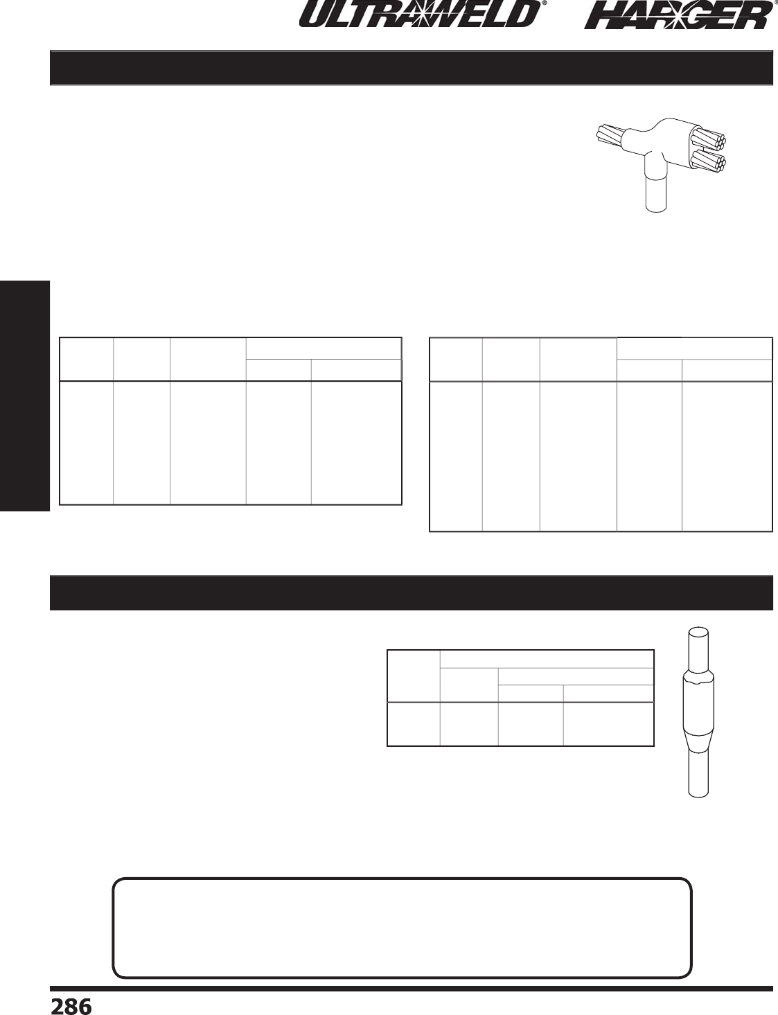
H
ar
g
er Li
g
htnin
g
& Groundin
g
•
©
2012 Phone 847-548-8700 • Fax 847-548-8755 • U.S. 800-842-743
7
2
86
286
Section 5
Ultraweld® Exothermic Connections
GG
(
Butt S
p
lice of Vertical
Ground Rods
)
Ground Rod to Ground Rod GG
Cable to Ground Rod GT
M
o
ld Inf
o
rmati
o
n
:
•
Molds listed are for stranded cable. For solid conductor, add suffi x "S" after conductor
n
u
m
b
er. i.e. 4S = 4 AWG s
o
li
d
c
o
n
du
ct
o
r.
•
Molds listed are for tappered
g
round rods. For threaded sectional rods, add suffi x
"
S" after the
g
round rod number. i.e. 58S = 5/8" sectional
g
round rod.
•
Price Ke
y
is the
Bold Letter
in the M
o
l
d
P
a
rt N
o
.
r
Re
q
uired Tools & Accessories
:
MH1 - H
a
n
d
le f
o
r "
K
"
Price Ke
y
Mold
s
MH2 - H
a
n
d
le f
o
r "
D
"
Price Ke
y
Mold
s
Rec
o
mmended T
oo
ls & Access
o
ries
:
CCBRSH1 - C
a
r
d
Cl
o
th Br
u
s
h
MCBRSH1 - Mold Cleanin
g
Brus
h
G
T
(
Horizontal Thru Cable Plus Ta
p
Cable to To
p
of Ground Rod
)
M
o
ld Inf
o
rmati
o
n
:
•
Molds listed are for tappered
g
round rods. For
threaded sectional rods, add suffi x "S" after the
g
round rod number. i.e. 58S = 5/8" sectional
g
round rod.
•
Price Ke
y
is the
Bold Letter
in the M
o
l
d
P
a
rt N
o
.
r
Re
q
uired Tools & Accessories
:
MH1 - H
a
n
d
le f
o
r "B
"
Price Ke
y
Mold
s
MH2 - H
a
n
d
le f
o
r "
C
"
Price Ke
y
Mold
s
GRCC - Ground Rod and Cable Clam
p
.
See pa
g
e 332 for details.
Rec
o
mmended T
oo
ls & Access
o
ries
:
CCBRSH1 - C
a
r
d
Cl
o
th Br
u
s
h
MCBRSH1 - Mold Cleanin
g
Brus
h
G
r
o
und
R
o
d
Si
ze
C
able
Si
ze
M
o
ld
P
art
No
.
W
el
d
Meta
l
U
ltraSh
o
t
NUWTUBE
5/
8"
#
6
#4
#2 S
o
l
#
2
1
/
0
2
/
0
3
/
0
4/
0
250
MCM
GT-586
K
GT-584
K
GT-582
S
K
GT-58
2
K
GT-581
/
0
K
GT-582
/
0
K
GT-583
/
0
K
GT-584
/
0
K
GT-5825CM
D
U
S9
0
U
S9
0
US
11
5
US
11
5
U
S1
50
U
S
200
U
S
250
U
S
250
U
S
300
NU
WT
U
BE9
0
NU
WT
U
BE9
0
NU
WT
U
BE11
5
NU
WT
U
BE11
5
NU
WT
U
BE1
50
NU
WT
U
BE
200
NU
WT
U
BE
250
NU
WT
U
BE
250
2
-N
U
WT
U
BE1
50
G
r
o
un
d
R
o
d
Si
ze
C
able
Si
ze
M
o
ld
P
art
No
.
W
el
d
Meta
l
U
ltraSh
o
t
NUWTUBE
3
/
4"
#
6
#4
#2 S
o
l
#
2
1
/
0
2
/
0
3
/
0
4/
0
250
MCM
300
MCM
350
MCM
GT-
3
4
6
K
GT-
3
44
K
GT-
3
4
2S
K
GT-
3
4
2
K
GT-341
/
0
K
GT-342
/
0
K
GT-343
/
0
K
GT-344
/
0
K
GT-
3
4
25
CM
D
GT-
3
4
3
CM
D
GT-
3
4
35
CM
D
U
S9
0
U
S9
0
US
11
5
US
11
5
U
S1
50
U
S
200
U
S
250
U
S
250
U
S
300
U
S4
00
U
S4
00
NU
WT
U
BE9
0
NU
WT
U
BE9
0
NU
WT
U
BE11
5
NU
WT
U
BE11
5
NU
WT
U
BE1
50
NU
WT
U
BE
200
NU
WT
U
BE
250
NU
WT
U
BE
250
2
-N
U
WT
U
BE1
50
2
-N
U
WT
U
BE
200
2
-N
U
WT
U
BE
200
G
r
o
und
R
o
d
Si
ze
Heav
y
Dut
y
Mold
M
o
ld
P
art
No
.
W
el
d
Mete
l
U
ltraSh
o
t N
U
WT
U
BE
1
/
2"
5/
8"
3
/
4"
GG-1
2
B
GG-58
C
GG-
34
C
U
S
250
U
S
300
U
S4
00
NU
WT
U
BE
250
2
-N
U
WT
U
BE1
50
2
-N
U
WT
U
BE
200
G
T Connect
i
on T
yp
e
G
T Connection T
yp
e continued
G
G Connect
i
on T
yp
e
N
O
TES
:
• Molds listed are for copper-clad steel
g
round rods.
• For weldin
g
to full size copper-clad steel, stainless steel,
g
alvanized steel or solid copper
g
round rods, add letter "F" to
g
round rod size. For sectional
g
round rods, add letter "S"
to
g
round rod size. See chart on pa
g
e 335 for details.
S
ect
io
n 5.5
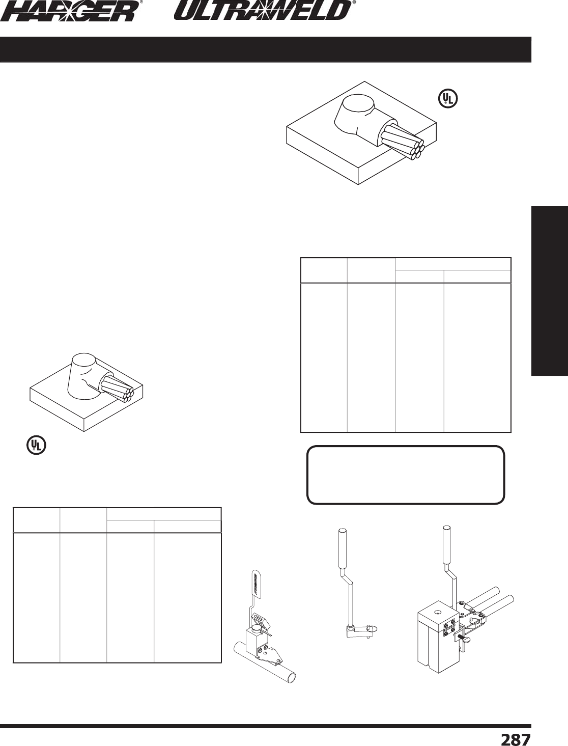
H
ar
g
er Li
g
htnin
g
& Groundin
g
•
©
2012 Phone 847-548-8700 • Fax 847-548-8755 • U.S. 800-842-743
7
2
87
287
Section 5
Ultraweld® Exothermic Connections
HB
M
o
ld Inf
o
rmati
o
n
:
•
HB
m
o
l
d
c
ab
le i
s
off
the steel s
u
rf
a
ce.
f
•
HD
m
o
l
d
c
ab
le i
s
on
the steel s
u
rf
a
ce.
•
M
o
l
d
s liste
d
a
re f
o
r str
a
n
d
e
d
c
ab
le. F
o
r s
o
li
d
conductor, add suffi x "S" after conductor number.
i.e. 4S = 4 AWG s
o
li
d
c
o
n
du
ct
o
r.
•
Molds with Price Ke
y
"
A
"
S
O
LD WITH FRAME.
•
If Frame not re
q
uired, add suffi x "-X" after the Mold
Pa
rt
No
.
•
Fr
a
me f
o
r "
A
"
Price Ke
y
Molds DO NOT INCLUDE
F
lint I
g
niters.
•
Price Ke
y
is the
Bold Letter
in the M
o
l
d
P
a
rt N
o
.
r
•
Fo
r
HB
mold Wear Plates, add suffi x "WP" to the
end of the Mold Part No. See pa
g
e 324 for details.
Re
q
uired Tools & Accessories
:
MH1 - H
a
n
d
le f
o
r "
B
"
Price Ke
y
Mold
s
MH2 - H
a
n
d
le f
o
r "
C
"
Price Ke
y
Mold
s
FLTIG - Flint I
g
niter when Price Key is "
A
"
Rec
o
mmended T
oo
ls & Access
o
ries
:
CCBRSH1 - C
a
r
d
Cl
o
th Br
u
s
h
MCBRSH1 - Mold Cleanin
g
Brus
h
U
MHDKIT - H
o
l
d
D
o
wn Ki
t
UMMHDA - Hold Down Kit when Price Ke
y
is "A"
HD
(
Horizontal Cable to Horizontal Flat
S
teel Surface, OFF Surface
)
(
Horizontal Cable to Horizontal
F
lat Steel Surface, ON Surface
)
HB / HD Cable to Steel Surface
UMHDKIT
U
MHDKIT with M
o
l
d
&
H
a
n
d
le
Pa
tente
d
C
able
Si
ze
M
o
ld
P
art
No
.
W
el
d
Meta
l
U
ltraSh
o
t
NUWTUBE
#
6
#2 S
o
l
#
2
1
/
0
2
/
0
3
/
0
4/
0
250
MCM
300
MCM
350
MCM
500
MCM
7
50
MCM
1
000
MCM
H
B-
6
B
H
B-
2S
B
H
B-
2
B
H
B-1
/
0
B
H
B-2
/
0
B
H
B-3
/
0
B
H
B-4
/
0
B
H
B-
25
CM
B
H
B-
3
CM
B
H
B-
35
CM
B
H
B-
5C
M
B
H
B-7
5C
M
C
H
B-1MM
C
U
S
65
U
S
65
U
S
65
U
S9
0
U
S9
0
US
11
5
US
11
5
US
11
5
U
S1
50
U
S
200
U
S
200
U
S
300
U
S4
00
NU
WT
U
BE
65
NU
WT
U
BE
65
NU
WT
U
BE
65
NU
WT
U
BE9
0
NU
WT
U
BE9
0
NU
WT
U
BE11
5
NU
WT
U
BE11
5
NU
WT
U
BE11
5
NU
WT
U
BE1
50
NU
WT
U
BE
200
NU
WT
U
BE
200
2
-N
U
WT
U
BE1
50
2
-N
U
WT
U
BE
200
C
able
Si
ze
M
o
ld
P
art
No
.
W
el
d
Meta
l
U
ltraSh
o
t
NUWTUBE
#
6
S
o
l
#
6
#4
#2 S
o
l
#
2
1
/
0
2
/
0
3
/
0
4/
0
250
MCM
300
MCM
350
MCM
500
MCM
7
50
MCM
1
000
MCM
H
D-
6S
A
H
D-
6
A
HD
-
4
A
H
D-
2S
A
H
D-
2
A
H
D-1
/
0
B
H
D-2
/
0
B
H
D-3
/
0
B
H
D-4
/
0
B
H
D-
25
CM
B
H
D-
3
CM
B
H
D-
35
CM
B
H
D-
5C
M
B
H
D-7
5C
M
C
H
D-1MM
C
US
4
5
US
4
5
US
4
5
US
4
5
US
4
5
U
S9
0
U
S9
0
US
11
5
US
11
5
US
11
5
U
S1
50
U
S
200
U
S
200
U
S
300
U
S4
00
NUWTUBE45
NUWTUBE45
NUWTUBE45
NUWTUBE45
NUWTUBE45
NU
WT
U
BE9
0
NU
WT
U
BE9
0
NU
WT
U
BE11
5
NU
WT
U
BE11
5
NU
WT
U
BE11
5
NU
WT
U
BE1
50
NU
WT
U
BE
200
NU
WT
U
BE
200
2
-N
U
WT
U
BE1
50
2
-N
U
WT
U
BE
200
HB Connect
i
on T
yp
e
HD Connect
i
on T
yp
e
L
iste
d
4
67
L
iste
d
4
67
S
ect
io
n 5.5
UMMHDA
N
O
TE
:
• For HD mold, ma
y
need Mold Sealer
(MLDSLR, see pa
g
e 326)
on conductors 1/0 and lar
g
er.

H
ar
g
er Li
g
htnin
g
& Groundin
g
•
©
2012 Phone 847-548-8700 • Fax 847-548-8755 • U.S. 800-842-743
7
2
88
288
Section 5
Ultraweld® Exothermic Connections
**Add Pi
p
e Size to Mold Part No.
See chart t
o
the left.
**Add Pi
p
e Size to Mold Part No.
See chart t
o
the left.
HB
HD
M
o
ld Inf
o
rmati
o
n
:
•
HB
m
o
l
d
c
ab
le i
s
off
the pipe surface.
f
•
HD
m
o
l
d
c
ab
le i
s
on
the
p
i
p
e surface.
•
M
o
l
d
s liste
d
a
re f
o
r str
a
n
d
e
d
c
ab
le. F
o
r s
o
li
d
conductor, add suffi x "S" after conductor number.
i.e. 4S = 4 AWG s
o
li
d
c
o
n
du
ct
o
r.
•
Molds with Price Ke
y
"
A
"
S
O
LD WITH FRAME.
•
Molds with Price Ke
y
"
A
"
do
n
o
t
u
se
a
h
a
n
d
le.
•
Fr
a
me f
o
r "
A
"
Price Ke
y
Molds DO NOT INCLUDE
Flint I
g
niters.
•
Price Ke
y
is the
Bold Letter
in the M
o
l
d
P
a
rt N
o
.
r
•
Fo
r
HB
mold Wear Plates, add suffi x "WP" to the
end of the Mold Part No. See pa
g
e 324 for details.
Re
q
uired Tools & Accessories
:
MH1 - H
a
n
d
le f
o
r "
B
"
Price Ke
y
Mold
s
FLTIG - Flint I
g
niter when Price Key is "
A
"
Rec
o
mmended T
oo
ls & Access
o
ries
:
CCBRSH1 - C
a
r
d
Cl
o
th Br
u
s
h
MCBRSH1 - Mold Cleanin
g
Brus
h
U
MHDKIT - H
o
l
d
D
o
wn Ki
t
OR
CSKITHP - Chain Su
pp
ort Kit for Horizontal Pi
pe
UMMHDA - Hold Down Kit when Price Ke
y
is "A"
(
Horizontal Cable to To
p
of Horizontal
S
teel Pi
p
e, OFF Surface
)
(
Horizontal Cable to To
p
of Horizontal
S
teel Pi
p
e, ON Surface
)
Cable to Steel Surface / Pipe HB / HD
CS
KITH
P
UMHDKIT
Pa
tente
d
C
able
Si
ze
M
o
ld
P
art
No
.
W
el
d
Meta
l
U
ltraSh
o
t
NUWTUBE
1
/
0
2
/
0
3
/
0
4/
0
250
MCM
H
B-1
/
0**B
H
B-2
/
0**B
H
B-3
/
0**B
H
B-4
/
0**B
H
B-
25
CM**B
U
S9
0
U
S9
0
US
11
5
US
11
5
US
11
5
NU
WT
U
BE9
0
NU
WT
U
BE9
0
NU
WT
U
BE11
5
NU
WT
U
BE11
5
NU
WT
U
BE11
5
C
able
Si
ze
M
o
ld
P
art
No
.
W
el
d
Meta
l
U
ltraSh
o
t
NUWTUBE
#
6
#4
#2 S
o
l
#2
1
/
0
2
/
0
3
/
0
4/
0
250
MCM
H
D-
6
**A
HD
-
4
**A
H
D-
2S
**A
H
D-
2
**A
H
D-1
/
0**B
H
D-2
/
0**B
H
D-3
/
0**B
H
D-4
/
0**B
H
D-
25
CM**B
US
4
5
US
4
5
US
4
5
US
4
5
U
S9
0
U
S9
0
US
11
5
US
11
5
US
11
5
NUWTUBE45
NUWTUBE45
NUWTUBE45
NUWTUBE45
NU
WT
U
BE9
0
NU
WT
U
BE9
0
NU
WT
U
BE11
5
NU
WT
U
BE11
5
NU
WT
U
BE11
5
C
ABLE TO HORIZONTAL STEEL PIPE
(
HB & HD
)
U
se Mold Part No. with Pi
p
e Size
(
**
)
Indicato
r
C
able Nominal Pi
p
e Size Pi
p
e Size Indicator
#1
a
n
d
Sm
a
lle
r
1
/
0 thru 250
12"
a
n
d
Sm
a
lle
r
14" and Lar
g
e
r
28" and Smalle
r
30" and Lar
g
e
r
N
ominal Pi
p
e Size
◊
No
n
e
N
ominal Pi
p
e Size
◊
No
n
e
E
xam
p
le: #1/0 cable to 2-1/2"
p
i
p
e = HB-1/02.5
B
◊
S
ee pa
g
e 335 for pipe sizes.
HD
(
Pi
p
e
)
Connection T
yp
e
HB
(
Pi
p
e
)
Connection T
yp
e
L
iste
d
4
67
L
iste
d
4
67
S
ect
io
n 5.5
UMMHDA

H
ar
g
er Li
g
htnin
g
& Groundin
g
•
©
2012 Phone 847-548-8700 • Fax 847-548-8755 • U.S. 800-842-743
7
2
89
289
Section 5
Ultraweld® Exothermic Connections
HT
Mold Information
:
•
HT
mold cable is
T
on
the steel s
u
rf
a
ce.
•
HU
m
o
l
d
c
ab
le i
s
off
the steel s
u
rf
a
ce.
f
•
M
o
l
d
s liste
d
a
re f
o
r str
a
n
d
e
d
c
ab
le. F
o
r s
o
li
d
conductor, add suffi x "S" after conductor number.
i.e. 4S = 4 AWG s
o
li
d
c
o
n
du
ct
o
r.
•
Molds with Price Ke
y
"
A
"
S
O
LD WITH FRAME.
•
If Frame not re
q
uired, add suffi x "-X" after the Mold
Pa
rt
No
.
•
Price Ke
y
is the
Bold Letter
in the M
o
l
d
P
a
rt N
o
.
r
•
Fo
r
HU
mold Wear Plates, add suffi x "WP" to the
end of the Mold Part No. See pa
g
e 324 for details.
Re
q
uired Tools & Accessories
:
MH1 - H
a
n
d
le f
o
r "
B
"
Price Ke
y
Mold
s
MH2 - H
a
n
d
le f
o
r "
C
"
Price Ke
y
Mold
s
FLTIG - Flint I
g
niter when price key is "
A
"
Recommended Tools & Accessories
:
CCBRSH1 - C
a
r
d
Cl
o
th Br
u
s
h
MCBRSH1 - Mold Cleanin
g
Brus
h
U
MHDKIT - H
o
l
d
D
o
wn Ki
t
UMMHDA - Hold Down Kit when Price Ke
y
is "A"
HU
(
Horizontal Thru Cable to Horizontal
F
lat Steel Surface, ON Surface
)
(
Horizontal Thru Cable to Horizontal
F
lat Steel Surface, OFF Surface
)
HT / HU Cable to Steel Surface
C
able
Si
ze
M
o
ld
P
art
No
.
W
el
d
Meta
l
U
ltraSh
o
t
NUWTUBE
#
6
#4
#2 S
o
l
#
2
1
/
0
2
/
0
3
/
0
4/
0
250
MCM
300
MCM
350
MCM
500
MCM
H
T-
6
A
HT
-
4
A
H
T-
2S
A
H
T-
2
A
H
T-1
/
0
B
H
T-2
/
0
B
H
T-3
/
0
B
H
T-4
/
0
B
H
T-
25
CM
B
H
T-
3
CM
B
H
T-
35
CM
B
H
T-
5C
M
C
US
4
5
US
4
5
US
4
5
US
4
5
U
S9
0
US
11
5
US
11
5
U
S1
50
U
S1
50
U
S
200
U
S
200
U
S
300
NUWTUBE45
NUWTUBE45
NUWTUBE45
NUWTUBE45
NU
WT
U
BE9
0
NU
WT
U
BE11
5
NU
WT
U
BE11
5
NU
WT
U
BE1
50
NU
WT
U
BE1
50
NU
WT
U
BE
200
NU
WT
U
BE
200
2
-N
U
WT
U
BE1
50
C
able
Si
ze
M
o
ld
P
art
No
.
W
el
d
Meta
l
U
ltraSh
o
t
NUWTUBE
1
/
0
2
/
0
3
/
0
4/
0
250
MCM
300
MCM
350
MCM
500
MCM
H
U-1
/
0
B
H
U-2
/
0
B
H
U-3
/
0
B
H
U-4
/
0
B
HU
-
25
CM
B
HU
-
3
CM
B
HU
-
35
CM
B
HU
-
5C
M
C
U
S9
0
US
11
5
US
11
5
U
S1
50
U
S1
50
U
S
200
U
S
250
U
S
300
NU
WT
U
BE9
0
NU
WT
U
BE11
5
NU
WT
U
BE11
5
NU
WT
U
BE1
50
NU
WT
U
BE1
50
NU
WT
U
BE
200
NU
WT
U
BE
250
2
-N
U
WT
U
BE1
50
HU Connect
i
on T
yp
e
HT Connect
i
on T
yp
e
S
ect
io
n 5.5
UMHDKIT
U
MHDKIT with M
o
l
d
&
H
a
n
d
l
e
Pa
tente
d
UMMHDA

H
ar
g
er Li
g
htnin
g
& Groundin
g
•
©
2012 Phone 847-548-8700 • Fax 847-548-8755 • U.S. 800-842-743
7
2
9
0
290
Section 5
Ultraweld® Exothermic Connections
VD
VA
M
o
ld Inf
o
rmati
o
n
:
•
M
o
l
d
s liste
d
a
re f
o
r str
a
n
d
e
d
c
ab
le. F
o
r s
o
li
d
conductor, add suffi x "S" after conductor number.
i.e. 4S = 4 AWG s
o
li
d
c
o
n
du
ct
o
r.
•
Price Ke
y
is the
Bold Letter
in the M
o
l
d
P
a
rt N
o
.
r
•
Fo
r
VA
mold Wear Plates, add suffi x "WP" to the
A
end of the Mold Part No. See pa
g
e 324 for details.
Re
q
uired Tools & Accessories
:
MH1 - H
a
n
d
le f
o
r "
B
"
a
n
d
"
K
"
Price Ke
y
Mold
s
MH2 - H
a
n
d
le f
o
r "
C
"
Price Ke
y
Mold
s
Rec
o
mmended T
oo
ls & Access
o
ries
:
CCBRSH1 - C
a
r
d
Cl
o
th Br
u
s
h
MCBRSH1 - Mold Cleanin
g
Brus
h
M
S
KIT - Ma
g
netic
S
upport Ki
t
(
Vertical Downward Cable to
Vertical Flat Steel Surface
)
(
Cable Down at 45° to Vertical
F
lat Steel Surface
)
Cable to Steel Surface VA / VD
MS
KIT
M
SKIT with M
o
l
d
H
a
n
d
le
Pa
tente
d
C
able
Si
ze
M
o
ld
P
art
No
.
W
el
d
Meta
l
U
ltraSh
o
t
NUWTUBE
#
6
#4
#2 S
o
l
#
2
1
/
0
2
/
0
3
/
0
4/
0
250
MCM
300
MCM
350
MCM
500
MCM
7
50
MCM
1
000
MCM
VA-
6
B
VA
-
4
B
VA-
2S
B
VA-
2
B
VA-1
/
0
B
VA-2
/
0
B
VA-3
/
0
B
VA-4
/
0
B
VA-
25
CM
B
VA-
3
CM
B
VA-
35
CM
B
VA-
5C
M
B
VA-7
5C
M
C
VA-1MM
C
US
4
5
US
4
5
US
4
5
US
4
5
U
S9
0
U
S9
0
US
11
5
US
11
5
US
11
5
U
S1
50
U
S
200
U
S
200
U
S
300
U
S4
00
NUWTUBE45
NUWTUBE45
NUWTUBE45
NUWTUBE45
NU
WT
U
BE9
0
NU
WT
U
BE9
0
NU
WT
U
BE11
5
NU
WT
U
BE11
5
NU
WT
U
BE11
5
NU
WT
U
BE1
50
NU
WT
U
BE
200
NU
WT
U
BE
200
2
-N
U
WT
U
BE1
50
2
-N
U
WT
U
BE
200
C
able
Si
ze
Mold
P
art
No
.
W
el
d
Meta
l
U
ltraSh
o
t
NUWTUBE
#
6
#4
#2 S
o
l
#
2
1
/
0
2
/
0
3
/
0
4/
0
250
MCM
300
MCM
350
MCM
500
MCM
VD-
6
B
VD
-
4
B
VD-
2S
B
VD-
2
B
VD-1
/
0
B
VD-2
/
0
B
VD-3
/
0
B
VD-4
/
0
B
VD-
25
CM
B
VD-
3
CM
B
VD-
35
CM
B
VD-
5C
M
K
US
4
5
U
S
65
U
S
65
U
S
65
US
11
5
US
11
5
U
S1
50
U
S1
50
U
S
200
U
S
200
U
S
250
U
S
300
NUWTUBE45
NU
WT
U
BE
65
NU
WT
U
BE
65
NU
WT
U
BE
65
NU
WT
U
BE11
5
NU
WT
U
BE11
5
NU
WT
U
BE1
50
NU
WT
U
BE1
50
NU
WT
U
BE
200
NU
WT
U
BE
200
NU
WT
U
BE
250
2
-N
U
WT
U
BE1
50
VA Connect
i
on T
yp
e
VD Connect
i
on T
yp
e
L
iste
d
4
67
S
ect
io
n 5.5
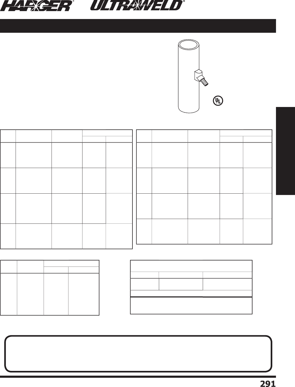
H
ar
g
er Li
g
htnin
g
& Groundin
g
•
©
2012 Phone 847-548-8700 • Fax 847-548-8755 • U.S. 800-842-743
7
29
1
291
Section 5
Ultraweld® Exothermic Connections
VA
Mold Information
:
•
Molds listed are for stranded cable. For solid conductor, add suffi x "S"
a
fter c
o
n
du
ct
o
r n
u
m
b
er. i.e. 4S = 4 AWG s
o
li
d
c
o
n
du
ct
o
r.
•
Price Ke
y
is the
Bold Letter
in the M
o
l
d
P
a
rt N
o
.
r
•
For mold Wear Plates, add suffi x "WP" to the end of the Mold Part No.
S
ee pa
g
e 324 for details.
Re
q
uired Tools & Accessories
:
CSH1 - Chain Su
pp
ort Handle clam
p
for "
B
"
Price Ke
y
Molds
OR
MH1 - M
o
l
d
H
a
n
d
le f
o
r "
B
"
Price Ke
y
Molds
AND
CSKIT - Chain Su
pp
ort Ki
t
Recommended Tools & Accessories
:
CCBRSH1 - C
a
r
d
Cl
o
th Br
u
s
h
MCBRSH1 - Mold Cleanin
g
Brus
h
**Add Horizontal or Vertical Pi
p
e
O
rientation and Pi
p
e Size Indicator.
S
ee chart to the ri
g
ht.
VA Cable to Steel Surface / Pipe
(
Cable Down at 45° to Side o
f
Vertical or Horizontal Steel Pi
p
e
)
C
able
Si
ze
M
o
ld
P
art
No
.
W
el
d
Meta
l
U
ltraSh
o
t
NUWTUBE
#
6
#4
#2 S
o
l
#
2
1
/
0
2
/
0
3
/
0
4/
0
VA-
6
**B
VA
-
4
**B
VA-
2S
**B
VA-
2
**B
VA-1
/
0**B
VA-2
/
0**B
VA-3
/
0**B
VA-4
/
0**B
US
4
5
US
4
5
US
4
5
US
4
5
U
S9
0
U
S9
0
US
11
5
US
11
5
NUWTUBE45
NUWTUBE45
NUWTUBE45
NUWTUBE45
NU
WT
U
BE9
0
NU
WT
U
BE9
0
NU
WT
U
BE11
5
NU
WT
U
BE11
5
C
ABLE T
O
VERTICAL STEEL PIPE
U
se Mold Part No.; add "V" with Pi
p
e Size
(
**
)
Indicato
r
C
able Nominal Pi
p
e Size Pi
p
e Size Indicator
#4 thr
u
2
50
30
"
a
n
d
Sm
a
lle
r
32" and Lar
g
e
r
N
ominal Pi
p
e Siz
e
◊
No
n
e
E
xam
p
le: #2 cable to 2-1/2"
p
i
p
e = VA-2V2.5
B
C
ABLE T
O
H
O
RIZ
O
NTAL STEEL PIPE
U
se Mold Part No.; add "H" and Pi
p
e Size
(
**
)
Indicato
r
E
xam
p
le: #2/0 cable to 6"
p
i
p
e = VA-2/0H6
B
◊
S
ee pa
g
e 335 for pipe sizes.
C
able
Si
ze
N
o
mina
l
P
ip
e S
i
ze
M
o
ld
Part N
o
.
W
el
d
Meta
l
UltraSh
o
t N
U
WT
U
BE
#
6
1-1/2" to 4" Pi
pe
4
" to 6" Pi
pe
6
" to 10" Pi
pe
12" to 30" Pi
pe
32" Pipe or Lar
g
e
r
VA-
6
V1.
25
X4
B
VA-
6
V4X
6
B
VA-
6
V
6
X1
0
B
V
A-
6
V1
2
X
30
B
VA-
6
B
US
4
5
US
4
5
US
4
5
US
4
5
US
4
5
NUWTUBE45
NUWTUBE45
NUWTUBE45
NUWTUBE45
NUWTUBE45
#4
1-1/2" to 4" Pi
pe
4
" to 6" Pi
pe
6
" to 10" Pi
pe
12" to 30" Pi
pe
32" Pipe or Lar
g
e
r
VA-4V1.
5
X
4
B
VA-4V4X
6
B
VA-4V
6
X1
0
B
V
A-4V1
2
X
30
B
VA
-
4
B
US
4
5
US
4
5
US
4
5
US
4
5
US
4
5
NU
WT
U
BE4
5
NUWTUBE45
NUWTUBE45
NUWTUBE45
NUWTUBE45
#
2
So
l
1/2" to 1" Pi
p
e
1-1/2" to 4" Pi
pe
4
" to 6" Pi
pe
6
" to 10" Pi
pe
12" to 30" Pi
pe
32" Pipe or Lar
g
e
r
VA-
2
SV.
5
X1B
VA-
2
SV1.
5
X4B
VA-
2
SV4X
6
B
VA-
2
SV
6
X1
0
B
VA-
2
SV1
2
X
30
B
VA-
2S
B
US
4
5
US
4
5
US
4
5
US
4
5
US
4
5
US
4
5
NU
WT
U
BE4
5
NU
WT
U
BE4
5
NU
WT
U
BE4
5
NU
WT
U
BE4
5
NU
WT
U
BE4
5
NU
WT
U
BE4
5
#
2
1-1/2" to 4" Pi
pe
4
" to 6" Pi
pe
6
" to 10" Pi
pe
12" to 30" Pi
pe
32" Pipe or Lar
g
e
r
VA-
2
V1.
5
X
4
B
VA-
2
V4X
6
B
VA-
2
V
6
X1
0
B
V
A-
2
V1
2
X
30
B
VA-
2
B
US
4
5
US
4
5
US
4
5
US
4
5
US
4
5
NUWTUBE45
NUWTUBE45
NUWTUBE45
NUWTUBE45
NUWTUBE45
C
able
Si
ze
N
o
mina
l
P
ip
e S
i
ze
M
o
ld
Part N
o
.
W
el
d
Meta
l
U
ltraSh
o
t N
U
WT
U
BE
1
/
0
2" to 4" Pi
p
e
4
" to 6" Pi
p
e
6
" to 10" Pi
p
e
12" to 30" Pi
p
e
32" Pipe or Lar
g
e
r
VA-1
/
0V2X
4
B
VA-1
/
0V4X6
B
VA-1
/
0V6X10
B
VA-1
/
0V12X30
B
VA-1
/
0
B
U
S9
0
U
S9
0
U
S9
0
U
S9
0
U
S9
0
NU
WT
U
BE9
0
NU
WT
U
BE9
0
NU
WT
U
BE9
0
NU
WT
U
BE9
0
NU
WT
U
BE9
0
2
/
0
2" to 4" Pi
p
e
4
" to 6" Pi
p
e
6
" to 10" Pi
p
e
12" to 30" Pi
p
e
32" Pipe or Lar
g
e
r
VA-2
/
0V2X
4
B
VA-2
/
0V4X6
B
VA-2
/
0V6X10
B
VA-2
/
0V12X30
B
VA-2
/
0
B
U
S9
0
U
S9
0
U
S9
0
U
S9
0
U
S9
0
NU
WT
U
BE9
0
NU
WT
U
BE9
0
NU
WT
U
BE9
0
NU
WT
U
BE9
0
NU
WT
U
BE9
0
3
/
0
2" to 4" Pi
p
e
4
" to 6" Pi
p
e
6
" to 10" Pi
p
e
12" to 30" Pi
p
e
32" Pipe or Lar
g
e
r
VA-3
/
0V2X
4
B
VA-3
/
0V4X6B
VA-3
/
0V6X10
B
VA-3
/
0V12X30
B
VA-3
/
0B
US
11
5
US
11
5
US
11
5
US
11
5
US
11
5
NU
WT
U
BE11
5
NU
WT
U
BE11
5
NU
WT
U
BE11
5
NU
WT
U
BE11
5
NU
WT
U
BE11
5
4/
0
2" to 4" Pi
p
e
4
" to 6" Pi
p
e
6
" to 10" Pi
p
e
12" to 30" Pi
p
e
32" Pipe or Lar
g
e
r
VA-4
/
0V2X
4
B
VA-4
/
0V4X6
B
VA-4
/
0V6X10
B
VA-4
/
0V12X30
B
VA-4
/
0
B
US
11
5
US
11
5
US
11
5
US
11
5
US
11
5
NU
WT
U
BE11
5
NU
WT
U
BE11
5
NU
WT
U
BE11
5
NU
WT
U
BE11
5
NU
WT
U
BE11
5
VA (Pipe) Connection Type (Ran
g
e Takin
g
)
VA
(
Pi
p
e
)
Connection T
yp
e
L
iste
d
4
67
S
ect
io
n 5.5
N
O
TE
:
T
hin walled pipe may be unsuitable for exothermic connections. If experiencin
g
burn throu
g
h issues with the pipe (typically
w
ith 2/0 or 4/0 conductors), addin
g
sand inside the fence post well past the exothermic connection may solve this problem.
Another solution would be to use a smaller conductor such as a #2 aw
g
j
umper which uses a smaller size weld metal. The
l
ast solution may be to use mechanical fence clamp assembly such as the ones found in Section 1.11 on pa
g
e 133.

H
ar
g
er Li
g
htnin
g
& Groundin
g
•
©
2012 Phone 847-548-8700 • Fax 847-548-8755 • U.S. 800-842-743
7
29
2
292
Section 5
Ultraweld® Exothermic Connections
VD
M
o
ld Inf
o
rmati
o
n
:
•
M
o
l
d
s liste
d
a
re f
o
r str
a
n
d
e
d
c
ab
le. F
o
r s
o
li
d
conductor, add suffi x "S" after conductor number.
i.e. 4S = 4 AWG s
o
li
d
c
o
n
du
ct
o
r.
•
Price Ke
y
is the
Bold Letter
in the M
o
l
d
P
a
rt N
o
.
r
Re
q
uired Tools & Accessories
:
CSH1 - Chain Su
pp
ort Handle clam
p
for "
B
"
Pri
ce
K
e
y
Mold
s
OR
MH1 - M
o
l
d
H
a
n
d
le f
o
r "
B
"
Price Ke
y
Molds
AND
CSKIT - Chain Su
pp
ort Ki
t
Rec
o
mmended T
oo
ls & Access
o
ries
:
CCBRSH1 - C
a
r
d
Cl
o
th Br
u
s
h
MCBRSH1 - Mold Cleanin
g
Brus
h
(
Vertical Downward Cable to Side o
f
Vertical or Horizontal Steel Pi
p
e
)
**Add Horizontal or Vertical Pi
p
e
O
rientation and Pi
p
e Size Indicator.
S
ee chart to the ri
g
ht.
Cable to Steel Surface / Pipe VD
CS
KIT
CS
H1
Pa
tente
d
C
able
Si
ze
N
o
mina
l
P
ip
e S
i
ze
M
o
ld
P
art
No
.
W
el
d
Meta
l
U
ltraSh
o
t
NUWTUBE
#2 S
o
l 1-1/4" to 4" Pi
p
eVD-
2
SV1.
25
X4
B
U
S
65
NU
WT
U
BE
65
#
2
1-1/4" to 4" Pi
p
eVD-
2
V1.
25
X
4
B
U
S
65
NU
WT
U
BE
65
1
/
0 1-1/4" to 3-1/2" Pi
pe
VD-1
/
0V1.25X3.5
B
U
S9
0
NU
WT
U
BE9
0
2
/
01-1/4" to 3-1/2" Pi
pe
2" to 4" Pi
p
e
VD-2
/
0V1.25X3.5
B
VD-2
/
0V2X4
B
U
S9
0
U
S9
0
NU
WT
U
BE9
0
NU
WT
U
BE9
0
4/
01-1/4" to 3-1/2" Pi
pe
2" to 4" Pi
p
e
VD-4
/
0V1.25X3.5
B
VD-4
/
0V2X4
B
U
S1
50
U
S1
50
NU
WT
U
BE1
50
NU
WT
U
BE1
50
C
able
Si
ze
M
o
ld
P
art
No
.
W
el
d
Meta
l
U
ltraSh
o
t
NUWTUBE
#
6
#4
#2 S
o
l
#
2
1
/
0
2
/
0
3
/
0
4/
0
250
MCM
VD-
6
**B
VD
-
4
**B
VD-
2S
**B
VD-
2
**B
VD-1
/
0**B
VD-2
/
0**B
VD-3
/
0**B
VD-4
/
0**B
VD-
25
CM**B
US
4
5
U
S
65
U
S
65
U
S
65
US
11
5
US
11
5
U
S1
50
U
S1
50
U
S
200
NUWTUBE45
NU
WT
U
BE
65
NU
WT
U
BE
65
NU
WT
U
BE
65
NU
WT
U
BE11
5
NU
WT
U
BE11
5
NU
WT
U
BE1
50
NU
WT
U
BE1
50
NU
WT
U
BE
200
C
ABLE T
O
VERTICAL STEEL PIPE
U
se Mold Part No.; add "V" with Pi
p
e Size
(
**
)
Indicato
r
C
able Nominal Pi
p
e Size Pi
p
e Size Indicator
#4 thr
u
2
50
30
"
a
n
d
Sm
a
lle
r
32" and Lar
g
e
r
N
ominal Pi
p
e Siz
e
◊
No
ne
E
xam
p
le: #2 cable to 2-1/2"
p
i
p
e = VD-2V2.5
B
C
ABLE T
O
H
O
RIZ
O
NTAL STEEL PIPE
U
se Mold Part No.; add "H" and Pi
p
e Size
(
**
)
Indicato
r
E
xam
p
le: #2/0 cable to 6"
p
i
p
e = VD-2/0H6
B
◊
S
ee pa
g
e 335 for pipe sizes.
VD (Pipe) Connection Type (Ran
g
e Takin
g
)
VD
(
Pi
p
e
)
Connection T
yp
e
S
ect
io
n 5.5
N
O
TE
:
T
hin walled pipe may be unsuitable for exothermic connections. If experiencin
g
burn throu
g
h issues with the pipe (typically
w
ith 2/0 or 4/0 conductors), addin
g
sand inside the fence post well past the exothermic connection may solve this problem.
Another solution would be to use a smaller conductor such as a #2 aw
g
j
umper which uses a smaller size weld metal. The
l
ast solution may be to use mechanical fence clamp assembly such as the ones found in Section 1.11 on pa
g
e 133.

H
ar
g
er Li
g
htnin
g
& Groundin
g
•
©
2012 Phone 847-548-8700 • Fax 847-548-8755 • U.S. 800-842-743
7
2
9
3
293
Section 5
Ultraweld® Exothermic Connections
VH
VL
◊
N
O
TES
:
• VL is
a
Left H
a
n
d
m
o
l
d
.
• To order a Ri
g
ht Hand mold, chan
g
e the VL in
the Mold Part No. to VR. Exam
p
le: VR-6
B
.
Mold Information
:
•
M
o
l
d
s liste
d
a
re f
o
r str
a
n
d
e
d
c
ab
le. F
o
r s
o
li
d
conductor, add suffi x "S" after conductor number.
i.e. 4S = 4 AWG s
o
li
d
c
o
n
du
ct
o
r.
•
Price Ke
y
is the
Bold Letter
in the M
o
l
d
P
a
rt N
o
.
r
•
Fo
r
VH
mold Wear Plates, add suffi x "WP" to the
end of the Mold Part No. See pa
g
e 324 for details.
Re
q
uired Tools & Accessories
:
MH1 - H
a
n
d
le f
o
r "
B
"
Price Ke
y
Mold
s
Rec
o
mmended T
oo
ls & Access
o
ries
:
CCBRSH1 - C
a
r
d
Cl
o
th Br
u
s
h
MCBRSH1 - Mold Cleanin
g
Brus
h
M
S
KIT - Ma
g
netic
S
upport Ki
t
(
Horizontal Thru Cable to Vertical
F
lat Steel Surface
)
(
Horizontal Dead End Cable to Vertical
F
l
a
t Steel S
u
rf
a
c
e
◊
)
VR
(
Horizontal Dead End Cable to Vertical
F
l
a
t Steel S
u
rf
a
c
e
◊
)
VH / VL / VR Cable to Steel Surface
MS
KITH
S
V
S
M
SKITHSVS with M
o
l
d
H
a
n
d
l
e
Pa
tente
d
C
able
Si
ze
M
o
ld
P
art
No
.
W
el
d
Meta
l
UltraSh
o
t
NUWTUBE
#
6
#4
#2 S
o
l
#
2
1
/
0
2
/
0
3
/
0
4/
0
250
MCM
300
MCM
350
MCM
500
MCM
VL-
6
B
VL
-
4
B
VL-
2S
B
VL-
2
B
VL-1
/
0
B
VL-2
/
0
B
VL-3
/
0
B
VL-4
/
0
B
VL-
25
CM
B
VL-
3
CM
B
VL-
35
CM
B
VL-
5C
M
B
US
4
5
US
4
5
US
4
5
US
4
5
U
S9
0
U
S9
0
US
11
5
US
11
5
US
11
5
U
S1
50
U
S
200
U
S
200
NUWTUBE45
NUWTUBE45
NUWTUBE45
NUWTUBE45
NU
WT
U
BE9
0
NU
WT
U
BE9
0
NU
WT
U
BE11
5
NU
WT
U
BE11
5
NU
WT
U
BE11
5
NU
WT
U
BE1
50
NU
WT
U
BE
200
NU
WT
U
BE
200
C
able
Si
ze
M
o
ld
P
art
No
.
W
el
d
Meta
l
U
ltraSh
o
t
NUWTUBE
#
6
#4
#2 S
o
l
#
2
1
/
0
2
/
0
3
/
0
4/
0
250
MCM
VH-
6
B
VH
-
4
B
VH-
2S
B
VH-
2
B
VH-1
/
0
B
VH-2
/
0
B
VH-3
/
0
B
VH-4
/
0
B
VH-
25
CM
B
U
S
65
U
S
65
U
S
65
U
S
65
US
11
5
US
11
5
U
S1
50
U
S1
50
U
S1
50
NU
WT
U
BE
65
NU
WT
U
BE
65
NU
WT
U
BE
65
NU
WT
U
BE
65
NU
WT
U
BE11
5
NU
WT
U
BE11
5
NU
WT
U
BE1
50
NU
WT
U
BE1
50
NU
WT
U
BE1
50
VH Connect
i
on T
yp
e
VL Connect
i
on T
yp
e
S
ect
io
n 5.5
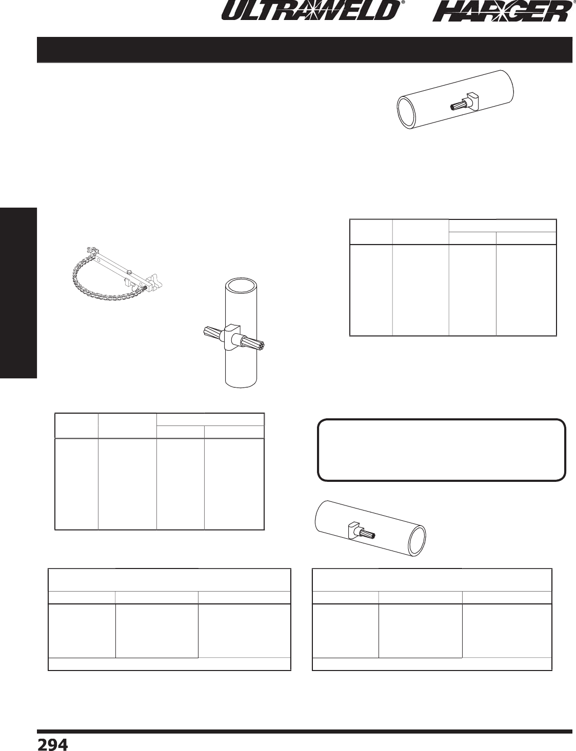
H
ar
g
er Li
g
htnin
g
& Groundin
g
•
©
2012 Phone 847-548-8700 • Fax 847-548-8755 • U.S. 800-842-743
7
294
294
Section 5
Ultraweld® Exothermic Connections
VH
**Add Pi
p
e Size and Vertical Pi
p
e to
M
o
ld Part N
o
. See chart bel
o
w.
**Add Pi
p
e Size and Horizontal Pi
p
e to
M
o
ld Part N
o
. See chart bel
o
w.
VL
M
o
ld Inf
o
rmati
o
n
:
•
Molds listed are for stranded cable. For solid conductor, add suffi x "S"
a
fter c
o
n
du
ct
o
r n
u
m
b
er.
i.e. 4S = 4 AWG s
o
li
d
c
o
n
du
ct
o
r.
•
Price Ke
y
is the
Bold Letter
in the M
o
l
d
P
a
rt N
o
.
r
•
Fo
r
VH
mold Wear Plates, add suffi x "WP" to the end of the Mold Part
N
o. See pa
g
e 324 for details.
Re
q
uired Tools & Accessories
:
Fo
r
VH
m
o
l
d
: MH1 - M
o
l
d
H
a
n
d
le f
o
r "
B
"
Price Ke
y
Molds
AND
CSKITHSVM - Chain Su
pp
ort Kit for VH Mold
Fo
r VL
&
V
R
molds: MH1 - Handle for "
R
B
"
Price Ke
y
Mold
s
Rec
o
mmended T
oo
ls & Access
o
ries
:
CCBRSH1 - C
a
r
d
Cl
o
th Br
u
s
h
MCBRSH1 - Mold Cleanin
g
Brus
h
◊
N
O
TES
:
• VL is
a
Left H
a
n
d
m
o
l
d
.
• To order a Ri
g
ht Hand mold, chan
g
e the VL in
the Mold Part No. to VR. Exam
p
le: VR-6
**
B
.
(
Horizontal Thru Cable to Side
o
f Vertical Steel Pi
p
e
)
(
Horizontal Dead End Cable to Side
o
f Horizontal Steel Pi
p
e
◊
)
VR
(
Horizontal Dead End Cable to Side
o
f Horizontal Steel Pi
p
e
◊
)
Cable to Steel Surface / Pipe VH / VL / VR
C
able
Si
ze
M
o
ld
P
art
No
.
W
el
d
Meta
l
U
ltraSh
o
t
NUWTUBE
#
6
#4
#2 S
o
l
#
2
1
/
0
2
/
0
3
/
0
4/
0
250
MCM
VL-
6
**B
VL
-
4
**B
VL-
2S
**B
VL-
2
**B
VL-1
/
0**B
VL-2
/
0**B
VL-3
/
0**B
VL-4
/
0**B
VL-
25
CM**B
US
4
5
US
4
5
US
4
5
US
4
5
U
S9
0
U
S9
0
US
11
5
US
11
5
US
11
5
NUWTUBE45
NUWTUBE45
NUWTUBE45
NUWTUBE45
NU
WT
U
BE9
0
NU
WT
U
BE9
0
NU
WT
U
BE11
5
NU
WT
U
BE11
5
NU
WT
U
BE11
5
C
able
Si
ze
Mold
P
art
No
.
W
el
d
Meta
l
U
ltraSh
o
t
NUWTUBE
#
6
#4
#2 S
o
l
#
2
1
/
0
2
/
0
3
/
0
4/
0
250
MCM
VH-
6
**B
VH
-
4
**B
VH-
2S
**B
VH-
2
**B
VH-1
/
0**B
VH-2
/
0**B
VH-3
/
0**B
VH-4
/
0**B
VH-
25
CM**B
U
S
65
U
S
65
U
S
65
U
S
65
US
11
5
US
11
5
U
S1
50
U
S1
50
U
S1
50
NU
WT
U
BE
65
NU
WT
U
BE
65
NU
WT
U
BE
65
NU
WT
U
BE
65
NU
WT
U
BE11
5
NU
WT
U
BE11
5
NU
WT
U
BE1
50
NU
WT
U
BE1
50
NU
WT
U
BE1
50
C
ABLE T
O
VERTICAL STEEL PIPE
U
se Mold Part No.; add "V" with Pi
p
e Size
(
**
)
Indicato
r
C
able Nominal Pi
p
e Size Pi
p
e Size Indicator
#1
a
n
d
Sm
a
lle
r
1
/
0 thru 250
12"
a
n
d
Sm
a
lle
r
24" and Lar
g
e
r
28" and Smalle
r
30" and Lar
g
e
r
N
ominal Pi
p
e Size
◊
No
ne
N
ominal Pi
p
e Size
◊
No
ne
E
xam
p
le: #2 cable to 2-1/2"
p
i
p
e = VH-2V2.5
B
◊
S
ee pa
g
e 335 for pipe sizes.
C
ABLE T
O
H
O
RIZ
O
NTAL STEEL PIPE
U
se Mold Part No.; add "H" with Pi
p
e Size
(
**
)
Indicato
r
C
able Nominal Pi
p
e Size Pi
p
e Size Indicator
#1
a
n
d
Sm
a
lle
r
1
/
0 thru 250
12"
a
n
d
Sm
a
lle
r
14" and Lar
g
e
r
28" and Smalle
r
30" and Lar
g
e
r
N
ominal Pi
p
e Size
◊
No
ne
N
ominal Pi
p
e Size
◊
No
ne
E
xam
p
le: #2 cable to 2-1/2"
p
i
p
e = VL-2H2.5
B
◊
S
ee pa
g
e 335 for pipe sizes.
VH
(
Pi
p
e
)
Connection T
yp
e
VL
(
Pi
p
e
)
Connection T
yp
e
CS
KITH
S
VM
(
Re
q
uired for VH Mold
)
S
ect
io
n 5.5
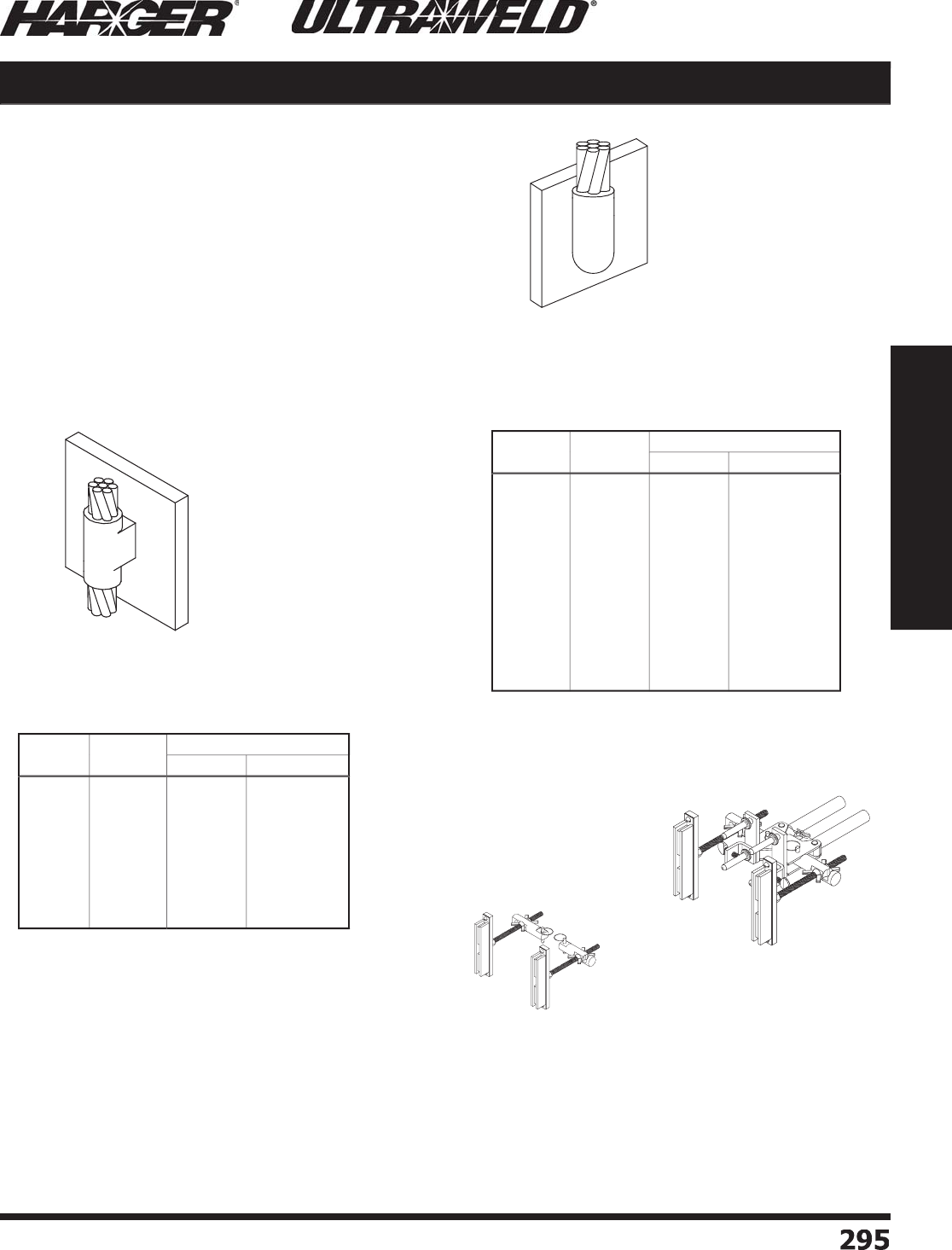
H
ar
g
er Li
g
htnin
g
& Groundin
g
•
©
2012 Phone 847-548-8700 • Fax 847-548-8755 • U.S. 800-842-743
7
2
9
5
295
Section 5
Ultraweld® Exothermic Connections
VU
VT
Mold Information
:
•
M
o
l
d
s liste
d
a
re f
o
r str
a
n
d
e
d
c
ab
le. F
o
r s
o
li
d
conductor, add suffi x "S" after conductor number.
i.e. 4S = 4 AWG s
o
li
d
c
o
n
du
ct
o
r.
•
Price Ke
y
is the
Bold Letter
in the M
o
l
d
P
a
rt N
o
.
r
•
Fo
r
VT
mold Wear Plates, add suffi x "WP" to the
T
end of the Mold Part No. See pa
g
e 324 for details.
Re
q
uired Tools & Accessories
:
MH1 - H
a
n
d
le f
o
r "
B
"
a
n
d
"
K
"
Price Ke
y
Mold
s
MH2 - H
a
n
d
le f
o
r "
D
"
Price Ke
y
Mold
s
Recommended Tools & Accessories
:
CCBRSH1 - C
a
r
d
Cl
o
th Br
u
s
h
MCBRSH1 - Mold Cleanin
g
Brus
h
M
S
KIT - Ma
g
netic
S
upport Ki
t
(
Vertical Thru Cable to Vertical
F
lat Steel Surface
)
(
Vertical Cable Dead End to
Vertical Flat Steel Surface
)
VT / VU Cable to Steel Surface
MS
KIT
M
SKIT with M
o
l
d
H
a
n
d
l
e
Pa
tente
d
C
able
Si
ze
M
o
ld
P
art
No
.
W
el
d
Meta
l
U
ltraSh
o
t
NUWTUBE
#
6
#4
#2 S
o
l
#
2
1
/
0
2
/
0
3
/
0
4/
0
250
MCM
VT-
6
B
VT
-
4
B
VT-
2S
B
VT-
2
B
VT-1
/
0
K
VT-2
/
0
K
VT-3
/
0
K
VT-4
/
0
K
VT-
25
CM
K
U
S9
0
U
S9
0
US
11
5
US
11
5
U
S
200
U
S
200
U
S
250
U
S
250
U
S
250
NU
WT
U
BE9
0
NU
WT
U
BE9
0
NU
WT
U
BE11
5
NU
WT
U
BE11
5
NU
WT
U
BE
200
NU
WT
U
BE
200
NU
WT
U
BE
250
NU
WT
U
BE
250
NU
WT
U
BE
250
C
able
Si
ze
M
o
ld
P
art
No
.
W
el
d
Meta
l
U
ltraSh
o
t
NUWTUBE
#
6
#4
#2 S
o
l
#
2
1
/
0
2
/
0
3
/
0
4/
0
250
MCM
300
MCM
350
MCM
500
MCM
7
50
MCM
V
U
-
6
B
VU
-
4
B
V
U
-
2S
B
V
U
-
2
B
VU-1
/
0
B
VU-2
/
0
B
VU-3
/
0
K
VU-4
/
0
K
V
U
-
25
CM
K
V
U
-
3
CM
K
V
U
-
35
CM
D
V
U
-
5C
M
D
V
U
-7
5C
M
D
U
S
65
U
S
65
U
S
65
U
S
65
U
S1
50
U
S1
50
U
S
200
U
S
200
U
S
200
U
S
250
U
S
300
U
S4
00
U
S
500
NU
WT
U
BE
65
NU
WT
U
BE
65
NU
WT
U
BE
65
NU
WT
U
BE
65
NU
WT
U
BE1
50
NU
WT
U
BE1
50
NU
WT
U
BE
200
NU
WT
U
BE
200
NU
WT
U
BE
200
NU
WT
U
BE
250
2
-N
U
WT
U
BE1
50
2
-N
U
WT
U
BE
200
2
-N
U
WT
U
BE
250
VU Connect
i
on T
yp
e
VT Connect
i
on T
yp
e
S
ect
io
n 5.5

H
ar
g
er Li
g
htnin
g
& Groundin
g
•
©
2012 Phone 847-548-8700 • Fax 847-548-8755 • U.S. 800-842-743
7
2
9
6
296
Section 5
Ultraweld® Exothermic Connections
VU
VT
**Add Pi
p
e Size and Horizontal or
Vertical Pi
p
e to Mold Part No.
S
ee chart bel
o
w.
M
o
ld Inf
o
rmati
o
n
:
•
M
o
l
d
s liste
d
a
re f
o
r str
a
n
d
e
d
c
ab
le. F
o
r s
o
li
d
conductor, add suffi x "S" after conductor number.
i.e. 4S = 4 AWG s
o
li
d
c
o
n
du
ct
o
r.
•
Price Ke
y
is the
Bold Letter
in the M
o
l
d
P
a
rt N
o
.
r
•
Fo
r
VT
mold Wear Plates, add suffi x "WP" to the end
T
o
f the Mold Part No. See pa
g
e 324 for details.
Re
q
uired Tools & Accessories
:
CSH1 - Chain Su
pp
ort Handle clam
p
for "
B
"
a
n
d
"
K
"
P
rice Ke
y
Mold
s
OR
MH1 - M
o
l
d
H
a
n
d
le f
o
r "
B
"
a
n
d
"
K
"
Price Ke
y
Molds
AND
CSKIT - Chain Su
pp
ort Ki
t
Rec
o
mmended T
oo
ls & Access
o
ries
:
CCBRSH1 - C
a
r
d
Cl
o
th Br
u
s
h
MCBRSH1 - Mold Cleanin
g
Brus
h
(
Vertical Thru Cable to Side o
f
Vertical or Horizontal Steel Pi
p
e
)
(
Vertical Cable Dead End to
S
i
d
e
o
f Vertic
a
l
o
r H
o
riz
o
nt
a
l
S
teel Pi
p
e
)
**Add Horizontal or Vertical Pi
p
e
O
rientation and Pi
p
e Size Indicator.
S
ee chart to the ri
g
ht.
Cable to Steel Surface / Pipe VT / VU
CS
KIT
CS
H1
Pa
tente
d
C
able
Si
ze
M
o
ld
P
art
No
.
W
el
d
Meta
l
UltraSh
o
t
NUWTUBE
#
6
#4
#2 S
o
l
#
2
1
/
0
2
/
0
3
/
0
4/
0
250
MCM
V
U
-
6
**B
VU
-
4
**B
V
U
-
2S
**B
V
U
-
2
**B
VU-1
/
0**B
VU-2
/
0**B
VU-3
/
0**
K
VU-4
/
0**
K
V
U
-
25
CM**
K
U
S
65
U
S
65
U
S
65
U
S
65
U
S1
50
U
S1
50
U
S
200
U
S
200
U
S
200
NUWTUBE
65
NUWTUBE
65
NUWTUBE
65
NUWTUBE
65
NUWTUBE
1
50
NUWTUBE
1
50
NUWTUBE
200
NUWTUBE
200
NUWTUBE
200
C
able
Si
ze
M
o
l
d
P
art
No
.
W
el
d
Meta
l
U
ltraSh
o
t
NUWTUBE
#
6
#4
#2 S
o
l
#
2
1
/
0
2
/
0
3
/
0
4/
0
250
MCM
VT-
6
**B
VT
-
4
**B
VT-
2S
**B
VT-
2
**B
VT-1
/
0**
K
VT-2
/
0**
K
VT-3
/
0**
K
VT-4
/
0**
K
VT-
25
CM**
K
U
S9
0
U
S9
0
US
11
5
US
11
5
U
S
200
U
S
200
U
S
250
U
S
250
U
S
250
NUWTUBE
90
NUWTUBE
90
NUWTUBE
11
5
NUWTUBE
11
5
NUWTUBE
200
NUWTUBE
200
NUWTUBE
250
NUWTUBE
250
NUWTUBE
250
C
ABLE T
O
VERTICAL STEEL PIPE
U
se Mold Part No.; add "V" with Pi
p
e Size
(
**
)
Indicato
r
C
able Nominal Pi
p
e Size Pi
p
e Size Indicator
#4 thr
u
2
50
28" and Smalle
r
30" and Lar
g
e
r
N
ominal Pi
p
e Size
◊
No
n
e
E
xam
p
le: #2 cable to 2-1/2"
p
i
p
e = VT-2V2.5
B
C
ABLE T
O
H
O
RIZ
O
NTAL STEEL PIPE
Use Mold Part No.; add "H" with Pi
p
e Size
(
**
)
Indicato
r
E
xam
p
le: #2/0 cable to 6"
p
i
p
e = VT-2/0H6
B
◊
S
ee pa
g
e 335 for pipe sizes.
VU
(
Pi
p
e
)
Connection T
yp
e
VT
(
Pi
p
e
)
Connection T
yp
e
S
ect
io
n 5.5

H
ar
g
er Li
g
htnin
g
& Groundin
g
•
©
2012 Phone 847-548-8700 • Fax 847-548-8755 • U.S. 800-842-743
7
29
7
297
Section 5
Ultraweld® Exothermic Connections
LE
Mold Information
:
•
M
o
l
d
s liste
d
a
re f
o
r str
a
n
d
e
d
c
ab
le. F
o
r s
o
li
d
conductor, add suffi x "S" after conductor number.
i.e. 4S = 4 AWG s
o
li
d
c
o
n
du
ct
o
r.
•
Price Ke
y
is the
Bold Letter
in the M
o
l
d
P
a
rt N
o
.
r
•
For mold Wear Plates, add suffi x "WP" to the end
o
f the Mold Part No. See pa
g
e 324 for details.
Re
q
uired Tools & Accessories
:
MH1 - H
a
n
d
le f
o
r "
B
"
Price Ke
y
Mold
s
MH2 - H
a
n
d
le f
o
r "
C
"
Price Ke
y
Mold
s
Recommended Tools & Accessories
:
CCBRSH1 - C
a
r
d
Cl
o
th Br
u
s
h
MCBRSH1 - Mold Cleanin
g
Brus
h
S
ee pa
g
es 314 & 315 for Lu
g
s.
(
Butt End S
p
lice of Horizontal
Cable to Lu
g
or Busbar
)
LE Cable to Lug or Busbar
C
able
Si
ze
L
u
g
Si
ze
M
o
ld
P
art
No
.
W
el
d
Meta
l
U
ltraSh
o
t
NUWTUBE
#
6
1
/
8 x 1
L
E-6181
B
US
4
5
NUWTUBE45
#4
1
/
8 x 1
L
E-4181
B
US
4
5
NUWTUBE45
#2 S
o
l1
/
8 x 1
L
E-2S181
B
US
4
5
NUWTUBE45
#
2
1
/
8 x 1
L
E-2181
B
US
4
5
NUWTUBE45
1
/
01
/
8 x 1
1
/
4 x 1
L
E-1
/
0181
B
L
E-1
/
0141
B
US
4
5
U
S
65
NUWTUBE45
NU
WT
U
BE
65
2
/
01
/
8 x 1
1
/
4 x 1
L
E-2
/
0181
B
L
E-2
/
0141
B
U
S
65
U
S
65
NU
WT
U
BE
65
NU
WT
U
BE
65
3
/
03
/
16 x 1
1
/
4 x 1
L
E-3
/
03161
B
L
E-3
/
0141
B
U
S9
0
U
S9
0
NU
WT
U
BE9
0
NU
WT
U
BE9
0
4/
0
3
/
16 x 1
1
/
4 x 1
1
/
4 x 1-1
/4
1
/
4 x 1-1
/2
L
E-4
/
03161
B
L
E-4
/
0141
B
L
E-4
/
0141.25
B
L
E-4
/
0141.5
B
U
S9
0
U
S9
0
U
S9
0
U
S9
0
NU
WT
U
BE9
0
NU
WT
U
BE9
0
NU
WT
U
BE9
0
NU
WT
U
BE9
0
C
able
Si
ze
L
u
g
Si
ze
M
o
ld
P
art
No
.
W
el
d
Meta
l
U
ltraSh
o
t
NUWTUBE
250
MC
M
1
/
4 x 1
1
/
4 x 1-1
/4
1
/
4 x 1-1
/2
L
E-
25
CM141
B
L
E-
25
CM141.
25
B
L
E-
25
CM141.
5
B
U
S9
0
U
S9
0
U
S9
0
NU
WT
U
BE9
0
NU
WT
U
BE9
0
NU
WT
U
BE9
0
300
MC
M
1
/
4 x 1
1
/
4 x 1-1
/4
1
/
4 x 1-1
/2
L
E-
3
CM141
B
L
E-
3
CM141.
25
B
L
E-
3
CM141.
5
B
U
S9
0
U
S9
0
U
S9
0
NU
WT
U
BE9
0
NU
WT
U
BE9
0
NU
WT
U
BE9
0
350
MC
M
1
/
4 x 1
1
/
4 x 1-1
/4
3
/
8 x 1
L
E-
35
CM141
B
L
E-
35
CM141.
25
B
L
E-35CM381
B
US
11
5
US
11
5
U
S1
50
NU
WT
U
BE11
5
NU
WT
U
BE11
5
NU
WT
U
BE1
50
500
MC
M
1
/
4 x 1-1
/2
1
/
4 x
2
3
/
8 x 1
3
/
8 x 1-1
/2
3
/
8 x
2
L
E-
5C
M141.
5
B
L
E-
5
CM14
2
B
L
E-5CM381
B
L
E-5CM381.5
B
L
E-5CM38
2
C
U
S
200
U
S
200
U
S
200
U
S
200
U
S
300
NU
WT
U
BE
200
NU
WT
U
BE
200
NU
WT
U
BE
200
NU
WT
U
BE
200
2
-N
U
WT
U
BE1
50
7
50
MC
M
1
/
4 x
2
3
/
8 x 1-1
/2
3
/
8 x
2
L
E-7
5
CM14
2
C
L
E-75CM381.5
C
L
E-75CM38
2
C
U
S
300
U
S
300
U
S
300
2
-N
U
WT
U
BE1
50
2
-N
U
WT
U
BE1
50
2
-N
U
WT
U
BE1
50
1
000
MC
M
3
/
8 x
2
7
/
16 x
2
1
/
2 x
2
L
E-1MM38
2
C
L
E-1MM71
62
C
L
E-1MM1
22
C
U
S4
00
U
S4
00
U
S
500
2
-N
U
WT
U
BE
200
2
-N
U
WT
U
BE
200
2
-N
U
WT
U
BE
250
LE Connection T
yp
e continuedLE Connect
i
on T
yp
e
S
ect
io
n 5.5

H
ar
g
er Li
g
htnin
g
& Groundin
g
•
©
2012 Phone 847-548-8700 • Fax 847-548-8755 • U.S. 800-842-743
7
2
98
298
Section 5
Ultraweld® Exothermic Connections
LBJ
M
o
ld Inf
o
rmati
o
n
:
•
M
o
l
d
s liste
d
a
re f
o
r str
a
n
d
e
d
c
ab
le. F
o
r s
o
li
d
conductor, add suffi x "S" after conductor number.
i.e. 4S = 4 AWG s
o
li
d
c
o
n
du
ct
o
r.
•
Price Ke
y
is the
Bold Letter
in the M
o
l
d
P
a
rt N
o
.
r
•
For mold Wear Plates, add suffi x "WP" to the end
o
f the Mold Part No. See pa
g
e 324 for details.
Re
q
uired Tools & Accessories
:
MH1 - H
a
n
d
le f
o
r "
B
"
Price Ke
y
Mold
s
Recommended Tools & Accessories
:
CCBRSH1 - C
a
r
d
Cl
o
th Br
u
s
h
MCBRSH1 - Mold Cleanin
g
Brus
h
S
ee pa
g
e 315 for Lu
g
s.
(
Butt End S
p
lice of Horizontal
Cable to Lu
g
Bent J
)
Cable to Lug or Busbar LBJ
C
able
Si
ze
L
u
g
Si
ze
M
o
ld
P
art
No
.
W
el
d
Meta
l
U
ltraSh
o
t
NUWTUBE
#
6
1
/
8 x 1
L
BJ-6181
B
U
S
32
NU
WT
U
BE
32
#4
1
/
8 x 1
L
BJ-4181
B
U
S
32
NU
WT
U
BE
32
#2 S
o
l1
/
8 x 1
L
BJ-2S181
B
U
S
32
NU
WT
U
BE
32
#
2
1
/
8 x 1
L
BJ-2181
B
US
4
5
NUWTUBE45
1
/
01
/
8 x 1
L
BJ-1
/
0181
B
US
4
5
NUWTUBE45
2
/
01
/
8 x 1
3
/
16 x 1
L
BJ-2
/
0181
B
L
BJ-2
/
03161
B
US
4
5
U
S
65
NUWTUBE45
NU
WT
U
BE
65
3
/
01
/
8 x 1
3
/
16 x 1
L
BJ-3
/
0181
B
L
BJ-3
/
03161
B
U
S
65
U
S
65
NU
WT
U
BE
65
NU
WT
U
BE
65
4/
01
/
8 x 1
3
/
16 x 1
L
BJ-4
/
0181
B
L
BJ-4
/
03161
B
U
S
65
U
S
65
NU
WT
U
BE
65
NU
WT
U
BE
65
LBJ Connect
i
on T
yp
e
S
ect
io
n 5.5
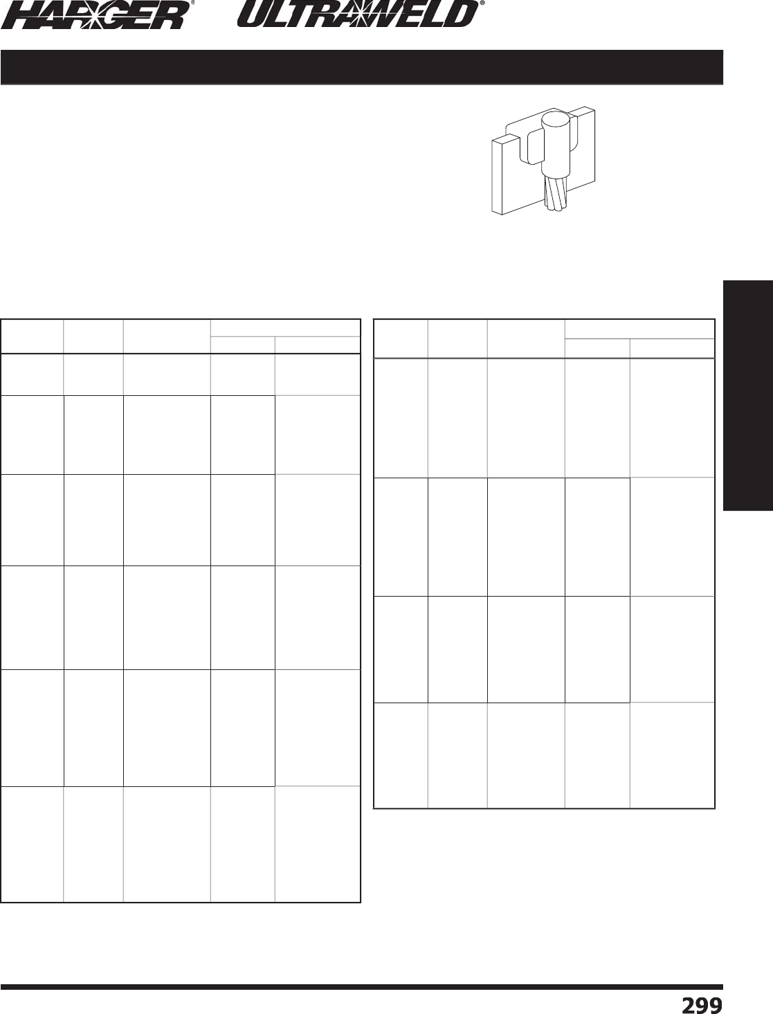
H
ar
g
er Li
g
htnin
g
& Groundin
g
•
©
2012 Phone 847-548-8700 • Fax 847-548-8755 • U.S. 800-842-743
7
299
299
Section 5
Ultraweld® Exothermic Connections
BD
M
o
ld Inf
o
rmati
o
n
:
•
Molds listed are for stranded cable. For solid conductor, add suffi x "S" after
c
o
n
du
ct
o
r n
u
m
b
er. i.e. 4S = 4 AWG s
o
li
d
c
o
n
du
ct
o
r.
•
Price Ke
y
is the
Bold Letter
in the M
o
l
d
P
a
rt N
o
.
r
Re
q
uired Tools & Accessories
:
MH1 - H
a
n
d
le f
o
r "
B
"
Price Ke
y
Mold
s
MH2 - H
a
n
d
le f
o
r "
C
"
Price Ke
y
Mold
s
MLDSLR - M
o
l
d
Se
a
le
r
Recommended Tools & Accessories
:
CCBRSH1 - C
a
r
d
Cl
o
th Br
u
s
h
MCBRSH1 - Mold Cleanin
g
Brus
h
(
Downward Vertical Cable to To
p
o
f H
o
riz
o
nt
a
l B
u
s
ba
r with F
a
ce in
Vertical Plane
)
BD Cable to Busbar
B
us
bar
Si
ze
C
able
Si
ze
M
o
ld
P
art
No
.
W
el
d
Meta
l
U
ltraSh
o
t
NUWTUBE
1
/
8 x 1
1
/
0
2
/
0
4/
0
B
D-1811
/
0
B
B
D-1812
/
0B
B
D-1814
/
0
B
U
S9
0
U
S9
0
US
11
5
NU
WT
U
BE9
0
NU
WT
U
BE9
0
NU
WT
U
BE11
5
1
/
8 x
2
1
/
0
2
/
0
4/
0
250
MCM
300
MCM
350
MCM
B
D-1821
/
0
B
B
D-1822
/
0B
B
D-1824
/
0B
B
D-18225CMB
B
D-1823CMB
B
D-18235CMB
U
S9
0
U
S9
0
US
11
5
US
11
5
U
S1
50
U
S1
50
NU
WT
U
BE9
0
NU
WT
U
BE9
0
NU
WT
U
BE11
5
NU
WT
U
BE11
5
NU
WT
U
BE1
50
NU
WT
U
BE1
50
1
/
4 x 1
1
/
0
2
/
0
4/
0
250
MCM
300
MCM
350
MCM
500
MCM
B
D-1411
/
0
B
B
D-1412
/
0
B
B
D-1414
/
0
B
B
D-141
25
CM
B
B
D-141
3
CM
B
B
D-141
35
CM
B
B
D-141
5C
M
B
US
11
5
US
11
5
U
S1
50
U
S1
50
U
S
200
U
S
200
U
S
250
NU
WT
U
BE11
5
NU
WT
U
BE11
5
NU
WT
U
BE1
50
NU
WT
U
BE1
50
NU
WT
U
BE
200
NU
WT
U
BE
200
NU
WT
U
BE
250
1
/
4 x 1-1
/2
1
/
0
2
/
0
4/
0
250
MCM
300
MCM
350
MCM
500
MCM
7
50
MCM
B
D-141.51
/
0B
B
D-141.52
/
0B
B
D-141.54
/
0B
B
D-141.
525
CMB
B
D-141.
53
CMB
B
D-141.
535
CMB
B
D-141.
55C
MB
B
D-141.
5
7
5C
M
C
US
11
5
US
11
5
U
S1
50
U
S1
50
U
S
200
U
S
200
U
S
250
U
S4
00
NU
WT
U
BE11
5
NU
WT
U
BE11
5
NU
WT
U
BE1
50
NU
WT
U
BE1
50
NU
WT
U
BE
200
NU
WT
U
BE
200
NU
WT
U
BE
250
2
-N
U
WT
U
BE
200
1
/
4 x
2
1
/
0
2
/
0
4/
0
250
MCM
300
MCM
350
MCM
500
MCM
7
50
MCM
1
000
MCM
B
D-1421
/
0
B
B
D-1422
/
0
B
B
D-1424
/
0
B
B
D-14
225
CM
B
B
D-14
23
CM
B
B
D-14
235
CM
B
B
D-14
25
CM
B
B
D-14
2
7
5
CM
C
B
D-14
2
1MM
C
US
11
5
US
11
5
U
S1
50
U
S1
50
U
S
200
U
S
200
U
S
250
U
S4
00
U
S
500
NU
WT
U
BE11
5
NU
WT
U
BE11
5
NU
WT
U
BE1
50
NU
WT
U
BE1
50
NU
WT
U
BE
200
NU
WT
U
BE
200
NU
WT
U
BE
250
2
-N
U
WT
U
BE
200
2
-N
U
WT
U
BE
250
1
/
4 x
3
&
WIDER
1
/
0
2
/
0
4/
0
250
MCM
300
MCM
350
MCM
500
MCM
7
50
MCM
1
000
MCM
B
D-1431
/
0B
B
D-1432
/
0B
B
D-1434
/
0B
B
D-14
325
CMB
B
D-14
33
CM
B
B
D-14
335
CMB
B
D-14
35
CMB
B
D-14
3
7
5
CM
C
B
D-14
3
1MM
C
US
11
5
US
11
5
U
S1
50
U
S1
50
U
S
200
U
S
200
U
S
250
U
S4
00
U
S
500
NU
WT
U
BE11
5
NU
WT
U
BE11
5
NU
WT
U
BE1
50
NU
WT
U
BE1
50
NU
WT
U
BE
200
NU
WT
U
BE
200
NU
WT
U
BE
250
2
-N
U
WT
U
BE
200
2
-N
U
WT
U
BE
250
B
us
bar
Si
ze
C
able
Si
ze
M
o
ld
P
art
No
.
W
el
d
Meta
l
U
ltraSh
o
t
NUWTUBE
3
/
8 x
2
1
/
0
2
/
0
4/
0
250
MCM
300
MCM
350
MCM
500
MCM
7
50
MCM
1
000
MCM
B
D-3821
/
0
B
B
D-3822
/
0
B
B
D-3824
/
0
B
B
D-38225CM
B
B
D-3823CM
B
B
D-38235CM
B
B
D-3825CM
B
B
D-38275CM
C
B
D-3821MM
C
US
11
5
US
11
5
U
S1
50
U
S1
50
U
S
200
U
S
200
U
S
250
U
S4
00
U
S
500
NU
WT
U
BE11
5
NU
WT
U
BE11
5
NU
WT
U
BE1
50
NU
WT
U
BE1
50
NU
WT
U
BE
200
NU
WT
U
BE
200
NU
WT
U
BE
250
2
-N
U
WT
U
BE
200
2
-N
U
WT
U
BE
250
3
/
8 x
3
&
WIDER
1
/
0
2
/
0
4/
0
250
MCM
300
MCM
350
MCM
500
MCM
7
50
MCM
1
000
MCM
B
D-3831
/
0
B
B
D-3832
/
0
B
B
D-3834
/
0
B
B
D-38325CM
B
B
D-3833CM
B
B
D-38335CM
B
B
D-3835CM
B
B
D-38375CM
C
B
D-3831MM
C
US
11
5
US
11
5
U
S1
50
U
S1
50
U
S
200
U
S
200
U
S
250
U
S4
00
U
S
500
NU
WT
U
BE11
5
NU
WT
U
BE11
5
NU
WT
U
BE1
50
NU
WT
U
BE1
50
NU
WT
U
BE
200
NU
WT
U
BE
200
NU
WT
U
BE
250
2
-N
U
WT
U
BE
200
2
-N
U
WT
U
BE
250
1
/
2 x
2
1
/
0
2
/
0
4/
0
250
MCM
300
MCM
350
MCM
500
MCM
7
50
MCM
B
D-1221
/
0B
B
D-1222
/
0
B
B
D-1224
/
0
B
B
D-1
2225
CM
B
B
D-1
223
CM
B
B
D-1
2235
CM
B
B
D-1
225
CM
C
B
D-1
22
7
5
CM
C
U
S1
50
U
S1
50
U
S
200
U
S
200
U
S
250
U
S
250
U
S
300
U
S
500
NU
WT
U
BE1
50
NU
WT
U
BE1
50
NU
WT
U
BE
200
NU
WT
U
BE
200
NU
WT
U
BE
250
NU
WT
U
BE
250
2
-N
U
WT
U
BE1
50
2
-N
U
WT
U
BE
250
1
/
2 x
3
&
WIDER
1
/
0
2
/
0
4/
0
250
MCM
300
MCM
350
MCM
500
MCM
7
50
MCM
B
D-1231
/
0
B
B
D-1232
/
0
B
B
D-1234
/
0
B
B
D-1
2325
CMB
B
D-1
233
CMB
B
D-1
2335
CMB
B
D-1
235
CM
C
B
D-1
23
7
5
CM
C
U
S1
50
U
S1
50
U
S
200
U
S
200
U
S
250
U
S
250
U
S
300
U
S
500
NU
WT
U
BE1
50
NU
WT
U
BE1
50
NU
WT
U
BE
200
NU
WT
U
BE
200
NU
WT
U
BE
250
NU
WT
U
BE
250
2
-N
U
WT
U
BE1
50
2
-N
U
WT
U
BE
250
BD Connect
i
on T
yp
e BD Connection T
yp
e continued
S
ect
io
n 5.5
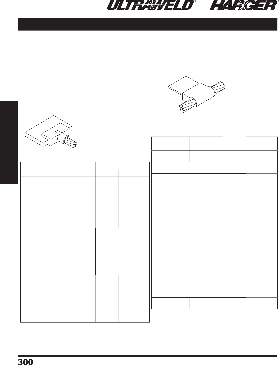
H
ar
g
er Li
g
htnin
g
& Groundin
g
•
©
2012 Phone 847-548-8700 • Fax 847-548-8755 • U.S. 800-842-743
7
300300
Section 5
Ultraweld® Exothermic Connections
BE
M
o
ld Inf
o
rmati
o
n
:
•
M
o
l
d
s liste
d
a
re f
o
r str
a
n
d
e
d
c
ab
le. F
o
r s
o
li
d
conductor, add suffi x "S" after conductor number.
i.e. 4S = 4 AWG s
o
li
d
c
o
n
du
ct
o
r.
•
Price Ke
y
is the
Bold Letter
in the M
o
l
d
P
a
rt N
o
.
r
•
Fo
r
BH
mold Wear Plates, add suffi x "WP" to the
end of the Mold Part No. See pa
g
e 324 for details.
Re
q
uired Tools & Accessories
:
MH1 - H
a
n
d
le f
o
r "
B
"
Price Ke
y
Mold
s
MH2 - H
a
n
d
le f
o
r "
C
"
Price Ke
y
Mold
s
Rec
o
mmended T
oo
ls & Access
o
ries
:
CCBRSH1 - C
a
r
d
Cl
o
th Br
u
s
h
MCBRSH1 - Mold Cleanin
g
Brus
h
BH
(
Horizontal Cable Tap to Ed
g
e o
f
H
orizontal Flat Busbar
)
(
Horizontal Flat Busbar Ta
p
to
H
orizontal Run Cable
)
Cable to Busbar BE / BH
Bus/Lu
g
Si
ze
C
able
Si
ze
M
o
ld
P
art
No
.
W
el
d
Meta
l
U
ltraSh
o
t
NUWTUBE
1
/
4 x 1-1
/2
&
WIDER
#
6
#2 S
o
l
#
2
1
/
0
2
/
0
3
/
0
4/
0
250
MCM
300
MCM
350
MCM
500
MCM
B
E-141.
56
B
B
E-141.
52S
B
B
E-141.
52
B
B
E-141.51
/
0B
B
E-141.52
/
0B
B
E-141.53
/
0B
B
E-141.54
/
0B
B
E-141.
525
CMB
B
E-141.
53
CMB
B
E-141.
535
CMB
B
E-141.
55C
MB
U
S
65
U
S
65
U
S
65
U
S9
0
U
S9
0
U
S9
0
U
S9
0
US
11
5
US
11
5
U
S1
50
U
S
200
NU
WT
U
BE
65
NU
WT
U
BE
65
NU
WT
U
BE
65
NU
WT
U
BE9
0
NU
WT
U
BE9
0
NU
WT
U
BE9
0
NU
WT
U
BE9
0
NU
WT
U
BE11
5
NU
WT
U
BE11
5
NU
WT
U
BE1
50
NU
WT
U
BE
200
3
/
8 x 1-1
/2
&
WIDER
1
/
0
2
/
0
3
/
0
4/
0
250
MCM
300
MCM
350
MCM
500
MCM
7
50
MCM
1
000
MCM
B
E-381.51
/
0B
B
E-381.52
/
0B
B
E-381.53
/
0B
B
E-381.54
/
0B
B
E-381.525CMB
B
E-381.53CMB
B
E-381.535CMB
B
E-381.55CMB
B
E-381.575CM
C
B
E-381.51MM
C
U
S9
0
U
S9
0
US
11
5
US
11
5
U
S1
50
U
S1
50
U
S
200
U
S
250
U
S
300
U
S4
00
NU
WT
U
BE9
0
NU
WT
U
BE9
0
NU
WT
U
BE11
5
NU
WT
U
BE11
5
NU
WT
U
BE1
50
NU
WT
U
BE1
50
NU
WT
U
BE
200
NU
WT
U
BE
250
2
-N
U
WT
U
BE1
50
2
-N
U
WT
U
BE
200
1
/
2 x 1-1
/2
&
WIDER
1
/
0
2
/
0
3
/
0
4/
0
250
MCM
300
MCM
350
MCM
500
MCM
7
50
MCM
1
000
MCM
B
E-121.51
/
0
B
B
E-121.52
/
0B
B
E-121.53
/
0B
B
E-121.54
/
0B
B
E-1
2
1.
525
CM
B
B
E-1
2
1.
53
CM
B
B
E-1
2
1.
535
CM
B
B
E-1
2
1.
55
CM
C
B
E-1
2
1.
5
7
5
CM
C
B
E-1
2
1.
5
1MM
C
US
11
5
US
11
5
U
S1
50
U
S1
50
U
S
200
U
S
200
U
S
250
U
S
300
U
S4
00
U
S
500
NU
WT
U
BE11
5
NU
WT
U
BE11
5
NU
WT
U
BE1
50
NU
WT
U
BE1
50
NU
WT
U
BE
200
NU
WT
U
BE
200
NU
WT
U
BE
250
2
-N
U
WT
U
BE1
50
2
-N
U
WT
U
BE
200
2
-N
U
WT
U
BE
250
C
able
Si
ze
Bus/Lu
g
Si
ze
M
o
ld
P
art
No
.
W
el
d
Meta
l
U
ltraSh
o
t
NUWTUBE
1
/
01
/
8 x 1
1
/
4 x 1
B
H-1
/
0181
B
B
H-1
/
0141
B
U
S
65
U
S9
0
NU
WT
U
BE
65
NU
WT
U
BE9
0
2
/
01
/
8 x 1
1
/
4 x 1
B
H-2
/
0181
B
B
H-2
/
0141
B
U
S9
0
US
11
5
NU
WT
U
BE9
0
NU
WT
U
BE11
5
3
/
0
3
/
16 x 1
1
/
4 x 1
1
/
4 x 1-1
/2
1
/
4 x
2
B
H-3
/
03161
B
B
H-3
/
0141
B
B
H-3
/
0141.5
B
B
H-3
/
014
2
B
US
11
5
U
S1
50
U
S
200
U
S
250
NU
WT
U
BE11
5
NU
WT
U
BE1
50
NU
WT
U
BE
200
NU
WT
U
BE
250
4/
0
3
/
16 x 1
1
/
4 x 1
1
/
4 x 1-1
/2
1
/
4 x
2
B
H-4
/
03161
B
B
H-4
/
0141
B
B
H-4
/
0141.5
B
B
H-4
/
014
2
B
U
S1
50
U
S1
50
U
S
200
U
S
250
NU
WT
U
BE1
50
NU
WT
U
BE1
50
NU
WT
U
BE
200
NU
WT
U
BE
250
250
MC
M
1
/
4 x 1
1
/
4 x 1-1
/2
1
/
4 x
2
B
H-
25
CM141B
B
H-
25
CM141.
5
B
B
H-
25
CM14
2
B
U
S1
50
U
S
200
U
S
250
NU
WT
U
BE1
50
NU
WT
U
BE
200
NU
WT
U
BE
250
300
MC
M
1
/
4 x 1
1
/
4 x 1-1
/2
1
/
4 x
2
B
H-
3
CM141B
B
H-
3
CM141.
5
B
B
H-
3
CM14
2
C
U
S
200
U
S
250
U
S
300
NU
WT
U
BE
200
NU
WT
U
BE
250
2
-N
U
WT
U
BE1
50
350
MC
M
1
/
4 x 1
1
/
4 x 1-1
/
4
1
/
4 x 1-1
/2
1
/
4 x
2
B
H-
35
CM141B
B
H-
35
CM141.
25
B
B
H-
35
CM141.
5
B
B
H-
35
CM14
2
C
U
S
200
U
S
250
U
S
250
U
S
300
NU
WT
U
BE
200
NU
WT
U
BE
250
NU
WT
U
BE
250
2
-N
U
WT
U
BE1
50
500
MC
M
1
/
4 x 1
1
/
4 x 1-1
/2
1
/
4 x
2
B
H-
5C
M141
B
B
H-
5C
M141.
5
C
B
H-
5
CM14
2
C
U
S
250
U
S
300
U
S4
00
NU
WT
U
BE
250
2
-N
U
WT
U
BE1
50
2
-N
U
WT
U
BE
200
7
50
MC
M
1
/
4 x 1-1
/2
1
/
4 x
2
3
/
8 x 1-1
/2
B
H-7
5C
M141.
5
C
B
H-7
5
CM14
2
C
B
H-75CM381.5
C
U
S4
00
U
S
500
U
S
500
2
-N
U
WT
U
BE
200
2
-N
U
WT
U
BE
250
2
-N
U
WT
U
BE
250
1
000
MC
M1
/
4 x 1-1
/2
B
H-1MM141.
5
C
U
S
500
2
-N
U
WT
U
BE
250
BE Connect
i
on T
yp
e
BH Connect
i
on T
yp
e
S
ect
io
n 5.5

H
ar
g
er Li
g
htnin
g
& Groundin
g
•
©
2012 Phone 847-548-8700 • Fax 847-548-8755 • U.S. 800-842-743
7
30
1
301
Section 5
Ultraweld® Exothermic Connections
BU
Mold Information
:
•
M
o
l
d
s liste
d
a
re f
o
r str
a
n
d
e
d
c
ab
le. F
o
r s
o
li
d
conductor, add suffi x "S" after conductor number.
i.e. 4S = 4 AWG s
o
li
d
c
o
n
du
ct
o
r.
•
Price Ke
y
is the
Bold Letter
in the M
o
l
d
P
a
rt N
o
.
r
Re
q
uired Tools & Accessories
:
MH1 - H
a
n
d
le f
o
r "
K
"
Price Ke
y
Mold
s
MH2 - H
a
n
d
le f
o
r "
D
"
Price Ke
y
Mold
s
Recommended Tools & Accessories
:
CCBRSH1 - C
a
r
d
Cl
o
th Br
u
s
h
MCBRSH1 - Mold Cleanin
g
Brus
h
(
Upward Vertical Cable Tap to Ed
g
e
o
f H
o
riz
o
nt
a
l B
u
s
ba
r with F
a
ce in
Vertical Plane
)
BU Cable to Busbar
B
us
bar
Si
ze
C
able
Si
ze
M
o
ld
P
art
No
.
W
el
d
Meta
l
U
ltraSh
o
t
NUWTUBE
1
/
8 x 1
1
/
0
2
/
0
4/
0
B
U-1811
/
0
K
B
U-1812
/
0
K
B
U-1814
/
0
K
US
11
5
US
11
5
US
11
5
NU
WT
U
BE11
5
NU
WT
U
BE11
5
NU
WT
U
BE11
5
1
/
8 x 1-1
/2
&
WIDER
1
/
0
2
/
0
4/
0
250
MCM
300
MCM
350
MCM
B
U-181.51
/
0
K
B
U-181.52
/
0
K
B
U-181.54
/
0
K
B
U-181.525CM
K
B
U-181.53CM
K
B
U-181.535CM
K
US
11
5
US
11
5
US
11
5
US
11
5
U
S1
50
U
S1
50
NU
WT
U
BE11
5
NU
WT
U
BE11
5
NU
WT
U
BE11
5
NU
WT
U
BE11
5
NU
WT
U
BE1
50
NU
WT
U
BE1
50
1
/
4 x 1
1
/
0
2
/
0
4/
0
250
MCM
300
MCM
350
MCM
500
MCM
B
U-1411
/
0
K
B
U-1412
/
0
K
B
U-1414
/
0
K
BU
-141
25
CM
K
BU
-141
3
CM
K
BU
-141
35
CM
K
BU
-141
5C
M
K
U
S1
50
U
S1
50
U
S1
50
U
S1
50
U
S
200
U
S
200
U
S
300
NU
WT
U
BE1
50
NU
WT
U
BE1
50
NU
WT
U
BE1
50
NU
WT
U
BE1
50
NU
WT
U
BE
200
NU
WT
U
BE
200
2
-N
U
WT
U
BE1
50
1
/
4 x 1-1
/2
&
WIDER
1
/
0
2
/
0
4/
0
250
MCM
300
MCM
350
MCM
500
MCM
7
50
MCM
B
U-141.51
/
0
K
B
U-141.52
/
0
K
B
U-141.54
/
0
K
BU
-141.
525
CM
K
BU
-141.
53
CM
K
BU
-141.
535
CM
K
BU
-141.
55C
M
K
BU
-141.
5
7
5C
M
D
U
S1
50
U
S1
50
U
S1
50
U
S1
50
U
S
200
U
S
200
U
S
300
U
S4
00
NU
WT
U
BE1
50
NU
WT
U
BE1
50
NU
WT
U
BE1
50
NU
WT
U
BE1
50
NU
WT
U
BE
200
NU
WT
U
BE
200
2
-N
U
WT
U
BE1
50
2
-N
U
WT
U
BE
200
3
/
8 x 1
1
/
0
2
/
0
4/
0
250
MCM
300
MCM
350
MCM
500
MCM
7
50
MCM
B
U-3811
/
0
K
B
U-3812
/
0
K
B
U-3814
/
0
K
B
U-38125CM
K
B
U-3813CM
K
B
U-38135CM
K
B
U-3815CM
K
B
U-38175CM
D
U
S1
50
U
S1
50
U
S1
50
U
S1
50
U
S
200
U
S
200
U
S
250
U
S4
00
NU
WT
U
BE1
50
NU
WT
U
BE1
50
NU
WT
U
BE1
50
NU
WT
U
BE1
50
NU
WT
U
BE
200
NU
WT
U
BE
200
NU
WT
U
BE
250
2
-N
U
WT
U
BE
200
B
us
bar
Si
ze
C
able
Si
ze
M
o
ld
P
art
No
.
W
el
d
Meta
l
U
ltraSh
o
t
NUWTUBE
3
/
8 x 1-1
/2
&
WIDER
1
/
0
2
/
0
4/
0
250
MCM
300
MCM
350
MCM
500
MCM
7
50
MCM
B
U-381.51
/
0
K
B
U-381.52
/
0
K
B
U-381.54
/
0
K
B
U-381.525CM
K
B
U-381.53CM
K
B
U-381.535CM
K
B
U-381.55CM
K
B
U-381.575CM
D
U
S1
50
U
S1
50
U
S1
50
U
S1
50
U
S
200
U
S
200
U
S
250
U
S4
00
NU
WT
U
BE1
50
NU
WT
U
BE1
50
NU
WT
U
BE1
50
NU
WT
U
BE1
50
NU
WT
U
BE
200
NU
WT
U
BE
200
NU
WT
U
BE
250
2
-N
U
WT
U
BE
200
1
/
2 x 1
1
/
0
2
/
0
4/
0
250
MCM
300
MCM
350
MCM
500
MCM
7
50
MCM
B
U-1211
/
0
K
B
U-1212
/
0
K
B
U-1214
/
0
K
BU
-1
2
1
25
CM
K
BU
-1
2
1
3
CM
K
BU
-1
2
1
35
CM
K
BU
-1
2
1
5
CM
D
BU
-1
2
17
5
CM
D
U
S
200
U
S
200
U
S
200
U
S
200
U
S
250
U
S
250
U
S
300
U
S
500
NU
WT
U
BE
200
NU
WT
U
BE
200
NU
WT
U
BE
200
NU
WT
U
BE
200
NU
WT
U
BE
250
NU
WT
U
BE
250
2
-N
U
WT
U
BE1
50
2
-N
U
WT
U
BE
250
1
/
2 x 1-1
/2
&
WIDER
1
/
0
2
/
0
4/
0
250
MCM
300
MCM
350
MCM
500
MCM
7
50
MCM
B
U-121.51
/
0
K
B
U-121.52
/
0
K
B
U-121.54
/
0
K
BU
-1
2
1.
525
CM
K
BU
-1
2
1.
53
CM
K
BU
-1
2
1.
535
CM
K
BU
-1
2
1.
55
CM
D
BU
-1
2
1.
5
7
5
CM
D
U
S
200
U
S
200
U
S
200
U
S
200
U
S
250
U
S
250
U
S
300
U
S
500
NU
WT
U
BE
200
NU
WT
U
BE
200
NU
WT
U
BE
200
NU
WT
U
BE
200
NU
WT
U
BE
250
NU
WT
U
BE
250
2
-N
U
WT
U
BE1
50
2
-N
U
WT
U
BE
250
BU Connect
i
on T
yp
e BU Connection T
yp
e continue
d
S
ect
io
n 5.5

H
ar
g
er Li
g
htnin
g
& Groundin
g
•
©
2012 Phone 847-548-8700 • Fax 847-548-8755 • U.S. 800-842-743
7
30
2
302
Section 5
Ultraweld® Exothermic Connections
BA
BB
M
o
ld Inf
o
rmati
o
n
:
•
Price Ke
y
is the
Bold Letter
in the M
o
l
d
P
a
rt N
o
.
r
Re
q
uired Tools & Accessories
:
MH1 - H
a
n
d
le f
o
r "
B
"
Price Ke
y
Mold
s
MH2 - H
a
n
d
le f
o
r "
C
"
Price Ke
y
Mold
s
Rec
o
mmended T
oo
ls & Access
o
ries
:
CCBRSH1 - C
a
r
d
Cl
o
th Br
u
s
h
MCBRSH1 - Mold Cleanin
g
Brus
h
(
Busbar 90°, Ta
p
Down, Run
H
orizontal, Busbar Face in
Vertical Plane
)
(
Horizontal Busbar Butt S
p
lice,
B
usbar Face in Vertical Plane
)
Busbar to Busbar BA / BB
B
us
bar
Si
ze
M
o
ld
P
art
No
.
W
el
d
Meta
l
U
ltraSh
o
t
NUWTUBE
1
/
8 x 1
1
/
8 x
2
B
A-181
B
B
A-18
2
B
US
4
5
U
S9
0
NUWTUBE45
NU
WT
U
BE9
0
3
/
16 x 1
3
/
16 x
2
B
A-
3
1
6
1
B
B
A-
3
1
62
B
U
S
65
US
11
5
NU
WT
U
BE
65
NU
WT
U
BE11
5
1
/
4 x 1
1
/
4 x 1-1
/
4
1
/
4 x 1-1
/2
1
/
4 x
2
1
/
4 x
3
1
/
4 x 4
B
A-141
B
B
A-141.
25
B
B
A-141.
5
B
B
A-14
2
B
B
A-14
3
C
B
A-144
C
U
S9
0
US
11
5
U
S1
50
U
S
200
U
S4
00
U
S
500
NU
WT
U
BE9
0
NU
WT
U
BE11
5
NU
WT
U
BE1
50
NU
WT
U
BE
200
2
-N
U
WT
U
BE
200
2
-N
U
WT
U
BE
250
3
/
8 x 1
3
/
8 x 1-1
/2
3
/
8 x
2
3
/
8 x
3
B
A-381
B
B
A-381.5
B
B
A-38
2
C
B
A-38
3
C
U
S1
50
U
S
250
U
S
300
U
S
500
NU
WT
U
BE1
50
NU
WT
U
BE
250
2
-N
U
WT
U
BE1
50
2
-N
U
WT
U
BE
250
1
/
2 x 1
1
/
2 x
2
BA
-
121
B
BA
-
122
C
U
S
200
U
S4
00
NU
WT
U
BE
200
2
-N
U
WT
U
BE
200
B
us
bar
Si
ze
M
o
ld
P
art
No
.
W
el
d
Meta
l
U
ltraSh
o
t
NUWTUBE
1
/
8 x 1
1
/
8 x
2
B
B-181
B
B
B-18
2
B
US
4
5
U
S9
0
NUWTUBE45
NU
WT
U
BE9
0
3
/
16 x 1
3
/
16 x
2
B
B-
3
1
6
1
B
B
B-
3
1
62
B
U
S
65
US
11
5
NU
WT
U
BE
65
NU
WT
U
BE11
5
1
/
4 x 1
1
/
4 x 1-1
/4
1
/
4 x 1-1
/2
1
/
4 x
2
1
/
4 x
3
1
/
4 x 4
B
B-141
B
B
B-141.
25
B
B
B-141.
5
B
B
B-14
2
B
B
B-14
3
C
B
B-14
4
C
U
S9
0
US
11
5
U
S1
50
U
S
200
U
S4
00
U
S
500
NU
WT
U
BE9
0
NU
WT
U
BE11
5
NU
WT
U
BE1
50
NU
WT
U
BE
200
2
-N
U
WT
U
BE
200
2
-N
U
WT
U
BE
250
3
/
8 x 1
3
/
8 x 1-1
/2
3
/
8 x
2
3
/
8 x
3
B
B-381
B
B
B-381.5
B
B
B-38
2
C
B
B-38
3
C
U
S1
50
U
S
250
U
S
300
U
S
500
NU
WT
U
BE1
50
NU
WT
U
BE
250
2
-N
U
WT
U
BE1
50
2
-N
U
WT
U
BE
250
1
/
2 x 1
1
/
2 x
2
B
B-1
2
1
B
B
B-1
22
C
U
S
200
U
S4
00
NU
WT
U
BE
200
2
-N
U
WT
U
BE
200
BB Connect
i
on T
yp
e
BA Connect
i
on T
yp
e
S
ect
io
n 5.5
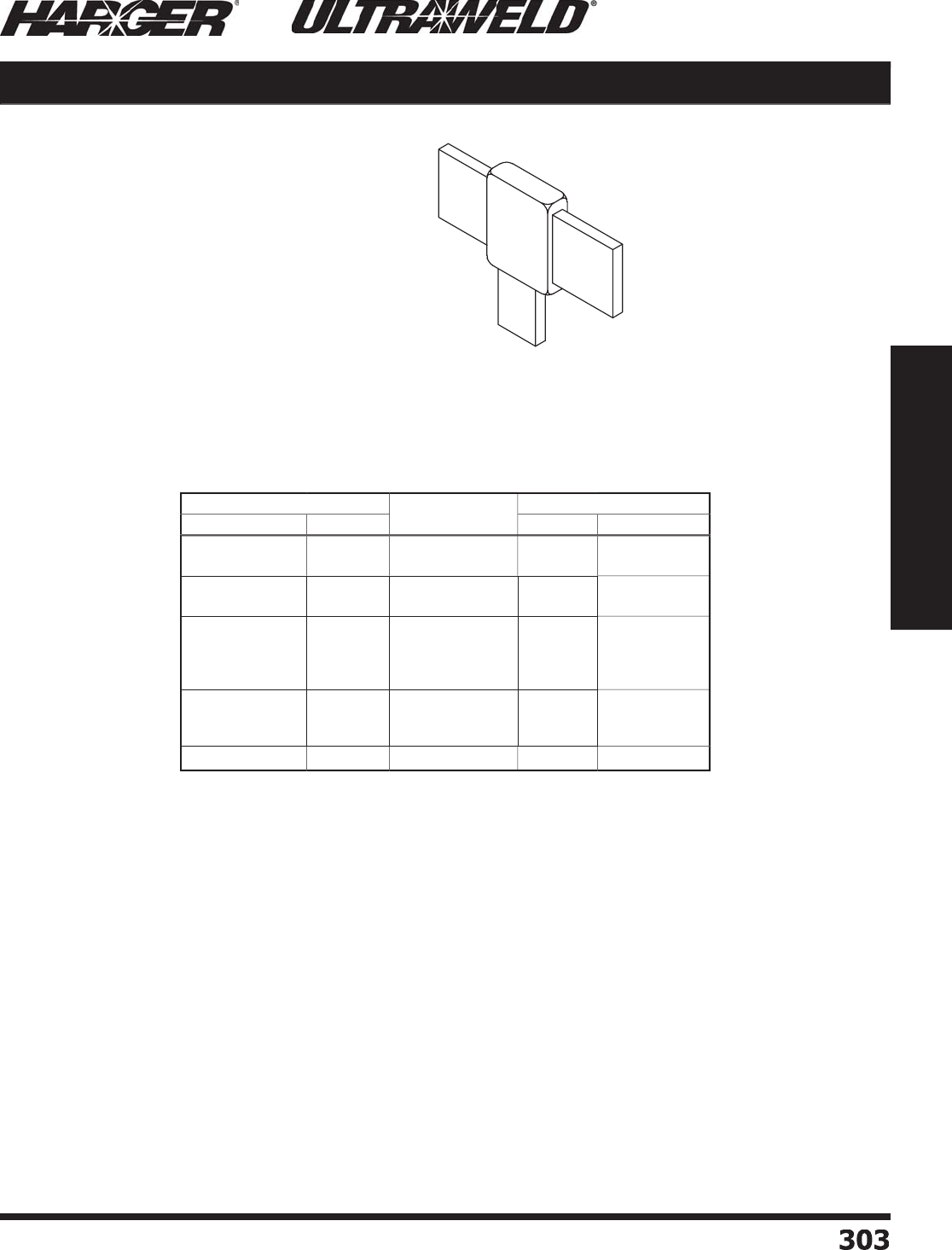
H
ar
g
er Li
g
htnin
g
& Groundin
g
•
©
2012 Phone 847-548-8700 • Fax 847-548-8755 • U.S. 800-842-743
7
303
303
Section 5
Ultraweld® Exothermic Connections
BT
Mold Information
:
•
Price Ke
y
is the
Bold Letter
in the M
o
l
d
P
a
rt N
o
.
r
Re
q
uired Tools & Accessories
:
MH1 - H
a
n
d
le f
o
r "
B
"
Price Ke
y
Mold
s
MH2 - H
a
n
d
le f
o
r "
C
"
Price Ke
y
Mold
s
Rec
o
mmended T
oo
ls & Access
o
ries
:
CCBRSH1 - C
a
r
d
Cl
o
th Br
u
s
h
MCBRSH1 - Mold Cleanin
g
Brus
h
(
Busbar Tee, Ta
p
Down, Thru
H
orizontal Run, Busbar Face
i
n Vertical Plane
)
BT Busbar to Busbar
RUN
TAP
B
us
bar Size M
o
ld
P
art
No
.
W
el
d
Meta
l
B
ar
Run
B
ar
T
a
p
U
ltraSh
o
t
NUWTUBE
1
/
8 x 1
1
/
8 x 2 & WIDER
1
/
8 x 1
1
/
8 x
2
B
T-181181
B
B
T-18218
2
B
U
S9
0
U
S
200
NU
WT
U
BE9
0
NU
WT
U
BE
200
3
/
16 x 1
3
/
16 x 2 & WIDER
3
/
16 x 1
3
/
16 x
2
B
T-
3
1
6
1
3
1
6
1
B
B
T-
3
1
623
1
62
B
US
11
5
U
S
200
NU
WT
U
BE11
5
NU
WT
U
BE
200
1
/
4 x 1
1
/
4 x 1-1
/4
1
/
4 x 1-1
/2
1
/
4 x 2 & WIDER
1
/
4 x 1
1
/
4 x 1-1
/4
1
/
4 x 1-1
/2
1
/
4 x
2
B
T-141141
B
B
T-141.
25
141.
25
B
B
T-141.
5
141.
5
B
B
T-14
2
14
2
C
U
S1
50
U
S
200
U
S
250
U
S4
00
NU
WT
U
BE1
50
NU
WT
U
BE
200
NU
WT
U
BE
250
2
-N
U
WT
U
BE
200
3
/
8 x 1
3
/
8 x 1-1
/2
3
/
8 x 2 & WIDER
3
/
8 x 1
3
/
8 x 1-1
/2
3
/
8 x
2
B
T-381381B
B
T-381.5381.5
C
B
T-38238
2
C
U
S
250
U
S4
00
U
S
500
NU
WT
U
BE
250
2
-N
U
WT
U
BE
200
2
-N
U
WT
U
BE
250
1
/
2 x 1 1
/
2 x 1
B
T-1
2
11
2
1
C
U
S
300
2
-N
U
WT
U
BE1
50
BT Connect
i
on T
yp
e
S
ect
io
n 5.5
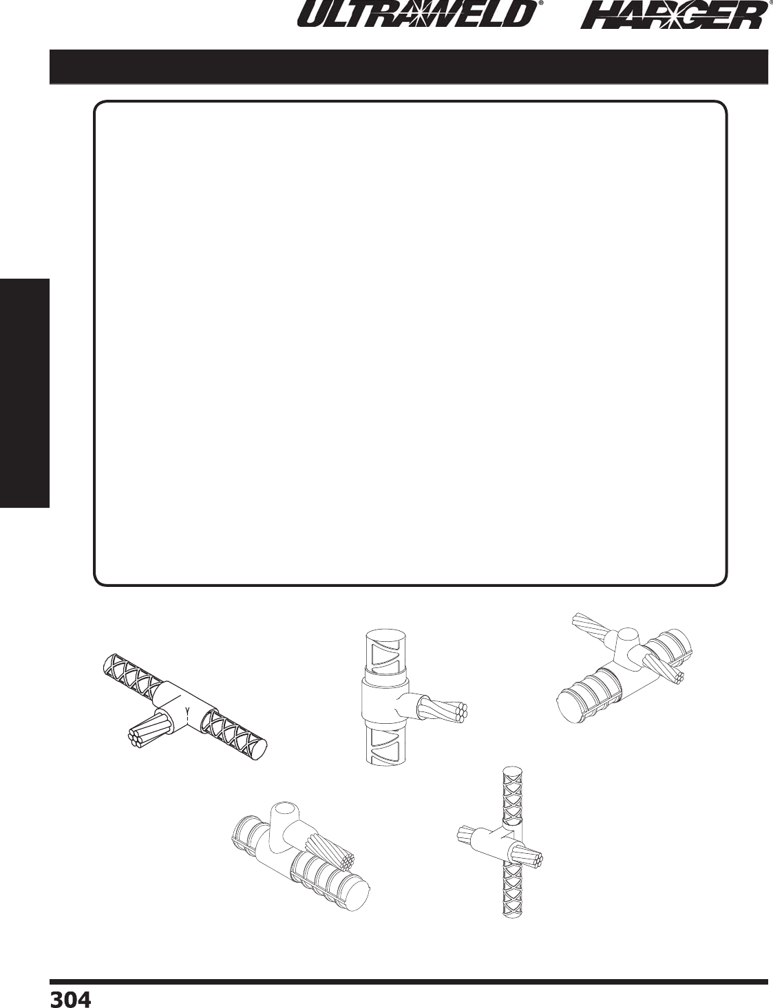
H
ar
g
er Li
g
htnin
g
& Groundin
g
•
©
2012 Phone 847-548-8700 • Fax 847-548-8755 • U.S. 800-842-743
7
304304
Section 5
Ultraweld® Exothermic Connections
APPLICATI
O
N N
O
TES
:
U
ltraweld C
o
nnecti
o
ns Used
f
or Groundin
g
Reinforcin
g
Bars
T
he Ultraweld process is ideal for providin
g
permanent connections of
g
roundin
g
conductors
and li
g
htnin
g
protection conductors to rebar. Exothermically weldin
g
to the rebar ensures that
the c
o
ncrete enc
a
se
d
c
o
nnecti
o
n will l
a
st the
du
r
a
ti
o
n
o
f the str
u
ct
u
re. T
o
ens
u
re th
a
t the
connection is made
p
ro
p
erl
y
, the mill scale must be removed from the rebar in the area of the
connection. In addition to the normal materials used to make an Ultraweld connection, packin
g
material is also required. The packin
g
material serves as a sealant barrier between the mold
and the rebar and thus prevents weld metal leaka
g
e. A piece of packin
g
material is
g
ood for
o
ne c
o
nnecti
o
n.
Ultraweld C
o
nnecti
o
ns t
o
Structural
Reinforcin
g
Bar
T
he Ultraweld process is only to be used for attachin
g
conductors to rebar and not as a means
to provide a structural welded
j
oint of the rebar itself. The weldin
g
of
g
round conductors to
rebar usin
g
the Ultraweld process will not be harmful if the stresses in the rebar are below its
y
ield point. Desi
g
n stresses for rebar are normally below 60% of the nominal yield stren
g
th
thus Ultraweld exothermic weldin
g
process should not be detrimental under desi
g
n stresses.
In practice it is best to make
g
roundin
g
attachments to rebar in areas away from the point o
f
m
a
xim
u
m stress. It is
b
est t
o
m
a
ke c
o
nnecti
o
ns ne
a
r the free en
d
o
f the re
ba
r.
RE
RB
R
O
RP
R
S
Cable to Rebar
S
ect
io
n 5.5
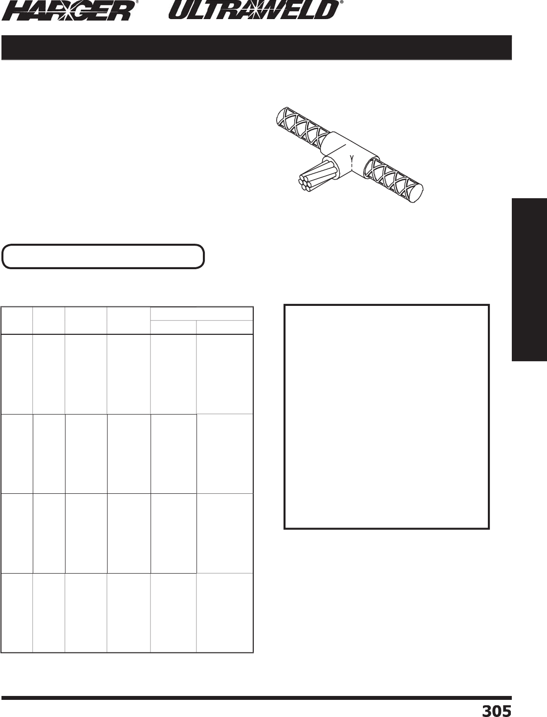
H
ar
g
er Li
g
htnin
g
& Groundin
g
•
©
2012 Phone 847-548-8700 • Fax 847-548-8755 • U.S. 800-842-743
7
305
305
Section 5
Ultraweld® Exothermic Connections
RB
Important: See Packin
g
Material Notes.
Mold Information
:
•
M
o
l
d
s liste
d
a
re f
o
r str
a
n
d
e
d
c
ab
le. F
o
r s
o
li
d
conductor, add suffi x "S" after conductor number.
i.e. 4S = 4 AWG s
o
li
d
c
o
n
du
ct
o
r.
•
Price Ke
y
is the
Bold Letter
in the M
o
l
d
P
a
rt N
o
.
r
•
For information on sizes not listed,
p
lease
contact the factor
y
.
Re
q
uired Tools & Accessories
:
MH1 - H
a
n
d
le f
o
r "
B
"
Price Ke
y
Mold
s
WRPSLV - Wra
p
Sleev
e
Recommended Tools & Accessories
:
CCBRSH1 - C
a
r
d
Cl
o
th Br
u
s
h
MCBRSH1 - Mold Cleanin
g
Brus
h
(
Tee of Horizontal Thru Rebar
&
Horizontal Ta
p
Cable
)
RB Cable to Rebar
Packin
g
Material Notes
Packin
g
Material or Wrap Sleeve(s)
are necessary when makin
g
Ultraweld
connections to Rebar. The two t
yp
es o
f
m
a
teri
a
l
u
se
d
a
re CERPM
o
r WRPSLV.
CERPM Packin
g
Material is a ceramic
fi
b
er m
a
teri
a
l
a
n
d
c
a
n
b
e
u
se
d
f
o
r
o
ne
connection only. CERPM is packa
g
ed in
q
uantities of 25
p
er box.
WRPSLV Co
pp
er Wra
p
Sleeve is
w
ra
pp
ed around the rebar for certain
connection styles. WRPSLV is packa
g
ed in
q
uantities of 50
p
er box.
Be sure to specify Packin
g
Material No.
w
hen orderin
g
Mold and Weld Metal. See
pa
g
es 325 & 326 for Packin
g
Material.
Rebar
Si
ze
C
able
Si
ze
M
o
ld
P
art
No
.
Packin
g
Mat'l N
o
.
W
el
d
Meta
l
U
ltraSh
o
t
NUWTUBE
3
#
6
#4
#2 S
o
l
#
2
1
/
0
2
/
0
3
/
0
4/
0
R
B-
36
B
R
B-
34
B
R
B-
32S
B
R
B-
32
B
R
B-31
/
0
B
R
B-32
/
0
B
R
B-33
/
0
B
R
B-34
/
0
B
W
RP
S
LV
W
RP
S
LV
W
RP
S
LV
W
RP
S
LV
W
RP
S
LV
W
RP
S
LV
W
RP
S
LV
W
RP
S
LV
US
4
5
US
4
5
U
S
65
U
S
65
U
S9
0
U
S9
0
US
11
5
US
11
5
NUWTUBE45
NUWTUBE45
NU
WT
U
BE
65
NU
WT
U
BE
65
NU
WT
U
BE9
0
NU
WT
U
BE9
0
NU
WT
U
BE11
5
NU
WT
U
BE11
5
4
#
6
#4
#2 S
o
l
#
2
1
/
0
2
/
0
3
/
0
4/
0
R
B-4
6
B
RB
-
44
B
R
B-4
2S
B
R
B-4
2
B
R
B-41
/
0
B
R
B-42
/
0
B
R
B-43
/
0
B
R
B-44
/
0
B
W
RP
S
LV
W
RP
S
LV
W
RP
S
LV
W
RP
S
LV
W
RP
S
LV
W
RP
S
LV
W
RP
S
LV
W
RP
S
LV
US
4
5
US
4
5
U
S
65
U
S
65
U
S9
0
U
S9
0
US
11
5
US
11
5
NUWTUBE45
NUWTUBE45
NU
WT
U
BE
65
NU
WT
U
BE
65
NU
WT
U
BE9
0
NU
WT
U
BE9
0
NU
WT
U
BE11
5
NU
WT
U
BE11
5
5
#
6
#4
#2 S
o
l
#
2
1
/
0
2
/
0
3
/
0
4/
0
R
B-
56
B
RB
-
54
B
R
B-
52S
B
R
B-
52
B
R
B-51
/
0
B
R
B-52
/
0
B
R
B-53
/
0
B
R
B-54
/
0
B
W
RP
S
LV
W
RP
S
LV
W
RP
S
LV
W
RP
S
LV
W
RP
S
LV
W
RP
S
LV
W
RP
S
LV
W
RP
S
LV
U
S9
0
U
S9
0
U
S9
0
U
S9
0
US
11
5
US
11
5
U
S1
50
U
S1
50
NU
WT
U
BE9
0
NU
WT
U
BE9
0
NU
WT
U
BE9
0
NU
WT
U
BE9
0
NU
WT
U
BE11
5
NU
WT
U
BE11
5
NU
WT
U
BE1
50
NU
WT
U
BE1
50
6
#
6
#4
#2 S
o
l
#
2
1
/
0
2
/
0
3
/
0
4/
0
R
B-
66
B
R
B-
64
B
R
B-
62S
B
R
B-
62
B
R
B-61
/
0
B
R
B-62
/
0
B
R
B-63
/
0
B
R
B-64
/
0
B
W
RP
S
LV
W
RP
S
LV
W
RP
S
LV
W
RP
S
LV
W
RP
S
LV
W
RP
S
LV
W
RP
S
LV
W
RP
S
LV
U
S9
0
U
S9
0
U
S9
0
U
S9
0
US
11
5
US
11
5
U
S1
50
U
S1
50
NU
WT
U
BE9
0
NU
WT
U
BE9
0
NU
WT
U
BE9
0
NU
WT
U
BE9
0
NU
WT
U
BE11
5
NU
WT
U
BE11
5
NU
WT
U
BE1
50
NU
WT
U
BE1
50
RB Connect
i
on T
yp
e
S
ect
io
n 5.5
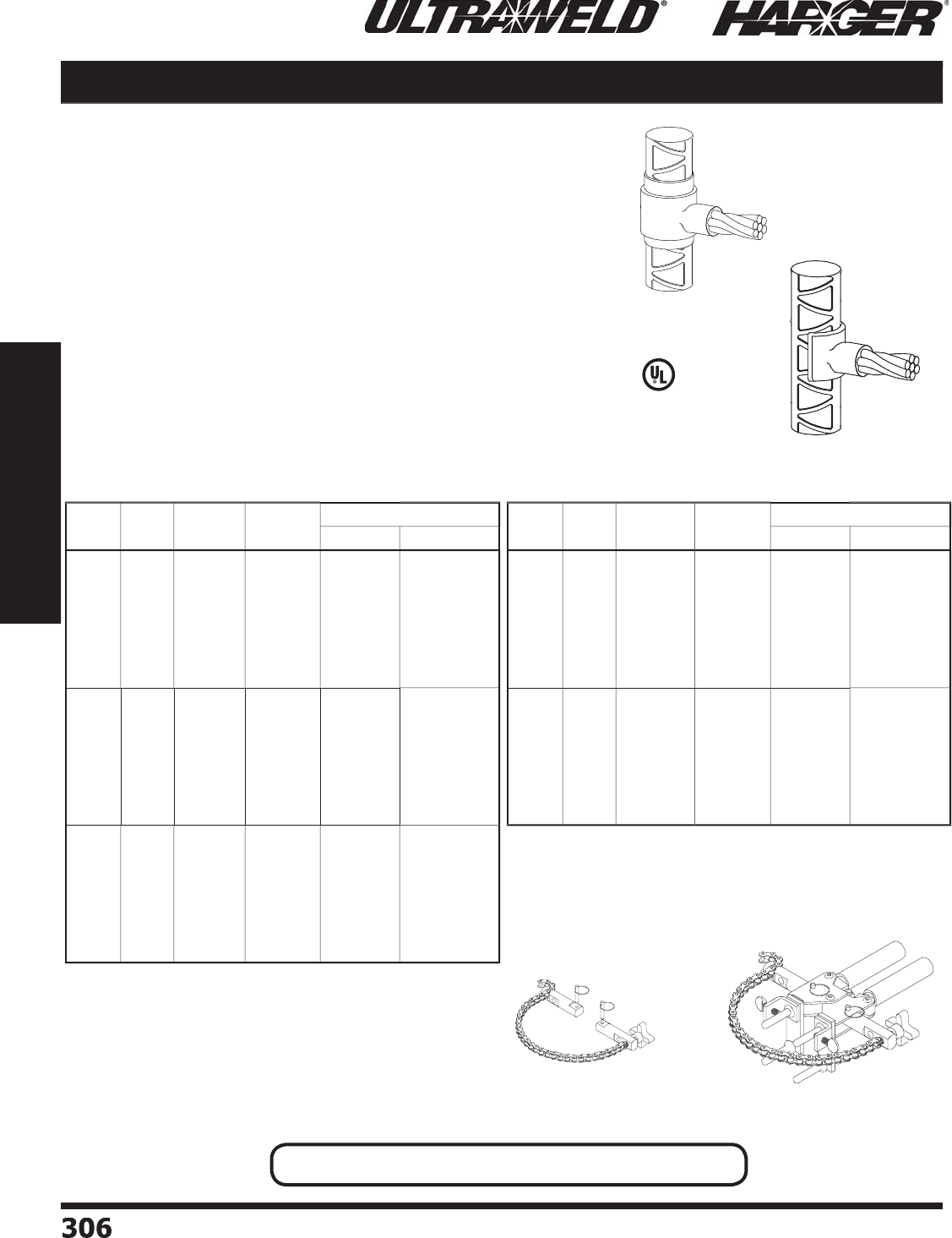
H
ar
g
er Li
g
htnin
g
& Groundin
g
•
©
2012 Phone 847-548-8700 • Fax 847-548-8755 • U.S. 800-842-743
7
306306
Section 5
Ultraweld® Exothermic Connections
Important: See Packin
g
Material Notes On Pa
g
e 305.
RE
M
o
ld Inf
o
rmati
o
n
:
•
Molds listed are for stranded cable. For solid conductor, add suffi x
"
S"
a
fter c
o
n
du
ct
o
r n
u
m
b
er. i.e. 4S = 4 AWG s
o
li
d
c
o
n
du
ct
o
r.
•
Price Ke
y
is the
Bold Letter
in the M
o
l
d
P
a
rt N
o
.
r
Re
q
uired Tools & Accessories
:
WRPSLV or CERPM - Rebar Packin
g
Material
CSH1 - Chain Su
pp
ort Handle clam
p
for "
B
"
&
"K" Price Ke
y
Mold
s
OR
MH1 - H
a
n
d
le f
o
r "
B
"
a
n
d
"K" Price Ke
y
Mold
s
**CSKIT - Chain Support Kit for #7 & Lar
g
er reba
r
Rec
o
mmended T
oo
ls & Access
o
ries
:
CCBRSH1 - C
a
r
d
Cl
o
th Br
u
s
h
MCBRSH1 - Mold Cleanin
g
Brus
h
(
Tee of Vertical Thru
R
e
ba
r
&
H
o
riz
o
nt
a
l
T
a
p
Cable
)
*
*Re
q
uires Chain Su
pp
ort Kit
(
#CSKIT
)
for welds
made to #7 and Lar
g
er rebar.
Cable to Rebar RE
R
E 7
&
Lar
g
e
r
CS
KIT
CS
H1
Pa
tente
d
Rebar
Si
ze
C
able
Si
ze
M
o
ld
P
art
No
.
Packin
g
Mat'l N
o
.
W
el
d
Meta
l
U
ltraSh
o
t
NUWTUBE
3
#
6
#4
#2 S
o
l
#
2
1
/
0
2
/
0
3
/
0
4/
0
R
E-
36
B
R
E-
3
4
B
R
E-
32S
B
R
E-
32
B
R
E-31
/
0
B
R
E-32
/
0
B
R
E-33
/
0
B
R
E-34
/
0
B
W
RP
S
LV
W
RP
S
LV
W
RP
S
LV
W
RP
S
LV
W
RP
S
LV
W
RP
S
LV
W
RP
S
LV
W
RP
S
LV
US
4
5
U
S
65
U
S
65
U
S
65
US
11
5
US
11
5
U
S1
50
U
S1
50
NUWTUBE45
NU
WT
U
BE
65
NU
WT
U
BE
65
NU
WT
U
BE
65
NU
WT
U
BE11
5
NU
WT
U
BE11
5
NU
WT
U
BE1
50
NU
WT
U
BE1
50
4
#
6
#4
#2 S
o
l
#
2
1
/
0
2
/
0
3
/
0
4/
0
R
E-4
6
B
RE
-
44
B
R
E-4
2S
B
R
E-4
2
B
R
E-41
/
0
B
R
E-42
/
0
B
R
E-43
/
0
B
R
E-44
/
0
B
W
RP
S
LV
W
RP
S
LV
W
RP
S
LV
W
RP
S
LV
W
RP
S
LV
W
RP
S
LV
W
RP
S
LV
W
RP
S
LV
US
4
5
U
S
65
U
S
65
U
S
65
US
11
5
US
11
5
U
S1
50
U
S1
50
NUWTUBE45
NU
WT
U
BE
65
NU
WT
U
BE
65
NU
WT
U
BE
65
NU
WT
U
BE11
5
NU
WT
U
BE11
5
NU
WT
U
BE1
50
NU
WT
U
BE1
50
5
#
6
#4
#2 S
o
l
#
2
1
/
0
2
/
0
3
/
0
4/
0
R
E-
56
B
RE
-
54
B
R
E-
52S
B
R
E-
52
B
R
E-51
/
0
B
R
E-52
/
0
B
R
E-53
/
0
B
R
E-54
/
0
B
W
RP
S
LV
W
RP
S
LV
W
RP
S
LV
W
RP
S
LV
W
RP
S
LV
W
RP
S
LV
W
RP
S
LV
W
RP
S
LV
US
4
5
U
S
65
U
S
65
U
S
65
US
11
5
US
11
5
U
S1
50
U
S1
50
NUWTUBE45
NU
WT
U
BE
65
NU
WT
U
BE
65
NU
WT
U
BE
65
NU
WT
U
BE11
5
NU
WT
U
BE11
5
NU
WT
U
BE1
50
NU
WT
U
BE1
50
Rebar
Si
ze
C
able
Si
ze
M
o
ld
P
art
No
.
Packin
g
Mat'l N
o
.
W
el
d
Meta
l
U
ltraSh
o
t
NUWTUBE
6
#
6
#4
#2 S
o
l
#
2
1
/
0
2
/
0
3
/
0
4/
0
R
E-
66
B
R
E-
6
4
B
R
E-
62S
B
R
E-
62
B
R
E-61
/
0
B
R
E-62
/
0
B
R
E-63
/
0
B
R
E-64
/
0
B
W
RP
S
LV
W
RP
S
LV
W
RP
S
LV
W
RP
S
LV
W
RP
S
LV
W
RP
S
LV
W
RP
S
LV
W
RP
S
LV
US
4
5
U
S
65
U
S
65
U
S
65
US
11
5
US
11
5
U
S1
50
U
S1
50
NUWTUBE45
NU
WT
U
BE
65
NU
WT
U
BE
65
NU
WT
U
BE
65
NU
WT
U
BE11
5
NU
WT
U
BE11
5
NU
WT
U
BE1
50
NU
WT
U
BE1
50
7**
&
L
ar
g
e
r
#
6
#4
#2 S
o
l
#
2
1
/
0
2
/
0
3
/
0
4/
0
R
E-7L
6
K
RE
-
7L4
K
R
E-7L
2S
K
R
E-7L
2
K
R
E-7L1
/
0
K
R
E-7L2
/
0
K
R
E-7L3
/
0
K
R
E-7L4
/
0
K
CERPM
3
CERPM
3
CERPM
3
CERPM
3
CERPM
3
CERPM
3
CERPM
3
CERPM
3
US
4
5
U
S
65
U
S
65
U
S
65
US
11
5
US
11
5
U
S1
50
U
S1
50
NUWTUBE45
NU
WT
U
BE
65
NU
WT
U
BE
65
NU
WT
U
BE
65
NU
WT
U
BE11
5
NU
WT
U
BE11
5
NU
WT
U
BE1
50
NU
WT
U
BE1
50
RE Connect
i
on T
yp
e RE Connection T
yp
e continued
L
iste
d
4
67
S
ect
io
n 5.5
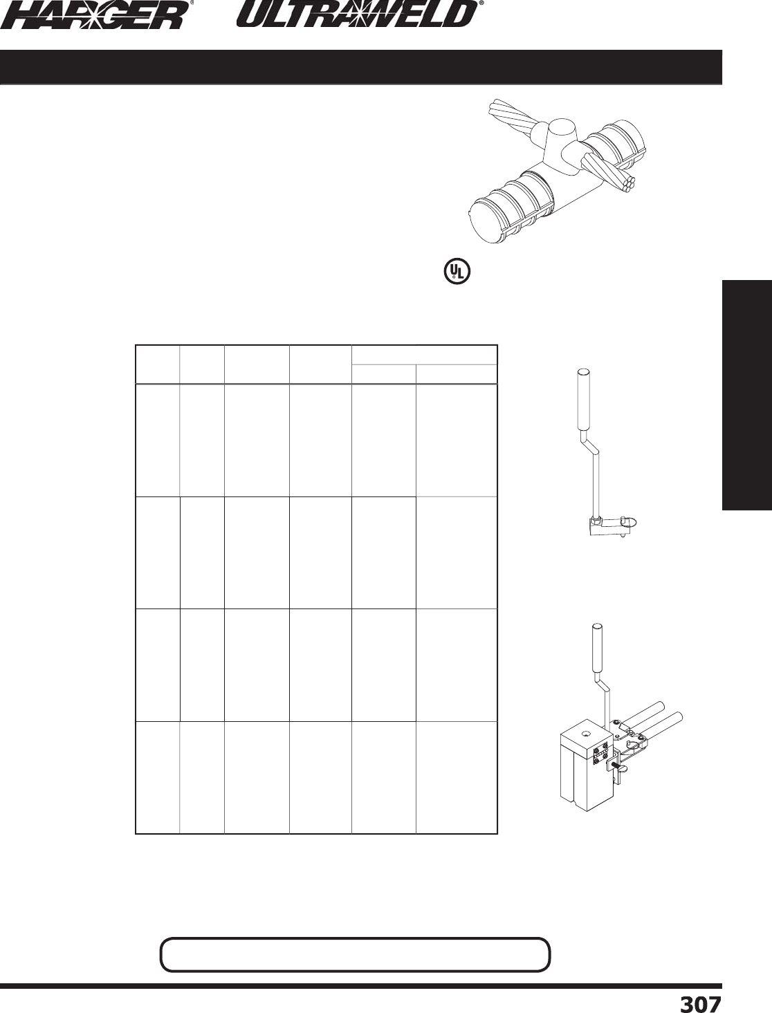
H
ar
g
er Li
g
htnin
g
& Groundin
g
•
©
2012 Phone 847-548-8700 • Fax 847-548-8755 • U.S. 800-842-743
7
30
7
307
Section 5
Ultraweld® Exothermic Connections
R
O
Mold Information
:
•
Molds listed are for stranded cable. For solid conductor, add suffi x
"
S"
a
fter c
o
n
du
ct
o
r n
u
m
b
er. i.e. 4S = 4 AWG s
o
li
d
c
o
n
du
ct
o
r.
•
Price Ke
y
is the
Bold Letter
in the M
o
l
d
P
a
rt N
o
.
r
•
For mold Wear Plates, add suffi x "WP" to the end of the Mold Part
N
o. See pa
g
e 324 for details.
Re
q
uired Tools & Accessories
:
MH1 - H
a
n
d
le f
o
r "
B
"
a
n
d
"
Q
"
Price Ke
y
Mold
s
W
RP
S
L
V
or CERPM - Rebar Packing Material
V
U
MHDKIT - H
o
l
d
D
o
wn Ki
t
Recommended Tools & Accessories
:
CCBRSH1 - C
a
r
d
Cl
o
th Br
u
s
h
MCBRSH1 - Mold Cleanin
g
Brus
h
(
Cross of Horizontal Cable
L
a
pp
ed Over Horizontal Rebar
)
RO Cable to Rebar
*
* Re
q
uires Hold Down Kit
(
#UMHDKIT
)
for weld
s
made to #6 and Lar
g
er rebar.
UMHDKIT
U
MHDKIT with M
o
l
d
&
H
a
n
d
le
Important: See Packin
g
Material Notes On Pa
g
e 305.
Pa
tente
d
Rebar
Si
ze
C
able
Si
ze
Mold
P
art
N
o.
Packin
g
Mat'l No.
W
el
d
Meta
l
U
ltraSh
o
t
NUWTUBE
3
#
6
#4
#2 S
o
l
#
2
1
/
0
2
/
0
3
/
0
4/
0
RO
-
36
B
RO
-
34
B
RO
-
32S
B
RO
-
32
B
R
O-31
/
0
Q
R
O-32
/
0
Q
R
O-33
/
0
Q
R
O-34
/
0
Q
W
RP
S
LV
W
RP
S
LV
W
RP
S
LV
W
RP
S
LV
W
RP
S
LV
W
RP
S
LV
W
RP
S
LV
W
RP
S
LV
U
S
65
U
S
65
U
S9
0
U
S9
0
US
11
5
US
11
5
U
S1
50
U
S1
50
NU
WT
U
BE
65
NU
WT
U
BE
65
NU
WT
U
BE9
0
NU
WT
U
BE9
0
NU
WT
U
BE11
5
NU
WT
U
BE11
5
NU
WT
U
BE1
50
NU
WT
U
BE1
50
4
#
6
#4
#2 S
o
l
#
2
1
/
0
2
/
0
3
/
0
4/
0
RO
-4
6
B
RO
-4
4
B
RO
-4
2S
B
RO
-4
2
B
R
O-41
/
0
Q
R
O-42
/
0
Q
R
O-43
/
0
Q
R
O-44
/
0
Q
W
RP
S
LV
W
RP
S
LV
W
RP
S
LV
W
RP
S
LV
W
RP
S
LV
W
RP
S
LV
W
RP
S
LV
W
RP
S
LV
U
S
65
U
S
65
U
S9
0
U
S9
0
US
11
5
US
11
5
U
S1
50
U
S1
50
NU
WT
U
BE
65
NU
WT
U
BE
65
NU
WT
U
BE9
0
NU
WT
U
BE9
0
NU
WT
U
BE11
5
NU
WT
U
BE11
5
NU
WT
U
BE1
50
NU
WT
U
BE1
50
5
#
6
#4
#2 S
o
l
#
2
1
/
0
2
/
0
3
/
0
4/
0
RO
-
56
B
RO
-
54
B
RO
-
52S
B
RO
-
52
B
R
O-51
/
0
Q
R
O-52
/
0
Q
R
O-53
/
0
Q
R
O-54
/
0
Q
W
RP
S
LV
W
RP
S
LV
W
RP
S
LV
W
RP
S
LV
W
RP
S
LV
W
RP
S
LV
W
RP
S
LV
W
RP
S
LV
U
S
65
U
S
65
U
S9
0
U
S9
0
US
11
5
US
11
5
U
S1
50
U
S1
50
NU
WT
U
BE
65
NU
WT
U
BE
65
NU
WT
U
BE9
0
NU
WT
U
BE9
0
NU
WT
U
BE11
5
NU
WT
U
BE11
5
NU
WT
U
BE1
50
NU
WT
U
BE1
50
6
**
&
L
ar
g
e
r
#
6
#4
#2 S
o
l
#
2
1
/
0
2
/
0
3
/
0
4/
0
RO
-
6
L
6
B
RO
-
6
L4
B
RO
-
6
L
2S
B
RO
-
6
L
2
B
R
O-6L1
/
0
B
R
O-6L2
/
0
B
R
O-6L3
/
0
B
R
O-6L4
/
0
B
C
ERPM1
C
ERPM1
C
ERPM1
C
ERPM1
C
ERPM
2
C
ERPM
2
C
ERPM
2
C
ERPM
2
U
S
65
U
S
65
U
S9
0
U
S9
0
US
11
5
US
11
5
U
S1
50
U
S1
50
NU
WT
U
BE
65
NU
WT
U
BE
65
NU
WT
U
BE9
0
NU
WT
U
BE9
0
NU
WT
U
BE11
5
NU
WT
U
BE11
5
NU
WT
U
BE1
50
NU
WT
U
BE1
50
RO Connect
i
on T
yp
e
L
iste
d
4
67
S
ect
io
n 5.5
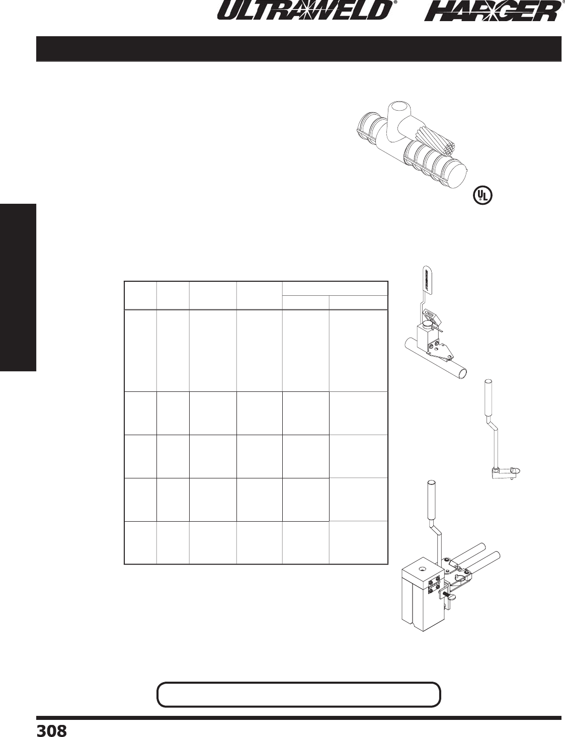
H
ar
g
er Li
g
htnin
g
& Groundin
g
•
©
2012 Phone 847-548-8700 • Fax 847-548-8755 • U.S. 800-842-743
7
308
308
Section 5
Ultraweld® Exothermic Connections
RP
M
o
ld Inf
o
rmati
o
n
:
•
Molds listed are for stranded cable. For solid conductor, add suffi x
"
S"
a
fter c
o
n
du
ct
o
r n
u
m
b
er. i.e. 4S = 4 AWG s
o
li
d
c
o
n
du
ct
o
r.
•
Molds with Price Ke
y
"
A
"
S
O
LD WITH FRAME.
•
If Frame not re
q
uired, add suffi x "-X" after the Mold Part No.
•
Price Ke
y
is the
Bold Letter
in the M
o
l
d
P
a
rt N
o
.
r
Re
q
uired Tools & Accessories
:
MH1 - H
a
n
d
le f
o
r "
B
"
Price Ke
y
Mold
s
WRPSLV or CERPM - Rebar Packin
g
Material
Recommended Tools & Accessories
:
CCBRSH1 - C
a
r
d
Cl
o
th Br
u
s
h
MCBRSH1 - Mold Cleanin
g
Brus
h
U
MHDKIT - H
o
l
d
D
o
wn Ki
t
UMMHDA - Hold Down Kit when Price Ke
y
is "A"
(
Parallel Cable Ta
p
o
f
Ho
riz
o
nt
a
l C
ab
le t
o
Thr
u
H
orizontal Rebar
)
Cable to Rebar RP
*
* Re
q
uires Hold Down Kit
(
#UMHDKIT
)
for weld
s
made to #6 and Lar
g
er Rebar.
UMHDKIT
Important: See Packin
g
Material Notes On Pa
g
e 305.
U
MHDKIT with M
o
l
d
&
H
a
n
d
le
Pa
tente
d
Rebar
Si
ze
C
able
Si
ze
M
o
ld
P
art
No
.
Packin
g
Mat'l N
o
.
W
el
d
Meta
l
U
ltraSh
o
t
NUWTUBE
3
#
6
#4
#2 S
o
l
#
2
1
/
0
2
/
0
3
/
0
4/
0
R
P-
36
B
R
P-
34
B
R
P-
32S
B
R
P-
32
B
R
P-31
/
0
B
R
P-32
/
0
B
R
P-33
/
0
B
R
P-34
/
0
B
W
RP
S
LV
W
RP
S
LV
W
RP
S
LV
W
RP
S
LV
W
RP
S
LV
W
RP
S
LV
W
RP
S
LV
W
RP
S
LV
U
S
25
U
S
32
US
4
5
US
4
5
U
S9
0
U
S9
0
US
11
5
US
11
5
NU
WT
U
BE
25
NU
WT
U
BE
32
NUWTUBE45
NUWTUBE45
NU
WT
U
BE9
0
NU
WT
U
BE9
0
NU
WT
U
BE11
5
NU
WT
U
BE11
5
4
&
L
ar
g
e
r
#
6
#4
#2 S
o
l
#
2
R
P-4L
6
A
RP
-
4L4
A
R
P-4L
2S
A
R
P-4L
2
A
C
ERPM1
C
ERPM1
C
ERPM1
C
ERPM1
U
S
25
U
S
32
US
4
5
US
4
5
NU
WT
U
BE
25
NU
WT
U
BE
32
NUWTUBE45
NUWTUBE45
4
1
/
0
2
/
0
3
/
0
4/
0
R
P-41
/
0
B
R
P-42
/
0
B
R
P-43
/
0
B
R
P-44
/
0
B
W
RP
S
LV
W
RP
S
LV
W
RP
S
LV
W
RP
S
LV
U
S9
0
U
S9
0
US
11
5
US
11
5
NU
WT
U
BE9
0
NU
WT
U
BE9
0
NU
WT
U
BE11
5
NU
WT
U
BE11
5
5
1
/
0
2
/
0
3
/
0
4/
0
R
P-51
/
0
B
R
P-52
/
0
B
R
P-53
/
0
B
R
P-54
/
0
B
W
RP
S
LV
W
RP
S
LV
W
RP
S
LV
W
RP
S
LV
U
S9
0
U
S9
0
US
11
5
US
11
5
NU
WT
U
BE9
0
NU
WT
U
BE9
0
NU
WT
U
BE11
5
NU
WT
U
BE11
5
6
**
&
L
ar
g
e
r
1
/
0
2
/
0
3
/
0
4/
0
R
P-6L1
/
0
B
R
P-6L2
/
0
B
R
P-6L3
/
0
B
R
P-6L4
/
0
B
C
ERPM
2
C
ERPM
2
C
ERPM
2
C
ERPM
2
U
S9
0
U
S9
0
US
11
5
US
11
5
NU
WT
U
BE9
0
NU
WT
U
BE9
0
NU
WT
U
BE11
5
NU
WT
U
BE11
5
RP Connect
i
on T
yp
e
L
iste
d
4
67
S
ect
io
n 5.5
UMMHDA
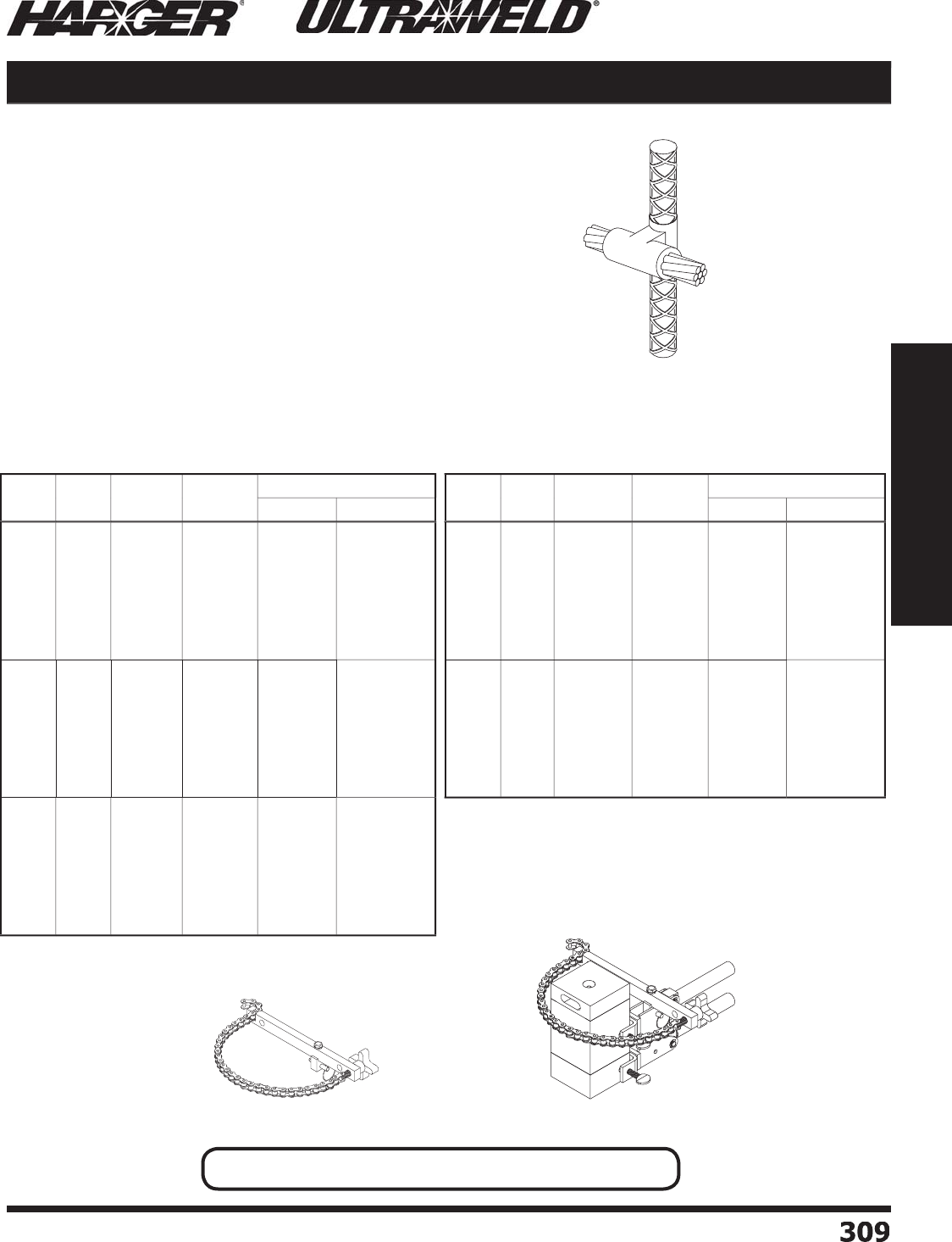
H
ar
g
er Li
g
htnin
g
& Groundin
g
•
©
2012 Phone 847-548-8700 • Fax 847-548-8755 • U.S. 800-842-743
7
30
9
309
Section 5
Ultraweld® Exothermic Connections
R
S
Mold Information
:
•
Molds listed are for stranded cable. For solid conductor, add suffi x
"
S"
a
fter c
o
n
du
ct
o
r n
u
m
b
er. i.e. 4S = 4 AWG s
o
li
d
c
o
n
du
ct
o
r.
•
Price Ke
y
is the
Bold Letter
in the M
o
l
d
P
a
rt N
o
.
r
•
For mold Wear Plates, add suffi x "WP" to the end of the Mold Part
N
o. See pa
g
e 324 for details.
Re
q
uired Tools & Accessories
:
MH1 - H
a
n
d
le f
o
r "
B
"
a
n
d
"
P
"
Price Ke
y
Mold
s
W
RP
S
L
V
or CERPM - Rebar Packing Material
V
**CSKITHSVM - Chain Support Kit for #7 and Lar
g
er reba
r
Recommended Tools & Accessories
:
CCBRSH1 - C
a
r
d
Cl
o
th Br
u
s
h
MCBRSH1 - Mold Cleanin
g
Brus
h
(
Horizontal Thru Cable to Side
o
f Vertical Rebar
)
*
* Re
q
uires Chain Su
pp
ort Kit
(
#CSKITHSVM
)
for welds made to #7 and Lar
g
er rebar.
RS Cable to Rebar
CS
KITH
S
VM CSKITHSVM with M
o
l
d
&
H
a
n
d
le
Important: See Packin
g
Material Notes On Pa
g
e 305.
Pa
tente
d
Rebar
Si
ze
C
able
Si
ze
M
o
ld
P
art
No
.
Packin
g
Mat'l N
o
.
W
el
d
Meta
l
U
ltraSh
o
t
NUWTUBE
3
#
6
#4
#2 S
o
l
#
2
1
/
0
2
/
0
3
/
0
4/
0
R
S-
36
P
R
S-
34
P
R
S-
32S
P
R
S-
32
P
R
S-31
/
0
P
R
S-32
/
0P
R
S-33
/
0P
R
S-34
/
0P
W
RP
S
LV
W
RP
S
LV
W
RP
S
LV
W
RP
S
LV
W
RP
S
LV
W
RP
S
LV
W
RP
S
LV
W
RP
S
LV
U
S9
0
U
S9
0
U
S9
0
U
S9
0
US
11
5
US
11
5
U
S1
50
U
S1
50
NU
WT
U
BE9
0
NU
WT
U
BE9
0
NU
WT
U
BE9
0
NU
WT
U
BE9
0
NU
WT
U
BE11
5
NU
WT
U
BE11
5
NU
WT
U
BE1
50
NU
WT
U
BE1
50
4
#
6
#4
#2 S
o
l
#
2
1
/
0
2
/
0
3
/
0
4/
0
R
S-4
6
P
RS
-4
4
P
RS
-4
2S
P
RS
-4
2
P
R
S-41
/
0
P
R
S-42
/
0
P
R
S-43
/
0
P
R
S-44
/
0
P
W
RP
S
LV
W
RP
S
LV
W
RP
S
LV
W
RP
S
LV
W
RP
S
LV
W
RP
S
LV
W
RP
S
LV
W
RP
S
LV
U
S9
0
U
S9
0
U
S9
0
U
S9
0
US
11
5
US
11
5
U
S1
50
U
S1
50
NU
WT
U
BE9
0
NU
WT
U
BE9
0
NU
WT
U
BE9
0
NU
WT
U
BE9
0
NU
WT
U
BE11
5
NU
WT
U
BE11
5
NU
WT
U
BE1
50
NU
WT
U
BE1
50
5
#
6
#4
#2 S
o
l
#
2
1
/
0
2
/
0
3
/
0
4/
0
R
S-
56
P
RS
-
54
P
R
S-
52S
P
R
S-
52
P
R
S-51
/
0
P
R
S-52
/
0
P
R
S-53
/
0
P
R
S-54
/
0
P
W
RP
S
LV
W
RP
S
LV
W
RP
S
LV
W
RP
S
LV
W
RP
S
LV
W
RP
S
LV
W
RP
S
LV
W
RP
S
LV
U
S9
0
U
S9
0
U
S9
0
U
S9
0
US
11
5
US
11
5
U
S1
50
U
S1
50
NU
WT
U
BE9
0
NU
WT
U
BE9
0
NU
WT
U
BE9
0
NU
WT
U
BE9
0
NU
WT
U
BE11
5
NU
WT
U
BE11
5
NU
WT
U
BE1
50
NU
WT
U
BE1
50
Rebar
Si
ze
C
able
Si
ze
M
o
ld
P
art
No
.
Packin
g
Mat'l N
o
.
W
el
d
Meta
l
U
ltraSh
o
t
NUWTUBE
6
#
6
#4
#2 S
o
l
#
2
1
/
0
2
/
0
3
/
0
4/
0
R
S-
66
P
R
S-
64
P
R
S-
62S
P
R
S-
62
P
R
S-61
/
0
P
R
S-62
/
0
P
R
S-63
/
0
P
R
S-64
/
0
P
W
RP
S
LV
W
RP
S
LV
W
RP
S
LV
W
RP
S
LV
W
RP
S
LV
W
RP
S
LV
W
RP
S
LV
W
RP
S
LV
U
S9
0
U
S9
0
U
S9
0
U
S9
0
US
11
5
US
11
5
U
S1
50
U
S1
50
NU
WT
U
BE9
0
NU
WT
U
BE9
0
NU
WT
U
BE9
0
NU
WT
U
BE9
0
NU
WT
U
BE11
5
NU
WT
U
BE11
5
NU
WT
U
BE1
50
NU
WT
U
BE1
50
7**
&
L
ar
g
e
r
#
6
#4
#2 S
o
l
#
2
1
/
0
2
/
0
3
/
0
4/
0
R
S-7L
6
B
RS
-7L4
B
RS
-7L
2S
B
RS
-7L
2
B
R
S-7L1
/
0
B
R
S-7L2
/
0
B
R
S-7L3
/
0
B
R
S-7L4
/
0
B
CERPM
3
CERPM
3
CERPM
3
CERPM
3
CERPM
3
CERPM
3
CERPM
3
CERPM
3
U
S9
0
U
S9
0
U
S9
0
U
S9
0
US
11
5
US
11
5
U
S1
50
U
S1
50
NU
WT
U
BE9
0
NU
WT
U
BE9
0
NU
WT
U
BE9
0
NU
WT
U
BE9
0
NU
WT
U
BE11
5
NU
WT
U
BE11
5
NU
WT
U
BE1
50
NU
WT
U
BE1
50
RS Connect
i
on T
yp
e RS Connection T
yp
e continued
S
ect
io
n 5.5
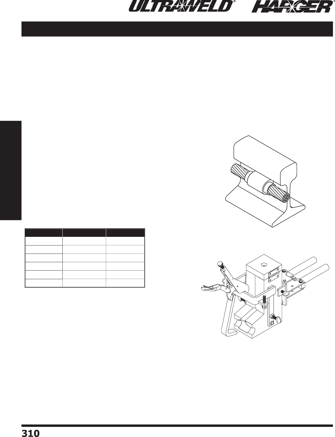
H
ar
g
er Li
g
htnin
g
& Groundin
g
•
©
2012 Phone 847-548-8700 • Fax 847-548-8755 • U.S. 800-842-743
7
3
1
0310
Section 5
Ultraweld® Exothermic Connections
•
Welded
g
roundin
g
connections to the web of 85 lb. to 140 lb. standard rails.
•
If the ampacity requirement cannot be met with a sin
g
le conductor listed, then two or more smaller conductors
c
a
n
b
e
u
se
d
.
•
M
o
l
d
s liste
d
a
re f
o
r c
o
ncentric c
o
n
du
ct
o
rs.
•
Mold frame includes ad
j
ustin
g
screws to position the mold at the neutral axis of the rail.
RMVH
Mold Information
:
•
M
o
l
d
s liste
d
a
re f
o
r c
o
ncentric str
a
n
d
e
d
c
ab
le.
•
Price Ke
y
is the
Bold Letter
in the M
o
l
d
P
a
rt N
o
.
r
Re
q
uired Tools & Accessories
:
MH1 - H
a
n
d
le f
o
r "
K
"
Price Ke
y
Mold
s
RMFRMW105C - Rail Clam
p
Flint I
g
niter (FLTIG) included with MH1
Rec
o
mmended T
oo
ls & Access
o
ries
:
CCBRSH2 - Cable Cleanin
g
Brus
h
MCBRSH1 - Mold Cleanin
g
Brus
h
RASP - Rasp for cleanin
g
rail
(
R
a
il
M
o
l
d
V
ertic
a
l We
b
H
o
rizontal Cable
)
•
Ultraweld exothermic materials meet re
q
uirements
o
f AREMA 8.1.34.
W
eb Groundin
g
Connections
T
he ad
j
ustin
g
screws on mold frame
p
osition conductor at neutral axis of rail
w
here stresses
a
re minim
a
l.
Cable to Rail RMVH
R
MFRMW1
05
C
M
H1
Size Mold Part No. Weld Metal
4
Co
ncentri
c
RMVH4
-
WEB-
K
NU
WT
U
BE9
0
R
2
C
o
ncentri
c
R
MVH
2
-WEB
-
K
NU
WT
U
BE9
0
R
1
Co
ncentri
c
R
MVH1-WEB
-
K
NU
WT
U
BE9
0
R
1
/
0 Concentri
c
R
MVH1
/
0-WEB
-
K
NU
WT
U
BE11
5
R
2
/
0 Concentri
c
R
MVH2
/
0-WEB
-
K
NU
WT
U
BE11
5
R
4/
0 Concentri
c
R
MVH4
/
0-WEB
-
K
NU
WT
U
BE1
50
R
RMVH Connect
i
on T
yp
e
S
ect
io
n 5.5
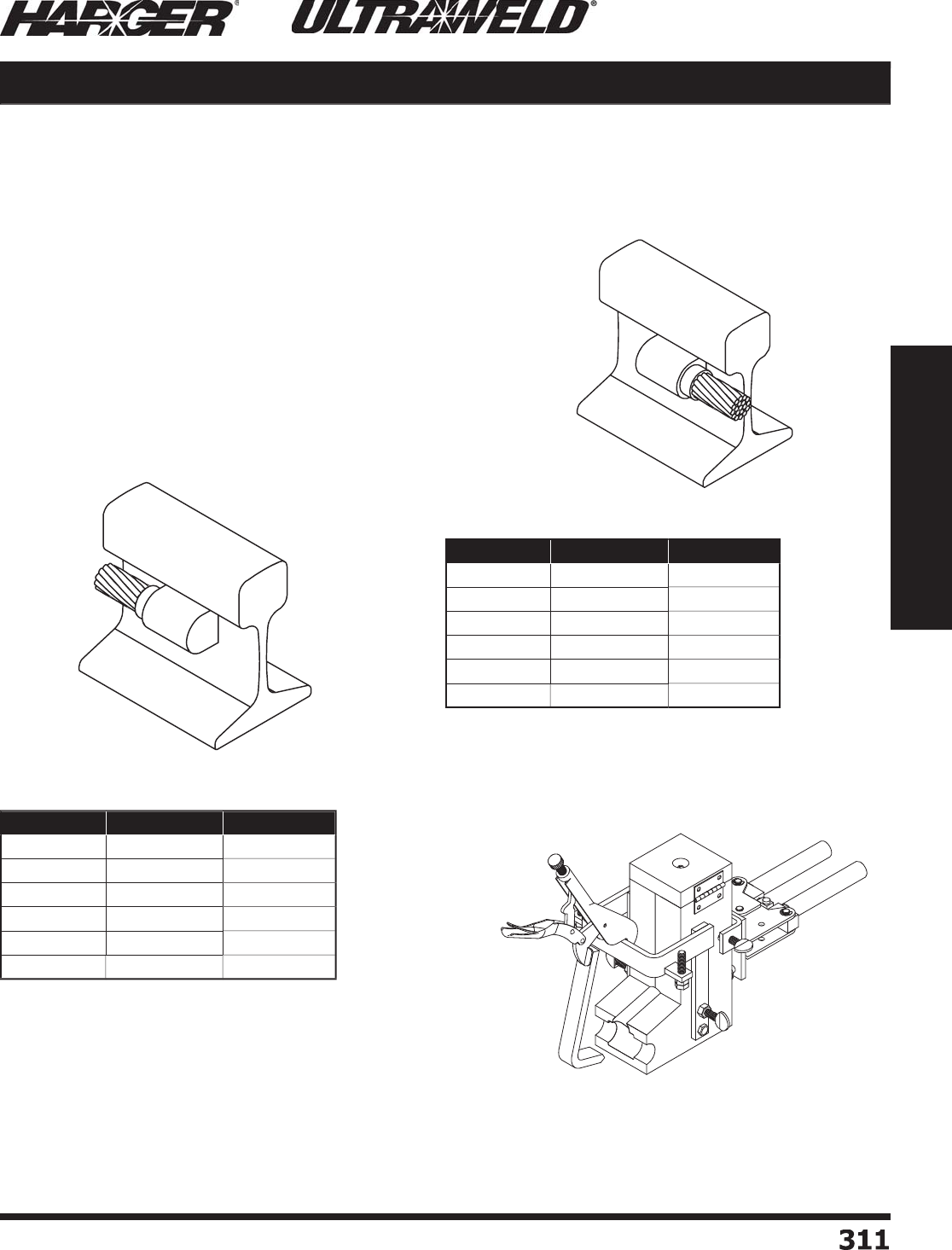
H
ar
g
er Li
g
htnin
g
& Groundin
g
•
©
2012 Phone 847-548-8700 • Fax 847-548-8755 • U.S. 800-842-743
7
3
11
311
Section 5
Ultraweld® Exothermic Connections
RMVR
M
o
ld Inf
o
rmati
o
n
:
•
M
o
l
d
s liste
d
a
re f
o
r c
o
ncentric str
a
n
d
e
d
c
ab
le.
•
Price Ke
y
is the
Bold Letter
in the M
o
l
d
P
a
rt N
o
.
r
Re
q
uired Tools & Accessories
:
MH1 - H
a
n
d
le f
o
r "
K
"
Price Ke
y
Mold
s
RMFRMW105C - Rail Clam
p
Flint I
g
niter (FLTIG) included with MH1
Rec
o
mmended T
oo
ls & Access
o
ries
:
CCBRSH2 - Cable Cleanin
g
Brus
h
MCBRSH1 - Mold Cleanin
g
Brus
h
RASP - Rasp for cleanin
g
rail
(
R
a
il
M
o
l
d
V
ertic
a
l We
b
R
ig
ht Hand Mold
)
RMVL
(
R
a
il
M
o
l
d
V
ertic
a
l We
b
L
eft Hand Mold
)
•
Ultraweld exothermic materials meet re
q
uirements
o
f AREMA 8.1.34.
•
Ultraweld exothermic materials meet re
q
uirements
o
f AREMA 8.1.34.
W
eb Groundin
g
Connections
T
he ad
j
ustin
g
screws on mold frame
p
osition conductor at neutral axis of rail
w
here stresses
a
re minim
a
l.
RMVL / RMVR Cable to Rail
R
MFRMW1
05
C
M
H1
Size Mold Part No. Weld Metal
4
Co
ncentri
c
RMVR4
-
WEB-
K
NU
WT
U
BE
65
R
2
C
o
ncentri
c
R
MVR
2
-WEB
-
K
NU
WT
U
BE
65
R
1
Co
ncentri
c
R
MVR1-WEB
-
K
NU
WT
U
BE
65
R
1
/
0 Concentri
c
R
MVR1
/
0-WEB
-
K
NU
WT
U
BE9
0
R
2
/
0 Concentri
c
R
MVR2
/
0-WEB
-
K
NU
WT
U
BE9
0
R
4/
0 Concentri
c
R
MVR4
/
0-WEB
-
K
NU
WT
U
BE11
5
R
Size Mold Part No. Weld Metal
4
Co
ncentri
c
RMVL4
-
WEB-
K
NU
WT
U
BE
65
R
2
C
o
ncentri
c
R
MVL
2
-WEB
-
K
NU
WT
U
BE
65
R
1
Co
ncentri
c
R
MVL1-WEB
-
K
NU
WT
U
BE
65
R
1
/
0 Concentri
c
R
MVL1
/
0-WEB
-
K
NU
WT
U
BE9
0
R
2
/
0 Concentri
c
R
MVL2
/
0-WEB
-
K
NU
WT
U
BE9
0
R
4/
0 Concentri
c
R
MVL4
/
0-WEB
-
K
NU
WT
U
BE11
5
R
RMVR Connect
i
on T
yp
e
RMVL Connect
i
on T
yp
e
S
ect
io
n 5.5

H
ar
g
er Li
g
htnin
g
& Groundin
g
•
©
2012 Phone 847-548-8700 • Fax 847-548-8755 • U.S. 800-842-743
7
3
12
312
Section 5
Ultraweld® Exothermic Connections
T
yp
e Mold Part No. Ground Rod Size Cable Size
Solid Stranded
G11
......................
G11588NU
.........................
5/
8"
....................
#6, #8
........................
#8
G11
......................
G11584NU
.........................
5/
8"
....................
#
3
, #
4
.....................
#4, #6
G11
......................
G11582NU
.........................
5/
8"
....................
#1, #
2
.....................
#
2
, #
3
G11
....................
G11581
/
0NU
.......................
5/
8"
...................
2/0, 1/0
.....................
1/0, #1
G11
....................
G11582
/
0NU
.......................
5/
8"
........................
—
............................
2
/
0
G21
......................
G21588NU
.........................
5/
8"
....................
#6, #8
........................
#8
G
2
1
......................
G21584NU
.........................
5/
8"
....................
#
3
, #
4
.....................
#4, #6
G
2
1
......................
G21582NU
.........................
5/
8"
....................
#1, #
2
.....................
#
2
, #
3
G
2
1
....................
G21581
/
0NU
.......................
5/
8"
...................
2/0, 1/0
.....................
1/0, #1
G
3
1
......................
G31588NU
.........................
5/
8"
....................
#6, #8
........................
#8
G
3
1
......................
G31584NU
.........................
5/
8"
....................
#
3
, #
4
.....................
#4, #6
G
3
1
......................
G31582NU
.........................
5/
8"
....................
#1, #
2
.....................
#
2
, #
3
G
3
1
...................
G31581
/
0NU*
.......................
5/
8"
...................
2/0, 1/0
.....................
1/0, #1
G
41
......................
G41588NU
.........................
5/
8"
....................
#6, #8
........................
#8
G
41
......................
G41584NU
.........................
5/
8"
....................
#
3
, #
4
.....................
#4, #6
G41
......................
G41582NU
.........................
5/
8"
....................
#1, #
2
.....................
#
2
, #
3
T
yp
e Mold Part No. Ground Rod Size Cable Size
S
o
lid Strande
d
G
11
......................
G11348NU
.........................
3
/
4"
....................
#6, #8
........................
#8
G
11
......................
G11
3
44N
U
.........................
3
/
4"
....................
#
3
, #
4
.....................
#4, #6
G
11
......................
G11
3
4
2
N
U
.........................
3
/
4"
....................
#1, #
2
.....................
#
2
, #
3
G
11
....................
G11341
/
0NU
.......................
3
/
4"
...................
2/0, 1/0
.....................
1/0, #1
G
11
....................
G11342
/
0NU
.......................
3
/
4"
........................
—
............................
2
/
0
G
2
1
......................
G21348NU
.........................
3
/
4"
....................
#6, #8
........................
#8
G
2
1
......................
G
2
1
3
44N
U
.........................
3
/
4"
....................
#
3
, #
4
.....................
#4, #6
G
2
1
......................
G
2
1
3
4
2
N
U
.........................
3
/
4"
....................
#1, #
2
.....................
#
2
, #
3
G
2
1
....................
G21341
/
0NU
.......................
3
/
4"
...................
2/0, 1/0
.....................
1/0, #1
G
3
1
......................
G31348NU
.........................
3
/
4"
....................
#6, #8
........................
#8
G
3
1
......................
G
3
1
3
44N
U
.........................
3
/
4"
....................
#
3
, #
4
.....................
#4, #6
G
3
1
......................
G
3
1
3
4
2
N
U
.........................
3
/
4"
....................
#1, #
2
.....................
#
2
, #
3
G
3
1
...................
G31341
/
0NU*
.......................
3
/
4"
...................
2/0, 1/0
.....................
1/0, #1
G
41
......................
G41348NU
.........................
3
/
4"
....................
#6, #8
........................
#8
G
41
......................
G41
3
44N
U
.........................
3
/
4"
....................
#
3
, #
4
.....................
#4, #6
G
41
......................
G41
3
4
2
N
U
.........................
3
/
4"
....................
#1, #
2
.....................
#
2
, #
3
N
O
TES
:
• Disposable sin
g
le use ceramic mold provides convenience and ease of use.
• Packa
g
ed 12 per box.
• Requires only a Flint I
g
niter (FLTIG) to make a connection. See pa
g
e 325.
• No frames or handle clam
p
s are re
q
uired.
Uni-Shots G11 / G21 / G31 / G41
G
11
G
21
G3
1
*
G3
1
G
41
L
iste
d
4
67
S
ect
io
n 5.6
NUWTube
(
Traditional
)
NEW

H
ar
g
er Li
g
htnin
g
& Groundin
g
•
©
2012 Phone 847-548-8700 • Fax 847-548-8755 • U.S. 800-842-743
7
3
1
3
313
Section 5
Ultraweld® Exothermic Connections
NEW
G11 / G21 / G31 / G41 Ultra Uni-Shots
S
ect
io
n 5.6
N
O
TES:
S
ee Notes on Pa
g
e 312. USCONTROLLER required to make Ultra Uni-Shot connection. See pa
g
e 322.
T
yp
e Mold Part No. Ground Rod Size Cable Size
S
o
lid Stranded
G
11
...............
G11588U
S
...........
......5/8”
............
.
.....#6, #8
...........
.
.....#8
G
11
...............
G11584U
S
...........
......5/8”
............
.
.....#
3
, #
4
........
.
.....#4, #6
G
11
...............
G11582U
S
...........
......5/8”
............
.
.....#1, #
2
........
.
.....#
2
, #
3
G
11
..............
G11581
/
0U
S
.........
......5/8”
...........
.
.....2/0, 1/0
.......
.
.....1/0, #1
G
11
..............
G11582
/
0U
S
.........
......5/8”
..............
.
.....2
/
0
..............
.
.....2
/
0
G
11
..............
G11584
/
0U
S
.........
......5/8”
..............
.
.....4
/
0
..............
.
.....4
/
0
G
2
1
...............
G21588U
S
...........
......5/8”
............
.
.....#6, #8
...........
.
.....#8
G
2
1
...............
G21584U
S
...........
......5/8”
............
.
.....#
3
, #
4
........
.
.....#4, #6
G
2
1
...............
G21582U
S
...........
......5/8”
............
.
.....#1, #
2
........
.
.....#
2
, #
3
G
2
1
..............
G21581
/
0U
S
.........
......5/8”
...........
.
.....2/0, 1/0
.......
.
.....1/0, #1
G
2
1
..............
G21582
/
0U
S
.........
......5/8”
..............
.
.....2
/
0
..............
.
.....2
/
0
G
2
1
..............
G21584
/
0U
S
.........
......5/8”
..............
.
.....4
/
0
..............
.
.....4
/
0
G
3
1
...............
G31588U
S
...........
......5/8”
............
.
.....#6, #8
...........
.
.....#8
G
3
1
...............
G31584U
S
...........
......5/8”
............
.
.....#
3
, #
4
........
.
.....#4, #6
G
3
1
...............
G31582U
S
...........
......5/8”
............
.
.....#1, #
2
........
.
.....#
2
, #
3
G
3
1
.............
G31581
/
0US*
........
......5/8”
...........
.
.....2/0, 1/0
.......
.
.....1/0, #1
G
41
...............
G41588U
S
...........
......5/8”
............
.
.....#6, #8
...........
.
.....#8
G
41
...............
G41584U
S
...........
......5/8”
............
.
.....#
3
, #
4
........
.
.....#4, #6
G
41
...............
G41582U
S
...........
......5/8”
............
.
.....#1, #
2
........
.
.....#
2
, #
3
G
41P
S
.............
G41PS8U
S
.............
.
.....
---
.............
.
.....#6, #8
...........
.
.....#8
T
yp
e Mold Part No. Ground Rod Size Cable Size
S
o
lid Strande
d
G
11
...............
G11348U
S
...........
......3/4”
............
.
.....#6, #8
...........
.
.....#8
G
11
...............
G11
3
44
US
...........
......3/4”
............
.
.....#
3
, #
4
........
.
.....#4, #6
G
11
...............
G11
3
4
2US
...........
......3/4”
............
.
.....#1, #
2
........
.
.....#
2
, #
3
G
11
..............
G11341
/
0U
S
.........
......3/4”
..............
.
.....1
/
0
...........
.
.....1/0, #1
G
11
..............
G11342
/
0U
S
.........
......3/4”
..............
.
.....2
/
0
..............
.
.....2
/
0
G
11
..............
G11344
/
0U
S
.........
......3/4”
..............
.
.....4
/
0
..............
.
.....4
/
0
G
2
1
...............
G21348U
S
...........
......3/4”
............
.
.....#6, #8
...........
.
.....#8
G
2
1
...............
G
2
1
3
44
US
...........
......3/4”
............
.
.....#
3
, #
4
........
.
.....#4, #6
G
2
1
...............
G
2
1
3
4
2US
...........
......3/4”
............
.
.....#1, #
2
........
.
.....#
2
, #
3
G
2
1
..............
G21341
/
0U
S
.........
......3/4”
...........
.
.....2/0, 1/0
.......
.
.....1/0, #1
G
2
1
..............
G21342
/
0U
S
.........
......3/4”
..............
.
.....2
/
0
..............
.
.....2
/
0
G
2
1
..............
G21344
/
0U
S
.........
......3/4”
..............
.
.....4
/
0
..............
.
.....4
/
0
G
3
1
...............
G31348U
S
...........
......3/4”
............
.
.....#6, #8
...........
.
.....#8
G
3
1
...............
G
3
1
3
44
US
...........
......3/4”
............
.
.....#
3
, #
4
........
.
.....#4, #6
G
3
1
...............
G
3
1
3
4
2US
...........
......3/4”
............
.
.....#1, #
2
........
.
.....#
2
, #
3
G
3
1
.............
G31341
/
0US*
........
......3/4”
...........
.
.....2/0, 1/0
.......
.
.....1/0, #1
G
41
...............
G41348U
S
...........
......3/4”
............
.
.....#6, #8
...........
.
.....#8
G
41
...............
G41
3
44
US
...........
......3/4”
............
.
.....#
3
, #
4
........
.
.....#4, #6
G
41
...............
G41
3
4
2US
...........
......3/4”
............
.
.....#1, #
2
........
.
.....#
2
, #
3
U
ltr
a
Sh
o
t
(
Electronic
)
G
11
G
21
G3
1
*
G3
1
G
41

H
ar
g
er Li
g
htnin
g
& Groundin
g
•
©
2012 Phone 847-548-8700 • Fax 847-548-8755 • U.S. 800-842-743
7
3
1
4314
Section 5
Ultraweld® Exothermic Connections
Tinned Copper Lugs Straight & Offset
S
ect
io
n 5.7
For Use with LE Style Molds on Pa
g
e 297.
S
XL
O
XL
Lu
g
S
i
ze
S
trai
g
ht
P
art
No
.
O
ff
s
et
P
art
No
.
N
o
.
of
H
o
les
S
crew
Si
ze
O
.C.
D
i
mens
ion
T
W
A
B
1
/
8 x 1
S
XL-181
S
XL-1812B
S
XL-1812C
S
XL-1812
D
OXL-181
OXL-1812B
OXL-1812C
OXL-1812
D
1
2
2
2
3
/
8
3
/
8
1
/2
1
/2
---
.75
1
1.7
5
1
/
8
1
/
8
1
/
8
1
/
8
1
1
1
1
1
/2
5/
8
5/
8
5/
8
7
/
8
3
3
3
3
/
16 x 1
S
XL-
3
1
6
1
S
XL-
3
1
6
1
2
B
S
XL-
3
1
6
1
2
C
S
XL-
3
1
6
1
2D
O
XL-
3
1
6
1
O
XL-
3
1
6
1
2
B
O
XL-
3
1
6
1
2
C
O
XL-
3
1
6
1
2D
1
2
2
2
3
/
8
3
/
8
1
/2
1
/2
---
.75
1
1.7
5
3
/
16
3
/
16
3
/
16
3
/
16
1
1
1
1
9/
16
5/
8
5/
8
5/
8
1-1
/
8
3
3
3
1
/
4 x 1
S
XL-141
S
XL-141
2
B
S
XL-141
2C
S
XL-141
2D
O
XL-141
O
XL-141
2
B
O
XL-141
2
C
O
XL-141
2D
1
2
2
2
1
/2
3
/
8
1
/2
1
/2
---
.75
1
1.7
5
1
/
4
1
/
4
1
/
4
1
/
4
1
1
1
1
5/
8
5/
8
5/
8
5/
8
1-1
/
8
3
3
3
1
/
4 x 1-1
/
2
S
XL-141.
5
S
XL-141.
52
B
S
XL-141.
52C
S
XL-141.
52D
O
XL-141.
5
O
XL-141.
52
B
O
XL-141.
52C
O
XL-141.
52D
1
2
2
2
5/
8
3
/
8
1
/2
1
/2
---
.75
1
1.7
5
1
/
4
1
/
4
1
/
4
1
/
4
1-1
/2
1-1
/2
1-1
/2
1-1
/2
3
/4
5/
8
5/
8
5/
8
1-1
/2
3
3
3
1
/
4 x
2
S
XL-14
22
B
S
XL-14
22C
S
XL-14
22D
O
XL-14
22
B
O
XL-14
22
C
O
XL-14
22D
2
2
2
3
/
8
1
/2
1
/2
.75
1
1.7
5
1
/
4
1
/
4
1
/
4
2
2
2
5/
8
5/
8
5/
8
3
3
3
3
/
8 x 1-1
/2
S
XL-381.5
S
XL-381.52B
S
XL-381.52
C
S
XL-381.52
D
OXL-381.5
OXL-381.52B
OXL-381.52
C
OXL-381.52
D
1
2
2
2
5/
8
3
/
8
1
/2
1
/2
---
.75
1
1.7
5
3
/
8
3
/
8
3
/
8
3
/
8
1-1
/2
1-1
/2
1-1
/2
1-1
/2
3
/4
5/
8
5/
8
5/
8
1-1
/2
3
3
3
3
/
8 x
2
S
XL-38
2
S
XL-3822B
S
XL-3822C
S
XL-3822
D
OXL-38
2
OXL-3822B
OXL-3822C
OXL-3822
D
1
2
2
2
5/
8
3
/
8
1
/2
1
/2
---
.75
1
1.7
5
3
/
8
3
/
8
3
/
8
3
/
8
2
2
2
2
1
5/
8
5/
8
5/
8
2-1
/
8
3
3
3
W
A
W
AO.C.
T
W
A
W
AO.C.
B
T
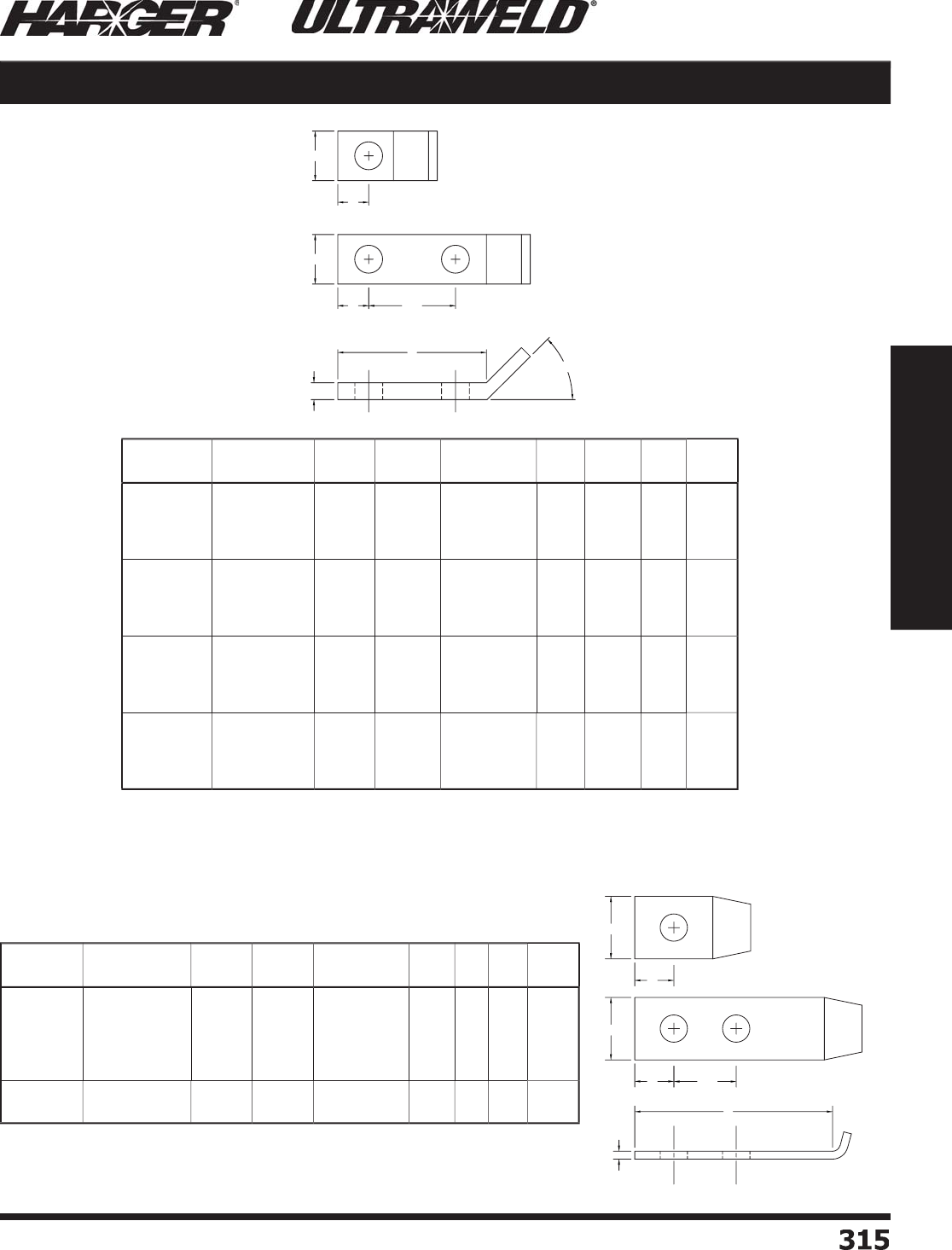
H
ar
g
er Li
g
htnin
g
& Groundin
g
•
©
2012 Phone 847-548-8700 • Fax 847-548-8755 • U.S. 800-842-743
7
3
1
5
315
Section 5
Ultraweld® Exothermic Connections
For Use with LE Style Molds on Pa
g
e 297.
Lu
g
S
i
ze
B
ent
P
art
No
.
N
o
.
of
H
o
les
S
crew
Si
ze
O
.C.
D
i
mens
ion
T
W
A
B
1
/
8 x 1
B
XL-181
B
XL-1812B
B
XL-1812
C
B
XL-1812
D
1
2
2
2
3
/
8
3
/
8
1
/2
1
/2
---
.75
1
1.7
5
1
/
8
1
/
8
1
/
8
1
/
8
1
1
1
1
7
/
16
5/
8
5/
8
5/
8
7
/
8
3
3
3
3
/
16 x 1
B
XL-
3
1
6
1
B
XL-
3
1
6
1
2B
B
XL-
3
1
6
1
2
C
B
XL-
3
1
6
1
2D
1
2
2
2
1
/2
3
/
8
1
/2
1
/2
---
.75
1
1.7
5
3
/
16
3
/
16
3
/
16
3
/
16
1
1
1
1
5/
8
5/
8
5/
8
5/
8
1-1
/4
3
3
3
1
/
4 x 1
B
XL-141
B
XL-141
2
B
B
XL-141
2C
B
XL-141
2D
1
2
2
2
1
/2
3
/
8
1
/2
1
/2
---
.75
1
1.7
5
1
/4
1
/4
1
/4
1
/4
1
1
1
1
5/
8
5/
8
5/
8
5/
8
1-1
/4
3
3
3
1
/
4 x 1-1
/
2
B
XL-141.
5
B
XL-141.
52
B
B
XL-141.
52C
B
XL-141.
52D
1
2
2
2
5/
8
3
/
8
1
/2
1
/2
---
.75
1
1.7
5
1
/4
1
/4
1
/4
1
/4
1-1
/2
1-1
/2
1-1
/2
1-1
/2
3
/
4
5/
8
5/
8
5/
8
1-1
/2
3
3
3
For Use with LBJ Style Molds on Pa
g
e 298.
Bent & Bent J Tinned Copper Lugs
Lu
g
S
i
ze
B
ent
J
P
art
No
.
N
o
.
of
H
o
les
S
crew
Si
ze
O
.C.
D
i
mens
ion
T
W
A
B
1
/
8 x 1
JXL-1813
/
8
JXL-181
JXL-1812C1
/4
JXL-1812C3
/
8
JXL-1812
D
1
1
2
2
2
3
/
8
1
/2
1
/
4
3
/
8
1
/2
---
---
1
1
1.7
5
1
/
8
1
/
8
1
/
8
1
/
8
1
/
8
1
1
1
1
1
5/
8
5/
8
5/
8
5/
8
5/
8
1-1
/
4
1-1
/
4
3
3
3
3
/
16 x 1 JXL-
3
1
6
1
JXL-
3
1
6
1
2D
1
2
1
/2
1
/2
---
1.7
5
3
/
16
3
/
16
1
1
5/
8
5/
8
1-1
/
4
3
S
ect
io
n 5.7
W
A
W
AO.C.
B
T
45°
W
AO.C.
T
W
A
B
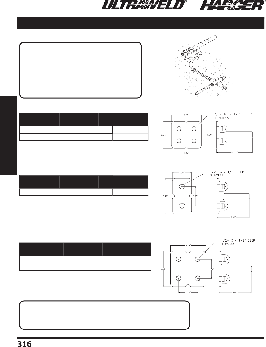
H
ar
g
er Li
g
htnin
g
& Groundin
g
•
©
2012 Phone 847-548-8700 • Fax 847-548-8755 • U.S. 800-842-743
7
3
1
6316
Section 5
Ultraweld® Exothermic Connections
•
NEMA hole spacin
g
.
•
Stud fi ts mold openin
g
for concentric strand conductor o
f
s
t
ud
size liste
d
.
Equipment Ground Plates
•
Stud fi ts mold openin
g
s for concentric strand conductor o
f
s
t
ud
size liste
d
.
Part No. Stud Size Qty. Approx. Each
Wt. (lbs.)
X
GP2.5
/
2.54
/
0
4/
0 AWG Con
c
EA
2
X
GP2.5
/
2.55CM
500
MCM C
o
n
c
EA
2
Part No. Stud Size Qty. Approx. Each
Wt. (lbs.)
X
GP1.75
/
3.254
/
0
4/
0 AWG Con
c
EA
1-1
/2
•
NEMA hole spacin
g
.
•
Stud fi ts mold openin
g
s for concentric strand conductor o
f
s
t
ud
size liste
d
.
Part No. Stud Size Qty. Approx. Each
Wt. (lbs.)
X
GP3.25
/
3.254
/
0
4/
0 AWG Con
c
EA
2-1
/2
X
GP3.25
/
3.255CM
500
MCM C
o
n
c
EA
2-1
/2
N
O
TES
:
• Use Ultraweld Type EGPCB or EGPCT molds to make strai
g
ht splices or
tee connections with
g
round conductors to equipment
g
round plates.
• Custom assemblies available. Please contact factor
y
for more information.
APPLICATI
O
N N
O
TE
:
E
quipment
g
round plates are cast into concrete
s
tructures to offer convenient connection
p
oints to
the
g
round system. The cast
g
round plates are made
from hi
g
h quality copper alloy and are easily
exothermicall
y
welded to co
pp
er conductors. The
resultin
g
connection has an ampacity that surpasses
th
a
t
o
f the c
o
n
du
ct
o
r
o
r the st
ud
.
S
ect
io
n 5.
8
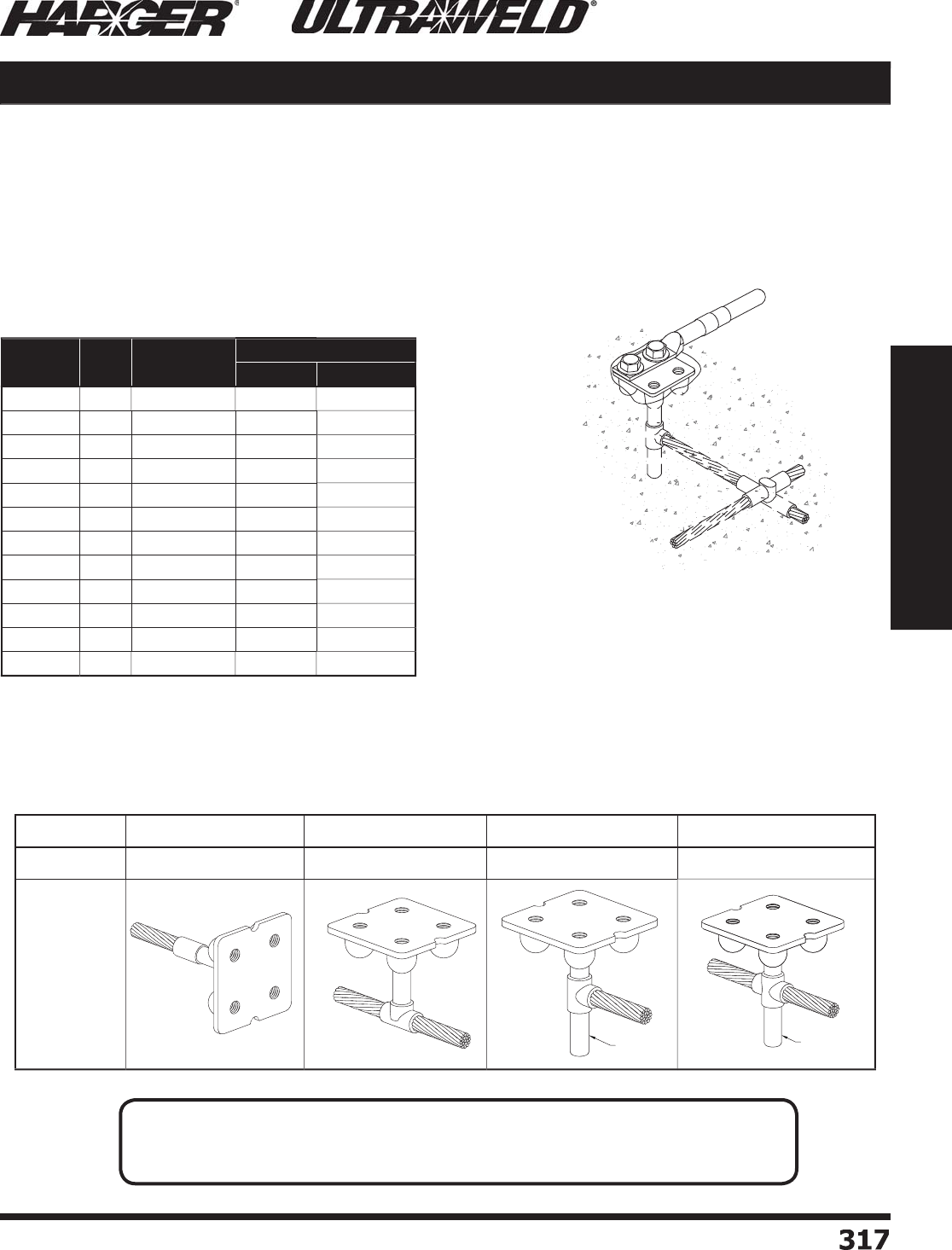
H
ar
g
er Li
g
htnin
g
& Groundin
g
•
©
2012 Phone 847-548-8700 • Fax 847-548-8755 • U.S. 800-842-743
7
3
17
317
Section 5
Ultraweld® Exothermic Connections
Equipment Ground Plate Molds
Mold Information
:
•
Molds listed are for stranded cable. For solid conductor, add suffi x “S” after conductor number.
i.e. 4S = 4 AWG s
o
li
d
c
o
n
du
ct
o
r.
•
Price Ke
y
is the B
o
ld Letter
i
n the M
o
l
d
P
a
rt N
o
.
•
For mold Wear Plates, add suffi x “WP” to the end of the Mold Part No. See pa
g
e 324 for details.
Re
q
uired Tools & Accessories
:
M
H1 - H
a
n
d
le f
o
r
“
B
” Price Ke
y
Mold
s
Rec
o
mmended T
oo
ls & Access
o
ries
:
CCBRSH1 - C
a
r
d
Cl
o
th Br
u
s
h
M
CBRSH1 - Mold Cleanin
g
Brus
h
E
q
ui
p
ment Ground
Plate Assembl
y
E
q
ui
p
ment Ground
G
r
o
und Electr
o
de
Sy
ste
m
Mold T
yp
eE
G
PCB E
G
PCT E
G
PI
D
E
G
PI
O
Co
nnect
ion
B
S
RT
GD
GO
G
r
o
und
Plate
A
ss
emblie
s
Plate
Stud Size Cable Mold
Part No.
Weld Metal
UltraShot NUWTUBE
4/
01
/
0
E
GPCB4
/
01
/
0
B
U
S9
0
NU
WT
U
BE9
0
4/
02
/
0
E
GPCB4
/
02
/
0
B
U
S9
0
NU
WT
U
BE9
0
4/
0
4/
0
E
GPCB4
/
04
/
0
B
U
S9
0
NU
WT
U
BE9
0
4/
01
/
0
E
GPCT4
/
01
/
0
B
U
S9
0
NU
WT
U
BE9
0
4/
02
/
0
E
GPCT4
/
02
/
0
B
U
S9
0
NU
WT
U
BE9
0
4/
0
4/
0
E
GPCT4
/
04
/
0
B
U
S1
50
NU
WT
U
BE1
50
4/
01
/
0
E
GPID4
/
01
/
0
B
U
S1
50
NU
WT
U
BE1
50
4/
02
/
0
E
GPID4
/
02
/
0
B
U
S1
50
NU
WT
U
BE1
50
4/
0
4/
0
E
GPID4
/
04
/
0
B
U
S1
50
NU
WT
U
BE1
50
4/
01
/
0
E
GPIO4
/
01
/
0
B
U
S1
50
NU
WT
U
BE1
50
4/
02
/
0
E
GPIO4
/
02
/
0
B
U
S1
50
NU
WT
U
BE1
50
4/
0
4/
0
E
GPIO4
/
04
/
0
B
U
S
200
NU
WT
U
BE
200
N
O
TE
:
• St
y
le EGPID and EGPIO assemblies have
p
osts formed from the Ultraweld connection
that fi t into 1/2" pipe that is used for support and positionin
g
the
g
round plate.
S
ect
io
n 5.8
POST POST
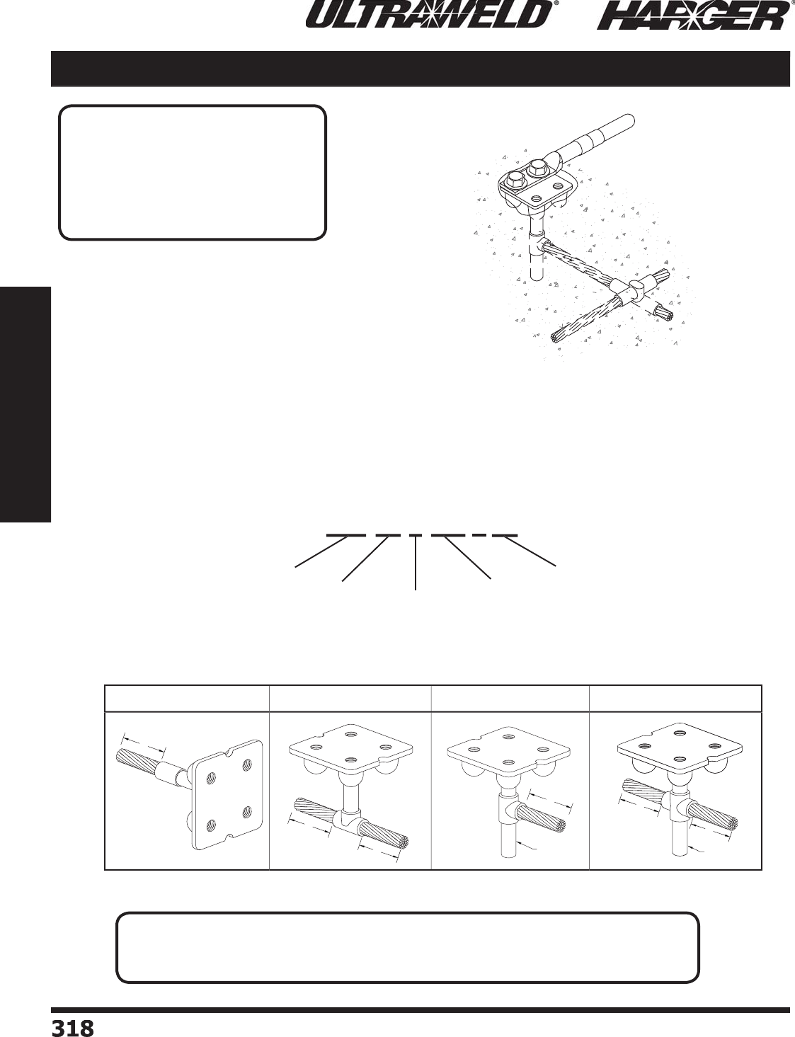
H
ar
g
er Li
g
htnin
g
& Groundin
g
•
©
2012 Phone 847-548-8700 • Fax 847-548-8755 • U.S. 800-842-743
7
318
318
Section 5
Ultraweld® Exothermic Connections
Part Numberin
g
System
:
"
XGP" + "Style" + "Ground Plate Desi
g
nation Code" + "Conductor" + "X" + "Conductor Len
g
th (in.)"
XGP
P
r
e
fi
x
C
o
n
du
ct
or
L
en
g
t
h
(
in.
)
C
o
n
du
ct
or
S
t
y
le
XGP BS D 1
/
0 X 2
4
Gr
ou
n
d
Pl
a
t
e
D
esi
g
natio
n
C
od
e
•
The assembl
y
is made to customer s
p
ecifi cations
p
er
the part numberin
g
system shown below.
•
Equipment
g
round plates are manufactured from hi
g
h
q
ualit
y
cast co
pp
er allo
y
.
•
Meets re
q
uirements of Federal S
p
ecifi cation
QQ
-B-691B.2 and ASTMB584.
•
The copper conductor is factory welded usin
g
the
U
ltraweld
p
rocess.
BS St
y
le RT St
y
le
G
D St
y
le
G
O St
y
le
Prefabricated Equipment Ground Plate Assemblies
Eq
ui
p
ment Ground
P
late Assembl
y
Eq
ui
p
ment Ground
Gr
ou
n
d
Electr
od
e
Sy
stem
APPLICATI
O
N N
O
TE
:
E
quipment
g
round plates are cast into
c
o
ncrete str
u
ct
u
res t
o
o
ffer c
o
nvenient
hi
g
h quality connection points to the
g
round system. The equipment
g
round
p
late assemblies
p
rovide ease o
f
i
nst
a
ll
a
ti
o
n
a
n
d
re
du
ce l
abo
r.
N
O
TE
:
• St
y
le GD and GO assemblies have
p
osts formed from the Ultraweld connection that fi t
into 1/2" pipe that is used for support and positionin
g
the
g
round plate.
S
ect
io
n 5.
8
L
L
L
L
POST
L
L
POST
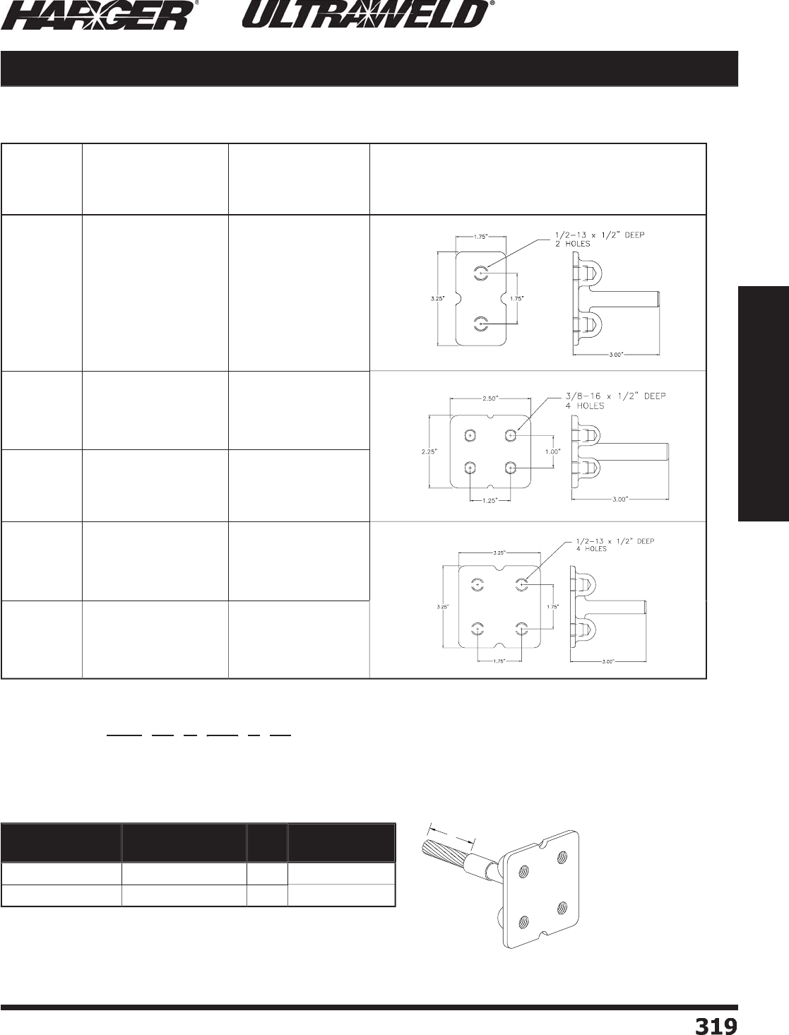
H
ar
g
er Li
g
htnin
g
& Groundin
g
•
©
2012 Phone 847-548-8700 • Fax 847-548-8755 • U.S. 800-842-743
7
3
19
319
Section 5
Ultraweld® Exothermic Connections
Equipment Ground Plate Assemblies
G
round Plate Desi
g
nation Code
:
Part Numberin
g
Example
:
Pa
rt N
u
m
b
er: X
G
P
B
S
D
1/0
/
X
24
is a XGP3.25/3.254/0 E
q
ui
p
ment Ground Plate with
1/0 conductor 24" lon
g
welded with Ultraweld BS connection.
G
r
o
und
Plate
Co
de
G
r
o
und Plate
Part N
u
mber
S
t
ud
Size
G
round Plate Fi
g
ure
A
X
GP1.75
/
3.254
/
0
4/
0 AWG Con
c
B
X
GP2.5
/
2.54
/
0
4/
0 AWG Con
c
C
X
GP2.5
/
2.55CM
500
MCM C
o
n
c
D
X
GP3.25
/
3.254
/
0
4/
0 AWG Con
c
E
X
GP3.25
/
3.255CM
500
MCM C
o
n
c
•
NEMA hole spacin
g
.
•
Stud fi ts mold openin
g
s for concentric strand conductor o
f
s
t
ud
size liste
d
.
M
o
st C
o
mm
o
n Assemblies
:
Part No. Stud Size Qty. Approx. Each
Wt. (lbs.)
X
GPBSD2
/
0X1
2
2
/
0-19 AWG Con
c
EA
2
X
GPBSD1
/
0X2
4
1
/
0-19 AWG Con
c
EA
2
S
ect
io
n 5.8
L
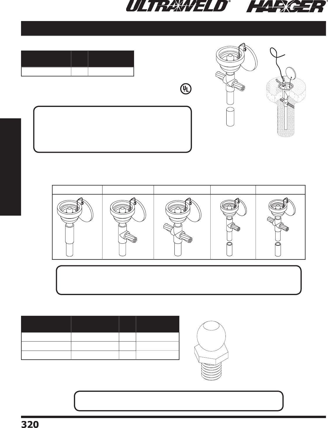
H
ar
g
er Li
g
htnin
g
& Groundin
g
•
©
2012 Phone 847-548-8700 • Fax 847-548-8755 • U.S. 800-842-743
7
3
2
0320
Section 5
Ultraweld® Exothermic Connections
L
iste
d
9
6
Aircraft Ground Receptacle
•
Ground receptacle desi
g
ned to be
exothermicall
y
connected to a
g
round rod.
•
Used as replacement studs for fl oor
g
round receptacles.
•
Can also be mounted on
g
round bars.
•
Brass Ball Stud: 3/4" in diameter, 1-1/2" total len
g
th.
Mold T
yp
es for Aircraft Ground Rece
p
tacles
FG
RB
S
FG
R
GD
F
GRG
O
FG
RI
GD
F
GRIG
O
Part No. Qty. Approx. Each
Wt. (lbs.)
SG
RX
EA
1-1
/
4
Part No. Thread
Size Qty. Approx. Each
Wt. (lbs.)
B
B
S
T
U
D1
4
1
/
4"
EA
1
/2
B
BSTUD38 3
/
8"
EA
1
/2
B
BST
U
D1
2
1
/
2"
EA
1
/2
Bra
ss
Ball St
uds
N
O
TE
:
• St
y
le FGRIGD and FGRIGO assemblies have
p
osts formed from the Ultraweld connection
that fi t into 1/2" pipe that is used for support and positionin
g
the
g
round plate.
APPLICATI
O
N N
O
TES
:
• Aircraft Ground Rece
p
tacles are used when tem
p
orar
y
g
rounds must be established.
• Used for
g
roundin
g
aircrafts durin
g
refuelin
g
.
• Receptacle: top is 3" in diameter, hei
g
ht is 3-1/2" tall.
N
O
TE
:
• Custom assemblies available. Please contact factor
y
for more information.
S
ect
io
n 5.9
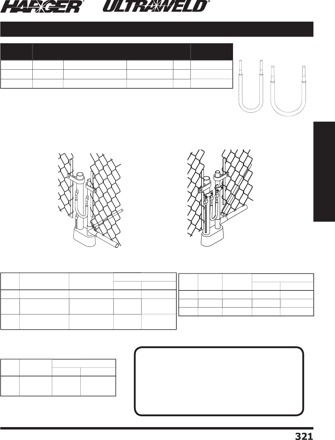
H
ar
g
er Li
g
htnin
g
& Groundin
g
•
©
2012 Phone 847-548-8700 • Fax 847-548-8755 • U.S. 800-842-743
7
3
21
321
Section 5
Ultraweld® Exothermic Connections
•
Can be used with the universal
p
i
p
e clam
p
s or can be exothermicall
y
w
elded to the fence/
g
ate post themselves.
•
Three sizes desi
g
ned to fi t either a #2 solid, 2/0 stranded or 4/0 stranded
ex
o
thermic m
o
l
d
.
•
Flex
j
umpers made from weldin
g
cable.
•
Standard len
g
th is 24" lon
g
.
•
Other len
g
ths available. Please contact factory for more information.
Flexible Gate Jumpers
Gate Jum
p
er welded
directl
y
to
p
osts.
Gate Jum
p
er welded to
U
PC clam
p
.
S
ee pa
g
e 134 for UPC's.
**Add Pi
p
e Size of Vertical Pi
p
e
to
M
o
ld Part N
o
.
•
See pa
g
e 297 for more LE Connection Types.
•
See pa
g
e 292 for more VD (Pipe) Connection Types.
Part No. Jumper
Size
Conductor Size
(AWG)
Approx. Each
Wt. (lbs.)
Box
Qty.
Approx. Box
Wt. (lbs.)
GJX
2
S
2
4#
2
AWG #2 s
o
li
d
1
/2
1
0
5
GJX2
/
02
4
2
/
0 AW
G
2
/
0 concentri
c
11
0
1
0
GJX4
/
02
4
4/
0 AW
G
4/
0 concentri
c
1-1
/2
1
0
1
5
C
able
Si
ze
N
o
mina
l
P
ip
e S
i
ze
M
o
ld
P
art
No
.
W
el
d
Meta
l
U
ltraSh
o
t
NUWTUBE
#2 S
o
l 1-1/4" to 4" Pi
pe
VD-
2
SV1.
25
X
4
B
U
S
65
NU
WT
U
BE
65
2
/
01-1/4" to 3-1/2" Pi
p
e
2" to 4" Pi
pe
VD-2
/
0V1.25X3.5
B
V
D-2
/
0V2X4
B
U
S9
0
U
S9
0
NU
WT
U
BE9
0
NU
WT
U
BE9
0
4/
01-1/4" to 3-1/2" Pi
p
e
2" to 4" Pi
pe
VD-4
/
0V1.25X3.5
B
V
D-4
/
0V2X4
B
U
S1
50
U
S1
50
NU
WT
U
BE1
50
NU
WT
U
BE1
50
C
able
Si
ze
L
u
g
Si
ze
M
o
ld
P
art
No
.
W
el
d
Meta
l
U
ltraSh
o
t
NUWTUBE
#2 S
o
l1
/
4" x 1"
L
E-
2S
141
B
U
S
65
NU
WT
U
BE
65
2
/
01
/
4" x 1"
L
E-2
/
0141
B
U
S
65
NU
WT
U
BE
65
4/
01
/
4" x 1"
L
E-4
/
0141
B
U
S9
0
NU
WT
U
BE9
0
C
able
Si
ze
M
o
ld
P
art
No
.
W
el
d
Meta
l
UltraSh
o
t
NUWTUBE
#2 S
o
l
2
/
0
4/
0
VD-
2S
V**B
VD-2
/
0V**B
VD-4
/
0V**B
U
S
65
US
11
5
U
S1
50
NU
WT
U
BE
65
NU
WT
U
BE11
5
NU
WT
U
BE1
50
VD (Pipe) Connection Type (Ran
g
e Takin
g
)LE Connect
i
on T
yp
e
VD
(
Pi
p
e
)
Connection T
yp
e
S
ect
io
n 5.10
N
O
TE
:
T
hin walled
p
i
p
e ma
y
be unsuitable for exothermic connections. I
f
experiencin
g
burn throu
g
h issues with the pipe (typically with 2/0
o
r 4/0 conductors), addin
g
sand inside the fence post well past the
exothermic connection ma
y
solve this
p
roblem. Another solution
w
ould be to use a smaller conductor such as a #2 AWG
j
umper
w
hich uses a smaller size weld metal. The last solution ma
y
be to
u
se mechanical fence clam
p
assembl
y
such as the ones found in
S
ection 1.11, pa
g
e 1
33
.
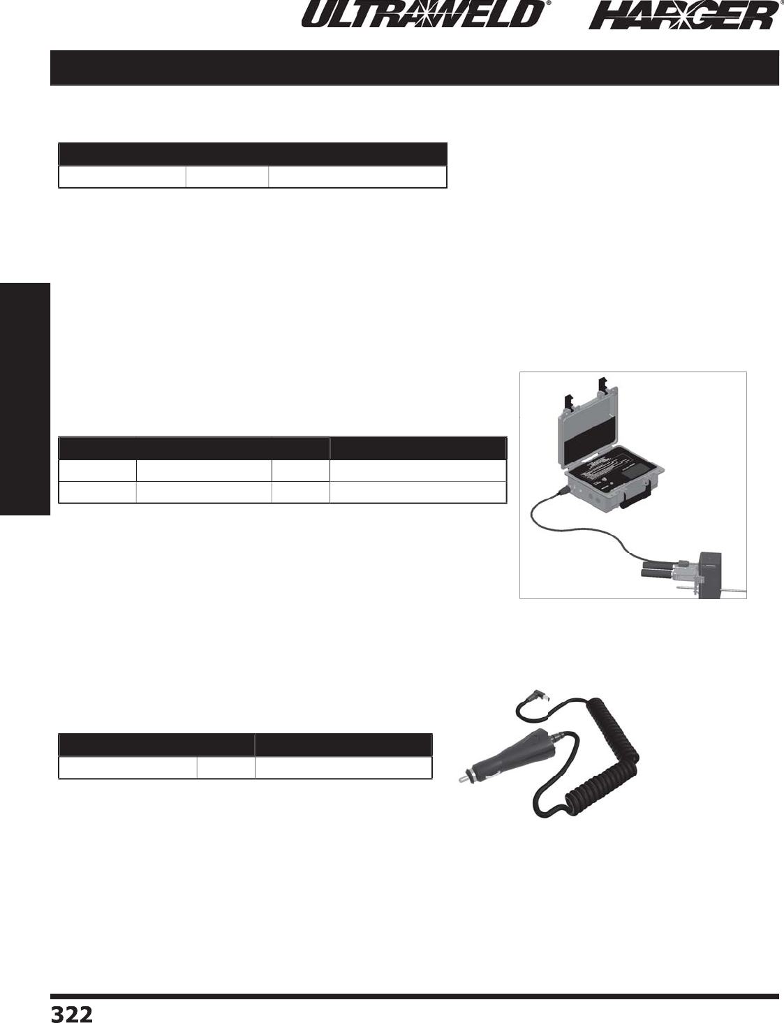
H
ar
g
er Li
g
htnin
g
& Groundin
g
•
©
2012 Phone 847-548-8700 • Fax 847-548-8755 • U.S. 800-842-743
7
3
22
322
Section 5
Ultraweld® Exothermic Connections
Materials, Tools & Accessories
•
Patented copper drop-in cartrid
g
e consumed durin
g
the reaction process.
•
Ru
gg
ed lon
g
lastin
g
12-volt rechar
g
eable battery control unit i
g
nites
hundreds of connections on a sin
g
le char
g
e.
•
Six-foot controller cord standard, 15-foot cord o
p
tional.
•
Cartrid
g
e is consumed leavin
g
no waste such as plastic or metal containers
on the
j
ob site.
•
Lon
g
lastin
g
U
ltra
-
reliable i
g
nition process allows for little to no downtime
on the
j
ob site.
•
Six or 15-foot cord allows for fl exibility in ti
g
ht spaces as well as maintainin
g
a
s
a
fe
d
ist
a
nce fr
o
m the re
a
cti
o
n.
U
ltraSh
o
t C
o
ntr
o
ller
Part No. Qty. Approx. Each Wt. (lbs.)
U
SC
O
NTR
O
LLER
EA
11
Part No. Description Qty Approx. Each Wt. (lbs.)
U
SLEAD
6
6
' C
o
ntr
o
ller C
o
r
d
EA
1
/
8
US
LEAD1
5
1
5
' C
o
ntr
o
ller C
o
r
d
EA
1
/
8
Co
ntr
o
ller C
o
rds
S
ect
io
n 5.11
Part No. Qty Approx. Each Wt. (lbs.)
USC
AR
C
HAR
G
ER
EA
1
/2
C
ar Char
g
er
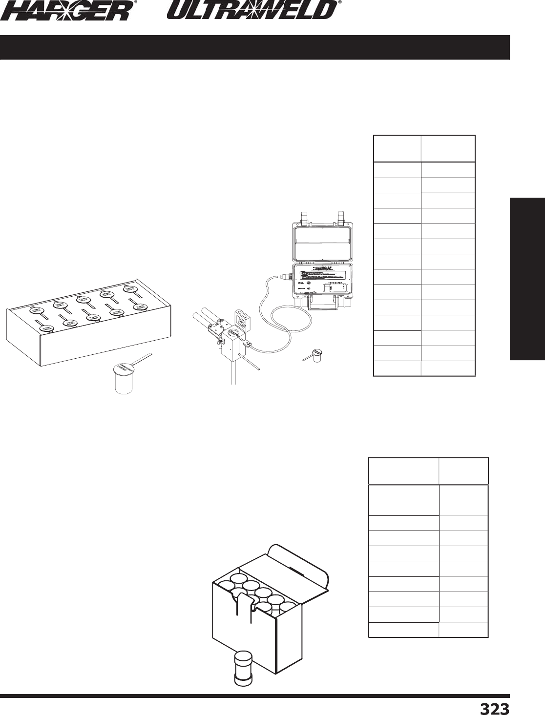
H
ar
g
er Li
g
htnin
g
& Groundin
g
•
©
2012 Phone 847-548-8700 • Fax 847-548-8755 • U.S. 800-842-743
7
3
2
3
323
Section 5
Ultraweld® Exothermic Connections
Materials, Tools & Accessories
W
el
d
Meta
l
NU
WT
ube
™
•
The weld metal, a mixture of copper oxide and aluminum, is packa
g
ed in
i
ndividual, moisture resistant
p
lastic tubes.
•
Dual chambers desi
g
n holds startin
g
material and weld metals
s
e
p
aratel
y
, in the same tube.
•
Easy to identify with color coded caps. Clear = Weld Metal, Oran
g
e =
S
tartin
g
material.
•
Each cartrid
g
e is marked with the size.
•
E
a
ch
bo
x
a
ls
o
c
o
nt
a
ins instr
u
cti
o
ns
a
n
d
met
a
l
d
isks.
O
nce met
a
l
d
isk is
u
se
d
f
o
r e
a
ch c
o
nnecti
o
n.
Si
ze
Q
ty. Per
C
art
on
NU
WT
U
BE1
5
20
NU
WT
U
BE
25
20
NU
WT
U
BE
32
20
NUWTUBE45
20
NU
WT
U
BE
65
20
NU
WT
U
BE9
0
1
0
NU
WT
U
BE11
5
1
0
NU
WT
U
BE1
50
1
0
NU
WT
U
BE
200
1
0
NU
WT
U
BE
250
1
0
NUWTube™
(
Pour & Shoot
)
W
el
d
Meta
l
Si
ze
Q
ty. Per
C
art
on
U
S
25
20
U
S
32
20
US
4
5
20
U
S
65
20
U
S9
0
1
0
US
11
5
1
0
U
S1
50
1
0
U
S
200
1
0
U
S
250
1
0
U
S
300
1
0
U
S4
00
5
U
S
500
5
U
S
600
5
U
S7
50
5
U
ltraSh
o
t
®
(Drop-In)
®
W
el
d
Meta
l
UltraShot
®
t
•
The weld metal, a mixture of copper oxide and aluminum, is packa
g
ed in
i
ndividual, moisture resistant co
pp
er dro
p
-ins.
•
The copper drop-in is consumed durin
g
the reaction process.
•
Each dro
p
-in is marked with the size.
•
The drop-ins are packa
g
ed in a box containin
g
either 5 units per box
(
4 boxes
p
er case
)
, 10 units
p
er box
(
5 boxes
p
er case
)
or 20 units
p
er
box
(
10 boxes
p
er case
)
.
S
ect
io
n 5.11
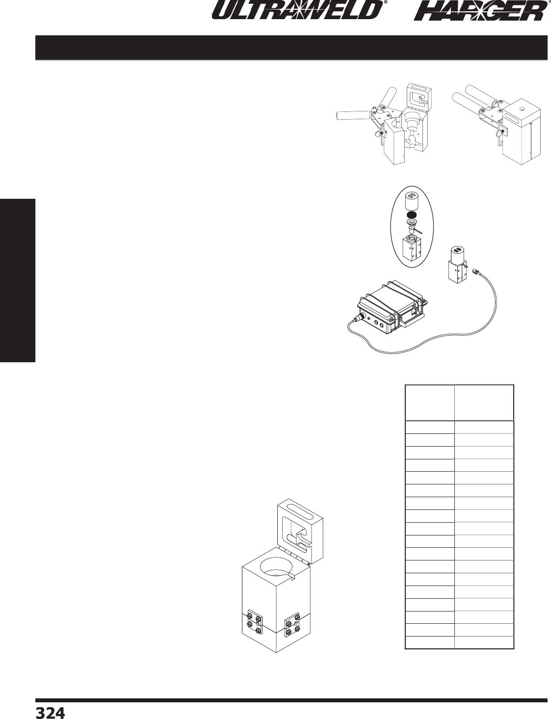
H
ar
g
er Li
g
htnin
g
& Groundin
g
•
©
2012 Phone 847-548-8700 • Fax 847-548-8755 • U.S. 800-842-743
7
3
2
4324
Section 5
Ultraweld® Exothermic Connections
•
Dependin
g
on the care and treatment of the mold, it will
avera
g
e 50 or more welds. Substantially more with the
U
ltraShot
p
rocess.
•
The Ultraweld Low Smoke process uses an inte
g
rated
fi lter system on the mold and electric i
g
nition of the weld
metal to
p
roduce a fi nished connection with minimal
s
moke emission. Ideal for indoor and confi ned s
p
ace
w
orkin
g
conditions.
•
For Ultraweld Low Smoke process, i
g
nition is
accom
p
lished with the use of a USCONTROLLER.
•
M
o
l
d
H
a
n
d
le n
o
t inl
ud
e
d
.
•
Wear
p
lates hel
p
extend the life of the mold.
•
The openin
g
s of the mold
g
et worn down due to forcin
g
a mold shut over "out of round" conductors, the ends o
f
conductors hittin
g
and chippin
g
the openin
g
s, etc.
•
Wear
p
lates can be su
pp
lied for all molds for cable sizes;
#2 Solid, 1/0 AWG throu
g
h 500 MCM and Copperweld
cable 7/#10 throu
g
h 19/#6.
•
To order, add the suffi x "WP" to the Ultraweld
p
art
number. Exam
p
le: RT-4/04/0
B
-WP
Available
W
el
d
Typ
e
Number
of
W
ear
Plate
s
BH
2
BS
2
GD
2
G
O
3
GS
3
HB
1
HU
2
LE
1
PB
*
3
PT
*
4
RO
2
RS
2
RT
3
VA
1
VH
2
VT
2
XO
4
XX
4
*
Wear
p
lates onl
y
available
o
n 1/0 stranded and lar
g
er or
Copperweld 7/#10 and lar
g
er run
and ta
p
cables. Also available from
#2 solid run and ta
p
cables.
M
o
lds
Materials, Tools & Accessories
W
ear Plate
s
O
p
en Mold Cl
o
se
d
M
o
l
d
S
ect
io
n 5.11
Lo
w Sm
o
ke
Mo
l
d
U
SC
O
NTR
O
LLER
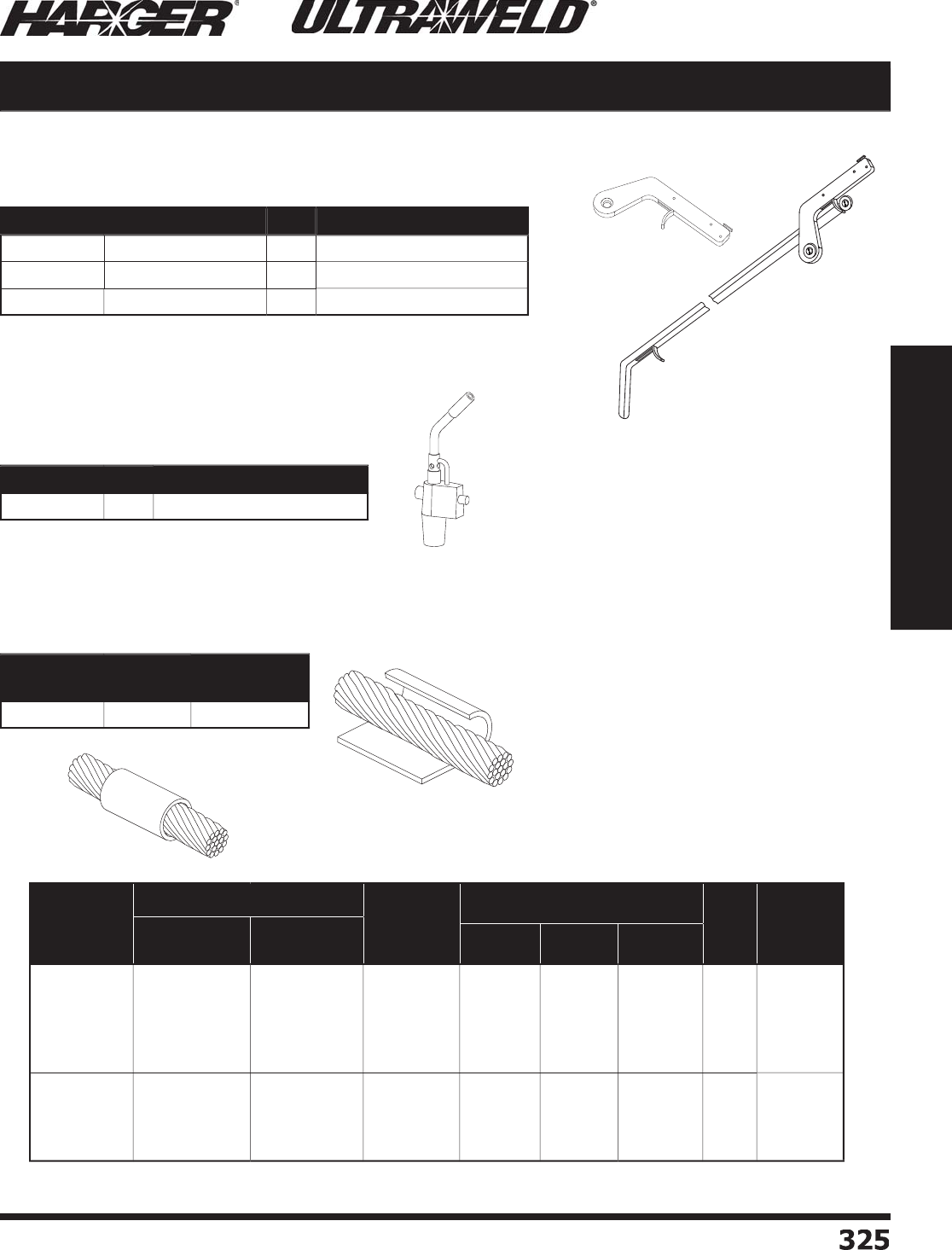
H
ar
g
er Li
g
htnin
g
& Groundin
g
•
©
2012 Phone 847-548-8700 • Fax 847-548-8755 • U.S. 800-842-743
7
3
2
5
325
Section 5
Ultraweld® Exothermic Connections
•
When makin
g
an Ultraweld connection, Flint I
g
niters are used to
ig
nite the startin
g
material.
•
Flint I
g
niters comes with MH1 and MH2 handle clamps.
•
Re
p
lacement Flints are also available.
•
Self-i
g
nitin
g
Torch Head is desi
g
ned to fi t
14 or 16 ounce
p
ro
p
ane c
y
linders.
•
Torches are re
q
uired to remove moisture
from the mold and conductors before makin
g
the
U
ltr
a
wel
d
c
o
nnecti
o
ns.
F
lint I
g
nite
r
36
" Extensi
on
Materials, Tools & Accessories
•
Wrap Sleeves can be used when weldin
g
cables smaller than indicated on mold ta
g
.
•
When the cable openin
g
in the mold
i
s lar
g
er than the cable, copper Wrap
S
leeves are wra
pp
ed around the cable
u
ntil the
d
i
a
meter is
abou
t the s
a
me size
as the mold cable openin
g
.
•
A co
pp
er Wra
p
Sleeve is also used for
w
rappin
g
around rebar for certain
connection st
y
les.
•
Adapter Sleeves can be used when weldin
g
cables smaller than indicated on mold ta
g
.
•
Adapter sleeves slide over the cable to adapt smaller size cables to a lar
g
er size mold.
Part No. Description Qty. Approx. Each Wt. (lbs.)
F
LTI
G
F
lint I
g
nite
r
EA
1
/4
F
LTI
G
EXT
36
" Extenti
on
EA
1-1
/2
RPLFLT
R
e
p
lacement Flint
s
EA
1
/
8
Part No. Qty. Approx. Each Wt. (lbs.)
T
R
C
H
D
EA
1-1
/4
Part No. Box Qty. Approx. Box
Wt. (lbs.)
W
RP
S
LV
50
1
/2
Part No.
Cable Size Use in
Mold for
Stranded
Sleeve Dimensions Box
Qty.
Approx.
Box Wt.
(lbs.)
Concentric
Strand Solid O.D I.D. Length
ADPSLV
6
ADP
S
LV4
ADP
S
LV
2
A
ADP
S
LV
2
B
ADP
S
LV1
#1
2
, 14
#7, 8, 10
#
6
#4
,
5
#4
#10, 1
2
, 14
#6, 8
#5
#
3
, 4
n
/a
#
6
#4
#
2
#
2
#1
.
1
56
.227
.2
9
2
.
28
7
.3
4
0
.
111
.
17
7
.
198
.2
4
6
.2
4
6
1.
00
1.
00
1.
00
1.
00
1.
00
25
50
25
50
50
1
/
4
1
/
4
1
/
4
1
/
4
1
/
4
ADPSLV1
/
0
ADPSLV2
/
0
ADPSLV3
/
0
ADPSLV4
/
0
#
2
#1
1/0, #1
2/0, 1/0
#1
1
/
0
2
/
0
3
/
0
1
/
0
2
/
0
3
/
0
4/
0
.3
7
0
.
4
20
.
4
52
.524
.307
.35
9
.
389
.
4
37
1.
00
1.
00
1.
00
1.
50
25
25
25
50
1
/
4
1
/
4
1
/
4
1
/
4
M
o
ld Access
o
ries
Flint I
g
niters
T
o
rch Head
Adaptin
g
Molds to Fit Conductors
W
ra
p
Sleeves
Ada
p
ter Sleeves
S
ect
io
n 5.11
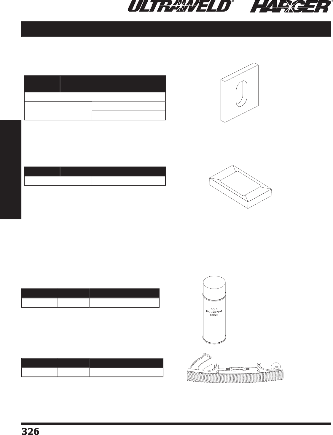
H
ar
g
er Li
g
htnin
g
& Groundin
g
•
©
2012 Phone 847-548-8700 • Fax 847-548-8755 • U.S. 800-842-743
7
3
2
6326
Section 5
Ultraweld® Exothermic Connections
Materials, Tools & Accessories
•
Packin
g
consists of preformed ceramic battin
g
.
•
Packin
g
is required on all rebar connections to prevent leaka
g
e.
•
Some connection st
y
les ma
y
re
q
uire wra
p
sleeves in
p
lace o
f
ceramic packin
g
.
•
Mold Sealer is for sealin
g
sli
g
htly worn molds to
g
uard
a
g
ainst leaka
g
e from lar
g
e stranded conductors.
•
Available in a convenient 1 pound packa
g
e.
Part No. Box
Qty. Approx. Box Wt. (lbs.)
C
ERPM1
25
1
/
4
C
ERPM
2
25
1
/
4
CERPM
3
25
1
/
4
Part No. Qty. Approx. Each Wt. (lbs.)
M
LD
S
LR
EA
1
Adaptin
g
Molds to Fit Conductors continued
C
eramic Rebar Packin
g
Materia
l
M
o
ld Sealer
C
able & Work Surface Pre
p
aratio
n
•
Ideal for removin
g
mill scale and rust from steel surfaces.
Part No. Qty. Unit Wt. (oz.)
CGS
EA
1
6
Part No. Qty. Approx. Each Wt. (lbs.)
R
A
SP
EA
2-1
/2
C
old Galvanizin
g
Spra
y
R
as
p
•
Instant cold
g
alvanizin
g
spray provides protection
equal to hot dip
g
alvanizin
g
.
•
Used for touchin
g
up surfaces affected by weldin
g
.
S
ect
io
n 5.11
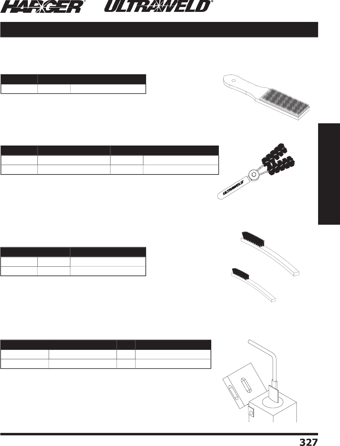
H
ar
g
er Li
g
htnin
g
& Groundin
g
•
©
2012 Phone 847-548-8700 • Fax 847-548-8755 • U.S. 800-842-743
7
3
27
327
Section 5
Ultraweld® Exothermic Connections
•
Ideal for cleanin
g
concentric stranded cable, especially very dirty or
o
xi
d
ize
d
c
o
n
du
ct
o
rs.
•
The Card Cloth Brush has short, stiff, metal bristles which are
g
enerally
preferred for cleanin
g
concentric conductors and busbars, that are not
heavil
y
oxidized.
Part No. Qty. Approx. Each Wt. (lbs.)
CC
BR
S
H1
EA
1
/
4
Part No. Description Qty. Approx. Each Wt. (lbs.)
CC
BR
S
H
2
Cable Cleanin
g
Brus
h
EA
3
/4
CC
BR
S
H
2
R
R
e
p
lacement Brush Pai
r
EA
1
/4
C
able & Work Surface Pre
p
aration continued
C
ard Cl
o
th Brus
h
C
able Cleanin
g
Brus
h
•
Sla
g
can be removed from molds by usin
g
a Mold Cleanin
g
Brush.
•
The brush is es
p
eciall
y
useful on vertical s
p
lit molds.
•
Consistent and proper use of the brush will aid in maintainin
g
or
exceedin
g
the avera
g
e mold life of 50 connections.
•
Sla
g
can be cleaned from the molds by usin
g
a Mold Cleanin
g
Spade.
•
The cleanin
g
spade is especially useful on horizontally split molds.
•
The cleanin
g
spades are specifi cally desi
g
ned to fi t the mold crucible for
a
g
iven ran
g
e of weld metal sizes.
•
Consistent and proper use of cleanin
g
spades will aid in maintainin
g
or
exceedin
g
the avera
g
e mold life of 50 connections.
Materials, Tools & Accessories
MC
BR
S
H1
MC
BR
S
H
2
Part No. Qty. Approx. Each Wt. (lbs.)
MC
BR
S
H1
EA
1
/
4
MC
BR
S
H
2
EA
1
/
16
Part No. Weld Metal Sizes Qty. Approx. Each Wt. (lbs.)
M
CSPD25
/
115
25
- 11
5
EA
1
/4
M
CSPD150
/
400 150 and lar
g
e
r
EA
1
/4
M
o
ld Care & Use
Mold Cleanin
g
Brushes
Mold Cleanin
g
Spades
S
ect
io
n 5.11
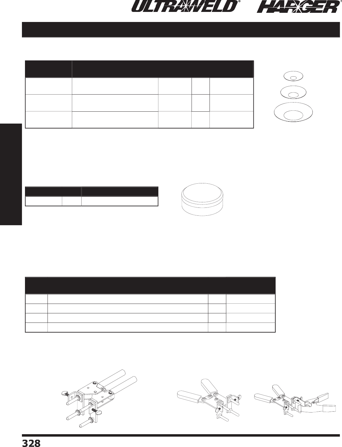
H
ar
g
er Li
g
htnin
g
& Groundin
g
•
©
2012 Phone 847-548-8700 • Fax 847-548-8755 • U.S. 800-842-743
7
328
328
Section 5
Ultraweld® Exothermic Connections
•
Mold Handle Clam
p
s are re
q
uired for all molds.
•
Some molds are used with s
p
ecialized frames.
•
Handle clamps MH1 & MH2 come with a fl int i
g
niter (FLTIG).
•
Handle clam
p
s have a Zinc Ultraseal
p
lated fi nish.
•
A Disk Kit contains three sizes of steel disks;
6
0 small, 30 medium and 30 lar
g
e.
•
The disk rests on the bottom of the crucible and holds the weld metal
p
owder in
p
lace until the reaction occurs.
•
A new disk is re
q
uired each time a weld is made.
•
Disks
a
re incl
ud
e
d
with the N
U
WT
U
BE Wel
d
Met
a
l.
MH4
Materials, Tools & Accessories
M
H
3
Pa
tente
d
Part No. Description Diameter Box
Qty.
Approx. Box
Wt. (lbs.)
D
ISK15
/
65
U
sed in molds usin
g
1
5
thr
u
65
wel
d
met
a
l3
/
4"
20
1
/
8
D
ISK90
/
115
U
sed in molds usin
g
90
thr
u
11
5
wel
d
mel
a
l1" 1
0
1
/
8
D
ISK150
/
500
U
sed in molds usin
g
1
50
thr
u
2
50
wel
d
met
a
l1-1
/
2" 1
0
1
/
4
Part No. Qty. Approx. Each Wt. (lbs.)
D
I
S
KKIT1
EA
1
/4
Part
No. Application Qty. Approx. Each
Wt. (lbs.)
M
H1
F
or All molds with B, E, K, P & Q mold
p
rice ke
y
(
3" wide
)
EA
2-3
/
4
M
H
2
F
or All molds with C, D, F & Z mold
p
rice ke
y
EA
3-1
/2
M
H
3
F
or Combo molds with L, M & N mold
p
rice ke
y
EA
1
/
4
MH4
F
or Combo molds with R mold
p
rice ke
y
EA
1-1
/2
Di
s
k
s
Di
s
k Kit
Mold Fastenin
g
& Mountin
g
Mold Handle Clam
p
s
M
H1, MH
2
S
ect
io
n 5.11
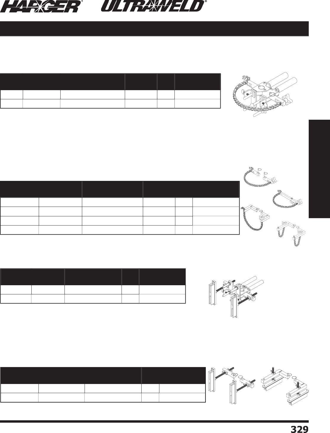
H
ar
g
er Li
g
htnin
g
& Groundin
g
•
©
2012 Phone 847-548-8700 • Fax 847-548-8755 • U.S. 800-842-743
7
3
29
329
Section 5
Ultraweld® Exothermic Connections
•
These kits convert the standard mold handle clamp into a ma
g
netic
s
u
pp
ort handle clam
p
.
•
These kits convert standard mold handle clam
p
s into chain su
pp
ort clam
p
s.
Materials, Tools & Accessories
CS
KIT
CS
KITH
S
VM
CS
KITH
P
Pa
tente
d
Pa
tente
d
Pa
tente
d
Pa
tente
d
Part
No.
Fits Mold
Price Key
For Following
Connection Types
Pipe/
Rebar Qty. Approx. Each
Wt. (lbs.)
CS
H1
B
,
E
,
K
RE
,
VA
,
VD
,
VT
,
VU
Vertic
a
l
EA
4
CS
H
2
C
, D,
F
VA
,
VD
,
VT
,
VU
Vertic
a
l
EA
4
-1
/2
Part No. Fits Mold
Price Key
For Following
Connection Types
Pipe/
Rebar Qty. Approx. Each
Wt. (lbs.)
CS
KIT
B
,
C
, D, E, F, K
RE
,
VA
,
VD
,
VT
,
VU
Vertic
a
l
EA
2
CS
KITH
S
VM
B
,
C
VH, R
S
Vertic
a
l
EA
3
CS
KITH
P
B
,
C
HB
,
HD
,
HT
,
HU
Ho
riz
o
nt
a
l
EA
3-1
/
4
CS
KITHPV
S
B
H
TCP, R
O
Ho
riz
o
nt
a
l
EA
4
Part No. Fits Mold
Price Key
Minimum Width
Requirements Qty. Approx. Each
Wt. (lbs.)
MS
H
C
1
B
,
E
,
K
8"
EA
6
MS
H
C2
C
, D,
F
8"
EA
6
-1
/2
Mold Fastenin
g
& Mountin
g
continued
C
hain Su
pp
ort Handle Clam
p
s
C
hain Su
pp
ort Kits
Ma
g
netic Support Handle Clamps
Ma
g
net
i
c Support K
i
ts
S
ect
io
n 5.11
•
Handle clam
p
s MSHC1 & MSHC2 come with MH1 & MH2 clam
p
s res
p
ectivel
y
as well as a MSKIT and a fl int i
g
niter (FLTIG).
•
Ma
g
netic Support Handle Clamp allows mold to be securely held in place to
s
teel s
u
rf
a
ces.
•
MSKIT converts the standard mold handle clamp into a ma
g
netic support
handle clam
p
.
•
Handle clam
p
s CSH1 & CSH2 come with MH1 & MH2 clam
p
s res
p
ectivel
y
as well as
a CSKIT and fl int i
g
niter (FLTIG).
•
Chain Su
pp
ort Handle Clam
p
s are used to securel
y
hold the mold to either a
v
ertical or horizontal
p
i
p
e.
•
A 20” len
g
th of chain, which fi ts up to 4” pipes, comes with the chain support
handle clam
p
s.
•
Extra chain len
g
th is available. Please contact factory for details.
MS
KIT
MS
KITH
S
V
S
Part No. Fits Mold
Price Key
Minimum Width
Requirements Qty. Approx. Each
Wt. (lbs.)
MS
KIT
B
,
C
, D, E, F, K 8"
EA
6
MS
KITH
S
V
S
B
,
C
, D, K 1
0
"
EA
5
CS
KITHPV
S
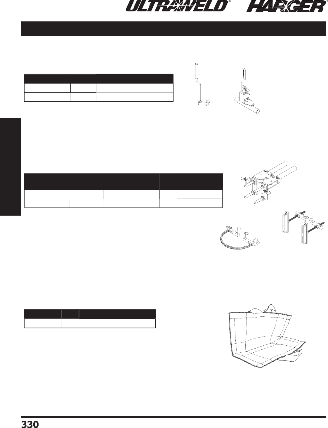
H
ar
g
er Li
g
htnin
g
& Groundin
g
•
©
2012 Phone 847-548-8700 • Fax 847-548-8755 • U.S. 800-842-743
7
330330
Section 5
Ultraweld® Exothermic Connections
•
Handle clamps MH1 & MH2 come with a fl int i
g
niter. (FLTIG)
•
Chain Su
pp
ort Handle Clam
p
securel
y
holds mold to a vertical
p
i
p
e.
•
Ma
g
netic Support Handle Clamp holds mold securely in place when
w
eldin
g
to steel surfaces.
M
H1, MH
2
CS
KIT
MS
KIT
Materials, Tools & Accessories
•
UMHDKIT: Attaches easil
y
to MH1 & MH2 handle clam
p
s
for holdin
g
mold in place.
•
U
MMHDA:
U
se
d
f
o
r h
o
riz
o
nt
a
l "A" m
o
l
d
s.
•
Contains an inner and outer E-
g
lass yarn with a padded non-crystalline
s
ilicate fi llin
g
, fi nished with Kevla
r
®
.
•
Extends mold life by protectin
g
a
g
ainst shock impact caused by rou
g
h
handlin
g
.
•
Protects exothermic welders from comin
g
into contact with hot molds.
•
Used as a protection blanket a
g
ainst weld splatter.
Pa
tente
d
Part No. Qty. Approx. Each Wt. (lbs.)
UMHDKIT
EA
1-1
/2
UMMHDA
EA
1
/2
Part No. Fits Mold
Price Key Kit Includes Qty. Approx. Each
Wt. (lbs.)
U
LTRAMH1KIT
B
,
E
,
K
M
H1,
CS
KIT, M
S
KIT
EA
7
U
LTRAMH
2
KIT
C
, D,
F
M
H
2
, CSKIT, MSKIT
EA
7-1
/2
Part No. Qty. Approx. Each Wt. (lbs.)
ULTRAWRAP
EA
2
Mold Fastenin
g
& Mountin
g
continued
H
o
ld D
o
wn Kit
Mold Handle Clam
p
Kits
M
o
ld Blanket
S
ect
io
n 5.11
UMMHDA
UMHDKIT
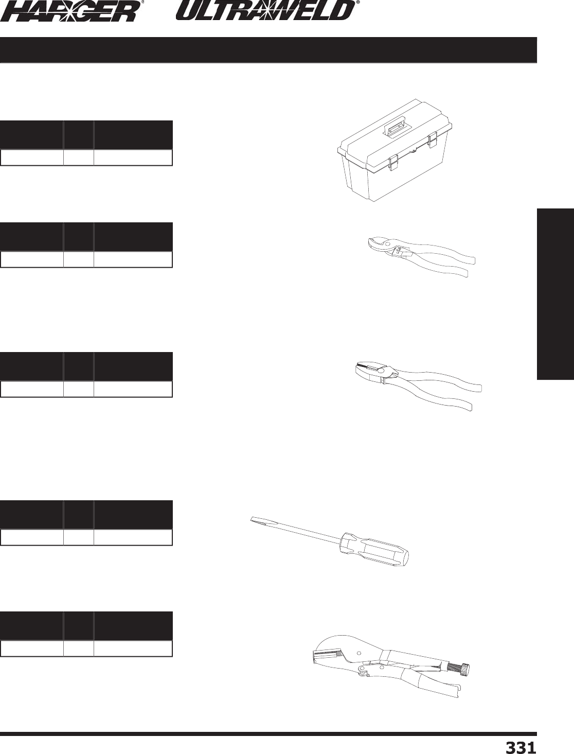
H
ar
g
er Li
g
htnin
g
& Groundin
g
•
©
2012 Phone 847-548-8700 • Fax 847-548-8755 • U.S. 800-842-743
7
33
1
331
Section 5
Ultraweld® Exothermic Connections
•
Screwdriver is 6" lon
g
with a 5/16" standard head.
•
10" Vise-Gri
p
®
strai
g
ht
j
aw lockin
g
pliers can be used as a pliers,
ad
j
ustable wrench, pipe wrench, or clamp.
•
They have a stron
g
g
rip with quick release and locks on to a
v
ariet
y
of sizes.
Materials, Tools & Accessories
•
9" Lineman's pliers are heavy duty with non-slip cushion
g
rips.
•
Made with heat treated for
g
ed alloy steel for increased tou
g
hness and durability.
•
Has a streamline head desi
g
n and it's hardened side cuttin
g
ed
g
es create a clean
cut and remain shar
p
.
•
Plastic toolbox measures 22" x 9.5" x 9.75" and includes a tra
y
.
•
Cable cutters desi
g
ned for special hi
g
h-levera
g
e to
g
ive excellent cuttin
g
capability.
•
The cable-
g
rippin
g
shear-type
j
aw makes clean cuts up to 2/0 soft copper cable.
•
Handles are plastic-dipped for comfort and to minimize fati
g
ue.
Part No. Qty. Approx. Each
Wt. (lbs.)
TOO
LB
O
X
EA
5
-1
/2
Part No. Qty. Approx. Each
Wt. (lbs.)
CC9
EA
1
/4
Part No. Qty. Approx. Each
Wt. (lbs.)
L
P9
EA
1-1
/
4
Part No. Qty. Approx. Each
Wt. (lbs.)
S
SS
6
EA
1
/4
Part No. Qty. Approx. Each
Wt. (lbs.)
VG1
0
EA
1-1
/
4
T
oo
lb
o
x & T
oo
ls
T
oo
lb
o
x
9" Cable C
u
tter
Lineman'
s
Plier
s
S
tandard Sl
o
t Screwdriver
S
tandard Vise-Gri
p
®
S
ect
io
n 5.11
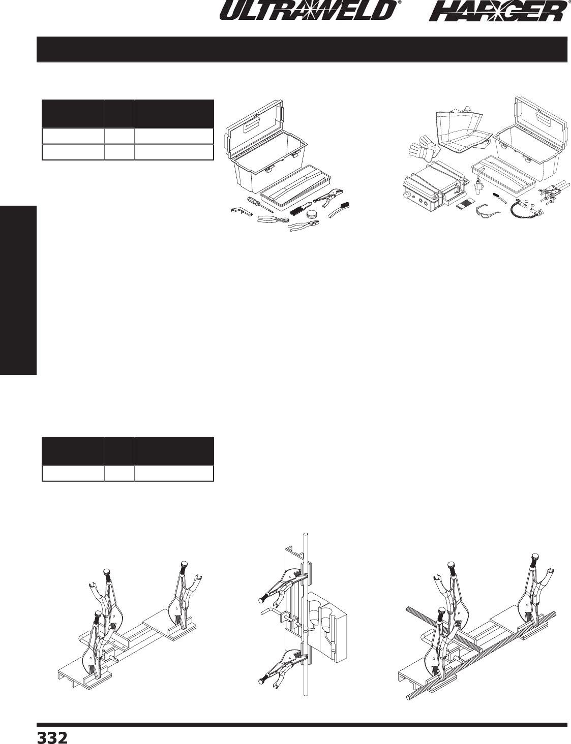
H
ar
g
er Li
g
htnin
g
& Groundin
g
•
©
2012 Phone 847-548-8700 • Fax 847-548-8755 • U.S. 800-842-743
7
33
2
332
Section 5
Ultraweld® Exothermic Connections
•
Clamp properly ali
g
ns and supports Ground Rods for weldin
g
type GG connections. See pa
g
e 286 for details.
•
Add-on third clamp (included) is used to convert into a Cable Clampin
g
system. Thus preventin
g
cables under
tension from movin
g
durin
g
weldin
g
and ensurin
g
no weld metal leaka
g
e. This ensures quality connections and
i
ncre
a
ses the life
o
f the m
o
l
d
.
Cable Clampin
g
Ground Rod Clampin
g
Materials, Tools & Accessories
•
T
OO
LKIT Incl
ud
e
s:
(
1
)
TOOLBOX: 22" x 9.5" x 9.75"
p
lastic toolbox with tra
y
(
1
)
CC9: 9" Cable Cutter
s
(
1
)
LP9: Lineman's Plier
s
(
1
)
SSS6: 6" Screwdrive
r
(
1
)
VG10: 10" Vise-Gri
ps
(1) FLTIG: Flint I
g
nite
r
(
1
)
CCBRSH1: Card Cloth Brus
h
(1) MCBRSH1: Mold Cleanin
g
Brus
h
(
1
)
DISKKIT: Disk Ki
t
Part No. Qty. Approx. Each
Wt. (lbs.)
TOO
LKIT
EA
1
0
U
ST
OO
LKIT
EA
23-1
/
4
Part No. Qty. Approx. Each
Wt. (lbs.)
G
R
CC
EA
18
T
oo
lkits
G
round Rod & Cable Clam
p
S
ect
io
n 5.11
•
U
ST
OO
LKIT Incl
ud
e
s:
(
1
)
USCONTROLLER
(
1
)
TOOLBOX: 22" x 9.5" x 9.75"
p
lastic toolbox with tra
y
(
1
)
MH1: Mold Handle
(
1
)
CSKIT: Chain Su
pp
ort Ki
t
(1) MCBRSH2: Mold Cleanin
g
Brus
h
(
1
)
SFTYGLS: Safet
y
Glasse
s
(
1
)
GLOVES: Leather Palm Glove
s
(
1
)
3MABPAD: Abrasive Pad
(
1
)
MOLDBKT: Mold Blanke
t
(1) TRCHD: Torch Head with I
g
nite
r
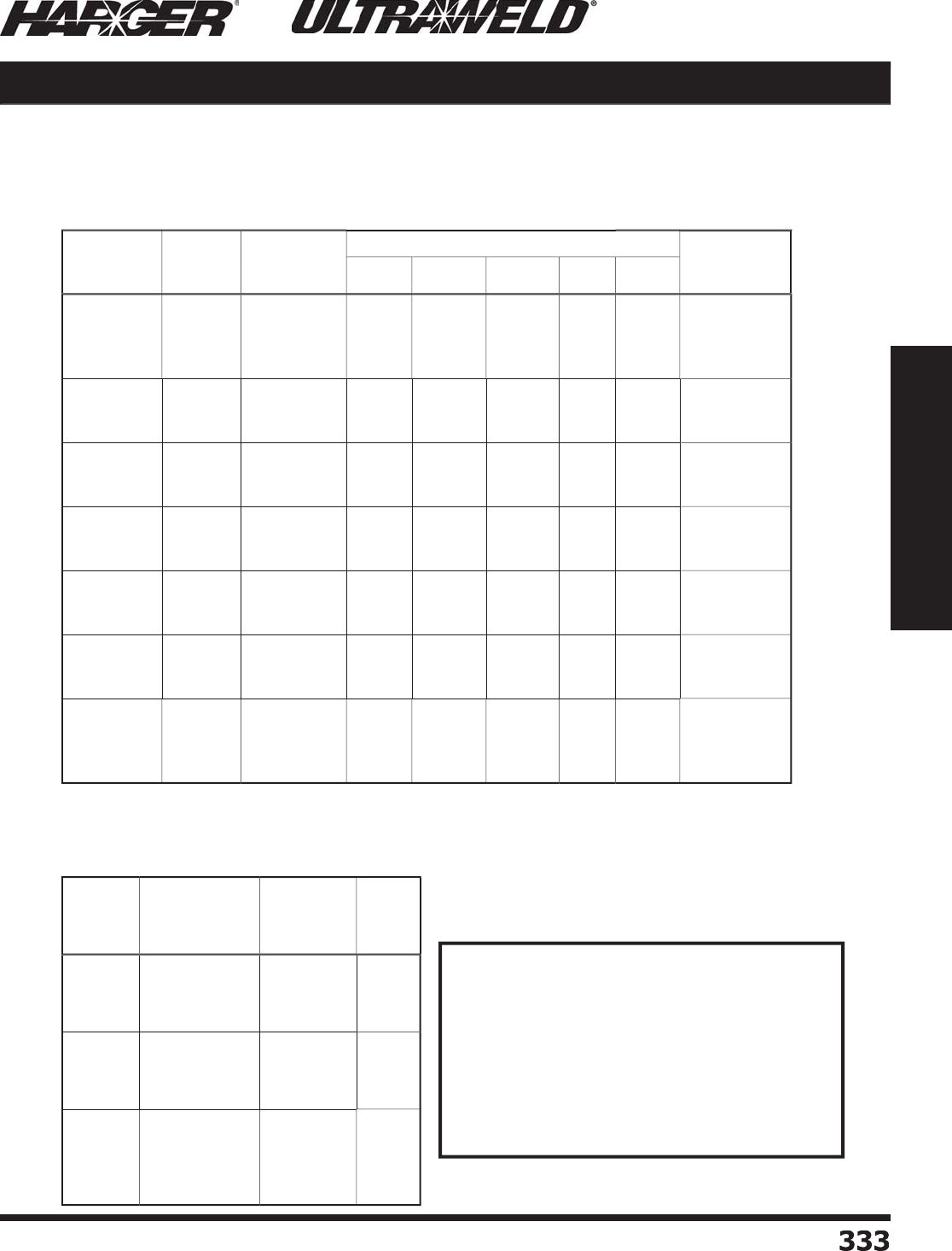
H
ar
g
er Li
g
htnin
g
& Groundin
g
•
©
2012 Phone 847-548-8700 • Fax 847-548-8755 • U.S. 800-842-743
7
333
333
Section 5
Ultraweld® Exothermic Connections
*
Cl
a
ss AA
Cable Codes Technical Information
Sq
uare Inches x 1273 = MCM
M
CM x 7.862 x 10
-4
= S
q
uare Inche
s
Sq
uare Inches x 645.2 = S
q
uare Millimete
r
Sq
uare Millimeter x 1.550 x 10-
3
= S
q
uare Inche
s
Sq
uare Millimeters x 1.9736 = MCM
M
CM x 0.5067 = S
q
uare Millimeter
s
1 MCM = 1 kcmil = 1,000 circular mil
Si
ze
in
C
irc
u
lar
mil
s
Si
ze
A.W.
G
.
Co
nduct
o
r
D
i
ameter
Number
o
f Wires
C
able C
o
de
7
19
3
7
6
1
9
1
1,000,000
800,000
750,000
700,000
1
000
800
7
50
7
00
1.1
5
2"
1.
03
1"
.
998"
.
9
6
4"
.
147
0
*
.
1424*
.
1
3
7
5
*
.
1
6
44*
.
114
5
.
11
0
9
.
1
0
71
.
1280
.
0938
.
0908
.
087
7
0
.148 1MM
8CM
7
5C
M
7
C
M
6
00,000
5
00,000
4
00,000
600
500
400
.
893"
.
813"
.
728"
.
1
2
7
3
.
1
6
22*
.
14
5
1
.0
99
2
.
11
62
.
1
0
4
0
.
081
2
.0
9
05
.
0810
6
CM
5C
M
4C
M
3
50,000
3
00,000
2
50,000
350
300
250
.
681"
.630
"
.5
7
5
"
.
1
357
.
1
257
.
114
7
.0
97
3
.0
9
00
.
082
2
.0
7
57
.0
7
0
1
.06
4
0
35
CM
3
CM
25
CM
2
11,600
167,800
1
33
,100
4/
0
3
/
0
2
/
0
.
528"
.
47
0
"
.
419"
.
17
3
9
.
1548
.
1
3
79
.
1
055
.0
94
0
.
083
7
.0
7
56
.0
7
63
.0600
4/
0
3
/
0
2
/
0
105,500
83,690
6
6,
3
70
1
/
0
1
2
.3
7
3
"
.33
2"
.
292"
.
1228
.
1
0
9
3
.0
97
4
.0
74
5
.0664
.05
91
.0534
.0
4
67
1
/
0
1
2
52
,6
3
0
4
1,740
2
6,
2
40
3
4
6
.
2
60
"
.
2
3
2"
.
184"
.
086
7
.0
77
2
.06
1
2
.0526
.0
4
6
9
.03
7
2
3
4
6
16,510
10,380
6
,5
3
0
4
,110
8
1
0
1
2
14
.
14
6
"
.
11
6
"
.0
91
5
"
.0
72
6
"
.
0486
.
0385
.0305
.02
4
2
.02
9
5
.0234
.
0185
.0
41
7
8
1
0
1
2
14
Si
ze
A.W.
G
.
C
r
o
ss
S
ectiona
l
A
rea
C
irc
u
lar Mil
s
Wi
re
D
i
ameter
C
able
Co
de
4/
0
3
/
0
2
/
0
1
/
0
2
11,600
167,800
1
33
,100
105,500
.
4
600
"
.
4
0
9
6
"
.
3648"
.3
249"
4/
0
S
3
/
0
S
2
/
0
S
1
/
0
S
1
2
3
4
83,690
6
6,
3
70
52
,6
3
0
4
1,740
.
2893"
.
2
5
7
6
"
.
2294"
.
2
0
4
3
"
1
S
2S
3S
4S
6
8
1
0
1
2
1
4
2
6,
2
50
16,510
10,380
6
,5
3
0
4
,110
.
1
6
2
0
"
.
1285"
.
1
0
19"
.
0808"
.06
41"
6S
8
S
1
0S
1
2S
14
S
Co
nduct
o
r Identifi cati
on
Bare Class A, B, and C Concentric Stranded Conductors
Based on A.S.T.M Standard S
p
ecifi cations
Bare Solid Co
pp
er Conductors
Based on A.S.T.M Standard S
p
ecifi cations
Co
nduct
o
r Area C
o
nversi
o
ns
S
ect
io
n 5.12
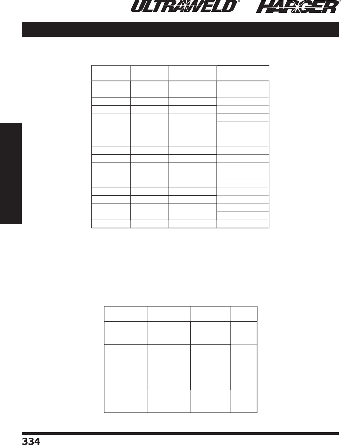
H
ar
g
er Li
g
htnin
g
& Groundin
g
•
©
2012 Phone 847-548-8700 • Fax 847-548-8755 • U.S. 800-842-743
7
334334
Section 5
Ultraweld® Exothermic Connections
Technical Information Cable Codes & Pipe Sizes
S
tandard Wei
g
ht ASTM A53-90-B
(
Schedule 40
)
ANSI/ASME B36.10M-1985
N
o
mina
l
Si
ze
O
.D.
W
al
l
Thickne
ss
M
o
ld
Co
de
1"
1-1
/
4"
1-1
/
2"
1.
3
1
5
"
1.
66
"
1.9"
.
1
33
"
.
14"
.
14
5
"
1
1.
25
1.
5
2"
2-1
/
2"
2.
3
7
5
"
2.875"
.
1
5
4"
.
2
03
"
2
2
.
5
3
"
3-1
/
2"
4
"
5
"
3
.
5
"
4
"
4
.
5
"
5
.
563
"
.
21
6
"
.
22
6
"
.
2
3
7"
.
258"
3
3
.
5
4
5
6
"
8"
1
0
"
6
.
6
2
5
"
8.625"
1
0
.7
5
"
.
28"
.3
22"
.365
"
6
8
1
0
S
teel Pi
p
e Sizes
S
ect
io
n 5.12
C
able C
o
de
C
able
S
trandin
g
N
o
minal
Diameter
(
in.
)
C
r
o
ss Secti
o
nal
Area
(
kcmil
)
3
/
10C
W
3
/
#10 C
W
.220
3
1.1
5
3
/
9C
W
3
/
#9 C
W
.2
4
7
39.28
3
/
8C
W
3
/
#8 C
W
.2
7
7
4
9.
53
7
/
10C
W
7
/
#10 C
W
.306
72.68
3
/
7C
W
3
/
#7 C
W
.3
11
62
.4
5
7
/
9C
W
7
/
#9 C
W
.3
4
3
9
1.
65
3
/
6C
W
3
/
#6 C
W
.3
49 78.75
7
/
8C
W
7
/
#8 C
W
.
385 11
5
.
60
3
/
5C
W
3
/
#5 C
W
.3
9
2
9
9.
3
1
7
/
7C
W
7
/
#7 C
W
.
4
33
14
5
.7
0
7
/
6C
W
7
/
#6 C
W
.
486 183.80
7
/
5C
W
7
/
#5 C
W
.5
4
6
23
1.
63
19
/
9C
W
19
/
#9 C
W
.5
7
2
248.70
7
/
4C
W
7
/
#4 C
W
.6
1
3
2
9
2
.
20
19
/
8C
W
19
/
#8 C
W
.6
4
2
3
1
3
.7
0
19
/
7C
W
19
/
#7 C
W
.
7
2
1
3
9
5
.
60
19
/
6C
W
19
/
#6 C
W
.
810
4
98.60
19
/
5C
W
19
/
#5 C
W
.
91
0
6
28.70
C
o
pp
er-Clad Steel Conductors

H
ar
g
er Li
g
htnin
g
& Groundin
g
•
©
2012 Phone 847-548-8700 • Fax 847-548-8755 • U.S. 800-842-743
7
335
335
Section 5
Ultraweld® Exothermic Connections
*
Plain steel, stainless steel, stainless clad rods or
g
alvanized steel.
*
* Add S to sectional
g
round rod size for connections to end of rod such as:
GD, GF, G
O
, GT, G
G
N
o
mina
l
Si
ze Materia
l
Typ
eBod
y
D
i
ameter
Threa
d
Si
ze
G
r
o
und R
o
d
Co
de
1
/
2"
Co
pp
er-clad
Co
pp
er-clad
S
teel*
Co
pp
er-clad
S
ecti
o
n
a
l
P
l
a
i
n
P
l
a
i
n
P
l
a
i
n
.505
"
.50
"
.50
"
.
47
5
"
9/
16"
N/
A
N/
A
N/
A
1
2F
1
2F
1
2F
1
2
5/
8"
S
teel*
Co
pp
er-clad
Co
pp
er-clad
P
l
a
i
n
P
l
a
i
n
S
ecti
o
n
a
l
.6
2
5
"
.563
"
.563
"
N/
A
N/
A
5/
8"
5
8
F
5
8
5
8S**
3
/
4"
S
teel*
Co
pp
er-clad
Co
pp
er-clad
P
l
a
i
n
P
l
a
i
n
S
ecti
o
n
a
l
.
7
5
"
.
682"
.
682"
N/
A
N/
A
3
/
4"
3
4
F
3
4
3
4S**
1"
S
teel*
Co
pp
er-clad
Co
pp
er-clad
P
l
a
i
n
P
l
a
i
n
S
ecti
o
n
a
l
1.
00
"
.
914"
.
914"
N/
A
N/
A
1"
1
0F
1
0
1
0
S**
G
r
o
und R
o
ds
Ground Rods & Bars Technical Information
Thickne
ss
W
i
d
t
h
C
irc
u
lar
Mil Size
W
ei
g
ht
Lbs.
p
er Foot Busbar C
o
de
1
/
8"
1"
1-1
/
2"
2"
159,
2
00
238,700
318,300
.
48
4
.
7
26
.
9
6
9
181
181.5
18
2
3
/
16" 1"
2"
238,700
4
77,500
.
7
27
1.4
5
3
1
6
1
3
1
62
1
/
4"
1"
1-1
/
2"
2"
3
"
4
"
318,300
4
77,500
63
6,600
9
54,900
1,
2
7
3
,000
.
9
6
9
1.4
5
1.9
4
2
.91
3.88
141
141.
5
14
2
14
3
144
3
/
8"
1"
1-1
/
2"
2"
3
"
4
"
4
77,500
716,
2
00
9
54,900
1,4
32
,000
1,910,000
1.4
5
2.18
2
.91
4
.
36
5
.81
381
381.5
38
2
38
3
384
1
/
2"
2"
3
"
4
"
1,
2
7
3
,000
1,910,000
2
,546,000
3.88
5
.81
7
.
75
1
22
1
23
1
2
4
Rectan
g
ular Copper Busbar
S
ect
io
n 5.12
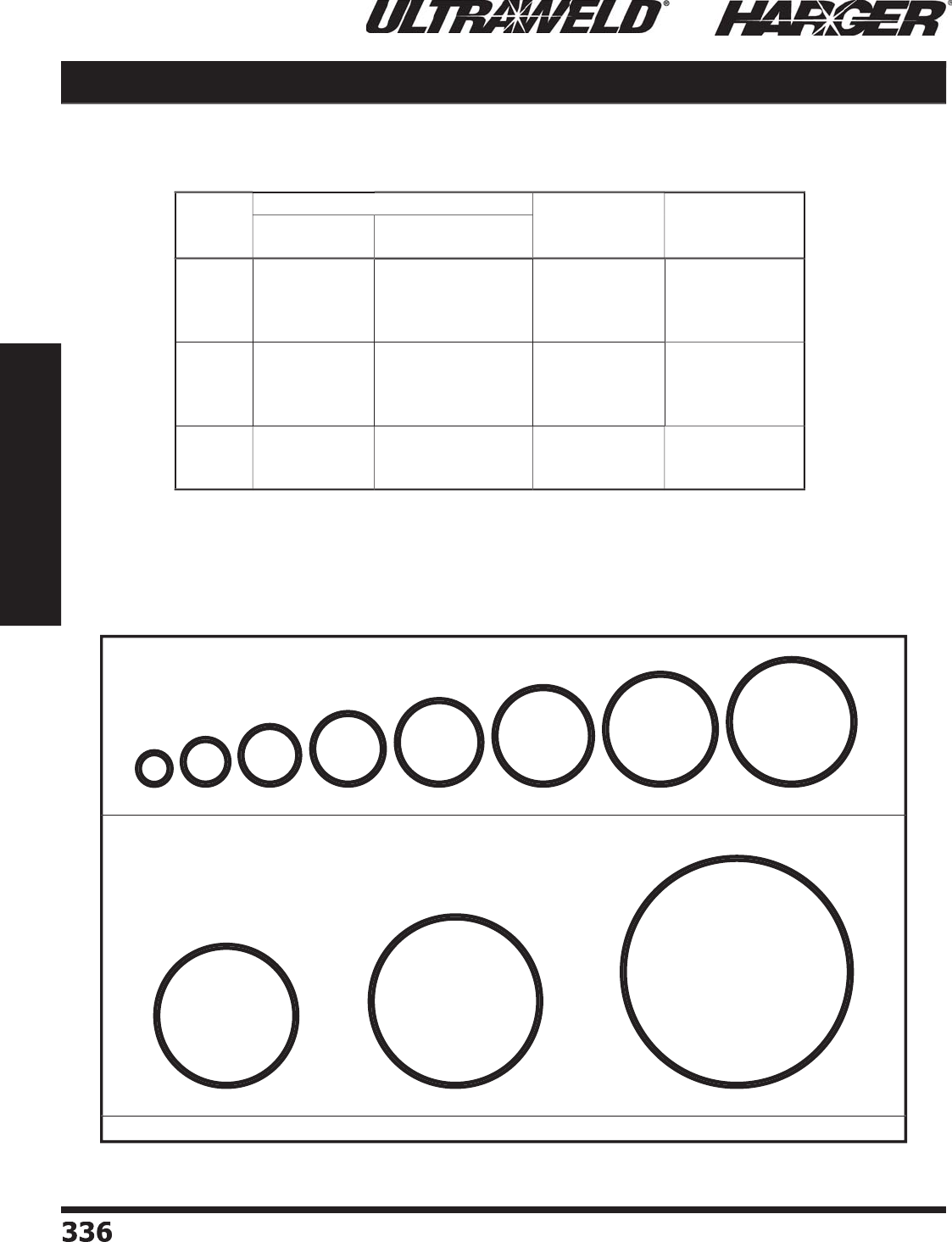
H
ar
g
er Li
g
htnin
g
& Groundin
g
•
©
2012 Phone 847-548-8700 • Fax 847-548-8755 • U.S. 800-842-743
7
336336
Section 5
Ultraweld® Exothermic Connections
S
ect
io
n 5.12
Rebar
Si
ze
s
N
o
minal Dimensi
o
ns E
q
uivalent
C
o
pp
er
S
ize
s*
Rebar C
o
de
D
i
ameter
Inche
s
C
r
o
ss-secti
o
na
l
Area-S
q
. Inches
3
4
5
6
.3
7
5
"
.50
"
.6
2
5
"
.
7
5
"
.
11"
.
2
0
"
.3
1"
.
44"
9
AW
G
7
5
3
3
4
5
6
7
8
9
1
0
.
875"
1"
1.128"
1.27"
.60
"
.
79"
1"
1.27"
2
1
1
/
0
2
/
0
7
8
9
1
0
11
14
18
1.41"
1.
6
9
3
"
2.2
5
7"
1.
56
"
2.2
5
"
4
"
3
/
0
250
MCM
450
11
14
18
Reinforcin
g
Bars
Technical Information Bars
.3
7
5”
.50”
.
6
2
5”
6
.
7
5”
7
.8
7
5”
8
1
”
9
1.12
8”
1
0
1.27
”
1
1
1.41
”
14
1.
693”
1
8
2.2
5
7
”
3
4
5
d
i
a
m
e
t
e
r
d
i
a
m
e
t
e
r
Rebar Size Chart
*
Based on 8% IACS, rounded to the next hi
g
her commercial copper size.

H
ar
g
er Li
g
htnin
g
& Groundin
g
•
©
2012 Phone 847-548-8700 • Fax 847-548-8755 • U.S. 800-842-743
7
33
7
337
Section 6
Technical Assistance
S
ect
io
n 6
Technical A
ss
i
s
tance
In
d
ex
Descr
i
pt
i
on Pa
g
e
6
.1 Li
g
htnin
g
Risk Assessmen
t
................................................................
338
6
.2 Structural Li
g
htnin
g
Protection System Specifi catio
n
............................
3
4
4
6
.3 Underwriters Laboratories Master Label Ins
p
ection Service
..................
348
6
.4 Typical Li
g
htnin
g
Protection Drawin
gs
................................................
3
49
6
.5 Li
g
htnin
g
Protection & Groundin
g
Detail
s
...........................................
353
6
.6 Wireless Communication Site LP & Groundin
g
System Specifi catio
n
......
364
6
.7 Wireless Communication Drawin
g
s & Detail
s
.......................................
3
7
0
6
.8 Si
g
nal Reference Grid System Specifi catio
n
.........................................
3
7
5
6
.9 Si
g
nal Reference Grid (SRG) Installation Instruction
s
..........................
3
79
6
.10 Groundin
g
& Bondin
g
for Communications System Specifi cation
(
ANSI-J-STD-607-A
)
..........................................................................
381
N
O
TE
:
O
ur catalo
g
drawin
g
s & details are available on
our CD version of this catalo
g
and our website.
Please contact us to request a Catalo
g
CD.

H
ar
g
er Li
g
htnin
g
& Groundin
g
•
©
2012 Phone 847-548-8700 • Fax 847-548-8755 • U.S. 800-842-743
7
338
338
Section 6
Technical Assistance
Har
g
er Li
g
htnin
g
& Groundin
g
i
s
p
leased to
p
resent the
Li
g
htnin
g
Ri
s
k A
ss
e
ss
ment
Gu
i
d
e
to
Aid in the Determinati
o
n
o
f the
Need for Li
g
htnin
g
Protectio
n
(p
er NFPA 780 2011 Edition
)
F
or years, architects, en
g
ineers, buildin
g
mana
g
ers, owners, and insurance
carriers have been seekin
g
a more professional method of evaluatin
g
the
need for li
g
htnin
g
protection.
In the past, the decision to provide li
g
htnin
g
protection was often based on
g
ambles and
g
uesswork by well-meanin
g
persons, not havin
g
specialized
trainin
g
in li
g
htnin
g
protection. Tra
g
ic and unnecessary losses have
o
ccurred because of this a
pp
roach.
N
ow, by use of this
g
uide, you may make a more accurate determination
re
g
ardin
g
the need for li
g
htnin
g
protection. Once the need for protection
has been established, loss of life and
p
ro
p
ert
y
can be avoided b
y
the
i
nstallation of an approved li
g
htnin
g
protection system.
In those s
p
ecial cases where
p
rofessional consultation or installation is
desired, Har
g
er Li
g
htnin
g
& Groundin
g
stands read
y
to be of service.
S
ect
io
n 6.1
Li
g
htnin
g
Risk Assessment
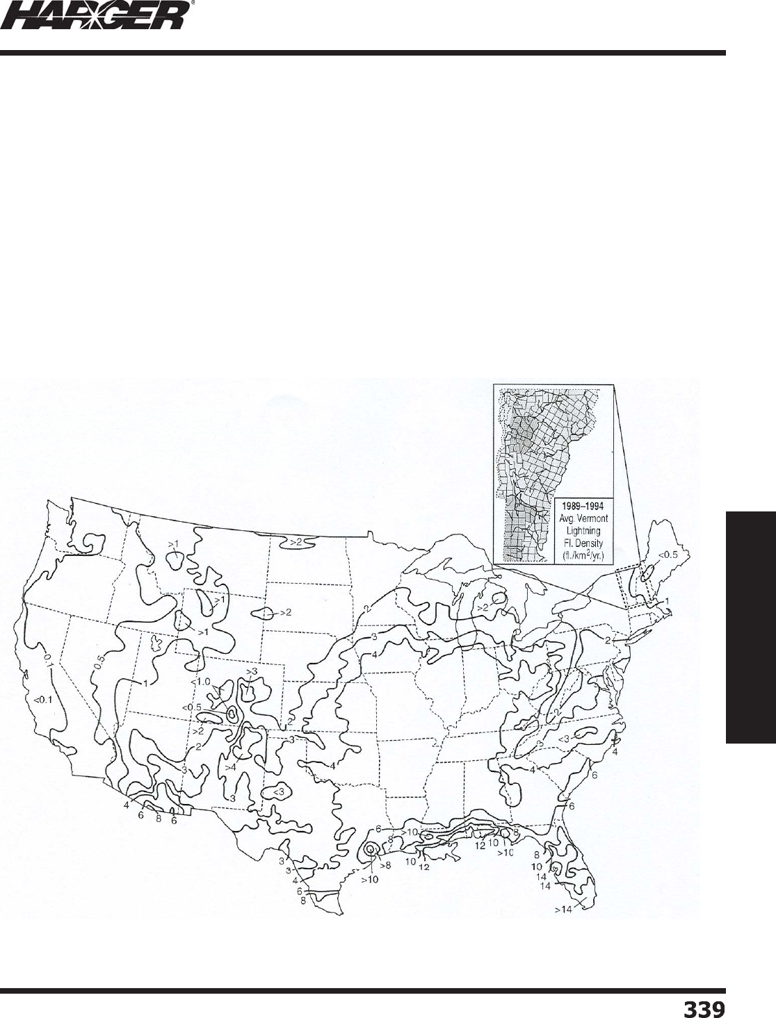
H
ar
g
er Li
g
htnin
g
& Groundin
g
•
©
2012 Phone 847-548-8700 • Fax 847-548-8755 • U.S. 800-842-743
7
33
9
339
Section 6
Technical Assistance
Fi
gu
re
r
1
1
:
Li
L
g
htnin
g
Flash Density
Ma
M
p
p
F
ew
ar
a
e
a
s
in
i
t
t
he
h
e
U
ni
te
t
d
St
a
tes
a
a
re free
fr
fr
om
m
m
t
t
hu
u
nd
n
er
r
r
st
o
rms
a
nd
t
he
he
ir
attendant hazards, b
ut
t
some
ar
r
r
ea
s
ha
ve
e
mor
e
st
or
o
ms
t
han
ot
ot
he
he
rs
s
.
Th
Th
e
ma
m
p
sh
s
ow
ow
w
s
th
t
e avera
g
e li
g
htnin
g
fl ash de
ns
ns
it
y in fl a
sh
s
es/km
2
/y
/y
ear -
fo
fo
o
o
r the
U
nite
d
St
a
te
e
s
.
L
i
g
htnin
g
data provided b
y
the U.S. National Li
g
htnin
g
Detection Network
TM
(
Measured li
g
htnin
g
fl ash densit
y
corrected for NLDN detection effi cienc
y)
1989-1998 Avera
g
e U.S. Li
g
htnin
g
Flash Densit
y
Flashes per Square Kilometer per
Year.
(
Courtesy Global Atmospherics, Inc.)
L
i
g
htnin
g
loss risk assessment involves the evaluation
o
f v
a
ri
ou
s criteri
a
t
o
d
etermine the risk
o
f l
o
ss
du
e
to li
g
htnin
g
. This
g
uide is desi
g
ned to assist in that
determination. As a
g
uide, it is not possible to cover
each special desi
g
n element that may render a
s
tructure more or less susceptible to li
g
htnin
g
dama
g
e.
In these s
p
ecial cases it is recommended the user seek
p
rofessional advice. Personal and economic factors are
v
er
y
im
p
ortant and must be considered in addition to
the assessment obtained by use of this
g
uide.
T
he probability that a structure or ob
j
ect will be struck
by li
g
htnin
g
is the product of the equivalent collection
area of the structure or ob
j
ect and the li
g
htnin
g
fl ash
densit
y
for the area that the structure is located.
T
his risk assessment method is a
g
uide that takes into
account the li
g
htnin
g
fl ash density and the followin
g
f
a
ct
o
rs:
1. Buildin
g
environment
2. T
yp
e of constructio
n
3
. Structure occu
p
anc
y
4
.
S
tr
u
ct
u
re c
o
ntent
s
5
. Li
g
htnin
g
stroke consequences
L
i
g
htnin
g
risk for a structure is the product of the
l
i
g
htnin
g
strike frequency and the consequence of the
s
trike t
o
the str
u
ct
u
re.
L
i
g
htnin
g
Flash Density (
N
g
)
- The
y
earl
y
number o
f
fl ashes to ground per square kilometer, lightning fl ash
g
density, is found in Fi
g
ure 1.
S
ect
io
n 6.1
Li
g
htnin
g
Risk Assessment
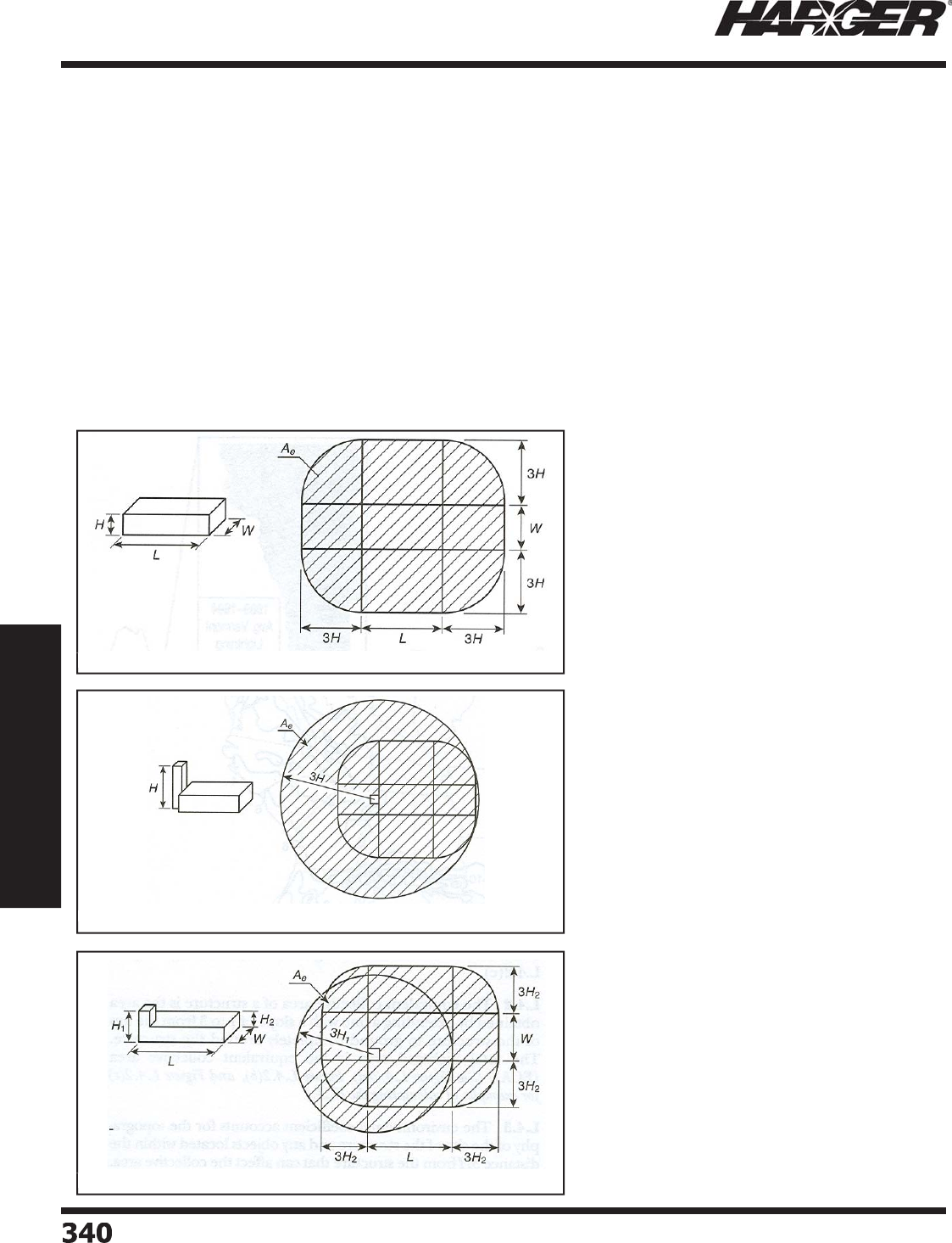
H
ar
g
er Li
g
htnin
g
& Groundin
g
•
©
2012 Phone 847-548-8700 • Fax 847-548-8755 • U.S. 800-842-743
7
3
4
0340
Section 6
Technical Assistance
Meth
o
d
:
Calculate and compare the expected Li
g
htnin
g
Strike Frequency (
N
d
) for the facility to the Tolerable Li
g
htnin
g
Strike
F
re
q
uenc
y
(N
c
)
.
S
tep 1: Determination of Expected Li
g
htnin
g
Strike Frequency (N
d
)
N
d
=
N
g
•
A
e
•
C
1 • 1
0
-
6
W
h
e
r
e
:
N
d
= the expected yearly li
g
htnin
g
strike frequency to the structure
N
g
= the yearly avera
g
e li
g
htnin
g
fl ash density in the re
g
ion where the structure is located (Determine value from
Figure 1)
g
A
e
= the e
q
uivalent collection area
(
m
2
) of the structure (Determine from Fi
g
ure 2
)
C
1 = the environmental coeffi cient
(
Determine value from Table 1
)
Fi
g
ure 2: Calculation of Equivalent Collection Volume (A
e
)
R
ectan
g
ular Structure
S
tr
u
ct
u
re where
a
Pr
o
minent P
a
rt
E
ncom
p
asses All Portions of the
Lo
wer P
a
rt
o
f the Str
u
ct
u
re.
S
tr
u
ct
u
re where Pr
o
minent P
a
rt
E
ncom
p
asses a Portion of the
Lo
wer P
a
rt
o
f the Str
u
ct
u
re.
For a rectan
g
ular structure, A
e
= LW + 6H
(
L + W
)
+
π
9H
2
.
A
e
=
π
9H
2
For com
p
lex structures determine the e
q
uivalent collective area.
S
ect
io
n 6.1
Li
g
htnin
g
Risk Assessment

H
ar
g
er Li
g
htnin
g
& Groundin
g
•
©
2012 Phone 847-548-8700 • Fax 847-548-8755 • U.S. 800-842-743
7
3
41
341
Section 6
Technical Assistance
S
tep 2: Tolerable Li
g
htnin
g
Frequency (N
c
)
T
he tolerable li
g
htnin
g
frequency (
N
c
) is a measure of the dama
g
e risk to the structure includin
g
factors affectin
g
risks to the structure, environment, and mone
y
loss.
It is c
a
lc
u
l
a
te
d
a
s f
o
ll
o
ws:
W
here v
a
l
u
es f
o
r
C
2
,
C
3
,
C
4
a
n
d
C
5
are determined from Tables 2 throu
g
h 5.
N
c
=
1.
5
x 1
0
-
3
C
2
•
C
3
•
C
4
•
C
5
Relative Structure L
o
cati
on
C
1
S
tructure located within a space containin
g
structures or trees of the
s
ame hei
g
ht or taller within a distance of 3
H
0
.
25
S
tructure surrounded b
y
smaller structures within a distance of 3
H
0
.
5
Isolated structure, no other structures within a distance of 3
H
1
Isolated structure on a hillto
p
2
Table 1: Envir
o
nmental C
o
effi cient
C
1
N
ote: 3H = 3 times the hi
g
hest point in the structure
C
2
S
tr
u
ct
u
re Metal R
oof
N
o
nmetallic R
oof
Flammable R
oo
f
M
et
a
l
0
.
5
1
2
No
nmet
a
lli
c
11
2
.
5
F
l
a
mm
ab
l
e
2
2
.
5
3
Table 2: Determinati
o
n
o
f Structural C
o
effi cient
C
2
S
tructural C
o
ntents
C
3
Lo
w v
a
l
u
e
a
n
d
n
o
nfl
a
mm
ab
le
0
.
5
S
t
a
n
d
v
a
l
u
e
a
n
d
n
o
nfl
a
mm
ab
l
e
1
H
i
g
h value, moderately fl ammable
2
E
xce
p
tional value, fl ammable, com
p
uter or electronic
s
3
E
xce
p
tional value, irre
p
laceable cultural content
s
4
Table 3: Determinati
o
n
o
f Structural C
o
ntents C
o
effi cient
C
3
S
ect
io
n 6.1
Li
g
htnin
g
Risk Assessment
H
ar
g
er Li
g
htnin
g
& Groundin
g
•
©
2012 Phone 847-548-8700 • Fax 847-548-8755 • U.S. 800-842-743
7
3
42
342
Section 6
Technical Assistance
S
te
p
3: Determine Protection Leve
l
Compare Step 1 Expected Li
g
htnin
g
Frequency (
N
d
) to Step 2 Tolerable Li
g
htnin
g
Frequency (
N
c
)
.
If N
d
>
N
c
then a li
g
htnin
g
protection system should be installed.
If N
d
<
N
c
then a li
g
htnin
g
protection system can be optional.
T
he risk assessment has been ada
p
ted from and
conforms to the Li
g
htnin
g
Risk Assessment presented
i
n NFPA 780-2011, Annex L. NFPA 780-2011 can be
p
urchased directl
y
from the National Fire Protection
Association (http://www.nfpa.or
g
/).
S
tructural C
o
ntents
C
4
U
noccu
p
ied
0
.
5
N
ormall
y
occu
p
ied 1
D
iffi cult to evaluate or risk of
p
ani
c
3
Table 4: Determination of Structural Occu
p
anc
y
Coeffi cient
C
4
S
tructural C
o
ntents
C
5
Continuit
y
of facilit
y
services not re
q
uired, no environmental im
p
act 1
Continuit
y
of facilit
y
services re
q
uired, no environmental im
p
ac
t
5
Conse
q
uences to the environmen
t
1
0
Table 5: Determination of Li
g
htnin
g
Consequence Coeffi cient
C
5
S
ect
io
n 6.1
Li
g
htnin
g
Risk Assessment
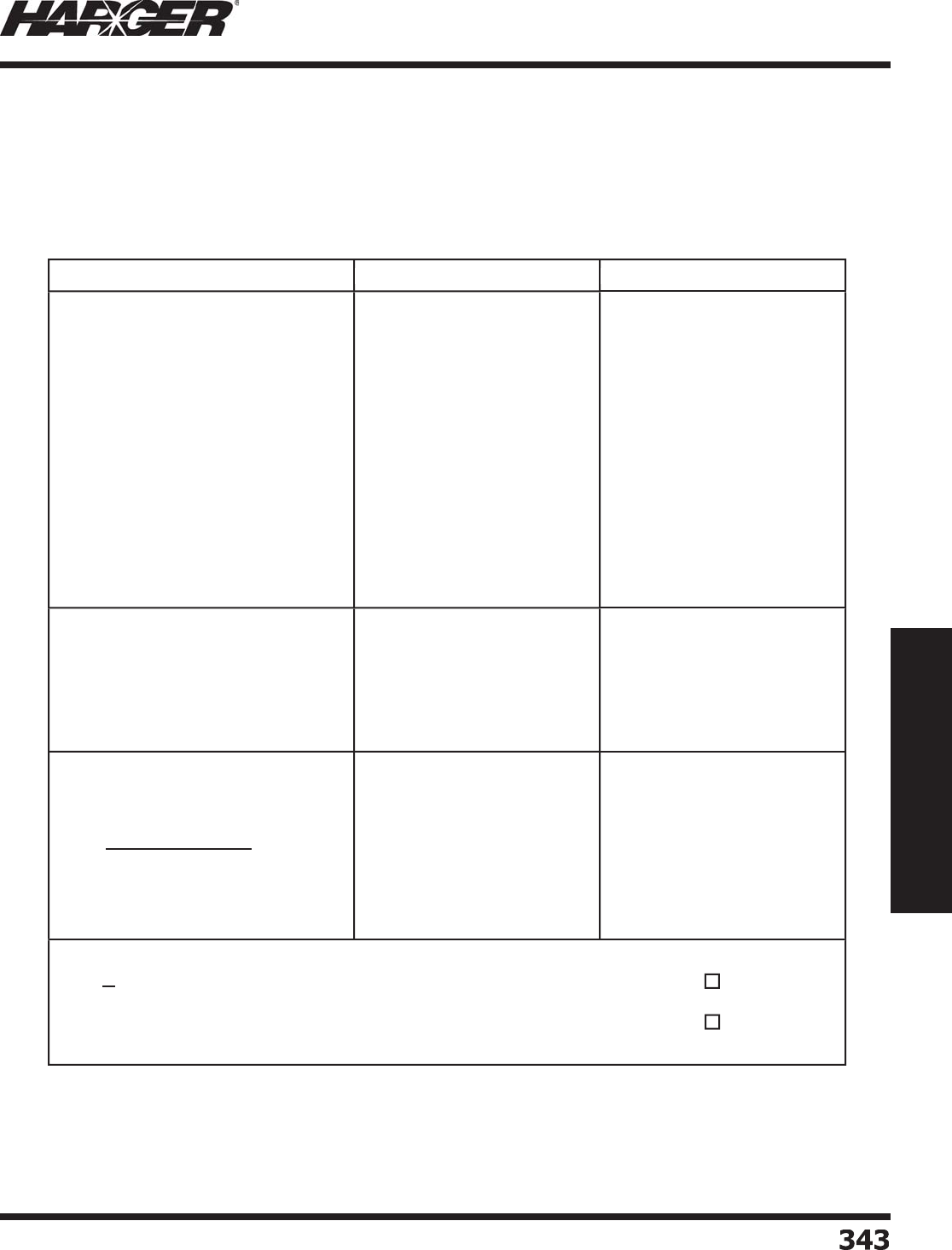
H
ar
g
er Li
g
htnin
g
& Groundin
g
•
©
2012 Phone 847-548-8700 • Fax 847-548-8755 • U.S. 800-842-743
7
3
4
3
343
Section 6
Technical Assistance
P
ro
j
ect: _________________________________________
D
ate:
_______________________
Data Input / Equations Computation Results
Eq
uivalent collection volume area.
A
e
= LW + 6H
(
L + W
)
+
π
9
H
2
(
for a rectan
g
ular structure
)
or
A
e
=
π
9
H
2
(
structure with a
p
rominent
p
ar
t
encompassin
g
all lower parts of structure
)
E
xpected li
g
htnin
g
strike frequenc
y
t
o
the str
u
ct
u
re
N
d
=
N
g
•
A
e
•
C
1 • 1
0
-
6
T
olerable li
g
htnin
g
frequency to
the str
u
ct
u
re.
If
N
d
<
N
c
- Li
g
htnin
g
Protection System may be optional
If
N
d
>
N
c
- Li
g
htnin
g
Protection System should be installed
L
=
W
=
H
=
H
2
=
or
H
=
A
e
=
N
g
=
A
e
=
C
1
=
N
d
=
C
2
=
C
3
=
C
4
=
C
5
=
N
c
=
N
c
=
1.
5
x 1
0
-
3
C
2
•
C
3
•
C
4
•
C
5
Li
g
htnin
g
Risk Assessment Worksheet
S
ect
io
n 6.1
Li
g
htnin
g
Risk Assessment

H
ar
g
er Li
g
htnin
g
& Groundin
g
•
©
2012 Phone 847-548-8700 • Fax 847-548-8755 • U.S. 800-842-743
7
3
4
4344
Section 6
Technical Assistance
Section 26 41 13 (Formerly 16670) – Structural Lightning Protection System Specifi cation
Part 1 –
G
ENERA
L
1.01 Summar
y
:
a. Provide a complete li
g
htnin
g
protection system for the buildin
g
(s) or structures included on the
contract drawin
g
s. The system shall provide safety for the buildin
g
, the buildin
g
s contents and
occupants by preventin
g
dama
g
e caused by li
g
htnin
g
. The desi
g
n of this system is to be in strict
accordance with this section of the specifi cations and all contract drawin
g
s that apply.
b. The li
g
htnin
g
protection system shall be installed by a fi rm actively en
g
a
g
ed in the installation of
Master Labeled Li
g
htnin
g
Protection Systems and shall be so listed by Underwriters Laboratories
Inc. The com
p
leted s
y
stem shall com
p
l
y
with the latest editions of the Installation Re
q
uirements for
Li
g
htnin
g
Protection Systems, UL96A and of the National Fire Protection Association’s Li
g
htnin
g
Protection Standard, NFPA 780.
c. The work covered under this section of the specifi cation consists of furnishin
g
labor, materials and
services required for the completion of a functional and unobtrusive li
g
htnin
g
protection system
approved by the architect, en
g
ineer and Underwriters Laboratories Inc.
1.02 References: The completed li
g
htnin
g
protection system shall comply with the latest issue of the followin
g
standards and form a
p
art of this s
p
ecifi cation.
a. NFPA 780, Standard for the Installation of Li
g
htnin
g
Protection Systems.
b. UL 96A, Installation Requirements for Li
g
htnin
g
Protection Systems
1.
03
S
ub
mitt
a
ls:
a. Shop drawin
g
s shall be submitted to the architect and en
g
ineer for approval prior to
commencement of the installation. Shop drawin
g
are to show the extent of the system layout
desi
g
ned specifi cally for the buildin
g
(s) or structures included in the contract drawin
g
s alon
g
with
details of the
p
roducts to be used in the installation.
1.04 Qualit
y
Assurance:
a. The installin
g
contractor shall furnish a UL Master Label or Letter of Findin
g
s upon completion of
the inst
a
ll
a
ti
o
n.
Part 2 – PR
O
D
U
CT
S
2.
0
1 St
a
n
da
r
d
a. All materials used in the installation shall be new and shall comply in wei
g
ht, size and composition
as re
q
uired b
y
UL 96A and NFPA 780 and shall be labeled or listed b
y
Underwriters Laboratories
Inc. for use in li
g
htnin
g
protection systems. The system furnished under this specifi cation shall be
the standard product of a manufacturer re
g
ularly en
g
a
g
ed in the production of li
g
htnin
g
protection equipment. The manufacturer shall be listed by UL as a reco
g
nized manufacturer of
li
g
htnin
g
protection components.
2.02 Acce
p
table Manufacturer
s
a. Har
g
er Li
g
htnin
g
Protection & Groundin
g
301 Zie
g
ler Drive, Grayslake, IL 60030
847-548-8700 ● 800-842-7437 ● Fax 847-548-8755
E-mail: har
g
ersales@har
g
er.com ● Website: www.har
g
er.com
S
ect
io
n 6.2
S
tructural Li
g
htnin
g
Protection System Specifi catio
n

H
ar
g
er Li
g
htnin
g
& Groundin
g
•
©
2012 Phone 847-548-8700 • Fax 847-548-8755 • U.S. 800-842-743
7
3
4
5
345
Section 6
Technical Assistance
Section 26 41 13 (Formerly 16670) – Structural Lightning Protection System
Specifi cation
2.
03
M
a
teri
a
l
s
a. Class I materials shall be used on structures that do not exceed 75 feet in hei
g
ht and Class II
materials shall be used on structures that are 75 feet or hi
g
her above avera
g
e
g
rade.
b. Copper materials shall not be mounted on aluminum surfaces includin
g
Galvalume,
g
alvanized steel
and zinc; this includes these materials that have been
p
ainted.
c. Aluminum materials shall not come into contact with earth or where ra
p
id deterioration is
p
ossible.
Aluminum materials shall not come into contact with co
pp
er surfaces.
2.
0
4 Air Termin
a
l
s
a. Air terminals shall pro
j
ect a minimum of ten inches above the ob
j
ect or area it is to protect and
shall be located at intervals not exceedin
g
20’-0” alon
g
rid
g
es and alon
g
the perimeter of fl at
or
g
ently slopin
g
roofs (fl at or
g
ently slopin
g
roofs include roofs that have a pitch less than 3:12).
Flat or
g
ently slopin
g
roofs exceedin
g
50’-0” in width shall be protected with additional air terminals
located at intervals not exceedin
g
50’. Air terminals shall be located within two feet of roof ed
g
es
and outside corners of
p
rotected areas.
b. Air terminals shall be installed on stacks, fl ues, mechanical units and other metallic ob
j
ects not
located within a zone of
p
rotection and which have an ex
p
osed metal thickness less than 3/16 of
an inch. Ob
j
ects havin
g
an exposed metal thickness 3/16 of an inch or
g
reater shall be connected
to the li
g
htnin
g
protection system as required by the specifi ed standards usin
g
main size conductor
and bondin
g
plates havin
g
a minimum of 3 square inches of surface contact area.
c. Air terminal bases shall be securel
y
fastened to the structure in accordance the s
p
ecifi ed standards
includin
g
the use of adhesive that is compatible with the surface it is to be used on or stainless
steel f
a
steners.
d. Main conductors shall be sized in accordance with the s
p
ecifi ed standards for Class I or Class II
structures and shall
p
rovide a two wa
y
horizontal or downward
p
ath from each air terminal to
connections with the
g
round system. Conductors shall be free of excessive splices and no bend of
a conductor shall form a fi nal included an
g
le of less than neither 90 de
g
rees nor have a radius of
bend less than 8 inches.
e. Down conductors shall be sized in accordance with the s
p
ecifi ed standards and in no case shall
be smaller than the main roof conductor. Down conductors shall be spaced at intervals avera
g
in
g
not more than 100 feet around the
p
erimeter of the structure. In no case shall a structure have
fewer than two down conductors. Where down conductors are installed ex
p
osed on the exterior of
a structure and are sub
j
ect to physical dama
g
e or displacement,
g
uards shall be used to protect the
conductor a minimum of 6 feet above
g
rade. Metallic
g
uards shall be bonded at each end.
f. In case of structural steel frame construction, down conductors ma
y
be omitted and roof
conductors shall be connected to the structural steel frame at intervals not exceedin
g
100 feet
alon
g
the perimeter of the structure.
S
ect
io
n 6.2
S
tructural Li
g
htnin
g
Protection System Specifi catio
n

H
ar
g
er Li
g
htnin
g
& Groundin
g
•
©
2012 Phone 847-548-8700 • Fax 847-548-8755 • U.S. 800-842-743
7
3
4
6346
Section 6
Technical Assistance
Section 26 41 13 (Formerly 16670) – Structural Lightning Protection System
Specifi cation
2.
05
R
oo
f Penetr
a
ti
o
ns
a. Roof
p
enetrations re
q
uired for down conductors or for connection to structural steel framework
shall be made usin
g
thru-roof assemblies with solid riser bars and appropriate roof fl ashin
g
.
Conductors shall not pass directly throu
g
h the roof. The roofi n
g
contractor shall furnish and
install the materials required to properly seal all roof penetrations of the li
g
htnin
g
protection
components and any additional roofi n
g
materials or preparations required by the roofi n
g
manufacturer for li
g
htnin
g
conductor runs to assure compatibility with the warranty for the roof
includin
g
roof pads that may be required to protect the roof under each of the li
g
htnin
g
protection
com
p
onen
t
s.
2.
06
Gr
ou
n
d
Termin
a
ti
o
ns:
a. Ground electrodes shall be copper clad steel and a minimum 5/8” diameter and 10 feet lon
g
. A
g
round electrode shall be provided for each down conductor. The down conductor shall be
connected to the
g
round electrode usin
g
a bronze
g
round rod clamp havin
g
a minimum of 1 ½”
contact between the
g
round electrode and the conductor measured parallel to the axis of the
g
round electrode, or by an Ultraweld exothermically welded connection. Ground electrodes shall
be located a minimum of 2 feet below
g
rade and shall be installed below the frost line where
possible (excludin
g
shallow topsoil conditions).
b. Where the structural steel framework is utilized as the down conductor for the system,
g
round
terminals shall be connected to columns around the
p
erimeter of the structure at intervals
avera
g
in
g
not more than 60 feet apart. Columns shall be
g
rounded usin
g
either bondin
g
plates
havin
g
8 square inches of surface contact area or by Ultraweld exothermically welded connections.
c. All
g
round electrodes shall be interconnected with a
g
round loop conductor on structures that
exceed 60 feet in hei
g
ht. The
g
round loop conductor shall be sized in accordance with the specifi ed
st
a
n
da
r
d
s
a
n
d
in n
o
c
a
se sh
a
ll
b
e sm
a
ller th
a
n the m
a
in r
oo
f c
o
n
du
ct
o
r.
2.07 Equipotential Groundin
g
a. Common interconnection of all
g
rounded systems within the buildin
g
shall be ensured by
interconnectin
g
to the li
g
htnin
g
protection system usin
g
main size conductor and fi ttin
g
s.
b. This interconnection shall include but is not limited to the electrical service, tele
p
hone and antenna
system
g
rounds as well as all under
g
round metallic pipin
g
systems includin
g
water,
g
as and sewer.
Interconnection to a
g
as or water line shall be made on the customer’s side of the meter.
c. Grounded metal bodies located within the required bondin
g
distance as determined by the bondin
g
distance formula in the latest edition of NFPA-780 Standard for the Installation of Li
g
htnin
g
Protection Systems shall be bonded to the li
g
htnin
g
protection system usin
g
the required bondin
g
c
o
n
du
ct
o
rs
a
n
d
c
o
nnecti
o
ns.
2.08 Sur
g
e Protectio
n
a. Sur
g
e suppression shall be provided at all power service entrances and at entrances of conductive
si
g
nal, data and communication services.
S
ect
io
n 6.2
S
tructural Li
g
htnin
g
Protection System Specifi catio
n

H
ar
g
er Li
g
htnin
g
& Groundin
g
•
©
2012 Phone 847-548-8700 • Fax 847-548-8755 • U.S. 800-842-743
7
3
47
347
Section 6
Technical Assistance
Section 26 41 13 (Formerly 16670) – Structural Lightning Protection System
Specifi cation
Part
3
– EXEC
U
TI
O
N
3
.
0
1 Inst
a
ll
a
ti
on
a. The installation shall be installed by an UL listed li
g
htnin
g
protection installation company.
3
.
0
2 C
oo
r
d
in
a
ti
on
a. Coordinate the installation of the li
g
htnin
g
protection system with other trade
s
b. Coordinate all roof penetrations, fasteners and adhesive with the roofi n
g
contractor prior to installin
g
an
y
materials on the roof.
3.03 Ins
p
ection and Certifi catio
n
a
. New
S
tr
u
ct
u
res:
i. Upon completion of the installation of the li
g
htnin
g
protection system the contractor shall furnish
the UL Master Label issued b
y
Underwriters Laboratories Inc.
b
. A
dd
iti
o
ns
o
r ren
o
v
a
ti
o
ns:
i. If the protected structure is an addition to or is attached to an existin
g
structure that does not
have a functionin
g
li
g
htnin
g
protection system, the contractor shall certify that the new system
installed complies with the specifi ed standards and shall advise the owner on the li
g
htnin
g
protection work required on the existin
g
structure so that a Master Label may be obtained.
ii. If the protected structure is an addition to or is attached to an existin
g
structure that does have a
li
g
htnin
g
protection system the contractor shall advise the owner of any additional work that may
be required in order to brin
g
the existin
g
li
g
htnin
g
protection system into compliance with the
s
p
ecifi ed standards and thus
q
ualif
y
for a Reconditioned Master Label from Underwriters
L
abo
r
a
t
o
ries Inc.
END
O
F SECTI
O
N 2
6
41 1
3
S
ect
io
n 6.2
S
tructural Li
g
htnin
g
Protection System Specifi catio
n

H
ar
g
er Li
g
htnin
g
& Groundin
g
•
©
2012 Phone 847-548-8700 • Fax 847-548-8755 • U.S. 800-842-743
7
348
348
Section 6
Technical Assistance
Master Label Ins
p
ection Service
Har
g
er Li
g
htnin
g
& Groundin
g
i
s
a
s
ub
scri
b
er t
o
the MASTER LABEL CERTIFICATE
P
ROGRAM of Underwriters Laboratories, Inc.
(
UL
)
as well as to the Factor
y
Ins
p
ection
P
ro
g
ram for Li
g
htnin
g
Protection Components.
U
nder the factory inspection service our li
g
htnin
g
protection conductors and components
are re
g
ularly inspected and tested by UL representatives. Har
g
er components bear the UL
l
abel or listed mark dependin
g
on the type of component.
T
he Master Label Certifi cate is available for complete Li
g
htnin
g
Protection System
i
nstallations that have been installed usin
g
only UL listed or labeled components in
accordance with the “Installation Requirements for Li
g
htnin
g
Protection Systems”, UL96A.
U
nderwriters Laboratories is a not-for-profi t or
g
anization en
g
a
g
ed in testin
g
for public
s
afety. It is THE ONLY third party testin
g
and inspection service available to purchasers
o
f li
g
htnin
g
protection systems that DOES NOT have direct industry involvement. It is not
i
nvolved in the marketin
g
, manufacture, or installation of li
g
htnin
g
protection systems
o
r components. Underwriters Laboratories has been active in the testin
g
and inspection
o
f li
g
htnin
g
protection components and systems since 1908. Their experience in the
s
afety testin
g
fi eld has earned them worldwide reco
g
nition and respect. UL is not a trade
o
r
g
anization with proprietary interests.
U
nderwriters inspection service for the li
g
htnin
g
protection industry involves two separate
i
nspection steps. A UL inspector inspects the li
g
htnin
g
protection components and labels
are a
pp
lied to conductors and air terminals at the factor
y
. A UL re
p
resentative then ins
p
ects
the installation of the completed li
g
htnin
g
protection system The UL Master Label Certifi cate
w
ill be issued within 48 hours of the com
p
letion of the ins
p
ection or after variances are
corrected. The UL Listed installer forwards the certifi cate to the owner, and can have the
certifi cate posted to the UL web site providin
g
proof that the li
g
htnin
g
protection system
i
s in com
p
liance with UL Standards. Certifi cates must be renewed ever
y
fi ve
y
ears which
re
q
uires another ins
p
ection b
y
UL.
Information on the UL Master Label Li
g
htnin
g
Protection Inspection Certifi cate Pro
g
ram can
b
e f
ou
n
d
a
t their we
b
site
http://www.ul.com/lightning/
p// /g g/
.
THERE IS N
O
S
U
BSTIT
U
TE F
O
R THE MASTER LABE
L
S
ect
io
n 6.3
U
nderwriters Lab
o
rat
o
ries Inc.
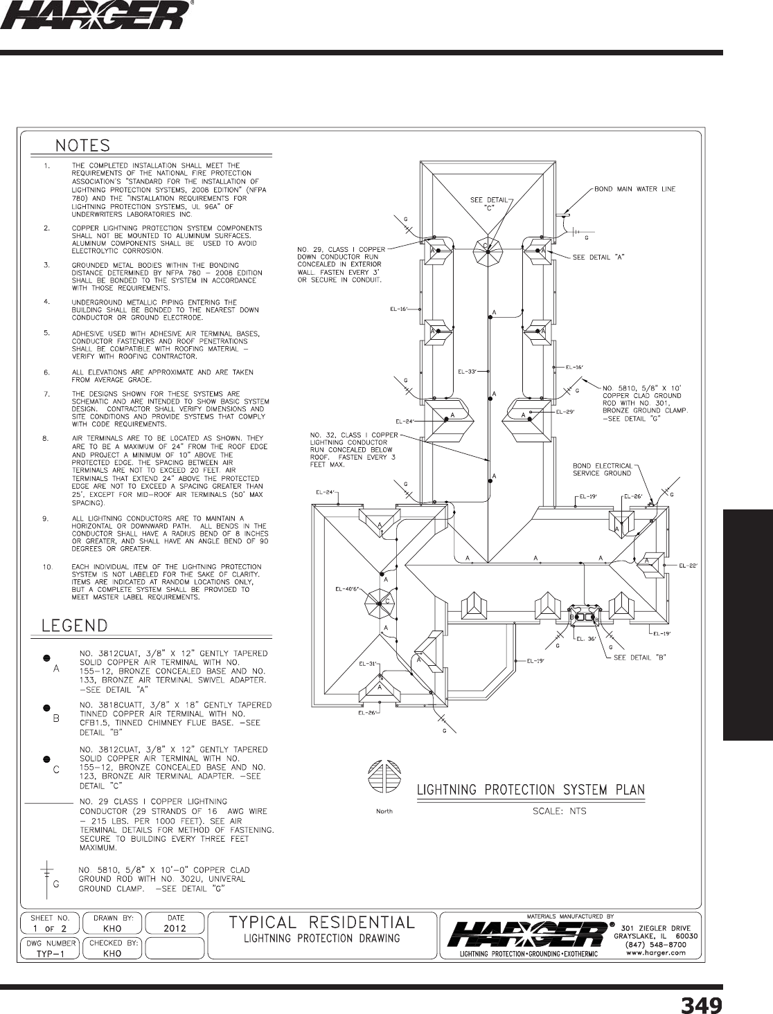
H
ar
g
er Li
g
htnin
g
& Groundin
g
•
©
2012 Phone 847-548-8700 • Fax 847-548-8755 • U.S. 800-842-743
7
3
49
349
Section 6
Technical Assistance
Residential Li
g
htnin
g
Protectio
n
S
ect
io
n 6.
4
Typical Li
g
htnin
g
Protection Drawin
g
s
2009
••
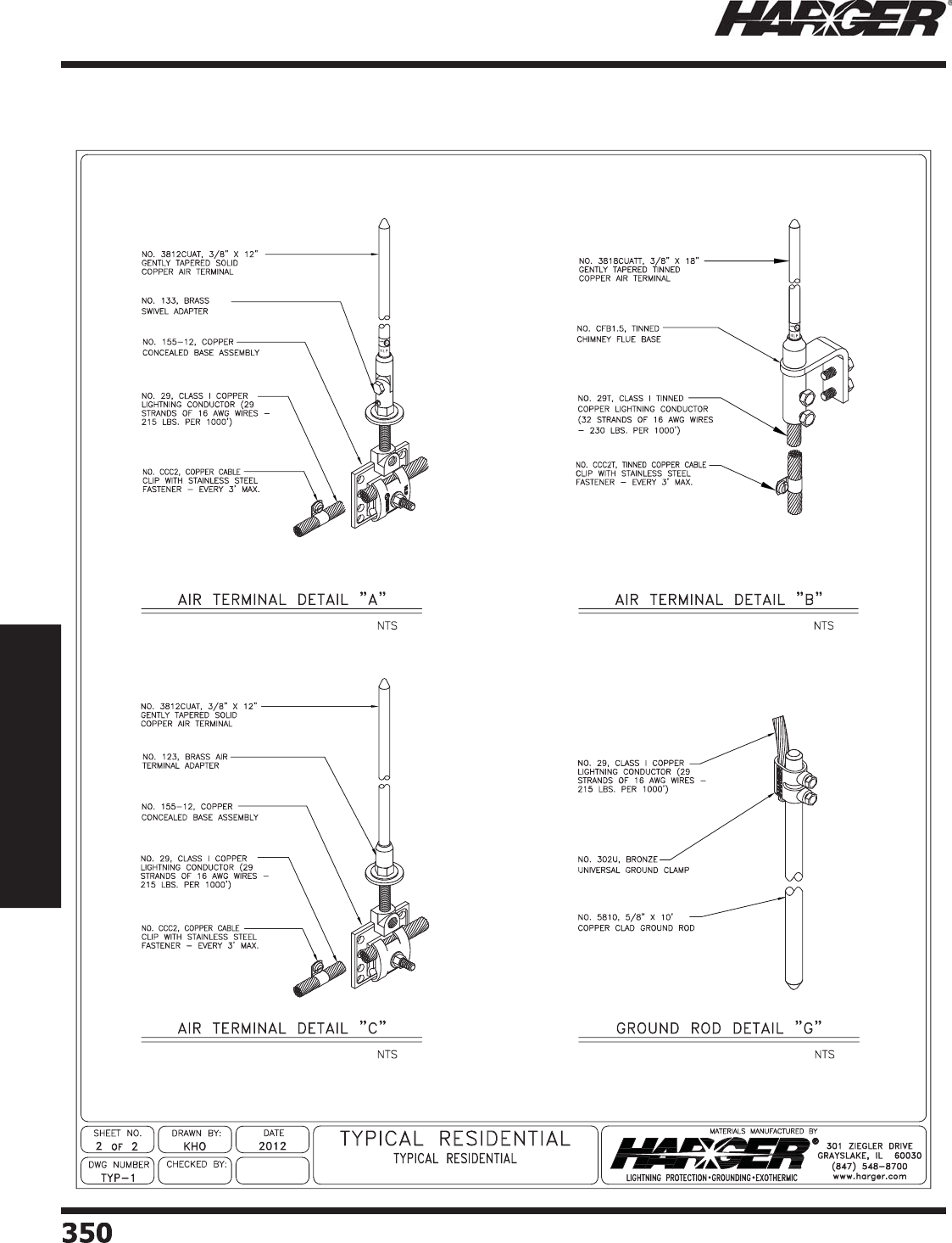
H
ar
g
er Li
g
htnin
g
& Groundin
g
•
©
2012 Phone 847-548-8700 • Fax 847-548-8755 • U.S. 800-842-743
7
350350
Section 6
Technical Assistance
Residential Li
g
htnin
g
Protectio
n
S
ect
io
n 6.
4
T
ypical Li
g
htnin
g
Protection Drawin
g
s
2009
••
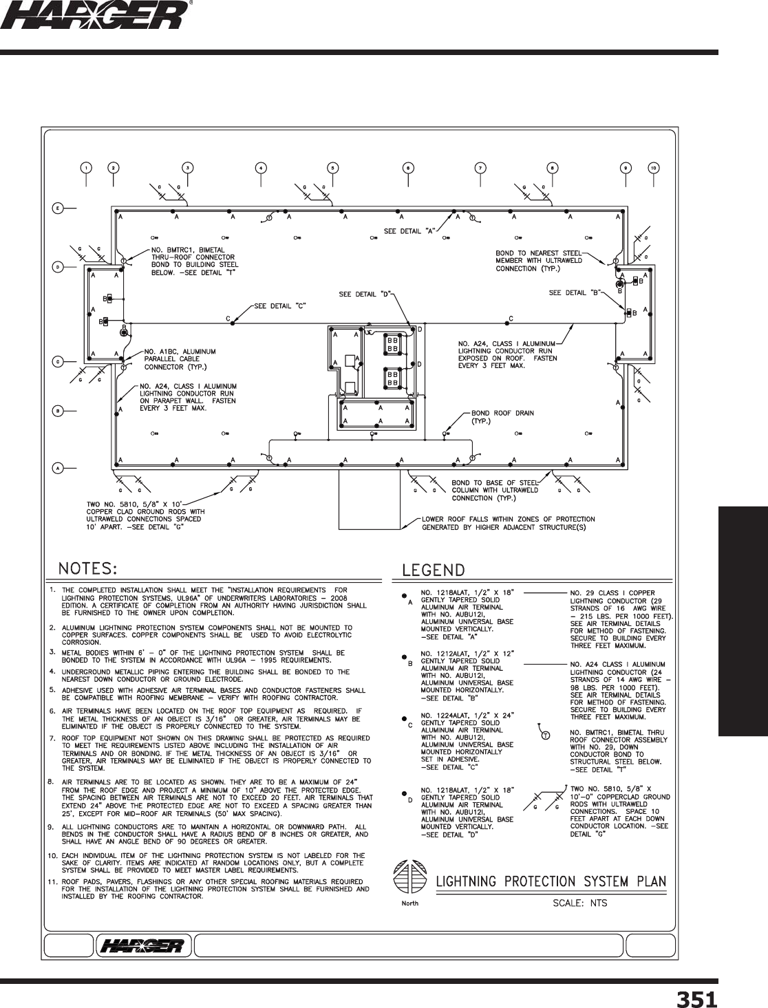
H
ar
g
er Li
g
htnin
g
& Groundin
g
•
©
2012 Phone 847-548-8700 • Fax 847-548-8755 • U.S. 800-842-743
7
35
1
351
Section 6
Technical Assistance
C
ommercial Li
g
htnin
g
Protectio
n
S
ect
io
n 6.
4
Typical Li
g
htnin
g
Protection Drawin
g
s
Typical Commercial Lightning Protection Drawing
© 2012
®SHEET NO.
1 OF 2
DATE
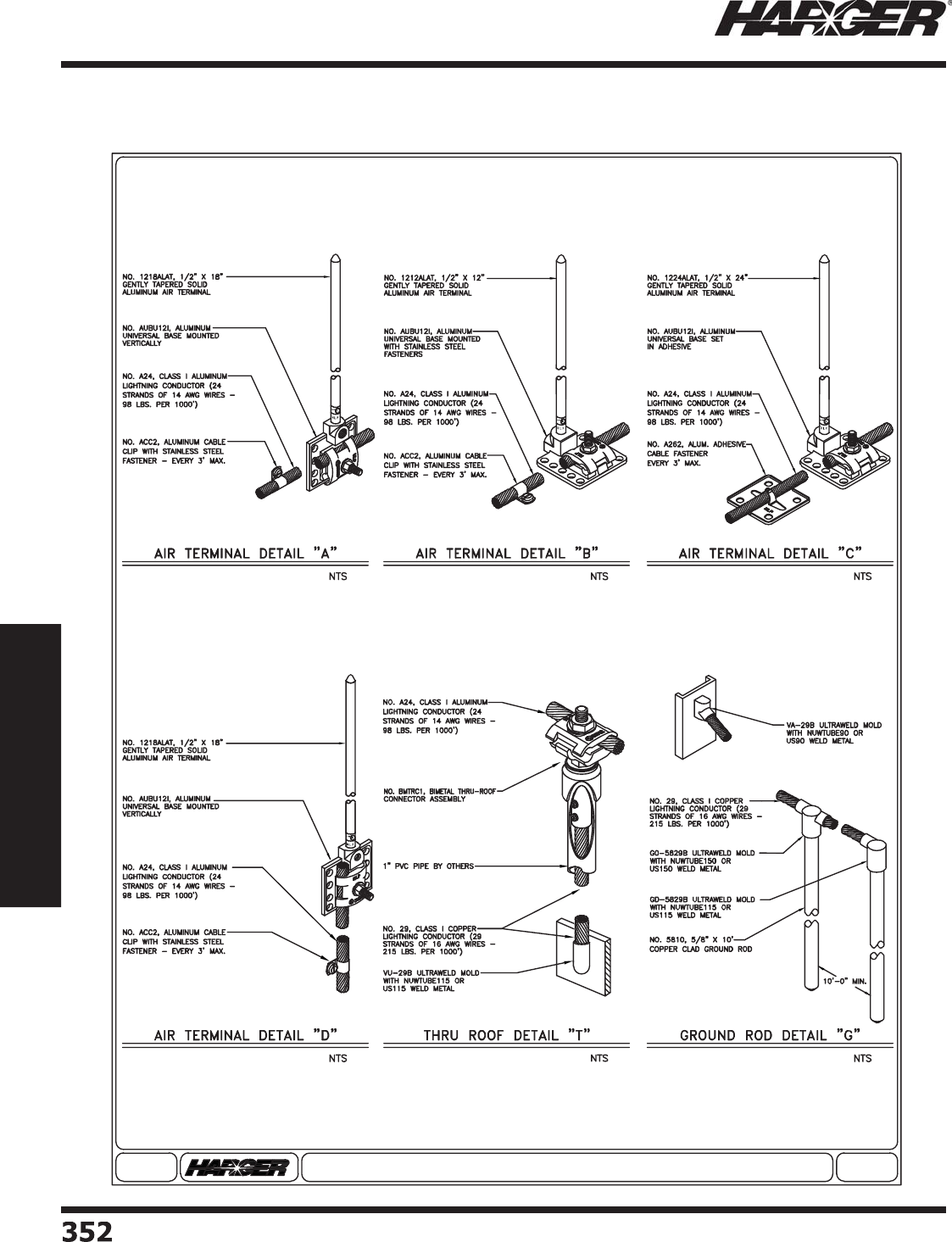
H
ar
g
er Li
g
htnin
g
& Groundin
g
•
©
2012 Phone 847-548-8700 • Fax 847-548-8755 • U.S. 800-842-743
7
35
2
352
Section 6
Technical Assistance
C
ommercial Li
g
htnin
g
Protectio
n
S
ect
io
n 6.
4
Typical Li
g
htnin
g
Protection Drawin
g
s
Typical Commercial Lightning Protection Drawing
© 2012
®SHEET NO.
2 OF 2
DATE
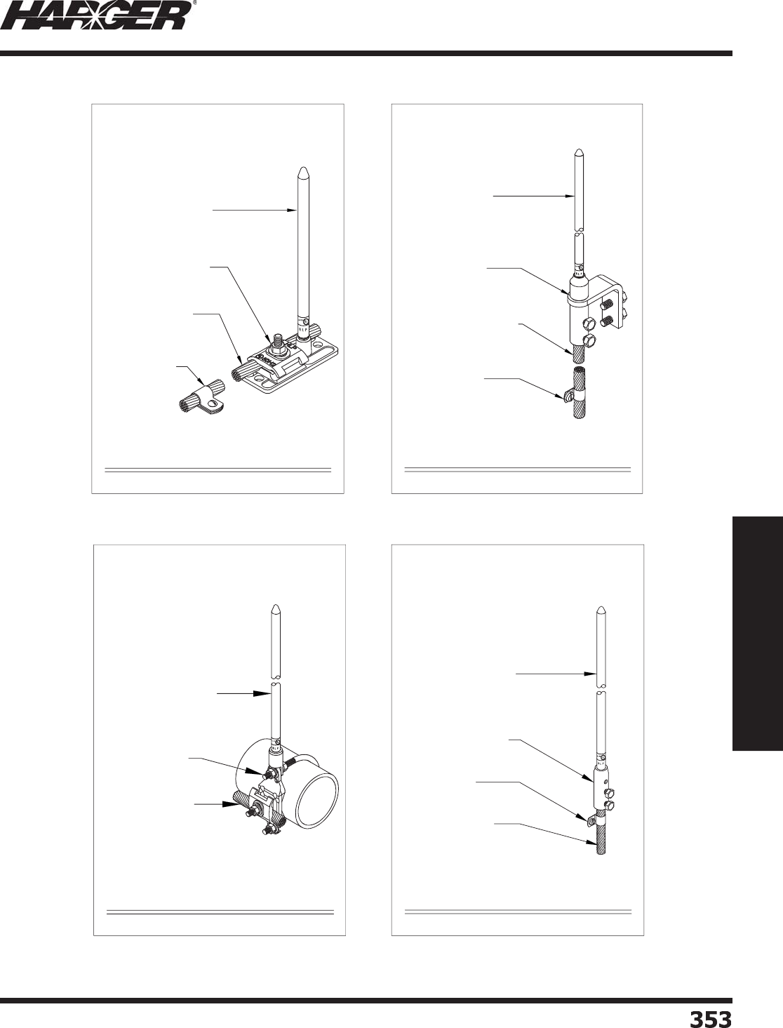
H
ar
g
er Li
g
htnin
g
& Groundin
g
•
©
2012 Phone 847-548-8700 • Fax 847-548-8755 • U.S. 800-842-743
7
353
353
Section 6
Technical Assistance
S
ect
io
n 6.5
Li
g
htnin
g
Protection & Groundin
g
Details
CUAT / ALAT - STYLE GENTLY
TAPERED AIR TERMINAL
151I - STYLE AIR TERMINAL BASE
151I - STYLE FLAT SURFACE
AIR TERMINAL BASE
CCC / ACC - STYLE
CABLE FASTENER
COPPER OR ALUMINUM,
CLASS I OR CLASS II
LIGHTNING PROTECTION
CONDUCTOR
NTS
HARGER LIGHTNING & GROUNDING
847-548-8700 800-842-7437 www.harger.com
2012
9
CFB - STYLE AIR TERMINAL BASE
CFB - STYLE CHIMNEY
FLUE AIR TERMINAL BASE
CUATT - STYLE GENTLY
TAPERED AIR TERMINAL
CCCT - STYLE CABLE
FASTENER
TINNED COPPER, CLASS I OR
CLASS II LIGHTNING
PROTECTION CONDUCTOR
NTS
HARGER LIGHTNING & GROUNDING
847-548-8700 800-842-7437 www.harger.com
2012
9
CUAT / ALAT - STYLE GENTLY
TAPERED AIR TERMINAL
PRB - STYLE PIPE AIR
TERMINAL BASE
COPPER OR ALUMINUM,
CLASS I OR CLASS II
LIGHTNING PROTECTION
CONDUCTOR
PRB - STYLE AIR TERMINAL BASE
NTS
HARGER LIGHTNING & GROUNDING
847-548-8700 800-842-7437 www.harger.com
2012
9
157 / 158 - STYLE AIR TERMINAL BASE
CUAT / ALAT - STYLE GENTLY
TAPERED AIR TERMINAL
157 / 158 - STYLE VERTICAL
AIR TERMINAL BASE
CCC / ACC - STYLE
CABLE FASTENER
COPPER OR ALUMINUM,
CLASS I OR CLASS II
LIGHTNING PROTECTION
CONDUCTOR
NTS
HARGER LIGHTNING & GROUNDING
847-548-8700 800-842-7437 www.harger.com
2012
9
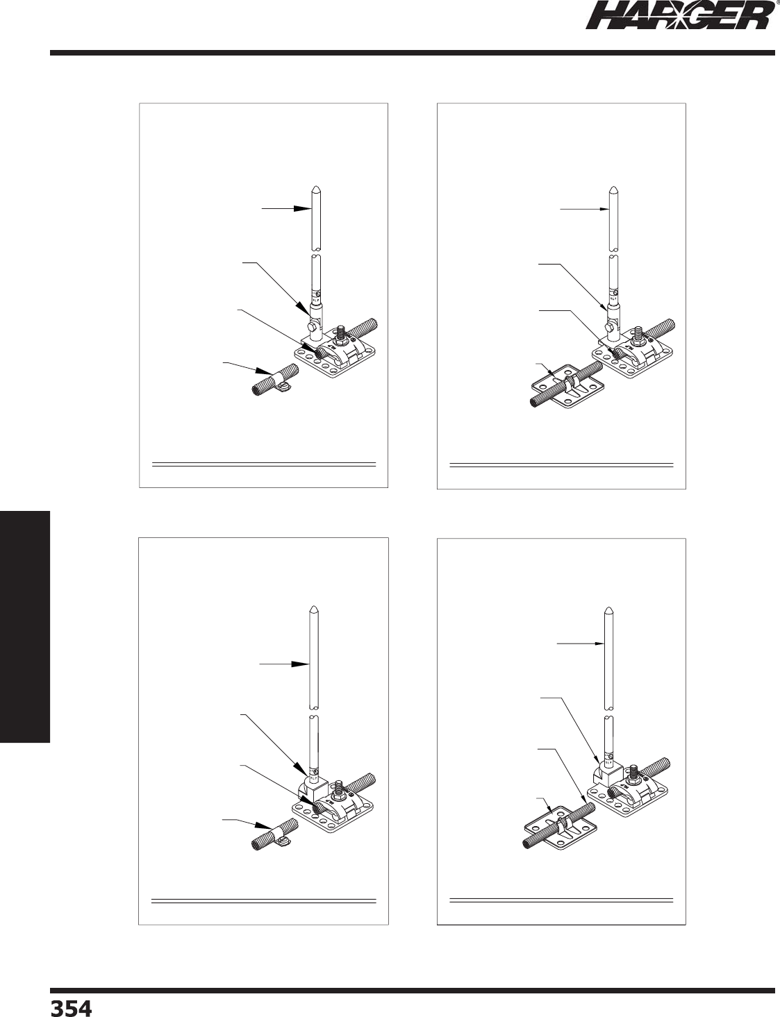
H
ar
g
er Li
g
htnin
g
& Groundin
g
•
©
2012 Phone 847-548-8700 • Fax 847-548-8755 • U.S. 800-842-743
7
354354
Section 6
Technical Assistance
S
ect
io
n 6.5
Li
g
htnin
g
Protection & Groundin
g
Details
UBS - STYLE AIR TERMINAL BASE WITH CC
CUAT / ALAT - STYLE GENTLY
TAPERED AIR TERMINAL
UBS - STYLE UNIVERSAL
SWIVAL AIR TERMINAL BASE
CCC / ACC - SERIES
CABLE FASTENER
COPPER OR ALUMINUM,
CLASS I OR CLASS II
LIGHTNING PROTECTION
CONDUCTOR
NTS
HARGER LIGHTNING & GROUNDING
847-548-8700 800-842-7437 www.harger.com
2012
9
UBS - STYLE AIR TERMINAL BASE WITH 262
CUAT / ALAT - STYLE GENTLY
TAPERED AIR TERMINAL
262 - SERIES ADHESIVE
CABLE FASTENER
COPPER OR ALUMINUM,
CLASS I OR CLASS II
LIGHTNING PROTECTION
CONDUCTOR
UBS - STYLE UNIVERSAL
SWIVAL AIR TERMINAL BASE
NTS
HARGER LIGHTNING & GROUNDING
847-548-8700 - 800-842-7437 - www.harger.com
© 2012
UBU - STYLE AIR TERMINAL BASE WITH CC
CUAT / ALAT - STYLE GENTLY
TAPERED AIR TERMINAL
UBU - STYLE UNIVERSAL
FLAT SURFACE AIR
TERMINAL BASE
MOUNTED HORIZONTALLY
CCC / ACC - SERIES
CABLE FASTENER
COPPER OR ALUMINUM,
CLASS I OR CLASS II
LIGHTNING PROTECTION
CONDUCTOR
NTS
HARGER LIGHTNING & GROUNDING
847-548-8700 800-842-7437 www.harger.com
2012
9
UBU - STYLE AIR TERMINAL BASE WITH 262
CUAT / ALAT - STYLE GENTLY
TAPERED AIR TERMINAL
262 - SERIES ADHESIVE
CABLE FASTENER
COPPER OR ALUMINUM,
CLASS I OR CLASS II
LIGHTNING PROTECTION
CONDUCTOR
UBU - STYLE UNIVERSAL
FLAT SURFACE AIR
TERMINAL BASE
MOUNTED HORIZONTALLY
NTS
HARGER LIGHTNING & GROUNDING
847-548-8700 - 800-842-7437 - www.harger.com
© 2012
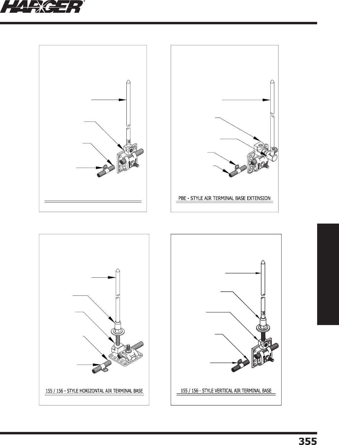
H
ar
g
er Li
g
htnin
g
& Groundin
g
•
©
2012 Phone 847-548-8700 • Fax 847-548-8755 • U.S. 800-842-743
7
355
355
Section 6
Technical Assistance
S
ect
io
n 6.5
Li
g
htnin
g
Protection & Groundin
g
Details
UBU - STYLE AIR TERMINAL BASE
CUAT / ALAT - STYLE GENTLY
TAPERED AIR TERMINAL
UBU - STYLE UNIVERSAL
FLAT SURFACE AIR
TERMINAL BASE
MOUNTED VERTICALLY
CCC / ACC - SERIES
CABLE FASTENER
COPPER OR ALUMINUM,
CLASS I OR CLASS II
LIGHTNING PROTECTION
CONDUCTOR
NTS
HARGER LIGHTNING & GROUNDING
847-548-8700 800-842-7437 www.harger.com
2012
9
CUAT / ALAT - STYLE GENTLY
TAPERED AIR TERMINAL
UBU - STYLE UNIVERSAL
FLAT SURFACE AIR
TERMINAL BASE
MOUNTED VERTICALLY
CCC / ACC - SERIES
CABLE FASTENER
COPPER OR ALUMINUM,
CLASS I OR CLASS II
LIGHTNING PROTECTION
CONDUCTOR
PBE - STYLE AIR TERMINAL
BASE EXTENSION
NTS
HARGER LIGHTNING & GROUNDING
847-548-8700 800-842-7437 www.harger.com
2012
9
CUAT / ALAT - STYLE GENTLY
TAPERED AIR TERMINAL
155 / 156 - STYLE
UNIVERSAL CONCEALED
AIR TERMINAL BASE
MOUNTED HORIZONTALLY
CCC / ACC - SERIES
CABLE FASTENER
COPPER OR ALUMINUM,
CLASS I OR CLASS II
LIGHTNING PROTECTION
CONDUCTOR
120 - STYLE AIR
TERMINAL ADAPTER
NTS
HARGER LIGHTNING & GROUNDING
847-548-8700 800-842-7437 www.harger.com
2012
9
CUAT / ALAT - STYLE GENTLY
TAPERED AIR TERMINAL
155 / 156 - STYLE
UNIVERSAL CONCEALED
AIR TERMINAL BASE
MOUNTED VERTICALLY
CCC / ACC - SERIES
CABLE FASTENER
COPPER OR ALUMINUM,
CLASS I OR CLASS II
LIGHTNING PROTECTION
CONDUCTOR
120 - STYLE AIR TERMINAL
ADAPTER
NTS
HARGER LIGHTNING & GROUNDING
847-548-8700 - 800-842-7437 - www.harger.com
© 2012
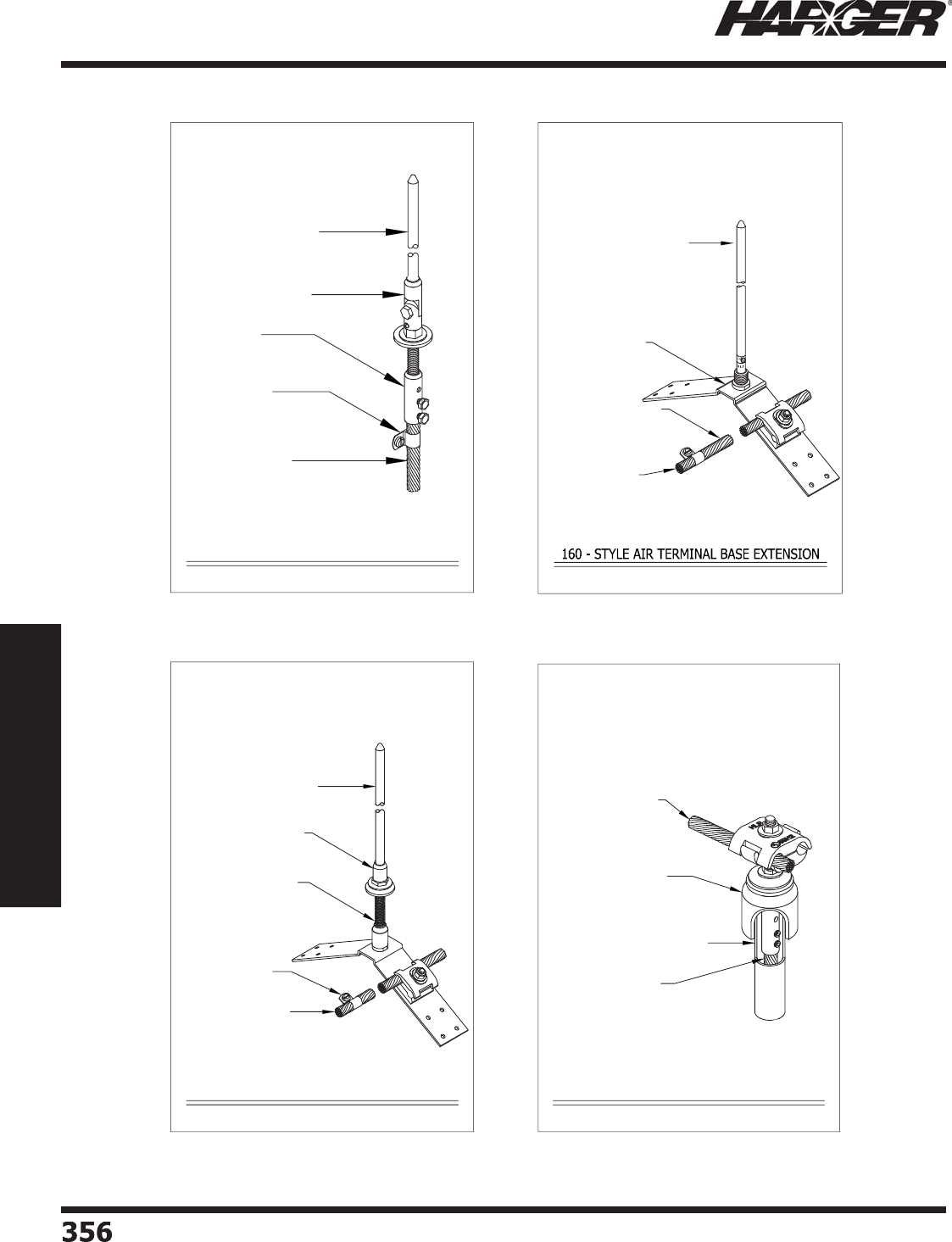
H
ar
g
er Li
g
htnin
g
& Groundin
g
•
©
2012 Phone 847-548-8700 • Fax 847-548-8755 • U.S. 800-842-743
7
356356
Section 6
Technical Assistance
S
ect
io
n 6.5
Li
g
htnin
g
Protection & Groundin
g
Details
158-XX - STYLE AIR TERMINAL BASE
CUAT / ALAT - STYLE GENTLY
TAPERED AIR TERMINAL
130 - STYLE AIR TERMINAL
SWIVEL ADAPTER
CCC / ACC - STYLE
CABLE FASTENER
COPPER OR ALUMINUM,
CLASS I OR CLASS II
LIGHTNING PROTECTION
CONDUCTOR
158-XX - STYLE
CONCEALED VERTICAL
AIR TERMINAL BASE
NTS
HARGER LIGHTNING & GROUNDING
847-548-8700 800-842-7437 www.harger.com
2012
9
CUAT / ALAT - STYLE GENTLY
TAPERED AIR TERMINAL
160 - STYLE RIDGE
SADDLE AIR TERMINAL
BASE
CCC / ACC - SERIES
CABLE FASTENER
COPPER OR ALUMINUM,
CLASS I OR CLASS II
LIGHTNING PROTECTION
CONDUCTOR
NTS
HARGER LIGHTNING & GROUNDING
847-548-8700 800-842-7437 www.harger.com
2012
9
1" PVC CONDUIT (NOT INCLUDED)
TRC STYLE THRU-ROOF CONNECTOR
TRC - STYLE THRU-ROOF
CONNECTOR
COPPER OR ALUMINUM,
CLASS I OR CLASS II
LIGHTNING PROTECTION
CONDUCTOR
COPPER OR ALUMINUM,
CLASS I OR CLASS II
LIGHTNING PROTECTION
CONDUCTOR
NTS
HARGER LIGHTNING & GROUNDING
847-548-8700 800-842-7437 www.harger.com
2012
9
162 - STYLE AIR TERMINAL BASE
CUAT / ALAT - STYLE GENTLY
TAPERED AIR TERMINAL
162 - STYLE CONCEALED
RIDGE AIR TERMINAL
BASE
CCC / ACC - STYLE
CABLE FASTENER
COPPER OR ALUMINUM,
CLASS I OR CLASS II
LIGHTNING PROTECTION
CONDUCTOR
120 - STYLE AIR TERMINAL
ADAPTER
NTS
HARGER LIGHTNING & GROUNDING
847-548-8700 800-842-7437 www.harger.com
2012
9
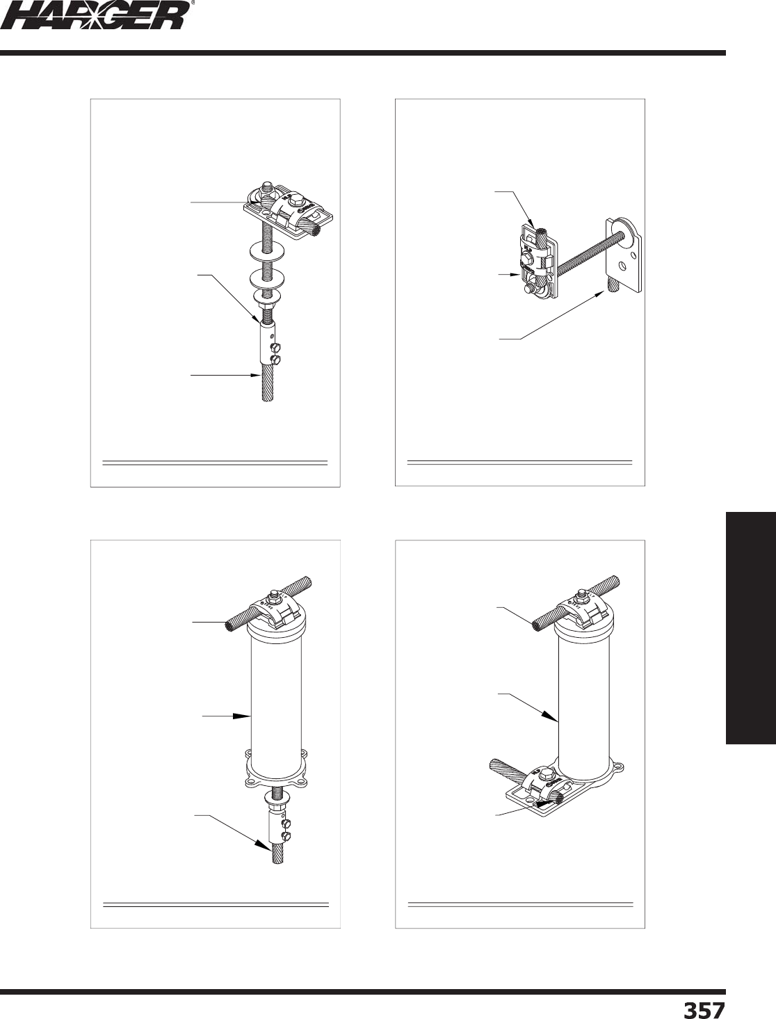
H
ar
g
er Li
g
htnin
g
& Groundin
g
•
©
2012 Phone 847-548-8700 • Fax 847-548-8755 • U.S. 800-842-743
7
35
7
357
Section 6
Technical Assistance
S
ect
io
n 6.5
Li
g
htnin
g
Protection & Groundin
g
Details
225 - STYLE THRU-ROOF CONNECTOR
225 - STYLE THRU-ROOF
CONNECTOR
COPPER OR ALUMINUM,
CLASS I OR CLASS II
LIGHTNING PROTECTION
CONDUCTOR
COPPER OR ALUMINUM,
CLASS I OR CLASS II
LIGHTNING PROTECTION
CONDUCTOR
NTS
HARGER LIGHTNING & GROUNDING
847-548-8700 800-842-7437 www.harger.com
2012
9
226 - STYLE THRU-ROOF CONNECTOR
226 - STYLE THRU-ROOF
CONNECTOR
COPPER OR ALUMINUM,
CLASS I OR CLASS II
LIGHTNING PROTECTION
CONDUCTOR
COPPER OR ALUMINUM,
CLASS I OR CLASS II
LIGHTNING PROTECTION
CONDUCTOR
NTS
HARGER LIGHTNING & GROUNDING
847-548-8700 800-842-7437 www.harger.com
2012
9
230V - STYLE THRU-ROOF CONNECTOR
230V - STYLE THRU-ROOF
CONNECTOR
COPPER OR ALUMINUM,
CLASS I OR CLASS II
LIGHTNING PROTECTION
CONDUCTOR
COPPER OR ALUMINUM,
CLASS I OR CLASS II
LIGHTNING PROTECTION
CONDUCTOR
NTS
HARGER LIGHTNING & GROUNDING
847-548-8700 800-842-7437 www.harger.com
2012
9
230H STYLE THRU-ROOF CONNECTOR
230H - STYLE THRU-ROOF
CONNECTOR
COPPER OR ALUMINUM,
CLASS I OR CLASS II
LIGHTNING PROTECTION
CONDUCTOR
COPPER OR ALUMINUM,
CLASS I OR CLASS II
LIGHTNING PROTECTION
CONDUCTOR
NTS
HARGER LIGHTNING & GROUNDING
847-548-8700 800-842-7437 www.harger.com
2012
9
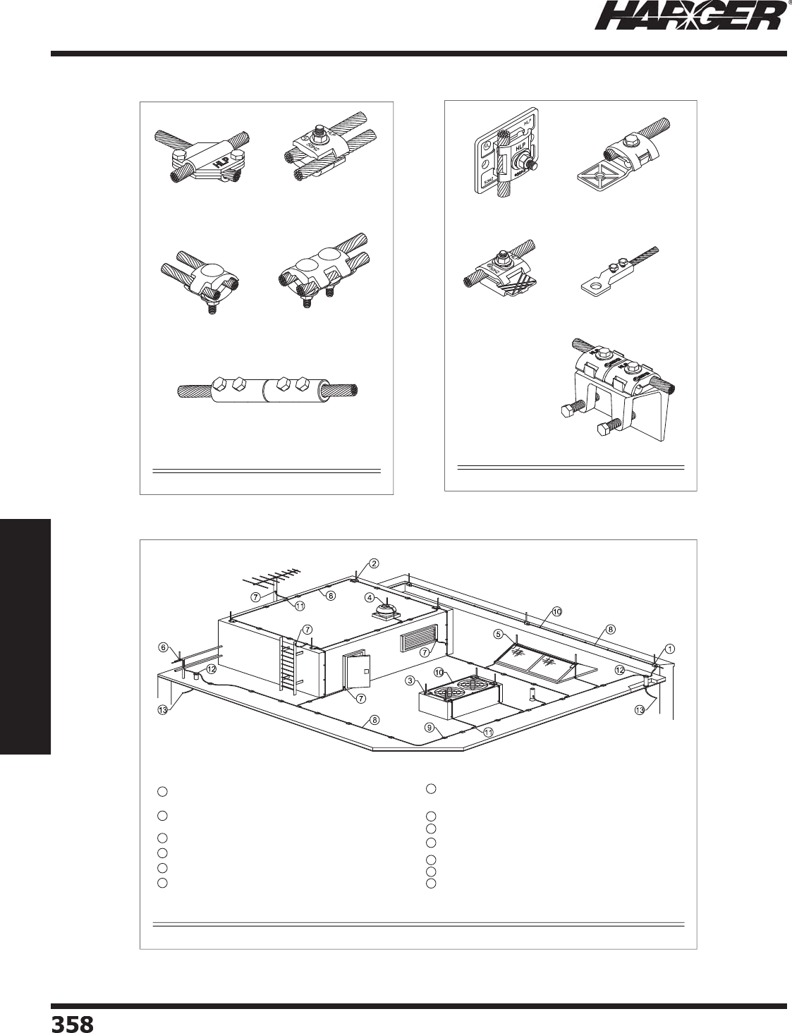
H
ar
g
er Li
g
htnin
g
& Groundin
g
•
©
2012 Phone 847-548-8700 • Fax 847-548-8755 • U.S. 800-842-743
7
358
358
Section 6
Technical Assistance
S
ect
io
n 6.5
Li
g
htnin
g
Protection & Groundin
g
Details
No. 210 Style Cross Run
Connector
No. B1BC Style Parallel
Connector
No. 208, Style Bonding
Connector
No. 204 Style Parallel
Connector
No. 211, Bi-Metal Connector
TYPICAL CABLE CONNECTORS
NTS
HARGER LIGHTNING & GROUNDING
847-548-8700 800-842-7437 www.harger.com
2012
9
No. 217, Style Bonding Plate No. 222, Style Heavy Duty
Bonding Lug
No. 213, Style Bonding Plate No. 216, Style Bonding Lug
No. 223, Style Flange
Bonding Plate
TYPICAL BONDING LUGS & PLATES
NTS
HARGER LIGHTNING & GROUNDING
847-548-8700 800-842-7437 www.harger.com
2012
9
11
THRU-ROOF CONNECTOR.
12
LIGHTNING DOWN CONDUCTOR.
VERTICALLY MOUNTED AIR TERMINAL ON PARAPET SPACE 20 FEET
MAXIMUM. SEE AIR TERMINAL DETAIL.
AIR TERMINAL MOUNTED ON EXHAUST FAN (`DEAD-END' METHOD).
AIR TERMINALS MOUNTED ON MECHANICAL EQUIPMENT ENCLOSURE.
HORIZONTALLY MOUNTED AIR TERMINAL ON ROOF SPACE 20 FEET
MAXIMUM. SEE AIR TERMINAL DETAIL.
4
3
2
1
BONDING DETAILS AND AIR TERMINAL LOCATIONS
SHOWN ARE TYPICAL, GENERAL EXAMPLES ONLY.
FINAL EXTENT OF BONDING AND SPECIFIC FITTING
APPLICATIONS TO BE DETERMINED IN FIELD BASED
ON ACTUAL SITE CONDITIONS.
6
7
8
9
10
BOND WINDOW, DOOR FRAMES, V.T.R.'S, LADDERS, AND ANTENNAS, OR
ANY METALLIC OBJECTS WITH BONDING LUGS AND SECONDARY
CONDUCTOR.
MAIN LIGHTNING CONDUCTOR.
CABLE CONNECTOR.
CABLE CLIP WITH STAINLESS STEEL SCREWS EVERY 3 FEET MAXIMUM
SPACING.
ADEHSIVE CABLE HOLDER EVERY 3 FEET MAXIMUM SPACING.
5AIR TERMINAL ON SKYLIGHT WITH SADDLE TYPE AIR TERMINAL BASE.
AIR TERMINAL MOUNTED ON GUARDRAIL WITH PIPE RAILING BASE. 13
TYPICAL ROOF LIGHTNING PROTECTION LAYOUT
NTS
HARGER LIGHTNING & GROUNDING
847-548-8700 800-842-7437 www.harger.com
2012
9
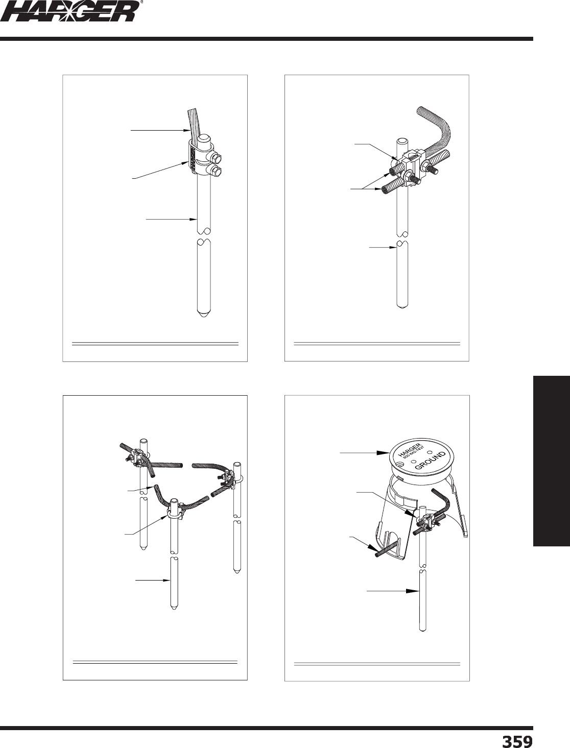
H
ar
g
er Li
g
htnin
g
& Groundin
g
•
©
2012 Phone 847-548-8700 • Fax 847-548-8755 • U.S. 800-842-743
7
35
9
359
Section 6
Technical Assistance
S
ect
io
n 6.5
Li
g
htnin
g
Protection & Groundin
g
Details
300 - STYLE GROUND ROD DETAIL
NO. 302U, UNIVERSAL
GROUND ROD CLAMP
COPPER, COPPER CLAD OR
STAINLESS STEEL GROUND
ROD
COPPER LIGHTNING
PROTECTION OR GROUNDING
CONDUCTOR
NTS
HARGER LIGHTNING & GROUNDING
847-548-8700 800-842-7437 www.harger.com
2012
9
305 - STYLE GROUND ROD DETAIL
NO. 305 - GROUND
ROD CLAMP
COPPER, COPPER CLAD OR
STAINLESS STEEL GROUND
ROD
COPPER LIGHTNING
PROTECTION OR GROUNDING
CONDUCTOR
NTS
HARGER LIGHTNING & GROUNDING
847-548-8700 800-842-7437 www.harger.com
2012
9
305 - GAW910 - GROUND ROD DETAIL
NO. 305 - GROUND
ROD CLAMP
COPPER, COPPER CLAD OR
STAINLESS STEEL GROUND
ROD
COPPER LIGHTNING
PROTECTION OR
GROUNDING
CONDUCTOR
GAW910 - TEST
WELL
NTS
HARGER LIGHTNING & GROUNDING
847-548-8700 800-842-7437 www.harger.com
2012
9
305 - DELTA GROUND ROD DETAIL
NO. 305 - GROUND
ROD CLAMP
COPPER, COPPER CLAD
OR STAINLESS STEEL
GROUND ROD
COPPER LIGHTNING
PROTECTION OR
GROUNDING
CONDUCTOR
NTS
HARGER LIGHTNING & GROUNDING
847-548-8700 800-842-7437 www.harger.com
2012
9
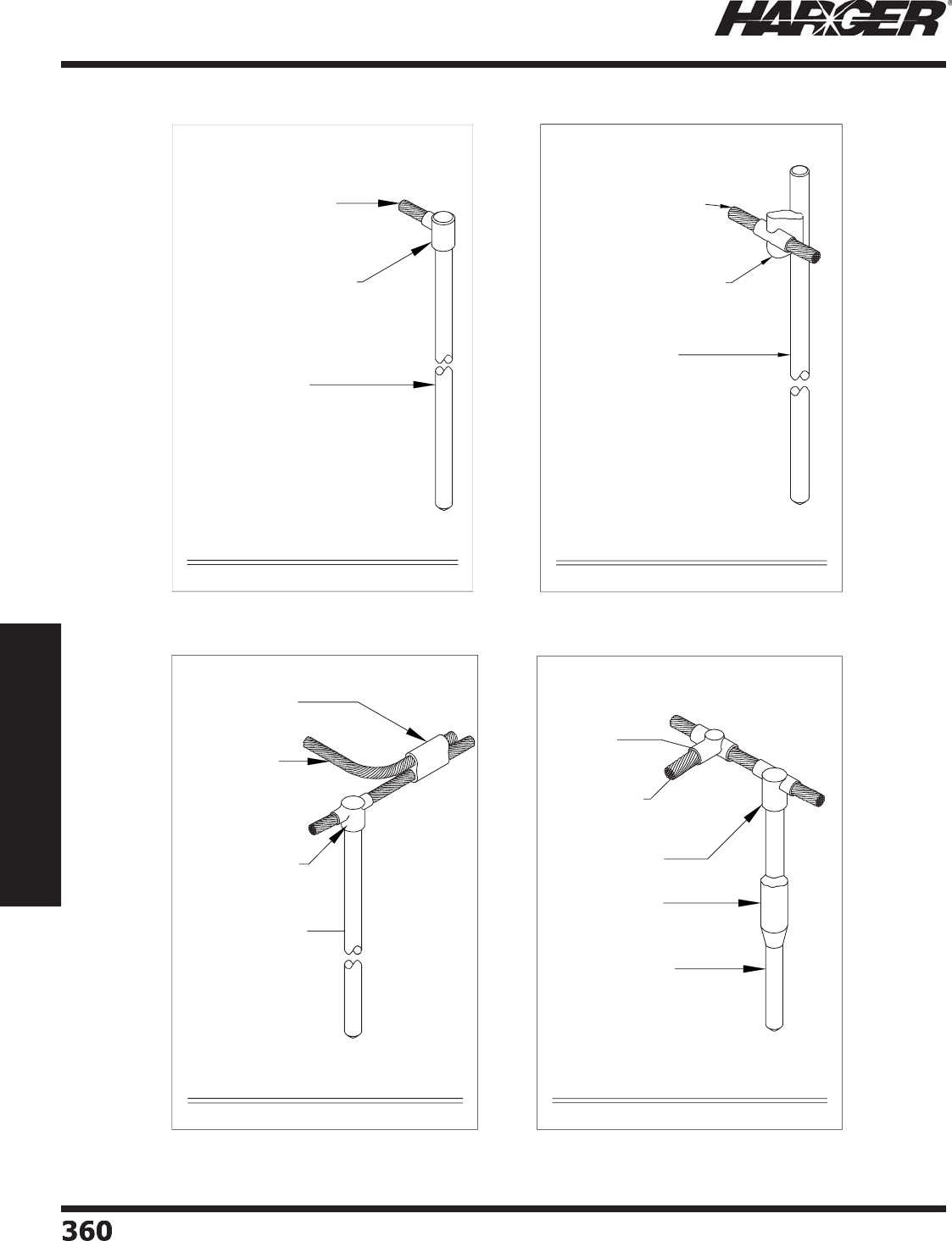
H
ar
g
er Li
g
htnin
g
& Groundin
g
•
©
2012 Phone 847-548-8700 • Fax 847-548-8755 • U.S. 800-842-743
7
360360
Section 6
Technical Assistance
S
ect
io
n 6.5
Li
g
htnin
g
Protection & Groundin
g
Details
GD- STYLE GROUND ROD DETAIL
GD - STYLE ULTRAWELD CONNECTION
COPPER, COPPER CLAD OR
STAINLESS STEEL GROUND
ROD
COPPER LIGHTNING PROTECTION
OR GROUNDING CONDUCTOR
NTS
HARGER LIGHTNING & GROUNDING
847-548-8700 800-842-7437 www.harger.com
2012
9
GD- STYLE GROUND ROD DETAIL
GS - STYLE ULTRAWELD CONNECTION
COPPER, COPPER CLAD OR
STAINLESS STEEL GROUND
ROD
COPPER LIGHTNING PROTECTION
OR GROUNDING CONDUCTOR
NTS
HARGER LIGHTNING & GROUNDING
847-548-8700 800-842-7437 www.harger.com
2012
9
GO - PT - GROUND ROD DETAIL
GO - STYLE ULTRAWELD
CONNECTION
COPPER, COPPER CLAD OR
STAINLESS STEEL GROUND
ROD
COPPER LIGHTNING
PROTECTION OR
GROUNDING CONDUCTOR
PT - STYLE ULTRAWELD
CONNECTION
NTS
HARGER LIGHTNING & GROUNDING
847-548-8700 800-842-7437 www.harger.com
2012
9
GO - RT - GROUND ROD DETAIL
GO - STYLE ULTRAWELD
CONNECTION
COPPER, COPPER CLAD OR
STAINLESS STEEL GROUND
ROD
COPPER LIGHTNING
PROTECTION OR
GROUNDING CONDUCTOR
RT - STYLE
ULTRAWELD
CONNECTION
GG - STYLE ULTRAWELD
CONNECTION
NTS
HARGER LIGHTNING & GROUNDING
847-548-8700 800-842-7437 www.harger.com
2012
9
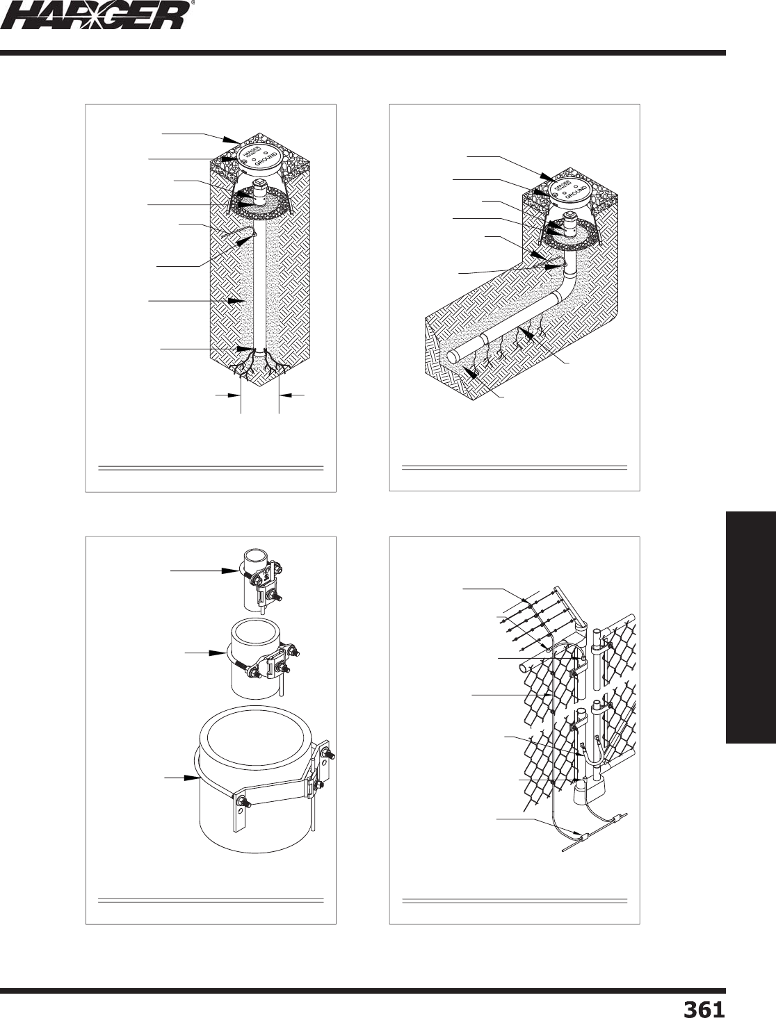
H
ar
g
er Li
g
htnin
g
& Groundin
g
•
©
2012 Phone 847-548-8700 • Fax 847-548-8755 • U.S. 800-842-743
7
36
1
361
Section 6
Technical Assistance
S
ect
io
n 6.5
Li
g
htnin
g
Protection & Groundin
g
Details
FINISH GRADE
BREATHER HOLES
BURY LINE
TEST WELL
LEECH HOLES
#2T SOLID TINNED
CONDUCTOR (OR AS
SPECIFIED)
ULTRAFILL
ULTRAWELD
CONNECTION
6" DIA. MIN.
NTS
EGR - VERTICAL STAINLESS STEEL
ENHANCED GROUND ROD
HARGER LIGHTNING & GROUNDING
847-548-8700 800-842-7437 www.harger.com
2012
9
FINISH GRADE
BREATHER HOLES
BURY LINE
ULTRAFILL
LEACH HOLES
TEST WELL
#2T SOLID TINNED
CONDUCTOR (OR AS
SPECIFIED)
ULTRAWELD
CONNECTION
NTS
EGR - HORIZONTAL ENHANCED
STAINLESS STEEL GROUND ROD
HARGER LIGHTNING & GROUNDING
847-548-8700 800-842-7437 www.harger.com
2012
9
CPC - APC - UPC - STYLE PIPE CLAMPS
CPC - APC 1/1.25 -
STYLE PIPE CLAMP
CPC - APC - STYLE PIPE
CLAMP
UPC - STYLE PIPE
CLAMP
NTS
HARGER LIGHTNING & GROUNDING
847-548-8700 800-842-7437 www.harger.com
2012
9
CONNECT GROUND CONDUCTOR
TO POST WITH VA STYLE
ULTRAWELD CONNECTION
CONNECT FENCE BONDING
CONDUCTOR TO GROUND
CONDUCTOR WITH PT STYLE
ULTRAWELD CONNECTION
NO. HD STYLE ULTRAWELD
CONNECTION
NO. VU STYLE ULTRAWELD
CONNECTION
NO. GJX STYLE GATE JUMPER
WITH VA STYLE ULTRAWELD
CONNECTION
NO. FGC2, FENCE
GROUNDING CLAMP
TYPICAL FENCE & GATE BONDING DETAIL
NTS
COPPER LIGHTNING
PROTECTION OR
GROUNDING CONDUCTOR
HARGER LIGHTNING & GROUNDING
847-548-8700 800-842-7437 www.harger.com
2012
9
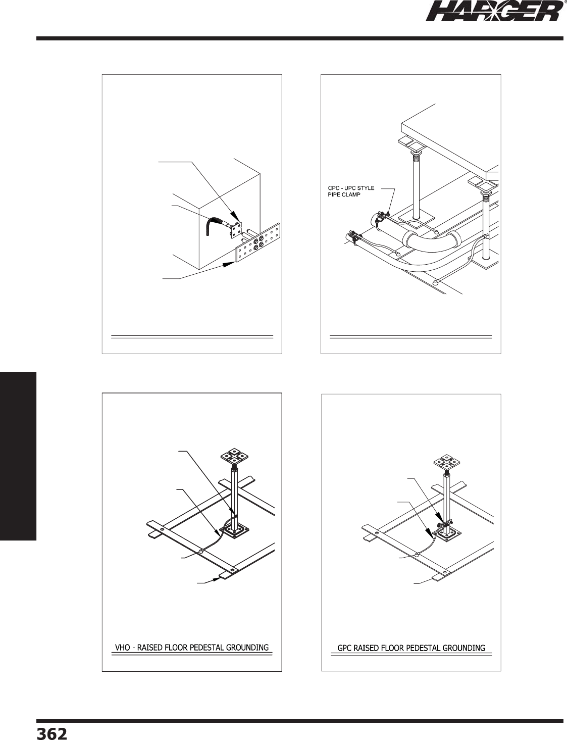
H
ar
g
er Li
g
htnin
g
& Groundin
g
•
©
2012 Phone 847-548-8700 • Fax 847-548-8755 • U.S. 800-842-743
7
36
2
362
Section 6
Technical Assistance
S
ect
io
n 6.5
Li
g
htnin
g
Protection & Groundin
g
Details
XGP3.25/3.254/0
EQUIPMENT GROUND PLATE
BS STYLE ULTRAWELD
CONNECTION
NO. GB38414.25TI,
3/8"x4"x14.25", COPPER
GROUND BAR
XGP IN-USE DETAIL
NTS
HARGER LIGHTNING & GROUNDING
847-548-8700 800-842-7437 www.harger.com
2012
9
CONDUIT TO SRG BONDING DETAIL
NTS
HARGER LIGHTNING & GROUNDING
847-548-8700 800-842-7437 www.harger.com
2012
9
BCF61.5016B ULTRAWELD
CONNECTION WITH US25 OR
NUWTUBE25 WELD METAL.
GPC6SQ, GROUND PEDESTAL
CLAMP
FLAT STRIP SIGNAL REFERENCE
GRID (SRG) 2"x0.016" COPPER
STRIP ON 2' CENTER TYPICAL.
VERIFY SIZE WITH HARGER
PRIOR TO ORDERING.
NO. 6 COPPER BONDING
CONDUCTOR (6-7 AWG)
NTS
HARGER LIGHTNING & GROUNDING
847-548-8700 800-842-7437 www.harger.com
2012
9
BCF61.5016B ULTRAWELD
CONNECTION WITH US25 OR
NUWTUBE25 WELD METAL.
VHO61SQMX ULTRAWELD
CONNECTION WITH US25 OR
NUWTUBE25 WELD METAL.
FLAT STRIP SIGNAL REFERENCE
GRID (SRG) 2"x0.016" COPPER
STRIP ON 2' CENTER TYPICAL.
VERIFY SIZE WITH HARGER
PRIOR TO ORDERING.
NO. 6 COPPER BONDING
CONDUCTOR (6-7 AWG)
NTS
HARGER LIGHTNING & GROUNDING
847-548-8700 - 800-842-7437 - www.harger.com
© 2012
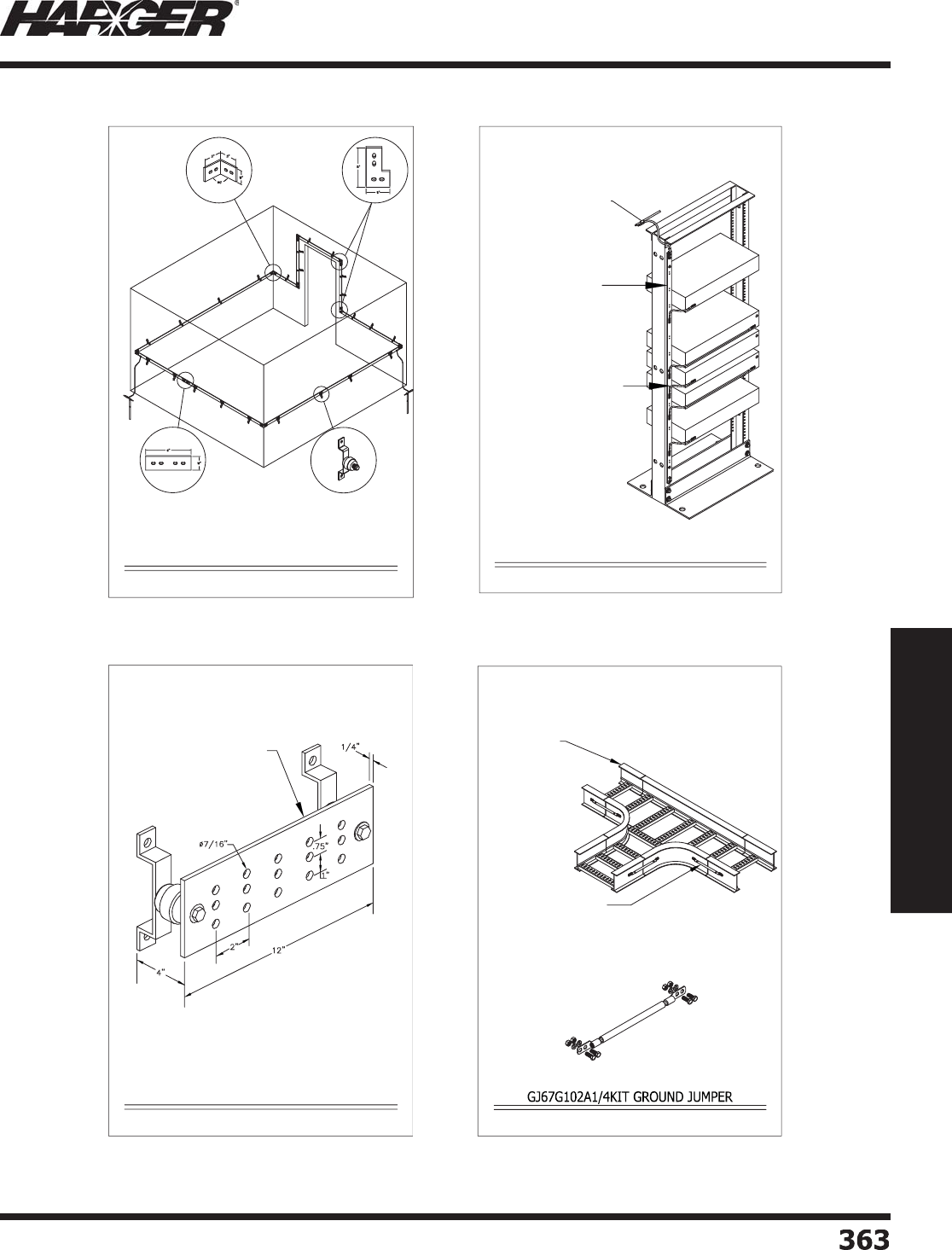
H
ar
g
er Li
g
htnin
g
& Groundin
g
•
©
2012 Phone 847-548-8700 • Fax 847-548-8755 • U.S. 800-842-743
7
363
363
Section 6
Technical Assistance
S
ect
io
n 6.5
Li
g
htnin
g
Protection & Groundin
g
Details
CUxxEL90 90°
Copper Elbow CUxxEL90FL 90°
Copper Elbow
CUxxSPL Copper Splice Plate WBKT1KIT, Bracket and
Insulator
TYPICAL PERIMETER GROUND BUS LAYOUT
NTS
HARGER LIGHTNING & GROUNDING
847-548-8700 800-842-7437 www.harger.com
2012
9
C-Type Compression Tap
No. RGBV145872A Rack
Ground Bar
GJ67G Style Ground Jumper
RACK GROUNDING DETAIL
NTS
HARGER LIGHTNING & GROUNDING
847-548-8700 800-842-7437 www.harger.com
2012
9
NO. GBI14412C, 1/4" X 4" X 12"
GROUND BUS BAR WITH "C"
HOLE PATTERN
NO. GBI14412C GROUND BAR DETAIL
NTS
HARGER LIGHTNING & GROUNDING
847-548-8700 800-842-7437 www.harger.com
2012
9NTS
CABLE TRAY
NO. GJ67G102A1/4KIT,
INSULATED GROUND JUMPER
WITH MOUNTING HARDWARE
HARGER LIGHTNING & GROUNDING
847-548-8700 800-842-7437 www.harger.com
2012
9

H
ar
g
er Li
g
htnin
g
& Groundin
g
•
©
2012 Phone 847-548-8700 • Fax 847-548-8755 • U.S. 800-842-743
7
364364
Section 6
Technical Assistance
Section 33 79 00 (Formerly 16711) – Wireless Communication Site Lightning
Protection and Grounding System Specifi cation
Part 1 –
G
ENERA
L
1.01 Summar
y
:
a. Provide a complete li
g
htnin
g
protection and
g
roundin
g
system for the tower and the buildin
g
(s) or
structures included on the contract drawin
g
s that do not fall within a zone of protection
g
enerated by
the taller tower. The system shall provide safety for the ob
j
ects mounted on the tower, the buildin
g
,
the buildin
g
s contents and occupants by preventin
g
dama
g
e caused by li
g
htnin
g
. The desi
g
n of this
system is to be in strict accordance with this section of the specifi cations and all contract drawin
g
s that
a
pp
l
y
.
b. The li
g
htnin
g
protection system on the buildin
g
(s) shall be installed by a fi rm actively en
g
a
g
ed in
the installation of Li
g
htnin
g
Protection System. The completed system shall comply with the
latest editions of the Installation Requirements for Li
g
htnin
g
Protection Systems, UL96A and of the
National Fire Protection Association’s Li
g
htnin
g
Protection Standard, NFPA 780.
c. The work covered under this section of the specifi cation consists of furnishin
g
an adequate number
of skilled trained
p
ersonnel, materials and services re
q
uired for the com
p
letion of a functional and
unobtrusive li
g
htnin
g
protection system on the shelter and a complete
g
roundin
g
system for the site.
1.
0
2 References:
a. Li
g
htnin
g
Protection for the Shelte
r
I. NFPA 780, Standard for the Installation of Li
g
htnin
g
Protection Systems.
II. UL 96A, Installation Requirements for Li
g
htnin
g
Protection Systems.
III. Har
g
er Li
g
htnin
g
Protection System Specifi cation Section 16670
b. Groundin
g
I. NFPA 70, National Electric Code
II. IEEE Std.1100, IEEE Recommended Practice for Powerin
g
and Groundin
g
Electronic Equipment.
1.
03
S
ub
mitt
a
ls:
a. Shop drawin
g
s shall be submitted to the architect and en
g
ineer for approval prior to commencement of
the installation. Shop drawin
g
s are to show the extent of the system layout desi
g
ned specifi cally for
the buildin
g
(s) or structures included in the contract drawin
g
s alon
g
with details of the products to be
u
se
d
in the inst
a
ll
a
ti
o
n.
Part 2 – T
O
WE
R
2.
0
1 Air Termin
a
ls:
a. Air terminal(s), (li
g
htnin
g
rod) shall extend a minimum of two feet above the tallest ob
j
ect on the
tower (verify all ob
j
ects on the tower fall within a zone of protection, the zone of protection shall
be determined by utilizin
g
the 150 foot radius rollin
g
sphere concept). If required the air terminals
may be mounted at an an
g
le on the side of the tower to insure the ob
j
ect falls within the zone of
p
rotection.
b. The air terminals shall be constructed of 304 stainless steel or copper clad steel for stren
g
th. Two
inches of thread shall be provided on the bottom of the air terminal for mountin
g
purposes. The
air terminal shall be fastened to the tower with pressure type connections utilizin
g
stainless steel nuts
a
n
d
l
o
ck w
a
shers.
S
ecti
o
n 6.6: Wireless C
o
mmunicati
o
n Site
Li
g
htnin
g
Protection & Groundin
g
System Specifi catio
n

H
ar
g
er Li
g
htnin
g
& Groundin
g
•
©
2012 Phone 847-548-8700 • Fax 847-548-8755 • U.S. 800-842-743
7
365
365
Section 6
Technical Assistance
Section 33 79 00 (Formerly 16711) – Wireless Communication Site Lightning
Protection and Grounding System Specifi cation
2.
0
2 D
o
wn C
o
n
du
ct
o
rs:
a. The tower le
g
s shall be utilized as the down conductor for the li
g
htnin
g
protection system as they
provide an acceptable path of conductance; in addition utilizin
g
the tower le
g
s will eliminate the need
to fasten the down conductor the entire hei
g
ht of the tower.
2.03 Groundin
g
a
. C
oa
x C
ab
les:
I. The coax cables shall be
g
rounded to the tower at the top and bottom, and ri
g
ht before enterin
g
the equipment shelter, usin
g
coaxial
g
roundin
g
kits. Ground bars may be mounted on the tower
to provide
g
roundin
g
points for the coaxial
g
roundin
g
kits. If the tower is taller than 150’,
the cables shall be
g
rounded every 75’ or less. The coax cables shall be run down the center of
the tower whenever
p
ossible.
b
. Gr
ou
n
d
R
od
s:
I. Ground radials utilizin
g
5/8” x 10’ copper clad steel
g
round rods and #2 AWG solid tin coated
copper
g
round conductor shall be used as the
g
roundin
g
electrodes. The
g
round conductor
shall be connected to the tower or to a tower le
g
g
roundin
g
strap with Ultraweld exothermic
connections. In new construction, the rebar in the tower footin
g
shall also be connected to the
g
roundin
g
system with Ultraweld exothermic connections.
II. The
g
round rods shall be spaced 16’ apart alon
g
the radial. The #2 AWG
g
round conductors shall
be connected to the
g
round rod usin
g
Ultraweld exothermic connections. The len
g
th and
number of
g
round radials required will vary due to
g
round resistance which is affected by the
soil conditions. The len
g
th of the radials should not be more than 75’. The
g
round resistance shall
be measured periodically, (durin
g
different climatic conditions), and shall always measure 5 Ohms
o
r less.
c. Ground Loo
p
Conducto
r
I. A
g
round loop conductor utilizin
g
#2 AWG solid tinned copper conductor shall encompass the base
of the tower and shall be connected to the shelter
g
roundin
g
system and shall interconnect all
g
round electrodes.
d. Gu
y
Wires:
I. Guy wires and
g
uy anchors shall also be
g
rounded. Tinned coated bronze or stainless steel
pressure connectors shall connect the
g
uy wires to the #2 AWG solid tinned copper conductors.
The
g
round conductor should be connected to the
g
uy anchor with Ultraweld exothermic
connections if
p
ermitted b
y
the manufacturer. The conductors shall be connected to two 5/8” x 10’
copper clad
g
round rods spaced 16’ apart with Ultraweld exothermic connections.
Part
3
– SHELTE
R
3.01 A shelter that is not located within a zone of protection
g
enerated by the tower shall be protected by a
li
g
htnin
g
protection system.
S
ecti
o
n 6.6: Wireless C
o
mmunicati
o
n Site
Li
g
htnin
g
Protection & Groundin
g
System Specifi catio
n

H
ar
g
er Li
g
htnin
g
& Groundin
g
•
©
2012 Phone 847-548-8700 • Fax 847-548-8755 • U.S. 800-842-743
7
366366
Section 6
Technical Assistance
3
.
0
2 Air Termin
a
ls:
a. Air terminals shall pro
j
ect a minimum of ten inches above the ob
j
ect or area it is to protect and shall
be located at intervals not exceedin
g
20’-0” alon
g
rid
g
es and alon
g
the perimeter of fl at or
g
ently
slopin
g
roofs (fl at or
g
ently slopin
g
roofs include roofs that have a pitch less than 3:12). Air terminals
shall be located within two feet of roof ed
g
es and outside corners of protected areas.
b. Air terminals shall be installed on mechanical units and other metallic ob
j
ects not located within a
zone of protection and which have an exposed metal thickness less than 3/16 of an inch. Ob
j
ects
havin
g
an exposed metal thickness 3/16 of an inch or
g
reater shall be connected to the li
g
htnin
g
protection system as required by the specifi ed standards usin
g
main size conductor and bondin
g
plates
havin
g
a minimum of 3 square inches of surface contact area.
c. Air terminal bases shall be securel
y
fastened to the structure in accordance the s
p
ecifi ed standards
includin
g
the use of adhesive that is compatible with the surface it is to be used on or stainless steel
f
a
steners.
d. Main conductors shall be sized in accordance with the s
p
ecifi ed standards for Class I or Class II
structures and shall
p
rovide a two wa
y
horizontal or downward
p
ath from each air terminal to
connections with the
g
round system. Conductors shall be free of excessive splices and no bend of a
conductor shall form a fi nal included an
g
le of less than neither 90 de
g
rees nor have a radius of bend
less than 8 inches.
e. Down conductors shall be sized in accordance with the s
p
ecifi ed standards and in no case shall be
smaller than the main roof conductor. Down conductors shall be spaced at intervals avera
g
in
g
not more than 100 feet around the
p
erimeter of the structure. In no case shall a structure have
fewer than two down conductors. Where down conductors are installed ex
p
osed on the exterior of
a structure and are sub
j
ect to physical dama
g
e or displacement,
g
uards shall be used to protect the
conductor a minimum of 6 feet above
g
rade. Metallic
g
uards shall be bonded at each end.
3
.
03
R
oo
f Penetr
a
ti
o
ns
a. Roof
p
enetrations re
q
uired for down conductors or for connection to structural steel framework shall
be made usin
g
thru-roof assemblies with solid riser bars and appropriate roof fl ashin
g
. Conductors
shall not pass directly throu
g
h the roof. The roofi n
g
contractor shall furnish and install the materials
required to properly seal all roof penetrations of the li
g
htnin
g
protection components and any
additional roofi n
g
materials or preparations required by the roofi n
g
manufacturer for li
g
htnin
g
conductor runs to assure compatibility with the warranty for the roof includin
g
roof pads that may be
required to protect the roof under each of the li
g
htnin
g
protection components.
3.04 Groundin
g
a. Ground loo
p
conducto
r
I. A
g
round loop conductor utilizin
g
#2 AWG solid tinned copper conductor shall encompass the
shelter and be connected to the tower
g
roundin
g
system and shall interconnect all
g
round
electr
od
es.
Section 33 79 00 (Formerly 16711) – Wireless Communication Site Lightning
Protection and Grounding System Specifi cation
S
ecti
o
n 6.6: Wireless C
o
mmunicati
o
n Site
Li
g
htnin
g
Protection & Groundin
g
System Specifi catio
n

H
ar
g
er Li
g
htnin
g
& Groundin
g
•
©
2012 Phone 847-548-8700 • Fax 847-548-8755 • U.S. 800-842-743
7
36
7
367
Section 6
Technical Assistance
b
. Gr
ou
n
d
electr
od
e
s
I. Ground electrodes shall be copper clad steel and a minimum 5/8” diameter and 10 feet lon
g
. A
g
round electrode shall be provided for each down conductor and shall be spaced on avera
g
e 16’
apart. The down conductor shall be connected to the
g
round electrode by an Ultraweld
exothermicall
y
welded connection. Ground electrodes shall be located a minimum of 2 feet below
g
rade and shall be installed below the frost line where possible (excludin
g
shallow
to
p
soil conditions
)
.
c. Bondin
g
I. The structural steel and or rebar of the shelter shall be connected to the
g
round loop at each
c
o
rner with
U
ltr
a
wel
d
ex
o
thermic c
o
nnecti
o
ns.
d
. Gr
ou
n
d
mes
h
I. Equipotential
g
round mesh shall be provided and connected to the tower
g
roundin
g
system
and the shelter
g
round loop with Ultraweld exothermic connections. The
g
round mesh can
be strate
g
ically placed to help protect personnel a
g
ainst step and touch volta
g
es and improve the
g
roundin
g
system. 5/8” x 10’ copper clad
g
round rods shall be connected to each corner of the
g
round mesh with Ultraweld exothermic connections.
e. Gr
ou
n
d
B
a
r
s
I. A ¼” thick copper exterior
g
round bar shall be provided and installed on the exterior of the
shelter near the point where the coax lines enter the shelter. The
g
round bar shall be connected to
the
g
roundin
g
system with an Ultraweld exothermic connection and shall serve as the sin
g
le point
g
round bus.
II. A ¼” thick copper interior
g
round bar shall be provided and installed on the inside of the shelter
on the opposite side of the wall that the exterior
g
round bar is mounted. The interior
g
round
bar shall be connected to the exterior bar usin
g
a min. 2” wide copper strap, #2 AWG solid
tinned copper
g
round conductor or with a solid copper or brass horizontal riser bar. When
usin
g
a copper fl at strap or conductor the connections to the interior and exterior bars should be
with an Ultraweld exothermic connection when possible. All interior equipment and
g
rounded
metal bodies shall be connected to the interior
g
round bar.
3.05 Equipotential Groundin
g
a. Common interconnection of all
g
rounded systems within the buildin
g
shall be ensured by
interconnectin
g
to the li
g
htnin
g
protection system usin
g
main size conductor and fi ttin
g
s.
b. This interconnection shall include but is not limited to the electrical service, tele
p
hone and antenna
system
g
rounds as well as all under
g
round metallic pipin
g
systems includin
g
water,
g
as and sewer.
Interconnection to a
g
as or water line shall be made on the customer’s side of the meter. Fences,
g
enerators and rebar in new construction shall also be bonded to the
g
roundin
g
system. Steps shall
be taken to ensure a continuous bond for all
g
rounded metal bodies. All under
g
round and wherever
possible above
g
round connections shall be with Ultraweld exothermic connections.
Part 4 – Diffi cult Groundin
g
Conditions
4.01 If the site soil resistivity is 15,000Ωcm or
g
reater, standard approaches to achievin
g
the required system
g
round resistance may be ineffective. In this situation, the
g
round electrode system may require the
use of enhanced
g
round rod electrodes and or the utilization of Ultrafi ll
g
round enhancement backfi ll
materials. Contact Har
g
er Li
g
htnin
g
& Groundin
g
for solutions when diffi cult
g
roundin
g
conditions are
enc
ou
ntere
d
.
Section 33 79 00 (Formerly 16711) – Wireless Communication Site Lightning
Protection and Grounding System Specifi cation
S
ecti
o
n 6.6: Wireless C
o
mmunicati
o
n Site
Li
g
htnin
g
Protection & Groundin
g
System Specifi catio
n

H
ar
g
er Li
g
htnin
g
& Groundin
g
•
©
2012 Phone 847-548-8700 • Fax 847-548-8755 • U.S. 800-842-743
7
368
368
Section 6
Technical Assistance
Part 5 – E
q
u
ip
ment Protect
i
o
n
5.01 RF Sur
g
e Protectio
n
a. All coax cables shall be
g
rounded to the sin
g
le point exterior
g
round bar before enterin
g
the buildin
g
.
In-line suppressors shall be installed immediately after the coax enters the buildin
g
. These suppressors
shall be
g
rounded to the interior
g
round bar.
5.02 A/C Sur
g
e Suppressio
n
a. Sur
g
e suppression shall be provided at all service entrances.
b. Sur
g
e protection shall be installed at the service entrance panel. The unit shall have one time
withstand sur
g
e capacity of 100 KA or more. (One time withstand if an 8 x 20 micro second pulse
stated in thousands of amperes). The sur
g
e protection unit shall be a UL 1449 listed device.
c. Series type plu
g
-in suppressors shall be installed at the plu
g
-in receptacles where sensitive
communications e
q
ui
p
ment is connected.
5.03 Telephone / Data Sur
g
e Suppressio
n
a. Sur
g
e suppression shall be provided at all service entrances and at entrances of conductive si
g
nal,
da
t
a
a
n
d
c
o
mm
u
nic
a
ti
o
n services.
b. In-line twisted
p
air
p
rotectors shall be installed for all tele
p
hone, data, fax, modem lines, etc. The
y
shall also be bonded to the interior
g
round bar.
Part 6 – Acce
p
table Sources / Manufacturers
6.01 Acce
p
table Manufacturer
s
a. Har
g
er Li
g
htnin
g
& Groundin
g
301 Zie
g
ler Drive, Grayslake, IL 60030
(
847
)
548-8700 ● 800-842-7437 ● Fax
(
847
)
548-8755
E-mail: har
g
ersales@har
g
er.com ● Web-site: www.har
g
er.com
b. Josl
yn
c. Times Micr
o
w
a
ve
Section 33 79 00 (Formerly 16711) – Wireless Communication Site Lightning
Protection and Grounding System Specifi cation
S
ecti
o
n 6.6: Wireless C
o
mmunicati
o
n Site
Li
g
htnin
g
Protection & Groundin
g
System Specifi catio
n

H
ar
g
er Li
g
htnin
g
& Groundin
g
•
©
2012 Phone 847-548-8700 • Fax 847-548-8755 • U.S. 800-842-743
7
36
9
369
Section 6
Technical Assistance
Section 33 79 00 (Formerly 16711) – Wireless Communication Site Lightning
Protection and Grounding System Specifi cation
Part 7 – List of A
pp
roved Materials
7.01 Air Terminals - #585CCAT, #586SS3AT, #586SS3AT, #585CCAT-2/0, #1224CUAT, #1212CUAT (Har
g
er
Li
g
htnin
g
& Groundin
g
) or other approved Har
g
er air terminal
s
7.02 Air Terminals Bases - #CUBU12I, #CPRB1.5/2AT12, #158 (Har
g
er Li
g
htnin
g
& Groundin
g
) or other
approved Har
g
er air terminal base
s
7.03 Coax Ground Kits – CGKB Series (Har
g
er Li
g
htnin
g
& Groundin
g)
7.04 Pressure Connectors - #204T, #SSC25/875 (Har
g
er Li
g
htnin
g
& Groundin
g
) or other approved Har
g
er
c
o
nnec
to
r
s
7.05 Ground Bars - #EPK Series, #GBIA14424M (Har
g
er Li
g
htnin
g
& Groundin
g
) or other approved Har
g
er
g
round bar
s
7.06 Ground Mesh - #GM121266, #GM121266SPR12 (Har
g
er Li
g
htnin
g
& Groundin
g)
7.07 Ground Rods - #5810 (Har
g
er Li
g
htnin
g
& Groundin
g)
7.08 Ground Conductor - #2T (Har
g
er Li
g
htnin
g
& Groundin
g)
7.09 Enhanced Ground Rods - #EGR Series (Har
g
er Li
g
htnin
g
& Groundin
g)
7.010 Ground Enhancement Material - #ULTRAFILL (Har
g
er Li
g
htnin
g
& Groundin
g)
7.011 Li
g
htnin
g
Conductor - #28T (Har
g
er Li
g
htnin
g
& Groundin
g)
7.012 Exothermic Connections – Ultraweld (Har
g
er Li
g
htnin
g
& Groundin
g)
END
O
F SECTI
O
N
33
79
00
S
ecti
o
n 6.6: Wireless C
o
mmunicati
o
n Site
Li
g
htnin
g
Protection & Groundin
g
System Specifi catio
n
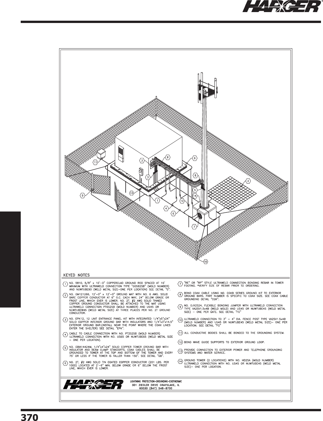
H
ar
g
er Li
g
htnin
g
& Groundin
g
•
©
2012 Phone 847-548-8700 • Fax 847-548-8755 • U.S. 800-842-743
7
3
7
0370
Section 6
Technical Assistance
Exterior Groundin
g
Layout
S
ect
io
n 6.7
W
ireless Communication Drawin
g
s
TYPICAL WIRELESS COMMUNICATION SITE
EXTERIOR GROUNDING PLAN
NTS
HARGER LIGHTNING & GROUNDING
847-548-8700 - 800-842-7437 - www.harger.com
© 2012
®
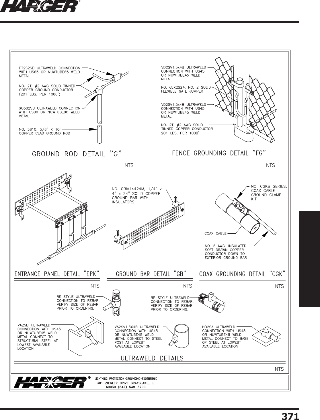
H
ar
g
er Li
g
htnin
g
& Groundin
g
•
©
2012 Phone 847-548-8700 • Fax 847-548-8755 • U.S. 800-842-743
7
3
71
371
Section 6
Technical Assistance
Exterior Groundin
g
Layout
S
ect
io
n 6.7
W
ireless Communication Drawin
g
s
TYPICAL WIRELESS COMMUNICATION SITE
EXTERIOR GROUNDING PLAN
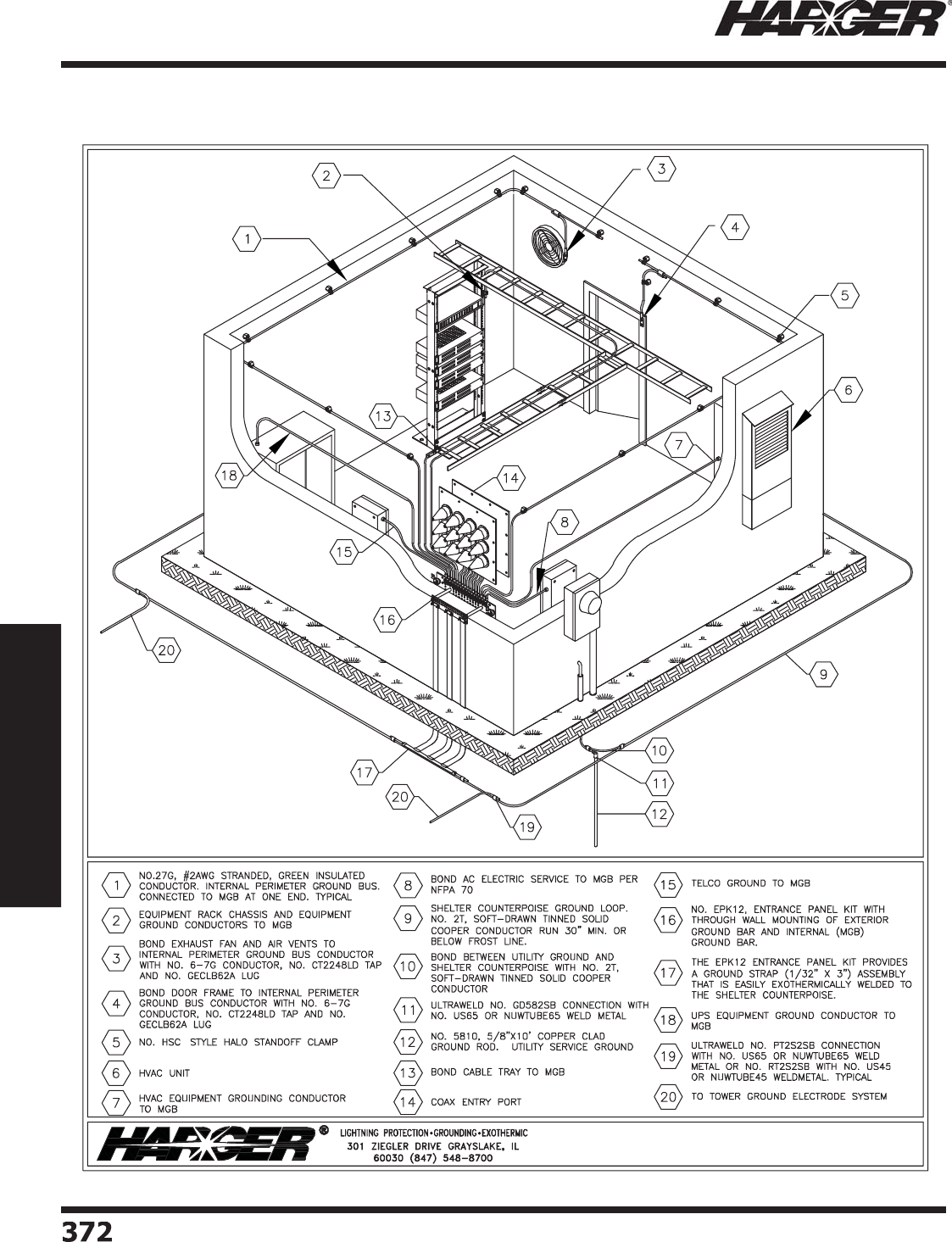
H
ar
g
er Li
g
htnin
g
& Groundin
g
•
©
2012 Phone 847-548-8700 • Fax 847-548-8755 • U.S. 800-842-743
7
3
72
372
Section 6
Technical Assistance
Interior Shelter La
y
out
S
ect
io
n 6.7
W
ireless Communication Drawin
g
s
INTERIOR SHELTER LAYOUT
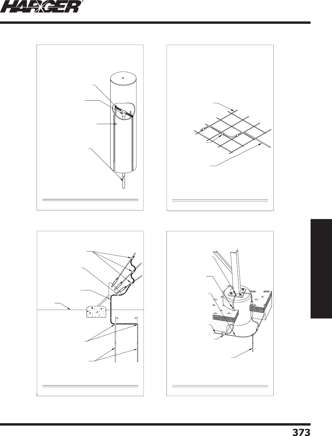
H
ar
g
er Li
g
htnin
g
& Groundin
g
•
©
2012 Phone 847-548-8700 • Fax 847-548-8755 • U.S. 800-842-743
7
3
7
3
373
Section 6
Technical Assistance
S
ect
io
n 6.7
W
ireless C
o
mmunicati
o
n Details
NO. 2T, SOFT DRAWN TINNED
SOLID COPPER CONDUCTOR
NO. GO582SB ULTRAWELD
CONNECTION WITH NO.
NUWTUBE90 WELDMETAL.
NO. 5810, 5/8" x 10' COPPER
CLAD GROUND ROD
NO. 360P42 10"Ø x 42" GROUND
ACCESS WELL WITH A NO. 10PS
STEEL COVER.
GO - ACCESS WELL DETAIL
NTS
HARGER LIGHTNING & GROUNDING
847-548-8700 800-842-7437 www.harger.com
2012
9
GM STYLE PREFABRICATED
COPPER GROUND MESH
PT STYLE ULTRAWELD
CONNECTION
COPPER GROUND WIRE
WIRE TO GROUND MAT DETAIL
NTS
HARGER LIGHTNING & GROUNDING
847-548-8700 800-842-7437 www.harger.com
2012
9
GUYED ANCHOR GROUNDING DETAIL
NO. GO582SB ULTRAWELD
CONNECTION WITH NO.
NUWTUBE90 WELD METAL
NO. 5810, 5/8" x 10' COPPER
CLAD GROUND ROD. TYP. OF 2
16'-0" MIN.
GRADE
NO. SSC25/875, STAINLESS
STEEL GUY WIRE CLAMP
NO. VT2SB ULTRAWELD
CONNECTION WITH NO.
NUWTUBE115 WELD
METAL.
NO. 2T TINNED COPPER
CONDUCTOR
NTS
HARGER LIGHTNING & GROUNDING
847-548-8700 800-842-7437 www.harger.com
2012
9
9
LATTICE TOWER GROUNDING DETAIL
1" PVC CONDUIT TO
EXTEND 16" BELOW
GRADE (TYP.)
NO. 2T, SOFT-DRAWN
TINNED SOLID COPPER
CONDUCTOR, RUN A
MIN. OF 6" BELOW
FROST LINE
NO. 5810, 5/8" DIA. X 10'-0" COPPER
CLAD GROUND ROD WITH ULTRAWELD
NO. GO582SB CONNECTION AND NO.
NUWTUBE90 WELD METAL
ULTRAWELD NO. PT2S2SB
CONNECTION WITH NO.
NUWTUBE65 WELD METAL.
NOTE: TOWER LIGHTING
REQUIREMENTS TO BE
VERIFIED PRIOR TO
CONSTRUCTION.
NOTE: DO NOT
CONNECT GROUNDING
WIRE DIRECTLY TO
ANCHOR BOLT OR NUT
ULTRAWELD NO. HD2SA
CONNECTION WITH NO.
NUWTUBE45 WELD
METAL.
TO COMMUNICATIONS
GROUND
NTS
HARGER LIGHTNING & GROUNDING
847-548-8700 800-842-7437 www.harger.com
2012
9
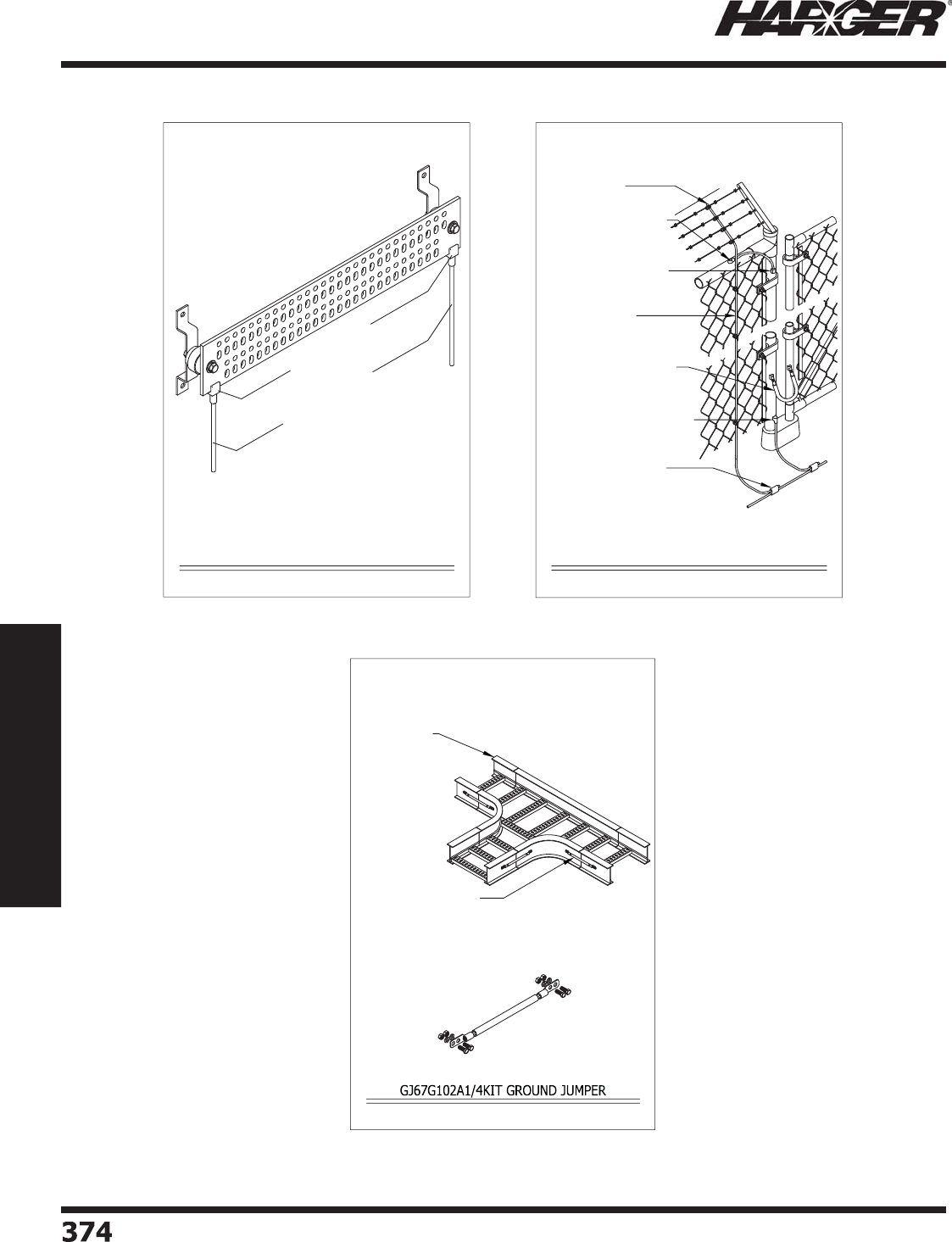
H
ar
g
er Li
g
htnin
g
& Groundin
g
•
©
2012 Phone 847-548-8700 • Fax 847-548-8755 • U.S. 800-842-743
7
3
7
4374
Section 6
Technical Assistance
S
ect
io
n 6.7
W
ireless C
o
mmunicati
o
n Details
EXOTHERMIC WELD
CONNECTION
NO. GBIT14424M-22T, 1/4" x 4" x 24" SOLID COPPER
GROUND BAR WITH INSULATORS AND BRACKETS,
AND WITH TWO 25'-0" NO. 2T, #2 AWG TIN COATED
COPPER GROUND CONDUCTORS
NO. GBIT14424M22T GROUND BAR DETAIL
#2AWG SOLID TINNED
CU X 25FT LONG
NTS
HARGER LIGHTNING & GROUNDING
847-548-8700 800-842-7437 www.harger.com
2012
9
CONNECT GROUND CONDUCTOR
TO POST WITH VA STYLE
ULTRAWELD CONNECTION
CONNECT FENCE BONDING
CONDUCTOR TO GROUND
CONDUCTOR WITH PT STYLE
ULTRAWELD CONNECTION
NO. HD STYLE ULTRAWELD
CONNECTION
NO. VU STYLE ULTRAWELD
CONNECTION
NO. GJX STYLE GATE JUMPER
WITH VA STYLE ULTRAWELD
CONNECTION
NO. FGC2, FENCE
GROUNDING CLAMP
TYPICAL FENCE & GATE BONDING DETAIL
NTS
COPPER LIGHTNING
PROTECTION OR
GROUNDING CONDUCTOR
HARGER LIGHTNING & GROUNDING
847-548-8700 800-842-7437 www.harger.com
2012
9
NTS
CABLE TRAY
NO. GJ67G102A1/4KIT,
INSULATED GROUND JUMPER
WITH MOUNTING HARDWARE
HARGER LIGHTNING & GROUNDING
847-548-8700 800-842-7437 www.harger.com
2012
9

H
ar
g
er Li
g
htnin
g
& Groundin
g
•
©
2012 Phone 847-548-8700 • Fax 847-548-8755 • U.S. 800-842-743
7
3
7
5
375
Section 6
Technical Assistance
S
ection 26 05 26.xx (Formerly 16065) – Si
g
nal Reference Grid System Specifi catio
n
Part 1 –
G
ENERA
L
1.01 Summar
y
a. Provide a complete
g
roundin
g
system that reduces or eliminates hi
g
h frequency transients by
achievin
g
a common
g
round reference for all equipment within a conti
g
uous area. It consists
of a si
g
nal reference
g
rid, low-impedance bondin
g
straps, transient suppression plates and bare copper
bondin
g
conductors.
b. The si
g
nal reference
g
rid system shall be installed by a fi rm actively en
g
a
g
ed in the installation of hi
g
h
frequency
g
round systems.
c. The work covered under this section of the specifi cation consists of furnishin
g
labor, materials and
services required for the completion of a functional si
g
nal reference
g
rid system approved by the
architect and en
g
inee
r
1.02 References: The completed si
g
nal reference
g
rid system shall comply with the latest issue of the followin
g
standards and form a
p
art of this s
p
ecifi cation.
a. IEEE Std.1100, IEEE Recommended Practice for Powerin
g
and Groundin
g
Electronic Equipment.
b. NFPA 70, National Electric Code
1.
03
S
ub
mitt
a
l
s
a. Layout drawin
g
(s) showin
g
the confi
g
uration of the si
g
nal reference
g
rid shall be submitted to the
architect and en
g
ineer for approval prior to installation.
b. Catalo
g
pa
g
es or technical data sheets for all products used to as part of the si
g
nal reference
g
rid
System shall be submitted to the architect and en
g
ineer for approval prior to installation.
1.04 Delivery, Stora
g
e and Handlin
g
a. Store products in manufacturer’s unopened packa
g
in
g
until ready for installation.
Part 2 – PR
O
D
U
CT
S
2.
0
1 St
a
n
da
r
d
a. All materials used in the installation shall be new and shall comply in wei
g
ht, size and composition
as re
q
uired b
y
manufacturer and shall be labeled or listed b
y
Underwriters Laboratories Inc. for use
in electrical
g
roundin
g
. The system furnished under this specifi cation shall be the standard product of a
manufacturer re
g
ularly en
g
a
g
ed in the production of hi
g
h frequency
g
roundin
g
equipment.
2.02 Acce
p
table Manufacturer
s
a. Har
g
er Li
g
htnin
g
& Groundin
g
301 Zie
g
ler Drive, Grayslake, IL 60030
(
847
)
548-8700 ● 800-842-7437 ● Fax
(
847
)
548-8755
E-mail: har
g
ersales@har
g
er.com ● Web-site: www.har
g
er.com
2.
03
M
a
teri
a
l
s
a. The si
g
nal reference
g
rid (SBG) shall be made from soft copper fl at strip, 2 inches wide by 26
g
a
g
e,
and factory-made usin
g
MIG welds on two-foot centers.
S
ect
io
n 6.8
S
i
g
nal Reference Grid System Specifi catio
n

H
ar
g
er Li
g
htnin
g
& Groundin
g
•
©
2012 Phone 847-548-8700 • Fax 847-548-8755 • U.S. 800-842-743
7
3
7
6376
Section 6
Technical Assistance
S
ection 26 05 26.xx (Formerly 16065) – Si
g
nal Reference Grid System Specifi catio
n
b
. SBG r
o
lls sh
a
ll
b
e
b
etween 4 feet t
o
1
6
feet wi
d
e.
c. All fi eld made connections to the si
g
nal reference
g
rid (SBG), raised fl oor pedestals, buildin
g
columns,
pipes and other metal items shall be made usin
g
the Ultraweld® Exothermic Weldin
g
Process.
d. The SBG sections shall be rolled on tubes with the outside of the roll
p
rotected for shi
p
ment.
e. SBG rolls shall be labeled on the ends for eas
y
identifi cation.
Part
3
– EXEC
U
TI
O
N
3
.
0
1 Gener
a
l Inst
a
ll
a
ti
on
a. The installation shall be installed b
y
a
q
ualifi ed, licensed electrical contractor.
3
.
0
2 SBG Inst
a
ll
a
ti
on
a. SBG sections shall be welded to
g
ether usin
g
Ultraweld Mold SBG2016K with US32 Weld Metal and
MH-1 Handle Clam
p
. For smokeless version add Suffi x “SX” to mold and weld metal
p
art numbers. To
j
oin sections to
g
ether, overlap the outside strip of one section over the outside strip of the ad
j
acent
section and weld to
g
ether every two feet.
b. The SBG should be installed 6 inches to 18 inches from the outside walls to avoid interference with
p
edestals. SBG does not have to be exactl
y
centered between
p
edestals.
c. Whenever an obstruction is encountered, it is acceptable to cut the SBG to
g
o around the obstruction
and splice connectin
g
pieces of the SBG to suit.
d. SBG squares should not line up between ad
j
acent sections in a room or between rooms. Offset squares,
fi rst in one direction, then the other. This prevents welds from lyin
g
on top of one another and minimizes
interference to
p
edestals.
e. The SBG does not have to be bonded to the fl oor in most circumstances. If an
y
section does not lie fl at,
p
edestal mastic or other convenient means can be used to bond to the fl oor. Pedestal mastic should be
used to hold the SBG to the fl oor near hi
g
h-speed air inlets. The mastic should not contain sulfur.
f. D
o
n
o
t
u
se m
a
stic
u
ntil
a
ll SBG m
a
ts h
a
ve
b
een inst
a
lle
d
a
n
d
a
ll
U
ltr
a
wel
d
c
o
nnecti
o
ns
b
etween m
a
ts
and all low im
p
edance riser and
p
edestal connections have been made.
g
. If a section of SBG is dama
g
ed, then repair with Mold SRG2016K with US32 Weld Metal and MH-1
Handle Clam
p
. For smokeless version add Suffi x “SX” to mold and weld metal
p
art numbers. It is
permissible to splice sections of copper strip to len
g
then SBG conductors so they clear preexistin
g
ob
j
ects on fl oor.
h. Use Low Im
p
edance Riser
(
LIR
)
to connect each e
q
ui
p
ment enclosure to the SBG. Ultraweld Mold
SRG2016K with US32 Weld Metal and MH-1 Handle Clam
p
is used for this connection. For smokeless
version add Suffi x “SX” to mold and weld metal
p
art numbers.
i. LIR to be 26
g
a
g
e x 2” x 72 copper strip, Part No.LIR72. Do not connect LIR risers to SBG strips closest
to outside walls. If
p
ossible, connect LIR no closer than the second SBG row awa
y
from outside walls of
r
oom
.
S
ect
io
n 6.
8
S
i
g
nal Reference Grid System Specifi catio
n

H
ar
g
er Li
g
htnin
g
& Groundin
g
•
©
2012 Phone 847-548-8700 • Fax 847-548-8755 • U.S. 800-842-743
7
3
77
377
Section 6
Technical Assistance
S
ection 26 05 26.xx (Formerly 16065) – Si
g
nal Reference Grid System Specifi catio
n
j
. Exceptions can be made re
g
ardin
g
HVAC equipment if these are already positioned near walls. Cut LIR
as short as
p
ossible in all cases.
k. Always install two LIRs per equipment cabinet with one LIR bein
g
20% to 40% lon
g
er than the next
and connect to the e
q
ui
p
ment on o
pp
osite sides.
3.03 Bondin
g
Pedestal
s
a. Connect every sixth pedestal in each direction to the SBG usin
g
#6 AWG 7 strand copper cable.
b. #6 AWG 7 strand copper is connected to the SBG with Mold BCF61.5016B usin
g
US25 Weld Metal and
MH-1 Handle Clam
p
.
c. For the 1” round
p
edestals, use Mold VH61RDMX, MH-4 Handle Clam
p
, and US25 Weld Metal.
d. For the 7/8” s
q
uare
p
edestals, use Mold VHO6.8SQMX, MH-4 Handle Clam
p
and US25 Weld Metal.
e. For the 1” s
q
uare
p
edestals, use Mold VHO61SQMX, MH-4 Handle Clam
p
and US25 Weld Metal. 3.6.
The cable should take the shortest path between the pedestal and the Si
g
nal Reference Grid. The
len
g
th of the wire should not exceed 2 feet.
f. For smokeless version add Suffi x “SX” to mold and weld metal
p
art numbers.
3.04 Bondin
g
Buildin
g
Steel
a. All columns within and at perimeter of the computer room shall be bonded to the SBG usin
g
#6 AWG 7
strand co
pp
er cable with Mold VA6B, MH-1 Handle Clam
p
and US45 Weld Metal.
b. #6 AWG 7 strand copper is connected to the SBG with Mold BCF61.5016B usin
g
US25 Weld Metal and
MH-1 Handle Clamp. The cable should take the shortest path between the buildin
g
steel and the Si
g
nal
Reference Gri
d
.
c. For smokeless version add Suffi x “SX” to mold and weld metal
p
art numbers.
3.05 Bondin
g
Other Steel Member
s
a. All conduits, water pipes, ducts, etc. enterin
g
the computer room shall be bonded to the SBG (at each
end of the room if these are horizontal
)
.columns within and at
p
erimeter of the com
p
uter room shall
be bonded to the SBG usin
g
#6 AWG 7 strand copper cable with Mold VA6B, MH-1 Handle Clamp and
U
S4
5
Wel
d
Met
a
l.
b. Use #6 AWG 7 strand co
pp
er cable.
c. Use Har
g
er Li
g
htnin
g
& Groundin
g
CPC Series of pipe clamps for attachin
g
the #6 wire to conduit,
water
p
i
p
es, and other round conductive members.
d. The #6 AWG 7 strand copper cable is connected to the SBG with Mold BCF61.5016B usin
g
US25 Weld
Metal and MH-1 Handle Clam
p
.
e. For smokeless version add Suffi x “SX” to mold and weld metal
p
art numbers.
S
ect
io
n 6.8
S
i
g
nal Reference Grid System Specifi catio
n

H
ar
g
er Li
g
htnin
g
& Groundin
g
•
©
2012 Phone 847-548-8700 • Fax 847-548-8755 • U.S. 800-842-743
7
378
378
Section 6
Technical Assistance
S
ection 26 05 26.xx (Formerly 16065) – Si
g
nal Reference Grid System Specifi catio
n
3
.
06
C
oo
r
d
in
a
ti
on
a. Coordinate the installation of the hi
g
h frequency si
g
nal reference
g
rid
g
roundin
g
system with other
trades to avoid dama
g
e of installed materials.
END
O
F SECTI
O
N 2
6
05
2
6
.xx
S
ect
io
n 6.
8
S
i
g
nal Reference Grid System Specifi catio
n
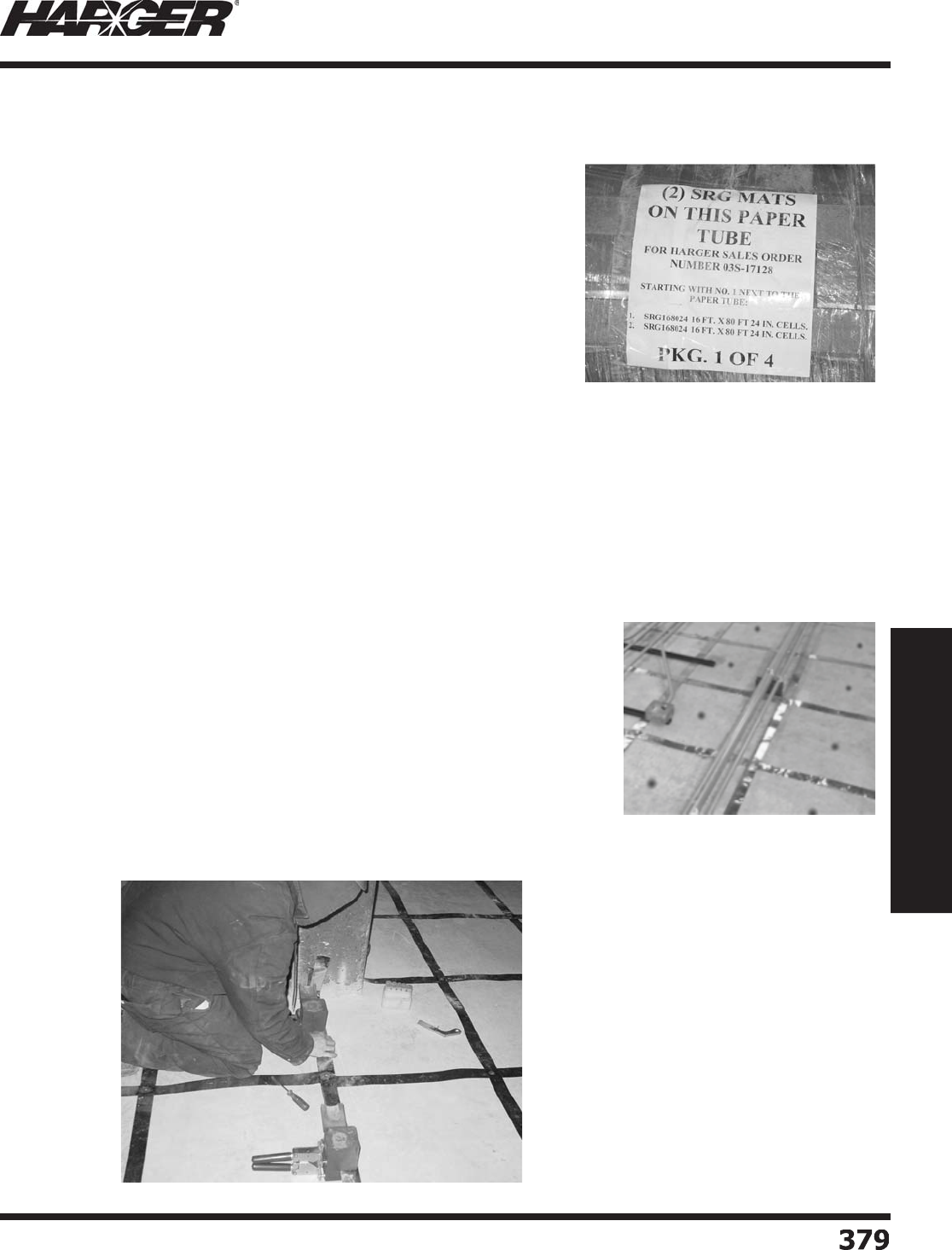
H
ar
g
er Li
g
htnin
g
& Groundin
g
•
©
2012 Phone 847-548-8700 • Fax 847-548-8755 • U.S. 800-842-743
7
3
79
379
Section 6
Technical Assistance
T
hese instructions are intended to ensure the proper installation of Har
g
er
S
i
g
nal Referenc
e
Grids
(
SRG
)
,
w
hile savin
g
time and money for the installer.
Rece
i
v
i
n
g
& Stora
g
e
1. Har
g
er SRG rolls are shipped in closed trucks unless otherwise
s
pecifi ed. This usually requires a loadin
g
dock and a forklift truck
capable of unloadin
g
the SRG rolls.
2. Har
g
er tries to limit SRG rolls to a wei
g
ht of 250 pounds each.
3. SRG rolls are labeled on the ends. If you are storin
g
the rolls
temporarily, make sure the marked ends are facin
g
in the same
direction for eas
y
identifi cation.
4
. Rolls should be checked a
g
ainst drawin
g
s and stacked so the fi rst
r
o
lls t
o
b
e inst
a
lle
d
a
re the e
a
siest
o
nes t
o
u
nst
a
ck.
5
. Indoor stora
g
e is recommended.
6
. Check your shipment a
g
ainst the shippin
g
papers and installation
drawin
g
s to be sure the proper quantity has been received. Any discrepancies of any kind should be
brou
g
ht to the attention of the carrier and your distributor.
7. Do not remove the roll
p
rotection until the roll is in
p
lace and read
y
to unroll.
Installation of the Si
g
nal Reference Grid
T
he SRG should be installed
p
rior to the installation of the raised fl oor
p
edestals.
1. Mark the location of
p
edestals on fl oor so the
y
can be avoided with
the SRG stri
p
s.
2. Start in one corner of the room with the
p
ro
p
er roll as identifi ed on
the drawin
g
. The pedestal spot should be approximately in center o
f
g
rid openin
g
. This will normally be 12" from the wall.
3. Any obstructions, such as columns or existin
g
obstacles, can be
handled in either of the followin
g
ways:
• C
u
t the SRG t
o
fi t
a
r
ou
n
d
the
ob
str
u
cti
o
n.
• Place the SRG on one side of the obstruction and, usin
g
one or mor
e
workers, pull the SRG around the obstruction cuttin
g
where needed.
P
edestal locations marked b
y
the do
t
Note - It’s oka
y
to cut and patch the
S
R
G
. Patching is done b
y
welding cu
t
s
ections together with the Ultrawel
d
process
.
S
ect
io
n 6.9
S
i
g
nal Reference Grid (SRG) Installation Instructions
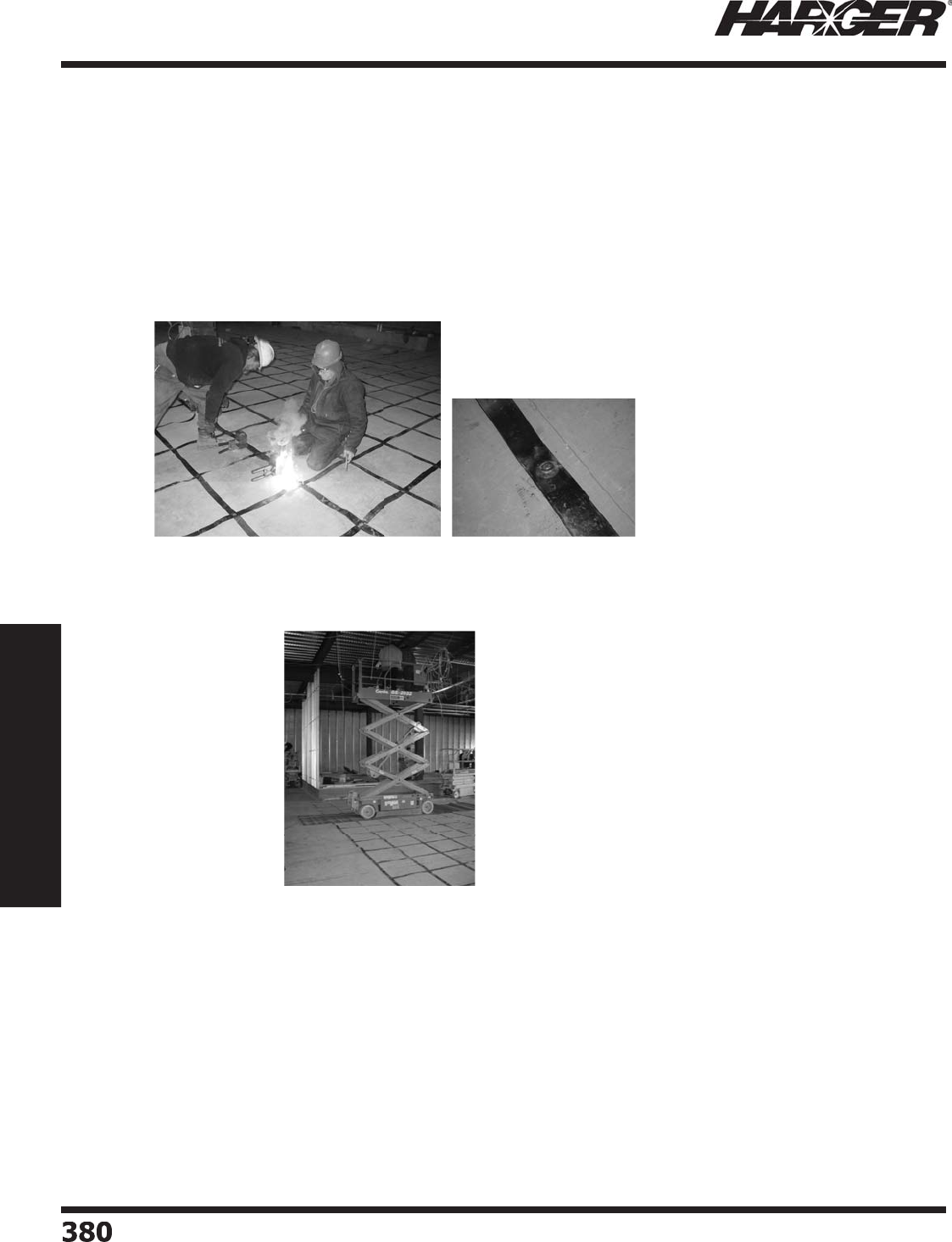
H
ar
g
er Li
g
htnin
g
& Groundin
g
•
©
2012 Phone 847-548-8700 • Fax 847-548-8755 • U.S. 800-842-743
7
380
380
Section 6
Technical Assistance
4
. The outside strip of ad
j
acent sections must overlap for interconnectin
g
with the Ultraweld Process. You
can
j
oin ad
j
acent sections of the SRG as you
g
o, or you can wait until the entire room is covered with
the SRG sections and then weld all at once. Never make a weld over a factor
y
weld.
5
. If the SRG were ever to rip or tear, it can be patched by weldin
g
.
6
. Puttin
g
pedestal mastic between the SRG and the fl oor can smooth any buckles in the SRG out. It
i
s not necessary to use other means of fastenin
g
to the fl oor. Do not use mastic until all Ultraweld
c
o
nnecti
o
ns h
a
ve
b
een m
ad
e.
7. All connections between sections of the SRG and the risers,
p
edestal bonds, column bonds, and other
metal bonded to the SRG shall use the Ultraweld molds and weld metal
p
rovided.
8. Pedestal mastic should be used to hold the SRG to the fl oor near hi
g
h-speed air inlets. Do not use
mastic until all ULTRAWELD connections have been made. Use mastic that does not contain sul
p
hur.
9
. When pullin
g
cables after the fl oor is installed, especially cables with connectors installed it is
s
u
gg
ested to put a cloth ba
g
or other protection over the end of the cable to protect the connector and
g
uard a
g
ainst sna
gg
in
g
the SRG.
S
pecifi c Instructions for Makin
g
Ultraweld Exothermic Connections
1. Follow the
g
eneral and specifi c instructions furnished with the mold.
2. If the Ultraweld Smokeless system is not bein
g
used, cover strip ad
j
acent to the mold to prevent any
s
platter from marrin
g
the SRG strip. Never make welds over factory welds.
3. If the Ultraweld Smokeless system is bein
g
used and prevention of even a small amount of dust is
critical, then clean and
p
re
p
are the mold for next weld in an area outside of the “clean area”.
If
not using Ultraweld
S
mokeless, cover strip adjacent to the mold to
p
revent an
y
splatter
f
rom marring the
S
R
G
strip. Never make weld
s
o
ver
f
actor
y
welds.
During and a
f
ter installation, care should be taken when
w
alking or operating equipment over the
S
R
G
to avoi
d
t
ripping and damaging the
S
R
G
. I
f
heav
y
or extended tra
ffi
c
i
s expected, sheets o
f
pl
y
wood or other durable covering
s
hould be used to cover the
S
R
G
.
S
ect
io
n 6.9
S
i
g
nal Reference Grid (SRG) Installation Instructions

H
ar
g
er Li
g
htnin
g
& Groundin
g
•
©
2012 Phone 847-548-8700 • Fax 847-548-8755 • U.S. 800-842-743
7
381
381
Section 6
Technical Assistance
Section 27 05 26 (Formerly 16740) – Grounding and Bonding for Communications
Systems Specifi cation
Part 1 –
G
ENERA
L
1.
0
1 W
o
rk Incl
ud
e
d
:
a. Provide all labor, materials, tools, installation e
q
ui
p
ment, and test e
q
ui
p
ment re
q
uired for the com
p
lete
installation of
g
roundin
g
and bondin
g
for telecommunications systems within the structure.
1.
0
2 Reference
s
a. ANSI-J-STD-607-A-2002 – Commercial Buildin
g
Groundin
g
(Earthin
g
) and Bondin
g
Requirements for
Telec
o
mm
u
nic
a
ti
o
n
s
b. National Fire Protection Association
(
NFPA – 70
)
, National Electrical Code
(
NEC
)
-2011
c. ANSI T1.333-2001 – Groundin
g
and Bondin
g
of Telecommunications Equipmen
t
1.03 Qualit
y
Assurance
a. The materials and their installation shall conform to the re
q
uirements of ANSI-J-STD-607-A-2002 and
the N
a
ti
o
n
a
l Electric
a
l C
od
e
b. Use adequate numbers of skilled work-persons thorou
g
hly trained and experienced on the necessary
crafts and com
p
letel
y
familiar with the s
p
ecifi ed re
q
uirements and methods needed for the
p
ro
p
er
p
erformance of the work of this Section.
Part 2 – PR
O
D
U
CT
S
2.
0
1 St
a
n
da
r
d
a. All materials used in the installation shall be new and shall comply in wei
g
ht, size and composition
as re
q
uired b
y
manufacturer and shall be labeled or listed b
y
Underwriters Laboratories Inc. for use in
electrical
g
roundin
g
.
2.02 Acce
p
table Manufacture
s
a. Har
g
er Li
g
htnin
g
& Groundin
g
301 Zie
g
ler Drive, Grayslake, IL 60030
(
847
)
548-8700 ● 800-842-7437 ● Fax
(
847
)
548-8755
E-mail: har
g
ersales@har
g
er.com ● Web-site: www.har
g
er.com
2.03 Telecommunications Main Groundin
g
Busbar (TMGB)
a. The TMGB shall be Har
g
er catalo
g
number GBI14412TMGB, ¼”T x 4”W x 12”L copper
g
round bar.
I. The TMGB shall be predrilled with holes for use with standard sized lu
g
s.
II. The TMGB shall be UL listed and meet the re
q
uirements of ANSI-J-STD-607-A-200
2
III. The TMGB shall be sized as above or len
g
thened to meet requirements of the immediate
application with consideration for future
g
rowth.
S
ect
io
n 6.10:
G
roundin
g
& Bondin
g
for Communications
Sy
stem S
p
ecifi cation
(
ANSI-J-STD-607-A
)

H
ar
g
er Li
g
htnin
g
& Groundin
g
•
©
2012 Phone 847-548-8700 • Fax 847-548-8755 • U.S. 800-842-743
7
382
382
Section 6
Technical Assistance
Section 27 05 26 (Formerly 16740) – Grounding and Bonding for Communications
Systems Specifi cation
2.04 Telecommunications Groundin
g
Busbar (TGB)
a. The TGB shall be Har
g
er catalo
g
number GBI14212TGB, ¼”T x 2”W x 12”L copper
g
round bar.
I. The TMGB shall be predrilled with holes for use with standard sized lu
g
s.
II. The TMGB shall be UL listed and meet the re
q
uirements of ANSI-J-STD-607-A-2002.
III. The TMGB shall be sized as above or len
g
thened to meet requirements of the immediate application
with consideration for future
g
rowth.
2.
05
C
o
n
du
ct
o
r
s
a. Conductors shall be stranded copper conductors with
g
reen insulatio
n
I. Minim
u
m c
o
n
du
ct
o
r size N
o
.
6
AWG.
II. Conductors shall be sized at 2 kcmil per linear foot of conductor len
g
th. For example: A conductor
25 feet in len
g
th shall be No. 2 AWG (66,360 cmil). A conductor 100 feet in len
g
th shall be No. 4/0
AWG
(
211,600 cmil
)
III. Ins
u
l
a
ti
o
n sh
a
ll
b
e r
a
te
d
f
o
r the envir
o
nment where it is inst
a
lle
d
.
2
.06 Connector Lu
gs
a. Lu
g
s for connectin
g
to the TMGB and TGB shall be UL Listed two-hole, lon
g
barrel, electro tin-plated
compression lu
g
s with inspection port, Har
g
er series GECLB.
I. Antioxidant
j
oint compound, Har
g
er series HCAJC shall be applied to the contact areas.
II. Lu
g
s shall be secured to the
g
round bars with ¼” minimum stainless steel hex head cap screws
with stainless steel washers, lock washers and nuts.
2.
0
7 Ex
o
thermic Wel
d
e
d
C
o
nnecti
o
n
s
a. Exothermic Welded connections shall be Ultraweld by Har
g
er.
I. Weld types BE shall be made to the
g
round bars usin
g
appropriate size weld metal.
II. Weld t
yp
es VA, VD, or VU shall be made to structural steel framework
Part
3
– EXEC
U
TI
O
N
3
.
0
1 Inst
a
ll
a
ti
on
a. The telecommunications main
g
roundin
g
bar (TMGB) is a dedicated extension of the buildin
g
g
roundin
g
electrode system for the telecommunications system. The TMGB should be located near the
telec
o
mm
u
nic
a
ti
o
ns service entr
a
nce
a
n
d
the electric service entr
a
nce.
I. The TMGB shall be connected to the main electric service entrance panel
g
round or the branch
electric panel
g
round that serves the telecommunications equipment.
II. The TMGB shall be located to minimize the len
g
th of the bondin
g
conductor for telecommunications
from the TMGB to the electric service
g
round.
III. The bondin
g
conductor for telecommunications shall be at least the same size as the
telecommunications backbone
(
TBB
)
conductor.
IV. The TMGB shall serve telecommunications e
q
ui
p
ment that is located in the same room or s
p
ace.
V. Connections to the TMGB shall be made by exothermic weldin
g
or by listed two-hole compression
lu
g
s.
S
ect
io
n 6.10:
G
roundin
g
& Bondin
g
for Communications
Sy
stem S
p
ecifi cation
(
ANSI-J-STD-607-A
)

H
ar
g
er Li
g
htnin
g
& Groundin
g
•
©
2012 Phone 847-548-8700 • Fax 847-548-8755 • U.S. 800-842-743
7
383
383
Section 6
Technical Assistance
Section 27 05 26 (Formerly 16740) – Grounding and Bonding for Communications
Systems Specifi cation
VI. All metal conduits or raceways for telecommunications cablin
g
located within the same room or
s
p
ace as the TMGB shall be bonded to the TMGB.
a. Metal conduits 1” diameter and lar
g
er shall be bonded usin
g
Har
g
er series CPC electro tin-
p
lated
p
i
p
e clam
p
s.
b. Metal conduits less than 1” diameter shall be bonded usin
g
Har
g
er TBGC4SCS electro tin-
plated conduit bondin
g
clamps.
c. Metal cable trays shall be bonded usin
g
Har
g
er TBCTC electro tin-plated cable tray bondin
g
clam
p
s.
d. Bondin
g
surface areas shall be cleaned to bare metal removin
g
all paint, etc. The contact
area shall be protected from corrosion usin
g
antioxidant
j
oint compound. Har
g
er series HCAJC
for copper to copper connections or Har
g
er series HAAJC for copper to aluminum or steel
c
o
nnecti
o
ns.
VII. Where an electric
p
ower
p
anel for telecommunications e
q
ui
p
ment is located in the same room or
space as the TMGB, the panel
g
round bus or panel enclosure shall be bonded to the TMGB.
VIII. The TMGB shall be located in an area that is accessible to telecommunications
p
ersonnel
b. The telecommunications backbone (TBB) is a conductor that ori
g
inates at the TMGB and extends
throu
g
hout the buildin
g
interconnectin
g
all telecommunications
g
roundin
g
busbars (TGBs) with
the TMGB.
I. The TBB shall be a co
pp
er conductor. The minimum size of the conductor shall be No. 6 AWG.
The size of the conductor shall be increased 2 kcmil per linear foot as the len
g
th of the TBB
increases. For example: A TBB 25 feet in len
g
th shall be No. 2 AWG (66,360 cmil). A TBB
100 feet in len
g
th shall be No. 4/0 AWG (211,600 cmil
)
II. The TBB conductors should be installed without s
p
lices. Where s
p
lices are necessar
y
, the number
of s
p
lices should be minimized and located in accessible telecommunications s
p
aces. S
p
lices shall
be made usin
g
exothermic weldin
g
, listed irreversible compression connectors or equivalent.
III. The buildin
g
water pipin
g
system shall not be used as a TBB.
IV. Met
a
llic c
ab
le shiel
d
s
o
r met
a
llic c
o
n
du
its sh
a
ll n
o
t
b
e
u
se
d
a
s
a
TBB.
c. A telecommunications
g
roundin
g
busbar (TGB) shall be provided in each area where
telecommunication equipment is located. The TGB is the
g
roundin
g
connection point for
telecommunications s
y
stems and e
q
ui
p
ment in each se
p
arate area.
I. The TGBs sh
a
ll
b
e c
o
nnecte
d
t
o
the TMGB vi
a
the TBB c
o
n
du
ct
o
r.
II. The TBB
a
n
d
o
ther TGBs within the s
a
me
a
re
a
sh
a
ll
b
e
bo
n
d
e
d
t
o
the TGB with
a
c
o
n
du
ct
o
r the
s
a
me size
a
s the TBB.
III. The bondin
g
conductor between the TBB and the TGB shall be continuous and routed in the
shortest strai
g
ht-line path possible.
S
ect
io
n 6.10:
G
roundin
g
& Bondin
g
for Communications
Sy
stem S
p
ecifi cation
(
ANSI-J-STD-607-A
)

H
ar
g
er Li
g
htnin
g
& Groundin
g
•
©
2012 Phone 847-548-8700 • Fax 847-548-8755 • U.S. 800-842-743
7
38
4384
Section 6
Technical Assistance
IV. Connections to the TGB shall be made by exothermic weldin
g
or by listed two-hole compression
lu
g
s.
V. All metal conduits or raceways for telecommunications cablin
g
located within the same room or
s
p
ace as the TGB shall be bonded to the TGB.
VI. Where an electric
p
ower
p
anel for telecommunications e
q
ui
p
ment is located in the same room or
space as the TGB, the panel
g
round bus or panel enclosure shall be bonded to the TGB.
d. Where there are multi
p
le telecommunications rooms or s
p
aces with multi
p
le TBBs, the TBBs
shall be interconnected with a Groundin
g
Equalizer (GE) conductor at the TGBs.
I. The GE shall be sized as s
p
ecifi ed for the TBB.
II. Connections of the GE to the TGBs shall be made by exothermic weldin
g
or by listed two-hole
compression lu
g
s.
e. In structural steel frame buildin
g
s, where the steel framework is accessible within the room; the TMGB
and each TGB shall be bonded to the structural steel frame usin
g
a minimum No. 6 AWG conductor.
I. Connections to the structural steel frame shall be made by exothermic weldin
g
or by Har
g
er No.
217 or Har
g
er No. 223T electro tin-plated bronze bondin
g
plates. The area of contact on the steel
frame shall be cleaned to bare metal removin
g
all paint and mill scale. The contact area
shall be protected from corrosion usin
g
Har
g
er series HAAJC antioxidant
j
oint compound.
II. Where the structural steel frame is external to the room and is accessible, the structural steel
should be bonded to the TGB or the TMGB usin
g
a minimum No. 6 AWG conductor.
END
O
F SECTI
O
N 27
05
2
6
Section 27 05 26 (Formerly 16740) – Grounding and Bonding for Communications
Systems Specifi cation
S
ect
io
n 6.10:
G
roundin
g
& Bondin
g
for Communications
Sy
stem S
p
ecifi cation
(
ANSI-J-STD-607-A
)

H
ar
g
er Li
g
htnin
g
& Groundin
g
•
©
2012 Phone 847-548-8700 • Fax 847-548-8755 • U.S. 800-842-743
7
385
385
Section 7
Indexes
S
ect
io
n 7
In
d
exe
s
In
d
ex
Descr
i
pt
i
on Pa
g
e
7.1 P
a
rt N
u
m
b
er In
d
e
x
...........................................................................
386
7.2 Ke
y
Word Inde
x
................................................................................
405

H
ar
g
er Li
g
htnin
g
& Groundin
g
•
©
2012 Phone 847-548-8700 • Fax 847-548-8755 • U.S. 800-842-743
7
386
386
Section 7
Indexes
S
ect
io
n 7.1
Part N
u
mber In
d
ex
Part Number Page No.
g
Part Number Page No.
g
Part Number Page No.
g
1
/
0-19
.......................................
1
2
1
/
019
G
......................................
1
2
1
0
.............................................
1
3
1
0
CC
.........................................
45
1
0
PB
G
.......................................
45
1
0
PB
S
.......................................
45
1
0
P
P
.........................................
45
1
0
P
S
.........................................
45
11
/
16WIN
S
................................
7
3
11
0
...........................................
18
11
00
A1
......................................
74
11
0
C
.........................................
19
1
20
.........................................
1
6
9
1208UPC
...................................
18
1
20N
.......................................
1
6
9
120T
.......................................
T
1
6
9
1
2
1
0
.........................................
18
1210ALAT
................................
T
1
6
4
1210CUAT
...............................
T
1
63
1
2
1
0
C
U
AT
N
.............................
1
63
1210CUATT
..............................
T
1
63
1
2
1
0
SS
3
....................................
20
121
.........................................
1
6
9
1212ALAT
................................
T
1
6
4
1
2
1
2
ALAT-WSC
36
.....................
1
66
1212ASTAT
..............................
T
1
65
1
2
1
2
ASTAT-WSC
36
...................
1
66
1212CSTAT
..............................
T
1
65
1212CUAT
...............................
T
1
63
1
2
1
2
C
U
AT
N
.............................
1
63
1212CUATT
..............................
T
1
63
1
2
1
2
C
U
AT-WSC
36
....................
1
66
1216ALAT
................................
T
1
6
4
1216ASTAT
..............................
T
1
65
1216CSTAT
..............................
T
1
65
1216CUAT
...............................
T
1
63
1
2
1
6
C
U
AT
N
.............................
1
63
1216CUATT
..............................
T
1
63
1218ALAT
................................
T
1
6
4
1218ASTAT
..............................
T
1
65
1218CSTAT
..............................
T
1
65
1218CUAT
...............................
T
1
63
1218CUAT
N
.............................
1
63
1218CUATT
..............................
T
1
63
1
2
1
N
.......................................
1
6
9
121T
.......................................
T
1
6
9
1
22
.........................................
1
6
9
1224ALAT
................................
T
1
6
4
1224ASTAT
..............................
T
1
65
1
22
4ASTAT-WSC
36
...................
1
66
1224CSTAT
..............................
T
1
65
1
22
4CSTAT-WSC
36
...................
1
66
1224CUAT
...............................
T
1
63
1
22
4C
U
AT
N
.............................
1
63
1224CUATT
..............................
T
1
63
1
22
4C
U
AT-WSC
36
....................
1
66
122-5
/
8F1
/
2
F
...........................
1
6
9
1
22N
.......................................
1
6
9
122T
.......................................
T
1
6
9
1
23
.........................................
1
6
9
1236ALAT
................................
T
1
6
4
1236CUAT
...............................
T
1
63
1
236
C
U
AT
N
.............................
1
63
1236CUATT
..............................
T
1
63
1
23N
.......................................
1
6
9
123T
.......................................
T
1
6
9
1
2
4
.........................................
1
6
9
1248ALAT
................................
T
1
6
4
1248CUAT
...............................
T
1
63
1248CUAT
N
.............................
1
63
1248CUATT
..............................
T
1
63
1248SCAT
................................
T
230
1
2
4
N
.......................................
1
6
9
124T
.......................................
T
1
6
9
1
25
.........................................
1
6
9
1
25N
.......................................
1
6
9
125T
.......................................
T
1
6
9
1
26
.........................................
17
0
1
26G
.........................................
20
1
26
G
U
PC
...................................
20
1
27
.........................................
17
0
127M
.......................................
17
0
128
.........................................
17
0
128
G
.........................................
20
128GUPC
...................................
20
128M
.......................................
17
0
1
2
9M
.......................................
17
0
1
2CC
.........................................
45
1
2
PB
G
.......................................
45
1
2
PB
S
.......................................
45
1
2
P
S
.........................................
45
1
2
T
G
.........................................
45
1
33
.........................................
171
1
33N
.......................................
171
133T
.......................................
T
171
1
3
4
.........................................
171
1
3
4
N
.......................................
171
134T
.......................................
T
171
1
35
.........................................
171
1
35N
.......................................
171
135T
.......................................
T
171
1
36
.........................................
171
1
36N
.......................................
171
136T
.......................................
T
171
1
37
.........................................
171
1
3
7
N
.......................................
171
137T
.......................................
T
171
138
.........................................
171
138
N
.......................................
171
138T
.......................................
T
171
1
3
9
.........................................
171
14
...........................................
1
55
140-18
....................................
17
2
140-18A
D
................................
17
2
14
0
-
2
4
....................................
17
2
14
0
-
2
4A
D
................................
17
2
14
0
-
36
....................................
17
2
14
0
-
36
A
D
................................
17
2
140-48
....................................
17
2
140-48A
D
................................
17
2
144-1
2
....................................
17
3
144-
2
4
....................................
17
3
144-
36
....................................
17
3
144-48
....................................
17
3
144-
60
....................................
17
3
14
5
-1
2
....................................
17
3
14
5
-
2
4
....................................
17
3
14
5
-
36
....................................
17
3
145-48
....................................
17
3
14
5
-
60
....................................
17
3
14
6
-1
2
....................................
17
3
14
6
-
2
4
....................................
17
3
14
6
-
36
....................................
17
3
146-48
....................................
17
3
14
6
-
60
....................................
17
3
14
7
.........................................
174
148
.........................................
174
149
.........................................
174
1
5
1
.........................................
178
1
5
11
2
I
....................................
178
15112IT
..................................
T
178
15138I
....................................
178
15138IT
..................................
T
178
151T
.......................................
T
178
1
55
-1
2
....................................
184
155-18
....................................
184
1
55
-
6
......................................
184
1
56
-1
2
....................................
184
156-18
....................................
184
1
56
-
6
......................................
184

H
ar
g
er Li
g
htnin
g
& Groundin
g
•
©
2012 Phone 847-548-8700 • Fax 847-548-8755 • U.S. 800-842-743
7
387
387
Section 7
Indexes
S
ect
io
n 7.1
Part N
u
mber In
d
ex
Part Number Page No.
g
Part Number Page No.
g
Part Number Page No.
g
1
56
BM-1
2
................................
184
156BM-18
................................
184
1
56
BM-
6
..................................
184
1
57
.........................................
180
1
5
7-1
2
....................................
184
157-18
....................................
184
1
5
7-
6
......................................
184
157T
.......................................
T
180
158
.........................................
180
158-1
2
....................................
184
158-18
....................................
184
158-5
/
8
...................................
180
158-5/8T
.................................
T
180
158-6
......................................
184
158BM-1
2
................................
184
158BM-18
................................
184
158BM-6
..................................
184
158T
.......................................
T
180
1
60
.........................................
181
160T
.......................................
T
181
1
62
-1
2
....................................
185
162-18
....................................
185
1
62
-
6
......................................
185
1
64
.........................................
186
18PB
G
.......................................
45
18PB
S
.......................................
45
18T
G
.........................................
45
2
...............................................
1
3
2
/
0-19
.......................................
1
2
2
/
019
G
......................................
1
2
2
/
0-
7
.........................................
1
2
2
/
0WC
.......................................
1
6
204
...............................
1
20
&
19
6
204T
.............................
T
1
20
&
19
6
205
.........................................
19
7
205T
.......................................
T
19
7
206
.........................................
19
7
206T
.......................................
T
19
7
207
.........................................
19
7
207T
.......................................
T
19
7
208
...............................
120 & 198
208T
.............................
T
120 & 198
2
1
0
.........................................
198
2
1
0
BM
.....................................
199
210T
.......................................
T
198
211R
.......................................
R
199
2
11XL
......................................
199
212-1
/2
...................................
20
1
212-1/2T
.................................
T
20
1
2
1
3
...............................
1
2
1
&
20
1
213T
.............................
T
1
2
1
&
20
1
2
1
6
.........................................
206
2
1
6
BM
.....................................
206
2
1
7
...............................
121 & 208
218
.........................................
207
218T
.......................................
T
207
2
19-1
......................................
208
219-1
/2
...................................
208
219-1/2T
.................................
T
208
219-1T
....................................
T
208
219-3
/
8
...................................
208
219-3/8T
.................................
T
208
219-5
/
8
...................................
208
219-5/8T
.................................
T
208
2
-19
G
........................................
1
2
2
-
7
............................................
1
2
220
.........................................
20
9
220T
.......................................
T
20
9
222
.........................................
207
222T
.......................................
T
207
223
...............................
1
2
1
&
20
9
223T
.............................
T
1
2
1
&
20
9
225
-1
2
....................................
188
225-18
....................................
188
225
-
6
......................................
188
225
BM-1
2
................................
188
225BM-18
................................
188
225
BM-
6
..................................
188
226
-1
2
....................................
189
226-18
....................................
189
226
-
6
......................................
189
226
BM-1
2
................................
189
226BM-18
................................
189
226
BM-
6
..................................
189
22
7
C
.......................................
194
22
7
G
.......................................
194
228C
.......................................
194
228
G
.......................................
194
230
H-1
2
..................................
191
230H-18
..................................
191
230H18BM
...............................
19
2
230
H-
2
4
..................................
191
230
HBM-1
2
..............................
191
230HBM-18
..............................
191
230
HBM-
24
..............................
191
230
V-1
2
..................................
191
230V-18
..................................
191
230V18BM
...............................
19
2
230
V-
2
4
..................................
191
230
VBM-1
2
..............................
191
230VBM-18
..............................
191
230
VBM-
24
..............................
191
23
1-1
2
....................................
202
23
1-4
......................................
202
23
1-
6
......................................
202
231-8
......................................
202
23
1S
2
-
2
..................................
1
22
23
1S
2
-
4
..................................
1
22
23
1S
2
-
6
..................................
1
22
2
4
0
-1
2
....................................
19
2
2
4
0
-
2
4
....................................
19
2
2
4
0
-
6
......................................
19
2
2
4-1
00
....................................
1
52
2
41-1
2
....................................
19
2
2
41-
2
4
....................................
19
2
2
41-
6
......................................
19
2
2
41
S
1
2
....................................
19
2
2
41
S24
....................................
19
2
2
41S
6
.....................................
19
2
2
4-
250
....................................
1
52
2
4-
25
C
O
IL
...............................
1
52
2
44
.........................................
19
3
244T
.......................................
T
19
3
2
4-
50
C
O
IL
...............................
1
52
2
4
5
.........................................
19
3
2
4
5
T
......................................
19
3
2
4
6
.........................................
19
3
246T
.......................................
T
19
3
250
.........................................
1
56
250260
....................................
255
26
1
.........................................
158
261T
.......................................
T
158
262
.........................................
158
262T
.......................................
T
158
26
4
.........................................
1
5
9
2
74-1
00
...................................
14
6
2
74S-1
00
.................................
14
6
2
7
5
-1
00
...................................
14
6
2
77S-1
00
.................................
14
6
2
7
G
...........................................
1
2
280-100
...................................
14
7
280-25
....................................
14
7
28-100
....................................
1
53
281-100
...................................
14
7
281-25
....................................
14
7
28-250
....................................
1
53
28-25COIL
...............................
1
53
28-50COIL
...............................
1
53
28T-100
...................................
1
53
28T-250
...................................
1
53

H
ar
g
er Li
g
htnin
g
& Groundin
g
•
©
2012 Phone 847-548-8700 • Fax 847-548-8755 • U.S. 800-842-743
7
388
388
Section 7
Indexes
Part N
u
mber In
d
ex
Part Number Page No.
g
Part Number Page No.
g
Part Number Page No.
g
S
ect
io
n 7.1
28T-25COIL
.............................
1
53
28T-50COIL
.............................
1
53
2
9
0
-1
00
...................................
14
6
2
9-1
00
....................................
1
52
2
91-1
00
...................................
14
6
2
9-
250
....................................
1
52
2
9-
25
C
O
IL
...............................
1
52
2
9-
500
....................................
1
52
2
9-
50
C
O
IL
...............................
1
52
2
9
5
-1
00
...................................
14
7
2
9
5
-
25
....................................
14
7
2
9
6
-1
00
...................................
14
7
2
9
6
-
25
....................................
14
7
2
9T-1
00
...................................
1
52
2
9T-
250
...................................
1
52
2
9T-
25
C
O
IL
.............................
1
52
2
9T-
500
...................................
1
52
2
9T-
50
C
O
IL
.............................
1
52
2T
.............................................
T
1
3
2
W
C
..........................................
1
6
3
/
0-19
.......................................
1
2
300
L
D
.......................................
25
30
1L
D
.......................................
25
302
L
D
.......................................
25
302U
.........................................
2
4
302U
GRC
...................................
25
303
L
D
.......................................
25
305
...........................................
2
4
32
-1
00
....................................
1
52
320
.........................................
1
60
32
1B
.......................................
1
60
32
1
G
.......................................
1
60
32
-
250
....................................
1
52
32
-
25
C
O
IL
...............................
1
52
32
-
500
....................................
1
52
32
-
50
C
O
IL
...............................
1
52
32
T-1
00
...................................
1
52
32
T-
250
...................................
1
52
32
T-
25
C
O
IL
.............................
1
52
32
T-
500
...................................
1
52
32
T-
50
C
O
IL
.............................
1
52
335
...........................................
27
335
-1
........................................
27
336
...........................................
27
336
-1
........................................
27
3
41
0
.........................................
18
3
41
0
C
.......................................
19
3
41
0G
.......................................
20
3
41
0
SS
3
....................................
20
3
41
0
T
D
.....................................
19
3
41
2
.........................................
18
348
...........................................
18
348C
.........................................
19
348
G
.........................................
20
348T
D
.......................................
19
34TDDRIVER
.............................
R
22
350
-4S
S
....................................
26
350-4T
......................................
T
26
350
-
5
S
S
....................................
26
350-5T
......................................
T
26
350
-
6
S
S
....................................
26
350-6T
......................................
T
26
35
1-4S
S
....................................
26
351-4T
......................................
T
26
35
1-
5
S
S
....................................
26
351-5T
......................................
T
26
35
1-
6
S
S
....................................
26
351-6T
......................................
T
26
358P4
2
......................................
43
358P
P
.......................................
43
358PP4
2
....................................
43
358P
S
.......................................
43
358T
.........................................
T
4
1
358TC
.......................................
4
1
360P36CILS80
...........................
44
360P36CILS80T
P
........................
44
360
P4
2
......................................
43
360P42CILS80
...........................
44
360P42CILS80T
P
........................
44
360
PB
G
.....................................
42
360
PB
S
......................................
42
360
PBST
P
..................................
42
360
P
P
.......................................
43
360
PP4
2
....................................
43
360
P
S
.......................................
43
360T
.........................................
T
4
1
360
TC
.......................................
4
1
362
PB
G
.....................................
42
362
PB
S
......................................
42
362
PBST
P
..................................
42
362
P
S
.......................................
43
362PS12CILS80
..........................
44
362PS24CILS80
..........................
44
362PS30CILS80
..........................
44
362T
.........................................
T
4
1
362
TC
.......................................
4
1
368PB
G
.....................................
42
368PB
S
......................................
42
368PBST
P
..................................
42
368T
.........................................
T
4
1
3810CUAT
...............................
T
1
62
3810CUAT
N
.............................
1
62
3810CUATT
..............................
T
1
62
3812CSTAT
..............................
T
1
65
3812CUAT
...............................
T
1
62
3812CUAT
N
.............................
1
62
3812CUATT
..............................
T
1
62
3816CSTAT
..............................
T
1
65
3816CUAT
...............................
T
1
62
3816CUAT
N
.............................
1
62
3816CUATT
..............................
T
1
62
3818CSTAT
..............................
T
1
65
3818CUAT
...............................
T
1
62
3818CUAT
N
.............................
1
62
3818CUATT
..............................
T
1
62
3824CSTAT
..............................
T
1
65
3824CSTAT-WSC36
...................
1
66
3824CUAT
...............................
T
1
62
3824CUAT
N
.............................
1
62
3824CUATT
..............................
T
1
62
3836CUAT
...............................
T
1
62
3836CUAT
N
.............................
1
62
3836CUATT
..............................
T
1
62
3848CUAT
...............................
T
1
62
3848CUAT
N
.............................
1
62
3848CUATT
..............................
T
1
62
3
MABPA
D
................................
14
7
4
...............................................
1
3
4/
0-19
.......................................
1
2
4/
019
G
......................................
1
2
4/
0-
7
.........................................
1
2
4/
0WC
.......................................
1
6
4
0-28
......................................
1
53
4
1
50
S
2
......................................
74
4
-19
G
........................................
1
2
4
-
7
............................................
1
2
4200
S
6
......................................
74
4
7
G
...........................................
1
2
4T
.............................................
T
1
3
5250
A
5
......................................
74
5
263A8
......................................
74
5
810
.........................................
18
5810ALAT
................................
T
1
6
4
5
810BCCATTSE
........................
1
67
5
810C
.......................................
19
5810CUAT
...............................
T
1
63
5
810CUAT
N
.............................
1
63
5810CUATT
..............................
T
1
63
5
810
G
.......................................
20
5
810GUPC
.................................
20

H
ar
g
er Li
g
htnin
g
& Groundin
g
•
©
2012 Phone 847-548-8700 • Fax 847-548-8755 • U.S. 800-842-743
7
389
389
Section 7
Indexes
Part N
u
mber In
d
ex
Part Number Page No.
g
Part Number Page No.
g
Part Number Page No.
g
S
ect
io
n 7.1
5
810SS
3
....................................
20
5
810UPC
...................................
18
5812ALAT
................................
T
1
6
4
5
812ALAT-WSC36
.....................
1
66
5812ASTAT
..............................
T
1
65
5812CSTAT
..............................
T
1
65
5812CUAT
...............................
T
1
63
5
812CUAT
N
.............................
1
63
5812CUATT
..............................
T
1
63
5816ALAT
................................
T
1
6
4
5816ASTAT
..............................
T
1
65
5816CSTAT
..............................
T
1
65
5816CUAT
...............................
T
1
63
5
816CUAT
N
.............................
1
63
5816CUATT
..............................
T
1
63
5818ALAT
................................
T
1
6
4
5818ASTAT
..............................
T
1
65
5818CSTAT
..............................
T
1
65
5818CUAT
...............................
T
1
63
5
818CUAT
N
.............................
1
63
5818CUATT
..............................
T
1
63
5824ALAT
................................
T
1
6
4
5824ASTAT
..............................
T
1
65
5824CSTAT
..............................
T
1
65
5824CUAT
...............................
T
1
63
5
824CUAT
N
.............................
1
63
5824CUATT
..............................
T
1
63
582GTEKIT
................................
T
3
9
5836ALAT
................................
T
1
6
4
5836CUAT
...............................
T
1
63
5
836CUAT
N
.............................
1
63
5836CUATT
..............................
T
1
63
583GTEKIT
................................
T
3
9
5848ALAT
................................
T
1
6
4
5848CUAT
...............................
T
1
63
5
848CUAT
N
.............................
1
63
5848CUATT
..............................
T
1
63
585CCAT
.................................
T
230
5
85CCAT-2
/
0
............................
230
586SS3AT
................................
T
230
5
86T
D
.......................................
19
5
88
...........................................
18
5
88C
.........................................
19
5
88
G
.........................................
20
5
88GUPC
...................................
20
5
88RU
S
.....................................
18
5
88SS
3
......................................
20
5
88T
D
.......................................
19
5
88UPC
.....................................
18
6
...............................................
1
3
6
-19
G
........................................
1
2
6
-
7
............................................
1
2
6
7
G
...........................................
1
2
6
CW
3D
......................................
14
6
P
P
...........................................
45
6T
.............................................
T
1
3
7
/
8WIN
S
...................................
7
3
8
...............................................
1
3
8-
7
............................................
1
2
8CC
...........................................
45
8P
P
...........................................
45
8P
S
...........................................
45
8T
.............................................
T
1
3
A1
0
.........................................
1
55
A1
2
1
.......................................
1
6
9
A1
22
.......................................
1
6
9
A122-5
/
8F1
/
2
F
.........................
1
6
9
A1
25
.......................................
1
6
9
A1
26
.......................................
17
0
A1
27
.......................................
17
0
A1
2
7M
.....................................
17
0
A128
.......................................
17
0
A128M
.....................................
17
0
A1
2
9M
.....................................
17
0
A1
36
.......................................
171
A1
37
.......................................
171
A138
.......................................
171
A1
3
9
.......................................
171
A140-18A
D
..............................
17
2
A14
0
-
2
4A
D
..............................
17
2
A14
0
-
36
A
D
..............................
17
2
A140-48A
D
..............................
17
2
A14
5
-1
2
..................................
17
3
A14
5
-
2
4
..................................
17
3
A14
5
-
36
..................................
17
3
A145-48
..................................
17
3
A14
5
-
60
..................................
17
3
A14
6
-1
2
..................................
17
3
A14
6
-
2
4
..................................
17
3
A14
6
-
36
..................................
17
3
A146-48
..................................
17
3
A14
6
-
60
..................................
17
3
A148
.......................................
174
A149
.......................................
174
A1
5
1
.......................................
178
A1
5
11
2
I
..................................
178
A1
56
-1
2
..................................
184
A156-18
..................................
184
A1
56
-
6
....................................
184
A158
.......................................
180
A158-1
2
..................................
184
A158-18
..................................
184
A158-5
/
8
.................................
180
A158-6
....................................
184
A158R
.....................................
R
180
A158R-5
/
8
...............................
180
A1
60
.......................................
181
A160-5
/
8
.................................
181
A1
62
-1
2
..................................
185
A162-18
..................................
185
A1
62
-
6
....................................
185
A1
64
.......................................
186
A1B
C
.......................................
200
A
204
.......................................
19
6
A205R
.....................................
R
19
7
A206R
.....................................
R
19
7
A
207
.......................................
19
7
A208
.......................................
198
A
2
1
0
......................................
198
A212-1
/2
.................................
20
1
A
2
1
3
.......................................
20
1
A
2
1
6
.......................................
206
A
2
1
7
.......................................
208
A218
.......................................
207
A
2
19-1
....................................
208
A219-1
/2
.................................
208
A219-3
/
8
.................................
208
A219-5
/
8
.................................
208
A
222
.......................................
207
A
223
.......................................
20
9
A
225
-1
2
..................................
188
A225-18
..................................
188
A
225
-
6
....................................
188
A225BM-18
..............................
188
A
226
-1
2
..................................
189
A226-18
..................................
189
A
226
-
6
....................................
189
A
23
11
2
....................................
202
A
23
1
4
.....................................
202
A
23
1
6
.....................................
202
A2318
.....................................
202
A
2
4-1
00
..................................
1
5
4
A
2
4-
250
..................................
1
5
4
A
2
4-
25
C
O
IL
.............................
1
5
4
A
2
4
4
.......................................
19
3
A
2
4
5
.......................................
19
3
A
2
4-
500
..................................
1
5
4
A
2
4-
50
C
O
IL
.............................
1
5
4
A
2
4
6
.......................................
19
3
A
250
.......................................
1
56

H
ar
g
er Li
g
htnin
g
& Groundin
g
•
©
2012 Phone 847-548-8700 • Fax 847-548-8755 • U.S. 800-842-743
7
3
9
0390
Section 7
Indexes
Part N
u
mber In
d
ex
Part Number Page No.
g
Part Number Page No.
g
Part Number Page No.
g
S
ect
io
n 7.1
A
26
1
.......................................
158
A
262
.......................................
158
A
2
74-1
00
.................................
14
6
A28-100
..................................
1
5
4
A28-250
..................................
1
5
4
A28-25COIL
.............................
1
5
4
A28-500
..................................
1
5
4
A28-50COIL
.............................
1
5
4
A
3
7R-1
00
................................
1
55
A
3
7R-
250
................................
1
55
A
3
7R-
25
C
O
IL
...........................
1
55
A
3
7R-
500
................................
1
55
A
3
7R-
50
C
O
IL
...........................
1
55
A4
...........................................
1
55
ABB
O
TTB
G
.................................
85
A
CC
1
.......................................
1
56
A
CC2
.......................................
1
56
ACC
3
.......................................
1
56
A
CC
4
.......................................
1
56
ADP
S
LV1
.................................
325
ADPSLV1
/
0
..............................
325
ADPSLV2
/
0
..............................
325
ADPSLV2A
...............................
A
325
ADP
S
LV
2
B
...............................
325
ADPSLV3
/
0
..............................
325
ADP
S
LV
4
.................................
325
ADPSLV4
/
0
..............................
325
ADPSLV
6
.................................
325
AFB1-1
/2
.................................
185
AFB1-5
/
8
.................................
185
ALRS
6
.7
5
.................................
181
AL
S
1
2
M
...................................
171
ALS58M
...................................
171
AL
S
B
.......................................
186
AL
SC
.......................................
1
57
APBE
2
.....................................
179
APBE2-5
/
8
...............................
179
APBE2-5
/
8X5
/
8
........................
179
APBE
3
.....................................
179
APBE3-5
/
8X5
/
8
........................
179
APC1.5
/2
.................................
203
APC1
/
1.25
...............................
203
APC2.5
/3
.................................
203
APC3.5
/4
.................................
203
APC5
/
6
....................................
203
APRB.5
/
1AT1
2
..........................
18
2
APRB.5
/
1AT58
..........................
18
2
APRB1.5
/
2AT1
2
........................
18
2
APRB1.5
/
2AT58
........................
18
2
APRB2.5
/
3AT1
2
........................
18
2
APRB2.5
/
3AT58
........................
18
2
APRB3.5
/
4AT1
2
........................
18
3
APRB3.5
/
4AT58
........................
18
3
APRB5
/
6AT1
2
...........................
18
3
APRB5
/
6AT58
...........................
18
3
ATR
C
1
.....................................
19
0
A
U
BS1
2
...................................
180
AUBS58
...................................
180
A
U
B
U
1
2
I
.................................
179
AUBU58I
.................................
179
B131LCA
..................................
A
11
6
B
1B
C
.............................
1
20
&
200
B51LA
.....................................
A
11
6
B
A1
2
1B
...................................
302
B
A1
22C
...................................
302
B
A141.
25
B
...............................
302
B
A141.
5
B
................................
302
B
A141B
...................................
302
B
A14
2
B
...................................
302
B
A14
3
C
...................................
302
B
A144
C
...................................
302
B
A181B
...................................
302
B
A182B
...................................
302
B
A
3
1
6
1B
.................................
302
B
A
3
1
62
B
.................................
302
B
A381.5B
................................
302
B
A381B
...................................
302
B
A382C
...................................
302
B
A383C
...................................
302
BATTERYCONNKIT
.....................
T
7
0
B
B1
2
1B
...................................
302
B
B1
22C
...................................
302
B
B141.
25
B
...............................
302
B
B141.
5
B
................................
302
B
B141B
...................................
302
B
B14
2
B
...................................
302
B
B14
3
C
...................................
302
B
B144
C
...................................
302
B
B181B
...................................
302
B
B182B
...................................
302
B
B
3
1
6
1B
.................................
302
B
B
3
1
62
B
.................................
302
B
B381.5B
................................
302
B
B381B
...................................
302
B
B382C
...................................
302
B
B383C
...................................
302
B
BST
U
D1
2
.......................
26
&
320
B
B
S
T
U
D1
4
.......................
26
&
320
B
BSTUD38
.......................
26
&
320
B
CF
2
1.
50
1
6
B
.............................
93
B
CF41.
50
1
6
B
.............................
93
B
CF
6
1.
50
1
6
B
.............................
93
B
CF
6
1.
50
1
6
BSX
.......................
2
4
5
B
D1221
/
0B
..............................
2
99
B
D1222
/
0B
..............................
2
99
B
D1
2225
CMB
...........................
2
99
B
D1
2235
CMB
...........................
2
99
B
D1
223
CMB
.............................
2
99
B
D1224
/
0B
..............................
2
99
B
D1
225
CMC
.............................
2
99
B
D1
22
7
5
CMC
...........................
2
99
B
D1231
/
0B
..............................
2
99
B
D1232
/
0B
..............................
2
99
B
D1
2325
CMB
...........................
2
99
B
D1
2335
CMB
...........................
2
99
B
D1
233
CMB
.............................
2
99
B
D1234
/
0B
..............................
2
99
B
D1
235
CMC
.............................
2
99
B
D1
23
7
5
CMC
...........................
2
99
B
D141.51
/
0B
...........................
2
99
B
D141.52
/
0B
...........................
2
99
B
D141.
525
CMB
........................
2
99
B
D141.
535
CMB
........................
2
99
B
D141.
53
CMB
..........................
2
99
B
D141.54
/
0B
...........................
2
99
B
D141.
55C
MB
..........................
2
99
B
D141.
5
7
5C
M
C
........................
2
99
B
D1411
/
0B
..............................
2
99
B
D1412
/
0B
..............................
2
99
B
D141
25
CMB
...........................
2
99
B
D141
35
CMB
...........................
2
99
B
D141
3
CMB
.............................
2
99
B
D1414
/
0B
..............................
2
99
B
D141
5C
MB
.............................
2
99
B
D1421
/
0B
..............................
2
99
B
D14
2
1MM
C
............................
2
99
B
D1422
/
0B
..............................
2
99
B
D14
225
CMB
...........................
2
99
B
D14
235
CMB
...........................
2
99
B
D14
23
CMB
.............................
2
99
B
D1424
/
0B
..............................
2
99
B
D14
25
CMB
.............................
2
99
B
D14
2
7
5
CMC
...........................
2
99
B
D1431
/
0B
..............................
2
99
B
D14
3
1MMC
............................
2
99
B
D1432
/
0B
..............................
2
99
B
D14
325
CMB
...........................
2
99
B
D14
335
CMB
...........................
2
99
B
D14
33
CMB
.............................
2
99
B
D1434
/
0B
..............................
2
99

H
ar
g
er Li
g
htnin
g
& Groundin
g
•
©
2012 Phone 847-548-8700 • Fax 847-548-8755 • U.S. 800-842-743
7
3
91
391
Section 7
Indexes
Part N
u
mber In
d
ex
Part Number Page No.
g
Part Number Page No.
g
Part Number Page No.
g
S
ect
io
n 7.1
B
D14
35
CMB
.............................
2
99
B
D14
3
7
5
CMC
...........................
2
99
B
D1811
/
0B
..............................
2
99
B
D1812
/
0B
..............................
2
99
B
D1814
/
0B
..............................
2
99
B
D1821
/
0B
..............................
2
99
B
D1822
/
0B
..............................
2
99
B
D18225CMB
...........................
2
99
B
D18235CMB
...........................
2
99
B
D1823CMB
.............................
2
99
B
D1824
/
0B
..............................
2
99
B
D3821
/
0B
..............................
2
99
B
D3821MMC
............................
2
99
B
D3822
/
0B
..............................
2
99
B
D38225CMB
...........................
2
99
B
D38235CMB
...........................
2
99
B
D3823CMB
.............................
2
99
B
D3824
/
0B
..............................
2
99
B
D3825CMB
.............................
2
99
B
D38275CMC
...........................
2
99
B
D3831
/
0B
..............................
2
99
B
D3831MMC
............................
2
99
B
D3832
/
0B
..............................
2
99
B
D38325CMB
...........................
2
99
B
D38335CMB
...........................
2
99
B
D3833CMB
.............................
2
99
B
D3834
/
0B
..............................
2
99
B
D3835CMB
.............................
2
99
B
D38375CMC
...........................
2
99
B
E121.51
/
0B
............................
300
B
E1
2
1.
5
1MM
C
..........................
300
B
E121.52
/
0B
............................
300
B
E1
2
1.
525
CMB
........................
300
B
E121.53
/
0B
............................
300
B
E1
2
1.
535
CMB
........................
300
B
E1
2
1.
53
CMB
..........................
300
B
E121.54
/
0B
............................
300
B
E1
2
1.
55
CMC
..........................
300
B
E1
2
1.
5
7
5
CMC
........................
300
B
E141.51
/
0B
............................
300
B
E141.52
/
0B
............................
300
B
E141.
525
CMB
........................
300
B
E141.
52
B
...............................
300
B
E141.
52
SB
.............................
300
B
E141.53
/
0B
............................
300
B
E141.
535
CMB
........................
300
B
E141.
53
CMB
..........................
300
B
E141.54
/
0B
............................
300
B
E141.
55C
MB
..........................
300
B
E141.
56
B
...............................
300
B
E381.51
/
0B
............................
300
B
E381.51MM
C
..........................
300
B
E381.52
/
0B
............................
300
B
E381.525CMB
........................
300
B
E381.53
/
0B
............................
300
B
E381.535CMB
........................
300
B
E381.53CMB
..........................
300
B
E381.54
/
0B
............................
300
B
E381.55CMB
..........................
300
B
E381.575CMC
........................
300
B
F16I1
/2
.................................
17
5
B
F
2
7BA
S
E
................................
17
5
B
F27I1
/2
.................................
17
5
B
GBI1468ISB4FAA
2
....................
6
1
B
GBI18413.25TEL
......................
6
1
B
GBI18417.75TEL
......................
6
1
B
GBI18428TEL
...........................
6
1
B
GBI1848.75TEL
........................
6
1
BGC4
.......................................
1
23
B
GC41.
25
-
2
.............................
1
23
B
GC4
2
.
5
-
4
...............................
1
23
BGC
4
SCS
.......................
1
23
&
226
B
GS1S12D3
/
8
..........................
108
B
GS1S24E3
/
8
...........................
108
B
GS1V12F1
/2
...........................
108
B
GS1V18D1
/2
..........................
108
B
GS2S12E1
/2
...........................
108
B
H1
/
0141B
..............................
300
B
H1
/
0181B
..............................
300
B
H1MM141.
5C
.........................
300
B
H2
/
0141B
..............................
300
B
H2
/
0181B
..............................
300
B
H
25
CM141.
5
B
........................
300
B
H
25
CM141B
...........................
300
B
H
25
CM14
2
B
...........................
300
B
H3
/
0141.5B
...........................
300
B
H3
/
0141B
..............................
300
B
H3
/
0142B
..............................
300
B
H3
/
03161B
............................
300
B
H
35
CM141.
25
B
......................
300
B
H
35
CM141.
5
B
........................
300
B
H
35
CM141B
...........................
300
B
H
35
CM14
2C
...........................
300
B
H
3
CM141.
5
B
..........................
300
B
H
3
CM141B
.............................
300
B
H
3
CM14
2C
.............................
300
B
H4
/
0141.5B
...........................
300
B
H4
/
0141B
..............................
300
B
H4
/
0142B
..............................
300
B
H4
/
03161B
............................
300
B
H
5C
M141.
5C
..........................
300
B
H
5C
M141B
.............................
300
B
H
5
CM14
2C
.............................
300
B
H7
5C
M141.
5C
........................
300
B
H7
5
CM14
2C
...........................
300
B
H75CM381.5C
........................
300
B
J
C
.........................................
232
B
M1B
C
....................................
200
BMBL
......................................
207
BMBP
......................................
2
1
0
B
MTR
C
1
..................................
19
0
B
MTR
C
1
U
................................
19
0
B
PBE
2
.....................................
179
B
PBE2-3
/
8
...............................
179
B
PBE2-3
/
8X3
/
8
........................
179
B
PBE2-5
/
8X5
/
8
........................
179
B
PBE
3
.....................................
179
B
PBE3-3
/
8
...............................
179
B
PBE3-3
/
8X3
/
8
........................
179
B
PBE3-5
/
8X5
/
8
........................
179
B
S1
/
0B
....................................
2
7
7
BS
1MM
C
..................................
2
7
7
B
S2
/
0B
....................................
2
7
7
B
S
25
CMB
.................................
2
7
7
BS2
L
.......................................
2
7
7
BS2S
L
.....................................
2
7
7
B
S3
/
0B
....................................
2
7
7
B
S
35
CMB
.................................
2
7
7
B
S
3
CMB
..................................
2
7
7
B
S4
/
0B
....................................
2
7
7
BS
4L
.......................................
2
7
7
BS5C
MB
..................................
277
BS
7
5C
M
C
.................................
2
7
7
BS
B
.........................................
186
B
T1
2
11
2
1
C
..............................
303
B
T141.
25
141.
25
B
.....................
303
B
T141.
5
141.
5
B
........................
303
BT141141B
..............................
303
B
T14
2
14
2C
..............................
303
B
T181181B
..............................
303
B
T182182B
..............................
303
B
T
3
1
6
1
3
1
6
1B
..........................
303
B
T
3
1
623
1
62
B
..........................
303
B
T381.5381.5
C
........................
303
B
T381381B
..............................
303
B
T382382C
..............................
303
BU121.51/0K
...........................
K
30
1
BU121.52/0K
...........................
K
30
1
BU121.525CMK
........................
K
30
1
BU121.535CMK
........................
K
30
1

H
ar
g
er Li
g
htnin
g
& Groundin
g
•
©
2012 Phone 847-548-8700 • Fax 847-548-8755 • U.S. 800-842-743
7
3
92
392
Section 7
Indexes
Part N
u
mber In
d
ex
Part Number Page No.
g
Part Number Page No.
g
Part Number Page No.
g
S
ect
io
n 7.1
BU121.53CMK
..........................
K
30
1
BU121.54/0K
...........................
K
30
1
BU
1
2
1.
55
CM
D
..........................
30
1
BU
1
2
1.
5
7
5
CM
D
........................
30
1
BU1211/0K
..............................
K
30
1
BU1212/0K
..............................
K
30
1
BU12125CMK
...........................
K
30
1
BU12135CMK
...........................
K
30
1
BU1213CMK
.............................
K
30
1
BU1214/0K
..............................
K
30
1
BU
1
2
1
5
CM
D
............................
30
1
BU
1
2
17
5
CM
D
...........................
30
1
BU141.51/0K
...........................
K
30
1
BU141.52/0K
...........................
K
30
1
BU141.525CMK
........................
K
30
1
BU141.535CMK
........................
K
30
1
BU141.53CMK
..........................
K
30
1
BU141.54/0K
...........................
K
30
1
BU141.55CMK
..........................
K
30
1
BU
141.
5
7
5C
M
D
........................
30
1
BU1411/0K
..............................
K
30
1
BU1412/0K
..............................
K
30
1
BU14125CMK
...........................
K
30
1
BU14135CMK
...........................
K
30
1
BU1413CMK
.............................
K
30
1
BU1414/0K
..............................
K
30
1
BU1415CMK
.............................
K
30
1
BU181.51/0K
...........................
K
30
1
BU181.52/0K
...........................
K
30
1
BU181.525CMK
........................
K
30
1
BU181.535CMK
........................
K
30
1
BU181.53CMK
..........................
K
30
1
BU181.54/0K
...........................
K
30
1
BU1811/0K
..............................
K
30
1
BU1812/0K
..............................
K
30
1
BU1814/0K
..............................
K
30
1
BU381.51/0K
...........................
K
30
1
BU381.52/0K
...........................
K
30
1
BU381.525CMK
........................
K
30
1
BU381.535CMK
........................
K
30
1
BU381.53CMK
..........................
K
30
1
BU381.54/0K
...........................
K
30
1
BU381.55CMK
..........................
K
30
1
B
U381.575CM
D
........................
30
1
BU3811/0K
..............................
K
30
1
BU3812/0K
..............................
K
30
1
BU38125CMK
...........................
K
30
1
BU38135CMK
...........................
K
30
1
BU3813CMK
.............................
K
30
1
BU3814/0K
..............................
K
30
1
BU3815CMK
.............................
K
30
1
B
U38175CM
D
...........................
30
1
B
W4S-1
00
...............................
144
B
W
6
S-1
00
...............................
144
B
W8S-100
...............................
144
B
XL141
....................................
3
1
5
B
XL141.
5
.................................
3
1
5
B
XL141.
52
B
.............................
3
1
5
B
XL141.
52
C
.............................
3
1
5
B
XL141.
52D
.............................
3
1
5
B
XL141
2
B
................................
3
1
5
B
XL141
2C
................................
3
1
5
B
XL141
2D
................................
3
1
5
B
XL181
....................................
3
1
5
B
XL1812B
................................
3
1
5
B
XL1812C
................................
3
1
5
B
XL1812
D
................................
3
1
5
B
XL
3
1
6
1
..................................
3
1
5
B
XL
3
1
6
1
2
B
..............................
3
1
5
B
XL
3
1
6
1
2
C
..............................
3
1
5
B
XL
3
1
6
1
2D
..............................
3
1
5
CB141.5144K
.............................
K
81
C
B141.
5
144
N
.............................
81
C
B141.
5
144
S
.............................
81
CB141144K
................................
K
81
C
B141144
N
................................
81
C
B141144
S
................................
81
CB142144K
................................
K
81
C
B14
2
144
N
................................
81
C
B14
2
144
S
................................
81
CC5
.........................................
22
4
CC7
.........................................
22
4
CC9
.........................................
33
1
CC
BR
S
H1
.................................
327
CC
BR
S
H
2
.................................
327
CCBRSH2R
...............................
R
327
CCC
1
.......................................
1
56
CCC1T
.....................................
T
1
56
CCC2
.......................................
1
56
CCC2T
.....................................
T
1
56
CCC
3
.......................................
1
56
CCC3T
.....................................
T
1
56
CCC
4
.......................................
1
56
CCC4T
.....................................
T
1
56
CCTVCCAT5
/
8
..........................
1
67
C
ERPM1
..................................
326
C
ERPM
2
..................................
326
CERPM
3
..................................
326
C
FB1.
5
....................................
185
CFB
2
.
25
..................................
185
CGARRBKT
04
...........................
22
1
CGARRBKT
07
...........................
22
1
CGARRBKT08
...........................
22
1
CGARRBKT1
2
...........................
22
1
CGARRBKT1
6
...........................
22
1
CGKB1
/
2-5
...............................
2
4
0
CGKB1-1
/
4-5
............................
2
4
0
CGKB1-5
/
8-5
............................
2
4
0
CGKB2-1
/
4-5
............................
2
4
0
CGKB3
/
8-5
...............................
2
4
0
CGKB5
/
8-5
...............................
2
4
0
CGKB7
/
8-5
...............................
2
4
0
CGKBB1
/
2-5
.............................
2
4
0
CGKBB1
/
4-3
/
8
..........................
2
4
0
CGKBB1-1
/
4-5
..........................
2
4
0
CGKBB1-5
/
8-5
..........................
2
4
0
CGKBB2-1
/
4-5
..........................
2
4
0
CGKBB3
/
8-5
.............................
2
4
0
CGKBB5
/
8-5
.............................
2
4
0
CGKBB7
/
8-5
.............................
2
4
0
CGS
...............................
147
&
326
CPC.5
/
.75
.........
9
5, 1
2
4,
2
0
3
&
2
45
CPC.5
/
.75T
P
............................
1
2
4
CPC1.5
/2
...
9
5, 1
2
4, 1
2
9,
2
0
3
&
2
45
CPC1.5
/
2T
P
.............................
1
2
4
CPC1
/
1.25
........
9
5, 1
2
4,
2
0
3
&
2
45
CPC1
/
1.25T
P
............................
1
2
4
CPC2.5
/3
........
1
2
4, 1
2
9,
2
0
3
&
2
45
CPC2.5
/
3T
P
.............................
1
2
4
CPC3.5
/
4
................
1
2
4,
2
0
3
&
2
45
CPC3.5
/
4T
P
.............................
1
2
4
CPC5
/
6
...................
1
2
4,
2
0
3
&
2
45
CPC5
/
6T
P
................................
1
2
4
CPRB.5
/
1AT1
2
..........................
18
2
CPRB.5
/
1AT38
..........................
18
2
CPRB.5
/
1AT58
..........................
18
2
CPRB1.5
/
2AT1
2
........................
18
2
CPRB1.5
/
2AT38
........................
18
2
CPRB1.5
/
2AT58
........................
18
2
CPRB2.5
/
3AT1
2
........................
18
2
CPRB2.5
/
3AT38
........................
18
2
CPRB2.5
/
3AT58
........................
18
2
CPRB3.5
/
4AT1
2
........................
18
3
CPRB3.5
/
4AT38
........................
18
3
CPRB3.5
/
4AT58
........................
18
3
CPRB5
/
6AT1
2
...........................
18
3
CPRB5
/
6AT38
...........................
18
3
CPRB5
/
6AT58
...........................
18
3
CRGC
2
.......................................
96
C
R
GC
4
.............................
96
&
1
22

H
ar
g
er Li
g
htnin
g
& Groundin
g
•
©
2012 Phone 847-548-8700 • Fax 847-548-8755 • U.S. 800-842-743
7
3
9
3
393
Section 7
Indexes
Part N
u
mber In
d
ex
Part Number Page No.
g
Part Number Page No.
g
Part Number Page No.
g
S
ect
io
n 7.1
CRGC
6
.............................
96
&
1
22
CS108S-100
.............................
14
2
CS44S-1
00
...............................
14
2
CS4
6
B-1
00
...............................
14
5
CS4
6
S-1
00
...............................
14
2
CS48S-100
...............................
14
2
CS
5
1
0
S-1
00
.............................
14
2
CS
5
4S-1
00
...............................
14
2
CS
5
7S-1
00
...............................
14
2
CS58B-100
...............................
14
5
CS58S-100
...............................
14
2
CS
6
1
0
S-1
00
.............................
14
2
CS
6
1
2
S-1
00
.............................
14
2
CS
6
1
6
S-1
00
.............................
14
2
CS
6
4S-1
00
...............................
14
2
CS
66
S-1
00
...............................
14
2
CS68B-100
...............................
14
5
CS68S-100
...............................
14
2
CS88S-100
...............................
14
2
CS
H1
.......................................
32
9
CS
H
2
.......................................
32
9
CSKIT
......................................
T
32
9
CS
KITH
P
..................................
32
9
CS
KITHPV
S
..............................
32
9
CS
KITH
S
VM
.............................
32
9
CT2
/
02
/
0
.................................
114
CT22
/
0
....................................
114
C
T
2222
.........................
114
&
2
4
6
C
T
2222
L
D
................................
11
5
CT2248
.........................
114
&
2
4
6
CT2248L
D
................................
11
5
CT24
/
0
....................................
114
CT4
/
02
/
0
.................................
114
CT4
/
04
/
0
.................................
114
CT444
6
...................................
114
CT4
666
...................................
114
CT4
666
L
D
................................
11
5
C
TR
C
1
.....................................
19
0
CU
141.
5
EL4
5
.............................
8
2
CU141.5EL45KIT
........................
T
8
2
C
U
141.
5
EL9
0
.............................
8
2
CU141.5EL90KIT
........................
T
8
2
CU
141.
5S
PL
...............................
8
2
CU141.5SPLKIT
..........................
T
8
2
CU
141EL4
5
................................
8
2
CU141EL45KIT
...........................
T
8
2
C
U
141EL9
0
................................
8
2
CU141EL90KIT
...........................
T
8
2
CU
141
S
PL
..................................
8
2
CU141SPLKIT
.............................
T
8
2
C
U
14
2
EL4
5
................................
8
2
CU142EL45KIT
...........................
T
8
2
C
U
14
2
EL9
0
................................
8
2
CU142EL90KIT
...........................
T
8
2
C
U
14
2
SPL
..................................
8
2
CU142SPLKIT
.............................
T
8
2
C
U
14
35
EL9
0
FL
...........................
8
2
CU1435EL90FLKIT
......................
T
8
2
C
U
BS1
2
...................................
180
CUBS38
...................................
180
CUBS58
...................................
180
C
U
B
U
1
2
I
.................................
179
CUBU38I
.................................
179
CUBU58I
.................................
179
C
U
FATM-1
0
..............................
168
C
U
FATM
20
-
5
-1
5
.......................
168
C
U
FATM-
50
..............................
168
C
U
FATM-9
0
..............................
168
C
U
FB1
062
..................................
1
5
C
U
FB1
20
94
................................
1
5
C
U
FB14
030
................................
1
5
C
U
FB1
5
1
25
................................
1
5
C
U
FB
3
4
062
................................
1
5
CUFB5806
2
................................
1
5
C
U
FS1
032
..................................
14
C
U
FS1
5032
................................
14
C
U
FS1
5
1
6
..................................
14
C
U
FS
20
1
6
..................................
14
C
U
FS
2032
..................................
14
C
U
FS
206
4
..................................
14
C
U
FS
30
1
6
..................................
14
C
U
FS
3032
..................................
14
C
U
FS4
0
1
6
..................................
14
CUFS5806
4
................................
14
C
U
FS
60
1
6
..................................
14
C
U
RS
6
.7
5
................................
181
C
U
S1
2
M
..................................
171
CUS12MT
................................
T
171
CUS38M
..................................
171
CUS38MT
................................
T
171
CUS58M
..................................
171
CUS58MT
................................
T
171
CUSC
.......................................
1
57
D
ET1
0C
...................................
257
D
ET2
/2
....................................
255
D
ET
20C
...................................
257
D
ET4TD
2
.................................
256
DET4TR2
.................................
256
D
ISK15
/
65
...............................
328
D
ISK150
/
500
...........................
328
D
ISK90
/
115
.............................
328
D
I
S
KKIT1
................................
328
D
TW4-1
00
...............................
14
3
D
TW
6
-1
00
...............................
14
3
D
TW8-100
...............................
14
3
E
GPCB4
/
01
/
0B
.........................
3
1
7
E
GPCB4
/
02
/
0B
.........................
3
1
7
E
GPCB4
/
04
/
0B
.........................
3
1
7
E
GPCT4
/
01
/
0B
.........................
3
1
7
E
GPCT4
/
02
/
0B
.........................
3
1
7
E
GPCT4
/
04
/
0B
.........................
3
1
7
E
GPID4
/
01
/
0B
.........................
3
1
7
E
GPID4
/
02
/
0B
.........................
3
1
7
E
GPID4
/
04
/
0B
.........................
3
1
7
E
GPIO4
/
01
/
0B
.........................
3
1
7
E
GPIO4
/
02
/
0B
.........................
3
1
7
E
GPIO4
/
04
/
0B
.........................
3
1
7
E
GR10LWG2
/
0
...........................
32
EGR10LWG2T
............................
T
32
E
GR10LWG4
/
0
...........................
32
E
GR10WG2
/
0
.............................
3
1
EGR10WG2T
..............................
T
3
1
E
GR10WG4
/
0
.............................
3
1
E
GR20LWG2
/
0
...........................
32
EGR20LWG2T
............................
T
32
E
GR20LWG4
/
0
...........................
32
E
GR20WG2
/
0
.............................
3
1
EGR20WG2T
..............................
T
3
1
E
GR20WG4
/
0
.............................
3
1
E
GR5WG4
/
0
...............................
3
1
E
GR8LWG2
/
0
.............................
32
EGR8LWG2T
..............................
T
32
E
GR8LWG4
/
0
.............................
32
E
GR8WG2
/
0
...............................
3
1
EGR8WG2T
................................
T
3
1
E
GR8WG4
/
0
...............................
3
1
E
GRSS10LWG2
/
0
........................
3
4
EGRSS10LWG2T
.........................
T
3
4
E
GRSS10LWG4
/
0
........................
3
4
E
GRSS10WG2
/
0
.........................
33
EGRSS10WG2T
..........................
T
33
E
GRSS10WG4
/
0
.........................
33
E
GRSS20LWG2
/
0
........................
3
4
EGRSS20LWG2T
.........................
T
3
4
E
GRSS20LWG4
/
0
........................
3
4
E
GRSS20WG2
/
0
.........................
33
EGRSS20WG2T
..........................
T
33
E
GRSS20WG4
/
0
.........................
33
E
GRSS5WG4
/
0
...........................
33
E
GRSS8LWG2
/
0
.........................
3
4

H
ar
g
er Li
g
htnin
g
& Groundin
g
•
©
2012 Phone 847-548-8700 • Fax 847-548-8755 • U.S. 800-842-743
7
3
9
4394
Section 7
Indexes
Part N
u
mber In
d
ex
Part Number Page No.
g
Part Number Page No.
g
Part Number Page No.
g
S
ect
io
n 7.1
EGRSS8LWG2T
...........................
T
3
4
E
GRSS8LWG4
/
0
.........................
3
4
E
GRSS8WG2
/
0
...........................
33
EGRSS8WG2T
............................
T
33
E
GRSS8WG4
/
0
...........................
33
E
PK1
2
.....................................
222
E
PK1
6
.....................................
222
E
PK
2
4
.....................................
222
E
PKPP
CS
T
5
..............................
222
E
S
2
4
0
.......................................
88
F
GA1.5
/
2-2.5
/
32WC24
..............
1
3
9
F
GA1.5
/
2-3.5
/
42WC24
..............
1
3
9
F
GA1.5
/
2-5
/
62WC24
.................
1
3
9
F
GC
2
.......................................
1
36
F
GC2
/
0
....................................
1
36
F
GC2
/
0T
P
................................
1
36
F
GC2-4
/
0
.................................
1
36
F
GC2-4
/
0T
P
.............................
1
36
F
GC
26
T
P
.................................
1
36
F
GC
2
T
P
...................................
1
36
FGC4
.......................................
1
36
FGC
4T
P
...................................
1
36
F
GC
6
.......................................
1
36
F
GC
6
T
P
...................................
1
36
F
GC8
.......................................
1
36
F
GC8T
P
...................................
1
36
F
LTI
G
......................................
325
FLTIGEXT
................................
T
325
FSC2
...............................
1
5
&
237
F
SC
3
...............................
1
5
&
237
FSC
4
...............................
1
5
&
237
F
SC
6
...............................
1
5
&
237
F
W
6
S-1
00
................................
144
F
W8S-100
................................
144
G11341
/
0NU
............................
3
1
2
G11341
/
0U
S
............................
3
1
3
G11342
/
0NU
............................
3
1
2
G11342
/
0U
S
............................
3
1
3
G11
3
4
2
N
U
...............................
3
1
2
G11
3
4
2US
...............................
3
1
3
G11344
/
0U
S
............................
3
1
3
G11
3
44N
U
...............................
3
1
2
G11
3
44
US
...............................
3
1
3
G11348NU
...............................
3
1
2
G11348U
S
...............................
3
1
3
G11581
/
0NU
............................
3
1
2
G11581
/
0U
S
............................
3
1
3
G11582
/
0NU
............................
3
1
2
G11582
/
0U
S
............................
3
1
3
G11582NU
...............................
3
1
2
G11582U
S
...............................
3
1
3
G11584
/
0U
S
............................
3
1
3
G11584NU
...............................
3
1
2
G11584U
S
...............................
3
1
3
G11588NU
...............................
3
1
2
G11588U
S
...............................
3
1
3
G21341
/
0NU
............................
3
1
2
G21341
/
0U
S
............................
3
1
3
G21342
/
0U
S
............................
3
1
3
G
2
1
3
4
2
N
U
...............................
3
1
2
G
2
1
3
4
2US
...............................
3
1
3
G21344
/
0U
S
............................
3
1
3
G
2
1
3
44N
U
...............................
3
1
2
G
2
1
3
44
US
...............................
3
1
3
G21348NU
...............................
3
1
2
G21348U
S
...............................
3
1
3
G21581
/
0NU
............................
3
1
2
G21581
/
0U
S
............................
3
1
3
G21582
/
0U
S
............................
3
1
3
G21582NU
...............................
3
1
2
G21582U
S
...............................
3
1
3
G21584
/
0U
S
............................
3
1
3
G21584NU
...............................
3
1
2
G21584U
S
...............................
3
1
3
G21588NU
...............................
3
1
2
G21588U
S
...............................
3
1
3
G31341
/
0NU
............................
3
1
2
G31341
/
0U
S
............................
3
1
3
G
3
1
3
4
2
N
U
...............................
3
1
2
G
3
1
3
4
2US
...............................
3
1
3
G
3
1
3
44N
U
...............................
3
1
2
G
3
1
3
44
US
...............................
3
1
3
G31348NU
...............................
3
1
2
G31348U
S
...............................
3
1
3
G31581
/
0NU
............................
3
1
2
G31581
/
0U
S
............................
3
1
3
G31582NU
...............................
3
1
2
G31582U
S
...............................
3
1
3
G31584NU
...............................
3
1
2
G31584U
S
...............................
3
1
3
G31588NU
...............................
3
1
2
G31588U
S
...............................
3
1
3
G41
3
4
2
N
U
...............................
3
1
2
G41
3
4
2US
...............................
3
1
3
G41
3
44N
U
...............................
3
1
2
G41
3
44
US
...............................
3
1
3
G41348NU
...............................
3
1
2
G41348U
S
...............................
3
1
3
G41582NU
...............................
3
1
2
G41582U
S
...............................
3
1
3
G41584NU
...............................
3
1
2
G41584U
S
...............................
3
1
3
G41588NU
...............................
3
1
2
G41588U
S
...............................
3
1
3
G41PS8U
S
...............................
3
1
3
GAW1
2
1
2
1
2
H
D
..........................
40
GAW121218H
D
..........................
40
GAW1
2
1
22
4H
D
..........................
40
GAW132418H
D
..........................
40
GAW91
0
....................................
43
G
B14.7
5
7.
5G
BE
..........................
6
9
GB38414.25TI
............................
7
0
GBI1411
2H
................................
54
GBI1411
6H
................................
54
GBI141
6H
..................................
54
GBI14210GKT
............................
T
57
GBI14210PKT
............................
T
57
GBI14
2
1
0
TGB
............................
6
4
GBI14210TGBKT
........................
T
65
GBI14
2
1
2G
................................
54
GBI14212GKT
............................
T
57
GBI14
2
1
2P
................................
54
GBI14212PKT
............................
T
57
GBI14
2
1
2
TGB
..................
6
4
&
2
4
6
GBI14212TGBKT
..............
T
65
&
2
4
6
GBI14
2
1
2
X
................................
55
GBI14
2
1
6G
................................
54
GBI14
2
1
6P
................................
54
GBI14
2
1
6
X
................................
55
GBI14
220
X
................................
55
GBI14
22
4X
................................
55
GBI14
26G
..................................
54
GBI14
26P
..................................
54
GBI14
26
TGB
....................
6
4
&
2
4
6
GBI1426TGBKT
................
T
65
&
2
4
6
GBI14
26
X
..................................
55
GBI1441
2
C
................................
55
GBI1441
2
J
.................................
56
GBI14412JKT
.............................
T
57
GBI1441
2
M
................................
56
GBI14412MKT
............................
T
57
GBI1441
2
TMGB
................
62
&
2
4
6
GBI14412TMGBKT
............
T
63
&
2
4
6
GBI1441
6
C
................................
55
GBI1441
6
J
.................................
56
GBI1441
6
M
................................
56
GBI144
20
C
................................
55
GBI144
20
J
.................................
56
GBI14420JKT
.............................
T
57
GBI144
20
M
................................
56

H
ar
g
er Li
g
htnin
g
& Groundin
g
•
©
2012 Phone 847-548-8700 • Fax 847-548-8755 • U.S. 800-842-743
7
3
9
5
395
Section 7
Indexes
Part N
u
mber In
d
ex
Part Number Page No.
g
Part Number Page No.
g
Part Number Page No.
g
S
ect
io
n 7.1
GBI14420MKT
............................
T
57
GBI144
20
TMGB
................
62
&
2
4
6
GBI14420TMGBKT
............
T
63
&
2
4
6
GBI144
2
4C
................................
55
GBI144
2
4J
.................................
56
GBI144
2
4M
................................
56
GBI144
2
4TMGB
..........................
62
GBI14424TMGBKT
......................
T
63
GBI144
6
C
..................................
55
GBI144
6
J
...................................
56
GBI144
6
M
.................................
56
GBIA14
2
1
2Z
..............................
5
9
GBIA14
2
1
6Z
..............................
5
9
GBIA14
220Z
..............................
5
9
GBIA14
26Z
................................
5
9
GBIA1441
2
M
..............................
5
9
GBIA1441
6
M
..............................
5
9
GBIA144
20
M
..............................
5
9
GBIA144
2
4M
..............................
5
9
GBIP14
2
1
0
TGB
..........................
6
4
GBIP14
2
1
2
TGB
..........................
6
4
GBIP14
26
TGB
............................
6
4
GBIP1441
2
JMGB
........................
60
GBIP1441
2
TMGB
........................
62
GBIP1441
6
JMGB
........................
60
GBIP144
20
JMGB
........................
60
GBIP144
20
TMGB
........................
62
GBIP144
2
4TMGB
........................
62
GBIP144
6
JMGB
..........................
60
GBIP14612CESPGFAA
.................
A
71
GBIP14612EMGSFAA
..................
A
71
GBIP14
6
1
2
MGPFAA
3
..................
71
GBIP14612TGPFAA
.....................
A
71
GBIS141
6
CGB
............................
6
9
GBIS1428EE
..............................
6
9
GBIT14412A2T
..........................
T
5
8
GBIT14412J2T
...........................
T
5
8
GBIT14416A2T
..........................
T
5
8
GBIT14416J2T
...........................
T
5
8
GBIT14420A2T
..........................
T
5
8
GBIT14420J2T
...........................
T
5
8
GBIT14424A2T
..........................
T
5
8
GBIT14424J2T
...........................
T
5
8
GBIT1446J2T
.............................
T
5
8
GBUKIT
.....................................
T
75
GBX1
0
1
06
.................................
88
GBX1
2
1
26
.................................
88
GBX18186
.................................
88
GBX
2
4
2
4
6
.................................
88
GBX886
.....................................
88
GD101
/
0B
................................
28
2
GD1
0
1MMC
..............................
28
2
GD102
/
0B
................................
28
2
GD1
025
CMB
............................
28
2
GD103
/
0B
................................
28
2
GD1
035
CMB
............................
28
2
GD1
03
CMB
..............................
28
2
GD104
/
0B
................................
28
2
GD1
05
CMB
..............................
28
2
GD1
0
7
5
CMB
............................
28
2
GD121
/
0B
................................
28
2
GD122
/
0B
................................
28
2
GD1
225
CMB
............................
28
2
GD1
22
B
...................................
28
2
GD1
22
SB
.................................
28
2
GD123
/
0B
................................
28
2
GD1
23
CMB
..............................
28
2
GD124
/
0B
................................
28
2
GD1
2
4L
...................................
28
2
GD1
26
L
...................................
28
2
GD341
/
0B
................................
28
2
GD342
/
0B
................................
28
2
GD
3
4
25
CMB
............................
28
2
GD
3
4
2
B
...................................
28
2
GD
3
4
2
SB
.................................
28
2
GD343
/
0B
................................
28
2
GD
3
4
35
CMB
............................
28
2
GD
3
4
3
CMB
..............................
28
2
GD344
/
0B
................................
28
2
GD
3
44L
...................................
28
2
GD
3
4
5
CMB
..............................
28
2
GD
3
4
6
L
...................................
28
2
GD
3
47
5
CMB
............................
28
2
GD581
/
0B
................................
28
2
GD582
/
0B
................................
28
2
GD5825CMB
............................
28
2
GD582B
...................................
28
2
GD582SB
.................................
28
2
GD583
/
0B
................................
28
2
GD5835CMB
............................
28
2
GD583CMB
..............................
28
2
GD584
/
0B
................................
28
2
GD584L
...................................
28
2
GD585CMB
..............................
28
2
GD586L
...................................
28
2
G
D
S
1
........................................
23
GDS1
2
.......................................
23
GDS
34
.......................................
23
GDS58
.......................................
23
GECL1
/
0
..................................
112
GECL
2
.....................................
11
2
GECL2
/
0
..................................
11
2
GECL21
/
4
................................
11
2
GECL23
/
8
................................
11
2
G
E
C
L
4
.....................................
11
2
GECL4
/
0
..................................
11
2
GECL
6
.....................................
11
2
GECL63
/
8
................................
11
2
GECLB1
/
0
................................
11
2
GECLB1
/
02
C
..................
11
3
&
2
4
6
GECLB1
/
02
D
............................
11
3
GECLB
2
...................................
11
2
GECLB2
/
0
................................
11
2
GECLB2
/
02
C
..................
11
3
&
2
4
6
GECLB2
/
02
D
............................
11
3
GECLB21
/4
..............................
11
2
GECLB22A
.....................
A
11
3
&
2
4
6
GECLB
22
B
...............................
11
3
GECLB
22
BC
...................
114
&
237
GECLB22BC250BK
..........
K
114
&
237
GECLB
22
BC
S
..................
114
&
237
GECLB22BCS250BK
........
K
114
&
237
GECLB
22
B
S
..............................
11
3
GECLB
22
C
.....................
11
3
&
2
4
6
GECLB
22
C
S
.............................
11
3
GECLB23
/
8
..............................
11
2
GECLB
2502
C
............................
11
3
GECLB
2502D
...........................
11
3
GECLB3
/
02
C
..................
11
3
&
2
4
6
G
E
C
LB
4
...................................
11
2
GECLB4
/
0
................................
11
2
GECLB4
/
02
C
..................
11
3
&
2
4
6
GECLB4
/
02
D
............................
11
3
GECLB42A
...............................
A
11
3
GECLB4
2
B
...............................
11
3
GECLB4
2
C
...............................
11
3
GECLB
5002
C
............................
11
3
GECLB
5002D
...........................
11
3
GECLB
6
...................................
11
2
GECLB62A
.....................
A
11
3
&
2
4
6
GECLB
62
B
...............................
11
3
GECLB
62
BC
...................
114
&
237
GECLB62BC250BK
..........
K
114
&
237
GECLB
62
C
.....................
11
3
&
2
4
6
GECLB62EIA
............................
A
11
2
GECLB
62
EIA9
0
.........................
112
GECLB63
/
8
..............................
11
2
GECLB7
502
C
............................
11
3
GECLB7
502D
...........................
11
3
G
EL1
.......................................
118

H
ar
g
er Li
g
htnin
g
& Groundin
g
•
©
2012 Phone 847-548-8700 • Fax 847-548-8755 • U.S. 800-842-743
7
3
9
6396
Section 7
Indexes
Part N
u
mber In
d
ex
Part Number Page No.
g
Part Number Page No.
g
Part Number Page No.
g
S
ect
io
n 7.1
GEL
2
.......................................
118
GEL
3
.......................................
118
G
EL4
.......................................
118
GE
O
L1
.....................................
119
GE
O
L
2
...........................
119
&
1
2
9
GE
O
L
3
.....................................
119
GE
O
L4
.....................................
119
GE
O
L
5
.....................................
119
GE
O
L
500
MCM
..........................
119
GESB1
/
0
..................................
119
GESB
2
.....................................
119
GESB2
/
0
..................................
119
GESB
250
.................................
119
GESB4
/
0
..................................
119
GESB
6
...........................
119
&
1
2
9
GF101/0K
................................
K
28
3
GF102
/
0
D
................................
28
3
GF1
025
CM
D
.............................
28
3
GF102K
...................................
K
28
3
GF103
/
0
D
................................
28
3
GF104
/
0
D
................................
28
3
GF104K
...................................
K
28
3
GF121/0K
................................
K
28
3
GF122/0K
................................
K
28
3
GF122K
...................................
K
28
3
GF122SK
.................................
K
28
3
GF123/0K
................................
K
28
3
GF124/0K
................................
K
28
3
GF124K
...................................
K
28
3
GF126K
...................................
K
28
3
GF341/0K
................................
K
28
3
GF342/0K
................................
K
28
3
GF
3
4
25
CM
D
.............................
28
3
GF342K
...................................
K
28
3
GF342SK
.................................
K
28
3
GF343
/
0
D
................................
28
3
GF
3
4
35
CM
D
.............................
28
3
GF
3
4
3
CM
D
..............................
28
3
GF344
/
0
D
................................
28
3
GF344K
...................................
K
28
3
GF346K
...................................
K
28
3
GF581/0K
................................
K
28
3
GF582/0K
................................
K
28
3
GF5825CM
D
.............................
28
3
GF582K
...................................
K
28
3
GF582SK
.................................
K
28
3
GF583
/
0
D
................................
28
3
GF5835CM
D
.............................
28
3
GF583CM
D
..............................
28
3
GF584
/
0
D
................................
28
3
GF584K
...................................
K
28
3
GF586K
...................................
K
28
3
GG1
2
B
.....................................
286
GG
3
4
C
.....................................
286
GG58
C
.....................................
286
GJ2/0WC120BEMA
.....................
A
86
GJ4
/
0WC36CE
............................
86
GJ67G102A1
/
4
...............
11
0
&
2
4
7
GJ67G102A1/4KIT
..........
T
11
0
&
2
4
7
GJ67G102A1
/
4KIT5
..................
11
0
GJ67G1211
/
4
...........................
1
0
9
GJ67G1211
/
4KIT5
....................
1
0
9
GJ67G122A1
/
4
...............
11
0
&
2
4
7
GJ67G122A1/4KIT
..........
T
11
0
&
2
4
7
GJ67G122A1
/
4KIT5
..................
11
0
GJ67G1811
/
4
...........................
1
0
9
GJ67G1811
/
4KIT5
....................
1
0
9
GJ67G2411
/
4
...........................
1
0
9
GJ67G2411
/
4KIT5
....................
1
0
9
GJ67G72EMSKIT
......................
T
11
0
GJ67G82A1
/
4
.................
11
0
&
2
4
7
GJ67G82A1/4KIT
............
T
11
0
&
2
4
7
GJ67G82A1
/
4KIT5
....................
11
0
GJX2
/
024
.......................
1
3
7
&
32
1
GJX
2
S
2
4
........................
1
3
7
&
32
1
GJX4
/
024
.......................
1
3
7
&
32
1
GM1
2
1
266
...............................
1
00
GM121266P2T
.........................
T
1
00
GM1
2
1
266
SPR1
2
......................
1
00
GM1
2506
1
2
...............................
97
GM1
25062
4
...............................
97
GM1
25066
.................................
97
GM310081
2
.............................
1
30
GM35081
2
...............................
1
30
GM37581
2
...............................
1
30
GO101
/
0B
................................
284
G
O
1
0
1MMC
..............................
284
GO102
/
0B
................................
284
G
O
1
025
CMB
............................
284
GO103
/
0B
................................
284
G
O
1
035
CMB
............................
284
G
O
1
03
CMB
..............................
284
GO104
/
0B
................................
284
G
O
1
05
CMB
..............................
284
G
O
1
0
7
5
CMC
............................
284
GO121
/
0B
................................
284
GO122
/
0B
................................
284
G
O
1
225
CMB
............................
284
G
O
1
22
B
...................................
284
G
O
1
22
SB
.................................
284
GO123
/
0B
................................
284
G
O
1
23
CMB
..............................
284
GO124
/
0B
................................
284
G
O
1
2
4L
...................................
284
G
O
1
26
L
...................................
284
GO341
/
0B
................................
284
GO342
/
0B
................................
284
G
O3
4
25
CMB
............................
284
G
O3
4
2
B
...................................
284
G
O3
4
2
SB
.................................
284
GO343
/
0B
................................
284
G
O3
4
35
CMB
............................
284
G
O3
4
3
CMB
..............................
284
GO344
/
0B
................................
284
G
O3
44M
..................................
284
G
O3
4
5
CMB
..............................
284
G
O3
4
6
L
...................................
284
G
O3
47
5
CMC
............................
284
GO581
/
0B
................................
284
GO582
/
0B
................................
284
GO5825CMB
............................
284
GO582B
...................................
284
GO582SB
.................................
284
GO583
/
0B
................................
284
GO5835CMB
............................
284
GO583CMB
..............................
284
GO584
/
0B
................................
284
GO584L
...................................
284
GO585CMB
..............................
284
GO586L
...................................
284
GP06212122T
............................
T
28
GP06212124
/
0
...........................
28
GP06212242T
............................
T
28
GP06212244
/
0
...........................
28
GP141818
..................................
28
GP14
2
4
2
4JD
P
............................
28
GP14
2
4
2
4
N
...............................
28
GP18182T
..................................
T
27
GP18184
/
0
................................
27
G
P1M
C
I
.....................................
96
GP24242T
..................................
T
27
GP24244
/
0
................................
27
GPC2
/
0RD1.75
.................
9
4
&
2
4
5
GPC
2
FSR
D
.................................
9
4
GPC
2
FSS
Q
.................................
9
4
GPC
2
R
D
..........................
9
4
&
2
4
5
GPC
2
S
Q
...........................
9
4
&
2
4
5
G
P
C
4R
D
..........................
9
4
&
2
4
5
GPC4S
Q
...........................
9
4
&
2
4
5
GPC
6
R
D
..........................
9
4
&
2
4
5

H
ar
g
er Li
g
htnin
g
& Groundin
g
•
©
2012 Phone 847-548-8700 • Fax 847-548-8755 • U.S. 800-842-743
7
3
97
397
Section 7
Indexes
Part N
u
mber In
d
ex
Part Number Page No.
g
Part Number Page No.
g
Part Number Page No.
g
S
ect
io
n 7.1
GPC6S
Q
...........................
9
4
&
2
4
5
G
R
C
1
........................................
22
GRC1
2
.......................................
22
GRC1
2
S
S
...................................
22
G
R
C
1
SS
.....................................
22
GRC
34
.......................................
22
GRC
3
4S
S
...................................
22
GRC58
.......................................
22
GRC58S
S
...................................
22
G
R
CC
......................................
332
GRCC
3
4
.....................................
22
GRCC58
.....................................
22
GRD
3
4I
.....................................
23
GRD58
......................................
23
G
RDA
SS
HDPER
S
........................
7
2
GRDS
34
.....................................
23
GRDS58
.....................................
23
GRDSTD1.
25
..............................
86
G
RDTE
S
TPI
N
...........................
25
9
GRNTAG
60
7PK1
0
.............
7
6
&
2
4
7
G
RNTA
G
DN
D
.............................
7
6
GS1062122A1
/4
.......................
1
07
GS1062122C3
/
8
.......................
1
07
GS1062182A1
/4
.......................
1
07
GS1062182C3
/
8
.......................
1
07
GS1062242A1
/4
.......................
1
07
GS1062242C3
/
8
.......................
1
07
GS120941213
/
8
.......................
1
05
GS12094122A1
/4
...........
1
06
&
226
GS12094122C3
/
8
.....................
1
06
GS12094182A1
/4
...........
1
06
&
226
GS12094182C3
/
8
.....................
1
06
GS120942413
/
8
.......................
1
05
GS12094242A1
/4
.....................
1
06
GS12094242C3
/
8
.....................
1
06
GS12094613
/
8
.........................
1
05
GS121
/
0
P
................................
285
GS122
/
0
P
................................
285
GS1
225
CM
P
.............................
285
GS122R
...................................
R
285
GS122SR
.................................
R
285
GS123
/
0
P
................................
285
GS124
/
0
P
................................
285
GS124R
...................................
R
285
GS126R
...................................
R
285
GS14030102A1
/4
.....................
1
06
GS1403012R13
/
8
.....................
1
05
GS14030162A1
/4
.....................
1
06
GS14030242A1
/4
.....................
1
06
GS1403024R13
/
8
.....................
1
05
GS140306R13
/
8
.......................
1
05
GS34062122A1
/4
.....................
1
06
GS34062122C3
/
8
.....................
1
06
GS34062182A1
/4
.....................
1
06
GS34062182C3
/
8
.....................
1
06
GS34062242A1
/4
.....................
1
06
GS34062242C3
/
8
.....................
1
06
GS34062302A1
/4
.....................
1
06
GS34062302C3
/
8
.....................
1
06
GS341
/
0
P
................................
285
GS342
/
0
P
................................
285
GS
3
4
25
CM
P
.............................
285
GS342R
...................................
R
285
GS342SR
.................................
R
285
GS343
/
0
P
................................
285
GS344
/
0
P
................................
285
GS344R
...................................
R
285
GS345CMY
...............................
Y
285
GS346R
...................................
R
285
GS438070BF1014KIT
................
T
1
07
GS5806215.188PTM
W
..............
1
05
GS581
/
0
P
................................
285
GS58101TIE
............................
1
07
GS582
/
0
P
................................
285
GS5825CM
P
.............................
285
GS582R
...................................
R
285
GS582SR
.................................
R
285
GS583
/
0
P
................................
285
GS584
/
0
P
................................
285
GS584R
...................................
R
285
GS585CMY
...............................
Y
285
GS586R
...................................
R
285
GT341/0K
................................
K
286
GT342/0K
................................
K
286
GT
3
4
25
CM
D
............................
286
GT342K
...................................
K
286
GT342SK
.................................
K
286
GT343/0K
................................
K
286
GT
3
4
35
CM
D
............................
286
GT
3
4
3
CM
D
..............................
286
GT344/0K
................................
K
286
GT344K
...................................
K
286
GT346K
...................................
K
286
GT581/0K
................................
K
286
GT582/0K
................................
K
286
GT5825CM
D
............................
286
GT582K
...................................
K
286
GT582SK
.................................
K
286
GT583/0K
................................
K
286
GT584/0K
................................
K
286
GT584K
...................................
K
286
GT586K
...................................
K
286
GTKIT
300
................................
25
9
GTKIT
500
................................
25
9
H
AAJC1
/2
................................
148
H
AAJC8
...................................
148
H
B1
/
0B
....................................
28
7
H
B1MM
C
.................................
28
7
H
B2
/
0B
....................................
28
7
H
B
25
CMB
................................
28
7
H
B
2
B
.......................................
28
7
H
B
2S
B
.....................................
28
7
H
B3
/
0B
....................................
28
7
H
B
35
CMB
................................
28
7
H
B
3
CMB
..................................
28
7
H
B4
/
0B
....................................
28
7
H
B
5C
MB
..................................
28
7
H
B
6
B
.......................................
28
7
H
B7
5C
M
C
................................
28
7
H
CAJC1
/2
................................
148
H
CAJC8
...................................
148
H
D1
/
0B
...................................
28
7
H
D1MM
C
.................................
28
7
H
D2
/
0B
...................................
28
7
H
D
25
CMB
................................
28
7
HD2A
......................................
A
28
7
HD2SA
....................................
A
28
7
H
D3
/
0B
...................................
28
7
H
D
35
CMB
................................
28
7
H
D
3
CMB
..................................
28
7
H
D4
/
0B
...................................
28
7
HD4A
......................................
A
28
7
H
D
5C
MB
..................................
28
7
HD6A
......................................
A
28
7
HD6SA
....................................
A
28
7
H
D7
5C
M
C
................................
28
7
H
SC1
00
...................................
22
4
H
SC1
00
C
.................................
22
4
H
SC1
00
CR
56
...........................
225
H
SC1
00
R
56
.............................
225
H
SC1
50
...................................
22
4
H
SC1
50
C
.................................
22
4
H
SC1
50
CR
56
...........................
225
H
SC1
50
R
56
.............................
225
H
T1
/
0B
....................................
289
H
T1
3
1LC
.................................
11
6
H
T2
/
0B
....................................
289
H
T
25
CMB
................................
289
HT2A
.......................................
A
289
HT2SA
.....................................
A
289

H
ar
g
er Li
g
htnin
g
& Groundin
g
•
©
2012 Phone 847-548-8700 • Fax 847-548-8755 • U.S. 800-842-743
7
398
398
Section 7
Indexes
Part N
u
mber In
d
ex
Part Number Page No.
g
Part Number Page No.
g
Part Number Page No.
g
S
ect
io
n 7.1
H
T3
/
0B
....................................
289
H
T
35
CMB
................................
289
H
T
3
CMB
..................................
289
H
T4
/
0B
....................................
289
HT4A
.......................................
A
289
H
T
5
1L
.....................................
11
6
H
T
5C
M
C
..................................
289
HT6A
.......................................
A
289
H
U1
/
0B
...................................
289
H
U2
/
0B
...................................
289
HU25
CMB
................................
289
H
U3
/
0B
...................................
289
HU35
CMB
................................
289
HU3
CMB
..................................
289
H
U4
/
0B
...................................
289
HU5C
M
C
..................................
289
IBTD
.........................................
77
IP
062
1
520
.
5
M
O
T
O
...................
226
IRR
G
RDKIT1
..............................
37
IRRGRDKIT
2
..............................
37
JXL181
....................................
3
1
5
JXL1812C1
/4
............................
3
1
5
JXL1812C3
/
8
............................
3
1
5
JXL1812
D
................................
3
1
5
JXL1813
/
8
...............................
3
1
5
JXL
3
1
6
1
..................................
3
1
5
JXL
3
1
6
1
2D
..............................
3
1
5
L
AB1
2
1
06
X
O
............................
2
4
2
L
ABA4
2
A
2
GKCGB
.....................
2
4
2
L
ABB4
2
A
2
GKCGB
.....................
2
4
2
L
ABKT1
2U
GBA
S
.......................
22
1
L
ABKT18UGBA
S
.......................
22
1
L
BJ1
/
0181B
.............................
298
L
BJ2
/
0181B
.............................
298
L
BJ2
/
03161B
............................
298
L
BJ2181B
................................
298
L
BJ2S181B
...............................
298
L
BJ3
/
0181B
.............................
298
L
BJ3
/
03161B
............................
298
L
BJ4
/
0181B
.............................
298
L
BJ4
/
03161B
............................
298
L
BJ4181B
................................
298
L
BJ6181B
................................
298
L
E1
/
0141B
...............................
2
9
7
L
E1
/
0181B
...............................
2
9
7
L
E1MM1
22C
.............................
2
9
7
L
E1MM382C
.............................
2
9
7
L
E1MM71
62
C
...........................
2
9
7
L
E2
/
0141B
...............
1
2
5, 1
3
4, 1
3
7,
.....................................
2
97
&
32
1
L
E2
/
0181B
...............................
2
9
7
L
E2181B
..................................
2
9
7
L
E
25
CM141.
25
B
.......................
2
9
7
L
E
25
CM141.
5
B
.........................
2
9
7
L
E
25
CM141B
............................
2
9
7
L
E
2S
141B
.......
1
2
5, 1
3
4, 1
3
7
&
32
1
L
E2S181B
................................
2
9
7
L
E3
/
0141B
...............................
2
9
7
L
E3
/
03161B
.............................
2
9
7
L
E
35
CM141.
25
B
.......................
2
9
7
L
E
35
CM141B
............................
2
9
7
L
E35CM381B
............................
2
9
7
L
E
3
CM141.
25
B
.........................
2
9
7
L
E
3
CM141.
5
B
...........................
2
9
7
L
E
3
CM141B
.............................
2
9
7
L
E4
/
0141.25B
..........................
2
9
7
L
E4
/
0141.5B
............................
2
9
7
L
E4
/
0141B
...............
1
2
5, 1
3
4, 1
3
7,
.....................................
2
97
&
32
1
L
E4
/
03161B
.............................
2
9
7
L
E4181B
..................................
2
9
7
L
E
5C
M141.
5
B
...........................
2
9
7
L
E
5
CM14
2
B
.............................
2
9
7
L
E5CM381.5B
...........................
2
9
7
L
E5CM381B
.............................
2
9
7
L
E5CM382C
.............................
2
9
7
L
E6181B
..................................
2
9
7
L
E7
5
CM14
2
C
............................
2
9
7
L
E75CM381.5C
.........................
2
9
7
L
E75CM382C
............................
2
9
7
L
I2
/
014
2
.......................
118 & 245
L
IR18
..............................
92
&
2
4
5
LIR18KIT
.........................
T
92
&
2
4
5
L
IR
24
..............................
92
&
2
4
5
LIR24KIT
.........................
T
92
&
2
4
5
L
IR
36
..............................
92
&
2
4
5
LIR36KIT
.........................
T
92
&
2
4
5
L
IR7
2
..............................
92
&
2
4
5
LIR72KIT
.........................
T
92
&
2
4
5
L
P9
.........................................
33
1
L
RCSS3
/
16X1
2
.........................
1
67
L
RCSS3
/
16X8
...........................
1
67
L
W4B-1
00
................................
14
5
L
W4S-1
00
................................
14
3
L
W
5
B-1
00
................................
14
5
L
W
5
S-1
00
................................
14
3
L
W
6
B-1
00
................................
14
5
L
W
6
S-1
00
................................
14
3
L
W8S-100
................................
14
3
M
1-1
0O
Z-B
..............................
1
5
9
M
1-1
0O
Z-
G
..............................
1
5
9
M
1-1
0O
Z-L
..............................
1
5
9
M
1-1
0O
Z-
W
.............................
1
5
9
MC
BR
S
H1
................................
327
MC
BR
S
H
2
................................
327
M
CSPD150
/
400
........................
327
M
CSPD25
/
115
..........................
327
MCT
........................................
T
11
5
M
CT81
/
0
.................................
11
5
M
H1
........................................
328
M
H
2
........................................
328
M
H
3
........................................
328
MH4
........................................
328
MLDSLR
...................................
R
326
M
OBGRDSTK58
2
........................
38
M
OBGRDSTK58
3
........................
38
M
S1
03
S-1
00
............................
14
2
M
S1
06
S-1
00
............................
14
2
M
S108S-100
............................
14
2
M
S41
2
S-1
00
............................
14
2
M
S44S-1
00
..............................
14
2
M
S4
6
S-1
00
..............................
14
2
M
S48S-100
..............................
14
2
MS
H
C
1
....................................
32
9
MS
H
C2
....................................
32
9
MSKIT
.....................................
T
32
9
MS
KITH
S
V
S
.............................
32
9
N
4
20
B-1
00
..............................
14
5
N
4
20
S-1
00
..............................
144
N
518B-100
..............................
14
5
N
518S-100
..............................
144
N
518SBON-10
..........................
144
N6
1
6
B-1
00
..............................
14
5
N6
1
6
S-1
00
..............................
144
N
813S-50
................................
144
NOOXCLR
................................
R
148
NU
WT
U
BE11
5
..........................
323
NU
WT
U
BE1
5
............................
323
NU
WT
U
BE1
50
..........................
323
NU
WT
U
BE
200
..........................
323
NU
WT
U
BE
25
............................
323
NU
WT
U
BE
250
..........................
323
NU
WT
U
BE
32
............................
323
NUWTUBE45
............................
323
NU
WT
U
BE
65
............................
323
NU
WT
U
BE9
0
............................
323
O
XL141
...................................
3
14
O
XL141.
5
................................
3
14
O
XL141.
52
B
.............................
3
14
O
XL141.
52
C
.............................
3
14

H
ar
g
er Li
g
htnin
g
& Groundin
g
•
©
2012 Phone 847-548-8700 • Fax 847-548-8755 • U.S. 800-842-743
7
3
99
399
Section 7
Indexes
Part N
u
mber In
d
ex
Part Number Page No.
g
Part Number Page No.
g
Part Number Page No.
g
S
ect
io
n 7.1
O
XL141.
52D
............................
3
14
O
XL141
2
B
...............................
3
14
O
XL141
2
C
...............................
3
14
O
XL141
2D
...............................
3
14
O
XL14
22
B
...............................
3
14
O
XL14
22
C
...............................
3
14
O
XL14
22D
...............................
3
14
OXL181
...................................
3
14
OXL1812B
...............................
3
14
OXL1812C
...............................
3
14
OXL1812
D
...............................
3
14
O
XL
3
1
6
1
.................................
3
14
O
XL
3
1
6
1
2
B
..............................
3
14
O
XL
3
1
6
1
2C
..............................
3
14
O
XL
3
1
6
1
2D
.............................
3
14
OXL381.5
................................
3
14
OXL381.52B
.............................
3
14
OXL381.52C
.............................
3
14
OXL381.52
D
............................
3
14
OXL38
2
...................................
3
14
OXL3822B
...............................
3
14
OXL3822C
...............................
3
14
OXL3822
D
...............................
3
14
P
B1
/
01
/
0B
...............................
2
7
7
P
B1
/
02B
..................................
2
7
7
P
B1
/
02SB
................................
2
7
7
P
B1
/
04B
..................................
2
7
7
P
B1
/
06B
..................................
2
7
7
P
B1
/
06SB
................................
2
7
7
P
B1
/
08SB
................................
2
7
7
P
B2
/
01
/
0B
...............................
2
7
7
P
B2
/
02
/
0B
...............................
2
7
7
P
B2
/
02B
..................................
2
7
7
P
B2
/
02SB
................................
2
7
7
P
B2
/
04B
..................................
2
7
7
P
B2
/
06B
..................................
2
7
7
P
B2
/
06SB
................................
2
7
7
P
B2
/
08SB
................................
2
7
7
P
B
22
B
.....................................
2
7
7
P
B
2
4B
.....................................
2
7
7
P
B
26
B
.....................................
2
7
7
P
B
26
SB
...................................
2
7
7
P
B28SB
...................................
2
7
7
P
B
2S2S
B
..................................
2
7
7
P
B4
/
01
/
0B
...............................
2
7
7
P
B4
/
02
/
0B
...............................
2
7
7
P
B4
/
02B
..................................
2
7
7
P
B4
/
02SB
................................
2
7
7
P
B4
/
04
/
0B
...............................
2
7
7
P
B4
/
04B
..................................
2
7
7
P
B4
/
06B
..................................
2
7
7
P
B4
/
06SB
................................
2
7
7
P
B4
/
08SB
................................
2
7
7
PB44B
.....................................
2
7
7
P
B4
6
B
.....................................
2
7
7
P
B4
6
SB
...................................
2
7
7
P
B48SB
...................................
2
7
7
P
B
66
B
.....................................
2
7
7
PS2S2S
M
.................................
278
PS
44M
.....................................
278
PS
4
S
4
S
M
.................................
278
P
S
66
L
......................................
278
P
S
6
S
6
SL
..................................
278
P
S88L
......................................
278
P
S8S6SL
..................................
1
2
9
P
S8S8SL
........................
129 & 278
P
SM4644C2
/
0
..........................
1
0
1
P
SM4666C1
/
0
S
........................
1
0
1
P
SM61066C4
/
0
S
.......................
1
0
1
P
T1
/
01
/
0B
...............................
278
P
T1
/
02B
..................................
278
P
T1
/
02SB
................................
278
P
T1
/
04B
..................................
278
P
T1
/
06B
..................................
278
P
T1
/
06SB
................................
278
P
T1
/
08B
..................................
278
P
T1
/
08SB
................................
278
P
T2
/
01
/
0B
...............................
278
P
T2
/
02
/
0B
...............................
278
P
T2
/
02B
..................................
278
P
T2
/
02SB
................................
278
P
T2
/
04B
..................................
278
P
T2
/
06B
..................................
278
P
T2
/
06SB
................................
278
P
T2
/
08B
..................................
278
P
T2
/
08SB
................................
278
P
T
22
B
.....................................
278
P
T
22S
B
...................................
278
P
T
2
4B
.....................................
278
P
T
26
B
.....................................
278
P
T
26
SB
...................................
278
P
T28B
.....................................
278
P
T28SB
...................................
278
P
T
2S2S
B
..................................
278
P
T3
/
01
/
0B
...............................
278
P
T3
/
02
/
0B
...............................
278
P
T3
/
02B
..................................
278
P
T3
/
02SB
................................
278
P
T3
/
03
/
0B
...............................
278
P
T3
/
04B
..................................
278
P
T3
/
06B
..................................
278
P
T3
/
06SB
................................
278
P
T3
/
08B
..................................
278
P
T3
/
08SB
................................
278
P
T4
/
01
/
0B
...............................
278
P
T4
/
02
/
0B
...............................
278
P
T4
/
02B
..................................
278
P
T4
/
02SB
................................
278
P
T4
/
03
/
0B
...............................
278
P
T4
/
04
/
0B
...............................
278
P
T4
/
04B
..................................
278
P
T4
/
06B
..................................
278
P
T4
/
06SB
................................
278
P
T4
/
08B
..................................
278
P
T4
/
08SB
................................
278
PT44B
.....................................
278
P
T4
6
B
.....................................
278
P
T4
6
SB
...................................
278
P
T48B
.....................................
278
P
T48SB
...................................
278
P
T
66
B
.....................................
278
P
T8S8SB
..................................
1
2
9
R
41
50
A
4
...................................
74
R
41
50
S
3
....................................
74
R
4
200
S
5
....................................
74
R
A
SP
.......................................
326
RB12A
...........................
A
1
23
&
1
2
9
R
B1
2
B
...........................
1
23
&
1
2
9
R
B31
/
0B
..................................
305
R
B32
/
0B
..................................
305
R
B
32
B
.....................................
305
R
B
32
SB
...................................
305
R
B33
/
0B
..................................
305
R
B34
/
0B
..................................
305
R
B
3
4B
.....................................
305
R
B
36
B
.....................................
305
R
B3GA8SX5
...................
1
30
&
19
6
R
B41
/
0B
..................................
305
R
B42
/
0B
..................................
305
R
B4
2
B
.....................................
305
R
B4
2S
B
...................................
305
R
B43
/
0B
..................................
305
R
B44
/
0B
..................................
305
RB44B
.....................................
305
R
B4
6
B
.....................................
305
R
B4GA
32
X
5
.............................
19
6
R
B51
/
0B
..................................
305
R
B52
/
0B
..................................
305
R
B
52
B
.....................................
305
R
B
52
SB
...................................
305

H
ar
g
er Li
g
htnin
g
& Groundin
g
•
©
2012 Phone 847-548-8700 • Fax 847-548-8755 • U.S. 800-842-743
7
400
400
Section 7
Indexes
Part N
u
mber In
d
ex
Part Number Page No.
g
Part Number Page No.
g
Part Number Page No.
g
S
ect
io
n 7.1
R
B53
/
0B
..................................
305
R
B54
/
0B
..................................
305
RB54B
.....................................
305
R
B
56
B
.....................................
305
R
B5GA28X10
...........................
19
6
R
B
5
GA
2
TX
5
.............................
19
6
R
B61
/
0B
..................................
305
R
B62
/
0B
..................................
305
R
B
62
B
.....................................
305
R
B
62
SB
...................................
305
R
B63
/
0B
..................................
305
R
B64
/
0B
..................................
305
R
B
6
4B
.....................................
305
R
B
66
B
.....................................
305
R
B6GA4
/
0X15
..........................
19
6
R
E31
/
0B
..................................
306
R
E32
/
0B
..................................
306
R
E
32
B
.....................................
306
R
E
32
SB
...................................
306
R
E33
/
0B
..................................
306
R
E34
/
0B
..................................
306
R
E
3
4B
.....................................
306
R
E
36
B
.....................................
306
R
E41
/
0B
..................................
306
R
E42
/
0B
..................................
306
R
E4
2
B
.....................................
306
R
E4
2S
B
...................................
306
R
E43
/
0B
..................................
306
R
E44
/
0B
..................................
306
RE44B
.....................................
306
R
E4
6
B
.....................................
306
R
E51
/
0B
..................................
306
R
E52
/
0B
..................................
306
R
E
52
B
.....................................
306
R
E
52
SB
...................................
306
R
E53
/
0B
..................................
306
R
E54
/
0B
..................................
306
RE54B
.....................................
306
R
E
56
B
.....................................
306
R
E61
/
0B
..................................
306
R
E62
/
0B
..................................
306
R
E
62
B
.....................................
306
R
E
62
SB
...................................
306
R
E63
/
0B
..................................
306
R
E64
/
0B
..................................
306
R
E
6
4B
.....................................
306
R
E
66
B
.....................................
306
RE7L1/0K
................................
K
306
RE7L2/0K
................................
K
306
RE7L2K
...................................
K
306
RE7L2SK
..................................
K
306
RE7L3/0K
................................
K
306
RE7L4/0K
................................
K
306
RE7L4K
...................................
K
306
RE7L6K
...................................
K
306
RGBH141.519.25A
......................
A
66
RGBH141.523.25A
......................
A
66
RGBH141.535.25A
......................
A
66
R
GBH14119.
25
................
66
&
2
4
6
R
GBH141
23
.
25
................
66
&
2
4
6
R
GBH141
35
.
25
................
66
&
2
4
6
R
GBHKIT14119.
25
...........
6
7
&
2
4
6
R
GBHKIT141
23
.
25
...........
6
7
&
2
4
6
R
GBHKIT141
35
.
25
...........
6
7
&
2
4
6
RGBV145836A
..................
A
6
8 & 246
RGBV145872A
..................
A
6
8 & 246
RGBVKIT145836A
............
A
6
8 & 246
RGBVKIT145872A
............
A
6
8 & 246
RGJ67G1082AKIT
.....................
T
2
4
7
R
HB
O
B
6
4S-1
0
..........................
14
2
R
HB
O
B
65
S-1
0
..........................
14
2
RMVH1/0-WEB-K
......................
K
3
1
0
RMVH1-WEB-K
.........................
K
3
1
0
RMVH2/0-WEB-K
......................
K
3
1
0
RMVH2-WEB-K
.........................
K
3
1
0
RMVH4/0-WEB-K
......................
K
3
1
0
RMVH4-WEB-K
.........................
K
3
1
0
RMVL1/0-WEB-K
......................
K
3
11
RMVL1-WEB-K
.........................
K
3
11
RMVL2/0-WEB-K
......................
K
3
11
RMVL2-WEB-K
.........................
K
3
11
RMVL4/0-WEB-K
......................
K
3
11
RMVL4-WEB-K
.........................
K
3
11
RMVR1/0-WEB-K
......................
K
3
11
RMVR1-WEB-K
.........................
K
3
11
RMVR2/0-WEB-K
......................
K
3
11
RMVR2-WEB-K
.........................
K
3
11
RMVR4/0-WEB-K
......................
K
3
11
RMVR4-WEB-K
.........................
K
3
11
R
O31/0
Q
.................................
307
R
O32/0
Q
.................................
307
RO32
B
.....................................
307
RO32
SB
...................................
307
R
O33/0
Q
.................................
307
R
O34/0
Q
.................................
307
RO3
4B
.....................................
307
RO36
B
.....................................
307
R
O38SB
...................................
1
2
9
R
O41/0
Q
.................................
307
R
O42/0
Q
.................................
307
RO
4
2
B
.....................................
307
RO
4
2
SB
...................................
307
R
O43/0
Q
.................................
307
R
O44/0
Q
.................................
307
RO
44B
.....................................
307
RO
4
6
B
.....................................
307
R
O48SB
...................................
1
2
9
R
O51/0
Q
.................................
307
R
O52/0
Q
.................................
307
RO52
B
.....................................
307
RO52
SB
...................................
307
R
O53/0
Q
.................................
307
R
O54/0
Q
.................................
307
RO5
4B
.....................................
307
RO56
B
.....................................
307
R
O58SB
...................................
1
2
9
R
O6L1
/
0B
................................
307
R
O6L2
/
0B
................................
307
RO6
L
2
B
...................................
307
RO6
L
2
SB
.................................
307
R
O6L3
/
0B
................................
307
R
O6L4
/
0B
................................
307
RO6
L4B
...................................
307
RO6
L
6
B
...................................
307
R
P31
/
0B
..................................
308
R
P32
/
0B
..................................
308
R
P
32
B
.....................................
308
R
P
32
SB
...................................
308
R
P33
/
0B
..................................
308
R
P34
/
0B
..................................
308
R
P
3
4B
.....................................
308
R
P
36
B
.....................................
308
R
P38SB
...................................
1
2
9
R
P41
/
0B
..................................
308
R
P42
/
0B
..................................
308
R
P43
/
0B
..................................
308
R
P44
/
0B
..................................
308
RP4L2A
...................................
A
308
RP4L2SA
..................................
A
308
RP4L4A
...................................
A
308
RP4L6A
...................................
A
308
RP4L8SA
..................................
A
1
2
9
R
P51
/
0B
..................................
308
R
P52
/
0B
..................................
308
R
P53
/
0B
..................................
308
R
P54
/
0B
..................................
308
R
P6L1
/
0B
................................
308
R
P6L2
/
0B
................................
308
R
P6L3
/
0B
................................
308
R
P6L4
/
0B
................................
308

H
ar
g
er Li
g
htnin
g
& Groundin
g
•
©
2012 Phone 847-548-8700 • Fax 847-548-8755 • U.S. 800-842-743
7
4
0
1
401
Section 7
Indexes
Part N
u
mber In
d
ex
Part Number Page No.
g
Part Number Page No.
g
Part Number Page No.
g
S
ect
io
n 7.1
RPLFLT
....................................
T
325
R
S31
/
0
P
..................................
30
9
R
S32
/
0
P
..................................
30
9
R
S
32P
.....................................
30
9
R
S
32
S
P
...................................
30
9
R
S33
/
0
P
..................................
30
9
R
S34
/
0
P
..................................
30
9
R
S
3
4
P
.....................................
30
9
R
S
36P
.....................................
30
9
R
S41
/
0
P
..................................
30
9
R
S42
/
0
P
..................................
30
9
RS
4
2P
.....................................
30
9
RS
4
2SP
...................................
30
9
R
S43
/
0
P
..................................
30
9
R
S44
/
0
P
..................................
30
9
RS
44
P
.....................................
30
9
R
S4
6P
.....................................
30
9
R
S51
/
0
P
..................................
30
9
R
S52
/
0
P
..................................
30
9
R
S
52P
.....................................
30
9
R
S
52
S
P
...................................
30
9
R
S53
/
0
P
..................................
30
9
R
S54
/
0
P
..................................
30
9
RS5
4
P
.....................................
30
9
R
S
56P
.....................................
30
9
R
S61
/
0
P
..................................
30
9
R
S62
/
0
P
..................................
30
9
R
S
62P
.....................................
30
9
R
S
62
S
P
...................................
30
9
R
S63
/
0
P
..................................
30
9
R
S64
/
0
P
..................................
30
9
R
S
6
4
P
.....................................
30
9
R
S
66P
.....................................
30
9
R
S7L1
/
0B
................................
30
9
R
S7L2
/
0B
................................
30
9
RS
7L
2
B
...................................
30
9
RS
7L
2S
B
..................................
30
9
R
S7L3
/
0B
................................
30
9
R
S7L4
/
0B
................................
30
9
RS
7L4B
...................................
30
9
R
S7L
6
B
...................................
30
9
R
T1
/
01
/
0B
...............................
2
79
R
T1
/
02B
..................................
2
79
R
T1
/
02SB
................................
2
79
R
T1
/
04B
..................................
2
79
R
T1
/
06B
..................................
2
79
R
T1MM1
/
0B
.............................
2
79
R
T1MM1MM
C
...........................
2
79
R
T1MM2
/
0B
.............................
2
79
R
T1MM
25
CMB
..........................
2
79
R
T1MM
35
CMB
..........................
2
79
R
T1MM
3
CMB
...........................
2
79
R
T1MM4
/
0B
.............................
2
79
R
T1MM
5C
M
C
...........................
2
79
R
T1MM7
5C
M
C
..........................
2
79
R
T2
/
01
/
0B
...............................
2
79
R
T2
/
02
/
0B
...............................
2
79
R
T2
/
02B
..................................
2
79
R
T2
/
02SB
................................
2
79
R
T2
/
04B
..................................
2
79
R
T2
/
06B
..................................
2
79
R
T
22
B
.....................................
2
79
R
T
22S
B
...................................
2
79
R
T
2
4B
.....................................
2
79
R
T25CM1
/
0B
............................
2
79
R
T25CM2
/
0B
............................
2
79
R
T
25
CM
25
CMB
........................
2
79
R
T
25
CM
2
B
...............................
2
79
R
T25CM3
/
0B
............................
2
79
R
T25CM4
/
0B
............................
2
79
R
T
26
B
.....................................
2
79
R
T
2S2S
B
.................................
2
79
R
T3
/
01
/
0B
...............................
2
79
R
T3
/
02
/
0B
...............................
2
79
R
T3
/
02B
..................................
2
79
R
T3
/
02SB
................................
2
79
R
T3
/
03
/
0B
...............................
2
79
R
T3
/
04B
..................................
2
79
R
T3
/
06B
..................................
2
79
R
T35CM1
/
0B
............................
2
79
R
T35CM2
/
0B
............................
2
79
R
T
35
CM
25
CMB
........................
2
79
R
T
35
CM
2
B
...............................
2
79
R
T35CM3
/
0B
............................
2
79
R
T
35
CM
35
CMB
........................
2
79
R
T
35
CM
3
CMB
..........................
2
79
R
T35CM4
/
0B
............................
2
79
R
T3CM1
/
0B
.............................
2
79
R
T3CM2
/
0B
.............................
2
79
R
T
3
CM
25
CMB
..........................
2
79
R
T
3
CM
2
B
.................................
2
79
R
T3CM3
/
0B
.............................
2
79
R
T
3
CM
3
CMB
............................
2
79
R
T3CM4
/
0B
.............................
2
79
R
T4
/
01
/
0B
...............................
2
79
R
T4
/
02
/
0B
...............................
2
79
R
T4
/
02B
..................................
2
79
R
T4
/
02SB
................................
2
79
R
T4
/
03
/
0B
...............................
2
79
R
T4
/
04
/
0B
...............................
2
79
R
T4
/
04B
..................................
2
79
R
T4
/
06B
..................................
2
79
RT44B
.....................................
2
79
R
T5CM1
/
0B
.............................
2
79
R
T5CM2
/
0B
.............................
2
79
R
T
5
CM
25
CMB
..........................
2
79
R
T
5
CM
2
B
.................................
2
79
R
T
5
CM
35
CMB
..........................
2
79
R
T
5
CM
3
CMB
............................
2
79
R
T5CM4
/
0B
.............................
2
79
R
T
5C
M
5C
MB
............................
2
79
R
T
66
B
.....................................
2
79
R
T75CM1
/
0B
............................
2
79
R
T75CM2
/
0B
............................
2
79
R
T7
5
CM
25
CMB
........................
2
79
R
T7
5
CM
35
CMB
........................
2
79
R
T7
5
CM
3
CMB
..........................
2
79
R
T75CM4
/
0B
............................
2
79
R
T7
5C
M
5C
M
C
..........................
2
79
R
T7
5C
M7
5C
M
C
........................
2
79
S
11
0
.........................................
2
1
S
1
5C
.........................................
2
1
S3
41
0
.......................................
2
1
S3
41
0
SS
3
..................................
2
1
S3
4
5C
.......................................
2
1
S
348
.........................................
2
1
S
5810
.......................................
2
1
S
5810SS
3
..................................
2
1
S
58
2
.........................................
2
1
S
582
C
.......................................
2
1
S
58
3
.........................................
2
1
S
583
C
.......................................
2
1
S
585
.........................................
2
1
S
585
C
.......................................
2
1
S
585SS
3
....................................
2
1
S
588
.........................................
2
1
S
588SS
3
....................................
2
1
SCGC
.......................................
202
S
EGR10WG2
/
0
...........................
35
SEGR10WG2T
............................
T
35
S
EGR10WG4
/
0
...........................
35
S
EGR20WG2
/
0
...........................
35
SEGR20WG2T
............................
T
35
S
EGR20WG4
/
0
...........................
35
S
EGR30WG2
/
0
...........................
35
SEGR30WG2T
............................
T
35
S
EGR30WG4
/
0
...........................
35
S
EGR40WG2
/
0
...........................
35
SEGR40WG2T
............................
T
35
S
EGR40WG4
/
0
...........................
35

H
ar
g
er Li
g
htnin
g
& Groundin
g
•
©
2012 Phone 847-548-8700 • Fax 847-548-8755 • U.S. 800-842-743
7
40
2
402
Section 7
Indexes
Part N
u
mber In
d
ex
Part Number Page No.
g
Part Number Page No.
g
Part Number Page No.
g
S
ect
io
n 7.1
SFBC3KIT
..................................
T
96
S
G
00
1
.....................................
2
1
2
S
G
002
.....................................
2
1
2
S
GR
20
.......................................
85
SG
RX
...............................
26
&
320
S
MGRD58U
................................
23
SMGRD58USHGR
........................
R
23
S
MS
0
1
26
SHWZ-
50
...........
7
3
&
14
6
SO
LAR-S
S
................................
2
1
3
S
RG1
05024
......................
9
1
&
2
4
5
S
RG1
25024
......................
9
1
&
2
4
5
SRG2016K
.................................
K
92
S
RG
20
1
6
KSX
............................
2
4
5
SSAA
...............................
A
7
6
&
232
SSAAKIT
..........................
T
7
6
&
232
SS
ATM
SC2
...............................
168
S
SBC1
2
-
50
...............................
236
S
SBC
23
-
50
...............................
236
S
SBC
3
4-
50
...............................
236
S
SBC4
5
-
50
...............................
236
S
SBC
56
-
50
...............................
236
S
SBC
6
7-
50
...............................
236
S
SC25
/
875
...............................
23
1
SSCUEL90141.5EXT
....................
T
8
3
SSCUEL90141.5INT
....................
T
8
3
S
SC
U
EL9
0
141EXT
.......................
8
3
SSCUEL90141INT
.......................
T
8
3
S
SC
U
EL9
0
14
2
EXT
.......................
8
3
SSCUEL90142INT
.......................
T
8
3
SSCU
PL141
................................
8
3
SSCU
PL141.
5
.............................
8
3
S
SC
U
PL14
2
................................
8
3
SSCU
PLHV141
............................
84
SSCU
PLHV141.
5
.........................
84
S
SC
U
PLHV14
2
............................
84
SSDCAA
...................................
A
236
S
SDCS
O
..................................
236
S
SGC.75
/
1-O
D
.........................
23
1
S
SGC1.00
/
1.625-O
D
.................
23
1
S
SGC1.625
/
2.375-O
D
...............
23
1
S
SGC2.375
/
3.5-O
D
...................
23
1
S
SS
6
.......................................
33
1
SSSC
1
.....................................
1
57
SSSC2
.....................................
1
57
S
W4S-1
00
...............................
14
3
S
W
5
S-1
00
...............................
14
3
S
W
6
S-1
00
...............................
14
3
S
W8S-100
...............................
14
3
S
XL141
....................................
3
14
S
XL141.
5
.................................
3
14
S
XL141.
52
B
.............................
3
14
S
XL141.
52
C
.............................
3
14
S
XL141.
52D
.............................
3
14
S
XL141
2
B
................................
3
14
S
XL141
2C
................................
3
14
S
XL141
2D
................................
3
14
S
XL14
22
B
................................
3
14
S
XL14
22C
................................
3
14
S
XL14
22D
................................
3
14
S
XL181
....................................
3
14
S
XL1812B
................................
3
14
S
XL1812
C
................................
3
14
S
XL1812
D
................................
3
14
S
XL
3
1
6
1
..................................
3
14
S
XL
3
1
6
1
2
B
..............................
3
14
S
XL
3
1
6
1
2C
..............................
3
14
S
XL
3
1
6
1
2D
..............................
3
14
S
XL381.5
.................................
3
14
S
XL381.52B
.............................
3
14
S
XL381.52C
.............................
3
14
S
XL381.52
D
.............................
3
14
S
XL38
2
....................................
3
14
S
XL3822B
................................
3
14
S
XL3822
C
................................
3
14
S
XL3822
D
................................
3
14
T
B1B
C
...........................
1
20
&
200
T
B
C
T
C
.....................................
1
22
T
B
GC
4
SCS
.....................
1
23
&
226
T
B
GC
4
SCSSS
.................
1
23
&
226
T
CEP4X
3
.................................
223
TC
EP4X4
.................................
223
TC
EP4X4H
S
.............................
223
TC
LI414DB
....................
118 & 129
T
C
U
BS1
2
.................................
180
T
CUBS38
.................................
180
T
CUBS58
.................................
180
T
C
U
B
U
1
2
I
................................
179
T
CUBU38I
................................
179
T
CUBU58I
................................
179
T
D
G
RDM
...................................
19
T
GB1825.5CC
S
...........................
6
9
T
GBI14
2
1
0
TGB
..........................
6
4
TGBI14210TGBKT
......................
T
65
T
GBI14
2
1
2
TGB
..........................
6
4
TGBI14212TGBKT
......................
T
65
T
GBI14
26
TGB
............................
6
4
TGBI1426TGBKT
........................
T
65
T
GBI1441
2
TMGB
........................
62
TGBI14412TMGBKT
....................
T
63
T
GBI144
20
TMGB
........................
62
TGBI14420TMGBKT
....................
T
63
T
GBI144
2
4TMGB
........................
62
TGBI14424TMGBKT
....................
T
63
T
GBIP14
2
1
0
TGB
........................
6
4
T
GBIP14
2
1
2
TGB
........................
6
4
T
GBIP14
26
TGB
..........................
6
4
T
GBIP1441
2
TMGB
......................
62
T
GBIP144
20
TMGB
......................
62
T
GBIP144
2
4TMGB
......................
62
TG
P1M
C
I
...................................
96
TOO
LB
O
X
................................
33
1
TOOLKIT
.................................
T
332
T
R
C
H
D
....................................
325
T
S
O
........................................
233
T
SOC.75
/
1.75
..........................
233
T
SOC2
/
2.75
.............................
233
T
SOC3
/
3.75
.............................
233
T
SOC4
/
4.75
.............................
233
T
SOC5
/
5.75
.............................
233
T
SOC6
/
6.75
.............................
233
T
SOCINS.75
/
1.75
.....................
23
4
T
SOCINS2
/
2.75
........................
23
4
T
SOCINS3
/
3.75
........................
23
4
T
SOCINS4
/
4.75
........................
23
4
T
SOCINS5
/
5.75
........................
23
4
T
SOCINS6
/
6.75
........................
23
4
T
SOCSI1.25
/
1.75
.....................
235
T
SOCSI2
/
2.75
..........................
235
T
SOCSI3
/
3.75
..........................
235
T
SOCSI4
/
4.75
..........................
235
T
SOCSI5
/
5.75
..........................
235
T
SOCSI6
/
6.75
..........................
235
T
S
O
IN
S
...................................
23
4
T
S
O
M
......................................
233
T
S
O
MIN
S
.................................
23
4
T
S
O
SI
.....................................
235
U2
19ATR-1
2
.............................
19
0
U2
19ATR-
6
..............................
19
0
U2
19BMTR-1
2
..........................
19
0
U2
19BMTR-
6
............................
19
0
U2
19TR-1
2
..............................
19
0
U2
19TR-
6
................................
19
0
U
BC61411
/
410KIT5
..................
247
U
BC61411
/
4KIT5
.....................
247
U
BC61811
/
410KIT5
..................
2
4
7
U
BC61811
/
4KIT5
.....................
2
4
7
U
BC63211
/
410KIT5
..................
2
4
7
U
BC63211
/
4KIT5
.....................
247
U
BC63811
/
410KIT5
..................
247
UG
KB-
5
...................................
2
41

H
ar
g
er Li
g
htnin
g
& Groundin
g
•
©
2012 Phone 847-548-8700 • Fax 847-548-8755 • U.S. 800-842-743
7
4
03
403
Section 7
Indexes
Part N
u
mber In
d
ex
Part Number Page No.
g
Part Number Page No.
g
Part Number Page No.
g
S
ect
io
n 7.1
UG
KB-
5
X
.................................
2
41
ULTRAFILL
.................................
36
U
LTRAFILL
25
.............................
36
ULTRAMH1KIT
.........................
T
330
ULTRAMH2KIT
.........................
T
330
ULTRAWRAP
............................
330
UMHDKIT
................................
T
330
UMMHDA
.................................
A
330
U
PC.75
/
1.25
..................
1
25
&
1
34
U
PC1.5
/2
.......................
1
25
&
1
34
U
PC1
0
C
...................................
1
25
U
PC1
2
C
...................................
1
25
U
PC2.5
/3
.......................
1
25
&
1
34
U
PC3.5
/
4
.......................
1
25
&
1
34
U
PC5
/
6
..........................
1
25
&
1
34
U
PC8C
.....................................
1
25
US
11
5
.....................................
323
U
S1
50
.....................................
323
U
S
200
.....................................
323
U
S
25
.......................................
323
U
S
250
.....................................
323
U
S
300
.....................................
323
U
S
32
.......................................
323
U
S4
00
.....................................
323
US
4
5
.......................................
323
U
S
500
.....................................
323
U
S
600
.....................................
323
U
S
65
.......................................
323
U
S7
50
.....................................
323
U
S9
0
.......................................
323
USCARCHARGER
......................
R
322
USCONTROLLER
............
R
2
7
6
&
322
US
LEAD1
5
...............................
322
U
SLEAD
6
.................................
322
USS
XFLR1
................................
2
7
6
U
SSXFLR
2
................................
2
7
6
U
SSXFLR
3
................................
2
7
6
VA1
/
0B
..........................
2
9
0
&
2
91
VA1
/
0V12X30B
.........................
2
91
VA1
/
0V2X4B
............................
2
91
VA1
/
0V4X6B
............................
2
91
VA1
/
0V6X10B
...........................
2
91
VA1MM
C
..................................
2
9
0
VA2
/
0B
..........................
2
9
0
&
2
91
VA2
/
0V12X30B
.........................
2
91
VA2
/
0V2X4B
............................
2
91
VA2
/
0V4X6B
............................
2
91
VA2
/
0V6X10B
...........................
2
91
VA
25
CMB
.................................
2
9
0
VA2B
........................
93
,
2
90
&
2
91
VA
2S
B
...........................
2
9
0
&
2
91
VA
2
SV.
5
X1B
.............................
2
91
VA
2
SV1.
5
X4B
...........................
2
91
VA
2
SV1
2
X
30
B
..........................
2
91
VA
2
SV4X
6
B
..............................
2
91
VA
2
SV
6
X1
0
B
............................
2
91
VA
2
V1.
5
X4B
.............................
2
91
VA
2
V1
2
X
30
B
............................
2
91
VA
2
V4X
6
B
...............................
2
91
VA
2
V
6
X1
0
B
..............................
2
91
VA3
/
0B
..........................
2
9
0
&
2
91
VA3
/
0V12X30B
.........................
2
91
VA3
/
0V2X4B
............................
2
91
VA3
/
0V4X6B
............................
2
91
VA3
/
0V6X10B
...........................
2
91
VA
35
CMB
.................................
2
9
0
VA
3
CMB
..................................
2
9
0
VA4
/
0B
..........................
2
9
0
&
2
91
VA4
/
0V12X30B
.........................
2
91
VA4
/
0V2X4B
............................
2
91
VA4
/
0V4X6B
............................
2
91
VA4
/
0V6X10B
...........................
2
91
VA4B
........................
93
,
2
90
&
2
91
VA4V1.
5
X4B
.............................
2
91
VA4V1
2
X
30
B
............................
2
91
VA4V4X
6
B
...............................
2
91
VA4V
6
X1
0
B
..............................
2
91
VA
5C
MB
..................................
2
9
0
VA
6
B
........................
93
,
2
90
&
2
91
VA
6
BSX
...................................
2
4
5
VA
6
V1.
25
X4B
...........................
2
91
VA
6
V1
2
X
30
B
............................
2
91
VA
6
V4X
6
B
...............................
2
91
VA
6
V
6
X1
0
B
..............................
2
91
VA7
5C
M
C
.................................
2
9
0
VD1
/
0B
....................................
2
9
0
VD1
/
0V1.25X3.5B
.....................
2
9
2
VD2
/
0B
....................................
2
9
0
VD2
/
0V1.25X3.5B
....
1
3
7,
2
9
2
&
32
1
VD2
/
0V2X4B
...........
1
3
7,
2
9
2
&
32
1
VD
25
CMB
................................
2
9
0
VD2B
.......................................
2
9
0
VD
2S
B
.....................................
2
9
0
VD
2
SV1.
25
X4B
........
1
3
7,
2
9
2
&
32
1
VD
2
V1.
25
X4B
..........................
2
9
2
VD3
/
0B
....................................
2
9
0
VD
35
CMB
................................
2
9
0
VD
3
CMB
..................................
2
9
0
VD4
/
0B
....................................
2
9
0
VD4
/
0V1.25X3.5B
....
1
3
7,
2
9
2
&
32
1
VD4
/
0V2X4B
...........
1
3
7,
2
9
2
&
32
1
VD4B
.......................................
2
9
0
VD5CMK
..................................
K
2
9
0
VD
6
B
.......................................
2
9
0
VG1
0
.......................................
33
1
VH1
/
0B
....................................
2
9
3
VH2
/
0B
....................................
2
9
3
VH
25
CMB
................................
2
9
3
VH
2
B
.......................................
2
9
3
VH
2S
B
.....................................
2
9
3
VH3
/
0B
....................................
2
9
3
VH4
/
0B
....................................
2
9
3
VH4B
.......................................
2
9
3
VH
6
B
.......................................
2
9
3
VH
O
61S
Q
MX
..............................
93
VH
O
61S
Q
MXSX
........................
2
4
5
VL1
/
0B
....................................
2
9
3
VL2
/
0B
....................................
2
9
3
VL
25
CMB
.................................
2
9
3
VL
2
B
.......................................
2
9
3
VL
2S
B
.....................................
2
9
3
VL3
/
0B
....................................
2
9
3
VL
35
CMB
.................................
2
9
3
VL
3
CMB
...................................
2
9
3
VL4
/
0B
....................................
2
9
3
VL4B
.......................................
2
9
3
VL
5C
MB
...................................
2
9
3
VL
6
B
.......................................
2
9
3
VR1
/
0B
....................................
2
9
3
VR2
/
0B
....................................
2
9
3
VR
25
CMB
................................
2
9
3
VR2B
.......................................
2
9
3
VR
2S
B
.....................................
2
9
3
VR3
/
0B
....................................
2
9
3
VR
35
CMB
................................
2
9
3
VR
3
CMB
..................................
2
9
3
VR4
/
0B
....................................
2
9
3
VR4B
.......................................
2
9
3
VR
5C
MB
..................................
2
9
3
VR
6
B
.......................................
2
9
3
VT1/0K
....................................
K
2
9
5
VT2/0K
....................................
K
2
9
5
VT25CMK
.................................
K
2
9
5
VT2B
.......................................
2
9
5
VT
2S
B
.....................................
2
9
5
VT3/0K
....................................
K
2
9
5
VT4/0K
....................................
K
2
9
5
VT4B
.......................................
2
9
5
VT
6
B
.......................................
2
9
5
VU1
/
0B
....................................
2
9
5

H
ar
g
er Li
g
htnin
g
& Groundin
g
•
©
2012 Phone 847-548-8700 • Fax 847-548-8755 • U.S. 800-842-743
7
404
404
Section 7
Indexes
Part N
u
mber In
d
ex
Part Number Page No.
g
Part Number Page No.
g
Part Number Page No.
g
S
ect
io
n 7.1
VU2
/
0B
....................................
2
9
5
VU25CMK
................................
K
2
9
5
V
U2
B
.......................................
2
9
5
V
U2
SB
.....................................
2
9
5
VU3/0K
....................................
K
2
9
5
V
U35
CM
D
................................
2
9
5
VU3CMK
..................................
K
2
9
5
VU4/0K
....................................
K
2
9
5
VU4B
.......................................
2
9
5
V
U5C
M
D
..................................
2
9
5
V
U6
B
.......................................
2
9
5
V
U
7
5C
M
D
................................
2
9
5
W
4B-1
00
.................................
14
5
W
4S-1
00
.................................
14
3
W5
B-1
00
.................................
14
5
W5
S-1
00
.................................
14
3
W6
B-1
00
.................................
14
5
W6
R-1
00
.......................
14
5
&
19
2
W6
R-
50
.........................
14
5
&
19
2
W6
S-1
00
.................................
14
3
W
8R-100
.......................
14
5
&
19
2
W
8R-50
.........................
14
5
&
19
2
W
8S-100
.................................
14
3
W
AVE-SS
03
.............................
2
1
3
W
AVE-TR
0
1
.............................
2
1
3
W
BKT1
......................................
74
W
BKT1H
D
.................................
74
W
BKT1HD
S
................................
74
WBKT1KIT
.................................
T
75
W
BKT
2
......................................
74
W
BKT
3
......................................
74
WBKT4
......................................
74
WP1KIT
...................................
T
2
41
WP3KIT
...................................
T
2
41
WP5KIT
...................................
T
2
41
WRPSLV
..................................
V
325
X
GP1.75
/
3.254
/
0
......................
3
1
6
X
GP2.5
/
2.54
/
0
.........................
3
1
6
X
GP2.5
/
2.55CM
........................
3
1
6
X
GP3.25
/
3.254
/
0
......................
3
1
6
X
GP3.25
/
3.255CM
....................
3
1
6
X
GPBSD1
/
0X2
4
........................
3
19
X
GPBSD2
/
0X1
2
........................
3
19
X
O1/01/0
Q
..............................
280
X
O1/02
Q
.................................
280
X
O1/04
Q
.................................
280
X
O2/01/0
Q
..............................
280
X
O2/02/0
Q
..............................
280
X
O2/02
Q
.................................
280
XO22
B
.....................................
280
XO2
4B
.....................................
280
X
O25CM1/0
Q
...........................
280
X
O25CM2/0
Q
...........................
280
XO2
5CM
2
5CM
Q
........................
280
XO2
5CM
2Q
..............................
280
X
O25CM3/0
Q
...........................
280
X
O25CM4/0
Q
...........................
280
XO2
S
2
SB
.................................
280
X
O3/01/0
Q
..............................
280
X
O3/02/0
Q
..............................
280
X
O3/02
Q
.................................
280
X
O3/03/0
Q
..............................
280
X
O35CM1/0
Q
...........................
280
X
O35CM2/0
Q
...........................
280
XO35
CM
25
CM
Z
........................
280
XO3
5CM
2Q
..............................
280
X
O35CM3
/
0
Z
...........................
280
XO35
CM
35
CM
Z
........................
280
XO35
CM
3
CM
Z
..........................
280
X
O35CM4
/
0
Z
...........................
280
X
O3CM1/0
Q
.............................
280
X
O3CM2/0
Q
.............................
280
XO3
CM
25
CM
Z
..........................
280
XO3
CM
2Q
................................
280
X
O3CM3/0
Q
.............................
280
XO3
CM
3
CM
Z
............................
280
X
O3CM4/0
Q
.............................
280
X
O4/01/0
Q
..............................
280
X
O4/02/0
Q
..............................
280
X
O4/02
Q
.................................
280
X
O4/03/0
Q
..............................
280
X
O4/04/0
Q
..............................
280
XO
44B
.....................................
280
X
O5CM1/0
Q
.............................
280
X
O5CM2
/
0
Z
.............................
280
XO5
CM
25
CM
Z
..........................
280
XO
5CM
2Q
................................
280
X
O5CM3
/
0
Z
.............................
280
XO5
CM
35
CM
Z
..........................
280
XO5
CM
3
CM
Z
............................
280
X
O5CM4
/
0
Z
.............................
280
XO5
CM
5
CM
Z
............................
280
XO66
B
.....................................
280
X
X1
/
01
/
0B
...............................
281
X
X1
/
02B
..................................
281
X
X1
/
04B
..................................
281
X
X2
/
01
/
0B
...............................
281
X
X2
/
02
/
0B
...............................
281
X
X2
/
02B
..................................
281
X
X
22
B
.....................................
281
X
X
2
4B
.....................................
281
X
X25CM1
/
0B
............................
281
X
X25CM2
/
0B
............................
281
X
X
25
CM
25
CMB
........................
281
X
X
25
CM
2
B
...............................
281
X
X25CM3
/
0B
............................
281
X
X25CM4
/
0B
............................
281
X
X
2S2S
B
.................................
281
X
X3
/
01
/
0B
...............................
281
X
X3
/
02
/
0B
...............................
281
X
X3
/
02B
..................................
281
X
X3
/
03
/
0B
...............................
281
X
X35CM1
/
0B
............................
281
X
X35CM2
/
0B
............................
281
X
X
35
CM
25
CMB
........................
281
X
X
35
CM
2
B
...............................
281
X
X35CM3
/
0B
............................
281
X
X
35
CM
35
CMB
........................
281
X
X
35
CM
3
CMB
..........................
281
X
X35CM4
/
0B
............................
281
X
X3CM1
/
0B
..............................
281
X
X3CM2
/
0B
..............................
281
X
X
3
CM
25
CMB
..........................
281
X
X
3
CM
2
B
.................................
281
X
X3CM3
/
0B
..............................
281
X
X
3
CM
3
CMB
............................
281
X
X3CM4
/
0B
..............................
281
X
X4
/
01
/
0B
...............................
281
X
X4
/
02
/
0B
...............................
281
X
X4
/
02B
..................................
281
X
X4
/
03
/
0B
...............................
281
X
X4
/
04
/
0B
...............................
281
XX44B
.....................................
281
X
X5CM1
/
0B
..............................
281
X
X5CM2
/
0B
..............................
281
X
X
5
CM
25
CM
C
..........................
281
X
X
5
CM
2
B
.................................
281
X
X5CM3
/
0C
..............................
281
X
X
5
CM
35
CM
C
..........................
281
X
X
5
CM
3
CM
C
............................
281
X
X5CM4
/
0C
..............................
281
X
X
5C
M
5C
M
C
............................
281
X
X
66
B
.....................................
281

H
ar
g
er Li
g
htnin
g
& Groundin
g
•
©
2012 Phone 847-548-8700 • Fax 847-548-8755 • U.S. 800-842-743
7
4
05
405
Section 7
Indexes
Ke
y
Word Index
Description Page No.
pg
Description Page No.
pg
Abra
s
ive Pa
d
.............................................
14
7
Acce
ss
Well
s
(
See Ground Access Wells
)
Ada
p
ters
Air Termin
a
l - Flexi
b
le
.................................
17
0
Air Termin
a
l - St
a
n
da
r
d
...............................
1
6
9
Air Termin
a
l - Swivel
...................................
171
An
g
le (Stainless Steel
)
........................
7
6
&
232
An
g
le (SS Down Conductor
)
........................
236
Ada
p
ter Sleeves
........................................
325
A
d
he
s
ive
s
M-1 Str
u
ct
u
r
a
l Se
a
l
a
n
t
................................
1
5
9
R
ubb
e
r
......................................................
1
5
9
Aircraft Ground Rece
p
tacle
.......................
320
Air Terminal
s
Al
u
min
u
m
.................................................
1
6
4
C
o
pp
er
......................................................
1
62
Dec
o
r
a
tive Fini
a
l
.........................................
17
5
Safet
y
Cable
...............................................
1
66
Safety Tip/STAT
..........................................
T
1
65
S
p
ecialt
y
....................................................
1
67
To
wer
.......................................................
230
Anchors
(
Ex
p
ansion
)
................................
14
7
Antioxidant Joint Com
p
ound
...................
148
A
rrest
o
rs
(
Li
g
htnin
g
Brackets
)
......................
22
1
A
ss
emblie
s
Air Termin
a
l
................................................
168
E
q
ui
p
ment Ground Plate
.............................
318
Fence Clam
p
..............................................
1
35
Fence
Ga
te
.................................................
138
Rebar Groundin
g
..............................
1
30
&
19
6
Thru-Roof
/
Wall
...........................................
19
0
B
a
s
e
s
1/2 Rid
g
e Saddle
........................................
181
Chimne
y
Flu
e
.............................................
185
C
o
nce
a
le
d
..................................................
184
Do
me
.......................................................
186
H
o
riz
o
nt
a
l
.................................................
178
Pipe Railin
g
...............................................
18
2
Rid
g
e Saddle
..............................................
181
Standin
g
Seam
..........................................
186
S
wivel
.......................................................
180
U
nivers
a
l
...................................................
179
Vertic
a
l
.....................................................
180
B
o
lts
(
Co
pp
er S
p
lit
)
............................
119
&
1
2
9
Blanket/Carrier
(
Mold
)
.............................
330
Bondin
g
Conductor
...................................
1
55
Bondin
g
Straps
.........................
105, 108 & 12
2
Pi
p
e
...........................................................
1
22
B
race
s
(
Air Terminal
)
....................................
17
2
Bracket
s
Li
g
htnin
g
Arrestor
......................................
22
1
Mountin
g
....................................................
74
Bra
ss
Ball St
uds
................................
26
&
320
Brass Gr
o
und Stud
......................................
86
Br
us
he
s
Cable Cleanin
g
...........................................
327
C
a
r
d
Cl
o
t
h
..................................................
327
Mold Cleanin
g
............................................
327
Busbars
(
See also Ground Bars
)
Co
pp
er Ground
.............................................
81
Telecom. Equipment Rack Groundin
g
.............
66
T
G
B
.............................................................
6
4
T
IA-607 Style Telecom. Groundin
g
.................
62
TM
G
B
..........................................................
62
Universal Mountin
g
Ki
t
..................................
75
B
us
bar Chart
..............................................
335
C
able
(
See Conductor
)
C
able Cli
p
s
................................................
1
56
Pre-f
o
rme
d
.................................................
1
56
C
able
Gu
ar
ds
.............................................
1
60
C
able H
o
lders
(
Adhesive
)
............................
158
C
ar Char
g
er
(
for USCONTROLLER
)
...............
322
C
hemical Gr
o
und R
o
ds
(
See Enhanced
Ground Rods
)
C
lam
p
s
(
See Also Connectors
)
B
a
n
d
..........................................................
236
Ban
jo
.........................................................
232
B
e
a
m
.........................................................
232
Bondin
g
.......................................................
9
4
Cable Tra
y
..................................................
1
22
Com
p
uter Room Ground
................................
96
Conduit Bondin
g
...............................
1
23
&
226
Fence Fabric Groundin
g
...............................
1
36
Flan
g
e Bondin
g
..........................................
1
2
1
Flat Stra
p
(
Co
pp
er
)
.............................
1
5
&
237
Gr
ou
n
d
R
od
.................................................
2
4
Gr
ou
n
d
R
od
&
C
ab
le
...................................
332
G
u
y
Wire
....................................................
23
1
Halo Standoff
.............................................
f
22
4
M
o
l
d
H
a
n
d
le
...............................................
328
Pe
d
est
a
l
.............................................
9
4
&
2
4
5
Pi
p
e Ground
(
APC Series
)
............................
203
Pi
p
e Ground
(
CPC Series
)
9
5,1
2
4,1
2
9,
2
0
3
&
2
45
Rebar & Water Pi
p
e
..........................
1
23
&
1
2
9
Standin
g
Seam
..........................................
1
57
S
tra
p
T
yp
e Pi
p
e
.........................................
202
Universal Pi
p
e
..................................
1
25
&
1
34
Water Pi
p
e Ground
.....................................
1
23
S
ect
io
n 7.2

H
ar
g
er Li
g
htnin
g
& Groundin
g
•
©
2012 Phone 847-548-8700 • Fax 847-548-8755 • U.S. 800-842-743
7
406
406
Section 7
Indexes
Ke
y
Word Index
Description Page No.
pg
Description Page No.
pg
Co
ax Gr
o
und Kits
CGKB
&
CGKBB
...........................................
2
4
0
U
nivers
a
l
....................................................
2
41
C
old Galvanizin
g
Spra
y
..................
147
&
326
C
om
p
ression Tools
.........................
11
5
&
11
6
Co
nduct
o
rs
Aluminum - Class I
(
LP
)
..............................
1
5
4
Aluminum - Class II
(
LP
)
.............................
1
55
Black Insulated Weldin
g
................................
1
6
Bondin
g
....................................................
1
55
Co
pp
er - Class I
(
LP
)
...................................
1
52
Co
pp
er - Class II
(
LP
)
.................................
1
53
Co
pp
er Flat Stra
p
.........................................
14
Gr
ou
n
d
........................................................
11
Ins
u
l
a
te
d
.............................................
1
2
&
1
6
Soild Co
pp
e
r
.................................................
1
3
Solid Co
pp
erweld
..........................................
14
Solid Tinned Co
pp
e
r
......................................
1
3
Stranded Co
pp
e
r
..........................................
1
2
Tinned Co
pp
er Flat Braid Stra
p
.....................
1
5
C
onductor Identifi cation
/
Cable Codes
.....
333
C
onnectors
/
Connections
1 B
o
l
t
..............................................
120 & 198
1 B
o
lt P
a
r
a
llel
...................................
1
20
&
200
2 B
o
l
t
........................................................
19
7
2 B
o
lt P
a
r
a
llel
..................................
1
20
&
19
6
4 B
o
l
t
........................................................
19
7
Bi-Met
a
l
....................................................
199
C
ab
le t
o
Fl
a
t Met
a
l
............................
1
2
1
&
20
1
C
r
o
ss R
u
n
.................................................
198
IBTD - Intersystem Bondin
g
Terminatio
n
........
77
P
a
r
a
llel C
ab
le
.............................................
20
1
Sillc
o
ck Gr
ou
n
d
...........................................
202
S
R
G
t
o
S
R
G
..................................................
92
"T"
............................................................
19
7
Thru-Roof Base Plate
/
Cable
.........................
19
3
Thru-Roof Ca
p
& Cable
...............................
19
3
Thru Roof
/
Wall
..........................................
188
T
yp
es of Connections
(
Exothermic
)
..............
262
Ultraweld & UltraShot
(
Exothermic
)
..............
26
1
C
ontroller
(
UltraShot
)
.....................
2
7
6
&
322
C
o
pp
er-Clad Steel Chart
............................
33
4
C
ou
p
lers
Extensi
o
n R
od
...........................................
174
Gr
ou
n
d
R
od
.................................................
22
Co
vers
Gr
ou
n
d
Access Well
......................................
44
Plexi
g
las
s
.....................................................
7
2
Detail Drawin
g
s
..............................
353
&
3
7
3
Di
s
k
s
(
Used with NUWTube Weld Metal
)
........
328
Dr
i
ver
s
Gr
ou
n
d
R
od
..................................................
23
Secti
o
n
a
l M
ob
ile
...........................................
23
Tie D
o
wn Gr
ou
n
d
R
od
...................................
22
Drive Sleeve
s
..............................................
23
Drive St
uds
.................................................
23
Dro
p
-ins
(
UltraShot
)
.................................
323
Earth Enhancement Material
(
See Ultrafi ll
)
Elb
o
ws
.........................................................
8
2
Electr
o
des
(
See Ground Rods
)
Electrol
y
tic Ground Rods
(
See Enhanced
Ground Rods
)
Encl
o
sures
(
See Ground Boxes
)
Enhanced Gr
o
und Electr
o
des
E
nhanced Ground Rods
(
EGR
)
......................
2
9
U
ltr
a
fi ll
.........................................................
36
Entrance Panel Kit
s
..................................
222
E
q
ui
p
ment Ground Plates
........................
3
1
6
Exothermic Connections
(
Ultraweld
)
......
26
1
Extens
io
ns
Air Termin
a
l
................................................
17
3
P
ara
p
et
B
ase
..............................................
179
F
a
s
tener
s
Ex
p
ansion Anchors
....................................
14
7
N
a
ils
.........................................................
14
6
Sheet Met
a
l Screws
...................................
14
6
TEK
S
S
crew
s
.............................................
14
7
Thread Formin
g
Scre
w
................................
14
6
Filters
(
Low Smoke
)
..................................
2
7
6
Finials - Dec
o
rative
...................................
17
5
Franklin R
od
(
See Air Terminals
)
G
r
o
und Access Wells
..................................
40
G
r
o
und Access Well C
o
vers
........................
45
G
r
o
und Bars
(
See also Busbars
)
BGB
(
Bent
)
...................................................
6
1
Telec
o
mm
u
nic
a
ti
o
n
s
....................................
2
4
6
Custom Desi
g
n Shee
t
....................................
53
FAA St
y
l
e
.....................................................
71
G
BI
..............................................................
54
GBIA
............................................................
A
5
9
G
BI
P
............................................................
60
GBIT
............................................................
T
5
8
H
o
le P
a
ttern
s
...............................................
5
1
Horizontal Rack
..........................................
k
2
4
6
St
y
le
s
..........................................................
4
9
Telc
o
............................................................
6
9
Vertical Rack
..............................................
k
2
4
6
S
ect
io
n 7.2

H
ar
g
er Li
g
htnin
g
& Groundin
g
•
©
2012 Phone 847-548-8700 • Fax 847-548-8755 • U.S. 800-842-743
7
4
0
7
407
Section 7
Indexes
Ke
y
Word Index
Description Page No.
pg
Description Page No.
pg
G
round Boxes
(
Enclosures
)
NEMA T
yp
e 1 Steel
.......................................
88
NEMA Type 4 Fiber
g
las
s
................................
88
G
r
o
und Enhancement Material
(
See Ultrafi ll
)
G
roundin
g
Equipment
A
ccess
W
e
ll
s
.................................................
40
Boxes
(
Enclosures
)
.......................................
88
C
o
n
du
ct
o
rs
..................................................
11
C
o
vers f
o
r Access Well
s
.................................
45
Fe
n
ce
........................................................
1
33
Ground Enhancement Material
(
Ultrafi ll
)
.......
36
Gr
ou
n
d
Pl
a
tes
..............................................
27
Ground Rod Clam
p
s
.....................................
2
4
Gr
ou
n
d
R
od
Driver
s
......................................
22
Ground Rods
(
Electrodes
)
..............................
18
J
um
p
er
s
.....................
109, 1
3
7,
22
6,
2
47
&
32
1
M
ob
ile Gr
ou
n
d
St
a
ke
s
...................................
38
Rece
p
tacles
(
Floor Ground/Aircraft
)
......
26
&
320
Secti
o
n
a
l M
ob
lie Gr
ou
n
d
R
od
Drive
r
...............
23
S
tra
ps
........................................................
1
05
G
r
o
und Mes
h
(
Wire
)
...........................
9
7
&
1
30
G
round Rods
(
Electrodes
)
Co
pp
er Clad Steel
.........................................
18
Enhanced
(
EGR
)
...........................................
2
9
G
a
lv
a
nize
d
...................................................
20
M
ob
ile Gr
ou
n
d
St
a
ke
s
...................................
38
Secti
o
n
a
l
......................................................
2
1
Solid Co
pp
e
r
.................................................
19
St
a
inless Steel
..............................................
20
Tie D
o
wn
&
Pl
a
stic M
o
l
d
................................
19
G
r
o
und R
o
d Size Chart
..............................
335
G
round/Bondin
g
Straps
............................
108
One Hole Bare Co
pp
er Braid
........................
1
07
O
ne H
o
le Tinne
d
Fl
a
t Br
a
i
d
..........................
1
05
Tw
o
H
o
le Tinne
d
Fl
a
t Br
a
i
d
..........................
1
06
Handle Clam
p
s
Chain Su
pp
ort
............................................
32
9
Ma
g
netic
S
upport
.......................................
32
9
M
o
l
d
..........................................................
328
Hardware & Access
o
ries
...........................
141
I
g
n
i
ters
Flin
t
...........................................................
325
T
o
rch He
ad
................................................
325
Insulat
o
rs
...........................................
7
3
&
7
4
Intersystem Bondin
g
Termination (IBTD)
.
77
J
oint Com
p
ound
(
Antioxidant
)
................
148
J
um
p
ers
B
ondin
g
...........................................
1
0
9
&
11
0
Door
..........................................................
226
Flexi
b
le G
a
te
....................................
1
3
7
&
32
1
O
ne H
o
le
...................................................
1
0
9
Tw
o
H
o
l
e
....................................................
11
0
K
i
t
s
B
eam Clam
p
(
SSAA
)
...........................
7
6
&
232
B
ondin
g
Conductor (One Hole Unit
)
.............
2
4
7
Bondin
g
Jumpe
r
...............................
1
0
9
&
11
0
Bondin
g
Strap
............................................
1
07
Bulk Head Entr
y
Panel
.................................
223
Chain Su
pp
ort
............................................
32
9
C
oa
x Gr
ou
n
d
..............................................
2
4
0
Disk
...........................................................
k
328
Elbow & S
p
licers with Kit
s
.............................
8
2
Enhanced Ground Rod
(
EGR
)
.........................
3
1
Entr
a
nce P
a
nel
...........................................
222
E
q
ui
p
ment Rack Ground
..............................
2
4
6
Ground Jum
p
e
r
..........................................
2
4
7
Ground Test (Har
g
er
)
..................................
25
9
H
o
l
d
D
o
w
n
.................................................
330
H
o
riz
o
nt
a
l R
a
ck Gr
ou
n
d
B
ar
.................
6
7
&
2
4
6
Irri
g
ation Groundin
g
.....................................
37
Low Im
p
edanc
e
..................................
92
&
2
4
5
Ma
g
netic
S
upport
.......................................
32
9
M
ob
ile Gr
ou
n
d
St
a
k
e
.....................................
38
Mold Handle Clam
p
.....................................
330
M
o
l
d
H
o
l
d
D
o
w
n
.........................................
330
St
a
tic Gr
ou
n
d
...............................................
85
Telecom. Equipment Rack Grnd
g
.
...................
65
TGB B
u
s
bar
........................................
65
&
2
4
6
TIA-607 Style Telecom. Grnd
g
. Busba
r
...
63
&
65
TMGB B
u
s
bar
.....................................
63
&
2
4
6
Toolkits
(
Ultraweld & UltraShot
)
...................
332
Universal Busbar Mountin
g
............................
75
U
nivers
a
l Gr
ou
n
d
........................................
2
41
Vertic
a
l R
a
ck Gr
ou
n
d
B
ar
.....................
6
8 & 246
Weather Proofi n
g
........................................
2
41
L
a
y
outs
Complete Li
g
htnin
g
Warnin
g
System
............
2
14
Data-Com Groundin
g
& Bondin
g
..................
2
44
Exterior Groundin
g
(Tower
)
.........................
228
Shelter Interi
or
...........................................
220
T
ypical Pool Groundin
g
................................
128
Li
g
htnin
g
Ro
d
(
See Air Terminal
)
Li
g
htnin
g
Warnin
g
Syste
m
.......................
2
1
2
L
o
w Sm
o
ke Filters
.....................................
2
7
6
L
o
w Sm
o
ke M
o
lds
......................................
2
7
6
S
ect
io
n 7.2

H
ar
g
er Li
g
htnin
g
& Groundin
g
•
©
2012 Phone 847-548-8700 • Fax 847-548-8755 • U.S. 800-842-743
7
4
08
408
Section 7
Indexes
Ke
y
Word Index
Description Page No.
pg
Description Page No.
pg
L
u
g
s
Bondin
g
....................................................
206
C
om
p
ression -
C
-T
ype
.................................
114
Com
p
ression - One Hol
e
..............................
11
2
Compression - Slotted Lon
g
Barrel
.....
114
&
237
Com
p
ression - S
p
ecialized
...........................
11
2
Compression - Two Hole Lon
g
Barrel
..
11
3
&
2
4
6
Exothermic (Strai
g
ht, Offset & Bent
)
..
3
14
&
3
1
5
La
y
-In
(
Aluminum
)
............................
118 & 245
Offset Terminal
(
Co
pp
er
)
...................
119
&
1
2
9
Terminal
(
Co
pp
er
)
.......................................
118
Tinned Co
pp
er La
y
-I
n
.......................
118 & 129
Mats
o
r Mes
h
(
See Ground Mesh or Safet
y
Mats
)
M
o
bile Gr
o
und Stakes
................................
38
M
o
lds
..........................................................
32
4
Eq
ui
p
ment Ground Plate
.............................
3
1
7
Exothermic
(
Ultraweld & UltraShot
)
..............
2
7
7
L
o
w Sm
o
k
e
................................................
2
7
6
R
a
il
............................................................
3
1
0
Mold Blanket/Carrier
................................
r
330
M
o
ld H
o
ld D
o
w
n
H
o
l
d
D
o
wn Kit
............................................
330
Ma
g
netic For A Mold
s
..................................
330
M
o
ld Sealer
...............................................
326
Nail
s
..........................................................
14
6
Numberin
g
Systems
B
ondin
g
Jumpe
r
.........................................
1
0
9
Bondin
g
Strap
............................................
1
0
4
Bondin
g
/Groundin
g
Strap
s
...........................
108
Co
pp
er Ground Mes
h
....................................
9
9
E
q
ui
p
ment Ground Plate Assemblie
s
............
3
19
Fence Clam
p
Assemblie
s
.............................
1
35
Fence G
a
te Assem
b
lie
s
................................
138
Ground Bar (Har
g
er
)
.....................................
4
8
Gr
ou
n
d
B
us
..................................................
80
Mold
(
Exothermic
)
......................................
2
7
5
Personnel Safet
y
Mat
s
.................................
1
0
1
Si
g
nal Reference Grid (SRG
)
..........................
9
1
Nu
t
s
Silic
o
n Br
o
nze
.............................................
14
5
St
a
inless Steel
............................................
144
Tam
p
er Res
i
stan
t
........................................
144
N
U
WT
u
be Wel
d
Meta
l
...............................
323
Packin
g
Materia
l
.............................
325
&
326
Pipe Bondin
g
Straps
.................................
1
22
Pi
p
e Size Chart
...........................................
33
4
Pitch P
o
ckets
............................................
194
Plate
s
Bondin
g
...........................................
121 & 208
Co
pp
er Ground
.............................................
27
E
q
ui
p
ment Ground
......................................
3
1
6
NEC Com
p
liant Co
pp
er Ground
......................
28
Thr
u
-R
oo
f B
a
s
e
..........................................
19
3
Rack Isolatin
g
Pad
...................................
226
R
as
p
...........................................................
326
Rebar Size Chart
........................................
336
Rece
p
tacles
(
Ground
)
.........................
26
&
320
Reinforcin
g
Bar Chart
................................
336
R
is
er Bar
s
(
Threaded
)
................................
19
2
R
is
er
s
- Low Im
p
edance
.......................
92
&
2
4
5
Roof Flashin
g
............................................
194
S
afet
y
Mats
(
Personnel
)
..............................
1
0
1
S
crew
s
Sheet Met
a
l
...............................................
14
6
Silicon Bronze
(
Hex Head Ca
p)
....................
14
5
Stainless Steel
(
Hex Head Ca
p)
....................
14
2
Stainless Steel
(
Slotted Rnd Head Machine
)
..
14
2
Tam
p
er Res
i
stan
t
........................................
14
2
TEK
S
........................................................
14
7
Thread Formin
g
..................................
7
3
&
14
6
S
helter Groundin
g
Components
..............
2
19
S
h
o
ts
(
See Uni-Shots
)
S
i
g
nal Referance Grid (SRG)
(
See Su
pp
lementar
y
B
ondin
g
Grids
)
S
mokeless Molds & Filters
(
See Low Smoke
)
Sp
ade
(
Mold Cleanin
g
)
...............................
327
Sp
licers
9
0
° S
a
n
d
wic
h
...............................................
83
S
a
n
d
wic
h
.....................................................
8
3
S
p
lice Plate
s
.........................................
82 & 8
4
S
tan
d
ar
d
Reference
s
IEEE St
d
11
00
......................................
9
1
&
9
4
Military Handbook 419A
................................
A
90
N
EC, Article 250
........................
18, 28, 77, 131
N
EC Article 680
..................................
1
3
0, 1
3
1
N
FPA 780
.....
156, 158, 160, 162, 163, 164, 172,
..........................................
188, 189, 190, 199
U
L 4
67
.............................................
18, 20, 30
U
L 9
6
...........
156, 158, 178, 206, 207, 208, 210
S
tan
d
-
O
ff
s
Insulated
(
TSOINS Series
)
...........................
23
4
Round Members
(
TSO Series
)
......................
233
Sna
p
-Ins
(
TSOSI Series
)
.............................
235
St
a
inless Steel D
o
wn C
o
n
du
ct
or
...................
236
S
trike Termination Device
(
See Air Terminal
)
S
ect
io
n 7.2

H
ar
g
er Li
g
htnin
g
& Groundin
g
•
©
2012 Phone 847-548-8700 • Fax 847-548-8755 • U.S. 800-842-743
7
4
0
9
409
Section 7
Indexes
Ke
y
Word Index
Description Page No.
pg
S
upplementary Bondin
g
Grid
............
90
&
2
4
5
Bondin
g
(SRG
)
.............................................
93
R
ou
n
d
-wir
e
..................................................
9
4
S
wimmin
g
Pool Groundin
g
......................
1
27
T
a
g
s
"
D
o
N
o
t Disc
o
nnect"
.....................................
7
6
Network Buildin
g
Ground
....................
7
6
&
2
4
7
Tam
p
er Res
i
stant
Bo
lt
s
..........................................................
14
2
Fence Fabric Groundin
g
...............................
1
36
Nut
............................................................
144
Pi
p
e Ground
(
CPC Series
)
....................
95
&
1
2
4
Telecom Lu
g
s
(
See Lu
g
s
)
Test E
q
u
ip
ment
(
Ground
)
...........................
2
49
Te
s
t Well
s
(
See Ground Access Wells
)
Thru-R
oo
f Access
o
ries
.............................
19
2
Thru-Roof
/
Wall Assemblies
.....................
19
0
Thru-Roof
/
Wall Connectors
.....................
188
T
oo
lb
o
x
.....................................................
33
1
T
oo
ls
C
ab
le C
u
tte
r
...............................................
33
1
Com
p
ression Tools
...........................
11
5
&
11
6
M
e
gg
e
r
®
Gr
ou
n
d
Testers
............................
255
Pli
e
r
s
.........................................................
33
1
Screw
d
rive
r
................................................
33
1
Ultraweld & UltraShot
(
Exothermic
)
..............
322
Vise-
G
ri
p
®
..................................................
33
1
Tower Groundin
g
Components
................
227
U
ltrafi ll
(
Earth Enhancement Material
)
...........
36
U
ltraShot
/
Ultraweld Connection Molds
..
2
7
7
U
ltraShot/Ultraweld Connection T
yp
es
..
262
UltraShot Controller
........................
2
7
6
&
322
U
ltraShot Dro
p
-ins
....................................
323
U
ltraSh
o
t Weld Meta
l
................................
323
U
ltraweld
/
NUWTube Pour & Shoot
P
r
o
cess
....................................................
2
7
3
U
ltraweld/UltraShot Dro
p
-In Process
......
2
74
U
ni-Sh
o
ts - NUWTube
..............................
3
1
2
U
ni-Shots
-
U
ltraShot
................................
3
1
3
W
a
s
her
s
N
eo
p
ren
e
.........................................
14
5
&
19
2
Silic
o
n Br
o
nze Fl
at
......................................
14
5
Silicon Bronze Lock
.....................................
k
14
5
St
a
inless Steel Belleville
..............................
144
Stainless Steel Dra
g
on Toot
h
.......................
14
3
St
a
inless Steel Fen
d
e
r
.................................
144
St
a
inless Steel Fl
at
......................................
14
3
Stainless Steel Lock
....................................
k
14
3
St
a
inless Steel St
ar
.....................................
14
3
S
ect
io
n 7.2
Description Page No.
pg
W
ear Plate
s
...............................................
32
4
W
el
d
Meta
l
(
UltraShot & NUWTube
)
............
323
W
ell
s
(
See Ground Access Wells
)
Wi
re
(
See Conductor
)
W
ra
p
Sleeves
............................................
325

H
ar
g
er Li
g
htnin
g
& Groundin
g
•
©
2012 Phone 847-548-8700 • Fax 847-548-8755 • U.S. 800-842-743
7
4
1
0
No
tes

H
ar
g
er Li
g
htnin
g
& Groundin
g
•
©
2012 Phone 847-548-8700 • Fax 847-548-8755 • U.S. 800-842-743
7
4
11
No
tes

H
ar
g
er Li
g
htnin
g
& Groundin
g
•
©
2012 Phone 847-548-8700 • Fax 847-548-8755 • U.S. 800-842-743
7
4
12
No
tes

H
ar
g
er Li
g
htnin
g
& Groundin
g
•
©
2012 Phone 847-548-8700 • Fax 847-548-8755 • U.S. 800-842-743
7
41
3
No
tes

H
ar
g
er Li
g
htnin
g
& Groundin
g
•
©
2012 Phone 847-548-8700 • Fax 847-548-8755 • U.S. 800-842-743
7
414
No
tes

H
ar
g
er Li
g
htnin
g
& Groundin
g
•
©
2012 Phone 847-548-8700 • Fax 847-548-8755 • U.S. 800-842-743
7
4
15
No
tes

H
ar
g
er Li
g
htnin
g
& Groundin
g
•
©
2012 Phone 847-548-8700 • Fax 847-548-8755 • U.S. 800-842-743
7
4
1
6
No
tes

H
ar
g
er Li
g
htnin
g
& Groundin
g
•
©
2012 Phone 847-548-8700 • Fax 847-548-8755 • U.S. 800-842-743
7
4
1
7
No
tes

H
ar
g
er Li
g
htnin
g
& Groundin
g
•
©
2012 Phone 847-548-8700 • Fax 847-548-8755 • U.S. 800-842-743
7
4
18
No
tes

H
ar
g
er Li
g
htnin
g
& Groundin
g
•
©
2012 Phone 847-548-8700 • Fax 847-548-8755 • U.S. 800-842-743
7
41
9
No
tes

H
ar
g
er Li
g
htnin
g
& Groundin
g
•
©
2012 Phone 847-548-8700 • Fax 847-548-8755 • U.S. 800-842-743
7
4
2
0
No
tes
