Product Detail Manual
94181-Attachment 94181-Attachment 94181-Attachment 662019 Batch6 unilog cesco-content
116263-Catalog 116263-Catalog 116263-Catalog 662019 Batch8 unilog cesco-content
133675-Catalog 133675-Catalog 133675-Catalog Batch9 unilog cesco-content
133676-Catalog 133676-Catalog 133676-Catalog Batch9 unilog cesco-content
693892-Catalog 693892-Catalog 693892-Catalog Batch9 unilog cesco-content
2014-07-05
: Pdf 105605-Attachment 105605-Attachment 662019 Batch5 unilog
Open the PDF directly: View PDF ![]() .
.
Page Count: 96
1
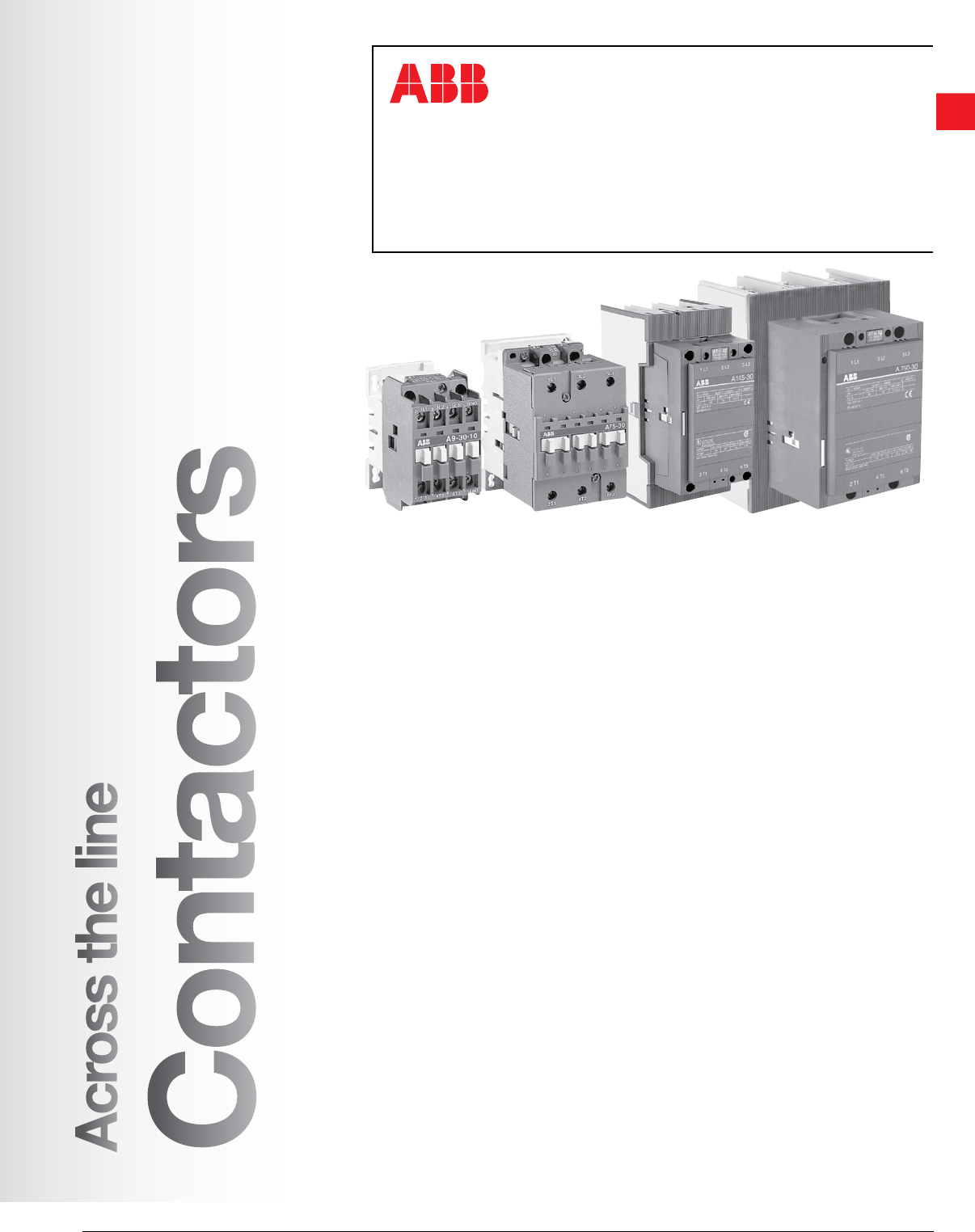
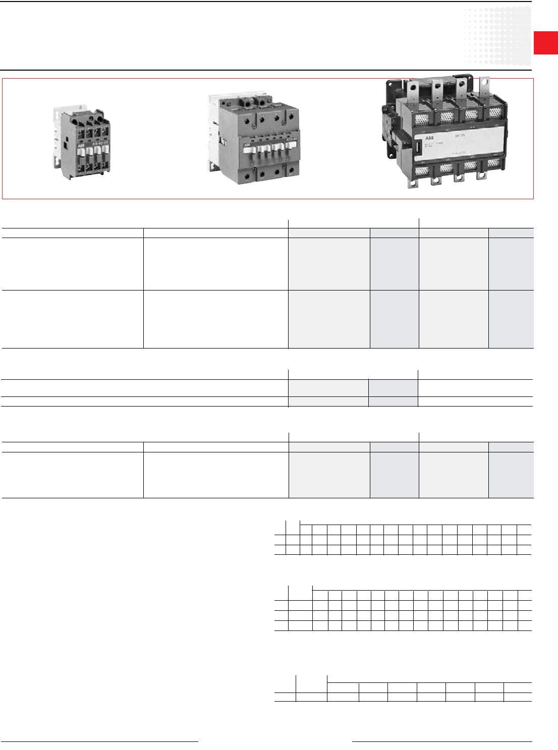
Across the line
contactors
Low Voltage Products & Systems 1.1
ABB Inc. • 888-385-1221 • www.abb.us/lowvoltage 1SXU000023C0202
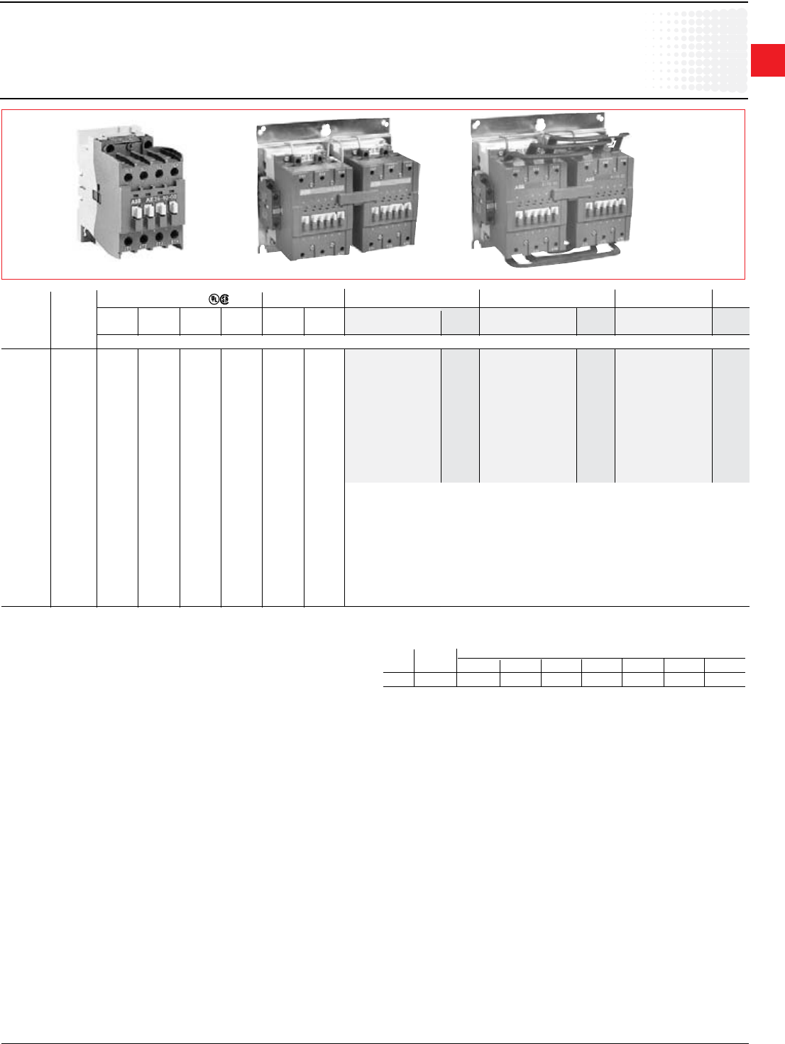
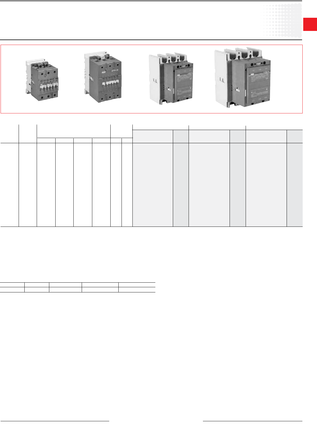
Across the line contactors
A9 - AF1650
A145 - AF1650
• Maximum UL/CSA horsepower ratings according
to UL508 and CSA22.2 No. 14
• Includes NEMA sizes 4 - 8
• CE mark
• 1 NO & 1 NC auxiliary contacts are standard and
up to 6 additional auxiliary contacts may be added
to provide a total of 8 (4 NO & 4 NC)
• Contactors ensure positive safety between their
auxiliary contact blocks.
• D.C. ratings and D.C. control operation available
• Easy maintenance of main contacts and coil
inspection
• Can be mounted in any position
• Terminal lugs sold separately. See page 1.25.
• Operates over an extended voltage range of 85%
to 110% of rated control voltage
• NEMA, UL, IEC, CSA, VDE and most other
international standards
• UL File No: E36588 (A/AF145 - AF750)
• UL File No: E73397 (AF1350 - AF1650)
• CSA File No: LR19700
A9 - A110
• Maximum UL/CSA horsepower ratings according
to UL508 and CSA22.2 No. 14
• Includes NEMA sizes 00 - 3
• CE mark
• Compact space saving design
• Standard auxiliary contact congurations:
A9 - A40 1 NO or 1 NC
A50 - A110 1 NO & 1 NC
• Contactor sizes A50 - A110 can be supplied
without auxiliaries
• Additional auxiliary contact blocks are available
• D.C. ratings & D.C. control operation available
• Fast, snap-on DIN rail mounting
• Double break contact design
• Snap-on front mounted accessories include
mechanical latch, pneumatic timer, and 1 & 4 pole
auxiliary contact blocks
• Contactors ensure positive safety between their
auxiliary contact blocks.
• Easy coil change
• Captive terminal screws
• NEMA, UL, IEC, CSA, VDE and most other
international standards
• Touch safe design: All connection terminals are
protected against accidental touch
• Terminals supplied open for ease of wiring
• Operates over an extended voltage range of 85%
to 110% of rated control voltage
• Screwdriver guide holes
• UL File No: E39231 (A9 - A75); (AE9 - AE75); (AL9
- AL40); (AF50 - AF75)
• UL File No: E36588 (A95 - A110);
(AE95 - AE110); (AF145 - AF750)
• CSA File No: LR56745 (A9 - A75); (AE9 - AE75);
(AF50 - AF75)
• CSA File No: LR19700 (A95 - A110);
(AE95 - AE110); (AF145 - AF750)
• CSA approved for elevator service
Across the line
Contactors
1
Across the line
contactors
1.2 Low Voltage Products & Systems
1SXU000023C0202 ABB Inc. • 888-385-1221 • www.abb.us/lowvoltage
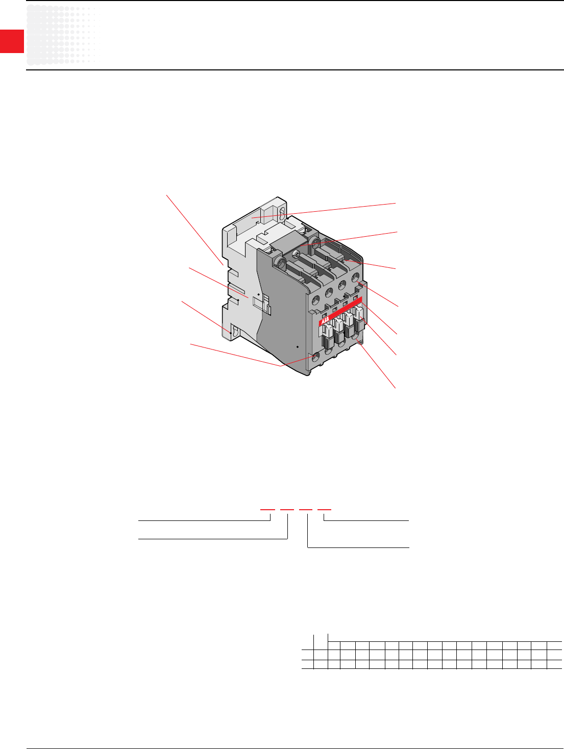
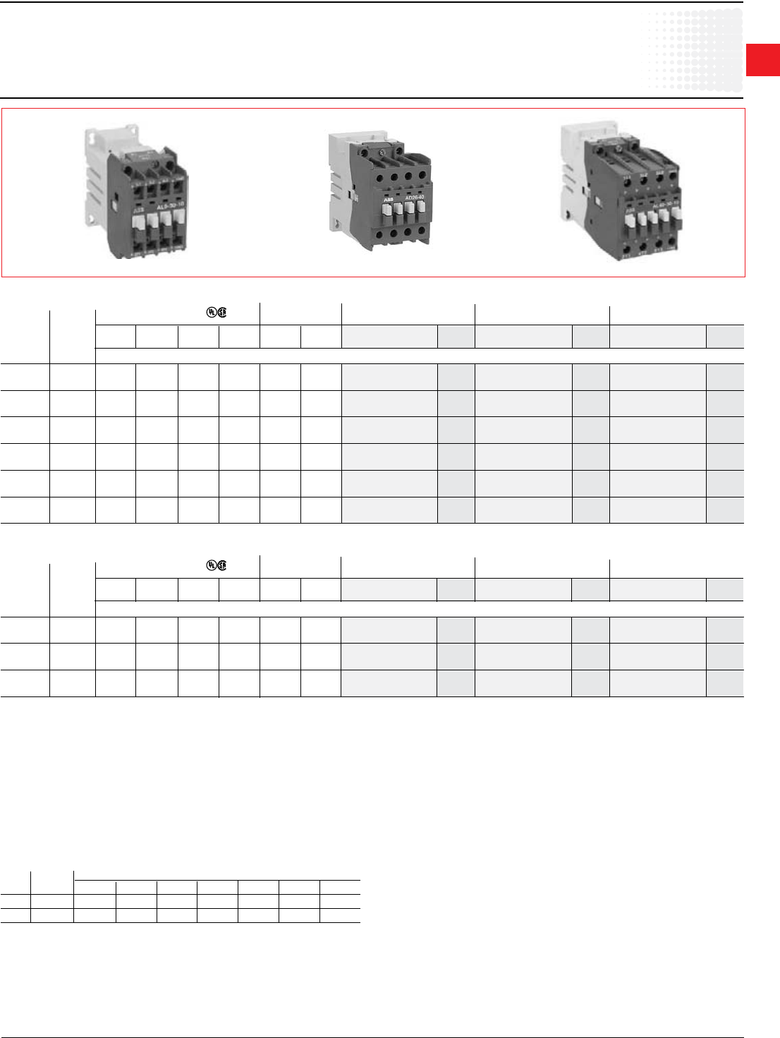
A9 - A300
General information
AC operated, UL rated, 3 phase
Application
A-Line contactors are mainly used for controlling 3-phase motors and for
controlling power circuits corresponding to their operating characteristics up to
690 and even 1000 VAC. and 440 VDC.
Description of 3 pole and 4 pole contactors A9 - A300
All A-Line contactors can be assembled side by side. The add-on or built-in
auxiliary contacts are suitable for low level currents.
Control circuit types
• A-Line types: AC operated with laminated magnetic circuit.
Contactor types
• 3 pole contactors with NO or NC built in auxiliary contact for A9 - A40
contactors; factory assembled auxiliary contacts for A50 - A300 contactors
• 4 pole contactors: 4 NO or 2 NO & 2 NC without any auxiliary contacts.
(A9 - A75)
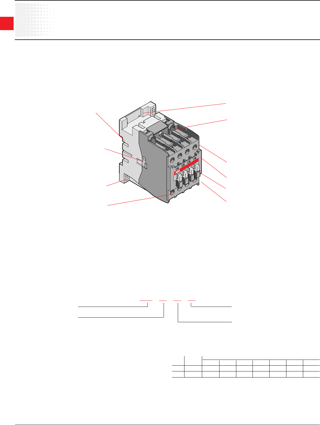
Catalog number explanation
A9-30-10-84
Frame size
Power pole
30 = 3 NO
40 = 4 NO
22 = 2 NO & 2 NC
Coil voltage
(see coil voltage selection chart)
Auxiliary contacts
10 = 1 NO & 0 NC
01 = 0 NO & 1 NC
11 = 1 NO & 1 NC
00 = No auxiliary provided
22 = 2 NO & 2 NC
Hz Cntr Volts
type 12 24 48 110 120 125 208 220 240 277 380 415 440 480 500 600
60 A 81 83 84 84 34 36 80 42 86 86 51 53 55
50 A 81 83 84 80 85 86 55
For other voltages, see page 1.24.
Coil voltage selection chart
A9 - A300
Location of surge suppressors.
Quick mounting on DIN rail: EN 50022 and
EN 50023 standards:
35 x 7.5mm for A9 - A40
35 x 15mm for A9 - A75
75mm for A45 - A110
Terminal screws:
• Posidrive (+,-) No 2 for all A9 - A75
• M8 hex threaded socket screw for A95 - A300
main terminals.
Terminal marking according to IEC 947-4-1,
EN 50005, EN 50012 and NEMA standards.
Connecting point for control leads in top part of
main terminals of A50 - A75 contactors. For A95
& A110 contactors these are additional power
connections.
Clear marking of coil voltages and frequencies.
Location of function marker.
Stops for attaching front mounted accessories.
Terminals in A9 - A110 contactors are delivered
in open position with captive screws (screws of
unused terminals must be tightened).
Screwdriver guidance for all terminals makes it
possible to use motorized screwdrivers.
All terminals provide protection against accidental
direct contact with live parts according to
VDE0106 - Part. 100.
All A9 - A40 contactor terminals as well as
A45 - A300 contactor auxiliary contact and coil
terminals ensure IP20 degree of protection
according to IEC 947-1.
Holes for screw mounting (screws not supplied).
Distance between holes according to
EN 50003.
Location of side mounted accessories: on right or
left hand side. Factory mounted on left hand side for
CAL5 on A50 - A300
1
Across the line
contactors
Low Voltage Products & Systems 1.3
ABB Inc. • 888-385-1221 • www.abb.us/lowvoltage 1SXU000023C0202
Discount schedule AA [OA] - A9 - A110
Discount schedule AEA [OC] - A145 - A300
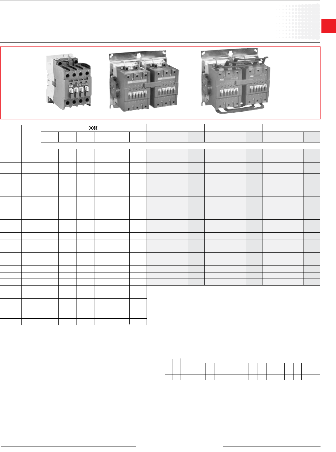
A9 - A300
Non-reversing, mechanically interlocked, reversing
AC operated, UL rated, 3 phase
A26-30-10-84 A110M-30-11-84 A110R-30-11-84
UL general UL motor
purpose switching
current current
Maximum motor Standard
horsepower ratings Aux. contacts Non-reversing Mechanically interlocked Reversing
Coil voltage selection
All AC operated catalog numbers include a 120VAC coil. To select other coil
voltages, substitute the code from the Coil Voltage Selection Chart for the two
digits after the last dash in the catalog number.
Ex.: A 240V coil is required for an A75 contactor: A75-30-11-80
Auxiliary contact blocks
For additional auxiliary contact blocks, see catalog number explanation on page
1.2. Add $ 20 to list price for each additional auxiliary, and see page 1.32 for
available combinations. Only side-mounted blocks are allowed to be factory
installed. If auxiliary contacts are not required for A50 - A300, subtract $ 40 from
list price and change catalog number to “00” instead of “11.”
Mechanical interlock
Mechanically interlocked contactors are designed for reversing, 2 speed, reduced
voltage, etc. type starter applications. The complete assembly consists of two
mechanically and electrically interlocked contactors mounted as follows with line
and load terminals:
• A9 - A16 — mounted on 35mm DIN rail
• A26 - A300 — mounted on common baseplate
Reversing
Reversing contactors are designed for reversing type starter applications. The
complete assembly consists of two mechanically and electrically interlocked
contactors mounted as follows with line and load terminals:
• A9 - A16 — mounted on 35mm DIN rail
• A26 - A300 — mounted on common baseplate
The NC electrical interlock is provided with the mechanical interlock for A9 - A110
contactors.
208V 240V 480V 575/600V NO NC Catalog List Catalog List Catalog List
number price number price number price
See Type AF contactors, page 1.9
Hz Cntr Volts
type 12 24 48 110 120 125 208 220 240 277 380 415 440 480 500 600
60 A 81 83 84 84 34 36 80 42 86 86 51 53 55
50 A 81 83 84 80 85 86 55
For other voltages, see page 1.24.
Coil voltage selection chart
Power wiring is not included. The NC electrical interlock is provided with the
mechanical interlock for A9 - A110 contactors.
AC1 UL rated
21 9 2 2 5 7.5 1 0 A9-30-10-84 $ 78 A9M-30-10-84 $ 255 A9R-30-10-84 $ 315
0 1 A9-30-01-84 A9M-30-01-84 A9R-30-01-84
25 11 3 3 7.5 10 1 0 A12-30-10-84 84 A12M-30-10-84 315 A12R-30-10-84 375
0 1 A12-30-01-84 A12M-30-01-84 A12R-30-01-84
30 17 5 5 10 15 1 0 A16-30-10-84 102 A16M-30-10-84 345 A16R-30-10-84 413
0 1 A16-30-01-84 A16M-30-01-84 A16R-30-01-84
40 28 7.5 10 20 25 1 0 A26-30-10-84 183 A26M-30-10-84 405 A26R-30-10-84 480
0 1 A26-30-01-84 A26M-30-01-84 A26R-30-01-84
50 34 10 10 25 30 1 0 A30-30-10-84 252 A30M-30-10-84 548 A30R-30-10-84 623
0 1 A30-30-01-84 A30M-30-01-84 A30R-30-01-84
60 42 10 15 30 40 1 0 A40-30-10-84 297 A40M-30-10-84 639 A40R-30-10-84 750
0 1 A40-30-01-84 A40M-30-01-84 A40R-30-01-84
80 54 15 20 40 50 1 1 A50-30-11-84 330 A50M-30-11-84 713 A50R-30-11-84 810
90 65 20 25 50 60 1 1 A63-30-11-84 372 A63M-30-11-84 870 A63R-30-11-84 1,013
105 80 25 30 60 75 1 1 A75-30-11-84 413 A75M-30-11-84 1,155 A75R-30-11-84 1,298
125 95 30 30 60 75 1 1 A95-30-11-84 450 A95M-30-11-84 1,230 A95R-30-11-84 1,425
140 110 30 40 75 100 1 1 A110-30-11-84 480 A110M-30-11-84 1,365 A110R-30-11-84 1,628
230 130 40 50 100 125 1 1 A145-30-11-84 825 A145M-30-11-84 2,235 A145R-30-11-84 2,250
250 156 50 60 125 150 1 1 A185-30-11-84 1,290 A185M-30-11-84 3,360 A185R-30-11-84 3,375
300 192 60 75 150 200 1 1 A210-30-11-84 1,635 A210M-30-11-84 4,035 A210R-30-11-84 4,050
350 248 75 100 200 250 1 1 A260-30-11-84 1,815 A260M-30-11-84 4,485 A260R-30-11-84 4,500
400 302 100 100 250 300 1 1 A300-30-11-84 1,875 A300M-30-11-84 5,460 A300R-30-11-84 5,475
550 414 125 150 350 400 1 1
650 480 150 200 400 500 1 1
750 602 200 250 500 600 1 1
900 810 250 300 600 700 1 1
1350 960 — 400 800 900 1 1
1650 1080 — 450 900 1000 1 1
1
Across the line
contactors
1.4 Low Voltage Products & Systems
1SXU000023C0202 ABB Inc. • 888-385-1221 • www.abb.us/lowvoltage
Uc (DC)
A1 A2
B2 - Holding
B1 - Pull-in
A3
NC contact in
4th contactor
pole
AE9 to AE40
Uc (DC)
A1 A2
B2 - Holding
B1 - Pull-in
CDL5 (AE45 to AE75)
CCL5 (AE95 to AE110)
Varistor
A3
U
AE45 to AE110
AE9 - AE110
General information
DC operated, UL rated, 3 phase
Application
A-Line contactors are mainly used for controlling 3-phase motors and for
controlling power circuits corresponding to their operating characteristics up to
690 and even 1000 VAC. and 440 VDC.
Control circuit types
AE types: with laminated magnetic circuit and double-winding coil fed from DC
supply via a CDL5 insertion contact mounted on the device. The CDL5 has an NC
lagging contact for insertion of the second winding. (See schematic.)
Catalog number explanation
AE9-30-00-81
Frame size
Power pole
30 = 3 NO
40 = 4 NO
22 = 2 NO & 2 NC
Coil voltage
(see coil voltage selection chart)
Auxiliary contacts
00 = No auxiliary provided
11 = 1 NO & 1 NC
AE9 - AE110
Location of surge suppressors.
Quick mounting on DIN rail: EN 50022 and
EN 50023 standards:
35 x 7.5mm for AE9 - AE40
35 x 15mm for AE9 - AE75
75mm for AE45 - AE110
Terminal screws:
• Posidrive (+,-) No° 2 for all AE9 - AE75
• M8 hex threaded socket screw for AE95 & AE110
Terminal marking according to IEC 947-4-1,
EN 50005, EN 50012 and NEMA standards.
Connecting point for control leads in top part of
main terminals of AE50 - AE75 contactors. For
AE95 & AE110 contactors these are additional
power connections.
Clear marking of coil voltages and frequencies.
Location of function marker.
Stops for attaching front mounted accessories.
Terminals delivered in open position with captive
screws (unused terminal screws must be
tightened).
Screwdriver guidance for all terminals makes it
possible to use motorized screwdrivers.
All terminals provide protection against accidental
direct contact with live parts according to
VDE0106 - Part. 100.
All AE9 - AE40 contactor terminals as well as
AE45 - AE110 contactor auxiliary contact and
coil terminals ensure IP20 degree of protection
according to IEC 947-1.
Holes for screw mounting (screws not supplied).
Distance between holes according to EN 50003.
Location of side mounted accessories: on right
or left hand side. Factory mounted on left hand
side for CAL5 on A50 - A300
• right hand side for CDL5/CCL5 on
AE45 - AE110
Hz Contr. Volts
type 12 24 48 110 125 220 240
DC AE 80 81 83 86 87 88 89
For other voltages, see page 1.24.
Coil voltage selection chart
1
Across the line
contactors
Low Voltage Products & Systems 1.5
ABB Inc. • 888-385-1221 • www.abb.us/lowvoltage 1SXU000023C0202
General UL motor
purpose switching
current current
Maximum motor Standard
horsepower ratings Aux. contacts Non-reversing Mechanically interlocked Reversing
208V 240V 480V 575/600V NO NC Catalog List Catalog List Catalog List
number price number price number price
AE9 - AE110
Non-reversing, mechanically interlocked, reversing
DC operated, UL rated, 3 phase
Coil voltage selection
All DC operated catalog numbers include a 24VDC coil. To select other coil
voltages, substitute the code from the Coil Voltage Selection Chart for the two
digits after the last dash in the catalog number.
Ex.: A 110V coil is required for an AE75 contactor: AE75-30-11-86
Auxiliary contact blocks
For additional auxiliary contact blocks, see catalog number explanation on page
1.4. Add $ 20 to list price for each additional auxiliary, and see page 1.32 for
available combinations.
Mechanical interlock
Mechanically interlocked contactors are designed for reversing, 2 speed, reduced
voltage, etc. type starter applications. The complete assembly consists of two
mechanically and electrically interlocked contactors mounted as follows with line
and load terminals:
• AE9 - AE16 — mounted on 35mm DIN rail
• AE26 - AE110 — mounted on common baseplate
Power wiring is not included.
The NC electrical interlock is provided with the mechanical interlock.
Reversing
Reversing contactors are designed for reversing type starter applications. The
complete assembly consists of two mechanically and electrically interlocked
contactors mounted as follows with line and load terminals:
• AE9 - AE16 — mounted on 35mm DIN rail
• AE26 - AE110 — mounted on common baseplate
The NC electrical interlock is provided with the mechanical interlock.
AE26-30-11-81 AE110M-30-11-81 AE110R-30-11-81
Discount schedule AA [OA] - AE9 - AE110
Hz Contr. Volts
type 12 24 48 110 125 220 240
DC AE 80 81 83 86 87 88 89
For other voltages, see page 1.24.
Coil voltage selection chart
AC1 UL rated
21 9 2 2 5 7.5 1 1 AE9-30-11-81 $ 118 AE9M-30-11-81 $ 335 AE9R-30-11-81 $ 395
25 11 3 3 7.5 10 1 1 AE12-30-11-81 124 AE12M-30-11-81 395 AE12R-30-11-81 455
30 17 5 5 10 15 1 1 AE16-30-11-81 142 AE16M-30-11-81 425 AE16R-30-11-81 493
40 28 7.5 10 20 25 1 1 AE26-30-11-81 223 AE26M-30-11-81 485 AE26R-30-11-81 560
50 34 10 10 25 30 1 1 AE30-30-11-81 292 AE30M-30-11-81 628 AE30R-30-11-81 703
60 42 10 15 30 40 1 1 AE40-30-11-81 337 AE40M-30-11-81 720 AE40R-30-11-81 830
80 54 15 20 40 50 1 1 AE50-30-11-81 375 AE50M-30-11-81 803 AE50R-30-11-81 930
90 65 20 25 50 60 1 1 AE63-30-11-81 477 AE63M-30-11-81 1,080 AE63R-30-11-81 1,208
105 80 25 30 60 75 1 1 AE75-30-11-81 518 AE75M-30-11-81 1,365 AE75R-30-11-81 1,493
125 95 30 30 60 75 1 1 AE95-30-11-81 555 AE95M-30-11-81 1,440 AE95R-30-11-81 1,635
140 110 30 40 75 100 1 1 AE110-30-11-81 690 AE110M-30-11-81 1,785 AE110R-30-11-81 2,048
230 130 40 50 100 125 1 1
250 156 50 60 125 150 1 1
300 192 60 75 150 200 1 1
350 248 75 100 200 250 1 1
400 302 100 100 250 300 1 1
550 414 125 150 350 400 1 1
650 480 150 200 400 500 1 1
750 602 200 250 500 600 1 1
900 810 250 300 600 700 1 1
1350 960 — 400 800 900 1 1
1650 1080 — 450 900 1000 1 1
See AF contactors, page 1.9
1
Across the line
contactors
1.6 Low Voltage Products & Systems
1SXU000023C0202 ABB Inc. • 888-385-1221 • www.abb.us/lowvoltage
AL9 - AL40
General information
DC operated, UL rated, 3 phase
Application
AL and AL...Z contactors are mainly used for controlling 3-phase motors and for
controlling power circuits corresponding to their operating characteristics up to
690 and even 1000 VAC. and 440 VDC.
Control circuit types
AL9 - AL40: DC coil with low power consumption of 3W to 3.5W
AL9Z - AL16Z: DC coil with low power consumption of 2.4W. Designed to be
directly controlled by PLC.
Catalog number explanation
AL9 - 30 - 10 - 81
Frame size
Power pole
30 = 3 NO
Coil voltage
(see coil voltage selection chart)
Auxiliary contacts
10 = 1 NO & 0 NC
01 = 0 NO & 1 NC
AL9 - AL40
Location of surge suppressors.
Quick mounting on DIN rail: EN 50022 and
EN 50023 standards:
35 x 7.5mm for AL9 - AL40
35 x 15mm for AL9 - AL40
Terminal screws:
• Posidrive (+,-) No° 2 for all AL contactors
Terminal marking according to IEC 60947-4-1,
EN 50005, EN 50012 and NEMA standards.
Clear marking of coil voltages and frequencies.
Location of function marker.
Stops for attaching front mounted accessories.
Terminals delivered in open position with captive
screws (unused terminal screws must be
tightened).
Screwdriver guidance for all terminals makes it
possible to use motorized screwdrivers.
All terminals provide protection against accidental
direct contact with live parts according to
VDE0106 - Part. 100.
All AL9 - AL40 contactor terminals as well as
contactor auxiliary contacts and coil terminals
ensure IP20 degree of protection according to
IEC 60947-1.
Holes for screw mounting (screws not supplied).
Distance between holes according to EN 50003.
Location of side mounted accessories: on right
or left hand side.
Hz Contr. Volts
type 12 24 48 110 125 220 240
DC AL 80 81 83 86 87 88 89
DC AL...Z 15 28
For other voltages, see page 1.24.
Coil voltage selection
1
Across the line
contactors
Low Voltage Products & Systems 1.7
ABB Inc. • 888-385-1221 • www.abb.us/lowvoltage 1SXU000023C0202
AL9 - AL40, AL9Z - AL16Z
Non-reversing, mechanically interlocked, reversing
DC operated, UL rated, 3 phase
Coil voltage selection
All DC operated catalog numbers include a 24VDC coil. To select other coil
voltages, substitute the code from the Coil Voltage Selection Chart for the two
digits after the last dash in the catalog number.
Ex.: A 48V coil is required for an AL30 contactor: AL30-30-10-83
Auxiliary contact blocks
For additional auxiliary contact blocks, see catalog number explanation on page
1.6. Add $ 20 to list price for each additional auxiliary, and see page 1.32 for
available combinations.
General UL motor
purpose switching
current current
Maximum motor Standard
horsepower ratings Aux. contacts Non-reversing Mechanically interlocked Reversing
AC1 UL rated
21 9 2 2 5 7.5 1 0 AL9-30-10-81 $ 138 AL9M-30-10-81 $ 411 AL9R-30-10-81 $ 433
0 1 AL9-30-01-81 AL9M-30-01-81 AL9R-30-01-81
25 11 3 3 7.5 10 1 0 AL12-30-10-81 169 AL12M-30-10-81 490 AL12R-30-10-81 498
0 1 AL12-30-01-81 AL12M-30-01-81 AL12R-30-01-81
30 17 5 5 10 15 1 0 AL16-30-10-81 188 AL16M-30-10-81 526 AL16R-30-10-81 527
0 1 AL16-30-01-81 AL16M-30-01-81 AL16R-30-01-81
40 28 7.5 10 20 25 1 0 AL26-30-10-81 238 AL26M-30-10-81 606 AL26R-30-10-81 643
0 1 AL26-30-01-81 AL26M-30-01-81 AL26R-30-01-81
50 34 10 10 20 30 1 0 AL30-30-10-81 326 AL30M-30-10-81 781 AL30R-30-10-81 826
0 1 AL30-30-01-81 AL30M-30-01-81 AL30R-30-01-81
60 42 10 15 30 40 1 0 AL40-30-10-81 376 AL40M-30-10-81 892 AL40R-30-10-81 912
0 1 AL40-30-01-81 AL40M-30-01-81 AL40R-30-01-81
208V 240V 480V 575/600V NO NC Catalog List Catalog List Catalog List
number price number price number price
AL Contactors — 3W and 3.5W consumption
AL9-30-10-81 AL26-30-10-81 AL40-30-10-81
Mechanical interlock
Mechanically interlocked contactors are designed for reversing, 2 speed, reduced
voltage, etc. type starter applications. The complete assembly consists of two
mechanically and electrically interlocked contactors mounted as follows with line
and load terminals:
• AL9 & AL16 — mounted on 35mm DIN rail
• AL26 & AL40 — mounted on common baseplate
Power wiring is not included.
The NC electrical interlock is provided
Reversing
Reversing contactors are designed for reversing type starter applications. The
complete assembly consists of two mechanically and electrically interlocked
contactors mounted with line and load terminals.
Discount schedule AA [OA] — AL9 - AL40
General UL motor
purpose switching
current current
Maximum motor Standard
horsepower ratings Aux. contacts Non-reversing Mechanically interlocked Reversing
AC1 UL rated
21 9 2 2 5 7.5 1 0 AL9Z-30-10-15 $ 141 AL9ZM-30-10-15 $ 319 AL9ZR-30-10-15 $ 429
0 1 AL9Z-30-01-15 AL9ZM-30-01-15 AL9ZR-30-01-15
25 11 3 3 7.5 10 1 0 AL12Z-30-10-15 173 AL12ZM-30-10-15 417 AL12ZR-30-10-15 477
0 1 AL12Z-30-01-15 AL12ZM-30-01-15 AL12ZR-30-01-15
30 17 5 5 10 15 1 0 AL16Z-30-10-15 188 AL16ZM-30-10-15 441 AL16ZR-30-10-15 501
0 1 AL16Z-30-01-15 AL16ZM-30-01-15 AL16ZR-30-01-15
208V 240V 480V 575/600V NO NC Catalog List Catalog List Catalog List
number price number price number price
ALZ Contactors — 2.4W consumption
1 Only coil voltages available for AL9Z – AL16Z.
Hz Contr. Volts
type 12 24 48 110 125 220 240
DC AL 80 81 83 86 87 88 89
DC AL...Z 15 28
For other voltages, see page 1.24.
Coil voltage selection
1
Across the line
contactors
1.8 Low Voltage Products & Systems
1SXU000023C0202 ABB Inc. • 888-385-1221 • www.abb.us/lowvoltage
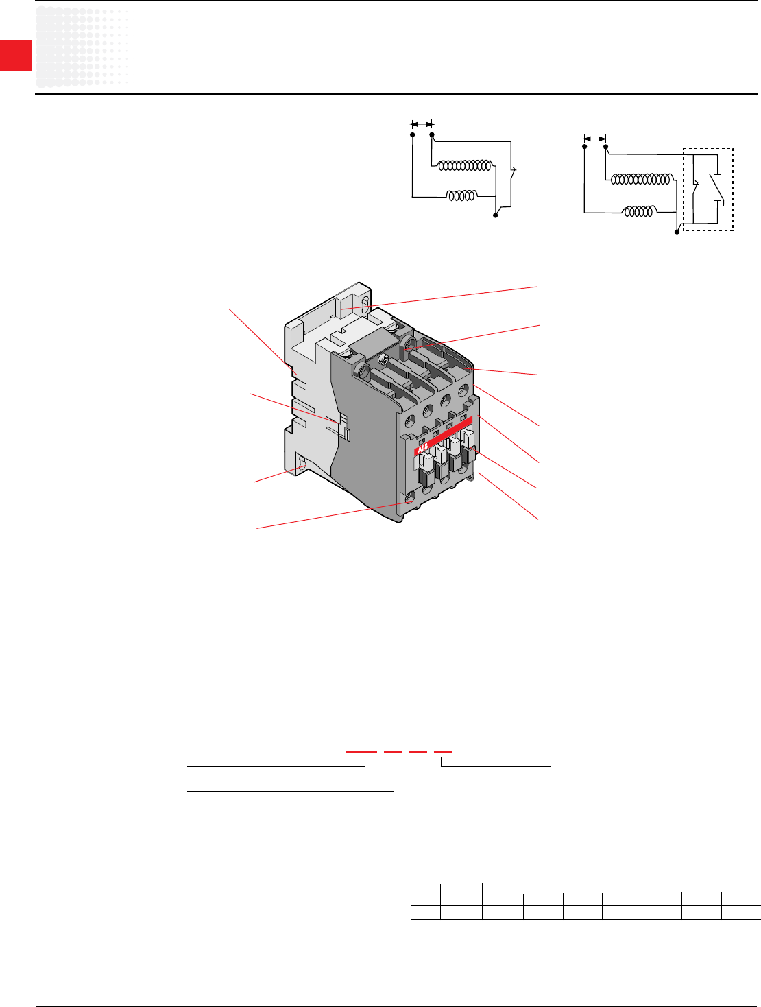
1 L1 3 L2
A1 A2
5 L3
UL
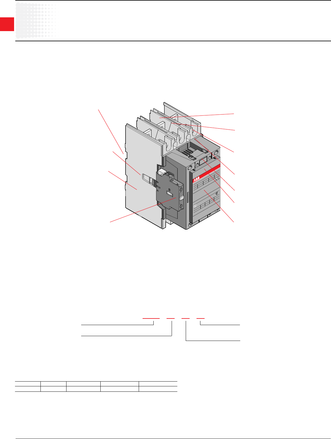
AF50 - AF1650
General information
AC & DC operated, UL rated, 3 phase
Application
A-Line contactors are mainly used for controlling 3-phase motors
and for controlling power circuits corresponding to their operating
characteristics up to 690 and even 1000 VAC. and 440 VDC.
Description of 3 pole contactors AF50 - AF1650
All AF contactors can be assembled side by side. The add-on auxiliary
contacts are suitable for low level currents.
Control circuit types
• AF types: AC/DC operated with laminated magnetic circuit.
Contact or types
• 3 pole contactors with 1 NO or 1 NC factory assembled auxiliary
contacts for AF50 - AF1650 contactors
Catalog number explanation
AF50 - 30 - 11 - 70
Frame size
Power pole
30 = 3 NO
40 = 4 NO
22 = 2 NO & 2 NC
Coil voltage
(see coil voltage selection chart)
Auxiliary contacts
11 = 1 NO & 1 NC
00 = No auxiliary provided
22 = 2 NO & 2 NC
AF50 - AF1650
Surge suppressors built in as standard on the
printed circuit board.
Quick mounting on DIN rail: EN 50022 and
EN 50023 standards:
35 x 15mm for AF50 - AF75
75mm for AF50 - AF110
Terminal screws:
• Posidrive (+,-) No 2 for all AF50 – AF75
• M8 hex threaded socket screw for AF95 –
AF1650 main terminals.
Terminal marking according to IEC 947-4-1,
EN 50005, EN 50012 and NEMA standards.
Connecting point for control leads in top part of
main terminals of AF50 - AF75 contactors. For
AF95 & AF110 contactors these are additional
power connections.
Clear marking of coil voltages and frequencies.
Location of function marker.
Stops for attaching front mounted accessories.
Terminals delivered in open position with captive
screws (screws of unused terminals must be
tightened).
Screwdriver guidance for all terminals makes it
possible to use motorized screwdrivers.
All terminals provide protection against accidental
direct contact with live parts according to VDE0106
- Part. 100.
All AF50- AF110 contactor terminals as well as
AF50 - AF1650 contactor auxiliary contact and
coil terminals ensure IP20 degree of protection
according to IEC 947-1.
Holes for screw mounting (screws not supplied).
Distance between holes according to
EN 50003.
Location of side mounted accessories: on right or
left hand side. Factory mounted on left hand side for
CAL5 on AF50 - AF1650
Coil voltage selection – AF50 to AF1650
AC/DC VOLTS, 40 - 60 Hz
24 - 60 DC 20 - 60 DC 48 - 130 AC/DC 100 - 250 AC/DC 250 - 500 AC//DC
68 172 269 70 371 4
1 AF400 – AF750, DC only.
2 AF50 – AF300, DC only.
3 Only option for AF1350 / AF1650.
4 AF400 - AF750 only.
1
Across the line
contactors
Low Voltage Products & Systems 1.9
ABB Inc. • 888-385-1221 • www.abb.us/lowvoltage 1SXU000023C0202
AF50 - AF1650
Non-reversing, mechanically interlocked, reversing
AC & DC operated, UL rated, 3 phase
1 AF400 – AF1250, DC only.
2 AF50 – AF300, DC only.
3 Only option for AF1350 - AF2050.
4 AF400 - AF750 only.
3 Pole
80 54 15 20 40 50 1 1 AF50-30-11-70 $ 450 AF50M-30-11-70 $ 953 AF50R-30-11-70 $ 1,050
90 65 20 25 50 60 1 1 AF63-30-11-70 495 AF63M-30-11-70 1,116 AF63R-30-11-70 1,259
105 80 25 30 60 75 1 1 AF75-30-11-70 535 AF75M-30-11-70 1,399 AF75R-30-11-70 1,542
125 95 30 30 60 75 1 1 AF95-30-11-70 570 AF95M-30-11-70 1,470 AF95R-30-11-70 1,665
140 110 30 40 75 100 1 1 AF110-30-11-70 600 AF110M-30-11-70 1,605 AF110R-30-11-70 1,868
230 130 40 50 100 125 1 1 AF145-30-11-70 1,110 AF145M-30-11-70 2,655 AF145R-30-11-70 2,670
250 156 50 60 125 150 1 1 AF185-30-11-70 1,635 AF185M-30-11-70 3,870 AF185R-30-11-70 3,375
300 192 60 75 150 200 1 1 AF210-30-11-70 1,980 AF210M-30-11-70 4,545 AF210R-30-11-70 4,560
350 248 75 100 200 250 1 1 AF260-30-11-70 2,235 AF260M-30-11-70 5,055 AF260R-30-11-70 5,070
400 302 100 100 250 300 1 1 AF300-30-11-70 2,385 AF300M-30-11-70 6,030 AF300R-30-11-70 6,045
550 414 125 150 350 400 1 1 AF400-30-11-70 3,120 AF400M-30-11-70 6,705 AF400R-30-11-70 6,720
650 480 150 200 400 500 1 1 AF460-30-11-70 4,425 AF460M-30-11-70 13,275 AF460R-30-11-70 13,290
750 602 200 250 500 600 1 1 AF580-30-11-70 6,900 AF580M-30-11-70 18,375 AF580R-30-11-70 18,390
900 810 250 300 600 700 1 1 AF750-30-11-70 7,200 AF750M-30-11-70 19,725 AF750R-30-11-70 19,740
1260 — — — — — 1 1 AF1250-30-11-70 8,120 — — — —
1350 960 — 400 800 900 1 1 AF1350-30-11-70 8,490 — — — —
1650 1080 — 450 900 1000 1 1 AF1650-30-11-70 10,230 — — — —
2050 — — — — — 1 1 AF2050-30-11-70 12,820 — — — —
General UL motor Standard Non-reversing Mechanically interlocked Reversing
purpose switching Maximum UL Listed auxiliary Catalog List Catalog List Catalog List
current current motor horsepower ratings contacts number price number price number price
AC1 208V 240V 480V 575/600V NO NC
AF63-30-11-70 AF95-30-11-70 AF400-30-11-70 AF750-30-11-70
Coil voltage selection – wide range AC/DC coils
All catalog numbers include a 100-250V AC/DC coil. To select other coil voltages,
substitute the code from the Coil Voltage Selection Chart for the two digits after
the last dash in the catalog number.
Ex.: A 24V coil is required for a AF110 contactor: AF110-30-11-72
Discount schedule AA [OA] - AF50 – AF110
Discount schedule AEA [OC] - AF145 - AF2050
Coil voltage selection – AF50 to AF1650
AC/DC VOLTS, 40 - 60 Hz
24 - 60 DC 20 - 60 DC 48 - 130 AC/DC 100 - 250 AC/DC 250 - 500 AC//DC
68 172 269 70 371 4
1
Across the line
contactors
1.10 Low Voltage Products & Systems
1SXU000023C0202 ABB Inc. • 888-385-1221 • www.abb.us/lowvoltage
A/AF/AL9 - A/AF/AL110
Contactors for ring tongue termination
AC & DC operated, UL rated, 3 phase
UL UL Motor UL/CSA horsepower ratings Auxiliary contacts AC operated DC operated
general purpose switching
current current 240V 480V 575/600V NO NC Catalog List Catalog List
AC1 number price number price
21 9 2 5 7.5 1 0 A93010RT-84 $ 83 AL93010RT-81 $ 152
0 1 A93001RT-84 AL93001RT-81
25 11 3 7.5 10 1 0 A123010RT-84 90 AL123010RT-81 186
0 1 A123001RT-84 AL123001RT-81
30 17 5 10 15 1 0 A163010RT-84 122 AL163010RT-81 207
0 1 A163001RT-84 AL163001RT-81 211
40 28 10 20 25 1 0 A263010RT-84 172 AL263010RT-81 262
0 1 A263001RT-84 AL263001RT-81
80 54 20 40 50 0 0 A503000RT-84 363 AF503000RT-70 582
90 65 25 50 60 0 0 A633000RT-84 417 AF633000RT-70 647
105 80 30 60 75 0 0 A753000RT-84 475 AF753000RT-70 687
125 95 30 60 75 0 0 AF95B3011RT-70 927 AF95B3011RT-70 927
140 110 40 75 100 0 0 AF110B3011RT-70 986 AF110B3011RT-70 986
Coil voltage selection – AC coils
All AC operated catalog numbers include a 120VAC coil. To select other coil
voltages, substitute the code from the AC coils Coil Voltage Selection Chart for
the two digits after the last dash in the catalog number.
Ex.: A 240V coil is required for an A75 contactor: A753000RT-80
Coil voltage selection – DC coils
All DC operated catalog numbers include a 24VDC coil. To select other coil
voltages, substitute the code from the DC coils Coil Voltage Selection Chart for
the two digits after the last dash in the catalog number.
Ex.: A 110V coil is required for an AE75 contactor: AE753000RT-86
Auxiliary contact blocks
For additional auxiliary contact blocks, see catalog number explanation on page
1.2. Add $ 20 to list price for each additional auxiliary, and see page 1.32 for
available combinations. Only side-mounted blocks are allowed to be factory
installed.
Coil voltage selection chart – AC coils
Cntr Volts
Hz type 12 24 48 110 120 125 208 220 240 277 380 415 440 480 500 600
60 A 81 83 84 84 34 36 80 42 86 86 51 53 55
50 A 81 83 84 80 85 86 55
For other voltages, see page 1.24.
Hz Contr. Volts
type 24 48 110 125 220 240
DC AE 81 83 86 87 88 89
For other voltages, see page 1.24.
Coil voltage selection chart – DC coils
Auxiliary contact block with ring tongue termination
Positioning Maximum number Contact Catalog List
of contact blocks description number price
Front mounting 1 block 2 NO & 2 NC CA5-22ERT
(C4-pole) A/AE9 – A/AE110 3 NO & 1 NC CA5-31ERT $ 35
4 NO CA5-40ERT
Discount schedule AA [OA] – A9 - A110
Discount schedule ABA [OF] – Auxiliary contact blocks
1
Across the line
contactors
Low Voltage Products & Systems 1.11
ABB Inc. • 888-385-1221 • www.abb.us/lowvoltage 1SXU000023C0202
A9 – AF1650
Non-reversing, mechanically interlocked, reversing
NEMA rated, AC operated, 3 phase
A26N1-30-10-84 A145N4-30-11-84 AF400N6-30-11-70
NEMA Continuous
size current
Maximum motor Standard
horsepower ratings Aux. contacts Non-reversing Mechanically interlocked Reversing
NEMA rated
00 9 1.5 1.5 2 1 0 A9N00-30-10-84 $ 78 A9N00M-10-84 $ 255 A9N00R-10-84 $ 315
0 18 3 3 5 1 0 A16N0-30-10-84 102 A16N0M-10-84 345 A16N0R-10-84 413
1 27 7.5 7.5 10 1 0 A26N1-30-10-84 183 A26N1M-10-84 405 A26N1R-10-84 480
2 45 10 15 25 1 1 A50N2-30-11-84 330 A50N2M-11-84 713 A50N2R-11-84 810
3 90 25 30 50 1 1 A75N3-30-11-84 413 A75N3M-11-84 1,155 A75N3R-11-84 1,298
4 135 40 50 100 1 1 A145N4-30-11-84 825 A145N4M-11-84 2,235 A145N4R-11-84 2,250
5 270 75 100 200 1 1 A260N5-30-11-84 1,815 A260N5M-11-84 4,485 A260N5R-11-84 4,500
6 540 150 200 400 1 1 AF460N6-3011-70 4,425 AF460N6M-11-70 13,275 AF460N6R-11-70 13,290
7 810 — 300 600 1 1 AF750N7-3011-70 7,200 AF750N7M-11-70 19,725 AF750N7R-11-70 19,740
8 1215 — 450 900 1 1 AF1650N83011-70 10,230 — — — —
Coil voltage selection – A contactors
All AC operated catalog numbers include a 120VAC coil. To select other coil
voltages, substitute the code from the Coil Voltage Selection Chart for the two
digits after the last dash in the catalog number.
Ex.: A 240V coil is required for an A75 contactor: A75N3-30-11-80
Coil voltage selection – wide range AC/DC coils
The NEMA size 6,7 and 8 contactors are provided with a wide range coil voltage.
They are shown with the standard 100-250V AC/DC coil. To select other ranges
substitute the code from the coil voltage selection chart for the two digits after the
last dash in the catalog number.
Ex.: A 24V coil is required for the AF460N6 contactor: AF460N6-3011-68
Auxiliary contact blocks
For additional auxiliary contact blocks, see catalog number explanation on page
1.2. Add $ 20 to list price for each additional auxiliary, and see page 1.32 for
available combinations.
Mechanical interlock
Mechanically interlocked contactors are designed for reversing, 2 speed, reduced
voltage, etc. type starter applications. The complete assembly consists of two
mechanically and electrically interlocked contactors mounted as follows with line
and load terminals:
• A9 - A16 — mounted on 35mm DIN rail
• A26 - A750 — mounted on common baseplate
Power wiring is not included.
For A9 - A110 contactors the NC electrical interlock is provided with the
mechanical interlock.
Discount schedule AA [OA] - A9 - A110
Discount schedule AEA [OC] - A145 - AF750
Reversing
Reversing contactors are designed for reversing type starter applications. The
complete assembly consists of two mechanically and electrically interlocked
contactors mounted as follows with line and load terminals:
• A9 - A16 — mounted on 35mm DIN rail
• A26 - A750 — mounted on common baseplate
For A9 - A750 contactors the NC electrical interlock is provided with the
mechanical interlock.
Hz Cntr
Volts
type 12 24 48 110 120 125 208 220 240 277 380 415 440 480 500 600
60 A 81 83 84 84 34 36 80 42 86 86 51 53 55
50 A 81 83 84 80 85 86 55
For other voltages, see page 1.24.
Coil voltage selection – A contactors
1 AF400 – AF750, DC only.
2 AF400 - AF750 only.
3 Only option for AF1650.
200V 230V 460/575V NO NC Catalog List Catalog List Catalog List
number price number price number price
AC/DC VOLTS, 40 - 60 HZ
24 - 60 DC 48 - 130 AC/DC 100 - 250 AC/DC 250-500 AC/DC
68 1 69 70 3 71 2
Coil voltage selection – AF460N6 to AF1650N8
1
Across the line
contactors
1.12 Low Voltage Products & Systems
1SXU000023C0202 ABB Inc. • 888-385-1221 • www.abb.us/lowvoltage
AE9 – AF1650, AL9 – AL26
Non-reversing, mechanically interlocked, reversing
NEMA rated, DC operated, 3 phase
AE26N1-30-11-81 AF145N4-30-11-68 AF460N6R-11-68
Coil voltage selection – AE contactors
All DC operated catalog numbers include a 24VDC coil. To select other coil
voltages, substitute the code from the Coil Voltage Selection Chart for the two
digits after the last dash in the catalog number.
Ex.: A 125V coil is required for an AE75 contactor: AE75N3-30-11-87
Coil voltage selection – AF wide range AC/DC coils
All catalog numbers include a 100-250V AC/DC coil. To select other coil voltages,
substitute the code from the Coil Voltage Selection Chart for the two digits after
the last dash in the catalog number.
Ex.: A 24V coil is required for a AF145 contactor: AF145N4-30-11-72
Auxiliary contact blocks
For additional auxiliary contact blocks, see catalog number explanation on page
1.2. Add $ 20 to list price for each additional auxiliary, and see page 1.32 for
available combinations.
Mechanical interlock
Mechanically interlocked contactors are designed for reversing, 2 speed, reduced
voltage, etc. type starter applications. The complete assembly consists of two
mechanically and electrically interlocked contactors mounted as follows with line
and load terminals:
• AE9 - AE16 — mounted on 35mm DIN rail
• AE26 - AE75 — mounted on common baseplate
Power wiring is not included.
For AE9 - AE75 contactors the NC electrical interlock is provided with the
mechanical interlock.
Discount schedule AA [OA] - A9 - A110
Discount schedule AEA [OC] - A145 - AF750
1 AF400 – AF750, DC only. 3 AF400 - AF750 only.
2 AF50 – AF300, DC only. 4 Only option for AF1650.
NEMA Continuous
size current
Maximum motor Standard
horsepower ratings Aux. contacts Non-reversing Mechanically interlocked Reversing
NEMA rated
00 9 1.5 1.5 2 1 0 AE9N00-30-11-81 $ 118 AE9N00M-11-81 $ 325 AE9N00R-11-81 $ 395
0 18 3 3 5 1 0 AE16N0-30-11-81 142 AE16N0M-11-81 425 AE16N0R-11-81 493
1 27 7.5 7.5 10 1 0 AE26N1-30-11-81 223 AE26N1M-11-81 485 AE26N1R-11-81 560
2 45 10 15 25 1 1 AE50N2-30-11-81 375 AE50N2M-11-81 803 AE50N2R-11-81 930
3 90 25 30 50 1 1 AE75N3-30-11-81 518 AE75N3M-11-81 1,365 AE75N3R-11-81 1,493
4 135 40 50 100 1 1 AF145N4-3011-70 1,110 AF145N4M-11-70 2,655 AF145N4R-11-70 2,670
5 270 75 100 200 1 1 AF260N5-3011-70 2,235 AF260N5M-11-70 5,055 AF260N5R-11-70 5,070
6 540 150 200 400 1 1 AF460N6-3011-70 4,425 AF460N6M-11-70 13,275 AF460N6R-11-70 13,290
7 810 — 300 600 1 1 AF750N7-3011-70 7,200 AF750N7M-11-70 19,725 AF750N7R-11-70 19,740
8 1215 — 450 900 1 1 AF1650N83011-70 10,230 — — — —
200V 230V 460/575V NO NC Catalog List Catalog List Catalog List
number price number price number price
AE & AF Contactors
NEMA Continuous
size current
Maximum motor Standard
horsepower ratings Aux. contacts Non-reversing Mechanically interlocked Reversing
NEMA rated
00 9 1.5 1.5 2 1 0 AL9N00-30-10-81 $ 155 AL9N00M-10-81 $ 319 AL9N00R-10-81 $ 379
0 18 3 3 5 1 0 AL16N0-30-10-81 205 AL16N0M-10-81 441 AL16N0R-10-81 501
1 27 7.5 7.5 10 1 0 AL26N1-30-10-81 253 AL26N1M-10-81 473 AL26N1R-10-81 533
208V 240V 460/575V NO NC Catalog List Catalog List Catalog List
number price number price number price
AL Contactors
Reversing
Reversing contactors are designed for reversing type starter applications. The
complete assembly consists of two mechanically and electrically interlocked
contactors mounted as follows with line and load terminals:
• AE9 - AE16 — mounted on 35mm DIN rail
• AE26 - AE75 — mounted on common baseplate
For AE9 - AE75 contactors the NC electrical interlock is provided with the
mechanical interlock.
Hz Contactor Volts
type 12 24 48 110 125 220 240
DC AE, AL – 81 83 86 87 88 89
Coil voltage selection – AE & AL contactors
Coil voltage selection – AF50 to AF1650
AC/DC VOLTS, 40 - 60 Hz
24 - 60 DC 20 - 60 DC 48 - 130 AC/DC
100 - 250 AC/DC
250 - 500 AC/DC
68 172 269 70 471 3
1
Across the line
contactors
Low Voltage Products & Systems 1.13
ABB Inc. • 888-385-1221 • www.abb.us/lowvoltage 1SXU000023C0202
A9-40-00 A75-40-00 EK175C4P-PL
4 Pole – 4 NO power poles
UL general purpose current AC operated DC operated
AC operated DC operated Catalog number List price Catalog number List price
21 21 A9-40-00-84 $ 120 AL9-40-00-81 $ 141
30 30 A16-40-00-84 165 AL16-40-00-81 192
40 40 A26-40-00-84 228 AL26-40-00-81 246
65 65 A45-40-00-84 360 AE45-40-00-86 420
80 80 A50-40-00-84 413 AE50-40-00-86 473
105 105 A75-40-00-84 525 AE75-40-00-86 570
150 150 EK110C4P-1L 743 EK110C4P-PL 953
200 200 EK150C4P-1L 1,013 EK150C4P-PL 1,238
250 250 EK175C4P-1L 1,763 EK175C4P-PL 1,988
300 300 EK210C4P-1L 2,025 EK210C4P-PL 2,280
400 400 EK370C4P-1L 4,650 EK370C4P-PL 5,010
600 600 EK550C4P-1L 6,510 EK550C4P-PL 7,005
1000 1 1000 1 EK1000C4P-1L 9,000 EK1000C4P-PL 9,700
Coil voltage selection
All AC operated catalog numbers include a 120VAC coil. All DC operated catalog
numbers include a 110VDC coil. To select other coil voltages, substitute the code
from the Coil Voltage Selection Chart for the two digits after the last dash in the
catalog number.
Ex.: A 240V coil is required for an A75 contactor: A75-30-00-80
Auxiliary contact blocks
For additional auxiliary contact blocks, see catalog number explanation on page
1.2. Add $ 20 to list price for each additional auxiliary, and see page 1.32 for
available combinations.
Accessories for EK
Please consult factory.
4 Pole – 2 NO & 2 NC power poles
21 21 A9-22-00-84 $ 120 AL9-22-00-81 $ 141
30 21 A16-22-00-84 165 AL16-22-00-81 215
40 30 A26-22-00-84 228 AL26-22-00-81 278
65 65 A45-22-00-84 360 AE45-22-00-86 420
105 105 A75-22-00-84 525 AE75-22-00-86 570
UL general purpose current AC operated DC operated
AC operated DC operated Catalog number List price Catalog number List price
Hz Contr. Volts
type 24 48 110 120 125 208 220 240 277 380 415 440 480 500 600
60 EK F G 1 B 2 C Z 3 4 6
50 EK N 1 J 3 M 5
DC EK Y W P Q R T
• For other voltages, consult factory.
• 24 & 48VAC coils are not available for sizes EK550. For these applications, use an
interposing control relay.
Coil voltage selection – EK contactors
Hz Cntr Volts
type 12 24 48 110 120 125 208 220 240 277 380 415 440 480 500 600
60 A 81 83 84 84 34 36 80 42 86 86 51 53 55
50 A 81 83 84 80 85 86 55
For other voltages, see page 1.24.
Coil voltage selection – A contactors
4 Pole – 4 NC power poles
UL general purpose current AC operated
AC Catalog List
operated number price
30 A16-04-00-84 $ 165
1 Not UL Listed. IEC value AC1 for 40°C.
Discount schedule AA [OA] - A9 - A75
Discount schedule AEA [OC] - EK110 - EK550
A9 – A/AE75 , EK110 – EK1000, AL9 – AL26
AC & DC operated, UL rated, 4 pole
Hz Contr. Volts
type 12 24 48 110 125 220 240
DC AE, AL – 81 83 86 87 88 89
For other voltages, see page 1.24.
Coil voltage selection – AE & AL contactors
1
Across the line
contactors
1.14 Low Voltage Products & Systems
1SXU000023C0202 ABB Inc. • 888-385-1221 • www.abb.us/lowvoltage
Auxiliary contact blocks
For additional auxiliary contact blocks, see catalog number explanation on page 1.8. Add $ 20 to the list price for each
additional auxiliary and see page 1.32 for available combinations. If auxiliary contacts are required for AF50 – AF750
contactors, add $ 40 to the list price and change the 8th & 9th digits in the catalog number from "00" to "11".
4 Pole — 2 NO - 2 NC power poles
65 0 0 AF45-22-00-70 $ 385
105 0 0 AF75-22-00-70 645
General Auxiliary Catalog List
purpose contacts number price
AC1 NO NC
4 Pole — 4 NO power poles
65 0 0 AF45-40-00-70 $ 385
80 0 0 AF50-40-00-70 435
105 0 0 AF75-40-00-70 645
General Auxiliary Catalog List
purpose contacts number price
AC1 NO NC
These contactors (2 NO & 2 NC power poles) can be used for controlling either 2 separate circuits, i.e. 2 loads with 2
separate supplies, or 1 circuit comprising 2 separate loads with 1 single supply (see diagrams below).
When the contactor operates, there is no mechanical overlapping between the NO main poles and NC main poles: Break
before Make.
These contactors (2 NO & 2 NC power poles) are not suitable for a reversing starter or a wye-delta starter or for controlling a
single load from 2 separate supplies.
AF45 - AF75
AC & DC operated, UL rated, 4 pole
Coil voltage selection – wide range AC/DC coils
All catalog numbers include a 100-250V AC/DC coil. To select other coil voltages,
substitute the code from the Coil Voltage Selection Chart for the two digits after
the last dash in the catalog number.
Ex.: A 24V coil is required for a AF45 contactor: AF45-22-00-72
1 AF400 – AF750, DC only.
2 AF50 – AF300, DC only.
Discount schedule AA [OA] - AF45 - AF75
AC/DC VOLTS, 40 - 60 HZ
24 - 60 DC 20 - 60 DC 48 - 130 AC/DC 100 - 250 AC/DC
68 1 72 2 69 70
Coil voltage selection – AF50 to AF75
A1
A2
1
2
R5
R6
R3
R4
7
8
Supply
Load
Load
1 single supply and 2 separate loads
A1
A2
1
2
R5
R6
R3
R4
7
8
"Back-up"
supply
"Main" supply
Load
Load
2 separate supplies and 2 separate loads
1
Across the line
contactors
Low Voltage Products & Systems 1.15
ABB Inc. • 888-385-1221 • www.abb.us/lowvoltage 1SXU000023C0202
Coil voltage selection
All AC operated catalog numbers include a 120VAC coil. To select other coil
voltages, substitute the code from the Coil Voltage Selection Chart for the two
digits after the last dash in the catalog number.
Auxiliary contact blocks
For additional auxiliary contact blocks, see catalog number explanation on page
1.2. Add $20 to list price for each additional auxiliary, and see page 1.32 for
available combinations.
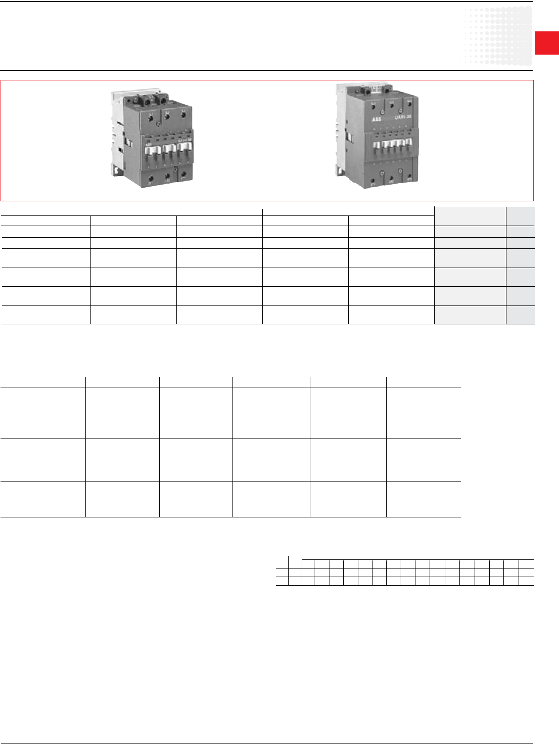
12.5 25 30 1 0 UA26-30-10-84 $ 225
16 32 40 1 0 UA30-30-10-84 338
20 40 50 0 0 UA50-30-00-84 345
1 1 UA50-30-11-84 375
27.5 55 70 0 0 UA75-30-00-84 450
1 1 UA75-30-11-84 480
35 70 75 0 0 UA95-30-00-84 465
1 1 UA95-30-11-84 495
40 80 85 0 0 UA110-30-00-84 525
1 1 UA110-30-11-84 570
For 3 phase capacitors carrying out single bank or stepped bank compensation.
Max. peak current Î: 100 times the capacitor nominal r.m.s. current at Ue ≤500V or 90 times for Ue>500V
Electrical durability: 100,000 operating cycles.
Max kvar switching capacity Standard auxiliary contacts Catalog List
240V 480V 575/600V NO NC number price
UA26 – UA110
for 3 phase capacitor switching, 3 phase
AC operated
UA75-30-00-84 UA95-30-00-84
Discount schedule AA [OA] - UA26 - UA110
Contactor 208V 240V 480V 600V Max amps
UA26 3.5 4.0 8.0 10.0 10
UA30 7.0 8.0 16.5 20.5 20
UA50 10.5 12.5 25.0 31.0 30
UA75 21.5 25.0 50.0 62.0 60
UA95 25.0 29.0 58.0 72.0 70
UA110 28.5 33.0 66.0 83.0 80
A145 43 50 100 125 120
A185 57 66 133 166 160
A210 66 77 153 192 185
A260 75 87 174 218 210
A300 88 101 203 254 245
AF400 119 137 274 343 330
AF460 142 164 329 410 396
AF580 178 205 411 514 495
AF750 214 247 495 618 595
Power in kvar
Coil voltage selection chart
Cntr Volts
Hz type 12 24 48 110 120 125 208 220 240 277 380 415 440 480 500 600
60 A 81 83 84 84 34 36 80 42 86 86 51 53 55
50 A 81 83 84 80 85 86 55
For other voltages, see page 1.24.
1
Across the line
contactors
1.16 Low Voltage Products & Systems
1SXU000023C0202 ABBInc.•888-385-1221•www.abb.us/lowvoltage
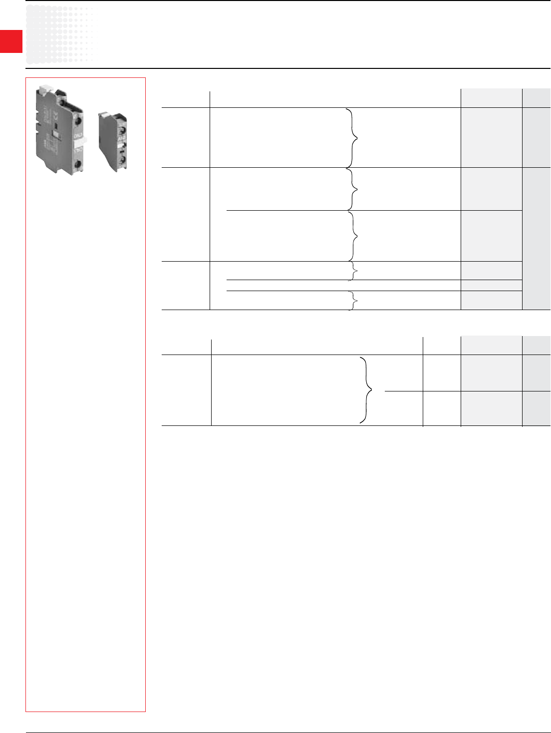
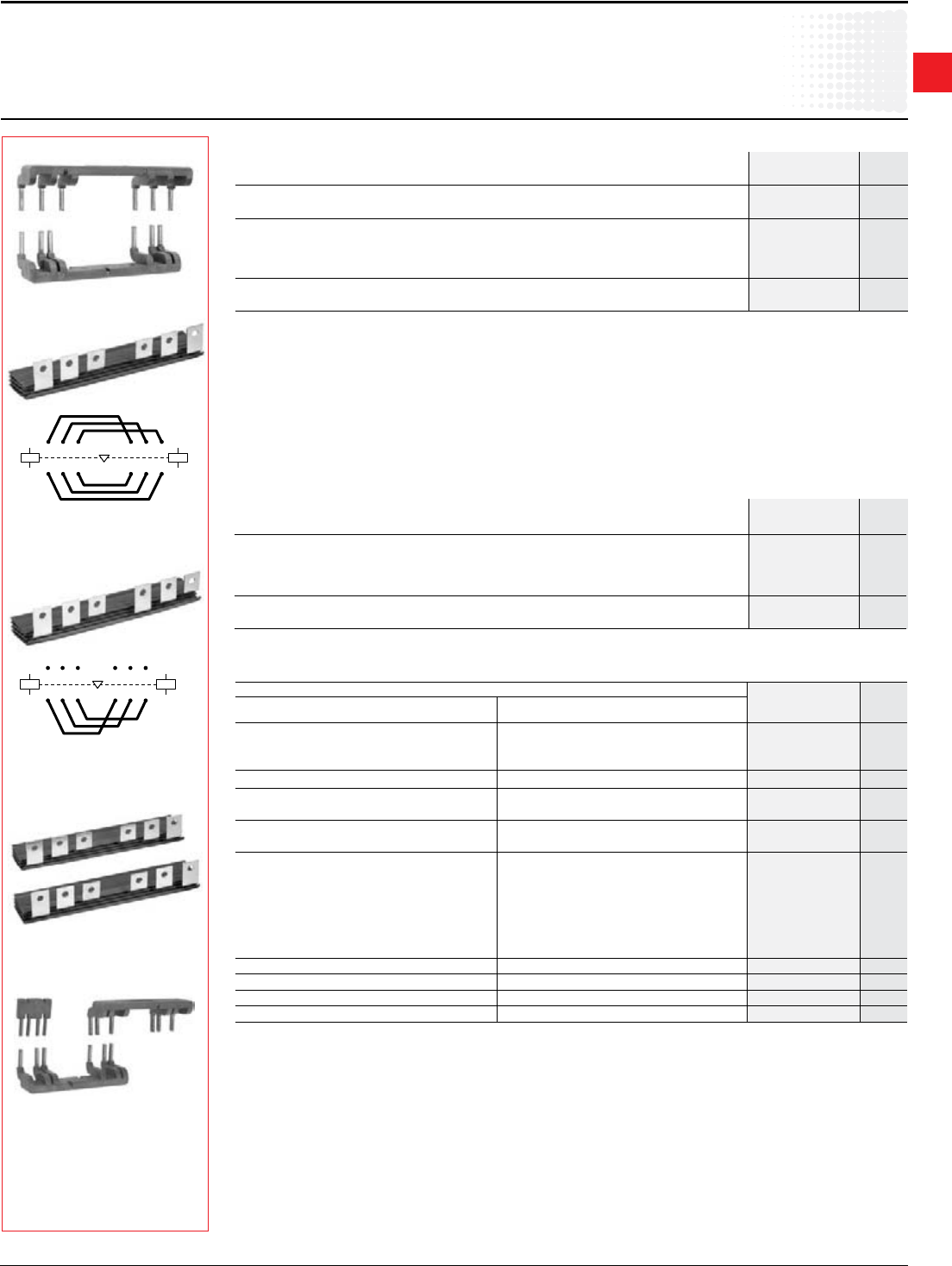
Auxiliary contact blocks – Standard
CAL5-11 CA5-10
Positioning Maximumnumber Contact Catalog List
ofcontactblocks Description number price
4blocks:A9–A26 1N.O. CA5-10
AE9–AE26 1N.C. CA5-01
Frontmounting AL9–AL26
(singlepole) 5blocks:A30,A40,AE30,AE40,AL30,AL40 1N.O.Earlymake CC5-10 $ 15
6blocks:A45–A110 1N.C.Latebreak CC5-01
AE45-AE110
AF45-AF110
A9–A26-40-00 4N.O. CA5-40E
A30 – A110 3N.O.&1N.C. CA5-31E
Frontmounting 1block: AE9–AE110 2N.O.&2N.C. CA5-22E
(4pole) 4N.C. CA5-04E
2N.O./2N.C.1 CA5-11/11E
3N.O.&1N.C. CA5-31M
1block: A9–A40-30-10 2N.O.&2N.C. CA5-22M
AL9–AL40-30-10 1N.O.&3N.C. CA5-13M 30
4N.C. CA5-04M
4N.O. CA5-40N
2N.O./2N.C.1 CA5-11/11M
2blocks:A9–A75,AE9-AE45 1N.O.&1N.C. CAL5-11
1block: AE50–AE75,AL9–AL40
Sidemounting 1block: A/AE/AF95-A/AE/AF110 1N.O.&1N.C. CAL18-11
(2pole) 2blocks:A145–A300,AF145-AF2050 1N.O.&1N.C.(insideLorR) CAL18-11
2blocks:A145–A300,AF145-AF2050 1N.O.&1N.C.(outside,LorR) CAL18-11B
Accessories
forA/AF/AL&AEcontactors
1Includes1N.O.&1N.C.overlapping
Auxiliary contact blocks–Frontmounting,switchinglowvoltageandlowcurrent
Positioning Maximumnumber Contact Degreeof Catalog List
ofcontactblocks Description protection number price
1N.O. IP40 CE5-10D0.1
4blocks:A9–A26 1N.C. IP40 CE5-01D0.1 $ 38
Frontmounting AE9–AE26 1N.O. IP40 CE5-10D2
(singlepole) AL9–AL26 1N.C. IP40 CE5-01D2
5blocks:A30,A40,AE30,AE40,AL30,AL40 1N.O. IP67 CE5-10W0.1
6blocks:A45–A110 1N.C. IP67 CE5-01W0.1 42
AE45-AE110 1N.O. IP67 CE5-10W2
AF45-AF110 1N.C. IP67 CE5-01W2
Discount schedule ABA [OF]
1
Across the line
contactors
Low Voltage Products & Systems 1.17
ABBInc.•888-385-1221•www.abb.us/lowvoltage 1SXU000023C0202
Electrical durability
AC-15accordingtoIEC947-5-1
makingcurrent:10x Iewherecosϕ=0.7andUe
breakingcurrent: I
ewherecosϕ = 0.4 and Ue
Thecurvesoppositeshowtheelectricaldurabilityoftheauxiliarycontactblocks
accordingtobreakingcurrentIc.
Thesecurveshavebeenplottedforresistiveandinductiveloadsupto690
V,40to60Hz.
Accessories
Auxiliarycontactblock technicaldata
CA5/CAL5-11/CAL18-11/CC5
Breaking current (A)
0.02 0.05 0.1 0.3 0.5 1 2 4 5 10
0.1
0.2
0.3
0.5
1
2
3
5
10
20
30
Million ops
3 6
0.2
CA 5, CAL 5
Breaking current (A)
0.02 0.05 0.1 0.3 0.5 1 2 4 5 10
0.1
0.2
0.3
0.5
1
2
3
5
10
20
30
A/AF210...AF750
AF1350/AF1650
Million ops.
3 6
0.2
A/AF95...A/AF185
CAL18 CA5, CAL5
Types 1-pole CA5, 4-pole CA5 CAL18-11
2-pole CAL5-11 and 1-pole CC5 CAL18-11B
Standards IEC 947-5-1andEN60947-5-1
Rated insulation voltage Ui
accordingtoIEC 947-5-1 V 690 690
accordingtoUL/CSA V 600 690
Rated operational voltage Ue ~ V 24to690
Conventional thermal current Ith A 16
Rated operational current Ie
inAC-15acc.toIEC 947-5-1 24to127V A 6
220 to 240 V A 4
380to440V A 3
500to690V A 2
inDC-13acc.toIEC947-5-1 24V A 6
48V A 2.8
72V A 1
125V A 0.55
250V A 0.3
Connecting terminals M3.5(+,-)pozidriv2screw
(deliveredinopenposition.Screwsofunusedterminalsshouldbetightened). withcableclamp
Connecting capacity
• Rigid solid 1 or 2 x mm2 1 to 4
• Flexible with cable end 1 x mm2 0.75to2.5
2 x mm2 0.75to2.5
Mechanical durability cycles 10million,A9-A75; 5million,A/AF95-A/AF185;
3million,A/AF210-AF750;
0.5million,AF1350&AF1650
Max. switching frequency cycles/h 3600
Electrical durability Seecurvebelow
Max. switching frequency cycles/h 1200
Rated making capacity 10 x IeAC-15
Rated breaking capacity 10 x IeAC-15
Rated short-time withstand current
Icw 1 s A 100
q = 40°C 0.1 s A 140
Min. switching capacity 17V/1mA 24V/50mA
Short-circuit protection-gG(gl)fuses
A 10
Power loss per pole at 6 A W 0.15
Degree of protection accordingtoIEC529,
IEC144,DIN40050andNFC20-010 IP20
1
Across the line
contactors
1.18 Low Voltage Products & Systems
1SXU000023C0202 ABBInc.•888-385-1221•www.abb.us/lowvoltage
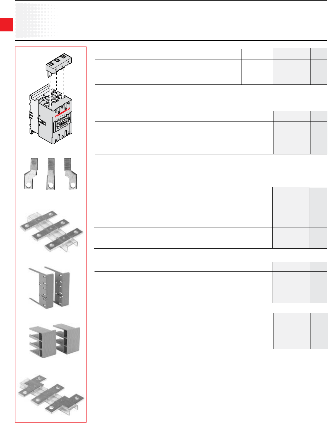
Accessories
Auxiliarycontactblock technicaldata
CE5
Auxiliary contact blocks for switching low level voltage and current
Types CE5-10D0.1 CE5-10DZ
CE5-01D0.1 CE5-01DZ
CE5-10W0.1 CE5-10WZ
CE5-01W0.1 CE5-01WZ
Version 100 mA Version 2 A
Standards IEC 947-5-1andEN60947-5-1
Approvals UL/CSA
Rated insulation voltage Ui
accordingtoIEC 947-5-1 V 250 250
accordingtoUL/CSA V 125 250
Rated operational voltage Ue V 125 250
Rated operational current Ie
inAC-15orAC-14acc.toIEC947-5-1 A 0.1 2
inDC-12acc.toIEC947-5-1 24V A 0.1 2
60 V A 0.1 0.5
110 V A 0.1 0.2
220 V A 0.1 0.1
Minimal switching 3V/1mA 17V/1mA
Reliability for the minimal switching 10 -8
Connecting terminals M3.5(+,-)posidriv2screwwithcableclamp
Connecting capacity
•Rigidsolid 1ou2(1...4)mm2
•Flexiblewithcableend 1ou2(0.75...2.5)mm2
Short circuit protection 100 mA 10 A
Degree of protection
accordingtoIEC529,IEC144,DIN40050,NFC20-010 IP20
Mounting Frontmountingoncontactors:A,AE,TAE9...110,AL,AF,GA,N,NE
Dimensions IdenticaltothoseofCA5singlepole
1
Across the line
contactors
Low Voltage Products & Systems 1.19
ABBInc.•888-385-1221•www.abb.us/lowvoltage 1SXU000023C0202
TP40DA
VE5-1
VM300H
Connections Mounting Catalog List
on number price
Auxiliary lead terminals
Connectsfromside A50 – A75 LK75-L $ 15
Connectsfromtop A50 – A75 LK75-F 15
Connectsfromside A95 – A110 LK110 23
Pneumatic timers
A9–A75 Ondelay0.1–40s 1 1 TP40DA
AE9–AE75 Ondelay10–180s 1 1 TP180DA $ 108
AL9–AL40 Offdelay0.1–40s 1 1 TP40IA
Offdelay10–180s 1 1 TP180IA
Mounting Timing Contacts Catalog List
on range N.O.N.C. number price
Interlocks for two horizontally mounted contactors –A9-A110
Mechanical/electrical A/AE/AL9–A/AE/AL40 – 2 VE5-1 $ 45
Mechanical/electrical A45–A110 – 2 VE5-2 1 45
Mechanical A/AE/AL9–A/AE/AL40 – – VM5-1 21
Feature Mounting Contacts Catalog List
on N.O.N.C. number price
Interlocks for two horizontally mounted contactors–A95-AF1250contactors
Mechanical A95 – A300 A145 – A300 VM300H $ 110
Mechanical A210 – A300 AF400 – AF460 VM300/460H 130
Mechanical AF400 – AF1250 AF400 – AF1250 VM750H 150
Feature Left Right Catalog List
contactors contactors number price
Interlocks for two vertically mounted contactors–A95-AF1250contactors
Mechanical A95 – A300 A145 – A300 VM300V $ 205
Mechanical A210 – A300 AF400 – AF460 VM300/460V 250
Mechanical AF400 – AF1250 AF400 – AF1250 VM750V 270
Feature Top Bottom Catalog List
contactor Contactor number price
Accessories
forA/AF/AL&AEcontactors
Discount schedule ABA [OF]
1UsetypeVE5-2formechanicalandelectricalinterlockingbetweenA30/A40andA50-A75contactors.
Interlocks for two horizontally mounted contactors–AF1350-AF2050contactors
Mechanical AF1350 – AF2050 AF1350 – AF2050 VM1650H $ 655
Feature Left Right Catalog List
contactor Contactor number price
LK75-L LK75-F LK110
1
Across the line
contactors
1.20 Low Voltage Products & Systems
1SXU000023C0202 ABBInc.•888-385-1221•www.abb.us/lowvoltage
Discount schedule ABA [OF]
Accessories
forA/AE/AL/AFcontactors
WB75A-04
BA5-50
Identification markers
Mounting Coil Catalog List
on voltage number price
A/AE/AL/AF9–A/AE/AL/AF110 Packof50 BA5-50 $ 15
Terminal lug kits(Setof3)
Wire For Catalog List
range contactor number price
6–300MCM A145 – A185 ATK185 $ 45
4 – 400 MCM A210 – A300 ATK300 68
(2)4-500MCM A210 – A300 ATK300/2 110
(2)2/0–500MCM AF400 – AF580 ATK580/2 150
(3)2/0–500MCM AF580 – AF1250 ATK750/3 225
(4)4/0–500MCM AF1350 ATK1350/4 235
(4)1/0–750MCM AF1350 – AF2050 ATK1650/4 335
(6)1/0–750MCM AF1350 – AF2050 ATK1650/6 560
ZL75
For contactors Catalog List
number price
Contact kits
3 Pole
A/AE/AF50 ZL50 $ 113
A/AE/AF63 ZL63 135
A/AE/AF75 ZL75 158
A/AE/AF95 ZL95 225
A/AE/AF110 ZL110 255
A/AF145 ZL145 300
A/AF185 ZL185 420
A/AF210 ZL210 525
A/AF260 ZL260 855
A/AF300 ZL300 1,020
AF400 ZL400 1,716
AF460 ZL460 2,434
AF580 ZL580 3,795
AF750 ZL750 3,960
AF1250 ZL1250 5,280
AF1350 ZL1350 4,255
AF1650 ZL1650 4,890
AF2050 ZL2050 6,290
4 Pole
A/AE45 ZLT45 150
A/AE50 ZLT50 150
A/AE75 ZLT75 210
3 Pole UA50 ZLU50 150
UA75 ZLU75 215
UA95 ZLU95 306
UA110 ZLU110 347
ATK185
For contactors Catalog List
number price
Mechanical latches
A9-A75,AE45-AE75,&AL9-AL40 WB75A-∆ $ 84
∆-Coilvoltagesufx.RefertoCoilVoltageSelectionchartandsubstitutethedesiredcoilvoltagesufxforthe∆.
Coil voltage selection chart – mechanicallatchesforA,AE&ALcontactors
Range: WB75AforcontactorsA9–A75,AL9–AL40,AE45–AE75andcontrolrelaysNandNL.
Description:WB75Ablock:containsamechanicallatchingdevicewithelectromagneticimpulseunlatching(ACorDC)
ormanualunlatching.Captivescrewtypeconnectingterminals,built-incableclamps,M3.5(=,-)posidrive1screwwith
screwdriverguidance,delivereduntightenedandprotectedagainstaccidentaldirectcontact.
Operation: Afterclosing,thecontactorcontinuestobeheldintheclosedpositionbythelatchingmechanismshouldthe
supplyvoltagefailatthecontactcoilterminals.
Contactoropeningcanbecontrolled:
• Electricallybyanimpulse*(ACorDC)ontheWB75Ablockcoil.Thecoilisnotdesignedtopermanentlyenergized.
• ManuallybypressingthepushbuttononthefrontfaceoftheWB75Ablock.
Mounting: WB75Aisclippedontothefrontfaceofthecontactor.
50Hz(AC/DC) 60Hz(AC) Voltage
code
24 24 – 28 01
42 42 – 48 02
48 48 – 55 03
110 110 – 127 04
ZL145
ATK750/3
50Hz(DC) 60Hz(AC) Voltage
code
220 – 230 220 – 255 06
230 – 240 230 – 277 05
380 – 415 380 – 440 07
415 – 440 440 – 480 08
1
Across the line
contactors
Low Voltage Products & Systems 1.21
ABBInc.•888-385-1221•www.abb.us/lowvoltage 1SXU000023C0202
BEM circuit diagram
BES110 connection diagram
Accessories
forA/AE/AL/AFcontactors
Discount schedule ABA [OF]
Connection kits for reversing
Application
Connectionsbetweenthemainpolesoftwo 3 pole contactorsmountedsidebysidesothattheyoperateasreversing
contactors.
Description
Theconnectionkitsforreversingcontactorsaremadeupofthreereversingconnectionsandthreephasetophase
connections.
BER16V –Moldedplastic,solidcopperbars
BER40V –Moldedplastic,solidcopperbars
BEM75and110-30 –Insulated,solidcopperbars
Mountingon3polecontactors Catalog List
number price
A/AE/AF50, A/AE/AF75 BES75-30 $ 75
A/AE/AF95, A/AE/AF110 BES110-30 90
A/AF145 – A/AF185 BES185-30 130
A/AF210 – A/AF300 BESA300-30 200
AF400 – AF460 BES460-30 425
AF580 – AF750 BES750-30 650
Theconnectionkitforphasetophasecontactorsismadeupofthreephasetophasebusbars.
Connection kits for phase to phase
Application
Connectionsbetweenthemainpolesofawye-deltastarter.
Connection kits for wye-delta starters
Mounting on contactors Catalog
number
List
price
Line and delta contactor Wyecontactor
A9 A9
BEY16V-2 $ 46A12 A9
A16 A12
A26 A16 BEY26-2 76
A30 A26 BEY40-2 76
A40 A26
A50 A30 BED50U 165
A63 A40
A75 A50 BED75U 180
A95 A75 BED95U 195
A110 A95 BED110U 225
A145 A110 BED145U 250
A185 A145 BED185U 290
A210 A185 BED210U 375
A260/A300 A210 BED300U 500
AF400/AF460 A260/A300 BED400U 850
AF460 AF400 BED460U 900
AF580 AF400/AF460 BED580U 1,250
AF750 AF580 BED750U 1,450
Description
Theconnectionkitsforwye-deltastartersaremadeupof:
•Threelinecontactor/wyecontactorconnections–lineside.
•Threewyecontactor/deltacontactorconnections–load
side.
•Theshortingconnectionforthe“S”contactor.
BEY16V-2,BEY26-2,BEY40-2–Moldedplastic,solid
copperbars
BED50UthruBED750U–Insulated,solidcopperbars.
Theaboveconnectionsetsallowamechanicalinterlockunitto
bemountedbetweenthewyeanddeltacontactorsifrequired.
BEM...
BES...
BED...
A1
A2
A1
A2
31 5 31 5
42 6 42 6
A1
A2
A1
A2
31 5 53
42 6 64
1
2
A/AE/AL9–A/AE/AL16 BER16V $ 35
A/AE/AL26–A/AE/AL40 BER40V 49
A/AE/AF50–A/AE/AF75 BEM75-30 165
A/AE/AF95,A/AE/AF110 BEM110-30 180
A/AF145–A/AF185 BEM185-30 260
A/AF210–A/AF300 BEMA300-30 470
AF400 – AF460 BEM460-30 850
AF580–AF750 BEM750-30 1,200
Mountingon3polecontactors Catalog List
number price
BER...
BEY...
1
Across the line
contactors
1.22 Low Voltage Products & Systems
1SXU000023C0202 ABBInc.•888-385-1221•www.abb.us/lowvoltage
Accessories
forA/AE/AL/AFcontactors
LD110
Terminal extensions
A/AE/AF50–A/AE/AF75 BEXT-75 $ 15
A/AE/AF95,A/AE/AF110 LW110 95
A/AF145–A/AF185 LX185 90
A/AF210–A/AF300 LX300 140
AF400 – AF460 LX460 195
AF580–AF750 LX750 225
Application
Theyaredesignedtoincreasethewidthofthecontactorterminalpadstoallowlargerconnectorstobemounted.
Description
Terminal extension setscontain3bars.
Mounting Catalog List
oncontactors number price
Terminal enlargements
A/AF95 – A/AF110 LW110 $ 95
A/AF145 – A/AF185 LW185 120
A/AF210 – A/AF300 LW300 130
AF400 – AF460 LW460 295
AF580 – AF750 LW750 355
AF1250 LW1250 375
For contactor Catalog List
number price
Terminal shrouds –twopieces
A/AF145 – A/AF185forushmount LT185-AC
A/AF145 – A/AF185forextendedmount LT185-AL
A/AF145 – A/AF185forshortingbarLY...betweenA(F)145/A(F)185&TA200DU LT185-AY $ 10
A/AF210 – A/AF300forushmount LT300-AC
A/AF210 – A/AF300forextendedmount LT300-AL
A/AF210 – A/AF300forshortingbarLY300 LT300-AY
AF400 – AF460forushmount LT460-AC
AF400 – AF460 for extended mount LT460-AL 20
AF580 – AF1250forushmount LT750-AC
AF580 – AF1250forextendedmount LT750-AL
For contactor Catalog List
number price
BEXT-75
Discount schedule ABA [OF]
LT185-AC
LT185-AL
LX...
LW...
Mountingon3polecontactors Wire Catalog List
range number price
A/AE/AL9 –A/AE/AL16(setof2) 16–6 LD-16 $ 20
A/AE/AL26(setof2) 14–6 LD-26 22
A/AE/AL30 –A/AE/AL40 12–4 LD-40 26
A/AE/AF50–A/AE/AF75 10–2 LD-75 28
A/AE/AF95–A/AE/AF110 8–1 LD-110 30
Utilization–TheLDseriesterminalblockisdesignedtoincreasetheconnectioncapacityofthecontactoronwhichitis
mounted.TheLD75andLD110terminalblocksaremountedinthethreeindependentapertureslocatedabovethebuilt-in
connectors.
Additional terminal blocks
Arc chutes
A/AF145 – A/AF185 ZW185 $ 130
A/AF210 – A/AF300 ZW300 180
A/AF400 – A/AF460 ZW460 190
A/AF580 – A/AF750 ZW750 230
AF1350 – AF1650 ZW1650 215
For contactor Catalog List
number price
1
Across the line
contactors
Low Voltage Products & Systems 1.23
ABBInc.•888-385-1221•www.abb.us/lowvoltage 1SXU000023C0202
Accessories
forA/AE/AFcontactors
Discount schedule ABA [OF]
BEA185/S3/S4
BEAD185D/S3/S4
LP185
BEA185H/S4
LY...
1 Notforusewithangehandles.
Vertical connection bars between contactor and MCCB –threebars
MCCB For contactor Catalog List
number price
T1 A/AE/AF50– A/AE/AF75 BEA75/T1 $ 85
T3 A/AE/AF95– A/AE/AF110 BEA110/T3 95
T3 A/AF145– A/AF185 BEA185/T3 60
S3,S4 A/AF145– A/AF185 BEA185/S3/S4 60
T4 A/AF145- A/AF185 BEA185/T4 70
T4 A/AF210- A/AF300 BEA210/T4 70
T5 A/AF210– A/AF300 BEA300/T5 75
T5 A/AF400- A/AF750 BEA750/T5 115
S5 A/AF210– A/AF300 BEA300/S5 75
S51 AF400 – AF460 BEA400/S5 95
S6 AF400– AF750 BEA750/S6 115
Vertical connection bars between contactor and MCCB –threebars
MCCB For contactor Catalog List
number price
S3,S4 A/AF145– A/AF185 BEA185D/S3/S4 $ 70
S4 A/AF210– A/AF300 BEA210D/S4 80
S5 A/AF210– A/AF300 BEA300D/S5 85
S5 AF400– AF460 BEA400D/S5 105
S6 AF400– AF750 BEA750D/S6 125
Tobeusedwhenpowertakeoffisneeded(IP00)orwithotherbusbars.(EX:Reversing,IP20)
Horizontal connection busbars between contactor and MCCB –threebars
MCCB For contactor Catalog List
number price
S3,S4 A/AF145– A/AF185 BEA185H/S4 $ 150
S4 A/AF210– A/AF300 BEA210H/S4 220
S5 A/AF210– A/AF300 BEA300H/S5 220
S5 AF400– AF460 BEA400H/S5 435
S6 AF400 – AF460 BEA460H/S6 660
S6 AF580– AF750 BEA750H/S6 670
Shorting bars, 2 pole
For contactor Catalog List
number price
A/AF145–A/AF185 LP185 $ 35
A/AF210–A/AF300 LP300 50
AF400 – AF460 LP460 50
AF580–AF750 LP750 50
Shorting bars, 3 pole
For contactor Catalog List
number price
A/AE45–A/AE/AF75 LF75 $ 40
A/AE/AF95–A/AE/AF110 LY110 40
A/AE/AF145–A/AE/AF185 LY185 40
A/AE/AF210–A/AE/AF300 LYA300 60
AF400 – AF460 LY460 60
AF580–AF750 LY750 60
1
Across the line
contactors
1.24 Low Voltage Products & Systems
1SXU000023C0202 ABBInc.•888-385-1221•www.abb.us/lowvoltage
Coils –ACoperated
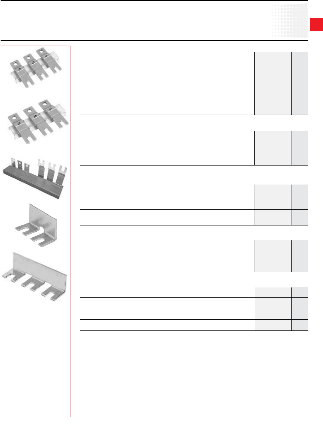
ZA16-81
Accessories
forA/AE/AL/AFcontactors
Coils&coilvoltagecodes
Discount schedule ABA [OF]
1 OnlyforA9–A16.
2 NotforA145–A300
3 A145–A300at60Hz,115Vonly
4 AF400–AF1250,DConly
5 AF45–AF300
6 AF400-AF750only
7 OnlyoptionforAF2050-AF1650
Coil voltage selection –AC/DCoperatedforAF50–AF2050
24–60VDC 68 4
20–60VDC 72 5
48–130VAC/VDC 69
100–250VAC/VDC 70 7
250–500VAC/DC 71 6
VAC&VDC Sufx
40-60Hz Code
12 80
24 81
42 82
48 83
50 21
60 84
75 85
110 86
125 87
220 88
240 89
250 38
Coil voltage selection–DCoperated for AE contactors
Voltage code
VDC AE
contactors
Coil voltage selection–ACoperated
forA9–A300;UA26–UA110
24 24 81
26 28 16
28 32 17
42 42 82
48 48 83
60 60 73
100 100 – 110 74 2
110 110 – 120 84
110–115 115–127 89 3
120 140 29
125–127 150 30
175 208 34
190 220 36
200 200 – 220 75 2
220 – 230 230 – 240 80
230 – 240 240 – 260 88
230–240 277 42
230/400 – 62 1
– 230/400 63 1
380–400 400–415 85
400–415 415–440 86
– 480 51
440 500 53
500 600 55
550 – 56
660–690 – 58
Voltage
VAC(50Hz) VAC(60Hz) Code
ZAF1650
ZP1650
For contactors Catalog List
number price
A9 – A16 ZA16-∆ $ 24
A26 – A40 ZA40-∆ 30
A45 – A75 ZA75-∆ 57
A95 – A110 ZA110-∆ 60
A145 – A185 ZA185-∆ 150
A210 – A300 ZA300-∆ 180
Coils –DCoperated
AE9– AE16 ZAE16-∆ 24
AE26 – AE40 ZAE40-∆ 30
AE45 – AE75 ZAE75-∆ 57
AE95 – AE110 ZAE110-∆ 90
AuxiliaryincludinganinsertioncontactandavaristorforDCoperatedcontactors
AE95 – AE110 CCL18-01 45
Coils –AC/DCoperated(coilandprintedcircuitboardexceptZAF1650)
AF45 – AF75 ZAF75-∆ 120
AF95,AF110 ZAF110-∆ 165
AF145–AF185 ZAF185-∆ 200
AF210 – AF300 ZAF300-∆ 240
AF400,AF460 ZAF460-∆ 450
AF580,AF750,AF1250 ZAF750-∆ 525
AF1350,AF2050(Setof2coilsonly) ZAF1650-∆ 920
Printed circuit board–AC/DCoperated
AF1350 – AF2050 ZP1650 1,620
∆–Coilvoltagesufx.RefertoCoilVoltageSelectionchartsbelowandsubstitutethedesiredcoilvoltagecodeforthe∆.
1
Across the line
contactors
Low Voltage Products & Systems 1.25
ABBInc.•888-385-1221•www.abb.us/lowvoltage 1SXU000023C0202
Accessories
for EK contactors
Coils&coilvoltagecodes
Coils–AC&DCoperated
VAC(50Hz) VAC(60Hz) Voltage
Code
Coil voltage selection – AC operated
forEK110–EK550
– 24 F
24 – N
– 48 G
110 120 1
– 208 B
– 240 2
220 – 230 – J
– 380 Z
380–400 440 3
400–415 – M
– 480 4
500 – 5
– 600 6
Consultfactoryifothervoltagesarerequired.
VDC Voltage
Code
Coil voltage selection – DC operated
forEK110–EK550
24 Y
48 W
110 P
125 Q
220 R
440 T
Consultfactoryifothervoltagesarerequired.
Discount schedule AB
ACCoils DCCoils
Contactor Catalog List Catalog List
size number price number price
EK110,EK150 KH210-∆ $ 200 KH210-∆ $ 200
EK175,EK210 KH300-∆ 240 KH300-∆ 240
EK370,EK550 KH800-∆ 580 KH800-∆ 580
∆–Coilvoltagesufx.RefertotheCoilVoltageSelectionchartandsubstitutethedesiredcoilvoltagesufxforthe∆.ACandDCoperatedcontactorsDONOThavethe
samemagnetstructure.Therefore,DCcoilswillnottonanACmagnetstructureandviceversa.
1
Across the line
contactors
1.26 Low Voltage Products & Systems
1SXU000023C0202 ABBInc.•888-385-1221•www.abb.us/lowvoltage
RV5/50
Accessories
SurgesuppressorsforA/AE/AL/EKcontactors
Surge suppression device
Discount schedule ABA [OF]
RC5-1/150
Technical data
Type Control Openingtime Residualovervoltage Remarks
circuit growthfactor orclippingvoltage
RT 5 /... transil diode Advantages • Goodenergyabsorption
32 DC 50V • Unpolarizedsystem
65 DC 100V • Simple,reliablesystem
90 DC 2.5to3 150V Drawback • Acertaindelayondropoutwhichdoesnot
150 DC 210V howeverreducecontactorbreakingcapacity.
264 DC 390V
Varistor RV 5/... Advantages • Highenergyabsorption;gooddamping
50 AC/DC 132V • Unpolarizedsystem
133 AC/DC 1.1to1.5 270V
250 AC/DC 480V Drawback • ClippingasfromUvdr,thusvoltagefrontupto
440 AC/DC 825V thispoint
RC 5-1/... or RC 5-2/... seetable AC Advantages • Veryfastclipping
RC-EH 300/... above 1.2 to 3 2 to 3 x Uc • Attenuationofsteepfrontsandthusof
highfrequencies
• Nooperatingdelays
Varistor + RC RC-EH ... Advantages • Highenergyabsorption:gooddamping
800/110 AC/DC 1.1to1.5 205V • Unpolarizedsystem
800/600 AC 1100V • TheRCsystemdampsthevoltage
frontundertheUvdr*threshold.
*Uvdr=Varistoroperatingvoltage
(voltagedependentresistor),tolerance±10%
12 – 32VDC RT5/32
25 – 65VDC RT5/65
AE9toAE110 50 – 90VDC RT5/90
AL9toAL40 77 – 150VDC RT5/150
150 – 264VDC RT5/264
24 – 50VAC/VDC RV5/50
A9toA110;AE9toAE110 50 – 133VAC/VDC RV5/133
AL9toAL40 110 – 250VAC/VDC RV5/250
250 – 440VAC/VDC RV5/440 $ 30
24 – 50VAC RC5-1/50
A9toA40 50 – 133VAC RC5-1/133
110 – 250VAC RC5-1/250
250 – 440VAC RC5-1/440
24 –50VAC RC5-2/50
A45toA300 50 – 133VAC RC5-2/133
110 – 250VAC RC5-2/250
250 – 440VAC RC5-2/440
EK110toEK210 24 – 48VAC RC-EH250/48
110 – 415VAC RC-EH250/415
EK370toEK550 48 – 110VAC RC-EH800/110 52
EK110toEK550 24 – 125VDC RC-EH800/110
EK370toEK550 220 – 600VAC RC-EH800/600
Mounting Voltage Catalog List
on range number price
1
Across the line
contactors
Low Voltage Products & Systems 1.27
ABBInc.•888-385-1221•www.abb.us/lowvoltage 1SXU000023C0202
A1
A2
Varistor (only)
General
Theoperationofinductivecircuitscausesovervoltages,inparticularonopeningofthecontactorcoil.
Theelectromagneticenergystoredbythecoilduringcontactorclosingisrestoredonopeningintheformofsurges,the
slopeandamplitudeofwhichmayrisetoseveralkilovolts.Anumberofdrawbacksareobservedrangingfrominterference
ontheelectronicdevicestobreakdownofinsulatorsandevendestructionofcertainsensitivecomponents.
Thegraphoppositereproducestheoscillogramshowingvoltagedischargesattheterminalsofa42V/50Hzcoilwithout
peakclipping.Thecoilwasswitchedby8series-connectedpolesofacontactorrelay.
Followingaburstofdischargeswithaverysteepslopeadampedoscillationemergeswithapeakvalueof3500V.
Overvoltage factor
TheovervoltagefactorkisdenedastheratioofthemaximumovervoltagepeakvalueÛs tothepeakvalueÛc ofthecoil
ratedcontrolvoltageUc:
Û
smax. Ûsmax. Ûs max.
k=_______ inDC: k=_______ orinAC: k=_______
Ûc Uc Uc√2
3500
Forexamplethefollowingisobtainedfortheabovegraph:k=_____ ≈ 60
42 √2
Surge suppressors
Toguardagainsttheharmfuleffectsoftheseovervoltages,ABBhasdevelopedarangeofsurgesuppressorsdesignedto
reducethekfactordenedaboveandtolimitorevencompletelyeliminatethehighpre-dampingvoltagefrequencies.
Eachcaseisdifferent,butthetechnicaldatatolerancesandthegeneroussizingofpartshaveenabledustoreducethe
numberofvariants.
Wehavechosenthefollowingsolutions:transildiodes,varistorsandRCblocks.
Note:Avaristorisaresistorwhosevalueincreasestoaverylargeextentwhenacertainvoltageisappliedatits
terminals.
Wiring diagrams
General technical data
Thehousingsandimpregnationresinsofthesurgesuppressorsaremadeofame-resistantmaterialsinaccordancewith
theUL94standard.
Thesesystemsarenotpolarized,i.e.d.c.operateddevicesdonothavetobeconnectedinaspecicdirection.
• Operatingtemperature:-20to+70°C
• Connectiontothecoilterminals(parallelmounting)
– For RT 5,RV 5,RC 5-1 and RC 5-2:clip-onforbothxingandconnection.
• Mounting:
– RT 5,RV 5 and RC 5:clippedontothetoppartofthecontactorbase.Thismountingmethodpreventsany
projectionsandchangeincontactordimensions.
– RC-EH:gluedtothetoppartofthecontactorbase.
Accessories
SurgesuppressorsforA/AE/AL/EKcontactors
Generalinformation
0
1000
100
U (V)
T (µs)
0
1000
100
A1
A2
Transil diode
A1
A2
RC type
A1
A2
U
Varistor + RC
1
Across the line
contactors
1.28 Low Voltage Products & Systems
1SXU000023C0202 ABBInc.•888-385-1221•www.abb.us/lowvoltage
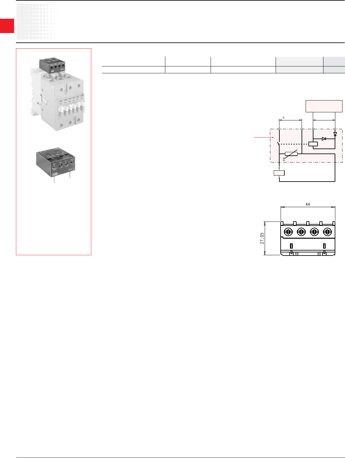
Accessories
Interface relays for A contactors
Application
RA5-1interfacerelaysaredesignedtoreceive24VDCsignalsdelivered
byPLC'sorothersourceswithalowoutputpowerandrestorethem
withsufcientpowertooperatethecoilsoftherelevantA9-A110
contactorsortheNcontrolrelays.
•IEConly
Description
RA5interfacerelaysaremadeupofaminiatureelectromechanicalrelay
equippedwithaN.O.contactandwithalowconsumption24VDCcoil.
TheinterfacerelaycoiliscontrolledbythePLCwhiletheN.O.contact
ensuresswitchingofthepowercontactor.
Coilswitchinggivesrisetoovervoltageswhichhaveadverseeffectson
theelectronicdevices,insulatorsand,moregenerally,oncomponent
lifetime.TheRA5-1isequippedwithsurgesuppressors:
•onthe24VDCrelaycoilviaadiode
•onthepowercontactorcoilviaavaristor.
Furthermore,theRA5-1areprotectedagainstrelaypolereversalbya
diodeinsertedbetweentheE1andE2inputterminals.
Connection
The“E1+”and“E2–”inputterminalsmustbeconnected,accordingto
theirpolarity,tothePLCoutput.
TheRA5isequippedwithtwoterminalpadsforconnectiontotheA1
andA2terminalsofthecontactorcoil.Thiscoilissuppliedbetweenthe
A0andA2terminalsoftheRA5.
A30-30-10+RA5
RA5
N,A9–A110 24VDC 24–250V,50,60Hz RA5-1 $ 75
NOTE:TheinterfacerelaysprovidedfortheAcontactorscanalsobeusedforUA,UA...,RAandGAtypes.
Mounting on Control Coil Catalog List
contactortypes voltageUc voltages number price
Interface relays
Discount schedule ABA [OF]
U
c
250 VAC 24 VDC
+–
RA 5
A0 E2 – E1 +
KM1
A1
A2
PLC
Output
A2
RA 5-1 interface relay for the A 9 – A 110
contactors and N control relays
Mounting
•RA5:terminalpadsclampedinsidethecontactorcoilterminals.
1
Across the line
contactors
Low Voltage Products & Systems 1.29
ABBInc.•888-385-1221•www.abb.us/lowvoltage 1SXU000023C0202
Accessories
Interfacerelaytechnicaldata
General technical data
Compliance with standards IEC 60255-5
Rated insulation voltage Ui
according to
IEC 60947-4-1
V a.c. 250
Permissible ambient temperature:
– for free air operation:
– at Uc = 24 V d.c. (between E1 and E2) °C -25 ... +70
– from 0.85 to 1.1 Uc °C -25 ... +55
– for storage °C -40 ... +70
Climatic withstand Complies with that of associated contactors
Operating altitude m ≤ 3000
Mounting position No limitation
Fixing Using the contactor A1 and A2 terminal connecting parts
Connecting terminals (delivered in open position) M3.5 (+,-) pozidriv 2 screws with cable clamp
Connecting capacity (min. ... max.)
– rigid solid 2 x mm2 1 ... 4
– 2 x mm2 0.75 ... 2.5
Tightening torque
– recommended Nm 1.00
– max. Nm 1.20
Degree of protection
according to
IEC 60947-1 / EN 60947-1
Protection against direct contact in acc. with EN 50274
and IEC 60529 / EN 60529 RA5-1 wired and mounted on the associated contactor
Working data
Surge suppression:
– for contactor coil Varistor
– for interface relay coil Diode
Protection against polarity reversal
between terminals E1 and E2 Diode
Interface relay operating time ms Closing and drop-out ≤ 10
Total operating time,
interface relay + contactor:
– between energization and:
N.O. contact closing ms 20 ... 37
N.C. contact opening ms 17 ... 32
– between de-energization and:
N.O. contact opening ms 17 ... 25
N.C. contact closing ms 20 ... 28
Electrical input data
Control voltage (E1and E2 terminals) Uc
– rated value V d.c. 24
– max. range at ambient temperature 20 °C V d.c. 19 ... 30
Max. consumption
for Uc = 24 V d.c., θ = 20 °C W 0.3
"0" status (relay open) for Uc V d.c. ≤ 2.4
or Ic mA < 1
"1" status (relay closed) for Uc V d.c. ≥ 19
Max. short supply interruption immunity time
ms 2
Electrical output data
Switching voltage (A0 and A2 terminals) V a.c. ≤ 250
Electrical durability million of operating cycles 2 (600 cycles/h) on A 9 ... A 75 contactors or N... contactor relay
0.5 (600 cycles/h) on A 95 and A 110 contactors
exible with cable end
1
Across the line
contactors
1.30 Low Voltage Products & Systems
1SXU000023C0202 ABBInc.•888-385-1221•www.abb.us/lowvoltage
Accessories
for A contactors
TE5Selectronictimerforwye-deltastarters
TE5S-*
Chart
Equivalentdiagram
Front face
Application
Utilization
Whenusedinwye-deltastarters,theTE5S lagsthewyeconnectionandprovidesalapseof50msbeforetheswitchoverto
thedeltaconnection.
Description
Accordingtothetypeofdevicechosen,theelectroniccircuithasa24VAC/VDC,110–120VACor220–230VACsupply.
Anoutputrelaywithreversingcontactensureshighcurrentswitching.Atwo-positionswitchallowsselectionofoneofthe
twotimedelayranges:0.8to8sor6to60s.The0.1to1.0adjustableknoballowsaninitialsettingwithoutstepswithinthe
previouslyselectedrangewhichcanthenbeadjustedusingastopwatch.
Note:Werecommendthatyouallowfortemperaturedriftforthenaladjustmentofthetimedelaysetting.Drift:–0.2%per
°C.Forexample,asettingmadeat20°Cwillyieldatimedelayshorterby7%at55°Cinanenclosure.(–0.2%per°Ci.e.–
0.2x35=–7%).
TheTE5S,whichisnotaffectedbythesesettings,establishesaxed“lapse”of50msbetweentheopeningofcontact15–
16andtheclosingofcontact15–18.Itisthistimedelaythatpreventsfromarcshort-circuitduringwyetodeltaswitching.
Operation
Onenergization,thegreenUindicatorlight(voltageapplied)comeson.Contact15–16thenimmediatelymovestothe
closedposition.
Count-downoftheprogrammedtimeimmediatelycommences.
Whenthetimedelayhaselapsed,contact15–16opensandatthesametimethe50mslapse,t2,beginsafterwhich
contact15–18movestotheclosedposition.TheyellowRindicatorlightcomeson.
Onde-energization,theUandRindicatorlightsgooutand,afterthe250msresettingtime,thedeviceisreadyforanew
cycle.
Mounting
Mountson35mmDINrail.
Discount schedule ABA [OF]
Electronic timer
15-18
U
15-16
t1 t2 = 50ms
R
TE 5S
t1 t1+t2
A1A2
16
15
18
TE5S
R
Star-Delta Timer
U
0.1
0.5
1.0
0.8 ... 8s t1
A1 15
16 A218
6 ... 60s
For Ratedcontrol Packing Unit Catalog List
contactors voltageUc piece weight number price
V kg
24AC/DC 1 0.080 TE5S-24
A9–AF750 110–120AC 1 0.080 TE5S-120 $ 120
220–240AC 1 0.080 TE5S-240
380–440AC 1 0.080 TE5S-440
1
Across the line
contactors
Low Voltage Products & Systems 1.31
ABBInc.•888-385-1221•www.abb.us/lowvoltage 1SXU000023C0202
Accessories
for A contactors
TE5Selectronictimerforwye-deltastarters,technicaldata
TechnicalData
Types TE5S-24 TE5S-120 TE5S-240 TE5S-440
Compliancewithstandards IEC60947-5-1,EN60947-5-1
RatedinsulationvoltageUi
accordingtoIEC60947-5-1 V 440
RatedoperationalvoltageUe V d.c. 24 –
accordingtoIEC60947-5-1 Va.c. 24...240 440
ConventionalfreeairthermalcurrentIth A 10
RatedoperationalcurrentIe acc.toIEC60947-5-1
AC-15 24-120Va.c. A 5 –
220-240Va.c. A 4 –
380-440Va.c. A – 3
DC-13 24 V d.c. A 4 –
Short-circuitprotection-gGtypefuses A 10
RatedsupplyvoltageUc V d.c. 24 – – –
Va.c. 24 110...120 220...240 380...440
–Ratedfrequencylimits Hz 48...63
–Supplyvoltagerange 0.85...1.1Uc
–Overvoltageprotection Built-invaristor
–Loadfactor % 100
–Averageconsumption –ind.c. W 0.7 – – –
–ina.c. VA 1.5 3.5 6.5 12.5
Time delay range (t1)selectedbyswitch s 0.8...8and6...60
–Temperaturedrift %per°C -0.2
–Mechanicalsettingaccuracy ±15%ofthesettingrange
–On-loadreiterationaccuracy
underconstantconditions ±2%after1millionoperatingcycles
Minimumtimelapse(t2) ms 50
Min.timelapseafter1millionoperatingcycles ms 40
Resettingtime(maximum) ms 250
Frontpaneldisplay: –greenindicatorlight Energization
–yellowindicatorlight Outputrelayactivated
Permissibleairtemperature
–foroperation °C -25...+60
– for storage °C -40...+85
Vibrationwithstandacc.to
IEC60068-2-6,EN60068-2-6 3gfrom10to300Hzinthe3directions
Shockwithstandacc.to 20g/11msindirectionsAandC
IEC60068-2-27,EN60068-2-27 15g/11msindirectionB
Electricaldurability inmillionsofop.cycles 1
Mechanicaldurability inmillionsofop.cycles 5
On-loadmaximumswitchingfrequency cycles/h 720 600
Fixing on mounting rail acc. to IEC/EN60715 35x7.5or35x15
Connectingterminals (+,-)pozidriv1screw
Connectingcapacity
– rigid solid 1 or 2 x mm2 1...2.5
–exiblewithcableend 1or2xmm2 0.75...2.5
Tighteningtorque Nm 0.6...0.8max.
Degreeofprotection Terminals IP20
accordingtoIEC60947-1/EN60947-1
andIEC60529/EN60529
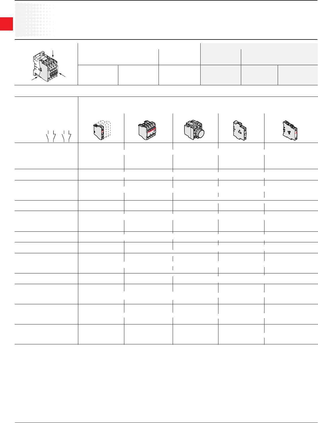
1
Across the line
contactors
1.32 Low Voltage Products & Systems
1SXU000023C0202 ABBInc.•888-385-1221•www.abb.us/lowvoltage
Contactor mounting configurations (standard from factory)
Auxiliarycontactsaremountedonthecontactorinthefollowingorder:
Left – 1st
Right – 2nd
Top – 3rd(LtoR)
Accessories
PossibleaccessorycombinationsforAcontactors
Positioning Accessories – Front face mounting Accessories – Side mounting
Auxiliary contacts Pneumatic Auxiliary Electrical or
1–pole 4–pole timers contacts mechanicalinterlock1
CA5-10 CA5-40 TP–D CAL5-11 VE5-1 VE5-2
orCA5-01 orCA5-22 orTP–I CAL18-11 orVM5-1 VM300H
orCA5-31 CAL18-11B VM300/460H
VM750H
1 Inmountingposition5(seepage1.36),thereshouldbenomorethan2"N.C."front-mountedauxiliarycontacts–TheCAL 5-11side-mountedblocksofferadditional"N.C."contacts.
2 Whateverthemountingposition(seepage1.36),thereshouldbenomorethan2"N.C."front-mountedauxiliarycontacts–TheCAL 5-11side-mountedblocksofferadditional"N.C."contacts.
Top
Front
face
Left
side
Configurations of accessories are different depending on whether front or side mounted.
N Contactor relays Accessories – Front mounting Accessories – Side mounting
A and AE Contactors Auxiliary contact blocks TP - A Pneumatic Auxiliary contact Blocks Interlock units
1-pole CA5- 4-pole CA5- timer block 2-pole CAL5-11,
CAL18-11
Type Main Built-in
poles auxiliary
contacts
A9 – A26 – 3 0 – 1 0
A9 – A26 – 3 0 – 0 1 1 1 to 4 CA5- OR 1 CA5- OR 1 TP - A block + 1 to 2 OR 1 VM/E 5-1 block
A9 – A26 – 4 0 – 0 0 1-poleblocks 4-poleblock CAL5-11 blocks +1CAL5-11 block
A9 – A26 – 2 2 – 0 0 1
AE9 – AE26 – 3 0 – 0 0
AL9 – AL26 – 3 0 – 1 0 1 to 4 CA5- OR 1 CA5- OR – OR 1 CAL5-11 block OR 1 VM/E 5-1 block
AL9 – AL26 – 3 0 – 0 1 1-poleblocks 4-poleblock +1CAL5-11 block
AL9 - AL16 – 4 0 – 0 0
AL9 - AL16 – 2 2 – 0 0 1 to 4 CA5- OR 1 CA5- OR – OR 1 CAL5-11 block OR 1 VM/E 5-1 block
AL26 – 4 0 – 0 0 1-poleblocks 4-poleblock +1CAL5-11 block
AL26 – 2 2 – 0 0
A9 – A16 – 3 0 – 2 2 – – – + 1 to 2 OR 1 VM/E 5-1 block
A9 – A26 – 3 0 – 3 2 CAL5-11 blocks +1CAL5-11 block
A30, A40 – 3 0 – 1 0 1to5CA5- OR 1 CA5- 4-poleblock OR 1 TP - A block + 1 to 2 OR 1 VM/E 5-1 block
A30, A40 – 3 0 – 0 1 1-poleblocks +1CA5-1-poleblock +1CA5-1-poleblock CAL5-11 blocks +1CAL5-11 block
AE30, AE40 – 3 0 – 1 0
AE30, AE40 – 3 0 – 0 1
AE30, AE40 – 3 0 – 1 0 1to5CA5- OR 1 CA5- 4-poleblock OR – OR 1 OR 1 VM/E 5-1 block
AE30, AE40 – 3 0 – 0 1 1-poleblocks +1CA5-1-poleblock
CAL5-11 block +1CAL5-11 block
A30, A40 – 3 0 – 3 2 1 CA5- – – + 1 to 2 OR 1 VM/E 5-1 block
1-poleblock CAL5-11 blocks +1CAL5-11 block
A50 – A75 – 3 0 – 0 0 1 to 6 CA5- 1 CA5- 4-poleblock 1TP - A block
A45 – A75 – 4 0 – 0 0 1-poleblocks OR +2CA5- 1-poleblocks
OR +2CA5- + 1 to 2 OR 1 VE5-2 block
A45, A75 – 2 2 – 0 0 2 1-poleblocks CAL5-11 blocks +1CAL5-11 block
A95, A110 – 3 0 – 0 0 – 2 CAL18-11blocks 1VE5-2+CAL5-11
A50 – A75 – 3 0 – 2 2 2 CA5- – – + 1 to 2 OR 1 VE5-2 block
A95, A110 – 3 0 – 2 2 1-poleblocks CAL5-11 blocks +1CAL5-11 block
AE50 – AE75 – 3 0 – 0 0 1 TP - A block 1CAL5-11block
AE45 – AE75 – 4 0 – 0 0 1 to 6 CA5- OR 1 CA5- 4-poleblock OR +2CA5- + 1 CAL5-11 block OR 1 VE5-2 block
AE45, AE75 – 2 2 – 0 0 2 1-poleblocks
+2CA5- 1-poleblocks
1-poleblocks 1CAL5-11 block
AE95, AE110 – 3 0 – 0 0 – 1 CAL18-11 block
A50 – A75 – 3 0 – 1 1 1 CA5- 4-poleblock 1TP - Ablock 1 CAL5-11 block 1 VE5-2 block
AE50, AE75 – 3 0 – 1 1 1 to 6 CA5- OR +2CA5- 1-poleblocks
OR +2CA5- – –
A95, A110 – 3 0 – 1 1 1-poleblocks 1-poleblocks + 1 CAL18-11 block OR 1 VE5-2 block
AE95, AE110 – 3 0 – 1 1 – – –
1 to 2 1 CAL18-11block
A145 – AF2050 – 3 0 – 0 0 – – – CAL18-11 blocks OR +1CAL18-11Bblock
+1to2
+VM300H or VM300/460H
CAL18-11Bblocks orVM750Hinterlock
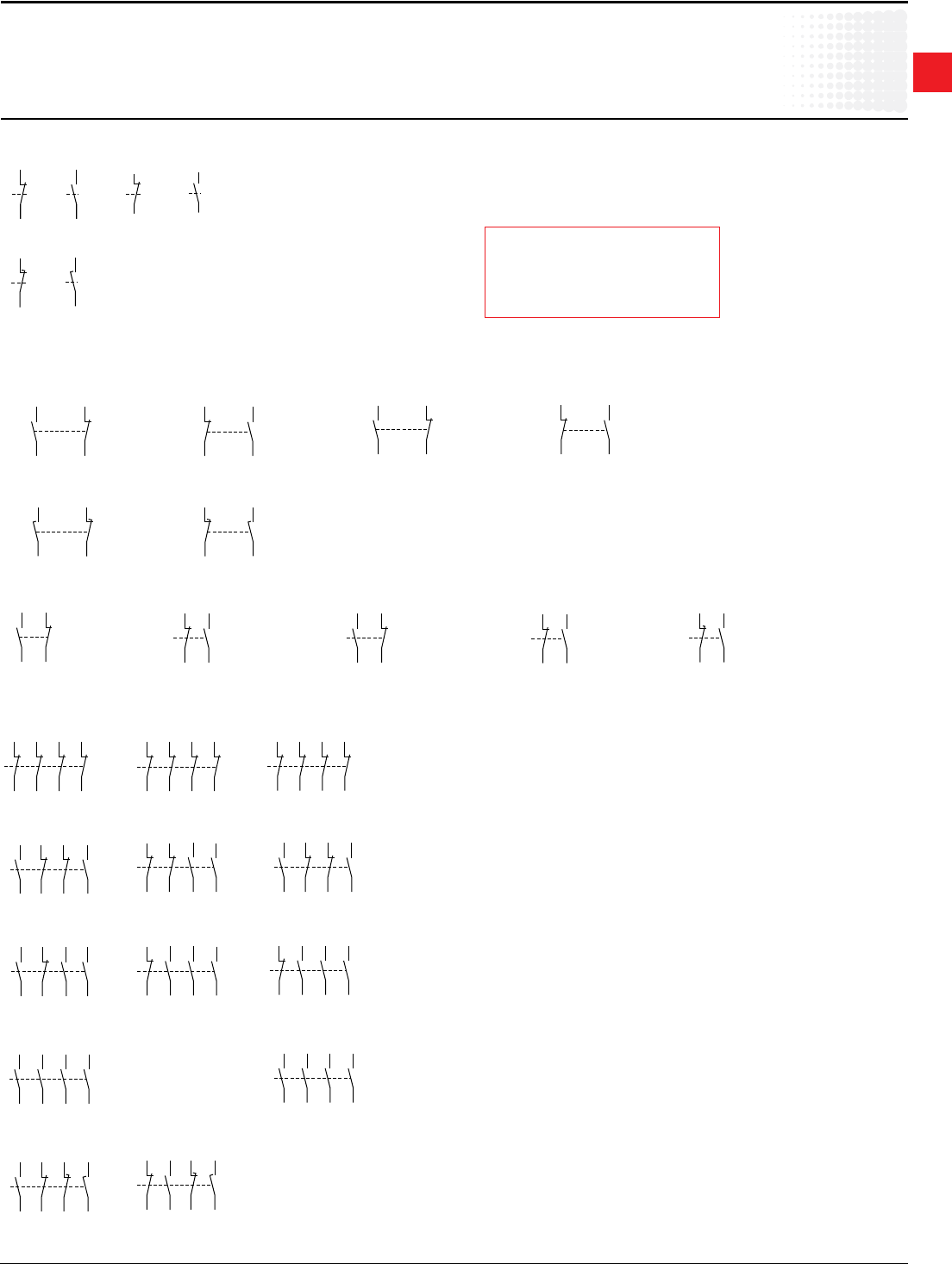
1
Across the line
contactors
Low Voltage Products & Systems 1.33
ABBInc.•888-385-1221•www.abb.us/lowvoltage 1SXU000023C0202
Accessories
Terminalmarkings
CA/CC/CAL/CCLauxiliarycontacts
One pole auxiliary contacts(topmounted)
Two pole auxiliary contacts
Four pole auxiliary contacts (Topmounted)
-1
-2
CA5-01
NC
-5
-6
CC5-01
NC
-3
-4
CA5-10
NO
-7
-8
CC5-10
NO
-1
-2
CE5-01
NC
-3
-4
CE5-10
NO
(EM/LB) (EM/LB)
21
22
11
12
41
42
31
32
CA5-04 E
NCNC NCNC
CA5-04 M
31
32
21
22
51
52
41
42
NCNC NCNC
CA5-04 N
61
62
51
52
81
82
71
72
NCNC NCNC
21
22
13
14
43
44
31
32
CA5-22 E
NO NCNC NO
21
22
31
32
43
44
53
54
CA5-22 M
NO NO
NC NC
CA5-22 N
61
62
53
54
83
84
71
72
NO NCNC NO
CA5-31 E
21
22
13
14
43
44
33
34
NO NC NONO
CA5-31 M
21
22
33
34
43
44
53
54
NONO NO
NC
51
52
63
64
73
74
83
84
CA5-31 N
NONO NO
NC
13
14
23
24
33
34
43
44
CA5-40 E
NO NONO NO —
CA5-40 N
53
54
63
64
73
74
83
84
NO NONO NO
CA5-11/11 E
21
22
13
14
47
48
35
36
NO NCNC NO
CA5-11/11 M
33
34
21
22
57
58
45
46
NC NO
NO
NC
(EM/LB) (EM/LB)
21X /
22X /
13X /
14X /
NO NC
43X
44X
31X
32X
CAL5-11 (L. h. s. mounted)
NC NO
43X /
44X /
31X /
32X /
21X
22X
13X
14X
CAL5-11 (R. h. s. mounted)
61X /
62X /
53X /
54X /
NO NC
83X
84X
71X
72X
CAL5-11B (L. h. s. mounted) CAL5-11B (R. h. s. mounted)
NC NO
83X /
84X /
71X /
72X /
61X
62X
53X
54X
25X /
26X /
17X /
18X /
NO NC
47X
48X
35X
36X
CCL5-11 (L. h. s. mounted) CCL5-11 (R. h. s. mounted)
NC NO
47X /
48X /
35X /
36X /
25X
26X
17X
18X
21
22
13
14
CAL16-11 A (L. h. s. mounted)
NO NC
CAL16-11 B (R. h. s. mounted)
43
44
31
32
NONC
61
62
53
54
CAL16-11 C (L. h. s. mounted)
NO NC
CAL16-11 D (R. h. s. mounted)
83
84
71
72
NO
NC
CAL16-11E
(L & R. h. s. mounted)
(EM/LB)
47
48
35
36
NO
NC
(EM/LB) (EM/LB)
Legend
L.H.S.=Lefthandsidemounted
R.H.S.=Righthandsidemounted
EM/LB=Earlymake/Latebreak
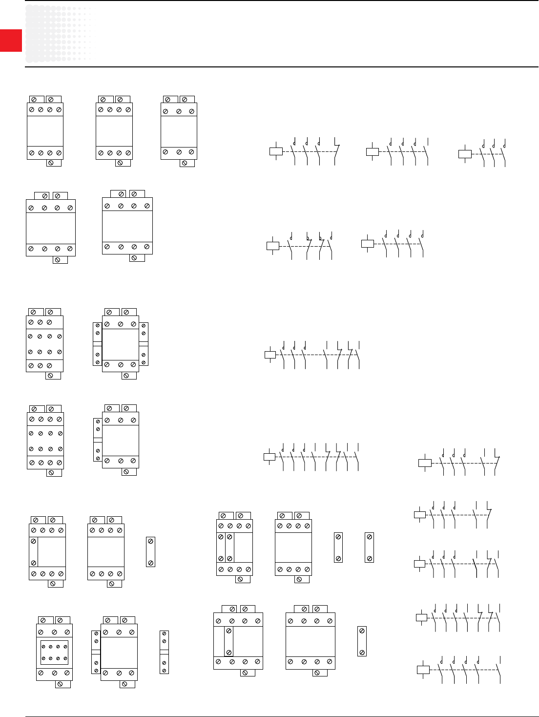
1
Across the line
contactors
1.34 Low Voltage Products & Systems
1SXU000023C0202 ABBInc.•888-385-1221•www.abb.us/lowvoltage
Accessories
Terminalmarkings&positioning
forA/UAcontactors
Standard devices without addition of auxiliary contacts
Other possible contact combinations with auxiliary contacts added by the user
Standard 3 pole devices with factory mounted auxiliary contacts
1R3 R5
2R4 R6
A9 – A26-22-00
A45 – A75-22-00
A1 A2
A2
7
8
1
L1
3
L2
5
L3
2
T1
4
T2
6
T3
A9 ... A26-40-00
A45 ... A75-40-00
A1 A2
A2
7
L4
8
T4
A1
A2
A50 – A110-30-00
UA50 – UA110-30-00
1L1
2T1
5L3
6T3
3L2
4T2
A1
A2
1
2
R5
R6
R3
R4
7
8
A9 – A26-22-00
A45 – A75-22-00
A1
1
L1
3
L2
5
L3
2
T1
4
T2
6
T3
A2
A2
A50 – A110-30-00
UA50 – UA110-30-00
A1
A2
1L1
2T1
3L2
4T2
5L3
6T3
13
NO
NO
14
A9 – A40-30-10
A1
A2
1L1
2T1
3L2
4T2
5L3
6T3
21
NC
NC
22
A9 – A40-30-01
A1
A2
A9 – A26-40-00
A45 – A75-40-00
1L1
2T1
3L2
4T2
5L3
6T3
7L4
8T4
A9 – A40-30-01
1L1 3L2 5L3
2T1 4T2 6T3
A1 A2
A2
21
NC
NC
22
A9 – A40-30-10
1
L1
3
L2
5
L3
2
T1
4
T2
6
T3
A1 A2
A2
13
NO
NO
14
A1
1
L1
2
T1
A2
13X
21X
14X
22X
A2
3
L2
5
L3
4
T2
6
T3
43X
31X
44X
32X
Combination
22
A1
A2
5L3
6T3
3L2
4T2
1L1
2T1
43
NO
NO
44
31
NC
NC
32
21
NC
NC
22
13
NO
NO
14
A9 – A16-30-22
A50 – A110-30-22
5L33L2
A1
A2 6T34T2
1L1
2T1
53
NO
NO
54
43
NO
NO
44
31
NC
NC
32
21
NC
NC
22
13
NO
NO
14
A9 – A40-30-32
A1
A2
1L1
2T1
3L2
4T2
21X
NC
NC
22X
5L3
6T3
13X
NO
NO
14X
A50 – A110-30-11
UA50 – UA110-30-11
A9 – A40-30-32
1
L1
3
L2
5
L3
2
T1
4
T2
6
T3
A1 A2
A2
13
NO
NO
14
NONC
NC NO
21 31 43 53
22 32 44 54
A1
1
L1
2
T1
A2
13X
21X
14X
22X
A2
3
L2
5
L3
4
T2
6
T3
NC
NO
NO
NC
2
A50 ... A110-30-11
UA50 ... UA110-30-11
A9 – A16-30-22
1
L1
3
L2
5
L3
2
T1
4
T2
6
T3
A1 A2
A2
NCNC
NO NO
13 21 31 43
14 22 32 44
A9 – A40-30-10 CA5-01 CA5-10
1
L1
3
L2
5
L3
2
T1
4
T2
6
T3
A1 A2
A2
13
NO
NO
14
Combination
21
=
=
1
L1
3
L2
5
L3
2
T1
4
T2
6
T3
A1 A2
A2
13
NO
NO
14
+ +
+ +
21
22
2-
2-
NC
33
34
3-
3-
NO
-1
-2
NC
-3
-4
NO
A1
A2
5L3
6T3
3L2
4T2
1L1
2T1
21
NC
NC
22
13
NO
NO
14
13
NO
NO
14
13
NO
NO
14
33
NO
NO
34
Combination 21
A9 – A40-30-10 CA5-01
1
L1
3
L2
5
L3
2
T1
4
T2
6
T3
A1 A2
A2
13
NO
NO
14
Combination
11
=
=
1
L1
3
L2
5
L3
2
T1
4
T2
6
T3
A1 A2
A2
13
NO
NO
14
+
+
21
22
2-
2-
NC
-1
-2
NC
43X
31X
44X
32X
A1
1L1
2T1
A2
13X
21X
14X
22X
A2
3L2 5L3
4T2 6T3
NC
NO
NO
NC
NC
NO
NO
NC
A50 – A75-30-11 CAL5-11
=
=
+
+
13 21 31 43
1L1 3L2 5L3
2T1 4T2 6T3
14 22 32 44
6-
6-
5-
5-
A1 A2
A2
NCNC
NO NO
A50 – A110-30-22
A1
A2
Combination 10
1L1
2T1
3L2
4T2
5L3
6T3
7L4
8T4
13
NO
NO
14
1
L1
3
L2
5
L3
2
T1
4
T2
6
T3
Combination
10
A1 A2
A2
7
L4
8
T4
13
14
6-
6-
2-
2-
3-
3-
4- 5-
4- 5-
NO
-3
-4
NO
1
L1
3
L2
5
L3
2
T1
4
T2
6
T3
A1 A2
A2
7
L4
8
T4
1-
1-
6-
6-
2-
2-
3-
3-
4- 5-
4- 5-
A45 – A75-40-00 CA5-10
=
=+
+
5L33L2
A1
A2 6T34T2
1L1
2T1
43X
NO
31X
NC
21X
NC
13X
NO
NO
14X
NC
22X
NC
32X
NO
44X
Combination 22
A1
A2
5L3
6T3
3L2
4T2
1L1
2T1
21
NC
NC
22
13
NO
NO
14
Combination 11
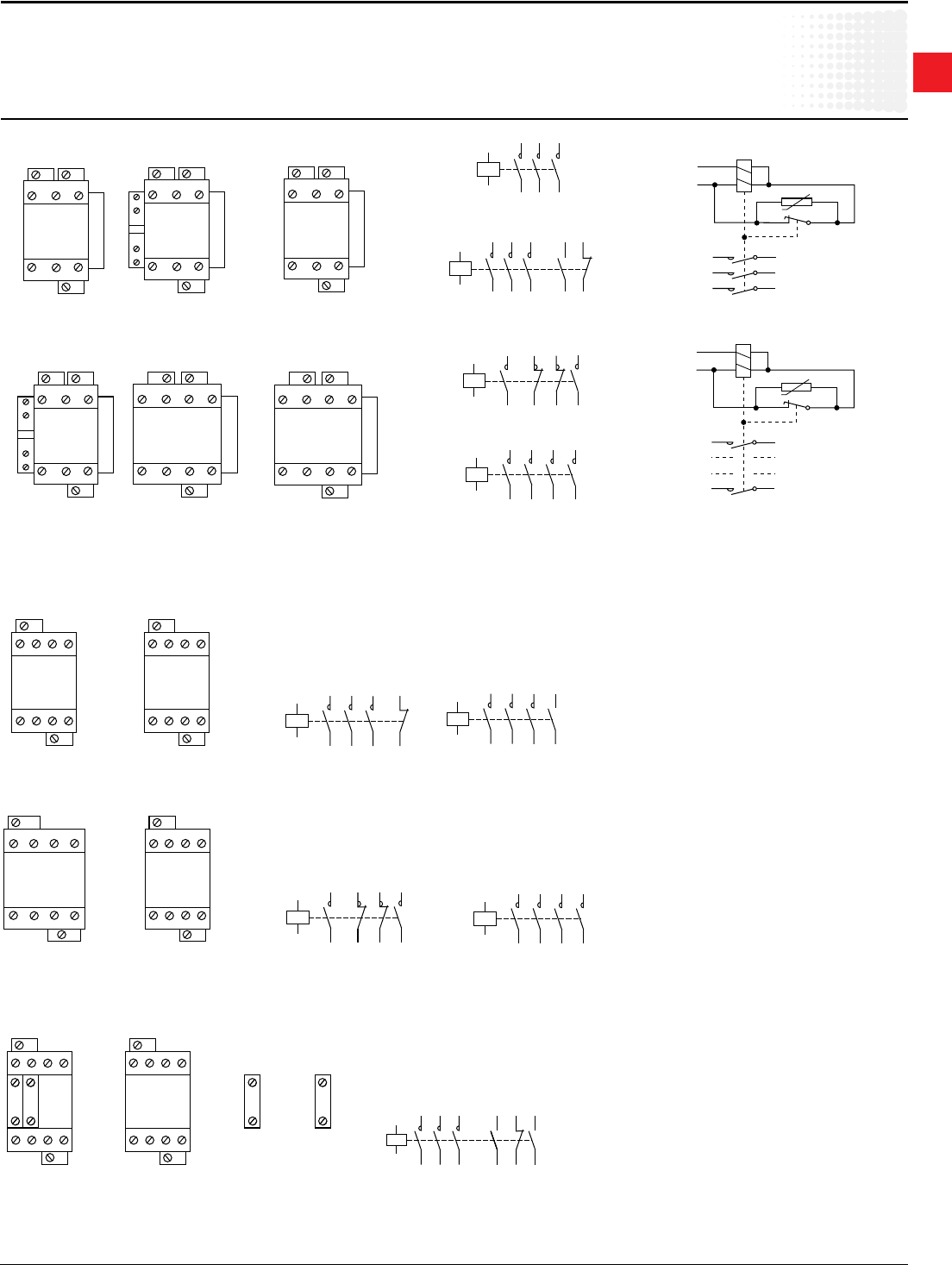
1
Across the line
contactors
Low Voltage Products & Systems 1.35
ABBInc.•888-385-1221•www.abb.us/lowvoltage 1SXU000023C0202
Accessories
Terminalmarkingandpositioning
forAE/ALcontactors
AE Contactors – D.C.operated
AL Contactors –D.C.operated
Standarddeviceswithoutadditionofauxiliarycontacts
Other possible contact combinations with auxiliary contacts added by the user
A1
1
L1
3
L2
5
L3
2
T1
4
T2
6
T3
A2
A3
C
D
L
5
AE50 – AE75-30-00
A1
A2
AE50 – AE110-30-00
1L1
2T1
5L3
6T3
3L2
4T2
A1
A2
1
2
R5
R6
R3
R4
7
8
AE45 – AE75-22-00
A1
1
L1
2
T1
A2
13X
21X
14X
22X
A3
3
L2
5
L3
4
T2
6
T3
NC
NO
C
C
L
5
NO
NC
AE95 – AE110-30-11
A1
A2
AE45 – AE75-40-00
1L1
2T1
3L2
4T2
5L3
6T3
7L4
8T4
1R3 R5
2R4 R6
A1 A2
A3
7
8
C
D
L
5
AE45 – AE75-22-00
A1
1
L1
3
L2
5
L3
2
T1
4
T2
6
T3
A2
A3
C
C
L
5
AE95 – AE110-30-00
A1
A2
1L1
2T1
3L2
4T2
21X
NC
NC
22X
5L3
6T3
13X
NO
NO
14X
AE50 – AE110-30-11
A1
1
L1
2
T1
A2
13X
21X
14X
22X
A3
3
L2
5
L3
4
T2
6
T3
NC
NO
C
D
L
5
NO
NC
AE50 – AE75-30-11
A3
A2
3 L2
1 L1
5 L3
4 T2
2 T1
6 T3
A1
U
35 X 36 X
{
VDC
Coil wiring
1
L1
3
L2
5
L3
2
T1
4
T2
6
T3
A1 A2
A3
7
L4
8
T4
C
D
L
5
AE45 – AE75-40-00
A3
A2
1 L1 2 T1
A1
U
15 X 16 X
{
VDC
7 L4 8 T4
Coil wiring
AL9 – AL40-30-01
1L1 3L2 5L3
2T1 4T2 6T3
A1
A2
21
NC
NC
22
A1
A2
1L1
2T1
3L2
4T2
5L3
6T3
21
NC
NC
22
AL9 – AL40-30-01
A1
A2
1L1
2T1
3L2
4T2
5L3
6T3
13
NO
NO
14
AL9 – AL40-30-10
A1
A2
1L1 3L2 5L3 7L4
2T1 4T2 6T3 8T4
AL9 – AL26-40-00
A1
A2
1
R
3
R
5 7
2
R
4
R
6 8
AL9 – AL26-22-00
A1
A2
AL9 – AL26-40-00
1L1
2T1
3L2
4T2
5L3
6T3
7L4
8T4
A1
A2
1
2
R5
R6
R3
R4
7
8
AL9 – AL26-22-00
AL9 – AL40-30-10 CA5-01 CA5-10Combination
21
=
=
+ +
++
1L1 3L2 5L3
2T1 4T2 6T3
A1
A2
13
NO
NO
14
2-
2-
3-
3-
4-
4-
5-
5-
1L1 3L2 5L3
2T1 4T2 6T3
A1
A2
13
NO
NO
14
21
22
NC
33
34
NO
-1
-2
NC
-3
-4
NO
A1
A2
5L3
6T3
3L2
4T2
1L1
2T1
21
NC
NC
22
13
NO
NO
14
13
NO
NO
14
13
NO
NO
14
33
NO
NO
34
Combination 21
AL9 – AL40-30-10
1L1 3L2 5L3
2T1 4T2 6T3
A1
A2
13
NO
NO
14
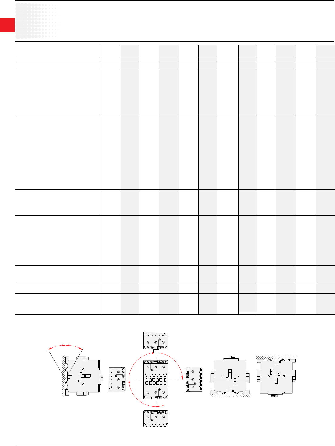
1
Across the line
contactors
1.36 Low Voltage Products & Systems
1SXU000023C0202 ABBInc.•888-385-1221•www.abb.us/lowvoltage
UL & CSA Technical data
A/AE9–A/AE/AF110,AL9–AL40
AC & DC operated
ABB contactor frame size A/AE/AL A/AE/AL A/AE/AL A/AE/AL A/AE/AL A/AE/AL A/AE/AF A/AE/AF A/AE/AF A/AE/AF A/AE/AF A/AE/AF
9 12 16 26 30 40 45 50 63 75 95 110
NEMAsize 00 — 0 1 1P — — 2 — 3 — —
Numberofpoles 3OR4 3 3OR4 3OR4 3 3 4 3OR4 3 3OR4 3 3
ACratinginformation
NEMAcont.amprating thermalcurrent 9 — 18 27 36 — — 45 — 90 — —
NEMAmaximumH.P.ratings 1phase
115 VAC 1/3 — 1 2 3 — — 3 — — — —
230 VAC 1 — 2 3 5 — — 7.5 — — — —
NEMAmaximumH.P.ratings 3phase
200 VAC 1.5 — 3 7.5 — — — 10 — 25 — —
230 VAC 1.5 — 3 7.5 — — — 15 — 30 — —
460/575 VAC 2 — 5 10 — — — 25 — 50 — —
U.L.generalpurposecurrent 40°C 21 25 30 40 50 60 65 80 90 105 125 140
Max.3PhSwitchingmotorloads A 9 11 17 28 34 42 — 54 65 80 95 110
U.L.maximumH.P.ratings 1phase
115 VAC 1/2 3/4 2HP,24A 2 3 3 — 3 5 7.5 7.5 10
230 VAC 2 2 3 5 7.5 7.5 — 7.5 10 15 20 25
U.L.maximumH.P.ratings 3phase
200-208 VAC 2 3 5 7.5 10 10 — 15 20 25 30 30
220-240 VAC 2 3 5 10 10 15 — 20 25 30 30 40
440-480 VAC 5 7.5 10 20 25 30 — 40 50 60 60 75
550-600 VAC 7.5 10 15 25 30 40 — 50 60 75 75 100
U.L.maximumH.P.ratings
120 VDC 1 1.5 2 3 3 5 — 7.5 10 10 — —
240 VDC 2 3 3 5 7.5 10 — 15 20 25 — —
Lighting—ballastandincandescent 600VAC 15 15 201 35 50 60 65 65 85 105 120 —
Resistiveheatingapplications 600VAC 15 15 20 35 50 60 65 65 85 105 — —
CSAElevatorratings
220–240VAC 3phase — — 5 — — 10 — 15 — 20 20 —
440–480VAC 3phase — — 10 — — 20 — 30 — 30 40 —
550–600VAC 3phase — — 10 — — 20 — 30 — 40 50 —
230VAC 1phase — — 2 — — 5 — 7.5 — 10 10 —
Auxiliarycontacts
NEMArating AC A600 A600 A600 A600 A600 A600 — A600 A600 A600 A600 A600
ACratedvoltage VAC 600 600 600 600 600 600 — 600 600 600 600 600
ACthermalratedcurrent A 10 10 10 10 10 10 — 10 10 10 10 10
ACmaximumvolt-amperemaking VA 7200 7200 7200 7200 7200 7200 — 7200 7200 7200 7200 7200
ACmaximumvolt-amperebreaking VA 720 720 720 720 720 720 — 720 720 720 720 720
NEMArating DC P600 P600 P600 P600 P600 P600 — P600 P600 P600 P600 P600
DCratedvoltage VDC 600 600 600 600 600 600 — 600 600 600 600 600
DCthermalratedcurrent A 5 5 5 5 5 5 — 5 5 5 5 5
DCMaximummake-break A 0.2 0.2 0.2 0.2 0.2 0.2 — 0.2 0.2 0.2 0.2 0.2
Approximateweight
Contactor lbs. 0.7 0.7 0.7 1.01 1.2 2.25 2.25 2.25 2.25 2.25 3.5 5
Starter lbs. 1.04 1.04 1.04 1.35 1.54 3 — 3 3 3 6 7
Terminalwirerange AWG 18-10 18-10 18-10 12-8 8-4 8-4 8-1 8-1 8-1 8-1 6-2/0 6-2/0
Numberofwiresperphase 2 2 2 2 2 2 1 1 1 1 1 1
Maximumshortcircuitratings
MCCB,MCP,Amps/kA 480VAC 50/35 50/35 50/35 100/35 150/65 150/65 — 150/85 250/85 250/85 250/85 250/85
MCCB,MCP,Amps/kA 600VAC 10/35 10/35 10/35 100/35 150/25 150/25 — — — — 250/35 250/35
Fuse,Amps—type/kA 600VAC 30J/200 30J/200 30J/200 60J/200 60J/200 100J/200 — 100J/200 200J/200 200J/200 200J/200 200J/200
Mounting positions
ABB
ABB
ABB
ABB
ABB
Pos. 2
Pos. 6
(AL unauthorized)
30°
30°
Pos. 1 ± 30°Pos. 3Pos. 4
Pos. 1
Pos. 5
1 30A Ballast
1
Across the line
contactors
Low Voltage Products & Systems 1.37
ABBInc.•888-385-1221•www.abb.us/lowvoltage 1SXU000023C0202
UL & CSA Technical data
A/AF145–AF750
AC & DC operated
ABB contactor frame size A/AF A/AF A/AF A/AF A/AF AF AF AF AF
145 185 210 260 300 400 460 580 750
NEMAsize 4 — — 5 — — 6 — 7
Numberofpoles 3 3 3 3 3 3 3 3 3
AC rating information
NEMAmaximumH.P.ratings 3phase
200 VAC 40 — — 75 — — 150 — —
230 VAC 50 — — 100 — — 200 — 300
460/575 V 100 — — 200 — — 400 — 600
U.L. general purpose current 40°C 230 250 300 350 400 550 650 750 900
Max.3Phswitchingmotorloads Amps 130 156 192 248 302 414 480 590 720
U.L.maximumH.P.ratings 1phase
115 VAC 10 15 — — — — — — —
230 VAC 25 30 40 50 — — — — —
U.L.maximumH.P.ratings 3phase
200—208 VAC 40 50 60 75 100 125 150 200 250
220—240 VAC 50 60 75 100 100 150 200 250 300
440—480 VAC 100 125 150 200 250 350 400 500 600
550—600 VAC 125 150 200 250 300 400 500 600 700
Lighting–ballastandincandescent 600VAC 200 — 300 — 400 — — — —
CSA Elevator ratings
220–240VAC 3phase 40 50 60 — — — —
240–480VAC 3phase Consult Consult 75 100 125 — — — —
550-600VAC 3phase factory factory 100 125 150 — — — —
230VAC 1phase — — — — — — —
Auxiliary contacts
NEMArating AC A600 A600 A600 A600 A600 A600 A600 A600 A600
ACratedvoltage VAC 600 600 600 600 600 600 600 600 600
ACthermalratedcurrent A 10 10 10 10 10 10 10 10 10
ACmaximumvolt—amperemaking VA 7200 7200 7200 7200 7200 7200 7200 7200 7200
ACmaximumvolt—amperebreaking VA 720 720 720 720 720 720 720 720 720
NEMArating DC P600 P600 P600 P600 P600 P600 P600 P600 P600
DCratedvoltage VDC 600 600 600 600 600 600 600 600 600
DCthermalratedcurrent A 5 5 5 5 5 5 5 5 5
DCMaximummake—break A 0.2 0.2 0.2 0.2 0.2 0.2 0.2 0.2 0.2
Approximate weight
Contactor lbs. 7.1 7.1 13 13 13 26 26 33 33
Starter lbs. 9.11 9.11 17.67 17.67 17.67 35 35 45 45
Terminal wire range
AWG 6-250MCM 6-250MCM 4-400MCM 4-400MCM 4-500MCM 250-500MCM 250-500MCM 2/0-500MCM 2/0-500MCM
Numberofwiresperphase 1 1 1 1 2 2 2 2 3
Maximum short circuit ratings
MCCB,MCP,amps/kA 480VAC 400/85 400/85 800/85 800/85 800/85 800/80 800/80 1200/42 1200/42
MCCB,MCP,amps/kA 600VAC 400/35 400/35 800/35 800/35 800/35 800/42 800/42 — —
Fuse,amps—Type/kA 600VAC 400J/200 400J/200 600J/200 600J/200 600J/200 1000L/80 1000L/80 1200L/80 1200L/80
1
Across the line
contactors
1.38 Low Voltage Products & Systems
1SXU000023C0202 ABBInc.•888-385-1221•www.abb.us/lowvoltage
UL & CSA Technical data
AF1350–AF1650
AC & DC operated
ABB contactor frame size AF AF
1350 1650
NEMAsize — 8
Numberofpoles 3 3
AC rating information
NEMAmaximumH.P.ratings 3phase
200 VAC — —
230 VAC — 450
460/575 V — 900
U.L. general purpose current 40°C 1350 1650
Max.3Phswitchingmotorloads Amps 960 1080
U.L.maximumH.P.ratings 1phase
115 VAC — —
230 VAC — —
U.L.maximumH.P.ratings 3phase
200—208 VAC — —
220—240 VAC 400 450
440—480 VAC 800 900
550—600 VAC 900 1000
Auxiliary contacts
NEMArating AC A600 A600
ACratedvoltage VAC 600 600
ACthermalratedcurrent A 10 10
ACmaximumvolt—amperemaking VA 7200 7200
ACmaximumvolt—amperebreaking VA 720 720
NEMArating DC P600 P600
DCratedvoltage VDC 600 600
DCthermalratedcurrent A 5 5
DCMaximummake—break A 0.2 0.2
Approximate weight
Contactor lbs. 75 75
Starter lbs. — —
Terminal wire range AWG 1/0-750MCM 1/0-750MCM
Numberofwiresperphase 4 6
Maximum short circuit ratings
MCCB,MCP,amps/kA 480VAC 2000/42 2000/42
MCCB,MCP,amps/kA 600VAC — —
Fuse,amps—Type/kA 600VAC 1600L/82 2000L/82
1
Across the line
contactors
Low Voltage Products & Systems 1.39
ABBInc.•888-385-1221•www.abb.us/lowvoltage 1SXU000023C0202
B1 B2
C2
C1
A
A
UL/CSA & IEC Technical data
A/AE9–A/AE/AF/TAE110
13gforAF45-22,AE45-22,AF75-22andAE75-22.
210gforAF45-22,AE45-22,AF75-22andAE75-22.
Contactor types: A..., AE... 9 12 16 26 30 40 45 50 63 75 95 110
AF..., TAE... – – – – – – 45 50 63 75 95 110
RatedinsulationvoltageUi
accordingtoIEC60947-4-1 V 1000
accordingtoUL/CSA V 600
RatedimpulsewithstandvoltageUimp.
kV 8
Standards DevicescomplyingwithinternationalstandardsIEC60947-1/60947-4-1
andEuropeanstandardsEN60947-1/60947-4-1
Airtemperatureclosetocontactor see"Conditionsforuse"page1.50,forcontrolvoltagelimitsandauthorizedmountingpositions
–ttedwiththermalO/Lrelay °C -25to+55
–withoutthermalO/Lrelay °C -40to+70(55max.forTAE...contactors)
–forstorage °C -60to+80 -40to+70
Climaticwithstand acc.toIEC60068-2-30and60068-2-11-UTEC63-100specicationII
acc.toIEC
68-2-30
Operatingaltitude m < 3000
Shockwithstand
acc.IEC60068-2-27andEN60068-2-27
Mountingposition1(seepage1.50) 1/2sinusoidalshockfor11ms:nochangeincontactposition
Shockdirection Makingposition Breakingposition
A 20 g 20 g
B1 10g 5g1
B2 15g2 15g2
C1 20 g 20 g
C2 20 g 20 g
NotvalidforDIN-rail
mounting
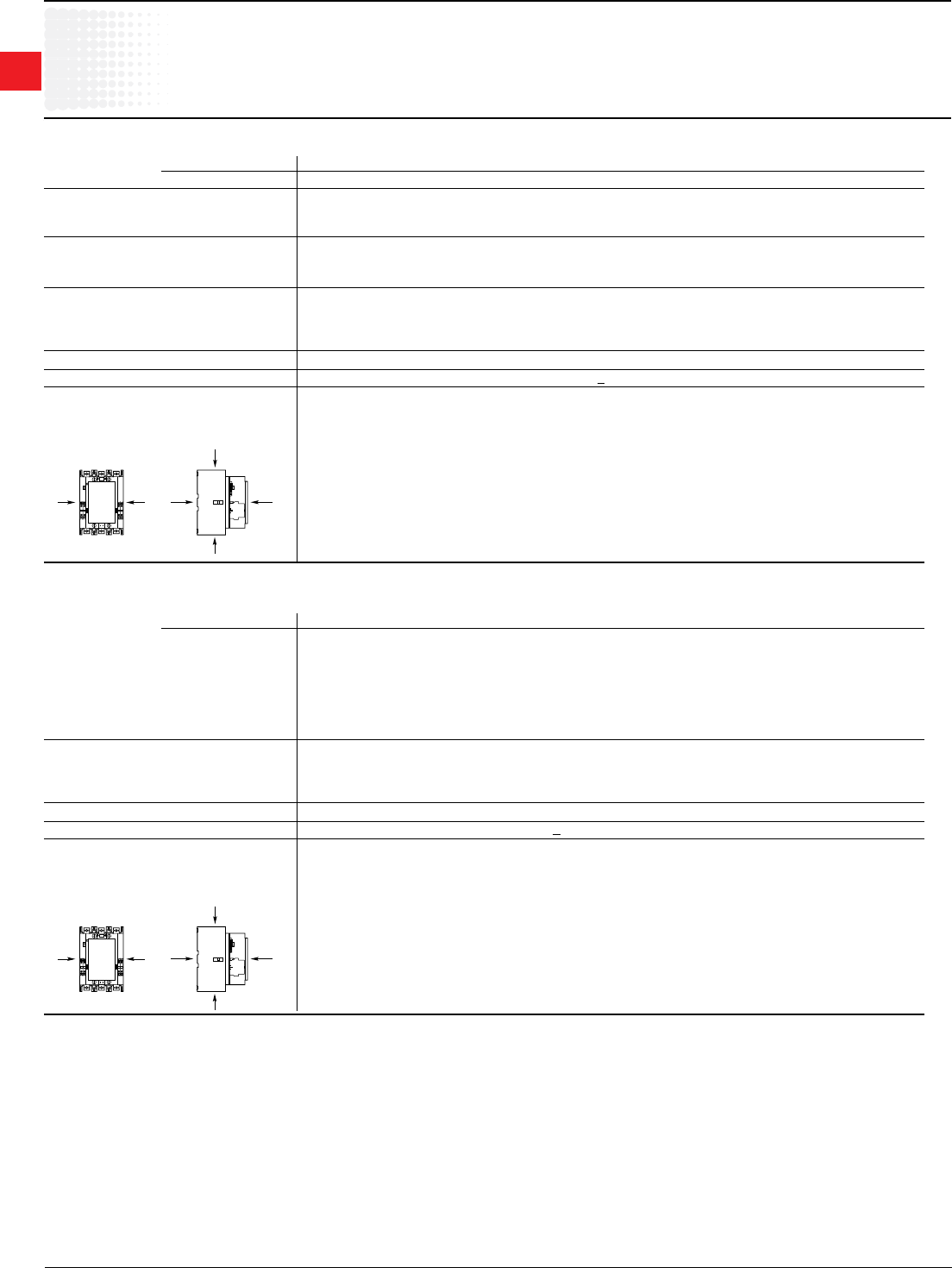
1
Across the line
contactors
1.40 Low Voltage Products & Systems
1SXU000023C0202 ABBInc.•888-385-1221•www.abb.us/lowvoltage
UL/CSA & IEC Technical data
A/AF145–AF1650
A/AF145 – AF750
Contactor types: A... 145 185 210 260 300 – – – –
AF... 145 185 210 260 300 400 460 580 750
RatedinsulationvoltageUi
accordingtoIEC60947-4-1 V 1000
accordingtoUL/CSA V600
RatedimpulsewithstandvoltageUimp.
kV 8
Standards DevicescomplyingwithinternationalstandardsIEC60947-1/60947-4-1
andEuropeanstandardsEN60947-1/60947-4-1
Airtemperatureclosetocontactor see"Conditionsforuse"page1.51,forcontrolvoltagelimitsandauthorizedmountingpositions
–ttedwiththermalO/Lrelay °C -25to+55
–withoutthermalO/Lrelay °C -40to+70
–forstorage °C -40to+70
Climaticwithstand acc.toIEC60068-2-30
Operatingaltitude m < 3000
Shockwithstand
acc.IEC60068-2-27andEN60068-2-27
Mountingposition1(seepage1.51) 1/2sinusoidalshockfor30ms:nochangeincontactposition
5ginalldirections(A,B1,B2,C1,C2)
B2
AAB1
C2
C1
ABB
AF1350 – AF1650
Contactor types: AF... 1350 1650
RatedinsulationvoltageUi
accordingtoIEC60947-4-1 1000
accordingtoUL/CSA V 600
RatedimpulsewithstandvoltageUimp.
kV 8
Standards DevicescomplyingwithinternationalstandardsIEC60947-1/60947-4-1
andEuropeanstandardsEN60947-1/60947-4-1
Airtemperatureclosetocontactor see"Conditionsforuse"page1.51,forcontrolvoltagelimitsandauthorizedmountingpositions
–ttedwiththermalO/Lrelay °C-25to+55
–withoutthermalO/Lrelay °C-40to+70
–forstorage °C-40to+70
Climaticwithstand acc.toIEC60068-2-30
Operatingaltitude m < 3000
Shockwithstand
acc.IEC60068-2-27andEN60068-2-27
Mountingposition1(Seepage1.51) 1/2sinusoidalshockfor30ms:nochangeincontactposition
5ginalldirections(A,B1,B2,C1,C2)
B2
AAB1
C2
C1
ABB
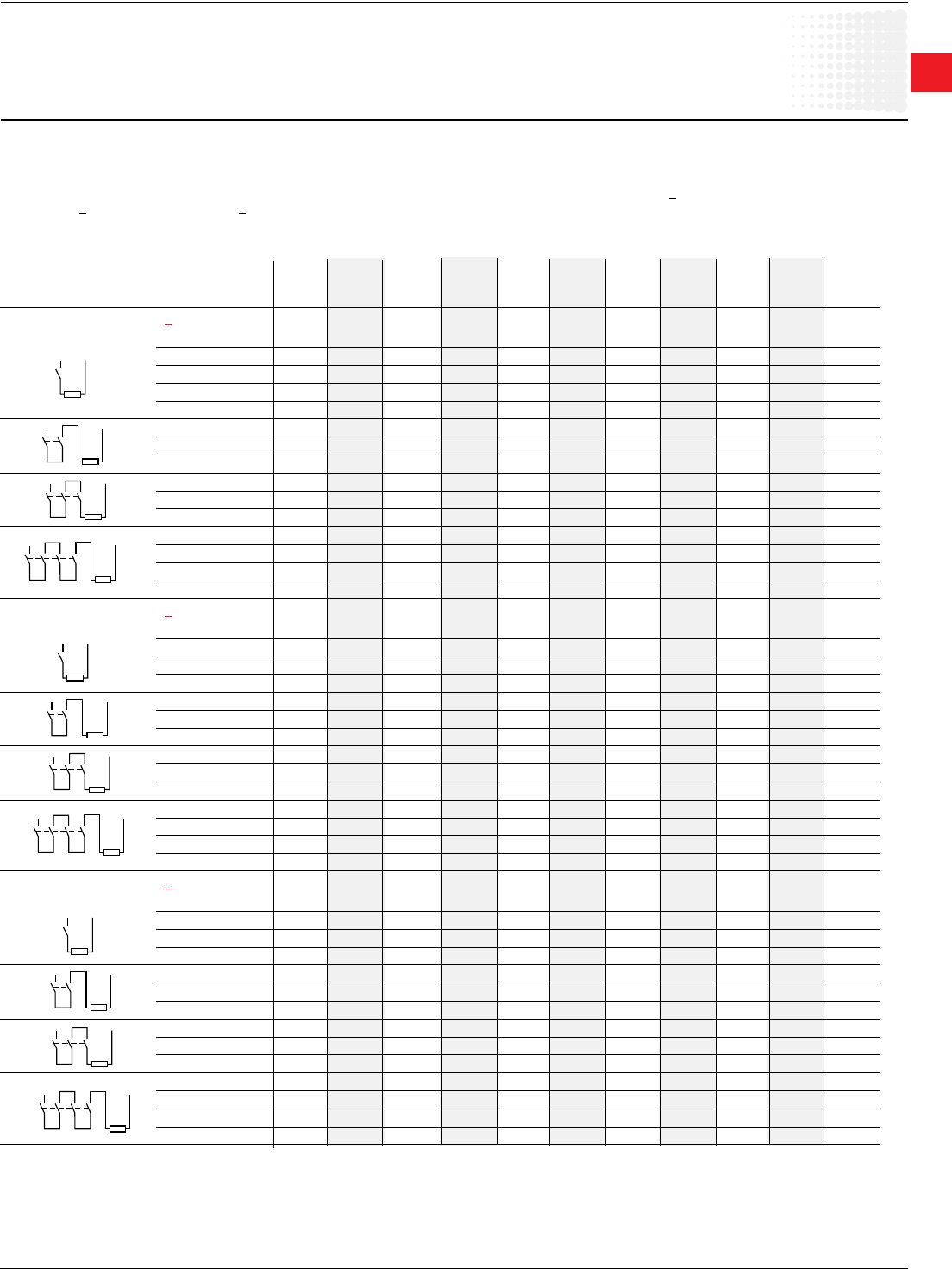
1
Across the line
contactors
Low Voltage Products & Systems 1.41
ABBInc.•888-385-1221•www.abb.us/lowvoltage 1SXU000023C0202
General
Thearcswitchingond.c.ismoredifcultthanona.c.
• Forselectingacontactoritisessentialtodeterminethecurrent,thevoltageandtheL/Rtimeconstantofthecontrolledload.
• Forinformation,typicaltimeconstantvaluesarequotedhereafter:non-inductiveloadssuchasresistancefurnaces(L/R~1ms),inductiveloadssuchasshunt
motors(L/R~2ms)orseriesmotors(L/R~7.5ms).
• Theadditionofaresistorinparallelwithaninductivewindinghelpsintheeliminationofthearcs.
• Allthepolesrequiredforbreakingmustbeconnectedinseriesbetweentheloadandthesourcepolaritynotlinkedtoearth(orchassis).
a.c. operated contactors A9 A12 A16 A26 A30 A40 A45 A50 A63 A75 GA75
a.c. / d.c. operated (electronic coil interface) – – – – – – AF45 AF50 AF63 AF75 –
d.c. operated contactors AE9 AE12 AE16 AE26 AE30 AE40 AE45 AE50 AE63 AE75 GAE75
UtilizationcategoryDC-1,L/R< 1 ms
≤72V A 25 27 30 45 55 60 70 100 110 120 120
110V A 10 15 20 – – – – – – – 120
220V A – – – – – – – – – – 120
440V A – – – – – – – – – – 100
600V A – – – – – – – – – – 75
≤72V A 25 27 30 45 55 60 70 100 110 120 –
110V A 25 27 30 45 55 60 70 100 110 120 –
220V A 10 15 20 – – – – – – – –
≤72V A 25 27 30 45 55 60 70 100 110 120 –
110V A 25 27 30 45 55 60 70 100 110 120 –
220V A 25 27 30 45 55 60 70 100 110 120 –
≤72V A 25 27 30 45 – – 70 100 – 120 –
110V A 25 27 30 45 – – 70 100 – 120 –
220V A 25 27 30 45 – – 70 100 – 120 –
440V A 10 15 20 – – – – – – – –
UtilizationcategoryDC-3,L/R< 2 ms
≤72V A 25 27 30 45 55 60 70 100 110 120 120
110V A 6 7 8 – – – – – – – 120
220V A – – – – – – – – – – 100
440V A – – – – – – – – – – 85
≤72V A 25 27 30 45 55 60 70 100 110 120 –
110V A 25 27 30 45 55 60 70 100 110 120 –
220V A 6 7 8 – – – – – – – –
≤72V A 25 27 30 45 55 60 70 100 110 120 –
110V A 25 27 30 45 55 60 70 100 110 120 –
220V A 25 27 30 45 55 60 70 100 110 120 –
≤72V A 25 27 30 45 – – 70 100 – 120 –
110V A 25 27 30 45 – – 70 100 – 120 –
220V A 25 27 30 45 – – 70 100 – 120 –
440V A 6 7 8 – – – – – – – –
UtilizationcategoryDC-5,L/R<7.5ms
≤72V A 9 12 16 25 30 40 50 50 63 75 85
110V A 4 4 4 – – – – – – – 85
220V A – – – – – – – – – – 85
440V A – – – – – – – – – – 35
≤72V A 25 27 30 45 55 60 70 100 110 120 –
110V A 10 15 20 30 45 50 70 80 90 100 –
220V A 4 4 4 – – – – – – – –
≤72V A 25 27 30 45 55 60 70 100 110 120 –
110V A 25 27 30 45 55 60 70 100 110 120 –
220V A 9 12 16 25 30 40 50 50 63 75 –
≤72V A 25 27 30 45 – – 70 100 – 120 –
110V A 25 27 30 45 – – 70 100 – 120 –
220V A 10 15 20 30 – – 70 70 – 100 –
440V A 4 4 4 – – – – – – – –
IEC Technical data
A/AE9–GAE75
DCcircuitswitching
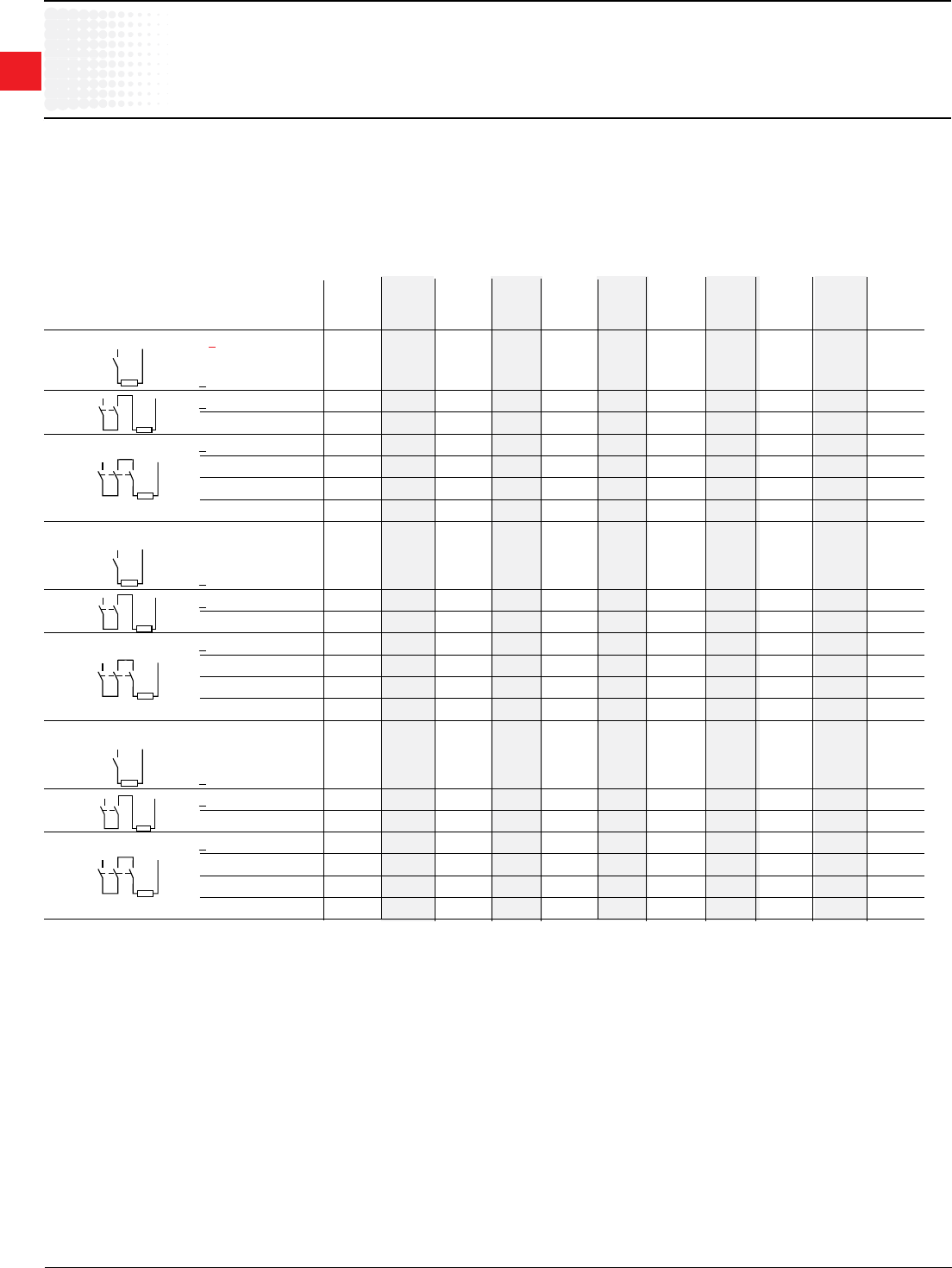
1
Across the line
contactors
1.42 Low Voltage Products & Systems
1SXU000023C0202 ABBInc.•888-385-1221•www.abb.us/lowvoltage
IEC Technical data
A/AF/AE95–AF750
DCcircuitswitching
Technical Data
• ThetablesindicateforthestandardcontactorstheIemax.operatingcurrentsdependingon:theutilizationcategory(i.e.L/R)DC-1,DC-3,DC-5asdenedinthe
IEC60947-4-1publication,theoperatingvoltageUe andthepolecouplingdetails.Seepage1.81.
Amperevaluesquotedinthetablesbelowarevalidfora-25…+70°Ctemperatureclosetothecontactors,aslongastheAC-1Amperevalues(seepages1.45-
146)forthecorrespondingambienttemperaturearenotexceeded.
• Max.switchingfrequency:300ops/h.
• Forswitchinghigherd.c.ratings,werecommendtheuseofbarmountedcontactors,Rseries(63…2000A).
TheselectiontableforAE50...AE110contactorscanbeusedfortheTAE50...TAE110types.
a.c. operated contactors A95 A110 A145 A185 A210 A260 A300 – – – –
a.c. / d.c. operated (electronic coil interface) AF95 AF110 AF145 AF185 AF210 AF260 AF300 AF400 AF460 AF580 AF750
d.c. operated contactors AE95 AE110 – – – – – – – – –
UtilizationcategoryDC-1,L/R< 1 ms
<110V A – – – – – – – 600 700 800 1050
<110V A 145 160 250 275 350 400 450 600 700 800 1050
220V A – – – – – – – 600 700 800 1050
<110V A 145 160 250 275 350 400 450 600 700 800 1050
220V A 145 160 250 275 350 400 450 600 700 800 1050
440V A – – – – – – – 600 700 800 1050
600V A – – – – – – – 600 700 800 1050
UtilizationcategoryDC-3,L/R≤2.5ms
<110V A – – – – – – – 600 700 800 1050
<110V A 145 160 250 275 350 400 450 600 700 800 1050
220V A – – – – – – – 600 700 800 1050
<110V A 145 160 250 275 350 400 450 600 700 800 1050
220V A 145 160 250 275 350 400 450 600 700 800 1050
440V A – – – – – – – 600 700 800 1050
600V A – – – – – – – 600 700 800 1050
UtilizationcategoryDC-5,L/R≤15ms
<110V A – – – – – – – 600 700 800 1050
<110V A 145 160 250 275 350 400 450 600 700 800 1050
220V A – – – – – – – 600 700 800 1050
<110V A 145 160 250 275 350 400 450 600 700 800 1050
220V A 145 160 250 275 350 400 450 600 700 800 1050
440V A – – – – – – – 600 700 800 1050
600V A – – – – – – – 600 700 800 1050
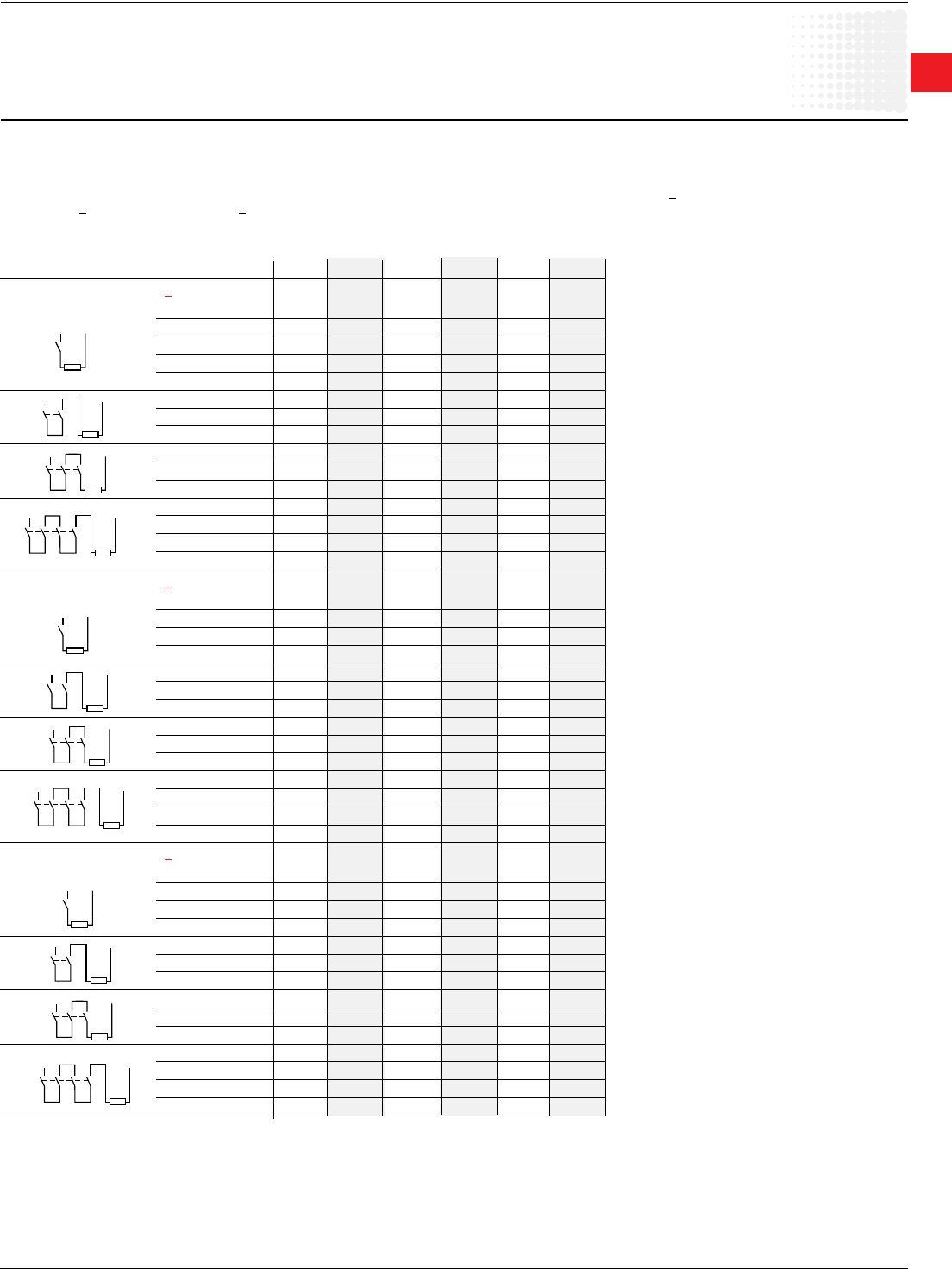
1
Across the line
contactors
Low Voltage Products & Systems 1.43
ABBInc.•888-385-1221•www.abb.us/lowvoltage 1SXU000023C0202
General
Thearcswitchingond.c.ismoredifcultthanona.c.
• Forselectingacontactoritisessentialtodeterminethecurrent,thevoltageandtheL/Rtimeconstantofthecontrolledload.
• Forinformation,typicaltimeconstantvaluesarequotedhereafter:noninductiveloadssuchasresistancefurnaces(L/R~1ms),inductiveloadssuchasshunt
motors(L/R~2ms)orseriesmotors(L/R~7.5ms).
• Theadditionofaresistorinparallelwithaninductivewindinghelpsintheeliminationofthearcs.
• Allthepolesrequiredforbreakingmustbeconnectedinseriesbetweentheloadandthesourcepolaritynotlinkedtoearth(orchassis).
A.C. operated contactors AL9 AL12 AL16 AL26 AL30 AL40
UtilizationcategoryDC-1,L/R< 1 ms
≤72V A 25 27 30 45 55 60
110V A 10 15 20 – – –
220V A – – – – – –
440V A – – – – – –
600V A – – – – – –
≤72V A 25 27 30 45 55 60
110V A 25 27 30 45 55 60
220V A 10 15 20 – – –
≤72V A 25 27 30 45 55 60
110V A 25 27 30 45 55 60
220V A 25 27 30 45 55 60
≤72V A 25 27 30 45 – –
110V A 25 27 30 45 – –
220V A 25 27 30 45 – –
440V A 10 15 20 – – –
UtilizationcategoryDC-3,L/R< 2 ms
≤72V A 25 27 30 45 55 60
110V A 6 7 8 – – –
220V A – – – – – –
440V A – – – – – –
≤72V A 25 27 30 45 55 60
110V A 25 27 30 45 55 60
220V A 6 7 8 – – –
≤72V A 25 27 30 45 55 60
110V A 25 27 30 45 55 60
220V A 25 27 30 45 55 60
≤72V A 25 27 30 45 – –
110V A 25 27 30 45 – –
220V A 25 27 30 45 – –
440V A 6 7 8 – – –
UtilizationcategoryDC-5,L/R<7.5ms
≤72V A 9 12 16 25 30 40
110V A 4 4 4 – – –
220V A – – – – – –
440V A – – – – – –
≤72V A 25 27 30 45 55 60
110V A 10 15 20 30 45 50
220V A 4 4 4 – – –
≤72V A 25 27 30 45 55 60
110V A 25 27 30 45 55 60
220V A 9 12 16 25 30 40
≤72V A 25 27 30 45 – –
110V A 25 27 30 45 – –
220V A 10 15 20 30 – –
440V A 4 4 4 – – –
IEC Technical data
AL9–AL40
DCcircuitswitching
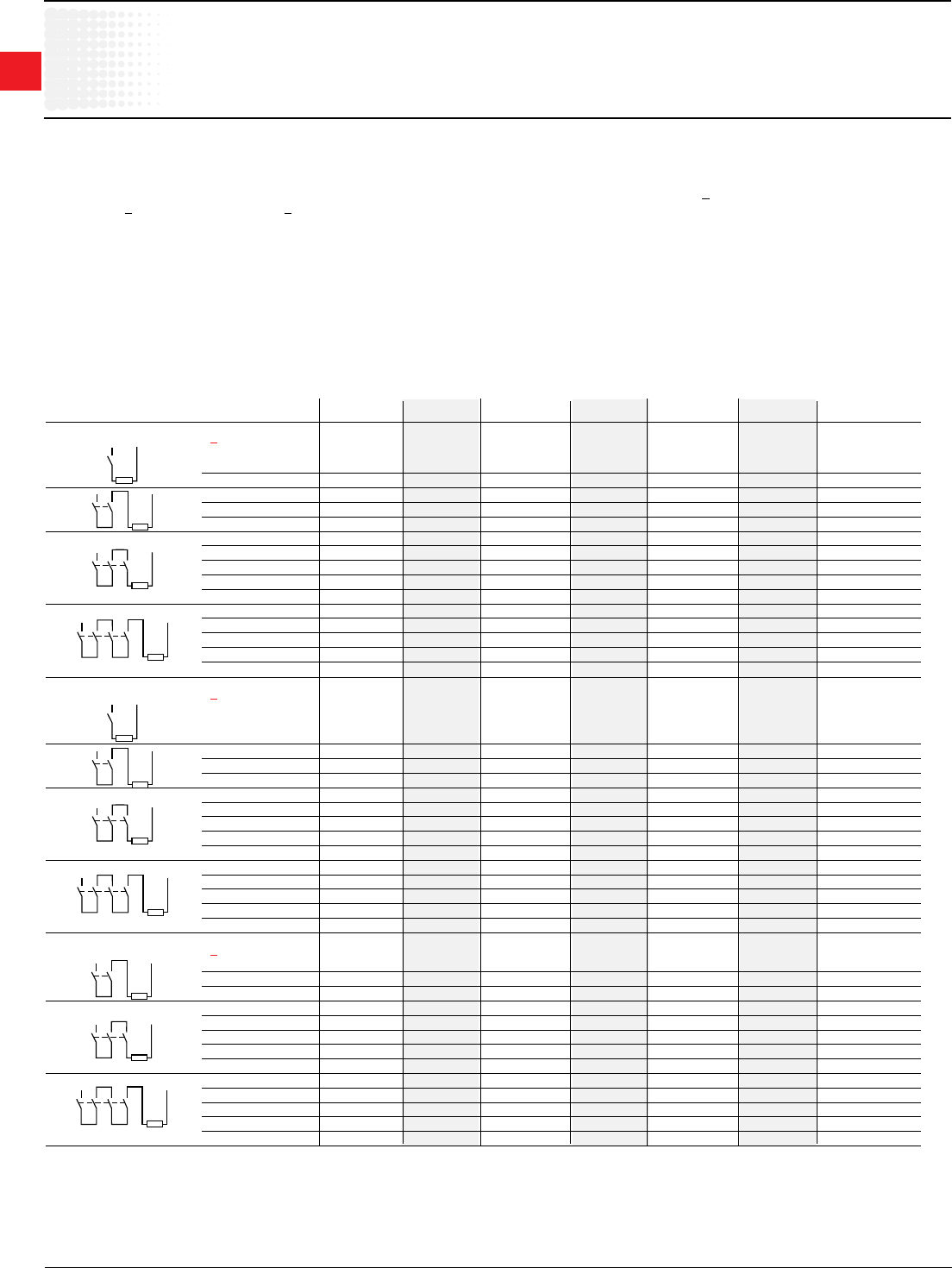
1
Across the line
contactors
1.44 Low Voltage Products & Systems
1SXU000023C0202 ABBInc.•888-385-1221•www.abb.us/lowvoltage
General
Thearcswitchingond.c.ismoredifcultthanona.c.
•Forselectingacontactoritisessentialtodeterminethecurrent,thevoltageandtheL/Rtimeconstantofthecontrolledload.
•Forinformation,typicaltimeconstantvaluesarequotedhereafter:noninductiveloadssuchasresistancefurnaces(L/R~1ms),inductiveloadssuchasshunt
motors(L/R~2ms)orseriesmotors(L/R~7.5ms).
•Theadditionofaresistorinparallelwithaninductivewindinghelpsintheeliminationofthearcs.
•Allthepolesrequiredforbreakingmustbeconnectedinseriesbetweentheloadandthesourcepolaritynotlinkedtoearth(orchassis).
Technical Data
•ThetablesindicateforthestandardcontactorstheIemax.operatingcurrentsdependingon:theutilizationcategory(i.e.L/R)DC-1,DC-3,DC-5asdenedin
theIEC60947-4-1publication(seepage1.75formoredetails),theoperatingvoltageUeandthepolecouplingdetails.
Amperevaluesquotedinthetablesbelowarevalidfora-25…+70°Ctemperatureclosetothecontactors,aslongastheAC-1Amperevalues(seepage1.61)
forthecorrespondingambienttemperaturearenotexceeded.
•Max.switchingfrequency:300ops/h.
•Forswitchinghigherd.c.ratings,werecommendtheuseofbarmountedcontactors,Rseries(63…2000A).
Selection Table
a.c. / d.c. operated contactors EK110 EK150 EK175 EK210 EK370 EK550 EK1000
UtilizationcategoryDC-1,L/R< 1 ms
≤72V A 120 145 210 210 370 550 –
110V A 120 145 210 210 370 550 –
≤72V A 200 200 300 300 550 800 –
110V A 200 200 300 300 550 800 –
220V A 200 200 300 300 550 800 –
≤72V A 200 200 300 300 550 800 –
110V A 200 200 300 300 550 800 –
220V A 200 200 300 300 550 800 –
440V A – – 210 210 450 650 –
600V A – – – – 450 650 –
≤72V A 200 200 300 300 550 800 –
110V A 200 200 300 300 550 800 –
220V A 200 200 300 300 550 800 –
440V A 200 200 260 300 450 650 –
600V A – – 260 300 450 650 –
UtilizationcategoryDC-3,L/R< 2 ms
≤72V A 120 145 210 210 370 550 –
≤72V A 135 145 210 210 450 650 –
110V A 135 135 210 210 450 650 –
220V A 135 135 210 210 450 650 –
≤72V A 135 145 210 210 450 650 –
110V A 135 135 210 210 450 650 –
220V A 135 135 210 210 450 650 –
440V A – – 210 210 450 650 –
600V A – – – – 450 650 –
≤72V A 135 145 210 210 450 650 –
110V A 135 135 210 210 450 650 –
220V A 135 135 210 210 450 650 –
440V A 135 135 210 210 450 650 –
600V A – – 170 210 450 650 –
UtilizationcategoryDC-5,L/R<7.5ms
≤72V A 135 145 210 210 450 650 –
110V A 135 135 210 210 450 650 –
220V A 135 135 210 210 450 650 –
≤72V A 135 145 210 210 450 650 –
110V A 135 135 210 210 450 650 –
220V A 135 135 210 210 450 650 –
440V A – – 210 210 450 650 –
600V A – – – – 450 650 –
≤72V A 135 145 210 210 450 650 –
110V A 135 135 210 210 450 650 –
220V A 135 135 210 210 450 650 –
440V A 135 135 210 210 450 650 –
600V A – – 170 210 450 650 –
IEC Technical data
EK110–EK1000
DCcircuitswitching
1
Across the line
contactors
Low Voltage Products & Systems 1.45
ABBInc.•888-385-1221•www.abb.us/lowvoltage 1SXU000023C0202
M
3
M
3
M
3
IEC Technical data
A/AE9–A/AE/AF/TAE110
Main Pole - Utilization Characteristics
Contactor types: A..., AE... 9 12 16 26 30 40 45 50 63 75 95 110
AF..., TAE... – – – – – – 45 50 63 75 95 110
RatedoperationalvoltageUemax. V 690 1000(690forAF...contactors)
Ratedfrequencylimits Hz 25-400
Conventionalfree-airthermalcurrentIth
acc.toIEC60947-4-1,
opencontactorsø≤40°C
A 26 28 30 45 65 65 100 100 125 125 145 160
withconductorcross-sectionalarea
mm2 4 4 4 6 16 16 35 35 50 50 50 70
RatedoperationalcurrentIe/AC-1
forairtemperatureclosetocontactor
ø≤40°C A 25 27 30 45 55 60 70 100 115 125 145 160
Uemax.690V ø≤55°C A 22 25 27 40 55 60 60 85 95 105 135 145
ø≤70°C 3 A 18 20 23 32 39 42 50 70 80 85 115 130
withconductorcross-sectionalareamm2 2.5 4 4 6 10 16 25 35 50 50 50 70
UtilizationcategorieAC-3
forairtemperatureclosetocontactor<55°C
RatedoperationalcurrentIeAC-31
220-230-240 V A 9 12 17 26 33 40 40 53 65 75 96 110
3-phasemotors 380-400V A 9 12 17 26 32 37 37 50 65 75 96 110
415V A 9 12 17 26 32 37 37 50 65 72 96 110
440V A 9 12 16 26 32 37 37 45 65 70 93 100
500V A 9 12 14 22 28 33 33 45 55 65 80 100
690V A 7 9 10 17 21 25 25 35 43 46 65 82
1000V A – – – – – – – 232 252 282 30 2 30 2
RatedoperationalpowerAC-31
1500r.p.m.50Hz 220-230-240V kW 2.2 3 4 6.5 9 11 11 15 18.5 22 25 30
1800r.p.m.60Hz 380-400V kW 4 5.5 7.5 11 15 18.5 18.5 22 30 37 45 55
3-phasemotors 415V kW 4 5.5 9 11 15 18.5 18.5 25 37 40 55 59
440V kW 4 5.5 9 15 18.5 22 22 25 37 40 55 59
500V kW 5.5 7.5 9 15 18.5 22 22 30 37 45 55 59
690V kW 5.5 7.5 9 15 18.5 22 22 30 37 40 55 75
1000V kW – – – – – – – 302 33 2 372 402 402
RatedmakingcapacityAC-3
accordingtoIEC60947-4-1 10xIeAC-3
RatedbreakingcapacityAC-3
accordingtoIEC60947-4-1 8xIeAC-3
Short-circuitprotectionforcontactors
withoutthermalO/Lrelay-Motorprotectionexcluded
Ue <500Va.c.-gGtypefuse A 25 32 32 50 63 80 100 125 160 160 200
Ratedshort-timewithstandcurrentIcw
at40°Cambienttemp.,infreeair,
fromacoldstate 1s A 250 280 300 400 600 1000 1320 1320
10s A 100 120 140 210 400 650 800 800
30s A 60 70 80 110 225 370 500 500
1min A 50 55 60 90 150 250 350 350
15min A 26 28 30 45 65 110 110 135 135 160 175
Maximumbreakingcapacity
cosø=0.45(cosø=0.35forIe >100A)
at440V A 250 420 820 900 1300 1160
at690V A 90 170 340 490 630 800
Heatdissipationperpole
Ie/AC-1 W 0.8 1 1.2 1.8 2.5 3 2.5 5 6.5 7 6.5 7.5
I
e/AC-3 W 0.1 0.2 0.35 0.6 0.9 1.3 0.65 1.3 1.5 2 2.7 3.6
Max.electricalswitchingfrequency
–forAC-1 cycles/h 600 600(300forAF...,AE...TAE...) 300
–forAC-3 cycles/h 1200(600forAE...) 600(300forAF...,AE...TAE...) 300
–forAC-2,AC-4 cycles/h 300 150 150
Electricaldurability seepages1.70-1.73
Mechanicaldurability
–millionsofoperatingcycles 10(5forAE...andTAE...contactors)
–max.mechanicalswitching
frequency cycles/h 3600(300forAF...contactors)
{
1 Forthecorrespondinghp/Avaluesof1500r.p.m.,50Hz,3-phasemotors,seepage1.76.
2 AF...contactorsexcluded
3 UnauthorizedforTAE...contactors.
1
Across the line
contactors
1.46 Low Voltage Products & Systems
1SXU000023C0202 ABBInc.•888-385-1221•www.abb.us/lowvoltage
IEC Technical data
A/AF145–AF750
1Conductorswithpreparation.
2 Dimensionsofthebars(inmm).
3 Forcurrentsabove450A,useterminalextension/enlargementpiecesLX300/LW300seepage1.31).
M
3
M
3
{
Main Pole - Utilization Characteristics
Contactor types: A... 145 185 210 260 300 – – – –
AF... 145 185 210 260 300 400 460 580 750
RatedoperationalvoltageUemax. V 690
Ratedfrequencylimits Hz 25...400
Conventionalfree-airthermalcurrentIth
acc.toIEC60947-4-1,
opencontactorsø≤40°C A 250 275 350 400 500 600 700 800 1050
withconductorcross-sectionalarea1
mm2 120 150 185 240 300
3
2x185 2x240 2x240
2x80x52
RatedoperationalcurrentIe/AC-1
forairtemperatureclosetocontactor
ø≤40°C A 250 275 350 400 500 600 700 800 1050
Uemax.690V ø≤55°C A 230 250 300 350 400 500 600 700 800
ø≤70°C A 180 180 240 290 325 400 480 580 720
withconductorcross-sectionalarea mm2 120 150 185 240 300
3
2x185 2x240 2x240
2x80x52
UtilizationcategorieAC-3
forairtemperatureclosetocontactor<55°C
RatedoperationalcurrentIeAC-3
220-230-240V A 145 185 210 260 305 400 460 580 750
3-phasemotors 380-400V A 145 185 210 260 305 400 460 580 750
415V A 145 185 210 260 300 400 460 580 750
440V A 145 185 210 240 280 400 460 580 750
500V A 145 170 210 240 280 400 460 580 750
690V A 120 170 210 220 280 350 400 500 650
1000V A – – – – – – – – –
RatedoperationalpowerAC-3
1500r.p.m.50Hz 220-230-240V kW 45 55 59 80 90 110 132 160 220
1800r.p.m.60Hz 380-400V kW 75 90 110 140 160 200 250 315 400
3-phasemotors 415V kW 75 90 110 140 160 220 250 355 425
440V kW 75 90 110 140 160 220 250 355 450
500V kW 90 110 132 180 200 250 315 400 520
690V kW 110 132 160 200 250 315 355 500 600
1000V kW – – – – – – – – –
RatedmakingcapacityAC-3
accordingtoIEC60947-4-1 10xIeAC-3
RatedbreakingcapacityAC-3
accordingtoIEC60947-4-1 8xIeAC-3
Short-circuitprotectionforcontactors
withoutthermalO/Lrelay-Motorprotectionexcluded
Ue <500Va.c.-gGtypefuse A 315 355 400 500 630 800 1000
Ratedshort-timewithstandcurrentIcw
at40°Cambienttemp.,infreeair,
fromacoldstate 1s A 1800 2000 2500 3500 4600 7000
10s A 1200 1500 1700 2400 4400 6400
30s A 800 1000 1200 1500 3100 4500
1min A 600 800 1000 1100 2500 3500
15min A 280 320 400 500 840 1300
Maximumbreakingcapacity
cosø=0.45(cosø=0.35forIe >100A)
at440V A 1500 2000 2300 2600 3000 4000 5000 6000 7500
at690V A 1200 1600 2000 2400 2500 3500 4500 5000 7000
Heatdissipationperpole
I
e/AC-1 W 13 16 18 25 32 30 42 32 50
I
e/AC-3 W 5 8 9 14 18 16 21 17 28
Max.electricalswitchingfrequency
–forAC-1 cycles/h 300 300 300 300
–forAC-3 cycles/h 300 300 300 300
–forAC-2,AC-4 cycles/h 150 150 60 60
Electricaldurability seepages1.65...1.69 – – – –
Mechanicaldurability
–millionsofoperatingcycles 5 3
–max.mechanicalswitching
frequency cycles/h 3600(300forAF...contactors) 300
1
Across the line
contactors
Low Voltage Products & Systems 1.47
ABBInc.•888-385-1221•www.abb.us/lowvoltage 1SXU000023C0202
M
3
M
3
{
IEC Technical data
AF1350–AF1650
1 Dimensionsofthebars(inmm).
Main Pole - Utilization Characteristics
Contactor types: AF... 1350 1650
RatedoperationalvoltageUemax. V 1000 1000
Ratedfrequencylimits Hz 25-400 25-400
Conventionalfree-airthermalcurrentIth
acc.toIEC60947-4-1,
opencontactorsø≤40°C A 1350 1650
withconductorcross-sectionalarea1
mm2 2/100x5 3/100x5
RatedoperationalcurrentIe/AC-1
forairtemperatureclosetocontactor
ø≤40°C A 1350 1650
Uemax.690V ø≤55°C A 1150 1450
ø≤70°C A 1000 1270
withconductorcross-sectionalarea mm2
2x80x51
2x80x51
UtilizationcategorieAC-3
forairtemperatureclosetocontactor<55°C
RatedoperationalcurrentIeAC-3
220-230-240V A 860 1050
3-phasemotors 380-400V A 860 1050
415V A 860 1050
440V A 860 1050
500V A — —
690V A — —
1000V A — —
RatedoperationalpowerAC-3
1500r.p.m.50Hz 220-230-240V kW 257 315
1800r.p.m.60Hz 380-400V kW 475 560
3-phasemotors 415V kW 500 600
440V kW 560 670
500V kW — —
690V kW — —
1000V kW — —
RatedmakingcapacityAC-3 10xIe,AC-3
accordingtoIEC60947-4-1
RatedbreakingcapacityAC-3 8xIe,AC-3
accordingtoIEC60947-4-1
Short-circuitprotectionforcontactors
Productcoordination
withoutthermalO/Lrelay-Motorprotectionexcluded
withABBcircuitbreaker
Ue <500Va.c.-gGtypefuse A
Consultfactory
Ratedshort-timewithstandcurrentIcw
at40°Cambienttemp.,infreeair,
fromacoldstate 1s A 10,000 12,000
10s A 8000 10,000
30s A 6000 7500
1min A 4500 5500
15min A 1600 2200
Maximumbreakingcapacity
cosø=0.45(cosø=0.35forIe >100A)
at440V A 10,000 12,000
at690V A — —
Max.electricalswitchingfrequency
–forAC-1 cycles/h 60 60
–forAC-3 cycles/h
–forAC-2,AC-4 cycles/h
Electricaldurability 50,000 50,000
Mechanicaldurability
–millionsofoperatingcycles 500,000 500,000
–max.mechanicalswitching
frequency cycles/h 60 60
1
Across the line
contactors
1.48 Low Voltage Products & Systems
1SXU000023C0202 ABBInc.•888-385-1221•www.abb.us/lowvoltage
IEC Technical data
A/AF9–AF110
150/60Hzcoils:voltagecodes80to88.seepage1.28.
Magnet System Characteristics for A... Contactors
Contactor types: A... 9 12 16 26 30 40 45 50 63 75 95 110
RatedcontrolcircuitvoltageUc
–at50Hz V 20...690
–at60Hz V 24...600
Coiloperatinglimits ø<55°C ø<70°C
accordingtoIEC60947-4-1 0.85...1.1xUc 0.85...1.1xUc
Drop-outvoltagein%ofUc roughly40...65%
Coilconsumption
Averagepull-invalue 50Hz VA 70 120 180 350
60Hz VA 80 140 210 450
50/60Hz1VA/VA 74/70 125/120 190/180 410/365
Averageholdingvalue 50Hz VA/W 8/2 12/3 18/5.5 22/6.5
60Hz VA/W 8/2 12/3 18/5.5 26/8
50/60Hz1 VA/W 8/2 12/3 18/5.5 27/7.5
Operatingtime
betweencoilenergizationand:
–N.O.contactclosing ms 10...26 8...21 8...27 10...25
–N.C.contactopening ms 7...21 6...18 7...22 7...22
betweencoilde-energizationand:
–N.O.contactopening ms 4...11 4...11 4...11 7...15
–N.C.contactclosing ms 9...16 7...14 7...14 10...18
Magnet System Characteristics for AF... Contactors
Contactor types: AF... – – – – – – 45 50 63 75 95 110
RatedcontrolcircuitvoltageUc
–at50Hz V 48...250 48...250
–at60Hz V 48...250 48...250
–d.c. V 20...250 20...250
Coiloperatinglimits ø<70°C
accordingtoIEC60947-4-1 0.85...1.1xUc
Drop-outvoltagein%ofUc 55%
Coilconsumption
Averagepull-invalue 50Hz VA 210 350
60Hz VA 210 350
d.c. W 190 400
Averageholdingvalue 50Hz VA/W 7/2.8 7/3.5
60Hz VA/W 7/2.8 7/3.5
d.c. W 2.8 2
Operatingtime
betweencoilenergizationand:
–N.O.contactclosing ms 30...100 30...80
–N.C.contactopening ms 27...95 27...77
betweencoilde-energizationand:
–N.O.contactopening ms 30...110 55...125
–N.C.contactclosing ms 35...115 60...130
1
Across the line
contactors
Low Voltage Products & Systems 1.49
ABBInc.•888-385-1221•www.abb.us/lowvoltage 1SXU000023C0202
IEC Technical data
A145—AF750
150/60Hzcoils:voltagecodes80to88.seepage1.28.
Magnet System Characteristics for A... Contactors
Contactor types: A... 145 185 210 260 300 – – – –
RatedcontrolcircuitvoltageUc
–at50Hz V 24...690
–at60Hz V 24...690
Coiloperatinglimits ø<70°C
accordingtoIEC60947-4-1 0.85...1.1xUc
Drop-outvoltagein%ofUc roughly25...65%
Coilconsumption
Averagepull-invalue 50Hz VA 550 1350
60Hz VA 600 1550
50/60Hz1 VA/VA 700/650 1700/1550
Averageholdingvalue 50Hz VA/W 35/11 60/16
60Hz VA/W 40/12 65/19
50/60Hz1 VA/W 44/13 80/21
Operatingtime
betweencoilenergizationand:
–N.O.contactclosing ms 13...27 17...35
–N.C.contactopening ms 8...22 12...30
betweencoilde-energizationand
–N.O.contactopening ms 5...10 7...13
–N.C.contactclosing ms 9...13 10...16
Magnet System Characteristics for AF... Contactors
Contactor types: AF... 145 185 210 260 300 400 460 580 750
RatedcontrolcircuitvoltageUc
–at50Hz V 48...250
–at60Hz V 48...250
–d.c. V 24...250
Coiloperatinglimits ø<70°C
accordingtoIEC60947-4-1 0.85...1.1xUc
Drop-outvoltagein%ofUc 55%
Coilconsumption
Averagepull-invalue 50Hz VA 430 470 890 850
60Hz VA 430 470 890 850
d.c. W 500 520 990 950
Averageholdingvalue 50Hz VA/W 12/3.5 10/2.5 12/4 12/4.5
60Hz VA/W 12/3.5 10/2.5 12/4 12/4.5
d.c. W 2 2 4 4.5
Operatingtime
betweencoilenergizationand:
–N.O.contactclosing ms 30...115 50...120
–N.C.contactopening ms 30...115 50...120
betweencoilde-energizationand
–N.O.contactopening ms 25...80 40...70
–N.C.contactclosing ms 25...80 40...70
1
Across the line
contactors
1.50 Low Voltage Products & Systems
1SXU000023C0202 ABBInc.•888-385-1221•www.abb.us/lowvoltage
IEC Technical data
AF1350–AF1650
150/60Hzcoils:voltagecodes80to88.seepage1.28.
Magnet System Characteristics for AF... Contactors
Contactor types: AF... 1350 1650
RatedcontrolcircuitvoltageUc
–at50Hz V 100-250
–at60Hz V 100-250
–d.c. V 100-250
Coiloperatinglimits ø<70°C
accordingtoIEC60947-4-1 0.85...1.1xUc
Drop-outvoltagein%ofUc 55%
Coilconsumption
Averagepull-invalue 50Hz VA 1900
60Hz VA 1900
d.c. W 1700
Averageholdingvalue 50Hz VA/W 48/17
60Hz VA/W 48/17
d.c. W 16
Operatingtime
betweencoilenergizationand:
–N.O.contactclosing ms 50-80
–N.C.contactopening ms 50-80
betweencoilde-energizationand
–N.O.contactopening ms 35-55
–N.C.contactclosing ms 35-55
WithPLC
betweencoilenergizationand
–N.O.contactopening ms 40-65
–N.C.contactclosing ms 40-65
betweencoilde-energizationand
–N.O.contactopening ms 10-30
–N.C.contactclosing ms 10-30
1
Across the line
contactors
Low Voltage Products & Systems 1.51
ABBInc.•888-385-1221•www.abb.us/lowvoltage 1SXU000023C0202
IEC Technical data
AE9—AE110
TAE45—TAE110
1 Theuseofsurgesuppressorsincreasestheopeningtimeonascaleof1.1to1.5foravaristorsuppressorandonascaleof4to8foradiodesuppressor.
AE9...AE40contactorsandUc >110V:tablevaluesforcontactorswithRV5surgesuppressor(factorymounted).
2 Theuseofsurgesuppressorsincreasestheopeningtimeonascaleof1.1to1.5foravaristorsuppressorandonascaleof4to8foradiodesuppressor.
Magnet System Characteristics for AE... Contactors
Contactor types: AE... 9 12 16 26 30 40 45 50 63 75 95 110
RatedcontrolcircuitvoltageUc
Vd.c. 12...250
Coiloperatinglimits ø<55°C ø<70°C
accordingtoIEC60947-4-1 0.85...1.1xUc
Drop-outvoltagein%ofUc roughly10...30% roughly15...40%
Coilconsumption-Averagevalues
–pull-invalue W 90 110 200 400
–holdingvalue W 2 2.5 4 2.4
Coiltimeconstant
–open L/R ms 2 3 3 6
–closed L/R ms 9 16 15 30...40
Operatingtime
betweencoilenergizationand:
–N.O.contactclosing ms 10...16 13...21 13...30 15...25
–N.C.contactopening ms 8...12 11...16 10...27 12...22
betweencoilde-energizationand
–N.O.contactopening ms 5...141 6 ... 12 1 5...151 15...201
–N.C.contactclosing ms 11...171 8...161 8...181 18...231
Magnet System Characteristics for TAE... Contactors
Contactor types: TAE... – – – – – – 45 50 – 75 95 110
RatedcontrolcircuitvoltageUc
Vd.c. 17...264
Coiloperatinglimits ø<55°C
accordingtoIEC60947-4-1 Ucmin....Ucmax.
Drop-outvoltagein%ofUcmax. roughly20...35%
Coilconsumption
valuesforUcmin....Ucmax.
–pull-invalue W 120...250 300...1000
–holdingvalue W 1.7...6.5 2...7
Coiltimeconstant
–open L/R ms 3 6
–closed L/R ms 15 40
Operatingtime
betweencoilenergizationand:
–N.O.contactclosing ms 13...30 15...25
–N.C.contactopening ms 10...27 12...22
betweencoilde-energizationand
–N.O.contactopening ms 5...152 15...202
–N.C.contactclosing ms 8...182 18...232
1
Across the line
contactors
1.52 Low Voltage Products & Systems
1SXU000023C0202 ABBInc.•888-385-1221•www.abb.us/lowvoltage
Built-in Auxiliary Contacts - Utilization Characteristics
Contactor types: A... 9 12 16 26 30 40 45 50 63 75 95 110
RatedoperationalvoltageUe
max.
V 690 – – – – – –
Conventionalfreeairthermal
current Ith-ø≤40°C A 16 – – – – – –
Ratedfrequencylimits Hz 25...400 – – – – – –
RatedoperationalcurrentIe/AC-15
accordingtoIEC60947-5-1
24-127V50/60Hz A 6 – – – – – –
220-240V50/60Hz A 4 – – – – – –
380-440V50/60Hz A 3 – – – – – –
500V50/60Hz A 2 – – – – – –
690V50/60Hz A 2 – – – – – –
RatedoperationalcurrentIe/DC-13
accordingtoIEC60947-5-1
24Vd.c. A/W 6/144 – – – – – –
48Vd.c. A/W 2.8/134 – – – – – –
72Vd.c. A/W 2/144 – – – – – –
125Vd.c. A/W 1.1/138 – – – – – –
250Vd.c. A/W 0.55/138 – – – – – –
Ratedmakingcapacity
acc.toIEC60947-5-1 10xIe/AC-15 – – – – – –
Ratedbreakingcapacity
acc.toIEC60947-5-1 10xIe/AC-15 – – – – – –
Short-circuitprotection
gGtypefuse A 10 – – – – – –
Ratedshort-timewithstandcurrentIcw
for1.0s A 100 – – – – – –
for0.1s A 140 – – – – – –
Minimumswitchingcapacity V/mA 17/5 – – – – – –
Non-overlappingtimebetween
N.O.andN.C.contacts ms >2 – – – – – –
Insulatingresistanceat500Vd.c.
afterdurabilitytest MOhm 5 – – – – – –
Heatdissipationperpoleat6A W 0.10 – – – – – –
IEC Technical data
A9—A110
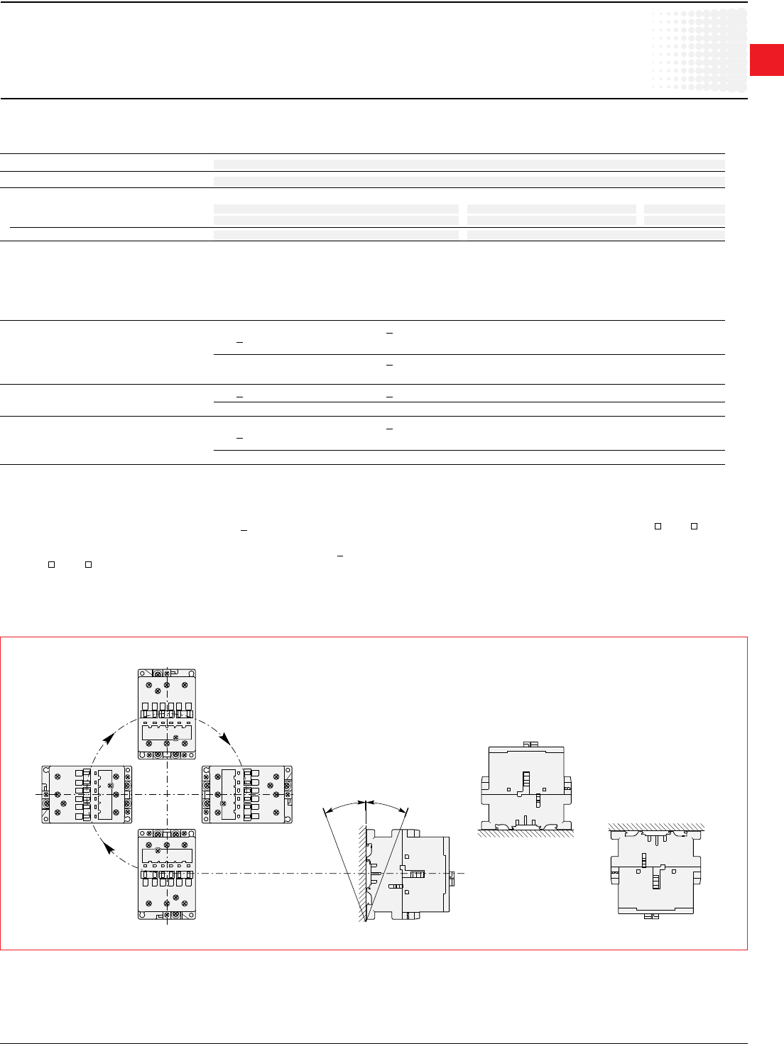
1
Across the line
contactors
Low Voltage Products & Systems 1.53
ABBInc.•888-385-1221•www.abb.us/lowvoltage 1SXU000023C0202
IEC Technical data
A/AE9—AF/TAE110
Position 1
Position 3
Position 4
Position 2
Position 5
Position 1 ± 30°
-30°
+30°
Position 6
ABB
ABB
ABB
ABB
Mounting characteristics
Contactor types: A..., AE... 9 12 16 26 30 40 45 50 63 75 95 110
AF..., TAE... – – – – – – 45 50 63 75 95 110
Mountingpositions see"Conditionsforuse"
Mountingdistances Thecontactorscanbeassembledsidebyside
Mounting
onDINrail 35x7.5mm 35x15mm
accordingtoIEC715andEN50022/EN50023 35x15mm 75x25mm 75x25mm
byscrews(notsupplied) 2xM4 2xM6
Conditions for Use
SustainableutilizationconditionsforcontactorsinvolvingatthesametimetheMountingposition,AmbienttemperatureandControlvoltageoperatinglimitsare
summarizedinthetablebelow.
Contactors Mountingposition Ambienttemperature Controlvoltage
1,1+30°,2,3,4,5 <55°C 0.85...1.1xUc
A9...A110,AE9...AE110 55...70°C Uc
6 <55°C 0.95...1.1xUc
>55°Cunauthorized –
AF45...AF110 1,1+30°,2,3,4,5 <70°C 0.85Ucmin....1.1xUcmax.
6unauthorized – –
1,1+30°,2,3,4,5 <55°C Ucmin....Ucmax.
TAE45...TAE110 >55°Cunauthorized –
6unauthorized – –
Notesfor4-polecontactors
Whateverthecoilvoltage:Pos.5unauthorizedforA45-22-00,AE45-22-00,A75-22-00,AE75-22-00contactors.
For60Hzcoilvoltage:(onlyfordevicesttedwithCA5-..andCAL5-11auxiliarycontactsorTPtimer)
– A45-40-00,A50-40-00andA75-40-00contactors
Mountingpositions1to5andambienttemperature<55°C:tolerancereducedto0.9...1.1Uc(insteadof0.85...1.1Uc)forcoilvoltagecodes7 and8 .
– A45-22-00andA75-22-00contactors
Mountingpositions1to4(pos.5unauthorized)andambienttemperature<55°C:tolerancereducedto0.9...1.1Uc(insteadof0.85...1.1Uc)forcoilvoltage
codes7 and8 .
Formountingposition6orambienttemperatureof55to70°Ctheinformationgivenonthispageremainsapplicable.
Mounting Positions (seetheabovetableforauthorizedpositions)
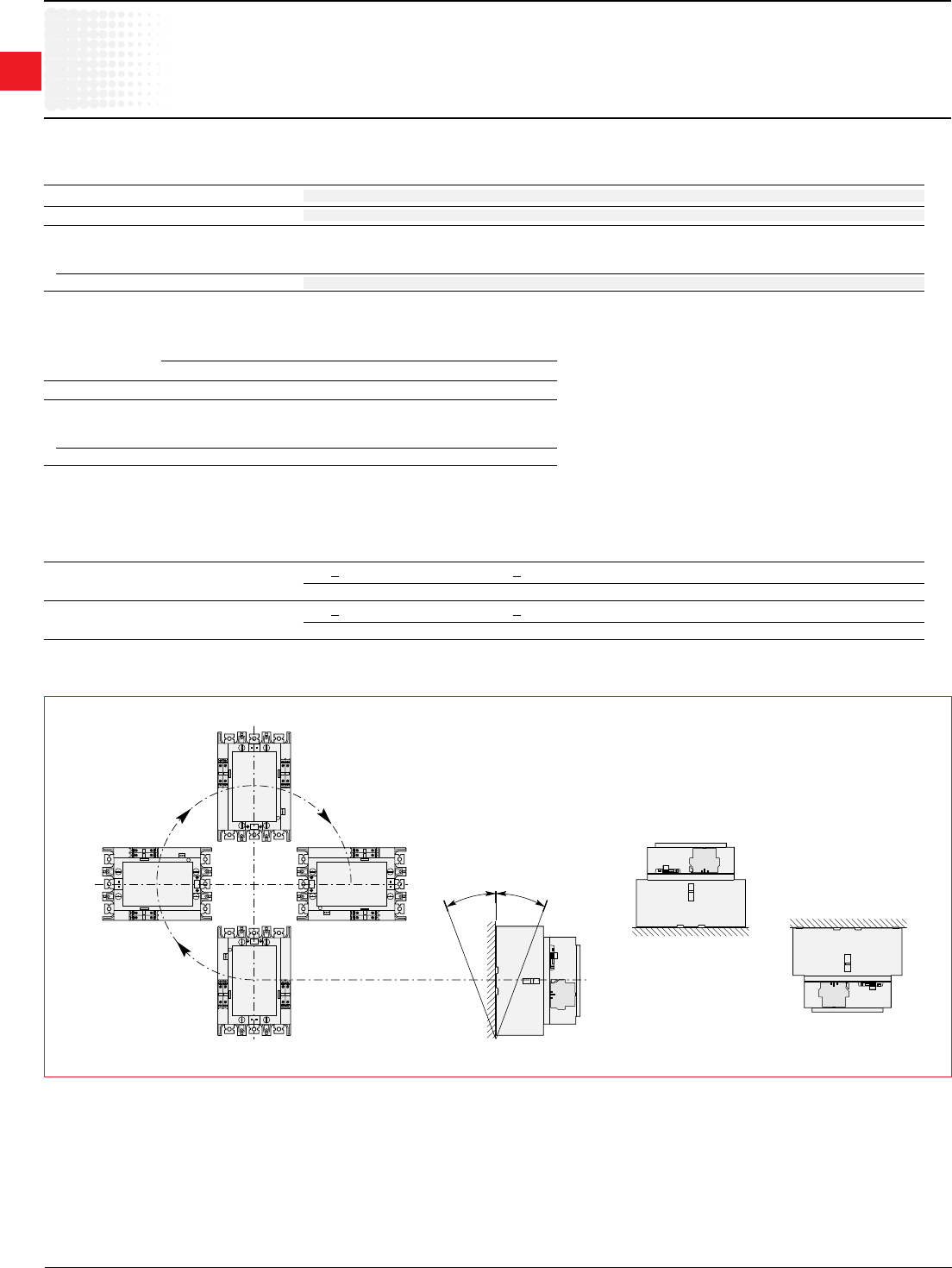
1
Across the line
contactors
1.54 Low Voltage Products & Systems
1SXU000023C0202 ABBInc.•888-385-1221•www.abb.us/lowvoltage
IEC Technical data
A/AF145–AF1650
ABB
ABB
ABB
ABB
-30°
+30°
Position 1
Position 3
Position 4
Position 2
Position 5
Position 1 ± 30°
Position 6
Mounting Characteristics — A/AF145 — AF750
Contactor types: A... 145 185 210 260 300 – – – –
AF... 145 185 210 260 300 400 460 580 750
Mountingpositions see"Conditionforuse"
Mountingdistances Thecontactorscanbeassembledsidebyside
Fixing
onDINrail – – – – – – – – –
accordingtoIEC715andEN50022/EN50023
byscrews(notsupplied) 4xM5 4xM6
Mounting Characteristics — AF1350 — AF1650
Contactor types: AF 1350 1650
Mountingpositions see"Conditionforuse"
Mountingdistances Thecontactorscanbeassembledsidebyside
Fixing
onDINrail – –
accordingtoIEC715andEN50022/EN50023
byscrews(notsupplied) 4xM8
Conditions for Use
SustainableutilizationconditionsforcontactorsinvolvingatthesametimetheMountingposition,AmbienttemperatureandControlvoltageoperatinglimitsare
summarizedinthetablebelow.
Contactors Mountingposition Ambienttemperature Controlvoltage
A145...A300 1,1+30°,2,3,4,5 <70°C 0.85...1.1xUc
6unauthorized – –
AF145...AF750 1,1+30°,2,3,4,5 <70°C 0.85xUcmin....1.1xUcmax.
6unauthorized – –
Mounting Positions (seetheabovetableforauthorizedpositions)
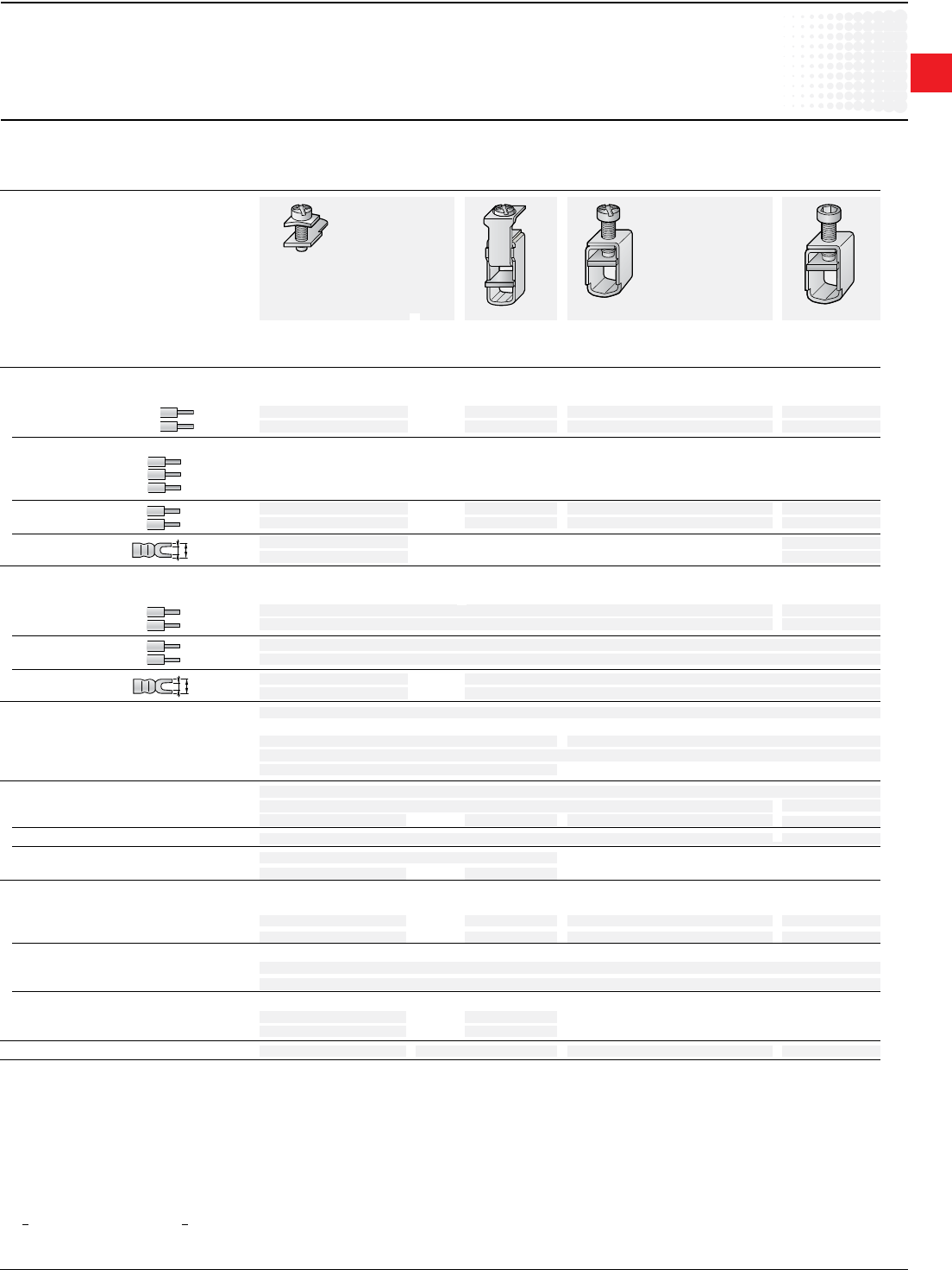
1
Across the line
contactors
Low Voltage Products & Systems 1.55
ABBInc.•888-385-1221•www.abb.us/lowvoltage 1SXU000023C0202
}
L
l
L
l
IEC Technical data
A/AE9–AF/TAE110
1 L <8andl>3.7forcoilterminal-L<10andl>4.2forbuilt-inauxiliaryterminals.
2WithLW110enlargementpiece.Seepage1.31.
Connecting Characteristics
Contactor types: A..., AE... 9 12 16 26 30 40 45 50 63 75 95 110
AF..., TAE... – – – – – – 45 50 63 75 95 110
Mainterminals
withcableclamp withdouble withsingleconnector withsingle
connector (13x10mm) connector
2x(5.6x6.5mm) (14x14mm)
Connectingcapacity(min....max.)
Mainconductors(poles)
Rigid: solid(≤4mm2) 1xmm2 1...4 1.5...6 2.5...16 6...50 10...95
stranded(≥6mm2) 2xmm2 1...4 1.5...6 2.5...16 6...16 6...35
Rigidwithconnector
singleforCucable mm2 – – – – – – – – – – – –
singleforAl/Cucable mm2 – – – – – – – – – – – –
doubleforAl/Cucable mm2 – – – – – – – – – – – –
Flexiblewithcableend 1xmm2 0.75...2.5 0.75...4 2.5...10 6...35 10...70
2xmm2 0.75...2.5 0.75...4 2.5...10 6...25 6...35
Barsorlugs Lmm≤ 8 10 – – – – – – 302
lmm> 3.7 4.2 – – – – – – 6
Auxiliaryconductors
(built-inauxiliaryterminals+coilterminals)
Rigidsolid 1xmm2 1...4 0.75...2.5
2xmm2 1...4 0.75...2.5
Flexiblewithcableend 1xmm2 0.75...2.5 1...2.5 0.75...2.5
2xmm2 0.75...2.5
Lugs Lmm≤ 8 18
lmm> 3.7 1 3.7
Degreeofprotectionacc.toIEC60947-1/ Protectionagainstdirectcontactacc.toVDE0106-Part.100
EN60947-1andIEC60529/EN60529
–Mainterminals IP20 IP10
–Coilterminals IP20
–Built-inauxiliaryterminals IP20 – – – – – –
Screwterminals (deliveredinopenposition,screwsofunusedterminalsmustbetightened)
Mainterminals (+,-)pozidriv2screws hexagonsocket
M3.5 M4 M5 M6 M8(s=4mm)
Coilterminals M3.5(+,-)pozidriv2screwswithcableclamp
Built-inauxiliaryterminals (+,-)pozidriv2screwswithcableclamp – – – – – –
M3.5 M4 M5 – – – – – –
Tighteningtorque
Mainpoleterminals
–recommended Nm/lb.in 1.00/9 1.7/15 2.30/20 4.00/35 6.00/53
–max. Nm 1.20 2.20 2.60 4.50 6.50
Coilterminals
–recommended Nm/lb.in 1.00/9
–max. Nm 1.20
Built-inauxiliaryterminals
–recommended Nm/lb.in 1.00/9 1.7/15 1.00/9 – – – – – –
–max. Nm 1.20 2.20 1.20 – – – – – –
Terminalmarkingandpositioning seepages1.34
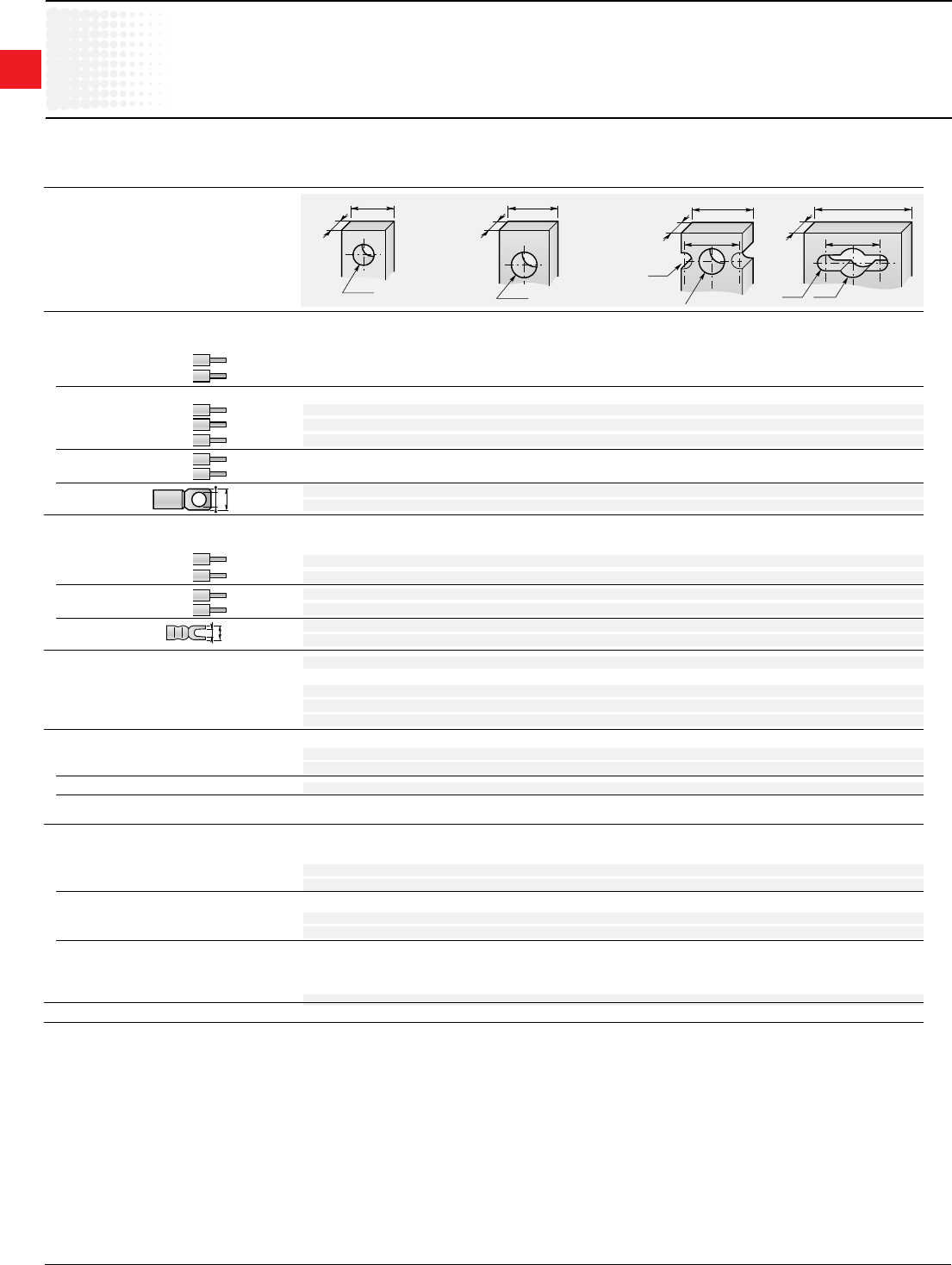
1
Across the line
contactors
1.56 Low Voltage Products & Systems
1SXU000023C0202 ABBInc.•888-385-1221•www.abb.us/lowvoltage
IEC Technical data
A/AF145–AF750
17.5
ø 8.5
5
20
ø 10.2
5
25
ø 6.5
22.5
ø 10.5
6
40
ø 6.5
22.5
ø 12.5
6
L
l
L
ø
Connecting Characteristics
Contactor types: A... 145 185 210 260 300 – – – –
AF... 145 185 210 260 300 400 460 580 750
Main terminals
Flattype
Connectingcapacity(min....max.)
Mainconductors(poles)
Rigid: 1xmm2
– – – – – – – – –
2xmm2
– – – – – – – – –
Rigid with connector
singleforCucable mm2 6...185 16...240 240 300
singleforAl/Cucable mm2 25...150 120...240 240 300
doubleforAl/Cucable mm2 – 2x95...120 2x240 3x185
Flexible
1xmm2 – – – – – – – – –
2xmm2 – – – – – – – – –
Barsorlugs Lmm≤ 24 32 47/45 52/50
Ømm> 8 10 10 12
Auxiliaryconductors
(coilterminals)
Rigidsolid 1xmm2 1...4
2xmm2 1...4
Flexiblewithcableend
1xmm2 0.75...2.5
2xmm2 0.75...2.5
Lugs Lmm≤ 8
lmm> 3.7
Degreeofprotectionacc.toIEC60947-1/ Protectionagainstdirectcontactacc.toVDE0106-part100
EN60947-1andIEC60529/EN60529
–Mainterminals IP00
–Coilterminals IP20
–Built-inauxiliaryterminals –
Screw terminals
Mainterminals Screwsandbolts
M8 M10 M10 M12
Coilterminals(deliveredinopenposition) M3.5(+,-)pozidriv2screwswithcableclamp
Built-inauxiliaryterminals – – – – – – – – –
– – – – – – – – –
Tightening torque
Mainpoleterminals
–recommended
Nm/lb.in
18/160 28/240 40/354 45/443
–max.
Nm
20 30 44 49
Coil terminals
–recommended
Nm/lb.in
1.00/9
–max.
Nm
1.20
Built-inauxiliaryterminals
–recommended
Nm/lb.in – – – – – – – – –
–max.
Nm
– – – – – – – – –
Terminalmarkingandpositioning seepages1.36&1.37
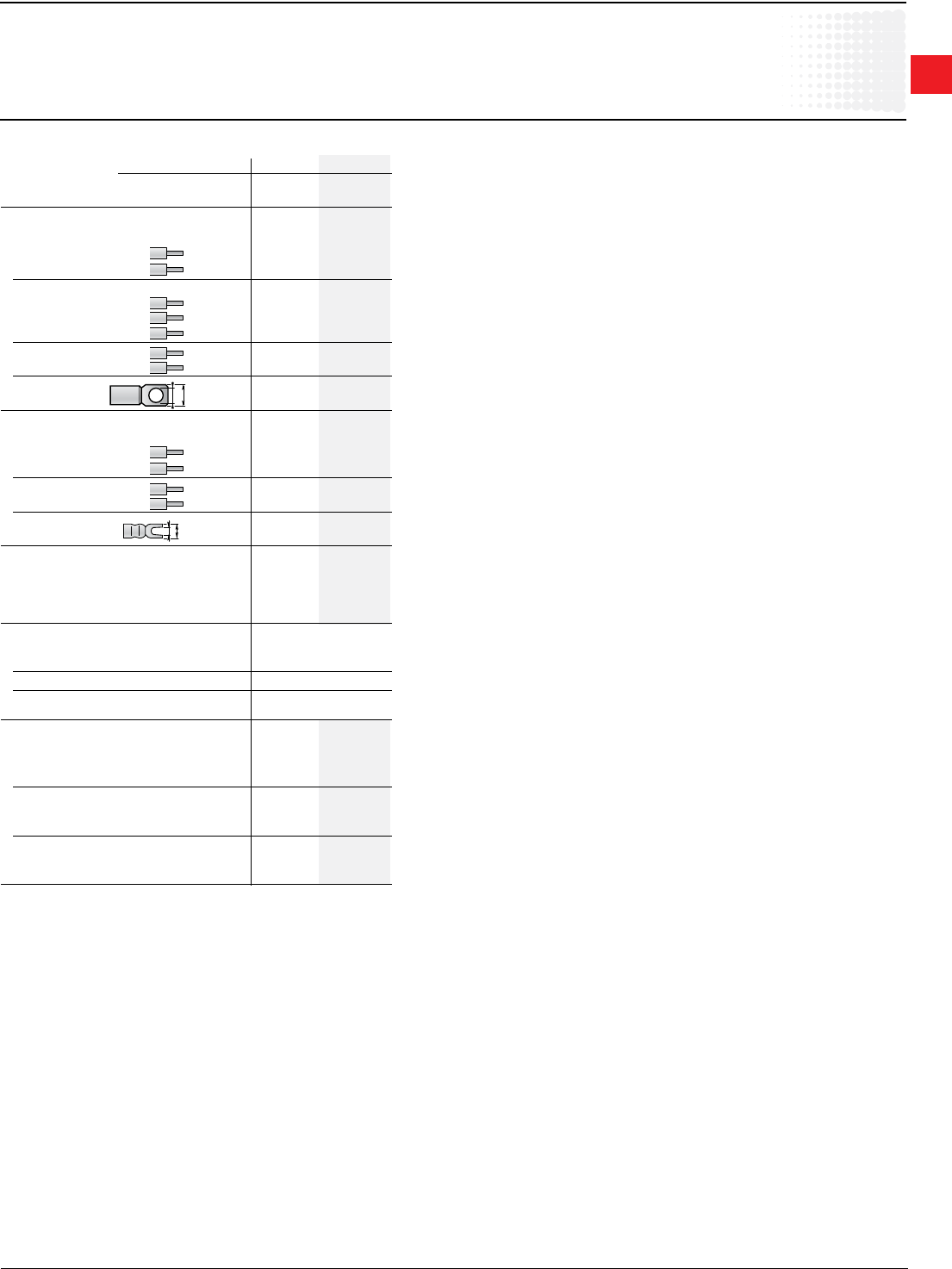
1
Across the line
contactors
Low Voltage Products & Systems 1.57
ABBInc.•888-385-1221•www.abb.us/lowvoltage 1SXU000023C0202
L
l
L
ø
IEC Technical data
AF1350–AF1650
Connecting Characteristics
Contactor types: AF... 1350 1650
Main terminals
Flattype
Connectingcapacity(min....max.)
Mainconductors(poles)
Rigid: 1xmm2 — —
2xmm2 — —
Rigid with connector
singleforCucable mm2 — —
singleforAl/Cucable mm2 — —
doubleforAl/Cucable mm2 — —
Flexible
1xmm2 — —
2xmm2 — —
Bars or lugs L mm ≤ 100 100
Ø mm > 12 12
Auxiliaryconductors
(coilterminals)
Rigidsolid 1xmm2 1...4 1...4
2xmm2 1...4 1...4
Flexiblewithcableend
1xmm2 0.75...2.5 0.75...2.5
2xmm2 0.75...2.5 0.75...2.5
Lugs Lmm≤ 8 8
lmm> 3.7 3.7
Degreeofprotectionacc.toIEC60947-1/
EN60947-1andIEC60529/EN60529
–Mainterminals IP00 IP00
–Coilterminals IP20 IP20
–Built-inauxiliaryterminals
Screwterminals Screwandbolts
Main terminals M12
Coilterminals(deliveredinopenposition) M3.5(+,-)pozidriv2screwswithcableclamp
Built-inauxiliaryterminals — —
Tightening torque
Mainpoleterminals
–recommended
Nm/lb.in
45/443 45/443
–max.
Nm
49 49
Coil terminals
–recommended
Nm/lb.in
1.00/9
1.00/9
–max.
Nm
1.20 1.20
Built-inauxiliaryterminals
–recommended
Nm/lb.in — —
–max.
Nm
— —
1
Across the line
contactors
1.58 Low Voltage Products & Systems
1SXU000023C0202 ABBInc.•888-385-1221•www.abb.us/lowvoltage
B1 B2
C2
C1
A
A
UL/CSA & IEC Technical data
AL9–AL40
Contactor types: AL AL9 AL12 AL16 AL26 AL30 AL40
RatedinsulationvoltageUi
accordingtoIEC60947-4-1 V 1000
accordingtoUL/CSA V 600
RatedimpulsewithstandvoltageU
imp.
kV 8
Standards DevicescomplyingwithinternationalstandardsIEC60947-1/60947-4-1
andEuropeanstandardsEN60947-1/60947-4-1
Airtemperatureclosetocontactor see"Conditionsforuse"page1.50,forcontrolvoltagelimitsandauthorizedmountingpositions
–ttedwiththermalO/Lrelay °C -25to+55
–withoutthermalO/Lrelay °C -40to+70(55max.forTAE...contactors)
–forstorage °C -60to+80
Climaticwithstand acc.toIEC60068-2-30and60068-2-11-UTEC63-100specicationII
Operatingaltitude m < 3000
Shock withstand
acc.IEC60068-2-27andEN60068-2-27
Mountingposition1(seepage1.50) 1/2sinusoidalshockfor11ms:nochangeincontactposition
Shockdirection Makingposition Breakingposition
A 20 g 20 g
B1 10 g 5 g
B2 15 g 15 g
C1 20 g 20 g
C2 20 g 20 g
1
Across the line
contactors
Low Voltage Products & Systems 1.59
ABBInc.•888-385-1221•www.abb.us/lowvoltage 1SXU000023C0202
M
3
M
3
M
3
IEC Technical data
AL9–AL40
Main Pole - Utilization Characteristics
Contactor types: AL AL9 AL12 AL16 AL26 AL30 AL40
RatedoperationalvoltageUemax. V 690
Ratedfrequencylimits Hz 25-400
Conventionalfree-airthermalcurrentIth
acc.toIEC60947-4-1,
opencontactorsø≤40°C
A 26 28 30 45 65 65
withconductorcross-sectionalarea
mm2 4 4 4 6 16 16 35
RatedoperationalcurrentIe/AC-1
forairtemperatureclosetocontactor
ø≤40°C A 25 27 30 45 55 60
Uemax.690V ø≤55°C A 22 25 27 40 55 60
ø≤70°C 3 A 18 20 23 32 39 42
withconductorcross-sectionalareamm2 2.5 4 4 6 10 16
UtilizationcategorieAC-3
forairtemperatureclosetocontactor<55°C
RatedoperationalcurrentIeAC-31
220-230-240 V A 9 12 17 26 33 40
3-phasemotors 380-400V A 9 12 17 26 32 37
415V A 9 12 17 26 32 37
440V A 9 12 16 26 32 37
500V A 9 12 14 22 28 33
690V A 7 9 10 17 21 25
1000V A – – – – – –
RatedoperationalpowerAC-31
1500r.p.m.50Hz 220-230-240V kW 2.2 3 4 6.5 9 11
1800r.p.m.60Hz 380-400V kW 4 5.5 7.5 11 15 18.5
3-phasemotors 415V kW 4 5.5 9 11 15 18.5
440V kW 4 5.5 9 15 18.5 22
500V kW 5.5 7.5 9 15 18.5 22
690V kW 5.5 7.5 9 15 18.5 22
1000V kW – – – – – –
RatedmakingcapacityAC-3
accordingtoIEC60947-4-1 10xIeAC-3
RatedbreakingcapacityAC-3
accordingtoIEC60947-4-1 8xIeAC-3
Short-circuitprotectionforcontactors
withoutthermalO/Lrelay-Motorprotectionexcluded
Ue <500Va.c.-gGtypefuse A 25 32 32 50 63
Ratedshort-timewithstandcurrentI
cw
at40°Cambienttemp.,infreeair,
fromacoldstate 1s A 250 280 300 400 600
10s A 100 120 140 210 400
30s A 60 70 80 110 225
1min A 50 55 60 90 150
15min A 26 28 30 45 65
Maximumbreakingcapacity
cosø=0.45(cosø=0.35forIe >100A)
at440V A 250 — — 420 820
at690V A 90 — — 170 340
Heatdissipationperpole
Ie/AC-1 W 0.8 1 1.2 1.8 2.5
I
e/AC-3 W 0.1 0.2 0.35 0.6 0.9
Max.electricalswitchingfrequency
–forAC-1 cycles/h 600
–forAC-3 cycles/h 1200
–forAC-2,AC-4 cycles/h 300
Mechanicaldurability
–millionsofoperatingcycles 10
–max.mechanicalswitching
frequency cycles/h 3600
{
1
Across the line
contactors
1.60 Low Voltage Products & Systems
1SXU000023C0202 ABBInc.•888-385-1221•www.abb.us/lowvoltage
IEC Technical data
AL9–AL40,TAL9-TAL40
1Theuseofsurgesuppressorsincreasestheopeningtimeonascaleof1.1to1.5foravaristorsuppressorandonascaleof4to8foradiodesuppressor.
Magnet system characteristics for AL contactors
Contactor types: AL AL9 AL12 16 26 30 40
RatedcontrolcircuitvoltageUc
Vd.c. 12...240(24V&48VforAL...Z)
Coiloperatinglimits ø<55°C
accordingtoIEC60947-4-1 0.85...1.1xUc
Drop-outvoltagein%ofUc roughly15...30%
Coilconsumption-Averagevalues
–pull-invalue W 3(2.4forAL9Z-AL16Z) 3.5
–holdingvalue W 3(2.4forAL9Z-AL16Z) 3.5
Coil time constant
–open L/R ms 40
–closed L/R ms 90
Operatingtime
betweencoilenergizationand:
–N.O.contactclosing ms 50...75
–N.C.contactopening ms 45...70
betweencoilde-energizationand
–N.O.contactopening ms 15...30
–N.C.contactclosing ms 17...32
Magnet System Characteristics for TAL... Contactors
Contactor types: TAL TAL9 TAL12 TAL16 TAL26 TAL30 TAL40
RatedcontrolcircuitvoltageUc
Vd.c. 9...264
Coiloperatinglimits ø<55°C
accordingtoIEC60947-4-1 0.85...1.1xUc
Drop-outvoltagein%ofUcmax. roughly20...35%
Coilconsumption
valuesforUcmax.and20°C
–Ucmax.DC W 8.5 9
–Ucmin.DC W 2.5 2.7
–UcDC W 5 5.4
Operatingtime
betweencoilenergizationand:
–N.O.contactclosing ms 50...100 55...110
–N.C.contactopening ms 20...70 25...75
betweencoilde-energizationand
–N.O.contactopening ms 10...171 12...181
–N.C.contactclosing ms 16...271 18...281
1
Across the line
contactors
Low Voltage Products & Systems 1.61
ABBInc.•888-385-1221•www.abb.us/lowvoltage 1SXU000023C0202
Built-in Auxiliary Contacts - Utilization Characteristics
Contactor types: AL AL9 AL12 AL16 AL26 AL30 AL40
RatedoperationalvoltageUe
max.
V 690
Conventionalfreeairthermal
current Ith-ø≤40°C A 16
Ratedfrequencylimits Hz 25...400
RatedoperationalcurrentIe/AC-15
accordingtoIEC60947-5-1
24-127V50/60Hz A 6
220-240V50/60Hz A 4
380-440V50/60Hz A 3
500V50/60Hz A 2
690V50/60Hz A 2
RatedoperationalcurrentIe/DC-13
accordingtoIEC60947-5-1
24Vd.c. A/W 6/144
48Vd.c. A/W 2.8/134
72Vd.c. A/W 2/144
125Vd.c. A/W 1.1/138
250Vd.c. A/W 0.55/138
Ratedmakingcapacity
acc.toIEC60947-5-1 10xIe/AC-15
Ratedbreakingcapacity
acc.toIEC60947-5-1 10xIe/AC-15
Short-circuitprotection
gGtypefuse A 10
Ratedshort-timewithstandcurrentI
cw
for 1.0 s A 100
for0.1s A 140
Minimumswitchingcapacity V/mA 17/5
Non-overlappingtimebetween
N.O.andN.C.contacts ms > 2
Insulating resistance at 500 V d.c.
afterdurabilitytest MOhm 5
Heatdissipationperpoleat6A W 0.10
IEC Technical data
AL9–AL40
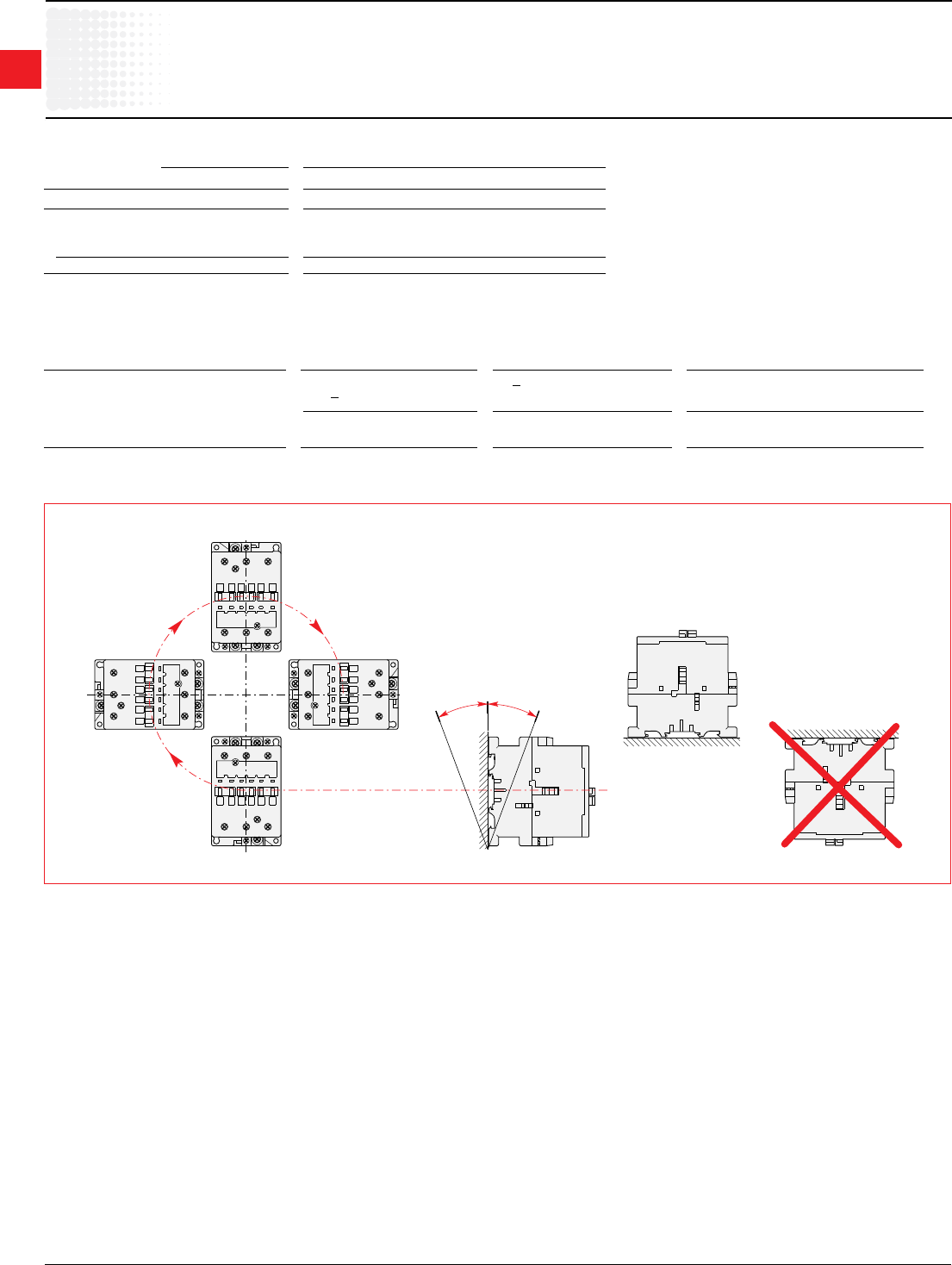
1
Across the line
contactors
1.62 Low Voltage Products & Systems
1SXU000023C0202 ABBInc.•888-385-1221•www.abb.us/lowvoltage
IEC Technical data
AL9–AL40
Mounting characteristics
Contactor types: AL AL9 AL12 AL16 AL26 AL30 AL40
Mountingpositions see"Conditionsforuse"
Mountingdistances Thecontactorscanbeassembledsidebyside
Mounting
onDINrail 35x7.5mm
accordingtoIEC715andEN50022/EN50023 35x15mm
byscrews(notsupplied) 2xM4
Conditions for Use
SustainableutilizationconditionsforcontactorsinvolvingatthesametimetheMountingposition,AmbienttemperatureandControlvoltageoperatinglimitsare
summarizedinthetablebelow.
Contactors Mountingposition Ambienttemperature Controlvoltage
1,1+30°,2,3,4,5 <55°C 0.85...1.1xUc
AL9–AL40 55...70°C Uc
6(Unauthorized)
Mounting Positions (seetheabovetableforauthorizedpositions)
Position 1
Position 3
Position 4
Position 2
Position 5
Position 1 ± 30°
-30°
+30°
Position 6
ABB
ABB
ABB
ABB
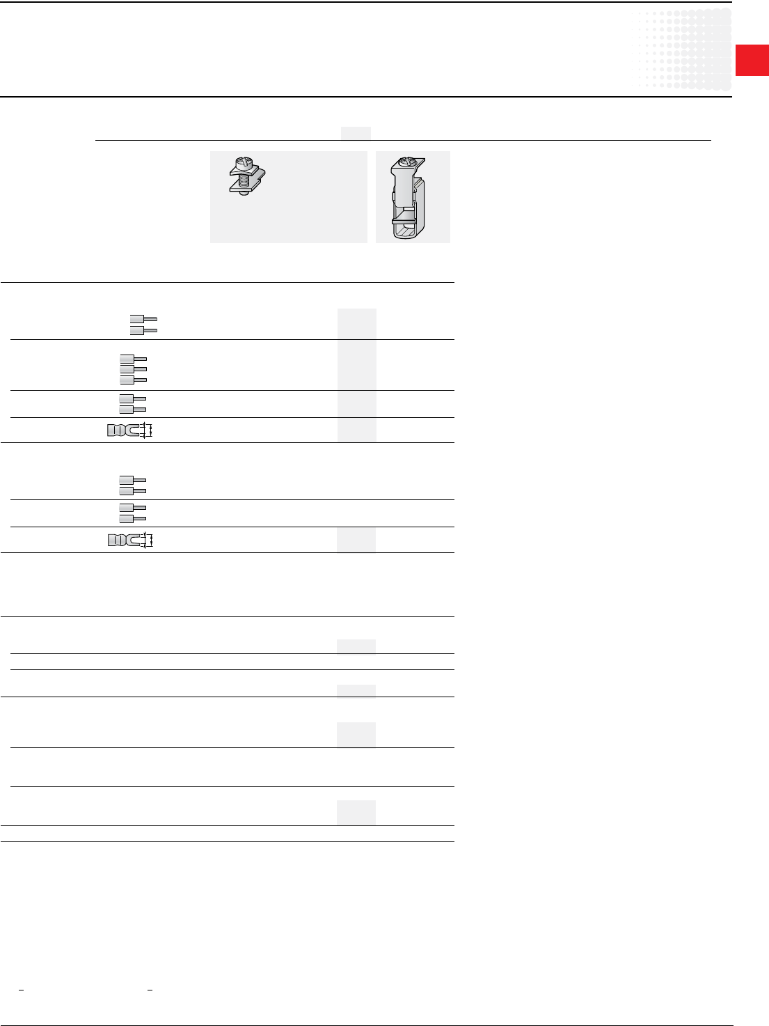
1
Across the line
contactors
Low Voltage Products & Systems 1.63
ABBInc.•888-385-1221•www.abb.us/lowvoltage 1SXU000023C0202
}
L
l
L
l
IEC Technical data
AL9–AL40
1 L <8andl>3.7forcoilterminal-L<10andl>4.2forbuilt-inauxiliaryterminals.
2WithLW110enlargementpiece.Seepage1.31.
Connecting Characteristics
Contactor types: AL AL9 AL12 AL16 AL26 AL30 AL40
Main terminals
withcableclamp withdouble
connector
2x(5.6x6.5mm)
Connectingcapacity(min....max.)
Mainconductors(poles)
Rigid: solid(≤4mm2) 1xmm2 1...4 1.5...6 2.5...16
stranded(≥6mm2) 2xmm2 1...4 1.5...6 2.5...16
Rigid with connector
singleforCucable mm2 – – – – – –
singleforAl/Cucable mm2 – – – – – –
doubleforAl/Cucable mm2 – – – – – –
Flexiblewithcableend 1xmm2 0.75...2.5 0.75...4 2.5 ... 10
2xmm2 0.75...2.5 0.75...4 2.5 ... 10
Barsorlugs Lmm≤ 8 10 – –
lmm> 3.7 4.2 – –
Auxiliaryconductors
(built-inauxiliaryterminals+coilterminals)
Rigidsolid 1xmm2 1...4
2xmm2 1...4
Flexiblewithcableend 1xmm2 0.75...2.5
2xmm2 0.75...2.5
Lugs Lmm≤ 8 18
lmm> 3.7 1 3.7
Degreeofprotectionacc.toIEC60947-1/ Protectionagainstdirectcontactacc.toVDE0106-Part.100
EN60947-1andIEC60529/EN60529
–Mainterminals IP20
–Coilterminals IP20
–Built-inauxiliaryterminals IP20
Screwterminals (deliveredinopenposition,screwsofunusedterminalsmustbetightened)
Mainterminals (+,-)pozidriv2screws
M3.5 M4 M5
Coilterminals M3.5(+,-)pozidriv2screwswithcableclamp
Built-inauxiliaryterminals (+,-)pozidriv2screwswithcableclamp
M3.5 M4 M5
Tightening torque
Mainpoleterminals
–recommended Nm/lb.in 1.00/9 1.7/15 2.30/20
–max. Nm 1.20 2.20 2.60
Coil terminals
–recommended Nm/lb.in 1.00/9
–max. Nm 1.20
Built-inauxiliaryterminals
–recommended Nm/lb.in 1.00/9 1.7/15 1.00/9
–max. Nm 1.20 2.20 1.20
Terminalmarkingandpositioning seepages1.35
1
Across the line
contactors
1.64 Low Voltage Products & Systems
1SXU000023C0202 ABBInc.•888-385-1221•www.abb.us/lowvoltage
IEC Technical data
EK110–EK1000
B2
A A B1
C2
C1
ABB
General Technical Data
Contactor types: EK... 110 150 175 210 370 550 1000
RatedinsulationvoltageUi
accordingtoIEC60947-4-1
V 1000
accordingtoUL/CSA
V 600
RatedimpulsewithstandvoltageU
imp.
kV 8
Standards DevicescomplyingwithinternationalstandardsIEC60947-1/60947-4-1
andEuropeanstandardsEN60947-1/60947-4-1
Airtemperatureclosetocontactor see"Conditionsforuse"page1.63,forcontrolvoltagelimitsandauthorizedmountingpositions
–ttedwiththermalO/Lrelay °C -25to+55
–withoutthermalO/Lrelay °C -40to+70
–forstorage °C -50to+70
Climaticwithstand acc.toIEC60068-2-30
Operatingaltitude m < 3000
Shock withstand
acc.IEC60068-2-27andEN60068-2-27
Mountingposition1(seepage1.63) 1/2sinusoidalshockfor15ms:nochangeincontactposition
Contactorinmakingorbreakingposition
Shockdirection: A,C1,C2: 10g
B1: 10 g
B2: 10 g
1
Across the line
contactors
Low Voltage Products & Systems 1.65
ABBInc.•888-385-1221•www.abb.us/lowvoltage 1SXU000023C0202
IEC Technical data
EK110–EK1000
{
M
3
M
3
Main Pole - Utilization Characteristics
Contactor types: EK... 110 150 175 210 370 550 1000
RatedoperationalvoltageUemax. V 1000 690
Ratedfrequencylimits Hz 25...400
Conventionalfree-airthermalcurrentIth
acc.toIEC60947-4-1,
opencontactorsø≤40°C A 200 250 300 350 550 800 1000
withconductorcross-sectionalarea
mm2 95 150 185 240 2x185 2x240 2x300
RatedoperationalcurrentIe/AC-1
forairtemperatureclosetocontactor
ø≤40°C A 200 250 300 350 550 800 1000
Uemax.690V ø≤55°C A 180 230 270 310 470 650 800
ø≤70°C A 155 200 215 250 400 575 720
withconductorcross-sectionalarea mm2 95 150 185 240 2x185 2x240 2x300
UtilizationcategorieAC-3
forairtemperatureclosetocontactor<55°C
RatedoperationalcurrentIeAC-3
220-230-240V A 120 145 210 400 550 –
3-phasemotors 380-400V A 120 145 210 400 550 –
415V A 120 145 210 400 550 –
440V A 120 145 210 370 550 –
500V A 120 145 210 370 550 –
690V A 120 120 210 370 550 –
1000V A 64 80 113 155 175 –
RatedoperationalpowerAC-3
1500r.p.m.50Hz 220-230-240V kW 30 45 59 110 160 –
1800r.p.m.60Hz 380-400V kW 55 75 110 200 280 –
3-phasemotors 415V kW 55 75 110 220 315 –
440V kW 59 75 110 220 315 –
500V kW 75 90 132 250 400 –
690V kW 110 110 160 355 500 –
1000V kW 90 110 160 220 250 –
RatedmakingcapacityAC-3
accordingtoIEC60947-4-1 10xIeAC-3 –
RatedbreakingcapacityAC-3
accordingtoIEC60947-4-1 8xIeAC-3 –
Short-circuitprotectionforcontactors
withoutthermalO/Lrelay-Motorprotectionexcluded
Ue <500Va.c.-gGtypefuse A 250 355 630 800 1000
Ratedshort-timewithstandcurrentI
cw
at40°Cambienttemp.,infreeair,
fromacoldstate 1s A 1700 1800 2300 5500 6800
10s A 900 1200 1680 5300 6400
30s A 600 700 1000 3700 4400
1min A 450 550 800 3000 3400
15 min A 210 250 320 1000 1200
Maximumbreakingcapacity
cosø=0.45(cosø=0.35forIe >100A)
at440V A 1400 1500 2000 5000 5400 –
at690V A 1100 1200 1700 5000 5400 –
Heatdissipationperpole
I
e/AC-1 W 10 13 18 40 60 80
I
e/AC-3 W 3 5 9 15 25 –
Max.electricalswitchingfrequency
–forAC-1 cycles/h 300 300
–forAC-3 cycles/h 300 –
–forAC-2,AC-4 cycles/h 150 120 –
Electricaldurability seepages1.75
Mechanicaldurability
–millionsofoperatingcycles 10 5
–max.mechanicalswitching
frequency cycles/h 3600 3600
1
Across the line
contactors
1.66 Low Voltage Products & Systems
1SXU000023C0202 ABBInc.•888-385-1221•www.abb.us/lowvoltage
IEC Technical data
EK110–EK1000
1"A"coilvoltagecodesseepage1.29.
250/60Hz"E"coilvoltagecodesseepage1.29.
Magnet System Characteristics for EK... Contactors - a.c. Operated
Contactor types: EK... 110 150 175 210 370 550 1000
RatedcontrolcircuitvoltageUc
–at50Hz V 24...500 48...500
–at60Hz V 24...600 110...600
Coiloperatinglimits ø<70°C
accordingtoIEC60947-4-1 0.85...1.1xUc
Drop-outvoltagein%ofUc roughly45...65%
Coilconsumption
Averagepull-invalue 50Hz1 VA 800 1100 3500
60Hz1 VA 900 1200 4000
50/60Hz2 VA/VA 500/500 630/630 3800/3400
Averageholdingvalue 50Hz1 VA/W 44/15 52/18 125/50
60Hz1 VA/W 52/18 65/22 140/60
50/60Hz2 VA/W 2.5/2.5 2.5/2.5 140/60
Operatingtime
betweencoilenergizationand:
–N.O.contactclosing ms 20...401/30...502 30 ... 60
–N.C.contactopening ms 15...351/25...452 25 ... 55
betweencoilde-energizationand:
–N.O.contactopening ms 7.5...151/95...1202 10 ... 20
–N.C.contactclosing ms 10...181/100...1252 13 ... 23
Magnet System Characteristics for EK... Contactors - d.c. Operated
Contactor types: EK... 110 150 175 210 370 550 1000
RatedcontrolcircuitvoltageUc
Vd.c. 12...220 24...220
Coiloperatinglimits ø<70°C
accordingtoIEC60947-4-1 0.85...1.1xUc
Drop-outvoltagein%ofUc roughly15...50%
Coilconsumption-Averagevalues
–pull-invalue W 500 630 1100
–holdingvalue W 2.5 2.5 20
Coil time constant
–open L/R ms 8 12
–closed L/R ms 50 60
Operatingtime
betweencoilenergizationand:
–N.O.contactclosing ms 30...50 60...80
–N.C.contactopening ms 27...47 55...75
betweencoilde-energizationand:
–N.O.contactopening ms 10...35
–N.C.contactclosing ms 13...38
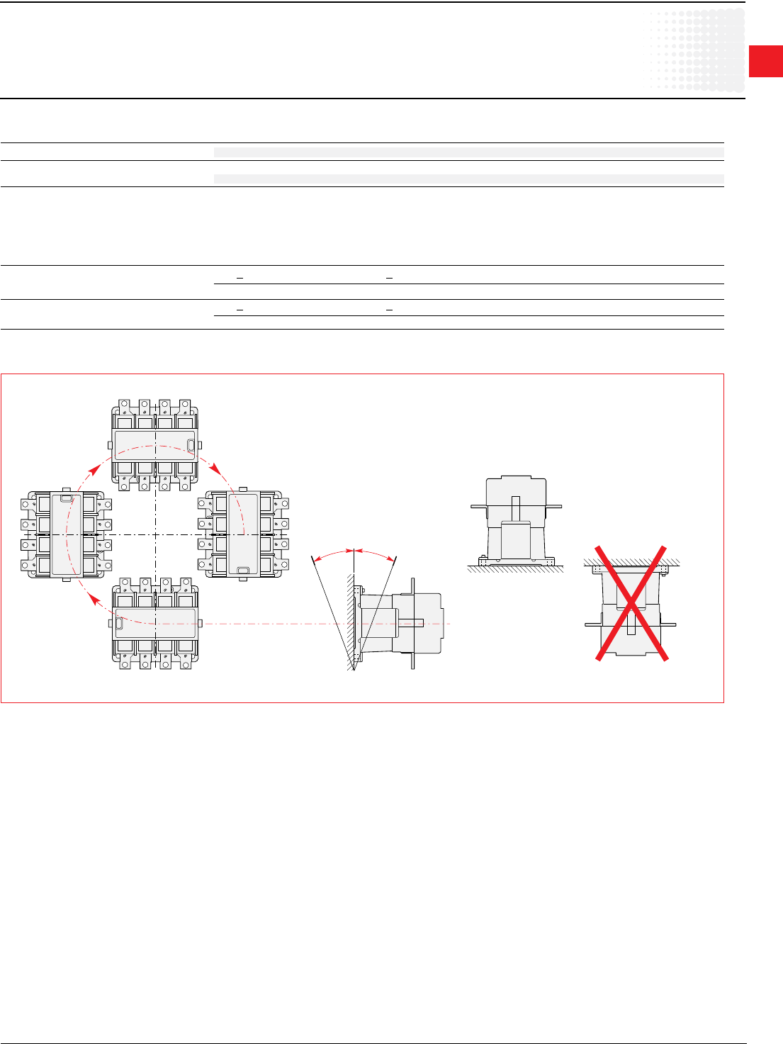
1
Across the line
contactors
Low Voltage Products & Systems 1.67
ABBInc.•888-385-1221•www.abb.us/lowvoltage 1SXU000023C0202
IEC Technical data
EK110–EK1000
1Dampingelementsaresupplied
ABB
ABB
ABB
ABB
Position 1
Position 3
Position 4
Position 2
Position 5
Position 1 ± 30°
-30°
+30°
Position 6
Mounting Characteristics
Contactor types: EK... 110 150 175 210 370 550 1000
Mountingpositions see"Conditionsforuse"
Fixing
byscrews(supplied) 4xM6 4xM6(1)
Conditions for Use
SustainableutilizationconditionsforcontactorsinvolvingatthesametimetheMountingposition,AmbienttemperatureandControlvoltageoperatinglimitsare
summarizedinthetablebelow.
Contactors Mountingposition Ambienttemperature Controlvoltage
E110...EK210 1,1+30°,3,4,5 <70°C 0.85...1.1xUc
2,6unauthorized
E370...EK1000 1,1+30°,2,3,4,5 <70°C 0.85...1.1xUc
6unauthorized
Mounting Positions (seetheabovetableforauthorizedpositions)
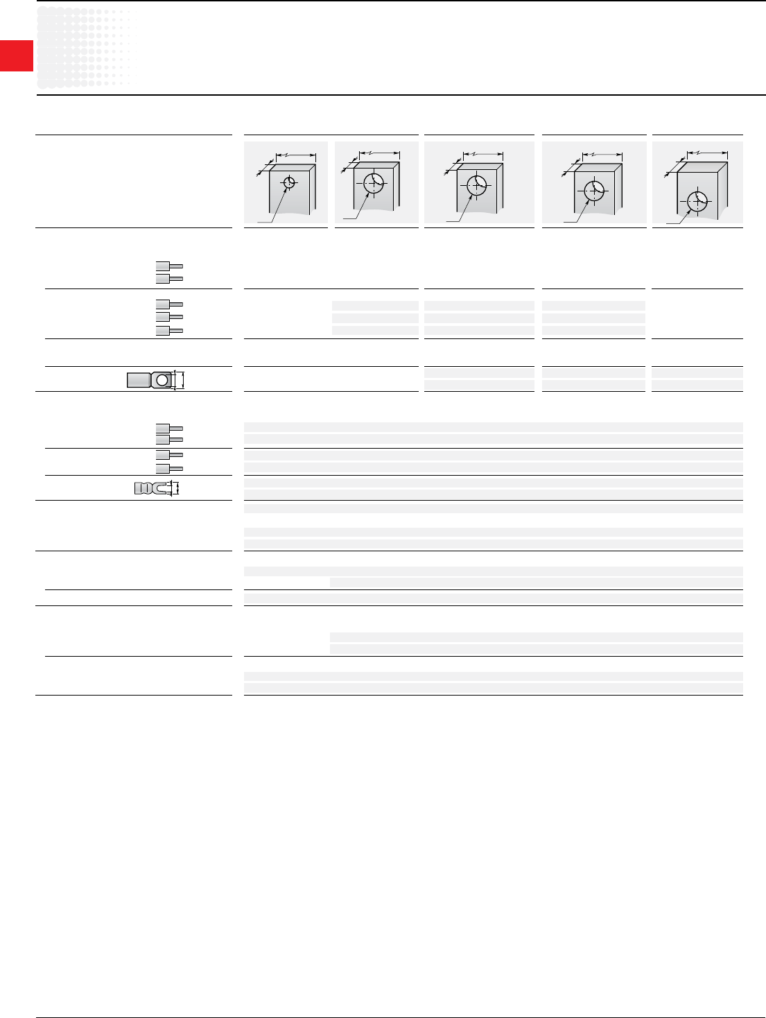
1
Across the line
contactors
1.68 Low Voltage Products & Systems
1SXU000023C0202 ABBInc.•888-385-1221•www.abb.us/lowvoltage
IEC Technical data
EK110–EK1000
L
l
L
ø
15
ø 6.6
4.5
20
ø 11
5
25
ø 11
6
40
ø 11
8
20
ø 11
4
Connecting Characteristics
Contactor types: EK... 110 150 175 210 370 550 1000
Main terminals
Flattype
Connectingcapacity(min....max.)
Mainconductors(poles)
Rigid: 1xmm2 – – – – – – –
2xmm2 – – – – – – –
Rigid with connector
singleforCucablemm2 25...120 25...185 70...300 –
singleforAl/Cucable mm2 10...70 35...120 70...300 95...300
doubleforAl/Cucable mm2 – – 2x35...185 2x95...300
Flexible
1xmm2 – – – – – – –
2xmm2 – – – – – – –
Bars or lugs L mm ≤ 30 30 33 55
Ø mm > 6 10 10 10
Auxiliaryconductors
(coilterminals)
Rigidsolid 1xmm2 0.5 ... 2.5
2xmm2 0.5 ... 2.5
Flexiblewithcableend
1xmm2 0.5 ... 2.5
2xmm2 0.5 ... 2.5
Lugs Lmm≤ 8
lmm> 3.7
Degreeofprotectionacc.toIEC60947-1/ Protectionagainstdirectcontactacc.toVDE0106-Part.100
EN60947-1andIEC60529/EN60529
–Mainterminals IP00
–Coilterminals IP20
Screw terminals
Mainterminals Screwsandbolts
M6 M10
Coilterminals(deliveredinopenposition) M3.5(+,-)pozidriv2screwswithcableclamp
Tightening torque
Mainpoleterminals
–recommended
Nm/lb.in
5/44 18/160
–max.
Nm
6 22
Coil terminals
–recommended
Nm/lb.in
1.00/9
–max.
Nm
1.20

1
Across the line
contactors
Low Voltage Products & Systems 1.69
ABBInc.•888-385-1221•www.abb.us/lowvoltage 1SXU000023C0202
IEC Technical data
Contactorelectricaldurability
andUtilizationcategories
General
Utilizationcategoriesdeterminethecurrentmakingandbreakingconditionsrelatingtothecharacteristicsoftheloadstobecontrolledbythecontactors.Interna-
tionalstandardIEC60947-4-1andEuropeanstandardEN60947-4-1arethestandardstobereferredto.
If IcisthecurrenttobebrokenbythecontactorandIetheratedoperationalcurrentnormallydrawnbytheload,then:
• CategoriesAC-1andAC-3:Ic=Ie
• CategoryAC-2:Ic=2.5xIe
• CategoryAC-4:Ic=6xIe
GenerallyspeakingIc=mxIewheremisamultipleoftheloadoperationalcurrent.
Onpages1.66-1.71,thecurvescorrespondingtocategoriesAC-1,AC-2,AC-3andAC-4representtheelectricaldurabilityvariationofstandardcontactorsin
relationtothebreakingcurrentIc .
Electricaldurabilityisexpressedinmillionsofoperatingcycles.
Thesecurveshavebeenplottedfor400V-50Hz3-phasecurrentsbutremainvalidupto690V-40...60Hzprovidedthatacheckiscarriedouttomakesure
thatattheoperationalvoltageUe,thecurrentIenormallydrawnbytheloaddoesnotexceedthevalueofthecontactorratedoperationalcurrent:Ie/AC-1for
categoryAC-1andIe/AC-3forcategoriesAC-3andAC-4.Thevaluesaregivenforeachtypeofcontactorinpages1.44,1.45,1.54,and1.61(TechnicalData).
Curve Utilization Mode
ElectricaldurabilityforecastandcontactorselectionforcategoriesAC-1,AC-2,AC-3orAC-4
• Notethecharacteristicsoftheloadtobecontrolled:
– Operationalvoltage ............................................................................................Ue
– Currentnormallydrawn ......................................................................................Ie (Ue/Ie/kWrelationformotors,+page0/0).
– Utilizationcategory ............................................................................................AC-1,AC-2,AC-3orAC-4
– Breakingcurrent .................................................................................................Ic=IeforAC-1andforAC-3;Ic=2.5xIeforAC-2;Ic=6xIeforAC-4
• DenethenumberofoperatingcyclesNrequired.
• Onthediagramcorrespondingtotheoperationalcategory,selectthecontactorwiththecurveimmediatelyabovetheintersectionpoint(Ic;N).
Electricaldurabilityforecastandcontactorselectionformixeddutymotorcontrol:AC-3(Ic=Ie)typeswitchingoffwhile"motorrunning"
and,occasionally,AC-4(Ic=6xIe)typeswitchingoffwhile"motoraccelerating".
• Notethecharacteristicsofthemotortobecontrolled:
– Operationalvoltage ............................................................................................Ue
– Currentnormallydrawnwhile"motorrunning" ..................................................Ie (Ue/Ie/kWrelationformotors,+0/0).
– BreakingcurrentforAC-3 ..................................................................................Ic=Ie
– BreakingcurrentforAC-4while"motoraccelerating" .......................................Ic=6xIe
– PercentageofAC-4operations .........................................................................K(onthebasisofthetotalnumberofoperatingcycles)
• DenethetotalnumberofoperatingcyclesNrequired.
• NotethesmallestcontactorratingcompatibleforAC-3(Ue/Ie)onpages2/62,2/63,2/73,and2/79.
• FortheselectedcontactormakeanoteofthefollowinginrelationtothevoltageusingdiagramAC-3page2/85andAC-4page2/86or2/87:
– Thenumberofoperatingcycles A for Ic=Ie (AC-3)
– ThenumberofoperatingcyclesB for Ic=6xIe (AC-4)
• CalculatetheestimatednumberofcyclesN'(N'isalwaysbelowA)
A
N'=
1+0.01K(A/B-1)
•IfN'istoolowinrelationtothetargetN,calculatetheestimatednumberofcyclesforahighercontactorrating.
Case of uninterrupted duty.
Amongthedifferentutilizationcategories,theuninterrupteddutyimpliesthefollowingremark.Thecombinatedeffectofenvironmentalconditionsandtheproper
temperatureoftheproductmayrequiresomedisposals.Asamatteroffact,forthisduty,theusedurationprevailsoverthenumberofoperatingcycles.
Forlongtermservice,somevericationsofpreventingmaintenanceareneededtocheckthefunctionalityoftheconcernedproduct(consultus).
Overadurationofveyears,intheseconditionsthecontactormightpresenthighinternalresistance.Werecommendtochangethecontactororchangethe
contacts.
1
Across the line
contactors
1.70 Low Voltage Products & Systems
1SXU000023C0202 ABBInc.•888-385-1221•www.abb.us/lowvoltage
1 3 5 7 9
1 3 5 7 9
1
3
5
7
9
1
3
5
7
9
1 3 5 7 9
1 3 5 7 9
1
3
5
7
9
10
1
0.1
0.2
0.3
0.5
3
5
10 100 10002 3 5 20 30 50 200 300 500
A 145
A 9
A 12
A 16
A 26
A 30
A 40
A 45
A 50
A 63
A 75
A 95
A 110
A 185
A 210
A 300
A 260
AF 400
AF 460
AF 580
AF 750
2
24
IEC Technical data
A9–AF750
Electricaldurability
Electrical Durability for AC-1 Utilization Category. Ambient Temperature < 55 °C
Switchingnon-inductiveorslightlyinductiveloads.ThebreakingcurrentIcforAC-1isequaltotheratedoperationalcurrentoftheload.
Millions of
operations
Breaking current Ic(A)
Example:
Ic/AC-1=24A–Electricaldurabilityrequired=2millionoperations.
UsingtheAC-1curvesaboveselecttheA30contactoratintersection" "(24A/2millionoperations).
1
Across the line
contactors
Low Voltage Products & Systems 1.71
ABBInc.•888-385-1221•www.abb.us/lowvoltage 1SXU000023C0202
10
1
10 100 10002 3 5 20 30 50 200 300 500
0.2
0.3
0.5
2
3
5
1 3 5 7 9
1
3
5
7
9
1
3
5
7
9
1 3 5 7 9 1 3 5 7 9
1 3 5 7 9 1 3 5 7 9
A 9
A 12
A 16
A 26
A 30
A 40
A 50
A 63
A 75
A 95
A 110
A 145
A 185
A 210
A 260
A300
AF 400
AF 460
AF 580
AF 750
1.5
79
1 3 5 7 9
1
3
5
7
9
1
3
5
7
9
1 3 5 7 9 1 3 5 7 9
1 3 5 7 9
1 3 5 7 9
10
1
10 100 10002 3 5 20 30 50 200 300 500
0.2
0.3
0.5
2
3
5
A 9
A 12
A 16
A 26
A 30
A 40
A 50
A 63
A 75
A 95
A 110
A 145
AF 400
AF 460
AF 580
AF 750
A 185
A 210
A 300
A 260
IEC Technical data
A9–AF750
Electricaldurability
Switching cage motors: starting and switching off running motors. The breaking current Ic for AC-3 is equal to the rated operational current Ie
(Ie=motorfullloadcurrent).
Electrical Durability for AC-3 Utilization Category-Ue <440V.AmbientTemperature<55°C
Millions of
operations
Breaking current Ic(A)
Electrical Durability for AC-3 Utilization Category-440V<Ue <690V.AmbientTemperature<55°C
Millions of
operations
Breaking current Ic(A)
Example:
Motorpower40kWforAC-3-Ue=400Vutilization–Electricaldurabilityrequired=1.5millionoperations.
40 kW, 400 V corresponds to Ie = 79 A. For AC-3: Ic = Ie. Select the A 110 contactor at intersection " " (79 A / 1.5 million operations) on the curves
(AC-3-Ue <440V).
1
Across the line
contactors
1.72 Low Voltage Products & Systems
1SXU000023C0202 ABBInc.•888-385-1221•www.abb.us/lowvoltage
30001000100102 3 5 20 30 50 200 300 500 2000 5000
10
1
0.1
0.005
0.01
0.02
0.03
0.05
0.3
0.5
2
3
5
1 3 5 7 9
1 3 5 7 9
1 3 5 7 9
1 3 5 7 9
1 3 5 7 9
1 3 5 7 9
1
3
5
7
9
1
3
5
7
9
1
3
5
7
9
1
3
5
7
9
1
3
5
7
9
1
3
5
7
9
A 9
A 12
A 16
A 26
A 30
A 40
A 50
A 63
A 75
A 95
A 110
A 260
A 300
A 145
A 185
A 210
0.2
510
A 9
A 12
A 16
A 26
A 30
A 40
A 50
A 63
A 75
A 95
A 110
A 260
A 300
A 145
AF 400
AF 460
AF 580
AF 750
A 185
A 210
0.2
510
IEC Technical data
A9–AF750
Electricaldurability
Electrical Durability for AC-2 or AC-4 Utilization Category-Ue <440V.AmbientTemperature<55°C
MaximumnumberofAC-2orAC-4operations: 300perhourforA9...A40contactors,
150perhourforA50...A300contactors.
Switching cage motors: starting, reverse operation and step-by-step operation. The breaking current Ic is equal to 2.5 x Ie for AC-2 and 6 x Ie for
AC-4,keepinginmindthatIeisthemotorratedoperationalcurrent(Ie=motorfull-loadcurrent).
Millions of
operations
Breaking current Ic(A)
Example:
Motorpower45kWforAC-4-Ue=400Vutilization–Electricaldurabilityrequired=0.2millionoperations.
45kW,400VcorrespondstoIe=85A.
ForAC-4:Ic=6xIe=510A-SelecttheA260contactoratintersection" "(510A/0.2millionoperations)onthecurves(AC-4-Ue <440V).
1
Across the line
contactors
Low Voltage Products & Systems 1.73
ABBInc.•888-385-1221•www.abb.us/lowvoltage 1SXU000023C0202
1 3 5 7 9
1 3 5 7 9
1 3 5 7 9
1 3 5 7 9
1 3 5 7 9
1 3 5 7 9
10
1
0.1
0.005
0.01
0.02
0.03
0.05
0.2
0.3
0.5
2
3
5
50001000100102 3 5 20 30 50 200 300 500 2000 3000
1
3
5
7
9
1
3
5
7
9
1
3
5
7
9
1
3
5
7
9
1
3
5
7
9
1
3
5
7
9
427
A 9
A 12
A 16
A 26
A 30
A 40
A 50
A 63
A 75
A 95
A 110
A 145
A 185
A 210
A 260
A 300
AF 400
AF 460
AF 580
AF 750
0.04
IEC Technical data
A9–AF750
Electricaldurability
Electrical Durability for AC-2 or AC-4 Utilization Category-440V<Ue <690V.AmbientTemperature<55°C
MaximumnumberofAC-2orAC-4operations: 300perhourforA9...A40contactors,
150perhourforA50...A300contactors.
Switchingcagemotors:starting,reverseoperationandstep-by-stepoperation.ThebreakingcurrentIcisequalto2.5xIeforAC-2and6xIe for
AC-4,keepinginmindthatIeisthemotorratedoperationalcurrent(Ie=motorfull-loadcurrent).
Millions of
operations
Breaking current Ic(A)
Example:
Motorpower59kWforAC-4-Ue=600Vutilization–Electricaldurabilityrequired=0.04millionoperations.
Asstatedonpage0/0:59kW,600VcorrespondstoIe=71.1A.
ForAC-4:Ic=6xIe=426.6A-SelecttheA145contactoratintersection" "(427A/0.04millionoperations)onthecurves
(AC-4-440V<Ue <690V).

1
Across the line
contactors
1.74 Low Voltage Products & Systems
1SXU000023C0202 ABBInc.•888-385-1221•www.abb.us/lowvoltage
IEC Technical data
AL9—AL40
Electricaldurability
Consult
factory
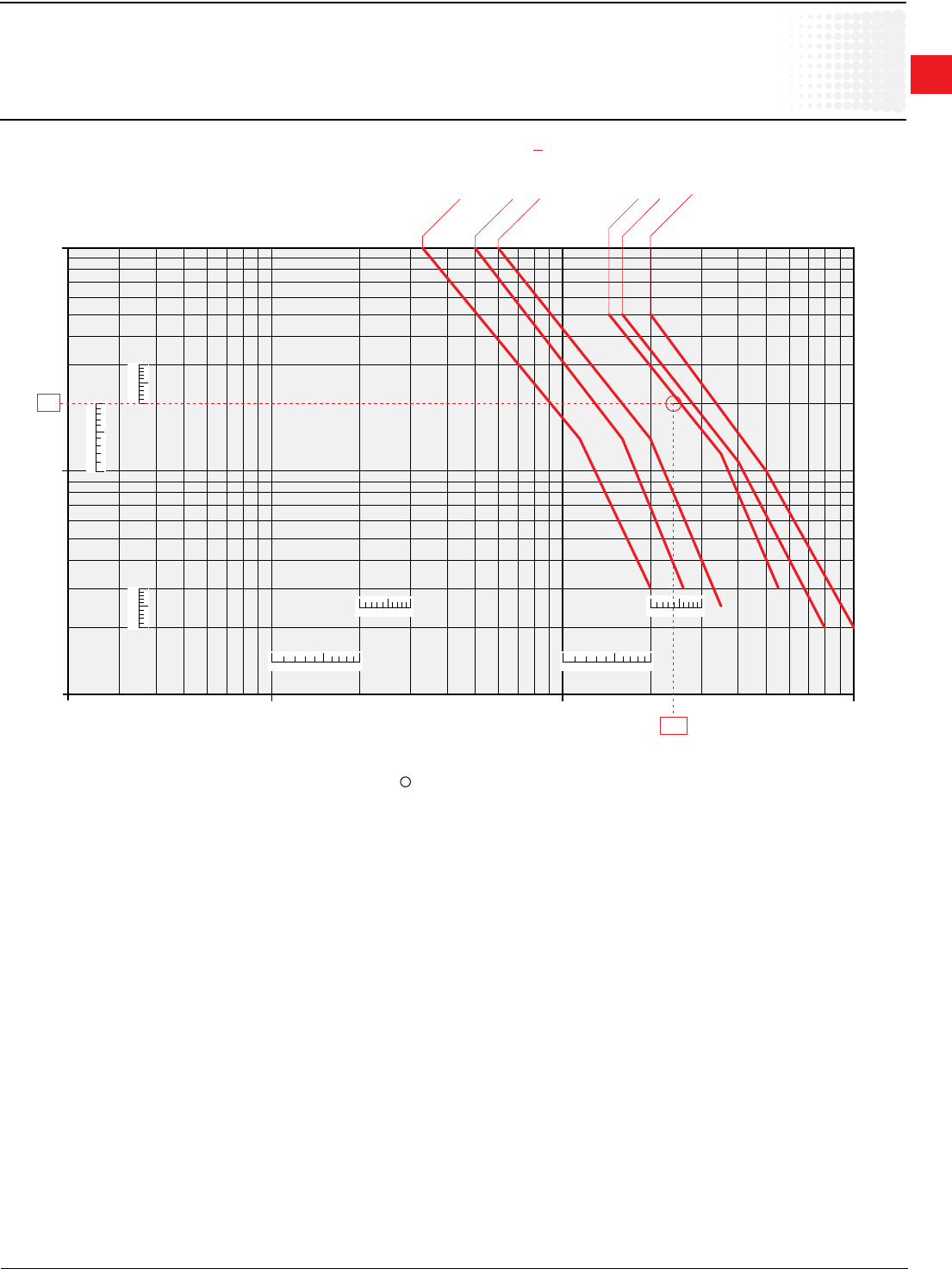
1
Across the line
contactors
Low Voltage Products & Systems 1.75
ABBInc.•888-385-1221•www.abb.us/lowvoltage 1SXU000023C0202
1 3 5 7 9
1 3 5 7 9
1
3
5
7
9
1
3
5
7
9
1
3
5
7
9
1 3 5 7 9
1 3 5 7 9
10
1
0.1
0.2
0.3
0.5
3
5
10 100 10002 3 5 20 30 50 200 300 500
EK 1000
EK 110
EK 150
EK 175
EK 210
EK 370
EK 550
2
240
IEC Technical data
EK110—EK1000
Electricaldurability
Electrical Durability for AC-1 Utilization Category. Ambient Temperature < 55 °C
Switchingnon-inductiveorslightlyinductiveloads.ThebreakingcurrentIcforAC-1isequaltotheratedoperationalcurrentoftheload.
Millions of
operations
Breaking current Ic(A)
Example:
Ic/AC-1=240A–Electricaldurabilityrequired=2millionoperations.
UsingtheAC-1curvesaboveselecttheEK370contactoratintersection" "(240A/2millionoperations).
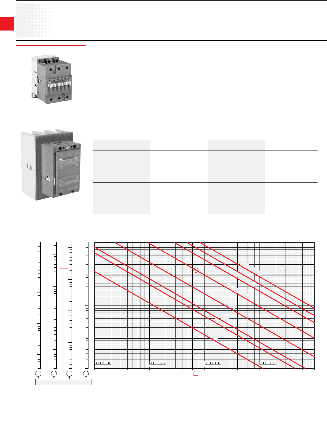
1
Across the line
contactors
1.76 Low Voltage Products & Systems
1SXU000023C0202 ABBInc.•888-385-1221•www.abb.us/lowvoltage
1
10
100
1000
10000
1
2000
20
2
3
5
30
50
200
300
500
3000
5000
2.5
10
100
1000
10000
2.5
25000
20000
2000
20
3
5
30
50
200
300
500
3000
5000
4
10
100
1000
10000
20000
40000
4
2000
20
5
30
50
200
300
500
3000
5000
30000
1 10 100 1000 100001.5
10
100
1000
10000
1.5
15000
20
2
3
5
30
50
200
300
500
3000
5000
2 3 5 20 30 50 200 300 500 2000 5000
Cross-sectional area (Cu) in mm
2
Coil pull-in consumption: in VA for a.c. fed contactors
in W for d.c. fed contactors
single line length in m.
1 3 5 7 9 1 3 5 7 9 1 3 5 7 9 1 3 5 7 9
2000
660 V - 690 V
500 V
380 V - 400 V
220 V - 230 V
110 V
60 V
48 V
24 V
70
IEC Technical data
Inuence of the length of conductors
used in contactor control circuits
A50-30-00
AF460-30-11
Permissible single length for the control circuit conductors on contactor closing:
Dependingonthecoilpull-inpowerconsumptiononthesupplyvoltageandonthecontrolcircuitconductorcross-sectionalarea.
Example:
A 9 contactor
Coilvoltage:230V50Hz,contactorcoilpull-inpowerconsumption:70VA,
controlcircuitconductorcross-sectionalarea:Cu1.5mm2.
Max. permissible length: 2000 m.
Undercertainconditionstheexcessivelengthofthecontrolcircuitconductorsmaypreventthecontactorfromcarrying
outclosingandopeningorders.
– noclosing: duetoexcessivevoltagedrop(ina.c.ord.c.).
– noopening: duetoexcessivecapacitance(ina.c.).
Contactor Closing (contactor with a.c. or d.c. fed control circuit)
The voltage drop is due to the pull-in current (pull-in power) and to the resistance of the control circuit
conductors.
Thetableandgraphbelowcanbeusedtodeterminethesinglelengthoflinefeeders(distancebetweenthecontroldevice
andthecontactorcoil)inrelationto:
l thecoilpull-inconsumption.
l thesupplyvoltage.
l theconnectingwirecross-sectionalarea.
Thegraphhasbeendrawnforamax.linevoltagedropof5%.
Coilpull-inconsumption(averagevalue)
Contactors a.c. control circuit Contactors d.c. control circuit
50Hz
A9,12,16 70VA AE9,12,16 90W
A26,30,40 120VA AE26,30,40 110W
A45,50,63,75 180VA AE45,50,63,75 200W
A95,110 450VA AE95,110 400W
A145,185 700VA BC9,16,18,25,30 7W
A210,260,300 1700VA
AF45,50,63,75 210VA AF45,50,63,75 190W
AF95,110 350VA AF95,110 400W
AF145,185 430VA AF145,185 500W
AF210,260,300 470VA AF210,260,300 520W
AF400,460 890VA AF400,460 990W
AF580,750 850VA AF580,750 950W
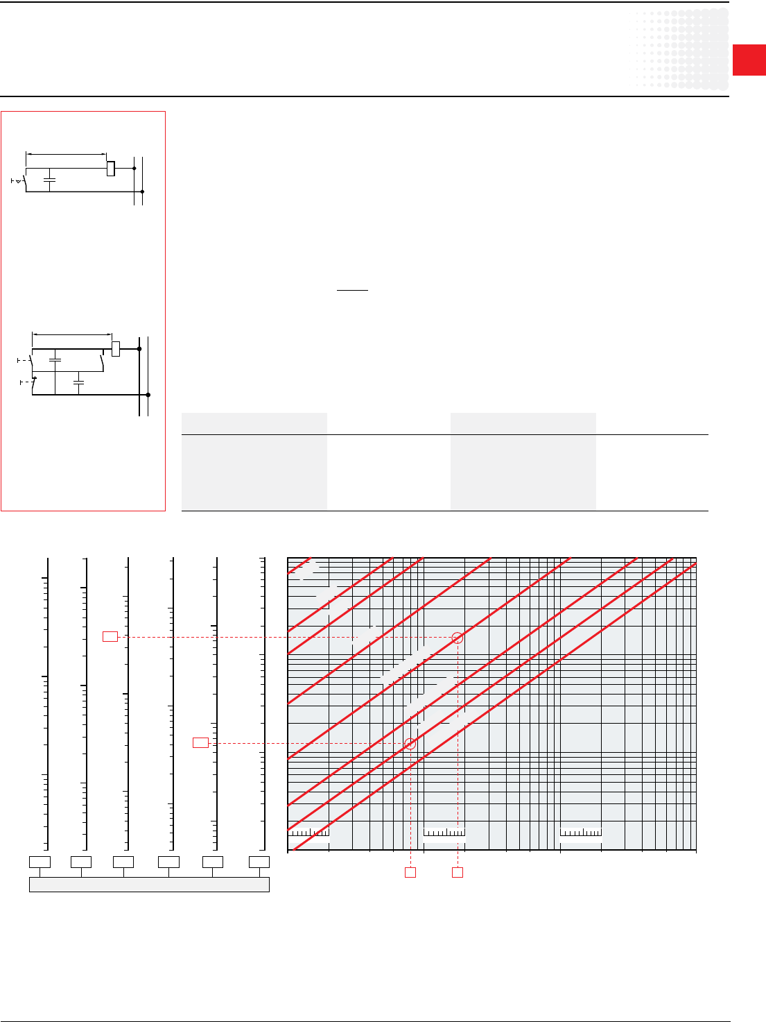
1
Across the line
contactors
Low Voltage Products & Systems 1.77
ABBInc.•888-385-1221•www.abb.us/lowvoltage 1SXU000023C0202
0.60
Coil holding consumption in VA
Single line length in metres
10
100
1000
2
1.7
3
5
20
30
50
200
300
500
1700
1 10 100 10002 3 5 20 30 50 200 300 500
0.10
10
100
1000
10000
20
30
50
200
300
500
2000
3000
5000
0.20
10
100
1000
20
30
50
200
300
500
2000
3000
5000
5
0.30
10
100
1000
3.3
5
20
30
50
200
300
500
2000
3300
0.40
10
100
1000
2.5
5
20
30
50
200
300
500
2000
2500
0.50
10
100
1000
2
3
5
20
30
50
200
300
500
2000
Line capacitance in
m
F/km
380
380 V - 400 V
660 V - 690 V
220 V - 230 V
110 V
60 V
48 V
24 V
500 V
188
60
1 3 5 7 9 1 3 5 7 91 3 5 7 9
IEC Technical data
Inuence of the length of conductors
used in contactor control circuits
Permissible single length for the control circuit conductors on contactor opening:
Dependingonthecoilholdingpowerconsumption,onthesupplyvoltageandonthecontrolcircuitconductorcapacity.
Single control line length
Wiring diagram A
Via maintained pushbutton and 2-core
cable(withacapacityof0.2µF/km,for
example).
Single control line length
Wiring diagram B
Viamomentarypushbuttonplushold-in
contactand3-corecable(withacapacity
of2x0.2=0.4µF/km,forexample).
Examples:
A 16 contactor
CoilvoltageUc =500V,50Hz,8VAcontactorcoilholdingconsum-
ption,controltype:diagramA,viamaintainedpushbutton,and2-core
cablewithacapacityof0.2µF/km.
Max. permissible length: 60 m.
A 50 contactor
CoilvoltageUc=230V,50Hz,18VAcontactorcoilholdingconsum-
ption,controltype:diagramBviamomentarypushbutton,hold-incon-
tactand3-corecablewithacapacityof2x0.2µF/km=0.4µF/km.
Max. permissible length: 380 m.
Contactor Opening (contactorwitha.c.fedcontrolcircuit)
Undercertainconditions,ana.c.operatedcontactordoesnotopenwhenthecontrolcircuitisde-energized.
Thisisduetoacriticalcapacityoftheexcessivelylongcontrolcircuitlineandthetypeofcontactorcoilcontrollayout
(seediagramsAandBopposite).
Thismaybecausedbythefollowingfactors:
• highcontrolvoltage.
• lowcoilholdingconsumption.
• lowcontactordrop-outvoltage(accordingtoIEC60947-4-1:0.2to0.75xUc).
Iflineslongerthanthoseindicatedarerequired,thefollowingmeasuresmustbetaken:
• selectacontactorwithahigherrating.
• selectalowercontrolvoltage.
• connect"RP"impedancesinparallelwiththecontactorcoil:
103
sizingofparallelresistor:RP = (withCinµF)
C
Thetableandgraphbelowcanbeusedtodeterminethesinglelengthoflinefeeders(distancebetweenthecontrol
deviceandthecontactorcoil)inrelationto:
• thecoilholdingconsumptionVA.
• thesupplyvoltage.
• thecapacityinµF/km(dependingonthecontrollayout).
WiringdiagramsAandBoppositeshowtwosupplyandcoilcontrolwiringexamples.
Coil holding consumption (averagevalue)
Contactors a.c. control circuit Contactors a.c. control circuit
50Hz 50Hz
A9,12,16 8VA AF45,50,63,75 7VA
A26,30,40 12VA AF95,110, 7VA
A45,50,63,75 18VA AF145,185, 12VA
A95,110 22VA AF210,260,300 10VA
A145,185 35VA AF400,460 12VA
A210,260,300 60VA AF580,750 12VA
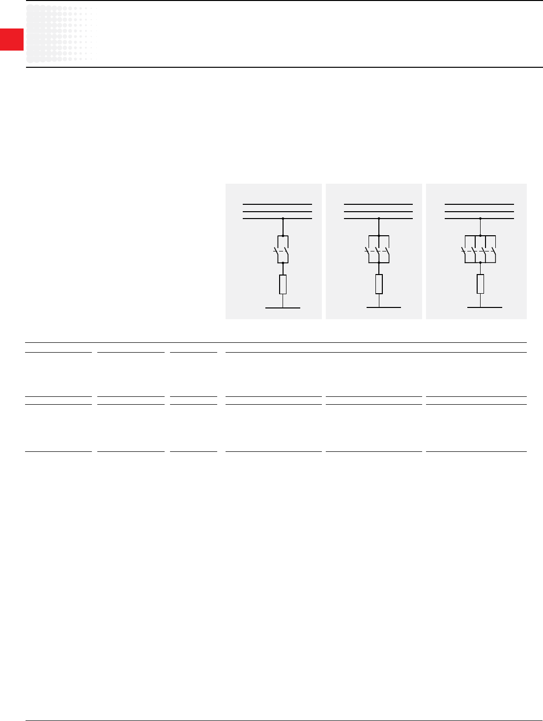
1
Across the line
contactors
1.78 Low Voltage Products & Systems
1SXU000023C0202 ABBInc.•888-385-1221•www.abb.us/lowvoltage
L2
L1
L3
N
L2
L1
L3
N
L2
L1
L3
N
IEC Technical data
Parallelconnectionofmainpoles
Parallel Connection of Main Poles
Purpose:Increasingthea.c.resistiveload.
Remarks:
–Parallelconnectionofmainpolestoincreasethed.c.resistiveloadisnotacceptable.
–Parallelconnectionofmainpolesdoes'ntincreasethebreakingcapacity.
Means:Thepolescanbeconnectedinparallelviashortingbars.Seepage1.30.
–LPandLHforparallelconnectionof2poles,
–LYandLFforparallelconnectionof3poles,
ThetablebelowshowstheupratingfactorforIe/AC-1max.inrelationtothenumberofpolesinparallelandforamax.switchingfrequency.
2polesin// 3polesin// 4polesin//
Contactors FactortobeappliedtotheratedoperationalcurrentIe/AC-1toobtainthepermissible
a.c.Operated d.c.Operated Cycles/h currentIe/AC-1with"n"polesinparallel.
3-pole contactors
A9...A75 AF50...AF75
AF50...AF75 AE...,TAE... 600 1.6 2.2 –
AL... A95...A300 AF145...AF750 300 1.6 2.2 –
AF145...AF750
4-pole contactors
A9...A75 AF45...AF75
AF45...AF75 AE...,TAE... 600 1.6 2.2 2.6
AL... EK... EK... 300 1.6 2.2 2.8

1
Across the line
contactors
Low Voltage Products & Systems 1.79
ABBInc.•888-385-1221•www.abb.us/lowvoltage 1SXU000023C0202
IEC Technical data
Temporaryorintermittentduty
Utilization of Contactors for Temporary / Intermittent Duty
ThetablebelowshowsthefactortobeappliedtotheratedoperationalcurrentIe /AC-1toobtainthepermissibleoperationalcurrentIe /AC-1in
relationtotheswitchingfrequencyandthecurrentowtimepercycle.
Operating cycles per hour 120 60 20 6 2 1
Currentowtime FactortobeappliedtotheratedoperationalcurrentIe /AC-1max.
percycleinseconds. toobtainthepermissiblecurrentIe /AC-1fortemporary/intermittentduty.
5 2.8 3.4 4 4.7 5 5.2
10 2.2 2.6 3 3.4 3.7 3.8
20 1.6 2 2.4 2.6 2.7 2.8
30 – 1.7 2.1 2.2 2.3 2.4
40 – 1.5 1.9 2.0 2.1 2.2
60 – – 1.7 1.8 1.8 1.9
Example:
A9contactor(intermittentduty,resistiveload)
RatedoperationalcurrentIe /AC-1at55°C(seepage1.42) 22A
Switchingfrequency 2operations/h
Currentowtimepercycle 20s
FactortobeappliedtothecurrentIe /AC-1 2.7
Permissiblecurrent:2.7x22= 59A

1
Across the line
contactors
1.80 Low Voltage Products & Systems
1SXU000023C0202 ABBInc.•888-385-1221•www.abb.us/lowvoltage
Altitude
Referstotheheightofthesitewheretheequipmentislocated,expressedin
metersabovethesealevel.
Ambient temperature
Temperatureoftheairsurroundingtheunit.
Circuits
• Auxiliary circuit
Alltheconductingpartsofacontactor,intendedtobeincludedinacircuit
different from the main circuit and the control circuit of the contactor e.g.
signalization,interlockingcircuitsetc…
• Control circuit
Alltheconductingpartsofacontactor(otherthanthemaincircuit)includedin
acircuitusedfortheclosingoperation,oropeningoperation,orboth,ofthe
contactor.
• Main circuit
Alltheconductingpartsofacontactorincludedinthecircuitwhichitisdesigned
tocloseoropen.
Coil operating range
ExpressedasamultipleoftheratedcontrolcircuitvoltageUcforthelowerand
upperlimits.
Cycle duration
Totaltimeoftheon-load+off-loadperiod.
Endurance / durability
• Electrical endurance
Numberofon-loadoperatingcycles(i.e.withcurrentonthemaincontacts)a
contactorcanachieve,variesdependingontheutilizationcategory.
• Mechanical endurance
Numberofoff-loadoperatingcycles(i.e.withoutcurrentonthemaincontacts)a
contactorcanachieve.
Inching
Energizingamotoronceorrepeatedlyforshortperiodstoobtainsmall
movementsofthedrivenmechanism.
Insulation class according to the VDE 0110 and NFC 20-040
Characterizescontactorssuitabilityinaccordancewithenvironmentand
utilizationconditions.Acontactorcanbeclassieddependingonitsown
clearanceandcreepagedistancesintheinsulationclassesA,B,C,Dwhich
correspondtodifferentinsulationvoltagevalues.
TheinsulationclassCisapplicabletomostoftheindustrialapplications.
EquipmentdescribedinthiscataloguecorrespondtoinsulationclassC.
Intermittent duty
Dutyinwhichthemaincontactsofacontactorremainclosedforperiodsoftime
insufcienttoallowthecontactortoreachthermalequilibrium,thecurrent-
carryingperiodsbeingseparatedbyoff-loadperiodsofsufcientdurationto
restoreequalityoftemperaturewiththecoolingmedium.
Mounting positions
Statedbythemanufacturer.Pleasenoterestrictionswhenapplicable.
On-load factor
Ratioofthecurrentowtimetothetotaltimeofthecyclex100.
Plugging
Stoppingorreversingamotorquicklybyinterchangingtwosupplyleadswhilst
the motor is running.
Rated breaking capacity; Rated making capacity
Valueofr.m.scurrentacontactorcanbreakormakeataxedvoltagevalue,
withintheconditionsspeciedbythestandards,dependingontheutilization
category.
Technical data
Technicaltermsanddenitions
Rated control circuit voltage Uc
Controlvoltagevalueforwhichthecontrolcircuitoftheunitissized.
Rated insulation voltage Ui
Voltagevaluewhichdesignatestheunitandtowhichdielectrictests,clearance
andcreepagedistancesarereferred.
Rated impulse withstand voltage Uimp
Thehighestpeakvalueofanimpulsevoltageofprescribedform1.2/50,which
doesnotcausebreakdownunderspeciedconditionsoftest.
Rated operating current Ie
Currentvaluestatedbythemanufacturerandtakingintoaccounttherated
operatingvoltageUe,theratedfrequency,theratedduty,theutilizationcategory,
theelectricalcontactlifeandthetypeoftheprotectiveenclosure.
Rated operating voltage Ue
Voltagevaluetowhichutilizationcharacteristicsofthecontactorarereferred,i.e.
phasetophasevoltagein3phasecircuits.
Conventional thermal current Ith
Valueofcurrentthecontactorcanwithstandwithpolesinclosedposition,in
freeairforaneighthourduty,withoutthetemperatureriseofitsvariousparts
exceedingthelimitsspeciedbythestandards.
Resistance to shocks
Requirementsapplicableforinstancetovehicles,craneoperationorswitchgear
slide-inmodulesystems.
Atthequotedpermissible«g»values,contactorsmustnotundergoachangein
switchingstateandO/Lrelaysmustnottrip.
Resistance to vibrations
Requirementsapplicabletoallthevehicles,vesselsandothersimilartransport
systems.Atthequotedamplitudeandvibrationfrequencyvalues,theunitmust
becapabletoachievetherequiredduty.
Short-circuit protection coordination
Achievedbyusingback-upprotectiondevicessuchascircuit-breakers,H.R.C.
fuses or standard fuses.
Co-ordinationtypesa,b,caredenedinIEC292-1publication,VDE0660,NFC
63-650standards.Co-ordinationtypes"1"and"2"aredenedinIEC947-4-1.
• Type 1 co-ordination
Therehasbeennodischargeofpartsbeyondtheenclosure.Damagetothe
contactorandtheoverloadrelayisacceptable.
• Type 2 co-ordination
Nodamagetotheoverloadrelayorotherpartshasoccurred,exceptthatwelding
ofcontactororstartercontactsispermitted,iftheyareeasilyseparated.
Switching frequency
Numberofoperatingcyclesperhour.
Time
• Closing time
Timebetweenenergizationofthecoiluntilthemomentthecontactsoftherst
currentpathtobeclosedactuallyclose.
• Opening time
Timefromthebeginningofstatecausingbreakinguntilthemomentwhenthe
contactsofthelastcurrentpathtobeopenedareopen.
• Minimal operation time
Shortestcontroldurationtoensurecompleteclosingoropeningofacontactor.
• Short time current permissible
Valueofcurrentwhichthecontactorcanwithstandinclosedpositionforashort
timeperiodandwithinspeciedconditions.
• Time constant
Ratioofinductancetotheresistance:L/R=mH/Ohm=ms.
1
Across the line
contactors
Low Voltage Products & Systems 1.81
ABBInc.•888-385-1221•www.abb.us/lowvoltage 1SXU000023C0202
IEC Technical data
Standards,utilizationcategories
Standards
•IECstandards158-1:“Contactors”andseriesIEC292:
“Motor-starters”havebeenrevisedandreplacedbythenewIEC947-4-1(1990-05):“ContactorsandMotor-starters”referringtoIEC947-1(1988):“Generalrules”
ThenewstandardswillconstitutethebasisofthefutureEuropeanandNationalstandards,notyetrevised.
Thereforetheratingsindicatedinthiscatalogareestablishedaccordingtotheformerandthefuturestandards.
•Mainchangesandadditionsinthenewstandardsare:
•Revisionandextensionoftheutilizationcategories(seehereafter)
•Replacementofthecoordinationclassestypesa,b,cbynewtypes:“1”(approximatelyequivalenttoformerclass“a”)and“2”(approximatelyequivalenttoformer
class“c”)withadditionalrequirements.
•Classicationofthethermaloverloadrelaysintrippingclasses:10A;10;20and30dependingontheirtrippingtimes,at1.5and7.2timestheirsettingcurrent,inorder
tocovermotorapplicationsdependingontheirstartingtimes.Class10AisadaptedformotorsaccordingtoIEC34-1.
•Introductionofteststoverifytheconnectingcapabilityandthemechanicalstrengthofterminals.
Utilization categories
Acontactordutyischaracterizedbytheutilizationcategoryplusindicationoftheratedoperatingvoltageandtheratedoperatingcurrent(seeatRated…),orthemotor
characteristics.
Utilization categories for contactors according to IEC 947-4-1
Alternatingcurrent: AC-1 Non-inductiveorslightlyinductiveloads,resistancefurnaces.Powerfactor0.7-0.8(slightlyinductive).
AC-2 Slip-ringmotors:starting,switching-off.
AC-3 Squirrel-cagemotors:starting,switching-offmotorsduringrunning.Powerfactor0.4-0.5(AC-3).
AC-4 Squirrel-cagemotors:starting,plugging,inching.
AC-5a Switchingofelectricdischargelampcontrols.
AC-5b Switchingofincandescentlamps.
AC-6a Switchingoftransformers.
AC-6b Switchingofcapacitorbanks
AC-8a Hermeticrefrigerantcompressormotorcontrolwithmanualresettingofoverloadreleases
AC-8b Hermeticrefrigerantcompressormotorcontrolwithautomaticresettingofoverloadreleases.
Directcurrent: DC-1 Non-inductiveorslightlyinductiveloads,resistancefurnaces.
DC-3 Shuntmotors:starting,plugging,inching.Dynamicbreakingofd.c.motors.
DC-5 Seriesmotors:starting,plugging,inching.Dynamicbreakingofd.c.motors.
DC-6 Switchingofincandescentlamps
Alternatingcurrent:AC-12 Controlofresistiveloadsandsolidstateloadswithisolationbyoptocouplers.
AC-13 Controlofsolidstateloadswithtransformerisolation.
AC-14 Controlofsmallelectromagneticloads(≤72VA).
AC-15 Controlofelectromagneticloads(>72VA).
Directcurrent: DC-12 Controlofresistiveloadsandsolidstateloadswithisolationbyoptocouplers.
DC-13 Controlofelectromagnets.
DC-14 Controlofelectromagneticloadshavingeconomyresistorsincircuit.
Utilization categories for contactor relays according to IEC 947-5-1
UtilizationcategoriesAC-1,AC-2,AC-3,AC-4andDC-1,DC-3,DC-5aremaintainedwithslightlymoreseveretests.
Othercategorieshavebeenaddedinordertostandardizespecicapplications.Infactsomecontactorapplicationsandthespeciccriteriacharacterizingthetypesof
loadcontrolledcanmodifytherecommendedutilizationcharacteristics.Thesemajorapplicationsare,forexample:
Switching of capacitor banks
Thisapplicationischaracterizedbyhighcurrentpeakswhenswitching-onthecontactorandpresenceofharmoniccurrentsonuninterruptedduty.Forthisapplication,
IEC947-4-1hasdenedanutilizationcategoryAC-6b.Practicalratingshavetobedenedaccordingtotestsor,inabsenceoftests,byacalculationindicatedinIEC
947-4-1.
Switching of transformers
Thisapplicationischaracterizedbyhighcurrentpeaksoncontactorclosingduetomagnetizationphenomena.ThecorrespondingutilizationcategoryaccordingtoIEC
947-4-1isAC-6a.Ratingsarederivedfromtest-valuesforAC-3orAC-4accordingtoformulagiveninIEC947-4-1.
Switching of lighting circuits
Thecurrentpeaksoncontactorclosingandpowerfactorvarydependingonthetypeoflamps,theswitchingmethodusedandifcompensationsystemsarettedor
not.
IEC947-4-1containstwostandardutilizationcategories
AC-5aforswitchingoftheelectricdischargelamps.
AC-5bforswitchingofincandescentlamp.
1
Across the line
contactors
1.82 Low Voltage Products & Systems
1SXU000023C0202 ABBInc.•888-385-1221•www.abb.us/lowvoltage
1 Toobtainfullloadcurrentsfor265Vand277Vmotors,decreasecorresponding220–240Vratingsby13percentand17percent.
UL/CSA Technical data
Motor data
1/10 3.0 — — 1.65 — — 1.5 — — 1.0 — — — — — — —
1/8 3.8 — — 2.1 — — 1.9 — — 1.2 — — — — — — —
1/6 4.4 — — 2.4 — — 2.2 — — 1.4 — — — — — — —
1/4 5.8 — — 3.2 — — 2.9 — — 1.8 — — — — — — —
1/3 7.2 — — 4.0 — — 3.6 — — 2.3 — — — — — — —
1/2 9.8 4.0 4.4 5.4 2.2 2.4 4.9 2.0 2.2 3.2 1.3 2.5 1.0 1.1 2.0 0.8 0.9
3/4 13.8 4.8 6.4 7.6 2.6 3.5 6.9 2.4 3.2 4.5 1.8 3.5 1.2 1.6 2.8 1.0 1.3
1 16.0 6.4 8.4 8.8 3.6 4.6 8.0 3.2 4.2 5.1 2.3 4.0 1.6 2.1 3.2 1.3 1.7
11/2 20.0 9.0 12.0 11.0 5.0 6.6 10.0 4.5 6.0 6.4 3.3 5.0 2.3 3.0 4.0 1.8 2.4
2 24.0 11.8 13.6 13.2 6.5 7.5 12.0 5.9 6.8 7.7 4.3 6.0 3.0 3.4 4.8 2.4 2.7
3 34.0 16.6 19.2 18.7 9.2 10.6 17.0 8.3 9.6 10.9 6.1 8.5 4.2 4.8 6.8 3.3 3.9
5 56.0 26.4 30.4 30.8 14.5 16.8 28.0 13.2 15.2 17.9 9.7 14.0 6.6 7.6 11.2 5.3 6.1
71/2 80.0 38.0 44.0 44.0 21.0 24.2 40.0 19.0 22.0 27.0 14.0 21.0 9.0 11.0 16.0 8.0 9.0
10 100.0 48.0 56.0 55.0 26.4 30.8 50.0 24.0 28.0 33.0 18.0 26.0 12.0 14.0. 20.0 10.0 11.0
15 135.0 72.0 84.0 75.0 39.6 46.2 68.0 36.0 42.0 44.0 27.0 34.0 18.0 21.0 27.0 14.0 17.0
20 — 94.0 108.0 96.8 52.0 60.0 88.0 47.0 54.0 56.0 34.0 44.0 23.0 27.0 35.0 19.0 22.0
25 — 118.0 136.0 121.0 65.0 75.0 110.0 59.0 68.0 70.0 44.0 55.0 29.0 34.0 44.0 24.0 27.0
30 — 138.0 160.0 150.0 76.0 88.0 136.0 69.0 80.0 87.0 51.0 68.0 35.0 40.0 54.0 28.0 32.0
40 — 180.0 208.0 194.0 100.0 115.0 176.0 90.0 104.0 112.0 66.0 88.0 45.0 52.0 70.0 36.0 41.0
50 — 226.0 260.0 238.0 125.0 143.0 216.0 113.0 130.0 139.0 83.0 108.0 56.0 65.0 86.0 45.0 52.0
60 — — — — 147.0 160.0 — 133.0 154.0 — 103.0 — 67.0 77.0 — 53.0 62.0
75 — — — — 183.0 212.0 — 166.0 192.0 — 128.0 — 83.0 96.0 — 66.0 77.0
100 — — — — 240.0 273.0 — 218.0 248.0 — 165.0 — 109.0 124.0 — 87.0 99.0
125 — — — — — 344.0 — — 312.0 — 208.0 — 135.0 156.0 — 108.0 125.0
150 — — — — — 396.0 — — 360.0 — 240.0 — 156.0 180.0 — 125.0 144.0
200 — — — — — 528.0 — — 480.0 — 320.0 — 208.0 240.0 — 167.0 192.0
250 — — — — — 663.0 — — 602.0 — 403.0 — — 302.0 — — 242.0
300 — — — — — — — — — — 482.0 — — 361.0 — — 289.0
350 — — — — — — — — — — 560.0 — — 414.0 — — 336.0
400 — — — — — — — — — — 636.0 — — 477.0 — — 382.0
500 — — — — — — — — — — 786.0 — — 590.0 — — 472.0
110–120V 200–208V 220–240V 380–415V1 440–480V 550–600V
Horse Single Two Three Single Two Three Single Two Three Single Three Single Two Three Single Two Three
power phase phase phase phase phase phase phase phase phase phase phase phase phase phase phase phase phase
Ampere ratings of 3 phase, AC induction motors
00.00
00.00
Inches
[Millimeters]
1
Across the line
contactors
Low Voltage Products & Systems 1.83
ABB Inc. • 888-385-1221 • www.abb.us/lowvoltage 1SXU000023C0202
A26
3.54
90
2.13
54
3.15
80
1.77
45
0.17
4.2
70
2.76
3.69
93.6
3.44
87.3
0.35
9
A26+VM5
3.54
90
4.84
123.0
5.25
133.4
5.25
133.4
3.69
93.6
3.44
87.3
0.35
9
4.03
102
70
2.76 3.15
80
4.64
117.9
0.17
4.2
1.77
45
2.72
69
2.32
59
4.64
117.9
0.22
5.5
A9-16,N
2.91
74
1.73
44
1.972.36
60 50
1.38
35
0.18
4.5
2.91
74
2.68
68
0.22
5.5
A9-16+VM5
5.50
139.7
2.91
74
4.06
103
1.38
35
2.36
60
1.97
50
2.32
59
0.18
4.5
2.91
74
2.68
68
0.22
5.5
A/AE26 — Contactor, 3 pole
A/AE26 + VM5 or VE5 — Mechanically interlocked contactor, 3 pole
Approximate dimensions
A/AE9 – A/AE26, 3 pole
A/AE9 – A/AE16 — Contactor, 3 pole
A/AE9 – A/AE16 + VM5 or VE5 — Mechanically interlocked contactor, 3 pole
00.00
00.00
Inches
[Millimeters]
1
Across the line
contactors
1.84 Low Voltage Products & Systems
1SXU000023C0202 ABB Inc. • 888-385-1221 • www.abb.us/lowvoltage
A30,40
4.26
108.3
4.02
102
0.35
9
3.15
80
1.77
0.17
4.2
70
2.13
54
3.54
90
45
2.76
A30,40+VM5
2.32
59
90
4.84
123.0
5.25
133.4
5.25
133.4
3.54
70 3.15
80
4.64
117.9
0.17
4.2
1.77
45 2.72
69
4.64
117.9
0.22
5.5
4.02
102
0.35
9
4.26
108.3
4.60
117
2.76
A( E ) 50-75
2.76
70
4.25
108
4.00
101.5
0.39
10
0.24
6.2
2.36
60
3.54
90
3.94
100
3.22
82
4.33
110
A50-75+VM5
6.10
155
6.62
168.2
6.50
165
110
4.33
4.25
108
4.00
101.5
0.39
10
4.54
115.3
5.87
149
6.00
152.5
0.22
5.5
3.00
76.3
0.24
6.2
90
3.94
100
3.54
2.36
60
3.35
85
A/AE30 & A/AE40 — Contactor, 3 pole
A/AE30 & A/AE40 + VM5 or VE5 — Mechanically interlocked contactor, 3 pole
Approximate dimensions
A/AE30 – A/AE/AF75, 3 pole
A/AE/AF50 – A/AE/AF75 — Contactor, 3 pole
A/AE/AF50 – A/AE/AF75 + VM5 or VE5 — Mechanically interlocked contactor, 3 pole
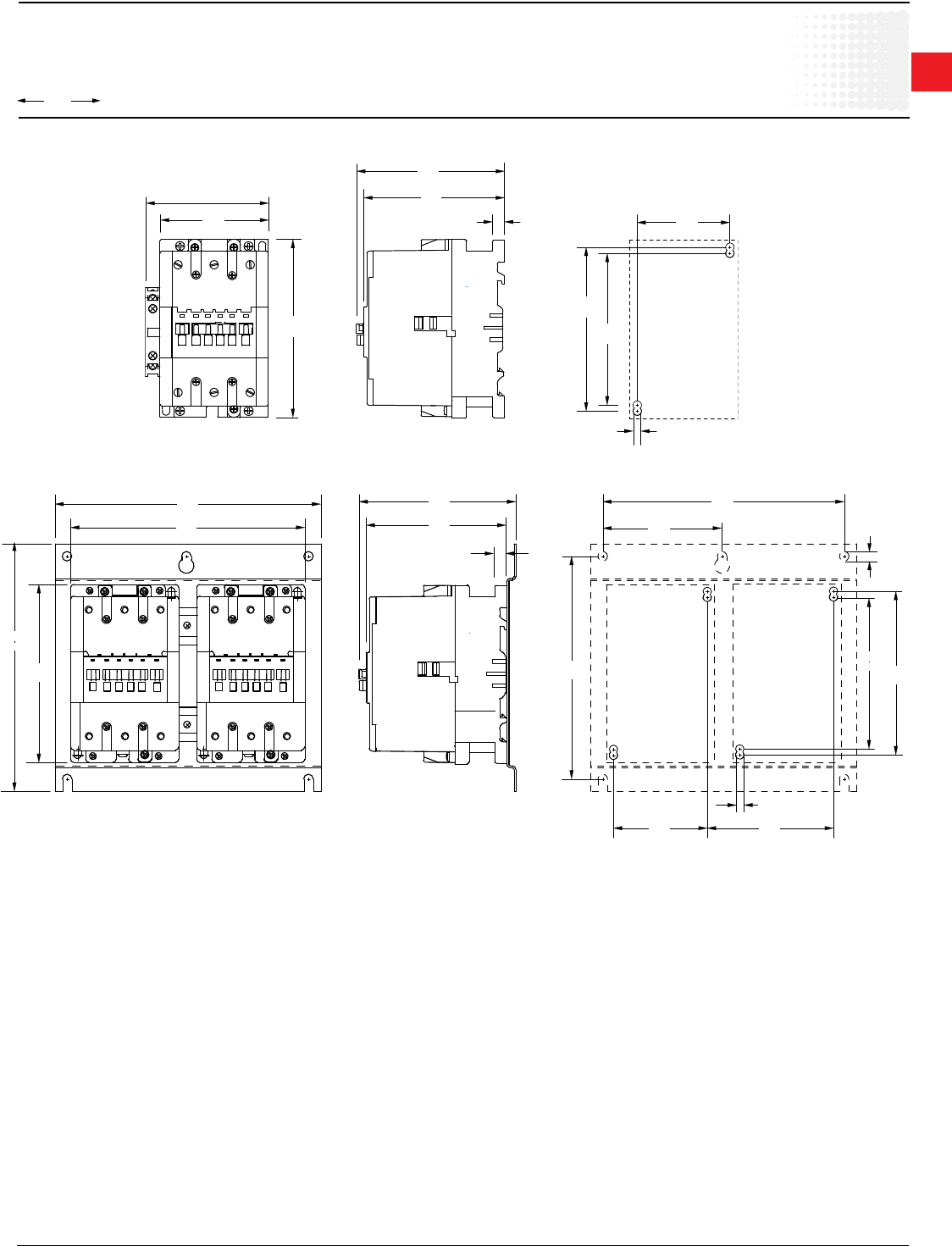
00.00
00.00
Inches
[Millimeters]
1
Across the line
contactors
Low Voltage Products & Systems 1.85
ABB Inc. • 888-385-1221 • www.abb.us/lowvoltage 1SXU000023C0202
A( E ) 95-A110
90
3.54
0.39
10
123.5
4.61
117
4.86
3.07
78
0.2
4
126
4.96
136
5.35
148
5.83
4.02
102
A95-110+VM5
7.68
195
8.10
205.7
148
4.33
8.70
221
4.86
123.5
0.39
10
5.17
131
7.28
185
7.91
200.1
3.90
99
0.31
8
126
5.35
136
3.07
78
4.13
105
0.24
6.2
4.96
Approximate dimensions
A/AE/AF95 & A/AE/AF110, 3 pole
A/AE/AF95 & A/AE/AF110 — Contactor, 3 pole
A/AE/AF95 & A/AE/AF110 + VE5 — Mechanically interlocked contactor, 3 pole
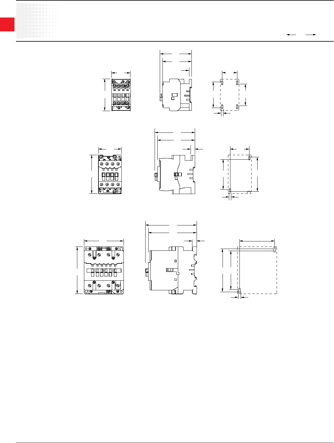
00.00
00.00
Inches
[Millimeters]
1
Across the line
contactors
1.86 Low Voltage Products & Systems
1SXU000023C0202 ABB Inc. • 888-385-1221 • www.abb.us/lowvoltage
A9-16,N
2.91
74
1.73
44
1.972.36
60 50
1.38
35
0.18
4.5
2.91
74
2.68
68
0.22
5.5
A26
3.54
90
2.13
54
3.15
80
1.77
45
0.17
4.2
70
2.76
3.69
93.6
3.44
87.3
0.35
9
A45
0.24
6.2
3.62
92
4.33
110
3.23
82
3.54
90
3.94
100
4.71
119.5
4.45
113
0.39
10
Approximate dimensions
A/AE9 – A/AE/AF75, 4 pole
A/AE9 – A/AE16 — Contactor, 4 pole
A/AE26 — Contactor, 4 pole
A/AE/AF45 – A/AE/AF75 — Contactor, 4 pole
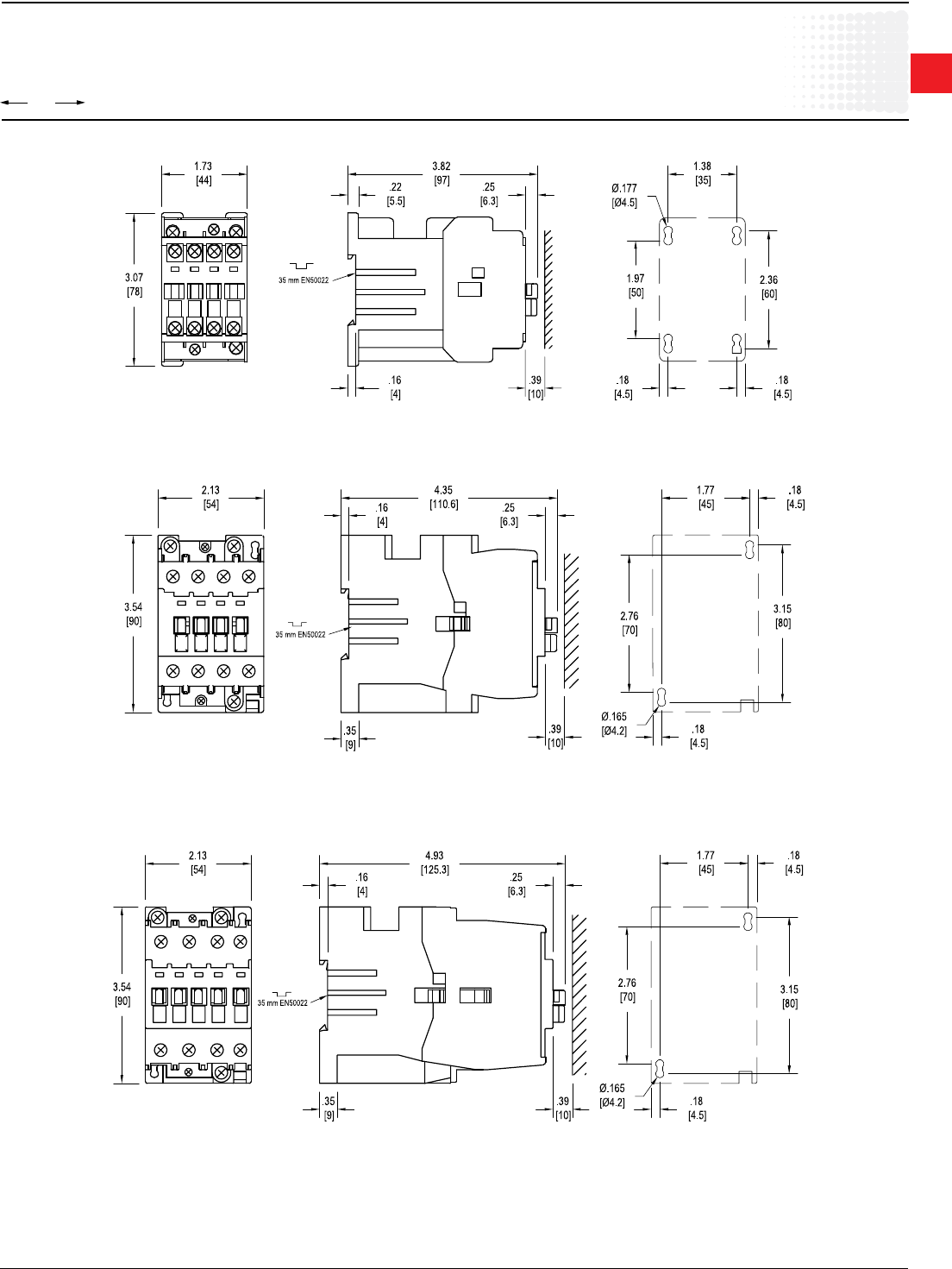
00.00
00.00
Inches
[Millimeters]
1
Across the line
contactors
Low Voltage Products & Systems 1.87
ABB Inc. • 888-385-1221 • www.abb.us/lowvoltage 1SXU000023C0202
Approximate dimensions
AL9 – AL40, 3 & 4 pole
AL9, AL12,, AL16 — Contactor, 3 & 4 pole
AL26 — Contactor, 3 & 4 pole
AL30, AL40 — Contactor, 3 pole
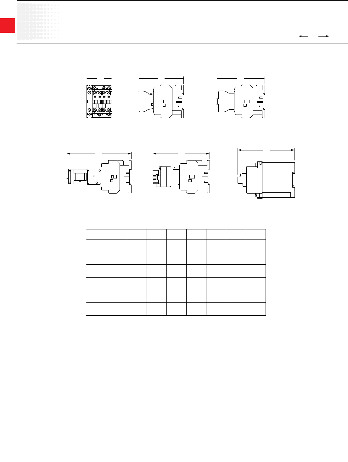
00.00
00.00
Inches
[Millimeters]
1
Across the line
contactors
1.88 Low Voltage Products & Systems
1SXU000023C0202 ABB Inc. • 888-385-1221 • www.abb.us/lowvoltage
MECH INTERLOCK D.C.
OPERATED
SIDE MOUNTED
AUXILIARY
A
SINGLE POLE
TOP MOUNTED
AUXILIARY
B C
FOUR POLE
TOP MOUNTED
AUXILIARY
ON-POSITION
LATCH
E
D
PNEUMATIC
TIMER
F
TYPE
A/AE9-16 IN
MM
A
2.20
56
B
3.96
100.5
C
4.21
107
D
5.71
145
E
5.00
127
F
–
–
A/AE26 IN
MM
2.20
56
4.72
119.8
4.97
126.3
6.47
164.3
5.76
146.3
–
–
A/AE30-40 IN
MM
2.20
56
5.30
134.5
5.55
141
7.05
179
6.34
161
–
–
A/AE/AF50-75 IN
MM
3.23
82
5.27
133.9
5.52
140.3
7.03
178.5
6.32
160.4
–
–
A/AE/AF45 IN
MM
4.09
104
5.73
145.5
5.98
152
7.48
190
6.77
172
–
–
A/AE/AF95-110 IN
MM
4.02
102
5.91
150
6.16
156.5
–
–
–
–
–
–
Approximate dimensions
Accessories for A/AE9 – A/AE/AF110
A/AE9 – A/AE40
A/AE/AF50 – A/AE/AF110
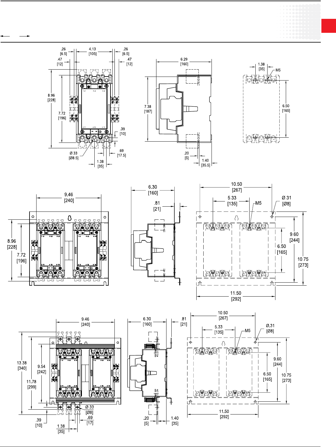
00.00
00.00
Inches
[Millimeters]
1
Across the line
contactors
Low Voltage Products & Systems 1.89
ABB Inc. • 888-385-1221 • www.abb.us/lowvoltage 1SXU000023C0202
Approximate dimensions
A/AF145 – A/AF185
A/AF145 & A/AF185
A/AF145, A/AF185 with mechanical interlock
A/AF145, A/AF185 reversing
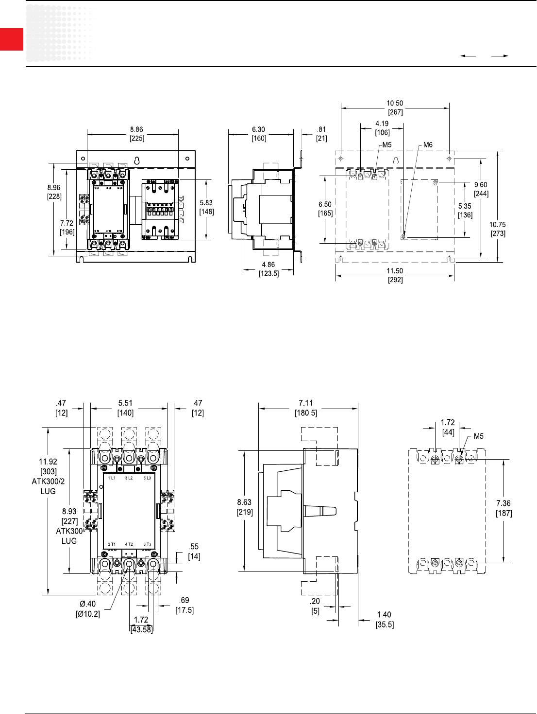
00.00
00.00
Inches
[Millimeters]
1
Across the line
contactors
1.90 Low Voltage Products & Systems
1SXU000023C0202 ABB Inc. • 888-385-1221 • www.abb.us/lowvoltage
Approximate dimensions
A/AF145 – A/AF300
A/AF145 – A/AE/AF95-110 mechanically interlocked
A/AF210, A/AF260, A/AF300
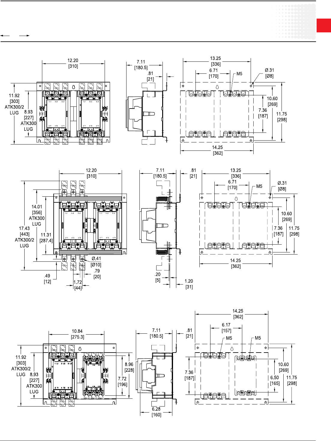
00.00
00.00
Inches
[Millimeters]
1
Across the line
contactors
Low Voltage Products & Systems 1.91
ABB Inc. • 888-385-1221 • www.abb.us/lowvoltage 1SXU000023C0202
Approximate dimensions
A/AF210 – A/AF300
A/AF210, A/AF260, A/AF300 with mechanical interlock
A/AF210, A/AF145 with mechanical interlock
A/AF210, A/AF260, A/AF300 reversing +TA450
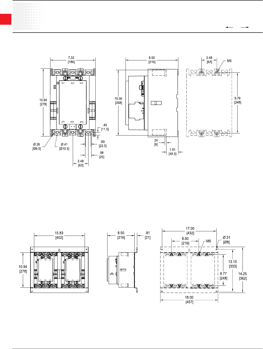
00.00
00.00
Inches
[Millimeters]
1
Across the line
contactors
1.92 Low Voltage Products & Systems
1SXU000023C0202 ABB Inc. • 888-385-1221 • www.abb.us/lowvoltage
Approximate dimensions
AF400 – AF460
AF400, AF460
AF400, AF460 with mechanical interlock
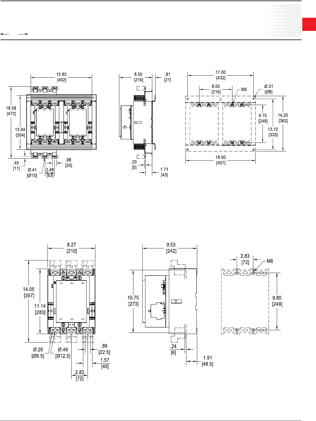
00.00
00.00
Inches
[Millimeters]
1
Across the line
contactors
Low Voltage Products & Systems 1.93
ABB Inc. • 888-385-1221 • www.abb.us/lowvoltage 1SXU000023C0202
Approximate dimensions
AF400 – AF750
AF580 – AF750
AF400, AF460 reversing
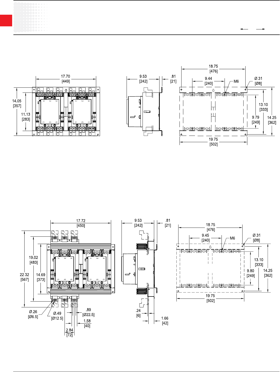
00.00
00.00
Inches
[Millimeters]
1
Across the line
contactors
1.94 Low Voltage Products & Systems
1SXU000023C0202 ABB Inc. • 888-385-1221 • www.abb.us/lowvoltage
AF580 – AF750 with mechanical interlock
Approximate dimensions
AF580 – AF750
AF580 – AF750 reversing
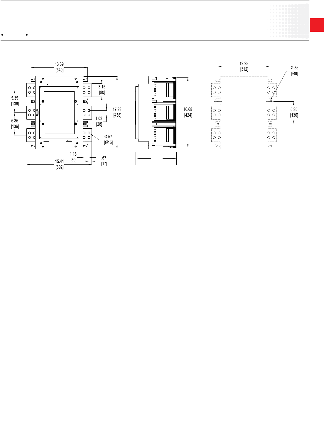
00.00
00.00
Inches
[Millimeters]
1
Across the line
contactors
Low Voltage Products & Systems 1.95
ABB Inc. • 888-385-1221 • www.abb.us/lowvoltage 1SXU000023C0202
9.6
[244]
Approximate dimensions
AF1350 – AF1650
AF1350 – AF1650
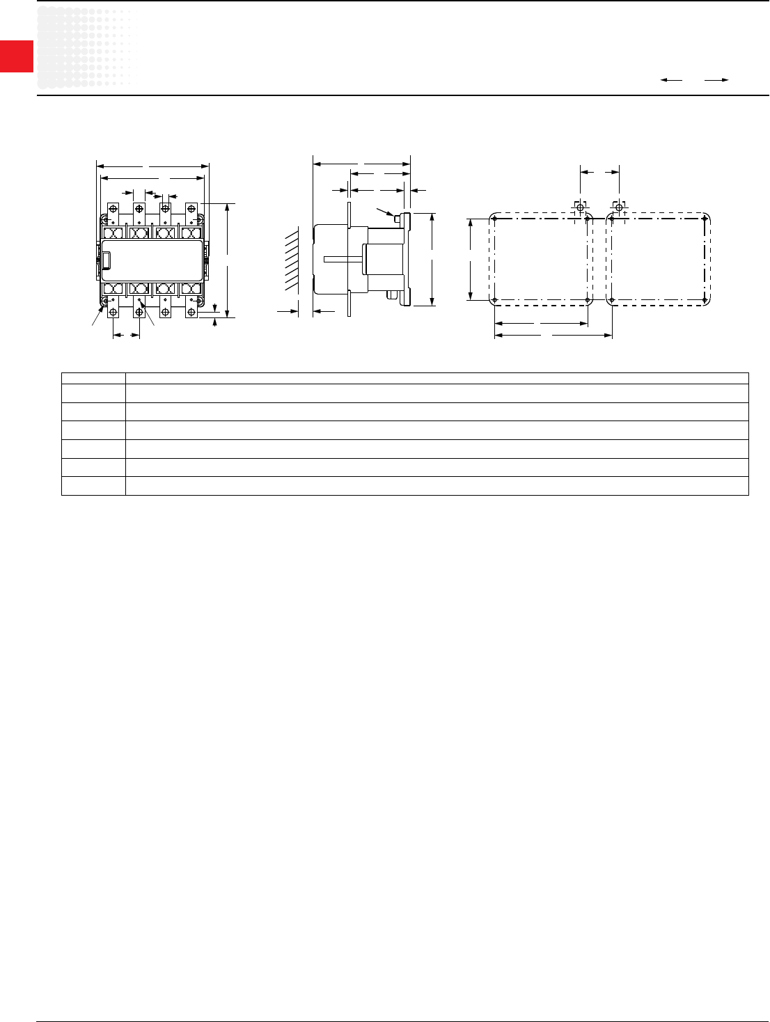
00.00
00.00
Inches
[Millimeters]
1
Across the line
contactors
1.96 Low Voltage Products & Systems
1SXU000023C0202 ABB Inc. • 888-385-1221 • www.abb.us/lowvoltage
EK110-550
C
C2
C1
F1
E
T
T1
P
P1
PE
H
DG
H1
K1
F
B1
B
M6 M4
B
6.50
165
6.50
165
EK 110
EK 150
in
mm
in
mm
B1
5.35
136
5.35
136
C1
5.51
140
5.51
140
E
1,57
40
1.57
40
C
4.72
120
4.72
120
D
0.26
6.6
0.43
11
K1H1
6.14
156
6.77
172
F1
1.69
43
1.65
42
H
6.14
156
6.14
156
F
1.61
41
1.65
42
G
0.59
15
0.79
20
P P1 T
0.39
10
0.39
10
T1
0.16
4
0.16
4
0.30
7.5
0.39
10
6.08
154.5
6.08
154.5
4.03
102.3
4.03
102.3
7.91
201
7.91
201
EK 175
EK 210
in
mm
in
mm
6.93
176
6.93
176
5.51
140
5.51
140
0.59
15
0.59
15
6.30
160
6.30
160
0.43
11
0.43
11
7.80
198
7.80
198
2.64
67
2.64
67
6.14
156
6.14
156
1.77
45
1.77
45
0.79
20
0.79
20
0.39
10
0.39
10
0.20
5
0.20
5
0.39
10
0.39
10
6.77
172
6.77
172
4.20
106.7
4.20
106.7
10.63
270
10.63
270
EK 370
EK 550
in
mm
in
mm
9.61
244
9.61
244
7.87
200
7.87
200
1.57
40
1.57
40
8.66
220
8.66
220
0.43
11
0.43
11
10.71
272
10.71
272
2.76
70
2.76
70
8.78
223
8.78
223
2.64
67
2.64
67
0.98
25
0.98
25
0.91
23
0.91
23
0.24
6
0.24
6
0.49
12.5
0.49
12.5
8.88
225.5
8.88
225.5
5.49
139.5
5.49
139.5
EK 1000
Approximate dimensions
EK110 – EK550, 4 pole
