CSM_NE1A SCPU_Series_DS_E_6_3
2014-11-11
: Pdf 105916-Attachment 105916-Attachment 006085 Batch12 unilog
Open the PDF directly: View PDF ![]() .
.
Page Count: 8
CSM_NE1A-SCPU_Series_DS_E_6_3
1
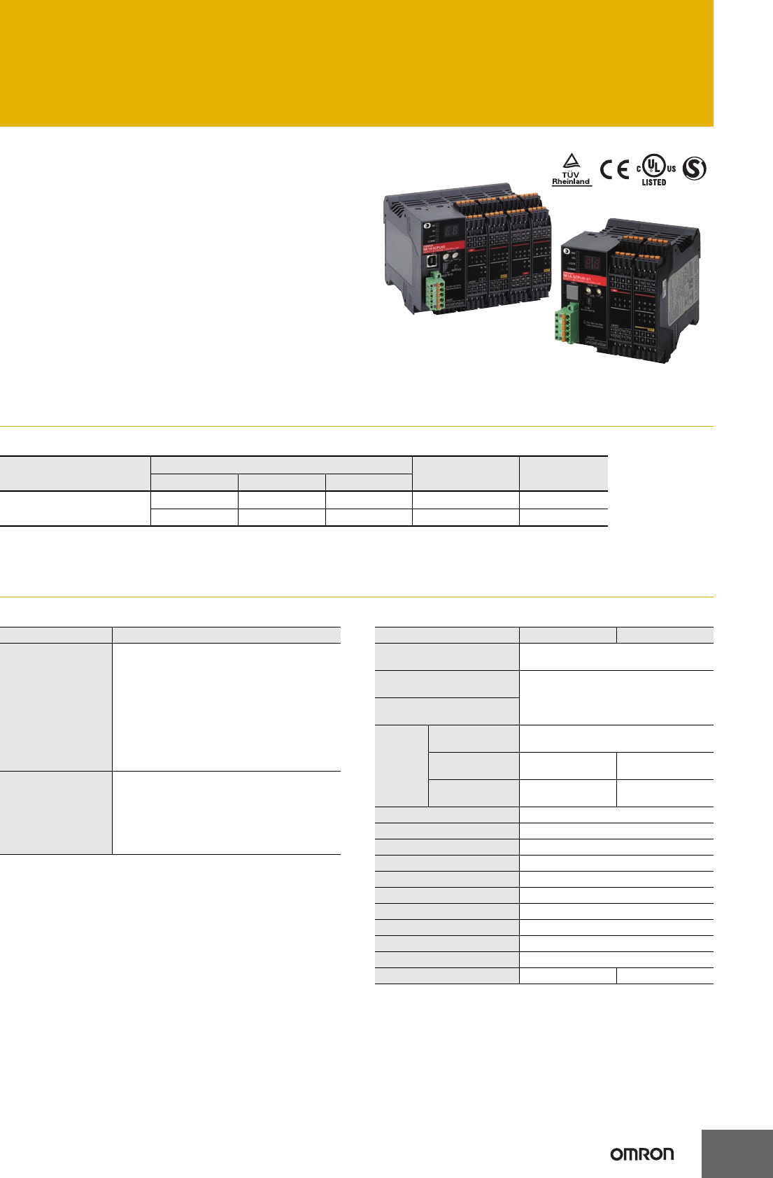
Safety Network Controller
NE1A-SCPU Series
Achieve Safety Control through
Programming.
• Compact Safety Controller.
• The NE1A-SCPU01-V1 provides 16 built-in safety inputs
and 8 built-in safety outputs.
The NE1A-SCPU02 provides 40 built-in safety inputs and
8 built-in safety outputs.
• Reduced wiring with safety networks. Connect up to 32
Safety Terminals.
• Monitor the safety system from Standard Controllers
across the network.
• ISO13849-1 (PLe) and IEC 61508 SIL3 certification.
Ordering Information
List of Models
Note: The standard NE1A Controllers are equipped with spring-cage terminal blocks, but other screw terminal blocks are available if desired, e.g.,
to replace previous terminals. Refer to CIP Safety on DeviceNet Accessories.
Specifications
Certified Standards Specifications
*1. V0-G0: Internal control circuit
V1-G1 (G): For external input device, test output
V2-G2 (G): For external output device
The two ground terminals on the NE1A-SCPU02 are internally
connected.
*2. Not including power consumption for external devices.
Name No. of I/O points Model Unit version
Safety inputs Test outputs Safety outputs
Safety Network Controllers 16 4 8 NE1A-SCPU01-V1 2.0
40 8 8 NE1A-SCPU02 2.0
Certification body Standard
TÜV Rheinland
NFPA 79-2012
EN ISO13849-1: 2008
IEC61508 part 1-7: 2010
IEC61131-2: 2007
EN ISO13849-2: 2012
EN61000-6-4: 2007
EN61000-6-2: 2005
EN60204-1: 2006
EN ISO13850: 2006(EN418: 1992)
ANSI RIA15.06-1999
ANSI B11.19-2010
UL
UL508
ANSI/ISA 12.12.01
UL1998
NFPA79
IEC61508
CSA22.2 No.142
CSA22.2 No.213
Item Model NE1A-SCPU01-V1 NE1A-SCPU02
Communications power sup-
ply voltage 11 to 25 VDC supplied via communications
connector
Internal circuit power supply
voltage (V0) *120.4 to 26.4 VDC (24 VDC −15%/+10%)
I/O power supply voltage (V1,
V2) *1
Current
con-
sumption
Communications
power supply 24 VDC, 15 mA
Internal circuit
power supply 24 VDC, 230 mA 24 VDC, 280 mA
I/O power supply
*2
24 VDC, 40 mA (Input)
120 mA (Output)
24 VDC, 80 mA (Input)
150 mA (Output)
Overvoltage category II
Noise immunity Conforms to IEC61131-2.
Vibration resistance 10 to 57 Hz: 0.35 mm, 57 to 150 Hz: 50 m/s2
Shock resistance 150 m/s2: 11 ms
Mounting method DIN Track (IEC 60715 TH35-7.5/TH35-15)
Ambient operating temperature
−10 to 55°C
Ambient operating humidity 10% to 95% (with no condensation)
Ambient storage temperature −40 to 70°C
Degree of protection IP20
Serial interface USB version 1.1
Weight 460 g max. 690 g max.
2
NE1A-SCPU Series
Safety Input Specifications
Safety Output Specifications
Test Output Specifications
*The maximum current for simultaneously ON outputs is 1.4 A.
(T0 to T3: NE1A-SCPU01-V1, T0 to T7: NE1A-SCPU02)
A 15 to 400-mA, 24-VDC external indicator can be connected to T3
and T7.
DeviceNet Communications Specifications
Input type Sinking inputs (PNP)
ON voltage 11 VDC min. between each terminal and
ground
OFF voltage 5 VDC min. between each terminal and
ground
OFF current 1 mA max.
Input current 4.5 mA
Output type Sourcing outputs (PNP)
Rated output
current 0.5 A max./output
ON residual
voltage 1.2 V max. between each output terminal and
V2
Leakage current 0.1 mA max.
Output type Sourcing outputs (PNP)
Rated output
current 0.7 A max./output *
ON residual
voltage 1.2 V max. between each output terminal and
V1
Leakage current 0.1 mA max.
Communications protocol DeviceNet compliant
Connection form Multi-drop system and T-branch system can be combined (for trunk line and branch lines)
Communications speed 500/250/125 kbps
Communications media Special cable, 5 conductors (2 for communications, 2 for power supply, 1 for shielding)
Communications distance
Communications power supply 11 to 25 VDC
No. of connectable nodes 63
Safety I/O communications
(Pre-Ver. 1.0)
Safety Master function
•Max. no. of connections: 16
•Max. data size: Input 16 bytes or output 16 bytes (per connection)
•Connection type: Single-cast, multi-cast
Safety Slave function
•Max. no. of connections: 4
•Max. data size: Input 16 bytes or output 16 bytes (per connection)
•Connection type: Single-cast, multi-cast
Safety I/O communications
(unit version 1.0 or later)
Safety Master function
•Max. no. of connections: 32
•Max. data size: Input 16 bytes or output 16 bytes (per connection)
•Connection type: Single-cast, multi-cast
Safety Slave function
•Max. no. of connections: 4
•Max. data size: Input 16 bytes or output 16 bytes (per connection)
•Connection type: Single-cast, multi-cast
Standard I/O communications
(all unit versions)
Standard Slave function
•Max. no. of connections: 2
•Max. data size: Input 16 bytes or output 16 bytes (per connection)
•Connection type: Poll, bit-strobe, COS, cyclic
Message communications Max. message length: 552 bytes
Note: Figures in parentheses ( ) indicate values when a thin cable is used.
Communications speed Max. network length Branch length Total branch length
500 kbps 100 m max. (100 m max.) 6 m max. 39 m max.
250 kbps 250 m max. (100 m max.) 78 m max.
125 kbps 500 m max. (100 m max.) 156 m max.
NE1A-SCPU Series
3
Functions
Function Blocks
NE1A-SCPU-series Controller support the following logic functions and function blocks. Support depends on the unit version.
Logic Functions Function Blocks
Name Function list entry Supporting unit
versions
NOT NOT
All
AND AND
OR OR
Exclusive OR EXOR
Exclusive NOR EXNOR
RS Flip-flop RS-FF 1.0 or later
Comparator Comparator
Name Function list entry Supporting unit
versions
Reset Reset
All
Restart Restart
Emergency Stop
Monitoring E-STOP
Light Curtain Monitoring Light Curtain
Monitoring
Safety Gate Monitoring Safety Gate
Monitoring
Two-hand Controller Two Hand Controller
Off-Delay Timer Off-Delay Timer
On-Delay Timer On-Delay Timer
User Mode Switch
Monitoring User Mode Switch
External Device
Monitoring EDM
Routing Routing
Muting Muting
1.0 or later
Enable Switch
Monitoring Enable Switch
Pulse Generator Pulse Generator
Counter Counter
Multiconnector Multi Connector
4
NE1A-SCPU Series
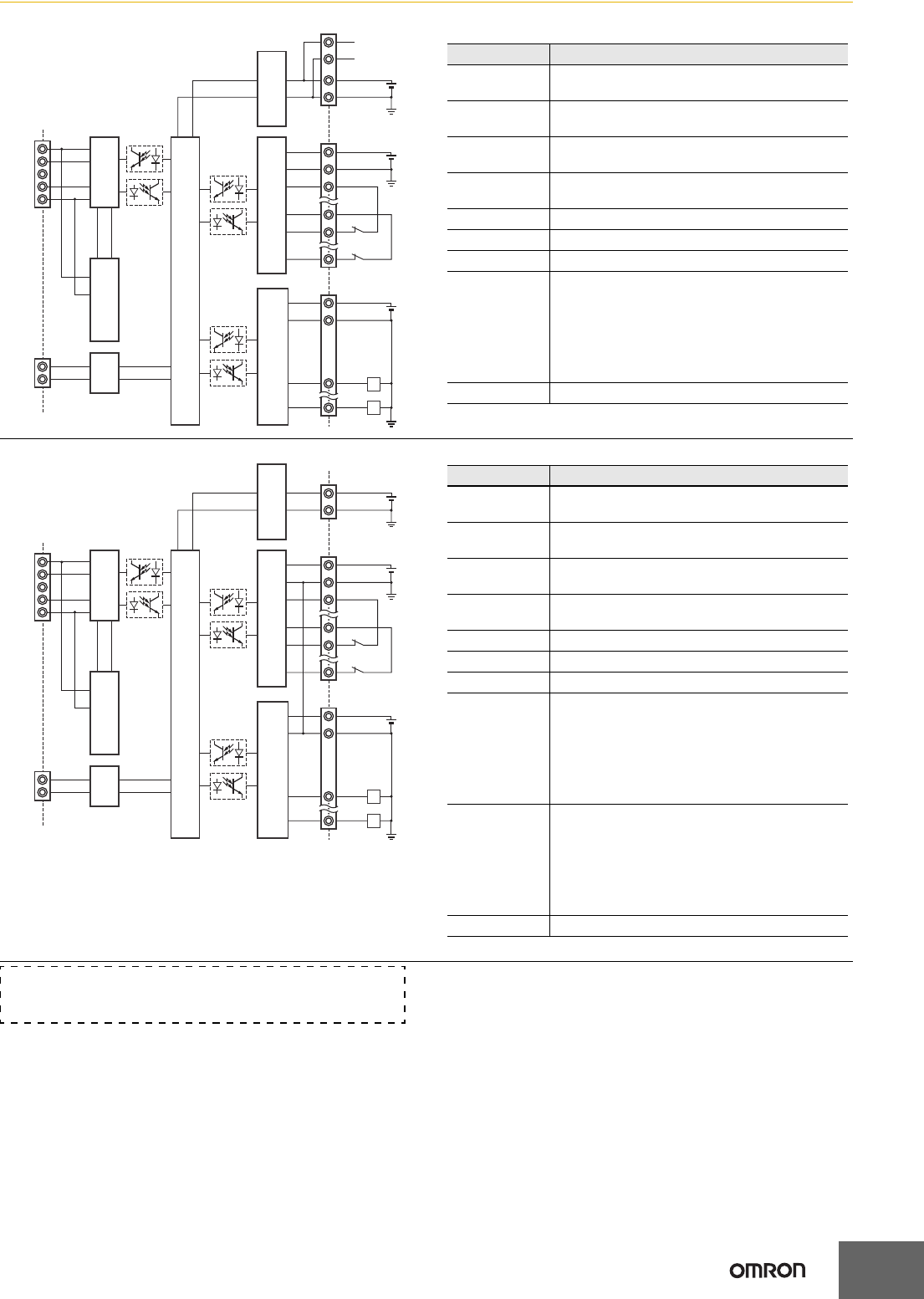
Internal Circuit Diagrams
NE1A-SCPU01-V1
NE1A-SCPU02
V+
CAN H
Shield
CAN L
V−
D+
D−USB
24 VDC
NC
NC
24 VDC
V0
G0
V0
G0
V1
G1
T0
T3
IN0
IN15
24 VDC
V2
G2
L
OUT0
L
OUT7
DC-DC Converter
(Insulated)
Safety Output Circuit Safety Input Circuit
Test Output Circuit
DC-DC Converter
(Non-insulated)
Internal Circuit
DeviceNet
Physical Layer
Terminal name Description
V0 Power supply terminal for internal circuit
The two V0 terminals are internally connected.
G0 Power supply terminal for internal circuit
The two G0 terminals are internally connected.
V1 Power supply terminal for external input device
and test output
G1 Power supply terminal for external input device
and test output
V2 Power supply terminal for external output device
G2 Power supply terminal for external output device
IN0 to IN15 Safety input terminal
T0 to T3
Test output terminal
Connected to IN0 to IN15 safety inputs.
Each test output terminal outputs a different test
pulse pattern.
Terminal T3 also supports a current monitoring
function for the output signal.
Example: Muting lamp
OUT0 to OUT7 Safety output terminals
V+
CAN H
Shield
CAN L
V−
D+
D−USB
V0
G0
V1
G
T0
T7
IN0
IN39
V2
G
L
OUT0
L
OUT7
DC-DC Converter
(Insulated)
Safety Output Circuit Safety Input Circuit
Test Output Circuit
DC-DC Converter
(Non-insulated)
Internal Circuit
DeviceNet
Physical Layer
24 VDC
24 VDC
24 VDC
Terminal name Description
V0 Power supply terminal for internal circuit
The two V0 terminals are internally connected.
G0 Power supply terminal for internal circuit
The two G0 terminals are internally connected.
V1 Power supply terminal for external input device
and test output
GPower supply terminal for external input device
and test output
V2 Power supply terminal for external output device
G Power supply terminal for external output device
IN0 to IN39 Safety input terminal
T0 to T3
Test output terminal
Connected to IN0 to IN19 safety inputs.
Each test output terminal outputs a different test
pulse pattern.
Terminal T3 also supports a current monitoring
function for the output signal.
Example: Muting lamp
T4 to T7
Test output terminal
Connected to IN20 to IN39 safety inputs.
Each test output terminal outputs a different test
pulse pattern.
Terminal T7 also supports a current monitoring
function for the output signal.
Example: Muting lamp
OUT0 to OUT7 Safety output terminals
Refer to the CIP Safety on DeviceNet Safety Network Controllers
Operation Manual (Cat. No. Z906) for wiring examples.
NE1A-SCPU Series
5
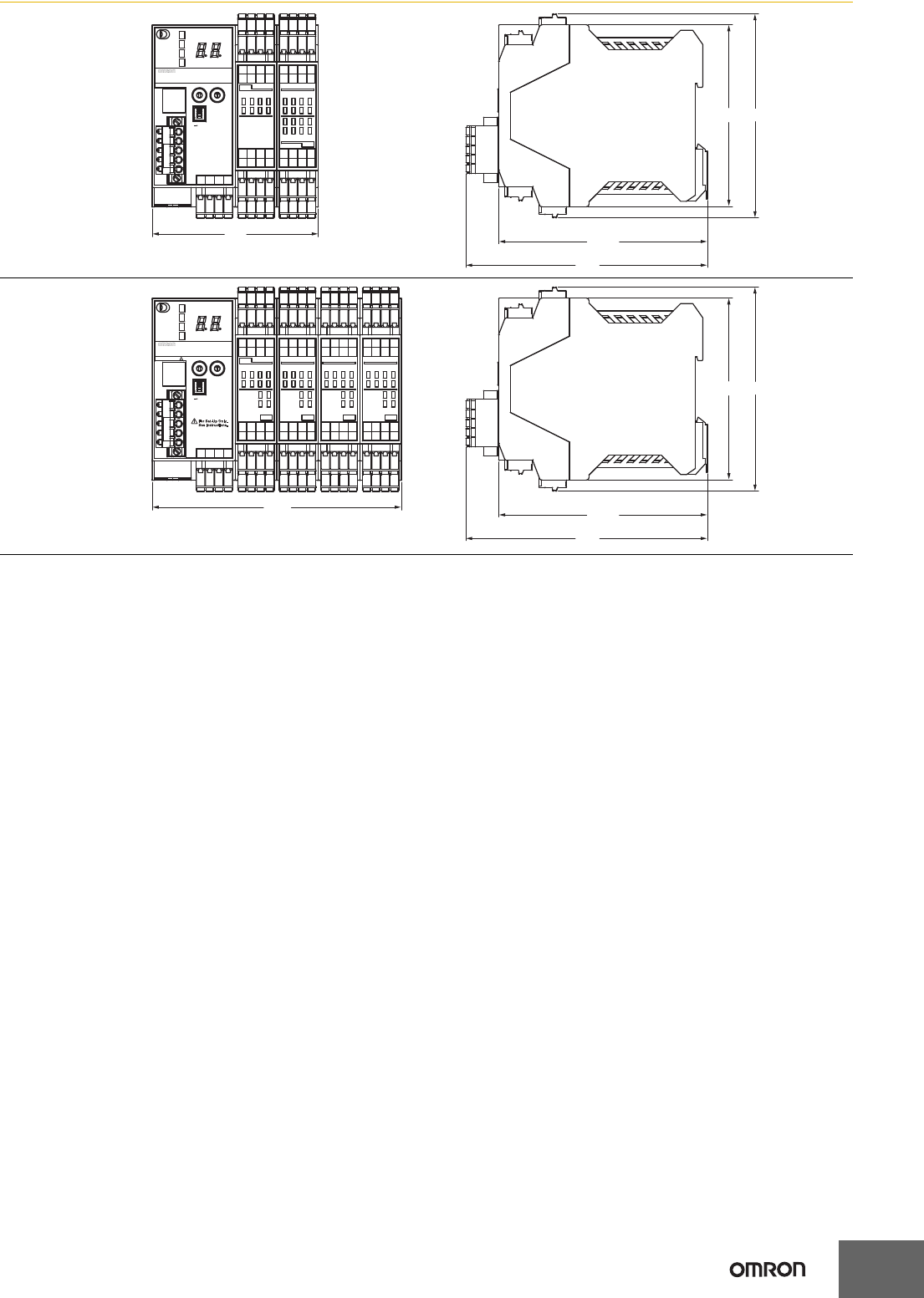
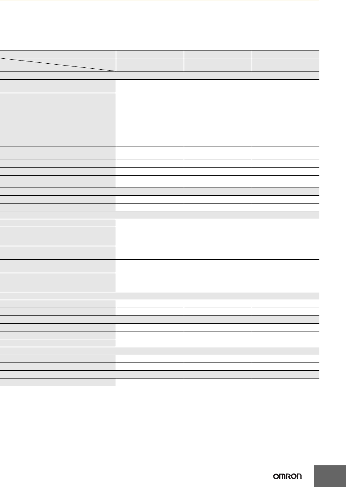
Dimensions (Unit: mm)
NE1A-SCPU01-V1
90.4
(99) 111.1
24VDC
×10 ×1
ON
1
0
1
0
3
2
5
4
7
6
1
0
3
2
5
4
7
6
1
0
3
2
5
4
7
6
9
8
11
10
13
12
15
14
3
2
5
4
7
6
9
8
11
10
13
12
15
14
SAFETY NETWORK CONTROLLER
00
USB
NS
MS
LOCK
COMM
NE1A-SCPU01-V1
NODE ADR
BAUD RATE
V0G0
24VDC OUT
IN
V1G1
V1G2
T0 T2
T1 T3
V1G1
V1G2
T0 T2
T1 T3
V0G0
1
2
3
4
O
N
(114.1)
131.4
NE1A-SCPU02
135.6
(99) 111.1
24VDC
×10 ×1
ON
1
0
1
0
3
2
5
4
7
6
1
0
3
2
17
16
19
18
T1
T0
T3
T2
1
0
3
2
17
16
19
18
9
8
11
10
13
12
15
14
3
2
5
4
7
6
9
8
11
10
13
12
15
14
SAFETY NETWORK CONTROLLER
00
USB
NS
MS
LOCK
COMM
NE1A-SCPU02
NODE ADR
BAUD RATE
V0G0
24VDC OUTIN
37
36
39
38
IN
IN
V1G
V2G
21
20
21
20
23
22
25
24
27
26
5
4
7
6
T5
T4
T7
T6
5
4
7
6
29
28
31
30
33
32
35
34
23
22
25
24
27
26
29
28
31
30
33
32
35
34
OUT
NCNC
NCNC
36 38
37 39
V0G0
1
2
3
4
O
N
(114.1)
131.4
6
NE1A-SCPU Series
Safety Precautions
Refer to the "Safety Precautions for All CIP Safety on DeviceNet Systems" for precautions.
Be sure to read the following user's manual for other details required for correct use of the Safety Network
Controller.
CIP Safety on DeviceNet Safety Network Controller User's Manual (Cat. No. Z916)
Functions Supported According to Unit Version
❍
: Supported, ---: Not supported
Model NE1ASCPU01 NE1ASCPU01-V1 NE1ASCPU02
Unit version
Function Pre-Ver. 1.0 Unit version
1.0/2.0 Unit version
1.0/2.0
Logic processing functions
Maximum program size (total number of function
blocks) 128 254 254
New Function Blocks
•RS flip-flop
•Multiconnector
•Muting
•Enable Switch Monitoring
•Pulse Generator
•Counter
•Comparator
---
❍❍
Selecting a rising edge as the reset condition for
Reset and Restart function blocks
---
❍❍
Using local I/O status in logic programming
---
❍❍
Using overall Unit status in logic programming
---
❍❍
Program execution wait functions
---
❍
(Unit version 2.0 or higher) ❍
(Unit version 2.0 or higher)
I/O control functions
Monitoring contact operation counter
---
❍❍
Mounting total ON time monitor
---
❍❍
DeviceNet communications functions
Number of safety I/O connections for Safety Master 16 32 32
Selecting operating mode for safety I/O
communications when communications errors
occur
---
❍❍
Attaching local output data to send data during
slave operation
---
❍❍
Attaching local I/O monitor data to send data during
slave operation
---
❍❍
Functions to communicate with devices existing on
other networks
(Off-Link connection)
---
❍
(Unit version 2.0 or higher) ❍
(Unit version 2.0 or higher)
System startup and error recovery functions
Storing log of nonfatal errors in nonvolatile memory
---
❍❍
Adding function block errors to error log
---
❍❍
Ethernet/IP communications functions
I/O communications
--- --- ---
Message communications
--- --- ---
Read/write of target I/O area
--- --- ---
Routing between DeviceNet and EtherNet/IP
I/O routing
--- --- ---
Message routing
--- --- ---
UDP/IP message communications functions
Message communications by UDP/IP
--- --- ---

NE1A-SCPU Series
7
Unit Versions and Network Configurator Versions
Network Configurator version 2.0@ or higher must be used when using a NE1A-SCPU01-V1 or NE1A-SCPU02 Safety Logic Controller with unit
version 2.0.
❍ : Applicable, ×: Not applicable
*1: It can be used as unit version 1.0.
Note: 1. Users who use Network Configurator version 1.5@ or earlier can upgrade to version 1.6@ at no charge.
2. When using Network Configurator version 1.6@, there are no operational differences in the NE1A-SCPU01-V1 and NE1A-SCPU02.
Model Network Configurator
Ver. 1.3@Ver. 1.5@Ver. 1.6@Ver. 2.0@/2.1@ Ver.2.2@Ver.3.3@
NE1A-SCPU01
Pre-Ver. 1.0 ❍❍❍❍❍❍
NE1A-SCPU01-V1
Unit version 1.0 ××❍❍❍❍
NE1A-SCPU02
Unit version 1.0 ××❍❍❍❍
NE1A-SCPU01-V1
Unit version 2.0 ××❍ (*1) ❍❍❍
NE1A-SCPU02
Unit version 2.0 ××❍ (*1) ❍❍❍

Terms and Conditions Agreement
Read and understand this catalog.
Please read and understand this catalog before purchasing the products. Please consult your OMRON representative if you
have any questions or comments.
Warranties.
(a) Exclusive Warranty. Omron’s exclusive warranty is that the Products will be free from defects in materials and workmanship
for a period of twelve months from the date of sale by Omron (or such other period expressed in writing by Omron). Omron
disclaims all other warranties, express or implied.
(b) Limitations. OMRON MAKES NO WARRANTY OR REPRESENTATION, EXPRESS OR IMPLIED, ABOUT
NON-INFRINGEMENT, MERCHANTABILITY OR FITNESS FOR A PARTICULAR PURPOSE OF THE PRODUCTS. BUYER
ACKNOWLEDGES THAT IT ALONE HAS DETERMINED THAT THE
PRODUCTS WILL SUITABLY MEET THE REQUIREMENTS OF THEIR INTENDED USE.
Omron further disclaims all warranties and responsibility of any type for claims or expenses based on infringement by the
Products or otherwise of any intellectual property right. (c) Buyer Remedy. Omron’s sole obligation hereunder shall be, at
Omron’s election, to (i) replace (in the form originally shipped with Buyer responsible for labor charges for removal or
replacement thereof) the non-complying Product, (ii) repair the non-complying Product, or (iii) repay or credit Buyer an amount
equal to the purchase price of the non-complying Product; provided that in no event shall Omron be responsible for warranty,
repair, indemnity or any other claims or expenses regarding the Products unless Omron’s analysis confirms that the Products
were properly handled, stored, installed and maintained and not subject to contamination, abuse, misuse or inappropriate
modification. Return of any Products by Buyer must be approved in writing by Omron before shipment. Omron Companies shall
not be liable for the suitability or unsuitability or the results from the use of Products in combination with any electrical or
electronic components, circuits, system assemblies or any other materials or substances or environments. Any advice,
recommendations or information given orally or in writing, are not to be construed as an amendment or addition to the above
warranty.
See http://www.omron.com/global/ or contact your Omron representative for published information.
Limitation on Liability; Etc.
OMRON COMPANIES SHALL NOT BE LIABLE FOR SPECIAL, INDIRECT, INCIDENTAL, OR CONSEQUENTIAL DAMAGES,
LOSS OF PROFITS OR PRODUCTION OR COMMERCIAL LOSS IN ANY WAY CONNECTED WITH THE PRODUCTS,
WHETHER SUCH CLAIM IS BASED IN CONTRACT, WARRANTY, NEGLIGENCE OR STRICT LIABILITY.
Further, in no event shall liability of Omron Companies exceed the individual price of the Product on which liability is asserted.
Suitability of Use.
Omron Companies shall not be responsible for conformity with any standards, codes or regulations which apply to the
combination of the Product in the Buyer’s application or use of the Product. At Buyer’s request, Omron will provide applicable
third party certification documents identifying ratings and limitations of use which apply to the Product. This information by itself
is not sufficient for a complete determination of the suitability of the Product in combination with the end product, machine,
system, or other application or use. Buyer shall be solely responsible for determining appropriateness of the particular Product
with respect to Buyer’s application, product or system. Buyer shall take application responsibility in all cases.
NEVER USE THE PRODUCT FOR AN APPLICATION INVOLVING SERIOUS RISK TO LIFE OR PROPERTY OR IN LARGE
QUANTITIES WITHOUT ENSURING THAT THE SYSTEM AS A WHOLE HAS BEEN DESIGNED TO ADDRESS THE RISKS,
AND THAT THE OMRON PRODUCT(S) IS PROPERLY RATED AND INSTALLED FOR THE INTENDED USE WITHIN THE
OVERALL EQUIPMENT OR SYSTEM.
Programmable Products.
Omron Companies shall not be responsible for the user’s programming of a programmable Product, or any consequence
thereof.
Performance Data.
Data presented in Omron Company websites, catalogs and other materials is provided as a guide for the user in determining
suitability and does not constitute a warranty. It may represent the result of Omron’s test conditions, and the user must correlate
it to actual application requirements. Actual performance is subject to the Omron’s Warranty and Limitations of Liability.
Change in Specifications.
Product specifications and accessories may be changed at any time based on improvements and other reasons. It is our
practice to change part numbers when published ratings or features are changed, or when significant construction changes are
made. However, some specifications of the Product may be changed without any notice. When in doubt, special part numbers
may be assigned to fix or establish key specifications for your application. Please consult with your Omron’s representative at
any time to confirm actual specifications of purchased Product.
Errors and Omissions.
Information presented by Omron Companies has been checked and is believed to be accurate; however, no responsibility is
assumed for clerical, typographical or proofreading errors or omissions.
2013.12
In the interest of product improvement, specifications are subject to change without notice.
OMRON Corporation
Industrial Automation Company
http://www.ia.omron.com/
(c)Copyright OMRON Corporation 2013 All Right Reserved.
