Schneider Electric DIGEST 175 Operator Mechanisms And Disconnect Switches
2014-07-05
: Pdf 109266-Attachment 109266-Attachment 785901 Batch5 unilog
Open the PDF directly: View PDF ![]() .
.
Page Count: 28
- Operator_Mechanisms_and_Disconnect_Switches.pdf
- Table of Contents
- Operator Mechanisms and Disconnect Switches
- UL 508 Motor Disconnect Switches
- IEC Style Disconnect Switches
- Dimensions
- IEC Style Disconnect Switches, UL 98 Listed
- GS1 Fusible and LK3 Non-Fusible Disconnect Switches
- Refer to Catalog 9421CT0301
- GS2EU3/GS2GU3, GS2 30 A/60 A Class J Fuse Clips
- GS2JU3, GS2 100 A Class J Fuses
- GS2MU3, GS2 200 A Class J Fuses
- GS2QU3, GS2 400 A Class J Fuses
- GS2SU3/GS2TU3, GS2 600 A Class J AND 800 A Class L Fuses
- Refer to Catalog 9421CT0301
- LK3DU3, Compact LK3 30 A
- LK3GU3/LK3JU3, LK3 60 A/100 A
- LK3MU3, LK3 200 A
- LK3QU3/LK3SU3, LK3 400 A/600 A
- LK3TU3/LK3UU3/LK3WU3, LK3 800 A/1000 A/1250 A
- NEMA Style Disconnect Switches
- Dimensions
- Disconnect Switches
- Bracket Mounted Disconnect Devices
- Flexible Cable Mechanisms
- Flexible Cable Mechanisms
- Disconnect Switch Accessories
- Disconnect Switches
- Door Closing Mechanisms
- Introduction
- Types M5, M6, M1, and M8
- Class 9423 / Refer to Catalog 9420CT9701
- Vault Type for Single and Multi-Door Enclosures
- View from Inside the Enclosure
- Class 9423 / Refer to Catalog 9420CT9701
- Vault Type for Single and Multi-Door Enclosures
- View from Inside the Enclosure
- Class 9423 / Refer to Catalog 9420CT9701
- Enclosure Construction and General Location Information For Types M5 and M6
- Enclosure Construction and General Location Information For Types M1 and M8
8-1
© 2009 Schneider Electric
All Rights Reserved
8OPERATOR MECHANISMS AND
DISCONNECT SWITCHES
Table of Contents
Section 8
Operator Mechanisms and
Disconnect Switches
UL 508 Motor Disconnect
Switch (p.8-2 )
UL 98 Fusible Switch
(p. 8-6)
UL 98 NEMA Style Rotary
Handle Disconnect Switch
(p. 8-12)
9422R Circuit Breaker
Mechanism (p. 8-23)
9421L Circuit Breaker Mechanism (p. 8-13)
9422 Circuit Breaker
Cable Operator (p. 8-16)
9423 Door Closing
Mechanisms (p. 8-25)
UL 508 NEMA Style Flange Handle
Disconnect Switch (p. 8-16)
Door-Mounted Switches and Circuit Breaker Mechanisms
Motor Disconnect Switches Mini-Vario and Vario™10–115 A 8-2
IEC Style Disconnect
Switches
GS1/ GS2 / LK3 / LK4 30–1200 A 8-6
NEMA Style Disconnect
Switches
D10 30–200 A 8-12
Circuit Breaker Mechanisms 9421L 15–1200 A 8-13
Flange-Mounted and Cable-Operated Disconnect Switches and
Circuit Breaker Mechanisms
Disconnect Switches 9422T 30–400 A 8-16
Disconnect Switches,
Bracket Mounted
8-20
Circuit Breaker Cable
Mechanisms
9422C 8-22
Circuit Breaker Mechanisms 9422R 15–1200 A 8-23
Accessories 8-23
Door Closing Mechanisms
Single-Door or Multi-Door
Closing Mechanisms
9423 Up to 91 in.
door
openings
8-25
Courtesy of Steven Engineering, Inc.-230 Ryan Way, South San Francisco, CA 94080-6370-Main Office: (650) 588-9200-Outside Local Area: (800) 258-9200-www.stevenengineering.com
www.schneider-electric.us
8OPERATOR MECHANISMS AND
DISCONNECT SWITCHES
8-2 © 2009 Schneider Electric
All Rights Reserved
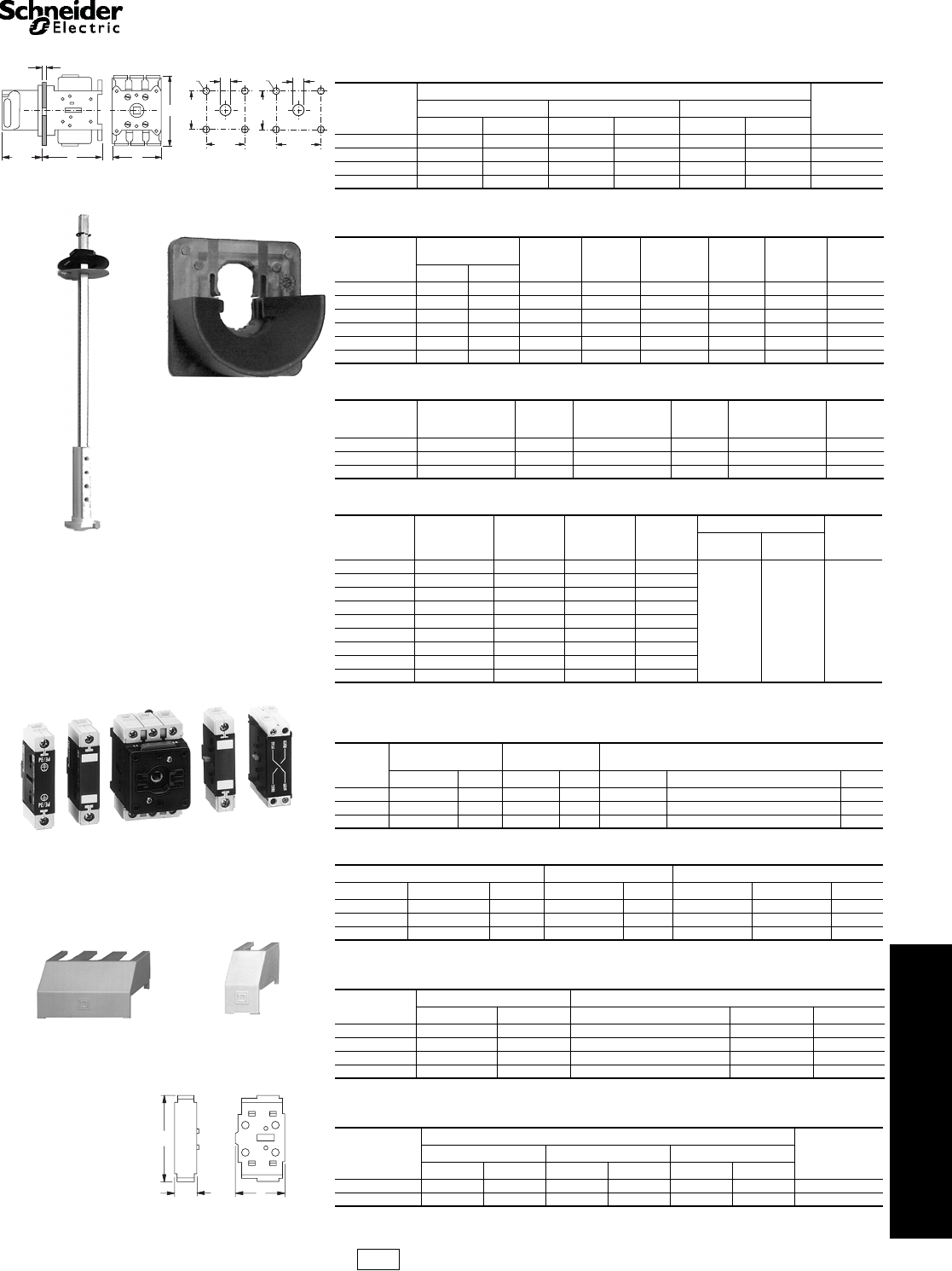
The Mini-Vario and Vario motor disconnect switch catalog
numbers can be identified as described in Table 8.1.
aSwitches/contacts are dual rated (UL/IEC).
Mini-Vario
aSwitches/contacts are dual rated (UL/IEC).
bAuxiliary contacts are dual rated (UL/IEC 10/12 A).
Table 8.1: Identification System
VCFN12GE
Model (V-Vario, K-Operator)
Operator Type/ Accessory Designation
CD Single hole Red & Yellow BD Single hole Black & Gray
CF Four hole Red & Yellow BF Four hole Black and Gray
CCD Single hole Red & Yellow w/extension
shaft VE Switch with Red handle installed on unit
(one padlock only)
CCF Four hole Red & Yellow w/ extension
shaft VD Switch with Black handle installed on unit
(no padlock provision)
Blank No operator or accessory ZAccessory, power pole, neutral or ground
Switch Typea
Blank 1 Var io 20/32 A
N12 Mini-Vario 10/12 A 2Var io 25/40 A
N20 Mini-Vario 16/20 A 3Var io 45/63 A
02 Var io 10/12 A 4Var io 63/80 A
01 Var io 16/20 A 5Vario 100/125 A
0Var io 20/25 A 6Vario 115/175 A
Enclosure Type (if applicable)
Blank No Enclosure G30, A30, W30 Type 1/12/4/4X Metallic (Class 9421)
GE Mini-Vario IP55
Non-Metallic GU Vario IP55 Non-Metallic
VBDN12
VCDN12
Table 8.2: Assembled Switches—IP65
Current Rating Complete Switches for Door Mounting (3-Padlock) Complete Switches for Rear Mounting,
Includes Extension Shaft (3-Padlock)
Red/Yellow (Single Hole) Black/Gray (Single Hole) Red/Yellow (Single Hole)
UL/IEC Catalog Number $ Price Catalog Number $ Price Catalog Number $ Price
10/12 A VCDN12 90.00 VBDN12 90.00 VCCDN12 134.00
16/20 A VCDN20 135.00 VBDN20 135.00 VCCDN20 161.00
Table 8.3: Enclosed Switches
Complete Switches Mounted in IP55 Non-metallic Enclosure
Red/Yellow Mounted In Sealable Enclosure, Non-UL Listed
Catalog Number $ Price
VCFN12GE 179.00
VCFN20GE 189.00
Table 8.4: Component Parts
Catalog
Number Description $ Price
VN12a10/12 A switch only 52.00
VN20a16/20 A switch only 63.00
VZN12aAdd on power pole for 10/12 A switch 26.00
VZN20aAdd on power pole for 16/20 A switch 31.50
VZN11 Neutral Pole with early make, late break for VN12 or
VN20 switch 29.30
VZN14 Grounding module for VN12 or VN20 29.30
VZN05 N.O. late make auxiliary contactb27.00
VZN06 N.C. early break auxiliary contactb27.00
VZN26 Single-pole shroud for auxiliary contacts 5.90
VZN08 Three-pole shroud for VN12 or VN20 7.70
VCFN12GE
VN12
VN12/KCC1YZ
Table 8.5: Operators and Accessories
Catalog
Number Description $ Price
KCC1YZ 45 x 45 mm Red & Yellow operator 39.20
KCD1PZ 60 x 60 mm Red & Yellow operator 39.20
KAD1PZ 60 x 60 mm Black & Gray operator 39.20
VZN17 300–340 mm shaft extension 22.50
VZN30 400–430 mm shaft extension 27.00
KZ32 Door interlocking plate for 45 or 60 mm operator 20.30
KZ83 Door mounting plate for 45 or 60 mm operator 20.30
VCCDN20
UL 508 Motor Disconnect
Switches
Mini-Vario and Vario™ Assembled and Enclosed Switches
Refer to Catalog 9421CT0301
CP1 Discount
Schedule
Courtesy of Steven Engineering, Inc.-230 Ryan Way, South San Francisco, CA 94080-6370-Main Office: (650) 588-9200-Outside Local Area: (800) 258-9200-www.stevenengineering.com
www.schneider-electric.us
8OPERATOR MECHANISMS AND
DISCONNECT SWITCHES
© 2009 Schneider Electric
All Rights Reserved 8-3
UL 508 Motor
Disconnect Switches
Mini-Vario and Vario™ Switches
Refer to Catalog 9421CT0301
Vario
aComplete switch includes handle operator, shaft, door interlock plate, and line terminal shroud.
The Vario Motor Disconnect Switch is also offered as an enclosed switch, which is made of
corrosion resistant material. The 3-pole version makes the Vario switch ideal for manual
motor control applications. They are compact, easy to wire and connect, and come undrilled
to allow variable cable entry positions. Note: VCGU enclosures are UL approved.
aAssembled, includes switches mounted in enclosure with handle.
bRefer to Table 8.11 and Table 8.12 for horsepower ratings.
The V1 and V2 come in metallic enclosures (NEMA Type 1, 4, 4X, and 12). The NEMA
Type 1 is supplied with conduit knockouts top and bottom. A VZ7 auxiliary contact can be
factory installed in these metallic enclosures by adding Form X11 to the catalog number. A
VZ20 auxiliary contact can be factory installed in these enclosures by adding Form X20 to
the catalog number. Price Adder $42.00
aAssembled, includes: switches mounted in enclosure with handle.
bFor indoor use only. The NEMA 4/4X enclosure is made of #304 stainless steel with 3/4 in. T&B stainless steel hubs
on the top and bottom.
aUL Rated, NEMA Type 1, 12, IP55.
Table 8.6: NEMA Type 1 and 12 Assembled Switches for Door Mounting
Operator
Style
Complete Switches (Switch and Handle) for Door Mounting (3-padlock)
Red/Yellow (Four Hole) Black/Gray (Four Hole) Red/Yellow (Single Hole) Black/Gray (Single Hole)
UL/IEC Catalog No. $ Price Catalog No. $ Price Catalog No. $ Price Catalog No. $ Price
10/12 A VCF02 125.00 VBF02 125.00 VCD02 134.00 VBD02 134.00
16/20 A VCF01 147.00 VBF01 147.00 VCD01 161.00 VBD01 161.00
20/25 A VCF0 174.00 VBF0 174.00 VCD0 206.00 VBD0 206.00
20/32 A VCF1 185.00 VBF1 185.00 VCD1 219.00 VBD1 219.00
25/40 A VCF2 237.00 VBF2 237.00 VCD2 252.00 VBD2 252.00
45/63 A VCF3 282.00 VBF3 282.00 ————
63/80 A VCF4 329.00 VBF4 329.00 ————
100/125 A VCF5 401.00 VBF5 401.00 ————
115/75 A VCF6 612.00 VBF6 612.00 ————
Table 8.7: NEMA Type 1 and 12 Assembled Switches for Rear Mounting
Operator
Style
Complete Switches for Rear Mounting
with Extension Shaft (3-Padlock)aSwitches with Handles Installed
on Unit, DIN Rail Mount Only
Red/Yellow (Four Hole) Red/Yellow (Single Hole) Red/Yellow (1-Padlock) Black/Gray (No-Padlock)
UL/IEC Catalog No. $ Price Catalog No. $ Price Catalog No. $ Price Catalog No. $ Price
10/12 A VCCF02 162.00 VCCD02 162.00 ————
16/20 A VCCF01 185.00 VCCD01 185.00 ————
20/25 A VCCF0 197.00 VCCD0 197.00 VVE0 149.00 VVD0 149.00
20/32 A VCCF1 206.00 VCCD1 206.00 VVE1 156.00 VVD1 156.00
25/40 A VCCF2 252.00 VCCD2 252.00 VVE2 180.00 VVD2 180.00
45/63 A VCCF3 320.00 ——VVE3 212.00 VVD3 212.00
63/80 A VCCF4 356.00 ——VVE4 300.00 VVD4 300.00
100/125 A VCCF5 464.00 ——— ———
115/75 A VCCF6 606.00 ——— ———
Table 8.8: Non-Metallic Enclosed Switches a b
Ampere Size
UL/IEC IP55-PVC 3-Pole, NEMA Type 1 & 12
Catalog No. $ Price
20/32 VC1GU 239.00
25/40 VC2GU 287.00
45/63 VC3GU 345.00
63/80 VC4GU 381.00
100/125 VC5GU 548.00
115/175 VC6GU 845.00
Table 8.9: Metallic Enclosed Switches a b
Ampere Size
UL/IEC
Horsepower Ratings NEMA Type 1 NEMA Type 12 NEMA Type 4/4Xb
240 V 480 V 600 V Catalog No. $ Price Catalog No. $ Price Catalog No. $ Price
20/32 5 10 10 9421V1G30 333.00 9421V1A30 548.00 9421V1W30 783.00
25/40 5 10 15 9421V2G30 381.00 9421V2A30 594.00 9421V2W30 831.00
Table 8.10: Non-Metallic Enclosed Switch Dimensionsa
Catalog No.aNo.
of
Poles
Dimensions
abcdef
in. mmin.mmin.mmin.mmin.mmin.mm
VC1GU–VC2GU 3 6.7 170 4.1 105 3.2 82 4.8 122 2.1 53 5.0 128
VC3GU–VC4GU 3 6.7 170 5.3 135 3.3 85 5.1 130 3.7 95 5.2 131
VC5GU–VC6GU 3 11.0 280 8.6 220 5.0 126 7.9 201 7.5 190 8.6 203
Table 8.11: Vario Manual Motor Control Switches, IEC
Ampere Size
IEC kW Rating 3-Pole Switch Body
230 V 240 V 400 V 415 V 500 V 690 V
12 3344 5.5 7.5
20 4 4 5.5 5.5 7.5 11
25 5.5 5.5 7.5 7.5 11 15
32 5.5 5.5 11 11 11 15
40 7.5 7.5 15 15 18.5 15
63 15 15 22 22 30 22
80 18.5 18.5 30 30 37 30
125 22223737 45 37
175 30304545 55 45
Non-Metallic Enclosure Metallic Enclosure
3.00
76 .31
8
5.38
137
6.88
175
5.63
143
4.25
108
5.88
149
NEMA Type 1 V1G30, V2G30
Metallic Enclosed Switch Dimensions
3.00
76
6.75
171
7.38
187
5.50
140
4.50
114
6.25
159
NEMA Type 4, 4X, 12
V1W30, V2W30, V1A30, V2A30
Ø 6.2
.25
e
b
da
c
f
Legend
Plate
Holder
VC1GU–VC6GU
CP1 Discount
Schedule
Courtesy of Steven Engineering, Inc.-230 Ryan Way, South San Francisco, CA 94080-6370-Main Office: (650) 588-9200-Outside Local Area: (800) 258-9200-www.stevenengineering.com
8-4 © 2009 Schneider Electric
All Rights Reserved
www.schneider-electric.us
8OPERATOR MECHANISMS AND
DISCONNECT SWITCHES
UL 508 Motor
Disconnect Switches
Mini-Vario and Vario™ Switches
Refer to Catalog 9421CT0301
Vario Manual Motor Control Switches
Vario switches act as enclosure disconnects when short
circuit protection is provided upstream of the switch (if
short circuit protection is not provided upstream, use
GS1, LK3, Class 9422 Type T or D10 disconnect
switches). Type V switches meet UL 508 requirements
as manual motor controllers.
aRefer to Table 8.11 and Table 8.12 for horsepower ratings.
Table 8.12: Vario Manual Motor Control
Switches, UL
Ampere
Size
UL
Horsepower Rating Shaft
Size 3-Pole Switch
Body
240 V 480 V 600 V mm Type
10 2 5 5 6 V02
16 3 7.5 7.5 6 V01
20 5 10 10 6 V0
20 5 10 10 6 V1
25 5 10 15 6 V2
45 10 20 30 8 V3
63 15 30 40 8 V4
100255050 8 V5
115305060 8 V6
Manual Motor
Control Switch
Table 8.13: Switch Bodya
Ampere Size
UL/IEC Shaft Size
mm
3 Pole Switch Body
Type $ Price
10/12 6 V02 62.00
16/20 6 V01 74.00
20/25 6 V0 84.00
20/32 6 V1 95.00
25/40 6 V2 143.00
45/63 8 V3 179.00
63/80 8 V4 215.00
100/125 8 V5 287.00
115/175 8 V6 428.00
aWhen using these handles for replacements on the non-metallic enclosed switches (see page 8-3),
the handle shaft supplied with the enclosure must be reused.
aThe door interlock plate included with VCC Kits has the same drilling as the handle operators.
Table 8.14: NEMA Type 1 and 12 Handle Operators: V02–V2 (6 mm Shaft), V3–V6 (8 mm Shaft) a
Operator Type Red/Yellow Single Hole
45 x 45 mm Red/Yellow Four Hole
45 x 45 mm Black/Gray Single Hole
45 x 45 mm Black/Gray Four Hole
45 x 45 mm
Switches No. of
Padlocks Catalog No. $ Price Catalog No. $ Price Catalog No. $ Price Catalog No. $ Price
V02–V2 0 KCC1LZ 39.20 KCE1LZ 39.20 KAC1BZ 39.20 KAE1BZ 39.20
V02–V2 1 KCC1YZ 39.20 KCE1YZ 39.20 ————
Operator Type Red/Yellow Single Hole
60 x 60 mm Red/Yellow Four Hole
60 x 60 mm Black/Gray Single Hole
60 x 60 mm Black/Gray Four Hole
60 x 60 mm
V02–V2 0 KDD1PZ 39.20 KDF1PZ 39.20 KBD1PZ 39.20 KBF1PZ 39.20
V3–V4 0 — —KDF2PZ 39.20 ——KBF2PZ 39.20
V02–V2 3 KCD1PZ 39.20 KCF1PZ 39.20 KAD1PZ 39.20 KAF1PZ 39.20
V3–V4 3 — —KCF2PZ 39.20 ——KAF2PZ 39.20
Operator Type Red/Yellow Four Hole
90 x 90 mm Black/Gray Four Hole
90 x 90 mm
V5–V6 0 KDF3PZ 107.00 KBF3PZ 107.00
V5–V6 3 KCF3PZ 107.00 KAF3PZ 107.00
aWhen using these handles for replacements on the non-metallic enclosed switches (see page 8-3),
the handle shaft supplied with the enclosure must be reused.
Table 8.15: Low Profile Handle Operatorsa
Operator Type Red/Yellow Single Hole
60 x 60 mm Red/Yellow Four Hole
60 x 60 mm Black/Gray Single Hole
60 x 60 Black/Gray Four Hole
60 x 60 mm
Switches No. of
Padlocks Catalog No. $ Price Catalog No. $ Price Catalog No. $ Price Catalog No. $ Price
V02–V2 3 KCD1YZ 39.20 KCF1YZ 39.20 KADIXZ 39.20 KAF1XZ 39.20
V3–V4 3 — —KCF2YZ 39.20 ——KAF2XZ 39.20
Operator Type Red/Yellow Four Hole
90 x 90 mm Black/Gray Four Hole
90 x 90 mm
V5–V6 3 KCG2YZ 72.00 KAG2XZ 72.00
Table 8.16: Gasket Kits
Catalog No. Description $ Price
KZ65 45 x 45 mm Gasket for V02-V2 for 4-hole type handles (order in quantities of 5)—IP65 5.90
KZ66 60 x 60 mm Gasket for V02-V2 for 4-hole type handles (order in quantities of 5) 12.00
KZ62 60 x 60 mm Gasket for V3-V4 for 4-hole type handles (order in quantities of 5) 12.00
KZ67 90 x 90 mm Gasket for V5-V6 for 4-hole type handles (order in quantities of 5)—IP65 15.60
Single-Hole
Mounting Dimensions
Four-Hole 60 x 60
Mounting Dimensions a
Four-Hole 90 x 90
Mounting Dimensions a
Table 8.17: Rear/Panel Mounting Switch Body Dimensions
Type Shaft
Extension
Dimensions
abcd
in. mm in. mm in. mm in. mm
V02 to V2 VZ17
VZ30
5.5–13.0
5.5–16.9
140–330
140–430 0.60 15 2.4 60 0.17 4.2
V3 to V4 VZ18
VZ31
5.5–12.6
5.5–16.5
140–320
140–420 0.79 20 2.4 60 0.20 5.2
V5 to V6 VZ18
VZ31
6.5–13.8
6.5–17.7
165–350
165–450 1.20 30 3.9 100 0.28 7.0
Four-Hole Operator
KDF3PZ and KBF3PZ
Four-Hole Operator
(All except KDF3PZ
and KBF3PZ)
Single-Hole Operator
Low-Profile Handle
KCD1YZ
22.5
3
12.7
5.5
48
48
13
68
13
5.5
68
a
b
c
dia. d
1.5-6
1.73
44
CP1 Discount
Schedule
Courtesy of Steven Engineering, Inc.-230 Ryan Way, South San Francisco, CA 94080-6370-Main Office: (650) 588-9200-Outside Local Area: (800) 258-9200-www.stevenengineering.com
www.schneider-electric.us
8OPERATOR MECHANISMS AND
DISCONNECT SWITCHES
© 2009 Schneider Electric
All Rights Reserved 8-5
UL 508 Motor
Disconnect Switches
Mini-Vario and Vario™ Accessories
Refer to Catalog 9421CT0301
aDimensions for single-hole mounting.
aEarly Break, Late Make.
bAuxiliary contacts are rated UL/IEC 10/12 A.
Table 8.18: Door Mounting Switch Body Dimensions
Switch Type
Dimensions Weight
Approx. lbs.
abc
in. mm in. mm in. mm
V02 to V2a2.83 72 2.17 55 2.91 74 0.44
V02 to V2 2.36 60 2.17 55 2.91 74 0.44
V3 to V4 2.56 65 2.36 60 3.27 83 1.10
V5 to V6 3.54 90 3.54 90 4.92 125 2.00
Table 8.19: Shaft Extension and Door Interlock
Switch Type
Maximum
Panel Depth Shaft
Extension
Kit $ Price Door
Interlock
Plate $ Price Door
Mounting
Plate $ Price
in. mm
V02 to V2 13.0 330 VZ17 28.70 KZ32 20.30 KZ83 20.30
V3, V4 12.6 320 VZ18 35.60 KZ74 39.20 KZ81 39.20
V5, V6 13.8 351 VZ18 35.60 KZ74 39.20 KZ81 39.20
V02 to V2 16.9 429 VZ30 35.60 KZ32 20.30 KZ83 20.30
V3, V4 16.5 419 VZ31 42.80 KZ74 39.20 KZ81 39.20
V5, V6 17.7 450 VZ31 42.80 KZ74 39.20 KZ81 39.20
Table 8.20: Accessories
Switch Type Line Side
Terminal Shroud
For Main Switch $ Price Terminal Shroud
for Add-on
Power Pole $ Price Terminal Shroud
for Auxiliary
Contact $ Price
V02 to V2 VZ8 8.40 VZ26 5.90 VZ29 5.90
V3, V4 VZ9 8.40 VZ27 5.90 VZ29 5.90
V5, V6 VZ10 12.00 VZ28 9.50 VZ29 5.90
Table 8.21: Add-On Contact Modules
Switch Type Main Pole
Module Main
Pole
Ampere
Rating
UL/IEC $ Price
Auxiliary Contacts
$ Price
1 N.O. &
1 N.C. a2 N.O.
V02 VZ02 VZ02 10/12 31.50
VZ7bVZ20b42.80
V01 VZ01 VZ01 16/20 32.90
V0 VZ0 VZ0 20/25 34.20
V1 VZ1 VZ1 20/32 35.60
V2 VZ2 VZ2 25/40 55.00
V3 VZ3 VZ3 45/63 66.00
V4 VZ4 VZ4 63/80 82.00
V5 — — — —
V6 — — — —
Table 8.22: Add-On Contact Modules
Switch
Type
Neutral Modules Early
Make/Late Break Grounding
Module Auxiliary Contacts
Catalog No. $ Price Catalog No. $ Price Catalog No. Description $ Price
V02–V2 VZ11 42.80 VZ14 42.80 VZ7 1 Late Make N.O. & 1 Early Break N.C. 42.80
V3–V4 VZ12 54.00 VZ15 54.00 VZ20 2 N.O. Contacts 42.80
V5–V6 VZ13 70.00 VZ16 70.00 ———
Table 8.23: Labeling Accessories
Nameplate Holder with Nameplate Nameplate Holder Only Nameplate Only
Size Catalog No. $ Price Catalog No. $ Price Use With Catalog No. $ Price
45 x 45 mm KZ13 4.80 KZ14 4.40 KZ14 KZ76 3.50
60 x 60 mm KZ15 4.80 KZ16 4.40 KZ16 KZ77 3.50
90 x 90 mm KZ103 7.80 KZ101 6.80 KZ1010 KZ100 3.50
Table 8.24: Shrouds
Switch Type 3-Pole Shroud Single-Pole Shroud
Catalog No. $ Price For Add-On Power Pole Catalog No. $ Price
V02–V2 VZ8 8.40 VZ02-VZ2, VZ11 & VZ14 VZ26 5.90
V3–V4 VZ9 8.40 VZ23, VZ4, VZ12 & VZ15 VZ27 6.90
V5–V6 VZ10 12.00 VZ13 & VZ16 VZ28 9.50
—— —For 2-Pole Aux. Contact VZ29 5.90
Table 8.25: Main Pole Module Dimensions
Switch Type
Dimensions Weight
Approx. lbs.
abc
in. mm in. mm in. mm
V02 to VZ2 0.63 16 2.9 74 1.38 35 0.10
VZ3 to VZ4 0.79 20 3.3 83 1.80 46 0.22
1.73
44
1.5-6
ab
c
.217
5.5 .217
5.5
2.68
68
2.68
68
1.89
48
1.89
48
.512
13.512
13
Door Interlock Plate
KZ32
Shaft Extension Kit
Add-On Contact Modules
Terminal Shroud
for Auxiliary Contact
VZ29
Terminal Shroud for
Main Switch
VZ8
a
b
c
Main Pole Module
CP1 Discount
Schedule
Courtesy of Steven Engineering, Inc.-230 Ryan Way, South San Francisco, CA 94080-6370-Main Office: (650) 588-9200-Outside Local Area: (800) 258-9200-www.stevenengineering.com
www.schneider-electric.us
8OPERATOR MECHANISMS AND
DISCONNECT SWITCHES
8-6 © 2009 Schneider Electric
All Rights Reserved
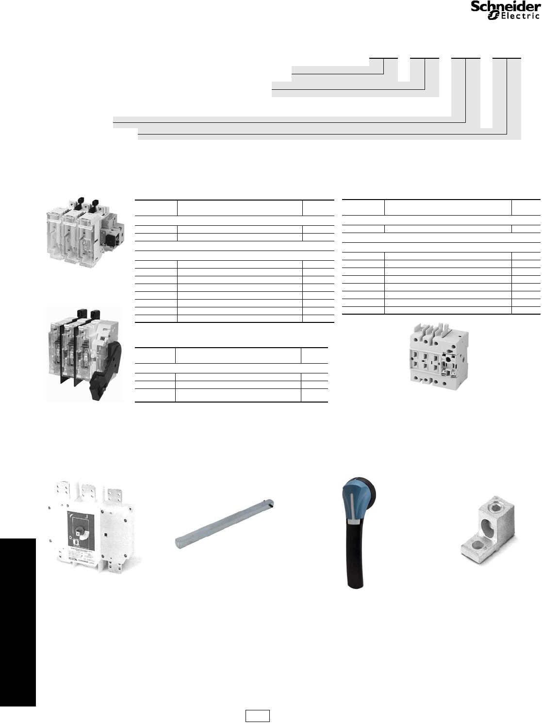
IEC Style Disconnect
Switches
GS1/GS2 Fusible and LK3/LK4 Non-Fusible, UL 98 Listed
Refer to Catalog 9421CT0301
Identification System
Note: All fusible switches through 400 A and non-fused switches through 200
A are equipped with a feature to test optional auxiliary contacts without
energizing the load when the appropriate GS1AHT*** handle is used.
aShipped with line side terminal shrouds, for additional shrouds see
page 8-8.
bTerminal lug must be ordered separately—see page 8-8.
For example:
LK3SU3 (600 A Non-Fusible Switch, use 15 x 12 Shaft) +
GS2AE6 (15 x 12 200 mm Type S Shaft) + GS2AH150
(Black/ Black, Lockable)
To add auxiliary contacts:
For front mounted contacts order LK3AD30 (front
mounted auxiliary contact holder) + GS2AM110 (N.O.
contact for GS1AD10, GS2AD11, and LK3AD30).
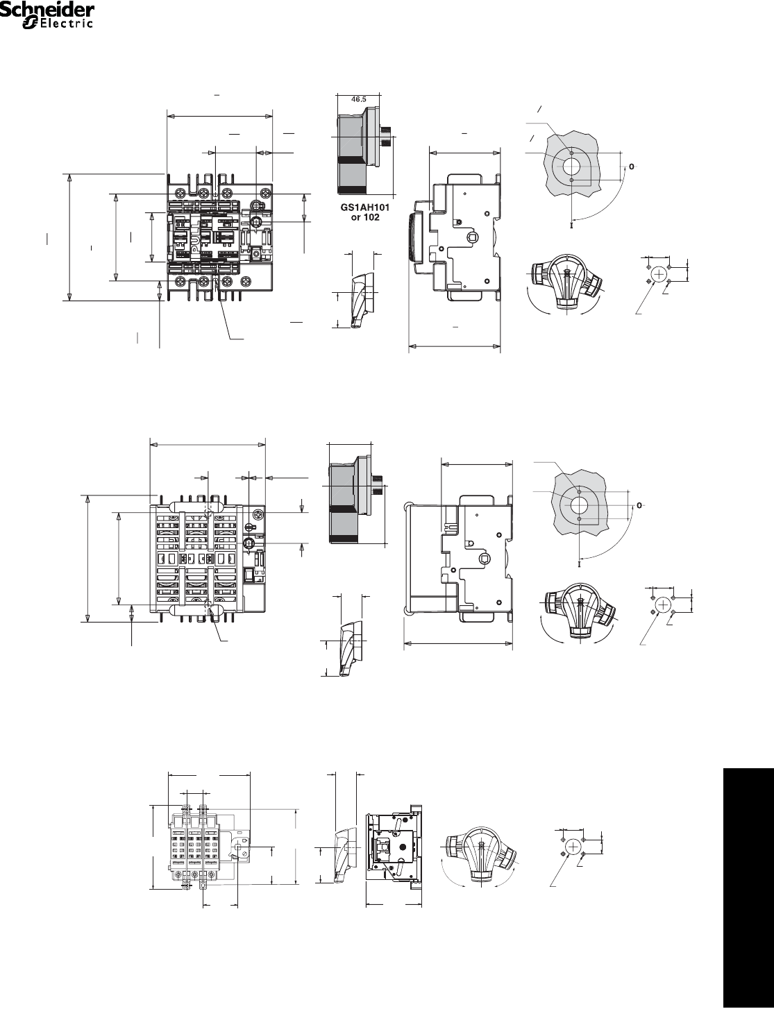
The GS1 part numbers can be identified as follows: GS1 D U 3
(See Catalog 9421CT0301 for specific applications.)
Model “GS1”, “GS2”—Fusible (Class J Fuse unless noted), “LK3”, “LK4”—Non-Fusible
Current Range, Operator Style (Front Operator unless noted), Accessory Type
“D”—30 A Front and Side Operation, “DD”—30 A Class CC Front and Side Operation “E”—30 A,
“EE”—30 A Class CC, “G”—60 A, “J”—100 A, “M”—200 A, “Q”—400 A, “S”—600 A, “T”—800 A
(Class L if Fused), “U”—1000 A, “W”—1200 A
UL Certification
Poles—Number of Poles 2 or 3
“AH”—Handle, “AHT”—Handle w/ Test, “AE”—Extension Shaft, “AD”—Aux contact holder, “AM”—Aux Contact
Table 8.26: Switches — Fusible
Catalog
Number Description $ Price
Compact GS1 Fusible IEC Style Disconnect Switches
GS1DDU3 30 A, 3-Pole, Class CC, use 5 x 5 Shaft 237.00
GS1DU3 30 A, 3-Pole, Class J, use 5 x 5 Shaft 260.00
GS2 Fusible IEC Style Disconnect Switches
GS2EEU3 30 A, 3-Pole, Class CC , use 10 x 10 Shaft 237.00
GS2EU3 30 A, 3-Pole, Class J, use 10 x 10 Shaft 260.00
GS2GU3 60 A, 3-Pole, Class J, use 10 x 10 Shaft 336.00
GS2JU3ab 100 A, 3-Pole, Class J, use 10 x 10 Shaft 536.00
GS2MU3ab 200 A, 3-Pole, Class J, use 10 x 10 Shaft 1181.00
GS2QU3ab 400 A, 3-Pole, Class J, use 10 x 10 Shaft 2252.00
GS2SU3ab 600 A, 3-Pole, Class J, use 15 x 12 Shaft 3378.00
GS2TU3ab 800 A, 3-Pole, Class L, use 15 x 12 Shaft 5061.00
Table 8.27: Switches — Fusible with Direct Mount
Side Handle
Catalog
Number Description $ Price
Switches with Direct Mount Side Handle
GS1EERU20 30 A, 2-Pole, Class CC 204.00
GS1EERU30 30 A, 3-Pole, Class CC 242.00
GS1AH01 Right Side Handle for
GS1EERU20 & GS1EERU30 46.40
30 A Side Handle
GS1EERU30
200 A Switch
GS2MU3
Table 8.28: Switches — Non-Fusible
Catalog
Number Description $ Price
Compact LK3 Non-Fusible IEC Style Disconnect Switches
LK3/LK4DU3 30 A, 3-Pole, 5 x 5 Shaft 218.00
LK4 Non-Fusible IEC Style Disconnect Switches
LK4GU3 60 A, 3-Pole, use 10 x 10 Shaft 263.00
LK4JU3 100 A, 3-Pole, use 10 x 10 Shaft 458.00
LK4MU3ab 200 A, 3-Pole, use 10 x 10 Shaft 1010.00
LK4QU3ab 400 A, 3-Pole, use 15 x 15 Shaft 1910.00
LK3SU3ab 600 A, 3-Pole, use 15 x 12 Shaft 2873.00
LK3TU3ab 800 A, 3-Pole, use 15 x 12 Shaft 4301.00
LK3UU3ab 1000 A, 3-Pole, use 15 x 12 Shaft 5372.00
LK3WU3ab 1200 A, 3-Pole, use 15 x 12 Shaft 6450.00
Compact 30 A Switch
LK3DU3
Example of the parts to order to build a complete switch:
Choose a switch + Shaft + Handle Assembly + Lugs if needed
600 A
LK3SU3
Shaft 200 mm
GS2AE5
Black Handle
GS2AH150
Lugs Kit
GS1AW503
CP1 Discount
Schedule
Courtesy of Steven Engineering, Inc.-230 Ryan Way, South San Francisco, CA 94080-6370-Main Office: (650) 588-9200-Outside Local Area: (800) 258-9200-www.stevenengineering.com
www.schneider-electric.us
8OPERATOR MECHANISMS AND
DISCONNECT SWITCHES
© 2009 Schneider Electric
All Rights Reserved 8-7
IEC Style Disconnect
Switches
GS1/GS2 Fusible and LK3/LK4 Non-Fusible, UL 98 Listed
Refer to Catalog 9421CT0301
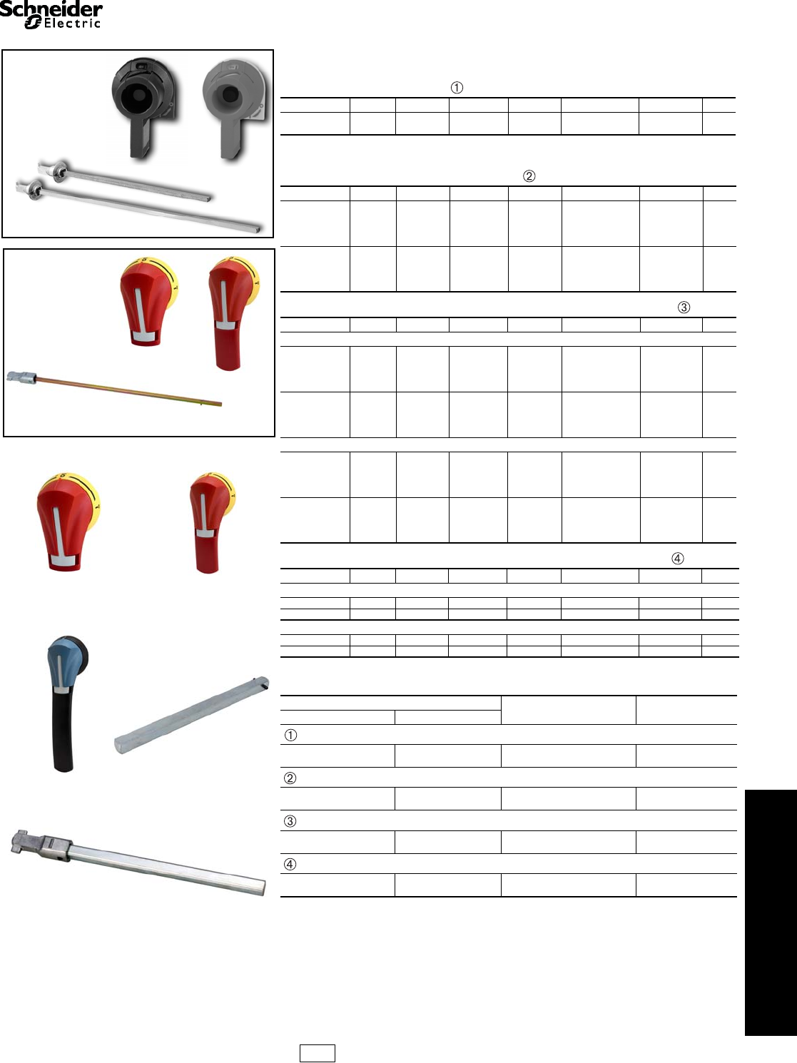
Handles
Note: Now UL approved for indoor or outdoor applications.
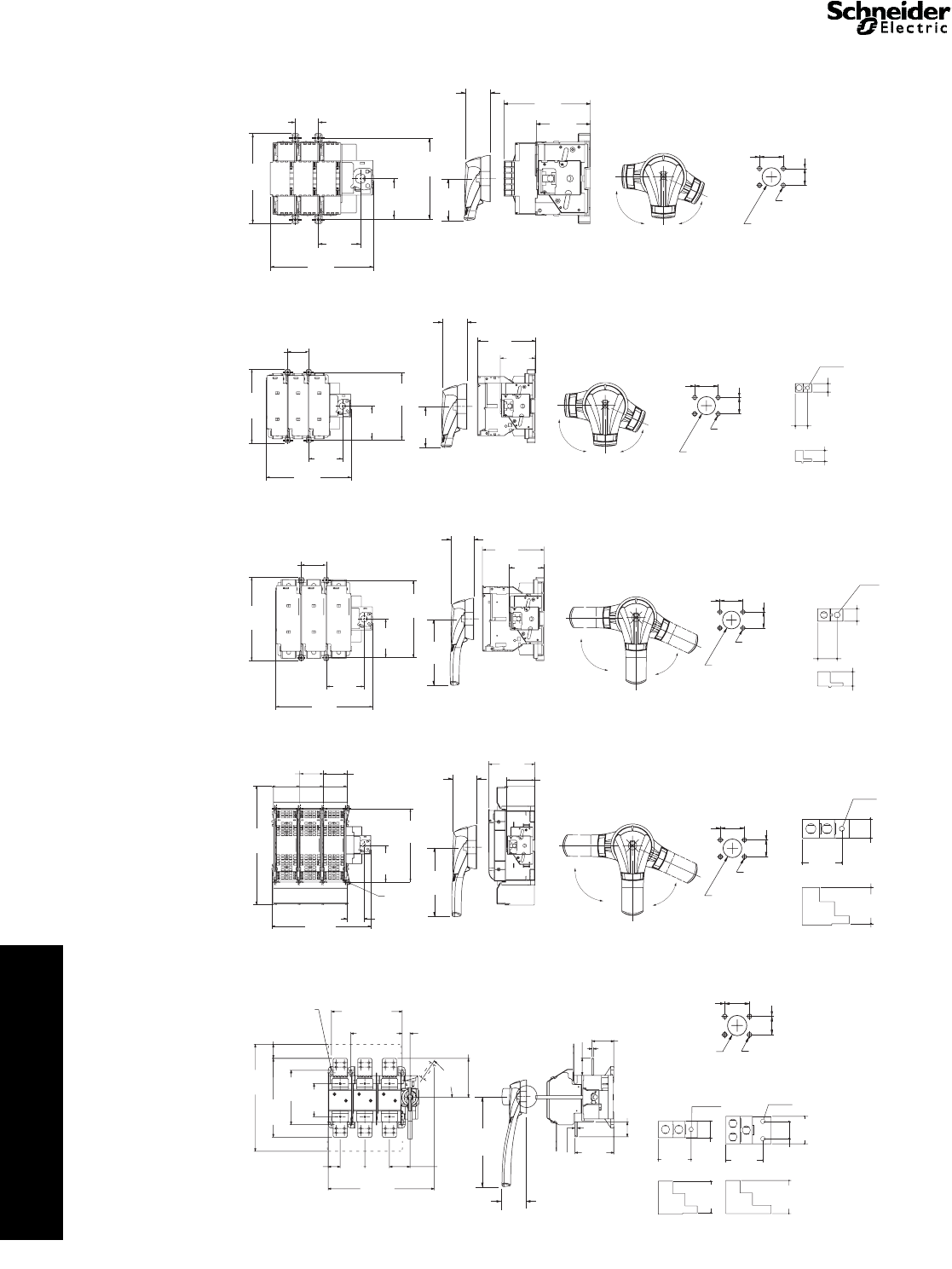
Table 8.29: Pistol Handles for Compact GS1 and LK3 for Use with Shaft Type D
(as listed below)
NEMA/UL Type IEC Type Defeatable Padlockable Color Operation Catalog No. $ Price
1, 12 IP54 Yes Yes Black Off/On (O/I) GS1AH101 51.00
1, 12 IP54 Yes Yes Red/Yellow Off/On (O/I) GS1AH102 51.00
Table 8.30: Pistol Handles for Compact and Standard GS1/GS2 and LK3/LK4 for
Compact GS1, 30 A, and Compact LK3 30 A (3 in. handles) for Use with
Shaft Type S (as listed below)
NEMA/UL Type IEC Type Defeatable Padlockable Color Operation Catalog No. $ Price
1, 3R, 12 IP54 Yes Yes Black Off/On (O/I) GS2AH110 62.00
1, 3R, 12 IP54 Yes Yes Red/Yellow Off/On (O/I) GS2AH120 62.00
1, 3R, 12 IP54 Yes Yes Black Test/Off/On (T/O/I) GS2AHT110 117.00
1, 3R, 12 IP54 Yes Yes Red/Yellow Test/Off/On (T/O/I) GS2AHT120 117.00
1, 3R, 4, 4X, 12 IP65 Yes Yes Black Off/On (O/I) GS2AH410 70.00
1, 3R, 4, 4X, 12 IP65 Yes Yes Red/Yellow Off/On (O/I) GS2AH420 70.00
1, 3R, 4, 4X, 12 IP65 Yes Yes Black Test/Off/On (T/O/I) GS2AHT410 117.00
1, 3R, 4, 4X, 12 IP65 Yes Yes Red/Yellow Test/Off/On (T/O/I) GS2AHT420 117.00
Table 8.31: Pistol Handles for Standard GS2 and LK4 (as listed below)
NEMA/UL Type IEC Type Defeatable Padlockable Color Operation Catalog No. $ Price
GS2 30–100 A and LK4 60–100 A (3 in. handles)
1, 3R, 12 IP54 Yes Yes Black Off/On (O/I) GS2AH110 62.00
1, 3R, 12 IP54 Yes Yes Red/Yellow Off/On (O/I) GS2AH120 62.00
1, 3R, 12 IP54 Yes Yes Black Test/Off/On (T/O/I) GS2AHT110 117.00
1, 3R, 12 IP54 Yes Yes Red/Yellow Test/Off/On (T/O/I) GS2AHT120 117.00
1, 3R, 4, 4X, 12 IP65 Yes Yes Black Off/On (O/I) GS2AH410 70.00
1, 3R, 4, 4X, 12 IP65 Yes Yes Red/Yellow Off/On (O/I) GS2AH420 70.00
1, 3R, 4, 4X, 12 IP65 Yes Yes Black Test/Off/On (T/O/I) GS2AHT410 117.00
1, 3R, 4, 4X, 12 IP65 Yes Yes Red/Yellow Test/Off/On (T/O/I) GS2AHT420 117.00
GS2 200–400 A and LK4 200 A (5 in. handles)
1, 3R, 12 IP54 Yes Yes Black Off/On (O/I) GS2AH130 70.00
1, 3R, 12 IP54 Yes Yes Red/Yellow Off/On (O/I) GS2AH140 70.00
1, 3R, 12 IP54 Yes Yes Black Test/Off/On (T/O/I) GS2AHT130 125.00
1, 3R, 12 IP54 Yes Yes Red/Yellow Test/Off/On (T/O/I) GS2AHT140 125.00
1, 3R, 4, 4X, 12 IP65 Yes Yes Black Off/On (O/I) GS2AH430 78.00
1, 3R, 4, 4X, 12 IP65 Yes Yes Red/Yellow Off/On (O/I) GS2AH440 78.00
1, 3R, 4, 4X, 12 IP65 Yes Yes Black Test/Off/On (T/O/I) GS2AHT430 132.00
1, 3R, 4, 4X, 12 IP65 Yes Yes Red/Yellow Test/Off/On (T/O/I) GS2AHT440 132.00
Table 8.32: Pistol Handles for Use with Shaft Type S (as listed below)
NEMA/UL Type IEC Type Defeatable Padlockable Color Operation Catalog No. $ Price
For LK3 400–1200 A
1, 3R, 4, 4X, 12 IP65 Yes Yes Black Off/On (O/I) GS2AH150 263.00
1, 3R, 4, 4X, 12 IP65 Yes Yes Red/Yellow Off/On (O/I) GS2AH160 263.00
For GS2 600–800 A
1, 3R, 4, 4X, 12 IP65 Yes Yes Black Off/On (O/I) GS2AH150 263.00
1, 3R, 4, 4X, 12 IP65 Yes Yes Red/Yellow Off/On (O/I) GS2AH160 263.00
Table 8.33: Shafts
Length Catalog No. $ Price
in. mm
Shaft 5 mm x 5 mm—for Use with Pistol Handles, Type D
12.6 320 GS1AE7 18.60
15.7 400 GS1AE71 23.30
Shaft 5 mm x 5 mm—for Use with Pistol Handles, Type G
12.6 320 GS2AE8 18.60
15.7 400 GS2AE81 23.30
Shaft 10 mm x 10 mm—for Use with Standard GS2 and LK4
12.6 320 GS2AE2 20.30
15.7 400 GS2AE21 25.00
Shaft 15 mm x 12 m—for Use with Pistol Handles
7.9 200 GS2AE5 32.60
15.7 400 GS2AE51 40.40
Type D
Alternate Handles for
Compact Switches
Only
Economical
Handle Design
Compact Shaft Kits
GS1AH101 GS1AH102
GS1AE7/AE71 Shafts
Type S
Standard
Handle Design
Use these shaft
kits when using
Compact Switches
GS2AH110
GS2AH120
GS2AE8/AE81 Shafts
GS2AH110 GS2AH120
GS2AH160 GS2AE5 / AE51
GS2AE2/AE21
Shafts
CP1 Discount
Schedule
Courtesy of Steven Engineering, Inc.-230 Ryan Way, South San Francisco, CA 94080-6370-Main Office: (650) 588-9200-Outside Local Area: (800) 258-9200-www.stevenengineering.com
www.schneider-electric.us
8OPERATOR MECHANISMS AND
DISCONNECT SWITCHES
8-8 © 2009 Schneider Electric
All Rights Reserved
IEC Style Disconnect
Switches
GS1/GS2 Fusible and LK3/LK4 Non-Fusible, UL 98 Listed
Refer to Catalog 9421CT0301
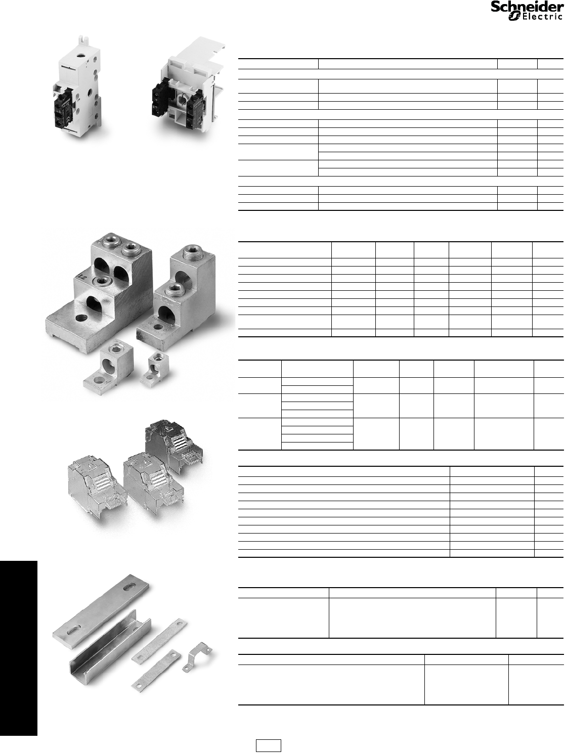
Accessories
aGS1AN• • contact blocks cannot be mixed with GS1ANT• • contact blocks on the same switch. You must use all
GS1AN11/GS1AN22 on a single switch OR all GS1ANT11/GS1ANT22 on a single switch.
aGS1 600–800 A and LK3 800–1250 A can receive 1 lug for 3 cables per terminal or 2 lugs for 2 cables per terminal.
aAll GS1 and LK3 switches supplied with line side shrouding.
bThree piece kit for either line or load side.
Table 8.34: Auxiliary Contacts
Type Description Catalog No. $ Price
For Compact LK3 / GS1
U = Upper or Top mounted Contact holder (for 5 to 8 auxiliary contacts). Standard products allow
up to 4 auxiliary contacts without any extra contact holders. GS1AD10 46.70
10 A 1 N.O. Contact Block GS2AM110 14.70
600 Vac 1 N.C. Contact Block GS2AM101 14.70
For LK4 60–200 A, GS2 30–800 A
U = Upper or Top mounted Contact holder required (for 1 to 8 upper auxiliary contacts) GS2AD11 46.70
10 A 1 N.O. Contact Block GS2AM110 14.70
600 Vac 1 N.C. Contact Block GS2AM101 14.70
S = Side mounted a1 N.O. & N.C. Contact Block (max of two blocks – any mix) GS1AN11 78.00
2 N.O. & N.C. Contact Block (max of two blocks – any mix) GS1AN22 140.00
S = Side mounted a1 N.O. & N.C. Contact Block w/ Test (max of two blocks – any mix) GS1ANT11 93.00
2 N.O. & N.C. Contact Block w/ Test (max of two blocks – any mix) GS1ANT22 156.00
For LK3 400–1200 A
U = Upper or Top mounted Contact holder (for 1 to 4 auxiliary contacts) LK3AD30 46.70
10 A 1 N.O. Contact Block GS2AM110 14.70
600 Vac 1 N.C. Contact Block GS2AM101 14.70
Table 8.35: Terminal Lugs
For use on Wire Size # of Wires
per Lug Wire Type Lugs per Kit Catalog No. $ Price
Compact GS1/LK3 #14–#10 1 Cu — Standard —
GS2 30 A CC #14–#10 1 Cu — Standard —
GS2 30 A J #14–#10 1 Cu — Standard —
GS2/LK4 60 A J #10–#3 1 Cu — Standard —
LK4 100 A #14–#2/0 1 Cu — Standard —
GS2 100 A #14–2/0 1 Cu/Al 6 GS1AW303 59.00
GS2/LK4 200 A #6–3/0 1 Cu/Al 6 GS1AW403 98.00
GS2 400–800 A
LK3 400–600 A a2 x 2–2 x 600 2 Cu/Al 6 GS1AW503 197.00
LK3 800–1200 A a4 x 2–4 x 600 2 Cu/Al 12 GS1AW903 395.00
Table 8.36: Power Distribution Lugs
For use on Wire Size
AWG (mm2)# of Wires
Per Lug Wire
Type Lugs per
Kit Catalog Number $ Price
GS2JU3 #8 (10) – #6 (16) 6Cu3GS1AW306 126.00
#14 (2.1) – #10 (6)
GS2MU3
GS2QU3
#6 (16) – #4 (35)
12 Cu 3 GS1AW406 209.00#8 (10)
#14 (2.1) – #10 (6)
GS2MU3
GS2QU3
#2 (35) – #2/0 (70)
6Cu3GS1AW506 233.00
#6 (16) – #4 (25)
#8 (10)
#12 (3.3) – #10 (4)
Table 8.37: Terminal Shrouds
For use on Line or Load Side aCatalog No. $ Price
Compact GS1/LK3 Standard —
All GS2/LK4 30 A Standard —
All GS2/LK4 60 A Standard —
LK4 100 A Standard —
GS2 100 A bGS1AP33 101.00
GS2/LK4 200 A bGS1AP43 132.00
GS2 400 A GS1APU53 140.00
LK3 400–600 A LK3AP63 86.00
GS2 600–800 A GS2AP73 140.00
LK3 800–1200 A LK3AP83 101.00
Table 8.38: Shorting Links
For use on Shorting Links per Kit Catalog No. $ Price
GS2 60 A 3 GS1AU203 29.60
GS2 100 A 3 GS1AU303 41.90
GS2 200 A 3 GS1AU403 62.10
GS2 400 A 3 GS1AU503 93.00
GS2 600–800 A 3 GS1AU803 156.00
Table 8.39: Shaft Padlocking Kit
For use on Catalog No. $ Price
Compact GS1/LK3 Standard —
LK4 60–200 A Standard —
GS2 30–400 A Standard —
LK3 400–1200 A GS1AXU3 62.00
GS2 600–800 A Standard —
GS1AD10 +
GS2AM110
GS2AM110 +
GS2AM101
Terminal
Lugs
Terminal Shrouds
Shorting Links
CP1 Discount
Schedule
Courtesy of Steven Engineering, Inc.-230 Ryan Way, South San Francisco, CA 94080-6370-Main Office: (650) 588-9200-Outside Local Area: (800) 258-9200-www.stevenengineering.com
www.schneider-electric.us
8OPERATOR MECHANISMS AND
DISCONNECT SWITCHES
© 2009 Schneider Electric
All Rights Reserved 8-9
Dimensions IEC Style Disconnect Switches, UL 98 Listed
Refer to Catalog 9421CT0311
GS1DDU3, 30 A Compact Class CC Fuses
GS1DU3, 30 A Compact Class J Fuses
GS2EEU3, 30 A Class CC Fuses
25.6
1"
37.3
115
32"
FIX
15
19
32
116
49
16 "
79.5
31
8"
96.5
33
4"
45
125
32"
18.3
23
32"
M 5
FIX
3
16
"
ø
114
18
2 ø 4.5
ø 31
50
90
2
-OFF
-ON
83.8
3
1
4
"
65
21
2""
"
"
63
2.48"
"
1.83
GS2AH/AHT110, 120, 410 or 420
2.75
70
1.72
43.9
OFF
ON
TEST
1.57
40
1.22
31
Ø
0.27
7
Ø(4)
90°
65°
1.10
28
"
Door Drilling
116
4.56
105.5
4.13
15.8
0.6384
3.38
28
1.0
37.315
1.47
FIX
65
99
3.88
2.5
63
2.48
46.5
1.83
1.25
0.13
2 ø 4.5
ø 31
50
90
2.0
-OFF
-ON
FIX 0.19
ø
.059
GS1AH101
or 102
GS2AH/AHT110, 120, 410 or 420
2.75
70
1.72
43.9
OFF
ON
TEST
1.57
40
1.22
31
Ø
0.27
7
Ø(4)
90°
65°
1.10
28
Door Drilling
1.13
Fix
29 Door Drilling
5.69
144
5.88
149
3.88
99
2.44
62
2.63
67
Fix
5.25
133
2.75
70
1.72
43.9
OFF
ON
TEST
1.57
40
1.22
31
Ø
0.27
7
Ø(4)
90°
65°
1.10
28
Mounting Hole Dimension
0.19 in. (4.8 mm)
GS2 AH / AHT 110, 120, 410 or 420
Courtesy of Steven Engineering, Inc.-230 Ryan Way, South San Francisco, CA 94080-6370-Main Office: (650) 588-9200-Outside Local Area: (800) 258-9200-www.stevenengineering.com
8-10 © 2009 Schneider Electric
All Rights Reserved
www.schneider-electric.us
8OPERATOR MECHANISMS AND
DISCONNECT SWITCHES
Dimensions GS1 Fusible and LK3 Non-Fusible Disconnect Switches
Refer to Catalog 9421CT0301
GS2EU3/GS2GU3, GS2 30 A/60 A Class J Fuse Clips
GS2JU3, GS2 100 A Class J Fuses
GS2MU3, GS2 200 A Class J Fuses
GS2QU3, GS2 400 A Class J Fuses
GS2SU3/GS2TU3, GS2 600 A Class J AND 800 A Class L Fuses
1.50
38
5.88
149
2.75
70
6.75
171
2.63
67
Fix 5.25
133
5.63
143
3.50
89 Door Drilling
OFF
ON
TEST
1.57
40
1.22
31
Ø
0.27
7
Ø(4)
90°
65°
1.10
28
2.75
70
1.72
43.9
Mounting Hole Dimension: 0.19 in. (4.8 mm)
Terminal Lugs 2/0 Max.
.25
Ø6.9
.75
19
.63
16
.88
22
2.06
52
7.19
183
8.25
210
3.31
84
3.31
84
Fix 6.56
167
5.63
1433.44
87
2.75
70
1.72
43.9
Door Drilling
OFF
ON
TEST
90°
65°
1.57
40
1.22
31
Ø
0.27
7
Ø(4)
1.10
28
Mounting Hole Dimension: 0.19 in. (4.8 mm)
Terminal Lugs 3/0 Max.
1.00
25
1.13
29
1.50
38
.44
11
Ø11.6
Fix 2.44
62
8.13
207
9.44
240
3.69
94
3.75
95
Fix 7.50
191
6.00
152 3.44
87
4.95
125.1
1.75
44.6
Door Drilling
1.57
40
1.22
31
Ø
0.27
7
Ø(4)
1.10
28
OFF
ON
90°
65
TEST
Mounting Hole Dimension: 0.19 in. (4.8 mm)
Terminal Lugs
2 x 600 MCM Max.
1.50
38
3.13
80
2.88
73
.38
10
Ø 10.2
Fix 2.81
72
Fix 8.81
224
2.81
72
14.31
363
11.94
303
2.06
52
4.44
112
5.56
141 3.44
87
Ø .25
6
4.95
125.1
1.75
44.6 Door Drilling
1.57
40
1.22
31
Ø
0.27
7
Ø(4)
1.10
28
OFF
ON
90°
65
TEST
Mounting Hole Dimension: 0.25 in. (6.3 mm)
Terminal Lugs
2X600 MCM Max. 3X600 MCM Max.
2.50
64
19.38
492 6.00
152
2.38
59 4.75
120 4.75
120 4.00
100
7.50
190
4.13
106
3.13
80
2.75
69
3.13
803.56
91 1.56
40
2.50
64
2.88
733.00
76
1.50
38
.50
13
.25
7
9.88
250
14.25
362
20.38
517
1.50
38 7.13
181
Ø 9.38 Fix 13.63
346
Fix 9.88
251
Locking
55°
Ø .38
10
Ø 44
11
Door
Drilling
1.57
40
1.22
31
Ø0.27
7
Ø(4)
1.10
28
2.40
61.1
8.26
209.8
Mounting Hole Dimension: 0.38 in. (9.6 mm)
Courtesy of Steven Engineering, Inc.-230 Ryan Way, South San Francisco, CA 94080-6370-Main Office: (650) 588-9200-Outside Local Area: (800) 258-9200-www.stevenengineering.com
www.schneider-electric.us
8OPERATOR MECHANISMS AND
DISCONNECT SWITCHES
© 2009 Schneider Electric
All Rights Reserved 8-11
Dimensions GS1 Fusible and LK3 Non-Fusible Disconnect Switches
Refer to Catalog 9421CT0301
LK3DU3, Compact LK3 30 A
LK3GU3/LK3JU3, LK3 60 A/100 A
LK3MU3, LK3 200 A
LK3QU3/LK3SU3, LK3 400 A/600 A
LK3TU3/LK3UU3/LK3WU3, LK3 800 A/1000 A/1250 A
90°
Door Drilling
4.56
116
3.78
96
1.94
37
.59
15
1.00
25
1.00
25
2.00
51
.75
19
1.83
46
2.59
66
2.48
63
3.84
98
1.78
45
.72
18
.56
14
Fix
3.13
80
Fix
Ø .19
M5
-ON
0-OFF
1.25
Ø 31
.13
2 Ø 4.5
Mounting Hole Dimension: 0.19 in. (4.8 mm)
Fix
1.50
38
Fix
5.25
133
Ø
.19
5
5.88
149
6.69
170
2.75
70
2.63
67
3.88
99
3.50
89 Door Drilling
2.75
70
1.72
43.9
OFF
ON
TEST
1.57
40
1.22
31
Ø
0.27
7
Ø(4)
90°
65°
1.10
28
Mounting Hole Dimension: 0.19 in. (4.8 mm)
Terminal Lugs 3/0 Max.
1.00
25
1.13
29
1.50
38
.44
11
Ø11.6
8.13
206
2.44
62
9.50
241
3.69
94
3.75
95
3.44
87
Ø
.19
5
Fix
7.50
191
Door Drilling
1.57
40
1.22
31
Ø
0.27
7
Ø(4)
1.10
28
4.95
125.1
1.75
44.6
OFF
ON
90°
65
TEST
Mounting Hole Dimension: 0.19 in. (4.8 mm)
Terminal Lugs
2 x 600 MCM Max.
1.50
38
3.13
80
2.88
73
.38
10
Ø 10.2
.81
20
11.00
279
.56
14
6.56
166
1.63
41
2.31
59
5.00
127
1.56
40
3.13
80
Fix
10.06
255
Fix
6.88
175
Fix
12.63
320
Door Drilling
1.57
40
1.22
31
Ø
0.27
7
Ø(4)
1.10
28
2.40
61.1
8.26
209.8
Mounting Hole Dimension: 0.25 in. (6.3 mm)
Terminal Lugs
2X600 MCM Max. 3X600 MCM Max.
3.13
80
3.56
91
1.56
40
2.50
64
2.88
73
3.00
76
1.50
38
Ø
.38
10
Ø
44
11
6.56
166
1.56
40
.81
20
.81
20
2.31
59
1.56
40
14.63
372
6.81
173
4.75
121
13.00
330
2.50
64
Fix
6.88
175
Fix
13.69
347
Door Drilling
1.57
40
1.22
31
Ø
0.27
7
Ø(4)
1.10
28
2.40
61.1
8.26
209.8
Mounting Hole Dimension: 0.38 in. (9.6 mm)
Courtesy of Steven Engineering, Inc.-230 Ryan Way, South San Francisco, CA 94080-6370-Main Office: (650) 588-9200-Outside Local Area: (800) 258-9200-www.stevenengineering.com
www.schneider-electric.us
8OPERATOR MECHANISMS AND
DISCONNECT SWITCHES
8-12 © 2009 Schneider Electric
All Rights Reserved
NEMA Style Disconnect
Switches
NEMA Style Door Mounted Disconnect Switches
Refer to Catalog 9420CT9701
aNon-fused ratings
aOne block per switch.
Note: These switches are for motor circuit applications.
aOne conductor per lug.
aContinuous current should not exceed switch rating (size). Fuse clip
kits should be sized to accommodate inrush.
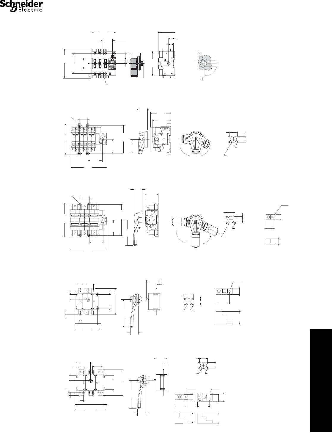
File D10
The D10 disconnect switch features high I2T rating, longer contact life, visible contact indication, fuse-mounting flexibility, dead-front construction,
and auxiliary interlocks.
A complete installation includes a D10 disconnect switch, D11 handle operator, and D12 fuse clip kit. The D10 accepts Class H, K, J, or R fuses or
can be used for non-fusible applications. The D10 disconnect switch is operated by a cast metal handle operator that is lockable in the “OFF”
position and defeatable in the “ON” position.
Table 8.40: Disconnect Switches (without fuse
clips or shorting straps)
600 V—Without Service Entrance Rating
Starter
NEMA
Type
Size
Rating
(A)
Max. Horsepower RatingaCatalog
Number $ Price
120 V 200–
240 V 480 V 600 V
0–1 30 5 10 20 25 D10S1 270.00
26010204050D10S2 292.00
3 100 15 30 60 75 D10S3 452.00
4 200 25 50 100 100 D10S4 860.00
600 V—With Service Entrance Rating
Starter
NEMA
Type
Size
Rating
(A)
Max. Horsepower Rating aCatalog
Number $ Price
120 V 200–
240 V 480 V 600 V
0–1 30 5 10 20 25 D10S1H 320.00
26010204050D10S2H 352.00
3 100 15 30 60 75 D10S3H 544.00
4 200 25 50 100 100 D10S4H 1154.00
Table 8.41: Rotary Handle Operator Kits and Shafts
Kits include: Handle, shaft, and actuator
NEMA Type 1, 3, 3R, 4, and 12
Description Rating
(A) Enclosure Interior
Depth—Inches Catalog
Number $ Price
Complete Kit with
Handle, Shaft, and
Actuator
30, 60,
100, 200
5–6 D11SF4 106.00
6–10 D11SF10 118.00
10–16 D11SF16 130.00
Shaft only 30, 60,
100, 200
6D11SH10 26.20
12 D11SH16 32.80
Table 8.42: Auxiliary Electrical Interlock
(for mounting on 30 A—200 A disconnect switch a)
Block Description
(with switch contacts open) Catalog
Number $ Price
1 N.O. D11N0 79.00
1 N.C. D11NC 79.00
1 N.O. and 1 N.C. D11N0C 116.00
2 N.O. D11N00 116.00
2 N.O. and 2 N.C. D11N0C2 130.00
Table 8.43: Interrupting and Withstandability
Ratings
Rating (A) Interrupting Rating
Amperes Symmetrical
600 Vac, 3Ø
Withstandability I2T
(Amperes2 seconds)
30 1,200 0.38 x 10⁶
60 1,800 1.28 x 10⁶
100 2.000 2.62 x 10⁶
200 3,600 5.25 x 10⁶
Line Shield
Centerline
of Switch
Operating
Shaft
IJ
D
A
B
E
FH
C
G
Table 8.44: Lug Data
Rating (A) Number
Per Pole Wire RangeaWire Type
30
1
#14–#8 Cu
60 #14–#4 Cu
100 #14–#1/0 Al–Cu
200 #6–250 kcmil Al–Cu
Table 8.45: Fuse Clip Kits
D10
Switch Size
Fuse Clip Rating aCatalog
Number $ Price
Amperes AC Volts Type
30 A
No Fuse D12C01 8.30
0–30 250 H, K D12C21 16.30
0–30 250 R D12CR21 65.00
0–30 600 H, K D12C61 24.50
0–30 600 R D12CR61 65.00
0–30 600 J D12CJ1 49.30
31–60 250 H, K D12C22 24.50
31–60 600 H, K D12C62 49.30
31–60 600 R D12CR62 82.50
31–60 600 J D12CJ2 57.50
61–100 250 H, K D12C23 65.00
60 A
No Fuse D12D02 24.50
0–30 250 R D12DR21 65.00
0–30 600 H, K D12D61 24.50
0–30 600 R D12DR61 65.00
31–60 250 H, K D12D22 23.80
31–60 250 R D12DR22 82.50
31–60 600 H, K D12D62 41.00
31–60 600 R D12DR62 82.50
31–60 600 J D12DJ2 57.50
61–100 250 H, K D12D23 65.00
61–100 600 H, K D12D63 115.00
61–100 600 J D12DJ3 106.30
61–100 600 R D12DR63 113.80
100 A
No Fuse D12E03 49.30
31–60 250 H, K D12E22 41.00
31–60 600 H, K D12E62 41.00
61–100 250 H, K D12E23 32.50
61–100 250 R D12ER23 115.00
61–100 600 H, K D12F63 90.00
61–100 600 R D12FR63 115.00
61–100 600 J D12EJ3 115.00
101–200 250 H, K D12F24 106.30
101–200 600 H, K D12F64 122.50
101–200 600 J D12FJ4 140.00
200 A
No Fuse D12F04 82.50
61–100 600 H, K D12F63 90.00
101–200 250 H, K D12F24 106.30
101–200 250 R D12FR24 140.00
101–200 600 H, K D12F64 122.50
101–200 600 R D12FR64 135.00
101–200 600 J D12FJ4 140.00
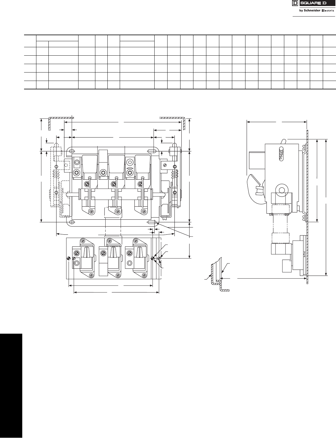
Table 8.46: Switch Dimensions (in inches)
Rating
(A)
Length Width Mounting Hole Dimensions Depth
ABCDEFGHIJKalb
30 7-5/16 4-15/32 5-7/8 3-15/32 6 3-15/32 1-7/8 13/32 5-7/16 3-1/4 4-3/32 4-11/32
60 7-5/16 4-15/32 5-7/8 3-15/32 6 3-15/32 1-7/8 13/32 5-7/16 3-1/4 4-11/32 4-11/32
100 9-27/32 5-11/32 8-3/16 4-5/8 5-13/16 3-13/16 2-11/16 51/64 7-5/16 4-3/16 5-23/32 4-27/32
200 12-3/16 7-7/32 8-3/16 4-5/8 5-13/16 3-13/16 2-11/16 51/64 7-5/16 4-3/16 5-23/32 4-27/32
aMaximum depth with largest fuse.
bDepth including insulating barrier on service entrance switches.
CP1 Discount
Schedule
Courtesy of Steven Engineering, Inc.-230 Ryan Way, South San Francisco, CA 94080-6370-Main Office: (650) 588-9200-Outside Local Area: (800) 258-9200-www.stevenengineering.com
www.schneider-electric.us
8OPERATOR MECHANISMS AND
DISCONNECT SWITCHES
© 2009 Schneider Electric
All Rights Reserved 8-13
NEMA Style Disconnect
Switches
Door-Mounted Operating Mechanisms for Square D Circuit Breakers
Class 9421 / Refer to Catalog 9420CT9701
Type L Circuit Breaker Mechanisms
Type L door-mounted, variable depth operating mechanisms feature heavy duty, all metal construction with trip
indication. All can be padlocked in the “OFF” position when the enclosure door is open. Further, the handle assemblies
can be locked “OFF” with up to three padlocks, which also locks when the door is closed. (The 3” handle accepts one
padlock.) Complete kits are rated for NEMA Type 1, 3R, and 12 enclosures. They include a handle assembly, operating
mechanism, and shaft assembly.
aContains support bracket.
aOptional accessory for use with 9421L operating mechanisms.
Note: Not used with GJL, NAL, NCL, NEL, NXL, NSF, NSJ, PowerPact® C, D, H, and J circuit breakers; use field-installed circuit breaker interlocks instead.
Table 8.47: Complete Kits
Complete Kit
Does Not Include Circuit Breaker Includes:
Operating Mechanism
Standard 6 in. Handle
Standard Shaft Kit
Includes:
Operating Mechanism
Standard 6 in. Handle
Long Shaft Kit
Includes:
Operating Mechanism
Short 3 in. Handle
Long Shaft Kit
Use With
Circuit Breaker or
Interrupter Type
No.
of
Poles
Frame
Size
(A) Type $ Price Mounting
Depth a
Min. – Max. Type $ Price Mounting
Depth a
Min. – Max. Type $ Price Mounting
Depth a
Min. – Max.
GJL 3 75, 100 LG1 140.00 5-1/2–10-1/4 LG4 158.00 5-1/2–20-7/8 LG3 198.00 5-1/2–20-7/8
FAL, FCL, FHL 2–3 100 LN1 140.00 5-1/2–10-7/16 LN4 158.00 5-1/2–21 LN3 198.00 5-1/2–21
KAL, KCL, KHL 2–3 250 LP1 171.00 6-1/4–11-3/16 LP4 189.00 6-1/4–21-3/4 LP3 230.00 6-1/4–21-3/4
NSF, PowerPact® H and J 2–3 250 LJ1 171.00 5-1/2–10-3/4 LJ4 189.00 5-1/2–21-3/8 — ——
LALc, LHLc, Q4L 2–3 400 LR1 242.00 6-5/16–10-7/8 LR4 255.00 6-5/16–21-1/2
3 in. handles are not recommended
for use with these circuit breakers.
MEL, MXL 2–3 800 LT1b242.00 7-3/16–11-5/8 LT4b255.00 7-3/16–22-1/4
MAL, MHL 2–3 1200 LT 1b242.00 7-3/16–11-5/8 LT4 b255.00 7-3/16–22-1/4
NAL, NCL, NEL, NXL 2–3 1200 LX1b242.00 8-1/4–12-3/4 LX4b255.00 8-1/4–23-3/8
PowerPact M and P e31200LW1d242.00 7-3/16–11-5/8 LW4d255.00 7-3/16–22-1/4
Table 8.48: Component Parts
Use With 3 in. Handle
Assemblies
Type 1, 3R, 12
Standard Handle
Assemblies
Type 1, 3R, 12
Operating
Mechanism
Includes
Lockout
Standard Shaft
(Support Bracket Not
Required)
Long Shaft
(Support Bracket Included)
Circuit Breaker or
Interrupter Type
No.
of
Poles
Frame
Size
(A) Type $ Price Type $ Price Type $ Price Mounting
Depth a
Min. – Max. Type $ Price Mounting
Depth a
Min. – Max. Type $ Price
GJL 3 75, 100 LH3 90.00 LH6 50.00 LG7 68.00 5-1/2–10-7/16 LS8 21.50 5-1/2–21 LS13 35.60
FAL, FCL, FHL 2–3 100 LH3 90.00 LH6 50.00 LF1 71.00 5-1/2–10-7/16 LS8 21.50 5-1/2–21 LS12 35.60
KAL, KCL, KHL 2–3 250 LH3 90.00 LH6 50.00 LK1 105.00 6-1/4–11-3/16 LS8 21.50 6-1/4–21-3/4 LS12 35.60
NSF, PowerPact H and J 2–3 250 LH3 90.00 LH6 50.00 LJ7 105.00 5-1/2–10-1/4 LS8 21.50 5-1/2–21-3/8 LS13 35.60
LALc, LHLc, Q4L 2–3 400 3 in. handles
are not
recommended
for use with
these circuit
breakers.
LH6 50.00 LL1 170.00 6-5/16–10-7/8 LS8 21.50 6-5/16–21-1/2 LS10 35.60
MEL, MXL 2–3 800 LH8 50.00 LM1 170.00 7-3/16–11-5/8 LS8 21.50 7-3/16–22-1/4 LS10 35.60
MAL, MHL 2–3 1200 LH8 50.00 LM1 170.00 7-3/16–11-5/8 LS8 21.50 7-3/16–22-1/4 LS10 35.60
NAL, NCL, NEL, NXL 2–3 1200 LH8 50.00 LX7 170.00 8-1/4–12-3/4 LS8 21.50 8-1/4–23-3/8 LS10 35.60
PowerPact M and Pe31200 LHP8 50.00 LW7 170.00 7-3/16–11-5/8 LS8 21.50 7-3/16–22-1/4 LS10 35.60
aMounting depth measured from circuit breaker mounting surface (control panel) to outside of enclosure door in inches.
bTypes LT1, LT4, LX1, and LX4 include an 8 in. handle rather than a 6 in. handle.
cNote: These operating mechanisms cannot be used with any LA/LH circuit breaker with an MB or MT suffix.
dType LW1 and LW4 include an 8 in. handle (9421LHP8) rather than a 6 in. handle.
eThese circuit breakers must use the 9421LHP** or LCP** handles only.
Table 8.49: NEMA Type 4 and 4X Handle Assemblies a
Use With Standard Handle Assemblies Special 3 in. Version
Circuit Breaker or
Interrupter Type
No.
of
Poles
Frame
Size
(A)
NEMA Type 1, 3R,
4, 12
(Painted)
NEMA Type 1, 3R,
4, 4X, 12
(Chrome Plated)
NEMA Type 1, 3R,
4, 12
(Painted)
NEMA Type 1, 3R,
4, 4X, 12
(Chrome Plated)
Type $ Price Type $ Price Type $ Price Type $ Price
GJL 3 75 LH46 90.00 LC46 149.00 LH43 165.00 LC43 233.00
FAL, FCL, FHL 2–3 100 LH46 90.00 LC46 149.00 LH43 165.00 LC43 233.00
KAL, KCL, KHL 2–3 250 LH46 90.00 LC46 149.00 LH43 165.00 LC43 233.00
NSF, PowerPact H and J 2–3 250 LH46 90.00 LC46 149.00 LH43 165.00 LC43 233.00
LAL, LHL, Q4L 2–3 400 LH46 90.00 LC46 149.00
3 in. handles are not recommended for use
with these circuit breakers.
MEL, MXL 2–3 800 LH48 90.00 LC48 149.00
MAL, MHL 2–3 1000 LH48 90.00 LC48 149.00
NAL, NCL, NEL, NXL 2–3 1200 LH48 90.00 LC48 149.00
PowerPact M and P 3 1200 LHP48 90.00 LCP48 149.00
aDue to gasketing, NEMA Type 3 & 4 handle assemblies are NOT trip indicating.
Table 8.50: IEC Style Operating Mechanisms
Circuit Breaker or
Interrupter Type
Type 1, 4, 4X, 12 Operating Mechanism
Includes Lockout Extension Shafts
Mounting Depth Type $ Price
Color Type $ Price Type $ Price Min. Max.
GJL Red/Yellow NW3 90.00 LG8 $71.00 6-1/8 10-3/4 NS16 28.70
Black NW3B 90.00 6-1/8 17-7/8 NS336a35.60
Table 8.51: Electrical Interlock Kits—Class 9999 a
Description Class Type $ Price
Single Pole Double Throw 9999 R47 131.00
Double Pole Double Throw 9999 R48 221.00
Operating
Mechanism
3 in. Handle
Assembly
Standard
Handle
Assembly
CP1 Discount
Schedule
Courtesy of Steven Engineering, Inc.-230 Ryan Way, South San Francisco, CA 94080-6370-Main Office: (650) 588-9200-Outside Local Area: (800) 258-9200-www.stevenengineering.com

8-14 © 2009 Schneider Electric
All Rights Reserved
www.schneider-electric.us
8OPERATOR MECHANISMS AND
DISCONNECT SWITCHES
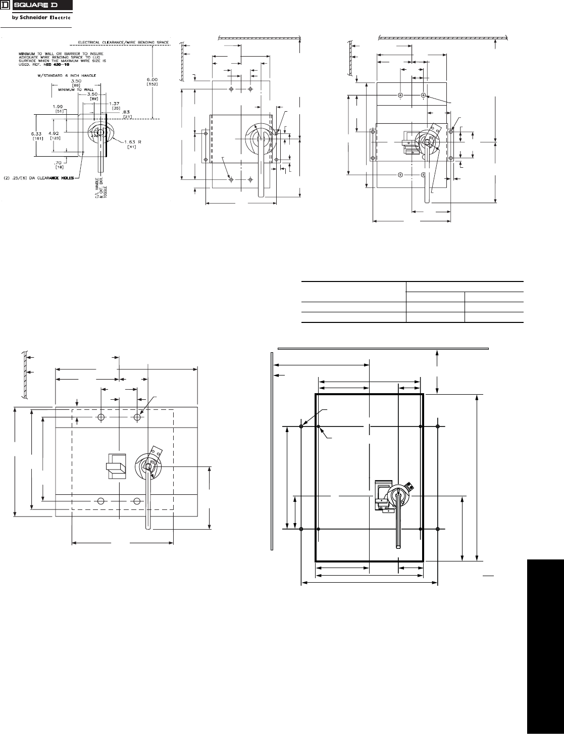
Dimensions Door Mounted Operating Mechanisms
Class 9421 / Refer to Catalog 9420CT9701
aMounting depth measured from circuit breaker mounting surface (control panel) to outside of enclosure door.
Table 8.52: Shaft Cutting Dimensions
Class Type Shaft Length
Formula
H = Standard Shaft H = Long Shaft
Min. Max. Min. Max.
9421 LG7, LG1, LG4, LG3 L = H–2.50 5.50 10.25 5.50 20.85
64 140 260 140 530
9421 LF1, LN1, LN3, LN4 L = H–2.88 5.50 10.44 5.50 21.00
73 140 265 140 533
9421 LK1, LP1, LP3, LP4 L = H–3.63 6.25 11.19 6.25 21.75
92 159 284 159 552
9421 LJ1, LJ4, LJ7 L= H–3.00 5.5 10.75 5.5 21.63
76 138 273 138 543
9421 LL1, LR1, LR4 L= H–3.13 6.31 10.88 6.31 21.50
79 160 276 160 546
9421 LM1, LT1, LT4 L= H–4.00 7.18 11.63 7.18 22.25
102 182 295 182 565
9421 LX7, LX1, LX4 L= H–5.17 8.25 12.75 8.25 23.38
131 210 324 210 594
9421 LW1, LW4, LW7 L= H–4.89 7.19 11.63 7.63 22.25
124 183 295 183 565
Handle Mechanism
Handle
Mechanism
(2) #8-32 Tap2.38
60
L
H
Mounting Depth
.28 Maximum
7 Door Thickness
L = Overall shaft length
H = Distance from inside of enclosure door to circuit
breaker mounting surface
1.38
35
3.50 Min.
45
1.18
30
.50
13
.45
12
4.72
120
1.77
45
3.94
100
Screw Driver
Interlock Pin
Location
CL
CL
X
Refer to NEC
Article 430-10
for minimum
dimension from
top mounting hole
to wall or barrier
to insure adequate
wire bending space.
Panel drilling for GJL circuit breaker
and operating mechanism a
2.25
57
1.50
38
7.00
178
1.6 3
41
6.00
152
R
5.13
130
(4) #8-32 Tap
1.56
40
.75
19
4.50
114
Hinge
Point of
Door
C
L Handle
Mechanism
C
L Handle & Ckt. Bkr. T oggle
Minimum to wall or
barrier to insure
adequate wire bending
space to lug surface
when maximum wire
size is used with
standard lugs.
Refer to NEC Article
430-10.
3.25 Minimum
83 (Both Sides)
Panel drilling for FAL, FCL, FHL circuit breaker
and operating mechanism
3.25 Minimum
83 (Both Sides)
2.25
57
1.50
38
13.50
343
1.6 3
41
6.00
152
R
7.13
181
(4) #10-24 Tap
C30080-120
1.81
46
.75
19
4.50
114
Hinge
Point of
Door
C
L Handle & Ckt. Bkr. T oggle
Minimum to wall or
barrier to insure
adequate wire bending
space to lug surface
when maximum wire
size is used with
standard lugs.
Refer to NEC Article
430-10.
Panel drilling for KAL, KCL, KHL circuit breaker
and operating mechanism
Courtesy of Steven Engineering, Inc.-230 Ryan Way, South San Francisco, CA 94080-6370-Main Office: (650) 588-9200-Outside Local Area: (800) 258-9200-www.stevenengineering.com
www.schneider-electric.us
8OPERATOR MECHANISMS AND
DISCONNECT SWITCHES
© 2009 Schneider Electric
All Rights Reserved 8-15
Dimensions Door Mounted Operating Mechanisms
Class 9421 / Refer to Catalog 9420CT9701
Circuit Breaker Type Dimensions = in. (mm)
AB
MAL, MHL 10.69 (272) 14.00 (356)
MEL, MXL 11.47 (291) 14.75 (375)
Panel Drilling for PowerPact® H and J
Circuit Breakers and Operating Mechanism
(4) 1/4-20 Tap
C
L Handle
C
L
Circuit Breaker
C
L Handle
9.25
235
4.57
116
6.00
152 19.19
487
.88
22
.88
22
6.00 Minimum
152 (Both Sides)
Hinge
Point
of Door
Minimum to wall or
barrier to insure adequate
wire bending space
to lug surface when
maximum wire size
is used with standard lugs.
Refer to NEC Article 430-10.
4.68
119
7.19
183
(4) #12-24 Tap
2.68
68
.56
14
6.00
152
.44
11
.38
10
3.00
76 2.00
51
1.00
25
1.59
40
1.63R
41
2.00
51
Panel Drilling for LAL, LHL, and Q4L
Circuit Breakers and Operating Mechanism
C
L
Circuit Breaker
4.50
114 3.00
76
3.09
79
3.50
89
1.66
42
A
B
4.937
125
8.00
203
.38
10
.44
11
1.63R
41
1.03
26
(4) 5/16-18 Tap
(4) 1/4-20 Tap
Minimum to wall or
barrier to insure
adequate wire bending
space to lug surface
when maximum wire
size is used. Refer to
NEC Article 430-10.
2.00
51
1.50
38
9.00
229
Hinge
Point
of
Door
5.09
129
10.19
259
X
8.00 Minimum
203 (Both Sides)
C
L
Handle
C
L
Handle
Panel Drilling for MAL, MEL, MHL, and MXL
Circuit Breakers and Operating Mechanism
Panel Drilling for NAL, NCL, NEL, and NXL
Circuit Breaker and Operating Mechanism
9.00 Minimum (Both Sides)
229
7.50
191
8.50
216
8.00
203
12.13
308
9.50
241
8.75
222 1.6 3R
41
1.66
42
5.00
127
3.16
80
2.50
64
(4) 1/4-20 Tap
15.00
381
Hinge
Point
of Door
C
L Handle
Mechanism
C
L
Circuit Breaker
C
L
Handle Mechanism
3.92
100 1.70
43
7.83
199
2.51
64
7.87
200
3.02
77
10.48
266
P
(4) #10-32 tap
N
(4) 1/4-20 tap
M
5.24
133 8.27
210
800 A:
2.49
63
800 A: 12.86
327
Q
R
R
MIN.: 8 in. (203 mm)
(both sides) X
1200 A:
4.10
104
1200 A: 16.26
413
in.
mm
Dim. =
Minimum to wall or barrier to
insure adequate wire bending
space to lug surface when
maximum wire size is used.
Refer to NEC Article 430-10.
Panel Drilling for PowerPact® M and P Circuit Breaker
and Operating Mechanism
Courtesy of Steven Engineering, Inc.-230 Ryan Way, South San Francisco, CA 94080-6370-Main Office: (650) 588-9200-Outside Local Area: (800) 258-9200-www.stevenengineering.com
www.schneider-electric.us
8OPERATOR MECHANISMS AND
DISCONNECT SWITCHES
8-16 © 2009 Schneider Electric
All Rights Reserved
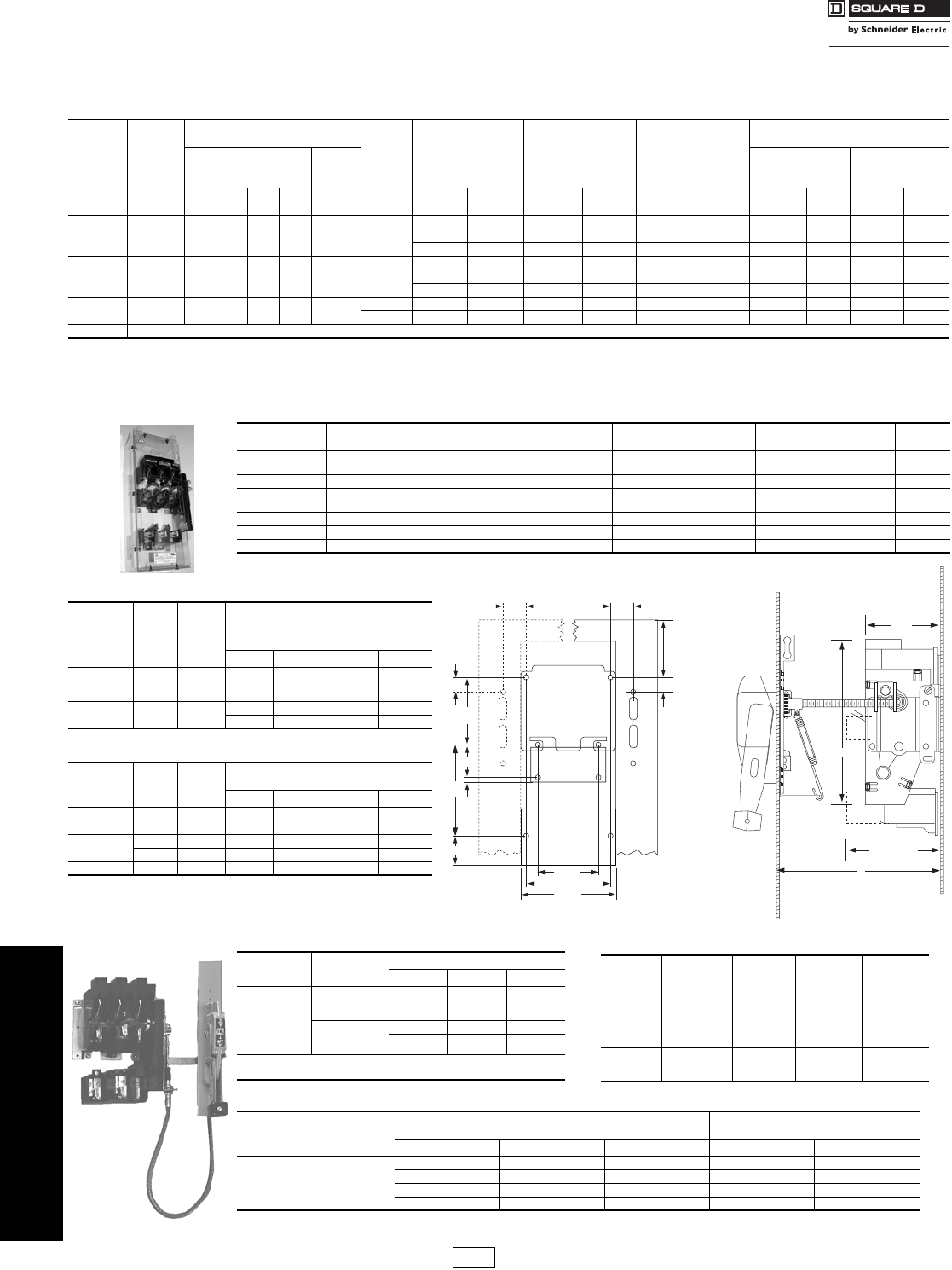
Disconnect Switches Flange Mounted, Variable Depth, and Cable Operated
Class 9422 / Refer to Catalog 9420CT9701
aNo Class Number is required.
bFor price, use Discount Schedule DE1, not CP1
The Class 9422 Type TCF, TCN, TDF, TDN, TEF, TEN disconnect switches were designed for control panel installations. These switches include common switch profile 30–100 A, interchangeable fuse
clips 30–60 A, and the ability to add fuse clip kits and cable mechanisms. They are compatible with 9422A and 9423, and are UL recognized and CSA certified.
Table 8.53: Class 9422 Flange Mounted, Variable Depth Disconnect Switches
Disconnect
Switch
Size
Variable
Depth
Mtg.
Range
Min.–Max.
(in.)
Maximum Horsepower Ratings
Fuse
Type
Fuse Clip Rating
(Amperes) Non-
Interchangeable Type
For Class H, J, K
or R Fuses Only
Switch and Operating
Mechanism Only—
Does Not Include
Handle Mechanism
Switch for Use With
Cable Operators
ONLY—
Does Not Include
Handle Mechanism or
Cable Operator
Switch and Operating Mechanism
and Handle Mechanism—Overpacked
AC Systems Volts
(Motor Volts) DC Using
2 Poles
250 V
Max.
Includes Type A1
Handle Mechanism Includes Type A2
Handle Mechanism
208
(200) 240
(230) 480
(460) 600
(575) 250 V 600 V Type $ Price Type $ Price Type $ Price Type $ Price
30 A 6-5/8–18 7.5 7.5 15 20 5
None — — TCN30 329.00 TCN30C 315.00 ATCN301 471.00 AT C N 3 0 2 585.00
H, K, J, R 30 — TCF30 372.00 TCF30C 359.00 AT C F 3 0 1 513.00 ATCF3 0 2 629.00
60 30 TCF33 399.00 TCF33C 386.00 AT C F 3 3 1 543.00 ATCF3 3 2 660.00
60 A 6-5/8–1815153050 10
None — — TDN60 386.00 TDN60C 372.00 ATDN601 527.00 AT D N 6 0 2 642.00
H, K, J, R 60 30 TDF60 458.00 TDF60C 444.00 AT D F 6 0 1 599.00 ATDF6 0 2 714.00
—60TDF63 485.00 TDF63C 471.00 AT D F 6 3 1 629.00 AT DF632 741.00
100 A 6-5/8–1825306075 20 None — — TEN10 570.00 TEN10C 557.00 ATEN101 714.00 ATEN1 0 2 827.00
H, K, J, R 100 100 TEF10 783.00 TEF10C 770.00 ATEF10 1 926.00 ATEF102 1040.00
200–400 A See 9422 TF and TG on page 8-17
Table 8.54: Internal Barrier Kits
Provide an additional barrier that helps prevent accidental contact with live parts. Field installed transparent barriers do not restrict visual inspection of the switch. Barriers provide IEC529 IP2X “finger safe”
protection when the door of the enclosed disconnect switch is open. A convenient door allows use of test probes without accessing fuses and replacement of fuses without removing barrier. Barrier must be
used with the skirt kit to enclose a panel mounted type 9422 disconnect.
Catalog No. ab Description Safety Switch Application
(F series only) 9422 Type T Disconnect
Application $ Price b
SS06 Interior barrier for 60 A safety switch, 30 or 60 A 9422 switch 600 Vac–60 A 600 Vac–30 A
600 Vac–60 A 220.00
SS10 Interior barrier for 100 A safety switch or 100 A 9422 switch 600 Vac–100 A 600 Vac–100 A 260.00
SS0306SK Skirt kit to enclose 30 or 60 A 9422 switch (requires SS06) — 600 Vac–30 A
600 Vac–60 A 300.00
SS10SK Skirt kit to enclose 100 A 9422 switch (requires SS10) — 600 Vac–100 A 340.00
30528-358-50S Interior barrier for 200 A 9422 disconnect switch — 600 Vac–200 A 272.00
30528-369-50S Interior barrier for 400 A 9422 disconnect switch — 600 Vac–400 A 390.00
Table 8.55: Class 9422 Replacement/Retrofit Fuse Clip Kits
Disconnect
Switch
Size
Switch
Type Fuse
Type
Fuse Clip Rating
(Amperes)
Line and Load
Fuse Clip Kit
(includes load base
and fuse pullers)
250 V 600 V Type $ Price
30 A
TCF30
TCN30
TCF33
H, K, J, R
30 — TC30 42.80
60 30 TC33 71.00
60 A TDN60 H, K, J, R 60 30 TC33 71.00
—60TD63 99.00
Table 8.56: Class R Fuse Clip Kits
Disconnect
Switch
Size
Switch
Type Fuse
Type
Fuse Clip Rating
(A) Rejection Feature —
Class R Kit b
250 V 600 V Cat No. a$ Price
30 A TCF30 R 30 — RFK03 32.69
TCF33 R 60 30 RFK06 34.00
60 A TDF60 R 60 30 RFK06 34.00
TDF63 R — 60 RFK06H 34.00
100 A TEF10 R 100 100 RFK10 64.00
aNo Class Number required.
bFor price, use Discount Schedule DE1, not CP1.
Table 8.57: Class 9999 Electrical Interlocks
Disconnect
Switch Size Switch Type Electrical Interlock
Contacts Type $ Price
30 A
60 A
100 A
TCF, TCN
TDF, TDN
TEF, TEN
SPDTaTC10 120.00
DPDTbTC20 239.00
BTCF, BTCN
BTDF, BTDN
BTEF, BTEN
SPDTaTC11 120.00
DPDTbTC21 239.00
a1 N.C. or 1 N.O. depending on wiring.
b2 N.C., 2 N.O. or 1 N.O., 1 N.C. depending on wiring.
1.41 1.41
1.00
0.30
1.50*
B
4.50
1.00
4.00
*0.30 for 100 A
Class J fuses
A
5.50
6.20
30 A
60 A = 3.50
100 A = 5.75
8.80"
4.00"
D
100A = 5.10"
D = Distance from handle mechanism
mounting surface to disconnect switch
surface. D min. = 6 5/8" D max. = 18"
Table 8.58: Dimensions
Switch
Type Maximum
Voltage Fuse Type
Class Dimension A Dimension B
30 A,
60 A
30 A, 250 V
30 A, 600 V
30 A, 600 V
60 A, 250 V
60 A, 600 V
60 A, 600 V
H, K, R
H, K, R
J
H, K, R
H, K, R
J
1.625
4.25
1.625
2.25
4.75
1.625
—
100 A
100 A, 250 V
100 A, 600 V
100 A, 600 V
H, K, R
H, K, R
J
—
3.25
5.25
3.25
Table 8.59: Class 9422 Disconnect Switch Cable Operators (must purchase switch separately)
Disconnect
Switch Size Switch Type Cable MechanismsaCable Mechanisms with A1
Handle for Types 1, 3, 3R, 4 and 12
Cable Length Type $ Price Type $ Price
30 A,
60 A,
100 A
TCF, TCN
TDF, TDN
TEF, TEN
36 in. CFT30 273.00 CFT31 417.00
48 in. CFT40 291.00 ——
60 in. CFT50 291.00 CFT51 432.00
120 in. CFT10 333.00 CFT11 476.00
aPurchase handle mechanism separately (9422, A1, A2, A3 or A4).
CP1 Discount
Schedule
Courtesy of Steven Engineering, Inc.-230 Ryan Way, South San Francisco, CA 94080-6370-Main Office: (650) 588-9200-Outside Local Area: (800) 258-9200-www.stevenengineering.com
www.schneider-electric.us
8OPERATOR MECHANISMS AND
DISCONNECT SWITCHES
© 2009 Schneider Electric
All Rights Reserved 8-17
Disconnect Switches Flange Mounted, Variable Depth
Class 9422 / Refer to Catalog 9420CT9701
Table 8.61: Class R Fuses
Fusible disconnect switches on this page and page 8-16
will accept Class R fuses as standard. A field installable
rejection kit is available which, when installed, rejects all
but Class R fuses. With the rejection kit and Class R fuses
installed, the switch is UL component recognized for use
on systems with up to 200,000 RMS symmetrical amperes
fault current available.
Table 8.62: Handle Mechanisms
Handle mechanism kits are used with all disconnect switch
and circuit breaker installations. The kits contain all parts
necessary for mounting the handle to the flange of the
enclosure. The Types A1–A4, A9–A10 are suitable for right
or left hand flange mounting. Two mounting methods are
offered. The Types A5–A8 handles are designed for right
hand mounting only.
aUse with 30–200 A switches and all circuit breaker mechanisms.
bAll external metal parts are either stainless steel or a chrome-plated
non-ferrous die casting.
cUse with 400 A Type TG1 and TG2 disconnect switches only.
dUse with Type D2 remote or dual adapter kit listed on page 8-24.
eUse with 9422 RM1 and 9422 CMP only.
Optional accessory for use with disconnect switches listed
on this page.
The type AP1 and AP2 handles are used exclusively on
the PowerPact® M and P Operating Mechanisms, 9422
RM1 and 9422 CMP. The dimensions are identical to
9422 A1.
Ordering Information
The 9422 Type T disconnect switches are designed for variable depth, flange mounting applications. These switches are
fully compatible with 9422 handle operators and 9423 door closing mechanisms. They feature: 200 and 400 A; fusible
(Classes H, K, J, or R fuses) and nonfusible; right or left flange mounting (except 400 A, which mounts only right hand
flange and requires a special enclosure), UL recognized, and CSA certified.
Table 8.60: Disconnect Switches
Disconnect
Switch
Size
Variable Depth
Mounting Range
Min.–Max. (in.)
Maximum Horsepower RatingsaFuse Clip Rating (A)
Non-Interchangeable
Type For Class
H, J, K, or R Fuses Only
Switch and Operating
Mechanism Only—
Does Not Include
Handle Mechanism
Switch and Operating Mechanism
and Handle Mechanism—Overpacked
AC Systems Volts (Motor Volts) DC
Using
2 Poles
250 V
Max.
Includes Type A1
Handle Mechanism Includes Type A2
Handle Mechanism
208
(200) 240
(230) 480
(460) 600
(575) 250 V 600 V Type $ Price Type $ Price Type $ Price
200 A 9.12–19.25b40 60 125 150 40
Non-Fusible TF1 1247.00 ATF11 1389.00 AT F 2 1 1503.00
200 200 TF2 1389.00 ATF12 1530.00 AT F 2 2 1646.00
—400TF3c2052.00 ATF13c2195.00 AT F 2 3 c2307.00
400 A
Fixed Depthd
11.38
(A5 or A6 Handle) 75 125 250 350 50
Non-Fusible TG1fg 2672.00
For handle selection, see Table 8.62.
400 A
Adj. Depthd
15.87–19e
(A7 or A8 Handle) 400 400 TG2fg 3027.00
aRefers to rating of switch only.
b9422 R2, shown on page 8-23, will extend maximum mounting depth 7 inches.
cAccommodates Class J fuses only.
dSwitches are either fixed-depth or adjustable; the handle will determine installation.
eIn increments of 0.63 inches.
fCommercially available enclosures may not accept type TG operating mechanisms. Contact enclosure manufacturer for availability of enclosures for use with these switches.
gRight hand flange mounting only.
Switch
Rating
(A) Type Fuse Clip Rating Class Type $ Price
250 Vac 600 Vac
200 TF 200 A 200 A 9999 SR4 47.60
400 TG 400 A 400 A 9999 SR5 107.00
Type of Handle NEMA Type Enclosure Type $ Price
6 in. a1, 3, 3R, 4 (sheet steel), 12 A1 143.00
4, 4X (stainless steel)bA2 257.00
6 in. ae 1, 3, 3R, 4 (sheet steel), 12 AP1 188.00
4, 4X (stainless steel)bAP2 338.00
4 in. a1, 3, 3R, 4 (sheet steel), 12 A3 143.00
4, 4X (stainless steel)bA4 257.00
12 in.
(fixed depth) c
1, 3, 3R, 4 (sheet steel), 12 A5 251.00
4 (stainless steel) A6 320.00
12 in.
(adjustable depth)c
1, 3, 3R, 4 (sheet steel), 12 A7 300.00
4 (stainless steel) A8 372.00
10 in. d1, 3, 3R, 4 (sheet steel), 12 A9 158.00
4 (stainless steel) A10 270.00
Table 8.63: Electrical Interlocks
For Use
On
Switch
Type
Class Single Pole
Interlock
Type $ Price Class Two Pole
Interlock
Type $ Price
TF, ATF 9999 R8 83.00 9999 R9 243.00
TG 9999 R35 275.00 9999 R36 521.00
ON
OFF
RESET
5.69
144
1.13
29
1.06
27
Type A1
Table 8.64: Lug Data
Disconnect
Switch Size Wire Size
Minimum–Maximum
30 A, 60 A #14–#2 Cu, #10–#2 Al
100 A #10–#0 Cu, #6–#0 Al
200 A #6–300 kcmil Cu or Al
400 A #4–500 kcmil Cu
.88
22
6.13 (9422 A1 and A2)
156
4.50 (9422 A3 and A4)
114
10.13 (9422 A9 and A10)
257
Enclosure
Flange
3.50 Maximum
89 “On”
Stiffener
Bracket
Door
Door Interlock
Hook
Door Interlock
Defeater Screw
2.16
55
C
L of Operating Mechanism
9422 A1, A2, A3, A4, A9, and A10 Handles
Rod used only on the
variable-depth mechanism.
CP1 Discount
Schedule
Courtesy of Steven Engineering, Inc.-230 Ryan Way, South San Francisco, CA 94080-6370-Main Office: (650) 588-9200-Outside Local Area: (800) 258-9200-www.stevenengineering.com
www.schneider-electric.us
8OPERATOR MECHANISMS AND
DISCONNECT SWITCHES
8-18 © 2009 Schneider Electric
All Rights Reserved
Disconnect Switches Flange Mounted, Variable Depth
Class 9422 / Refer to Catalog 9420CT9701
Dimensions
Table 8.65: Dimensions (in. / mm) for 200 A Type TF Disconnect Switches
Type Switch Size ABC DaEFGHJKLMNPQRST
(A) Fuse Clips Min.–Max.
TF1 200 None 13.33
339 9.38
238 1.64
42 9.12–19.25
232 489 2.33
59 8.00
203 ———
9.44
240 6.50
165 9.53
242 ———
3.14
80 1.03
26 0.75
19
TF2 200 Class J
200 A 600 V 13.33
339 9.38
238 1.64
42 9.12–19.25
232 489 2.33
59 8.00
203 0.09
3—2.77
70 9.44
240 6.50
165 —14.11
358 —9.63
245 3.14
80 1.03
26 0.75
19
TF2 200 Class H, K, R
200 A 250 V 13.33
339 9.38
238 1.64
42 9.12–19.25
232 489 2.33
59 8.00
203 0.09
3—4.14
105 9.44
240 6.50
165 —15.48
393 —9.63
245 3.14
80 1.03
26 0.75
19
TF2 200 Class H, K, R
200 A 600 V 13.33
339 9.38
238 1.64
42 9.12–19.25
232 489 2.33
59 8.00
203 0.09
3—6.64
169 9.44
240 6.50
165 —17.98
457 —9.63
245 3.14
80 1.03
26 0.75
19
TF3 200 Class J
400 A 600 V 13.33
339 9.38
238 1.64
42 9.12–19.25
232 489 2.33
59 8.00
203 0.09
3—2.77
70 9.44
240 6.50
165 9.53
242 18.53
471 —9.63
245 3.14
80 1.03
26 0.75
19
aThe dimensions shown may be extended 7” by utilizing 9422 R2 (two required per switch).
A
K
B
T
CE
Q
P
G
200 A
100 A
(2) 1/4-20 Tap
H
R
S
F
Vertical C
L Flange
Mt’d Oper. Mech.
S
B
F
100 A – For (4) 1/4-20 Tap
200 A – For (4) 5/16 -18 Tap
L
Dt
Enclosure Flange
Enclosure Door
Distance from outside
of flange to disconnect
switch mounting surface.
N
M
B = Minimum to wall or
barrier, right or left
hand mounting to
insure adequate wire
bending space to lug
surface when maximum
wire size is used. Refer
to NEC Article 430-10.
Courtesy of Steven Engineering, Inc.-230 Ryan Way, South San Francisco, CA 94080-6370-Main Office: (650) 588-9200-Outside Local Area: (800) 258-9200-www.stevenengineering.com

www.schneider-electric.us
8OPERATOR MECHANISMS AND
DISCONNECT SWITCHES
© 2009 Schneider Electric
All Rights Reserved 8-19
Disconnect Switches Flange Mounted, Variable Depth
Class 9422 / Refer to Catalog 9420CT9701
Disconnect Switches—400 A Type TG
Outline Dimensions and General Location, 400 A Disconnect Switches Non-Fusible and Non-Interchangeable
Fuse Clip Type Fusible Switches
Table 8.66: Handle Mechanism—Type A5 through A8
NOTE: Commercially available enclosures may not accept type TG
operating mechanisms. Contact the enclosure manufacturer
for availability of enclosures for use with these switches.
Switch
Type BX
TG1, 2 11.28
286 16.06
408
Note: B and X = Minimum to wall or
barrier to insure adequate wire
bending space to lug surface
when maximum wire size is
used.
Refer to NEC Article 430.10.
11.69
297
1.88
48
9.88
251
3.63
92
Enclosure
Flange
Defeater
Guide
for
Class 9423
Type M1 Kit
Operating
Link
Door
Door Hook
Figure 1
3.75 Max.
95 "On"
C
L of Operating
Mechanism
1.44
37
Figure 2
13.00
330
11.50
292
3.00
76
1. 5 0
38 4.88
124
0.75
19
0.38
10
4.78
121
4.25
108
23.81
605
7.50
191
0.50
13
8.50
216
24.00
610
BX
(2) Mtg. Holes
in Switch Mtg.
Surface
(2) Switch Mtg.
Brackets
D30064-973 B
Figure 3
C
L of Operating
Handle
(2) 0.34 Dia.
9 Holes
Table 8.67: Non-fusible and Fusible Switches
Dimension D = Distance from outside of flange to
disconnect switch mounting surface.
For Type TG1 or TG2 with:
Type A5 or A6 fixed
depth handle mechanism D = 11.38
289
Type A7 or A8 adjustable
depth handle mechanism D = 15.87
403 to 19
483
In steps of 0.63
16
Note: Copper lugs are standard on all Type TG
disconnect switches.
* D = Mounting depth measured from the switch mounting
surface to the surface of flange.
5.50
140
24.00
610
1.86
47
8.13
206
*D
Weld
Weld
Figure 4
13.54
344
12.14
308
23.80
604
25.00
635
8.38
213
6.97
177
3.97
101
1.40
36
0.86
22
0.60
15 B
Class J Fuse
400 A 600 Volt
Class H, K, R Fuses
400 A 250 Volt
Class H, K, R Fuses
400 A 600 Volt
Provision for (2) 5/16 Mtg. Screws
Enclosure
C
L of Operating
Mechanism
Figure 5
Dim. = in.
mm
Courtesy of Steven Engineering, Inc.-230 Ryan Way, South San Francisco, CA 94080-6370-Main Office: (650) 588-9200-Outside Local Area: (800) 258-9200-www.stevenengineering.com
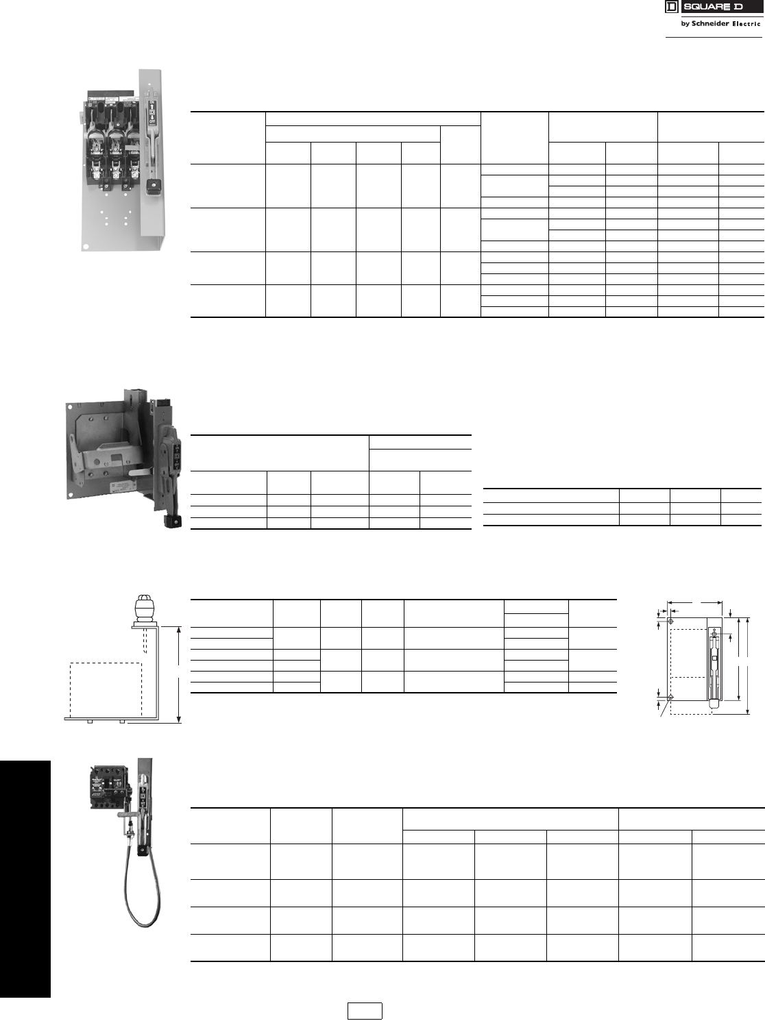
www.schneider-electric.us
8OPERATOR MECHANISMS AND
DISCONNECT SWITCHES
8-20 © 2009 Schneider Electric
All Rights Reserved
Bracket Mounted
Disconnect Devices
Type T Disconnect Switches
Class 9422 / Refer to Catalog 9420CT9701
The Class 9422 Type T disconnect switches listed in the
table below are shipped with the switch and external
handle assembled to a bracket, ready for installation into
the enclosure. A trim plate is provided with each kit to
prevent any mounting screws from being accessible from
the front and also to provide an attractive installation.These
switches can be used with Class 9423 door closing
mechanisms.
aSpace saving design—Type J fuses mounted on the non-fused
bracket.
Note: For Lug Data, see 8-17; for Electrical Interlocks, see page 8-16. Note: Some enclosures may not accept the listed bracket mounted operating
mechanisms; contact the enclosure manufacturer.
aNote: These operating mechanisms cannot be used with any LA/LH
circuit breaker with an MB or MT suffix.
Note: Some enclosures may not accept the listed bracket mounted
operating mechanisms; contact the enclosure manufacturer.
Table 8.70: Electrical Interlock Kits—Class 9999
Optional accessory for use with circuit breaker operating
mechanisms listed to the left and the flexible cable
mechanisms listed below, except GJL.
Note: Not used with GJL; use field installed circuit breaker interlocks.
Table 8.72: Class 9422—Flexible Cable
Mechanisms for Use With Square D
Circuit Breakers
For use with Square D circuit breakers and Class 9422 A
handle operators. Especially designed for tall, deep
enclosures where placement flexibility is required. See
page 8-21 for dimensions.
Table 8.68: Bracket Mounted Disconnect Switches
Disconnect
Switch Size
Maximum Horsepower Rating
Fuse Type
Fuse Clip Rating Bracketed Mounted Switch
Mechanism
and Handle
AC System Volts (Motor Voltage) 250
Vdc208
(200) 240
(230) 480
(480) 600
(600) 250 V
(A) 600 V
(A) Catalog No. $ Price
30 A 7.5 7.5 15 20 5
None — — BTCN30 471.00
H, K, J, R 30 — BTCF30 543.00
60 30 BTCF33 543.00
Ja60 30 BTCF32 543.00
60 A 1515305010
None — — BTDN60 527.00
H, K, J, R 60 30 BTDF60 585.00
—60BTDF63 629.00
Ja—60BTDF62 629.00
100 A 2530607520
None — — BTEN10 714.00
H, K, J, R 100 100 BTEF10 926.00
Ja100 100 BTEF11 926.00
200 A 40 60 125 150 40
None — — TFB1 1488.00
H, K, J, R 200 200 TFB2 1610.00
J—400TFB3 2264.00
Table 8.69: Bracket Mounted Operating Mechanisms for Use With Square D® Circuit Breakers
The circuit breaker operating mechanisms listed below are shipped with the external operating handle assembled to a
bracket. Circuit breakers are not included and must be ordered separately. A trim plate is provided with each kit to
prevent any mounting screws from being accessible from the front and also to provide an attractive installation.The
operating handle is Type A1. These switches can be used with Class 9423 door closing mechanisms.
Use With
Operating Mechanism
Right Hand
Flange Mounting
Circuit Breaker or
Interrupter Type No. of
Poles Frame Size
(A) Cat. No. $ Price
FAL, FHL 2–3 100 BN1 257.00
KAL, KHL 2–3 250 BP1 270.00
LALa, LHLa, Q4L 2–3 400 BR1 543.00
Description Class Type $ Price
Single Pole, Double Throw 9999 R26 131.00
Double Pole, Double Throw 9999 R27 243.00
D
Disconnect
Device
Table 8.71: Dimensions
Type A
in. (mm) C
in. (mm) D
in. (mm) Min. Enclosure Deptha
in. (mm)
Fusible Device F
in. (mm)
E in. (mm)
BTCN, BTDN, BTEN 6.56 (167) 8.00 (203) —
BTCF, BTDF, BTEF 9.50 (241) 1.88 (48) 8.56 (217) 10.00 (254) 11.88 (302) 6.38 (162)
TFB1 11.50 (292) 3.88 (99) 9.50 (241) 12.00 (305) — 13.19 (335)
TFB2, TFB3 20.00 (508) 20.00b(508)
BG1, BN1 8.75 (222) 1.13 (29) 6.50 (165) 8.00 (203) 7.13 (181)
BP1 9.13 (232) 7.38 (187)
aThe minimum enclosure depth is greater than Dimension D since additional space is needed when mounting
the mechanism.
bFuses and fuse base assembly do not extend beyond bracket.
Note: Back panel support is recommended for Types TFB1, 2, & 3. Other devices may also require support if the
flange is not sufficiently rigid.
ON
OFF
0.38
10
0.38
10
F
C
AE
0.38
10
Fused
Non Fused
and Circuit
Breaker
Disconnect
Device
(2) 0.38
Dia. Mounting Holes
10
(
For back
p
anel su
pp
ort if necessar
y
.
)
Circuit Breaker
Type No. of
Poles Frame Size
(A)
Cable Mechanism Cable Mechanisms with A1 Handle
For Types 1, 3, 3R, 4, 12
Cable Length Catalog No. $ Price Catalog No. $ Price
GJL 3 100
36 in. CGJ30 273.00 CGJ31 417.00
48 in. CGJ40 291.00 CGJ41 432.00
60 in. CGJ50 291.00 CGJ51 432.00
120 in. CGJ10 333.00 CGJ11 476.00
FAL, FHL 2 - 3 100
36 in. CFA30 273.00 CFA31 417.00
60 in. CFA50 291.00 CFA51 432.00
120 in. CFA10 333.00 CFA11 476.00
KAL, KHL 2 - 3 250
36 in. CKA30 288.00 CKA31 431.00
60 in. CKA50 305.00 CKA51 446.00
120 in. CKA10 347.00 CKA11 489.00
LALa, LHLa, Q4L 2 - 3 400
36 in. CLA30 486.00 CLA31 630.00
60 in. CLA50 504.00 CLA51 647.00
120 in. CLA10 548.00 CLA11 689.00
aNote: These operating mechanisms cannot be used with any LA/LH circuit breaker with an MB or MT suffix.
CP1 Discount
Schedule
Courtesy of Steven Engineering, Inc.-230 Ryan Way, South San Francisco, CA 94080-6370-Main Office: (650) 588-9200-Outside Local Area: (800) 258-9200-www.stevenengineering.com
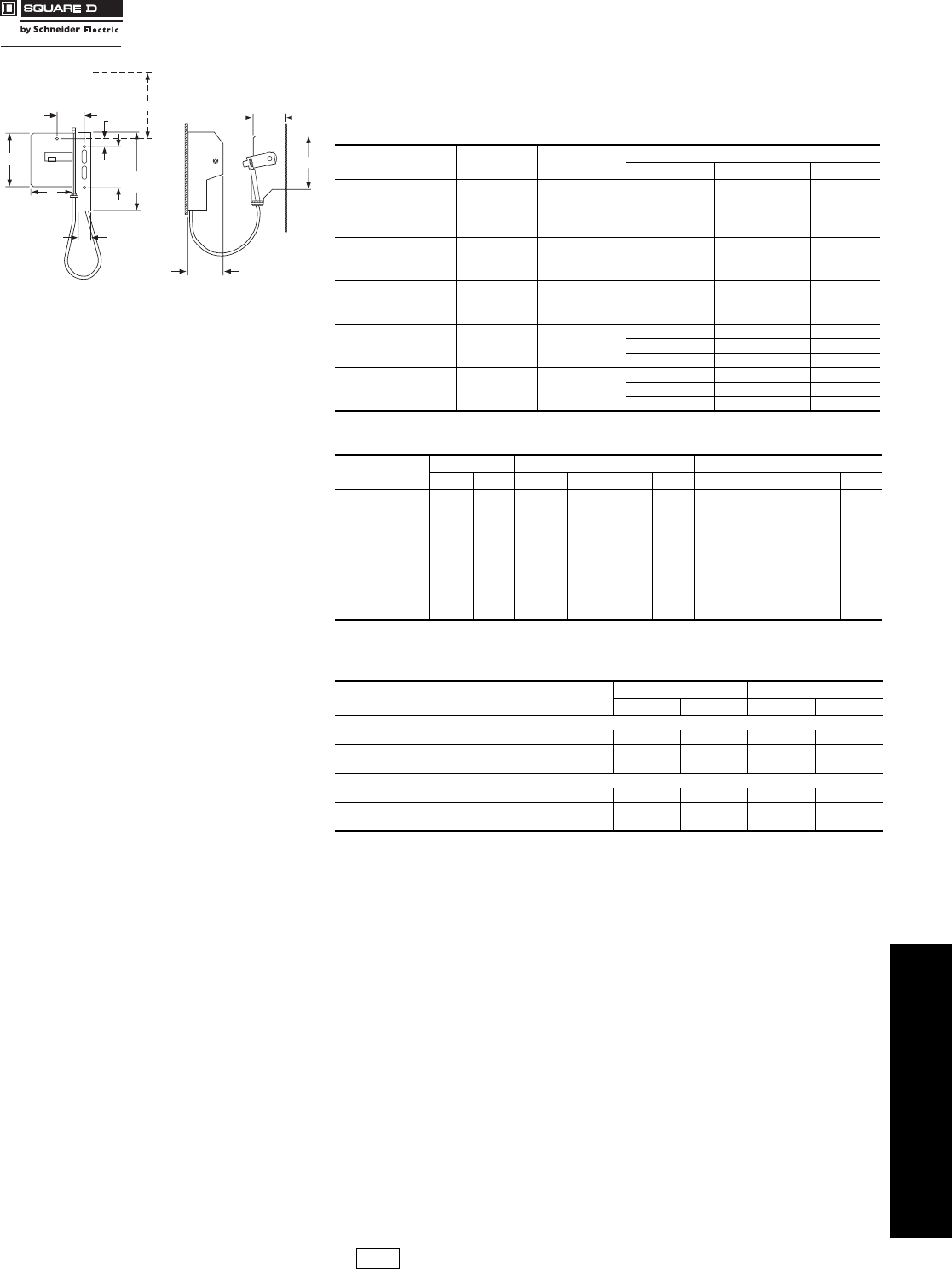
www.schneider-electric.us
8OPERATOR MECHANISMS AND
DISCONNECT SWITCHES
© 2009 Schneider Electric
All Rights Reserved 8-21
Flexible Cable
Mechanisms
For Circuit Breakers
Class 9422 / Refer to Catalog 9420CT9701
Table 8.73: Flexible Cable Mechanisms for Use with Schneider Electric® (formerly
Merlin Gerin®) and PowerPact® 3-Pole Circuit Breakers
For use with Class 9422 A handle operators especially designed for tall, deep enclosures
where placement flexibility is required.
NOTE: No external auxiliary contacts are available for the following circuit breakers:
GJL circuit breakers must use internal catalog No. AAC.
PowerPact D circuit breakers must use internal catalog No. AAC.
For additional variations, contact CIC at 1-888-SQUARE D (1-888-778-2733).
Circuit Breaker
Type No. of
Poles Frame Size
A
Cable Mechanism
Length Type $ Price
MG-NSF
PowerPact
H- and J-Frame 2 - 3 250
36 in. CSF30 288.00
60 in. CSF50 305.00
84 in. CSF70 323.00
120 in. CSF10 347.00
MG-NSF 4250
36 in. CSF304 297.00
60 in. CSF504 314.00
120 in. CSF104 356.00
MG-NSJ
PowerPact D 3600
36 in. CSJ30 486.00
60 in. CSJ50 504.00
120 in. CSJ10 548.00
MG-NSJ
PowerPact D 4600
36 in. CSJ304 500.00
60 in. CSJ504 516.00
120 in. CSJ104 558.00
PowerPact
M- and P-Frame 31200
36 in. CMP40 759.00
50 in. CMP50 785.00
120 in. CMP10 857.00
Table 8.74: Cable Operating Mechanisms for Circuit Breakers—Dimensions
Type ABCD E
in. mm in. mm in. mm in. mm in. mm
CGJ 3.50 89 5.25 133 2.50 63 3.75 95 5.25 133
CFA 4.26 108 8.50 216 3.75 95 6.75 171 8.50 216
CKA 4.94 125 10.13 257 3.75 95 7.13 181 10.13 257
CLA 6.00 152 11.00 279 3.75 95 10.19 259 11.00 279
CSF 3-Pole 5.85 149 7.97 202 3.50 89 4.84 123 7.97 202
CSF 4-Pole 5.85 149 7.97 202 3.50 89 8.08 205 7.97 202
CSJ 3-Pole 4.13 105 9.50 241 3.00 76 7.25 183 9.50 241
CSJ 4-Pole 4.13 105 9.50 241 3.00 76 9.03 229 9.50 241
CMP 8.744 222 15.00 381 2.38 60 12.41 315 15.00 381
Table 8.75: Class 9999 Auxiliary Contact Kits for Disconnect Switches and
Circuit Breakers
Class Type SPDT DPDT
Type $ Price Type $ Price
Disconnect Switches
9422 BTCF, BTCN, BTDF, BTEF, BTEN TC11 120.00 TC21 239.00
9422 TCF, TCN, TDF, TDN, TEF, TEN TC10 120.00 TC11 239.00
9422 TF R8 87.00 R9 243.00
Circuit Breaker Operating Mechanisms
9421 LF, LK, LL, LM, LN, LP, LR, LT, LW R47 131.00 R48 221.00
9422 RM, RN, RP, RQ, RR, RT R26 131.00 R27 243.00
9422 CFA, CKA, CLA, CSF, CMP R26 131.00 R27 243.00
1.44
37
9.12
232
4.25
108
4.69
119
1.00
25
CA
B
X
E
D
Refer to NEC Article 430-10 for minimum
dimension X from circuit breaker top
mounting hole to wall or barrier to
ensure adequate wire bending space.
Note: Bend radius in cable must never be less than 6 inches.
Electrical clearances must be maintained between cable
and live electrical parts.
CP1 Discount
Schedule
Courtesy of Steven Engineering, Inc.-230 Ryan Way, South San Francisco, CA 94080-6370-Main Office: (650) 588-9200-Outside Local Area: (800) 258-9200-www.stevenengineering.com
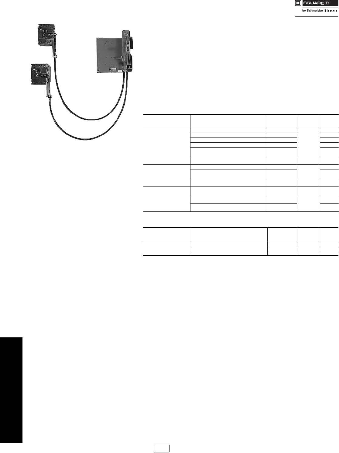
www.schneider-electric.us
8OPERATOR MECHANISMS AND
DISCONNECT SWITCHES
8-22 © 2009 Schneider Electric
All Rights Reserved
Flexible Cable
Mechanisms
For Circuit Breakers
Class 9422 / Refer to Catalog 9420CT9701
Dual Cable Operating Mechanisms for Square D® Circuit Breakers
Dual Cable Operator Mechanisms are designed for use with Square D GJL and
PowerPact® D, H, and J circuit breakers through 600 A frame sizes. The cable mechanisms
allow for a single handle operator, Class 9422A1, to operate both circuit breakers. The
cable mechanism is designed especially for tall, deep enclosures where placement
flexibility is required. There are numerous cable arrangements to choose from to
accommodate many applications.
Features
•Separate cables for each circuit breaker
•Rugged metal flange handle operator
•Maximized flexibility of circuit breaker placement for existing and new applications
•Control panel can be fed from two separate supply voltages (if required)
•Dual mechanism allows both separate supply voltages to be controlled by a single
handle to improve security features
Table 8.76: Dual Cable Operating Mechanisms Selection
Circuit Breaker Type Cable Length
in. / mm
(quantity)
Catalog
Number Frame Size
(max.) $ Price
GJL
36 in. / 914 mm (2) 9422CGJD3
100 A
585.00
48 in. / 1219 mm (2) 9422CGJD4 608.00
60 in. / 1524 mm (2) 9422CGJD5 675.00
120 in. / 3048 mm (2) 9422CGJD1 788.00
36 in. / 914 mm (1)
60 in. / 1524 mm (1) 9422CGJD8 642.00
60 in. / 1524 mm (1)
120 in. / 3048 mm (1) 9422CGJD9 720.00
PowerPact H & J
MG NSF
120 in. / 3048 mm (2) 9422CSFD1
250 A
693.00
36 in. / 914 mm (1)
60 in. / 1524 mm (1) 9422CSFD35 648.00
60 in. / 1524 mm (1-CSF 3 pole)
60 in. / 1524 mm (1-CSF 4 pole) 9422CSFD345 672.00
PowerPact D
MG NSJ
120 in. / 3048 mm (1-CSF) &
120 in. / 3048 mm (1-CSJ) 9422CSFJD10
250 A &
600 A
894.00
36 in. / 914 mm (1-CSF) &
36 in. / 914 mm (1-CSJ) 9422CSFJD30 774.00
60 in. / 1524 mm (1-CSF)
60 in. / 1524 mm (1-CSJ) 9422CSFJD50 809.00
Table 8.77: Special Left-hand Mounted Single Cable Operating Mechanisms
Circuit Breaker Type Cable Length
in. / mm
(quantity)
Catalog
Number Frame Size
(max.) $ Price
FAL
120 in. / 3048 mm (1) 9422CFAL10
100 A
350.00
36 in. / 914 mm (1) 9422CFAL30 287.00
60 in. / 1524 mm (1) 9422CFAL50 318.00
CP1 Discount
Schedule
Courtesy of Steven Engineering, Inc.-230 Ryan Way, South San Francisco, CA 94080-6370-Main Office: (650) 588-9200-Outside Local Area: (800) 258-9200-www.stevenengineering.com
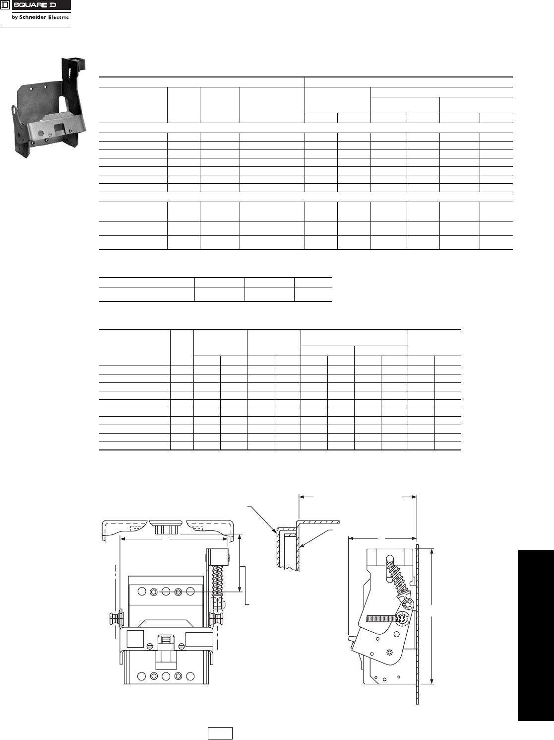
www.schneider-electric.us
8OPERATOR MECHANISMS AND
DISCONNECT SWITCHES
© 2009 Schneider Electric
All Rights Reserved 8-23
Disconnect Switch
Accessories
Flange Mounted, Variable Depth
Class 9422 / Refer to Catalog 9420CT9701
Designed for installation in custom built control enclosures where main or branch circuit protective devices are required. All
circuit breaker operating mechanisms are suitable for either right- or left-hand flange mounting, convertible on the job.
aClass 9422 Type R2 will extend mounting depth 7 inches (see page 8-24).
aNot for use with the GJL operating mechanism.
Table 8.78: Variable Depth Mechanisms for Use with Square D® and Schneider Electric® (formerly
Merlin Gerin®) Circuit Breakers
Use with Operating Mechanism
Circuit Breaker
Frame Size No. of
Poles Frame Size
A
Variable Depth Mtg.
Range Min.-Max.a
(Inches)
Operating Mechanism
Only—Does Not Include
Handle Mechanism
Operating Mechanism and Handle Mechanism
Includes Type A1
Handle Mechanism Includes Type A2
Handle Mechanism
Type $ Price Type $ Price Type $ Price
Square D Circuit Breakers
GJL 3 100 6.00–17.75 RG1 116.00 ARG11 257.00 ARG21 372.00
FAL, FHL 2–3 100 5.38–17.75 RN1 116.00 ARN11 257.00 ARN21 372.00
KAL, KHL 2–3 250 6.38–17.88 RP1 129.00 ARP11 270.00 ARP21 386.00
LALc, LHLc, Q4L 2–3 400 7.44–18.25 RR1 329.00 ARR11 471.00 ARR21 585.00
MEL, MXL 2–3 800 9.00–18.38 RT1 449.00 ART11 593.00 ART21 705.00
MAL, MHL 2–3 1200 9.00–18.38 RT1 449.00 ART11 593.00 ART21 705.00
NAL, NCL, NEL, NXL 2–3 1200 11.00–18.37 RX1 513.00 ——— —
Schneider Electric (formerly Merlin Gerin) and PowerPact® Frame 3-Pole Circuit Breakers
MG-NSF
PowerPact
H- and J-Frame
2–3 250 5.88–17.75 RQ1 185.00 ——— —
MG-NSJ
PowerPact D 3 600 9.00–17.75 RS1 383.00 ——— —
PowerPact
M- and P-Frame 3 1200 9.00–18.38 RM1 513.00 ——— —
Table 8.79: Electrical Interlocks—Class 9999
Description Class Type $ Price
Single Pole, Double Throw
Double Pole, Double Throw
9999
9999
R26a
R27a131.00
243.00
Table 8.80: Dimensions
Circuit Breaker
Frame Size Type
Width
(A) Height
(B)
Distance to Enclosure Flangea
(C) Bracket Depth
(D)
Minimum Maximum
in.mmin.mmin.mmin.mmin.mm
GJL RG1 5.00 127 4.75 121 6.00 152 17.75 451 4.00 102
FAL, FHL RN1 6.75 171 8.50 216 5.51 140 17.75 451 4.26 108
KAL, KHL RP1 7.13 181 10.13 257 6.51 165 17.88 454 4.94 125
LALc, LHLc, Q4L RR1 10.19 259 11.00 279 7.44 189 18.25 464 6.00 152
MEL, MXL RT1 13.38 340 14.00 356 9.00 229 18.38 467 9.69 246
MAL, MHLbRT1 13.38 340 14.00 356 9.00 229 18.38 467 9.69 246
NAL, NCL, NEL, NXL RX1 19.63 499 13.50 343 11.00 279 18.37 467 9.00 229
MG-NSF RQ 4.84 123 7.97 203 5.875 149 17.75 451 5.62 143
MG-NSJ RS 9.27 236 9.5 241 9.0 228 17.75 451 5.73 146
PowerPact M & P RM 12.29 312 15 381 10.5 267 18.9 480 8.73 222
a9422 R2 will extend dimension 7 in. Two required.
bMinimum mounting depth when using MAL or MHL circuit breakers can be decreased to
7.63 inches by using the Class 9422 Type RT1B conversion kit. $23.00
cWarning: These operating mechanisms cannot be used with any LA / LH circuit breaker with an MB or MT suffix.
Minimum to wall or barrier.
Right or left hand mounting
to insure adequate wire
bending space to lug
surface when maximum
wire size is used.
Refer to NEC Article
430-10.
C
L
R.H. Handle
C
L L.H. Handle
A
B
D
C = Distance from Outside of
Flange to Circuit Breaker
Mounting Surface
Enclosure Flange
Enclosure Door
CP1 Discount
Schedule
Courtesy of Steven Engineering, Inc.-230 Ryan Way, South San Francisco, CA 94080-6370-Main Office: (650) 588-9200-Outside Local Area: (800) 258-9200-www.stevenengineering.com
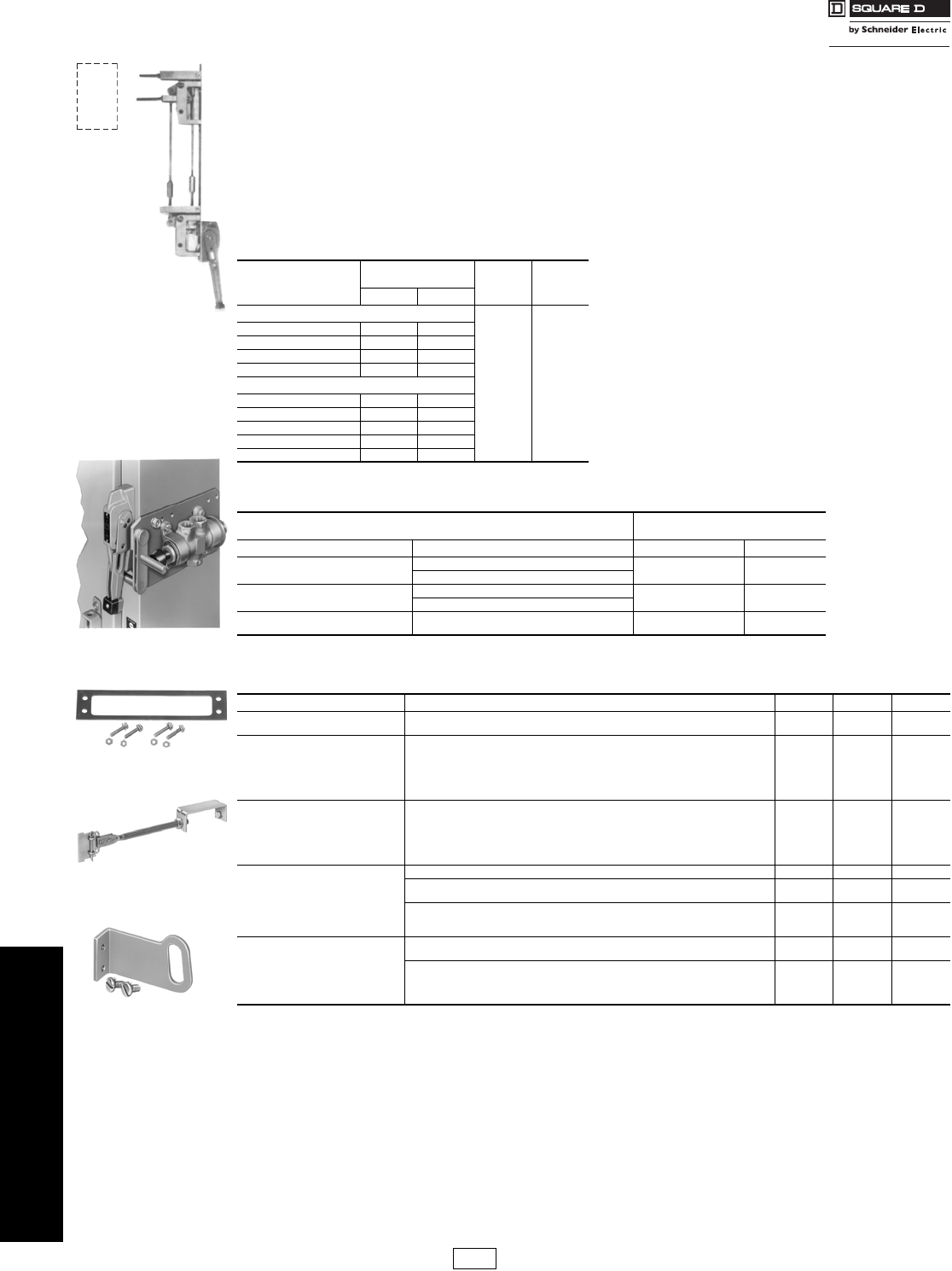
8-24 © 2009 Schneider Electric
All Rights Reserved
www.schneider-electric.us
8OPERATOR MECHANISMS AND
DISCONNECT SWITCHES
Disconnect Switches Flange Mounted, Variable Depth Disconnect Switch Accessories
Class 9422 / Refer to Catalog 9420CT9701
Remote or Dual Adapter Kit
For the remote or dual operation of 30, 60, 100 and 200 A disconnect switches, or GJL, FAL, FHL, KAL, KHL, LAL,
LHL, Q4L, MAL, MHL, MEL and MXL circuit breakers.
Remote Operation—permits mounting the Class 9422 Type A9 or A10 handle mechanism at a lower level than the
disconnect device it controls. This arrangement is often required where the disconnect device is mounted too high for
personnel to easily reach a conventional operator.
Dual Operation—permits controlling two disconnect devices, one in line with and one remote from a single Class 9422
Type A9 or A10 handle mechanism.
NOTE: A Class 9422 Type A9 or A10 handle (page 8-17) and the preferred mounting method must be used.
aPrices do not include air valves or handle mechanism. For more information on air valves listed above contact Parker at
C-PARKER@PARKER.COM, or call 1-800-272-7537.
Table 8.81: Disconnect Device
Disconnect Device
Enclosure Mounting
Depth Type $ Price
Min. Max.
Disconnect Switch
D2 251.00
30 A Type TCF/TCN 10.63 19.50
60 A Type TDF/TDN 10.63 19.50
100 A Type TEF/TEN 12.13 20.25
200 A Type TF 13.13 20.81
Circuit Breaker
GJL 10.50 19.50
FAL, FHL 10.66 19.50
KAL, KHL 11.13 19.50
LAL, LHL, Q4L 12.13 19.88
MAL, MHL,MEL, MXL 13.75 20.25
Table 8.82: Air Valve Interlock
Note that air valve interlocks only accept the specific three-way air valves, manufactured by Parker, listed in the table below.
Parker Valve Model NumberaClass 9422
Air Valve Interlock
Air Valve Size Knob Operated Type $ Price
0.50 NPT
13
M04841885 G1 513.00
M08541848
0.75 NPT
19
M04861885 G2 513.00
M08561848
1.00 NPT
25 M00080004 G1 513.00
Table 8.83: Other Accessories
Accessory Description Class Type $ Price
Alternate Mounting Kit Permits mounting Class 9422 Type A1 or A2 handle mechanisms in
enclosures with flange thickness of 16 gauge to 0.5 in. 9422 AM2 14.30
Channel/Flange Support Kit
Auxiliary kit recommended for use with 30 and 60 A disconnect switches and
FAL, FCL, FHL, KAL KHL, NSF and NSJ circuit breaker mechanisms when
these devices are to be mounted on the center channel of a multi-door
enclosure or when extra rigidity for the flange is required. Supplied as
standard with 100 and 200 A disconnect switches and LAL, LHL, Q4L, MAL,
MHL, MEL and MXL circuit breaker mechanisms.
9422 C1 42.80
Auxiliary Lock Plate
Auxiliary kit recommended for use with the Class 9422 Type A-1 flange
handle to facilitate padlocking the handle in the “OFF” position. Primarily
used when the handle is mounted on the center channel of a multi-door
enclosure. Also in any case where the enclosure doors interfere with the
normal padlock slot in the flange handle. Meets both the Automotive and
NFPA 79 specifications.
9422 L1 36.00
Special Lugs for
Disconnect Switches
Copper Lugs only—Specify Form Y157 — — No Charge
Tin Plated Aluminum Lugs for 400 A Type TG Switch—Specify Form Y1572
(000–750 kcmil Cu/Al wire) ——No Charge
Anderson Type VCEL Compression Lugs—Specify Form Y1574
Exceptions: None of the 30 A or 60 A disconnect switches are available with
compression lugs.
——No Charge
Operating Rods
Standard operating rod for use with Class 9422 variable depth mechanisms.
Included as standard in each kit. 9422 R1 28.70
Extra long operating rod for use with Class 9422 variable depth mechanisms.
Can be used as a substitute for the standard rod included in each kit to
increase the maximum mounting depth 7 in. (Two are required for Types ARR,
RR, ART, RT, ATE, TE, ATF, TF).
9422 R2 50.00
Switch
or
Breaker
Remote operation shown
(handle mechanism not
included in kit)
Air valve interlock
mounted on enclosure
Alternate Mounting Kit
Channel/Flange
Support Kit
Auxiliary Lock Plate
CP1 Discount
Schedule
Courtesy of Steven Engineering, Inc.-230 Ryan Way, South San Francisco, CA 94080-6370-Main Office: (650) 588-9200-Outside Local Area: (800) 258-9200-www.stevenengineering.com
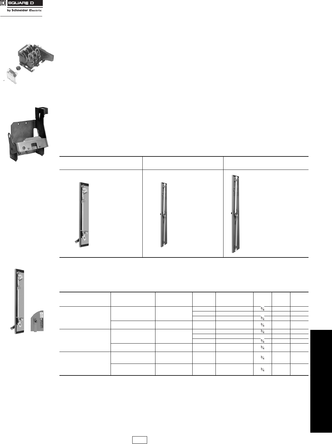
www.schneider-electric.us
8OPERATOR MECHANISMS AND
DISCONNECT SWITCHES
© 2009 Schneider Electric
All Rights Reserved 8-25
Door Closing
Mechanisms
Introduction
Class 9423 / Refer to Catalog 9420CT9701
Class 9423 door closing mechanisms cover a range of enclosures with up to 91 inch high maximum door openings.
The door closing mechanisms are designed to be used on control enclosures and interlocked with a Class 9422
disconnect device, although they all can be used independently. Three different systems are available and their use is
as recommended below. A complete system is available for interlocking all the doors of a multi-door enclosure with the
master door when using the 6 in. or 8 in. vault handle mechanism.
Note that the “Master Door” is defined to be the door of a single or multi-door enclosure which is interlocked directly
with the disconnect device. The master door can be hinged on either the right or left hand side. It can be located in any
position on a multi-door enclosure. On the other hand, an “Auxiliary Door” is defined to be any remaining doors of a
multi-door enclosure which are interlocked with the master door by means of the overhead interlocking system as
illustrated on pages 8-26 and 8-27.
Selection Procedure
Step 1.
Determine enclosure construction (number of doors, door height, hinge location, etc.).
Step 2.
Determine Class 9422 disconnect device to be used—either a disconnect switch or a circuit breaker mechanism.
Step 3.
Determine the location of the disconnect device and handle mechanism (right or left hand flange or center channel).
Step 4.
Select the door closing mechanism required.
Step 5.
Select the auxiliary door closing mechanisms and multi-door interlocking hardware, if required. (A complete system for
interlocking all auxiliary doors of a multi-door enclosure with center channel is available for the medium and large
enclosures.)
The door closing mechanisms listed below are for use on small to medium size single door control enclosures. They
are designed to be used in conjunction with Class 9422 flange mounted disconnect switches and circuit breaker
operating mechanisms; however, they can be used independently as well. When used on properly designed and
gasketed NEMA Type 12 enclosures, they meet NFPA 79 standards.
aSuitable for door depths of 1-1/8 in., 1-1/4 in., 1-3/8 in. and 1-1/2 in..
Table 8.84: Door Closing Mechanism
60 in. Maximum Door
Opening
(Recommended)
46–60 in. Door
Opening
(Recommended)
61–91 in. Door
Opening
(Recommended)
•2 Point Locking
is Standard
•A Third Roller
Latch Kit is
Available for 3
Point Locking
•For 3/4 in.
Door Depths
•For use on
Single or
Multi-Door
Enclosures
•For use with
Doors Hinged
on Right or Left
Side
•Referred to as
the 6 in. Vault
Handle
Mechanism
•For 3/4 in.
Door Depths
•For use on Single
or Multi-Door
Enclosures
•For use with Doors
Hinged on Right or
Left Side
•Referred to as the
8 in. Vault Handle
Mechanism
•For 1-1/8 in.
Door Depths
Table 8.85: Single Door Enclosures—NEMA Type 4 or 12 with 60 in. High Maximum Opening
Description For Use On
(Enclosure Type)
Use In
Conjunction
With
Door Latch
Handle
Length
Suggested
Maximum
Door Opening
Door
Depth Type $ Price
Two point, roller latch, door
closing mechanism for use
on enclosures with doors
hinged on the left hand side.
NEMA Type 4 and 12
Sheet Steel
Class 9422
Types A1, A3, A9
4 in. Less than 39 in. M4 228.00
4 in. Less than 39 in. aM10 314.00
6 in. 60 in. M9 243.00
NEMA Type 4 and 12
Stainless Steel
Class 9422 Types
A2, A4, A10 4 in. Less than 39 in. M24 300.00
Two point, roller latch, door
closing mechanism for use
on enclosures with doors
hinged on the right hand side.
NEMA Type 4 and 12
Sheet Steel
Class 9422
Types A1, A3, A9
4 in. Less than 39 in. M4L 228.00
4 in. Less than 39 in. aM10L 314.00
6 in. 60 in. M9L 243.00
NEMA Type 4 and 12
Stainless Steel
Class 9422 Types
A2, A4, A10 4 in. Less than 39 in. M24L 300.00
Third roller latch kit for 3
point locking; for use where
3 point locking is desired or
where the door opening is
39 in. or more.
NEMA Type 4 and 12
Sheet Steel
Class 9423
Types M4, M9,
M4L, M9L
—— M3 50.00
NEMA Type 4 and 12
Stainless Steel
Class 9423
Types M24,
M24L
—— M23 57.00
9422 TCN30
Circuit Breaker
Mechanism
Type M4
Latch bar not included,
but most prepunched
enclosures that accept
Square D® operating
mechanisms supply a
predrilled latch bar.
CP1 Discount
Schedule
Courtesy of Steven Engineering, Inc.-230 Ryan Way, South San Francisco, CA 94080-6370-Main Office: (650) 588-9200-Outside Local Area: (800) 258-9200-www.stevenengineering.com
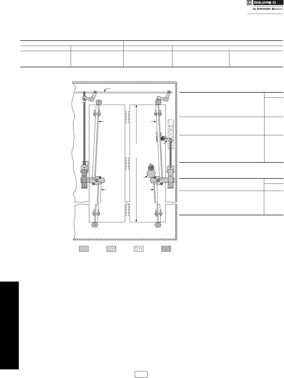
www.schneider-electric.us
8OPERATOR MECHANISMS AND
DISCONNECT SWITCHES
8-26 © 2009 Schneider Electric
All Rights Reserved
Door Closing
Mechanisms
Types M5, M6, M1, and M8
Class 9423 / Refer to Catalog 9420CT9701
Vault Type for Single and Multi-Door Enclosures
Table 8.86 shows the requirements for the door closing
mechanism, the locking bar kit, and the mechanical
interlock kit, if used.
View from Inside the Enclosure NOTE: All mechanisms listed on this page are
suitable for either left or right hand mounting.
Table 8.86: Single or Multi-Door Enclosures—NEMA Type 12 with 40 in. to 60 in. Door Opening
Single-Door Enclosure Multi-Door Enclosure
Without Interlocking With Interlocking Without Interlocking With Interlocking
1—M6 door closing mechanism
1—Type M660 locking bar kit
1—M6 door closing mechanism
1—Type M660 locking bar kit
1—Type M5 (use with 9422A handles)
For each door:
1—M6 door closing mechanism
1—Type M660 locking bar kit
For Master door:
1—M6 door closing mechanism
1—Type M660 locking bar kit
1—Type M5 (for use with 9422A handles)
For each Auxiliary door:
1—M6 door closing mechanism
1—Type M660 locking bar kit
Necessary quantities of Types M2 and
M7 for each door (see below)
1/4" Dia. Rod (Supplied By User)
Locking
Bar
Locking
Bar
Locking
Bar
Auxiliary Door Master Door
(Single Door)
Locking
Bar
Door
Opening
Type M6 Type M7 Type M2
Type M5
A
C
B
Note: A - Interlocking lever extension of the flange mounted handle
mechanism.
Note: B - Actual enclosure opening—not door height.
Note: C - Screwdriver interlock assembly can be ordered separately.
Class 9423 Type CEQ2493. $45.00
Table 8.87: Door Interlocks
Type M6 Door Closing Mechanism $ Price
The Class 9423 Type M6 door closing mechanism is designed
to close and seal 0.75 in. deep doors of single or multi-door
NEMA Type 12 enclosures. The Type M6 can be used on
doors hinged on either the left or right hand side.
Recommended door openings are from 40–60 in. Vault type
handle length is 6 in.
257.00
Type M660 Locking Bar Kits
The lock bar kit for the Type M6 door closing mechanism
contains two lock bars and is available from stock. The bars
can be cut to fit door openings through 60 in. One lock bar kit
is required for each Type M6 ordered.
86.00
Type M5
The Class 9423 Type M5 mechanical interlock kit is designed
to interlock a Class 9422 handle mechanism with the Type M6
door closing mechanism. This kit prevents opening the master
door (or single door) with the disconnect handle in the “ON”
position, making it mandatory to use a screwdriver to gain entry
to the enclosure at any time, regardless of the disconnect
handle position.
215.00
Table 8.88: Required Accessories for
Auxiliary Doors
Type M2 $ Price
One Type M2 kit is required for each auxiliary door. This kit is
required to interlock any auxiliary door(s) with the master door. 257.00
Type M7
The first auxiliary door requires 2 Type M7 kits. Additional
auxiliary doors require only 1 Type M7 kit. The 0.25 in. diameter
rod used to interconnect the M7 kits is furnished by the user. If
the distance between any two Type M7 kits exceeds 36 in., an
additional Type M7 kit should be installed to prevent the rod
from buckling.
71.00
CP1 Discount
Schedule
Courtesy of Steven Engineering, Inc.-230 Ryan Way, South San Francisco, CA 94080-6370-Main Office: (650) 588-9200-Outside Local Area: (800) 258-9200-www.stevenengineering.com
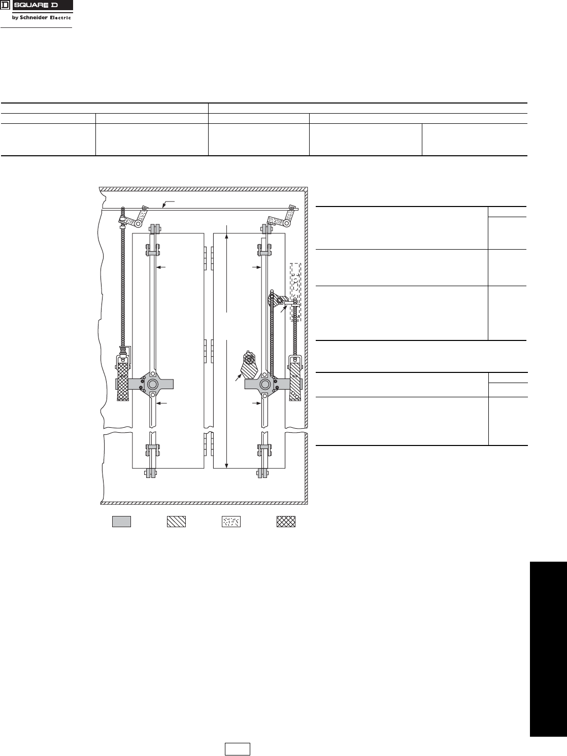
www.schneider-electric.us
8OPERATOR MECHANISMS AND
DISCONNECT SWITCHES
© 2009 Schneider Electric
All Rights Reserved 8-27
Door Closing
Mechanisms
For Single and Multi-Door Enclosures
Class 9423 / Refer to Catalog 9420CT9701
View from Inside the Enclosure NOTE: All mechanisms listed on this page are suitable
for either left or right hand mounting.
Vault Type for Single and Multi-Door Enclosures
Table 8.89 shows the requirements for the door closing
mechanism, the locking bar kit, and the mechanical
interlock kit, if used.
Table 8.89: Single Or Multi-Door Enclosures—NEMA Type 12 with 61 in. to 91 in. Door Openings
Single-Door Enclosure Multi-Door Enclosure
Without Interlocking With Interlocking Without Interlocking With Interlocking
1—M8 door closing mechanism
1—Type M891 locking bar kit
1—M8 door closing mechanism
1—Type M891 locking bar kit
1—Type M1 (for use with 9422A handles)
For each door:
1—M8 door closing mechanism
1—Type M891 locking bar kit
For Master door:
1—M8 door closing mechanism
1—Type M891 locking bar kit
1—Type M1 (for use with 9422A handles)
For each Auxiliary door:
1—M8 door closing mechanism
1—Type M891 locking bar kit
Necessary quantities of Types M2 and
M7 for each door (see below)
A
1/4" Dia. Rod (supplied by user)
Locking
Bar
Locking
Bar
Locking
Bar
Auxiliary Door Master Door
(Single Door)
Locking
Bar
Door
Opening
Type M8Type M1 Type M7 Type M2
C
B
Note: A - Interlocking lever extension of the flange mounted handle
mechanism.
Note: B - Actual enclosure opening—not door height.
Note: C - Screwdriver interlock assembly can be ordered separately.
Class 9423 Type CEQ2493. $45.00
Table 8.90: Door Interlocks
Type M8 Door Closing Mechanism $ Price
The Class 9423 Type M8 door closing mechanism is designed
to close and seal 1.125 in. deep doors of single or multi-door
NEMA Type 12 enclosures. The Type M8 can be used on doors
hinged on either the left or right hand side. Recommended door
openings are from 61–91 in. Vault type handle length is 8 in.
500.00
Type M891 Locking Bar Kits
The lock bar kit for the Type M8 door closing mechanism
contains two lock bars and is available from stock. The bars can
be cut to fit door openings through 91 in.. One lock bar kit is
required for each Type M8 ordered.
86.00
Type M1
The Class 9423 Type M1 mechanical interlock kit is designed to
interlock a Class 9422 handle mechanism with the Type M8
door closing mechanism. This kit prevents opening the master
door (or single door) with the disconnect handle in the “ON”
position, making it mandatory to use a screwdriver to gain entry
to the enclosure at any time, regardless of the disconnect
handle position.
428.00
Table 8.91: Required Accessories for
Auxiliary Doors
Type M2 $ Price
One Type M2 kit is required for each auxiliary door. This kit is
required to interlock any auxiliary door(s) with the master door. 257.00
Type M7
The first auxiliary door requires 2 Type M7 kits. Additional
auxiliary doors require only 1 Type M7 kit. The 0.25 in. diameter
rod used to interconnect the M7 kits is furnished by the user. If
the distance between any two Type M7 kits exceeds 36 in., an
additional Type M7 kit should be installed to prevent the rod
from buckling.
71.00
CP1 Discount
Schedule
Courtesy of Steven Engineering, Inc.-230 Ryan Way, South San Francisco, CA 94080-6370-Main Office: (650) 588-9200-Outside Local Area: (800) 258-9200-www.stevenengineering.com
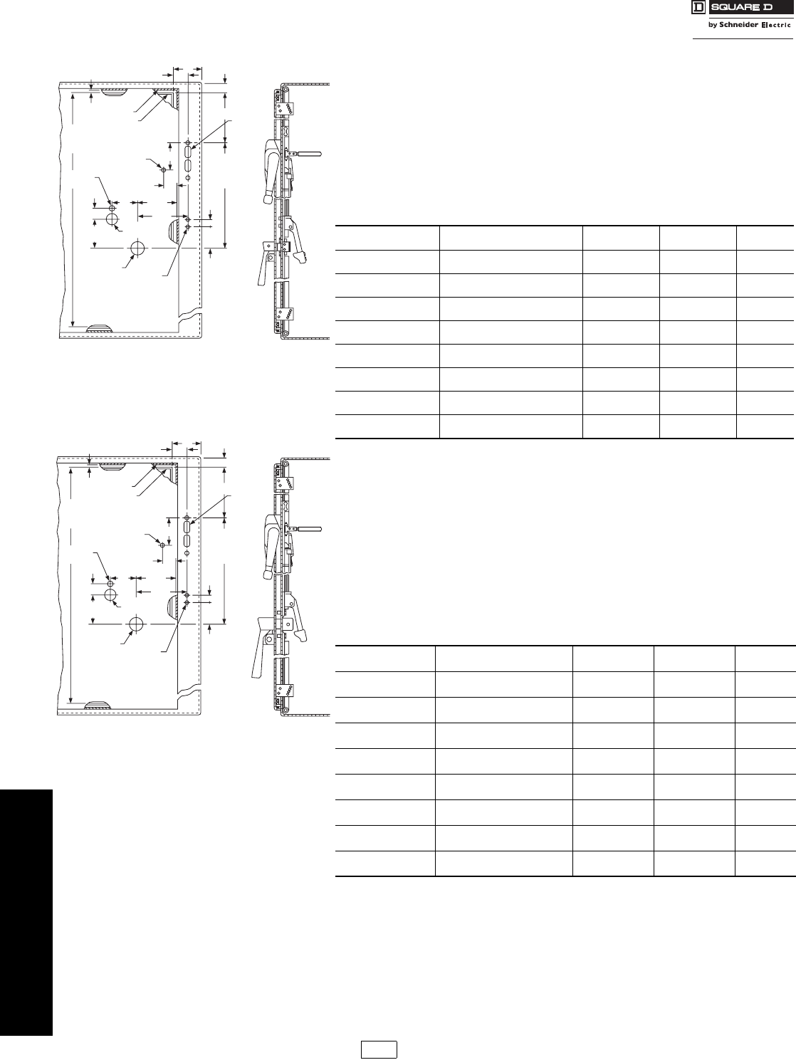
www.schneider-electric.us
8OPERATOR MECHANISMS AND
DISCONNECT SWITCHES
8-28 © 2009 Schneider Electric
All Rights Reserved
Door Closing
Mechanisms
Types M5, M6, M1 and M8
Class 9423 / Refer to Catalog 9420CT9701
Enclosure Construction and General Location Information
For Types M5 and M6
Drilling and location information below is complete for a single door enclosure with door
hinged on left side, incorporating a Type M6, M5, and Class 9422 handle mechanism.
Transpose all horizontal dimensions for doors hinged on right side.
Dimension A
Note: Single door enclosures: A minimum = 1 in.
Note: Multi-Door enclosures without overhead interlocking system: A minimum = 1 in.
Note: Multi-Door enclosures with overhead interlocking system: A minimum = 4½ in.
Note: Overhead interlocking system consists of the required number of Class 9423 Type M2 and M7 kits for interlocking
the auxiliary doors with the master door. See page 8-26.
Enclosure Construction and General Location Information
For Types M1 and M8
Drilling and location information below is complete for a single door enclosure with the door
hinged on the left side, incorporating a Type M8, M1, and Class 9422 handle mechanism.
Transpose all horizontal dimensions for doors hinged on the right side.
Dimension A
Note: Single door enclosures: A minimum = 1½ in.
Note: Multi-Door enclosures without overhead interlocking system: A minimum = 1½ in.
Note: Multi-Door enclosures with overhead interlocking system: A minimum = 4½ in.
Note: Overhead interlocking system consists of the required number of Class 9423 Type M2 and M7 kits for interlocking
the auxiliary doors with the master door. See page 8-27.
Table 8.92: Dimension B (Minimums)
Type Disconnect
Device If A = 1
Minimum B = If A = 4½
Minimum B = C
TCF, TCN, TDF, TDN, TD 60 A Disconnect Switch 3-/16 2-1/2 3-3/16
TE, TEF, TEN 100 A Disconnect Switch 5-1/4 2-1/2 3-3/16
TF 200 A Disconnect Switch 11-5/8 8-1/8 3-3/16
TG 400 A Disconnect Switch 15-1/16 11-9/16 6-3/4
RN1 FAL, FHL,
Circuit Breaker 4-27/32 2-1/2 3-3/16
RP1 KAL, KHL
Circuit Breaker 11-5/32 7-21/32 3-3/16
RR2 ILL Circuit Breaker 17-31/32 14-15/32 3-3/16
RT1 MAL, MHL, MEL, MXL
Circuit Breaker 18-5/8 15-1/8 3-3/16
Table 8.93: Dimension B (Minimums)
Type Disconnect
Device If A = 1½
Minimum B = If A = 4½
Minimum B = C
TCF, TCN, TDF, TDN, TD 60 A Disconnect Switch 2-15/16 2-1/2 3-3/16
TE, TEF, TEN 100 A Disconnect Switch 4-3/4 2-1/2 3-3/16
TF 200 A Disconnect Switch 11-1/8 8-1/8 3-3/16
TG 400 A Disconnect Switch 14-9/16 11-9/16 5-7/8
RN1 FAL, FHL
Circuit Breaker 4-11/32 2-1/2 3-3/16
RP1 KAL, KHL
Circuit Breaker 10-21/32 7-21/32 3-3/16
RR2 ILL Circuit Breaker 17-15/32 14-15/32 3-3/16
RT1 MAL, MHL, MEL, MXL
Circuit Breaker 18-1/8 15-1/8 3-3/16
2.25
Minimum
57
2.63
67
1.00
25
1.63
41
2.00
51
3.50
89
0.69
18
2.81
71
3.69
94
17.69
Minimum
449
33.69
Minimum
856
1.50
38
0.25
Reference
6
0.2
Dia.
5 (2 Holes)
0.33
Dia.
8
0.2
Dia.
5
0.88
Dia.
22
0.7
Dia.
18
Enclosure Door
Enclosure
A
B
C
Flange
Drilling
See Class
9422
Digest
Section
Door Opening Recommended
40 Inches Minimum
60 Inches Maximum
C
L
of Door
+.010
-.000
3.00
Minimum
76
2.25
57
1.00
25
1.88
48
2.50
64
3.50
89
0.69
18
3.75
95
4.75
121
17.69
Minimum
449
33.69
Minimum
856
1.50
38
0.50
Reference
13
0.2
Dia.
5 (2 Holes)
0.33
Dia.
8
0.2
Dia.
5
1.00
Dia.
25
0.7
Dia.
18
Enclosure Door
Enclosure
A
B
C
Flange
Drilling
See Class
9422
Digest
Section
Door Opening Recommended
61 Inches Minimum
91 Inches Maximum
C
L
of Door
CP1 Discount
Schedule
Courtesy of Steven Engineering, Inc.-230 Ryan Way, South San Francisco, CA 94080-6370-Main Office: (650) 588-9200-Outside Local Area: (800) 258-9200-www.stevenengineering.com
