Ifm General Catalogue English 2012 111220 Catalog
2014-09-27
: Pdf 111220-Catalog 111220-Catalog 006828 Batch8 unilog
Open the PDF directly: View PDF ![]() .
.
Page Count: 648 [warning: Documents this large are best viewed by clicking the View PDF Link!]
fluid sensors
and diagnostic
systems
bus,
identification
and control systems
position
sensors
and object
recognition
2012
2012


visit our website:
www.ifm.com
Over 70 locations worldwide – at a glance at w
www.ifm.com
ifm electronic gmbh
Friedrichstraße 1
45128 Essen
Tel. +49 / 201 / 24 22-0
Fax +49 / 201 / 24 22-1200
E-Mail: info@ifm.com
ifm article no. 7511459 We reserve the right to make technical alterations without prior notice. Printed in Germany on non-chlorine bleached paper. 10/11
Cert no. IMO-COC-027827

ifm – the company 6 - 7
General information 8 - 9
Standards and approvals / list of articles 10 - 48
Sensors for special applications 50 - 52
Inductive sensors 54 - 135
Capacitive sensors 136 - 153
Touch sensors 154 - 155
Magnetic sensors 158 - 165
Cylinder sensors 166 - 184
Valve sensors 186 - 199
Photoelectric sensors 200 - 318
Object recognition 320 - 330
Encoders 332 - 345
Evaluation systems 346 - 358
Evaluation systems for safety and EX 360 - 368
Level sensors 370 - 387
Flow sensors 388 - 415
Pressure sensors 416 - 450
Temperature sensors 452 - 473
Diagnostic systems 474 - 481
Bus system AS-interface 482 - 512
Identification systems 514 - 528
Control systems for mobile vehicles 530 - 559
Power supplies 560 - 569
Connection technology 570 - 644
ifm – worldwide addresses 646 - 647

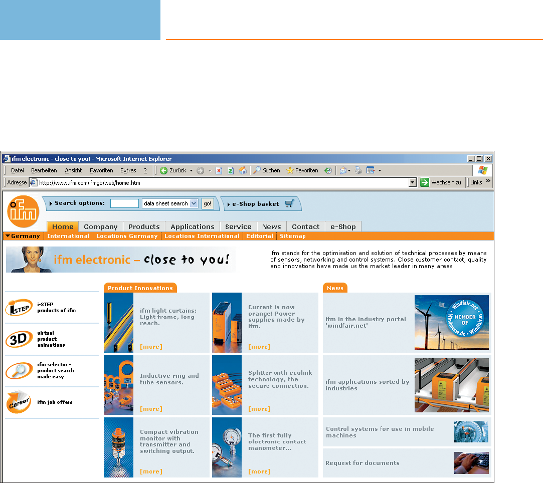
The company in your vicinity.
State-of-the-art communication.
With the right address – www.ifm.com – only a mouse click separates you from the
world of automation technology. See the power of our products in interactive
representations. Gain an impression with 3-dimension-al views of our units. Down-
load CAD drawings for direct integration in your applications. Or order online in
ifm’s e-shop - fast, convenient and reliable.
We are there for you.
Close contact with our customers is part of our success. Therefore we have
consistently developed our sales network right from the start. Today ifm electronic is
represented in more than 70 countries – close to you! With application advice and
service at the heart of our operation. For the introduction of new products and
technologies we support you with workshops and seminars in our training centres or
in your plant.
Security by success.
Since its foundation in 1969 ifm electronic has constantly grown, now having more
than 4300 employees worldwide, and achieved a turnover of more than EUR 470
million in 2010. This success gives you the security of having a reliable partner for the
implementation of your automation projects. Comprehensive service and a warranty
of up to 5 years on standard units are just two examples of this reliability.
2000 201019901980
1970
100
0
200
300
400
500
sales development in million EUR
Turnover
development
since 1970.
ifm – the company
6

branch office
trade partner
ifm – the company
7
A sign of innovation.
Not only components.
ifm stands for a large range of different sensors and systems for automation. Our
range of of more than 7,800 articles guarantees flexibility and compatibility. So there
is always a reliable solution for your automation projects – from the individual sensor
with practical accessories to the complete system.
Availability guaranteed.
Your deadlines matter to us. That is why we are constantly optimising our production
processes in order to be able to quickly and flexibly produce large quantities at a
constantly high quality – and to continue to shorten delivery times. Your order is
dispatched via our centralised logistics centre reliably and on time.
Quality as part of our philosophy.
The quality standard of our products is an integral part of our company philosophy.
And we guarantee it! So we provide you, the users, with a maximum degree of
security: By means of our own production technology, ifm film technology, as well as
by means of extensive quality assurance measures such as 100 % final testing.
By quality we understand, for example, ecologically conscious production – Made in
Germany!
The development
of innovative
products is one
of our core
competences.
Under the name of
i-step we have
come up with a
new product gene-
ration which
implements sophi-
sticated technolo-
gies in industrially
compatible and
easy to handle
products. From
high-quality stan-
dard solutions to
products specially
tailored to the
requirements of
the individual
industries – from
mobile machines
to the food
industry.
www.ifm.com
Information around the clock and
around the globe in 23 languages on the internet.
• Information
- product innovations
- company news
- exhibition info
- locations
- jobs
• Documentation
- data sheets
- operating instructions
- manuals
- approvals
- CAD data
• Communication*
- request for documents
- recall service
- live advice
- newsletter
• Selection
- interactive product selection aids
- configuration tools
- data sheet direct
• Animation
- virtual product animations
- flash movies (video sequences)
• Application
- applications
- product recommendations
- calculation aids
• Transaction*
- e-shop processing
- e-procurement catalogues
- B2B services
*Some offered information is available country-specific
General information
Product selectors and further information can be found at: www.ifm.com
8
General information
Product selectors and further information can be found at: www.ifm.com
9
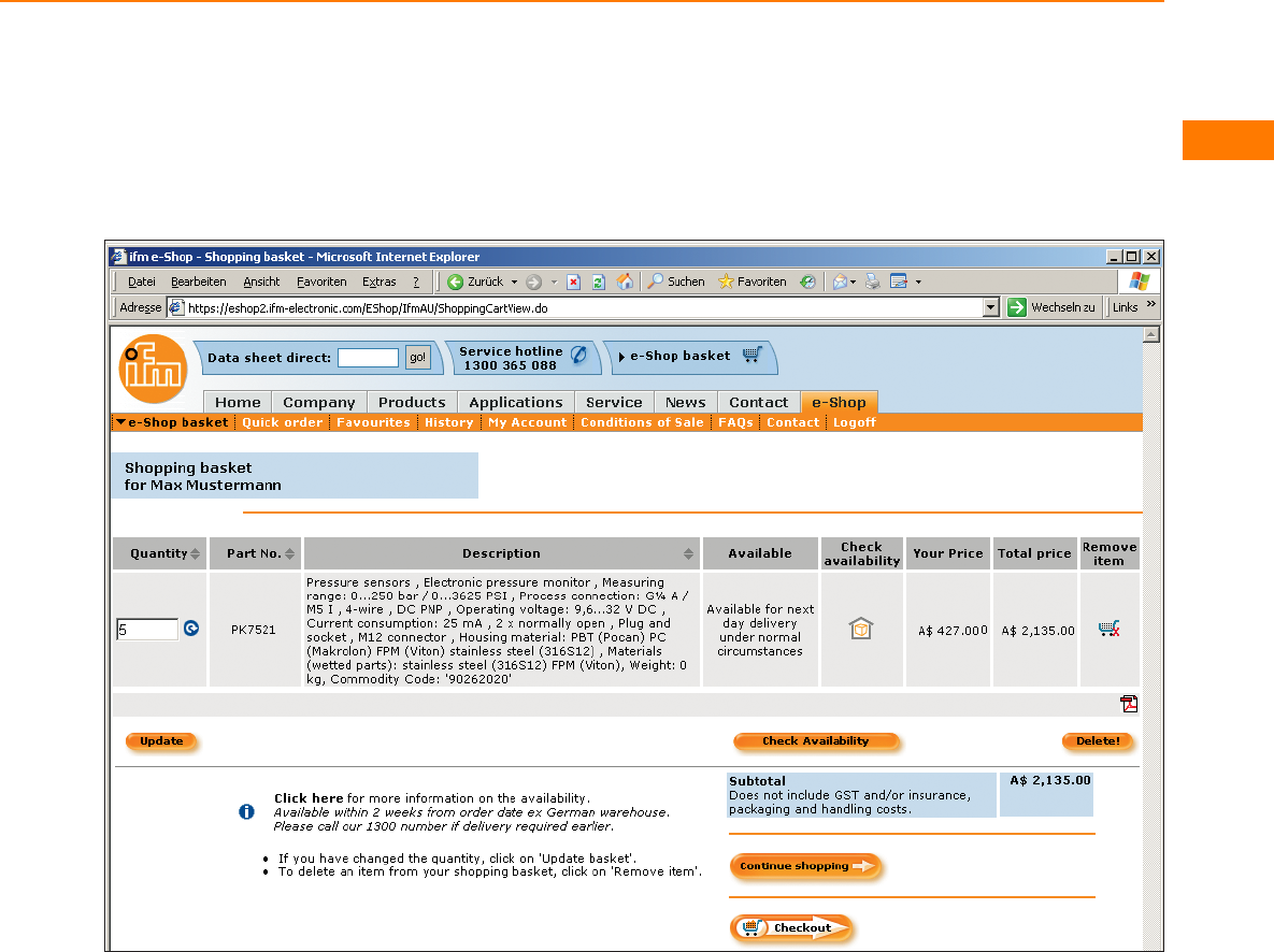
Convenient order processing
via the e-shop** on the internet.
Secured authentication
Customer-related price
indication
Real time availability check
Personal product favourites
Online parcel tracking
Individual order history
Convenient quick input form
Simple order processing
Management of shipping
addresses
Confirmations by e-mail
** Already available in many countries.

3A 3A Sanitary Standards, Inc. (3-A SSI) is an independent, not-for-profit corporation
dedicated to advancing hygienic equipment design for the food, beverage, and
pharmaceutical industries.
AS-i Actuator-Sensor Interface. Bus system for the first binary field level.
ATEX Atmosphère Explosible. ATEX comprises the directives of the European Union in the
field of explosion protection. On the one hand there is the 94/9/EC ATEX product
directive and on the other hand the 1999/92/EC ATEX operation directive.
CCC CCC (China Compulsory Certification) is a compulsory Chinese certification for
certain products put on the market in China. Which products are concerned is
specified in a catalogue created by the Chinese authorities.
cCSAus Testing a product by CSA according to the safety standards applicable in Canada and
the USA.
CE Conformité Européenne. By affixing the CE marking to a product, the manufacturer
declares that it meets EU safety, health and environmental requirements.
cRUus Testing components by UL according to the safety standards applicable in Canada
and the USA. Components can be used when the “condition of acceptability“ is
complied with for the final product.
CSA Canadian Standards Association. A non-governmental Canadian organisation that
sets standards and tests and certifies products for their reliability. By now it is active
worldwide.
cULus Testing components by UL according to the safety standards applicable in Canada
and the USA.
DIBt (WHG) Deutsches Institut für Bautechnik (Federal Water Act). The Federal Water Act (WHG)
is the essential part of the German law relating to water . It contains provisions for
the protection and use of surface water and ground water and also regulations
about the expansion of waters, water planning and flood protection.
e1 Approval by the Kraftfahrt-Bundesamt (German Federal Motor Transport Authority).
The e1 type approval by the German Federal Motor Transport Authority certifies that
the units comply with the automotive standards. Units with this marking are allowed
to be mounted on vehicles without expiry of their operating permit.
EHEDG European Hygienic Engineering & Design Group. European supervisory authority for
food and drugs. This authority grants approvals for products and materials used in
the food and pharmaceutical industries.
FDA Food and Drug Administration. US-American supervisory authority for food and
drugs. This authority grants approvals for products and materials used in the food
and pharmaceutical industries.
Standards and approvals /
list of articles
Product selectors and further information can be found at: www.ifm.com
10

FM Factory Mutual Research. A US-based insurance company that specializes in loss
prevention services in the property insurance market sector. They provide material
research, material testing and certifications in the field of fire and explosion
protection.
PROFIBUS Process Field Bus. Fieldbus system for important data quantities. It is available in
several versions such as Profibus FMS, DP or PA. Profibus DP can be used over longer
distances, e.g. as fieldbus for AS-i.
TÜV Technischer Überwachungs Verein (technical inspection association). The German
TÜV is a private-sector body carrying out technical safety tests that are stipulated by
government laws or instructions.
UL Underwriters Laboratories. An organisation founded in the USA for testing and
certifying products and their safety.
Standards and approvals /
list of articles
Product selectors and further information can be found at: www.ifm.com
11

Standards and approvals /
list of articles
Product selectors and further information can be found at: www.ifm.com
12
Order
no.
Approvals Catalogue
page
AC0017 CE 192
AC0019 CE 192
AC001S CE, CUL 494
AC0020 CE 192
AC0021 CE 192
AC0022 CE 192
AC0023 CE 192
AC002S CE, CUL 494
AC003S CE, CUL 494
AC004S CE, CUL 494
AC005S CE, CUL 494
AC006S CE 494
AC007S CE, CUL 494
AC009S CE, CRUUS 494
AC010S CE, CUL 494
AC0115 CE 502
AC0116 CE 502
AC011S CE, CUL 494
AC012S CE, CUL 494
AC015S CE, CRUUS 495
AC016S CE, CUL 495
AC030S CE, CUL 494
AC031S CE, CUL 494
AC032S CE, CUL 494
AC0340 485
AC1145 CE 485
AC1146 CE 485
AC1147 CE 485
AC1150 493
AC1151 CE 493
AC1154 CE 499
AC115S 502
AC116S 502
AC1207 CE, CUL 485, 564
AC1209 CE, CUL 485, 564
AC1212 CE, CUL 485, 565
AC1216 CE, CRUUS 485, 564
AC1218 CE, CRUUS 485, 565
AC1220 CE, CRUUS, CUL 564
AC1221 CE, CRUUS, CUL 564
AC1223 CE 486, 565
AC1224 CE, CRUUS 485, 564
AC1226 CE, CRUUS 485, 564
AC1236 CE, CRUUS, CUL 564
AC1244 CE, CRUUS, CUL 564
AC1250 CE, CRUUS 485
AC1318 CE, CUL 484
AC1324 CE, CUL 484
AC1327 CE, CUL 484
AC1331 CE, CUL 484
Order
no.
Approvals Catalogue
page
AC1332 CE, CUL 484
AC1337 CE, CUL 484
AC1353 CE, CUL 484
AC1354 CE, CUL 484
AC1355 CE, CUL 484
AC1356 CE, CUL 484
AC1365 CE, CUL 484
AC1366 CE, CUL 484
AC1375 CE, CUL 484
AC1376 CE, CUL 484
AC1401 CE, CUL, Profinet 484
AC1402 CE, CUL, Profinet 484
AC2032 CE 490
AC2035 CE 490
AC2055 CE, CUL 493
AC2057 CE 493
AC2086 CE 488
AC2087 CE 488
AC2088 CE 488
AC2211 CE 486
AC2212 CE 486
AC2216 CE, CUL 487
AC2217 CE, CUL 487
AC2218 CE, CUL 487
AC2219 CE, CUL 487
AC2220 CE, CUL 487
AC2225 CE 485
AC2250 CE, CRUUS 486
AC2251 CE, CRUUS 486
AC2252 CE, CRUUS 486
AC2254 CE, CRUUS 486
AC2255 CE, CRUUS 486
AC2256 CE, CRUUS 486
AC2257 CE, CRUUS 486
AC2258 CE, CRUUS 486
AC2259 CE, CRUUS 487
AC2264 CE, CRUUS 486
AC2267 CE, CRUUS 486
AC2310 CE, CUL 493
AC2315 CE, CUL 189, 493
AC2316 CE, CUL 189, 493
AC2317 CE, CUL 189, 493
AC2410 CE, CUL 490
AC2411 CE, CUL 490
AC2412 CE, CUL 490
AC2413 CE, CUL 489
AC2417 CE, CUL 490
AC2451 CE, CUL 490
AC2452 CE, CUL 490
AC2457 CE, CUL 490

Standards and approvals /
list of articles
(CCC) = CCC approval is not required
13
Order
no.
Approvals Catalogue
page
AC2458 CE, CUL 490
AC2459 CE, CUL 490
AC2464 CE, CUL 490
AC2465 CE, CUL 490
AC2466 CE, CUL 490
AC246A CE 493
AC2480 CE 490
AC2516 CE 488
AC2517 CE 488
AC2518 CE 488
AC2519 CE 488
AC2520 CE 488
AC2616 CE 491
AC2617 CE 491
AC2618 CE 491
AC2619 CE 491
AC2620 CE 491
AC2709 CE, CRUUS 487
AC2729 CE, CRUUS 487
AC2731 CE 487
AC2739 CE, CRUUS 487
AC2900 CE, CUL 491
AC2904 CE, CUL 491
AC2910 CE, CUL 491
AC2916 CE, CUL 491
AC3000 499
AC315A CE 191, 493
AC316A CE 190, 493
AC317A CE 190, 493
AC326A CE, (CCC) 191
AC4000 CE 499
AC4001 499
AC4002 CE 499
AC4003 CSA, UL 499
AC4004 CSA, UL 500
AC4006 499
AC4007 500
AC4008 500
AC5000 CUL 491
AC5003 CUL 492
AC5005 497
AC5007 499
AC5010 CUL 492
AC5011 CUL 492
AC5014 CUL 492
AC5015 492
AC5031 492, 499
AC505A CE 489
AC507A CE 489
AC508A CE 489
Order
no.
Approvals Catalogue
page
AC514A CE 489
AC515A CE 489
AC5200 CE, CUL 487
AC5203 CE, CUL 487
AC5204 CE, CUL 488
AC5205 CE, CUL 487
AC5208 CE, CUL 487
AC5209 CE, CUL 488
AC5210 CE, CUL 488
AC5211 CE, CUL 488
AC5212 CE, CUL 488
AC5213 CE, CUL 488
AC5214 CE, CUL 488
AC5215 CE, CUL 487
AC5222 CE, CUL 489
AC5223 CE, CUL 489
AC5224 CE, CUL 489
AC5225 CE, CUL 489
AC5227 CE 492
AC5228 CE 492
AC522A CE 489
AC5230 CE, CUL 489
AC5235 CE, CUL 488
AC5236 CE, CUL 488
AC5243 CE 492
AC5245 CE, CUL 489
AC5246 CE 492
AC5249 CE 492
AC5251 CE 492
AC5253 CE 492
AC5270 CE 492
AC5271 CE 492
AC5274 CE, CUL 489
AC5275 CE, CUL 489
AC528A CE 493
AC5292 CE, CUL 489
AC535A CE 489
AC542A CE 493
AC546A CE 493
AC551A CE 493
AC570A CE 493
ANT805 526
ANT810 526
ANT820 526
ANT830 526
ANT910 526
ANT930 526
CP9006 536
CP9008 536
CR0020 CE, E1 534

Standards and approvals /
list of articles
Product selectors and further information can be found at: www.ifm.com
14
Order
no.
Approvals Catalogue
page
CR0032 CE, E1 535
CR0200 CE, E1 535
CR0232 CE, E1 535
CR0301 CE, E1 536
CR0302 CE, E1 536
CR0303 CE, E1 536
CR0401 CE, E1 533
CR0403 CE, E1 533
CR0421 CE, E1 534
CR0451 CE, E1 534
CR0505 CE, E1 534
CR1050 CE, E1 538
CR1051 CE, E1 538
CR1052 CE, E1 538
CR1053 CE, E1 538
CR1055 CE, E1 538
CR1056 CE, E1 538
CR1070 CE, E1 537
CR1071 CE, E1 537
CR1080 CE, E1 538
CR1081 CE, E1 538
CR1500 CE 537
CR2011 CE 536
CR2012 CE, E1 537
CR2013 CE 536
CR2014 CE, E1 537
CR2016 CE, E1 537
CR2031 CE, E1 536
CR2032 CE, E1 536
CR2033 CE, E1 537
CR2101 CE 539
CR2102 CE, E1 539
CR2500 CE, E1 535
CR2512 CE, E1 537
CR2513 CE, E1 537
CR3001 CE 545
CR3002 CE 545
CR3003 CE 545
CR3004 CE 545
CR3101 CE 539
CR3105 CE 539
CR3106 CE 539
CR7021 CE, E1 535
CR7201 CE, E1 535
CR7506 CE, E1 535
DA0001 CE 351
DA0116 CE, CUL 351
DA0122 CE, CUL 351
DA101S CE, TuevNord 351
DD0001 CE 350
Order
no.
Approvals Catalogue
page
DD0022 CE 351
DD0116 CE, CUL 351
DD0122 CE, CUL 351
DD2001 CE 348
DD2002 CE 348
DD2003 CE, CUL 348
DD2004 CE, CUL 348
DD2005 CE, CUL 348
DD2006 CE, CUL 348
DD2103 CE, CUL 348
DD2105 CE, CUL 349
DI0001 CE 352
DI0002 CE 352
DI0004 CE 352
DI001A CE 353
DI002A CE 353
DI5001 CE 352
DI5003 CE 352
DI5004 CE 352
DI5005 CE 352
DI5007 CE 352
DI5009 CE 353
DI5011 CE 352
DI501A CE 353
DI502A CE 353
DI503A CE 353
DI6001 CE, CUL 352
DI601A CE 353
DL2003 CE, CUL 354
DN0001 CE 562
DN0012 CE 562
DN0200 CE 562
DN1022 CE, CUL 563
DN1030 CE, CRUUS, CUL 562
DN1031 CE, CRUUS, CUL 562
DN2013 CE, CUL 563
DN2014 CE, CUL 563
DN2021 CE 563
DN2032 CE, CUL 563
DN2033 CE, CUL 563
DN2034 CE, CUL 563
DN2035 CE, CUL 563
DN2036 CE, CUL 563
DN2112 CE 563
DN2114 CE, CUL 563
DN2134 CE, CUL 563
DN3011 CE, CRUUS, CUL 562
DN3012 CE, CRUUS, CUL 562
DR2003 CE, CUL 350
DR2005 CE, CUL 350

Standards and approvals /
list of articles
(CCC) = CCC approval is not required
15
Order
no.
Approvals Catalogue
page
DS2001 CE 349
DS2003 CE, CUL 349
DS2005 CE, CUL 349
DS2006 CE, CUL 349
DS2103 CE, CUL 349
DS2105 CE, CUL 350
DT0001 CE 562
DTA100 CE, CUL 496, 524
DTA101 CE, CUL 496, 524
DTA200 CE, CUL 496, 524
DTA201 CE, CUL 496, 524
DTA300 CE, CUL 496, 524
DTA301 CE, CUL 524
DTE800 CE 526
DTE900 CE 526
DW2003 CE, CUL 350
DW2004 CE, CUL 350
DX2001 CE 354
DX2002 CE 354
DX2003 CE 354
DX2011 CE 354
DX2012 CE 355
E10013 577
E10014 110
E10015 111
E10016 110
E10017 110, 147
E10058 580
E10076 111, 147
E10077 112, 147
E10136 574
E10137 577
E10154 110
E10155 110
E10189 579
E10190 579
E10191 579
E10192 110
E10193 110, 147
E10200 579
E10204 110
E10221 110, 163
E10261 579
E10437 598
E10447 342, 578
E10448 343, 578
E10579 194
E10584 194
E10585 194
E10597 195
Order
no.
Approvals Catalogue
page
E10661 193
E10730 112, 501
E10734 110, 163
E10735 111, 147
E10736 111, 147
E10737 112, 147
E10741 111
E10742 111
E10743 112
E10749 164
E10750 164
E10751 164
E10752 164
E10753 164
E10754 164
E10802 498
E10803 498
E10806 111
E10807 112
E10808 112
E10848 110
E10849 110
E10865 574
E10866 574
E10867 574
E10868 574
E10880 147
E10886 579
E10887 578
E10976 576
E10977 576
E11027 146
E11030 146
E11032 146
E11034 146
E11036 146
E11037 147
E11043 580
E11047 111, 163
E11048 111, 163
E11049 112, 551
E11078 147
E11114 111
E11115 112
E11214 597
E11215 597
E11216 597
E11217 597
E11218 598
E11219 598

Standards and approvals /
list of articles
Product selectors and further information can be found at: www.ifm.com
16
Order
no.
Approvals Catalogue
page
E11226 577
E11227 577
E11231 328, 576
E11232 328, 576
E11243 195
E11248 CRUUS 579
E11249 CRUUS 579
E11250 CRUUS 579
E11251 CRUUS 579
E11278 193
E11310 195
E11311 328, 576
E11416 595
E11417 595
E11418 595
E11419 595
E11420 595
E11421 595
E11422 596
E11423 596
E11424 596
E11425 596
E11426 596
E11427 596
E11428 596
E11429 596
E11430 597
E11431 596
E11432 596
E11433 596
E11434 596
E11435 596
E11436 597
E11437 597
E11438 597
E11439 597
E11440 597
E11504 CRUUS 581
E11505 CRUUS 581
E11506 CRUUS 582
E11507 CRUUS 582
E11508 CRUUS 574
E11509 CRUUS 574
E11510 574
E11511 CRUUS 575
E11512 CRUUS 575
E11521 110
E11530 109
E11531 109
E11533 111
Order
no.
Approvals Catalogue
page
E11534 111
E11550 580
E11551 581
E11552 572
E11553 573
E11569 364
E11572 476
E11589 548
E11591 548
E11592 548
E11593 548
E11594 548
E11596 548
E11597 548
E11598 548
E11599 548
E11645 577
E11664 476
E11697 577
E11736 578
E11737 578
E11738 578
E11739 577
E11740 577
E11741 578
E11742 578
E11743 578
E11744 578
E11745 578
E11746 578
E11747 578
E11775 601
E11796 179
E11797 178
E11798 180
E11799 178
E11801 178
E11803 164
E11807 328, 576
E11816 176
E11817 176
E11818 177
E11819 177
E11820 177
E11821 177
E11822 177
E11823 177
E11846 179
E11847 498
E11857 607

Standards and approvals /
list of articles
(CCC) = CCC approval is not required
17
Order
no.
Approvals Catalogue
page
E11858 607
E11859 609
E11860 608
E11861 607
E11862 607
E11863 607
E11864 608
E11865 608
E11872 180
E11877 179
E11890 180
E11891 180
E11892 179
E11894 179
E11895 180
E11898 328, 520
E11900 195
E11912 179
E11913 179
E11914 180
E11928 180
E11950 328, 576
E11957 179
E11958 178
E11959 178
E11960 178
E11961 178
E11975 177
E11976 177
E11977 177
E11978 177
E11979 177
E11980 177
E11981 177
E11982 177
E11984 195
E11986 343
E11987 343
E11988 179
E11989 195
E12004 180
E12009 195
E12010 195
E12015 178
E12017 178
E12042 195
E12043 195
E12074 343
E12090 328, 520
E12123 195
Order
no.
Approvals Catalogue
page
E12153 147
E12163 147
E12164 179
E12166 576
E12167 576
E12168 576
E12169 576
E12170 195
E12204 328, 520
E12205 328, 520
E12208 194
E12209 194
E12212 194
E12231 178
E12232 178
E12233 178
E12234 179
E12274 261
E17105 193
E17118 193
E17148 193
E17205 193
E17294 193
E17295 194
E17296 194
E17320 193
E17321 193
E17322 193
E17323 193
E17324 193
E17325 193
E17326 193
E17327 194
E17328 194
E17329 194
E17330 194
E17331 194
E19503 112
E1D100 253, 261
E20003 225
E20004 225
E20005 226
E20051 270
E20052 270
E20053 271
E20054 270
E20055 271
E20056 271
E20057 271
E20058 271

Standards and approvals /
list of articles
Product selectors and further information can be found at: www.ifm.com
18
Order
no.
Approvals Catalogue
page
E20059 269
E20060 269
E20061 270
E20062 269
E20078 271
E20102 272
E20103 272
E20104 272
E20105 272
E20106 272
E20107 272
E20127 270
E20128 270
E20129 270
E20130 270
E20211 272
E20215 271
E20228 269
E20230 270
E20249 270
E20353 272
E20428 580
E20430 580
E20452 226
E20453 226
E20454 226
E20489 271
E20492 270
E20493 270
E20494 271
E20495 271
E20505 270
E20506 270
E20507 271
E20590 227
E20593 272
E20600 272
E20603 265
E20606 265
E20609 265
E20612 265
E20615 265
E20633 266
E20639 266
E20645 266
E20648 266
E20651 266
E20654 266
E20679 271
E20680 271
Order
no.
Approvals Catalogue
page
E20689 265
E20711 266
E20712 266
E20714 265
E20715 267
E20716 232
E20717 232
E20718 113, 148
E20719 113, 148
E20720 227, 252
E20721 227, 252
E20722 252, 287
E20724 226
E20737 252
E20738 576
E20744 226, 287
E20748 266
E20749 267
E20750 265
E20751 265
E20752 265
E20753 265
E20754 271
E20755 272
E20756 266
E20757 265
E20758 266
E20762 272
E20765 267
E20767 267
E20772 267
E20773 268
E20774 268
E20775 268
E20788 230
E20789 230
E20792 230
E20793 230
E20796 232
E20811 113, 148
E20813 112, 113
E20814 113
E20838 576
E20843 232
E20844 232
E20856 113
E20857 113
E20860 113
E20861 113
E20864 113

Standards and approvals /
list of articles
(CCC) = CCC approval is not required
19
Order
no.
Approvals Catalogue
page
E20865 113
E20866 113, 148
E20867 113, 148
E20869 113, 148
E20870 114, 148
E20873 114, 148
E20874 114, 148
E20875 114, 148
E20877 231
E20901 525
E20903 226
E20907 226
E20911 226
E20914 226
E20915 226
E20938 232, 254
E20939 325, 327
E20940 232, 254
E20941 325, 520
E20946 325, 519
E20948 325, 519
E20950 233
E20951 233, 254
E20952 326
E20953 225
E20954 225
E20956 225
E20964 228
E20965 228
E20966 229
E20968 229
E20969 229
E20970 229, 253
E20973 229, 253
E20974 228, 253
E20975 253
E20976 253
E20984 228
E20988 252
E20989 252
E20990 251
E20991 252
E20992 251
E20993 251
E20994 252
E21007 226
E21012 230
E21015 226
E21056 228
E21057 228
Order
no.
Approvals Catalogue
page
E21076 325, 520
E21079 253, 261
E21081 232, 254
E21083 230
E21084 230
E21085 229, 287
E21086 229, 288
E21087 229, 287
E21088 229, 231
E21095 229, 253
E21101 266
E21102 266
E21103 265
E21104 266
E21105 267
E21106 267
E21107 267
E21109 325, 519
E21110 232, 325
E21111 325
E21112 325, 519
E21113 325, 519
E21114 230
E21115 226
E21116 231
E21117 231
E21118 231
E21119 231
E21120 231
E21122 229, 231
E21125 233
E21126 233
E21133 253, 261
E21135 328
E21136 328
E21137 328, 547
E21138 328, 547
E21139 328, 548
E21140 329
E21142 230
E21144 227
E21145 227
E21159 253, 260
E21165 326, 520
E21166 326, 520
E21168 326, 520
E21169 520
E21171 254, 261
E21172 326
E21200 227

Standards and approvals /
list of articles
Product selectors and further information can be found at: www.ifm.com
20
Order
no.
Approvals Catalogue
page
E21201 227
E21202 227
E21203 227
E21204 232, 254
E21205 232
E21206 227, 252
E21207 227, 252
E21208 232, 254
E21209 232, 254
E21210 230, 287
E21211 230, 288
E21212 230, 288
E21213 233, 288
E21214 233, 288
E21215 CUL 231
E21216 231
E21217 231
E21218 231
E21219 252
E21220 252
E21221 229, 253
E21222 229, 253
E21223 230, 287
E21228 327
E21229 327
E21232 327
E21237 CE 228
E21238 CE 228
E21239 CE 228
E21240 CE 228
E21248 261
E2D106 326
E2D107 324
E2D108 325
E2D109 325
E2D110 324, 519
E2D112 324, 519
E2D200 324
E2D400 324, 327
E2D401 324, 327
E2D402 324, 327
E2I200 518
E2I210 518
E2I211 518
E2I212 519
E2I213 519
E30000 381, 439
E30003 439
E30006 437, 463
E30007 381, 439
Order
no.
Approvals Catalogue
page
E30009 442
E30010 439
E30013 EHEDG 442
E30016 465
E30017 465
E30018 465
E30024 465
E30025 465
E30047 465
E30049 465
E30050 439
E30052 FDA 442
E30055 EHEDG 382, 468
E30056 EHEDG 382, 468
E30057 439
E30058 439
E30059 439
E30063 439
E30064 442
E30065 439
E30070 442
E30071 442
E30072 442
E30073 465
E30076 438
E30077 438
E30078 437, 463
E30079 437, 463
E30080 CE 476
E30091 464
E30094 438, 466
E30098 476
E30101 437
E30104 437
E30107 465
E30108 465
E30112 329, 478
E30115 478
E30116 439
E30117 476
E30122 EHEDG 381, 405
E30123 FDA 439
E30124 FDA 439
E30128 441, 467
E30130 EHEDG 441
E30132 479
E30393 EHEDG 464
E30396 CE 438, 463
E30398 CE, CUL 438, 463
E30399 381, 438

Standards and approvals /
list of articles
(CCC) = CCC approval is not required
21
Order
no.
Approvals Catalogue
page
E30400 381, 438
E30401 381, 438
E30402 381, 438
E30403 EHEDG 464
E30405 CE 438, 463
E30407 465
E33001 441
E33002 441
E33012 441
E33013 442
E33022 EHEDG 442
E33031 442
E33131 EHEDG, FDA 442
E33201 EHEDG, FDA 382, 404
E33202 EHEDG, FDA 404, 440
E33208 EHEDG, FDA 440
E33209 EHEDG, FDA 440
E33211 EHEDG, FDA 404, 440
E33212 EHEDG, FDA 381, 404
E33213 EHEDG, FDA 381, 404
E33221 EHEDG, FDA 404, 440
E33222 EHEDG, FDA 405, 440
E33228 EHEDG, FDA 441
E33229 EHEDG, FDA 441
E33242 FDA 405, 441
E33340 FDA 441
E33401 EHEDG 383, 467
E33402 EHEDG 383, 468
E33430 EHEDG 383, 468
E33431 465
E33601 EHEDG 442
E33612 EHEDG 442
E33701 EHEDG, FDA 382, 404
E33702 EHEDG, FDA 404, 440
E33711 EHEDG, FDA 404, 440
E33712 EHEDG, FDA 381, 404
E33713 EHEDG, FDA 381, 404
E33721 EHEDG, FDA 405, 441
E33722 EHEDG, FDA 405, 441
E33731 EHEDG, FDA 405, 441
E33732 EHEDG, FDA 405, 441
E35010 464
E35020 464
E35030 464
E35050 464
E35110 464
E35220 464
E37010 464
E37020 464
E37030 464
Order
no.
Approvals Catalogue
page
E37340 438
E37350 438
E37360 439
E3D103 327
E3D200 327
E3D201 327
E40048 405
E40078 402
E40079 402
E40083 402
E40096 403, 466
E40097 403, 466
E40098 403, 466
E40099 403, 466
E40100 403, 466
E40101 403, 466
E40104 403, 466
E40106 403
E40107 466
E40114 403, 466
E40115 403
E40124 403, 465
E40128 466
E40129 403
E40136 402
E40138 403
E40148 465
E40151 406
E40153 406
E40161 402
E40162 403
E40171 404
E40178 405
E40179 406
E40180 406
E40189 405
E40196 406
E40197 406
E40198 406
E40199 405
E40203 404
E40205 406
E40213 406
E40214 406
E40215 406
E40216 406
E40217 406
E43000 379
E43001 378
E43002 379

Standards and approvals /
list of articles
Product selectors and further information can be found at: www.ifm.com
22
Order
no.
Approvals Catalogue
page
E43003 378
E43004 378
E43006 378
E43007 378
E43008 378
E43009 378
E43012 378
E43013 379
E43014 378
E43016 379
E43019 378
E43100 379
E43101 379
E43102 379
E43103 379
E43201 379
E43202 379
E43203 379
E43204 380
E43205 380
E43206 379
E43207 380
E43208 380
E43209 380
E43210 380
E43211 380
E43212 380
E43213 380
E43214 380
E43215 380
E43216 380
E43217 380
E43218 380
E43219 380
E43220 381
E43221 381
E43300 EHEDG 382, 468
E43301 EHEDG 382, 468
E43302 EHEDG 382
E43303 EHEDG 382
E43304 EHEDG 382, 468
E43305 EHEDG 382, 468
E43306 EHEDG 382, 468
E43307 EHEDG 383, 468
E43308 EHEDG 383, 468
E43309 EHEDG 382
E43310 EHEDG 382
E43311 EHEDG 383
E43312 EHEDG 383
E43900 146
Order
no.
Approvals Catalogue
page
E43902 146
E43904 146
E43910 379
E60006 342
E60022 341
E60027 341
E60028 341
E60033 340
E60034 340
E60035 340
E60036 340
E60041 340
E60062 341
E60063 341
E60064 341
E60065 341
E60066 341
E60067 341
E60076 342
E60095 342
E60098 342
E60110 342
E60111 342
E60112 342
E60117 341
E60118 341
E60119 341
E60120 341
E60121 341
E60122 343
E60123 343
E60124 343
E60128 343
E60136 343
E60137 342
E60138 342
E60141 343
E60144 343
E60146 343
E60147 343
E60157 343
E60174 342
E60175 342
E60302 340
E7000A 499
E7001S 498
E7002S 498
E7003S 498
E7004S 498
E7005S 498

Standards and approvals /
list of articles
(CCC) = CCC approval is not required
23
Order
no.
Approvals Catalogue
page
E70062 500
E70067 500
E7006S CE 498
E7007S CE 494
E70096 497
E70113 500
E70142 580
E70188 496
E70200 496
E70211 499
E70213 499
E70230 CRUUS 496
E70231 496
E70232 496
E70233 496
E70236 496
E70271 497
E70297 498
E70299 500
E70320 499
E70354 CUL 491, 497
E70377 CUL 491, 497
E70381 497
E70399 500
E7040S 498
E70413 500
E70423 499
E70424 549
E70454 CUL 491, 497
E70481 497
E70498 497
E70499 497
E73004 498, 550
E7354A CE 497
E7377A CE 497
E75222 498
E75227 500
E75228 500
E75232 500
E79995 497
E79998 497
E80100 CE 355
E80102 CE 355
E80110 CE 356
E80301 501, 524
E80302 501, 524
E80304 501, 525
E80310 232, 254
E80311 501, 524
E80312 501, 524
Order
no.
Approvals Catalogue
page
E80317 501, 524
E80318 501, 524
E80319 501, 525
E80320 501, 525
E80321 CE 501, 525
E80322 501, 525
E80323 CE 501, 525
E80324 CE 525
E80330 527
E80331 527
E80340 527
E80350 526
E80351 526
E89005 CE 354
E89010 356
E89013 356
E89150 CE 355
EBC001 CUL 599
EBC002 CUL 599
EBC003 CUL 601
EBC004 CUL 601
EBC005 CUL 599
EBC006 CUL 599
EBC007 CUL 601
EBC008 CUL 601
EBC009 CUL 599
EBC010 CUL 599
EBC011 CUL 601
EBC012 CUL 601
EBC013 CUL 598
EBC014 CUL 600
EBC015 CUL 598
EBC016 CUL 600
EBC017 CUL 598
EBC018 CUL 600
EBC019 CUL 598
EBC020 CUL 600
EBC021 CUL 599
EBC022 CUL 600
EBC023 CUL 599
EBC024 CUL 600
EBC025 CUL 598
EBC026 CUL 600
EBC027 CUL 598
EBC028 CUL 600
EBC029 CUL 598
EBC030 CUL 600
EBC031 CUL 598
EBC032 CUL 600
EBC033 CUL 599

Standards and approvals /
list of articles
Product selectors and further information can be found at: www.ifm.com
24
Order
no.
Approvals Catalogue
page
EBC034 CUL 600
EBC035 CUL 599
EBC036 CUL 601
EC0400 CE, E1 533
EC0401 533, 534
EC0402 533
EC0403 534
EC0451 533
EC0452 533
EC0453 533
EC0456 533
EC0457 534
EC1021 550
EC1410 549
EC1411 549
EC1412 549
EC1413 549
EC1450 549
EC1451 549
EC1452 549
EC1453 549
EC1520 546
EC1521 546
EC1522 546
EC1523 547
EC1524 548
EC2013 546
EC2015 550
EC2016 550
EC2019 CE 539
EC2025 545
EC2032 547
EC2034 547
EC2036 CE 539
EC2045 CE 539
EC2046 546
EC2049 545
EC2050 547
EC2053 546
EC2056 547
EC2058 547
EC2059 550
EC2060 CE 539
EC2061 CE 539
EC2062 547
EC2063 547
EC2074 536
EC2075 546
EC2076 547
EC2077 545
Order
no.
Approvals Catalogue
page
EC2080 329, 478
EC2081 545
EC2082 CE 539
EC2083 549
EC2084 546
EC2086 546
EC2088 547
EC2089 546
EC2090 546
EC2091 547
EC2092 550
EC2093 550
EC2095 CE, E1 549
EC2096 545
EC2097 546
EC2098 549
EC2099 548
EC2110 549
EC2112 CE 533
EC2113 533
EC2114 548
EC2115 549
ENC01A 619
ENC02A 619
ENC03A 620
ENC04A 619
ENC05A 619
ENC06A 619
ENC07A 620
ENC08A 620
ENC09A 620
ENC10A 620
ENC11A 620
ENC12A 620
ENC13A 620
ENC14A 620
EVC001 CRUUS 574
EVC002 CRUUS 575
EVC003 CRUUS 575
EVC004 CRUUS 574
EVC005 CRUUS 574
EVC006 CRUUS 574
EVC007 CRUUS 575
EVC008 CRUUS 575
EVC009 CRUUS 575
EVC010 CRUUS 592
EVC011 CRUUS 592
EVC012 CRUUS 592
EVC013 CRUUS 592
EVC014 CRUUS 592

Standards and approvals /
list of articles
(CCC) = CCC approval is not required
25
Order
no.
Approvals Catalogue
page
EVC015 CRUUS 592
EVC016 CRUUS 592
EVC017 CRUUS 592
EVC018 CRUUS 592
EVC019 CRUUS 592
EVC020 CRUUS 592
EVC021 CRUUS 593
EVC022 CRUUS 593
EVC023 CRUUS 593
EVC024 CRUUS 593
EVC025 CRUUS 593
EVC026 CRUUS 593
EVC027 CRUUS 593
EVC028 CRUUS 593
EVC029 CRUUS 593
EVC030 CRUUS 593
EVC031 CRUUS 593
EVC032 CRUUS 593
EVC033 CRUUS 593
EVC034 CRUUS 593
EVC035 CRUUS 594
EVC036 CRUUS 594
EVC037 CRUUS 594
EVC038 CRUUS 594
EVC039 CRUUS 594
EVC040 CRUUS 591
EVC041 CRUUS 591
EVC042 CRUUS 591
EVC043 CRUUS 591
EVC044 CRUUS 591
EVC045 CRUUS 591
EVC046 CRUUS 591
EVC047 CRUUS 591
EVC048 CRUUS 591
EVC049 CRUUS 591
EVC04A 620
EVC050 CRUUS 591
EVC051 CRUUS 591
EVC052 CRUUS 591
EVC053 CRUUS 592
EVC054 CRUUS 592
EVC055 CRUUS 594
EVC056 CRUUS 594
EVC057 CRUUS 594
EVC058 CRUUS 594
EVC059 CRUUS 595
EVC05A 620
EVC060 CRUUS 594
EVC061 CRUUS 594
EVC062 CRUUS 594
Order
no.
Approvals Catalogue
page
EVC063 CRUUS 594
EVC064 CRUUS 594
EVC065 CRUUS 595
EVC066 CRUUS 595
EVC067 CRUUS 595
EVC068 CRUUS 595
EVC069 CRUUS 595
EVC06A 620
EVC070 CRUUS 575
EVC071 CRUUS 575
EVC072 CRUUS 575
EVC073 CRUUS 575
EVC074 CRUUS 575
EVC075 CRUUS 575
EVC076 CRUUS 581
EVC077 CRUUS 581
EVC078 CRUUS 581
EVC079 CRUUS 581
EVC07A 621
EVC080 CRUUS 581
EVC081 CRUUS 581
EVC094 CRUUS 582
EVC095 CRUUS 581
EVC09A 621
EVC10A 621
EVC11A 621
EVC12A 621
EVC13A 621
EVC141 CRUUS 572
EVC142 CRUUS 572
EVC143 CRUUS 572
EVC144 CRUUS 572
EVC145 CRUUS 572
EVC146 CRUUS 572
EVC147 CRUUS 572
EVC148 CRUUS 572
EVC149 CRUUS 572
EVC150 CRUUS 572
EVC151 CRUUS 572
EVC152 CRUUS 573
EVC153 CRUUS 573
EVC154 CRUUS 573
EVC155 CRUUS 573
EVC161 CRUUS 573
EVC162 CRUUS 573
EVC163 CRUUS 573
EVC164 CRUUS 573
EVC165 CRUUS 573
EVC166 CRUUS 573
EVC210 CRUUS 587

Standards and approvals /
list of articles
Product selectors and further information can be found at: www.ifm.com
26
Order
no.
Approvals Catalogue
page
EVC211 CRUUS 587
EVC212 CRUUS 587
EVC213 CRUUS 587
EVC214 CRUUS 587
EVC215 CRUUS 586
EVC216 CRUUS 586
EVC217 CRUUS 586
EVC218 CRUUS 586
EVC219 CRUUS 586
EVC220 CRUUS 587
EVC221 CRUUS 587
EVC222 CRUUS 587
EVC223 CRUUS 587
EVC224 CRUUS 587
EVC225 CRUUS 586
EVC226 CRUUS 586
EVC227 CRUUS 586
EVC228 CRUUS 586
EVC229 CRUUS 586
EVC230 CRUUS 585
EVC231 CRUUS 585
EVC232 CRUUS 586
EVC233 CRUUS 586
EVC234 CRUUS 586
EVC235 CRUUS 587
EVC236 CRUUS 587
EVC237 CRUUS 587
EVC238 CRUUS 587
EVC239 CRUUS 588
EVC240 CRUUS 588
EVC241 CRUUS 588
EVC242 CRUUS 588
EVC243 CRUUS 588
EVC244 CRUUS 588
EVC245 CRUUS 588
EVC246 CRUUS 588
EVC247 CRUUS 588
EVC248 CRUUS 588
EVC249 CRUUS 588
EVC250 CRUUS 589
EVC251 CRUUS 589
EVC252 CRUUS 589
EVC253 CRUUS 589
EVC254 CRUUS 589
EVC255 CRUUS 588
EVC256 CRUUS 589
EVC257 CRUUS 589
EVC258 CRUUS 589
EVC259 CRUUS 589
EVC260 CRUUS 584
Order
no.
Approvals Catalogue
page
EVC261 CRUUS 584
EVC262 CRUUS 584
EVC263 CRUUS 584
EVC264 CRUUS 584
EVC265 CRUUS 582
EVC266 CRUUS 582
EVC267 CRUUS 582
EVC268 CRUUS 583
EVC269 CRUUS 583
EVC270 CRUUS 584
EVC271 CRUUS 584
EVC272 CRUUS 584
EVC273 CRUUS 584
EVC274 CRUUS 584
EVC275 CRUUS 582
EVC276 CRUUS 582
EVC277 CRUUS 582
EVC278 CRUUS 582
EVC279 CRUUS 582
EVC280 CRUUS 583
EVC281 CRUUS 583
EVC282 CRUUS 583
EVC283 CRUUS 583
EVC284 CRUUS 583
EVC285 CRUUS 589
EVC286 CRUUS 589
EVC287 CRUUS 589
EVC288 CRUUS 589
EVC289 CRUUS 590
EVC290 CRUUS 590
EVC291 CRUUS 590
EVC292 CRUUS 590
EVC293 CRUUS 590
EVC294 CRUUS 590
EVC295 CRUUS 590
EVC296 CRUUS 590
EVC297 CRUUS 590
EVC298 CRUUS 590
EVC299 CRUUS 590
EVC300 CRUUS 585
EVC301 CRUUS 585
EVC302 CRUUS 585
EVC303 CRUUS 585
EVC304 CRUUS 585
EVC305 CRUUS 583
EVC306 CRUUS 583
EVC307 CRUUS 583
EVC308 CRUUS 583
EVC309 CRUUS 583
EVC310 CRUUS 585

Standards and approvals /
list of articles
(CCC) = CCC approval is not required
27
Order
no.
Approvals Catalogue
page
EVC311 CRUUS 585
EVC312 CRUUS 585
EVC313 CRUUS 585
EVC314 CRUUS 585
EVC315 CRUUS 583
EVC316 CRUUS 584
EVC317 CRUUS 584
EVC318 CRUUS 584
EVC319 CRUUS 584
EVM001 CRUUS 622
EVM002 CRUUS 622
EVM003 CRUUS 622
EVM004 CRUUS 621
EVM005 CRUUS 621
EVM006 CRUUS 621
EVM007 CRUUS 622
EVM008 CRUUS 622
EVM009 CRUUS 622
EVM010 CRUUS 621
EVM012 CRUUS 621
EVM036 CRUUS 622
EVM037 CRUUS 622
EVM038 CRUUS 622
EVM039 CRUUS 622
EVM040 CRUUS 622
EVM041 CRUUS 622
EVT001 CRUUS 606
EVT002 CRUUS 606
EVT003 CRUUS 607
EVT004 CRUUS 606
EVT005 CRUUS 606
EVT006 CRUUS 606
EVT007 CRUUS 607
EVT008 CRUUS 607
EVT009 CRUUS 607
EVT010 CRUUS 608
EVT011 CRUUS 608
EVT012 CRUUS 608
EVT013 CRUUS 608
EVT014 CRUUS 608
EVT015 CRUUS 608
EVT022 CRUUS 616
EVT023 CRUUS 616
EVT024 CRUUS 616
EVT025 CRUUS 616
EVT026 CRUUS 616
EVT027 CRUUS 616
EVT028 CRUUS 615
EVT029 CRUUS 615
EVT030 CRUUS 615
Order
no.
Approvals Catalogue
page
EVT031 CRUUS 616
EVT032 CRUUS 616
EVT033 CRUUS 616
EVT034 CRUUS 616
EVT035 CRUUS 616
EVT036 CRUUS 616
EVT037 CRUUS 616
EVT038 CRUUS 616
EVT039 CRUUS 617
EVT040 CRUUS 618
EVT041 CRUUS 618
EVT042 CRUUS 618
EVT043 CRUUS 618
EVT044 CRUUS 618
EVT045 CRUUS 618
EVT046 CRUUS 617
EVT047 CRUUS 617
EVT048 CRUUS 617
EVT049 CRUUS 618
EVT050 CRUUS 618
EVT051 CRUUS 618
EVT052 CRUUS 618
EVT053 CRUUS 618
EVT054 CRUUS 618
EVT055 CRUUS 618
EVT056 CRUUS 618
EVT057 CRUUS 619
EVT058 CRUUS 619
EVT059 CRUUS 619
EVT060 CRUUS 619
EVT061 CRUUS 619
EVT062 CRUUS 619
EVT063 CRUUS 619
EVT064 CRUUS 606
EVT067 CRUUS 606
EVT069 CRUUS 607
EVT071 CRUUS 607
EVT072 CRUUS 608
EVT073 CRUUS 608
EVT074 CRUUS 608
EVT122 CRUUS 605
EVT123 CRUUS 605
EVT124 CRUUS 605
EVT125 CRUUS 605
EVT126 CRUUS 605
EVT127 CRUUS 605
EVT128 CRUUS 605
EVT129 CRUUS 605
EVT130 CRUUS 605
EVT131 CRUUS 605

Standards and approvals /
list of articles
Product selectors and further information can be found at: www.ifm.com
28
Order
no.
Approvals Catalogue
page
EVT132 CRUUS 605
EVT133 CRUUS 605
EVT134 CRUUS 605
EVT135 CRUUS 606
EVT136 CRUUS 606
EVT137 CRUUS 606
EVT138 CRUUS 606
EVT139 CRUUS 606
EVT140 CRUUS 606
EVT141 CRUUS 606
EVT142 CRUUS 609
EVT143 CRUUS 609
EVT144 CRUUS 609
EVT145 CRUUS 609
EVT146 CRUUS 609
EVT147 CRUUS 609
EVT148 CRUUS 609
EVT149 CRUUS 609
EVT150 CRUUS 609
EVT151 CRUUS 609
EVT152 CRUUS 609
EVT153 CRUUS 610
EVT154 CRUUS 610
EVT155 CRUUS 610
EVT156 CRUUS 610
EVT157 CRUUS 610
EVT158 CRUUS 610
EVT159 CRUUS 610
EVT160 CRUUS 610
EVT161 CRUUS 610
EVT162 CRUUS 610
EVT163 CRUUS 610
EVT164 CRUUS 610
EVT165 CRUUS 610
EVT166 CRUUS 611
EVT167 CRUUS 611
EVT168 CRUUS 611
EVT169 CRUUS 611
EVT170 CRUUS 611
EVT171 CRUUS 611
EVT172 CRUUS 611
EVT173 CRUUS 611
EVT174 CRUUS 611
EVT175 CRUUS 611
EVT176 CRUUS 611
EVT177 CRUUS 611
EVT178 CRUUS 613
EVT179 CRUUS 613
EVT180 CRUUS 613
EVT181 CRUUS 613
Order
no.
Approvals Catalogue
page
EVT182 CRUUS 613
EVT183 CRUUS 613
EVT184 CRUUS 613
EVT185 CRUUS 613
EVT186 CRUUS 613
EVT187 CRUUS 613
EVT188 CRUUS 613
EVT189 CRUUS 613
EVT190 CRUUS 613
EVT191 CRUUS 614
EVT192 CRUUS 614
EVT193 CRUUS 614
EVT194 CRUUS 614
EVT195 CRUUS 614
EVT196 CRUUS 614
EVT197 CRUUS 614
EVT198 CRUUS 614
EVT199 CRUUS 614
EVT200 CRUUS 614
EVT201 CRUUS 614
EVT236 CRUUS 615
EVT237 CRUUS 615
EVT238 CRUUS 615
EVT239 CRUUS 615
EVT240 CRUUS 615
EVT242 CRUUS 615
EVT243 CRUUS 615
EVT244 CRUUS 615
EVT245 CRUUS 615
EVT246 CRUUS 615
EVT248 CRUUS 617
EVT249 CRUUS 617
EVT250 CRUUS 617
EVT251 CRUUS 617
EVT253 CRUUS 617
EVT254 CRUUS 617
EVT255 CRUUS 617
EVT256 CRUUS 617
EVT257 CRUUS 617
EVT260 CRUUS 612
EVT261 CRUUS 612
EVT262 CRUUS 612
EVT263 CRUUS 612
EVT265 CRUUS 612
EVT266 CRUUS 612
EVT267 CRUUS 612
EVT268 CRUUS 612
EVT269 CRUUS 613
EVT279 CRUUS 611
EVT280 CRUUS 612

Standards and approvals /
list of articles
(CCC) = CCC approval is not required
29
Order
no.
Approvals Catalogue
page
EVT281 CRUUS 612
EVT283 CRUUS 612
EVT284 CRUUS 612
EVT285 CRUUS 612
EVT286 CRUUS 612
EVW001 CRUUS 602
EVW002 CRUUS 602
EVW003 CRUUS 602
EVW004 CRUUS 602
EVW005 CRUUS 602
EVW006 CRUUS 602
EVW007 CRUUS 602
EVW008 CRUUS 602
EVW009 CRUUS 602
EVW010 CRUUS 603
EVW011 CRUUS 603
EVW012 CRUUS 603
EVW013 CRUUS 602
EVW014 CRUUS 602
EVW015 CRUUS 602
EVW022 CRUUS 603
EVW023 CRUUS 603
EVW024 CRUUS 603
EVW025 CRUUS 603
EVW028 CRUUS 604
EVW030 CRUUS 603
EVW031 CRUUS 603
EVW034 CRUUS 603
EVW036 CRUUS 603
EVW037 CRUUS 603
EVW048 CRUUS 604
EVW049 CRUUS 604
EVW050 CRUUS 604
EVW051 CRUUS 604
EVW052 CRUUS 604
EVW053 CRUUS 604
EVW054 CRUUS 604
EVW055 CRUUS 604
EVW056 CRUUS 604
EVW057 CRUUS 604
EVW058 CRUUS 604
EVW059 CRUUS 604
EY1001 CE 311
EY1002 CE 311
EY1003 CE 311
EY1004 CE 311
EY1005 CE 311
EY1006 CE 311
EY1007 CE 311
EY1008 CE 311
Order
no.
Approvals Catalogue
page
EY1009 CE 311
EY1010 CE 312
EY1011 CE 313
EY1013 CE 313
EY1014 CE 313
EY1015 CE 313
EY2001 CE 313
EY2002 CE 313
EY2003 CE 313
EY2004 CE 313
EY2005 CE 313
EY3001 CE 312
EY3002 CE 312
EY3004 CE 312
EY3005 CE 312
EY3006 312
EY3007 312
EY3008 312
EY3009 312
EY3010 312
EY3011 312
EY3090 312
EY3091 312
EY3092 312
EY3098 CE 312
EY3099 CE 313
G1501S CE, CUL, TuevNord 107, 311
G1502S CE, CUL, TuevNord 107, 311
G1503S CE, CUL, TuevNord 107, 311
G2001S CE 311, 364
GF711S CE, CUL, TuevNord 106
GG505S CE, CUL, TuevNord 105, 495
GG507S CE, CUL, TuevNord 105
GG711S CE, CUL, TuevNord 106
GG712S CE, CUL, TuevNord 106
GG851S CE, CUL 106
GI505S CE, CUL, TuevNord 105, 495
GI506S CE, CUL, TuevNord 105
GI701S CE, CUL, TuevNord 106
GI711S CE, CUL, TuevNord 106
GI712S CE, CUL, TuevNord 106
GM504S CE, CUL, TuevNord 105, 495
GM505S CE, CUL, TuevNord 105, 495
GM701S CE, CUL, TuevNord 106
GM705S CE, CUL, TuevNord 106
I7R201 CE, CUL, (CCC) 75
I7R202 CE, CUL, (CCC) 76
I7R203 CE, CUL, (CCC) 75
I7R204 CE, CUL, (CCC) 76
I7R205 CE, CUL, (CCC) 75

Standards and approvals /
list of articles
Product selectors and further information can be found at: www.ifm.com
30
Order
no.
Approvals Catalogue
page
I7R206 CE, CUL, (CCC) 76
I7R207 CE, CUL, (CCC) 75
I7R208 CE, CUL, (CCC) 76
I7R209 CE, CUL, (CCC) 75
I7R210 CE, CUL, (CCC) 76
I7R211 CE, CUL, (CCC) 75
I7R212 CE, CUL, (CCC) 76
I7R213 CE, CUL, (CCC) 76
I7R214 CE, CUL, (CCC) 76
I7R215 CE, CUL, (CCC) 76
I7R216 CE, CUL, (CCC) 76
I7R217 CE, CUL, (CCC) 76
I85000 CE, CUL, (CCC) 77
I85001 CE, CUL, (CCC) 77
I85002 CE, CUL, (CCC) 77
I85003 CE, CUL, (CCC) 77
I85004 CE, CUL, (CCC) 77
I85005 CE, CUL, (CCC) 77
I85006 CE, CUL, (CCC) 77
I85007 CE, CUL, (CCC) 77
IA0004 CCC, CE 78
IA0027 CCC, CE 78
IA0032 CCC, CE, CUL 78
IA5062 CE, CUL, (CCC) 69
IA5063 CE, CUL, (CCC) 69
IA5082 CE, (CCC) 69
IA5108 CCC, CE 69
IA5122 CCC, CE, CUL 69
IA5127 CE, CUL, (CCC) 69
IB0004 CCC, CE 79
IB0016 CCC, CE, CUL 79
IB0017 CE, CCC 79
IB0026 CCC, CE 79
IB0027 CE, CCC 79
IB5063 CE, CUL, (CCC) 70
IB5096 CE, (CCC) 69
IB5124 CCC, CE, CUL 70
IB5133 CE, (CCC) 70
IC0003 CCC, CE, CUL 80
IC5005 CE, CUL, (CCC) 74
ID0013 CCC, CE, CUL 80
ID0014 CE, CCC 80
ID0049 CCC, CE 80
ID5005 CE, CUL, (CCC) 75
ID5026 CE, (CCC) 75
ID5046 CE, CUL, (CCC) 75
ID5055 CE, CUL, (CCC) 74
ID5058 CE, (CCC) 75
ID5059 CE, CUL, (CCC) 102
IE5072 CE, (CCC) 60
Order
no.
Approvals Catalogue
page
IE5090 CE, CUL, (CCC) 62
IE5099 CE, (CCC) 60
IE5121 CE, (CCC) 60
IE5129 CE, (CCC) 60
IE5202 CE, (CCC) 61
IE5203 CE, CUL, (CCC) 62
IE5215 CE, (CCC) 85
IE5222 CE, (CCC) 60
IE5238 CE, (CCC) 61
IE5258 CE, CUL, (CCC) 61
IE5287 CE, CUL, (CCC) 61
IE5288 CE, CUL, (CCC) 62
IE5295 CE, (CCC) 85
IE5312 CE, (CCC) 62
IE5327 CE, CUL, (CCC) 62
IE5338 CE, CUL, (CCC) 62
IE5340 CE, CUL, (CCC) 62
IE5343 CE, CUL, (CCC) 61
IE5344 CE, CUL, (CCC) 61
IE5345 CE, CUL, (CCC) 61
IE5346 CE, CUL, (CCC) 61
IE5348 CE, CUL, (CCC) 60
IE5349 CE, CUL, (CCC) 62
IE5350 CE, CUL, (CCC) 62
IE5351 CE, CUL, (CCC) 61
IE5352 CE, CUL, (CCC) 61
IE5366 CE, CUL, (CCC) 61
IE5367 CE, CUL, (CCC) 61
IE5368 CE, CUL, (CCC) 60
IE5369 CE, CUL, (CCC) 60
IE5379 CE, (CCC) 62
IE5381 CE, (CCC) 87
IE5382 CE, (CCC) 87
IE5390 CE, (CCC) 93
IE5391 CE, (CCC) 93
IE9203 CCC, CE 95
IE9902 CCC, CE 95
IE9940 CE, (CCC) 96
IEC200 CE, CUL, (CCC) 91
IEC201 CE, CUL, (CCC) 91
IEC202 CE, CUL, (CCC) 91
IEC203 CE, CUL, (CCC) 92
IER200 CE, CUL, (CCC) 98
IER201 CE, CUL, (CCC) 98
IER203 CE, CUL, (CCC) 98
IER204 CE, CUL, (CCC) 99
IER205 CE, CUL, (CCC) 100
IER206 CE, CUL, (CCC) 99
IF0001 CCC, CE 78
IF0003 CE, CCC 78

Standards and approvals /
list of articles
(CCC) = CCC approval is not required
31
Order
no.
Approvals Catalogue
page
IF0005 CCC, CE 78
IF0007 CCC, CE 78
IF5188 CE, (CCC) 63
IF5249 CE, (CCC) 63
IF5297 CE, (CCC) 63
IF5313 CE, CCC 63
IF5329 CE, (CCC) 63
IF5345 CE, (CCC) 63
IF5514 CE, (CCC) 86
IF5594 CE, (CCC) 86
IF5597 CE, CCC 63
IF5598 CCC, CE, CUL 63
IF5644 CE, CCC 63
IF5645 CCC, CE 63
IF5646 CCC, CE 63
IF5647 CCC, CE, CUL 64
IF5670 CE, CUL, (CCC) 101
IF5675 CE, CUL, (CCC) 102
IF5750 CE, CUL, (CCC) 101
IF5751 CE, CUL, (CCC) 102
IF5759 CCC, CE 86
IF5760 CCC, CE, CUL 86
IF5796 CE, (CCC) 86
IF5813 CE, (CCC) 86
IF5815 CE, (CCC) 85
IF5851 CE, CUL, (CCC) 86
IF6028 CE, (CCC) 66
IF6029 CE, (CCC) 67
IF6030 CE, (CCC) 66
IF6031 CE, (CCC) 67
IF9222 CCC, CE 96
IF9920 CCC, CE 96
IF9924 CCC, CE 96
IFC200 CE, CUL, (CCC) 88
IFC201 CE, CUL, (CCC) 89
IFC202 CE, CUL, (CCC) 88
IFC204 CE, CUL, (CCC) 87
IFC205 CE, CUL, (CCC) 88
IFC206 CE, CUL, (CCC) 87, 94
IFC207 CE, CUL, (CCC) 88
IFC208 CE, CUL, (CCC) 89
IFC209 CE, CUL, (CCC) 88, 94
IFC210 CE, CUL, (CCC) 88, 94
IFC229 CE, CUL, (CCC) 88
IFC230 CE, CUL, (CCC) 88
IFC234 CE, (CCC) 88
IFC235 CE, (CCC) 89
IFC237 CE, CUL, (CCC) 88
IFC238 CE, CUL, (CCC) 88
IFC239 CE, CUL, (CCC) 96
Order
no.
Approvals Catalogue
page
IFC241 CE, CUL, (CCC) 96
IFC243 CE, CUL, (CCC) 96
IFC246 CE, CUL, (CCC) 93
IFC247 CE, CUL, (CCC) 495, 95
IFC258 CE, CUL, (CCC) 92
IFC259 CE, CUL, (CCC) 93
IFC263 CE, CUL, (CCC) 92
IFC264 CE, CUL, (CCC) 93
IFC266 CE, CUL, (CCC) 92
IFM203 CE, CUL, E1, (CCC) 103, 540
IFM204 CE, E1, (CCC) 103, 540
IFM205 CCC, CE, CUL, E1 103, 540
IFM206 CCC, CE, CUL, E1 103, 540
IFM207 CE, CUL, E1, (CCC) 102, 540
IFM208 CE, CUL, E1, (CCC) 102, 540
IFM209 CCC, CE, CUL, E1 102, 540
IFM210 CCC, CE, CUL, E1 103, 540
IFR200 CE, CUL, (CCC) 98
IFR202 CE, CUL, (CCC) 98
IFR203 CE, CUL, (CCC) 99
IFR204 CE, CUL, (CCC) 99
IFR205 CE, CUL, (CCC) 100
IFR206 CE, (CCC) 99
IFS200 CE, CUL, (CCC) 57
IFS201 CE, CUL, (CCC) 57
IFS204 CE, CUL, (CCC) 57
IFS205 CE, CUL, (CCC) 57
IFS206 CE, CUL, (CCC) 57
IFS207 CE, CUL, (CCC) 57
IFS208 CE, CUL, (CCC) 57
IFS209 CE, CUL, (CCC) 57
IFS210 CE, CUL, (CCC) 57
IFS211 CE, CUL, (CCC) 57
IFS212 CE, CUL, (CCC) 57
IFS213 CE, CUL, (CCC) 57
IFS214 CE, CUL, (CCC) 62
IFS215 CE, CUL, (CCC) 63
IFS216 CE, CUL, (CCC) 62
IFS217 CE, CUL, (CCC) 63
IFT200 CE, CUL, (CCC) 81
IFT201 CE, CUL, (CCC) 81
IFT202 CE, CUL, (CCC) 81
IFT203 CE, CUL, (CCC) 81
IFT204 CE, CUL, (CCC) 81
IFT205 CE, CUL, (CCC) 81
IFT206 CE, CUL, (CCC) 81
IFT207 CE, CUL, (CCC) 81
IFT208 CE, CUL, (CCC) 81
IFT209 CE, CUL, (CCC) 82
IFT210 CE, CUL, (CCC) 81

Standards and approvals /
list of articles
Product selectors and further information can be found at: www.ifm.com
32
Order
no.
Approvals Catalogue
page
IFT216 CE, CUL, (CCC) 81
IFT217 CE, CUL, (CCC) 81
IFT240 CE, CUL, (CCC) 84
IFT243 CE, (CCC) 84
IFT244 CE, CUL, (CCC) 84
IFT245 CE, CUL, (CCC) 84
IFT246 CE, CUL, (CCC) 84
IFW200 CE, CUL, (CCC) 100
IFW201 CE, CUL, (CCC) 100
IG0005 CE, CUL, CCC 78
IG0006 CE, CUL, CCC 78
IG0011 CCC, CE, CUL 78
IG0012 CCC, CE 78
IG5202 CE, (CCC) 86
IG5221 CE, (CCC) 64
IG5285 CE, (CCC) 64
IG5397 CE, (CCC) 64
IG5398 CE, (CCC) 64
IG5399 CE, (CCC) 64
IG5401 CE, (CCC) 64
IG5533 CCC, CE 64
IG5593 CE, CCC 64
IG5594 CCC, CE 64
IG5595 CCC, CE, CUL 65
IG5596 CCC, CE 65
IG5597 CCC, CE 65
IG5602 CE, (CCC) 86
IG5647 CE, CUL, (CCC) 102
IG5667 CE, CUL, (CCC) 102
IG5682 CCC, CE 96
IG5718 CCC, CE 65
IG5719 CCC, CE 65
IG5772 CCC, CE, CUL 87
IG5806 CCC, CE 86
IG5813 CE, (CCC) 86
IG5846 CE, (CCC) 86
IG5953 CE, (CCC) 58
IG5954 CE, (CCC) 58
IG6083 CE, (CCC) 66
IG6084 CE, (CCC) 67
IG6086 CE, (CCC) 66
IG6087 CE, (CCC) 67
IG9983 CCC, CE 96
IG9984 CCC, CE 96
IGC200 CE, CUL, (CCC) 89
IGC201 CE, CUL, (CCC) 90
IGC202 CE, CUL, (CCC) 89
IGC203 CE, CUL, (CCC) 90
IGC204 CE, CUL, (CCC) 89
IGC205 CE, CUL, (CCC) 90
Order
no.
Approvals Catalogue
page
IGC206 CE, CUL, (CCC) 89
IGC207 CE, CUL, (CCC) 89
IGC208 CE, CUL, (CCC) 90
IGC209 CE, CUL, (CCC) 89, 94
IGC210 CE, CUL, (CCC) 90, 94
IGC220 CE, CUL, (CCC) 90
IGC221 CE, CUL, (CCC) 89
IGC222 CE, (CCC) 90
IGC223 CE, (CCC) 90
IGC224 CE, CUL, (CCC) 89
IGC225 CE, CUL, (CCC) 90
IGC232 CE, CUL, (CCC) 93
IGC233 CE, CUL, (CCC) 94
IGC234 CE, CUL, (CCC) 495, 95
IGC235 CE, CUL, (CCC) 495, 95
IGC248 CE, CUL, (CCC) 92
IGC249 CE, CUL, (CCC) 93
IGC250 CE, CUL, (CCC) 93
IGC252 CE, CUL, (CCC) 92
IGM200 CE, CUL, E1, (CCC) 103, 541
IGM201 CE, CUL, E1, (CCC) 104, 541
IGM202 CE, CUL, E1, (CCC) 103, 541
IGM203 CE, CUL, E1, (CCC) 103, 541
IGM204 CCC, CE, CUL, E1 104, 541
IGM205 CCC, CE, CUL, E1 104, 541
IGM206 CCC, CE, CUL, E1 103, 540
IGM207 CCC, CE, CUL, E1 103, 541
IGR200 CE, CUL, (CCC) 98
IGR202 CE, CUL, (CCC) 98
IGR203 CE, CUL, (CCC) 99
IGR204 CE, CUL, (CCC) 99
IGR205 CE, CUL, (CCC) 100
IGR206 CE, (CCC) 99
IGS200 CE, CUL, (CCC) 58
IGS201 CE, CUL, (CCC) 58
IGS204 CE, CUL, (CCC) 58
IGS205 CE, CUL, (CCC) 58
IGS206 CE, CUL, (CCC) 58
IGS207 CE, CUL, (CCC) 58
IGS208 CE, CUL, (CCC) 58
IGS209 CE, CUL, (CCC) 58
IGS210 CE, CUL, (CCC) 59
IGS212 CE, CUL, (CCC) 58
IGS213 CE, CUL, (CCC) 58
IGS214 CE, CUL, (CCC) 64
IGS216 CE, CUL, (CCC) 64
IGS217 CE, CUL, (CCC) 64
IGT200 CE, CUL, (CCC) 82
IGT201 CE, CUL, (CCC) 82
IGT202 CE, CUL, (CCC) 82

Standards and approvals /
list of articles
(CCC) = CCC approval is not required
33
Order
no.
Approvals Catalogue
page
IGT203 CE, CUL, (CCC) 82
IGT204 CE, CUL, (CCC) 82
IGT205 CE, CUL, (CCC) 82
IGT206 CE, CUL, (CCC) 82
IGT207 CE, CUL, (CCC) 82
IGT208 CE, CUL, (CCC) 82
IGT209 CE, CUL, (CCC) 83
IGT219 CE, CUL, (CCC) 82
IGT220 CE, CUL, (CCC) 82
IGT240 CE, CUL, (CCC) 87
IGT247 CE, CUL, (CCC) 84
IGT248 CE, CUL, (CCC) 85
IGT249 CE, CUL, (CCC) 84
IGT250 CE, CUL, (CCC) 85
IGW200 CE, CUL, (CCC) 100
IGW201 CE, CUL, (CCC) 100
II0005 CE, CCC 78
II0006 CE, CCC 79
II0011 CE, CUL, CCC 79
II0012 CE, CUL, CCC 79
II5166 CE, (CCC) 65
II5256 CE, (CCC) 65
II5284 CE, (CCC) 65
II5300 CE, (CCC) 65
II5346 CE, (CCC) 65
II5369 CE, (CCC) 65
II5436 CCC, CE 66
II5488 CE, CCC 65
II5489 CE, CCC 66
II5490 CE, CCC 66
II5491 CCC, CE 66
II5492 CE, CCC 66
II5493 CE, CCC 65
II5503 CE, CUL, (CCC) 102
II5689 CE, CUL, (CCC) 87
II5733 CCC, CE 87
II5751 CCC, CE 87
II5776 CE, (CCC) 87
II5913 CE, (CCC) 67
II5914 CE, (CCC) 67
II5916 CE, (CCC) 66
II5917 CE, (CCC) 67
IIC200 CE, CUL, (CCC) 90
IIC201 CE, CUL, (CCC) 91
IIC206 CE, CUL, (CCC) 90, 95
IIC207 CE, CUL, (CCC) 91
IIC208 CE, (CCC) 91
IIC209 CE, (CCC) 91
IIC210 CE, CUL, (CCC) 91
IIC211 CE, CUL, (CCC) 91
Order
no.
Approvals Catalogue
page
IIC213 CE, CUL, (CCC) 97
IIC218 CE, CUL, (CCC) 94
IIC219 CE, CUL, (CCC) 94
IIC220 CE, CUL, (CCC) 495, 95
IIC221 CE, CUL, (CCC) 495, 95
IIC224 CE, CUL, (CCC) 92
IIC226 CE, CUL, (CCC) 92
IIM200 CE, CUL, E1, (CCC) 104, 542
IIM201 CE, CUL, E1, (CCC) 104, 542
IIM202 CE, CUL, E1, (CCC) 104, 541
IIM203 CE, CUL, E1, (CCC) 104, 542
IIM208 CCC, CE, CUL, E1 104, 542
IIM209 CCC, CE, CUL, E1 105, 542
IIM210 CCC, CE, CUL, E1 104, 541
IIM211 CCC, CE, CUL, E1 104, 541
IIR200 CE, CUL, (CCC) 98
IIR202 CE, CUL, (CCC) 98
IIR203 CE, CUL, (CCC) 99
IIR204 CE, CUL, (CCC) 99
IIR205 CE, CUL, (CCC) 100
IIR206 CE, (CCC) 99
IIS204 CE, CUL, (CCC) 59
IIS205 CE, CUL, (CCC) 59
IIS206 CE, CUL, (CCC) 59
IIS207 CE, CUL, (CCC) 59
IIS208 CE, CUL, (CCC) 59
IIS209 CE, CUL, (CCC) 59
IIS210 CE, CUL, (CCC) 59
IIS211 CE, CUL, (CCC) 59
IIT002 CCC, CE, CUL 83
IIT200 CE, CUL, (CCC) 83
IIT202 CE, CUL, (CCC) 83
IIT204 CE, CUL, (CCC) 83
IIT205 CE, CUL, (CCC) 83
IIT206 CE, CUL, (CCC) 83
IIT207 CE, CUL, (CCC) 83
IIT208 CE, CUL, (CCC) 84
IIT209 CE, CUL, (CCC) 83
IIT212 CE, CUL, (CCC) 83
IIT213 CE, CUL, (CCC) 83
IIT228 CE, CUL, (CCC) 85
IIT230 CE, CUL, (CCC) 85
IIT231 CE, CUL, (CCC) 85
IIT232 CE, CUL, (CCC) 85
IIW200 CE, CUL, (CCC) 100
IIW201 CE, CUL, (CCC) 100
IL5002 CE, CUL, (CCC) 70
IL5003 CE, CUL, (CCC) 70
IL5004 CE, CUL, (CCC) 70
IL5005 CE, CUL, (CCC) 70

Standards and approvals /
list of articles
Product selectors and further information can be found at: www.ifm.com
34
Order
no.
Approvals Catalogue
page
IL5020 CE, CUL, (CCC) 70
IL5022 CE, CUL, (CCC) 70
IM0010 CCC, CE, CUL 80
IM0011 CCC, CE, CUL 80
IM0049 CCC, CE 80
IM0053 CCC, CE 80
IM0054 CCC, CE 80
IM5019 CE, CUL, (CCC) 74
IM5020 CE, CUL, (CCC) 74
IM5037 CCC, CE 74
IM5038 CCC, CE 74
IM5046 CE, (CCC) 74
IM5115 CE, CUL, (CCC) 72
IM5116 CE, CUL, (CCC) 72
IM5117 CE, CUL, (CCC) 73
IM5118 CE 495, 74
IM5119 CE, CUL, (CCC) 100, 72
IM5120 CE, CUL, (CCC) 101, 72
IM5123 CE, CUL, (CCC) 73
IM5124 CE, CUL, (CCC) 101, 73
IM5125 CE, CUL, (CCC) 101, 73
IM5126 CE, CUL, (CCC) 101, 74
IM5127 CE, (CCC) 97
IM5128 CE, CUL, (CCC) 72
IM5129 CE, CUL, (CCC) 101, 73
IM5130 CE, CUL, (CCC) 72
IM5131 CE, CUL, (CCC) 73
IM5132 CE, CUL, (CCC) 101, 73
IM5133 CE, CUL, (CCC) 101, 73
IM5134 CE, CUL, (CCC) 73
IM5135 CE, CUL, (CCC) 101, 73
IM5136 CE, CUL, (CCC) 73
IM5137 CE, (CCC) 97
IM5138 CE, (CCC) 97
IM5139 CE, (CCC) 67
IM5140 CE, (CCC) 67
IM5141 CE, (CCC) 67
IM5142 CE, (CCC) 67
IN0073 CCC, CE 79
IN0077 CCC, CE 79
IN0081 CCC, CE 79
IN0085 CCC, CE 79
IN0108 CCC, CE, CUL 189
IN0110 CCC, CE 188
IN507A CE 191
IN508A CE 191
IN509A CE 191
IN5121 CE, (CCC) 71
IN5129 CE, (CCC) 71
IN5186 CE, (CCC) 71
Order
no.
Approvals Catalogue
page
IN5188 CE, (CCC) 71
IN5207 CE, CCC 71
IN5208 CCC, CE, CUL 71
IN5212 CE, CUL, (CCC) 72
IN5224 CE, (CCC) 188
IN5225 CE, CUL, (CCC) 188
IN5230 CE, CUL, (CCC) 71
IN5251 CE, (CCC) 188
IN5281 CE, (CCC) 105, 542
IN5282 CE, (CCC) 105, 542
IN5285 CE, CUL, (CCC) 188
IN5304 CE, (CCC) 188
IN5323 CE 188
IN5327 CE, CUL, (CCC) 188
IN5331 CE, (CCC) 188
IN5334 CE, CUL, (CCC) 189
IN5409 CE, (CCC) 189
IO5016 CE, (CCC) 97
IO5017 CE, (CCC) 97
IO5018 CE, (CCC) 97
IS5001 CE, CUL, (CCC) 70
IS5026 CE, CUL, (CCC) 71
IS5031 CE, CUL, (CCC) 71
IS5035 CE, CUL, (CCC) 71
IS5070 CE, (CCC) 71
IS5071 CE, CUL, (CCC) 71
IT5001 CE, (CCC) 68
IT5021 CE, CUL, (CCC) 68
IT5034 CE, CUL, (CCC) 68
IT5039 CE, CUL, (CCC) 68
IT5040 CE, CUL, (CCC) 69
IT5042 CE, CUL, (CCC) 68
IT5044 CE, CUL, (CCC) 69
IV5003 CE 74
IV5004 CE 74
IV5025 CE 102
IW5051 CE, (CCC) 72
IW5053 CE, (CCC) 72
IW5058 CE, (CCC) 72
IW5062 CE, (CCC) 72
IW5064 CE, CUL, (CCC) 72
IX5002 CE, (CCC) 191
IX5006 CE, (CCC) 191
IX5010 CE, (CCC) 191
IX5030 CE, (CCC) 192
IY5029 CE, (CCC) 59
IY5036 CE, CUL, (CCC) 60
IY5048 CE, CUL, (CCC) 60
IY5049 CE, CUL, (CCC) 60
IY5051 CE, (CCC) 60

Standards and approvals /
list of articles
(CCC) = CCC approval is not required
35
Order
no.
Approvals Catalogue
page
IY5052 CE, (CCC) 60
IZ5026 CE, CUL, (CCC) 68
IZ5035 CE, CUL, (CCC) 68
IZ5046 CE, CUL, (CCC) 68
IZ5047 CE, CUL, (CCC) 68
IZ5048 CE, CUL, (CCC) 68
IZ5051 CE, (CCC) 68
IZ5052 CE, (CCC) 68
JAC201 CE, (CCC) 285
JAT201 CE, (CCC) 285
KB0025 CCC, CE, CUL 142
KB0029 CCC, CE, CUL 142
KB5001 CE, CUL, (CCC) 140
KB5002 CE, CUL, (CCC) 140
KB5003 CE, CUL, (CCC) 140
KB5004 CE, CUL, (CCC) 140
KB5062 CE, (CCC) 140
KB5096 CE, (CCC) 140
KD0009 CCC, CE 142
KD0012 CCC, CE 142
KD0013 CCC, CE 142
KD5018 CE, (CCC) 141
KD5022 CE, (CCC) 140
KD5024 CE, (CCC) 140
KD5039 CE, (CCC) 140
KF5001 CE, CUL 138
KF5002 CE, CUL 138
KF5013 CE, CUL 138
KG0008 CCC, CE 141
KG0009 CCC, CE 141
KG0010 CCC, CE 141
KG0016 CCC, CE 144
KG5040 CCC, CE 138
KG5041 CE 138
KG5043 CE, (CCC) 138
KG5047 CCC, CE 138
KG5057 CE, (CCC) 138
KG5065 CE, CUL 143
KG5066 CE, CUL 143
KG5067 CE, CUL 142
KG5069 CE, CUL 142
KG5071 CE, CUL 143
KI0016 CCC, CE, CUL 141
KI0020 CCC, CE, CUL 141
KI0024 CCC, CE, CUL 141
KI0040 CCC, CE 141
KI0042 CE 145
KI0054 CCC, CE 144
KI5001 CE, CUL, (CCC) 138
KI5002 CE, CUL, (CCC) 138
Order
no.
Approvals Catalogue
page
KI5015 CE, CUL, (CCC) 139
KI5019 CE, CUL, (CCC) 139
KI5023 CCC, CE, CUL 139
KI5024 CE, CUL, (CCC) 139
KI5030 CCSAUS, CE, FM, IEC 144
KI5031 CCSAUS, CE, FM 145
KI5038 CE, (CCC) 139
KI5065 CE 145
KI5082 CE, CUL 144
KI5083 CE, CUL 144
KI5084 CE, CUL 139
KI5085 CE, CUL 139
KI5086 CE, CUL 139
KI5087 CE, CUL 139
KI5207 CE, CSA, CUL, (CCC) 139
KN5121 CE, (CCC) 144
KQ6001 CE, CUL 143
KQ6002 CE, CUL 143
KQ6003 CE, CUL 143
KQ6004 CE, CUL 143
KQ6005 CE, CUL 143
KT5001 CE, (CCC) 156
KT5002 CE, (CCC) 156
KX5001 CCSAUS, CE, FM 145
KX5002 CCSAUS, CE, FM 145
LDH100 CE 378, 479
LI2141 CE, CUL 377
LI2142 CE, CUL 377
LI2143 CE, CUL 377
LI5141 CE, CUL 377
LI5142 CE, CUL 377
LI5143 CE, CUL 377
LI5144 CE, CUL 377
LK1022 CE, CUL 372
LK1023 CE, CUL 372
LK1024 CE, CUL 372
LK1222 CE 372
LK1223 CE 372
LK1224 CE 372
LK3122 CE, CUL 372
LK3123 CE, CUL 372
LK3124 CE, CUL 372
LK8122 CE, CUL 372
LK8123 CE, CUL 372
LK8124 CE, CUL 373
LL8022 CE, CUL 374
LL8023 CE, CUL 374
LL8024 CE, CUL 374
LMT100 CE, CUL, EHEDG, FDA 373
LMT110 CE, CUL, EHEDG, FDA 373

Standards and approvals /
list of articles
Product selectors and further information can be found at: www.ifm.com
36
Order
no.
Approvals Catalogue
page
LR3000 CE, CUL 373
LR3300 CE, CUL 373
LR7000 CE, CUL 373
LR7300 CE, CUL 373
LR8000 CE, CUL 373
LR8300 CE, CUL 373
LT8022 CE, CUL 374
LT8023 CE, CUL 374
LT8024 CE, CUL 374
ME5010 CE, CUL, (CCC) 161
ME5011 CE, CUL, (CCC) 160
ME5015 CE, (CCC) 161
MF5004 CE, (CCC) 161
MFS200 CE, CUL, (CCC) 161
MFS201 CE, CUL, (CCC) 160
MFS202 CE, CUL, (CCC) 161
MFS203 CE, CUL, (CCC) 161
MFS209 CE, CUL, (CCC) 160
MFS210 CE, CUL, (CCC) 160
MFS211 CE, CUL, (CCC) 160
MFT200 CE, CUL, (CCC) 162
MFT202 CE, CUL, (CCC) 162
MFT204 CE, CUL, (CCC) 162
MGS200 CE, CUL, (CCC) 161
MGS201 CE, CUL, (CCC) 161
MGS202 CE, (CCC) 161
MGS204 CE, CUL, (CCC) 160
MGS205 CE, CUL, (CCC) 160
MGS206 CE, CUL, (CCC) 160
MGT200 CE, CUL, (CCC) 162
MGT201 CE, (CCC) 162
MGT203 CE, CUL, (CCC) 162
MK500A CE 174
MK501A CE 174
MK502A CE 173
MK503A CE, (CCC) 174
MK5100 CE, CUL, (CCC) 168
MK5101 CE, CUL, (CCC) 168
MK5102 CE, CUL, (CCC) 169
MK5103 CE, CUL, (CCC) 168
MK5104 CE, CUL, (CCC) 169
MK5105 CE, CUL, (CCC) 169
MK5106 CE, CUL, (CCC) 169
MK5107 CE, CUL, (CCC) 169
MK5108 CE, CUL, (CCC) 169
MK5109 CE, CUL, (CCC) 169
MK5110 CE, CUL, (CCC) 172
MK5111 CE, CUL, (CCC) 172
MK5112 CE, CUL, (CCC) 169
MK5114 CE, CUL, (CCC) 168
Order
no.
Approvals Catalogue
page
MK5115 CE, CUL, (CCC) 168
MK5117 CE, CUL, (CCC) 168
MK5122 CE, CUL, (CCC) 169
MK5124 CE, CUL, (CCC) 168
MK5128 CE, CUL, (CCC) 172
MK5137 CE, CUL, (CCC) 172
MK5138 CE, CUL, (CCC) 173
MK5139 CE, CUL, (CCC) 173
MK5140 CE, CUL, (CCC) 172
MK5155 CE, CUL, (CCC) 173
MK5156 CE, CUL, (CCC) 172
MK5157 CE, CUL, (CCC) 173
MK5158 CE, CUL, (CCC) 173
MK5159 CE, CUL, (CCC) 173
MK5161 CE, CUL, (CCC) 172
MK5186 CE, UL, (CCC) 172
MK5300 CE, CUL, (CCC) 174
MK5301 CE, CUL, (CCC) 174
MK5302 CE, CUL, (CCC) 175
MK5304 CE, CUL, (CCC) 175
MK5305 CE, CUL, (CCC) 175
MK5306 CE, CUL, (CCC) 174
MK5307 CE, CUL, (CCC) 174
MK5308 CE, CUL, (CCC) 175
MK5309 CE, CUL, (CCC) 175
MK5310 CE, CUL, (CCC) 175
MK5311 CE, CUL, (CCC) 175
MK5312 CE, CUL, (CCC) 175
MK5314 CE, CUL, (CCC) 175
MK5315 CE, CUL, (CCC) 176
MK5325 CE, CUL, (CCC) 176
MK5326 CE, CUL, (CCC) 176
MK5328 CE, (CCC) 176
MK5329 CE, (CCC) 176
MK5330 CE, (CCC) 176
MK5331 CE, (CCC) 176
MK5900 CE, CUL, (CCC) 168
MK5902 CE, CUL, (CCC) 168
MN5200 CE, (CCC) 162
MR0100 CE, UL 170
MR0101 CE, UL 170
MR0102 CE, UL 170
MR0107 CE, UL 170
MR0117 CE, UL 170
MR0119 CE, UL 170
MR0120 CE, UL 171
MR0121 CE, UL 171
MR0122 CE, UL 171
MR0123 CE, UL 171
MR0901 CE, CUL 170

Standards and approvals /
list of articles
(CCC) = CCC approval is not required
37
Order
no.
Approvals Catalogue
page
MR0902 CE, CUL 170
MR500A CE 171
MR501A CE, (CCC) 171
MS5010 CE, CUL, (CCC) 162
MS5011 CE, CUL, (CCC) 161
N0030A CE, CSA, FM 145, 368
N0031A CE 109, 145
N0032A CE, CSA, FM 109, 145
N0033A CE 109, 145
N0530A CE 109, 146
N0531A CE, CSA, FM, IEC 109, 146
N0532A CE, CSA, FM, IEC 109, 146
N0533A CE 109, 146
N0534A CE, CSA, FM, IEC 109, 146
N7S20A CE, IEC 108
N7S21A CE, IEC 108
N7S23A CE, IEC 109
N95001 CE, IEC 190
N95002 CE 190
NE5001 CCSAUS, CE, FM 107
NF5001 CCSAUS, CE, FM 107
NF5002 CCSAUS, CE, FM, IEC 107
NF5003 CCSAUS, CE, FM 107
NF5004 CCSAUS, CE, FM 107
NG5001 CCSAUS, CE, FM 107
NG5002 CCSAUS, CE, FM, IEC 108
NG5003 CCSAUS, CE, FM 108
NG5004 CCSAUS, CE, FM 108
NI5001 CCSAUS, CE, FM 108
NI5002 CCSAUS, CE, FM, IEC 108
NI5003 CCSAUS, CE, FM 108
NI5004 CCSAUS, CE, FM 108
NN5002 CCSAUS, CE, FM 108
NN5008 CCSAUS, CE, FM 190
NN5009 CCSAUS, CE, FM 190
NN5011 CCSAUS, CE, FM 190
NN5013 CE 190
NS5002 CCSAUS, CE, FM, IEC 108
NT5001 CCSAUS, CE, FM 107
O1D100 CE, CUL, (CCC) 260
O1D101 CE, CUL, (CCC) 250
O1D103 CE, CUL, (CCC) 260
O1D104 CE, CUL, (CCC) 251
O1D105 CE, CUL, (CCC) 260
O1D106 CE, CUL, (CCC) 260
O1D155 CE, CUL, (CCC) 260
O1D300 CE, CUL, (CCC) 260
O2D220 CE, CUL, (CCC) 322
O2D222 CE, CUL, (CCC) 322
O2D224 CE, CUL, (CCC) 322
Order
no.
Approvals Catalogue
page
O2D225 CE, CUL, (CCC) 322
O2D227 CE, CUL, (CCC) 322
O2D229 CE, CUL, (CCC) 322
O2D900 CE, CUL, (CCC) 323
O2D901 CE, CUL, (CCC) 323
O2D902 CE, CUL, (CCC) 323
O2D903 CE, CUL, (CCC) 323
O2D904 CE, CUL, (CCC) 323
O2D905 CE, CUL, (CCC) 323
O2D906 CE, (CCC) 323
O2D907 CE, (CCC) 323
O2D908 CE, (CCC) 323
O2D909 CE, (CCC) 324, 518
O2D910 CE, (CCC) 323
O2D911 CE, (CCC) 323
O2D912 CE, (CCC) 323
O2I100 CE, CUL, (CCC) 518
O2I101 CE, CUL, (CCC) 518
O2I102 CE, CUL, (CCC) 518
O2I103 CE, CUL, (CCC) 518
O2I104 CE, CUL, (CCC) 518
O2I105 CE, CUL, (CCC) 518
O2M110 CE, E1, (CCC) 538
O2M113 CE, E1, (CCC) 538
O2V100 CE, CUL, (CCC) 322
O2V102 CE, CUL, (CCC) 322
O2V104 CE, CUL, (CCC) 322
O3D200 CE, CUL, (CCC) 326
O3D201 CE, CUL, (CCC) 326
O4E200 CE, CUL, (CCC) 224
O4E201 CE, CUL, (CCC) 224
O4E500 CE, CUL, (CCC) 225
O4E501 CE, CUL, (CCC) 224
O4H200 CE, CUL, (CCC) 224
O4H201 CE, CUL, (CCC) 224
O4H500 CE, CUL, (CCC) 225
O4H501 CE, CUL, (CCC) 225
O4P200 CE, CUL, (CCC) 224
O4P201 CE, CUL, (CCC) 224
O4P500 CE, CUL, (CCC) 225
O4P501 CE, CUL, (CCC) 225
O4S200 CE, CUL, (CCC) 224
O4S500 CE, CUL, (CCC) 224
O4S501 CE, CUL, (CCC) 224
O5C500 CE, CUL, (CCC) 285
O5E200 CE, CUL, (CCC) 221
O5E500 CE, CUL, (CCC) 222
O5E501 CE, CUL, (CCC) 221
O5E502 CE, CUL, (CCC) 222
O5E51A CE, (CCC) 223

Standards and approvals /
list of articles
Product selectors and further information can be found at: www.ifm.com
38
Order
no.
Approvals Catalogue
page
O5E700 CE, CUL, (CCC) 251
O5G500 CE, CUL, (CCC) 284
O5H200 CE, CUL, (CCC) 221
O5H201 CE, CUL, (CCC) 221
O5H500 CE, CUL, (CCC) 222
O5H501 CE, CUL, (CCC) 222
O5H503 CE, CUL, (CCC) 222
O5H504 CE, CUL, (CCC) 222
O5H51A CE, (CCC) 223
O5H700 CE, CUL, (CCC) 251
O5K500 CE, CUL, (CCC) 284
O5P200 CE, CUL, (CCC) 221
O5P201 CE, CUL, (CCC) 221
O5P500 CE, CUL, (CCC) 222
O5P501 CE, CUL, (CCC) 222
O5P502 CE, CUL, (CCC) 222
O5P51A CE, (CCC) 223
O5P700 CE, CUL, (CCC) 251
O5S200 CE, CUL, (CCC) 221
O5S500 CE, CUL, (CCC) 221
O5S501 CE, CUL, (CCC) 221
O5S51A CE, (CCC) 222
O5S700 CE, CUL, (CCC) 251
O7E200 CE, UL, (CCC) 215
O7E201 CE, UL, (CCC) 215
O7E202 CE, UL, (CCC) 215
O7E203 CE, UL, (CCC) 215
O7H200 CE, UL, (CCC) 216
O7H201 CE, UL, (CCC) 216
O7H202 CE, UL, (CCC) 216
O7H203 CE, UL, (CCC) 216
O7H204 CE, UL, (CCC) 216
O7H205 CE, UL, (CCC) 216
O7H206 CE, UL, (CCC) 216
O7H207 CE, UL, (CCC) 216
O7H208 CE, UL, (CCC) 216
O7H209 CE, UL, (CCC) 216
O7H210 CE, UL, (CCC) 216
O7H211 CE, UL, (CCC) 216
O7P200 CE, UL, (CCC) 215
O7P201 CE, UL, (CCC) 215
O7P202 CE, UL, (CCC) 215
O7P203 CE, UL, (CCC) 215
O7S200 CE, UL, (CCC) 215
OBF500 CE, CUL, (CCC) 264
OBF501 CE, CUL, (CCC) 264
OBF502 CE, CUL, (CCC) 264
OBF503 CE, CUL, (CCC) 264
OF5010 CE, CUL, (CCC) 205
OF5012 CE, CUL, (CCC) 205
Order
no.
Approvals Catalogue
page
OF5014 CE, CUL, (CCC) 204
OF5016 CE, CUL, (CCC) 204
OF5018 CE, CUL, (CCC) 204
OF5019 CE, CUL, (CCC) 204
OF5021 CE, CUL, (CCC) 204
OF5022 CE, CUL, (CCC) 204
OF5024 CE, CUL, (CCC) 204
OF5025 CE, CUL, (CCC) 204
OF5026 CE, CUL, (CCC) 205
OF5027 CE, CUL, (CCC) 205
OF5032 CE, CUL, (CCC) 205
OF5048 CE, CUL, (CCC) 205
OF5049 CE, CUL, (CCC) 205
OF5050 CE, CUL, (CCC) 204
OF5051 CE, CUL, (CCC) 204
OF5060 CE, CUL, (CCC) 205
OF5062 CE, CUL, (CCC) 204
OG0028 CCC, CE 206
OG0029 CCC, CE 206
OG0030 CCC, CE, CUL 206
OG0031 CCC, CE 206
OG0032 CCC, CE 207
OG0033 CCC, CE 207
OG0034 CCC, CE 208
OG0035 CCC, CE 208
OG0038 CCC, CE 206
OG0039 CCC, CE 206
OG0040 CCC, CE 208
OG0041 CCC, CE 208
OG0043 CCC, CE 207
OG0044 CCC, CE 207
OG0047 CE, CCC 208
OG5123 CE, CUL, (CCC) 210
OG5124 CE, CUL, (CCC) 210
OG5125 CE, CUL, (CCC) 210
OG5126 CE, CUL, (CCC) 210
OG5127 CE, CUL, (CCC) 210
OG5128 CE, CUL, (CCC) 210
OG5129 CE, CUL, (CCC) 210
OGE100 CE, CUL, (CCC) 205
OGE101 CE, CUL, (CCC) 206
OGE102 CE, CUL, (CCC) 206
OGE103 CE, CUL, (CCC) 206
OGE200 CE, CUL, (CCC) 206
OGE201 CE, CUL, (CCC) 206
OGE280 CE, CUL, (CCC) 212
OGE281 CE, CUL, (CCC) 212
OGE282 CE, CUL, (CCC) 212
OGE300 CE, CUL, (CCC) 211
OGE301 CE, CUL, (CCC) 211

Standards and approvals /
list of articles
(CCC) = CCC approval is not required
39
Order
no.
Approvals Catalogue
page
OGE302 CE, CUL, (CCC) 210
OGE303 CE, CUL, (CCC) 210
OGE500 CE, CUL, (CCC) 209
OGE502 CE, CUL, (CCC) 208
OGE700 CE, CUL, (CCC) 248
OGE701 CE, CUL, (CCC) 248
OGH200 CE, CUL, (CCC) 208
OGH280 CE, CUL, (CCC) 213
OGH281 CE, CUL, (CCC) 213
OGH282 CE, CUL, (CCC) 213
OGH283 CE, CUL, (CCC) 213
OGH300 CE, CUL, (CCC) 212
OGH301 CE, CUL, (CCC) 212
OGH302 CE, CUL, (CCC) 212
OGH303 CE, CUL, (CCC) 212
OGH304 CE, CUL, (CCC) 212
OGH305 CE, CUL, (CCC) 212
OGH306 CE, CUL, (CCC) 211
OGH307 CE, CUL, (CCC) 211
OGH308 CE, CUL, (CCC) 211
OGH309 CE, CUL, (CCC) 211
OGH310 CE, CUL, (CCC) 211
OGH311 CE, CUL, (CCC) 211
OGH500 CE, CUL, (CCC) 209
OGH501 CE, CUL, (CCC) 209
OGH502 CE, CUL, (CCC) 209
OGH504 CE, CUL, (CCC) 209
OGH580 CE, CUL, (CCC) 213
OGH581 CE, CUL, (CCC) 213
OGH700 CE, CUL, (CCC) 248
OGP100 CE, CUL, (CCC) 206
OGP101 CE, CUL, (CCC) 207
OGP102 CE, CUL, (CCC) 207
OGP103 CE, CUL, (CCC) 207
OGP200 CE, CUL, (CCC) 207
OGP201 CE, CUL, (CCC) 207
OGP280 CE, CUL, (CCC) 212
OGP281 CE, CUL, (CCC) 212
OGP282 CE, CUL, (CCC) 213
OGP283 CE, CUL, (CCC) 213
OGP300 CE, CUL, (CCC) 211
OGP301 CE, CUL, (CCC) 211
OGP302 CE, CUL, (CCC) 211
OGP303 CE, CUL, (CCC) 211
OGP500 CE, CUL, (CCC) 209
OGP502 CE, CUL, (CCC) 209
OGP503 CE, CUL, (CCC) 209
OGP700 CE, CUL, (CCC) 248
OGP701 CE, CUL, (CCC) 248
OGS100 CE, CUL, (CCC) 205
Order
no.
Approvals Catalogue
page
OGS200 CE, CUL, (CCC) 206
OGS280 CE, CUL, (CCC) 212
OGS300 CE, CUL, (CCC) 211
OGS301 CE, CUL, (CCC) 210
OGS500 CE, CUL, (CCC) 209
OGS501 CE, CUL, (CCC) 208
OGS700 CE, CUL, (CCC) 248
OGS701 CE, CUL, (CCC) 248
OGT100 CE, CUL, (CCC) 207
OGT101 CE, CUL, (CCC) 207
OGT102 CE, CUL, (CCC) 207
OGT103 CE, CUL, (CCC) 207
OGT200 CE, CUL, (CCC) 208
OGT500 CE, CUL, (CCC) 209
OH5001 CE, (CCC) 213
OH5002 CE, (CCC) 213
OH5003 CE, (CCC) 214
OH5004 CE, (CCC) 214
OH5005 CE, (CCC) 215
OH5006 CE, (CCC) 214
OH5007 CE, (CCC) 215
OH5008 CE, (CCC) 214
OH5009 CE, (CCC) 215
OH5010 CE, (CCC) 214
OH5011 CE, (CCC) 214
OH5012 CE, (CCC) 214
OH5015 CE, (CCC) 214
OH5016 CE, (CCC) 214
OH5017 CE, (CCC) 214
OH5018 CE, (CCC) 214
OH5019 CE, (CCC) 214
OH5020 CE, (CCC) 213
OJ5000 CE, CUL, (CCC) 220
OJ5001 CE, CUL, (CCC) 220
OJ5004 CE, CUL, (CCC) 220
OJ5005 CE, CUL, (CCC) 220
OJ5006 CE, CUL, (CCC) 219
OJ5008 CE, CUL, (CCC) 219
OJ5009 CE, CUL, (CCC) 219
OJ5010 CE, CUL, (CCC) 219
OJ5011 CE, CUL, (CCC) 219
OJ5012 CE, CUL, (CCC) 219
OJ5014 CE, CUL, (CCC) 250
OJ5016 CE, CUL, (CCC) 250
OJ5017 CE, CUL, (CCC) 250
OJ5019 CE, CUL, (CCC) 249
OJ5020 CE, CUL, (CCC) 250
OJ5022 CE, CUL, (CCC) 218
OJ5023 CE, CUL, (CCC) 218
OJ5024 CE, CUL, (CCC) 218

Standards and approvals /
list of articles
Product selectors and further information can be found at: www.ifm.com
40
Order
no.
Approvals Catalogue
page
OJ5026 CE, CUL, (CCC) 218
OJ5027 CE, CUL, (CCC) 218
OJ5028 CE, CUL, (CCC) 218
OJ5030 CE, CUL, (CCC) 217
OJ5031 CE, CUL, (CCC) 217
OJ5032 CE, CUL, (CCC) 217
OJ5033 CE, CUL, (CCC) 217
OJ5034 CE, CUL, (CCC) 217
OJ5036 CE, CUL, (CCC) 249
OJ5038 CE, CUL, (CCC) 248
OJ5039 CE, CUL, (CCC) 249
OJ5041 CE, CUL, (CCC) 248
OJ5042 CE, CUL, (CCC) 248
OJ5044 CE, CUL, (CCC) 220
OJ5048 CE, CUL, (CCC) 218
OJ5052 CE, CUL, (CCC) 250
OJ5054 CE, CUL, (CCC) 249
OJ5056 CE, CUL, (CCC) 250
OJ5058 CE, CUL, (CCC) 249
OJ5060 CE, CUL, (CCC) 220
OJ5061 CE, CUL, (CCC) 220
OJ5062 CE, CUL, (CCC) 219
OJ5063 CE, CUL, (CCC) 219
OJ5065 CE, CUL, (CCC) 219
OJ5067 CE, CUL, (CCC) 219
OJ5069 CE, CUL, (CCC) 220
OJ5070 CE, CUL, (CCC) 220
OJ5071 CE, CUL, (CCC) 218
OJ5078 CE, CUL, (CCC) 218
OJ5085 CE, CUL, (CCC) 284
OJ5086 CE, CUL, (CCC) 284
OJ5100 CE, CUL, (CCC) 220
OJ5104 CE, CUL, (CCC) 220
OJ5108 CE, CUL, (CCC) 219
OJ5109 CE, CUL, (CCC) 219
OJ5114 CE, CUL, (CCC) 250
OJ5116 CE, CUL, (CCC) 250
OJ5117 CE, (CCC) 250
OJ5122 CE, CUL, (CCC) 218
OJ5126 CE, CUL, (CCC) 218
OJ5130 CE, CUL, (CCC) 217
OJ5131 CE, CUL, (CCC) 217
OJ5136 CE, CUL, (CCC) 249
OJ5138 CE, CUL, (CCC) 249
OJ5139 CE, CUL, (CCC) 249
OJ5141 CE, CUL, (CCC) 249
OJ5142 CE, CUL, (CCC) 249
OJ5144 CE, CUL, (CCC) 220
OJ5148 CE, CUL, (CCC) 218
OJ5152 CE, CUL, (CCC) 250
Order
no.
Approvals Catalogue
page
OJ5154 CE, CUL, (CCC) 249
OJ5158 CE, CUL, (CCC) 249
OJ5185 CE, CUL, (CCC) 284
OJ5186 CE, CUL, (CCC) 284
OJ5189 CE, CUL, (CCC) 284
OJ5190 CE, CUL, (CCC) 284
OJ5191 CE, CUL, (CCC) 284
OJE200 CE, CUL, (CCC) 217
OJH200 CE, CUL, (CCC) 217
OJP200 CE, CUL, (CCC) 217
OJR200 CE, CUL, (CCC) 217
OJS200 CE, CUL, (CCC) 216
OK5001 CCC, CE, CUL 268
OK5008 CCC, CE, CUL 269
OL0004 CCC, CE 223
OL0005 CCC, CE 223
OL0006 CE 223
OL0007 CCC, CE 223
OL0009 CCC, CE 223
OO5000 CE, CUL, (CCC) 264
OO5001 CE, CUL, (CCC) 264
OO5002 CE, CUL, (CCC) 264
OO5003 CE, CUL, (CCC) 264
OO5004 CE, CUL, (CCC) 268
OO5005 CE, CUL, (CCC) 268
OO5006 CE, CUL, (CCC) 268
OO5007 CE, CUL, (CCC) 268
OPL200 CE, CUL, (CCC) 287
OPL201 CE, CUL, (CCC) 287
OPL202 CE, CUL, (CCC) 287
OPL203 CE, CUL, (CCC) 287
OPU200 CE, (CCC) 285
OPU201 CE, CUL, (CCC) 285
OPU202 CE, CUL, (CCC) 285
OPU203 CE, CUL, (CCC) 285
OPU204 CE, CUL, (CCC) 285
OPU205 CE, CUL, (CCC) 286
OPU207 CE, (CCC) 286
OPU208 CE, CUL, (CCC) 286
OPU209 CE, CUL, (CCC) 286
OPU210 CE, CUL, (CCC) 286
OPU211 CE, CUL, (CCC) 286
OPU700 CE, CUL, (CCC) 286
OPU701 CE, CUL, (CCC) 286
OPU702 CE, CUL, (CCC) 286
OU5001 CCC, CE, CUL 269
OU5002 CCC, CE, CUL 269
OU5043 CCC, CE, CUL 269
OU5044 CCC, CE, CUL 269
OY001S CE, CUL, (CCC) 296

Standards and approvals /
list of articles
(CCC) = CCC approval is not required
41
Order
no.
Approvals Catalogue
page
OY002S CE, CUL, (CCC) 296
OY003S CE, CUL, (CCC) 296
OY004S CE, CUL, (CCC) 296
OY005S CE, CUL, (CCC) 296
OY006S CE, CUL, (CCC) 296
OY007S CE, CUL, (CCC) 296
OY008S CE, CUL, (CCC) 296
OY009S CE, CUL, (CCC) 296
OY010S CE, CUL, (CCC) 296
OY031S CE, CUL, (CCC) 304
OY032S CE, CUL, (CCC) 304
OY033S CE, CUL, (CCC) 304
OY034S CE, CUL, (CCC) 304
OY035S CE, CUL, (CCC) 304
OY036S CE, CUL, (CCC) 304
OY037S CE, CUL, (CCC) 304
OY038S CE, CUL, (CCC) 304
OY039S CE, CUL, (CCC) 304
OY040S CE, CUL, (CCC) 305
OY041S CE, CUL, (CCC) 297
OY042S CE, CUL, (CCC) 297
OY043S CE, CUL, (CCC) 297
OY044S CE, CUL, (CCC) 297
OY045S CE, CUL, (CCC) 297
OY046S CE, CUL, (CCC) 298
OY047S CE, CUL, (CCC) 298
OY048S CE, CUL, (CCC) 298
OY049S CE, CUL, (CCC) 298
OY050S CE, CUL, (CCC) 298
OY051S CE, CUL, (CCC) 305
OY052S CE, CUL, (CCC) 305
OY053S CE, CUL, (CCC) 305
OY054S CE, CUL, (CCC) 305
OY055S CE, CUL, (CCC) 305
OY056S CE, CUL, (CCC) 305
OY057S CE, CUL, (CCC) 305
OY058S CE, CUL, (CCC) 305
OY059S CE, CUL, (CCC) 305
OY060S CE, CUL, (CCC) 305
OY061S CE, CUL, (CCC) 299
OY062S CE, CUL, (CCC) 299
OY063S CE, CUL, (CCC) 299
OY064S CE, CUL, (CCC) 299
OY065S CE, CUL, (CCC) 299
OY066S CE, CUL, (CCC) 299
OY067S CE, CUL, (CCC) 299
OY068S CE, CUL, (CCC) 299
OY069S CE, CUL, (CCC) 299
OY070S CE, CUL, (CCC) 299
OY072S CE, CUL, (CCC) 306
Order
no.
Approvals Catalogue
page
OY073S CE, CUL, (CCC) 306
OY074S CE, CUL, (CCC) 306
OY075S CE, CUL, (CCC) 306
OY076S CE, CUL, (CCC) 306
OY077S CE, CUL, (CCC) 306
OY078S CE, CUL, (CCC) 306
OY079S CE, CUL, (CCC) 306
OY080S CE, CUL, (CCC) 306
OY082S CE, CUL, (CCC) 300
OY083S CE, CUL, (CCC) 300
OY084S CE, CUL, (CCC) 301
OY085S CE, CUL, (CCC) 301
OY086S CE, CUL, (CCC) 301
OY087S CE, CUL, (CCC) 301
OY088S CE, CUL, (CCC) 301
OY089S CE, CUL, (CCC) 301
OY090S CE, CUL, (CCC) 301
OY094S CE, CUL, (CCC) 306
OY095S CE, CUL, (CCC) 306
OY096S CE, CUL, (CCC) 306
OY097S CE, CUL, (CCC) 307
OY098S CE, CUL, (CCC) 307
OY099S CE, CUL, (CCC) 307
OY100S CE, CUL, (CCC) 307
OY104S CE, CUL, (CCC) 302
OY105S CE, CUL, (CCC) 302
OY106S CE, CUL, (CCC) 302
OY107S CE, CUL, (CCC) 302
OY108S CE, CUL, (CCC) 302
OY109S CE, CUL, (CCC) 302
OY110S CE, CUL, (CCC) 302
OY111S CE, CUL, (CCC) 307
OY112S CE, CUL, (CCC) 307
OY113S CE, CUL, (CCC) 307
OY114S CE, CUL, (CCC) 303
OY115S CE, CUL, (CCC) 303
OY116S CE, CUL, (CCC) 303
OY120S CE, CUL, (CCC) 304
OY121S CE, CUL, (CCC) 304
OY122S CE, CUL, (CCC) 304
OY204S CE, CUL, (CCC) 303
OY205S CE, CUL, (CCC) 303
OY206S CE, CUL, (CCC) 303
OY207S CE, CUL, (CCC) 303
OY208S CE, CUL, (CCC) 303
OY209S CE, CUL, (CCC) 303
OY210S CE, CUL, (CCC) 303
OY221S CE, CUL, (CCC) 296
OY222S CE, CUL, (CCC) 296
OY223S CE, CUL, (CCC) 297

Standards and approvals /
list of articles
Product selectors and further information can be found at: www.ifm.com
42
Order
no.
Approvals Catalogue
page
OY224S CE, CUL, (CCC) 297
OY225S CE, CUL, (CCC) 297
OY226S CE, CUL, (CCC) 297
OY227S CE, CUL, (CCC) 297
OY228S CE, CUL, (CCC) 297
OY229S CE, CUL, (CCC) 297
OY230S CE, CUL, (CCC) 297
OY241S CE, CUL, (CCC) 298
OY242S CE, CUL, (CCC) 298
OY243S CE, CUL, (CCC) 298
OY244S CE, CUL, (CCC) 298
OY245S CE, CUL, (CCC) 298
OY246S CE, CUL, (CCC) 298
OY247S CE, CUL, (CCC) 298
OY248S CE, CUL, (CCC) 298
OY249S CE, CUL, (CCC) 299
OY250S CE, CUL, (CCC) 299
OY261S CE, CUL, (CCC) 300
OY262S CE, CUL, (CCC) 300
OY263S CE, CUL, (CCC) 300
OY264S CE, CUL, (CCC) 300
OY265S CE, CUL, (CCC) 300
OY266S CE, CUL, (CCC) 300
OY267S CE, CUL, (CCC) 300
OY268S CE, CUL, (CCC) 300
OY269S CE, CUL, (CCC) 300
OY270S CE, CUL, (CCC) 300
OY282S CE, CUL, (CCC) 301
OY283S CE, CUL, (CCC) 301
OY284S CE, CUL, (CCC) 301
OY285S CE, CUL, (CCC) 301
OY286S CE, CUL, (CCC) 301
OY287S CE, CUL, (CCC) 301
OY288S CE, CUL, (CCC) 302
OY289S CE, CUL, (CCC) 302
OY290S CE, CUL, (CCC) 302
OY403S CE, (CCC) 307
OY405S CE, (CCC) 307
OY407S CE, (CCC) 307
OY411S CE, (CCC) 310
OY412S CE, (CCC) 310
OY413S CE, (CCC) 310
OY421S CE, (CCC) 308
OY422S CE, (CCC) 308
OY423S CE, (CCC) 309
OY431S CE, (CCC) 309
OY432S CE, (CCC) 309
OY433S CE, (CCC) 309
OY434S CE, (CCC) 309
OY435S CE, (CCC) 309
Order
no.
Approvals Catalogue
page
OY436S CE, (CCC) 309
OY437S CE, (CCC) 309
OY438S CE, (CCC) 309
OY439S CE, (CCC) 309
OY440S CE, (CCC) 309
OY441S CE, (CCC) 308
OY442S CE, (CCC) 308
OY443S CE, (CCC) 308
OY444S CE, (CCC) 308
OY445S CE, (CCC) 308
OY446S CE, (CCC) 308
OY447S CE, (CCC) 308
OY448S CE, (CCC) 308
OY449S CE, (CCC) 308
OY450S CE, (CCC) 308
OY901S CE, (CCC) 310
OY902S CE, (CCC) 310
OY903S CE, (CCC) 310
OY951S CE, (CCC) 310
OY952S CE, (CCC) 310
OY953S CE, (CCC) 310
PA3020 CE, CUL 426, 543
PA3021 CE, CUL 426, 543
PA3022 CE, CUL 426, 543
PA3023 CE, CUL 427, 543
PA3024 CE, CUL 427, 543
PA3026 CE, CUL 427
PA3027 CE, CUL 427
PA3028 CE, CUL 375, 427
PA3029 CE, CUL 427
PA3060 CE 426, 543
PA3521 CE 427
PA3523 CE, CUL 427
PA3524 CE, CUL 427
PA3526 CE 427
PA3528 CE, CUL 427
PA9020 CE 427, 543
PA9021 CE 427, 543
PA9022 CE, CUL 427, 543
PA9023 CE, CUL 428, 544
PA9024 CE, CUL 428, 544
PA9026 CE, CUL 428
PA9027 CE, CUL 428
PA9028 CE, CUL 428
PA9029 CE, CUL 428
PA9060 CE 427
PE3000 CE, CUL 436
PE3001 CE, CUL 436
PE3002 CE, CUL 436
PE3003 CE, CUL 436

Standards and approvals /
list of articles
(CCC) = CCC approval is not required
43
Order
no.
Approvals Catalogue
page
PE3004 CE, CUL 437
PE3006 CE, CUL 437
PE3009 CE, CUL 437
PE3029 CE, CUL 437
PE7002 CE, CUL 436
PE7003 CE, CUL 436
PE7004 CE, CUL 436
PE7006 CE, CUL 436
PE7009 CE, CUL 436
PF2053 CE, CUL, EHEDG, FDA 433
PF2054 CE, CUL, EHEDG, FDA 433
PF2056 CE, CUL, EHEDG, FDA 433
PF2057 CE, CUL, EHEDG, FDA 433
PF2058 CE, CUL, EHEDG, FDA 433
PF2609 CE, CUL, EHEDG, FDA 434
PF2652 CE, CUL, EHEDG, FDA 433
PF2653 CE, CUL, EHEDG, FDA 434
PF2654 CE, CUL, EHEDG, FDA 434
PF2656 CE, CUL, EHEDG, FDA 434
PF2657 CE, CUL, EHEDG, FDA 434
PF2658 CE, CUL, EHEDG, FDA 434
PF2953 CE, CUL, FDA 434
PF2954 CE, CUL, FDA 434
PF2956 CE, CUL, FDA 434
PF2957 CE, CUL, FDA 434
PG2409 CE, CUL 422
PG2450 CE 421
PG2451 CE, CUL 421
PG2452 CE, CUL 421
PG2453 CE, CUL 422
PG2454 CE, CUL 422
PG2455 CE, CUL 422
PG2456 CE, CUL 422
PG2457 CE, CUL 422
PG2458 CE, CUL 422
PG2489 CE, CUL 422
PG2789 CE, EHEDG, FDA 376, 432
PG2793 CE, CUL, EHEDG, FDA 432
PG2794 CE, CUL, EHEDG, FDA 432
PG2795 CE, CUL, EHEDG, FDA 432
PG2796 CE, CUL, EHEDG, FDA 376, 432
PG2797 CE, CUL, EHEDG, FDA 376, 432
PG2798 CE, CUL, EHEDG, FDA 376, 432
PG2799 CE, CUL, EHEDG, FDA 376, 432
PG2889 CE, CUL, EHEDG 376, 433
PG2893 CE, CUL, EHEDG 432
PG2894 CE, CUL, EHEDG 433
PG2895 CE, CUL, EHEDG 433
PG2896 CE, CUL, EHEDG 376, 433
PG2897 CE, CUL, EHEDG 376, 433
Order
no.
Approvals Catalogue
page
PG2898 CE, CUL, EHEDG 376, 433
PG2899 CE, CUL, EHEDG 376, 433
PI003A CE, FDA 429
PI008A CE, FDA 430
PI2789 CE, CUL, EHEDG, FDA 375, 431
PI2793 CE, CUL, EHEDG, FDA 431
PI2794 CE, CUL, EHEDG, FDA 431
PI2795 CE, CUL, EHEDG, FDA 431
PI2796 CE, CUL, EHEDG, FDA 375, 431
PI2797 CE, CUL, EHEDG, FDA 375, 431
PI2798 CE, CUL, EHEDG, FDA 375, 431
PI2799 CE, CUL, EHEDG, FDA 375, 431
PI2889 CE, CUL 375, 432
PI2893 CE, CUL 431
PI2894 CE, CUL 431
PI2895 CE, CUL 431
PI2896 CE, CUL 375, 431
PI2897 CE, CUL 376, 432
PI2898 CE, CUL 376, 432
PI2899 CE, CUL 376, 432
PI2994 CE, CUL, FDA 430
PI7993 CE, CUL, FDA 431
PK5520 CE, CUL 422
PK5521 CE, CUL 422
PK5522 CE, CUL 422
PK5523 CE, CUL 422
PK5524 CE, CUL 422
PK6220 CE, CUL 424
PK6222 CE, CUL 424
PK6224 CE, CUL 424
PK6520 CE, CUL 423
PK6521 CE, CUL 423
PK6522 CE, CUL 423
PK6523 CE, CUL 423
PK6524 CE, CUL 423
PK6732 CE, CUL 423
PK6734 CE, CUL 423
PK7520 CE, CUL 423
PK7521 CE, CUL 423
PK7522 CE, CUL 423
PK7524 CE, CUL 423
PK8730 CE, CUL 423
PK8732 CE, CUL 423
PK8734 CE, CUL 423
PL2053 CE, CUL, EHEDG, FDA 434
PL2054 CE, CUL, EHEDG, FDA 434
PL2056 CE, CUL, EHEDG, FDA 434
PL2057 CE, CUL, EHEDG, FDA 434
PL2058 CE, CUL, EHEDG, FDA 435
PL2652 CE, CUL, EHEDG, FDA 435

Standards and approvals /
list of articles
Product selectors and further information can be found at: www.ifm.com
44
Order
no.
Approvals Catalogue
page
PL2653 CE, CUL, EHEDG, FDA 435
PL2654 CE, CUL, EHEDG, FDA 435
PL2656 CE, CUL, EHEDG, FDA 435
PL2657 CE, CUL, EHEDG, FDA 435
PL2658 CE, CUL, EHEDG, FDA 435
PM2053 CE, CUL, EHEDG, FDA 435
PM2054 CE, CUL, EHEDG, FDA 435
PM2055 CE, CUL, EHEDG, FDA 435
PM2056 CE, CUL, EHEDG, FDA 435
PM2057 CCSAUS, CE, CUL, EHEDG, FDA 435
PM2058 CE, CUL, EHEDG, FDA 435
PM2653 CE, CUL, EHEDG, FDA 435
PM2654 CE, CUL, EHEDG, FDA 435
PM2655 CE, CUL, EHEDG, FDA 436
PM2656 CE, CUL, EHEDG, FDA 436
PM2657 CE, CUL, EHEDG, FDA 436
PM2658 CE, CUL, EHEDG, FDA 436
PN006A CE 429
PN016A CE 429
PN2009 CE, CUL 418
PN2020 CE, CUL 418
PN2021 CE, CUL 418
PN2022 CE, CUL 418
PN2023 CE, CUL 418
PN2024 CE, CUL 418
PN2026 CE, CUL 418
PN2027 CE, CUL 418
PN2028 CE, CUL 418
PN2209 CE, CUL 418
PN2220 CE, CUL 418
PN2221 CE, CUL 418
PN2222 CE, CUL 418
PN2223 CE, CUL 418
PN2224 CE, CUL 419
PN2226 CE, CUL 419
PN2228 CE, CUL 419
PN3000 CE, CUL 419
PN3001 CE, CUL 419
PN3002 CE, CUL 419
PN3003 CE, CUL 419
PN3004 CE, CUL 419
PN3006 CE, CUL 419
PN3007 CE, CUL 419
PN3029 CE, CUL 419
PN3060 CE 419
PN5000 CE, CUL 419
PN5001 CE, CUL 420
PN5002 CE, CUL 420
PN5003 CE, CUL 420
PN5004 CE, CUL 420
Order
no.
Approvals Catalogue
page
PN5006 CE, CUL 420
PN5007 CE, CUL 420
PN5200 CE, CUL 420
PN5202 CE, CUL 420
PN5204 CE, CUL 420
PN7000 CE, CUL 420
PN7001 CE, CUL 420
PN7002 CE, CUL 420
PN7003 CE, CUL 420
PN7004 CE, CUL 420
PN7006 CE, CUL 421
PN7007 CE, CUL 421
PN7009 CE, CUL 421
PN7060 CE 420
PN7200 CE, CUL 421
PN7201 CE, CUL 421
PN7202 CE, CUL 421
PN7203 CE, CUL 421
PN7204 CE, CUL 421
PN7206 CE, CUL 421
PN7209 CE, CUL 421
PN7809 CE, CUL 430
PN7834 CE, CUL 430
PNI024 CE 429
PP000E CE, E1 544
PP001E CE, E1 544
PP002E CE, E1 544
PP003E CE, E1 544
PP004E CE, E1 544
PP0520 CE 425
PP0521 CE 425
PP0522 CE, CUL 425
PP0523 CE, CUL 425
PP0524 CE, CUL 425
PP2001 CE, CUL 438, 550
PP7550 CE 425, 543
PP7551 CE 425, 543
PP7552 CE, CUL 425, 543
PP7553 CE, CUL 425, 543
PP7554 CE, CUL 425, 543
PP7556 CE, CUL 425
PPA020 CE 428, 495
PPA024 CE, CUL 495
PQ0809 CE, CUL 430
PQ0834 CE, CUL 430
PQ7809 CE, CUL 430
PQ7834 CE, CUL 430
PS307A CE, GL, IEC 375, 429
PS308A CE, GL, IEC 375, 429
PS317A CE, GL, IEC 375, 429

Standards and approvals /
list of articles
(CCC) = CCC approval is not required
45
Order
no.
Approvals Catalogue
page
PS3208 CE 374, 428
PS3407 CE 374, 428
PS3417 CE 374, 428
PS7570 CE 428
PT3540 CE, CUL 424
PT3541 CE, CUL 424
PT3542 CE, CUL 424
PT3543 CE, CUL 424
PT3544 CE, CUL 424
PT3550 CE, CUL 425, 544
PT3551 CE, CUL 426, 544
PT3552 CE, CUL 426, 544
PT3553 CE, CUL 426, 544
PT3554 CE, CUL 426, 544
PT9540 CE, CUL 424
PT9541 CE, CUL 424
PT9542 CE, CUL 424
PT9543 CE, CUL 424
PT9544 CE, CUL 424
PT9550 CE, CUL 426, 544
PT9551 CE, CUL 426, 544
PT9552 CE, CUL 426, 545
PT9553 CE, CUL 426, 545
PT9554 CE, CUL 426, 545
PY2068 CE, CUL 418
RA6001 CE, C_NRTL_US 337
RA6007 CE, C_NRTL_US 337
RA6011 CE, C_NRTL_US 337
RA6013 CE, C_NRTL_US 337
RA6015 CE, C_NRTL_US 338
RA6029 CE, C_NRTL_US 338
RB1015 CE, C_NRTL_US 334
RB6001 CE, C_NRTL_US 334
RB6002 CE, C_NRTL_US 334
RB6003 CE, C_NRTL_US 334
RB6004 CE, C_NRTL_US 334
RB6005 CE, C_NRTL_US 334
RB6006 CE, C_NRTL_US 334
RB6007 CE, C_NRTL_US 334
RB6009 CE, C_NRTL_US 334
RB6010 CE, C_NRTL_US 334
RB6011 CE, C_NRTL_US 334
RB6012 CE, C_NRTL_US 334
RB6013 CE, C_NRTL_US 334
RB6014 CE, C_NRTL_US 334
RB6015 CE, C_NRTL_US 335
RB6016 CE, C_NRTL_US 335
RB6029 CE, C_NRTL_US 335
RB6044 CE, C_NRTL_US 334
RM3001 CE, C_NRTL_US 339
Order
no.
Approvals Catalogue
page
RM3005 CE, C_NRTL_US 339
RM6101 CE, C_NRTL_US 339
RM6104 CE, C_NRTL_US 339
RM7003 CE, C_NRTL_US 339
RM7004 CE, C_NRTL_US 340
RM9000 CE, E1, (CCC) 340, 542
RN6055 CE, C_NRTL_US 338
RN7003 CE, C_NRTL_US 339
RN7004 CE, C_NRTL_US 339
RO6342 CE, C_NRTL_US 338
RO6343 CE, C_NRTL_US 338
RO6344 CE, C_NRTL_US 338
RO6345 CE, C_NRTL_US 338
RO6348 CE, C_NRTL_US 338
RO6349 CE, C_NRTL_US 338
RO6350 CE, C_NRTL_US 338
RU1016 CE, C_NRTL_US 335
RU1024 CE, C_NRTL_US 335
RU1025 CE, C_NRTL_US 335
RU1033 CE, C_NRTL_US 335
RU1036 CE, C_NRTL_US 335
RU6003 CE, C_NRTL_US 335
RU6010 CE, C_NRTL_US 335
RU6013 CE, C_NRTL_US 335
RU6016 CE, C_NRTL_US 335
RU6024 CE, C_NRTL_US 335
RU6025 CE, C_NRTL_US 335
RU6033 CE, C_NRTL_US 335
RU6036 CE, C_NRTL_US 336
RU6040 CE, C_NRTL_US 336
RU6045 CE, C_NRTL_US 336
RU6052 CE, C_NRTL_US 336
RV1016 CE, C_NRTL_US 336
RV1024 CE, C_NRTL_US 336
RV1025 CE, C_NRTL_US 336
RV1033 CE, C_NRTL_US 336
RV1036 CE, C_NRTL_US 336
RV1051 CE, C_NRTL_US 336
RV6001 CE, C_NRTL_US 336
RV6003 CE, C_NRTL_US 336
RV6009 CE, C_NRTL_US 336
RV6010 CE, C_NRTL_US 336
RV6013 CE, C_NRTL_US 336
RV6016 CE, C_NRTL_US 337
RV6018 CE, C_NRTL_US 337
RV6024 CE, C_NRTL_US 337
RV6025 CE, C_NRTL_US 337
RV6028 CE, C_NRTL_US 337
RV6033 CE, C_NRTL_US 337
RV6034 CE, C_NRTL_US 337

Standards and approvals /
list of articles
Product selectors and further information can be found at: www.ifm.com
46
Order
no.
Approvals Catalogue
page
RV6036 CE, C_NRTL_US 337
RV6040 CE, C_NRTL_US 337
RV6100 CE, C_NRTL_US 337
SA3010 CE 393
SBU323 CE, CUL 394
SBU324 CE, CUL 394
SBU325 CE, CUL 394
SBU623 CE, CUL 394
SBU624 CE, CUL 394
SBU625 CE, CUL 395
SBY323 CE 395
SBY332 CE, CUL 395
SBY333 CE, CUL 395
SBY334 CE, CUL 395
SBY346 CE, CUL 395
SBY357 CE, CUL 395
SD2000 CE, CUL 401
SD5000 CE, CUL 401
SD5100 CE, CUL 401
SD6000 CE, CUL 401
SD6050 CE, CUL 401
SD6100 CE, CUL 401
SD8000 CE, CUL 401
SD9000 CE, CUL 401
SF0516 CUL 397
SF0540 397
SF111A CE 398
SF120A CE 399
SF121A CE 398
SF211A CE 398
SF220A CE 399
SF221A CE 399
SF223A CE 399
SF2405 CUL 397
SF2410 CUL 397
SF311A CE 398
SF320A CE, IEC 399
SF321A CE, IEC 399
SF323A CE 399
SF3405 397
SF3410 397
SF5200 CUL 396
SF5201 CUL 396
SF5300 CUL 396
SF5350 CUL 396
SF5700 CUL 396
SF5701 CUL 396
SF5702 CUL 396
SF5703 CUL 396
SF5704 CUL 396
Order
no.
Approvals Catalogue
page
SF5800 CUL 396
SF6200 CUL 395
SF6201 CUL 395
SF620A CE 399
SI0553 CE 393
SI5000 CE, CUL 392
SI5002 CE, CUL 392
SI5004 CE, CUL 392
SI5006 CE, CUL 392
SI5007 CE, CUL 393
SI500A CE 394
SI5010 CE, CUL 392
SI5100 CE 393
SI6600 CE, CUL, EHEDG, FDA 394
SI6700 CE, CUL, EHEDG, FDA 394
SI6800 CE, CUL, EHEDG, FDA 394
SL0101 CE 400
SL0201 CE 400
SL5101 CE 400
SM6000 CE, CUL 391
SM6004 CE, CUL 391
SM6050 CE, CUL 392
SM6100 CE, CUL, KTW 391
SM7000 CE, CUL 391
SM7004 CE, CUL 391
SM7050 CE, CUL 392
SM7100 CE, CUL, KTW 391
SM8000 CE, CUL 391
SM8004 CE, CUL 391
SM8050 CE, CUL 392
SM8100 CE, CUL, KTW 391
SN0150 CE, CUL 397
SN0151 CE, CUL 398
SN2301 CE, IEC 400
SN2302 CE, IEC 400
SQ0500 CE, CUL 401
SR0150 CE, CUL 398
SR0153 CE, CUL 398
SR2301 CE, IEC 400
SR5900 CE, CUL 398
SR5906 CE, CUL 398
SU7000 CE, CUL 402
SU7200 CE, CUL 402
SU8000 CE, CUL 402
SU8200 CE, CUL 402
SU9000 CE, CUL 402
SU9004 CE, CUL 402
TA3130 CE, CUL 459
TA3131 CE, CUL 459
TA3171 CE, CUL 459

Standards and approvals /
list of articles
(CCC) = CCC approval is not required
47
Order
no.
Approvals Catalogue
page
TA3231 CE, CUL 462
TA3233 CE, CUL 462
TA3237 CE, CUL 462
TA3333 CE, CUL 459
TA3337 CE, CUL 459
TA3430 CE, CUL, EHEDG 462
TA3431 CE, CUL, EHEDG 462
TA3437 CE, EHEDG 462
TAA131 CE, CUL 460
TAA431 CE, CUL, EHEDG 462
TAD181 CE, CUL, EHEDG 462
TAD191 CE, CUL, EHEDG 462
TAD981 CE, CUL, EHEDG 462
TAD991 CE, CUL, EHEDG 463
TK6130 CE, CUL 454
TK6330 CE, CUL 454
TK7130 CE, CUL 454
TK7330 CE, CUL 454
TK7480 CE, CUL 454
TM4101 CUL 457
TM4311 CUL 457
TM4331 CUL 457
TM4341 CUL 457
TM4361 CUL 457
TM4411 CUL 457
TM4431 CUL 457
TM4441 CUL 457
TM4461 CUL 457
TM4501 CUL 461
TM4511 CUL 461
TM4531 CUL 461
TM4541 CUL 461
TM4591 CUL 461
TM4801 CUL 460
TM4811 CUL 460
TM4831 CUL 460
TM4841 CUL 460
TM4901 CUL 461
TM4911 CUL 461
TM4931 CUL 461
TM4941 CUL 461
TM9900 CUL 457
TM9950 CUL 456
TN2531 CE, CUL 454
TN7531 CE, CUL 454
TP3231 CE, CUL 455
TP3232 CE, CUL 455
TP3233 CE, CUL 455
TP3237 CE, CUL 455
TP9237 CE, CUL 455
Order
no.
Approvals Catalogue
page
TR2432 CE, CUL 455
TR7432 CE, CUL 455
TR8430 CE, CUL 454
TS0759 458
TS2051 CUL 458, 461
TS2056 458, 461
TS2229 458
TS2251 458
TS2256 458
TS2659 458
TS2759 458
TS2789 458
TS325A CE 459
TS4759 457
TS502A CE 459
TS5051 CUL 458, 461
TS522A CE 459
TS9281 458
TT0281 CUL 456
TT0291 CUL 460
TT1050 CUL 455
TT1081 CUL 456
TT1281 CUL 456
TT1291 CUL 460
TT2050 CUL 456
TT2081 CUL 456
TT2281 CUL 456
TT2291 CUL 460
TT3050 CUL 456
TT3081 CUL 456
TT3281 CUL 456
TT3291 CUL 460
TT5050 CUL 456
TT5081 CUL 456
TT9281 CUL 456
TT9291 CUL 460
VB1001 CE, CUL 476
VE1001 CE, CUL 476
VE1101 CE, CUL 476
VE1103 CE, CUL 476
VE113A CE, IEC 476
VES001 476
VES003 477
VKV021 CE, CUL 477
VKV022 CE, CUL 477
VOS001 477
VOS002 478
VOS003 478
VOS004 478
VSA001 CE, CUL 478

Standards and approvals /
list of articles
Product selectors and further information can be found at: www.ifm.com
48
Order
no.
Approvals Catalogue
page
VSA002 CE, CUL 478
VSA004 CE, CUL 478
VSA005 CE, CUL 478
VSE002 CE, CUL 477
VSE100 CE, CUL 477
VTV122 CE, CUL 477
ZZ0214 CE, (CCC) 192

Standards and approvals /
list of articles
(CCC) = CCC approval is not required
49

Sensors for special applications
Product selectors and further information can be found at: www.ifm.com
50
AS-Interface AS-interface (actuator sensor interface) is a worldwide manufacturer-independent
standard for the connection of actuators and sensors of the first field level. Data and
power supply are jointly transmitted via a two-wire cable. Wiring complexity,
documentation and set-up times are reduced.
ATEX ATEX (Atmosphère explosible) is a brief description of the uniform EU directives
94/9/EC (for manufactures of units for hazardous areas) and 1999/92/EC (for
operators of plants for hazardous areas) governing the safety requirements for
explosion-hazardous areas. Since 30 June 2003, units for hazardous areas have to
be approved to 94/9/EU regulations. For further information about international
directives see the “Approvals“ chapter.
e1 type approval The e1 type approval by the German Federal Motor Transport Authority certifies that
the units comply with the automotive standards.
IO-Link IO-Link is a field-bus independent and open point-to-point communication interface.
It is a low-cost possibility to transmit parameter, diagnosis and process data from a
sensor or an actuator via an I/O module.
Safety The EC Machinery Directive stipulates machinery should not present a risk. If safety
is dependent on control systems, these must be designed so as to minimise
malfunction. The IEC 62061 und ISO 13849-1 standards apply. Classification is made
either in the Safety Integrity Level (SIL 1-3 in IEC 62061) or in the Performance Level
(PL a-e in ISO 13849-1).
Sensors for special applications
Product selectors and further information can be found at: www.ifm.com
51
AS-i sensors Page
AS-i sensors 495 - 496
Valve sensors 189 - 189
192 - 192
Temperature sensors 460
Sensors for hazardous areas (ATEX) Page
Inductive sensors 107 - 109
Capacitive sensors 144 - 145
Cylinder sensor 173 - 174
Valve sensors 190 - 191
Photoelectric sensors 222 - 223
Flow sensors 394 - 394
398 - 399
Pressure sensors 375 - 375
429 - 430
Temperature sensors 459 - 459
Diagnostic systems 476
Sensors with e1 approval Page
Inductive sensors 540 - 542
Sensors for special applications
Product selectors and further information can be found at: www.ifm.com
52
Sensors with e1 approval Page
Pressure sensors 543 - 545
Sensors with IO-Link Page
Pressure sensors 425
Temperature sensors 454 - 455
462 - 463
Sensors for safety technology Page
Inductive sensors 105 - 106
Safety light curtains 296 - 309
Safety light grid 303 - 304
307 - 310

Sensors for special applications
Product selectors and further information can be found at: www.ifm.com
53
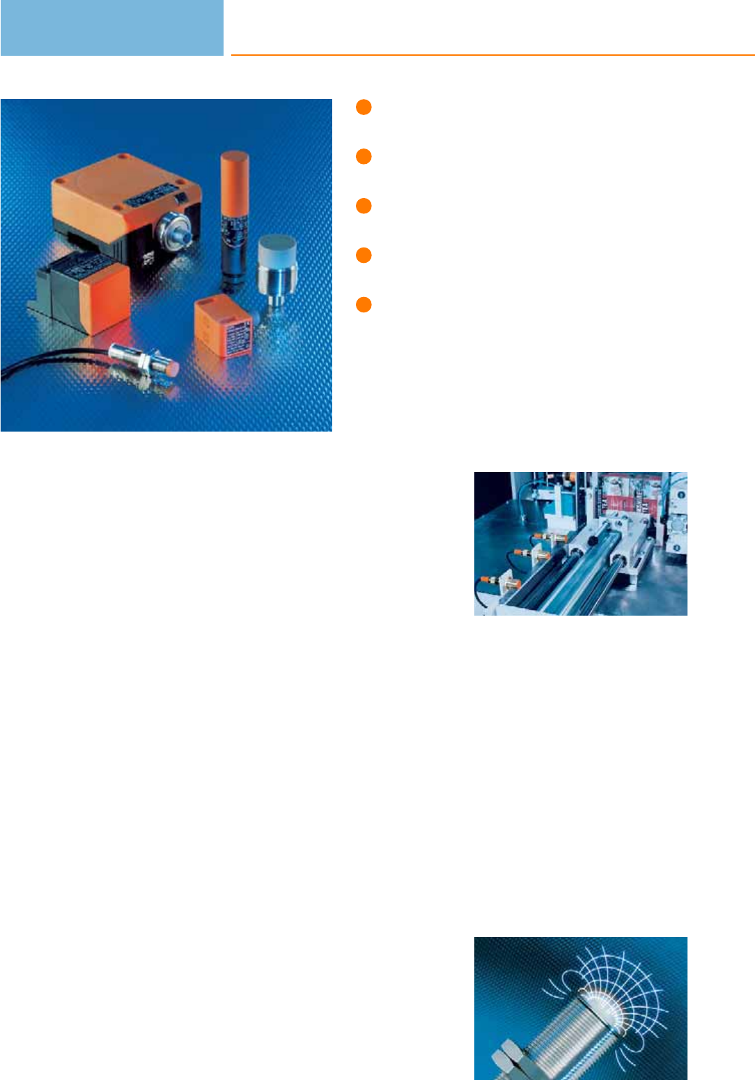
Sensors for almost all application areas.
Wide choice of housing styles and
operating voltages.
High-quality housing materials.
Cylindrical housings: Ø 3…34 mm, rectan-
gular housings: 5 x 5 x 24 to 105 x 80 x 40.
Extensive range of fixing accessories
and connection technology.
Inductive sensors
In all automated processes sensors are absolutely necessary to provide the PLC with
information. They supply the necessary signals on positions, limits or serve as pulse
pick-ups for counting tasks or for monitoring rotational speed. Inductive and
capacitive sensors are nowadays indispensable for industrial usage. As compared to
mechanical switches they offer ideal conditions: non-contact operation free from
any wear and tear, high switching frequencies and accuracy. In addition, they are
insensitive to vibration, dust and moisture. Inductive sensors detect all metals
without contact.
Operating principle of inductive sensors
Inductive sensors take advantage of the physical effect of the change in the quality
factor in a resonant circuit caused by eddy current losses in conductive materials.
This is how it works: An LC tuned circuit generates a high frequency electromag-
netic field. This field is radiated from the active face of the sensor. If a conductive
material enters this field, eddy currents will be formed in accordance with the law
of inductance which draw energy from the oscillator. This reduces the oscillation
amplitude. The change is converted into a switching signal. The operating principle
permits detection of all metals irrespective of whether they are moving or not.
Application sensors
Every application has its own requirements as regards the sensors to be used.
Temperature shocks, mechanical influences or aggressive cleaning agents are just a
few of the possible environmental influences to which sensors are subjected. ifm
electronic therefore offers inductive sensors which have been developed for special
applications. This includes for example the use of selected housing materials such
as stainless steel, LCP, PEEK, PBT or Duroplast. An innovative, consistent sealing
concept from the sensor to the connector ensures ideal protection against ingress
of moisture and aggressive media.
Typical application:
Positioning sensing in
automation technol-
ogy; inductive sensors
operate reliably and
without wear.
High frequency
electromagnetic field:
The inductive sensor
detects all metals.
Inductive sensors
54

Inductive sensors
55
System overview Page
Sensors with increased sensing range for industrial applications 57 - 59
Sensors for industrial applications, threaded housings 59 - 66
Sensors with analogue output 4...20 mA for industrial applications 66 - 67
Sensors with analogue output 0...10 V for industrial applications 67
Sensors with smooth sleeve for industrial applications 68 - 70
Sensors for industrial applications, rectangular housings 70 - 75
Ring sensors for industrial applications 75 - 76
Tube sensors for industrial applications 77
Sensors for industrial applications, AC and AC/DC 78 - 80
Sensors for hygienic and wet areas with increased sensing range 81 - 84
Full metal sensors for hygienic and wet areas 84 - 85
Sensors for hygienic and wet areas 85 - 87
Sensors for oils and coolants with increased sensing range 87 - 91
Full metal sensors for oils and coolants 91 - 92
Full metal sensors for oils and coolants with correction factor K = 0 92 - 93
Sensors for oils and coolants with correction factor K = 1 93 - 94
Sensors for oils and coolants with ceramic sensing face 94 - 95
Sensors for oils and coolants, AS-i system 95
Sensors for oils and coolants, threaded housings 95 - 97
Sensors for oils and coolants, rectangular housings 97
Full metal sensors with non-stick coating against weld spatter 98 - 100
Electromagnetic field immune sensors with correction factor K = 1 100 - 101
Electromagnetic field immune sensors 101 - 102
Sensors for mobile applications 102 - 105
Fail-safe inductive sensors for series connection to IEC 62061 SILcl 3 and ISO 13849-1 PL e 105
Inductive sensors for safety-related applications, 2 x OSSD, SIL 2, PL d 106
Inductive sensors for safety-related applications, 2 x OSSD, SIL 3, PL e 106
Safety relays with relay outputs for fail-safe sensors 107
Safety relays with solid state outputs for fail-safe sensors 107
Sensors with ATEX approval 1D / 2G 107 - 108
Slot sensors for industrial applications 108 - 109

System overview Page
Switching amplifiers with ATEX approval 109
Accessories for sensors with smooth sleeve 109 - 110
Accessories for threaded M8 housings 110
Accessories for threaded M12 housings 111
Accessories for threaded M18 housings 111 - 112
Accessories for threaded M30 housings 112
Accessories for rectangular housings 112
System components 113 - 114
Wiring diagrams 114 - 116
Scale drawings / drawing no. – CAD download: www.ifm.com 116 - 135
Inductive sensors
56
Product selectors and further information can be found at: www.ifm.com
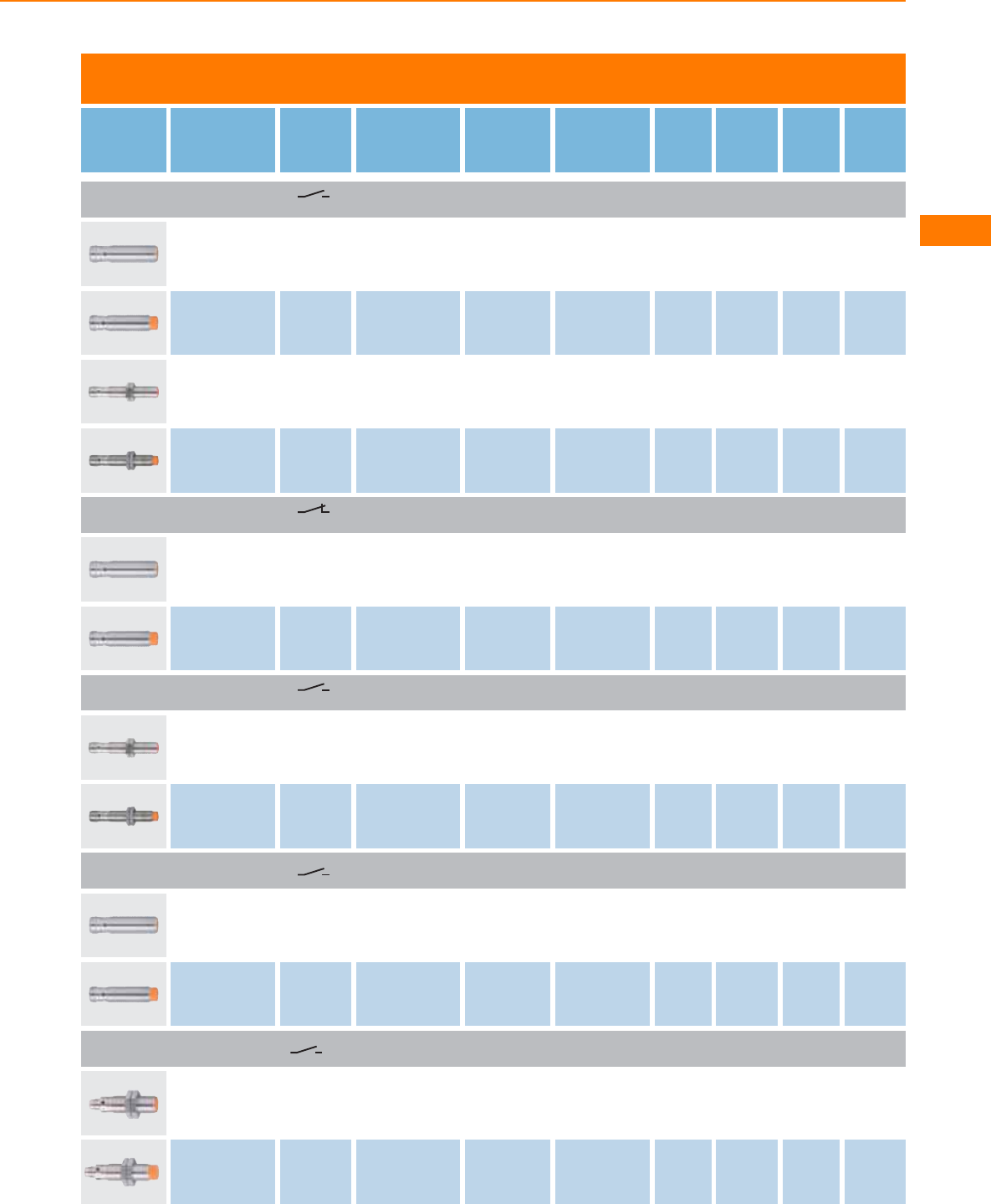
Sensors with increased sensing range for industrial applications
Type Dimensions
[mm]
Sensing
range
[mm]
Material Ub
[V]
Protection f
[Hz]
Iload
[mA]
Draw-
ing
no.
Order
no.
M12 connector · Output function · 3-wire · DC PNP · Wiring diagram no. 1 · Connector groups 9, 10, 11, 12, 107, 108, 109,
110, 135, 136
M12 / L = 45 4 f brass 10...36 IP 67 700 100 1 IFS204
M12 / L = 50 7 nf brass 10...36 IP 67 700 100 2IFS205
M12 / L = 70 4 f brass 10...36 IP 67 700 100 3 IFS212
M12 / L = 70 7 nf brass 10...36 IP 67 700 100 4IFS213
M12 connector · Output function · 3-wire · DC PNP · Wiring diagram no. 2 · Connector groups 9, 10, 11, 12, 107, 108, 109,
110, 135, 136
M12 / L = 45 4 f brass 10...36 IP 67 700 100 1 IFS206
M12 / L = 50 7 nf brass 10...36 IP 67 700 100 2IFS207
M12 connector · Output function · 3-wire · 3-wire DC PNP; 2-wire DC PNP/NPN · Wiring diagram no. 31 · Connector groups
9, 10, 11, 12, 107, 108, 109, 110, 135, 136
M12 / L = 70 4 f brass 10...30 IP 67 500 100 3 IFS208
M12 / L = 70 7 nf brass 10...30 IP 67 500 100 4IFS209
M12 connector · Output function · 2-wire · DC PNP/NPN · Wiring diagram no. 32 · Connector groups 9, 11, 107, 108, 135
M12 / L = 45 4 f brass 10...30 IP 67 700 100 1 IFS200
M12 / L = 50 7 nf brass 10...30 IP 67 700 100 2IFS201
M8 connector · Output function · 3-wire · DC PNP · Wiring diagram no. 1 · Connector groups 1, 2, 3, 68
M12 / L = 46 4 f brass 10...36 IP 67 700 100 5 IFS210
M12 / L = 51 7 nf brass 10...36 IP 67 700 100 6IFS211
Inductive sensors
57
You can find wiring diagrams and scale drawings from page 114
Type Dimensions
[mm]
Sensing
range
[mm]
Material Ub
[V]
Protection f
[Hz]
Iload
[mA]
Draw-
ing
no.
Order
no.
M12 connector · Output function · 3-wire · DC PNP · Wiring diagram no. 1 · Connector groups 9, 10, 11, 12, 107, 108, 109,
110, 135, 136
M18 / L = 46 8 f brass 10...36 IP 67 400 100 7 IGS204
M18 / L = 51 12 nf brass 10...36 IP 67 300 100 8IGS205
M18 / L = 70 8 f brass 10...36 IP 67 400 100 9 IGS212
M18 / L = 70 12 nf brass 10...36 IP 67 300 100 10 IGS213
M12 connector · Output function · 3-wire · DC PNP · Wiring diagram no. 2 · Connector groups 9, 10, 11, 12, 107, 108, 109,
110, 135, 136
M18 / L = 46 8 f brass 10...36 IP 67 400 100 7 IGS206
M18 / L = 51 12 nf brass 10...36 IP 67 300 100 8IGS207
M12 connector · Output function · 3-wire · 3-wire DC PNP; 2-wire DC PNP/NPN · Wiring diagram no. 31 · Connector groups 9,
10, 11, 12, 107, 108, 109, 110, 135, 136
M18 / L = 70 8 f brass 10...30 IP 67 400 100 9 IGS208
M18 / L = 70 12 nf brass 10...30 IP 67 300 100 10 IGS209
M12 connector · Output function · 2-wire · DC PNP/NPN · Wiring diagram no. 32 · Connector groups 9, 11, 107, 108, 135
M18 / L = 46 8 f brass 10...30 IP 67 300 100 7 IGS200
M18 / L = 51 12 nf brass 10...30 IP 67 250 100 8IGS201
M12 connector · Output function · 2-wire · DC PNP/NPN · Wiring diagram no. 33 · Connector groups 9, 11, 107, 108,
135
M18 / L = 70 8 f brass 10...36 IP 68 400 100 11 IG5953
M18 / L = 72 12 nf brass 10...36 IP 67 250 100 12 IG5954
Inductive sensors
58
Product selectors and further information can be found at: www.ifm.com
Type Dimensions
[mm]
Sensing
range
[mm]
Material Ub
[V]
Protection f
[Hz]
Iload
[mA]
Draw-
ing
no.
Order
no.
M8 connector · Output function · 3-wire · DC PNP · Wiring diagram no. 1 · Connector groups 1, 2, 3, 68
M18 / L = 46 8 f brass 10...36 IP 67 400 100 13 IGS210
M12 connector · Output function · 3-wire · DC PNP · Wiring diagram no. 1 · Connector groups 9, 10, 11, 12, 107, 108, 109,
110, 135, 136
M30 / L = 50 15 f brass 10...36 IP 67 100 100 14 IIS204
M30 / L = 50 22 nf brass 10...36 IP 67 100 100 15 IIS205
M30 / L = 70 15 f high-grade st. steel 10...36 IP 67 100 100 16 IIS210
M30 / L = 70 22 nf high-grade st. steel 10...36 IP 67 100 100 17 IIS211
M12 connector · Output function · 3-wire · DC PNP · Wiring diagram no. 2 · Connector groups 9, 10, 11, 12, 107, 108, 109,
110, 135, 136
M30 / L = 50 15 f brass 10...36 IP 67 100 100 14 IIS208
M30 / L = 50 22 nf brass 10...36 IP 67 100 100 15 IIS209
M12 connector · Output function · 3-wire · 3-wire DC PNP; 2-wire DC PNP/NPN · Wiring diagram no. 31 · Connector groups
9, 10, 11, 12, 107, 108, 109, 110, 135, 136
M30 / L = 70 15 f brass 10...36 IP 67 100 100 16 IIS206
M30 / L = 70 22 nf brass 10...36 IP 67 100 100 17 IIS207
f = flush / nf = non flush
Sensors for industrial applications, threaded housings
Type Dimensions
[mm]
Sensing
range
[mm]
Material Ub
[V]
Protection f
[Hz]
Iload
[mA]
Draw-
ing
no.
Order
no.
Cable 2 m · Output function · 3-wire · DC PNP · Wiring diagram no. 3
M5 / L = 30 0.8 f stainless steel 10...36 IP 65 2000 100 18 IY5029
Inductive sensors
59
You can find wiring diagrams and scale drawings from page 114

Type Dimensions
[mm]
Sensing
range
[mm]
Material Ub
[V]
Protection f
[Hz]
Iload
[mA]
Draw-
ing
no.
Order
no.
Cable 2 m · Output function · 3-wire · DC PNP · Wiring diagram no. 3
M5 / L = 23 0.8 f stainless steel 10...30 IP 65 2000 100 19 IY5051
M5 / L = 23 1.2 f stainless steel 10...30 IP 65 < 2000 100 19 IY5052
M5 / L = 27 1.5 nf stainless steel 10...30 IP 67 1800 100 20 IY5049
M8 connector · Output function · 3-wire · DC PNP · Wiring diagram no. 1 · Connector groups 1, 2, 3, 68
M5 / L = 45 0.8 f stainless steel 10...36 IP 65 2000 100 21 IY5036
M5 / L = 41 1.5 nf stainless steel 10...30 IP 67 1800 100 22 IY5048
Cable 2 m · Output function · 3-wire · DC PNP · Wiring diagram no. 3
M8 / L = 35 1 f brass 10...36 IP 67 750 200 23 IE5072
M8 / L = 50 1 f brass 10...36 IP 67 750 200 24 IE5121
M8 / L = 50 1 f PBT 10...36 IP 67 1000 200 24 IE5129
M8 / L = 20 1.5 f stainless steel 10...30 IP 67 4000 200 25 IE5348
M8 / L = 27 2 f high-grade st. steel 10...30 IP 67 1500 100 26 IE5368
M8 / L = 35 2 nf PBT 10...36 IP 67 800 200 23 IE5099
M8 / L = 27 4 nf high-grade st. steel 10...30 IP 67 500 100 27 IE5369
Cable 2 m · Output function · 2-wire · DC PNP/NPN · Wiring diagram no. 34
M8 / L = 50 1 f brass 5...36 IP 67 2000 200 24 IE5222
Inductive sensors
60
Product selectors and further information can be found at: www.ifm.com

Type Dimensions
[mm]
Sensing
range
[mm]
Material Ub
[V]
Protection f
[Hz]
Iload
[mA]
Draw-
ing
no.
Order
no.
Cable 2 m · Output function · 2-wire · DC PNP/NPN · Wiring diagram no. 34
M8 / L = 50 2 nf brass 5...36 IP 67 2700 200 28 IE5238
M8 / L = 50 2 nf PBT (Pocan) 5...36 IP 67 2000 200 24 IE5202
Cable 2 m · Output function · 3-wire · 3-wire DC PNP; 2-wire DC PNP/NPN · Wiring diagram no. 35
M8 / L = 37 3 f brass 10...30 IP 67 1000 100 29 IE5343
M8 / L = 37 5 nf brass 10...30 IP 67 700 100 30 IE5345
Cable with connector 0.3 m · Output function · 3-wire · 3-wire DC PNP; 2-wire DC PNP/NPN · Wiring diagram no. 31 ·
Connector groups 1, 2, 3, 68
M8 / L = 37 3 f brass 10...30 IP 67 1000 100 29 IE5344
M8 / L = 37 5 nf brass 10...30 IP 67 700 100 30 IE5346
Cable with connector 0.3 m · Output function · 3-wire · 3-wire DC PNP; 2-wire DC PNP/NPN · Wiring diagram no. 31 ·
Connector groups 9, 10, 11, 12, 107, 108, 109, 110, 135, 136
M8 / L = 37 3 f brass 10...30 IP 67 1000 100 29 IE5351
M8 / L = 37 5 nf brass 10...30 IP 67 700 100 30 IE5352
M8 connector · Output function · 3-wire · DC PNP · Wiring diagram no. 1 · Connector groups 1, 2, 3, 68
M8 / L = 50 2 f brass 10...36 IP 67 1000 250 31 IE5287
M8 / L = 30 2 f high-grade st. steel 10...30 IP 67 / 1500 100 32 IE5366
M8 / L = 30 4 nf high-grade st. steel 10...30 IP 67 700 100 33 IE5367
M8 connector · Output function · 3-wire · DC PNP · Wiring diagram no. 4 · Connector groups 1, 2, 3, 68
M8 / L = 50 1 f brass 10...36 IP 65 > 2000 250 34 IE5258
Inductive sensors
61
You can find wiring diagrams and scale drawings from page 114
Type Dimensions
[mm]
Sensing
range
[mm]
Material Ub
[V]
Protection f
[Hz]
Iload
[mA]
Draw-
ing
no.
Order
no.
M8 connector · Output function · 3-wire · 3-wire DC PNP; 2-wire DC PNP/NPN · Wiring diagram no. 31 · Connector groups 1,
2, 3, 68
M8 / L = 40 3 f brass 10...30 IP 67 1000 100 35 IE5338
M8 / L = 40 5 nf high-grade st. steel 10...30 IP 67 700 100 36 IE5340
M8 connector · Output function · 3-wire · 3-wire DC PNP; 2-wire DC PNP/NPN · Wiring diagram no. 36 · Connector groups 1,
2, 3, 68
M8 / L = 40 3 f brass 10...30 IP 67 1000 100 37 IE5349
M8 / L = 40 5 nf high-grade st. steel 10...30 IP 67 700 100 36 IE5350
M12 connector · Output function · 3-wire · DC PNP · Wiring diagram no. 1 · Connector groups 9, 10, 11, 12, 107, 108, 109,
110, 135, 136
M8 / L = 53 1 f brass 10...36 IP 67 750 200 38 IE5090
M8 / L = 62 2 f brass 10...36 IP 67 1000 250 39 IE5312
M8 / L = 50 2 f high-grade st. steel 10...36 IP 68 1000 100 40 IE5379
M8 / L = 62 4 nf brass 10...36 IP 67 300 200 41 IE5288
M12 connector · Output function · 3-wire · DC PNP · Wiring diagram no. 2 · Connector groups 9, 10, 11, 12, 107, 108, 109,
110, 135, 136
M8 / L = 62 2 f brass 10...36 IP 67 800 250 42 IE5327
M12 connector · Output function · 2-wire · DC PNP/NPN · Wiring diagram no. 33 · Connector groups 9, 11, 107, 108,
135
M8 / L = 69 1 f brass 5...36 IP 67 2700 200 43 IE5203
M12 connector · Output function · 3-wire · DC PNP · Wiring diagram no. 1 · Connector groups 9, 10, 11, 12, 107, 108, 109,
110, 135, 136
M12 / L = 45 2 f brass 10...36 IP 67 700 100 1 IFS214
M12 / L = 70 2 f brass 10...36 IP 67 700 100 3IFS216
Inductive sensors
62
Product selectors and further information can be found at: www.ifm.com
Type Dimensions
[mm]
Sensing
range
[mm]
Material Ub
[V]
Protection f
[Hz]
Iload
[mA]
Draw-
ing
no.
Order
no.
M12 connector · Output function · 3-wire · DC PNP · Wiring diagram no. 1 · Connector groups 9, 10, 11, 12, 107, 108, 109,
110, 135, 136
M12 / L = 50 4 nf brass 10...36 IP 67 700 100 2 IFS215
M12 / L = 70 4 nf brass 10...36 IP 67 700 100 4IFS217
Cable 2 m · Output function · 3-wire · DC PNP · Wiring diagram no. 3
M12 / L = 35 2 f brass 10...36 IP 67 1500 150 44 IF5188
M12 / L = 71 2 f brass 10...55 IP 67 800 250 45 IF5297
M12 / L = 71 2 f PBT 10...55 IP 67 800 250 45 IF5313
M12 / L = 35 4 nf brass 10...36 IP 67 1500 150 46 IF5249
M12 / L = 71 4 nf brass 10...36 IP 67 1500 250 47 IF5329
M12 / L = 71 4 nf PBT 10...36 IP 67 400 250 45 IF5345
Cable 2 m · Output function · 2-wire · DC PNP/NPN · Wiring diagram no. 34
M12 / L = 71 2 f brass 10...55 IP 67 1100 400 45 IF5645
M12 / L = 71 2 f PBT 10...55 IP 67 1100 400 45 IF5644
M12 / L = 71 4 nf brass 10...55 IP 67 1500 400 47 IF5646
M12 / L = 71 4 nf PBT 10...55 IP 67 1500 400 45 IF5597
M12 connector · Output function · 2-wire · DC PNP/NPN · Wiring diagram no. 33 · Connector groups 9, 11, 107,
108, 135
M12 / L = 83 2 f brass 10...55 IP 67 1100 300 48 IF5598
Inductive sensors
63
You can find wiring diagrams and scale drawings from page 114
Type Dimensions
[mm]
Sensing
range
[mm]
Material Ub
[V]
Protection f
[Hz]
Iload
[mA]
Draw-
ing
no.
Order
no.
M12 connector · Output function · 2-wire · DC PNP/NPN · Wiring diagram no. 33 · Connector groups 9, 11, 107,
108, 135
M12 / L = 83 4 nf brass 10...55 IP 67 1500 300 49 IF5647
M12 connector · Output function · 3-wire · DC PNP · Wiring diagram no. 1 · Connector groups 9, 10, 11, 12, 107, 108, 109,
110, 135, 136
M18 / L = 46 5 f brass 10...36 IP 67 400 100 7IGS214
M18 / L = 70 5 f brass 10...36 IP 67 400 100 9 IGS216
M18 / L = 70 8 nf brass 10...36 IP 67 300 100 10 IGS217
Cable 2 m · Output function · 3-wire · DC PNP · Wiring diagram no. 3
M18 / L = 38 5 f brass 18...36 IP 67 500 150 50 IG5221
M18 / L = 80 5 f brass 10...36 IP 67 500 250 51 IG5397
M18 / L = 80 5 f PBT 10...36 IP 67 500 250 51 IG5399
M18 / L = 38 8 nf brass 18...36 IP 67 200 150 52 IG5285
M18 / L = 80 8 nf brass 10...36 IP 67 300 250 53 IG5398
M18 / L = 80 8 nf PBT 10...36 IP 67 300 250 51 IG5401
Cable 2 m · Output function · 2-wire · DC PNP/NPN · Wiring diagram no. 34
M18 / L = 80 5 f PBT 10...55 IP 67 700 400 51 IG5593
M18 / L = 80 5 f brass 10...55 IP 67 700 400 51 IG5594
M18 / L = 80 8 nf PBT 10...55 IP 67 300 400 51 IG5533
Inductive sensors
64
Product selectors and further information can be found at: www.ifm.com
Type Dimensions
[mm]
Sensing
range
[mm]
Material Ub
[V]
Protection f
[Hz]
Iload
[mA]
Draw-
ing
no.
Order
no.
Cable 2 m · Output function · 2-wire · DC PNP/NPN · Wiring diagram no. 34
M18 / L = 80 8 nf brass 10...55 IP 67 300 400 53 IG5596
M12 connector · Output function · 2-wire · DC PNP/NPN · Wiring diagram no. 33 · Connector groups 9, 11, 107, 108,
135
M18 / L = 70 5 f brass 10...55 IP 67 700 400 54 IG5595
M18 / L = 76 8 nf brass 10...55 IP 67 300 400 55 IG5597
Terminals · Output function · 2-wire · DC PNP/NPN · Wiring diagram no. 37
M18 / L = 110 5 f PBT 10...55 IP 65 800 400 56 IG5718
M18 / L = 110 8 nf PBT 10...55 IP 65 300 400 56 IG5719
Cable 2 m · Output function · 3-wire · DC PNP · Wiring diagram no. 3
M30 / L = 45 10 f brass 18...36 IP 67 300 150 57 II5166
M30 / L = 81 10 f brass 10...36 IP 67 250 250 58 II5256
M30 / L = 81 10 f PBT 10...36 IP 67 250 250 58 II5369
M30 / L = 45 15 nf brass 18...36 IP 67 250 150 59 II5346
M30 / L = 81 15 nf brass 10...36 IP 67 250 250 60 II5284
M30 / L = 81 15 nf PBT 10...36 IP 67 250 250 58 II5300
Cable 2 m · Output function · 2-wire · DC PNP/NPN · Wiring diagram no. 34
M30 / L = 45 10 f brass 10...55 IP 67 450 400 57 II5493
M30 / L = 81 10 f PBT 10...55 IP 67 450 400 58 II5488
Inductive sensors
65
You can find wiring diagrams and scale drawings from page 114
Type Dimensions
[mm]
Sensing
range
[mm]
Material Ub
[V]
Protection f
[Hz]
Iload
[mA]
Draw-
ing
no.
Order
no.
Cable 2 m · Output function · 2-wire · DC PNP/NPN · Wiring diagram no. 34
M30 / L = 81 10 f brass 10...55 IP 67 450 400 58 II5489
M30 / L = 81 15 nf PBT 10...55 IP 67 200 400 58 II5436
M30 / L = 81 15 nf brass 10...55 IP 67 200 400 60 II5491
M12 connector · Output function · 2-wire · DC PNP/NPN · Wiring diagram no. 33 · Connector groups 9, 11, 107,
108, 135
M30 / L = 78 10 f brass 10...55 IP 67 450 400 61 II5490
M30 / L = 78 15 nf brass 10...55 IP 67 200 400 62 II5492
f = flush / nf = non flush
Sensors with analogue output 4...20 mA for industrial applications
Type Dimensions
[mm]
Sensing
range
[mm]
Material Ub
[V]
Protection f
[Hz]
Iload
[mA]
Draw-
ing
no.
Order
no.
M12 connector · Output function 4...20 mA analogue · 3-wire · DC analogue · Wiring diagram no. 5 · Connector groups 9, 11, 107,
108, 135
M12 / L = 70 0.2...2 f brass 15...30 IP 67 – – 3 IF6028
M12 / L = 70 0.4...4 nf brass 15...30 IP 67 – – 4 IF6030
M18 / L = 60 0.5...5 f brass 15...30 IP 67 – – 63 IG6086
M18 / L = 60 0.8...8 nf brass 15...30 IP 67 – – 64 IG6083
M30 / L = 70 1.0...10 f brass 15...30 IP 67 – – 16 II5916
Inductive sensors
66
Product selectors and further information can be found at: www.ifm.com
Type Dimensions
[mm]
Sensing
range
[mm]
Material Ub
[V]
Protection f
[Hz]
Iload
[mA]
Draw-
ing
no.
Order
no.
M12 connector · Output function 4...20 mA analogue · 3-wire · DC analogue · Wiring diagram no. 5 · Connector groups 9, 11, 107,
108, 135
M30 / L = 70 1.0...15 nf brass 15...30 IP 67 – – 17 II5913
40 x 40 x 54 1...15 f PA (polyamide) 15...30 IP 67 – – 65 IM5139
40 x 40 x 54 1...26 nf PA (polyamide) 15...30 IP 67 – – 65 IM5141
f = flush / nf = non flush
Sensors with analogue output 0...10 V for industrial applications
Type Dimensions
[mm]
Sensing
range
[mm]
Material Ub
[V]
Protection f
[Hz]
Iload
[mA]
Draw-
ing
no.
Order
no.
M12 connector · Output function 0...10 V analogue · 3-wire · DC analogue · Wiring diagram no. 5 · Connector groups 9, 11, 107,
108, 135
M12 / L = 70 0.2...2 f brass 15...30 IP 67 – – 3 IF6029
M12 / L = 70 0.4...4 nf brass 15...30 IP 67 – – 4 IF6031
M18 / L = 60 0.5...5 f brass 15...30 IP 67 – – 63 IG6087
M18 / L = 60 0.8...8 nf brass 15...30 IP 67 – – 64 IG6084
M30 / L = 70 1.0...10 f brass 15...30 IP 67 – – 16 II5917
M30 / L = 70 1.0...15 nf brass 15...30 IP 67 – – 17 II5914
40 x 40 x 54 1...15 f PA (polyamide) 15...30 IP 67 – – 65 IM5140
40 x 40 x 54 1...26 nf PA (polyamide) 15...30 IP 67 – – 65 IM5142
f = flush / nf = non flush
Inductive sensors
67
You can find wiring diagrams and scale drawings from page 114
Sensors with smooth sleeve for industrial applications
Type Dimensions
[mm]
Sensing
range
[mm]
Material Ub
[V]
Protection f
[Hz]
Iload
[mA]
Draw-
ing
no.
Order
no.
Cable 2 m · Output function · 3-wire · DC PNP · Wiring diagram no. 3
Ø 4 / L = 30 0.8 f stainless steel 10...36 IP 65 2000 100 66 IZ5026
Ø 4 / L = 23 0.8 f stainless steel 10...30 IP 65 2000 100 67 IZ5051
Ø 3 / L = 27 1 nf stainless steel 10...30 IP 67 5000 100 68 IZ5048
Ø 4 / L = 23 1.2 f stainless steel 10...30 IP 65 > 2000 100 67 IZ5052
Ø 4 / L = 27 1.5 nf stainless steel 10...30 IP 67 1800 100 69 IZ5047
M8 connector · Output function · 3-wire · DC PNP · Wiring diagram no. 1 · Connector groups 1, 2, 3, 68
Ø 4 / L = 45 0.8 f stainless steel 10...36 IP 65 2000 100 70 IZ5035
M8 connector · Output function · 3-wire · DC PNP · Wiring diagram no. 1 · Connector groups 104, 105
Ø 4 / L = 41 1.5 nf stainless steel 10...30 IP 67 1800 100 71 IZ5046
Cable 2 m · Output function · 3-wire · DC PNP · Wiring diagram no. 3
Ø 6.5 / L = 35 1 f brass 10...36 IP 67 900 200 72 IT5001
Ø 6.5 / L = 19 2 f stainless steel 10...30 IP 67 1000 200 73 IT5039
Ø 6.5 / L = 27 2 f high-grade st. steel 10...30 IP 67 1500 100 74 IT5042
M8 connector · Output function · 3-wire · DC PNP · Wiring diagram no. 1 · Connector groups 1, 2, 3, 68
Ø 6.5 / L = 49 1 f brass 10...36 IP 65 > 2000 250 75 IT5021
Ø 6.5 / L = 49 1.5 f brass 10...36 IP 65 2000 250 75 IT5034
Inductive sensors
68
Product selectors and further information can be found at: www.ifm.com

Type Dimensions
[mm]
Sensing
range
[mm]
Material Ub
[V]
Protection f
[Hz]
Iload
[mA]
Draw-
ing
no.
Order
no.
M8 connector · Output function · 3-wire · DC PNP · Wiring diagram no. 1 · Connector groups 1, 2, 3, 68
Ø 6.5 / L = 30 2 f high-grade st. steel 10...30 IP 67 1500 100 76 IT5040
Ø 6.5 / L = 50 4 nf high-grade st. steel 10...30 IP 67 300 100 77 IT5044
Cable 2 m · Output function · 3-wire · DC PNP · Wiring diagram no. 3
Ø 20 / L = 77 10 nf PBT 10...36 IP 67 300 250 78 IA5082
Cable 2 m · Output function · 2-wire · DC PNP/NPN · Wiring diagram no. 34
Ø 20 / L = 77 10 nf PBT 10...55 IP 67 300 400 78 IA5108
M12 connector · Output function · 3-wire · DC PNP · Wiring diagram no. 1 · Connector groups 9, 10, 11, 12, 107, 108, 109,
110, 135, 136
Ø 20 / L = 93 10 nf PBT 10...36 IP 67 300 250 79 IA5127
Terminals · Output function · 3-wire · DC PNP · Wiring diagram no. 6
Ø 20 / L = 92 10 nf PBT 10...36 IP 65 300 250 80 IA5062
Terminals · Output function · 3-wire · DC PNP · Wiring diagram no. 6
Ø 20 / L = 92 10 nf PBT 10...36 IP 65 300 250 80 IA5063
Terminals · Output function · 2-wire · DC PNP/NPN · Wiring diagram no. 37
Ø 20 / L = 92 10 nf PBT 10...55 IP 65 300 300 80 IA5122
Cable 2 m · Output function · 3-wire · DC PNP · Wiring diagram no. 3
Ø 34 / L = 82 20 nf PBT 10...36 IP 67 60 250 81 IB5096
Inductive sensors
69
You can find wiring diagrams and scale drawings from page 114

Type Dimensions
[mm]
Sensing
range
[mm]
Material Ub
[V]
Protection f
[Hz]
Iload
[mA]
Draw-
ing
no.
Order
no.
Terminals · Output function · 2-wire · DC PNP/NPN · Wiring diagram no. 37
Ø 34 / L = 98 20 nf PBT 10...55 IP 65 300 300 82 IB5124
Terminals · Output function · 3-wire · DC PNP · Wiring diagram no. 6
Ø 34 / L = 98 20 nf PBT 10...36 IP 65 350 250 82 IB5063
Ø 34 / L = 98 30 nf PBT 10...36 IP 65 350 200 82 IB5133
f = flush / nf = non flush
Sensors for industrial applications, rectangular housings
Type Dimensions
[mm]
Sensing
range
[mm]
Material Ub
[V]
Protection f
[Hz]
Iload
[mA]
Draw-
ing
no.
Order
no.
Cable 2 m · Output function · 3-wire · DC PNP · Wiring diagram no. 3
25 x 5 x 5 0.8 f aluminium 10...30 IP 65 1000 100 83 IL5022
40 x 8 x 8 2 f brass 10...36 IP 65 2000 250 84 IL5002
40 x 8 x 8 2 f brass 10...36 IP 65 2000 250 84 IL5003
40 x 8 x 8 2.5 f brass 10...36 IP 65 2000 250 84 IL5020
M8 connector · Output function · 3-wire · DC PNP · Wiring diagram no. 1 · Connector groups 1, 2, 3, 68
40 x 8 x 8 2 f brass 10...36 IP 65 2000 250 85 IL5004
40 x 8 x 8 2 f brass 10...36 IP 65 2000 250 85 IL5005
Cable 2 m · Output function · 3-wire · DC PNP · Wiring diagram no. 3
28 x 10 x 16 2 f PBT 10...36 IP 67 800 200 86 IS5001
Inductive sensors
70
Product selectors and further information can be found at: www.ifm.com
Type Dimensions
[mm]
Sensing
range
[mm]
Material Ub
[V]
Protection f
[Hz]
Iload
[mA]
Draw-
ing
no.
Order
no.
Cable 2 m · Output function · 3-wire · DC PNP · Wiring diagram no. 3
28 x 10 x 16 3 nf PBT 10...36 IP 67 100 200 86 IS5031
28 x 10 x 16 4 nf PBT 10...36 IP 67 2000 250 87 IS5070
Cable 2 m · Output function · 2-wire · DC PNP/NPN · Wiring diagram no. 34
28 x 10 x 16 2 f PBT 5...36 IP 67 2000 200 86 IS5026
M8 connector · Output function · 3-wire · DC PNP · Wiring diagram no. 1 · Connector groups 1, 2, 3, 68
28 x 10 x 16 2 f PBT 10...36 IP 67 800 200 88 IS5035
28 x 10 x 16 4 nf PBT 10...36 IP 67 2000 250 88 IS5071
Cable 2 m · Output function · 3-wire · DC PNP · Wiring diagram no. 3
40 x 12 x 26 2 f PBT 10...36 IP 67 1400 250 89 IN5121
40 x 12 x 26 4 nf PBT 10...36 IP 67 1300 250 89 IN5129
Cable 2 m · Output function · 2-wire · DC PNP/NPN · Wiring diagram no. 34
40 x 12 x 26 2 f PBT 10...55 IP 67 1300 400 89 IN5207
40 x 12 x 26 4 nf PBT 10...55 IP 67 1200 400 89 IN5208
Cable 2 m · Output function · 3-wire · DC PNP · Wiring diagram no. 7
40 x 12 x 26 2 f PBT 10...36 IP 67 1400 250 89 IN5186
40 x 12 x 26 4 nf PBT 10...36 IP 67 1300 250 89 IN5188
M8 connector · Output function · 3-wire · DC PNP · Wiring diagram no. 1 · Connector groups 1, 2, 3, 68
40 x 12 x 26 2 f PBT 10...36 IP 67 1400 250 90 IN5230
Inductive sensors
71
You can find wiring diagrams and scale drawings from page 114
Type Dimensions
[mm]
Sensing
range
[mm]
Material Ub
[V]
Protection f
[Hz]
Iload
[mA]
Draw-
ing
no.
Order
no.
M8 connector · Output function · 3-wire · DC PNP · Wiring diagram no. 1 · Connector groups 1, 2, 3, 68
40 x 12 x 26 4 nf PBT 10...36 IP 65 1300 250 90 IN5212
Cable 2 m · Output function · 3-wire · DC PNP · Wiring diagram no. 3
60 x 36 x 10 5 f PBT 10...36 IP 67 400 250 91 IW5051
60 x 36 x 10 8 nf PBT 10...36 IP 67 300 250 91 IW5058
Cable 2 m · Output function · 3-wire · DC PNP · Wiring diagram no. 7
60 x 36 x 10 8 nf PBT 10...36 IP 67 300 250 92 IW5053
M8 connector · Output function · 3-wire · DC PNP · Wiring diagram no. 1 · Connector groups 1, 2, 3, 68
60 x 36 x 10 8 nf PBT 10...36 IP 65 300 250 93 IW5064
M8 connector · Output function · 3-wire · DC PNP · Wiring diagram no. 4 · Connector groups 1, 2, 3, 68
60 x 36 x 10 8 nf PBT 10...36 IP 67 300 250 93 IW5062
M12 connector · Output function · 3-wire · DC PNP · Wiring diagram no. 1 · Connector groups 9, 10, 11, 12, 107, 108, 109,
110, 135, 136
40 x 40 x 54 20 f PA (polyamide) 10...36 IP 67 100 200 65 IM5115
40 x 40 x 54 20 f PA (polyamide) 10...36 IP 67 200 200 65 IM5128
40 x 40 x 54 20 f PA (polyamide) 10...36 IP 67 200 200 94 IM5119
40 x 40 x 54 35 nf PA (polyamide) 10...36 IP 67 80 200 65 IM5116
40 x 40 x 54 35 nf PA (polyamide) 10...36 IP 67 200 200 65 IM5130
40 x 40 x 54 35 nf PA (polyamide) 10...36 IP 67 200 200 94 IM5120
Inductive sensors
72
Product selectors and further information can be found at: www.ifm.com
Type Dimensions
[mm]
Sensing
range
[mm]
Material Ub
[V]
Protection f
[Hz]
Iload
[mA]
Draw-
ing
no.
Order
no.
M12 connector · Output function · 3-wire · DC PNP · Wiring diagram no. 1 · Connector groups 9, 10, 11, 12, 107, 108, 109,
110, 135, 136
40 x 40 x 54 40 nf PA (polyamide) 10...36 IP 67 60 200 65 IM5117
40 x 40 x 54 40 nf PA (polyamide) 10...36 IP 67 200 200 65 IM5131
40 x 40 x 54 40 nf PA (polyamide) 10...36 IP 67 200 200 94 IM5129
M12 connector · Output function · 3-wire · DC PNP · Wiring diagram no. 8 · Connector groups 9, 11, 107, 108, 135
40 x 40 x 54 20 f PA (polyamide) 10...36 IP 67 100 200 65 IM5123
M12 connector · Output function · 4-wire · DC PNP · Wiring diagram no. 8 · Connector groups 9, 11, 12, 107, 108, 109,
135, 136
40 x 40 x 54 20 f PA (polyamide) 10...36 IP 67 200 200 65 IM5132
M12 connector · Output function · 3-wire · DC PNP · Wiring diagram no. 8 · Connector groups 97, 98, 99, 100
40 x 40 x 54 20 f PA (polyamide) 10...36 IP 67 200 200 94 IM5124
M12 connector · Output function · 4-wire · DC PNP · Wiring diagram no. 8 · Connector groups 9, 11, 12, 107, 108, 109,
135, 136
40 x 40 x 54 35 nf PA (polyamide) 10...36 IP 67 80 200 65 IM5134
40 x 40 x 54 35 nf PA (polyamide) 10...36 IP 67 200 200 65 IM5133
M12 connector · Output function · 4-wire · DC PNP · Wiring diagram no. 8 · Connector groups 97, 98, 99, 100
40 x 40 x 54 35 nf PA (polyamide) 10...36 IP 67 200 200 94 IM5125
M12 connector · Output function · 4-wire · DC PNP · Wiring diagram no. 8 · Connector groups 9, 11, 12, 107, 108, 109,
135, 136
40 x 40 x 54 40 nf PA (polyamide) 10...36 IP 67 60 200 65 IM5136
40 x 40 x 54 40 nf PA (polyamide) 10...36 IP 67 / IP 69K 200 200 65 IM5135
Inductive sensors
73
You can find wiring diagrams and scale drawings from page 114
Type Dimensions
[mm]
Sensing
range
[mm]
Material Ub
[V]
Protection f
[Hz]
Iload
[mA]
Draw-
ing
no.
Order
no.
M12 connector · Output function · 4-wire · DC PNP · Wiring diagram no. 8 · Connector groups 97, 98, 99, 100
40 x 40 x 54 40 nf PA (polyamide) 10...36 IP 67 200 200 94 IM5126
M12 connector · 2-wire · AS-i · Wiring diagram no. 9 · Connector groups 9, 11, 107, 108, 135
40 x 40 x 54 15 f PBT 26.5...31.6 IP 67 100 –65 IM5118
Terminals · Output function · 3-wire · DC PNP · Wiring diagram no. 6
40 x 40 x 120 15 f PPE 10...36 IP 65 350 250 95 IM5020
40 x 40 x 120 20 nf PPE 10...36 IP 65 350 250 95 IM5019
40 x 40 x 120 30 nf PPE 10...36 IP 65 100 250 95 IM5046
Terminals · Output function · 2-wire · DC PNP/NPN · Wiring diagram no. 37
40 x 40 x 120 15 f PPE 10...55 IP 65 > 350 400 95 IM5037
40 x 40 x 120 20 nf PPE 10...55 IP 65 > 300 400 95 IM5038
Terminals · Output function · 4-wire · DC PNP · Wiring diagram no. 10
40 x 40 x 118 15 f PBT 10...60 IP 67 150 200 96 IV5003
40 x 40 x 118 20 f PBT 10...60 IP 67 150 200 97 IV5004
Terminals · Output function · 3-wire · DC PNP · Wiring diagram no. 38
90 x 60 x 40 40 nf PPE 10...36 IP 65 15 250 98 IC5005
M12 connector · Output function · 3-wire · DC PNP · Wiring diagram no. 1 · Connector groups 9, 10, 11, 12, 107, 108, 109,
110, 135, 136
92 x 80 x 40 50 f PPE 10...36 IP 67 70 250 99 ID5055
Inductive sensors
74
Product selectors and further information can be found at: www.ifm.com

Type Dimensions
[mm]
Sensing
range
[mm]
Material Ub
[V]
Protection f
[Hz]
Iload
[mA]
Draw-
ing
no.
Order
no.
M12 connector · Output function · 4-wire · DC PNP · Wiring diagram no. 8 · Connector groups 9, 11, 12, 107, 108, 109,
135, 136
92 x 80 x 40 50 f PPE 10...36 IP 67 70 250 99 ID5058
Terminals · Output function · 3-wire · DC PNP · Wiring diagram no. 38
105 x 80 x 40 60 nf PPE 10...36 IP 65 100 250 100 ID5005
M12 connector · Output function normally open / closed programmable · 3-wire · DC PNP · Wiring diagram no. 1 · Connector
groups 9, 10, 11, 12, 107, 108, 109, 110, 135, 136
105 x 80 x 40 60 nf PPE 10...36 IP 67 100 250 101 ID5046
Cable 2 m · Output function · 3-wire · DC PNP · Wiring diagram no. 3
120 x 80 x 30 50 nf PPE 10...36 IP 67 100 250 102 ID5026
f = flush / nf = non flush
Ring sensors for industrial applications
Type Inside
diameter
[mm]
Operating
principle
Minimum
diameter of
the steel ball
[Ø mm]
Part speed
max.
[m/s]
Pulse
stretching
[ms]
Response time /
break time
[ms]
Draw-
ing
no.
Order
no.
M12 connector · Output function · 3-wire · DC PNP · Wiring diagram no. 11 · Connector groups 9, 10, 11, 12, 107, 108,
109, 110, 135, 136
10.1 static 1.5 35 10...150 0.5 / 10 103 I7R201
10.1 dynamic 0.6 35 0.1...150 0.2 / 0.2 103 I7R203
15.1 static 2 35 10...150 0.5 / 10 104 I7R205
15.1 dynamic 0.8 35 0.1...150 0.2 / 0.2 104 I7R207
20.1 static 2.5 35 10...150 0.5 / 10 105 I7R209
20.1 dynamic 1.0 35 0.1...150 0.2 / 0.2 105 I7R211
Inductive sensors
75
You can find wiring diagrams and scale drawings from page 114
Type Inside
diameter
[mm]
Operating
principle
Minimum
diameter of
the steel ball
[Ø mm]
Part speed
max.
[m/s]
Pulse
stretching
[ms]
Response time /
break time
[ms]
Draw-
ing
no.
Order
no.
M12 connector · Output function · 3-wire · DC PNP · Wiring diagram no. 11 · Connector groups 9, 10, 11, 12, 107, 108,
109, 110, 135, 136
25.1 static 3.0 35 10...150 0.5 / 10 106 I7R213
25.1 dynamic 1.2 35 0.1...150 0.2 / 0.2 106 I7R215
M12 connector · Output function · 3-wire · DC NPN · Wiring diagram no. 12 · Connector groups 9, 10, 11, 12, 107, 108,
109, 110, 135, 136
10.1 static 1.5 35 10...150 0.5 / 10 103 I7R202
M12 connector · Output function · 3-wire · DC NPN · Wiring diagram no. 12 · Connector groups 9, 11, 107, 108, 135
10.1 dynamic 0.6 35 0.1...150 0.2 / 0.2 103 I7R204
15.1 static 2 35 10...150 0.5 / 10 104 I7R206
15.1 dynamic 0.8 35 0.1...150 0.2 / 0.2 104 I7R208
20.1 static 2.5 35 10...150 0.5 / 10 105 I7R210
20.1 dynamic 1.0 35 0.1...150 0.2 / 0.2 105 I7R212
25.1 static 3.0 35 10...150 0.5 / 10 106 I7R214
25.1 dynamic 1.2 35 0.1...150 0.2 / 0.2 106 I7R216
M12 connector · Output function · 3-wire · DC PNP · Wiring diagram no. 11 · Connector groups 9, 10, 11, 12, 107, 108,
109, 110, 135, 136
51 static 6 35 10...150 0.5 / 10 107 I7R217
Inductive sensors
76
Product selectors and further information can be found at: www.ifm.com
Tube sensors for industrial applications
Type Sensing
range
[mm]
Operating
principle
Minimum
diameter of
the steel ball
[Ø mm]
Part speed
max.
[m/s]
Pulse
stretching
[ms]
Response time /
break time
[ms]
Draw-
ing
no.
Order
no.
M8 connector · Output function · 3-wire · DC PNP · Wiring diagram no. 11 · Connector groups 1, 2, 3, 68
≤ 14 static 3.0 35 100 0.5 / 100 108 I85000
M8 connector · Output function · 3-wire · DC NPN · Wiring diagram no. 12 · Connector groups 1, 3, 68
≤ 14 static 3.0 35 100 0.5 / 100 108 I85001
Cable with connector 0.09 m · Output function · 3-wire · DC PNP · Wiring diagram no. 11 · Connector groups 9, 10, 11, 12,
107, 108, 109, 110, 135, 136
≤ 14 static 3.0 35 100 0.5 / 100 109 I85002
Cable with connector 0.09 m · Output function · 3-wire · DC NPN · Wiring diagram no. 12 · Connector groups 9, 11, 107, 108,
135
≤ 14 static 3.0 35 100 0.5 / 100 109 I85003
M8 connector · Output function · 3-wire · DC PNP · Wiring diagram no. 11 · Connector groups 1, 2, 3, 68
≤ 20 dynamic 1.0 35 100 0.2 / 100 108 I85004
M8 connector · Output function · 3-wire · DC NPN · Wiring diagram no. 12 · Connector groups 1, 3, 68
≤ 20 dynamic 1.0 35 100 0.2 / 100 108 I85005
Cable with connector 0.09 m · Output function · 3-wire · DC PNP · Wiring diagram no. 11 · Connector groups 9, 10, 11, 12,
107, 108, 109, 110, 135, 136
≤ 20 dynamic 1.0 35 100 0.2 / 100 109 I85006
Cable with connector 0.09 m · Output function · 3-wire · DC NPN · Wiring diagram no. 12 · Connector groups 9, 11, 107, 108,
135
≤ 20 dynamic 1.0 35 100 0.2 / 100 109 I85007
Inductive sensors
77
You can find wiring diagrams and scale drawings from page 114
Sensors for industrial applications, AC and AC/DC
Type Dimensions
[mm]
Sensing
range
[mm]
Material Ub
[V]
Protection f
AC / DC
[Hz]
Iload
AC / DC
[mA]
Draw-
ing
no.
Order
no.
Cable 2 m · Output function · 2-wire · AC · Wiring diagram no. 13
M12 / L = 71 2 f PBT 20...250 IP 67 25 250 45 IF0001*
M12 / L = 71 2 f brass 20...250 IP 67 25 250 45 IF0005*
M12 / L = 71 4 nf PBT 20...250 IP 67 25 250 45 IF0003*
M12 / L = 71 4 nf brass 20...250 IP 67 25 250 47 IF0007*
Cable 2 m · Output function · 2-wire · AC/DC · Wiring diagram no. 14
M18 / L = 80 5 f PBT 20...250 IP 67 25 / 50 350 / 100 51 IG0005*
M18 / L = 80 5 f brass 20...250 IP 67 25 / 50 350 / 100 51 IG0011*
M18 / L = 80 8 nf PBT 20...250 IP 67 25 / 50 350 / 100 51 IG0006*
M18 / L = 80 8 nf brass 20...250 IP 67 25 / 50 350 / 100 53 IG0012*
Ø 20 / L = 77 10 nf PBT 20...250 IP 67 25 / 70 350 / 100 78 IA0004*
Cable 2 m · Output function · 2-wire · AC/DC · Wiring diagram no. 15
Ø 20 / L = 77 10 nf PBT 20...250 IP 67 25 / 70 350 / 100 78 IA0027*
Terminals · Output function · 2-wire · AC/DC · Wiring diagram no. 16
Ø 20 / L = 92 10 nf PBT 20...250 IP 65 25 / 70 350 / 100 80 IA0032*
Cable 2 m · Output function · 2-wire · AC/DC · Wiring diagram no. 14
M30 / L = 81 10 f PBT 20...250 IP 67 25 / 50 350 / 100 58 II0005*
Inductive sensors
78
Product selectors and further information can be found at: www.ifm.com

Type Dimensions
[mm]
Sensing
range
[mm]
Material Ub
[V]
Protection f
AC / DC
[Hz]
Iload
AC / DC
[mA]
Draw-
ing
no.
Order
no.
Cable 2 m · Output function · 2-wire · AC/DC · Wiring diagram no. 14
M30 / L = 81 10 f brass 20...250 IP 67 25 / 50 350 / 100 58 II0011*
M30 / L = 81 15 nf PBT 20...250 IP 67 25 / 50 350 / 100 58 II0006*
M30 / L = 81 15 nf brass 20...250 IP 67 25 / 50 350 / 100 60 II0012*
Ø 34 / L = 82 20 nf PBT 20...250 IP 67 25 / 50 350 / 100 81 IB0004*
Ø 34 / L = 82 30 nf PBT 20...250 IP 67 25 / 50 350 / 100 81 IB0026*
Cable 2 m · Output function · 2-wire · AC/DC · Wiring diagram no. 15
Ø 34 / L = 82 20 nf PBT 20...250 IP 67 25 / 50 350 / 100 81 IB0017*
Ø 34 / L = 82 30 nf PBT 20...250 IP 67 25 / 50 350 / 100 81 IB0027*
Terminals · Output function · 2-wire · AC/DC · Wiring diagram no. 16
Ø 34 / L = 98 20 nf PBT 20...250 IP 65 25 / 50 350 / 100 82 IB0016*
Cable 2 m · Output function · 2-wire · AC/DC · Wiring diagram no. 14
40 x 12 x 26 2 f PBT 20...250 IP 67 25 / 50 350 / 100 89 IN0073*
40 x 12 x 26 4 nf PBT 20...250 IP 67 25 / 50 350 / 100 89 IN0081*
Cable 2 m · Output function · 2-wire · AC/DC · Wiring diagram no. 15
40 x 12 x 26 2 f PBT 20...250 IP 67 25 / 50 350 / 100 89 IN0077*
40 x 12 x 26 4 nf PBT 20...250 IP 67 25 / 50 350 / 100 89 IN0085*
Inductive sensors
79
You can find wiring diagrams and scale drawings from page 114
Type Dimensions
[mm]
Sensing
range
[mm]
Material Ub
[V]
Protection f
AC / DC
[Hz]
Iload
AC / DC
[mA]
Draw-
ing
no.
Order
no.
Terminals · Output function · 2-wire · AC/DC · Wiring diagram no. 16
40 x 40 x 120 15 f PPE 20...250 IP 65 20 / 55 350 / 100 95 IM0011*
40 x 40 x 120 20 nf PPE 20...250 IP 65 20 / 55 350 / 100 95 IM0010*
1/2“ connector · Output function · 2-wire · AC/DC · Wiring diagram no. 17 · Connector group 26
40 x 40 x 66 35 nf PPE 20...250 IP 67 20 / 50 350 / 100 110 IM0049*
M12 connector · Output function · 2-wire · AC/DC · Wiring diagram no. 17 · Connector group 8
40 x 40 x 66 20 f PPE 20...250 IP 67 25 / 140 350 / 100 111 IM0054*
40 x 40 x 66 35 nf PPE 20...250 IP 67 20 / 50 350 / 100 111 IM0053*
Terminals · Output function · 2-wire · AC/DC · Wiring diagram no. 39
90 x 60 x 40 40 nf PPE 20...250 IP 65 10 350 / 100 98 IC0003*
Cable 2 m · Output function · 2-wire · AC/DC · Wiring diagram no. 14
120 x 80 x 30 50 nf modified PPE 20...250 IP 65 25 / 35 350 / 100 102 ID0014*
M12 connector · Output function · 2-wire · AC/DC · Wiring diagram no. 17 · Connector group 8
92 x 80 x 40 50 f modified PPE 20...250 IP 67 25 350 / 100 99 ID0049*
Terminals · Output function · 2-wire · AC/DC · Wiring diagram no. 39
105 x 80 x 40 60 nf modified PPE 20...250 IP 65 4 350 / 100 100 ID0013*
f = flush / nf = non flush
* Note for AC and AC/DC units
Miniature fuse to IEC60127-2 sheet 1, ≤ 2 A (fast acting). Recommendation: check the unit for reliable function after a short
circuit.
Inductive sensors
80
Product selectors and further information can be found at: www.ifm.com
Sensors for hygienic and wet areas with increased sensing range
Type Dimensions
[mm]
Sensing
range
[mm]
Material Ub
[V]
Protection f
[Hz]
Iload
[mA]
Draw-
ing
no.
Order
no.
M12 connector · Output function · 3-wire · DC PNP · Wiring diagram no. 1 · Connector groups 107, 109
M12 / L = 45 4 f high-grade st. steel 10...36 IP 68 / IP 69K 800 100 1 IFT203
M12 / L = 50 7 nf high-grade st. steel 10...36 IP 68 / IP 69K 800 100 112 IFT200
M12 / L = 70 4 f high-grade st. steel 10...36 IP 68 / IP 69K 700 100 3 IFT216
M12 / L = 70 7 nf high-grade st. steel 10...36 IP 68 / IP 69K 800 100 4IFT217
M12 connector · Output function · 3-wire · DC PNP · Wiring diagram no. 2 · Connector groups 107, 109
M12 / L = 45 4 f high-grade st. steel 10...36 IP 68 / IP 69K 800 100 1 IFT204
M12 / L = 50 7 nf high-grade st. steel 10...36 IP 68 / IP 69K 800 100 112 IFT201
M12 connector · Output function · 3-wire · 3-wire DC PNP; 2-wire DC PNP/NPN · Wiring diagram no. 31 · Connector groups
107, 109
M12 / L = 70 4 f high-grade st. steel 10...36 IP 68 / IP 69K 500 100 3 IFT205
M12 / L = 70 7 nf high-grade st. steel 10...30 IP 68 / IP 69K 700 100 113 IFT202
Ø 12 / L = 70 7 nf high-grade st. steel 10...30 IP 68 / IP 69K 700 100 114 IFT210
Cable 6 m · Output function · 3-wire · DC PNP · Wiring diagram no. 3
M12 / L = 50 4 f high-grade st. steel 10...36 IP 68 / IP 69K 800 100 115 IFT206
M12 / L = 61 7 nf high-grade st. steel 10...36 IP 68 / IP 69K 800 100 116 IFT208
Cable 10 m · Output function · 3-wire · DC PNP · Wiring diagram no. 3
M12 / L = 50 4 f high-grade st. steel 10...36 IP 68 / IP 69K 800 100 115 IFT207
Inductive sensors
81
You can find wiring diagrams and scale drawings from page 114
Type Dimensions
[mm]
Sensing
range
[mm]
Material Ub
[V]
Protection f
[Hz]
Iload
[mA]
Draw-
ing
no.
Order
no.
Cable 10 m · Output function · 3-wire · DC PNP · Wiring diagram no. 3
M12 / L = 61 7 nf high-grade st. steel 10...36 IP 68 / IP 69K 800 100 116 IFT209
M12 connector · Output function · 3-wire · DC PNP · Wiring diagram no. 1 · Connector groups 107, 109
M18 / L = 46 8 f high-grade st. steel 10...36 IP 68 / IP 69K 600 100 7IGT203
M18 / L = 51 12 nf high-grade st. steel 10...36 IP 68 / IP 69K 300 100 117 IGT200
M18 / L = 70 8 f high-grade st. steel 10...36 IP 68 / IP 69K 400 100 9IGT219
M18 / L = 70 12 nf high-grade st. steel 10...36 IP 68 / IP 69K 300 100 10 IGT220
M12 connector · Output function · 3-wire · DC PNP · Wiring diagram no. 2 · Connector groups 107, 109
M18 / L = 46 8 f high-grade st. steel 10...36 IP 68 / IP 69K 600 100 7IGT204
M18 / L = 51 12 nf high-grade st. steel 10...36 IP 68 / IP 69K 300 100 117 IGT201
M12 connector · Output function · 3-wire · 3-wire DC PNP; 2-wire DC PNP/NPN · Wiring diagram no. 31 · Connector groups
107, 109
M18 / L = 70 8 f high-grade st. steel 10...36 IP 68 / IP 69K 400 100 9IGT205
M18 / L = 70 12 nf high-grade st. steel 10...30 IP 68 / IP 69K 300 100 118 IGT202
Cable 6 m · Output function · 3-wire · DC PNP · Wiring diagram no. 3
M18 / L = 57 8 f high-grade st. steel 10...36 IP 68 / IP 69K 600 100 119 IGT206
M18 / L = 62 12 nf high-grade st. steel 10...36 IP 68 / IP 69K 300 100 120 IGT208
Cable 10 m · Output function · 3-wire · DC PNP · Wiring diagram no. 3
M18 / L = 57 8 f high-grade st. steel 10...36 IP 68 / IP 69K 400 100 119 IGT207
Inductive sensors
82
Product selectors and further information can be found at: www.ifm.com
Type Dimensions
[mm]
Sensing
range
[mm]
Material Ub
[V]
Protection f
[Hz]
Iload
[mA]
Draw-
ing
no.
Order
no.
Cable 10 m · Output function · 3-wire · DC PNP · Wiring diagram no. 3
M18 / L = 62 12 nf high-grade st. steel 10...36 IP 68 / IP 69K 300 100 120 IGT209
M12 connector · Output function · 3-wire · DC PNP · Wiring diagram no. 1 · Connector groups 107, 109
M30 / L = 50 14 f high-grade st. steel 10...36 IP 68 / IP 69K 100 100 14 IIT205
M30 / L = 50 22 nf high-grade st. steel 10...36 IP 68 / IP 69K 100 100 121 IIT200
M30 / L = 70 15 f high-grade st. steel 10...36 IP 68 / IP 69K 100 100 16 IIT212
M30 / L = 70 22 nf high-grade st. steel 10...36 IP 68 / IP 69K 100 100 17 IIT213
M12 connector · Output function · 3-wire · 3-wire DC PNP; 2-wire DC PNP/NPN · Wiring diagram no. 31 · Connector groups
107, 109
M30 / L = 70 14 f high-grade st. steel 10...36 IP 68 / IP 69K 50 100 16 IIT204
M30 / L = 70 22 nf high-grade st. steel 10...36 IP 68 / IP 69K 100 100 17 IIT202
1/2“ UNF-Connector · Output function · 2-wire · AC/DC · Wiring diagram no. 18 · Connector group 26
M30 / L = 70 22 nf high-grade st. steel 20...140 IP 68 / IP 69K 25 / 100 200 122 IIT002
Cable 6 m · Output function · 3-wire · DC PNP · Wiring diagram no. 3
M30 / L = 59 22 nf high-grade st. steel 10...36 IP 68 / IP 69K 100 100 123 IIT207
M30 / L = 59 14 f high-grade st. steel 10...36 IP 68 / IP 69K 100 100 124 IIT209
Cable 10 m · Output function · 3-wire · DC PNP · Wiring diagram no. 3
M30 / L = 59 14 f high-grade st. steel 10...36 IP 68 / IP 69K 100 100 124 IIT206
Inductive sensors
83
You can find wiring diagrams and scale drawings from page 114
Type Dimensions
[mm]
Sensing
range
[mm]
Material Ub
[V]
Protection f
[Hz]
Iload
[mA]
Draw-
ing
no.
Order
no.
Cable 10 m · Output function · 3-wire · DC PNP · Wiring diagram no. 3
M30 / L = 59 22 nf high-grade st. steel 10...36 IP 68 / IP 69K 100 100 123 IIT208
f = flush / nf = non flush
Full metal sensors for hygienic and wet areas
Type Dimensions
[mm]
Sensing
range
[mm]
Material Ub
[V]
Protection f
[Hz]
Iload
[mA]
Draw-
ing
no.
Order
no.
M12 connector · Output function · 3-wire · DC PNP · Wiring diagram no. 1 · Connector groups 107, 109
M12 / L = 60 3 f high-grade st. steel 10...36 IP 68 / IP 69K 100 100 125 IFT243
M12 / L = 60 3 f high-grade st. steel 10...36 IP 68 / IP 69K 100 100 126 IFT240
M12 connector · Output function · 3-wire · DC PNP · Wiring diagram no. 1 · Connector groups 107, 109, 113
M12 / L = 70 6 nf high-grade st. steel 10...36 IP 65 / IP 67 / IP 68
/ IP 69K 500 100 127 IFT245
M12 connector · Output function · 3-wire · DC NPN · Wiring diagram no. 19 · Connector group 107
M12 / L = 60 3 f high-grade st. steel 10...36 IP 68 / IP 69K 100 100 126 IFT244
M12 connector · Output function · 3-wire · DC NPN · Wiring diagram no. 19 · Connector groups 107, 113
M12 / L = 70 6 nf high-grade st. steel 10...36 IP 65 / IP 67 / IP 68
/ IP 69K 500 100 127 IFT246
M12 connector · Output function · 3-wire · DC PNP · Wiring diagram no. 1 · Connector groups 107, 109
M18 / L = 70 5 f high-grade st. steel 10...36 IP 68 / IP 69K 100 100 54 IGT247
M12 connector · Output function · 3-wire · DC PNP · Wiring diagram no. 1 · Connector groups 107, 109, 113
M18 / L = 70 12 nf high-grade st. steel 10...36 IP 65 / IP 67 / IP 68
/ IP 69K 500 100 128 IGT249
Inductive sensors
84
Product selectors and further information can be found at: www.ifm.com
Type Dimensions
[mm]
Sensing
range
[mm]
Material Ub
[V]
Protection f
[Hz]
Iload
[mA]
Draw-
ing
no.
Order
no.
M12 connector · Output function · 3-wire · DC NPN · Wiring diagram no. 19 · Connector groups 107, 109
M18 / L = 70 5 f high-grade st. steel 10...36 IP 68 / IP 69K 100 100 54 IGT248
M12 connector · Output function · 3-wire · DC NPN · Wiring diagram no. 19 · Connector groups 107, 113
M18 / L = 70 12 nf high-grade st. steel 10...36 IP 65 / IP 67 / IP 68
/ IP 69K 500 100 128 IGT250
M12 connector · Output function · 3-wire · DC PNP · Wiring diagram no. 1 · Connector groups 107, 109
M30 / L = 70 10 f high-grade st. steel 10...36 IP 68 / IP 69K 50 100 129 IIT228
M12 connector · Output function · 3-wire · DC PNP · Wiring diagram no. 1 · Connector groups 107, 109, 113
M30 / L = 70 25 nf high-grade st. steel 10...36 IP 65 / IP 67 / IP 68
/ IP 69K 250 100 130 IIT231
M12 connector · Output function · 3-wire · DC NPN · Wiring diagram no. 19 · Connector group 107
M30 / L = 70 10 f high-grade st. steel 10...36 IP 68 / IP 69K 50 100 129 IIT230
M12 connector · Output function · 3-wire · DC NPN · Wiring diagram no. 19 · Connector groups 107, 113
M30 / L = 70 25 nf high-grade st. steel 10...36 IP 65 / IP 67 / IP 68
/ IP 69K 250 100 130 IIT232
f = flush / nf = non flush
Sensors for hygienic and wet areas
Type Dimensions
[mm]
Sensing
range
[mm]
Material Ub
[V]
Protection f
[Hz]
Iload
[mA]
Draw-
ing
no.
Order
no.
M12 connector · Output function · 3-wire · DC PNP · Wiring diagram no. 1 · Connector groups 107, 108, 109, 110, 135, 136
M8 / L = 70 1 f high-grade st. steel 10...36 IP 67 2000 200 131 IE5215
M8 / L = 55 2 nf high-grade st. steel 10...36 IP 67 2000 200 132 IE5295
M12 / L = 44 2 f high-grade st. steel 10...36 IP 67 1200 250 133 IF5815
Inductive sensors
85
You can find wiring diagrams and scale drawings from page 114

Type Dimensions
[mm]
Sensing
range
[mm]
Material Ub
[V]
Protection f
[Hz]
Iload
[mA]
Draw-
ing
no.
Order
no.
M12 connector · Output function · 3-wire · DC PNP · Wiring diagram no. 1 · Connector groups 107, 108, 109, 110, 135, 136
M12 / L = 59 2 f high-grade st. steel 10...36 IP 67 1100 200 134 IF5514
M12 / L = 83 2 f high-grade st. steel 10...36 IP 67 800 250 48 IF5851
M12 / L = 44 4 nf high-grade st. steel 10...36 IP 67 1400 150 135 IF5796
M12 / L = 59 4 nf high-grade st. steel 10...36 IP 67 1400 250 136 IF5813
M12 / L = 83 4 nf high-grade st. steel 10...36 IP 67 400 250 49 IF5594
M12 connector · Output function · 2-wire · DC PNP/NPN · Wiring diagram no. 33 · Connector groups 107, 108, 135
M12 / L = 83 2 f high-grade st. steel 10...55 IP 67 1100 400 48 IF5759
M12 / L = 83 4 nf high-grade st. steel 10...55 IP 67 1500 300 49 IF5760
Cable 2 m · Output function · 4-wire · DC PNP · Wiring diagram no. 20
M18 / L = 80 8 nf high-grade st. steel 10...36 IP 67 320 250 53 IG5202
M12 connector · Output function · 3-wire · DC PNP · Wiring diagram no. 1 · Connector groups 107, 108, 109, 110, 135, 136
M18 / L = 76 5 f high-grade st. steel 10...36 IP 67 500 250 137 IG5813
M18 / L = 90 8 nf high-grade st. steel 10...36 IP 67 300 250 138 IG5602
M12 connector · Output function · 4-wire · DC PNP · Wiring diagram no. 8 · Connector groups 107, 108, 109, 135, 136
M18 / L = 45 10 nf high-grade st. steel 10...36 IP 67 300 250 139 IG5846
M12 connector · Output function · 2-wire · DC PNP/NPN · Wiring diagram no. 33 · Connector groups 107, 108, 135
M18 / L = 90 5 f high-grade st. steel 10...55 IP 67 700 400 140 IG5806
Inductive sensors
86
Product selectors and further information can be found at: www.ifm.com
Type Dimensions
[mm]
Sensing
range
[mm]
Material Ub
[V]
Protection f
[Hz]
Iload
[mA]
Draw-
ing
no.
Order
no.
M12 connector · Output function · 2-wire · DC PNP/NPN · Wiring diagram no. 33 · Connector groups 107, 108, 135
M18 / L = 77 8 nf high-grade st. steel 10...55 IP 67 300 300 141 IG5772
M12 connector · Output function · 3-wire · 3-wire DC PNP; 2-wire DC PNP/NPN · Wiring diagram no. 31 · Connector groups
107, 109
M18 / L = 70 8 nf high-grade st. steel 10...36 IP 68 / IP 69K 300 100 118 IGT240
M12 connector · Output function · 3-wire · DC PNP · Wiring diagram no. 1 · Connector groups 107, 108, 109, 110, 135, 136
M30 / L = 92 10 f high-grade st. steel 10...36 IP 67 250 250 142 II5689
M30 / L = 92 15 nf high-grade st. steel 10...36 IP 67 200 250 143 II5776
M12 connector · Output function · 2-wire · DC PNP/NPN · Wiring diagram no. 33 · Connector groups 107, 108, 135
M30 / L = 92 10 f high-grade st. steel 10...55 IP 67 450 400 142 II5751
M30 / L = 78 15 nf high-grade st. steel 10...55 IP 67 200 400 62 II5733
f = flush / nf = non flush
Sensors for oils and coolants with increased sensing range
Type Dimensions
[mm]
Sensing
range
[mm]
Material Ub
[V]
Protection f
[Hz]
Iload
[mA]
Draw-
ing
no.
Order
no.
M12 connector · Output function · 3-wire · DC PNP · Wiring diagram no. 1 · Connector groups 9, 10, 11, 12, 107, 108, 109,
110, 135, 136
M8 / L = 50 2 f high-grade st. steel 10...36 IP 67 1000 200 40 IE5381
M8 / L = 50 4 nf high-grade st. steel 10...36 IP 67 700 200 144 IE5382
M12 / L = 45 4 f brass 10...36 IP 68 700 100 1 IFC204
M12 / L = 45 4 f brass 10...36 IP 68 700 100 1IFC206
Inductive sensors
87
You can find wiring diagrams and scale drawings from page 114

Type Dimensions
[mm]
Sensing
range
[mm]
Material Ub
[V]
Protection f
[Hz]
Iload
[mA]
Draw-
ing
no.
Order
no.
M12 connector · Output function · 3-wire · DC PNP · Wiring diagram no. 1 · Connector groups 9, 10, 11, 12, 107, 108, 109,
110, 135, 136
M12 / L = 60 4 f brass 10...36 IP 68 700 200 126 IFC229
M12 / L = 70 4 f brass 10...36 IP 68 700 100 3IFC237
M12 connector · Output function · 3-wire · DC PNP · Wiring diagram no. 2 · Connector groups 9, 10, 11, 12, 107, 108, 109,
110, 135, 136
M12 / L = 45 4 f brass 10...36 IP 68 700 100 1 IFC207
M12 / L = 45 4 f brass 10...36 IP 68 700 100 1IFC209
M12 connector · Output function · 2-wire · DC PNP/NPN · Wiring diagram no. 32 · Connector groups 9, 11, 107, 108, 135
M12 / L = 45 4 f brass 10...30 IP 68 700 100 1 IFC200
M12 connector · Output function · 2-wire · DC PNP/NPN · Wiring diagram no. 40 · Connector groups 9, 11, 107, 108, 135
M12 / L = 45 4 f brass 10...30 IP 68 700 100 1IFC202
M12 connector · Output function · 3-wire · 3-wire DC PNP; 2-wire DC PNP/NPN · Wiring diagram no. 31 · Connector groups
9, 10, 11, 12, 107, 108, 109, 110, 135, 136
M12 / L = 70 4 f brass 10...30 IP 68 500 100 3 IFC210
M12 connector · Output function · 2-wire · DC PNP/NPN · Wiring diagram no. 33 · Connector groups 9, 11, 107,
108, 135
M12 / L = 60 4 f brass 10...36 IP 68 700 100 126 IFC234
M12 connector · Output function · 3-wire · DC PNP · Wiring diagram no. 1 · Connector groups 9, 10, 11, 12, 107, 108, 109,
110, 135, 136
M12 / L = 50 7 nf brass 10...36 IP 68 700 100 2 IFC205
M12 / L = 60 7 nf brass 10...36 IP 68 700 200 145 IFC230
M12 / L = 70 7 nf brass 10...36 IP 68 700 100 4 IFC238
Inductive sensors
88
Product selectors and further information can be found at: www.ifm.com
Type Dimensions
[mm]
Sensing
range
[mm]
Material Ub
[V]
Protection f
[Hz]
Iload
[mA]
Draw-
ing
no.
Order
no.
M12 connector · Output function · 3-wire · DC PNP · Wiring diagram no. 2 · Connector groups 9, 10, 11, 12, 107, 108, 109,
110, 135, 136
M12 / L = 50 7 nf brass 10...36 IP 68 700 100 2 IFC208
M12 connector · Output function · 2-wire · DC PNP/NPN · Wiring diagram no. 32 · Connector groups 9, 11, 107, 108, 135
M12 / L = 50 7 nf brass 10...30 IP 68 700 100 2IFC201
M12 connector · Output function · 2-wire · DC PNP/NPN · Wiring diagram no. 33 · Connector groups 9, 11, 107,
108, 135
M12 / L = 60 7 nf brass 10...36 IP 68 500 100 145 IFC235
M12 connector · Output function · 3-wire · DC PNP · Wiring diagram no. 1 · Connector groups 9, 10, 11, 12, 107, 108, 109,
110, 135, 136
M18 / L = 46 8 f brass 10...36 IP 68 400 100 7IGC204
M18 / L = 46 8 f brass 10...36 IP 68 400 100 7 IGC206
M18 / L = 60 8 f brass 10...36 IP 68 400 200 63 IGC221
M18 / L = 70 8 f brass 10...36 IP 68 400 100 9 IGC224
M12 connector · Output function · 3-wire · DC PNP · Wiring diagram no. 2 · Connector groups 9, 10, 11, 12, 107, 108, 109,
110, 135, 136
M18 / L = 46 8 f brass 10...36 IP 68 400 100 7IGC207
M18 / L = 46 8 f brass 10...36 IP 68 400 100 7 IGC209
M12 connector · Output function · 2-wire · DC PNP/NPN · Wiring diagram no. 32 · Connector groups 9, 11, 107, 108, 135
M18 / L = 46 8 f brass 10...30 IP 68 400 100 7IGC200
M12 connector · Output function · 2-wire · DC PNP/NPN · Wiring diagram no. 40 · Connector groups 9, 11, 107, 108, 135
M18 / L = 46 8 f brass 10...30 IP 68 300 100 7 IGC202
Inductive sensors
89
You can find wiring diagrams and scale drawings from page 114
Type Dimensions
[mm]
Sensing
range
[mm]
Material Ub
[V]
Protection f
[Hz]
Iload
[mA]
Draw-
ing
no.
Order
no.
M12 connector · Output function · 2-wire · DC PNP/NPN · Wiring diagram no. 33 · Connector groups 9, 11, 107, 108,
135
M18 / L = 70 8 f brass 10...30 IP 68 400 100 9 IGC222
M12 connector · Output function · 3-wire · 3-wire DC PNP; 2-wire DC PNP/NPN · Wiring diagram no. 31 · Connector groups
9, 10, 11, 12, 107, 108, 109, 110, 135, 136
M18 / L = 70 8 f brass 10...30 IP 68 400 100 9IGC210
M12 connector · Output function · 3-wire · DC PNP · Wiring diagram no. 1 · Connector groups 9, 10, 11, 12, 107, 108, 109,
110, 135, 136
M18 / L = 51 12 nf brass 10...36 IP 68 300 100 8 IGC205
M18 / L = 60 12 nf brass 10...36 IP 68 300 200 64 IGC220
M18 / L = 70 12 nf brass 10...36 IP 68 300 100 10 IGC225
M12 connector · Output function · 3-wire · DC PNP · Wiring diagram no. 2 · Connector groups 9, 10, 11, 12, 107, 108, 109,
110, 135, 136
M18 / L = 51 12 nf brass 10...36 IP 68 300 100 8IGC208
M12 connector · Output function · 2-wire · DC PNP/NPN · Wiring diagram no. 32 · Connector groups 9, 11, 107, 108, 135
M18 / L = 51 12 nf brass 10...30 IP 68 250 100 8 IGC201
M12 connector · Output function · 2-wire · DC PNP/NPN · Wiring diagram no. 40 · Connector groups 9, 11, 107, 108, 135
M18 / L = 51 12 nf brass 10...30 IP 68 250 100 8IGC203
M12 connector · Output function · 2-wire · DC PNP/NPN · Wiring diagram no. 33 · Connector groups 9, 11, 107, 108,
135
M18 / L = 70 12 nf brass 10...36 IP 68 300 100 10 IGC223
M12 connector · Output function · 3-wire · DC PNP · Wiring diagram no. 1 · Connector groups 9, 10, 11, 12, 107, 108, 109,
110, 135, 136
M30 / L = 50 15 f brass 10...36 IP 68 100 100 14 IIC200
M30 / L = 60 15 f brass 10...36 IP 68 100 200 146 IIC206
Inductive sensors
90
Product selectors and further information can be found at: www.ifm.com
Type Dimensions
[mm]
Sensing
range
[mm]
Material Ub
[V]
Protection f
[Hz]
Iload
[mA]
Draw-
ing
no.
Order
no.
M12 connector · Output function · 3-wire · DC PNP · Wiring diagram no. 1 · Connector groups 9, 10, 11, 12, 107, 108, 109,
110, 135, 136
M30 / L = 70 15 f high-grade st. steel 10...36 IP 68 100 100 16 IIC210
M12 connector · Output function · 2-wire · DC PNP/NPN · Wiring diagram no. 33 · Connector groups 9, 11, 107,
108, 135
M30 / L = 70 15 f brass 10...30 IP 68 100 100 16 IIC208
M12 connector · Output function · 3-wire · DC PNP · Wiring diagram no. 1 · Connector groups 9, 10, 11, 12, 107, 108, 109,
110, 135, 136
M30 / L = 50 22 nf brass 10...36 IP 68 100 100 15 IIC201
M30 / L = 60 22 nf brass 10...36 IP 68 100 200 147 IIC207
M30 / L = 70 22 nf high-grade st. steel 10...36 IP 68 100 100 17 IIC211
M12 connector · Output function · 2-wire · DC PNP/NPN · Wiring diagram no. 33 · Connector groups 9, 11, 107,
108, 135
M30 / L = 70 22 nf brass 10...30 IP 68 100 100 17 IIC209
f = flush / nf = non flush
Full metal sensors for oils and coolants
Type Dimensions
[mm]
Sensing
range
[mm]
Material Ub
[V]
Protection f
[Hz]
Iload
[mA]
Draw-
ing
no.
Order
no.
M8 connector · Output function · 3-wire · DC PNP · Wiring diagram no. 1 · Connector groups 1, 2, 3, 68
M8 / L = 50 2 f high-grade st. steel 10...36 IP 67 100 100 148 IEC201
M8 connector · Output function · 3-wire · DC NPN · Wiring diagram no. 19 · Connector groups 1, 3, 68
M8 / L = 50 2 f high-grade st. steel 10...36 IP 67 100 100 148 IEC202
M12 connector · Output function · 3-wire · DC PNP · Wiring diagram no. 1 · Connector groups 107, 108, 109, 110, 135, 136
M8 / L = 60 2 f high-grade st. steel 10...36 IP 67 / IP 68 100 100 149 IEC200
Inductive sensors
91
You can find wiring diagrams and scale drawings from page 114

Type Dimensions
[mm]
Sensing
range
[mm]
Material Ub
[V]
Protection f
[Hz]
Iload
[mA]
Draw-
ing
no.
Order
no.
M12 connector · Output function · 3-wire · DC NPN · Wiring diagram no. 19 · Connector groups 9, 11, 107, 108, 135
M8 / L = 60 2 f high-grade st. steel 10...36 IP 67 / IP 68 100 100 149 IEC203
M12 connector · Output function · 3-wire · DC PNP · Wiring diagram no. 1 · Connector groups 9, 10, 11, 12, 107, 108, 109,
110, 135, 136
M12 / L = 60 3 f high-grade st. steel 10...36 IP 67 / IP 68 100 100 126 IFC258
M12 connector · Output function · 3-wire · DC NPN · Wiring diagram no. 19 · Connector groups 9, 11, 107, 108, 135
M12 / L = 60 3 f high-grade st. steel 10...36 IP 67 / IP 68 100 100 126 IFC266
M12 connector · Output function · 3-wire · DC PNP · Wiring diagram no. 1 · Connector groups 9, 10, 11, 12, 107, 108, 109,
110, 135, 136
M18 / L = 70 5 f high-grade st. steel 10...36 IP 67 / IP 68 100 100 54 IGC248
M12 connector · Output function · 3-wire · DC NPN · Wiring diagram no. 19 · Connector groups 9, 11, 107, 108, 135
M18 / L = 70 5 f high-grade st. steel 10...36 IP 67 / IP 68 100 100 54 IGC252
M12 connector · Output function · 3-wire · DC PNP · Wiring diagram no. 1 · Connector groups 9, 10, 11, 12, 107, 108, 109,
110, 135, 136
M30 / L = 70 10 f high-grade st. steel 10...36 IP 67 / IP 68 50 100 129 IIC224
M12 connector · Output function · 3-wire · DC NPN · Wiring diagram no. 19 · Connector groups 9, 11, 107, 108, 135
M30 / L = 70 10 f high-grade st. steel 10...36 IP 67 / IP 68 50 100 129 IIC226
f = flush / nf = non flush
Full metal sensors for oils and coolants with correction factor K = 0
Type Dimensions
[mm]
Sensing
range
[mm]
Material Ub
[V]
Protection f
[Hz]
Iload
[mA]
Draw-
ing
no.
Order
no.
M12 connector · Output function · 3-wire · DC PNP · Wiring diagram no. 1 · Connector groups 9, 10, 11, 12, 107, 108, 109,
110, 135, 136
M12 / L = 60 2.5 f high-grade st. steel 10...36 IP 68 100 100 126 IFC263
Inductive sensors
92
Product selectors and further information can be found at: www.ifm.com
Type Dimensions
[mm]
Sensing
range
[mm]
Material Ub
[V]
Protection f
[Hz]
Iload
[mA]
Draw-
ing
no.
Order
no.
M12 connector · Output function · 3-wire · DC PNP · Wiring diagram no. 2 · Connector groups 9, 10, 11, 12, 107, 108, 109,
110, 135, 136
M12 / L = 60 2.5 f high-grade st. steel 10...36 IP 68 100 100 126 IFC264
M12 connector · Output function · 3-wire · DC PNP · Wiring diagram no. 1 · Connector groups 9, 10, 11, 12, 107, 108, 109,
110, 135, 136
M18 / L = 70 4.5 f high-grade st. steel 10...36 IP 68 100 100 150 IGC249
M12 connector · Output function · 3-wire · DC PNP · Wiring diagram no. 2 · Connector groups 9, 10, 11, 12, 107, 108, 109,
110, 135, 136
M18 / L = 70 4.5 f high-grade st. steel 10...36 IP 68 100 100 150 IGC250
f = flush / nf = non flush
Sensors for oils and coolants with correction factor K = 1
Type Dimensions
[mm]
Sensing
range
[mm]
Material Ub
[V]
Protection f
[Hz]
Iload
[mA]
Draw-
ing
no.
Order
no.
M8 connector · Output function · 3-wire · DC PNP · Wiring diagram no. 1 · Connector groups 1, 2, 3, 68
M8 / L = 65 1.5 f high-grade st. steel 10...30 IP 67 1000 200 151 IE5390
M8 / L = 65 4 nf high-grade st. steel 10...30 IP 67 1000 200 152 IE5391
M12 connector · Output function · 3-wire · DC PNP · Wiring diagram no. 1 · Connector groups 97, 98, 99, 100
M12 / L = 65 3 f brass 10...30 IP 68 > 2000 200 153 IFC259
M12 connector · Output function · 3-wire · DC PNP · Wiring diagram no. 1 · Connector groups 9, 10, 11, 12, 107, 108, 109,
110, 135, 136
M12 / L = 65 8 nf high-grade st. steel 10...30 IP 68 > 2000 200 154 IFC246
M18 / L = 65 5 f high-grade st. steel 10...30 IP 68 > 2000 200 155 IGC232
Inductive sensors
93
You can find wiring diagrams and scale drawings from page 114
Type Dimensions
[mm]
Sensing
range
[mm]
Material Ub
[V]
Protection f
[Hz]
Iload
[mA]
Draw-
ing
no.
Order
no.
M12 connector · Output function · 3-wire · DC PNP · Wiring diagram no. 1 · Connector groups 9, 10, 11, 12, 107, 108, 109,
110, 135, 136
M18 / L = 65 12 nf high-grade st. steel 10...30 IP 68 > 2000 200 156 IGC233
M30 / L = 65 10 f high-grade st. steel 10...30 IP 68 1000 200 157 IIC218
M30 / L = 65 22 nf high-grade st. steel 10...30 IP 68 1000 200 158 IIC219
f = flush / nf = non flush
Sensors for oils and coolants with ceramic sensing face
Type Dimensions
[mm]
Sensing
range
[mm]
Material Ub
[V]
Protection f
[Hz]
Iload
[mA]
Draw-
ing
no.
Order
no.
M12 connector · Output function · 3-wire · DC PNP · Wiring diagram no. 1 · Connector groups 9, 10, 11, 12, 107, 108, 109,
110, 135, 136
M12 / L = 45 4 f brass 10...36 IP 68 700 100 1 IFC206
M12 connector · Output function · 3-wire · DC PNP · Wiring diagram no. 2 · Connector groups 9, 10, 11, 12, 107, 108, 109,
110, 135, 136
M12 / L = 45 4 f brass 10...36 IP 68 700 100 1IFC209
M12 connector · Output function · 3-wire · 3-wire DC PNP; 2-wire DC PNP/NPN · Wiring diagram no. 31 · Connector groups
9, 10, 11, 12, 107, 108, 109, 110, 135, 136
M12 / L = 70 4 f brass 10...30 IP 68 500 100 3 IFC210
M12 connector · Output function · 3-wire · DC PNP · Wiring diagram no. 2 · Connector groups 9, 10, 11, 12, 107, 108, 109,
110, 135, 136
M18 / L = 46 8 f brass 10...36 IP 68 400 100 7IGC209
M12 connector · Output function · 3-wire · 3-wire DC PNP; 2-wire DC PNP/NPN · Wiring diagram no. 31 · Connector groups
9, 10, 11, 12, 107, 108, 109, 110, 135, 136
M18 / L = 70 8 f brass 10...30 IP 68 400 100 9 IGC210
Inductive sensors
94
Product selectors and further information can be found at: www.ifm.com
Type Dimensions
[mm]
Sensing
range
[mm]
Material Ub
[V]
Protection f
[Hz]
Iload
[mA]
Draw-
ing
no.
Order
no.
M12 connector · Output function · 3-wire · DC PNP · Wiring diagram no. 1 · Connector groups 9, 10, 11, 12, 107, 108, 109,
110, 135, 136
M30 / L = 60 15 f brass 10...36 IP 68 100 200 146 IIC206
f = flush / nf = non flush
Sensors for oils and coolants, AS-i system
Type Dimensions
[mm]
Sensing
range
[mm]
Material Ub
[V]
Protection f
[Hz]
Iload
[mA]
Draw-
ing
no.
Order
no.
M12 connector · 2-wire · AS-i · Wiring diagram no. 9 · Connector groups 9, 11, 107, 108, 135
M12 / L = 60 4 f high-grade st. steel 26.5...31.6 IP 68 100 – 126 IFC247
M18 / L = 60 8 f high-grade st. steel 26.5...31.6 IP 68 100 –63 IGC234
M18 / L = 60 12 nf high-grade st. steel 26.5...31.6 IP 68 100 – 64 IGC235
M30 / L = 60 14 f high-grade st. steel 26.5...31.6 IP 68 100 –146 IIC220
M30 / L = 60 22 nf high-grade st. steel 26.5...31.6 IP 68 100 – 147 IIC221
f = flush / nf = non flush
Sensors for oils and coolants, threaded housings
Type Dimensions
[mm]
Sensing
range
[mm]
Material Ub
[V]
Protection f
[Hz]
Iload
[mA]
Draw-
ing
no.
Order
no.
Cable 2 m · Output function · 2-wire · DC PNP/NPN · Wiring diagram no. 41
M8 / L = 42 2 f brass 10...55 IP 67 1000 100 159 IE9203
Cable with connector 0.8 m · Output function · 2-wire · DC PNP/NPN · Wiring diagram no. 21 · Connector groups 9, 11, 107,
108, 135
M8 / L = 42 2 f brass 10...55 IP 67 1000 100 160 IE9902
Inductive sensors
95
You can find wiring diagrams and scale drawings from page 114
Type Dimensions
[mm]
Sensing
range
[mm]
Material Ub
[V]
Protection f
[Hz]
Iload
[mA]
Draw-
ing
no.
Order
no.
M12 connector · Output function · 2-wire · DC PNP/NPN · Wiring diagram no. 21 · Connector groups 9, 11, 107, 108, 135
M8 / L = 69 1 f brass 5...36 IP 65 2000 200 43 IE9940
Cable 2 m · Output function · 2-wire · DC PNP/NPN · Wiring diagram no. 41
M12 / L = 54 2 f brass 10...55 IP 67 800 100 161 IF9222
Cable with connector 0.8 m · Output function · 2-wire · DC PNP/NPN · Wiring diagram no. 21 · Connector groups 9, 11, 107,
108, 135
M12 / L = 54 2 f brass 10...55 IP 67 800 100 162 IF9920
Cable 2 m · Output function · 2-wire · DC PNP/NPN · Wiring diagram no. 22
M18 / L = 54 5 f brass 10...55 IP 67 700 400 163 IG5682
M12 connector · Output function · 3-wire · DC PNP · Wiring diagram no. 1 · Connector groups 9, 10, 11, 12, 107, 108, 109,
110, 135, 136
M12 / L = 45 2 f brass 10...36 IP 68 700 200 1 IFC239
M12 / L = 60 2 f brass 10...36 IP 68 700 200 126 IFC243
M12 / L = 70 2 f brass 10...36 IP 68 700 200 3 IFC241
M12 connector · Output function · 2-wire · DC PNP/NPN · Wiring diagram no. 21 · Connector groups 9, 11, 107, 108, 135
M12 / L = 60 2 f brass 10...55 IP 67 800 100 164 IF9924
Cable with connector 0.8 m · Output function · 2-wire · DC PNP/NPN · Wiring diagram no. 21 · Connector groups 9, 11, 107,
108, 135
M18 / L = 58 5 f brass 10...55 IP 67 700 400 165 IG9984
M12 connector · Output function · 2-wire · DC PNP/NPN · Wiring diagram no. 21 · Connector groups 9, 11, 107, 108, 135
M18 / L = 65 5 f brass 10...55 IP 67 700 400 166 IG9983
Inductive sensors
96
Product selectors and further information can be found at: www.ifm.com
Type Dimensions
[mm]
Sensing
range
[mm]
Material Ub
[V]
Protection f
[Hz]
Iload
[mA]
Draw-
ing
no.
Order
no.
M12 connector · Output function · 3-wire · DC PNP · Wiring diagram no. 1 · Connector groups 9, 10, 11, 12, 107, 108, 109,
110, 135, 136
M30 / L = 50 15 nf high-grade st. steel 10...36 IP 68 100 200 15 IIC213
f = flush / nf = non flush
Sensors for oils and coolants, rectangular housings
Type Dimensions
[mm]
Sensing
range
[mm]
Material Ub
[V]
Protection f
[Hz]
Iload
[mA]
Draw-
ing
no.
Order
no.
Cable with connector 0.8 m · Output function · 2-wire · DC PNP/NPN · Wiring diagram no. 21 · Connector groups 9, 11, 107,
108, 135
26 x 26 x 26 10 f polyamide 10...36 IP 67 250 100 167 IO5017
Cable with connector 0.15 m · Output function · 2-wire · DC PNP/NPN · Wiring diagram no. 21 · Connector groups 9, 11, 107,
108, 135
26 x 26 x 26 10 f polyamide 10...36 IP 67 250 100 167 IO5018
M12 connector · Output function · 2-wire · DC PNP/NPN · Wiring diagram no. 21 · Connector groups 9, 11, 107, 108, 135
26 x 26 x 43 10 f polyamide 10...36 IP 67 250 100 168 IO5016
Cable with connector 0.8 m · Output function · 2-wire · DC PNP/NPN · Wiring diagram no. 42 · Connector groups 9, 11, 107,
108, 135
40 x 40 x 54 15 f PA (polyamide) 10...36 IP 67 200 100 169 IM5137
Cable with connector 0.8 m · Output function · 2-wire · DC PNP/NPN · Wiring diagram no. 43 · Connector groups 9, 11, 107,
108, 135
40 x 40 x 54 15 f PA (polyamide) 10...36 IP 67 200 100 169 IM5138
M12 connector · Output function · 2-wire · DC PNP/NPN · Wiring diagram no. 43 · Connector groups 9, 11, 107, 108, 135
40 x 40 x 54 15 f PA (polyamide) 10...36 IP 67 200 100 170 IM5127
f = flush / nf = non flush
Inductive sensors
97
You can find wiring diagrams and scale drawings from page 114
Full metal sensors with non-stick coating against weld spatter
Type Dimensions
[mm]
Sensing
range
[mm]
Material Ub
[V]
Protection f
[Hz]
Iload
[mA]
Draw-
ing
no.
Order
no.
M12 connector · Output function · 3-wire · DC PNP · Wiring diagram no. 1 · Connector groups 97, 98, 99, 100
M8 / L = 60 2 f high-grade st. steel 10...36 IP 67 / IP 68 100 100 149 IER200
M12 connector · Output function · 3-wire · DC NPN · Wiring diagram no. 19 · Connector groups 97, 99, 100
M8 / L = 60 2 f high-grade st. steel 10...36 IP 67 / IP 68 100 100 149 IER201
M12 connector · Output function · 3-wire · DC PNP · Wiring diagram no. 1 · Connector groups 97, 98, 99, 100
M12 / L = 60 4 f high-grade st. steel 10...36 IP 67 2 100 126 IFR200
M12 connector · Output function · 3-wire · DC NPN · Wiring diagram no. 19 · Connector groups 97, 99, 100
M12 / L = 60 4 f high-grade st. steel 10...36 IP 67 2100 126 IFR202
M12 connector · Output function · 3-wire · DC PNP · Wiring diagram no. 1 · Connector groups 97, 98, 99, 100
M18 / L = 70 6 f high-grade st. steel 10...36 IP 67 2 100 54 IGR200
M12 connector · Output function · 3-wire · DC NPN · Wiring diagram no. 19 · Connector groups 97, 99, 100
M18 / L = 70 6 f high-grade st. steel 10...36 IP 67 2100 54 IGR202
M12 connector · Output function · 3-wire · DC PNP · Wiring diagram no. 1 · Connector groups 97, 98, 99, 100
M30 / L = 70 12 f high-grade st. steel 10...36 IP 67 2 100 129 IIR200
M12 connector · Output function · 3-wire · DC NPN · Wiring diagram no. 19 · Connector groups 97, 99, 100
M30 / L = 70 12 f high-grade st. steel 10...36 IP 67 2100 129 IIR202
Cable with connector 0.3 m · Output function · 2-wire · DC PNP/NPN · Wiring diagram no. 21 · Connector groups 97, 99, 100
M8 / L = 45 2 f high-grade st. steel 10...36 IP 67 150 100 171 IER203
Inductive sensors
98
Product selectors and further information can be found at: www.ifm.com
Type Dimensions
[mm]
Sensing
range
[mm]
Material Ub
[V]
Protection f
[Hz]
Iload
[mA]
Draw-
ing
no.
Order
no.
Cable with connector 0.3 m · Output function · 2-wire · DC PNP/NPN · Wiring diagram no. 23 · Connector groups 97, 99, 100
M8 / L = 45 2 f high-grade st. steel 10...36 IP 67 150 100 171 IER206
Cable with connector 0.3 m · Output function · 2-wire · DC PNP/NPN · Wiring diagram no. 21 · Connector groups 97, 99, 100
M12 / L = 40 4 f high-grade st. steel 10...36 IP 67 75 100 172 IFR203
Cable with connector 0.3 m · Output function · 2-wire · DC PNP/NPN · Wiring diagram no. 23 · Connector groups 97, 99, 100
M12 / L = 40 4 f high-grade st. steel 10...36 IP 67 75 100 172 IFR206
Cable with connector 0.3 m · Output function · 2-wire · DC PNP/NPN · Wiring diagram no. 21 · Connector groups 97, 99, 100
M18 / L = 40 6 f high-grade st. steel 10...36 IP 67 50 100 173 IGR203
Cable with connector 0.3 m · Output function · 2-wire · DC PNP/NPN · Wiring diagram no. 23 · Connector groups 97, 99, 100
M18 / L = 40 6 f high-grade st. steel 10...36 IP 67 50 100 173 IGR206
Cable with connector 0.3 m · Output function · 2-wire · DC PNP/NPN · Wiring diagram no. 21 · Connector groups 97, 99, 100
M30 / L = 40 12 f high-grade st. steel 10...36 IP 67 25 100 174 IIR203
Cable with connector 0.3 m · Output function · 2-wire · DC PNP/NPN · Wiring diagram no. 23 · Connector groups 97, 99, 100
M30 / L = 40 12 f high-grade st. steel 10...36 IP 67 25 100 174 IIR206
Cable 3 m · Output function · 2-wire · DC PNP/NPN · Wiring diagram no. 24
M8 / L = 45 2 f high-grade st. steel 10...36 IP 67 150 100 175 IER204
M12 / L = 40 4 f high-grade st. steel 10...36 IP 67 75 100 176 IFR204
M18 / L = 40 6 f high-grade st. steel 10...36 IP 67 50 100 177 IGR204
M30 / L = 40 12 f high-grade st. steel 10...36 IP 67 25 100 178 IIR204
Inductive sensors
99
You can find wiring diagrams and scale drawings from page 114
Type Dimensions
[mm]
Sensing
range
[mm]
Material Ub
[V]
Protection f
[Hz]
Iload
[mA]
Draw-
ing
no.
Order
no.
Cable 5 m · Output function · 2-wire · DC PNP/NPN · Wiring diagram no. 24
M8 / L = 45 2 f high-grade st. steel 10...36 IP 67 150 100 175 IER205
M12 / L = 40 4 f high-grade st. steel 10...36 IP 67 75 100 176 IFR205
M18 / L = 40 6 f high-grade st. steel 10...36 IP 67 50 100 177 IGR205
M30 / L = 40 12 f high-grade st. steel 10...36 IP 67 25 100 178 IIR205
f = flush / nf = non flush
Electromagnetic field immune sensors with correction factor K = 1
Type Dimensions
[mm]
Sensing
range
[mm]
Material Ub
[V]
Protection f
[Hz]
Iload
[mA]
Draw-
ing
no.
Order
no.
M12 connector · Output function · 3-wire · DC PNP · Wiring diagram no. 1 · Connector groups 97, 98, 99, 100
M12 / L = 65 3 f brass 10...30 IP 67 4000 200 179 IFW200
M12 / L = 65 8 nf brass 10...30 IP 67 4000 200 180 IFW201
M12 connector · Output function · 3-wire · DC PNP · Wiring diagram no. 1 · Connector groups 9, 10, 11, 12, 107, 108, 109,
110, 135, 136
M18 / L = 65 5 f brass 10...30 IP 67 2000 200 155 IGW200
M18 / L = 65 12 nf brass 10...30 IP 67 2000 200 156 IGW201
M30 / L = 65 10 f brass 10...30 IP 67 1000 200 157 IIW200
M30 / L = 65 22 nf brass 10...30 IP 67 1000 200 181 IIW201
40 x 40 x 54 20 f PA (polyamide) 10...36 IP 67 200 200 94 IM5119
Inductive sensors
100
Product selectors and further information can be found at: www.ifm.com
Type Dimensions
[mm]
Sensing
range
[mm]
Material Ub
[V]
Protection f
[Hz]
Iload
[mA]
Draw-
ing
no.
Order
no.
M12 connector · Output function · 3-wire · DC PNP · Wiring diagram no. 1 · Connector groups 9, 10, 11, 12, 107, 108, 109,
110, 135, 136
40 x 40 x 54 35 nf PA (polyamide) 10...36 IP 67 200 200 94 IM5120
40 x 40 x 54 40 nf PA (polyamide) 10...36 IP 67 200 200 94 IM5129
M12 connector · Output function · 3-wire · DC PNP · Wiring diagram no. 8 · Connector groups 97, 98, 99, 100
40 x 40 x 54 20 f PA (polyamide) 10...36 IP 67 200 200 94 IM5124
M12 connector · Output function · 4-wire · DC PNP · Wiring diagram no. 8 · Connector groups 97, 98, 99, 100
40 x 40 x 54 35 nf PA (polyamide) 10...36 IP 67 200 200 94 IM5125
40 x 40 x 54 40 nf PA (polyamide) 10...36 IP 67 200 200 94 IM5126
M12 connector · Output function · 4-wire · DC PNP · Wiring diagram no. 8 · Connector groups 9, 11, 12, 107, 108, 109,
135, 136
40 x 40 x 54 20 f PA (polyamide) 10...36 IP 67 200 200 65 IM5132
40 x 40 x 54 35 nf PA (polyamide) 10...36 IP 67 200 200 65 IM5133
40 x 40 x 54 40 nf PA (polyamide) 10...36 IP 67 / IP 69K 200 200 65 IM5135
f = flush / nf = non flush
Electromagnetic field immune sensors
Type Dimensions
[mm]
Sensing
range
[mm]
Material Ub
[V]
Protection f
[Hz]
Iload
[mA]
Draw-
ing
no.
Order
no.
M12 connector · Output function · 3-wire · DC PNP · Wiring diagram no. 1 · Connector groups 97, 98, 99, 100
M12 / L = 60 2 f brass 10...36 IP 67 1000 250 182 IF5670
M12 / L = 60 2 f brass 10...36 IP 67 1000 250 182 IF5750
Inductive sensors
101
You can find wiring diagrams and scale drawings from page 114
Type Dimensions
[mm]
Sensing
range
[mm]
Material Ub
[V]
Protection f
[Hz]
Iload
[mA]
Draw-
ing
no.
Order
no.
M12 connector · Output function · 3-wire · DC PNP · Wiring diagram no. 1 · Connector groups 97, 98, 99, 100
M12 / L = 60 4 nf brass 10...36 IP 67 1000 250 183 IF5675
M12 / L = 60 4 nf brass 10...36 IP 67 1000 250 183 IF5751
M18 / L = 60 5 f brass 10...36 IP 67 700 250 63 IG5647
M18 / L = 60 5 f brass 10...36 IP 67 700 250 63 IG5667
M30 / L = 60 10 f brass 10...36 IP 67 250 250 184 II5503
40 x 40 x 118 15 f modified PPE 10...60 IP 67 50 200 185 IV5025
M12 connector · Output function · 4-wire · DC PNP · Wiring diagram no. 8 · Connector groups 97, 98, 99, 100
92 x 80 x 40 50 f PPE 10...36 IP 67 70 250 99 ID5059
f = flush / nf = non flush
Sensors for mobile applications
Type Dimensions
[mm]
Sensing
range
[mm]
Material Ub
[V]
Protection f
[Hz]
Iload
[mA]
Draw-
ing
no.
Order
no.
Cable 6 m · Output function · 3-wire · 3-wire DC PNP; 2-wire DC PNP/NPN · Wiring diagram no. 35
M12 / L = 79 4 f stainless steel 10...36 IP 67 / IP 69K 400 100 186 IFM207
Cable 6 m · Output function · 3-wire · DC PNP · Wiring diagram no. 3
M12 / L = 79 4 f stainless steel 10...60 IP 67 / IP 69K 400 200 186 IFM209
Cable 6 m · Output function · 3-wire · 3-wire DC PNP; 2-wire DC PNP/NPN · Wiring diagram no. 35
M12 / L = 79 7 nf stainless steel 10...36 IP 67 / IP 69K 300 100 187 IFM208
Inductive sensors
102
Product selectors and further information can be found at: www.ifm.com
Type Dimensions
[mm]
Sensing
range
[mm]
Material Ub
[V]
Protection f
[Hz]
Iload
[mA]
Draw-
ing
no.
Order
no.
Cable 6 m · Output function · 3-wire · DC PNP · Wiring diagram no. 3
M12 / L = 79 7 nf high-grade st. steel 10...60 IP 67 / IP 69K 300 200 187 IFM210
M12 connector · Output function · 3-wire · 3-wire DC PNP; 2-wire DC PNP/NPN · Wiring diagram no. 31 · Connector groups
135, 136
M12 / L = 70 4 f high-grade st. steel 10...36 IP 67 / IP 69K 400 100 188 IFM203
M12 connector · Output function · 3-wire · DC PNP · Wiring diagram no. 1 · Connector groups 135, 136
M12 / L = 70 4 f high-grade st. steel 10...60 IP 67 / IP 69K 400 200 188 IFM205
M12 connector · Output function · 3-wire · 3-wire DC PNP; 2-wire DC PNP/NPN · Wiring diagram no. 31 · Connector groups
135, 136
M12 / L = 70 7 nf high-grade st. steel 10...36 IP 67 / IP 69K 300 100 113 IFM204
M12 connector · Output function · 3-wire · DC PNP · Wiring diagram no. 1 · Connector groups 135, 136
M12 / L = 70 7 nf stainless steel 10...60 IP 67 / IP 69K 300 200 113 IFM206
Cable 6 m · Output function · 3-wire · 3-wire DC PNP; 2-wire DC PNP/NPN · Wiring diagram no. 35
M18 / L = 81 8 f stainless steel 10...36 IP 67 / IP 69K 200 100 189 IGM202
Cable 6 m · Output function · 3-wire · DC PNP · Wiring diagram no. 3
M18 / L = 81 8 f stainless steel 10...60 IP 67 / IP 69K 200 200 189 IGM206
Cable 6 m · Output function · 3-wire · 3-wire DC PNP; 2-wire DC PNP/NPN · Wiring diagram no. 35
M18 / L = 81 12 nf stainless steel 10...36 IP 67 / IP 69K 200 100 190 IGM203
Cable 6 m · Output function · 3-wire · DC PNP · Wiring diagram no. 3
M18 / L = 81 12 nf stainless steel 10...60 IP 67 / IP 69K 200 200 190 IGM207
M12 connector · Output function · 3-wire · 3-wire DC PNP; 2-wire DC PNP/NPN · Wiring diagram no. 31 · Connector groups
135, 136
M18 / L = 70 8 f stainless steel 10...36 IP 67 / IP 69K 200 100 150 IGM200
Inductive sensors
103
You can find wiring diagrams and scale drawings from page 114
Type Dimensions
[mm]
Sensing
range
[mm]
Material Ub
[V]
Protection f
[Hz]
Iload
[mA]
Draw-
ing
no.
Order
no.
M12 connector · Output function · 3-wire · DC PNP · Wiring diagram no. 1 · Connector groups 135, 136
M18 / L = 70 8 f stainless steel 10...60 IP 67 / IP 69K 200 200 150 IGM204
M12 connector · Output function · 3-wire · 3-wire DC PNP; 2-wire DC PNP/NPN · Wiring diagram no. 31 · Connector groups
135, 136
M18 / L = 70 12 nf stainless steel 10...36 IP 67 / IP 69K 200 100 191 IGM201
M12 connector · Output function · 3-wire · DC PNP · Wiring diagram no. 1 · Connector groups 135, 136
M18 / L = 70 12 nf stainless steel 10...60 IP 67 / IP 69K 200 200 191 IGM205
Cable 6 m · Output function · 3-wire · 3-wire DC PNP; 2-wire DC PNP/NPN · Wiring diagram no. 35
M30 / L = 81 12 f stainless steel 10...36 IP 67 / IP 69K 100 100 192 IIM202
Cable 6 m · Output function · 3-wire · DC PNP · Wiring diagram no. 3
M30 / L = 81 12 f stainless steel 10...60 IP 67 / IP 69K 100 200 192 IIM210
Cable 6 m · Output function · 3-wire · 3-wire DC PNP; 2-wire DC PNP/NPN · Wiring diagram no. 35
M30 / L = 81 22 nf stainless steel 10...36 IP 67 / IP 69K 100 100 193 IIM203
Cable 6 m · Output function · 3-wire · DC PNP · Wiring diagram no. 3
M30 / L = 81 22 nf stainless steel 10...60 IP 67 / IP 69K 100 200 193 IIM211
M12 connector · Output function · 3-wire · 3-wire DC PNP; 2-wire DC PNP/NPN · Wiring diagram no. 31 · Connector groups
135, 136
M30 / L = 70 12 f stainless steel 10...36 IP 67 / IP 69K 100 100 16 IIM200
M12 connector · Output function · 3-wire · DC PNP · Wiring diagram no. 1 · Connector groups 135, 136
M30 / L = 70 12 f stainless steel 10...60 IP 67 / IP 69K 100 200 16 IIM208
M12 connector · Output function · 3-wire · 3-wire DC PNP; 2-wire DC PNP/NPN · Wiring diagram no. 31 · Connector groups
135, 136
M30 / L = 70 22 nf stainless steel 10...36 IP 67 / IP 69K 100 100 17 IIM201
Inductive sensors
104
Product selectors and further information can be found at: www.ifm.com
Type Dimensions
[mm]
Sensing
range
[mm]
Material Ub
[V]
Protection f
[Hz]
Iload
[mA]
Draw-
ing
no.
Order
no.
M12 connector · Output function · 3-wire · DC PNP · Wiring diagram no. 1 · Connector groups 135, 136
M30 / L = 70 22 nf stainless steel 10...60 IP 67 / IP 69K 100 200 17 IIM209
Cable 3 m · Output function · 2-wire · DC PNP · Wiring diagram no. 25
40 x 12 x 26 4 nf PBT 10...36 IP 67 70 –89 IN5281
Cable 3 m · Output function · 2-wire · DC PNP · Wiring diagram no. 26
40 x 12 x 26 4 nf PBT 10...36 IP 67 70 – 89 IN5282
f = flush / nf = non flush
Fail-safe inductive sensors for series connection to IEC 62061 SILcl 3 and ISO 13849-1 PL e
Type Length
[mm]
Enable
zone
[mm]
Housing
material
Ub
DC
[V]
Protection Response time in case
of a safety request /
enable time
[ms]
Draw-
ing
no.
Order
no.
M12 connector · Wiring diagram no. 44 · Connector groups 107, 108, 135
55 3...6 nf high-grade st. steel 24 IP 68 / IP 69K ≤ 20 / ≤ 200 194 GG505S
65 1...4 f brass 24 IP 68 / IP 69K ≤ 20 / ≤ 200 195 GG507S
39 6...12 nf high-grade st. steel 24 IP 68 / IP 69K ≤ 20 / ≤ 200 196 GI505S
39 6...12 nf high-grade st. steel 24 IP 68 / IP 69K ≤ 20 / ≤ 200 196 GI506S
66 10...15 nf PPE 24 IP 65 / IP 67 ≤ 20 / ≤ 200 197 GM504S
66 10...20 nf PPE 24 IP 67 ≤ 20 / ≤ 200 197 GM505S
f = flush / nf = non flush
Inductive sensors
105
You can find wiring diagrams and scale drawings from page 114
Inductive sensors for safety-related applications, 2 x OSSD, SIL 2, PL d
Type Length
[mm]
Enable
zone
[mm]
Housing
material
Ub
DC
[V]
Protection Response time in case
of a safety request /
enable time
[ms]
Draw-
ing
no.
Order
no.
M12 connector · Wiring diagram no. 45 · Connector groups 107, 108, 135
45 0.5...4 nf high-grade st. steel 24 IP 65 / IP 67 ≤ 1 / ≤ 1 113 GF711S
35 1...8 nf high-grade st. steel 24 IP 65 / IP 67 ≤ 1 / ≤ 1 198 GG711S
44.5 1...5 f brass 24 IP 65 / IP 67 ≤ 1 / ≤ 1 199 GG712S
M12 connector · Wiring diagram no. 27 · Connector groups 107, 108, 135
53 > 10 f brass 24 IP 65 / IP 67 ≤ 5 / ≤ 5 200 GG851S
M12 connector · Wiring diagram no. 45 · Connector groups 107, 108, 135
30 1...15 nf high-grade st. steel 24 IP 65 / IP 67 ≤ 10 / ≤ 1 201 GI711S
45 1...10 f high-grade st. steel 24 IP 65 / IP 67 ≤ 10 / ≤ 1 202 GI712S
f = flush / nf = non flush
Inductive sensors for safety-related applications, 2 x OSSD, SIL 3, PL e
Type Length
[mm]
Enable
zone
[mm]
Housing
material
Ub
DC
[V]
Protection Response time in case
of a safety request /
enable time
[ms]
Draw-
ing
no.
Order
no.
M12 connector · Wiring diagram no. 45 · Connector groups 107, 108, 135
39 6...12 nf high-grade st. steel 24 IP 68 / IP 69K ≤ 50 / ≤ 200 196 GI701S
66 10...15 nf PPE 24 IP 65 / IP 67 ≤ 50 / ≤ 200 197 GM701S
66 4...20 nf PPE 24 IP 65 / IP 67 ≤ 50 / ≤ 200 197 GM705S
f = flush / nf = non flush
Inductive sensors
106
Product selectors and further information can be found at: www.ifm.com

Safety relays with relay outputs for fail-safe sensors
Type Description Order
no.
Safety relay · Terminal block Phoenix Contact MSTBO · For the connection of electronic and mechanical fail-safe sensors/switches
and for use as two-hand control · Housing materials: PA · Complies with the requirements: ISO 13849-1: category 4 · ISO 13849-1:
PL e · IEC 61508: SIL 3 · EN 574: type IIIC
G1501S
Safety relay · Terminal block Phoenix Contact MSTBO · For the connection of electronic and mechanical fail-safe sensors/switches
and for use as two-hand control · Housing materials: PA · Complies with the requirements: ISO 13849-1: category 4 · ISO 13849-1:
PL e · IEC 61508: SIL 3 · EN 574: type IIIC
G1502S
Safety relays with solid state outputs for fail-safe sensors
Type Description Order
no.
Safety relay · Terminal block Phoenix Contact MSTBO · For the connection of electronic and mechanical fail-safe sensors/switches
and for use as two-hand control · Housing materials: PA · Complies with the requirements: ISO 13849-1: category 4 · ISO 13849-1:
PL e · IEC 61508: SIL 3 · EN 574: type IIIC
G1503S
Sensors with ATEX approval 1D / 2G
Type Dimensions
[mm]
Sensing
range
[mm]
Material Unom.
at 1 KΩ
[V]
Ub
[V]
Internal
capacit.
[nF]
Internal
inductance
[μH]
f
[Hz]
Draw-
ing
no.
Order
no.
Cable 2 m · Output function · 2-wire · Connection to certified intrinsically safe circuits with the max. values
U = 15 V / I = 50 mA / P = 120 mW · Wiring diagram no. 28
Ø 6.5 / L = 30 1 f brass 8.2 DC 7.5...30 80 70 2000 203 NT5001
M8 / L = 30 1 f brass 8.2 DC 7.5...30 80 70 2000 204 NE5001
M12 / L = 30 2 f PBT 8.2 DC 7.5...30 140 340 1200 205 NF5001
M12 / L = 30 4 nf PBT 8.2 DC 7.5...30 140 130 1500 205 NF5003
M12 / L = 30 2 f brass 8.2 DC 7.5...30 140 340 1200 205 NF5002
M12 / L = 30 4 nf brass 8.2 DC 7.5...30 140 130 1500 206 NF5004
M18 / L = 33 5 f PBT 8.2 DC 7.5...30 145 45 720 207 NG5001
Inductive sensors
107
You can find wiring diagrams and scale drawings from page 114
Type Dimensions
[mm]
Sensing
range
[mm]
Material Unom.
at 1 KΩ
[V]
Ub
[V]
Internal
capacit.
[nF]
Internal
inductance
[μH]
f
[Hz]
Draw-
ing
no.
Order
no.
Cable 2 m · Output function · 2-wire · Connection to certified intrinsically safe circuits with the max. values
U = 15 V / I = 50 mA / P = 120 mW · Wiring diagram no. 28
M18 / L = 33 8 nf PBT 8.2 DC 7.5...30 155 50 300 207 NG5003
M18 / L = 33 5 f brass 8.2 DC 7.5...30 145 45 720 207 NG5002
M18 / L = 33 8 nf brass 8.2 DC 7.5...30 155 50 300 208 NG5004
M30 / L = 41 10 f PBT 8.2 DC 7.5...30 145 140 450 209 NI5001
M30 / L = 41 15 nf PBT 8.2 DC 7.5...30 145 110 200 209 NI5003
M30 / L = 41 10 f brass 8.2 DC 7.5...30 145 140 450 209 NI5002
M30 / L = 41 15 nf brass 8.2 DC 7.5...30 145 110 200 210 NI5004
28 x 10 x 16 2 f PBT 8.2 DC 7.5...30 80 110 800 211 NS5002
40 x 12 x 26 4 nf PBT 8.2 DC 7.5...30 110 135 400 212 NN5002
f = flush / nf = non flush
Slot sensors for industrial applications
Type Dimensions
[mm]
Sensing
range
[mm]
Material Ub
[V]
Protection f
[Hz]
Iload
[mA]
Draw-
ing
no.
Order
no.
Cable 0.5 m · Output function · Connection to certified intrinsically safe circuits with the max. values
U = 15 V / I = 50 mA / P = 120 mW · Wiring diagram no. 28
Special design – PBT – IP 67 5000 – 213 N7S20A
Cable with connector 0.065 m · Output function · Connection to certified intrinsically safe circuits with the max. values
U = 15 V / I = 50 mA / P = 120 mW · Wiring diagram no. 29
Special design –PBT –IP 67 3000 –214 N7S21A
Inductive sensors
108
Product selectors and further information can be found at: www.ifm.com

Type Dimensions
[mm]
Sensing
range
[mm]
Material Ub
[V]
Protection f
[Hz]
Iload
[mA]
Draw-
ing
no.
Order
no.
Cable 0.065 m · Output function · Connection to certified intrinsically safe circuits with the max. values
U = 15 V / I = 50 mA / P = 120 mW · Wiring diagram no. 30
special design – PBT – IP 67 3000 – 215 N7S23A
Switching amplifiers with ATEX approval
Type Description Order
no.
Switching amplifier for Namur sensors according to 94/9/EG (ATEX) · NV1121/230VAC/RL/1D/1G · ATEX approval · Group II,
category (1) G D · 1-channel · Relay output · Programmable output function · Short-circuit and wire monitoring N0031A
Switching amplifier for Namur sensors according to 94/9/EG (ATEX) · NV1221/115VAC/RL/1D/1G · ATEX approval · Group II,
category (1) G D · 2-channel · Relay outputs · Programmable output function · Short-circuit and wire monitoring N0032A
Switching amplifier for Namur sensors according to 94/9/EG (ATEX) · NV1221/230VAC/RL/1D/1G · ATEX approval · Group II,
category (1) G D · 2-channel · Relay outputs · Programmable output function · Short-circuit and wire monitoring N0033A
Switching amplifier for Namur sensors according to 94/9/EG (ATEX) · NV1121/24VDC/RL/1D/1G · ATEX approval · Group II,
category (1) G D · 1-channel · Relay output · Programmable output function · Short-circuit and wire monitoring N0530A
Switching amplifier for Namur sensors according to 94/9/EG (ATEX) · NV1122/24VDC/TR/1D/1G · ATEX approval · Group II,
category (1) G D · 1-channel · Transistor outputs · Programmable output function · Short-circuit and wire monitoring N0531A
Switching amplifier for Namur sensors according to 94/9/EG (ATEX) · NV1223/24VDC/OK/1D/1G · ATEX approval · Group II,
category (1) G D · 2-channel · Optocoupler output · Programmable output function · Short-circuit and wire monitoring N0532A
Switching amplifier for Namur sensors according to 94/9/EG (ATEX) · NV1221/24VDC/RL/1D/1G · ATEX approval · Group II,
category (1) G D · 2-channel · Relay outputs · Programmable output function · Short-circuit and wire monitoring N0533A
Switching amplifier for Namur sensors according to 94/9/EG (ATEX) · NV1222/24VDC/TR/1D/1G · ATEX approval · Group II,
category (1) G D · 2-channel · Transistor outputs · Programmable output function · Short-circuit and wire monitoring N0534A
Accessories for sensors with smooth sleeve
Type Description Order
no.
Mounting clip · Ø 12 mm · for smooth body switches - Ø 12 mm · Form V · Housing materials: V4A E11530
Mounting clip · Ø 18 mm · for smooth body switches - Ø 18 mm · Form V · Housing materials: V4A E11531
Inductive sensors
109
You can find wiring diagrams and scale drawings from page 114
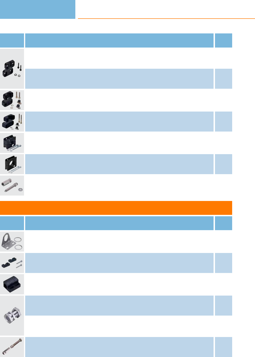
Type Description Order
no.
Mounting clamp · Ø 4 mm · Housing materials: TPE E10204
Mounting clamp · Ø 6.5 mm · Housing materials: PPE E10014
Mounting clamp · Ø 20 mm · Housing materials: PA E10192
Mounting clamp · Ø 34 mm · Housing materials: PA E10193
Mounting clamp · Ø 20 mm · Housing materials: Mounting clamp: PBT / socket screw: steel galvanised E10016
Mounting clamp · Ø 34 mm · Housing materials: PBT E10017
Limit plungers · for type Ø 6.5 mm · with Sn = 1 mm f · Housing materials: Limit plungers: free cutting steel / plunger: C45K
hardened on front / nut: brass nickel-plated E10155
Accessories for threaded M8 housings
Type Description Order
no.
Angle bracket · for type M8 · Housing materials: stainless steel E10734
Mounting clamp · Ø 8 mm · Housing materials: aluminium black anodised E10221
Mounting clamp · Ø 8 mm · with end stop · for type M8 · Housing materials: PC E11521
Mounting sleeve · M12 x 1 - Ø 8 mm · 32 mm · with end stop · for type M8 · Housing materials: brass special coating E10848
Mounting sleeve · M12 x 1 - Ø 8 mm · 42 mm · with end stop · for type M8 · Housing materials: brass special coating E10849
Limit plungers · for types M8 x 1 · with Sn = 1 mm f, 2 mm f and 3 mm f · Housing materials: Limit plungers: free cutting steel /
plunger: C45K hardened on front / nut: brass nickel-plated E10154
Inductive sensors
110
Product selectors and further information can be found at: www.ifm.com
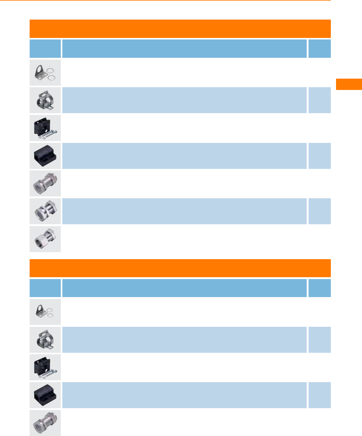
Accessories for threaded M12 housings
Type Description Order
no.
Angle bracket · for type M12 · Housing materials: stainless steel E10735
Mounting clip · Form O · for type M12 · Housing materials: stainless steel E11533
Mounting clamp · Ø 12 mm · Housing materials: PBT E10015
Mounting clamp · Ø 12 mm · with end stop · for type M12 · Housing materials: PC E11047
Mounting sleeve · M16 x 1 - Ø 12 mm · 45 mm · with end stop · for type M12 · Housing materials: brass nickel-plated E10741
Mounting sleeve · M16 x 1 - Ø 12 mm · 34 mm · with end stop · for type M12 · Housing materials: brass nickel-plated E10806
Mounting sleeve · M16 x 1 - Ø 12 mm · with end stop · for type M12 · Housing materials: brass nickel-plated E11114
Accessories for threaded M18 housings
Type Description Order
no.
Angle bracket · for type M18 · Housing materials: stainless steel E10736
Mounting clip · Form O · for type M18 · Housing materials: stainless steel E11534
Mounting clamp · Ø 20 mm - Ø 18 mm · with reducing bush · for type M18 · Housing materials: PBT E10076
Mounting clamp · Ø 18 mm · with end stop · for type M18 · Housing materials: PC E11048
Mounting sleeve · M24 x 1.5 - Ø 18 mm · 58 mm · with end stop · for type M18 · Housing materials: brass nickel-plated E10742
Inductive sensors
111
You can find wiring diagrams and scale drawings from page 114
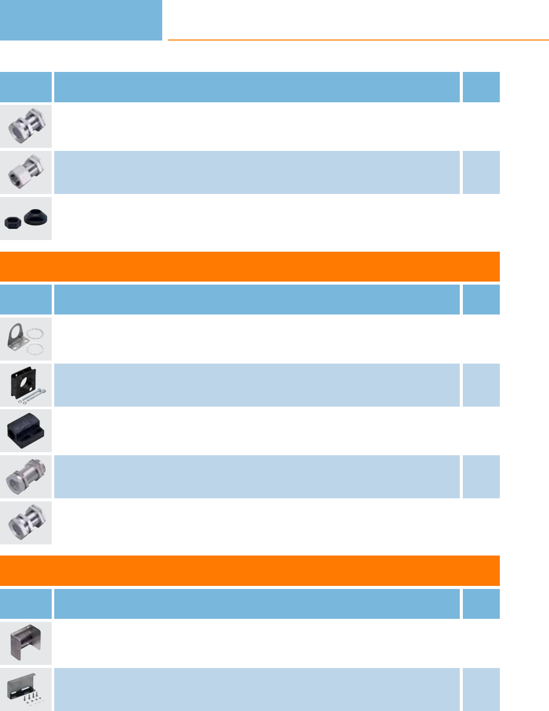
Type Description Order
no.
Mounting sleeve · M24 x 1.5 - Ø 18 mm · 36 mm · with end stop · for type M18 · Housing materials: brass nickel-plated E10807
Mounting sleeve · M22 x 1 - Ø 18 mm · with end stop · for type M18 · Housing materials: brass white bronze coated E11115
Plastic nut for flow plate · M18 x 1 · Housing materials: POM E19503
Accessories for threaded M30 housings
Type Description Order
no.
Angle bracket · for type M30 · Housing materials: stainless steel E10737
Mounting clamp · Ø 34 mm - Ø 30 mm · with reducing bush · for type M30 · Housing materials: PBT E10077
Mounting clamp · Ø 30 mm · with end stop · for type M30 · Housing materials: PC E11049
Mounting sleeve · M36 x 1.5 - Ø 30 mm · 58 mm · with end stop · for type M30 · Housing materials: brass nickel-plated E10743
Mounting sleeve · M36 x 1.5 - Ø 30 mm · 36 mm · with end stop · for type M30 · Housing materials: brass nickel-plated E10808
Accessories for rectangular housings
Type Description Order
no.
Mounting bracket · with integrated snap-on rail · for type IDC · Housing materials: stainless steel E10730
Protective bracket · for cable units · for type IW, KW, OW · Housing materials: stainless steel 316Ti / 1.4571 E20813
Inductive sensors
112
Product selectors and further information can be found at: www.ifm.com

System components
Type Description Order
no.
Mounting set · Ø 18.5 mm · Clamp mounting · free-standing M10 · for type OG, IG, KG · Housing materials: clamp: diecast zinc /
fixture: steel E20718
Mounting set · Ø 18.5 mm · Clamp mounting · free-standing M10 · for type OG, IG, KG · Housing materials: clamp: diecast zinc /
fixture: steel E20719
Angle bracket · Clamp mounting · for type IW, OW, KQ5 · Housing materials: stainless steel 316Ti / 1.4571 E20811
Protective bracket · for cable units · for type IW, KW, OW · Housing materials: stainless steel 316Ti / 1.4571 E20813
Protective bracket · for devices with M8 connection · for type OW, IW · Housing materials: stainless steel 316Ti / 1.4571 E20814
Mounting set · Ø 12.2 mm · Clamp mounting · free-standing M8 · for type OF, IF · Housing materials: fixture: stainless steel 316Ti /
1.4571 / clamp: diecast zinc E20856
Mounting set · Ø 12.2 mm · Clamp mounting · free-standing M8 · for type OF, IF · Housing materials: fixture: stainless steel 316Ti /
1.4571 / clamp: stainless steel E20857
Mounting set · Ø 12.2 mm · Clamp mounting · free-standing M8 · for type OF, IF · Housing materials: fixture: stainless steel 316Ti /
1.4571 / clamp: diecast zinc E20860
Mounting set · Ø 12.2 mm · Clamp mounting · free-standing M8 · for type OF, IF · Housing materials: fixture: stainless steel 316Ti /
1.4571 / clamp: stainless steel E20861
Mounting set · Ø 12.2 mm · Clamp mounting · aluminium profile · for type OF, IF · Housing materials: fixture: stainless steel 316Ti /
1.4571 / clamp: diecast zinc / Cube: diecast zinc E20864
Mounting set · Ø 12.2 mm · Clamp mounting · aluminium profile · for type OF, IF · Housing materials: fixture: stainless steel 316Ti /
1.4571 / clamp: diecast zinc / Cube: diecast zinc E20865
Mounting set · Ø 18.5 mm · Clamp mounting · aluminium profile · for type OG, IG, KG · Housing materials: fixture: stainless steel
316Ti / 1.4571 / clamp: diecast zinc / Cube: diecast zinc E20866
Mounting set · Ø 18.5 mm · Clamp mounting · aluminium profile · for type OG, IG, KG · Housing materials: fixture: stainless steel
316Ti / 1.4571 / clamp: diecast zinc / Cube: diecast zinc E20867
Mounting set · Ø 18.5 mm · Clamp mounting · free-standing M10 · for type OG, IG, KG · Housing materials: fixture: stainless steel
316Ti / 1.4571 / clamp: stainless steel E20869
Inductive sensors
113
You can find wiring diagrams and scale drawings from page 114
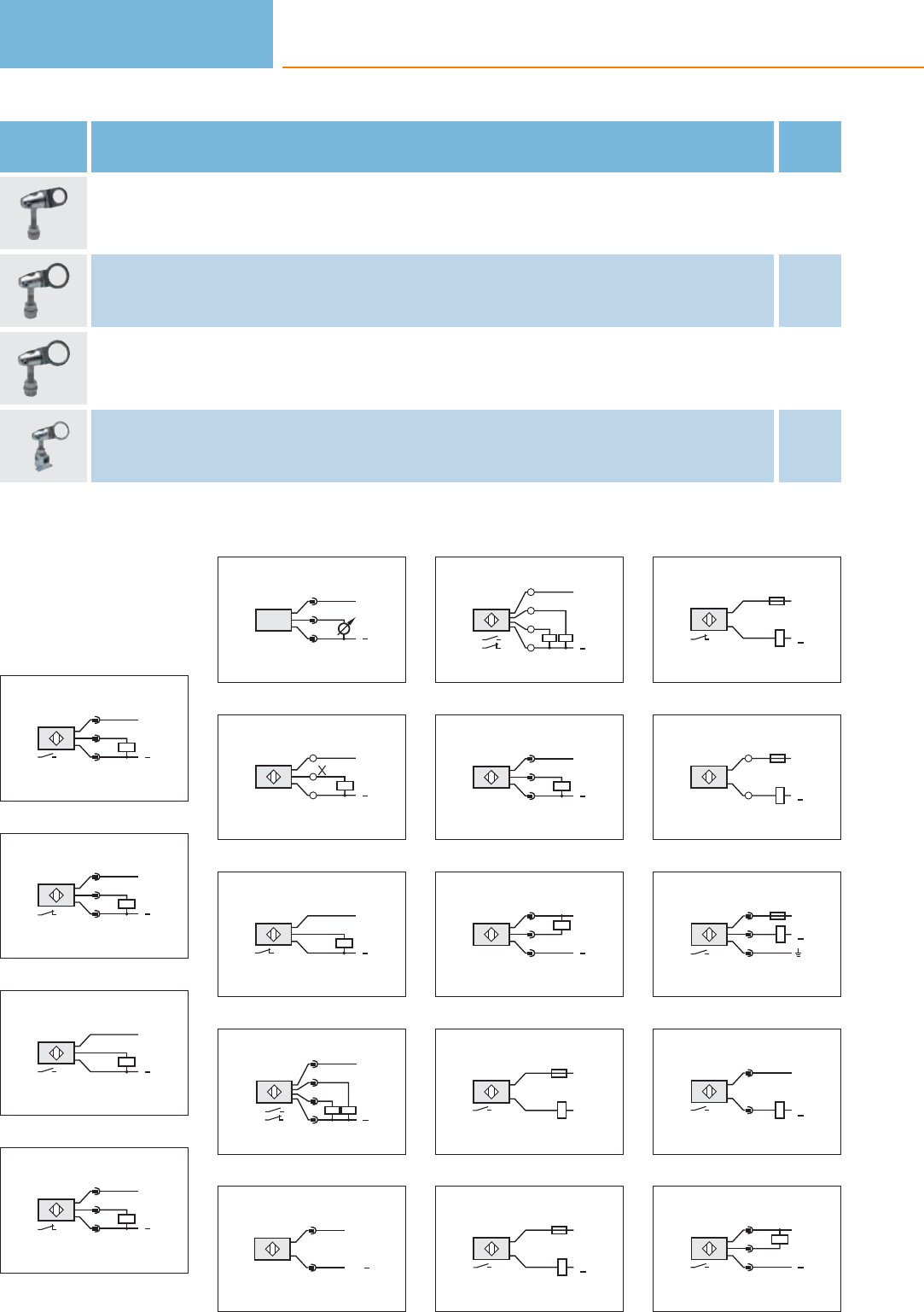
Type Description Order
no.
Mounting set · Ø 18.5 mm · Clamp mounting · free-standing M10 · for type OG, IG, KG · Housing materials: fixture: stainless steel
316Ti / 1.4571 / clamp: stainless steel E20870
Mounting set · Ø 30.2 mm · Clamp mounting · free-standing M12 · for type OI, II, KI · Housing materials: fixture: stainless steel
316Ti / 1.4571 / clamp: diecast zinc E20873
Mounting set · Ø 30.2 mm · Clamp mounting · free-standing M12 · for type OI, II, KI · Housing materials: fixture: stainless steel
316Ti / 1.4571 / clamp: stainless steel E20874
Mounting set · Ø 30.2 mm · Clamp mounting · aluminium profile · for type OI, II, KI · Housing materials: fixture: stainless steel
316Ti / 1.4571 / clamp: diecast zinc / Cube: diecast zinc E20875
Core colours
BN brown
BU blue
BK black
WH white
Wiring diagrams
1
L+
L
1
4
3
2
L+
L
1
2
3
3
BN
BK
BU
L+
L
4
L+
L
1
4
3
5
L+
L
1
3
2
6
/
L+
L
13
/
24
7
BN
BK
BU
L+
L
8
4
L
L+
1
2
3
2:
4:
9
AS-i+
1
3
AS-i
10
L
L+
4
2
1
3
2:
4:
11
L+
L
1
4
3
12
L+
L
1
4
3
13
BN
BU
L1
N
14
BN
BU
L+
L1
L
N
15
BN
BU
L+
L1
L
N
16
/
13
/
24
L1
L+
L
N
17
1
3
2
L1
L+
L
N
18
3
2
L1
N
L+
L
19
L+
L
1
4
3
Inductive sensors
114
Product selectors and further information can be found at: www.ifm.com
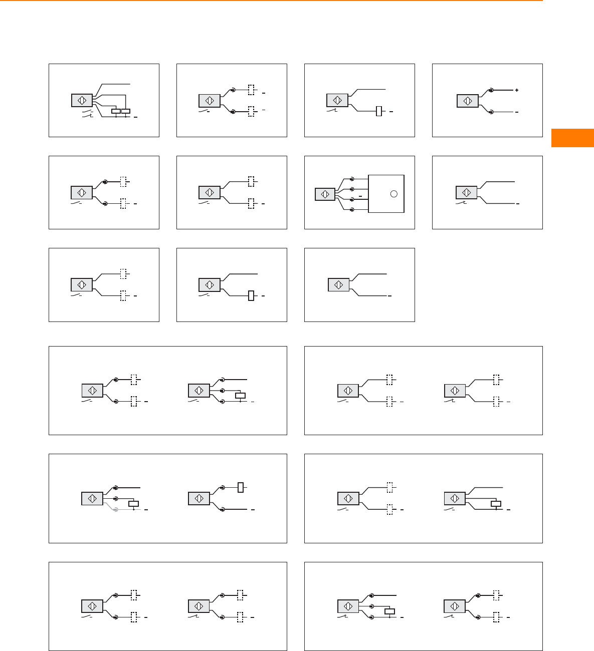
Wiring diagrams
20
L
L+
WH:
BK :
BK
BU
WH
BN
21
L+
L
1
4
22
BK
BK
L+
L
23
3
4L
L
L
+
L
+
24
L
BN
BU
L+
25
BN
BU L
L+
26
BN
BU L
L+
27
3
1
4
2
L+
L
A1
A2
+24 V
IN2
GND
IN1
1
28
+
BN
BU
29
3
2
30
+
BN
BU
31
L+
L
1
4
L+
L
1
4
3
32
L+
L
1
4
NPN
L+
L
1
4
3
PNP
33
L+
L
1
4
L+
L
1
4
34
WH
BK
L+
L L
BK
WH
L+
35
L+
L
BN
BK
BU
L+
L
BN
BK
36
L+
L
1
4
3
L+
L
1
4
Inductive sensors
115
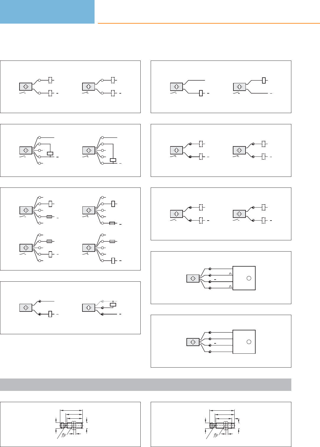
Wiring diagrams
37
L+
L
/
13
/
24
L+
L
/
13
/
24
38
2
4
3
1
5
L+
L
2
4
3
1
5
L+
L
39
2
4
3
1
5
AC;
DC NPN
L+
N
L
L1
2
4
3
1
5
AC;
DC NPN
L+
N
L
L1
2
4
3
1
5
DC PNP
L+
L
2
4
3
1
5
DC PNP
L+
L
40
L+
L
4
3
PNP
L+
L
1
4
3
NPN
41
BN
BU
L+
L
NPN
BN
BU
L+
L
PNP
42
L+
L
1
2
L+
L
1
2
43
L+
L
1
4
L+
L
1
4
44
(BK)
3
1
4
2
L+
L
(BN)
A
TE
(BU)
(WH)
+24 V
OUT
GND
IN
1
45
(BK)
3
1
4
2
L+
L
(BN)
A2
A1
(BU)
(WH)
+24 V
IN1
GND
IN2
1
Scale drawings / drawing no. – CAD download: www.ifm.com
1
45
34
32
M12x1
17
4
M12 x1
LED 4 x 90°
2
32
M12x1
17
4
5
M12 x1
39
50
LED 4 x 90°
Inductive sensors
116
Product selectors and further information can be found at: www.ifm.com
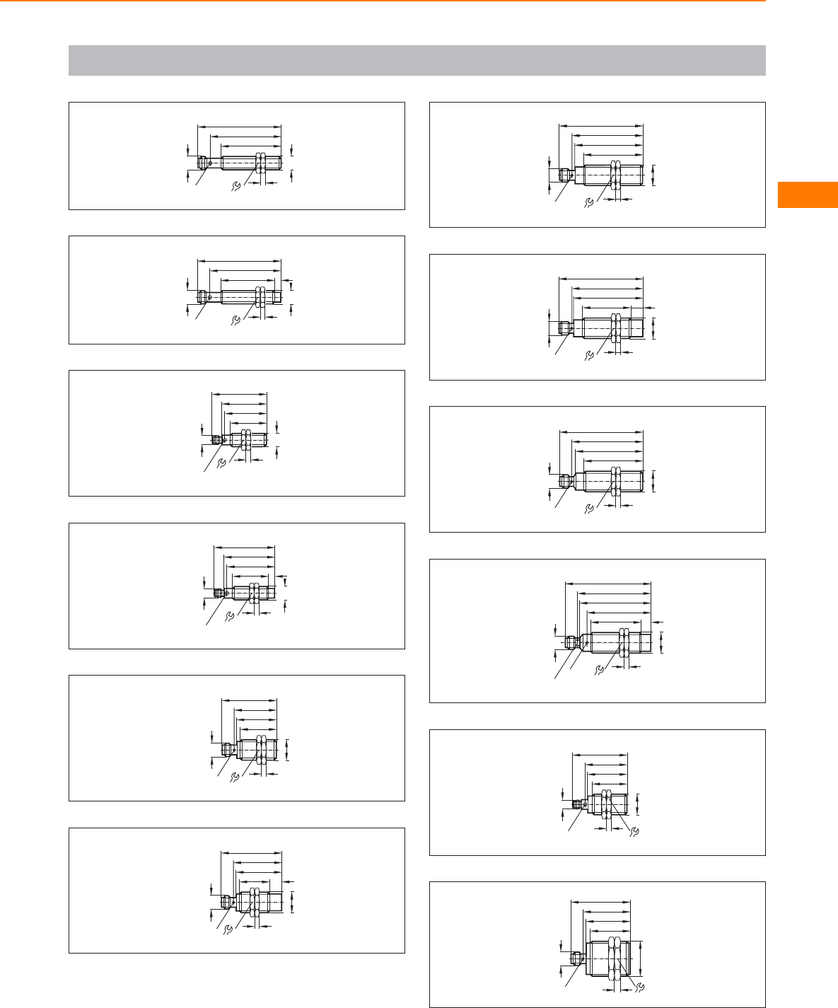
Scale drawings / drawing no. – CAD download: www.ifm.com
3
LED 4 x 90°
59
70
50
M12x1
17
4
M12 x1
4
45
M12x1
17
4
5
M12 x1
59
70
LED 4 x 90°
5
35
30
M12x1
17
4
46
LED 4 x 90°
38
M8x1
6
40
30
M12x1
17
4
51
LED 4 x 90°
43
M8x1
5
7
M18 x1
M12 x1
30
33
46
35
4
24
LED 4 x 90°
8
M18 x1
M12 x1
25
38
51
40
4
24
10
LED 4 x 90°
9
M18 x1
M12 x1
49
56,5
70
59
4
24
LED 4 x 90°
10
M18 x1
M12 x1
40
58
70
LED 4 x 90°
60
10
4
24
11
M18 x1
M12 x1
49
56
70
59
4
24
LED 4 x 90°
12
60
M18 x1
4
M12 x1
42
53
72
8
61
LED 24
LED 4 x 90°
13
46
LED 4 x 90°
M18 x1
4
33
35
24
M8x1
29
14
39
33
M30x1,5
37
50
M12 x1
LED 4 x 90° 536
Inductive sensors
117
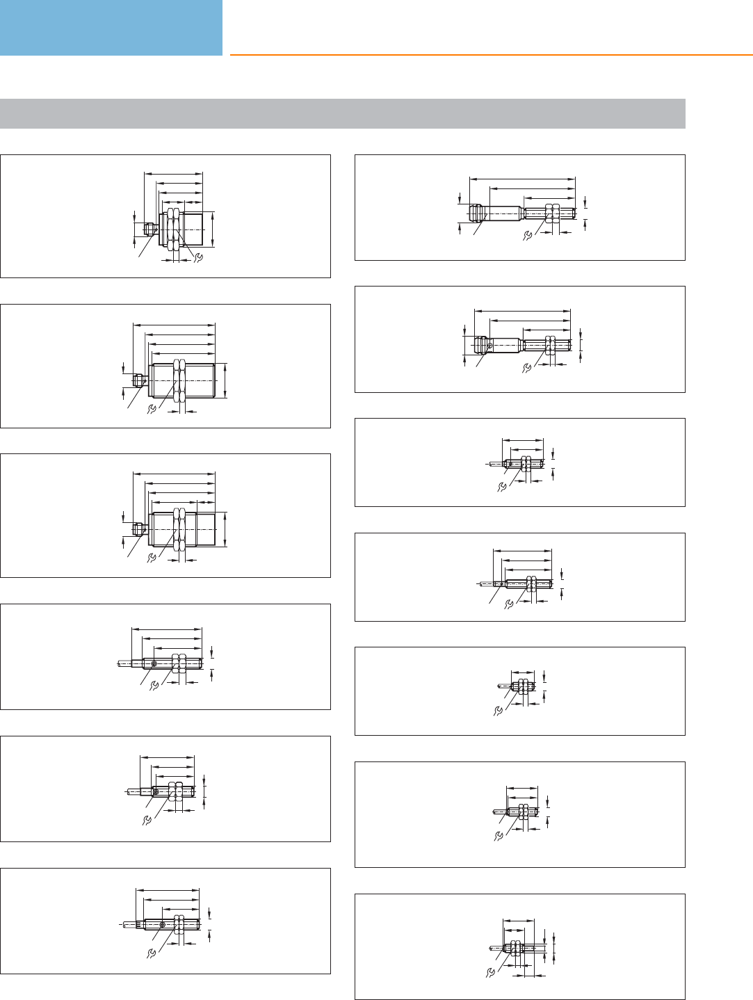
Scale drawings / drawing no. – CAD download: www.ifm.com
15
39
19
M30x1,5
37
50
M12 x1
LED 4 x 90° 5
15
36
16
59
53
M30x1,5
57
70
M12 x1
LED 4 x 90° 5
36
17
LED 4 x 90°
59
38
M30x1,5
5
57
70
36
M12 x1
15
18
8
LED
20
25
30
M5x0,5
2,7
19
16
LED
18
23
M5x0,5
2,7
8
20
15,5
LED
24
27
M5x 0,5
7
2
21
LED 4 x 90° 8
22
45
M5x0,5
2,7
M8x1
36
22
7
20
41
2
LED 4 x 90°
M8x1
34
M5x0,5
23
27
35
M8x1
LED 4
13
24
39
42
50
LED
M8x1
4
13
25
20
LED
M8x1
4
13
26
27
M8x1
4
LED
13
25
27
27
18
4
8
LED
13
6,5
M8x1
Inductive sensors
118
Product selectors and further information can be found at: www.ifm.com
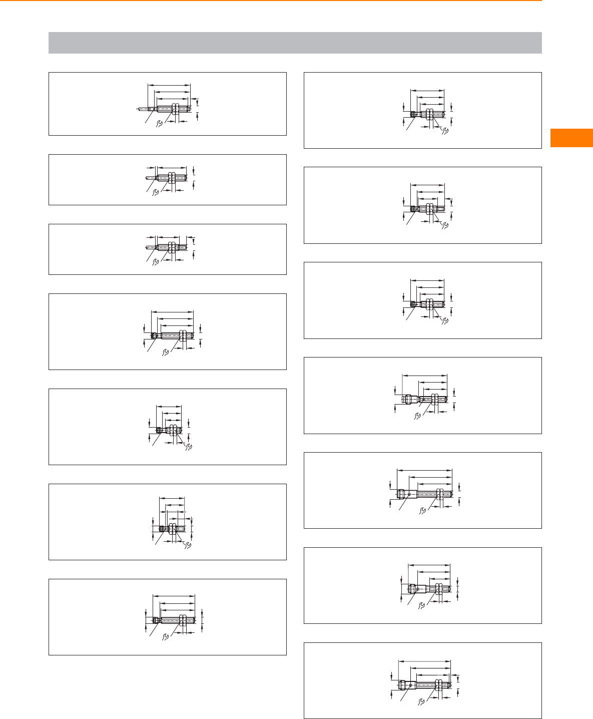
Scale drawings / drawing no. – CAD download: www.ifm.com
28
36,5
42
50
LED
M8x1
4
13
2,5
29
35
LED
M8x1
4
13
2
30
27
LED
M8x1
4
13
8
2
31
38,5
42,5
M8x1
4
13
M8x1
LED 4 x 90°
50
32
18,5
30
M8x1
4
13
M8x1
22,5
LED 4 x 90°
33
12
30
M8x1
LED 4 x 90°
M8x1
8
22,5
4
13
34
39
M8x1
LED 4 x 90°
4
13
M8x1
42
50
35
4
13
28,5
40
M8x1
LED 4 x 90°
M8x1
32,5
36
23
40
M8x1
LED 4 x 90°
4
13
M8x1
8
32,5
37
4
13
28,5
40
M8x1
LED 4 x 90°
M8x1
32,5
38
27
34
M8x1
LED 4
13
M12 x1
53
39
M8x1
4
13
M12 x1
62
50
40
LED 4 x 90°
40
M12 x1
50
39
25
LED 4 x 90° 13
4
M8x1
41
M8x1
4
13
M12 x1
62
47
38 2
LED 4 x 90°
Inductive sensors
119
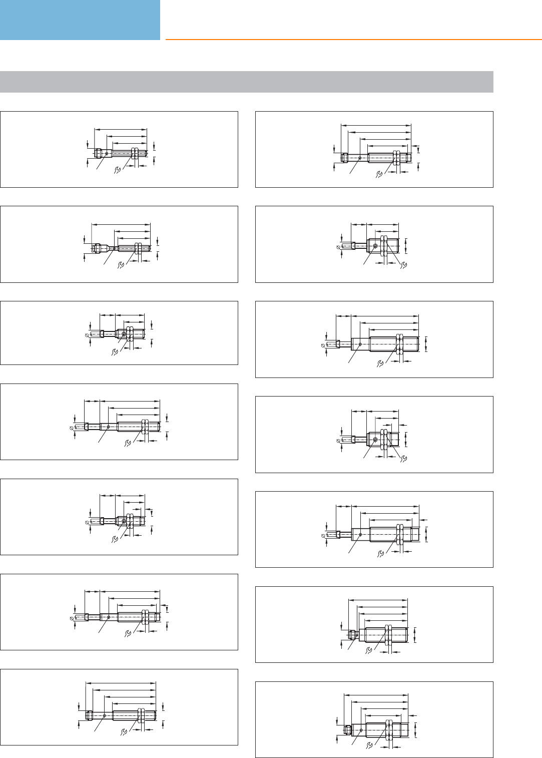
Scale drawings / drawing no. – CAD download: www.ifm.com
42
M8x1
4
13
M12 x1
62
47
40
LED 4 x 90°
43
38
42
M8x1
LED
4
13
69
M12 x1
44
35
24
M12x1
4
LED
17
9
18
45
9
18 71
60
50
M12x1
LED 17
4
46
4
35
24
M12x1
4
LED
17
9
18
47
9
18 71
60
46
M12x1
LED 17
4
4
48
M12 x1
74
60
51
M12x1
LED 17
4
83
49
83
60
47
M12x1
LED 17
4
4
M12 x1
74
50
38
27
M18 x1
4
LED 24
9
18
51
24
LED
8018
69
58
M18 x1
4
9
52
9
18
M18 x1
4
LED 24
38
27
8
53
24
LED
80
18
69
50
M18 x1
4
9
8
54
59
57
50
M18 x1
4
M12 x1
70
24LED 4 x 90°
55
24
67
55
42
M18 x1
4
LED
8
M12 x1
76
Inductive sensors
120
Product selectors and further information can be found at: www.ifm.com
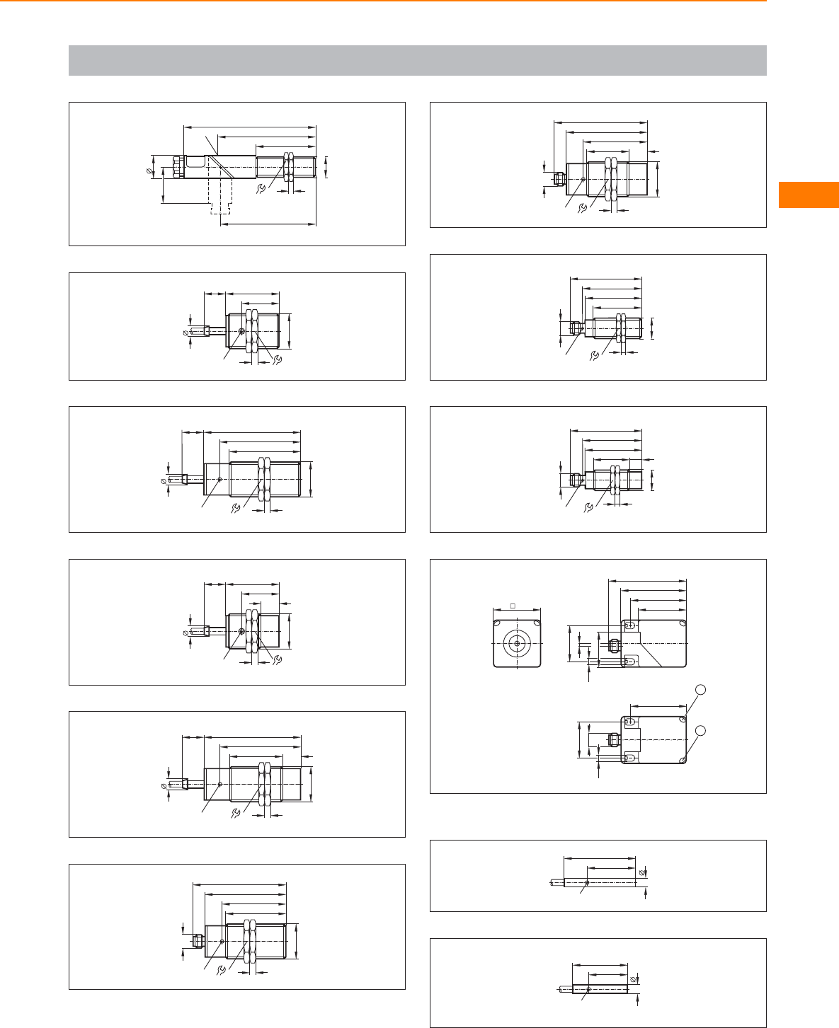
Scale drawings / drawing no. – CAD download: www.ifm.com
56
79
24
50
M18 x1
4
110
20
30
81
LED
57
45
31
5
M30x1,5
36
LED
9
18
58
36
81
67
59
5
M30x1,5
9
18
LED
59
15
45
31
5
M30x1,5
36
LED
9
18
60
81
67
5
1544
36
M30x1,5
9
18
LED
61
36
68
53
50
5
LED
M30x1,5
M12 x1
78
62
15
36
68
53
35
5
LED
M30x1,5
M12 x1
78
63
M18 x1
M12 x1
40
47
60
LED 4 x 90°
4
24
49
64
M18 x1
30 10
M12 x1
47
60
LED 4 x 90°
49
4
24
65
40
66
40
54
M12 x1
30
30
2
2
1
46
46
5,5
5,5 29,5
1: LED yellow, 2: LED green
66
LED
30
20
4
67
LED
23
16
4
Inductive sensors
121
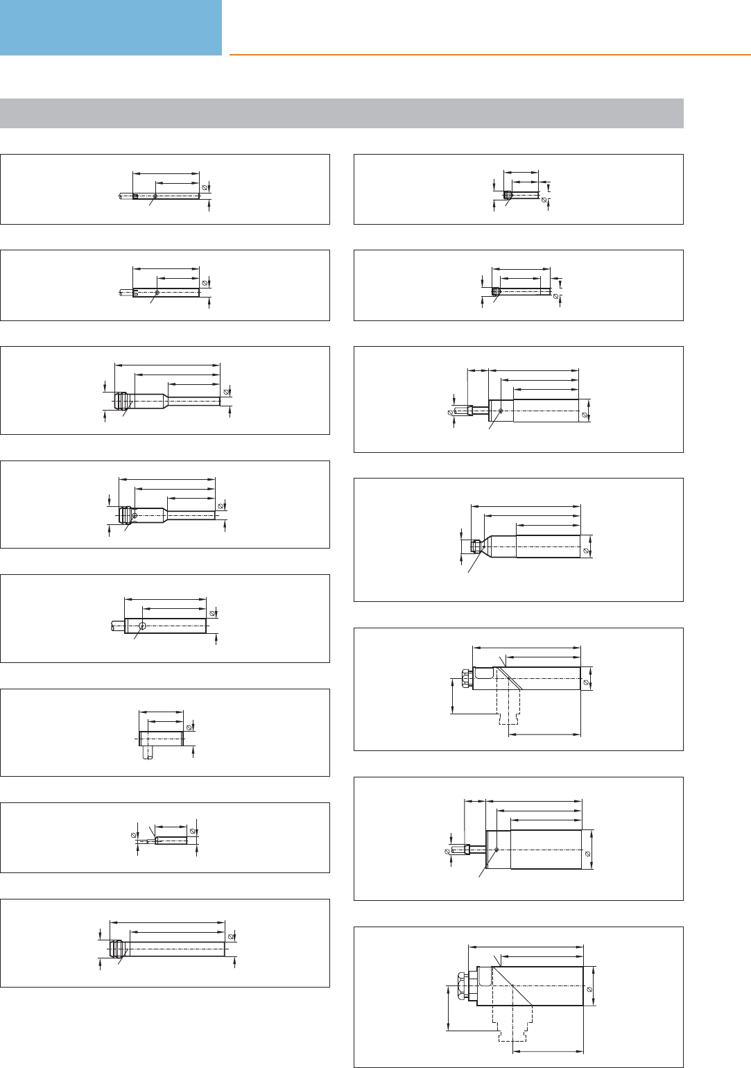
Scale drawings / drawing no. – CAD download: www.ifm.com
68
LED
27
17
3
69
LED
27
15,4
4
70
36
LED 4 x 90°
M8x1
4
45
22
71
34
LED 4 x 90°
M8x1
4
41
20
72
LED
6,5
35
27
73
6,5
15
19
74
LED
3,5
27
6,5
75
40
M8x1
6,5
49
LED 4 x 90°
76
30
22,5
LED 4 x 90°
M8x1
6,5
77
50
34,5
LED 4 x 90°
M8x1
6,5
8
78
9
18
20
77
66
55
LED
79
M12 x1
LED 4 x 90°
20
93
81
55
80
62
92
63
30
LED
20
81
9
18
LED
34
82
72
60
82
98
70
LED
34
38
60
Inductive sensors
122
Product selectors and further information can be found at: www.ifm.com
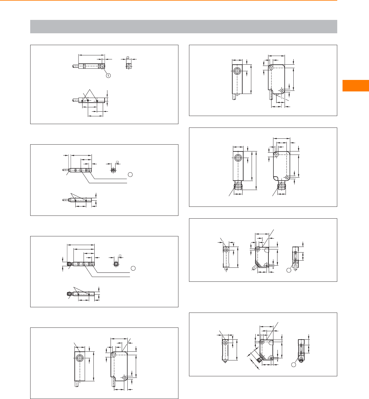
Scale drawings / drawing no. – CAD download: www.ifm.com
83
LED
M1,6
x
0,35
5,5
3,5
14
14
5
2,8
25
1: sensing face
84
20 10
5
M3
8
LED
40
5
20
IL 5003
4
IL 5002
1
1: sensing face
85
LED 20 10
5
M3
8
40
5
20
M8x1
LED
52
IL 5005
IL 5004
1
1: sensing face
86
10,2
27,8
LED
5,6
16
5,1
22,2
2,75
3,1
3,5
2,8
3,1
LED
10,4
87
10,2
27,8
5,6
16
22,2
2,75
3,1
3,5
2,8
3,1
LED
10,4
8
88
10,2
27,8
LED
5,6
M8x1
36,8
16
22,2
2,75
3,1
3,5
2,8
3,1
10,4
M8x1
LED
89
40
6
12
LED
4
26
13
32
3,2
4
5
LED
3,2
18
16 10
1
1: threaded insert M3, depth 5.8 mm, max. tightening torque
1.2 Nm (screw fixing class 8.8) when brass insert in contact with
counterpart.
90
4
5
18
M8x1
9
6
LED
1
12
40
3,2
32 4
13
LED
26
3,2
1016
1: threaded insert M3, depth 5.8 mm, max. tightening torque
1.2 Nm (screw fixing class 8.8) when brass insert in contact with
counterpart.
Inductive sensors
123

Scale drawings / drawing no. – CAD download: www.ifm.com
91
4
3
4
20
LED
13
4
10
1624
28
36
60
15 3,2
4,2
3,2
8
92
4
3
LED
4
20
12
4
10
1624
28
36
60
15 3,2
4,2
3,2
8
93
4
3
60
36
16
3,2
28
3,2
15
8
24
4,2
M8x1
73
4
4
LED
10
12
20
94
40
66
40
54
M12 x1
30
30
2
5,5
5,5
1
2
46
46
29,5
1: LED yellow, 2: LED green
95
40
10,4
45,6
LED
32
5,3
30
61,5
77
5,1
121
101
LED
27
96
40
13
7,35,3
46
30
60
LED
58
5,3
40
118
LED
97
7,35,3
46
LED
30
60
13
7
LED
58
5,3
40
118
LED
29
40
98
90
30
45
7,5
45
9,3
5,5
60
16
LED
pot.
40
12
8
16
Inductive sensors
124
Product selectors and further information can be found at: www.ifm.com
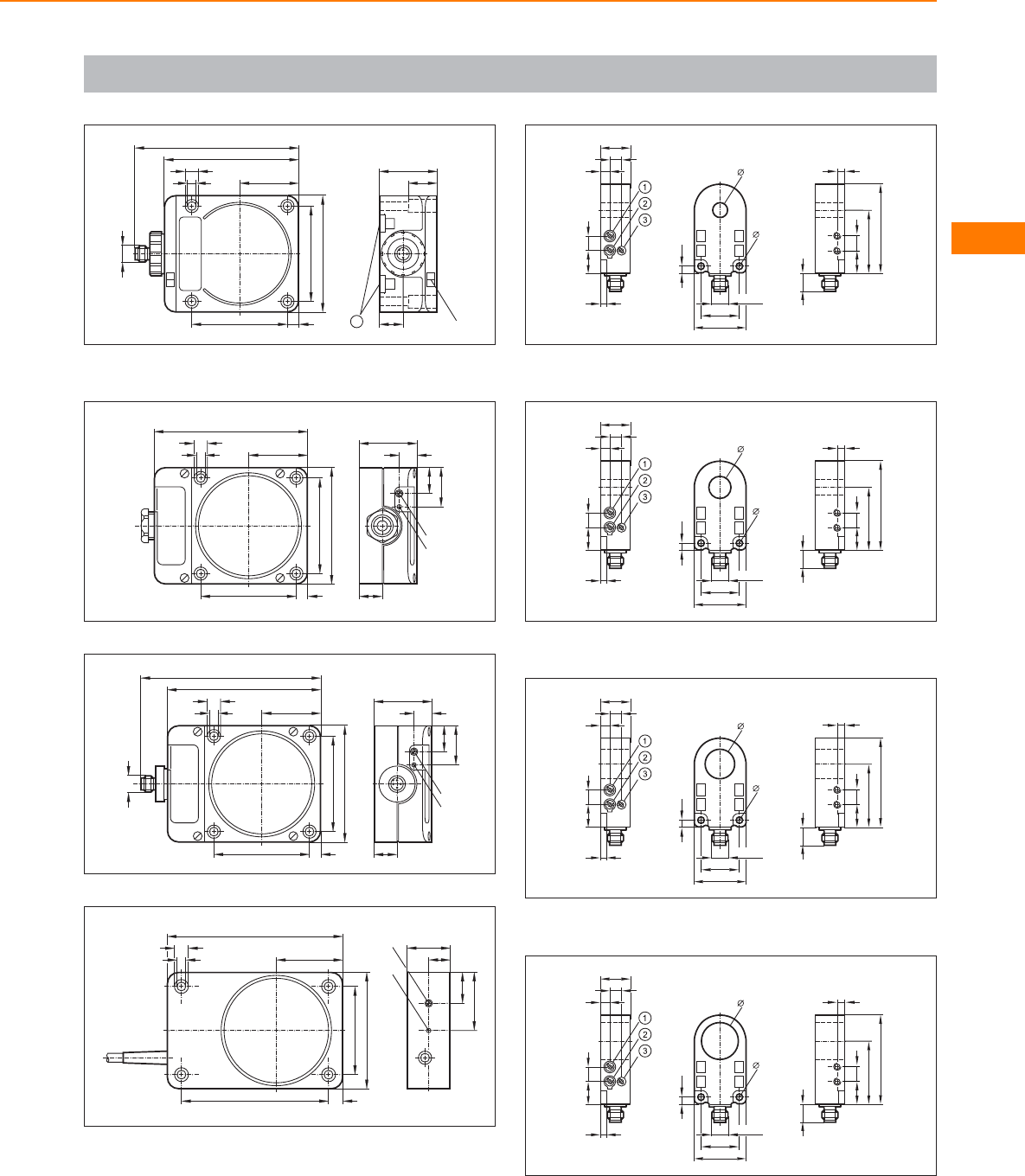
Scale drawings / drawing no. – CAD download: www.ifm.com
99
92
80
40
7,5
65
65
5,5
9,3
M12 x1
112
40
LED
17
1
20
1: mounting on DIN rail
100
105
80
40
7,5
65
65
5,5
9,3 40
12
27
18
LED
pot.
16
101
105
80
40
7,5
65
65
5,5
9,3
M12 x1
123
40
12
27
18
LED
pot.
16
102
120
45
80
60
10
100
6
9,5
40
21
30
15
pot.
LED
103
11
1015
42,5
60
5
M12 x1
26
35
4,5
10,1
4,5
4
15 10
6
8
20
1: Sensitivity, 2: Output function, 3: Pulse stretching time
104
11
1015
42,5
60
5
M12 x1
26
35
4,5
15,1
4,5
4
15 10
6
8
20
1: Sensitivity, 2: Output function, 3: Pulse stretching time
105
11
1015
42,5
60
5
M12 x1
26
35
4,5
20,1
4,5
4
15 10
6
8
20
1: Sensitivity, 2: Output function, 3: Pulse stretching time
106
11
1015
42,5
60
5
M12 x1
26
35
4,5
25,1
4,5
4
15 10
6
8
20
1: Sensitivity, 2: Output function, 3: Pulse stretching time
Inductive sensors
125
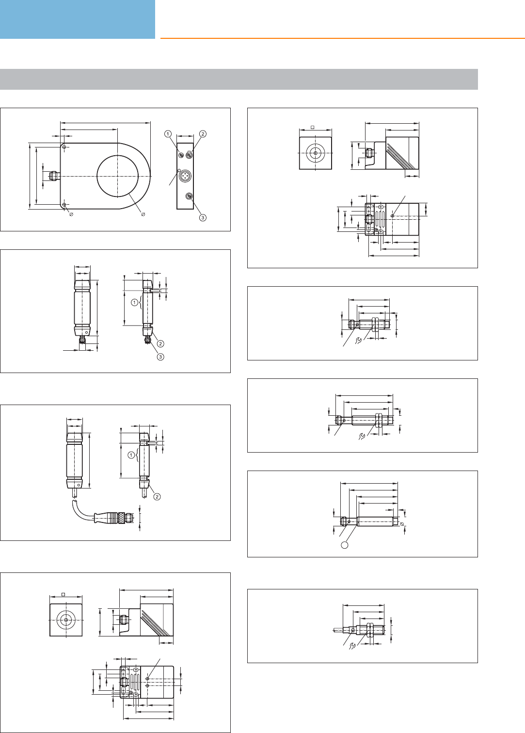
Scale drawings / drawing no. – CAD download: www.ifm.com
107
110
70
4,5 51
70
80
M12x1
LED
20
5
108
M8x1
17
20
709
12
1345
3
5,5
1: sensing face, 2: LED operating status, 3: LED switching status
109
17
20
70
M12x1
12
1345
3
5,5
1: sensing face, 2: LED operating status
110
40
LED
46
61
30
20
5,4
10
5,4
6
8,5
33
1/2" 20UNF 2A
LS100
40
66
17
34
111
40
M12 x1
40
66
17
34
LED
46
61
30
20
5,4
10
5,4
6
16
33
112
32
M12x1
17
4
5
M12 x1
39
50
LED 4 x 90°
113
45
M12x1
17
4
5
M12 x1
59
70
LED
114
50
5
M12 x1
59
70
LED 4 x 90°
12
47
1
1: locating groove
115
50
37
29
M12x1
17
4
LED
Inductive sensors
126
Product selectors and further information can be found at: www.ifm.com
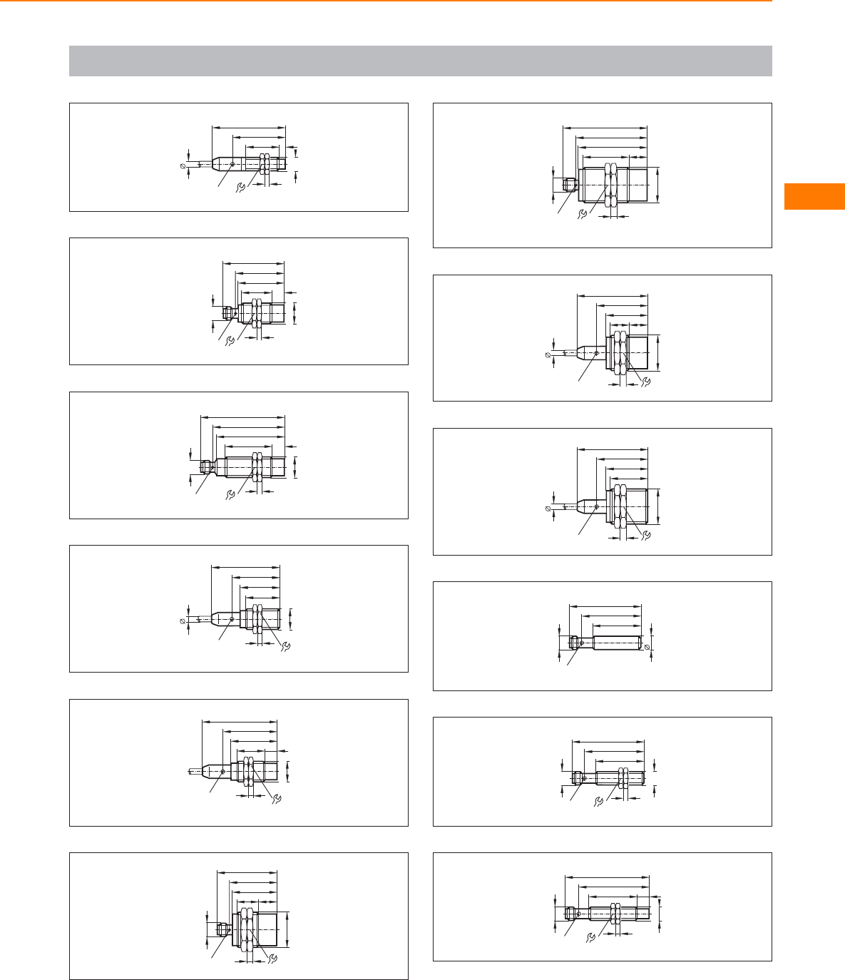
Scale drawings / drawing no. – CAD download: www.ifm.com
116
5
61
44
28
M12x1
LED 4 x 90° 17
4
5
117
M18 x1
M12 x1
25
38
51
40
4
24
10
LED 4 x 90°
118
M18 x1
M12 x1
39
56
70
LED 4 x 90°
59
10
4
24
119
57
39,5
29
33
LED
4 x 90°
M18 x1
4
24
5
120
62
44,5
24
LED
4 x 90°
38
M18 x1
4
24
10
121
39
18
M30x1,5
37
50
M12 x1
LED 4 x 90° 5
15
36
122
38
M30x1,5
57
70
LED
4 x 90°
5
36
15
59
1/2"-20UNF-2A
123
16
M30x1,5
15
35
5
42
LED 4 x 90°
59
536
124
31
M30x1,5
35
5
42
LED 4 x 90°
59
36
5
125
60
LED 4 x 90°
49
40
12
M12 x1
126
49
40
M12x1
17
4
M12 x1
LED 4 x 90°
60
127
40
M12x1
17
4
10
M12 x1
70
59
LED 4 x 90°
Inductive sensors
127
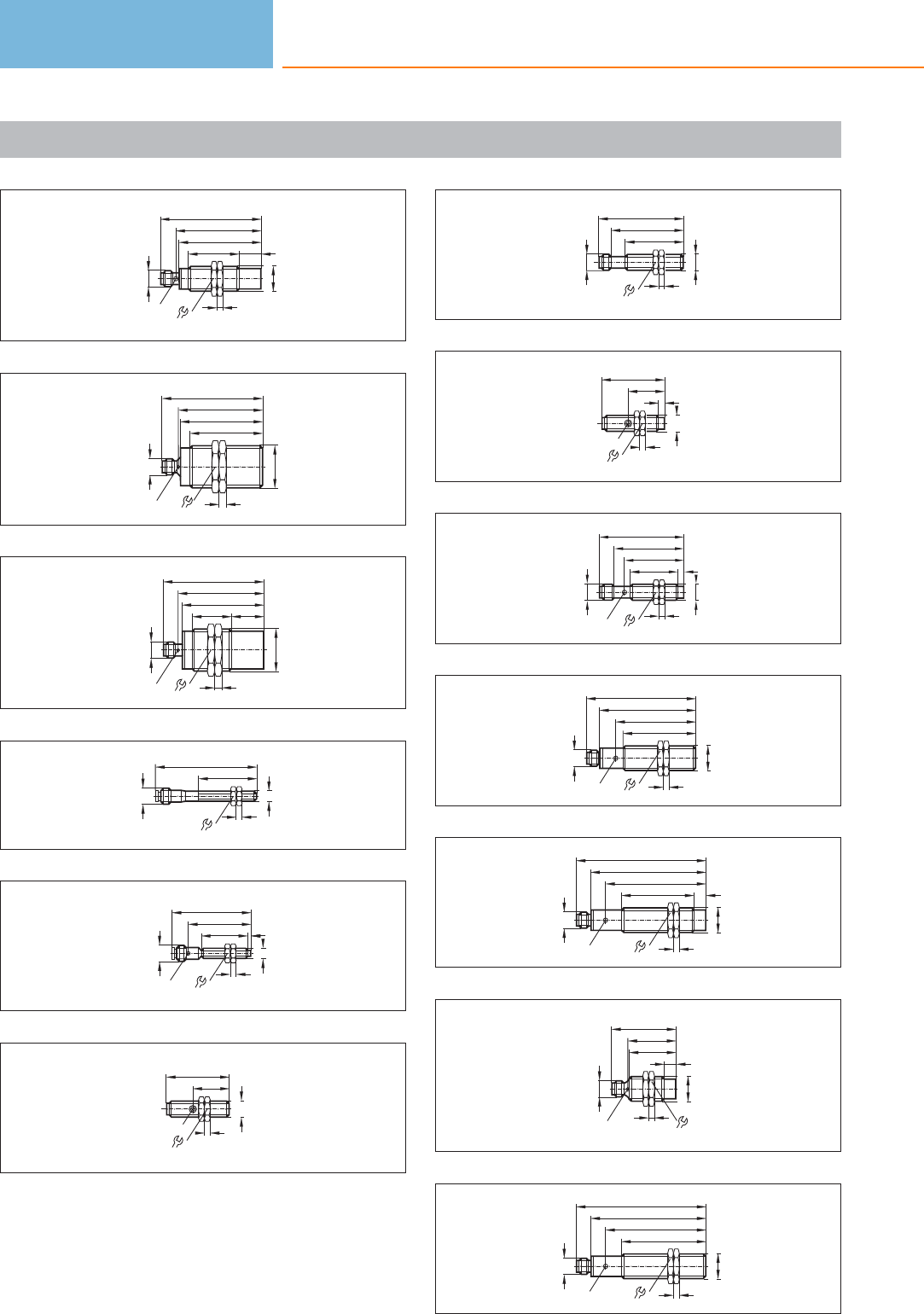
Scale drawings / drawing no. – CAD download: www.ifm.com
128
24
M18 x1
M12 x1
35 15
4
57
70
59
LED 4 x 90°
129
58
50
M30x1,5
5
57
70
36
M12 x1
LED 4 x 90°
130
M30x1,5
5
M12 x1
22,527,5
57
59
70
LED 4 x 90° 36
131
40
M8x1
4
13
70
M12 x1
132
31,5
43
M8x1
4
13
55
M12 x1
2,5
LED 4 x 90°
133
44
25
M12x1
4
17
LED
134
50
40
M12x1
17
4
M12 x1
59
135
17
4
44
25
M12x1
4
LED
136
48
33
M12x1
17
4
4
M12 x1
59
41
LED
137
67
24
55
50
M18 x1
4
LED
M12 x1
76
138
24
80
69
50
M18 x1
4
LED
8
M12 x1
90
139
M18 x1
M12 x1
32
33
45
LED 4 x 90°
8
4
24
140
24
80
69
58
M18 x1
4
LED
M12 x1
90
Inductive sensors
128
Product selectors and further information can be found at: www.ifm.com
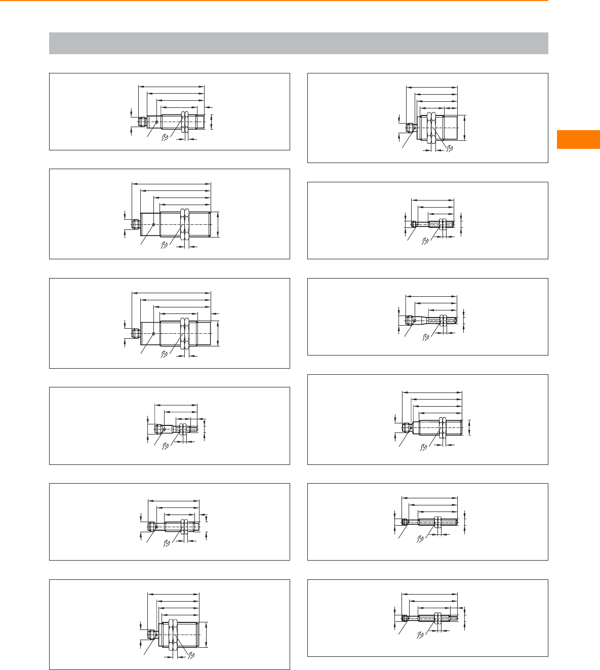
Scale drawings / drawing no. – CAD download: www.ifm.com
141
24
67
56
42
M18 x1
4
LED
8
M12 x1
77
142
36
82
66
59
5
LED
M30x1,5
M12 x1
92
143
36
82
66
44
5
LED
M30x1,5
M12 x1
92
15
144
M8x1
M12 x1
50
39
17 8
LED 4 x 90° 13
4
145
49
35
M12x1
17
4
M12 x1
LED 4 x 90°
60
5
146
49
43
M30x1,5
5
47
60
M12 x1
LED 4 x 90° 36
147
49
28
M30x1,5
5
47
60
M12 x1
LED 4 x 90°
15
36
148
30
42,5
M8x1
4
13
M8x1
LED 4 x 90°
50
149
M8x1
4
13
M12 x1
60
49
33
LED 4 x 90°
150
M18 x1
M12 x1
50
57
70
59
4
24
LED 4 x 90°
151
46,5
65
M8x1
LED
4 x 90°
M8x1
4
13
57,3
152
38,5
65
M8x1
LED
4 x 90°
M8x1
4
13
57,3
8
Inductive sensors
129
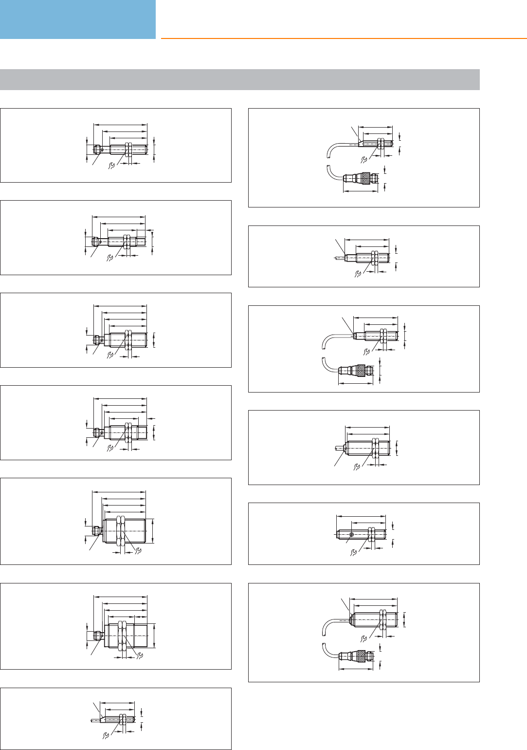
Scale drawings / drawing no. – CAD download: www.ifm.com
153
54
45
M12x1
4
M12 x1
LED 4 x 90°
65
17
154
54
35
M12x1
M12 x1
LED 4 x 90°
65
10
17
4
155
M18 x1
4
LED 4 x 90° 24
M12 x1
52
54
65
45
156
10
M18 x1
4
LED 4 x 90° 24
M12 x1
35
54
65
52
157
53
49
M30x1,5
5
52
65
M12 x1
LED 4 x 90° 36
158
54
32
M30x1,5
5
52
65
M12 x1
15
36
LED 4 x 90°
159
13
35
M8x1
4
LED 42
160
42
M12x1
13
35
M8x1
4
LED 42
161
LED
40
M12x1
4
17
54
162
42
M12x1
40
M12x1
4
17
54
LED
163
24
54
52
M18 x1
4
LED
164
60
41
M12x1
4
17
LED
165
42
M12x1
58
52
M18 x1
4
24
LED
Inductive sensors
130
Product selectors and further information can be found at: www.ifm.com
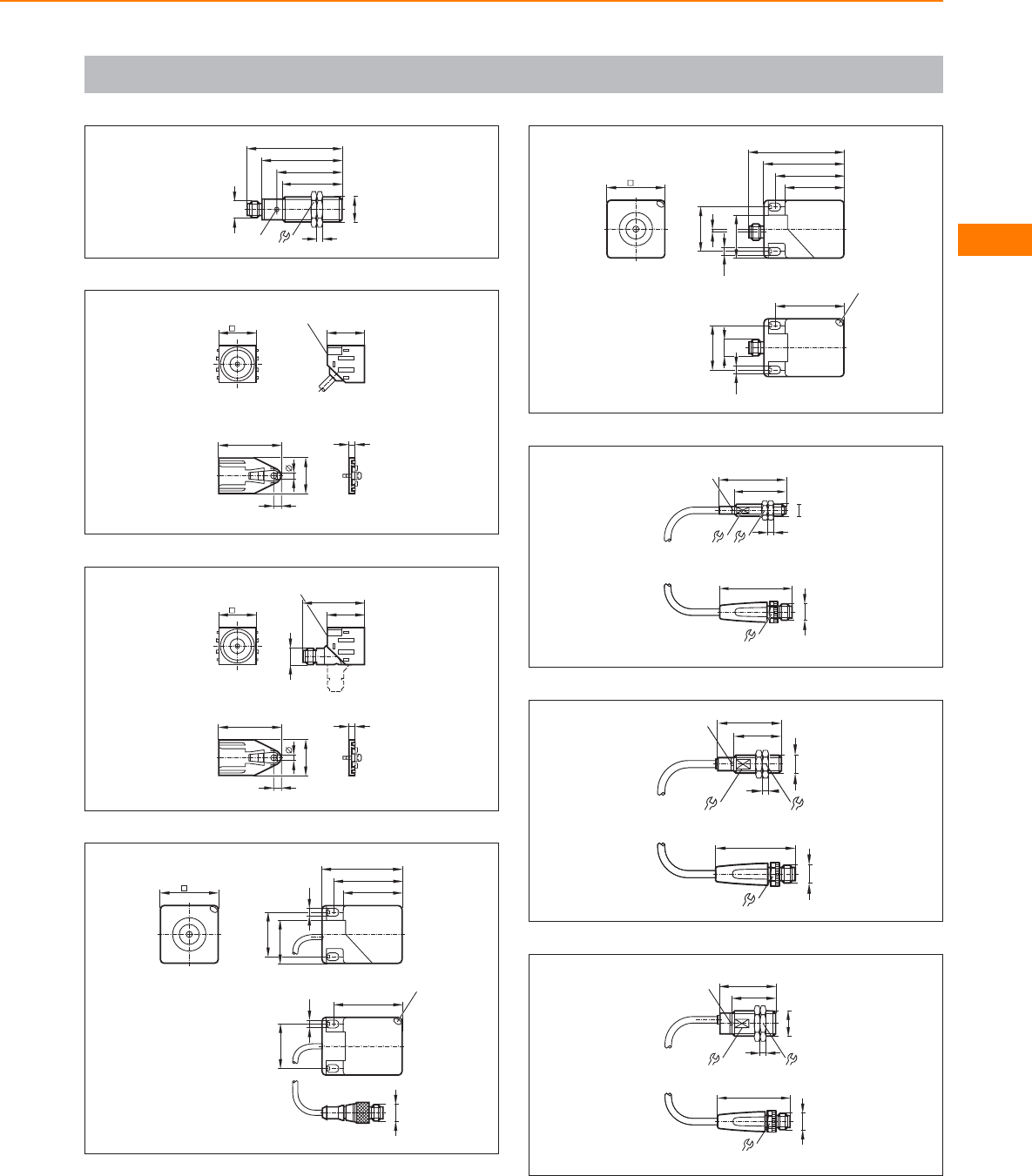
Scale drawings / drawing no. – CAD download: www.ifm.com
166
55
M18 x1
4
LED 24
M12 x1
40
44
65
167
3
43
25
4
6
26 26
LED
168
3
43
25
4
6
26
M12 x1
42,5
26
LED
169
40 40
54
30
46
5,5
30
46
LED
5,5
M12x1
29,5
170
40
66
40
54
M12 x1
30
30
2
46
46
5,5
5,5
LED
29,5
171
M12x1
14
≤ 49,3
LED
M8 x1
45
35
7
4
13
172
M12x1
14
49
M12x1
4
LED
11 17
40
30
173
M12x1
14
49
LED
17
M18 x1
4
24
40
30
Inductive sensors
131
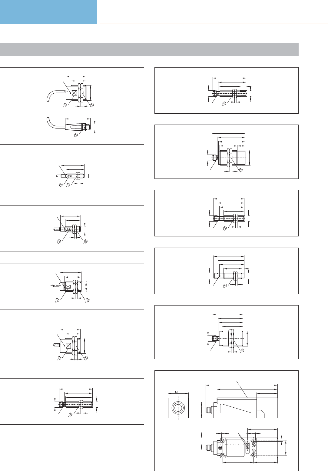
Scale drawings / drawing no. – CAD download: www.ifm.com
174
M12x1
14
49
40
536
LED
M30x1,5
30
28
175
LED
M8 x1
45
35
7
4
13
176
M12x1
4
LED
11 17
40
30
177
LED
17
M18 x1
4
24
40
30
178
40
536
LED
M30x1,5
30
28
179
54
52
M12x1
4
M12 x1
LED 4 x 90°
65
17
180
54
42
M12x1
M12 x1
LED 4 x 90°
65
10
17
4
181
53
34
M30x1,5
5
52
65
M12 x1
LED 4 x 90°
15
36
182
48
40
M12x1
17
4
M12 x1
51
60
LED 4 x 90°
183
36
M12x1
17
4
4
M12 x1
48
51
60
LED 4 x 90°
184
48
40
M30x1,5
5
46,5
60
M12 x1
36
LED 4 x 90°
185
40
118
LED
M12 x1
139
13
7,3
5,3
46
30
60
LED
58
5,3
40
Inductive sensors
132
Product selectors and further information can be found at: www.ifm.com
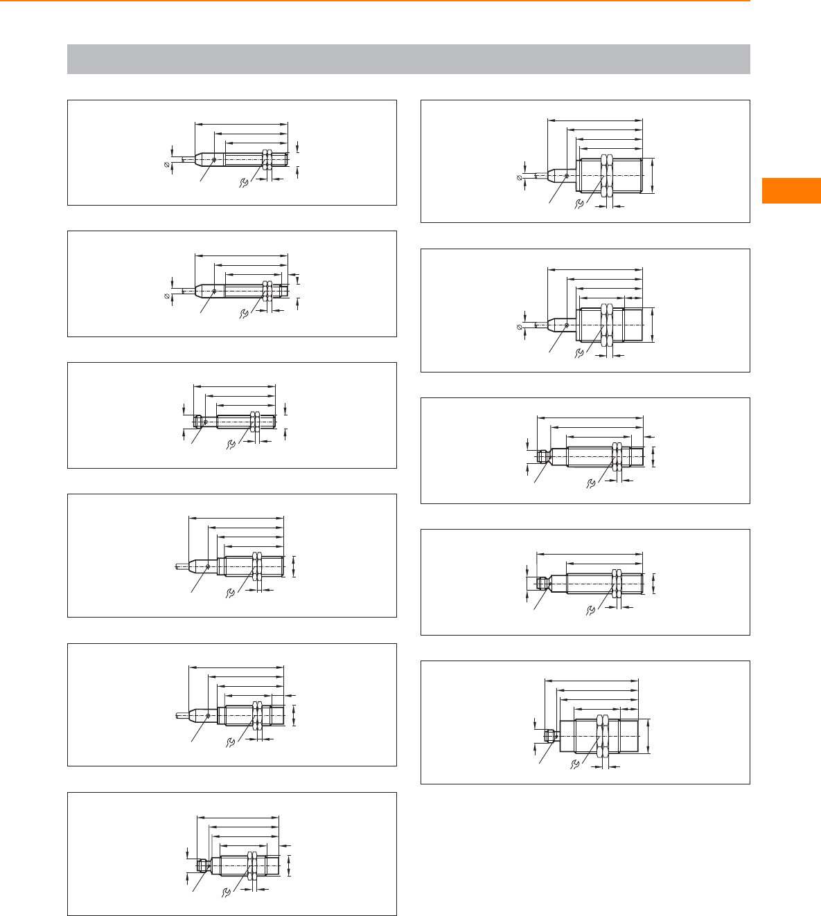
Scale drawings / drawing no. – CAD download: www.ifm.com
186
5,4
79
62
53
M12x1
LED 4 x 90° 17
4
187
5,4
79
62
48
LED 4 x 90° 17
4
M12x1
5
188
59
50
M12x1
17
4
M12 x1
LED
70
189
64
LED 4 x 90° 24
81
57
50
M18 x1
4
190
64
LED 4 x 90° 24
81
57
40
M18 x1
4
10
191
M18 x1
M12 x1
40
57
70
LED 4 x 90°
59
10
4
24
192
36
53
M30x1,5
57
5
5
64
LED 4 x 90°
81
193
36
38
M30x1,5
15
57
5
5
64
LED 4 x 90°
81
194
M18 x1
55 10
M12 x1
90,5
LED 8 x 45°
79
4
24
195
65
M12 x1
LED 8 x 45°
90,5
4
24
M18 x1
196
LED 4 x 90°
69
39
M30x1,5
5
67
80
36
M12 x1
15
Inductive sensors
133
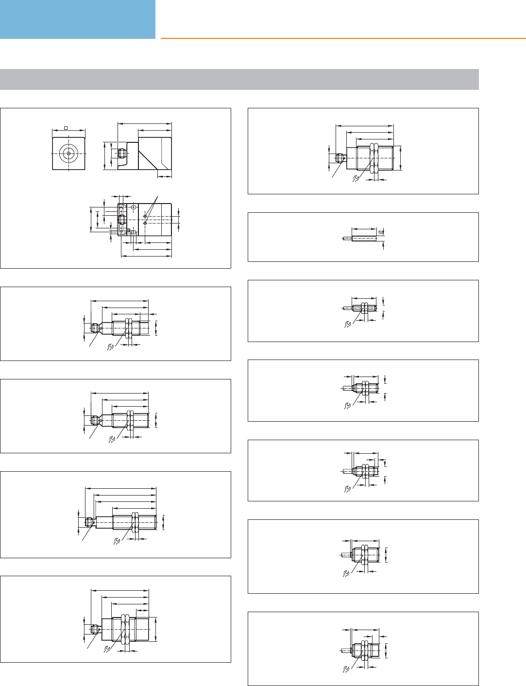
Scale drawings / drawing no. – CAD download: www.ifm.com
197
40
M12 x1
40
66
17
34
LED
46
61
30
20
5,4
10
5,4
6
8,5
33
198
35
M12 x1
LED 2 x 180°
70,5
M18 x1
57
4
24
10
199
45
M12 x1
LED 2 x 180°
70,5
4
24
M18 x1
57
200
M18 x1
M12 x1
4
24
LED 4 x 90°
53
73,5
86,5
75,5
201
LED 4 x 90°
M30x1,5
5
45
70
36
M12x1
15
57
202
LED
M30x1,5
5
45
70
36
M12x1
57
203
6,5
30
204
30
M8x1
4
13
205
30
M12x1
4
2
17
206
4
30
M12x1
4
2
17
207
33
M18 x1
4
2
24
208
M18 x1
4
233
8
24
Inductive sensors
134
Product selectors and further information can be found at: www.ifm.com
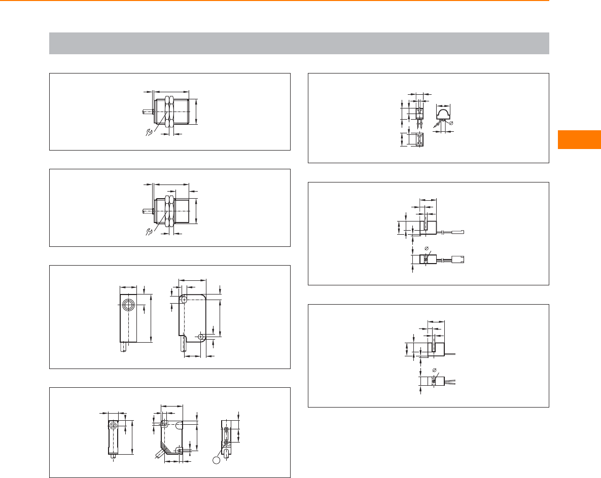
Scale drawings / drawing no. – CAD download: www.ifm.com
209
241
5
M30x1,5
36
210
241
5
M30x1,5
15
36
211
10,2
27,8
5,6
16
22,2
2,75
3,1
3,5
2,8
3,1
10,4
212
40
6,2
12
16 10
1
4
26
32
3,2
4
5
3,2
18
1: threaded insert M3, depth 5.8 mm, max. tightening torque
1.2 Nm (screw fixing class 8.8) when brass insert in contact with
counterpart.
213
8
2
15
1,5
11
11 6
15
3,7
214
19
5
3,5
15
10
2
1,8
10
215
19
5
3,5
15
10
2
1,8
10
Inductive sensors
135
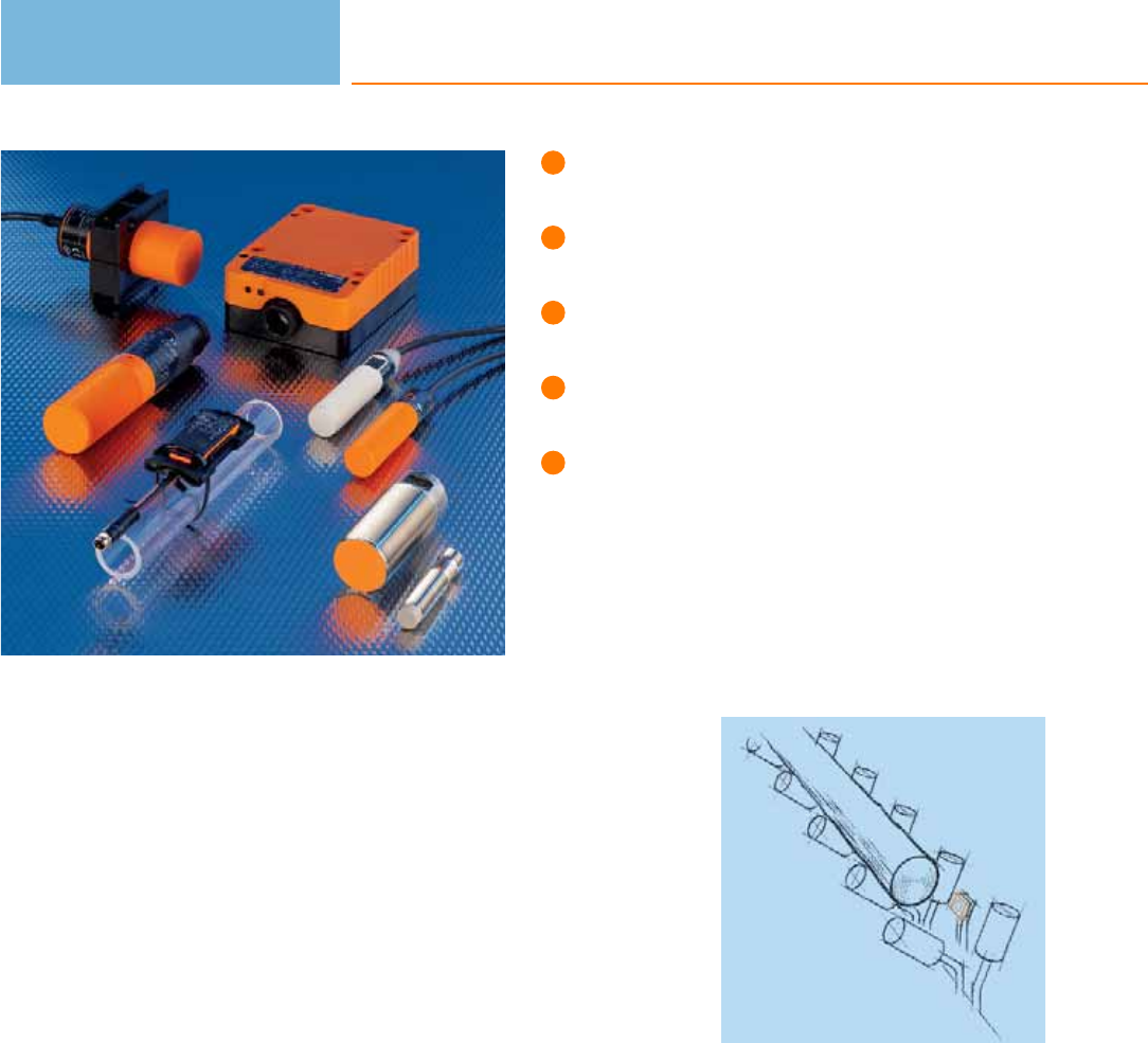
High operational reliability due
to increased noise immunity.
Sensing range adjustable by means
of a potentiometer or pushbutton.
Plastic or metal housing for
different applications.
Variable: connector, connection
cable or connection terminals.
Assortment of tank and sight glass
mounting acccessories.
Capacitive sensors
Capacitive sensors are used for the non-contact detection of any objects. In contrast
to inductive sensors, which only detect metallic objects, capacitive sensors can also
detect non-metallic materials. Typical applications are in the wood, paper, glass,
plastic, food and chemical industries. In a packaging system, capacitive sensors
monitor that the contents of a cardboard box is complete, for example, or check
the presence of non-metallic caps. Another application is to monitor the conveying
of sheets of glass on a roller conveyor.
Operating principle
The capacitance between the active electrode of the sensor and the electrical earth
potential is evaluated. An approaching object influences the electrical alternating
field between these two “capacitor plates” and, consequently, the capacitance. This
applies to metallic and non-metallic objects. By means of the potentiometer or the
pushbutton the user can set the sensitivity.
Increased noise immunity
When detecting objects, very small changes in capacitance must be evaluated and
converted into switching signals. This makes high requirements for the electronics.
The sensors must be designed so that they are insensitive to fluctuations of the
parasitic basic capacitances, as these can amount to a multiple of the change in
capacitance to be measured. Moreover, the sensors must be insensitive to electro-
magnetic interference which typically occurs in the application area.
ifm electronic has developed future-oriented solutions to meet the high sensor
requirements. A patented circuit concept efficiently prevents the mentioned
problems and ensures reliable functioning for all relevant noise parameters.
Not only metal:
Capacitive sensors
detect almost all
materials, here
for example a log
in a saw mill.
Capacitive sensors
136

System overview Page
Sensors for industrial applications, DC 138 - 141
Sensors for industrial applications, AC and AC/DC 141 - 142
Sensors for the detection of conductive media through a wall 142 - 143
Sensors for the detection of granulates for the plastics industry, DC 143 - 144
Sensors for the detection of granulates for the plastics industry, AC / DC 144
Sensors with ATEX approval 144 - 145
Switching amplifiers with ATEX approval 145 - 146
Accessories mounting adapters 146 - 147
Accessories mounting components 147
Accessories mounting sets 148
Wiring diagrams 148 - 150
Scale drawings / drawing no. – CAD download: www.ifm.com 150 - 153
Capacitive sensors
137
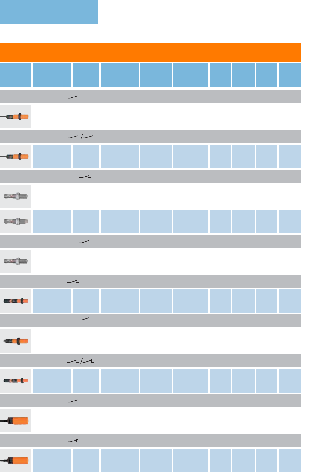
Sensors for industrial applications, DC
Type Dimensions
[mm]
Sensing
range
[mm]
Material Ub
[V]
Protection f
[Hz]
Iload
[mA]
Draw-
ing
no.
Order
no.
Cable 2 m · Output function · DC PNP · Wiring diagram no. 1
M18 / L = 84 8 nf PBT 10...36 IP 67 50 250 1 KG5043
Cable 2 m · Output function · DC PNP/NPN · Wiring diagram no. 22
M18 / L = 84 8 nf PBT 10...55 IP 67 50 400 1KG5047
M12 connector · Output function · DC PNP · Wiring diagram no. 2 · Connector groups 9, 10, 11
M12 / L = 60 4 f high-grade st. steel 10...36 IP 65 50 100 2 KF5001
M12 / L = 61 8 nf high-grade st. steel 10...36 IP 65 50 100 3KF5002
M12 connector · Output function · DC NPN · Wiring diagram no. 3 · Connector groups 9, 10, 11
M12 / L = 60 4 f high-grade st. steel 10...36 IP 65 50 100 2 KF5013
Terminals · Output function · DC PNP · Wiring diagram no. 4
M18 / L = 110 8 nf PBT 10...36 IP 65 50 250 4KG5041
M12 connector · Output function · DC PNP · Wiring diagram no. 5 · Connector groups 9, 10, 11, 12, 107, 108, 109, 110,
135, 136
M18 / L = 93.8 8 nf PBT 10...36 IP 67 50 250 5 KG5057
Terminals · Output function · DC PNP/NPN · Wiring diagram no. 23
M18 / L = 110 8 nf PBT 10...55 IP 65 50 400 4KG5040
Cable 2 m · Output function · DC PNP · Wiring diagram no. 1
M30 / L = 81 15 nf PBT 10...36 IP 65 40 250 6 KI5002
Cable 2 m · Output function · DC PNP · Wiring diagram no. 6
M30 / L = 81 15 nf PBT 10...36 IP 65 40 250 6KI5001
Capacitive sensors
138
Product selectors and further information can be found at: www.ifm.com
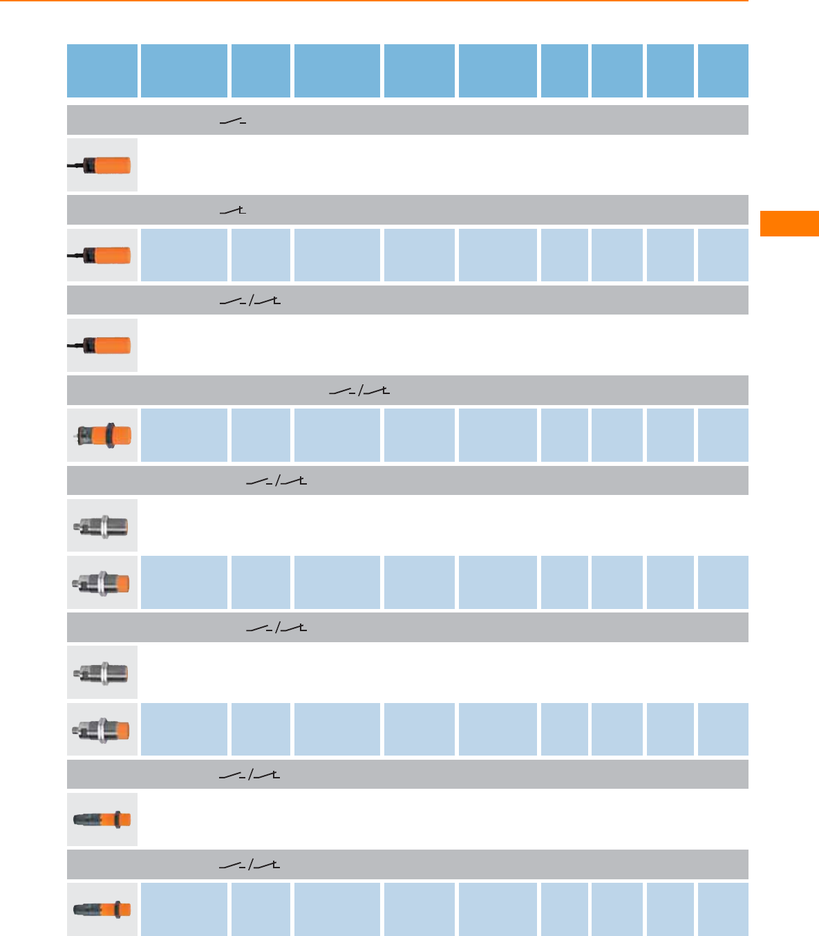
Type Dimensions
[mm]
Sensing
range
[mm]
Material Ub
[V]
Protection f
[Hz]
Iload
[mA]
Draw-
ing
no.
Order
no.
Cable 2 m · Output function · DC NPN · Wiring diagram no. 7
M30 / L = 81 15 nf PBT 10...36 IP 65 40 250 6 KI5015
Cable 2 m · Output function · DC NPN · Wiring diagram no. 8
M30 / L = 81 15 nf PBT 10...36 IP 65 40 250 6KI5019
Cable 2 m · Output function · DC PNP · Wiring diagram no. 24
M30 / L = 81 15 nf PBT 10...36 IP 65 40 250 6 KI5207
connector (DIN EN 175301-803) · Output function · DC PNP · Wiring diagram no. 9 · Connector group 30
M30 / L = 92 15 nf PBT 10...36 IP 65 40 250 7KI5038
M12 connector · Output function · DC PNP · Wiring diagram no. 2 · Connector groups 9, 10, 11, 12
M30 / L = 90 8 f high-grade st. steel 10...36 IP 65 / IP 67 10 100 8 KI5085
M30 / L = 90 15 nf high-grade st. steel 10...36 IP 65 / IP 67 10 100 9KI5087
M12 connector · Output function · DC PNP/NPN · Wiring diagram no. 25 · Connector groups 9, 10, 11, 12
M30 / L = 90 8 f high-grade st. steel 10...36 IP 65 / IP 67 10 100 8 KI5084
M30 / L = 90 15 nf high-grade st. steel 10...36 IP 65 / IP 67 10 100 9KI5086
Terminals · Output function · DC PNP · Wiring diagram no. 10
M30 / L = 125 15 nf PBT 10...55 IP 65 40 250 10 KI5023
Terminals · Output function · DC NPN · Wiring diagram no. 11
M30 / L = 125 15 nf PBT 10...36 IP 65 40 250 10 KI5024
Capacitive sensors
139
You can find wiring diagrams and scale drawings from page 148
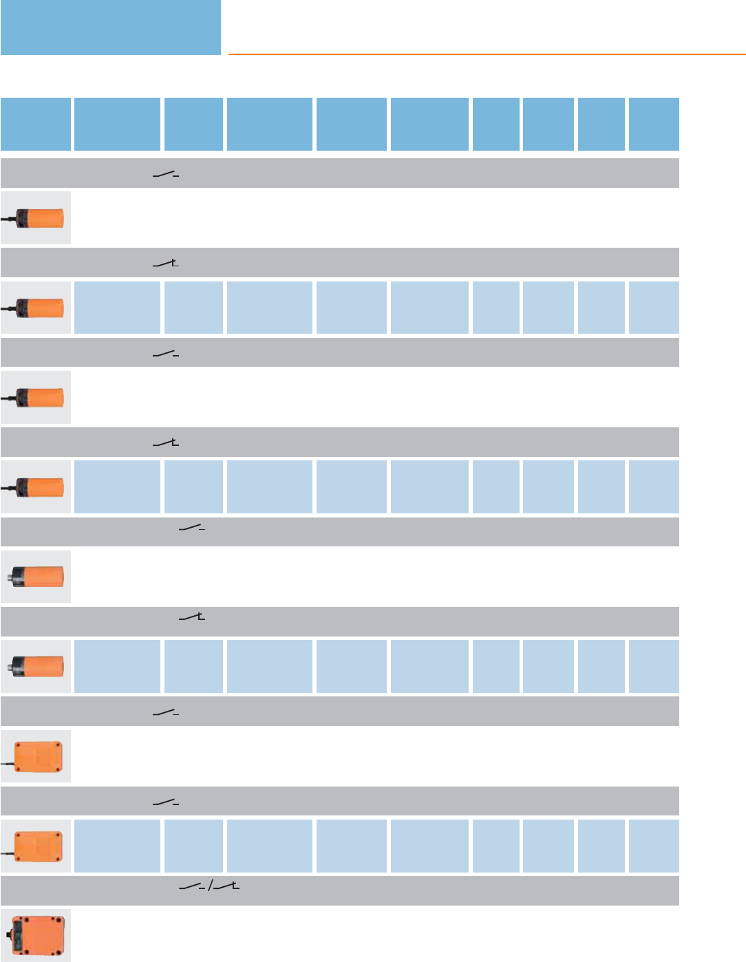
Type Dimensions
[mm]
Sensing
range
[mm]
Material Ub
[V]
Protection f
[Hz]
Iload
[mA]
Draw-
ing
no.
Order
no.
Cable 2 m · Output function · DC PNP · Wiring diagram no. 1
Ø 34 / L = 81 20 nf PBT 10...36 IP 65 40 250 11 KB5004
Cable 2 m · Output function · DC PNP · Wiring diagram no. 6
Ø 34 / L = 81 20 nf PBT 10...36 IP 65 40 250 11 KB5002
Cable 2 m · Output function · DC NPN · Wiring diagram no. 7
Ø 34 / L = 81 20 nf PBT 10...36 IP 65 40 250 11 KB5001
Cable 2 m · Output function · DC NPN · Wiring diagram no. 8
Ø 34 / L = 81 20 nf PBT 10...36 IP 65 40 250 11 KB5003
M12 connector · Output function · DC PNP · Wiring diagram no. 5 · Connector groups 9, 10, 11, 12, 107, 108, 109, 110,
135, 136
Ø 34 / L = 93 20 nf PBT 10...36 IP 65 40 250 12 KB5062
M12 connector · Output function · DC PNP · Wiring diagram no. 12 · Connector groups 9, 10, 11, 12, 107, 108, 109, 110,
135, 136
Ø 34 / L = 93 20 nf PBT 10...36 IP 65 40 250 12 KB5096
Cable 2 m · Output function · DC PNP · Wiring diagram no. 1
120 x 80 x 30 60 nf modified PPO 10...36 IP 65 10 250 13 KD5022
Cable 2 m · Output function · DC NPN · Wiring diagram no. 7
120 x 80 x 30 60 nf modified PPO 10...36 IP 65 10 250 13 KD5024
M12 connector · Output function · DC PNP · Wiring diagram no. 26 · Connector groups 9, 10, 11, 12, 107, 108, 109,
110, 135, 136
105 x 80 x 40 60 nf modified PPO 10...36 IP 65 10 250 14 KD5039
Capacitive sensors
140
Product selectors and further information can be found at: www.ifm.com
Type Dimensions
[mm]
Sensing
range
[mm]
Material Ub
[V]
Protection f
[Hz]
Iload
[mA]
Draw-
ing
no.
Order
no.
Terminals · Output function · DC PNP · Wiring diagram no. 27
105 x 80 x 40 60 nf modified PPO 10...36 IP 65 10 250 15 KD5018
f = flush / nf = non flush
Sensors for industrial applications, AC and AC/DC
Type Dimensions
[mm]
Sensing
range
[mm]
Material Ub
[V]
Protection f
AC / DC
[Hz]
Iload
AC / DC
[mA]
Draw-
ing
no.
Order
no.
Cable 2 m · Output function · AC/DC · Wiring diagram no. 13
M18 / L = 84 8 nf PBT 20...250 IP 67 25 / 50 350 / 100 1 KG0009*
Cable 2 m · Output function · AC/DC · Wiring diagram no. 14
M18 / L = 84 8 nf PBT 20...250 IP 67 25 / 50 350 / 100 1KG0010*
Terminals · Output function · AC/DC · Wiring diagram no. 15
M18 / L = 110 8 nf PBT 20...250 IP 65 25 / 50 350 / 100 4 KG0008*
Cable 2 m · Output function · AC/DC · Wiring diagram no. 13
M30 / L = 81 15 nf PBT 20...250 IP 65 25 / 40 250 6KI0016*
Cable 2 m · Output function · AC/DC · Wiring diagram no. 14
M30 / L = 81 15 nf PBT 20...250 IP 65 25 / 40 250 6 KI0020*
connector (DIN EN 175301-803) · Output function · AC/DC · Wiring diagram no. 16 · Connector group 30
M30 / L = 92 15 nf PBT 20...250 IP 65 25 / 40 250 7KI0040*
Terminals · Output function · AC/DC · Wiring diagram no. 17
M30 / L = 125 15 nf PBT 20...250 IP 65 25 / 40 250 10 KI0024*
Capacitive sensors
141
You can find wiring diagrams and scale drawings from page 148
Type Dimensions
[mm]
Sensing
range
[mm]
Material Ub
[V]
Protection f
AC / DC
[Hz]
Iload
AC / DC
[mA]
Draw-
ing
no.
Order
no.
Cable 2 m · Output function · AC/DC · Wiring diagram no. 13
Ø 34 / L = 81 20 nf PBT 20...250 IP 65 25 / 40 250 11 KB0025*
Cable 2 m · Output function · AC/DC · Wiring diagram no. 14
Ø 34 / L = 81 20 nf PBT 20...250 IP 65 25 / 40 250 11 KB0029*
Cable 2 m · Output function · AC/DC · Wiring diagram no. 13
120 x 80 x 30 60 nf modified PPO 20...250 IP 65 10 250 13 KD0012*
Cable 2 m · Output function · AC/DC · Wiring diagram no. 14
120 x 80 x 30 60 nf modified PPO 20...250 IP 65 10 250 13 KD0013*
Terminals · Output function · AC/DC · Wiring diagram no. 28
105 x 80 x 40 60 nf modified PPO 20...250 IP 65 10 250 15 KD0009*
f = flush / nf = non flush
* Note for AC and AC/DC units
Miniature fuse to IEC60127-2 sheet 1, ≤ 2 A (fast acting). Recommendation: check the unit for reliable function after a short
circuit.
Sensors for the detection of conductive media through a wall
Type Dimensions
[mm]
Sensing
range
[mm]
Material Ub
[V]
Protection f
[Hz]
Iload
[mA]
Draw-
ing
no.
Order
no.
Cable 2 m · Output function · DC PNP/NPN · Wiring diagram no. 29
M18 / L = 77 8 nf PP 10...36 IP 65 / IP 67 10 200 16 KG5067
Cable 2 m · Output function · DC PNP · Wiring diagram no. 18
M18 / L = 77 8 nf PP 10...36 IP 65 / IP 67 10 200 16 KG5069
Capacitive sensors
142
Product selectors and further information can be found at: www.ifm.com
Type Dimensions
[mm]
Sensing
range
[mm]
Material Ub
[V]
Protection f
[Hz]
Iload
[mA]
Draw-
ing
no.
Order
no.
M12 connector · Output function · DC PNP · Wiring diagram no. 2 · Connector groups 9, 10, 11, 12, 107, 108, 109, 110,
135, 136
M18 / L = 87 8 nf PBT 10...36 IP 65 / IP 67 10 200 17 KG5071
Cable 2 m · Output function · 1x open collector with automatic load detection (DC PNP or DC NPN) ·
Wiring diagram no. 29
20 x 14 x 48 12 nf PBT 10...36 IP 65 / IP 67 10 100 18 KQ6001
Cable 2 m · Output function · 1x open collector DC PNP · Wiring diagram no. 18
20 x 14 x 48 12 nf PBT 10...36 IP 65 / IP 67 10 100 18 KQ6002
Cable with connector 0.04 m · Output function · 1x open collector with automatic load detection (DC PNP or
DC NPN) · Wiring diagram no. 25 · Connector groups 4, 5
20 x 14 x 48 12 nf PBT 10...36 IP 65 / IP 67 10 100 18 KQ6003
Cable with connector 0.04 m · Output function · 1x open collector DC PNP · Wiring diagram no. 2 · Connector
groups 4, 5
20 x 14 x 48 12 nf PBT 10...36 IP 65 / IP 67 10 100 18 KQ6004
Cable with connector 0.1 m · Output function · 1x open collector DC PNP · Wiring diagram no. 2 · Connector
groups 9, 10, 11
20 x 14 x 48 12 nf PBT 10...36 IP 65 / IP 67 10 100 18 KQ6005
f = flush / nf = non flush
Sensors for the detection of granulates for the plastics industry, DC
Type Dimensions
[mm]
Sensing
range
[mm]
Material Ub
[V]
Protection f
[Hz]
Iload
[mA]
Draw-
ing
no.
Order
no.
M12 connector · Output function · DC PNP/NPN · Wiring diagram no. 25 · Connector groups 9, 10, 11, 12
M18 / L = 87 12 nf PBT 10...36 IP 65 / IP 67 10 200 17 KG5065
M12 connector · Output function · DC PNP · Wiring diagram no. 2 · Connector groups 9, 10, 11, 12
M18 / L = 87 12 nf PBT 10...36 IP 65 / IP 67 10 200 17 KG5066
Capacitive sensors
143
You can find wiring diagrams and scale drawings from page 148
Type Dimensions
[mm]
Sensing
range
[mm]
Material Ub
[V]
Protection f
[Hz]
Iload
[mA]
Draw-
ing
no.
Order
no.
M12 connector · Output function · DC PNP · Wiring diagram no. 30 · Connector groups 9, 11, 107, 108, 135
M30 / L = 116 nf PPS 10...30 IP 67 10 200 19 KN5121
M12 connector · Output function · DC PNP/NPN · Wiring diagram no. 25 · Connector groups 9, 10, 11, 12, 107, 108,
109, 110, 135, 136
M30 / L = 90 20 nf PBT 10...36 IP 65 / IP 67 10 200 20 KI5082
M12 connector · Output function · DC PNP · Wiring diagram no. 2 · Connector groups 9, 10, 11, 12, 107, 108, 109, 110,
135, 136
M30 / L = 90 20 nf PBT 10...36 IP 65 / IP 67 10 200 20 KI5083
f = flush / nf = non flush
Sensors for the detection of granulates for the plastics industry, AC / DC
Type Dimensions
[mm]
Sensing
range
[mm]
Material Ub
[V]
Protection f
[Hz]
Iload
[mA]
Draw-
ing
no.
Order
no.
1/2“ UNF-Connector · Output function · AC/DC · Wiring diagram no. 19 · Connector group 26
M18 / L = 87 12 nf PBT 20...250 IP 65 / IP 67 10 150 21 KG0016*
M30 20 nf PBT 20...250 IP 65 / IP 67 10 150 22 KI0054*
f = flush / nf = non flush
* Note for AC and AC/DC units
Miniature fuse to IEC60127-2 sheet 1, ≤ 2 A (fast acting). Recommendation: check the unit for reliable function after a short
circuit.
Sensors with ATEX approval
Type Dimensions
[mm]
Sensing
range
[mm]
Material Unom.
at 1 KΩ
[V]
Ub
[V]
Internal
capacit.
[nF]
Internal
inductance
[μH]
f
[Hz]
Draw-
ing
no.
Order
no.
Cable 2 m · Output function · Connection to certified intrinsically safe circuits with the max. values
U = 15 V / I = 50 mA / P = 120 mW · Wiring diagram no. 20
M30 / L = 81 15 nf PBT 8.2 DC 7.5...15 375 1 40 6 KI5030
Capacitive sensors
144
Product selectors and further information can be found at: www.ifm.com
Type Dimensions
[mm]
Sensing
range
[mm]
Material Unom.
at 1 KΩ
[V]
Ub
[V]
Internal
capacit.
[nF]
Internal
inductance
[μH]
f
[Hz]
Draw-
ing
no.
Order
no.
Cable 6 m · Output function · Connection to certified intrinsically safe circuits with the max. values
U = 15 V / I = 50 mA / P = 120 mW · Wiring diagram no. 20
M30 / L = 81 15 nf PBT 8.2 DC 7.5...15 375.64 3 40 6 KI5031
Terminals · Output function · DC PNP · Wiring diagram no. 10
M30 / L = 151 15 nf PBT 10...30 DC – – – 10 23 KI5065
Terminals · Output function · AC/DC · Wiring diagram no. 17
M30 / L = 151 15 nf PBT 20...250
AC/DC – – – 25 / 50 23 KI0042*
Cable 2 m · Output function · Connection to certified intrinsically safe circuits with the max. values
U = 15 V / I = 50 mA / P = 120 mW · Wiring diagram no. 21
M34 / L = 92 15 nf brass 8.2 DC 7.5...15 375 140 24 KX5001
Cable 6 m · Output function · Connection to certified intrinsically safe circuits with the max. values
U = 15 V / I = 50 mA / P = 120 mW · Wiring diagram no. 21
M34 / L = 92 15 nf brass 8.2 DC 7.5...15 375.64 3 40 24 KX5002
f = flush / nf = non flush
* Note for AC and AC/DC units
Miniature fuse to IEC60127-2 sheet 1, ≤ 2 A (fast acting), Place the fuse outside the hazardous area. Recommendation: check
the unit for reliable function after a short circuit.
Switching amplifiers with ATEX approval
Type Ub
[V]
Power / current
consumption
[VA] / [mA]
f
[Hz]
Ta
[°C]
Output Protection Draw-
ing
no.
Order
no.
115 1.0 / 10 -20...60 relay (1 changeover contact) IP 20 25 N0030A
230 1.0 / 10 -20...60 relay (1 changeover contact) IP 20 25 N0031A
115 1.3 / 10 -20...60 relay (1 changeover contact per channel) IP 20 25 N0032A
230 1.3 / 10 -20...60 relay (1 changeover contact per channel) IP 20 25 N0033A
Capacitive sensors
145
You can find wiring diagrams and scale drawings from page 148
Type Ub
[V]
Power / current
consumption
[VA] / [mA]
f
[Hz]
Ta
[°C]
Output Protection Draw-
ing
no.
Order
no.
24 / < 23 10 -20...60 relay (1 changeover contact) IP 20 25 N0530A
24 / < 50 5000 -20...60 2 transistor outputs PNP
(100 mA, short-circuit protection) IP 20 25 N0531A
24 / < 50 5000 -20...60 2 outputs (optocoupler, bipolar,
100 mA, short-circuit protection) IP 20 25 N0532A
24 / < 50 10 -20...60 relay (1 changeover contact per channel) IP 20 25 N0533A
24 / < 50 5000 -20...60 2 transistor outputs PNP
(100 mA, short-circuit protection) IP 20 25 N0534A
Accessories mounting adapters
Type Description Order
no.
Mounting adapter · M18 x 1 - G ¾ · Housing materials: POM E43900
Mounting adapter · M18 x 1 - G 1 · Housing materials: POM E43904
Mounting adapter · M30 x 1.5 - G 1¼ · Housing materials: PVDF / EPDM E11036
Mounting adapter · M30 x 1.5 - G 1½ · Housing materials: PVDF / EPDM E11034
Mounting adapter · Ø 34 mm - G 1½ · Housing materials: POM E11027
Locknut · G ¾ · for mounting adapter · Housing materials: POM E43902
Locknut · G 1¼ · for mounting adapter · Housing materials: PVDF E11030
Locknut · G 1½ · for mounting adapter · Housing materials: PVDF E11032
Capacitive sensors
146
Product selectors and further information can be found at: www.ifm.com
Type Description Order
no.
Protective cover · G 1¼ · for mounting adapter · Housing materials: PES black transparent E11078
Accessories mounting components
Type Description Order
no.
Mounting clamp · Ø 34 mm · Housing materials: PBT E10017
Mounting clamp · Ø 20 mm - Ø 18 mm · with reducing bush · for type M18 · Housing materials: PBT E10076
Mounting clamp · Ø 34 mm - Ø 30 mm · with reducing bush · for type M30 · Housing materials: PBT E10077
Mounting clamp · Ø 34 mm · Housing materials: PA E10193
Angle bracket · for type M12 · Housing materials: stainless steel E10735
Angle bracket · for type M18 · Housing materials: stainless steel E10736
Angle bracket · for type M30 · Housing materials: stainless steel E10737
Mounting adapter for free-standing mounting · for type KQ5, KQ6 · Housing materials: adapter: PBT / inserts: brass / screw: steel
galvanised · Pack quantity: 1 E12153
Mounting adapter · Pipe and tube installation KQ5 / KQ6 with cable ties · Fixing of the types KQ5 and KQ6 to pipes and tubes ·
Housing materials: Mounting adapter: PA 12 black E12163
Fixing strap · Length: 760 mm · for capacitive level sensors · for type KNQ, KQ5, KQ6 · Housing materials: PA · Pack quantity: 5E10880
Mounting set · M30 x 1.5 / G ¼...G 1 · for capacitive sensors on rising pipes G ¼" - 1" · Housing materials: POM E11037
Capacitive sensors
147
You can find wiring diagrams and scale drawings from page 148
Accessories mounting sets
Type Description Order
no.
Mounting set · Ø 18.5 mm · Clamp mounting · free-standing M10 · for type OG, IG, KG · Housing materials: clamp: diecast zinc /
fixture: steel E20718
Mounting set · Ø 18.5 mm · Clamp mounting · free-standing M10 · for type OG, IG, KG · Housing materials: clamp: diecast zinc /
fixture: steel E20719
Mounting set · Ø 18.5 mm · Clamp mounting · aluminium profile · for type OG, IG, KG · Housing materials: fixture: stainless steel
316Ti / 1.4571 / clamp: diecast zinc / Cube: diecast zinc E20866
Mounting set · Ø 18.5 mm · Clamp mounting · aluminium profile · for type OG, IG, KG · Housing materials: fixture: stainless steel
316Ti / 1.4571 / clamp: diecast zinc / Cube: diecast zinc E20867
Mounting set · Ø 18.5 mm · Clamp mounting · free-standing M10 · for type OG, IG, KG · Housing materials: fixture: stainless steel
316Ti / 1.4571 / clamp: stainless steel E20869
Mounting set · Ø 18.5 mm · Clamp mounting · free-standing M10 · for type OG, IG, KG · Housing materials: fixture: stainless steel
316Ti / 1.4571 / clamp: stainless steel E20870
Mounting set · Ø 30.2 mm · Clamp mounting · free-standing M12 · for type OI, II, KI · Housing materials: fixture: stainless steel
316Ti / 1.4571 / clamp: diecast zinc E20873
Mounting set · Ø 30.2 mm · Clamp mounting · free-standing M12 · for type OI, II, KI · Housing materials: fixture: stainless steel
316Ti / 1.4571 / clamp: stainless steel E20874
Mounting set · Ø 30.2 mm · Clamp mounting · aluminium profile · for type OI, II, KI · Housing materials: fixture: stainless steel 316Ti
/ 1.4571 / clamp: diecast zinc / Cube: diecast zinc E20875
Angle bracket · Clamp mounting · for type IW, OW, KQ5 · Housing materials: stainless steel 316Ti / 1.4571 E20811
Core colours
BN brown
BU blue
BK black
WH white
GN/YE green/yellow
Wiring diagrams
1
BN
BK
BU
L+
L
2
L+
L
1
4
3
3
L+
L
1
4
3
Capacitive sensors
148
Product selectors and further information can be found at: www.ifm.com
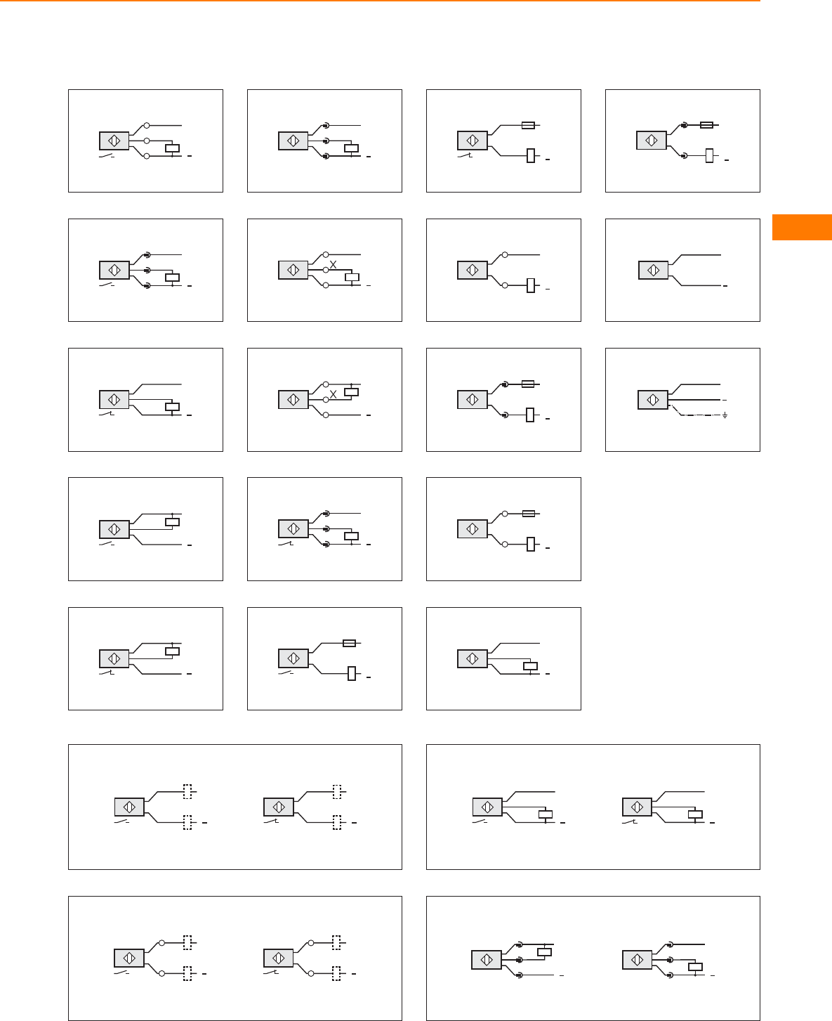
Wiring diagrams
4
L
L+
/
24
1
3
5
L+
L
1
4
3
6
BN
BK
BU
L+
L
7
L
BN
BK
BU
L+
8
L
BN
BK
BU
L+
9
L+
L
1
3
2
10
/
L+
L
13
/
24
11
/
24
/
13
L
L+
12
L+
L
1
2
3
13
BN
BU
L+
L1
L
N
14
BN
BU
L+
L1
L
N
15
/
13
/
24
L1
L+
L
N
16
1
2
L1
N
L+
L
17
/
13
/
24
L1
L+
L
N
18
BN
BK
BU
L+
L
19
2
3
L1
N
L+
L
20
+
BN
BU
21
BN
GN/ YE
BU
+
22
WH
BK
L+
L L
BK
WH
L+
23
L+
L
/
13
/
24
L+
L
/
13
/
24
24
BU
BK
BN
L+
L
BN
BK
BU
L+
L
25
L+
L
1
4
3
L+
L
1
4
3
Capacitive sensors
149
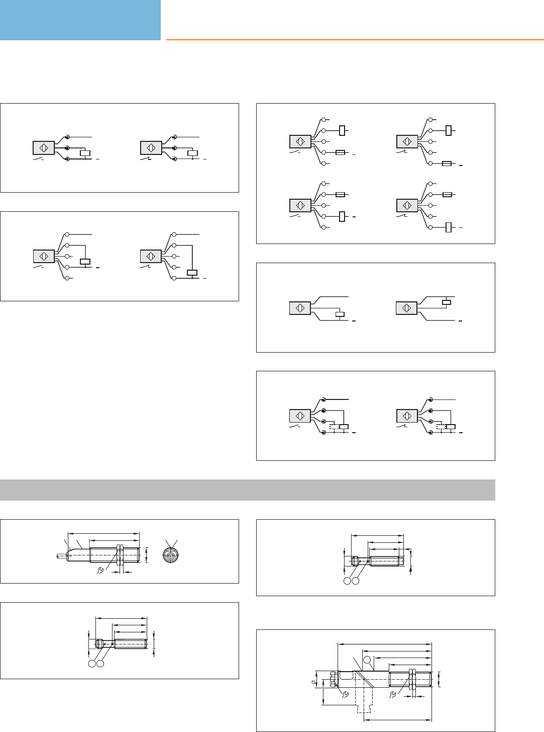
Wiring diagrams
26
L+
L
1
4
3
L+
L
1
4
2
27
2
4
3
1
5
L+
L
2
4
3
1
5
L+
L
28
2
4
3
1
5
AC;
DC NPN
L+
N
L
L1
2
4
3
1
5
AC;
DC NPN
L+
N
L
L1
2
4
3
1
5
DC PNP
L+
L
2
4
3
1
5
DC PNP
L+
L
29
L
L+
BN
BK
BU L
L+
BN
BK
BU
30
L
L+
4
2
3
1
2
L
L+
4
1
3
Scale drawings / drawing no. – CAD download: www.ifm.com
1
24
58
4
84
M18 x1
pot.LED LED
pot.
2
40,2
38,2
M12x1
M12 x1
59,8
12
1: LED 4 x 90°, 2: with pot.
3
34,6
M12x1
5
M12 x1
41,6
61,2
12
1: LED 4 x 90°, 2: with pot.
4
80
24
67,2
50
M18 x1
4
110
20
30
81
LED
17
1
1: with pot.
Capacitive sensors
150
Product selectors and further information can be found at: www.ifm.com
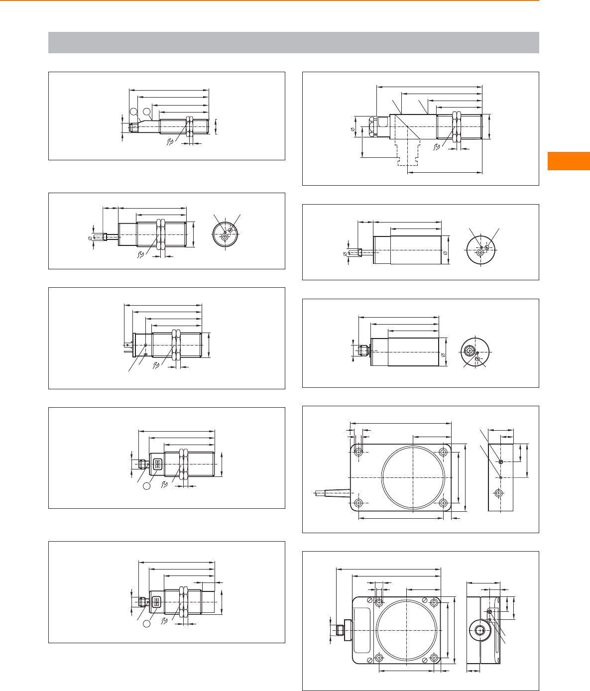
Scale drawings / drawing no. – CAD download: www.ifm.com
5
1
24
58
4
84
M18 x1
93,8
67,2
M12 x1
2
1: with pot., 2: LED
6
36
81
59
5
M30x1,5
9
18
pot.
LED
7
LED
36
66
5
59
M30x1,5
92
pot.
82
8
60
M30x1,5
77
90
LED (4 x 90°) 5
M12 x 1
36
1
1: Programming buttons
9
60
M30x1,5
77
90
LED (4 x 90°) 5
M12 x 1
36
1
15
1: Programming buttons
10
36
64
54
5
M30x1,5
95
125
37
25
88
LED pot.
11
9
18
34
81
60 LED pot.
12
34
81
60
M12x1
93
LED pot.
13
120
45
80
60
10
100
6
9,5
40
21
30
15
pot.
LED
14
105
80
40
7,5
65
65
5,5
9,3
M12x1
120
40
12
27
18
LED
pot.
16
Capacitive sensors
151
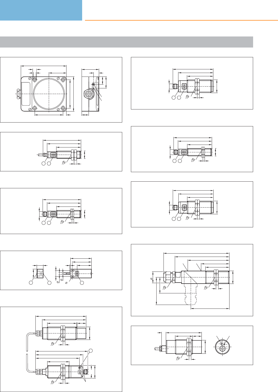
Scale drawings / drawing no. – CAD download: www.ifm.com
15
105
80
40
7,5
65
65
5,5
9,3 40
12
27
18
LED
pot.
16
16
24
M18 x1
12
77
56
88
6
1: LED ring, 2: Programming buttons
17
24
77
56
M18 x1
4
M12 x1
87
12
1: LED ring, 2: Programming buttons
18
3,2
48
33
43,7
2
5,5
3
13,4
14
20
1
2
1
1: Programming buttons, 2: sensing face
19
116
5
68 20
36
M30x1,5
101
109
5
50
36
M30x1,5
M12 x1
LED
120
100
1
1: Programming button
20
61
M30x1,5
80
90
5
M12 x 1
36
2
1
1: LED ring, 2: Programming buttons
21
24
77
56
M18 x1
4
1/2“ UNF
87
12
22
61
80
90
5
M30
36
2
1
1/2" UNF
1: LED ring, 2: Programming buttons
23
36
64
54
5
M30x1,5
95
125
37
88
LED POTI
26
151
63
24
24
82
20
40
M34x1,5
10
5
41
LED
pot.
Capacitive sensors
152
Product selectors and further information can be found at: www.ifm.com
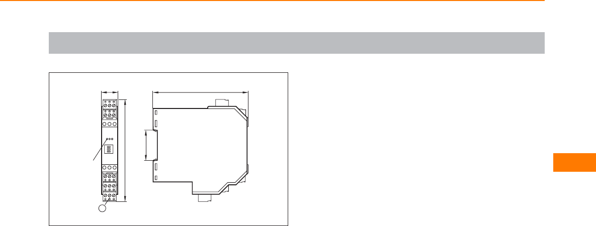
Scale drawings / drawing no. – CAD download: www.ifm.com
25
112
35,5
20
120
LED
1
1: Combicon plug with screw terminals (optional)
Capacitive sensors
153
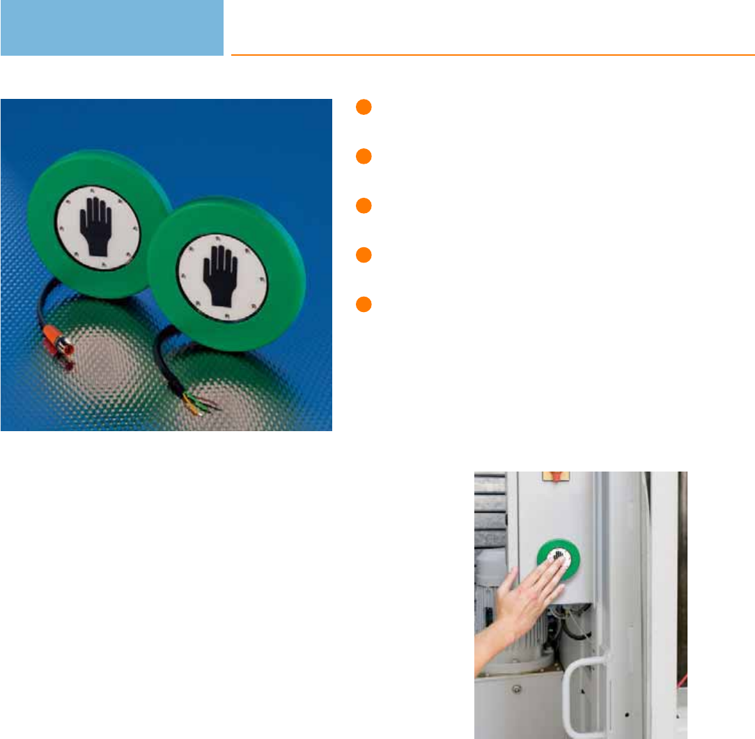
Non-contact switching,
no pressure necessary.
Free of wear and maintenance.
Optical feedback by LEDs
in case of switching.
Oil-resistant, protection rating
IP 69K, impact and scratch resistant.
Easy wiring thanks to
tried-and-tested 3-wire technology.
Capacitive touch sensors
Capacitive touch sensors are well known from trains where they are used for ope-
ning doors. They are also frequently used in industry, e.g. as start / stop buttons on
machines. Moreover, capacitive touch sensors can be used as a button on mobile
machinery. They are also used on pedestrian crossing lights. The advantage: designs
for handicapped people with Braille are possible.
Touch sensitive switching
The dynamic-capacitive measuring principle detects an approaching human hand.
The electronics suppresses interference such as water, layers of ice and static
foreign bodies.
The touch sensors also switch through glass, thus offering further installation flexi-
bility, e.g. for protection against vandalism.
As compared to mechanical switches the sensors operate without wear. Since the
touch sensors react to contact, no pressure is required for activation. This means
considerably increased ease of use. LEDs as optical feedback signal that the sensor
has been activated.
Touch sensors
154

System overview Page
Dynamic capacitive touch sensors 156
Touch sensors
155
Scale drawings / drawing no. – CAD download: www.ifm.com 156
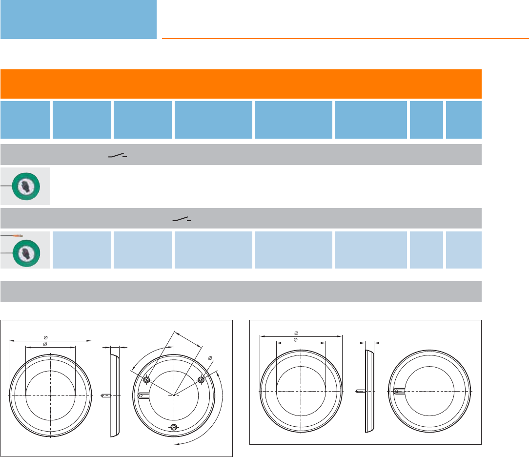
Dynamic capacitive touch sensors
Type Ub
[V]
Iload
[mA]
Current
consumption
[mA]
Ambient
temperature
[°C]
Protection Draw-
ing
no.
Order
no.
Cable 2 m · Output function · DC PNP
24 500 30 -40...85 IP 69K 1 KT5001
Cable with connector 0.3 m · Output function · DC PNP
24 500 30 -40...85 IP 69K 2KT5002
Touch sensors
156
Product selectors and further information can be found at: www.ifm.com
Scale drawings / drawing no. – CAD download: www.ifm.com
1
100
60,2 10
60°
38
120°
4,3
2
10
100
60,2

Touch sensors
157
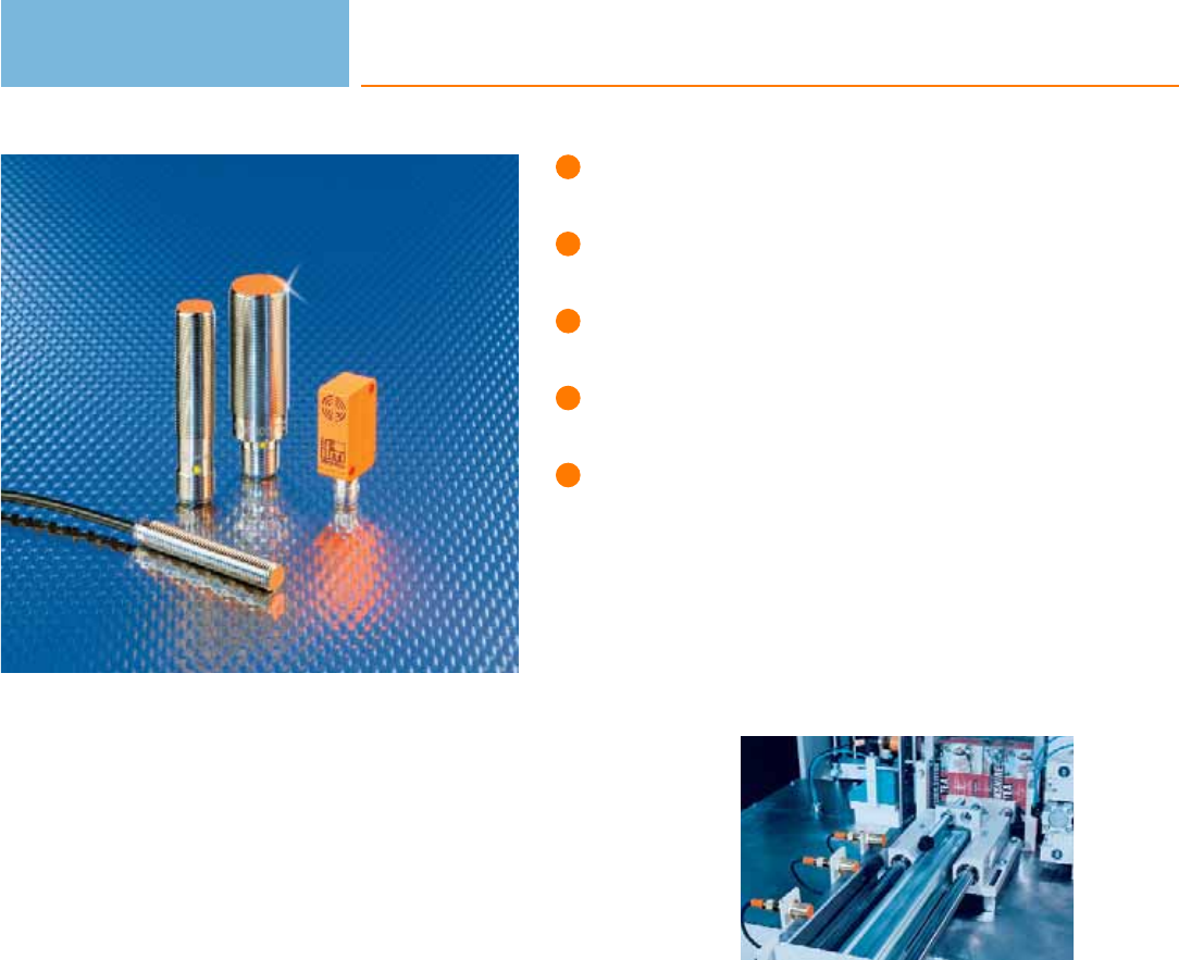
Detection also through
non-magnetisable metals.
Small designs with very long
sensing ranges up to 100 mm.
Cylinder and rectangular designs
for demanding applications.
Wide temperature range for
universal use.
Flush or non-flush installation in
non-magnetisable metals.
Magnetic sensors
Magnetic sensors are used for the detection of positions without contact or wear
and tear in control technology. They are used where inductive sensors reach their
limits. The advantage: Compared to inductive sensors magnetic sensors have a
considerably higher sensing range and smaller housings.
Since magnetic fields penetrate all non-magnetisable materials, the sensors can
detect magnets through walls made of non-ferrous metal, stainless steel,
aluminium, plastic or wood.
In gate systems, for example, the magnet sensor only detects the magnet which is
to be detected. Any possible influences by aluminium in the environment do not
impact the sensor.
In the food industry the magnetic sensor is often used in connection with pigs
(cleaning devices which pass through the inside of pipes). By means of magnetic
sensors their exact position can be detected from the outside through the wall of
the stainless steel pipe.
Operating principle
Magnetic sensors from ifm electronic use state-of-the-art GMR (Giant Magneto
Resistive Effect) technology. The measuring cell consists of resistors with several
extremely fine, ferromagnetic and non-magnetic layers. Whereas in a conventional
Wheatstone bridge circuit two screened and two unscreened GMR resistors are
combined, a large signal proportional to the magnetic field is produced if a mag-
netic field is present. As from a defined threshold value an output signal is switched
via a comparator.
Installation
Magnetic sensors can be mounted flush with all materials (even metals) without
reduction in the sensing range. Depending on the orientation of the magnetic field
the sensor can be damped from the front or from the side.
The sensor switches
as soon as the
magnet has reached
the switch-on point.
The direction of
movement of the
magnet is not
important.
Magnetic sensors
158

System overview Page
Full metal sensors for industrial applications 160
Sensors for industrial applications 160 - 162
Full metal sensors for hygienic and wet areas 162
Sensors for hygienic and wet areas 162
Accessories mounting components 163
Accessories mounting sets 163
Accessories damping magnets 164
Wiring diagrams 164
Scale drawings / drawing no. – CAD download: www.ifm.com 165
Magnetic sensors
159
Full metal sensors for industrial applications
Type Dimensions
[mm]
Sensing
range
[mm]
Material Ub
[V]
Protection f
[Hz]
Iload
[mA]
Draw-
ing
no.
Order
no.
M12 connector · Output function · DC PNP · Wiring diagram no. 1 · Connector groups 107, 108, 109, 110, 135, 136
M12 / L = 60 60 high-grade st. steel 10...30 IP 65 / IP 67 5000 200 1 MFS211
M12 connector · Output function · DC NPN · Wiring diagram no. 2 · Connector groups 107, 108, 109, 110, 135, 136
M12 / L = 60 60 high-grade st. steel 10...30 IP 65 / IP 67 5000 200 1MFS209
M12 connector · Output function · DC PNP · Wiring diagram no. 3 · Connector groups 107, 108, 135
M12 / L = 60 60 high-grade st. steel 10...30 IP 65 / IP 67 5000 200 1 MFS210
M12 connector · Output function · DC PNP · Wiring diagram no. 1 · Connector groups 107, 108, 109, 110, 135, 136
M18 / L = 60 70 high-grade st. steel 10...30 IP 65 / IP 67 5000 200 2MGS204
M12 connector · Output function · DC NPN · Wiring diagram no. 2 · Connector groups 107, 108, 135
M18 / L = 60 70 high-grade st. steel 10...30 IP 65 / IP 67 5000 200 2 MGS205
M12 connector · Output function · DC PNP · Wiring diagram no. 3 · Connector groups 107, 108, 135
M18 / L = 60 70 high-grade st. steel 10...30 IP 65 / IP 67 5000 200 2MGS206
Sensors for industrial applications
Type Dimensions
[mm]
Sensing
range
[mm]
Material Ub
[V]
Protection f
[Hz]
Iload
[mA]
Draw-
ing
no.
Order
no.
Cable 2 m · Output function · DC PNP · Wiring diagram no. 4
M8 / L = 50 60 V4A (316S12) 10...30 IP 67 5000 200 3 ME5011
M12 / L = 50 60 high-grade st. steel 10...30 IP 67 5000 200 4MFS201
Magnetic sensors
160
Product selectors and further information can be found at: www.ifm.com
Type Dimensions
[mm]
Sensing
range
[mm]
Material Ub
[V]
Protection f
[Hz]
Iload
[mA]
Draw-
ing
no.
Order
no.
Cable 2 m · Output function · DC NPN · Wiring diagram no. 5
M8 / L = 40 60 V4A (316S12) 10...30 IP 67 5000 200 5 ME5015
M8 connector · Output function · DC PNP · Wiring diagram no. 1 · Connector groups 1, 2, 3, 68
M8 / L = 60 60 V4A (316S12) 10...30 IP 67 5000 200 6 ME5010
Cable 2 m · Output function · DC NPN · Wiring diagram no. 5
M12 / L = 50 60 high-grade st. steel 10...30 IP 67 5000 200 4MFS202
M12 connector · Output function · DC NPN · Wiring diagram no. 2 · Connector groups 9, 10, 11, 12, 107, 108, 109, 110,
135, 136
M12 / L = 60 60 high-grade st. steel 10...30 IP 67 5000 200 1MFS203
M12 connector · Output function · DC PNP · Wiring diagram no. 1 · Connector groups 9, 10, 11, 12, 107, 108, 109, 110,
135, 136
M12 / L = 60 60 stainless steel 10...30 IP 67 – 200 1 MF5004
M12 / L = 60 60 high-grade st. steel 10...30 IP 67 5000 200 1MFS200
M18 / L = 60 70 stainless steel 10...30 IP 67 5000 200 2 MGS200
Cable 2 m · Output function · DC PNP · Wiring diagram no. 4
M18 / L = 50 70 stainless steel 10...30 IP 67 5000 200 7MGS201
Cable 2 m · Output function · DC PNP · Wiring diagram no. 6
M18 / L = 50 70 stainless steel 10...30 IP 67 5000 200 7 MGS202
Cable 2 m · Output function · DC PNP · Wiring diagram no. 4
28 x 10 x 16 60 PBT 10...30 IP 67 5000 200 8MS5011
Magnetic sensors
161
You can find wiring diagrams and scale drawings from page 164
Type Dimensions
[mm]
Sensing
range
[mm]
Material Ub
[V]
Protection f
[Hz]
Iload
[mA]
Draw-
ing
no.
Order
no.
M8 connector · Output function · DC PNP · Wiring diagram no. 1 · Connector groups 1, 2, 3, 68
28 x 10 x 16 60 PBT 10...30 IP 67 5000 200 9 MS5010
Cable with connector 0.15 m · Output function · DC PNP · Wiring diagram no. 1 · Connector groups 1, 2, 3, 68
40 x 12 x 26 60 PBT 10...30 IP 67 –200 10 MN5200
Full metal sensors for hygienic and wet areas
Type Dimensions
[mm]
Sensing
range
[mm]
Material Ub
[V]
Protection f
[Hz]
Iload
[mA]
Draw-
ing
no.
Order
no.
M12 connector · Output function · DC PNP · Wiring diagram no. 1 · Connector groups 107, 108, 109, 110, 135, 136
M12 / L = 60 60 high-grade st. steel 10...30 IP 65 / IP 68 / IP
69K 5000 100 1 MFT202
M18 / L = 60 70 high-grade st. steel 10...30 IP 65 / IP 68 / IP
69K 5000 100 2 MGT203
Sensors for hygienic and wet areas
Type Dimensions
[mm]
Sensing
range
[mm]
Material Ub
[V]
Protection f
[Hz]
Iload
[mA]
Draw-
ing
no.
Order
no.
M12 connector · Output function · DC PNP · Wiring diagram no. 1 · Connector groups 107, 108, 109, 110, 135, 136
M12 / L = 60 60 high-grade st. steel 10...30 IP 68 / IP 69K 5000 200 1 MFT200
Ø 12 / L = 60 60 high-grade st. steel 10...30 IP 65 / IP 68 / IP
69K 5000 100 11 MFT204
M12 connector · Output function · DC PNP · Wiring diagram no. 1 · Connector groups 9, 10, 11, 12, 107, 108, 109, 110,
135, 136
M18 / L = 60 70 high-grade st. steel 10...30 IP 68 / IP 69K 5000 200 2MGT200
M12 connector · Output function · DC PNP · Wiring diagram no. 1 · Connector groups 107, 109
M18 / L = 60 100 high-grade st. steel 10...30 IP 68 / IP 69K – 200 2 MGT201
Magnetic sensors
162
Product selectors and further information can be found at: www.ifm.com
Accessories mounting components
Type Description Order
no.
Angle bracket · for type M8 · Housing materials: stainless steel E10734
Angle bracket · for type M12 · Housing materials: stainless steel E10735
Angle bracket · for type M18 · Housing materials: stainless steel E10736
Mounting clamp · Ø 8 mm · Housing materials: aluminium black anodised E10221
Mounting clamp · Ø 12 mm · with end stop · for type M12 · Housing materials: PC E11047
Mounting clamp · Ø 18 mm · with end stop · for type M18 · Housing materials: PC E11048
Accessories mounting sets
Type Description Order
no.
Mounting set · Ø 18.5 mm · Clamp mounting · free-standing M10 · for type OG, IG, KG · Housing materials: clamp: diecast zinc /
fixture: steel E20718
Mounting set · Ø 18.5 mm · Clamp mounting · free-standing M10 · for type OG, IG, KG · Housing materials: clamp: diecast zinc /
fixture: steel E20719
Mounting set · Ø 18.5 mm · Clamp mounting · free-standing M10 · for type OG, IG, KG · Housing materials: fixture: stainless steel
316Ti / 1.4571 / clamp: stainless steel E20869
Mounting set · Ø 18.5 mm · Clamp mounting · free-standing M10 · for type OG, IG, KG · Housing materials: fixture: stainless steel
316Ti / 1.4571 / clamp: stainless steel E20870
Mounting set · Ø 18.5 mm · Clamp mounting · aluminium profile · for type OG, IG, KG · Housing materials: fixture: stainless steel
316Ti / 1.4571 / clamp: diecast zinc / Cube: diecast zinc E20866
Mounting set · Ø 18.5 mm · Clamp mounting · aluminium profile · for type OG, IG, KG · Housing materials: fixture: stainless steel
316Ti / 1.4571 / clamp: diecast zinc / Cube: diecast zinc E20867
Magnetic sensors
163
You can find wiring diagrams and scale drawings from page 164
Accessories damping magnets
Type Description Order
no.
Damping magnet · M 1.0 · Housing materials: Samarium cobalt E10749
Damping magnet · M 2.0 · Housing materials: AlNiCo E10750
Damping magnet · M 3.0 · Housing materials: Barium ferrite E10751
Damping magnet · M 4.0 · Housing materials: Barium ferrite E10752
Damping magnet · M 4.1 · Housing materials: Barium ferrite / stainless steel E11803
Damping magnet · M 5.0 · Housing materials: Barium ferrite E10753
Damping magnet · M 5.1 · Housing materials: Barium ferrite with plastic coating / steel E10754
Core colours
BK black
BN brown
BU blue
Wiring diagrams
1
L+
L
1
4
3
2
L+
L
1
4
3
3
L+
L
1
2
3
4
BN
BK
BU
L+
L
5
L
BN
BK
BU
L+
6
BN
BK
BU
L+
L
Magnetic sensors
164
Product selectors and further information can be found at: www.ifm.com
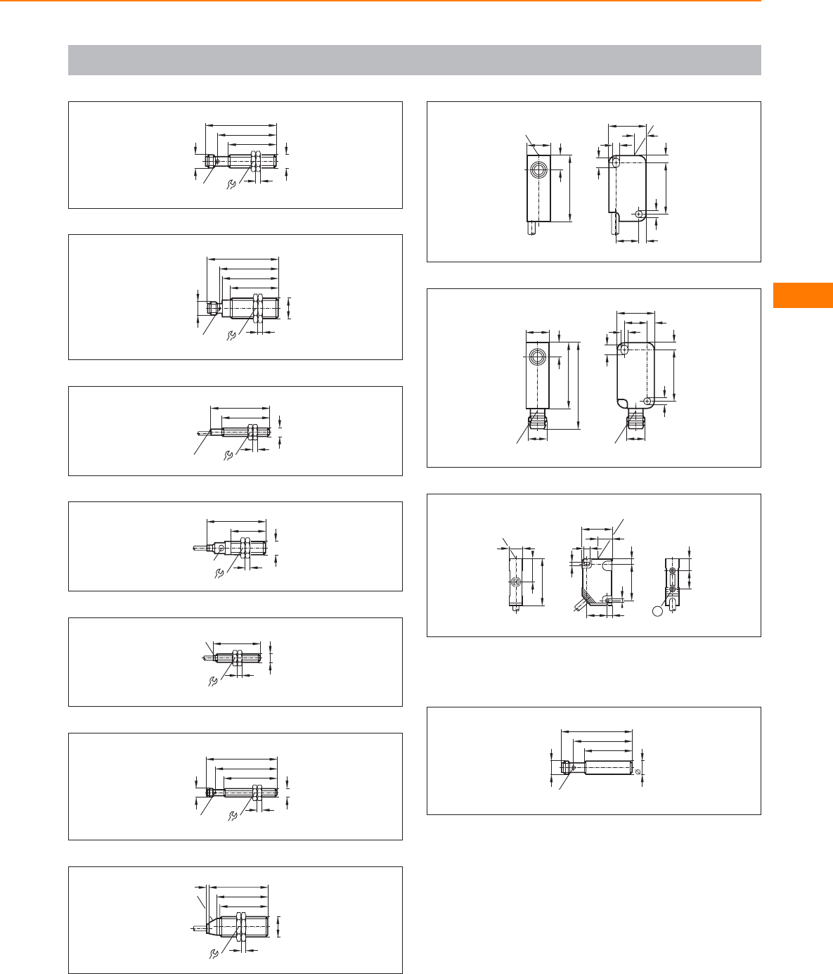
Scale drawings / drawing no. – CAD download: www.ifm.com
1
49
40
M12x1
17
4
M12 x1
LED 4 x 90°
60
2
M18 x1
M12 x1
40
47
60
LED 4 x 90°
4
24
49
3
40
50
M8x1
4
13
LED
4
50
29
M12x1
4
LED
17
5
40
M8x1
4
13
LED
6
45
52
M8x1
4
13
M8x1
LED 4 x 90°
60
7
24
50
43
40
M18 x1
2
LED
4
8
10,2
27,8
LED
5,6
16
5,1
22,2
2,75
3,1
3,5
2,8
3,1
LED
10,4
9
10,2
27,8
LED
5,6
M8x1
36,8
16
22,2
2,75
3,1
3,5
2,8
3,1
10,4
M8x1
LED
10
16 10
1
40
20
12
LED
4
26
13
32
3,2
4
5
LED
3,2
18
1: threaded insert M3, depth 5.8 mm, max. tightening torque
1.2 Nm (screw fixing class 8.8) when brass insert in contact with
counterpart.
11
60
LED 4 x 90°
49
40
12
M12 x1
Magnetic sensors
165
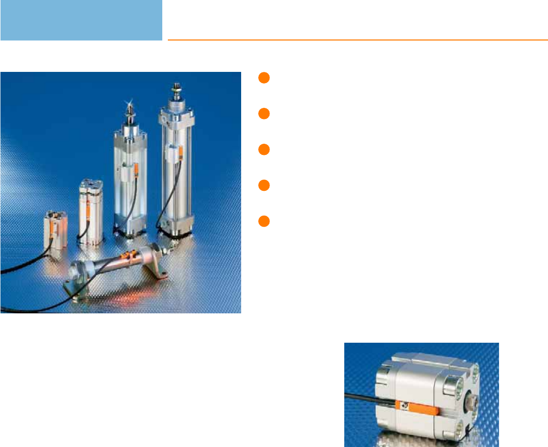
Self-clamping fixture for easy
adjustment and quick mounting.
Convenient: can be easily inserted
into the slot from the top.
Suitable for almost all C and T slots.
Unit versions available with connection
cable and M8 / M12 cable plug.
Wide selection of adapter
accessories.
Cylinder sensors
Cylinder sensors are used for position detection of pistons in pneumatic cylinders.
They are directly mounted onto the cylinder. The ring magnet attached to the
piston is sensed through the housing wall of non-magnetisable material
(e.g. aluminium, brass or stainless steel). ifm electronic offers a standard solution for
different cylinder types and manufacturers.
Operating principle
ifm electronic‘s cylinder sensors use state-of-the-art GMR and AMR technology: A
GMR element is made up of extremely thin magnetic layers, each separated by a
nonmagnetic layer. Without external field they align in an antiparallel manner which
results in a defined electrical resistance. If these layers are exposed to a magnetic
field, the magnetic layers align in a parallel manner. This results in a large change in
resistance that is converted into a switching signal by the internal electronics.
An AMR element consists of thin ferromagnetic stripes. Electrical resistance is
highest without external magnetic fields. The effect of a magnetic field reduces
resistance. This change is converted into a switching signal by the internal
electronics. Advantage: This method enables exact measurement of even very small
changes of the magnetic field where space is extremely limited. This results in a
smaller hysteresis and a short travel distance. So, the sensors can be used wherever
exact positioning is required (e.g. short-stroke cylinder).
Response sensitivity
The response sensitivity applies equally to either magnetic polarity and without
external field influence. The magnetic flux density in most pneumatic cylinders is
between 5 and 25 millitesla (mT). ifm electronic’s cylinder sensors are factory set so
that they detect these magnetic fields safely.
Travel distance
The travel distance describes the section which is covered by the magnet in the
sensing zone. It depends on the strength of the magnet. The short response times
of the sensors allow very high travel speeds.
Position sensing:
Cylinder sensors
monitor the position
of the piston in a
pneumatic cylinder.
Cylinder sensors
166

System overview Page
T-slot sensors for industrial applications 168 - 169
T-slot reed sensors for industrial applications, 2-wire 170
T-slot reed sensors for industrial applications, 3-wire 170 - 171
T-slot reed sensors with ATEX approval 1G/1D 171
T-slot reed sensors with ATEX approval 3D/3G 171
T-slot sensors for hygienic and wet ares 172
T-slot sensors for short-stroke cylinders 172 - 173
T-slot sensors for short-stroke cylinders for hygienic and wet areas 173
T-slot sensors with ATEX approval 1G/1D 173
T-slot sensors with ATEX approval 3D/3G 174
T-slot sensors with ATEX approval 3D 174
Non flush C-slot sensors for industrial applications 174 - 175
Flush C-slot sensors for industrial applications 175 - 176
C-slot sensors for short-stroke cylinders 176
Fixing straps for clean line cylinders 176 - 177
Clips 178
Adapters for tie rod and integrated profile 178 - 179
Adapters for trapezoidal slot cylinders 179
Various adapters and memorisation blocks 179 - 180
Wiring diagrams 180 - 181
Scale drawings / drawing no. – CAD download: www.ifm.com 181 - 184
Cylinder sensors
167
T-slot sensors for industrial applications
Type Dimensions
[mm]
Material Ub
[V]
f
[Hz]
Protection Iload
[mA]
Ta
[°C]
Draw-
ing
no.
Order
no.
M8 connector · Output function · 3-wire · DC PNP · Wiring diagram no. 1 · Connector groups 1, 2, 3, 68
27.5 x 18 x 15.5 PA (polyamide) 10...30 > 6000 IP 65 / IP 67 100 -25...85 1 MK5900
M8 connector · Output function · 3-wire · DC NPN · Wiring diagram no. 2 · Connector groups 1, 2, 3, 68
27.5 x 18 x 15.5 PA (polyamide) 10...30 > 6000 IP 65 / IP 67 100 -25...85 1MK5902
Cable 2 m · Output function · 3-wire · DC PNP · Wiring diagram no. 4
25 x 5 x 6.5 PA (polyamide) 10...30 > 10000 IP 65 / IP 67 100 -25...85 2 MK5100
25 x 5 x 6.5 PA (polyamide) 10...30 > 10000 IP 65 / IP 67 200 -25...85 2MK5115
Cable 2 m · Output function · 3-wire · DC NPN · Wiring diagram no. 5
25 x 5 x 6.5 PA (polyamide) 10...30 > 10000 IP 65 / IP 67 100 -25...85 2 MK5114
Cable 2 m · Output function · 2-wire · DC PNP/NPN · Wiring diagram no. 6
25 x 5 x 6.5 PA (polyamide) 10...30 4000 IP 65 / IP 67 100 -25...85 2MK5103
Cable 6 m · Output function · 3-wire · DC PNP · Wiring diagram no. 4
25 x 5 x 6.5 PA (polyamide) 10...30 > 10000 IP 65 / IP 67 200 -25...85 2 MK5117
Cable 10 m · Output function · 3-wire · DC PNP · Wiring diagram no. 4
25 x 5 x 6.5 PA (polyamide) 10...30 > 10000 IP 65 / IP 67 100 -25...85 2MK5124
Cable with connector 0.3 m · Output function · 3-wire · DC PNP · Wiring diagram no. 1 · Connector groups 1, 2, 3, 68
25 x 5 x 6.5 PA (polyamide) 10...30 > 10000 IP 65 / IP 67 100 -25...85 3 MK5101
Cylinder sensors
168
Product selectors and further information can be found at: www.ifm.com
Type Dimensions
[mm]
Material Ub
[V]
f
[Hz]
Protection Iload
[mA]
Ta
[°C]
Draw-
ing
no.
Order
no.
Cable with connector 0.3 m · Output function · 3-wire · DC PNP · Wiring diagram no. 1 · Connector groups 1, 2, 3, 68
25 x 5 x 6.5 PA (polyamide) 10...30 > 10000 IP 65 / IP 67 200 -25...85 3 MK5106
25 x 5 x 6.5 PA (polyamide) 10...30 > 10000 IP 65 / IP 67 100 -25...85 4MK5102
Cable with connector 0.3 m · Output function · 3-wire · DC NPN · Wiring diagram no. 2 · Connector groups 1, 3, 68
25 x 5 x 6.5 PA (polyamide) 10...30 > 10000 IP 65 / IP 67 100 -25...85 3 MK5112
Cable with connector 0.3 m · Output function · 2-wire · DC PNP/NPN · Wiring diagram no. 7 · Connector groups 1, 3
25 x 5 x 6.5 PA (polyamide) 10...30 4000 IP 65 / IP 67 100 -25...85 3MK5104
25 x 5 x 6.5 PA (polyamide) 10...30 4000 IP 65 / IP 67 100 -25...85 4 MK5105
Cable with connector 1 m · Output function · 3-wire · DC PNP · Wiring diagram no. 1 · Connector groups 1, 2, 3, 68
25 x 5 x 6.5 PA (polyamide) 10...30 > 10000 IP 65 / IP 67 100 -25...85 4MK5122
Cable with connector 0.3 m · Output function · 3-wire · DC PNP · Wiring diagram no. 1 · Connector groups 9, 10, 11, 12, 107,
108, 109, 110, 135, 136
25 x 5 x 6.5 PA (polyamide) 10...30 > 10000 IP 65 / IP 67 100 -25...85 5 MK5107
25 x 5 x 6.5 PA (polyamide) 10...30 > 10000 IP 65 / IP 67 200 -25...85 5MK5108
Cable with connector 0.3 m · Output function · 2-wire · DC PNP/NPN · Wiring diagram no. 7 · Connector groups 9, 11, 107,
108, 135
25 x 5 x 6.5 PA (polyamide) 10...30 4000 IP 65 / IP 67 100 -25...85 5 MK5109
* Note for AC and AC/DC units
Miniature fuse to IEC60127-2 sheet 1, ≤ 0,175 A (fast acting). Recommendation: check the unit for reliable function after a
short circuit.
Cylinder sensors
169
You can find wiring diagrams and scale drawings from page 180
T-slot reed sensors for industrial applications, 2-wire
Type Dimensions
[mm]
Material Ub
[V]
f
[Hz]
Protection Iload
[mA]
Ta
[°C]
Draw-
ing
no.
Order
no.
M8 connector · Output function · 2-wire · AC/DC PNP/NPN · Wiring diagram no. 8
27.5 x 18 x 15.5 PA (polyamide) 5...50 1000 IP 65 / IP 67 100 -25...70 1 MR0901*
Cable 2 m · Output function · 2-wire · AC/DC PNP/NPN · Wiring diagram no. 9
30.5 x 5 x 6.5 PA (polyamide) 5...120 1000 IP 67 100 -25...70 6MR0100*
Cable 6 m · Output function · 2-wire · AC/DC PNP/NPN · Wiring diagram no. 9
30.5 x 5 x 6.5 PA (polyamide) 5...120 1000 IP 67 100 -25...70 6 MR0117*
Cable with connector 0.3 m · Output function · 2-wire · AC/DC PNP/NPN · Wiring diagram no. 8 · Connector groups 1, 3
30.5 x 5 x 6.5 PA (polyamide) 5...60 1000 IP 67 100 -25...70 7MR0101*
30.5 x 5 x 6.5 PA (polyamide) 5...60 1000 IP 67 100 -25...70 8 MR0102*
Cable with connector 0.3 m · Output function · 2-wire · AC/DC PNP/NPN · Wiring diagram no. 8 · Connector groups 9, 11,
107, 108, 135
30.5 x 5 x 6.5 PA (polyamide) 5...60 1000 IP 67 100 -25...70 9MR0107*
* Note for AC and AC/DC units
Miniature fuse to IEC60127-2 sheet 1, ≤ 0,175 A (fast acting). Recommendation: check the unit for reliable function after a
short circuit.
T-slot reed sensors for industrial applications, 3-wire
Type Dimensions
[mm]
Material Ub
[V]
f
[Hz]
Protection Iload
[mA]
Ta
[°C]
Draw-
ing
no.
Order
no.
Cable with connector 0.3 m · Output function · 3-wire · AC/DC PNP · Wiring diagram no. 3 · Connector groups 1, 2, 3, 68
30.5 x 5 x 6.5 PA (polyamide) 5...50 1000 IP 65 / IP 67 350 / 500 -25...70 7MR0119*
Cylinder sensors
170
Product selectors and further information can be found at: www.ifm.com
M8 connector · Output function · 3-wire · AC/DC PNP · Wiring diagram no. 3
27.5 x 18 x 15.5 PA (polyamide) 5...50 1000 IP 65 / IP 67 350 / 500 -25...70 1 MR0902*
Cable with connector 0.3 m · Output function · 3-wire · AC/DC PNP · Wiring diagram no. 3 · Connector groups 1, 2, 3, 68
30.5 x 5 x 6.5 PA (polyamide) 5...50 1000 IP 65 / IP 67 350 / 500 -25...70 8 MR0120*
Type Dimensions
[mm]
Material Ub
[V]
f
[Hz]
Protection Iload
[mA]
Ta
[°C]
Draw-
ing
no.
Order
no.
Cable 2 m · Output function · 3-wire · AC/DC PNP · Wiring diagram no. 10
30.5 x 5 x 6.5 PA (polyamide) 5...50 1000 IP 65 / IP 67 350 / 500 -25...70 6MR0122*
Cable 6 m · Output function · 3-wire · AC/DC PNP · Wiring diagram no. 10
30.5 x 5 x 6.5 PA (polyamide) 5...50 1000 IP 65 / IP 67 350 / 500 -25...70 6 MR0123*
Cable with connector 0.3 m · Output function · 3-wire · AC/DC PNP · Wiring diagram no. 3 · Connector groups 9, 10, 11, 12,
107, 108, 109, 110, 135, 136
30.5 x 5 x 6.5 PA (polyamide) 5...50 1000 IP 65 / IP 67 350 / 500 -25...70 9MR0121*
* Note for AC and AC/DC units
Miniature fuse to IEC60127-2 sheet 1, ≤ 0.75 A (fast blow, DC operation), ≤ 0.6 A (fast blow, AC operation). Recommendation:
check the unit for reliable function after a short circuit.
T-slot reed sensors with ATEX approval 1G/1D
Type Dimensions
[mm]
Material Ub
[V]
f
[Hz]
Protection Iload
[mA]
Ta
[°C]
Draw-
ing
no.
Order
no.
Cable 6 m · Output function · 2-wire · Connection to certified intrinsically safe circuits with the max. values
U = 15 V / I = 50 mA / P = 120 mW · Wiring diagram no. 6
30.5 x 5 x 6.5 PA (polyamide) – – IP 65 / IP 67 – -25...70 6 MR500A
T-slot reed sensors with ATEX approval 3D/3G
Type Dimensions
[mm]
Material Ub
[V]
f
[Hz]
Protection Iload
[mA]
Ta
[°C]
Draw-
ing
no.
Order
no.
Cable 6 m · Output function · 2-wire · DC PNP/NPN · Wiring diagram no. 11
30.5 x 5 x 6.5 PA (polyamide) 5...30 – IP 65 / IP 67 100 -20...60 6 MR501A*
* Note for AC and AC/DC units
Miniature fuse to IEC60127-2 sheet 1, ≤ 0,175 A (fast acting). Recommendation: check the unit for reliable function after a
short circuit.
Cylinder sensors
171
You can find wiring diagrams and scale drawings from page 180
T-slot sensors for hygienic and wet ares
Type Dimensions
[mm]
Material Ub
[V]
f
[Hz]
Protection Iload
[mA]
Ta
[°C]
Draw-
ing
no.
Order
no.
Cable 2 m · Output function · 3-wire · DC PNP · Wiring diagram no. 4
25 x 5 x 6.5 PA (polyamide) 10...30 > 10000 IP 65 / IP 67 /
IP 69K 100 -25...85 2 MK5110
Cable 6 m · Output function · 3-wire · DC PNP · Wiring diagram no. 4
25 x 5 x 6.5 PA (polyamide) 10...30 > 10000 IP 65 / IP 67 /
IP 69K 100 -25...85 2MK5128
Cable with connector 0.3 m · Output function · 3-wire · DC PNP · Wiring diagram no. 1 · Connector groups 9, 10, 11, 12,
107, 108, 109, 110, 135, 136
25 x 5 x 6.5 PA (polyamide) 10...30 > 10000 IP 65 / IP 67 /
IP 69K 100 -25...85 10 MK5111
Cable with connector 0.3 m · Output function · 3-wire · DC NPN · Wiring diagram no. 2 · Connector groups 9, 11, 107,
108, 135
25 x 5 x 6.5 PA (polyamide) 10...30 > 6000 IP 65 / IP 67 /
IP 69K 100 -25...85 11 MK5186
T-slot sensors for short-stroke cylinders
Type Dimensions
[mm]
Material Ub
[V]
f
[Hz]
Protection Iload
[mA]
Ta
[°C]
Draw-
ing
no.
Order
no.
Cable 2 m · Output function · 3-wire · DC PNP · Wiring diagram no. 4
25 x 5 x 6.5 PA (polyamide) 10...30 > 6000 IP 65 / IP 67 100 -25...85 12 MK5140
Cable 2 m · Output function · 3-wire · DC PNP · Wiring diagram no. 12
25 x 5 x 6.5 PA (polyamide) 10...30 > 6000 IP 65 / IP 67 100 -25...85 12 MK5156
Cable 10 m · Output function · 3-wire · DC PNP · Wiring diagram no. 4
25 x 5 x 6.5 PA (polyamide) 10...30 > 6000 IP 65 / IP 67 100 -25...85 12 MK5161
Cable with connector 0.3 m · Output function · 3-wire · DC NPN · Wiring diagram no. 2 · Connector groups 1, 3, 68
25 x 5 x 6.5 PA (polyamide) 10...30 > 6000 IP 65 / IP 67 100 -25...85 13 MK5137
Cylinder sensors
172
Product selectors and further information can be found at: www.ifm.com
Type Dimensions
[mm]
Material Ub
[V]
f
[Hz]
Protection Iload
[mA]
Ta
[°C]
Draw-
ing
no.
Order
no.
Cable with connector 0.3 m · Output function · 3-wire · DC PNP · Wiring diagram no. 1 · Connector groups 1, 2, 3, 68
25 x 5 x 6.5 PA (polyamide) 10...30 > 6000 IP 65 / IP 67 100 -25...85 13 MK5138
Cable with connector 0.3 m · Output function · 3-wire · DC PNP · Wiring diagram no. 13 · Connector groups 1, 2, 3, 68
25 x 5 x 6.5 PA (polyamide) 10...30 > 6000 IP 65 / IP 67 100 -25...85 13 MK5155
Cable with connector 0.3 m · Output function · 3-wire · DC PNP · Wiring diagram no. 1 · Connector groups 1, 2, 3, 68
25 x 5 x 6.5 PA (polyamide) 10...30 > 6000 IP 65 / IP 67 100 -25...85 14 MK5159
Cable with connector 0.3 m · Output function · 3-wire · DC PNP · Wiring diagram no. 1 · Connector groups 9, 10, 11, 12, 107,
108, 109, 110, 135, 136
25 x 5 x 6.5 PA (polyamide) 10...30 > 6000 IP 65 / IP 67 100 -25...85 15 MK5139
T-slot sensors for short-stroke cylinders for hygienic and wet areas
Type Dimensions
[mm]
Material Ub
[V]
f
[Hz]
Protection Iload
[mA]
Ta
[°C]
Draw-
ing
no.
Order
no.
Cable 2 m · Output function · 3-wire · DC PNP · Wiring diagram no. 4
25 x 5 x 6.5 PA (polyamide) 10...30 > 6000 IP 65 / IP 67 /
IP 69K 100 -25...85 12 MK5158
Cable with connector 0.3 m · Output function · 3-wire · DC PNP · Wiring diagram no. 1 · Connector groups 9, 10, 11, 12, 107,
108, 109, 110, 135, 136
25 x 5 x 6.5 PA (polyamide) 10...30 > 6000 IP 65 / IP 67 /
IP 69K 100 -25...85 11 MK5157
T-slot sensors with ATEX approval 1G/1D
Type Dimensions
[mm]
Material Ub
[V]
f
[Hz]
Protection Iload
[mA]
Ta
[°C]
Draw-
ing
no.
Order
no.
Cable 6 m · Output function · 2-wire · Connection to certified intrinsically safe circuits with the max. values
U = 15 V / I = 50 mA / P = 120 mW · Wiring diagram no. 6
25 x 5 x 6.5 PA (polyamide) – – IP 65 / IP 67 – -25...70 12 MK502A
Cylinder sensors
173
You can find wiring diagrams and scale drawings from page 180
T-slot sensors with ATEX approval 3D/3G
Type Dimensions
[mm]
Material Ub
[V]
f
[Hz]
Protection Iload
[mA]
Ta
[°C]
Draw-
ing
no.
Order
no.
Cable 6 m · Output function · 3-wire · DC PNP · Wiring diagram no. 4
25 x 5 x 6.5 PA (polyamide) 10...30 > 6000 IP 65 / IP 67 100 -20...60 12 MK503A
T-slot sensors with ATEX approval 3D
Type Dimensions
[mm]
Material Ub
[V]
f
[Hz]
Protection Iload
[mA]
Ta
[°C]
Draw-
ing
no.
Order
no.
Cable 2 m · Output function · 3-wire · DC PNP · Wiring diagram no. 4
25 x 5 x 6.5 PA (polyamide) 10...30 > 10000 IP 67 100 -25...60 2 MK500A
Cable with connector 0.3 m · Output function · 3-wire · DC PNP · Wiring diagram no. 1 · Connector groups 132, 134
25 x 5 x 6.5 PA (polyamide) 10...30 > 10000 IP 67 100 -25...60 10 MK501A
Non flush C-slot sensors for industrial applications
Type Dimensions
[mm]
Material Ub
[V]
f
[Hz]
Protection Iload
[mA]
Ta
[°C]
Draw-
ing
no.
Order
no.
Cable 2 m · Output function · 3-wire · DC PNP · Wiring diagram no. 4
17.5 x 2.8 x 7.7 PA (polyamide) 10...30 > 10000 IP 65 / IP 67 100 -25...85 16 MK5300
Cable 2 m · Output function · 3-wire · DC NPN · Wiring diagram no. 5
17.5 x 2.8 x 7.7 PA (polyamide) 10...30 > 10000 IP 65 / IP 67 100 -25...85 16 MK5306
Cable with connector 0.3 m · Output function · 3-wire · DC PNP · Wiring diagram no. 1 · Connector groups 1, 2, 3, 68
17.5 x 2.8 x 7.7 PA (polyamide) 10...30 > 10000 IP 65 / IP 67 100 -25...85 17 MK5301
Cable with connector 0.3 m · Output function · 3-wire · DC NPN · Wiring diagram no. 2 · Connector groups 1, 3, 68
17.5 x 2.8 x 7.7 PA (polyamide) 10...30 > 10000 IP 65 / IP 67 100 -25...85 17 MK5307
Cylinder sensors
174
Product selectors and further information can be found at: www.ifm.com
Type Dimensions
[mm]
Material Ub
[V]
f
[Hz]
Protection Iload
[mA]
Ta
[°C]
Draw-
ing
no.
Order
no.
Cable with connector 0.3 m · Output function · 3-wire · DC PNP · Wiring diagram no. 1 · Connector groups 1, 2, 3, 68
17.5 x 2.8 x 7.7 PA (polyamide) 10...30 > 10000 IP 65 / IP 67 100 -25...85 18 MK5302
Cable with connector 0.5 m · Output function · 3-wire · DC PNP · Wiring diagram no. 1 · Connector groups 1, 2, 3, 68
17.5 x 2.8 x 7.7 PA (polyamide) 10...30 > 10000 IP 65 / IP 67 100 -25...85 18 MK5305
Cable with connector 0.3 m · Output function · 3-wire · DC PNP · Wiring diagram no. 1 · Connector groups 9, 10, 11, 12, 107,
108, 109, 110, 135, 136
17.5 x 2.8 x 7.7 PA (polyamide) 10...30 > 10000 IP 65 / IP 67 100 -25...85 19 MK5304
Flush C-slot sensors for industrial applications
Type Dimensions
[mm]
Material Ub
[V]
f
[Hz]
Protection Iload
[mA]
Ta
[°C]
Draw-
ing
no.
Order
no.
Cable 2 m · Output function · 3-wire · DC PNP · Wiring diagram no. 4
25.8 x 2.8 x 5 PA (polyamide) 10...30 > 10000 IP 65 / IP 67 100 -25...85 20 MK5312
Cable 2 m · Output function · 3-wire · DC NPN · Wiring diagram no. 5
25.8 x 2.8 x 5 PA (polyamide) 10...30 > 10000 IP 65 / IP 67 100 -25...85 20 MK5309
Cable with connector 0.3 m · Output function · 3-wire · DC PNP · Wiring diagram no. 1 · Connector groups 1, 2, 3, 68
25.8 x 2.8 x 5 PA (polyamide) 10...30 > 10000 IP 65 / IP 67 100 -25...85 21 MK5310
25.8 x 2.8 x 5 PA (polyamide) 10...30 > 10000 IP 65 / IP 67 100 -25...85 22 MK5311
Cable with connector 0.3 m · Output function · 3-wire · DC PNP · Wiring diagram no. 1 · Connector groups 9, 10, 11, 107,
108, 110, 135
25.8 x 2.8 x 5 PA (polyamide) 10...30 > 10000 IP 65 / IP 67 100 -25...85 23 MK5314
Cable with connector 0.3 m · Output function · 3-wire · DC NPN · Wiring diagram no. 2 · Connector groups 1, 3, 68
25.8 x 2.8 x 5 PA (polyamide) 10...30 > 10000 IP 65 / IP 67 100 -25...85 21 MK5308
Cylinder sensors
175
You can find wiring diagrams and scale drawings from page 180
Type Dimensions
[mm]
Material Ub
[V]
f
[Hz]
Protection Iload
[mA]
Ta
[°C]
Draw-
ing
no.
Order
no.
Cable with connector 0.5 m · Output function · 3-wire · DC PNP · Wiring diagram no. 1 · Connector groups 1, 2, 3, 68
25.8 x 2.8 x 5 PA (polyamide) 10...30 > 10000 IP 65 / IP 67 100 -25...85 22 MK5315
C-slot sensors for short-stroke cylinders
Type Dimensions
[mm]
Material Ub
[V]
f
[Hz]
Protection Iload
[mA]
Ta
[°C]
Draw-
ing
no.
Order
no.
Cable 2 m · Output function · 3-wire · DC PNP · Wiring diagram no. 4
25.8 x 2.8 x 5 PA (polyamide) 10...30 > 5000 IP 65 / IP 67 100 -25...85 20 MK5325
Cable with connector 0.3 m · Output function · 3-wire · DC PNP · Wiring diagram no. 1 · Connector groups 1, 2, 3, 68
25.8 x 2.8 x 5 PA (polyamide) 10...30 > 5000 IP 65 / IP 67 100 -25...85 21 MK5326
26.1 x 2.8 x 5.5 PA (polyamide) 10...30 > 5000 IP 65 / IP 67 100 -25...85 24 MK5328
Cable 2 m · Output function · 3-wire · DC PNP · Wiring diagram no. 4
17.5 x 2.8 x 7.7 PA (polyamide) 10...30 > 5000 IP 65 / IP 67 100 -25...85 25 MK5329
Cable with connector 0.3 m · Output function · 3-wire · DC PNP · Wiring diagram no. 1 · Connector groups 1, 2, 3, 68
17.5 x 2.8 x 7.7 PA (polyamide) 10...30 > 5000 IP 65 / IP 67 100 -25...85 26 MK5330
17.5 x 2.8 x 7.7 PA (polyamide) 10...30 > 5000 IP 65 / IP 67 100 -25...85 27 MK5331
Fixing straps for clean line cylinders
Type Description Order
no.
Fixing strap for clean-line cylinders · Piston diameter · Ø 8...12 mm · for type MKT · Housing materials: adapter: PA / Fixing strap:
stainless steel E11816
Fixing strap for clean-line cylinders · Piston diameter · Ø 16...20 mm · for type MKT · Housing materials: adapter: PA / Fixing strap:
stainless steel E11817
Cylinder sensors
176
Product selectors and further information can be found at: www.ifm.com

Type Description Order
no.
Fixing strap for clean-line cylinders · Piston diameter · Ø 25...32 mm · for type MKT · Housing materials: adapter: PA / Fixing strap:
stainless steel E11818
Fixing strap for clean-line cylinders · Piston diameter · Ø 40 mm · for type MKT · Housing materials: adapter: PA / Fixing strap:
stainless steel E11819
Fixing strap for clean-line cylinders · Piston diameter · Ø 50 mm · for type MKT · Housing materials: adapter: PA / Fixing strap:
stainless steel E11820
Fixing strap for clean-line cylinders · Piston diameter · Ø 63 mm · for type MKT · Housing materials: adapter: PA / Fixing strap:
stainless steel E11821
Fixing strap for clean-line cylinders · Piston diameter · Ø 80 mm · for type MKT · Housing materials: adapter: PA / Fixing strap:
stainless steel E11822
Fixing strap for clean-line cylinders · Piston diameter · Ø 100 mm · for type MKT · Housing materials: adapter: PA / Fixing strap:
stainless steel E11823
Fixing strap for clean-line cylinders · Ø 10...16 mm · for type MKT · Housing materials: adapter: stainless steel / Fixing strap:
stainless steel E11975
Fixing strap for clean-line cylinders · Ø 20...25 mm · for type MKT · Housing materials: adapter: stainless steel / Fixing strap:
stainless steel E11976
Fixing strap for clean-line cylinders · Ø 32 mm · for type MKT · Housing materials: adapter: stainless steel / Fixing strap: stainless steel E11977
Fixing strap for clean-line cylinders · Ø 40 mm · for type MKT · Housing materials: adapter: stainless steel / Fixing strap: stainless steel E11978
Fixing strap for clean-line cylinders · Ø 50 mm · for type MKT · Housing materials: adapter: stainless steel / Fixing strap: stainless steel E11979
Fixing strap for clean-line cylinders · Ø 63 mm · for type MKT · Housing materials: adapter: stainless steel / Fixing strap: stainless steel E11980
Fixing strap for clean-line cylinders · Ø 80 mm · for type MKT · Housing materials: adapter: stainless steel / Fixing strap: stainless steel E11981
Fixing strap for clean-line cylinders · Ø 100 mm · for type MKT · Housing materials: adapter: stainless steel / Fixing strap:
stainless steel E11982
Cylinder sensors
177
You can find wiring diagrams and scale drawings from page 180
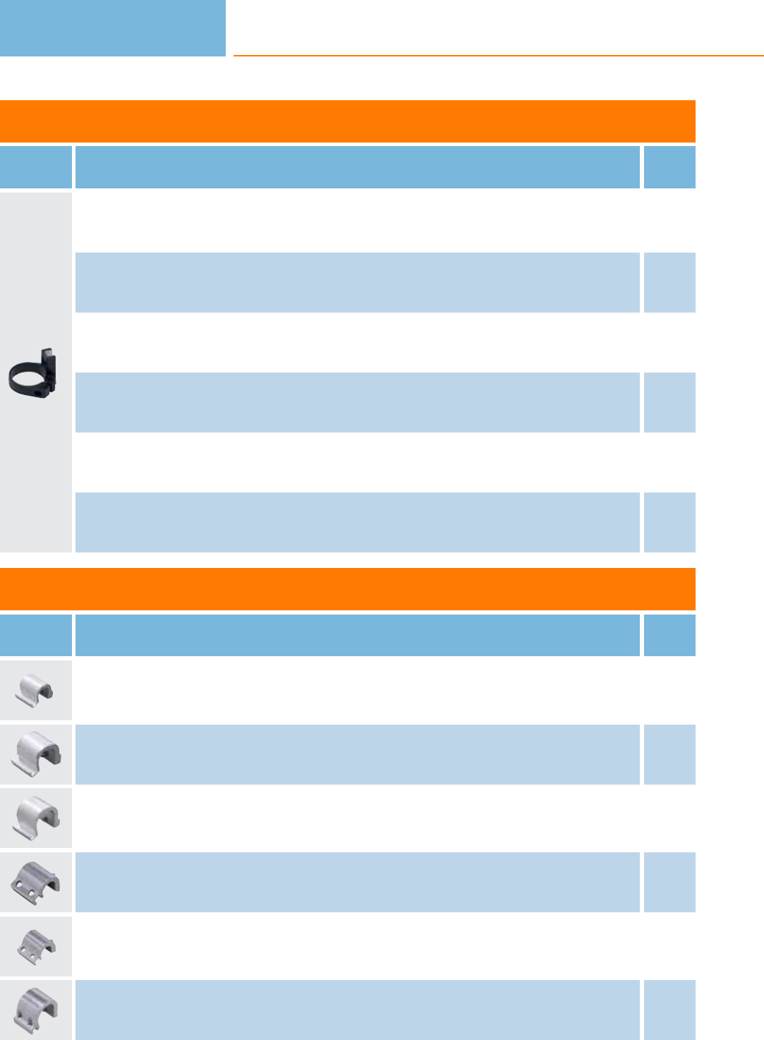
Clips
Type Description Order
no.
Clip · for types MKT (T-slot cylinder sensors) · Piston diameter 12 mm · Housing materials: POM / fixture: aluminium / screw:
stainless steel E11961
Clip · for types MKT (T-slot cylinder sensors) · Piston diameter 16 mm · Housing materials: POM / fixture: aluminium / screw:
stainless steel E11958
Clip · for types MKT (T-slot cylinder sensors) · Piston diameter 20 mm · Housing materials: POM / fixture: aluminium / screw:
stainless steel E11959
Clip · for types MKT and MKI (T-slot cylinder sensors) · Piston diameter 25 mm · Housing materials: POM / fixture: aluminium / screw:
stainless steel E11960
Clip · for types MKT (T-slot cylinder sensors) · Clamping range 44-45 mm · Piston diameter 40 mm · Housing materials: POM /
fixture: aluminium / screw: stainless steel E12015
Clip · for types MKT (T-slot cylinder sensors) · Clamping range 35-36 mm · Piston diameter 32 mm · Housing materials: POM /
fixture: aluminium / screw: stainless steel E12017
Adapters for tie rod and integrated profile
Type Description Order
no.
Adapter for tie rod / integrated profile cylinders · for types MKT (T-slot cylinder sensors) · Clamping range 5...11 mm · Housing
materials: aluminium / screw: stainless steel E11797
Adapter for tie rod / integrated profile cylinders · for types MKT (T-slot cylinder sensors) · Clamping range 9...15 mm · Housing
materials: aluminium / screw: stainless steel E11799
Adapter for tie rod / integrated profile cylinders · for types MKT (T-slot cylinder sensors) · Clamping range 14...20 mm · Housing
materials: aluminium / screw: stainless steel E11801
Adapter for tie rod / integrated profile cylinders · for types MKT (T-slot cylinder sensors) · Clamping range 5...11 mm · Housing
materials: aluminium / screw: stainless steel E12231
Adapter for tie rod / integrated profile cylinders · for types MKT (T-slot cylinder sensors) · Clamping range 9...13.5 mm · Housing
materials: aluminium / screw: stainless steel E12232
Adapter for tie rod / integrated profile cylinders · for types MKT (T-slot cylinder sensors) · Clamping range 9...17 mm · Housing
materials: aluminium / screw: stainless steel E12233
Cylinder sensors
178
Product selectors and further information can be found at: www.ifm.com
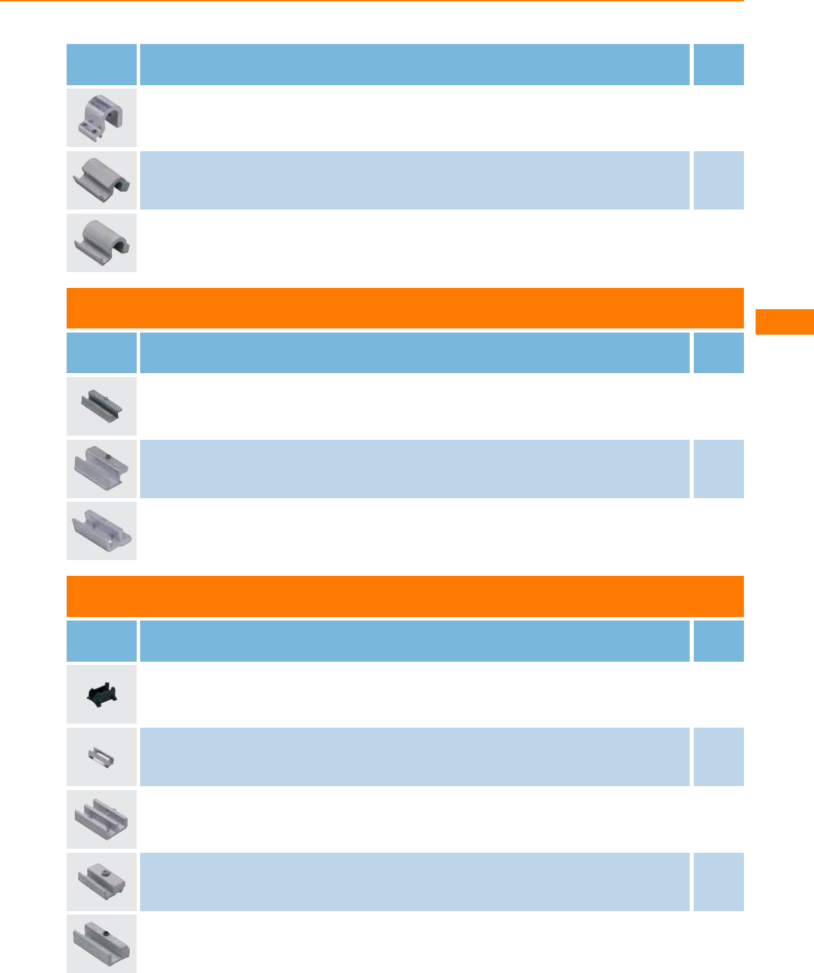
Type Description Order
no.
Adapter for tie rod / integrated profile cylinders · for types MKT (T-slot cylinder sensors) · Clamping range 13...15 mm · Housing
materials: aluminium / screw: stainless steel E12234
Adapter for tie rod cylinders (or cylinders of the same dimensions) · for types MKT (T-slot cylinder sensors) · Clamping range
3...5 mm · Housing materials: aluminium / screw: stainless steel E11913
Adapter for tie rod cylinders (or cylinders of the same dimensions) · for types MKT (T-slot cylinder sensors) · Clamping range
5...7 mm · Housing materials: aluminium / screw: stainless steel E11912
Adapters for trapezoidal slot cylinders
Type Description Order
no.
Adapter for trapezoidal slot cylinders · for types MKT (T-slot cylinder sensors) · Housing materials: aluminium alloy / set screw:
stainless steel E11796
Adapter for trapezoidal slot cylinders · for types MKT (T-slot cylinder sensors) · Housing materials: aluminium alloy / set screw:
stainless steel E11957
Adapter for trapezoidal slot cylinders · for types MKT (T-slot cylinder sensors) · Housing materials: aluminium alloy / set screw:
stainless steel E11988
Various adapters and memorisation blocks
Type Description Order
no.
Adapter for clean-line cylinders · for types MKT (T-slot cylinder sensors) · Housing materials: PA · Pack quantity: 10 E11846
Adapter for clean-line cylinders · for types MKT (T-slot cylinder sensors) · Housing materials: stainless steel E11877
Adapter for Bosch Rexroth cylinders ICL series and Festo cylinders type CDN · for types MKT (T-slot cylinder sensors) · Housing
materials: adapter: aluminium anodised / screw: stainless steel E12164
Adapter for Bosch-Rexroth cylinders PRA / PRB series (or cylinders of the same dimensions) · for types MKT (T-slot cylinder sensors) ·
Housing materials: aluminium / screw: stainless steel E11892
Adapter for Bosch-Rexroth cylinders 523 series (or cylinders of the same dimensions) · for types MKT (T-slot cylinder sensors) · L-slot ·
Housing materials: aluminium / screw: stainless steel E11894
Cylinder sensors
179
You can find wiring diagrams and scale drawings from page 180
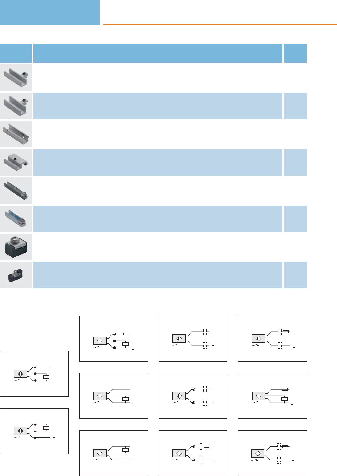
Type Description Order
no.
Adapter for SMC cylinders ECDQ2 series (or cylinders of the same dimensions) · for types MKT (T-slot cylinder sensors) · T-slot rail,
flat · Housing materials: aluminium / screw: stainless steel E11890
Adapter for SMC cylinders CDQ2 series (or cylinders of the same dimensions) · for types MKT (T-slot cylinder sensors) · T-slot rail,
high · Housing materials: aluminium / screw: stainless steel E11891
Adapter for SMC cylinder CP95 · for types MKT (T-slot cylinder sensors) · Housing materials: stainless steel E11872
Adapter for Festo cylinders type DZH (or cylinders of the same dimensions) · for types MKT (T-slot cylinder sensors) · Housing
materials: aluminium / screw: stainless steel E11895
T-slot adapter for C-slot sensor · for types MKC (C-slot cylinder sensor) for installation in T-slot cylinders · (height 5 mm) · Housing
materials: diecast zinc / fixing element: stainless steel E11928
T-slot adapter for C-slot sensor · for types MKC (C-slot cylinder sensor) for installation in T-slot cylinders · (height 7.7 mm) · Housing
materials: diecast zinc / fixing element: stainless steel E11914
T-slot cylinder memorisation block · for types MKT (T-slot cylinder sensors) · Housing materials: PA / stainless steel E11798
C-slot cylinder memorisation block · for types MKC (C-slot cylinder sensors) · Housing materials: PA / stainless steel E12004
Core colours
BK black
BN brown
BU blue
Wiring diagrams
1
L+
L
1
4
3
2
L+
L
1
4
3
3
1
4
3
L1
L+
L
N
4
BN
BK
BU
L+
L
5
L
BN
BK
BU
L+
6
L
BN
BU
L+
7
L+
L
1
4
8
N
L1
1
4
L+
L
9
N
L1
BN
BU
L+
L
10
BN
BU
BK
L1
L+
L
N
11
L
L+
BN
BU
Cylinder sensors
180
Product selectors and further information can be found at: www.ifm.com
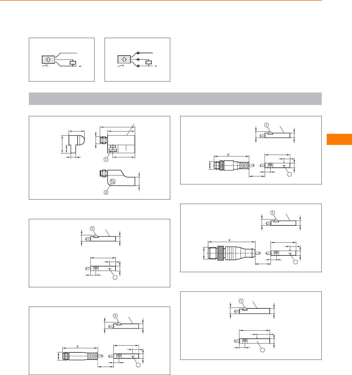
Wiring diagrams
12
BN
BK
BU
L+
L
13
L+
L
1
4
3
Scale drawings / drawing no. – CAD download: www.ifm.com
1
15,5
5
8
18
M8x1
27,5
35
22
8,5
LED
1: fixing element, 2: combined head screw for fixing element
2
5
2
6,2
5,7
25,3
5,1
6,5
LED
1: Fastening clamp, 2: sensing face
3
L
M8x1
37
5
2
6,2
5,7
25,3
5,1
6,5
LED
1: Fastening clamp, 2: sensing face
4
L
5
2
6,2
5,7
25,3
5,1
6,5
LED
M8x1
41,5
1: Fastening clamp, 2: sensing face
5
L
5
2
6,2
5,7
25,3
5,1
6,5
LED
M12 x1
55
1: Fastening clamp, 2: sensing face
6
5
13
5,7
30,5
5,7
6,5
LED
2
1: Fastening clamp, 2: sensing face
Cylinder sensors
181
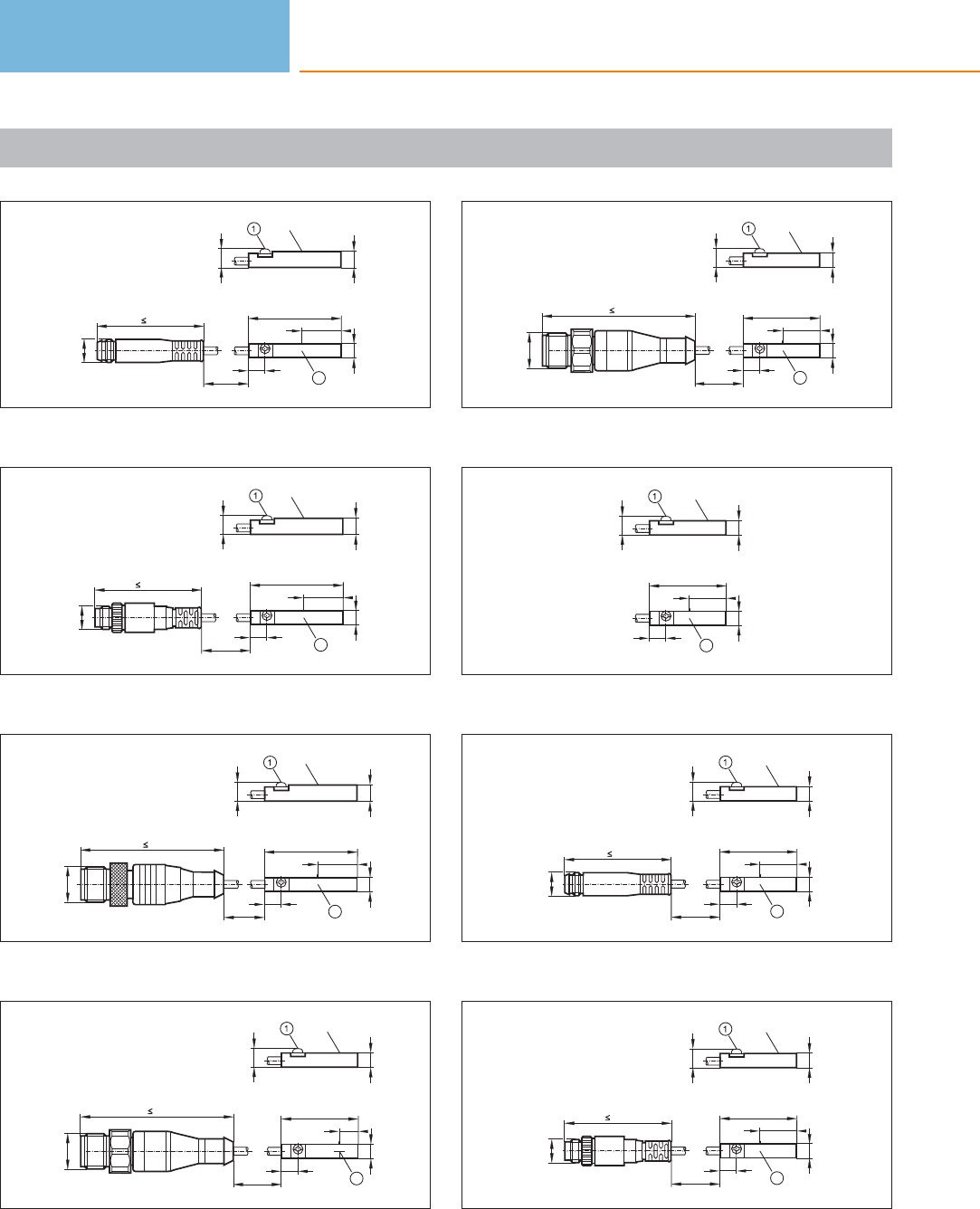
Scale drawings / drawing no. – CAD download: www.ifm.com
7
5
13
5,7
30,5
5,7
6,5
LED
2
L
M8x1
37
1: Fastening clamp, 2: sensing face
8
5
13
5,7
30,5
5,7
6,5
LED
2
M8x1
L
41,5
1: Fastening clamp, 2: sensing face
9
5
13
5,7
30,5
5,7
6,5
LED
2
L
M12 x1
55
1: Fastening clamp, 2: sensing face
10
L
5
2
6,2
5,7
25,3
5,1
6,5
LED
M12 x1
55
1: Fastening clamp, 2: sensing face
11
L
M12 x1
55
5
12
5,7
25,3
5,1
6,5
LED
2
1: Fastening clamp, 2: sensing face
12
5
12
5,7
25,3
5,1
6,5
LED
2
1: Fastening clamp, 2: sensing face
13
L
M8x1
37
5
12
5,7
25,3
5,1
6,5
LED
2
1: Fastening clamp, 2: sensing face
14
L
M8x1
41,5
5
12
5,7
25,3
5,1
6,5
LED
2
1: Fastening clamp, 2: sensing face
Cylinder sensors
182
Product selectors and further information can be found at: www.ifm.com
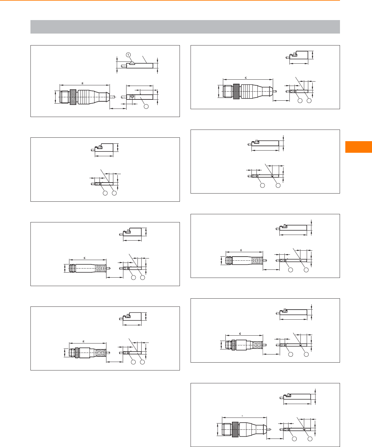
Scale drawings / drawing no. – CAD download: www.ifm.com
15
L
M12 x1
55
5
12
5,7
25,3
5,1
6,5
LED
2
1: Fastening clamp, 2: sensing face
16
17,5
7,7
2,8
4,8
1
4,2
LED
2
1: Fastening clamp, 2: sensing face
17
M8x1
L
37
17,5
7,7
LED
2,8
4,8
12
4,2
1: Fastening clamp, 2: sensing face
18
L
M8x1
41,5
17,5
7,7
LED
2,8
4,8
12
4,2
1: Fastening clamp, 2: sensing face
19
L
M12 x1
55
17,5
7,7
LED
2,8
4,8
12
4,2
1: Fastening clamp, 2: sensing face
20
LED
2,8
4,8
1
25,8
5
6,5
2
1: Fastening clamp, 2: sensing face
21
M8x1
L
37
LED
2,8
4,8
1
25,8
5
6,5
2
1: Fastening clamp, 2: sensing face
22
L
M8x1
41,5 LED
2,8
4,8
1
25,8
5
6,5
2
1: Fastening clamp, 2: sensing face
23
L
M12 x1
LED
2,8
4,8
1
25,8
5
6,5
2
40
1: Fastening clamp, 2: sensing face
Cylinder sensors
183
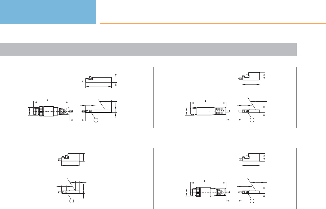
Scale drawings / drawing no. – CAD download: www.ifm.com
24
L
M8x1
41,5 LED
2,8
4,8
1
26,1
5,5
6,5
1: Fastening clamp
25
17,5
7,7
2,8
4,8
1
4,2
LED
1: Fastening clamp
26
M8x1
L
37
17,5
7,7
LED
2,8
4,8
1
4,2
1: Fastening clamp
27
L
M8x1
41,5
17,5
7,7
LED
2,8
4,8
1
4,2
1: Fastening clamp
Cylinder sensors
184
Product selectors and further information can be found at: www.ifm.com

Cylinder sensors
185
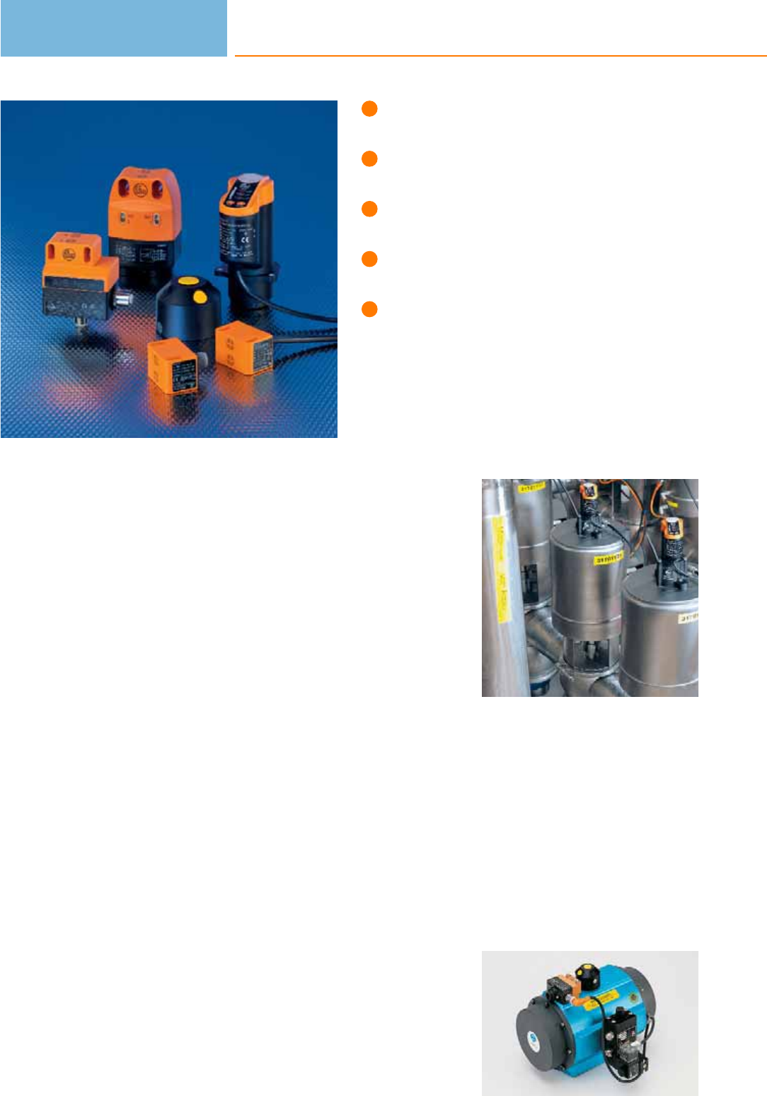
Dual inductive feedback sensors for
valves and actuators.
Straightforward fit to standard actuators
based on VDI / VDE 3845.
AS-i dual sensor for quick and safe
installation due to “plug & play”.
Compact, weatherproof and
low maintenance.
Also available as complete set including
all the accessories for a valve.
Valve sensors
In industrial processes where liquids, air or gases are used valves are needed for
dosing and control. There is a wide variety of valve types; butterfly or ball valves
being the most common quarter-turn types.
These valves are seldom operated manually. Pneumatic valve actuators are normally
used for mechanical positioning. The valve position must be monitored electronical-
ly. On the one hand to provide a feedback to the controller when a certain position
(e.g. “open” or “closed”) is reached. On the other hand it is necessary to monitor
the valves centrally.
Mechanical switches are still often used for position feedback on the actuator shaft.
For other solutions several inductive sensors are used together with a switch target
for position detection. Disadvantage: Mounting is mechanically complex. Where
there are temperature fluctuations condensing humidity leads to corrosion and thus
malfunction.
Operating principle
An innovative design eliminates the disadvantages of these conventional solutions.
In 1992 ifm electronic developed a standard which is now used by many leading
actuator manufacturers. A round switch target, known as a “puck”, with two metal
screws offset by 90° is mounted on the actuator shaft. The screws are located at a
different height. A compact dual inductive sensor (type IND) with two integral sen-
sors detects the upper or lower metal screw depending on the valve position and
thus the two switch positions.
Advantages
Due to the simple construction the system operates safely with no wear at all. It is
virtually resistant to external influence and meets the protection rating IP 67. Under
certain conditions the unit can even be self-cleaning. Compared to conventional
solutions the sensor weight is low. The sensors are also resistant to mechanical
stress such as vibration and shock.
Feedback: Monitoring
of pneumatic and
manual valves must
be possible.
Valve sensors
186

System overview Page
Sensors for industrial applications 188 - 189
Sensors for industrial applications, AS-i system 189
Sensors with ATEX approval 1G/2G and 1D 190
Sensors with ATEX approval 3D and / or 3G 190 - 191
Sensors for rising stem valves 191 - 192
Sensors for rising stem valves, AS-i system 192
Added value packages with Bürkert solenoid valve 192
Added value packages with Norgren Herion solenoid valve 192
Switching cams for sensors with quarter-turn actuators 193 - 194
Accessories for sensors with quarter-turn actuators 194 - 195
Accessories for sensors with rising stem valve 195
Wiring diagrams 196
Scale drawings / drawing no. – CAD download: www.ifm.com 196
Valve sensors
187
Sensors for industrial applications
Type Dimensions
[mm]
Sensing
range
[mm]
Material Ub
[V]
Protection f
AC / DC
[Hz]
Iload
AC / DC
[mA]
Draw-
ing
no.
Order
no.
Cable 2 m · Output function · DC PNP · Wiring diagram no. 1
40 x 26 x 26 4 nf PBT 10...36 IP 67 1300 250 1 IN5251
Cable 6 m · Output function · DC PNP · Wiring diagram no. 1
40 x 26 x 26 4 nf PC (polycarbonate) 10...36 IP 67 1300 250 1IN5304
Cable 10 m · Output function · DC PNP · Wiring diagram no. 1
40 x 26 x 26 4 nf PBT 10...36 IP 67 1300 250 1 IN5323
Cable 2 m · Output function · AC/DC · Wiring diagram no. 2
40 x 26 x 40 4 nf PBT 20...250 IP 67 25 / 50 350 / 100 2IN0110*
M12 connector · Output function · DC PNP/NPN · Wiring diagram no. 13 · Connector groups 9, 11, 107, 108, 135
40 x 26 x 26 4 nf PBT 10...36 IP 67 1300 250 3 IN5224
M12 connector · Output function · DC PNP/NPN · Wiring diagram no. 3 · Connector groups 9, 11, 107, 108, 135
40 x 26 x 47 4 nf PBT 10...36 IP 67 250 250 4IN5331
M12 connector · Output function · DC PNP · Wiring diagram no. 4 · Connector groups 9, 11, 12, 107, 108, 109, 135, 136
40 x 26 x 26 4 nf PBT 10...36 IP 67 1300 250 3 IN5225
40 x 26 x 47 4 nf PBT 10...36 IP 67 1300 250 4IN5327
M18 connector · Output function · DC PNP · Wiring diagram no. 4 · Connector group 21
40 x 26 x 26 4 nf PBT 10...36 IP 67 1300 250 5 IN5285
Valve sensors
188
Product selectors and further information can be found at: www.ifm.com
Type Dimensions
[mm]
Sensing
range
[mm]
Material Ub
[V]
Protection f
AC / DC
[Hz]
Iload
AC / DC
[mA]
Draw-
ing
no.
Order
no.
M18 connector · Output function · AC/DC · Wiring diagram no. 5 · Connector group 21
40 x 26 x 40 4 nf PBT 20...250 IP 67 25 / 50 350 / 100 6 IN0108*
Rd 24 x 1/8 connector 6 pins · Output function · DC PNP · Connector groups 31, 38
40 x 26 x 60 4 nf PBT 10...36 IP 67 1300 250 7IN5334
Terminals · Output function · DC PNP · Wiring diagram no. 14
33 x 60 x 92 4 nf PA (polyamide) 10...30 IP 67 500 100 8 IN5409
f = flush / nf = non flush
* Note for AC and AC/DC units
Miniature fuse to IEC60127-2 sheet 1, ≤ 2 A (fast acting). Recommendation: check the unit for reliable function after a short
circuit.
Sensors for industrial applications, AS-i system
Type Dimensions
[mm]
Sensing
range
[mm]
Material Ub
[V]
Protection f
AC / DC
[Hz]
Iload
AC / DC
[mA]
Draw-
ing
no.
Order
no.
M12 connector · 1 x 2 inputs · Wiring diagram no. 6 · Connector groups 11, 13, 14, 107, 113, 115, 135, 137
55 x 60 x 35 4 nf PBT (Pocan) 26.5...31.6 IP 67 – – 9 AC2315
M12 connector · Output function transistor PNP · 2 inputs / 1 output · Connector groups 9, 11, 38, 108, 116
55 x 60 x 35 4 nf PBT (Pocan) 26.5...31.6 IP 67 – – 10 AC2316
M12 connector · Output function transistor PNP · 2 inputs / 2 outputs · Connector groups 9, 11, 38, 108, 116
55 x 60 x 35 4 nf PBT (Pocan) 26.5...31.6 IP 67 – – 10 AC2317
f = flush / nf = non flush
Valve sensors
189
You can find wiring diagrams and scale drawings from page 196
Sensors with ATEX approval 1G/2G and 1D
Type Dimensions
[mm]
Sensing
range
[mm]
Material Unom.
at 1 KΩ
[V]
Ub
[V]
Internal
capacit.
[nF]
Internal
inductance
[μH]
f
[Hz]
Draw-
ing
no.
Order
no.
M12 connector · Output function 2 x normally closed · Connection to certified intrinsically safe circuits with the max. values
U = 15 V / I = 50 mA / P = 120 mW · Wiring diagram no. 7 · Connector group 131
40 x 26 x 26 4 nf PBT 8.2 DC 7.5...15 DC 140 130 1800 11 NN5008
Cable 2 m · Output function 2 x normally closed · Connection to certified intrinsically safe circuits with the max. values
U = 15 V / I = 50 mA / P = 120 mW · Wiring diagram no. 8
40 x 26 x 26 4 nf PBT 8.2 DC 7.5...15 DC 140 130 1800 1NN5009
Cable 10 m · Output function 2 x normally closed · Connection to certified intrinsically safe circuits with the max. values
U = 15 V / I = 50 mA / P = 120 mW · Wiring diagram no. 8
40 x 26 x 26 4 nf PBT 8.2 DC 7.5...15 DC 140 140 1800 1 NN5011
M18 connector · Output function 2 x normally closed · Connection to certified intrinsically safe circuits with the max. values
U = 15 V / I = 50 mA / P = 120 mW · Wiring diagram no. 9 · Connector group 21
40 x 26 x 26 4 nf PBT 8.2 DC 7.5...15 DC 140 130 1800 5NN5013
Rd 24 x 1/8 connector 6 pins · Output function 2 x normally closed · Connection to certified intrinsically safe circuits with the
max. values U = 15 V / I = 50 mA / P = 120 mW · Connector groups 31, 61
40 x 26 x 60 4 nf PBT 8.2 DC – 150 150 250 7 N95001
40 x 26 x 60 4 nf PBT 8.2 DC –100 150 1300 7N95002
f = flush / nf = non flush
Sensors with ATEX approval 3D and / or 3G
Type Dimensions
[mm]
Sensing
range
[mm]
Material Ub
[V]
Protection f
AC / DC
[Hz]
Iload
AC / DC
[mA]
Draw-
ing
no.
Order
no.
M12 connector · Output function transistor PNP · 2 inputs / 2 outputs · Connector groups 132, 134
55 x 60 x 35 4 nf PBT (Pocan) 26.5...31.6 IP5X – – 10 AC317A
M12 connector · Output function transistor PNP · 2 inputs / 1 output · Connector groups 132, 134
55 x 60 x 35 4 nf PBT (Pocan) 26.5...31.6 IP5X – – 10 AC316A
Valve sensors
190
Product selectors and further information can be found at: www.ifm.com
Type Dimensions
[mm]
Sensing
range
[mm]
Material Ub
[V]
Protection f
AC / DC
[Hz]
Iload
AC / DC
[mA]
Draw-
ing
no.
Order
no.
M12 connector · Output function transistor PNP · 2 inputs / 1 output · Connector groups 132, 134
55 x 60 x 35 4 PBT (Pocan) 26.5...31.6 IP 67 – – 12 AC326A
M12 connector · 1 x 2 inputs · Wiring diagram no. 6 · Connector groups 132, 134
55 x 60 x 35 4 nf PBT (Pocan) 26.5...31.6 IP5X – – 9 AC315A
M12 connector · Output function · DC PNP · Wiring diagram no. 4 · Connector groups 132, 134
40 x 26 x 47 4 PBT 10...30 IP 67 1300 100 13 IN507A
Cable 2 m · Output function · DC PNP · Wiring diagram no. 1
40 x 26 x 26 4 nf PBT (Pocan) 10...30 IP 67 1300 100 1IN508A
M12 connector · Output function · DC PNP · Wiring diagram no. 4 · Connector groups 132, 134
40 x 26 x 47 4 nf PBT (Pocan) 10...30 IP 67 1300 100 4 IN509A
f = flush / nf = non flush
Sensors for rising stem valves
Type Dimensions
[mm]
Sensing
range
[mm]
Material Ub
[V]
Protection f
AC / DC
[Hz]
Iload
AC / DC
[mA]
Draw-
ing
no.
Order
no.
Cable 2 m · Output function 1...5 V analogue · DC · Wiring diagram no. 10
67.5 x 43 x 110 0...80 PA 18...36 IP 65 / IP 67 – – 14 IX5002
Cable 2 m · Output function 3 x normally open · DC PNP · Wiring diagram no. 11
67.5 x 43 x 110 0...80 PA 18...36 IP 65 / IP 67 –100 15 IX5006
Cable with connector 0.3 m · Output function 3 x normally open · DC PNP · Wiring diagram no. 12 · Connector groups 113, 115, 137
65 x 52 x 110 0...80 PA 18...36 IP 65 / IP 67 – 100 16 IX5010
Valve sensors
191
You can find wiring diagrams and scale drawings from page 196
Type Dimensions
[mm]
Sensing
range
[mm]
Material Ub
[V]
Protection f
AC / DC
[Hz]
Iload
AC / DC
[mA]
Draw-
ing
no.
Order
no.
Cable with connector 0.3 m · Output function 3 x normally open · DC PNP · Wiring diagram no. 12 · Connector groups 113, 115, 137
65 x 43 x 110 0.2 PA 18...36 IP 65 / IP 67 – 100 17 ZZ0214
Sensors for rising stem valves, AS-i system
Type Dimensions
[mm]
Sensing
range
[mm]
Material Ub
[V]
Protection f
AC / DC
[Hz]
Iload
AC / DC
[mA]
Draw-
ing
no.
Order
no.
Cable with connector 0.3 m · AS-i · Wiring diagram no. 6 · Connector groups 11, 13, 14, 107, 113, 115, 135, 137
65 x 52 x 110 0...80 PA 26.5...31.6 IP 65 / IP 67 – – 16 IX5030
Added value packages with Bürkert solenoid valve
Type Description Order
no.
Added value package AS-i for pneumatic quarter-turn actuators · A/B slave · Shaft height 20 mm · Hole spacing 80 mm · Connector AC0017
Added value package AS-i for pneumatic quarter-turn actuators · A/B slave · Shaft height 30 mm · Hole spacing 80 mm · Connector AC0019
Added value package AS-i for pneumatic quarter-turn actuators · A/B slave · Shaft height 30 mm · Hole spacing 130 mm ·
Connector AC0020
Added value packages with Norgren Herion solenoid valve
Type Description Order
no.
Added value package AS-i for pneumatic quarter-turn actuators · A/B slave · Shaft height 20 mm · Hole spacing 80 mm · Connector AC0021
Added value package AS-i for pneumatic quarter-turn actuators · A/B slave · Shaft height 30 mm · Hole spacing 80 mm · Connector AC0022
Added value package AS-i for pneumatic quarter-turn actuators · A/B slave · Shaft height 30 mm · Hole spacing 130 mm ·
Connector AC0023
Valve sensors
192
Product selectors and further information can be found at: www.ifm.com
Switching cams for sensors with quarter-turn actuators
Type Description Order
no.
Target puck · Ø 53 mm · Adjustable between 0° and 360° · Housing materials: Target puck: PVC / screws: high-grade stainless steel E10661
Target puck · Ø 53 mm · 6 possible switching flag positions · with drain holes · Housing materials: Target puck: PA 6 / screws: high-
grade stainless steel E17105
Target puck · Ø 53 mm · Housing materials: Target puck: PBT / screws: high-grade stainless steel E17118
Target puck · Ø 53 mm · 8 possible switching flag positions · with drain holes · Housing materials: Target puck: PA 6 / screws: high-
grade stainless steel E17294
Target puck · Ø 53 mm · 3 possible switching flag positions · Housing materials: Target puck: PA 6 black / screws: V2A E17320
Target puck · Ø 53 mm · 8 possible switching flag positions · Housing materials: Target puck: PA 6 black / screws: V2A E17321
Target puck · Ø 53 mm · Housing colour: blue · 8 possible switching flag positions · Housing materials: Target puck: PA 6 blue /
screws: V2A E17322
Target puck · Ø 53 mm · Housing colour: red · 8 possible switching flag positions · Housing materials: Target puck: PA 6 / screws:
V2A E17323
Target puck · Ø 55 mm · Inverted function · Housing materials: Target puck: PVC / screws: high-grade stainless steel / Metal ring:
stainless steel E17205
Target puck · Ø 59 mm · for Neles actuator type B1CU 6/20E · Housing materials: Target puck: POM E11278
Target puck · Ø 65 mm · Housing materials: Target puck: PVC / screws: high-grade stainless steel E17148
Target puck · Ø 65 mm · Housing colour: black · 8 possible switching flag positions · Housing materials: Target puck: PA 6 / screws:
V2A E17324
Target puck · Ø 65 mm · Housing colour: blue · 8 possible switching flag positions · Housing materials: Target puck: PA 6 / screws:
V2A E17325
Target puck · Ø 65 mm · Housing colour: red · 8 possible switching flag positions · Housing materials: Target puck: PA 6 / screws:
V2A E17326
Valve sensors
193
You can find wiring diagrams and scale drawings from page 196
Type Description Order
no.
Target puck · Ø 65 mm · Housing materials: Target puck: PA 6 / screws: V2A E17327
Target puck · Ø 102 · Housing materials: Target puck: PA 6 / screws: V2A E17328
Target puck · Ø 102 · Housing colour: black · 8 possible switching flag positions · Housing materials: Target puck: PA 6 / screws: V2A E17329
Target puck · Ø 102 · Housing colour: blue · 8 possible switching flag positions · Housing materials: Target puck: PA 6 / screws: V2A E17330
Target puck · Ø 102 · Housing colour: red · 8 possible switching flag positions · Housing materials: Target puck: PA 6 / screws: V2A E17331
direction indicator black · 12 x 4.8 · For target puck · Housing materials: POM E17295
direction indicator yellow · 12 x 4.8 · For target puck · Housing materials: POM E17296
Accessories for sensors with quarter-turn actuators
Type Description Order
no.
Spacer · 10 mm · for compensation between target pucks and dual sensor IND · Housing materials: PBT E10579
Spacer · 3 mm · for compensation between target pucks and dual sensor IND · Housing materials: PBT E10584
Spacer · 5 mm · for compensation between target pucks and dual sensor IND · Housing materials: PBT E10585
Cable gland · M20 x 1.5 · Housing materials: PA 6.6 E12208
Protective cap · M20 x 1.5 · Housing materials: PA 6.6 E12209
Plug for covering the oblong holes · Housing materials: EPDM · Pack quantity: 10 E12212
Valve sensors
194
Product selectors and further information can be found at: www.ifm.com
Type Description Order
no.
reinforcement bracket · for type IND · Housing materials: stainless steel 316Ti / 1.4571 E11310
protective housing · Accessory for valve sensors · for type IND · Housing materials: stainless steel E11984
Mounting kit · MS-MEC-KU-RA—F04A · for ball valve Mecafrance ISO5211/F04 DN25 PN40 · Detection of the “ON/OFF” position by
means of the IND dual sensor E10597
Mounting kit for limit position feedback · tyco 792E-100 · for Keystone actuators E11243
Accessories for sensors with rising stem valve
Type Description Order
no.
Mounting adapter · for Kieselmann seat valves · accessory for IX · Housing materials: adapter: PA / Target: stainless steel 1.4404 E12123
Mounting adapter · for Alfa Laval valves · accessory for IX · Housing materials: adapter: PA / Target: stainless steel 316L / 1.4404 E11900
Mounting adapter · for Südmo valves · accessory for IX · Housing materials: adapter: PA / Target: stainless steel 316L / 1.4404 E11989
Mounting adapter · for Georg Fischer diaphragm valve Diastar with mounting kit M12 · accessory for IX · Housing materials: adapter:
POM / Target: stainless steel E12009
Mounting adapter · for Georg Fischer diaphragm valve Diastar with mounting kit M16 · accessory for IX · Housing materials: adapter:
POM / Target: stainless steel E12010
Mounting adapter · for Bardiani valves · accessory for IX · Housing materials: adapter: PA / Target: stainless steel 1.4404 E12170
Mounting adapter · IX / Ø 30 mm · for Gemü actuators with mounting kit · accessory for IX · Housing materials: adapter: POM /
Target: stainless steel E12042
Mounting adapter · IX / Ø 45 mm · for Gemü actuators with mounting kit · accessory for IX · Housing materials: adapter: POM /
Target: stainless steel E12043
Valve sensors
195
You can find wiring diagrams and scale drawings from page 196
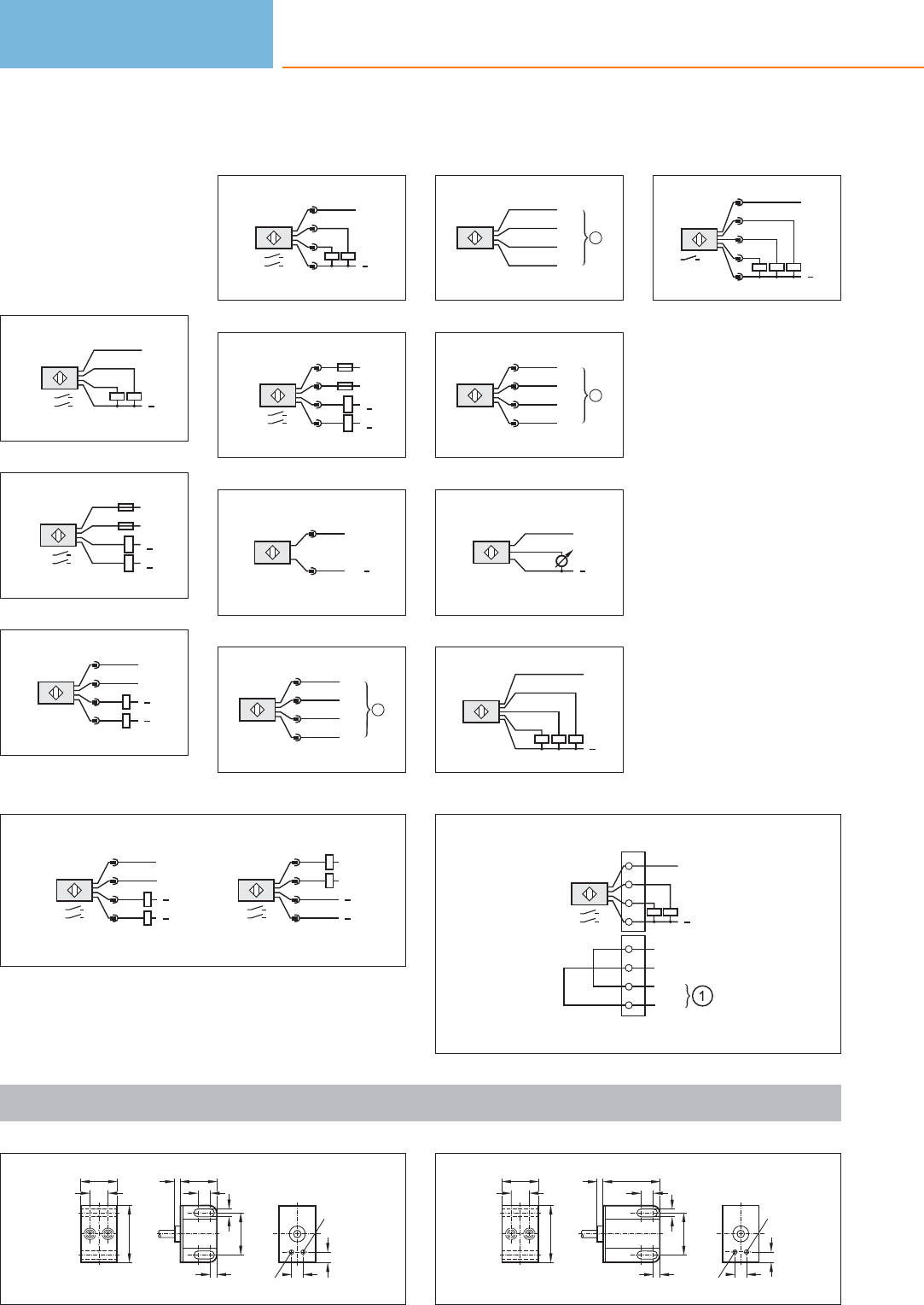
Core colours
BN brown
BU blue
BK black
WH white
GY grey
Wiring diagrams
1
L
L+
BK
WH
BN
BU
WH:
BK: A1
A2
2
BN
BU
L+
L1
L
N
WH
L+
L1
BK
L
N
BU:
BK: A1
A2
3
L
L+
L+
L
2 WH
1 BN
4 BK
3 BU
4
L
L+
3 BU
2 WH
4 BK
1 BN
2:
4: A1
A2
5
L+
L1
L
N
L+
L1
L
N
1
2
4
3
A1
A2
1+4
2+3
6
AS-i+
1
3
AS-i
7
Out 1
3 BU
2 WH
4 BK
1 BN L+ 1
L+ 2
Out 2
1
8
Out 1
BK
BU
WH
BN L+ 1
L+ 2
Out 2 1
9
Out 2
4 BK
2 BU
3 WH
1 BN L+ 1
L+ 2
Out 1
1
10
BN
BK
BU
L+
L
11
GY
WH
BK
BN
BU L
L+
12
L+
L
1
5
4
2
3
13
L
L+
L+
L
2:
1: A1
A2
2 WH
1 BN
4 BK
3 BU
L
L+
L+
L
3:
4: A1
A2
2 WH
1 BN
4 BK
3 BU
NPN
PNP
14
L
L+
2
4
1
3
4:
2: A2
A1
6
7
8
5
IN +
IN -
OUT +
OUT -
Scale drawings / drawing no. – CAD download: www.ifm.com
1
40
26
13
9
LED
A1
A2
6,5
LED
8,5
426
4,5
5,5
30
2
40
26
13
9
LED
A1
A2
6,5
LED
8,5
440
4,5
5,5
30
Valve sensors
196
Product selectors and further information can be found at: www.ifm.com
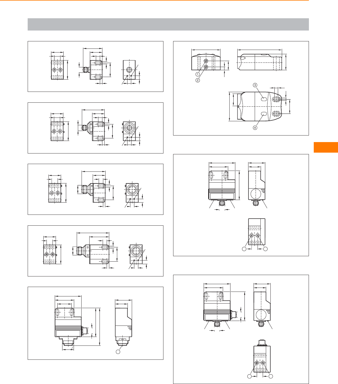
Scale drawings / drawing no. – CAD download: www.ifm.com
3
40
26
13
M12 x1
8,5
26
4,5
5,5
30
40
9
LED
A1
A2
6,5
LED
4
40
26
13
9
LED
A1
A2
6,5
LED
8,5
26
4,5
5,5
30
47
M12 x1
5
40
26
13
9
LED
A1
A2
6,5
LED
8,5
26
4,5
5,5
30
49
M18 x1
6
40
26
13
9
LED
A1
A2
6,5
LED
8,5
40
4,5
5,5
30
M18 x1
67
7
M12 x1
40
55
60
Rd 24 x18
78
30 26
35
1
1: field connection
8
33
92
6,3
18,8
60
7,5
5,5
30
60
M20x1,5
1: sensor 1, 2: sensor 2, 3: LED OUT 2, 4: LED OUT 1
9
26
35
LED
M12 x1
40
55
LED
LED
60
13 1
2
1: sensor 1, 2: sensor 2
10
26
35
LED
M12 x1
M12 x1
40
55
LED
LED
60
13 1
2
1: sensor 1, 2: sensor 2
Valve sensors
197
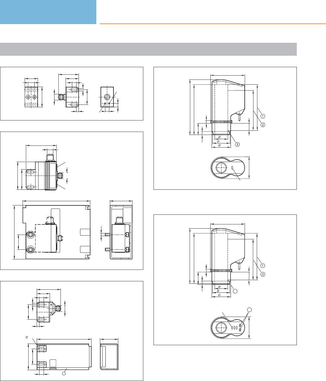
Scale drawings / drawing no. – CAD download: www.ifm.com
11
40
26
13
9
LED
A1
A2
6,5
LED
M12 x1
8,5
26
4,5
5,5
30
40
12
M12 x1
M12 x1
40
55
LED
LED
60
132
105
30
42
M5
13
30
50,7
106 34,6
5,5
8,5 1
M12 x1
8,5
26
4,5
5,5
30
47
1: protective housing
14
6
6,2
25
99,6
110
14
80
87,5
26
34,8
38
43
LED
67,5
1: Max. spindle stroke , 2: Measuring range, 3: Initial value of the
measuring range (zero point)
15
67,5
26
34,8
38
6,2
6
25
14
3
43
3 LED 4
88,6
80
99,6
110
1: Max. spindle stroke , 2: Measuring distance, 3: Initial value of the
measuring range (zero point) , 4: Programming buttons
Valve sensors
198
Product selectors and further information can be found at: www.ifm.com
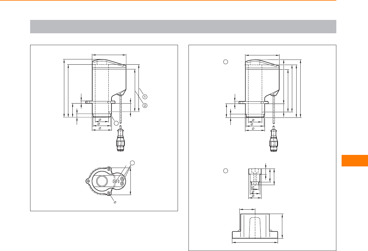
Scale drawings / drawing no. – CAD download: www.ifm.com
16
52
3 LED 4
65
110
99,6
26
80
34,8
38
6,2
4,5
26,5
15,5
3
4,3
88,6
1: Max. spindle stroke , 2: Measuring distance, 3: Initial value of the
measuring range (zero point) , 4: Programming buttons
17
2
25
30,6
14
19
10
24
65
83,5
110
99,6
26
80
88,6
34,8
38
6,2
4,5
26,5
15,5
1
46,5
88
27
1: Valve sensor IX5010, 2: Mounting adapter E11900
Valve sensors
199
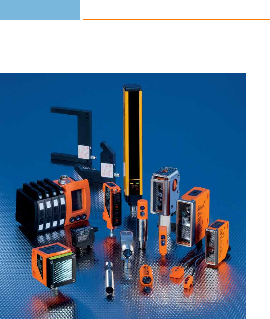
Photoelectric sensors
200

Photoelectric sensors
201
Infrared / red light
sensors
System description / System overview
Product selection chart
Wiring diagrams
Scale drawings / drawing no. – CAD download: www.ifm.com
202 - 203
204 - 233
233 - 234
234 - 245
Laser sensors
System description / System overview
Product selection chart
Wiring diagrams
Scale drawings / drawing no. – CAD download: www.ifm.com
246 - 247
248 - 254
254
255 - 257
Distance detection
System description / System overview
Product selection chart
Wiring diagrams
Scale drawings / drawing no. – CAD download: www.ifm.com
258 - 259
260 - 261
261
261
Fibre optics
System description / System overview
Product selection chart
Wiring diagrams
Scale drawings / drawing no. – CAD download: www.ifm.com
262 - 263
264 - 273
273
274 - 280
For specific systems
System description / System overview
Product selection chart
Wiring diagrams
Scale drawings / drawing no. – CAD download: www.ifm.com
282 - 283
284 - 288
288 - 289
289 - 292
Safety light curtains /
light grids
System description / System overview
Product selection chart
Wiring diagrams
Scale drawings / drawing no. – CAD download: www.ifm.com
294 - 295
296 - 314
314
315 - 318
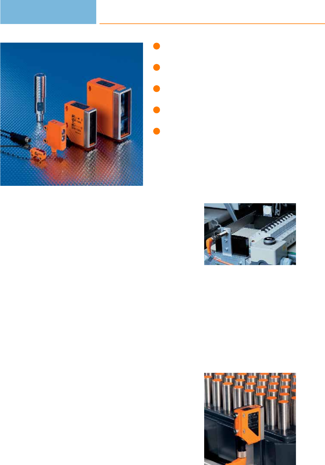
Visible red light for easy adjustment.
Versions for use in hygienic and
wet areas.
LED display to check operation,
switching status and function.
Quick set-up due to easy teaching.
Extensive range of system components
for easy and safe mounting.
Photoelectric sensors
Automation technology can no longer be imagined without photoelectric sensors as
“artificial eyes”. They are used where safe and non-contact detection of the exact
position of objects is required. The material of the objects to be detected is of no
importance. Compared to inductive sensors photoelectric sensors have a much
higher sensing zone.
Through-beam sensors
A through-beam sensor is distinguished by a long range. The system consists of two
separate components: a transmitter and a receiver. The light only travels one way
(from the transmitter to the receiver). Adverse effects in the applications, such as
dust in the air, dirt on the lenses, steam or mist do not immediately interfere with
the system (high excess gain).
Retro-reflective sensors
For a retro-reflective sensor the transmitter and receiver are incorporated into one
housing. By means of a reflector the transmitted light is returned to the receiver.
Diffuse reflection sensors
A diffuse reflection sensor is used for the direct detection of objects. Transmitter
and receiver are incorporated into one housing. The transmitter emits light which
is reflected by the object to be detected and seen by the receiver. This system
evaluates the reflected light of an object.
Therefore additional components (e.g. reflectors for retro-reflective sensors) are not
necessary to operate a diffuse reflection sensor.
Fixing options
ifm electronic offers a complete component system of easy-to-use mounting sets
that make installation easier for you. The solutions consist of a clamp which is
fastened with only one screw, keeps the sensors safely in place and at the same
time guarantees free movement in all axes.
The reflector reflects
the light beam: For a
retro-reflective sensor
transmitter and re-
ceiver are integrated
into one housing.
Artificial eyes: Photo-
electric sensors are
used to detect posi-
tions in automation
technology.
Photoelectric sensors
202

System overview Page
Cylindrical OF housing (M12) BasicLine 204 - 205
Cylindrical housing OG (M18) BasicLine 205 - 208
Cylindrical housing OG (M18) PerformanceLine 208 - 209
Cylindrical housing OG (M18) BasicLine with lateral sensing face 210
Cylindrical housing OG (M18) WetLine for hygienic and wet areas 210 - 212
OG housing (M18), rectangular 212 - 213
Rectangular OH housing BasicLine 213 - 215
Rectangular housing O7 BasicLine 215 - 216
Rectangular housing OJ BasicLine, lateral sensing face 216 - 217
Rectangular housing OJ PerformanceLine, lateral sensing face 217 - 218
Rectangular housing OJ PerformanceLine, front sensing face 219 - 220
Rectangular housing O5 BasicLine 221
Rectangular housing O5 PerformanceLine 221 - 222
Rectangular housing O5 PerformanceLine with ATEX approval 3D 222 - 223
Rectangular OL housing BasicLine 223
Rectangular housing O4 BasicLine 224
Rectangular housing O4 PerformanceLine 224 - 225
Prismatic reflectors, reflective tape and fixing components 225 - 226
Accessories OF housing 227
Accessories OG housing 227
Accessories OH housing 228
Accessories O7 housing 228
Accessories OJ housing 228 - 229
Accessories O5 housing 229 - 230
Accessories OL housing 230 - 231
Accessories O4 housing 231
Accessories for system components 232 - 233
Wiring diagrams 233 - 234
Scale drawings / drawing no. – CAD download: www.ifm.com 234 - 245
Infrared / red light
sensors
203
Cylindrical OF housing (M12) BasicLine
Type Operating principle Range Type
of light
Spot Ø at
max.
range
[mm]
Output
H = light-on
D = dark-on
Wiring
diagr.
no.
Draw-
ing
no.
Order
no.
Through-beam sensor · Cable 2 m · 10...36 DC · metal · IP 67
Transmitter 4 m infrared 700 – 1 1 OF5018
Receiver 4 m infrared –H/D PNP 24 1OF5019
Through-beam sensor · M12 connector · 10...36 DC · metal · IP 65 · Connector groups 9, 11, 107, 108, 135
Transmitter 4 m infrared 700 – 2 2 OF5021
Through-beam sensor · M12 connector · 10...36 DC · metal · IP 65 · Connector groups 9, 10, 11, 107, 108, 110, 135
Receiver 4 m infrared –H/D PNP 25 3OF5022
Retro-reflective sensor · Cable 2 m · 10...36 DC · metal · IP 67
Retro-reflective sensor 0.05...2 m infrared 140 H/D PNP 24 1 OF5014
Polarisation filter 0.2...0.8 m red 70 H/D PNP 24 1OF5024
Retro-reflective sensor 0.05...2 m infrared 140 H/D NPN 26 1 OF5050
Retro-reflective sensor · M12 connector · 10...36 DC · metal · IP 65 · Connector groups 9, 10, 11, 107, 108, 110, 135
Retro-reflective sensor 0.05...2 m infrared 140 H/D PNP 25 3OF5016
Polarisation filter 0.2...0.8 m red 70 H/D PNP 25 3 OF5025
Retro-reflective sensor · M12 connector · 10...36 DC · metal · IP 65 · Connector groups 9, 11, 107, 108, 135
Retro-reflective sensor 0.05...2 m infrared 140 H/D NPN 27 3OF5051
Polarisation filter 0.2...0.8 m red 70 H/D NPN 27 3 OF5062
Photoelectric sensors
204
Product selectors and further information can be found at: www.ifm.com
Type Operating principle Range Type
of light
Spot Ø at
max.
range
[mm]
Output
H = light-on
D = dark-on
Wiring
diagr.
no.
Draw-
ing
no.
Order
no.
Diffuse reflection sensor · Cable 2 m · 10...36 DC · metal · IP 67
Diffuse reflection sensor 1...200 mm infrared 92 H/D PNP 24 1 OF5010
Diffuse reflection sensor 1...200 mm infrared 92 H/D NPN 28 1OF5048
Diffuse reflection sensor 1...400 mm infrared 185 H/D PNP 24 1 OF5026
Diffuse reflection sensor · Cable 6 m · 10...36 DC · high-grade stainless steel · IP 67
Diffuse reflection sensor 1...200 mm infrared 92 H/D PNP 24 1OF5032
Diffuse reflection sensor · M12 connector · 10...36 DC · metal · IP 65 · Connector groups 9, 10, 11, 107, 108, 110, 135
Diffuse reflection sensor 1...200 mm infrared 92 H/D PNP 25 3 OF5012
Diffuse reflection sensor 1...400 mm infrared 185 H/D PNP 25 3OF5027
Diffuse reflection sensor · M12 connector · 10...36 DC · metal · IP 65 · Connector groups 9, 11, 107, 108, 135
Diffuse reflection sensor 1...200 mm infrared 92 H/D NPN 29 3 OF5049
Diffuse reflection sensor 1...400 mm infrared 185 H/D NPN 29 3OF5060
Cylindrical housing OG (M18) BasicLine
Type Operating principle Range Type
of light
Spot Ø at
max.
range
[mm]
Output
H = light-on
D = dark-on
Wiring
diagr.
no.
Draw-
ing
no.
Order
no.
Through-beam sensor · M12 connector · 10...30 DC · plastics · IP 67 · Connector groups 9, 11, 107, 108, 135
Transmitter 8 m red 600 – 2 4 OGS100
Through-beam sensor · M12 connector · 10...30 DC · plastics · IP 67 · Connector groups 9, 10, 11, 12, 107, 108, 109, 110, 135, 136
Receiver 8 m red –D PNP 3 4 OGE100
Infrared / red light
sensors
205
You can find wiring diagrams and scale drawings from page 233
Type Operating principle Range Type
of light
Spot Ø at
max.
range
[mm]
Output
H = light-on
D = dark-on
Wiring
diagr.
no.
Draw-
ing
no.
Order
no.
Through-beam sensor · M12 connector · 10...30 DC · plastics · IP 67 · Connector groups 9, 10, 11, 12, 107, 108, 109, 110, 135, 136
Receiver 8 m red – H PNP 4 4 OGE101
Receiver 8 m red –D NPN 5 4 OGE102
Receiver 8 m red – H NPN 5 4 OGE103
Through-beam sensor · M12 connector · 10...36 DC · high-grade stainless steel · IP 67 · Connector groups 9, 11, 107, 108, 135
Transmitter 20 m red 800 – 2 5 OGS200
Through-beam sensor · M12 connector · 10...36 DC · high-grade stainless steel · IP 67 · Connector groups 9, 10, 11, 12, 107, 108,
109, 110, 135, 136
Receiver 20 m red – D PNP 3 5 OGE200
Receiver 20 m red –H PNP 4 5 OGE201
Through-beam sensor · Cable 2 m · 20...250 AC/DC (47...63 Hz AC) · plastics · IP 67
Transmitter 15 m infrared 2000 – 6 6 OG0028
Receiver 15 m infrared –H AC/DC 7 6 OG0029
Receiver 15 m infrared – D AC/DC 7 6 OG0038
Through-beam sensor · 1/2“ connector · 20...250 AC/DC (47...63 Hz AC) · plastics · IP 67 · Connector group 26
Transmitter 15 m infrared 2000 – 8 7 OG0030
Receiver 15 m infrared – H AC/DC 9 7 OG0031
Receiver 15 m infrared –D AC/DC 9 7 OG0039
Retro-reflective sensor · M12 connector · 10...30 DC · plastics · IP 67 · Connector groups 9, 10, 11, 12, 107, 108, 109, 110, 135, 136
Polarisation filter 0.05...2.5 m red 200 D PNP 3 4 OGP100
Photoelectric sensors
206
Product selectors and further information can be found at: www.ifm.com
Type Operating principle Range Type
of light
Spot Ø at
max.
range
[mm]
Output
H = light-on
D = dark-on
Wiring
diagr.
no.
Draw-
ing
no.
Order
no.
Retro-reflective sensor · M12 connector · 10...30 DC · plastics · IP 67 · Connector groups 9, 10, 11, 12, 107, 108, 109, 110, 135, 136
Polarisation filter 0.05...2.5 m red 200 H PNP 4 4 OGP101
Polarisation filter 0.05...2.5 m red 200 D NPN 5 4 OGP102
Polarisation filter 0.05...2.5 m red 200 H NPN 5 4 OGP103
Retro-reflective sensor · M12 connector · 10...36 DC · high-grade stainless steel · IP 67 · Connector groups 9, 10, 11, 12, 107, 108,
109, 110, 135, 136
Polarisation filter 0.03...4 m red 160 D PNP 3 5 OGP200
Polarisation filter 0.03...4 m red 160 H PNP 4 5 OGP201
Retro-reflective sensor · Cable 2 m · 20...250 AC/DC (47...63 Hz AC) · plastics · IP 67
Polarisation filter 3 m red 262 H AC/DC 7 6 OG0043
Polarisation filter 3 m red 262 D AC/DC 7 6 OG0032
Retro-reflective sensor · 1/2“ connector · 20...250 AC/DC (47...63 Hz AC) · plastics · IP 67 · Connector group 26
Polarisation filter 3 m red 262 H AC/DC 9 7 OG0044
Polarisation filter 3 m red 262 D AC/DC 9 7 OG0033
Diffuse reflection sensor · M12 connector · 10...30 DC · plastics · IP 65 · Connector groups 9, 10, 11, 12, 107, 108, 109, 110, 135, 136
Diffuse reflection sensor 10...400 mm red 25 H PNP 3 8 OGT100
Diffuse reflection sensor 10...400 mm red 25 D PNP 3 8 OGT101
Diffuse reflection sensor 10...400 mm red 25 H NPN 5 8 OGT102
Diffuse reflection sensor 10...400 mm red 25 D NPN 5 8 OGT103
Infrared / red light
sensors
207
You can find wiring diagrams and scale drawings from page 233
Type Operating principle Range Type
of light
Spot Ø at
max.
range
[mm]
Output
H = light-on
D = dark-on
Wiring
diagr.
no.
Draw-
ing
no.
Order
no.
Diffuse reflection sensor · M12 connector · 10...36 DC · high-grade stainless steel · IP 65 · Connector groups 9, 10, 11, 12, 107, 108,
109, 110, 135, 136
Diffuse reflection sensor 2...600 mm red 50 H PNP 3 9 OGT200
Background suppression 15...250 mm red 15 H PNP 3 9 OGH200
Diffuse reflection sensor · Cable 2 m · 20...250 AC/DC (47...63 Hz AC) · plastics · IP 67
Diffuse reflection sensor 1...600 mm infrared < 169 H AC/DC 7 6 OG0034
Diffuse reflection sensor 1...600 mm infrared < 169 D AC/DC 7 6 OG0040
Diffuse reflection sensor · Cable 0.377 m · 20...250 AC/DC (47...63 Hz AC) · plastics · IP 67
Diffuse reflection sensor 1...600 mm infrared < 169 H AC/DC 7 6 OG0047
Diffuse reflection sensor · 1/2" connector · 20...250 AC/DC (47...63 Hz AC) · plastics · IP 67 · Connector group 26
Diffuse reflection sensor 1...600 mm infrared < 169 H AC/DC 9 7 OG0035
Diffuse reflection sensor 1...600 mm infrared < 169 D AC/DC 9 7 OG0041
* Note for AC and AC/DC units
Miniature fuse to IEC60127-2 sheet 1, ≤ 2 A (fast acting). Recommendation: check the unit for reliable function after a short
circuit.
Cylindrical housing OG (M18) PerformanceLine
Type Operating principle Range Type
of light
Spot Ø at
max.
range
[mm]
Output
H = light-on
D = dark-on
Wiring
diagr.
no.
Draw-
ing
no.
Order
no.
Through-beam sensor · Cable 2 m · 10...36 DC · high-grade stainless steel · IP 67
Transmitter 25 m red 1000 – 1 10 OGS501
Receiver 25 m red –H/D PNP 10 11 OGE502
Photoelectric sensors
208
Product selectors and further information can be found at: www.ifm.com
Type Operating principle Range Type
of light
Spot Ø at
max.
range
[mm]
Output
H = light-on
D = dark-on
Wiring
diagr.
no.
Draw-
ing
no.
Order
no.
Through-beam sensor · M12 connector · 10...36 DC · high-grade stainless steel · IP 67 · Connector groups 9, 11, 107, 108, 135
Transmitter 25 m red 1000 – 2 12 OGS500
Through-beam sensor · M12 connector · 10...36 DC · high-grade stainless steel · IP 67 · Connector groups 9, 10, 11, 12, 107, 108,
109, 110, 135, 136
Receiver 25 m red –H/D PNP 313 OGE500
Retro-reflective sensor · Cable 2 m · 10...36 DC · high-grade stainless steel · IP 67
Polarisation filter 0.03...5 m red 200 H/D PNP 10 11 OGP502
Retro-reflective sensor · M12 connector · 10...36 DC · high-grade stainless steel · IP 67 · Connector groups 9, 10, 11, 12, 107, 108,
109, 110, 135, 136
Polarisation filter 0.03...5 m red 200 H/D PNP 313 OGP500
Retro-reflective sensor · M12 connector · 10...36 DC · high-grade stainless steel · IP 67 · Connector groups 9, 11, 107, 108, 135
Polarisation filter 0.03...5 m red 200 H/D NPN 5 13 OGP503
Diffuse reflection sensor · Cable 2 m · 10...36 DC · high-grade stainless steel · IP 67
Background suppression 15...300 mm red 25 H/D PNP 10 11 OGH501
Diffuse reflection sensor · M12 connector · 10...36 DC · high-grade stainless steel · IP 67 · Connector groups 9, 10, 11, 12, 107, 108,
109, 110, 135, 136
Diffuse reflection sensor 2...800 mm red 66 H/D PNP 3 13 OGT500
Background suppression 15...300 mm red 25 H/D PNP 313 OGH500
Diffuse reflection sensor · M12 connector · 10...36 DC · high-grade stainless steel · IP 67 · Connector groups 9, 11, 107, 108, 135
Background suppression 15...300 mm red 25 H/D NPN 5 13 OGH504
Background suppression 15...300 mm red 25 H/D NPN 513 OGH502
Infrared / red light
sensors
209
You can find wiring diagrams and scale drawings from page 233
Cylindrical housing OG (M18) BasicLine with lateral sensing face
Type Operating principle Range Type
of light
Spot Ø at
max.
range
[mm]
Output
H = light-on
D = dark-on
Wiring
diagr.
no.
Draw-
ing
no.
Order
no.
Through-beam sensor · M12 connector · 10...30 DC · high-grade stainless steel · IP 68 · Connector groups 9, 11, 107, 108, 135
Transmitter 9 m red < 3000 – 2 14 OG5129
Receiver 9 m red –H PNP 11 14 OG5127
Receiver 9 m red – D PNP 12 14 OG5128
Retro-reflective sensor · M12 connector · 10...30 DC · high-grade stainless steel · IP 68 · Connector groups 9, 11, 107, 108, 135
Polarisation filter 3 m red < 96 H PNP 11 14 OG5125
Polarisation filter 3 m red < 96 D PNP 12 14 OG5126
Diffuse reflection sensor · M12 connector · 10...30 DC · high-grade stainless steel · IP 68 · Connector groups 9, 11, 107, 108, 135
Background suppression 100 mm red < 16 H PNP 11 15 OG5123
Diffuse reflection sensor · M12 connector · 10...30 DC · high-grade stainless steel · IP 68 · Connector groups 9, 10, 11, 12, 107, 108,
109, 110, 135, 136
Background suppression 200 mm red < 28 H PNP 11 15 OG5124
Cylindrical housing OG (M18) WetLine for hygienic and wet areas
Type Operating principle Range Type
of light
Spot Ø at
max.
range
[mm]
Output
H = light-on
D = dark-on
Wiring
diagr.
no.
Draw-
ing
no.
Order
no.
Through-beam sensor · Cable 6 m · 10...36 DC · high-grade stainless steel · IP 67 / IP 68 / IP 69K
Transmitter 20 m red 800 – 1 16 OGS301
Receiver 20 m red –D PNP 10 16 OGE302
Receiver 20 m red – H PNP 10 16 OGE303
Photoelectric sensors
210
Product selectors and further information can be found at: www.ifm.com
Type Operating principle Range Type
of light
Spot Ø at
max.
range
[mm]
Output
H = light-on
D = dark-on
Wiring
diagr.
no.
Draw-
ing
no.
Order
no.
Through-beam sensor · M12 connector · 10...36 DC · high-grade stainless steel · IP 67 / IP 68 / IP 69K · Connector group 107
Transmitter 20 m red 800 – 2 5 OGS300
Through-beam sensor · M12 connector · 10...36 DC · high-grade stainless steel · IP 67 / IP 68 / IP 69K · Connector groups 107, 109
Receiver 20 m red –D PNP 3 5 OGE300
Receiver 20 m red – H PNP 4 5 OGE301
Retro-reflective sensor · Cable 6 m · 10...36 DC · high-grade stainless steel · IP 67 / IP 68 / IP 69K
Polarisation filter 0.03...4 m red 160 D PNP 10 16 OGP302
Polarisation filter 0.03...4 m red 160 H PNP 10 16 OGP303
Retro-reflective sensor · M12 connector · 10...36 DC · high-grade stainless steel · IP 67 / IP 68 / IP 69K · Connector groups 107, 109
Polarisation filter 0.03...4 m red 160 D PNP 3 5 OGP300
Polarisation filter 0.03...4 m red 160 H PNP 4 5 OGP301
Diffuse reflection sensor · Cable 6 m · 10...36 DC · high-grade stainless steel · IP 67 / IP 68 / IP 69K
Background suppression 100 mm red 8H PNP 10 17 OGH306
Background suppression 100 mm red 8 D PNP 10 17 OGH307
Background suppression 200 mm red 12 H PNP 10 17 OGH308
Background suppression 200 mm red 12 D PNP 10 17 OGH309
Background suppression 300 mm red 15 H PNP 10 17 OGH310
Background suppression 300 mm red 15 D PNP 10 17 OGH311
Infrared / red light
sensors
211
You can find wiring diagrams and scale drawings from page 233
Type Operating principle Range Type
of light
Spot Ø at
max.
range
[mm]
Output
H = light-on
D = dark-on
Wiring
diagr.
no.
Draw-
ing
no.
Order
no.
Diffuse reflection sensor · M12 connector · 10...36 DC · high-grade stainless steel · IP 67 / IP 68 / IP 69K · Connector groups 107, 109
Background suppression 100 mm red 8 H PNP 3 18 OGH300
Background suppression 100 mm red 8D PNP 318 OGH301
Background suppression 200 mm red 12 H PNP 3 18 OGH302
Background suppression 200 mm red 12 D PNP 318 OGH303
Background suppression 300 mm red 15 H PNP 3 18 OGH304
Background suppression 300 mm red 15 D PNP 318 OGH305
OG housing (M18), rectangular
Type Operating principle Range Type
of light
Spot Ø at
max.
range
[mm]
Output
H = light-on
D = dark-on
Wiring
diagr.
no.
Draw-
ing
no.
Order
no.
Through-beam sensor · M12 connector · 10...30 DC · high-grade stainless steel · IP 67 · Connector groups 9, 11, 107, 108, 135
Transmitter 20 m red 800 – 2 19 OGS280
Receiver 20 m red –D NPN 13 19 OGE282
Through-beam sensor · M12 connector · 10...30 DC · high-grade stainless steel · IP 67 · Connector groups 9, 10, 11, 12, 107, 108,
109, 110, 135, 136
Receiver 20 m red – D PNP 14 19 OGE280
Receiver 20 m red –H PNP 419 OGE281
Retro-reflective sensor · M12 connector · 10...30 DC · metal · IP 67 · Connector groups 9, 10, 11, 12, 107, 108, 109, 110, 135, 136
Polarisation filter 0.1...4 m red 160 D PNP 14 19 OGP280
Polarisation filter 0.1...4 m red 160 H PNP 419 OGP281
Photoelectric sensors
212
Product selectors and further information can be found at: www.ifm.com
Type Operating principle Range Type
of light
Spot Ø at
max.
range
[mm]
Output
H = light-on
D = dark-on
Wiring
diagr.
no.
Draw-
ing
no.
Order
no.
Retro-reflective sensor · M12 connector · 10...30 DC · metal · IP 67 · Connector groups 9, 11, 107, 108, 135
Polarisation filter 0.1...4 m red 160 D NPN 13 19 OGP282
Polarisation filter 0.1...4 m red 160 H NPN 15 19 OGP283
Diffuse reflection sensor · M12 connector · 10...30 DC · metal · IP 67 · Connector groups 9, 10, 11, 12, 107, 108, 109, 110, 135, 136
Background suppression 100 mm red 7 H PNP 4 19 OGH280
Background suppression 200 mm red 13 H PNP 419 OGH281
Background suppression 15...200 mm red 13 H/D PNP 3 20 OGH580
Diffuse reflection sensor · M12 connector · 10...30 DC · metal · IP 67 · Connector groups 9, 11, 107, 108, 135
Background suppression 100 mm red 7H NPN 15 19 OGH282
Background suppression 200 mm red 13 H NPN 15 19 OGH283
Background suppression 15...200 mm red 13 H/D NPN 520 OGH581
Rectangular OH housing BasicLine
Type Operating principle Range Type
of light
Spot Ø at
max.
range
[mm]
Output
H = light-on
D = dark-on
Wiring
diagr.
no.
Draw-
ing
no.
Order
no.
Through-beam sensor · Cable 2 m · 10...30 DC · plastics · IP 67
Transmitter 1.2 m red 10 – 1 21 OH5001
Receiver 1.2 m red –D PNP 16 21 OH5002
Through-beam sensor · Cable with connector 0.2 m · 10...30 DC · plastics · IP 67 · Connector groups 1, 3, 68
Transmitter 1.2 m red 10 – 2 21 OH5020
Infrared / red light
sensors
213
You can find wiring diagrams and scale drawings from page 233
Type Operating principle Range Type
of light
Spot Ø at
max.
range
[mm]
Output
H = light-on
D = dark-on
Wiring
diagr.
no.
Draw-
ing
no.
Order
no.
Through-beam sensor · Cable with connector 0.2 m · 10...30 DC · plastics · IP 67 · Connector groups 1, 2, 3, 68
Receiver 1.2 m red – D PNP 14 21 OH5015
Through-beam sensor · Cable with connector 0.2 m · 10...30 DC · plastics · IP 67 · Connector groups 4, 5, 70
Transmitter 1.2 m red 10 – 2 21 OH5012
Receiver 1.2 m red – D PNP 14 21 OH5003
Retro-reflective sensor · Cable 2 m · 10...30 DC · plastics · IP 67
Polarisation filter 0.8 m red 10 D PNP 16 22 OH5010
Retro-reflective sensor · Cable with connector 0.2 m · 10...30 DC · plastics · IP 67 · Connector groups 1, 2, 3, 68
Polarisation filter 0.8 m red 10 D PNP 14 22 OH5019
Retro-reflective sensor · Cable with connector 0.2 m · 10...30 DC · plastics · IP 67 · Connector groups 4, 5, 70
Polarisation filter 0.8 m red 10 D PNP 14 22 OH5011
Diffuse reflection sensor · Cable 2 m · 10...30 DC · plastics · IP 67
Background suppression 1...15 mm red 2.5 H PNP 17 23 OH5008
Background suppression 1...30 mm red 4.5 H PNP 17 23 OH5006
Diffuse reflection sensor 2...50 mm red 3.5 H PNP 17 23 OH5004
Diffuse reflection sensor · Cable with connector 0.2 m · 10...30 DC · plastics · IP 67 · Connector groups 1, 2, 3, 68
Diffuse reflection sensor 2...50 mm red 3.5 H PNP 423 OH5016
Background suppression 1...15 mm red 2.5 H PNP 4 23 OH5018
Background suppression 1...30 mm red 4.5 H PNP 423 OH5017
Photoelectric sensors
214
Product selectors and further information can be found at: www.ifm.com
Type Operating principle Range Type
of light
Spot Ø at
max.
range
[mm]
Output
H = light-on
D = dark-on
Wiring
diagr.
no.
Draw-
ing
no.
Order
no.
Diffuse reflection sensor · Cable with connector 0.2 m · 10...30 DC · plastics · IP 67 · Connector groups 4, 5, 70
Diffuse reflection sensor 2...50 mm red 3.5 H PNP 4 23 OH5005
Background suppression 1...15 mm red 2.5 H PNP 423 OH5009
Background suppression 1...30 mm red 4.5 H PNP 4 23 OH5007
Rectangular housing O7 BasicLine
Type Operating principle Range Type
of light
Spot Ø at
max.
range
[mm]
Output
H = light-on
D = dark-on
Wiring
diagr.
no.
Draw-
ing
no.
Order
no.
Through-beam sensor · Cable with connector 0.2 m · 10...30 DC · plastics · IP 65 · Connector groups 1, 3, 68
Transmitter 0...1.5 m red 90 – 2 24 O7S200
Through-beam sensor · Cable with connector 0.2 m · 10...30 DC · plastics · IP 65 · Connector groups 1, 2, 3, 68
Receiver 0...1.5 m red –D PNP 14 25 O7E200
Receiver 0...1.5 m red – H PNP 4 25 O7E201
Receiver 0...1.5 m red –D NPN 13 25 O7E202
Receiver 0...1.5 m red – H NPN 15 25 O7E203
Retro-reflective sensor · Cable with connector 0.2 m · 10...30 DC · plastics · IP 65 · Connector groups 1, 2, 3, 68
Polarisation filter 0.03...1 m red 55 D PNP 14 26 O7P200
Polarisation filter 0.03...1 m red 55 H PNP 4 26 O7P201
Polarisation filter 0.03...1 m red 55 D NPN 13 26 O7P202
Polarisation filter 0.03...1 m red 55 H NPN 15 26 O7P203
Infrared / red light
sensors
215
You can find wiring diagrams and scale drawings from page 233
Type Operating principle Range Type
of light
Spot Ø at
max.
range
[mm]
Output
H = light-on
D = dark-on
Wiring
diagr.
no.
Draw-
ing
no.
Order
no.
Diffuse reflection sensor · Cable with connector 0.2 m · 10...30 DC · plastics · IP 65 · Connector groups 1, 2, 3, 68
Background suppression 1...30 mm red 2.5 H PNP 4 27 O7H200
Background suppression 1...30 mm red 2.5 D PNP 14 27 O7H201
Background suppression 1...30 mm red 2.5 H NPN 15 27 O7H206
Background suppression 1...30 mm red 2.5 D NPN 13 27 O7H207
Background suppression 0...50 mm red 2.5 H PNP 4 27 O7H202
Background suppression 0...50 mm red 2.5 H NPN 15 27 O7H208
Background suppression 0...50 mm red 2.5 D NPN 13 27 O7H209
Background suppression 0...50 mm red 2.5 D PNP 14 27 O7H203
Background suppression 0...100 mm red 7 H PNP 4 27 O7H204
Background suppression 0...100 mm red 7D PNP 14 27 O7H205
Background suppression 0...100 mm red 7 H NPN 15 27 O7H210
Background suppression 0...100 mm red 7D NPN 13 27 O7H211
Rectangular housing OJ BasicLine, lateral sensing face
Type Operating principle Range Type
of light
Spot Ø at
max.
range
[mm]
Output
H = light-on
D = dark-on
Wiring
diagr.
no.
Draw-
ing
no.
Order
no.
Through-beam sensor · M8 connector · 10...30 DC · plastics · IP 67 · Connector groups 1, 3, 68
Transmitter 0...10 m red < 1000 – 2 28 OJS200
Photoelectric sensors
216
Product selectors and further information can be found at: www.ifm.com
Type Operating principle Range Type
of light
Spot Ø at
max.
range
[mm]
Output
H = light-on
D = dark-on
Wiring
diagr.
no.
Draw-
ing
no.
Order
no.
Through-beam sensor · M8 connector · 10...30 DC · plastics · IP 67 · Connector groups 1, 2, 3, 68
Receiver 10 m – – D PNP 3 28 OJE200
Retro-reflective sensor · M8 connector · 10...30 DC · plastics · IP 67 · Connector groups 1, 2, 3, 68
Retro-reflective sensor 1.8 m red 64 D PNP 328 OJR200
Polarisation filter 1.8 m red 64 D PNP 3 28 OJP200
Diffuse reflection sensor · M8 connector · 10...30 DC · plastics · IP 67 · Connector groups 1, 2, 3, 68
Background suppression 100 mm red < 13 H PNP 329 OJH200
Rectangular housing OJ PerformanceLine, lateral sensing face
Type Operating principle Range Type
of light
Spot Ø at
max.
range
[mm]
Output
H = light-on
D = dark-on
Wiring
diagr.
no.
Draw-
ing
no.
Order
no.
Through-beam sensor · Cable 2 m · 10...30 DC · plastics · IP 67
Transmitter 10 m red 1000 – 1 30 OJ5033
Receiver 10 m red –H/D PNP 18 30 OJ5034
Through-beam sensor · M8 connector · 10...30 DC · plastics · IP 67 · Connector groups 4, 5, 70
Transmitter 10 m red 1000 – 2 31 OJ5030
Receiver 10 m red –H/D PNP 19 31 OJ5031
Receiver 10 m red – H/D NPN 20 31 OJ5032
Transmitter 10 m red 1000 – 2 32 OJ5130
Receiver 10 m – – H/D PNP 19 32 OJ5131
Infrared / red light
sensors
217
You can find wiring diagrams and scale drawings from page 233
Type Operating principle Range Type
of light
Spot Ø at
max.
range
[mm]
Output
H = light-on
D = dark-on
Wiring
diagr.
no.
Draw-
ing
no.
Order
no.
Retro-reflective sensor · Cable 2 m · 10...30 DC · plastics · IP 67
Polarisation filter 0...2 m red 64 H/D PNP 18 30 OJ5028
Retro-reflective sensor · M8 connector · 10...30 DC · plastics · IP 67 · Connector groups 4, 5, 70
Polarisation filter 0...2 m red 64 H/D PNP 19 31 OJ5026
Polarisation filter 0...2 m red 64 H/D NPN 20 31 OJ5027
Polarisation filter 0...2 m red 64 H/D PNP 19 32 OJ5126
Diffuse reflection sensor · Cable 2 m · 10...30 DC · plastics · IP 67
Diffuse reflection sensor 1...600 mm red 60 H/D PNP 18 33 OJ5024
Diffuse reflection sensor · Cable with connector 0.15 m · 10...30 DC · plastics · IP 67 · Connector groups 9, 10, 11, 107, 108, 110, 135
Background suppression 15...400 mm red < 18 H/D PNP 19 34 OJ5078
Diffuse reflection sensor · M8 connector · 10...30 DC · plastics · IP 67 · Connector groups 4, 5, 70
Diffuse reflection sensor 1...600 mm red 60 H/D PNP 19 35 OJ5022
Diffuse reflection sensor 1...600 mm red 60 H/D NPN 20 35 OJ5023
Diffuse reflection sensor 1...1000 mm infrared 150 H/D PNP 19 35 OJ5071
Background suppression 15...400 mm red < 18 H/D PNP 19 36 OJ5048
Diffuse reflection sensor 1...600 mm red 60 H/D PNP 19 37 OJ5122
Background suppression 15...400 mm red < 18 H/D PNP 19 38 OJ5148
Photoelectric sensors
218
Product selectors and further information can be found at: www.ifm.com
Rectangular housing OJ PerformanceLine, front sensing face
Type Operating principle Range Type
of light
Spot Ø at
max.
range
[mm]
Output
H = light-on
D = dark-on
Wiring
diagr.
no.
Draw-
ing
no.
Order
no.
Through-beam sensor · Cable 2 m · 10...30 DC · plastics · IP 67
Transmitter 10 m red 1000 – 1 39 OJ5011
Receiver 10 m red –H/D PNP 18 39 OJ5012
Through-beam sensor · Cable with connector 0.15 m · 10...30 DC · plastics · IP 67 · Connector groups 9, 11, 107, 108, 135
Transmitter 10 m red 1000 – 2 39 OJ5065
Through-beam sensor · Cable with connector 0.15 m · 10...30 DC · plastics · IP 67 · Connector groups 9, 10, 11, 107, 108, 110, 135
Receiver 10 m red –H/D PNP 19 39 OJ5067
Through-beam sensor · M8 connector · 10...30 DC · plastics · IP 67 · Connector groups 4, 5, 70
Transmitter 10 m red 1000 – 2 40 OJ5008
Receiver 10 m red –H/D PNP 19 40 OJ5009
Receiver 10 m red – H/D NPN 20 40 OJ5010
Transmitter 10 m red 1000 – 2 41 OJ5108
Receiver 10 m red – H/D PNP 19 41 OJ5109
Retro-reflective sensor · Cable 2 m · 10...30 DC · plastics · IP 67
Polarisation filter 0...2 m red 64 H/D PNP 18 39 OJ5006
Retro-reflective sensor · Cable with connector 0.15 m · 10...30 DC · plastics · IP 67 · Connector groups 9, 10, 11, 107, 108, 110, 135
Polarisation filter 0...2 m red 64 H/D PNP 19 39 OJ5063
Polarisation filter 0...2 m red 64 H/D PNP 19 39 OJ5062
Infrared / red light
sensors
219
You can find wiring diagrams and scale drawings from page 233
Type Operating principle Range Type
of light
Spot Ø at
max.
range
[mm]
Output
H = light-on
D = dark-on
Wiring
diagr.
no.
Draw-
ing
no.
Order
no.
Retro-reflective sensor · M8 connector · 10...30 DC · plastics · IP 67 · Connector groups 4, 5, 70
Polarisation filter 0...2 m red 64 H/D PNP 19 40 OJ5004
Polarisation filter 0...2 m red 64 H/D NPN 20 40 OJ5005
Polarisation filter 0...2 m red 64 H/D PNP 19 41 OJ5104
Diffuse reflection sensor · Cable with connector 0.15 m · 10...30 DC · plastics · IP 67 · Connector groups 9, 11, 107, 108, 135
Diffuse reflection sensor 1...600 mm red 60 H/D PNP 19 42 OJ5061
Diffuse reflection sensor 1...600 mm red 60 H/D PNP 19 42 OJ5060
Background suppression 15...400 mm red < 18 H/D PNP 19 43 OJ5069
Diffuse reflection sensor · M8 connector · 10...30 DC · plastics · IP 67 · Connector groups 4, 5, 70
Diffuse reflection sensor 1...600 mm red 60 H/D PNP 19 44 OJ5000
Diffuse reflection sensor 1...600 mm red 60 H/D NPN 20 44 OJ5001
Diffuse reflection sensor 1...1000 mm infrared 150 H/D PNP 19 44 OJ5070
Background suppression 15...400 mm red < 18 H/D PNP 19 45 OJ5044
Diffuse reflection sensor 1...600 mm red 60 H/D PNP 19 46 OJ5100
Background suppression 15...400 mm red < 18 H/D PNP 19 47 OJ5144
Photoelectric sensors
220
Product selectors and further information can be found at: www.ifm.com
Rectangular housing O5 BasicLine
Type Operating principle Range Type
of light
Spot Ø at
max.
range
[mm]
Output
H = light-on
D = dark-on
Wiring
diagr.
no.
Draw-
ing
no.
Order
no.
Through-beam sensor · M12 connector · 10...36 DC · plastics · IP 67 · Connector groups 9, 11, 107, 108, 135
Transmitter 20 m red 500 – 2 48 O5S200
Through-beam sensor · M12 connector · 10...36 DC · plastics · IP 67 · Connector groups 9, 10, 11, 12, 107, 108, 109, 110, 135, 136
Receiver 20 m red –D PNP 14 48 O5E200
Retro-reflective sensor · M12 connector · 10...36 DC · plastics · IP 67 · Connector groups 9, 10, 11, 12, 107, 108, 109, 110, 135, 136
Polarisation filter 0.1...7 m red 175 D PNP 14 49 O5P200
Polarisation filter 0.1...7 m red 175 H PNP 21 49 O5P201
Diffuse reflection sensor · M12 connector · 10...36 DC · plastics · IP 65 · Connector groups 9, 10, 11, 12, 107, 108, 109, 110, 135, 136
Background suppression 50...1400 mm red 50 H PNP 4 50 O5H200
Diffuse reflection sensor · M12 connector · 10...36 DC · plastics · IP 67 · Connector groups 9, 11, 107, 108, 135
Background suppression 50...1400 mm red 50 H NPN 15 50 O5H201
Rectangular housing O5 PerformanceLine
Type Operating principle Range Type
of light
Spot Ø at
max.
range
[mm]
Output
H = light-on
D = dark-on
Wiring
diagr.
no.
Draw-
ing
no.
Order
no.
Through-beam sensor · Cable 2 m · 10...36 DC · plastics · IP 67
Transmitter 25 m red 625 – 1 51 O5S501
Receiver 25 m red –H/D PNP 10 52 O5E501
Through-beam sensor · M12 connector · 10...36 DC · plastics · IP 67 · Connector groups 9, 11, 107, 108, 135
Transmitter 25 m red 625 – 2 48 O5S500
Infrared / red light
sensors
221
You can find wiring diagrams and scale drawings from page 233
Type Operating principle Range Type
of light
Spot Ø at
max.
range
[mm]
Output
H = light-on
D = dark-on
Wiring
diagr.
no.
Draw-
ing
no.
Order
no.
Through-beam sensor · M12 connector · 10...36 DC · plastics · IP 67 · Connector groups 9, 10, 11, 12, 107, 108, 109, 110, 135, 136
Receiver 25 m red – H/D PNP 3 53 O5E500
Receiver 25 m red –H/D NPN 553 O5E502
Retro-reflective sensor · Cable 2 m · 10...36 DC · plastics · IP 67
Polarisation filter 0.075...10 m red 250 H/D PNP 10 54 O5P501
Retro-reflective sensor · M12 connector · 10...36 DC · plastics · IP 67 · Connector groups 9, 10, 11, 12, 107, 108, 109, 110, 135, 136
Polarisation filter 0.075...10 m red 250 H/D PNP 355 O5P500
Retro-reflective sensor · M12 connector · 10...36 DC · plastics · IP 67 · Connector groups 9, 11, 107, 108, 135
Polarisation filter 0.075...10 m red 250 H/D NPN 5 55 O5P502
Diffuse reflection sensor · Cable 2 m · 10...36 DC · plastics · IP 67
Background suppression 50...1800 mm red 50 H/D PNP 10 54 O5H503
Diffuse reflection sensor · M12 connector · 10...36 DC · plastics · IP 67 · Connector groups 9, 10, 11, 12, 107, 108, 109, 110, 135, 136
Background suppression 50...1800 mm red 50 H/D PNP 3 55 O5H500
Background suppression 60...700 mm red 35 H/D PNP 355 O5H501
Background suppression 50...1800 mm red 50 H/D NPN 5 55 O5H504
Rectangular housing O5 PerformanceLine with ATEX approval 3D
Type Operating principle Range Type
of light
Spot Ø at
max.
range
[mm]
Output
H = light-on
D = dark-on
Wiring
diagr.
no.
Draw-
ing
no.
Order
no.
Through-beam sensor · M12 connector · 10...30 DC · plastics · IP 65 · Connector groups 132, 134
Transmitter 25 m red 625 – 2 56 O5S51A
Photoelectric sensors
222
Product selectors and further information can be found at: www.ifm.com

Type Operating principle Range Type
of light
Spot Ø at
max.
range
[mm]
Output
H = light-on
D = dark-on
Wiring
diagr.
no.
Draw-
ing
no.
Order
no.
Through-beam sensor · M12 connector · 10...30 DC · plastics · IP 65 · Connector groups 132, 134
Receiver 25 m red – H/D PNP 3 56 O5E51A
Retro-reflective sensor · M12 connector · 10...30 DC · plastics · IP 65 · Connector groups 132, 134
Polarisation filter 0.075...10 m red 250 H/D PNP 356 O5P51A
Diffuse reflection sensor · M12 connector · 10...30 DC · plastics · IP 65 · Connector groups 132, 134
Background suppression 50...1800 mm red 50 H/D PNP 3 56 O5H51A
Rectangular OL housing BasicLine
Type Operating principle Range Type
of light
Spot Ø at
max.
range
[mm]
Output
H = light-on
D = dark-on
Wiring
diagr.
no.
Draw-
ing
no.
Order
no.
Through-beam sensor · Terminals · 20...250 AC/DC (47...63 Hz AC) · plastics · IP 67
Transmitter 25 m infrared < 2500 – 22 57 OL0006
Receiver 25 m infrared –H/D relay 23 57 OL0007
Retro-reflective sensor · Terminals · 20...250 AC/DC (47...63 Hz AC) · plastics · IP 67
Polarisation filter 0.3...5 m red 250 H/D relay 23 58 OL0004*
Diffuse reflection sensor · Terminals · 20...250 AC/DC (47...63 Hz AC) · plastics · IP 67
Diffuse reflection sensor 1...1000 mm infrared < 300 H/D relay 23 57 OL0005*
Diffuse reflection sensor 1...800 mm infrared < 80 H/D relay 23 57 OL0009*
* Note for AC and AC/DC units
Miniature fuse to IEC60127-2 sheet 1, ≤ 5 A (fast acting). Recommendation: check the unit for reliable function after a short
circuit.
Infrared / red light
sensors
223
You can find wiring diagrams and scale drawings from page 233

Rectangular housing O4 BasicLine
Type Operating principle Range Type
of light
Spot Ø at
max.
range
[mm]
Output
H = light-on
D = dark-on
Wiring
diagr.
no.
Draw-
ing
no.
Order
no.
Through-beam sensor · M12 connector · 10...36 DC · plastics · IP 67 · Connector groups 9, 11, 107, 108, 135
Transmitter 0...50 m red 1000 – 2 59 O4S200
Through-beam sensor · M12 connector · 10...36 DC · plastics · IP 67 · Connector groups 9, 10, 11, 12, 107, 108, 109, 110, 135, 136
Receiver 0...50 m red –D PNP 14 60 O4E200
Receiver 0...50 m red – H PNP 4 60 O4E201
Retro-reflective sensor · M12 connector · 10...36 DC · plastics · IP 67 · Connector groups 9, 10, 11, 12, 107, 108, 109, 110, 135, 136
Polarisation filter 0.3...18 m red 500 D PNP 14 61 O4P200
Polarisation filter 0.3...18 m red 500 H PNP 4 61 O4P201
Diffuse reflection sensor · M12 connector · 10...36 DC · plastics · IP 65 · Connector groups 9, 10, 11, 12, 107, 108, 109, 110, 135, 136
Background suppression 100...2000 mm red 100 H PNP 462 O4H200
Background suppression 100...2000 mm red 100 D PNP 14 62 O4H201
Rectangular housing O4 PerformanceLine
Type Operating principle Range Type
of light
Spot Ø at
max.
range
[mm]
Output
H = light-on
D = dark-on
Wiring
diagr.
no.
Draw-
ing
no.
Order
no.
Through-beam sensor · Cable 2 m · 10...36 DC · plastics · IP 67
Transmitter 80 m red 2400 – 1 63 O4S501
Receiver 80 m red –H/D PNP 10 64 O4E501
Through-beam sensor · M12 connector · 10...36 DC · plastics · IP 67 · Connector groups 9, 11, 107, 108, 135
Transmitter 80 m red 2400 – 2 59 O4S500
Photoelectric sensors
224
Product selectors and further information can be found at: www.ifm.com
Type Operating principle Range Type
of light
Spot Ø at
max.
range
[mm]
Output
H = light-on
D = dark-on
Wiring
diagr.
no.
Draw-
ing
no.
Order
no.
Through-beam sensor · M12 connector · 10...36 DC · plastics · IP 67 · Connector groups 9, 10, 11, 12, 107, 108, 109, 110, 135, 136
Receiver 80 m red – H/D PNP 3 65 O4E500
Retro-reflective sensor · Cable 2 m · 10...36 DC · plastics · IP 67
Polarisation filter 0.3...22 m red 660 H/D PNP 10 66 O4P501
Retro-reflective sensor · M12 connector · 10...36 DC · plastics · IP 67 · Connector groups 9, 10, 11, 12, 107, 108, 109, 110, 135, 136
Polarisation filter 0.3...22 m red 660 H/D PNP 3 67 O4P500
Diffuse reflection sensor · Cable 2 m · 10...36 DC · plastics · IP 67
Background suppression 100...2600 mm red 50 H/D PNP 10 68 O4H501
Diffuse reflection sensor · M12 connector · 10...36 DC · plastics · IP 67 · Connector groups 9, 10, 11, 12, 107, 108, 109, 110, 135, 136
Background suppression 100...2600 mm red 50 H/D PNP 3 69 O4H500
Prismatic reflectors, reflective tape and fixing components
Type Description Order
no.
Prismatic reflector · Ø 20 mm · round · for red light and infrared light retro-reflective sensors · Housing materials: plastics E20003
Prismatic reflector · Ø 25 mm · round · fixing by screw · for red light and infrared light retro-reflective sensors · Housing materials:
plastics E20953
Prismatic reflector · Ø 35 mm · round · fixing by screw · for red light and infrared light retro-reflective sensors · Housing materials:
plastics E20954
Prismatic reflector · Ø 42 mm · round · for red light and infrared light retro-reflective sensors · Housing materials: plastics E20004
Prismatic reflector · Ø 50 mm · round · fixing by screw · for red light and infrared light retro-reflective sensors · Housing materials:
plastics E20956
Infrared / red light
sensors
225
You can find wiring diagrams and scale drawings from page 233
Type Description Order
no.
Prismatic reflector · Ø 80 mm · round · for red light and infrared light retro-reflective sensors · Housing materials: plastics E20005
Prismatic reflector · 18 x 40 mm · rectangular · for red light and infrared light retro-reflective sensors · Housing materials: plastics E21115
Prismatic reflector · 45 x 28 mm · rectangular · for red light and infrared light retro-reflective sensors · Housing materials: plastics E20452
Prismatic reflector · 50 x 50 mm · rectangular · for red light and infrared light retro-reflective sensors · Housing materials: plastics E20744
Prismatic reflector · 93 x 45 mm · rectangular · for red light and infrared light retro-reflective sensors · Housing materials: plastics E20453
Prismatic reflector · 95 x 95 mm · rectangular · for red light and infrared light retro-reflective sensors · Housing materials: plastics E20454
Mounting set · for reflector · Clamp mounting · rod mounting Ø 30 mm · Housing materials: fixture: stainless steel 316Ti / 1.4571 /
clamp: aluminium transparent anodised E21007
Mounting set · for reflector · Ø 25 mm · Clamp mounting · free-standing M8 · Housing materials: fixture: stainless steel 316Ti /
1.4571 / clamp: stainless steel E20903
Mounting set · for reflector · Ø 35 mm · Clamp mounting · free-standing M8 · Housing materials: fixture: stainless steel 316Ti /
1.4571 / clamp: stainless steel E20907
Mounting set · for reflector · Ø 50 mm · Clamp mounting · free-standing M10 · Housing materials: fixture: stainless steel 316Ti /
1.4571 / clamp: stainless steel E20911
Mounting set · for reflector · Ø 80 mm · Clamp mounting · free-standing M12 · Housing materials: fixture: stainless steel 316Ti /
1.4571 / clamp: diecast zinc E20914
Mounting set · for reflector · Ø 80 mm · Clamp mounting · free-standing M12 · Housing materials: fixture: stainless steel 316Ti /
1.4571 / clamp: stainless steel E20915
Angle bracket · for reflector · 50 x 50 mm · Housing materials: fixture: stainless steel 316Ti / 1.4571 E20724
Reflective tape · TS-02 · 50 x 1000 mm · for red light and infrared light retro-reflective sensors · Housing materials: plasticsE21015
Photoelectric sensors
226
Product selectors and further information can be found at: www.ifm.com
Accessories OF housing
Type Description Order
no.
angle support · 90° · for type OF · Housing materials: housing: ABS / lens: PC E20590
Angle bracket · Ø 12 mm · with end stop · Mounting clamp · Clamp mounting · for type IF, KF, OF · Housing materials: clamp:
diecast zinc / fixture: stainless steel / Mounting clamp: PC black E21144
Mounting set · Ø 12.2 mm · Clamp mounting · rod mounting Ø 10 mm · for type OF, IF · Housing materials: fixture: stainless steel
316Ti / 1.4571 / clamp: diecast zinc E21200
Mounting set · Ø 12.2 mm · Clamp mounting · rod mounting Ø 10 mm · for type OF, IF · Housing materials: fixture: stainless steel
316Ti / 1.4571 / clamp: stainless steel E21201
Mounting set · Ø 12.2 mm · Clamp mounting · rod mounting Ø 10 mm · for type OF, IF · Housing materials: fixture: stainless steel
316Ti / 1.4571 / clamp: diecast zinc E21202
Mounting set · Ø 12.2 mm · Clamp mounting · rod mounting Ø 10 mm · for type OF, IF · Housing materials: fixture: stainless steel
316Ti / 1.4571 / clamp: stainless steel E21203
Accessories OG housing
Type Description Order
no.
Angle bracket · for type M18 · Housing materials: stainless steel E10736
Angle bracket · Ø 18 mm · with end stop · Mounting clamp · Clamp mounting · for type OG, IG, KG · Housing materials: clamp:
diecast zinc / fixture: stainless steel / Mounting clamp: PC black E21145
Mounting set · Ø 18.5 mm · Clamp mounting · rod mounting Ø 12 mm · for type OG, IG, KG · Housing materials: clamp: diecast
zinc / fixture: steel E20720
Mounting set · Ø 18.5 mm · Clamp mounting · rod mounting Ø 12 mm · for type OG, IG, KG · Housing materials: clamp: diecast
zinc / fixture: steel E20721
Mounting set · Ø 18.5 mm · Clamp mounting · rod mounting Ø 12 mm · for type OG, IG, KG · Housing materials: clamp: high-grade
stainless steel / fixture: high-grade stainless steel E21206
Mounting set · Ø 18.5 mm · Clamp mounting · rod mounting Ø 12 mm · for type OG, IG, KG · Housing materials: clamp: high-grade
stainless steel / fixture: high-grade stainless steel E21207
Infrared / red light
sensors
227
You can find wiring diagrams and scale drawings from page 233
Accessories OH housing
Type Description Order
no.
Angle bracket · for free-standing mounting · for type OH · Housing materials: Angle bracket: stainless steel 316Ti / 1.4571 E21057
Mounting set · for type OH · Housing materials: ABS E21056
Accessories O7 housing
Type Description Order
no.
Mounting set · O7 · Clamp mounting · rod mounting Ø 10 mm · Housing materials: fixture: stainless steel / clamp: stainless steel /
screw: stainless steel / Nut: stainless steel E21237
Mounting set · O7 · Free-standing mounting · free-standing · Housing materials: fixture: stainless steel / screws: stainless steel E21238
Mounting set · O7 · Free-standing mounting · with fine adjustment · free-standing · Housing materials: fixture: stainless steel /
Spring: spring steel / screws: stainless steel E21239
Mounting set · O7 · ball joint · free-standing · Housing materials: fixture: diecast zinc / mounting base: diecast zinc / screws:
stainless steel E21240
Accessories OJ housing
Type Description Order
no.
Angle bracket · for type OJ · Housing materials: high-grade stainless steel E20984
Basic clip · OJ · Housing materials: high-grade stainless steel E20965
Basic clip · OJ · Housing materials: diecast zinc E20964
Swivel-mount clip · for type OJ · Housing materials: diecast zinc E20974
Photoelectric sensors
228
Product selectors and further information can be found at: www.ifm.com
Type Description Order
no.
Mounting set · OJ · for side lens · Clamp mounting · free-standing M8 · Housing materials: fixture: stainless steel 316Ti / 1.4571 /
clamp: diecast zinc E20968
Mounting set · OJ · for side lens · Clamp mounting · free-standing M8 · Housing materials: fixture: stainless steel 316Ti / 1.4571 /
clamp: stainless steel E20969
Mounting set · OJ · for side lens · rod mounting Ø 10 mm · Housing materials: clamp: diecast zinc / fixture: stainless steel 316Ti /
1.4571 E21095
Mounting set · OJ · for side lens · Clamp mounting · rod mounting Ø 10 mm · Housing materials: fixture: stainless steel 316Ti /
1.4571 / clamp: diecast zinc E21222
Mounting set · OJ · for side lens · Clamp mounting · rod mounting Ø 10 mm · Housing materials: fixture: stainless steel 316Ti /
1.4571 / clamp: stainless steel E20973
Mounting set · OJ · for front lens · Clamp mounting · free-standing M8 · Housing materials: clamp: diecast zinc / fixture: stainless
steel 316Ti / 1.4571 E20966
Mounting set · OJ · for front lens · Clamp mounting · rod mounting Ø 10 mm · Housing materials: fixture: stainless steel 316Ti /
1.4571 / clamp: diecast zinc E20970
Mounting set · OJ · for front lens · Clamp mounting · rod mounting · Housing materials: fixture: stainless steel 316Ti / 1.4571 /
clamp: stainless steel E21221
Accessories O5 housing
Type Description Order
no.
Angle bracket · for type O5 · Housing materials: stainless steel 316Ti / 1.4571 E21087
Angle bracket · for type O5 · Housing materials: stainless steel 316Ti / 1.4571 E21085
Angle bracket · O5, O4 · for mounting O5, O4 sensors instead of OL sensors · Dovetail clamp · Housing materials: Dovetail clamp:
AlMgSi0.5 / fixture: AlMg3 E21122
Dovetail clamp · for type DTS, O4, O5 · Housing materials: AlMgSi0.5 E21088
Mounting brackets Mounting on the back of the unit · for type O5 · Housing materials: stainless steel 316Ti / 1.4571 E21086
Infrared / red light
sensors
229
You can find wiring diagrams and scale drawings from page 233
Type Description Order
no.
Mounting sleeve · O5 · for mounting O5 sensors instead of OC sensors · Housing materials: AlZnMgCu1.5 F51/52 E21114
Mounting set · Clamp mounting · with protective cover · rod mounting Ø 12 mm · for type O5 · Housing materials: fixture: stainless
steel 316Ti / 1.4571 / clamp: high-grade stainless steel E21223
Mounting set · Clamp mounting · with protective cover · rod mounting Ø 12 mm · for type O5 · Housing materials: stainless steel
316Ti / 1.4571 / clamp: diecast zinc E21210
Mounting set · Clamp mounting · rod mounting Ø 12 mm · for type O5 · Housing materials: stainless steel 316Ti / 1.4571 / clamp:
diecast zinc E21211
Mounting set · Clamp mounting · rod mounting Ø 12 mm · for type O5 · Housing materials: stainless steel 316Ti / 1.4571 / clamp:
high-grade stainless steel E21212
Mounting set · Clamp mounting · with protective cover · rod mounting Ø 14 mm · for type O5 · Housing materials: fixture: stainless
steel 316Ti / 1.4571 / clamp: stainless steel E21142
Mounting set · Clamp mounting · with protective cover · free-standing M10 · for type O5 · Housing materials: stainless steel 316Ti /
1.4571 / clamp: diecast zinc E21084
Mounting set · Clamp mounting · free-standing M10 · for type O5 · Housing materials: stainless steel 316Ti / 1.4571 / clamp: diecast
zinc E21083
Accessories OL housing
Type Description Order
no.
Angle bracket · for type OL · Housing materials: stainless steel E20788
Angle bracket · with protective cover · for type OL · Housing materials: stainless steel E20789
Mounting set · Clamp mounting · free-standing M12 · for type OL · Housing materials: fixture: stainless steel / clamp: diecast zinc E20792
Mounting set · OL · Clamp mounting · rod mounting Ø 40 mm · Housing materials: fixture: stainless steel 316Ti / 1.4571 / clamp:
aluminium transparent anodised E21012
Mounting set · Clamp mounting · with protective cover · free-standing M12 · for type OL · Housing materials: fixture: stainless steel /
clamp: diecast zinc E20793
Photoelectric sensors
230
Product selectors and further information can be found at: www.ifm.com
Type Description Order
no.
Mounting set · Clamp mounting · with protective cover · free-standing M12 · for type OL · Housing materials: clamp: stainless steel /
fixture: stainless steel 316Ti / 1.4571 E20877
Accessories O4 housing
Type Description Order
no.
Angle bracket · O1D, O4 · for type O1D, O4 · Housing materials: stainless steel 316L / 1.4404 E21120
Angle bracket · O4 · for type O4 · Housing materials: stainless steel 316L / 1.4404 E21117
Angle bracket · O5, O4 · for mounting O5, O4 sensors instead of OL sensors · Dovetail clamp · Housing materials: Dovetail clamp:
AlMgSi0.5 / fixture: AlMg3 E21122
Dovetail clamp · for type DTS, O4, O5 · Housing materials: AlMgSi0.5 E21088
Mounting brackets Mounting on the back of the unit · O4 · for type O4 · Housing materials: stainless steel 316Ti / 1.4571 E21116
Mounting set · Clamp mounting · with protective cover · rod mounting Ø 12 mm · for type O4 · Housing materials: stainless steel
316L / 1.4404 / clamp: diecast zinc E21215
Mounting set · Clamp mounting · with protective cover · rod mounting Ø 12 mm · for type O4 · Housing materials: stainless steel
316L / 1.4404 / clamp: high-grade stainless steel E21216
Mounting set · Clamp mounting · rod mounting Ø 12 mm · for type O4 · Housing materials: stainless steel 316L / 1.4404 / clamp:
diecast zinc E21217
Mounting set · Clamp mounting · rod mounting Ø 12 mm · for type O4 · Housing materials: stainless steel 316L / 1.4404 / clamp:
high-grade stainless steel E21218
Mounting set · O4 · Clamp mounting · for type O4 · Housing materials: stainless steel 316L / 1.4404 / clamp: diecast zinc E21118
Mounting set · O4 · Clamp mounting · with protective cover · for type O4 · Housing materials: stainless steel 316L / 1.4404 / clamp:
diecast zinc E21119
Mounting set · O4 · Clamp mounting · for type O4 · Housing materials: stainless steel 316L / 1.4404 / clamp: diecast zinc E21118
Infrared / red light
sensors
231
You can find wiring diagrams and scale drawings from page 233
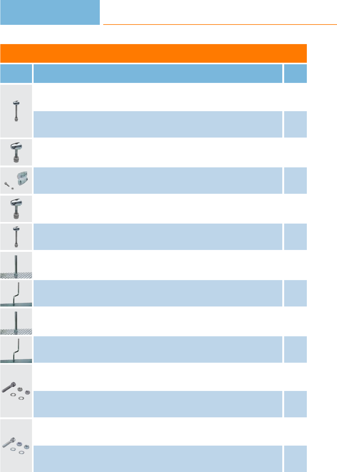
Accessories for system components
Type Description Order
no.
clamp · Ø 10 mm; M8 · free-standing M8 · Housing materials: clamp: diecast zinc E20843
clamp · Ø 10 mm; M8 · free-standing M8 · Housing materials: clamp: stainless steel 316Ti / 1.4571 E20844
clamp · Ø 12 mm; M10 · free-standing M10 · Housing materials: clamp: diecast zinc E20716
clamp · Ø 12 mm · rod mounting Ø 12 mm · Housing materials: clamp: diecast zinc E20717
clamp · Ø 12 mm · rod mounting Ø 12 mm · Housing materials: clamp: stainless steel E21110
clamp · Ø 14 mm; M12 · free-standing M12 · Housing materials: clamp: diecast zinc E20796
mounting rod · Ø 10 / M8 · Length: 150 mm · straight · Housing materials: stainless steel 316Ti / 1.4571 E21081
mounting rod · Ø 10 / M8 · Length: 200 mm · angled · Housing materials: stainless steel 316Ti / 1.4571 E80310
mounting rod · Ø 12 / M10 · Length: 130 mm · straight · Housing materials: stainless steel 316Ti / 1.4571 E20938
mounting rod · Ø 12 / M10 · Length: 200 mm · angled · Housing materials: stainless steel 316Ti / 1.4571 E20940
Head cap screw · M8 x 40 mm · ISO 4762 (DIN 912) · free-standing M8 · Housing materials: screw: steel galvanised E21204
Head cap screw · M8 x 40 mm · ISO 4762 (DIN 912) · free-standing M8 · Housing materials: screw: high-grade stainless steel E21205
Head cap screw · M10 x 45 mm · ISO 4762 (DIN 912) · free-standing M10 · Housing materials: screw: steel galvanised E21208
Head cap screw · M10 x 45 mm · ISO 4762 (DIN 912) · free-standing M10 · Housing materials: screw: high-grade stainless steel E21209
Photoelectric sensors
232
Product selectors and further information can be found at: www.ifm.com
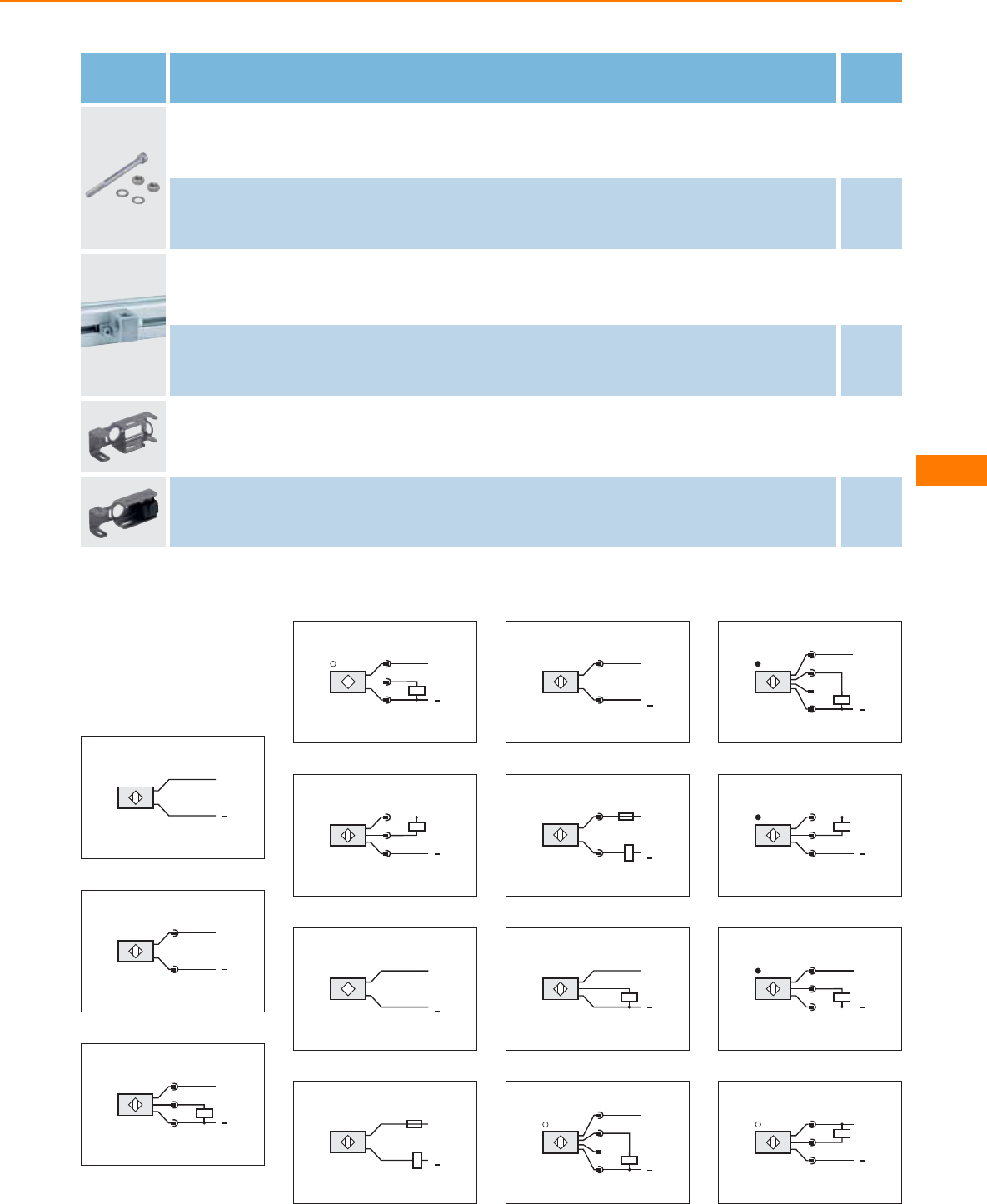
Type Description Order
no.
Head cap screw · M10 x 120 mm · ISO 4762 (DIN 912) · free-standing M10 · Housing materials: screw: steel galvanised E21213
Head cap screw · M10 x 120 mm · ISO 4762 (DIN 912) · free-standing M10 · Housing materials: screw: high-grade stainless steel E21214
Cube · M8 · aluminium profile · Housing materials: diecast zinc E20950
Cube · M10 · aluminium profile · Housing materials: diecast zinc E20951
Protective bracket for free-standing and rod mounting · Ø 18 mm · Clamp mounting · Housing materials: stainless steel 316L /
1.4404 E21125
Protective bracket for free-standing and rod mounting · Ø 18 mm · with end stop · Mounting clamp · Clamp mounting · Housing
materials: Mounting clamp: PC black / Angle bracket: stainless steel 316L / 1.4404 E21126
Core colours
BN brown
BU blue
BK black
WH white
Wiring diagrams
1
L+
L
BN
BU
2
1
3
L+
L
3
L+
L
1
4
3
4
L+
L
1
4
3
5
L+
L
1
4
3
6
L1
L+
L
N
BN
BU
7
L1
L+
L
N
BN
BU
8
2
3
L1
N
L+
L
9
2
3
L1
N
L+
L
10
BN
BK
BU
L+
L
11
L
L+
4
2 n.c.
1
3
12
L+
4
2 n.c.
1
3L
13
L+
L
1
4
3
14
L+
L
1
4
3
15
L+
L
1
4
3
Infrared / red light
sensors
233
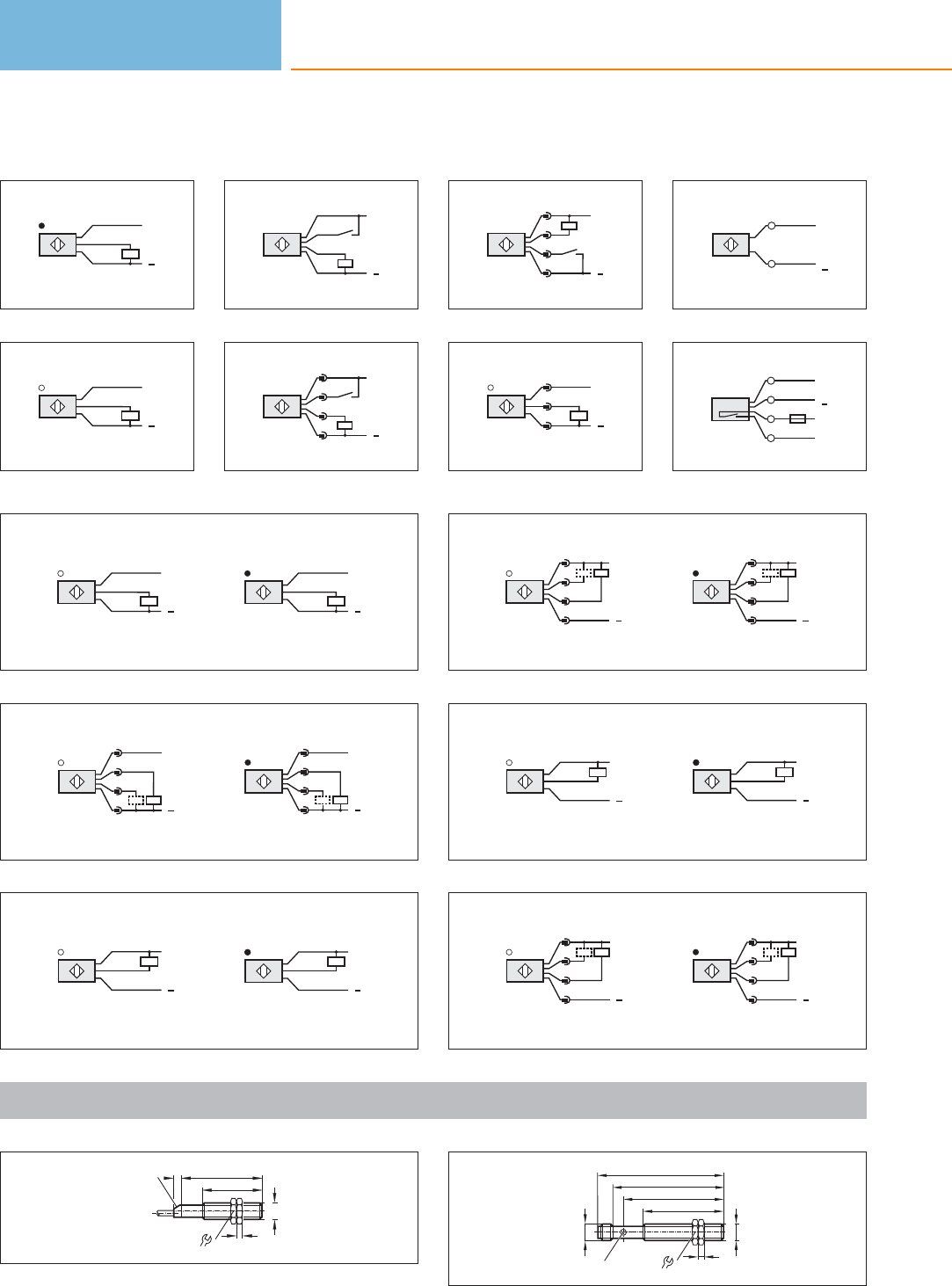
Wiring diagrams
16
L
BN
BK
BU
L+
17
L
BN
BK
BU
L+
18
WH
BK
BN
BU
L+
L
WH: Teach
19
L+
2
4
1
3
L
2: Teach
20
L+
2
4
1
3
L
2: Teach
21
L+
L
1
2
3
22
L1
L+
L
1
N
2
23
L+
L
L1
N
2
3
1
4
24
L
BN
BK
BU
L+
L
BU
BK
BN
L+
25
L
L+
3
2
4
1
L
L+
1
2
4
3
26
L
BU
BK
BN
L+
L
BN
BK
BU
L+
27
L
L+
1
4
2
3
L
L+
3
4
2
1
28
L
BN
BK
BU
L+
L
BU
BK
BN
L+
29
L
L+
3
4
2
1
L
L+
1
4
2
3
Scale drawings / drawing no. – CAD download: www.ifm.com
1
55
40
M12x1
17
4
5
2 LED
2
M12 x1
74
70
54
M12x1
LED 17
4
85
Photoelectric sensors
234
Product selectors and further information can be found at: www.ifm.com
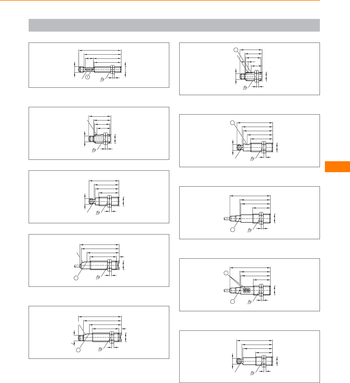
Scale drawings / drawing no. – CAD download: www.ifm.com
3
M12 x1
74
55
54
M12x1
3xLED 17
4
85
17
1: with pot.
4
M18 x1
M12 x1
34
44
LED
4
24
31
27,5
5
M18 x1
M12 x1
40
47
60
49
LED 4 x 90°
4
24
6
76
64
53
M18 x1
4
5,2
78,5
24
LED
1
1: pushbutton
7
76
64
53
M18 x1
4
5,2
86
24
LED
" 20UNF
2
1
1
1: pushbutton
8
M18 x1
M12 x1
34
44
21,4
LED
4
24
31
6,5
1
1: with pot.
9
M18 x1
M12 x1
44
59
72
61
LED 4 x 90°
50
1
4
24
1: with pot.
10
M18 x1
35,6
58
80,4
60,4
1
4
24
1: LED 4 x 90°
11
M18 x1
33,8
59
80,4
60,6
1
4
24
2
1: Programming buttons, 2: LED 4 x 90°
12
M18 x1
M12 x1
34
59
72
61
LED 4 x 90°
4
24
Infrared / red light
sensors
235
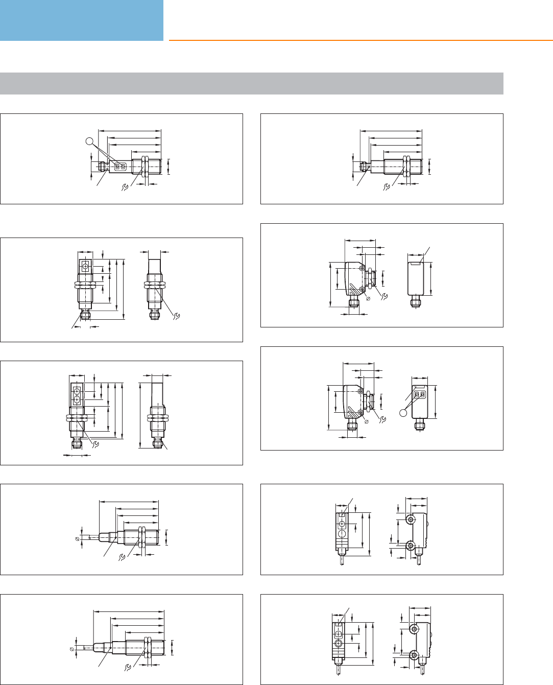
Scale drawings / drawing no. – CAD download: www.ifm.com
13
M18 x1
M12 x1
34
59
72
61
LED 4 x 90°
1
4
24
1: Programming buttons
14
14,5
24
M18 x1
M12 x1
70,1
59,3
34
4
16
LED 4 x 90°
8,2
15
LED 4 x 90°
13,6
75
M18 x1
M12 x1
64
62
29
4
19
9,7
27
24
16
M18 x1
40
47
68,6
49
LED 4 x 90°
4
24
5
17
44
59
80,4
61
LED 4 x 90°
5
M18 x1
4
24
18
M18 x1
M12 x1
44
59
72
61
LED 4 x 90°
4
24
19
18
LEDs
38
M18 x1
M12 x1
11,5
35,4
15,9
24,1
52
24
3,3
20
3,3
M18 x1
M12 x1
11,5
35,4
15,9
24,1
52
24
LEDs
1
18
38
1: setting pushbuttons
21
3,9
9,6
12,5
3,2
15
2,9
7,6
6,4
20,6
25,1
LED
22
3,9
9,6
12,5
3,2
15
2,9
7,6
6,4
20,6
25,1
5,7
LED
Photoelectric sensors
236
Product selectors and further information can be found at: www.ifm.com
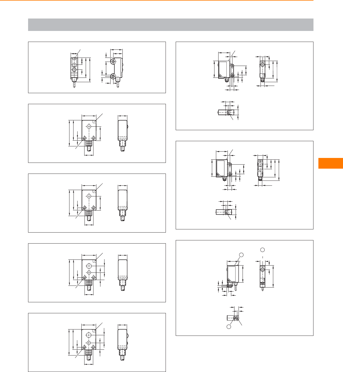
Scale drawings / drawing no. – CAD download: www.ifm.com
23
3,9
9,6
12,5
3,2
15
2,9
7,6
7,2
20,6
25,1
5
LED
24
9
15
14,1
LED 9
26
20,3
2,7
M3
25
9
15
26
20,3
14,1
2,7
M3
LED 9
26
9
15
7,6
6,5
LED 9
26
20,3
2,7
M3
27
9
15
6,5
7,8
LED 9
26
20,3
2,7
M3
28
24 LED
35
8,5
1,8
5,3
19
3,5
5
M8x1
36,5
11
8,2
43,5
9
LED
4
11,6
29
9
LED
4
11,6
19,5
M8x1
36,5
11
43,5
9,5
24 LED
35
8,5
1,8
5,3
19
3,5
5
30
45
11
LED
8,2
1
9
LED
4
1
24
8,8
3,2
3,1
3,1
LED
35
1
1: pushbutton
Infrared / red light
sensors
237
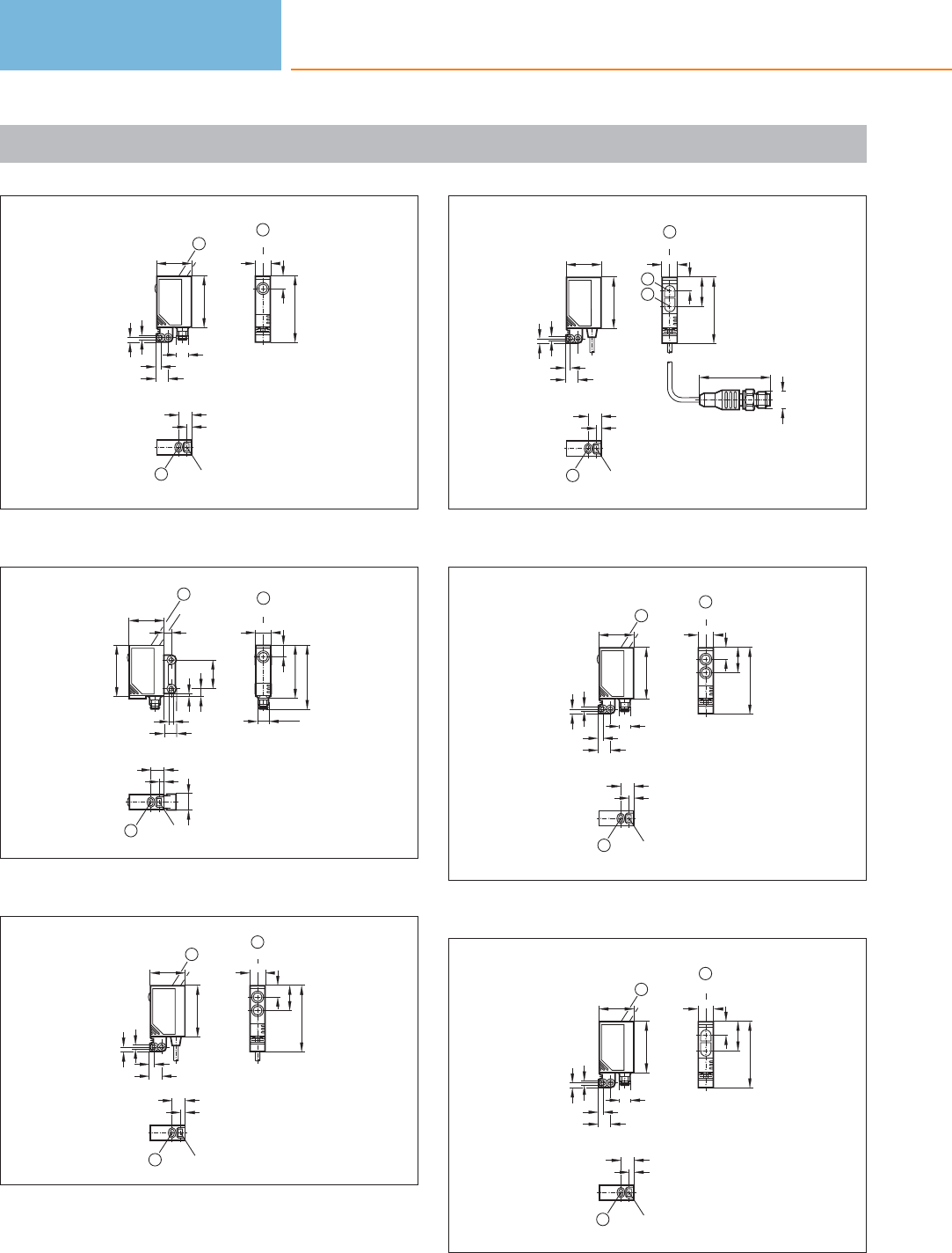
Scale drawings / drawing no. – CAD download: www.ifm.com
31
45
11
LED
8,2
1
24
3,2
3,1
LED
35
M8x1
8,8
3,1
1
9
LED
4
1
1: pushbutton
32
1
9
LED
4
11,6
M8x1
1
36,5
11
LED
8,2
43,5
1
24 LED
35
8,5
1,8
5,3
19
3,5
5
1: pushbutton
33
11
LED
7, 6
16,6
45
1
9
LED
4
1
24
8,8
3,2
3,1
3,1
LED
35
1
1: pushbutton
34
24
3,2
3,1
35
8,8
3,1
9
LED
4
1
1
48
M12 x1
11
LED
45
9,5
19,5
2
3
1: pushbutton, 2: Receiver, 3: Transmitter
35
11
LED
7, 6
16,6
45
1
24
3,2
3,1
LED
35
M8x1
8,8
3,1
1
9
LED
4
1
1: pushbutton
36
11
LED
45
9,5
19,5
1
9
LED
4
1
24
3,2
3,1
LED
35
M8x1
8,8
3,1
1
1: pushbutton
Photoelectric sensors
238
Product selectors and further information can be found at: www.ifm.com
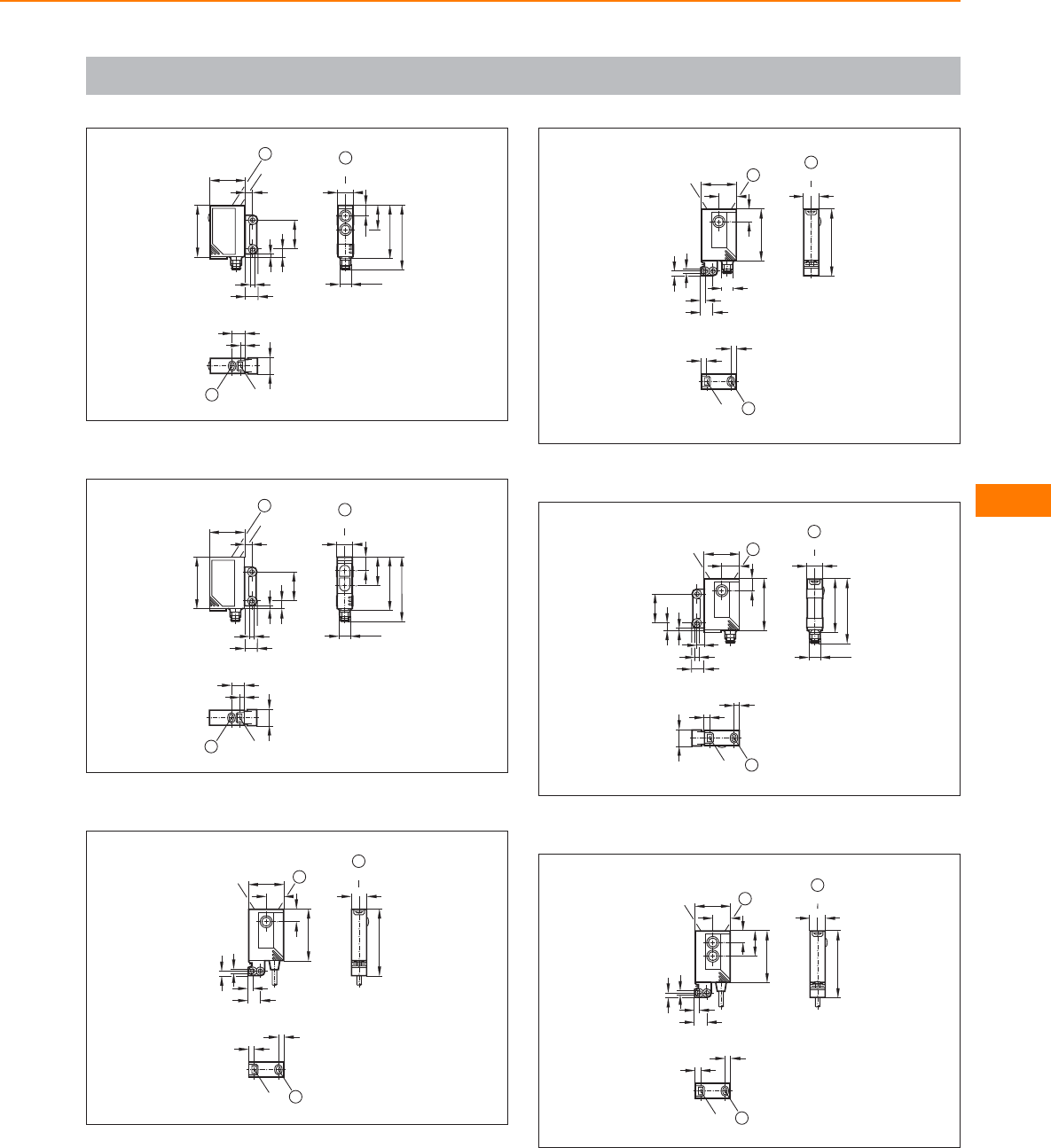
Scale drawings / drawing no. – CAD download: www.ifm.com
37
9
LED
4
11,6
1
24 LED
35
8,5
1,8
5,3
19
3,5
5
1
M8x1
36,5
11
LED
43,5
7,6
16,6
1
1: pushbutton
38
24 LED
35
8,5
1,8
5,3
19
3,5
5
1
9
LED
4
11,6
1
19,5
M8x1
36,5
11
LED
43,5
1
9,5
1: pushbutton
39
45
11
LED
1
24
12
8,8
3,2
3,1
3,1
LED
8,2
35
1
4
LED
4
1
1: pushbutton
40
45
11
LED
1
4
LED
4
1
24
8,2
12
35
8,8
3,2
3,1
3,1
LED
M8x1
1
1: pushbutton
41
1
LED
4
4
11,6
1
36,5
11
LED
43,5
M8x1
19
1
24
12
LED
8,2
35
3,5
8,5
5
1,8
5,3
1: pushbutton
42
45
11
LED
1
24
7, 6
16,6
12
35
8,8
3,2
3,1
3,1
LED 1
4
LED
4
1
1: pushbutton
Infrared / red light
sensors
239
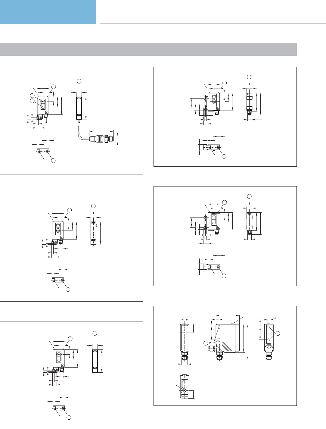
Scale drawings / drawing no. – CAD download: www.ifm.com
43
48
M12 x1
45
11
LED
1
LED
4
4
1
24
9,5
19,5
12
35
8,8
3,2
3,1
3,1
LED
2
3
1
1: pushbutton, 2: Receiver, 3: Transmitter
44
45
11
LED
1
3,1
24
7, 6
16,6
12
35
8,8
3,2
3,1
LED
M8x1
1
4
LED
4
1
1: pushbutton
45
45
11
LED
1
24
9,5
19,5
12
35
8,8
3,2
3,1
3,1
LED
M8x1
1
LED
4
4
1
1: pushbutton
46
1
LED
4
4
11,6
M8x1
1
36,5
11
LED
43,5
19
1
24
12
LED
3,5
8,5
5
1,8
5,3
7,6
16,6
35
1: pushbutton
47
M8x1
1
36,5
11
LED
43,5
1
LED
4
4
11,6
19
1
24
12
LED
3,5
8,5
5
1,8
5,3
9,5
35
19,5
1: pushbutton
48
LED
15,4
18,2
M12 x1
17
5x9
6
25
1
56
6,4
46,8
25
70,3
5
LED
6
1
1: When a M5 mounting screw is used, the max. tightening torque is
2 Nm.
Photoelectric sensors
240
Product selectors and further information can be found at: www.ifm.com
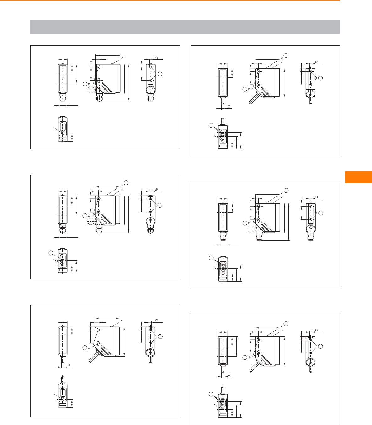
Scale drawings / drawing no. – CAD download: www.ifm.com
49
18,2
M12 x1
17
36,5
LED
15,4
5x9
6
25
1
56
6,4
46,8
25
70,3
5
LED
6
1
1: When a M5 mounting screw is used, the max. tightening torque is
2 Nm.
50
1
38
10
1
LED
24,3
15,4
18,2
M12 x1
19,5
37
5x9
6
25
2
56
6,4
46,8
25
70,3
5
1
LED
6
2
1: with pot., 2: When a M5 mounting screw is used, the max. tighte-
ning torque is 2 Nm.
51
5x9
25
56
6,4
46,8
25
5
1
LED
6
18,2
17
5
6
LED
15,4
1
1: When a M5 mounting screw is used, the max. tightening torque is
2 Nm.
52
5x9
25
2
56
6,4
46,8
25
5
1
LED
6
2
18,2
17
5
6
1
LED
30,5
24,3
15,4
1: Programming buttons, 2: When a M5 mounting screw is used, the
max. tightening torque is 2 Nm.
53
1
LED
30,5
24,3
15,4
5x9
6
25
2
56
6,4
46,8
25
70,3
5
1
LED
6
2
18,2
M12 x1
17
1: Programming buttons, 2: When a M5 mounting screw is used, the
max. tightening torque is 2 Nm.
54
56
6,4
46,8
25
5
1
LED
6
2
5x9
25
2
6
1
LED
30,5
24,3
15,4
18,2
19,5
37
5
1: Programming buttons, 2: When a M5 mounting screw is used, the
max. tightening torque is 2 Nm.
Infrared / red light
sensors
241
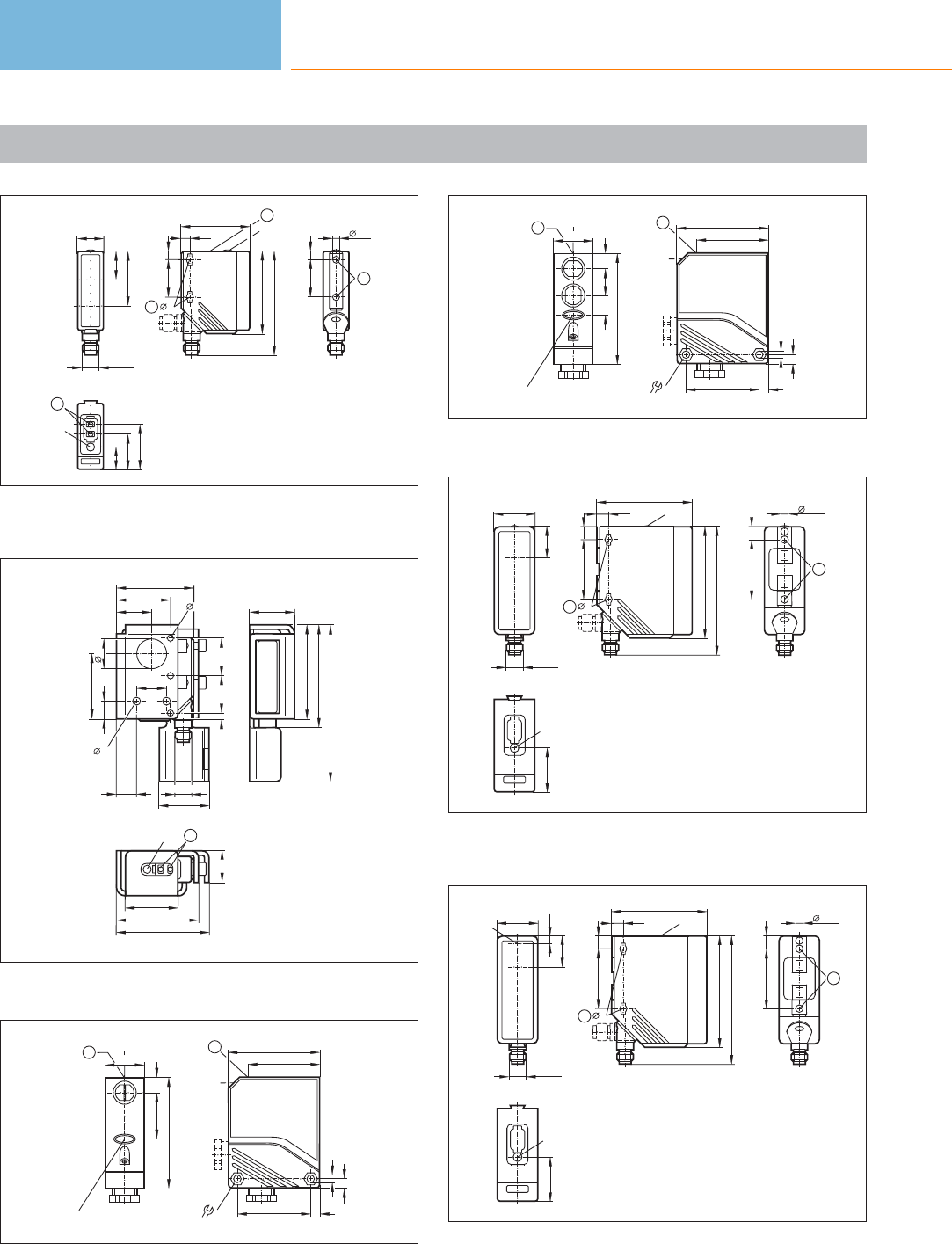
Scale drawings / drawing no. – CAD download: www.ifm.com
55
18,2
M12 x1
19,5
37
1
LED
30,5
24,3
15,4
5x9
6
25
2
56
6,4
46,8
25
70,3
5
1
LED
6
2
1: Programming buttons, 2: When a M5 mounting screw is used, the
max. tightening torque is 2 Nm.
56
51,8
1
LED
35
55
62
21,1
30
63
69
105
25
4
13,5
12
36
25
M12 x1
33,3
4,2
23,5
43,5
5,3
20
20
1: Programming buttons
57
27
LED
1031
75
LED
1
6
62
50
49
5,5
6
LED
8,6
1
1: pushbutton
58
6
62
50
49
5,5
6
8,6
LED
1
27
LED
101813
75
LED
1
1: pushbutton
59
7,9
63,8
LED
40
5
8,5
74,4
86,2
1
8,5
40
5x10
1
M12 x1
27
21,1
LED
29,5
1: When a M5 mounting screw is used, the max. tightening torque is
2 Nm.
60
7,9
63,8
LED
40
5
8,5
74,4
86,2
1
8,5
40
5x10
1
LED
29,5
M12 x1
27
5,2
21,1
LED
1: When a M5 mounting screw is used, the max. tightening torque is
2 Nm.
Photoelectric sensors
242
Product selectors and further information can be found at: www.ifm.com
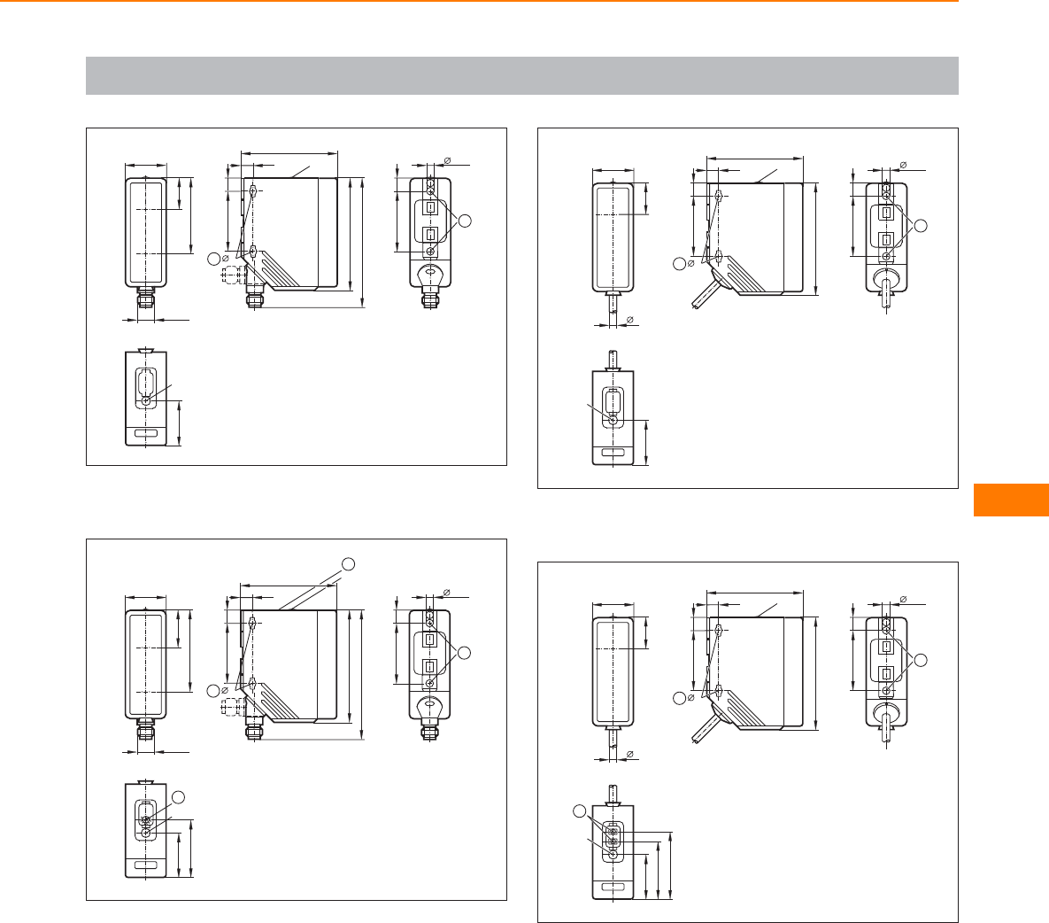
Scale drawings / drawing no. – CAD download: www.ifm.com
61
7,9
63,8
LED
40
5
8,5
74,4
86,2
1
8,5
40
5x10
1
M12 x1
27
21,1
50,9
LED
29,5
1: When a M5 mounting screw is used, the max. tightening torque is
2 Nm.
62
7,9
63,8 LED
40
5
8,5
74,4
86,2
2
1
8,5
40
5x10
2
M12 x1
27
25,3
54,8
LED
29,5
1
38
10
38,6
1
1: with pot., 2: When a M5 mounting screw is used, the max. tighte-
ning torque is 2 Nm.
63
27
21,1
5
29,5
LED
7,9
63,8
LED
40
5
8,5
74,4
1
8,5
40
5x10
1
1: When a M5 mounting screw is used, the max. tightening torque is
2 Nm.
64
27
21,2
5
29,5
44,5
38,3
2
LED
7,9
63,8
LED
40
5
8,5
74,4
1
8,5
40
5x10
1
1: When a M5 mounting screw is used, the max. tightening torque is
2 Nm., 2: Programming buttons
Infrared / red light
sensors
243
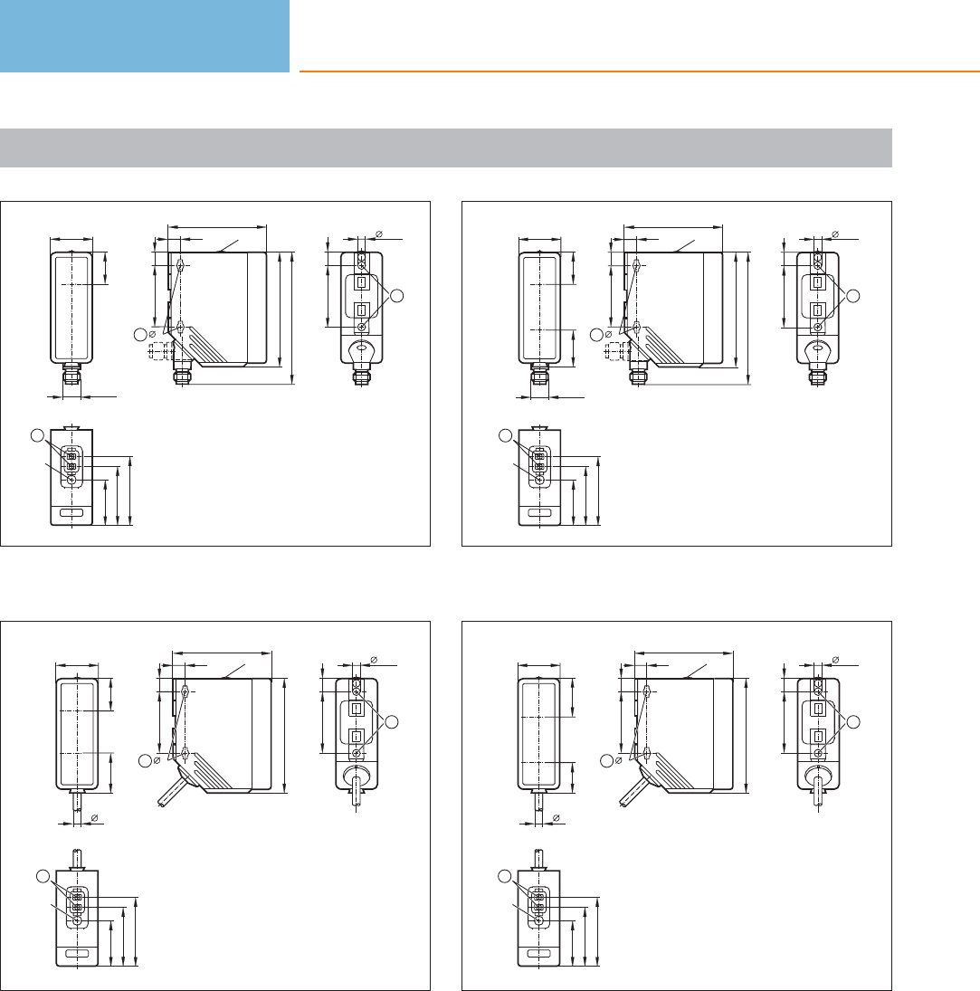
Scale drawings / drawing no. – CAD download: www.ifm.com
65
7,9
63,8
LED
40
5
8,5
74,4
86,2
1
8,5
40
5x10
1
29,5
44,5
38,3
2
LED
M12 x1
27
21,2
1: When a M5 mounting screw is used, the max. tightening torque is
2 Nm., 2: Programming buttons
66
29,5
44,5
38,3
2
LED
7,9
63,8
LED
40
5
8,5
74,4
1
8,5
40
5x10
1
27
21,223,5
5
1: When a M5 mounting screw is used, the max. tightening torque is
2 Nm., 2: Programming buttons
67
7,9
63,8
LED
40
5
8,5
74,4
86,2
1
8,5
40
5x10
1
29,5
44,5
38,3
2
LED
M12 x1
27
21,2
23,5
1: When a M5 mounting screw is used, the max. tightening torque is
2 Nm., 2: Programming buttons
68
27
25,319,7
5
29,5
44,5
38,3
2
LED
7,9
63,8
LED
40
5
8,5
74,4
1
8,5
40
5x10
1
1: When a M5 mounting screw is used, the max. tightening torque is
2 Nm., 2: Programming buttons
Photoelectric sensors
244
Product selectors and further information can be found at: www.ifm.com
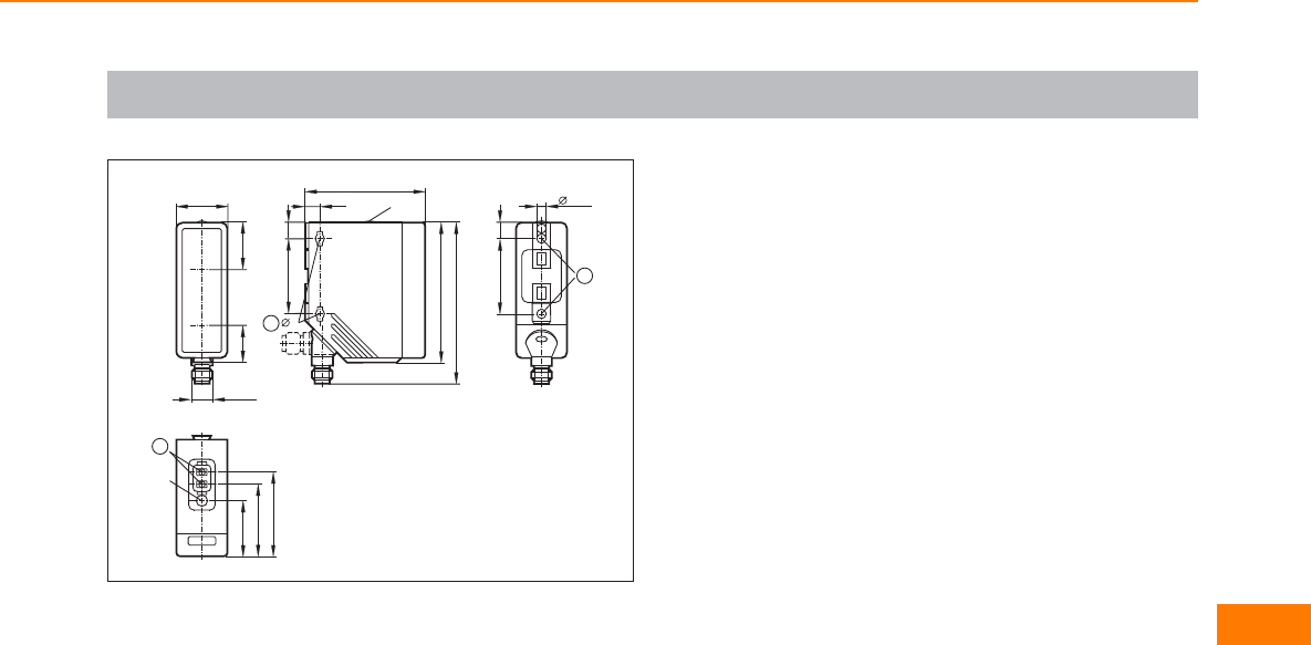
Scale drawings / drawing no. – CAD download: www.ifm.com
69
7,9
63,8
LED
40
5
8,5
74,4
86,2
1
8,5
40
5x10
1
29,5
44,5
38,3
2
LED
M12 x1
27
25,3
19,7
1: When a M5 mounting screw is used, the max. tightening torque is
2 Nm., 2: Programming buttons
Infrared / red light
sensors
245
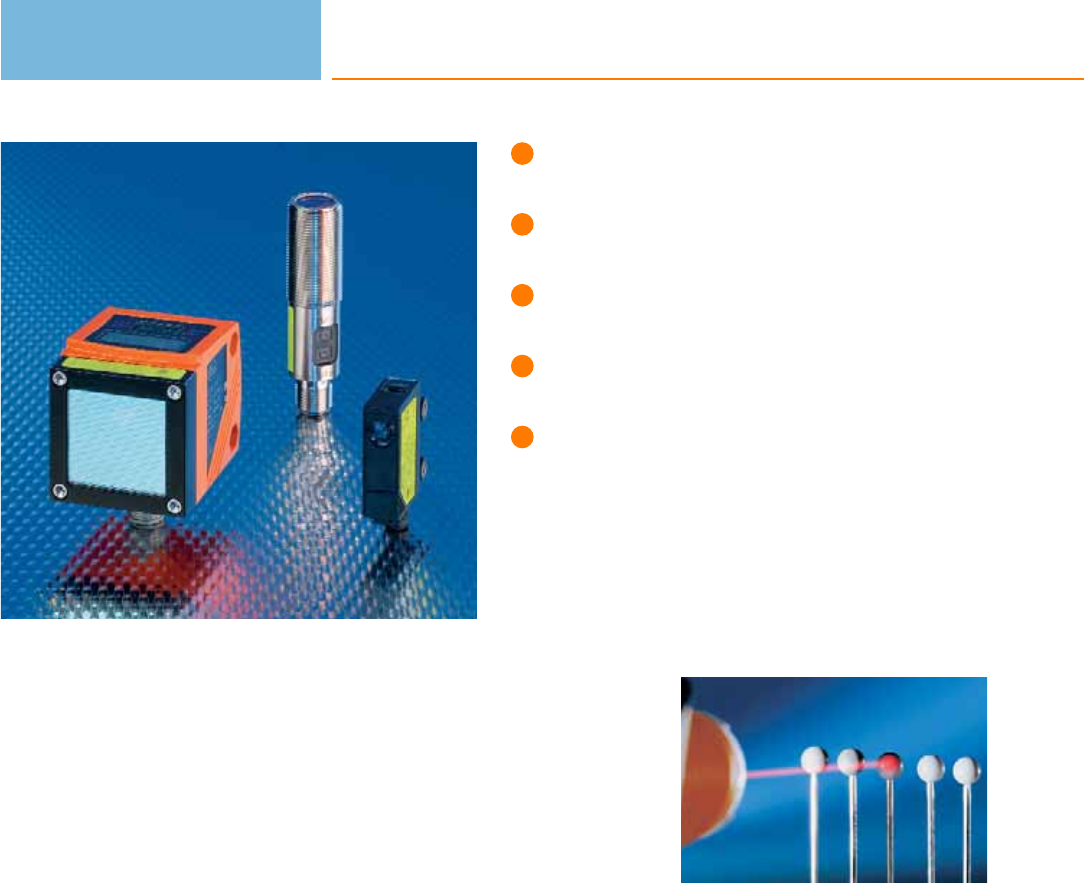
Detection of minute objects.
Clearly visible red light for easy setting
to the object.
Automatic switch point setting by
pressing a pushbutton.
Application sensors available for special
application areas.
System components available for
fine adjustment.
Laser sensors
Laser sensors are used where detection of small objects or precise positioning is
required. They are available as through-beam sensors, retro-reflective sensors or
diffuse reflection sensors.
Laser light consists of light waves of identical length which have a defined phase
relation (coherence). This results in an important feature of laser systems, that is the
almost parallel light beam. Result: Due to the small angle of divergence long ranges
of up to 60 metres can be achieved. The laser spot which is also clearly visible at
daylight simplifies the alignment of the system. Apart from the advantages some
points have to be taken into account for the selection of the suitable optical system:
Compared to standard sensors the laser sensors have a reduced temperature range
(-10...60 °C). Life is limited to approx. 50,000 hours. Basically laser systems are
more expensive than normal red light sensors. In view of the small light spot and
the often high ranges the system is more sensitive to vibrations than standard
sensors.
Coherent: Laser
sensors emit light of
a defined wave length
and the same phase
position.
Photoelectric sensors
246

System overview Page
Cylindrical OG housing (M18) Laser PerformanceLine, laser class 1 248
Rectangular OJ housing Laser PerformanceLine, lateral sensing face, laser class 1 248 - 249
Rectangular OJ housing Laser PerformanceLine, front sensing face, laser class 1 249 - 250
Rectangular O1 housing Laser PerformanceLine with background suppression, laser class 2 250 - 251
Rectangular housing O5 Laser class 1 251
Prismatic reflector 251 - 252
Accessories OG housing 252
Accessories OJ housing 253
Accessories O1 housing 253 - 254
Accessories for system components 254
Wiring diagrams 254
Scale drawings / drawing no. – CAD download: www.ifm.com 255
Laser sensors
247
Cylindrical OG housing (M18) Laser PerformanceLine, laser class 1
Type Operating principle Range Type
of light
Spot Ø at
max.
range
[mm]
Output
H = light-on
D = dark-on
Wiring
diagr.
no.
Draw-
ing
no.
Order
no.
Through-beam sensor · M12 connector · 10...36 DC · high-grade stainless steel · IP 65 / IP 67 · Connector groups 9, 11, 107, 108, 135
Transmitter 2 m red 5 – 1 1 OGS701
Transmitter 60 m red 312 – 1 1 OGS700
Through-beam sensor · M12 connector · 10...36 DC · high-grade stainless steel · IP 65 / IP 67 · Connector groups 9, 10, 11, 12, 107,
108, 109, 110, 135, 136
Receiver 2 m red – H/D PNP 2 2 OGE701
Receiver 60 m red –H/D PNP 2 2 OGE700
Retro-reflective sensor · M12 connector · 10...36 DC · high-grade stainless steel · IP 65 / IP 67 · Connector groups 9, 10, 11, 12, 107,
108, 109, 110, 135, 136
Polarisation filter 0.2...2 m red 5 H/D PNP 2 2 OGP701
Polarisation filter 0.2...15 m red 78 H/D PNP 2 2 OGP700
Diffuse reflection sensor · M12 connector · 10...36 DC · high-grade stainless steel · IP 65 / IP 67 · Connector groups 9, 10, 11, 12,
107, 108, 109, 110, 135, 136
Background suppression 20...200 mm red 1.2 H/D PNP 2 2 OGH700
Rectangular OJ housing Laser PerformanceLine, lateral sensing face, laser class 1
Type Operating principle Range Type
of light
Spot Ø at
max.
range
[mm]
Output
H = light-on
D = dark-on
Wiring
diagr.
no.
Draw-
ing
no.
Order
no.
Through-beam sensor · M8 connector · 10...30 DC · plastics · IP 67 · Connector groups 4, 5, 70
Transmitter 1 m red < 4 – 1 3 OJ5041
Receiver 1 m red –H/D PNP 3 3 OJ5042
Transmitter 15 m red < 24 – 1 3 OJ5038
Photoelectric sensors
248
Product selectors and further information can be found at: www.ifm.com
Type Operating principle Range Type
of light
Spot Ø at
max.
range
[mm]
Output
H = light-on
D = dark-on
Wiring
diagr.
no.
Draw-
ing
no.
Order
no.
Through-beam sensor · M8 connector · 10...30 DC · plastics · IP 67 · Connector groups 4, 5, 70
Receiver 15 m red – H/D PNP 3 3 OJ5039
Transmitter 1 m red < 4 – 1 4 OJ5141
Receiver 1 m red – H/D PNP 3 4 OJ5142
Transmitter 15 m red < 24 – 1 4 OJ5138
Receiver 15 m red – H/D PNP 3 4 OJ5139
Retro-reflective sensor · M8 connector · 10...30 DC · plastics · IP 67 · Connector groups 4, 5, 70
Polarisation filter 8 m red < 12 H/D PNP 3 3 OJ5036
Polarisation filter 8 m red < 12 H/D PNP 3 4 OJ5136
Diffuse reflection sensor · M8 connector · 10...30 DC · plastics · IP 67 · Connector groups 4, 5, 70
Background suppression 7...150 mm red 0.8 H/D PNP 3 5 OJ5058
Background suppression 15...200 mm red 2x1 H/D PNP 3 6 OJ5054
Background suppression 7...150 mm red 0.8 H/D PNP 3 7 OJ5158
Background suppression 15...200 mm red 2x1 H/D PNP 3 8 OJ5154
Rectangular OJ housing Laser PerformanceLine, front sensing face, laser class 1
Type Operating principle Range Type
of light
Spot Ø at
max.
range
[mm]
Output
H = light-on
D = dark-on
Wiring
diagr.
no.
Draw-
ing
no.
Order
no.
Through-beam sensor · M8 connector · 10...30 DC · plastics · IP 67 · Connector groups 4, 5, 70
Transmitter 1 m red < 4 – 1 9 OJ5019
Laser sensors
249
You can find wiring diagrams and scale drawings from page 254
Type Operating principle Range Type
of light
Spot Ø at
max.
range
[mm]
Output
H = light-on
D = dark-on
Wiring
diagr.
no.
Draw-
ing
no.
Order
no.
Through-beam sensor · M8 connector · 10...30 DC · plastics · IP 67 · Connector groups 4, 5, 70
Receiver 1 m red – H/D PNP 3 9 OJ5020
Transmitter 15 m red < 24 – 1 9 OJ5016
Receiver 15 m red – H/D PNP 3 9 OJ5017
Transmitter 15 m red < 24 – 1 10 OJ5116
Receiver 15 m red – H/D PNP 3 10 OJ5117
Retro-reflective sensor · M8 connector · 10...30 DC · plastics · IP 67 · Connector groups 4, 5, 70
Polarisation filter 8 m red < 12 H/D PNP 3 9 OJ5014
Polarisation filter 8 m red < 12 H/D PNP 3 10 OJ5114
Diffuse reflection sensor · M8 connector · 10...30 DC · plastics · IP 67 · Connector groups 4, 5, 70
Background suppression 7...150 mm red 0.8 H/D PNP 311 OJ5056
Background suppression 15...200 mm red 2x1 H/D PNP 3 12 OJ5052
Background suppression 15...200 mm red 2x1 H/D PNP 313 OJ5152
Rectangular O1 housing Laser PerformanceLine with background suppression, laser class 2
Type Operating principle Range Type
of light
Spot Ø at
max.
range
[mm]
Output
H = light-on
D = dark-on
Wiring
diagr.
no.
Draw-
ing
no.
Order
no.
Optical distance sensor · M12 connector · 10...30 DC · metal · IP 67 · Connector groups 9, 10, 11, 12, 107, 108, 109, 110, 135, 136
Background suppression 0.2...10 m – 6
normally open / closed
programmable
PNP
214O1D101
Photoelectric sensors
250
Product selectors and further information can be found at: www.ifm.com
Type Operating principle Range Type
of light
Spot Ø at
max.
range
[mm]
Output
H = light-on
D = dark-on
Wiring
diagr.
no.
Draw-
ing
no.
Order
no.
Optical distance sensor · M12 connector · 10...30 DC · metal · IP 67 · Connector groups 9, 11, 107, 108, 135
Background suppression 0.2...10 m – 6
normally open / closed
programmable
NPN
414O1D104
Rectangular housing O5 Laser class 1
Type Operating principle Range Type
of light
Spot Ø at
max.
range
[mm]
Output
H = light-on
D = dark-on
Wiring
diagr.
no.
Draw-
ing
no.
Order
no.
Through-beam sensor · M12 connector · 10...36 DC · plastics · IP 67 · Connector groups 9, 11, 107, 108, 135
Transmitter 60 m red 150 – 1 15 O5S700
Through-beam sensor · M12 connector · 10...36 DC · plastics · IP 67 · Connector groups 9, 10, 11, 12, 107, 108, 109, 110, 135, 136
Receiver 60 m red –H/D PNP 216 O5E700
Retro-reflective sensor · M12 connector · 10...36 DC · plastics · IP 67 · Connector groups 9, 10, 11, 12, 107, 108, 109, 110, 135, 136
Polarisation filter 15 m red 40 H/D PNP 2 17 O5P700
Diffuse reflection sensor · M12 connector · 10...36 DC · plastics · IP 67 · Connector groups 9, 10, 11, 12, 107, 108, 109, 110, 135, 136
Background suppression 20...200 mm red 1.2 H/D PNP 218 O5H700
Prismatic reflector
Type Description Order
no.
Prismatic reflector · Ø 10 mm · round · fixing by screw · M3 · for retro-reflective laser sensors · Housing materials: screw: stainless
steel 316 / 1.4401 / spring washer: stainless steel 316 / 1.4401 / Nut: stainless steel 316 / 1.4401 / front plate: PMMA / base: ABS E20990
Prismatic reflector · Ø 15 mm · round · fixing by screw · M3 · for retro-reflective laser sensors · Housing materials: screw: stainless
steel 316 / 1.4401 / spring washer: stainless steel 316 / 1.4401 / Nut: stainless steel 316 / 1.4401 / front plate: PMMA / base: ABS E20992
Prismatic reflector · Ø 19 mm · round · fixing by screw · M3 · for retro-reflective laser sensors · Housing materials: screw: stainless
steel 316 / 1.4401 / spring washer: stainless steel 316 / 1.4401 / Nut: stainless steel 316 / 1.4401 / front plate: PMMA / base: ABS E20993
Laser sensors
251
You can find wiring diagrams and scale drawings from page 254
Type Description Order
no.
Prismatic reflector · 11 x 11 mm · rectangular · fixing by screw · M3 · for retro-reflective laser sensors · Housing materials: screw:
stainless steel 316 / 1.4401 / spring washer: stainless steel 316 / 1.4401 / Nut: stainless steel 316 / 1.4401 / front plate: PMMA /
base: ABS
E20991
Prismatic reflector · 14 x 23 mm · rectangular · for retro-reflective laser sensors · Housing materials: front plate: PMMA / base: ABS E20989
Prismatic reflector · 30 x 20 mm · rectangular · for retro-reflective laser sensors · Housing materials: front plate: PMMA / base: ABS E20994
Prismatic reflector · 50 x 10 mm · rectangular · for retro-reflective laser sensors · Housing materials: front plate: PMMA / base: ABS E20988
Prismatic reflector · 50 x 50 mm · rectangular · for retro-reflective laser sensors and glass and film detection · Housing materials:
plastics E20722
Accessories OG housing
Type Description Order
no.
Fixture for mounting and fine adjustment of laser units · Ø 18.5 mm · Clamp mounting · rod or free-standing depending on the
clamp · for type OG · Housing materials: stainless steel 316Ti / 1.4571 E20737
Fixture for mounting and fine adjustment of laser units · Ø 18.5 mm · Clamp mounting · rod mounting Ø 12 mm · for type OG ·
Housing materials: fixture: stainless steel 316Ti / 1.4571 / clamp: high-grade stainless steel E21220
Fixture for mounting and fine adjustment of laser units · Ø 18.5 mm · Clamp mounting · rod mounting Ø 12 mm · for type OG ·
Housing materials: fixture: stainless steel 316Ti / 1.4571 / clamp: diecast zinc E21219
Mounting set · Ø 18.5 mm · Clamp mounting · rod mounting Ø 12 mm · for type OG, IG, KG · Housing materials: clamp: diecast
zinc / fixture: steel E20720
Mounting set · Ø 18.5 mm · Clamp mounting · rod mounting Ø 12 mm · for type OG, IG, KG · Housing materials: clamp: diecast
zinc / fixture: steel E20721
Mounting set · Ø 18.5 mm · Clamp mounting · rod mounting Ø 12 mm · for type OG, IG, KG · Housing materials: clamp: high-grade
stainless steel / fixture: high-grade stainless steel E21206
Mounting set · Ø 18.5 mm · Clamp mounting · rod mounting Ø 12 mm · for type OG, IG, KG · Housing materials: clamp: high-grade
stainless steel / fixture: high-grade stainless steel E21207
Photoelectric sensors
252
Product selectors and further information can be found at: www.ifm.com
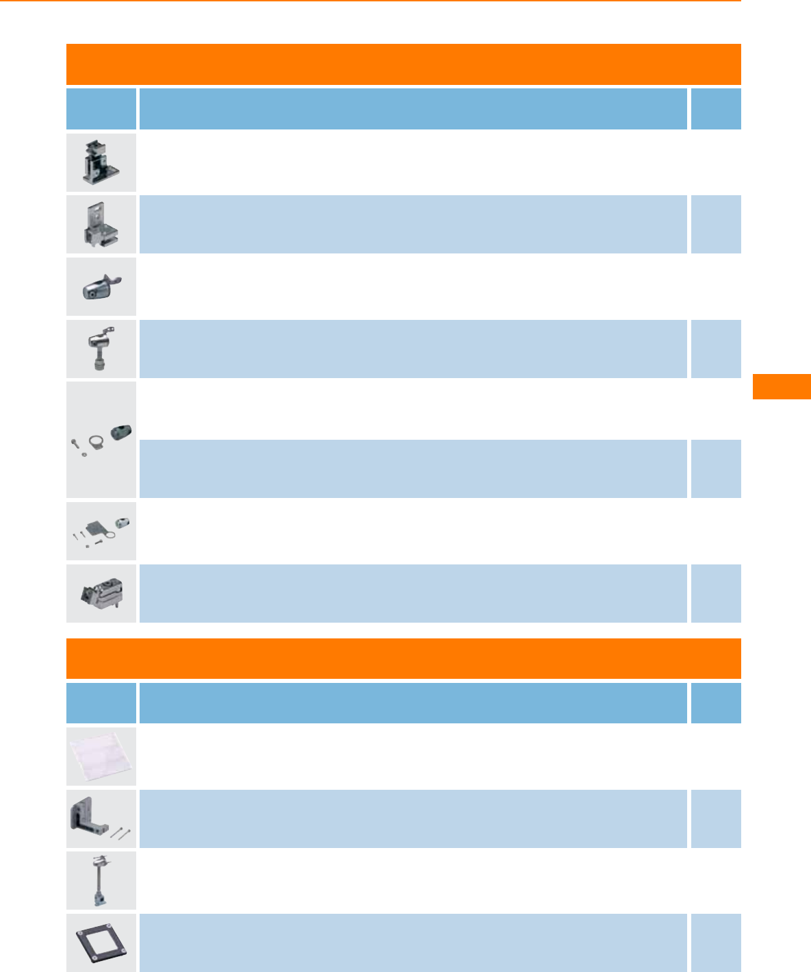
Accessories OJ housing
Type Description Order
no.
Fixture for mounting and fine adjustment of laser units · for front lens · for type OJ · Housing materials: diecast zinc E20975
Fixture for mounting and fine adjustment of laser units · for side lens · for type OJ · Housing materials: diecast zinc E20976
Mounting set · OJ · for front lens · Clamp mounting · rod mounting Ø 10 mm · Housing materials: fixture: stainless steel 316Ti /
1.4571 / clamp: diecast zinc E20970
Mounting set · OJ · for front lens · Clamp mounting · rod mounting · Housing materials: fixture: stainless steel 316Ti / 1.4571 /
clamp: stainless steel E21221
Mounting set · OJ · for side lens · Clamp mounting · rod mounting Ø 10 mm · Housing materials: fixture: stainless steel 316Ti /
1.4571 / clamp: diecast zinc E21222
Mounting set · OJ · for side lens · Clamp mounting · rod mounting Ø 10 mm · Housing materials: fixture: stainless steel 316Ti /
1.4571 / clamp: stainless steel E20973
Mounting set · OJ · for side lens · rod mounting Ø 10 mm · Housing materials: clamp: diecast zinc / fixture: stainless steel 316Ti /
1.4571 E21095
Swivel-mount clip · for type OJ · Housing materials: diecast zinc E20974
Accessories O1 housing
Type Description Order
no.
Prismatic reflector · 226 x 262 mm · rectangular · for type O1D · Housing materials: plastics E21159
Fixture for mounting and fine adjustment of laser units · O1D · Clamp mounting · rod or free-standing depending on the clamp ·
Housing materials: fixture: aluminium transparent anodised / plastics: POM / screws: stainless steel E1D100
Mounting set · E2D101 + E20938 + E20951 E21079
Protective cover · O1D · Housing materials: bezel: ZnAl4Cu1 finish black / window: PMMA transparent and colourless / sealing: FPM
75+/-5 Shore A black / screws: stainless steel E21133
Laser sensors
253
You can find wiring diagrams and scale drawings from page 254
Type Description Order
no.
Protective cover · O1D · Housing materials: bezel: ZnAl4Cu1 finish black / window: glass transparent and colourless / sealing: FPM
75+/-5 Shore A black / screws: stainless steel E21171
Accessories for system components
Type Description Order
no.
mounting rod · Ø 10 / M8 · Length: 150 mm · straight · Housing materials: stainless steel 316Ti / 1.4571 E21081
mounting rod · Ø 10 / M8 · Length: 200 mm · angled · Housing materials: stainless steel 316Ti / 1.4571 E80310
mounting rod · Ø 12 / M10 · Length: 130 mm · straight · Housing materials: stainless steel 316Ti / 1.4571 E20938
mounting rod · Ø 12 / M10 · Length: 200 mm · angled · Housing materials: stainless steel 316Ti / 1.4571 E20940
Head cap screw · M8 x 40 mm · ISO 4762 (DIN 912) · free-standing M8 · Housing materials: screw: steel galvanised E21204
Head cap screw · M10 x 45 mm · ISO 4762 (DIN 912) · free-standing M10 · Housing materials: screw: steel galvanised E21208
Head cap screw · M10 x 45 mm · ISO 4762 (DIN 912) · free-standing M10 · Housing materials: screw: high-grade stainless steel E21209
Cube · M10 · aluminium profile · Housing materials: diecast zinc E20951
Wiring diagrams
1
1
3
L+
L
2
L+
L
1
4
3
3
L+
2
4
1
3
L
2: Teach
4
L+
L
1
4
3
Photoelectric sensors
254
Product selectors and further information can be found at: www.ifm.com
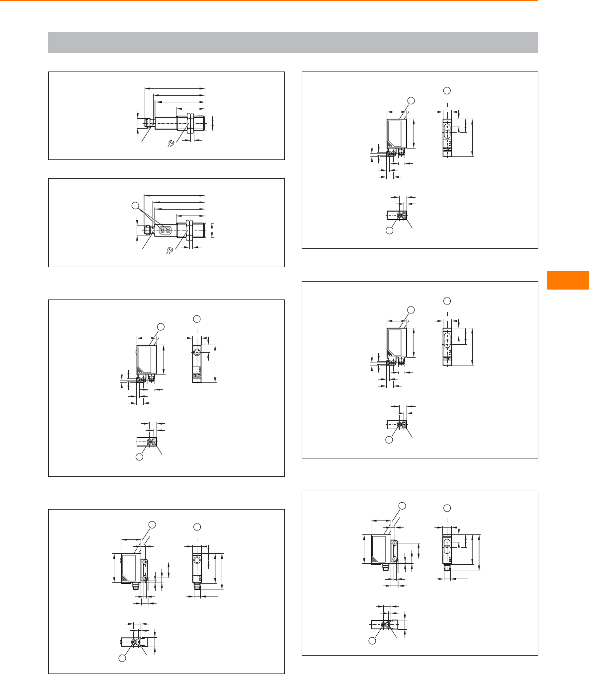
Scale drawings / drawing no. – CAD download: www.ifm.com
1
M18 x1
M12 x1
34
59
72
61
LED 4 x 90°
4
24
2
M18 x1
M12 x1
34
59
72
61
LED 4 x 90°
1
4
24
1: Programming buttons
3
45
11
LED
8,2
1
24
3,2
3,1
LED
35
M8x1
8,8
3,1
1
9
LED
4
1
1: pushbutton
4
1
9
LED
4
11,6
M8x1
1
36,5
11
LED
8,2
43,5
1
24 LED
35
8,5
1,8
5,3
19
3,5
5
1: pushbutton
5
11
LED
45
9,5
15,5
1
24
3,2
3,1
LED
35
M8x1
8,8
3,1
1
9
LED
4
1
1: pushbutton
6
11
LED
45
9,5
19,5
1
9
LED
4
1
24
3,2
3,1
LED
35
M8x1
8,8
3,1
1
1: pushbutton
7
24 LED
35
8,5
1,8
5,3
19
3,5
5
1
9
LED
4
11,6
1
M8x1
36,5
11
LED
43,5
1
9,5
15,5
1: pushbutton
Laser sensors
255
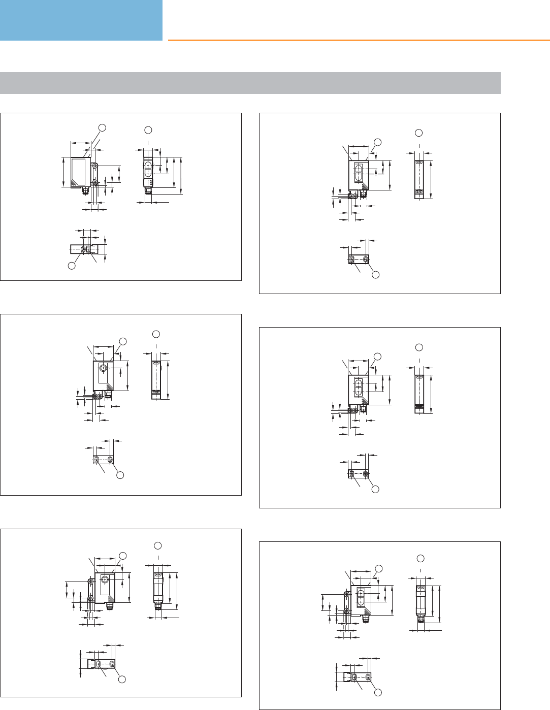
Scale drawings / drawing no. – CAD download: www.ifm.com
8
24 LED
35
8,5
1,8
5,3
19
3,5
5
1
9
LED
4
11,6
1
19,5
M8x1
36,5
11
LED
43,5
1
9,5
1: pushbutton
9
45
11
LED
1
4
LED
4
1
24
8,2
12
35
8,8
3,2
3,1
3,1
LED
M8x1
1
1: pushbutton
10
1
LED
4
4
11,6
1
36,5
11
LED
43,5
M8x1
19
1
24
12
LED
8,2
35
3,5
8,5
5
1,8
5,3
1: pushbutton
11
45
11
LED
1
LED
4
4
1
24
9,5
15,5
12
35
8,8
3,2
3,1
3,1
LED
M8x1
1
1: pushbutton
12
45
11
LED
1
24
9,5
19,5
12
35
8,8
3,2
3,1
3,1
LED
M8x1
1
LED
4
4
1
1: pushbutton
13
M8x1
1
36,5
11
LED
43,5
1
LED
4
4
11,6
19
1
24
12
LED
3,5
8,5
5
1,8
5,3
9,5
35
19,5
1: pushbutton
Photoelectric sensors
256
Product selectors and further information can be found at: www.ifm.com
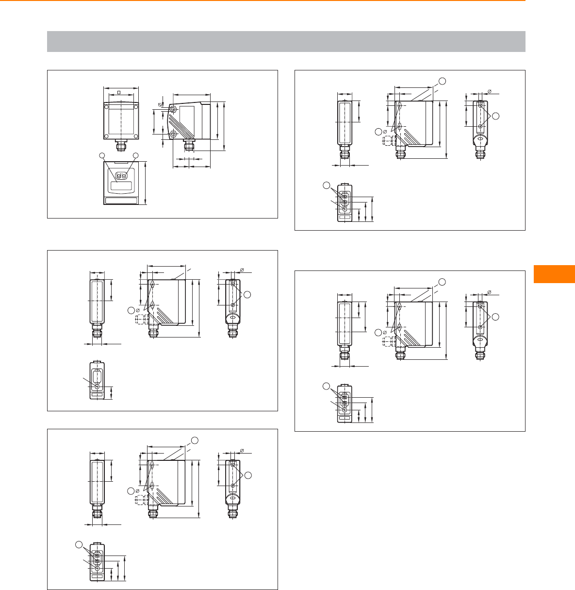
Scale drawings / drawing no. – CAD download: www.ifm.com
14
52
1 2
30
45
2520
4,5
6
45
59
42
M12x1
30
1: 4-digit alphanumeric display, 2: Programming buttons
15
LED
15,4
18,2
M12 x1
26
5x9
6
25
1
56
6,4
46,8
25
70,3
5
LED
6
1
16
1
LED
30,5
24,3
15,4
5x9
6
25
2
56
6,4
46,8
25
70,3
5
1
LED
6
2
18,2
M12 x1
26
17
18,2
M12 x1
26
1
LED
30,5
24,3
15,4
5x9
6
25
2
56
6,4
46,8
25
70,3
5
1
LED
6
2
1: Programming buttons, 2: When a M5 mounting screw is used, the
max. tightening torque is 2 Nm.
18
18,2
M12 x1
19,5
37
1
LED
30,5
24,3
15,4
5x9
6
25
2
56
6,4
46,8
25
70,3
5
1
LED
6
2
1: Programming buttons, 2: When a M5 mounting screw is used, the
max. tightening torque is 2 Nm.
Laser sensors
257
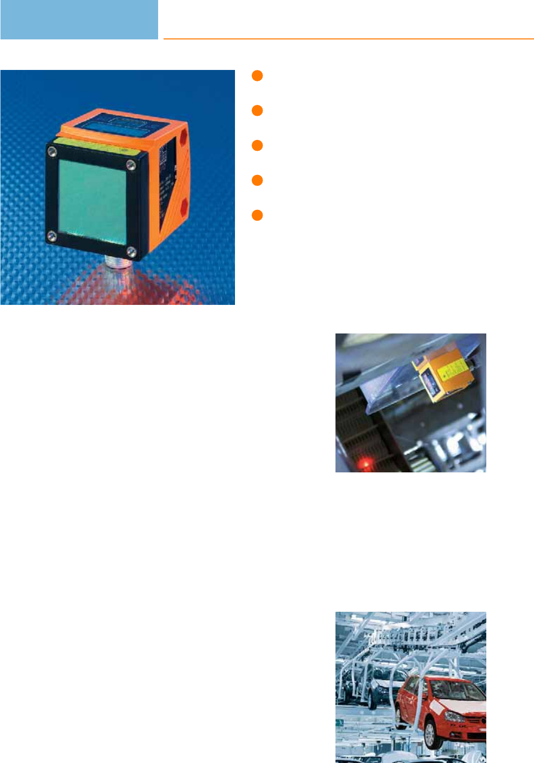
Non-contact distance detection
at a high range.
Analogue and switching outputs.
Small light spot and exact
background suppression.
Compact and robust metal
housing.
Unbeatable price / performance ratio.
Optical distance detection using PMD technology
For collision avoidance, completeness check, level monitoring or as diffuse reflection
sensor with an extraordinary range: The efector pmd distance sensors can be used
in a wide range of applications. Depending on the type, the laser sensors precisely
determine distances up to 10 m or up to 75 m when a reflector is used. The robust
metal housing ensures operational reliability even under rough operating
conditions.
Operating principle
The efector pmd laser sensors operate to the time-of-flight principle.
The pmd sensor’s receiver element is a „System-on-Chip“ design. Both sensor
element and electronics for signal evaluation are integrated on a single silicon chip
called a Photonic Mixer Device (PMD). Advantage: This innovative ifm design offers
high performance in a compact, industrially compatible housing – at a fraction of
the price of conventional systems.
The determined distance is indicated on the 4-digit display and provided via the
scalable analogue output (4…20 mA). The user can program two switching outputs
which switch when a certain distance is reached. Up to 50 measurements per
second are possible (adjustable). The light spot diameter is 6 mm at a 10 m dis-
tance. This makes the sensor suitable for applications requiring exact background
suppression. An outstanding feature of efector pmd is the extremely compact size
of only 42 x 45 x 52 mm.
The efector pmd
provides an analogue
signal that is propor-
tional to the object-
to-sensor distance.
Collision avoidance
on an overhead con-
veyor: efector pmd
monitors distances
between products.
Photoelectric sensors
258

System overview Page
Rectangular O1 housing for optical distance measurement, laser class 1 260
Rectangular O1 housing for optical distance measurement, laser class 2 260
Rectangular O1 housing for optical level measurement, laser class 2 260
Accessories 260 - 261
Wiring diagrams 261
Scale drawings / drawing no. – CAD download: www.ifm.com 261
Distance detection
259

Rectangular O1 housing for optical distance measurement, laser class 1
Type Operating principle Range Sampling
rate
[Hz]
Spot Ø at
max.
range
[mm]
Ub
[V]
Wiring
diagr.
no.
Draw-
ing
no.
Order
no.
Output OUT1: normally open / closed programmable OUT2: normally open / closed programmable or analogue
(4...20 mA / 0...10 V, scalable) · Wiring diagram no. 1 · Connector groups 9, 10, 11, 107, 108, 110, 135
Optical distance sensor 0.3...6 m 1...33 6 18...30 1 1 O1D155
Rectangular O1 housing for optical distance measurement, laser class 2
Type Operating principle Range Sampling
rate
[Hz]
Spot Ø at
max.
range
[mm]
Ub
[V]
Wiring
diagr.
no.
Draw-
ing
no.
Order
no.
Output OUT1: normally open / closed programmable OUT2: normally open / closed programmable or analogue
(4...20 mA / 0...10 V, scalable) · Wiring diagram no. 1 · Connector groups 9, 10, 11, 107, 108, 110, 135
Optical distance sensor 1...75 m 1...33 150 18...30 1 1 O1D106
Optical distance sensor 0.2...10 m 1...33 618...30 1 1 O1D105
Optical distance sensor 0.2...10 m 1...50 6 18...30 1 1 O1D100
Output OUT1: normally open / closed programmable OUT2: normally open / closed programmable or analogue
(4...20 mA / 0...10 V, scalable) · Wiring diagram no. 2 · Connector groups 9, 11, 107, 108, 135
Optical distance sensor 0.2...10 m 1...50 618...30 2 1 O1D103
Rectangular O1 housing for optical level measurement, laser class 2
Type Operating principle Range Sampling
rate
[Hz]
Spot Ø at
max.
range
[mm]
Ub
[V]
Wiring
diagr.
no.
Draw-
ing
no.
Order
no.
Output OUT1: normally open / closed programmable OUT2: normally open / closed programmable or analogue
(4...20 mA / 0...10 V, scalable) · Wiring diagram no. 1 · Connector groups 9, 10, 11, 107, 108, 110, 135
Optical level sensor 0.2...10 m 1...33 6 18...30 1 1 O1D300
Accessories
Type Description Order
no.
Prismatic reflector · 226 x 262 mm · rectangular · for type O1D · Housing materials: plastics E21159
Photoelectric sensors
260
Product selectors and further information can be found at: www.ifm.com
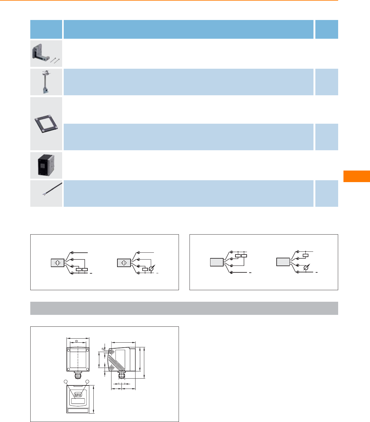
Type Description Order
no.
Fixture for mounting and fine adjustment of laser units · O1D · Clamp mounting · rod or free-standing depending on the clamp ·
Housing materials: fixture: aluminium transparent anodised / plastics: POM / screws: stainless steel E1D100
Mounting set · E2D101 + E20938 + E20951 E21079
Protective cover · O1D · Housing materials: bezel: ZnAl4Cu1 finish black / window: PMMA transparent and colourless / sealing: FPM
75+/-5 Shore A black / screws: stainless steel E21133
Protective cover · O1D · Housing materials: bezel: ZnAl4Cu1 finish black / window: glass transparent and colourless / sealing: FPM
75+/-5 Shore A black / screws: stainless steel E21171
Cooling box · Protective housing with an active cooling system for the O1D design · for type O1D · Housing materials: housing:
aluminium transparent anodised / cover: aluminium black anodised / bezel: aluminium black anodised / window: float glass / cable
gland: brass nickel-plated / nozzle: brass nickel-plated / sealing: FPM
E21248
Cable · 10 m E12274
Wiring diagrams
1
L+
L
3
4
2
1
Out 1
Out 2
4:
2:
4
L
L+
1
2
3
Out 1
Out 2
4:
2:
2
L
L+
Out 2
Out 1
2:
4: 3
4
2
1
L+
L
Out 2
Out 1
2:
4: 3
2
4
1
Scale drawings / drawing no. – CAD download: www.ifm.com
1
52
1 2
30
45
2520
4,5
6
45
59
42
M12x1
30
1: 4-digit alphanumeric display, 2: Programming buttons
Distance detection
261
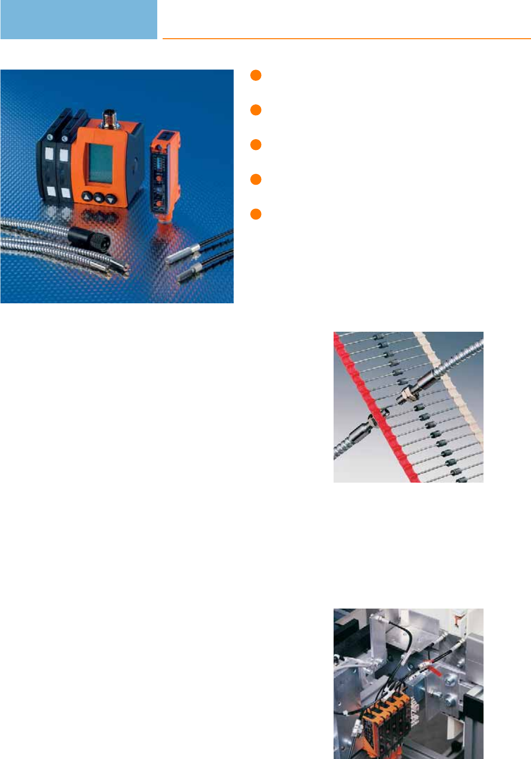
Easy connection of different fibre optics.
Manual or automatic setting by means
of “teach in”.
LED display to check operation,
switching status and function.
Various fibre materials for different
applications.
Easy mounting, also on DIN rail possible.
Fibre optics systems
If there is only little mounting space for standard photoelectric sensors, fibre optics
can be used. They are connected via fibre optic amplifiers which contain the control
monitor and photoelectric components. There are two operating principles:
Through-beam principle
Transmitting and receiving fibre optics are laid separately. The two ends (fibre optic
heads) are mounted opposite each other. The light beam interruption is evaluated
according to the through-beam principle.
Diffuse reflection principle
Transmitting and receiving fibre optics are in one sheath and one sensing head.
Evaluation is based on the diffuse reflection principle.
Classification of the fibre optics
Glass fibre optics
Fibre optics made of silicate glass are more resistant to heat, ageing and chemicals
than acrylic fibre optics. They do not change their optical response when they are
bent. Glass fibre optics cannot be cut to length by the user.
Acrylic fibre optics
Acrylic fibre optics are suited for standard applications if no particular demands
such as heat or chemical resistance are made. They can be cut to length and are less
expensive than glass fibre optics.
High-flex fibre optics
If the minimum bending radius is not adhered to, the fibre is damaged. High-flex
fibre optics allow extremely small bending radii.
Three versions of fibre optic amplifiers are available
Some versions of the OOF and OBF housings feature special functions: the function
check output indicates a problem of the unit before it fails (short circuit on the out-
put, internal fault, low excess gain). The pulse stretching function (delay time)
allows the user to set a minimum pulse duration on the switching output.
Minute objects up to
0.5 mm are detected
safely.
Fibre optic systems
can also be mounted
in places where access
is difficult.
Photoelectric sensors
262

System overview Page
OOF amplifiers for acrylic fibre optics 264
OBF amplifiers for acrylic fibre optics 264
Acrylic fibre optics for OBF / OOF housings, through-beam system 265
Acrylic fibre optics for OBF / OOF housings, through-beam system, highly flexible 265 - 266
Acrylic fibre optics for OBF / OOF housings, diffuse reflection system 266 - 267
Acrylic fibre optics for OBF / OOF housings, diffuse reflection system, highly flexible 267
Acrylic fibre optics for OBF / OOF housings, through-beam system, can be cut to length 267
Acrylic fibre optics for OBF / OOF housings, diffuse reflection system, can be cut to length 267
Acrylic fibres on a reel for OBF housing 268
OOF amplifiers for glass fibre optics 268
OKF amplifiers for glass fibre optics 268 - 269
OUF amplifiers for glass fibre optics 269
Glass fibre optics for OOF / OKF and OUF housings, through-beam system 269 - 270
Glass fibre optics for OOF / OKF and OUF housings, diffuse reflection system 270 - 271
Accessories 271 - 272
Wiring diagrams 273
Scale drawings / drawing no. – CAD download: www.ifm.com 274
Fibre optics
263
OOF amplifiers for acrylic fibre optics
Type Number
of input
channels
For
fibre
optics
Type
of light
Sensing
range
through beam
Sensing
range
diffuse
Output
H = light-on
D = dark-on
Ub
[V]
Draw-
ing
no.
Order
no.
Type OOF · M12 connector · plastics · DC · Wiring diagram no. 1 · Connector groups 15, 17, 18
2 FE/FT-11 red 3.8 m 0...300 mm H/D PNP 12...36 1 OO5000
Type OOF · M12 connector · plastics · DC · Wiring diagram no. 5 · Connector groups 17, 18
4 FE/FT-11 red 3.8 m 0...300 mm H/D PNP 12...36 2OO5001
Type OOF · M16 connector · plastics · DC · Wiring diagram no. 6 · Connector group 20
6 FE/FT-11 red 3.8 m 0...300 mm H/D PNP 12...36 3 OO5002
Type OOF · M16 connector · plastics · DC · Wiring diagram no. 7 · Connector group 20
8 FE/FT-11 red 3.8 m 0...300 mm H/D PNP 12...36 4OO5003
OBF amplifiers for acrylic fibre optics
Type Number
of input
channels
For
fibre
optics
Type
of light
Sensing
range
through beam
Sensing
range
diffuse
Output
H = light-on
D = dark-on
Ub
[V]
Draw-
ing
no.
Order
no.
Type OBF · M12 connector · plastics · DC · Wiring diagram no. 8 · Connector groups 9, 10, 11, 107, 108, 110, 135
1 FE/FT-11 red 0...2 m 0...100 mm H/D PNP/NPN 10...30 5 OBF500
Type OBF · M8 connector · plastics · DC · Wiring diagram no. 8 · Connector groups 4, 5, 70
1FE/FT-11 red 0...2 m 0...100 mm H/D PNP/NPN 10...30 6OBF501
Type OBF · Cable 2 m · plastics · DC · Wiring diagram no. 9
1 FE/FT-11 red 0...2 m 0...100 mm H/D PNP/NPN 10...30 7 OBF502
Type OBF · M8 connector · plastics · DC · Wiring diagram no. 10 · Connector groups 1, 3
1FE/FT-11 red 0...2 m 0...100 mm H/D PNP/NPN 10...30 6OBF503
Photoelectric sensors
264
Product selectors and further information can be found at: www.ifm.com
Acrylic fibre optics for OBF / OOF housings, through-beam system
Type System Fibre optic
material
Range
OB50.. / OBF5.. / OO50..
[mm]
Sensing
head
material
Ambient
temperature
[°C]
Sheathing
material
Draw-
ing
no.
Order
no.
FE-11 PMMA 60 / 130 / 160 aluminium -40...70 PE (polyethylene) 8 E20609
FE-11 PMMA 60 / 130 / 160 aluminium -40...70 PE (polyethylene) 9E20612
FE-11 PMMA 150 / 210 / 800 aluminium -40...70 PE (polyethylene) 9 E20615
FE-11 PMMA 150 / 300 / 700 aluminium -40...70 PE (polyethylene) 10 E20757
FE-11 PMMA 200 / 350 / 800 aluminium -40...70 PE (polyethylene) 11 E20603
FE-11 PMMA 200 / 450 / 800 aluminium -40...70 PE (polyethylene) 9E20606
FE-11 PMMA 400 / 900 / 1600 aluminium -40...70 PE (polyethylene) 12 E20753
FE-11 PMMA 1200 / 2000 / 3800 aluminium -40...70 PE (polyethylene) 13 E20752
FE-11 PMMA 60 / 130 / 160 stainless steel -40...70 PE (polyethylene) 14 E20751
FE-11 PMMA 140 / 230 / 400 stainless steel -40...70 PE (polyethylene) 15 E20714
FE-11 PMMA 200 / 450 / 800 stainless steel -40...70 PE (polyethylene) 16 E20750
FE-11 PMMA 20 / 20 / 20 PA -25...60 PE (polyethylene) 17 E20689
Acrylic fibre optics for OBF / OOF housings, through-beam system, highly flexible
Type System Fibre optic
material
Range
OB50.. / OBF5.. / OO50..
[mm]
Sensing
head
material
Ambient
temperature
[°C]
Sheathing
material
Draw-
ing
no.
Order
no.
FE-11 PMMA 50 / 56 / 120 aluminium -40...60 PE (polyethylene) 8 E21103
Fibre optics
265
You can find wiring diagrams and scale drawings from page 273
Type System Fibre optic
material
Range
OB50.. / OBF5.. / OO50..
[mm]
Sensing
head
material
Ambient
temperature
[°C]
Sheathing
material
Draw-
ing
no.
Order
no.
FE-11 PMMA 50 / 56 / 120 aluminium -40...60 PE (polyethylene) 9 E21104
FE-11 PMMA 250 / 350 / 750 aluminium -40...60 PE (polyethylene) 18 E21101
FE-11 PMMA 250 / 350 / 750 aluminium -40...60 PE (polyethylene) 9 E21102
Acrylic fibre optics for OBF / OOF housings, diffuse reflection system
Type System Fibre optic
material
Range
OB50.. / OBF5.. / OO50..
[mm]
Sensing
head
material
Ambient
temperature
[°C]
Sheathing
material
Draw-
ing
no.
Order
no.
FT-11 PMMA 6 / 10 / aluminium -40...70 PE (polyethylene) 19 E20756
FT-11 PMMA 20 / 25 / 60 aluminium -40...70 PE (polyethylene) 20 E20639
FT-11 PMMA 20 / 25 / 60 aluminium -40...70 PE (polyethylene) 11 E20712
FT-11 PMMA 60 / 70 / 300 aluminium -40...70 PE (polyethylene) 21 E20645
FT-11 PMMA 60 / 90 / 300 aluminium -40...70 PE (polyethylene) 21 E20651
FT-11 PMMA 60 / 70 / 300 aluminium -40...70 PE (polyethylene) 22 E20648
FT-11 PMMA 60 / 90 / 300 aluminium -40...70 PE (polyethylene) 22 E20654
FT-11 PMMA 60 / 75 / 200 aluminium -40...70 PE (polyethylene) 23 E20758
FT-11 PMMA 70 / 100 / 300 aluminium -40...70 PE (polyethylene) 22 E20633
FT-11 PMMA 15 / 25 / 60 stainless steel -40...70 PE (polyethylene) 24 E20748
FT-11 PMMA 20 / 25 / 60 stainless steel -40...70 PE (polyethylene) 25 E20711
Photoelectric sensors
266
Product selectors and further information can be found at: www.ifm.com
Type System Fibre optic
material
Range
OB50.. / OBF5.. / OO50..
[mm]
Sensing
head
material
Ambient
temperature
[°C]
Sheathing
material
Draw-
ing
no.
Order
no.
FT-11 PMMA 40 / 60 / 150 stainless steel -40...70 PE (polyethylene) 26 E20715
FT-11 PMMA 70 / 100 / 300 stainless steel -40...70 PE (polyethylene) 27 E20749
FE-11 PMMA – – -30...70 PE (polyethylene) 28 E20772
Acrylic fibre optics for OBF / OOF housings, diffuse reflection system, highly flexible
Type System Fibre optic
material
Range
OB50.. / OBF5.. / OO50..
[mm]
Sensing
head
material
Ambient
temperature
[°C]
Sheathing
material
Draw-
ing
no.
Order
no.
FT-11 PMMA 10 / 10 / 30 aluminium -40...60 PE (polyethylene) 29 E21106
FT-11 PMMA 10 / 10 / 30 aluminium -40...60 PE (polyethylene) 18 E21107
FT-11 PMMA 70 / 104 / 180 aluminium -40...60 PE (polyethylene) 30 E21105
Acrylic fibre optics for OBF / OOF housings, through-beam system, can be cut to length
Type System Fibre optic
material
Range
OB50.. / OBF5.. / OO50..
[mm]
Sensing
head
material
Ambient
temperature
[°C]
Sheathing
material
Draw-
ing
no.
Order
no.
FE-11 PMMA 175 / 370 / 700 aluminium -40...70 – 31 E20767
Acrylic fibre optics for OBF / OOF housings, diffuse reflection system, can be cut to length
Type System Fibre optic
material
Range
OB50.. / OBF5.. / OO50..
[mm]
Sensing
head
material
Ambient
temperature
[°C]
Sheathing
material
Draw-
ing
no.
Order
no.
FT-11 PMMA 55 / 110 / 235 aluminium -40...70 – 32 E20765
Fibre optics
267
You can find wiring diagrams and scale drawings from page 273
Acrylic fibres on a reel for OBF housing
Type Description Order
no.
acrylic fibres on a reel · 20 m · for type OBF · Housing materials: PE (polyethylene), Fibre optic: PMMA, can be cut to length E20773
acrylic fibres on a reel · 50 m · for type OBF · Housing materials: PE (polyethylene), Fibre optic: PMMA, can be cut to length E20774
acrylic fibres on a reel · 20 m · for type OBF · Housing materials: PE (polyethylene), Fibre optic: PMMA, can be cut to length E20775
OOF amplifiers for glass fibre optics
Type Number
of input
channels
For
fibre
optics
Type
of light
Sensing
range
through beam
Sensing
range
diffuse
Output
H = light-on
D = dark-on
Ub
[V]
Draw-
ing
no.
Order
no.
Type OOF · M12 connector · plastics · DC · Wiring diagram no. 1 · Connector groups 15, 17, 18
2 FE/FT-00 red 0.4 m 0...200 mm H/D PNP 12...36 33 OO5004
Type OOF · M12 connector · plastics · DC · Wiring diagram no. 5 · Connector groups 17, 18
4 FE/FT-00 red 0.4 m 0...200 mm H/D PNP 12...36 34 OO5005
Type OOF · M16 connector · plastics · DC · Wiring diagram no. 6 · Connector group 20
6 FE/FT-00 red 0.4 m 0...200 mm H/D PNP 12...36 35 OO5006
Type OOF · M16 connector · plastics · DC · Wiring diagram no. 7 · Connector group 20
8 FE/FT-00 red 0.4 m 0...200 mm H/D PNP 12...36 36 OO5007
OKF amplifiers for glass fibre optics
Type Number
of input
channels
For
fibre
optics
Type
of light
Sensing
range
through beam
Sensing
range
diffuse
Output
H = light-on
D = dark-on
Ub
[V]
Draw-
ing
no.
Order
no.
Type OKF · Cable 2 m · plastics · DC · Wiring diagram no. 11
1 FE/FT-00 red 0...0.12 m 0...40 mm H/D PNP 10...50 37 OK5001
Photoelectric sensors
268
Product selectors and further information can be found at: www.ifm.com
Type Number
of input
channels
For
fibre
optics
Type
of light
Sensing
range
through beam
Sensing
range
diffuse
Output
H = light-on
D = dark-on
Ub
[V]
Draw-
ing
no.
Order
no.
Type OKF · M12 connector · plastics · DC · Wiring diagram no. 12 · Connector groups 9, 10, 11, 107, 108, 110, 135
1 FE/FT-00 red 0...0.12 m 0...40 mm H/D PNP 10...50 38 OK5008
OUF amplifiers for glass fibre optics
Type Number
of input
channels
For
fibre
optics
Type
of light
Sensing
range
through beam
Sensing
range
diffuse
Output
H = light-on
D = dark-on
Ub
[V]
Draw-
ing
no.
Order
no.
Type OUF · Cable 2 m · plastics · DC · Wiring diagram no. 2
1 FE/FT-00 infrared 0.12 m 40 mm H PNP 10...55 39 OU5001
1FE/FT-00 infrared 0.12 m 40 mm D PNP 10...55 39 OU5002
Type OUF · M12 connector · plastics · DC · Wiring diagram no. 3 · Connector groups 9, 10, 11, 12, 107, 108, 109, 110, 135, 136
1 FE/FT-00 infrared 0...0.12 m 0...40 mm H PNP 10...50 40 OU5043
Type OUF · M12 connector · plastics · DC · Wiring diagram no. 4 · Connector groups 9, 10, 11, 12, 107, 108, 109, 110, 135, 136
1FE/FT-00 infrared 0...0.12 m 0...40 mm D PNP 10...50 40 OU5044
Glass fibre optics for OOF / OKF and OUF housings, through-beam system
Type System Fibre optic
material
Range
OOF / OKF / OUF
[mm]
Sensing
head
material
Ambient
temperature
[°C]
Sheathing
material
Draw-
ing
no.
Order
no.
FE-00 glass 400 / 120 / 120 aluminium -20...80 PVC 41 E20059
FE-00 glass 400 / 120 / 120 aluminium -20...80 PVC 42 E20060
FE-00 glass 400 / 120 / 120 aluminium -20...80 PVC 43 E20062
FE-00 glass 400 / 120 / 120 aluminium -20...80 PVC 44 E20228
Fibre optics
269
You can find wiring diagrams and scale drawings from page 273
Type System Fibre optic
material
Range
OOF / OKF / OUF
[mm]
Sensing
head
material
Ambient
temperature
[°C]
Sheathing
material
Draw-
ing
no.
Order
no.
FE-00 glass 160 / 50 / 50 stainless steel -20...80 PVC 45 E20061
FE-00 glass 400 / 120 / 120 aluminium -40...290 aluminium 46 E20128
FE-00 glass 400 / 120 / 120 aluminium -40...290 aluminium 47 E20130
FE-00 glass 400 / 120 / 120 aluminium -40...290 aluminium 48 E20129
FE-00 glass 160 / 50 / 50 stainless steel -40...290 aluminium 49 E20127
FE-00 glass 160 / 50 / 50 stainless steel -20...150 metal silicone 50 E20506
FE-00 glass 400 / 120 / 120 stainless steel -20...150 metal silicone 51 E20505
FE-00 glass 400 / 120 / 120 stainless steel -20...150 metal silicone 52 E20492
FE-00 glass 400 / 120 / 120 stainless steel -20...150 metal silicone 53 E20493
Glass fibre optics for OOF / OKF and OUF housings, diffuse reflection system
Type System Fibre optic
material
Range
OOF / OKF / OUF
[mm]
Sensing
head
material
Ambient
temperature
[°C]
Sheathing
material
Draw-
ing
no.
Order
no.
FT-00 glass 200 / 40 / 40 aluminium -20...80 PVC 54 E20051
FT-00 glass 200 / 40 / 40 aluminium -20...80 PVC 55 E20052
FT-00 glass 200 / 40 / 40 aluminium -20...80 PVC 56 E20054
FT-00 glass 200 / 40 / 40 brass -20...80 PVC 57 E20249
FT-00 glass 24 / 6 / 6 stainless steel -20...80 PVC 58 E20230
Photoelectric sensors
270
Product selectors and further information can be found at: www.ifm.com
Type System Fibre optic
material
Range
OOF / OKF / OUF
[mm]
Sensing
head
material
Ambient
temperature
[°C]
Sheathing
material
Draw-
ing
no.
Order
no.
FT-00 glass 24 / 8 / 8 stainless steel -20...80 PVC 45 E20053
FT-00 glass 200 / 40 / 40 aluminium -40...290 aluminium 59 E20055
FT-00 glass 200 / 40 / 40 aluminium -40...290 aluminium 60 E20056
FT-00 glass 200 / 40 / 40 aluminium -40...290 aluminium 61 E20058
FT-00 glass 24 / 8 / 8 stainless steel -40...290 aluminium 49 E20057
FT-00 glass 24 / 8 / 8 stainless steel -20...150 metal silicone 50 E20507
FT-00 glass 200 / 40 / 40 stainless steel -20...150 metal silicone 62 E20489
FT-00 glass 200 / 40 / 40 stainless steel -20...150 metal silicone 63 E20494
FT-00 glass 200 / 40 / 40 stainless steel -20...150 metal silicone 56 E20495
FT-00 glass - / 40 / 40 brass -20...80 –64 E20078
FT-00 glass 200 / 40 / 40 stainless steel -25...80 – 65 E20215
Accessories
Type Description Order
no.
Lens attachment · Ø 5 mm / M3 · for through-beam fibre optics · Housing materials: aluminium black anodised / glass · Pack
quantity: 1 E20679
Lens attachment · Ø 6 mm / M4 · for through-beam fibre optics · Housing materials: aluminium black anodised / glass · Pack
quantity: 1 E20680
Lens attachment · D5x10-M3-ALU · for through-beam fibre optics · M3 · Housing materials: aluminium black anodised · Pack
quantity: 2 E20754
Fibre optics
271
You can find wiring diagrams and scale drawings from page 273
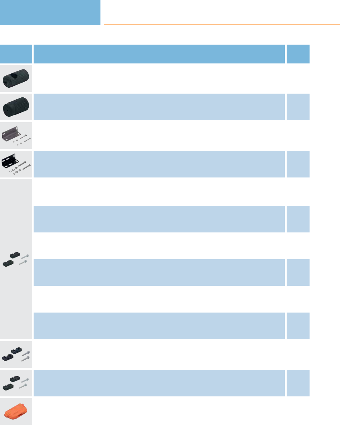
Type Description Order
no.
Lens attachment · D5x10-M4-ALU · for through-beam fibre optics · M4 · Housing materials: aluminium black anodised ·
Pack quantity: 2 E20755
Diaphragm attachment · D5x10-M3-ALU/D0.4 · for through-beam fibre optics · M3 · Housing materials: aluminium black anodised ·
Pack quantity: 2 E20762
Angle bracket · for type OBF · Housing materials: steel galvanised E20593
Angle bracket · OU · with mounting material · Housing materials: galvanised steel E20211
Mounting clamp · Ø 3 mm · for fibre optics · Housing materials: aluminium black anodised E20107
Mounting clamp · Ø 3.5 mm · for fibre optics · Housing materials: aluminium black anodised E20106
Mounting clamp · Ø 4.5 mm · for fibre optics · Housing materials: aluminium black anodised E20105
Mounting clamp · Ø 5 mm · for fibre optics · Housing materials: aluminium black anodised E20104
Mounting clamp · Ø 6 mm · for fibre optics · Housing materials: aluminium black anodised E20103
Mounting clamp · Ø 7 mm · for fibre optics · Housing materials: aluminium black anodised E20102
Mounting clamp · Ø 8 mm · Housing materials: aluminium black anodised E10221
Mounting clamp · Ø 10 mm · for fibre optics · Housing materials: PBT E20353
cutter for fibre optics · for type FE/FT-11 · Housing materials: plastics E20600
Photoelectric sensors
272
Product selectors and further information can be found at: www.ifm.com
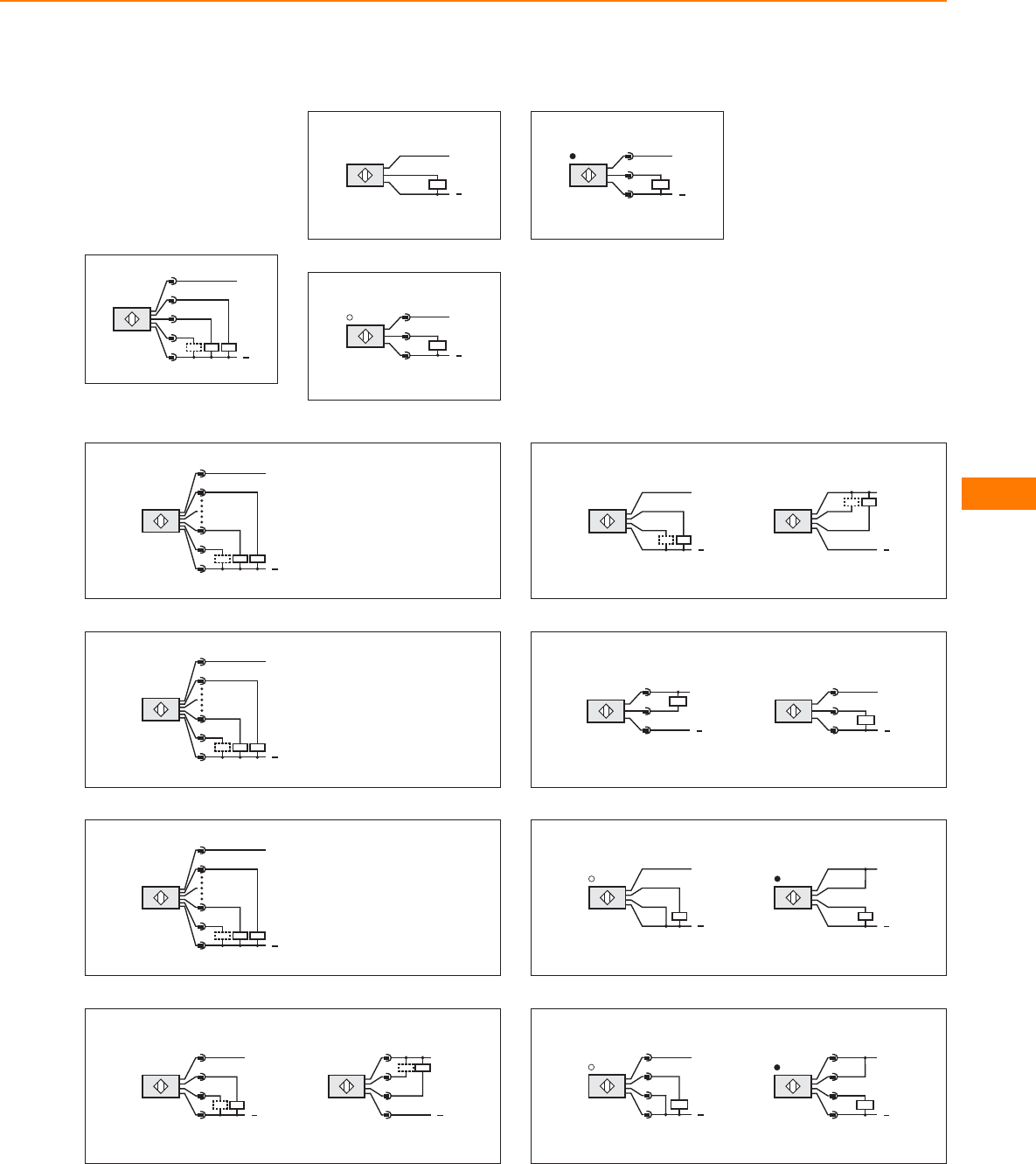
Core colours
BK black
BN brown
BU blue
VT lilac
WH white
Wiring diagrams
1
L+
L
1
4
2
7
3
Out 2
Out 1
2:
4:
2
BN
BK
BU
L+
L
3
L+
L
1
4
3
4
L+
L
1
2
3
5
4:
2:
5:
Out 1
Out 2
Out 3
6: Out 4
L+
L
1
4
6
7
3
6
L+
L
A
E
T
O
L
E:
P:
S:
Out 1
Out 2
Out 3
G: Out 4
C:
T:
Out 5
Out 6
7
E:
P:
S:
Out 1
Out 2
Out 3
G: Out 4
C:
T:
Out 5
Out 6
N:
J:
Out 7
Out 8
L+
L
A
E
J
O
L
8
2
L
L+
4
1
3
4
L
L+
2
1
3
9
L
L+
L
L+
BK
VT
BN
BU
BK
VT
BN
BU
10
L+
L
1
4
3
L+
L
1
4
3
11
L
L+
BU
BK
BN
WH
L
L+
WH
BU
BK
BN
12
L+
2
4
1
3
L
L
L+
4
2
1
3
Fibre optics
273
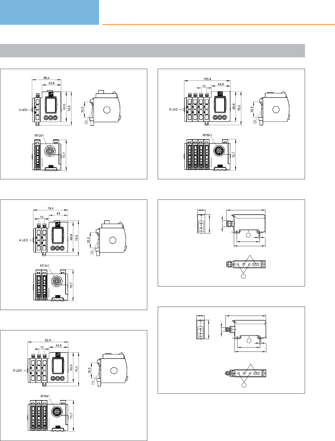
Scale drawings / drawing no. – CAD download: www.ifm.com
1
1: mounting on DIN rail
2
1: mounting on DIN rail
3
1: mounting on DIN rail
4
1: mounting on DIN rail
5
15
36
LED
2
M12 x1
1
74
60
44
3,2
1: mounting on DIN rail, 2: setting pushbuttons
6
LED
2
1
77
60
44
3,2
M8x1
15
36
1: mounting on DIN rail, 2: setting pushbuttons
Photoelectric sensors
274
Product selectors and further information can be found at: www.ifm.com
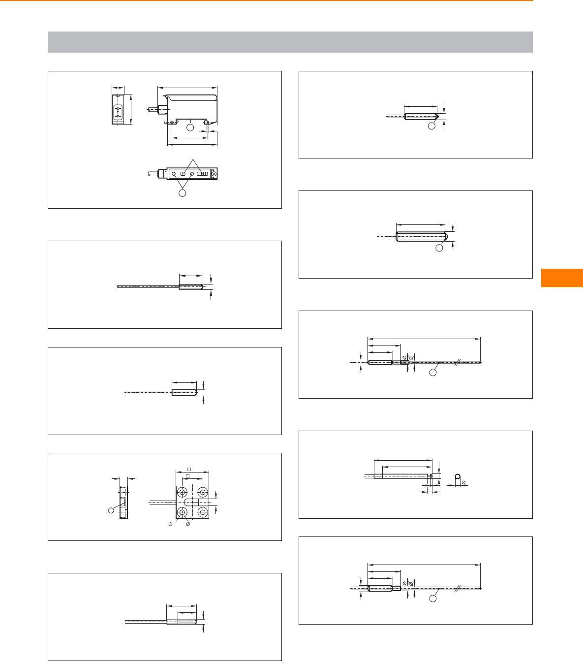
Scale drawings / drawing no. – CAD download: www.ifm.com
7
72
60
44
3,2
1
15
36
LED
2
1: mounting on DIN rail, 2: setting pushbuttons
8
14,5
M3
9
15
M4
10
4,3
20
12,3
3,4 6
5
1
1: Sensing surface
11
18
11
M3
12
20
M4
1
1: glass lens
13
M6
30
1
1: glass lens
14
15
20
M3
~110
2,3
1,5
1
1: bendable
15
35
30
2,9
3
1
3
16
~110
15
20
M4
2,9
2
1
1: bendable
Fibre optics
275
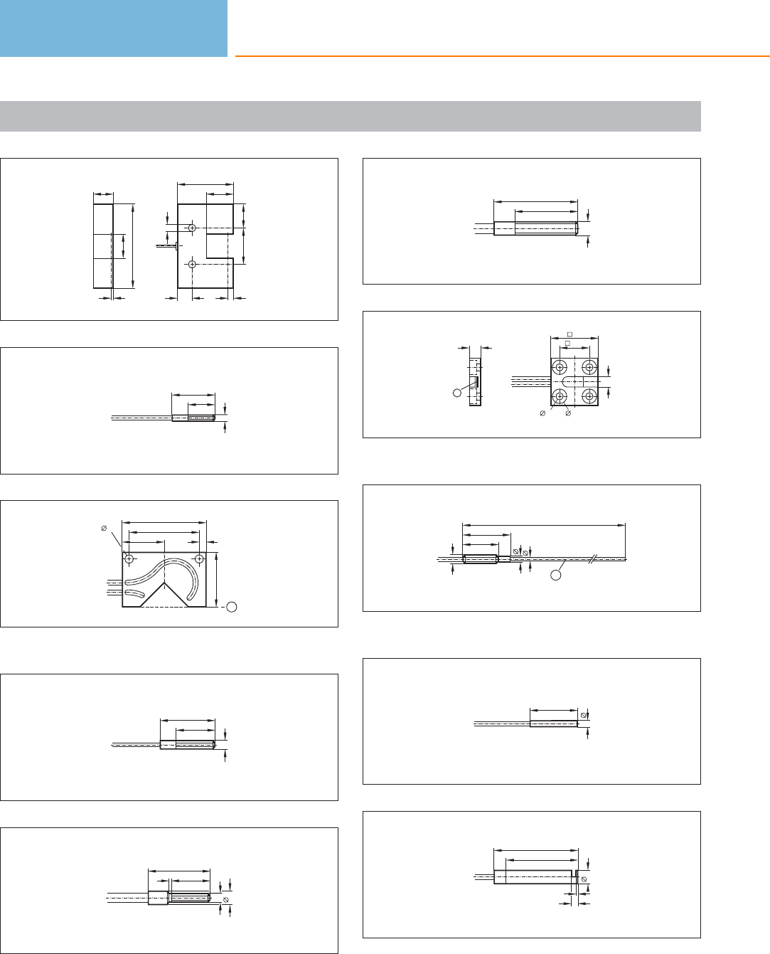
Scale drawings / drawing no. – CAD download: www.ifm.com
17
17
20
70
2
47
22
12,5
30 20
5
6,5
18
20
12
M3
19
17,5 3
29
35
3,4
23
1
1: Reference edge
20
23
M4
16
21
26
M4
161
6
22
35
M6
26
23
5
1
4,3
20
12,3
3,4 6
1: Sensing surface
24
15
20
M4
~110
2,9
1,6
1
1: bendable
25
20
3
26
35
30
6
3
1
Photoelectric sensors
276
Product selectors and further information can be found at: www.ifm.com
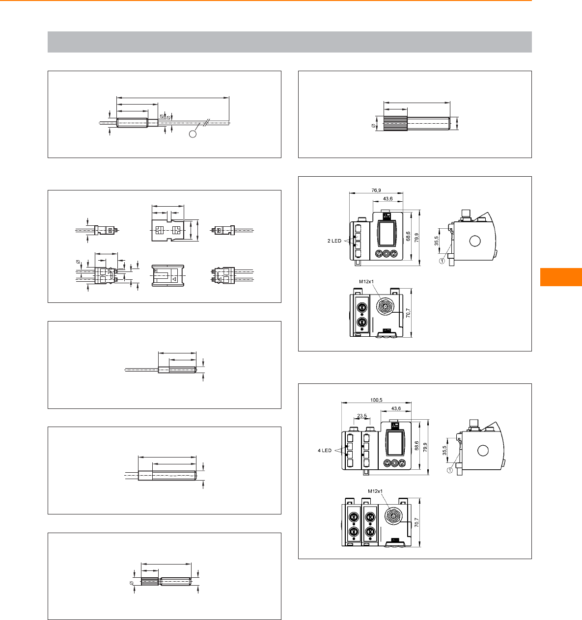
Scale drawings / drawing no. – CAD download: www.ifm.com
27
19
25
M6
~110
4,6
2,7
1
1: bendable
28
19,4
9,4 2,2
11
13
6
10,1
2,1
5,08
8,7
2x 2,2
7
13,7
29
23
M4
15
30
35
M6
23
31
30
10,5
5
M5
32
40
M8
9
14,5
33
1: mounting on DIN rail
34
1: mounting on DIN rail
Fibre optics
277
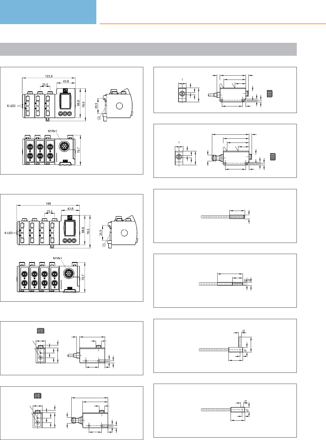
Scale drawings / drawing no. – CAD download: www.ifm.com
35
1: mounting on DIN rail
36
1: mounting on DIN rail
37
30 5
10
9
19
LED
pot.
12,5
25
4,3
4,1
506
M11x1
38
30 5
10
9
19
LED
pot.
12,5
25
4,3
4,1
50
M11x1
M12 x1
72
39
16
28
4
9
pot.
LED
7
40
4,3
3,5
51
21
6
43
pot.
LED
5
M11x1
40
16
28
4
9
pot.
LED
7
40
51
21
43
pot.
LED
M12 x1
73
4,3
3,5
5
M11x1
41
15
M4
42
25
10
2,5
3,5
43
14
15
5
3
2,5
44
14
5
3
2,5
Photoelectric sensors
278
Product selectors and further information can be found at: www.ifm.com
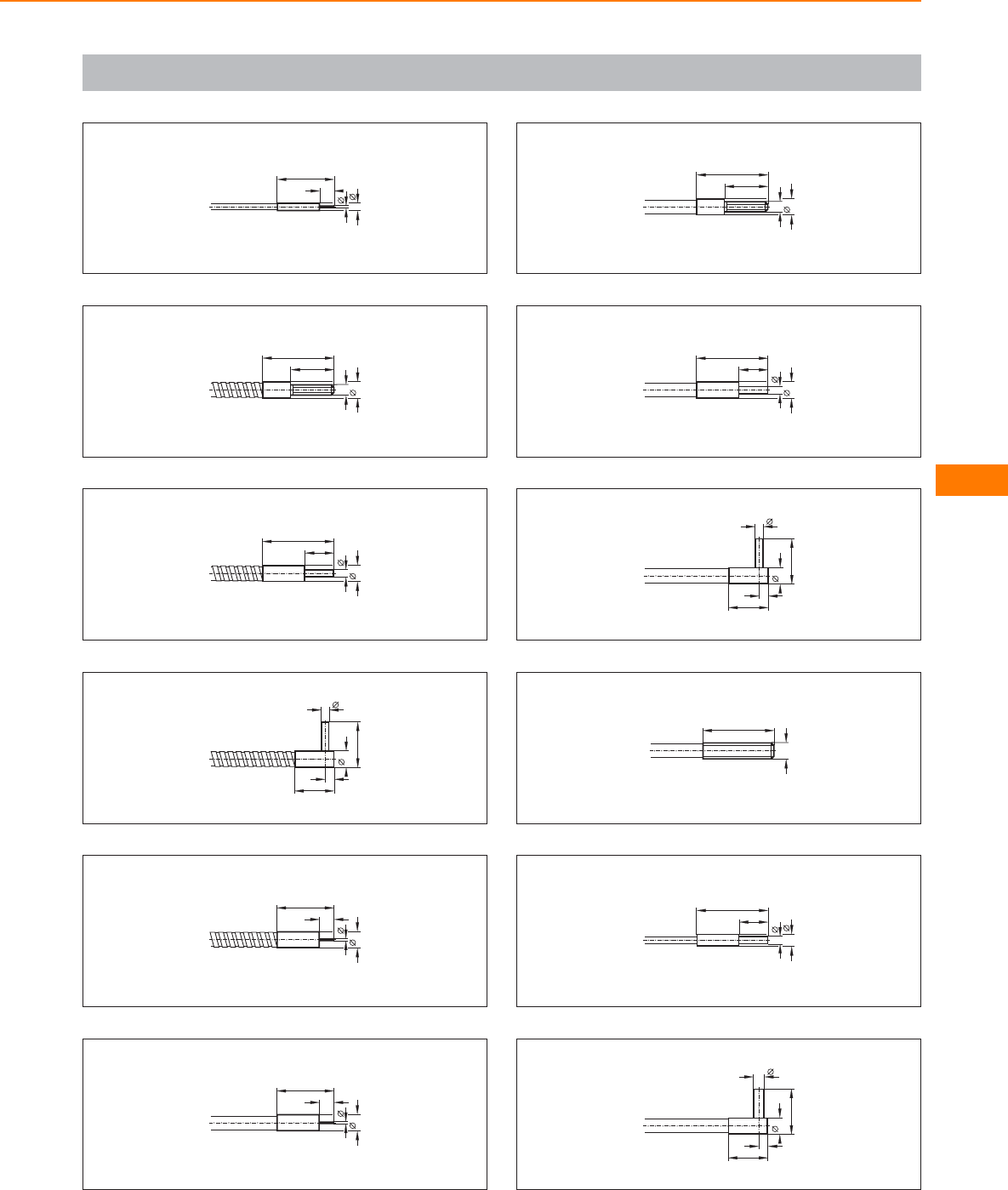
Scale drawings / drawing no. – CAD download: www.ifm.com
45
20
5
3
1
46
25
15
M4
6
47
25
10
3
6
48
14
16
6
3
3
49
20
5
6
1
50
20
5
6
1
51
25
15
M4
6
52
25
10
3
6
53
14
16
6
3
3
54
25
M6
55
25
10
3
4,5
56
14
16
6
4
3
Fibre optics
279
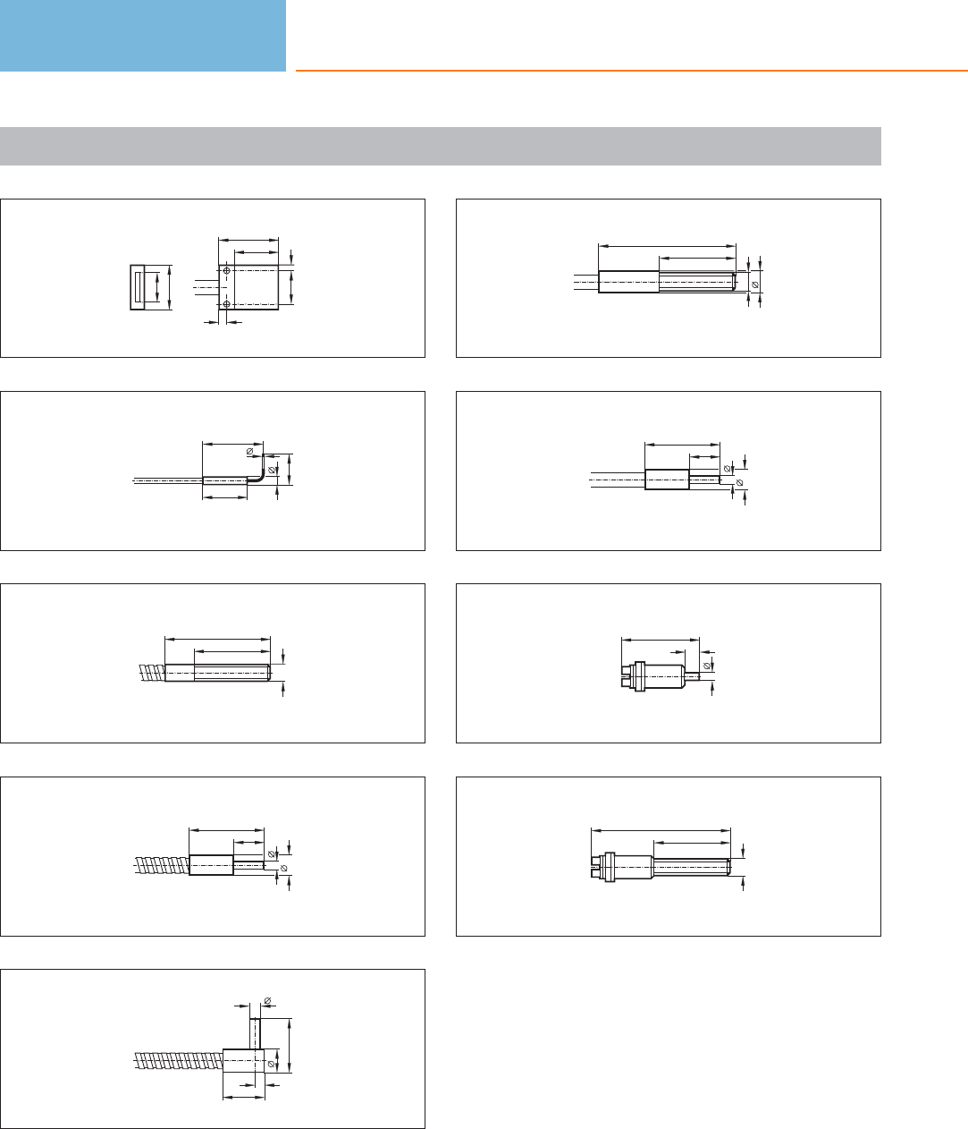
Scale drawings / drawing no. – CAD download: www.ifm.com
57
10
15
20
15
11
2,5
2
58
15
3
1
6
59
35
25
M6
60
25
10
3
7
61
14
18
8
4
3
62
45
25
M6
7
63
25
10
3
7
64
26
3
5
65
46
25
M6
Photoelectric sensors
280
Product selectors and further information can be found at: www.ifm.com

Fibre optics
281
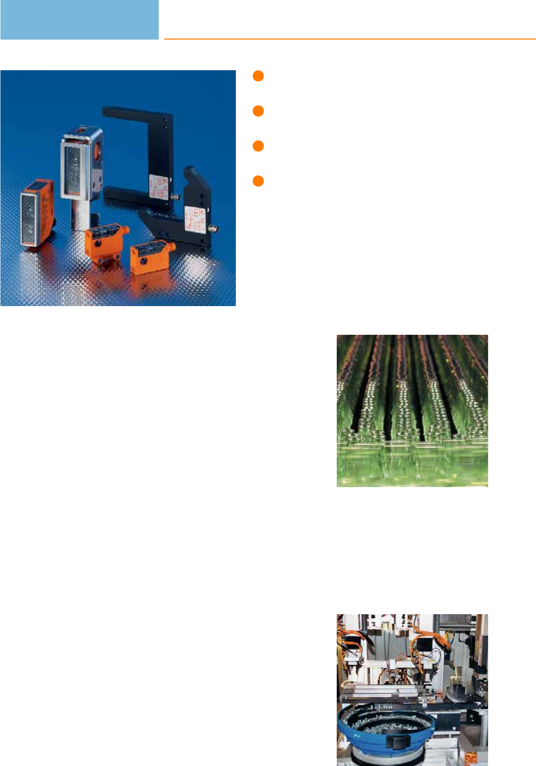
High-quality photoelectric sensors for
different applications.
Excellent price / performance ratio.
Easy adjustment via teach buttons
or potentiometer.
Wide range of system components
for easy and safe mounting.
Detection of transparent objects
Counting bottles and glasses or the reliable monitoring of film for tear can be
performed without problem using specially designed retro-reflective sensors.
ifm electronic offers a retro-reflective sensor with a small switching hysteresis, in
particular for the detection of transparent objects. Due to the operating principle,
retro-reflective sensors have the advantage that the light beam must pass the object
to be detected twice, weakening the light sufficiently to detect a transparent object
reliably. Precise adjustment is made by means of the teach buttons.
Contrast sensor
The O5 contrast sensor is specially suitable for detecting print marks and particularly
flat objects.
With its RGB transmitter LED the sensor detects even very small differences in
contrast. During set-up it automatically selects the optimum transmitter colour from
the colours red green blue (RGB) to ensure maximum energy difference of the
reflected light. In addition, the teach method saves time and money. Pressing the
teach buttons twice is enough for the sensor to be ready for operation.
High-resolution colour sensor
The new electronic colour sensor from ifm electronic detects the colour, packaging,
label or imprint of objects at a high resolution. With the five selectable tolerance
steps, the colour sensor perfectly differentiates even the finest shades of colour
from the background or other objects. The unit is set to the colour to be detected
by one push of the button. This saves time and money.
Optical fork and angle sensors
The optical fork and angle sensors are made from distortion-resistant diecast zinc
and feature a high switching frequency. Applications are in particular part monitor-
ing in feeding technology and handling systems. Further application examples are
belt edge and double feed monitoring.
Sensitivity setting using the potentiometer and setting of light-on / dark-on mode
using the rotary switch are simple and time-saving. No complex adjustment is
required because transmitter and receiver are already aligned towards each other.
Due to the fine and precise red light beam which is constant across the entire fork
width, out-of-balance monitoring of shafts can also be carried out.
Typical application for
contrast sensors:
Counting of glass
bottles.
The optical fork and
angle sensors are
especially used for
part monitoring in
feeding technology
and handling systems.
Photoelectric sensors
282

System overview Page
Sensors for the detection of transparent objects 284
Contrast sensors 284
Sensors for colour detection 285
Photoelectric sensors 285
Optical fork sensors 285 - 286
Laser fork sensors, laser class 2 286
Optical angle sensors 287
Prismatic reflector 287
Accessories O5 housing 287 - 288
Accessories for system components 288
Wiring diagrams 288 - 289
Scale drawings / drawing no. – CAD download: www.ifm.com 289 - 292
For specific systems
283
Sensors for the detection of transparent objects
Type Operating principle Range Type
of light
Spot Ø at
max.
range
[mm]
Output
H = light-on
D = dark-on
Wiring
diagr.
no.
Draw-
ing
no.
Order
no.
Retro-reflective sensor · PVC cable 0.15 m · 10...30 DC · plastics · IP 67 · Connector groups 9, 10, 11, 12, 107, 108, 109, 110, 135, 136
Polarisation filter 0.2...1.5 m red 64 H/D PNP 1 1 OJ5191
Polarisation filter 0.2...1.5 m red 64 H/D PNP 1 2 OJ5190
Retro-reflective sensor · M8 connector · 10...30 DC · plastics · IP 67 · Connector groups 4, 5, 70
Polarisation filter 0.2...1.5 m red 64 H/D PNP 2 3 OJ5085
Polarisation filter 0.2...1.5 m red 64 H/D PNP 2 4 OJ5086
Polarisation filter 0.2...1.5 m red 64 H/D PNP 2 5 OJ5186
Polarisation filter 0.2...1.5 m red 64 H/D NPN 3 5 OJ5189
Polarisation filter 0.2...1.5 m red 64 H/D PNP 2 6 OJ5185
Retro-reflective sensor · M12 connector · 10...36 DC · plastics · IP 67 · Connector groups 11, 13, 14, 107, 109, 110, 113, 115, 135, 137
Polarisation filter 0...1.5 m red 40 / 80 H/D PNP/NPN 7 7 O5G500
Contrast sensors
Type Operating principle Range Type
of light
Spot Ø at
max.
range
[mm]
Output
H = light-on
D = dark-on
Wiring
diagr.
no.
Draw-
ing
no.
Order
no.
M12 connector · 10...36 DC · plastics · IP 67 · Connector groups 11, 13, 14, 107, 109, 110, 113, 115, 135, 136, 137
Diffuse contrast sensor 18...22 mm red 1.5 x 5 H/D PNP/NPN 8 8 O5K500
Photoelectric sensors
284
Product selectors and further information can be found at: www.ifm.com
Sensors for colour detection
Type Operating principle Measuring
range
Light spot
diameter
[mm]
Ub
[V]
Current
consumption
[mA]
Sampling rate /
switching frequency
[Hz]
Draw-
ing
no.
Order
no.
M12 connector · Output function light-on / dark-on programmable · DC PNP/NPN · Wiring diagram no. 4 · Connector groups 11, 13,
14, 107, 109, 110, 113, 115, 135, 137
Colour sensor 15...19 mm 2.5 x 6 10...36 50 2000 8 O5C500
Photoelectric sensors
Type Dimensions
[mm]
Sensing
range
[mm]
Material Ub
[V]
Protection f
[Hz]
Iload
[mA]
Draw-
ing
no.
Order
no.
M12 connector · Output function · DC PNP · Wiring diagram no. 5 · Connector groups 107, 108, 110, 135
M12 / L = 63 50 f high-grade st. steel 10...30 IP 68 1600 100 9 JAC201
M12 / L = 63 50 f high-grade st. steel 10...30 IP 68 / IP 69K 1600 100 9JAT201
f = flush / nf = non flush
Optical fork sensors
Type Fork width
(w)
[mm]
Fork depth
(d)
[mm]
Smallest
detectable
object Ø
[mm]
Switching
frequency
[Hz]
Output
H = light-on
D = dark-on
Ub
[V]
Draw-
ing
no.
Order
no.
Optical fork sensor · Type OPU · M8 connector · metal · DC · Wiring diagram no. 9 · Connector groups 1, 2, 3, 68
10 17 0.3 10000 H/D PNP/NPN 10...35 10 OPU200
Optical fork sensor · Type OPU · M8 connector · metal · DC · Wiring diagram no. 1 · Connector groups 1, 2, 3, 68
20 25 0.4 4000 H/D PNP 10...35 11 OPU201
30 35 0.5 4000 H/D PNP 10...35 12 OPU202
50 55 0.5 4000 H/D PNP 10...35 13 OPU203
80 55 0.5 4000 H/D PNP 10...35 14 OPU204
For specific systems
285
You can find wiring diagrams and scale drawings from page 288
Type Fork width
(w)
[mm]
Fork depth
(d)
[mm]
Smallest
detectable
object Ø
[mm]
Switching
frequency
[Hz]
Output
H = light-on
D = dark-on
Ub
[V]
Draw-
ing
no.
Order
no.
Optical fork sensor · Type OPU · M8 connector · metal · DC · Wiring diagram no. 1 · Connector groups 1, 2, 3, 68
120 60 0.8 2000 H/D PNP 10...35 15 OPU205
Optical fork sensor · Type OPU · M8 connector · metal · DC · Wiring diagram no. 6 · Connector groups 1, 3, 68
20 25 0.4 4000 H/D NPN 10...35 11 OPU207
30 35 0.5 4000 H/D NPN 10...35 12 OPU208
50 55 0.5 4000 H/D NPN 10...35 13 OPU209
80 55 0.5 4000 H/D NPN 10...35 14 OPU210
120 60 0.8 2000 H/D NPN 10...35 15 OPU211
Laser fork sensors, laser class 2
Type Fork width
(w)
[mm]
Fork depth
(d)
[mm]
Smallest
detectable
object Ø
[mm]
Switching
frequency
[Hz]
Output
H = light-on
D = dark-on
Ub
[V]
Draw-
ing
no.
Order
no.
Optical fork sensor · Type OPU · M8 connector · metal · DC · Wiring diagram no. 1 · Connector groups 1, 2, 3, 68
30 30 0.05 3000 H/D PNP 10...30 16 OPU700
50 50 0.05 3000 H/D PNP 10...30 17 OPU701
80 50 0.05 3000 H/D PNP 10...30 18 OPU702
Photoelectric sensors
286
Product selectors and further information can be found at: www.ifm.com
Optical angle sensors
Type Side length
(x, y)
[mm]
Sensor width
(z)
[mm]
Smallest
detectable
object Ø
[mm]
Switching
frequency
[Hz]
Output
H = light-on
D = dark-on
Ub
[V]
Draw-
ing
no.
Order
no.
Optical angle sensor · Type OPL · M8 connector · metal · DC · Wiring diagram no. 1 · Connector groups 1, 2, 3, 68
50 60 0.5 4000 H/D PNP 10...35 19 OPL200
80 100 0.7 4000 H/D PNP 10...35 20 OPL201
Optical angle sensor · Type OPL · M8 connector · metal · DC · Wiring diagram no. 6 · Connector groups 1, 3, 68
50 60 0.5 4000 H/D NPN 10...35 19 OPL202
80 100 0.7 4000 H/D NPN 10...35 20 OPL203
Prismatic reflector
Type Description Order
no.
Prismatic reflector · 50 x 50 mm · rectangular · for red light and infrared light retro-reflective sensors · Housing materials: plastics E20744
Prismatic reflector · 50 x 50 mm · rectangular · for retro-reflective laser sensors and glass and film detection · Housing materials:
plastics E20722
Accessories O5 housing
Type Description Order
no.
Angle bracket · for type O5 · Housing materials: stainless steel 316Ti / 1.4571 E21085
Angle bracket · for type O5 · Housing materials: stainless steel 316Ti / 1.4571 E21087
Mounting set · Clamp mounting · with protective cover · rod mounting Ø 12 mm · for type O5 · Housing materials: fixture: stainless
steel 316Ti / 1.4571 / clamp: high-grade stainless steel E21223
Mounting set · Clamp mounting · with protective cover · rod mounting Ø 12 mm · for type O5 · Housing materials: stainless steel
316Ti / 1.4571 / clamp: diecast zinc E21210
For specific systems
287
You can find wiring diagrams and scale drawings from page 288
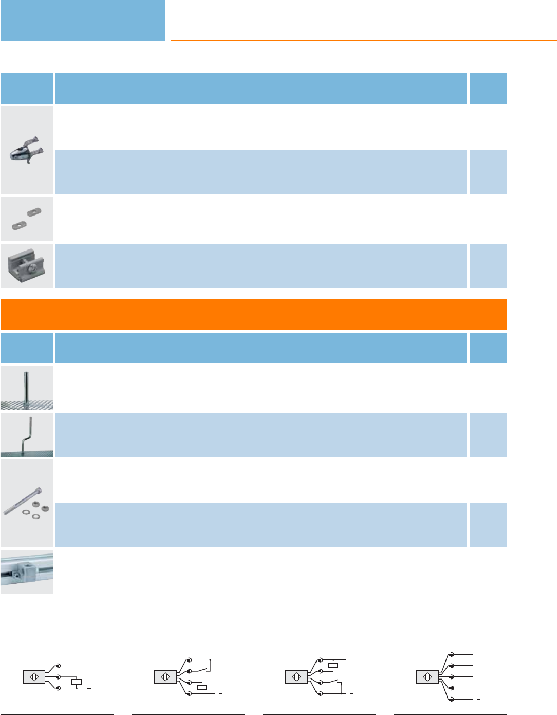
Type Description Order
no.
Mounting set · Clamp mounting · rod mounting Ø 12 mm · for type O5 · Housing materials: stainless steel 316Ti / 1.4571 / clamp:
diecast zinc E21211
Mounting set · Clamp mounting · rod mounting Ø 12 mm · for type O5 · Housing materials: stainless steel 316Ti / 1.4571 / clamp:
high-grade stainless steel E21212
Mounting brackets Mounting on the back of the unit · for type O5 · Housing materials: stainless steel 316Ti / 1.4571 E21086
Dovetail clamp · for type DTS, O4, O5 · Housing materials: AlMgSi0.5 E21088
Accessories for system components
Type Description Order
no.
mounting rod · Ø 12 / M10 · Length: 130 mm · straight · Housing materials: stainless steel 316Ti / 1.4571 E20938
mounting rod · Ø 12 / M10 · Length: 200 mm · angled · Housing materials: stainless steel 316Ti / 1.4571 E20940
Head cap screw · M10 x 120 mm · ISO 4762 (DIN 912) · free-standing M10 · Housing materials: screw: steel galvanised E21213
Head cap screw · M10 x 120 mm · ISO 4762 (DIN 912) · free-standing M10 · Housing materials: screw: high-grade stainless steel E21214
Cube · M10 · aluminium profile · Housing materials: diecast zinc E20951
Wiring diagrams
1
L+
L
1
4
3
2
L+
2
4
1
3
L
2: Teach
3
L+
2
4
1
3
L
2: Teach
4
L+
L
2
5
1
4
3
Out
N.C.
AT
Photoelectric sensors
288
Product selectors and further information can be found at: www.ifm.com
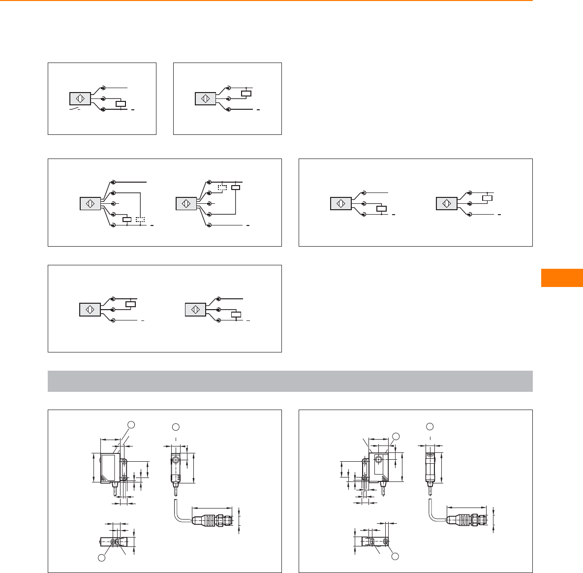
Wiring diagrams
5
L+
L
1
4
3
6
L+
L
1
4
3
7
L+
L
2
5
1
4
3
n.c.
L+
L
2
5
1
4
3
n.c.
8
L+
L
1
4
3
L+
L
1
4
3
9
L+
L
1
4
3
L+
L
1
4
3
Scale drawings / drawing no. – CAD download: www.ifm.com
1
1
36,5
11
LED
8,2
1
9
LED
4
11,6
1
24 LED
35
8,5
1,8
5,3
19
3,5
5
48
M12 x1
1: pushbutton
2
1
36,5
11
LED
LED
4
4
1
11,6
24
12
LED
8,2
35
3,5
8,5
5
1,8
5,3
19
1
48
M12 x1
1: pushbutton
For specific systems
289
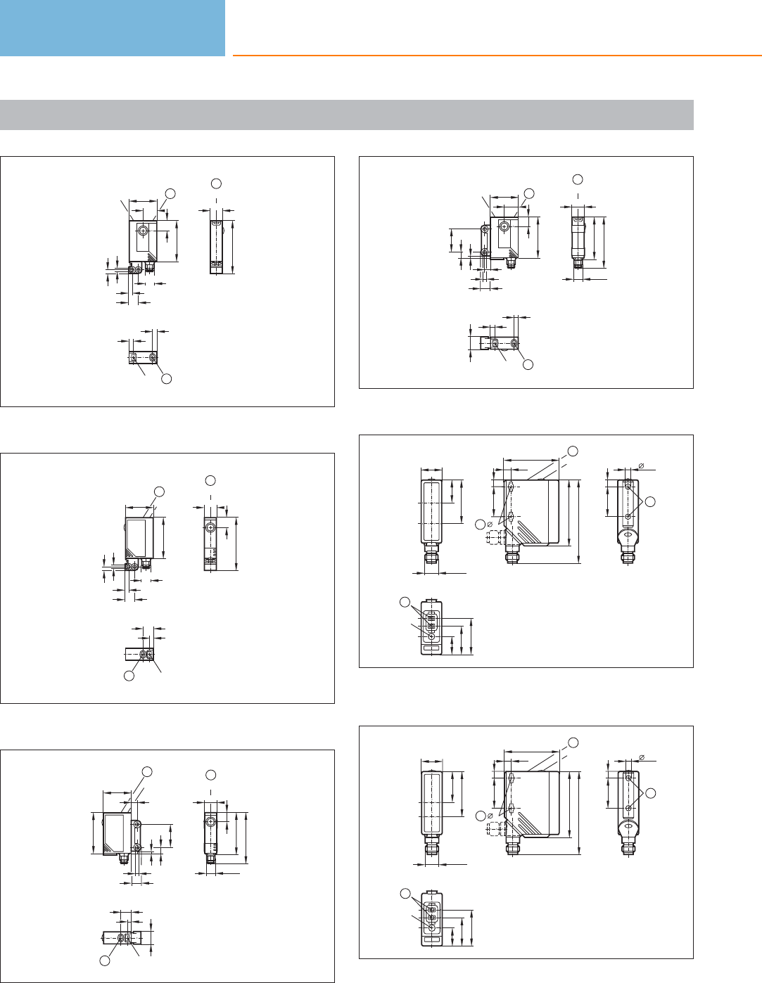
Scale drawings / drawing no. – CAD download: www.ifm.com
3
45
11
LED
1
4
LED
4
1
24
8,2
12
35
8,8
3,2
3,1
3,1
LED
M8x1
1
1: pushbutton
4
45
11
LED
8,2
1
24
3,2
3,1
LED
35
M8x1
8,8
3,1
1
9
LED
4
1
1: pushbutton
5
1
9
LED
4
11,6
M8x1
1
36,5
11
LED
8,2
43,5
1
24 LED
35
8,5
1,8
5,3
19
3,5
5
1: pushbutton
6
1
LED
4
4
11,6
1
36,5
11
LED
43,5
M8x1
19
1
24
12
LED
8,2
35
3,5
8,5
5
1,8
5,3
1: pushbutton
7
18,2
M12 x1
19,5
37
1
LED
30,5
24,3
15,4
5x9
6
25
2
56
6,4
46,8
25
70,3
5
1
LED
6
2
1: Programming buttons, 2: When a M5 mounting screw is used, the
max. tightening torque is 2 Nm.
8
56
6,4
46,8
25
70,3
5
1
LED
6
2
1
LED
30,5
24,3
15,4
5x9
6
25
2
18,2
M12 x1
25,9
38
1: Programming buttons, 2: When a M5 mounting screw is used, the
max. tightening torque is 2 Nm.
Photoelectric sensors
290
Product selectors and further information can be found at: www.ifm.com
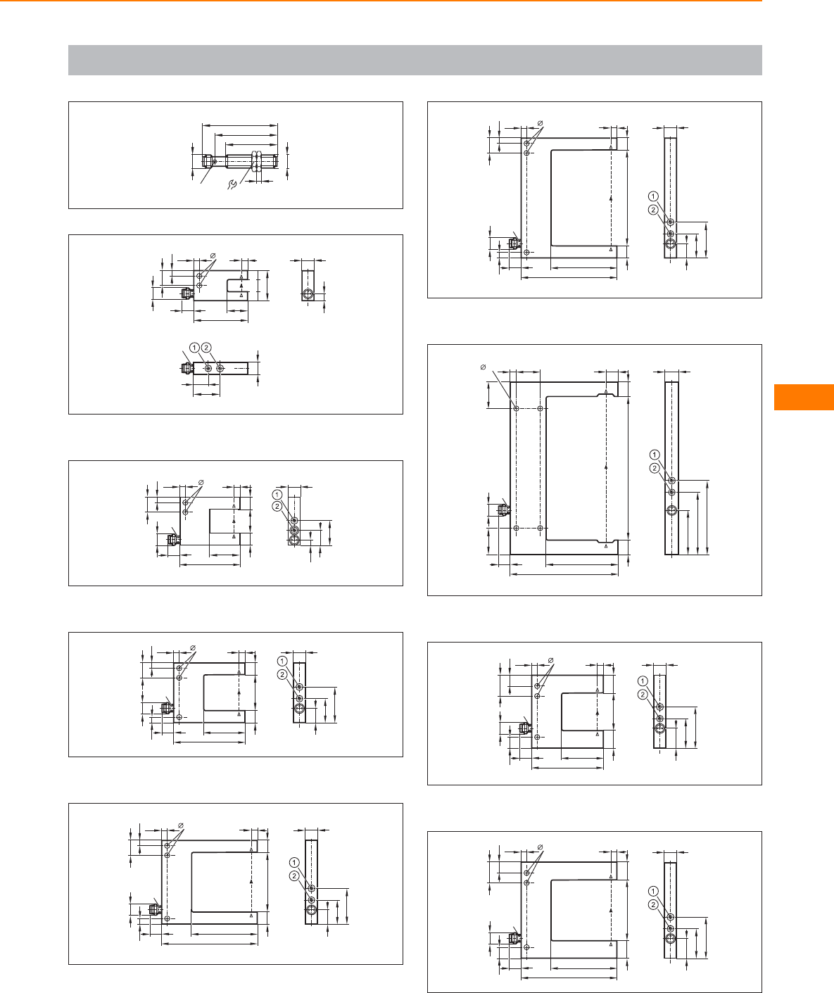
Scale drawings / drawing no. – CAD download: www.ifm.com
9
M12x1
17
4
M12 x1
52
63
LED 4 x 90°
43
10
6
M8x1
10
4,3
4,5
4,5
12,5
10
W=10
4
D=17
45
25
LED
12
22
10
1: output function switch , 2: potentiometer sensitivity
11
W=20
4,3
4,5
4,5
D=25
5
50
M8x1
10
LED
12,5
1010
4,5
12
20,5
10
1: potentiometer sensitivity, 2: output function switch
12
12
20
30
M8x1
10
LED
4,3
4,5
4,5
4,5
12,5
10
10 10
W=30
5
D=35
60
1: potentiometer sensitivity, 2: output function switch
13
12
20
30
10
M8x1
10
LED
4,3
4,5
4,5
4,5
12,5
10 10
W=50
5
D=55
80
1: potentiometer sensitivity, 2: output function switch
14
12
20
30
M8x1
10
LED
4,3
4,5
4,54,5
12,5
10
10 10
W=80
5
D=55
80
1: potentiometer sensitivity, 2: output function switch
15
37
52
62
12
M8x1
10
LED
4,3 520
2222
12 12
W=120
10
D=60
90
1: potentiometer sensitivity, 2: output function switch
16
17
25
35
10
M8x1
10
LED
4,3
4,5
9,59,5
17,5
15 15
W=30
5
D=35
60
1: potentiometer sensitivity, 2: output function switch
17
17
25
35
10
M8x1
10
LED
4,3
4,5
9,59,5
17,5
15 15
W=50
5
D=55
80
1: potentiometer sensitivity, 2: output function switch
For specific systems
291
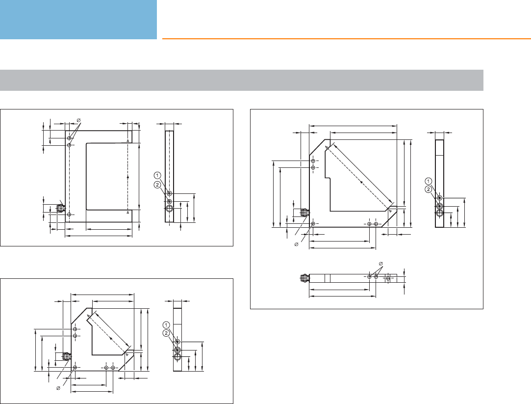
Scale drawings / drawing no. – CAD download: www.ifm.com
18
17
25
35
M8x1
10
LED
4,3
4,5
9,59,5
17,5
10
15 15
W=80
5
D=55
80
1: potentiometer sensitivity, 2: output function switch
19
75
10
Z
60
Y=50
75
22,5
4,3
4,5
4,5
42
50
X=50
M8x1
42
50
10,5
LED
17,5
25,5
35,5
10
1: potentiometer sensitivity, 2: output function switch
20
105
10
Z
100
Y=80
105
22,5
4,3
4,5
4,5
72
80
X=80
M8x1
72
80
10,5
LED
72
80
4,3
6,7
17,5
25,5
35,5
10
1: potentiometer sensitivity, 2: output function switch
Photoelectric sensors
292
Product selectors and further information can be found at: www.ifm.com

For specific systems
293
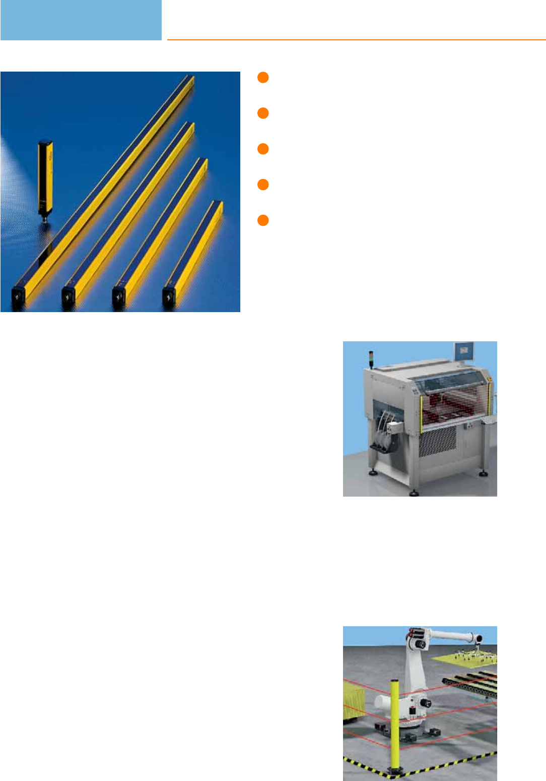
Slim design with ranges up to
20 m for all protected areas.
Type 2 and type 4 safety
light curtains to IEC 61496.
With SIL 2 & 3 to IEC 61508
and PL d & e to ISO 13849.
Can be installed in L shape
without dead band.
Easy connection via the tried
and tested M12 connector.
Safety light curtains and light grids
Safety light curtains and safety light grids are used where movements of machine
parts represent a risk for people or goods.
The difference of the systems is the different resolution of the beams.
Depending on the risk, the protective function is classified into finger, hand or body
protection as well as primary guarding. When the light beam is interrupted, the
protective equipment ensures deactivation of the outputs. The machine is brought
into the state defined as safe.
Tested safety
The safety light curtains and light grids from ifm electronic have been developed
according to the current standards EN 61496, ISO 13849-1 and IEC 62061 and
certified by TÜV. They meet the requirements of type 2 with SILcl 2 and PL d as well
as type 4 with SILcl 3 and PL e.
Slim design and long range
The safety light curtains and safety light grids from ifm electronic are distinguished
by the very slim design (28 x 30 mm) and long ranges up to 20 m. Finger, hand and
body protection reliably ensure primary guarding or access prevention. ifm offers
new safety light grids for applications with especially long ranges. The new housing
of our OY9 is slightly bigger and offers a range up to 60 m.
These light curtains are designed for protected area heights of 160 mm to 1510
mm in intervals of 150 mm. A resolution (detection capacity) of 14, 20, 30, 40, 50
or 90 mm can be selected. Light grids are offered with 2, 3 or 4 beams.
Safety light grids are also available as active / passive system.
Safety light curtains
can be used for finger
or hand protection.
Safe protection of
bodies on a robot cell.
Photoelectric sensors
294

System overview Page
Safety light curtains type 4, SIL 3, PL e, resolution 14 mm, protected area width up to 6 m 296
Safety light curtains type 4, SIL 3, PL e, resolution 20 mm, protected area width up to 20 m 296 - 297
Safety light curtains type 4, SIL 3, PL e, resolution 30 mm, protected area width up to 12 m 297 - 298
Safety light curtains type 4, SIL 3, PL e, resolution 30 mm, protected area width up to 20 m 298 - 299
Safety light curtains type 4, SIL 3, PL e, resolution 40 mm, protected area width up to 12 m 299
Safety light curtains type 4, SIL 3, PL e, resolution 40 mm, protected area width up to 20 m 300
Safety light curtains type 4, SIL 3, PL e, resolution 50 mm, protected area width up to 12 m 300 - 301
Safety light curtains type 4, SIL 3, PL e, resolution 50 mm, protected area width up to 20 m 301 - 302
Safety light curtains type 4, SIL 3, PL e, resolution 90 mm, protected area width up to 12 m 302
Safety light curtains type 4, SIL 3, PL e, resolution 90 mm, protected area width up to 20 m 303
Safety light grids type 4, SIL 3, PL e, 2, 3, 4 beams, protected area width up to 12 m 303
Safety light grids type 4, SIL 3, PL e, 2, 3, 4 beams, protected area width up to 20 m 304
Safety light curtains type 2, SIL 2, PL d, resolution 30 mm, protected area width up to 12 m 304 - 305
Safety light curtains type 2, SIL 2, PL d, resolution 40 mm, protected area width up to 12 m 305
Safety light curtains type 2, SIL 2, PL d, resolution 50 mm, protected area width up to 12 m 306
Safety light curtains type 2, SIL 2, PL d, resolution 90 mm, protected area width up to 12 m 306 - 307
Safety light grids type 2, SIL 2, PL d, 2, 3, 4 beams, protected area width up to 12 m 307
Safety light curtains for hygienic and wet areas type 4, SIL 3, PL e, resolution 14 mm,
protected area width up to 5 m 307
Safety light curtains for hygienic and wet areas type 4, SIL 3, PL e, resolution 30 mm,
protected area width up to 15 m 308
Safety light grids for hygienic and wet areas type 4, SIL 3, PL e, 2, 3, 4 beams,
protected area width up to 15 m 308 - 309
Safety light curtains for hygienic and wet areas type 2, SIL 2, PL d, resolution 30 mm,
protected area width up to 10 m 309
Safety light grids type 4, SIL 3, PL e, 2, 3, 4 beams, protected area width up to 60 m 310
Safety light grids with active / passive system type 4, SIL 3, PL e, 2, 3, 4 beams, protected area width up to 6 m 310
Safety light grids for hygienic and wet areas type 2, SIL 2, PL d, 2, 3, 4 beams, protected area width up to 10 m 310
Safety relays for safety light curtains 311
Accessories for safety light curtains 311 - 313
Bases for safety light curtains 313
Bases for safety light curtains with corner mirror 313
Accessories necessary for bases 313
Wiring diagrams 314
Scale drawings / drawing no. – CAD download: www.ifm.com 315
Safety light curtains /
light grids
295
Safety light curtains type 4, SIL 3, PL e, resolution 14 mm, protected area width up to 6 m
Type Sensor
length
[mm]
Resolution /
detection capacity
[mm]
Protected area
height
[mm]
Protected area
width
[m]
Response
time
[ms]
Ub
[V]
Draw-
ing
no.
Order
no.
M12 connector · Wiring diagram no. 1, 2 · Connector groups 17, 18
213 14 160 0...3 / 1...6 4 24 1 OY001S
363 14 310 0...3 / 1...6 5.5 24 1OY002S
513 14 460 0...3 / 1...6 7.5 24 1 OY003S
663 14 610 0...3 / 1...6 924 1OY004S
813 14 760 0...3 / 1...6 11 24 1 OY005S
963 14 910 0...3 / 1...6 13 24 1OY006S
1113 14 1060 0...3 / 1...6 14.5 24 1 OY007S
1263 14 1210 0...3 / 1...6 16.5 24 1OY008S
1413 14 1360 0...3 / 1...6 18 24 1 OY009S
1563 14 1510 0...3 / 1...6 20 24 1OY010S
Safety light curtains type 4, SIL 3, PL e, resolution 20 mm, protected area width up to 20 m
Type Sensor
length
[mm]
Resolution /
detection capacity
[mm]
Protected area
height
[mm]
Protected area
width
[m]
Response
time
[ms]
Ub
[V]
Draw-
ing
no.
Order
no.
M12 connector · Wiring diagram no. 1, 2 · Connector groups 17, 18
213 20 160 0...10 / 3...20 4 24 1 OY221S
363 20 310 0...10 / 3...20 5.5 24 1OY222S
Photoelectric sensors
296
Product selectors and further information can be found at: www.ifm.com
Type Sensor
length
[mm]
Resolution /
detection capacity
[mm]
Protected area
height
[mm]
Protected area
width
[m]
Response
time
[ms]
Ub
[V]
Draw-
ing
no.
Order
no.
M12 connector · Wiring diagram no. 1, 2 · Connector groups 17, 18
513 20 460 0...10 / 3...20 7.5 24 1 OY223S
663 20 610 0...10 / 3...20 924 1OY224S
813 20 760 0...10 / 3...20 11 24 1 OY225S
963 20 910 0...10 / 3...20 13 24 1OY226S
1113 20 1060 0...10 / 3...20 14.5 24 1 OY227S
1263 20 1210 0...10 / 3...20 16.5 24 1OY228S
1413 20 1360 0...10 / 3...20 18 24 1 OY229S
1563 20 1510 0...10 / 3...20 20 24 1OY230S
Safety light curtains type 4, SIL 3, PL e, resolution 30 mm, protected area width up to 12 m
Type Sensor
length
[mm]
Resolution /
detection capacity
[mm]
Protected area
height
[mm]
Protected area
width
[m]
Response
time
[ms]
Ub
[V]
Draw-
ing
no.
Order
no.
M12 connector · Wiring diagram no. 1, 2 · Connector groups 17, 18
213 30 160 0...4 / 3...12 4 24 2 OY041S
363 30 310 0...4 / 3...12 5.5 24 2OY042S
513 30 460 0...4 / 3...12 7.5 24 2 OY043S
663 30 610 0...4 / 3...12 8.5 24 2OY044S
813 30 760 0...4 / 3...12 10.5 24 2 OY045S
Safety light curtains /
light grids
297
You can find wiring diagrams and scale drawings from page 314
Type Sensor
length
[mm]
Resolution /
detection capacity
[mm]
Protected area
height
[mm]
Protected area
width
[m]
Response
time
[ms]
Ub
[V]
Draw-
ing
no.
Order
no.
M12 connector · Wiring diagram no. 1, 2 · Connector groups 17, 18
963 30 910 0...4 / 3...12 12 24 2 OY046S
1113 30 1060 0...4 / 3...12 14 24 2OY047S
1263 30 1210 0...4 / 3...12 15.5 24 2 OY048S
1413 30 1360 0...4 / 3...12 17 24 2OY049S
1563 30 1510 0...4 / 3...12 18.5 24 2 OY050S
Safety light curtains type 4, SIL 3, PL e, resolution 30 mm, protected area width up to 20 m
Type Sensor
length
[mm]
Resolution /
detection capacity
[mm]
Protected area
height
[mm]
Protected area
width
[m]
Response
time
[ms]
Ub
[V]
Draw-
ing
no.
Order
no.
M12 connector · Wiring diagram no. 1, 2 · Connector groups 17, 18
213 30 160 0...10 / 3...20 3 24 1 OY241S
363 30 310 0...10 / 3...20 424 1OY242S
513 30 460 0...10 / 3...20 5 24 1 OY243S
663 30 610 0...10 / 3...20 624 1OY244S
813 30 760 0...10 / 3...20 6.5 24 1 OY245S
963 30 910 0...10 / 3...20 7.5 24 1OY246S
1113 30 1060 0...10 / 3...20 8.5 24 1 OY247S
1263 30 1210 0...10 / 3...20 9.5 24 1OY248S
Photoelectric sensors
298
Product selectors and further information can be found at: www.ifm.com
Type Sensor
length
[mm]
Resolution /
detection capacity
[mm]
Protected area
height
[mm]
Protected area
width
[m]
Response
time
[ms]
Ub
[V]
Draw-
ing
no.
Order
no.
M12 connector · Wiring diagram no. 1, 2 · Connector groups 17, 18
1413 30 1360 0...10 / 3...20 10 24 1 OY249S
1563 30 1510 0...10 / 3...20 11 24 1OY250S
Safety light curtains type 4, SIL 3, PL e, resolution 40 mm, protected area width up to 12 m
Type Sensor
length
[mm]
Resolution /
detection capacity
[mm]
Protected area
height
[mm]
Protected area
width
[m]
Response
time
[ms]
Ub
[V]
Draw-
ing
no.
Order
no.
M12 connector · Wiring diagram no. 1, 2 · Connector groups 17, 18
213 40 160 0...4 / 3...12 3.5 24 2 OY061S
363 40 310 0...4 / 3...12 4.5 24 2OY062S
513 40 460 0...4 / 3...12 5.5 24 2 OY063S
663 40 610 0...4 / 3...12 6.5 24 2OY064S
813 40 760 0...4 / 3...12 7.5 24 2 OY065S
963 40 910 0...4 / 3...12 924 2OY066S
1113 40 1060 0...4 / 3...12 10 24 2 OY067S
1263 40 1210 0...4 / 3...12 11 24 2OY068S
1413 40 1360 0...4 / 3...12 12 24 2 OY069S
1563 40 1510 0...4 / 3...12 13 24 2OY070S
Safety light curtains /
light grids
299
You can find wiring diagrams and scale drawings from page 314

Safety light curtains type 4, SIL 3, PL e, resolution 40 mm, protected area width up to 20 m
Type Sensor
length
[mm]
Resolution /
detection capacity
[mm]
Protected area
height
[mm]
Protected area
width
[m]
Response
time
[ms]
Ub
[V]
Draw-
ing
no.
Order
no.
M12 connector · Wiring diagram no. 1, 2 · Connector groups 17, 18
213 40 160 0...10 / 3...20 3 24 1 OY261S
363 40 310 0...10 / 3...20 3.5 24 1OY262S
513 40 460 0...10 / 3...20 4 24 1 OY263S
663 40 610 0...10 / 3...20 4.5 24 1OY264S
813 40 760 0...10 / 3...20 5 24 1 OY265S
963 40 910 0...10 / 3...20 624 1OY266S
1113 40 1060 0...10 / 3...20 6.5 24 1 OY267S
1263 40 1210 0...10 / 3...20 724 1OY268S
1413 40 1360 0...10 / 3...20 7.5 24 1 OY269S
1563 40 1510 0...10 / 3...20 824 1OY270S
Safety light curtains type 4, SIL 3, PL e, resolution 50 mm, protected area width up to 12 m
Type Sensor
length
[mm]
Resolution /
detection capacity
[mm]
Protected area
height
[mm]
Protected area
width
[m]
Response
time
[ms]
Ub
[V]
Draw-
ing
no.
Order
no.
M12 connector · Wiring diagram no. 1, 2 · Connector groups 17, 18
363 50 310 0...4 / 3...12 4 24 2 OY082S
513 50 460 0...4 / 3...12 4.5 24 2OY083S
Photoelectric sensors
300
Product selectors and further information can be found at: www.ifm.com
Type Sensor
length
[mm]
Resolution /
detection capacity
[mm]
Protected area
height
[mm]
Protected area
width
[m]
Response
time
[ms]
Ub
[V]
Draw-
ing
no.
Order
no.
M12 connector · Wiring diagram no. 1, 2 · Connector groups 17, 18
663 50 610 0...4 / 3...12 5.5 24 2 OY084S
813 50 760 0...4 / 3...12 6.5 24 2OY085S
963 50 910 0...4 / 3...12 7.5 24 2 OY086S
1113 50 1060 0...4 / 3...12 8.5 24 2OY087S
1263 50 1210 0...4 / 3...12 9 24 2 OY088S
1413 50 1360 0...4 / 3...12 10 24 2OY089S
1563 50 1510 0...4 / 3...12 11 24 2 OY090S
Safety light curtains type 4, SIL 3, PL e, resolution 50 mm, protected area width up to 20 m
Type Sensor
length
[mm]
Resolution /
detection capacity
[mm]
Protected area
height
[mm]
Protected area
width
[m]
Response
time
[ms]
Ub
[V]
Draw-
ing
no.
Order
no.
M12 connector · Wiring diagram no. 1, 2 · Connector groups 17, 18
363 50 310 0...10 / 3...20 3 24 1 OY282S
513 50 460 0...10 / 3...20 3.5 24 1OY283S
663 50 610 0...10 / 3...20 4 24 1 OY284S
813 50 760 0...10 / 3...20 4.5 24 1OY285S
963 50 910 0...10 / 3...20 5 24 1 OY286S
1113 50 1060 0...10 / 3...20 5.5 24 1OY287S
Safety light curtains /
light grids
301
You can find wiring diagrams and scale drawings from page 314
Type Sensor
length
[mm]
Resolution /
detection capacity
[mm]
Protected area
height
[mm]
Protected area
width
[m]
Response
time
[ms]
Ub
[V]
Draw-
ing
no.
Order
no.
M12 connector · Wiring diagram no. 1, 2 · Connector groups 17, 18
1263 50 1210 0...10 / 3...20 6 24 1 OY288S
1413 50 1360 0...10 / 3...20 6.5 24 1OY289S
1563 50 1510 0...10 / 3...20 7 24 1 OY290S
Safety light curtains type 4, SIL 3, PL e, resolution 90 mm, protected area width up to 12 m
Type Sensor
length
[mm]
Resolution /
detection capacity
[mm]
Protected area
height
[mm]
Protected area
width
[m]
Response
time
[ms]
Ub
[V]
Draw-
ing
no.
Order
no.
M12 connector · Wiring diagram no. 1, 2 · Connector groups 17, 18
663 90 610 0...4 / 3...12 4 24 2 OY104S
813 90 760 0...4 / 3...12 4.5 24 2OY105S
963 90 910 0...4 / 3...12 5 24 2 OY106S
1113 90 1060 0...4 / 3...12 5.5 24 2OY107S
1263 90 1210 0...4 / 3...12 5.5 24 2 OY108S
1413 90 1360 0...4 / 3...12 624 2OY109S
1563 90 1510 0...4 / 3...12 6.5 24 2 OY110S
Photoelectric sensors
302
Product selectors and further information can be found at: www.ifm.com
Safety light curtains type 4, SIL 3, PL e, resolution 90 mm, protected area width up to 20 m
Type Sensor
length
[mm]
Resolution /
detection capacity
[mm]
Protected area
height
[mm]
Protected area
width
[m]
Response
time
[ms]
Ub
[V]
Draw-
ing
no.
Order
no.
M12 connector · Wiring diagram no. 1, 2 · Connector groups 17, 18
663 90 610 0...10 / 3...20 3 24 1 OY204S
813 90 760 0...10 / 3...20 3.5 24 1OY205S
963 90 910 0...10 / 3...20 3.5 24 1 OY206S
1113 90 1060 0...10 / 3...20 3.5 24 1OY207S
1263 90 1210 0...10 / 3...20 4 24 1 OY208S
1413 90 1360 0...10 / 3...20 424 1OY209S
1563 90 1510 0...10 / 3...20 4.5 24 1 OY210S
Safety light grids type 4, SIL 3, PL e, 2, 3, 4 beams, protected area width up to 12 m
Type Dimensions
[mm]
Number
of beams
Protected
area height
[mm]
Protected
area width
[m]
Response
time
[ms]
Ub
[V]
Draw-
ing
no.
Order
no.
M12 connector · Wiring diagram no. 1, 2 · Connector groups 17, 18
L x 28 x 30 2 510 0...4 / 3...12 2.5 24 3 OY114S
L x 28 x 30 3810 0...4 / 3...12 324 3OY115S
L x 28 x 30 4 910 0...4 / 3...12 3 24 3 OY116S
Safety light curtains /
light grids
303
You can find wiring diagrams and scale drawings from page 314
Safety light grids type 4, SIL 3, PL e, 2, 3, 4 beams, protected area width up to 20 m
Type Dimensions
[mm]
Number
of beams
Protected
area height
[mm]
Protected
area width
[m]
Response
time
[ms]
Ub
[V]
Draw-
ing
no.
Order
no.
M12 connector · Wiring diagram no. 1, 2 · Connector groups 17, 18
L x 28 x 30 2 510 0...10 / 3...20 2.5 24 3 OY120S
L x 28 x 30 3810 0...10 / 3...20 2.5 24 3OY121S
L x 28 x 30 4 910 0...10 / 3...20 2.5 24 3 OY122S
Safety light curtains type 2, SIL 2, PL d, resolution 30 mm, protected area width up to 12 m
Type Sensor
length
[mm]
Resolution /
detection capacity
[mm]
Protected area
height
[mm]
Protected area
width
[m]
Response
time
[ms]
Ub
[V]
Draw-
ing
no.
Order
no.
M12 connector · Wiring diagram no. 1, 2 · Connector groups 17, 18
213 30 160 0...4 / 3...12 4.5 24 2 OY031S
363 30 310 0...4 / 3...12 624 2OY032S
513 30 460 0...4 / 3...12 8 24 2 OY033S
663 30 610 0...4 / 3...12 9.5 24 2OY034S
813 30 760 0...4 / 3...12 11 24 2 OY035S
963 30 910 0...4 / 3...12 12.5 24 2OY036S
1113 30 1060 0...4 / 3...12 14.5 24 2 OY037S
1263 30 1210 0...4 / 3...12 16 24 2OY038S
1413 30 1360 0...4 / 3...12 17.5 24 2 OY039S
Photoelectric sensors
304
Product selectors and further information can be found at: www.ifm.com
Type Sensor
length
[mm]
Resolution /
detection capacity
[mm]
Protected area
height
[mm]
Protected area
width
[m]
Response
time
[ms]
Ub
[V]
Draw-
ing
no.
Order
no.
M12 connector · Wiring diagram no. 1, 2 · Connector groups 17, 18
1563 30 1510 0...4 / 3...12 19.5 24 2 OY040S
Safety light curtains type 2, SIL 2, PL d, resolution 40 mm, protected area width up to 12 m
Type Sensor
length
[mm]
Resolution /
detection capacity
[mm]
Protected area
height
[mm]
Protected area
width
[m]
Response
time
[ms]
Ub
[V]
Draw-
ing
no.
Order
no.
M12 connector · Wiring diagram no. 1, 2 · Connector groups 17, 18
213 40 160 0...4 / 3...12 4 24 2 OY051S
363 40 310 0...4 / 3...12 524 2OY052S
513 40 460 0...4 / 3...12 6 24 2 OY053S
663 40 610 0...4 / 3...12 724 2OY054S
813 40 760 0...4 / 3...12 8 24 2 OY055S
963 40 910 0...4 / 3...12 9.5 24 2OY056S
1113 40 1060 0...4 / 3...12 10.5 24 2 OY057S
1263 40 1210 0...4 / 3...12 11.5 24 2OY058S
1413 40 1360 0...4 / 3...12 12.5 24 2 OY059S
1563 40 1510 0...4 / 3...12 13.5 24 2OY060S
Safety light curtains /
light grids
305
You can find wiring diagrams and scale drawings from page 314
Safety light curtains type 2, SIL 2, PL d, resolution 50 mm, protected area width up to 12 m
Type Sensor
length
[mm]
Resolution /
detection capacity
[mm]
Protected area
height
[mm]
Protected area
width
[m]
Response
time
[ms]
Ub
[V]
Draw-
ing
no.
Order
no.
M12 connector · Wiring diagram no. 1, 2 · Connector groups 17, 18
363 50 310 0...4 / 3...12 4.5 24 2 OY072S
513 50 460 0...4 / 3...12 5.5 24 2OY073S
663 50 610 0...4 / 3...12 6 24 2 OY074S
813 50 760 0...4 / 3...12 724 2OY075S
963 50 910 0...4 / 3...12 8 24 2 OY076S
1113 50 1060 0...4 / 3...12 924 2OY077S
1263 50 1210 0...4 / 3...12 10 24 2 OY078S
1413 50 1360 0...4 / 3...12 10.5 24 2OY079S
1563 50 1510 0...4 / 3...12 11.5 24 2 OY080S
Safety light curtains type 2, SIL 2, PL d, resolution 90 mm, protected area width up to 12 m
Type Sensor
length
[mm]
Resolution /
detection capacity
[mm]
Protected area
height
[mm]
Protected area
width
[m]
Response
time
[ms]
Ub
[V]
Draw-
ing
no.
Order
no.
M12 connector · Wiring diagram no. 1, 2 · Connector groups 17, 18
663 90 610 0...4 / 3...12 4 24 2 OY094S
813 90 760 0...4 / 3...12 4.5 24 2OY095S
963 90 910 0...4 / 3...12 5 24 2 OY096S
Photoelectric sensors
306
Product selectors and further information can be found at: www.ifm.com
Type Sensor
length
[mm]
Resolution /
detection capacity
[mm]
Protected area
height
[mm]
Protected area
width
[m]
Response
time
[ms]
Ub
[V]
Draw-
ing
no.
Order
no.
M12 connector · Wiring diagram no. 1, 2 · Connector groups 17, 18
1113 90 1060 0...4 / 3...12 5.5 24 2 OY097S
1263 90 1210 0...4 / 3...12 624 2OY098S
1413 90 1360 0...4 / 3...12 6.5 24 2 OY099S
1563 90 1510 0...4 / 3...12 724 2OY100S
Safety light grids type 2, SIL 2, PL d, 2, 3, 4 beams, protected area width up to 12 m
Type Dimensions
[mm]
Number
of beams
Protected
area height
[mm]
Protected
area width
[m]
Response
time
[ms]
Ub
[V]
Draw-
ing
no.
Order
no.
M12 connector · Wiring diagram no. 1, 2 · Connector groups 17, 18
L x 28 x 30 2 510 0...4 / 3...12 3 24 3 OY111S
L x 28 x 30 3810 0...4 / 3...12 3.5 24 3OY112S
L x 28 x 30 4 910 0...4 / 3...12 3.5 24 3 OY113S
Safety light curtains for hygienic and wet areas type 4, SIL 3, PL e, resolution 14 mm,
protected area width up to 5 m
Type Sensor
length
[mm]
Resolution /
detection capacity
[mm]
Protected area
height
[mm]
Protected area
width
[m]
Response
time
[ms]
Ub
[V]
Draw-
ing
no.
Order
no.
Cable 15 m · Wiring diagram no. 3, 4
630 14 460 0...2 / 1...5 7.5 24 4 OY403S
930 14 760 0...2 / 1...5 11 24 4OY405S
1230 14 1060 0...2 / 1...5 14.5 24 4 OY407S
Safety light curtains /
light grids
307
You can find wiring diagrams and scale drawings from page 314
Safety light curtains for hygienic and wet areas type 4, SIL 3, PL e, resolution 30 mm,
protected area width up to 15 m
Type Sensor
length
[mm]
Resolution /
detection capacity
[mm]
Protected area
height
[mm]
Protected area
width
[m]
Response
time
[ms]
Ub
[V]
Draw-
ing
no.
Order
no.
Cable 15 m · Wiring diagram no. 3, 4
330 30 160 0...7 / 3...15 3 24 4 OY441S
480 30 310 0...7 / 3...15 424 4OY442S
630 30 460 0...7 / 3...15 5 24 4 OY443S
780 30 610 0...7 / 3...15 624 4OY444S
930 30 760 0...7 / 3...15 6.5 24 4 OY445S
1080 30 910 0...7 / 3...15 7.5 24 4OY446S
1230 30 1060 0...7 / 3...15 8.5 24 4 OY447S
1380 30 1210 0...7 / 3...15 9.5 24 4OY448S
1530 30 1360 0...7 / 3...15 10 24 4 OY449S
1680 30 1510 0...7 / 3...15 11 24 4OY450S
Safety light grids for hygienic and wet areas type 4, SIL 3, PL e, 2, 3, 4 beams,
protected area width up to 15 m
Type Dimensions
[mm]
Number
of beams
Protected
area height
[mm]
Protected
area width
[m]
Response
time
[ms]
Ub
[V]
Draw-
ing
no.
Order
no.
Cable 15 m · Wiring diagram no. 3, 4
L x 70 x 50 2 510 0...7 / 3...15 2.5 24 5 OY421S
L x 70 x 50 3810 0...7 / 3...15 2.5 24 5OY422S
Photoelectric sensors
308
Product selectors and further information can be found at: www.ifm.com
Type Dimensions
[mm]
Number
of beams
Protected
area height
[mm]
Protected
area width
[m]
Response
time
[ms]
Ub
[V]
Draw-
ing
no.
Order
no.
Cable 15 m · Wiring diagram no. 3, 4
L x 70 x 50 4 910 0...7 / 3...15 2.5 24 5 OY423S
Safety light curtains for hygienic and wet areas type 2, SIL 2, PL d, resolution 30 mm,
protected area width up to 10 m
Type Sensor
length
[mm]
Resolution /
detection capacity
[mm]
Protected area
height
[mm]
Protected area
width
[m]
Response
time
[ms]
Ub
[V]
Draw-
ing
no.
Order
no.
Cable 15 m · Wiring diagram no. 3, 4
330 30 160 0...3 / 2...10 4.5 24 6 OY431S
480 30 310 0...3 / 2...10 624 6OY432S
630 30 460 0...3 / 2...10 8 24 6 OY433S
780 30 610 0...3 / 2...10 9.5 24 6OY434S
930 30 760 0...3 / 2...10 11 24 6 OY435S
1080 30 910 0...3 / 2...10 12.5 24 6OY436S
1230 30 1060 0...3 / 2...10 14.5 24 6 OY437S
1380 30 1210 0...3 / 2...10 16 24 6OY438S
1530 30 1360 0...3 / 2...10 17.5 24 6 OY439S
1680 30 1510 0...3 / 2...10 19.5 24 6OY440S
Safety light curtains /
light grids
309
You can find wiring diagrams and scale drawings from page 314
Safety light grids type 4, SIL 3, PL e, 2, 3, 4 beams, protected area width up to 60 m
Type Dimensions
[mm]
Number
of beams
Protected
area height
[mm]
Protected
area width
[m]
Response
time
[ms]
Ub
[V]
Draw-
ing
no.
Order
no.
M12 connector · Wiring diagram no. 1, 2 · Connector groups 17, 18
L x 50 x 60 2 510 8...30 / 18...60 7 24 7 OY951S
L x 50 x 60 3810 8...30 / 18...60 724 7OY952S
L x 50 x 60 4 910 8...30 / 18...60 7 24 7 OY953S
Safety light grids with active / passive system type 4, SIL 3, PL e, 2, 3, 4 beams,
protected area width up to 6 m
Type Dimensions
[mm]
Number
of beams
Protected
area height
[mm]
Protected
area width
[m]
Response
time
[ms]
Ub
[V]
Draw-
ing
no.
Order
no.
M12 connector · Wiring diagram no. 2 · Connector groups 17, 18
L x 50 x 60 2 510 0...6 / 0...6 10 24 8 OY901S
L x 50 x 60 3810 0...6 / 0...6 10.5 24 8OY902S
L x 50 x 60 4 910 0...6 / 0...6 10.5 24 8 OY903S
Safety light grids for hygienic and wet areas type 2, SIL 2, PL d, 2, 3, 4 beams,
protected area width up to 10 m
Type Dimensions
[mm]
Number
of beams
Protected
area height
[mm]
Protected
area width
[m]
Response
time
[ms]
Ub
[V]
Draw-
ing
no.
Order
no.
Cable 15 m · Wiring diagram no. 3, 4
L x 70 x 50 2 510 0...3 / 2...10 3 24 9 OY411S
L x 70 x 50 3810 0...3 / 2...10 3.5 24 9OY412S
L x 70 x 50 4 910 0...3 / 2...10 3.5 24 9 OY413S
Photoelectric sensors
310
Product selectors and further information can be found at: www.ifm.com
Safety relays for safety light curtains
Type Description Draw-
ing
no.
Order
no.
Safety relay · Muting relay · Housing for DIN rail mounting · For the connection of safety light curtains / safety light grids
with OSSD · Safety category type 4 to IEC 61496 · for industrial applications · Complies with the requirements:
ISO 13849-1: category 4 · ISO 13849-1: PL e · IEC 61508: SIL 3
10 G2001S
Safety relay · Terminal block Phoenix Contact MSTBO · For the connection of electronic and mechanical fail-safe
sensors/switches and for use as two-hand control · PA · Complies with the requirements: ISO 13849-1: category 4 ·
ISO 13849-1: PL e · IEC 61508: SIL 3 · EN 574: type IIIC
11 G1501S
Safety relay · Terminal block Phoenix Contact MSTBO · For the connection of electronic and mechanical fail-safe
sensors/switches and for use as two-hand control · PA · Complies with the requirements: ISO 13849-1: category 4 ·
ISO 13849-1: PL e · IEC 61508: SIL 3 · EN 574: type IIIC
12 G1503S
Safety relay · Terminal block Phoenix Contact MSTBO · For the connection of electronic and mechanical fail-safe
sensors/switches and for use as two-hand control · PA · Complies with the requirements: ISO 13849-1: category 4 ·
ISO 13849-1: PL e · IEC 61508: SIL 3 · EN 574: type IIIC
13 G1502S
Accessories for safety light curtains
Type Description Order
no.
Corner mirror · Length: 250 mm · for safety light curtains · Protected area height · 160 mm · for type OY · Housing materials:
aluminium epoxy-powder coated / plastics / Accessories: steel galvanised EY1001
Corner mirror · Length: 400 mm · for safety light curtains · Protected area height · 310 mm · for type OY · Housing materials:
aluminium epoxy-powder coated / plastics / Accessories: steel galvanised EY1002
Corner mirror · Length: 540 mm · for safety light curtains · Protected area height · 460 mm · for type OY · Housing materials:
aluminium epoxy-powder coated / plastics / Accessories: steel galvanised EY1003
Corner mirror · Length: 715 mm · for safety light curtains · Protected area height · 610 mm · for safety light grids · 2 beams · for
type OY · Housing materials: aluminium epoxy-powder coated / plastics / Accessories: steel galvanised EY1004
Corner mirror · Length: 885 mm · for safety light curtains · Protected area height · 760 mm · for type OY · Housing materials:
aluminium epoxy-powder coated / plastics / Accessories: steel galvanised EY1005
Corner mirror · Length: 1060 mm · for safety light curtains · Protected area height · 910 mm · for safety light grids · 3 beams · for
type OY · Housing materials: aluminium epoxy-powder coated / plastics / Accessories: steel galvanised EY1006
Corner mirror · Length: 1230 mm · for safety light curtains · Protected area height · 1060 mm · for safety light grids · 4 beams · for
type OY · Housing materials: aluminium epoxy-powder coated / plastics / Accessories: steel galvanised EY1007
Corner mirror · Length: 1400 mm · for safety light curtains · Protected area height · 1210 mm · for type OY · Housing materials:
aluminium epoxy-powder coated / plastics / Accessories: steel galvanised EY1008
Corner mirror · Length: 1450 mm · for safety light curtains · Protected area height · 1360 mm · for type OY · Housing materials:
aluminium epoxy-powder coated / plastics / Accessories: steel galvanised EY1009
Safety light curtains /
light grids
311
You can find wiring diagrams and scale drawings from page 314
Type Description Order
no.
Corner mirror · Length: 1600 mm · for safety light curtains · Protected area height · 1510 mm · for type OY · Housing materials:
aluminium epoxy-powder coated / plastics / Accessories: steel galvanised EY1010
Vibration damper · for type OY · Housing materials: rubber / metal galvanised · Pack quantity: 4 EY3001
Vibration damper · for type OY · Housing materials: rubber / metal galvanised · Pack quantity: 6 EY3002
Rotatable brackets · axial ± 90° · for type OY · Housing materials: Angle bracket: steel black · Pack quantity: 4 EY3011
Adjustable brackets · axial ± 7° · for type OY · Housing materials: metal galvanised · Pack quantity: 4 EY3004
Adjustable brackets · axial ± 7° · for type OY · Housing materials: metal galvanised · Pack quantity: 6 EY3005
Test rod · Ø 14 mm · Probe length: 150 mm · for safety light curtains · for type OY · Housing materials: aluminium EY3006
Test rod · Ø 20 mm · Probe length: 150 mm · for safety light curtains · for type OY · Housing materials: aluminium EY3007
Test rod · Ø 30 mm · Probe length: 150 mm · for safety light curtains · for type OY · Housing materials: aluminium EY3008
Test rod · Ø 40 mm · Probe length: 150 mm · for safety light curtains · for type OY · Housing materials: aluminium EY3009
Test rod · Ø 50 mm · Probe length: 150 mm · for safety light curtains · for type OY · Housing materials: aluminium EY3010
Adapter cable · straight · For the connection of safety light curtains / safety light grids with OSSD · Configured for automatic
operation · Free from silicone · Free from halogen · gold-plated contacts · 0.1 m · Housing materials: TPU orange / PA EY3090
Adapter cable · straight · For the connection of safety light curtains / safety light grids with OSSD · Configured for „long range„ ·
Free from silicone · Free from halogen · gold-plated contacts · 0.1 m · Housing materials: TPU orange / PA EY3091
Adapter cable · straight · For the connection of safety light curtains / safety light grids with OSSD · Configured for „short range„ ·
Free from silicone · Free from halogen · gold-plated contacts · 0.1 m · Housing materials: TPU orange / PA EY3092
Laser adjustment aid · for type OY9xxS · for safety light grids · Housing materials: plastics EY3098
Photoelectric sensors
312
Product selectors and further information can be found at: www.ifm.com

Type Description Order
no.
Laser adjustment aid · for safety light curtains · for type OY · Housing materials: plastics EY3099
Bases for safety light curtains
Type Description Order
no.
Base · Length: 1010 mm · for safety light grids · 2 beams · for safety light curtains · ≤ 760 mm · for type OY · Housing materials:
aluminium epoxy-powder coated / plastics · Pack quantity: 1 EY2001
Base · Length: 1340 mm · for safety light grids · 3 beams · 4 beams · for safety light curtains · ≤ 1060 mm · for type OY · Housing
materials: aluminium epoxy-powder coated / plastics · Pack quantity: 1 EY2002
Base · Length: 1680 mm · for safety light curtains · ≤1360 mm · for type OY · Housing materials: aluminium epoxy-powder coated /
plastics · Pack quantity: 1 EY2003
Base · Length: 1980 mm · for safety light curtains · ≤ 1510 mm · for type OY · Housing materials: aluminium epoxy-powder coated /
plastics · Pack quantity: 1 EY2004
Bases for safety light curtains with corner mirror
Type Description Order
no.
Corner mirror with base · Length: 1010 mm · for safety light grids · 2 beams · for safety light curtains · ≤ 760 mm · for type OY ·
Housing materials: aluminium epoxy-powder coated / plastics · Pack quantity: 1 EY1011
Corner mirror with base · Length: 1340 mm · for safety light grids · 3 beams · 4 beams · for safety light curtains · ≤ 1060 mm · for
type OY · Housing materials: aluminium epoxy-powder coated / plastics · Pack quantity: 1 EY1013
Corner mirror with base · Length: 1680 mm · for safety light curtains · ≤1360 mm · for type OY · Housing materials: aluminium
epoxy-powder coated / plastics · Pack quantity: 1 EY1014
Corner mirror with base · Length: 1980 mm · for safety light curtains · ≤ 1510 mm · for type OY · Housing materials: aluminium
epoxy-powder coated / plastics · Pack quantity: 1 EY1015
Accessories necessary for bases
Type Description Order
no.
Mounting base · for type OY · Pack quantity: 1 EY2005
Safety light curtains /
light grids
313
You can find wiring diagrams and scale drawings from page 314
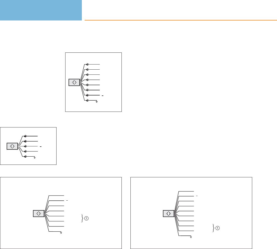
Core colours
BK black
BN brown
BU blue
GN green
GY grey
PK pink
RD red
VT lilac
WH white
YE yellow
Wiring diagrams
1
5
4
3
2
1
Range 0
Range 1
L+
L
2
5
4
3
2
6
7
1OSSD1
OSSD2
K1/K2/Restart
SEL_A
SEL_B
8
L+
L
3
L
L+
BN
BU
GY
WH
GN
YE
RD
PK n.c.
0 V DC
Range 1
Range 0
24 V AC/DC
4
L
L+
BN
BU
GY
WH
GN
YE
BK
VT
RD
PK
24 V AC/DC
0 V DC
K1/K2/Restart
SEL_A
SEL_B
OSSD1
OSSD2
1: Heating 1: Heating
Photoelectric sensors
314
Product selectors and further information can be found at: www.ifm.com
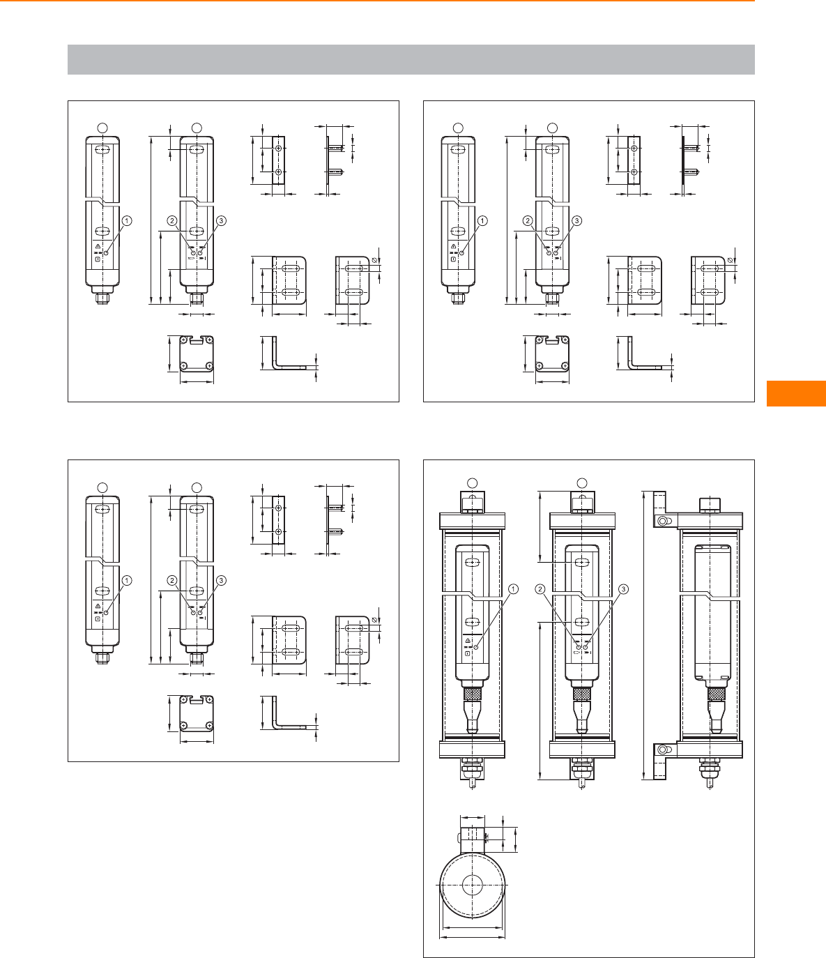
Scale drawings / drawing no. – CAD download: www.ifm.com
1
40
2010
3
10
10,5
28
28
5,5
40
10
20 10
1,5
M5
14,5
30
28
T
M12x1
11
29,5
61,5
L
R
T: Transmitter, R: Receiver, 1: LED 3 colours (red/green/orange),
2: LED 2 colours (yellow/blue), 3: LED 2 colours (red/green) T: Transmitter, R: Receiver, 1: LED 3 colours (red/green/orange),
2: LED 2 colours (yellow/blue), 3: LED 2 colours (red/green)
2
40
2010
3
10
10,5
28
28
5,5
40
10
20 10
1,5
M5
14,5
30
28
T
M12x1
11
29,5
61,5
L
R
T: Transmitter, R: Receiver, 1: LED 3 colours (red/green/orange),
2: LED (yellow), 3: LED 2 colours (red/green)
3
40
2010
3
10
10,5
28
28
5,5
40
10
20 10
1,5
M5
14,5
30
28
T
M12x1
51
29,5
102
L
R
4
T
L
R
131 60
50
20
9
20
56
T: Transmitter, R: Receiver, 1: LED 3 colours (red/green/orange),
2: LED 2 colours (yellow/blue), 3: LED 2 colours (red/green)
Safety light curtains /
light grids
315
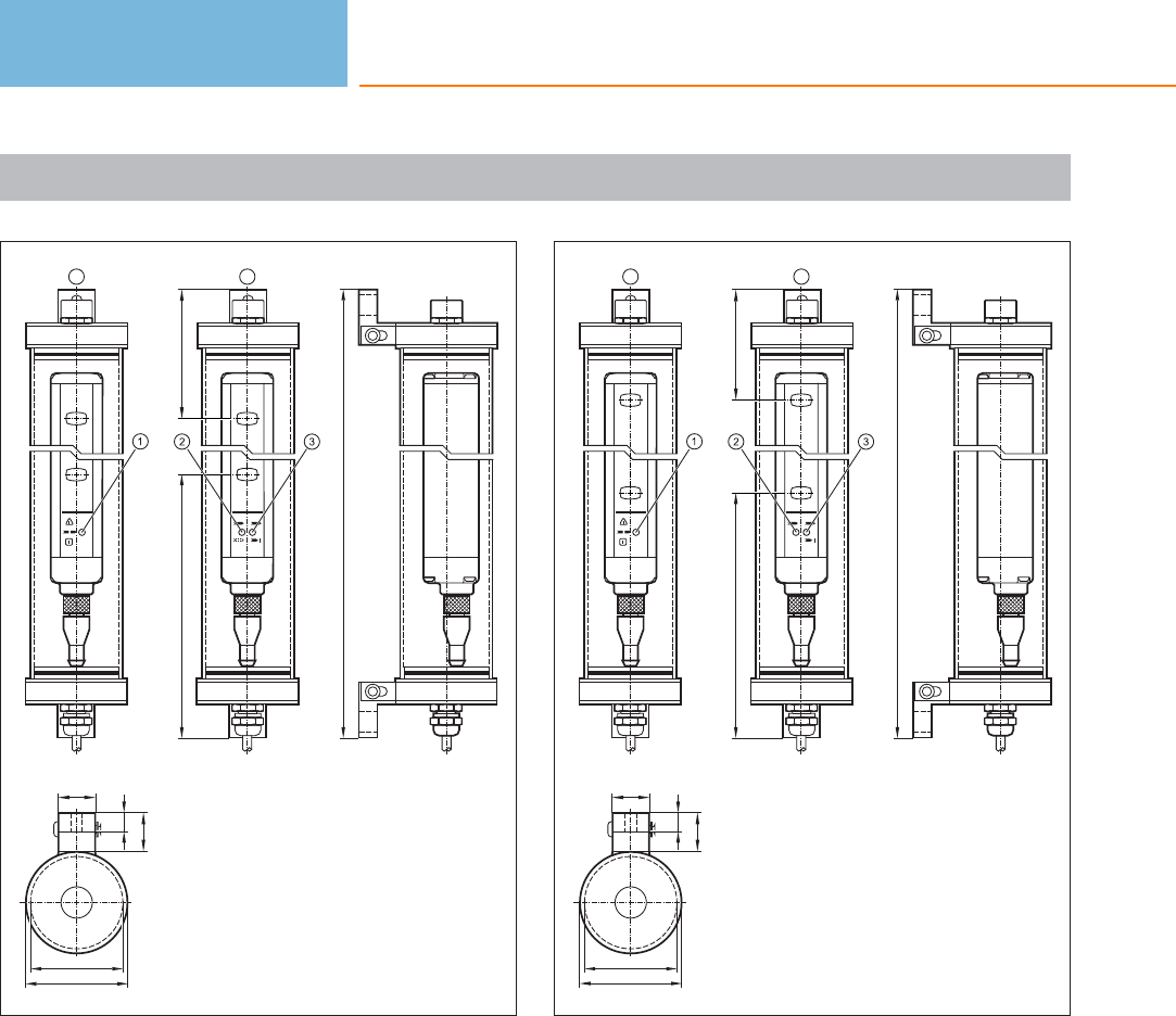
Scale drawings / drawing no. – CAD download: www.ifm.com
5
T
L
R
171 100
50
20
9
20
56
T: Transmitter, R: Receiver, 1: LED 3 colours (red/green/orange),
2: LED 2 colours (yellow/blue), 3: LED 2 colours (red/green)
6
T
L
R
131 60
50
20
9
20
56
T: Transmitter, R: Receiver, 1: LED 3 colours (red/green/orange),
2: LED 2 colours (yellow/blue), 3: LED 2 colours (red/green)
Photoelectric sensors
316
Product selectors and further information can be found at: www.ifm.com
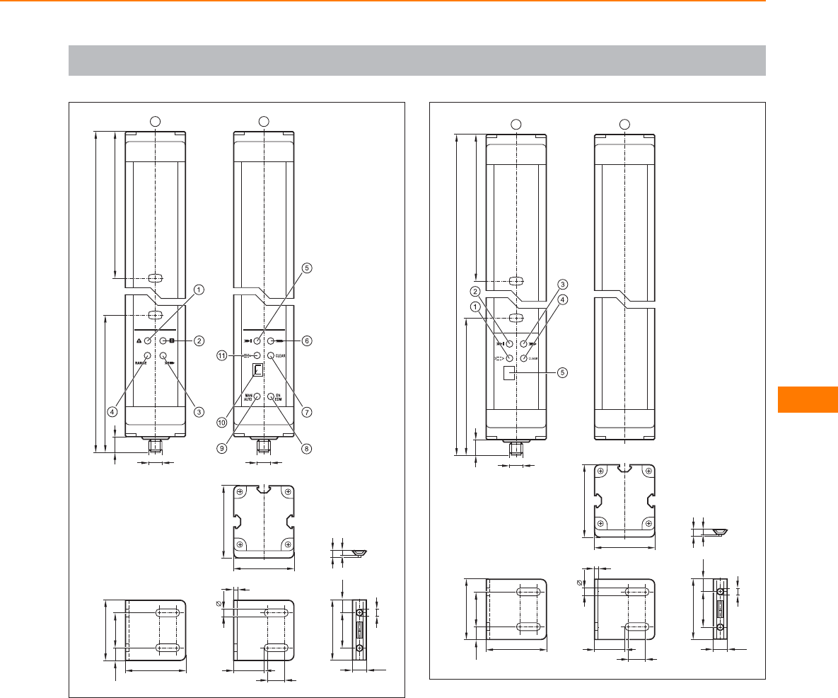
Scale drawings / drawing no. – CAD download: www.ifm.com
7
50
3010,5
3
13,5
25
50
6,5
M6
50
11,8
30 10,5 5
5,7
TR
M12x1
50
60
M12x1
13
114
122
L
T: Transmitter, R: Receiver, 1: LED (red), 2: LED (green), 3: LED
(yellow), 4: LED (orange), 5: LED (red), 6: LED (green), 7: LED (yellow),
8: LED (yellow), 9: LED (yellow), 10: display, 11: LED (orange)
8
50
3010,5
3
13,5
25
50
6,5
M6
50
11,8
30 10,5 5
5,7
AP
M12x1
50
60
13
114
122
L
A: active element, P: passive element, 1: LED (orange), 2: LED (red),
3: LED (green), 4: LED (yellow), 5: display
Safety light curtains /
light grids
317
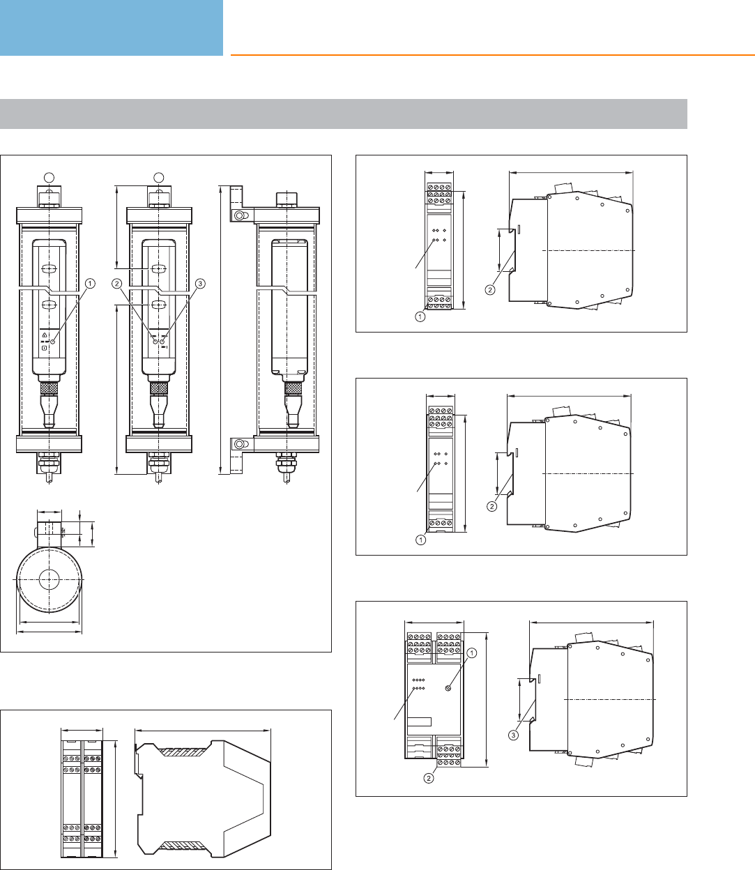
Scale drawings / drawing no. – CAD download: www.ifm.com
9
T
L
R
171 100
56
50
20
9
20
T: Transmitter, R: Receiver, 1: LED 3 colours (red/green/orange), 2:
LED 2 colours (yellow/blue), 3: LED 2 colours (red/green)
10
114,5
99
35
11
25
100
LED
35,5
105
1: Combicon connector with screw terminals, 2: mounting on DIN rail
12
25
100
LED
105
35,5
1: Combicon connector with screw terminals, 2: mounting on DIN rail
13
114
LED
50 105
35,5
1: Rotary switch for switch-off delay, 2: Combicon connector with
screw terminals, 3: mounting on DIN rail
Photoelectric sensors
318
Product selectors and further information can be found at: www.ifm.com

Safety light curtains /
light grids
319
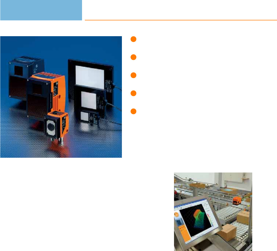
2D vision sensor for object
recognition.
3D sensor for assessment of
distance, level or volume.
3D camera for spatial detection
of scenes and objects.
Illumination units with high
luminous power.
Tough, industrial housings.
2D vision sensor for object recognition
In automation technology visions sensors are an integral part of assembly and
manufacturing tasks as well as quality control and thus increase efficiency. They are
cameras with application-specific evaluation, i.e. reliable electronic eyes at a low
cost and a high degree of integration. In a robust, industrially compatible housing
they combine lighting, lens, camera chip, evaluation and process connections for
the integration in the higher-level controller.
The application possibilities of efector dualis range from presence, position and
orientation monitoring, via sorting and counting tasks to quality control.
3D sensor for assessment of distance, level or volume
efector pmd 3d is the first industrial 3D sensor that can assess objects in three
dimensions at a glance.
Special feature: The time-of-flight measurement and evaluation are integrated on
one chip. Each pixel of this chip matrix evaluates its distance to the object. The
image of the object on the chip matrix and the respective distance values
correspond to a 3D image.
This technology enables the detailed assessment of the object’s or scene’s condi-
tions by means of volume, distance or level detection in three dimensions. Typical
applications are completeness checks and level monitoring in the food industry as
well as presence and dimension monitoring in conveying.
3D camera for detection in three dimensions of scenes and objects
The pmd 3d camera detects scenes and objects in their spatial dimensions at a
glance. In contrast to laser scanners it does not require moving components and is
thus robust and wear-free. The operating principle is the same as for the 3D sensor.
Besides the 3D distance image the camera provides a grey image of the scene. The
combination of these images offers integrators the possibility to freely program
application-specific tasks by means of a software development kit. This results in
low-cost application solutions in the areas of packaging, storage and materials
handling, airport logistics, collision avoidance, robotics, monitoring of space and
persons.
Set-up in just a few
steps: The profes-
sional and easy menu
guidance allows
configuration of the
efector dualis to your
application in just six
operating steps.
Object recognition
320

System overview Page
Object inspection sensors 322
Sensors for object recognition with PNP output function 322
Sensors for object recognition with NPN output function 322
Illumination units, backlight 323
Illumination units, spotlight 324
Software for 2D sensors 324
Panel PC for vision sensors 324
Fixing components for 2D sensors 324 - 326
Reflective tapes, diffusers and protective panes for 2D sensors 326
Sensors for 3D object recognition 326
Software for 3D sensors 327
Panel PC for vision sensors 327
Fixing components for 3D sensors 327
Connection cables for 2D and 3D sensors 328 - 329
Wiring diagrams 329
Scale drawings / drawing no. – CAD download: www.ifm.com 329
Object recognition
321

Object inspection sensors
Type Operating
principle
Max.
field of view size
[mm]
Resolution Detection
rate
[Hz]
Type
of light
Ambient
temperature
[°C]
Draw-
ing
no.
Order
no.
Type O2 · M12 plug, 8 poles M12 socket, 4 poles · metal · DC · Connector groups 17, 18
CMOS image sensor B/W,
VGA resolution 640 x 480 640 x 480 0.1 10 white light -10...60 1 O2V100
CMOS image sensor B/W,
VGA resolution 640 x 480 1280 x 960 0.3 10 white light -10...60 1O2V102
CMOS image sensor B/W,
VGA resolution 640 x 480 400 x 300 0.08 10 white light -10...60 2 O2V104
Sensors for object recognition with PNP output function
Type Operating
principle
Max.
field of view size
[mm]
Resolution Detection
rate
[Hz]
Type
of light
Ambient
temperature
[°C]
Draw-
ing
no.
Order
no.
Type O2 · M12 plug, 8 poles M12 socket, 4 poles · metal · DC · Connector groups 17, 18
CMOS image sensor B/W,
VGA resolution 640 x 480 400 x 300 0.08 10 infrared -10...60 2 O2D224
CMOS image sensor B/W,
VGA resolution 640 x 480 640 x 480 0.1 10 infrared -10...60 1O2D220
CMOS image sensor B/W,
VGA resolution 640 x 480 1280 x 960 0.3 10 infrared -10...60 1 O2D222
Sensors for object recognition with NPN output function
Type Operating
principle
Max.
field of view size
[mm]
Resolution Detection
rate
[Hz]
Type
of light
Ambient
temperature
[°C]
Draw-
ing
no.
Order
no.
Type O2 · M12 plug, 8 poles M12 socket, 4 poles · metal · DC · Connector groups 17, 18
CMOS image sensor B/W,
VGA resolution 640 x 480 400 x 300 0.08 10 infrared -10...60 2 O2D225
CMOS image sensor B/W,
VGA resolution 640 x 480 640 x 480 0.1 10 infrared -10...60 1O2D227
CMOS image sensor B/W,
VGA resolution 640 x 480 1280 x 960 0.3 10 infrared -10...60 1 O2D229
Object recognition
322
Product selectors and further information can be found at: www.ifm.com
Illumination units, backlight
Type Dimensions
[mm]
Type
of light
Active
illuminated
area
[mm]
I0
normal light
intensity
[mA]
I0
high light
intensity
[mA]
Trigger Draw-
ing
no.
Order
no.
PUR cable 2 m · metal · DC · Wiring diagram no. 1
66.5 x 33.4 x 9.2 red 25 x 25 50 25 External; 24 V PNP to
IEC61131-1 3O2D900
66.5 x 33.4 x 9.2 infrared 25 x 25 50 25 External; 24 V PNP to
IEC61131-1 3O2D901
103 x 81 x 9.2 red 50 x 50 200 100 External; 24 V PNP to
IEC61131-1 4O2D902
103 x 81 x 9.2 infrared 50 x 50 200 100 External; 24 V PNP to
IEC61131-1 4O2D903
156 x 133 x 9.2 red 100 x 100 450 250 External; 24 V PNP to
IEC61131-1 5O2D904
156 x 133 x 9.2 infrared 100 x 100 450 250 External; 24 V PNP to
IEC61131-1 5O2D905
PUR cable 0.15 m · metal · DC · Wiring diagram no. 2 · Connector groups 9, 11, 107, 108, 135
66.5 x 33.4 x 9.2 red 25 x 25 50 25 External; 24 V PNP to
IEC61131-1 3O2D910
66.5 x 33.4 x 9.2 infrared 25 x 25 50 25 External; 24 V PNP to
IEC61131-1 3O2D906
103 x 81 x 9.2 red 50 x 50 200 100 External; 24 V PNP to
IEC61131-1 4O2D911
103 x 81 x 9.2 infrared 50 x 50 200 100 External; 24 V PNP to
IEC61131-1 4O2D907
156 x 133 x 9.2 red 100 x 100 450 250 External; 24 V PNP to
IEC61131-1 5O2D912
156 x 133 x 9.2 infrared 100 x 100 450 250 External; 24 V PNP to
IEC61131-1 5O2D908
Object recognition
323
You can find wiring diagrams and scale drawings from page 329
Illumination units, spotlight
Type Dimensions
[mm]
Type
of light
Active
illuminated
area
[mm]
I0
normal light
intensity
[mA]
I0
high light
intensity
[mA]
Trigger Draw-
ing
no.
Order
no.
M12 connector · metal · DC · Wiring diagram no. 2 · Connector groups 9, 11, 107, 108, 135
42 x 42 x 31 red – 180 90 External; 24 V PNP to
IEC61131-1 6O2D909
Software for 2D sensors
Type Description Order
no.
Operating software · O2D E2D200
Panel PC for vision sensors
Type Description Order
no.
Touch Panel PC · AFL-12A-ATOM-N270/WT-R/1GB-R20 · 12.1„ colour display · Intel Atom CPU 1.6 GHz · 1 GByte RAM · Windows
XP Embedded E2D400
Mounting bracket · for Touch Panel PC · for wall mounting · VESA standard 100 x 100 mm · Housing materials: fixture: metal E2D401
Mounting set · for Touch Panel PC · for control cabinet mounting · Housing materials: fixture: metal / End cap: plastics E2D402
Fixing components for 2D sensors
Type Description Order
no.
Mounting set · O2D, O2M, O2I · Clamp mounting · rod mounting Ø 12 mm · Housing materials: fixture: stainless steel / clamp:
stainless steel E2D110
Mounting set · O2D, O2M, O2I · Clamp mounting · rod mounting Ø 14 mm · Housing materials: fixture: stainless steel / clamp:
stainless steel E2D112
Mounting set · Backlight 25 x 25 mm · Clamp mounting · Housing materials: Mounting plate: stainless steel / clamp: high-grade
stainless steel E2D107
Object recognition
324
Product selectors and further information can be found at: www.ifm.com
Type Description Order
no.
Mounting set · Backlight 50 x 50 mm · Clamp mounting · Housing materials: Mounting plate: stainless steel / clamp: high-grade
stainless steel E2D108
Mounting set · Backlight 100 x 100 mm · Clamp mounting · Housing materials: Mounting plate: stainless steel / clamp: high-grade
stainless steel E2D109
clamp · Ø 12 mm · rod mounting Ø 12 mm · Housing materials: clamp: stainless steel E21110
clamp · Ø 14 mm · rod mounting Ø 14 mm · Housing materials: clamp: stainless steel E21109
clamp · Ø 12 mm; M10 · free-standing M10 · Housing materials: clamp: stainless steel E20946
clamp · Ø 14 mm; M12 · free-standing M12 · Housing materials: clamp: stainless steel E20948
mounting rod · Ø 12 / M10 · Length: 130 mm · straight · Housing materials: stainless steel 316Ti / 1.4571 E20938
mounting rod · Ø 12 / M10 · Length: 200 mm · angled · Housing materials: stainless steel 316Ti / 1.4571 E20940
mounting rod · Ø 12 · Length: 150 mm · straight · Housing materials: stainless steel 316Ti / 1.4571 E21111
mounting rod · Ø 12 · Length: 200 mm · straight · Housing materials: stainless steel 316Ti / 1.4571 E21112
mounting rod · Ø 12 · Length: 300 mm · straight · Housing materials: stainless steel 316Ti / 1.4571 E21113
mounting rod · Ø 14 / M12 · Length: 130 mm · straight · Housing materials: stainless steel 316Ti / 1.4571 E20939
mounting rod · Ø 14 / M12 · Length: 200 mm · angled · Housing materials: stainless steel 316Ti / 1.4571 E20941
Connection piece · Ø 20 mm · for the connection of two clamps with Ø 20 mm · Housing materials: stainless steel 316L / 1.4404 E21076
Object recognition
325
You can find wiring diagrams and scale drawings from page 329
Type Description Order
no.
Cube · M10 · aluminium profile · Housing materials: diecast zinc E20951
Cube · M12 · aluminium profile · Housing materials: diecast zinc E20952
Reflective tapes, diffusers and protective panes for 2D sensors
Type Description Order
no.
Reflective tape · TS-03 · 100 x 100 mm · Housing materials: plastics E2D106
Plastic diffuser · O2D / O2I · Housing materials: housing: diecast zinc black / lens: PMMA E21165
Plastic protective pane for the food industry · O2D / O2I · Housing materials: housing: diecast zinc black / lens: PMMA E21166
Glass protective pane · O2D / O2I · Housing materials: housing: diecast zinc black / lens: float glass E21168
Daylight filter · O2D · Housing materials: housing: diecast zinc black / lens: PMMA / Metal ring: aluminium black anodised E21172
Sensors for 3D object recognition
Type Operating
principle
Resolution
(pixels)
Angle of aperture
(horizontal x vertical)
[°]
Lighting Max.
sampling
rate
[Hz]
Ambient
temperature
[°C]
Draw-
ing
no.
Order
no.
PMD 3D sensor · Type O3D · M12 connector · metal · DC · Connector groups 17, 18
PMD 3D sensor 64 x 48 30° x 40° Infrared LED 20 -10...50 7 O3D200
PMD 3D camera · Type O3D · M12 connector · metal · DC · Connector groups 17, 18
PMD 3D camera 64 x 48 30° x 40° Infrared LED 20 -10...50 7O3D201
Object recognition
326
Product selectors and further information can be found at: www.ifm.com
Software for 3D sensors
Type Description Order
no.
Operating software for PMD 3D sensor · O3D E3D200
Operating software for PMD 3D camera · O3D E3D201
Panel PC for vision sensors
Type Description Order
no.
Touch Panel PC · AFL-12A-ATOM-N270/WT-R/1GB-R20 · 12.1„ colour display · Intel Atom CPU 1.6 GHz · 1 GByte RAM · Windows
XP Embedded E2D400
Mounting bracket · for Touch Panel PC · for wall mounting · VESA standard 100 x 100 mm · Housing materials: fixture: metal E2D401
Mounting set · for Touch Panel PC · for control cabinet mounting · Housing materials: fixture: metal / End cap: plastics E2D402
Fixing components for 3D sensors
Type Description Order
no.
Mounting set · O3D · Clamp mounting · rod mounting Ø 14 mm · Housing materials: fixture: stainless steel / clamp: stainless steel E3D103
mounting rod · Ø 14 / M12 · Length: 130 mm · straight · Housing materials: stainless steel 316Ti / 1.4571 E20939
mounting rod · Ø 14 · Length: 200 mm · straight · Housing materials: stainless steel 316Ti / 1.4571 E21228
mounting rod · Ø 14 · Length: 300 mm · straight · Housing materials: stainless steel 316Ti / 1.4571 E21229
mounting rod · Ø 14 · Length: 500 mm · straight · Housing materials: stainless steel 316Ti / 1.4571 E21232
Object recognition
327
You can find wiring diagrams and scale drawings from page 329
Connection cables for 2D and 3D sensors
Type Description Order
no.
Jumper · straight / straight · Ethernet · Cross-over patch cable · 2 m · Housing materials: PUR / PC E11898
Jumper · straight / straight · Ethernet · Patch cable · 2 m · Housing materials: PUR / PC E12090
Jumper · straight / straight · Ethernet · gold-plated contacts · 2 m · Housing materials: TPU E21138
Jumper · straight / straight · Ethernet · gold-plated contacts · 5 m · Housing materials: TPU E21139
Jumper · straight / straight · Ethernet · gold-plated contacts · 10 m · Housing materials: TPU E21137
Jumper · straight / straight · Ethernet · 2 m · Housing materials: PUR E21135
Jumper · straight / straight · Ethernet · 5 m · Housing materials: PUR E21136
Jumper · straight / straight · Ethernet · Cross-over patch cable · 10 m · Housing materials: PUR / PC E12204
Jumper · straight / straight · Ethernet · Cross-over patch cable · 20 m · Housing materials: PUR / PC E12205
Socket · angled · Free from silicone · Free from halogen · gold-plated contacts · M12 connector · 2 m · Housing materials: PUR E11231
Socket · angled · Free from silicone · Free from halogen · gold-plated contacts · M12 connector · 5 m · Housing materials: PUR E11232
Socket · straight · Free from halogen · M12 connector · 5 m · Housing materials: PUR E11807
Socket · straight · Free from halogen · M12 connector · 10 m · Housing materials: PUR E11311
Socket · straight · Free from halogen · M12 connector · 2 m · Housing materials: PUR E11950
Object recognition
328
Product selectors and further information can be found at: www.ifm.com
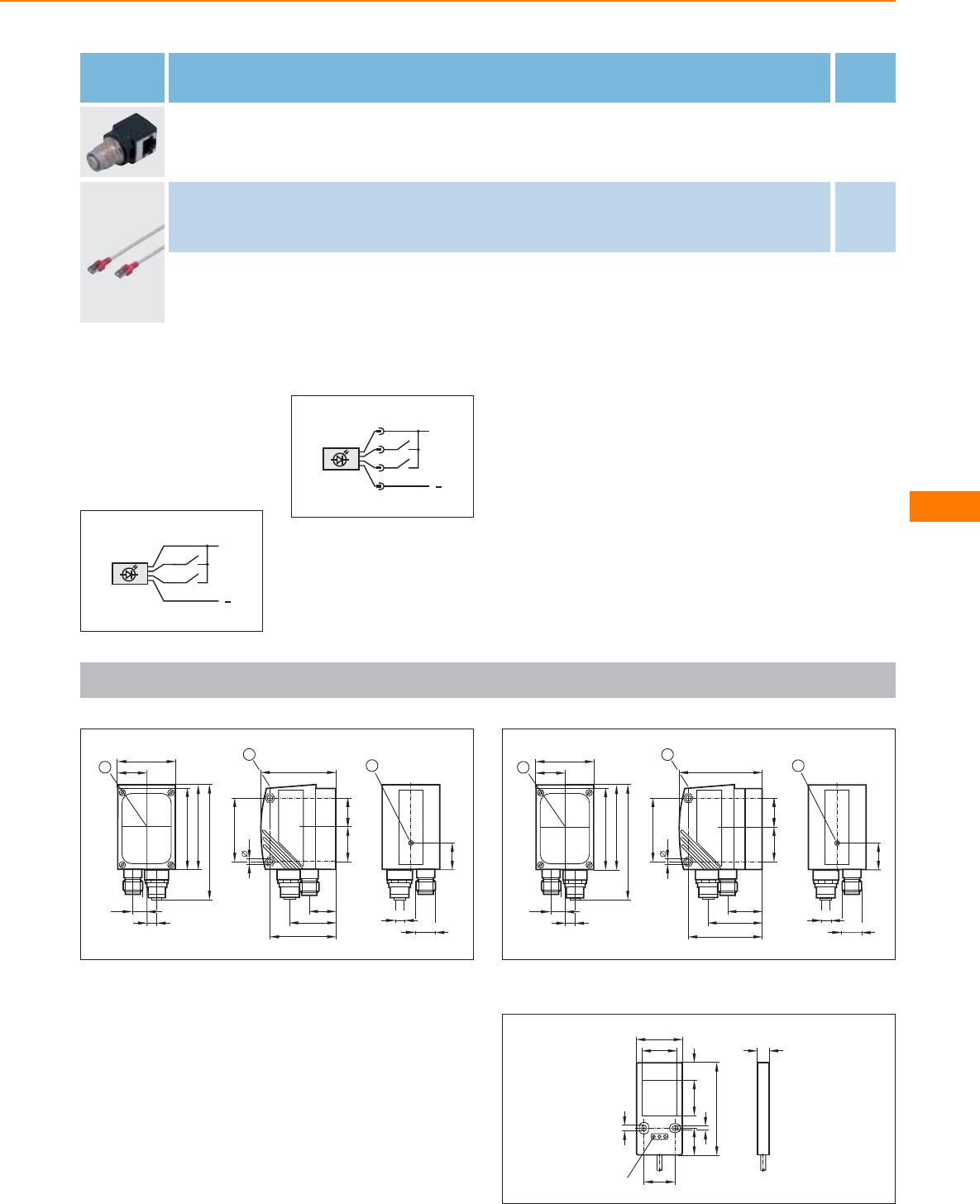
Type Description Order
no.
Adapter · angled · Connector E21140
Jumper · straight / straight · Ethernet · Cross-over patch cable · 2 m · Housing materials: PUR EC2080
Jumper · straight / straight · Ethernet · Cross-over patch cable · 5 m · Housing materials: PUR E30112
Core colours
BK black
BN brown
BU blue
WH white
Wiring diagrams
1
L+
L
BN
BK
WH
BU
2
L+
L
1
4
2
3
Scale drawings / drawing no. – CAD download: www.ifm.com
1
M12x1
2
19
M12x1
53,5
4,3
20,5
44
19,7
33
1
45
24,5
42
57
80
60
21
9,5
7
3
1: display, 2: Focus setting, 3: Centre of the lens axes
2
M12x1
2
19
M12x1
42
57
80
60
21
9,5
7
359
4,3
20,5
49,5
25,2
38,5
1
45
24,5
1: display, 2: Focus setting, 3: Centre of the lens axes
3
9,2
33,4
25
25
21,9
66,5
19
3
4
3 LED
12,6
Object recognition
329
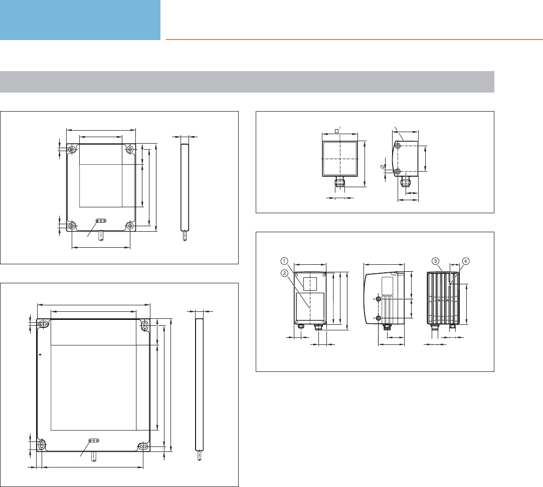
Scale drawings / drawing no. – CAD download: www.ifm.com
4
81
50
50
103
90
68
3,3
4,3
3 LED
24,6
9,8
5
9,8
133
100
100
156
141
119
7,3
3 LED
3,3
6
6
31
6
31
4,3
14
30
LED
24
M12 x1
54
LED
42
7
95
60,5
40
45 63,8
16
75
137
120
123,5
18
M12x1
M12x1
94
21,5
1: lens, 2: Illumination unit, 3: Display / buttons / LEDs,
4: Focus setting
Object recognition
330
Product selectors and further information can be found at: www.ifm.com

Object recognition
331
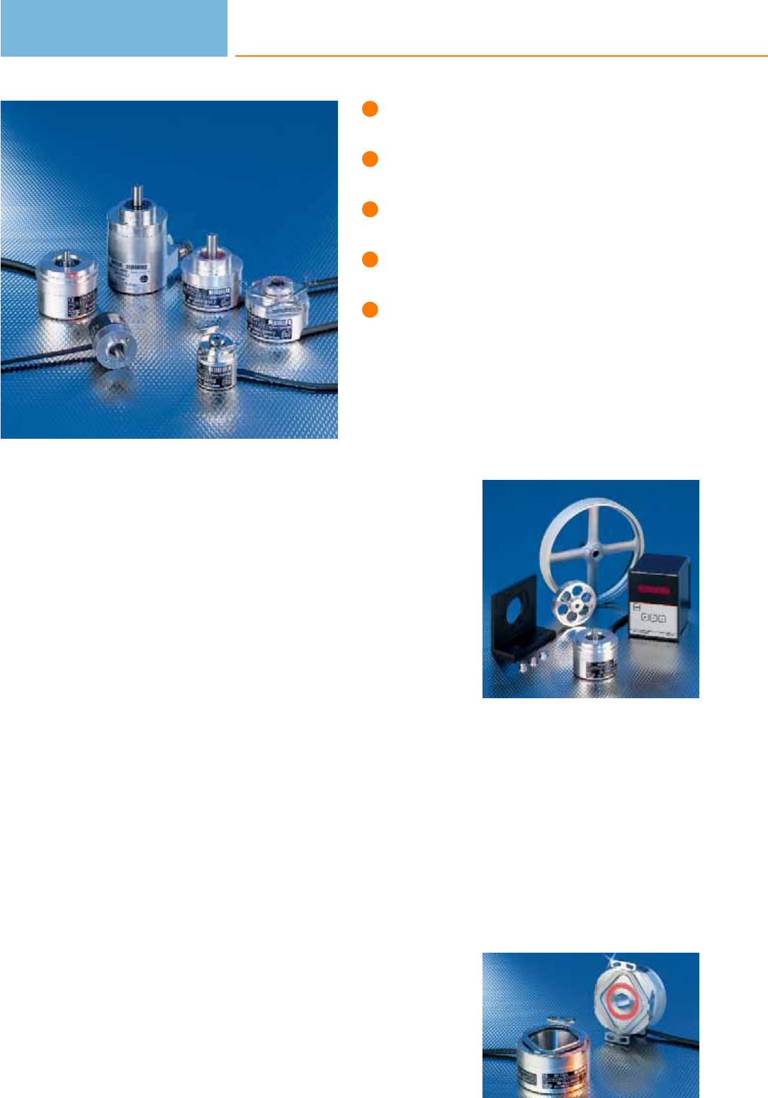
Robust designs.
Industrial standard housings.
Cable entry for axial and radial use.
Designs with integrated
bus interface.
Hollow shaft encoder for direct
mounting on actuators.
Encoders
In many manufacturing and production processes encoders are indispensable as
reliable transducers to ensure precise positioning. They convert rotary movement
into digital signals. Encoders use the wear-free photoelectric detection. A pulse disc
firmly attached to the shaft ensures this detection.
Incremental encoders
Incremental encoders generate a precisely defined number of pulses per revolution.
They are a measure of the angular or linear distance moved.
The coded disc is divided into separate segments which are alternately transparent
or opaque. An LED emits a parallel-orientated light beam which illuminates all seg-
ments of the coded disc. Photo elements receive the modulated light and convert it
into two sinusoidal signals. Digitalisation electronics amplify the signals and shape
them into square-wave pulse trains which are generated via the line driver in the
output. The phase difference between signals A and B, which are phase-shifted by
90 degrees, allows evaluation of the direction of rotation.
Absolute encoders
Absolute encoders provide an absolute numerical value for each angular position.
This code value is available immediately after power is applied. This “absolute”
value makes a reference procedure like the one required for the incremental
encoder unnecessary. Absolute encoders are used wherever angular positions have
to be allocated to a certain value and where the detection of the present position is
absolutely necessary in the case of a power failure.
Singleturn and multiturn
Singleturn encoders divide a mechanical revolution (0 to 360 degrees) into a certain
number of measuring steps. The measuring values are repeated after one revolu-
tion. The maximum resolution is 8192. Multiturn encoders, however, do not only
detect angular positions but also distinguish between multiple revolutions.
Linear measurement
by means of a count-
er: Rotary movement
is converted into
digital signals.
Hollow shaft encoder
for direct mounting
on the axis.
Encoders
332

System overview Page
Incremental encoders with solid shaft 334 - 337
Incremental encoders with hollow shaft 337 - 338
Absolut singleturn - encoders (SSI) 338
Absolute multiturn encoders (SSI) 339
Absolute multiturn encoders (Profibus) 339
Absolute singleturn - encoders (CANopen) 339
Absolute multiturn - encoders (CANopen) 339 - 340
Absolute multiturn - encoders (CANopen) for mobile applications 340
Fixing accessories for encoders 340
Couplings for encoders 341
Measuring wheels for encoders 342
Connectors for encoders 342 - 343
Scale drawings / drawing no. – CAD download: www.ifm.com 344 - 345
Encoders
333
Incremental encoders with solid shaft
Type Resolution Ub
[V]
f
[kHz]
Iload
[mA]
Shaft
[mm]
Ambient
temperature
[°C]
Cable
entry
Draw-
ing
no.
Order
no.
Cable 2 m · Output function TTL output 20 mA
500 5 300 20 6 -30...100 radial / axially 1 RB1015
Cable 2 m · Output function HTL-output 50 mA, short-circuit protected < 1 min
510...30 160 50 6-30...70 radial / axially 1RB6044
10 10...30 160 50 6 -30...70 radial / axially 1 RB6001
20 10...30 160 50 6-30...70 radial / axially 1RB6002
25 10...30 160 50 6 -30...70 radial / axially 1 RB6003
30 10...30 160 50 6-30...70 radial / axially 1RB6004
50 10...30 160 50 6 -30...70 radial / axially 1 RB6005
60 10...30 160 50 6-30...70 radial / axially 1RB6006
100 10...30 160 50 6 -30...70 radial / axially 1 RB6007
125 10...30 160 50 6-30...70 radial / axially 1RB6009
150 10...30 160 50 6 -30...70 radial / axially 1 RB6010
200 10...30 160 50 6-30...70 radial / axially 1RB6011
250 10...30 160 50 6 -30...70 radial / axially 1 RB6012
360 10...30 160 50 6-30...70 radial / axially 1RB6013
400 10...30 160 50 6 -30...70 radial / axially 1 RB6014
Encoders
334
Product selectors and further information can be found at: www.ifm.com
Type Resolution Ub
[V]
f
[kHz]
Iload
[mA]
Shaft
[mm]
Ambient
temperature
[°C]
Cable
entry
Draw-
ing
no.
Order
no.
Cable 2 m · Output function HTL-output 50 mA, short-circuit protected < 1 min
500 10...30 160 50 6 -30...70 radial / axially 1 RB6015
600 10...30 160 50 6-30...70 radial / axially 1RB6016
1000 10...30 160 50 6 -30...70 radial / axially 1 RB6029
Cable 2 m · Output function TTL output 20 mA
500 5300 20 6-40...100 radial / axially 2RU1016
1000 5 300 20 6 -40...100 radial / axially 2 RU1024
1024 5300 20 6-40...100 radial / axially 2RU1025
2000 5 300 20 6 -40...100 radial / axially 2 RU1033
2500 5300 20 6-40...100 radial / axially 2RU1036
Cable 2 m · Output function HTL-output 50 mA, short-circuit protected < 1 min
100 10...30 300 50 6 -40...100 radial / axially 2 RU6003
250 10...30 300 50 6-40...100 radial / axially 2RU6010
360 10...30 300 50 6 -40...100 radial / axially 2 RU6013
500 10...30 300 50 6-40...100 radial / axially 2RU6016
1000 10...30 300 50 6 -40...100 radial / axially 2 RU6024
1024 10...30 300 50 6-40...100 radial / axially 2RU6025
2000 10...30 300 50 6 -40...100 radial / axially 2 RU6033
Encoders
335
You can find scale drawings from page 344
Type Resolution Ub
[V]
f
[kHz]
Iload
[mA]
Shaft
[mm]
Ambient
temperature
[°C]
Cable
entry
Draw-
ing
no.
Order
no.
Cable 2 m · Output function HTL-output 50 mA, short-circuit protected < 1 min
2500 10...30 300 50 6 -40...100 radial / axially 2 RU6036
3600 10...30 300 50 6-40...100 radial / axially 2RU6040
5000 10...30 300 50 6 -40...100 radial / axially 2 RU6045
10000 10...30 300 50 6-40...100 radial / axially 2RU6052
Cable 2 m · Output function TTL output 20 mA
500 5 300 20 10 -40...100 radial / axially 3 RV1016
1000 5300 20 10 -40...100 radial / axially 3RV1024
1024 5 300 20 10 -40...100 radial / axially 3 RV1025
2000 5300 20 10 -40...100 radial / axially 3RV1033
2500 5 300 20 10 -40...100 radial / axially 3 RV1036
5000 5300 20 10 -40...100 radial / axially 3RV1051
Cable 2 m · Output function HTL-output 50 mA, short-circuit protected < 1 min
50 10...30 300 50 10 -40...100 radial / axially 3 RV6001
100 10...30 300 50 10 -40...100 radial / axially 3RV6003
200 10...30 300 50 10 -40...100 radial / axially 3 RV6009
250 10...30 300 50 10 -40...100 radial / axially 3RV6010
360 10...30 300 50 10 -40...100 radial / axially 3 RV6013
Encoders
336
Product selectors and further information can be found at: www.ifm.com
Type Resolution Ub
[V]
f
[kHz]
Iload
[mA]
Shaft
[mm]
Ambient
temperature
[°C]
Cable
entry
Draw-
ing
no.
Order
no.
Cable 2 m · Output function HTL-output 50 mA, short-circuit protected < 1 min
500 10...30 300 50 10 -40...100 radial / axially 3 RV6016
600 10...30 300 50 10 -40...100 radial / axially 3RV6018
1000 10...30 300 50 10 -40...100 radial / axially 3 RV6024
1024 10...30 300 50 10 -40...100 radial / axially 3RV6025
1250 10...30 300 50 10 -40...100 radial / axially 3 RV6028
2000 10...30 300 50 10 -40...100 radial / axially 3RV6033
2048 10...30 300 50 10 -40...100 radial / axially 3 RV6034
2500 10...30 300 50 10 -40...100 radial / axially 3RV6036
3600 10...30 300 50 10 -40...100 radial / axially 3 RV6040
5000 10...30 300 50 10 -40...100 radial / axially 3RV6100
Incremental encoders with hollow shaft
Type Resolution Ub
[V]
f
[kHz]
Iload
[mA]
Shaft
[mm]
Ambient
temperature
[°C]
Cable
entry
Draw-
ing
no.
Order
no.
Cable 2 m · Output function HTL-output 50 mA, short-circuit protected < 1 min
10 10...30 160 50 6 H7 -30...70 radial / axially 4 RA6001
100 10...30 160 50 6 H7 -30...70 radial / axially 4RA6007
200 10...30 160 50 6 H7 -30...70 radial / axially 4 RA6011
360 10...30 160 50 6 H7 -30...70 radial / axially 4RA6013
Encoders
337
You can find scale drawings from page 344
Type Resolution Ub
[V]
f
[kHz]
Iload
[mA]
Shaft
[mm]
Ambient
temperature
[°C]
Cable
entry
Draw-
ing
no.
Order
no.
Cable 2 m · Output function HTL-output 50 mA, short-circuit protected < 1 min
500 10...30 160 50 6 H7 -30...70 radial / axially 4 RA6015
1000 10...30 160 50 6 H7 -30...70 radial / axially 4RA6029
Cable 1 m · Output function HTL-output 50 mA, short-circuit protected < 1 min
100 10...30 300 50 12 H7 -40...100 radial / axially 5 RO6342
360 10...30 300 50 12 H7 -40...100 radial / axially 5RO6343
500 10...30 300 50 12 H7 -40...100 radial / axially 5 RO6344
1024 10...30 300 50 12 H7 -40...100 radial / axially 5RO6345
3600 10...30 300 50 12 H7 -40...100 radial / axially 5 RO6348
4096 10...30 300 50 12 H7 -40...100 radial / axially 5RO6349
5000 10...30 300 50 12 H7 -40...100 radial / axially 5 RO6350
Absolut singleturn - encoders (SSI)
Type Resolution Ub
[V]
f
[kHz]
Iload
[mA]
Shaft
[mm]
Ambient
temperature
[°C]
Cable
entry
Draw-
ing
no.
Order
no.
Cable 1 m · Output function SSI data interface
8192 10...30 – – 10 -40...85 radial / axially 6 RN6055
Encoders
338
Product selectors and further information can be found at: www.ifm.com
Absolute multiturn encoders (SSI)
Type Resolution Ub
[V]
f
[kHz]
Iload
[mA]
Shaft
[mm]
Ambient
temperature
[°C]
Cable
entry
Draw-
ing
no.
Order
no.
Cable 1 m · Output function SSI data interface
8192 10...30 – – 6 -40...85 radial / axially 2 RM6101
8192 10...30 – – 10 -40...85 radial / axially 7RM6104
Absolute multiturn encoders (Profibus)
Type Resolution Ub
[V]
f
[kHz]
Iload
[mA]
Shaft
[mm]
Ambient
temperature
[°C]
Cable
entry
Draw-
ing
no.
Order
no.
Terminals · Output function Profibus data interface
25 bits 10...30 – – 6 -40...70 – 8 RM3001
25 bits 10...30 – – 10 -40...70 – 9 RM3005
Absolute singleturn - encoders (CANopen)
Type Resolution Ub
[V]
f
[kHz]
Iload
[mA]
Shaft
[mm]
Ambient
temperature
[°C]
Cable
entry
Draw-
ing
no.
Order
no.
Terminals · Output function CANopen interface
13 bits 9...36 – – 6 -40...70 – 8 RN7003
13 bits 9...36 – – 10 -40...70 – 9 RN7004
Absolute multiturn - encoders (CANopen)
Type Resolution Ub
[V]
f
[kHz]
Iload
[mA]
Shaft
[mm]
Ambient
temperature
[°C]
Cable
entry
Draw-
ing
no.
Order
no.
Terminals · Output function CANopen interface
25 bits 9...36 – – 6 -40...70 – 8 RM7003
Encoders
339
You can find scale drawings from page 344
Type Resolution Ub
[V]
f
[kHz]
Iload
[mA]
Shaft
[mm]
Ambient
temperature
[°C]
Cable
entry
Draw-
ing
no.
Order
no.
Terminals · Output function CANopen interface
25 bits 9...36 – – 10 -40...70 – 9 RM7004
Absolute multiturn - encoders (CANopen) for mobile applications
Type Resolution Ub
[V]
f
[kHz]
Iload
[mA]
Shaft
[mm]
Ambient
temperature
[°C]
Cable
entry
Draw-
ing
no.
Order
no.
M12 connector · Output function CANopen interface · Connector group 137
24 bits 10...30 – – 10 -40...85 axial 10 RM9000
Fixing accessories for encoders
Type Description Order
no.
Resilient base for angle flanges · Housing materials: aluminium black anodised E60036
Angle bracket · for encoders · for type RB, RC, RU, RN, RM · Housing materials: aluminium black anodised E60033
Angle bracket · for encoders · for type RM, RMU, RN, RU · Housing materials: aluminium black anodised E60034
Angle bracket · for encoders · for type RMV, RV · Housing materials: aluminium black anodised E60035
Angle bracket · for encoders · for type RM · Housing materials: aluminium black anodised E60302
Fastening clamp · for synchro flange · Housing materials: steel E60041
Encoders
340
Product selectors and further information can be found at: www.ifm.com
Couplings for encoders
Type Description Order
no.
Flexible coupling with clamp connection [KV] · Ø 4 mm / Ø 6 mm · Housing materials: aluminium E60119
Flexible coupling with clamp connection [KV] · Ø 6 mm / Ø 6 mm · Housing materials: aluminium E60064
Flexible coupling with clamp connection [KV] · Ø 6 mm / Ø 6 mm · Housing materials: aluminium E60065
Flexible coupling with clamp connection [KV] · Ø 6 mm / Ø 8 mm · Housing materials: aluminium E60120
Flexible coupling with clamp connection [KV] · Ø 6 mm / Ø 10 mm · Housing materials: aluminium E60066
Flexible coupling with clamp connection [KV] · Ø 10 mm / Ø 10 mm · Housing materials: aluminium E60067
Flexible coupling with adjusting screw connection [SV] · Ø 4 mm / Ø 6 mm · Housing materials: aluminium E60062
Flexible coupling with adjusting screw connection [SV] · Ø 6 mm / Ø 6 mm · Housing materials: aluminium E60063
Flexible coupling with adjusting screw connection [SV] · Ø 6 mm / Ø 8 mm · Housing materials: aluminium E60027
Flexible coupling with adjusting screw connection [SV] · Ø 6 mm / Ø 10 mm · Housing materials: aluminium E60028
Flexible coupling with adjusting screw connection [SV] · Ø 10 mm / Ø 10 mm · Housing materials: aluminium E60022
Spring disc coupling electrically isolating · Ø 6 mm / Ø 6 mm · Housing materials: diecast zinc / PA E60121
Spring disc coupling electrically isolating · Ø 6 mm / Ø 10 mm · Housing materials: diecast zinc / PA E60117
Spring disc coupling electrically isolating · Ø 10 mm / Ø 10 mm · Housing materials: diecast zinc / PA E60118
Encoders
341
You can find scale drawings from page 344
Measuring wheels for encoders
Type Description Order
no.
Measuring wheel · Ø 159.15 mm / Ø 10 mm · cross-knurl · Housing materials: wheel: aluminium E60098
Measuring wheel · Ø 63.6 mm / Ø 6 mm · aluminium · Housing materials: wheel: aluminium E60006
Measuring wheel · Ø 63.6 mm / Ø 10 mm · aluminium · Housing materials: wheel: aluminium E60095
Measuring wheel · Ø 159.15 mm / Ø 10 mm · rubber · Housing materials: wheel: aluminium / tread: NBR nitrile E60076
Measuring wheel · Ø 159.15 mm / Ø 10 mm · smooth plastic · Housing materials: wheel: Hytrel TPE-E E60110
Measuring wheel · Ø 63.66 ±0.1 mm / Ø 6 mm · smooth plastic · Housing materials: wheel: Hytrel TPE-E E60111
Measuring wheel · Ø 63.66 ±0.1 mm / Ø 10 mm · smooth plastic · Housing materials: wheel: Hytrel TPE-E E60112
Measuring wheel · Ø 63.66 ±0.1 mm / Ø 6 mm · grooved plastic · Housing materials: wheel: Hytrel TPE-E E60137
Measuring wheel · Ø 63.66 ±0.1 mm / Ø 10 mm · grooved plastic · Housing materials: wheel: Hytrel TPE-E E60138
Connectors for encoders
Type Description Order
no.
Socket · straight · wirable · M18 connector · Housing materials: brass nickel-plated E60174
Socket · angled · wirable · M18 connector · Housing materials: brass nickel-plated E60175
Socket · angled · wirable · M23 connector · Housing materials: brass nickel-plated E10447
Encoders
342
Product selectors and further information can be found at: www.ifm.com
Type Description Order
no.
Socket · straight · wirable · M23 connector · Housing materials: brass nickel-plated E10448
Socket · straight · wirable · M23 connector · Housing materials: brass plastic coated / PA 6.6 black E60124
Socket · straight · wirable · M23 connector · Housing materials: brass plastic coated / PA 6.6 black E60122
Socket · straight · wirable · M23 connector · Housing materials: brass nickel-plated E60136
Socket · straight · M23 connector · 5 m · Housing materials: brass plastic coated / PA 6.6 black E60144
Socket · straight · M23 connector · 10 m · Housing materials: brass plastic coated / PA 6.6 black E60147
Socket · angled · Free from silicone · gold-plated contacts · M12 connector · 2 m · Housing materials: PUR E11986
Socket · angled · Free from silicone · gold-plated contacts · M12 connector · 10 m · Housing materials: PUR E11987
Socket · straight · Free from silicone · Free from halogen · gold-plated contacts · M12 connector · 10 m · Housing materials: PUR E12074
Plug · straight · wirable · M23 connector · Housing materials: brass plastic coated / PA 6.6 black E60141
Socket · straight · wirable · M23 connector · Housing materials: brass plastic coated / PA 6.6 black E60157
Socket · straight · wirable · M23 connector · Housing materials: brass plastic coated / PA 6.6 black E60146
Plug · straight · wirable · M23 connector · Housing materials: brass plastic coated / PA 6.6 black E60123
Plug · straight · wirable · M23 connector · Housing materials: brass plastic coated / PA 6.6 black E60128
Encoders
343
You can find scale drawings from page 344
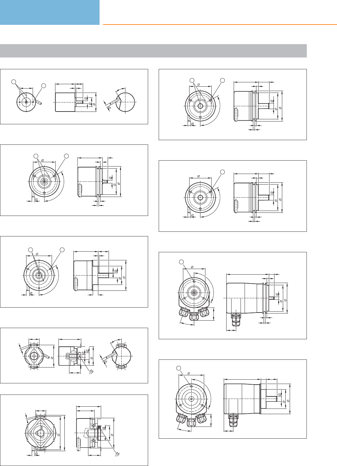
Scale drawings / drawing no. – CAD download: www.ifm.com
1
25
1
2
37,5
6
18
35
2
15
30°
4,5
1: reference mark, 2: M3 5 mm deep
2
4
3
6
50
58
3
10
h7
46,7±0,5
6
120°
42
12
1: reference mark, 2: M4 5 mm deep
3
10
36
58
f8
1
1,5
20
46,7±0,5
10
6
48
120°
12
1: reference mark, 2: M3 5 mm deep
4
3,3
42
20
6
35
1,52x
13,5
42,1
21
H7
30°
4,5
5
20
63
68
3,2
6
34,5
12 H7
24
28
47,2±0,5
58
TX 8
6
6
120°
42
12
4
3
10
50
58
3
20
h7
46,7±0,5
1: reference mark, 2: M4 5 mm deep
7
4
3
10
50
58
3
20
h7
46,7±0,5
6
120°
42
1
M4 5 mm deep
8
120°
42
20°
24
1
80
18
4
3
6
50
58
3
10,5
h7
1: M4 5 mm deep
9
120°
48
20°
24
1
70
18
10
36
58
20
f8
10
1: M4 5 mm deep
Encoders
344
Product selectors and further information can be found at: www.ifm.com
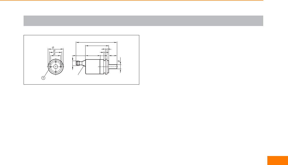
Scale drawings / drawing no. – CAD download: www.ifm.com
10
36,5
30
24
LED
2023 36 9
100
4
4
10
57
M12 x1
Encoders
345
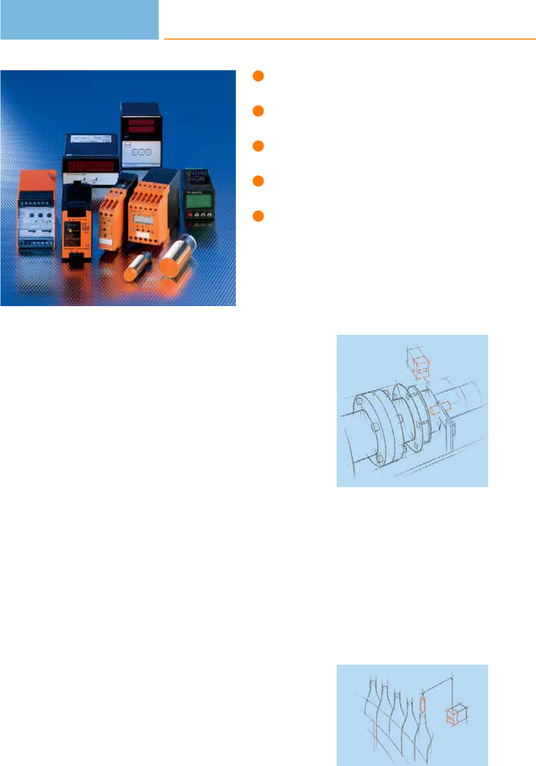
Easy adjustment and parameter
setting.
Primary voltage 24V dc or
110 / 230V ac, wide-range input.
Programmable switching characteristics.
Standstill, overspeed, direction, slip and
frequency conversion, counter.
Switching relays and transistor outputs,
scalable analogue output.
Evaluation systems
Although PLC applications in industrial automation are becoming more and more
versatile there are still numerous processes in practice which require decentralised
monitoring.
For this ifm electronic offers a number of pulse evaluation systems in the product
group “ecomat 200”. The application area ranges from simple standstill monitoring
or blockage protection of a conveyor belt, maximum speed monitoring in wind
power stations, slip monitoring of couplings through to direction monitoring, e.g.
twin pumps with non-return valves.
Different units for rail mounting and compact designs in M18 and M30 metal
housings are available. They include microprocessor-controlled units for pane
mounting to display analogue signals, RPM, speeds, processing times, quantities
and electronic preset counters for the detection of quantities or linear
measurement.
All units are distinguished by a high reliability and easy handling. Independent of
the PLC they indicate operating states or signal faults. This helps to reduce down-
times and production loss.
ifm electronic offers the following evaluation systems:
– Speed monitors
– Standstill monitors
– Slip / synchronisation monitors
– Direction monitors
– Frequency-to-current converters
– Threshold relays
– Displays with frequency and analogue input
– Counters
– Switching amplifiers
Pulse evaluation
systems are used for
decentralised moni-
toring of drives.
Machine cycles must
also be monitored in
conveying.
Evaluation systems
346

Evaluation systems
347
System overview Page
Universal speed monitors 348
Universal speed monitors with sensor wire monitoring 348
Dual speed monitors 348
Dual speed monitors with sensor wire monitoring 349
Slip monitors 349
Slip monitors with sensor wire monitoring 349
Slip / synchronous monitors 349
Slip / synchronous monitors with sensor wire monitoring 350
Combined direction and speed monitors 350
Frequency-to-current converters 350
Standard speed monitors 350 - 351
Standstill monitors 351
Safety standstill monitors, SIL 3, PL e 351
Speed monitor with integrated sensor 352 - 353
Speed monitors with integrated sensor, ATEX category 3D 353
Multifunctional displays for digital signals / frequency input 354
Universal counters 354
2-channel threshold relay for analogue standard signals 354
Multifunctional displays for analogue standard signals 354 - 355
Accessories pulse divider / pulse stretcher 355
Accessories 355 - 356
Wiring diagrams 356
Scale drawings / drawing no. – CAD download: www.ifm.com 356 - 358
Universal speed monitors
Type Ub
[V]
In-
puts
Input
function
Setting
range
[puls. / min.]
Setting
range
[Hz]
Out-
puts
analog
Out-
puts
relays
Out-
puts
transist.
Draw-
ing
no.
Order
no.
FR-1 · 2 switch points for monitoring overspeed/underspeed and acceptable range
230 AC (50...60 Hz) /
24 DC 1 PNP / NPN / Namur 1...60000 0.1...1000 1 2 2 1 DD2001
110...240 AC/DC
(50...60 Hz) / 27 DC
(typ. 24 DC)
1PNP / NPN / Namur 1...60000 0.1...1000 1 2 2 1 DD2003
23...60 AC/DC
(50...60 Hz) / 27 DC
(typ. 24 DC)
1 PNP / NPN / Namur 1...60000 0.1...1000 1 2 2 1 DD2004
Universal speed monitors with sensor wire monitoring
Type Ub
[V]
In-
puts
Input
function
Setting
range
[puls. / min.]
Setting
range
[Hz]
Out-
puts
analog
Out-
puts
relays
Out-
puts
transist.
Draw-
ing
no.
Order
no.
FR-1N · 2 switch points for monitoring overspeed/underspeed and acceptable range
110...240 AC/DC
(50...60 Hz) / 27 DC
(typ. 24 DC)
1 Namur 8.2 V 1...60000 0.1...1000 1 2 4 1 DD2103
Dual speed monitors
Type Ub
[V]
In-
puts
Input
function
Setting
range
[puls. / min.]
Setting
range
[Hz]
Out-
puts
analog
Out-
puts
relays
Out-
puts
transist.
Draw-
ing
no.
Order
no.
FR-2 · 1 switch point each for monitoring overspeed/underspeed and acceptable range
230 AC (50...60 Hz) /
24 DC 2 PNP / NPN / Namur 1...60000 0.1...1000 – 2 2 1 DD2002
110...240 AC/DC
(50...60 Hz) / 27 DC
(typ. 24 DC)
2PNP / NPN / Namur 1...60000 0.1...1000 – 2 2 1 DD2005
23...60 AC/DC
(50...60 Hz) / 27 DC
(typ. 24 DC)
2 PNP / NPN / Namur 1...60000 0.1...1000 – 2 2 1 DD2006
Evaluation systems
348
Product selectors and further information can be found at: www.ifm.com
Dual speed monitors with sensor wire monitoring
Type Ub
[V]
In-
puts
Input
function
Setting
range
[puls. / min.]
Setting
range
[Hz]
Out-
puts
analog
Out-
puts
relays
Out-
puts
transist.
Draw-
ing
no.
Order
no.
FR-2N · 1 switch point each for monitoring overspeed/underspeed and acceptable range
110...240 AC/DC
(50...60 Hz) / 27 DC
(typ. 24 DC)
2 Namur 8.2 V 1...60000 0.1...1000 – 2 4 1 DD2105
Slip monitors
Type Ub
[V]
In-
puts
Input
function
Setting range Out-
puts
relays
Out-
puts
transist.
Draw-
ing
no.
Order
no.
FS-1 · 1 switching output for slip monitoring; 1 switching output for overspeed/underspeed and acceptable range
230 AC (50...60 Hz) /
24 DC 1 PNP / NPN / Namur
slip: 0.1...99.9 % rotational speed
(frequency): 1...60000 pulses/min
(0.1...1000 Hz)
221DS2001
110...240 AC/DC
(50...60 Hz) / 27 DC
(typ. 24 DC)
1PNP / NPN / Namur
slip: 0.1...99.9 % rotational speed
(frequency): 1...60000 pulses/min
(0.1...1000 Hz)
2 2 1 DS2003
Slip monitors with sensor wire monitoring
Type Ub
[V]
In-
puts
Input
function
Setting range Out-
puts
relays
Out-
puts
transist.
Draw-
ing
no.
Order
no.
FS-1N · 1 switching output for slip monitoring; 1 switching output for overspeed/underspeed and acceptable range
110...240 AC/DC
(50...60 Hz) / 27 DC
(typ. 24 DC)
1 Namur 8.2 V
slip: 0.1...99.9 % rotational speed
(frequency): 1...60000 pulses/min
(0.1...1000 Hz)
221DS2103
Slip / synchronous monitors
Type Ub
[V]
In-
puts
Input
function
Setting range Out-
puts
relays
Out-
puts
transist.
Draw-
ing
no.
Order
no.
FS-2 · 2 switch points for slip/synchronous monitoring
110...240 AC/DC
(50...60 Hz) / 27 DC
(typ. 24 DC)
1 PNP / NPN / Namur pulse differences: 1...999
reset time: 0.0...1000.0 s 221DS2005
FS-3 · 2 switch points for synchronous monitoring
110...240 AC/DC
(50...60 Hz) / 27 DC
(typ. 24 DC)
1PNP / NPN / Namur pulse differences: 1...999
hysteresis: 1...999 2 2 1 DS2006
Evaluation systems
349
You can find wiring diagrams and scale drawings from page 356

Slip / synchronous monitors with sensor wire monitoring
Type Ub
[V]
In-
puts
Input
function
Setting range Out-
puts
relays
Out-
puts
transist.
Draw-
ing
no.
Order
no.
FS-2N · 2 switch points for slip/synchronous monitoring
110...240 AC/DC
(50...60 Hz) / 27 DC
(typ. 24 DC)
1 Namur 8.2 V pulse differences: 1...999
reset time: 0.0...1000.0 s 221DS2105
Combined direction and speed monitors
Type Ub
[V]
In-
puts
Input
function
Setting range Out-
puts
relays
Out-
puts
transist.
Draw-
ing
no.
Order
no.
FD-1 · 1 switching output for indication of direction; 1 switching output for overspeed/underspeed and acceptable range
110...240 AC/DC
(50...60 Hz) / 27 DC
(typ. 24 DC)
1 PNP / NPN / Namur
cycle time: 0.0...1000 s
rotational speed (frequency): 1...60000
pulses/min (1...1000 Hz)
221DR2003
FD-2 · 2 switching outputs for separate indication of direction; adjustable reset times for standstill monitoring
110...240 AC/DC
(50...60 Hz) / 27 DC
(typ. 24 DC)
1PNP / NPN / Namur reset time: 0.0...1000 s 2 2 1 DR2005
Frequency-to-current converters
Type Ub
[V]
In-
puts
Input
function
Setting
range
[puls. / min.]
Setting
range
[Hz]
Out-
puts
analog
Out-
puts
relays
Out-
puts
transist.
Draw-
ing
no.
Order
no.
FA-1 · Conversion of pulse sequences into analogue standard signals
27 DC (typ. 24 DC) 1 PNP / NPN / Namur 0...600000 0...10000 2 1 1 1 DW2004
110...240 AC/DC
(50...60 Hz) / 27 DC
(typ. 24 DC)
1PNP / NPN / Namur 0...600000 0...10000 2 1 1 1 DW2003
Standard speed monitors
Type Ub
[V]
In-
puts
Input
function
Setting
range
[puls. / min.]
Setting
range
[Hz]
Out-
puts
analog
Out-
puts
relays
Out-
puts
transist.
Draw-
ing
no.
Order
no.
D100 · evaluation of pulse sequences with regard to overspeed and underspeed; rotational speed monitoring
230 AC (50...60 Hz) /
24 DC 1 PNP 5...5000 – – 1 – 2 DD0001
Evaluation systems
350
Product selectors and further information can be found at: www.ifm.com
Type Ub
[V]
In-
puts
Input
function
Setting
range
[puls. / min.]
Setting
range
[Hz]
Out-
puts
analog
Out-
puts
relays
Out-
puts
transist.
Draw-
ing
no.
Order
no.
D100 · evaluation of pulse sequences with regard to overspeed and underspeed; rotational speed monitoring
230 AC (50...60 Hz) /
24 DC 1 PNP 10...10000 – – 1 – 2 DD0022
110...240 AC/DC
(50...60 Hz) / 27 DC
(typ. 24 DC)
1 PNP 5...5000 – – 1 1 2 DD0116
27...60 AC/DC
(50...60 Hz) / 27 DC
(typ. 24 DC)
1 PNP 5...5000 – – 1 1 2 DD0122
Standstill monitors
Type Ub
[V]
In-
puts
Input
function
Setting
range
[puls. / min.]
Setting
range
[Hz]
Out-
puts
analog
Out-
puts
relays
Out-
puts
transist.
Draw-
ing
no.
Order
no.
A300 · Evaluation of pulse sequences with regard to underspeed or missing pulse
230 AC (50...60 Hz) /
24 DC 1 PNP 5...25 /
20...100 ––1 –3DA0001
110...240 AC/DC
(50...60 Hz) / 27 DC
(typ. 24 DC)
1 PNP 5...25 /
20...100 – – 1 1 3 DA0116
27...60 AC/DC
(50...60 Hz) / 27 DC
(typ. 24 DC)
1 PNP 5...25 /
20...100 ––1 13DA0122
Safety standstill monitors, SIL 3, PL e
Type Ub
[V]
In-
puts
Input
function
Setting
range
[puls. / min.]
Setting
range
[Hz]
Out-
puts
analog
Out-
puts
relays
Out-
puts
transist.
Draw-
ing
no.
Order
no.
· Monitoring rotational or linear movements for minimum switch point not reached (standstill)
24 DC 1 PNP – 0.2 / 0.5 /
1.0 / 2.0 –2 1 4DA101S
Evaluation systems
351
You can find wiring diagrams and scale drawings from page 356
Speed monitor with integrated sensor
Type Dimensions
[mm]
Sensing
range
[mm]
Electrical
design
Ub
[V]
Setting
range
[puls. / min.]
Start-up
delay
[s]
Draw-
ing
no.
Order
no.
Output · Wiring diagram no. 1 · Connector groups 9, 10, 11, 12, 107, 108, 109, 110, 135, 136
M18 / L = 68 12 nf DC PNP 10...36 DC 3...6000 0...15 5 DI6001
Output · Wiring diagram no. 2
M30 / L = 81 10 f AC/DC 20...250 AC/DC 5...300 12 6DI0001*
M30 / L = 81 10 f AC/DC 20...250 AC/DC 50...3000 12 6 DI0002*
M30 / L = 81 10 f AC/DC 20...250 AC/DC 5...300 < 0.5 6DI0004*
Output · Wiring diagram no. 3
M30 / L = 81 10 f DC PNP 10...36 DC 3...300 15 6 DI5001
M30 / L = 81 10 f DC PNP 10...36 DC 30...3000 15 6DI5003
M30 / L = 81 10 f DC PNP 10...36 DC 30...3000 0 6 DI5011
Output · Wiring diagram no. 4
M30 / L = 81 10 f DC PNP 10...36 DC 3...300 15 6DI5005
Output · Wiring diagram no. 5
M30 / L = 81 10 f DC PNP 10...36 DC 3...300 15 7 DI5004
M30 / L = 81 10 f DC PNP 10...36 DC 3...300 5 7 DI5007
Evaluation systems
352
Product selectors and further information can be found at: www.ifm.com
Type Dimensions
[mm]
Sensing
range
[mm]
Electrical
design
Ub
[V]
Setting
range
[puls. / min.]
Start-up
delay
[s]
Draw-
ing
no.
Order
no.
Output · Wiring diagram no. 6 · Connector groups 9, 10, 11, 12, 107, 108, 109, 110, 135, 136
M30 / L = 82 10 f DC PNP 10...36 DC 3...300 15 8 DI5009
f = flush / nf = non flush
* Note for AC and AC/DC units
Miniature fuse to IEC60127-2 sheet 1, ≤ 2 A (fast acting). Recommendation: check the unit for reliable function after a short
circuit.
Speed monitors with integrated sensor, ATEX category 3D
Type Dimensions
[mm]
Sensing
range
[mm]
Electrical
design
Ub
[V]
Setting
range
[puls. / min.]
Start-up
delay
[s]
Draw-
ing
no.
Order
no.
Output · Wiring diagram no. 2
M30 / L = 81 10 f AC/DC 20...250 AC/DC 5...300 12 6 DI001A*
M30 / L = 81 10 f AC/DC 20...250 AC/DC 50...3000 12 6DI002A*
Output · Wiring diagram no. 3
M30 / L = 81 10 f DC PNP 10...36 DC 5...300 15 6 DI501A
Output · Wiring diagram no. 6 · Connector groups 132, 134
M30 / L = 82 10 f DC PNP 10...36 DC 5...300 15 8DI502A
M30 / L = 82 10 f DC PNP 10...36 DC 5...300 5 8 DI503A
Output · Wiring diagram no. 1
M18 / L = 68 12 nf DC PNP 10...36 DC 3...6000 0...15 5DI601A
f = flush / nf = non flush
* Note for AC and AC/DC units
Miniature fuse to IEC60127-2 sheet 1, ≤ 2 A (fast acting), Place the fuse outside the hazardous area. Recommendation: check
the unit for reliable function after a short circuit.
Evaluation systems
353
You can find wiring diagrams and scale drawings from page 356
Evaluation systems
354
Product selectors and further information can be found at: www.ifm.com
Multifunctional displays for digital signals / frequency input
Type Ub
[V]
In-
puts
Input
function
Setting
range
[puls. / min.]
Setting
range
[Hz]
Out-
puts
analog
Out-
puts
relays
Out-
puts
transist.
Draw-
ing
no.
Order
no.
FX 360 · universal evaluation and display for all physical units which can be derived from pulse sequences
115/230 2 PNP / NPN – – – – – 9 DX2001
115/230 2PNP / NPN – – 2 – – 9 DX2002
115/230 2 PNP / NPN – – – – 2 9 DX2003
Universal counters
Type Ub
[V]
In-
puts
Input
function
Setting range Out-
puts
relays
Out-
puts
transist.
Draw-
ing
no.
Order
no.
Preset counter with 2 presets
90...260 AC 1 PNP / NPN – 2 – 10 E89005
2-channel threshold relay for analogue standard signals
Type Ub
[V]
In-
puts
Input
function
Setting
range
[puls. / min.]
Setting
range
[Hz]
Out-
puts
analog
Out-
puts
relays
Out-
puts
transist.
Draw-
ing
no.
Order
no.
AL-3 · 2-channel analogue threshold relay for analogue standard signals
110...240 AC/DC
(50...60 Hz) / 27 DC
(typ. 24 DC)
2 2 x 0/4...20 mA – – 1 1 1 11 DL2003
Multifunctional displays for analogue standard signals
Type Ub
[V]
In-
puts
Input
function
Setting
range
[puls. / min.]
Setting
range
[Hz]
Out-
puts
analog
Out-
puts
relays
Out-
puts
transist.
Draw-
ing
no.
Order
no.
AX 360 · universal unit for the display of analogue standard signals (e.g. of pressure, temperature,or flow sensors)
115/230 2 0/4...20 mA /
0...10 V –––––9DX2011
Evaluation systems
355
You can find wiring diagrams and scale drawings from page 356
Type Ub
[V]
In-
puts
Input
function
Setting
range
[puls. / min.]
Setting
range
[Hz]
Out-
puts
analog
Out-
puts
relays
Out-
puts
transist.
Draw-
ing
no.
Order
no.
AX 360 · universal unit for the display of analogue standard signals (e.g. of pressure, temperature,or flow sensors)
115/230 2 0/4...20 mA /
0...10 V ––––29DX2012
· scaleable display for sensors with analogue output (e.g. pressure sensors, flow sensors)
– 1 4...20 mA – – – – – 12 E89150
Accessories pulse divider / pulse stretcher
Type Description Draw-
ing
no.
Order
no.
Pulse divider · Ratio input/output pulse 10:1 · Housing for DIN rail mounting · plastics 13 E80100
Pulse divider · Division 1...255 14 E80102
Pulse stretcher · Pulse length · IN (min): > 0.2 ms / OUT: 25 ms · Housing for DIN rail mounting · plastics 13 E80110
Accessories
Type Description Order
no.
Angle bracket · for type M18 · Housing materials: stainless steel E10736
Angle bracket · for type M30 · Housing materials: stainless steel E10737
Mounting clamp · Ø 20 mm - Ø 18 mm · with reducing bush · for type M18 · Housing materials: PBT E10076
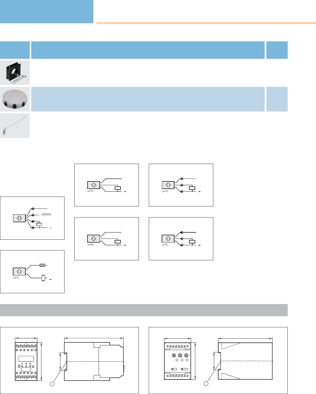
Evaluation systems
356
Product selectors and further information can be found at: www.ifm.com
Type Description Order
no.
Target for pulse pickups · Strap dimensions 7 x 220 mm E89013
Core colours
BN brown
BU blue
BK black
Wiring diagrams
1
4
L
L+
1
2
3
2
BN
BU
L+
L1
L
N
3
BN
BK
BU
L+
L
4
BN
BK
BU
L+
L
5
L+
L
1
3
2
6
L+
L
1
4
3
Scale drawings / drawing no. – CAD download: www.ifm.com
1
45
78
14
6
5
2
19 20 21 22 23 24
13 14 15 16 17 18
3
9
7A1 8A2 10 11 12
120
35,5
1
1: mounting on DIN rail
2
55
75
1 2 3 4 5 6 7 8
9 10 11 12 13 14 15 16
110
35,5
1
1: mounting on DIN rail
Product selectors and further information can be found at: www.ifm.com
Mounting clamp · Ø 34 mm - Ø 30 mm · with reducing bush · for type M30 · Housing materials: PBT E10077
Target wheel · Plastic disk with 8 screws as „target„ · Centered drill holes E89010
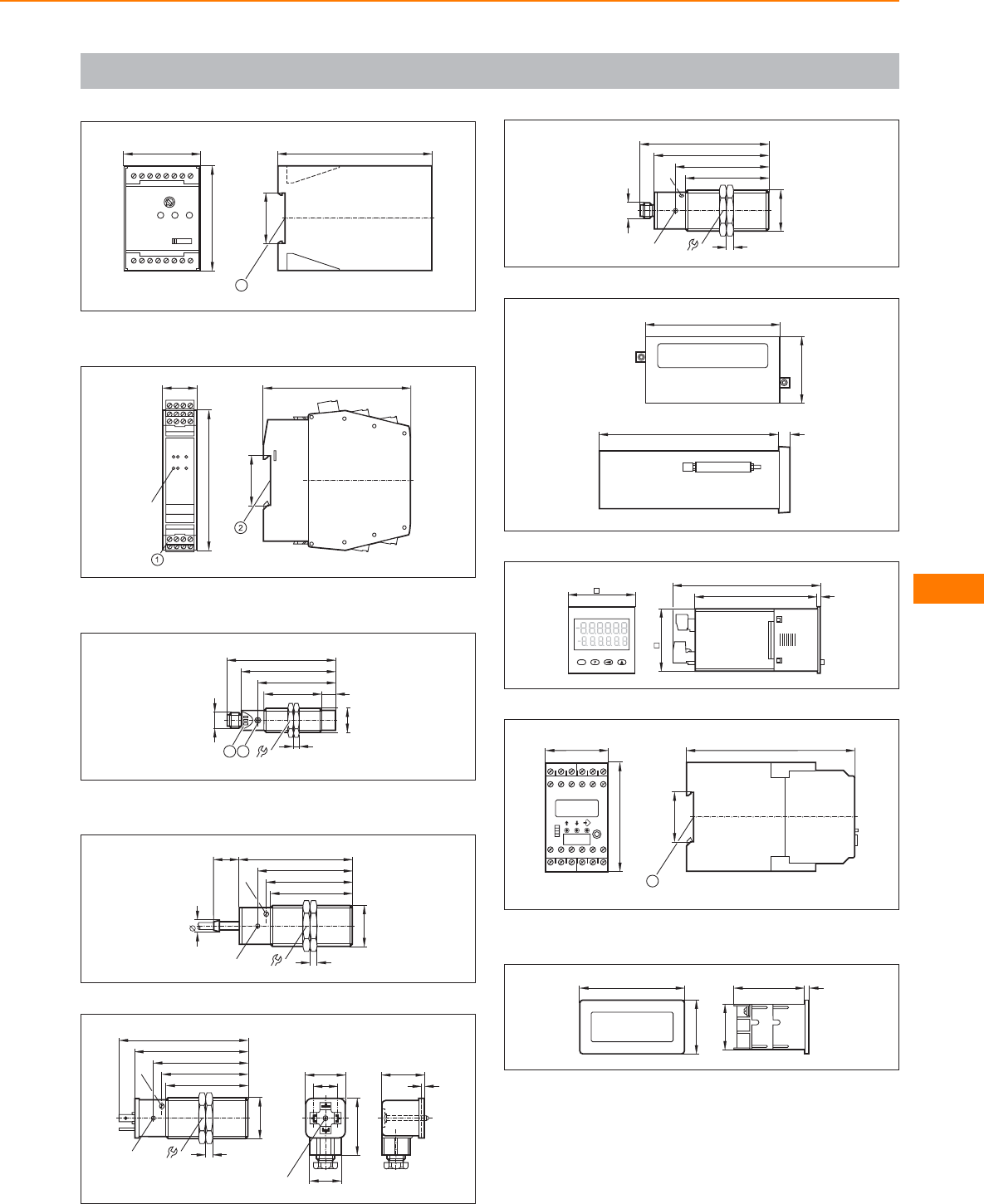
Evaluation systems
357
3
55
75
1 2 3 4 5 6 7 8
9 10 11 12 13 14 15 16
110
35,5
1
1: mounting on DIN rail
4
25
100
LED
35,5
105
1: Combicon connector with screw terminals, 2: mounting on DIN rail
5
M12 x1
77
56
40
M18 x1
68
10
4
24
2
1
1: 3 LED, 2: setting pushbutton
6
36
81
67
58
5
M30x1,5
9
18
2 LED
pot. 61
7
31
2
29
18
41
M3 23
36
81
67
58
5
M30x1,5
2 LED
pot. 61
92
8
36
82
66
59
5
LED
M30x1,5
M12x1
92
pot.
9
96
48
129 9
10
48
105
86,5 3
45
11
45
78
14
6
5
2
19 20 21 22 23 24
13 14 15 16 17 18
3
9
78 10 11 12
120
35,5
1
1: mounting on DIN rail
12
75
39
50 4
33
control panel cutout: 68 x 33 mm (according to DIN)
Scale drawings / drawing no. – CAD download: www.ifm.com
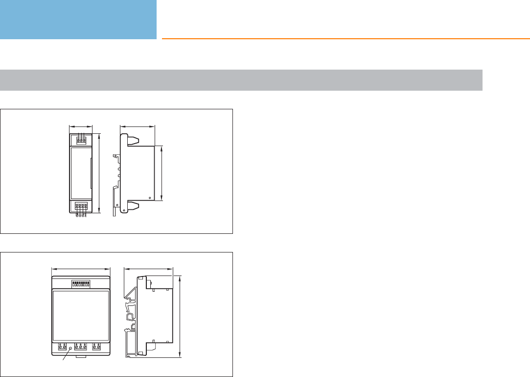
Evaluation systems
358
Product selectors and further information can be found at: www.ifm.com
Scale drawings / drawing no. – CAD download: www.ifm.com
13
66
42
28
96
1 2 3
4 5 6 7
14
98
59
LED
71

Evaluation systems
359
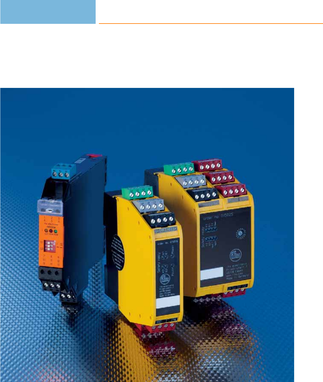
Evaluation systems
for safety and EX
360

Evaluation systems
for safety and EX
361
Safety
System description / System overview
Product selection chart
Scale drawings / drawing no. – CAD download: www.ifm.com
362 - 363
364
365
EX
System description / System overview
Product selection chart
Scale drawings / drawing no. – CAD download: www.ifm.com
366 - 367
368
368
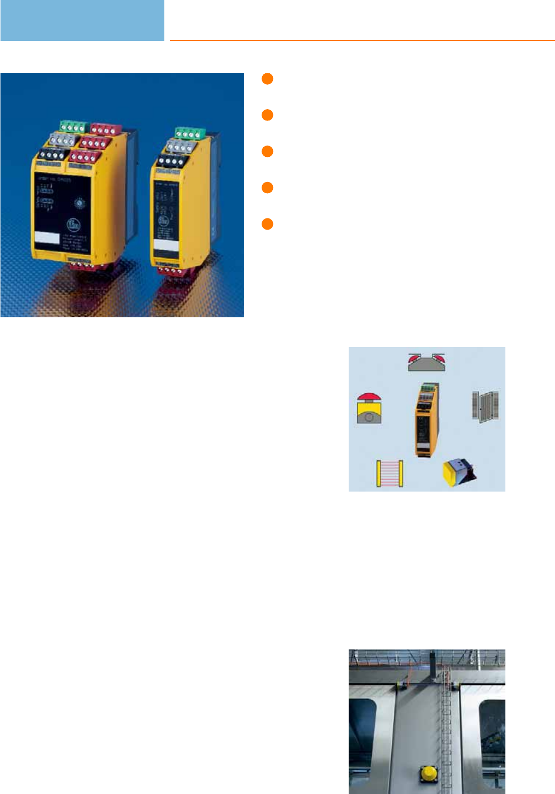
Multifunctional with relay outputs
or semiconductor outputs.
Connection of electro-sensitive
protective equipment.
e-stop and possibility to connect
mechanical safety relays.
Two-hand control to EN 574 up to
type IIIC, mechanical or electronic.
Certified to IEC 61508, ISO 13849-1,
EN 574.
Safety relays for protection of operators and machinery
The EC machinery directive stipulates machinery should not present a risk (EN1050
and EN ISO 14121-1). Since there is no zero risk, the aim is to achieve an acceptable
residual risk. If safety is dependent on control systems, these must be designed so
as to minimise malfunction.
For this, ifm offers multifunctional safety relays. A major advantage of these units is
their flexibility. They perform monitoring tasks in safety applications in conjunction
with different electro-sensitive protective equipment (ESPE).
On the safe side.
The relays are certified according to IEC 61508 SIL3, ISO 13849-1 PL e and EN 574
up to type IIIC.
They have several multifunctional self-detecting and self-monitoring inputs as well
as short-circuit proof outputs. Concerning the type of output the user can select
between relay outputs and semiconductor outputs. Moreover, outputs with switch-
off delay are available for specific applications.
It is possible to connect OSSD sensors, mechanical switches (e-stop) or implement
two-hand applications with electronic or mechanical switches. When used as two-
hand control devices, the requirements of type IIIB to EN574 can be met.
The units have a simultaneity monitoring of inputs. The offer the functions
“automatic start” or “monitored start” and also allow monitoring of external relay
contacts.
Mechanical as well as
electronic safety sen-
sors can be connected
to the safety relays.
Safety relays monitor
complete series of
safety sensors.
Evaluation systems
for safety and EX
362

System overview Page
Safety relays with relay outputs for fail-safe sensors 364
Safety relays with solid state outputs for fail-safe sensors 364
Safety relays for safety light curtains 364
Accessories 364
Scale drawings / drawing no. – CAD download: www.ifm.com 365
Safety
363
Safety relays with relay outputs for fail-safe sensors
Type Ub
[V]
Electrical
design
ISO 13849-1:
Categorie /
performance Level
IEC 61508:
SIL
Draw-
ing
no.
Order
no.
24 relay 4 / e 3 1 G1501S
24 relay 4 / e 3 2 G1502S
Safety relays with solid state outputs for fail-safe sensors
Type Ub
[V]
Electrical
design
ISO 13849-1:
Categorie /
performance Level
IEC 61508:
SIL
Draw-
ing
no.
Order
no.
24 Semi-conductor outputs 4 / e 3 3 G1503S
Safety relays for safety light curtains
Type Ub
[V]
Electrical
design
ISO 13849-1:
Categorie /
performance Level
IEC 61508:
SIL
Draw-
ing
no.
Order
no.
24 relay 4 / e 3 4 G2001S
Accessories
Type Description Order
no.
Safety T-splitter · T-piece for the pseudo-serial connection of fail-safe sensors · Housing materials: PUR E11569
Evaluation systems
for safety and EX
364
Product selectors and further information can be found at: www.ifm.com
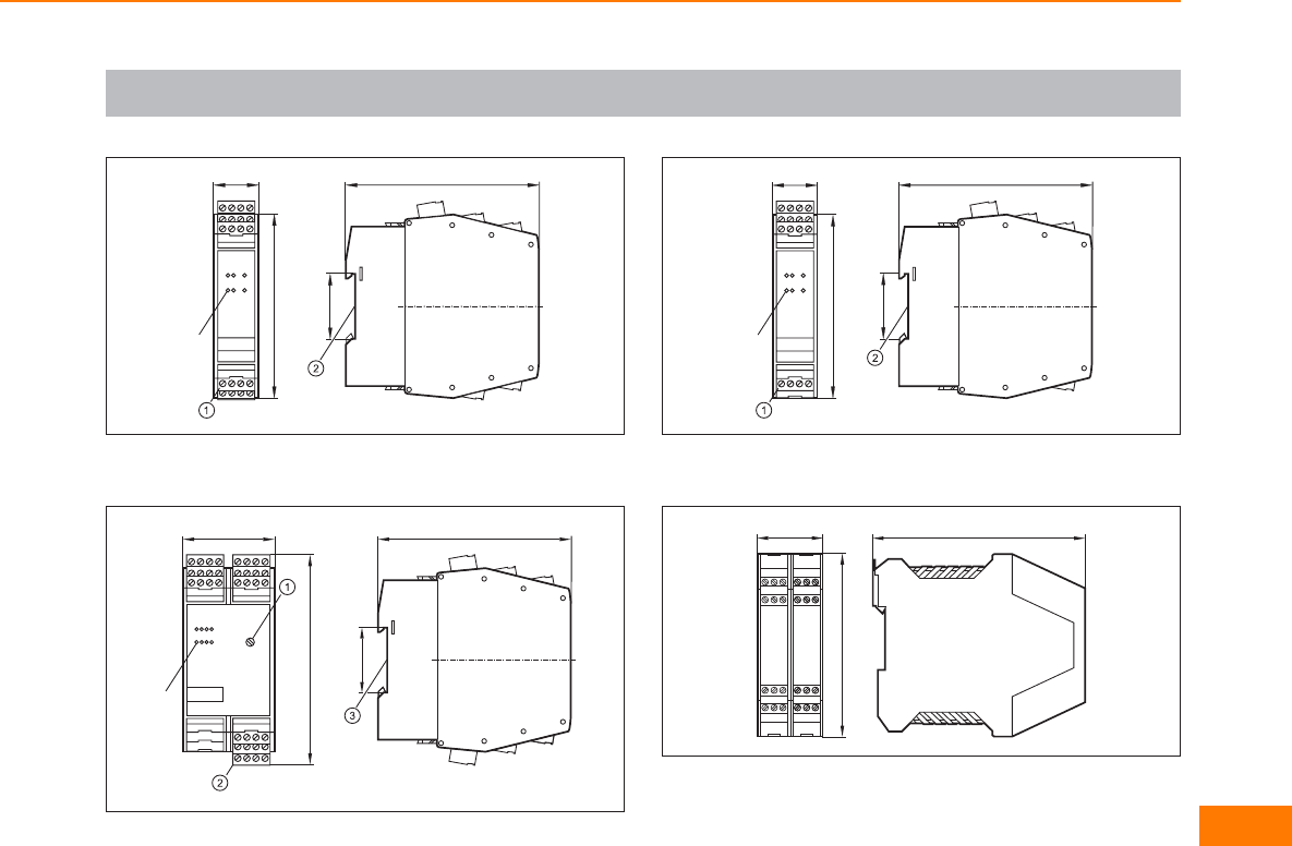
Scale drawings / drawing no. – CAD download: www.ifm.com
1
25
100
LED
35,5
105
1: Combicon connector with screw terminals, 2: mounting on DIN rail
2
114
LED
50 105
35,5
1: Rotary switch for switch-off delay, 2: Combicon connector with
screw terminals, 3: mounting on DIN rail
3
25
100
LED
105
35,5
1: Combicon connector with screw terminals, 2: mounting on DIN rail
4
114,5
99
35
Safety
365
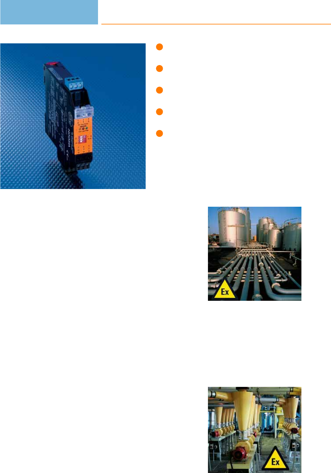
One or two-channel NAMUR switching
amplifiers to IEC 60947-5-6.
Short-circuit and wire-break monitoring.
Programmable output function.
Relay or transistor outputs.
Easy mounting on DIN rail.
Hazardous gas and dust areas
ATEX stands for “atmosphère explosible“. The 94/9/EC and 1992/92/EC directives
are also commonly called “ATEX directives”.
You can find hazardous areas in many different industries. Examples are the food
and feedstuffs industry, woodworking, disposal and recycling operations and the
typical industries of chemistry, for example gas and oil-processing plants.
It is basically distinguished between “G” (gas, i.e. fog, steams) and “D” (dust).
There are three unit categories each for gas and dust (1 - 3) that are analogous to
the gas zones 0 / 1 / 2 or dust zones 20 / 21 / 22. Example: Electrical apparatus of
the 1G category may be operated in zone 0.
NAMUR switching amplifiers for hazardous areas
The one or two-channel NAMUR switching amplifiers evaluate the sensor signal and
control the output. They meet all requirements of the ATEX directives. Switching
amplifiers with relay and transistor output are available. The switching amplifiers are
designed for the connection of NAMUR sensors to IEC 60947-5-6 and mechanical
switches. They provide the voltage supply via an electrical separation for the
intrinsically safe circuit.
Further features of the switching amplifiers are:
– Programmable effective direction of the output.
– Relay output designed as changeover contact.
– Short-circuit proof transistor outputs.
– The sensor cables are monitored for wire break and short circuit. In case of a
fault, the output is blocked or the relay is de-energised.
Typical hazardous gas
areas are found in the
chemical industry, for
example in gas and
petroleum processing.
Examples for the
hazardous dust areas
are the food and
feedstuffs industries,
but also disposal and
recycling operations.
Evaluation systems
for safety and EX
366

System overview Page
Switching amplifiers with ATEX approval 368
Scale drawings / drawing no. – CAD download: www.ifm.com 368
EX
367
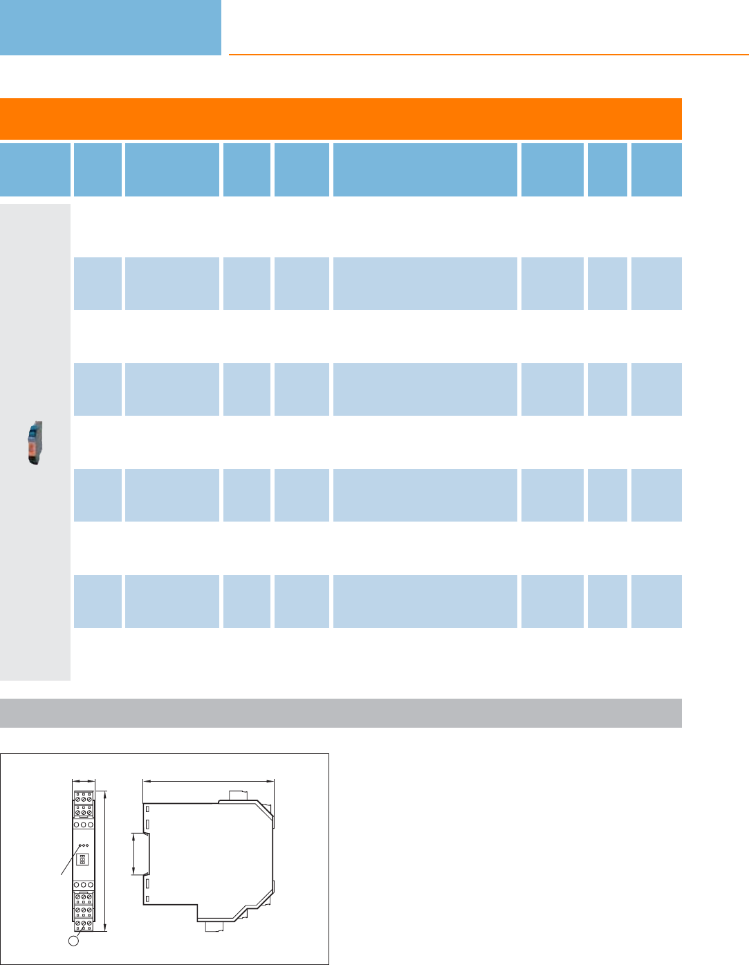
Switching amplifiers with ATEX approval
Type Ub
[V]
Power / current
consumption
[VA] / [mA]
f
[Hz]
Ta
[°C]
Output Protection Draw-
ing
no.
Order
no.
115 1.0 / 10 -20...60 relay (1 changeover contact) IP 20 1 N0030A
230 1.0 / 10 -20...60 relay (1 changeover contact) IP 20 1N0031A
115 1.3 / 10 -20...60 relay (1 changeover contact per channel) IP 20 1 N0032A
230 1.3 / 10 -20...60 relay (1 changeover contact per channel) IP 20 1N0033A
24 / < 23 10 -20...60 relay (1 changeover contact) IP 20 1 N0530A
24 / < 50 5000 -20...60 2 transistor outputs PNP
(100 mA, short-circuit protection) IP 20 1N0531A
24 / < 50 5000 -20...60 2 outputs (optocoupler, bipolar,
100 mA, short-circuit protection) IP 20 1 N0532A
24 / < 50 10 -20...60 relay (1 changeover contact per channel) IP 20 1N0533A
24 / < 50 5000 -20...60 2 transistor outputs PNP
(100 mA, short-circuit protection) IP 20 1 N0534A
Scale drawings / drawing no. – CAD download: www.ifm.com
1
112
35,5
20
120
LED
1
1: Combicon plug with screw terminals (optional)
Evaluation systems
for safety and EX
368
Product selectors and further information can be found at: www.ifm.com

EX
369
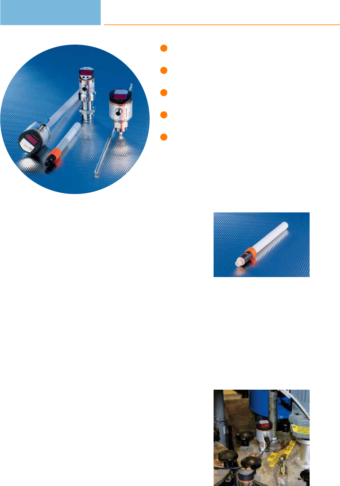
No movings parts means high
reliability and long life.
Guided wave radar, capacitive and
hydrostatic level sensors.
Outputs for continuous or point level
measurement.
Integrated LED display for local
indication of the current level.
Suitable for common industrial and
process fluids.
Level sensors
In industrial applications where fluids or bulk material are used, storage tanks or
silos are used for processing or storing of media. Sensors are used to detect the
levels. Even critical process conditions such as emptying a hydraulic tank or the
unintentional overspill of a tank are monitored by level sensors.
Advantages of electronic sensors
Deposits and wear and tear often lead to failures in particular if mechanical
switches are in contact with the medium. The electronic ifm sensors however can
do without any mechanical components. This makes the sensors especially robust
and reliable.
Another advantage of electronic sensors is the local indication of the level or the
easy setting of the switching threshold simply by pressing a button.
Measurement technique
For continuous level measurement the level is detected continuously, converted
into an electrical signal and indicated. Depending on the type the units have freely
programmable switching outputs or an analogue output for further processing.
Continuous level sensors from ifm electronic use three different physical measuring
principles:
For capacitive measurement the probe and the tank form an electrical capacitor.
The capacity changes with the level and is converted into a level measurement by a
microprocessor.
For hydrostatic level measurement a measuring cell detects the hydrostatic pressure
of the material. Here the pressure change is a measure for the level.
The efector gwr level sensor operates on the principle of guided wave radar.
Electromagnetic pulses are transmitted by the sensor head and guided along the
probe. If the microwave pulse hits the medium to be detected, it is reflected and
the time of flight is evaluated by the sensor.
Measurement in
the medium:
Probe sensors will be
directly immersed in
the medium to be
monitored.
For special applica-
tions: Capacitive
probe sensor for
monitoring oils and
coolants.
Level sensors
370

System overview Page
Electronic level sensors for oils and coolants, approval to the German Federal Water Act (WHG), section 19 372
Electronic level sensors for oils and coolants 372 - 373
Point level sensors for hygienic areas 373
Variable level sensors, guided wave radar 373
Compact sensors for level and temperature monitoring 374
Compact sensors for level and leakage monitoring 374
Sensors for hydrostatic level monitoring 374 - 375
Sensors for hydrostatic level monitoring ATEX category 1G/1D 375
Sensors for hydrostatic level monitoring in hygienic and wet areas 375 - 376
Point level sensors for oils and coolants, approval to the German Federal Water Act (WHG), section 19 377
Point level sensors for oils and lubricants 377
Oil moisture sensor 378
Accessories for level sensors LK, LT, LL, LI 378 - 379
Accessories for level sensors LR 379 - 381
Accessories for level sensors PA, PG, PI, PN, PS, PY 381 - 382
Accessories for level sensors LM 382 - 383
Wiring diagrams 383 - 384
Scale drawings / drawing no. – CAD download: www.ifm.com 384 - 387
Level sensors
371
Electronic level sensors for oils and coolants, approval to the German Federal Water Act
(WHG), section 19
Type Probe length
[mm]
Active
zone
[mm]
Inactive
zone
[mm]
Ub
[V]
Medium
temperature
water
[°C]
Medium
temperature
oil
[°C]
Iload
[mA]
Draw-
ing
no.
Order
no.
M12 connector · Output function 1 x normally open / closed programmable (OUT1) 1 x normally closed (OUT-OP, overflow
output) · DC PNP · Wiring diagram no. 1 · Connector groups 9, 11, 12, 107, 108, 109, 135, 136
264 195 53 / 15 12...30 0...35 0...65 200 1 LK1222
472 390 53 / 30 12...30 0...35 0...65 200 1LK1223
728 585 102 / 40 12...30 0...35 0...65 200 1 LK1224
Electronic level sensors for oils and coolants
Type Probe length
[mm]
Active
zone
[mm]
Inactive
zone
[mm]
Ub
[V]
Medium
temperature
water
[°C]
Medium
temperature
oil
[°C]
Iload
[mA]
Draw-
ing
no.
Order
no.
M12 connector (according to EN 61076-2-101) · Output function 1 x analogue 4...20 mA / 0...10 V (OUT2); 1 x normally open /
closed programmable (OUT-OP) · DC PNP · Wiring diagram no. 2 · Connector groups 9, 10, 11, 107, 108, 110, 135
264 195 53 / 15 18...30 0...35 (LK3122 +
E43100: 0...65) 0...70 200 2 LK3122
472 390 53 / 30 18...30 0...35 (LK3123 +
E43101: 0...60) 0...70 200 2LK3123
728 585 102 / 40 18...30 0...35 (LK3124 +
E43102: 0...55) 0...70 200 2 LK3124
M12 connector (according to EN 61076-2-101) · Output function 2 x normally open / closed programmable · DC PNP ·
Wiring diagram no. 3 · Connector groups 9, 11, 12, 107, 108, 109, 135, 136
264 195 53 / 15 18...30 0...35 (LK1022 +
E43100: 0...65) 0...70 200 2LK1022
472 390 53 / 30 18...30 0...35 (LK1023 +
E43101: 0...60) 0...70 200 2 LK1023
728 585 102 / 40 18...30 0...35 (LK1024 +
E43102: 0...55) 0...70 200 2LK1024
M12 connector (according to EN 61076-2-101) · Output function 3 x normally open / closed programmable (OUT1...OUT3);
1 x normally open / closed programmabl (OUT-OP) · DC PNP · Wiring diagram no. 4 · Connector groups 17, 18
264 195 53 / 15 18...30 0...35 (LK8122 +
E43100: 0...65) 0...70 200 3 LK8122
472 390 53 / 30 18...30 0...35 (LK8123 +
E43101: 0...60) 0...70 200 3LK8123
Level sensors
372
Product selectors and further information can be found at: www.ifm.com
Type Probe length
[mm]
Active
zone
[mm]
Inactive
zone
[mm]
Ub
[V]
Medium
temperature
water
[°C]
Medium
temperature
oil
[°C]
Iload
[mA]
Draw-
ing
no.
Order
no.
M12 connector (according to EN 61076-2-101) · Output function 3 x normally open / closed programmable (OUT1...OUT3);
1 x normally open / closed programmabl (OUT-OP) · DC PNP · Wiring diagram no. 4 · Connector groups 17, 18
728 585 102 / 40 18...30 0...35 (LK8124 +
E43102: 0...55) 0...70 200 3 LK8124
Point level sensors for hygienic areas
Type Process
connection
Process pressure
max.
[bar]
Application Protection Draw-
ing
no.
Order
no.
M12 connector · Output function normally open / closed complementary · DC PNP · Wiring diagram no. 5 · Connector groups 9,
11, 12, 107, 108, 109, 135, 136
G½ -1...16 water, water-based medium IP 68 / IP 69K 4 LMT100
G½ -1...16 oils, grease IP 68 / IP 69K 4LMT110
Variable level sensors, guided wave radar
Type Process
connection
Probe length
[mm]
Active
zone
[mm]
Inactive
zone
[mm]
Ub
[V]
Medium
temperature
[°C]
Iload
[mA]
Draw-
ing
no.
Order
no.
M12 connector (according to EN 61076-2-101) · Output function normally open / closed programmable; 4...20 mA or 0...10 V ·
DC PNP · Wiring diagram no. 6 · Connector groups 9, 10, 11, 107, 108, 110, 135
G¾ A 100...1600 HIGH: L - 40;
LOW: L - 60
HIGH: 30 / 10;
LOW: 30 / 30 18...30 0...80 200 5 LR3000
¾" NPT 150...1600 L - 50 40/10 18...30 0...80 200 6LR3300
M12 connector (according to EN 61076-2-101) · Output function 2 x normally open / closed programmable · DC PNP ·
Wiring diagram no. 3 · Connector groups 9, 11, 12, 107, 108, 109, 135, 136
G¾ A 100...1600 HIGH: L - 40;
LOW: L - 60
HIGH: 30 / 10;
LOW: 30 / 30 18...30 0...80 200 5 LR7000
¾„ NPT 150...1600 L - 50 40/10 18...30 0...80 200 6LR7300
M12 connector (according to EN 61076-2-101) · Output function 4 x normally open / closed programmable · DC PNP ·
Wiring diagram no. 7 · Connector groups 17, 18
G¾ A 100...1600 HIGH: L - 40;
LOW: L - 60
HIGH: 30 / 10;
LOW: 30 / 30 18...30 0...80 200 7 LR8000
¾„ NPT 150...1600 L - 50 –18...30 0...80 200 8LR8300
Level sensors
373
You can find wiring diagrams and scale drawings from page 383
Compact sensors for level and temperature monitoring
Type Probe length
[mm]
Active
zone
[mm]
Inactive
zone
[mm]
Ub
[V]
Medium
temperature
water
[°C]
Medium
temperature
oil
[°C]
Iload
[mA]
Draw-
ing
no.
Order
no.
M12 connector (according to EN 61076-2-101) · Output function 2 x normally open / closed programmable (level) 2 x normally
open / closed programmable (temperature) · DC PNP · Wiring diagram no. 8 · Connector groups 17, 18
264 195 53 / 15 18...30 – 0...70 200 9 LT8022
472 390 53 / 30 18...30 –0...70 200 9LT8023
728 585 102 / 40 18...30 – 0...70 200 9 LT8024
Compact sensors for level and leakage monitoring
Type Probe length
[mm]
Active
zone
[mm]
Inactive
zone
[mm]
Ub
[V]
Medium
temperature
water
[°C]
Medium
temperature
oil
[°C]
Iload
[mA]
Draw-
ing
no.
Order
no.
M12 connector (according to EN 61076-2-101) · Output function 4 x normally open / closed programmable · DC PNP ·
Wiring diagram no. 9 · Connector groups 17, 18
264 195 53 / 15 18...30 0...35 (LL8022 +
E43100: 0...65) 0...70 200 9 LL8022
472 390 53 / 30 18...30 0...35 (LL8023 +
E43101: 0...60) 0...70 200 9LL8023
728 585 102 / 40 18...30 0...35 (LL8024 +
E43102: 0...55) 0...70 200 9 LL8024
Sensors for hydrostatic level monitoring
Type Process
connection
Display
LED
Measuring
range
[bar]
Poverload
max. [bar]
Pbursting
min. [bar]
Ub
DC
[V]
Draw-
ing
no.
Order
no.
Output 4...20 mA analogue · Wiring diagram no. 10
– – 0...0.25 2 2.4 10...30 10 PS3208
– – 0...0.6 44.8 10...30 10 PS3407
– – 0...1 5 6 10...30 10 PS3417
Level sensors
374
Product selectors and further information can be found at: www.ifm.com
Type Process
connection
Display
LED
Measuring
range
[bar]
Poverload
max. [bar]
Pbursting
min. [bar]
Ub
DC
[V]
Draw-
ing
no.
Order
no.
Output 4...20 mA analogue · Wiring diagram no. 11 · Connector groups 9, 11, 107, 108, 135
G¼ I – 0...0.25 10 30 9.6...32 11 PA3028
Sensors for hydrostatic level monitoring ATEX category 1G/1D
Type Measuring
range
[bar]
Cable length /
material
Poverload
max. [bar]
Pbursting
min. [bar]
Ub
DC
[V]
Draw-
ing
no.
Order
no.
Output 4...20 mA analogue · Wiring diagram no. 12
0...0.25 5 m
FEP cable 2 2.4 10...30 12 PS308A
0...0.6 10 m
FEP cable 44.8 10...30 12 PS307A
0...1 15 m
FEP cable 5 6 10...30 12 PS317A
Sensors for hydrostatic level monitoring in hygienic and wet areas
Type Process
connection
Display
LED
Measuring
range
[bar]
Poverload
max. [bar]
Pbursting
min. [bar]
Ub
DC
[V]
Draw-
ing
no.
Order
no.
M12 connector · Output function 1 x normally open / normally closed programmable + 1 x normally open / normally closed pro-
grammable or 1 x analogue (4...20 / 20...4 mA, scalable) · Wiring diagram no. 14 · Connector groups 9, 10, 11, 107, 108, 110, 135
Aseptoflex Vario Display unit -0.005...0.1 4 30 20...32 13 PI2789
Aseptoflex Vario Display unit -0.0124...0.25 10 30 20...32 13 PI2798
Aseptoflex Vario Display unit -1...1 10 30 20...32 13 PI2799
Aseptoflex Vario Display unit -0.05...1 10 30 20...32 13 PI2797
Aseptoflex Vario Display unit -0.124...2.5 20 50 20...32 13 PI2796
G1 A Display unit -0.005...0.1 430 20...32 14 PI2889
G1 A Display unit -0.124...2.5 20 50 20...32 14 PI2896
Level sensors
375
You can find wiring diagrams and scale drawings from page 383
Type Process
connection
Display
LED
Measuring
range
[bar]
Poverload
max. [bar]
Pbursting
min. [bar]
Ub
DC
[V]
Draw-
ing
no.
Order
no.
M12 connector · Output function 1 x normally open / normally closed programmable + 1 x normally open / normally closed pro-
grammable or 1 x analogue (4...20 / 20...4 mA, scalable) · Wiring diagram no. 14 · Connector groups 9, 10, 11, 107, 108, 110, 135
G1 A Display unit -0.05...1 10 30 20...32 14 PI2897
G1 A Display unit -0.0124...0.25 10 30 20...32 14 PI2898
G1 A Display unit -1...1 10 30 20...32 14 PI2899
M12 connector · Output function 1 x normally open / closed programmable + 1 x analogue (4...20 / 20...4 mA, scalable) ·
Wiring diagram no. 15 · Connector groups 9, 10, 11, 107, 108, 110, 135
Aseptoflex Vario Display unit -0.005...0.1 430 18...32 15 PG2789
Aseptoflex Vario Display unit -0.0124...0.25 10 30 18...32 15 PG2798
Aseptoflex Vario Display unit -1...1 10 30 18...32 15 PG2799
Aseptoflex Vario Display unit -0.05...1 10 30 18...32 15 PG2797
Aseptoflex Vario Display unit -0.124...2.5 20 50 18...32 15 PG2796
G1 A Display unit -0.124...2.5 20 50 18...32 16 PG2896
G1 A Display unit -0.05...1 10 30 18...32 16 PG2897
G1 A Display unit -0.0124...0.25 10 30 18...32 16 PG2898
G1 A Display unit -1...1 10 30 18...32 16 PG2899
G1 A Display unit -0.005...0.1 4 30 18...32 16 PG2889
Level sensors
376
Product selectors and further information can be found at: www.ifm.com
Point level sensors for oils and coolants, approval to the German Federal Water Act (WHG),
section 19
Type Probe length
[mm]
Output Ub
[V]
Medium
temperature
water
[°C]
Medium
temperature
oil
[°C]
Iload
[mA]
Draw-
ing
no.
Order
no.
M12 connector · Output function · DC PNP · Wiring diagram no. 13 · Connector groups 9, 10, 11, 12, 107, 108, 109, 110,
135, 136
132 normally closed 10...36 0...35 0...65 200 17 LI2141
273 normally closed 10...36 0...35 0...65 200 17 LI2142
481 normally closed 10...36 0...35 0...65 200 17 LI2143
Point level sensors for oils and lubricants
Type Probe length
[mm]
Output Ub
[V]
Medium
temperature
water
[°C]
Medium
temperature
oil
[°C]
Iload
[mA]
Draw-
ing
no.
Order
no.
M12 connector · Output function · DC PNP · Wiring diagram no. 13 · Connector groups 9, 10, 11, 12, 107, 108, 109,
110, 135, 136
132 normally open / closed
programmable 10...36 0...35 (LI5141 +
E43103: 0...65) 0...65 200 17 LI5141
273 normally open / closed
programmable 10...36 0...35 (LI5142 +
E43100: 0...65) 0...65 200 17 LI5142
481 normally open / closed
programmable 10...36 0...35 (LI5143 +
E43101: 0...60) 0...65 200 17 LI5143
737 normally open / closed
programmable 10...36 0...35 (LI5144 +
E43102: 0...55) 0...65 200 17 LI5144
Level sensors
377
You can find wiring diagrams and scale drawings from page 383
Oil moisture sensor
Type Process
connection
Pressure
rating
[bar]
Protection Medium
temperature
oil
[°C]
Ambient
temperature
[°C]
Draw-
ing
no.
Order
no.
M12 connector · Output function 4...20 mA analogue · Wiring diagram no. 16 · Connector groups 16, 17, 18
G¾ 10 IP 67 -20...100 -20...85 18 LDH100
Accessories for level sensors LK, LT, LL, LI
Type Description Order
no.
Flange plate · 54-52X52 D16 · for capacitive level sensors LK, LI, LT, LL · Housing materials: flange: aluminium anodised / nut:
stainless steel / Spacer: brass / rubber ring: FPM / sealing: Tesnit E43007
Flange plate · 65-80 D16 · for capacitive level sensors LK, LI, LT, LL · Housing materials: flange: aluminium anodised / nut: stainless
steel / Spacer: brass / rubber ring: FPM E43006
Flange plate · 73-90 D16 · for capacitive level sensors LK, LI, LT, LL · according to DIN 24557 · Housing materials: aluminium
anodised / nut: stainless steel / Spacer: brass / rubber ring: FPM / sealing: NBR E43001
Mounting adapter · G ¾ D16 · for capacitive level sensors LK, LI, LT, LL · Housing materials: flange: stainless steel / nut: stainless
steel / Spacer: brass / rubber ring: FPM / sealing: Tesnit E43003
Mounting adapter · G ¾ D16 · for capacitive level sensors LI · Housing materials: brass nickel-plated / TPE / sealing: Viton E43019
Mounting adapter · G ¾ D22 · for climatic tube LK / LI · Housing materials: stainless steel / NBR / Tesnit / brass E43008
Mounting adapter · ¾" NPT D16 · for capacitive level sensors LK, LI, LT, LL · Housing materials: flange: stainless steel / nut: stainless
steel / Spacer: brass / rubber ring: FPM E43012
Mounting adapter · ¾" NPT D22 · for climatic tube LK / LI · Housing materials: stainless steel / NBR / brass E43014
Mounting adapter · G 1 D16 · for capacitive level sensors LK, LI, LT, LL · Housing materials: flange: stainless steel / nut: stainless
steel / Spacer: brass / rubber ring: FPM / sealing: Tesnit E43004
Mounting adapter · G 1 D22 · for climatic tube LK / LI · Housing materials: stainless steel / NBR / Tesnit / brass E43009
Level sensors
378
Product selectors and further information can be found at: www.ifm.com
Type Description Order
no.
Mounting adapter · 1" NPT D16 · for capacitive level sensors LK, LI, LT, LL · Housing materials: flange: stainless steel / nut: stainless
steel / Spacer: brass / rubber ring: FPM E43013
Climatic tube · Length: 132 mm · for capacitive level sensors LK, LI · Housing materials: PPH / NBR E43103
Climatic tube · Length: 264 mm · for capacitive level sensors LK, LI · Housing materials: PPH / NBR E43100
Climatic tube · Length: 472 mm · for capacitive level sensors LK, LI · Housing materials: PPH / NBR E43101
Climatic tube · Length: 728 mm · for capacitive level sensors LK, LI · Housing materials: PPH / NBR E43102
Mounting clamp · Ø 16 mm · for capacitive level sensors LK, LI, LT, LL · Housing materials: PP E43000
Mounting set · Ø 16 mm · for capacitive level sensors LK, LI, LT, LL · Housing materials: PP / Metal parts: steel galvanised E43016
Welding adapter · Ø 50 D16 · for capacitive level sensors LK, LI, LT, LL · Housing materials: flange: stainless steel / nut: stainless
steel / Spacer: brass / rubber ring: FPM E43002
Protective cover · for LK / LL / LR / LT sensors · Housing materials: PP E43910
Accessories for level sensors LR
Type Description Order
no.
Flange plate · 65-80 / G ¾ · for level sensors LR · Housing materials: flange: stainless steel E43202
Flange plate · 73-90 / G ¾ · for level sensors LR · according to DIN 24557 · Housing materials: flange: stainless steel / sealing: NBR E43201
Flange plate · 73-90 / ¾" NPT · for level sensors LR · according to DIN 24557 · Housing materials: flange: stainless steel / sealing:
NBR E43206
Probe · Probe length: 240 mm · for level sensors LR · Housing materials: stainless steel E43203
Level sensors
379
You can find wiring diagrams and scale drawings from page 383

Type Description Order
no.
Probe · Probe length: 450 mm · for level sensors LR · Housing materials: stainless steel E43204
Probe · Probe length: 700 mm · for level sensors LR · Housing materials: stainless steel E43205
Probe · Probe length: 1000 mm · for level sensors LR · Housing materials: stainless steel E43207
Probe · Probe length: 1200 mm · for level sensors LR · Housing materials: stainless steel E43208
Probe · Probe length: 1400 mm · for level sensors LR · Housing materials: stainless steel E43209
Probe · Probe length: 1600 mm · for level sensors LR · Housing materials: stainless steel E43210
Coaxial pipe · Length: 240 mm · G¾ · for level sensors LR · Housing materials: stainless steel / sealing: Tesnit / centring piece: PP /
fixing bracket: stainless steel E43211
Coaxial pipe · Length: 450 mm · G¾ · for level sensors LR · Housing materials: stainless steel / sealing: Tesnit / centring piece: PP /
fixing bracket: stainless steel E43212
Coaxial pipe · Length: 700 mm · G¾ · for level sensors LR · Housing materials: stainless steel / sealing: Tesnit / centring piece: PP /
fixing bracket: stainless steel E43213
Coaxial pipe · Length: 1000 mm · G¾ · for level sensors LR · Housing materials: stainless steel / sealing: Tesnit / centring piece: PP /
fixing bracket: stainless steel E43214
Coaxial pipe · Length: 1200 mm · G¾ · for level sensors LR · Housing materials: stainless steel / sealing: Tesnit / centring piece: PP /
fixing bracket: stainless steel E43215
Coaxial pipe · Length: 1400 mm · G¾ · for level sensors LR · Housing materials: stainless steel / sealing: Tesnit / centring piece: PP /
fixing bracket: stainless steel E43216
Coaxial pipe · Length: 1600 mm · G¾ · for level sensors LR · Housing materials: stainless steel / sealing: Tesnit / centring piece: PP /
fixing bracket: stainless steel E43217
Coaxial pipe · Length: 450 mm · ¾" NPT · for level sensors LR · Housing materials: stainless steel / centring piece: PP / fixing bracket:
stainless steel E43218
Coaxial pipe · Length: 700 mm · ¾" NPT · for level sensors LR · Housing materials: stainless steel / centring piece: PP / fixing bracket:
stainless steel E43219
Level sensors
380
Product selectors and further information can be found at: www.ifm.com
Type Description Order
no.
Coaxial pipe · Length: 1000 mm · ¾" NPT · for level sensors LR · Housing materials: stainless steel / centring piece: PP / fixing
bracket: stainless steel E43220
Coaxial pipe · Length: 1600 mm · ¾" NPT · for level sensors LR · Housing materials: stainless steel / centring piece: PP / fixing
bracket: stainless steel E43221
Accessories for level sensors PA, PG, PI, PN, PS, PY
Type Description Order
no.
Adapter · G ¼ - G ½ · Housing materials: stainless steel / sealing: FPM E30000
Adapter · G ¼ - G ¼ · Housing materials: stainless steel / FPM E30007
Cable clamp fastener · for submersible pressure transmitter PS3 · Housing materials: steel / plastics E30399
Filter element · for submersible pressure transmitter PS3 · for fixing on the capillary tube E30400
Splitter box · with ventilation and terminal block · for submersible pressure transmitter PS3 · Housing materials: plastics E30401
Additional weight · for submersible pressure transmitter PS3 · Housing materials: stainless steel 316Ti / 1.4571 E30402
Welding adapter · Ø 50 mm · for units with Aseptoflex Vario adapter · Sealing by sealing ring · Housing materials: stainless steel
316L / 1.4435 E30122
Aseptoflex Vario adapter · pipe fitting · DN40 (1.5") · DIN 11851 · for units with Aseptoflex Vario adapter · Sealing by sealing ring ·
Housing materials: stainless steel 316L / 1.4435 E33212
Aseptoflex Vario adapter · pipe fitting · DN50 (2") · DIN 11851 · for units with Aseptoflex Vario adapter · Sealing by sealing ring ·
Housing materials: stainless steel 316L / 1.4435 E33213
Aseptoflex Vario adapter · pipe fitting · DN40 (1.5") · DIN 11851 · for units with Aseptoflex Vario adapter · Metal to metal seal ·
Housing materials: stainless steel 316L / 1.4435 E33712
Aseptoflex Vario adapter · pipe fitting · DN50 (2") · DIN 11851 · for units with Aseptoflex Vario adapter · Metal to metal seal ·
Housing materials: stainless steel 316L / 1.4435 E33713
Level sensors
381
You can find wiring diagrams and scale drawings from page 383
Type Description Order
no.
Aseptoflex Vario adapter · Clamp · 1-1.5" · ISO 2852 · for units with Aseptoflex Vario adapter · Sealing by sealing ring · Housing
materials: stainless steel 316L / 1.4435 E33201
Aseptoflex Vario adapter · Clamp · 1-1.5" · ISO 2852 · for units with Aseptoflex Vario adapter · Metal to metal seal · Housing
materials: stainless steel 316L / 1.4435 E33701
Accessories for level sensors LM
Type Description Order
no.
Welding adapter · G ½ - Ø 29 mm · for pipes · Housing materials: stainless steel 316L / 1.4435 E43301
Welding adapter · G ½ - Ø 29 mm · for pipes · with leakage port · Housing materials: stainless steel 316L / 1.4435 E43310
Welding adapter · G ½ - Ø 30 mm · for tanks · Housing materials: stainless steel 316L / 1.4435 E43300
Welding adapter · G ½ - Ø 30 mm · for tanks · with leakage port · Housing materials: stainless steel 316L / 1.4435 E43309
Welding adapter · G ½ - Ø 35 mm · ball · Housing materials: stainless steel 316L / 1.4404 E30055
Welding adapter · G ½ - Ø 45 mm · collar · Housing materials: stainless steel 316L / 1.4404 E30056
Tuning fork adapter · G ¾ · Housing materials: stainless steel 316L / 1.4435 E43302
Tuning fork adapter · G 1 · Housing materials: stainless steel 316L / 1.4435 E43303
Adapter · G ½ · pipe fitting · DN25 (1") · DIN 11851 · Housing materials: stainless steel 316L / 1.4435 E43304
Adapter · G ½ · pipe fitting · DN40 (1.5") · DIN 11851 · Housing materials: stainless steel 316L / 1.4435 E43305
Adapter · G ½ · Varivent type F · DN25 (1"), D = 50 · Housing materials: stainless steel 316L / 1.4435 E43306
Level sensors
382
Product selectors and further information can be found at: www.ifm.com
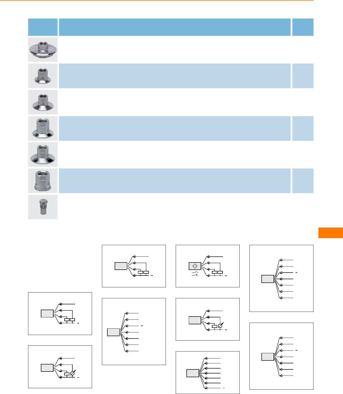
Type Description Order
no.
Adapter · G ½ · Varivent type N · DN40 (1.5"), D = 68 · Housing materials: stainless steel 316L / 1.4435 E43307
Adapter · G ½ · Clamp · 1-1.5" · ISO 2852 / DIN 32676 · with leakage port · Housing materials: stainless steel 316L / 1.4435 E43311
Adapter · G ½ · Clamp · 2" · ISO 2852 / DIN 32676 · with leakage port · Housing materials: stainless steel 316L / 1.4435 E43312
G ½ adapter · Clamp · 1-1.5" · ISO 2852 / DIN 32676 · for units with G ½ adaptation · Housing materials: stainless steel 316L /
1.4404 E33401
G ½ adapter · Clamp · 2" · ISO 2852 / DIN 32676 · for units with G ½ adaptation · Housing materials: stainless steel 316L / 1.4404 E33402
G ½ adapter · DN25 · SMS · for units with G ½ adaptation · Housing materials: stainless steel 316L / 1.4404 E33430
sealing plug · G ½ · for G ½ adapter · Housing materials: stainless steel 316L / 1.4435 E43308
Core colours
BN brown
GY grey
WH white
BU blue
GN green
Wiring diagrams
1
L
L+
3 BU
4 BK
2 WH
1 BN
Out- OP
Out 1
2:
4:
2
L+
L
3 BU
4 BK
2 WH
1 BN
Out- OP
Out 2
4:
2:
3
2
L
L+
4
1
3
Out 1
Out 2
4:
2:
4
Out- OP / Out 4
3
4
2
5
6
Out 1
Out 3
L+
1
n.c.
7
Out 2
L
5
4
L
L+
1
2
3
2:
4:
6
L+
L
OUT1
OUT2
4:
2:
4
2
1
3
7
L+
L
n.c.
Out 4
Out 1
Out 2
1
2
4
6
7
3
Out 3
5
8
Out 4
3
4
2
5
6
Out 1
Out 3
L+
1
n.c.
7
Out 2
L
9
Out-OP
3
4
2
5
6
Out 1
Out 3
L+
1
n.c.
7
Out 2
L
Level sensors
383
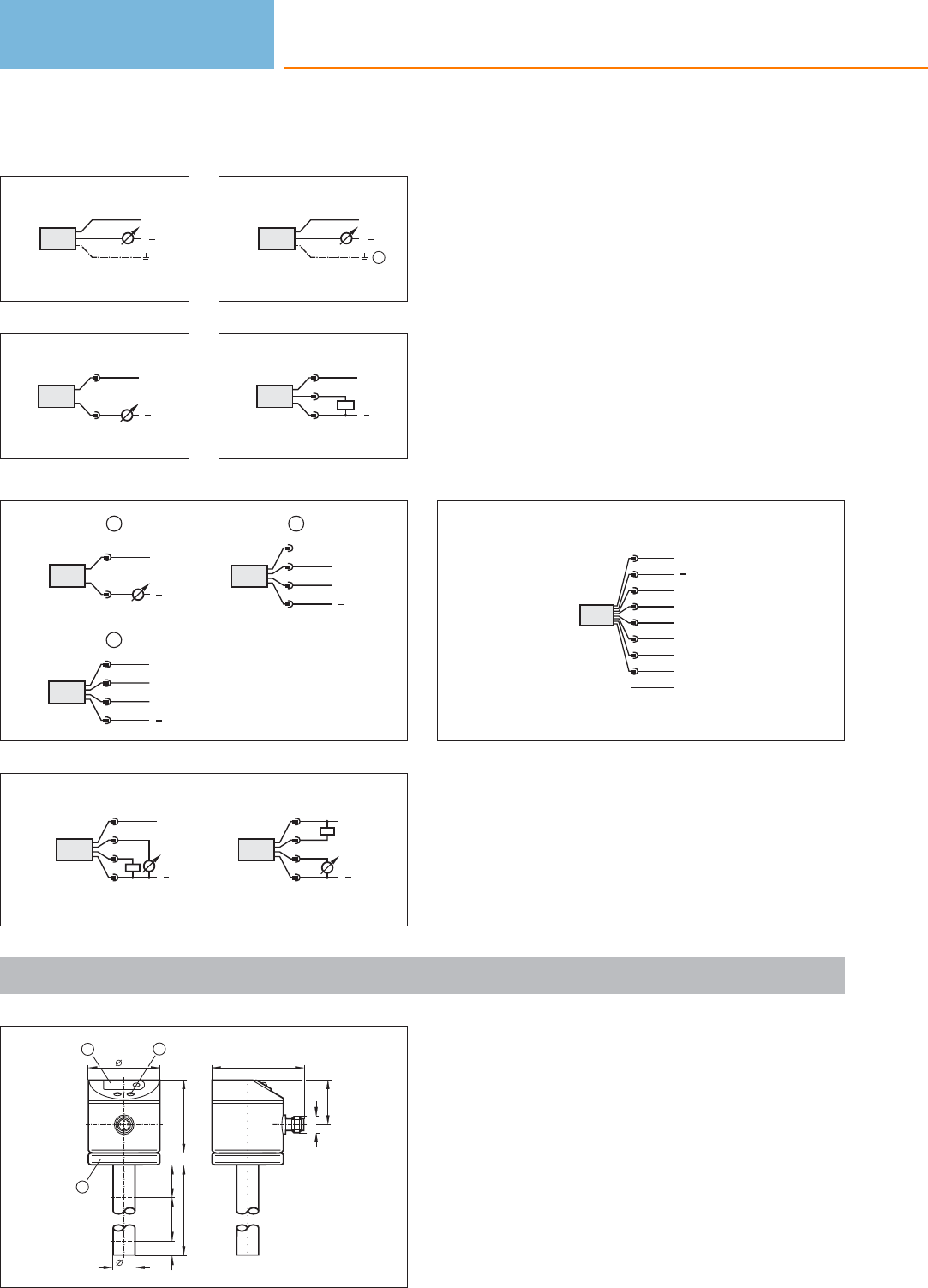
Wiring diagrams
10
BN
GY
WH
L+
L
11
L+
L
1
2
12
1
BN
BU
GN
L+
L
13
L+
L
1
4
3
14
4
1
3
2
L+
L
OUT2
OUT1
2
4
1
3
2
L+
L
P
3
L+
L
1
2
1
15
4
1
3
2
L+
L
2
1
3
4
L+
L
16
screen
L+
L
Out 1
Out 2
1
8
7
6
3
4
5
2
n.c.
n.c.
n.c.
n.c.
Scale drawings / drawing no. – CAD download: www.ifm.com
1
I1
L
16
50
518
A
I2
12
3
30,5
64
M12 x1
1: 7-segment LED display, 2: Programming buttons, 3: Housing
connection with cable lug for cable 1.5 - 2.5 mm²
Level sensors
384
Product selectors and further information can be found at: www.ifm.com
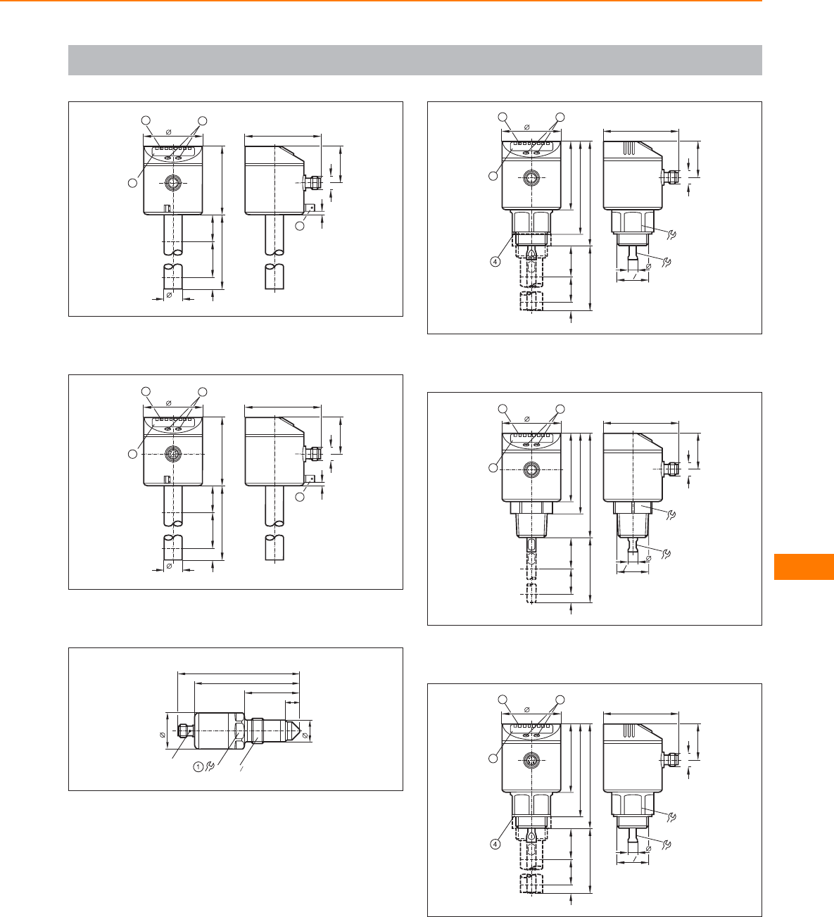
Scale drawings / drawing no. – CAD download: www.ifm.com
2
30,5
64
M12 x1
4
3
I1
L
16
50
57
AI2
3
2
1
1: 4-digit alphanumeric display, 2: LEDs, 3: Programming buttons, 4:
Housing connection (flat-pin connector 6.3 mm following DIN 46244)
3
30,5
64
M12 x1
4
3
I1
L
16
50
57
AI2
3
2
1
1: 4-digit alphanumeric display, 2: LEDs, 3: Programming buttons, 4:
Housing connection (flat-pin connector 6.3 mm following DIN 46244)
4
12
46
88
30
18
102
G2
1
LED 27
1: tightening torque 20...25 Nm
5
30
63
M12 x1
G
4
3
86
32
I1
L
50
57
AI2
3
2
1
78
87
1: 4-digit alphanumeric display, 2: LEDs (display unit / switching
status), 3: Programming buttons, 4: sealing
6
I1
L
50
57
AI2
3
2
1
67
87
30
63
M12 x1
"NPT
8
4
3
6
32
1: 4-digit alphanumeric display, 2: LEDs (display unit / switching
status), 3: Programming buttons
7
30
63
M12 x1
G
4
3
86
32
I1
L
50
57
AI2
3
2
1
78
87
1: 4-digit alphanumeric display, 2: LEDs (display unit / switching
status), 3: Programming buttons, 4: sealing
Level sensors
385
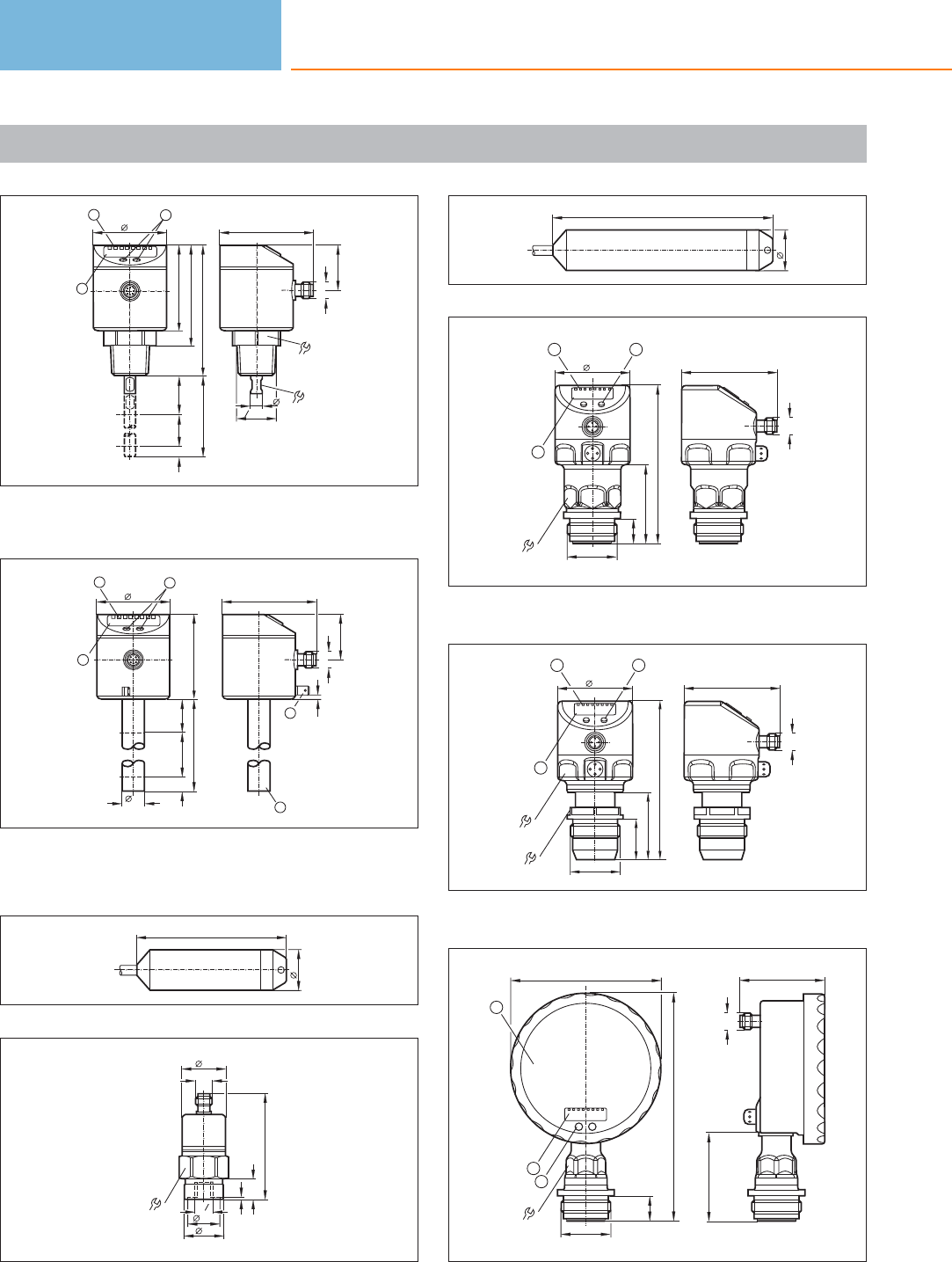
Scale drawings / drawing no. – CAD download: www.ifm.com
8
30
63
M12 x1
"NPT
8
4
3
6
32
I1
L
50
57
AI2
3
2
1
67
87
1: 4-digit alphanumeric display, 2: LEDs (display unit / switching
status), 3: Programming buttons
9
30,5
64
M12 x1
5
4
3
I1
L
16
50
57
AI2
3
2
1
1: 4-digit alphanumeric display, 2: LEDs, 3: Programming buttons,
4: Housing connection (flat-pin connector 6.3 mm following DIN
46244), 5: Position of the temperature measuring element
10
100
27
11
75
M12 x1
30
30
27
1, 3
21,5
14
G4
1
12
27
147
13
16,8
G1
64
M12 x1
105,8
52,8
50
34
1
23
1: 4-digit alphanumeric display, 2: LEDs, 3: Programming button
14
64
M12 x1
105,6
45,1
27,4
50
34
46
1
23
G1
1: 4-digit alphanumeric display, 2: LEDs, 3: Programming button
15
24
3
153
16,8
100
2
1
57
60,5
M12 x1
G1
1: Analogue display, 2: 4-digit alphanumeric display, 3: Programming
button
Level sensors
386
Product selectors and further information can be found at: www.ifm.com
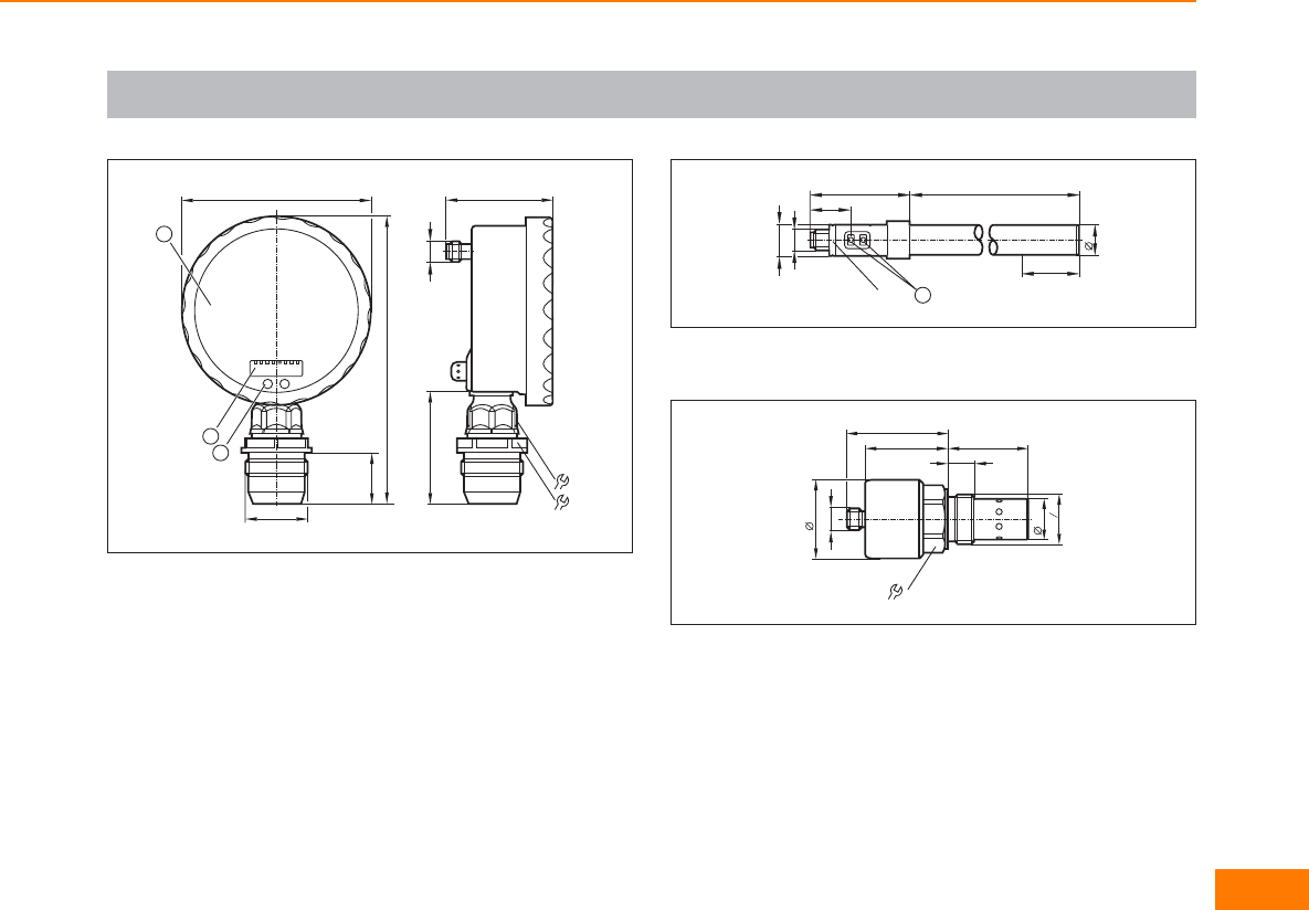
Scale drawings / drawing no. – CAD download: www.ifm.com
16
24
34
3
153
27
100
2
1
G1
57
60,5 M12 x1
1: Analogue display, 2: 4-digit alphanumeric display, 3: Touch button
(programming button)
17
L
16
53
M12 x1
LED
21,3
1
16,6
A
1: Programming buttons
18
32
42
M12x1
21,6
54
44 43
14
G4
3
Level sensors
387
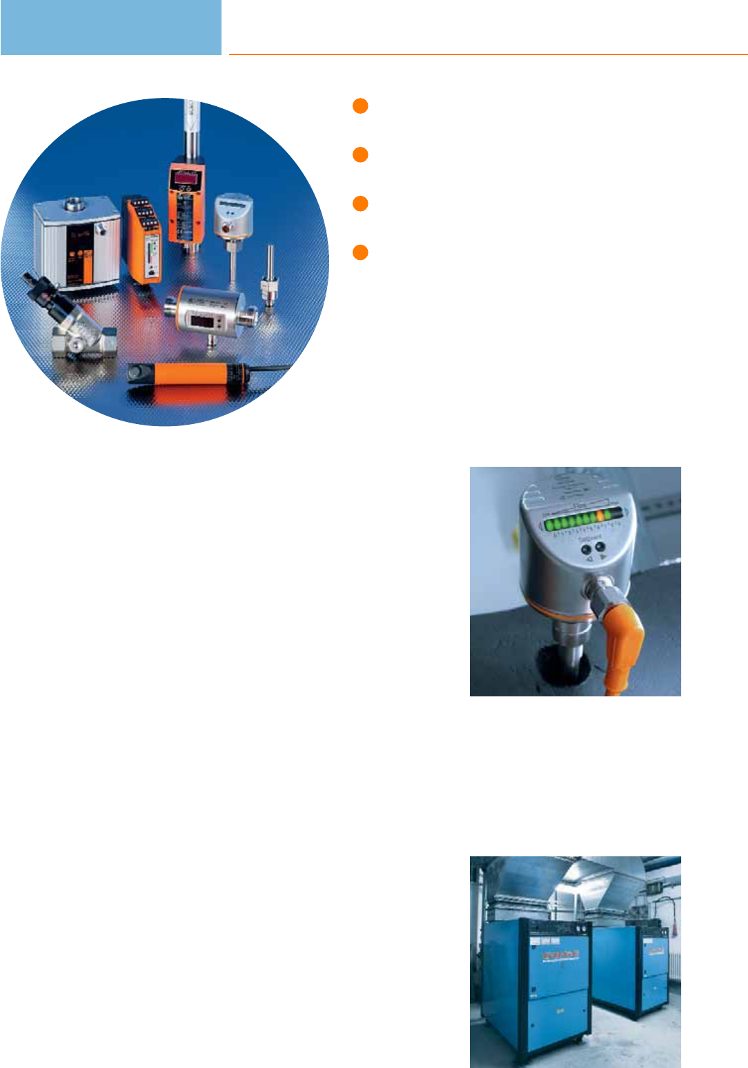
For liquids and gases.
Special versions for food
applications and hazardous areas.
Optional fittings for variable
process connection.
Flow monitoring also for
aggressive media.
Flow sensors
In almost all fields of process and plant engineering liquids or gases are used for
coolant and lubricant supply of machines and units, ventilation of installations and
buildings and the processing of products. In case of no flow of these media
considerable damage and downtime may result. Thus it is very important to monitor
these media. In modern installations electronic flow monitors are used for this
purpose. They work without wear and tear and without mechanical components.
This guarantees reliable monitoring even in case of difficult media over a long
period.
Operating principle
Electronic flow sensors from ifm electronic operate with different measurement
techniques. They meet all requirements from a simple monitoring function to the
exact detection of flow quantities.
Harmonised operating menus ensure that operators who use different flow sensors
can quickly and precisely carry out settings on the sensors. Some flow sensors
feature an integrated temperature monitor which makes an additional measuring
point unnecessary. This enables to control processes in the optimum operating
status especially with regard to energy savings.
Analogue, binary and pulse outputs offer various possibilities to process the
measured data. Due to the flexible programming by means of pushbuttons the
flow sensors can be adapted to different conditions. The sensors are mounted via
adapters.
Monitoring very small
flow rates: Flow moni-
tor with flow adapter.
Optimised
consumption of
compressed air.
Flow sensors
388

Flow sensors
389
System overview Page
Magnetic-inductive flow sensors with integrated temperature measurement (sealing material FKM) 391
Magnetic-inductive flow sensors with integrated temperature measurement (sealing material EPDM) 391
Magnetic-inductive flow sensors (sealing material FKM) 392
Compact housings for adapters for flow monitoring 392
Compact housings can be configured for T-pieces for flow monitoring 393
Compact housings for adapters for flow monitoring, Hastelloy sensor tip 393
Compact housings for adapters for flow monitoring, titanium sensor tip 393
Compact designs for adapter with flow and temperature monitoring 393
Compact housings for adapters with ATEX approval group II, category 3D / 3G 394
Compact housings for adapters for hygienic and wet areas 394
Mechatronic flow sensors for machine tools 394 - 395
Mechatronic flow sensors for liquids 395
Flow sensors for connection to control monitors, industrial applications 395 - 396
Flow sensors for connection to control monitors, industrial applications, titanium housing 396
Flow sensors for connection to control monitors for hygienic and wet areas 397
Flow sensors for connection to control monitors for aggressive media, ceramic housing 397
Control monitors for industrial applications 397 - 398
Flow sensors for connection to control monitors with ATEX approval 398 - 399
Flow sensors for connection to control monitors with ATEX approval, ceramic housing 399
Control monitors with ATEX approval 400
Air flow monitors 400
Compressed air meters 401
Compressed air meter for special gases 401
Inline sensor for small dosing quantities of water and aqueous solutions 401
Ultrasonic flow rate sensors for liquids (water, glycol solutions, oils) 402
Accessories for flow sensors and control monitors 402 - 404
Flange adapters for flow sensors 404 - 405
Accessories for airflow monitors 405
Accessories for volumetric flow sensors 405 - 406
Grounding clamps for magnetic-inductive volumetric flow sensors 406
Wiring diagrams 407 - 408

System overview Page
Scale drawings / drawing no. – CAD download: www.ifm.com 408 - 415
Flow sensors
390
Product selectors and further information can be found at: www.ifm.com
Magnetic-inductive flow sensors with integrated temperature measurement
(sealing material FKM)
Type Process
connection
Measuring
range
[l/min]
Medium
temperature
[°C]
Pressure
rating
[bar]
Response
time
[s]
Ub
[V]
Draw-
ing
no.
Order
no.
Output OUT1: normally open / closed programmable or pulse OUT2: normally open / closed programmable or analogue
(4...20 mA / 0...10 V, scaleable) · Wiring diagram no. 1 · Connector groups 9, 10, 11, 107, 108, 110, 135
G½ 0.25...25.00 -10...70 16 < 0.150 19...30 1 SM6000
Output 2 x analogue (4...20 mA scalable) · Wiring diagram no. 2 · Connector groups 9, 11, 107, 108, 135
G½ 0.1...25.00 -10...70 16 < 0.150 20...30 1SM6004
Output OUT1: normally open / closed programmable or pulse OUT2: normally open / closed programmable or analogue
(4...20 mA / 0...10 V, scaleable) · Wiring diagram no. 1 · Connector groups 9, 10, 11, 107, 108, 110, 135
G¾ 0.5...50.0 -10...70 16 < 0.150 19...30 2 SM7000
Output 2 x analogue (4...20 mA scalable) · Wiring diagram no. 2 · Connector groups 9, 11, 107, 108, 135
G¾ 0.2...50.0 -10...70 16 < 0.150 20...30 2SM7004
Output OUT1: normally open / closed programmable or pulse OUT2: normally open / closed programmable or analogue
(4...20 mA / 0...10 V, scaleable) · Wiring diagram no. 1 · Connector groups 9, 10, 11, 107, 108, 110, 135
G1 0.7...100.0 -10...70 16 < 0.150 19...30 3 SM8000
Output 2 x analogue (4...20 mA scalable) · Wiring diagram no. 2 · Connector groups 9, 11, 107, 108, 135
G1 0.2...100.0 -10...70 16 < 0.150 20...30 3SM8004
Magnetic-inductive flow sensors with integrated temperature measurement
(sealing material EPDM)
Type Process
connection
Measuring
range
[l/min]
Medium
temperature
[°C]
Pressure
rating
[bar]
Response
time
[s]
Ub
[V]
Draw-
ing
no.
Order
no.
Output OUT1: normally open / closed programmable or pulse OUT2: normally open / closed programmable or analogue
(4...20 mA / 0...10 V, scaleable) · Wiring diagram no. 1 · Connector groups 9, 10, 11, 107, 108, 110, 135
G½ 0.25...25.00 -10...70 16 < 0.150 19...30 1 SM6100
G¾ 0.5...50.0 -10...70 16 < 0.150 19...30 2SM7100
G1 0.7...100.0 -10...70 16 < 0.150 19...30 3 SM8100
Flow sensors
391
You can find wiring diagrams and scale drawings from page 407
Magnetic-inductive flow sensors (sealing material FKM)
Type Process
connection
Measuring
range
[l/min]
Medium
temperature
[°C]
Pressure
rating
[bar]
Response
time
[s]
Ub
[V]
Draw-
ing
no.
Order
no.
M12 connector · Output function 4...20 mA analogue · DC · Wiring diagram no. 3 · Connector groups 9, 10, 11, 107, 108, 110, 135
G½ 0...25 -10...70 16 < 0.150 19...30 4 SM6050
G¾ 0...50 -10...70 16 < 0.150 19...30 5SM7050
G1 0...100 -10...70 16 < 0.150 19...30 6 SM8050
Compact housings for adapters for flow monitoring
Type Setting range
liquids / gases
[cm/s]
Greatest
sensitivity
[cm/s]
Medium
temperature
[°C]
Pressure
rating
[bar]
Response
time
[s]
Ub
[V]
Draw-
ing
no.
Order
no.
M12 connector · Wiring diagram no. 4 · Connector groups 9, 10, 11, 107, 108, 110, 135
3...300 / 200...3000 3...100 / 200...800 -25...80 30 1...10 19...36 7 SI5000
M12 connector · Wiring diagram no. 5 · Connector groups 9, 10, 11, 107, 108, 110, 135
3...300 / 200...3000 3...100 / 200...800 -25...80 300 1...10 19...36 8SI5002
1/2“ UNF-Connector · Wiring diagram no. 6 · Connector group 27
3...300 / 200...3000 3...100 / 200...800 -25...80 300 1...10 85...265 9 SI5006*
M12 connector · Wiring diagram no. 3 · Connector groups 9, 11, 107, 108, 135
3...300 / - 3...100 -25...80 / - 300 1...10 19...36 8SI5004
M12 connector · Wiring diagram no. 7 · Connector groups 9, 10, 11, 107, 108, 110, 135
3...300 / 200...3000 3...100 / 200...800 -25...80 300 1...2 / 1...10 19...36 8 SI5010
* Note for AC and AC/DC units
Miniature fuse to IEC60127-2 sheet 1, ≤ 5 A (fast acting). Recommendation: check the unit for reliable function after a short
circuit.
Flow sensors
392
Product selectors and further information can be found at: www.ifm.com
Compact housings can be configured for T-pieces for flow monitoring
Type Setting range
liquids / gases
[cm/s]
Greatest
sensitivity
[cm/s]
Medium
temperature
[°C]
Pressure
rating
[bar]
Response
time
[s]
Ub
[V]
Draw-
ing
no.
Order
no.
M12 connector · Wiring diagram no. 18 · Connector groups 9, 10, 11, 107, 108, 110, 135
0.1...12.0 (NW15)
0.2...24.0 (NW19)
0.4...48.0 (NW24)
– 0...80 30 5 20...28 10 SA3010
Compact housings for adapters for flow monitoring, Hastelloy sensor tip
Type Setting range
liquids / gases
[cm/s]
Greatest
sensitivity
[cm/s]
Medium
temperature
[°C]
Pressure
rating
[bar]
Response
time
[s]
Ub
[V]
Draw-
ing
no.
Order
no.
M12 connector · Wiring diagram no. 7 · Connector groups 9, 10, 11, 107, 108, 110, 135
3...300 / 200...3000 3...100 / 200...800 -25...80 300 1...2 / 1...10 19...36 8 SI0553
Compact housings for adapters for flow monitoring, titanium sensor tip
Type Setting range
liquids / gases
[cm/s]
Greatest
sensitivity
[cm/s]
Medium
temperature
[°C]
Pressure
rating
[bar]
Response
time
[s]
Ub
[V]
Draw-
ing
no.
Order
no.
M12 connector · Wiring diagram no. 7 · Connector groups 9, 10, 11, 107, 108, 110, 135
3...300 / 200...3000 3...100 / 200...800 -25...80 300 1...2 / 1...10 19...36 8 SI5100
Compact designs for adapter with flow and temperature monitoring
Type Setting range
liquids / gases
[cm/s]
Greatest
sensitivity
[cm/s]
Medium
temperature
[°C]
Pressure
rating
[bar]
Response
time
[s]
Ub
[V]
Draw-
ing
no.
Order
no.
M12 connector · Wiring diagram no. 5 · Connector groups 9, 10, 11, 107, 108, 110, 135
3...300 / 200...3000 3...100 / 200...800 -25...80 300 1...10 19...36 8 SI5007
Flow sensors
393
You can find wiring diagrams and scale drawings from page 407
Compact housings for adapters with ATEX approval group II, category 3D / 3G
Type Setting range
liquids / gases
[cm/s]
Greatest
sensitivity
[cm/s]
Medium
temperature
[°C]
Pressure
rating
[bar]
Response
time
[s]
Ub
[V]
Draw-
ing
no.
Order
no.
M12 connector · Wiring diagram no. 4 · Connector groups 132, 134
3...300 / 200...3000 3...100 / 200...800 -25...80 30 1...10 19...36 7 SI500A
Compact housings for adapters for hygienic and wet areas
Type Setting range
liquids / gases
[cm/s]
Greatest
sensitivity
[cm/s]
Medium
temperature
[°C]
Pressure
rating
[bar]
Response
time
[s]
Probe
length
[mm]
Draw-
ing
no.
Order
no.
M12 connector · Wiring diagram no. 4 · Connector groups 9, 10, 11, 107, 108, 110, 135
3...300 / 200...3000 3...100 / 200...800 -25...95 30 1...10 20 11 SI6600
3...300 / 200...3000 3...100 / 200...800 -25...95 30 1...10 38 12 SI6700
3...300 / 200...3000 3...100 / 200...800 -25...95 30 1...10 55 13 SI6800
Mechatronic flow sensors for machine tools
Type Process
connection
Measuring
range
[l/min]
Medium
temperature
[°C]
Pressure
rating
[bar]
Response
time
[s]
Ub
[V]
Draw-
ing
no.
Order
no.
M12 connector · Output function · DC PNP · Wiring diagram no. 8 · Connector groups 9, 10, 11, 107, 108, 110, 135
G½ 0.3...25 0...60 200 < 0.01 24 14 SBU323
G½ 0.3...50 0...60 200 < 0.01 24 14 SBU324
G½ 0.3...75 0...60 200 < 0.01 24 14 SBU325
M12 connector · Output function analogue · DC · Wiring diagram no. 9 · Connector groups 9, 11, 107, 108, 135
G½ 0.3...25 0...60 200 < 0.01 24 15 SBU623
G½ 0.3...50 0...60 200 < 0.01 24 15 SBU624
Flow sensors
394
Product selectors and further information can be found at: www.ifm.com
Type Process
connection
Measuring
range
[l/min]
Medium
temperature
[°C]
Pressure
rating
[bar]
Response
time
[s]
Ub
[V]
Draw-
ing
no.
Order
no.
M12 connector · Output function analogue · DC · Wiring diagram no. 9 · Connector groups 9, 11, 107, 108, 135
G½ 0.3...75 0...60 200 < 0.01 24 15 SBU625
Mechatronic flow sensors for liquids
Type Process
connection
Measuring
range
[l/min]
Medium
temperature
[°C]
Pressure
rating
[bar]
Response
time
[s]
Ub
[V]
Draw-
ing
no.
Order
no.
M12 connector · Output function · DC PNP · Wiring diagram no. 8 · Connector groups 9, 10, 11, 107, 108, 110, 135
Rp ¾ 1...15 0...85 25 < 0.01 24 16 SBY332
Rp ½ 2...20 0...85 25 < 0.01 24 17 SBY323
Rp ¾ 1...25 0...85 25 < 0.01 24 16 SBY333
Rp ¾ 2...50 0...85 25 < 0.01 24 16 SBY334
Rp 1 5...100 0...85 25 < 0.01 24 18 SBY346
Rp 1½ 20...200 0...85 25 < 0.01 24 19 SBY357
Flow sensors for connection to control monitors, industrial applications
Type Setting range
liquids / gases
[cm/s]
Greatest
sensitivity
[cm/s]
Medium
temperature
[°C]
Response
time
[s]
Max. T0
gradient
[K/min]
Pressure
rating
[bar]
Draw-
ing
no.
Order
no.
M12 connector · Wiring diagram no. 10 · Connector groups 13, 14, 113, 115, 137
3...300 / 200...3000 3...60 / 200...800 -25...80 1...10 30 30 20 SF6200
3...300 / 200...3000 3...60 / 200...800 -25...80 1...10 30 30 21 SF6201
Flow sensors
395
You can find wiring diagrams and scale drawings from page 407
Type Setting range
liquids / gases
[cm/s]
Greatest
sensitivity
[cm/s]
Medium
temperature
[°C]
Response
time
[s]
Max. T0
gradient
[K/min]
Pressure
rating
[bar]
Draw-
ing
no.
Order
no.
M12 connector · Wiring diagram no. 10 · Connector groups 113, 115, 137
3...300 / 200...3000 3...60 / 200...800 -25...80 1...10 300 300 22 SF5200
3...300 / 200...3000 3...60 / 200...800 -25...80 1...10 300 30 23 SF5201
Cable 6 m · Wiring diagram no. 11
3...300 / 200...3000 3...60 / 200...800 -25...80 1...10 300 300 24 SF5350
3...300 / 200...3000 3...60 / 200...800 0...120 / 0...100 1...10 300 300 24 SF5300
Flow sensors for connection to control monitors, industrial applications, titanium housing
Type Setting range
liquids / gases
[cm/s]
Greatest
sensitivity
[cm/s]
Medium
temperature
[°C]
Response
time
[s]
Max. T0
gradient
[K/min]
Pressure
rating
[bar]
Draw-
ing
no.
Order
no.
Cable 6 m · Wiring diagram no. 11
3...300 / 200...3000 3...60 / 200...800 0...120 / 0...100 1...10 300 300 24 SF5800
M12 connector · Wiring diagram no. 10 · Connector groups 113, 115, 137
3...300 / 200...3000 3...60 / 200...800 -25...80 1...10 300 300 22 SF5700
3...300 / 200...3000 3...60 / 200...800 -25...80 1...10 300 300 25 SF5701
3...300 / 200...3000 3...60 / 200...800 -25...80 1...10 300 300 26 SF5702
3...300 / 200...3000 3...60 / 200...800 -25...80 1...10 300 300 27 SF5703
3...300 / 200...3000 3...60 / 200...800 -25...80 1...10 300 300 28 SF5704
Flow sensors
396
Product selectors and further information can be found at: www.ifm.com
Flow sensors for connection to control monitors for hygienic and wet areas
Type Setting range
liquids / gases
[cm/s]
Greatest
sensitivity
[cm/s]
Medium
temperature
[°C]
Response
time
[s]
Max. T0
gradient
[K/min]
Pressure
rating
[bar]
Draw-
ing
no.
Order
no.
Cable 6 m · Wiring diagram no. 11
3...300 / 200...2000 3...60 / 200...800 0...120 / 0...100 1...10 15 30 – SF0516
Flow sensors for connection to control monitors for aggressive media, ceramic housing
Type Setting range
liquids / gases
[cm/s]
Greatest
sensitivity
[cm/s]
Medium
temperature
[°C]
Response
time
[s]
Max. T0
gradient
[K/min]
Pressure
rating
[bar]
Draw-
ing
no.
Order
no.
M12 connector · Wiring diagram no. 10 · Connector groups 13, 14, 113, 115, 137
3...60 / - 3...40 / - 5...70 / - 2...20 7 30 29 SF2405
3...60 / - 3...40 / - 5...70 / - 2...20 730 30 SF3405
Cable 6 m · Wiring diagram no. 11
3...60 / - 3...40 / - 5...70 / - 2...20 7 30 31 SF2410
3...60 / - 3...40 / - 5...70 / - 2...20 730 32 SF3410
Cable 16 m · Wiring diagram no. 11
3...60 / 200...1500 3...40 / 200...800 5...70 / -10...80 2...20 7 30 31 SF0540
Control monitors for industrial applications
Type Ub/
Tolerance
[V] / [%]
Current
consumpt.
[mA]
Power
consumpt.
[VA]
Power-on
delay
time
[s]
Output
when flow is
present
Output
when
temperature
is exceeded
Output
in case of
wire break
Draw-
ing
no.
Order
no.
Combicon connector · Wiring diagram no. 19
90...240 AC
/ -5 /+10 – 4 10...80 relay energised relay energised relay de-energised 33 SN0150*
Flow sensors
397
You can find wiring diagrams and scale drawings from page 407
Type Ub/
Tolerance
[V] / [%]
Current
consumpt.
[mA]
Power
consumpt.
[VA]
Power-on
delay
time
[s]
Output
when flow is
present
Output
when
temperature
is exceeded
Output
in case of
wire break
Draw-
ing
no.
Order
no.
Combicon connector · Wiring diagram no. 20
90...240 AC
/ -5 /+10 – 4 10...80 relay energised – relay de-energised 33 SN0151*
Combicon connector · Wiring diagram no. 21
24 DC / +10
/ -20 90 –10...80 relay energised relay energised relay de-energised 33 SR0150*
Combicon connector · Wiring diagram no. 22
24 DC / +10
/ -10 90 – 10...80 relay energised – relay de-energised 33 SR0153*
M12 connector · Wiring diagram no. 4 · Connector groups 9, 10, 11, 107, 108, 110, 135
19...36 DC 70 –10 no / nc
programmable – – 34 SR5900
1/2“ UNF-Connector · Wiring diagram no. 6 · Connector group 27
85...265 AC
/ -5 / +10 –< 3.510 no / nc
programmable ––35SR5906*
* Note for AC and AC/DC units
Miniature fuse to IEC60127-2 sheet 1, ≤ 5 A (fast acting). Recommendation: check the unit for reliable function after a short
circuit.
Flow sensors for connection to control monitors with ATEX approval
Type Setting range
liquids / gases
[cm/s]
Greatest
sensitivity
[cm/s]
Medium
temperature
[°C]
Response
time
[s]
Max. T0
gradient
[K/min]
Pressure
rating
[bar]
Draw-
ing
no.
Order
no.
Cable 6 m · Wiring diagram no. 12
3...300 / 200...2000 3...60 / 200...800 -20...60 1...10 15 300 36 SF111A
3...300 / 200...2000 3...60 / 200...800 -20...60 1...10 15 300 37 SF211A
3...300 / 200...2000 3...60 / 200...800 -20...60 1...10 15 300 38 SF311A
3...300 / 200...2000 3...60 / 200...800 -20...70 1...10 15 30 39 SF121A
Flow sensors
398
Product selectors and further information can be found at: www.ifm.com
Type Setting range
liquids / gases
[cm/s]
Greatest
sensitivity
[cm/s]
Medium
temperature
[°C]
Response
time
[s]
Max. T0
gradient
[K/min]
Pressure
rating
[bar]
Draw-
ing
no.
Order
no.
Cable 6 m · Wiring diagram no. 12
3...300 / 200...2000 3...60 / 200...800 -20...70 1...10 15 30 40 SF221A
3...300 / 200...2000 3...60 / 200...800 -20...70 1...10 15 30 41 SF321A
M12 connector · Wiring diagram no. 13 · Connector group 133
3...300 / 200...2000 3...60 / 200...800 -20...70 1...10 15 30 42 SF120A
3...300 / 200...2000 3...60 / 200...800 -20...70 1...10 15 30 43 SF220A
3...300 / 200...2000 3...60 / 200...800 -20...70 1...10 15 30 44 SF320A
3...300 / 200...3000 3...60 / 200...800 -20...70 1...10 15 30 20 SF620A
Flow sensors for connection to control monitors with ATEX approval, ceramic housing
Type Setting range
liquids / gases
[cm/s]
Greatest
sensitivity
[cm/s]
Medium
temperature
[°C]
Response
time
[s]
Max. T0
gradient
[K/min]
Pressure
rating
[bar]
Draw-
ing
no.
Order
no.
Cable 6 m · Wiring diagram no. 12
3...60 / - 3...40 / - 5...70 / - 2...20 7 30 31 SF223A
3...60 / - 3...40 / - 5...70 / - 2...20 730 32 SF323A
Flow sensors
399
You can find wiring diagrams and scale drawings from page 407
Control monitors with ATEX approval
Type Ub/
Tolerance
[V] / [%]
Current
consumpt.
[mA]
Power
consumpt.
[VA]
Power-on
delay
time
[s]
Output
when flow is
present
Output
when
temperature
is exceeded
Output
in case of
wire break
Draw-
ing
no.
Order
no.
15 terminals...2.5 mm²
230 AC / ±
10 – 5 30 relay energised – relay de-energised 45 SN2301*
110 AC / ±
10 – 5 30 relay energised –relay de-energised 45 SN2302*
24 DC / ± 10 125 – 30 relay energised – relay de-energised 45 SR2301*
* Note for AC and AC/DC units
Miniature fuse to IEC60127-2 sheet 1, ≤ 5 A (fast acting), Place the fuse outside the hazardous area. Recommendation: check
the unit for reliable function after a short circuit.
Air flow monitors
Type Setting range
liquids / gases
[cm/s]
Greatest
sensitivity
[cm/s]
Medium
temperature
[°C]
Response
time
[s]
Ub/ tolerance
[V] / [%]
Draw-
ing
no.
Order
no.
Cable 2 m · Wiring diagram no. 14
100...1000 100...400 -10...50 3...60 80...250 AC/DC 46 SL0101*
Cable 2 m · Wiring diagram no. 15
100...1000 100...400 -10...50 3...60 24 AC 46 SL0201*
Cable 2 m · Wiring diagram no. 16
100...1000 100...400 -10...50 3...60 24 DC ± 25 % 46 SL5101
* Note for AC and AC/DC units
Miniature fuse to IEC60127-2 sheet 1, ≤ 5 A (fast acting). Recommendation: check the unit for reliable function after a short
circuit.
Flow sensors
400
Product selectors and further information can be found at: www.ifm.com
Compressed air meters
Type Process
connection
Setting range
[Nm3/h]
Accuracy within
measuring range
Pressure
rating
[bar]
Response
time
[s]
Ub
[V]
Draw-
ing
no.
Order
no.
Output OUT1: normally open / closed programmable or pulse OUT2: normally open / closed programmable or analogue
(4...20 mA scaleable) · Wiring diagram no. 23 · Connector groups 9, 10, 11, 107, 108, 110, 135
G¼ (DN8) 0.14...15.00
A): ± (3% MW + 0.3%
MEW) / B): ± (6% MW +
0.6% MEW) *
16 < 0.1 19...30 47 SD5000
R½ (DN15) 0.7...75.0
A): ± (3% MW + 0.3%
MEW) / B): ± (6% MW +
0.6% MEW) *
16 < 0.1 19...30 48 SD6000
G½ (DN15) 0.7...75.0 ± (15% MW + 1.5%
MEW) * 16 < 0.1 19...30 49 SD6050
R1 (DN25) 2.0...225.0
A): ± (3% MW + 0.3%
MEW) / B): ± (6% MW +
0.6% MEW) *
16 < 0.1 19...30 50 SD8000
R1½ (DN40) 3.5...410.0
A): ± (3% MW + 0.3%
MEW) / B): ± (6% MW +
0.6% MEW) *
16 < 0.1 19...30 51 SD9000
R2 (DN50) 6...700
A): ± (3% MW + 0.3%
MEW) / B): ± (6% MW +
0.6% MEW) *
16 < 0.1 19...30 52 SD2000
Compressed air meter for special gases
Type Process
connection
Setting range
[Nm3/h]
Medium
temperature
[°C]
Pressure
rating
[bar]
Response
time
[s]
Ub
[V]
Draw-
ing
no.
Order
no.
Output OUT1: normally open / closed programmable or pulse OUT2: normally open / closed programmable or analogue
(4...20 mA scaleable) · Wiring diagram no. 23 · Connector groups 9, 10, 11, 107, 108, 110, 135
G¼ (DN8)
Ar: 0.08...24.54 / CO2: 0.047
(0.04)...14.38 / N2: 0.05
(0.06)...14.94
0...60 16 < 0.1 19...30 47 SD5100
R½ (DN15)
Ar: 0.39 (0.4)...118.2 / CO2:
0.24 (0.2)...71.7 / N2: 0.24
(0.2)...73.0
0...60 16 < 0.1 19...30 53 SD6100
Inline sensor for small dosing quantities of water and aqueous solutions
Type Process
connection
Measuring range
[ml/min]
Display range
[ml/min]
Pressure
rating
[bar]
Medium
temp.
[°C]
Draw-
ing
no.
Order
no.
M12 connector · Wiring diagram no. 23 · Connector groups 9, 10, 11, 107, 108, 110, 135
G1/8 1...200 0...240 10 0...60 54 SQ0500
Flow sensors
401
You can find wiring diagrams and scale drawings from page 407
Ultrasonic flow rate sensors for liquids (water, glycol solutions, oils)
Type Process
connection
Measuring
range
[l/min]
Medium
temperature
[°C]
Pressure
rating
[bar]
Response
time
[s]
Ub
[V]
Draw-
ing
no.
Order
no.
Output 2 x normally open / closed programmable · Wiring diagram no. 17 · Connector groups 9, 10, 11, 107, 108, 110, 135
G¾ 0.1...50.0 -10...80 16 < 0.250 19...30 55 SU7200
G1 0.2...100.0 -10...80 16 < 0.250 19...30 56 SU8200
Output OUT1: normally open / closed programmable or pulse OUT2: normally open / closed programmable or analogue
(4...20 mA / 0...10 V, scaleable) · Wiring diagram no. 1 · Connector groups 9, 10, 11, 107, 108, 110, 135
G¾ 0.1...50.0 -10...80 16 < 0.250 19...30 55 SU7000
G1 0.2...100.0 -10...80 16 < 0.250 19...30 56 SU8000
G1¼ 0.4...200.0 -10...80 16 < 0.250 19...30 57 SU9000
Output 2 x analogue (4...20 mA scalable) · Wiring diagram no. 2 · Connector groups 9, 11, 107, 108, 135
G1¼ 0.0...200.0 -10...80 16 < 0.250 19...30 57 SU9004
Accessories for flow sensors and control monitors
Type Description Order
no.
T-piece · R½ - M26 x 1.5 - R½ · for sensors and adapters with process connection M26 x 1.5 · Flow rate: 0...10 l/min · Housing
materials: stainless steel 316L / 1.4404 E40136
Progressive ring T-piece DIN 2353 · QL 18-18-18 · for sensors and adapters with process connection M26 x 1.5 · Recommendation:
precision steel pipes 18 x 1.5 to DIN 2391/ISO 3304 · Housing materials: stainless steel 316Ti / 1.4571 E40078
Progressive ring T-piece DIN 2353 · QL 22-18-22 · for sensors and adapters with process connection M26 x 1.5 · Recommendation:
precision steel pipes 22 x 1.5 to DIN 2391/ISO 3304 · Housing materials: stainless steel 316Ti / 1.4571 E40079
Progressive ring T-piece DIN 2353 · QL 28-18-28 · for sensors and adapters with process connection M26 x 1.5 · Recommendation:
precision steel pipes 28 x 1.5 to DIN 2391/ISO 3304 · Housing materials: brass E40083
Adapter block · D10 / G ¼ · for flow sensors type SID, SF5 · Optimised for flow rate · 0.2...2 l/min (SI1xxx) 0.2...3 l/min (SI5xxx) ·
Housing materials: stainless steel 316L / 1.4404 E40161
Flow sensors
402
Product selectors and further information can be found at: www.ifm.com
Type Description Order
no.
Adapter block · D15 / G ½ · for flow sensors type SID, SF5 · Optimised for flow rate · 0.5...5 l/min (SI1xxx) 0.5...7 l/min (SI5xxx) ·
Housing materials: stainless steel 316L / 1.4404 E40162
Adapter · M18 x 1.5 - G ½ · Insertion depth of the probe of SID, SFD, TN: · 21 mm · Housing materials: titanium E40114
Adapter · M18 x 1.5 - G ¼ · Insertion depth of the probe of SID, SFD, TN: · 13.5 mm · Housing materials: titanium E40115
Adapter · M18 x 1.5 - L18 · for mounting in T-pieces · Insertion depth of the probe of SID, SFD, TN: · 28.5 mm · Housing materials:
nut: stainless steel 316Ti / 1.4571 / adapter: stainless steel 316L / 1.4404 / O-ring: FPM 16 x 1.5 gr 70° Shore A E40104
Adapter · M18 x 1.5 - M12 x 1 · Insertion depth of the probe of SID, SFD, TN: · 13.5 mm · Housing materials: stainless steel 316L /
1.4404 E40101
Adapter · M18 x 1.5 - M12 x 1 · Insertion depth of the probe of SID, SFD, TN: · 13.5 mm · Housing materials: brass E40100
Adapter · M18 x 1.5 - ¼" NPT · Insertion depth of the probe of SID, SFD, TN: · 13.9 mm · Housing materials: stainless steel 316L /
1.4404 E40106
Adapter · M18 x 1.5 - G ¼ · Insertion depth of the probe of SID, SFD, TN: · 13.5 mm · Housing materials: stainless steel 316L /
1.4404 E40099
Adapter · M18 x 1.5 - G ¼ · Insertion depth of the probe of SID, SFD, TN: · 13.5 mm · Housing materials: brass E40098
Adapter · M18 x 1.5 - G ½ · Insertion depth of the probe of SID, SFD, TN: · 21 mm · Housing materials: stainless steel 316L / 1.4404 E40096
Adapter · M18 x 1.5 - G ½ · Insertion depth of the probe of SID, SFD, TN: · 21 mm · Housing materials: brass E40097
Mounting adapter · M18 x 1.5 - Ø 23 mm · Insertion depth of the probe of SID, SFD, TN: · 21 mm · Housing materials: PE-100 E40138
Welding adapter · M18 x 1.5 - Ø 24 mm · Insertion depth of the probe of SID, SFD, TN: · 15 mm · Housing materials: stainless steel
316L / 1.4404 E40124
Flow adapter (for low flow rates) · M12 x 1 - G 1/8 · for flow sensors and compact flow monitors with adapter · Housing materials:
stainless steel 316L / 1.4404 E40129
Flow sensors
403
You can find wiring diagrams and scale drawings from page 407
Type Description Order
no.
Combicon connector · with cage clamps 4 poles · Housing materials: current carrying parts: copper alloy tin-plated · Pack quantity: 5 E40171
Protective cover · for flow sensors type SI5xxx, SI6xxx, SR59xx · Housing materials: PP uncoloured E40203
Flange adapters for flow sensors
Type Description Order
no.
Aseptoflex Vario adapter · Clamp · 1-1.5" · ISO 2852 · for units with Aseptoflex Vario adapter · Sealing by sealing ring · Housing
materials: stainless steel 316L / 1.4435 E33201
Aseptoflex Vario adapter · Clamp · 2" · ISO 2852 · for units with Aseptoflex Vario adapter · Sealing by sealing ring · Housing
materials: stainless steel 316L / 1.4435 E33202
Aseptoflex Vario adapter · Clamp · 1-1.5" · ISO 2852 · for units with Aseptoflex Vario adapter · Metal to metal seal · Housing
materials: stainless steel 316L / 1.4435 E33701
Aseptoflex Vario adapter · Clamp · 2" · ISO 2852 · for units with Aseptoflex Vario adapter · Metal to metal seal · Housing materials:
stainless steel 316L / 1.4435 E33702
Aseptoflex Vario adapter · pipe fitting · DN32 (1.25") · DIN 11851 · for units with Aseptoflex Vario adapter · Sealing by sealing ring ·
Housing materials: stainless steel 316L / 1.4435 E33211
Aseptoflex Vario adapter · pipe fitting · DN40 (1.5") · DIN 11851 · for units with Aseptoflex Vario adapter · Sealing by sealing ring ·
Housing materials: stainless steel 316L / 1.4435 E33212
Aseptoflex Vario adapter · pipe fitting · DN50 (2") · DIN 11851 · for units with Aseptoflex Vario adapter · Sealing by sealing ring ·
Housing materials: stainless steel 316L / 1.4435 E33213
Aseptoflex Vario adapter · pipe fitting · DN32 (1.25") · DIN 11851 · for units with Aseptoflex Vario adapter · Metal to metal seal ·
Housing materials: stainless steel 316L / 1.4435 E33711
Aseptoflex Vario adapter · pipe fitting · DN40 (1.5") · DIN 11851 · for units with Aseptoflex Vario adapter · Metal to metal seal ·
Housing materials: stainless steel 316L / 1.4435 E33712
Aseptoflex Vario adapter · pipe fitting · DN50 (2") · DIN 11851 · for units with Aseptoflex Vario adapter · Metal to metal seal ·
Housing materials: stainless steel 316L / 1.4435 E33713
Aseptoflex Vario adapter · Varivent type F · DN25 (1"), D = 50 · for units with Aseptoflex Vario adapter · Sealing by sealing ring ·
Housing materials: stainless steel 316L / 1.4435 E33221
Flow sensors
404
Product selectors and further information can be found at: www.ifm.com
Type Description Order
no.
Aseptoflex Vario adapter · Varivent type N · DN40 (1.5"), D = 68 · for units with Aseptoflex Vario adapter · Sealing by sealing ring ·
Housing materials: stainless steel 316L / 1.4435 E33222
Aseptoflex Vario adapter · Varivent type F · DN25 (1"), D = 50 · for units with Aseptoflex Vario adapter · Metal to metal seal ·
Housing materials: stainless steel 316L / 1.4435 E33721
Aseptoflex Vario adapter · Varivent type N · DN40 (1.5"), D = 68 · for units with Aseptoflex Vario adapter · Metal to metal seal ·
Housing materials: stainless steel 316L / 1.4435 E33722
Aseptoflex Vario adapter · pipe fitting · DN40 (1.5") · SMS · for units with Aseptoflex Vario adapter · Metal to metal seal · Housing
materials: stainless steel 316L / 1.4435 E33731
Aseptoflex Vario adapter · pipe fitting · DN50 (2") · SMS · for units with Aseptoflex Vario adapter · Metal to metal seal · Housing
materials: stainless steel 316L / 1.4435 E33732
Aseptoflex Vario adapter · flange · DRD · D = 65 · for units with Aseptoflex Vario adapter · Sealing by sealing ring · Housing
materials: stainless steel 316L / 1.4435 E33242
Welding adapter · Ø 50 mm · for units with Aseptoflex Vario adapter · Sealing by sealing ring · Housing materials: stainless steel
316L / 1.4435 E30122
Accessories for airflow monitors
Type Description Order
no.
Mounting clamp · Ø 23 mm · for air flow monitor SLG · Housing materials: PBT E40048
Accessories for volumetric flow sensors
Type Description Order
no.
Adapter · G ½ - R ½ · R ½ · for flow monitor type SM6 · flat seal · Housing materials: stainless steel 316Ti / 1.4571 · Pack quantity: 2 E40199
Adapter · G ½ - G ¾ · G ½ · for flow monitor type SM6 · flat seal · Housing materials: high-grade stainless steel E40189
Adapter · G ¾ - R ½ · for flow monitor type SM7 / SU7 · Housing materials: high-grade stainless steel · Pack quantity: 2 E40178
Flow sensors
405
You can find wiring diagrams and scale drawings from page 407
Type Description Order
no.
Adapter · G 1 - R ½ · for flow monitor type SM8 / SU8 · Housing materials: high-grade stainless steel · Pack quantity: 2 E40179
Adapter · G 1 - R ¾ · for flow monitor type SM8 / SU8 · Housing materials: high-grade stainless steel · Pack quantity: 2 E40180
Adapter · G ¾ I - R½ · for flow monitor type SM7 / SU7 · Housing materials: brass · Pack quantity: 2 E40151
Adapter · G 1 - R¾ · for flow monitor type SM8 / SU8 · Housing materials: brass · Pack quantity: 2 E40153
Adapter · G 1¼ - R 1 · for flow monitor type SU9 · Housing materials: high-grade stainless steel · Pack quantity: 2 E40205
Adapter · G ½ - G ½ · for flow monitor type SM6 · Housing materials: stainless steel 316L / 1.4404 · Pack quantity: 2 E40213
Adapter · G ¾ - G ½ · for flow monitor type SM7 / SU7 · Housing materials: stainless steel 316L / 1.4404 · Pack quantity: 2 E40214
Adapter · G 1 - G ¾ · for flow monitor type SM8 / SU8 · Housing materials: stainless steel 316L / 1.4404 · Pack quantity: 2 E40215
Adapter · G ¾ - G ¾ · for flow monitor type SM7 / SU7 · Housing materials: stainless steel 316L / 1.4404 · Pack quantity: 2 E40216
Adapter · G 1 - G 1 · for flow monitor type SM8 / SU8 · Housing materials: stainless steel 316L / 1.4404 · Pack quantity: 2 E40217
Grounding clamps for magnetic-inductive volumetric flow sensors
Type Description Order
no.
Grounding clamp G½ · for flow monitor type SM6 · Housing materials: stainless steel E40196
Grounding clamp G ¾ · for flow monitor type SM7 · Housing materials: stainless steel E40197
Grounding clamp G 1 · for flow monitor type SM8 · Housing materials: stainless steel E40198
Flow sensors
406
Product selectors and further information can be found at: www.ifm.com
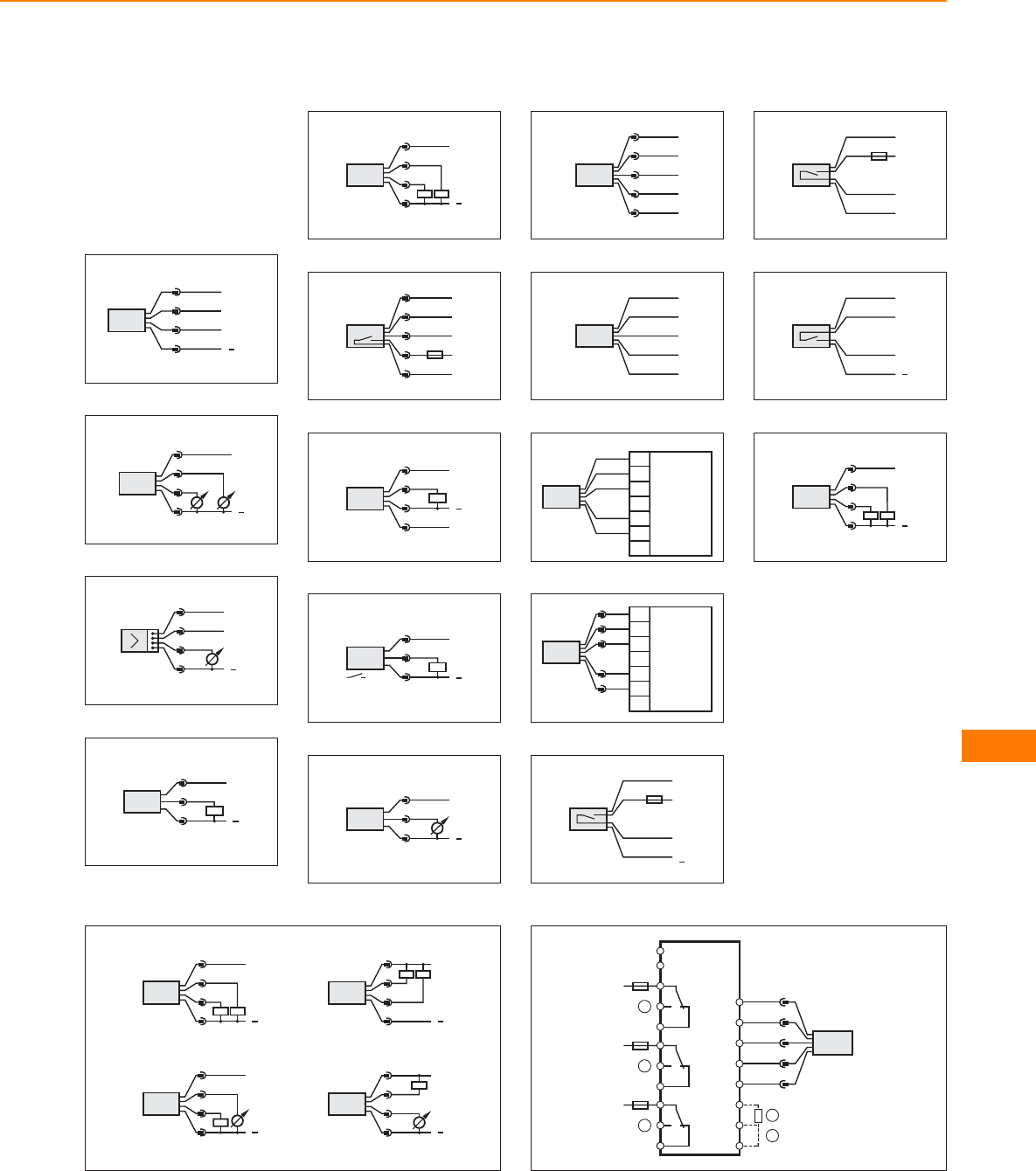
Core colours
BN brown
BU blue
BK black
WH white
GY grey
Wiring diagrams
1
4
1
3
2OUT2/InD
L+
L
BN
BU
OUT1
WH
BK
2
L+
L
OUT1
OUT2
4:
2:
4
2
1
3
3
L+
L
3
2
4
1
n.c.
4
L+
L
1
4
3
5
L
L+
3
2
4
1
S2 S1
6
1
3
4
2
5
n.c.
L1
N
Out
7
P
L+
1
4
3
2
L
8
3
L+
L
1
4
9
L+
L
1
3
2
10
2 WH
1 BN
4 BK
3 BU
5 GY
11
BU
BK
BN
WH
GY
12
BN
WH
BK
BU
1
2
3
7
8
9
GY
VS2000 Exi
13
1
2
3
7
8
9
VS2000 Exi
1 BN
2 WH
4 BK
3 BU
5 GY
14
BN
WH
BU
BK
L1
N
L+
L
15
BN
WH
BU
BK
L1
N
16
BN
WH
BU
BK
L+
L
17
2
L
L+
4
1
3
Out 1
Out 2
4:
2:
18
4
L
L+
2
1
3
Out 1
Out 2
4:
2:
4
L
L+
2
1
3
Out 1
Out 2
4:
2:
4
1
3
2
L+
L
Out 1
Out 2
4:
2:
2
1
3
4
L+
L
Out 1
Out 2
4:
2:
19
AC L
N
12
11
10
9
8
7
6
5
4
2
1
19
18
17
5
4
1
3
2
GY
BK
BN
BU
WH
20
21
22
23
24
1
2
3
5
4
Flow sensors
407
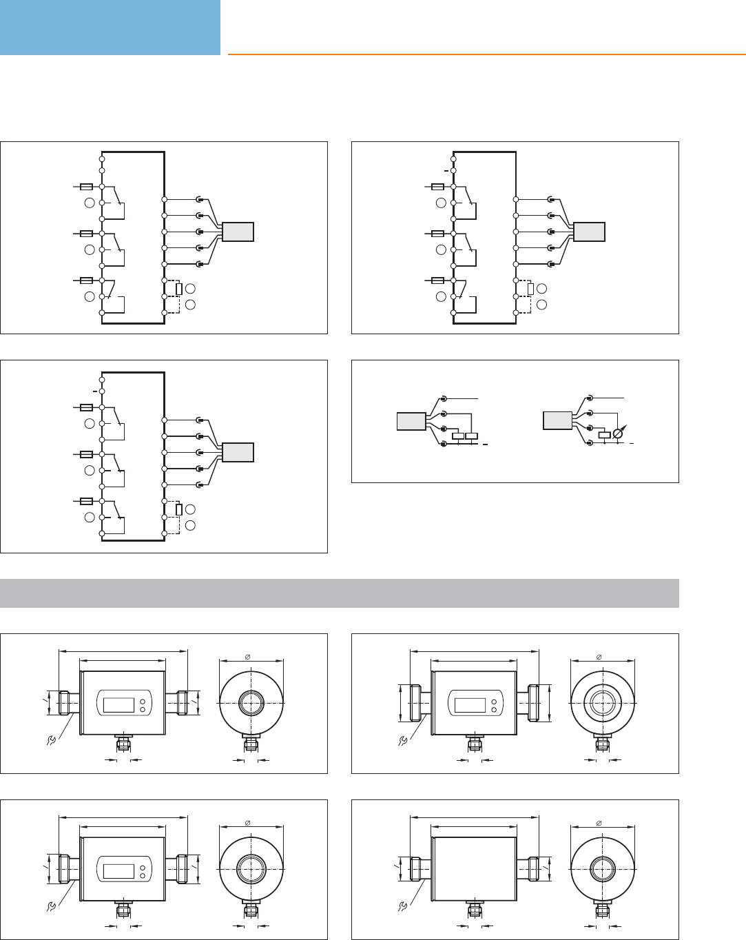
Wiring diagrams
20
AC L
N
12
11
10
9
8
7
6
5
4
2
1
19
18
17
5
4
1
3
2
GY
BK
BN
BU
WH
20
21
22
23
24
1
2
3
5
4
21
12
11
10
9
8
7
6
5
4
2
1
19
18
17
5
4
1
3
2
GY
BK
BN
BU
WH
20
21
22
23
24
1
2
3
5
4
DC L+
L
22
DC L+
L
12
11
10
9
8
7
6
5
4
2
1
19
18
17
5
4
1
3
2
GY
BK
BN
BU
WH
20
21
22
23
24
1
2
3
5
4
23
L+
L
Out 2
Out 1
2:
4: 3
4
2
1
L
L+
Out 2
Out 1
2:
4: 3
4
2
1
Scale drawings / drawing no. – CAD download: www.ifm.com
1
110
73
M12 x1
16
G
G
2
1
2
1
M12 x1
54
2
G4
3
G4
3
110
73
M12 x1
19
M12 x1
54
3
G1
G1
110
73
M12 x1
19
M12 x1
54
4
110
73
M12 x1
16
G
G
2
1
2
1
M12 x1
54
Flow sensors
408
Product selectors and further information can be found at: www.ifm.com
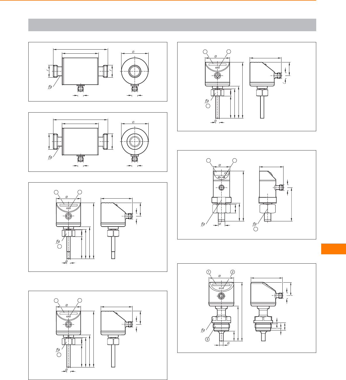
Scale drawings / drawing no. – CAD download: www.ifm.com
5
G4
3
G4
3
110
73
M12 x1
19
M12 x1
54
6
G1
G1
110
73
M12 x1
19
M12 x1
54
7
22
12
3
113
60
65
14
7,7
45
50
27
63
M12 x1
1: LED display, 2: setting pushbutton, 3: tightening torque 25 Nm
8
22
12
113
60
65
14
8,2
45
50
27
63
M12 x1
3
1: LED display, 2: setting pushbutton, 3: tightening torque 25 Nm
9
22
12
113
60
65
14
8,2
45
50
27
63
" 20UNF 2A
2
1
3
1: LED display, 2: setting pushbutton, 3: tightening torque 25 Nm
10
49
68
M12 x1
32
3
37
102
14
18
34
36
2
1
1: 7-segment LED display, 2: Programming buttons, 3: internal thread
M26 x 1.5
11
M12 x1
34
7,7
50
20
15
2
4
71
119
27
63
1: LED display, 2: setting pushbutton, 3: G1/Aseptoflex Vario thread
Flow sensors
409
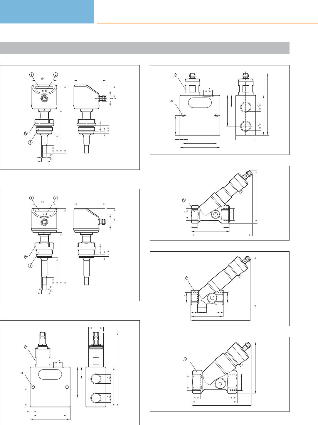
Scale drawings / drawing no. – CAD download: www.ifm.com
12
M12 x1
34
7,7
10,8
50
38
15
2
4
15
89
137
27
63
1: LED display, 2: setting pushbutton, 3: G1/Aseptoflex Vario thread
13
M12 x1
34
7,7
10,8
50
55
15
2
4
15
106
154
27
63
1: LED display, 2: setting pushbutton, 3: G1/Aseptoflex Vario thread
14
30
G
2
1
G
2
1
80
62
24
150...167
40
G
2
1
80
68
6
40
6,3
26
15
G
2
1
80
68
6
40
6,3
26
G
2
1
G
2
1
80
62
24
124,5
40
16
113...123,5
76,5
32
97...105,5
13
13
Rp 4
3
Rp 4
3
17
102...109
66,5
13 18 13
113...123,5
27
Rp 2
1
Rp 2
1
18
17 17
42
120...129
91,5
106...112
Rp 1
Rp 1
Flow sensors
410
Product selectors and further information can be found at: www.ifm.com
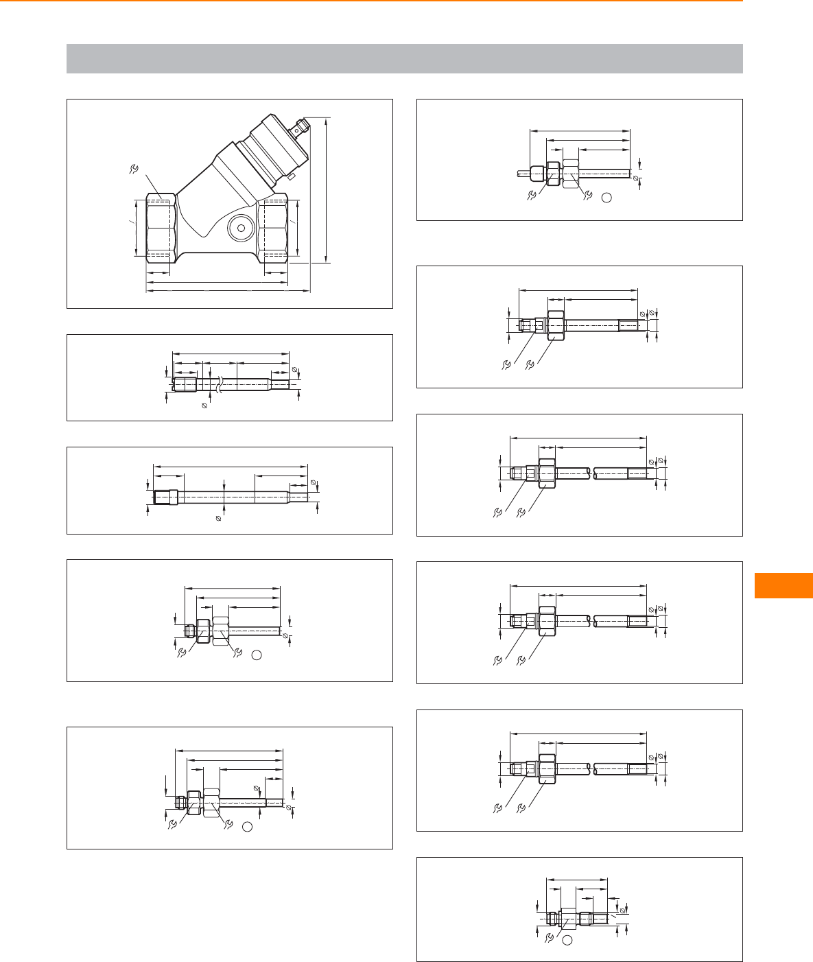
Scale drawings / drawing no. – CAD download: www.ifm.com
19
56
137...146,5
121,5
121...127,5
Rp 1 2
1
Rp 1 2
1
20 20
20
7,7
45
15
M12x1
217
10
20
25 146
21
7,7
45
15
M12x1
132
10
26
22
M12 x1
82
72
22
14
8,2
44
19 1
1: internal thread M18 x 1.5
23
M12 x1
92
82
22
14
7,7
55
19 1
8,2
15
internal thread M18 x 1.5
24
86
72
22
14
8,2
44
19 1
1: internal thread M18 x 1.5
25
102
6414
M12x1
2211
8,2
10
26
132
9414
M12x1
2211
8,2
10
27
182
14414
M12x1
2211
8,2
10
28
282
24414
M12x1
2211
8,2
10
29
8,6
M12 x1
52
12
2713
17
G
4
1
1
1: tightening torque max. 8 Nm
Flow sensors
411
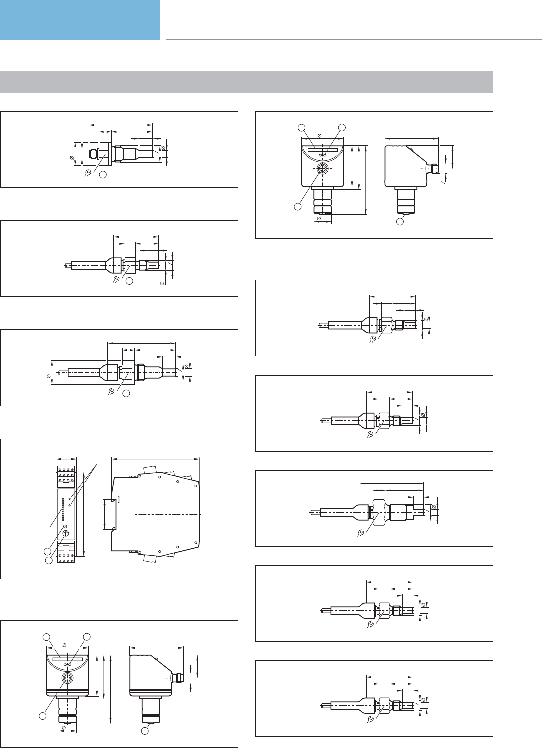
Scale drawings / drawing no. – CAD download: www.ifm.com
30
M12 x1
G
2
1
15,5
45
15
72
15
8,6
27
1
1: tightening torque max. 30 Nm
31
52
8,6
12
2713
G
4
1
17 1
1: tightening torque max. 8 Nm
32
G
2
1
15,5
45
15
76,5
15
8,6
1
27
1: tightening torque max. 30 Nm
33
103,5
35,5
25
100
2
1
LEDs
LEDs
1234
5678
9101112
21 22 23 24
17 18 19 20
1: Potentiometer (switch point flow), 2: Potentiometer (switch point
temperature)
34
27
64
M12 x1
4
12
83
52
48
50
19,7
3
1: LED display, 2: setting pushbutton, 3: connection for voltage
supply and output signals, 4: connection for flow sensor
35
27
64
4
12
83
52
48
50
19,7
3
" 20UNF 2A
2
1
1: LED display, 2: setting pushbutton, 3: connection for voltage sup-
ply and output signals, 4: connection for flow sensor
36
17
55
12
2713
8,2
M12x1
37
17
55
12
27
13
8,2
G4
1
38
G2
1
12
45
15
75
8,2
27
39
17
55
12
2713
M12x1
7,7
40
17
55
12
2713
7,7
G4
1
Flow sensors
412
Product selectors and further information can be found at: www.ifm.com
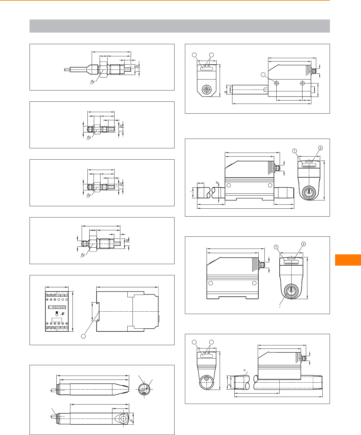
Scale drawings / drawing no. – CAD download: www.ifm.com
41
12
45
15
75
27
G2
1
7,7
42
M12 x1
M12x1
7,7
52
12
27
13
17
43
M12 x1
7,7
52
12
27
13
17
G4
1
44
M12 x1
12
45
15
75
7,7
27
G
2
1
45
45
78
12
19 20 21
13 14 15 16 17 18
3
9
78
+
120
35,5
1
1: mounting on DIN rail
46
14 0
133
113
32
23
2 LED
pot.
2 LED
47
182,3
21,3
M12 x1
100
111
74,5
G14
/
45
12
G14
/
60 20
31
3
1: 4-digit alphanumeric display, 2: Programming buttons, 3: hole for
M5 fixing screw
48
45
79,5
100
111
M12 x1
R2
1
14
160 40
300
21,3
1: 4-digit alphanumeric display, 2: Programming buttons
49
G2
1
45
79,5
100
111
M12 x1
1: 4-digit alphanumeric display, 2: Programming buttons
50
475
375
27,3
33,7
R 1
M12 x1
100
11 1
88,5
45
12
1: 4-digit alphanumeric display, 2: Programming buttons
Flow sensors
413
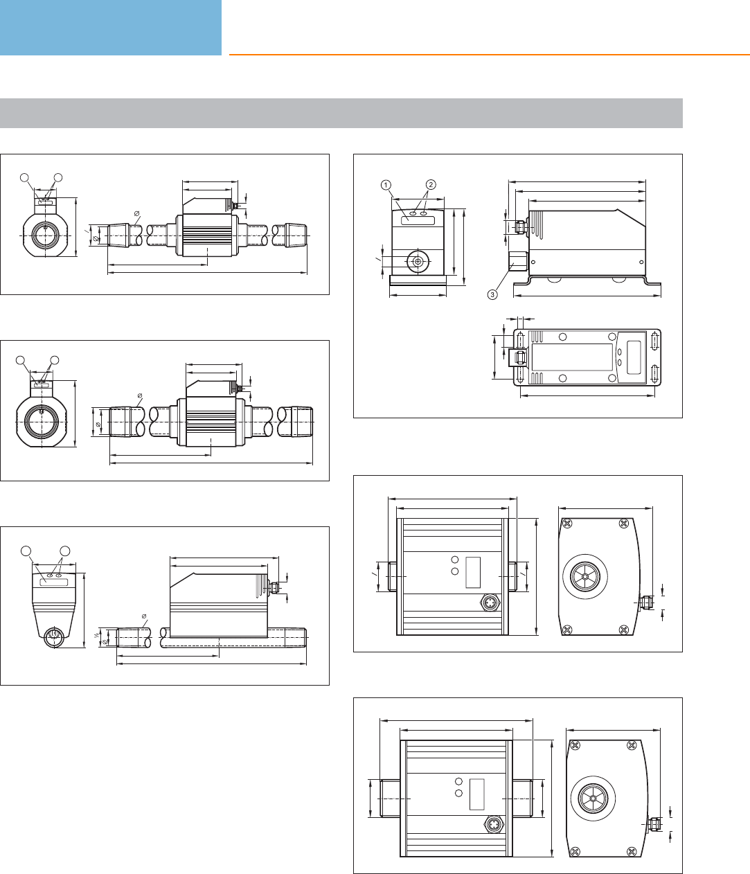
Scale drawings / drawing no. – CAD download: www.ifm.com
51
39
R112
275
475
42
100
111
M12 x1
120
45
12
1: 4-digit alphanumeric display, 2: Programming buttons
52
133
45
12
54
R2
51
100
111
M12 x1
275
475
1: 4-digit alphanumeric display, 2: Programming buttons
53
R
210
300
16,1
21,3
M12 x1
100
111
76,8
45
12
1: 4-digit alphanumeric display, 2: Programming buttons
54
114
4,5
37
10 M12 x1
100
125
111
117
56
45
G
8
1
48
65
1: 4-digit alphanumeric display, 2: Programming buttons, 3: flow
conditioner
55
G4
3
G4
3
110
96
100
80,5
M12 x1
installation length with pipe adapter E40151 / E40154: 185 mm
56
80,5
M12 x1
G1
130
96
100
G1
installation length with pipe adapter E40152 / E40155: 205 mm,
installation length with pipe adapter E40153 / E40156: 215 mm
Flow sensors
414
Product selectors and further information can be found at: www.ifm.com
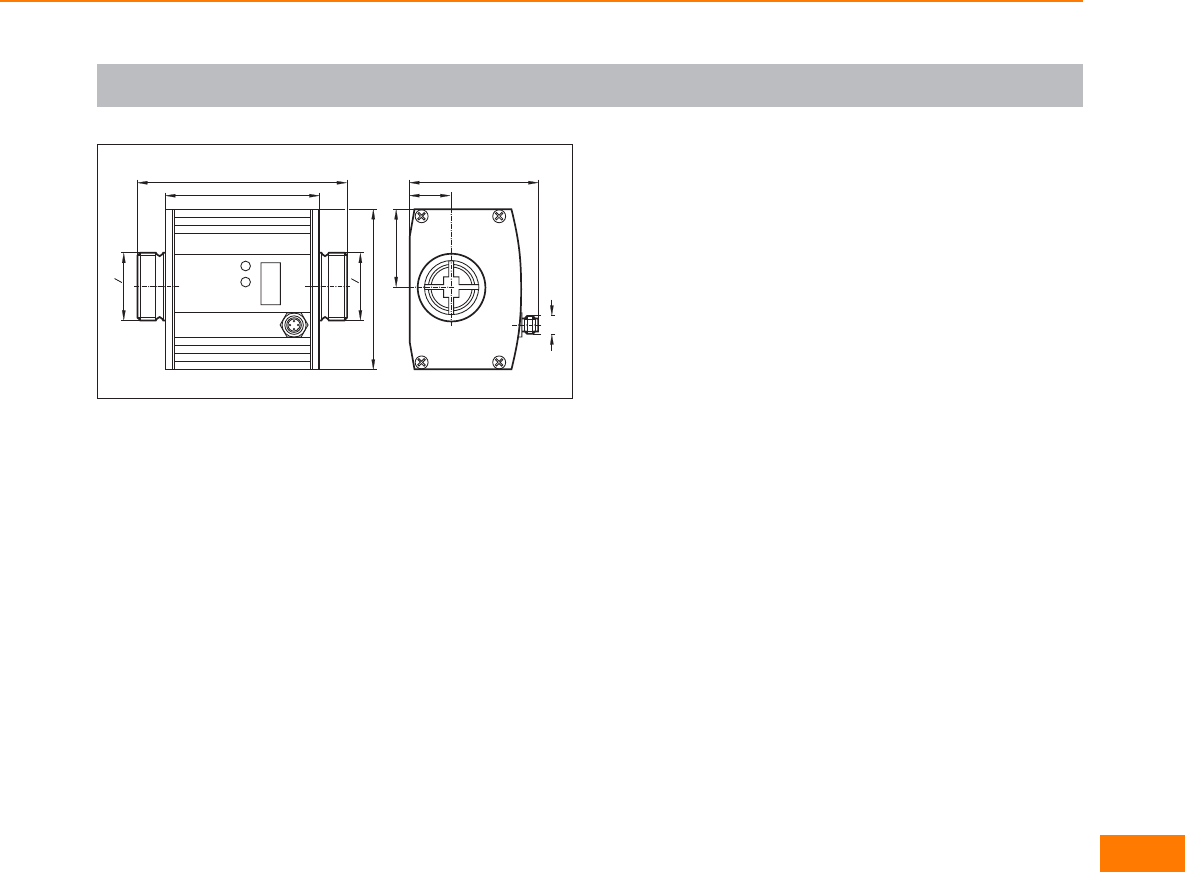
Scale drawings / drawing no. – CAD download: www.ifm.com
57
80,5
M12 x1
26
48
130
96
100
G1
4
1
G1
4
1
Flow sensors
415
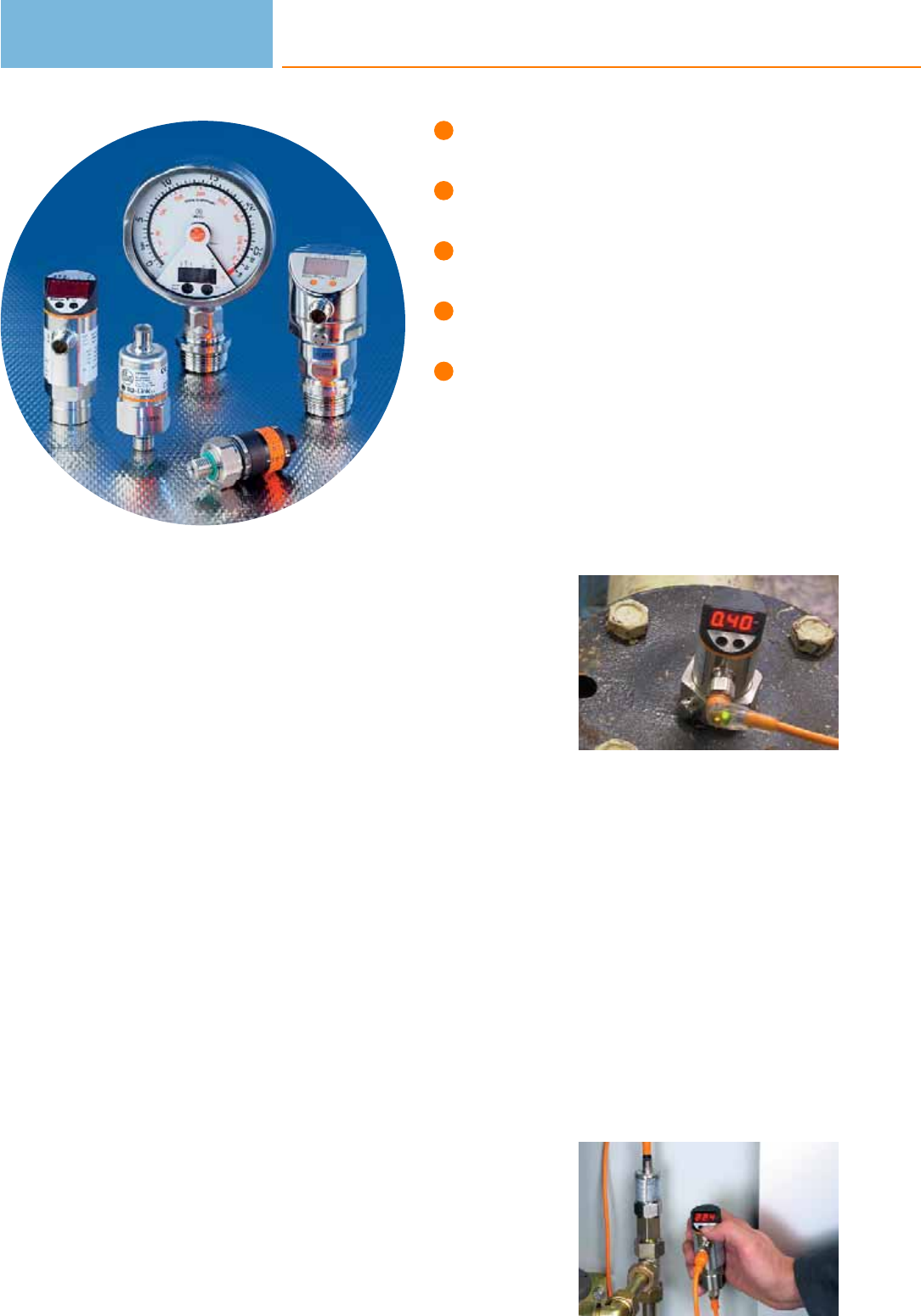
Transmitters or sensors with
integrated control monitor.
Units with special design for
hygienic applications.
Measuring principles with overload
protection and a good long-term stability.
Measuring range from -1…600 bar.
Variable process connection and
sealing technology via adapter.
Pressure sensors
ifm offers a wide range of electronic pressure and vacuum sensors to meet the
requirements of various industrial applications. The ceramic-capacitive measuring
cell, tried and tested a million times, is complemented by a stainless steel measuring
cell with thick-film wire strain gauges (series PK, PV, PT) and a piezoresistive
measuring technique (for pneumatic applications).
All units have robust housings and do not require moving parts such as pistons or
springs. The result: the sensors are extremely shock and vibration resistant and
operate without any wear or maintenance.
The tried and tested ceramic-capacitive measuring principle is corrosion-resistant
and long-term stable. In the long run this guarantees continuous accuracy of the
measured values. The sensors are resistant to dynamic pressure peaks and
guarantee high overload resistance even in the case of extreme pressure peaks
that occur for example with fast closing valves.
Units with wire strain gauge in thick-film technology on a stainless steel measuring
cell are distinguished by their very compact and robust design. They can be used
in almost all industrial areas. The welded stainless steel measuring cell without
any seals ensures a high degree of safety, in particular for applications with gas
pressures of up to 400 bar as well as in air-conditioning and refrigerating technol-
ogy where aggressive coolants (freons) are used.
Local display:
the clearly readable
LED display shows
the current system
pressure.
Separate display /
programming unit
PP2001.
Pressure sensors
416

System overview Page
Sensors with switching outputs and analogue outputs and display 418 - 419
Sensors with switching outputs and display 419 - 421
Electronic contact manometers with switching output and analogue output 421 - 422
PK sensors with mechanical setting and switching outputs 422 - 424
PT sensors for industrial applications with analogue outputs 424
PP sensors for mobile applications with switching outputs, IO-Link 425
PT sensors for mobile applications with analogue outputs 425 - 426
PA / PPA sensors for industrial applications with analogue outputs / AS-i 426 - 428
Part seat monitoring 428
Sensors for hydrostatic level monitoring 428
Sensors for hydrostatic level monitoring ATEX category 1G/1D 429
PNI sensors with analogue input 429
Sensors with ATEX approval 3D 429
Sensors with ATEX approval 3D/3G 429 - 430
Sensors for pneumatic applications 430
PI sensors for hygienic and wet areas with switching and analogue output 430
PI sensors with 2 switching outputs for hygienic and wet areas 431
Full metal sensors for hygienic and wet areas with switching output and analogue output, IO-Link 431 - 432
Electronic contact manometers for hygienic and wet areas with switching output and analogue output 432 - 433
PF sensors for hygienic and wet areas with switching and analogue output 433 - 434
PL / PM sensors without display for hygienic and wet areas with analogue output 434 - 436
PE sensors with display with 2 switching outputs or switching and analogue output 436 - 437
Fixing components for pressure sensors 437
Accessories and software 437 - 438
Adapters and accessories for adapters 438 - 439
Flange adapters 440 - 442
Wiring diagrams 443 - 444
Scale drawings / drawing no. – CAD download: www.ifm.com 444 - 450
Pressure sensors
417
Sensors with switching outputs and analogue outputs and display
Type Process
connection
Display
LED
Measuring
range
[bar]
Poverload
max. [bar]
Pbursting
min. [bar]
Ub
DC
[V]
Draw-
ing
no.
Order
no.
M12 connector · Output function 1 x normally open / closed programmable + 1 x analogue (I / U, scaleable 1:4) ·
Wiring diagram no. 14 · Connector groups 9, 10, 11, 107, 108, 110, 135
G¼ I Display unit -0.25...0.25 10 30 18...32 1 PY2068
M12 connector · Output function 2 x normally open / closed programmable or 1 x normally open / closed programmable +
1 x analogue (4...20 mA / 0...10 V; scaleable 1:4) · Wiring diagram no. 15 · Connector groups 9, 10, 11, 107, 108, 110, 135
G¼ I Display unit 0...400 600 1000 20...30 2PN2020
G¼ I Display unit 0...250 400 850 20...30 3 PN2021
G¼ I Display unit 0...100 300 650 20...30 3PN2022
G¼ I Display unit -1...25 100 350 20...30 3 PN2023
G¼ I Display unit -1...10 75 150 18...32 3PN2024
G¼ I Display unit -0.1253...2.5 20 50 18...32 3 PN2026
G¼ I Display unit -0.05...1 10 30 18...32 3PN2027
G¼ I Display unit -1...1 20 50 20...30 3 PN2009
G¼ I Display unit -0.0125...0.25 10 30 18...32 3PN2028
¼" NPT Display unit -1...1 20 50 20...30 4 PN2209
¼" NPT Display unit 0...400 600 1000 20...30 5PN2220
¼" NPT Display unit 0...250 400 850 20...30 4 PN2221
¼" NPT Display unit 0...100 300 650 20...30 4PN2222
¼" NPT Display unit -1...25 100 350 20...30 4 PN2223
Pressure sensors
418
Product selectors and further information can be found at: www.ifm.com
Type Process
connection
Display
LED
Measuring
range
[bar]
Poverload
max. [bar]
Pbursting
min. [bar]
Ub
DC
[V]
Draw-
ing
no.
Order
no.
M12 connector · Output function 2 x normally open / closed programmable or 1 x normally open / closed programmable +
1 x analogue (4...20 mA / 0...10 V; scaleable 1:4) · Wiring diagram no. 15 · Connector groups 9, 10, 11, 107, 108, 110, 135
¼" NPT Display unit -1...10 75 150 18...32 4 PN2224
¼" NPT Display unit -0.125...2.5 20 50 20...30 4PN2226
¼" NPT Display unit -0.0125...0.25 10 30 18...32 4 PN2228
M12 connector · Output function normally open / closed programmable; 4...20 mA or 0...10 V · Wiring diagram no. 1 ·
Connector groups 9, 10, 11, 107, 108, 110, 135
G¼ I Display unit 0...600 800 1200 18...36 6PN3060
G¼ I Display unit 0...400 600 1000 18...36 6 PN3000
G¼ I Display unit 0...250 400 850 18...36 1PN3001
G¼ I Display unit 0...100 300 650 18...36 1 PN3002
G¼ I Display unit 0...25 150 350 18...36 1PN3003
G¼ I Display unit -1...10 75 150 18...36 1 PN3004
G¼ I Display unit 0...2.5 20 50 18...36 1PN3006
G¼ I Display unit 0...1 10 30 18...36 1 PN3007
G¼ I Display unit -1...0 10 30 18...36 1PN3029
Sensors with switching outputs and display
Type Process
connection
Display
LED
Measuring
range
[bar]
Poverload
max. [bar]
Pbursting
min. [bar]
Ub
DC
[V]
Draw-
ing
no.
Order
no.
M12 connector · Output function · DC PNP · Wiring diagram no. 2 · Connector groups 9, 10, 11, 107, 108, 110, 135
G¼ I Display unit 0...400 600 1000 18...36 6 PN5000
Pressure sensors
419
You can find wiring diagrams and scale drawings from page 443
Type Process
connection
Display
LED
Measuring
range
[bar]
Poverload
max. [bar]
Pbursting
min. [bar]
Ub
DC
[V]
Draw-
ing
no.
Order
no.
M12 connector · Output function · DC PNP · Wiring diagram no. 2 · Connector groups 9, 10, 11, 12, 107, 108, 109, 110,
135, 136
G¼ I Display unit 0...250 400 850 18...36 1 PN5001
G¼ I Display unit 0...100 300 650 18...36 1PN5002
G¼ I Display unit 0...25 150 350 18...36 1 PN5003
G¼ I Display unit -1...10 75 150 18...36 1PN5004
G¼ I Display unit 0...2.5 20 50 18...36 1 PN5006
G¼ I Display unit 0...1 10 30 18...36 1PN5007
M12 connector · Output function · DC PNP · Wiring diagram no. 2 · Connector groups 9, 10, 11, 107, 108, 110, 135
¼" NPT Display unit 0...400 600 1000 18...36 7 PN5200
¼" NPT Display unit 0...100 300 650 18...36 8PN5202
¼" NPT Display unit -1...10 75 150 18...36 8 PN5204
M12 connector · Output function 2 x normally open / closed programmable or 1 x normally open / closed programmable + 1 x
normally closed (diagnostic function) · DC PNP/NPN · Wiring diagram no. 16 · Connector groups 9, 11, 12, 107, 108, 109, 135, 136
G¼ I Display unit 0...600 800 1200 18...36 6PN7060
G¼ I Display unit 0...400 600 1000 18...36 6 PN7000
G¼ I Display unit 0...250 400 850 18...36 1PN7001
G¼ I Display unit 0...100 300 650 18...36 1 PN7002
G¼ I Display unit 0...25 150 350 18...36 1PN7003
G¼ I Display unit -1...10 75 150 18...36 1 PN7004
Pressure sensors
420
Product selectors and further information can be found at: www.ifm.com
Type Process
connection
Display
LED
Measuring
range
[bar]
Poverload
max. [bar]
Pbursting
min. [bar]
Ub
DC
[V]
Draw-
ing
no.
Order
no.
M12 connector · Output function 2 x normally open / closed programmable or 1 x normally open / closed programmable + 1 x
normally closed (diagnostic function) · DC PNP/NPN · Wiring diagram no. 16 · Connector groups 9, 11, 12, 107, 108, 109, 135, 136
G¼ I Display unit 0...2.5 20 50 18...36 1 PN7006
G¼ I Display unit 0...1 10 30 18...36 1PN7007
G¼ I Display unit -1...1 20 50 18...36 1 PN7009
¼" NPT Display unit 0...400 600 1000 18...36 7PN7200
¼" NPT Display unit 0...250 400 850 18...36 8 PN7201
¼" NPT Display unit 0...100 300 650 18...36 8PN7202
¼" NPT Display unit 0...25 150 350 18...36 8 PN7203
¼" NPT Display unit -1...10 75 150 18...36 8PN7204
¼" NPT Display unit 0...2.5 20 50 18...36 8 PN7206
¼" NPT Display unit -1...1 20 50 18...36 8PN7209
Electronic contact manometers with switching output and analogue output
Type Process
connection
Display
LED
Measuring
range
[bar]
Poverload
max. [bar]
Pbursting
min. [bar]
Ub
DC
[V]
Draw-
ing
no.
Order
no.
M12 connector · Output function 1 x normally open / closed programmable + 1 x analogue (4...20 / 20...4 mA, scalable) · DC
PNP/NPN · Wiring diagram no. 14 · Connector groups 9, 10, 11, 107, 108, 110, 135
G½ Display unit 0...400 800 1200 18...32 9 PG2450
G½ Display unit 0...250 600 1000 18...32 9PG2451
G½ Display unit 0...100 300 700 18...32 9 PG2452
Pressure sensors
421
You can find wiring diagrams and scale drawings from page 443
Type Process
connection
Display
LED
Measuring
range
[bar]
Poverload
max. [bar]
Pbursting
min. [bar]
Ub
DC
[V]
Draw-
ing
no.
Order
no.
M12 connector · Output function 1 x normally open / closed programmable + 1 x analogue (4...20 / 20...4 mA, scalable) ·
DC PNP/NPN · Wiring diagram no. 14 · Connector groups 9, 10, 11, 107, 108, 110, 135
G½ Display unit -1...25 100 300 18...32 9 PG2453
G½ Display unit -1...10 50 150 18...32 9PG2454
G½ Display unit -1...4 30 100 18...32 9 PG2455
G½ Display unit -0.125...2.5 20 50 18...32 9PG2456
G½ Display unit -0.05...1 10 30 18...32 9 PG2457
G½ Display unit -0.0125...0.25 10 30 18...32 9PG2458
G½ Display unit -0.005...0.1 4 30 18...32 9 PG2489
G½ Display unit -1...1 10 30 18...32 9PG2409
PK sensors with mechanical setting and switching outputs
Type Process
connection
Display
LED
Measuring
range
[bar]
Poverload
max. [bar]
Pbursting
min. [bar]
Ub
DC
[V]
Draw-
ing
no.
Order
no.
M12 connector · Output function · DC PNP · Wiring diagram no. 2 · Connector groups 9, 11, 12, 107, 108, 109, 135, 136
G¼ A / M5 I Operation 0...400 600 1600 9.6...32 10 PK5520
G¼ A / M5 I Operation 0...250 400 1000 9.6...32 10 PK5521
G¼ A / M5 I Operation 0...100 200 1000 9.6...32 10 PK5522
G¼ A / M5 I Operation 0...25 60 500 9.6...32 10 PK5523
G¼ A / M5 I Operation 0...10 25 300 9.6...32 10 PK5524
Pressure sensors
422
Product selectors and further information can be found at: www.ifm.com
Type Process
connection
Display
LED
Measuring
range
[bar]
Poverload
max. [bar]
Pbursting
min. [bar]
Ub
DC
[V]
Draw-
ing
no.
Order
no.
M12 connector · Output function normally open / closed complementary · DC PNP · Wiring diagram no. 3 · Connector groups 9,
11, 12, 107, 108, 109, 135, 136
G¼ A / M5 I Operation 0...400 600 1600 9.6...32 10 PK6520
G¼ A / M5 I Operation 0...250 400 1000 9.6...32 10 PK6521
G¼ A / M5 I Operation 0...100 200 1000 9.6...32 10 PK6522
G¼ A / M5 I Operation 0...25 60 500 9.6...32 10 PK6523
G¼ A / M5 I Operation 0...10 25 300 9.6...32 10 PK6524
M12 connector · Output function · DC PNP · Wiring diagram no. 4 · Connector groups 9, 11, 12, 107, 108, 109, 135, 136
G¼ A / M5 I Switching status 0...400 600 1600 9.6...32 10 PK7520
G¼ A / M5 I Switching status 0...250 400 1000 9.6...32 10 PK7521
G¼ A / M5 I Switching status 0...100 200 1000 9.6...32 10 PK7522
G¼ A / M5 I Switching status 0...10 25 300 9.6...32 10 PK7524
M12 connector · Output function normally open / closed complementary · DC PNP · Wiring diagram no. 3 · Connector groups 9,
11, 12, 107, 108, 109, 135, 136
R¼ A / M5 I Operation 0...100 200 1000 9.6...32 11 PK6732
R¼ A / M5 I Operation 0...10 25 300 9.6...32 11 PK6734
M12 connector · Output function normally open / closed complementary · DC NPN · Wiring diagram no. 5 · Connector groups 9,
11, 12, 107, 108, 109, 135, 136
R¼ A / M5 I Operation 0...400 600 1600 9.6...32 11 PK8730
R¼ A / M5 I Operation 0...100 200 1000 9.6...32 11 PK8732
R¼ A / M5 I Operation 0...10 25 300 9.6...32 11 PK8734
Pressure sensors
423
You can find wiring diagrams and scale drawings from page 443
Type Process
connection
Display
LED
Measuring
range
[bar]
Poverload
max. [bar]
Pbursting
min. [bar]
Ub
DC
[V]
Draw-
ing
no.
Order
no.
M12 connector · Output function normally open / closed complementary · DC PNP · Wiring diagram no. 3 · Connector groups 9,
11, 12, 107, 108, 109, 135, 136
¼" NPT A / M5 I Operation 0...400 600 1600 9.6...32 12 PK6220
¼" NPT A / M5 I Operation 0...100 200 1000 9.6...32 12 PK6222
¼" NPT A / M5 I Operation 0...10 25 300 9.6...32 12 PK6224
PT sensors for industrial applications with analogue outputs
Type Process
connection
Display
LED
Measuring
range
[bar]
Poverload
max. [bar]
Pbursting
min. [bar]
Ub
DC
[V]
Draw-
ing
no.
Order
no.
M12 connector · Output function 4...20 mA analogue · DC · Wiring diagram no. 6 · Connector groups 9, 11, 107, 108, 135
G¼ A – 0...400 600 1600 8.5...36 13 PT3540
G¼ A –0...250 400 1000 8.5...36 13 PT3541
G¼ A – 0...100 200 1000 8.5...36 13 PT3542
G¼ A –0...25 60 600 8.5...36 13 PT3543
G¼ A – 0...10 25 300 8.5...36 13 PT3544
M12 connector · Output function 0...10 V analogue · DC · Wiring diagram no. 7 · Connector groups 9, 11, 107, 108, 135
G¼ A –0...400 600 1600 16...36 13 PT9540
G¼ A – 0...250 400 1000 16...36 13 PT9541
G¼ A –0...100 200 1000 16...36 13 PT9542
G¼ A – 0...25 60 600 16...36 13 PT9543
G¼ A –0...10 25 300 16...36 13 PT9544
Pressure sensors
424
Product selectors and further information can be found at: www.ifm.com
PP sensors for mobile applications with switching outputs, IO-Link
Type Process
connection
Display
LED
Measuring
range
[bar]
Poverload
max. [bar]
Pbursting
min. [bar]
Ub
DC
[V]
Draw-
ing
no.
Order
no.
M12 connector · Output function 2 x normally open / closed programmable or 1 x normally open / closed programmable +
1 x normally closed (diagnostic function) · DC PNP · Wiring diagram no. 8 · Connector groups 9, 11, 12, 107, 108, 109, 135, 136
G¼ A / M5 I Operation 0...400 600 1000 9.6...36 14 PP7550
G¼ A / M5 I Operation 0...250 400 850 9.6...36 14 PP7551
G¼ A / M5 I Operation 0...100 300 650 9.6...36 15 PP7552
G¼ A / M5 I Operation 0...25 150 350 9.6...36 16 PP7553
G¼ A / M5 I Operation -1...10 75 150 9.6...36 16 PP7554
G¼ A / M5 I Operation 0...2.5 20 50 9.6...36 16 PP7556
M12 connector · Output function 2 x normally open / closed programmable or 1 x normally open / closed programmable +
1 x normally closed (diagnostic function) · DC NPN · Wiring diagram no. 8 · Connector groups 9, 11, 12, 107, 108, 109, 135, 136
G¼ A / M5 I Operation 0...400 600 1000 9.6...36 14 PP0520
G¼ A / M5 I Operation 0...250 400 850 9.6...36 14 PP0521
G¼ A / M5 I Operation 0...100 300 650 9.6...36 15 PP0522
G¼ A / M5 I Operation 0...25 150 350 9.6...36 16 PP0523
G¼ A / M5 I Operation -1...10 75 150 9.6...36 16 PP0524
PT sensors for mobile applications with analogue outputs
Type Process
connection
Display
LED
Measuring
range
[bar]
Poverload
max. [bar]
Pbursting
min. [bar]
Ub
DC
[V]
Draw-
ing
no.
Order
no.
M12 connector · Output function 4...20 mA analogue · DC · Wiring diagram no. 6 · Connector group 135
G¼ A – 0...400 600 1600 8.5...36 13 PT3550
Pressure sensors
425
You can find wiring diagrams and scale drawings from page 443
Type Process
connection
Display
LED
Measuring
range
[bar]
Poverload
max. [bar]
Pbursting
min. [bar]
Ub
DC
[V]
Draw-
ing
no.
Order
no.
M12 connector · Output function 4...20 mA analogue · DC · Wiring diagram no. 6 · Connector group 135
G¼ A – 0...250 400 1000 8.5...36 13 PT3551
G¼ A –0...100 200 1000 8.5...36 13 PT3552
G¼ A – 0...25 60 600 8.5...36 13 PT3553
G¼ A –0...10 25 300 8.5...36 13 PT3554
M12 connector · Output function 0...10 V analogue · DC · Wiring diagram no. 7 · Connector group 135
G¼ A – 0...400 600 1600 16...36 13 PT9550
G¼ A –0...250 400 1000 16...36 13 PT9551
G¼ A – 0...100 200 1000 16...36 13 PT9552
G¼ A –0...25 60 600 16...36 13 PT9553
G¼ A – 0...10 25 300 16...36 13 PT9554
PA / PPA sensors for industrial applications with analogue outputs / AS-i
Type Process
connection
Display
LED
Measuring
range
[bar]
Poverload
max. [bar]
Pbursting
min. [bar]
Ub
DC
[V]
Draw-
ing
no.
Order
no.
M12 connector · Output function 4...20 mA analogue · DC · Wiring diagram no. 6 · Connector groups 9, 11, 107, 108, 135
G¼ I – 0...600 800 1200 9.6...32 17 PA3060
G¼ I –0...400 600 1000 9.6...32 18 PA3020
G¼ I – 0...250 400 850 9.6...32 18 PA3021
G¼ I –0...100 300 650 9.6...32 19 PA3022
Pressure sensors
426
Product selectors and further information can be found at: www.ifm.com
Type Process
connection
Display
LED
Measuring
range
[bar]
Poverload
max. [bar]
Pbursting
min. [bar]
Ub
DC
[V]
Draw-
ing
no.
Order
no.
M12 connector · Output function 4...20 mA analogue · DC · Wiring diagram no. 6 · Connector groups 9, 11, 107, 108, 135
G¼ I – 0...25 150 350 9.6...32 19 PA3023
G¼ I –0...10 75 150 9.6...32 19 PA3024
G¼ I – 0...2.5 20 50 9.6...32 19 PA3026
G¼ I –0...1 10 30 9.6...32 19 PA3027
G¼ I – 0...0.25 10 30 9.6...32 19 PA3028
G¼ I –-1...0 10 30 9.6...32 19 PA3029
G¼ A / M5 I – 0...250 400 850 9.6...32 20 PA3521
G¼ A / M5 I –0...25 150 350 9.6...32 20 PA3523
G¼ A / M5 I – 0...10 75 150 9.6...32 20 PA3524
G¼ A / M5 I –0...2.5 20 50 9.6...32 20 PA3526
G¼ A / M5 I – 0...0.25 10 30 9.6...32 20 PA3528
M12 connector · Output function 0...10 V analogue · DC · Wiring diagram no. 7 · Connector groups 9, 11, 107, 108, 135
G¼ I –0...600 800 1200 16...32 21 PA9060
G¼ I – 0...400 600 1000 16...32 21 PA9020
G¼ I –0...250 400 850 16...32 19 PA9021
G¼ I – 0...100 300 650 16...32 19 PA9022
Pressure sensors
427
You can find wiring diagrams and scale drawings from page 443
Type Process
connection
Display
LED
Measuring
range
[bar]
Poverload
max. [bar]
Pbursting
min. [bar]
Ub
DC
[V]
Draw-
ing
no.
Order
no.
M12 connector · Output function 0...10 V analogue · DC · Wiring diagram no. 7 · Connector groups 9, 11, 107, 108, 135
G¼ I – 0...25 150 350 16...32 19 PA9023
G¼ I –0...10 75 150 16...32 19 PA9024
G¼ I – 0...2.5 20 50 16...32 19 PA9026
G¼ I –0...1 10 30 16...32 19 PA9027
G¼ I – 0...0.25 10 30 16...32 19 PA9028
G¼ I –-1...0 10 30 16...32 19 PA9029
M12 connector · AS-i · Wiring diagram no. 9 · Connector groups 9, 11, 107, 108, 135
G¼ I - 0...400 600 1000 18...31.6 22 PPA020
Part seat monitoring
Type Description Order
no.
Control unit for part seat monitoring · Setting by adjustment of the pneumatic bridge · Integrated pressure sensor with 2 switching
outputs · and 4-digit alphanumerical display for trend display or display of current pressure · Cable PS7570
Sensors for hydrostatic level monitoring
Type Measuring
range
[bar]
Cable length /
material
Poverload
max. [bar]
Pbursting
min. [bar]
Ub
DC
[V]
Draw-
ing
no.
Order
no.
Output 4...20 mA analogue · Wiring diagram no. 10
0...0.25 5 m
PUR cable 2 2.4 10...30 23 PS3208
0...0.6 10 m
PUR cable 44.8 10...30 23 PS3407
0...1 15 m
PUR cable 5 6 10...30 23 PS3417
Pressure sensors
428
Product selectors and further information can be found at: www.ifm.com
Sensors for hydrostatic level monitoring ATEX category 1G/1D
Type Measuring
range
[bar]
Cable length /
material
Poverload
max. [bar]
Pbursting
min. [bar]
Ub
DC
[V]
Draw-
ing
no.
Order
no.
Output 4...20 mA analogue · Wiring diagram no. 11
0...0.25 5 m
FEP cable 2 2.4 10...30 24 PS308A
0...0.6 10 m
FEP cable 44.8 10...30 24 PS307A
0...1 15 m
FEP cable 5 6 10...30 24 PS317A
PNI sensors with analogue input
Type Process
connection
Display
LED
Measuring
range
[bar]
Poverload
max. [bar]
Pbursting
min. [bar]
Ub
DC
[V]
Draw-
ing
no.
Order
no.
M12 connector · Output function 2 x normally open / closed programmable · DC PNP/NPN · Wiring diagram no. 12 · Connector
groups 16, 17, 18
G¼ I Display unit 0...10 50 150 18...30 1 PNI024
Sensors with ATEX approval 3D
Type Process
connection
Display
LED
Measuring
range
[bar]
Poverload
max. [bar]
Pbursting
min. [bar]
Ub
DC
[V]
Draw-
ing
no.
Order
no.
M12 connector · Output function normally open / closed programmable; 4...20 mA or 0...10 V · DC PNP · Wiring diagram no. 1 ·
Connector groups 132, 134
G¼ I Display unit 0...2.5 20 50 18...36 25 PN006A
M12 connector · Output function 2 x normally open / closed programmable or 1 x normally open / closed programmable +
1 x normally closed (diagnostic function) · DC PNP/NPN · Wiring diagram no. 16 · Connector groups 132, 134
G¼ I Display unit 0...2.5 20 50 18...36 25 PN016A
Sensors with ATEX approval 3D/3G
Type Process
connection
Display
LED
Measuring
range
[bar]
Poverload
max. [bar]
Pbursting
min. [bar]
Ub
DC
[V]
Draw-
ing
no.
Order
no.
M12 connector · Output function 1 x normally open / closed programmable + 1 x analogue (I / U, scaleable 1:4) · DC PNP/NPN ·
Wiring diagram no. 14 · Connector groups 132, 134
G1 A Display unit -1...25 100 350 18...32 26 PI003A
Pressure sensors
429
You can find wiring diagrams and scale drawings from page 443
Type Process
connection
Display
LED
Measuring
range
[bar]
Poverload
max. [bar]
Pbursting
min. [bar]
Ub
DC
[V]
Draw-
ing
no.
Order
no.
M12 connector · Output function 1 x normally open / closed programmable + 1 x analogue (I / U, scaleable 1:4) · DC PNP/NPN ·
Wiring diagram no. 14 · Connector groups 132, 134
G1 A Display unit -0.0124...0.25 10 30 18...32 26 PI008A
Sensors for pneumatic applications
Type Process
connection
Display
LED
Measuring
range
[bar]
Poverload
max. [bar]
Pbursting
min. [bar]
Ub
DC
[V]
Draw-
ing
no.
Order
no.
M12 connector · Output function 2 x normally open / closed programmable or 1 x normally open / closed programmable + 1 x
normally closed (diagnostic function) · DC PNP/NPN · Wiring diagram no. 16 · Connector groups 9, 11, 12, 107, 108, 109, 135, 136
G 1/8 I Display unit -1...1 20 30 18...36 27 PN7809
G 1/8 I Display unit -1...10 20 30 18...36 27 PN7834
M8 connector · Output function 2 x normally open / closed programmable or 1 x normally open / closed programmable +
1 x normally closed (diagnostic function) · DC PNP · Wiring diagram no. 4 · Connector groups 4, 5, 70
G 1/8 I Display unit -1...1 20 30 18...32 28 PQ7809
G 1/8 I Display unit -1...10 20 30 18...32 28 PQ7834
M8 connector · Output function 2 x normally open / closed programmable or 1 x normally open / closed programmable +
1 x normally closed (diagnostic function) · DC NPN · Wiring diagram no. 13 · Connector groups 4, 5, 70
G 1/8 I Display unit -1...1 20 30 18...32 28 PQ0809
G 1/8 I Display unit -1...10 20 30 18...32 28 PQ0834
PI sensors for hygienic and wet areas with switching and analogue output
Type Process
connection
Display
LED
Measuring
range
[bar]
Poverload
max. [bar]
Pbursting
min. [bar]
Ub
DC
[V]
Draw-
ing
no.
Order
no.
M12 connector · Output function 1 x normally open / closed programmable + 1 x analogue (I / U, scaleable 1:4) · DC PNP/NPN ·
Wiring diagram no. 14 · Connector groups 9, 10, 11, 107, 108, 110, 135
G ¾ A Display unit -1...10 50 150 18...32 29 PI2994
Pressure sensors
430
Product selectors and further information can be found at: www.ifm.com
PI sensors with 2 switching outputs for hygienic and wet areas
Type Process
connection
Display
LED
Measuring
range
[bar]
Poverload
max. [bar]
Pbursting
min. [bar]
Ub
DC
[V]
Draw-
ing
no.
Order
no.
M12 connector · Output function 2 x normally open / closed programmable or 1 x normally open / closed programmable + 1 x
normally closed (diagnostic function) · DC PNP/NPN · Wiring diagram no. 16 · Connector groups 9, 11, 12, 107, 108, 109, 135, 136
G ¾ A Display unit -1...25 100 350 18...32 29 PI7993
Full metal sensors for hygienic and wet areas with switching output and analogue output, IO-
Link
Type Process
connection
Display
LED
Measuring
range
[bar]
Poverload
max. [bar]
Pbursting
min. [bar]
Ub
DC
[V]
Draw-
ing
no.
Order
no.
M12 connector · Output function 1 x normally open / normally closed programmable + 1 x normally open / normally closed pro-
grammable or 1 x analogue (4...20 / 20...4 mA, scalable) · Wiring diagram no. 17 · Connector groups 9, 10, 11, 107, 108, 110, 135
Aseptoflex Vario Display unit -1...25 100 350 20...32 30 PI2793
Aseptoflex Vario Display unit -1...10 50 150 20...32 30 PI2794
Aseptoflex Vario Display unit -1...4 30 100 20...32 30 PI2795
Aseptoflex Vario Display unit -0.124...2.5 20 50 20...32 30 PI2796
Aseptoflex Vario Display unit -0.05...1 10 30 20...32 30 PI2797
Aseptoflex Vario Display unit -0.0124...0.25 10 30 20...32 30 PI2798
Aseptoflex Vario Display unit -1...1 10 30 20...32 30 PI2799
Aseptoflex Vario Display unit -0.005...0.1 430 20...32 30 PI2789
G1 A Display unit -1...25 100 350 20...32 31 PI2893
G1 A Display unit -1...10 50 150 20...32 31 PI2894
G1 A Display unit -1...4 30 100 20...32 31 PI2895
G1 A Display unit -0.124...2.5 20 50 20...32 31 PI2896
Pressure sensors
431
You can find wiring diagrams and scale drawings from page 443
Type Process
connection
Display
LED
Measuring
range
[bar]
Poverload
max. [bar]
Pbursting
min. [bar]
Ub
DC
[V]
Draw-
ing
no.
Order
no.
M12 connector · Output function 1 x normally open / normally closed programmable + 1 x normally open / normally closed pro-
grammable or 1 x analogue (4...20 / 20...4 mA, scalable) · Wiring diagram no. 17 · Connector groups 9, 10, 11, 107, 108, 110, 135
G1 A Display unit -0.05...1 10 30 20...32 31 PI2897
G1 A Display unit -0.0124...0.25 10 30 20...32 31 PI2898
G1 A Display unit -1...1 10 30 20...32 31 PI2899
G1 A Display unit -0.005...0.1 430 20...32 31 PI2889
Electronic contact manometers for hygienic and wet areas with switching output and
analogue output
Type Process
connection
Display
LED
Measuring
range
[bar]
Poverload
max. [bar]
Pbursting
min. [bar]
Ub
DC
[V]
Draw-
ing
no.
Order
no.
M12 connector · Output function 1 x normally open / closed programmable + 1 x analogue (4...20 / 20...4 mA, scalable) · DC
PNP/NPN · Wiring diagram no. 14 · Connector groups 9, 10, 11, 107, 108, 110, 135
Aseptoflex Vario Display unit -1...25 100 350 18...32 32 PG2793
Aseptoflex Vario Display unit -1...10 50 150 18...32 32 PG2794
Aseptoflex Vario Display unit -1...4 30 100 18...32 32 PG2795
Aseptoflex Vario Display unit -0.124...2.5 20 50 18...32 32 PG2796
Aseptoflex Vario Display unit -0.05...1 10 30 18...32 32 PG2797
Aseptoflex Vario Display unit -0.0124...0.25 10 30 18...32 32 PG2798
Aseptoflex Vario Display unit -1...1 10 30 18...32 32 PG2799
Aseptoflex Vario Display unit -0.005...0.1 430 18...32 32 PG2789
G1 A Display unit -1...25 100 350 18...32 33 PG2893
Pressure sensors
432
Product selectors and further information can be found at: www.ifm.com
Type Process
connection
Display
LED
Measuring
range
[bar]
Poverload
max. [bar]
Pbursting
min. [bar]
Ub
DC
[V]
Draw-
ing
no.
Order
no.
M12 connector · Output function 1 x normally open / closed programmable + 1 x analogue (4...20 / 20...4 mA, scalable) · DC
PNP/NPN · Wiring diagram no. 14 · Connector groups 9, 10, 11, 107, 108, 110, 135
G1 A Display unit -1...10 50 150 18...32 33 PG2894
G1 A Display unit -1...4 30 100 18...32 33 PG2895
G1 A Display unit -0.124...2.5 20 50 18...32 33 PG2896
G1 A Display unit -0.05...1 10 30 18...32 33 PG2897
G1 A Display unit -0.0124...0.25 10 30 18...32 33 PG2898
G1 A Display unit -1...1 10 30 18...32 33 PG2899
G1 A Display unit -0.005...0.1 4 30 18...32 33 PG2889
PF sensors for hygienic and wet areas with switching and analogue output
Type Process
connection
Display
LED
Measuring
range
[bar]
Poverload
max. [bar]
Pbursting
min. [bar]
Ub
DC
[V]
Draw-
ing
no.
Order
no.
M12 connector · Output function 2 x normally open / closed programmable or 1 x normally open / closed programmable +
1 x analogue (4...20 mA / 0...10 V; scaleable 1:4) · Wiring diagram no. 15 · Connector groups 9, 10, 11, 107, 108, 110, 135
Aseptoflex Switching status -1...25 100 350 20...30 34 PF2053
Aseptoflex Switching status -0.5...10 50 150 20...30 34 PF2054
Aseptoflex Switching status -0.13...2.5 20 50 20...30 34 PF2056
Aseptoflex Switching status -0.05...1 10 30 20...30 34 PF2057
Aseptoflex Switching status -0.013...0.25 10 30 20...30 34 PF2058
G1 A Switching status -1...100 200 650 20...30 35 PF2652
Pressure sensors
433
You can find wiring diagrams and scale drawings from page 443
Type Process
connection
Display
LED
Measuring
range
[bar]
Poverload
max. [bar]
Pbursting
min. [bar]
Ub
DC
[V]
Draw-
ing
no.
Order
no.
M12 connector · Output function 2 x normally open / closed programmable or 1 x normally open / closed programmable +
1 x analogue (4...20 mA / 0...10 V; scaleable 1:4) · Wiring diagram no. 15 · Connector groups 9, 10, 11, 107, 108, 110, 135
G1 A Switching status -1...25 100 350 20...30 36 PF2653
G1 A Switching status -0.5...10 50 150 20...30 36 PF2654
G1 A Switching status -0.13...2.5 20 50 20...30 36 PF2656
G1 A Switching status -0.05...1 10 30 20...30 36 PF2657
G1 A Switching status -0.013...0.25 10 30 20...30 36 PF2658
G1 A Switching status -0.99...1 20 50 20...30 36 PF2609
G ¾ A Switching status -1...25 100 200 20...30 37 PF2953
G ¾ A Switching status -0.5...10 50 150 20...30 37 PF2954
G ¾ A Switching status -0.13...2.5 20 50 20...30 37 PF2956
G ¾ A Switching status -0.05...1 10 30 20...30 37 PF2957
PL / PM sensors without display for hygienic and wet areas with analogue output
Type Process
connection
Display
LED
Measuring
range
[bar]
Poverload
max. [bar]
Pbursting
min. [bar]
Ub
DC
[V]
Draw-
ing
no.
Order
no.
M12 connector · Output function 4...20 mA analogue · 3-wire DC; 2-wire DC · Wiring diagram no. 18 · Connector groups 9, 11,
107, 108, 135
Aseptoflex – -1...25 100 350 14...30 38 PL2053
Aseptoflex –-0.5...10 50 150 14...30 38 PL2054
Aseptoflex – -0.13...2.5 20 50 14...30 38 PL2056
Aseptoflex –-0.05...1 10 30 14...30 38 PL2057
Pressure sensors
434
Product selectors and further information can be found at: www.ifm.com
Type Process
connection
Display
LED
Measuring
range
[bar]
Poverload
max. [bar]
Pbursting
min. [bar]
Ub
DC
[V]
Draw-
ing
no.
Order
no.
M12 connector · Output function 4...20 mA analogue · 3-wire DC; 2-wire DC · Wiring diagram no. 18 · Connector groups 9, 11,
107, 108, 135
Aseptoflex – -0.0125...0.25 10 30 14...30 38 PL2058
G1 A –-1...100 200 650 14...30 39 PL2652
G1 A – -1...25 100 350 14...30 40 PL2653
G1 A –-0.5...10 50 150 14...30 40 PL2654
G1 A – -0.13...2.5 20 50 14...30 40 PL2656
G1 A –-0.05...1 10 30 14...30 40 PL2657
G1 A – -0.0125...0.25 10 30 14...30 40 PL2658
M12 connector · Output function 4...20 mA analogue · DC · Wiring diagram no. 18 · Connector groups 9, 11, 107, 108, 135
Aseptoflex –-1...25 100 350 14...30 41 PM2053
Aseptoflex – -0.5...10 50 150 14...30 41 PM2054
Aseptoflex –-0.99...4 30 100 14...30 41 PM2055
Aseptoflex – -0.13...2.5 20 50 14...30 41 PM2056
Aseptoflex –-0.05...1 10 30 14...30 41 PM2057
Aseptoflex – -0.0125...0.25 10 30 14...30 41 PM2058
M12 connector · Output function 4...20 mA analogue · 3-wire DC; 2-wire DC · Wiring diagram no. 18 · Connector groups 9, 11,
107, 108, 135
G1 A –-1...25 100 350 14...30 42 PM2653
G1 A – -0.5...10 50 150 14...30 42 PM2654
Pressure sensors
435
You can find wiring diagrams and scale drawings from page 443
Type Process
connection
Display
LED
Measuring
range
[bar]
Poverload
max. [bar]
Pbursting
min. [bar]
Ub
DC
[V]
Draw-
ing
no.
Order
no.
M12 connector · Output function 4...20 mA analogue · 3-wire DC; 2-wire DC · Wiring diagram no. 18 · Connector groups 9, 11,
107, 108, 135
G1 A – -0.99...4 30 100 14...30 42 PM2655
G1 A –-0.13...2.5 20 50 14...30 42 PM2656
G1 A – -0.05...1 10 30 14...30 42 PM2657
G1 A –-0.0125...0.25 10 30 14...30 42 PM2658
PE sensors with display with 2 switching outputs or switching and analogue output
Type Process
connection
Display
LED
Measuring
range
[bar]
Poverload
max. [bar]
Pbursting
min. [bar]
Ub
DC
[V]
Draw-
ing
no.
Order
no.
M12 connector · Output function 2 x normally open / closed programmable or 1 x normally open / closed programmable + 1 x
normally closed (diagnostic function) · DC PNP/NPN · Wiring diagram no. 16 · Connector groups 9, 11, 12, 107, 108, 109, 135, 136
G¼ I Display unit -1...1 20 50 18...36 1 PE7009
G¼ I Display unit 0...2.5 20 50 18...36 1PE7006
G¼ I Display unit -1...10 75 150 18...36 1 PE7004
G¼ I Display unit 0...25 150 350 18...36 1PE7003
G¼ I Display unit 0...100 300 650 18...36 1 PE7002
M12 connector · Output function normally open / closed programmable; 4...20 mA or 0...10 V · DC PNP · Wiring diagram no. 1 ·
Connector groups 9, 10, 11, 107, 108, 110, 135
G¼ I Display unit 0...400 600 1000 18...36 6PE3000
G¼ I Display unit 0...250 400 850 18...36 1 PE3001
G¼ I Display unit 0...100 300 650 18...36 1PE3002
G¼ I Display unit 0...25 150 350 18...36 1 PE3003
Pressure sensors
436
Product selectors and further information can be found at: www.ifm.com
Type Process
connection
Display
LED
Measuring
range
[bar]
Poverload
max. [bar]
Pbursting
min. [bar]
Ub
DC
[V]
Draw-
ing
no.
Order
no.
M12 connector · Output function normally open / closed programmable; 4...20 mA or 0...10 V · DC PNP · Wiring diagram no. 1 ·
Connector groups 9, 10, 11, 107, 108, 110, 135
G¼ I Display unit -1...10 75 150 18...36 1 PE3004
G¼ I Display unit 0...2.5 20 50 18...36 1PE3006
G¼ I Display unit -1...0 10 30 18...36 1 PE3029
G¼ I Display unit -1...1 20 50 18...36 1PE3009
Fixing components for pressure sensors
Type Description Order
no.
Mounting clamp · Ø 34 mm · Housing materials: PBT E10017
Mounting clamp · Ø 34 mm · Housing materials: PA E10193
Mounting device 2 way · for fluid sensors · Housing materials: POM E30078
Mounting device 3 way · for fluid sensors · Housing materials: POM E30079
Accessories and software
Type Description Order
no.
Protective cover · for fluid sensors with connector M12 · Housing materials: polyurethane E30006
Protective cover · for fluid sensors · stainless steel with transparent Teflon window · Housing materials: stainless steel 316Ti /
1.4571 / PFA / Viton / ventilation strip: Teflon film 0.32 mm / O-ring: Viton E30101
Protective cover · for fluid sensors · stainless steel with transparent Teflon window · Housing materials: stainless steel 316Ti /
1.4571 / PFA / EPDM / ventilation strip: Teflon film 0.32 mm / O-ring: EPDM E30104
Pressure sensors
437
You can find wiring diagrams and scale drawings from page 443
Type Description Order
no.
Memory plug · Parameter memory for IO-Link sensors · Housing materials: PA PACM 12 / PET / sealing: FPM / nut: stainless steel
316L / 1.4404 / connector: TPU E30398
Teach button · for sensors PP0xE, PP052x, PP755x · for memory plug (E30398) · 0.9 m · Housing materials: stainless steel / PA /
PMMA E30405
Programming/ display unit · for EPS and IO-Link sensors · Connector · Housing materials: stainless steel 316L / 1.4404 / PC
copolymer / PBT / FPM PP2001
Protective cover · with lead seal option · for pressure sensors type PK · for temperature sensors type TK · for vibration monitor VK ·
Housing materials: PP transparent E30094
IO-Link interface · for parameter setting and analysis of units with DTM specification · Supported communication protocols: IO-Link
(4800 and 38400 bits/s) EPS protocol (19200 bits/s) · contains ifm Container software (E30110) E30396
Cable clamp fastener · for submersible pressure transmitter PS3 · Housing materials: steel / plastics E30399
Filter element · for submersible pressure transmitter PS3 · for fixing on the capillary tube E30400
Splitter box · with ventilation and terminal block · for submersible pressure transmitter PS3 · Housing materials: plastics E30401
Additional weight · for submersible pressure transmitter PS3 · Housing materials: stainless steel 316Ti / 1.4571 E30402
DIN rail clip · Housing materials: stainless steel E37340
Push-in air fitting · QS-G 1/8-6 · with hexagonal socket 4 mm a/f · for tube with Ø 6 mm · Housing materials: steel / PBT / brass /
aluminium · Pack quantity: 4 E30076
Push-in air fitting · QS-G 1/8-8 · with hexagonal socket 5 mm a/f · for tube with Ø 8 mm · Housing materials: steel / PBT / brass /
aluminium · Pack quantity: 4 E30077
Adapters and accessories for adapters
Type Description Order
no.
Adapter · R1/8 - R1/8 · rotatable · Housing materials: brass nickel-plated E37350
Pressure sensors
438
Product selectors and further information can be found at: www.ifm.com
Type Description Order
no.
T pipe mounting set · G1/2 · with reducer G1/2 - G1/8, adapter R1/8 - R1/8 rotatable, seal G1/2 · Housing materials: brass
nickel-plated E37360
Flange adapter · G ¼ · Hole spacing · 31.1 mm · Housing materials: sealing: NBR, acrylonitrile-butadiene-rubber / flange:
aluminium / hollow screw: brass E30003
Adapter · G ¼ - G ½ · Housing materials: stainless steel / sealing: FPM E30000
Adapter · G ¼ - G ¼ · Housing materials: stainless steel / FPM E30007
Adapter · G ¼ - M20 x 1.5 · Housing materials: stainless steel / FPM E30010
Adapter · G ¼ - G ½ · Housing materials: stainless steel / sealing: FPM E30050
Adapter · ¼" NPT - G ¼ · Housing materials: stainless steel 316Ti / 1.4571 E30058
Adapter · ¼" NPT - G ½ · Housing materials: stainless steel 316Ti / 1.4571 E30059
Adapter · G ¼ - DN16 · G¼ small flange DIN 28403 DN16 · Housing materials: stainless steel E30065
Flange adapter · G ¼ · for pressure sensors type PP7 / type PK · Housing materials: stainless steel / O-ring: NBR E30063
Adapter · G 1 - G ½ · Housing materials: stainless steel 316L / 1.4404 / sealing: FPM E30116
Damping screw · for pressure sensors with M5 internal thread E30057
O-ring · 24 x 2 · Housing materials: FKM FDA compliant · Pack quantity: 1 E30123
Sealing ring · for Aseptoflex Vario adapter · Housing materials: PEEK FDA compliant · Pack quantity: 1 E30124
Pressure sensors
439
You can find wiring diagrams and scale drawings from page 443
Flange adapters
Type Description Order
no.
Aseptoflex Vario adapter · Clamp · 1-1.5" · ISO 2852 · for units with Aseptoflex Vario adapter · Sealing by sealing ring · Housing
materials: stainless steel 316L / 1.4435 E33201
Aseptoflex Vario adapter · Clamp · 2" · ISO 2852 · for units with Aseptoflex Vario adapter · Sealing by sealing ring · Housing
materials: stainless steel 316L / 1.4435 E33202
Aseptoflex Vario adapter · with leakage port · Clamp · 1-1.5" · ISO 2852 · for units with Aseptoflex Vario adapter · Sealing by
sealing ring · Housing materials: stainless steel 316L / 1.4435 E33208
Aseptoflex Vario adapter · with leakage port · Clamp · 2" · ISO 2852 · for units with Aseptoflex Vario adapter · Sealing by sealing
ring · Housing materials: stainless steel 316L / 1.4435 E33209
Aseptoflex Vario adapter · Clamp · 1-1.5" · ISO 2852 · for units with Aseptoflex Vario adapter · Metal to metal seal · Housing
materials: stainless steel 316L / 1.4435 E33701
Aseptoflex Vario adapter · Clamp · 2" · ISO 2852 · for units with Aseptoflex Vario adapter · Metal to metal seal · Housing materials:
stainless steel 316L / 1.4435 E33702
Aseptoflex Vario adapter · pipe fitting · DN32 (1.25") · DIN 11851 · for units with Aseptoflex Vario adapter · Sealing by sealing ring ·
Housing materials: stainless steel 316L / 1.4435 E33211
Aseptoflex Vario adapter · pipe fitting · DN40 (1.5") · DIN 11851 · for units with Aseptoflex Vario adapter · Sealing by sealing ring ·
Housing materials: stainless steel 316L / 1.4435 E33212
Aseptoflex Vario adapter · pipe fitting · DN50 (2") · DIN 11851 · for units with Aseptoflex Vario adapter · Sealing by sealing ring ·
Housing materials: stainless steel 316L / 1.4435 E33213
Aseptoflex Vario adapter · pipe fitting · DN32 (1.25") · DIN 11851 · for units with Aseptoflex Vario adapter · Metal to metal seal ·
Housing materials: stainless steel 316L / 1.4435 E33711
Aseptoflex Vario adapter · pipe fitting · DN40 (1.5") · DIN 11851 · for units with Aseptoflex Vario adapter · Metal to metal seal ·
Housing materials: stainless steel 316L / 1.4435 E33712
Aseptoflex Vario adapter · pipe fitting · DN50 (2") · DIN 11851 · for units with Aseptoflex Vario adapter · Metal to metal seal ·
Housing materials: stainless steel 316L / 1.4435 E33713
Aseptoflex Vario adapter · Varivent type F · DN25 (1"), D = 50 · for units with Aseptoflex Vario adapter · Sealing by sealing ring ·
Housing materials: stainless steel 316L / 1.4435 E33221
Aseptoflex Vario adapter · Varivent type N · DN40 (1.5"), D = 68 · for units with Aseptoflex Vario adapter · Sealing by sealing ring ·
Housing materials: stainless steel 316L / 1.4435 E33222
Pressure sensors
440
Product selectors and further information can be found at: www.ifm.com
Type Description Order
no.
Aseptoflex Vario adapter · with leakage port · Varivent type F · DN25 (1"), D = 50 · for units with Aseptoflex Vario adapter · Sealing
by sealing ring · Housing materials: stainless steel 316L / 1.4435 E33228
Aseptoflex Vario adapter · with leakage port · Varivent type N · DN40 (1.5"), D = 68 · for units with Aseptoflex Vario adapter ·
Sealing by sealing ring · Housing materials: stainless steel 316L / 1.4435 E33229
Aseptoflex Vario adapter · Varivent type F · DN25 (1"), D = 50 · for units with Aseptoflex Vario adapter · Metal to metal seal ·
Housing materials: stainless steel 316L / 1.4435 E33721
Aseptoflex Vario adapter · Varivent type N · DN40 (1.5"), D = 68 · for units with Aseptoflex Vario adapter · Metal to metal seal ·
Housing materials: stainless steel 316L / 1.4435 E33722
Aseptoflex Vario adapter · pipe fitting · DN40 (1.5") · SMS · for units with Aseptoflex Vario adapter · Metal to metal seal · Housing
materials: stainless steel 316L / 1.4435 E33731
Aseptoflex Vario adapter · pipe fitting · DN50 (2") · SMS · for units with Aseptoflex Vario adapter · Metal to metal seal · Housing
materials: stainless steel 316L / 1.4435 E33732
Aseptoflex Vario adapter · flange · DRD · D = 65 · for units with Aseptoflex Vario adapter · Sealing by sealing ring · Housing
materials: stainless steel 316L / 1.4435 E33242
Universal process adapter · for units with Aseptoflex Vario adapter · Sealing by sealing ring · Housing materials: stainless steel 316L /
1.4435 E33340
Welding adapter · Ø 50 mm · for units with Aseptoflex Vario adapter · Sealing by sealing ring · Housing materials: stainless steel
316L / 1.4435 E30122
Welding adapter · Ø 50 mm · with leakage port · for units with Aseptoflex Vario adapter · Sealing by sealing ring · Housing
materials: stainless steel 316L / 1.4435 E30130
Adapter plug · for Aseptoflex Vario adapter · Housing materials: high-grade stainless steel E30128
Aseptoflex adapter · Clamp · 1-1.5" · ISO 2852 · for units with Aseptoflex adapter · Housing materials: stainless steel 316L / 1.4404 E33001
Aseptoflex adapter · Clamp · 2" · ISO 2852 · for units with Aseptoflex adapter · Housing materials: stainless steel 316L / 1.4404 E33002
Aseptoflex adapter · pipe fitting · DN40 (1.5") · DIN 11851 · for units with Aseptoflex adapter · Housing materials: stainless steel
316L / 1.4404 E33012
Pressure sensors
441
You can find wiring diagrams and scale drawings from page 443
Type Description Order
no.
Aseptoflex adapter · pipe fitting · DN50 (2") · DIN 11851 · for units with Aseptoflex adapter · Housing materials: stainless steel
316L / 1.4404 E33013
Aseptoflex adapter · Varivent type N · DN40 (1.5"), D = 68 · for units with Aseptoflex adapter · Housing materials: stainless steel
316L / 1.4404 E33022
Aseptoflex adapter · pipe fitting · DN40 (1.5") · SMS · for units with Aseptoflex adapter · Housing materials: stainless steel 316L /
1.4404 E33031
Aseptoflex adapter · NEUMO BioConnect flange form V · 4 holes · DN40 · pipe connection to DIN 11866 line A DIN 11850 ·
Housing materials: stainless steel 316L / 1.4435 E33131
Welding adapter · Ø 50 mm · with Aseptoflex thread · Housing materials: stainless steel 316L / 1.4404 / O-ring: FPM FDA compliant E30052
Adapter plug for welding adapter with Aseptoflex thread · Housing materials: high-grade stainless steel E30064
G 1 adapter · Clamp · 1-1.5" · ISO 2852 · for units with G 1 adaptation · Housing materials: stainless steel 316L / 1.4435 E33601
G 1 adapter · pipe fitting · DN40 (1.5") · DIN 11851 · for units with G 1 adaptation · Housing materials: stainless steel 316L / 1.4435 E33612
Welding adapter · G 1 - Ø 50 mm · Housing materials: stainless steel 316L / 1.4404 E30013
Welding adapter · G 1 - Ø 50 mm · Housing materials: stainless steel 316L / 1.4404 / O-ring: Viton / O-ring: EPDM E30072
Adapter plug · G 1 · Housing materials: high-grade stainless steel E30070
Welding adapter · G ¾ - Ø 50 mm · Housing materials: stainless steel 316L / 1.4404 E30009
Adapter plug · G ¾ · Housing materials: high-grade stainless steel E30071
Pressure sensors
442
Product selectors and further information can be found at: www.ifm.com
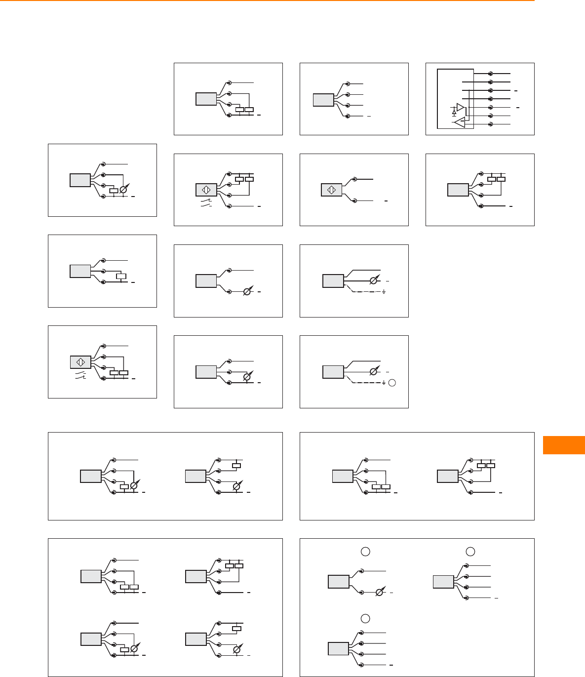
Core colours
BN brown
GY grey
WH white
BU blue
GN green
Wiring diagrams
1
L+
L
3 BU
4 BK
2 WH
1 BN
2
L+
L
1
4
3
3
4
L
L+
1
2
3
2:
4:
4
2
L
L+
4
1
3
Out 1
Out 2
4:
2:
5
L
L+
4:
3
2:
4
2
1
6
L+
L
1
2
7
L+
L
1
3
2
8
4
1
3
2OUT2
L+
L
OUT1/Teach/
Data
9
AS-i+
1
3
AS-i
10
BN
GY
WH
L+
L
11
1
BN
BU
GN
L+
L
12
L+
L
Uref
Out 1
Out 2
In
In+
1
2
3
5
6
7
4
OU2
OU1
+
InP2
10 V
13
Out 2
Out 1
4
L
L+
2
1
3
2:
4:
14
4
1
3
2
L+
L
2
1
3
4
L+
L
15
4
L
L+
2
1
3
Out 1
Out 2
4:
2:
4
L
L+
2
1
3
Out 1
Out 2
4:
2:
4
1
3
2
L+
L
Out 1
Out 2
4:
2:
2
1
3
4
L+
L
Out 1
Out 2
4:
2:
16
Out 1
Out 2
4
L
L+
2
1
3
4:
2:
4
L
L+
2
1
3
Out 1
Out 2
4:
2:
17
4
1
3
2
L+
L
OUT2
OUT1
2
4
1
3
2
L+
L
P
3
L+
L
1
2
1
Pressure sensors
443
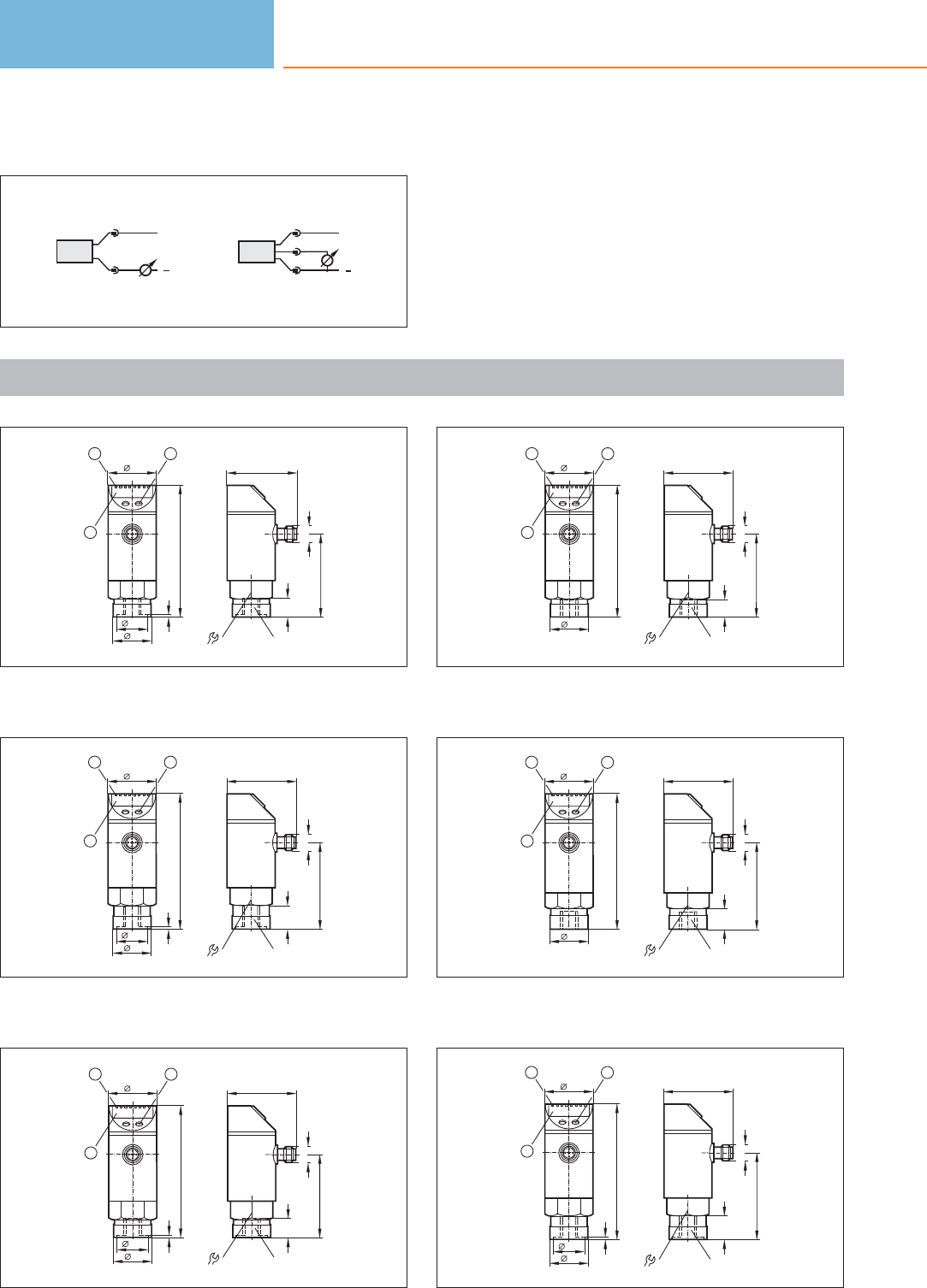
Wiring diagrams
18
L+
L
1
2
L+
L
1
3
2
Scale drawings / drawing no. – CAD download: www.ifm.com
1
91,5
34
27
1, 3
21,5
23
1
30
48
57,3
G
M12 x1
14
14
/
1: 4-digit alphanumeric display, 2: LEDs (display unit / switching
status), 3: Programming button
2
30
47,8
59,6
G
M12 x1
16,5
14
/
94,1
34
27
1, 3
21,5
23
1
1: 4-digit alphanumeric display, 2: LEDs (display unit / switching
status), 3: Programming button
3
91,5
34
27
1, 3
21,5
23
1
30
47
57,3
G
M12 x1
14
14
/
1: 4-digit alphanumeric display, 2: LEDs (display unit / switching
status), 3: Programming button
4
91,5
34
27
23
1
30
47
57,3
M12 x1
12
"NPT
14
/
1: 4-digit alphanumeric display, 2: LEDs (display unit / switching
status), 3: Programming button
5
94,1
34
27
23
1
30
47,8
59,8
"NPT
M12 x1
14
14
/
1: 4-digit alphanumeric display, 2: LEDs (display unit / switching
status), 3: Programming button
6
30
48
59,6
G
M12 x1
16,5
14
/
94,1
34
27
1, 3
21,5
23
1
1: 4-digit alphanumeric display, 2: LEDs (display unit / switching
status), 3: Programming button
Pressure sensors
444
Product selectors and further information can be found at: www.ifm.com
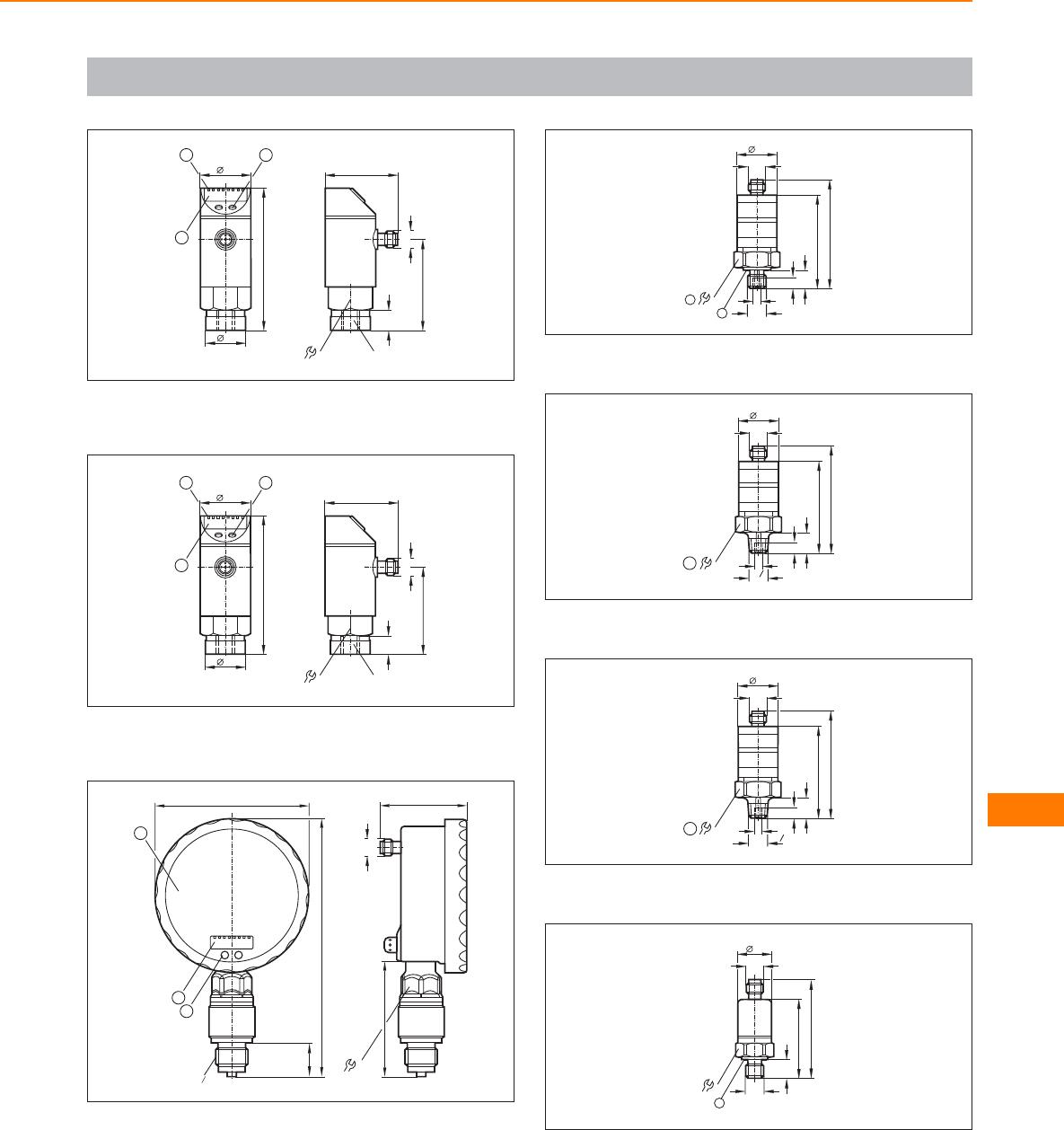
Scale drawings / drawing no. – CAD download: www.ifm.com
7
30
48
59,8
M12 x1
12
''NPT
14
/
94
34
27
23
1
1: 4-digit alphanumeric display, 2: LEDs (display unit / switching
status), 3: Programming button
8
91,5
34
27
23
1
30
48
57,3
M12 x1
12
''NPT
14
/
1: 4-digit alphanumeric display, 2: LEDs (display unit / switching
status), 3: Programming button
9
3
169
22
100
2
1
24
75,5
57
M12 x1
G2
1
1: Analogue display, 2: 4-digit alphanumeric display, 3: Touch button
(programming button)
10
61,6
12
M12 x1
27
27
71,6
G14
/
M5
7,5
2
1
1: tightening torque 25 Nm, 2: sealing FPM / DIN 3869-14
11
60,6
13
R4
1
M12 x1
27
27
70,6
M5
7,5
1
1: tightening torque 25 Nm
12
60,6
13
M12 x1
27
27
70,6
M5
7,5
" NPT
4
1
1
1: tightening torque 25 Nm
13
22
1
51,2
12
G14
/
65,1
M12 x1
22
1: sealing FPM / DIN 3869-14, tightening torque 25 Nm
Pressure sensors
445
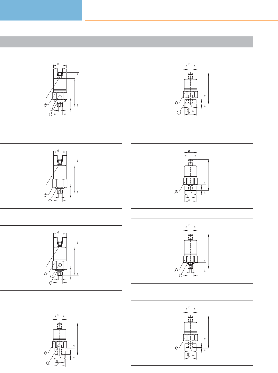
Scale drawings / drawing no. – CAD download: www.ifm.com
14
79,5
M12 x1
30
G14
/
2
LED
65,5
30
12
M5
1
1: Pressure relief mechanism, No mechanical force must be exerted
on the pressure relief mechanism., 2: sealing FPM / DIN 3869-14
15
79,5
M12 x1
30
30
12
G14
/
M5
1
LED
65,5
1: sealing FPM / DIN 3869-14
16
79,5
M12 x1
30
4
2
65,5
30
12
G1/
M5
1
LED
1: ventilation, 2: sealing FPM / DIN 3869-14
17
77,5
M12 x1
30
30
27
1, 3
21,5
16,5
G4
1
1: Pressure relief mechanism, No mechanical force must be exerted
on the pressure relief mechanism.
18
75
M12 x1
30
30
27
1, 3
21,5
14
G4
1
1: Pressure relief mechanism, No mechanical force must be exerted
on the pressure relief mechanism.
19
75
M12 x1
30
30
27
1, 3
21,5
14
G4
1
20
79,5
M12 x1
30
30
14
G14
/
M5
1
1: sealing FPM / DIN 3869-14
21
77,5
M12 x1
30
30
27
1, 3
21,5
16,5
G4
1
Pressure sensors
446
Product selectors and further information can be found at: www.ifm.com
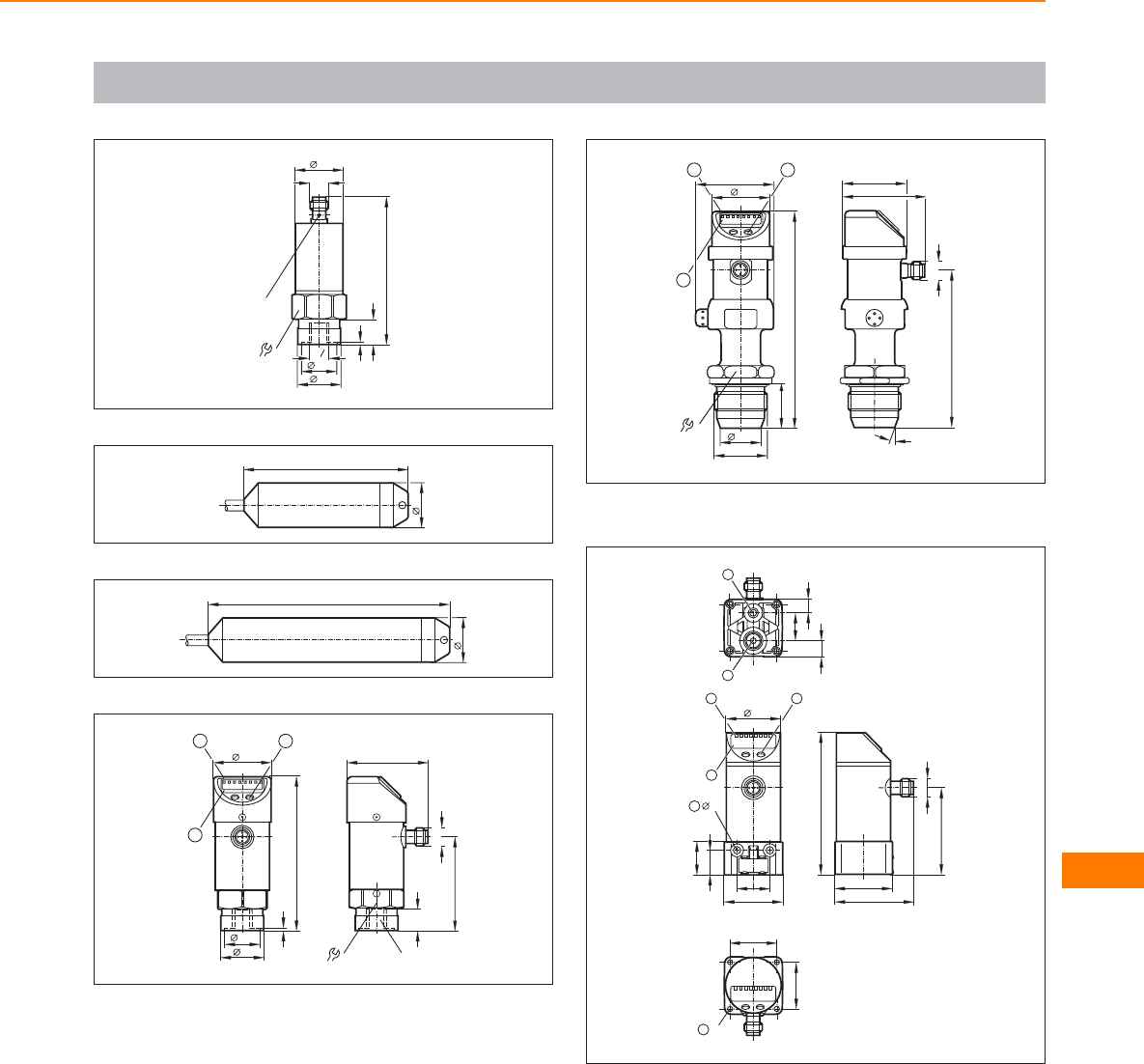
Scale drawings / drawing no. – CAD download: www.ifm.com
22
90,6
M12 x1
30
30
LED
27
1, 3
21,5
15,7
G4
1
23
100
27
24
27
147
25
94
36
27
21,5
23
1
30
49
57,3
G
M12 x1
14
14
/
1,3
1: 4-digit alphanumeric display, 2: LEDs (display unit / switching
status), 3: Programming button
26
G1
25,4
132
36
23
48
27
1
95,5
M12 x1
20°
50,5
39
36
1: 4-digit alphanumeric display, 2: LEDs, 3: Programming button
27
1
2
10
17
8
20
34
3
4
35,6
20
15
4,5
5
6
86,6
52,3
M12x1
35
48,4
7
M4
28,5
28,5
1: ventilation connection M5; max. tightening torque 2.5 Nm,
2: main pressure connection G 1/8; tightening torque max. 8 Nm,
3: Programming button, 4: LEDs (display unit / switching status),
5: 4-digit alphanumeric display, 6: for mounting screw M4; max.
tightening torque 2.5 Nm, 7: for mounting screw M4; max.
tightening torque 2.5 Nm
Pressure sensors
447
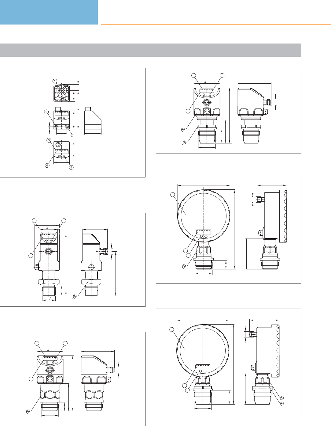
Scale drawings / drawing no. – CAD download: www.ifm.com
28
4,2
35
4,75
3220
42
32
30
20,7
11,3
1: main pressure connection G 1/8; tightening torque max. 8 Nm,
thread length max: 7.5 mm, 2: for mounting screw M4; max.
tightening torque 2.5 Nm, 3: LEDs (display unit / switching status),
4: 4-digit alphanumeric display, 5: Programming button
29
47
85
M12 x1
36
119
34
23
48
20,6
1
G4
3
1: 4-digit alphanumeric display, 2: LEDs (display unit / switching
status), 3: Programming button
30
16,8
G1
64
M12 x1
105,8
52,8
50
34
1
23
1: 4-digit alphanumeric display, 2: LEDs, 3: Programming button
31
64
M12 x1
105,6
45,1
27,4
50
34
46
1
23
G1
1: 4-digit alphanumeric display, 2: LEDs, 3: Programming button
32
24
3
153
16,8
100
2
1
57
60,5
M12 x1
G1
1: Analogue display, 2: 4-digit alphanumeric display, 3: Programming
button
33
24
34
3
153
27
100
2
1
G1
57
60,5 M12 x1
1: Analogue display, 2: 4-digit alphanumeric display, 3: Touch button
(programming button)
Pressure sensors
448
Product selectors and further information can be found at: www.ifm.com
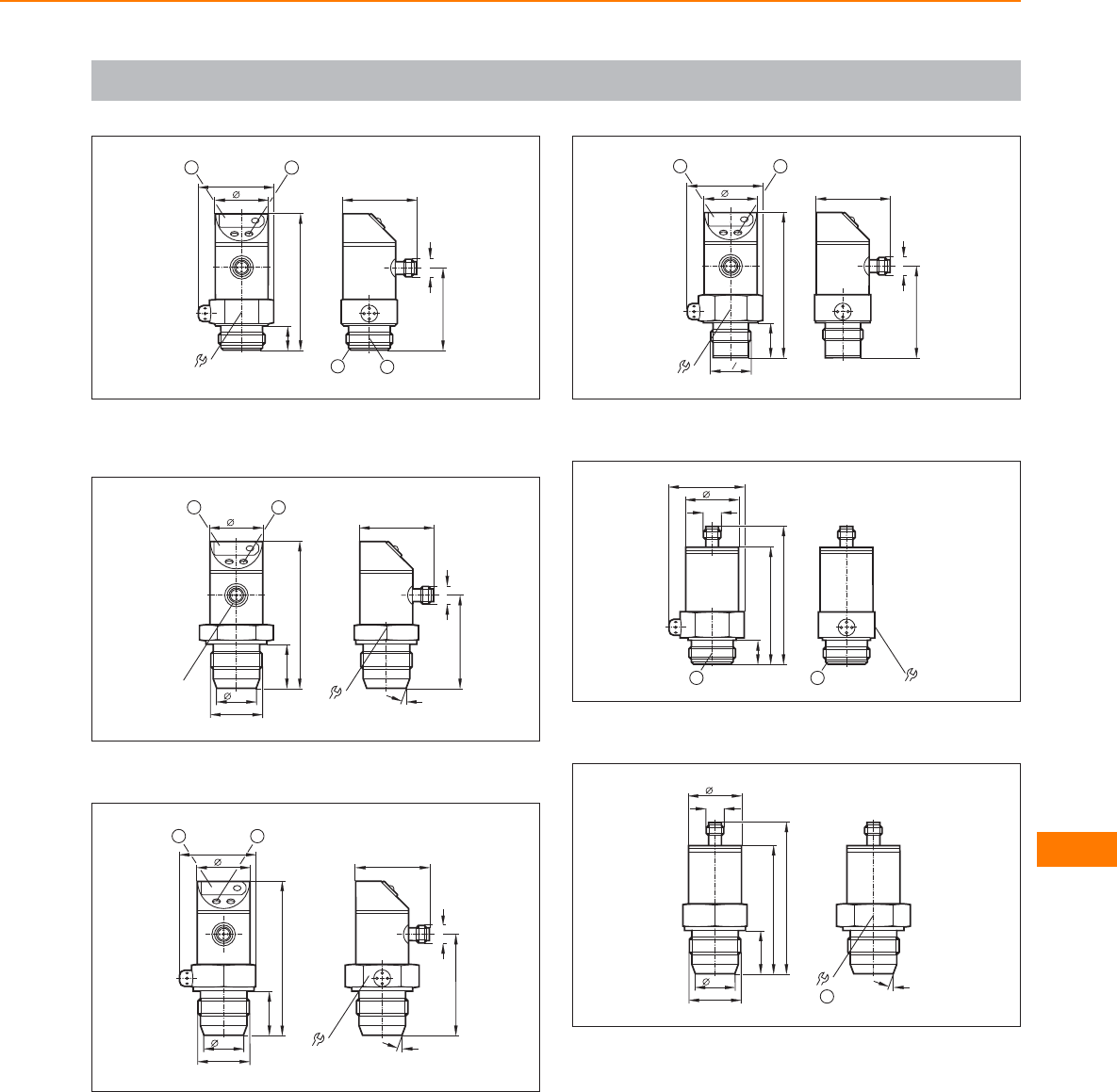
Scale drawings / drawing no. – CAD download: www.ifm.com
34
85,5
34
15
48
36
12
3
46,5
51
M12 x1
4
1: 7-segment LED display, 2: Programming button, 3: Aseptoflex
sealing edge, 4: Aseptoflex thread
35
46,5
58
M12 x1
41 20°
92
34
M12 x1
27,5
G1
25,4
12
1: 7-segment LED display, 2: Programming button
36
97,4
34
27,5
G1
25,4
48,5
12
46,5
63,1
M12 x1
41 20°
1: 7-segment LED display, 2: Programming button
37
91,1
34
20,5
G4
3
36
48
12
46,5
56,5
M12 x1
1: 7-segment LED display, 2: Programming button
38
36
2
73
34
15
M12 x1
87
48
1
1: Aseptoflex thread, 2: Aseptoflex sealing edge
39
41 20°
1
34
M12 x1
81
27
G1
25,4
95,2
1: tightening torque 20 Nm
Pressure sensors
449
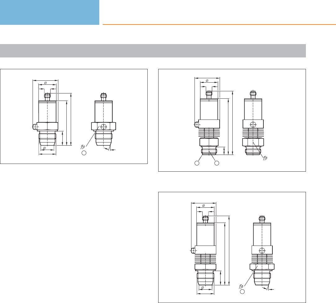
Scale drawings / drawing no. – CAD download: www.ifm.com
40
34
M12 x1
48,5
85,3
27
G1
25,4
99,5
1
41 20°
1: tightening torque 20 Nm
41
36
107
34
15
M12 x1
121,5
48
12
1: Aseptoflex sealing edge, 2: Aseptoflex thread
42
41 20°
1
117, 3
34
M12 x1
131,5
48
27
G1
25,4
1: tightening torque 20 Nm
Pressure sensors
450
Product selectors and further information can be found at: www.ifm.com

Pressure sensors
451
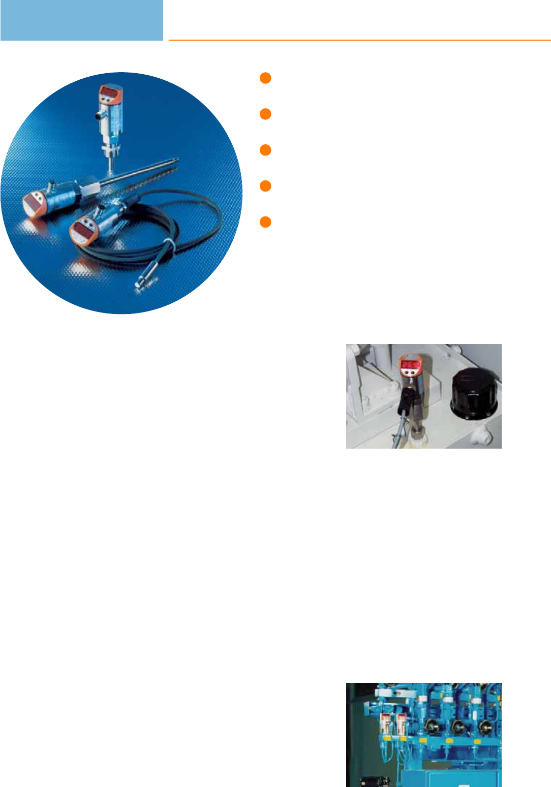
Increased process safety
due to self-monitoring.
Integrated or separate
control monitors selectable.
Modular concept –
tailor-made for every application.
Optional fittings for variable connection.
Robust construction for high resistance
to shock and vibration.
Temperature sensors
The temperature sensors of ifm electronic are based on a PT100 or PT1000 resistor.
The measured temperature value corresponds to a change in resistance and is con-
verted into an electrical analogue signal. A microprocessor controls the evaluation
of the electrical signal. The current system temperature is indicated by LEDs directly
on the control monitor.
The microprocessor and the display make process adjustment much easier. The user
can set the values for the switch points, hysteresis and measuring range by means
of programming buttons even without the system temperature being applied. This
enables installation and setup of the system within a few minutes. The values are
safely stored in an EEPROM independent of the supply voltage.
Film technology is used for the electronic circuitry. A flexible, temperature-resistant
and extremely resistant polyimide film is used as carrier of the SMD components.
Together with a special potting method an extreme shock and vibration resistance is
achieved.
From sensor to system
A complete temperature measurement system usually consists of several
components. The temperature in a medium is detected by a sensor and is converted
into an electrical measured signal. The mechanical design and the dimensions of
the sensors must vary to enable use for different media and measuring points.
Depending on the application ifm electronic offers a selection of robust probe sen-
sors or types with connection cables. To indicate and process the measured value
the sensor is connected to a separate control monitor. It indicates the measured
value on its integrated display. To complete the modular systems ifm electronic
offers compact temperature sensors with integrated control monitors. If a local tem-
perature display is not required, temperature transmitters are frequently used.
ifm electronic provides units with excellent response time (TA series) that either
have standard output signals or an integrated AS-i interface. In hygienic applications
the self-monitoring, calibration-free temperature transmitter TAD is an excellent
choice.
Local display of the
current temperature.
Imperative: tempera-
ture monitoring in air
conditioning.
Temperature sensors
452

System overview Page
Compact temperature sensors 454
Compact temperature sensors with display, IO-Link 454
Control monitors for temperature sensors 454
Control monitors for temperature sensors, IO-Link 455
Modular temperature transmitters 455
Pt1000 probe sensors for standard applications 455 - 456
Pt100 probe sensors for standard applications 456 - 457
Pt100 probe sensors for standard applications 457
Cable sensors for standard applications 457 - 458
Cable sensors with bolt-on sensor for standard applications 458
Cable sensors for ATEX applications 3D/3G 459
Cable sensors with bolt-on sensors for ATEX 3D / 3G applications 459
Temperature transmitters for standard applications 459
AS-i temperature transmitters for standard applications 460
Probe sensors for hygienic and wet areas 460
Sensors with process connection for hygienic and wet areas 460 - 461
Cable sensors for hygienic and wet areas 461
Temperature transmitters for hygienic and wet areas 462
AS-i temperature transmitters for hygienic and wet areas 462
Self-monitoring temperature transmitters for hygienic and wet areas, IO-Link 462 - 463
Accessories for temperature sensors TN / TR 463
Accessories and software 463
Thermowells for temperature sensors 464
Adapters 464 - 466
Hygienic adapters 466 - 468
Wiring diagrams 468 - 469
Scale drawings / drawing no. – CAD download: www.ifm.com 470 - 473
Temperature sensors
453
Compact temperature sensors
Type Measuring
range
[°C]
Process
connection
Probe length
[mm]
Ub
[V]
Dynamic response
T05 / T09
[s]
Drawing
no.
Order
no.
M12 connector · Output function normally open / closed complementary · DC PNP · Wiring diagram no. 1 · Connector groups 9,
11, 12, 107, 108, 109, 135, 136
-25...140 G¼ A 39 9.6...32 1 / 3 1 TK6130
-25...140 ¼" NPT 39 9.6...32 1 / 3 2TK6330
M12 connector · Output function · DC PNP · Wiring diagram no. 2 · Connector groups 9, 11, 12, 107, 108, 109, 135, 136
-25...140 G¼ A 39 9.6...32 1 / 3 1 TK7130
-25...140 ¼" NPT 39 9.6...32 1 / 3 2TK7330
M12 connector · Output function 1 x normally open / 1 x normally closed · DC PNP · Wiring diagram no. 2 · Connector groups 9,
11, 12, 107, 108, 109, 135, 136
-25...140 G½ A 267 9.6...32 1 / 3 3 TK7480
Compact temperature sensors with display, IO-Link
Type Measuring
range
[°C]
Process
connection
Probe length
[mm]
Ub
[V]
Dynamic response
T05 / T09
[s]
Drawing
no.
Order
no.
M12 connector · Output function 1 x normally open / closed programmable + 1 x analogue (4...20 mA / 0...10 V, scalable) ·
DC PNP/NPN · Wiring diagram no. 4 · Connector groups 9, 10, 11, 107, 108, 110, 135
-40...150 M18 x 1.5 45 18...32 1 / 3 4 TN2531
M12 connector · Output function 2 x normally open / closed programmable · DC PNP/NPN · Wiring diagram no. 5 · Connector
groups 9, 11, 12, 107, 108, 109, 135, 136
-40...150 M18 x 1.5 45 18...32 1 / 3 4TN7531
Control monitors for temperature sensors
Type Measuring
range
[°C]
Process
connection
Display
LED
Ub
[V]
Current
consump.
[mA]
Iload
[mA]
Drawing
no.
Order
no.
M12 connector · Output function 4 x normally open / closed programmable · DC PNP · Wiring diagram no. 6 · Connector groups
17, 18
-40...150 G½ A Display unit 18...28 90 < 500 5 TR8430
Temperature sensors
454
Product selectors and further information can be found at: www.ifm.com
Control monitors for temperature sensors, IO-Link
Type Measuring
range
[°C]
Process
connection
Display
LED
Ub
[V]
Current
consump.
[mA]
Iload
[mA]
Drawing
no.
Order
no.
M12 connector · Output function 1 x normally open / closed programmable + 1 x analogue (4...20 mA / 0...10 V, scalable) ·
DC PNP/NPN · Wiring diagram no. 7 · Connector groups 9, 10, 11, 107, 108, 110, 135
-40...300 G½ A Display unit 18...32 50 250 6 TR2432
M12 connector · Output function 2 x normally open / closed programmable · DC PNP/NPN · Wiring diagram no. 8 · Connector
groups 107, 108, 135
-40...300 G½ A Display unit 18...32 50 250 6TR7432
Modular temperature transmitters
Type Measuring
range
[°C]
Process
connection
Ub
[V]
Ambient
temperature
[°C]
Measuring element Drawing
no.
Order
no.
M12 connector · Output function 4...20 mA analogue · DC · Wiring diagram no. 9 · Connector groups 9, 11, 107, 108, 135
-50...300 M12 20...32 -25...70 for Pt100 and Pt1000
measuring elements 7TP3232
0...100 M12 20...32 -25...70 for Pt100 and Pt1000
measuring elements 7TP3237
-50...150 M12 20...32 -25...70 for Pt100 and Pt1000
measuring elements 7TP3231
-18...148.9 M12 20...32 -25...70 for Pt100 and Pt1000
measuring elements 7TP3233
M12 connector · Output function 0...10 V analogue · DC · Wiring diagram no. 10 · Connector groups 9, 11, 107, 108, 135
0...100 M12 18...32 -25...70 for Pt100 and Pt1000
measuring elements 7TP9237
Pt1000 probe sensors for standard applications
Type Measuring
range
[°C]
Diameter
[mm]
Probe length
[mm]
Sensor
element
Dynamic response
T05 / T09
[s]
Drawing
no.
Order
no.
M12 connector · high-grade stainless steel · Wiring diagram no. 3
-40...150 10 160 1 x Pt 1000 1 / 3 8 TT1050
Temperature sensors
455
You can find wiring diagrams and scale drawings from page 468
Type Measuring
range
[°C]
Diameter
[mm]
Probe length
[mm]
Sensor
element
Dynamic response
T05 / T09
[s]
Drawing
no.
Order
no.
M12 connector · high-grade stainless steel · Wiring diagram no. 3
-40...150 10 260 1 x Pt 1000 1 / 3 8 TT2050
-40...150 10 360 1 x Pt 1000 1 / 3 8TT3050
-40...150 10 560 1 x Pt 1000 1 / 3 8 TT5050
Pt100 probe sensors for standard applications
Type Measuring
range
[°C]
Diameter
[mm]
Probe length
[mm]
Sensor
element
Dynamic response
T05 / T09
[s]
Drawing
no.
Order
no.
M12 connector · high-grade stainless steel · Connector groups 9, 11, 107, 108, 135
-40...150 6 100 1 x Pt 100 1 / 3 9 TT0281
-40...150 6150 1 x Pt 100 1 / 3 9TT1281
-40...150 6 250 1 x Pt 100 1 / 3 9 TT2281
-40...150 6350 1 x Pt 100 1 / 3 9TT3281
-40...150 6 50 1 x Pt 100 1 / 3 9 TT9281
-40...150 10 160 1 x Pt 100 1 / 3 8TT1081
-40...150 10 260 1 x Pt 100 1 / 3 8 TT2081
-40...150 10 360 1 x Pt 100 1 / 3 8TT3081
-40...150 10 560 1 x Pt 100 1 / 3 8 TT5081
-40...125 8.2 44 1 x Pt 100 1 / 3 10 TM9950
Temperature sensors
456
Product selectors and further information can be found at: www.ifm.com
Type Measuring
range
[°C]
Diameter
[mm]
Probe length
[mm]
Sensor
element
Dynamic response
T05 / T09
[s]
Drawing
no.
Order
no.
M12 connector · metal · Connector groups 9, 11, 107, 108, 135
-40...125 8.2 44 1 x Pt 100 1 / 3 10 TM9900
Pt100 probe sensors for standard applications
Type Measuring
range
[°C]
Process
connection
Probe length
[mm]
Sensor
element
Dynamic response
T05 / T09
[s]
Drawing
no.
Order
no.
M12 connector · high-grade stainless steel · Connector groups 9, 11, 107, 108, 135
-40...150 ½" NPT 50 1 x Pt 100 1 / 3 11 TM4311
-40...150 ½" NPT 100 1 x Pt 100 1 / 3 11 TM4331
-40...150 ½" NPT 150 1 x Pt 100 1 / 3 11 TM4341
-40...150 ½" NPT 250 1 x Pt 100 1 / 3 11 TM4361
-40...150 G ¼ 25 1 x Pt 100 1 / 3 12 TM4101
-40...150 G½ 50 1 x Pt 100 1 / 3 13 TM4411
-40...150 G ½ 100 1 x Pt 100 1 / 3 13 TM4431
-40...150 G ½ 150 1 x Pt 100 1 / 3 13 TM4441
-40...150 G ½ 250 1 x Pt 100 1 / 3 13 TM4461
Cable sensors for standard applications
Type Measuring
range
[°C]
Diameter
[mm]
Cable
material
Sensor
element
Dynamic response
T05 / T09
[s]
Drawing
no.
Order
no.
Cable 4 m · high-grade stainless steel
-30...180 M5 / L = 25.7 silicone cable 1 x Pt 100 3 / 8 14 TS4759
Temperature sensors
457
You can find wiring diagrams and scale drawings from page 468
Type Measuring
range
[°C]
Diameter
[mm]
Cable
material
Sensor
element
Dynamic response
T05 / T09
[s]
Drawing
no.
Order
no.
Cable with connector 2 m · high-grade stainless steel · Connector groups 9, 11, 107, 108, 135
-40...150 Ø 6 / L = 45 FPM (Viton) cable 1 x Pt 1000 3 / 10 15 TS2251
-40...150 Ø 10 / L = 45 FPM (Viton) cable 1 x Pt 1000 6 / 25 16 TS2051
-50...250 Ø 6 / L = 50 PTFE cable 1 x Pt 100 11 / 37 17 TS2256
-50...250 Ø 10 / L = 50 PTFE cable 1 x Pt 100 12 / 39 18 TS2056
-30...90 M5 PUR cable 1 x Pt 100 3 / 8 19 TS2789
-30...180 –silicone cable 1 x Pt 100 3 / 8 20 TS2759
-30...180 M6 / L = 25.7 silicone cable 1 x Pt 100 3 / 8 21 TS2659
Cable with connector 2.5 m · high-grade stainless steel · Connector groups 9, 11, 107, 108, 135
-40...150 Ø 6 / L = 45 FPM (Viton) cable 1 x Pt 100 3 / 10 22 TS9281
Cable with connector 5 m · high-grade stainless steel · Connector groups 9, 11, 107, 108, 135
-40...150 Ø 10 / L = 45 FPM (Viton) cable 1 x Pt 1000 6 / 25 16 TS5051
Cable with connector 10 m · high-grade stainless steel · Connector groups 9, 11, 107, 108, 135
-30...180 –silicone cable 1 x Pt 100 3 / 8 20 TS0759
Cable sensors with bolt-on sensor for standard applications
Type Measuring
range
[°C]
Diameter
[mm]
Cable
material
Sensor
element
Dynamic response
T05 / T09
[s]
Drawing
no.
Order
no.
Cable with connector 2 m · stainless steel · Connector groups 9, 11, 107, 108, 135
-25...90 M6 / 12 x 51 PUR cable 1 x Pt 100 9 / 15 23 TS2229
Temperature sensors
458
Product selectors and further information can be found at: www.ifm.com
Cable sensors for ATEX applications 3D/3G
Type Measuring
range
[°C]
Diameter
[mm]
Cable
material
Sensor
element
Dynamic response
T05 / T09
[s]
Drawing
no.
Order
no.
Cable 3 m · high-grade stainless steel
-20...80 Ø 5/6 / L = 40 silicone cable 1 x Pt 100 4 / 10 24 TS325A
Cable sensors with bolt-on sensors for ATEX 3D / 3G applications
Type Measuring
range
[°C]
Diameter
[mm]
Cable
material
Sensor
element
Dynamic response
T05 / T09
[s]
Drawing
no.
Order
no.
Cable 5 m · high-grade stainless steel
-20...80 M6 / 10 x 42 silicone cable 1 x Pt 100 13 / 39 25 TS522A
-20...80 10 silicone cable 1 x Pt 1000 18 / 42 26 TS502A
Temperature transmitters for standard applications
Type Measuring
range
[°C]
Process
connection
Probe length
[mm]
Ub
[V]
Dynamic response
T05 / T09
[s]
Drawing
no.
Order
no.
M12 connector · high-grade stainless steel · DC · Connector groups 9, 11, 107, 108, 135
-50...150 G¼ A 60 10...30 1 / 3 27 TA3131
0...140 G¼ A 60 10...30 1 / 3 27 TA3130
-50...150 G¼ A 200 10...30 1 / 3 28 TA3171
-17.8...148.9 ¼" NPT 60 10...30 1 / 3 29 TA3333
0...100 ¼" NPT 60 10...30 1 / 3 29 TA3337
Temperature sensors
459
You can find wiring diagrams and scale drawings from page 468
AS-i temperature transmitters for standard applications
Type Measuring
range
[°C]
Process
connection
Probe length
[mm]
Ub
[V]
Dynamic response
T05 / T09
[s]
Drawing
no.
Order
no.
M12 connector · high-grade stainless steel · DC · Connector groups 9, 11, 107, 108, 135
-10...150 G¼ A 60 18...31.6 1 / 3 30 TAA131
Probe sensors for hygienic and wet areas
Type Measuring
range
[°C]
Diameter
[mm]
Probe length
[mm]
Sensor
element
Dynamic response
T05 / T09
[s]
Drawing
no.
Order
no.
M12 connector · high-grade stainless steel · Connector groups 9, 11, 107, 108, 135
-40...150 6 100 1 x Pt 100 1 / 3 9 TT0291
-40...150 6150 1 x Pt 100 1 / 3 9TT1291
-40...150 6 250 1 x Pt 100 1 / 3 9 TT2291
-40...150 6350 1 x Pt 100 1 / 3 9TT3291
-40...150 6 50 1 x Pt 100 1 / 3 9 TT9291
Sensors with process connection for hygienic and wet areas
Type Measuring
range
[°C]
Process
connection
Probe length
[mm]
Sensor
element
Dynamic response
T05 / T09
[s]
Drawing
no.
Order
no.
M12 connector · high-grade stainless steel · Connector groups 9, 11, 107, 108, 135
-40...150 Clamp 1-1.5"
ISO 2852 30 1 x Pt 100 1 / 3 31 TM4801
-40...150 Clamp 1-1.5"
ISO 2852 50 1 x Pt 100 1 / 3 31 TM4811
-40...150 Clamp 1-1.5"
ISO 2852 100 1 x Pt 100 1 / 3 31 TM4831
-40...150 Clamp 1-1.5"
ISO 2852 150 1 x Pt 100 1 / 3 31 TM4841
Temperature sensors
460
Product selectors and further information can be found at: www.ifm.com
Type Measuring
range
[°C]
Process
connection
Probe length
[mm]
Sensor
element
Dynamic response
T05 / T09
[s]
Drawing
no.
Order
no.
M12 connector · high-grade stainless steel · Connector groups 9, 11, 107, 108, 135
-40...150 Clamp 2" 30 1 x Pt 100 1 / 3 32 TM4901
-40...150 Clamp 2" 50 1 x Pt 100 1 / 3 32 TM4911
-40...150 Clamp 2" 100 1 x Pt 100 1 / 3 32 TM4931
-40...150 Clamp 2" 150 1 x Pt 100 1 / 3 32 TM4941
-40...150 G½ with s
ealing cone 20 1 x Pt 100 1 / 3 33 TM4591
-40...150 G½ with s
ealing cone 30 1 x Pt 100 1 / 3 33 TM4501
-40...150 G½ with s
ealing cone 50 1 x Pt 100 1 / 3 33 TM4511
-40...150 G½ with
sealing cone 100 1 x Pt 100 1 / 3 33 TM4531
-40...150 G½ with
sealing cone 150 1 x Pt 100 1 / 3 33 TM4541
Cable sensors for hygienic and wet areas
Type Measuring
range
[°C]
Diameter
[mm]
Cable
material
Sensor
element
Dynamic response
T05 / T09
[s]
Drawing
no.
Order
no.
Cable with connector 2 m · high-grade stainless steel · Connector groups 9, 11, 107, 108, 135
-40...150 Ø 10 / L = 45 FPM (Viton) cable 1 x Pt 1000 6 / 25 16 TS2051
Cable with connector 5 m · high-grade stainless steel · Connector groups 9, 11, 107, 108, 135
-40...150 Ø 10 / L = 45 FPM (Viton) cable 1 x Pt 1000 6 / 25 16 TS5051
Cable with connector 2 m · high-grade stainless steel · Connector groups 9, 11, 107, 108, 135
-50...250 Ø 10 / L = 50 PTFE cable 1 x Pt 100 12 / 39 18 TS2056
Temperature sensors
461
You can find wiring diagrams and scale drawings from page 468
Temperature transmitters for hygienic and wet areas
Type Measuring
range
[°C]
Process
connection
Probe length
[mm]
Ub
[V]
Dynamic response
T05 / T09
[s]
Drawing
no.
Order
no.
M12 connector · high-grade stainless steel · DC · Connector groups 9, 11, 107, 108, 135
0...100 G½ A 87.5 10...30 1 / 3 34 TA3437
0...140 G½ A 87.5 10...30 1 / 3 34 TA3430
-10...150 G½ A 87.5 10...30 1 / 3 34 TA3431
0...100 Ø 6 mm 123 10...30 1 / 3 35 TA3237
-17.8...148.9 Ø 6 mm 123 10...30 1 / 3 35 TA3233
-10...150 Ø 6 mm 123 10...30 1.2 / 3.5 35 TA3231
AS-i temperature transmitters for hygienic and wet areas
Type Measuring
range
[°C]
Process
connection
Probe length
[mm]
Ub
[V]
Dynamic response
T05 / T09
[s]
Drawing
no.
Order
no.
M12 connector · high-grade stainless steel · DC · Connector groups 9, 11, 107, 108, 135
-10...150 G½ A 87.5 18...31.6 1 / 3 36 TAA431
Self-monitoring temperature transmitters for hygienic and wet areas, IO-Link
Type Measuring
range
[°C]
Process
connection
Probe length
[mm]
Ub
[V]
Dynamic response
T05 / T09
[s]
Drawing
no.
Order
no.
M12 connector · Output function normally open / normally closed / heartbeat programmable, 4...20 mA analogue · DC PNP/NPN ·
Wiring diagram no. 11 · Connector groups 9, 10, 11, 107, 108, 110, 135
0...150 Aseptoflex Vario 87.5 18...32 3 / 6 37 TAD181
0...150 Aseptoflex Vario 33 18...32 3 / 6 38 TAD981
0...150 G½ A 87.5 18...32 3 / 6 39 TAD191
Temperature sensors
462
Product selectors and further information can be found at: www.ifm.com
Type Measuring
range
[°C]
Process
connection
Probe length
[mm]
Ub
[V]
Dynamic response
T05 / T09
[s]
Drawing
no.
Order
no.
M12 connector · Output function normally open / normally closed / heartbeat programmable, 4...20 mA analogue · DC PNP/NPN ·
Wiring diagram no. 11 · Connector groups 9, 10, 11, 107, 108, 110, 135
0...150 G½ A 33 18...32 3 / 6 40 TAD991
Accessories for temperature sensors TN / TR
Type Description Order
no.
Mounting clamp · Ø 34 mm · Housing materials: PBT E10017
Mounting clamp · Ø 34 mm · Housing materials: PA E10193
Mounting device 2 way · for fluid sensors · Housing materials: POM E30078
Mounting device 3 way · for fluid sensors · Housing materials: POM E30079
Protective cover · for fluid sensors with connector M12 · Housing materials: polyurethane E30006
Accessories and software
Type Description Order
no.
IO-Link interface · for parameter setting and analysis of units with DTM specification · Supported communication protocols: IO-Link
(4800 and 38400 bits/s) EPS protocol (19200 bits/s) · contains ifm Container software (E30110) E30396
Memory plug · Parameter memory for IO-Link sensors · Housing materials: PA PACM 12 / PET / sealing: FPM / nut: stainless steel
316L / 1.4404 / connector: TPU E30398
Teach button · for sensors PP0xE, PP052x, PP755x · for memory plug (E30398) · 0.9 m · Housing materials: stainless steel / PA /
PMMA E30405
Temperature sensors
463
You can find wiring diagrams and scale drawings from page 468
Thermowells for temperature sensors
Type Description Order
no.
Welding thermowell · Ø 10 mm · Probe length: 173 mm · Housing materials: stainless steel 316Ti / 1.4571 E35220
Welding thermowell · Ø 35 mm · Probe length: 126.5 mm · for type TA343x, TAA431, TAD191 · Housing materials: stainless steel
316L / 1.4404 E30403
Thermowell for temperature sensors · G ½ · Probe length: 53 mm · for type TA34xx, TAA431, TAD191 · Housing materials: stainless
steel 316L / 1.4404 E30393
Thermowell for temperature sensors · Ø 10 mm - G ½ · Probe length: 82 mm · Housing materials: stainless steel 316L / 1.4404 E35010
Thermowell for temperature sensors · Ø 10 mm - G ½ · Probe length: 182 mm · Housing materials: stainless steel 316L / 1.4404 E35020
Thermowell for temperature sensors · Ø 10 mm - G ½ · Probe length: 282 mm · Housing materials: stainless steel 316L / 1.4404 E35030
Thermowell for temperature sensors · Ø 10 mm - G ½ · Probe length: 482 mm · Housing materials: stainless steel 316L / 1.4404 E35050
Thermowell for temperature sensors · Ø 10 mm - ½„ NPT · Probe length: 72 mm · Housing materials: stainless steel 316Ti / 1.4571 E35110
Thermowell for temperature sensors · Ø 6 mm - G ½ · Probe length: 82 mm · Housing materials: stainless steel 316Ti / 1.4571 E37010
Thermowell for temperature sensors · Ø 6 mm - G ½ · Probe length: 182 mm · Housing materials: stainless steel 316Ti / 1.4571 E37020
Thermowell for temperature sensors · Ø 6 mm - G ½ · Probe length: 282 mm · Housing materials: stainless steel 316Ti / 1.4571 E37030
Adapters
Type Description Order
no.
Thread cover · Ø 24 mm - G ½ · to cover the G½ thread for installation in hygienic areas · for type TR · Housing materials: stainless
steel E30091
Temperature sensors
464
Product selectors and further information can be found at: www.ifm.com
Type Description Order
no.
Mounting set · for direct connection of temperature sensors TT to control monitors TR · Housing materials: stainless steel E30017
Clamp fitting · Ø 6/8/10 mm - G ½ · for temperature sensors TS / TT · Housing materials: stainless steel / FPM E30018
Clamp fitting · Ø 6/8/10 mm - ½" NPT · for temperature sensors TS / TT · Housing materials: stainless steel / FPM E30025
Mounting adapter · M18 x 1.5 - Ø 23 mm · PVC adapter to be glued into the pipe · Insertion depth of the probe of SID, SFD, TN: ·
21 mm · Housing materials: PVC E40148
Adapter · G ¼ - G ¼ · Housing materials: stainless steel 316L / 1.4404 E30107
Adapter · M18 x 1.5 - G ½ · Housing materials: stainless steel 316L / 1.4404 / O-ring: FPM (fitted) E30073
Welding adapter · M18 x 1.5 - Ø 24 mm · Insertion depth of the probe of SID, SFD, TN: · 15 mm · Housing materials: stainless steel
316L / 1.4404 E40124
Welding adapter · Ø 24.7 mm · ball · for temperature sensors Ø 6 mm · Clamp fitting · Housing materials: stainless steel 316L /
1.4404 E30108
Welding adapter · Ø 25 mm · ball · for temperature sensors Ø 6 mm · Clamp fitting · Housing materials: stainless steel 316L /
1.4404 / rubber ring: PEEK E30407
Progressive ring fitting for temperature sensors · Ø 10 mm - G ½ · Housing materials: stainless steel 316Ti / 1.4571 E30016
Progressive ring fitting for temperature sensors · Ø 10 mm - ½" NPT · Housing materials: stainless steel 316Ti / 1.4571 E30024
Progressive ring fitting for temperature sensors · Ø 6 mm - G ½ · Housing materials: stainless steel 316Ti / 1.4571 E30047
Progressive ring fitting for temperature sensors · Ø 6 mm - ¼" NPT · Housing materials: stainless steel 316Ti / 1.4571 E30049
Progressive ring fitting for temperature sensors · Ø 6 mm - G ¼ · Housing materials: stainless steel 316Ti / 1.4571 E33431
Temperature sensors
465
You can find wiring diagrams and scale drawings from page 468
Type Description Order
no.
Adapter · M18 x 1.5 - G ½ · Insertion depth of the probe of SID, SFD, TN: · 21 mm · Housing materials: titanium E40114
Adapter · M18 x 1.5 - M12 x 1 · Insertion depth of the probe of SID, SFD, TN: · 13.5 mm · Housing materials: titanium E40128
Adapter · M18 x 1.5 - L18 · for mounting in T-pieces · Insertion depth of the probe of SID, SFD, TN: · 28.5 mm · Housing materials:
nut: stainless steel 316Ti / 1.4571 / adapter: stainless steel 316L / 1.4404 / O-ring: FPM 16 x 1.5 gr 70° Shore A E40104
Adapter · M18 x 1.5 - M12 x 1 · Insertion depth of the probe of SID, SFD, TN: · 13.5 mm · Housing materials: stainless steel 316L /
1.4404 E40101
Adapter · M18 x 1.5 - M12 x 1 · Insertion depth of the probe of SID, SFD, TN: · 13.5 mm · Housing materials: brass E40100
Adapter · M18 x 1.5 - G ¼ · Insertion depth of the probe of SID, SFD, TN: · 13.5 mm · Housing materials: stainless steel 316L /
1.4404 E40099
Adapter · M18 x 1.5 - G ¼ · Insertion depth of the probe of SID, SFD, TN: · 13.5 mm · Housing materials: brass E40098
Adapter · M18 x 1.5 - G ½ · Insertion depth of the probe of SID, SFD, TN: · 21 mm · Housing materials: stainless steel 316L / 1.4404 E40096
Adapter · M18 x 1.5 - G ½ · Insertion depth of the probe of SID, SFD, TN: · 21 mm · Housing materials: brass E40097
Adapter · M18 x 1.5 - ½" NPT · Insertion depth of the probe of SID, SFD, TN: · 23 mm · Housing materials: stainless steel 316L /
1.4404 E40107
Adapter · M18 x 1.5 - G ½ · Housing materials: stainless steel 316L / 1.4404 / O-ring: FPM (fitted) E30073
Protective cover · with lead seal option · for pressure sensors type PK · for temperature sensors type TK · for vibration monitor VK ·
Housing materials: PP transparent E30094
Hygienic adapters
Type Description Order
no.
Aseptoflex Vario adapter · Clamp · 1-1.5" · ISO 2852 · for units with Aseptoflex Vario adapter · Sealing by sealing ring · Housing
materials: stainless steel 316L / 1.4435 E33201
Temperature sensors
466
Product selectors and further information can be found at: www.ifm.com
Type Description Order
no.
Aseptoflex Vario adapter · Clamp · 2" · ISO 2852 · for units with Aseptoflex Vario adapter · Sealing by sealing ring · Housing
materials: stainless steel 316L / 1.4435 E33202
Aseptoflex Vario adapter · Clamp · 1-1.5" · ISO 2852 · for units with Aseptoflex Vario adapter · Metal to metal seal · Housing
materials: stainless steel 316L / 1.4435 E33701
Aseptoflex Vario adapter · Clamp · 2" · ISO 2852 · for units with Aseptoflex Vario adapter · Metal to metal seal · Housing materials:
stainless steel 316L / 1.4435 E33702
Aseptoflex Vario adapter · pipe fitting · DN40 (1.5") · DIN 11851 · for units with Aseptoflex Vario adapter · Sealing by sealing ring ·
Housing materials: stainless steel 316L / 1.4435 E33212
Aseptoflex Vario adapter · pipe fitting · DN50 (2") · DIN 11851 · for units with Aseptoflex Vario adapter · Sealing by sealing ring ·
Housing materials: stainless steel 316L / 1.4435 E33213
Aseptoflex Vario adapter · pipe fitting · DN40 (1.5") · DIN 11851 · for units with Aseptoflex Vario adapter · Metal to metal seal ·
Housing materials: stainless steel 316L / 1.4435 E33712
Aseptoflex Vario adapter · pipe fitting · DN50 (2") · DIN 11851 · for units with Aseptoflex Vario adapter · Metal to metal seal ·
Housing materials: stainless steel 316L / 1.4435 E33713
Aseptoflex Vario adapter · Varivent type N · DN40 (1.5"), D = 68 · for units with Aseptoflex Vario adapter · Sealing by sealing ring ·
Housing materials: stainless steel 316L / 1.4435 E33222
Aseptoflex Vario adapter · Varivent type N · DN40 (1.5"), D = 68 · for units with Aseptoflex Vario adapter · Metal to metal seal ·
Housing materials: stainless steel 316L / 1.4435 E33722
Aseptoflex Vario adapter · pipe fitting · DN40 (1.5") · SMS · for units with Aseptoflex Vario adapter · Metal to metal seal · Housing
materials: stainless steel 316L / 1.4435 E33731
Aseptoflex Vario adapter · pipe fitting · DN50 (2") · SMS · for units with Aseptoflex Vario adapter · Metal to metal seal · Housing
materials: stainless steel 316L / 1.4435 E33732
Welding adapter · Ø 50 mm · for units with Aseptoflex Vario adapter · Sealing by sealing ring · Housing materials: stainless steel
316L / 1.4435 E30122
Adapter plug · for Aseptoflex Vario adapter · Housing materials: high-grade stainless steel E30128
G ½ adapter · Clamp · 1-1.5" · ISO 2852 / DIN 32676 · for units with G ½ adaptation · Housing materials: stainless steel 316L /
1.4404 E33401
Temperature sensors
467
You can find wiring diagrams and scale drawings from page 468
Type Description Order
no.
G ½ adapter · Clamp · 2" · ISO 2852 / DIN 32676 · for units with G ½ adaptation · Housing materials: stainless steel 316L / 1.4404 E33402
G ½ adapter · DN25 · SMS · for units with G ½ adaptation · Housing materials: stainless steel 316L / 1.4404 E33430
Welding adapter · G ½ - Ø 30 mm · for tanks · Housing materials: stainless steel 316L / 1.4435 E43300
Welding adapter · G ½ - Ø 29 mm · for pipes · Housing materials: stainless steel 316L / 1.4435 E43301
Adapter · G ½ · pipe fitting · DN25 (1") · DIN 11851 · Housing materials: stainless steel 316L / 1.4435 E43304
Adapter · G ½ · pipe fitting · DN40 (1.5") · DIN 11851 · Housing materials: stainless steel 316L / 1.4435 E43305
Adapter · G ½ · Varivent type F · DN25 (1"), D = 50 · Housing materials: stainless steel 316L / 1.4435 E43306
Adapter · G ½ · Varivent type N · DN40 (1.5"), D = 68 · Housing materials: stainless steel 316L / 1.4435 E43307
sealing plug · G ½ · for G ½ adapter · Housing materials: stainless steel 316L / 1.4435 E43308
Welding adapter · G ½ - Ø 35 mm · ball · Housing materials: stainless steel 316L / 1.4404 E30055
Welding adapter · G ½ - Ø 45 mm · collar · Housing materials: stainless steel 316L / 1.4404 E30056
Wiring diagrams
1
4
L
L+
1
2
3
2:
4:
2
2
L
L+
4
1
3
Out 1
Out 2
4:
2:
3
1
2
3
4
Temperature sensors
468
Product selectors and further information can be found at: www.ifm.com
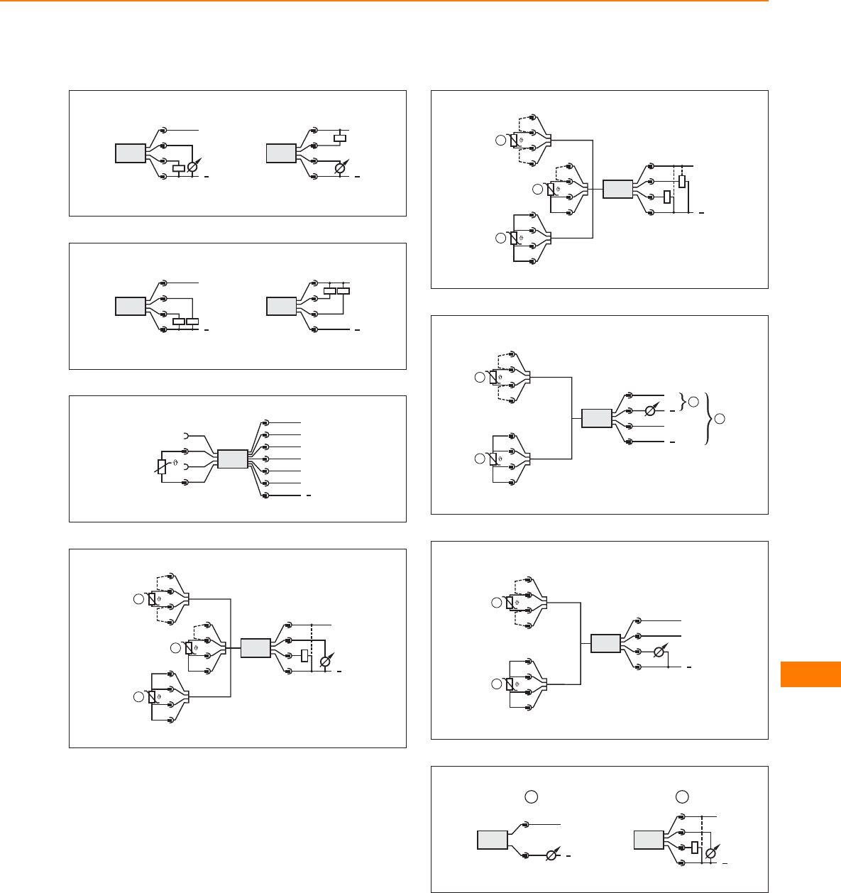
Wiring diagrams
4
4
1
3
2
L+
L
2
1
3
4
L+
L
5
Out 1
Out 2
4
L
L+
2
1
3
4:
2:
4
L
L+
2
1
3
Out 1
Out 2
4:
2:
6
TR 8430
L+
L
n.c.
Out 4
Out 1
Out 2
1
2
4
6
7
3
Out 3
5
3 (n.c.)
1 (n.c.)
4
2
7
L+
L
1 BN
2 WH
4 BK
3 BU
TR 2432
1
2
3
4
2
B
1
2
3
4
3
1
1
2
3
4
B
B
8
L+
L
1 BN
2 WH
4 BK
3 BU
1
2
3
4
2
B
1
2
3
4
3
1
1
2
3
4
B
B
TR
9
4
1
3
2
L+
L
L
IO-Link
1
2
3
4
1
2
3
4
1
2
3
4
B
B
TP
10
4
1
3
2
L+
L
IO-Link
1
2
3
4
1
2
1
2
3
4
B
B
TP
11
2
L+
L
1
L+
L
3 BU
4 BK
2 WH
1 BN
2 WH
1 BN
Temperature sensors
469
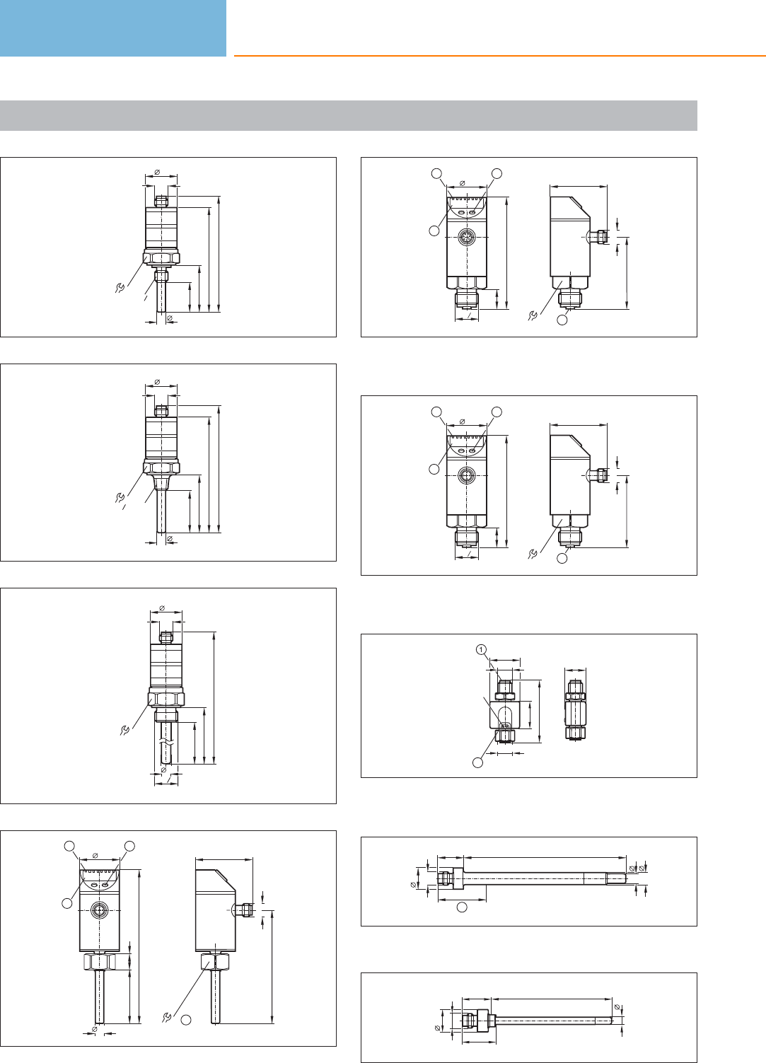
Scale drawings / drawing no. – CAD download: www.ifm.com
1
39
M12 x1
27
27
96,5
25
8,2
G4
1
87
2
48
M12 x1
27
27
105,5
35
8,2
-18 NPT
4
1
96
3
267
M12 x1
27
27
327
G2
1
8
255
4
45 14
128
34
8,2
23
1
48
94,5
M12x1
22 4
1: 4-digit alphanumeric display, 2: LEDs, 3: Programming button,
4: internal thread M18 x 1.5
5
93
34
16,5
G2
1
23
1
30
48
60
M12 x1
4
1: 4-digit alphanumeric display, 2: LEDs, 3: Programming button,
4: connection for temperature sensor
6
93
34
16,5
G2
1
23
1
30
48
60
M12 x1
4
1: 4-digit alphanumeric display, 2: LEDs, 3: Programming button,
4: connection for temperature sensor
7
18
M12x1
M12x1
25
LED
22
52
2
1: connection for voltage supply and output signals, 2: connection
for temperature sensor
8
8
L
10
M12x1
21,5
18,5
40
1
1: plug area
9
M12x1
18,5
24 L
27,7
6
Temperature sensors
470
Product selectors and further information can be found at: www.ifm.com
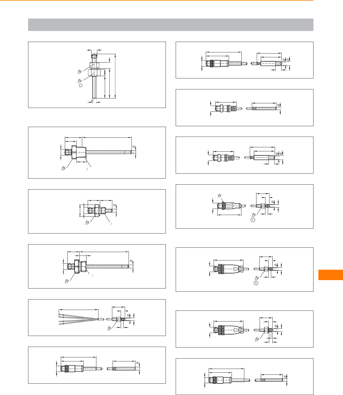
Scale drawings / drawing no. – CAD download: www.ifm.com
10
90
60
22
14
8,2
44
12
M12x1
19
1
1: internal thread M18 x 1.5
11
6
L
35
23
20
2
1" NPT
M12x1
27
12
6
24 L
24,5
M12x1
22 G4
1
13
M12x1
24 L
6
14
G2
1
27
14
80 ± 5 25,7
5,4
M5
4
8
8
15
M12 x1
6
45
72
48
16
M12 x1
72
48 50
12
10
7
42
17
M12 x1
42,5 50
6
18
50
12
10
7
42
M12 x1
42,5
19
25,7
5,4
M5
4
8
8
M12 x1
49,5
14
1: tightening torque 1.5 Nm
20
M12 x1
58
25,7
5,4
M5
4
8
8
1: tightening torque 1.5 Nm
21
M12 x1
58
25,7
2,5
M6
5
8
13 6,5
22
M12 x1
72
48 45
6
Temperature sensors
471
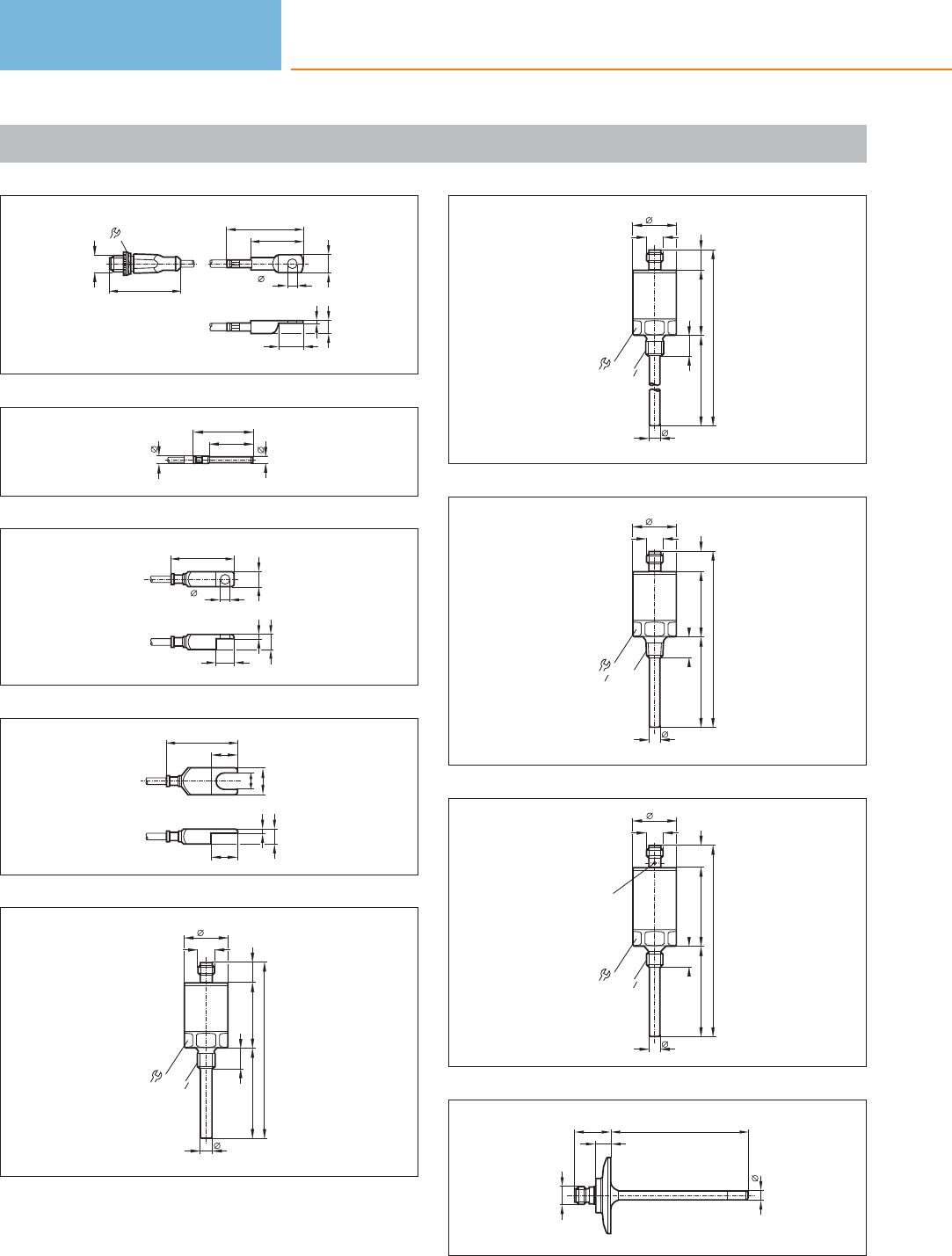
Scale drawings / drawing no. – CAD download: www.ifm.com
23
M12 x1
49,5
14 35
6,5
51
12
17
8,7
1,8
24
30
5
6
40
25
42
6,5
10
12
10
3
26
48
18
11
18
18
10
3
27
44
60
8,2
M12x1
30
27
13,7
117,7
13,5
G4
1
28
44
200
8
M12x1
30
27
13,7
257,7
13,5
G4
1
29
4460
8,2
M12x1
30
27
13,7
117,7
13,5
-18 NPT
4
1
30
5360
8,2
M12x1
30
27
14,9
127,9
13,5
G4
1
LED
31
6
L
24
10
M12x1
Temperature sensors
472
Product selectors and further information can be found at: www.ifm.com
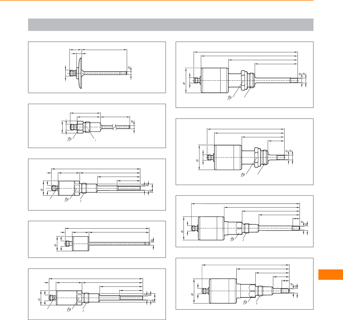
Scale drawings / drawing no. – CAD download: www.ifm.com
32
6
L
24
10
M12x1
33
6
47,5 L
24,5
M12x1
22
61,6
G2
1
34
G2
1
43,8 123
8,2
10
M12x1
30
27
18,3
13,7
47,5
180,5
LED
87,5
35
34 123
6
M12x1
30
14
171
36
G2
1
52,8 123
8,2
10
M12x1
30
27
18,3
14,7
47,5
190,5
LED
87,5
37
34 G1
8
10
50,4
87,5
140,5
210,5
M12x1
195,7
38
34 G1
8
10
50,4
33
86
156
141,2
M12x1
39
M12 x1
50,4
231
161
27
87,5
10
123
8
G2
1
14
40
M12 x1
50,4
176,5
106,5
27
33
10
68,5
8
G2
1
14
Temperature sensors
473
Online vibration diagnosis – optimum
price / performance ratio.
Decentralised monitoring of plant and
equipment integrated into the machine.
Compact field units and modular
control cabinet units.
Digital and analogue alarm outputs.
Standard data interface (OPC).
Diagnostic systems
efector octavis is a vibration monitor which not only detects vibration data, but also
carries out signal analysis and machine diagnosis directly on the machine. The
machine condition is determined and is forwarded to the PLC or to SCADA
software. It fulfils the main requirements for modern machine monitoring: compati-
bility, modularity and transferable configuration.
Compatible and modular
The compatibility with data structures such as the OPC interface makes it possible
to integrate condition data into a higher-level system. With the requirement for
modularity the user can define the extent of condition monitoring to be implemen-
ted – this means the complete range of diagnosis is possible right from the “first
unit”. Transferable configuration is attained with application-related parameter sets.
A wizard function in the software guides the user through creating, managing and
archiving the monitoring parameters.
Trend memory
All units of the octavis family type VE / VSE feature an internal trend memory which
ensures detailed analysis and optimisation of the application even without external
data recording. The storage intervals are freely selectable. This means that the
storage length of the non volatile ring buffer is adjusted to the requirements.
The suitable system for your application:
– Standard vibration characteristic values / permanent machine protection:
VSE, VE, VK, VT
– Internal trend memory / root cause analysis: VSE, VE
– Online diagnosis / early damage detection: VSE (VE partly)
– Network capability of the system: VSE (VE partly*)
– Load meter: VSE
*Profibus DP gateway
Internal trend memory
(type VE / VSE) of all
monitored diagnosis
factors can be evalu-
ated via PC software.
Easy vibration
monitoring: Type VK
provides a com-
bination of switching
output and trans-
mitter function in
conjunction with the
tried and tested
easy-turn concept.
Diagnostic systems
474

System overview Page
Compact vibration diagnostic units with g-monitor to ISO 10816 type VB/VE 476
Software VB / VE 476
Accessories VB / VE 476
Vibration monitors for vibration monitoring of machines and plants to ISO 10816 type VK 477
Vibration transmitters for vibration monitoring of machines and plants to ISO 10816 type VT 477
Accessories VK 477
Diagnostic electronics - control cabinet modules for vibration diagnosis type VSE 477
Accessories VSE 477 - 478
Connection cables VSE 478
Vibration sensors for connection to external diagnostic electronics VSE - type VSA 478
Accessories VSA 478 - 479
Oil moisture sensor 479
Wiring diagrams 479
Scale drawings / drawing no. – CAD download: www.ifm.com 479
Diagnostic systems
475
Compact vibration diagnostic units with g-monitor to ISO 10816 type VB/VE
Type Description Draw-
ing
no.
Order
no.
Vibration monitoring of up to 2 diagnosis values and 2 g-monitors, RMS; peak; method of analysis FFT/H-FFT;
integrated history function; speed source connectable; integrated LED-diagnosis; RS232 serial interface; PC-software
required; IP67; 2 switching outputs; measurement range +/-25g; frequency resolution 1.25Hz; speed range
500... 6000 rpm; connection M12x1 and M8x1 plug connection
1VB1001
Vibration monitoring of up to 5 diagnosis values and 2 g-monitors; RMS; peak: method of analysis FFT/H-FFT;
integrated history function; speed source connectable; integrated LED-diagnosis; RS232 serial interface; PC-software
required; IP67; 2 switching outputs; measuring range +/-25g; frequency resolution adjustable 1.25Hz or 0.125Hz;
speed range 12... 12 000 rpm; Connection M12x1 and M8x1 plug connection
1VE1001
Vibration monitoring of up to 5 diagnosis values and 2 g-monitors; RMS; peak; method of analysis FFT/H-FFT;
integrated history function; speed source connectable; RS485 serial interface; PC-software required; IP 69k; 2 switching
outputs; measuring range +/-25g; frequency resolution adjustable 1.25Hz or. 0.125Hz; speed range 12... 12 000 rpm;
connection M12x1 and M8x1 plug connection
2VE1101
Vibration monitoring of up to 5 diagnosis values and 2 g-monitors; method of analysis FFT; integrated history function;
speed source connectable; RS232 serial interface; PC-software required; IP 69k; 2 switching outputs; measuring range
+/-25g; frequency resolution 15.625Hz; speed range 1500... 96000 rpm; connection M12x1 und M8x1 plug connection
3VE1103
Compact unit for ATEX approval group II; category 2D/2G; vibration monitoring of up to 5 diagnosis values and
2 g-monitors; method of analysis FFT/H-FFT; integrated history function; speed source connectable; RS485 serial
interface; PC-software required; IP 69k; 1 switching output; measuring range +/-25g; frequency resolution 1.25 Hz;
frequency range 3...6000 Hz; speed range 120..12000 rpm; connection cable 5m
4VE113A
Software VB / VE
Type Description Draw-
ing
no.
Order
no.
Expert software for efector octavis · Types VB and VE – VES001
Accessories VB / VE
Type Description Order
no.
Parameter setting cable for efector octavis · straight / straight · 3 m · Housing materials: PUR E11572
USB/RS485 adapter cable · straight / straight E30098
USB/RS485 adapter cable · straight / straight · For efector octavis VE113A E30117
Power supply · 2 m · Housing materials: PPE E30080
Y connection cable · 2 way · Free from halogen · 0.25 m · Housing materials: TPU E11664
Diagnostic systems
476
Product selectors and further information can be found at: www.ifm.com
Vibration monitors for vibration monitoring of machines and plants to ISO 10816 type VK
Type Description Draw-
ing
no.
Order
no.
IP67; 1 switching output and response delay (1...60s) adjustable via setting rings; 1 analogue output
(4mA = 0 mm/s, 20 mA=25 mm/s); M12 connector; measuring range RMS 0...25 mm/s; frequency range 10...1000 Hz;
accuracy / deviation (in % of span): switchpoint accuracy < +/-4, repeatability <1; M12 connector
5VKV021
IP67; 1 switching output and response delay (1...60s) adjustable via setting rings; 1 analogue output
(4mA = 0 mm/s, 20 mA=50 mm/s); M12 connector; measuring range RMS 0...50 mm/s; frequency range 10...1000 Hz;
accuracy / deviation (in % of span): switchpoint accuracy < +/-4, repeatability <1; M12 connector
5VKV022
Vibration transmitters for vibration monitoring of machines and plants to ISO 10816 type VT
Type Description Draw-
ing
no.
Order
no.
Vibration transmitter · Connection via M12 connector · Vibration transmitter to ISO 10816 · Measuring range veff:
0...25 mm/s · Analogue output 4...20 mA · stainless steel 316L / 1.4404 6VTV122
Accessories VK
Type Description Order
no.
Protective cover · with lead seal option · for pressure sensors type PK · for temperature sensors type TK · for vibration monitor VK ·
Housing materials: PP transparent E30094
Diagnostic electronics - control cabinet modules for vibration diagnosis type VSE
Type Description Draw-
ing
no.
Order
no.
Frequency-selective machine monitoring of up to 4 measurement points and 2 other process quantities; Ethernet interface
TCP/IP; PC-software required; RMS, a-peak, a_RMS; integrated history function with real-time clock; 2 switching outputs
or 1 switching and 1 analogue output; 12 freely configurable counters operating hours, events, load)
7VSE002
Frequency-selective machine monitoring of up to 4 measurement points and 2 other process quantities; Ethernet
interface TCP/IP; PC-software required; RMS a-peak, a_RMS; integrated history function with real-time clock;
2 switching outputs or 1 switching and 1 analolgue output; up to 8 freely configurable I/O; 12 freely configurable
counters (operating hours, events, load)
8VSE100
Accessories VSE
Type Description Number of
connections
Order
no.
Parameter setting software for VSExxx – VES003
octavis OPC server · Software · German/English 25 VOS001
Diagnostic systems
477
You can find wiring diagrams and scale drawings from page 479
Type Description Number of
connections
Order
no.
octavis OPC server · Software · German/English 50 VOS002
octavis OPC server · Software · German/English 75 VOS003
octavis OPC server · Software · German/English 100 VOS004
Connection cables VSE
Type Description Order
no.
Jumper · straight / straight · Ethernet · Cross-over patch cable · 5 m · Housing materials: PUR E30112
Jumper · straight / straight · Ethernet · Cross-over patch cable · 2 m · Housing materials: PUR EC2080
Vibration sensors for connection to external diagnostic electronics VSE - type VSA
Type Description Draw-
ing
no.
Order
no.
Vibration sensors based on MEMs technology; measuring range +/- 25g; IP 68 /IP 69k;
frequency range 0...6000 Hz; linearity 0.2%; overload protection 500g; ambient temperature -30...125°C;
M12 connector; recommended cable length 30m
9VSA001
Vibration sensors based on MEMs technology; measuring range +/- 25g; IP 67;
frequency range 0...6000 Hz; linearity 0.2%; overload protection 500g; ambient temperature -30...85°C;
connection cable PUR with cable plug M12 / 0.6m
10 VSA002
Vibration sensors based on MEMs technology; extremely small design; measuring range +/- 25g; IP 67;
frequency range 0...10000 Hz; linearity 0.2%; overload protection 500g; ambient temperature -30...100°C
(contact temperature - 20...80°C); connection cable PUR 3m
11 VSA004
Vibration sensors based on MEMs technology; extremely small design; measuring range +/- 25g; IP 67;
frequency range 0...10000 Hz; linearity 0.2%; overload protection 500g; ambient temperature -30...100°C
(contact temperature - 20...80°C); connection cable PUR 10m
11 VSA005
Accessories VSA
Type Description Order
no.
conical washer · Ø 8.4 / 15 mm · for efector octavis · Housing materials: stainless steel 316Ti / 1.4571 E30115
Diagnostic systems
478
Product selectors and further information can be found at: www.ifm.com
Type Description Order
no.
Adapter · M8-M8 · for the VSA001 vibration sensor · Electrical isolation · Housing materials: PEEK E30132
Oil moisture sensor
Type Process
connection
Pressure
rating
[bar]
Protection Medium
temperature
oil
[°C]
Ambient
temperature
[°C]
Draw-
ing
no.
Order
no.
M12 connector · Output function 4...20 mA analogue · Wiring diagram no. 1 · Connector groups 16, 17, 18
G¾ 10 IP 67 -20...100 -20...85 12 LDH100
Wiring diagrams
1
screen
L+
L
Out 1
Out 2
1
8
7
6
3
4
5
2
n.c.
n.c.
n.c.
n.c.
Scale drawings / drawing no. – CAD download: www.ifm.com
1
20 M5
M12 x1
46,4
58,2
14
6
5,3
36
37,6
5,3
5
10
4
M8x1
LED
1
1: Programming buttons
2
M12 x1
46,4
58,2
14
65,3
36
20 M5
37,6
5
10
4
5,3
M8x1
Diagnostic systems
479
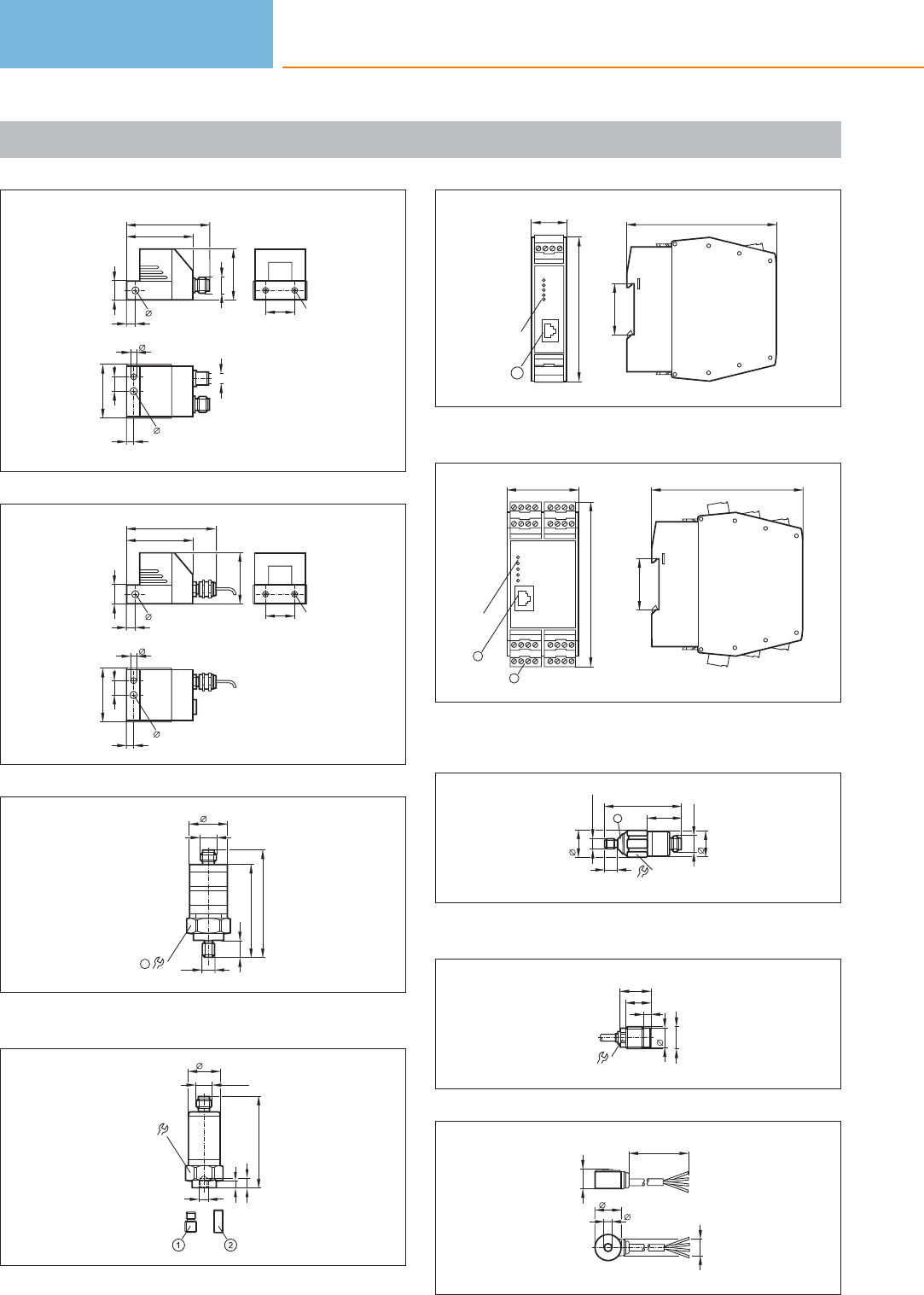
Scale drawings / drawing no. – CAD download: www.ifm.com
3
M12 x1
46,4
58,2
14
65,3
36
20 M5
37,6
5
10
4
5,3
M8x1
4
20 M5
46,4
62,2
14
65,3
36
37,6
5
10
4
5,3
5
63,7
11
M12 x1
27
27
73,1
M8
1
1: tightening torque 15 Nm
6
M12 x1
22
63,25
4,5
1/4''-28 UNF
22
6,5
1: Threaded adapter 1/4“-28 UNF / M8, 2: Threaded adapter 1/4“-
28 UNF, tightening torque 8 Nm
7
103,4
35,5
25,4
100
1
LEDs
1: Ethernet interface
8
50
114
LEDs
2
1
105
35,5
1: Ethernet interface, 2: Combicon plug with screw terminals
(optional)
9
18,5
M8x1,25
M12 x1
17
53
24
17
8
1
1: conical angle = 90°
10
13
M16x1,5
14
22
18
5
11
18
11,5
13,5
L
5,5
Diagnostic systems
480
Product selectors and further information can be found at: www.ifm.com
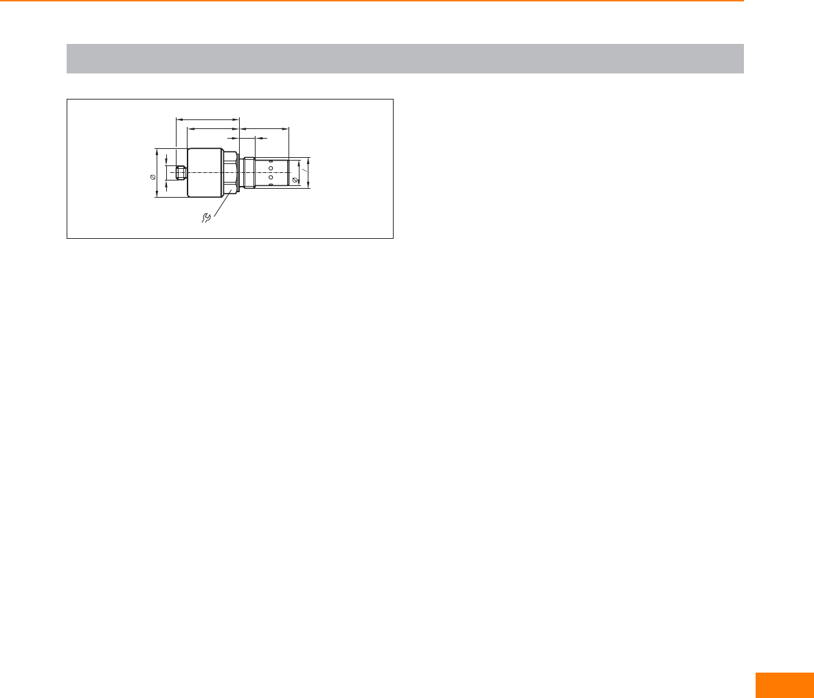
Scale drawings / drawing no. – CAD download: www.ifm.com
12
32
42
M12x1
21,6
54
44 43
14
G4
3
Diagnostic systems
481
Manufacturer-independent
standard.
Worldwide acceptance as a
wiring system.
Communication from the
sensor to the controller.
“Safety at Work” for
safety-related applications.
Intelligent system solutions
for special tasks.
Bus system AS-interface
AS-interface (AS-i = actuator sensor interface) is a manufacturer-independent stan-
dard for the connection of actuators and sensors of the first field level. It is the only
wiring system accepted worldwide. With 20 million slaves installed AS-i has been
tried and tested as a low-cost feeder for all common fieldbuses for many years.
The product range includes AS-i components for different areas from packaging
and conveying via silo applications, machine tools, robotics and automation to the
food industry and mobile vehicles.
Safe
The sophisticated AS-i technology and the extended diagnostic possibilities provide
high reliability and machine uptime.
“Safety at Work” is the extension of the AS-interface by safety-related components.
Safety components up to the highest control category 4 to EN 954-1, SIL 3 to IEC
61508 and EN ISO 13849 - 1 / PL e can be connected to AS-i.
Easy
Due to the standardised system, the low wiring complexity and the quick connec-
tion technology, AS-i enables simple “Plug & Play”. The reduction of terminals leads
to reduced documentation.
Data and energy are jointly transmitted via a two-wire cable. The reverse polarity
protected insulation displacement technology helps avoid errors. The modularity
and the tree structure smoothly fit to the way the plant is put together.
Cost-optimised
It’s the end result that matters: Wiring complexity, documentation and set-up times
are significantly reduced. The decentralisation of the AS-i participants leads to
smaller and less expensive control cabinets. Simple diagnosis and a clear system
design result in high machine uptime and avoid downtimes.
With “Safety at
Work” AS-i also
solves safety-
related tasks.
Reduced cost:
reduced wiring com-
plexity for faster
installation and fewer
error sources.
Bus system AS-interface
482

System overview Page
Controllers, gateways and software 484 - 485
AS-i repeaters 485
AS-i power supplies 485 - 486
Insulation monitors 486
I/O modules for control cabinets 486 - 487
Field modules IP 67 487 - 490
Universal modules 490 - 491
Field modules IP 69K and accessories 491
Module lower parts 491 - 492
Pneumatic and actuator solutions 492 - 493
Safety at Work 494 - 495
AS-i sensors 495 - 496
Combicon connectors 496
Flat cable splitters and accessories 496 - 498
Accessories Safety at Work 498
Accessories lower parts and addressing units 499 - 500
Accessories pneumatic components 500
Accessories RFID 501
AS-i manuals 502
Scale drawings / drawing no. – CAD download: www.ifm.com 502 - 512
Bus system AS-interface
483
Controllers, gateways and software
Type Number
of
AS-i masters
Description Draw-
ing
no.
Order
no.
1SmartLink DP · AS-i gateway / Profibus DP · Full master functions · Graphic display · Housing
materials: aluminium / steel sheet galvanised 1AC1375
2AS-i DP gateway · Full master functions · Graphic display · Profibus DP interface · Housing materials:
aluminium / steel sheet galvanised 2AC1376
1AS-i DP controller E · AS-i PLC with Profibus-DP interface · Full master functions · Graphic display ·
Housing materials: aluminium / steel sheet galvanised 2AC1365
2AS-i DP controller E · AS-i PLC with Profibus-DP interface · Full master functions · Graphic display ·
Housing materials: aluminium / steel sheet galvanised 2AC1366
1
AS-i controller E · AS-i controller freely programmable · Profibus DP interface · Ethernet programming
interface · Full master functions · Graphic display · Housing materials: aluminium / steel sheet
galvanised
2AC1355
2
AS-i controller E · AS-i controller freely programmable · Profibus DP interface · Ethernet programming
interface · Full master functions · Graphic display · Housing for DIN rail mounting · Housing materials:
aluminium / steel sheet galvanised
2AC1356
1AS-i Ethernet / IP Controller E · Full master functions · Graphic display · Housing materials:
aluminium / steel sheet galvanised 3AC1327
2AS-i Ethernet / IP Controller E · Full master functions · Graphic display · Housing materials:
aluminium / steel sheet galvanised 3AC1337
1AS-i DeviceNet controller E · AS-i controller with DeviceNet interface · Full master functions ·
Graphic display · Housing materials: aluminium / steel sheet galvanised 4AC1318
2AS-i DeviceNet controller E · AS-i controller with DeviceNet interface · Full master functions ·
Graphic display · Housing materials: aluminium / steel sheet galvanised 4AC1324
1AS-i CANopen Controller E · AS-i controller with CANopen interface · Full master functions ·
Graphic display · Housing materials: aluminium / steel sheet galvanised 4AC1331
2AS-i CANopen Controller E · AS-i controller with CANopen interface · Full master functions ·
Graphic display · Housing materials: aluminium / steel sheet galvanised 4AC1332
1AS-i controller E · AS-i controller freely programmable · Full master functions · Graphic display ·
Ethernet programming interface · Housing materials: aluminium / steel sheet galvanised 5AC1353
2AS-i controller E · AS-i controller freely programmable · Full master functions · Graphic display ·
Ethernet programming interface · Housing materials: aluminium / steel sheet galvanised 5AC1354
1
AS-i Profinet gateway · AS-i master · Ethernet configuration interface · Profinet RT device class B ·
LCD colour display · Device supply either via 24 V or AS-i (AS-i bus 1) · Housing materials: aluminium
powder coated / steel sheet galvanised / Makrolon
6AC1401
2
AS-i Profinet gateway · AS-i master · Ethernet configuration interface · Profinet RT device class B ·
LCD colour display · Device supply either via 24 V or AS-i (AS-i bus 1) · Housing materials: aluminium
powder coated / steel sheet galvanised / Makrolon
6AC1402
Bus system AS-interface
484
Product selectors and further information can be found at: www.ifm.com
Type Number
of
AS-i masters
Description Draw-
ing
no.
Order
no.
– AS-i data decoupling module · Combicon connection · Housing materials: Makrolon 7 AC1250
–CodeSys for Automation Alliance · Software CD for Controller E German/English version 2.3 ·
Single user licence · For all Windows operating systems –AC0340
AS-i repeaters
Type Description Draw-
ing
no.
Order
no.
AS-i repeater · Extension of the AS-i network by another 100 m · One additional AS-i power supply necessary ·
Combicon connection · PA 6.6 –AC2225
Passive AS-i bus termination · Extension of the cable to a maximum of 200 m without additional repeater ·
Improvement of the signal quality · Monitoring of the supply voltage by means of LEDs –AC1147
eASI-Tester · Local diagnosis of the AS-i network · Creation of test reports for AS-i networks · User-friendly diagnosis
and evaluation via the connected PC 8AC1145
AS-i tuner diagnostic module · Extension of the cable to a maximum of 200 m without additional repeater ·
Monitoring of the message quality · Display of critical states by „traffic light„ LEDs · PBT 9AC1146
AS-i power supplies
Type Output
current
AS-i [A]
Description Draw-
ing
no.
Order
no.
2.8 Power supply · AS-i power supply 115/230 V AC · Integrated data decoupling · Jumper to deactivate
the AS-i communication · NEC Class II Power Source · 85 watts · aluminium / steel sheet galvanised 10 AC1216
2.8
Power supply · AS-i power supply 115/230 V AC · Integrated data decoupling ·
Jumper to deactivate the AS-i communication · NEC Class II Power Source · cage clamps · 85 watts ·
aluminium / steel sheet galvanised
11 AC1226
2.8 Power supply · Integrated data decoupling · AS-i combined power supply 115/230 V AC for 26 V
and AS-i · aluminium 12 AC1209
2.8 Power supply · DC convertor 24 V DC for AS-i system voltage · Integrated data decoupling ·
aluminium 13 AC1207
4
Power supply · AS-i power supply 115/230 V AC · Integrated data decoupling ·
Jumper to deactivate the AS-i communication · Earth fault monitor integrated · 120 Watt · aluminium
/ steel sheet galvanised
14 AC1224
2 x 4 Power supply · AS-i dual power supply 115/230 V AC 2 x AS-i · Integrated data decoupling ·
aluminium 15 AC1212
8Power supply · AS-i power supply 115/230 V AC · Integrated data decoupling ·
Jumper to deactivate the AS-i communication · 240 watts · aluminium / steel sheet galvanised 16 AC1218
Bus system AS-interface
485
You can find scale drawings from page 502
Type Output
current
AS-i [A]
Description Draw-
ing
no.
Order
no.
8Power supply · Three-phase AS-i power supply 400...500 V AC · Integrated data decoupling · Jumper
to deactivate the AS-i communication · 240 watts · aluminium / steel sheet galvanised 17 AC1223
Insulation monitors
Type Description Draw-
ing
no.
Order
no.
AS-i insulation monitor · Detection of asymmetric insulation faults · Screw terminal 18 AC2211
AS-i insulation monitor · Detection of symmetric and asymmetric insulation faults · Screw terminal 18 AC2212
I/O modules for control cabinets
Type Inputs /
outputs
Description Draw-
ing
no.
Order
no.
4 inputs Active AS-i module · String mounting possible · Addressing socket · Version 2.1 with
extended addressing mode · Digital inputs · Combicon connection · PA 19 AC2250
4 inputs
Active AS-i module · String mounting possible · Addressing socket · Input supply from
external PELV voltage source · Version 2.1 with extended addressing mode ·
Digital inputs · Combicon connection · PA
19 AC2254
4 outputs Active AS-i module · String mounting possible · Addressing socket · Version 2.1 ·
Digital outputs · Combicon connection · PA 19 AC2252
4 inputs / 2 outputs Active AS-i module · String mounting possible · Addressing socket · Version 2.1 with
extended addressing mode · Digital inputs · Combicon connection · PA 19 AC2256
4 inputs / 2 outputs
Active AS-i module · String mounting possible · Addressing socket · Input supply from
external PELV voltage source · Version 2.1 with extended addressing mode ·
Digital inputs and outputs · Combicon connection · PA
19 AC2255
4 inputs / 3 outputs Active AS-i module · String mounting possible · Addressing socket · Version 2.1 with
extended addressing mode · Digital inputs and outputs · Combicon connection · PA 19 AC2264
4 inputs / 4 outputs Active AS-i module · String mounting possible · Addressing socket · Version 2.1 ·
Digital inputs and outputs · Combicon connection · PA 19 AC2251
4 inputs / 4 outputs;
bidirectional
Active AS-i module · String mounting possible · Addressing socket · External sensor
supply PELV · Version 2.1 · Digital inputs and outputs · Combicon connection · PA 19 AC2257
4 inputs / 4 outputs;
bidirectional
Active AS-i module · String mounting possible · Addressing socket · External sensor
supply PELV · Version 3.0 with extended addressing mode · Digital inputs and outputs ·
Combicon connection · PA
20 AC2267
4 inputs / 4 outputs Active AS-i module · String mounting possible · Addressing socket · Version 2.1 ·
Combicon connection · PA 6.6 21 AC2258
Bus system AS-interface
486
Product selectors and further information can be found at: www.ifm.com
Type Inputs /
outputs
Description Draw-
ing
no.
Order
no.
4 inputs / 4 outputs Active AS-i module · String mounting possible · Addressing socket · Input supply from
external PELV voltage source · Version 2.1 · Combicon connection · PA 6.6 21 AC2259
4 inputs 4...20 mA
Active AS-i module · AS-i profile S-7.3 · 4 analogue inputs 4...20 mA ·
For the connection of 2-wire, 3-wire or 4-wire sensors · Combicon connector for sensor
connection · PA 6.6
19 AC2216
4 inputs 0...10 V
Active AS-i module · AS-i profile S-7.3 · 4 analogue inputs 0...10 V ·
For the connection of 2-wire, 3-wire or 4-wire sensors · Combicon connector for sensor
connection · PA 6.6
19 AC2217
4 outputs 0...20 mA
Active AS-i module · AS-i profile S-7.3 · 4 analogue outputs 0...20 mA ·
For the connection of 2-wire actuators or 4-wire actuators with separate 24 V supply ·
Combicon connector for actuator connection · PA 6.6
19 AC2218
4 outputs 0...10 V
Active AS-i module · AS-i profile S-7.3 · 4 analogue outputs 0...10 V · For the connection
of 2-wire actuators or 4-wire actuators with separate 24 V supply · Combicon connector
for actuator connection · PA 6.6
19 AC2219
4 inputs Pt100 Active AS-i module · 4 analogue inputs temperature Pt100 · AS-i profile S-7.3 ·
Combicon connection · PBT 19 AC2220
4 inputs / 4 outputs;
bidirectional Active AS-i module · PCB size 105 x 45 x 17 mm · Digital inputs and outputs 22 AC2709
4 inputs / 3 outputs;
bidirectional
Active AS-i module · AS-i slave with extended addressing mode · PCB size 105 x 45 x 17
mm · Digital inputs and outputs 22 AC2739
2 inputs / 1 LED output Active AS-i module · Only suited for mechanical contacts 23 AC2729
3 inputs / 3 outputs Active AS-i module · AS-i version 2.1 with extended addressing mode 24 AC2731
Field modules IP 67
Type Inputs /
outputs
Description Draw-
ing
no.
Order
no.
4-way splitter box ClassicLine splitter box module · Three orientations of the flat cable are possible · AS-i and
AUX splitter box for the connection of intelligent sensors/actuators · Sockets M12 x 1 · PA 25 AC5200
4 inputs Active ClassicLine module · Addressing socket · Three orientations of the flat c
able are possible · Digital inputs · Sockets M12 x 1 · PA 25 AC5205
4 inputs
Active ClassicLine module · Version 2.11 and 3.0 with extended addressing mode ·
Addressing socket · Three orientations of the flat cable are possible · Digital inputs ·
Sockets M12 x 1 · PA
25 AC5215
3 outputs
Active ClassicLine module · Version 2.11 and 3.0 with extended addressing mode ·
Addressing socket · Three orientations of the flat cable are possible · Digital outputs ·
Sockets M12 x 1 · PA
25 AC5203
4 outputs Active ClassicLine module · Addressing socket · Three orientations of the flat cable are
possible · Digital outputs · Sockets M12 x 1 · PA 25 AC5208
Bus system AS-interface
487
You can find scale drawings from page 502
Type Inputs /
outputs
Description Draw-
ing
no.
Order
no.
4 outputs Active ClassicLine module · Addressing socket · Three orientations of the flat cable are
possible · Digital outputs · Sockets M12 x 1 · PA 25 AC5213
2 outputs / 2 inputs
Active ClassicLine module · Version 2.11 and 3.0 with extended addressing mode ·
Addressing socket · Three orientations of the flat cable are possible · Digital outputs and
inputs · Sockets M12 x 1 · PA
25 AC5214
2 inputs / 2 outputs Active ClassicLine module · Addressing socket · Three orientations of the flat cable are
possible · Digital inputs and outputs (2 A) · Sockets M12 x 1 · PA 25 AC5211
8 digital inputs (2 Slaves)
Active ClassicLine module · Version 2.11 and 3.0 with extended addressing mode ·
Addressing socket · Three orientations of the flat cable are possible · Digital inputs ·
Sockets M12 x 1 · PA
26 AC5210
4 inputs / 4 outputs;
bidirectional
Active ClassicLine module · Addressing socket · Three orientations of the flat cable are
possible · Digital inputs and outputs · Sockets M12 x 1 · PA 26 AC5209
4 inputs / 4 outputs;
bidirectional
Active ClassicLine module · Addressing socket · Three orientations of the flat cable are
possible · Digital inputs and outputs (2 A) · Sockets M12 x 1 · PA 26 AC5212
4 inputs / 3 outputs;
bidirectional
Active ClassicLine module · Addressing socket · Three orientations of the flat cable are
possible · Version 2.11 and 3.0 with extended addressing mode · Digital inputs and
outputs · Sockets M12 x 1 · PA
26 AC5204
4 inputs / 4 outputs;
bidirectional
Active ClassicLine module · Only for operation with AS-i masters with the profile M4 ·
Addressing socket · Three orientations of the flat cable are possible · Version 3.0 with
extended addressing mode · Digital inputs and outputs · Sockets M12 x 1 · PA
26 AC5235
4 inputs / 4 outputs;
bidirectional
Active ClassicLine module · Addressing socket · Three orientations of the flat cable are
possible · Version 3.0 with extended addressing mode · Digital inputs and outputs (2 A) ·
Sockets M12 x 1 · PA
26 AC5236
2 pushbuttons / 2 LED displays Active module upper parts AS-i illuminated pushbutton module · Power supply via AS-i
cable · A/B slave · Pushbutton functions: normally open / normally closed · PBT –AC2088
2 pushbuttons / 2 LED displays Active module upper parts AS-i illuminated pushbutton module · Power supply via AS-i
cable · Colour inserts changeable · PBT 27 AC2086
1 pushbutton / 1 key-operated
switch / 1 LED display
Active module upper part AS-i illuminated pushbutton module with key-operated switch ·
Power supply via AS-i cable · Illuminated pushbutton colour and cover upper parts
selectable · Version 2.1 with extended addressing mode · PBT
27 AC2087
4 inputs 4...20 mA
Active ClassicLine module · AS-i profile S-7.3 · 4 analogue inputs 4...20 mA · IR
addressing possible · For the connection of 2-wire, 3-wire or 4-wire sensors ·
Sockets M12 x 1 · PBT
28 AC2516
4 inputs 0...10 V Active ClassicLine module · AS-i profile S-7.3 · 4 analogue inputs 0...10 V · IR addressing
possible · For the connection of 2-wire, 3-wire or 4-wire sensors · Sockets M12 x 1 · PBT 28 AC2517
4 outputs 0...20 mA Active ClassicLine module · AS-i profile S-7.3 · IR addressing possible · 4 analogue outputs
0...20 mA · For the connection of 2-wire actuators · Sockets M12 x 1 · PBT 28 AC2518
4 outputs 0...10 V Active ClassicLine module · AS-i profile S-7.3 · 4 analogue outputs 0...10 V · IR addressing
possible · For the connection of 2-wire actuators · Sockets M12 x 1 · PBT 28 AC2519
4 inputs Pt100 Active ClassicLine module · 4 analogue inputs temperature Pt100 · AS-i profile S-7.3 ·
IR addressing possible · Sockets M12 x 1 · PBT 28 AC2520
Bus system AS-interface
488
Product selectors and further information can be found at: www.ifm.com
Type Inputs /
outputs
Description Draw-
ing
no.
Order
no.
2 inputs 4...20 mA
Active ClassicLine module · 2 analogue inputs 4...20 mA · For the connection of 2-wire
and 3-wire sensors · Addressing socket · Three orientations of the flat cable are possible ·
PA
25 AC5222
2 inputs 4...20 mA
Active ClassicLine module · 2 analogue inputs 4...20 mA · For the connection of 2-wire
and 4-wire sensors · Electrical isolation · Addressing socket · Three orientations of the flat
cable are possible · PA
25 AC5223
2 outputs / 2 inputs
Active ClassicLine module · Version 2.11 and 3.0 with extended addressing mode ·
Addressing socket · Three orientations of the flat cable are possible · Outputs supplied
from AS-i · Digital outputs and inputs · Sockets M12 x 1 · PA
25 AC5224
2 IO-Link ports
Active ClassicLine module · 2 IO-Link ports · For the connection of IO-Link sensors and
actuators, binary sensors and binary actuators · Addressing socket · Three orientations of
the flat cable are possible · PA
25 AC5225
4 inputs
Active ClassicLine module · Addressing socket · Three orientations of the flat cable are
possible · ATEX approval · Group II, category 3D · Only in conjunction with impact
protection housing E7000A or equivalent protection · Digital inputs · Sockets M12 x 1 ·
PA
25 AC505A
4 inputs
Active ClassicLine module · Version 2.11 and 3.0 with extended addressing mode ·
Addressing socket · Three orientations of the flat cable are possible · ATEX approval ·
Group II, category 3D · Only in conjunction with impact protection housing E7000A or
equivalent protection · Digital inputs · Sockets M12 x 1 · PA
25 AC515A
4 outputs
Active ClassicLine module · Addressing socket · Three orientations of the flat cable are
possible · ATEX approval · Group II, category 3D · Only in conjunction with impact
protection housing E7000A or equivalent protection · Digital outputs · Sockets M12 x 1 ·
PA
25 AC508A
2 inputs / 2 outputs
Active ClassicLine module · Addressing socket · Three orientations of the flat cable are
possible · ATEX approval · Group II, category 3D · Only in conjunction with impact
protection housing E7000A or equivalent protection · Digital inputs and outputs (2 A) ·
Sockets M12 x 1 · PA
25 AC507A
2 outputs / 2 inputs
Active ClassicLine module · Version 2.11 and 3.0 with extended addressing mode ·
Addressing socket · Three orientations of the flat cable are possible · ATEX approval ·
Group II, category 3D · Only in conjunction with impact protection housing E7000A or
equivalent protection · Digital outputs and inputs · Sockets M12 x 1 · PA
25 AC514A
2 inputs 4...20 mA
Active AS-i module · 2 analogue inputs 4...20 mA · For the connection of 2-wire and 3-
wire sensors · Addressing socket · Three orientations of the flat cable are possible · ATEX
approval · Group II, category 3D · Only in conjunction with impact protection housing
E7000A or equivalent protection · PA
25 AC522A
2 inputs Active AS-i module 25 AC5230
4 inputs / 4 outputs;
bidirectional
Active ClassicLine module · Only for operation with AS-i masters with the profile M4 ·
Addressing socket · Version 3.0 with extended addressing mode · ATEX approval · Group
II, category 3D · Only in conjunction with impact protection housing E7000A or equivalent
protection · Digital inputs and outputs · Sockets M12 x 1 · PA
26 AC535A
4-way splitter box
Passive compact module · AS-i splitter box for the connection of intelligent
sensors/actuators · Sockets M12 x 1 · PA 6.6 / socket: brass nickel-plated / threaded
inserts in the lower part: brass nickel-plated / O-Ring : Viton
29 AC2413
Bus system AS-interface
489
You can find scale drawings from page 502
4 inputs
Active ClassicLine module · Version 2.11 and 3.0 with extended addressing mode ·
Addressing socket · Three orientations of the flat cable are possible · Digital inputs ·
Sockets M12 x 1 · PA
25 AC5245
4 inputs / 3 outputs;
bidirectional
Active ClassicLine module · Addressing socket · Three orientations of the flat cable are
possible · Version 2.11 and 3.0 with extended addressing mode · Digital inputs and
outputs · Sockets M12 x 1 · PA
26 AC5274
4 inputs / 4 outputs;
bidirectional
Active ClassicLine module · Only for operation with AS-i masters with the profile M4 ·
Addressing socket · Three orientations of the flat cable are possible · Version 3.0 with
extended addressing mode · Digital inputs and outputs · Sockets M12 x 1 · PA
26 AC5275
4 inputs / 3 outputs;
bidirectional
Active ClassicLine module · Version 2.11 and 3.0 with extended addressing mode ·
Addressing socket · Three orientations of the flat cable are possible · inputs externally
supplied · Sockets M12 x 1 · PA
26 AC5292
Type Inputs /
outputs
Description Draw-
ing
no.
Order
no.
4 outputs
Active CompactLine module · IR addressing possible · Digital outputs · Sockets M12 x 1 ·
PA / socket: brass nickel-plated / threaded inserts in the lower part: brass nickel-plated /
O-Ring : Viton
32 AC2417
2 inputs / 2 outputs
Active CompactLine module · IR addressing possible · Digital inputs and outputs · Sockets
M12 x 1 · PA / socket: brass nickel-plated / threaded inserts in the lower part: brass nickel-
plated / O-Ring : Viton
32 AC2411
2 inputs / 2 outputs
Active CompactLine module · IR addressing possible · Digital inputs and outputs · Sockets
M12 x 1 · PA / socket: brass nickel-plated / threaded inserts in the lower part: brass nickel-
plated / O-Ring : Viton
32 AC2458
4 inputs / 4 outputs;
bidirectional
Active CompactLine module · Digital inputs and outputs · Sockets M12 x 1 · PA / socket:
brass nickel-plated / threaded inserts in the lower part: brass nickel-plated / O-Ring : Viton 33 AC2465
4 inputs / 4 outputs;
bidirectional
Active CompactLine module · IR addressing possible · Digital inputs and outputs · Sockets
M12 x 1 · PA / socket: brass nickel-plated / threaded inserts in the lower part: brass nickel-
plated / O-Ring : Viton
34 AC2412
4 inputs / 4 outputs;
bidirectional
Active CompactLine module · IR addressing possible · Digital inputs and outputs · Sockets
M12 x 1 · PA / socket: brass nickel-plated / threaded inserts in the lower part: brass nickel-
plated / O-Ring : Viton
34 AC2459
4 inputs / 4 outputs;
bidirectional
Active CompactLine module · IR addressing possible · External sensor supply PELV · Digital
inputs and outputs · Sockets M12 x 1 · PA / socket: brass nickel-plated / threaded inserts
in the lower part: brass nickel-plated / O-Ring : Viton
34 AC2466
4 inputs / 4 outputs;
bidirectional
Active CompactLine module · IR addressing possible · Digital inputs and outputs · Sockets
M12 x 1 · PA / socket: stainless steel 316L / 1.4404 / threaded inserts in the lower part:
stainless steel 316L / 1.4404 / screws in the lower part: stainless steel
34 AC2452
4 inputs Active AS-i module · Version 2.1 with extended addressing mode · Digital inputs · Sockets
M8 x 1 · PA / O-ring: FPM 35 AC2480
Universal modules
Type Inputs /
outputs
Description Draw-
ing
no.
Order
no.
4 inputs Active module upper part AS-universal module · Digital inputs · Connection via cage
clamps · PBT / stainless steel 36 AC2032
4 inputs / 4 outputs;
bidirectional
Active module upper part AS-universal module · Digital inputs and outputs · Connection
via cage clamps · PBT / stainless steel 37 AC2035
Bus system AS-interface
490
Product selectors and further information can be found at: www.ifm.com
4 inputs
Active CompactLine module · IR addressing possible · Digital inputs · Sockets M12 x 1 · PA
/ socket: brass nickel-plated / threaded inserts in the lower part: brass nickel-plated / O-
Ring : Viton
30 AC2410
4 inputs
Active CompactLine module · IR addressing possible · Version 2.11 and 3.0 with extended
addressing mode · Digital inputs · Sockets M12 x 1 · PA / socket: brass nickel-plated /
threaded inserts in the lower part: brass nickel-plated / O-Ring : Viton
30 AC2457
4 inputs
Active CompactLine module · IR addressing possible · high-grade stainless steel · Digital
inputs · Sockets M12 x 1 · PA / socket: stainless steel 316L / 1.4404 / threaded inserts in
the lower part: stainless steel 316L / 1.4404 / screws in the lower part: stainless steel
30 AC2451
4 inputs Active CompactLine module · Digital inputs · Sockets M12 x 1 · PA / socket: brass nickel-
plated / threaded inserts in the lower part: brass nickel-plated / O-Ring : Viton 31 AC2464
2 inputs 4...20 mA Active AS-i module IP 65 · 2 analogue inputs 4...20 mA · AS-i profile S-7.3 · For the
connection of 2-wire, 3-wire or 4-wire sensors · Connection via cage clamps · PBT 38 AC2616
2 inputs 0...10 V Active AS-i module IP 65 · 2 analogue inputs 0...10 V · AS-i profile S-7.3 · For the
connection of 2-wire, 3-wire or 4-wire sensors · Connection via cage clamps · PBT 38 AC2617
2 outputs 0...20 mA
Active AS-i module IP 65 · 2 analogue outputs 0...20 mA · AS-i profile S-7.3 · For the
connection of 2-wire actuators or 4-wire actuators with separate 24 V supply ·
Connection via cage clamps · PBT
38 AC2618
2 outputs 0...10 V
Active AS-i module IP 65 · 2 analogue outputs 0...10 V · AS-i profile S-7.3 · For the
connection of 2-wire actuators or 4-wire actuators with separate 24 V supply ·
Connection via cage clamps · PBT
38 AC2619
Type Inputs /
outputs
Description Draw-
ing
no.
Order
no.
4 inputs Pt100 Active AS-i module IP 65 · 4 analogue inputs temperature Pt100 · AS-i profile S-7.3 ·
Connection via cage clamps · PBT 37 AC2620
Field modules IP 69K and accessories
Type Inputs /
outputs
Description Draw-
ing
no.
Order
no.
4 inputs / 3 outputs
Active ProcessLine module · Version 2.1 with extended addressing mode · Protection
rating IP 69K · high-grade stainless steel · Digital inputs and outputs · Sockets M12 x 1 ·
high-grade stainless steel / Makrolon / O-ring: EPDM
39 AC2904
8 digital inputs (2 Slaves)
Active ProcessLine module · Version 2.1 with extended addressing mode · Protection
rating IP 69K · high-grade stainless steel · Digital inputs · Sockets M12 x 1 · high-grade
stainless steel / Makrolon / O-ring: EPDM
40 AC2910
8-way splitter box
Passive splitter box AS-i ProcessLine · Protection rating IP 69K · high-grade stainless steel ·
AS-i and AUX splitter box for the connection of intelligent sensors/actuators · Sockets
M12 x 1 · high-grade stainless steel / Makrolon
41 AC2900
4 inputs 4...20 mA Active AS-i module · 4 analogue inputs 4...20 mA · For the connection of 2-wire and 3-
wire sensors · Threaded bush: stainless steel 316L / 1.4404 / Makrolon / O-ring: EPDM 42 AC2916
AS-i / 24 V FC splitter · V4A · AS-i voltage and external auxiliary voltage via the M12 socket · Metal
parts: stainless steel 316L / 1.4404 / Blanks: FPM / O-ring: EPDM –E70354
AS-i FC splitter · AS-i voltage via M12 socket · Metal parts: stainless steel 316L / 1.4404 / O-
ring: EPDM / socket: PP GF30 / blade seal: TPE –E70454
AS-i / 24 V FC splitter · Metal parts: stainless steel 316L / 1.4404 / Blanks: FPM / O-ring: EPDM – E70377
Module lower parts
Type Inputs /
outputs
Description Draw-
ing
no.
Order
no.
FC coupling module Module lower part flat cable · AS-i interface to module upper part · Quick mounting
technology for AS-i flat cable · PBT 43 AC5000
Bus system AS-interface
491
You can find scale drawings from page 502
Type Inputs /
outputs
Description Draw-
ing
no.
Order
no.
FC-E coupling module with
external power supply
FC-E coupling module · stainless steel · AS-i interface to module upper part · Quick
mounting technology for AS-i flat cable · PBT / stainless steel 43 AC5015
SC coupling module Module lower part screw connection · AS-i interface to module upper part · Screw
terminal · PBT 45 AC5031
Pneumatic and actuator solutions
Type Inputs /
outputs
Description Draw-
ing
no.
Order
no.
2 inputs / 2 outputs; AirBox
supply via AS-i
AS-i AirBox · 2 x 3/2-way slide valves free from overlapping · Three orientations of the flat
cable are possible · AS-i flat cable connection · Addressing socket · AS-i profile S-3.F.F · PA
/ POM
46 AC5227
4 inputs / 2 outputs; AirBox
supply via AS-i
AS-i AirBox · 2 x 3/2-way slide valves free from overlapping · Three orientations of the flat
cable are possible · AS-i flat cable connection · Version 2.11 and 3.0 with extended
addressing mode · Addressing socket · PA / POM
46 AC5228
4 inputs / 2 outputs; AirBox
supply via external 24 V DC
AS-i AirBox · 2 x 3/2-way slide valves free from overlapping · Three orientations of the flat
cable are possible · AS-i flat cable connection · Version 2.11 and 3.0 with extended
addressing mode · Addressing socket · PA / POM
46 AC5243
4 inputs / 1 output ; AirBox
supply via AS-i
AS-i AirBox · 5/2-way slide valve free from overlapping · Three orientations of the flat
cable are possible · AS-i flat cable connection · Version 2.11 and 3.0 with extended
addressing mode · Addressing socket · PA / POM
47 AC5246
4 inputs / 1 output; AirBox
supply via external voltage 24
V DC
AS-i AirBox · 5/2-way slide valve free from overlapping · Three orientations of the flat
cable are possible · AS-i flat cable connection · Version 2.11 and 3.0 with extended
addressing mode · Addressing socket · PA / POM
47 AC5249
4 inputs / 2 outputs; AirBox
supply via AS-i
AS-i AirBox · 5/2-way bistable slide valve free from overlapping · Three orientations of the
flat cable are possible · AS-i flat cable connection · Version 2.11 and 3.0 with extended
addressing mode · Addressing socket · PA / POM
46 AC5251
4 inputs / 2 outputs; AirBox
supply via external 24 V DC
AS-i AirBox · 5/2-way bistable slide valve free from overlapping · Three orientations of the
flat cable are possible · AS-i flat cable connection · Version 2.11 and 3.0 with extended
addressing mode · Addressing socket · PA / POM
46 AC5253
4 inputs / 2 outputs; AirBox
supply via AS-i
AS-i AirBox · 5/3-way slide valve free from overlapping · Three orientations of the flat
cable are possible · AS-i flat cable connection · Version 2.11 and 3.0 with extended
addressing mode · Addressing socket · PA / POM
46 AC5270
4 inputs / 2 outputs; AirBox
supply via external 24 V DC
AS-i AirBox · 5/3-way slide valve free from overlapping · Three orientations of the flat
cable are possible · AS-i flat cable connection · Addressing socket · Version 2.11 and 3.0
with extended addressing mode · PA / POM
46 AC5271
Bus system AS-interface
492
Product selectors and further information can be found at: www.ifm.com
FC-E coupling module with
external power supply
FC-E coupling module · AS-i interface to module upper part · Quick mounting technology
for AS-i flat cable · PBT 43 AC5003
FC coupling module Module lower part flat cable · with addressing plug · AS-i interface to module upper part ·
Quick mounting technology for AS-i flat cable · PBT 44 AC5010
FC-E coupling module with
external power supply
FC-E coupling module · with addressing plug · AS-i interface to module upper part · Quick
mounting technology for AS-i flat cable · PBT 44 AC5011
FC coupling module Module lower part flat cable · stainless steel · AS-i interface to module upper part · Quick
mounting technology for AS-i flat cable · PBT / stainless steel 43 AC5014
Type Inputs /
outputs
Description Draw-
ing
no.
Order
no.
4 inputs / 2 outputs; AirBox
supply via AS-i
AS-i AirBox · 2 x 3/2-way slide valves free from overlapping · Three orientations of the flat
cable are possible · Digital inputs · Addressing socket · AS-i profile S-7.F.F · Versions 2.11
and 3.0 · ATEX approval · Group II, category 3D · Only in conjunction with impact
protection housing E7000A or equivalent protection · PA / POM
46 AC542A
4 inputs / 2 outputs; AirBox
supply via AS-i
AS-i AirBox · 2 x 3/2-way slide valves free from overlapping · Three orientations of the flat
cable are possible · AS-i flat cable connection · Version 2.11 and 3.0 with extended
addressing mode · Addressing socket · ATEX approval · Group II, category 3D · Only in
conjunction with impact protection housing E7000A or equivalent protection · PA / POM
46 AC528A
4 inputs / 1 output ; AirBox
supply via AS-i
AS-i AirBox · 5/2-way slide valve free from overlapping · Three orientations of the flat
cable are possible · AS-i flat cable connection · Version 2.11 and 3.0 with extended
addressing mode · Addressing socket · ATEX approval · Group II, category 3D · Only in
conjunction with impact protection housing E7000A or equivalent protection · PA / POM
47 AC546A
2 inputs / 1 output; AirBox
supply via AS-i
AS-i AirBox · 5/2-way slide valve free from overlapping · Three orientations of the flat
cable are possible · Digital inputs · Addressing socket · AS-i profile S-3.F.F · ATEX approval
· Group II, category 3D · Only in conjunction with impact protection housing E7000A or
equivalent protection · PA / POM
46 AC246A
4 inputs / 2 outputs; AirBox
supply via AS-i
AS-i AirBox · 5/2-way bistable slide valve free from overlapping · Three orientations of the
flat cable are possible · AS-i flat cable connection · Version 2.11 and 3.0 with extended
addressing mode · Addressing socket · ATEX approval · Group II, category 3D · Only in
conjunction with impact protection housing E7000A or equivalent protection · PA / POM
46 AC551A
4 inputs / 2 outputs; AirBox
supply via AS-i
AS-i AirBox · 5/3-way slide valve free from overlapping · Three orientations of the flat
cable are possible · AS-i flat cable connection · Version 2.11 and 3.0 with extended
addressing mode · Addressing socket · ATEX approval · Group II, category 3D · Only in
conjunction with impact protection housing E7000A or equivalent protection · PA / POM
46 AC570A
2 x 2 inputs / 2 outputs
AS-i AirBox · Connection to the pneumatic system by tube fittings · Manual override by
pressing/releasing or pressing/turning/locking · 2 x 2 digital inputs · 2 pneumatic outputs ·
Sockets M12 x 1 · housing: PBT / Metal parts: stainless steel / sealing: Viton
48 AC2055
2 inputs / 1 output NO/NC
selectable (monostable)
AS-i AirBox · Connection to the pneumatic system by tube fittings · 1 x 2 or 2 x 1 digital
inputs · 1 pneumatic output (NO/NC selectable) · Sockets M12 x 1 · housing: PBT / Metal
parts: stainless steel / sealing: Viton
49 AC2057
2 inputs / 1 output Dual sensor for actuator feedback · Sensing range 4 mm · 2 inductive position sensors
integrated · Version 2.1 · Connector · PBT / PC / plug / socket stainless steel 50 AC2310
1 x 2 inputs Dual sensor · Sensing range 4 mm · 2 inductive position sensors integrated · Version 2.1
with extended addressing mode · Connector · PBT / connector housing: stainless steel 51 AC2315
2 inputs / 1 output
Dual sensor for actuator feedback · Sensing range 4 mm · 2 inductive position sensors
integrated · Version 2.1 with extended addressing mode · Connector · PBT / PC / plug /
socket stainless steel
50 AC2316
2 inputs / 2 outputs
Dual sensor for actuator feedback · Sensing range 4 mm · 2 inductive position sensors
integrated · Version 2.1 with extended addressing mode · Connector · PBT / PC / plug /
socket stainless steel
50 AC2317
1 x 2 inputs
Dual sensor · Sensing range 4 mm · 2 inductive position sensors integrated · Version 2.1
with extended addressing mode · ATEX approval · Group II, category 3D · Connector · PBT
/ connector housing: stainless steel
51 AC315A
2 inputs / 1 output
Dual sensor for actuator feedback · Sensing range 4 mm · 2 inductive position sensors
integrated · Version 2.1 with extended addressing mode · ATEX approval · Group II,
category 3D · Connector · PBT / PC / plug / socket stainless steel
50 AC316A
2 inputs / 2 outputs
Dual sensor for actuator feedback · Sensing range 4 mm · 2 inductive position sensors
integrated · Version 2.1 with extended addressing mode · ATEX approval · Group II,
category 3D · Connector · PBT / PC / plug / socket stainless steel
50 AC317A
3 inputs / 4 outputs MOVIMOT module for SEW drives · Digital inputs and outputs 52 AC1151
2 inputs / 1 serial interface MOVIMOT module for SEW drives · Easy selection of preset frequencies · RS-485 interface
· Digital inputs and outputs · Sockets M12 x 1 · PBT 53 AC1150
Bus system AS-interface
493
You can find scale drawings from page 502
Safety at Work
Type Description Draw-
ing
no.
Order
no.
AS-i safety monitor · Basic version · 1-channel · Control category 4 to EN954-1, IEC 61508 / SIL 3 and EN ISO 13849 - 1
PL e · Configuration and setup by configuration software ASIMON · Screw terminal · polyamide black 54 AC001S
AS-i safety monitor · Basic version · 2-channel · Control category 4 to EN954-1, IEC 61508 / SIL 3 and EN ISO 13849 - 1
PL e · Configuration and setup by configuration software ASIMON · Screw terminal · polyamide black 54 AC002S
AS-i safety monitor · Extended functionality · 1-channel · Control category 4 to EN954-1, IEC 61508 / SIL 3 and EN ISO
13849 - 1 PL e · Configuration and setup by configuration software ASIMON · Screw terminal 54 AC003S
AS-i safety monitor · Extended functionality · 2-channel · Control category 4 to EN954-1, IEC 61508 / SIL 3 and EN ISO
13849 - 1 PL e · Configuration and setup by configuration software ASIMON · Screw terminal 54 AC004S
AS-i safety monitor · Extended functionality and integrated safe slave for triggering a safe AS-i output · 1-channel ·
Control category 4 to EN954-1, IEC 61508 / SIL 3 and EN ISO 13849 - 1 PL e · Configuration and setup by configuration
software ASIMON V3.0 · Screw terminal · polyamide black
55 AC031S
AS-i safety monitor · Extended functionality and integrated safe slave for triggering a safe AS-i output · 2-channel ·
Control category 4 to EN954-1, IEC 61508 / SIL 3 and EN ISO 13849 - 1 PL e · Configuration and setup by configuration
software ASIMON V3.0 · Screw terminal
55 AC032S
Safe active AS-i module · Performance Level e to EN ISO 13849-1 et IEC 61508 / SIL 3 for the connection of mechanical
contacts · Combicon connection 56 AC009S
Safe active AS-i output module · Control category 4 to EN954-1, IEC 61508 / SIL 3 and EN ISO 13849 - 1 PL e · for the
safe triggering of actuators · Combicon connection 20 AC030S
Safe active AS-i module · Connection via M12x1 sockets or cage clamps · Control category 4 according to EN954-1 and
IEC 61508 / SIL 3 · Version 2.1 · For connection of an electro-sensitive protective equipment (ESPE) type 4 to EN 61496-1 ·
AS-i interface to FC-E lower parts
57 AC007S
Safe AS-i input module · IR addressing possible · AS-i version 2.1 · Performance Level e to EN ISO 13849-1 for the
connection of mechanical contacts · Sockets M12 x 1 · PBT 58 AC005S
Safe active AS-i ClassicLine module · IR addressing possible · AS-i version 2.1 · Category 4 to EN954-1 and IEC 61508 / SIL
3 for connection of mechanical contacts · Sockets M12 x 1 59 AC006S
Illuminated E-STOP · front mounting · reset by turning · 2 NC contacts / 1 red LED · fool-proof E-STOP to EN ISO 13850 /
EN 418 –E7007S
Illuminated E-STOP with integrated AS-i connection · Connector M12 x 1 · AS-i interface via AS-i flat cable IP 67 · fool-
proof E-STOP to EN ISO 13850 / EN 418 · Pull to reset 60 AC010S
Key-release E-STOP with integrated AS-i connection · Connector M12 x 1 · AS-i interface via AS-i flat cable IP 67 · fool-
proof E-STOP to EN ISO 13850 / EN 418 · Reset by key operation 61 AC011S
safe AS-i e-stop operating unit with integrated AS-i connection · AS-i interface via M12 x 1 connector · fool-proof E-STOP
to EN ISO 13850 / EN 418 · Pull to reset · interchangeable button inserts 62 AC012S
Bus system AS-interface
494
Product selectors and further information can be found at: www.ifm.com
Type Description Draw-
ing
no.
Order
no.
Safe active AS-i ClassicLine module · AS-i version 2.1 · IR addressing possible · Control category 4 according to EN954-1 ·
For the connection of fail-safe inductive sensors of the control category 4 · Sockets M12 x 1 –AC016S
AS-i safety PCB · Connection of mechanical contact and LED components · Certification according to EN 954-1 / category
4 and IEC 61508 / SIL 3 23 AC015S
Fail-safe inductive sensor · GIMC-4030-US · M12 connector · PPE / diecast zinc · Complies with the requirements: ISO
13849-1: category 4 · ISO 13849-1: PL e · IEC 61508: SIL 3 63 GM504S
Fail-safe inductive sensor · GIMC-4035-US · M12 connector · PPE / diecast zinc · Complies with the requirements: ISO
13849-1: category 4 · ISO 13849-1: PL e · IEC 61508: SIL 3 63 GM505S
Fail-safe inductive sensor · GIGA-4015-US/V4A · M18 x 1 · M12 connector · high-grade stainless steel / PBT · Complies
with the requirements: ISO 13849-1: category 4 · ISO 13849-1: PL e · IEC 61508: SIL 3 64 GG505S
Fail-safe inductive sensor · GIIA-4030-US/V4A · M30 x 1.5 · M12 connector · PEEK / high-grade stainless steel / O-ring:
EPDM · Complies with the requirements: ISO 13849-1: category 4 · ISO 13849-1: PL e · IEC 61508: SIL 3 65 GI505S
AS-i sensors
Type Description Draw-
ing
no.
Order
no.
Inductive sensor · IFK2004BASI/M/US · M12 x 1 · Sensing range 4 mm · gold-plated contacts · Connector · V4A / active
face: LCP uncoloured 66 IFC247
Inductive sensor · IGK2008BASI/M/US · M18 x 1 · Sensing range 8 mm · gold-plated contacts · Connector · threaded
sleeve: V4A / active face: LCP uncoloured / lock nuts: brass 67 IGC234
Inductive sensor · IGK2012-ASI/M/US · M18 x 1 · Sensing range 12 mm · gold-plated contacts · Connector · threaded
sleeve: V4A / active face: LCP uncoloured / lock nuts: brass 68 IGC235
Inductive sensor · IIK2014BASI/M/US · M30 x 1.5 · Sensing range 14 mm · gold-plated contacts · Connector · V4A / active
face: LCP uncoloured 69 IIC220
Inductive sensor · IIK2022-ASI/M/US · M30 x 1.5 · Sensing range 22 mm · gold-plated contacts · Connector · V4A / active
face: LCP uncoloured 70 IIC221
Inductive sensor · IMC2015-ASI/US · Sensing range 15 mm · Sensing face in 5 positions selectable · Connector · PBT / PPE 71 IM5118
Electronic pressure sensor · Analogue value (16 bit value incl. sign) · AS-i profile S-7.3 · Measuring range 0...400 bar ·
Connector · stainless steel / PA 72 PPA020
Electronic pressure sensor · Analogue value (16 bit value incl. sign) · AS-i profile S-7.3 · Measuring range 0...10 bar ·
Connector · stainless steel / PA 73 PPA024
Bus system AS-interface
495
You can find scale drawings from page 502
Type Description Draw-
ing
no.
Order
no.
Read/write head · DTSLF AARWASUS01 · with integrated AS-i slave profile 7.4 · M12 connector · PA 74 DTA100
Read head · DTSLF AAROASUS01 · with integrated AS-i slave profile 7.3 · M12 connector · PA 74 DTA101
Read/write head · DTSLF MCRWASUS01 · with integrated AS-i slave profile 7.4 · M12 connector ·
Sensing face in 5 positions selectable · PA 71 DTA200
Read head · DTSLF MCROASUS01 · with integrated AS-i slave profile 7.3 · M12 connector ·
Sensing face in 5 positions selectable · PA 71 DTA201
Read/write head · DTSLF DCRWASUS01 · with integrated AS-i slave profile 7.4 · M12 connector ·
housing: PPE / Metal parts: diecast zinc / brass nickel-plated 75 DTA300
Combicon connectors
Type Description Order
no.
Combicon connector · with screw terminals 4-pole · Housing materials: current carrying parts: copper alloy tin-plated ·
Pack quantity: 6 E70230
Combicon connector · with screw terminals 4-pole · Housing materials: current carrying parts: copper alloy tin-plated ·
Pack quantity: 100 E70231
Combicon connector · with cage clamps 4 poles · Housing materials: current carrying parts: copper alloy tin-plated ·
Pack quantity: 6 E70232
Combicon connector · with cage clamps 4 poles · Housing materials: current carrying parts: copper alloy tin-plated ·
Pack quantity: 100 E70233
Combicon connector · QIC · with insulation displacement terminals 4-pole (0.75...1 mm2) · Housing materials: current carrying parts:
copper alloy tin-plated · Pack quantity: 6 E70236
Flat cable splitters and accessories
Type Description Order
no.
PAAS M12 · AS-i and external voltage via M12 socket · Sockets M12 x 1 · Housing materials: PA 6.6 / socket housing: stainless steel
316L / 1.4404 / screws: stainless steel 316L / 1.4404 / O-Ring : Viton E70188
PAAS splitter box · Distribution of the AS-i voltage or the external 24 V supply · Housing materials: PA / screws: stainless steel 316L /
1.4404 / sealing: NBR E70200
Bus system AS-interface
496
Product selectors and further information can be found at: www.ifm.com
Type Description Order
no.
FC splitter · Distribution of the AS-i voltage or the external 24 V supply · Housing materials: PA 6 GF35 Grivory E70381
FC splitter · AS-i voltage via M12 socket · Housing materials: Metal parts: stainless steel 316L / 1.4404 / O-ring: EPDM / socket: PP
GF30 / blade seal: TPE E70454
FC splitter · AS-i voltage and external auxiliary voltage via the M12 socket · Housing materials: Metal parts: stainless steel 316L /
1.4404 / Blanks: FPM / O-ring: EPDM E70354
FC splitter · Housing materials: Metal parts: stainless steel 316L / 1.4404 / Blanks: FPM / O-ring: EPDM E70377
FC splitter · high-grade stainless steel · ATEX approval · Group II, category 3D/3G · AS-i voltage and external auxiliary voltage via the
M12 socket · Housing materials: Metal parts: stainless steel 316L / 1.4404 / Blanks: FPM / O-ring: EPDM E7354A
FC splitter · ATEX approval · Group II, category 3D/3G · Distribution of the AS-i voltage or the external 24 V supply · Housing
materials: Metal parts: stainless steel 316L / 1.4404 / Blanks: FPM / O-ring: EPDM E7377A
FC insulation displacement connector · Socket M12 - AS-i flat cable · Housing materials: PA 6-GF-FR / brass nickel-plated AC5005
FC insulation displacement connector · Socket M12 - AS-i flat cable · Housing materials: sealing: NBR / housing: PA / O-ring: FPM /
screws: stainless steel / nut: stainless steel / Contact pins: brass gold-plated E70271
FC insulation displacement connector · Socket M12 - AS-i flat cable · Housing materials: PA E70096
FC insulation displacement connector · Distribution of the AS-i voltage and the external 24 V supply to M12 socket · 1 m · Housing
materials: housing: PA 6 GF35 Grivory / Socket: PUR E70481
FC insulation displacement connector · Transition from flat cable to round cable · Cable length 2 m · 2 m · Housing materials: PA 6
GF35 Grivory / round cable: PUR / outer sheath insulation: PVC E70498
FC insulation displacement connector · Transition from flat cable to round cable · Cable length 5 m · 5 m · Housing materials: PA 6
GF35 Grivory / round cable: PUR / outer sheath insulation: PVC E70499
Flat cable insulation displacement connector E79995
FC insulation displacement connector · straight / angled E79998
Bus system AS-interface
497
You can find scale drawings from page 502
Type Description Order
no.
Splitter box · 8 way · Cable · 25 m · Housing materials: high-grade stainless steel E11847
T splitter · 2 way · Free from halogen · Free from silicone · gold-plated contacts · Housing materials: PUR E10802
T splitter · 2 way · Free from halogen · Free from silicone · gold-plated contacts · Housing materials: PUR E10803
Protective cap · M12 · for M12 sockets of ClassicLine modules, CompactLine modules and AirBoxes · Housing materials: PA black E73004
Protective cap · M12 · for M12 socket to cover the unused inputs and outputs on the module; for unused inputs of splitter boxes ·
for ProcessLine modules · Housing materials: PVC E70297
Connector for analogue modules · for AC5222, AC5223, AC2516, AC2566 · Housing materials: PVC E75222
Accessories Safety at Work
Type Description Order
no.
AS-i Safety at Work · ASIMON programming software · Version 3.0 · Configuration, set-up and diagnostics of the AS-i safety
monitor E7040S
Connection cable PC / AS-i safety monitor · Parameter setting cable PC / AS-i safety monitor · Western connector RJ 45 8 poles / D-
Sub socket 9 poles · 2.5 m E7001S
Connection cable AS-i safety monitor / AS-i safety monitor · Download cable AS-i safety monitor / AS-i safety monitor · Western
connector RJ 45 8 poles · 0.3 m E7002S
EMERGENCY STOP label IP66 4 languages D,GB,F,I · EMERGENCY STOP label 4 languages for a safe illuminated EMERGENCY STOP
button with integrated AS-i interface AC010S · 50 x 50 mm E7003S
EMERGENCY STOP protective collar · EMERGENCY STOP protective collar for safe E-STOP AC010S / AC011S E7004S
bridging plug for safety modules · Housing materials: PUR E7005S
Adapter plug · straight · M20 - M12 · M12 connector · 0.07 m · Housing materials: polyamide E7006S
Bus system AS-interface
498
Product selectors and further information can be found at: www.ifm.com
Accessories lower parts and addressing units
Type Description Order
no.
AS-i addressing unit · AS-i version 3.0 with extended addressing mode AC1154
Addressing cable · for AS-i slaves · 1.6 m E70213
Addressing cable · for the addressing of active AS-i compact modules E70423
Addressing cable · for the addressing of active AS-i modules with infrared addressing interface · 1 m E70211
Programming cable for controller E · Western connector RJ11 6 poles / D-Sub socket 9 poles · 1.55 m E70320
Module lower part screw connection · Screw terminal · Housing materials: PBT AC5031
Screw terminal insert for AC5101/AC5031 for additional 24 V supply AC5007
impact protection housing · for ATEX ClassicLine modules and ATEX AirBoxes · Housing materials: stainless steel E7000A
Use of the lower part as branching box · Housing materials: plastics AC3000
AS-i flat cable · reverse polarity protection due to special shape · 100 m · for use in isolation displacement connector technology for
FC lower parts and compact modules AC4001
AS-i flat cable · reverse polarity protection due to special shape · 100 m · for use in isolation displacement connector technology for
FC lower parts and compact modules AC4006
AS-i flat cable · reverse polarity protection due to special shape · for use in isolation displacement connector technology for FC lower
parts and compact modules AC4000
AS-i flat cable · reverse polarity protection due to special shape · for use in isolation displacement connector technology for FC lower
parts and compact modules AC4002
AS-i flat cable · reverse polarity protection due to special shape · for use in isolation displacement connector technology for FC lower
parts and compact modules AC4003
Bus system AS-interface
499
You can find scale drawings from page 502
Type Description Order
no.
AS-i flat cable · reverse polarity protection due to special shape · for use in isolation displacement connector technology for FC lower
parts and compact modules AC4004
AS-i flat cable · for the food industry · reverse polarity protection due to special shape · 100 m AC4007
AS-i flat cable · for the food industry · reverse polarity protection due to special shape · 100 m AC4008
JOKARI flat cable stripping tool E70062
Flat cable blank · Length: 60 mm · to cover the unused cable entry · for FC splitter E70354 · Housing materials: silicone rubber blue ·
Pack quantity: 10 E70299
Flat cable blank · Length: 60 mm · to cover the unused cable entry · for CompactLine modules (AC24xx), ClassicLine modules
(AC52xx) or AirBoxes (AC52xx) · Housing materials: EPDM black · Pack quantity: 10 E70399
Heat-shrink cap · for sealing the flat cable ends · Housing materials: plastics · Pack quantity: 10 E70113
Flat cable seal · Housing materials: ULTRAMID / sealing: NBR · Pack quantity: 10 E70413
Cable clip for fixing the AS-i flat cable · Housing materials: PA 6.6 · Pack quantity: 100 E70067
Accessories pneumatic components
Type Description Order
no.
Silencer · Housing materials: connection piece: PP / filter: PE · Pack quantity: 10 E75232
Push-in T-fitting · Housing materials: housing: PBT / release ring: polyoxymethylene / tooth lock washer: stainless steel / form ring:
acrylonitrile butadiene caoutchouc · Pack quantity: 10 E75227
Push-in L-fitting · Housing materials: housing: PBT / release ring: polyoxymethylene / tooth lock washer: stainless steel / form ring:
acrylonitrile butadiene caoutchouc · Pack quantity: 10 E75228
Bus system AS-interface
500
Product selectors and further information can be found at: www.ifm.com
Accessories RFID
Type Description Order
no.
ID tag · ID-TAG/M5x16.5/01 · M5 x 16.5 mm · Screw mounting · Housing materials: PA black (RAL 9005) E80301
ID tag · ID-TAG/TRIANGLE HOUSING/01 · with ID tag E80301 · Housing materials: PBT orange (RAL 2003) / PA black (RAL 9005) E80302
Angle bracket · Housing materials: stainless steel E80304
ID tag · ID-TAG/M18x1/01 · M18 x 1 mm · Screw mounting · in metal · Housing materials: threaded sleeve: PBT orange E80311
ID tag · ID-TAG/D12x2/01 · Ø 12 x 2 mm · Housing materials: PPS black E80312
ID tag · ID-TAG/D20x2.15/01 · Ø 20 x 2.15 mm · Housing materials: polycarbonate black E80317
ID tag · ID-TAG/D30x2.15/01 · Ø 30 x 2.15 mm · Housing materials: polycarbonate black E80318
ID tag · ID-TAG/D50x2.2/01 · Ø 50 x 2.2 mm · Housing materials: polycarbonate black E80319
ID tag · ID-TAG/ISO-Card/01 · 54 x 86 x 1 mm · Housing materials: PVC white E80320
RFID Handheld Reader USB · suitable for use in PCs or notebooks · 125 kHz · 1.8 m · Housing materials: PS E80321
ID tag · ID-TAG/D26x4/01 · Ø 26 x 4 mm · Housing materials: PA High Temperature E80322
RFID Handheld Reader CF Card · suitable for use in handheld PCs, pocket PCs or PDAs with CompactFlash interface · 125 kHz E80323
Mounting bracket · with integrated snap-on rail · for type IDC · Housing materials: stainless steel E10730
Bus system AS-interface
501
You can find scale drawings from page 502
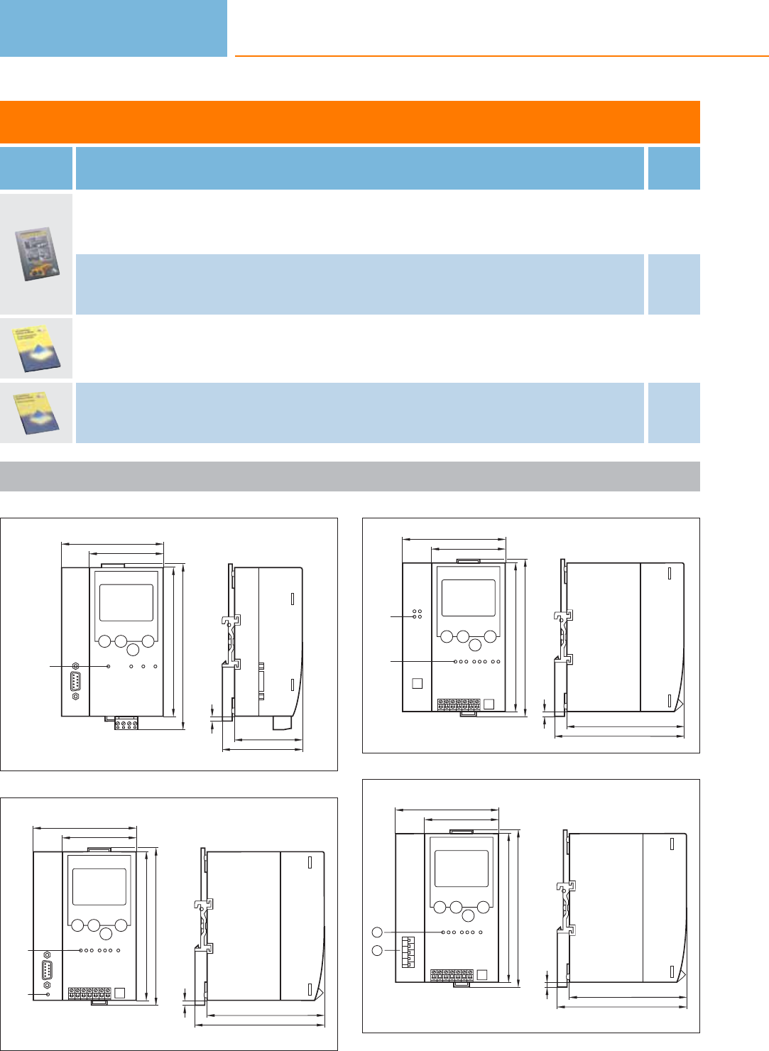
AS-i manuals
Type Description Order
no.
ecolog asi system · AS-Interface Manual (German) AC0115
ecolog asi system · AS-Interface Manual (English) AC0116
Manual · AS-interface Safety at Work (German) Introduction and application examples AC115S
Manual · AS-interface Safety at Work (English) Introduction and application examples AC116S
Scale drawings / drawing no. – CAD download: www.ifm.com
1
85
124
138
LED
62
4
68
57
2
4
107
97
86
124
131
LED
62
LED
3
4
107
97
86
124
131
LED
62
LED
4
1
2
4
107
97
86
124
131
62
1: LED, 2: DeviceNet interface
Bus system AS-interface
502
Product selectors and further information can be found at: www.ifm.com
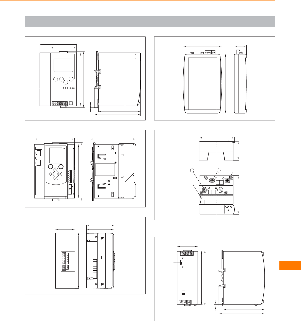
Scale drawings / drawing no. – CAD download: www.ifm.com
5
86
124
131
LED
62
4
107
97
6
106,2
93
135,5
128,2
7
128,2
45 62,8
65,5
8
2991
138
9
44
83
90
M12 x1
LED
12
1: tune button, 2: mode selector
10
4
107
96
49
124
131
Jumper
LED
Bus system AS-interface
503
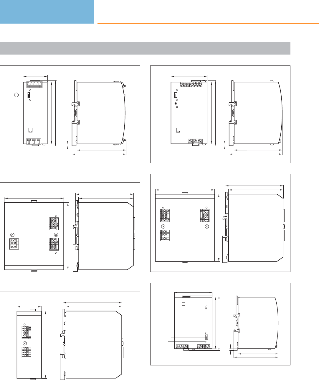
Scale drawings / drawing no. – CAD download: www.ifm.com
11
4
109
98
49
124
131
LED
1
1: Jumper
12
113
118,5
134
120
13
134
50 112,5
118,5
14
4
107
96
73
124
131
LED
Jumper
15
113
118,5
134
120
16
4
107
96
91
124
131
Jumper
LED
Bus system AS-interface
504
Product selectors and further information can be found at: www.ifm.com
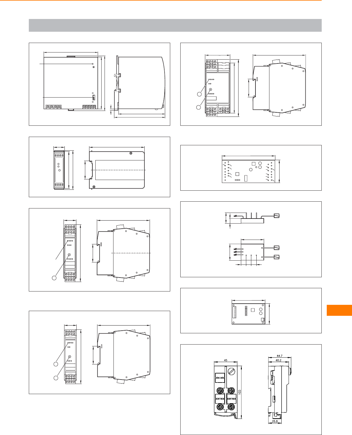
Scale drawings / drawing no. – CAD download: www.ifm.com
17
4
122
111
129
124
131
LED
Jumper
18
74
22,5
78
110
35,5
19
105
35,5
25
114
LEDs
1
1: Addressing socket
20
2
105
35,5
25
108
1
1: Addressing socket, 2: LED
21
105
35,5
50
114
10 0
1
2
1: LED, 2: Addressing socket
22
45
105
23
9
21
UUUU
44
32
910 10
24
40,5
65,5
A+A-
I3 I2 I1 I+ I-O1O2 O3
25
Bus system AS-interface
505
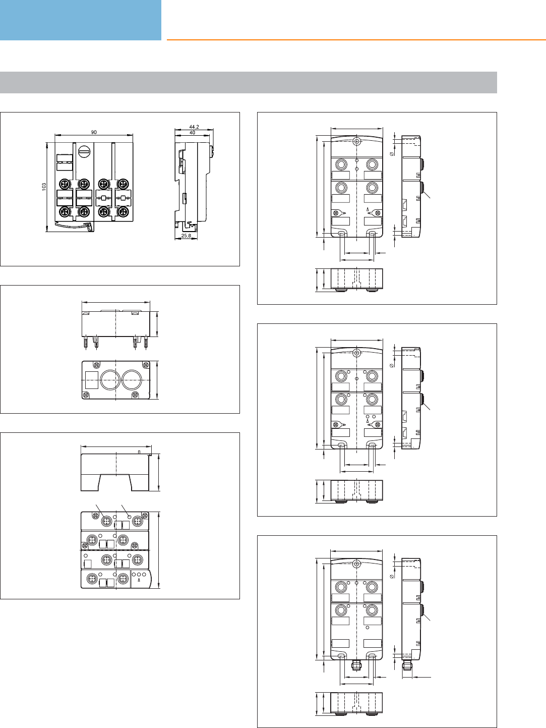
Scale drawings / drawing no. – CAD download: www.ifm.com
26
27
45 30
80
28
44
83
90
LED
M12x1
29
13
42
23
27
4,7 107
118,2
5
4,5
28,5
39
7,5
60
M12x1
30
12
43
23
27
4,7 107
118,2
5
4,5
28,5
39
7,5
60
M12x1
31
23
27
5
4,5
M12x1
12
43
4,7 107
118,2
28,5
39
7,5
60
M12x1
Bus system AS-interface
506
Product selectors and further information can be found at: www.ifm.com
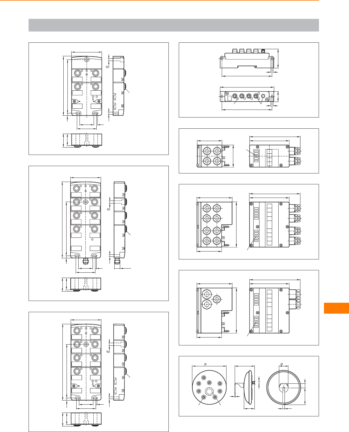
Scale drawings / drawing no. – CAD download: www.ifm.com
32
23
27
5
4,5
M12x1
12
43
4,7 107
118,2
28,5
39
7,5
60
33
23
27
12
4
6
8
3
5
7
4,7 107
152
28,5
39
7,5
60
5
4,5
M12x1
M12x1
34
23
27
12
4
6
8
3
5
7
4,7 107
152
28,5
39
7,5
60
5
4,5
M12x1
35
100
4,5
108
20,6
M8x1
LED
100
38,5
4,5
36
45
50
LEDs
80
102
37
91
50
71
LED
80
102
38
91
50
71
LED
80
102
39
M12 x1
43,6
80
137,3 36
64,9
8,2
2
18
M12 x1 LED
Bus system AS-interface
507
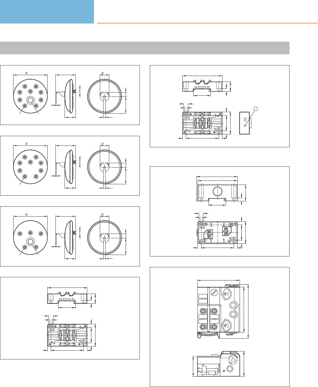
Scale drawings / drawing no. – CAD download: www.ifm.com
40
M12 x1
43,6
80
137,3 36
64,9
8,2
2
18
M12 x1 LED
41
M12 x1
43,6
80
137,3 36
64,9
8,2
2
18
M12 x1
42
M12 x1
43,6
80
137,3 36
64,9
8,2
2
18
M12 x1 LED
43
80
20
6
35
66
31
9,6
5,3
45
77
77
44
80
20
6
35
66
31
9,6
5,3
45
77
77
1
1: Addressing socket
45
80
82,5
33
6
35
66
45
9,6
5,3
31
77
77
46
2
4
0
1
0
1
91
108
85
1
50
40
Bus system AS-interface
508
Product selectors and further information can be found at: www.ifm.com
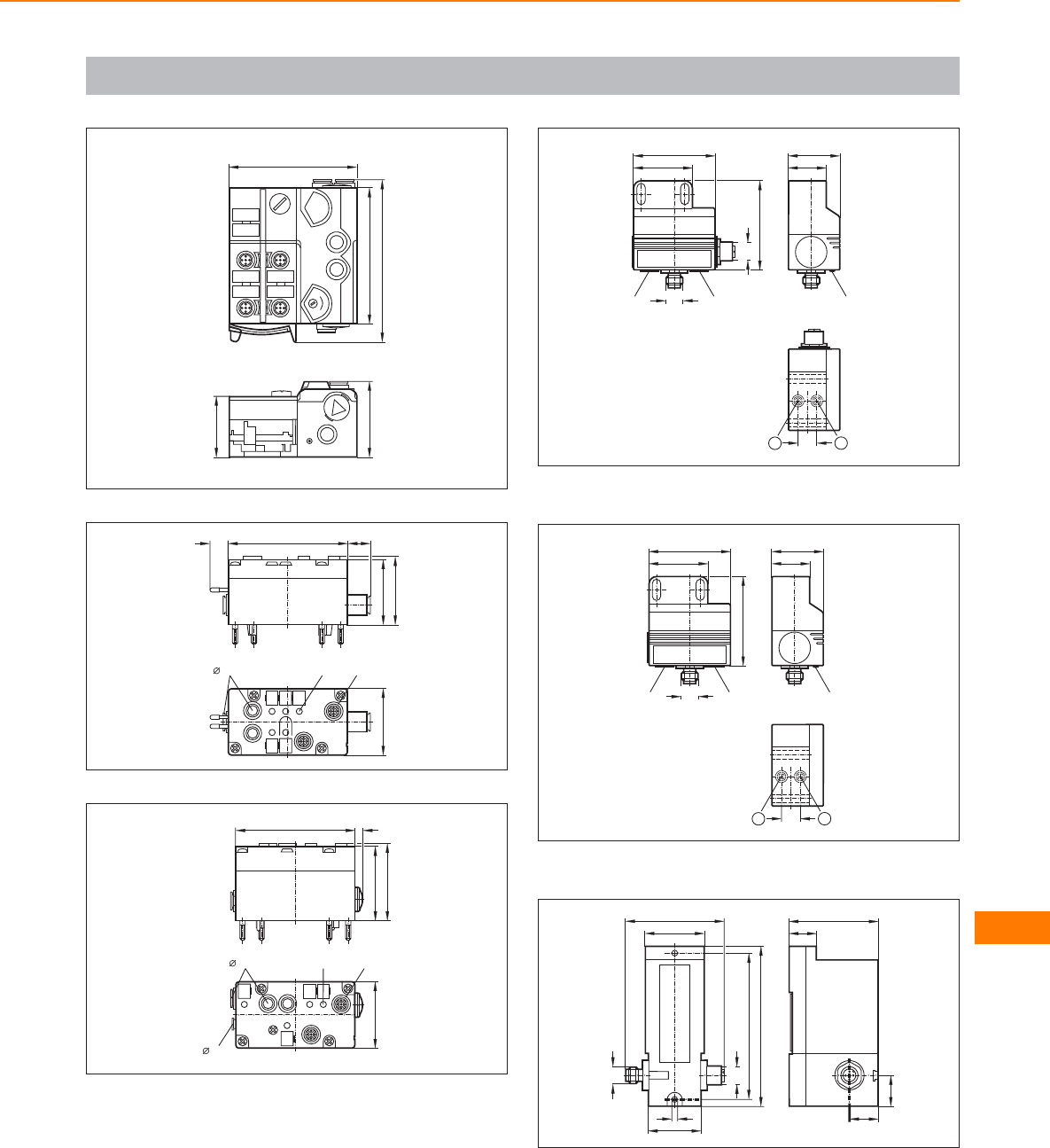
Scale drawings / drawing no. – CAD download: www.ifm.com
47
1
50
40
2
4
0
1
91
108
85
48
44
46
8012 15
M12x1
45
LED
8 mm
49
M12 x1
45
LED
8 mm
4 mm
5
50
52
80
50
26
35
LED
M12 x1
M12 x1
40
55
LED
LED
60
13 1
2
1: sensor 1, 2: sensor 2
51
26
35
LED
M12 x1
40
55
LED
LED
60
13 1
2
1: sensor 1, 2: sensor 2
52
19
60
20,5
19
M12x1
M12x1
66
40
3,8
36
97
107
Bus system AS-interface
509
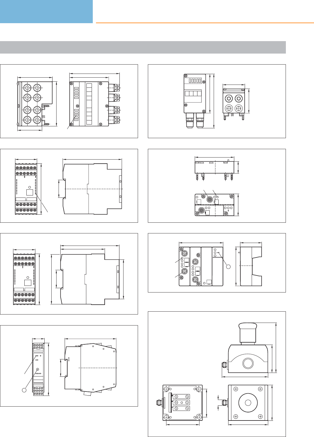
Scale drawings / drawing no. – CAD download: www.ifm.com
53
91
50
71
LED
80
102
54
120
35,5
45
104
LED
55
45
105,9
120
35,5
102
82,6
91,2
56
105
35,5
25
108
LEDs
1
1: Addressing socket
57
45,5
49,4
80
111
58
25
80
45
LEDM12x1
59
90
LED
M12 x1
1
80
44
1: fixture infrared adapter
60
58,5
66,5
UUUU
93,5
56
105
M12x1
72
80
Bus system AS-interface
510
Product selectors and further information can be found at: www.ifm.com
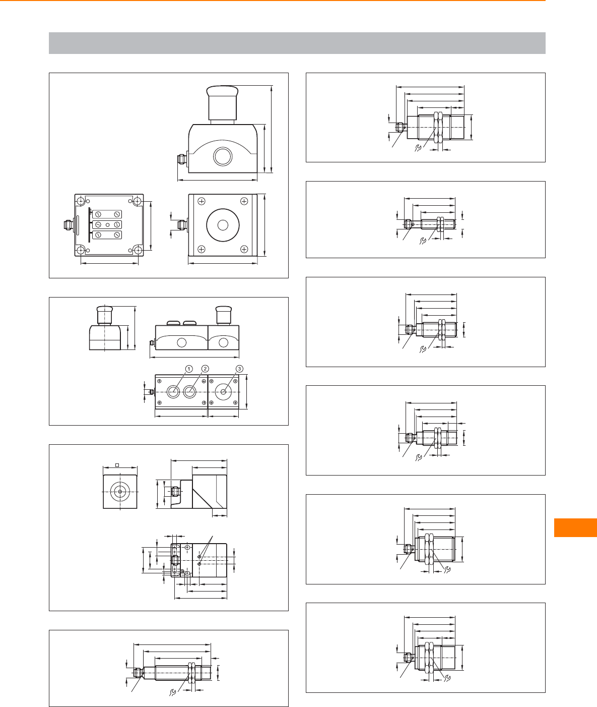
Scale drawings / drawing no. – CAD download: www.ifm.com
61
M12x1
72
80
58,5
66,5
93,5
56
105
62
56
104
208
120 72
M12x1
80
63
40
M12 x1
40
66
17
34
LED
46
61
30
20
5,4
10
5,4
6
8,5
33
64
M18 x1
55 10
M12 x1
90,5
LED 8 x 45°
79
4
24
65
LED 4 x 90°
69
39
M30x1,5
5
67
80
36
M12 x1
15
66
49
40
M12x1
17
4
M12 x1
LED 4 x 90°
60
67
M18 x1
M12 x1
40
47
60
LED 4 x 90°
4
24
49
68
M18 x1
30 10
M12 x1
47
60
LED 4 x 90°
49
4
24
69
49
43
M30x1,5
5
47
60
M12 x1
LED 4 x 90° 36
70
49
28
M30x1,5
5
47
60
M12 x1
LED 4 x 90°
15
36
Bus system AS-interface
511
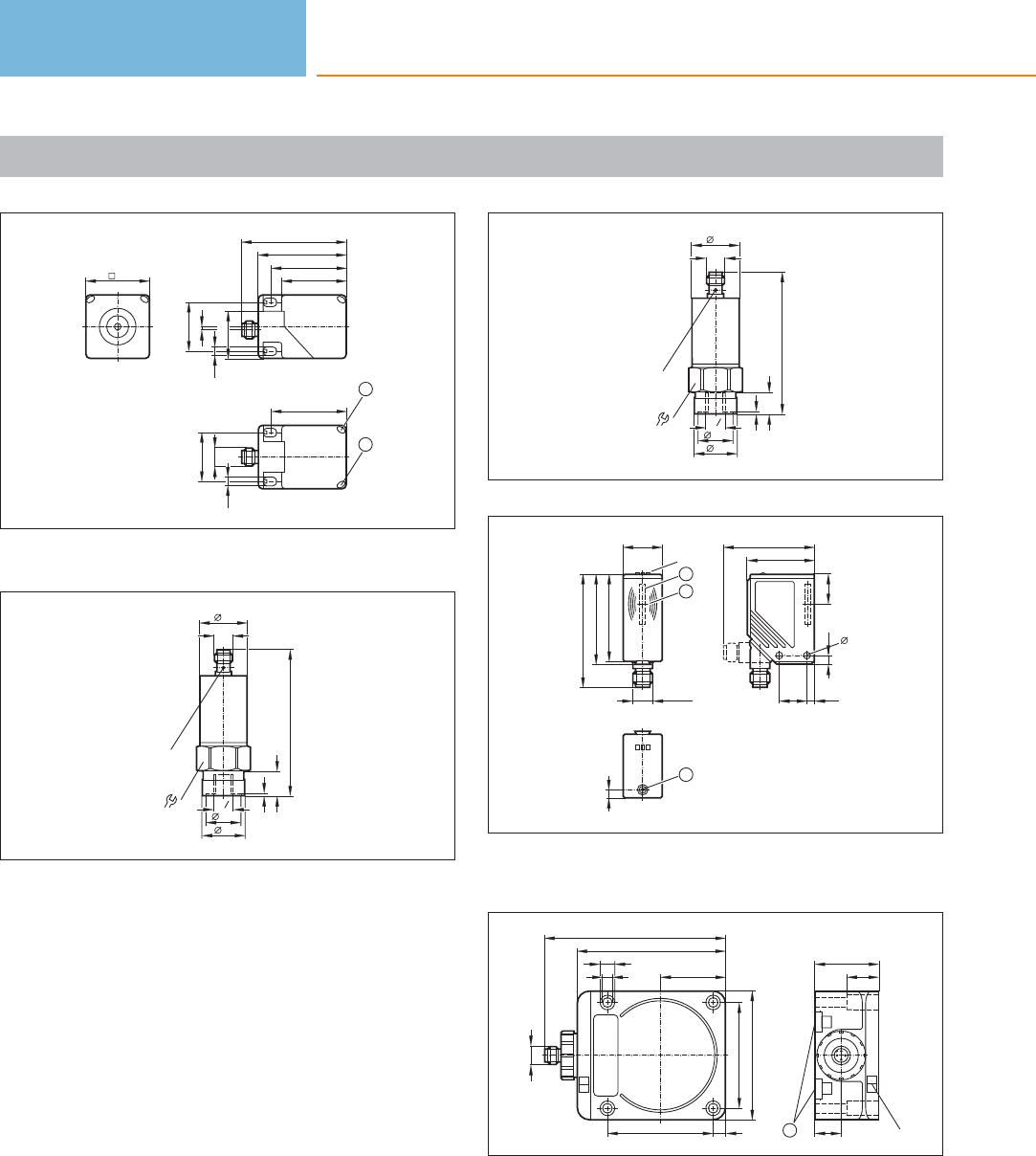
Scale drawings / drawing no. – CAD download: www.ifm.com
71
40
66
40
54
M12 x1
30
30
2
2
1
46
46
5,5
5,5 29,5
1: LED yellow, 2: LED green
72
90,6
M12 x1
30
30
LED
27
1, 3
21,5
15,7
G4
1
73
88
M12 x1
30
30
LED
27
1, 3
21,5
13,5
G4
1
74
5
2
41
4,517
56
17
4,2
5,5
M12 x1
24
55
70
LED
2
1
53,5
1: integrated antenna , 2: tag positioning mark (middle of the anten-
na)
75
92
80
40
7,5
65
65
5,5
9,3
M12 x1
112
40
LED
17
1
20
1: mounting on DIN rail
Bus system AS-interface
512
Product selectors and further information can be found at: www.ifm.com

Bus system AS-interface
513
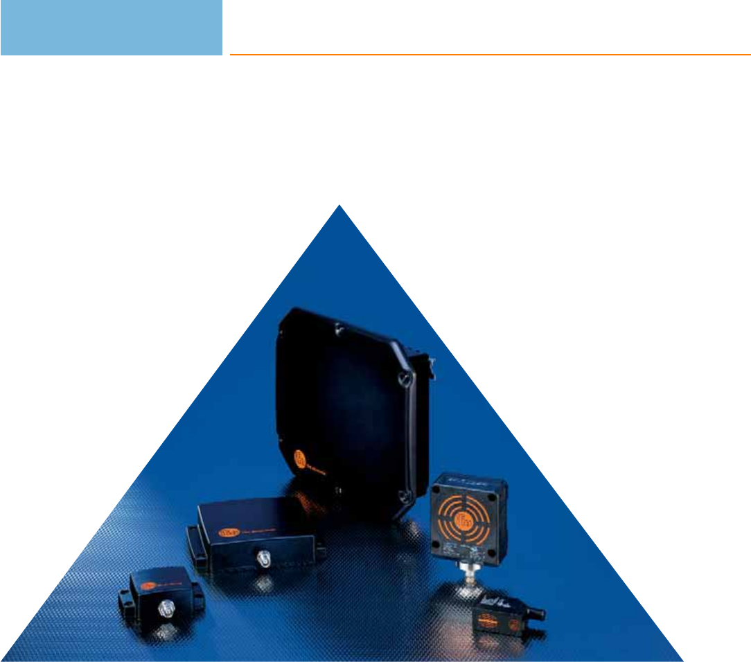
Identification systems
514

Identification systems
515
Multicode reading systems
System description / System overview
Product selection chart
Wiring diagrams
Scale drawings / drawing no. – CAD download: www.ifm.com
516 - 517
518 - 521
521
521
RF-identification systems
System description / System overview
Product selection chart
Scale drawings / drawing no. – CAD download: www.ifm.com
522 - 523
524
527 - 528
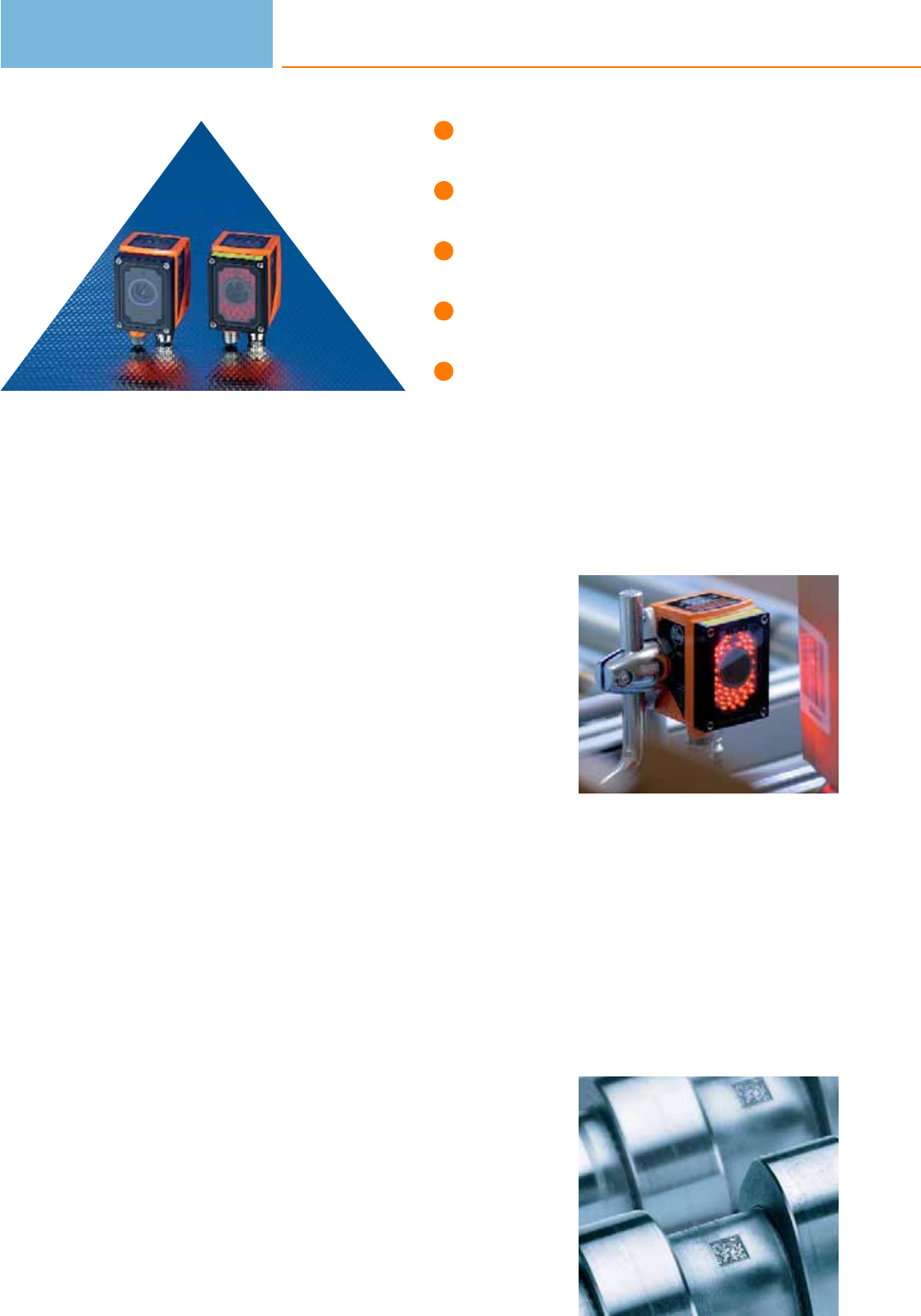
Orientation-independent identification
of 1D and 2D codes.
Very small housing for flexible use.
Simple, menu-guided parameter setting.
Integrated lighting.
High reading reliability even with
soiled / damaged codes.
Multicode reader
The ECC200 Data Matrix code is becoming more and more popular throughout
industry alongside familiar barcodes. In this code lots of information can be stored
in a very small space and read using the compact multicode reader. The industrially
compatible mounting and wiring technology as well as the standardised process
interfaces RS-232, Ethernet TCP/IP and EtherNet/IP enable easy and quick integra-
tion into the industrial control technology. Applications can be found in many
different industrial areas: from the product tracking and production control to pro-
duct identification.
Orientation-independent reading
Independent of the orientation and the number of codes, the high-performance
algorithms automatically decode 1D or 2D codes. The optimisation parameters of
the codes and functions of the multicode reader undergo continuous development
and are made available as upgrades.
Code comparison in the sensor
Complex application programming is no longer necessary due to adjustable,
selective code identification and comparison in the sensor. This allows a defined
number of characters within a code to be checked and signalled via the switching
output if they match.
Reliable identification of 1D and 2D codes
In addition to the automatic exposure setting, manual adjustment is also possible.
So optimum results are achieved even with highly reflective metal surfaces. For
evaluation of the code quality parameter, ISO / IEC 15415 or 16022 can be used.
The Data Matrix code
The Data Matrix code is a two-dimensional code containing much more information
with the same structure size than codes such as bar codes or stacked codes. Several
thousand characters can be stored in one code.
An important feature of the Data Matrix code is the high reading reliability. If the
code is soiled or damaged, the intelligent system can completely recompose the
information from different segments again. The Data Matrix code can be structured
differently and is variable in shape and size. The size can cover 1 x 1 mm to
100 x 100 mm.
Lose no time: The
multicode reader can
be configured in a
few minutes and is
then ready for use.
Only five guided steps
are necessary for the
multicode reader to
be ready for opera-
tion. Whether printed
on paper, graved by
laser or dot-peened
on metal: Reliable
detection of the code,
independent of the
sensor orientation.
Identification systems
516

System overview Page
Multicode reader 518
Illumination units 518
Software 518 - 519
Fixing components 519 - 520
Protective panes and diffusers 520
Connection technology 520
Wiring diagrams 521
Scale drawings / drawing no. – CAD download: www.ifm.com 521
Multicode reading systems
517
Multicode reader
Type Dimensions
[mm]
Max.
field of
view size
[mm]
Type
of light
LED
Motion speed
int. / ext. lighting
[m/s]
Process
interface
Draw-
ing
no.
Order
no.
M12 plug, 8 poles M12 socket, 4 poles · Connector groups 17, 18
60 x 42 x 53.5 68 x 50 red light 3 / 5 Ethernet TCP/IP,
EtherNet/IP, RS-232 1O2I100
60 x 42 x 53.5 140 x 100 red light 3 / 5 Ethernet TCP/IP,
EtherNet/IP, RS-232 1O2I102
60 x 42 x 59 400 x 300 red light 3 / 5 Ethernet TCP/IP,
EtherNet/IP, RS-232 2O2I104
60 x 42 x 53.5 68 x 50 infrared 3 / 5 Ethernet TCP/IP,
EtherNet/IP, RS-232 1O2I101
60 x 42 x 53.5 140 x 100 infrared 3 / 5 Ethernet TCP/IP,
EtherNet/IP, RS-232 1O2I103
60 x 42 x 59 400 x 300 infrared 3 / 5 Ethernet TCP/IP,
EtherNet/IP, RS-232 2O2I105
Illumination units
Type Dimensions
[mm]
Type
of light
Active
illuminated
area
[mm]
I0
normal light
intensity
[mA]
I0
high light
intensity
[mA]
Trigger Draw-
ing
no.
Order
no.
M12 connector · metal · DC · Wiring diagram no. 1 · Connector groups 9, 11, 107, 108, 135
42 x 42 x 31 red – 180 90 External; 24 V PNP to
IEC61131-1 3O2D909
Software
Type Description Number of
connections
Order
no.
Operating software · O2I · for multicode reader · Create and manage application-specific configurations
Monitor mode for set-up and service Service reports for statistical evaluations –E2I200
Multicode reader OPC server · Software · German/English 25 E2I210
Multicode reader OPC server · Software · German/English 50 E2I211
Identification systems
518
Product selectors and further information can be found at: www.ifm.com
Type Description Number of
connections
Order
no.
Multicode reader OPC server · Software · German/English 75 E2I212
Multicode reader OPC server · Software · German/English 100 E2I213
Fixing components
Type Description Order
no.
Mounting set · O2D, O2M, O2I · Clamp mounting · rod mounting Ø 12 mm · Housing materials: fixture: stainless steel / clamp:
stainless steel E2D110
Mounting set · O2D, O2M, O2I · Clamp mounting · rod mounting Ø 14 mm · Housing materials: fixture: stainless steel / clamp:
stainless steel E2D112
clamp · Ø 12 mm; M10 · free-standing M10 · Housing materials: clamp: stainless steel E20946
clamp · Ø 12 mm · rod mounting Ø 12 mm · Housing materials: clamp: stainless steel E21110
clamp · Ø 14 mm; M12 · free-standing M12 · Housing materials: clamp: stainless steel E20948
clamp · Ø 14 mm · rod mounting Ø 14 mm · Housing materials: clamp: stainless steel E21109
mounting rod · Ø 12 · Length: 200 mm · straight · Housing materials: stainless steel 316Ti / 1.4571 E21112
mounting rod · Ø 12 · Length: 300 mm · straight · Housing materials: stainless steel 316Ti / 1.4571 E21113
mounting rod · Ø 12 / M10 · Length: 130 mm · straight · Housing materials: stainless steel 316Ti / 1.4571 E20938
mounting rod · Ø 12 / M10 · Length: 200 mm · angled · Housing materials: stainless steel 316Ti / 1.4571 E20940
mounting rod · Ø 14 / M12 · Length: 130 mm · straight · Housing materials: stainless steel 316Ti / 1.4571 E20939
Multicode reading systems
519
You can find wiring diagrams and scale drawings from page 521
Type Description Order
no.
mounting rod · Ø 14 / M12 · Length: 200 mm · angled · Housing materials: stainless steel 316Ti / 1.4571 E20941
Connection piece · Ø 20 mm · for the connection of two clamps with Ø 20 mm · Housing materials: stainless steel 316L / 1.4404 E21076
Protective panes and diffusers
Type Description Order
no.
Plastic diffuser · O2D / O2I · Housing materials: housing: diecast zinc black / lens: PMMA E21165
Plastic protective pane for the food industry · O2D / O2I · Housing materials: housing: diecast zinc black / lens: PMMA E21166
Glass protective pane · O2D / O2I · Housing materials: housing: diecast zinc black / lens: float glass E21168
Laser protection pane plastic · O2D / O2I · Housing materials: housing: diecast zinc black / lens: PMMA / filter: polycarbonate E21169
Connection technology
Type Description Order
no.
Jumper · straight / straight · Ethernet · Cross-over patch cable · 2 m · Housing materials: PUR / PC E11898
Jumper · straight / straight · Ethernet · Patch cable · 2 m · Housing materials: PUR / PC E12090
Jumper · straight / straight · Ethernet · Cross-over patch cable · 10 m · Housing materials: PUR / PC E12204
Jumper · straight / straight · Ethernet · Cross-over patch cable · 20 m · Housing materials: PUR / PC E12205
Identification systems
520
Product selectors and further information can be found at: www.ifm.com
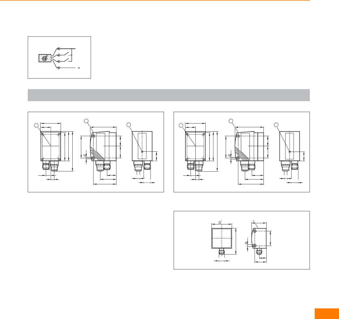
Wiring diagrams
1
L+
L
1
4
2
3
Scale drawings / drawing no. – CAD download: www.ifm.com
1
M12x1
2
19
M12x1
53,5
4,3
20,5
44
19,7
33
1
45
24,5
42
57
80
60
21
9,5
7
3
1: display, 2: Focus setting, 3: Centre of the lens axes
2
M12x1
2
19
M12x1
42
57
80
60
21
9,5
7
359
4,3
20,5
49,5
25,2
38,5
1
45
24,5
1: display, 2: Focus setting, 3: Centre of the lens axes
3
31
4,3
14
30
LED
24
M12 x1
54
LED
42
Multicode reading systems
521
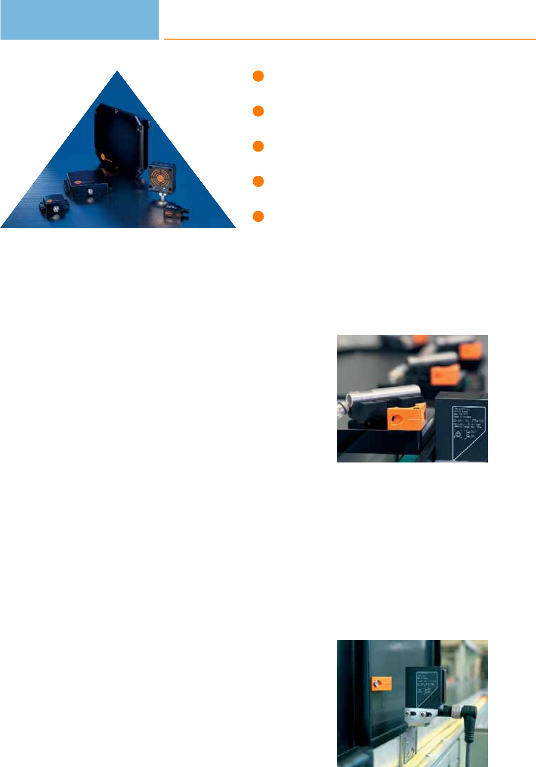
Identification systems
522
Industrially compatible RFID solutions
in 125 kHz or UHF technology.
Connection via AS-Interface (125 kHz)
or Ethernet (UHF).
All components integrated into
industrially compatible housings.
High reading reliability even under
difficult operating conditions.
Easy to mount and set up.
RF-identification systems
The constant increase of the degree of automation in modern production plants is
increasingly supported by identification systems. Their tasks include, for example,
the control or release of production steps or the assignment of information about
each product in logistics.
Operating principle
The RFID system generates an electromagnetic field for reading and writing data.
The electromagnetic field emitted by the antenna induces voltage in the passive
ID tag. The activated ID tag (transponder) transmits the code to the fieldbus inter-
face via the evaluation electronics.
125 kHz system with AS-Interface
ifm electronic supplies the first RFID system for AS-Interface (AS-i) worldwide. It
allows reading and writing of code carriers (ID tags), benefiting from the advan-
tages of AS-i.
Up to 31 read / write heads can be connected to one AS-i master. Antenna,
electronics and AS-i interface are integrated in a compact housing. Voltage is
supplied via AS-i. No additional operating voltage required.
The typical ranges of the 125 kHz system are some centimetres.
UHF system with Ethernet
As components of the UHF system platform, the read / write units DTE800 for
Europe and DTE900 for the USA are compliant with 865-870 MHz and
902-928 MHz respectively. The data transmission and parameter setting are carried
out via Ethernet. The ultra-low and low-range antennas are distinguished by the
near field. In order to achieve a high selectivity, the smallest possible designs are
used as they manage short reading ranges.
Due to its smaller dimensions the mid-range antenna is chosen for applications in
the near / far field with reading ranges of up to 2 m.
The wide-range antenna have been developed for applications in the far field where
reading ranges of up to 7 m are required.
The ID tag provides
flexibility for different
types of installation.
The ID tag is mounted
to tanks or workpiece
carriers – in the tag
fixture or alternatively
by direct mounting
using an M5 grub
screw.

System overview Page
RFID systems 524
ID tags 524 - 525
Handheld readers 525
Fixing components 525
RFID systems 526
RFID systems 526
ID tags 526
RFID systems 527
Scale drawings / drawing no. – CAD download: www.ifm.com 527 - 528
RF-identification systems
523
RFID systems
Type Dimensions
[mm]
Travel speed
read / write
[m/s]
Process
interface
Draw-
ing
no.
Order
no.
M12 connector · Connector groups 9, 11, 107, 108, 135
55 x 24 x 41 read: ≤ 0.5 (distance to the ID tag 15 mm) write: only static AS-i 1 DTA100
55 x 24 x 41 read: ≤ 0.5 (distance to the ID tag 15 mm) AS-i 1DTA101
40 x 40 x 54 read: ≤ 0.5 (distance to the ID tag 30 mm) write: only static AS-i 2 DTA200
40 x 40 x 54 read: ≤ 0.5 (distance to the ID tag 30 mm) AS-i 2DTA201
92 x 80 x 40 read: ≤ 0.5 (distance to the ID tag 40 mm) write: only static AS-i 3 DTA300
92 x 80 x 40 read: ≤ 0.5 (distance to the ID tag 40 mm) AS-i 3DTA301
ID tags
Type Description Order
no.
ID tag · ID-TAG/M5x16.5/01 · M5 x 16.5 mm · Screw mounting · Housing materials: PA black (RAL 9005) E80301
ID tag · ID-TAG/TRIANGEL HOUSING/01 · with ID tag E80301 · Housing materials: PBT orange (RAL 2003) / PA black (RAL 9005) E80302
ID tag · ID-TAG/M18x1/01 · M18 x 1 mm · Screw mounting · in metal · Housing materials: threaded sleeve: PBT orange E80311
ID tag · ID-TAG/D12x2/01 · Ø 12 x 2 mm · Housing materials: PPS black E80312
ID tag · ID-TAG/D20x2.15/01 · Ø 20 x 2.15 mm · Housing materials: polycarbonate black E80317
ID tag · ID-TAG/D30x2.15/01 · Ø 30 x 2.15 mm · Housing materials: polycarbonate black E80318
Identification systems
524
Product selectors and further information can be found at: www.ifm.com
Type Description Order
no.
ID tag · ID-TAG/D50x2.2/01 · Ø 50 x 2.2 mm · Housing materials: polycarbonate black E80319
ID tag · ID-TAG/D26x4/01 · Ø 26 x 4 mm · Housing materials: PA High Temperature E80322
ID tag · ID-TAG/ISO-Card/01 · 54 x 86 x 1 mm · Housing materials: PVC white E80320
Handheld readers
Type Description Order
no.
RFID Handheld Reader USB · suitable for use in PCs or notebooks · 125 kHz · 1.8 m · Housing materials: PS E80321
RFID Handheld Reader CF Card · suitable for use in handheld PCs, pocket PCs or PDAs with CompactFlash interface · 125 kHz E80323
RFID Handheld Reader RS-232 · suitable for use in PCs or notebooks · 125 kHz · Housing materials: PS E80324
Fixing components
Type Description Order
no.
Angle bracket · Housing materials: stainless steel E80304
Mounting set · Clamp mounting · aluminium profile · for type OC · Housing materials: fixture: stainless steel 316Ti / 1.4571 / clamp:
diecast zinc / Cube: diecast zinc E20901
Mounting bracket · with integrated snap-on rail · for type IDC · Housing materials: stainless steel E10730
Mounting set · Clamp mounting · aluminium profile · for type OC · Housing materials: fixture: stainless steel 316Ti / 1.4571 / clamp:
diecast zinc / Cube: diecast zinc E20901
Dovetail clamp · for type DTS, O4, O5 · Housing materials: AlMgSi0.5 E21088
RF-identification systems
525
You can find scale drawings from page 527
RFID systems
Type Dimensions
[mm]
Operating
frequency
[MHz]
Trans-
mission
power
[mW ERP]
Number
of antenna
inputs
Process
interface
Output Draw-
ing
no.
Order
no.
M12 connector · Connector groups 9, 11, 107, 108, 135
233.5 x 270 x 68 865-868 (ETSI) 2000 4 Ethernet TCP/IP
2 external digital inputs and
2 outputs through M12
connector
4DTE800
233.5 x 270 x 68 902...928
(FCC) 2000 4Ethernet TCP/IP
2 external digital inputs and
2 outputs through M12
connector
4DTE900
RFID systems
Type Dimensions
[mm]
Operating
frequency
[MHz]
Antenna
gain
[cBic]
Max.
input power
[mW]
Protection Draw-
ing
no.
Order
no.
TNC socket
63 x 28 x 90 865...928 -30 1000 IP 67 5 ANT805
63 x 28 x 90 865...870 -15 500 IP 67 5ANT810
126 x 37 x 156 865...870 4 – IP 67 6 ANT820
271 x 270 x 42 865...870 8.5 –IP 67 7ANT830
63 x 28 x 90 902...928 (FCC) -15 500 IP 67 5 ANT910
271 x 270 x 42 902...928 8.5 –IP 67 7ANT930
ID tags
Type Description Order
no.
ID tag · ID-TAG/D50x3.3/04 · Ø 50 x 3.3 mm · Housing materials: PA 6 E80350
ID tag · ID-TAG/D55x13/04 · Ø 55 x 13 mm · Housing materials: PA 6 E80351
Identification systems
526
Product selectors and further information can be found at: www.ifm.com
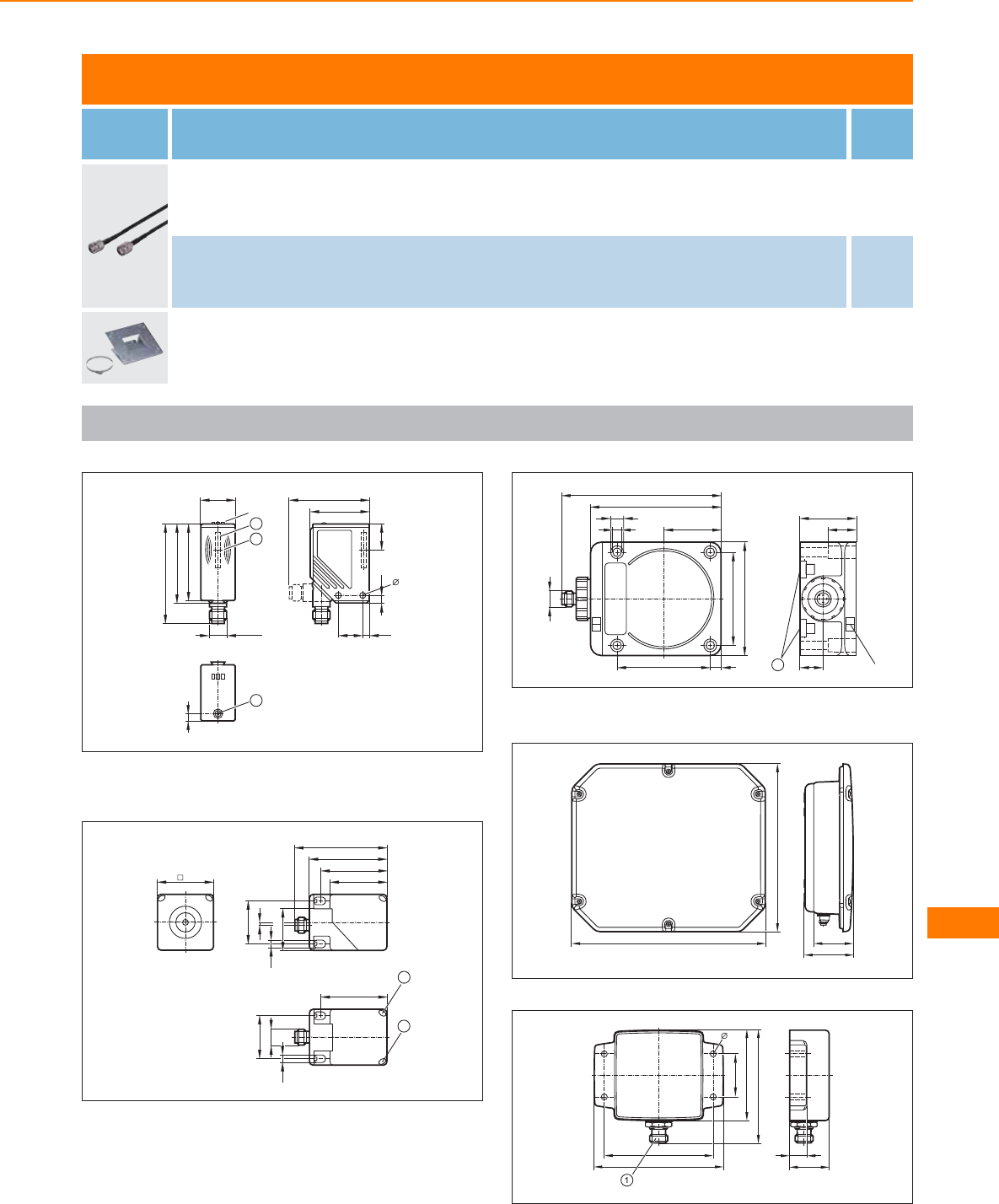
RFID systems
Type Description Order
no.
Jumper · straight / straight · For RFID antenna · 3 m E80330
Jumper · straight / straight · For RFID antenna · 6 m E80331
Clamp · For RFID antenna · Housing materials: fixture: steel sheet galvanised / screws: stainless steel / Fixing strap: stainless steel E80340
Scale drawings / drawing no. – CAD download: www.ifm.com
1
5
2
41
4,517
56
17
4,2
5,5
M12 x1
24
55
70
LED
2
1
53,5
1: integrated antenna , 2: tag positioning mark (middle of the anten-
na)
2
40
66
40
54
M12 x1
30
30
2
2
1
46
46
5,5
5,5 29,5
1: LED yellow, 2: LED green
3
92
80
40
7,5
65
65
5,5
9,3
M12 x1
112
40
LED
17
1
20
1: mounting on DIN rail
4
68
270 55
233,2
5
90
30
63
79,5
12
28
76
4,2
1: TNC socket
RF-identification systems
527
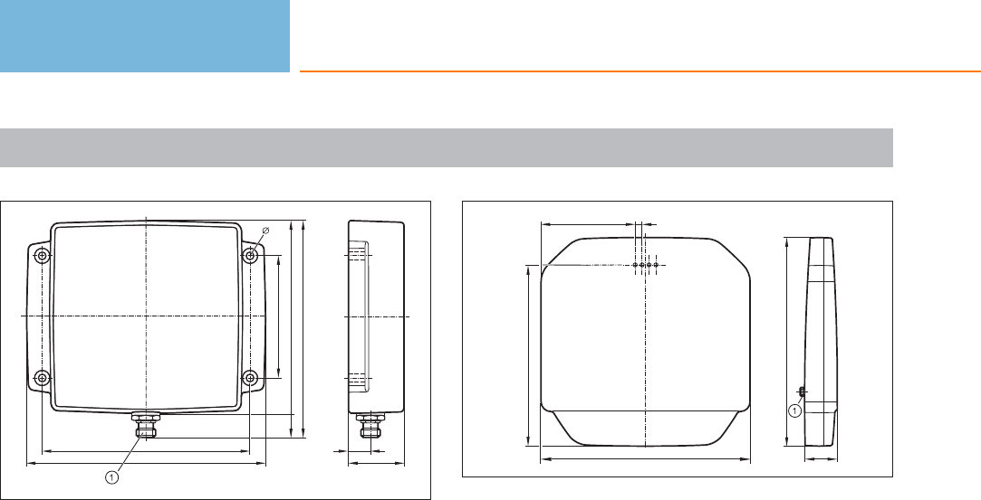
Scale drawings / drawing no. – CAD download: www.ifm.com
6
156
138
126
80
37
15
148
4,2
1: TNC socket
7
270 42
271
236
122 9
1: TNC socket
Identification systems
528
Product selectors and further information can be found at: www.ifm.com

RF-identification systems
529
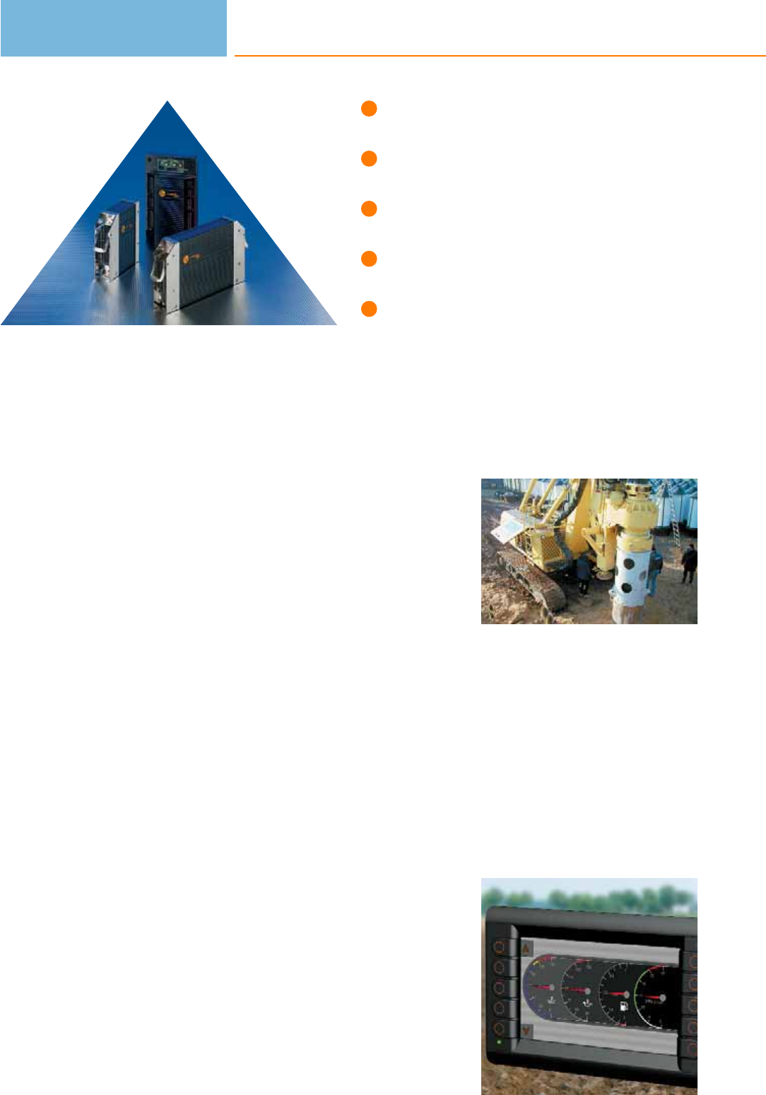
Controllers, I/O modules, displays
and sensors for mobile applications.
Compact and extremely robust design.
Extensive range of accessories for
installation and diagnostics.
CAN interface with CANopen protocol.
e1 type approval of the German
Federal Office for Motor Traffic.
Control technology for mobile applications
Life today cannot be imagined without electronics in modern motor vehicles and
mobile machines. Many necessary and convenient functions could not be
implemented without electronic support. In contrast to electronics in consumer
goods and “normal” industrial applications such as packaging machines and con-
veyors the requirements for components for mobile applications are much higher.
Electronic requirements
The components need to be carefully selected, mainly because of the extreme
mechanical stress caused by impacts and shocks and the use at extreme operating
temperatures. The direct influence of dirt, humidity and water often cannot be
excluded in field applications. Therefore a high protection rating and a special
selection of the materials are required for the devices.
In addition to mechanical and environmental influences, electrical interference
affecting the whole system as well as individual devices, have to be taken into
account. A wide supply voltage range and well-adapted protective measures ensure
safe operation of the devices even in case of large voltage fluctuations by the
battery / generator system. Strong conducted or radiated interference must not
influence the function either.
For device networking the CAN bus has become the successful standard in the last
few years. Whereas for the high volume production of passenger cars special,
optimised and well-adapted protocols are used, the CANopen protocol has become
indispensable in mobile machines. Manufacturer and industry-specific protocols,
such as diagnostic engine data according to SAE J 1939, can be coupled to the
machine process via gateways.
Extreme shock and
vibration: Reliable
function of the sensi-
tive electronics must
be guaranteed under
harsh operating
conditions as well.
Especially when
several machine parts
are interconnected
CAN offers decisive
advantages.
Control systems
for mobile vehicles
530

Control systems
for mobile vehicles
531
System overview Page
BasicController 533
Starter set ecomatmobile Basic 533
Accessories for BasicController 533
BasicRelay 534
Accessories for BasicRelay 534
BasicDisplay 534
Accesssories for BasicDisplay 534
16-bit ClassicController 534
32-bit ClassicController 535
16-bit ExtendedController 535
32-bit ExtendedController 535
16-bit SafetyController 535
16-bit SmartController 535
CabinetController for use in control cabinets 536
Accessories and software 536
CompactModules 536
CompactModules metal 536 - 537
SmartModules 537
CabinetModules 537
KeypadModules 537
PDM360 smart with 2.5" monochrome display 537
PDM360 compact with 3.8" monochrome display 538
PDM360 with 5.7" display 538
PDM360 NG with 7" display 538
Camera systems for PDM360 color 538
Remote maintenance and data storage 539
Interface and diagnosis 539
Inclination sensors 539
Inductive sensors for mobile applications 540 - 542
Absolute multiturn - encoders (CANopen) for mobile applications 542
Electronic pressure sensors for mobile applications 543 - 545

System overview Page
Converters and PWM modules 545
Connection technology for control systems 545 - 548
Accessories 549 - 550
Connection technology with signal converter 550
Load-dump modules 550
Accessories for sensors for mobile applications 550 - 551
Wiring diagrams 551
Scale drawings / drawing no. – CAD download: www.ifm.com 552
Control systems
for mobile vehicles
532
Product selectors and further information can be found at: www.ifm.com
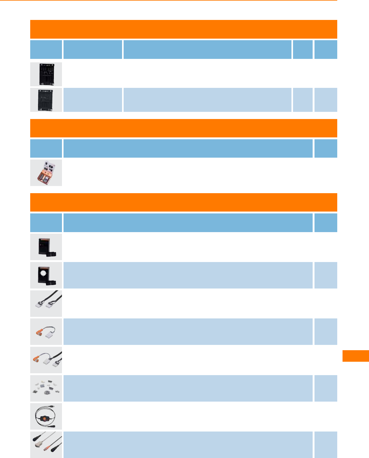
BasicController
Type Inputs /
outputs
Description Draw-
ing
no.
Order
no.
20 BasicController · 12 inputs / 8 outputs · 2 CAN interfaces · Configurable input / output
functions · Programming according to IEC 61131-3 · 8...32 V DC 1CR0401
24 BasicController · 12 inputs / 12 outputs · 2 CAN interfaces · Configurable input / output
functions · Programming according to IEC 61131-3 · 8...32 V DC 2CR0403
Starter set ecomatmobile Basic
Type Description Order
no.
Starter set ecomatmobile Basic EC0400
Accessories for BasicController
Type Description Order
no.
Cover · for BasicController CR040x and BasicRelay CR042x · incl. cable seal EC0401
Cover · for BasicController CR040x · Built-in display recess for BasicDisplay CR0451 · incl. cable seal EC0402
Jumper · wired · for 2 BasicControllers CR040x · CAN interface · Power supply · 0.5 m EC0451
Jumper · wired · for 1 BasicController CR040x and 1 BasicDisplay CR0451 · CAN interface · Power supply · M12 connector · 0.1 m EC0452
Jumper · wired · for 2 BasicControllers CR040x and 1 BasicDisplay CR0451 · CAN interface · Power supply · M12 connector · 0.5 m EC0453
Plug set · for BasicController CR040x · wirable · Complete set of contacts / contact housings utilising all connections to a
BasicController EC0456
CANfox · CAN/RS232-USB interface · Programming and diagnosis of CAN systems · 5 V DC (via USB interface) EC2112
Adapter cable · for CAN interface CANfox · CAN adapter: DIN connector, 6 poles / M12 connector, 5 poles · RS-232 adapter: DIN
connector, 6 poles / Sub-D plug, 9 poles · Cable length 1 m EC2113
Control systems
for mobile vehicles
533
You can find wiring diagrams and scale drawings from page 551
BasicRelay
Type Inputs /
outputs
Description Draw-
ing
no.
Order
no.
–BasicRelay · Locations for 6 automotive relays and 10 automotive fuses ( (6.3 mm) · 2
supply rails and 6 power distributors · freely wirable 3CR0421
Accessories for BasicRelay
Type Description Order
no.
Set of contacts · for BasicRelay CR0421 · wirable · utilising all connections to a BasicRelay EC0457
Cover · for BasicController CR040x and BasicRelay CR042x · incl. cable seal EC0401
BasicDisplay
Type Inputs /
outputs
Description Draw-
ing
no.
Order
no.
–
BasicDisplay · 2.8" colour display · 5 freely programmable backlit function keys · Rocker
switch for cursor function · CAN interface · Programming according to IEC 61131-3 ·
8...32 V DC
4CR0451
Accesssories for BasicDisplay
Type Description Order
no.
Mounting frame · for BasicDisplay CR0451 · panel · Housing materials: steel sheet EC0403
16-bit ClassicController
Type Inputs /
outputs
Description Draw-
ing
no.
Order
no.
24
ClassicController · Programmable mobile controller type R 360 · 2 nd CAN interface for
gateway function according to SAE J 1939 · Configurable input / output functions ·
Programming according to IEC 61131-3 · 24 inputs/outputs · 10...32 V DC
5CR0505
40
ClassicController · Programmable mobile controller type R 360 · 2 nd CAN interface for
gateway function according to SAE J 1939 · Configurable input / output functions ·
Programming according to IEC 61131-3 · 40 inputs/outputs · 10...32 V DC
5CR0020
Control systems
for mobile vehicles
534
Product selectors and further information can be found at: www.ifm.com

32-bit ClassicController
Type Inputs /
outputs
Description Draw-
ing
no.
Order
no.
32
ClassicController · 32 Bit · Programmable mobile controller type R 360 · 32-bit processor ·
16 inputs / 16 outputs · 4 CAN interfaces · Configurable input / output functions ·
Programming according to IEC 61131-3 · CoDeSys 2.3 · 10...32 V DC
5CR0032
16-bit ExtendedController
Type Inputs /
outputs
Description Draw-
ing
no.
Order
no.
80
ExtendedController · 16 Bit · Programmable mobile controller type R 360 · Configurable
input / output functions · Programming according to IEC 61131-3 · 2 control units · 80
inputs/outputs · 10...32 V DC
6CR0200
32-bit ExtendedController
Type Inputs /
outputs
Description Draw-
ing
no.
Order
no.
80
ExtendedController · 32 Bit · Programmable mobile controller type R 360 · 32-bit
processor · Configurable input / output functions · Programming according to IEC 61131-
3 · 80 inputs/outputs · 10...32 V DC
6CR0232
16-bit SafetyController
Type Inputs /
outputs
Description Draw-
ing
no.
Order
no.
24
SafetyController · Programmable mobile controller type R 360 · for safety applications ·
SILcl 2 (IEC 62061) · PL d (EN ISO 13849-1) · 2 nd CAN interface for gateway function
according to SAE J 1939 · Configurable input / output functions · Programming according
to IEC 61131-3 · 24 inputs/outputs · 10...32 V DC
5CR7506
40
SafetyController · Programmable mobile controller type R 360 · for safety applications ·
SILcl 2 (IEC 62061) · PL d (EN ISO 13849-1) · 2 nd CAN interface for gateway function
according to SAE J 1939 · Configurable input / output functions · Programming according
to IEC 61131-3 · 40 inputs/outputs · 10...32 V DC
5CR7021
80
SafetyController · Programmable mobile controller type R 360 · for safety applications ·
SILcl 2 (IEC 62061) · PL d (EN ISO 13849-1) · 2 nd CAN interface for gateway function
according to SAE J 1939 · Configurable input / output functions · Programming according
to IEC 61131-3 · 80 inputs/outputs · 10...32 V DC
6CR7201
16-bit SmartController
Type Inputs /
outputs
Description Draw-
ing
no.
Order
no.
12
SmartController · Programmable mobile controller type R 360 · 2 nd CAN interface for
gateway function according to SAE J 1939 · Configurable input / output functions ·
Programming according to IEC 61131-3 · 8 inputs / 4 outputs · 10...32 V DC
7CR2500
Control systems
for mobile vehicles
535
You can find wiring diagrams and scale drawings from page 551
CabinetController for use in control cabinets
Type Inputs /
outputs
Description Draw-
ing
no.
Order
no.
42
CabinetController · Programmable mobile controller type R 360 · Configurable input /
output functions · Programming according to IEC 61131-3 · 24 inputs / 18 outputs ·
10...32 V DC
8CR0301
36
CabinetController · Programmable mobile controller type R 360 · Configurable input /
output functions · Programming according to IEC 61131-3 · 24 inputs / 12 outputs ·
10...32 V DC
9CR0302
42
CabinetController · Programmable mobile controller type R 360 · 2 nd CAN interface for
gateway function according to SAE J 1939 · Configurable input / output functions ·
Programming according to IEC 61131-3 · 24 inputs / 18 outputs · 10...32 V DC
10 CR0303
Accessories and software
Type Description Draw-
ing
no.
Order
no.
Programming software CoDeSys · for configuration, programming and diagnosis of ifm controller systems · German
version · incl. the DVD „Software, tools and documentation„ –CP9006
Programming software CoDeSys · for configuration, programming and diagnosis of ifm controller systems · English version
· incl. the DVD „Software, tools and documentation„ –CP9008
Starter set ecomat R 360 Smart Controller · consisting of: · controller CR2500 · I/O simulator box incl. connection cable
and connectors · plug-in power supply · DVD with programming software CoDeSys · project examples and manuals –EC2074
CompactModules
Type Inputs /
outputs
Description Draw-
ing
no.
Order
no.
8CompactModule · Output module digital and analogue for R 360 systems · CAN interface
· Configurable input / output functions · 8 outputs · Connector M12 x 1 · 10...32 V DC 11 CR2011
8
CompactModule · I/O module digital and analogue for R 360 systems · CAN interface ·
Configurable input / output functions · 8 inputs / 4 outputs · Connector M12 x 1 ·
Programming according to IEC 61131-3 · 10...32 V DC
11 CR2013
CompactModules metal
Type Inputs /
outputs
Description Draw-
ing
no.
Order
no.
8
CompactModule Metal · Output module digital and analogue for R 360 systems · CAN
interface · CAN parameters adjustable via coding switch · Configurable input / output
functions · 8 outputs · Connector M12 x 1 · Surface electrostatically coated (cathodic
immersion) · 10...32 V DC
12 CR2031
16
CompactModule Metal · I/O module digital and analogue for R 360 systems · CAN
interface · CAN parameters adjustable via coding switch · Configurable input / output
functions · 8 inputs / 8 outputs · Connector M12 x 1 · Surface electrostatically coated
(cathodic immersion) · 10...32 V DC
13 CR2032
Control systems
for mobile vehicles
536
Product selectors and further information can be found at: www.ifm.com
Type Inputs /
outputs
Description Draw-
ing
no.
Order
no.
12
CompactModule Metal · I/O module digital and analogue for R 360 systems · CAN
interface · CAN parameters adjustable via coding switch · Configurable input / output
functions · 8 inputs / 4 outputs · Connector M12 x 1 · Surface electrostatically coated
(cathodic immersion) · 10...32 V DC
14 CR2033
SmartModules
Type Inputs /
outputs
Description Draw-
ing
no.
Order
no.
12 SmartModule · I/O module digital and analogue for R 360 systems · CAN interface · 4
inputs / 8 outputs · Configurable input / output functions · 10...32 V DC 7CR2512
12 SmartModule · I/O module digital and analogue for R 360 systems · CAN interface · 8
inputs / 4 outputs · Configurable input / output functions · 10...32 V DC 7CR2513
CabinetModules
Type Inputs /
outputs
Description Draw-
ing
no.
Order
no.
16 CabinetModule · I/O module digital and analogue for R 360 systems · CAN interface ·
16 inputs/outputs · Configurable input / output functions · 10...32 V DC 15 CR2012
16
CabinetModule · I/O module digital and analogue for R 360 systems · CAN interface ·
16 inputs/outputs · CAN parameters adjustable via coding switch · Configurable input /
output functions · 10...32 V DC
16 CR2014
32
CabinetModule · I/O module digital and analogue for R 360 systems · CAN interface ·
16 inputs / 16 outputs · CAN parameters adjustable via coding switch · Configurable
input / output functions · 10...32 V DC
17 CR2016
KeypadModules
Type Description Draw-
ing
no.
Order
no.
KeypadModule · CAN interface · Mounting in control cabinets and on walls · Programming according to IEC 61131-3 ·
10...30 V DC 18 CR1500
PDM360 smart with 2.5" monochrome display
Type Display
resolution
(pixels)
Display
type
Display
illumination
Description Draw-
ing
no.
Order
no.
128 x 64 COG monochr. LED
Process and dialogue module PDM360 smart · 2.5"
monochrome display · 12 freely programmable backlit
function keys · Programming according to IEC 61131-3 ·
10...32 V DC
19 CR1070
128 x 64 COG monochr. LED
Process and dialogue module PDM360 smart · 2.5"
monochrome display · 12 freely programmable backlit
function keys · 4 inputs / 4 outputs · Programming
according to IEC 61131-3 · 10...32 V DC
19 CR1071
Control systems
for mobile vehicles
537
You can find wiring diagrams and scale drawings from page 551
PDM360 compact with 3.8" monochrome display
Type Display
resolution
(pixels)
Display
type
Display
illumination
Description Draw-
ing
no.
Order
no.
240 x 320 FSTN monochr. LED
Process and dialogue module PDM360 compact · 3.8"
monochrome display · 3 freely programmable backlit
function keys · Encoder with pushbutton · Ethernet ·
Programming according to IEC 61131-3 · 10...32 V DC
20 CR1052
240 x 320 FSTN monochr. LED
Process and dialogue module PDM360 compact · 3.8"
monochrome display · 3 freely programmable backlit function keys
· Encoder with pushbutton · 2 inputs / 2 outputs · Real-time clock ·
Ethernet · Programming according to IEC 61131-3 · 10...32 V DC
20 CR1053
320 x 240 FSTN monochr. LED
Process and dialogue module PDM360 compact · 3.8"
monochrome display · 3 freely programmable backlit
function keys · Encoder with pushbutton · Ethernet ·
Programming according to IEC 61131-3 · 10...32 V DC
21 CR1055
320 x 240 FSTN monochr. LED
Process and dialogue module PDM360 compact · 3.8"
monochrome display · 3 freely programmable backlit function keys
· Encoder with pushbutton · 2 inputs / 2 outputs · Real-time clock ·
Ethernet · Programming according to IEC 61131-3 · 10...32 V DC
21 CR1056
PDM360 with 5.7" display
Type Display
resolution
(pixels)
Display
type
Display
illumination
Description Draw-
ing
no.
Order
no.
320 x 240 FSTN monochr. LED
Process and dialogue module PDM360 · 5.7" monochrome
display · 6 freely programmable backlit function keys ·
Encoder with pushbutton · Real-time clock · Buzzer ·
Programming according to IEC 61131-3 · 10...32 V DC
22 CR1050
320 x 240 TFT colour LED
Process and dialogue module PDM360 · 5.7" colour
display · 6 freely programmable backlit function keys ·
Encoder with pushbutton · Real-time clock · Buzzer ·
Programming according to IEC 61131-3 · 10...32 V DC
22 CR1051
PDM360 NG with 7" display
Type Display
resolution
(pixels)
Display
type
Display
illumination
Description Draw-
ing
no.
Order
no.
800 x 480 TFT colour LED
7" colour display · 9 freely programmable backlit function
keys · Encoder with pushbutton · 1 input / 1 output ·
Real-time clock · Buzzer · Programming according to IEC
61131-3 · 10...32 V DC
23 CR1080
800 x 480 TFT colour LED
7" colour display · 9 freely programmable backlit function
keys · Rocker switch with pushbutton · 1 input / 1 output
· Real-time clock · Buzzer · Programming according to IEC
61131-3 · 10...32 V DC
24 CR1081
Camera systems for PDM360 color
Type Image
resolution
(pixels)
Description Draw-
ing
no.
Order
no.
320 x 240
Ethernet camera · O2M · camera system for mobile vehicles · selectable image mirror
function · lens heating · programming and parameter setting interface for CoDeSys 2.3 ·
angle of aperture 75°
25 O2M110
320 x 240
Ethernet camera · O2M · camera system for mobile vehicles · selectable image mirror
function · lens heating · programming and parameter setting interface for CoDeSys 2.3 ·
angle of aperture 115°
25 O2M113
Control systems
for mobile vehicles
538
Product selectors and further information can be found at: www.ifm.com
Remote maintenance and data storage
Type Description Draw-
ing
no.
Order
no.
CAN GSM quad-band radio modem · GSM modem quad-band · for the transfer of SMS messages and data packets ·
10...30 V DC 26 CR3105
CAN GSM/GPS quad-band radio modem · GSM modem quad-band · for the transfer of SMS messages and data packets ·
with GPS receiver for location tracking · 10...30 V DC 27 CR3106
CANmem · Data memory and logger for CANopen systems · Use of SD/MMC memory cards and PC cards to the PCMCIA
standard · Parameter setting to IEC 61131 · 10...30 V DC 28 CR3101
Interface and diagnosis
Type Description Draw-
ing
no.
Order
no.
CAN analyser · Hand-held terminal to monitor and enter data messages in CAN systems – EC2036
Inclination sensors
Type Description Draw-
ing
no.
Order
no.
Inclination sensor · CAN interface · ± 15° · 2 axes · Configurable output functions · 10...32 V DC 29 CR2101
Inclination sensor · CAN interface · Analogue outputs · 4...20 mA · ± 45° · 2 axes · Configurable output functions ·
10...32 V DC 30 CR2102
Inclination sensor · ± 90° · 15...30 V DC · Output 0...10 V · Cable 31 EC2019
Inclination sensor · ± 90° · Input 8...30 V DC · Output 0.5...4.5 V · Cable 31 EC2045
Inclination sensor · ± 20° · Analogue output · 4...20 mA 31 EC2060
Inclination sensor · ± 90° · Analogue output · 4...20 mA 31 EC2082
Tilt sensor · free from mercury · semi-conductor output · 10...30 V DC · Cable 32 EC2061
Control systems
for mobile vehicles
539
You can find wiring diagrams and scale drawings from page 551
Inductive sensors for mobile applications
Type Dimensions
[mm]
Sensing
range
[mm]
Material Ub
[V]
Protection f
[Hz]
Iload
[mA]
Draw-
ing
no.
Order
no.
Cable 6 m · Output function · DC PNP · Wiring diagram no. 1
M12 / L = 79 4 f stainless steel 10...60 IP 67 / IP 69K 400 200 33 IFM209
Cable 6 m · Output function · 3-wire DC PNP; 2-wire DC PNP/NPN · Wiring diagram no. 8
M12 / L = 79 4 f stainless steel 10...36 IP 67 / IP 69K 400 100 33 IFM207
Cable 6 m · Output function · DC PNP · Wiring diagram no. 1
M12 / L = 79 7 nf high-grade st. steel 10...60 IP 67 / IP 69K 300 200 34 IFM210
Cable 6 m · Output function · 3-wire DC PNP; 2-wire DC PNP/NPN · Wiring diagram no. 8
M12 / L = 79 7 nf stainless steel 10...36 IP 67 / IP 69K 300 100 34 IFM208
M12 connector · Output function · DC PNP · Wiring diagram no. 2 · Connector groups 135, 136
M12 / L = 70 4 f high-grade st. steel 10...60 IP 67 / IP 69K 400 200 35 IFM205
M12 connector · Output function · 3-wire DC PNP; 2-wire DC PNP/NPN · Wiring diagram no. 9 · Connector groups 135, 136
M12 / L = 70 4 f high-grade st. steel 10...36 IP 67 / IP 69K 400 100 35 IFM203
M12 connector · Output function · DC PNP · Wiring diagram no. 2 · Connector groups 135, 136
M12 / L = 70 7 nf stainless steel 10...60 IP 67 / IP 69K 300 200 36 IFM206
M12 connector · Output function · 3-wire DC PNP; 2-wire DC PNP/NPN · Wiring diagram no. 9 · Connector groups 135, 136
M12 / L = 70 7 nf high-grade st. steel 10...36 IP 67 / IP 69K 300 100 36 IFM204
Cable 6 m · Output function · DC PNP · Wiring diagram no. 1
M18 / L = 81 8 f stainless steel 10...60 IP 67 / IP 69K 200 200 37 IGM206
Control systems
for mobile vehicles
540
Product selectors and further information can be found at: www.ifm.com
Type Dimensions
[mm]
Sensing
range
[mm]
Material Ub
[V]
Protection f
[Hz]
Iload
[mA]
Draw-
ing
no.
Order
no.
Cable 6 m · Output function · 3-wire DC PNP; 2-wire DC PNP/NPN · Wiring diagram no. 8
M18 / L = 81 8 f stainless steel 10...36 IP 67 / IP 69K 200 100 37 IGM202
Cable 6 m · Output function · DC PNP · Wiring diagram no. 1
M18 / L = 81 12 nf stainless steel 10...60 IP 67 / IP 69K 200 200 38 IGM207
Cable 6 m · Output function · 3-wire DC PNP; 2-wire DC PNP/NPN · Wiring diagram no. 8
M18 / L = 81 12 nf stainless steel 10...36 IP 67 / IP 69K 200 100 38 IGM203
M12 connector · Output function · DC PNP · Wiring diagram no. 2 · Connector groups 135, 136
M18 / L = 70 8 f stainless steel 10...60 IP 67 / IP 69K 200 200 39 IGM204
M12 connector · Output function · 3-wire DC PNP; 2-wire DC PNP/NPN · Wiring diagram no. 9 · Connector groups 135, 136
M18 / L = 70 8 f stainless steel 10...36 IP 67 / IP 69K 200 100 39 IGM200
M12 connector · Output function · DC PNP · Wiring diagram no. 2 · Connector groups 135, 136
M18 / L = 70 12 nf stainless steel 10...60 IP 67 / IP 69K 200 200 40 IGM205
M12 connector · Output function · 3-wire DC PNP; 2-wire DC PNP/NPN · Wiring diagram no. 9 · Connector groups 135, 136
M18 / L = 70 12 nf stainless steel 10...36 IP 67 / IP 69K 200 100 40 IGM201
Cable 6 m · Output function · DC PNP · Wiring diagram no. 1
M30 / L = 81 12 f stainless steel 10...60 IP 67 / IP 69K 100 200 41 IIM210
Cable 6 m · Output function · 3-wire DC PNP; 2-wire DC PNP/NPN · Wiring diagram no. 8
M30 / L = 81 12 f stainless steel 10...36 IP 67 / IP 69K 100 100 41 IIM202
Cable 6 m · Output function · DC PNP · Wiring diagram no. 1
M30 / L = 81 22 nf stainless steel 10...60 IP 67 / IP 69K 100 200 42 IIM211
Control systems
for mobile vehicles
541
You can find wiring diagrams and scale drawings from page 551
Type Dimensions
[mm]
Sensing
range
[mm]
Material Ub
[V]
Protection f
[Hz]
Iload
[mA]
Draw-
ing
no.
Order
no.
Cable 6 m · Output function · 3-wire DC PNP; 2-wire DC PNP/NPN · Wiring diagram no. 8
M30 / L = 81 22 nf stainless steel 10...36 IP 67 / IP 69K 100 100 42 IIM203
M12 connector · Output function · DC PNP · Wiring diagram no. 2 · Connector groups 135, 136
M30 / L = 70 12 f stainless steel 10...60 IP 67 / IP 69K 100 200 43 IIM208
M12 connector · Output function · 3-wire DC PNP; 2-wire DC PNP/NPN · Wiring diagram no. 9 · Connector groups 135, 136
M30 / L = 70 12 f stainless steel 10...36 IP 67 / IP 69K 100 100 43 IIM200
M12 connector · Output function · DC PNP · Wiring diagram no. 2 · Connector groups 135, 136
M30 / L = 70 22 nf stainless steel 10...60 IP 67 / IP 69K 100 200 44 IIM209
M12 connector · Output function · 3-wire DC PNP; 2-wire DC PNP/NPN · Wiring diagram no. 9 · Connector groups 135, 136
M30 / L = 70 22 nf stainless steel 10...36 IP 67 / IP 69K 100 100 44 IIM201
Cable 3 m · Output function · DC PNP · Wiring diagram no. 3
40 x 12 x 26 4 nf PBT 10...36 IP 67 70 –45 IN5281
Cable 3 m · Output function · DC PNP · Wiring diagram no. 4
40 x 12 x 26 4 nf PBT 10...36 IP 67 70 – 45 IN5282
f = flush / nf = non flush
Absolute multiturn - encoders (CANopen) for mobile applications
Type Resolution Ub
[V]
f
[kHz]
Iload
[mA]
Shaft
[mm]
Ambient
temperature
[°C]
Cable
entry
Draw-
ing
no.
Order
no.
M12 connector · Output function CANopen interface · Connector group 137
24 bits 10...30 – – 10 -40...85 axial 46 RM9000
Control systems
for mobile vehicles
542
Product selectors and further information can be found at: www.ifm.com
Electronic pressure sensors for mobile applications
Type Process
connection
Display
LED
Measuring
range
[bar]
Poverload
max. [bar]
Pbursting
min. [bar]
Ub
DC
[V]
Draw-
ing
no.
Order
no.
M12 connector · Output function 2 x normally open / closed programmable or 1 x normally open / closed programmable +
1 x normally closed (diagnostic function) · Wiring diagram no. 5 · Connector groups 9, 11, 12, 107, 108, 109, 135, 136
G¼ A / M5 I Operation 0...400 600 1000 9.6...36 47 PP7550
G¼ A / M5 I Operation 0...250 400 850 9.6...36 47 PP7551
G¼ A / M5 I Operation 0...100 300 650 9.6...36 48 PP7552
G¼ A / M5 I Operation 0...25 150 350 9.6...36 49 PP7553
G¼ A / M5 I Operation -1...10 75 150 9.6...36 49 PP7554
M12 connector · Output function 4...20 mA analogue · Wiring diagram no. 6 · Connector groups 9, 11, 107, 108, 135
G¼ I –0...400 600 1000 9.6...32 50 PA3020
G¼ I – 0...250 400 850 9.6...32 50 PA3021
G¼ I –0...100 300 650 9.6...32 51 PA3022
G¼ I – 0...25 150 350 9.6...32 51 PA3023
G¼ I –0...10 75 150 9.6...32 51 PA3024
G¼ I – 0...600 800 1200 9.6...32 52 PA3060
M12 connector · Output function 0...10 V analogue · Wiring diagram no. 7 · Connector groups 9, 11, 107, 108, 135
G¼ I –0...400 600 1000 16...32 53 PA9020
G¼ I – 0...250 400 850 16...32 51 PA9021
G¼ I –0...100 300 650 16...32 51 PA9022
Control systems
for mobile vehicles
543
You can find wiring diagrams and scale drawings from page 551
Type Process
connection
Display
LED
Measuring
range
[bar]
Poverload
max. [bar]
Pbursting
min. [bar]
Ub
DC
[V]
Draw-
ing
no.
Order
no.
M12 connector · Output function 0...10 V analogue · Wiring diagram no. 7 · Connector groups 9, 11, 107, 108, 135
G¼ I – 0...25 150 350 16...32 51 PA9023
G¼ I –0...10 75 150 16...32 51 PA9024
M12 connector · Output function 2 x normally open / closed programmable or 1 x normally open / closed programmable +
1 x normally closed (diagnostic function) · Wiring diagram no. 5 · Connector groups 135, 136
G¼ A / M5 I Operation 0...400 600 1000 9.6...36 47 PP000E
G¼ A / M5 I Operation 0...250 400 850 9.6...36 47 PP001E
G¼ A / M5 I Operation 0...100 300 650 9.6...36 48 PP002E
G¼ A / M5 I Operation 0...25 150 350 9.6...36 49 PP003E
G¼ A / M5 I Operation -1...10 75 150 9.6...36 49 PP004E
M12 connector · Output function 4...20 mA analogue · Wiring diagram no. 6 · Connector group 135
G¼ A –0...400 600 1600 8.5...36 54 PT3550
G¼ A – 0...250 400 1000 8.5...36 54 PT3551
G¼ A –0...100 200 1000 8.5...36 54 PT3552
G¼ A – 0...25 60 600 8.5...36 54 PT3553
G¼ A –0...10 25 300 8.5...36 54 PT3554
M12 connector · Output function 0...10 V analogue · Wiring diagram no. 7 · Connector group 135
G¼ A – 0...400 600 1600 16...36 54 PT9550
G¼ A –0...250 400 1000 16...36 54 PT9551
Control systems
for mobile vehicles
544
Product selectors and further information can be found at: www.ifm.com
Type Process
connection
Display
LED
Measuring
range
[bar]
Poverload
max. [bar]
Pbursting
min. [bar]
Ub
DC
[V]
Draw-
ing
no.
Order
no.
M12 connector · Output function 0...10 V analogue · Wiring diagram no. 7 · Connector group 135
G¼ A – 0...100 200 1000 16...36 54 PT9552
G¼ A –0...25 60 600 16...36 54 PT9553
G¼ A – 0...10 25 300 16...36 54 PT9554
Converters and PWM modules
Type Description Draw-
ing
no.
Order
no.
PWM / analogue module 55 CR3001
PWM / analogue module 55 CR3002
PWM / analogue module 56 CR3003
PWM / analogue module 56 CR3004
DC/DC converter · Input 18...36 V DC · Output 10 V DC 57 EC2025
Module for current measurement with ecomat R 360 controller 58 EC2049
Connection technology for control systems
Type Description Order
no.
Cable with connector · for process and dialogue modules PDM360 · 19-pole · push-pull locking · Cable length 2 m · suitable for
panel mounting or control cabinet mounting EC2077
Cable with connector · for process and dialogue modules PDM360 · 19-pole · Cable length 2 m · suitable for panel mounting,
control cabinet mounting and mounting base EC2081
Control systems
for mobile vehicles
545
You can find wiring diagrams and scale drawings from page 551
programming cable · e.g. for ClassicController CR0032 or ExtendedController CR0232 · wired EC2096
Type Description Order
no.
Jumper · straight / straight · Ethernet · Cross-over patch cable · 2 m · Housing materials: PUR EC2080
Jumper · straight / straight · Ethernet · Cross-over patch cable · 2 m · Housing materials: PUR / PC E11898
Cable with connector · AMP 55-pole · wired · Cable length 1.2 m · Cores sealed individually · Core cross-section 1 mm2EC2084
Cable with connector · AMP 55-pole · wired · Cable length 1.2 m · Core cross-section 1 mm2EC2086
Cable with connector · AMP 55-pole · wired · Cable length 2.5 m · Cores sealed individually · Core cross-section 1 mm2EC2097
Cable with connector · AMP 55-pole · wired · Cable length 2.5 m · Core cross-section 1 mm2EC2046
Connector AMP 55-pole · wirable · with contacts (AMP Junior Timer) EC2013
Plug set for CabinetModule CR2012 / CR2014 · wirable · consisting of: · AMP Crimp housing 1 x 6 pins, 2 x 18 pins incl. Crimp
contacts (Junior Power Timer) EC2053
Plug set for CabinetController CR0301 / CR0302 · wirable · consisting of: · AMP Crimp housing 1 x 6 pins, 2 x 10 pins, 3 x 18 pins
incl. Crimp contacts (Junior Power Timer) EC2075
Plug set for CabinetModule CR201x · wirable · consisting of: · AMP Crimp housing 1 x 6 pins, 2 x 14 pins, 2 x 18 pins incl. Crimp
contacts (Junior Power Timer) EC2089
Plug set · wirable · consisting of: · AMP Crimp housing 2 x 6 pins, 2 x 10 pins, 3 x 18 pins incl. Crimp contacts (Junior Power Timer) EC2090
Cable with connector · AMP 6-pole · wired · fully wired · Cable length 1.2 m · Core cross-section 1 mm2EC1520
Cable with connector · AMP 10-pole · wired · fully wired · Cable length 1.2 m · Core cross-section 1 mm2EC1521
Cable with connector · AMP 14-pole · wired · fully wired · Cable length 1.2 m · Core cross-section 1 mm2EC1522
Control systems
for mobile vehicles
546
Product selectors and further information can be found at: www.ifm.com
Type Description Order
no.
Cable with connector · AMP 18-pole · wired · fully wired · Cable length 1.2 m · Core cross-section 1 mm2EC1523
Adapter cable for CAN analyser and spring terminal box · 9-pole D-SUB (female) · 5-pole socket; M12 · 2-pole cable for power
supply with bare ends · integrated CAN terminal resistor (120 Ω) switchable EC2050
Adapter cable for CAN devices with M12 connector (5 pole) · e.g. CANmem, CANremote or inclination sensors EC2062
Plug for Danfoss PWM valves EC2056
Plug for Danfoss PWM valves · M12 connector EC2088
CAN communication cable · cable length 2 m interface 9-pole D-SUB (female) · cable ends with lugs EC2034
Spring terminal box · Accessory for simulator and starter set EC2032
Serial interface cable · 2 x 9-pole D-SUB (female) · 1:1 · e.g. for PC communication, configuration or uploads of firmware updates ·
Cable length 2 m EC2063
USB connection cable · type A to type Mini B · for PC communication, configuration and uploads of firmware updates ·
cable length 1.8 m EC2058
RS-232 Programming adapter · with gender changer for pin-socket conversion EC2076
programming cable · cable length 2 m interface 9-pole D-SUB (female) · AMP 6-pole · Test input (AMP connector, pin 5) connected
to VBB via link EC2091
programming cable · e.g. for ClassicController CR0032 or ExtendedController CR0232 · wired EC2096
Jumper · straight / straight · Ethernet · gold-plated contacts · 10 m · Housing materials: TPU E21137
Jumper · straight / straight · Ethernet · gold-plated contacts · 2 m · Housing materials: TPU E21138
Control systems
for mobile vehicles
547
You can find wiring diagrams and scale drawings from page 551
Type Description Order
no.
Jumper · straight / straight · Ethernet · gold-plated contacts · 5 m · Housing materials: TPU E21139
Socket · straight · Free from halogen · gold-plated contacts · M12 connector · 2 m · Housing materials: PUR E11596
Socket · straight · Free from halogen · gold-plated contacts · M12 connector · 5 m · Housing materials: PUR E11597
Terminating resistor socket · straight · gold-plated contacts · M12 connector · Housing materials: TPU E11589
Plug · straight · Free from halogen · gold-plated contacts · M12 connector · 2 m · Housing materials: PUR E11598
Plug · straight · Free from halogen · gold-plated contacts · M12 connector · 5 m · Housing materials: PUR E11599
Jumper · straight / straight · Free from halogen · gold-plated contacts · 0.3 m · Housing materials: PUR E11591
Jumper · straight / straight · Free from halogen · gold-plated contacts · 1 m · Housing materials: PUR E11592
Jumper · straight / straight · Free from halogen · gold-plated contacts · 2 m · Housing materials: PUR E11593
Jumper · straight / straight · Free from halogen · gold-plated contacts · 5 m · Housing materials: PUR E11594
Plug · straight · Free from halogen · gold-plated contacts · M12 connector · 5 m · Housing materials: PUR E11599
Cable with connector · AMP 18-pole · wired · partially wired · for input signals · Cable length 1.2 m · Core cross-section 1 mm2EC1524
Set of programming cables · for CAN interface CANfox · Cable BasicController: DIN connector, 6-pole / standard timer contact
housing, 6-pole · Cable BasicDisplay: DIN connector, 6-pole / M12 socket, 5-pole · CAN interface · Voltage supply via individual wires
with end ferrules · Cable length 1 m · 1 m
EC2114
Jumper · for process and dialogue modules PDM360 NG · USB socket for installation in control panel or dashboard · 1.5 m EC2099
Control systems
for mobile vehicles
548
Product selectors and further information can be found at: www.ifm.com
Seal and vibration absorber · for process and dialogue modules PDM360 NG · panel · Housing materials: TPE black · Pack quantity: 5 EC2115
Accessories
Type Description Order
no.
Protective cap · M12 · for M12 sockets of CompactModule Metal · Housing materials: PA black EC2098
Snap in set · e.g. for process and dialogue monitors PDM360, PDM360 compact or PDM360 smart · for panel mounting · consisting
of: · 4 plastic springs EC1452
Fixing set · e.g. for process and dialogue monitors PDM360, PDM360 compact or PDM360 smart · for control cabinet mounting ·
consisting of: · 4 mounting brackets, 4 cylinder screws EC1453
Mounting base · for process and dialogue modules PDM360 · for use as a desktop unit EC2083
Mounting plate · RAM mount system · Ball size 1.5„ (C) · e.g. for process and dialogue monitors PDM360 NG, PDM360, PDM360
compact or PDM360 smart · for use as a desktop unit EC1410
Mounting arm short · 90 mm · RAM mount system · Ball size 1.5„ (C) · e.g. for process and dialogue monitors PDM360 NG,
PDM360, PDM360 compact or PDM360 smart · for use as a desktop unit EC1411
Mounting arm standard · 144 mm · RAM mount system · Ball size 1.5„ (C) · e.g. for process and dialogue monitors PDM360 NG,
PDM360, PDM360 compact or PDM360 smart · for use as a desktop unit EC1412
Mounting arm long · 231 mm · RAM mount system · Ball size 1.5„ (C) · e.g. for process and dialogue monitors PDM360 NG,
PDM360, PDM360 compact or PDM360 smart · for use as a desktop unit EC1413
Seal and vibration absorber · for process and dialogue modules PDM360 smart, PDM360 compact EC1450
Seal and vibration absorber · for process and dialogue modules PDM360 EC1451
Mounting frame and vibration absorber · for process and dialogue modules PDM360 NG · panel · Housing materials: steel sheet EC2110
label tag · 20 x 9 mm · Housing materials: plastics white · Pack quantity: 10 E70424
Control systems
for mobile vehicles
549
You can find wiring diagrams and scale drawings from page 551
Ethernet switch · 5 ports · Autosensing · Autocrossing · 10/100Base-TX · Redundant voltage supply · 10...30 V DC EC2095
Type Description Order
no.
Protective cap · M12 · for M12 sockets of ClassicLine modules, CompactLine modules and AirBoxes · Housing materials: PA black E73004
Connection technology with signal converter
Type Description Order
no.
plug-in power supply · with interchangeable mains plugs (EU/UK/USA/AUS) · Output 24 V DC / 1000 mA EC2059
CANremote GSM planar aerial · GSM 850/900/1800/1900 · Cable length 3 m · SMA aerial connector · flat design for mounting on
all plain surfaces EC2092
CANremote GPS planar aerial · with integrated amplifier · Cable length 3 m · SMA aerial connector · flat design for mounting on all
plain surfaces EC2093
SD memory card · 2 GByte · for mobile applications EC1021
Load-dump modules
Type Description Order
no.
Load-Dump-Module · 12 V DC EC2015
Load-Dump-Module · 24 V DC EC2016
Accessories for sensors for mobile applications
Type Description Order
no.
Programming/ display unit · for EPS and IO-Link sensors · Connector · Housing materials: stainless steel 316L / 1.4404 / PC
copolymer / PBT / FPM PP2001
Mounting clamp · Ø 12 mm · with end stop · for type M12 · Housing materials: PC E11047
Mounting clamp · Ø 18 mm · with end stop · for type M18 · Housing materials: PC E11048
Control systems
for mobile vehicles
550
Product selectors and further information can be found at: www.ifm.com
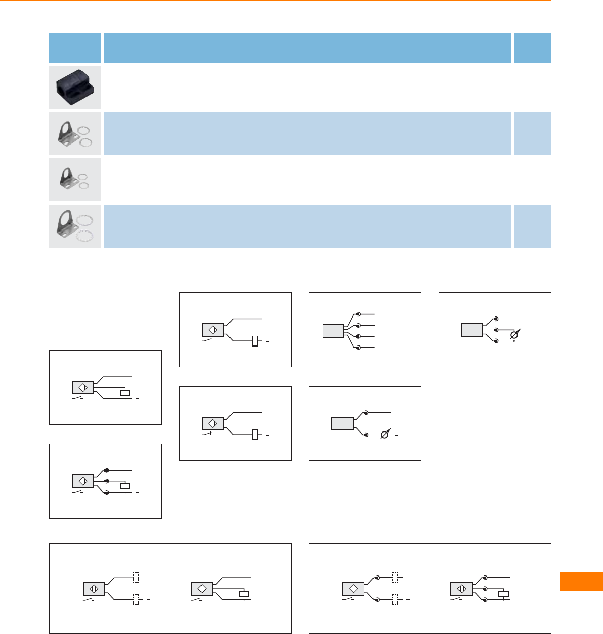
Type Description Order
no.
Mounting clamp · Ø 30 mm · with end stop · for type M30 · Housing materials: PC E11049
Angle bracket · for type M12 · Housing materials: stainless steel E10735
Angle bracket · for type M18 · Housing materials: stainless steel E10736
Angle bracket · for type M30 · Housing materials: stainless steel E10737
Core colours
BK black
BN brown
BU blue
Wiring diagrams
1
BN
BK
BU
L+
L
2
L+
L
1
4
3
3
BN
BU L
L+
4
BN
BU L
L+
5
4
1
3
2OUT2
L+
L
OUT1/Teach/
Data
6
L+
L
1
2
7
L+
L
1
3
2
8
L+
L
BN
BK
BU
L+
L
BN
BK
9
L+
L
1
4
L+
L
1
4
3
Control systems
for mobile vehicles
551
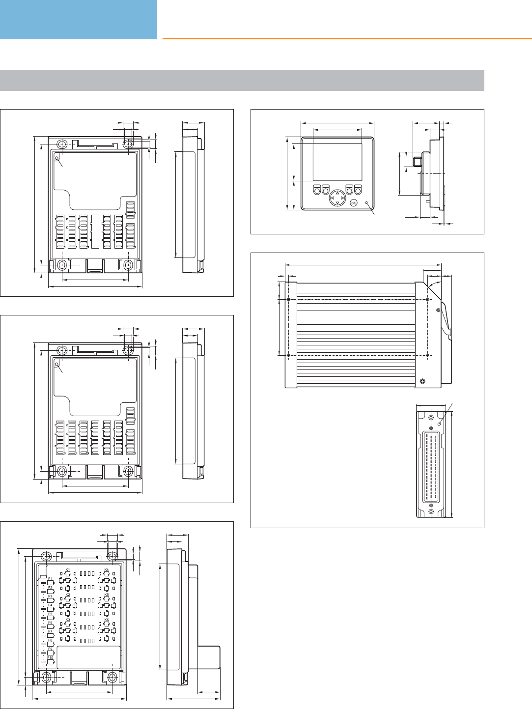
Scale drawings / drawing no. – CAD download: www.ifm.com
1
18
ABCD E F
N2
P/N1
25,5
127
163
145
12,5
8,5
6,5
10,5
79,7
112
LED
8,5
2
18
A B C D E F
N2
P/N1
25,5
127
163
145
12,5
8,5
6,5
10,5
79,7
112
LED
8,5
3
18
25,5
127
163
145
12,5
8,5
6,5
10,5
79,7
112
26,5
63,5
8,5
4
LED
M12x1
M52x1,5
1,5
11,2
87,5 31,3 5
58,6
87,5
44,235,2
12,3
5
153
43 LED
225
20
5,5
26
80
15
26
45°
Control systems
for mobile vehicles
552
Product selectors and further information can be found at: www.ifm.com
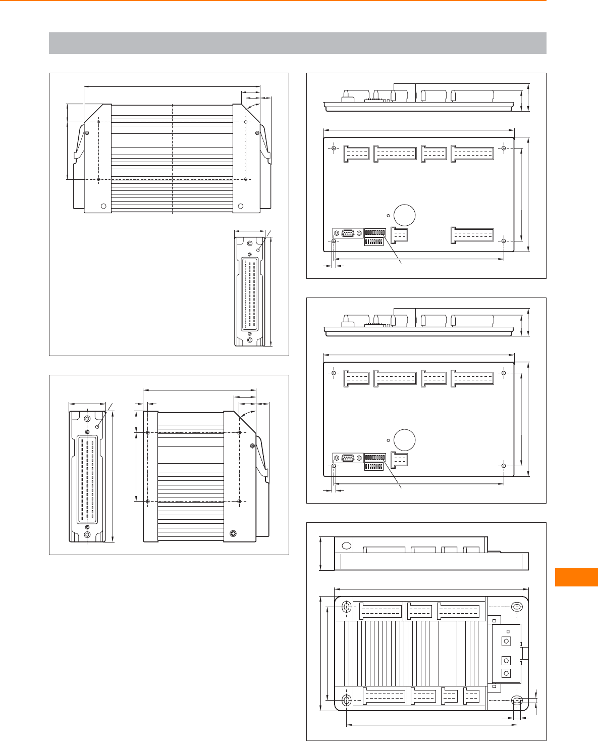
Scale drawings / drawing no. – CAD download: www.ifm.com
6
153
43 LED
247
20
26
80
15
26
45°
7
153
43 LED
132
20
5,5
26
80
15
26
45°
8
25
33
223
134
108
198
4,5 10 LED
9
25
33
223
134
108
198
4,5 10 LED
10
X10 X11
X20 X21
198
226
133
108
39
5,8
7,8
X12
P/N1N2
Control systems
for mobile vehicles
553
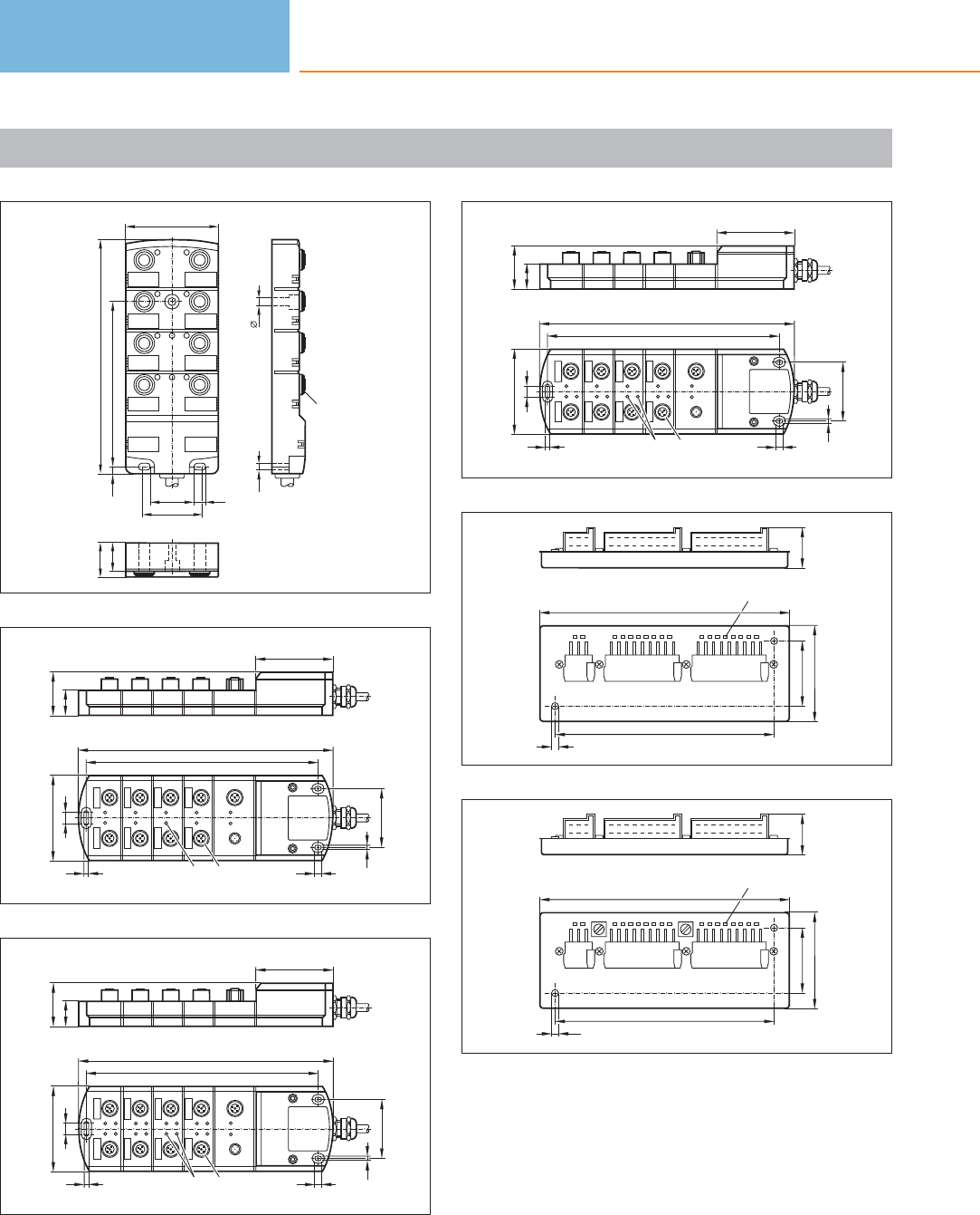
Scale drawings / drawing no. – CAD download: www.ifm.com
11
12
4
6
8
3
5
7
18
22
4,7 107
152
5
4,5
28,5
39
7,5
60
M12x1
PWR
DIA
12
69
23
39
LED M12 x1
9
52
6
227
205
5
5
77
PWR DIA
1
3
5
7
2
4
6
8
CAN in CAN out
13
69
23
39
LED M12 x1
9
52
6
227
205
5
5
77
PWR DIA
1
3
5
7
2
4
6
8
CAN in CAN out
14
69
23
39
LED M12 x1
9
52
6
227
205
5
5
77
PWR DIA
1
3
5
7
2
4
6
8
CAN in CAN out
15
163
63
42,3
18 LED
142,3
4,5
27
16
163
63
42,3
18 LED
142,3
4,5
27
Control systems
for mobile vehicles
554
Product selectors and further information can be found at: www.ifm.com
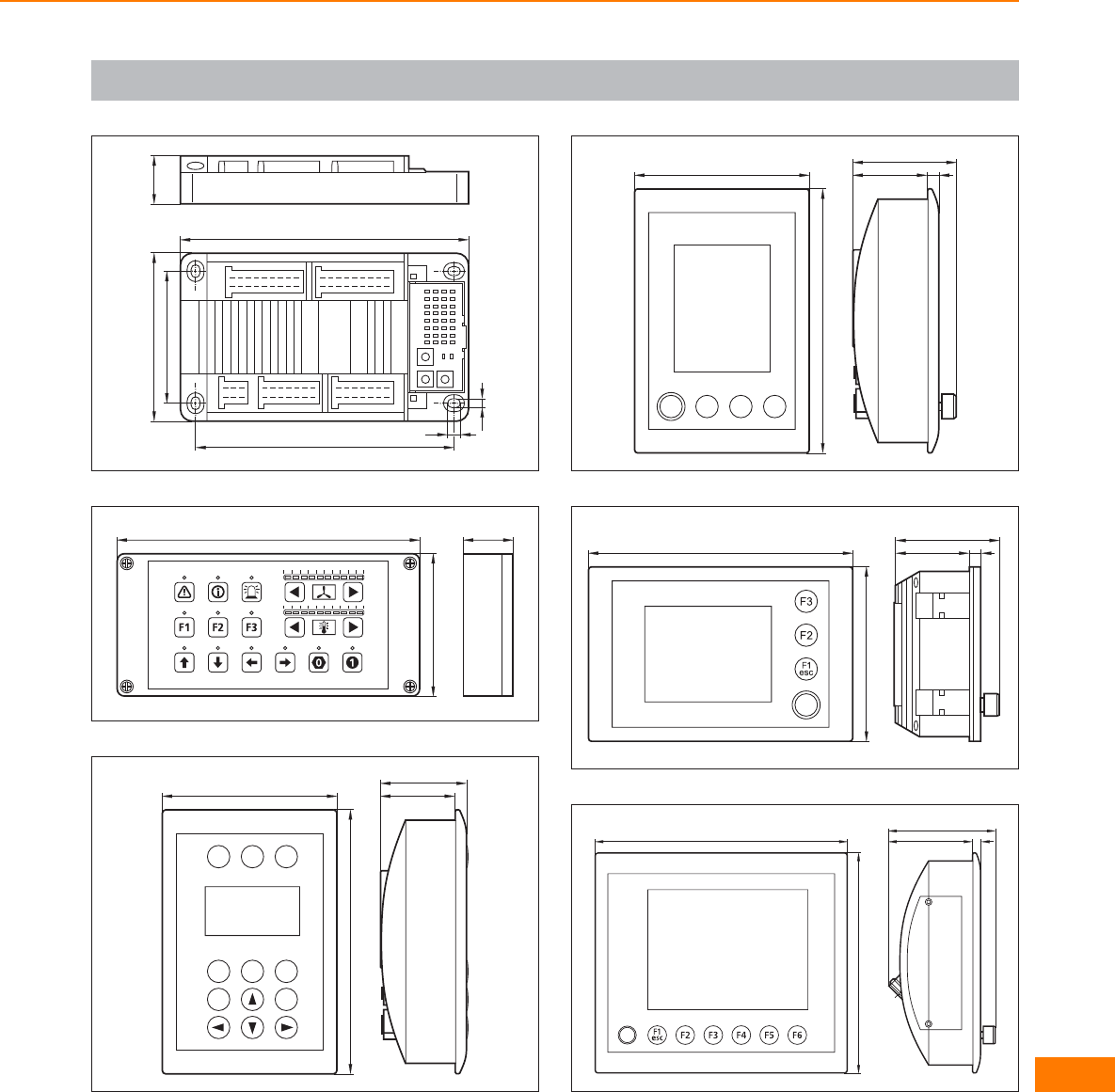
Scale drawings / drawing no. – CAD download: www.ifm.com
17
X10 X11
P/N1 X20 X21
161
181
105
82
30
5,8
7,8
18
32
90
190
19
46,4
53,4
109
165
F2 F3
F1
F5 F6
F4
ok
esc
20
46,4
65,3
7
F3
F2
F1
esc
109
165
21
109
165 46,4
65,3
7
22
189
165
63
81
7
Control systems
for mobile vehicles
555
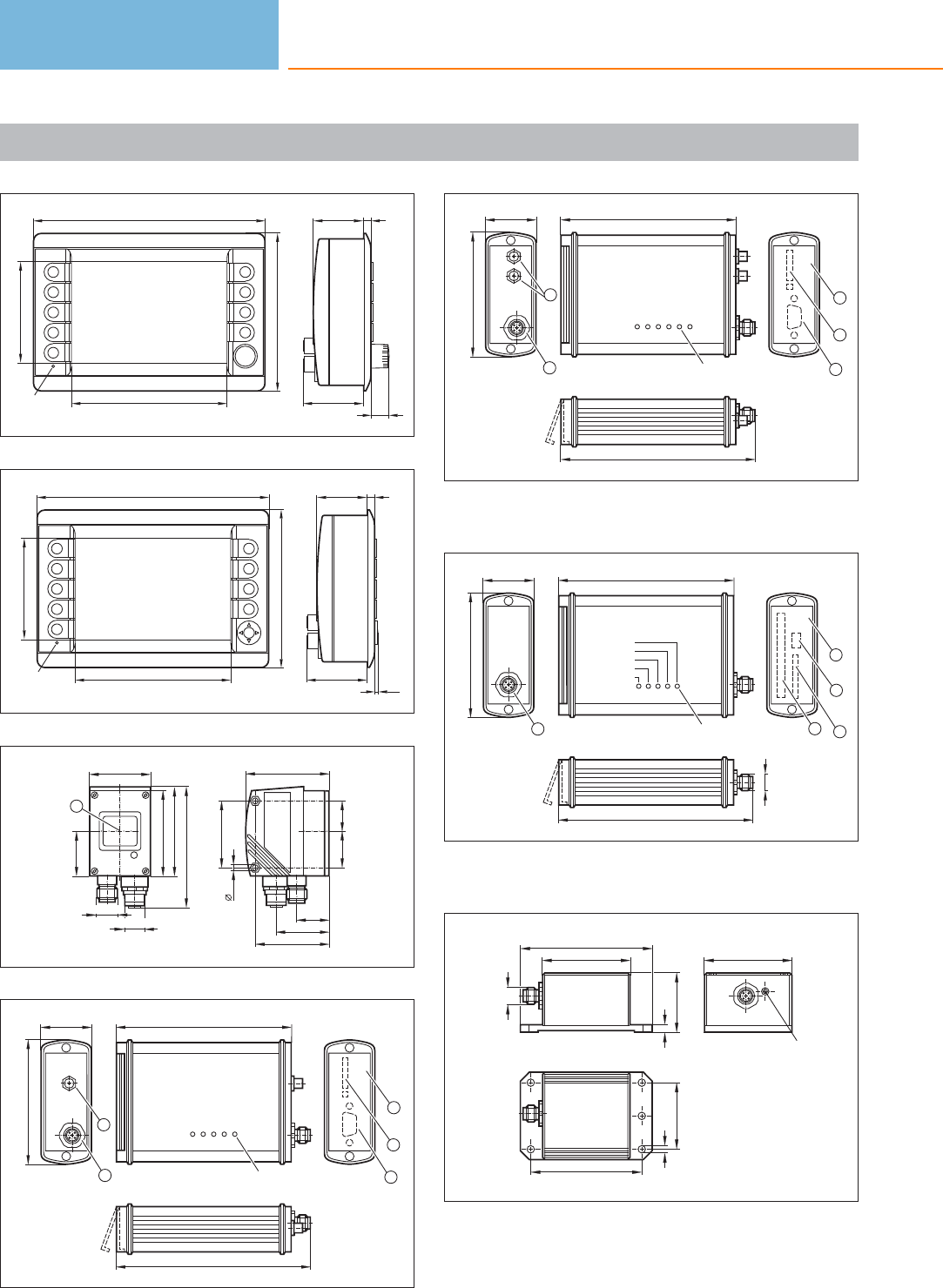
Scale drawings / drawing no. – CAD download: www.ifm.com
23
225
153,4
92,4
146
55
18
746,6
LED
24
225
153,4
92,4
146
55
746,6
LED
2,5
25
55
45
45,6
21,1
34,1
4,3
42
57
80
M12 x1
M12x1
60
20,524,5
30,5
1
26
118
128
5 LED
35
85
4
3
2
1
5
1: SMA aerial connector, 2: CANopen interface, 3: protective cover,
4: SIM card, 5: RS-232 interface
27
118
128
6 LED
35
85
4
3
2
1
5
1: SMA aerial connector, 2: CANopen interface, 3: protective cover,
4: SIM card, 5: RS-232 interface
28
M12 x1
117,5
130
5 LED
35
85
CARD ERROR
CARD ACCESS
ON
ERROR
CAN
5
2
4
1
3
1: CANopen interface, 2: protective cover, 3: USB, type Mini-B
(socket), 4: SD/MMC slot, 5: PCMCIA slot
29
M12 x1
6
41
60
90
60
LED
75
45
5,3
Control systems
for mobile vehicles
556
Product selectors and further information can be found at: www.ifm.com
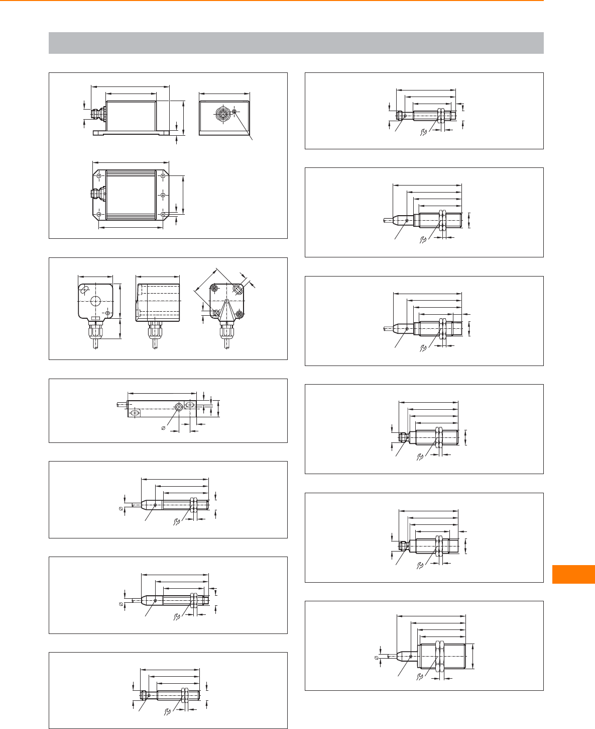
Scale drawings / drawing no. – CAD download: www.ifm.com
30
75
45
5,3
90
M12 x1
6
41
60
92
60
LED
31
52
41
41
24
5
37
5,2
32
6,2
81
20
2,75
5,25
8,25
12,75
33
5,4
79
62
53
M12x1
LED 4 x 90° 17
4
34
5,4
79
62
48
LED 4 x 90° 17
4
M12x1
5
35
59
50
M12x1
17
4
M12 x1
LED
70
36
45
M12x1
17
4
5
M12 x1
59
70
LED
37
64
LED 4 x 90° 24
81
57
50
M18 x1
4
38
64
LED 4 x 90° 24
81
57
40
M18 x1
4
10
39
M18 x1
M12 x1
50
57
70
59
4
24
LED 4 x 90°
40
M18 x1
M12 x1
40
57
70
LED 4 x 90°
59
10
4
24
41
36
53
M30x1,5
57
5
5
64
LED 4 x 90°
81
Control systems
for mobile vehicles
557
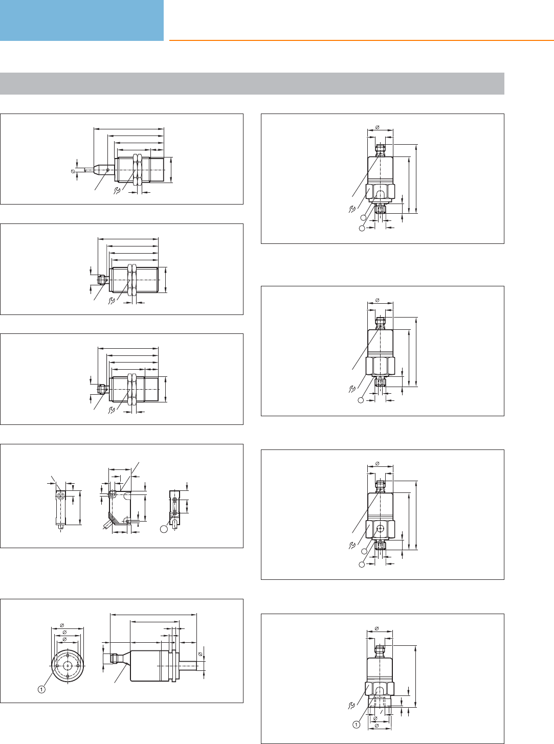
Scale drawings / drawing no. – CAD download: www.ifm.com
42
36
38
M30x1,5
15
57
5
5
64
LED 4 x 90°
81
43
59
53
M30x1,5
57
70
M12 x1
LED 4 x 90° 5
36
44
LED 4 x 90°
59
38
M30x1,5
5
57
70
36
M12 x1
15
45
40
6
12
LED
4
26
13
32
3,2
4
5
LED
3,2
18
16 10
1
1: threaded insert M3, depth 5.8 mm, max. tightening torque 1.2
Nm (screw fixing class 8.8) when brass insert in contact with
counterpart.
46
36,5
30
24
LED
2023 36 9
100
4
4
10
57
M12 x1
47
79,5
M12 x1
30
G14
/
2
LED
65,5
30
12
M5
1
1: Pressure relief mechanism, No mechanical force must be exerted
on the pressure relief mechanism., 2: sealing FPM / DIN 3869-14
48
79,5
M12 x1
30
30
12
G14
/
M5
1
LED
65,5
1: sealing FPM / DIN 3869-14
49
79,5
M12 x1
30
4
2
65,5
30
12
G1/
M5
1
LED
1: ventilation, 2: sealing FPM / DIN 3869-14
50
75
M12 x1
30
30
27
1, 3
21,5
14
G4
1
1: Pressure relief mechanism, No mechanical force must be exerted
on the pressure relief mechanism.
Control systems
for mobile vehicles
558
Product selectors and further information can be found at: www.ifm.com
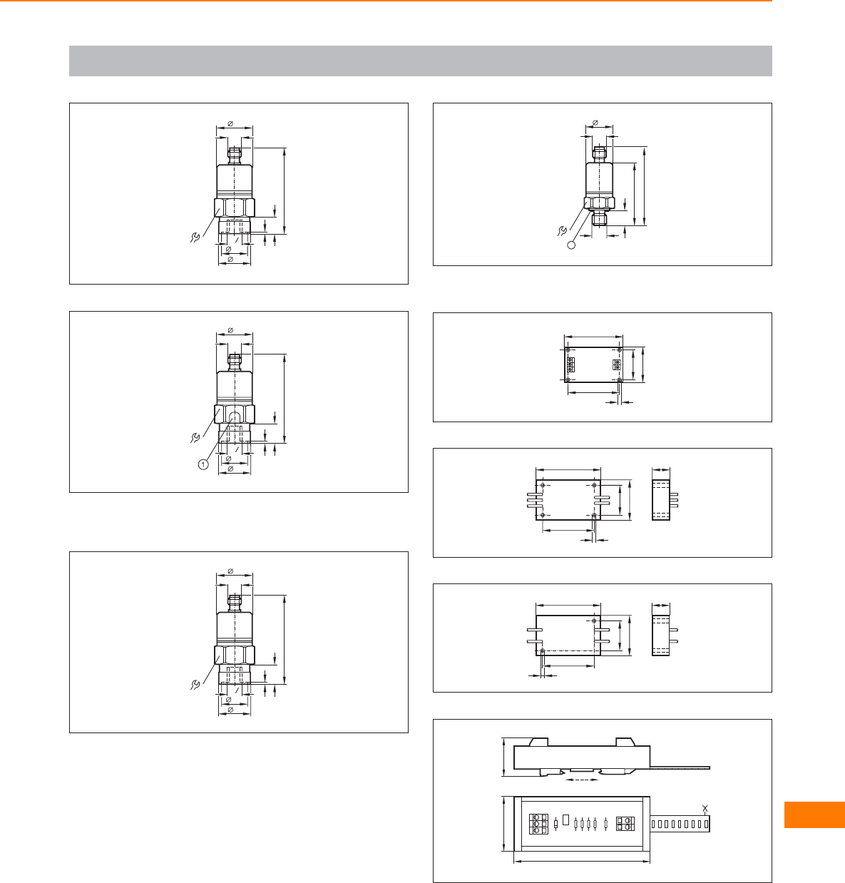
Scale drawings / drawing no. – CAD download: www.ifm.com
51
75
M12 x1
30
30
27
1, 3
21,5
14
G4
1
52
77,5
M12 x1
30
30
27
1, 3
21,5
16,5
G4
1
1: Pressure relief mechanism, No mechanical force must be exerted
on the pressure relief mechanism.
53
77,5
M12 x1
30
30
27
1, 3
21,5
16,5
G4
1
54
22
1
51,2
12
G14
/
65,1
M12 x1
22
1: sealing FPM / DIN 3869-14, tightening torque 25 Nm
55
42,5
49
30
24,5
3,2
56
42,5
54
34
24,5
3,2
15
57
42,5
54
34
24,5
3
15
58
3245
112
1
2
3
5
4
Control systems
for mobile vehicles
559
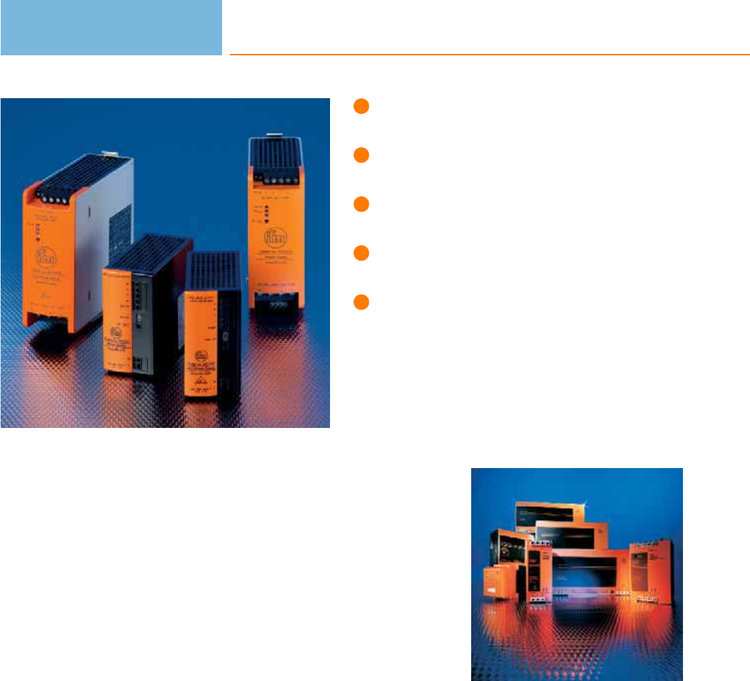
International approval package and
wide-range input for worldwide use.
Partly adjustable output voltage.
Power reserves to cover temporary
overload or supply failure.
Output short-circuit, overload, and
no-load protected.
State signalled via DC-ok output.
Power supplies
Transformer power supplies provide a low voltage, normally 24 V DC. A transformer
according to DIN 0551 ensures a safe electrical separation from mains voltage and
low voltage. The output voltage can be regulated (± 5 %) or smoothed by means of
capacitors. The different designs and output powers allow adaptation to diverse
operating conditions.
Switched-mode power supplies
Primary switched-mode power supplies are a compact and economical solution to
supply sensors and actuators. As opposed to conventional transformer power
supplies with regulated output voltage primary switched-mode power supplies need
no heavy transformers so that there are fewer iron and copper losses. They are
therefore distinguished by a very high degree of efficiency of up to 92 %. Due to
the operating principle by means of high frequency transformers switched-mode
power supplies are much smaller and lighter than transformer power supplies with
identical power. Nevertheless they guarantee an electrical separation. Furthermore,
they offer a wide input voltage range as standard, e.g. 340 to 576 V AC. This
makes them fit for worldwide use.
ifm switched-mode power supplies have a regulated output voltage of typ. 24 V DC
with a tolerance of ± 2 %. Apart from few exceptions the output voltage can be set
between 24 V and 28 V to compensate for example for a voltage drop on long
cables. Between no load and full load they ensure a stable supply voltage and thus
operational reliability in case of supply voltage fluctuations.
Power reserves
Mains fluctuations up to ± 15 % and mains interference are compensated for. Even
mains voltage dips of a few milliseconds are compensated for, the output voltage is
completely maintained. An active inrush
current limitation reduces the inrush current via a fixed resistor which is bridged
after start up.
The outputs are protected against short circuits and overload.
Suitable for the
application: ifm
provides power
supplies in different
power classes.
Power supplies
560

System overview Page
Power supplies / switching amplifiers with one output 562
Power supplies / switching amplifiers with 2 inputs and 2 outputs 562
Switched-mode power supplies, new BasicLine design in a robust metal housing 562
Switched-mode power supplies, single phase, new BasicLine design in a compact plastic housing 562
Standard switched-mode power supplies, single phase 563
Standard switched-mode power supplies, three phases 563
AS-i switched-mode power supplies, single phase, new ClassicLine design in a robust metal housing 564
AS-i switched-mode power supplies, single phase, new BasicLine design in a compact plastic housing 564
AS-i switched-mode power supplies, single phase, discontinued types 564
AS-i switched-mode power supplies, single phase, SilverLine 564 - 565
AS-i dual switched-mode power supplies, single phase, SilverLine 565
AS-i switched-mode power supplies, three phases, SilverLine 565
Scale drawings / drawing no. – CAD download: www.ifm.com 565 - 569
Power supplies
561
Power supplies / switching amplifiers with one output
Type Current
[mA]
Output voltage
[V]
Nominal voltage
[V]
Output Draw-
ing
no.
Order
no.
max. 100 24 DC ±5% 230 AC (47...63 Hz) relay (1 changeover contact) 1 DN0001
max. 100 24 DC ±5% 110 AC (47...63 Hz) relay (1 changeover contact) 1DN0012
max. 40 24 DC ±5% 230 AC (50...60 Hz) / 24 DC relay (1 changeover contact) 1 DT0001
Power supplies / switching amplifiers with 2 inputs and 2 outputs
Type Current
[mA]
Output voltage
[V]
Nominal voltage
[V]
Output Draw-
ing
no.
Order
no.
max. 300 24 V DC ± 3 % 110...240 AC / -15 / +10 2 relays (1 changeover contact
per channel) 2DN0200
Switched-mode power supplies, new BasicLine design in a robust metal housing
Type Current
[A]
Output voltage
[V]
Nominal voltage
[V]
Mains
buffering time
[ms]
Efficiency
typ.
[%]
Draw-
ing
no.
Order
no.
2.5 24...28 100...240 AC 450 (230 V AC; 24 V DC; 2.5 A) 87.1 3 DN3011
524...28 100...240 AC 205 (230 V AC; 24 V DC; 5 A) 88.9 3DN3012
Switched-mode power supplies, single phase, new BasicLine design in a compact plastic hou-
sing
Type Current
[A]
Output voltage
[V]
Nominal voltage
[V]
Mains
buffering time
[ms]
Efficiency
typ.
[%]
Draw-
ing
no.
Order
no.
1.25 24...28 100...240 AC 120 (230 V AC; 24 V DC; 1.25 A) 84 4 DN1030
2.5 24...28 100...240 AC 90 (230 V AC; 24 V DC; 2.5 A) 88 4DN1031
Power supplies
562
Product selectors and further information can be found at: www.ifm.com
Standard switched-mode power supplies, single phase
Type Current
[A]
Output voltage
[V]
Nominal voltage
[V]
Mains
buffering time
[ms]
Efficiency
typ.
[%]
Draw-
ing
no.
Order
no.
3 12...15 DC (±2%) 115 / 230 AC > 20 87 5 DN2021
424 DC (+5% / -1%) 115 / 230 AC > 37 90 6DN2112
4.1 24...28 DC (±2%) 115 / 230 AC > 40 (230 V AC;
24 V DC / 4.1 A) 90 7 DN1022
10 24...28 DC (±2%) 115 / 230 AC > 20 90 8DN2013
20 24...28 DC (±2%) 230 AC > 20 91 9 DN2014
20 24...28 DC, ±2% 115 / 230 AC 15 / 30 90 9DN2114
Standard switched-mode power supplies, three phases
Type Current
[A]
Output voltage
[V]
Nominal voltage
[V]
Mains
buffering time
[ms]
Efficiency
typ.
[%]
Draw-
ing
no.
Order
no.
5 24...28 DC (±2%) 3 x 400...500 AC > 16 89 10 DN2032
10 24...28 DC (±2%) 3 x 400...500 AC > 24 90 11 DN2033
20 24...28 DC (±2%) 3 x 400 AC > 11 92 12 DN2034
20 24...28 DC (±2%) 3 x 400...500 AC;
±15% > 11 92 13 DN2134
40 24...28 DC (±2%) 3 x 400...500 AC > 15 92.5 14 DN2035
30 24...28 DC (±2%) 3 x 400...500 AC > 10 93 15 DN2036
Power supplies
563
You can find scale drawings from page 565
AS-i switched-mode power supplies, single phase, new ClassicLine design in a robust
metal housing
Type Current
[A]
Output voltage
[V]
Nominal voltage
[V]
Mains
buffering time
[ms]
Efficiency
typ.
[%]
Draw-
ing
no.
Order
no.
2.8 29.5...31.6 DC 100...240 AC 330 (230 V AC) 88 16 AC1236
429.5...31.6 DC 100...240 AC 195 (230 V AC / 24 V DC) 88 16 AC1244
AS-i switched-mode power supplies, single phase, new BasicLine design in a compact
plastic housing
Type Current
[A]
Output voltage
[V]
Nominal voltage
[V]
Mains
buffering time
[ms]
Efficiency
typ.
[%]
Draw-
ing
no.
Order
no.
0.95 29.5...31.6 DC 100...240 AC 120 (230 V AC) 86 17 AC1220
1.9 29.5...31.6 DC 100...240 AC 90 (230 V AC) 88 17 AC1221
AS-i switched-mode power supplies, single phase, discontinued types
Type Current
[A]
Output voltage
[V]
Nominal voltage
[V]
Mains
buffering time
[ms]
Efficiency
typ.
[%]
Draw-
ing
no.
Order
no.
2.8 29.5...31.6 DC 115 / 230 AC > 10 88 18 AC1216
429.5...31.6 DC 115 / 230 AC > 10 90 19 AC1224
AS-i switched-mode power supplies, single phase, SilverLine
Type Current
[A]
Output voltage
[V]
Nominal voltage
[V]
Mains
buffering time
[ms]
Efficiency
typ.
[%]
Draw-
ing
no.
Order
no.
2.8 29.5...31.6 DC 115 / 230 AC > 10 88 20 AC1226
2.8 29.5...31.6 DC 115 / 230 AC > 10 88 21 AC1209
2.8 29.5...31.6 DC 24 DC > 10 87 22 AC1207
Power supplies
564
Product selectors and further information can be found at: www.ifm.com
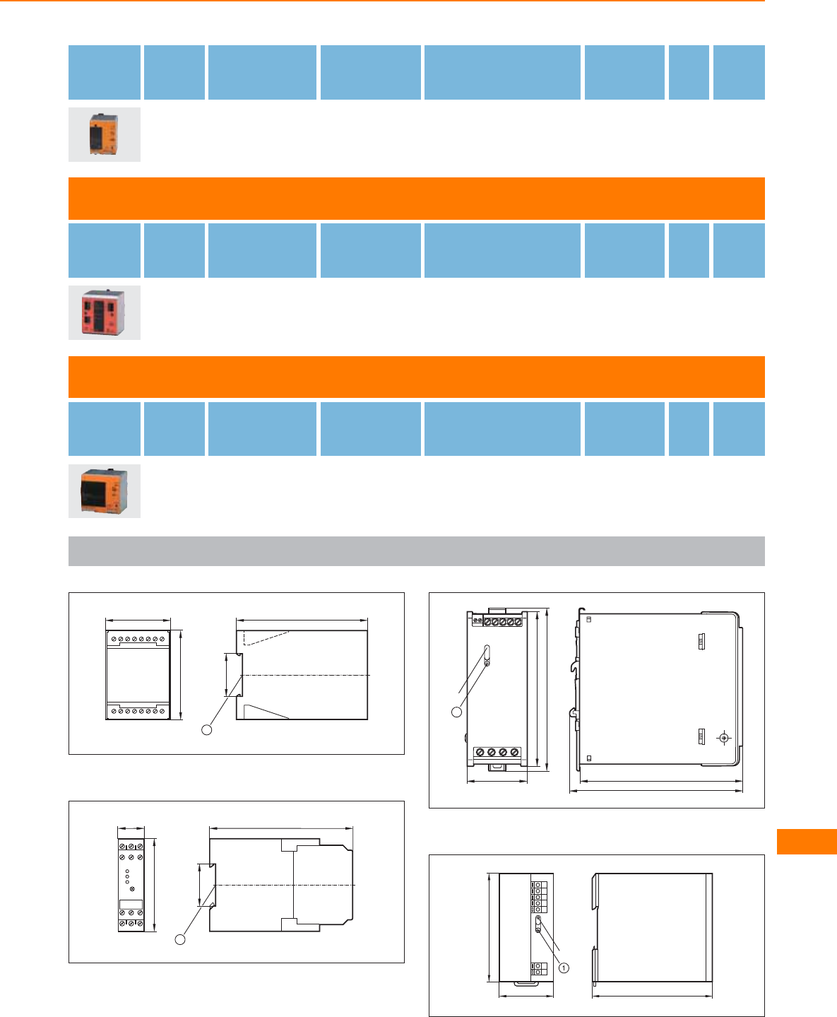
Type Current
[A]
Output voltage
[V]
Nominal voltage
[V]
Mains
buffering time
[ms]
Efficiency
typ.
[%]
Draw-
ing
no.
Order
no.
8 29.5...31.6 DC 115 / 230 AC > 10 92 23 AC1218
AS-i dual switched-mode power supplies, single phase, SilverLine
Type Current
[A]
Output voltage
[V]
Nominal voltage
[V]
Mains
buffering time
[ms]
Efficiency
typ.
[%]
Draw-
ing
no.
Order
no.
2 x 4 2 x 29.5...31.6 DC 115 / 230 AC > 10 87 24 AC1212
AS-i switched-mode power supplies, three phases, SilverLine
Type Current
[A]
Output voltage
[V]
Nominal voltage
[V]
Mains
buffering time
[ms]
Efficiency
typ.
[%]
Draw-
ing
no.
Order
no.
8 29.5...31.6 DC 3 x 400...500 AC 22 (400V) 91.5 25 AC1223
Scale drawings / drawing no. – CAD download: www.ifm.com
1
55
75
1 2 3 4 5 6 7 8
9 10 11 12 13 14 15 16
110
35,5
1
1: mounting on DIN rail
2
22,5
78
L+ L– I1
LNI2
12 14 11
22
21 24
35,5
120
1
1: mounting on DIN rail
3
136
144
136
50
129
1
LEDs
1: with pot.
4
45 100
90
LED
1: with pot.
Power supplies
565

Scale drawings / drawing no. – CAD download: www.ifm.com
5
89
4
107
124
49
LED
131
6
124
64
LED
131
89
4
107
7
35,5
107
73
75
83
LED
pot.
1
1: jumper „single/parallel operation“
8
89
4
107
124
120
131
LED
9
124
220
131
LED
227
89
4
107
10
124
73
LED
131
4
122
103
11
4
121
110
90
124
131
3
2
1
6
5
4
1: LED red, 2: reset push button, 3: jumper “overload performance“,
4: jumper “single/parallel operation“, 5: with pot., 6: LED green
Power supplies
566
Product selectors and further information can be found at: www.ifm.com
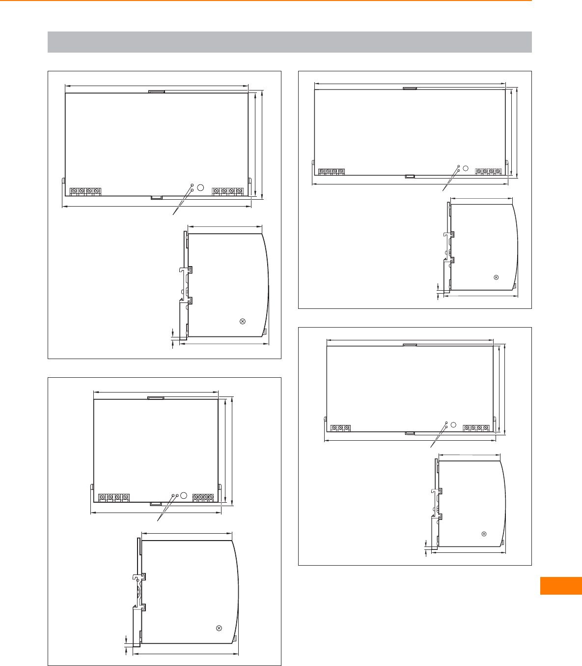
Scale drawings / drawing no. – CAD download: www.ifm.com
12
89
4
107
124
220
131
227
LED
13
4
127
108
124
150
131
157
LED
14
89
4
107
124
275
131
282
LED
15
89
4
107
124
240
131
LED
247
Power supplies
567
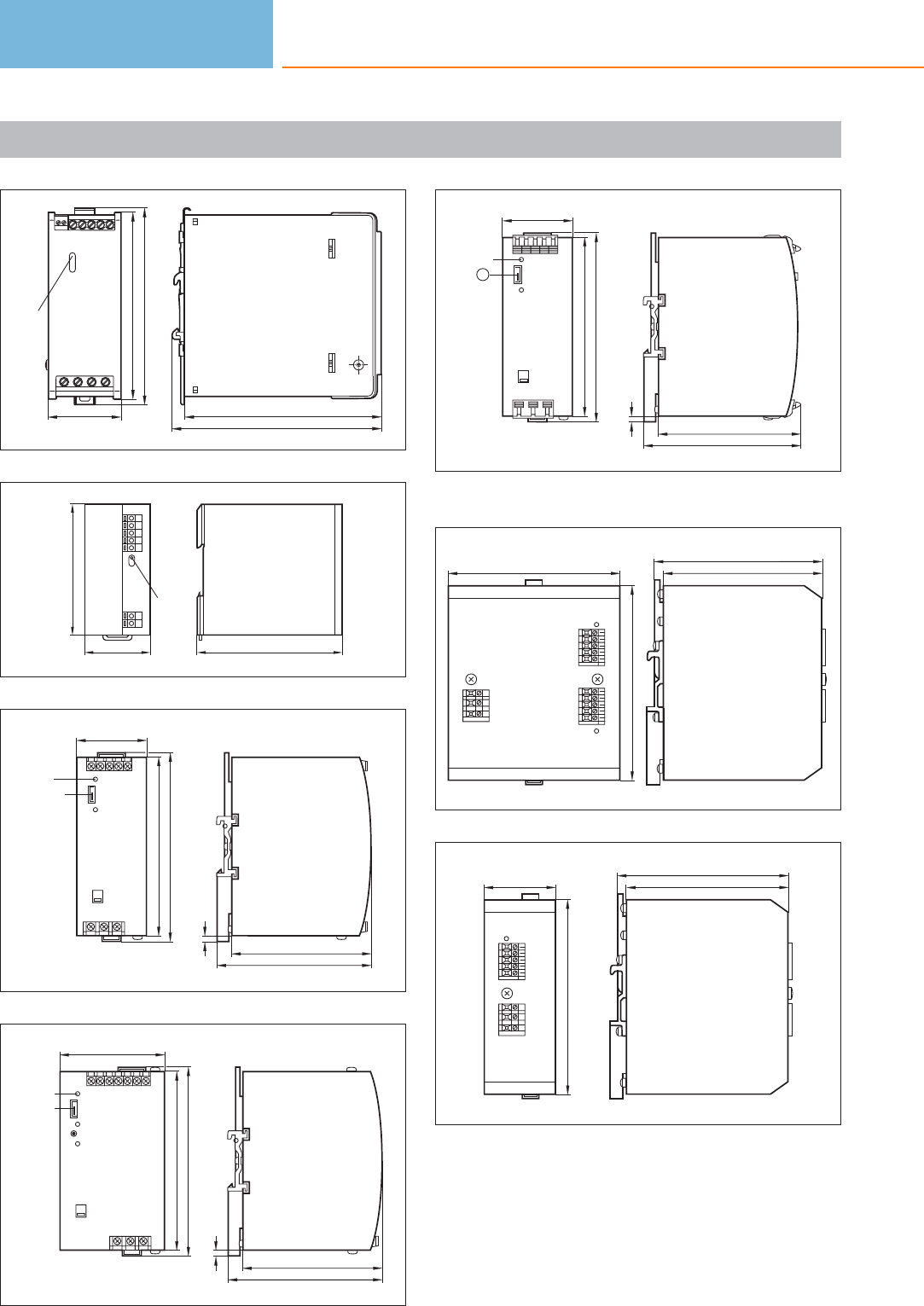
Scale drawings / drawing no. – CAD download: www.ifm.com
16
136
144
136
50
129
LED
17
45 100
90
LED
18
4
107
96
49
124
131
Jumper
LED
19
4
107
96
73
124
131
LED
Jumper
20
4
109
98
49
124
131
LED
1
1: Jumper
21
113
118,5
134
120
22
134
50 112,5
118,5
Power supplies
568
Product selectors and further information can be found at: www.ifm.com
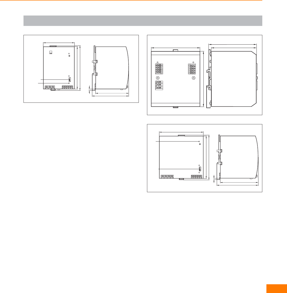
Scale drawings / drawing no. – CAD download: www.ifm.com
23
4
107
96
91
124
131
Jumper
LED
24
113
118,5
134
120
25
4
122
111
129
124
131
LED
Jumper
Power supplies
569
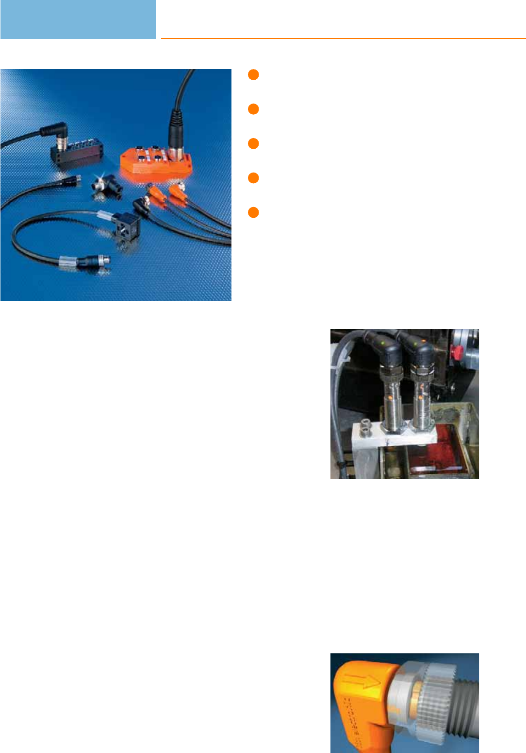
Complete product range: sockets,
plugs, jumper cables, splitter boxes.
Various cable materials for
different applications.
High-quality materials for
maximum reliability.
“ecolink” series with innovative
quality features.
Integrated LEDs for easy diagnosis.
Connection technology
With a wide variety of different sensor designs ifm electronic offers a wide range of
high quality connectors. The choice of types covers common M8, M12, M18 types
through to valve plugs. The “ecolink” connectors (order no. EVxxxx) offer addi-
tional quality features.
ecolink - a new dimension in connection technology
Due to the special installation of a mechanical end stop the O-ring is always
correctly compressed and so permanently maintains its sealing function. The con-
nector remains securely positioned on the unit even in case of extreme vibration
and impacts. Novel design and a transparent black housing ensure that even in
bright lighting conditions the LEDs are more clearly visible than with the clear
transparent versions.
For industrial applications:
High-quality materials suited to the requirements in industrial environments. Largely
resistant to oils, greases and coolants.
For hygienic and wet areas:
PVC housing and cable, gold-plated contacts and high-grade stainless steel nuts are
the optimum choice for long life.
For hazardous areas
Connection technology for ATEX categories 2D, 3D and 3G. With the EC type
examination certificate for components from DEKRA EXAM the connection tech-
nology meets the strictest requirements.
For welding applications
Halogen-free PUR cables prevent burning-in of weld spatter; teflon-coated coupling
nuts prevent weld spatter sticking. The cables are also suited for drag chains and
torsional movements.
For sensors in robust applications:
The saw tooth contoured vibration protection secures against strong shocks and
vibrations. The high protection rating, wide temperature range and high-quality
housing materials (high-grade stainless steel, TPU) ensure permanent safe con-
nection in harsh environments.
Black, transparent
housing for optimum
LED visibility.
Maximum operational
reliability due to the
new vibration protec-
tion with end stop.
Connection technology
570

System overview Page
M8 sockets for industrial applications 572 - 573
M12 sockets for industrial applications 573 - 576
M16 sockets for industrial applications 577
M18 sockets for industrial applications 577
M23 sockets for industrial applications 577 - 579
1/2" sockets for industrial applications 579
7/8" sockets for industrial applications 580
DIN sockets for industrial applications 580
RD24 sockets for industrial applications 580
M8 cable plugs for industrial applications 580 - 581
M12 cable plugs for industrial applications 581 - 582
M8 - M8 jumpers for industrial applications 582 - 585
M8 socket - M12 plug jumpers for industrial applications 585 - 588
M8 plug - M12 socket jumpers for industrial applications 588 - 590
M12 - M12 jumpers for industrial applications 591 - 595
Valve - plug jumpers for industrial applications 595 - 597
Splitter boxes for industrial applications 597 - 601
Splitter boxes for hygienic and wet areas 601
Connectors weld slag resistant 602 - 603
Jumpers weld slag resistant 603 - 604
Connectors for hygienic and wet areas 605 - 609
Jumpers for hygienic and wet areas 609 - 614
Jumpers for hygienic and wet areas 615 - 619
Connectors for hazardous areas 619 - 620
Jumpers for hazardous areas 621
Connectors for robust applications 621 - 623
Wiring diagrams 623 - 628
Scale drawings / drawing no. – CAD download: www.ifm.com 629 - 644
Connection technology
571
M8 sockets for industrial applications
Type Cable Wire
specification
Material
housing/
nut
U
[V]
Ta
[°C]
Pro-
tection
LEDs Draw-
ing
no.
Order
no.
Group 1 · Socket M8, 3-pole, 3-wire · Wiring diagram no. 1
2 m black
PUR cable 3 x 0.25 mm2, Ø 3.7 mm TPU /
brass
50 AC
60 DC -25...90 IP 67 / IP 68 /
IP 69K – 1 EVC141
5 m black
PUR cable 3 x 0.25 mm2, Ø 3.7 mm TPU /
brass
50 AC
60 DC -25...90 IP 67 / IP 68 /
IP 69K – 1 EVC142
10 m black
PUR cable 3 x 0.25 mm2, Ø 3.7 mm TPU /
brass
50 AC
60 DC -25...90 IP 67 / IP 68 /
IP 69K – 1 EVC143
2 m black
PUR cable 3 x 0.25 mm2, Ø 3.7 mm TPU /
brass
50 AC
60 DC -25...90 IP 67 / IP 68 /
IP 69K – 2 EVC144
5 m black
PUR cable 3 x 0.25 mm2, Ø 3.7 mm TPU /
brass
50 AC
60 DC -25...90 IP 67 / IP 68 /
IP 69K – 2 EVC145
10 m black
PUR cable 3 x 0.25 mm2, Ø 3.7 mm TPU /
brass
50 AC
60 DC -25...90 IP 67 / IP 68 /
IP 69K – 2 EVC146
Group 2 · Socket M8, 3-pole, 3-wire, LED, PNP · Wiring diagram no. 2
2 m black
PUR cable 3 x 0.25 mm2, Ø 3.7 mm TPU /
brass 10...36 DC -25...90 IP 67 / IP 68 /
IP 69K
green /
yellow 3EVC147
5 m black
PUR cable 3 x 0.25 mm2, Ø 3.7 mm TPU /
brass 10...36 DC -25...90 IP 67 / IP 68 /
IP 69K
green /
yellow 3EVC148
10 m black
PUR cable 3 x 0.25 mm2, Ø 3.7 mm TPU /
brass 10...36 DC -25...90 IP 67 / IP 68 /
IP 69K
green /
yellow 3EVC149
Group 3 · Socket M8, 3-pole · Wiring diagram no. 3
wirable –PA /
brass
60 AC
75 DC -25...90 IP 68 – – E11552
Group 4 · Socket M8, 4-pole, 4-wire · Wiring diagram no. 4
2 m black
PUR cable 4 x 0.25 mm2, Ø 3.7 mm TPU /
brass
50 AC
60 DC -25...90 IP 67 / IP 68 /
IP 69K – 4 EVC150
5 m black
PUR cable 4 x 0.25 mm2, Ø 3.7 mm TPU /
brass
50 AC
60 DC -25...90 IP 67 / IP 68 /
IP 69K – 4 EVC151
Connection technology
572
Product selectors and further information can be found at: www.ifm.com
Type Cable Wire
specification
Material
housing/
nut
U
[V]
Ta
[°C]
Pro-
tection
LEDs Draw-
ing
no.
Order
no.
Group 4 · Socket M8, 4-pole, 4-wire · Wiring diagram no. 4
10 m black
PUR cable 4 x 0.25 mm2, Ø 3.7 mm TPU /
brass
50 AC
60 DC -25...90 IP 67 / IP 68 /
IP 69K – 4 EVC152
2 m black
PUR cable 4 x 0.25 mm2, Ø 3.7 mm TPU /
brass
50 AC
60 DC -25...90 IP 67 / IP 68 /
IP 69K – 5 EVC153
5 m black
PUR cable 4 x 0.25 mm2, Ø 3.7 mm TPU /
brass
50 AC
60 DC -25...90 IP 67 / IP 68 /
IP 69K – 5 EVC154
10 m black
PUR cable 4 x 0.25 mm2, Ø 3.7 mm TPU /
brass
50 AC
60 DC -25...90 IP 67 / IP 68 /
IP 69K – 5 EVC155
Group 5 · Socket M8, 4-pole · Wiring diagram no. 5
wirable –PA /
brass
60 AC
75 DC -25...90 IP 68 – – E11553
M12 sockets for industrial applications
Type Cable Wire
specification
Material
housing/
nut
U
[V]
Ta
[°C]
Pro-
tection
LEDs Draw-
ing
no.
Order
no.
Group 6 · Socket M12, 2-pole, 4-wire · Wiring diagram no. 6
2 m black
PUR cable 2 x 0.34 mm2, Ø 4.9 mm TPU /
brass
250 AC
300 DC -25...90 IP 67 / IP 68 /
IP 69K – 6 EVC164
5 m black
PUR cable 2 x 0.34 mm2, Ø 4.9 mm TPU /
brass
250 AC
300 DC -25...90 IP 67 / IP 68 /
IP 69K – 6 EVC165
10 m black
PUR cable 2 x 0.34 mm2, Ø 4.9 mm TPU /
brass
250 AC
300 DC -25...90 IP 67 / IP 68 /
IP 69K – 6 EVC166
Group 7 · Socket M12, 2-pole, 2-wire · Wiring diagram no. 6
2 m black
PUR cable 2 x 0.34 mm2, Ø 4.9 mm TPU /
brass
250 AC
300 DC -25...90 IP 67 / IP 68 /
IP 69K – 7 EVC161
5 m black
PUR cable 2 x 0.34 mm2, Ø 4.9 mm TPU /
brass
250 AC
300 DC -25...90 IP 67 / IP 68 /
IP 69K – 7 EVC162
10 m black
PUR cable 2 x 0.34 mm2, Ø 4.9 mm TPU /
brass
250 AC
300 DC -25...90 IP 67 / IP 68 /
IP 69K – 7 EVC163
Connection technology
573
You can find wiring diagrams and scale drawings from page 623
Type Cable Wire
specification
Material
housing/
nut
U
[V]
Ta
[°C]
Pro-
tection
LEDs Draw-
ing
no.
Order
no.
Group 8 · socket M12, 2-pole + PE, 3-wire · Wiring diagram no. 7
2 m orange
PVC cable
3 x AWG 22 (3 x
0.34 mm2), Ø 5 mm
TPU /
brass
250 AC
300 DC -25...90 IP 67 – 8 E10865
5 m orange
PVC cable
3 x AWG 22 (3 x
0.34 mm2), Ø 5 mm
TPU /
brass
250 AC
300 DC -25...90 IP 67 – 8 E10866
2 m orange
PVC cable
3 x AWG 22 (3 x
0.34 mm2), Ø 5 mm
TPU /
brass
250 AC
300 DC -25...90 IP 67 – 9 E10867
5 m orange
PVC cable
3 x AWG 22 (3 x
0.34 mm2), Ø 5 mm
TPU /
brass
250 AC
300 DC -25...90 IP 67 – 9 E10868
Group 9 · Socket M12, 4-pole · Wiring diagram no. 5
wirable ...0.75 mm2(Ø 4...6 mm) PA /
brass 250 AC/DC -25...85 IP 68 –10 E11509
wirable ...0.75 mm2(Ø 4...6 mm) PA /
brass 250 AC/DC -25...85 IP 68 –11 E11508
Group 10 · Socket M12, 4-pole, LED, PNP · Wiring diagram no. 8
wirable ...0.75 mm2(Ø 4...6 mm) PA /
brass 10...30 DC -25...85 IP 68 green /
yellow 12 E11510
wirable ...0.75 mm2(Ø 4...6 mm) PA 10...30 DC -40...85 IP 67 green /
yellow 11 E10136
Group 11 · Socket M12, 5/4-pole, 4-wire · Wiring diagram no. 4
2 m black
PUR cable 4 x 0.34 mm2, Ø 4.9 mm TPU /
brass
250 AC
300 DC -25...90 IP 67 / IP 68 /
IP 69K –13 EVC004
5 m black
PUR cable 4 x 0.34 mm2, Ø 4.9 mm TPU /
brass
250 AC
300 DC -25...90 IP 67 / IP 68 /
IP 69K –13 EVC005
10 m black
PUR cable 4 x 0.34 mm2, Ø 4.9 mm TPU /
brass
250 AC
300 DC -25...90 IP 67 / IP 68 /
IP 69K –13 EVC006
2 m black
PUR cable 4 x 0.34 mm2, Ø 4.9 mm TPU /
brass
250 AC
300 DC -25...90 IP 67 / IP 68 /
IP 69K –14 EVC001
Connection technology
574
Product selectors and further information can be found at: www.ifm.com
Type Cable Wire
specification
Material
housing/
nut
U
[V]
Ta
[°C]
Pro-
tection
LEDs Draw-
ing
no.
Order
no.
Group 11 · Socket M12, 5/4-pole, 4-wire · Wiring diagram no. 4
5 m black
PUR cable 4 x 0.34 mm2, Ø 4.9 mm TPU /
brass
250 AC
300 DC -25...90 IP 67 / IP 68 /
IP 69K –14 EVC002
10 m black
PUR cable 4 x 0.34 mm2, Ø 4.9 mm TPU /
brass
250 AC
300 DC -25...90 IP 67 / IP 68 /
IP 69K –14 EVC003
Group 12 · Socket M12, 5/4-pole, 4-wire, LED, PNP · Wiring diagram no. 9
2 m black
PUR cable 4 x 0.34 mm2, Ø 4.9 mm TPU /
brass 10...36 DC -25...90 IP 67 / IP 68 /
IP 69K
green /
2 x yellow 15 EVC007
5 m black
PUR cable 4 x 0.34 mm2, Ø 4.9 mm TPU /
brass 10...36 DC -25...90 IP 67 / IP 68 /
IP 69K
green /
2 x yellow 15 EVC008
10 m black
PUR cable 4 x 0.34 mm2, Ø 4.9 mm TPU /
brass 10...36 DC -25...90 IP 67 / IP 68 /
IP 69K
green /
2 x yellow 15 EVC009
Group 13 · Socket M12, 5-pole · Wiring diagram no. 10
wirable ...0.75 mm2(Ø 4...6 mm) PA /
brass 125 AC/DC -25...85 IP 68 –16 E11512
wirable ...0.75 mm2(Ø 4...6 mm) PA /
brass 125 AC/DC -25...85 IP 68 –17 E11511
Group 14 · Socket M12, 5-pole, 5-wire · Wiring diagram no. 11
2 m black
PUR cable 5 x 0.34 mm2, Ø 4.9 mm TPU /
brass
30 AC
36 DC -25...90 IP 67 / IP 68 /
IP 69K –13 EVC073
5 m black
PUR cable 5 x 0.34 mm2, Ø 4.9 mm TPU /
brass
30 AC
36 DC -25...90 IP 67 / IP 68 /
IP 69K –13 EVC074
10 m black
PUR cable 5 x 0.34 mm2, Ø 4.9 mm TPU /
brass
30 AC
36 DC -25...90 IP 67 / IP 68 /
IP 69K –13 EVC075
2 m black
PUR cable 5 x 0.34 mm2, Ø 4.9 mm TPU /
brass
30 AC
36 DC -25...90 IP 67 / IP 68 /
IP 69K –14 EVC070
5 m black
PUR cable 5 x 0.34 mm2, Ø 4.9 mm TPU /
brass
30 AC
36 DC -25...90 IP 67 / IP 68 /
IP 69K –14 EVC071
10 m black
PUR cable 5 x 0.34 mm2, Ø 4.9 mm TPU /
brass
30 AC
36 DC -25...90 IP 67 / IP 68 /
IP 69K –14 EVC072
Connection technology
575
You can find wiring diagrams and scale drawings from page 623
Type Cable Wire
specification
Material
housing/
nut
U
[V]
Ta
[°C]
Pro-
tection
LEDs Draw-
ing
no.
Order
no.
Group 15 · Socket M12, 8-pole, 6-wire · Wiring diagram no. 12
5 m black
PUR cable 6 x 0.34 mm2, Ø 6 mm TPU /
diecast zinc 60 AC/DC -25...85 IP 68 –18 E10976
10 m black
PUR cable 6 x 0.34 mm2, Ø 6 mm TPU /
diecast zinc 60 AC/DC -25...85 IP 68 –18 E10977
Group 16 · socket M12, 8-pole, 7-wire + screen · Wiring diagram no. 13
2 m black
PUR cable 7 x 0.25 mm2+ screen TPU /
diecast zinc 60 AC/DC -25...85 IP 67 –18 E20738
5 m black
PUR cable 7 x 0.25 mm2+ screen TPU /
diecast zinc 60 AC/DC -25...85 IP 67 –19 E20838
Group 17 · socket M12, 8-pole, 8-wire, for temperature sensors TR 8... · Wiring diagram no. 14
2 m black
PUR cable 8 x 0.25 mm2, Ø 6.2 mm PUR /
brass
30 AC
36 DC -25...80 IP 67 –20 E11231
5 m black
PUR cable 8 x 0.25 mm2, Ø 6.2 mm PUR /
brass
30 AC
36 DC -25...80 IP 67 –20 E11232
2 m black
PUR cable 8 x 0.25 mm2, Ø 6.2 mm PUR /
brass
30 AC
36 DC -25...80 IP 68 –21 E11950
5 m black
PUR cable 8 x 0.25 mm2, Ø 6.2 mm PUR /
brass
30 AC
36 DC -25...80 IP 68 –21 E11807
10 m black
PUR cable 8 x 0.25 mm2, Ø 6.2 mm PUR /
brass
30 AC
36 DC -25...80 IP 68 –21 E11311
Group 18 · Socket M12, 8/7-pole, 8-wire · Wiring diagram no. 15
5 m black
PUR cable 8 x 0.25 mm2TPU /
brass
30 AC
36 DC -40...80 IP 68 –20 E12168
10 m black
PUR cable 8 x 0.25 mm2TPU /
brass
30 AC
36 DC -40...80 IP 68 –20 E12169
5 m black
PUR cable 8 x 0.25 mm2TPU /
brass
30 AC
36 DC -40...80 IP 67 –21 E12166
10 m black
PUR cable 8 x 0.25 mm2TPU /
brass
30 AC
36 DC -40...80 IP 67 –21 E12167
Connection technology
576
Product selectors and further information can be found at: www.ifm.com
M16 sockets for industrial applications
Type Cable Wire
specification
Material
housing/
nut
U
[V]
Ta
[°C]
Pro-
tection
LEDs Draw-
ing
no.
Order
no.
Group 19 · socket M16, 14-pole, 10-wire · Wiring diagram no. 16
5 m black
PUR cable
8 x 0.34 mm2+ 2 x
0.75 mm2, Ø 9.1 mm
PUR /
brass 30 DC -25...90 IP 68 –22 E11226
10 m black
PUR cable
8 x 0.34 mm2+ 2 x
0.75 mm2, Ø 9.1 mm
PUR /
brass 30 DC -25...90 IP 68 –22 E11227
Group 20 · Socket M16, 14-pole, 12-wire · Wiring diagram no. 17
2 m black
PUR cable
10 x 0.25 mm2+ 2 x
0.34 mm2, Ø 7.5 mm
PUR /
brass 30 DC -25...90 IP 67 –23 E11645
5 m black
PUR cable
10 x 0.25 mm2+ 2 x
0.34 mm2, Ø 7.5 mm
PUR /
brass 30 DC -25...90 IP 67 –23 E11697
M18 sockets for industrial applications
Type Cable Wire
specification
Material
housing/
nut
U
[V]
Ta
[°C]
Pro-
tection
LEDs Draw-
ing
no.
Order
no.
Group 21 · Socket M18, 4-pole · Wiring diagram no. 5
wirable ...0.75 mm2(Ø 6...8 mm) PA 20...250
AC/DC -40...85 IP 65 –24 E10013
wirable ...0.75 mm2(Ø 6...8 mm) PA /
ULTRAMID
20...250
AC/DC -40...85 IP 65 –25 E10137
M23 sockets for industrial applications
Type Cable Wire
specification
Material
housing/
nut
U
[V]
Ta
[°C]
Pro-
tection
LEDs Draw-
ing
no.
Order
no.
Group 22 · Socket M23, 12-pole · Wiring diagram no. 18
5 m black
PUR cable
8 x 0.5 mm2+ 3 x
1.0 mm2, Ø 9.3 mm
PUR /
brass 63 AC/DC -25...80 IP 67 –26 E11739
10 m black
PUR cable
8 x 0.5 mm2+ 3 x
1.0 mm2, Ø 9.3 mm
PUR /
brass 63 AC/DC -25...80 IP 67 –26 E11740
Connection technology
577
You can find wiring diagrams and scale drawings from page 623
Type Cable Wire
specification
Material
housing/
nut
U
[V]
Ta
[°C]
Pro-
tection
LEDs Draw-
ing
no.
Order
no.
Group 22 · Socket M23, 12-pole · Wiring diagram no. 18
15 m black
PUR cable
8 x 0.5 mm2+ 3 x
1.0 mm2, Ø 9.3 mm
PUR /
brass 63 AC/DC -25...80 IP 67 –26 E11741
5 m black
PUR cable
8 x 0.5 mm2+ 3 x
1.0 mm2, Ø 9.3 mm
PUR /
brass 63 AC/DC -25...80 IP 67 –27 E11736
10 m black
PUR cable
8 x 0.5 mm2+ 3 x
1.0 mm2, Ø 9.3 mm
PUR /
brass 63 AC/DC -25...80 IP 67 –27 E11737
15 m black
PUR cable
8 x 0.5 mm2+ 3 x
1.0 mm2, Ø 9.3 mm
PUR /
brass 63 AC/DC -25...80 IP 67 –27 E11738
Group 23 · socket M23, 12-pole, numbering anticlockwise
wirable ...1 mm2(Ø 10...14 mm) brass 10...30 DC -25...90 IP 65 –28 E10448
wirable ...1 mm2(Ø 10...14 mm) brass 10...30 DC -25...90 IP 65 –29 E10447
Group 24 · Socket M23, 19-pole · Wiring diagram no. 50
5 m black
PUR cable
16 x 0.5 mm2+ 3 x
1.0 mm2, Ø 11.6 mm
PUR /
brass 63 AC/DC -25...80 IP 67 –30 E11745
10 m black
PUR cable
16 x 0.5 mm2+ 3 x
1.0 mm2, Ø 11.6 mm
PUR /
brass 63 AC/DC -25...80 IP 67 –30 E11746
15 m black
PUR cable
16 x 0.5 mm2+ 3 x
1.0 mm2, Ø 11.6 mm
PUR /
brass 63 AC/DC -25...80 IP 67 –30 E11747
5 m black
PUR cable
16 x 0.5 mm2+ 3 x
1.0 mm2, Ø 11.6 mm
PUR /
brass 63 AC/DC -25...80 IP 67 –31 E11742
10 m black
PUR cable
16 x 0.5 mm2+ 3 x
1.0 mm2, Ø 11.6 mm
PUR /
brass 63 AC/DC -25...80 IP 67 –31 E11743
15 m black
PUR cable
16 x 0.5 mm2+ 3 x
1.0 mm2, Ø 11.6 mm
PUR /
brass 63 AC/DC -25...80 IP 67 –31 E11744
Group 25 · Socket M23, 19-pole
wirable ...1 mm2(Ø 10...14 mm) brass 10...30 DC -25...90 IP 65 – – E10887
Connection technology
578
Product selectors and further information can be found at: www.ifm.com
Type Cable Wire
specification
Material
housing/
nut
U
[V]
Ta
[°C]
Pro-
tection
LEDs Draw-
ing
no.
Order
no.
Group 25 · Socket M23, 19-pole
wirable ...1 mm2(Ø 10...14 mm) brass 10...30 DC -25...90 IP 65 – – E10886
1/2" sockets for industrial applications
Type Cable Wire
specification
Material
housing/
nut
U
[V]
Ta
[°C]
Pro-
tection
LEDs Draw-
ing
no.
Order
no.
Group 26 · socket 1/2", 2-pole + PE, 3-wire · Wiring diagram no. 19
2 m yellow
PVC cable 3 x AWG22, Ø 5.2 mm TPU /
brass
250 AC
300 DC -25...90 IP 67 –32 E10190
5 m yellow
PVC cable 3 x AWG22, Ø 5.2 mm TPU /
brass
250 AC
300 DC -25...90 IP 67 –33 E10200
2 m yellow
PVC cable 3 x AWG22, Ø 5.2 mm TPU /
brass
250 AC
300 DC -25...90 IP 67 –34 E10189
5 m yellow
PVC cable 3 x AWG22, Ø 5.2 mm TPU /
brass
250 AC
300 DC -25...90 IP 67 –35 E10191
10 m yellow
PVC cable 3 x AWG22, Ø 5.2 mm TPU /
brass
250 AC
300 DC -25...90 IP 67 –33 E10261
Group 27 · socket 1/2", 5-pole, 4-wire · Wiring diagram no. 20
5 m black
PUR cable 4 x 0.34 mm2, Ø 4.7 mm TPU /
brass 300 AC -25...90 IP 67 –36 E11248
10 m black
PUR cable 4 x 0.34 mm2, Ø 4.7 mm TPU /
brass 300 AC -25...90 IP 67 –36 E11249
5 m black
PUR cable 4 x 0.34 mm2, Ø 4.7 mm TPU /
brass 300 AC -25...90 IP 67 –37 E11250
10 m black
PUR cable 4 x 0.34 mm2, Ø 4.7 mm TPU /
brass 300 AC -25...90 IP 67 –37 E11251
Connection technology
579
You can find wiring diagrams and scale drawings from page 623
7/8" sockets for industrial applications
Type Cable Wire
specification
Material
housing/
nut
U
[V]
Ta
[°C]
Pro-
tection
LEDs Draw-
ing
no.
Order
no.
Group 28 · socket 7/8", 2-pole + PE, 3-wire · Wiring diagram no. 21
2 m black
PVC cable 3 x 0.75 mm2, Ø 5.2 mm TPU /
diecast zinc 250 AC -40...80 IP 68 –38 E20428
Group 29 · socket 7/8", 3-pole, 3-wire · Wiring diagram no. 22
2 m black
PVC cable 3 x 0.5 mm2, Ø 5.4 mm TPU 10...30 DC -40...80 IP 68 –38 E20430
DIN sockets for industrial applications
Type Cable Wire
specification
Material
housing/
nut
U
[V]
Ta
[°C]
Pro-
tection
LEDs Draw-
ing
no.
Order
no.
Group 30 · socket DIN A (DIN EN 175301-803) · Wiring diagram no. 23
wirable ...1.5 mm2(Ø 6...8 mm) PA ... 250 AC
...300 DC -40...125 IP 65 –39 E10058
RD24 sockets for industrial applications
Type Cable Wire
specification
Material
housing/
nut
U
[V]
Ta
[°C]
Pro-
tection
LEDs Draw-
ing
no.
Order
no.
Group 31 · socket Rd24, 6-pole + PE · Wiring diagram no. 24
wirable ...2.5 mm2(Ø 10...12 mm) PBT 250 AC
300 DC -40...100 IP 67 –40 E70142
wirable ...2.5 mm2(Ø 6...8 mm) PBT /
PA
250 AC
300 DC -40...100 IP 67 –41 E11043
M8 cable plugs for industrial applications
Type Cable Wire
specification
Material
housing/
nut
U
[V]
Ta
[°C]
Pro-
tection
LEDs Draw-
ing
no.
Order
no.
Group 32 · Plug M8, 3-pole · Wiring diagram no. 25
wirable –PA /
brass
60 AC
75 DC -25...90 IP 68 – – E11550
Connection technology
580
Product selectors and further information can be found at: www.ifm.com
Type Cable Wire
specification
Material
housing/
nut
U
[V]
Ta
[°C]
Pro-
tection
LEDs Draw-
ing
no.
Order
no.
Group 33 · Plug M8, 4-pole · Wiring diagram no. 26
wirable –PA /
brass
60 AC
75 DC -25...90 IP 68 – – E11551
M12 cable plugs for industrial applications
Type Cable Wire
specification
Material
housing/
nut
U
[V]
Ta
[°C]
Pro-
tection
LEDs Draw-
ing
no.
Order
no.
Group 34 · Plug M12, 4-pole, 4-wire · Wiring diagram no. 27
2 m black
PUR cable 4 x 0.34 mm2, Ø 4.9 mm TPU /
brass
250 AC
300 DC -25...90 IP 67 / IP 68 /
IP 69K –42 EVC079
5 m black
PUR cable 4 x 0.34 mm2, Ø 4.9 mm TPU /
brass
250 AC
300 DC -25...90 IP 67 / IP 68 /
IP 69K –42 EVC080
10 m black
PUR cable 4 x 0.34 mm2, Ø 4.9 mm TPU /
brass
250 AC
300 DC -25...90 IP 67 / IP 68 /
IP 69K –42 EVC081
2 m black
PUR cable 4 x 0.34 mm2, Ø 4.9 mm TPU /
brass
250 AC
300 DC -25...90 IP 67 / IP 68 /
IP 69K –43 EVC076
5 m black
PUR cable 4 x 0.34 mm2, Ø 4.9 mm TPU /
brass
250 AC
300 DC -25...90 IP 67 / IP 68 /
IP 69K –43 EVC077
10 m black
PUR cable 4 x 0.34 mm2, Ø 4.9 mm TPU /
brass
250 AC
300 DC -25...90 IP 67 / IP 68 /
IP 69K –43 EVC078
Group 35 · Plug M12, 4-pole · Wiring diagram no. 26
wirable ...0.75 mm2(Ø 4...6 mm) PA /
brass 250 AC/DC -25...85 IP 68 –44 E11505
wirable ...0.75 mm2(Ø 4...6 mm) PA /
brass 250 AC/DC -25...85 IP 68 –45 E11504
Group 36 · Plug M12, 5-pole, 5-wire · Wiring diagram no. 28
2 m black
PUR cable 5 x 0.34 mm2, Ø 4.9 mm TPU /
brass
30 AC
36 DC -25...90 IP 67 / IP 68 /
IP 69K –46 EVC095
Connection technology
581
You can find wiring diagrams and scale drawings from page 623
Type Cable Wire
specification
Material
housing/
nut
U
[V]
Ta
[°C]
Pro-
tection
LEDs Draw-
ing
no.
Order
no.
Group 37 · Plug M12, 5-pole, 5-wire · Wiring diagram no. 29
2 m black
PUR cable 5 x 0.34 mm2, Ø 4.9 mm TPU /
brass
30 AC
36 DC -25...90 IP 67 / IP 68 /
IP 69K –47 EVC094
Group 38 · Plug M12, 5-pole · Wiring diagram no. 30
wirable ...0.75 mm2(Ø 4...6 mm) PA /
brass 125 AC/DC -25...85 IP 68 –48 E11507
wirable ...0.75 mm2(Ø 4...6 mm) PA /
brass 125 AC/DC -25...85 IP 68 –49 E11506
M8 - M8 jumpers for industrial applications
Type Cable Wire
specification
Material
housing/
nut
U
[V]
Ta
[°C]
Pro-
tection
LEDs Draw-
ing
no.
Order
no.
Group 39 · Jumper , plug: M8, 3-pole, socket: M8, 3-pole, 3-wire · Wiring diagram no. 31
0.3 m black
PUR cable 3 x 0.25 mm2, Ø 3.7 mm TPU /
brass
50 AC
60 DC -25...90 IP 67 / IP 68 /
IP 69K –50 EVC275
0.6 m black
PUR cable 3 x 0.25 mm2, Ø 3.7 mm TPU /
brass
50 AC
60 DC -25...90 IP 67 / IP 68 /
IP 69K –50 EVC276
1 m black
PUR cable 3 x 0.25 mm2, Ø 3.7 mm TPU /
brass
50 AC
60 DC -25...90 IP 67 / IP 68 /
IP 69K –50 EVC277
2 m black
PUR cable 3 x 0.25 mm2, Ø 3.7 mm TPU /
brass
50 AC
60 DC -25...90 IP 67 / IP 68 /
IP 69K –50 EVC278
5 m black
PUR cable 3 x 0.25 mm2, Ø 3.7 mm TPU /
brass
50 AC
60 DC -25...90 IP 67 / IP 68 /
IP 69K –50 EVC279
0.3 m black
PUR cable 3 x 0.25 mm2, Ø 3.7 mm TPU /
brass
50 AC
60 DC -25...90 IP 67 / IP 68 /
IP 69K –51 EVC265
0.6 m black
PUR cable 3 x 0.25 mm2, Ø 3.7 mm TPU /
brass
50 AC
60 DC -25...90 IP 67 / IP 68 /
IP 69K –51 EVC266
1 m black
PUR cable 3 x 0.25 mm2, Ø 3.7 mm TPU /
brass
50 AC
60 DC -25...90 IP 67 / IP 68 /
IP 69K –51 EVC267
Connection technology
582
Product selectors and further information can be found at: www.ifm.com
Type Cable Wire
specification
Material
housing/
nut
U
[V]
Ta
[°C]
Pro-
tection
LEDs Draw-
ing
no.
Order
no.
Group 39 · Jumper , plug: M8, 3-pole, socket: M8, 3-pole, 3-wire · Wiring diagram no. 31
2 m black
PUR cable 3 x 0.25 mm2, Ø 3.7 mm TPU /
brass
50 AC
60 DC -25...90 IP 67 / IP 68 /
IP 69K –51 EVC268
5 m black
PUR cable 3 x 0.25 mm2, Ø 3.7 mm TPU /
brass
50 AC
60 DC -25...90 IP 67 / IP 68 /
IP 69K –51 EVC269
Group 40 · Jumper , plug: M8, 3-pole, socket: M8, 3-pole, 3-wire, LED · Wiring diagram no. 32
0.3 m black
PUR cable 3 x 0.25 mm2, Ø 3.7 mm TPU /
brass 10...36 DC -25...90 IP 67 / IP 68 /
IP 69K
green /
yellow 50 EVC280
0.6 m black
PUR cable 3 x 0.25 mm2, Ø 3.7 mm TPU /
brass 10...36 DC -25...90 IP 67 / IP 68 /
IP 69K
green /
yellow 50 EVC281
1 m black
PUR cable 3 x 0.25 mm2, Ø 3.7 mm TPU /
brass 10...36 DC -25...90 IP 67 / IP 68 /
IP 69K
green /
yellow 50 EVC282
2 m black
PUR cable 3 x 0.25 mm2, Ø 3.7 mm TPU /
brass 10...36 DC -25...90 IP 67 / IP 68 /
IP 69K
green /
yellow 50 EVC283
5 m black
PUR cable 3 x 0.25 mm2, Ø 3.7 mm TPU /
brass 10...36 DC -25...90 IP 67 / IP 68 /
IP 69K
green /
yellow 50 EVC284
Group 41 · Jumper , plug: M8, 4-pole, socket: M8, 3-pole, 3-wire · Wiring diagram no. 31
0.3 m black
PUR cable 3 x 0.25 mm2, Ø 3.7 mm TPU /
brass
50 AC
60 DC -25...90 IP 67 / IP 68 /
IP 69K –52 EVC305
0.6 m black
PUR cable 3 x 0.25 mm2, Ø 3.7 mm TPU /
brass
50 AC
60 DC -25...90 IP 67 / IP 68 /
IP 69K –52 EVC306
1 m black
PUR cable 3 x 0.25 mm2, Ø 3.7 mm TPU /
brass
50 AC
60 DC -25...90 IP 67 / IP 68 /
IP 69K –52 EVC307
2 m black
PUR cable 3 x 0.25 mm2, Ø 3.7 mm TPU /
brass
50 AC
60 DC -25...90 IP 67 / IP 68 /
IP 69K –52 EVC308
5 m black
PUR cable 3 x 0.25 mm2, Ø 3.7 mm TPU /
brass
50 AC
60 DC -25...90 IP 67 / IP 68 /
IP 69K –52 EVC309
0.3 m black
PUR cable 3 x 0.25 mm2, Ø 3.7 mm TPU /
brass
50 AC
60 DC -25...90 IP 67 / IP 68 /
IP 69K –53 EVC315
Connection technology
583
You can find wiring diagrams and scale drawings from page 623
Type Cable Wire
specification
Material
housing/
nut
U
[V]
Ta
[°C]
Pro-
tection
LEDs Draw-
ing
no.
Order
no.
Group 41 · Jumper , plug: M8, 4-pole, socket: M8, 3-pole, 3-wire · Wiring diagram no. 31
0.6 m black
PUR cable 3 x 0.25 mm2, Ø 3.7 mm TPU /
brass
50 AC
60 DC -25...90 IP 67 / IP 68 /
IP 69K –53 EVC316
1 m black
PUR cable 3 x 0.25 mm2, Ø 3.7 mm TPU /
brass
50 AC
60 DC -25...90 IP 67 / IP 68 /
IP 69K –53 EVC317
2 m black
PUR cable 3 x 0.25 mm2, Ø 3.7 mm TPU /
brass
50 AC
60 DC -25...90 IP 67 / IP 68 /
IP 69K –53 EVC318
5 m black
PUR cable 3 x 0.25 mm2, Ø 3.7 mm TPU /
brass
50 AC
60 DC -25...90 IP 67 / IP 68 /
IP 69K –53 EVC319
Group 42 · Jumper , plug: M8, 3-pole, socket: M8, 4-pole, 3-wire · Wiring diagram no. 31
0.3 m black
PUR cable 3 x 0.25 mm2, Ø 3.7 mm TPU /
brass
50 AC
60 DC -25...90 IP 67 / IP 68 /
IP 69K –54 EVC260
0.6 m black
PUR cable 3 x 0.25 mm2, Ø 3.7 mm TPU /
brass
50 AC
60 DC -25...90 IP 67 / IP 68 /
IP 69K –54 EVC261
1 m black
PUR cable 3 x 0.25 mm2, Ø 3.7 mm TPU /
brass
50 AC
60 DC -25...90 IP 67 / IP 68 /
IP 69K –54 EVC262
2 m black
PUR cable 3 x 0.25 mm2, Ø 3.7 mm TPU /
brass
50 AC
60 DC -25...90 IP 67 / IP 68 /
IP 69K –54 EVC263
5 m black
PUR cable 3 x 0.25 mm2, Ø 3.7 mm TPU /
brass
50 AC
60 DC -25...90 IP 67 / IP 68 /
IP 69K –54 EVC264
0.3 m black
PUR cable 3 x 0.25 mm2, Ø 3.7 mm TPU /
brass
50 AC
60 DC -25...90 IP 67 / IP 68 /
IP 69K –55 EVC270
0.6 m black
PUR cable 3 x 0.25 mm2, Ø 3.7 mm TPU /
brass
50 AC
60 DC -25...90 IP 67 / IP 68 /
IP 69K –55 EVC271
1 m black
PUR cable 3 x 0.25 mm2, Ø 3.7 mm TPU /
brass
50 AC
60 DC -25...90 IP 67 / IP 68 /
IP 69K –55 EVC272
2 m black
PUR cable 3 x 0.25 mm2, Ø 3.7 mm TPU /
brass
50 AC
60 DC -25...90 IP 67 / IP 68 /
IP 69K –55 EVC273
5 m black
PUR cable 3 x 0.25 mm2, Ø 3.7 mm TPU /
brass
50 AC
60 DC -25...90 IP 67 / IP 68 /
IP 69K –55 EVC274
Connection technology
584
Product selectors and further information can be found at: www.ifm.com
Type Cable Wire
specification
Material
housing/
nut
U
[V]
Ta
[°C]
Pro-
tection
LEDs Draw-
ing
no.
Order
no.
Group 43 · Jumper , plug: M8, 4-pole, socket: M8, 4-pole, 4-wire · Wiring diagram no. 33
0.3 m black
PUR cable 4 x 0.25 mm2, Ø 3.7 mm TPU /
brass
50 AC
60 DC -25...90 IP 67 / IP 68 /
IP 69K –56 EVC300
0.6 m black
PUR cable 4 x 0.25 mm2, Ø 3.7 mm TPU /
brass
50 AC
60 DC -25...90 IP 67 / IP 68 /
IP 69K –56 EVC301
1 m black
PUR cable 4 x 0.25 mm2, Ø 3.7 mm TPU /
brass
50 AC
60 DC -25...90 IP 67 / IP 68 /
IP 69K –56 EVC302
2 m black
PUR cable 4 x 0.25 mm2, Ø 3.7 mm TPU /
brass
50 AC
60 DC -25...90 IP 67 / IP 68 /
IP 69K –56 EVC303
5 m black
PUR cable 4 x 0.25 mm2, Ø 3.7 mm TPU /
brass
50 AC
60 DC -25...90 IP 67 / IP 68 /
IP 69K –56 EVC304
Group 44 · Jumper , plug: M8, 4-pole, socket: M8, 4-pole, 3-wire · Wiring diagram no. 33
0.3 m black
PUR cable 4 x 0.25 mm2, Ø 3.7 mm TPU /
brass
50 AC
60 DC -25...90 IP 67 / IP 68 /
IP 69K –57 EVC310
0.6 m black
PUR cable 4 x 0.25 mm2, Ø 3.7 mm TPU /
brass
50 AC
60 DC -25...90 IP 67 / IP 68 /
IP 69K –57 EVC311
1 m black
PUR cable 4 x 0.25 mm2, Ø 3.7 mm TPU /
brass
50 AC
60 DC -25...90 IP 67 / IP 68 /
IP 69K –57 EVC312
2 m black
PUR cable 4 x 0.25 mm2, Ø 3.7 mm TPU /
brass
50 AC
60 DC -25...90 IP 67 / IP 68 /
IP 69K –57 EVC313
5 m black
PUR cable 4 x 0.25 mm2, Ø 3.7 mm TPU /
brass
50 AC
60 DC -25...90 IP 67 / IP 68 /
IP 69K –57 EVC314
M8 socket - M12 plug jumpers for industrial applications
Type Cable Wire
specification
Material
housing/
nut
U
[V]
Ta
[°C]
Pro-
tection
LEDs Draw-
ing
no.
Order
no.
Group 45 · Jumper , plug: M12, 3-pole, socket: M8, 3-pole, 3-wire · Wiring diagram no. 31
0.3 m black
PUR cable 3 x 0.34 mm2, Ø 4.9 mm TPU /
brass
50 AC
60 DC -25...90 IP 67 / IP 68 /
IP 69K –58 EVC230
0.6 m black
PUR cable 3 x 0.34 mm2, Ø 4.9 mm TPU /
brass
50 AC
60 DC -25...90 IP 67 / IP 68 /
IP 69K –58 EVC231
Connection technology
585
You can find wiring diagrams and scale drawings from page 623
Type Cable Wire
specification
Material
housing/
nut
U
[V]
Ta
[°C]
Pro-
tection
LEDs Draw-
ing
no.
Order
no.
Group 45 · Jumper , plug: M12, 3-pole, socket: M8, 3-pole, 3-wire · Wiring diagram no. 31
1 m black
PUR cable 3 x 0.34 mm2, Ø 4.9 mm TPU /
brass
50 AC
60 DC -25...90 IP 67 / IP 68 /
IP 69K –58 EVC232
2 m black
PUR cable 3 x 0.34 mm2, Ø 4.9 mm TPU /
brass
50 AC
60 DC -25...90 IP 67 / IP 68 /
IP 69K –58 EVC233
5 m black
PUR cable 3 x 0.34 mm2, Ø 4.9 mm TPU /
brass
50 AC
60 DC -25...90 IP 67 / IP 68 /
IP 69K –58 EVC234
0.3 m black
PUR cable 3 x 0.34 mm2, Ø 4.9 mm TPU /
brass
50 AC
60 DC -25...90 IP 67 / IP 68 /
IP 69K –59 EVC215
0.6 m black
PUR cable 3 x 0.34 mm2, Ø 4.9 mm TPU /
brass
50 AC
60 DC -25...90 IP 67 / IP 68 /
IP 69K –59 EVC216
1 m black
PUR cable 3 x 0.34 mm2, Ø 4.9 mm TPU /
brass
50 AC
60 DC -25...90 IP 67 / IP 68 /
IP 69K –59 EVC217
2 m black
PUR cable 3 x 0.34 mm2, Ø 4.9 mm TPU /
brass
50 AC
60 DC -25...90 IP 67 / IP 68 /
IP 69K –59 EVC218
5 m black
PUR cable 3 x 0.34 mm2, Ø 4.9 mm TPU /
brass
50 AC
60 DC -25...90 IP 67 / IP 68 /
IP 69K –59 EVC219
Group 46 · Jumper , plug: M12, 3-pole, socket: M8, 3-pole, 3-wire, LED · Wiring diagram no. 32
0.3 m black
PUR cable 3 x 0.34 mm2, Ø 4.9 mm TPU /
brass 10...36 DC -25...90 IP 67 / IP 68 /
IP 69K
green /
yellow 60 EVC225
0.6 m black
PUR cable 3 x 0.34 mm2, Ø 4.9 mm TPU /
brass 10...36 DC -25...90 IP 67 / IP 68 /
IP 69K
green /
yellow 60 EVC226
1 m black
PUR cable 3 x 0.34 mm2, Ø 4.9 mm TPU /
brass 10...36 DC -25...90 IP 67 / IP 68 /
IP 69K
green /
yellow 60 EVC227
2 m black
PUR cable 3 x 0.34 mm2, Ø 4.9 mm TPU /
brass 10...36 DC -25...90 IP 67 / IP 68 /
IP 69K
green /
yellow 60 EVC228
5 m black
PUR cable 3 x 0.34 mm2, Ø 4.9 mm TPU /
brass 10...36 DC -25...90 IP 67 / IP 68 /
IP 69K
green /
yellow 60 EVC229
Connection technology
586
Product selectors and further information can be found at: www.ifm.com
Type Cable Wire
specification
Material
housing/
nut
U
[V]
Ta
[°C]
Pro-
tection
LEDs Draw-
ing
no.
Order
no.
Group 47 · Jumper , plug: M12, 3-pole, socket: M8, 4-pole, 3-wire · Wiring diagram no. 31
0.3 m black
PUR cable 3 x 0.34 mm2, Ø 4.9 mm TPU /
brass
50 AC
60 DC -25...90 IP 67 / IP 68 /
IP 69K –61 EVC210
0.6 m black
PUR cable 3 x 0.34 mm2, Ø 4.9 mm TPU /
brass
50 AC
60 DC -25...90 IP 67 / IP 68 /
IP 69K –61 EVC211
1 m black
PUR cable 3 x 0.34 mm2, Ø 4.9 mm TPU /
brass
50 AC
60 DC -25...90 IP 67 / IP 68 /
IP 69K –61 EVC212
2 m black
PUR cable 3 x 0.34 mm2, Ø 4.9 mm TPU /
brass
50 AC
60 DC -25...90 IP 67 / IP 68 /
IP 69K –61 EVC213
5 m black
PUR cable 3 x 0.34 mm2, Ø 4.9 mm TPU /
brass
50 AC
60 DC -25...90 IP 67 / IP 68 /
IP 69K –61 EVC214
0.3 m black
PUR cable 3 x 0.34 mm2, Ø 4.9 mm TPU /
brass
50 AC
60 DC -25...90 IP 67 / IP 68 /
IP 69K –62 EVC220
0.6 m black
PUR cable 3 x 0.34 mm2, Ø 4.9 mm TPU /
brass
50 AC
60 DC -25...90 IP 67 / IP 68 /
IP 69K –62 EVC221
1 m black
PUR cable 3 x 0.34 mm2, Ø 4.9 mm TPU /
brass
50 AC
60 DC -25...90 IP 67 / IP 68 /
IP 69K –62 EVC222
2 m black
PUR cable 3 x 0.34 mm2, Ø 4.9 mm TPU /
brass
50 AC
60 DC -25...90 IP 67 / IP 68 /
IP 69K –62 EVC223
5 m black
PUR cable 3 x 0.34 mm2, Ø 4.9 mm TPU /
brass
50 AC
60 DC -25...90 IP 67 / IP 68 /
IP 69K –62 EVC224
Group 48 · Jumper , plug: M12, 4-pole, socket: M8, 4-pole, 3-wire · Wiring diagram no. 33
0.3 m black
PUR cable 4 x 0.34 mm2, Ø 4.9 mm TPU /
brass
50 AC
60 DC -25...90 IP 67 / IP 68 /
IP 69K –63 EVC235
0.6 m black
PUR cable 4 x 0.34 mm2, Ø 4.9 mm TPU /
brass
50 AC
60 DC -25...90 IP 67 / IP 68 /
IP 69K –63 EVC236
1 m black
PUR cable 4 x 0.34 mm2, Ø 4.9 mm TPU /
brass
50 AC
60 DC -25...90 IP 67 / IP 68 /
IP 69K –63 EVC237
2 m black
PUR cable 4 x 0.34 mm2, Ø 4.9 mm TPU /
brass
50 AC
60 DC -25...90 IP 67 / IP 68 /
IP 69K –63 EVC238
Connection technology
587
You can find wiring diagrams and scale drawings from page 623
Type Cable Wire
specification
Material
housing/
nut
U
[V]
Ta
[°C]
Pro-
tection
LEDs Draw-
ing
no.
Order
no.
Group 48 · Jumper , plug: M12, 4-pole, socket: M8, 4-pole, 3-wire · Wiring diagram no. 33
5 m black
PUR cable 4 x 0.34 mm2, Ø 4.9 mm TPU /
brass
50 AC
60 DC -25...90 IP 67 / IP 68 /
IP 69K –63 EVC239
0.3 m black
PUR cable 4 x 0.34 mm2, Ø 4.9 mm TPU /
brass
50 AC
60 DC -25...90 IP 67 / IP 68 /
IP 69K –64 EVC240
0.6 m black
PUR cable 4 x 0.34 mm2, Ø 4.9 mm TPU /
brass
50 AC
60 DC -25...90 IP 67 / IP 68 /
IP 69K –64 EVC241
1 m black
PUR cable 4 x 0.34 mm2, Ø 4.9 mm TPU /
brass
50 AC
60 DC -25...90 IP 67 / IP 68 /
IP 69K –64 EVC242
2 m black
PUR cable 4 x 0.34 mm2, Ø 4.9 mm TPU /
brass
50 AC
60 DC -25...90 IP 67 / IP 68 /
IP 69K –64 EVC243
5 m black
PUR cable 4 x 0.34 mm2, Ø 4.9 mm TPU /
brass
50 AC
60 DC -25...90 IP 67 / IP 68 /
IP 69K –64 EVC244
M8 plug - M12 socket jumpers for industrial applications
Type Cable Wire
specification
Material
housing/
nut
U
[V]
Ta
[°C]
Pro-
tection
LEDs Draw-
ing
no.
Order
no.
Group 49 · Jumper , plug: M8, 3-pole, socket: M12, 5/4-pole, 3-wire · Wiring diagram no. 31
0.3 m black
PUR cable 3 x 0.34 mm2, Ø 4.9 mm TPU /
brass
50 AC
60 DC -25...90 IP 67 / IP 68 /
IP 69K –65 EVC245
0.6 m black
PUR cable 3 x 0.34 mm2, Ø 4.9 mm TPU /
brass
50 AC
60 DC -25...90 IP 67 / IP 68 /
IP 69K –65 EVC246
1 m black
PUR cable 3 x 0.34 mm2, Ø 4.9 mm TPU /
brass
50 AC
60 DC -25...90 IP 67 / IP 68 /
IP 69K –65 EVC247
2 m black
PUR cable 3 x 0.34 mm2, Ø 4.9 mm TPU /
brass
50 AC
60 DC -25...90 IP 67 / IP 68 /
IP 69K –65 EVC248
5 m black
PUR cable 3 x 0.34 mm2, Ø 4.9 mm TPU /
brass
50 AC
60 DC -25...90 IP 67 / IP 68 /
IP 69K –65 EVC249
Group 50 · Jumper , plug: M8, 3-pole, socket: M12, 5-pole, 3-wire · Wiring diagram no. 31
0.3 m black
PUR cable 3 x 0.34 mm2, Ø 4.9 mm TPU /
brass
50 AC
60 DC -25...90 IP 67 / IP 68 /
IP 69K –66 EVC255
Connection technology
588
Product selectors and further information can be found at: www.ifm.com
Type Cable Wire
specification
Material
housing/
nut
U
[V]
Ta
[°C]
Pro-
tection
LEDs Draw-
ing
no.
Order
no.
Group 50 · Jumper , plug: M8, 3-pole, socket: M12, 5-pole, 3-wire · Wiring diagram no. 31
0.6 m black
PUR cable 3 x 0.34 mm2, Ø 4.9 mm TPU /
brass
50 AC
60 DC -25...90 IP 67 / IP 68 /
IP 69K –66 EVC256
1 m black
PUR cable 3 x 0.34 mm2, Ø 4.9 mm TPU /
brass
50 AC
60 DC -25...90 IP 67 / IP 68 /
IP 69K –66 EVC257
2 m black
PUR cable 3 x 0.34 mm2, Ø 4.9 mm TPU /
brass
50 AC
60 DC -25...90 IP 67 / IP 68 /
IP 69K –66 EVC258
5 m black
PUR cable 3 x 0.34 mm2, Ø 4.9 mm TPU /
brass
50 AC
60 DC -25...90 IP 67 / IP 68 /
IP 69K –66 EVC259
Group 51 · Jumper , plug: M8, 3-pole, socket: M12, 5-pole, 3-wire, LED · Wiring diagram no. 32
0.3 m black
PUR cable 3 x 0.34 mm2, Ø 4.9 mm TPU /
brass 10...36 DC -25...90 IP 67 / IP 68 /
IP 69K
green /
yellow 67 EVC250
0.6 m black
PUR cable 3 x 0.34 mm2, Ø 4.9 mm TPU /
brass 10...36 DC -25...90 IP 67 / IP 68 /
IP 69K
green /
yellow 67 EVC251
1 m black
PUR cable 3 x 0.34 mm2, Ø 4.9 mm TPU /
brass 10...36 DC -25...90 IP 67 / IP 68 /
IP 69K
green /
yellow 67 EVC252
2 m black
PUR cable 3 x 0.34 mm2, Ø 4.9 mm TPU /
brass 10...36 DC -25...90 IP 67 / IP 68 /
IP 69K
green /
yellow 67 EVC253
5 m black
PUR cable 3 x 0.34 mm2, Ø 4.9 mm TPU /
brass 10...36 DC -25...90 IP 67 / IP 68 /
IP 69K
green /
yellow 67 EVC254
Group 52 · Jumper , plug: M8, 4-pole, socket: M12, 5-pole, 3-wire · Wiring diagram no. 33
0.3 m black
PUR cable 4 x 0.34 mm2, Ø 4.9 mm TPU /
brass
50 AC
60 DC -25...90 IP 67 / IP 68 /
IP 69K –68 EVC285
0.6 m black
PUR cable 4 x 0.34 mm2, Ø 4.9 mm TPU /
brass
50 AC
60 DC -25...90 IP 67 / IP 68 /
IP 69K –68 EVC286
1 m black
PUR cable 4 x 0.34 mm2, Ø 4.9 mm TPU /
brass
50 AC
60 DC -25...90 IP 67 / IP 68 /
IP 69K –68 EVC287
2 m black
PUR cable 4 x 0.34 mm2, Ø 4.9 mm TPU /
brass
50 AC
60 DC -25...90 IP 67 / IP 68 /
IP 69K –68 EVC288
Connection technology
589
You can find wiring diagrams and scale drawings from page 623
Type Cable Wire
specification
Material
housing/
nut
U
[V]
Ta
[°C]
Pro-
tection
LEDs Draw-
ing
no.
Order
no.
Group 52 · Jumper , plug: M8, 4-pole, socket: M12, 5-pole, 3-wire · Wiring diagram no. 33
5 m black
PUR cable 4 x 0.34 mm2, Ø 4.9 mm TPU /
brass
50 AC
60 DC -25...90 IP 67 / IP 68 /
IP 69K –68 EVC289
Group 53 · Jumper , plug: M8, 4-pole, socket: M12, 5/4-pole, 3-wire · Wiring diagram no. 33
0.3 m black
PUR cable 4 x 0.34 mm2, Ø 4.9 mm TPU /
brass
50 AC
60 DC -25...90 IP 67 / IP 68 /
IP 69K –69 EVC295
0.6 m black
PUR cable 4 x 0.34 mm2, Ø 4.9 mm TPU /
brass
50 AC
60 DC -25...90 IP 67 / IP 68 /
IP 69K –69 EVC296
1 m black
PUR cable 4 x 0.34 mm2, Ø 4.9 mm TPU /
brass
50 AC
60 DC -25...90 IP 67 / IP 68 /
IP 69K –69 EVC297
2 m black
PUR cable 4 x 0.34 mm2, Ø 4.9 mm TPU /
brass
50 AC
60 DC -25...90 IP 67 / IP 68 /
IP 69K –69 EVC298
5 m black
PUR cable 4 x 0.34 mm2, Ø 4.9 mm TPU /
brass
50 AC
60 DC -25...90 IP 67 / IP 68 /
IP 69K –69 EVC299
Group 54 · Jumper , plug: M8, 4-pole, socket: M12, 5-pole, 3-wire, LED · Wiring diagram no. 34
0.3 m black
PUR cable 4 x 0.34 mm2, Ø 4.9 mm TPU /
brass 10...36 DC -25...90 IP 67 / IP 68 /
IP 69K
green /
2 x yellow 70 EVC290
0.6 m black
PUR cable 4 x 0.34 mm2, Ø 4.9 mm TPU /
brass 10...36 DC -25...90 IP 67 / IP 68 /
IP 69K
green /
2 x yellow 70 EVC291
1 m black
PUR cable 4 x 0.34 mm2, Ø 4.9 mm TPU /
brass 10...36 DC -25...90 IP 67 / IP 68 /
IP 69K
green /
2 x yellow 70 EVC292
2 m black
PUR cable 4 x 0.34 mm2, Ø 4.9 mm TPU /
brass 10...36 DC -25...90 IP 67 / IP 68 /
IP 69K
green /
2 x yellow 70 EVC293
5 m black
PUR cable 4 x 0.34 mm2, Ø 4.9 mm TPU /
brass 10...36 DC -25...90 IP 67 / IP 68 /
IP 69K
green /
2 x yellow 70 EVC294
Connection technology
590
Product selectors and further information can be found at: www.ifm.com
M12 - M12 jumpers for industrial applications
Type Cable Wire
specification
Material
housing/
nut
U
[V]
Ta
[°C]
Pro-
tection
LEDs Draw-
ing
no.
Order
no.
Group 55 · Jumper , plug: M12, 3-pole, socket: M12, 5-pole, 3-wire · Wiring diagram no. 31
0.3 m black
PUR cable 3 x 0.34 mm2, Ø 4.9 mm TPU /
brass
250 AC
300 DC -25...90 IP 67 / IP 68 /
IP 69K –71 EVC045
0.6 m black
PUR cable 3 x 0.34 mm2, Ø 4.9 mm TPU /
brass
250 AC
300 DC -25...90 IP 67 / IP 68 /
IP 69K –71 EVC046
1 m black
PUR cable 3 x 0.34 mm2, Ø 4.9 mm TPU /
brass
250 AC
300 DC -25...90 IP 67 / IP 68 /
IP 69K –71 EVC047
2 m black
PUR cable 3 x 0.34 mm2, Ø 4.9 mm TPU /
brass
250 AC
300 DC -25...90 IP 67 / IP 68 /
IP 69K –71 EVC048
5 m black
PUR cable 3 x 0.34 mm2, Ø 4.9 mm TPU /
brass
250 AC
300 DC -25...90 IP 67 / IP 68 /
IP 69K –71 EVC049
0.3 m black
PUR cable 3 x 0.34 mm2, Ø 4.9 mm TPU /
brass
250 AC
300 DC -25...90 IP 67 / IP 68 /
IP 69K –72 EVC040
0.6 m black
PUR cable 3 x 0.34 mm2, Ø 4.9 mm TPU /
brass
250 AC
300 DC -25...90 IP 67 / IP 68 /
IP 69K –72 EVC041
1 m black
PUR cable 3 x 0.34 mm2, Ø 4.9 mm TPU /
brass
250 AC
300 DC -25...90 IP 67 / IP 68 /
IP 69K –72 EVC042
2 m black
PUR cable 3 x 0.34 mm2, Ø 4.9 mm TPU /
brass
250 AC
300 DC -25...90 IP 67 / IP 68 /
IP 69K –72 EVC043
5 m black
PUR cable 3 x 0.34 mm2, Ø 4.9 mm TPU /
brass
250 AC
300 DC -25...90 IP 67 / IP 68 /
IP 69K –72 EVC044
Group 56 · Jumper , plug: M12, 3-pole, socket: M12, 5-pole, 3-wire, LED · Wiring diagram no. 32
0.3 m black
PUR cable 3 x 0.34 mm2, Ø 4.9 mm TPU /
brass 10...36 DC -25...90 IP 67 / IP 68 /
IP 69K
green /
yellow 73 EVC050
0.6 m black
PUR cable 3 x 0.34 mm2, Ø 4.9 mm TPU /
brass 10...36 DC -25...90 IP 67 / IP 68 /
IP 69K
green /
yellow 73 EVC051
1 m black
PUR cable 3 x 0.34 mm2, Ø 4.9 mm TPU /
brass 10...36 DC -25...90 IP 67 / IP 68 /
IP 69K
green /
yellow 73 EVC052
Connection technology
591
You can find wiring diagrams and scale drawings from page 623
Type Cable Wire
specification
Material
housing/
nut
U
[V]
Ta
[°C]
Pro-
tection
LEDs Draw-
ing
no.
Order
no.
Group 56 · Jumper , plug: M12, 3-pole, socket: M12, 5-pole, 3-wire, LED · Wiring diagram no. 32
2 m black
PUR cable 3 x 0.34 mm2, Ø 4.9 mm TPU /
brass 10...36 DC -25...90 IP 67 / IP 68 /
IP 69K
green /
yellow 73 EVC053
5 m black
PUR cable 3 x 0.34 mm2, Ø 4.9 mm TPU /
brass 10...36 DC -25...90 IP 67 / IP 68 /
IP 69K
green /
yellow 73 EVC054
Group 57 · Jumper , plug: M12, 4-pole, socket: M12, 5-pole, 4-wire · Wiring diagram no. 33
0.3 m black
PUR cable 4 x 0.34 mm2, Ø 4.9 mm TPU /
brass
250 AC
300 DC -25...90 IP 67 / IP 68 /
IP 69K –74 EVC015
0.6 m black
PUR cable 4 x 0.34 mm2, Ø 4.9 mm TPU /
brass
250 AC
300 DC -25...90 IP 67 / IP 68 /
IP 69K –74 EVC016
1 m black
PUR cable 4 x 0.34 mm2, Ø 4.9 mm TPU /
brass
250 AC
300 DC -25...90 IP 67 / IP 68 /
IP 69K –74 EVC017
2 m black
PUR cable 4 x 0.34 mm2, Ø 4.9 mm TPU /
brass
250 AC
300 DC -25...90 IP 67 / IP 68 /
IP 69K –74 EVC018
5 m black
PUR cable 4 x 0.34 mm2, Ø 4.9 mm TPU /
brass
250 AC
300 DC -25...90 IP 67 / IP 68 /
IP 69K –74 EVC019
0.3 m black
PUR cable 4 x 0.34 mm2, Ø 4.9 mm TPU /
brass
250 AC
300 DC -25...90 IP 67 / IP 68 /
IP 69K –75 EVC010
0.6 m black
PUR cable 4 x 0.34 mm2, Ø 4.9 mm TPU /
brass
250 AC
300 DC -25...90 IP 67 / IP 68 /
IP 69K –75 EVC011
1 m black
PUR cable 4 x 0.34 mm2, Ø 4.9 mm TPU /
brass
250 AC
300 DC -25...90 IP 67 / IP 68 /
IP 69K –75 EVC012
2 m black
PUR cable 4 x 0.34 mm2, Ø 4.9 mm TPU /
brass
250 AC
300 DC -25...90 IP 67 / IP 68 /
IP 69K –75 EVC013
5 m black
PUR cable 4 x 0.34 mm2, Ø 4.9 mm TPU /
brass
250 AC
300 DC -25...90 IP 67 / IP 68 /
IP 69K –75 EVC014
Group 58 · Jumper , plug: M12, 4-pole, socket: M12, 5-pole, 4-wire, LED · Wiring diagram no. 34
0.3 m black
PUR cable 4 x 0.34 mm2, Ø 4.9 mm TPU /
brass 10...36 DC -25...90 IP 67 / IP 68 /
IP 69K
green /
2 x yellow 76 EVC020
Connection technology
592
Product selectors and further information can be found at: www.ifm.com
Type Cable Wire
specification
Material
housing/
nut
U
[V]
Ta
[°C]
Pro-
tection
LEDs Draw-
ing
no.
Order
no.
Group 58 · Jumper , plug: M12, 4-pole, socket: M12, 5-pole, 4-wire, LED · Wiring diagram no. 34
0.6 m black
PUR cable 4 x 0.34 mm2, Ø 4.9 mm TPU /
brass 10...36 DC -25...90 IP 67 / IP 68 /
IP 69K
green /
2 x yellow 76 EVC021
1 m black
PUR cable 4 x 0.34 mm2, Ø 4.9 mm TPU /
brass 10...36 DC -25...90 IP 67 / IP 68 /
IP 69K
green /
2 x yellow 76 EVC022
2 m black
PUR cable 4 x 0.34 mm2, Ø 4.9 mm TPU /
brass 10...36 DC -25...90 IP 67 / IP 68 /
IP 69K
green /
2 x yellow 76 EVC023
5 m black
PUR cable 4 x 0.34 mm2, Ø 4.9 mm TPU /
brass 10...36 DC -25...90 IP 67 / IP 68 /
IP 69K
green /
2 x yellow 76 EVC024
Group 59 · Jumper , plug: M12, 4-pole, socket: M12, 5-pole, 4-wire · Wiring diagram no. 33
0.3 m black
PUR cable 4 x 0.34 mm2, Ø 4.9 mm TPU /
brass
250 AC
300 DC -25...90 IP 67 / IP 68 /
IP 69K –77 EVC025
0.6 m black
PUR cable 4 x 0.34 mm2, Ø 4.9 mm TPU /
brass
250 AC
300 DC -25...90 IP 67 / IP 68 /
IP 69K –77 EVC026
1 m black
PUR cable 4 x 0.34 mm2, Ø 4.9 mm TPU /
brass
250 AC
300 DC -25...90 IP 67 / IP 68 /
IP 69K –77 EVC027
2 m black
PUR cable 4 x 0.34 mm2, Ø 4.9 mm TPU /
brass
250 AC
300 DC -25...90 IP 67 / IP 68 /
IP 69K –77 EVC028
5 m black
PUR cable 4 x 0.34 mm2, Ø 4.9 mm TPU /
brass
250 AC
300 DC -25...90 IP 67 / IP 68 /
IP 69K –77 EVC029
0.3 m black
PUR cable 4 x 0.34 mm2, Ø 4.9 mm TPU /
brass
250 AC
300 DC -25...90 IP 67 / IP 68 /
IP 69K –78 EVC030
0.6 m black
PUR cable 4 x 0.34 mm2, Ø 4.9 mm TPU /
brass
250 AC
300 DC -25...90 IP 67 / IP 68 /
IP 69K –78 EVC031
1 m black
PUR cable 4 x 0.34 mm2, Ø 4.9 mm TPU /
brass
250 AC
300 DC -25...90 IP 67 / IP 68 /
IP 69K –78 EVC032
2 m black
PUR cable 4 x 0.34 mm2, Ø 4.9 mm TPU /
brass
250 AC
300 DC -25...90 IP 67 / IP 68 /
IP 69K –78 EVC033
5 m black
PUR cable 4 x 0.34 mm2, Ø 4.9 mm TPU /
brass
250 AC
300 DC -25...90 IP 67 / IP 68 /
IP 69K –78 EVC034
Connection technology
593
You can find wiring diagrams and scale drawings from page 623
Type Cable Wire
specification
Material
housing/
nut
U
[V]
Ta
[°C]
Pro-
tection
LEDs Draw-
ing
no.
Order
no.
Group 60 · Jumper , plug: M12, 4-pole, socket: M12, 5-pole, 4-wire, LED · Wiring diagram no. 34
0.3 m black
PUR cable 4 x 0.34 mm2, Ø 4.9 mm TPU /
brass 10...36 DC -25...90 IP 67 / IP 68 /
IP 69K
green /
2 x yellow 79 EVC035
0.6 m black
PUR cable 4 x 0.34 mm2, Ø 4.9 mm TPU /
brass 10...36 DC -25...90 IP 67 / IP 68 /
IP 69K
green /
2 x yellow 79 EVC036
1 m black
PUR cable 4 x 0.34 mm2, Ø 4.9 mm TPU /
brass 10...36 DC -25...90 IP 67 / IP 68 /
IP 69K
green /
2 x yellow 79 EVC037
2 m black
PUR cable 4 x 0.34 mm2, Ø 4.9 mm TPU /
brass 10...36 DC -25...90 IP 67 / IP 68 /
IP 69K
green /
2 x yellow 79 EVC038
5 m black
PUR cable 4 x 0.34 mm2, Ø 4.9 mm TPU /
brass 10...36 DC -25...90 IP 67 / IP 68 /
IP 69K
green /
2 x yellow 79 EVC039
Group 61 · Jumper , plug: M12, 5-pole, socket: M12, 5-pole, 5-wire · Wiring diagram no. 35
0.3 m black
PUR cable 5 x 0.34 mm2, Ø 4.9 mm TPU /
brass
30 AC
36 DC -25...90 IP 67 / IP 68 /
IP 69K –80 EVC060
0.6 m black
PUR cable 5 x 0.34 mm2, Ø 4.9 mm TPU /
brass
30 AC
36 DC -25...90 IP 67 / IP 68 /
IP 69K –80 EVC061
1 m black
PUR cable 5 x 0.34 mm2, Ø 4.9 mm TPU /
brass
30 AC
36 DC -25...90 IP 67 / IP 68 /
IP 69K –80 EVC062
2 m black
PUR cable 5 x 0.34 mm2, Ø 4.9 mm TPU /
brass
30 AC
36 DC -25...90 IP 67 / IP 68 /
IP 69K –80 EVC063
5 m black
PUR cable 5 x 0.34 mm2, Ø 4.9 mm TPU /
brass
30 AC
36 DC -25...90 IP 67 / IP 68 /
IP 69K –80 EVC064
0.3 m black
PUR cable 5 x 0.34 mm2, Ø 4.9 mm TPU /
brass
30 AC
36 DC -25...90 IP 67 / IP 68 /
IP 69K –81 EVC055
0.6 m black
PUR cable 5 x 0.34 mm2, Ø 4.9 mm TPU /
brass
30 AC
36 DC -25...90 IP 67 / IP 68 /
IP 69K –81 EVC056
1 m black
PUR cable 5 x 0.34 mm2, Ø 4.9 mm TPU /
brass
30 AC
36 DC -25...90 IP 67 / IP 68 /
IP 69K –81 EVC057
2 m black
PUR cable 5 x 0.34 mm2, Ø 4.9 mm TPU /
brass
30 AC
36 DC -25...90 IP 67 / IP 68 /
IP 69K –81 EVC058
Connection technology
594
Product selectors and further information can be found at: www.ifm.com
Type Cable Wire
specification
Material
housing/
nut
U
[V]
Ta
[°C]
Pro-
tection
LEDs Draw-
ing
no.
Order
no.
Group 61 · Jumper , plug: M12, 5-pole, socket: M12, 5-pole, 5-wire · Wiring diagram no. 35
5 m black
PUR cable 5 x 0.34 mm2, Ø 4.9 mm TPU /
brass
30 AC
36 DC -25...90 IP 67 / IP 68 /
IP 69K –81 EVC059
0.3 m black
PUR cable 5 x 0.34 mm2, Ø 4.9 mm TPU /
brass
30 AC
36 DC -25...90 IP 67 / IP 68 /
IP 69K –82 EVC065
0.6 m black
PUR cable 5 x 0.34 mm2, Ø 4.9 mm TPU /
brass
30 AC
36 DC -25...90 IP 67 / IP 68 /
IP 69K –82 EVC066
1 m black
PUR cable 5 x 0.34 mm2, Ø 4.9 mm TPU /
brass
30 AC
36 DC -25...90 IP 67 / IP 68 /
IP 69K –82 EVC067
2 m black
PUR cable 5 x 0.34 mm2, Ø 4.9 mm TPU /
brass
30 AC
36 DC -25...90 IP 67 / IP 68 /
IP 69K –82 EVC068
5 m black
PUR cable 5 x 0.34 mm2, Ø 4.9 mm TPU /
brass
30 AC
36 DC -25...90 IP 67 / IP 68 /
IP 69K –82 EVC069
Valve - plug jumpers for industrial applications
Type Cable Wire
specification
Material
housing/
nut
U
[V]
Ta
[°C]
Pro-
tection
LEDs Draw-
ing
no.
Order
no.
Group 62 · Jumper , plug: M12, 3-pole, valve plug: Housing A, 4-pole, 3-wire, LED · Wiring diagram no. 36
0.3 m black
PUR cable 3 x 0.5 mm2, Ø 5 mm PUR /
brass 24 AC/DC -25...80 IP 67 yellow 83 E11416
0.6 m black
PUR cable 3 x 0.5 mm2, Ø 5 mm PUR /
brass 24 AC/DC -25...80 IP 67 yellow 83 E11417
1 m black
PUR cable 3 x 0.5 mm2, Ø 5 mm PUR /
brass 24 AC/DC -25...80 IP 67 yellow 83 E11418
2 m black
PUR cable 3 x 0.5 mm2, Ø 5 mm PUR /
brass 24 AC/DC -25...80 IP 67 yellow 83 E11419
5 m black
PUR cable 3 x 0.5 mm2, Ø 5 mm PUR /
brass 24 AC/DC -25...80 IP 67 yellow 83 E11420
Group 63 · Jumper , plug: M12, 3-pole, valve plug: Housing B, 3-pole, 3-wire, LED · Wiring diagram no. 37
0.3 m black
PUR cable 3 x 0.5 mm2, Ø 5 mm PUR /
brass 24 AC/DC -25...80 IP 67 yellow 84 E11421
Connection technology
595
You can find wiring diagrams and scale drawings from page 623
Type Cable Wire
specification
Material
housing/
nut
U
[V]
Ta
[°C]
Pro-
tection
LEDs Draw-
ing
no.
Order
no.
Group 63 · Jumper , plug: M12, 3-pole, valve plug: Housing B, 3-pole, 3-wire, LED · Wiring diagram no. 37
0.6 m black
PUR cable 3 x 0.5 mm2, Ø 5 mm PUR /
brass 24 AC/DC -25...80 IP 67 yellow 84 E11422
1 m black
PUR cable 3 x 0.5 mm2, Ø 5 mm PUR /
brass 24 AC/DC -25...80 IP 67 yellow 84 E11423
2 m black
PUR cable 3 x 0.5 mm2, Ø 5 mm PUR /
brass 24 AC/DC -25...80 IP 67 yellow 84 E11424
5 m black
PUR cable 3 x 0.5 mm2, Ø 5 mm PUR /
brass 24 AC/DC -25...80 IP 67 yellow 84 E11425
Group 64 · Jumper , plug: M12, 3-pole, valve plug: Housing B, 3-pole, 3-wire, LED · Wiring diagram no. 37
0.3 m black
PUR cable 3 x 0.5 mm2, Ø 5 mm PUR /
brass 24 AC/DC -25...80 IP 67 yellow 85 E11431
0.6 m black
PUR cable 3 x 0.5 mm2, Ø 5 mm PUR /
brass 24 AC/DC -25...80 IP 67 yellow 85 E11432
1 m black
PUR cable 3 x 0.5 mm2, Ø 5 mm PUR /
brass 24 AC/DC -25...80 IP 67 yellow 85 E11433
2 m black
PUR cable 3 x 0.5 mm2, Ø 5 mm PUR /
brass 24 AC/DC -25...80 IP 67 yellow 85 E11434
5 m black
PUR cable 3 x 0.5 mm2, Ø 5 mm PUR /
brass 24 AC/DC -25...80 IP 67 yellow 85 E11435
Group 65 · Jumper , plug: M12, 3-pole, valve plug: Housing C, 4-pole, 3-wire, LED · Wiring diagram no. 36
0.3 m black
PUR cable 3 x 0.5 mm2, Ø 5 mm PUR /
brass 24 AC/DC -25...80 IP 65 yellow 86 E11426
0.6 m black
PUR cable 3 x 0.5 mm2, Ø 5 mm PUR /
brass 24 AC/DC -25...80 IP 65 yellow 86 E11427
1 m black
PUR cable 3 x 0.5 mm2, Ø 5 mm PUR /
brass 24 AC/DC -25...80 IP 65 yellow 86 E11428
2 m black
PUR cable 3 x 0.5 mm2, Ø 5 mm PUR /
brass 24 AC/DC -25...80 IP 65 yellow 86 E11429
Connection technology
596
Product selectors and further information can be found at: www.ifm.com
Type Cable Wire
specification
Material
housing/
nut
U
[V]
Ta
[°C]
Pro-
tection
LEDs Draw-
ing
no.
Order
no.
Group 65 · Jumper , plug: M12, 3-pole, valve plug: Housing C, 4-pole, 3-wire, LED · Wiring diagram no. 36
5 m black
PUR cable 3 x 0.5 mm2, Ø 5 mm PUR /
brass 24 AC/DC -25...80 IP 65 yellow 86 E11430
Group 66 · Jumper , plug: M12, 3-pole, valve plug: Housing C, 4-pole, 3-wire, LED · Wiring diagram no. 36
0.3 m black
PUR cable 3 x 0.5 mm2, Ø 5 mm PUR /
brass 24 AC/DC -25...80 IP 67 yellow 87 E11436
0.6 m black
PUR cable 3 x 0.5 mm2, Ø 5 mm PUR /
brass 24 AC/DC -25...80 IP 67 yellow 87 E11437
1 m black
PUR cable 3 x 0.5 mm2, Ø 5 mm PUR /
brass 24 AC/DC -25...80 IP 67 yellow 87 E11438
2 m black
PUR cable 3 x 0.5 mm2, Ø 5 mm PUR /
brass 24 AC/DC -25...80 IP 67 yellow 87 E11439
5 m black
PUR cable 3 x 0.5 mm2, Ø 5 mm PUR /
brass 24 AC/DC -25...80 IP 67 yellow 87 E11440
Splitter boxes for industrial applications
Type Cable Wire
specification
Material
housing/
nut
U
[V]
Ta
[°C]
Pro-
tection
LEDs Draw-
ing
no.
Order
no.
Group 67 · splitter box M8, 3-pole · Wiring diagram no. 51
5 m black
PUR cable
8 x 0.34 mm2+ 2 x
0.75 mm2, Ø 9.1 mm PBT-GF 20 10...30 DC -25...90 IP 68 green /
8 x yellow 88 E11214
10 m black
PUR cable
8 x 0.34 mm2+ 2 x
0.75 mm2, Ø 9.1 mm PBT-GF 20 10...30 DC -25...90 IP 68 green /
8 x yellow 88 E11215
Group 68 · splitter box M8, 3-pole · Wiring diagram no. 52
M12 connector –PBT-GF 20 10...30 DC -25...90 IP 68 green /
4 x yellow 89 E11216
Group 69 · splitter box M8, 4-pole · Wiring diagram no. 53
5 m black
PUR cable
16 x 0.34 mm2+ 2 x
0.75 mm2, Ø 11.4 mm PBT-GF 20 10...30 DC -20...80 IP 67 green /
16 x yellow 90 E11217
Connection technology
597
You can find wiring diagrams and scale drawings from page 623
Type Cable Wire
specification
Material
housing/
nut
U
[V]
Ta
[°C]
Pro-
tection
LEDs Draw-
ing
no.
Order
no.
Group 69 · splitter box M8, 4-pole · Wiring diagram no. 53
10 m black
PUR cable
16 x 0.34 mm2+ 2 x
0.75 mm2, Ø 9.1 mm PBT-GF 20 10...30 DC -20...80 IP 67 green /
16 x yellow 90 E11218
Group 70 · splitter box M8, 4-pole · Wiring diagram no. 54
M16 connector –PBT-GF 20 10...30 DC -25...90 IP 68 green /
8 x yellow 91 E11219
Group 71 · M12 splitter box for 1 signal · Wiring diagram no. 38
5 m black
PUR cable 4 x 0.25 mm2, Ø 5 mm TPU /
brass 10...55 DC -25...80 IP 67 –92 E10437
Group 72 · M12 splitter box for 1 signal · Wiring diagram no. 39
5 m black
PUR cable
4 x 0.34 mm2+ 3 x 1 mm2,
Ø 7.5 mm PA 60 AC
75 DC -25...80 IP 67 –93 EBC013
10 m black
PUR cable
4 x 0.34 mm2+ 3 x 1 mm2,
Ø 7.5 mm PA 60 AC
75 DC -25...80 IP 67 –93 EBC025
Group 73 · M12 splitter box for 1 signal
5 m black
PUR cable
4 x 0.34 mm2+ 3 x 1 mm2,
Ø 7.5 mm PA 10...30 DC -25...80 IP 67 green /
4 x yellow 94 EBC015
10 m black
PUR cable
4 x 0.34 mm2+ 3 x 1 mm2,
Ø 7.5 mm PA 10...30 DC -25...80 IP 67 green /
4 x yellow 94 EBC027
Group 74 · M12 splitter box for 1 signal · Wiring diagram no. 40
5 m black
PUR cable
6 x 0.34 mm2+ 3 x 1 mm2,
Ø 7.8 mm PA 60 AC
75 DC -25...80 IP 67 –95 EBC017
10 m black
PUR cable
6 x 0.34 mm2+ 3 x 1 mm2,
Ø 7.8 mm PA 60 AC
75 DC -25...80 IP 67 –95 EBC029
Group 75 · M12 splitter box for 1 signal · Wiring diagram no. 55
5 m black
PUR cable
6 x 0.34 mm2+ 3 x 1 mm2,
Ø 7.8 mm PA 10...30 DC -25...80 IP 67 green /
6 x yellow 96 EBC019
10 m black
PUR cable
6 x 0.34 mm2+ 3 x 1 mm2,
Ø 7.8 mm PA 10...30 DC -25...80 IP 67 green /
6 x yellow 96 EBC031
Connection technology
598
Product selectors and further information can be found at: www.ifm.com
Type Cable Wire
specification
Material
housing/
nut
U
[V]
Ta
[°C]
Pro-
tection
LEDs Draw-
ing
no.
Order
no.
Group 76 · M12 splitter box for 1 signal · Wiring diagram no. 41
5 m black
PUR cable
8 x 0.34 mm2+ 3 x
0.75 mm2, Ø 8.2 mm PA 60 AC
75 DC -25...80 IP 67 –97 EBC021
10 m black
PUR cable
8 x 0.34 mm2+ 3 x
0.75 mm2, Ø 8.2 mm PA 60 AC
75 DC -25...80 IP 67 –97 EBC033
Group 77 · M12 splitter box for 1 signal · Wiring diagram no. 56
5 m black
PUR cable
8 x 0.34 mm2+ 3 x
0.75 mm2, Ø 8.2 mm PA 10...30 DC -25...80 IP 67 green /
8 x yellow 98 EBC023
10 m black
PUR cable
8 x 0.34 mm2+ 3 x
0.75 mm2, Ø 8.2 mm PA 10...30 DC -25...80 IP 67 green /
8 x yellow 98 EBC035
Group 78 · M12 splitter box for 1 signal · Wiring diagram no. 42
M23 connector – PA 60 AC
75 DC -25...80 IP 67 –99 EBC001
Group 79 · M12 splitter box for 2 signals · Wiring diagram no. 57
M23 connector – PA 60 AC
75 DC -25...80 IP 67 –100 EBC002
Group 80 · M12 splitter box for 1 signal · Wiring diagram no. 43
M23 connector – PA 60 AC
75 DC -25...80 IP 67 –101 EBC005
Group 81 · M12 splitter box for 1 signal · Wiring diagram no. 58
M23 connector – PA 10...30 DC -25...80 IP 67 green /
6 x yellow 102 EBC006
Group 82 · M12 splitter box for 1 signal · Wiring diagram no. 44
M23 connector – PA 60 AC
75 DC -25...80 IP 67 –103 EBC009
Group 83 · M12 splitter box for 1 signal · Wiring diagram no. 59
M23 connector – PA 10...30 DC -25...80 IP 67 green /
8 x yellow 104 EBC010
Connection technology
599
You can find wiring diagrams and scale drawings from page 623
Type Cable Wire
specification
Material
housing/
nut
U
[V]
Ta
[°C]
Pro-
tection
LEDs Draw-
ing
no.
Order
no.
Group 84 · M12 splitter box for 2 signals · Wiring diagram no. 45
5 m black
PUR cable
8 x 0.34 mm2+ 3 x
1.0 mm2, Ø 8.2 mm PA 60 AC
75 DC -25...80 IP 67 –93 EBC014
10 m black
PUR cable
8 x 0.34 mm2+ 3 x
1.0 mm2, Ø 8.2 mm PA 60 AC
75 DC -25...80 IP 67 –93 EBC026
Group 85 · M12 splitter box for 2 signals · Wiring diagram no. 60
5 m black
PUR cable
8 x 0.34 mm2+ 3 x
1.0 mm2, Ø 8.2 mm PA 10...30 DC -25...80 IP 67 green /
8 x yellow 105 EBC016
10 m black
PUR cable
8 x 0.34 mm2+ 3 x
1.0 mm2, Ø 8.2 mm PA 10...30 DC -25...80 IP 67 green /
8 x yellow 105 EBC028
Group 86 · M12 splitter box for 2 signals · Wiring diagram no. 61
5 m black
PUR cable
12 x 0.34 mm2+ 3 x
1.0 mm2, Ø 8.8 mm PA 60 AC
75 DC -25...80 IP 67 –95 EBC018
10 m black
PUR cable
12 x 0.34 mm2+ 3 x
1.0 mm2, Ø 8.8 mm PA 60 AC
75 DC -25...80 IP 67 –95 EBC030
Group 87 · M12 splitter box for 2 signals · Wiring diagram no. 62
5 m black
PUR cable
12 x 0.34 mm2+ 3 x
1.0 mm2, Ø 8.8 mm PA 10...30 DC -25...80 IP 67 green /
12 x yellow 106 EBC020
10 m black
PUR cable
12 x 0.34 mm2+ 3 x
1.0 mm2, Ø 8.8 mm PA 10...30 DC -25...80 IP 67 green /
12 x yellow 106 EBC032
Group 88 · M12 splitter box for 1 signal · Wiring diagram no. 63
5 m black
PUR cable
16 x 0.34 mm2+ 3 x
0.75 mm2, Ø 9.7 mm PA 60 AC
75 DC -25...80 IP 67 –97 EBC022
10 m black
PUR cable
16 x 0.34 mm2+ 3 x
0.75 mm2, Ø 9.7 mm PA 60 AC
75 DC -25...80 IP 67 –97 EBC034
Group 89 · M12 splitter box for 2 signals · Wiring diagram no. 64
5 m black
PUR cable
16 x 0.34 mm2+ 3 x
1.0 mm2, Ø 9.7 mm PA 10...30 DC -25...80 IP 67 green /
16 x yellow 107 EBC024
Connection technology
600
Product selectors and further information can be found at: www.ifm.com
Type Cable Wire
specification
Material
housing/
nut
U
[V]
Ta
[°C]
Pro-
tection
LEDs Draw-
ing
no.
Order
no.
Group 89 · M12 splitter box for 2 signals · Wiring diagram no. 64
10 m black
PUR cable
16 x 0.34 mm2+ 3 x
1.0 mm2, Ø 9.7 mm PA 10...30 DC -25...80 IP 67 green /
16 x yellow 107 EBC036
Group 90 · M12 splitter box for 2 signals · Wiring diagram no. 46
M23 connector – PA 60 AC
75 DC -25...80 IP 67 –108 EBC003
Group 91 · M12 splitter box for 2 signals · Wiring diagram no. 65
M23 connector – PA 10...30 DC -25...80 IP 67 green /
8 x yellow 109 EBC004
Group 92 · M12 splitter box for 1 signal · Wiring diagram no. 47
M23 connector – PA 60 AC
75 DC -25...80 IP 67 –110 EBC007
Group 93 · M12 splitter box for 2 signals · Wiring diagram no. 66
M23 connector – PA 10...30 DC -25...80 IP 67 green /
12 x yellow 111 EBC008
Group 94 · M12 splitter box for 2 signals · Wiring diagram no. 48
M23 connector – PA 60 AC
75 DC -25...80 IP 67 –112 EBC011
Group 95 · M12 splitter box for 2 signals · Wiring diagram no. 67
M23 connector – PA 10...30 DC -25...80 IP 67 green /
16 x yellow 113 EBC012
Splitter boxes for hygienic and wet areas
Type Cable Wire
specification
Material
housing/
nut
U
[V]
Ta
[°C]
Pro-
tection
LEDs Draw-
ing
no.
Order
no.
Group 96 · splitter box M12 · Wiring diagram no. 64
10 m black
PUR / PVC cable
3 x 0.75 mm2+ 16 x
0.34 mm2, Ø 11 mm
high-grade
stainless steel 10...36 DC -5...70 IP 69K green /
16 x yellow 114 E11775
Connection technology
601
You can find wiring diagrams and scale drawings from page 623
Connectors weld slag resistant
Type Cable Wire
specification
Material
housing/
nut
U
[V]
Ta
[°C]
Pro-
tection
LEDs Draw-
ing
no.
Order
no.
Group 97 · Socket M12, 5/4-pole, 4-wire · Wiring diagram no. 4
2 m grey
PUR cable 4 x 0.34 mm2, Ø 4.9 mm TPU /
brass
250 AC
300 DC -25...90 IP 67 / IP 68 /
IP 69K –13 EVW004
5 m grey
PUR cable 4 x 0.34 mm2, Ø 4.9 mm TPU /
brass
250 AC
300 DC -25...90 IP 67 / IP 68 /
IP 69K –13 EVW005
10 m grey
PUR cable 4 x 0.34 mm2, Ø 4.9 mm TPU /
brass
250 AC
300 DC -25...90 IP 67 / IP 68 /
IP 69K –13 EVW006
2 m grey
PUR cable 4 x 0.34 mm2, Ø 4.9 mm TPU /
brass
250 AC
300 DC -25...90 IP 67 / IP 68 /
IP 69K –14 EVW001
5 m grey
PUR cable 4 x 0.34 mm2, Ø 4.9 mm TPU /
brass
250 AC
300 DC -25...90 IP 67 / IP 68 /
IP 69K –14 EVW002
10 m grey
PUR cable 4 x 0.34 mm2, Ø 4.9 mm TPU /
brass
250 AC
300 DC -25...90 IP 67 / IP 68 /
IP 69K –14 EVW003
Group 98 · Socket M12, 5/4-pole, 4-wire, LED, PNP · Wiring diagram no. 9
2 m grey
PUR cable 4 x 0.34 mm2, Ø 4.9 mm TPU /
brass 10...36 DC -25...90 IP 67 / IP 68 /
IP 69K
green /
2 x yellow 15 EVW007
5 m grey
PUR cable 4 x 0.34 mm2, Ø 4.9 mm TPU /
brass 10...36 DC -25...90 IP 67 / IP 68 /
IP 69K
green /
2 x yellow 15 EVW008
10 m grey
PUR cable 4 x 0.34 mm2, Ø 4.9 mm TPU /
brass 10...36 DC -25...90 IP 67 / IP 68 /
IP 69K
green /
2 x yellow 15 EVW009
Group 99 · Socket M12, 5/4-pole, 5-wire · Wiring diagram no. 11
2 m grey
PUR cable 5 x 0.34 mm2, Ø 5.1 mm TPU /
brass
30 AC
36 DC -25...90 IP 67 / IP 68 /
IP 69K –13 EVW013
5 m grey
PUR cable 5 x 0.34 mm2, Ø 5.1 mm TPU /
brass
30 AC
36 DC -25...90 IP 67 / IP 68 /
IP 69K –13 EVW014
10 m grey
PUR cable 5 x 0.34 mm2, Ø 5.1 mm TPU /
brass
30 AC
36 DC -25...90 IP 67 / IP 68 /
IP 69K –13 EVW015
Connection technology
602
Product selectors and further information can be found at: www.ifm.com
Type Cable Wire
specification
Material
housing/
nut
U
[V]
Ta
[°C]
Pro-
tection
LEDs Draw-
ing
no.
Order
no.
Group 100 · Socket M12, 5/4-pole, 5-wire · Wiring diagram no. 11
2 m grey
PUR cable 5 x 0.34 mm2, Ø 5.1 mm TPU /
brass
30 AC
36 DC -25...90 IP 67 / IP 68 /
IP 69K –14 EVW010
5 m grey
PUR cable 5 x 0.34 mm2, Ø 5.1 mm TPU /
brass
30 AC
36 DC -25...90 IP 67 / IP 68 /
IP 69K –14 EVW011
10 m grey
PUR cable 5 x 0.34 mm2, Ø 5.1 mm TPU /
brass
30 AC
36 DC -25...90 IP 67 / IP 68 /
IP 69K –14 EVW012
Jumpers weld slag resistant
Type Cable Wire
specification
Material
housing/
nut
U
[V]
Ta
[°C]
Pro-
tection
LEDs Draw-
ing
no.
Order
no.
Group 101 · Jumper , plug: M12, 4-pole, socket: M12, 5-pole, 4-wire · Wiring diagram no. 33
0.3 m grey
PUR cable 4 x 0.34 mm2, Ø 4.9 mm TPU /
brass
250 AC
300 DC -25...90 IP 67 / IP 68 /
IP 69K –74 EVW036
0.5 m grey
PUR cable 4 x 0.34 mm2, Ø 4.9 mm TPU /
brass
250 AC
300 DC -25...90 IP 67 / IP 68 /
IP 69K –74 EVW022
1 m grey
PUR cable 4 x 0.34 mm2, Ø 4.9 mm TPU /
brass
250 AC
300 DC -25...90 IP 67 / IP 68 /
IP 69K –74 EVW030
2 m grey
PUR cable 4 x 0.34 mm2, Ø 4.9 mm TPU /
brass
250 AC
300 DC -25...90 IP 67 / IP 68 /
IP 69K –74 EVW031
5 m grey
PUR cable 4 x 0.34 mm2, Ø 4.9 mm TPU /
brass
250 AC
300 DC -25...90 IP 67 / IP 68 /
IP 69K –74 EVW034
Group 102 · Jumper , plug: M12, 4-pole, socket: M12, 5-pole, 4-wire · Wiring diagram no. 33
0.3 m grey
PUR cable 4 x 0.34 mm2, Ø 4.9 mm TPU /
brass
250 AC
300 DC -25...90 IP 67 / IP 68 /
IP 69K –75 EVW037
0.5 m grey
PUR cable 4 x 0.34 mm2, Ø 4.9 mm TPU /
brass
250 AC
300 DC -25...90 IP 67 / IP 68 /
IP 69K –75 EVW023
1 m grey
PUR cable 4 x 0.34 mm2, Ø 4.9 mm TPU /
brass
250 AC
300 DC -25...90 IP 67 / IP 68 /
IP 69K –75 EVW024
2 m grey
PUR cable 4 x 0.34 mm2, Ø 4.9 mm TPU /
brass
250 AC
300 DC -25...90 IP 67 / IP 68 /
IP 69K –75 EVW025
Connection technology
603
You can find wiring diagrams and scale drawings from page 623
Type Cable Wire
specification
Material
housing/
nut
U
[V]
Ta
[°C]
Pro-
tection
LEDs Draw-
ing
no.
Order
no.
Group 102 · Jumper , plug: M12, 4-pole, socket: M12, 5-pole, 4-wire · Wiring diagram no. 33
5 m grey
PUR cable 4 x 0.34 mm2, Ø 4.9 mm TPU /
brass
250 AC
300 DC -25...90 IP 67 / IP 68 /
IP 69K –75 EVW028
Group 103 · Jumper , plug: M12, 5-pole, socket: M12, 5-pole, 4-wire · Wiring diagram no. 35
0.3 m grey
PUR cable 5 x 0.34 mm2, Ø 5.1 mm TPU /
brass
30 AC
36 DC -25...90 IP 67 / IP 68 /
IP 69K –80 EVW054
0.6 m grey
PUR cable 5 x 0.34 mm2, Ø 5.1 mm TPU /
brass
30 AC
36 DC -25...90 IP 67 / IP 68 /
IP 69K –80 EVW055
1 m grey
PUR cable 5 x 0.34 mm2, Ø 5.1 mm TPU /
brass
30 AC
36 DC -25...90 IP 67 / IP 68 /
IP 69K –80 EVW056
2 m grey
PUR cable 5 x 0.34 mm2, Ø 5.1 mm TPU /
brass
30 AC
36 DC -25...90 IP 67 / IP 68 /
IP 69K –80 EVW057
5 m grey
PUR cable 5 x 0.34 mm2, Ø 5.1 mm TPU /
brass
30 AC
36 DC -25...90 IP 67 / IP 68 /
IP 69K –80 EVW058
10 m grey
PUR cable 5 x 0.34 mm2, Ø 5.1 mm TPU /
brass
30 AC
36 DC -25...90 IP 67 / IP 68 /
IP 69K –80 EVW059
0.3 m grey
PUR cable 5 x 0.34 mm2, Ø 5.1 mm TPU /
brass
30 AC
36 DC -25...90 IP 67 / IP 68 /
IP 69K –81 EVW048
0.6 m grey
PUR cable 5 x 0.34 mm2, Ø 5.1 mm TPU /
brass
30 AC
36 DC -25...90 IP 67 / IP 68 /
IP 69K –81 EVW049
1 m grey
PUR cable 5 x 0.34 mm2, Ø 5.1 mm TPU /
brass
30 AC
36 DC -25...90 IP 67 / IP 68 /
IP 69K –81 EVW050
2 m grey
PUR cable 5 x 0.34 mm2, Ø 5.1 mm TPU /
brass
30 AC
36 DC -25...90 IP 67 / IP 68 /
IP 69K –81 EVW051
5 m grey
PUR cable 5 x 0.34 mm2, Ø 5.1 mm TPU /
brass
30 AC
36 DC -25...90 IP 67 / IP 68 /
IP 69K –81 EVW052
10 m grey
PUR cable 5 x 0.34 mm2, Ø 5.1 mm TPU /
brass
30 AC
36 DC -25...90 IP 67 / IP 68 /
IP 69K –81 EVW053
Connection technology
604
Product selectors and further information can be found at: www.ifm.com
Connectors for hygienic and wet areas
Type Cable Wire
specification
Material
housing/
nut
U
[V]
Ta
[°C]
Pro-
tection
LEDs Draw-
ing
no.
Order
no.
Group 104 · Socket M8, 3-pole, 3-wire · Wiring diagram no. 1
2 m orange
PVC cable 3 x 0.34 mm2, Ø 4.9 mm
PVC /
stainless steel
316L / 1.4404
50 AC
60 DC -25...80 IP 67 / IP 68 /
IP 69K –115 EVT122
5 m orange
PVC cable 3 x 0.34 mm2, Ø 4.9 mm
PVC /
stainless steel
316L / 1.4404
50 AC
60 DC -25...80 IP 67 / IP 68 /
IP 69K –115 EVT123
10 m orange
PVC cable 3 x 0.34 mm2, Ø 4.9 mm
PVC /
stainless steel
316L / 1.4404
50 AC
60 DC -25...80 IP 67 / IP 68 /
IP 69K –115 EVT124
25 m orange
PVC cable 3 x 0.34 mm2, Ø 4.9 mm
PVC /
stainless steel
316L / 1.4404
50 AC
60 DC -25...80 IP 67 / IP 68 /
IP 69K –115 EVT125
2 m orange
PVC cable 3 x 0.34 mm2, Ø 4.9 mm
PVC /
stainless steel
316L / 1.4404
50 AC
60 DC -25...80 IP 67 / IP 68 /
IP 69K –116 EVT126
5 m orange
PVC cable 3 x 0.34 mm2, Ø 4.9 mm
PVC /
stainless steel
316L / 1.4404
50 AC
60 DC -25...80 IP 67 / IP 68 /
IP 69K –116 EVT127
10 m orange
PVC cable 3 x 0.34 mm2, Ø 4.9 mm
PVC /
stainless steel
316L / 1.4404
50 AC
60 DC -25...80 IP 67 / IP 68 /
IP 69K –116 EVT128
25 m orange
PVC cable 3 x 0.34 mm2, Ø 4.9 mm
PVC /
stainless steel
316L / 1.4404
50 AC
60 DC -25...80 IP 67 / IP 68 /
IP 69K –116 EVT129
Group 105 · Socket M8, 3-pole, 3-wire, LED, PNP · Wiring diagram no. 2
2 m orange
PVC cable 3 x 0.34 mm2, Ø 4.9 mm
PVC /
stainless steel
316L / 1.4404
10...36 DC -25...80 IP 67 / IP 68 /
IP 69K
green /
yellow 117 EVT130
5 m orange
PVC cable 3 x 0.34 mm2, Ø 4.9 mm
PVC /
stainless steel
316L / 1.4404
10...36 DC -25...80 IP 67 / IP 68 /
IP 69K
green /
yellow 117 EVT131
10 m orange
PVC cable 3 x 0.34 mm2, Ø 4.9 mm
PVC /
stainless steel
316L / 1.4404
10...36 DC -25...80 IP 67 / IP 68 /
IP 69K
green /
yellow 117 EVT132
25 m orange
PVC cable 3 x 0.34 mm2, Ø 4.9 mm
PVC /
stainless steel
316L / 1.4404
10...36 DC -25...80 IP 67 / IP 68 /
IP 69K
green /
yellow 117 EVT133
Group 106 · Socket M8, 4-pole, 4-wire · Wiring diagram no. 4
2 m orange
PVC cable 4 x 0.34 mm2, Ø 4.9 mm
PVC /
stainless steel
316L / 1.4404
50 AC
60 DC -25...80 IP 67 / IP 68 /
IP 69K –118 EVT134
Connection technology
605
You can find wiring diagrams and scale drawings from page 623
Type Cable Wire
specification
Material
housing/
nut
U
[V]
Ta
[°C]
Pro-
tection
LEDs Draw-
ing
no.
Order
no.
Group 106 · Socket M8, 4-pole, 4-wire · Wiring diagram no. 4
5 m orange
PVC cable 4 x 0.34 mm2, Ø 4.9 mm
PVC /
stainless steel
316L / 1.4404
50 AC
60 DC -25...80 IP 67 / IP 68 /
IP 69K –118 EVT135
10 m orange
PVC cable 4 x 0.34 mm2, Ø 4.9 mm
PVC /
stainless steel
316L / 1.4404
50 AC
60 DC -25...80 IP 67 / IP 68 /
IP 69K –118 EVT136
25 m orange
PVC cable 4 x 0.34 mm2, Ø 4.9 mm
PVC /
stainless steel
316L / 1.4404
50 AC
60 DC -25...80 IP 67 / IP 68 /
IP 69K –118 EVT137
2 m orange
PVC cable 4 x 0.34 mm2, Ø 4.9 mm
PVC /
stainless steel
316L / 1.4404
50 AC
60 DC -25...80 IP 67 / IP 68 /
IP 69K –119 EVT138
5 m orange
PVC cable 4 x 0.34 mm2, Ø 4.9 mm
PVC /
stainless steel
316L / 1.4404
50 AC
60 DC -25...80 IP 67 / IP 68 /
IP 69K –119 EVT139
10 m orange
PVC cable 4 x 0.34 mm2, Ø 4.9 mm
PVC /
stainless steel
316L / 1.4404
50 AC
60 DC -25...80 IP 67 / IP 68 /
IP 69K –119 EVT140
25 m orange
PVC cable 4 x 0.34 mm2, Ø 4.9 mm
PVC /
stainless steel
316L / 1.4404
50 AC
60 DC -25...80 IP 67 / IP 68 /
IP 69K –119 EVT141
Group 107 · Socket M12, 5/4-pole, 4-wire · Wiring diagram no. 4
2 m orange
PVC cable 4 x 0.34 mm2, Ø 4.9 mm
PVC /
stainless steel
316L / 1.4404
250 AC
300 DC -25...100 IP 67 / IP 68 /
IP 69K –120 EVT067
5 m orange
PVC cable 4 x 0.34 mm2, Ø 4.9 mm
PVC /
stainless steel
316L / 1.4404
250 AC
300 DC -25...100 IP 67 / IP 68 /
IP 69K –120 EVT004
10 m orange
PVC cable 4 x 0.34 mm2, Ø 4.9 mm
PVC /
stainless steel
316L / 1.4404
250 AC
300 DC -25...100 IP 67 / IP 68 /
IP 69K –120 EVT005
25 m orange
PVC cable 4 x 0.34 mm2, Ø 4.9 mm
PVC /
stainless steel
316L / 1.4404
250 AC
300 DC -25...100 IP 67 / IP 68 /
IP 69K –120 EVT006
2 m orange
PVC cable 4 x 0.34 mm2, Ø 4.9 mm
PVC /
stainless steel
316L / 1.4404
250 AC
300 DC -25...100 IP 67 / IP 68 /
IP 69K –121 EVT064
5 m orange
PVC cable 4 x 0.34 mm2, Ø 4.9 mm
PVC /
stainless steel
316L / 1.4404
250 AC
300 DC -25...100 IP 67 / IP 68 /
IP 69K –121 EVT001
10 m orange
PVC cable 4 x 0.34 mm2, Ø 4.9 mm
PVC /
stainless steel
316L / 1.4404
250 AC
300 DC -25...100 IP 67 / IP 68 /
IP 69K –121 EVT002
Connection technology
606
Product selectors and further information can be found at: www.ifm.com
Type Cable Wire
specification
Material
housing/
nut
U
[V]
Ta
[°C]
Pro-
tection
LEDs Draw-
ing
no.
Order
no.
Group 107 · Socket M12, 5/4-pole, 4-wire · Wiring diagram no. 4
25 m orange
PVC cable 4 x 0.34 mm2, Ø 4.9 mm
PVC /
stainless steel
316L / 1.4404
250 AC
300 DC -25...100 IP 67 / IP 68 /
IP 69K –121 EVT003
Group 108 · Socket M12, 4-pole · Wiring diagram no. 5
wirable ...0.75 mm2(Ø 4...6 mm) PA / high-grade
st. steel 240 AC/DC -25...85 IP 67 –122 E11862
wirable ...0.75 mm2(Ø 4...6 mm) PA / high-grade
st. steel 240 AC/DC -25...90 IP 67 –123 E11861
Group 109 · Socket M12, 5/4-pole, 4-wire, LED, PNP · Wiring diagram no. 9
2 m orange
PVC cable 4 x 0.34 mm2, Ø 4.9 mm
PVC /
stainless steel
316L / 1.4404
10...36 DC -25...100 IP 67 / IP 68 /
IP 69K
green /
2 x yellow 124 EVT069
5 m orange
PVC cable 4 x 0.34 mm2, Ø 4.9 mm
PVC /
stainless steel
316L / 1.4404
10...36 DC -25...100 IP 67 / IP 68 /
IP 69K
green /
2 x yellow 124 EVT007
10 m orange
PVC cable 4 x 0.34 mm2, Ø 4.9 mm
PVC /
stainless steel
316L / 1.4404
10...36 DC -25...100 IP 67 / IP 68 /
IP 69K
green /
2 x yellow 124 EVT008
25 m orange
PVC cable 4 x 0.34 mm2, Ø 4.9 mm
PVC /
stainless steel
316L / 1.4404
10...36 DC -25...100 IP 67 / IP 68 /
IP 69K
green /
2 x yellow 124 EVT009
Group 110 · Socket M12, 5/4-pole, LED, PNP · Wiring diagram no. 49
wirable ...0.75 mm2(Ø 4...6 mm) PBT / high-grade
st. steel 10...30 DC -25...85 IP 67 / IP 69K green /
yellow 125 E11863
Group 111 · Plug M12, 4-pole · Wiring diagram no. 26
wirable ...0.75 mm2(Ø 4...6 mm) PA / high-grade
st. steel 240 AC/DC -25...85 IP 67 –126 E11858
wirable ...0.75 mm2(Ø 4...6 mm) PA / high-grade
st. steel 250 AC/DC -25...85 IP 67 –127 E11857
Group 112 · Plug M12, 4-pole, 4-wire · Wiring diagram no. 27
2 m orange
PVC cable 4 x 0.34 mm2, Ø 4.9 mm
PVC /
stainless steel
316L / 1.4404
250 AC
300 DC -25...100 IP 67 / IP 68 /
IP 69K –128 EVT071
Connection technology
607
You can find wiring diagrams and scale drawings from page 623
Type Cable Wire
specification
Material
housing/
nut
U
[V]
Ta
[°C]
Pro-
tection
LEDs Draw-
ing
no.
Order
no.
Group 112 · Plug M12, 4-pole, 4-wire · Wiring diagram no. 27
5 m orange
PVC cable 4 x 0.34 mm2, Ø 4.9 mm
PVC /
stainless steel
316L / 1.4404
250 AC
300 DC -25...100 IP 67 / IP 68 /
IP 69K –128 EVT072
10 m orange
PVC cable 4 x 0.34 mm2, Ø 4.9 mm
PVC /
stainless steel
316L / 1.4404
250 AC
300 DC -25...100 IP 67 / IP 68 /
IP 69K –128 EVT073
Group 113 · Socket M12, 5-pole, 5-wire · Wiring diagram no. 11
5 m orange
PVC cable 5 x 0.34 mm2, Ø 5.1 mm
PVC /
stainless steel
316L / 1.4404
30 AC
36 DC -25...100 IP 67 / IP 68 /
IP 69K –120 EVT013
10 m orange
PVC cable 5 x 0.34 mm2, Ø 5.1 mm
PVC /
stainless steel
316L / 1.4404
30 AC
36 DC -25...100 IP 67 / IP 68 /
IP 69K –120 EVT014
25 m orange
PVC cable 5 x 0.34 mm2, Ø 5.1 mm
PVC /
stainless steel
316L / 1.4404
30 AC
36 DC -25...100 IP 67 / IP 68 /
IP 69K –120 EVT015
5 m orange
PVC cable 5 x 0.34 mm2, Ø 5.1 mm
PVC /
stainless steel
316L / 1.4404
30 AC
36 DC -25...100 IP 67 / IP 68 /
IP 69K –121 EVT010
10 m orange
PVC cable 5 x 0.34 mm2, Ø 5.1 mm
PVC /
stainless steel
316L / 1.4404
30 AC
36 DC -25...100 IP 67 / IP 68 /
IP 69K –121 EVT011
25 m orange
PVC cable 5 x 0.34 mm2, Ø 5.1 mm
PVC /
stainless steel
316L / 1.4404
30 AC
36 DC -25...100 IP 67 / IP 68 /
IP 69K –121 EVT012
Group 114 · Plug M12, 5-pole, 5-wire · Wiring diagram no. 29
2 m orange
PVC cable 5 x 0.34 mm2, Ø 5.1 mm
PVC /
stainless steel
316L / 1.4404
30 AC
36 DC -25...100 IP 67 / IP 68 /
IP 69K –129 EVT074
Group 115 · Socket M12, 5-pole · Wiring diagram no. 10
wirable ...0.75 mm2(Ø 4...6 mm) PA / high-grade
st. steel 60 AC/DC -25...85 IP 67 –130 E11865
wirable ...0.75 mm2(Ø 4...6 mm) PA / high-grade
st. steel 60 AC/DC -25...90 IP 67 –131 E11864
Group 116 · Plug M12, 5-pole · Wiring diagram no. 30
wirable ...0.75 mm2(Ø 4...6 mm) PA / high-grade
st. steel 60 AC/DC -25...85 IP 67 –132 E11860
Connection technology
608
Product selectors and further information can be found at: www.ifm.com
Type Cable Wire
specification
Material
housing/
nut
U
[V]
Ta
[°C]
Pro-
tection
LEDs Draw-
ing
no.
Order
no.
Group 116 · Plug M12, 5-pole · Wiring diagram no. 30
wirable ...0.75 mm2(Ø 4...6 mm) PA / high-grade
st. steel 125 AC/DC -25...85 IP 67 –133 E11859
Jumpers for hygienic and wet areas
Type Cable Wire
specification
Material
housing/
nut
U
[V]
Ta
[°C]
Pro-
tection
LEDs Draw-
ing
no.
Order
no.
Group 117 · Jumper , plug: M8, 3-pole, socket: M8, 3-pole, 3-wire · Wiring diagram no. 31
0.3 m orange
PVC cable 3 x 0.34 mm2, Ø 4.9 mm
PVC /
stainless steel
316L / 1.4404
50 AC
60 DC -25...80 IP 67 / IP 68 /
IP 69K –134 EVT142
0.6 m orange
PVC cable 3 x 0.34 mm2, Ø 4.9 mm
PVC /
stainless steel
316L / 1.4404
50 AC
60 DC -25...80 IP 67 / IP 68 /
IP 69K –134 EVT143
1 m orange
PVC cable 3 x 0.34 mm2, Ø 4.9 mm
PVC /
stainless steel
316L / 1.4404
50 AC
60 DC -25...80 IP 67 / IP 68 /
IP 69K –134 EVT144
2 m orange
PVC cable 3 x 0.34 mm2, Ø 4.9 mm
PVC /
stainless steel
316L / 1.4404
50 AC
60 DC -25...80 IP 67 / IP 68 /
IP 69K –134 EVT145
5 m orange
PVC cable 3 x 0.34 mm2, Ø 4.9 mm
PVC /
stainless steel
316L / 1.4404
50 AC
60 DC -25...80 IP 67 / IP 68 /
IP 69K –134 EVT146
10 m orange
PVC cable 3 x 0.34 mm2, Ø 4.9 mm
PVC /
stainless steel
316L / 1.4404
50 AC
60 DC -25...80 IP 67 / IP 68 /
IP 69K –134 EVT147
0.3 m orange
PVC cable 3 x 0.34 mm2, Ø 4.9 mm
PVC /
stainless steel
316L / 1.4404
50 AC
60 DC -25...80 IP 67 / IP 68 /
IP 69K –135 EVT148
0.6 m orange
PVC cable 3 x 0.34 mm2, Ø 4.9 mm
PVC /
stainless steel
316L / 1.4404
50 AC
60 DC -25...80 IP 67 / IP 68 /
IP 69K –135 EVT149
1 m orange
PVC cable 3 x 0.34 mm2, Ø 4.9 mm
PVC /
stainless steel
316L / 1.4404
50 AC
60 DC -25...80 IP 67 / IP 68 /
IP 69K –135 EVT150
2 m orange
PVC cable 3 x 0.34 mm2, Ø 4.9 mm
PVC /
stainless steel
316L / 1.4404
50 AC
60 DC -25...80 IP 67 / IP 68 /
IP 69K –135 EVT151
5 m orange
PVC cable 3 x 0.34 mm2, Ø 4.9 mm
PVC /
stainless steel
316L / 1.4404
50 AC
60 DC -25...80 IP 67 / IP 68 /
IP 69K –135 EVT152
Connection technology
609
You can find wiring diagrams and scale drawings from page 623
Type Cable Wire
specification
Material
housing/
nut
U
[V]
Ta
[°C]
Pro-
tection
LEDs Draw-
ing
no.
Order
no.
Group 117 · Jumper , plug: M8, 3-pole, socket: M8, 3-pole, 3-wire · Wiring diagram no. 31
10 m orange
PVC cable 3 x 0.34 mm2, Ø 4.9 mm
PVC /
stainless steel
316L / 1.4404
50 AC
60 DC -25...80 IP 67 / IP 68 /
IP 69K –135 EVT153
Group 118 · Jumper , plug: M8, 3-pole, socket: M8, 3-pole, 3-wire, LED · Wiring diagram no. 32
0.3 m orange
PVC cable 3 x 0.34 mm2, Ø 4.9 mm
PVC /
stainless steel
316L / 1.4404
10...36 DC -25...80 IP 67 / IP 68 /
IP 69K
green /
yellow 136 EVT154
0.6 m orange
PVC cable 3 x 0.34 mm2, Ø 4.9 mm
PVC /
stainless steel
316L / 1.4404
10...36 DC -25...80 IP 67 / IP 68 /
IP 69K
green /
yellow 136 EVT155
1 m orange
PVC cable 3 x 0.34 mm2, Ø 4.9 mm
PVC /
stainless steel
316L / 1.4404
10...36 DC -25...80 IP 67 / IP 68 /
IP 69K
green /
yellow 136 EVT156
2 m orange
PVC cable 3 x 0.34 mm2, Ø 4.9 mm
PVC /
stainless steel
316L / 1.4404
10...36 DC -25...80 IP 67 / IP 68 /
IP 69K
green /
yellow 136 EVT157
5 m orange
PVC cable 3 x 0.34 mm2, Ø 4.9 mm
PVC /
stainless steel
316L / 1.4404
10...36 DC -25...80 IP 67 / IP 68 /
IP 69K
green /
yellow 136 EVT158
10 m orange
PVC cable 3 x 0.34 mm2, Ø 4.9 mm
PVC /
stainless steel
316L / 1.4404
10...36 DC -25...80 IP 67 / IP 68 /
IP 69K
green /
yellow 136 EVT159
Group 119 · Jumper , plug: M8, 3-pole, socket: M8, 3-pole, 3-wire · Wiring diagram no. 31
0.3 m orange
PVC cable 3 x 0.34 mm2, Ø 4.9 mm
PVC /
stainless steel
316L / 1.4404
50 AC
60 DC -25...80 IP 67 / IP 68 /
IP 69K –137 EVT160
0.6 m orange
PVC cable 3 x 0.34 mm2, Ø 4.9 mm
PVC /
stainless steel
316L / 1.4404
50 AC
60 DC -25...80 IP 67 / IP 68 /
IP 69K –137 EVT161
1 m orange
PVC cable 3 x 0.34 mm2, Ø 4.9 mm
PVC /
stainless steel
316L / 1.4404
50 AC
60 DC -25...80 IP 67 / IP 68 /
IP 69K –137 EVT162
2 m orange
PVC cable 3 x 0.34 mm2, Ø 4.9 mm
PVC /
stainless steel
316L / 1.4404
50 AC
60 DC -25...80 IP 67 / IP 68 /
IP 69K –137 EVT163
5 m orange
PVC cable 3 x 0.34 mm2, Ø 4.9 mm
PVC /
stainless steel
316L / 1.4404
50 AC
60 DC -25...80 IP 67 / IP 68 /
IP 69K –137 EVT164
10 m orange
PVC cable 3 x 0.34 mm2, Ø 4.9 mm
PVC /
stainless steel
316L / 1.4404
50 AC
60 DC -25...80 IP 67 / IP 68 /
IP 69K –137 EVT165
Connection technology
610
Product selectors and further information can be found at: www.ifm.com
Type Cable Wire
specification
Material
housing/
nut
U
[V]
Ta
[°C]
Pro-
tection
LEDs Draw-
ing
no.
Order
no.
Group 119 · Jumper , plug: M8, 3-pole, socket: M8, 3-pole, 3-wire · Wiring diagram no. 31
0.3 m orange
PVC cable 3 x 0.34 mm2, Ø 4.9 mm
PVC /
stainless steel
316L / 1.4404
50 AC
60 DC -25...80 IP 67 / IP 68 /
IP 69K –138 EVT166
0.6 m orange
PVC cable 3 x 0.34 mm2, Ø 4.9 mm
PVC /
stainless steel
316L / 1.4404
50 AC
60 DC -25...80 IP 67 / IP 68 /
IP 69K –138 EVT167
1 m orange
PVC cable 3 x 0.34 mm2, Ø 4.9 mm
PVC /
stainless steel
316L / 1.4404
50 AC
60 DC -25...80 IP 67 / IP 68 /
IP 69K –138 EVT168
2 m orange
PVC cable 3 x 0.34 mm2, Ø 4.9 mm
PVC /
stainless steel
316L / 1.4404
50 AC
60 DC -25...80 IP 67 / IP 68 /
IP 69K –138 EVT169
5 m orange
PVC cable 3 x 0.34 mm2, Ø 4.9 mm
PVC /
stainless steel
316L / 1.4404
50 AC
60 DC -25...80 IP 67 / IP 68 /
IP 69K –138 EVT170
10 m orange
PVC cable 3 x 0.34 mm2, Ø 4.9 mm
PVC /
stainless steel
316L / 1.4404
50 AC
60 DC -25...80 IP 67 / IP 68 /
IP 69K –138 EVT171
Group 120 · Jumper , plug: M8, 3-pole, socket: M8, 3-pole, 3-wire, LED · Wiring diagram no. 32
0.3 m orange
PVC cable 3 x 0.34 mm2, Ø 4.9 mm
PVC /
stainless steel
316L / 1.4404
10...36 DC -25...80 IP 67 / IP 68 /
IP 69K
green /
yellow 139 EVT172
0.6 m orange
PVC cable 3 x 0.34 mm2, Ø 4.9 mm
PVC /
stainless steel
316L / 1.4404
10...36 DC -25...80 IP 67 / IP 68 /
IP 69K
green /
yellow 139 EVT173
1 m orange
PVC cable 3 x 0.34 mm2, Ø 4.9 mm
PVC /
stainless steel
316L / 1.4404
10...36 DC -25...80 IP 67 / IP 68 /
IP 69K
green /
yellow 139 EVT174
2 m orange
PVC cable 3 x 0.34 mm2, Ø 4.9 mm
PVC /
stainless steel
316L / 1.4404
10...36 DC -25...80 IP 67 / IP 68 /
IP 69K
green /
yellow 139 EVT175
5 m orange
PVC cable 3 x 0.34 mm2, Ø 4.9 mm
PVC /
stainless steel
316L / 1.4404
10...36 DC -25...80 IP 67 / IP 68 /
IP 69K
green /
yellow 139 EVT176
10 m orange
PVC cable 3 x 0.34 mm2, Ø 4.9 mm
PVC /
stainless steel
316L / 1.4404
10...36 DC -25...80 IP 67 / IP 68 /
IP 69K
green /
yellow 139 EVT177
Group 121 · Jumper , plug: M8, 3-pole, socket: M8, 4-pole, 3-wire · Wiring diagram no. 31
0.3 m orange
PVC cable 3 x 0.34 mm2, Ø 4.9 mm
PVC /
stainless steel
316L / 1.4404
50 AC
60 DC -25...80 IP 67 / IP 68 /
IP 69K –140 EVT279
Connection technology
611
You can find wiring diagrams and scale drawings from page 623
Type Cable Wire
specification
Material
housing/
nut
U
[V]
Ta
[°C]
Pro-
tection
LEDs Draw-
ing
no.
Order
no.
Group 121 · Jumper , plug: M8, 3-pole, socket: M8, 4-pole, 3-wire · Wiring diagram no. 31
0.6 m orange
PVC cable 3 x 0.34 mm2, Ø 4.9 mm
PVC /
stainless steel
316L / 1.4404
50 AC
60 DC -25...80 IP 67 / IP 68 /
IP 69K –140 EVT280
1 m orange
PVC cable 3 x 0.34 mm2, Ø 4.9 mm
PVC /
stainless steel
316L / 1.4404
50 AC
60 DC -25...80 IP 67 / IP 68 /
IP 69K –140 EVT281
0.3 m orange
PVC cable 3 x 0.34 mm2, Ø 4.9 mm
PVC /
stainless steel
316L / 1.4404
50 AC
60 DC -25...80 IP 67 / IP 68 /
IP 69K –141 EVT283
0.6 m orange
PVC cable 3 x 0.34 mm2, Ø 4.9 mm
PVC /
stainless steel
316L / 1.4404
50 AC
60 DC -25...80 IP 67 / IP 68 /
IP 69K –141 EVT284
1 m orange
PVC cable 3 x 0.34 mm2, Ø 4.9 mm
PVC /
stainless steel
316L / 1.4404
50 AC
60 DC -25...80 IP 67 / IP 68 /
IP 69K –141 EVT285
5 m orange
PVC cable 3 x 0.34 mm2, Ø 4.9 mm
PVC /
stainless steel
316L / 1.4404
50 AC
60 DC -25...80 IP 67 / IP 68 /
IP 69K –141 EVT286
Group 122 · Jumper , plug: M8, 3-pole, socket: M12, 5-pole, 3-wire · Wiring diagram no. 31
0.3 m orange
PVC cable 3 x 0.34 mm2, Ø 4.9 mm
PVC /
stainless steel
316L / 1.4404
50 AC
60 DC -25...80 IP 67 / IP 68 /
IP 69K –142 EVT260
0.6 m orange
PVC cable 3 x 0.34 mm2, Ø 4.9 mm
PVC /
stainless steel
316L / 1.4404
50 AC
60 DC -25...80 IP 67 / IP 68 /
IP 69K –142 EVT261
1 m orange
PVC cable 3 x 0.34 mm2, Ø 4.9 mm
PVC /
stainless steel
316L / 1.4404
50 AC
60 DC -25...80 IP 67 / IP 68 /
IP 69K –142 EVT262
2 m orange
PVC cable 3 x 0.34 mm2, Ø 4.9 mm
PVC /
stainless steel
316L / 1.4404
50 AC
60 DC -25...80 IP 67 / IP 68 /
IP 69K –142 EVT263
0.3 m orange
PVC cable 3 x 0.34 mm2, Ø 4.9 mm
PVC /
stainless steel
316L / 1.4404
50 AC
60 DC -25...80 IP 67 / IP 68 /
IP 69K –143 EVT265
0.6 m orange
PVC cable 3 x 0.34 mm2, Ø 4.9 mm
PVC /
stainless steel
316L / 1.4404
50 AC
60 DC -25...80 IP 67 / IP 68 /
IP 69K –143 EVT266
1 m orange
PVC cable 3 x 0.34 mm2, Ø 4.9 mm
PVC /
stainless steel
316L / 1.4404
50 AC
60 DC -25...80 IP 67 / IP 68 /
IP 69K –143 EVT267
2 m orange
PVC cable 3 x 0.34 mm2, Ø 4.9 mm
PVC /
stainless steel
316L / 1.4404
50 AC
60 DC -25...80 IP 67 / IP 68 /
IP 69K –143 EVT268
Connection technology
612
Product selectors and further information can be found at: www.ifm.com
Type Cable Wire
specification
Material
housing/
nut
U
[V]
Ta
[°C]
Pro-
tection
LEDs Draw-
ing
no.
Order
no.
Group 122 · Jumper , plug: M8, 3-pole, socket: M12, 5-pole, 3-wire · Wiring diagram no. 31
5 m orange
PVC cable 3 x 0.34 mm2, Ø 4.9 mm
PVC /
stainless steel
316L / 1.4404
50 AC
60 DC -25...80 IP 67 / IP 68 /
IP 69K –143 EVT269
Group 123 · Jumper , plug: M8, 4-pole, socket: M8, 4-pole, 4-wire · Wiring diagram no. 33
0.3 m orange
PVC cable 4 x 0.34 mm2, Ø 4.9 mm
PVC /
stainless steel
316L / 1.4404
50 AC
60 DC -25...80 IP 67 / IP 68 /
IP 69K –144 EVT178
0.6 m orange
PVC cable 4 x 0.34 mm2, Ø 4.9 mm
PVC /
stainless steel
316L / 1.4404
50 AC
60 DC -25...80 IP 67 / IP 68 /
IP 69K –144 EVT179
1 m orange
PVC cable 4 x 0.34 mm2, Ø 4.9 mm
PVC /
stainless steel
316L / 1.4404
50 AC
60 DC -25...80 IP 67 / IP 68 /
IP 69K –144 EVT180
2 m orange
PVC cable 4 x 0.34 mm2, Ø 4.9 mm
PVC /
stainless steel
316L / 1.4404
50 AC
60 DC -25...80 IP 67 / IP 68 /
IP 69K –144 EVT181
5 m orange
PVC cable 4 x 0.34 mm2, Ø 4.9 mm
PVC /
stainless steel
316L / 1.4404
50 AC
60 DC -25...80 IP 67 / IP 68 /
IP 69K –144 EVT182
10 m orange
PVC cable 4 x 0.34 mm2, Ø 4.9 mm
PVC /
stainless steel
316L / 1.4404
50 AC
60 DC -25...80 IP 67 / IP 68 /
IP 69K –144 EVT183
0.3 m orange
PVC cable 4 x 0.34 mm2, Ø 4.9 mm
PVC /
stainless steel
316L / 1.4404
50 AC
60 DC -25...80 IP 67 / IP 68 /
IP 69K –145 EVT184
0.6 m orange
PVC cable 4 x 0.34 mm2, Ø 4.9 mm
PVC /
stainless steel
316L / 1.4404
50 AC
60 DC -25...80 IP 67 / IP 68 /
IP 69K –145 EVT185
1 m orange
PVC cable 4 x 0.34 mm2, Ø 4.9 mm
PVC /
stainless steel
316L / 1.4404
50 AC
60 DC -25...80 IP 67 / IP 68 /
IP 69K –145 EVT186
2 m orange
PVC cable 4 x 0.34 mm2, Ø 4.9 mm
PVC /
stainless steel
316L / 1.4404
50 AC
60 DC -25...80 IP 67 / IP 68 /
IP 69K –145 EVT187
5 m orange
PVC cable 4 x 0.34 mm2, Ø 4.9 mm
PVC /
stainless steel
316L / 1.4404
50 AC
60 DC -25...80 IP 67 / IP 68 /
IP 69K –145 EVT188
10 m orange
PVC cable 4 x 0.34 mm2, Ø 4.9 mm
PVC /
stainless steel
316L / 1.4404
50 AC
60 DC -25...80 IP 67 / IP 68 /
IP 69K –145 EVT189
0.3 m orange
PVC cable 4 x 0.34 mm2, Ø 4.9 mm
PVC /
stainless steel
316L / 1.4404
50 AC
60 DC -25...80 IP 67 / IP 68 /
IP 69K –146 EVT190
Connection technology
613
You can find wiring diagrams and scale drawings from page 623
Type Cable Wire
specification
Material
housing/
nut
U
[V]
Ta
[°C]
Pro-
tection
LEDs Draw-
ing
no.
Order
no.
Group 123 · Jumper , plug: M8, 4-pole, socket: M8, 4-pole, 4-wire · Wiring diagram no. 33
0.6 m orange
PVC cable 4 x 0.34 mm2, Ø 4.9 mm
PVC /
stainless steel
316L / 1.4404
50 AC
60 DC -25...80 IP 67 / IP 68 /
IP 69K –146 EVT191
1 m orange
PVC cable 4 x 0.34 mm2, Ø 4.9 mm
PVC /
stainless steel
316L / 1.4404
50 AC
60 DC -25...80 IP 67 / IP 68 /
IP 69K –146 EVT192
2 m orange
PVC cable 4 x 0.34 mm2, Ø 4.9 mm
PVC /
stainless steel
316L / 1.4404
50 AC
60 DC -25...80 IP 67 / IP 68 /
IP 69K –146 EVT193
5 m orange
PVC cable 4 x 0.34 mm2, Ø 4.9 mm
PVC /
stainless steel
316L / 1.4404
50 AC
60 DC -25...80 IP 67 / IP 68 /
IP 69K –146 EVT194
10 m orange
PVC cable 4 x 0.34 mm2, Ø 4.9 mm
PVC /
stainless steel
316L / 1.4404
50 AC
60 DC -25...80 IP 67 / IP 68 /
IP 69K –146 EVT195
0.3 m orange
PVC cable 4 x 0.34 mm2, Ø 4.9 mm
PVC /
stainless steel
316L / 1.4404
50 AC
60 DC -25...80 IP 67 / IP 68 /
IP 69K –147 EVT196
0.6 m orange
PVC cable 4 x 0.34 mm2, Ø 4.9 mm
PVC /
stainless steel
316L / 1.4404
50 AC
60 DC -25...80 IP 67 / IP 68 /
IP 69K –147 EVT197
1 m orange
PVC cable 4 x 0.34 mm2, Ø 4.9 mm
PVC /
stainless steel
316L / 1.4404
50 AC
60 DC -25...80 IP 67 / IP 68 /
IP 69K –147 EVT198
2 m orange
PVC cable 4 x 0.34 mm2, Ø 4.9 mm
PVC /
stainless steel
316L / 1.4404
50 AC
60 DC -25...80 IP 67 / IP 68 /
IP 69K –147 EVT199
5 m orange
PVC cable 4 x 0.34 mm2, Ø 4.9 mm
PVC /
stainless steel
316L / 1.4404
50 AC
60 DC -25...80 IP 67 / IP 68 /
IP 69K –147 EVT200
10 m orange
PVC cable 4 x 0.34 mm2, Ø 4.9 mm
PVC /
stainless steel
316L / 1.4404
50 AC
60 DC -25...80 IP 67 / IP 68 /
IP 69K – 147 EVT201
Connection technology
614
Product selectors and further information can be found at: www.ifm.com

Jumpers for hygienic and wet areas
Type Cable Wire
specification
Material
housing/
nut
U
[V]
Ta
[°C]
Pro-
tection
LEDs Draw-
ing
no.
Order
no.
Group 124 · Jumper , plug: M12, 3-pole, socket: M8, 3-pole, 3-wire · Wiring diagram no. 31
0.3 m orange
PVC cable 3 x 0.34 mm2, Ø 4.9 mm
PVC /
stainless steel
316L / 1.4404
50 AC
60 DC -25...80 IP 67 / IP 68 /
IP 69K –148 EVT236
0.6 m orange
PVC cable 3 x 0.34 mm2, Ø 4.9 mm
PVC /
stainless steel
316L / 1.4404
50 AC
60 DC -25...80 IP 67 / IP 68 /
IP 69K –148 EVT237
1 m orange
PVC cable 3 x 0.34 mm2, Ø 4.9 mm
PVC /
stainless steel
316L / 1.4404
50 AC
60 DC -25...80 IP 67 / IP 68 /
IP 69K –148 EVT238
2 m orange
PVC cable 3 x 0.34 mm2, Ø 4.9 mm
PVC /
stainless steel
316L / 1.4404
50 AC
60 DC -25...80 IP 67 / IP 68 /
IP 69K –148 EVT239
5 m orange
PVC cable 3 x 0.34 mm2, Ø 4.9 mm
PVC /
stainless steel
316L / 1.4404
50 AC
60 DC -25...80 IP 67 / IP 68 /
IP 69K –148 EVT240
0.3 m orange
PVC cable 3 x 0.34 mm2, Ø 4.9 mm
PVC /
stainless steel
316L / 1.4404
50 AC
60 DC -25...80 IP 67 / IP 68 /
IP 69K –149 EVT242
0.6 m orange
PVC cable 3 x 0.34 mm2, Ø 4.9 mm
PVC /
stainless steel
316L / 1.4404
50 AC
60 DC -25...80 IP 67 / IP 68 /
IP 69K –149 EVT243
1 m orange
PVC cable 3 x 0.34 mm2, Ø 4.9 mm
PVC /
stainless steel
316L / 1.4404
50 AC
60 DC -25...80 IP 67 / IP 68 /
IP 69K –149 EVT244
2 m orange
PVC cable 3 x 0.34 mm2, Ø 4.9 mm
PVC /
stainless steel
316L / 1.4404
50 AC
60 DC -25...80 IP 67 / IP 68 /
IP 69K –149 EVT245
5 m orange
PVC cable 3 x 0.34 mm2, Ø 4.9 mm
PVC /
stainless steel
316L / 1.4404
50 AC
60 DC -25...80 IP 67 / IP 68 /
IP 69K –149 EVT246
Group 125 · Jumper , plug: M12, 3-pole, socket: M12, 5/4/3-pole, 3-wire · Wiring diagram no. 31
0.3 m orange
PVC cable 3 x 0.34 mm2, Ø 4.9 mm
PVC /
stainless steel
316L / 1.4404
250 AC
300 DC -25...100 IP 67 / IP 68 /
IP 69K –150 EVT028
0.6 m orange
PVC cable 3 x 0.34 mm2, Ø 4.9 mm
PVC /
stainless steel
316L / 1.4404
250 AC
300 DC -25...100 IP 67 / IP 68 /
IP 69K –150 EVT029
1 m orange
PVC cable 3 x 0.34 mm2, Ø 4.9 mm
PVC /
stainless steel
316L / 1.4404
250 AC
300 DC -25...100 IP 67 / IP 68 /
IP 69K –150 EVT030
Connection technology
615
You can find wiring diagrams and scale drawings from page 623
Type Cable Wire
specification
Material
housing/
nut
U
[V]
Ta
[°C]
Pro-
tection
LEDs Draw-
ing
no.
Order
no.
Group 125 · Jumper , plug: M12, 3-pole, socket: M12, 5/4/3-pole, 3-wire · Wiring diagram no. 31
2 m orange
PVC cable 3 x 0.34 mm2, Ø 4.9 mm
PVC /
stainless steel
316L / 1.4404
250 AC
300 DC -25...100 IP 67 / IP 68 /
IP 69K –150 EVT031
5 m orange
PVC cable 3 x 0.34 mm2, Ø 4.9 mm
PVC /
stainless steel
316L / 1.4404
250 AC
300 DC -25...100 IP 67 / IP 68 /
IP 69K –150 EVT032
10 m orange
PVC cable 3 x 0.34 mm2, Ø 4.9 mm
PVC /
stainless steel
316L / 1.4404
250 AC
300 DC -25...100 IP 67 / IP 68 /
IP 69K –150 EVT033
0.3 m orange
PVC cable 3 x 0.34 mm2, Ø 4.9 mm
PVC /
stainless steel
316L / 1.4404
250 AC
300 DC -25...100 IP 67 / IP 68 /
IP 69K –151 EVT022
0.6 m orange
PVC cable 3 x 0.34 mm2, Ø 4.9 mm
PVC /
stainless steel
316L / 1.4404
250 AC
300 DC -25...100 IP 67 / IP 68 /
IP 69K –151 EVT023
1 m orange
PVC cable 3 x 0.34 mm2, Ø 4.9 mm
PVC /
stainless steel
316L / 1.4404
250 AC
300 DC -25...100 IP 67 / IP 68 /
IP 69K –151 EVT024
2 m orange
PVC cable 3 x 0.34 mm2, Ø 4.9 mm
PVC /
stainless steel
316L / 1.4404
250 AC
300 DC -25...100 IP 67 / IP 68 /
IP 69K –151 EVT025
5 m orange
PVC cable 3 x 0.34 mm2, Ø 4.9 mm
PVC /
stainless steel
316L / 1.4404
250 AC
300 DC -25...100 IP 67 / IP 68 /
IP 69K –151 EVT026
10 m orange
PVC cable 3 x 0.34 mm2, Ø 4.9 mm
PVC /
stainless steel
316L / 1.4404
250 AC
300 DC -25...100 IP 67 / IP 68 /
IP 69K –151 EVT027
Group 126 · Jumper , plug: M12, 3-pole, socket: M12, 5/4/3-pole, 3-wire, LED · Wiring diagram no. 32
0.3 m orange
PVC cable 3 x 0.34 mm2, Ø 4.9 mm
PVC /
stainless steel
316L / 1.4404
10...36 DC -25...100 IP 67 / IP 68 /
IP 69K
green /
yellow 152 EVT034
0.6 m orange
PVC cable 3 x 0.34 mm2, Ø 4.9 mm
PVC /
stainless steel
316L / 1.4404
10...36 DC -25...100 IP 67 / IP 68 /
IP 69K
green /
yellow 152 EVT035
1 m orange
PVC cable 3 x 0.34 mm2, Ø 4.9 mm
PVC /
stainless steel
316L / 1.4404
10...36 DC -25...100 IP 67 / IP 68 /
IP 69K
green /
yellow 152 EVT036
2 m orange
PVC cable 3 x 0.34 mm2, Ø 4.9 mm
PVC /
stainless steel
316L / 1.4404
10...36 DC -25...100 IP 67 / IP 68 /
IP 69K
green /
yellow 152 EVT037
5 m orange
PVC cable 3 x 0.34 mm2, Ø 4.9 mm
PVC /
stainless steel
316L / 1.4404
10...36 DC -25...100 IP 67 / IP 68 /
IP 69K
green /
yellow 152 EVT038
Connection technology
616
Product selectors and further information can be found at: www.ifm.com
Type Cable Wire
specification
Material
housing/
nut
U
[V]
Ta
[°C]
Pro-
tection
LEDs Draw-
ing
no.
Order
no.
Group 126 · Jumper , plug: M12, 3-pole, socket: M12, 5/4/3-pole, 3-wire, LED · Wiring diagram no. 32
10 m orange
PVC cable 3 x 0.34 mm2, Ø 4.9 mm
PVC /
stainless steel
316L / 1.4404
10...36 DC -25...100 IP 67 / IP 68 /
IP 69K
green /
yellow 152 EVT039
Group 127 · Jumper , plug: M12, 4-pole, socket: M8, 4-pole, 4-wire · Wiring diagram no. 33
0.3 m orange
PVC cable 4 x 0.34 mm2, Ø 4.9 mm
PVC /
stainless steel
316L / 1.4404
50 AC
60 DC -25...80 IP 67 / IP 68 /
IP 69K –153 EVT248
0.6 m orange
PVC cable 4 x 0.34 mm2, Ø 4.9 mm
PVC /
stainless steel
316L / 1.4404
50 AC
60 DC -25...80 IP 67 / IP 68 /
IP 69K –153 EVT249
1 m orange
PVC cable 4 x 0.34 mm2, Ø 4.9 mm
PVC /
stainless steel
316L / 1.4404
50 AC
60 DC -25...80 IP 67 / IP 68 /
IP 69K –153 EVT250
5 m orange
PVC cable 4 x 0.34 mm2, Ø 4.9 mm
PVC /
stainless steel
316L / 1.4404
50 AC
60 DC -25...80 IP 67 / IP 68 /
IP 69K –153 EVT251
0.3 m orange
PVC cable 4 x 0.34 mm2, Ø 4.9 mm
PVC /
stainless steel
316L / 1.4404
50 AC
60 DC -25...80 IP 67 / IP 68 /
IP 69K –154 EVT253
0.6 m orange
PVC cable 4 x 0.34 mm2, Ø 4.9 mm
PVC /
stainless steel
316L / 1.4404
50 AC
60 DC -25...80 IP 67 / IP 68 /
IP 69K –154 EVT254
1 m orange
PVC cable 4 x 0.34 mm2, Ø 4.9 mm
PVC /
stainless steel
316L / 1.4404
50 AC
60 DC -25...80 IP 67 / IP 68 /
IP 69K –154 EVT255
2 m orange
PVC cable 4 x 0.34 mm2, Ø 4.9 mm
PVC /
stainless steel
316L / 1.4404
50 AC
60 DC -25...80 IP 67 / IP 68 /
IP 69K –154 EVT256
5 m orange
PVC cable 4 x 0.34 mm2, Ø 4.9 mm
PVC /
stainless steel
316L / 1.4404
50 AC
60 DC -25...80 IP 67 / IP 68 /
IP 69K –154 EVT257
Group 128 · Jumper , plug: M12, 4-pole, socket: M12, 5/4-pole, 4-wire · Wiring diagram no. 33
0.3 m orange
PVC cable 4 x 0.34 mm2, Ø 4.9 mm
PVC /
stainless steel
316L / 1.4404
250 AC
300 DC -25...100 IP 67 / IP 68 /
IP 69K –155 EVT046
0.6 m orange
PVC cable 4 x 0.34 mm2, Ø 4.9 mm
PVC /
stainless steel
316L / 1.4404
250 AC
300 DC -25...100 IP 67 / IP 68 /
IP 69K –155 EVT047
1 m orange
PVC cable 4 x 0.34 mm2, Ø 4.9 mm
PVC /
stainless steel
316L / 1.4404
250 AC
300 DC -25...100 IP 67 / IP 68 /
IP 69K –155 EVT048
Connection technology
617
You can find wiring diagrams and scale drawings from page 623

Type Cable Wire
specification
Material
housing/
nut
U
[V]
Ta
[°C]
Pro-
tection
LEDs Draw-
ing
no.
Order
no.
Group 128 · Jumper , plug: M12, 4-pole, socket: M12, 5/4-pole, 4-wire · Wiring diagram no. 33
2 m orange
PVC cable 4 x 0.34 mm2, Ø 4.9 mm
PVC /
stainless steel
316L / 1.4404
250 AC
300 DC -25...100 IP 67 / IP 68 /
IP 69K –155 EVT049
5 m orange
PVC cable 4 x 0.34 mm2, Ø 4.9 mm
PVC /
stainless steel
316L / 1.4404
250 AC
300 DC -25...100 IP 67 / IP 68 /
IP 69K –155 EVT050
10 m orange
PVC cable 4 x 0.34 mm2, Ø 4.9 mm
PVC /
stainless steel
316L / 1.4404
250 AC
300 DC -25...100 IP 67 / IP 68 /
IP 69K –155 EVT051
0.3 m orange
PVC cable 4 x 0.34 mm2, Ø 4.9 mm
PVC /
stainless steel
316L / 1.4404
250 AC
300 DC -25...100 IP 67 / IP 68 /
IP 69K –156 EVT040
0.6 m orange
PVC cable 4 x 0.34 mm2, Ø 4.9 mm
PVC /
stainless steel
316L / 1.4404
250 AC
300 DC -25...100 IP 67 / IP 68 /
IP 69K –156 EVT041
1 m orange
PVC cable 4 x 0.34 mm2, Ø 4.9 mm
PVC /
stainless steel
316L / 1.4404
250 AC
300 DC -25...100 IP 67 / IP 68 /
IP 69K –156 EVT042
2 m orange
PVC cable 4 x 0.34 mm2, Ø 4.9 mm
PVC /
stainless steel
316L / 1.4404
250 AC
300 DC -25...100 IP 67 / IP 68 /
IP 69K –156 EVT043
5 m orange
PVC cable 4 x 0.34 mm2, Ø 4.9 mm
PVC /
stainless steel
316L / 1.4404
250 AC
300 DC -25...100 IP 67 / IP 68 /
IP 69K –156 EVT044
10 m orange
PVC cable 4 x 0.34 mm2, Ø 4.9 mm
PVC /
stainless steel
316L / 1.4404
250 AC
300 DC -25...100 IP 67 / IP 68 /
IP 69K –156 EVT045
Group 129 · Jumper , plug: M12, 4-pole, socket: M12, 5/4-pole, 4-wire, LED · Wiring diagram no. 34
0.3 m orange
PVC cable 4 x 0.34 mm2, Ø 4.9 mm
PVC /
stainless steel
316L / 1.4404
10...36 DC -25...100 IP 67 / IP 68 /
IP 69K
green /
2 x yellow 157 EVT052
0.6 m orange
PVC cable 4 x 0.34 mm2, Ø 4.9 mm
PVC /
stainless steel
316L / 1.4404
10...36 DC -25...100 IP 67 / IP 68 /
IP 69K
green /
2 x yellow 157 EVT053
1 m orange
PVC cable 4 x 0.34 mm2, Ø 4.9 mm
PVC /
stainless steel
316L / 1.4404
10...36 DC -25...100 IP 67 / IP 68 /
IP 69K
green /
2 x yellow 157 EVT054
2 m orange
PVC cable 4 x 0.34 mm2, Ø 4.9 mm
PVC /
stainless steel
316L / 1.4404
10...36 DC -25...100 IP 67 / IP 68 /
IP 69K
green /
2 x yellow 157 EVT055
5 m orange
PVC cable 4 x 0.34 mm2, Ø 4.9 mm
PVC /
stainless steel
316L / 1.4404
10...36 DC -25...100 IP 67 / IP 68 /
IP 69K
green /
2 x yellow 157 EVT056
Connection technology
618
Product selectors and further information can be found at: www.ifm.com
Type Cable Wire
specification
Material
housing/
nut
U
[V]
Ta
[°C]
Pro-
tection
LEDs Draw-
ing
no.
Order
no.
Group 129 · Jumper , plug: M12, 4-pole, socket: M12, 5/4-pole, 4-wire, LED · Wiring diagram no. 34
10 m orange
PVC cable 4 x 0.34 mm2, Ø 4.9 mm
PVC /
stainless steel
316L / 1.4404
10...36 DC -25...100 IP 67 / IP 68 /
IP 69K
green /
2 x yellow 157 EVT057
Group 130 · Jumper , plug: M12, 5-pole, socket: M12, 5-pole, 5-wire · Wiring diagram no. 35
0.3 m orange
PVC cable 5 x 0.34 mm2, Ø 5.1 mm
PVC /
stainless steel
316L / 1.4404
30 AC
36 DC -25...100 IP 67 / IP 68 /
IP 69K –158 EVT058
0.6 m orange
PVC cable 5 x 0.34 mm2, Ø 5.1 mm
PVC /
stainless steel
316L / 1.4404
30 AC
36 DC -25...100 IP 67 / IP 68 /
IP 69K –158 EVT059
1 m orange
PVC cable 5 x 0.34 mm2, Ø 5.1 mm
PVC /
stainless steel
316L / 1.4404
30 AC
36 DC -25...100 IP 67 / IP 68 /
IP 69K –158 EVT060
2 m orange
PVC cable 5 x 0.34 mm2, Ø 5.1 mm
PVC /
stainless steel
316L / 1.4404
30 AC
36 DC -25...100 IP 67 / IP 68 /
IP 69K –158 EVT061
5 m orange
PVC cable 5 x 0.34 mm2, Ø 5.1 mm
PVC /
stainless steel
316L / 1.4404
30 AC
36 DC -25...100 IP 67 / IP 68 /
IP 69K –158 EVT062
10 m orange
PVC cable 5 x 0.34 mm2, Ø 5.1 mm
PVC /
stainless steel
316L / 1.4404
30 AC
36 DC -25...100 IP 67 / IP 68 /
IP 69K –158 EVT063
Connectors for hazardous areas
Type Cable Wire
specification
Material
housing/
nut
U
[V]
Ta
[°C]
Pro-
tection
LEDs Draw-
ing
no.
Order
no.
Group 131 · Socket M12, 5/4-pole, 4-wire · Wiring diagram no. 4
2 m blue
PUR cable 4 x 0.34 mm2, Ø 4.9 mm TPU /
brass ...30 DC -25...90 IP 67 –13 ENC04A
5 m blue
PUR cable 4 x 0.34 mm2, Ø 4.9 mm TPU /
brass ...30 DC -25...90 IP 67 –13 ENC05A
10 m blue
PUR cable 4 x 0.34 mm2, Ø 4.9 mm TPU /
brass ...30 DC -25...90 IP 67 –13 ENC06A
2 m blue
PUR cable 4 x 0.34 mm2, Ø 4.9 mm TPU /
brass ...30 DC -25...90 IP 67 –14 ENC01A
5 m blue
PUR cable 4 x 0.34 mm2, Ø 4.9 mm TPU /
brass ...30 DC -25...90 IP 67 –14 ENC02A
Connection technology
619
You can find wiring diagrams and scale drawings from page 623
Type Cable Wire
specification
Material
housing/
nut
U
[V]
Ta
[°C]
Pro-
tection
LEDs Draw-
ing
no.
Order
no.
Group 131 · Socket M12, 5/4-pole, 4-wire · Wiring diagram no. 4
10 m blue
PUR cable 4 x 0.34 mm2, Ø 4.9 mm TPU /
brass ...30 DC -25...90 IP 67 –14 ENC03A
Group 132 · Socket M12, 5/4-pole, 4-wire · Wiring diagram no. 4
2 m black
PUR cable 4 x 0.34 mm2, Ø 4.9 mm
TPU /
stainless steel
316L / 1.4404
60 AC
60 DC -20...60 IP 67 –159 EVC04A
5 m black
PUR cable 4 x 0.34 mm2, Ø 4.9 mm
TPU /
stainless steel
316L / 1.4404
60 AC
60 DC -20...60 IP 67 –159 EVC05A
10 m black
PUR cable 4 x 0.34 mm2, Ø 4.9 mm
TPU /
stainless steel
316L / 1.4404
60 AC
60 DC -20...60 IP 67 –159 EVC06A
Group 133 · Socket M12, 5-pole, 5-wire · Wiring diagram no. 11
2 m blue
PUR cable 5 x 0.34 mm2, Ø 4.9 mm TPU /
brass ...30 DC -25...90 IP 67 –13 ENC10A
5 m blue
PUR cable 5 x 0.34 mm2, Ø 4.9 mm TPU /
brass ...30 DC -25...90 IP 67 –13 ENC11A
10 m blue
PUR cable 5 x 0.34 mm2, Ø 4.9 mm TPU /
brass ...30 DC -25...90 IP 67 –13 ENC12A
25 m blue
PUR cable 5 x 0.34 mm2, Ø 4.9 mm TPU /
brass ...30 DC -25...90 IP 67 –13 ENC13A
50 m blue
PUR cable 5 x 0.34 mm2, Ø 4.9 mm TPU /
brass ...30 DC -25...90 IP 67 –13 ENC14A
2 m blue
PUR cable 5 x 0.34 mm2, Ø 4.9 mm TPU /
brass ...30 DC -25...90 IP 67 –14 ENC07A
5 m blue
PUR cable 5 x 0.34 mm2, Ø 4.9 mm TPU /
brass ...30 DC -25...90 IP 67 –14 ENC08A
10 m blue
PUR cable 5 x 0.34 mm2, Ø 4.9 mm TPU /
brass ...30 DC -25...90 IP 67 –14 ENC09A
Connection technology
620
Product selectors and further information can be found at: www.ifm.com
Jumpers for hazardous areas
Type Cable Wire
specification
Material
housing/
nut
U
[V]
Ta
[°C]
Pro-
tection
LEDs Draw-
ing
no.
Order
no.
Group 134 · Jumper , plug: M12, 4-pole, socket: M12, 5/4-pole, 4-wire · Wiring diagram no. 33
2 m black
PUR cable 4 x 0.34 mm2, Ø 4.9 mm
TPU /
stainless steel
316L / 1.4404
60 AC
60 DC -20...60 IP 67 –160 EVC07A
0.3 m black
PUR cable 4 x 0.34 mm2, Ø 4.9 mm
TPU /
stainless steel
316L / 1.4404
60 AC
60 DC -20...60 IP 67 –160 EVC09A
0.6 m black
PUR cable 4 x 0.34 mm2, Ø 4.9 mm
TPU /
stainless steel
316L / 1.4404
60 AC
60 DC -20...60 IP 67 –160 EVC10A
1 m black
PUR cable 4 x 0.34 mm2, Ø 4.9 mm
TPU /
stainless steel
316L / 1.4404
60 AC
60 DC -20...60 IP 67 –160 EVC11A
5 m black
PUR cable 4 x 0.34 mm2, Ø 4.9 mm
TPU /
stainless steel
316L / 1.4404
60 AC
60 DC -20...60 IP 67 –160 EVC12A
10 m black
PUR cable 4 x 0.34 mm2, Ø 4.9 mm
TPU /
stainless steel
316L / 1.4404
60 AC
60 DC -20...60 IP 67 –160 EVC13A
Connectors for robust applications
Type Cable Wire
specification
Material
housing/
nut
U
[V]
Ta
[°C]
Pro-
tection
LEDs Draw-
ing
no.
Order
no.
Group 135 · Socket M12, 5/4-pole, 4-wire · Wiring diagram no. 4
2 m black
PUR cable 4 x 0.34 mm2, Ø 4.9 mm
TPU /
stainless steel
316L / 1.4404
250 AC
300 DC -40...90 IP 67 / IP 68 /
IP 69K –159 EVM004
5 m black
PUR cable 4 x 0.34 mm2, Ø 4.9 mm
TPU /
stainless steel
316L / 1.4404
250 AC
300 DC -40...90 IP 67 / IP 68 /
IP 69K –159 EVM005
10 m black
PUR cable 4 x 0.34 mm2, Ø 4.9 mm
TPU /
stainless steel
316L / 1.4404
250 AC
300 DC -40...90 IP 67 / IP 68 /
IP 69K –159 EVM006
25 m black
PUR cable 4 x 0.34 mm2, Ø 4.9 mm
TPU /
stainless steel
316L / 1.4404
250 AC
300 DC -40...90 IP 67 / IP 68 /
IP 69K –159 EVM012
50 m black
PUR cable 4 x 0.34 mm2, Ø 4.9 mm
TPU /
stainless steel
316L / 1.4404
250 AC
300 DC -40...90 IP 67 / IP 68 /
IP 69K –159 EVM010
Connection technology
621
You can find wiring diagrams and scale drawings from page 623
Type Cable Wire
specification
Material
housing/
nut
U
[V]
Ta
[°C]
Pro-
tection
LEDs Draw-
ing
no.
Order
no.
Group 135 · Socket M12, 5/4-pole, 4-wire · Wiring diagram no. 4
2 m black
PUR cable 4 x 0.34 mm2, Ø 4.9 mm
TPU /
stainless steel
316L / 1.4404
250 AC
300 DC -40...90 IP 67 / IP 68 /
IP 69K –161 EVM001
5 m black
PUR cable 4 x 0.34 mm2, Ø 4.9 mm
TPU /
stainless steel
316L / 1.4404
250 AC
300 DC -40...90 IP 67 / IP 68 /
IP 69K –161 EVM002
10 m black
PUR cable 4 x 0.34 mm2, Ø 4.9 mm
TPU /
stainless steel
316L / 1.4404
250 AC
300 DC -40...90 IP 67 / IP 68 /
IP 69K –161 EVM003
Group 136 · Socket M12, 5/4-pole, 4-wire, LED, PNP · Wiring diagram no. 9
2 m black
PUR cable 4 x 0.34 mm2, Ø 4.9 mm
TPU /
stainless steel
316L / 1.4404
10...36 DC -40...90 IP 67 / IP 68 /
IP 69K
green /
2 x yellow 162 EVM007
5 m black
PUR cable 4 x 0.34 mm2, Ø 4.9 mm
TPU /
stainless steel
316L / 1.4404
10...36 DC -40...90 IP 67 / IP 68 /
IP 69K
green /
2 x yellow 162 EVM008
10 m black
PUR cable 4 x 0.34 mm2, Ø 4.9 mm
TPU /
stainless steel
316L / 1.4404
10...36 DC -40...90 IP 67 / IP 68 /
IP 69K
green /
2 x yellow 162 EVM009
Group 137 · Socket M12, 5-pole, 5-wire · Wiring diagram no. 11
2 m black
PUR cable 5 x 0.34 mm2, Ø 4.9 mm
TPU /
stainless steel
316L / 1.4404
30 AC
36 DC -40...90 IP 67 / IP 68 /
IP 69K –159 EVM039
5 m black
PUR cable 5 x 0.34 mm2, Ø 4.9 mm
TPU /
stainless steel
316L / 1.4404
30 AC
36 DC -40...90 IP 67 / IP 68 /
IP 69K –159 EVM040
10 m black
PUR cable 5 x 0.34 mm2, Ø 4.9 mm
TPU /
stainless steel
316L / 1.4404
30 AC
36 DC -40...90 IP 67 / IP 68 /
IP 69K –159 EVM041
2 m black
PUR cable 5 x 0.34 mm2, Ø 4.9 mm
TPU /
stainless steel
316L / 1.4404
30 AC
36 DC -40...90 IP 67 / IP 68 /
IP 69K –161 EVM036
5 m black
PUR cable 5 x 0.34 mm2, Ø 4.9 mm
TPU /
stainless steel
316L / 1.4404
30 AC
36 DC -40...90 IP 67 / IP 68 /
IP 69K –161 EVM037
10 m black
PUR cable 5 x 0.34 mm2, Ø 4.9 mm
TPU /
stainless steel
316L / 1.4404
30 AC
36 DC -40...90 IP 67 / IP 68 /
IP 69K –161 EVM038
2 m black
PUR cable 5 x 0.34 mm2, Ø 4.9 mm
TPU /
stainless steel
316L / 1.4404
30 AC
36 DC -40...90 IP 67 / IP 68 /
IP 69K –159 EVM039
Connection technology
622
Product selectors and further information can be found at: www.ifm.com
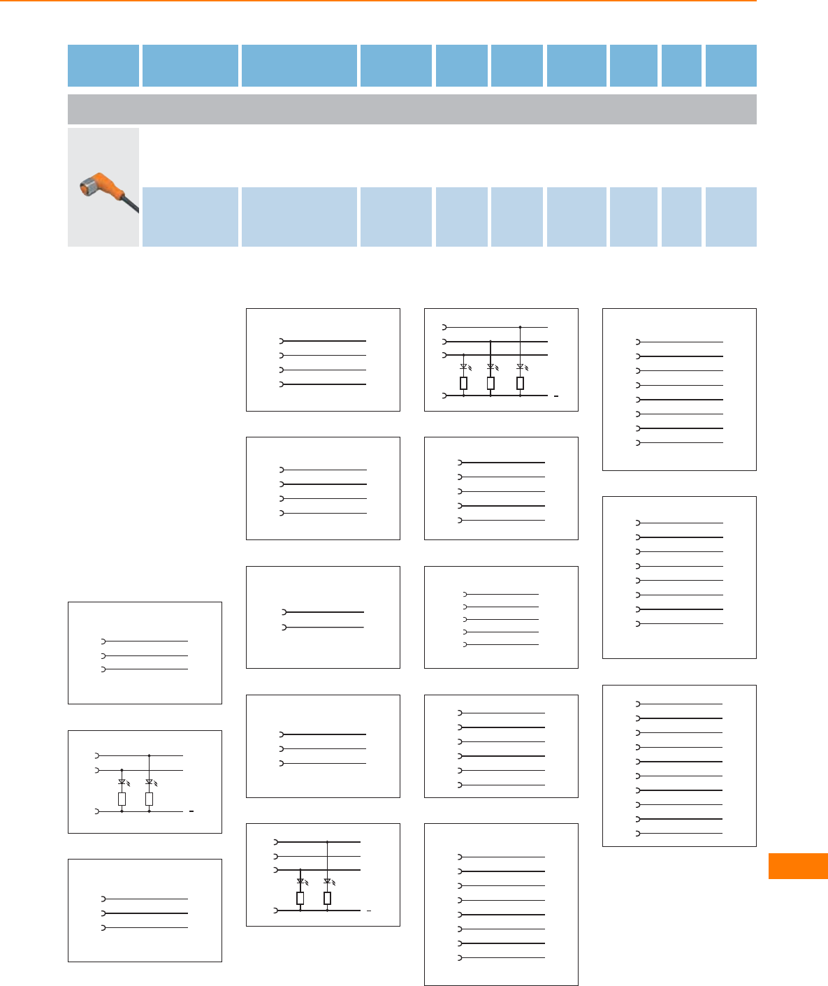
Type Cable Wire
specification
Material
housing/
nut
U
[V]
Ta
[°C]
Pro-
tection
LEDs Draw-
ing
no.
Order
no.
Group 137 · Socket M12, 5-pole, 5-wire · Wiring diagram no. 11
5 m black
PUR cable 5 x 0.34 mm2, Ø 4.9 mm
TPU /
stainless steel
316L / 1.4404
30 AC
36 DC -40...90 IP 67 / IP 68 /
IP 69K –159 EVM040
10 m black
PUR cable 5 x 0.34 mm2, Ø 4.9 mm
TPU /
stainless steel
316L / 1.4404
30 AC
36 DC -40...90 IP 67 / IP 68 /
IP 69K –159 EVM041
Core colours
BK black
BN brown
BU blue
WH white
GN/YE green/yellow
GY grey
GN green
YE yellow
PK pink
screen screen
OG orange
VT lilac
RD red
RD/BK red/black
RD/WH red/white
Wiring diagrams
1
1
3
BN
BU
4BK
2
1
3
L+
4
L
YE GN
BN
BU
BK
out
3
1
3
4
4
1
2
3
4
BN
WH
BU
BK
5
1
2
3
4
6
1
4
WH
BK
7
1
2
3
GN/YE
BK
BU
8
L+
L
out
out
1
3
4
YE GN
2
9
out
out
L+
L
1
3
4
YE GN
BN
BU
BK
2WH
YE
10
1
2
3
4
5
11
1
2
3
4
5
BN
WH
BU
BK
GY
12
1
2
3
4
5
WH
GN
YE
GY
BN
7BU
13
4
5
6
7
8
2
3
1
YE
GY
PK
BU
screen
BN
GN
WH
14
4
5
6
7
8
2
3
1
BK
GY
PK
VT
OG
WH
BU
BN
15
1
2
3
4
WH
BN
GN
YE
5GY
6PK
7BU
8RD
16
J
L
N
O
P
C
E
A
GN
BU
GN/BN
RD/BU
WH
WH/GN
GY/PK
BN
S
T
GY
YE
Connection technology
623
Wiring diagrams
17
G
J
L
N
O
C
E
A
PK
GN
BU
RD/BU
VT
GY/PK
BK
BN
P
R
S
T
WH
RD
GY
YE
18
4
5
6
7
8
2
3
1
GY
GY/PK
RD/BU
WH/GN
BN/GN
GN
YE
WH
9
10
11
12
BU
BN
YE/GN
19
1
2
3
GN
RD/BK
RD/WH
20
1
2
4
5
BK
BU
BN
WH
21
1
2
3
BN
GN/YE
BU
22
1
2
3
BN
BK
BU
23
1
2
3
24
4
5
6
2
3
1
25
1
3
4
26
1
2
3
4
27
1
2
3
4
BN
WH
BU
BK
28
1
2
3
4
5
BN
WH
BU
BK
GN/YE
29
1BN
2WH
3BU
4BK
5GY
30
1
2
3
4
5
31
1
3
4
1
3
4
32
1
3
L+
4
L
YEGN
1
3
4
out
33
1
2
3
1
2
3
44
34
out
out
L+
L
1
3
4
GN YE
2
1
3
4
2
YE
35
1
2
3
4
1
2
3
4
55
36
1
2
YE
4
3
5
37
1
2
4
3
5
YE
38
BN
BU
BK
WH
1 (1...2)
3 (1...2)
4 (1)
4 (2)
39
WH
GN
YE
GY
BU
GN/YE
BN
4 (1)
4 (2)
4 (3)
4 (4)
3 (1...4)
5 (1...4)
1 (1...4)
40
WH
GN
YE
GY
BU
GN/YE
BN
4 (1)
4 (2)
4 (3)
4 (4)
3 (1...6)
5 (1...6)
1 (1...6)
PK
RD
4 (5)
4 (6)
41
WH
GN
YE
GY
BU
GN/YE
BN
4 (1)
4 (2)
4 (3)
4 (4)
3 (1...8)
5 (1...8)
1 (1...8)
PK
RD
4 (5)
4 (6)
BK
VT
4 (7)
4 (8)
Connection technology
624
Product selectors and further information can be found at: www.ifm.com
Wiring diagrams
42
12
1
2
3
4
9
10
11 1 (1...4)
3 (1...4)
5 (1...4)
4 (1)
4 (2)
4 (3)
4 (4)
43
12
1
2
3
4
9
10
11 1 (1...6)
3 (1...6)
5 (1...6)
4 (1)
4 (2)
4 (3)
4 (4)
5
6
4 (5)
4 (6)
44
12
1
2
3
4
9
10
11 1 (1...8)
3 (1...8)
5 (1...8)
4 (1)
4 (2)
4 (3)
4 (4)
5
6
4 (5)
4 (6)
7
8
4 (7)
4 (8)
45
GY/PK
RD/BU
WH/GN
BN/GN
WH
BU
GN/YE
BN
2 (1)
2 (2)
2 (3)
2 (4)
4 (1)
3 (1...4)
5 (1...4)
1 (1...4)
GN
YE
GY
4 (2)
4 (3)
4 (4)
46
15
7
5
4
16
6
12
19
4 (1)
2 (1)
4 (2)
2 (2)
4 (3)
3 (1...4)
5 (1...4)
1 (1...4)
8
3
14
2 (3)
4 (4)
2 (4)
+
-
47
19 1 (1...6)
6 3 (1...6)
15 4 (1)
12 5 (1...6)
7 2 (1)
5 4 (2)
4 2 (2)
16 4 (3)
8 2 (3)
3 4 (4)
14 2 (4)
17 4 (5)
9 2 (5)
2 4 (6)
13 2 (6)
48
19 1 (1...8)
6 3 (1...8)
15 4 (1)
12 5 (1...8)
72 (1)
54 (2)
42 (2)
16 4 (3)
82 (3)
34 (4)
14 2 (4)
17 4 (5)
92 (5)
24 (6)
13 2 (6)
11 4 (7)
10 2 (7)
14 (8)
18 2 (8)
49
L+
L
1
3
4
YE GN
BN
BU
BK
2WH
50
4
5
6
7
8
2
3
1
RD/BU
GN
BU
GY/PK
WH/GN
RD
GY
VT
9
10
11
12
WH/YE
WH/GY
BK
GN/YE
13
14
15
YE/BN
BN/GN
WH
16
17
18
19
YE
PK
GY/BN
BN
51
BN
WH
GN
GN
1 (1...8)
3 (1...8)
4 (1)
4 (2)
4 (3)
4 (4)
YE
YE
GY
4 (5)
4 (6)
PK
RD
4 (7)
4 (8)
BK
VT
+
-
BU
52
5
1
7
GN
2
1 (1...4)
3 (1...4)
4 (1)
4 (2)
4 (3)
4 (4)
YE
3
4
+
-
Connection technology
625
Wiring diagrams
53
BN
WH
GN
GY/PK
1 (1...8)
4 (1)
2 (1)
4 (2)
2 (2)
YE
GN
RD/BU
4 (3)
2 (3)
YE
WH/GN
4 (4)
2 (4)
GY
BN/GN
+
-
BU 3 (1...8)
4 (5)
2 (5)
PK
WH/YE
4 (6)
2 (6)
RD
YE/BN
4 (7)
2 (7)
BK
WH/GY
4 (8)
2 (8)
VT
GY/BN
54
A
P
L
GN
E
1 (1...4)
3 (1...4)
4 (1)
2 (1)
4 (2)
2 (2)
YE
J
O
4 (3)
2 (3)
T
C
4 (4)
2 (4)
S
N
+
-
55
BN
WH
GN/YE
GN
GN
1 (1...6)
5 (1...6)
4 (1)
4 (2)
4 (3)
4 (4)
YE
YE
GY
4 (5)
4 (6)
PK
RD
+
-
BU 3 (1...6)
56
WH
GN
GN
1 (1...8)
3 (1...8)
4 (1)
4 (2)
4 (3)
4 (4)
YE
YE
GY
+
-
BU
BN
4 (5)
4 (6)
PK
RD
4 (7)
4 (8)
BK
VT
5 (1...8)
GN/YE
57
1
GN
2
1 (1...4)
3 (1...4)
4 (1)
4 (2)
4 (3)
4 (4)
YE
3
4
+
-
-
10
9
11
5 (1...4)
12
58
1
GN
2
1 (1...6)
3 (1...6)
4 (1)
4 (2)
4 (3)
4 (4)
YE
3
4
+
-
-
10
9
11
4 (5)
4 (6)
5
6
5 (1...6)
12
Connection technology
626
Product selectors and further information can be found at: www.ifm.com
Wiring diagrams
59
1
GN
2
1 (1...8)
3 (1...8)
4 (1)
4 (2)
4 (3)
4 (4)
YE
3
4
+
-
-
10
9
11
4 (5)
4 (6)
5
6
4 (7)
4 (8)
7
8
5 (1...8)
12
60
BN
WH
GN/YE
GN
GY/PK
1 (1...4)
5 (1...4)
4 (1)
2 (1)
4 (2)
2 (2)
YE
GN
RD/BU
4 (3)
2 (3)
YE
WH/GN
4 (4)
2 (4)
GY
BN/GN
+
-
BU 3 (1...4)
61
GY/PK
RD/BU
WH/GN
BN/GN
WH
BU
GN/YE
BN
2 (1)
2 (2)
2 (3)
2 (4)
4 (1)
3 (1...6)
5 (1...6)
1 (1...6)
WH/YE
YE/BN
2 (5)
2 (6)
GN
YE
GY
PK
RD
4 (2)
4 (3)
4 (4)
4 (5)
4 (6)
62
GN
1 (1...8)
5 (1...8)
4 (1)
2 (1)
4 (2)
2 (2)
YE
4 (3)
2 (3)
4 (4)
2 (4)
+
-
3 (1...8)
4 (5)
2 (5)
PK
WH/YE
4 (6)
2 (6)
RD
YE/BN
BN
WH
GN/YE
GY/PK
GN
RD/BU
YE
WH/GN
GY
BN/GN
BU
63
GY/PK
RD/BU
WH/GN
BN/GN
WH
BU
GN/YE
BN
2 (1)
2 (2)
2 (3)
2 (4)
4 (1)
3 (1...8)
5 (1...8)
1 (1...8)
WH/YE
YE/BN
2 (5)
2 (6)
WH/GY
GY/BN
2 (7)
2 (8)
GN
YE
GY
PK
RD
4 (2)
4 (3)
4 (4)
4 (5)
4 (6)
BK
VT
4 (7)
4 (8)
Connection technology
627
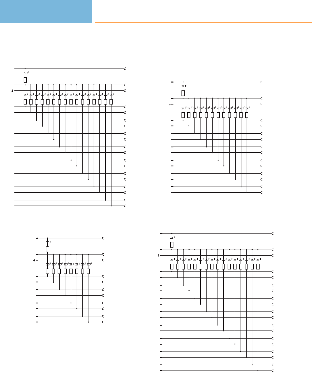
Wiring diagrams
64
GN
1 (1...8)
5 (1...8)
4 (1)
2 (1)
4 (2)
2 (2)
YE
4 (3)
2 (3)
4 (4)
2 (4)
+
-
3 (1...8)
4 (5)
2 (5)
4 (6)
2 (6)
4 (7)
2 (7)
4 (8)
2 (8)
PK
WH/YE
RD
YE/BN
BK
WH/GY
VT
GY/BN
BN
WH
GN/YE
GY/PK
GN
RD/BU
YE
WH/GN
GY
BN/GN
BU
65
19
15
12
GN
7
1 (1...4)
5 (1...4)
4 (1)
2 (1)
4 (2)
2 (2)
YE
5
4
4 (3)
2 (3)
16
8
4 (4)
2 (4)
3
14
+
-
6 3 (1...4)
66
19
15
12
GN
7
1 (1...6)
5 (1...6)
4 (1)
2 (1)
4 (2)
2 (2)
YE
5
4
4 (3)
2 (3)
16
8
4 (4)
2 (4)
3
14
+
-
63 (1...6)
4 (5)
2 (5)
17
9
4 (6)
2 (6)
2
13
67
19
15
12
GN
7
1 (1...8)
5 (1...8)
4 (1)
2 (1)
4 (2)
2 (2)
YE
5
4
4 (3)
2 (3)
16
8
4 (4)
2 (4)
3
14
+
-
6 3 (1...8)
4 (5)
2 (5)
17
9
4 (6)
2 (6)
2
13
4 (7)
2 (7)
11
10
4 (8)
2 (8)
1
18
Connection technology
628
Product selectors and further information can be found at: www.ifm.com
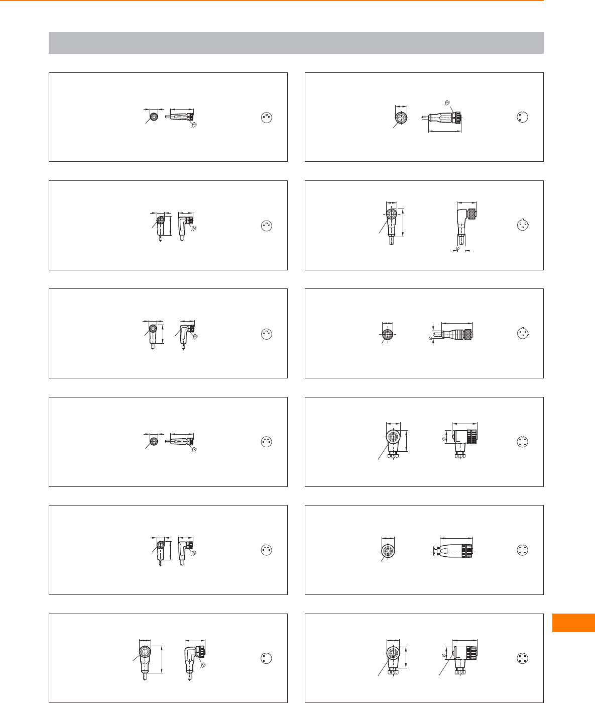
Scale drawings / drawing no. – CAD download: www.ifm.com
1
9
10 31
M8x1 1
4
3
2
9
10 19
M8x1
25,5
1
4
3
3
9
10 19
M8x1
25,5
LED 1
4
3
4
9
10 31
M8x1
4
3
2
1
5
9
10 19
M8x1
25,5
4
3
2
1
6
15,5
M12x1
36,5
26,5
14
1
4
7
15,5
M12x1 45
14
1
4
8
15
M12 x1
39
27
10,5
3
1
2
9
15
M12 x1
10,5
43
3
1
2
10
35
18
20
M12 x1
30
3
12
4
11
18
M12 x1
46
3
12
4
12
18
M12 x1
30
35
18
2 LED
3
12
4
Connection technology
629
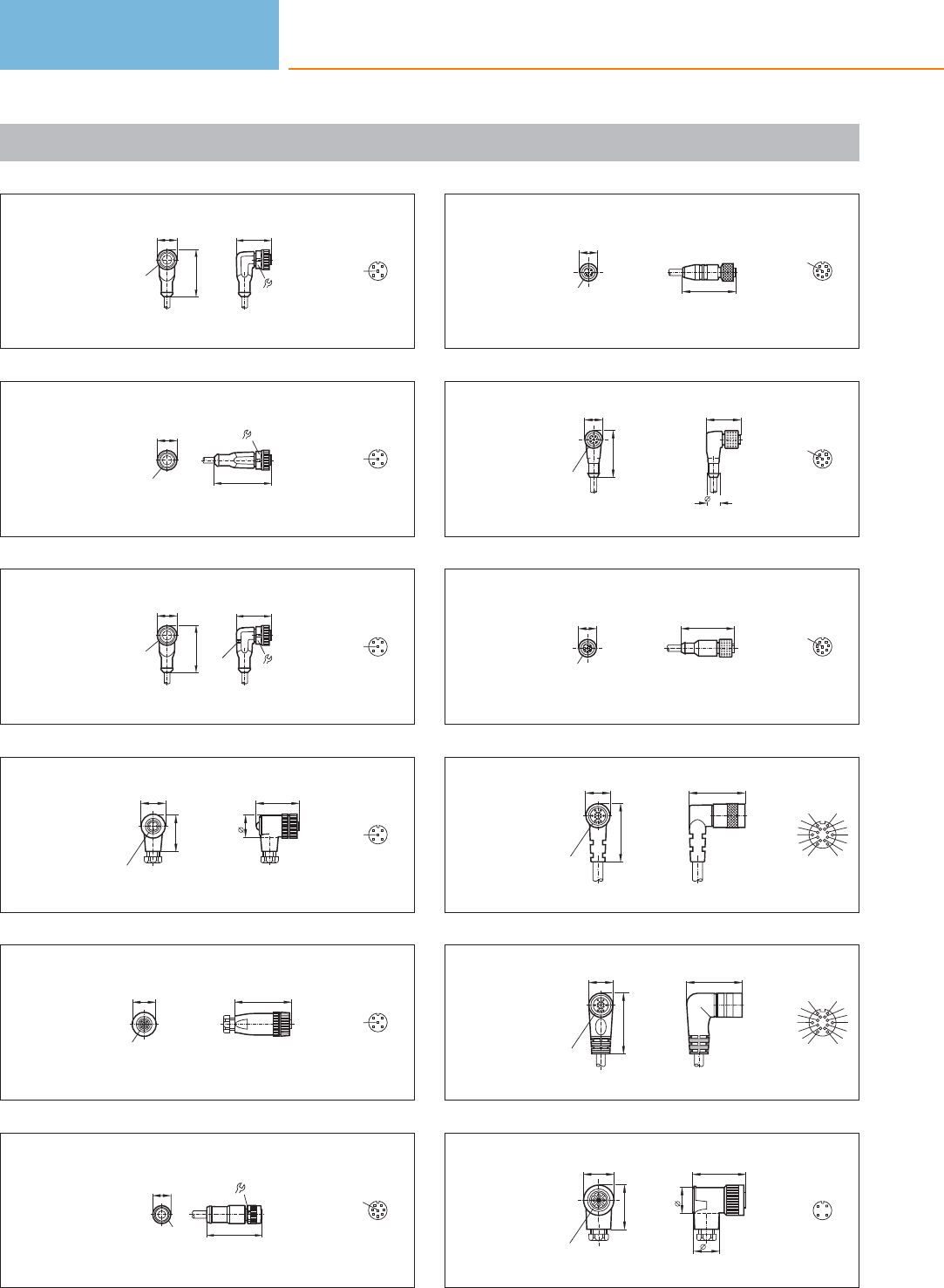
Scale drawings / drawing no. – CAD download: www.ifm.com
13
15,5
M12x1
36,5
26,5
14 3
12
4
5
14
15,5
M12x1 45
14
3
12
4
5
15
15,5
M12x1
36,5
26,5
14
3 LED 3
12
4
5
16
35
18
20
M12 x1
30
3
12
4
5
17
20
M12 x1
46
3
12
4
5
18
13
Ø14,5
43,9M12x1
4
12
65
3
7
8
19
43
15
M12 x1
4
12
65
3
7
8
20
15
38
M12 x1
28
10,5
4
12
65
3
7
8
21
15
M12 x1
43
4
12
65
3
7
8
22
20
M16 x 1
47
45
A
M
N
C
O
PE
L
U
T
J
S
R
G
23
45
20
M16 x1
49
A
M
N
C
O
PE
L
U
T
J
S
R
G
24
25
M18 x1
36
21
43
21
3
14
2
Connection technology
630
Product selectors and further information can be found at: www.ifm.com
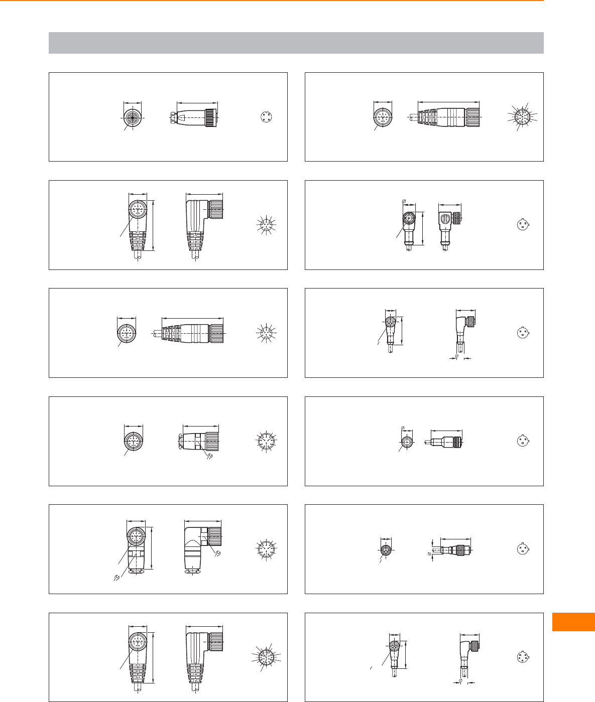
Scale drawings / drawing no. – CAD download: www.ifm.com
25
25
M18 x1
56
3
14
2
26
51
70
26
M 23 x 1
9
8
112
7
6
5
11
10
2
34
27
26
M 23 x 1
85 9
8
112
7
6
5
11
10
2
34
28
49
20
26
M 23 x 1
1
2
3
411 5
6
7
8
9
10 12
29
20
58
26
M 23 x 1
51
24
1
2
3
411 5
6
7
8
9
10 12
30
51
70
26
M 23 x 1
1
2
3
4567
8
9
10
11
12
13
14
15
16
17
18
19
31
26
M 23 x 1
85
1
2
3
4567
8
9
10
11
12
13
14
15
16
17
18
19
32
26
M12x1
14,5
38,5
3
1
2
33
27
10,5
15
39
G
2
1
3
1
2
34
14,5 42,5
1/2" 20UNF
3
1
2
35
42
10,5
15
G
2
1
3
1
2
36
27
10,5
15
39
"-20UNF
2
1
32
51
4
Connection technology
631
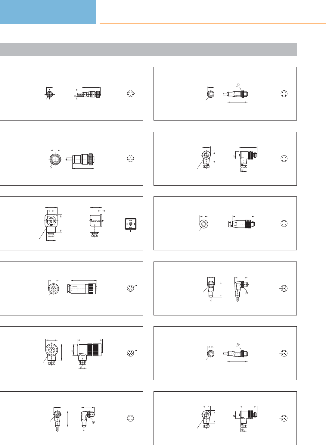
Scale drawings / drawing no. – CAD download: www.ifm.com
37
15
M12 x1
10,5
43
32
51
4
38
49,9
G
8
7
Ø26
1
2
3
39
29
18
42
M3 22
28
2
21
3
40
29
Rd 24
71
4
16
3
52
41
29
Rd 24
38,5
20
59
26
4
16
3
52
42
15,5
M12x1
36,5
30,5
14 43
21
43
15,5
M12x1 49,5
14
43
21
44
42
18
15
20
M12 x1
31
43
21
45
52
20
M12 x1
43
21
46
15,5
M12x1
36,5
30,5
14 4
21
3
5
47
15,5
M12x1 49,5
14
4
21
3
5
48
42
18
15
20
M12 x1
31
4
21
3
5
Connection technology
632
Product selectors and further information can be found at: www.ifm.com
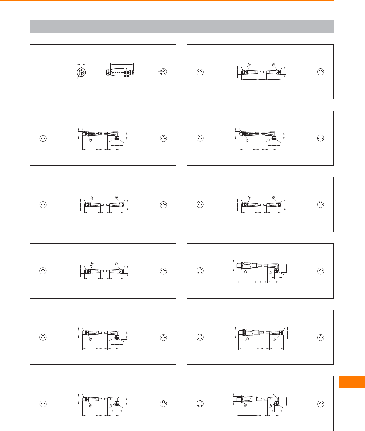
Scale drawings / drawing no. – CAD download: www.ifm.com
49
52
20
M12 x1
4
21
3
5
50
M8x1
9
M8x1
10
10
10
25,5
36 L
9
19
3
4
11
4
3
51
9
M8x1 9
M8x1 9M8x1
10
10
10
31
36 L
3
4
11
4
3
52
9
M8x1 9
M8x1 9M8x1
10
10
10
31
36 L
2
1
4
3
1
4
3
53
M8x1
9
M8x1
10
10
10
25,5
36 L
9
19
2
1
4
3
1
4
3
54
M8x1
9
M8x1
10
10
10
25,5
36 L
9
19
3
4
1
4
3
2
1
55
9
M8x1 9
M8x1 9M8x1
10
10
10
31
36 L
3
4
1
4
3
2
1
56
M8x1
9
M8x1
10
10
10
25,5
36 L
9
19
2
1
4
3
4
3
2
1
57
9
M8x1 9
M8x1 9M8x1
10
10
10
31
36 L
2
1
4
3
4
3
2
1
58
M8x1
10
25,5
L
9
19
49,5
14
M12x1
4
1
31
4
3
59
L
9
49,5
14
M12x1
M8x1
10
31
4
1
31
4
3
60
M8x1
10
25,5
L
9
19
LED
49,5
14
M12x1
4
1
31
4
3
Connection technology
633
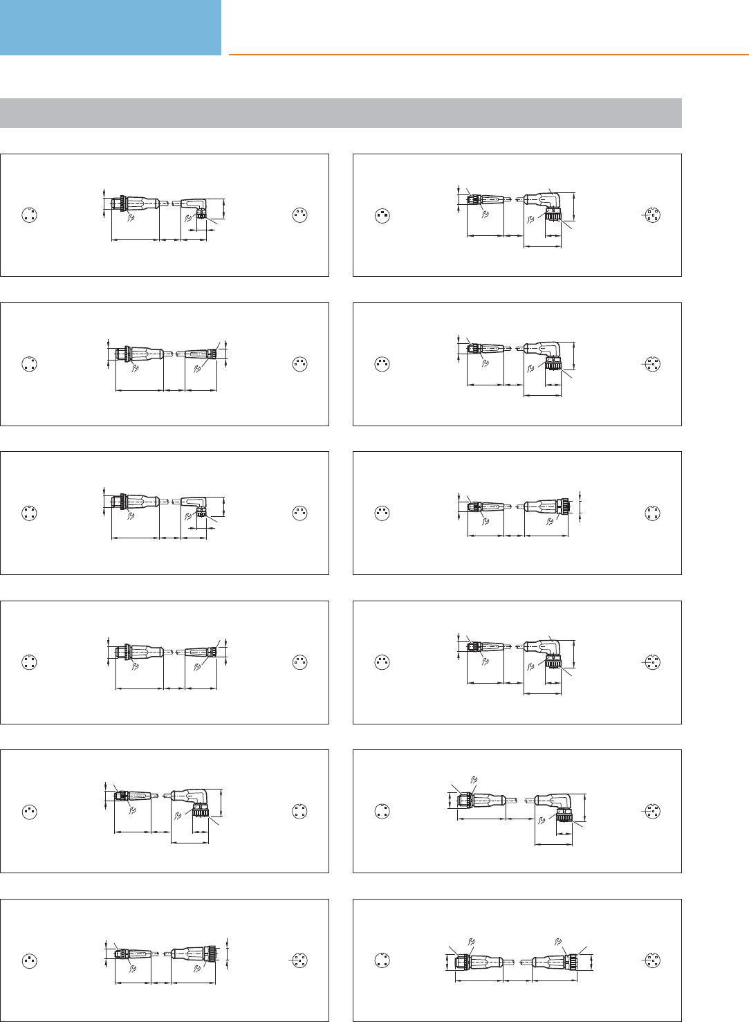
Scale drawings / drawing no. – CAD download: www.ifm.com
61
M8x1
10
25,5
L
9
19
49,5
14
M12x1
4
1
3
4
3
2
1
62
L
9
49,5
14
M12x1
M8x1
10
31
4
1
3
4
3
2
1
63
M8x1
10
25,5
L
9
19
49,5
14
M12x1
43
21 4
3
2
1
64
L
9
49,5
14
M12x1
M8x1
10
31
43
21 4
3
2
1
65
M12x1
26,5
14
36,5
15,5
M8x1
9
10
10
36 L
3
4
13
12
4
66
45
M8x1
9
10
10
36 L
14
M12x1
3
4
13
12
4
5
67
M12x1
26,5
14
36,5
15,5
M8x1
9
10
10
36 L
LED
3
4
13
12
4
5
68
M12x1
26,5
14
36,5
15,5
M8x1
9
10
10
36 L
2
1
4
3
3
12
4
5
69
45
M8x1
9
10
10
36 L
14
M12x1
2
1
4
3
3
12
4
70
M12x1
26,5
14
36,5
15,5
M8x1
9
10
10
36 L
LED
2
1
4
3
3
12
4
5
71
49,5
14
L
15,5
M12x1
M12x1
26,5
14
36,5
15,5
4
1
33
12
4
5
72
49,5
14
15,5
M12x1
45
14
L
15,5
M12x1
4
1
33
12
4
5
Connection technology
634
Product selectors and further information can be found at: www.ifm.com
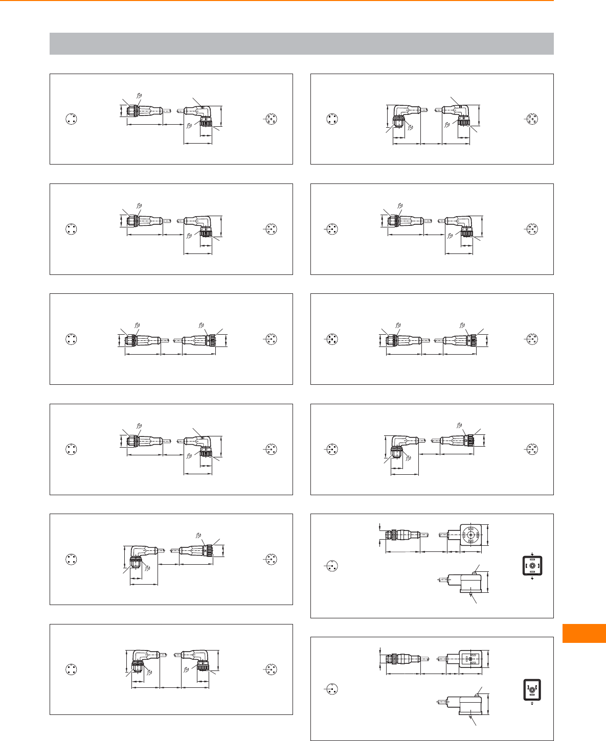
Scale drawings / drawing no. – CAD download: www.ifm.com
73
49,5
14
L
15,5
M12x1
M12x1
26,5
14
36,5
15,5
LED
4
1
33
12
4
5
74
49,5
14
L
15,5
M12x1
M12x1
26,5
14
36,5
15,5
43
21
3
12
4
5
75
49,5
14
15,5
M12x1
45
14
L
15,5
M12x1
43
21
3
12
4
5
76
49,5
14
L
15,5
M12x1
M12x1
26,5
14
36,5
15,5
LED
43
21
3
12
4
5
77
15,5
M12x1
45
14
L
M12x1
30,5
14
36,5
15,5
43
21
3
12
4
5
78
L
M12x1
26,5
14
36,5
15,5
M12x1
30,5
14
36,5
15,5
43
21
3
12
4
5
79
L
M12x1
26,5
14
36,5
15,5
LED
M12x1
30,5
14
36,5
15,5
43
21
3
12
4
5
80
49,5
14
L
15,5
M12x1
M12x1
26,5
14
36,5
15,5
4
21
3
5
3
12
4
5
81
49,5
14
15,5
M12x1
45
14
L
15,5
M12x1
4
21
3
5
3
12
4
5
82
15,5
M12x1
45
14
L
M12x1
30,5
14
36,5
15,5
4
21
3
5
3
12
4
5
83
L17,5 29,5
29,5
M12 x1
47
LED
M3
28,5
4
3
52 1
84
LED
M3
28,5
L17,5 31,5
24
M12 x1
47
4
3
5
12
Connection technology
635
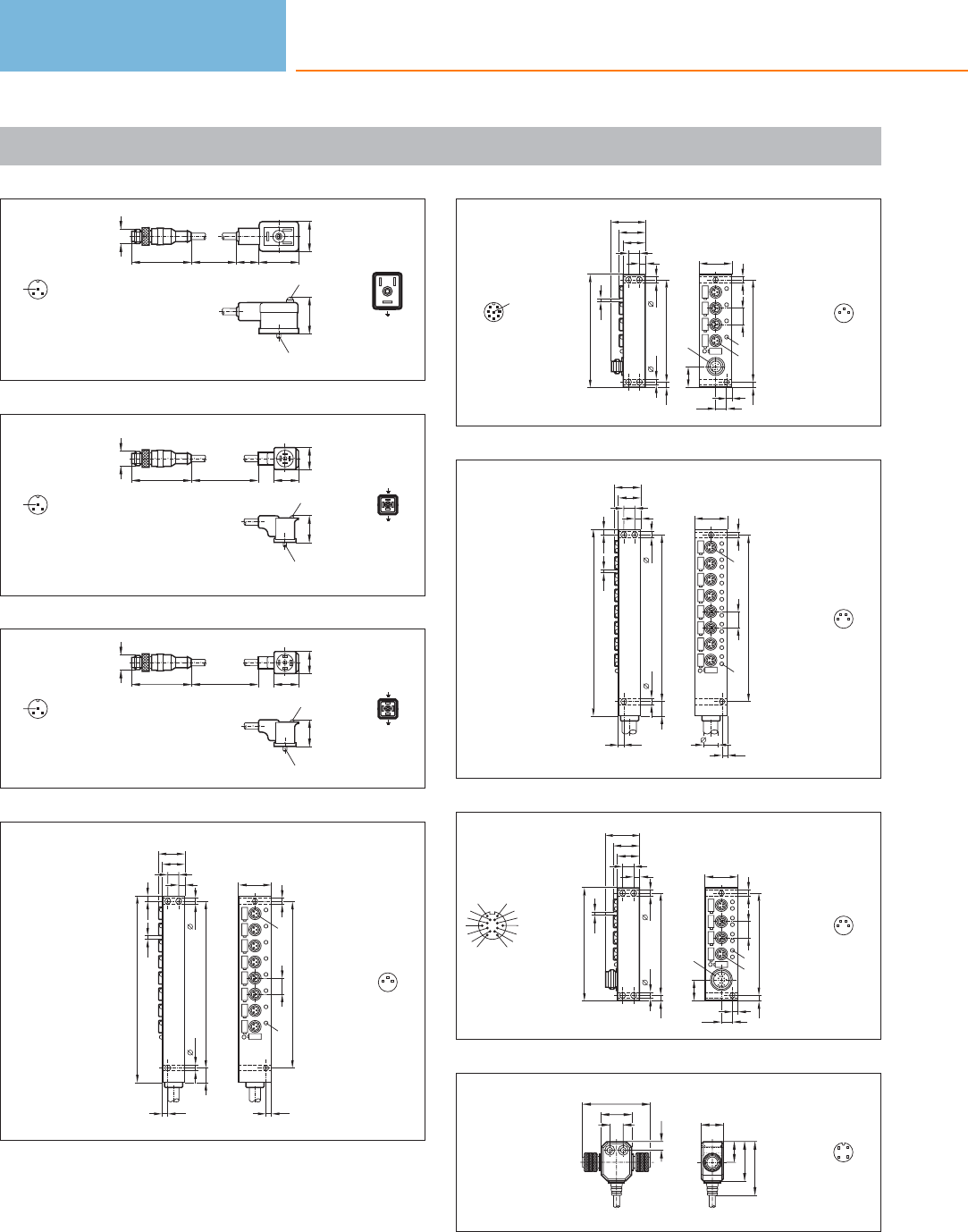
Scale drawings / drawing no. – CAD download: www.ifm.com
85
LED
M3
28,5
L17,5 31,5
24
M12 x1
47
4
3
5
12
86
L12 20
18
M12 x1
47
LED
M 2,5
21,5
4
3
512
87
M3
L12 20
18
M12 x1
47
LED
21,5
4
3
512
88
145
129
4,5
4,5
8,5
18
21
M8x1
LED
129
12,5 4,5
26
5
4,52,6
4,5
11,5
4,5
1
4
3
89
88
27
79
4,54,5
8,5
18
21
M8x1
LED
79
4,5
26
M12 x1
4,5
8,5
5
4,5
16
4,5
12,5
2,6
6
21
45
7
3
8
1
4
3
90
11,5
145
129
4,5
4,5
8,5
18
21
M8x1
LED
129
12,5 4,5
26
5
4,52,6
4,5
11,5
4,5
4
3
2
1
91
88
27
79
4,54,5
8,5
18
21
M8x1
LED
79
4,5
26
4,5
8,5
5
4,5
16
4,5
12,5
2,6
M16 x 0,75
AM
N
C
O
P
E
L
U
T
J
S
RG
4
3
2
1
92
10,4
23,5
17
53
6,5
16
30,5
42
3
12
4
Connection technology
636
Product selectors and further information can be found at: www.ifm.com
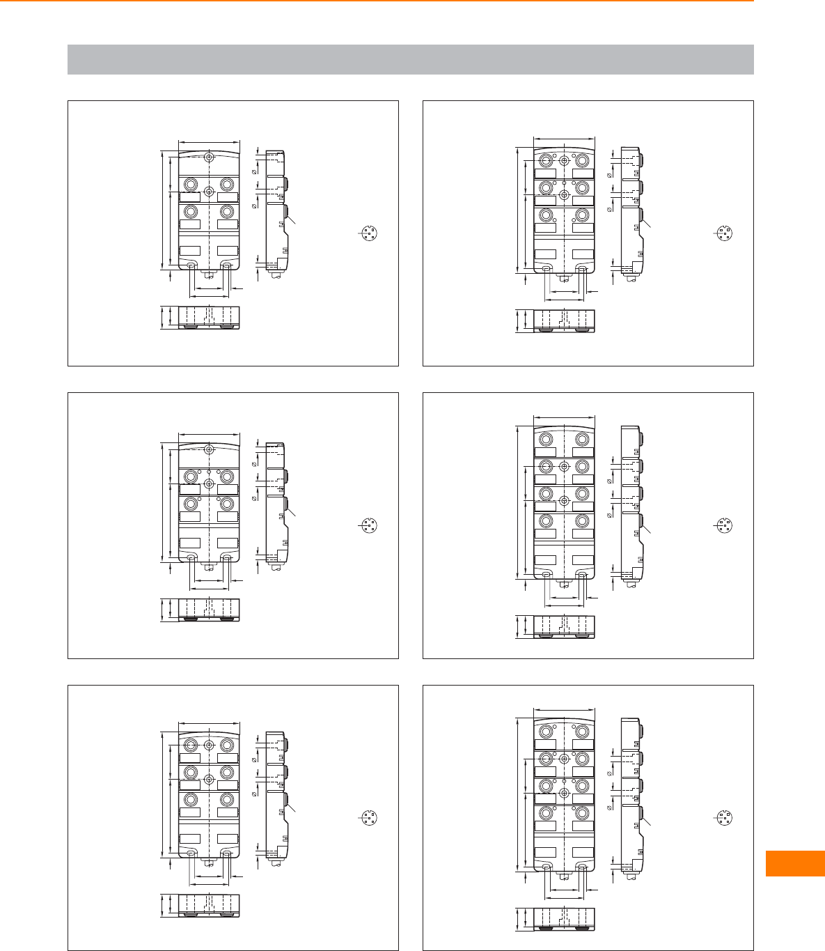
Scale drawings / drawing no. – CAD download: www.ifm.com
93
12
43
18
22
4,7 73
118,2
34
55
4,5
28,5
39
7,5
60
M12x1
3
12
4
5
94
12
43
PWR
18
22
4,7 73
118,2
34
55
4,5
28,5
39
7,5
60
M12x1
3
12
4
5
95
12
4
6
3
5
18
22
4,7 73
125
34
55
4,5
28,5
39
7,5
60
M12x1
3
12
4
5
96
12
4
6
3
5
PWR
18
22
4,7 73
125
34
55
4,5
28,5
39
7,5
60
M12x1
3
12
4
5
97
12
4
6
8
3
5
7
18
22
4,7 73
152
34
55
4,5
28,5
39
7,5
60
M12x1 3
12
4
5
98
12
4
6
8
3
5
7
PWR
18
22
4,7 73
152
34
55
4,5
28,5
39
7,5
60
M12x1 3
12
4
5
Connection technology
637
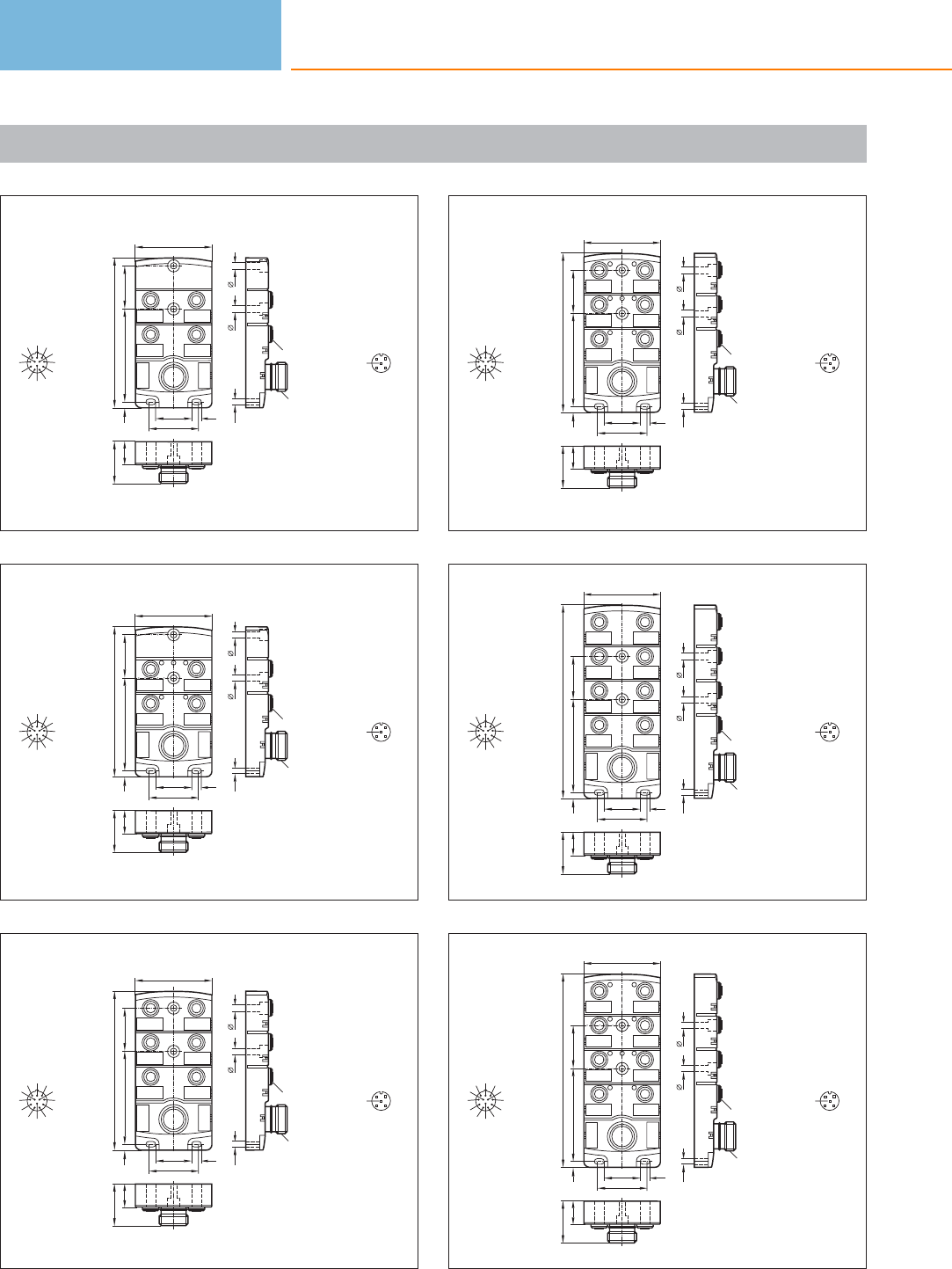
Scale drawings / drawing no. – CAD download: www.ifm.com
99
12
43
18
33
4,7 73
118,2
34
55
4,5
28,5
39
7,5
60
M23 x 1
M12x1
9
8
1
12
7
6511
10
2
3
43
12
4
5
100
12
43
PWR
18
33
4,7 73
118,2
34
55
4,5
28,5
39
7,5
60
M23 x 1
M12x1
9
8
1
12
7
6511
10
2
3
43
12
4
5
101
12
4
6
3
5
18
33
4,7 73
125
34
55
4,5
28,5
39
7,5
60
M23 x 1
M12x1
9
8
1
12
7
6511
10
2
3
43
12
4
5
102
12
4
6
3
5
PWR
18
33
4,7 73
125
34
55
4,5
28,5
39
7,5
60
M23 x 1
M12x1
9
8
1
12
7
6511
10
2
3
43
12
4
5
103
12
4
6
8
3
5
7
18
33
4,7 73
152
34
55
4,5
28,5
39
7,5
60
M23 x 1
M12x1
9
8
1
12
7
6511
10
2
3
43
12
4
5
104
12
4
6
8
3
5
7
PWR
18
33
4,7 73
152
34
55
4,5
28,5
39
7,5
60
M23 x 1
M12x1
9
8
1
12
7
6511
10
2
3
43
12
4
5
Connection technology
638
Product selectors and further information can be found at: www.ifm.com
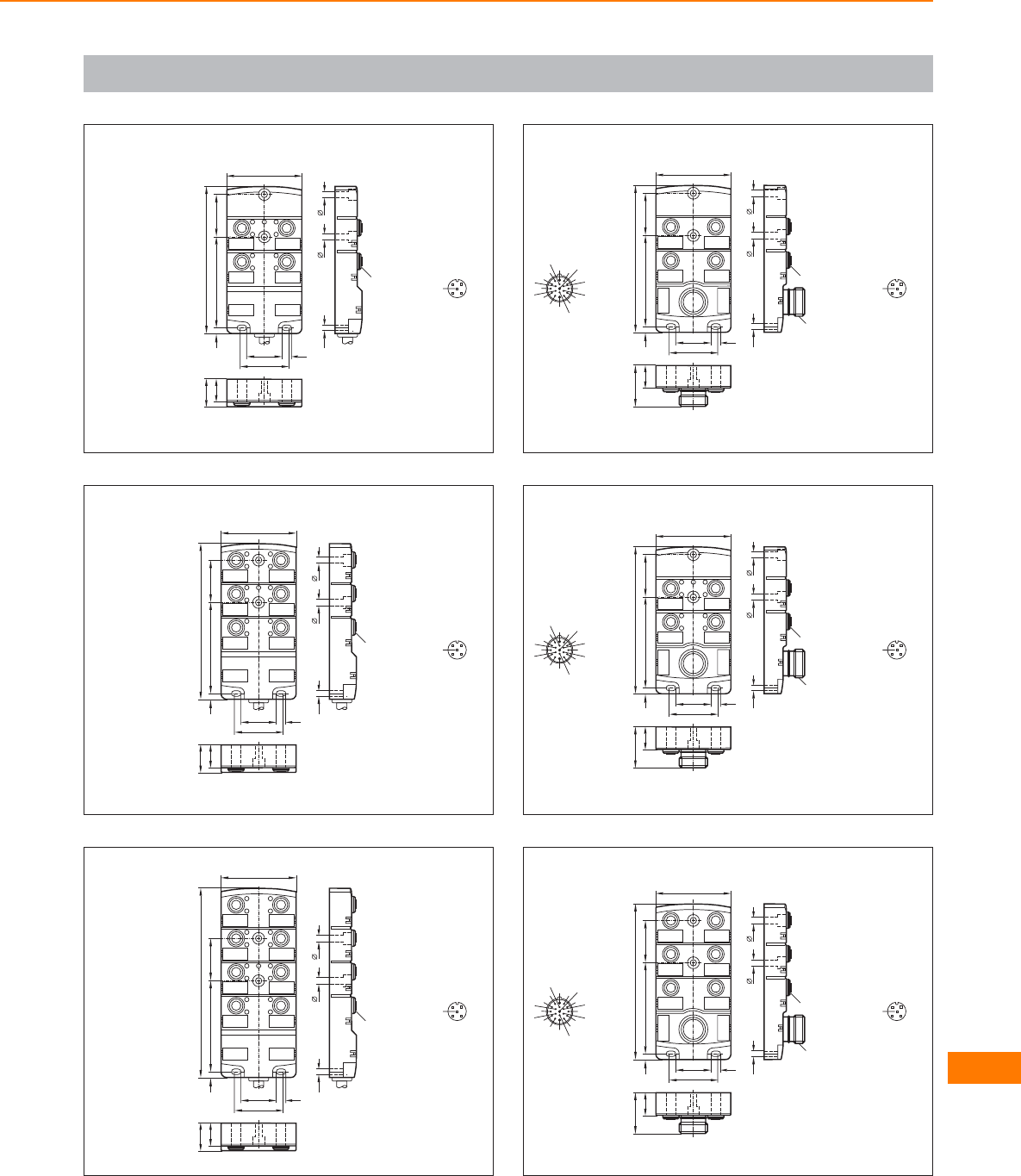
Scale drawings / drawing no. – CAD download: www.ifm.com
105
12
43
PWR
B
A
B
A
B
A
B
A
18
22
4,7 73
118,2
34
55
4,5
28,5
39
7,5
60
M12x1
3
12
4
5
106
12
4
6
3
5
PWR
B
A
B
A
B
A
B
A
B
A
B
A
18
22
4,7 73
125
34
55
4,5
28,5
39
7,5
60
M12x1
3
12
4
5
107
12
4
6
8
3
5
7
PWR
B
A
B
A
B
A
B
A
B
A
B
A
B
A
B
A
18
22
4,7 73
152
34
55
4,5
28,5
39
7,5
60
M12x1 3
12
4
5
108
12
43
18
33
4,7 73
118,2
34
55
4,5
28,5
39
7,5
60
M23 x 1
M12x1
1
2
3
4
5
6
7
8
9
10
11 12
13
14
15
16
17
18 19
3
12
4
5
109
12
43
PWR
B
A
B
A
B
A
B
A
18
33
4,7 73
118,2
34
55
4,5
28,5
39
7,5
60
M23 x 1
M12x1
1
2
3
4
5
6
7
8
9
10
11 12
13
14
15
16
17
18 19
3
12
4
5
110
12
4
6
3
5
18
33
4,7 73
125
34
55
4,5
28,5
39
7,5
60
M23 x 1
M12x1
1
2
3
4
5
6
7
8
9
10
11 12
13
14
15
16
17
18 19
3
12
4
5
Connection technology
639
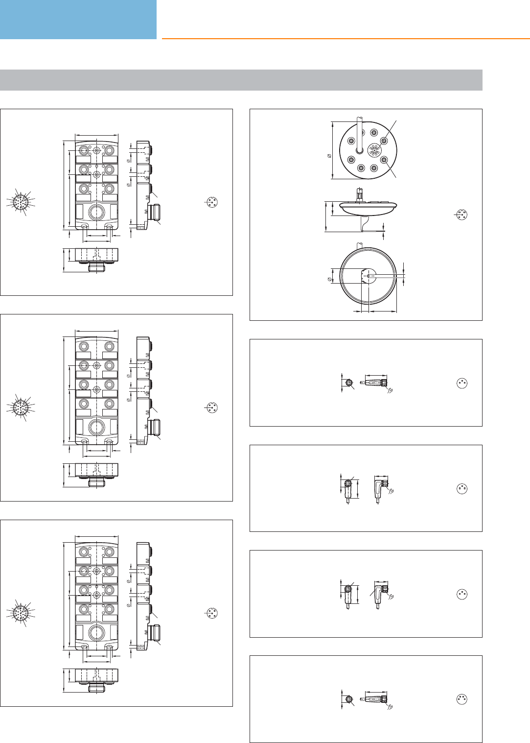
Scale drawings / drawing no. – CAD download: www.ifm.com
111
12
4
6
3
5
PWR
B
A
B
A
B
A
B
A
B
A
B
A
18
33
4,7 73
125
34
55
4,5
28,5
39
7,5
60
M23 x 1
M12x1
1
2
3
4
5
6
7
8
9
10
11 12
13
14
15
16
17
18 19
3
12
4
5
112
12
4
6
8
3
5
7
18
33
4,7 73
152
34
55
4,5
28,5
39
7,5
60
M23 x 1
M12x1
1
2
3
4
5
6
7
8
9
10
11 12
13
14
15
16
17
18 19
3
12
4
5
113
12
4
6
8
3
5
7
PWR
B
A
B
A
B
A
B
A
B
A
B
A
B
A
B
A
18
33
4,7 73
152
34
55
4,5
28,5
39
7,5
60
M23 x 1
M12x1
1
2
3
4
5
6
7
8
9
10
11 12
13
14
15
16
17
18 19
3
12
4
5
114
2
34
72
36
64,9
8,2
18
137,3
M12 x1
LED
3
12
4
5
115
9
31
M8x1
10
1
4
3
116
9
19
25,5
M8x1
10
1
4
3
117
9
19
25,5
LED
M8x1
10
1
4
3
118
9
31
M8x1
10
4
3
2
1
Connection technology
640
Product selectors and further information can be found at: www.ifm.com
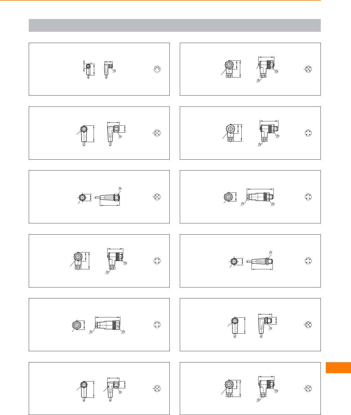
Scale drawings / drawing no. – CAD download: www.ifm.com
119
9
19
25,5
M8x1
10
4
3
2
1
120
15,5
M12x1
36,5
26,5
14 3
12
4
5
121
15,5
45
14
M12 x1
3
12
4
5
122
36
18
13
M12 x1
38
20
3
12
4
123
20
M12 x 1 1813
54
3
12
4
124
15,5
M12x1
36,5
26,5
14
LED 3
12
4
5
125
36
18
13
M12 x1
38
20
LED
3
12
4
5
126
40
13
M12 x1
38
20
18 43
21
127
20
M12 x 1 13
60
18
43
21
128
15,5
49
14
M12 x1
43
21
129
15,5
M12x1
36,5
30,5
14 4
21
3
5
130
36
18
13
M12 x1
38
20
3
12
4
5
Connection technology
641

Scale drawings / drawing no. – CAD download: www.ifm.com
131
20
M12 x 1 1813
54
3
12
4
5
132
40
13
M12 x1
38
20
18 4
21
3
5
133
20
M12 x 1 13
60
18
4
21
3
5
134
M8x1 9
M8x1 9M8x1
10
10
31
36 L
3
4
11
4
3
135
M8x1M8x1
10
36 L
19
99 M8x1
25,5
10
3
4
11
4
3
136
M8x1M8x1
10
36 L
19
LED
99 M8x1
25,5
10
3
4
11
4
3
137
9M8x1
10
31L
25
9
M8x1
25,5
10
3
4
11
4
3
138
L
25
9
M8x1
25,5
10
19
9M8x1
25,5
10
3
4
11
4
3
139
L
25
9
M8x1
25,5
10
19
LED
9M8x1
25,5
10
3
4
11
4
3
140
M8x1 9
M8x1 9M8x1
10
10
31
36 L
3
4
1
4
3
2
1
141
M8x1M8x1
10
36 L
19
99 M8x1
25,5
10
3
4
1
4
3
2
1
142
9
M8x1
10
14
45
L
36
15,5
M12 x1
3
4
13
12
4
5
Connection technology
642
Product selectors and further information can be found at: www.ifm.com
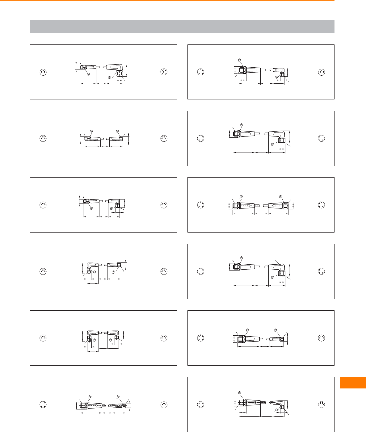
Scale drawings / drawing no. – CAD download: www.ifm.com
143
M8x1
10
36 L
9
15,5
M12x1
36,5
26,5
14
3
4
13
12
4
5
144
M8x1 9
M8x1 9M8x1
10
10
31
36 L
2
1
4
3
4
3
2
1
145
M8x1M8x1
10
36 L
19
99 M8x1
25,5
10
2
1
4
3
4
3
2
1
146
9M8x1
10
31L
25
9
M8x1
25,5
10
2
1
4
3
4
3
2
1
147
L
25
9
M8x1
25,5
10
19
9M8x1
25,5
10
2
1
4
3
4
3
2
1
148
9M8x1
10
31
L
15,5
49,5
14
M12x1
4
1
31
4
3
149
L
49
17 9
19
25,5 M8x1
10
15,5
14
M12 x1
4
1
31
4
3
150
L
49
14
15,5
M12 x1
M12x1
36,5
15,5
26,5
14
4
1
33
1
4
151
L
15,5
M12 x1
49
14
45
15,5
M12 x1 14
4
1
33
1
4
152
L
49
14
15,5
M12 x1
M12x1
36,5
15,5
26,5
14
LED
4
1
33
1
4
153
9M8x1
10
31
L
15,5
49,5
14
M12x1
43
21 4
3
2
1
154
L
49
17 9
19
25,5 M8x1
10
15,5
14
M12 x1
43
21 4
3
2
1
Connection technology
643

Scale drawings / drawing no. – CAD download: www.ifm.com
155
L
49
14
15,5
M12 x1
M12x1
36,5
15,5
26,5
14
43
21
3
12
4
156
L
15,5
M12 x1
49
14
45
15,5
M12 x1 14
43
21
3
12
4
157
L
49
14
15,5
M12 x1
M12x1
36,5
15,5
26,5
14
LED
43
21
3
12
4
158
L
15,5
M12 x1
49
14
45
15,5
M12 x1 14
4
21
3
5
3
12
4
5
159
15,5
M12x1
36,5
26,5
14 3
12
4
5
160
31
14
15,5
26,5
14
15,5
36,5 36,5
M12x1 M12x1
L
43
21
3
12
4
161
15,5
M12x1 45
14
3
12
4
5
162
3 LED
15,5
M12x1
36,5
26,5
14 3
12
4
5
Connection technology
644
Product selectors and further information can be found at: www.ifm.com

Connection technology
645

Argentina
ifm electronic s.r.l.
Manuela Sáenz 323
5º piso, oficina 3
C1107BPA - Puerto Madero
Buenos Aires, Argentina
Tel. (011) 5353-3436
Fax (011) 5353-3436
Interior 0810-345-3436
info.ar@ifm.com
www.ifm.com/ar
Australia
ifm efector pty ltd.
PO Box 479
Suite 3, 745 Springvale Road
Mulgrave VIC 3170
Tel. 1300 365 088
Fax 1300 365 070
sales.au@ifm.com
www.ifmefector.com.au
Austria
ifm electronic gmbh
Wienerbergstraße 41
Gebäude E
1120 Vienna
Tel. +43 / 1 / 617 45 00
Fax +43 / 1 / 617 45 00 10
info.at@ifm.com
www.ifm.com/at
Bangladesh
Sensotec Automation
Red Crescent Chamber
87, Motijheel
Commercial Area
Dhaka 1000
Bangladesh
Tel. +880 171 546 890
sensotec@agni.com
Belarus
DEPOSIT INVEST
Joint-Stock Company
Block 2,
27 Zheleznodorovhnaya street
220089 Minsk
Republic of Belarus
Tel. +375-17-270 75 06
Fax +375-17-270 75 07
george_ozerov@list.ru
Belgium and
Luxembourg
ifm electronic n.v./s.a.
Zuiderlaan 91
1731 Zellik
Tel. +32 2 481 0220
Fax +32 2 463 1795
info.be@ifm.com
www.ifm.com/be
Bolivia
BAVARIA S.R.L.
Álvaro Baptista Vargas
Zona Morocollo,
Urb. Santos Pariamo
C. Mario Diaz de medina
(26-A), Nr. 32
La Paz - Bolivia
Tel.: 00-591-2-277 13 78
Mobile: 00-591-720-47 442
alvarobaptista@bavaria.bo
www.bavaria.bo
Brazil
ifm electronic Ltda.
Rua Eleonora Cintra, 140
Jardim Analia Franco
03337-000 Sāo Paulo/SP
Tel. +55-11-2672-1730
Fax +55-11-2673-3501
info.br@ifm.com
www.ifm.com/br
Bulgaria
ifm electronic eood
1202 Sofia
ul. Klokotnica No 2A
Business Centre IVEL
fl.4, office 17
Tel. +359 2 807 59 69
Fax +359 2 807 59 60
info.bg@ifm.com
Canada
ifm efector Canada Inc.
700 Dorval Drive /
Corporate Centre
Oakville; L6K3V3 Ontario
Tel. +1-800-441-8246
Fax +1-800-329-0436
info@ifmefector.ca
www.ifmefector.ca
Chile
Electronica Industrial
Schädler y Cia. Ltda.
Av. Antonio Varas 1871
Providencia
6641545 Santiago
Tel. +56 / 2 / 274 74 30
Fax +56 / 2 / 204 93 38
info@schadler.com
www.schadler.com
China
ifm electronic
(Shanghai) Co., Ltd
Building 15,
No.1000 Zhangheng Road,
Pu Dong District,
201203 Shanghai, P. R. China
Tel. +86 21 3813 4800
Tel. +86 400 880 6651
Fax +86 21 5027 8669
info.cn@ifm.com
www.ifm.com/cn
ifm electronic (HK) Ltd
Unit 2106, 21/F,
Tower 2, Metroplaza
No. 223 Hing Fong Road,
Kwai Chung,
N.T., Hong Kong.
Tel. +852 3528-0462
Fax +852 3697-0222
info.hk@ifm.com
www.ifm.com/hk
ifm electronic
(Taiwan) Limited
2C, Bao-Cheng
Enterprise Tower,
No. 6 Mincyuan Second Road,
Cianjhen District,
Kaohsiung City,
Postal Code 806, Taiwan,
R.O.C.
Tel. +886-7-335-7778
Fax +886-7-335-6878
info.tw@ifm.com
www.ifm.com/tw
Columbia
SENSOMATIC Y CIA LTDA.
CALLE 1 C 25a - 50
BOGOTA D.C. COLOMBIA
Tel. +57 313 430 2264
Tel. +57 1 407 96 96
info@sensomatic-ltda.com
www.sensomatic-ltda.com
Costa Rica
Gen Bus S.A
Santa Rosa, Sto. Domingo,
Heredia. Bodegas Del Sol,
Bodega No. 22
COSTA RICA
Tel. + (506) 25 60 39 58
Tel. + (506) 22 62 39 27
Fax: + (506) 22 62 16 74
Croatia
ifm electronic gmbh
Wienerbergstr. 41
Gebäude E
A-1120 Wien
Tel. +43 / 1 / 617 45 00
Fax +43 / 1 / 617 45 00 10
info.hr@ifm.com
www.ifm.com/hr
Czech Republic
ifm electronic spol.s.r.o.
U Křížku 571
252 43 Prague
Tel. +420 / 2 / 67 990 211
Fax +420 / 2 / 67 750 180
info.cz@ifm.com
www.ifm.com/cz
Denmark
ifm electronic a/s
Ringager 4A, 1.sal tv.
2605 Brøndby
Tel. +45 70 20 11 08
Fax +45 70 20 11 09
info.dk@ifm.com
www.ifm.com/dk
Dominican Republic
WECH
AUTOCONTROLES S. A.
Ave. Romulo Betancourt 2158
Edificio Wech
Urb. Renacimiento
Santo Domingo
Dominican Republic
Tel.: + 1 809-531-0550
Fax: + 1 809-531-9175
wech@verizon.net.do
www.wechautocontroles.
com.do
Ecuador
INSELEC CIA. LTDA.
Av. de los Arupos
E1-202 y Pan. Norte- Km 5 ½
Quito
Tel. +593 2 28074- 76 - 78
Fax +593 2 2807475
inselec@inselec.com.ec
www.inselec.com.ec
Egypt
Egyptian Establishment for
Electromechanical Supplies
Mr. Ahmed Gouda
27 Al-Salam Street
Al Arezona, Al Haram Road
Giza 12111, Cairo
Tel. +20 / 2 / 586 49 49
Fax +20 / 2 / 586 49 49
Mobile +20 10 10 61 791
ahmed_gouda97@yahoo.com
Estonia
Pesmel Estonia LTD
Segu 4
76505 Saue
Estonia
Tel.: +372 674 73 30
Fax: +372 674 73 31
pesmel@pesmel.ee
www.pesmel.ee
Finland
ifm electronic oy
Vaakatie 5
00440 Helsinki
Tel. +358 / 9 / 751 777 00
Fax +358 / 9 / 751 777 10
info.fi@ifm.com
www.ifm.com/fi
France
ifm electronic
Siège :
Savoie Technolac BP226
73374 Le Bourget du Lac
Agence commerciale :
Immeuble Uranus
1-3 rue Jean Richepin
93192 NOISY LE GRAND
CEDEX
Tél: 0820 22 30 01
Fax: 0820 22 22 04
info.fr@ifm.com
www.ifm.com/fr
Germany
ifm electronic gmbh
Friedrichstr. 1
45128 Essen
Tel. +49 201 24 22 0
Fax +49 201 24 22 12 00
info@ifm.com
www.ifm.com/de
Greece
ifm electronic
monoprosopi E.P.E.
27, Andrea Papandreou Street
15125 Amaroussi
Greece
Tel. +30 210 61 800 90
Fax +30 210 61 994 00
info.gr@ifm.com
www.ifm.com/gr
Guatemala
Ingenieros Civiles
Electromecánicos
Asociados, S.A. (IASA)
5 Av. 20-13 Zona 14
Guatemala City
GUATEMALA
Teléfono: 502 - 23670868
info@iasa.com.gt
Honduras
R y D INDUSTRIAL
Bo. Paz Barahona
11 Ave. 14 y 15 Calle
S.O. #142
San Pedro Sula
Tel. +504 5503703
Fax +504 5501108
ramonmorales@sulanet.net
Hungary
ifm electronic kft.
Szent Imre út 59. I.em.
H-9028 Győr
Tel. +36-96 / 518-397
Fax +36-96 / 518-398
info.hu@ifm.com
www.ifm.com/hu
India
ifm electronic India Pvt. Ltd.
Plot No. P-39/1
MIDC Gokul Shirgaon
Kolhapur – 416234
Maharashtra State, India
Tel. +91 / 231 / 267 27 70
Fax +91 / 231 / 267 23 88
info@ifm-electronic.in
www.ifm.com/in
Indonesia
PT Indoserako Sejahtera
Jl. P. Jayakarta 121 No. 59
10730 Jakarta Pusat
Tel. +62 / 21 6 24 8923
Fax +62 / 21 6 24 8922
iso297@dnet.net.id
Ireland
ifm electronic (Ireland) Ltd.
No. 7, The Courtyard
Kilcarbery Business Park
New Nangor Road
Clondalkin
Dublin 22
Tel. +353 / 1 / 413 60 66
Fax +353 / 1 / 457 38 28
sales_ie@ifm.com
www.ifm.com/ie
Israel
Astragal Ltd.
3, Hashikma Str.
Azur 58001
P.O. Box 99
Azur 58190
Tel. +972 / 3 / 5 59 16 60
Fax +972 / 3 / 5 59 23 40
astragal@astragal.co.il
www.astragal.co.il
Italy
ifm electronic
Centro Direzionale Colleoni
Palazzo Andromeda 2
Via Paracelo n° 18
20041 Agrate Brianza
(Milano)
Tel. +39 / 039 68 99 982
Fax +39 / 039 68 99 995
info.it@ifm.com
www.ifm.com/it
Japan
efector co. ltd.
Chiba Higashi
Techno Green Park
2-9-20 Okayamadai
Togane-shi, Chiba 283-0826
Tel. +81 / 475 50 3003
Fax +81 / 475 50 3013
ifm-j@efector.co.jp
www.ifm.com/jp
Jordan
Al Mashreqan
Trading Supplies
P.O.Box.851054
11185 Swaifieh
Amman - Jordan.
Tel. +962 6 581 8841
Fax +962 6 581 8892
info@mashreqan.com
ifm – worldwide
addresses
646
Product selectors and further information can be found at: www.ifm.com

Korea
ifm electronic Ltd.
2F Hyundai
Liberty House #201
Hannam-Dong 258,
Yongsan-Gu,
Seoul, Korea
Tel. +82 2-790-5610
Fax +82 2-790-5613
info.kr@ifm.com
www.ifm.com/kr
Latvia
EC Systems
Katlakalna Str. 4A
1073 Riga
Latvia
Tel.: +371 724 1231
Fax: +371 724 8478
alnis@ecsystems.lv
www.ecsystems.lv
Lebanon
Middle East Development
Co. SAL (MEDEVCO)
Medevco Building
Jeita Main Road
Jeita - Kesrouan
Lebanon
Mail address :
P.O.Box 67
Jounieh
Lebanon
Tel. +961-9-233550
Fax +961-9-233554
info@medevco-lebanon.com
Lithuania
Elinta UAB
Terminalo g. 3, Biruliškių k.,
Karmėlavos sen.
LT-54469 Kauno raj.
(Kauno LEZ)
Lithuania
Tel.: +370 37 351 999
Fax: +370 37 452 780
sales@elinta.lt
www.elintosprekyba.lt
Malaysia
ifm electronic Pte. Ltd
Malaysian Branch Office
No. 2-4-2, Fourth Floor
Tower 2 @ PFCC,
Jalan Puteri 1/2
Bandar Puteri Puchong,
47100 Puchong, Selangor
Tel. +603 - 8063 9522
Fax +603 - 8063 9524
sales.my@ifm.com
ifm electronic
Asia Regional Office
21, Jalan Kemunting
Taman Kebun The
80250 Johor Bahru
Johor, West Malaysia
Tel. +607 - 332 5022
Fax +607 - 332 1577
sales.my@ifm.com
Mexico
ifm efector
S. de R.L. de C.V.
Anillo Periférico, 1816-1
Col. Hacienda San Jerónimo
Monterrey, N.L.
Mexico 64630
Tel. +52-81-8040-3535
Fax +52-81-8040-2343
www.ifmefector.mx
Netherlands
ifm electronic b.v.
Deventerweg 1 E
3843 GA Harderwijk
Tel. +31 / 341 438 438
Fax +31 / 341 438 430
info.nl@ifm.com
www.ifm.com/nl
New Zealand
ifm efector pty ltd.
Unit B, 20 Cain Road
Penrose, Auckland
Tel. +64 / 95 79 69 91
Fax +64 / 95 79 92 82
sales.nz@ifm.com
www.ifm.com/nz
Nigeria
Automated Process Ltd
3rd Floor, 32 Lagos Abeokuta
Expressway
Near Cement Bus Stop
Dopemu, Agege
Lagos State, Nigeria
Tel. + 234 / 01 / 4729 967
Fax + 234 /01 / 4925 865
sales@automated-process.com
www.automated-process.com
Norway
Siv.Ing. J.F.Knudtzen AS
Billingstadsletta 97
1396 Billingstad
Postboks 160
1378 Nesbru
Tel. +47 / 66 98 33 50
Fax +47 / 66 98 09 55
firmapost@jfknudtzen.no
www.jfknudtzen.no
Oman
Technical Engineering
Company LLC.
P.O. Box 59
Madinat Al Sultan Qaboos
Postal Code 115
Sultanate of Oman
Tel. +968 24503593
Fax +968 24503573
tecoman@omantel.net.om
Pakistan
AB Automation
Shop No.2. Rubab Chamber
M.A. Jinnah Road
Off Sarai Road
Karachi
Tel. +92 / 21 / 2412 278
Fax +92 / 21 / 2422 277
abauto@cyber.net.pk
Panama
RyD Industrial Panamá
Av. Ricarco J. Alfaro, Plaza
Aventura, Piso 4, Oficina 417
Panamá
PANAMÁ
Tel. (507) 203-2766,
Tel. (507) 396-3550
Fax: (507) 396-3551
ventaspn@rydindustrial.com
Peru
dekatec s.a.c.
Los Calderos 188
Urb. Vulcano, Ate
Lima / Peru
Tel. +511 / 348 0293
Tel. +511 / 348 0458
Tel. +511 / 348 2269
Fax +511 / 349 0110
dkleffmann@dekatec.com.pe
www.dekatec.com.pe
Philippines
Gram Industrial, Inc.
Unit 201 Common
Goal Tower
Finance cor., Industry St.,
Madrigal Business Park
Ayala Alabang
Muntinlupa City 1770
Tel. 632-8502218 / 8508496
Fax: 632-8077173 / 8503055
efector@gram.com.ph
Poland
ifm electronic Sp.z o.o.
ul. Kosciuszki 175
PL 40-524 Katowice
Tel. +48 / 32 / 60 87 454
Fax +48 / 32 / 60 87 455
info.pl@ifm.com
www.ifm.com/pl
Portugal
ifm electronic –
Sucursal em Portugal
Avenida da Republica 2503
4430-208 Vila Nova de Gaia
Tel. +351 / 22 / 37 17 108
Fax +351 / 22 / 37 17 110
info.pt@ifm.com
www.ifm.com/pt
Romania
ifm electronic s.r.l.
Str. Cristian Nr. 5
550073 Sibiu
Tel.: 0040 269 224550
Fax: 0040 269 224766
info.ro@ifm.com
Russia
ifm electronic
Ibragimova, 31, k.50
office 607
105318 Moscow
Tel.: +7 (495) 921-44-14
Fax: +7 (495) 651-82-97
info.ru@ifm.com
www.ifm.com/ru
Saudi Arabia
Noor Al-Shomoe
for Electric & Maintenance
King Khalid Street, Cross 5
P.O. Box 2571
Al-Khobar 31952
Kingdom of Saudi Arabia
Tel. +9 663 864 49 58
Fax +9 663 894 63 41
h.o.info@nooralshomoe.com
Singapore
ifm electronic Pte. Ltd.
25, Intern. Business Park
#03-104 German Center
609 916 Singapore
Tel. +65 / 6 / 5 62 86 61
Fax +65 / 6 / 5 62 86 60
sales_sg@ifm.com
www.ifm.com/sg
Slovakia
ifm electronic spol. s.r.o.
Rybnicna 40
831 06 Bratislava
Tel. +421 / 2 / 44 87 23 29
Fax +421 / 2 / 44 64 60 42
info.sk@ifm.com
www.ifm.com/sk
South Africa
ifm electronic (pty) Ltd
Shorrok House
Route 21 Corporate Park
Nellmapius Drive,
Irene Ext. 30,
Centurion 0157,
Pretoria
Postnet Suite 279
Private bag X8
Elardus Park
0047
Tel. +27 (0) 861 IFM RSA /
436 772
Fax +27(0)12 450 0322
info.za@ifm.com
www.ifm.com/za
Spain
ifm electronic s.l.
Edificio Prima Muntadas A
Parc Mas Blau
C/Berguedà 1
08820 El Prat de Llobregat
Tel. +34 / 93 / 479 30 80
Fax +34 / 93 / 479 30 86
info.es@ifm.com
www.ifm.com/es
Sweden
ifm electronic ab
Drakegatan 6
41250 Gothenburg
Tel. +46 31 750 23 00
Fax +46 31 750 23 29
info.se@ifm.com
www.ifm.com/se
Switzerland
ifm electronic ag
Altgraben 27
4624 Härkingen
Tel. 0800 88 80 33
Fax 0800 88 80 39
info.ch@ifm.com
www.ifm.com/ch
Syria
I.E.C. Industrial
Engineering Center
P.O. Box 15
Sehnaya, Damascus
Syria
Tel. + 963 11 532 13 19
Fax. + 963 11 442 12 27
info@iec-automation.com
Thailand
Sang Chai Meter Co., Ltd.
694/16-19 Phaholyothin Road
Samsen Nai, Phayathai
Bangkok 10400
Tel. +66 / 2 / 616 8051
Fax +66 / 2 / 616 8050
scmth@ksc.th.com
Turkey
ifm electronic Elektrikli
ve Elektronik Aletler
İth.İhr.Paz.Tic.Ltd.Şti.
Merkez Mah. Nadide Sok.
Anıttepe Sitesi No:28
34381 Şişli / İstanbul
Tel. +90 / 212 / 210 5080
Fax +90 / 212 / 221 7159
info.tr@ifm.com
www.ifm.com/tr
Ukraina
ifm electronic
Mariny Raskovoj 11
02660 Kiev
Ukraine
Tel. +380 44 501 8543
Fax +380 44 501 8543
info.ua@ifm.com
www.ifm.com/ua
United Arab Emirates
Noor Al-Shomoe Electrical
Equipments Est.
P.O. Box: 64052
Warehouse No: 27A
6 Street, Al Quoz Industrial 1
Al Quoz, Dubai
United Arab Emirates
Tel. +9714 3403918
Fax +9714 3403819
Mobile +971 505084834
alshomoe@emirates.net.ae
www.nooralshomoe.com
United Arab Emirates –
Abu DhabiAl Injazat
Technical Trading Services
P.O. Box 42895
Abu Dhabi
United Arab Emirates
Tel. +971 2 622 6030
Fax +971 2 622 3050
kamran@injazat.ae
United Kingdom
ifm electronic Ltd.
efector House
Kingsway Business Park
Oldfield Road
Hampton
Middlesex TW12 2HD
Tel. +44 / 20 / 8213 0000
Fax +44 / 20 / 8213 0001
enquiry_gb@ifm.com
www.ifm.com/uk
USA
ifm efector, inc.
782 Springdale Drive
Exton, PA 19341
Tel. +1 / 610 524 2000
Fax +1 / 610 524 2010
info@ifmefector.com
www.ifmefector.com
Venezuela
Petrobornas, C.A.
Calle Pricipal,
Centro Comercial Astur,
Nivel PB, Local 05,
Sector Matanzas, UD-321,
Puerto Ordaz - Estado Bolivar
Venezuela
Tel. +58 286-994 3406
Tel. +58 286-718 1123
Fax +58 286-994 3406
Fax +58 286-994 4711
info@petrobornas.net
www.petrobornas.net
Vietnam
Thien Viet Electrical Service
and Trading Co., Ltd.
784 Dien Bien Phu Str.
Ward 11, Dist. 10
Ho-Chi-Minh-City, Viet Nam
Tel: (+84 8) 38309916 -
38352644/46 – 39381628/29
Fax: (+84 8) 38309915
thivicoltd@hcm.vnn.vn
ifm – worldwide
addresses
647

www.ifm.com
