Volume 5 Tab 1 111234 Catalog
128140-Attachment 128140-Attachment 128140-Attachment Batch9 unilog cesco-content
2014-10-22
: Pdf 111234-Catalog 111234-Catalog Batch9 unilog
Open the PDF directly: View PDF ![]() .
.
Page Count: 251 [warning: Documents this large are best viewed by clicking the View PDF Link!]
Volume 5—Motor Control and Protection CA08100006E—August 2012 www.eaton.com V5-T1-1
1
1
1
1
1
1
1
1
1
1
1
1
1
1
1
1
1
1
1
1
1
1
1
1
1
1
1
1
1
1
IEC Contactors and Starters
IEC Contactors and Starters
1.1 XT IEC Power Control
Product Overview . . . . . . . . . . . . . . . . . . . . . . . . . . . . . . . . . . . . . . . . V5-T1-2
Relays and Timers . . . . . . . . . . . . . . . . . . . . . . . . . . . . . . . . . . . . . . . . V5-T1-3
Miniature Controls . . . . . . . . . . . . . . . . . . . . . . . . . . . . . . . . . . . . . . . . V5-T1-18
Contactors and Starters . . . . . . . . . . . . . . . . . . . . . . . . . . . . . . . . . . . . V5-T1-35
Thermal Overload Relays . . . . . . . . . . . . . . . . . . . . . . . . . . . . . . . . . . . V5-T1-128
C440/XT Electronic Overload Relay . . . . . . . . . . . . . . . . . . . . . . . . . . . V5-T1-141
Manual Motor Protectors . . . . . . . . . . . . . . . . . . . . . . . . . . . . . . . . . . . V5-T1-157
Combination Motor Controllers . . . . . . . . . . . . . . . . . . . . . . . . . . . . . . V5-T1-193
XT Electronic Manual Motor Protector . . . . . . . . . . . . . . . . . . . . . . . . V5-T1-216
Reference Data . . . . . . . . . . . . . . . . . . . . . . . . . . . . . . . . . . . . . . . . . . V5-T1-229
Courtesy of CMA/Flodyne/Hydradyne ▪ Motion Control ▪ Hydraulic ▪ Pneumatic ▪ Electrical ▪ Mechanical ▪ (800) 426-5480 ▪ www.cmafh.com
V5-T1-2 Volume 5—Motor Control and Protection CA08100006E—August 2012 www.eaton.com
1
1
1
1
1
1
1
1
1
1
1
1
1
1
1
1
1
1
1
1
1
1
1
1
1
1
1
1
1
1
1.1
IEC Contactors and Starters
XT
IEC Power Control
XT IEC Power Control
Contents
Description Page
Relays and Timers . . . . . . . . . . . . . . . . . . . . . . . . . V5-T1-3
Miniature Controls . . . . . . . . . . . . . . . . . . . . . . . . . V5-T1-18
Contactors and Starters . . . . . . . . . . . . . . . . . . . . V5-T1-35
Thermal Overload Relays . . . . . . . . . . . . . . . . . . . V5-T1-128
C440/XT Electronic Overload Relay . . . . . . . . . . . V5-T1-141
Manual Motor Protectors . . . . . . . . . . . . . . . . . . . V5-T1-157
Combination Motor Controllers . . . . . . . . . . . . . . . V5-T1-193
XT Electronic Manual Motor Protector . . . . . . . . . V5-T1-216
Reference Data . . . . . . . . . . . . . . . . . . . . . . . . . . . V5-T1-229
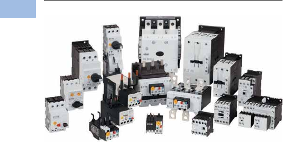
Product Overview
The XT line of IEC power
control offers starting and
protection solutions ideal for
control panels.
Innovations in the design and
development allow users to
reduce material costs, reduce
installation effort, and
enhance panel safety and
performance all in a compact
design. Some of these key
innovations include:
●Toolless assembly of
manual motor controllers
and reversing contactors
●Low coil consumption
●Front accessibility to coil
terminations
●Built-in surge suppression
on electronic coils
●Built-in auxiliary contact for
contactors up to 32A in a
45 mm frame
●Finger-safe and back-of-
hand proof ratings
●Direct PLC control on
185A–2000A contactors
The XT line includes a large
offering of power control
components and accessories
that cover a broad range of
applications and ratings:
●Three-pole contactors to
2000A
●Four-pole contactors to
200A
●Capacitor contactors to
680 kVar
●Mini contactors to 9A
●Relays to 16A
●Thermal overload relays to
630A
●Electronic overload relays
to 1500A
●Manual motor protectors
to 65A
●Manual motor controllers
and combination motor
controllers to 65A
Courtesy of CMA/Flodyne/Hydradyne ▪ Motion Control ▪ Hydraulic ▪ Pneumatic ▪ Electrical ▪ Mechanical ▪ (800) 426-5480 ▪ www.cmafh.com
Volume 5—Motor Control and Protection CA08100006E—August 2012 www.eaton.com V5-T1-3
1
1
1
1
1
1
1
1
1
1
1
1
1
1
1
1
1
1
1
1
1
1
1
1
1
1
1
1
1
1
1.1
IEC Contactors and Starters
XT
IEC Power Control
Relays and Timers
Contents
Description Page
Relays and Timers
Catalog Number Selection . . . . . . . . . . . . . . . . V5-T1-4
Product Selection . . . . . . . . . . . . . . . . . . . . . . . V5-T1-5
Accessories . . . . . . . . . . . . . . . . . . . . . . . . . . . V5-T1-6
Technical Data and Specifications . . . . . . . . . . V5-T1-12
Dimensions . . . . . . . . . . . . . . . . . . . . . . . . . . . V5-T1-16
An Eaton
Green Solution
Miniature Controls . . . . . . . . . . . . . . . . . . . . . . . . . V5-T1-18
Contactors and Starters . . . . . . . . . . . . . . . . . . . . V5-T1-35
Thermal Overload Relays . . . . . . . . . . . . . . . . . . . . V5-T1-128
C440/XT Electronic Overload Relay . . . . . . . . . . . . V5-T1-141
Manual Motor Protectors . . . . . . . . . . . . . . . . . . . V5-T1-157
Combination Motor Controllers . . . . . . . . . . . . . . . V5-T1-193
XT Electronic Manual Motor Protector . . . . . . . . . V5-T1-216
Reference Data . . . . . . . . . . . . . . . . . . . . . . . . . . . V5-T1-229
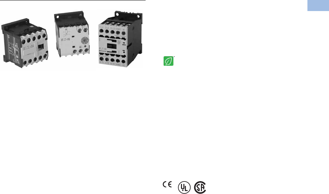
Relays and Timers
Product Description
Eaton’s new line of XT relays
and timers includes mini and
standard frame control relays
and auxiliary contacts, mini
electronic on-delay and
multi-function timers and
an electronic star-delta
(wye-delta) timer for use
in star-delta (wye-delta)
combinations. Because XT
meets UL®, CSA® and CE
standards, it is the perfect
product solution for IEC
applications all over the
world. The compact, space
saving and easy to install XT
line of IEC contactors and
starters is the efficient and
effective solution for
customer applications.
Features
●For use with mini and
standard frame size
contactors and starters
●Control relays
●AC control from 12V to
550V 50 Hz, 600V 60 Hz
●DC control from
12V to 220V
●On-delay and multi-
function timers
●24–240 Vac/Vdc control
●Available with screw or
spring cage terminals
●Four-pole configurations
●IP20 finger and back-of-
hand proof
●Large ambient temperature
range: –25° to 50°C [–13°
to 122°F]
●The XTRE control relays
have positively driven
contacts between the relay
and the auxiliary contact
modules as well as within
the auxiliary contact
modules
Standards and Certifications
●IEC EN 60947
●CE approved
●UL
●CSA
Instructional Leaflets
Pub51219 XTRM Mini Control Relays
Pub51210 XTRE Control Relays
Pub51244 XTTR Electronic Star-Delta (Wye-Delta) Timer
Pub51245 XTMT Mini Electronic On-Delay and
Multi-Function Timers
Courtesy of CMA/Flodyne/Hydradyne ▪ Motion Control ▪ Hydraulic ▪ Pneumatic ▪ Electrical ▪ Mechanical ▪ (800) 426-5480 ▪ www.cmafh.com
V5-T1-4 Volume 5—Motor Control and Protection CA08100006E—August 2012 www.eaton.com
1
1
1
1
1
1
1
1
1
1
1
1
1
1
1
1
1
1
1
1
1
1
1
1
1
1
1
1
1
1
1.1
IEC Contactors and Starters
XT
IEC Power Control
Catalog Number Selection
XT—Relays
XT—Timers
XT RE C10 B22 AD
Product Family Code
RM = Mini IEC control
relay
RE = IEC control relay
Coil Code
See table on Page V5-T1-5.
Product Line Prefix
XT = XT IEC power control
Terminations
Blank =Screw
terminals
C= Spring cage
terminals
Conventional Thermal
Current Rating
10 = 10A
Frame
XTRM
A = 45 mm—mini
XTRE
B = 45 mm—standard
Contact
Configuration
40 = 4NO
31 = 3NO-1NC
22 = 2NO-2NC
Product Family Code
MT = Mini IEC timing
relay
TR = Electronic timing
relay star-delta
(wye-delta)
Coil Code
B = 24–240 Vac/Vdc
Product Line Prefix
XT = XT IEC power control Function
XTMT
11 = On-delay
70 = Adjustable
XTTE
51 = Star-delta
Time Range Max.
XTMT
30S = 1.5–30s
60H = 05–1s
0.15–3s
0.5–10s
3–60s
0.15–3 min
0.5–3 min
3–60 min
0.15–3h
0.5–3h
3–60h
XTTR
60S =3–60s
XT MT 6 B 30S 11 B
Conventional
Thermal Current
Rating
6 = 6A
Frame
A = 45 mm
Courtesy of CMA/Flodyne/Hydradyne ▪ Motion Control ▪ Hydraulic ▪ Pneumatic ▪ Electrical ▪ Mechanical ▪ (800) 426-5480 ▪ www.cmafh.com
Volume 5—Motor Control and Protection CA08100006E—August 2012 www.eaton.com V5-T1-5
1
1
1
1
1
1
1
1
1
1
1
1
1
1
1
1
1
1
1
1
1
1
1
1
1
1
1
1
1
1
1.1
IEC Contactors and Starters
XT
IEC Power Control
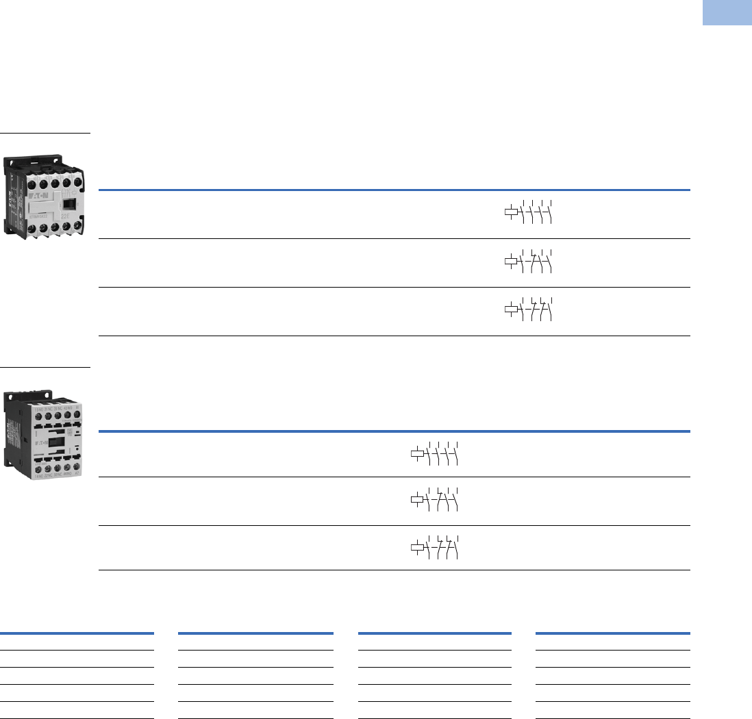
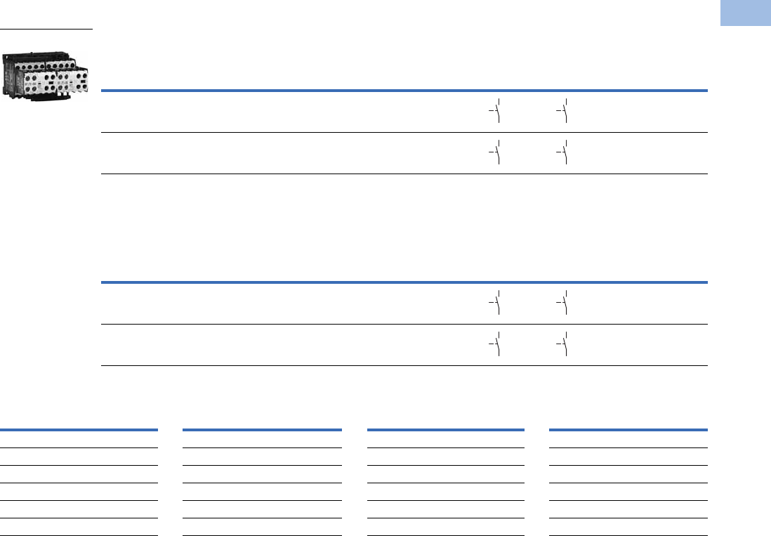
Product Selection
When Ordering
●Orders must be placed in multiples of the package quantity listed
●DC operated control relays have a built-in suppressor circuit
●Contact terminal numbers to EN50011
●Coil terminal numbers to EN50005
Mini Control Relays
Control Relays
Coil Voltage Suffix
Notes
1Underscore (_) indicates magnet coil suffix required. See Coil Voltage Suffix table above.
2DC operated control relays XTRE(C)10B22_ can only be combined with two-pole auxiliary contacts.
Conventional
Thermal
Current Ith (A)
Contact
Configuration
Rated Operational Current
AC-15 Ie (A) Circuit
Symbol
Screw Terminal
Catalog Number 1
220–240V 380–415V 500V
10 4NO 6 3 1.5 XTRM10A40_
10 3NO-1NC 6 3 1.5 XTRM10A31_
10 2NO-2NC 6 3 1.5 XTRM10A22_
Conventional
Thermal
Current Open
at 60°C Ith
(A)
Contact
Configuration
Rated Operational Current
AC-15 Ie (A)
Circuit
Symbol
Screw Terminal
Catalog Number 1
Spring Cage
Terminal
Catalog Number 1
220–240V 380–415V 500V
16 4NO 6 4 1.5 XTRE10B40_ XTREC10B40_
16 3NO-1NC 6 4 1.5 XTRE10B31_ XTREC10B31_
16 2NO-2NC 6 4 1.5 XTRE10B22_ 2XTREC10B22_ 2
Coil Voltage Suffix Code Coil Voltage Suffix Code Coil Voltage Suffix Code Coil Voltage Suffix Code
110V 50 Hz, 120V 60 Hz
A
415V 50 Hz, 480V 60 Hz
C
380V 50 Hz, 440V 60 Hz
L
120 Vdc
AD
220V 50 Hz, 240V 60 Hz
B
550V 50 Hz, 600V 60 Hz
D
380V 60 Hz
P
220 Vdc
BD
230V 50 Hz
F
208V 60 Hz
E
12V 50/60 Hz
R
12 Vdc
RD
24V 50/60 Hz
T
190V 50 Hz, 220V 60 Hz
G
42V 50 Hz, 48V 60 Hz
W
48 Vdc
WD
24 Vdc
TD
240V 50 Hz, 277V 60 Hz
H
48V 50 Hz
Y
120 Vdc
AD
TRM10A_
14
13 33
34
43
44
A1
A2
23
24
14
13 21
22
33
34
43
44
A1
A2
14
13 21
22
31
32
43
44
A1
A2
XTREC10_
14
13 33
34
43
44
A1
A2
23
24
14
13 21
22
33
34
43
44
A1
A2
14
13 21
22
31
32
43
44
A1
A2
Courtesy of CMA/Flodyne/Hydradyne ▪ Motion Control ▪ Hydraulic ▪ Pneumatic ▪ Electrical ▪ Mechanical ▪ (800) 426-5480 ▪ www.cmafh.com
V5-T1-6 Volume 5—Motor Control and Protection CA08100006E—August 2012 www.eaton.com
1
1
1
1
1
1
1
1
1
1
1
1
1
1
1
1
1
1
1
1
1
1
1
1
1
1
1
1
1
1
1.1
IEC Contactors and Starters
XT
IEC Power Control
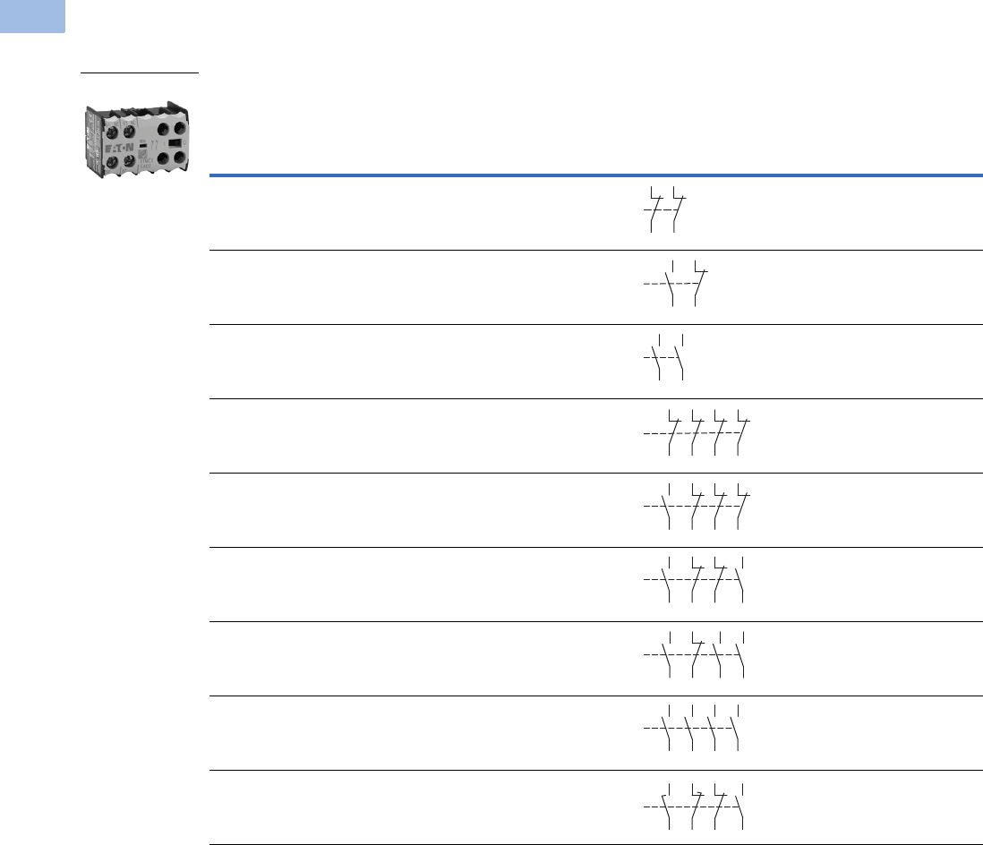
Accessories
Auxiliary Contacts
Front-Mount Auxiliary Contacts for Use with XTRM Mini Control Relays
Notes
1 Orders must be placed in multiples of package quantity listed.
2 One early-make contact (NOE), one late-break contact (NCL).
Conventional
Thermal Current,
Ith
Open (A)
Rated Operational Current
AC-15 Ie (A)
Contact
Configuration Contact Sequence
Pkg.
Qty. 1
Screw Terminal
Catalog Number
220V
230V
240V
380V
400V
415V 500V
10 4 2 1.5 2NC 5 XTMCXFA02
10 4 2 1.5 1NO-1NC 5 XTMCXFA11
10 4 2 1.5 2NO 5 XTMCXFA20
10 4 2 1.5 4NC 5 XTMCXFA04
10 4 2 1.5 1NO-3NC 5 XTMCXFA13
10 4 2 1.5 2NO-2NC 5 XTMCXFA22
10 4 2 1.5 3NO-1NC 5 XTMCXFA31
10 4 2 1.5 4NO 5 XTMCXFA40
10 4 2 1.5 1NO-1NC
1NOE-1NCL
5XTMCXFAL22 2
XTMCXF_
51
52
61
62
54
53 61
62
54
63
64
53
51
52
61
62
71
72 82
81
53 61 71 81
82
72
62
54
54
53 61
62
71
72
83
84
54
53 61
62
73
74
83
84
54
63 73
64 74
53 83
84
58
57 65
66
71
72
83
84
Courtesy of CMA/Flodyne/Hydradyne ▪ Motion Control ▪ Hydraulic ▪ Pneumatic ▪ Electrical ▪ Mechanical ▪ (800) 426-5480 ▪ www.cmafh.com
Volume 5—Motor Control and Protection CA08100006E—August 2012 www.eaton.com V5-T1-7
1
1
1
1
1
1
1
1
1
1
1
1
1
1
1
1
1
1
1
1
1
1
1
1
1
1
1
1
1
1
1.1
IEC Contactors and Starters
XT
IEC Power Control
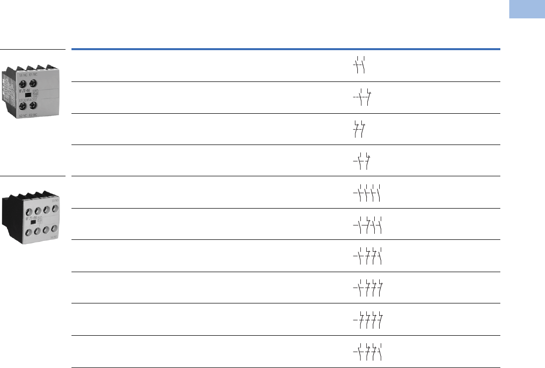
Front-Mount Auxiliary Contacts for Use with XTRE Control Relays 1
Notes
1 Interlocked opposing contacts, to IEC/EN 60947-5-1 Annex L (positively driven), within the auxiliary contact modules (not NOE and NCL contacts) and between the
auxiliary contacts and built-in contacts of the XTRE control relays.
2 Orders must be placed in multiples of package quantity listed.
3 Catalog number is shown with screw type terminal. For spring cage, add a “C” before the last 2 digits. For example, to order a spring cage version of the XTCEXFAC22,
change the catalog number to XTCEXFACC22.
4 One early-make contact (NOE), one late-break contact (NCL).
Conventional
Thermal Current,
Ith (A), Open at 60°C Poles
Rated Operational Current AC-15 Ie (A)
Contact
Configuration Circuit Symbol
Pkg.
Qty. 2
Screw Terminal
Catalog Number
220V
230V
240V
380V
400V
415V 500V
16 2 6 3 1.5 2NO 5 XTCEXFAC20
16 2 6 3 1.5 1NO-1NC 5 XTCEXFAC11 3
16 2 6 3 1.5 2NC 5 XTCEXFAC02
16 2 6 3 1.5 1NOE-1NCL5XTCEXFALC11 4
16 4 6 3 1.5 4NO 5 XTCEXFAC40 3
16 4 6 3 1.5 3NO-1NC 5 XTCEXFAC31 3
16 4 6 3 1.5 2NO-2NC 5 XTCEXFAC22 3
16 4 6 3 1.5 1NO-3NC 5 XTCEXFAC13
16 4 6 3 1.5 4NC 5 XTCEXFAC04
16 4 6 3 1.5 1NO-1NC
1NOE-1NCL
5XTCEXFCLC22 4
Two-Pole
Four-Pole
54
63
6
4
53
54
53 61
62
51
52
61
62
58
57 6
5
66
54
63 73
64 74
53 83
84
54
53 61
62
73
74
83
84
54
53 61
62
71
72
83
84
53 61 71 81
82
72
62
54
51
52
61
62
71
72 82
81
58
5765
66
71
72
83
84
Courtesy of CMA/Flodyne/Hydradyne ▪ Motion Control ▪ Hydraulic ▪ Pneumatic ▪ Electrical ▪ Mechanical ▪ (800) 426-5480 ▪ www.cmafh.com
V5-T1-8 Volume 5—Motor Control and Protection CA08100006E—August 2012 www.eaton.com
1
1
1
1
1
1
1
1
1
1
1
1
1
1
1
1
1
1
1
1
1
1
1
1
1
1
1
1
1
1
1.1
IEC Contactors and Starters
XT
IEC Power Control
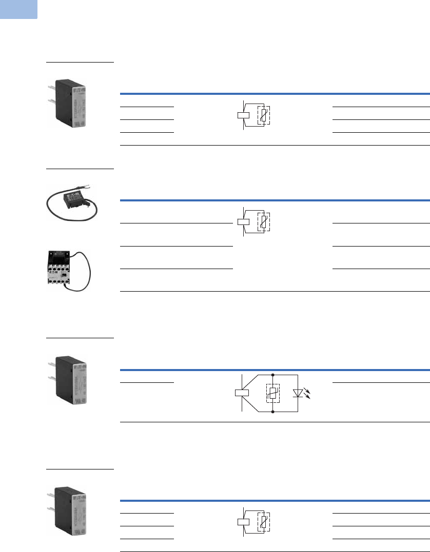
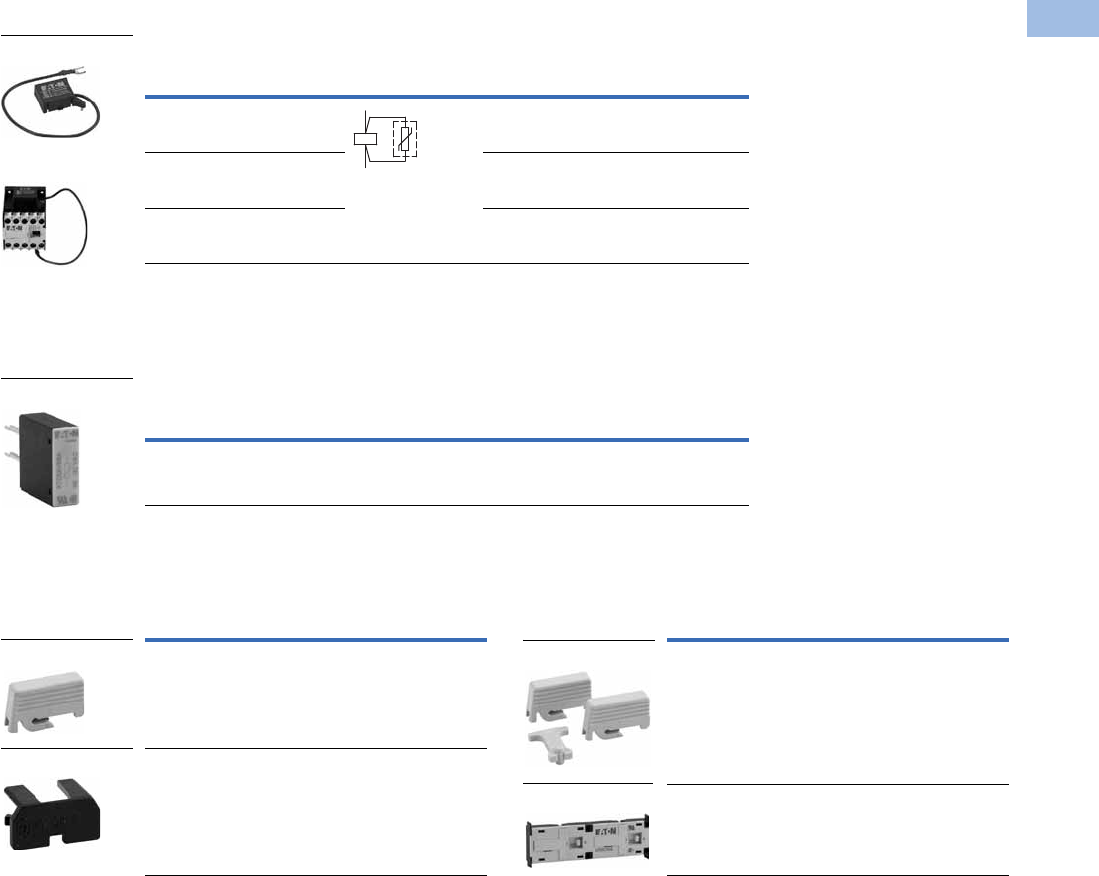
Suppressors
For AC operated contactors 50–60 Hz. On DC operated contactor relays and on XTRE10B, the
suppressor circuit is built-in. Note dropout delay.
Varistor Suppressor 12
Varistor Suppressor for XTRE
Varistor Suppressor for XTRM
Varistor Suppressor with Integrated LED 12
Varistor Suppressor for XTRE
RC Suppressor 12
RC Suppressor for XTRE
Notes
1 Note dropout delay.
2 For AC operated contactors, 50/60 Hz. DC operated contactors have an integrated suppressor.
3 Orders must be placed in multiples of package quantity listed.
Voltage
For Use
with… Contact Sequence
Pkg.
Qty.
3
Catalog Number
24–48 XTRE(C)10B 10 XTCEXVSBW
48–130 10 XTCEXVSBA
130–240 10 XTCEXVSBB
240–500 10 XTCEXVSBC
Voltage
For Use
with… Circuit Symbol
Pkg.
Qty.
3
Catalog Number
24–48 XTRM6A_,
XTRM9A_
10 XTMCXVSW
48–130 XTRM6A_,
XTRM9A_
10 XTMCXVSA
110–250 XTRM6A_,
XTRM9A_
10 XTMCXVSB
380–415 XTRM6A_,
XTRM9A_
10 XTMCXVSN
Voltage
For Use
with… Contact Sequence
Pkg.
Qty.
3
Catalog Number
24–48 XTRE(C)10B 10 XTCEXVSLBW
130–240 10 XTCEXVSLBB
Voltage
For Use
with… Contact Sequence
Pkg.
Qty.
3
Catalog Number
24–48 XTRE(C)10B 10 XTCEXRSBW
48–130 10 XTCEXRSBA
110–240 10 XTCEXRSBB
240–500 10 XTCEXRSBC
XTCEXVSB_
A1
A2
XTMCXVS_
XTRM Relay with
Installed Suppressor
A1
A2
XTCEXVSLB_
A1
A2
XTCEXRSB_
A1
A2
Courtesy of CMA/Flodyne/Hydradyne ▪ Motion Control ▪ Hydraulic ▪ Pneumatic ▪ Electrical ▪ Mechanical ▪ (800) 426-5480 ▪ www.cmafh.com
Volume 5—Motor Control and Protection CA08100006E—August 2012 www.eaton.com V5-T1-9
1
1
1
1
1
1
1
1
1
1
1
1
1
1
1
1
1
1
1
1
1
1
1
1
1
1
1
1
1
1
1.1
IEC Contactors and Starters
XT
IEC Power Control
RC Suppressor 12
RC Suppressor for XTRM 3
Free-Wheel Diode Suppressor
In addition to the built-in suppressor circuit for DC actuated contactors. Prevents negative breaking
voltage when contactors are used in combination with a safety PLC.
Free-Wheel Diode Suppressor for XTRE
Connector 5
Connector
Mechanical Interlock 6
Mechanical Interlock
Notes
1 Note dropout delay.
2 For AC operated contactors, 50/60 Hz. DC operated contactors have an integrated suppressor.
3 For AC operated contactors, 50/60 Hz. Note dropout delay.
4 Orders must be placed in multiples of package quantity listed.
5 For mechanically arranging contactors in combinations. Distance between contactors is 0 mm.
6 For two contactors with AC or DC operated magnet system that are horizontally or vertically mounted.
For Frame B, mechanical lifespan is 2.5 x 10⁶ operations and the distance between contactors is 0 mm.
Voltage
For Use
with…
Circuit
Symbol
Pkg.
Qty.
4
Catalog Number
24–48 XTRM6A_,
XTRM9A_
10 XTMCXRSW
48–130 XTRM6A_,
XTRM9A_
10 XTMCXRSA
110–250 XTRM6A_,
XTRM9A_
10 XTMCXRSB
XTMCXRS_
XTRM Relay with
Installed Suppressor
A1
A2
Voltage
For Use
with…
Pkg.
Qty.
4
Catalog Number
130–240
XTRE10B
10 XTCEXVSLBB
XTCEXVSLBB
For Use
with…
Pkg.
Qty.
4
Catalog Number
XTRE(C)10B 50 XTCEXCNC
XTRM10A 50 XTMCXCN
XTCEXCNC
XTMCXCN
For Use
with…
Pkg.
Qty.
4
Catalog Number
XTRE10B_ 5 XTCEXMLB
XTRM10A_ 5 XTMCXML
XTCEXMLB
XTMCXML
Courtesy of CMA/Flodyne/Hydradyne ▪ Motion Control ▪ Hydraulic ▪ Pneumatic ▪ Electrical ▪ Mechanical ▪ (800) 426-5480 ▪ www.cmafh.com
V5-T1-10 Volume 5—Motor Control and Protection CA08100006E—August 2012 www.eaton.com
1
1
1
1
1
1
1
1
1
1
1
1
1
1
1
1
1
1
1
1
1
1
1
1
1
1
1
1
1
1
1.1
IEC Contactors and Starters
XT
IEC Power Control
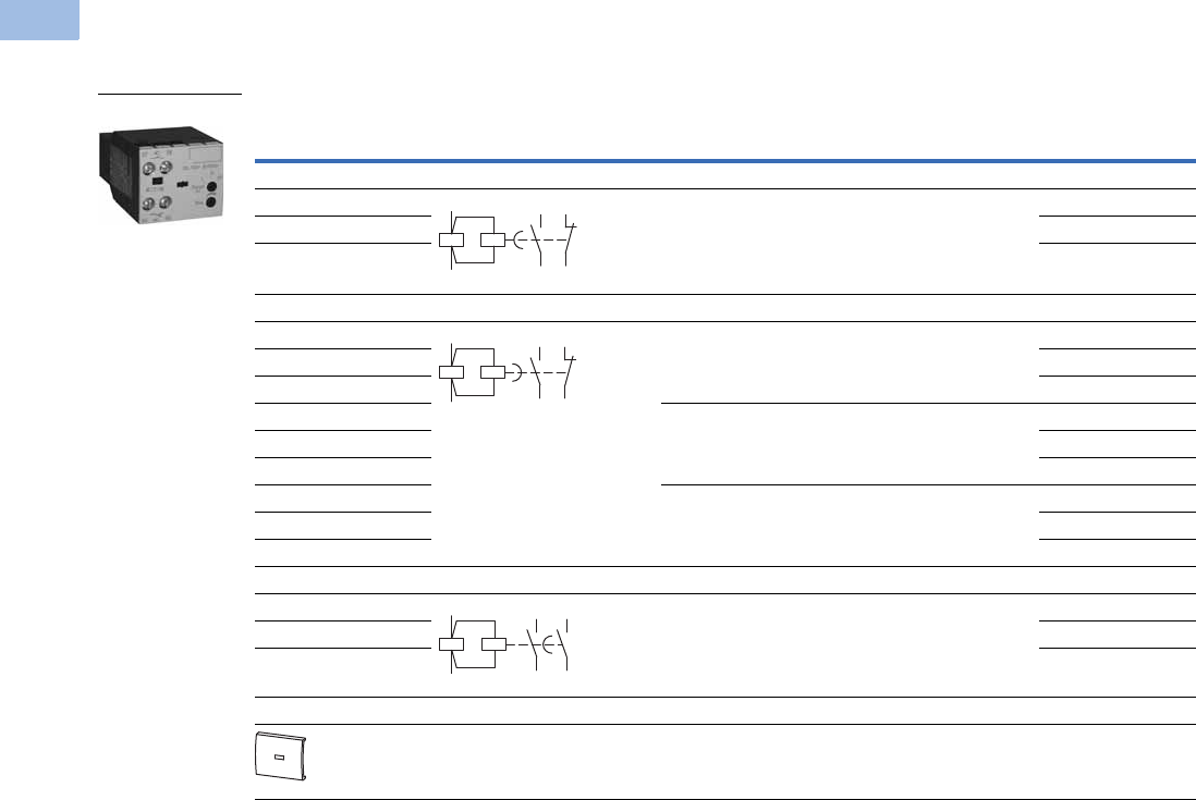
Electronic Timer Modules
Front- (top-) mounted timer modules for use with XTRE10B control relays. Can not be combined with top-mount auxiliary
contacts, XTCEXF_.
Electronic Timer Modules for XTRE
Note
1 Orders must be placed in multiples of package quantity listed.
Voltage Contact Sequence Timing Range
For Use
with…
Pkg.
Qty. 1Catalog Number
On-Delay
24 Vac/Vdc 0.05–1s
0.5–10s
15–100s
XTRE10B_ 1 XTCEXTEEC11T
100–130 Vac XTCEXTEEC11A
200–240 Vac XTCEXTEEC11B
Off-Delay
24 Vac/Vdc 0.05–1s XTRE10B_ 1 XTCEXTED1C11T
100–130 Vac XTCEXTED1C11A
200–240 Vac XTCEXTED1C11B
24 Vac/Vdc 0.5–10s XTRE10B_ 1 XTCEXTED10C11T
100–130 Vac XTCEXTED10C11A
200–240 Vac XTCEXTED10C11B
24 Vac/Vdc 5–100s XTRE10B_ 1 XTCEXTED100C11T
100–130 Vac XTCEXTED100C11A
200–240 Vac XTCEXTED100C11B
Star-Delta
24 Vac/Vdc 1–30s XTRE10B_ 1 XTCEXTEYC20T
100–130 Vac XTCEXTEYC20A
200–240 Vac XTCEXTEYC20B
Sealable Shroud
Transparent sealable shroud used to protect
electronic timer modules from unwanted access.
XTCEXTEE,
XTCEXTED,
XTCEXTEY
1XTCEXTESHRD
XTCEXT_
57
58
65
66
A1
A2
57
58
65
66
A1
A2
57
58
67
68
A1
A2
Courtesy of CMA/Flodyne/Hydradyne ▪ Motion Control ▪ Hydraulic ▪ Pneumatic ▪ Electrical ▪ Mechanical ▪ (800) 426-5480 ▪ www.cmafh.com
Volume 5—Motor Control and Protection CA08100006E—August 2012 www.eaton.com V5-T1-11
1
1
1
1
1
1
1
1
1
1
1
1
1
1
1
1
1
1
1
1
1
1
1
1
1
1
1
1
1
1
1.1
IEC Contactors and Starters
XT
IEC Power Control
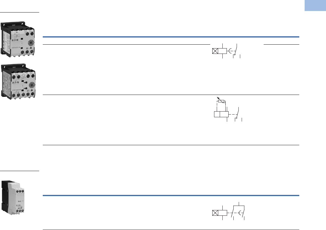
Mini Electronic Timers
Mini Electronic On-Delay Timers
Electronic Star-Delta (Wye-Delta) Timers
Electronic Star-Delta (Wye-Delta) Timers
Actuating Voltage
24–240 50/60 Hz
24–240 Vdc
Admissible Cable Length Connection to
Cable unscreened, with cable cross-section 0.5–1.5 mm2Y1/Y2, Z1/Z2
Two-core cable M250
Two-core cable in the same cable duct with the main cable, 50/60 Hz M50
Conventional
Thermal Current
Ie (A)
Rated Operational Current
Ie AC-11 Amps Time
Range Function
Terminal Marking
According to
EN 50042 Catalog Number 220/230/240V 380/400/440V
6 3 3 1.5–30 sec Fixed, on-delay XTMT6A30S11B
6 3 6 0.05–1 sec
0.15–3 sec
0.5–10 sec
3–60 sec
0.15–3 min
0.5–10 min
3–60 min
0.15–3h
0.5–10h
3–60h
Fixed, on-delay XTMT6A60H11B
6 3 3 0.05–1 sec
0.15–3 sec
0.5–10 sec
3–60 sec
0.15–3 min
0.5–10 min
3–60 min
0.15–3h
0.5–10h
3–60h
Adjustable:
on-delay;
fleeting contact
on energization;
flashing; pulse
generating;
ON-OFF
XTMT6A60H70B
Conventional
Thermal Current
Ie (A)
Rated Operational Current
Ie AC-11 Amps Time
Range Function
Terminal Marking
According to
EN 50042 Catalog Number 230V 400V
6 3 3 3–60 sec Fixed, star-delta XTTR6A60S51B
XTMT6A_
A1
A2
15
16 18
A1
A2
Z2Z1
15
16 18
XTTR6A60S51
A1
A2 18
17
28
Courtesy of CMA/Flodyne/Hydradyne ▪ Motion Control ▪ Hydraulic ▪ Pneumatic ▪ Electrical ▪ Mechanical ▪ (800) 426-5480 ▪ www.cmafh.com
V5-T1-12 Volume 5—Motor Control and Protection CA08100006E—August 2012 www.eaton.com
1
1
1
1
1
1
1
1
1
1
1
1
1
1
1
1
1
1
1
1
1
1
1
1
1
1
1
1
1
1
1.1
IEC Contactors and Starters
XT
IEC Power Control
Technical Data and Specifications
Relays and Timers
Note
1Damp heat, constant, to IEC 60068-2-78; damp heat, cyclical, to IEC 60068-2-30.
Description XTRE XTCEXFAC_ XTCEXTE_ XTRM XTMCXFA_
General
Standards IEC/EN 60947,
VDE 0660,
UL, CSA
IEC/EN 60947,
VDE 0660,
UL, CSA
DIN EN 61812,
IEC/EN 60947,
VDE 060, UL, CSA
IEC/EN 60947,
VDE 0660,
UL, CSA
IEC/EN 60947,
VDE 0660,
UL, CSA
Lifespan, mechanical—operations
AC operated 20,000,000 10,000,000 3,000,000 10,000,000 10,000,000
DC operated 20,000,000 10,000,000 3,000,000 20,000,000 20,000,000
Maximum operating frequency (ops/hr) 9000 9000 — 9000 9000
Climatic proofing 11 1 11
Ambient temperature
Open (°C, min./max.) –25/60 –25/60 –40/80 –25/50 –25/50
Enclosed (°C, min./max.) –25/40 –25/40 –25–60 –25/40 –25/40
Ambient temperature for storage (°C, min./max.) –40/80 –40/80 –25–40 — —
Mounting position As required,
not suspended
As required, except
vertically A1/A2 at
the bottom
As required, except
vertically A1/A2 at
the bottom
Mechanical shock resistance (IEC/EN 60068-2-27)
Half-sinusoidal shock 10 ms
Base unit with auxiliary contact module
Make contact 7g 7g 6g 10g 10g
Break contact 5g 5g 6g 8g 8g
Degree of protection IP20 IP20 IP20 IP20 IP20
Protection against direct contact from the front
when actuated by a perpendicular test finger (IEC 536)
Finger and
back-of-hand proof
Finger and
back-of-hand proof
Finger and
back-of-hand proof
Finger and
back-of-hand proof
Finger and
back-of-hand proof
Weight
AC operated (kg) 0.23 0.05 0.08 0.17 —
DC operated (kg) 0.28 0.05 0.08 0.20 —
Terminal capacity
Screw terminals
Solid (mm2) 1 x (0.75–4)0.
2 x (0.75–2.5)
1 x (0.75–4)0.
2 x (0.75–2.5)
1 x (0.75–2.5)
2 x (0.75–1.5)
1 x (0.75–2.5)
2 x (0.75–2.5)
1 x (0.75–2.5)
2 x (0.75–2.5)
Flexible with ferrule (mm2) 1 x (0.75–2.5)
2 x (0.75–2.5)
1 x (0.75–2.5)
2 x (0.75–2.5)
1 x (0.75–1.5)
2 x (0.75–1.5)
1 x (0.75–1.5)
2 x (0.75–1.5)
1 x (0.75–1.5)
2 x (0.75–1.5)
Solid or stranded (AWG) 18–14 18–14 18–14
Terminal screw M3.5 M3.5 M3.5 M3.5 M3.5
Pozidriv screwdriver Size 2 Size 2 Size 2 Size 2 Size 2
Standard screwdriver (mm) 0.8 x 5.5
1 x 6
0.8 x 5.5
1 x 6
0.8 x 5.5
1 x 6
0.8 x 5.5
1 x 6
0.8 x 5.5
1 x 6
Max. tightening torque (Nm) 1.2 1.2 1.2 1.2 1.2
Spring cage terminals
Solid (mm2) 1 x (0.75–2.5)
2 x (0.75–2.5)
1 x (0.75–2.5)
2 x (0.75–2.5)
—
—
1 x (0.75–2.5)
2 x (0.75–2.5)
1 x (0.75–2.5)
2 x (0.75–2.5)
Flexible with or without ferrule DIN 46228 (mm2) 1 x (0.75–2.5)
2 x (0.75–2.5)
1 x (0.75–2.5)
2 x (0.75–2.5)
—
—
1 x (0.75–2.5)
2 x (0.75–2.5)
1 x (0.75–2.5)
2 x (0.75–2.5)
Solid or stranded (AWG) 18–14 18–14 — 18–14 18–14
Standard screwdriver (mm) 0.6 x 3.5 0.6 x 3.5 — 0.6 x 3.5 0.6 x 3.5
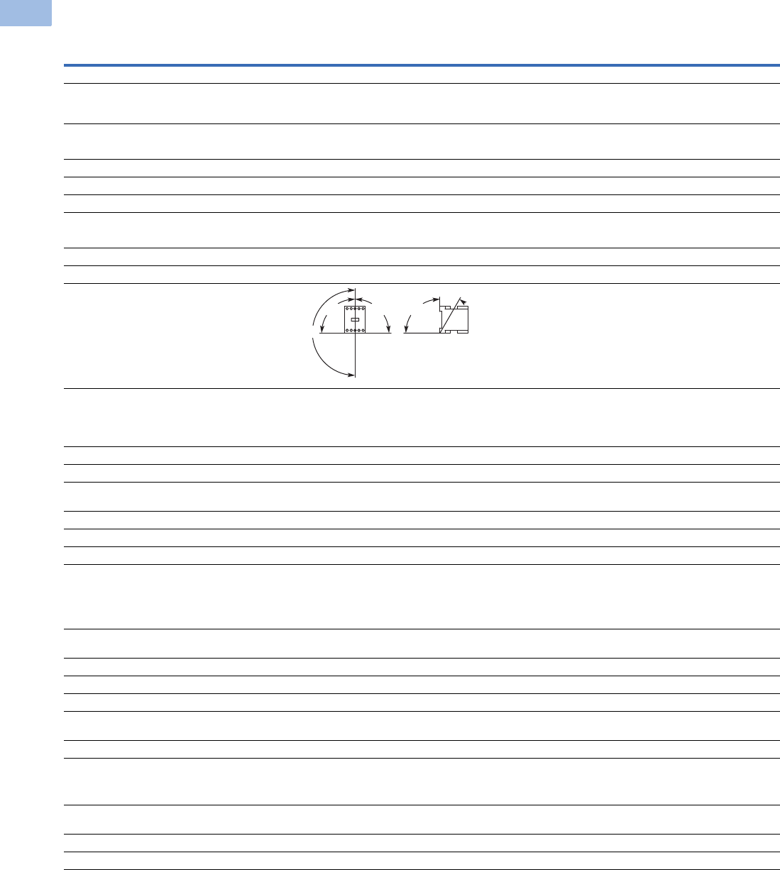
180°
30°
90°90°90°
Courtesy of CMA/Flodyne/Hydradyne ▪ Motion Control ▪ Hydraulic ▪ Pneumatic ▪ Electrical ▪ Mechanical ▪ (800) 426-5480 ▪ www.cmafh.com

Volume 5—Motor Control and Protection CA08100006E—August 2012 www.eaton.com V5-T1-13
1
1
1
1
1
1
1
1
1
1
1
1
1
1
1
1
1
1
1
1
1
1
1
1
1
1
1
1
1
1
1.1
IEC Contactors and Starters
XT
IEC Power Control
Relays and Timers, continued
Note
1Making and breaking conditions to DC13, time constant as stated.
Description XTRE XTCEXFAC_ XTCEXTE_ XTRM XTMCXFA_
Contacts
Interlocked opposing contacts to ZH 1/457,
including auxiliary contact module
Yes Yes No Yes Yes
Rated impulse withstand voltage (Uimp) Vac 6000 6000 6000 6000 6000
Overvoltage category/pollution degree III/3 III/3 III/3 III/3 III/3
Rated insulation voltage (Ui) Vac 690 690 600 690 690
Rated operational voltage (Ue) Vac 690 500 400 600 600
Safe isolation to VDE 0106 Part 101 and Part 101/A1
Between coil and auxiliary contacts (Vac) 400 400 250 300 300
Between the auxiliary contacts (Vac) 400 400 250 300 300
Rated operational current
AC-15 220/240V Ie6 6 Please inquire 6 4
380/415V Ie4 3 Please inquire 3 2
500V Ie1.5 — — 1.5 1.5
DC-13
1
DC13 L/R
<
15 ms
Contacts in series—voltage:
1—24V 10
10 —
2.5 2.5
1—60V
66
———
2—60V 10 10 — 2.5 2.5
1—110V 3 3 — — —
3—110V 6 6 — 1.5 1.5
1—220V 1 1 — — —
3—220V
55
—
0.5 0.5
DC13 L/R
<
50 ms
Contacts in series—voltage:
3—24V 4
——
——
3—60V 4
——
——
3—110V 2
——
——
3—220V 1
——
——
Control circuit reliability
(at Ue = 24 Vdc, Umin = 17, Imin = 5.4 mA)
Failure rate = <10–8, <1 failure
in 100 million operations
— Failure rate = <10–8, <1 failure
in 100 million operations
Conventional thermal current (Ith) 16 16 6 10 10
Short-circuit rating without welding
Maximum overcurrent protective device
220/240V–XTPR Frame B 4 — — 4 4
380/415V–XTPR Frame B 4 — — 4 4
Short-circuit protection, max. fuse
500V (A gG/gL) 10 10 6 6 6
500V (A fast) — — — 10 10
Current heat losses at load of I
th
AC operated (W) 0.3 0.3 — 0.2 0.2
DC operated (W) 0.3 0.3 — 0.3 0.3
Courtesy of CMA/Flodyne/Hydradyne ▪ Motion Control ▪ Hydraulic ▪ Pneumatic ▪ Electrical ▪ Mechanical ▪ (800) 426-5480 ▪ www.cmafh.com

V5-T1-14 Volume 5—Motor Control and Protection CA08100006E—August 2012 www.eaton.com
1
1
1
1
1
1
1
1
1
1
1
1
1
1
1
1
1
1
1
1
1
1
1
1
1
1
1
1
1
1
1.1
IEC Contactors and Starters
XT
IEC Power Control
Relays and Timers, continued
Note
1Smoothed DC or three-phase bridge rectifier.
Description XTRE XTCEXFAC_ XTCEXTE_ XTRM XTMCXFA_
Magnet Systems
Pickup and dropout values
AC operated
Single-voltage coil 50 Hz and dual-voltage coil 50 Hz,
60 Hz (pickup x U
c
)
0.8–1.1 — 0.85–11 0.8–1.1 —
Dual-frequency coil 50/60 Hz (pickup x U
c
) 0.8–1.1 — — 0.85–1.1 —
DC operated
1
Pickup voltage (pickup x U
c
) 0.8–1.1 — 0.7–1.2 0.85–1.3 —
At 24V: without auxiliary contact module (40°C) (pickup x U
c
) 0.7–1.3 — — 0.7–1.3 —
Power consumption
Single-voltage coil 50 Hz and dual-voltage coil 50 Hz, 60 Hz
Pickup VA 24 — — 25 —
Pickup W 19 — — 22 —
Sealing VA 3.4 — 2 4.6 —
Sealing W 1.2 — 1.8 1.3 —
Dual-frequency coil 50/60 Hz at 50 Hz
Pickup VA 27 — — 30 —
Pickup W 22 — — 26 —
Sealing VA 4.2 — — 5.4 —
Sealing W 1.4 — — 1.6 —
Dual-frequency coil 50/60 Hz at 60 Hz
Pickup VA 25 — — 29 —
Pickup W 21 — — 24 —
Sealing VA 3.3 — — 3.9 —
Sealing W 1.2 — — 1.2 —
DC operated
Pull-in = sealing (W) 3 — — 2.6 —
Duty factor (% DF) 100 — 100 100 —
Switching times at 100% U
c
(approximate values)
AC operated closing delay (ms)
<
21 — — 14–21 —
AC operated NO contact opening delay (ms)
<
18 — — 8–18 —
AC operated with auxiliary contact module,
max. closing delay (ms)
—— — 4545
DC operated closing delay (ms)
<
31 — — 26–35 —
DC operated NO contact opening delay (ms)
<
12 — — 15–25 —
DC operated with auxiliary contact module,
max. closing delay (ms)
—— — 7070
Courtesy of CMA/Flodyne/Hydradyne ▪ Motion Control ▪ Hydraulic ▪ Pneumatic ▪ Electrical ▪ Mechanical ▪ (800) 426-5480 ▪ www.cmafh.com
Volume 5—Motor Control and Protection CA08100006E—August 2012 www.eaton.com V5-T1-15
1
1
1
1
1
1
1
1
1
1
1
1
1
1
1
1
1
1
1
1
1
1
1
1
1
1
1
1
1
1
1.1
IEC Contactors and Starters
XT
IEC Power Control
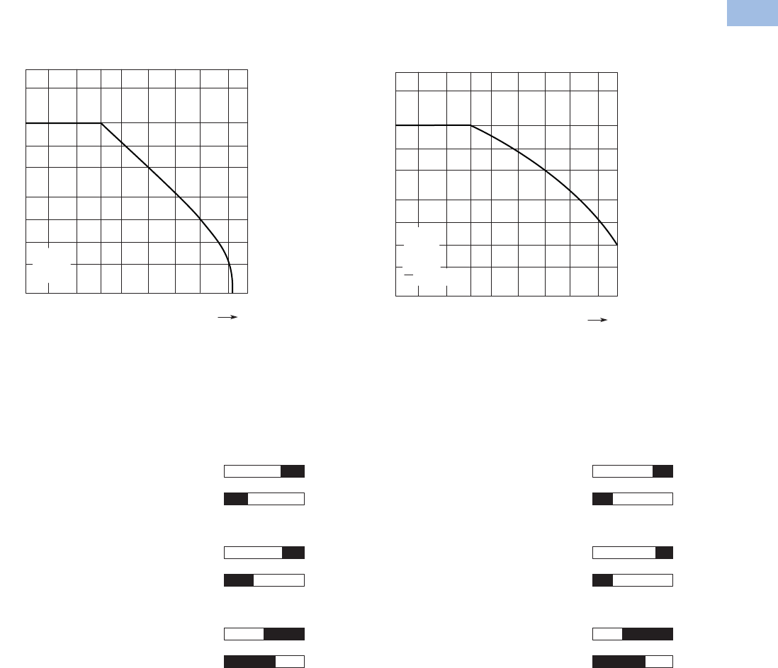
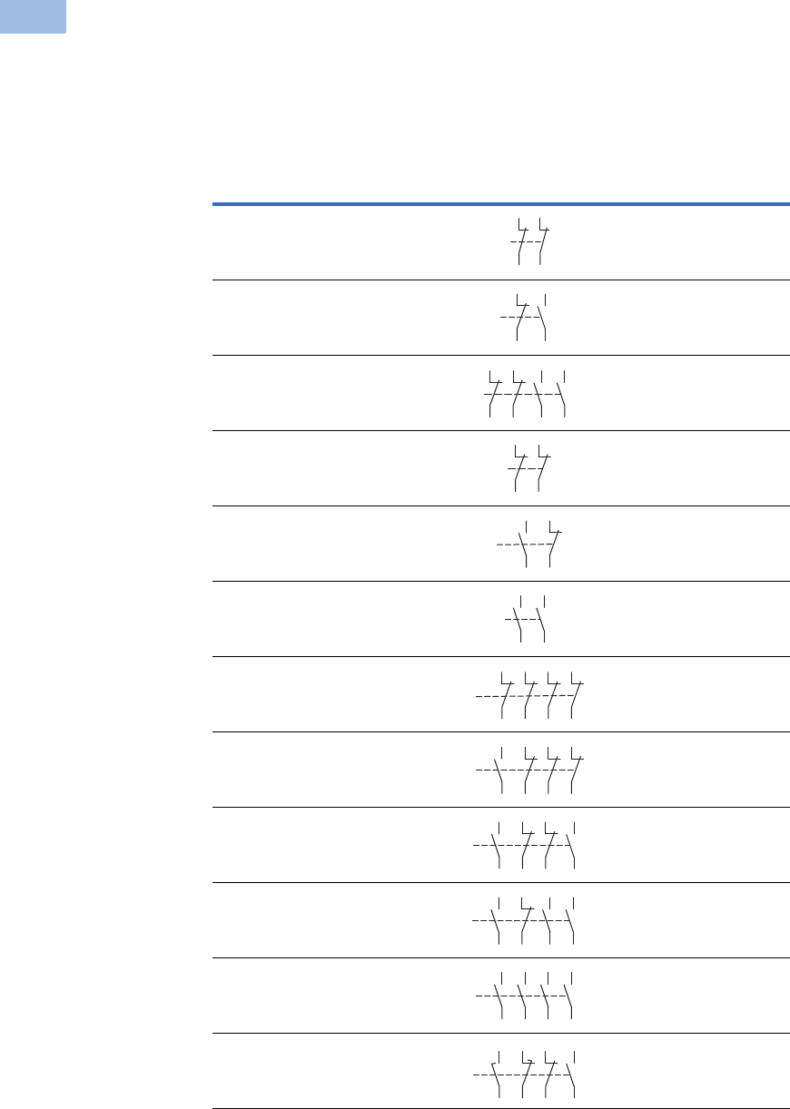
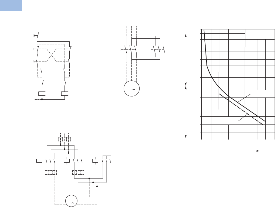
Control Relays—Characteristic Curves
XTRE (AC-15) XTRE (DC-13) 1
The diagrams show the closing and opening travel of the contact of the contactor relays and auxiliary contacts at no load.
Tolerances are not taken into consideration.
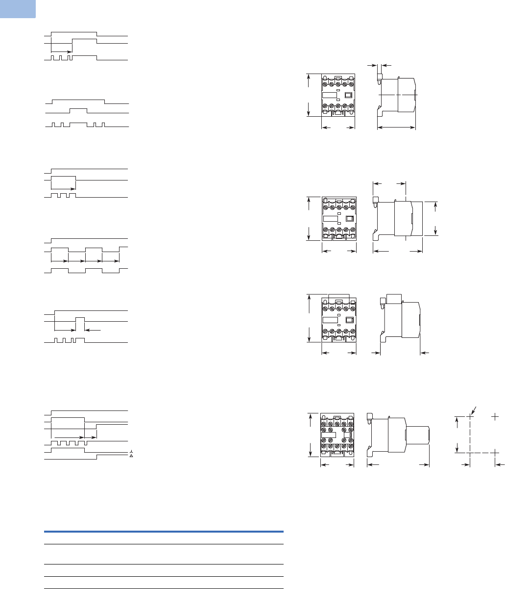
Contact Travel Diagrams
XTRE
Note
1Making and breaking conditions to DC-13, time constant as stated.
Component lifespan (operations)
Ie = Rated operational current
AC-15
240 V
0.01 0.050.02 20.1 0.5 152.0 10 A
20
10
5
2
1
0.5
0.2
0.1
106
Ie
L
R
DC-13
24 V
= 50 ms
Component lifespan (operations)
Ie = Rated operational current
0.01 0.050.02 20.1 0.5 150.2 10 A
20
10
5
2
1
0.5
0.2
0.1
106
Ie
4.5
4.5
3.30
01.0 2.9
2.9
2.10
00.7
4.5
4.5
3.20
01.6 2.9
2.9
2.30
00.7
4.5
4.5
2.00
02.8 2.9
2.9
1.10
01.9
Normally open contact
XTRE_ — AC Operation
XTCEXFALC_ — AC Operation
XTCEXFAC_ — AC Operation
Normally closed contact
Normally open contact
Normally closed contact
Normally open contact (early make)
Normally closed contact (late make)
Normally open contact
XTRE — DC Operation
XTCEXFALC_ — DC Operation
XTCEXFAC_ — DC Operation
Normally closed contact
Normally open contact
Normally closed contact
Normally open contact (early make)
Normally closed contact (late make)
Courtesy of CMA/Flodyne/Hydradyne ▪ Motion Control ▪ Hydraulic ▪ Pneumatic ▪ Electrical ▪ Mechanical ▪ (800) 426-5480 ▪ www.cmafh.com
V5-T1-16 Volume 5—Motor Control and Protection CA08100006E—August 2012 www.eaton.com
1
1
1
1
1
1
1
1
1
1
1
1
1
1
1
1
1
1
1
1
1
1
1
1
1
1
1
1
1
1
1.1
IEC Contactors and Starters
XT
IEC Power Control
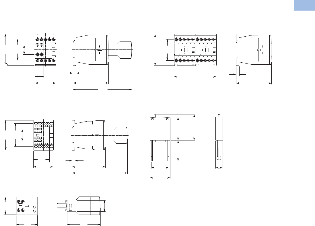
Flow Diagrams—Electronic Timers, XTMT Mini Timers
On-Delay
ON-OFF Function
Fleeting Contact on Energization
Flashing, Pulse Initiating
Pulse Generating
Star-Delta (Wye-Delta) Timer
Star-Delta
Rating Data
Rating Data for Approved Types
Pilot Duty General Use
Control Relays—XTMR
A600, P300 10A–600 Vac
0.5A–250 Vdc
Timers—XTMT, XTTR
B300 6A–250 Vac
LED
A1-A2
15-18
t
A1-A2
15-18
OFFONOFF
LED
A1-A2
15-18
t
LED
LED
tttt
A1-A2
15-18
LED
A1-A2
15-18
0.5 s
t
17-18
ttu
A1-A2
17-28
Power LED
LED
LED
Dimensions
Approximate Dimensions in mm [in.]
Mini Contactor Relays
Mini Control Relay XTRM
XTRM Mini Control Relay with IP40 XTMCX Shroud
XTRM Mini Control Relay with RC or Varistor Suppressor
XTRM Mini Control Relay with XTMCXFA Auxiliary Contact
45
[1.77]
58
[2.28]
52 – 54
[2.05] – [2.13]
5.5 [.22]
45
[1.77]
58
[2.28]
65.3
[2.57]
43
[1.69]
45
[1.77]
52 – 54
[2.05] – [2.13]
45
[1.77]
62.5
[2.46]
45
[1.77]
83 – 86
[3.27] – [3.39]
58
[2.28]
50
[1.97]
35
[1.38]
M4
Courtesy of CMA/Flodyne/Hydradyne ▪ Motion Control ▪ Hydraulic ▪ Pneumatic ▪ Electrical ▪ Mechanical ▪ (800) 426-5480 ▪ www.cmafh.com
Volume 5—Motor Control and Protection CA08100006E—August 2012 www.eaton.com V5-T1-17
1
1
1
1
1
1
1
1
1
1
1
1
1
1
1
1
1
1
1
1
1
1
1
1
1
1
1
1
1
1
1.1
IEC Contactors and Starters
XT
IEC Power Control
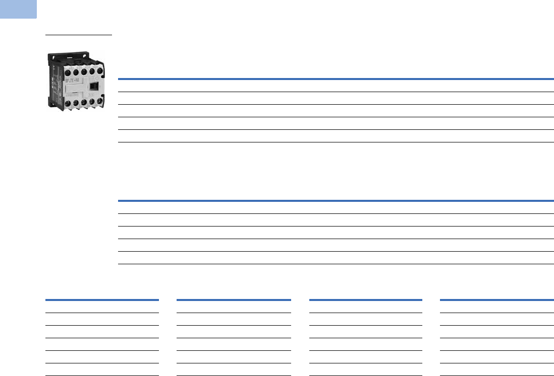
Approximate Dimensions in mm [in.]
Control Relays
Control Relay XTRE with XTCEXFA Auxiliary Contact
Control Relay with Spring Cage Terminals XTREC
with XTCEXFA Auxiliary Contact
Electronic Timer Module XTCEXTE
18
[.71]
45
[1.77]
6.5
[.26]
75
[2.95] 117
[4.61]
68
[2.68]
45
[1.77]
18
[.71]
26.4
[1.04]
52.3
[2.06]
45
[1.77]
36
[1.42] 6.5
[.26] 75
[2.95] 125
[4.92]
68
[2.68]
38
[1.50]
25
[.98]
70
[2.76]
45
[1.77]
Control Relay XTRE with XTCEXMLB Mechanical Interlock
Coil Suppressors for Use with XTRE Control Relays
6.5
[.26]
75
[2.95]
45
[1.77]
68
[2.68]
90
[3.54]
Approx.
32 [1.26]
25
[.98]
19.2
[.76]
25.9
[1.02]
28
[1.10]
9
[.35]
Courtesy of CMA/Flodyne/Hydradyne ▪ Motion Control ▪ Hydraulic ▪ Pneumatic ▪ Electrical ▪ Mechanical ▪ (800) 426-5480 ▪ www.cmafh.com

V5-T1-18 Volume 5—Motor Control and Protection CA08100006E—August 2012 www.eaton.com
1
1
1
1
1
1
1
1
1
1
1
1
1
1
1
1
1
1
1
1
1
1
1
1
1
1
1
1
1
1
1.1
IEC Contactors and Starters
XT
IEC Power Control
XTMC Miniature Contactor
Contents
Description Page
Relays and Timers . . . . . . . . . . . . . . . . . . . . . . . . . V5-T1-3
Miniature Controls
Catalog Number Selection . . . . . . . . . . . . . . . . V5-T1-19
Product Selection . . . . . . . . . . . . . . . . . . . . . . . V5-T1-20
Accessories. . . . . . . . . . . . . . . . . . . . . . . . . . . . V5-T1-24
Technical Data and Specifications . . . . . . . . . . . V5-T1-27
Wiring Diagrams . . . . . . . . . . . . . . . . . . . . . . . . V5-T1-32
Dimensions. . . . . . . . . . . . . . . . . . . . . . . . . . . . V5-T1-34
An Eaton
Green Solution
Contactors and Starters . . . . . . . . . . . . . . . . . . . . V5-T1-35
Thermal Overload Relays . . . . . . . . . . . . . . . . . . . V5-T1-128
C440/XT Electronic Overload Relay . . . . . . . . . . . V5-T1-141
Manual Motor Protectors . . . . . . . . . . . . . . . . . . . V5-T1-157
Combination Motor Controllers . . . . . . . . . . . . . . . V5-T1-193
XT Electronic Manual Motor Protector . . . . . . . . . V5-T1-216
Reference Data . . . . . . . . . . . . . . . . . . . . . . . . . . . V5-T1-229
Miniature Controls
Product Description
Eaton’s new line of
XT
miniature controls includes
non-reversing and reversing
mini contactors, mini overload
relays and snap-on
accessories. A wide range of
applications is possible,
including small electrical
motors from fractional to 5 hp
(460 Vac) or up to 4 kW (400
Vac).
Application Description
Due to its compact size, the
XT line of mini controls is
best suited to be applied in
light-duty loads, such as
hoisting, packaging, material
handling, heating, lighting and
automation systems. XT mini
contactors are a particularly
compact, economic and
environmentally friendly
solution wherever control
of small motors or loads
is required.
Features
Mini Contactors—Types XTMC
and XTMF, 6–9A
●AC control from 12V to
550V 50 Hz, 600V 60 Hz
●DC control from
12V to 220V
●Reversing or non-reversing
●Three- and four-pole
configurations
●Three-pole XTMC
●Four-pole XTMF
●Panel or DIN rail mounting
●IP20 finger and back-of-
hand proof
●Low noise operation
●High degree of climatic
proofing
●Large ambient temperature
range –25° to 50°C [–13° to
122°F]
Mini Overload Relays—
Bimetallic
Type XTOM
●Phase failure sensitivity
●Direct mount to XTMC and
XTMF mini contactors
●Trip Class 10
●11 s ett in g s t o c ove r
0.1 to 12A
●Ambient temperature
compensated –5° to 50°C
[23° to 122°F]
●Manual and automatic
reset by selector switch
●One make (NO) or one
break (NC) auxiliary contact
as standard
●Test/Off button
●Trip-free release
Standards and Certifications
●IEC EN 60947
●CE approved
●UL
●CSA
●CCC
●ATEX
Courtesy of CMA/Flodyne/Hydradyne ▪ Motion Control ▪ Hydraulic ▪ Pneumatic ▪ Electrical ▪ Mechanical ▪ (800) 426-5480 ▪ www.cmafh.com

Volume 5—Motor Control and Protection CA08100006E—August 2012 www.eaton.com V5-T1-19
1
1
1
1
1
1
1
1
1
1
1
1
1
1
1
1
1
1
1
1
1
1
1
1
1
1
1
1
1
1
1.1
IEC Contactors and Starters
XT
IEC Power Control
Instructional Leaflets
Pub51219 XTMC, XTMF Mini Contactors, XTRM Mini
Control Relay and Accessories
Pub51243 XTOM Mini Overload Relays
Pub51206 Mini Reversing Link Kits
MN03402002E XTOM Mini Overload Relays Installation
and User Manual
Catalog Number Selection
XT IEC Miniature Contactors
XT IEC Miniature Overload Relays
XT MC 6 A 10 A
Type
MC = Three-pole FVNR
mini IEC contactor
MF = Four-pole FVNR mini
IEC contactor
MR = Three-pole FVR mini
IEC contactor
Designation
XT = XT IEC power control
Current Rating,
AC-3
XTMC
6 = 6.6A
9 = 8.8A
XTMF
9 = 8.8A
Integral Auxiliary Contact
01 = 1NC
10 = 1NO
Coil Codes
A= 110V 50 Hz, 120V 60 Hz
B= 220V 50 Hz, 240V 60 Hz
F= 230V 50 Hz
T= 24V 50/60 Hz
TD = 24 Vdc
C= 415V 50 Hz, 480V 60 Hz
D= 550V 50 Hz, 600V 60 Hz
E= 208V 60 Hz
G= 190V 50 Hz, 220V 60 Hz
H= 240V 50 Hz, 277V 60 Hz
L= 380V 50 Hz, 440V 60 Hz
N= 400V 50 Hz
P= 380V 60 Hz
R= 12V 50/60 Hz
W= 42V 50 Hz, 48V 60 Hz
Y= 48V 50 Hz
AD = 120 Vdc
BD = 220 Vdc
RD = 12 Vdc
WD = 48 Vdc
Frame Size
A = 45 mm mini
Type
OM = Mini overload relay
Trip Class
C1 = Class 10A
Designation
XT = XT IEC power control Frame Size
A = 45 mm mini
XT OM P16 AC1
Overload Release
P16 = 0.1–0.16A
P24 = 0.16–0.24A
P40 = 0.24–0.4A
P60 = 0.4–0.6A
001 = 0.6–1A
1P6 = 1–1.6A
2P4 = 1.6–2.4A
004 =2.4–4A
006 = 4–6A
009 = 6–9A
012 = 9–12A
Courtesy of CMA/Flodyne/Hydradyne ▪ Motion Control ▪ Hydraulic ▪ Pneumatic ▪ Electrical ▪ Mechanical ▪ (800) 426-5480 ▪ www.cmafh.com
V5-T1-20 Volume 5—Motor Control and Protection CA08100006E—August 2012 www.eaton.com
1
1
1
1
1
1
1
1
1
1
1
1
1
1
1
1
1
1
1
1
1
1
1
1
1
1
1
1
1
1
1.1
IEC Contactors and Starters
XT
IEC Power Control
Product Selection
Full Voltage Non-Reversing Miniature Contactors
Maximum UL Ratings—Single-Phase and Three-Phase
Maximum IEC Ratings AC-3
Magnet Coil Suffix
Notes
IEC Utilization Categories, see Page V5-T1-242.
AC-1: Non-inductive or slightly inductive loads.
AC-3: Squirrel cage motors—starting, switching of motors during running.
AC-4: Squirrel cage motors—starting, plugging, inching.
1Underscore (_) indicates magnetic coil suffix required.
2With DC operation: Integrated diode resistor combination, coil rating 2.6W.
3XTMF four-pole contactor not available with “D” or “R” coil voltage suffix.
Horsepower Ratings
Number of
Power Poles
Auxiliary
Contacts
Screw Terminal
Catalog Number 1
Single-Phase Three-Phase
115V 200V 230V 200V 230V 460V 575V
1/43/411-1/22333 1NO XTMC6A10_
1/43/411-1/22333 1NC XTMC6A01_
1/211-1/223553 1NO XTMC9A10_
1/211-1/223553 1NC XTMC9A01_
1/211-1/223554 — XTMF9A00_
Operational Current
AC-3 Amp Rating
380/400V
Conventional Free
Air Thermal Current
AC-1 at 50°C
Three-Phase Motors 50–60 Hz
Number of
Power Poles
Auxiliary
Contacts
Screw Terminal
Catalog Number 1
220–
240V
380–
400V 550V
660/
690V
6.6 20 1.53333 1NO XTMC6A10_
6.6 20 1.53333 1NC XTMC6A01_
8.8 20 2.24443 1NO XTMC9A10_
8.8 20 2.24443 1NC XTMC9A01_
8.8 20 2.24444 — XTMF9A00_
Coil Voltage Suffix Code Coil Voltage Suffix Code Coil Voltage Suffix Code Coil Voltage Suffix Code
110V 50 Hz, 120V 60 Hz A415V 50 Hz, 480V 60 Hz C380V 60 Hz P120 Vdc AD
220V 50 Hz, 240V 60 Hz B550V 50 Hz, 600V 60 Hz D 312V 50/60 Hz R 3220 Vdc BD
230V 50 Hz F208V 60 Hz E42V 50 Hz, 48V 60 Hz W12 Vdc RD
24V 50/60 Hz T190V 50 Hz, 220V 60 Hz G48V 50 Hz Y48 Vdc WD
24 Vdc TD 2240V 50 Hz, 277V 60 Hz H——— —
— — 380V 50 Hz, 440V 60 Hz L——— —
XTMC_
Courtesy of CMA/Flodyne/Hydradyne ▪ Motion Control ▪ Hydraulic ▪ Pneumatic ▪ Electrical ▪ Mechanical ▪ (800) 426-5480 ▪ www.cmafh.com
Volume 5—Motor Control and Protection CA08100006E—August 2012 www.eaton.com V5-T1-21
1
1
1
1
1
1
1
1
1
1
1
1
1
1
1
1
1
1
1
1
1
1
1
1
1
1
1
1
1
1
1.1
IEC Contactors and Starters
XT
IEC Power Control
Full Voltage Reversing Miniature Contactors
Maximum UL Ratings—Single-Phase and Three-Phase
Maximum IEC Ratings AC-3
Magnet Coil Suffix
Notes
IEC Utilization Categories, see Page V5-T1-242.
AC-1: Non-inductive or slightly inductive loads.
AC-3: Squirrel cage motors—starting, switching of motors during running.
AC-4: Squirrel cage motors—starting, plugging, inching.
1Underscore (_) indicates magnetic coil suffix required. See Magnet Coil Suffix table above.
2The factory-installed reversing mini contactor includes (2) XTMC…01 contactors, (2) XTMCXFA20 2NO front-mount auxiliary contacts
(1) XTMCXRL reversing link kit and (1) XTMCXML mechanical interlock.
3XTMF four-pole contactor not available with “D” or “R” coil voltage suffix.
Horsepower Ratings
Catalog Number 12
Single-Phase Three-Phase Spare Auxiliary Contacts
115V 200V 230V 200V 230V 460V 575V K1M K2M
1/4 3/4 1 1-1/2 2 3 3 XTMR6A21_
1/211-1/22355 XTMR9A21_
Operational Current
AC-3 Amp Rating
380/400V
Conventional Free
Air Thermal Current
AC-1 at 50°C
Three-Phase Motors 50–60 Hz
Catalog Number 12
220/
230/
240V
380/
400/
440V 500V
660/
690V
Spare Auxiliary Contacts
K1M K2M
6.6 20 1.5333 XTMR6A21_
8.8 20 2.2444 XTMR9A21_
Coil Voltage Suffix Code Coil Voltage Suffix Code Coil Voltage Suffix Code Coil Voltage Suffix Code
110V 50 Hz, 120V 60 Hz A415V 50 Hz, 480V 60 Hz C380V 60 Hz P120 Vdc AD
220V 50 Hz, 240V 60 Hz B550V 50 Hz, 600V 60 Hz D 312V 50/60 Hz R 3220 Vdc BD
230V 50 Hz F208V 60 Hz E42V 50 Hz, 48V 60 Hz W12 Vdc RD
24V 50/60 Hz T190V 50 Hz, 220V 60 Hz G48V 50 Hz Y48 Vdc WD
24 Vdc TD 2240V 50 Hz, 277V 60 Hz H——— —
— — 380V 50 Hz, 440V 60 Hz L——— —
XTMR_
64
63
64
63
64
63
64
63
64
63
64
63
64
63
64
63
Courtesy of CMA/Flodyne/Hydradyne ▪ Motion Control ▪ Hydraulic ▪ Pneumatic ▪ Electrical ▪ Mechanical ▪ (800) 426-5480 ▪ www.cmafh.com

V5-T1-22 Volume 5—Motor Control and Protection CA08100006E—August 2012 www.eaton.com
1
1
1
1
1
1
1
1
1
1
1
1
1
1
1
1
1
1
1
1
1
1
1
1
1
1
1
1
1
1
1.1
IEC Contactors and Starters
XT
IEC Power Control
Star-Delta (Wye-Delta) Miniature Contactors
Maximum Current UL Ratings—Single-Phase and Three-Phase 1
Maximum IEC Ratings AC-3 1
Mini Overload Relay Settings (A)
Notes
Depending on the coordination type required (i.e., Type 1 or Type 2) it must be established
whether the fuse protection and the input wiring for the main and delta contactors are to be
common or separate.
1Operating frequency: 30 starts/hour. See Magnet Coil Suffix table on following page.
2Underscore (_) indicates magnet coil suffix required.
Horsepower Ratings Maximum
Changeover
Time (sec.)
Spare Auxiliary Contacts
K1M
Component
Description Catalog Number 2
Single-Phase Three-Phase
115V 200V 230V 200V 230V 460V 575V
1/211-1/22357-1/230 K1M main contactorXTMC9A10_
K1M auxiliary contact XTMCXFC22
K5M delta contactor XTMC9A01_
K3M star contactor XTMC9A10_
K3M auxiliary contact XTMCXFC02
K1T timing relay XTTR6A60S51B
Horsepower Ratings Maximum
Changeover
Time (sec.)
Spare Auxiliary Contacts
K1M
Component
Description Catalog Number 2
Three-Phase Motors 50–60 Hz
220/230/240V 380/400/440V 500V
4 5.5 5.5 30 K1M main contactor XTMC9A10_
K1M auxiliary contact XTMCXFC22
K5M delta contactor XTMC9A01_
K3M star contactor XTMC9A10_
K3M auxiliary contact XTMCXFC02
K1T timing relay XTTR6A60S51B
Setting Starting
A: IN x 0.58
Motor protection in the Y and delta configurations.
<
15 sec
B: IN x 1
Only partial motor protection in star position
15–40 sec
C: IN x 0.58
Motor not protected in star position.
>40 sec
Timing relay set to approximately 10 sec.
XTMC_
21
22
31
32
53
54
21
22
31
32
53
54
Courtesy of CMA/Flodyne/Hydradyne ▪ Motion Control ▪ Hydraulic ▪ Pneumatic ▪ Electrical ▪ Mechanical ▪ (800) 426-5480 ▪ www.cmafh.com
Volume 5—Motor Control and Protection CA08100006E—August 2012 www.eaton.com V5-T1-23
1
1
1
1
1
1
1
1
1
1
1
1
1
1
1
1
1
1
1
1
1
1
1
1
1
1
1
1
1
1
1.1
IEC Contactors and Starters
XT
IEC Power Control
Magnet Coil Suffix
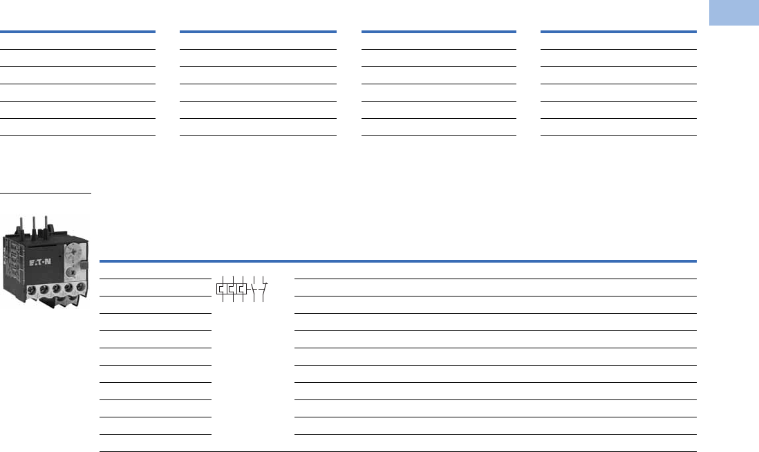
Mini Overload Relays
Mini Overload Relays 23
Notes
1 With DC operation: Integrated diode resistor combination, coil rating 2.6W.
2 Short-circuit protection: Observe the maximum permissible fuse of the contactor with direct device mounting. See MN03402002E for more information.
3 When fitted directly to the contactor, a clearance of at least 5 mm is required between the overload relays.
Coil Voltage Suffix Code Coil Voltage Suffix Code Coil Voltage Suffix Code Coil Voltage Suffix Code
110V 50 Hz, 120V 60 Hz A415V 50 Hz, 480V 60 Hz C400V 50 Hz N120 Vdc AD
220V 50 Hz, 240V 60 Hz B550V 50 Hz, 600V 60 Hz D380V 60 Hz P220 Vdc BD
230V 50 Hz F208V 60 Hz E12V 50/60 Hz R12 Vdc RD
24V 50/60 Hz T190V 50 Hz, 220V 60 Hz G24V 50 Hz U48 Vdc WD
24 Vdc TD 1240V 50 Hz, 277V 60 Hz H42V 50 Hz, 48V 60 Hz W——
— — 380V 50 Hz, 440V 60 Hz L48V 50 Hz Y——
Overload
Release It
Trip
Class
Contact
Sequence
Contact
Configuration
Short-Circuit Protection (A)
Catalog Number
Type 1
Coordination,
gG/gL
Type 2
Coordination,
gG/gL
Circuit
Breaker
CEC/NEC
Fuse
0.1–0.16A 10A 1NO-1NC 20 0.5 15 — XTOMP16AC1
0.16–0.24A 10A 1NO-1NC 20 1 15 — XTOMP24AC1
0.24–0.4A 10A 1NO-1NC 20 2 15 — XTOMP40AC1
0.4–0.6A 10A 1NO-1NC 20 2 15 — XTOMP60AC1
0.6–1A 10A 1NO-1NC 20 4 15 3 XTOM001AC1
1–1.6A 10A 1NO-1NC 20 6 15 6 XTOM1P6AC1
1.6–2.4A 10A 1NO-1NC 20 6 15 6 XTOM2P4AC1
2.4–4A 10A 1NO-1NC 20 15 15 XTOM004AC1
4–6A 10A 1NO-1NC 20 15 20 XTOM006AC1
6–9A 10A 1NO-1NC 20 15 35 XTOM009AC1
9–12A 10A 1NO-1NC — — 45 XTOM012AC1
XTOM_
6429896
97 95
Courtesy of CMA/Flodyne/Hydradyne ▪ Motion Control ▪ Hydraulic ▪ Pneumatic ▪ Electrical ▪ Mechanical ▪ (800) 426-5480 ▪ www.cmafh.com
V5-T1-24 Volume 5—Motor Control and Protection CA08100006E—August 2012 www.eaton.com
1
1
1
1
1
1
1
1
1
1
1
1
1
1
1
1
1
1
1
1
1
1
1
1
1
1
1
1
1
1
1.1
IEC Contactors and Starters
XT
IEC Power Control
Accessories
Auxiliary Contacts
Front-mounted snap-on auxiliary contacts for mini contactors are available with screw terminals in a
variety of contact configurations. Auxiliary contact modules are standard with interlocked opposing
contacts, except in the case of early-make or late-break contacts.
Front-Mount Auxiliary Contacts for Use with Mini Contactors
Notes
1 Orders must be placed in multiples of package quantity listed.
2 One early-make contact (NOE), one late-break contact (NCL).
Conventional Free Air
Thermal Current,
Ith = Ie, AC-1 in Amps
Contact
Configuration Contact Sequence
Pkg.
Qty. 1
Screw Terminal
Catalog Number
10 2NC 5 XTMCXFC02
10 1NO-1NC 5 XTMCXFD11
10 2NO-2NC 5 XTMCXFC22
10 2NC 5 XTMCXFA02
10 1NO-1NC 5 XTMCXFA11
10 2NO 5 XTMCXFA20
10 4NC 5 XTMCXFA04
10 1NO-3NC 5 XTMCXFA13
10 2NO-2NC 5 XTMCXFA22
10 3NO-1NC 5 XTMCXFA31
10 4NO 5 XTMCXFA40
10 1NO-1NC
1NOE-1NCL
5XTMCXFAL22 2
21
22
31
32
21
22
33
34
21
22
31
32
43
44
53
54
51
52
61
62
54
53 61
62
54
63
64
53
51
52
61
62
71
72 82
81
53 61 71 81
82
72
62
54
54
53 61
62
71
72
83
84
54
53 61
62
73
74
83
84
54
63 73
64 74
53 83
84
58
57 65
66
71
72
83
84
Courtesy of CMA/Flodyne/Hydradyne ▪ Motion Control ▪ Hydraulic ▪ Pneumatic ▪ Electrical ▪ Mechanical ▪ (800) 426-5480 ▪ www.cmafh.com
Volume 5—Motor Control and Protection CA08100006E—August 2012 www.eaton.com V5-T1-25
1
1
1
1
1
1
1
1
1
1
1
1
1
1
1
1
1
1
1
1
1
1
1
1
1
1
1
1
1
1
1.1
IEC Contactors and Starters
XT
IEC Power Control
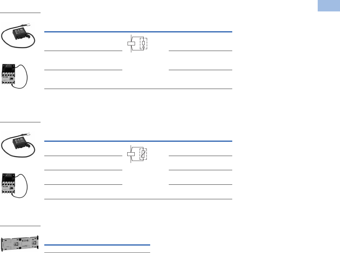
Suppressors
RC Suppressor 1
Varistor Suppressor 3
Mechanical Interlock
Mechanical Interlock
Notes
For two contactors with AC or DC operated magnet system that are horizontally or vertically mounted,
the distance between contactors is 0 mm and the mechanical lifespan is 2.5 x 10⁶ operations.
1 For AC operated contactors, 50/60 Hz. Note dropout delay.
2 Orders must be placed in multiples of package quantity listed.
3 For AC operated contactors, 50/60 Hz. DC operated contactors have integrated varistor suppressors.
Voltage
For Use
with…
Circuit Symbol
Pkg.
Qty.
2
Catalog Number
24–48 XTMC6A_,
XTMC9A_
10 XTMCXRSW
48–130 XTMC6A_,
XTMC9A_
10 XTMCXRSA
110–250 XTMC6A_,
XTMC9A_
10 XTMCXRSB
Voltage
For Use
with…
Circuit Symbol
Pkg.
Qty.
2
Catalog Number
24–48 XTMC6A_,
XTMC9A_
10 XTMCXVSW
48–130 XTMC6A_,
XTMC9A_
10 XTMCXVSA
110–250 XTMC6A_,
XTMC9A_
10 XTMCXVSB
380–415 XTMC6A_,
XTMC9A_
10 XTMCXVSN
Description
Pkg.
Qty. 2Catalog Number
Mechanical interlock 5 XTMCXML
XTMCXR_
XTMC Relay with
Installed Suppressor
A1
A2
XTMCX_
XTMC Relay with
Installed Suppressor
A1
A2
XTMCXML
Courtesy of CMA/Flodyne/Hydradyne ▪ Motion Control ▪ Hydraulic ▪ Pneumatic ▪ Electrical ▪ Mechanical ▪ (800) 426-5480 ▪ www.cmafh.com
V5-T1-26 Volume 5—Motor Control and Protection CA08100006E—August 2012 www.eaton.com
1
1
1
1
1
1
1
1
1
1
1
1
1
1
1
1
1
1
1
1
1
1
1
1
1
1
1
1
1
1
1.1
IEC Contactors and Starters
XT
IEC Power Control
Additional Accessories
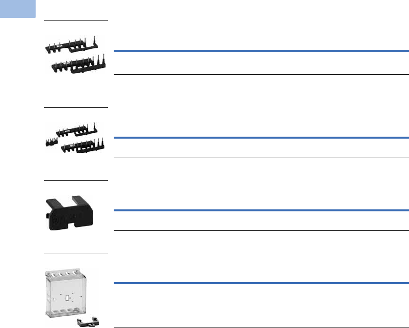
Reversing Link Kit 12
Star-Delta (Wye-Delta) Link Kit 45
Connector
IP40 Sealable Transparent Shroud
Notes
1 The following control cables are integrated as part of the electrical interlock: K1M: A1–K2M: 21; K1M: 21–K2M: A1
2 Reversing link kit does not include mechanical interlock. See Mechanical Interlock.
3 Orders must be placed in multiples of package quantity listed.
4 The following control cables are integrated in addition to the electrical interlock: K3M: A1–K5M: 21; K3M: 21–K5M: A1; K3M: A2–K5M: A2
5 When combined with overload relay, use separate mounting.
6 0 mm distance between contactors.
Description
Pkg.
Qty. 3Catalog Number
Main current wiring for reversing contactors and starters 1 XTMCXRL
Description
Pkg.
Qty. 3Catalog Number
Main current wiring for star-delta (wye-delta) combinations.
Includes the star-delta bridge
1XTMCXSDL
Description
Pkg.
Qty. 3Catalog Number
For mechanically arranging contactors and timing relays in
combinations
50 XTMCXCN 6
Description
Pkg.
Qty. 3Catalog Number
IP40 sealable transparent shroud, snap fitting on mini contactor 1 XTMCXSHROUD
XTMCXRL
XTMCXSDL
XTMCXCN
XTMCXSHROUD
Courtesy of CMA/Flodyne/Hydradyne ▪ Motion Control ▪ Hydraulic ▪ Pneumatic ▪ Electrical ▪ Mechanical ▪ (800) 426-5480 ▪ www.cmafh.com

Volume 5—Motor Control and Protection CA08100006E—August 2012 www.eaton.com V5-T1-27
1
1
1
1
1
1
1
1
1
1
1
1
1
1
1
1
1
1
1
1
1
1
1
1
1
1
1
1
1
1
1.1
IEC Contactors and Starters
XT
IEC Power Control
Technical Data and Specifications
XT Miniature Controls—General
Note
1As required, except vertical with terminals A1/A2 at the bottom.
Description
XTMC6A_ XTMC9A_ XTMF9A_
AC Coils DC Coils AC Coils DC Coils AC Coils DC Coils
Physical and Electrical
Standards IEC/EN 60947,
VDE 0660, CSA,
UL, CCC
IEC/EN 60947,
VDE 0660, CSA,
UL, CCC
IEC/EN 60947,
VDE 0660, CSA,
UL, CCC
IEC/EN 60947,
VDE 0660, CSA,
UL, CCC
IEC/EN 60947,
VDE 0660, CSA,
UL, CCC
IEC/EN 60947,
VDE 0660, CSA,
UL, CCC
Weights in kg [lb] 0.2 [0.44] 0.17 [0.37] 0.2 [0.44] 0.17 [0.34] 0.2 [0.44] 0.17 [0.37]
Mechanical life—operations 10,000,000 20,000,000 10,000,000 20,000,000 10,000,000 10,000,000
Mechanical life—coil at 50 Hz 7 — 7 — 7 —
Maximum mechanical operating frequency (ops/hr) 9000 9000 9000 9000 9000 9000
Insulation voltage (Ui) Vac 690 690 690 690 690 690
Impulse withstand voltage (Uimp) Vac 6000 6000 6000 6000 6000 6000
Operational Voltage (Ue) Vac 690 690 690 690 690 690
Safe isolation to VDE 0106 Part 101 and Part 101/A1
Between coil and contacts (Vac) 300 300 300 300 300 300
Between contacts (Vac) 300 300 300 300 300 300
Making capacity (amps) 110 110 110 110 110 110
Breaking capacity (amps)
220/230V 90 90 90 90 90 90
380/400V 90 90 90 90 90 90
500V 64 64 64 64 64 64
660/690V 54 54 54 54 54 54
Short-circuit protection rating maximum fuse (gL/gG)
Type 2 coordination (A) 10 10 10 10 10 10
Type 1 coordination (A) 20 20 20 20 20 20
Degree of protection IP20 IP20 IP20 IP20 IP20 IP20
Flexible with ferrule (mm2) 1 x (0.75–1.5)
2 x (0.75–1.5)
1 x (0.75–1.5)
2 x (0.75–1.5)
1 x (0.75–1.5)
2 x (0.75–1.5)
1 x (0.75–1.5)
2 x (0.75–1.5)
1 x (0.75–1.5)
2 x (0.75–1.5)
1 x (0.75–1.5)
2 x (0.75–1.5)
Solid or stranded (AWG) 18–14 18–14 18–14 18–14 18–14 18–14
Terminal screw M3.5 M3.5 M3.5 M3.5 M3.5 M3.5
Pozidriv screwdriver Size 2 Size 2 Size 2 Size 2 Size 2 Size 2
Standard screwdriver (mm) 0.8 x 5.5
1 x 6
0.8 x 5.5
1 x 6
0.8 x 5.5
1 x 6
0.8 x 5.5
1 x 6
0.8 x 5.5
1 x 6
0.8 x 5.5
1 x 6
Max. tightening torque
Nm 1.21.21.21.21.21.2
Lb-in 10.6 10.6 10.6 10.6 10.6 10.6
Terminal capacity of spring cage main terminals
Solid (mm2) 1 x (1–2.5)
2 x (1–2.5)
1 x (1–2.5)
2 x (1–2.5)
1 x (1–2.5)
2 x (1–2.5)
1 x (1–2.5)
2 x (1–2.5)
1 x (1–2.5)
2 x (1–2.5)
1 x (1–2.5)
2 x (1–2.5)
Flexible with ferrule (mm2) 1 x (1–2.5)
2 x (1–2.5)
1 x (1–2.5)
2 x (1–2.5)
1 x (1–2.5)
2 x (1–2.5)
1 x (1–2.5)
2 x (1–2.5)
1 x (1–2.5)
2 x (1–2.5)
1 x (1–2.5)
2 x (1–2.5)
Standard screwdriver (mm) 0.6 x 3.5 0.6 x 3.5 0.6 x 3.5 0.6 x 3.5 0.6 x 3.5 0.6 x 3.5
Mounting position 111111
A2
A1
Courtesy of CMA/Flodyne/Hydradyne ▪ Motion Control ▪ Hydraulic ▪ Pneumatic ▪ Electrical ▪ Mechanical ▪ (800) 426-5480 ▪ www.cmafh.com

V5-T1-28 Volume 5—Motor Control and Protection CA08100006E—August 2012 www.eaton.com
1
1
1
1
1
1
1
1
1
1
1
1
1
1
1
1
1
1
1
1
1
1
1
1
1
1
1
1
1
1
1.1
IEC Contactors and Starters
XT
IEC Power Control
XT Miniature Controls—General, continued
Note
1Damp heat, constant, to IEC 60 068-2-78; damp heat, cyclic, to IEC 60 068-2-30.
Description
XTMC6A_ XTMC9A_ XTMF9A_
AC Coils DC Coils AC Coils DC Coils AC Coils DC Coils
Environmental
Ambient temperature –25° to 50°C
[–13° to 122°F]
–25° to 50°C
[–13° to 122°F]
–25° to 50°C
[–13° to 122°F]
–25° to 50°C
[–13° to 122°F]
–25° to 50°C
[–13° to 122°F]
–25° to 50°C
[–13° to 122°F]
Mechanical shock resistance (IEC/EN 60068-2-27)
Half-sinusoidal shock 10 ms
Contactor without auxiliary contact module
Main contact—make contact 10g 10g 10g 10g 10g 10g
Main contact—break/make contact 10/8g 10/8g 10/8g 10/8g — —
Contactor with auxiliary contact module
Main contact—make contact 10g 10g 10g 10g 10g 10g
Main contact—make/break contact 20/20g 20/20g 20/20g 20/20g 20/20g 20/20g
Climatic proofing 111111
Pollution degree III/3 III/3 III/3 III/3 III/3 III/3
Courtesy of CMA/Flodyne/Hydradyne ▪ Motion Control ▪ Hydraulic ▪ Pneumatic ▪ Electrical ▪ Mechanical ▪ (800) 426-5480 ▪ www.cmafh.com

Volume 5—Motor Control and Protection CA08100006E—August 2012 www.eaton.com V5-T1-29
1
1
1
1
1
1
1
1
1
1
1
1
1
1
1
1
1
1
1
1
1
1
1
1
1
1
1
1
1
1
1.1
IEC Contactors and Starters
XT
IEC Power Control
XT Miniature Controls—Magnet Systems
Note
1Smoothed DC or three-phase bridge rectifier.
Description
XTMC6A_ XTMC9A_ XTMF9A_
AC Coils DC Coils AC Coils DC Coils AC Coils DC Coils
Voltage Tolerance
Pickup (x Uc)
Single-voltage coil 50 Hz and dual-voltage coil 50 Hz, 60 Hz
0.8–1.1 — 0.8–1.1 — 0.8–1.1 —
Dual frequency coil 50/60 Hz 0.85–1.1 — 0.85–1.1 — 0.85–1.1 —
DC operated 1— 0.8–1.1 — 0.8–1.1 — 0.85–1.1
Power Consumption
AC operation
Pickup VA
Single-voltage coil 50 Hz and dual-voltage coil 50 Hz, 60 Hz 25 — 25 — 25 —
Dual frequency coil 50/60 Hz at 50 Hz 30 — 30 — 30 —
Dual frequency coil 50/60 Hz at 60 Hz 29 — 29 — 29 —
Pickup W
Single-voltage coil 50 Hz and dual-voltage coil 50 Hz, 60 Hz 22 — 22 — 22 —
Dual frequency coil 50/60 Hz at 50 Hz 26 — 26 — 26 —
Dual frequency coil 50/60 Hz at 60 Hz 24 — 24 — 24 —
Sealing VA
Single-voltage coil 50 Hz and dual-voltage coil 50 Hz, 60 Hz 4.6 — 4.6 — 4.6 —
Dual frequency coil 50/60 Hz at 50 Hz 5.4 — 5.4 — 5.4 —
Dual frequency coil 50/60 Hz at 60 Hz 3.9 — 3.9 — 3.9 —
Sealing W
Single-voltage coil 50 Hz and dual-voltage coil 50 Hz, 60 Hz 1.3 — 1.3 — 1.3 —
Dual frequency coil 50/60 Hz at 50 Hz 1.6 — 1.6 — 1.6 —
Dual frequency coil 50/60 Hz at 60 Hz 1.1 — 1.1 — 1.1 —
DC operated 1
Power consumption pickup = sealing (VA/W) — 2.6 — 2.6 — 2.6
Duty factor (%) 100 100 100 100 100 100
Switching Time at 100% Uc
Make contact
Closing delay min. (ms) 14 26 14 26 14 26
Closing delay max. (ms) 21 35 21 35 21 35
Opening delay min. (ms) 8 15 8 15 8 15
Opening delay max. (ms) 18 25 18 25 18 25
Closing delay with top-mounting auxiliary contact (ms) Max. 45 Max. 70 Max. 45 Max. 70 Max. 45 Max. 70
Reversing Contactors
Changeover time at 100% Uc
Minimum (ms) 16 40 16 40 16 40
Maximum (ms) 21 50 21 50 21 50
Arcing time at 690 Vac (ms) Max. 12 Max. 12 Max. 12 Max. 12 Max. 12 Max. 12
Courtesy of CMA/Flodyne/Hydradyne ▪ Motion Control ▪ Hydraulic ▪ Pneumatic ▪ Electrical ▪ Mechanical ▪ (800) 426-5480 ▪ www.cmafh.com

V5-T1-30 Volume 5—Motor Control and Protection CA08100006E—August 2012 www.eaton.com
1
1
1
1
1
1
1
1
1
1
1
1
1
1
1
1
1
1
1
1
1
1
1
1
1
1
1
1
1
1
1.1
IEC Contactors and Starters
XT
IEC Power Control
XT Miniature Controls
Notes
1At maximum permissible ambient temperature.
2Rated operation current (le) in amperes, at maximum permissible ambient temperature.
Description
XTMC6A_ XTMC9A_ XTMF9A_
AC Coils DC Coils AC Coils DC Coils AC Coils DC Coils
AC-1 Operation
Conventional free air thermal current, three-pole, 50–60 Hz (A)
at 40°C (Ith) 222222222222
at 50°C (Ith) 202020202020
at 55°C (Ith) 191919191919
Conventional free air thermal current, single-pole (Ith)505050506060
AC-3 Operation
Rated operational current, 50/60 Hz 1 (Ie) in amperes (A)
220/230V 6.6 6.6 9.0 9.0 9.0 9.0
240V 6.6 6.6 9.0 9.0 9.0 9.0
380/400V 6.6 6.6 9.0 9.0 9.0 9.0
415V 6.6 6.6 9.0 9.0 9.0 9.0
440V 6.6 6.6 9.0 9.0 9.0 9.0
500V 5.0 5.0 6.4 6.4 6.4 6.4
660/690V 3.5 3.5 4.8 4.8 4.8 4.8
Rated power (P) in kilowatts (kW)
220/230V 1.5 1.5 2.2 2.2 2.2 2.2
240V 1.8 1.8 2.5 2.5 2.5 2.5
380/400V 3.0 3.0 4.0 4.0 4.0 4.0
415V 3.1 3.1 4.3 4.3 4.3 4.3
440V 3.3 3.3 4.6 4.6 4.6 4.6
500V 3.0 3.0 4.0 4.0 4.0 4.0
660/690V 3.0 3.0 4.0 4.0 4.0 4.0
AC-4 Operation
Rated operational current, 50/60 Hz 1 (Ie) in amperes (A)
220/230V 5.0 5.0 6.6 6.6 6.6 6.6
240V 5.0 5.0 6.6 6.6 6.6 6.6
380/400V 5.0 5.0 6.6 6.6 6.6 6.6
415V 5.0 5.0 6.6 6.6 6.6 6.6
440V 5.0 5.0 6.6 6.6 6.6 6.6
500V 3.7 3.7 5.0 5.0 5.0 5.0
660/690V 2.9 2.9 3.4 3.4 3.4 3.4
Rated power (P) in kilowatts (kW)
220/230V 1.1 1.1 1.5 1.5 1.5 1.5
240V 1.3 1.3 1.8 1.8 1.8 1.8
380/400V 2.2 2.2 3.0 3.0 3.0 3.0
415V 2.3 2.3 3.1 3.1 3.1 3.1
440V 2.4 2.4 3.3 3.3 3.3 3.3
500V 2.2 2.2 3.0 3.0 3.0 3.0
660/690V 2.2 2.2 3.0 3.0 3.0 3.0
DC-1 Operation 2
12V 20202020——
24V 20202020——
60V 20202020——
110V 20 20 20 20 — —
220V 20 20 20 20 — —
Courtesy of CMA/Flodyne/Hydradyne ▪ Motion Control ▪ Hydraulic ▪ Pneumatic ▪ Electrical ▪ Mechanical ▪ (800) 426-5480 ▪ www.cmafh.com

Volume 5—Motor Control and Protection CA08100006E—August 2012 www.eaton.com V5-T1-31
1
1
1
1
1
1
1
1
1
1
1
1
1
1
1
1
1
1
1
1
1
1
1
1
1
1
1
1
1
1
1.1
IEC Contactors and Starters
XT
IEC Power Control
XT Miniature Controls, continued
XT Miniature Controls—Auxiliary Contacts
Note
1Rated operation current (le) in amperes, at maximum permissible ambient temperature.
Description
XTMC6A_ XTMC9A_ XTMF9A_
AC Coils DC Coils AC Coils DC Coils AC Coils DC Coils
DC-3 Operation 1
12V 6688——
24V 6688——
60V 3344——
110V 2233——
220V — — — — 1.0 1.0
DC-4 Operation 1
12V 1.8 1.8 2.5 2.5 — —
24V 1.8 1.8 2.5 2.5 — —
60V 1.8 1.8 2.5 2.5 — —
110V 1.1 1.1 1.5 1.5 2.5 2.5
220V 0.2 0.2 0.3 0.3 1.0 1.0
Current Heat Loss (Three- or Four-Pole) in Watts
at Ith 2.0 3.5 2.0 3.5 2.7 4.7
at Ie to AC-3/400V 0.3 0.4 0.5 0.7 — —
Description
Built-In Auxiliary
XTMC
Add-On Auxiliary
XTMCXF_
Interlocked opposing contacts to ZH1/457, including auxiliary contact module Yes Yes
Rated impulse withstand voltage, Uimp (Vac) 6000 6000
Overvoltage category/pollution degree III/3 III/3
Rated insulation voltage, Ui (Vac) 690 690
Rated operational voltage, Ue (Vac) 600 600
Safe isolation to VDE 0106 Part 101 and Part 101(A) in Vac
Between coil and auxiliary contacts 300 300
Between the auxiliary contacts 300 300
Rated operational current
AC-15, Ie
220/240V 6A 4A
380/415V 3A 2A
500V 1.5A 1.5A
DC-13 (contacts in series)
1: 24V 2.5A 2.5A
2: 60V 2.5A 2.5A
3: 100V 1.5A 1.5A
3: 220V 0.5A 0.5A
Conventional thermal current, Ith 10A 10A
Control circuit reliability (at Ue = 24 Vdc, Umin = 17V, I min = 5.4 mA) <10–8, <1 failure at 100 million operations <10–8, <1 failure at 100 million operations
Component lifespan at Ue = 240V
AC-15, operations x 1060.2 0.2
DC-13 L/R = 50 ms: 2 contacts in series at Ie = 0.5A, operations x 1060.15 0.15
Short-circuit rating without welding
Short-circuit protection rating maximum fuse, 500V gG/gL 6A 6A
Short-circuit protection rating maximum fuse, 500V fast 10A 10A
Current heat loss at conventional free air thermal current Ith per contact, W 0.2 0.2
Courtesy of CMA/Flodyne/Hydradyne ▪ Motion Control ▪ Hydraulic ▪ Pneumatic ▪ Electrical ▪ Mechanical ▪ (800) 426-5480 ▪ www.cmafh.com
V5-T1-32 Volume 5—Motor Control and Protection CA08100006E—August 2012 www.eaton.com
1
1
1
1
1
1
1
1
1
1
1
1
1
1
1
1
1
1
1
1
1
1
1
1
1
1
1
1
1
1
1.1
IEC Contactors and Starters
XT
IEC Power Control
Wiring Diagrams
XTMR Reversing Contactor
Control Circuit
XTMR Reversing Contactor
Power Circuit
XT Mini Star-Delta (Wye-Delta)
Contactor Power Circuit
K2M
54
K1M 54
53 53
K2M
22
21 K1M 22
21
K1M
A1
A2
K2M A1
A2
I54
53
53
II 21
22
22
21
21
22
0
54
UVW
K1M
M
M1
K2M
1
64
2
5
6
4
2
353
1
3
K1M
5
642
31
K5M
5
642
31
K3M
642
351
U1
V1
W1
M1
3
M1
V2
W2
U2
AC
B
Tripping Characteristics
Tripping Characteristics Chart
These tripping characteristics
are mean values of the
spread at 20°C ambient
temperature in a cold state.
Tripping time depends on
response current. With
devices at operating
temperature, the tripping
time of the overload relay
reduces to approximately
25% of the read off value.
Specific characteristics for
each individual setting range
can be found on Page
V5-T1-33.
2h
100
60
40
20
10
6
4
2
1
40
20
10
6
4
2
1
0.6
XTOM
1 1.5 2 3 4 68 10 15 20
x Setting Current
2-Phase
Seconds Minutes
3-Phase
Courtesy of CMA/Flodyne/Hydradyne ▪ Motion Control ▪ Hydraulic ▪ Pneumatic ▪ Electrical ▪ Mechanical ▪ (800) 426-5480 ▪ www.cmafh.com
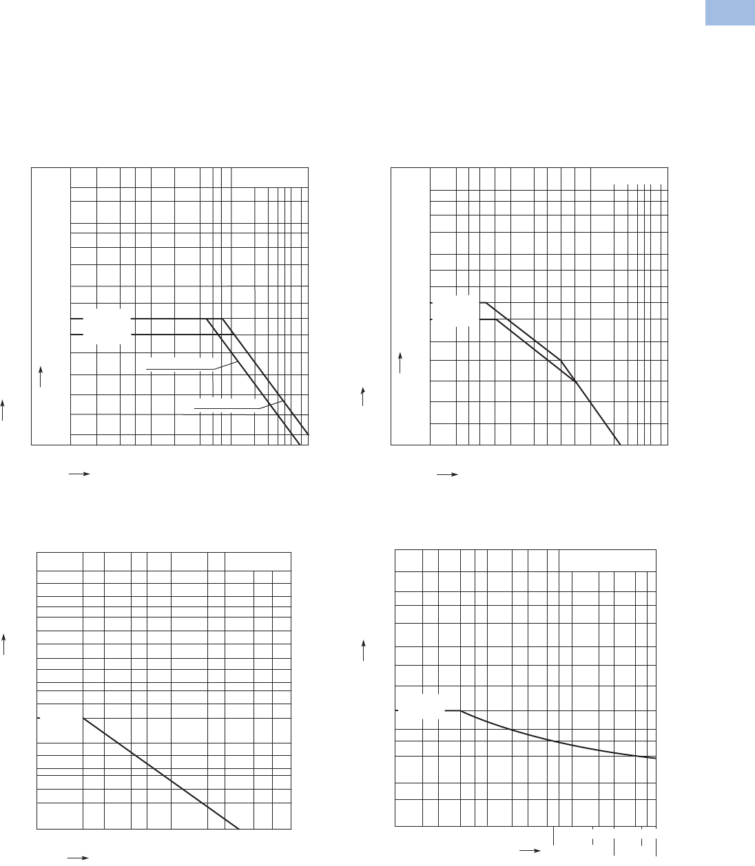
Volume 5—Motor Control and Protection CA08100006E—August 2012 www.eaton.com V5-T1-33
1
1
1
1
1
1
1
1
1
1
1
1
1
1
1
1
1
1
1
1
1
1
1
1
1
1
1
1
1
1
1.1
IEC Contactors and Starters
XT
IEC Power Control
Electrical Switching Operation Charts
Squirrel cage motors
Operating characteristics
Starting: from rest
Stopping: after attaining a full running speed
Electrical characteristics
Make (NO): Up to 6x rated motor current
Breaking (NC): 1x rated motor current
Normal Switching Duty—AC-3/400V
Switching Duty for Non-Motor Loads, Three- and
Four-Pole—AC-1/400V
Squirrel cage motors
Operating characteristics
Jogging, plugging, reversing
Electrical characteristics
Make (NO): 6x rated motor current
Breaking (NC): 6x rated motor current
Extreme Switching Duty—AC-4/400V
Short Time Loading, Three-Pole—AC-1/400V
(time interval between two loading cycles: 15 minutes)
XTMC 6A
kW A
0.01
0.02
0.04
0.06
0.1
0.2
0.4
0.6
0.75
1
2
3
4
5
6
8
10
8.8
12
16
23
30
36
43
58
6.5
5
3.5
2.5
2
1.6
30
22
18.5
15
11
7. 5
5.5
4
3
2.2
1.5
1.1
0.8
0.55
XTMC AC Coil
XTMC 9A
XTMC DC Coil
AC-3/400V
Component lifespan (millions of operations)
Rated output of three-phase motors, 50 – 60 Hz
Rated operational current le 50 – 60 Hz
AC-1/400V
0.1 0.2 0.5 0.7 713510
2
1
3
4
0.3 2
5
1400
1000
700
500
275
350
160
100
55
35
20
10
7
XTMC 9A
XTMC 6A
Component lifespan (millions of operations)
Breaking current
kW A
0.01
0.02 0.04
0.06
0.1
0.2 0.4
0.6
1
62
3
4
58
10
22
18.5
15
11
7. 5
5.5
4
3
2.2
1.5
1.1
0.8
0.55
0.37
0.03
0.3
0.25
43
36
30
23
16
12
8.8
6.5
3.5
2.5
2
1.6
1.2
0.8
XTMC 9A
5
AC-4/400V
Component lifespan (millions of operations)
Rated output of three-phase motors, 50 – 60 Hz
Rated operational current le 50 – 60 Hz
XTMC 6A
AC-1/400V
70 100
5020
537 30
102
A
700
500
400
300
15
200
100
70
50
40
30
150
10 min
15 min
900
200 300
1 min 3 min
5 min
500
20
700
XTMC 9A
XTMC 6A
Seconds
Duration of load
Short-time current
Courtesy of CMA/Flodyne/Hydradyne ▪ Motion Control ▪ Hydraulic ▪ Pneumatic ▪ Electrical ▪ Mechanical ▪ (800) 426-5480 ▪ www.cmafh.com
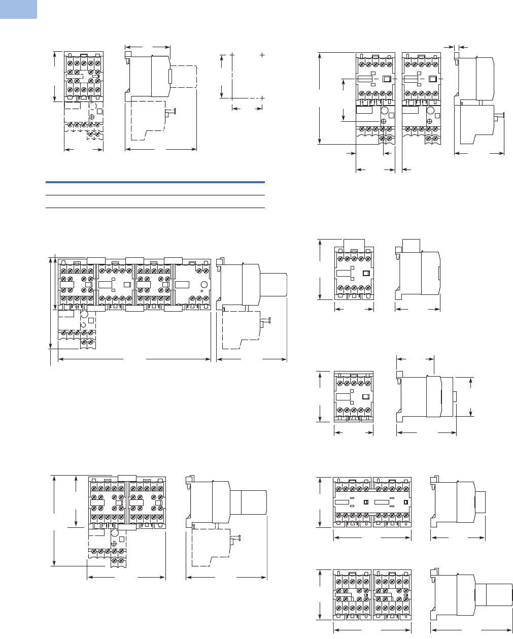
V5-T1-34 Volume 5—Motor Control and Protection CA08100006E—August 2012 www.eaton.com
1
1
1
1
1
1
1
1
1
1
1
1
1
1
1
1
1
1
1
1
1
1
1
1
1
1
1
1
1
1
1.1
IEC Contactors and Starters
XT
IEC Power Control
Dimensions
Approximate Dimensions in mm [in.]
Non-Reversing Mini Contactor
Star-Delta Starter Combinations
Reversing Mini Contactor
Non-Reversing Mini Contactor with Overload Relay
XTMCXRSA, XTMCXVSA Mini Suppressors
XTMCXTSA Mini Sealable Shroud
XTMCXML Mechanical Interlock
XTMC XTMCC
D 52 [2.05] 54 [2.13]
D1 83 [3.27] 86 [3.39]
35
[1.38]
58
[2.28]
D1
D
50
[1.97]
M4
45
[1.77]
61
[2.40]
108
[4.25]
180
[7.09]
83
[3.27]
90
[3.54]
94
[3.70]
61
[2.40]
108
[4.25]
5.5 [.22]
58
[2.28]
≥ 5 [.20]
45
[1.77]
32
[1.26]
49
[1.93]
106
[4.17]
52
[2.05]
45
[1.77]
62.5
[2.46]
43
[1.69]
45
[1.77]
58
[2.28]
69
[2.72]
45
[1.77]
90
[3.54]
94
[3.70]
63
[2.48]
90
[3.54]
58
[2.28]
58
[2.28]
Courtesy of CMA/Flodyne/Hydradyne ▪ Motion Control ▪ Hydraulic ▪ Pneumatic ▪ Electrical ▪ Mechanical ▪ (800) 426-5480 ▪ www.cmafh.com
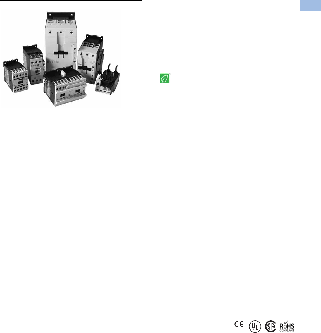
Volume 5—Motor Control and Protection CA08100006E—August 2012 www.eaton.com V5-T1-35
1
1
1
1
1
1
1
1
1
1
1
1
1
1
1
1
1
1
1
1
1
1
1
1
1
1
1
1
1
1
1.1
IEC Contactors and Starters
XT
IEC Power Control
XT Family of Contactors
Contents
Description Page
Relays and Timers . . . . . . . . . . . . . . . . . . . . . . . . . V5-T1-3
Miniature Controls . . . . . . . . . . . . . . . . . . . . . . . . . V5-T1-18
Contactors and Starters
Product Identification . . . . . . . . . . . . . . . . . . . . V5-T1-36
Catalog Number Selection . . . . . . . . . . . . . . . . V5-T1-38
Product Selection . . . . . . . . . . . . . . . . . . . . . . . V5-T1-39
Accessories . . . . . . . . . . . . . . . . . . . . . . . . . . . . V5-T1-65
Technical Data and Specifications . . . . . . . . . . . V5-T1-78
Wiring Diagrams . . . . . . . . . . . . . . . . . . . . . . . . V5-T1-109
Dimensions . . . . . . . . . . . . . . . . . . . . . . . . . . . . V5-T1-114
An Eaton
Green Solution
Thermal Overload Relays . . . . . . . . . . . . . . . . . . . . V5-T1-128
C440/XT Electronic Overload Relay . . . . . . . . . . . V5-T1-141
Manual Motor Protectors . . . . . . . . . . . . . . . . . . . V5-T1-157
Combination Motor Controllers . . . . . . . . . . . . . . . V5-T1-193
XT Electronic Manual Motor Protector . . . . . . . . . V5-T1-216
Reference Data . . . . . . . . . . . . . . . . . . . . . . . . . . . V5-T1-229
Contactors and Starters
Product Description
The Eaton XT contactors
and starters includes non-
reversing and reversing
contactors, overload relays
and a variety of related
accessories. Because XT
meets IEC, UL®, CSA® and
CE standards, it is the perfect
product solution for IEC
applications all over the
world. The compact, space
saving and easy to install
XT
line of IEC
contactors and
starters is the efficient
and
effective solution for
customer applications from
7A to 2450A.
Application Description
The XT line of IEC power
control was engineered to
provide highly effective
control and protection for a
variety of loads, including
motors, compressors,
pumps, resistive, capacitor
banks, isolation, and others.
XT also includes IEC ratings
for lighting applications as
well.
XT contactors can be used in
safety applications according
to EN 954-1, EN ISO 13849-1
and IEC 62061 up to Category
4, Pl e and SIL 3. Information
concerning safety related
characteristics (B10 and B10d
values) is available online. The
auxiliary contact modules and
built-in auxiliary contacts
meet IEC EN 60947-5-1
Annex L (positively driven)
and IEC EN 60947-4-1
Annex F (mirror contacts).
Reference
Refer to Volume 10—Enclosed Control, CA08100012E,
Tab 3, section 3.1 for additional Product information on
IEC Non-Metallic Enclosed Contactors and Starters.
Features and Benefits
●AC control from
12V to 600V 50/60 Hz
●DC control from
12V to 220V
●Available with screw or
spring cage terminals
●Reversing or non-reversing
contactors and starters
●AC-3 contactor ratings to
1000A and AC-1 contactor
ratings to 2000A
●Non-reversing starters
to 650A
●Panel or DIN rail mounting
to 65A
●IP20 finger and back-of-
hand proof
●Large ambient temperature
range, –25 to 50°C
[–13 to 122°F]
●AC and DC controlled
contactors in the same
compact frame
●Low power consumption
AC and DC coils
●Built-in NO or NC auxiliary
contacts to 32A
●Plug-in accessories for
reduced installation time
●Coil replacement on
Frames C–N (18–820A)
●Contact replacement on
Frames D–N (40 –820A)
●Integrated suppressor
7–150A DC operated
contactors and 185–2000A
AC and DC operated
contactors
Standards and Certifications
●IEC EN 60947
●CE approved
●UL
●CSA
●ATEX
●RoHS
Note: For Type 2 Coordination,
see Page V5-T1-230.
Courtesy of CMA/Flodyne/Hydradyne ▪ Motion Control ▪ Hydraulic ▪ Pneumatic ▪ Electrical ▪ Mechanical ▪ (800) 426-5480 ▪ www.cmafh.com
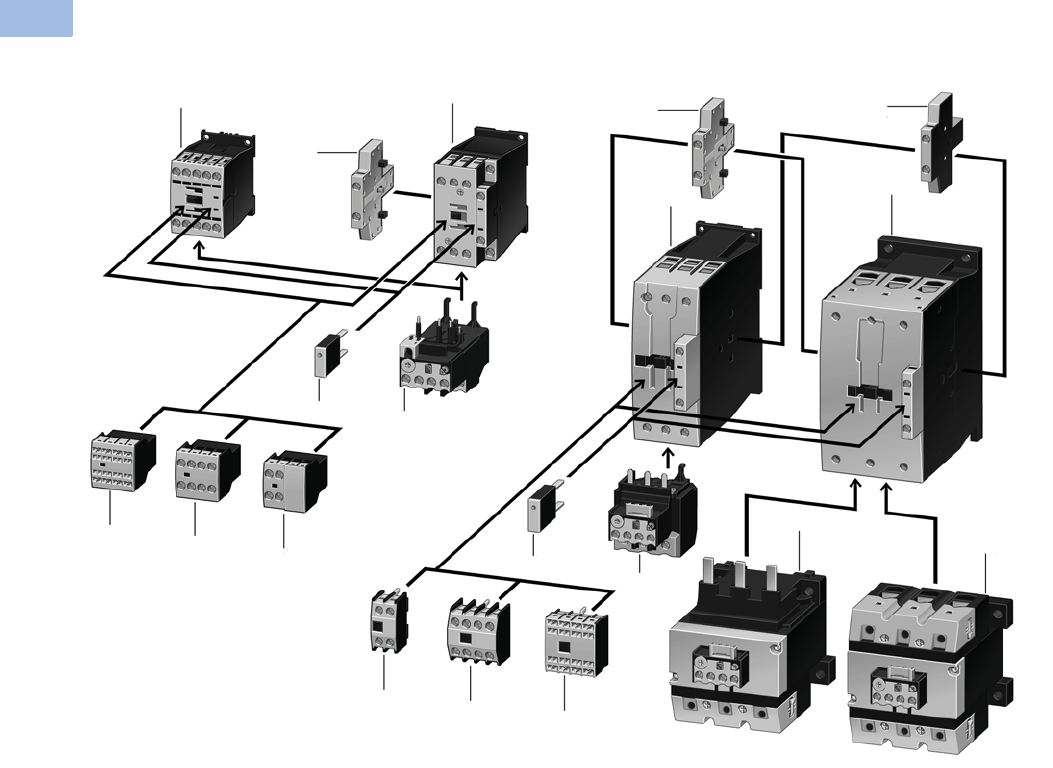
V5-T1-36 Volume 5—Motor Control and Protection CA08100006E—August 2012 www.eaton.com
1
1
1
1
1
1
1
1
1
1
1
1
1
1
1
1
1
1
1
1
1
1
1
1
1
1
1
1
1
1
1.1
IEC Contactors and Starters
XT
IEC Power Control
Product Identification
XTCE007B to XTCE170G (7 to 170A) Contactors
Notes
1Contactor up to 170A AC-3 (see Page V5-T1-39)
AC: 12–600V, 50, 60, 50/60 Hz
0.8–1.1 x Uc)
DC: 12–250V
XTCE…B_ (7–15A): 0.8–1.1 x Uc
XTCE…C_–XTCE…G_(18–150A): 0.7–1.2 x Uc
24V: 0.7–1.3 x Uc at 40°C without additional auxiliary contacts
Coils for special voltages
“Safe Isolation” to IEC 536 between coil and contacts
2Suppressors (see Page V5-T1-71)
RC suppressor
Varistor suppressor
Free-wheel diode suppressor
3Overload Relays (see Page V5-T1-130)
Can be mounted directly
Separate mounting, possible
Protection of EEx e-motors
4Auxiliary Contact Modules (see Page V5-T1-24)
Two-pole, plug-in type
Four-pole, plug-in type
Overlapping contacts
Two-pole, side-mounting
11
4
23
4
4
4
4
4
4
44
1
1
2
3
3
3
Courtesy of CMA/Flodyne/Hydradyne ▪ Motion Control ▪ Hydraulic ▪ Pneumatic ▪ Electrical ▪ Mechanical ▪ (800) 426-5480 ▪ www.cmafh.com
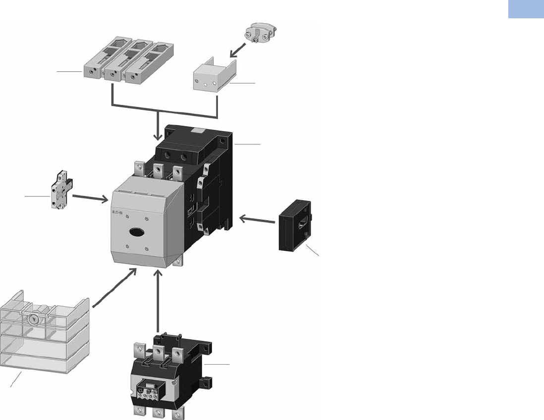
Volume 5—Motor Control and Protection CA08100006E—August 2012 www.eaton.com V5-T1-37
1
1
1
1
1
1
1
1
1
1
1
1
1
1
1
1
1
1
1
1
1
1
1
1
1
1
1
1
1
1
1.1
IEC Contactors and Starters
XT
IEC Power Control
XTCE185–XTCE20 Contactors
Notes
1XTCE Contactors for 185–2000A
(see Page V5-T1-46)
Multi-voltage coils:
24–48 Vdc
48–110 Vac/Vdc
110–250 Vac/Vdc
250–500 Vac
0.7–1.15 x Uc
Actuation options:
Directly
From the PLC
With low-consumption contact
XTCS Contactors for 185–570A AC-3
(see Page V5-T1-42)
Control voltages:
110–120V 50/60 Hz
220–240V 50/60 Hz
Conventional operation
2Cable Terminal Block
(see Page V5-T1-97)
One or two conductors per phase
Round and flat conductor connectable
Finger-proof
3Flat Strip Conductor Terminals
(see Page V5-T1-97)
One or two strips per phase
Control circuit terminal
Cover for fingerproofing
4Mechanical Interlock
(see Page V5-T1-73)
Fits between contactors
5Overload Relays
(see Page V5-T1-130)
Can be mounted directly
Separate mounting, possible
Protection of EEx e-motors
PTB certificate
6Terminal Shroud
(see Page V5-T1-75)
Finger-proof
7Auxiliary Contact Modules
(see Page V5-T1-24)
Two-pole, side-mounting
3
1
2
7
4
5
6
Courtesy of CMA/Flodyne/Hydradyne ▪ Motion Control ▪ Hydraulic ▪ Pneumatic ▪ Electrical ▪ Mechanical ▪ (800) 426-5480 ▪ www.cmafh.com
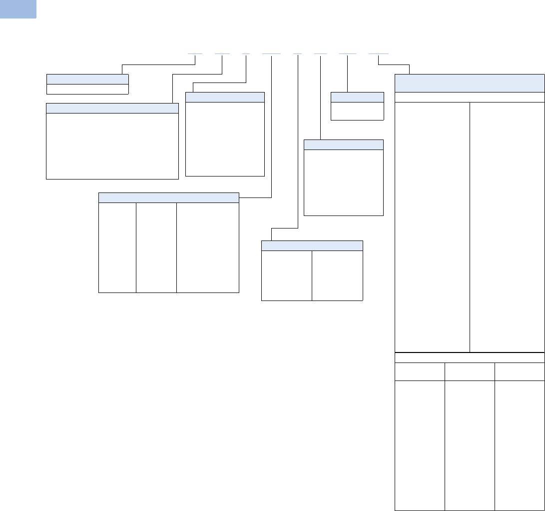
V5-T1-38 Volume 5—Motor Control and Protection CA08100006E—August 2012 www.eaton.com
1
1
1
1
1
1
1
1
1
1
1
1
1
1
1
1
1
1
1
1
1
1
1
1
1
1
1
1
1
1
1.1
IEC Contactors and Starters
XT
IEC Power Control
Catalog Number Selection
XT IEC Contactors and Starters
XTAE, XTAS and XTAR Starters Only—
Maximum Overload Relay
XTOB Maximum Overload Rating
Frame B
P16 = 0.1–0.16A
P24 = 0.16–0.24A
P40 = 0.24–0.4A
P60 = 0.4–0.6A
001 = 0.6–1A
1P6 = 1.0–1.6A
2P4 = 1.6–2.4A
004 = 2.4–4A
006 =4–6A
010 =6–10A
012 =9–12A
016 = 12–16A
Frame C
P16 = 0.1–0.16A
P24 = 0.16–0.24A
P40 = 0.24–0.4A
P60 = 0.4–0.6A
001 = 0.6–1A
1P6 = 1.0–1.6A
2P4 = 1.6–2.4A
004 = 2.4–4A
006 =4–6A
010 =6–10A
016 = 10–16A
024 = 16–24A
032 = 24–32A
Frame D
010 =6–10A
016 = 10–16A
024 = 16–24A
040 = 24–40A
057 = 40–57A
065 = 50–65A
075 = 65–75A
Frame F
035 = 25–35A
050 = 35–50A
070 = 50–70A
100 = 70–100A
Frame G
035 = 25–35A
050 = 35–50A
070 = 50–70A
100 = 70–100A
125 = 95–125A
150 = 120–150A
175 = 145–175A
Frame L
070 = 50–70A
100 = 70–100A
125 = 95–125A
160 = 120–160A
220 = 160–220A
250 = 200–250A
Type
CE = Three-pole FVNR IEC contactor
CS = Three-pole FVNR S Series IEC contactor
CF = Four-pole FVNR IEC contactor
CR = Three-pole FVR IEC contactor
CC = IEC capacitor contactor
AE = FVNR IEC starter
AS = FVNR S-Series IEC starter
AR = FVR IEC starter
Designation
XT = XT line of IEC control
Terminations
Blank = Screw terminals
(6–65A);
5 mm (80–150A);
no lugs
(185–2000A)
C= Spring cage
terminals consult
local sales office
for availability
XTOE Maximum Overload Rating
Standard
Type Suffix
Ground Fault
Type Suffix
Frame B
0.33–1.65A
1–5A
4–20A
Frame C
0.33–1.65A
1–5A
4–20A
9–45A
Frame D
9–45A
20–100A
Frame F, G
20–100A
Frame G, H
35–175A
5E1P6
5E005
5E020
5E1P6
5E005
5E020
5E045
5E045
5E100
5E100
5E175
5G1P6
5G005
5G020
5G1P6
5G005
5G020
5G045
5G045
5G100
5G100
5G175
Frame Size Designation
B= 45 mm
C= 45 mm
D= 55 mm
F= 90 mm
G= 90 mm
H= 140 mm
L= 140 mm
M= 160 mm
N= 250 mm
P= 260 mm
R= 515 mm
Built-In Auxiliary Contact
01 =1NC
10 =1NO
00 = 0NO–0NC
S1 = 1NO–1NC
side-mount auxiliary
11 = 1NO–1NC
top-mount auxiliary
22 = 2NO–2NC
Current Ratings, AC-3
007 = 7A
009 = 9A
012 = 12A
015 = 15A
018 = 18A
025 = 25A
032 = 32A
040 = 40A
050 = 50A
065 = 65A
072 = 72A
080 = 80A
095 = 95A
115= 115A
150 = 150A
170 = 170A
185 = 185A
225 = 225A
250 = 250A
300 = 300A
400 = 400A
500 = 500A
570 = 570A
580 = 580A
650 = 650A
750 = 750A
820 = 820A
C10 = 1000A
C14 = 1400A, AC-1
C16 = 1600A, AC-3
C20 = 2000A, AC-1
XT CE C007 B01 AD P16
Coil Codes
See Page
V5-T1-53.
Courtesy of CMA/Flodyne/Hydradyne ▪ Motion Control ▪ Hydraulic ▪ Pneumatic ▪ Electrical ▪ Mechanical ▪ (800) 426-5480 ▪ www.cmafh.com
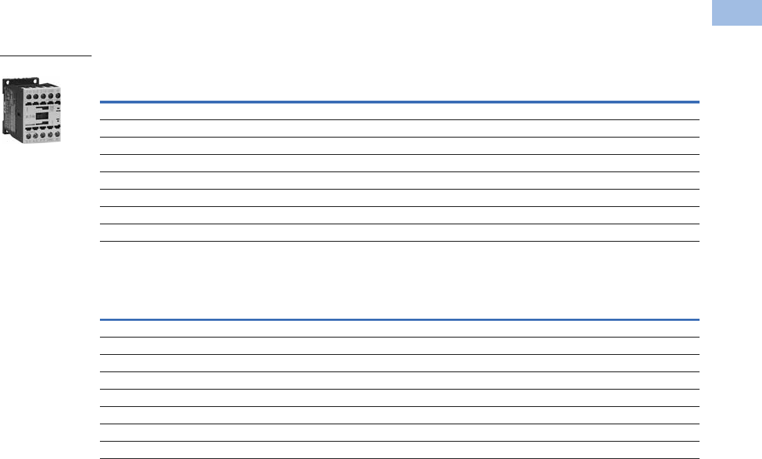
Volume 5—Motor Control and Protection CA08100006E—August 2012 www.eaton.com V5-T1-39
1
1
1
1
1
1
1
1
1
1
1
1
1
1
1
1
1
1
1
1
1
1
1
1
1
1
1
1
1
1
1.1
IEC Contactors and Starters
XT
IEC Power Control
Product Selection
Full Voltage, Non-Reversing Contactors
Three-Pole Contactors, Frame B—UL/CSA Ratings
Three-Pole Contactors, Frame B—IEC Ratings
Notes
The 7–32A XTCE contactors have positively driven contacts between the integrated auxiliary contact and
the auxiliary contact module as well as within the auxiliary contact modules.
DC operated contactors (Frames B–G, 7–150A) have a built-in suppressor circuit.
1 Underscore (_) indicates magnet coil suffix required. See Page V5-T1-53.
2 For spring cage terminals, insert C after the fourth digit of the catalog number. Example: XTCEC007B10A.
For 7–12A XTCEC contactors, the power, auxiliary and coil terminals are spring cage.
For 18–32A XTCEC contactors, the auxiliary and coil terminals are spring cage.
For 40–150A XTCEC contactors, the coil terminals only are spring cage.
3 For electrical life contactor application data. See Page V5-T1-45.
UL General Purpose
Ampere Rating
Single-Phase hp Ratings Three-Phase hp Ratings Auxiliary
Contacts
Screw Terminal
Catalog Number 12
115V 200V 230V 200V 230V 460V 575V
20 1/4 3/4 1 1-1/2 2 3 5 1NO XTCE007B10_
20 1/4 3/4 1 1-1/2 2 3 5 1NC XTCE007B01_
20 1/211-1/23357-1/21NO XTCE009B10_
20 1/211-1/23357-1/21NC XTCE009B01_
20 1223 3 10
310 1NO XTCE012B10_
20 1223 3 10
310 1NC XTCE012B01_
20 1235 5 10
310 1NO XTCE015B10_
20 1235 5 10
310 1NC XTCE015B01_
AC-3
Ie (A)
AC-1 (40°C)
Ie = Ith (A)
Maximum kW Ratings AC-3/Three-Phase Motors 50–60 Hz Auxiliary
Contacts
Screw Terminal
Catalog Number 12
220/230V 380/400V 415V 660/690V
722 2.2 3 43.5 1NOXTCE007B10_
722 2.2 3 43.5 1NCXTCE007B01_
922 2.5 4 5.54.5 1NOXTCE009B10_
922 2.5 4 5.54.5 1NCXTCE009B01_
12 22 3.5 5.5 7 6.5 1NO XTCE012B10_
12 22 3.5 5.5 7 6.5 1NC XTCE012B01_
15.5 22 4 7.5 8 7 1NO XTCE015B10_
15.5 22 4 7.5 8 7 1NC XTCE015B01_
Frame B
Courtesy of CMA/Flodyne/Hydradyne ▪ Motion Control ▪ Hydraulic ▪ Pneumatic ▪ Electrical ▪ Mechanical ▪ (800) 426-5480 ▪ www.cmafh.com
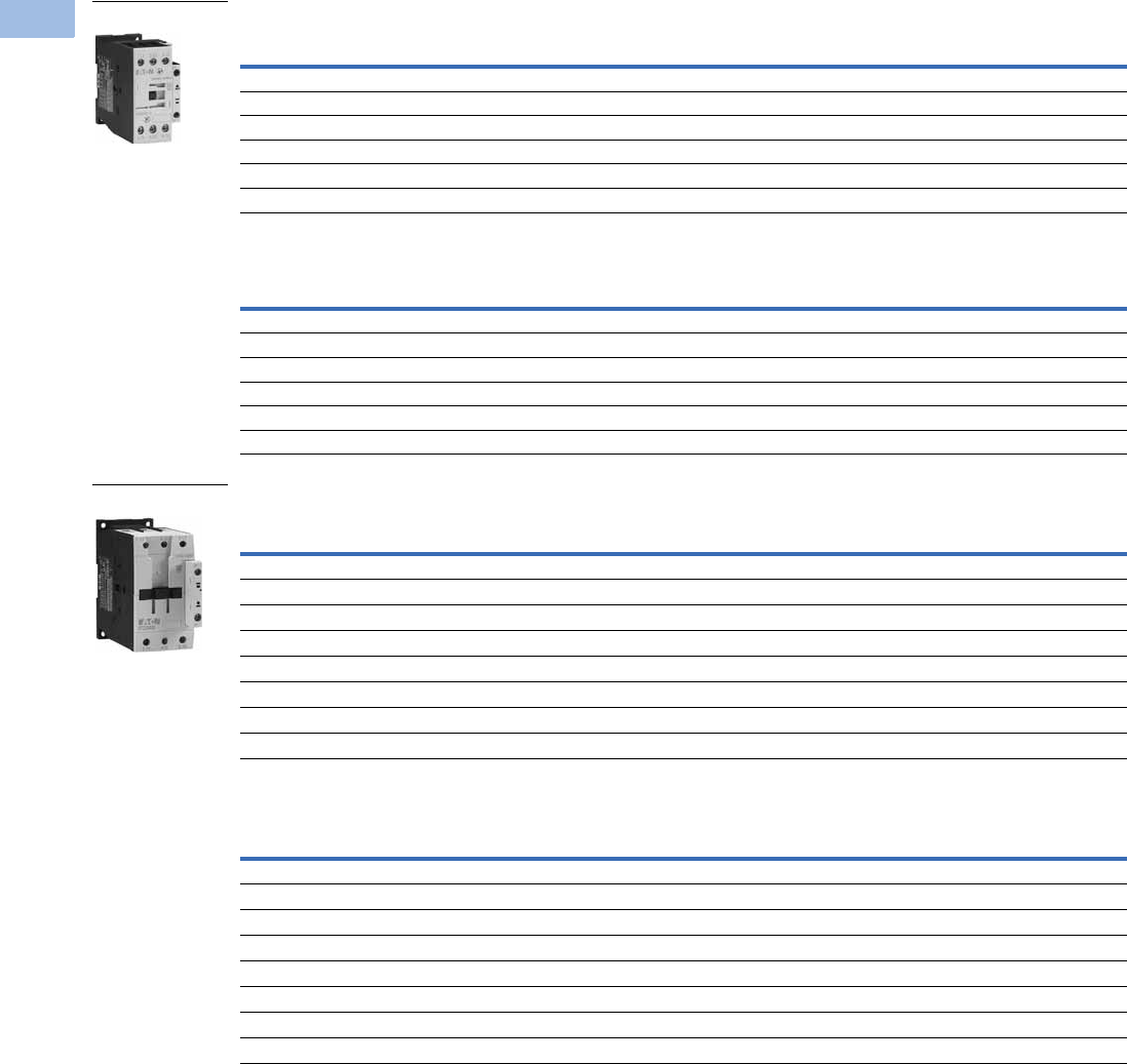
V5-T1-40 Volume 5—Motor Control and Protection CA08100006E—August 2012 www.eaton.com
1
1
1
1
1
1
1
1
1
1
1
1
1
1
1
1
1
1
1
1
1
1
1
1
1
1
1
1
1
1
1.1
IEC Contactors and Starters
XT
IEC Power Control
Three-Pole Contactors, Frame C—UL/CSA Ratings
Three-Pole Contactors, Frame C—IEC Ratings
Three-Pole Contactors, Frame D—UL/CSA Ratings
Three-Pole Contactors, Frame D—IEC Ratings
Notes
The 7–32A XTCE contactors have positively driven contacts between the integrated auxiliary contact and
the auxiliary contact module as well as within the auxiliary contact modules.
The 40–65A XTCE contactors have positively driven contacts within the auxiliary contact module.
Six auxiliary contacts are possible with a combination of side-mounted and front-mount auxiliary contacts.
DC operated contactors (Frames B–G, 7–150A) have a built-in suppressor circuit.
1 Underscore (_) indicates magnet coil suffix required. See Page V5-T1-53.
2 For spring cage terminals, insert C after the fourth digit of the catalog number. Example: XTCEC007B10A.
For 7–12A XTCEC contactors, the power, auxiliary and coil terminals are spring cage.
For 18–32A XTCEC contactors, the auxiliary and coil terminals are spring cage.
For 40–150A XTCEC contactors, the coil terminals only are spring cage.
UL General Purpose
Ampere Rating
Single-Phase hp Ratings Three-Phase hp Ratings Auxiliary
Contacts
Screw Terminal
Catalog Number 12
115V 200V 230V 200V 230V 460V 575V
40 2235 5 10151NO XTCE018C10_
40 2235 5 10151NC XTCE018C01_
40 2357-1/21015201NO XTCE025C10_
40 2357-1/21015201NC XTCE025C01_
40 355101020251NO XTCE032C10_
40 355101020251NC XTCE032C01_
AC-3
Ie (A)
AC-1 (40°C)
Ie = Ith (A)
Maximum kW Ratings AC-3/Three-Phase Motors 50–60 Hz Auxiliary
Contacts
Screw Terminal
Catalog Number 12
220/230V 380/400V 415V 660/690V
18 40 5 7.5 10 11 1NO XTCE018C10_
18 40 5 7.5 10 11 1NC XTCE018C01_
25 45 7.5 11 14.5 14 1NO XTCE025C10_
25 45 7.5 11 14.5 14 1NC XTCE025C01_
32 45 10 15 18 17 1NO XTCE032C10_
32 45 10 15 18 17 1NC XTCE032C01_
UL General Purpose
Ampere Rating
Single-Phase hp Ratings Three-Phase hp Ratings Auxiliary
Contacts
Screw Terminal
Catalog Number 12
115V 200V 230V 200V 230V 460V 575V
63 3 5 7-1/2 10 15 30 40 — XTCE040D00_
63 3 5 7-1/2 10 15 30 40 1NO-1NC XTCE040DS1_
80 3 7-1/2 10 15 20 40 50 — XTCE050D00_
80 3 7-1/2 10 15 20 40 50 1NO-1NC XTCE050DS1_
88 5 101520255060 — XTCE065D00_
88 5 101520255060 1NO-1NCXTCE065DS1_
88 5 101520255060 — XTCE072D00_
88 5 101520255060 1NO-1NCXTCE072DS1_
AC-3
Ie (A)
AC-1 (40°C)
Ie = Ith (A)
Maximum kW Ratings AC-3/Three-Phase Motors 50–60 Hz Auxiliary
Contacts
Screw Terminal
Catalog Number 12
220/230V 380/400V 415V 660/690V
40 60 12.5 18.5 24 23 — XTCE040D00_
40 60 12.5 18.5 24 23 1NO-1NC XTCE040DS1_
50 80 15.5 22 30 30 — XTCE050D00_
50 80 15.5 22 30 30 1NO-1NC XTCE050DS1_
65 98 20 30 39 35 — XTCE065D00_
65 98 20 30 39 35 1NO-1NC XTCE065DS1_
72 98 22 37 41 35 — XTCE072D00_
72 98 22 37 41 35 1NO-1NC XTCE072DS1_
Frame C
Frame D
Courtesy of CMA/Flodyne/Hydradyne ▪ Motion Control ▪ Hydraulic ▪ Pneumatic ▪ Electrical ▪ Mechanical ▪ (800) 426-5480 ▪ www.cmafh.com
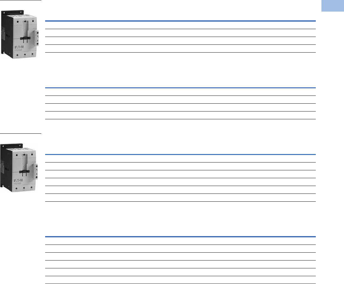
Volume 5—Motor Control and Protection CA08100006E—August 2012 www.eaton.com V5-T1-41
1
1
1
1
1
1
1
1
1
1
1
1
1
1
1
1
1
1
1
1
1
1
1
1
1
1
1
1
1
1
1.1
IEC Contactors and Starters
XT
IEC Power Control
Three-Pole Contactors, Frame F—UL/CSA Ratings
Three-Pole Contactors, Frame F—IEC Ratings
Three-Pole Contactors, Frame G—UL/CSA Ratings
Three-Pole Contactors, Frame G—IEC Ratings
Notes
The 40–65A XTCE contactors have positively driven contacts within the auxiliary contact module.
Six auxiliary contacts are possible with a combination of side-mounted and front-mount auxiliary contacts.
DC operated contactors (Frames B–G, 7–150A) have a built-in suppressor circuit.
1 Underscore (_) indicates magnet coil suffix required. See Page V5-T1-53.
2 For spring cage terminals, insert C after the fourth digit of the catalog number. Example: XTCEC007B10A.
For 7–12A XTCEC contactors, the power, auxiliary and coil terminals are spring cage.
For 18–32A XTCEC contactors, the auxiliary and coil terminals are spring cage.
For 40–150A XTCEC contactors, the coil terminals only are spring cage.
UL General Purpose
Ampere Rating
Single-Phase hp Ratings Three-Phase hp Ratings Auxiliary
Contacts
Screw Terminal
Catalog Number 12
115V 200V 230V 200V 230V 460V 575V
125 7-1/2 15 15 25 30 60 75 — XTCE080F00_
125 7-1/2 15 15 25 30 60 75 1NO-1NC XTCE080FS1_
125 7-1/2 15 15 25 40 75 100 — XTCE095F00_
125 7-1/2 15 15 25 40 75 100 1NO-1NC XTCE095FS1_
AC-3
Ie (A)
AC-1 (40°C)
Ie = Ith (A)
Maximum kW Ratings AC-3/Three-Phase Motors 50–60 Hz Auxiliary
Contacts
Screw Terminal
Catalog Number 12
220/230V 380/400V 415V 660/690V
80 110 25 37 48 63 — XTCE080F00_
80 110 25 37 48 63 1NO-1NC XTCE080FS1_
95 130 30 45 57 75 — XTCE095F00_
95 130 30 45 57 75 1NO-1NC XTCE095FS1_
UL General Purpose
Ampere Rating
Single-Phase hp Ratings Three-Phase hp Ratings Auxiliary
Contacts
Screw Terminal
Catalog Number 12
115V 200V 230V 200V 230V 460V 575V
160 10252540 50 100100— XTCE115G00_
160 10252540 50 1001001NO-1NCXTCE115GS1_
180 10253040 60 125125— XTCE150G00_
180 10253040 60 1251251NO-1NCXTCE150GS1_
180 10253040 60 125125— XTCE170G00_
180 10253040 60 1251251NO-1NCXTCE170GS1_
AC-3
Ie (A)
AC-1 (40°C)
Ie = Ith (A)
Maximum kW Ratings AC-3/Three-Phase Motors 50–60 Hz Auxiliary
Contacts
Screw Terminal
Catalog Number 12
220/230V 380/400V 415V 660/690V
115 160 37 55 70 90 — XTCE115G00_
115 160 37 55 70 90 1NO-1NC XTCE115GS1_
150 190 48 75 91 96 — XTCE150G00_
150 190 48 75 91 96 1NO-1NC XTCE150GS1_
170 190 52 90 100 96 — XTCE170G00_
170 190 52 90 100 96 1NO-1NC XTCE170GS1_
Frame F
Frame G
Courtesy of CMA/Flodyne/Hydradyne ▪ Motion Control ▪ Hydraulic ▪ Pneumatic ▪ Electrical ▪ Mechanical ▪ (800) 426-5480 ▪ www.cmafh.com

V5-T1-42 Volume 5—Motor Control and Protection CA08100006E—August 2012 www.eaton.com
1
1
1
1
1
1
1
1
1
1
1
1
1
1
1
1
1
1
1
1
1
1
1
1
1
1
1
1
1
1
1.1
IEC Contactors and Starters
XT
IEC Power Control
Three-Pole Contactors, Frame H (Electronic Coil)—UL/CSA Ratings
Three-Pole Contactors, Frame H (Electronic Coil)—IEC Ratings
Three-Pole Contactors, Frame L—UL/CSA Ratings
Three-Pole Contactors, Frame L—IEC Ratings
Notes
1 Underscore (_) indicates magnet coil suffix required. See Page V5-T1-53. Terminals not included. See Page V5-T1-75 for terminal accessories.
2 Does not include lugs.
3 For 185–500A contactors at 660/690V or 1000V: Do not reverse directly.
UL General Purpose
Ampere Rating
Three-Phase hp Ratings Auxiliary
Contacts
Catalog
Number 12
200V 240V 480V 600V
250 50601251502NO-2NCXTCE185H22_
250 60751502002NO-2NCXTCE225H22_
AC-3
Ie (A)
AC-1 (40°C)
Ie = Ith (A)
Maximum kW Ratings AC-3/Three-Phase Motors 50–60 Hz Auxiliary
Contacts
Catalog
Number 12
220/230V 380/400V 660/690V 31000V 3
185 337 55 90 140 108 2NO-2NC XTCE185H22_
225 386 70 110 215 108 2NO-2NC XTCE225H22_
UL General Purpose Three-Phase hp Ratings Auxiliary
Contacts
Catalog
Number 12
Ampere Rating 200V 230V 460V 575V
Standard Coil (110/120V, 230/240 Vac Coil Only)
300 75 100 200 250 2NO-2NC XTCS250L22_
350 100 125 250 300 2NO-2NC XTCS300L22_
Electronic Coil
300 75 100 200 250 2NO-2NC XTCE250L22_
350 100 125 250 300 2NO-2NC XTCE300L22_
AC-3
Ie (A)
AC-1 (40°C)
Ie = Ith (A)
Maximum kW Ratings AC-3/Three-Phase Motors 50–60 Hz Auxiliary
Contacts
Catalog
Number 12
220/230V 380/400V 660/690V 31000V 3
Standard Coil (110/120V, 230/240 Vac Coil Only)
250 429 75 132 240 108 2NO-2NC XTCS250L22_
300 490 90 160 195 132 2NO-2NC XTCS300L22_
Electronic Coil
250 429 75 132 240 108 2NO-2NC XTCE250L22_
300 490 90 160 195 132 2NO-2NC XTCE300L22_
Frame H
Frame L
Courtesy of CMA/Flodyne/Hydradyne ▪ Motion Control ▪ Hydraulic ▪ Pneumatic ▪ Electrical ▪ Mechanical ▪ (800) 426-5480 ▪ www.cmafh.com
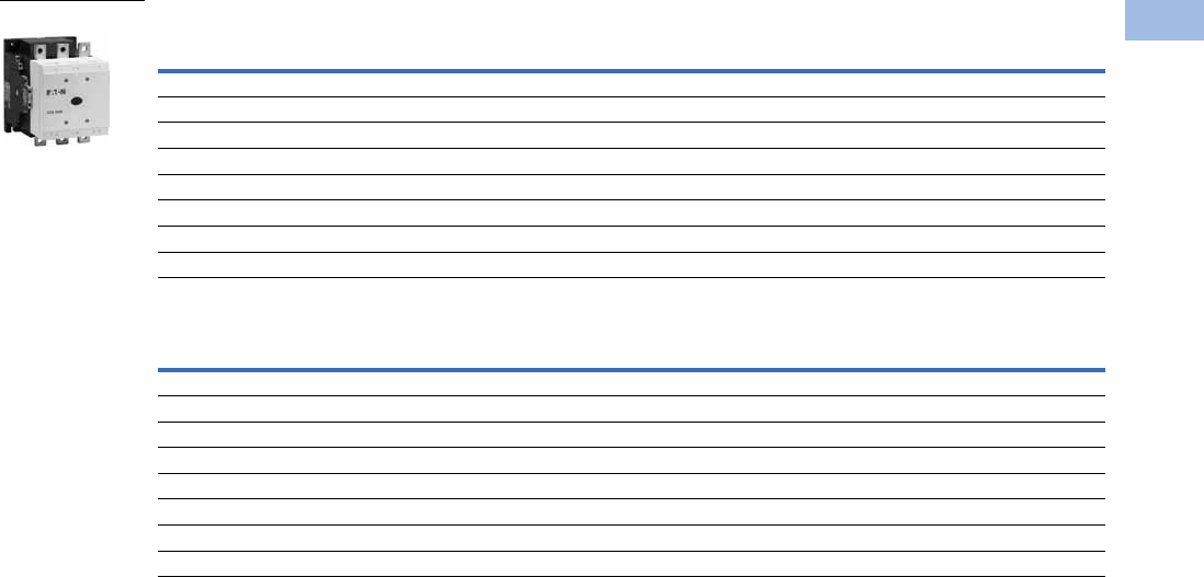
Volume 5—Motor Control and Protection CA08100006E—August 2012 www.eaton.com V5-T1-43
1
1
1
1
1
1
1
1
1
1
1
1
1
1
1
1
1
1
1
1
1
1
1
1
1
1
1
1
1
1
1.1
IEC Contactors and Starters
XT
IEC Power Control
Three-Pole Contactors, Frame M—UL/CSA Ratings
Three-Pole Contactors, Frame M—IEC Ratings
Notes
1 Underscore (_) indicates magnet coil suffix required. See Page V5-T1-53. Terminals not included. See Page V5-T1-75 for terminal accessories.
2 Does not include lugs.
3 For 185–500A contactors at 660/690V or 1000V: Do not reverse directly.
UL General Purpose
Ampere Rating
Three-Phase hp Ratings Auxiliary
Contacts
Catalog
Number 12
200V 230V 460V 575V
Standard Coil (110/120V, 230/240 Vac Coil Only)
450 125 150 300 400 2NO-2NC XTCS400M22_
550 150 200 400 500 2NO-2NC XTCS500M22_
550 150 200 400 500 2NO-2NC XTCS570M22_
Electronic Coil
450 125 150 300 400 2NO-2NC XTCE400M22_
550 150 200 400 500 2NO-2NC XTCE500M22_
550 150 200 400 500 2NO-2NC XTCE570M22_
AC-3
Ie (A)
AC-1 (40°C)
Ie = Ith (A)
Maximum kW Ratings AC-3/Three-Phase Motors 50–60 Hz Auxiliary
Contacts
Catalog
Number 12
220/230V 380/400V 415V 660/690V 31000V 3
Standard Coil (110/120V, 230/240 Vac Coil Only)
400 612 125 200 240 344 132 2NO-2NC XTCS400M22_
500 857 155 250 300 344 132 2NO-2NC XTCS500M22_
580 980 155 315 350 344 132 2NO-2NC XTCS570M22_
Electronic Coil
400 612 125 200 240 344 132 2NO-2NC XTCE400M22_
500 857 155 250 300 344 132 2NO-2NC XTCE500M22_
580 980 155 315 350 344 132 2NO-2NC XTCE570M22_
Frame M
Courtesy of CMA/Flodyne/Hydradyne ▪ Motion Control ▪ Hydraulic ▪ Pneumatic ▪ Electrical ▪ Mechanical ▪ (800) 426-5480 ▪ www.cmafh.com
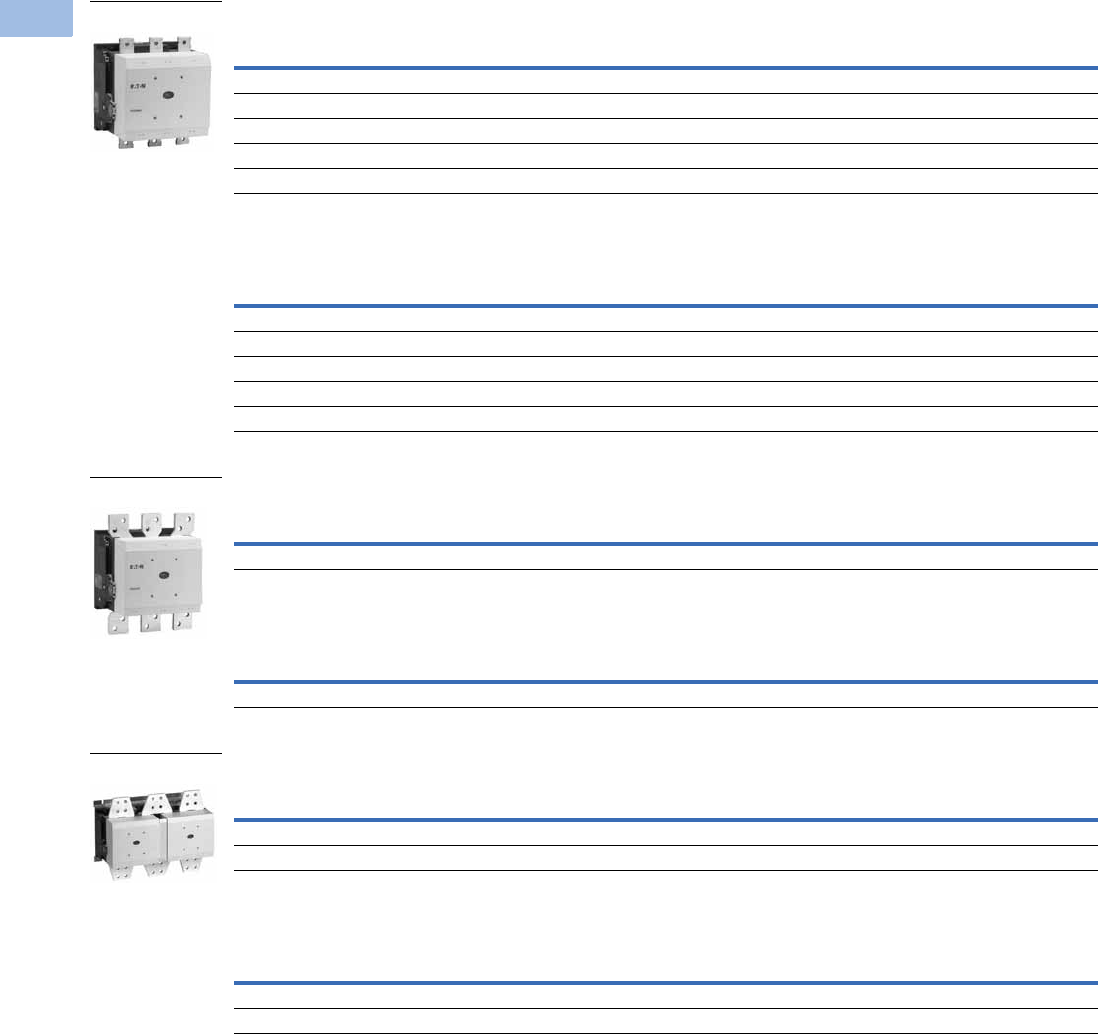
V5-T1-44 Volume 5—Motor Control and Protection CA08100006E—August 2012 www.eaton.com
1
1
1
1
1
1
1
1
1
1
1
1
1
1
1
1
1
1
1
1
1
1
1
1
1
1
1
1
1
1
1.1
IEC Contactors and Starters
XT
IEC Power Control
Three-Pole Contactors, Frame N (Electronic Coil)—UL/CSA Ratings
Three-Pole Contactors, Frame N (Electronic Coil)—IEC Ratings
Three-Pole Contactors, Frame P (Electronic Coil)—UL/CSA Ratings
Three-Pole Contactors, Frame P (Electronic Coil)—IEC Ratings
Three-Pole Contactors, Frame R (Electronic Coil)—UL/CSA Ratings
Three-Pole Contactors, Frame R (Electronic Coil)—IEC Ratings
Notes
1 Underscore (_) indicates magnet coil suffix required. See Page V5-T1-53. Terminals not included. See Page V5-T1-75 for terminal accessories.
2 Does not include lugs.
3 When operating the 580–2000A XTCE contactors with frequency inverters, the suppressor on the load side must be removed. The load side suppressor must also be
removed when performing a high-voltage test—see Pub51204, Pub51209.
4 For 185–500A contactors at 660/690V or 1000V: do not reverse directly.
UL General Purpose
Ampere Rating
Three-Phase hp Ratings Auxiliary
Contacts Catalog Number 12
200V 230V 460V 575V
630 200 200 400 600 2NO-2NC XTCE580N22_ 3
700 200 250 500 600 2NO-2NC XTCE650N22_ 3
800 250 300 600 700 2NO-2NC XTCE750N22_ 3
850 290 350 700 860 2NO-2NC XTCE820N22_ 3
1100 350 420 850 980 2NO-2NC XTCEC10N22_ 3
AC-3
Ie (A)
AC-1 (40°C)
Ie = Ith (A)
Maximum kW Ratings AC-3/Three-Phase Motors 50–60 Hz Auxiliary
Contacts Catalog Number 12
220/230V 380/400V 415V 660/690V 41000V 4
580 980 185 315 348 560 600 2NO-2NC XTCE580N22_ 3
650 1041 205 355 390 630 600 2NO-2NC XTCE650N22_ 3
750 1102 240 400 455 720 800 2NO-2NC XTCE750N22_ 3
820 1225 260 450 500 750 800 2NO-2NC XTCE820N22_ 3
1000 1225 315 560 610 1000 1000 2NO-2NC XTCEC10N22_ 3
UL General Purpose
Ampere Rating
Three-Phase hp Ratings Auxiliary
Contacts Catalog Number 12
200V 230V 460V 575V
1400 — — — — 2NO-2NC XTCEC14P22_ 3
AC-3
Ie (A)
AC-1 (40°C)
Ie = Ith (A)
Maximum kW Ratings AC-3/Three-Phase Motors 50–60 Hz Auxiliary
Contacts Catalog Number 12
220/230V 380/400V 415V 660/690V 41000V 4
— 1714 — — — — — 2NO-2NC XTCEC14P22_ 3
UL General Purpose
Ampere Rating
Three-Phase hp Ratings Auxiliary
Contacts Catalog Number 12
200V 230V 460V 575V
1600 560 640 1200 1300 2NO-2NC XTCEC16R22_ 3
2000 — — — — 2NO-2NC XTCEC20R22_ 3
AC-3
Ie (A)
AC-1 (40°C)
Ie = Ith (A)
Maximum kW Ratings AC-3/Three-Phase Motors 50–60 Hz Auxiliary
Contacts Catalog Number 12
220/230V 380/400V 415V 660/690V 41000V 4
1600 2200 500 900 900 1600 1700 2NO-2NC XTCEC16R22_ 3
— 2450 — — — — — 2NO-2NC XTCEC20R22_ 3
Frame N
Frame P
Frame R
Courtesy of CMA/Flodyne/Hydradyne ▪ Motion Control ▪ Hydraulic ▪ Pneumatic ▪ Electrical ▪ Mechanical ▪ (800) 426-5480 ▪ www.cmafh.com
Volume 5—Motor Control and Protection CA08100006E—August 2012 www.eaton.com V5-T1-45
1
1
1
1
1
1
1
1
1
1
1
1
1
1
1
1
1
1
1
1
1
1
1
1
1
1
1
1
1
1
1.1
IEC Contactors and Starters
XT
IEC Power Control
Contactor
Application Data 12
Full Voltage Non-Reversing Three-Pole Contactors—
Contact Sequence (Circuit Symbols)—Standard Offering
Four-Pole Contactors with Screw Terminals—Maximum UL/CSA Motor Ratings
Four-Pole Contactors with Screw Terminals—Maximum IEC Ratings
Notes
1See Page V5-T1-111 for electrical life curves.
2AC and DC operated contactors have a built-in suppressor circuit (Frames L–R, 185–2000A).
3Underscore (_) indicates magnet coil suffix required. See Page V5-T1-53.
Catalog
Prefix
Electrical Life (Operations)
for 10 hp, 480V (14.2A)
Applications
XTCE012B 1 million
XTCE015B 1.2 million
XTCE018C 2 million
Contactor
Frame
Auxiliary
Contacts Contact Sequence
B–C 1NO
B–C 1NC
D–G —
L–R 2NO-2NC
2
35
46
A1
A2
113
14
2
35
46
A1
A2
121
22
2
35
46
A1
A2
1
Single-Phase hp Ratings Three-Phase hp Ratings Auxiliary
Contacts
Contact
Sequence Catalog Number 3
115V 230V 200V 230V 460V 575V
12331010— XTCF020B00_
——7.57.510151NO XTCF032C10_
— — 7.5 10 15 20 1NO XTCF045C10_
——10153040— XTCF063D00_
——15204050— XTCF080D00_
——25306075— XTCF125G00_
——254075100— XTCF160G00_
——4050100125— XTCF200G00_
AC-3
Ie (A)
AC-1
(40°C)
Three-Phase hp Ratings Auxiliary
Contacts
Contact
Sequence Catalog Number 3
200V 230V 460V 575V
12 22 3 3 10 10 — XTCF020B00_
12 22 3.5 5.5 7 6.5 — XTCF020B00_
18 32 5 7.5 10 11 1NO XTCF032C10_
25 45 7.5 11 14.5 14 1NO XTCF045C10_
40 63 12.5 18.5 24 23 — XTCF063D00_
50 80 15.5 22 30 30 — XTCF080D00_
8012525374863— XTCF125G00_
9516030455775— XTCF160G00_
115 200 37 55 70 90 — XTCF200G00_
Courtesy of CMA/Flodyne/Hydradyne ▪ Motion Control ▪ Hydraulic ▪ Pneumatic ▪ Electrical ▪ Mechanical ▪ (800) 426-5480 ▪ www.cmafh.com
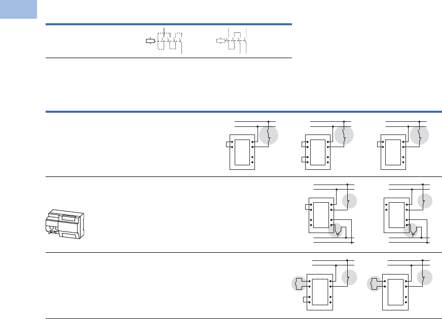
V5-T1-46 Volume 5—Motor Control and Protection CA08100006E—August 2012 www.eaton.com
1
1
1
1
1
1
1
1
1
1
1
1
1
1
1
1
1
1
1
1
1
1
1
1
1
1
1
1
1
1
1.1
IEC Contactors and Starters
XT
IEC Power Control
Switching of DC Currents 1
Controlling XTCS and XTCE Contactors Frames L–R (185–2000A)
Notes
1When necessary, cable to be supplied by customer.
2Standstill in an emergency (emergency-stop).
3Command device connection.
Description Single-Pole Two-Pole
XTCF020B–XTCF200G
>60 Vdc
Description
XTCS250L–XTCS500M,
XTCE_H XTCEC16R, XTCEC20R XTCE250L–XTCEC14P
Conventional
A1/A2 are applied to voltage in the usual manner.
Direct from the PLC
A 24V output from the PLC can be connected directly to
connections A3/A4.
—
From Low-Consumption Command Devices
Command devices, which can only be subject to minimal loads
such as circuit board relays, control circuit devices or position
switches can be connected directly to A10/A11.
—
A10
A11
A2
A1
A3
A4
(+) L1
(–) N
b
A10
A11
A2
A1
A3
A4
TY
TX
(+) L1
(–) N
b
A10
A11
A2
A1
A3
A4
(+) L1
(–) N
b
A2
A1
A3
A4
24V
GND
(+) L1
(–) N
b
A10
A11
TY
TX
A10
A11
A2
A1
A3
A4
24V
GND
(+) L1
(–) N
b
A10
A11
A2
A1
A3
A4
c
b
(+) L1
(–) N
TY
TX
A10
A11
A2
A1
A3
A4
c
b
(+) L1
(–) N
Courtesy of CMA/Flodyne/Hydradyne ▪ Motion Control ▪ Hydraulic ▪ Pneumatic ▪ Electrical ▪ Mechanical ▪ (800) 426-5480 ▪ www.cmafh.com
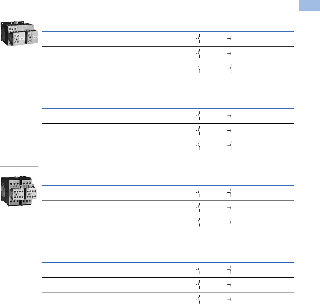
Volume 5—Motor Control and Protection CA08100006E—August 2012 www.eaton.com V5-T1-47
1
1
1
1
1
1
1
1
1
1
1
1
1
1
1
1
1
1
1
1
1
1
1
1
1
1
1
1
1
1
1.1
IEC Contactors and Starters
XT
IEC Power Control
Full Voltage, Reversing Contactors
Contactors with Screw Terminals, Frame B—Maximum UL/CSA Ratings
Contactors with Screw Terminals, Frame B—Maximum IEC Ratings
Contactors with Screw Terminals, Frame C—Maximum UL/CSA Ratings
Contactors with Screw Terminals, Frame C—Maximum IEC Ratings
Note
1 Underscore (_) indicates magnet coil suffix required. See Page V5-T1-53.
Single-Phase hp Ratings Three-Phase hp Ratings Spare Auxiliary Contacts
Catalog Number 1
115V 230V 200V 230V 460V 575V K1M K2M
1/4 1 1-1/2 2 3 5 XTCR007B21_
1/21-1/22357-1/2 XTCR009B21_
1/2 2 3 3 7-1/2 10 XTCR012B21_
AC-3
Ie (A)
Three-Phase Motors 50–60 Hz Spare Auxiliary Contacts
Catalog Number 1
220/230V 380/400V 415V 660/690V K1M K2M
72.2343.5 XTCR007B21_
92.5 4 5.5 4.5 XTCR009B21_
12 3.5 5.5 7 6.5 XTCR012B21_
Single-Phase hp Ratings Three-Phase hp Ratings Spare Auxiliary Contacts
Catalog Number 1
115V 230V 200V 230V 460V 575V K1M K2M
23 551015 XTCR018C21_
2 5 7-1/2 7-1/2 15 20 XTCR025C21_
3 5 10 10 20 25 XTCR032C21_
AC-3
Ie (A)
Three-Phase Motors 50–60 Hz Spare Auxiliary Contacts
Catalog Number 1
220/230V 380/400V 415V 660/690V K1M K2M
1857.5811 XTCR018C21_
25 7.5 11 14.5 14 XTCR025C21_
32 10 15 18 17 XTCR032C21_
Frame B
64
63
64
63
64
63
64
63
64
63
64
63
64
63
64
63
64
63
64
63
64
63
64
63
Frame C
64
63
64
63
64
63
64
63
64
63
64
63
64
63
64
63
64
63
64
63
64
63
64
63
Courtesy of CMA/Flodyne/Hydradyne ▪ Motion Control ▪ Hydraulic ▪ Pneumatic ▪ Electrical ▪ Mechanical ▪ (800) 426-5480 ▪ www.cmafh.com
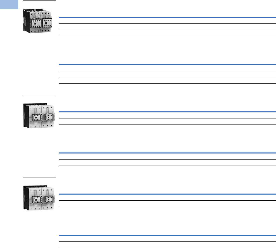
V5-T1-48 Volume 5—Motor Control and Protection CA08100006E—August 2012 www.eaton.com
1
1
1
1
1
1
1
1
1
1
1
1
1
1
1
1
1
1
1
1
1
1
1
1
1
1
1
1
1
1
1.1
IEC Contactors and Starters
XT
IEC Power Control
Contactors with Screw Terminals, Frame D—Maximum UL/CSA Ratings
Contactors with Screw Terminals, Frame D—Maximum IEC Ratings
Contactors with Screw Terminals, Frame F—Maximum UL/CSA Ratings
Contactors with Screw Terminals, Frame F—Maximum IEC Ratings
Contactors with Screw Terminals, Frame G—Maximum UL/CSA Ratings
Contactors with Screw Terminals, Frame G—Maximum IEC Ratings
Note
1 Underscore (_) indicates magnet coil suffix required. See Page V5-T1-53.
Single-Phase hp Ratings Three-Phase hp Ratings Spare Auxiliary Contacts
Catalog Number 1
115V 230V 200V 230V 460V 575V K1M K2M
3 7-1/2 10 15 30 40 — — XTCR040D11_
3 10 15204050 — — XTCR050D11_
5 15 20255060 — — XTCR065D11_
AC-3
Ie (A)
Three-Phase Motors 50–60 Hz Spare Auxiliary Contacts
Catalog Number 1
220/230V 380/400V 415V 660/690V K1M K2M
40 12.5 18.5 24 23 — — XTCR040D11_
50 15.5 22 30 30 — — XTCR050D11_
65 20 30 39 35 — — XTCR065D11_
Single-Phase hp Ratings Three-Phase hp Ratings Spare Auxiliary Contacts
Catalog Number 1
115V 230V 200V 230V 460V 575V K1M K2M
7-1/215 25306075 — — XTCR080F11_
7-1/215 254075100 — — XTCR095F11_
AC-3
Ie (A)
Three-Phase Motors 50–60 Hz Spare Auxiliary Contacts
Catalog Number 1
220/230V 380/400V 415V 660/690V K1M K2M
80 25 37 48 63 — — XTCR080F11_
95 30 45 57 75 — — XTCR095F11_
Single-Phase hp Ratings Three-Phase hp Ratings Spare Auxiliary Contacts
Catalog Number 1
115V 230V 200V 230V 460V 575V K1M K2M
10 25 40 50 100 100 — — XTCR115G11_
15 30 40 60 100 100 — — XTCR150G11_
AC-3
Ie (A)
Three-Phase Motors 50–60 Hz Spare Auxiliary Contacts
Catalog Number 1
220/230V 380/400V 415V 660/690V K1M K2M
11537557090— — XTCR115G11_
15048759196— — XTCR150G11_
Frame D
Frame F
Frame G
Courtesy of CMA/Flodyne/Hydradyne ▪ Motion Control ▪ Hydraulic ▪ Pneumatic ▪ Electrical ▪ Mechanical ▪ (800) 426-5480 ▪ www.cmafh.com

Volume 5—Motor Control and Protection CA08100006E—August 2012 www.eaton.com V5-T1-49
1
1
1
1
1
1
1
1
1
1
1
1
1
1
1
1
1
1
1
1
1
1
1
1
1
1
1
1
1
1
1.1
IEC Contactors and Starters
XT
IEC Power Control
XTCR Reversing Contactor Components
Magnet Coil Suffix
Note
1Frames L–M only.
Quantity Frame B C D F G
2 Contactor XTCE…B01_ XTCE…C01_ XTCE…D00_ XTCE…F00_ XTCE…G00_
2 Auxiliary contact XTCEXFAC20 XTCEXFAC20 XTCEXFBG11 XTCEXFBG11 XTCEXFBG11
1 Mechanical interlock XTCEXMLB XTCEXMLC XTCEXMLD XTCEXMLG XTCEXMLG
1 Reversing link kit XTCEXRLB XTCEXRLC XTCEXRLD XTCEXRLG XTCEXRLG
Coil Voltage Suffix Code Coil Voltage Suffix Code Coil Voltage Suffix Code Coil Voltage Suffix Code
Frames A–B Frames C–F Frame G Frames L–N
110V 50 Hz, 120V 60 Hz A110V 50 Hz, 120V 60 Hz A100–120V 50/60 Hz A110–250 Vdc 40–60 Hz A
220V 50 Hz, 240V 60 Hz B220V 50 Hz, 240V 60 Hz B190–240V 50/60 Hz B250–500V 40–60 Hz C
230V 50 Hz F230V 50 Hz F24V 50/60 Hz T48–110 Vdc 40–60 Hz Y
24V 50/60 Hz T24V 50/60 Hz T24–27 Vdc TD 24–48 Vdc TD 1
24 Vdc TD 24–27 Vdc TD 480–500V 50/60 Hz CFrames L–M, S-Series
415V 50 Hz, 480V 60 Hz C415V 50 Hz, 480V 60 Hz C380–440V 50/60 Hz L110–120V 50/60 Hz A
550V 50 Hz, 600V 60 Hz D550V 50 Hz, 600V 60 Hz D42–48V 50/60 Hz W220–240V 50/60 Hz B
208V 60 Hz E208V 60 Hz E110–130 Vdc AD Frames P–R
190V 50 Hz, 220V 60 Hz G 190V 50 Hz, 220V 60 Hz G200–240 Vdc BD 230–250 Vdc 50–60 Hz B
240V 50 Hz, 277V 60 Hz H240V 50 Hz, 277V 60 Hz H48–60 Vdc WD
380V 50 Hz, 440V 60 Hz L380V 50 Hz, 440V 60 Hz LFrame H
400V 50 Hz N 400V 50 Hz N100–120V 50/60 Hz A
380V 60 Hz P380V 60 Hz P190–240V 50/60 Hz B
12V 50/60 Hz R 12V 50/60 Hz R480–500V 50/60 Hz C
42V 50 Hz, 48V 60 Hz W42V 50 Hz, 48V 60 Hz W380–440V 50/60 Hz L
48V 50 Hz Y48V 50 Hz Y24V 50/60Hz T
120 Vdc AD 110–130 Vdc AD 42–48V 50/60Hz W
220 Vdc BD 200–240 Vdc BD 110–130 Vdc AD
12 Vdc RD 48–60 Vdc WD 200–240 Vdc BD
48 Vdc WD 24–27 Vdc TD
48–60 Vdc WD
Courtesy of CMA/Flodyne/Hydradyne ▪ Motion Control ▪ Hydraulic ▪ Pneumatic ▪ Electrical ▪ Mechanical ▪ (800) 426-5480 ▪ www.cmafh.com
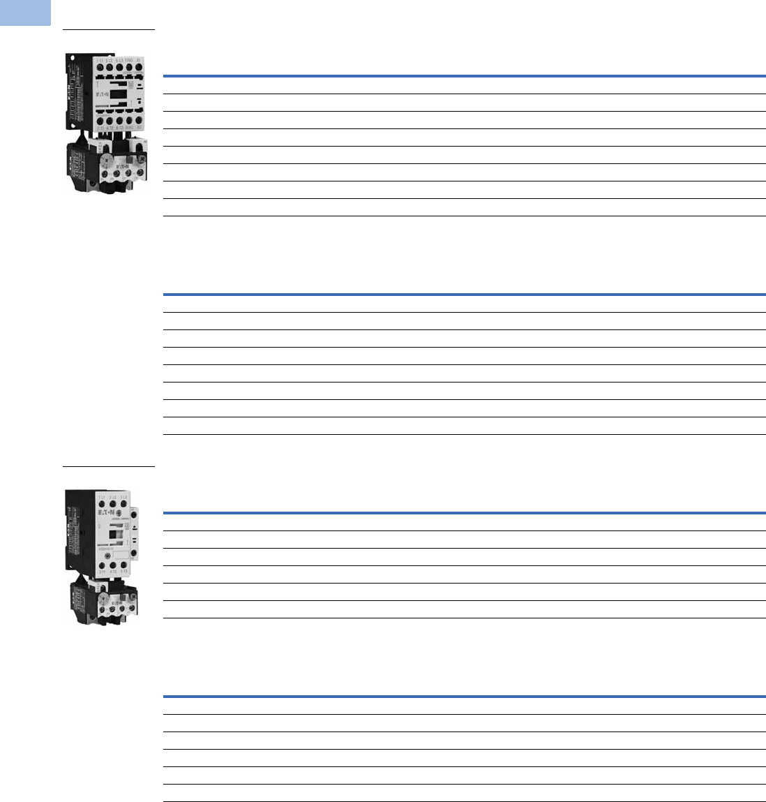
V5-T1-50 Volume 5—Motor Control and Protection CA08100006E—August 2012 www.eaton.com
1
1
1
1
1
1
1
1
1
1
1
1
1
1
1
1
1
1
1
1
1
1
1
1
1
1
1
1
1
1
1.1
IEC Contactors and Starters
XT
IEC Power Control
Full Voltage, Non-Reversing Starters, with Bimetallic or Electronic Overload
Three-Pole Starters, Frame B—Maximum UL/CSA Ratings 1
Three-Pole Starters, Frame B—Maximum IEC Ratings 1
Three-Pole Starters, Frame C—Maximum UL/CSA Ratings 1
Three-Pole Starters, Frame C—Maximum IEC Ratings 1
Notes
1 Products shown are with the bimetallic overload relay.
2 Underscore (_) indicates magnet coil suffix required. See Page V5-T1-53.
3 Underscore (_) indicates overload relay suffix required. See Page V5-T1-54.
4 For electrical life contactor application data. See Page V5-T1-53.
Single-Phase hp Ratings Three-Phase hp Ratings Auxiliary
Contacts Catalog Number 23
115V 230V 200V 230V 460V 575V
1/4 1 1-1/2 2 3 5 1NO XTAE007B10_ _
1/4 1 1-1/2 2 3 5 1NC XTAE007B01_ _
1/21-1/23357-1/21NOXTAE009B10_ _
1/21-1/23357-1/21NCXTAE009B01_ _
12 3310
410 1NO XTAE012B10_ _
12 3310
410 1NC XTAE012B01_ _
13 5510
410 1NO XTAE015B10_ _
13 5510
410 1NC XTAE015B01_ _
AC-3
Ie (A) AC-1
Three-Phase Motors 50–60 Hz Auxiliary
Contacts Catalog Number 23
220/230V 380/400V 415V 660/690V
7202.2343.5 1NOXTAE007B10_ _
7202.2343.5 1NCXTAE007B01_ _
920 2.5 4 5.5 4.5 1NO XTAE009B10_ _
920 2.5 4 5.5 4.5 1NC XTAE009B01_ _
12 20 3.5 5.5 7 6.5 1NO XTAE012B10_ _
12 20 3.5 5.5 7 6.5 1NC XTAE012B01_ _
15.5 20 4 7.5 8 7 1NO XTAE015B10_ _
15.5 20 4 7.5 8 7 1NC XTAE015B01_ _
Single-Phase hp Ratings Three-Phase hp Ratings Auxiliary
Contacts Catalog Number 23
115V 230V 200V 230V 460V 575V
23 5510
415 1NO XTAE018C10_ _
23 5510
415 1NC XTAE018C01_ _
2 5 7-1/2 7-1/2 15 20 1NO XTAE025C10_ _
2 5 7-1/2 7-1/2 15 20 1NC XTAE025C01_ _
3 5 10 10 20 25 1NO XTAE032C10_ _
3 5 10 10 20 25 1NC XTAE032C01_ _
AC-3
Ie (A) AC-1
Three-Phase Motors 50–60 Hz Auxiliary
Contacts Catalog Number 23
220/230V 380/400V 415V 660/690V
18 35 5 7.5 10 11 1NO XTAE018C10_ _
18 35 5 7.5 10 11 1NC XTAE018C01_ _
25 40 7.5 11 14.5 14 1NO XTAE025C10_ _
25 40 7.5 11 14.5 14 1NC XTAE025C01_ _
32 40 10 15 18 17 1NO XTAE032C10_ _
32 40 10 15 18 17 1NC XTAE032C01_ _
Frame B
Frame C
Courtesy of CMA/Flodyne/Hydradyne ▪ Motion Control ▪ Hydraulic ▪ Pneumatic ▪ Electrical ▪ Mechanical ▪ (800) 426-5480 ▪ www.cmafh.com

Volume 5—Motor Control and Protection CA08100006E—August 2012 www.eaton.com V5-T1-51
1
1
1
1
1
1
1
1
1
1
1
1
1
1
1
1
1
1
1
1
1
1
1
1
1
1
1
1
1
1
1.1
IEC Contactors and Starters
XT
IEC Power Control
Three-Pole Starters, Frame D—Maximum UL/CSA Ratings 1
Three-Pole Starters, Frame D—Maximum IEC Ratings 1
Three-Pole Starters, Frame F—Maximum UL/CSA Ratings 1
Three-Pole Starters, Frame F—Maximum IEC Ratings 1
Three-Pole Starters, Frame G—Maximum UL/CSA Ratings 1
Three-Pole Starters, Frame G—Maximum IEC Ratings 1
Notes
1 Products shown are with the bimetallic overload relay.
2 Underscore (_) indicates magnet coil suffix required. See Page V5-T1-53.
3 Underscore (_) indicates overload relay suffix required. See Page V5-T1-54.
Single-Phase hp Ratings Three-Phase hp Ratings Auxiliary
Contacts Catalog Number 23
115V 230V 200V 230V 460V 575V
3 7-1/2 10 15 30 40 — XTAE040D00_ _
3 10 15204050 — XTAE050D00_ _
5 15 20255060 —XTAE065D00_ _
AC-3
Ie (A) AC-1
Three-Phase Motors 50–60 Hz Auxiliary
Contacts Catalog Number 23
220/230V 380/400V 415V 660/690V
40 50 12.5 18.5 24 23 — XTAE040D00_ _
50 60 15.5 22 30 30 — XTAE050D00_ _
65 72 20 30 39 35 — XTAE065D00_ _
Single-Phase hp Ratings Three-Phase hp Ratings Auxiliary
Contacts Catalog Number 23
115V 230V 200V 230V 460V 575V
7-1/215 25306075 — XTAE080F00_ _
7-1/215 254075100 — XTAE095F00_ _
AC-3
Ie (A) AC-1
Three-Phase Motors 50–60 Hz Auxiliary
Contacts Catalog Number 23
220/230V 380/400V 415V 660/690V
80 110 25 37 48 63 — XTAE080F00_ _
95 110 30 45 57 75 — XTAE095F00_ _
Single-Phase hp Ratings Three-Phase hp Ratings Auxiliary
Contacts Catalog Number 23
115V 230V 200V 230V 460V 575V
10 25 40 50 100 125 — XTAE115G00_ _
15 30 40 60 125 125 — XTAE150G00_ _
AC-3
Ie (A) AC-1
Three-Phase Motors 50–60 Hz Auxiliary
Contacts Catalog Number 23
220/230V 380/400V 415V 660/690V
115 160 37 55 70 105 — XTAE115G00_ _
150 160 48 75 91 125 — XTAE150G00_ _
Frame D
Frame F
Frame G
Courtesy of CMA/Flodyne/Hydradyne ▪ Motion Control ▪ Hydraulic ▪ Pneumatic ▪ Electrical ▪ Mechanical ▪ (800) 426-5480 ▪ www.cmafh.com

V5-T1-52 Volume 5—Motor Control and Protection CA08100006E—August 2012 www.eaton.com
1
1
1
1
1
1
1
1
1
1
1
1
1
1
1
1
1
1
1
1
1
1
1
1
1
1
1
1
1
1
1.1
IEC Contactors and Starters
XT
IEC Power Control
Full Voltage, Reversing Starters, with Bimetallic or Electronic Overload
Reversing Starters with Screw Terminals, Frame B—Maximum UL/CSA Ratings
Reversing Starters with Screw Terminals, Frame B—Maximum IEC Ratings
Reversing Starters with Screw Terminals, Frame C—Maximum UL/CSA Ratings
Reversing Starters with Screw Terminals, Frame C—Maximum IEC Ratings
Reversing Starters with Screw Terminals, Frame D—Maximum UL/CSA Ratings
Reversing Starters with Screw Terminals, Frame D—Maximum IEC Ratings
Notes
1 Underscore (_) indicates magnet coil suffix required. See Page V5-T1-53.
2 Underscore (_) indicates overload relay suffix required. See Page V5-T1-54.
Single-Phase hp Ratings Three-Phase hp Ratings
Catalog Number 12
115V 230V 200V 230V 460V 575V
1/4 1 1-1/2 2 3 5 XTAR007B21_ _
1/21-1/23357-1/2XTAR009B21_ _
12 331010 XTAR012B21_ _
AC-3
Ie (A)
Three-Phase Motors 50–60 Hz
Catalog Number 12
220/230V 380/400V 415V 660/690V
72.2343.5XTAR007B21_ _
92.5 4 5.5 4.5 XTAR009B21_ _
12 3.5 5.5 7 6.5 XTAR012B21_ _
Single-Phase hp Ratings Three-Phase hp Ratings
Catalog Number 12
115V 230V 200V 230V 460V 575V
23 551015 XTAR018C21_ _
2 5 7-1/2 7-1/2 15 20 XTAR025C21_ _
3 5 10 10 20 25 XTAR032C21_ _
AC-3
Ie (A)
Three-Phase Motors 50–60 Hz
Catalog Number 12
220/230V 380/400V 415V 660/690V
1857.5811XTAR018C21_ _
25 7.5 11 14.5 14 XTAR025C21_ _
32 10 15 18 17 XTAR032C21_ _
Single-Phase hp Ratings Three-Phase hp Ratings
Catalog Number 12
115V 230V 200V 230V 460V 575V
3 7-1/2 10 15 30 40 XTAR040D11_ _
3 10 15204050 XTAR050D11_ _
5 15 20255060 XTAR065D11_ _
AC-3
Ie (A)
Three-Phase Motors 50–60 Hz
Catalog Number 12
220/230V 380/400V 415V 660/690V
40 12.5 18.5 24 23 XTAR040D11_ _
50 15.5 22 30 30 XTAR050D11_ _
65 20 30 39 35 XTAR065D11_ _
Courtesy of CMA/Flodyne/Hydradyne ▪ Motion Control ▪ Hydraulic ▪ Pneumatic ▪ Electrical ▪ Mechanical ▪ (800) 426-5480 ▪ www.cmafh.com

Volume 5—Motor Control and Protection CA08100006E—August 2012 www.eaton.com V5-T1-53
1
1
1
1
1
1
1
1
1
1
1
1
1
1
1
1
1
1
1
1
1
1
1
1
1
1
1
1
1
1
1.1
IEC Contactors and Starters
XT
IEC Power Control
Starter Application Data 1
Magnet Coil Suffix
Notes
1See Page V5-T1-111 for electrical life curves.
2Frames L–M only.
Catalog Prefix AC-3 Electrical Life (Operations)
XTAE012B 12A 1 million
XTAE015B 15A 1.2 million
XTAE018C 18A 2 million
Coil Voltage Suffix Code Coil Voltage Suffix Code Coil Voltage Suffix Code Coil Voltage Suffix Code
Frames A–B Frames C–F Frame G Frames L–N
110V 50 Hz, 120V 60 Hz A110V 50 Hz, 120V 60 Hz A100–120V 50/60 Hz A110–250 Vdc 40–60 Hz A
220V 50 Hz, 240V 60 Hz B220V 50 Hz, 240V 60 Hz B190–240V 50/60 Hz B250–500V 40–60 Hz C
230V 50 Hz F230V 50 Hz F24V 50/60 Hz T48–110 Vdc 40–60 Hz Y
24V 50/60 Hz T24V 50/60 Hz T24–27 Vdc TD 24–48 Vdc TD 2
24 Vdc TD 24–27 Vdc TD 480–500V 50/60 Hz CFrames L–M, S-Series
415V 50 Hz, 480V 60 Hz C415V 50 Hz, 480V 60 Hz C380–440V 50/60 Hz L110–120V 50/60 Hz A
550V 50 Hz, 600V 60 Hz D550V 50 Hz, 600V 60 Hz D42–48V 50/60 Hz W220–240V 50/60 Hz B
208V 60 Hz E208V 60 Hz E110–130 Vdc AD Frames P–R
190V 50 Hz, 220V 60 Hz G 190V 50 Hz, 220V 60 Hz G200–240 Vdc BD 230–250 Vdc 50–60 Hz B
240V 50 Hz, 277V 60 Hz H240V 50 Hz, 277V 60 Hz H48–60 Vdc WD
380V 50 Hz, 440V 60 Hz L380V 50 Hz, 440V 60 Hz LFrame H
400V 50 Hz N 400V 50 Hz N100–120V 50/60 Hz A
380V 60 Hz P380V 60 Hz P190–240V 50/60 Hz B
12V 50/60 Hz R 12V 50/60 Hz R480–500V 50/60 Hz C
42V 50 Hz, 48V 60 Hz W42V 50 Hz, 48V 60 Hz W380–440V 50/60 Hz L
48V 50 Hz Y48V 50 Hz Y24V 50/60Hz T
120 Vdc AD 110–130 Vdc AD 42–48V 50/60Hz W
220 Vdc BD 200–240 Vdc BD 110–130 Vdc AD
12 Vdc RD 48–60 Vdc WD 200–240 Vdc BD
48 Vdc WD 24–27 Vdc TD
48–60 Vdc WD
Courtesy of CMA/Flodyne/Hydradyne ▪ Motion Control ▪ Hydraulic ▪ Pneumatic ▪ Electrical ▪ Mechanical ▪ (800) 426-5480 ▪ www.cmafh.com

V5-T1-54 Volume 5—Motor Control and Protection CA08100006E—August 2012 www.eaton.com
1
1
1
1
1
1
1
1
1
1
1
1
1
1
1
1
1
1
1
1
1
1
1
1
1
1
1
1
1
1
1.1
IEC Contactors and Starters
XT
IEC Power Control
Bimetallic Overload Relay Suffix
Electronic Overload Relay Suffix
Note
1Catalog number refers to direct mount overload relay. Add an S to the end of the catalog number for separate mount.
Motor Full
Load Amperes Suffix Code
For Use with
Contactor
Ampere Range
Overload Relay
Catalog Number
Motor Full
Load Amperes Suffix Code
For Use with
Contactor
Ampere Range
Overload Relay
Catalog Number
Frame B Frame D
0.1–0.16 P16 7–15A XTOBP16BC1 6–10 010 40–72A XTOB010DC1
0.16–0.24 P24 7–15A XTOBP24BC1 10–16 016 40–72A XTOB016DC1
0.24–0.4 P40 7–15A XTOBP40BC1 16–24 024 40–72A XTOB024DC1
0.4–0.6 P60 7–15A XTOBP60BC1 24–40 04 40–72A XTOB040DC1
0.6–1 001 7–15A XTOB001BC1 40–57 057 50–72A XTOB057DC1
1–1.6 1P6 7–15A XTOB1P6BC1 50–65 065 65–72A XTOB065DC1
1.6–2.4 2P4 7–15A XTOB2P4BC1 65–75 075 65–72A XTOB075DC1
2.4–4 004 7–15A XTOB004BC1 Frame F
4–6 006 7–15A XTOB006BC1 25–35 035 80–95A XTOB055GC1 1
6–10 010 7–15A XTOB010BC1 35–50 050 80–95A XTOB050GC1 1
9–12 012 9–15A XTOB012BC1 50–70 070 80–95A XTOB070GC1 1
12–16 016 12–15A XTOB016BC1 70–100 100 80–95A XTOB100GC1 1
Frame C Frame G
0.1–0.16 P16 18–32A XTOBP16CC1 25–35 035 115–170A XTOB055GC1 1
0.16–0.24 P24 18–32A XTOBP24CC1 35–50 050 115–170A XTOB050GC1 1
0.24–0.4 P40 18–32A XTOBP40CC1 50–70 070 115–170A XTOB070GC1 1
0.4–0.6 P60 18–32A XTOBP60CC1 70–100 100 115–170A XTOB100GC1 1
0.6–1 001 18–32A XTOB001CC1 95–125 125 115–170A XTOB125GC1 1
1–1.6 1P6 18–32A XTOB1P6CC1 120–150 150 150–170A XTOB150GC1 1
1.6–2.4 2P4 18–32A XTOB2P4CC1 145–175 175 150–170A XTOB175GC1 1
2.4–4 004 18–32A XTOB004CC1
4–6 006 18–32A XTOB006CC1
6–10 010 18–32A XTOB010CC1
10–16 016 18–32A XTOB016CC1
16–24 024 18–32A XTOB024CC1
24–32 032 25–32A XTOB032CC1
XTOE Maximum Overload Rating
Standard Type Suffix Ground Fault Type Suffix
Frame B
0.33–1.65A 5E1P6 5G1P6
1–5A 5E005 5G005
4–20A 5E020 5G020
Frame C
0.33–1.65A 5E1P6 5G1P6
1–5A 5E005 5G005
4–20A 5E020 5G020
9–45A 5E045 5G045
Frame D
9–45A 5E045 5G045
20–100A 5E100 5G100
Frame F, G
20–100A 5E100 5G100
Frame G
35–175A 5E175 5G175
Courtesy of CMA/Flodyne/Hydradyne ▪ Motion Control ▪ Hydraulic ▪ Pneumatic ▪ Electrical ▪ Mechanical ▪ (800) 426-5480 ▪ www.cmafh.com

Volume 5—Motor Control and Protection CA08100006E—August 2012 www.eaton.com V5-T1-55
1
1
1
1
1
1
1
1
1
1
1
1
1
1
1
1
1
1
1
1
1
1
1
1
1
1
1
1
1
1
1.1
IEC Contactors and Starters
XT
IEC Power Control
Star-Delta (Wye-Delta) Starters
Frame B—Maximum UL/CSA Ratings
Frame B—Maximum IEC Ratings
Note
1 Underscore (_) indicates magnet coil suffix required. See Page V5-T1-62.
Three-Phase hp Ratings Max. Changeover
Time (sec)
Component
Description Catalog Number 1
200V 230V 460V 575V
3 3 2-1/2 10 <20 K1M main contactor XTCE007B10_
K5M delta contactor XTCE007B01_
K3M star contactor XTCE007B01_
Mechanical interlock XTCEXMLB
K1T timing relay XTTR6A60S51B
Overload relay XTOB…BC1
(3) auxiliary contacts XTCEXFAC20
Star-delta link kit XTCEXSDLB
3 5 7-1/2 10 <20 K1M main contactor XTCE009B10_
K5M delta contactor XTCE009B01_
K3M star contactor XTCE009B01_
Mechanical interlock XTCEXMLB
K1T timing relay XTTR6A60S51B
Overload relay XTOB…BC1
(3) auxiliary contacts XTCEXFAC20
Star-delta link kit XTCEXSDLB
5 5 10 15 <20 K1M main contactor XTCE012B10_
K5M delta contactor XTCE012B01_
K3M star contactor XTCE012B01_
Mechanical interlock XTCEXMLB
K1T timing relay XTTR6A60S51B
Overload relay XTOB…BC1
(3) auxiliary contacts XTCEXFAC20
Star-delta link kit XTCEXSDLB
AC-3
Ie (A)
Three-Phase Motors 50–60 Hz Max. Changeover
Time (sec)
Component
Description Catalog Number 1
220/230V 380/400V 415V 500V 660/690V 1000V
12 3 5.5 7 5.5 5.5 — <20 K1M main contactor XTCE007B10_
K5M delta contactor XTCE007B01_
K3M star contactor XTCE007B01_
Mechanical interlock XTCEXMLB
K1T timing relay XTTR6A60S51B
Overload relay XTOB…BC1
(3) auxiliary contacts XTCEXFAC20
Star-delta link kit XTCEXSDLB
16 4 7.5 8 7.5 7.5 — <20 K1M main contactor XTCE009B10_
K5M delta contactor XTCE009B01_
K3M star contactor XTCE009B01_
Mechanical interlock XTCEXMLB
K1T timing relay XTTR6A60S51B
Overload relay XTOB…BC1
(3) auxiliary contacts XTCEXFAC20
Star-delta link kit XTCEXSDLB
22 5.5 11 14.5 11 11 — <20 K1M main contactor XTCE012B10_
K5M delta contactor XTCE012B01_
K3M star contactor XTCE012B01_
Mechanical interlock XTCEXMLB
K1T timing relay XTTR6A60S51B
Overload relay XTOB…BC1
(3) auxiliary contacts XTCEXFAC20
Star-delta link kit XTCEXSDLB
Courtesy of CMA/Flodyne/Hydradyne ▪ Motion Control ▪ Hydraulic ▪ Pneumatic ▪ Electrical ▪ Mechanical ▪ (800) 426-5480 ▪ www.cmafh.com

V5-T1-56 Volume 5—Motor Control and Protection CA08100006E—August 2012 www.eaton.com
1
1
1
1
1
1
1
1
1
1
1
1
1
1
1
1
1
1
1
1
1
1
1
1
1
1
1
1
1
1
1.1
IEC Contactors and Starters
XT
IEC Power Control
Frame C—Maximum UL/CSA Ratings
Frame C—Maximum IEC Ratings
Note
1 Underscore (_) indicates magnet coil suffix required. See Page V5-T1-62.
Three-Phase hp Ratings Max. Changeover
Time (sec)
Component
Description Catalog Number 1
200V 230V 460V 575V
7-1/2 7-1/2 15 20 <20 K1M main contactor XTCE018C10_
K5M delta contactor XTCE018C01_
K3M star contactor XTCE018C01_
Mechanical interlock XTCEXMLC
K1T timing relay XTTR6A60S51B
Overload relay XTOB…CC1
(3) auxiliary contacts XTCEXFAC20
Star-delta link kit XTCEXSDLC
10 15 30 40 <20 K1M main contactor XTCE025C10_
K5M delta contactor XTCE025C01_
K3M star contactor XTCE025C01_
Mechanical interlock XTCEXMLC
K1T timing relay XTTR6A60S51B
Overload relay XTOB…CC1
(3) auxiliary contacts XTCEXFAC20
Star-delta link kit XTCEXSDLC
15 20 40 50 <20 K1M main contactor XTCE032C10_
K5M delta contactor XTCE032C01_
K3M star contactor XTCE032C01_
Mechanical interlock XTCEXMLC
K1T timing relay XTTR6A60S51B
Overload relay XTOB…CC1
(3) auxiliary contacts XTCEXFAC20
Star-delta link kit XTCEXSDLC
AC-3
Ie (A)
Three-Phase Motors 50–60 Hz Max. Changeover
Time (sec)
Component
Description Catalog Number 1
220/230V 380/400V 415V 500V 660/690V 1000V
30 7.5 15 19 18.5 18.5 — <20 K1M main contactor XTCE018C10_
K5M delta contactor XTCE018C01_
K3M star contactor XTCE018C01_
Mechanical interlock XTCEXMLC
K1T timing relay XTTR6A60S51B
Overload relay XTOB…CC1
(3) auxiliary contacts XTCEXFAC20
Star-delta link kit XTCEXSDLC
45 11 22 30 30 22 — <20 K1M main contactor XTCE025C10_
K5M delta contactor XTCE025C01_
K3M star contactor XTCE025C01_
Mechanical interlock XTCEXMLC
K1T timing relay XTTR6A60S51B
Overload relay XTOB…CC1
(3) auxiliary contacts XTCEXFAC20
Star-delta link kit XTCEXSDLC
55 15 30 39 37 30 — <20 K1M main contactor XTCE032C10_
K5M delta contactor XTCE032C01_
K3M star contactor XTCE032C01_
Mechanical interlock XTCEXMLC
K1T timing relay XTTR6A60S51B
Overload relay XTOB…CC1
(3) auxiliary contacts XTCEXFAC20
Star-delta link kit XTCEXSDLC
Courtesy of CMA/Flodyne/Hydradyne ▪ Motion Control ▪ Hydraulic ▪ Pneumatic ▪ Electrical ▪ Mechanical ▪ (800) 426-5480 ▪ www.cmafh.com

Volume 5—Motor Control and Protection CA08100006E—August 2012 www.eaton.com V5-T1-57
1
1
1
1
1
1
1
1
1
1
1
1
1
1
1
1
1
1
1
1
1
1
1
1
1
1
1
1
1
1
1.1
IEC Contactors and Starters
XT
IEC Power Control
Frame D—Maximum UL/CSA Ratings
Frame D—Maximum IEC Ratings
Note
1 Underscore (_) indicates magnet coil suffix required. See Page V5-T1-62.
Three-Phase hp Ratings Max. Changeover
Time (sec)
Component
Description Catalog Number 1
200V 230V 460V 575V
20 25 50 60 <20 K1M main contactor XTCE040D00_
K5M delta contactor XTCE040D00_
K3M star contactor XTCE040D00_
Mechanical interlock XTCEXMLD
K1T timing relay XTTR6A60S51B
Overload relay XTOB…DC1
(2) auxiliary contacts (K1M, K3M) XTCEXFBG11
(1) auxiliary contact (K5M) XTCEXFBG31
Star-delta link kit XTCEXSDLD
25 30 60 75 <20 K1M main contactor XTCE050D00_
K5M delta contactor XTCE050D00_
K3M star contactor XTCE040D00_
Mechanical interlock XTCEXMLD
K1T timing relay XTTR6A60S51B
Overload relay XTOB…DC1
(2) auxiliary contacts (K1M, K3M) XTCEXFBG11
(1) auxiliary contact (K5M) XTCEXFBG31
Star-delta link kit XTCEXSDLD
40 50 100 125 <20 K1M main contactor XTCE065D00_
K5M delta contactor XTCE065D00_
K3M star contactor XTCE040D00_
Mechanical interlock XTCEXMLD
K1T timing relay XTTR6A60S51B
Overload relay XTOB…DC1
(2) auxiliary contacts (K1M, K3M) XTCEXFBG11
(1) auxiliary contact (K5M) XTCEXFBG31
Star-delta link kit XTCEXSDLD
AC-3
Ie (A)
Three-Phase Motors 50–60 Hz Max. Changeover
Time (sec)
Component
Description Catalog Number 1
220/230V 380/400V 415V 500V 660/690V 1000V
70 18.5 37 37 45 37 — <20 K1M main contactor XTCE040D00_
K5M delta contactor XTCE040D00_
K3M star contactor XTCE040D00_
Mechanical interlock XTCEXMLD
K1T timing relay XTTR6A60S51B
Overload relay XTOB…DC1
(2) auxiliary contacts (K1M, K3M) XTCEXFBG11
(1) auxiliary contact (K5M) XTCEXFBG31
Star-delta link kit XTCEXSDLD
90 22 45 45 55 45 — <20 K1M main contactor XTCE050D00_
K5M delta contactor XTCE050D00_
K3M star contactor XTCE040D00_
Mechanical interlock XTCEXMLD
K1T timing relay XTTR6A60S51B
Overload relay XTOB…DC1
(2) auxiliary contacts (K1M, K3M) XTCEXFBG11
(1) auxiliary contact (K5M) XTCEXFBG31
Star-delta link kit XTCEXSDLD
115 30 55 55 75 55 — <20 K1M main contactor XTCE065D00_
K5M delta contactor XTCE065D00_
K3M star contactor XTCE040D00_
Mechanical interlock XTCEXMLD
K1T timing relay XTTR6A60S51B
Overload relay XTOB…DC1
(2) auxiliary contacts (K1M, K3M) XTCEXFBG11
(1) auxiliary contact (K5M) XTCEXFBG31
Star-delta link kit XTCEXSDLD
Courtesy of CMA/Flodyne/Hydradyne ▪ Motion Control ▪ Hydraulic ▪ Pneumatic ▪ Electrical ▪ Mechanical ▪ (800) 426-5480 ▪ www.cmafh.com

V5-T1-58 Volume 5—Motor Control and Protection CA08100006E—August 2012 www.eaton.com
1
1
1
1
1
1
1
1
1
1
1
1
1
1
1
1
1
1
1
1
1
1
1
1
1
1
1
1
1
1
1.1
IEC Contactors and Starters
XT
IEC Power Control
Frame F—Maximum UL/CSA Ratings
Frame F—Maximum IEC Ratings
Notes
1 Underscore (_) indicates magnet coil suffix required. See Page V5-T1-62.
2 If mechanical interlock of star contactor is required, it must be the same frame size of the delta contactor or use the same
mechanical interlock, see Page V5-T1-73 for mechanical interlocks. (Example: XTCE…L22_ and XTCE…M22_ both use
mechanical interlock XTCEXMLM.)
Three-Phase hp Ratings Max. Changeover
Time (sec)
Component
Description Catalog Number 1
200V 230V 460V 575V
40 60 125 150 <20 K1M main contactor XTCE080F00_
K5M delta contactor XTCE080F00_
K3M star contactor XTCE080F00_
Mechanical interlock 2XTCEXMLG
K1T timing relay XTTR6A60S51B
Overload relay XTOB…FC1
(2) auxiliary contacts (K1M, K3M) XTCEXFBG11
(1) auxiliary contact (K5M) XTCEXFBG31
Star-delta link kit XTCEXSDLF
40 60 125 150 <20 K1M main contactor XTCE095F00_
K5M delta contactor XTCE095F00_
K3M star contactor XTCE080F00_
Mechanical interlock 2XTCEXMLG
K1T timing relay XTTR6A60S51B
Overload relay XTOB…FC1
(2) auxiliary contacts (K1M, K3M) XTCEXFBG11
(1) auxiliary contact (K5M) XTCEXFBG31
Star-delta link kit XTCEXSDLF
AC-3
Ie (A)
Three-Phase Motors 50–60 Hz Max. Changeover
Time (sec)
Component
Description Catalog Number 1
220/230V 380/400V 415V 500V 660/690V 1000V
140 37 75 75 90 90 — <20 K1M main contactor XTCE080F00_
K5M delta contactor XTCE080F00_
K3M star contactor XTCE080F00_
Mechanical interlock 2XTCEXMLG
K1T timing relay XTTR6A60S51B
Overload relay XTOB…FC1
(2) auxiliary contacts (K1M, K3M) XTCEXFBG11
(1) auxiliary contact (K5M) XTCEXFBG31
Star-delta link kit XTCEXSDLF
165 45 90 110 110 132 — <20 K1M main contactor XTCE095F00_
K5M delta contactor XTCE095F00_
K3M star contactor XTCE080F00_
Mechanical interlock 2XTCEXMLG
K1T timing relay XTTR6A60S51B
Overload relay XTOB…FC1
(2) auxiliary contacts (K1M, K3M) XTCEXFBG11
(1) auxiliary contact (K5M) XTCEXFBG31
Star-delta link kit XTCEXSDLF
Courtesy of CMA/Flodyne/Hydradyne ▪ Motion Control ▪ Hydraulic ▪ Pneumatic ▪ Electrical ▪ Mechanical ▪ (800) 426-5480 ▪ www.cmafh.com

Volume 5—Motor Control and Protection CA08100006E—August 2012 www.eaton.com V5-T1-59
1
1
1
1
1
1
1
1
1
1
1
1
1
1
1
1
1
1
1
1
1
1
1
1
1
1
1
1
1
1
1.1
IEC Contactors and Starters
XT
IEC Power Control
Frame G—Maximum UL/CSA Ratings
Frame G—Maximum IEC Ratings
Note
1 Underscore (_) indicates magnet coil suffix required. See Page V5-T1-62.
Three-Phase hp Ratings Max. Changeover
Time (sec)
Component
Description Catalog Number 1
200V 230V 460V 575V
50 60 125 150 <20 K1M main contactor XTCE115G00_
K5M delta contactor XTCE115G00_
K3M star contactor XTCE080F00_
Mechanical interlock XTCEXMLG
K1T timing relay XTTR6A60S51B
Overload relay XTOB…GC1
(2) auxiliary contacts XTCEXFBG11
(1) auxiliary contact (K5M) XTCEXFBG31
Star-delta link kit XTCEXSDLG
75 100 200 250 <20 K1M main contactor XTCE150G00_
K5M delta contactor XTCE150G00_
K3M star contactor XTCE080F00_
Mechanical interlock XTCEXMLG
K1T timing relay XTTR6A60S51B
Overload relay XTOB…GC1
(2) auxiliary contacts XTCEXFBG11
(1) auxiliary contact (K5M) XTCEXFBG31
Star-delta link kit XTCEXSDLG
AC-3
Ie (A)
Three-Phase Motors 50–60 Hz Max. Changeover
Time (sec)
Component
Description Catalog Number 1
220/230V 380/400V 415V 500V 660/690V 1000V
200 55 110 132 132 160 — <20 K1M main contactor XTCE115G00_
K5M delta contactor XTCE115G00_
K3M star contactor XTCE080F00_
Mechanical interlock XTCEXMLG
K1T timing relay XTTR6A60S51B
Overload relay XTOB…GC1
(2) auxiliary contacts XTCEXFBG11
(1) auxiliary contact (K5M) XTCEXFBG31
Star-delta link kit XTCEXSDLG
260 75 132 148 160 160 — <20 K1M main contactor XTCE150G00_
K5M delta contactor XTCE150G00_
K3M star contactor XTCE080F00_
Mechanical interlock XTCEXMLG
K1T timing relay XTTR6A60S51B
Overload relay XTOB…GC1
(2) auxiliary contacts XTCEXFBG11
(1) auxiliary contact (K5M) XTCEXFBG31
Star-delta link kit XTCEXSDLG
Courtesy of CMA/Flodyne/Hydradyne ▪ Motion Control ▪ Hydraulic ▪ Pneumatic ▪ Electrical ▪ Mechanical ▪ (800) 426-5480 ▪ www.cmafh.com

V5-T1-60 Volume 5—Motor Control and Protection CA08100006E—August 2012 www.eaton.com
1
1
1
1
1
1
1
1
1
1
1
1
1
1
1
1
1
1
1
1
1
1
1
1
1
1
1
1
1
1
1.1
IEC Contactors and Starters
XT
IEC Power Control
Frame L—Maximum UL/CSA Ratings
Frame L—Maximum IEC Ratings
Frame M—Maximum UL/CSA Ratings
Frame M—Maximum IEC Ratings
Notes
1 Underscore (_) indicates magnet coil suffix required. See Page V5-T1-62.
2 If mechanical interlock of star contactor is required, it must be the same frame size of the delta contactor or use the same
mechanical interlock, see Page V5-T1-73 for mechanical interlocks. (Example: XTCE…L22_ and XTCE…M22_ both use
mechanical interlock XTCEXMLM.)
Three-Phase hp Ratings Max. Changeover
Time (sec)
Component
Description Catalog Number 1
200V 230V 460V 575V
125 150 300 400 <30 K1M main contactor XTCS250L22_
K5M delta contactor XTCS250L22_
K3M star contactor XTCS250L22_
Mechanical interlock XTCEXMLM
K1T timing relay XTTR6A60S51B
Overload relay XTOB…LC1
AC-3
Ie (A)
Three-Phase Motors 50–60 Hz Max. Changeover
Time (sec)
Component
Description Catalog Number 1
220/230V 380/400V 415V 500V 660/690V 1000V
430 132 250 300 315 400 200 <30 K1M main contactor XTCS250L22_
K5M delta contactor XTCS250L22_
K3M star contactor XTCS250L22_
Mechanical interlock XTCEXMLM
K1T timing relay XTTR6A60S51B
Overload relay XTOB…LC1
Three-Phase hp Ratings Max. Changeover
Time (sec)
Component
Description Catalog Number 1
200V 230V 460V 575V
200 250 500 600 <20 K1M main contactor XTCS400M22_
K5M delta contactor XTCS400M22_
K3M star contactor XTCS250L22_
Mechanical interlock XTCEXMLM
K1T timing relay XTTR6A60S51B
Overload relay XTOT…C3S
290 350 700 860 <30 K1M main contactor XTCS500M22_
K5M delta contactor XTCS500M22_
K3M star contactor XTCS300M22_
Mechanical interlock XTCEXMLM
K1T timing relay XTTR6A60S51B
Overload relay XTOT…C3S
AC-3
Ie (A)
Three-Phase Motors 50–60 Hz Max. Changeover
Time (sec)
Component
Description Catalog Number 1
220/230V 380/400V 415V 500V 660/690V 1000V
685 200 355 390 450 560 220 <20 K1M main contactor XTCS400M22_
K5M delta contactor XTCS400M22_
K3M star contactor XTCS250L22_
Mechanical interlock XTCSXMLM
K1T timing relay XTTR6A60S51B
Overload relay XTOT…C3S
860 250 450 500 560 600 220 <30 K1M main contactor XTCS500M22_
K5M delta contactor XTCS500M22_
K3M star contactor XTCS300M22_
Mechanical interlock XTCEXMLM
K1T timing relay XTTR6A60S51B
Overload relay XTOT…C3S
Courtesy of CMA/Flodyne/Hydradyne ▪ Motion Control ▪ Hydraulic ▪ Pneumatic ▪ Electrical ▪ Mechanical ▪ (800) 426-5480 ▪ www.cmafh.com

Volume 5—Motor Control and Protection CA08100006E—August 2012 www.eaton.com V5-T1-61
1
1
1
1
1
1
1
1
1
1
1
1
1
1
1
1
1
1
1
1
1
1
1
1
1
1
1
1
1
1
1.1
IEC Contactors and Starters
XT
IEC Power Control
Frame N—Maximum UL/CSA Ratings are not applicable.
Frame N—Maximum IEC Ratings
Notes
Main circuit: Depending on the coordination type required (i.e., Type 1 or Type 2) it must be established whether the fuse protection and the input wiring for the main and
delta contactors are to be common or separate.
Control circuit: If the combinations are used in the scope of the IEC/EN 60 204-1, VDE 0113 part 1, point 9.1.1 regarding the supply of control circuits is to be observed.
1 Underscore (_) indicates magnet coil suffix required. See Page V5-T1-62.
2 If mechanical interlock of star contactor is required, it must be the same frame size of the delta contactor or use the same mechanical interlock,
see Page V5-T1-73 for mechanical interlocks. (Example: XTCE…L22_ and XTCE…M22_ both use mechanical interlock XTCEXMLM.)
AC-3
Ie (A)
Three-Phase Motors 50–60 Hz Max. Changeover
Time (sec)
Component
Description Catalog Number 1
220/230V 380/400V 415V 500V 660/690V 1000V
1000 300 560 610 710 900 355 <30 K1M main contactor XTCE580N22_
K5M delta contactor XTCE580N22_
K3M star contactor XTCE580N22_
Mechanical interlock 2XTCEXMLN
K1T timing relay XTTR6A60S51B
Overload relay XTOT…C3S
1120 350 630 680 750 950 355 <30 K1M main contactor XTCE650N22_
K5M delta contactor XTCE650N22_
K3M star contactor XTCE580N22_
Mechanical interlock 2XTCEXMLN
K1T timing relay XTTR6A60S51B
Overload relay XTOT…C3S
1290 400 710 760 900 1200 1400 <30 K1M main contactor XTCE750N22_
K5M delta contactor XTCE750N22_
K3M star contactor XTCE580N22_
Mechanical interlock XTCEXMLN
K1T timing relay XTTR6A60S51B
Overload relay XTOT…C3S
1400 450 800 850 950 1300 1400 <30 K1M main contactor XTCE820N22_
K5M delta contactor XTCE820N22_
K3M star contactor XTCE580N22_
Mechanical interlock XTCEXMLN
K1T timing relay XTTR6A60S51
Overload relay XTOT…C3S
1700 560 1000 1050 1200 1700 1700 <20 K1M main contactor XTCEC10N22_
K5M delta contactor XTCEC10N22_
K3M star contactor XTCE650N22_
Mechanical interlock XTCEXMLN
K1T timing relay XTTR6A60S51B
Overload relay XTOT…C3S
Courtesy of CMA/Flodyne/Hydradyne ▪ Motion Control ▪ Hydraulic ▪ Pneumatic ▪ Electrical ▪ Mechanical ▪ (800) 426-5480 ▪ www.cmafh.com
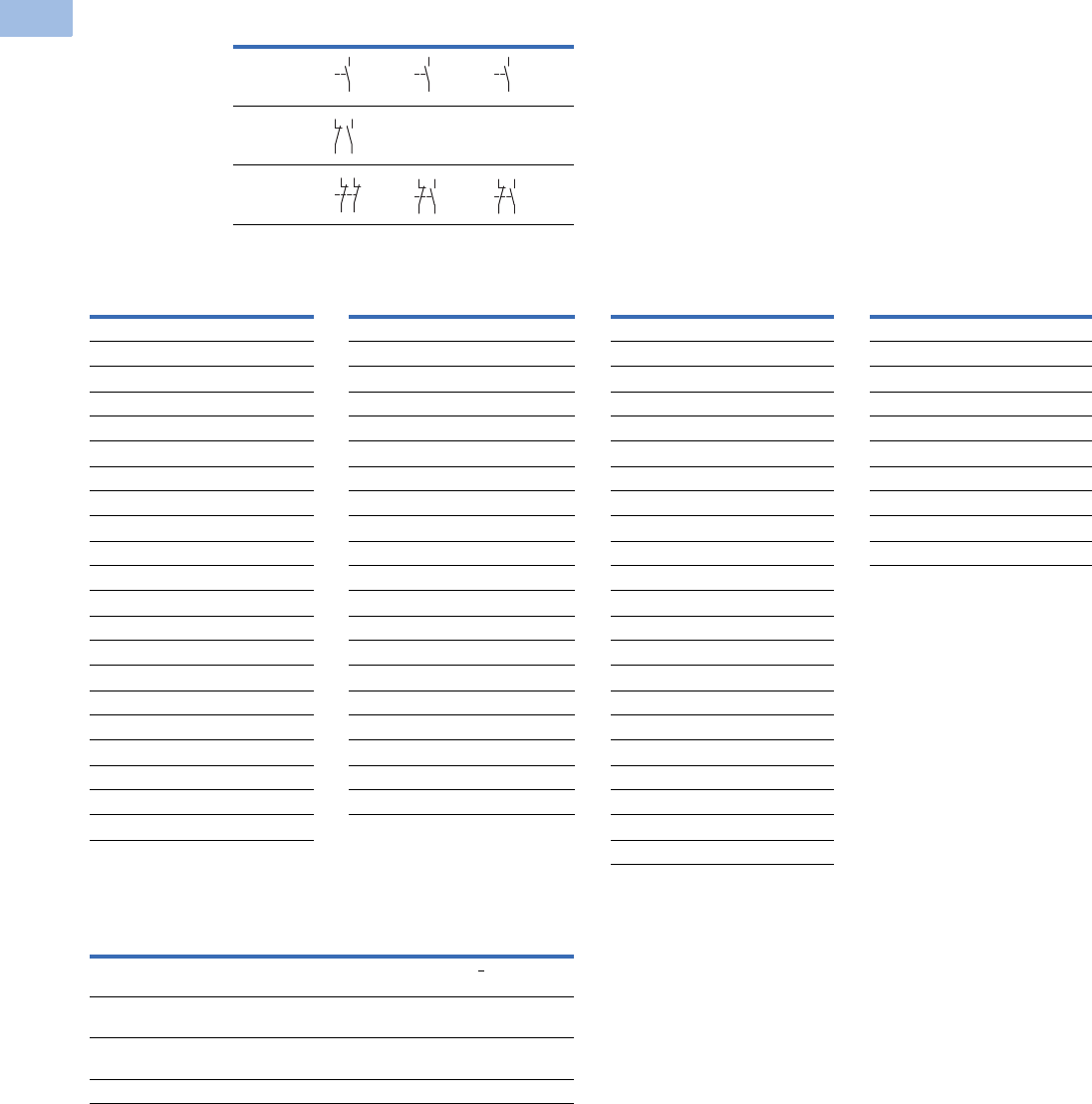
V5-T1-62 Volume 5—Motor Control and Protection CA08100006E—August 2012 www.eaton.com
1
1
1
1
1
1
1
1
1
1
1
1
1
1
1
1
1
1
1
1
1
1
1
1
1
1
1
1
1
1
1.1
IEC Contactors and Starters
XT
IEC Power Control
Spare Auxiliary Contacts
Magnet Coil Suffix
Overload Relay Settings (A)
Note
1Frames L–M only.
AC-3 K1M K3M K5M
12–55
90–260 — —
315–1700
Coil Voltage Suffix Code Coil Voltage Suffix Code Coil Voltage Suffix Code Coil Voltage Suffix Code
Frames A–B Frames C–F Frame G Frames L–N
110V 50 Hz, 120V 60 Hz A110V 50 Hz, 120V 60 Hz A100–120V 50/60 Hz A110–250 Vdc 40–60 Hz A
220V 50 Hz, 240V 60 Hz B220V 50 Hz, 240V 60 Hz B190–240V 50/60 Hz B250–500V 40–60 Hz C
230V 50 Hz F230V 50 Hz F24V 50/60 Hz T48–110 Vdc 40–60 Hz Y
24V 50/60 Hz T24V 50/60 Hz T24–27 Vdc TD 24–48 Vdc TD 1
24 Vdc TD 24–27 Vdc TD 480–500V 50/60 Hz CFrames L–M, S-Series
415V 50 Hz, 480V 60 Hz C415V 50 Hz, 480V 60 Hz C380–440V 50/60 Hz L110–120V 50/60 Hz A
550V 50 Hz, 600V 60 Hz D550V 50 Hz, 600V 60 Hz D42–48V 50/60 Hz W220–240V 50/60 Hz B
208V 60 Hz E208V 60 Hz E110–130 Vdc AD Frames P–R
190V 50 Hz, 220V 60 Hz G 190V 50 Hz, 220V 60 Hz G200–240 Vdc BD 230–250 Vdc 50–60 Hz B
240V 50 Hz, 277V 60 Hz H240V 50 Hz, 277V 60 Hz H48–60 Vdc WD
380V 50 Hz, 440V 60 Hz L380V 50 Hz, 440V 60 Hz LFrame H
400V 50 Hz N 400V 50 Hz N100–120V 50/60 Hz A
380V 60 Hz P380V 60 Hz P190–240V 50/60 Hz B
12V 50/60 Hz R 12V 50/60 Hz R480–500V 50/60 Hz C
42V 50 Hz, 48V 60 Hz W42V 50 Hz, 48V 60 Hz W380–440V 50/60 Hz L
48V 50 Hz Y48V 50 Hz Y24V 50/60Hz T
120 Vdc AD 110–130 Vdc AD 42–48V 50/60Hz W
220 Vdc BD 200–240 Vdc BD 110–130 Vdc AD
12 Vdc RD 48–60 Vdc WD 200–240 Vdc BD
48 Vdc WD 24–27 Vdc TD
48–60 Vdc WD
Setting Starting
A: IN x 0.58
Motor protection in the star (wye) and delta configurations
<
15 sec
B: IN x 1
Only partial motor protection in star position
15–40 sec
C: IN x 0.58
Motor not protected in star (wye) position
>40 sec
Timing relay set to approximately 10 sec
64
63
64
63
64
63
21
22
33
34
21
22
31
32
31
32
43
44
31
32
43
44
Courtesy of CMA/Flodyne/Hydradyne ▪ Motion Control ▪ Hydraulic ▪ Pneumatic ▪ Electrical ▪ Mechanical ▪ (800) 426-5480 ▪ www.cmafh.com
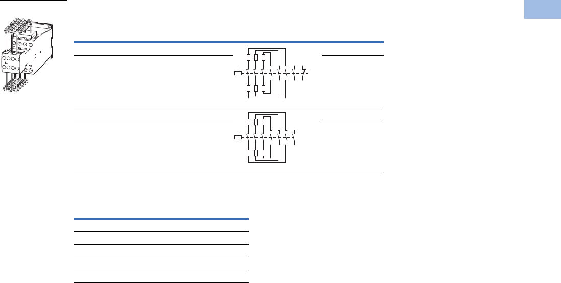
Volume 5—Motor Control and Protection CA08100006E—August 2012 www.eaton.com V5-T1-63
1
1
1
1
1
1
1
1
1
1
1
1
1
1
1
1
1
1
1
1
1
1
1
1
1
1
1
1
1
1
1.1
IEC Contactors and Starters
XT
IEC Power Control
XTCC Contactors for Three-Phase Capacitors
Magnet Coil Suffix
Notes
Weld-resistant for capacitors with inrush current peaks up to 180 x IN.
1 With series resistors, without quick-discharge resistor.
2 Underscore (_) indicates magnet coil suffix required.
Three-Phase Capacitors, 50–60 Hz
Open kVAR Ratings 1
Contact Sequence Catalog Number 2
230V 400V 525V 690V
11 20 25 33.3 XTCC020C11_
15 25 33.3 40 XTCC025C11_
20 33.3 40 55 XTCC033D10_
25 50 65 85 XTCC050D10_
Coil Voltage Suffix Code
110V 50 Hz, 120V 60 Hz A
220V 50 Hz, 240V 60 Hz B
230V 50 Hz, 240V 60 Hz F
400V 50 Hz, 440V 60 Hz N
24V 50/60 Hz T
XTCC0_
A1
A2
1
2
3
4
5
6
21
22
13
14
A1
A2
1
2
3
4
5
6
13
14
Courtesy of CMA/Flodyne/Hydradyne ▪ Motion Control ▪ Hydraulic ▪ Pneumatic ▪ Electrical ▪ Mechanical ▪ (800) 426-5480 ▪ www.cmafh.com

V5-T1-64 Volume 5—Motor Control and Protection CA08100006E—August 2012 www.eaton.com
1
1
1
1
1
1
1
1
1
1
1
1
1
1
1
1
1
1
1
1
1
1
1
1
1
1
1
1
1
1
1.1
IEC Contactors and Starters
XT
IEC Power Control
Engineering Notes for XTCC and XTCE Contactors for Power Factor Correction
Individual Compensation, Open Version Group Compensation, with Reactor, Open Version
Group Compensation, without Reactor, Open Version
Catalog
Number
Switching Duty in kVAR
230V 400V, 420V, 440V 525V 690V
XTCE007B 1.5 3 3.5 5
XTCE009B 24 4.56
XTCE012B 2.5 4.5 5.5 7
XTCE015B 2.5 4.5 5.5 7
XTCE018C 6.5 12 14.5 19
XTCE025C 713.5 1621
XTCE032C 7.5 14.5 17 22.5
XTCE040D 11 20.5 24.5 32
XTCE050D 11.5 22 26 34.5
XTCE065D 12.5 23.5 28 37
XTCE080F 16 30.5 36.5 48
XTCE095F 18 34 41 54
XTCE115G 24 46 54.5 72
XTCE150G 28 53 63.5 83.5
XTCE580N 175 300 400 300
Catalog
Number
Switching Duty in kVAR
230V 400V, 420V, 440V 525V 690V
XTCE007B 47 7.512
XTCE009B 5 8 10 14
XTCE012B 5.5 1 12 16
XTCE015B 5.5 10 12 16
XTCE018C 7.5 16 20 28
XTCE025C 918 2330
XTCE032C 10 20 24 32
XTCE040D 13 25 30 40
XTCE050D 16 30 36 48
XTCE065D 19 36 43 57
XTCE080F 30 58 68 90
XTCE095 34 6 7 10
XTCE115G 44 8 100 125
XTCE150 5 97 115 152
XTCE250L 110 190 260 340
XTCE400M 160 280 370 480
XTCE500M 220 390 500 680
Catalog
Number
Switching Duty in kVAR
230V 400V, 420V, 440V 525V 690V
XTCC020C 11 20 25 33.3
XTCC025C 15 25 33.3 40
XTCC033D 20 33.3 40 55
XTCC050D 25 50 65 85
XTCE580N 145 250 333 250
Courtesy of CMA/Flodyne/Hydradyne ▪ Motion Control ▪ Hydraulic ▪ Pneumatic ▪ Electrical ▪ Mechanical ▪ (800) 426-5480 ▪ www.cmafh.com
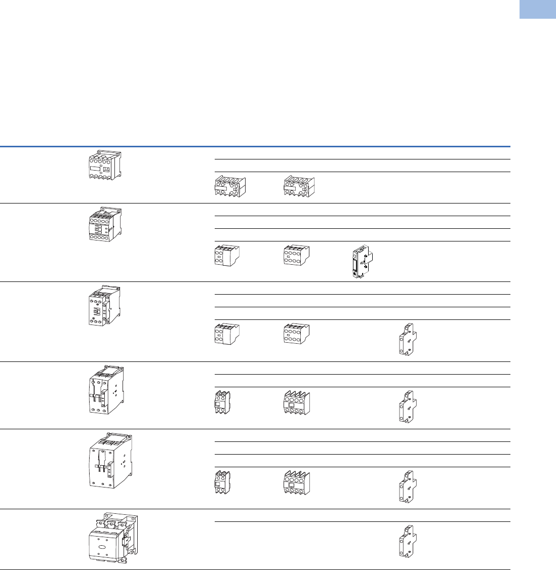
Volume 5—Motor Control and Protection CA08100006E—August 2012 www.eaton.com V5-T1-65
1
1
1
1
1
1
1
1
1
1
1
1
1
1
1
1
1
1
1
1
1
1
1
1
1
1
1
1
1
1
1.1
IEC Contactors and Starters
XT
IEC Power Control
Accessories
Auxiliary Contacts
Front-mounted snap-on
auxiliary contacts for XT
contactors are available
with screw or spring cage
terminals in a variety of
contact configurations.
Auxiliary Contacts Possible Combinations
Notes
Forced operation contact to IEC/EN 60947-5-1 Appendix L (positively driven), inside the auxiliary contact unit
(not early close and late opening).
Auxiliary normally closed contact can be used as mirror contact to IEC/EN 60947-4-1 Appendix F (not late opening).
No auxiliary contacts can be fitted between two contactors.
Frame
Size
Catalog
Number Contactor
Built-In
Auxiliary
Front (Top) Mount Side-Mount Total Auxiliary
Contacts AvailableTwo-Pole Four-Pole Single-Pole Two-Pole
AXTMC6A_ –
XTMC9A_
1NO or 1NC 1 — — — 3
—1 ——5
—— —
BXTCE007B_ –
XTCE015B_
1NO or 1NC 1 — — — 3
—1 ——5
——1—2
——
CXTCE018C_ –
XTCE032C_
1NO or 1NC 1 — — — 3
—1 ——5
———13
——
DXTCE040D00_ –
XTCE065D00_
—1 — — 2 6
—1 —16
——
F–G XTCE080F00_ –
XTCE150G00_
—1 — — 2 6
—1 —28
———48
——
L–R XTCE185H22_ –
XTCEC20R22_
2NO–2NC — — 2 8
—— —
Courtesy of CMA/Flodyne/Hydradyne ▪ Motion Control ▪ Hydraulic ▪ Pneumatic ▪ Electrical ▪ Mechanical ▪ (800) 426-5480 ▪ www.cmafh.com
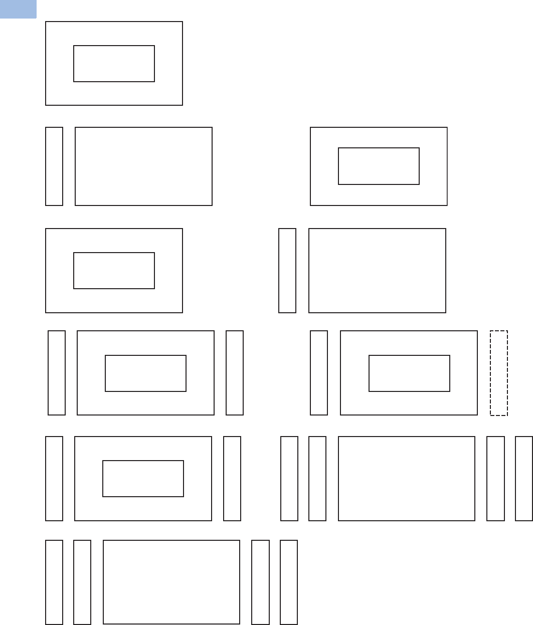
V5-T1-66 Volume 5—Motor Control and Protection CA08100006E—August 2012 www.eaton.com
1
1
1
1
1
1
1
1
1
1
1
1
1
1
1
1
1
1
1
1
1
1
1
1
1
1
1
1
1
1
1.1
IEC Contactors and Starters
XT
IEC Power Control
Auxiliary Contact Combinations
XTMC6A_–XTMC9A_
XTMCXF...A_
Two-Pole or Four-Pole
XTCE018C_–XTCE032C_
XTCEXSCC11
or +
XTCE007B_– XTCE032C_
XTCEXF...C_
Two-Pole or Four-Pole
XTCE040D_– XTCE065D_
XTCEXF...G_
Two-Pole
XTCEXSBN11
or +
XTCEXSBN11
+
XTCEXSBN11
+
XTCEXSBN11
+
XTCE040D_– XTCE065D_
XTCEXF...G_
Four-Pole
XTCE080F_–XTCE150G_
XTCEXF...G_
Two-Pole or Four-Pole XTCE080F_–XTCE150G_
XTCEXSBN11
XTCEXSBN11
XTCEXSCN11
or +
XTCEXSCN11
+
+
XTCEXSBN11
XTCEXSBN11
+
++
XTCE185H_–XTCEC20R_
XTCEXSBR11 (Built-In)
XTCEXSBR11 (Built-In)
XTCEXSCR11
+
XTCEXSCR11
+
++
Frames L–R
Frames F–G
Frame D
Frame C
Frame A
XTCE007B_–XTCE015B_
XTCEXSAB_
or+
XTCE007B_–XTCE015B_
XTCEXF...C_
Two-Pole or Four-Pole
Frame B
Not for use with mechanical interlock.
Courtesy of CMA/Flodyne/Hydradyne ▪ Motion Control ▪ Hydraulic ▪ Pneumatic ▪ Electrical ▪ Mechanical ▪ (800) 426-5480 ▪ www.cmafh.com

Volume 5—Motor Control and Protection CA08100006E—August 2012 www.eaton.com V5-T1-67
1
1
1
1
1
1
1
1
1
1
1
1
1
1
1
1
1
1
1
1
1
1
1
1
1
1
1
1
1
1
1.1
IEC Contactors and Starters
XT
IEC Power Control
Auxiliary Contacts
Frames B–C, Front (Top) Mount—Two-Pole
Frames B–C, Front (Top) Mount—Four-Pole
Notes
1 Orders must be placed in multiples of package quantity listed.
2 1 early-make contact (1NOE), 1 late-break contact (1NCL).
3 To avoid duplicate terminal numbers in contact sequence, these auxiliary contacts should only be used with contactors
having a built-in 1NO contact (XTCE…B10_, XTCE…C10_).
4 Catalog number is shown with screw type terminal. For spring cage, add a “C” before the last 2 digits. For example,
to order a spring cage version of the XTCEXFAC22, change the catalog number to XTCEXFACC22.
Conventional Thermal Current,
Open at 60°C
Ith = Ie, AC-1 in Amps
Contact
Configuration
Circuit
Symbol
Pkg.
Qty. 1
Screw Terminal
Catalog Number
16 2NO 5 XTCEXFAC20
16 1NO-1NC 5 XTCEXFAC11 4
16 2NC 5 XTCEXFAC02
16 1NOE-1NCL5XTCEXFALC11 2
16 1NO-1NC 5 XTCEXFDC11 3
16 2NC 5 XTCEXFCC02 3
Conventional Thermal Current,
Open at 60°C
Ith = Ie, AC-1 in Amps
Contact
Configuration
Circuit
Symbol
Pkg.
Qty. 1
Screw Terminal
Catalog Number
16 4NO 5 XTCEXFAC40 4
16 3NO-1NC 5 XTCEXFAC31 4
16 2NO-2NC 5 XTCEXFAC22 4
16 1NO-3NC 5 XTCEXFAC13
16 4NC 5 XTCEXFAC04
16 1NOE-1NCL5XTCEXFCLC22 2
16 2NO-2NC 5 XTCEXFCC22 3
XTCEXF_
54
63
64
53
54
53 61
62
51
52
61
62
58
57 6
5
66
21
22
31
32
XTCEXF_
54
63 73
64 74
53 83
8
4
54
53 61
62
73
74
83
84
54
53 61
62
71
72
83
84
53 61 71 81
82
72
62
54
51
52
61
62
71
72 82
81
58
5765
66
71
72
83
84
21
22
31
32
43
44
53
54
Courtesy of CMA/Flodyne/Hydradyne ▪ Motion Control ▪ Hydraulic ▪ Pneumatic ▪ Electrical ▪ Mechanical ▪ (800) 426-5480 ▪ www.cmafh.com
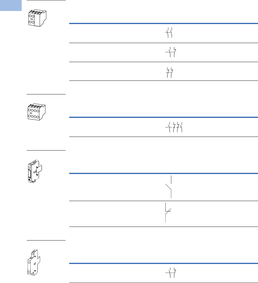
V5-T1-68 Volume 5—Motor Control and Protection CA08100006E—August 2012 www.eaton.com
1
1
1
1
1
1
1
1
1
1
1
1
1
1
1
1
1
1
1
1
1
1
1
1
1
1
1
1
1
1
1.1
IEC Contactors and Starters
XT
IEC Power Control
Frames B–C, Front (Top) Mount—Tall Version Two-Pole 1
Frames B–C, Front (Top) Mount—Tall Version Four-Pole 1
Frame B, Side-Mount—Single-Pole
Frame C, Side-Mount—Two-Pole
Notes
Interlocked opposing contacts, to IEC/EN 60947-5-1 Annex L (positively driven), within the auxiliary contact modules
(not NO [early make] and NC [late break] contacts) and for the built-in auxiliary contacts of the XTCE007B_–XTCE032C_.
Auxiliary break contact can be used as mirror contact to IEC/EN 60947-4-1 Annex F (not NC [late break] contact).
No auxiliary contacts can be fitted between two contactors.
1 Front (top) mount tall version is for use with Frame B electrical wire bridges and link kits (see Page V5-T1-74) and
toolless plug combination connection kits: XTCEXRLB, XTCEXSDLB, XTPAXTPCB, XTPAXTPCRB, XTPAX.
2 Orders must be placed in multiples of package quantity listed.
3 Can be mounted to the left side of contactor only. Cannot be used in combination with front (top) mount auxiliary
contacts or mechanical interlocks.
Conventional Thermal Current,
Open at 60°C
Ith = Ie, AC-1 in Amps
Contact
Configuration
Circuit
Symbol
Pkg.
Qty. 2
Screw Terminal
Catalog Number
16 2NO 5 XTCEXFATC20
16 1NO-1NC 5 XTCEXFATC11
16 2NC 5 XTCEXFATC02
Conventional Thermal Current,
Open at 60°C
Ith = Ie, AC-1 in Amps
Contact
Configuration
Circuit
Symbol
Pkg.
Qty. 2
Screw Terminal
Catalog Number
16 2NO-2NC 5 XTCEXFATC22
Conventional Thermal Current,
Open at 60°C
Ith = Ie, AC-1 in Amps
Contact
Configuration
Circuit
Symbol
Pkg.
Qty. 2
Screw Terminal
Catalog Number
16 1NO 1 XTCEXSAB10 3
16 1NC 1 XTCEXSAB01 3
Conventional Thermal Current,
Open at 60°C
Ith = Ie, AC-1 in Amps
Contact
Configuration
Circuit
Symbol
Pkg.
Qty. 2
Screw Terminal
Catalog Number
10 1NO-1NC 1 XTCEXSCC11 3
XTCEXFATC_
54
63
64
53
54
53 61
62
51
52
61
62
XTCEXFATC22
54
53 61
62
71
72
83
8
4
XTCEXSAB_
53
54
51
52
XTCEXSCC11
54
53 61
62
Courtesy of CMA/Flodyne/Hydradyne ▪ Motion Control ▪ Hydraulic ▪ Pneumatic ▪ Electrical ▪ Mechanical ▪ (800) 426-5480 ▪ www.cmafh.com
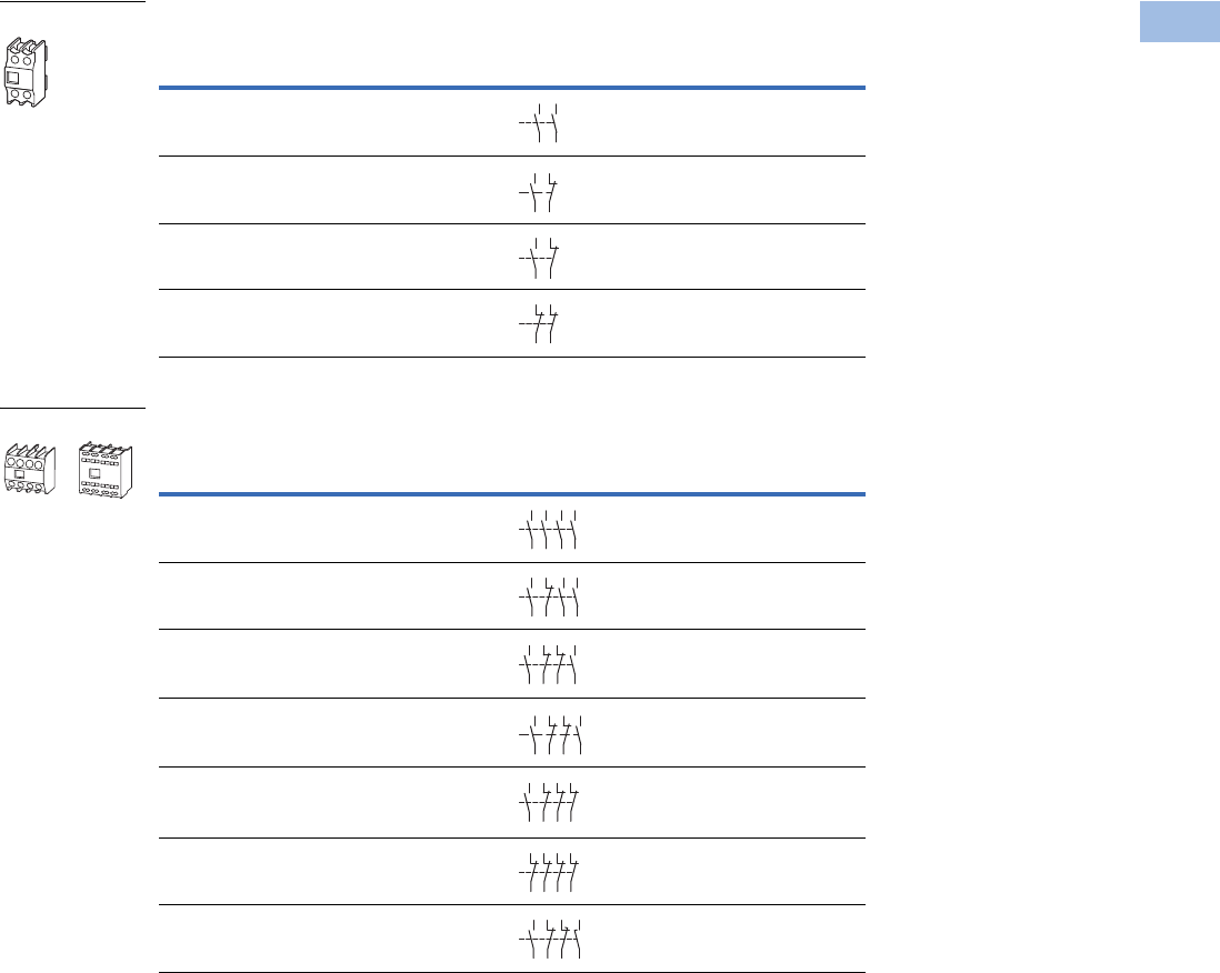
Volume 5—Motor Control and Protection CA08100006E—August 2012 www.eaton.com V5-T1-69
1
1
1
1
1
1
1
1
1
1
1
1
1
1
1
1
1
1
1
1
1
1
1
1
1
1
1
1
1
1
1.1
IEC Contactors and Starters
XT
IEC Power Control
Frames D–G—Two-Pole
Frames D–G—Four-Pole
Notes
Interlocked opposing contacts, to IEC/EN 60947-5-1 Annex L (positively driven), within the auxiliary contact modules
(not NO (early make) and NC (late break) contacts) and for the built-in auxiliary contacts of the XTCE007B_–XTCE032C_.
Auxiliary break contact can be used as mirror contact to IEC/EN 60947-4-1 Annex F (not NC (late break) contact).
No auxiliary contacts can be fitted between two contactors.
1 Orders must be placed in multiples of package quantity listed.
2 A “_” denotes catalog numbers are incomplete. To complete the catalog number for ordering a spring cage terminal,
insert a C in the “_” position or remove “_” for screw type terminal.
3 One early-make contact (1NOE), one late-break contact (1NCL).
Conventional Thermal Current,
Open at 60°C
Ith = Ie, AC-1 in Amps
Contact
Configuration
Circuit
Symbol
Pkg.
Qty. 1
Screw Terminal
Catalog Number
16 2NO 5 XTCEXFBG20
16 1NO-1NC 5 XTCEXFAG11
16 1NO-1NC 5 XTCEXFBG11
16 2NC 5 XTCEXFBG02
Conventional Thermal Current,
Open at 60°C
Ith = Ie, AC-1 in Amps
Contact
Configuration
Circuit
Symbol
Pkg.
Qty. 1
Screw Terminal
Catalog Number
16 4NO-0NC 5 XTCEXFBG40
16 3NO-1NC 5 XTCEXFBG31
16 2NO-2NC 5 XTCEXFBG22
16 2NO-2NC 5 XTCEXFAG_22 2
16 1NO-3NC 5 XTCEXFBG13
16 0NO-4NC 5 XTCEXFBG04
16 1NOE-1NCL5XTCEXFBLG22 3
XTCEXF_
14 24
13 23
54
53 61
62
14
13 21
22
12
11 21
22
XTCEXF_
14
13 23
24
33
34
43
44
14
13 21
22
33
34
43
44
14
13 21
22
31
32
43
4
4
54
53 61
62
71
72
8
3
84
14
13 21
22
31
32
41
42
12
11 21
22
31
32
41
42
14
13 21
22
35
36
47
48
Courtesy of CMA/Flodyne/Hydradyne ▪ Motion Control ▪ Hydraulic ▪ Pneumatic ▪ Electrical ▪ Mechanical ▪ (800) 426-5480 ▪ www.cmafh.com
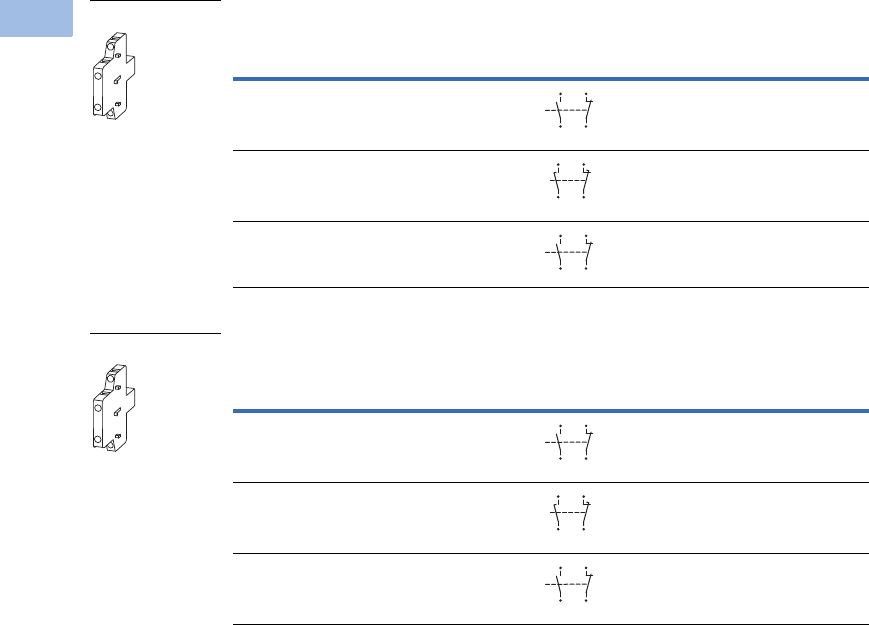
V5-T1-70 Volume 5—Motor Control and Protection CA08100006E—August 2012 www.eaton.com
1
1
1
1
1
1
1
1
1
1
1
1
1
1
1
1
1
1
1
1
1
1
1
1
1
1
1
1
1
1
1.1
IEC Contactors and Starters
XT
IEC Power Control
Frames D–G, 40–170A Side Mount (Snap-On)—Two-Pole
Frames H–R, 40–2000A Side Mount (Screw Mount)—Two-Pole
Notes
1 Orders must be placed in multiples of package quantity listed.
2 1 early-make contact (1NOE), 1 late-break contact (1NCL).
3 To avoid duplicate terminal numbers in contact sequence, the XTCEXSCN11 should be used with Frame D
when a top mount auxiliary is also installed.
4 For replacement only. XTCEXSBR11 and XTCEXSBLR11 cannot be added onto side mount auxiliaries that come with
the Frames L–R contactors as standard. To add auxiliaries onto the included side auxiliaries on Frames L–R
contactors, use XTCEXSCR11.
Conventional Free Air
Thermal Current,
Ith = Ie, AC-1 in Amps
Contact
Configuration
Circuit
Symbol
Pkg.
Qty. 1
Screw Terminal
Catalog Number
10 1NO–1NC 1 XTCEXSBN11
10 1NOE–1NCL1XTCEXSBLN11 2
10 1NO–1NC 1 XTCEXSCN11 3
Conventional Free Air
Thermal Current,
Ith = Ie, AC-1 in Amps
Contact
Configuration
Circuit
Symbol
Pkg.
Qty. 1
Screw Terminal
Catalog Number
10 1NO–1NC 1 XTCEXSBR11 4
10 1NOE–1NCL1XTCEXSBLR11
10 1NO–1NC 1 XTCEXSCR11
XTCEXS_
13
44
14
43
21
32
31
22
17
48
18
47
25
36
26
35
53
84
54
83
61
72
71
62
XTCEXS_
13
44
14
43
21
32
31
22
17
48
18
47
25
36
26
35
53
84
54
83
61
72
71
62
Courtesy of CMA/Flodyne/Hydradyne ▪ Motion Control ▪ Hydraulic ▪ Pneumatic ▪ Electrical ▪ Mechanical ▪ (800) 426-5480 ▪ www.cmafh.com
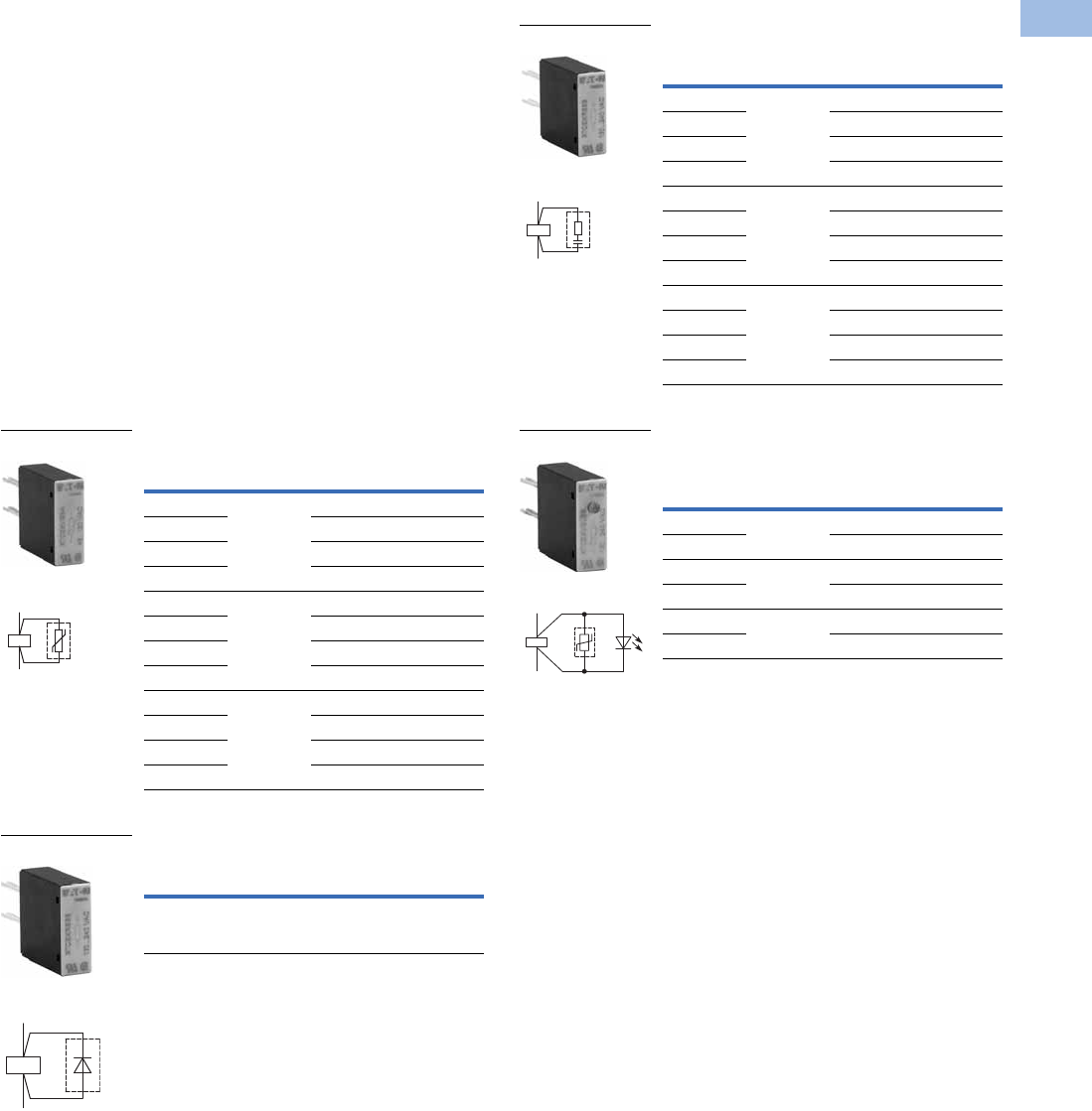
Volume 5—Motor Control and Protection CA08100006E—August 2012 www.eaton.com V5-T1-71
1
1
1
1
1
1
1
1
1
1
1
1
1
1
1
1
1
1
1
1
1
1
1
1
1
1
1
1
1
1
1.1
IEC Contactors and Starters
XT
IEC Power Control
Suppressors
The switching of contactor
coils can generate voltage
transients that may cause
arching on switch contacts
and/or damage electronics on
the control line. Either an RC
or varistor suppressor is
recommended in these types
of applications. All XT DC
contactor coils have built-in
suppression.
Varistor suppressors clamp
the voltage transient above
the maximum coil voltage and
are recommended when the
level of the transient is
known to not exceed the coil
voltage. RC suppressors slow
and reduce the level of the
voltage transient but do not
clamp them at a specific
level. The slowing of the
transient can reduce
electrical interference.
These are recommended in
applications where operating
rates are high.
Varistor Suppressor 12
Free-Wheel Diode Suppressor 4
Voltage
For Use
with…
Pkg.
Qty. 3Catalog Number
24–48 XTCE007B–
XTCE015B,
XTCF020B
10 XTCEXVSBW
48–130 10 XTCEXVSBA
130–240 10 XTCEXVSBB
240–500 10 XTCEXVSBC
24–48 XTCE018C–
XTCE032C
10 XTCEXVSCW
48–130 10 XTCEXVSCA
130–240 10 XTCEXVSCB
240–500 10 XTCEXVSCC
24–48 XTCE040D–
XTCE095F
10 XTCEXVSFW
48–130 10 XTCEXVSFA
130–240 10 XTCEXVSFB
240–500 10 XTCEXVSFC
Voltage
DC
For Use
with…
Pkg.
Qty. 3Catalog Number
12–250 XTCE007B–
XTCE015B,
XTCF020B
10 XTCEXDSB
XTCEXVS_
Contact Sequence
A2
A1
XTCEXDSB
Contact Sequence
A1
A2
RC Suppressor 12
Varistor Suppressor with
Integrated LED 12
Notes
1Note dropout delay.
2For AC operated contactors, 50–60 Hz. DC operated contactors and XTCE115G_
to XTCE170G_ have a built-in suppressor circuit.
3Orders must be placed in multiples of package quantity listed.
4In addition to the built-in suppressor circuit for DC actuated contactors. Prevents
negative breaking voltage when contactors are used in combination with a safety PLC.
Voltage
For Use
with…
Pkg.
Qty. 3Catalog Number
24–48 XTCE007B–
XTCE015B,
XTCF020B
10 XTCEXRSBW
48–130 10 XTCEXRSBA
110–240 10 XTCEXRSBB
240–500 10 XTCEXRSBC
24–48 XTCE018C–
XTCE032C
10 XTCEXRSCW
110–130 10 XTCEXRSCA
130–240 10 XTCEXRSCB
240–500 10 XTCEXRSCC
24–48
XTCE040D–
XTCE095F
10 XTCEXRSFW
110–130
10 XTCEXRSFA
130–240
10 XTCEXRSFB
240–500
10 XTCEXRSFC
Voltage
AC
For Use
with…
Pkg.
Qty. 3Catalog Number
24–48 XTCE007B–
XTCE015B
10 XTCEXVSLBW
130–240 10 XTCEXVSLBB
24–48 XTCE018C–
XTCE032C
10 XTCEXVSLCW
130–240 10 XTCEXVSLCB
24–48 XTCE040D–
XTCE095F
10 XTCEXVSLFW
130–240 10 XTCEXVSLFB
XTCEXRS_
Contact Sequence
A1
A2
XTCEXVSL_
Contact Sequence
A1
A2
Courtesy of CMA/Flodyne/Hydradyne ▪ Motion Control ▪ Hydraulic ▪ Pneumatic ▪ Electrical ▪ Mechanical ▪ (800) 426-5480 ▪ www.cmafh.com
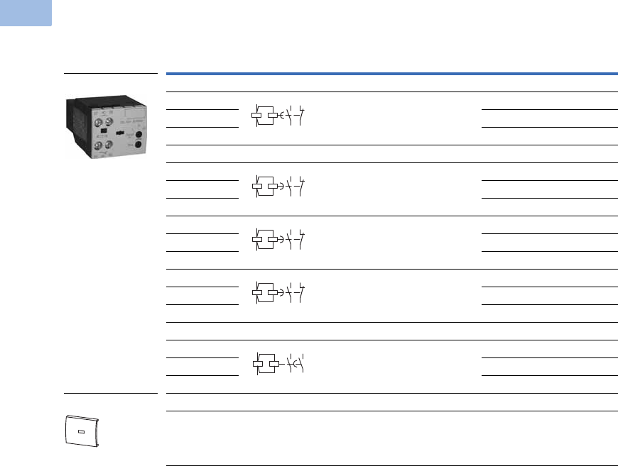
V5-T1-72 Volume 5—Motor Control and Protection CA08100006E—August 2012 www.eaton.com
1
1
1
1
1
1
1
1
1
1
1
1
1
1
1
1
1
1
1
1
1
1
1
1
1
1
1
1
1
1
1.1
IEC Contactors and Starters
XT
IEC Power Control
Electronic Timer Modules
Frames B–C Contactors (7–32A) 1
Notes
1 Front (top) mounted timer modules for use with XTCE…B and XTCE…C contactors.
Cannot be combined with top-mount auxiliary contacts, XTCEXF…C_.
2 Orders must be placed in multiples of package quantity listed.
Voltage
Contact
Sequence
Timing
Range
For Use
with…
Pkg.
Qty. 2Catalog Number
On-Delay
24 Vac/Vdc 0.05s–1s
0.5s–10s
5s–100s
XTCE…B_
XTCE…C_
1XTCEXTEEC11T
100–130 Vac 1 XTCEXTEEC11A
200–240 Vac 1 XTCEXTEEC11B
Off-Delay
24 Vac/Vdc 0.05s–1s XTCE…B_
XTCE…C_
1XTCEXTED1C11T
100–130 Vac 1 XTCEXTED1C11A
200–230 Vac 1 XTCEXTED1C11B
24 Vac/Vdc 0.5s–10s XTCE…B_
XTCE…C_
1XTCEXTED10C11T
100–130 Vac 1 XTCEXTED10C11A
200–240 Vac 1 XTCEXTED10C11B
24 Vac/Vdc 5s–100s XTCE…B_
XTCE…C_
1XTCEXTED100C11T
100–130 Vac 1 XTCEXTED100C11A
200–240 Vac 1 XTCEXTED100C11B
Star-Delta
24 Vac/Vdc 1s–30s XTCE…B_
XTCE…C_
1XTCEXTEYC20T
100–130 Vac 1 XTCEXTEYC20A
200–240 Vac 1 XTCEXTEYC20B
Sealable Shroud
— Transparent sealable shroud used to
protect electronic timer modules from
unwanted access
XTCEXTEE,
XTCEXTED,
XTCEXTEY
1XTCEXTESHRD
XTCEXTE_
XTCEXTESHRD
57
58
65
66
A1
A2
57
58
65
66
A1
A2
57
58
65
66
A1
A2
57
58
65
66
A1
A2
57
58
67
68
A1
A2
Courtesy of CMA/Flodyne/Hydradyne ▪ Motion Control ▪ Hydraulic ▪ Pneumatic ▪ Electrical ▪ Mechanical ▪ (800) 426-5480 ▪ www.cmafh.com
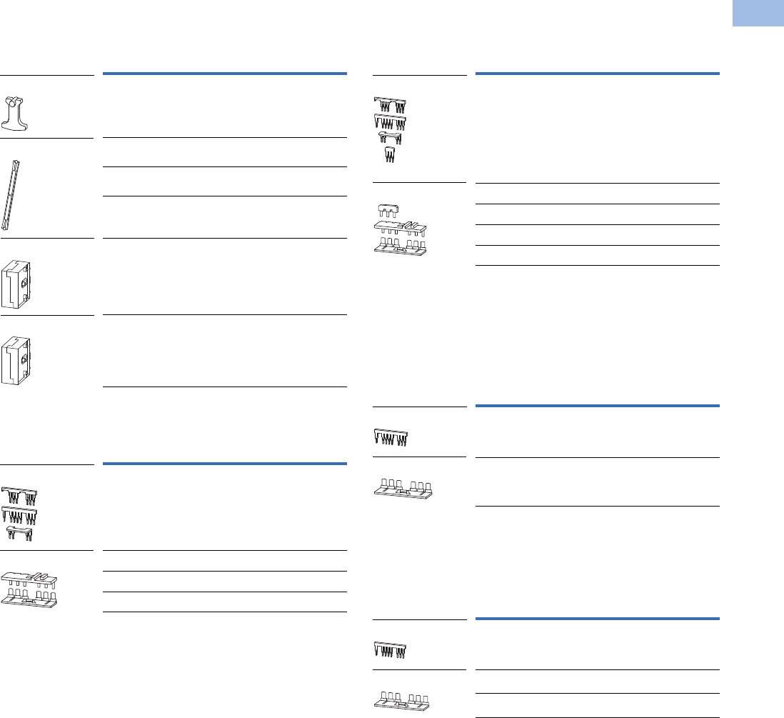
Volume 5—Motor Control and Protection CA08100006E—August 2012 www.eaton.com V5-T1-73
1
1
1
1
1
1
1
1
1
1
1
1
1
1
1
1
1
1
1
1
1
1
1
1
1
1
1
1
1
1
1.1
IEC Contactors and Starters
XT
IEC Power Control
Additional Accessories
Mechanical Interlock 1
Reversing Link Kits
Main current wiring for reversing combinations. Includes
paralleling bridge and reversing bridge. Does not include
mechanical interlock, see table on this page.
Star-Delta (Wye-Delta) Link Kits
Main current wiring for star-delta (wye-delta) combinations.
includes paralleling bridge, reversing bridge and star-delta
bridge. Does not include mechanical interlock, see table on
this page.
Paralleling Bridge
Component part of reversing link kit (XTCEXRL_). Parallels the
phases on the line-side of two contactors.
Reversing Bridge
Component part of reversing link kit (XTCEXRL_). Reverses the
phases on the load-side of two contactors.
Notes
1For two contactors with AC or DC operated magnet system which are horizontally or vertically mounted. For Frames B–G, mechanical lifespan is 2.5 x 10⁶ operations
and the distance between contactors is 0 mm. For Frames L–N, mechanical lifespan is 5 x 10⁶ operations and no auxiliary contact can be mounted between the
mechanical interlock and the contactor—the distance between contactors is 15 mm.
2Orders must be placed in multiples of package quantity listed.
3XTCEXMLG and XTCEXMLN consist of an interlock element and mounting plate.
4Also includes interlocking bridge (XTCEXLBB). The following control cables are integrated
for electrical interlock: K1M: A1–K2M: 21; K1M: 21–K2M: A1; K1M: A2–K2M: A2.
For Use
with…
Pkg.
Qty. 2Catalog Number
XTCE007B–XTCE015B,
XTCF020B
5XTCEXMLB
XTCE018C–XTCE032C,
XTCF032C–XTCF045C
1XTCEXMLC
XTCE040D–XTCE072D,
XTCF063D–XTCF080D
1XTCEXMLD
XTCE080F–XTCE170G,
XTCF125G–XTCF200G
1XTCEXMLG 3
XTCE185H–XTCE570M 1 XTCEXMLM
XTCE580N–XTCEC10N 1 XTCEXMLN 3
For Use
with…
Pkg.
Qty. 2Catalog Number
XTCE007B–XTCE015B 1 XTCEXRLB 4
XTCE018C–XTCE032C 1 XTCEXRLC
XTCE040D–XTCE065D 1 XTCEXRLD
XTCE080F–XTCE150G 1 XTCEXRLG
XTCEXMLB
XTCEXML_
XTCEXMLM
XTCEXMLN
XTCEXRLB
XTCEXRL_
For Use
with…
Pkg.
Qty. 2Catalog Number
XTCE007B–XTCE015B 1 XTCEXSDLB 3
XTCE018C–XTCE032C 1 XTCEXSDLC
XTCE040D–XTCE065D 1 XTCEXSDLD
XTCE080F–XTCE095F 1 XTCEXSDLF
XTCE115G–XTCE150G 1 XTCEXSDLG
For Use
with…
Pkg.
Qty. 2Catalog Number
XTCE007B–XTCE015B 20 XTCEXPBB
XTCE018C–XTCE032C 20 XTCEXPBC
For Use
with…
Pkg.
Qty. 2Catalog Number
XTCE007B–XTCE015B 20 XTCEXRBB
XTCE018C–XTCE032C 20 XTCEXRBC
XTCE040D–XTCE065D 10 XTCEXRBD
XTCEXSDLB
XTCEXSDL_
XTCEXPBB
XTCEXPBC
XTCEXRBB
XTCEXRB_
Courtesy of CMA/Flodyne/Hydradyne ▪ Motion Control ▪ Hydraulic ▪ Pneumatic ▪ Electrical ▪ Mechanical ▪ (800) 426-5480 ▪ www.cmafh.com
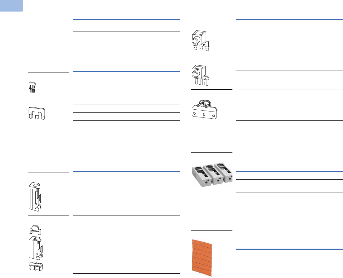
V5-T1-74 Volume 5—Motor Control and Protection CA08100006E—August 2012 www.eaton.com
1
1
1
1
1
1
1
1
1
1
1
1
1
1
1
1
1
1
1
1
1
1
1
1
1
1
1
1
1
1
1.1
IEC Contactors and Starters
XT
IEC Power Control
Electrical Interlocking Bridge
Star-Delta (Wye-Delta) Bridge
Component part of star-delta link kit (XTCEXSDL_). Commons
the three phases on the line side of shorting contactor.
Connector
Parallel Link 456
For using one contactor per phase. Each package comes with
two links for line: load.
Terminal Lug Assembly
For connection of: round conductor, flexible and stranded,
flat strip conductor, with control circuit terminal. See Page
V5-T1-97 for terminal capacities.
Contactor Labels
Notes
1Orders must be placed in multiples of package quantity listed.
2Frame B is toolless connection type.
3For mechanically arranging contactors in combinations. Distance between contactors is 0 mm.
4Fourth pole can be broken off: four-pole: Ith = 60A; three-pole: Ith = 50A.
5AC-1 current carrying capacity of the contactor increases by a factor of 2.5. For XTCEXPLKL185, one shroud
is included for protection against accidental contact.
6Protected against accidental contact in accordance with IEC 536.
7Quantity 1 equals one sheet. One sheet contains 240 labels.
For Use
with…
Pkg.
Qty. 1Catalog Number
XTCE007B–XTCE015B 20 XTCEXLBB
For Use
with…
Pkg.
Qty. 1Catalog Number
XTCE007B–XTCE015B 20 XTCEXSDBB 2
XTCE080F–XTCE170G 1 XTCEXSDBG
XTCE185L–XTCE400M 1 XTCEXSDB400
XTCE500M 1 XTCEXSDB500
For Use
with…
Pkg.
Qty. 1Catalog Number
XTCE007B–XTCE032C 50 XTCEXCNC
XTCE040D–XTCE170G 10 XTCEXCNG
XTCEXSDB
XTCEXSDB_
XTCEXCNC
XTCEXCNG
For Use
with…
Pkg.
Qty. 1Catalog Number
XTCE007B –XTCE015B 5 XTCEXPLKB
XTCE018C –XTCE032C 5 XTCEXPLKC
XTCE040D –XTCE072D 1 XTCEXPLKD
XTCE080F–XTCE170G 1 XTCEXPLKG
XTCE185L 1 XTCEXPLKL185
For Use
with…
Pkg.
Qty. 1Catalog Number
XTCE185–XTCE225H 1 XTCEXTLA225A
XTCS250L–XTCS400M,
XTCE250L_–XTCE400M_
2XTCEXTLA400
For Use
with…
Pkg.
Qty. Catalog Number
XTC… 25 XGKE-GE 7
XTCEXPLKB
XTCEXPLK_
XTCEXPLKL185
XTCEXTLA400
XGKE-GE
Courtesy of CMA/Flodyne/Hydradyne ▪ Motion Control ▪ Hydraulic ▪ Pneumatic ▪ Electrical ▪ Mechanical ▪ (800) 426-5480 ▪ www.cmafh.com
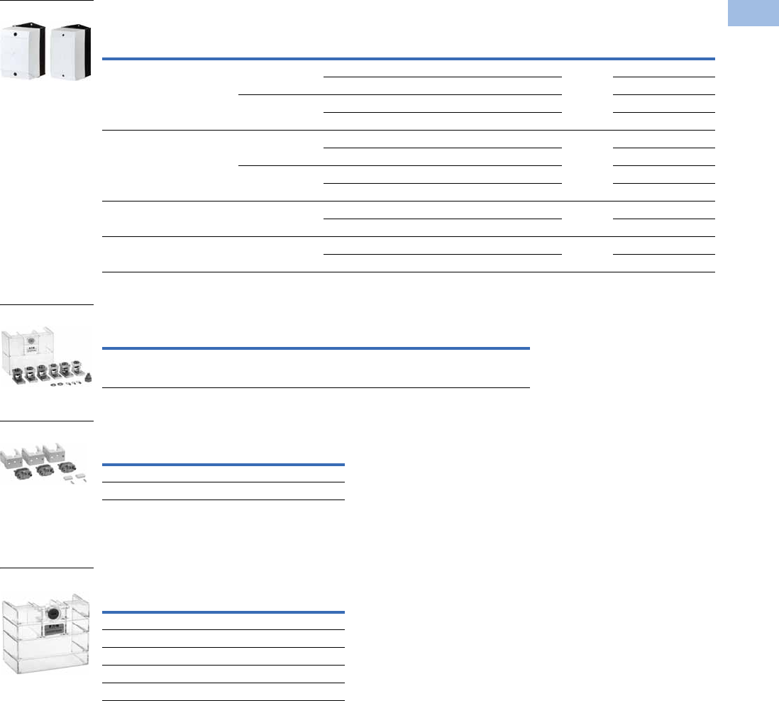
Volume 5—Motor Control and Protection CA08100006E—August 2012 www.eaton.com V5-T1-75
1
1
1
1
1
1
1
1
1
1
1
1
1
1
1
1
1
1
1
1
1
1
1
1
1
1
1
1
1
1
1.1
IEC Contactors and Starters
XT
IEC Power Control
CI-K Basic Enclosures 12
Terminal Lug Kit—Set of Three Lugs
Terminal Flat Bar 6
For connection of a flat strip conductor. Comes with control
circuit terminal (consisting of three flat strip conductor terminals).
Te rm i n a l S h ro u d
Protection against direct contact with connection lugs when
touched vertically from the front.
Notes
1Enclosure base RAL 9005, black/enclosure top only RAL 7035. light gray.
2Degree of protection—IEC: IP65; UL/CSA: Type 1, 3R, 4X, 12, 13—indoor and outdoor use.
3CI-K2X_: 4 x 1/2 inch knockouts.
4CI-K3X_, CI-K4X_, CI-K5X_: Smooth overall with sharp corners.
5Orders must be placed in multiples of package quantity listed.
6Not UL listed.
Dimensions in Inches (mm)
Pkg.
Qty. Width Height
External
Depth
Internal
Depth Internal Mounting Type Catalog Number
3.94 (100.0) 6.30 (160.0) 3.94 (100.0) 2.87 (73.0) With mounting rail 1 CI-K2X-100-TS-NA 3
3.11 (79.0) With mounting plate CI-K2X-100-M-NA 3
5.71 (145.0) 4.65 (118.0) With mounting rail CI-K2X-145-TS-NA 3
4.88 (124.0) With mounting plate CI-K2X-145-M-NA 3
4.72 (120.0) 7.87 (200.0) 4.92 (125.0) 3.66 (93.0) With mounting rail 1 CI-K3X-125-TS-NA 4
3.86 (98.0) With mounting plate CI-K3X-125-M-NA 4
6.30 (160.0) 5.04 (128.0) With mounting rail CI-K3X-160-TS-NA 4
5.24 (133.0) With mounting plate CI-K3X-160-M-NA 4
6.30 (160.0) 9.45 (240.0) 6.30 (160.0) 5.04 (128.0) With mounting rail 1 CI-K4X-160-TS-NA 4
5.24 (133.0) With mounting plate CI-K4X-160-M-NA 4
7.87 (200.0) 11.02 (280.0) 6.30 (160.0) 5.04 (128.0) With mounting rail 1 CI-K5X-160-TS-NA 4
5.24 (133.0) With mounting plate CI-K5X-160-M-NA 4
For Use
with… Description
Pkg.
Qty. 5Catalog Number
XTCE500M, XTCE570M #4-500 kcmil two-phase Cu/Al 500A 1 XTCEXTL500
For Use
with…
Pkg.
Qty. 5Catalog Number
XTCE500M–XTCE570M 1 XTCEXTFB650
XTCE750N–XTCE820N 1 XTCEXTFB820
For Use
with…
Pkg.
Qty. 5Catalog Number
XTCE185H–XTCE225H 1 XTCEXTS225
XTCE250L–XTCE400M 1 XTCEXTS400
XTCE500M–XTCE570M 1 XTCEXTS500
XTCE580N–XTCE650N 1 XTCEXTS650
XTCE750N–XTCEC10N 1 XTCEXTS820
CI-K Basic Enclosures
XTCEXCN_
XTCEXTFB6_
XTCEXTS_
Courtesy of CMA/Flodyne/Hydradyne ▪ Motion Control ▪ Hydraulic ▪ Pneumatic ▪ Electrical ▪ Mechanical ▪ (800) 426-5480 ▪ www.cmafh.com
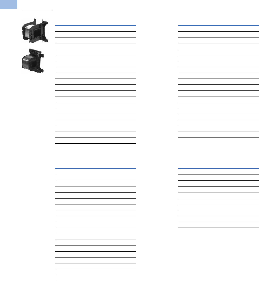
V5-T1-76 Volume 5—Motor Control and Protection CA08100006E—August 2012 www.eaton.com
1
1
1
1
1
1
1
1
1
1
1
1
1
1
1
1
1
1
1
1
1
1
1
1
1
1
1
1
1
1
1.1
IEC Contactors and Starters
XT
IEC Power Control
Renewal Parts
Replacement Coil—Frame C
Replacement Coil—Frame D
Replacement Coil—Frame F 1
Replacement Coil—Frame G 2
Notes
1Frame F replacement coils can only be used with contactors having the
following date codes:
DC coils, 2706 or later; AC coils, 4706 or later.
2Frame G replacement coils can only be used with contactors having date codes of 2706 or
later.
Voltage
Coil
Suffix Catalog Number
110/50 120/60 A XTCERENCOILCA
110–130 Vdc AD XTCERENCOILCAD
220/50 240/60 B XTCERENCOILCB
200–240 Vdc BD XTCERENCOILCBD
415/50 480/60 C XTCERENCOILCC
550/50 600/60 D XTCERENCOILCD
208/60 E XTCERENCOILCE
230/50 F XTCERENCOILCF
190/50 220/60 G XTCERENCOILCG
240/50 277/60 H XTCERENCOILCH
380/50 440/60 L XTCERENCOILCL
400/50 N XTCERENCOILCN
380/60 P XTCERENCOILCP
12/50 12/60 R XTCERENCOILCR
12–14 Vdc RD XTCERENCOILCRD
24/50 24/60 T XTCERENCOILCT
24–27 Vdc TD XTCERENCOILCTD
42/50 48/60 W XTCERENCOILCW
48–60 Vdc WD XTCERENCOILCWD
48/50 Y XTCERENCOILCY
Voltage
Coil
Suffix Catalog Number
110/50 120/60 A XTCERENCOILDA
110–130 Vdc AD XTCERENCOILDAD
220/50 240/60 B XTCERENCOILDB
200–240 Vdc BD XTCERENCOILDBD
415/50 480/60 C XTCERENCOILDC
550/50 600/60 D XTCERENCOILDD
208/60 E XTCERENCOILDE
230/50 F XTCERENCOILDF
190/50 220/60 G XTCERENCOILDG
240/50 277/60 H XTCERENCOILDH
380/50 440/60 L XTCERENCOILDL
400/50 N XTCERENCOILDN
380/60 P XTCERENCOILDP
12/50 12/60 R XTCERENCOILDR
12–14 Vdc RD XTCERENCOILDRD
24/50 24/60 T XTCERENCOILDT
24–27 Vdc TD XTCERENCOILDTD
42/50 48/60 W XTCERENCOILDW
48–60 Vdc WD XTCERENCOILDWD
48/50 Y XTCERENCOILDY
XTCERENC_
Voltage
Coil
Suffix Catalog Number
110/50 120/60 A XTCERENCOILFA
110–130 Vdc AD XTCERENCOILFAD
220/50 240/60 B XTCERENCOILFB
200–240 Vdc BD XTCERENCOILFBD
415/50 480/60 C XTCERENCOILFC
550/50 600/60 D XTCERENCOILFD
208/60 E XTCERENCOILFE
230/50 F XTCERENCOILFF
190/50 220/60 G XTCERENCOILFG
240/50 277/60 H XTCERENCOILFH
380/50 440/60 L XTCERENCOILFL
400/50 N XTCERENCOILFN
380/60 P XTCERENCOILFP
12/50 12/60 R XTCERENCOILFR
24/50 24/60 T XTCERENCOILFT
24–27 Vdc TD XTCERENCOILFTD
42/50 48/60 W XTCERENCOILFW
48–60 Vdc WD XTCERENCOILFWD
48/50 Y XTCERENCOILFY
Voltage
Coil
Suffix Catalog Number
100–120V 50/60 A XTCERENCOILGA
110–130 Vdc AD XTCERENCOILGAD
190–240V 50/60 B XTCERENCOILGB
200–240 Vdc BD XTCERENCOILGBD
480–500V 50/60 C XTCERENCOILGC
380–440V 50/60 L XTCERENCOILGL
4/50 24/60 T XTCERENCOILGT
24–27 Vdc TD XTCERENCOILGTD
42–48V 50/60 W XTCERENCOILGW
48–60 Vdc WD XTCERENCOILGWD
Courtesy of CMA/Flodyne/Hydradyne ▪ Motion Control ▪ Hydraulic ▪ Pneumatic ▪ Electrical ▪ Mechanical ▪ (800) 426-5480 ▪ www.cmafh.com

Volume 5—Motor Control and Protection CA08100006E—August 2012 www.eaton.com V5-T1-77
1
1
1
1
1
1
1
1
1
1
1
1
1
1
1
1
1
1
1
1
1
1
1
1
1
1
1
1
1
1
1.1
IEC Contactors and Starters
XT
IEC Power Control
Replacement Coil—Frame H
Replacement Coil—Frame L 1
Replacement Coil—Frame L, S-Series
Replacement Coil—Frame M 1
Replacement Coil—Frame M, S-Series
Replacement Coil—Frame N 1
Replacement Contact Kit
Replacement Vacuum Tube Assembly
Replacement Arc Chamber
Note
1Electronic modules including coils.
Voltage
Coil
Suffix Catalog Number
100–120V 50/60 Hz A XTCERENCOILHA
190–240V 50/60 Hz B XTCERENCOILHB
480–500V 50/60 Hz C XTCERENCOILHC
380–440V 50/60 Hz L XTCERENCOILHL
24V 50/60Hz T XTCERENCOILHT
42–48V 50/60Hz W XTCERENCOILHW
110–130 Vdc AD XTCERENCOILHAD
200–240 Vdc BD XTCERENCOILHBD
24–27 Vdc TD XTCERENCOILHTD
48–60 Vdc WD XTCERENCOILHWD
Voltage
Coil
Suffix Catalog Number
110–250 Vac/Vdc A XTCERENCOILLA
250–500V 40–60 C XTCERENCOILLC
24–48 Vdc TD XTCERENCOILLTD
48–110 Vac/Vdc Y XTCERENCOILLY
Voltage
Coil
Suffix Catalog Number
110–120V 50/60 Hz A XTCSRENCOILLA
220–240V 50/60 Hz B XTCSRENCOILLB
Voltage
Coil
Suffix Catalog Number
110–250 Vac/Vdc A XTCERENCOILMA
250–500V 40–60 C XTCERENCOILMC
24–48 Vdc TD XTCERENCOILMTD
48–110 Vac/Vdc Y XTCERENCOILMY
Voltage
Coil
Suffix Catalog Number
110–120V 50/60 Hz A XTCSRENCOILMA
220–240V 50/60 Hz B XTCSRENCOILMB
Voltage
Coil
Suffix Catalog Number
110–250 Vac/Vdc A XTCERENCOILNA
250–500V 40–60 C XTCERENCOILNC
48–110 Vac/Vdc Y XTCERENCOILNY
For Use with… Catalog Number
XTCE040D–XTCE065D XTCERENCONTACTD
XTCE250L XTCERENCONTACTL
XTCE300M–XTCE570M XTCERENCONTACTM
XTCE085F–XTCE095F XTCERENCONTACTF
XTCE115G–XTCE150G XTCERENCONTACTG
For Use with… Catalog Number
XTCE580N XTCERENVACT580
XTCE650N XTCERENVACT650
XTCE750N XTCERENVACT750
XTCE820N XTCERENVACT820
For Use with… Catalog Number
XTCE250L XTCERENARC250
XTCE300M XTCERENARC300
XTCE400M XTCERENARC400
XTCE500M–XTCE570M XTCERENARC500
Courtesy of CMA/Flodyne/Hydradyne ▪ Motion Control ▪ Hydraulic ▪ Pneumatic ▪ Electrical ▪ Mechanical ▪ (800) 426-5480 ▪ www.cmafh.com

V5-T1-78 Volume 5—Motor Control and Protection CA08100006E—August 2012 www.eaton.com
1
1
1
1
1
1
1
1
1
1
1
1
1
1
1
1
1
1
1
1
1
1
1
1
1
1
1
1
1
1
1.1
IEC Contactors and Starters
XT
IEC Power Control
Technical Data and Specifications
XT Contactors—Frame B
Notes
1Rated operational current: Making and breaking conditions to DC-13, L/R constant as stated.
2IEC 60947 Standard.
3Damp heat, constant, to IEC 60068-2-78; damp heat, cyclical, to IEC 60068-2-30.
Description XTCE007B XTCE009B XTCE012B XTCE015B
General
Standards IEC/EN 60947, VDE 0660,
UL, CSA, CCC, RoHS
IEC/EN 60947, VDE 0660,
UL, CSA, CCC, RoHS
IEC/EN 60947, VDE 0660,
UL, CSA, CCC, RoHS
IEC/EN 60947, VDE 0660,
UL, CSA, CCC, RoHS
Weights in kg [lb]
AC operated 0.23 [0.51] 0.23 [0.51] 0.23 [0.51] 0.23 [0.51]
DC operated 0.28 [0.62] 0.28 [0.62] 0.28 [0.62] 0.28 [0.62]
Mechanical life—operations 10,000,000 10,000,000 10,000,000 10,000,000
Mechanical operating frequency (ops/hr)
AC operated 9000 9000 9000 5000
DC operated 9000 9000 9000 5000
Electrical life See Curves,
Page V5-T1-111
See Curves,
Page V5-T1-111
See Curves,
Page V5-T1-111
See Curves,
Page V5-T1-111
Electrical operating frequency (ops/hr)—see Curves, Page V5-T1-111
AC-1; 400V Ie800 800 800 800
AC-3; 400V Ie1000 1000 1000 1000
AC-4; 400V Ie300 300 300 300
Climatic proofing 3333
Insulation voltage (Ui) Vac 690 690 690 690
Impulse withstand voltage (Uimp) Vac 8000 8000 8000 8000
Operational voltage (Ue) Vac 690 690 690 690
Safe isolation to VDE 0106 Part 101 and Part 101/A1
Between coil and contacts (Vac) 400 400 400 400
Between contacts (Vac) 400 400 400 400
Making capacity up to 690V (amps) 1112 112 144 155
Breaking capacity (amps)
220/230V 70 90 120 124
380/400V 70 90 120 124
500V 50 70 100 100
660/690V 40 50 70 70
Short-circuit protection rating maximum fuse
Type 2 coordination 2
400V; gG/gL 500V 20 20 20 20
690V; gG/gL 690V 16 16 20 20
Type 1 coordination 2
400V; gG/gL 500V 35 35 35 63
690V; gG/gL 690V 20 20 20 50
Degree of protection IP20 IP20 IP20 IP20
Protection against direct contact when actuated from front (IEC 536) Finger and
back-of-hand proof
Finger and
back-of-hand proof
Finger and
back-of-hand proof
Finger and
back-of-hand proof
Terminal capacity main cable—screw terminals
Solid (mm2) 1 x (0.75–4)
2 x (0.75–2.5)
1 x (0.75–4)
2 x (0.75–2.5)
1 x (0.75–4)
2 x (0.75–2.5)
1 x (0.75–4)
2 x (0.75–2.5)
Flexible with ferrule (mm2) 1 x (0.75–2.5)
1 x (0.75–2.5)
1 x (0.75–2.5)
1 x (0.75–2.5)
1 x (0.75–2.5)
1 x (0.75–2.5)
1 x (0.75–2.5)
1 x (0.75–2.5)
Solid or stranded (AWG) 18–14 18–14 18–14 18–14
Terminal capacity control circuit cable—screw terminals
Solid (mm2) 1 x (0.75–4)
2 x (0.75–2.5)
1 x (0.75–4)
2 x (0.75–2.5)
1 x (0.75–4)
2 x (0.75–2.5)
1 x (0.75–4)
2 x (0.75–2.5)
Courtesy of CMA/Flodyne/Hydradyne ▪ Motion Control ▪ Hydraulic ▪ Pneumatic ▪ Electrical ▪ Mechanical ▪ (800) 426-5480 ▪ www.cmafh.com

Volume 5—Motor Control and Protection CA08100006E—August 2012 www.eaton.com V5-T1-79
1
1
1
1
1
1
1
1
1
1
1
1
1
1
1
1
1
1
1
1
1
1
1
1
1
1
1
1
1
1
1.1
IEC Contactors and Starters
XT
IEC Power Control
XT Contactors—Frame B, continued
Description XTCE007B XTCE009B XTCE012B XTCE015B
General, continued
Flexible with ferrule (mm2) 1 x (0.75–2.5)
1 x (0.75–2.5)
1 x (0.75–2.5)
1 x (0.75–2.5)
1 x (0.75–2.5)
1 x (0.75–2.5)
1 x (0.75–2.5)
1 x (0.75–2.5)
Solid or stranded (AWG) 18–14 18–14 18–14 18–14
Main cable and control circuit cable connection screw/bolt M3.5 M3.5 M3.5 M3.5
Tightening torque
Nm 1.2 1.2 1.2 1.2
Lb-in 10.6 10.6 10.6 10.6
Tools
Main and control circuit cable—screw terminals Size 2 Size 2 Size 2 Size 2
Pozidriv screwdriver 0.8 x 5.5 0.8 x 5.5 0.8 x 5. 0.8 x 5.5
Standard screwdriver 1 x 6 1 x 6 1 x 6 1 x 6
Terminal capacity main circuit cable—spring cage terminals
Solid (mm2) 1 x (0.75–2.5)
1 x (0.75–2.5)
1 x (0.75–2.5)
1 x (0.75–2.5)
1 x (0.75–2.5)
1 x (0.75–2.5)
1 x (0.75–2.5)
1 x (0.75–2.5)
Flexible (mm2) 1 x (0.75–2.5)
1 x (0.75–2.5)
1 x (0.75–2.5)
1 x (0.75–2.5)
1 x (0.75–2.5)
1 x (0.75–2.5)
1 x (0.75–2.5)
1 x (0.75–2.5)
Flexible with ferrule (mm2) 1 x (0.75–2.5)
1 x (0.75–2.5)
1 x (0.75–2.5)
1 x (0.75–2.5)
1 x (0.75–2.5)
1 x (0.75–2.5)
1 x (0.75–2.5)
1 x (0.75–2.5)
Solid or stranded (AWG) 18–14 18–14 18–14 18–14
Terminal capacity control circuit cable—spring cage terminals
Solid (mm2) 1 x (0.75–2.5)
1 x (0.75–2.5)
1 x (0.75–2.5)
1 x (0.75–2.5)
1 x (0.75–2.5)
1 x (0.75–2.5)
1 x (0.75–2.5)
1 x (0.75–2.5)
Flexible (mm2) 1 x (0.75–2.5)
1 x (0.75–2.5)
1 x (0.75–2.5)
1 x (0.75–2.5)
1 x (0.75–2.5)
1 x (0.75–2.5)
1 x (0.75–2.5)
1 x (0.75–2.5)
Flexible with ferrule (mm2) 1 x (0.75–2.5)
1 x (0.75–2.5)
1 x (0.75–2.5)
1 x (0.75–2.5)
1 x (0.75–2.5)
1 x (0.75–2.5)
1 x (0.75–2.5)
1 x (0.75–2.5)
Solid or stranded (AWG) 18–14 18–14 18–14 18–14
Tools
Main and control circuit cable—spring cage terminals
Stripping length (mm) 10 10 10 10
Screwdriver blade width (mm) 3.5 3.5 3.5 3.5
Mounting position, AC and DC operated
Ambient temperature
Open –25 to 60°C
[–13 to 140°F]
–25 to 60°C
[–13 to 140°F]
–25 to 60°C
[–13 to 140°F]
–25 to 60°C
[–13 to 140°F]
Enclosed –25 to 40°C
[–13 to 104°F]
–25 to 40°C
[–13 to 104°F]
–25 to 40°C
[–13 to 104°F]
–25 to 40°C
[–13 to 104°F]
Ambient storage temperature –40 to 80°C
[–40 to 176°F]
–40 to 80°C
[–40 to 176°F]
–40 to 80°C
[–40 to 176°F]
–40 to 80°C
[–40 to 176°F]
Environmental
Mechanical shock resistance (IEC/EN 60068-2-27)
Half-sinusoidal shock 10 ms
Main contact—NO contact 10g 10g 10g 10g
Auxiliary contact—NO contact 7g 7g 7g 7g
Auxiliary contact—NC contact 5g 5g 5g 5g
Overvoltage category/pollution degree III/3 III/3 III/3 III/3
180°
90°
90°
90°
30°
Courtesy of CMA/Flodyne/Hydradyne ▪ Motion Control ▪ Hydraulic ▪ Pneumatic ▪ Electrical ▪ Mechanical ▪ (800) 426-5480 ▪ www.cmafh.com

V5-T1-80 Volume 5—Motor Control and Protection CA08100006E—August 2012 www.eaton.com
1
1
1
1
1
1
1
1
1
1
1
1
1
1
1
1
1
1
1
1
1
1
1
1
1
1
1
1
1
1
1.1
IEC Contactors and Starters
XT
IEC Power Control
XT Contactors—Frames C–D
Notes
1IEC 60947 Standard.
2Damp heat, constant, to IEC 60068-2-78; damp heat, cyclic, to IEC 60 068-2-30.
Description XTCE018C XTCE025C XTCE032C XTCE040D XTCE050D XTCE065D, XTCE072D
General
Standards IEC/EN 60947,
VDE 0660, UL, CSA,
CCC, RoHS
IEC/EN 60947,
VDE 0660, UL, CSA,
CCC, RoHS
IEC/EN 60947,
VDE 0660, UL, CSA,
CCC, RoHS
IEC/EN 60947,
VDE 0660, UL, CSA,
CCC, RoHS
IEC/EN 60947,
VDE 0660, UL, CSA,
CCC, RoHS
IEC/EN 60947,
VDE 0660, UL, CSA,
CCC, RoHS
Weights in kg [lb]
AC operated 0.42 [0.93] 0.42 [0.93] 0.42 [0.93] 0.9 [2.0] 0.9 [2.0] 0.9 [2.0]
DC operated 0.48 [1.06] 0.48 [1.06] 0.48 [1.06] 1.1 [2.4] 1.1 [2.4] 1.1 [2.4]
Mechanical life—operations 10,000,000 10,000,000 10,000,000 10,000,000 10,000,000 10,000,000
Mechanical operating frequency (ops/hr)
AC operated 5000 5000 5000 5000 5000 5000
DC operated 5000 5000 5000 5000 5000 5000
Electrical mechanical operating frequency (ops/hr)—
see Curves, Page V5-T1-111
AC-1; 400V Ie800 800 800 800 800 800
AC-3; 400V Ie800 800 800 800 800 800
AC-4; 400V Ie300 300 300 300 300 300
Climatic proofing 222222
Insulation voltage (Ui) Vac 690 690 690 690 690 690
Impulse withstand voltage (Uimp) Vac 8000 8000 8000 8000 8000 8000
Operating voltage (Ue) Vac 690 690 690 690 690 690
Safe isolation to VDE 0106 Part 101 and Part 101/A1
Between coil and contacts (Vac) 440 440 440 440 440 440
Between contacts (Vac) 238 440 440 440 440 440
Making capacity (amps) 238 350 384 560 700 910
Breaking capacity (amps)
220/230V 170 250 320 400 500 650
380/400V 170 250 320 400 500 650
500V 170 250 320 400 500 650
660/690V 120 150 180 250 320 370
Short-circuit protection rating maximum fuse (amps)
Type 2 coordination 1
400V; gG/gL 500V 25 35 63 63 80 125
690V; gG/gL 690V 25 35 35 50 63 80
Type 1 coordination 1
400V; gG/gL 500V 63 100 125 125 160 250
690V; gG/gL 690V 50 50 63 80 80 100
Degree of protection IP00 IP00 IP00 IP00 IP00 IP00
Protection against direct contact when
actuated from front (IEC 536)
Finger and
back-of-hand proof
Finger and
back-of-hand proof
Finger and
back-of-hand proof
Finger and
back-of-hand proof
Finger and
back-of-hand proof
Finger and
back-of-hand proof
Terminal capacity main cable—screw terminals
Solid (mm2) 1 x (0.75–16)
2 x (0.75–10)
1 x (0.75–16)
2 x (0.75–10)
1 x (0.75–16)
2 x (0.75–10)
1 x (0.75–16)
2 x (0.75–10)
1 x (0.75–16)
2 x (0.75–10)
1 x (0.75–16)
2 x (0.75–10)
Flexible with ferrule (mm2) 1 x (0.75–16)
2 x (0.75–10)
1 x (0.75–16)
2 x (0.75–10)
1 x (0.75–16)
2 x (0.75–10)
1 x (2.5–35)
2 x (2.5–25)
1 x (2.5–35)
2 x (2.5–25)
1 x (2.5–35)
2 x (2.5–25)
Stranded (mm2) 1 x 16 1 x 16 1 x 16 1 x (16–50)
2 x (16–35)
1 x (16–50)
2 x (16–35)
1 x (16–50)
2 x (16–35)
Solid or stranded (AWG) 18–6 18–6 18–6 12–2 12–2 12–2
Flat conductor
(number of segments x width x thickness) (mm)
———2 x (6 x 9 x 0.8)2 x (6 x 9 x 0.8)2 x (6 x 9 x 0.8)
Courtesy of CMA/Flodyne/Hydradyne ▪ Motion Control ▪ Hydraulic ▪ Pneumatic ▪ Electrical ▪ Mechanical ▪ (800) 426-5480 ▪ www.cmafh.com
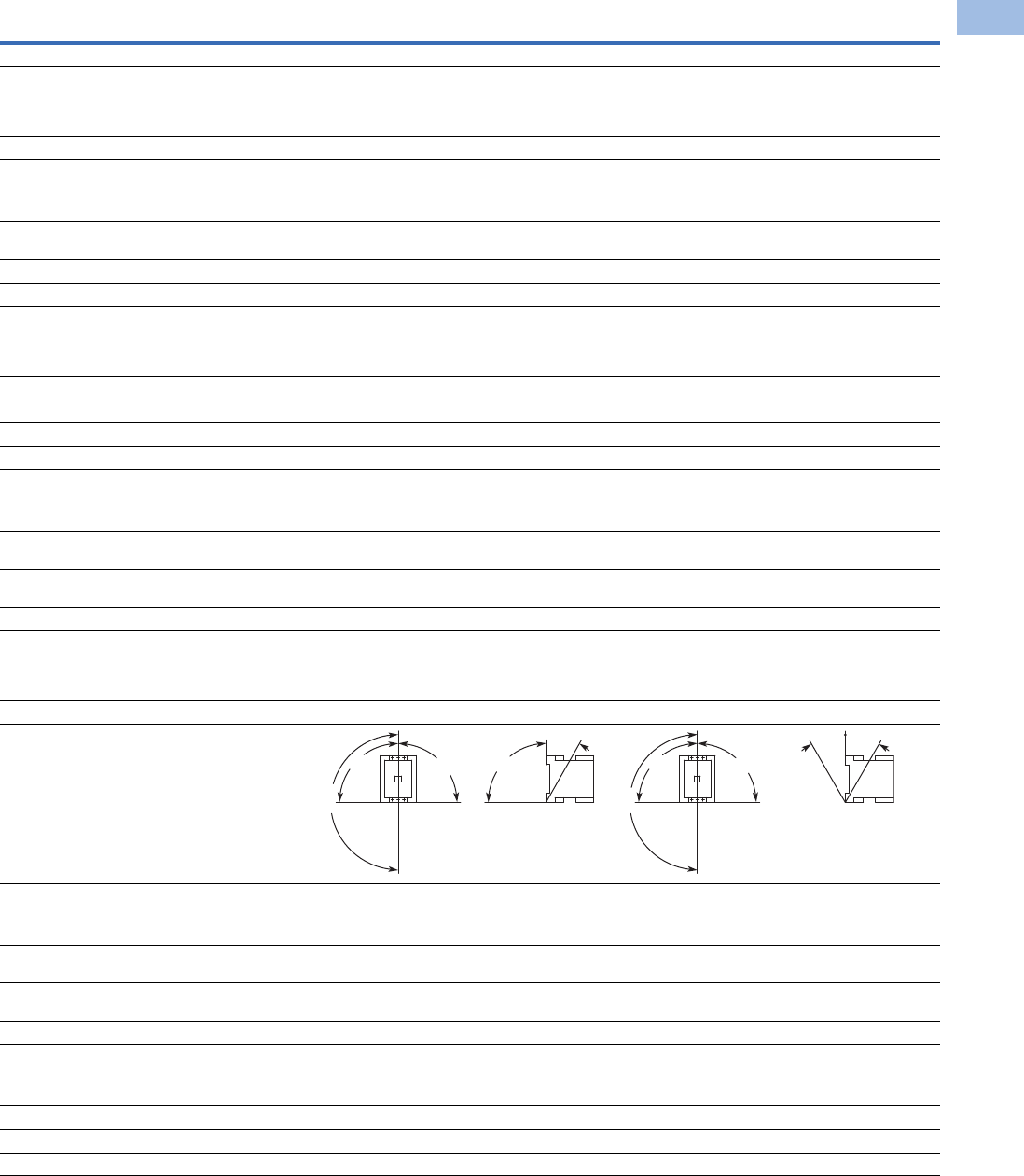
Volume 5—Motor Control and Protection CA08100006E—August 2012 www.eaton.com V5-T1-81
1
1
1
1
1
1
1
1
1
1
1
1
1
1
1
1
1
1
1
1
1
1
1
1
1
1
1
1
1
1
1.1
IEC Contactors and Starters
XT
IEC Power Control
XT Contactors—Frames C–D, continued
Description XTCE018C XTCE025C XTCE032C XTCE040D XTCE050D XTCE065D, XTCE072D
General, continued
Main cable connection screw/bolt M5 M5 M5 M6 M6 M6
Tightening torque
Nm 3333.33.33.3
Lb-in 26.6 26.6 26.6 29.2 29.2 29.2
Terminal capacity control circuit cable—screw terminals
Solid (mm2) 1 x (0.75–4)
2 x (0.75–4)
1 x (0.75–4)
2 x (0.75–4)
1 x (0.75–4)
2 x (0.75–4)
1 x (0.75–4)
2 x (0.75–4)
1 x (0.75–4)
2 x (0.75–4)
1 x (0.75–4)
2 x (0.75–4)
Flexible with ferrule (mm2) 1 x (0.75–2.5)
2 x (0.75–2.5)
1 x (0.75–2.5)
2 x (0.75–2.5)
1 x (0.75–2.5)
2 x (0.75–2.5)
1 x (0.75–2.5)
2 x (0.75–2.5)
1 x (0.75–2.5)
2 x (0.75–2.5)
1 x (0.75–2.5)
2 x (0.75–2.5)
Solid or stranded (AWG) 18–14 18–14 18–14 18–14 18–14 18–14
Control circuit cable connection screw/bolt M3.5 M3.5 M3.5 M3.5 M3.5 M3.5
Tightening torque
Nm 1.2 1.2 1.2 1.2 1.2 1.2
Lb-in 10.6 10.6 10.6 10.6 10.6 10.6
Tools
Main and control circuit cable—screw terminals Size 2 Size 2 Size 2 Size 2 Size 2 Size 2
Pozidriv screwdriver 0.8 x 5.5 0.8 x 5.5 0.8 x 5.5 0.8 x 5.5 0.8 x 5.5 0.8 x 5.5
Standard screwdriver 1 x 6 1 x 6 1 x 6 1 x 6 1 x 6 1 x 6
Terminal capacity control circuit cable—spring cage terminals
Solid (mm2) 1 x (0.75–2.5)
2 x (0.75–2.5)
1 x (0.75–2.5)
2 x (0.75–2.5)
1 x (0.75–2.5)
2 x (0.75–2.5)
1 x (0.75–2.5)
2 x (0.75–2.5)
1 x (0.75–2.5)
2 x (0.75–2.5)
1 x (0.75–2.5)
2 x (0.75–2.5)
Flexible (mm2) 1 x (0.75–2.5)
2 x (0.75–2.5)
1 x (0.75–2.5)
2 x (0.75–2.5)
1 x (0.75–2.5)
2 x (0.75–2.5)
1 x (0.75–2.5)
2 x (0.75–2.5)
1 x (0.75–2.5)
2 x (0.75–2.5)
1 x (0.75–2.5)
2 x (0.75–2.5)
Flexible with ferrule (mm2) 1 x (0.75–2.5)
2 x (0.75–2.5)
1 x (0.75–2.5)
2 x (0.75–2.5)
1 x (0.75–2.5)
2 x (0.75–2.5)
1 x (0.75–2.5)
2 x (0.75–2.5)
1 x (0.75–2.5)
2 x (0.75–2.5)
1 x (0.75–2.5)
2 x (0.75–2.5)
Solid or stranded (AWG) 18–14 18–14 18–14 18–14 18–14 18–14
Tools
Main and control circuit cable—spring cage terminals
Stripping length (mm) 10 10 10 10 10 10
Screwdriver blade width (mm) 3.5 3.5 3.5 3.5 3.5 3.5
Mounting position, AC and DC operated
Ambient temperature
Open –25 to 60°C
[–13 to 140°F]
–25 to 60°C
[–13 to 140°F]
–25 to 60°C
[–13 to 140°F]
–25 to 60°C
[–13 to 140°F]
–25 to 60°C
[–13 to 140°F]
–25 to 60°C
[–13 to 140°F]
Enclosed –25 to 40°C
[–13 to 104°F]
–25 to 40°C
[–13 to 104°F]
–25 to 40°C
[–13 to 104°F]
–25 to 40°C
[–13 to 104°F]
–25 to 40°C
[–13 to 104°F]
–25 to 40°C
[–13 to 104°F]
Ambient storage temperature –40 to 80°C
[–40 to 176°F]
–40 to 80°C
[–40 to 176°F]
–40 to 80°C
[–40 to 176°F]
–40 to 80°C
[–40 to 176°F]
–40 to 80°C
[–40 to 176°F]
–40 to 80°C
[–40 to 176°F]
Environmental
Mechanical shock resistance
(IEC/EN 60068-2-27)
Main contact—NO Contact 101010101 1
Auxiliary contact—NO Contact 777777
Auxiliary contact—NC Contact 555555
Overvoltage category/pollution degree III/3 III/3 III/3 III/3 III/3 III/3
180°
90°
90°
90°
30°
180°
90°
90°
30° 30°
Courtesy of CMA/Flodyne/Hydradyne ▪ Motion Control ▪ Hydraulic ▪ Pneumatic ▪ Electrical ▪ Mechanical ▪ (800) 426-5480 ▪ www.cmafh.com

V5-T1-82 Volume 5—Motor Control and Protection CA08100006E—August 2012 www.eaton.com
1
1
1
1
1
1
1
1
1
1
1
1
1
1
1
1
1
1
1
1
1
1
1
1
1
1
1
1
1
1
1.1
IEC Contactors and Starters
XT
IEC Power Control
XT Contactors—Frames F–G
Notes
1IEC 60947 Standard.
2Damp heat, constant, to IEC 60068-2-78; damp heat, cyclic, to IEC 60 068-2-30.
Description XTCE080F XTCE095F XTCE115G XTCE150G XTCE170G
General
Standards IEC/EN 60947,
VDE 0660, UL, CSA,
CCC, RoHS
IEC/EN 60947,
VDE 0660, UL, CSA,
CCC, RoHS
IEC/EN 60947,
VDE 0660, UL, CSA,
CCC, RoHS
IEC/EN 60947,
VDE 0660, UL, CSA,
CCC, RoHS
IEC/EN 60947,
VDE 0660, UL, CSA,
CCC, RoHS
Weights in kg [lb]
AC operated 2 [4.41] 2 [4.41] 2 [4.41] 2 [4.41] 2 [4.41]
DC operated 2.1 [4.63] 2.1 [4.63] 2.1 [4.63] 2.1 [4.63] 2.1 [4.63]
Mechanical life—operations 10,000,000 10,000,000 10,000,000 10,000,000 10,000,000
Mechanical operating frequency (ops/hr)
AC operated 3600 3600 3600 3600 3600
DC operated 3600 3600 3600 3600 3600
Electrical mechanical operating frequency (ops/hr)—
see Curves, Page V5-T1-111
AC-1; 400V Ie800 800 800 800 800
AC-3; 400V Ie800 800 800 800 800
AC-4; 400V Ie300 300 300 300 300
Climatic proofing 22222
Insulation voltage (Ui) Vac 690 690 690 690 690
Impulse withstand voltage (Uimp) Vac 8000 8000 8000 8000 8000
Operational voltage (Ue) Vac 690 690 690 690 690
Safe isolation to VDE 0106 Part 101 and Part 101/A1
Between coil and contacts (Vac) 690 690 690 690 690
Between contacts (Vac) 690 690 690 690 690
Making capacity (amps) 1120 1330 1610 2100 2100
Breaking capacity (amps)
220/230V 800 950 1150 1500 1500
380/400V 800 950 1150 1500 1500
500V 800 950 1150 1500 1500
660/690V 650 800 1100 1200 1320
1000V —————
Short-circuit protection rating maximum fuse
Type 2 coordination 1
400V; gG/gL 500V 160 160 250 25 400
690V; gG/gL 690V 160 160 25 250 25
Type 1 coordination 1
400V; gG/gL 500V 250 25 250 250 400
690V; gG/gL 690V 200 200 250 250 250
Degree of protection IP00 IP00 IP00 IP00 IP00
Protection against direct contact when actuated from front (IEC 536) Finger and
back-of-hand proof
Finger and
back-of-hand proof
Finger and
back-of-hand proof
Finger and
back-of-hand proof
Finger and
back-of-hand proof
Terminal capacity main cable—screw terminals
Solid (mm2) —————
Flexible with ferrule (mm2) 1 x (10–95)
2 x (10–70)
1 x (10–95)
2 x (10–70)
1 x (10–95)
2 x (10–70)
1 x (10–95)
2 x (10–70)
1 x (10–95)
2 x (10–70)
Stranded (mm2) 1 x (10–95)
2 x (10–20)
1 x (10–95)
2 x (10–20)
1 x (10–95)
2 x (10–20)
1 x (10–95)
2 x (10–20)
1 x (10–95)
2 x (10–20)
Flat conductor
(number of segments x width x thickness) (mm)
2 x (6 x 16 x 0.8) 2 x (6 x 16 x 0.8) 2 x (6 x 16 x 0.8) 2 x (6 x 16 x 0.8) 2 x (6 x 16 x 0.8)
Solid or stranded (AWG) 8–3/0 8–3/0 8–3/0 8–3/0 8–3/0
Main cable connection screw/bolt M10 M10 M10 M10 M10
Tightening torque
Nm 14 14 14 14 14
Lb-in 123.9 123.9 123.9 123.9 123.9
Courtesy of CMA/Flodyne/Hydradyne ▪ Motion Control ▪ Hydraulic ▪ Pneumatic ▪ Electrical ▪ Mechanical ▪ (800) 426-5480 ▪ www.cmafh.com
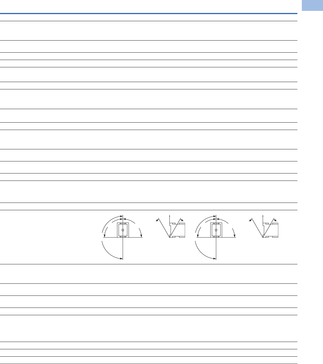
Volume 5—Motor Control and Protection CA08100006E—August 2012 www.eaton.com V5-T1-83
1
1
1
1
1
1
1
1
1
1
1
1
1
1
1
1
1
1
1
1
1
1
1
1
1
1
1
1
1
1
1.1
IEC Contactors and Starters
XT
IEC Power Control
XT Contactors—Frames F–G, continued
Description XTCE080F XTCE095F XTCE115G XTCE150G XTCE170G
General, continued
Terminal capacity control circuit cable—screw terminals
Solid (mm2) 1 x (0.75–4)
1 x (0.75–4)
1 x (0.75–4)
1 x (0.75–4)
1 x (0.75–4)
1 x (0.75–4)
1 x (0.75–4)
1 x (0.75–4)
1 x (0.75–4)
1 x (0.75–4)
Flexible with ferrule (mm2) 1 x (0.75–2.5)
2 x (0.75–2.5)
1 x (0.75–2.5)
2 x (0.75–2.5)
1 x (0.75–2.5)
2 x (0.75–2.5)
1 x (0.75–2.5)
2 x (0.75–2.5)
1 x (0.75–2.5)
2 x (0.75–2.5)
Solid or stranded (AWG) 18–14 18–14 18–14 18–14 18–14
Control circuit cable connection screw/bolt M3.5 M3.5 M3.5 M3.5 M3.5
Tightening torque
Nm 1.2 1.2 1.2 1.2 1.2
Lb-in 10.6 10.6 10.6 10.6 10.6
Tools
Main circuit cable—screw terminals
Hexagon socket-head spanner (mm) 5 5 5 5 5
Control circuit cable—screw terminals
Pozidriv screwdriver Size 2 Size 2 Size 2 Size 2 Size 2
Standard screwdriver 1 x 6, 0.8 x 5.5 1 x 6, 0.8 x 5.5 1 x 6, 0.8 x 5.5 1 x 6, 0.8 x 5.5 1 x 6, 0.8 x 5.5
Terminal capacity control circuit cable—spring cage terminals
Solid (mm2) 1 x (0.75–2.5)
2 x (0.75–2.5)
1 x (0.75–2.5)
2 x (0.75–2.5)
1 x (0.75–2.5)
2 x (0.75–2.5)
1 x (0.75–2.5)
2 x (0.75–2.5)
1 x (0.75–2.5)
2 x (0.75–2.5)
Flexible (mm2) 1 x (0.75–2.5)
2 x (0.75–2.5)
1 x (0.75–2.5)
2 x (0.75–2.5)
1 x (0.75–2.5)
2 x (0.75–2.5)
1 x (0.75–2.5)
2 x (0.75–2.5)
1 x (0.75–2.5)
2 x (0.75–2.5)
Flexible with ferrule (mm2) 1 x (0.75–2.5)
2 x (0.75–2.5)
1 x (0.75–2.5)
2 x (0.75–2.5)
1 x (0.75–2.5)
2 x (0.75–2.5)
1 x (0.75–2.5)
2 x (0.75–2.5)
1 x (0.75–2.5)
2 x (0.75–2.5)
Solid or stranded (AWG) 18–14 18–14 18–14 18–14 18–14
Tools
Control circuit cable—spring cage terminals
Stripping length (mm) 10 10 10 10 10
Screwdriver blade width (mm) 3.5 3.5 3.5 3.5 3.5
Mounting position, AC and DC operated
Ambient temperature
Open –25 to 60°C
[–13 to 140°F]
–25 to 60°C
[–13 to 140°F]
–25 to 60°C
[–13 to 140°F]
–25 to 60°C
[–13 to 140°F]
–25 to 60°C
[–13 to 140°F]
Enclosed –25 to 40°C
[–13 to 104°F]
–25 to 40°C
[–13 to 104°F]
–25 to 40°C
[–13 to 104°F]
–25 to 40°C
[–13 to 104°F]
–25 to 40°C
[–13 to 104°F]
Ambient storage temperature –40 to 80°C
[–40 to 176°F]
–40 to 80°C
[–40 to 176°F]
–40 to 80°C
[–40 to 176°F]
–40 to 80°C
[–40 to 176°F]
–40 to 80°C
[–40 to 176°F]
Environmental
Mechanical shock resistance
(IEC/EN 60068-2-27)
Half-sinusoidal shock 10 ms
Main contact—NO contact 10g 10g 10g 10g 10g
Auxiliary contact—NO contact 7g 7g 7g 7g 7g
Auxiliary contact—NC contact 5g 5g 5g 5g 5g
Overvoltage category/pollution degree III/3 III/3 III/3 III/3 III/3
180°
90°
90°
30° 30°
180°
90°
90°
30° 30°
Courtesy of CMA/Flodyne/Hydradyne ▪ Motion Control ▪ Hydraulic ▪ Pneumatic ▪ Electrical ▪ Mechanical ▪ (800) 426-5480 ▪ www.cmafh.com

V5-T1-84 Volume 5—Motor Control and Protection CA08100006E—August 2012 www.eaton.com
1
1
1
1
1
1
1
1
1
1
1
1
1
1
1
1
1
1
1
1
1
1
1
1
1
1
1
1
1
1
1.1
IEC Contactors and Starters
XT
IEC Power Control
XT Contactors—Frames H–M
Notes
1IEC 60947 Standard.
2Damp heat, constant, to IEC 60068-2-78; damp heat, cyclic, to IEC 60 068-2-30.
3Screw tightening with flat cable terminal or cable terminal blocks. See terminal capacity for cable terminal blocks.
Description XTCE185H XTCE225H
XTCE250L,
XTCS250L
XTCE300L,
XTCS300L
XTCE400M
XTCS400M
XTCE500M,
XTCS500M
XTCE570M
XTCS570M
General
Standards IEC/EN 60947,
VDE 0660,
UL, CSA
IEC/EN 60947,
VDE 0660,
UL, CSA
IEC/EN 60947,
VDE 0660,
UL, CSA
IEC/EN 60947,
VDE 0660,
UL, CSA
IEC/EN 60947,
VDE 0660,
UL, CSA
IEC/EN 60947,
VDE 0660,
UL, CSA
IEC/EN 60947,
VDE 0660,
UL, CSA
Weights in kg [lb] 3.2 [7.1] 3.2 [7.1] 6.5 [14.3] 6.5 [14.3] 8 [18] 8 [18] 8 [18]
Mechanical life—operations 10,000,000 10,000,000 10,000,000 10,000,000 7,000,000 7,000,000 7,000,000
Mechanical operating frequency (ops/hr)
AC operated 3000 3000 3000 3000 2000 2000 2000
DC operated 3000 3000 3000 3000 2000 2000 2000
Mechanical operating frequency (ops/hr) See Page V5-T1-93
Climatic proofing 2222222
Insulation voltage (Ui) Vac 1000 1000 1000 1000 1000 1000 1000
Impulse withstand voltage (Uimp) Vac 8000 8000 8000 8000 8000 8000 8000
Operating voltage (Ue) Vac 1000 1000 1000 1000 1000 1000 1000
Safe isolation to VDE 0106 Part 101 and Part 101/A1
Between coil and contacts (Vac) 500 500 500 500 500 500 500
Between contacts (Vac) 500 500 500 500 500 500 500
Making capacity (amps) 2700 2700 3000 3600 5500 5500 5500
Breaking capacity (amps)
Between coil and contacts (Vac)
220/230V 2250 2250 2500 3000 5000 5000 5000
380/400V 2250 2250 2500 3000 5000 5000 5000
500V 2250 2250 2500 3000 5000 5000 5000
660/690V 2250 2250 2500 3000 5000 5000 5000
1000V 760 760 760 950 950 950 950
Short-circuit protection rating maximum fuse
Type 2 coordination 1
400V; gG/gL 500V 315 315 315 315 500 500 500
690V; gG/gL 690V 250 250 315 315 500 500 500
1000V; gG/gL 1000V 160 160 160 160 200 200 200
Degree of protection IP00 IP00 IP00 IP00 IP00 IP00 IP00
Protection against direct contact when
actuated from front (IEC 536)
Finger and back-of-hand proof with terminal shroud or terminal block
Main cable cross-section
Flexible with cable lug (mm2) 50–185 50–185 50–240 50–240 50–240 50–240 50–240
Stranded with cable lug (mm2) 50–185 70–185 70–240 70–240 70–240 70–240 70–240
Solid or stranded (AWG) 1/0–350 kcmil 2/0–250 kcmil 1/0–250 kcmil 2/0–500 kcmil 1/0–250 kcmil 1/0–250 kcmil 1/0–250 kcmil
Flat conductor (mm) 3333333
Busbar—width in mm 32 32 25 25 25 30 30
Main cable connection screw/bolt M10 M10 M10 M10 M10 M10 M10
Tightening torque
Nm 24 24 24 24 2 2 2
Lb-in 213 213 213 213 213 213 213
Courtesy of CMA/Flodyne/Hydradyne ▪ Motion Control ▪ Hydraulic ▪ Pneumatic ▪ Electrical ▪ Mechanical ▪ (800) 426-5480 ▪ www.cmafh.com
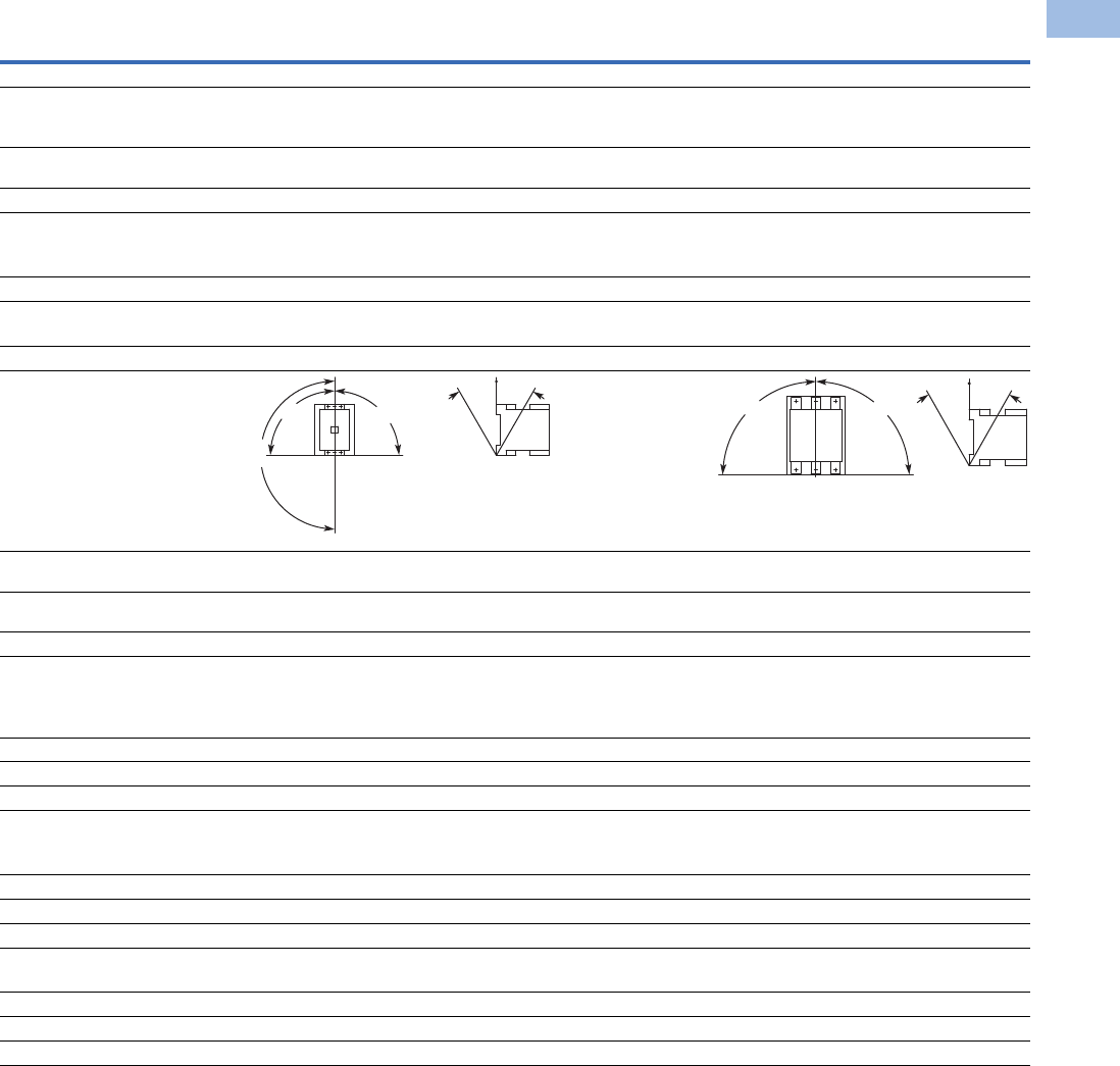
Volume 5—Motor Control and Protection CA08100006E—August 2012 www.eaton.com V5-T1-85
1
1
1
1
1
1
1
1
1
1
1
1
1
1
1
1
1
1
1
1
1
1
1
1
1
1
1
1
1
1
1.1
IEC Contactors and Starters
XT
IEC Power Control
XT Contactors—Frames H–M, continued
Note
1When using contactors for group compensation, a minimum inductance of approx. 6 uh per capacitor must be available to limit the high
inrush current peaks. This corresponds to an air-cored coil with five windings and a coil diameter of approximately 140 mm. The conductor
cross-section must be selected according to the rated current per phase.
Description XTCE185H XTCE225H
XTCE250L,
XTCS250L
XTCE300L,
XTCS300L
XTCE400M
XTCS400M
XTCE500M,
XTCS500M
XTCE570M
XTCS570M
General, continued
Control circuit cable cross-sections
Solid (mm2) 1 x (0.75–2.5)
2 x (0.75–2.5)
1 x (0.75–2.5)
2 x (0.75–2.5)
1 x (0.75–2.5)
2 x (0.75–2.5)
1 x (0.75–2.5)
2 x (0.75–2.5)
1 x (0.75–2.5)
2 x (0.75–2.5)
1 x (0.75–2.5)
2 x (0.75–2.5)
1 x (0.75–2.5)
2 x (0.75–2.5)
Flexible with ferrule (mm2) 1 x (0.75–2.5)
2 x (0.75–2.5)
1 x (0.75–2.5)
2 x (0.75–2.5)
1 x (0.75–2.5)
2 x (0.75–2.5)
1 x (0.75–2.5)
2 x (0.75–2.5)
1 x (0.75–2.5)
2 x (0.75–2.5)
1 x (0.75–2.5)
2 x (0.75–2.5)
1 x (0.75–2.5)
2 x (0.75–2.5)
Solid or stranded (AWG) 2 x (18–12) 2 x (18–12) 2 x (18–12) 2 x (18–12) 2 x (18–12) 2 x (18–12) 2 x (18–12)
Control circuit cable connection screw/bolt M3.5 M3.5 M3.5 M3.5 M3.5 M3.5 M3.5
Tightening torque
Nm 1.2 1.2 1.2 1.2 1.2 1.2 1.2
Lb-in 10.6 10.6 10.6 10.6 10.6 10.6 10.6
Tools
Main cable wrench 16 mm 16 mm 16 mm 16 mm 16 mm 16 mm 16 mm
Control circuit cable pozidriv screwdriver Size 2 Size 2 Size 2 Size 2 Size 2 Size 2 Size 2
Mounting position, AC and DC operated
Ambient temperature –25 to 60°C
[–13 to 140°F]
–25 to 60°C
[–13 to 140°F]
–25 to 60°C
[–13 to 140°F]
–25 to 60°C
[–13 to 140°F]
–25 to 60°C
[–13 to 140°F]
–25 to 60°C
[–13 to 140°F]
–25 to 60°C
[–13 to 140°F]
Ambient storage temperature –40 to 80°C
[–40 to 176°F]
–40 to 80°C
[–40 to 176°F]
–40 to 80°C
[–40 to 176°F]
–40 to 80°C
[–40 to 176°F]
–40 to 80°C
[–40 to 176°F]
–40 to 80°C
[–40 to 176°F]
–40 to 80°C
[–40 to 176°F]
Environmental
Mechanical shock
Resistance (IEC/EN 60068-2-27)
Half-sinusoidal shock 10 ms
Main contact—NO contact 10g 10g 10g 10g 10g 10g 10g
Auxiliary contact—NO contact 10g 10g 10g 10g 10g 10g 10g
Auxiliary contact—NC contact 8g 8g 8g 8g 8g 8g 8g
Overvoltage category/pollution degree III/3 III/3 III/3 III/3 III/3 III/3 III/3
Switching capacity, kVAR 1
Individual compensation
230V — — — — — — —
400/420/440V — — — — — — —
525V 220 220 — 307 — — —
690V 133 133 — 177 — — —
Group compensation, with choke
230V — — 100 — 160 160 160
400/420/440V — — 190 — 280 280 280
525V — — 260 — 370 370 370
690V — — 340 — 480 480 480
180°
90°
90°
30° 30°
90° 90°
30°30°
Courtesy of CMA/Flodyne/Hydradyne ▪ Motion Control ▪ Hydraulic ▪ Pneumatic ▪ Electrical ▪ Mechanical ▪ (800) 426-5480 ▪ www.cmafh.com

V5-T1-86 Volume 5—Motor Control and Protection CA08100006E—August 2012 www.eaton.com
1
1
1
1
1
1
1
1
1
1
1
1
1
1
1
1
1
1
1
1
1
1
1
1
1
1
1
1
1
1
1.1
IEC Contactors and Starters
XT
IEC Power Control
XT Contactors—Frames N–R
Notes
1IEC 60947 Standard.
2Damp heat, constant, to IEC 60068-2-78; damp heat, cyclic, to IEC 60 068-2-30.
3Screw tightening with flat cable terminal or cable terminal blocks. See terminal capacity for cable terminal blocks.
Description XTCE580N XTCE650N
XTCE750N,
XTCE820N XTCEC10N XTCEC14P
XTCEC16R,
XTCEC20R
General
Standards IEC/EN 60947,
VDE 0660, UL, CSA
IEC/EN 60947,
VDE 0660, UL, CSA
IEC/EN 60947,
VDE 0660, UL, CSA
IEC/EN 60947,
VDE 0660, UL, CSA
IEC/EN 60947,
VDE 0660, UL, CSA
IEC/EN 60947,
VDE 0660, UL, CSA
Weights in kg [lb] 15 [33] 15 [33] 15 [33] 15 [33] 15, [33] 32 [70]
Mechanical life—operations 5,000,000 5,000,000 5,000,000 5,000,000 5,000,000 5,000,000
Mechanical operating frequency (ops/hr)
AC operated 1000 1000 1000 1000 1000 1000
DC operated 1000 1000 1000 1000 1000 1000
Maximum operating frequency (ops/hr) See Page V5-T1-113
Climatic proofing 222222
Insulation voltage (Ui) Vac 1000 1000 1000 1000 1000 1000
Impulse withstand voltage (Uimp) Vac 8000 8000 8000 8000 8000 8000
Operating voltage (Ue) Vac 1000 1000 1000 1000 1000 1000
Safe isolation to VDE 0106 Part 101 and Part 101/A1
Between coil and contacts (Vac) 500 500 500 500 500 500
Between contacts (Vac) 500 500 500 500 500 500
Making capacity (amps) 7800 7800 9840 9840 9840 19000, 9840
Breaking capacity (amps)
220/230V 6500 6500 8200 8200 8200 16000, 8200
380/400V 6500 6500 8200 8200 8200 16000, 8200
500V 6500 6500 8200 8200 8200 16000, 8200
660/690V 6500 6500 8200 8200 8200 16000, 8200
1000V 4350 4350 5800 5800 5800 5800
Short-circuit protection rating maximum fuse
Type 2 coordination 1
400V; gG/gL 500V 630 630 630 630 — —
690V; gG/gL 690V 630 630 630 630 — —
1000V; gG/gL 1000V 500 500 630 630 — —
Type 1 coordination 1
400V; gG/gL 500V 1000 1000 1200 1200 — —
690V; gG/gL 690V 1000 1000 1200 1200 — —
1000V; gG/gL 1000V 630 630 800 800 — —
Degree of protection IP00 IP00 IP00 IP00 IP00 IP00
Protection against direct contact when actuated
from front (IEC 536)
Finger and back-of-
hand proof with
terminal shroud or
terminal block
Finger and back-of-
hand proof with
terminal shroud or
terminal block
Finger and back-of-
hand proof with
terminal shroud or
terminal block
Finger and back-of-
hand proof with
terminal shroud or
terminal block
Finger and back-of-
hand proof with
terminal shroud or
terminal block
Finger and back-of-
hand proof with
terminal shroud or
terminal block
Main cable cross-section
Flexible with cable lug (mm2) 50-240 50-240 50-240 50-240 50-240 50-240
Stranded with cable lug (mm2) 70-240 70-240 70-240 70-240 70-240 70-240
Solid or stranded (AWG) 2/0–500 kcmil 2/0–500 kcmil 2/0–500 kcmil 2/0–500 kcmil 2/0–500 kcmil 2/0–500 kcmil
Flat conductor (mm) 333333
Busbar—width in mm 50 50 50 50 50 50
Main cable connection screw/bolt M10 M10 M12 M12 M12 M1
Tightening torque
Nm 24 24 35 35 35 35
Lb-in 213 213 311 311 311 311
Courtesy of CMA/Flodyne/Hydradyne ▪ Motion Control ▪ Hydraulic ▪ Pneumatic ▪ Electrical ▪ Mechanical ▪ (800) 426-5480 ▪ www.cmafh.com
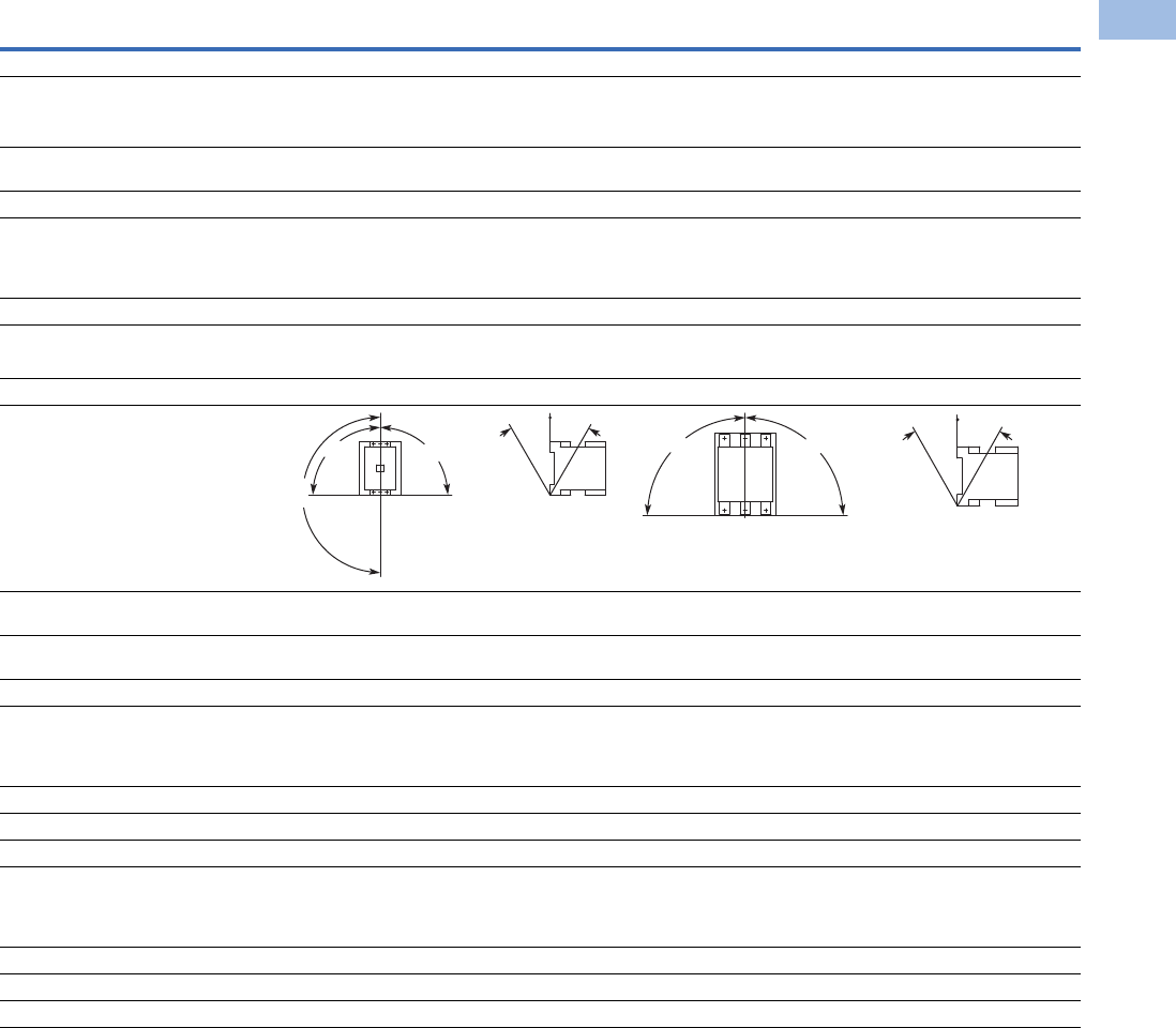
Volume 5—Motor Control and Protection CA08100006E—August 2012 www.eaton.com V5-T1-87
1
1
1
1
1
1
1
1
1
1
1
1
1
1
1
1
1
1
1
1
1
1
1
1
1
1
1
1
1
1
1.1
IEC Contactors and Starters
XT
IEC Power Control
XT Contactors—Frames N–R, continued
Note
1When using contactors for group compensation, a minimum inductance of approx. 6 uh per capacitor must be available to limit the high
inrush current peaks. This corresponds to an air-cored coil with five windings and a coil diameter of approximately 140 mm. The conductor
cross-section must be selected according to the rated current per phase.
Description XTCE580N XTCE650N XTCE750N, XTCE820N XTCEC10N XTCEC14P XTCEC16R, XTCEC20R
General, continued
Control circuit cable cross-sections
Solid (mm2) 1 x (0.75–2.5)
2 x (0.75–2.5)
1 x (0.75–2.5)
2 x (0.75–2.5)
1 x (0.75–2.5)
2 x (0.75–2.5)
1 x (0.75–2.5)
2 x (0.75–2.5)
1 x (0.75–2.5)
2 x (0.75–2.5)
1 x (0.75–2.5)
2 x (0.75–2.5)
Flexible with ferrule (mm2) 1 x (0.75–2.5)
2 x (0.75–2.5)
1 x (0.75–2.5)
2 x (0.75–2.5)
1 x (0.75–2.5)
2 x (0.75–2.5)
1 x (0.75–2.5)
2 x (0.75–2.5)
1 x (0.75–2.5)
2 x (0.75–2.5)
1 x (0.75–2.5)
2 x (0.75–2.5)
Solid or stranded (AWG) 2 x (18–12) 2 x (18–12) 2 x (18–12) 2 x (18–12) 2 x (18–12) 2 x (18–12)
Control circuit cable connection screw/bolt M3.5 M3.5 M3.5 M3.5 M3.5 M3.5
Tightening torque
Nm 1.2 1.2 1.2 1.2 1.2 1.2
Lb-in 10.6 10.6 10.6 10.6 10.6 10.6
Tools
Main cable wrench 16 mm 16 mm 18 mm 18 mm 18 mm 18 mm
Control circuit cable pozidriv screwdriver Size 2 Size 2 Size 2 Size 2 Size 2 Size 2
Mounting position, AC and DC operated
Ambient temperature –25 to 60°C
[–13 to 140°F]
–25 to 60°C
[–13 to 140°F]
–25 to 60°C
[–13 to 140°F]
–25 to 60°C
[–13 to 140°F]
–25 to 60°C
[–13 to 140°F]
–25 to 60°C
[–13 to 140°F]
Ambient storage temperature –40 to 80°C
[–40 to 176°F]
–40 to 80°C
[–40 to 176°F]
–40 to 80°C
[–40 to 176°F]
–40 to 80°C
[–40 to 176°F]
–40 to 80°C
[–40 to 176°F]
–40 to 80°C
[–40 to 176°F]
Environmental
Mechanical shock resistance (IEC/EN 60068-2-27)
Half-sinusoidal shock 10 ms (g)
Main contact—NO contact 10 10 10 10 10 10
Auxiliary contact—NO contact 10 10 10 10 10 10
Auxiliary contact—NC contact 8 8 8 8 8 8
Overvoltage category/pollution degree III/3 III/3 III/3 III/3 III/3 III/3
Switching capacity, kVAR 1
Individual compensation
230V 175 — — — — —
400/420/440V 300 — — — — —
525V 400 — — — — —
690V 300 — — — — —
180°
90°
90°
30° 30°
30°30°
90° 90°
Courtesy of CMA/Flodyne/Hydradyne ▪ Motion Control ▪ Hydraulic ▪ Pneumatic ▪ Electrical ▪ Mechanical ▪ (800) 426-5480 ▪ www.cmafh.com

V5-T1-88 Volume 5—Motor Control and Protection CA08100006E—August 2012 www.eaton.com
1
1
1
1
1
1
1
1
1
1
1
1
1
1
1
1
1
1
1
1
1
1
1
1
1
1
1
1
1
1
1.1
IEC Contactors and Starters
XT
IEC Power Control
Coil Data—Frames B–D
Notes
10.7–1.3 without additional auxiliary contact modules and ambient temperature +40°C [104°F].
2Coil Suffix TD: Umin 24 Vdc/Umax 27 Vdc.
Coil Suffix WD: Umin 48 Vdc/Umax 60 Vdc.
Coil Suffix AD: Umin 110 Vdc/Umax 130 Vdc.
Coil Suffix BD: Umin 200 Vdc/Umax 240 Vdc.
Example:
Uc = 0.7 x Umin—1.2 x Umax
Uc = 0.7 x 24V—1.2 x 27 Vdc
Description XTCE007B XTCE009B
XTCE012B,
XTCF020B XTCE015B XTCE018C XTCE025C XTCE032C XTCE040D XTCE050D
XTCE065D,
XTCE072D
Voltage Tolerance
Pickup (x Uc)
AC operated 0.8–1.1 0.8–1.1 0.8–1.1 0.8–1.1 0.8–1.1 0.8–1.1 0.8–1.1 0.8–1.1 0.8–1.1 0.8–1.1
DC operated 0.8–1.1 10.8–1.1 10.8–1.1 10.8–1.1 10.7–1.2 20.7–1.2 20.7–1.2 20.7–1.2 20.7–1.2 20.7–1.2 2
Dropout (x Uc)
AC operated 0.3–0.6 0.3–0.6 0.3–0.6 0.3–0.6 0.3–0.6 0.3–0.6 0.3–0.6 0.3–0.6 0.3–0.6 0.3–0.6
DC operated 0.15–0.6 0.15–0.6 0.15–0.6 0.15–0.6 0.15–0.6 0.15–0.6 0.15–0.6 0.15–0.6 0.15–0.6 0.15–0.6
Power Consumption of the Coil at Cold State and 1.0 x Uc
AC operated
Single-voltage coil 50 Hz
Pickup VA 24 24 24 24 52 52 52 149 149 149
Pickup W 19191919404040808080
Sealing VA 3.4 3.4 3.4 3.4 7.1 7.1 7.1 16 16 16
Sealing W 1.2 1.2 1.2 1.2 2.1 2.1 2.1 4.3 4.3 4.3
Single-voltage coil 60 Hz
Pickup VA 30 30 30 30 67 67 67 178 178 178
Pickup W 23232323505050117117117
Sealing VA 4.4 4.4 4.4 4.4 8.7 8.7 8.7 19 19 19
Sealing W 1.4 1.4 1.4 1.4 2.6 2.6 2.6 5.3 5.3 5.3
50/60 Hz
Pickup VA 27
25
27
25
27
25
27
25
62
58
62
58
62
58
168
154
168
154
168
154
Pickup W 22
21
22
21
22
21
22
21
48
43
48
43
48
43
120
43
120
43
120
43
Sealing VA 4.2
3.3
4.2
3.3
4.2
3.3
4.2
3.3
9.1
6.5
9.1
6.5
9.1
6.5
22
14
22
14
22
14
Sealing W 1.4
1.2
1.4
1.2
1.4
1.2
1.4
1.2
2.5
2
2.5
2
2.5
2
5.3
4.3
5.3
4.3
5.3
4.3
DC operated
Pickup W 3 3 4.5 4.5 12 at 24V 12 at 24V 12 at 24V 24 at 24V 24 at 24V 24 at 24V
Sealing W 3 3 4.5 4.5 0.5 at 24V 0.5 at 24V 0.5 at 24V 0.5 at 24V 0.5 at 24V 0.5 at 24V
Duty factor (%DF) 100 100 100 100 100 100 100 100 100 100
Switching Time at 100% Uc (Approximate Values)
Main contact
AC operated
Closing delay (ms) <21 <21 <21 <21 <22 <22 <22 <18 <18 <18
Opening delay (ms) <18 <18 <18 <18 <14 <14 <14 <13 <13 <13
DC operated
Closing delay (ms) <31 <31 <31 <31 <47 <47 <47 <54 <54 <54
Opening delay (ms) <12 <12 <12 <12 <30 <30 <30 <24 <24 <24
Arcing time (ms) 10 10 10 10 10 10 10 10 10 10
Electromagnetic Compatibility (EMC)
Emitted interference To EN-60947-1 To EN-60947-1 To EN-60947-1 To EN-60947-1 To EN-60947-1 To EN-60947-1 To EN-60947-1 To EN-60947-1 To EN-60947-1 To EN-60947-1
Noise immunity To EN-60947-1 To EN-60947-1 To EN-60947-1 To EN-60947-1 To EN-60947-1 To EN-60947-1 To EN-60947-1 To EN-60947-1 To EN-60947-1 To EN-60947-1
Courtesy of CMA/Flodyne/Hydradyne ▪ Motion Control ▪ Hydraulic ▪ Pneumatic ▪ Electrical ▪ Mechanical ▪ (800) 426-5480 ▪ www.cmafh.com

Volume 5—Motor Control and Protection CA08100006E—August 2012 www.eaton.com V5-T1-89
1
1
1
1
1
1
1
1
1
1
1
1
1
1
1
1
1
1
1
1
1
1
1
1
1
1
1
1
1
1
1.1
IEC Contactors and Starters
XT
IEC Power Control
Coil Data—Frames F–G
Note
1At 24V: 0.7–1.3 without additional auxiliary contact modules and ambient temperature +40°C [104°F].
Description XTCE80F XTCE95F XTCE115G XTCE150G XTCE170G
Voltage Tolerance
Pickup (x Uc)
AC operated 0.8–1.1 0.8–1.1 0.8–1.1 0.8–1.1 0.8–1.1
DC operated 0.7–1.2 10.7–1.2 10.7–1.2 10.7–1.2 10.7–1.2 1
Dropout (x Uc)
AC operated 0.3–0.6 0.3–0.6 0.25–0.6 0.25–0.6 0.25–0.6
DC operated 0.15–0.6 0.15–0.6 0.15–0.6 0.15–0.6 0.15–0.6
Power Consumption of the Coil at Cold State and 1.0 x Uc
AC operated
Single-voltage coil 50 Hz
Pickup VA 310 310 180 180 180
Pickup W 165 165 130 130 130
Sealing VA 26 26 3.1 3.1 3.1
Sealing W 5.8 5.8 2.1 2.1 2.1
Single-voltage coil 60 Hz
Pickup VA 345 345 170 170 170
Pickup W 190 190 130 130 130
Sealing VA 30 30 3.1 3.1 3.1
Sealing W 7.1 7.1 2.1 2.1 2.1
50/60 Hz
Pickup VA 372 328 170 170 170
Pickup W 190 190 130 130 130
Sealing VA 37.1 22.6 3.1 3.1 3.1
Sealing W 7.5 6.1 2.1 2.1 2.1
DC operated
Pickup W 90 at 24V 90 at 24V 149 at 24V 149 at 24V 149 at 24V
Sealing W 1.3 at 24V 1.3 at 24V 2.1 at 24V 2.1 at 24V 2.1 at 24V
Duty factor (%DF) 100 100 100 100 100
Switching Time at 100% Uc (Approximate Values)
Main contact
AC operated
Closing delay (ms) <20 <20 <33 <33 <33
Opening delay (ms) <14 <14 <41 <41 <41
DC operated
Closing delay (ms) <45 <45 <35 <35 <35
Opening delay (ms) <34 <34 <30 <30 <30
Arcing time (ms) 15 15 15 15 15
Permissible residual current with actuation of
A1–A2 by the electronics (with 0 signal) (mA)
<
1
<
1
<
1
<
1
<
1
Electromagnetic Compatibility (EMC)
Emitted interference To EN60947-1 To EN60947-1 To EN60947-1 To EN60947-1 To EN60947-1
Noise immunity To EN60947-1 To EN60947-1 To EN60947-1 To EN60947-1 To EN60947-1
Courtesy of CMA/Flodyne/Hydradyne ▪ Motion Control ▪ Hydraulic ▪ Pneumatic ▪ Electrical ▪ Mechanical ▪ (800) 426-5480 ▪ www.cmafh.com

V5-T1-90 Volume 5—Motor Control and Protection CA08100006E—August 2012 www.eaton.com
1
1
1
1
1
1
1
1
1
1
1
1
1
1
1
1
1
1
1
1
1
1
1
1
1
1
1
1
1
1
1.1
IEC Contactors and Starters
XT
IEC Power Control
Coil Data—Frames H–R
Note
1Control transformer with Uk
<
6%.
Description XTCE185H, XTCE225H XTCE250L, XTCS250L XTCE300L, XTCS300L
XTCE400M, XTCS400M, XTCE500M,
XTCS500M, XTCE570M, XTCS570M
Voltage Tolerance
Pickup (x Uc)
XTCE185H–XTCEC20R 0.8 x Ucmin–1.15 x Ucmax 0.7 x Ucmin–1.15 x Ucmax 0.7 x Ucmin–1.15 x Ucmax 0.7 x Ucmin–1.15 x Ucmax
XTCS250L–XTCS500M — 0.85 x Ucmin–1.1 x Ucmax 0.85 x Ucmin–1.1 x Ucmax 0.85 x Ucmin–1.1 x Ucmax
Dropout (x Uc)
XTCE185H–XTCEC20R 0.2 x Ucmin–0.6 x Ucmax 0.2 x Ucmin–0.6 x Ucmax 0.2 x Ucmin–0.6 x Ucmax 0.2 x Ucmin–0.6 x Ucmax
XTCS250L–XTCS500M — 0.2 x Ucmin–0.4 x Ucmax 0.2 x Ucmin–0.4 x Ucmax 0.2 x Ucmin–0.4 x Ucmax
Power Consumption of the Coil at Cold State and 1.0 x Uc
XTCE185H–XTCEC20R
Pickup VA 210 1250 1380 1450 1
Pickup W 180 200 250 350
Sealing VA 2.6 4.3 4.3 4.3
Sealing W 2.1 3.3 3.3 3.3
XTCS250L–XTCS500M
Pickup VA — 360 360 715
Pickup W — 325 625 645
Sealing VA — 4.3 4.3 4.3
Sealing W — 3.3 3.3 3.3
Duty factor (%DF) — 100 100 100
Switching Time at 100% Main Contact Uc (Approximate Values)
XTCE185H–XTCEC20R
Closing delay (ms) <60 <100 <80 <80
Opening delay (ms) <40 <80 <110 <80
XTCS250L–XTCS500M
Closing delay (ms) — <50 <55 <50
Opening delay (ms) — <40 <40 <40
Reaction in Threshold and Sealing State Transition Range (XTCE185H–XTCEC20R)
Voltage interruptions
(0–0.2 x Ucmin)
<
10 ms Time is bridged successfully Time is bridged successfully Time is bridged successfully Time is bridged successfully
(0–0.2 x Ucmin) >10 ms Dropout of the contactor Dropout of the contactor Dropout of the contactor Dropout of the contactor
Voltage dips
(0.2–0.6 x Ucmin)
<
12 ms Time is bridged successfully Time is bridged successfully Time is bridged successfully Time is bridged successfully
(0.2–0.6 x Ucmin) >12 ms Contactor remains switched on Contactor remains switched on Dropout of the contactor Contactor remains switched on
(0.6–0.7 x Ucmin) Contactor remains switched on Contactor remains switched on Contactor remains switched on Contactor remains switched on
Excess voltage
(1.15–1.3 x Ucmax) Contactor remains switched on Contactor remains switched on Contactor remains switched on Contactor remains switched on
(>1.3 x Ucmax)
<
3s Contactor remains switched on Contactor remains switched on Contactor remains switched on Contactor remains switched on
(>1.3 x Ucmax) >3s Dropout of the contactor Dropout of the contactor Dropout of the contactor Dropout of the contactor
Pickup phase
(0–0.7 x Ucmin) Contactor does not switch on Contactor does not switch on Contactor does not switch on Contactor does not switch on
(0.7 x Ucmin –1.15 x Ucmax) Contactor switches on with certainty Contactor switches on with certainty Contactor switches on with certainty Contactor switches on with certainty
(>1.15 x Ucmax) Contactor switches on with certainty Contactor switches on with certainty Contactor switches on with certainty Contactor switches on with certainty
Courtesy of CMA/Flodyne/Hydradyne ▪ Motion Control ▪ Hydraulic ▪ Pneumatic ▪ Electrical ▪ Mechanical ▪ (800) 426-5480 ▪ www.cmafh.com

Volume 5—Motor Control and Protection CA08100006E—August 2012 www.eaton.com V5-T1-91
1
1
1
1
1
1
1
1
1
1
1
1
1
1
1
1
1
1
1
1
1
1
1
1
1
1
1
1
1
1
1.1
IEC Contactors and Starters
XT
IEC Power Control
Coil Data—Frames H–R, continued
Coil Data—Frames N–R
Note
1Control transformer with Uk
<
7%.
Description XTCE185H, XTCE225H XTCE250L, XTCS250L XTCE300L, XTCS300L
XTCE400M, XTCS400M,
XTCE500M, XTCS500M,
XTCE570M, XTCS570M
Reaction in Threshold and Sealing State Transition Range (XTCE185H–XTCEC20R), continued
Permissible contact resistance (of the external command
device with actuation of A11), ohms
— ≤500 ≤500 ≤500
Permissible residual current (with actuation of A11
by the electronics with 0 signal)
—≤1≤1≤1
SPS signal level (A3–A4) to IEC/EN 61131-2 (Type 2)
High 15V 15V 15V 15V
Low 5V5V5V5V
Electromagnetic compatibility (EMC) This product is designed for operation in industrial environments (environment 2). The use in residential environments
(environment 1) could cause electrical interference so that addition suppression must be planned.
Description XTCE580N
XTCE750N,
XTCE820N XTCEC10N XTCEC14P
XTCE16R,
XTCEC20R
Voltage Tolerance
Pickup (x Uc)
XTCE185L–XTCEC20R 0.7 x Ucmin–1.15 x Ucmax 0.7 x Ucmin–1.15 x Ucmax 0.7 x Ucmin–1.15 x Ucmax 0.7 x Ucmin–1.15 x Ucmax 0.7 x Ucmin–1.15 x Ucmax
XTCS185L–XTCS500M 0.85 x Ucmin–1.1 x Ucmax 0.85 x Ucmin–1.1 x Ucmax 0.85 x Ucmin–1.1 x Ucmax 0.85 x Ucmin–1.1 x Ucmax 0.85 x Ucmin–1.1 x Ucmax
Dropout (x Uc)
XTCE185L–XTCEC20R 0.2 x Ucmin–0.6 x Ucmax 0.2 x Ucmin–0.6 x Ucmax 0.2 x Ucmin–0.6 x Ucmax 0.2 x Ucmin–0.6 x Ucmax 0.2 x Ucmin–0.6 x Ucmax
XTCS185L–XTCS500M 0.2 x Ucmin–0.4 x Ucmax 0.2 x Ucmin–0.4 x Ucmax 0.2 x Ucmin–0.4 x Ucmax 0.2 x Ucmin–0.4 x Ucmax 0.2 x Ucmin–0.4 x Ucmax
Power Consumption of the Coil at Cold State and 1.0 x Uc
XTCE185L–XTCEC20R
Pickup VA 800 1800 1800 1800 11600 1
Pickup W 700 700 700 700 1400
Sealing VA 7.5 7.5 7.5 7.5 15
Sealing W 6.5 6.5 6.5 6.5 13
XTCS185L–XTCS500M
Pickup VA — — — — —
Pickup W — — — — —
Sealing VA — — — — —
Sealing W — — — — —
Duty factor (%DF) 100 100 100 100 100
Switching Time at 100% Main Contact Uc (Approximate Values)
XTCE185L–XTCEC20R
Closing delay (ms) <70 <70 <70 <70 <70
Opening delay (ms) <70 <70 <70 <40 <40
XTCS185L–XTCS500M
Closing delay (ms) — — — — —
Opening delay (ms) — — — — —
Courtesy of CMA/Flodyne/Hydradyne ▪ Motion Control ▪ Hydraulic ▪ Pneumatic ▪ Electrical ▪ Mechanical ▪ (800) 426-5480 ▪ www.cmafh.com

V5-T1-92 Volume 5—Motor Control and Protection CA08100006E—August 2012 www.eaton.com
1
1
1
1
1
1
1
1
1
1
1
1
1
1
1
1
1
1
1
1
1
1
1
1
1
1
1
1
1
1
1.1
IEC Contactors and Starters
XT
IEC Power Control
Coil Data—Frames N–R, continued
Note
1This product is designed for operation in industrial environments. Usage in domestic areas can cause radio frequency interference (RFI).
Noise suppression measures must be provided for the additional interference.
Description XTCE580N
XTCE750N,
XTCE820N XTCEC10N XTCEC14P
XTCE16R,
XTCEC20R
Reaction in Threshold and Sealing State Transition Range (XTCE185L–XTCEC20R)
Voltage interruptions
(0–0.2 x Ucmin)
<
10 ms Time is bridged
successfully
Time is bridged
successfully
Time is bridged
successfully
Time is bridged
successfully
Time is bridged
successfully
(0–0.2 x Ucmin) >10 ms Dropout of the contactor Dropout of the contactor Dropout of the contactor Dropout of the contactor Dropout of the contactor
Voltage dips
(0.2–0.6 x Ucmin)
<
12 ms Time is bridged
successfully
Time is bridged
successfully
Time is bridged
successfully
Time is bridged
successfully
Time is bridged
successfully
(0.2–0.6 x Ucmin) >12 ms Dropout of the contactor Dropout of the contactor Dropout of the contactor Dropout of the contactor Dropout of the contactor
(0.6–0.7 x Ucmin) Contactor remains
switched on
Contactor remains
switched on
Contactor remains
switched on
Contactor remains
switched on
Contactor remains
switched on
Excess voltage
(1.15–1.3 x Ucmax) Contactor remains
switched on
Contactor remains
switched on
Contactor remains
switched on
Contactor remains
switched on
Contactor remains
switched on
(>1.3 x Ucmax)
<
3s Contactor remains
switched on
Contactor remains
switched on
Contactor remains
switched on
Contactor remains
switched on
Contactor remains
switched on
(>1.3 x Ucmax) >3s Dropout of the contactor Dropout of the contactor Dropout of the contactor Dropout of the contactor Dropout of the contactor
Pickup phase
(0–0.7 x Ucmin) Contactor does not
switch on
Contactor does not
switch on
Contactor does not
switch on
Contactor does not
switch on
Contactor does not
switch on
(0.7 x Ucmin –1.15 x Ucmax) Contactor switches on
with certainty
Contactor switches on
with certainty
Contactor switches on
with certainty
Contactor switches on
with certainty
Contactor switches on
with certainty
(>1.15 x Ucmax) Contactor switches on
with certainty
Contactor switches on
with certainty
Contactor switches on
with certainty
Contactor switches on
with certainty
Contactor switches on
with certainty
Permissible contact resistance (of the external
command device with actuation of A11), ohms
<
500
<
500
<
500
<
500
<
500
Permissible residual current (with actuation of A11
by the electronics with 0 signal)
<
1
<
1
<
1
<
1
<
1
SPS signal level (A3–A4) to IEC/EN 61131-2 (Type 2)
High 15V 15V 15V 15V 15V
Low 5V5V5V5V5V
Electromagnetic compatibility (EMC) 11111
Courtesy of CMA/Flodyne/Hydradyne ▪ Motion Control ▪ Hydraulic ▪ Pneumatic ▪ Electrical ▪ Mechanical ▪ (800) 426-5480 ▪ www.cmafh.com

Volume 5—Motor Control and Protection CA08100006E—August 2012 www.eaton.com V5-T1-93
1
1
1
1
1
1
1
1
1
1
1
1
1
1
1
1
1
1
1
1
1
1
1
1
1
1
1
1
1
1
1.1
IEC Contactors and Starters
XT
IEC Power Control
XT Contactors—Four-Pole
Notes
1Damp heat, constant, to IEC 60068-2-3.
2Damp heat, cyclical, to IEC 60068-2-30.
Description XTCF020B XTCF032C XTCF045C XTCF063D XTCF080D XTCF125G XTCF160G XTCF200G
General
Standards IEC/EN 60947,
VDE 0660, UL,
CSA
IEC/EN 60947,
VDE 0660, UL,
CSA
IEC/EN 60947,
VDE 0660, UL,
CSA
IEC/EN 60947,
VDE 0660, UL,
CSA
IEC/EN 60947,
VDE 0660, UL,
CSA
IEC/EN 60947,
VDE 0660, UL,
CSA
IEC/EN 60947,
VDE 0660, UL,
CSA
IEC/EN 60947,
VDE 0660, UL,
CSA
Weights in kg [lb]
AC operated 0.22 [0.49] 0.49 [1.1] 0.49 [1.1] 1.0 [2.3] 1.0 [2.3] 2.8 [6.2] 2.8 [6.2] 2.8 [6.2]
DC operated 0.29 [0.64] 0.49 [1.1] 0.49 [1.1] 1.0 [2.3] 1.0 [2.3] 2.8 [6.2] 2.8 [6.2] 2.8 [6.2]
Mechanical life—operations 10,000,000 10,000,000 10,000,000 10,000,000 10,000,000 10,000,000 10,000,000 10,000,000
Mechanical operating frequency (ops/hr)
AC operated 5000 5000 5000 5000 5000 3600 3600 3600
DC operated 5000 5000 5000 5000 5000 3600 3600 3600
Electrical life See Curves,
Page
V5-T1-111
See Curves,
Page
V5-T1-111
See Curves,
Page
V5-T1-111
See Curves,
Page
V5-T1-111
See Curves,
Page
V5-T1-111
See Curves,
Page
V5-T1-111
See Curves,
Page
V5-T1-111
See Curves,
Page
V5-T1-111
Electrical operating frequency (ops/hr) 600 600 600 600 600 600 600 600
Climatic proofing 11111111
22222222
Insulation voltage (Ui) Vac 690 690 690 690 690 690 690 690
Impulse withstand voltage (Uimp) Vac 8000 8000 8000 8000 8000 8000 8000 8000
Operation voltage (Ue) Vac 690 690 690 690 690 690 690 690
Safe isolation to VDE 0106 Part 101 and Part 101/A1
Between coil and contacts (Vac) 400 440 440 440 440 440 440 440
Between contacts (Vac) 400 440 440 440 440 440 440 440
Making capacity up to 690V (amps) 144 238 350 560 700 1120 1330 1800
Breaking capacity (amps)
220/230V 120 180 250 00 00 800 950 1150
380/400V 120 180 250 400 500 800 950 1150
500V 100 180 250 400 500 800 950 1150
660/690V 70 120 144 250 296 650 750 800
Short-circuit protection rating maximum fuse
Type 2 coordination
400V; gG/gL 500V 20 35 35 63 80 160 160 250
690V; gG/gL 690V 2 35 35 50 63 160 160 200
Type 1 coordination
400V; gG/gL 500V 35 6 100 125 160 250 250 250
690V; gG/gL 690V 25 50 50 80 80 200 200 200
Degree of protection with accessories IP20 IP00 IP00 IP00 IP00 IP00 IP00 IP00
———IP20IP20IP20IP20IP20
Protection against direct contact when
actuated from front (IEC 536)
Finger and
back-of-hand
proof
Finger and
back-of-hand
proof
Finger and
back-of-hand
proof
Finger and
back-of-hand
proof
Finger and
back-of-hand
proof
Finger and
back-of-hand
proof
Finger and
back-of-hand
proof
Finger and
back-of-hand
proof
Courtesy of CMA/Flodyne/Hydradyne ▪ Motion Control ▪ Hydraulic ▪ Pneumatic ▪ Electrical ▪ Mechanical ▪ (800) 426-5480 ▪ www.cmafh.com
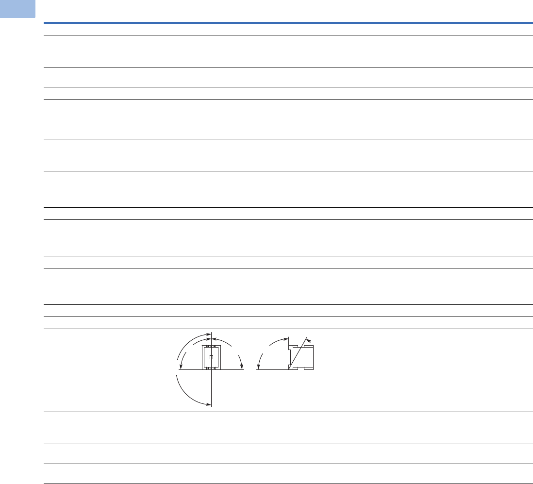
V5-T1-94 Volume 5—Motor Control and Protection CA08100006E—August 2012 www.eaton.com
1
1
1
1
1
1
1
1
1
1
1
1
1
1
1
1
1
1
1
1
1
1
1
1
1
1
1
1
1
1
1.1
IEC Contactors and Starters
XT
IEC Power Control
XT Contactors—Four-Pole, continued
Description XTCF020B XTCF032C XTCF045C XTCF063D XTCF080D XTCF125G XTCF160G XTCF200G
General, continued
Terminal capacity main cable—screw terminals
Solid (mm2) 1 x (0.75–4)
2 x (0.75–2.5)
1 x (0.75–16)
2 x (0.75 –10)
1 x (0.75–16)
2 x (0.75 –10)
1 x (2.5 –16)
2 x (2.5 –16)
1 x (2.5 –16)
2 x (2.5 –16)
———
Flexible with ferrule (mm2) 1 x (0.75–2.5)
2 x (0.75–2.5)
1 x (0.75–16)
2 x (0.75–10)
1 x (0.75–16)
2 x (0.75–10)
1 x (2.5–35)
2 x (2.5–25)
1 x (2.5–35)
2 x (2.5–25)
1 x (10 –95)
2 x (10–70)
1 x (10 –95)
2 x (10–70)
1 x (10 –95)
2 x (10–70)
Solid or stranded (AWG) 18–14 18–6 18–6 12–2 12–2 8–250 kcmil 8–250 kcmil 8–250 kcmil
Terminal capacity control circuit cable—screw
terminals
Solid (mm2) 1 x (0.75–4)
2 x (0.75–2.5)
1 x (0.75–4)
2 x (0.75–2.5)
1 x (0.75–4)
2 x (0.75–2.5)
1 x (0.75–4)
2 x (0.75–2.5)
1 x (0.75–4)
2 x (0.75–2.5)
1 x (0.75–4)
2 x (0.75–2.5)
1 x (0.75–4)
2 x (0.75–2.5)
1 x (0.75–4)
2 x (0.75–2.5)
Flexible with ferrule (mm2) 1 x (0.75–2.5)
2 x (0.75–2.5)
1 x (0.75–2.5)
2 x (0.75–2.5)
1 x (0.75–2.5)
2 x (0.75–2.5)
1 x (0.75–2.5)
2 x (0.75–2.5)
1 x (0.75–2.5)
2 x (0.75–2.5)
1 x (0.75–2.5)
2 x (0.75–2.5)
1 x (0.75–2.5)
2 x (0.75–2.5)
1 x (0.75–2.5)
2 x (0.75–2.5)
Solid or stranded (AWG) 18–14 18–14 18–14 18–14 18–14 18–14 18–14 18–14
Main cable connection screw/bolt
Tightening torque
Nm 1.2 3 3 3.3 3.3 14 14 14
Lb-in 10.6 26.6 26.6 29.2 29.2 123.9 123.9 123.9
Control circuit cable connection screw/bolt
Tightening torque
Nm 1.2 1.2 1.2 1.2 1.2 1.2 1.2 1.2
Lb-in 10.6 10.6 10.6 10.6 10.6 10.6 10.6 10.6
Tools
Main and control circuit cable—
Screw terminals 22222———
Pozidriv screwdriver 0.8 x 5.5 0.8 x 5.5 0.8 x 5.5 0.8 x 5.5 0.8 x 5.5 — — —
Standard screwdriver 1 x 6 1 x 6 1 x 6 1 x 6 1 x 6 — — —
Mounting position, AC and DC operated
Ambient temperature
Open –25 to 60°C
(–13 to 140°F)
–25 to 60°C
(–13 to 140°F)
–25 to 60°C
(–13 to 140°F)
–25 to 60°C
(–13 to 140°F)
–25 to 60°C
(–13 to 140°F)
–25 to 60°C
(–13 to 140°F)
–25 to 60°C
(–13 to 140°F)
–25 to 60°C
(–13 to 140°F)
Enclosed –25 to 40°C
(–13 to 104°F)
–25 to 40°C
(–13 to 104°F)
–25 to 40°C
(–13 to 104°F)
–25 to 40°C
(–13 to 104°F)
–25 to 40°C
(–13 to 104°F)
–25 to 40°C
(–13 to 104°F)
–25 to 40°C
(–13 to 104°F)
–25 to 40°C
(–13 to 104°F)
Ambient storage temperature –40 to 80°C
(–40 to 176°F)
–40 to 80°C
(–40 to 176°F)
–40 to 80°C
(–40 to 176°F)
–40 to 80°C
(–40 to 176°F)
–40 to 80°C
(–40 to 176°F)
–40 to 80°C
(–40 to 176°F)
–40 to 80°C
(–40 to 176°F)
–40 to 80°C
(–40 to 176°F)
180°
90°
90°
90°
30°
Courtesy of CMA/Flodyne/Hydradyne ▪ Motion Control ▪ Hydraulic ▪ Pneumatic ▪ Electrical ▪ Mechanical ▪ (800) 426-5480 ▪ www.cmafh.com

Volume 5—Motor Control and Protection CA08100006E—August 2012 www.eaton.com V5-T1-95
1
1
1
1
1
1
1
1
1
1
1
1
1
1
1
1
1
1
1
1
1
1
1
1
1
1
1
1
1
1
1.1
IEC Contactors and Starters
XT
IEC Power Control
XT Contactors—Four-Pole, continued
Description XTCF020B XTCF032C XTCF045C XTCF063D XTCF080D XTCF125G XTCF160G XTCF200G
Environmental
Mechanical shock resistance (IEC/EN 60068-2-27)
Half-sinusoidal shock 10 ms
Main contact—NO contact 10g 10g 10g 10g 10g 10g 10g 10g
Auxiliary contact—NO contact 7g 7g 7g 7g 7g 7g 7g 7g
Auxiliary contact—NC contact 5g 5g 5g 5g 5g 5g 5g 5g
Overvoltage category/pollution degree III/3 III/3 III/3 III/3 III/3 III/3 III/3 III/3
Coil Data Voltage Tolerance
Pickup (x Uc)
AC operated 0.8–1.1 0.8–1.1 0.8–1.1 0.8–1.1 0.8–1.1 0.8–1.1 0.8–1.1 0.8–1.1
DC operated 0.8–1.1 0.7–1.2 0.7–1.2 0.7–1.2 0.7–1.2 0.7–1.2 0.7–1.2 0.7–1.2
Dropout (x Uc)
AC operated 0.4–0.6 0.4–0.6 0.4–0.6 0.4–0.6 0.4–0.6 0.4–0.6 0.4–0.6 0.4–0.6
DC operated 0.2–0.6 0.2–0.6 0.2–0.6 0.2–0.6 0.2–0.6 0.2–0.6 0.2–0.6 0.2–0.6
Power Consumption of the Coil at Cold State and 1.0 x Uc
AC operated 50/50Hz
Pickup VA 24 50 50 150 150 180 180 180
Pickup W 19 40 40 95 95 150 150 150
Sealing VA 4 8 8 16 16 3.1 3.1 3.1
Sealing W 1.2 2.4 2.4 4 4 2.1 2.1 2.1
DC operated
Pickup W 4.5 12 12 24 24 149 149 149
Sealing W 4.5 0.5 0.5 0.5 0.5 2.1 2.1 2.1
Duty factor (%DF) 100 100 100 100 100 100 100 100
Switching Time at 100% Uc (Approximate Values)
Main contact
AC operated
Closing delay (ms) 15 to 21 6 to 22 6 to 22 12 to 18 12 to 18 28 to 33 28 to 33 28 to 33
Opening delay (ms) 9 to 18 8 to 14 8 to 14 8 to 13 8 to 13 35 to 41 35 to 41 35 to 41
DC operated
Closing delay (ms) 31 47 47 54 54 35 35 35
Opening delay (ms) 12 30 30 24 24 30 30 30
Arcing time (ms) 10 10 10 10 10 15 15 15
Courtesy of CMA/Flodyne/Hydradyne ▪ Motion Control ▪ Hydraulic ▪ Pneumatic ▪ Electrical ▪ Mechanical ▪ (800) 426-5480 ▪ www.cmafh.com

V5-T1-96 Volume 5—Motor Control and Protection CA08100006E—August 2012 www.eaton.com
1
1
1
1
1
1
1
1
1
1
1
1
1
1
1
1
1
1
1
1
1
1
1
1
1
1
1
1
1
1
1.1
IEC Contactors and Starters
XT
IEC Power Control
Auxiliary Contacts
Notes
1Making and breaking conditions to DC-13, time L/R contact as stated.
2See fuses overlay for time/current characteristic (on request).
3Conventional thermal current (Ith) of XTCEXSCC_ is 10A.
Description
XTCE007B_–
XTCE032C
XTCEXFAC_
XTCEXFATC_
XTCEXFCC_
XTCEXSCC_ XTCEXFAG_
XTCEXSBLN_
XTCEXSBN_
XTCEXSBNC_
XTCEXSCN_
XTCEXSCNC_
Interlocked opposing contacts with an auxiliary contact
module (to IEC 60947-5 -1 Annex L)
— Yes Yes Yes Yes
Break contact (not late-break contact) suitable as a mirror
contact (to IEC/EN 60947-4 -1 Annex F)
XTCE007B_–
XTCE032C
XTCE007B_–XTCE032C XTCE007B_–XTCE032C XTCE040D_–XTCE065D_ XTCE040D_–XTCE065D_
XTCE185L_–XTCEC10N_
Rated impulse withstand voltage, (Uimp) Vac 6000 6000 6000 6000 6000
Overvoltage category/pollution degree III/3 III/3 III/3 III/3 III/3
Rated insulation voltage, (Ui) Vac 690 690 690 690 690
Rated operational voltage, (Ue) Vac 500 500 500 500 500
Safe isolation to VDE 0106 Part 101 and Part 101(A) in Vac
Between coil and auxiliary contacts 400 400 400 440 440
Between the auxiliary contacts 400 400 400 440 440
Rated operational current, le
AC-15
230V 6A 6A 6A 6A 6A
380/415V 4A 3A 4A 4A 4A
500V 1.5A — 1.5A 1.5A 1.5A
DC-3 L/R
<
5 ms 1
24V 10A 10A 10A 10A 10A
60V 6A6A6A6A6A
110V 3A 3A 3A 3A 3A
220V 1A 1A 1A 1A 1A
Conventional thermal current, Ith 16A 16A 16A 310A 10A
Control circuit reliability
(at Ue = 24 Vdc, Umin = 17 V, Imin = 5.4 mA)
<10-8, <1 failure at
100 million operations
<10-8, <1 failure at
100 million operations
<10-8, <1 failure at
100 million operations
<10-8, <1 failure at
100 million operations
<10-8, <1 failure at
100 million operations
Component lifespan, operations x 106
at Ue = 230V, AC-15, 3A
1.3 1.3 1.3 1.3 1.3
Short-circuit rating without welding 2
Maximum fuse, gG/gL 10A 10A 10A 16A 16A
Courtesy of CMA/Flodyne/Hydradyne ▪ Motion Control ▪ Hydraulic ▪ Pneumatic ▪ Electrical ▪ Mechanical ▪ (800) 426-5480 ▪ www.cmafh.com

Volume 5—Motor Control and Protection CA08100006E—August 2012 www.eaton.com V5-T1-97
1
1
1
1
1
1
1
1
1
1
1
1
1
1
1
1
1
1
1
1
1
1
1
1
1
1
1
1
1
1
1.1
IEC Contactors and Starters
XT
IEC Power Control
Parallel Link
Cable Terminal Block, Flat Cable Terminal
AC Ratings—AC-1 Operation
Description XTCEXPLKB XTECXPLKC XTCEXPLKD XTCEXPLKG XTCEXPLK185
Terminal capacity
Solid (mm2) 1–161616——
Flexible with ferrule (mm2) 1 x (0.5–25)
2 x (0.5–16)
1 x (16–35) 1 x (16–120) — —
Stranded (mm2) 1 x (0.5–25)
2 x (0.5–16)
1 x (16–50) 1 x (16–120) 1 x (35–300)
2 x (35–120)
—
Flat conductor—number of segments x width x thickness (mm) 6 x 9 x 0.8 — — 2 x (11 x 21 x 1) 1 x (6 x 16 x 0.8)
2 x (20 x 32 x 0.5)
2 x (11 x 21 x 1)
Tightening torque (Nm) 4 4 14 — —
Tools
Pozidriv screwdriver Size 2 Size 2 — — —
Hexagon socket head spanner—SW (mm) — — 5 6 —
Conventional thermal current
Three-pole (Ith) A 50 100 180 400 —
Four-pole (Ith) A 60————
Description XTCEXTLA400 XTCEXPLK185 XTCEXTFB650 XTCEXTFB820
Terminal capacity
Stranded (mm2) 1 x (120–300)
2 x (70–240)
———
Stranded (AWG) 1 x (250–600 kcmil)
2 x (2/0–500 kcmil)
———
Flat conductor—number of segments x width x thickness (mm) — 1 x (6 x 16 x 0.8)
2 x (20 x 32 x 0.5)
2 x (11 x 21 x 1)
1 x (6 x 16 x 0.8)
2 x (20 x 32 x 0.5)
2 x (11 x 21 x 1)
1 x (6 x 16 x 0.8)
2 x (10 x 40 x 1)
2 x (20 x 40 x 0.5)
Description XTCE007B XTCE009B XTCE012B XTCE015B XTCE018C XTCE025C XTCE032C
Conventional free air thermal current, three-pole, 50–60 Hz
Open
at 40°C (Ith) 22A 22A 22A 22A 40A 45A 45A
at 50°C (Ith) 21A 21A 21A 21A 38A 43A 43A
at 55°C (Ith) 21A 21A 21A 21A 37A 42A 42A
at 60°C (Ith) 20A 20A 20A 20A 35A 40A 40A
Enclosed 18A 18A 18A 18A 32A 36A 36A
Conventional free air thermal current, single-pole (Ith)
Open 50A 50A 50A 50A 88A 100A 100A
Enclosed 45A 45A 45A 45A 80A 90A 90A
Courtesy of CMA/Flodyne/Hydradyne ▪ Motion Control ▪ Hydraulic ▪ Pneumatic ▪ Electrical ▪ Mechanical ▪ (800) 426-5480 ▪ www.cmafh.com

V5-T1-98 Volume 5—Motor Control and Protection CA08100006E—August 2012 www.eaton.com
1
1
1
1
1
1
1
1
1
1
1
1
1
1
1
1
1
1
1
1
1
1
1
1
1
1
1
1
1
1
1.1
IEC Contactors and Starters
XT
IEC Power Control
AC Ratings—AC-3 Operation
AC Ratings—AC-4 Operation
Notes
1At maximum permissible ambient temperature.
2Example—
The transformer has a nominal current of 10A with an inrush current of 18 times the nominal current. So, the contactor must have an
AC-3 current of 18/6 x 10A = 30A. Using an XTCE032C (32A AC-3) contactor is recommended.
Description XTCE007B XTCE009B XTCE012B XTCE015B XTCE018C XTCE025C XTCE032C
Rated operational current, 50/60 Hz 1 (Ie) in amperes
220/230V 7 9 12 15.5 18 25 32
240V 7 9 12 15.5 18 25 32
380/400V 7 9 12 15.5 18 25 32
415V 7 9 12 15.5 18 25 32
440V 7 9 12 15.5 18 25 32
500V 5 7 10 12.5 18 25 32
660/690V 4 5 7 9 12 15 18
1000V — — — — — — —
Rated power (P) in kilowatts
220/230V 2.2 2.5 3.5 4 5 7.5 10
240V 2.2 3 4 4.6 5.5 8.5 11
380/400V 3 4 5.5 7.5 7.5 11 15
415V 4 5.5 7 8 10 14.5 19
440V 4.5 5.5 7.5 8.4 10.5 15.5 20
500V 3.5 4.5 7 7.5 12 17.5 23
660/690V 3.5 4.5 6.5 7 11 14 17
1000V — — — — — — —
Description XTCE007B XTCE009B XTCE012B XTCE015B XTCE018C XTCE025C XTCE032C
Rated operational current, 50/60 Hz 2 (Ie) in amperes
220/230V 5 6 7 7 10 13 15
240V 5 6 7 7 10 13 15
380/400V 5 6 7 7 10 13 15
415V 5 6 7 7 10 13 15
440V 5 6 7 7 10 13 15
500V 4.5 5 6 6 1 13 1
660/690V 4 4.5 5 5 8 10 12
1000V — — — — — — —
Rated power (P) in kilowatts
220/230V 1 1.5 2 2 2.5 3.5 4
240V 1.5 1.6 2.2 2.2 3 4 4.5
380/400V 2.2 2.5 3 3 4.5 6 7
415V 2.3 2.8 3.4 3.4 5 6.5 7.5
440V 2.4 3 3.6 3.6 5.5 7 8
500V 2.5 2.8 3.5 3.5 6 8 9
660/690V 2.9 3.6 4.4 4.4 6.5 8.5 10
1000V — — — — — — —
Courtesy of CMA/Flodyne/Hydradyne ▪ Motion Control ▪ Hydraulic ▪ Pneumatic ▪ Electrical ▪ Mechanical ▪ (800) 426-5480 ▪ www.cmafh.com

Volume 5—Motor Control and Protection CA08100006E—August 2012 www.eaton.com V5-T1-99
1
1
1
1
1
1
1
1
1
1
1
1
1
1
1
1
1
1
1
1
1
1
1
1
1
1
1
1
1
1
1.1
IEC Contactors and Starters
XT
IEC Power Control
AC Ratings—AC-6A Operation
AC Ratings—AC-6B Operation
AC Ratings—AC-1 Operation
Notes
1Example—
The transformer has a nominal current of 10A with an inrush current of 18 times the nominal current. So, the contactor must have an
AC-3 current of 18/6 x 10A = 30A. Using an XTCE032C (32A AC-3) contactor is recommended.
2For 225–275A, use 2X 70 mm2 wire.
3At maximum permissible ambient temperature.
Description XTCE007B XTCE009B XTCE012B XTCE015B XTCE018C XTCE025C XTCE032C
Transformer loads Values are
application specific
Values are
application specific
Values are
application specific
Values are
application specific
Values are
application specific
Values are
application specific
Values are
application specific
Calculation is Ie AC-3 = X / 6 * Ie transformer where X is the inrush current of the transformer and Ie transformer is the nominal current. 1
Description XTCE007B XTCE009B XTCE012B XTCE015B XTCE018C XTCE025C XTCE032C
Capacitor loads
Individual compensation rated operational current Ie
of three-phase capacitors in amperes
Up to 525V See Page V5-T1-63 for capacitor ratings
690V See Page V5-T1-63 for capacitor ratings
Maximum inrush current peak (x Ie) 30303030303030
Component lifesaving (operations) — — — — — — —
Maximum operating frequency (ops/hr) — — — — — — —
Description XTCE040D XTCE050D XTCE065D XTCE072D XTCE080F XTCE095F XTCE115G XTCE150G XTCE170G
Conventional free air thermal current,
three-pole, 50–60 Hz
Open
at 40°C (Ith) 60A 80A 98A 98A 110A 130A 160A 190A 275A 2
at 50°C (Ith) 57A 71A 88A 88A 98A 125A 142A 180A 200A
at 55°C (Ith) 55A 68A 83A 83A 94A 115A 135A 170A 190A
at 60°C (Ith) 50A 65A 80A 80A 90A 110A 130A 160A 185A
Enclosed 45A 58A 72A 72A 80A 100A 115A 144A 166A
Conventional free air thermal current,
single-pole (Ith)
Open 125A 162A 200A 200A 225A 275A 325A 400A 460A
Enclosed 112A 145A 180A 180A 200A 250A 285A 360A 415A
Courtesy of CMA/Flodyne/Hydradyne ▪ Motion Control ▪ Hydraulic ▪ Pneumatic ▪ Electrical ▪ Mechanical ▪ (800) 426-5480 ▪ www.cmafh.com

V5-T1-100 Volume 5—Motor Control and Protection CA08100006E—August 2012 www.eaton.com
1
1
1
1
1
1
1
1
1
1
1
1
1
1
1
1
1
1
1
1
1
1
1
1
1
1
1
1
1
1
1.1
IEC Contactors and Starters
XT
IEC Power Control
AC Ratings—AC-3 Operation
AC Ratings—AC-4 Operation
Note
1At maximum permissible ambient temperature.
Description XTCE040D XTCE050D XTCE065D XTCE072D XTCE080F XTCE095F XTCE115G XTCE150G XTCE170G
Rated operational current, 50/60 Hz 1 (Ie) in amperes
220/230V 40 50 65 72 80 95 115 150 170
240V 40 50 65 72 80 95 115 150 170
380/400V 40 50 65 7 80 95 115 150 170
415V 40 50 65 72 80 95 115 150 170
440V 40 50 65 72 80 95 115 15 170
500V 40 50 65 72 80 95 115 150 170
660/690 25 32 37 37 65 80 93 100 150
1000V — — — — — — — — —
Rated power (P) in kilowatts
220/230V 12.5 15.5 20 22 25 30 37 48 52
240V 13.5 17 22 35 27.5 34 40 52 57
380/400V 18.5 22 30 37 37 45 55 75 90
415V 24 30 39 41 43 57 70 91 100
440V 25 32 41 44 51 60 75 95 105
500V 28 36 47 45 58 70 85 110 120
660/690V 23 30 35 35 63 75 90 96 140
1000V — — — — — — — — —
Description XTCE040D XTCE050D XTCE065D XTCE072D XTCE080F XTCE095F XTCE115G XTCE150G XTCE170G
Rated operational current, 50/60 Hz 1 (Ie) in amperes
220/230V 18 21 25 25 40 50 55 65 65
240V 18 21 25 25 40 50 55 65 65
380/400V 18 21 25 25 40 50 55 65 65
415V 18 21 25 25 40 50 55 65 65
440V 18 21 25 25 40 50 55 65 65
500V 18 21 25 25 40 50 55 65 65
660/690V 14 17 20 20 40 50 45 50 50
1000V — — — — — — — — —
Rated power (P) in kilowatts
220/230V 5 6 7 7 12 16 17 20 20
240V 5.5 6.5 7.5 7.5 13 17 19 22 22
380/400V 9 10 12 12 20 26 28 33 33
415V 9.51113132430333939
440V 10 12 14 14 25 32 35 41 41
500V 11 13 16 16 29 36 40 47 47
660/690V 12 14 17 17 26 35 43 48 48
1000V — — — — — — — — —
Courtesy of CMA/Flodyne/Hydradyne ▪ Motion Control ▪ Hydraulic ▪ Pneumatic ▪ Electrical ▪ Mechanical ▪ (800) 426-5480 ▪ www.cmafh.com

Volume 5—Motor Control and Protection CA08100006E—August 2012 www.eaton.com V5-T1-101
1
1
1
1
1
1
1
1
1
1
1
1
1
1
1
1
1
1
1
1
1
1
1
1
1
1
1
1
1
1
1.1
IEC Contactors and Starters
XT
IEC Power Control
AC Ratings—AC6-A Operation
AC Ratings—AC6-B Operation
AC Ratings—AC-1 Operation
Note
1Example—The transformer has a nominal current of 10A with an inrush current of 18 times the nominal current. So, the contactor must have an
AC-3 current of 18/6 x 10A = 30A. Using an XTCE032C (32A AC-3) contactor is recommended.
Description XTCE040D XTCE050D XTCE065D XTCE072D XTCE080F XTCE095F XTCE115G XTCE150G XTCE170G
Transformer loads Values are
application
specific
Values are
application
specific
Values are
application
specific
Values are
application
specific
Values are
application
specific
Values are
application
specific
Values are
application
specific
Values are
application
specific
Values are
application
specific
Calculation is Ie AC-3 = X / 6 * Ie transformer where X is the inrush current of the transformer and Ie transformer is the nominal current. 1
Description XTCE040D XTCE050D XTCE065D XTCE072D XTCE080F XTCE095F XTCE115G XTCE150G XTCE170G
Capacitor loads
Individual compensation rated operational current Ie of
three-phase capacitors in amperes
Up to 525V See Page V5-T1-63 for capacitor ratings
690V See Page V5-T1-63 for capacitor ratings
Maximum inrush current peak (x Ie) 303030303030303030
Component lifesaving (operations) — — — — — — — — —
Maximum operating frequency (ops/hr) — — — — — — — — —
Description XTCE185H XTCE225L XTCE250L XTCE300L XTCE400M XTCE500M XTCE570M XTCE580N
Conventional free air thermal current, three-pole, 50–60 Hz
at 40°C (Ith) 337 356 429 490 612 857 857 980
at 50°C (Ith)301 310 383 438 548 767 767 876
at 55°C (Ith)287 295 366 418 522 731 731 836
at 60°C (Ith)275 285 350 400 500 700 700 800
Conventional free air thermal current, single-pole (Ith)245 275 875 315 1250 1750 1750 2000
Courtesy of CMA/Flodyne/Hydradyne ▪ Motion Control ▪ Hydraulic ▪ Pneumatic ▪ Electrical ▪ Mechanical ▪ (800) 426-5480 ▪ www.cmafh.com

V5-T1-102 Volume 5—Motor Control and Protection CA08100006E—August 2012 www.eaton.com
1
1
1
1
1
1
1
1
1
1
1
1
1
1
1
1
1
1
1
1
1
1
1
1
1
1
1
1
1
1
1.1
IEC Contactors and Starters
XT
IEC Power Control
AC Ratings—AC-3 Operation
AC Ratings—AC-4 Operation
Note
1At maximum permissible ambient temperature.
Description XTCE185H XTCE225L XTCE250L XTCE300L XTCE400M XTCE500M XTCE570M XTCE580N
Rated operational current, 50/60 Hz 1 (Ie) in amperes
220/230V 185 225 250 300 400 500 580 580
240V 185 225 250 300 400 500 580 580
380/400V 185 225 250 300 400 500 580 580
415V 185 225 250 300 400 500 580 580
440V 185 225 250 300 400 500 580 580
500V 185 225 250 300 400 500 580 580
660/690V 150 160 250 210 400 500 580 580
1000V 76 76 76 95 95 95 95 435
Rated power (P) in kilowatts
220/230V 55 70 75 90 125 155 185 185
240V 62 75 85 100 132 170 200 200
380/400V 90 110 132 160 200 250 315 315
415V 110 132 148 180 240 300 348 348
440V 115 138 157 185 255 345 370 370
500V 132 160 180 215 290 360 420 420
660/690V 140 150 240 195 344 344 344 560
1000V 108 108 108 132 132 132 132 600
Description XTCE185H XTCE225L XTCE250L XTCE300L XTCE400M XTCE500M XTCE570M XTCE580N
Rated operational current, 50/60 Hz 1 (Ie) in amperes
220/230V 136 164 200 200 296 360 360 456
240V 136 164 200 200 296 360 360 456
380/400V 136 164 200 200 296 360 360 456
415V 136 164 200 200 296 360 360 456
440V 136 164 200 200 296 360 360 456
500V 136 164 200 200 296 360 360 456
660/690V 110 120 200 200 296 360 360 456
1000V 55 55 76 76 95 95 95 348
Rated power (P) in kilowatts
220/230V 41 51 62 75 92 112 112 143
240V 45 54 68 82 101 122 122 156
380/400V 75 90 110 132 160 200 200 250
415V 80 96 117 142 176 216 216 274
440V 85 102 125 150 186 229 229 290
500V 96 116 143 172 214 260 260 330
660/690V 102 110 189 160 283 344 344 440
1000V 77 77 108 109 132 132 132 509
Courtesy of CMA/Flodyne/Hydradyne ▪ Motion Control ▪ Hydraulic ▪ Pneumatic ▪ Electrical ▪ Mechanical ▪ (800) 426-5480 ▪ www.cmafh.com

Volume 5—Motor Control and Protection CA08100006E—August 2012 www.eaton.com V5-T1-103
1
1
1
1
1
1
1
1
1
1
1
1
1
1
1
1
1
1
1
1
1
1
1
1
1
1
1
1
1
1
1.1
IEC Contactors and Starters
XT
IEC Power Control
AC Ratings—AC-1 Operation
AC Ratings—AC-3 Operation
Notes
1Up to 690V.
2At maximum permissible ambient temperature.
Description XTCE650N XTCE750N XTCE820N XTCEC10N XTCEC14P XTCEC16R XTCEC20R
Conventional free air thermal current, three-pole,
50–60 Hz
at 40°C (Ith) 1041 1102 1225 1225 1714 12200 2450
1
at 50°C (Ith) 931 986 1095 1095 1533 11970 2190 1
at 55°C (Ith) 888 940 1044 1044 1462 11800 2089
1
at 60°C (Ith) 850 900 1000 1000 1400 11800 2000
1
Conventional free air thermal current,
single-pole (Ith)
2125 2250 2500 2500 3500 4500 5000
Description XTCE650N XTCE750N XTCE820N XTCEC10N XTCEC14P XTCEC16R XTCEC20R
Rated operational current, 50/60 Hz 2 (Ie) in amperes
220/230V 650 750 820 1000 — 1600 —
240V 650 750 820 1000 — 1600 —
380/400V 650 750 820 1000 — 1600 —
415V 650 750 820 1000 — 1600 —
440V 650 750 820 1000 — 1600 —
500V 650 750 820 1000 — 1600 —
660/690V 650 750 820 1000 — 1600 —
1000V 435 580 580 700 — — —
Rated power (P) in kilowatts
220/230V 205 240 260 315 — 500 —
240V 225 260 285 340 — 550 —
380/400V 355 400 450 560 — 900 —
415V 390 455 500 610 — 930 —
440V 420 480 525 650 — 1000 —
500V 470 550 600 730 — 1180 —
660/690V 630 720 750 1000 — 1600 —
1000V 600 800 800 1000 — — —
Courtesy of CMA/Flodyne/Hydradyne ▪ Motion Control ▪ Hydraulic ▪ Pneumatic ▪ Electrical ▪ Mechanical ▪ (800) 426-5480 ▪ www.cmafh.com

V5-T1-104 Volume 5—Motor Control and Protection CA08100006E—August 2012 www.eaton.com
1
1
1
1
1
1
1
1
1
1
1
1
1
1
1
1
1
1
1
1
1
1
1
1
1
1
1
1
1
1
1.1
IEC Contactors and Starters
XT
IEC Power Control
AC Ratings—AC-4 Operation
AC Ratings—AC-6A Operation
Notes
1At maximum permissible ambient temperature.
2Example—The transformer has a nominal current of 10A with an inrush current of 18 times the nominal current. So, the contactor must have an
AC-3 current of 18/6 x 10A = 30A. Using an XTCE032C (32A AC-3) contactor is recommended.
Description XTCE650N XTCE750N XTCE820N XTCEC10N XTCEC14P XTCEC16R XTCEC20R
Rated operational current, 50/60 Hz 1 (Ie) in amperes
220/230V 512 576 656 800 — 1280 —
240V 512 576 656 800 — 1280 —
380/400V 512 576 656 800 — 1280 —
415V 512 576 656 800 — 1280 —
440V 512 576 656 800 — 1280 —
500V 512 576 656 800 — 1280 —
660/690V 512 576 656 800 — 1280 —
1000V 348 464 464 700 — — —
Rated power (P) in kilowatts
220/230V 161 181 209 260 — 30 —
240V 176 200 228 280 — 450 —
380/400V 280 315 355 450 — 750 —
415V 307 346 394 490 — 770 —
440V 32 367 41 520 — 830 —
500V 370 417 474 590 — 940 —
660/690V 494 556 633 780 — 1300 —
1000V 509 678 678 1000 — — —
Description XTCE650N XTCE750N XTCE820N XTCEC10N XTCEC14P XTCEC16R XTCEC20R
Transformer loads Values are
application
specific
Values are
application
specific
Values are
application
specific
Values are
application
specific
Values are
application
specific
Values are
application
specific
Values are
application
specific
Calculation is Ie AC-3 = X / 6 * Ie transformer where X is the inrush current of the transformer and Ie transformer is the nominal current. 2
Courtesy of CMA/Flodyne/Hydradyne ▪ Motion Control ▪ Hydraulic ▪ Pneumatic ▪ Electrical ▪ Mechanical ▪ (800) 426-5480 ▪ www.cmafh.com

Volume 5—Motor Control and Protection CA08100006E—August 2012 www.eaton.com V5-T1-105
1
1
1
1
1
1
1
1
1
1
1
1
1
1
1
1
1
1
1
1
1
1
1
1
1
1
1
1
1
1
1.1
IEC Contactors and Starters
XT
IEC Power Control
AC Ratings—AC-6B Operation
AC Ratings—Four-Pole—AC-1 Operation
AC Ratings—Four-Pole—AC-3 Operation
Description XTCE650N XTCE750N XTCE820N XTCEC10N XTCEC14P XTCEC16R XTCEC20R
Capacitor loads
Individual compensation rated operational
current Ie of three-phase capacitors in amperes
Up to 525V 463 463 463 463 — — —
690V 265 265 265 265 — — —
Maximum inrush current peak (x Ie) 30303030— — —
Component lifesaving (operations) 100,000 100,000 100,000 100,000 — — —
Maximum operating frequency (ops/hr) 200 200 200 200 — — —
Description XTCF020B XTCF032C XTCF045C XTCF063D XTCF080D XTCF125G XTCF160G XTCF200G
Conventional free air thermal current, three-pole, 50-60 Hz
Open (amps)
at 40°C (Ith) 22 32 45 3 80 125 160 200
at 50°C (Ith) 213041607611615188
at 60°C (Ith) 2028395469108138172
Enclosed (amps) 18 27 36 50 64 100 128 160
Conventional free air thermal current, single-pole
Open (amps) 60 84 117 162 207 325 415 516
Enclosed (amps) 54 76 105 146 186 292 373 464
Description XTCF020B XTCF032C XTCF045C XTCF063D XTCF080D XTCF125G XTCF160G XTCF200G
Rated operational current, 50/60 Hz (Ie) in amperes
220/230V 12 18 25 40 50 80 95 115
240V 12 18 25 40 50 80 95 115
380/400V 12 18 25 40 50 80 95 115
415V 12 18 25 40 50 80 95 115
440V 12 18 25 40 50 80 95 115
500V 10 18 25 40 50 80 95 115
660/690V 7 12152532658093
Rated power, (P) in kilowatts
220/230V 3.5 5 7.5 2.5 15.5 25 30 37
240V 4 5.5 8.5 13.5 17 27.5 33 40
380/400V 5.5 7.5 11 18.5 22 37 45 55
415V 7 1014.52430485770
440V 7.510.515.52532516075
500V 47 12 17.5 28 36 58 70 85
660/690V 6.511142330637590
Courtesy of CMA/Flodyne/Hydradyne ▪ Motion Control ▪ Hydraulic ▪ Pneumatic ▪ Electrical ▪ Mechanical ▪ (800) 426-5480 ▪ www.cmafh.com

V5-T1-106 Volume 5—Motor Control and Protection CA08100006E—August 2012 www.eaton.com
1
1
1
1
1
1
1
1
1
1
1
1
1
1
1
1
1
1
1
1
1
1
1
1
1
1
1
1
1
1
1.1
IEC Contactors and Starters
XT
IEC Power Control
DC Ratings—DC-1
DC Ratings—DC-3
Description
Rated Operation
Current {1} (Ie) in
Amperes XTCE007B XTCE009B
XTCE012B,
XTCF020B XTCE015B XTCE018C XTCE025C XTCE032C XTCE040D XTCE050D XTCE065D
60V 20202020354040506072
110V 20 20 20 20 35 40 40 50 50 72
220V 15 15 15 15 3 4 40 45 45 65
440V 1 1.3 1.3 1.3 2.9 2.9 2.9 2.9 2.9 2.9
XTCE080F XTCE095F XTCE115G XTCE150G XTCE185H XTCE225H XTCE250L XTCE300L XTCE400M XTCE500M
60V 110 110 160 160 300 300 300 300 400 400
110V 110 110 16 160 300 300 300 300 400 400
220V 70 70 90 90 300 300 300 300 400 400
440V 4.5 4.5 4.5 4.5 11 11 11 11 11 11
XTCE580N XTCE650N XTCE750N XTCE820N XTCEC10N XTCEC14P XTCEC20R XTCEC16R
60V — — — — — — — —
110V — — — — — — — —
220V — — — — — — — —
440V ————————
Description
Rated Operation
Current {1} (Ie) in
Amperes XTCE007B XTCE009B XTCE012B XTCE015B XTCE018C XTCE025C XTCE032C XTCE040D XTCE050D XTCE065D
60V 20202020353540506072
110V 20 20 20 20 35 35 40 50 50 72
220V 1.5 1.5 1.5 1.5 10 10 25 25 25 35
440V 0.2 0.2 0.2 0.2 0.6 0.6 0.6 0.6 0.6 0.6
XTCE080F XTCE095F XTCE115G XTCE150G XTCE185H XTCE225H XTCE250L XTCE300L XTCE400M XTCE500M
60V 110 110 160 160 300 300 300 300 400 400
110V 110 110 160 160 300 300 300 300 400 400
220V 35 35 40 40 300 300 300 300 400 400
440V 1111— — — — — —
XTCE580N XTCE650N XTCE750N XTCE820N XTCEC10N XTCEC14P XTCEC20R XTCEC16R
60V — — — — — — — —
110V — — — — — — — —
220V — — — — — — — —
440V — — — — — — — —
Courtesy of CMA/Flodyne/Hydradyne ▪ Motion Control ▪ Hydraulic ▪ Pneumatic ▪ Electrical ▪ Mechanical ▪ (800) 426-5480 ▪ www.cmafh.com

Volume 5—Motor Control and Protection CA08100006E—August 2012 www.eaton.com V5-T1-107
1
1
1
1
1
1
1
1
1
1
1
1
1
1
1
1
1
1
1
1
1
1
1
1
1
1
1
1
1
1
1.1
IEC Contactors and Starters
XT
IEC Power Control
DC Ratings—DC-5
DC Ratings—Four-Pole—DC-1 Operation
DC Ratings—Four-Pole—DC-3 Operation
DC Ratings—Four-Pole—DC-5 Operation
Description
Rated Operation
Current {1} (Ie) in
Amperes XTCE007B XTCE009B XTCE012B XTCE015B XTCE018C XTCE025C XTCE032C XTCE040D XTCE050D XTCE065D
60V 20202020353540506072
110V 20 20 20 20 35 35 40 50 50 72
220V 1.5 1.5 1.5 1.5 10 10 25 25 25 35
440V 0.2 0.2 0.2 0.2 0.6 0.6 0.6 0.6 0.6 0.6
XTCE080F XTCE095F XTCE115G XTCE150G XTCE185H XTCE225H XTCE250L XTCE300L XTCE400M XTCE500M
60V 110 110 160 160 300 300 300 300 400 400
110V 110 110 160 160 300 300 300 300 400 400
220V 35 35 40 40 300 300 300 300 400 400
440V 1111— — — — — —
XTCE580N XTCE650N XTCE750N XTCE820N XTCEC10N XTCEC14P XTCEC20R
60V — — — — — — —
110V — — — — — — —
220V — — — — — — —
440V — — — — — — —
Description
Rated Operation
Current {1} (Ie) in
Amperes XTCF020B XTCF032C XTCF045C XTCF063D XTCF080D XTCF125G XTCF160G XTCF200G
60V 2232456380125160200
110V 22 32 45 6 80 125 160 200
220V 6 32456380125160200
440V 1.33355100125150
Description
Rated Operation
Current {1} (Ie) in
Amperes XTCF020B XTCF032C XTCF045C XTCF063D XTCF080D XTCF125G XTCF160G XTCF200G
60V 2032456380125160200
110V 20 32 45 63 80 125 160 200
220V 1.532456380125160200
440V 0.266887595115
Description
Rated Operation
Current {1} (Ie) in
Amperes XTCF020B XTCF032C XTCF045C XTCF063D XTCF080D XTCF125G XTCF160G XTCF200G
60V 2032456380125160200
110V 20 25 32 508 80 125 160 200
220V 1.515223870100125150
440V 0.24488607590
Courtesy of CMA/Flodyne/Hydradyne ▪ Motion Control ▪ Hydraulic ▪ Pneumatic ▪ Electrical ▪ Mechanical ▪ (800) 426-5480 ▪ www.cmafh.com

V5-T1-108 Volume 5—Motor Control and Protection CA08100006E—August 2012 www.eaton.com
1
1
1
1
1
1
1
1
1
1
1
1
1
1
1
1
1
1
1
1
1
1
1
1
1
1
1
1
1
1
1.1
IEC Contactors and Starters
XT
IEC Power Control
Current Heat Loss (Three-Pole) in Watts
Current Heat Loss (Four-Pole) in Watts
Description XTCE007B XTCE009B
XTCE012B,
XTCF020B XTCE015B XTCE018C XTCE025C XTCE032C XTCE040D
Current heat loss (three-pole) in watts
at Ith 33337.39.612.111.3
at Ie to AC-3/400V 0.37 0.6 1.1 1.8 1.9 3.8 6.1 7.2
Impedance per pole, megohms2.52.52.52.52221.5
XTCE050D XTCE065D XTCE072D XTCE080F XTCE095F XTCE115G XTCE150G XTCE170G
Current heat loss (three-pole) in watts
at Ith 19 28.8 28.8 12.2 18.2 20.3 30.7 41.1
at Ie to AC-3/400V 11.3 19 23 9.6 13.5 15.9 27.0 34.7
Impedance per pole, megohms 1.5 1.5 1.5 0.5 0.5 0.4 0.4 0.4
XTCE185H XTCE225H XTCE250L XTCE300L XTCE400M XTCE500M XTCE580N XTCE650N
Current heat loss (three-pole) in watts
at Ith 34 45 55 37 58 113 61 69
at Ie to AC-3/400V 16 23 28 21 37 58 32 41
Impedance per pole, megohms — — — — — — — —
XTCE750N XTCE820N XTCEC10N XTCEC14P XTCEC20R XTCEC16R
Current heat loss (three-pole) in watts
at Ith 78 96 96 188 192 155
at Ie to AC-3/400V 54 65 96 — — 123
Impedance per pole, megohms — — — — — —
Description XTCF020B XTCF032C XTCF045C XTCF063D XTCF080D XTCF125G XTCF160G XTCF200G
Current heat loss (four-pole) in watts
at Ith 4.7 8.2 12 16 23 29 46 60
Impedance per pole, megohms 2.5 2 1.5 1 0.7 0.6 0.6 0.5
Courtesy of CMA/Flodyne/Hydradyne ▪ Motion Control ▪ Hydraulic ▪ Pneumatic ▪ Electrical ▪ Mechanical ▪ (800) 426-5480 ▪ www.cmafh.com
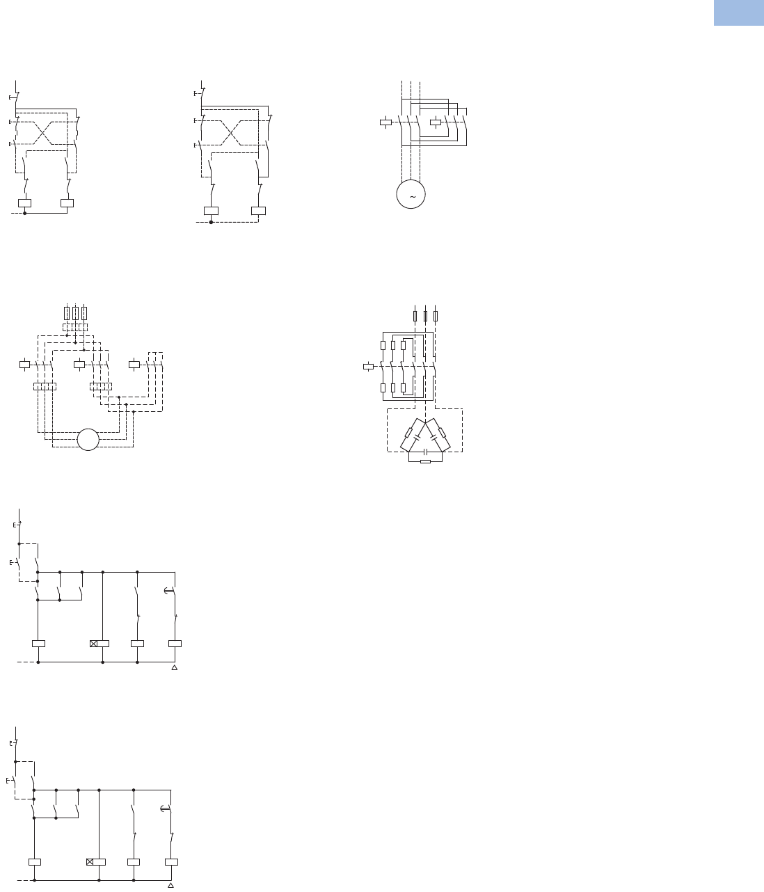
Volume 5—Motor Control and Protection CA08100006E—August 2012 www.eaton.com V5-T1-109
1
1
1
1
1
1
1
1
1
1
1
1
1
1
1
1
1
1
1
1
1
1
1
1
1
1
1
1
1
1
1.1
IEC Contactors and Starters
XT
IEC Power Control
Wiring Diagrams
7–150A XTCR Reversing Contactors
Control Circuit—7–32A Control Circuit—40–170A
Star-Delta (Wye-Delta) Starters
Power Circuit—12–385A AC-3
Control Circuit—12–55A AC-3
Control Circuit—70–1700A AC-3
K2M
54
K1M 54
53 53
K2M 22
21 K1M 22
21
K1M A1
A2 K2M A1
A2
I14
13
13
II 21
22
22
21
21
22
0
14
K2M 14
K1M 14
13 13
K2M 22
21 K1M 22
21
K1M A1
A2 K2M A1
A2
(-)N
I14
13
13
II 21
22
22
21
21
22
0
14
K1M 15
642 K5M 15
642 K3M 1
33
35
642
U1
V1
W1 M1
3~
M1
V2
W2
U2
AC
B
0.58 x ln
0.58 x ln
L1 L2 L3
F1
1 x l
n
S11
0
(–)N
K1M
K3M
K3M
K5M
K1
I
K1M
K1M
K5M
K3M
K1
K5M
NY
K1T
21
22
13
14
A2
A1
A2
A1
53
54
22
21
28
17
17
18
14
13
53
54
53
54
A2
A1
A2
A1
22
21
S11
0
(–)N
K1M
K3M
K3M
K5M
K1
I
K1M
K1M
K5M
K3M
K1
K5M
NY
K1T
21
22
13
14
A2
A1
A2
A1
13
14
22
21
28
17
17
18
14
13
13
14
43
44
A2
A1
A2
A1
22
21
Power Circuit—7–150A with
Mechanical Interlock 80–
150A on Mounting Plate
XTCC Contactors for Three-Phase Capacitors
Power Circuit—11–85 kVar
In the case of group
compensation, multi-stage
capacitor banks are
connected to the mains, as
required. In the process,
transient currents of up to
180 x Ie can flow between
the capacitors. The capacitors
are pre-charged via the early-
make auxiliary contacts and
the fitted wire resistors,
thereby reducing the inrush
current. The main contacts
then close after a time lag
and carry the uninterrupted
current. The contactors for
capacitors are weld-resistant
with inrush current peaks up
to 180 x 1 Ie due to their
special contacts. For
switching reactive-power
compensation equipment
with chokes, observe
design notes.
For switching of power factor
connection with reactors,
please observe engineering
notes, Page V5-T1-64. Use of
the contactors XTCE without
series resistor for centralized
power factor correction—
when using contactors for
group compensation, a
minimum inductance of
approximately 6 μH per
capacitor must be available to
limit the high inrush current
peaks. This corresponds to an
air-cored coil with 5 windings
and a coil diameter of
approximately 140 mm
diameter. The conductor
cross-section must be
selected according to the
rated current per phase.
UVW
K1M
M
M1
K2M
135
64
2
13 5
6
4
2
3
A1
A2
R11 R11
R11
C1
1
2
3
4
5
L1 L2 L3
6
Courtesy of CMA/Flodyne/Hydradyne ▪ Motion Control ▪ Hydraulic ▪ Pneumatic ▪ Electrical ▪ Mechanical ▪ (800) 426-5480 ▪ www.cmafh.com
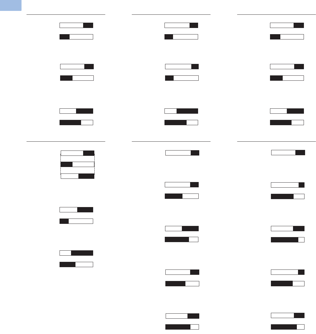
V5-T1-110 Volume 5—Motor Control and Protection CA08100006E—August 2012 www.eaton.com
1
1
1
1
1
1
1
1
1
1
1
1
1
1
1
1
1
1
1
1
1
1
1
1
1
1
1
1
1
1
1.1
IEC Contactors and Starters
XT
IEC Power Control
Contactor Contact Travel Diagrams
Note: The diagrams indicate the closing and travel of the contacts of the contactors and auxiliary
contacts at no-load. Tolerances are not taken into consideration.
4.5
4.5
3.30
01.0 2.9
2.9
2.10
00.7 4.4
4.4
3.30
01.0
4.5
4.5
3.20
01.6 2.9
2.9
2.30
00.7 4.4
4.4
3.20
01.6
4.5
4.5
2.00
02.8 2.9
2.9
1.10
01.9 4.4
4.4
2.00
02.8
6.040
1.8
3.2
7. 5
5.10 1180
7. 5
7. 5
5.7
3.9
0
0
11
11
9.20
07. 4
6
6
3.20
01.6
7. 5
5.40
7. 5
3.8
0
11
11
7. 30
08.9
6
6
2.00
02.8
7. 5
7. 5
5.45
3.6
0
0
11
11
8.950
07. 1
7. 5
4.950
7. 5
4.1
011
11
7. 60
08.45
XTCE 7–15A, XTC—AC
Frame B
Frame C Frame D Frames F and G
XTCEXSAC11
XTCEXF...LC_
XTCE 15–32A
XTCEXSBLN11 XTCEXSBLN11
XTCEXS...N_
XTCEXF...G_
XTCEXF...LG_
XTCE 80–170A
XTCEXF...LC_
XTCEXSAC11
XTCE 12–15A, XTCF—DC
XTCEXS...N_
XTCEXF...LG_
XTCEXF...G_
XTCE 40–72A
XTCEXF...LC_
XTCEXSAC11
XTCE 7–9A—DC
NO contact
NC contact
NO contact
NC contact
NO contact
NC contact
NO contact
NC contact
NO contact
NC contact
NO contact
NC contact
NO contact
NC contact
NO contact
NC contact
NO contact
NC contact
NO contact
Auxiliary NC
Auxiliary NO
NO contactNO contact
NO contact
NC contact
NO contact
NC contact
XTCEXSAC11, XTCEXF...C_
NO contact
NC contact
NO contact
NC contact
NO contact
NC contact
XTCEXF...LC_
NO contact
NC contact
NO contact
NC contact
NO contact
NC contact
NO contact
NC contact
NO contact
NC contact
Courtesy of CMA/Flodyne/Hydradyne ▪ Motion Control ▪ Hydraulic ▪ Pneumatic ▪ Electrical ▪ Mechanical ▪ (800) 426-5480 ▪ www.cmafh.com
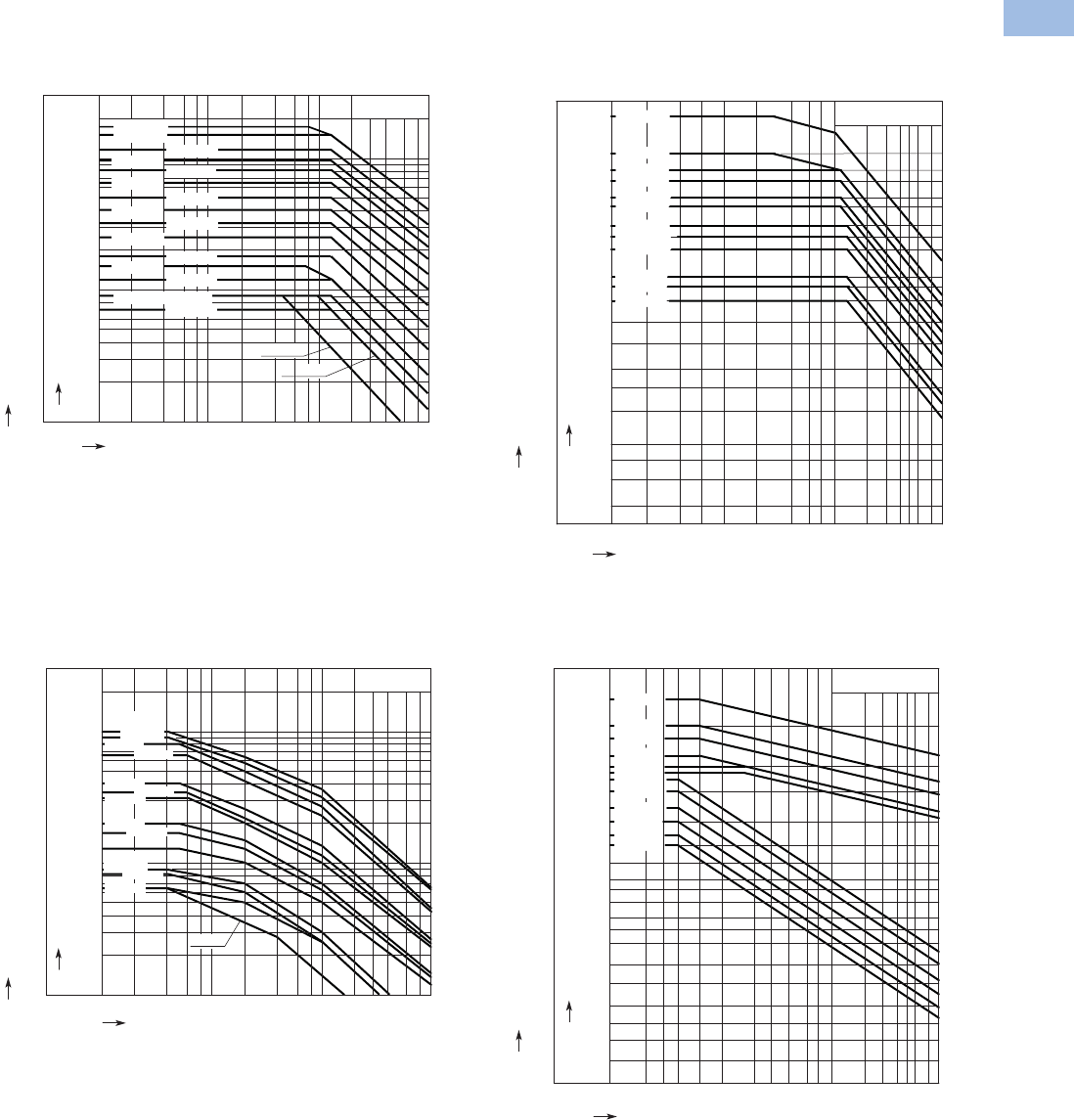
Volume 5—Motor Control and Protection CA08100006E—August 2012 www.eaton.com V5-T1-111
1
1
1
1
1
1
1
1
1
1
1
1
1
1
1
1
1
1
1
1
1
1
1
1
1
1
1
1
1
1
1.1
IEC Contactors and Starters
XT
IEC Power Control
Electrical Life Curves
Normal Switching Duty
XTCE007B–XTCE170G XTCE185H–XTCEC16R
Extreme Switching Duty
XTCE007B–XTCE170G XTCE185H–XTCEC16R
Rated Output of Three-phase Motors 50 – 60 Hz
Rated Operational Current Ie 50 – 60 Hz
Component Lifespan (millions of operations)
A
kW
150
11 5
95
80
65
50
40
32
25
18
12
9
7
5
4
3
2
AC-3/400V
75
55
45
37
30
22
18.5
15
11
7. 5
5.5
4
3
0.01 0.02 0.04 0.06 0.1 0.2 0.4 0.6 1 2 4 6 10
XTCE032C
XTCE050D
XTCE025C
XTCE015B
XTCE040D
XTCE065D
XTCE080F
XTCE115G
XTCE095F
XTCE150G
170
90 XTCE170G
XTCE018C
XTCE012B
XTCE009B, XTMC9A
XTCE007B
XTMC9A
XTMC9A
Rated Output of Three-phase Motors 50 – 60 Hz
Rated Operational Current Ie 50 – 60 Hz
Component Lifespan (millions of operations)
AC-3/400 V
kW
132
110
90
75
55
45
37
30
22
18.5
15
11
7. 5
A
820
750
650
580
500
400
300
250
450
900
400
355
315
250
200
160
225
185
145
104
85
72
58
43
36
30
23
16
XTCE185H
XTCE225H
XTCE250L
XTCE300L
XTCE400M
XTCE500M
XTCE580N
XTCE650N
XTCE750N
XTCE820N
0.01 0.02 0.04 0.06 0.1 0.2 0.4 0.6 1 2 3 4 5 6 8 10
1600
XTCEC10N
XTCEC16R
560 1000
Rated Output of Three-phase Motors 50 – 60 Hz
Rated Operational Current Ie 50 – 60 Hz
Component Lifespan (millions of operations)
A
kW
100
90
80
66
40
35
32
20
17
13
9
8.3
6.5
52
47
41
33
19
17
15
9
7. 5
5.5
4
3.5
2.5
5
4
3
2
AC-4/400V
0.01 0.02 0.04 0.06 0.1 0.2 0.4 0.6 1 2 4 6 10
XTCE150G,
XTCE170G
XTCE065D
XTCE032C
XTCE012B,
XTCE015B
XTCE007B
XTCE115G
XTCE080F
XTCE050D
XTCE025C
XTCE009B
XTMC9A
XTCE095F
XTCE040D
Rated Output of Three-phase Motors 50 – 60 Hz
Rated Operational Current I
e
50 – 60 Hz
Component Lifespan (millions of operations)
XTCE185H
kW
315
280
200
160
110
90
75
55
45
37
30
22
18.5
15
11
7. 5
5.5
4
3
2.2
1.5
576
355
450
750
656
512
360
250 456
296
200
132 240
164
140
104
85
72
58
43
36
30
23
16
12
8.8
6.5
5
3.5
XTCE225H
XTCE250L
XTCE300L
XTCE750N
XTCE820N
800 XTCEC10N
1280 XTCEC16R
XTCE650N
XTCE580N
XTCE500M
XTCE400M
AC-4/400 V
A
0.01 0.02 0.03 0.04 0.06 0.1 0.2 0.3 0.4 0.6 1 2 3 4 5 6 8 10
Courtesy of CMA/Flodyne/Hydradyne ▪ Motion Control ▪ Hydraulic ▪ Pneumatic ▪ Electrical ▪ Mechanical ▪ (800) 426-5480 ▪ www.cmafh.com
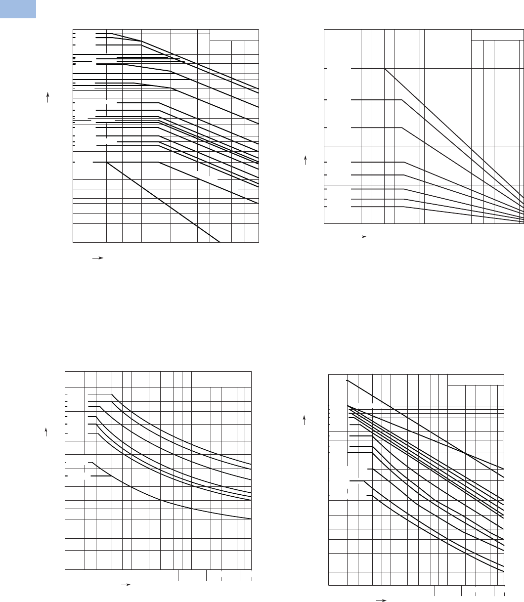
V5-T1-112 Volume 5—Motor Control and Protection CA08100006E—August 2012 www.eaton.com
1
1
1
1
1
1
1
1
1
1
1
1
1
1
1
1
1
1
1
1
1
1
1
1
1
1
1
1
1
1
1.1
IEC Contactors and Starters
XT
IEC Power Control
Switching Duty for Non-Motor Loads
Three-Pole—XTCE007B–XTCEC20R Four-Pole—XTCF020B–XTCF200G
Short-Time Loading
Three-Pole—XTCE007B–XTCEC20R Three-Pole—XTCE080F–XTCEC16R
2000
1800
XTCEC16R
XTCEC14P
AC-1/400 V
0.1 0.2 75.0 0.7 1 3510
2
1
3
4
23.0
5
900 850
1400
1000
700
800
500
400
275
300
350
160
10
7
XTCE185H
XTCE225H
XTCE400M
XTCE300L
XTCE250L
XTCE750N
XTCE650N
XTCE500M XTCE580N
XTCEC20R
XTCE820N, XTCEC10N
130
XTCE115G
110
XTCE095F
90
XTCE080F
80
XTCE065D
65
XTCE050D
50
XTCE040D
40
35
XTCE018C
20
XTMC9A
XTCE007B, XTCE009B, XTCE012B, XTCE015B
XTCE150G, XTCE170G
XTCE025C, XTCE032C
Breaking Current A
Component Lifespan (millions of operations)
AC-1/400 V
Breaking Current A
Component Lifespan (millions of operations)
XTCF020B
XTCF032C
XTCF045C
XTCF063D
XTCF080D
XTCF125G
XTCF160G
XTCF200G
0.2 0.4 0.6 1 2 4 6 100.1
200
160
125
80
63
45
32
22
Operating characteristics:
Non-inductive and slightly inductive loads
Electrical characteristics:
Switch on: 1 x Rated current
Switch off: 1 x Rated current
Utilization category:
10 0% AC-1
Typical applications:
Electrical heating
10 min 15 min
1 min 3 min 5 min
AC-1/400 V
70 100
5072030
35102
A
700
500
600
400
300
250
15
200
120
100
70
50
40
30
150
900
200 300 500
20
700
XTCE018C
90
XTCE007B,
XTCE009B
XTCE050D
XTCE065D
450 XTCE040D
350 XTCE032C
XTCE025C
Seconds
XTCE012B,
XTCE015B
Short-time Current
Duration of load
10 min 15 min1 min 3 min 5 min
XTCEC10N, XTCEC14P
90030070 100507203035 102
A
8000
10000
19000
6000
5000
4000
3000
2500
2000
1800
110 0
1000
700
500
400
300
1500
XTCE080F, XTCE095F
XTCE185H, XTCE225H
XTCE250L
700200 500
200
AC-1/400 V
XTCEC16R
XTCE115G,
XTCE150G,
XTCE170G
Seconds
XTCE300L
XTCE500M
XTCE580N
XTCE650N
XTCE750N
XTCE820N
XTCE400M
XTCEC20R
Short-time Current
Duration of load
Courtesy of CMA/Flodyne/Hydradyne ▪ Motion Control ▪ Hydraulic ▪ Pneumatic ▪ Electrical ▪ Mechanical ▪ (800) 426-5480 ▪ www.cmafh.com
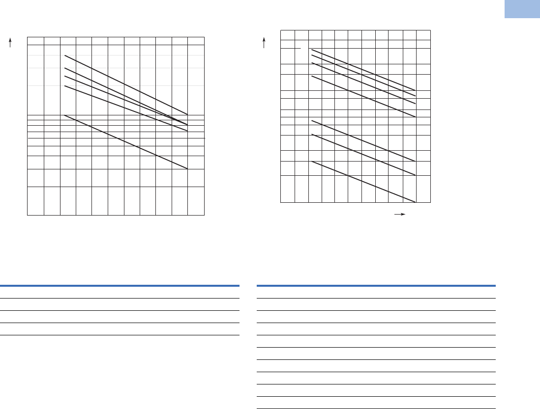
Volume 5—Motor Control and Protection CA08100006E—August 2012 www.eaton.com V5-T1-113
1
1
1
1
1
1
1
1
1
1
1
1
1
1
1
1
1
1
1
1
1
1
1
1
1
1
1
1
1
1
1.1
IEC Contactors and Starters
XT
IEC Power Control
Maximum Operating Frequency—Related to Rating and Utilization Category (400V)
7 to 150 hp
Utilization Category 1
185 to 820 hp
Utilization Category 1
Note
1PN = max. motor rating (kW/hp) of the relevant contactor.
ops./h = max. number of operations per hour.
Type
Characteristic Curve Above
AC-1 AC-3 AC-2, AC-4
XTCE007B–XTCE015B 3 1 5
XTCE018C–XTCE032C 3 2 5
XTCE040D–XTCE065D 3 2 5
XTCE080F–XTCE150G 3 4 5
6000
4000
2000
1000
800
600
400
200
100
010 20 30 40 50 60 70 80 90 100 %
PN [kW/hp]
a
b
e
c
d
Ops./h
Type
Characteristic Curve Above
AC-1 AC-3 AC-2, AC-4
XTCE185H 2 1 6
XTCE225H 2 1 6
XTCE250L 2 1 6
XTCE300L 3 2 7
XTCE400M 3 2 7
XTCE500M 3 2 7
XTCE580N 3 4 5
XTCE650N 3 4 5
XTCE750N 3 4 5
XTCE820N 3 4 5
PN [kW/hp]
Ops./h
4000
3000
2000
600
500
400
300
200
150
100
50
010 20 30 40 50 60 70 80 90 100 %
1500
1000
800
a
b
d
c
e
f
g
Courtesy of CMA/Flodyne/Hydradyne ▪ Motion Control ▪ Hydraulic ▪ Pneumatic ▪ Electrical ▪ Mechanical ▪ (800) 426-5480 ▪ www.cmafh.com
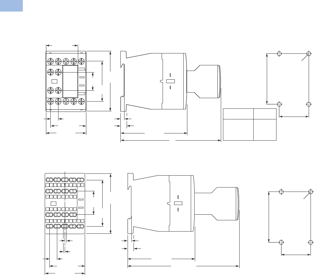
V5-T1-114 Volume 5—Motor Control and Protection CA08100006E—August 2012 www.eaton.com
1
1
1
1
1
1
1
1
1
1
1
1
1
1
1
1
1
1
1
1
1
1
1
1
1
1
1
1
1
1
1.1
IEC Contactors and Starters
XT
IEC Power Control
Dimensions
Approximate Dimensions in mm [in]
XTCE Contactors (Three-Pole)
Frame B, XTCE007B and XTCE015B Contactors with Screw Terminals (7–15A) XTCF020B
Frame B, XTCEC007B–XTCEC012B Contactors with Spring Cage Terminals (7–12A)
18
[.71] 45
[1.77]
68
[2.68]
45 [1.77]
36 [1.42]
8.7 [.34]
Typ. 5.1 [.20] 6.5 [.26]
75 [2.95]
C
3.2 [.13]
Auxiliary
Type
XTCEXFAC_
XTCEXFCC_
XTCEXFATC_
C
117 [4.61]
117 [4.61]
125 [4.92]
35 [1.38]
4 x M4 Dia.
60 [2.36]
68
[2.68]
6.5 [.26]
3.2 [.13]
75 [2.95]
125.2 [4.93]
26.4
[1.04]
52.3
[2.06]
45 [1.77]
5.1 [.20]
1.8
[.07]
1.8
[.07]
8.7 [.34]
Typ.
35 [1.38]
4 x M4 Dia.
60 [2.36]
Courtesy of CMA/Flodyne/Hydradyne ▪ Motion Control ▪ Hydraulic ▪ Pneumatic ▪ Electrical ▪ Mechanical ▪ (800) 426-5480 ▪ www.cmafh.com
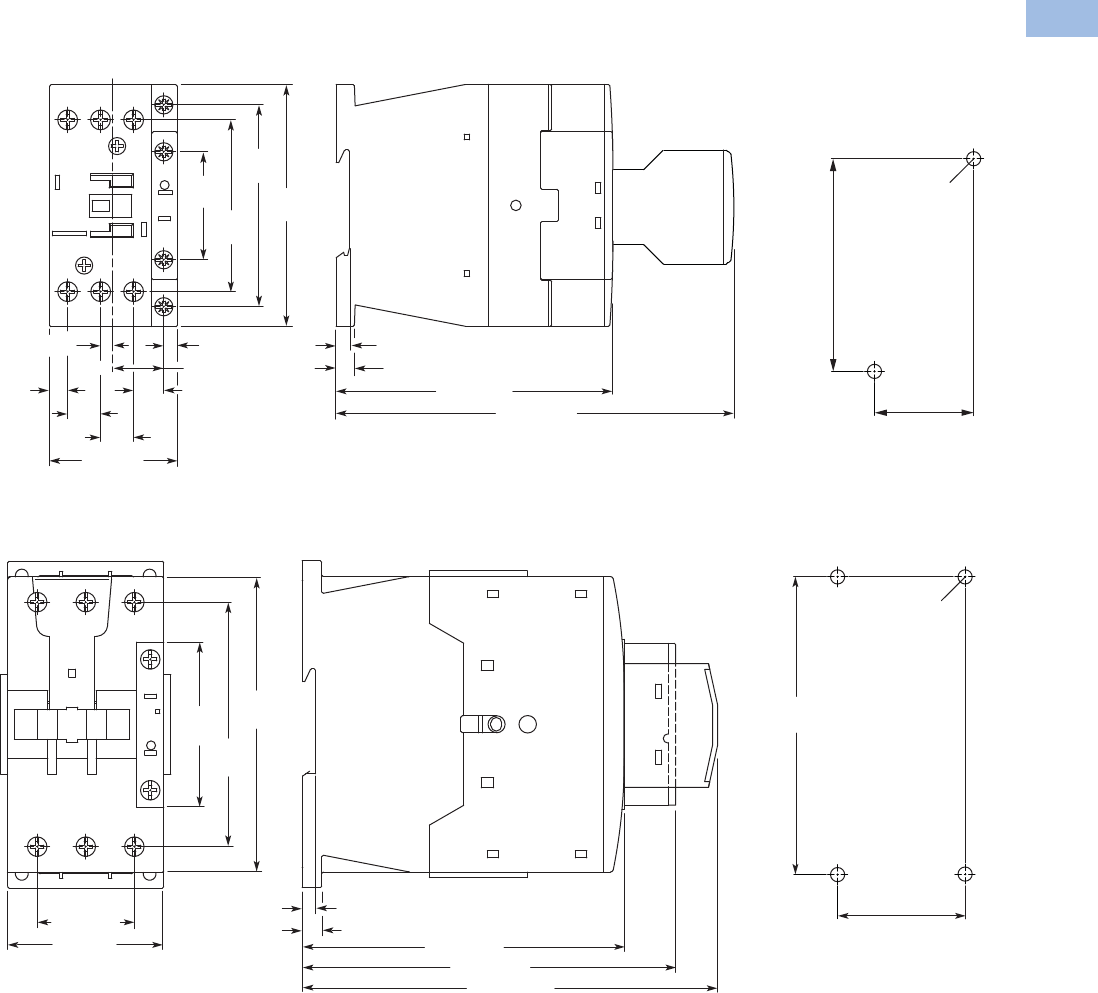
Volume 5—Motor Control and Protection CA08100006E—August 2012 www.eaton.com V5-T1-115
1
1
1
1
1
1
1
1
1
1
1
1
1
1
1
1
1
1
1
1
1
1
1
1
1
1
1
1
1
1
1.1
IEC Contactors and Starters
XT
IEC Power Control
Approximate Dimensions in mm [in]
Frame C, XTCE018C–XTCE032C Contactors (18–32A)
Frame D, XTCE040D–XTCE072D Contactors (72A)
11. 6
[.46] 11. 6
[.46]
4.5 [.17]
17.7 [.70]
10.6
[.42]
6.4
[.25]
38
[1.50]
71
[2.80]
60.4
[2.38]
85
[3.46]
45 [1.77]
4.8 [.19]
138.7 [5.46]
6.5 [.26]
97
.4 [3.83]
Note: Sideways distance to grounded parts: 6 mm [.39 in]
4.5 [.17]
35 [1.38]
2 x M4 Dia.
75 [2.95]
6.9 [.27]
4.7 [.19]
34.4 [1.35]
113.8 [4.48]
132.1 [5.20]
146.8 [5.78]
Note: Sideways distance to
grounded parts: 6 mm [.39 in]
55 [2.17]
57
[2.24]
86.4
[3.40]
104
[4.09]
45 [1.77]
4 x M4 Dia.
105 [4.13]
Courtesy of CMA/Flodyne/Hydradyne ▪ Motion Control ▪ Hydraulic ▪ Pneumatic ▪ Electrical ▪ Mechanical ▪ (800) 426-5480 ▪ www.cmafh.com

V5-T1-116 Volume 5—Motor Control and Protection CA08100006E—August 2012 www.eaton.com
1
1
1
1
1
1
1
1
1
1
1
1
1
1
1
1
1
1
1
1
1
1
1
1
1
1
1
1
1
1
1.1
IEC Contactors and Starters
XT
IEC Power Control
Approximate Dimensions in mm [in]
Frames F–G, XTCE080F–XTCE170G Contactors (80–170A)
Frames H–M, XTCE185H–XTCE570M Contactors (185–580A)
Note: Sideways distance to
grounded parts: 10 mm [.39 in]
90 [3.54]
111 [4.37]
82.5 [3.25]
85.5 [3.37]
142 [5.59]
160 [6.30]
76.5 [3.01]
57 [2.24]
170 [6.69]
156 [6.14]
4 x M6 Dia.
156 [6.14]
70 [2.79]
W W1W2W3W4H H1 H2 H3 D D1 D2
Frame H 140 [5.51] 160 [6.30] 120 [4.72] 20 [.79] 41 [1.61] 180 [7.09] 165 [6.50] 190 [7.48] 160 [6.30] 158 [6.22] 4 [.16] 83 [3.27]
Frame L 140 [5.51] 160 [6.30] 120 [4.72] 20 [.79] 48 [1.89] 180 [7.09] 164 [6.46] 189 [7.44] 160 [6.30] 208 [8.19] 5 [.20] 140 [5.51]
Frame M 160 [6.30] 180 [7.09] 130 [5.12] 25 [.98] 48 [1.89] 200 [7.87] 184 [7.24] 209 [8.23] 180 [7.09] 216 [8.50] 6 [.24] 140 [5.51]
160 [6.30] 180 [7.09] 130 [5.12] 38 [1.50] 57 [2.24] 200 [7.87] 189 [7.44] 219 [8.62] 180 [7.09] 216 [8.50] 6 [.24] 140 [5.51]
D8 [.31]
D2
H3
W2
M6 Dia.
D1
W3
H1 H
W4
W
11 [.43] Dia.
W1
H2
Courtesy of CMA/Flodyne/Hydradyne ▪ Motion Control ▪ Hydraulic ▪ Pneumatic ▪ Electrical ▪ Mechanical ▪ (800) 426-5480 ▪ www.cmafh.com
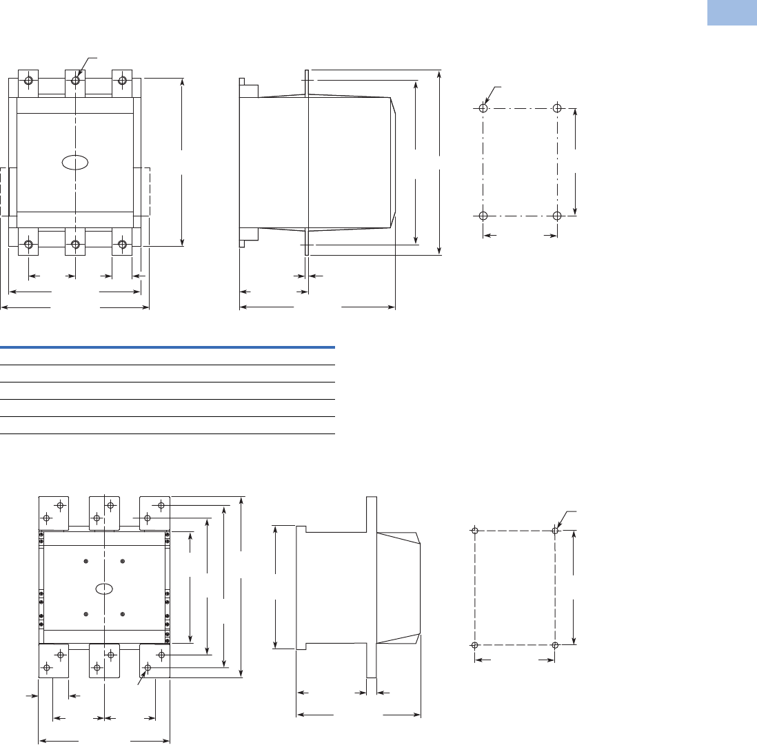
Volume 5—Motor Control and Protection CA08100006E—August 2012 www.eaton.com V5-T1-117
1
1
1
1
1
1
1
1
1
1
1
1
1
1
1
1
1
1
1
1
1
1
1
1
1
1
1
1
1
1
1.1
IEC Contactors and Starters
XT
IEC Power Control
Approximate Dimensions in mm [in]
Frame N, XTCE580N–XTCEC10N Contactors (580–1000A)
Frame P, XTCEC14P Contactor (1400A, AC-1)
W H D1 A (Dia.)
XTCE580N 45 [1.77] 296 [11.65] 6 [.24] 13.5 [.53]
XTCE650N 45 [1.77] 296 [11.65] 6 [.24] 13.5 [.53]
XTCE750N 45 [1.77] 296 [11.65] 6 [.24] 13.5 [.53]
XTCE820N 45 [1.77] 296 [11.65] 6 [.24] 13.5 [.53]
XTCEC10N 45 [1.77] 296 [11.65] 10 [.40] 13.5 [.53]
250 [9.84]
80
[3.15] W
A Dia.
232
[9.13]
232 [9.13]
H
140 [5.51]
256
[10.08]
270 [10.63]
D1
165 [6.50]
215
[8.46]
M6
Dia.
100
[3.94]
60
[2.36]
100
[3.94]
210
[8.27]
232
[9.13]
256
[10.08]
342
[13.46]
308
[12.13]
260 [10.24]
14 [.55]
Dia.
232 [9.13]
130 [5.12] 10
[.39]
165 [6.50]
215
[8.46]
M6 Dia.
Courtesy of CMA/Flodyne/Hydradyne ▪ Motion Control ▪ Hydraulic ▪ Pneumatic ▪ Electrical ▪ Mechanical ▪ (800) 426-5480 ▪ www.cmafh.com
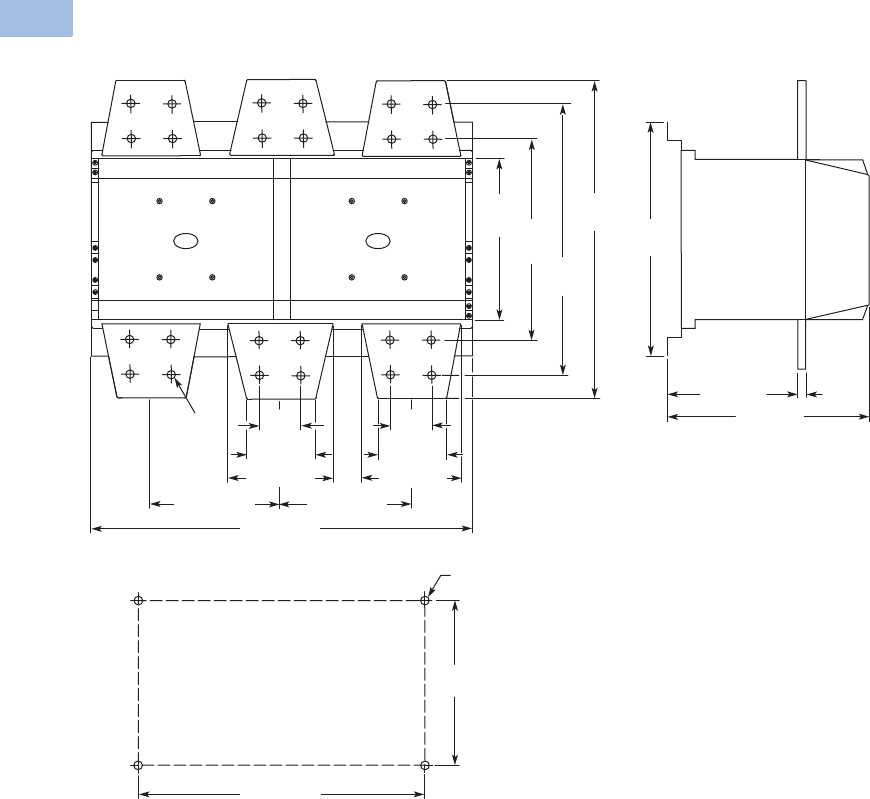
V5-T1-118 Volume 5—Motor Control and Protection CA08100006E—August 2012 www.eaton.com
1
1
1
1
1
1
1
1
1
1
1
1
1
1
1
1
1
1
1
1
1
1
1
1
1
1
1
1
1
1
1.1
IEC Contactors and Starters
XT
IEC Power Control
Approximate Dimensions in mm [in]
Frame R, XTCEC16R, XTCEC20R Contactors
125 [4.92]
172.5 [6.79]172.5 [6.79]
210
[8.27]
272
10.71]
352
[13.86]
392
[15.43]
14 [.55]
Dia.
300
[11.81]
252 [9.92]
150 [5.91] 10 [.39]
80 [3.15]
40
[1.57]
80 [3.15]
150 [5.90]
515 [20.28]
430 [16.93]
270
[10.63]
M6 Dia.
Courtesy of CMA/Flodyne/Hydradyne ▪ Motion Control ▪ Hydraulic ▪ Pneumatic ▪ Electrical ▪ Mechanical ▪ (800) 426-5480 ▪ www.cmafh.com
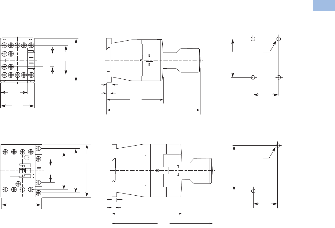
Volume 5—Motor Control and Protection CA08100006E—August 2012 www.eaton.com V5-T1-119
1
1
1
1
1
1
1
1
1
1
1
1
1
1
1
1
1
1
1
1
1
1
1
1
1
1
1
1
1
1
1.1
IEC Contactors and Starters
XT
IEC Power Control
Approximate Dimensions in mm [in]
XTCF Contactors (Four-Pole)
Frame B, XTCF020B Contactors
Frame C, XTCF032C–XTCF045C Contactors
35.0
[1.38]
60.0
[2.36]
2 x M4
36.0
[1.42]
45.0
[1.77]
6.5
[0.26]
3.2
[0.13] 75.0
[2.95]
11 7. 0
[4.61]
45.0
[1.77]
18.0
[0.71]
68.0
[2.68]
35.0
[1.38]
75.0
[2.95]
2 x M4
58.0
[2.28]
6.5
[0.26]
4.5
[0.18] 97.4
[3.83]
138.0
[5.43]
71.0
[2.80]
60.0
[2.36]
85.0
[3.35]
38.0
[1.50]
Courtesy of CMA/Flodyne/Hydradyne ▪ Motion Control ▪ Hydraulic ▪ Pneumatic ▪ Electrical ▪ Mechanical ▪ (800) 426-5480 ▪ www.cmafh.com
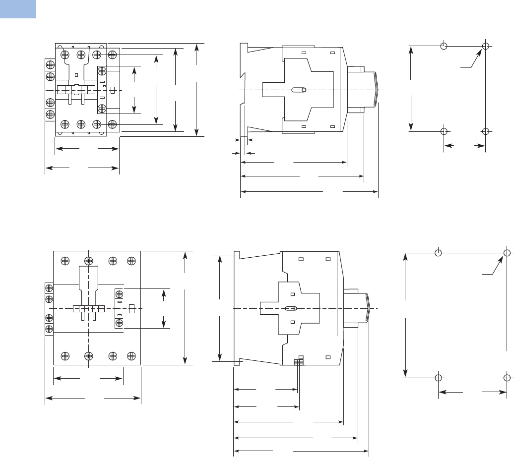
V5-T1-120 Volume 5—Motor Control and Protection CA08100006E—August 2012 www.eaton.com
1
1
1
1
1
1
1
1
1
1
1
1
1
1
1
1
1
1
1
1
1
1
1
1
1
1
1
1
1
1
1.1
IEC Contactors and Starters
XT
IEC Power Control
Approximate Dimensions in mm [in]
Frame D, XTCF063D–XTCF080D Contactors
Frame G, XTCF125G–XTCF200G Contactors
45.0
[1.77]
105.0
[4.13]
2 x M4
74.0
[2.91]
6.9
[0.27]
4.7
[0.19] 114.0
[4.49] 132.1
[5.20]
85.0
[3.35]
104.0
[4.09]
86.4
[3.40]
115.0
[4.53]
57.0
[2.24]
147.0
[5.79]
70.0
[2.76]
156.0
[6.14]
4 x M6
122.0
[4.80]
133.0
[5.24]
170.0
[6.69]
57.0
[2.24]
82.5
[3.25]
142.0
[5.59]
160.0
[6.30]
85.5
[3.37]
175.0
[6.89]
156.0
[6.14]
Courtesy of CMA/Flodyne/Hydradyne ▪ Motion Control ▪ Hydraulic ▪ Pneumatic ▪ Electrical ▪ Mechanical ▪ (800) 426-5480 ▪ www.cmafh.com
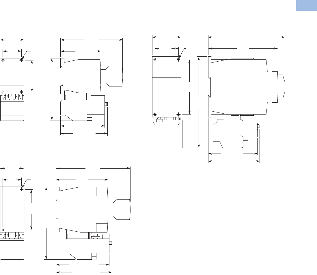
Volume 5—Motor Control and Protection CA08100006E—August 2012 www.eaton.com V5-T1-121
1
1
1
1
1
1
1
1
1
1
1
1
1
1
1
1
1
1
1
1
1
1
1
1
1
1
1
1
1
1
1.1
IEC Contactors and Starters
XT
IEC Power Control
Approximate Dimensions in mm [in]
XTAE Starters with XTOB Overload Relay
Frame B, XTAE007B–XTAE015B Starters with
XTOB (7–12A)
Frame C, XTAE018C–XTAE032C Starters with
XTOB (18–32A)
Frame D, XTAE040D–XTAE065D Starters with XTOB
(40–65A)
88.4 [3.48]
To Reset
83.3 [3.28]
75.8
[2.98]
35
[1.38]
Mounting
Holes for
M4 or #8
Screws
(4 Places)
11 7. 8
[4.64]
60
[2.36]
11 7. 1
[4.61]
45.3
[1.78]
105.3 [4.15]
To Reset
100.2 [3.94]
136.4
[5.37]
75
[2.95]
97.8
[3.85]
35
[1.38]
Mounting
Holes for
M4 or #8
Screws
(2 Places)
139.8
[5.50]
45
[1.77]
98 [3.86]
To Reset
93.6 [3.69]
174
[6.85]
105
[4.13]
132.5
[5.22]
45
[1.77]
Mounting
Holes for
M4 or #8
Screws
(4 Places)
146
[5.75]
60
[2.36]
Courtesy of CMA/Flodyne/Hydradyne ▪ Motion Control ▪ Hydraulic ▪ Pneumatic ▪ Electrical ▪ Mechanical ▪ (800) 426-5480 ▪ www.cmafh.com
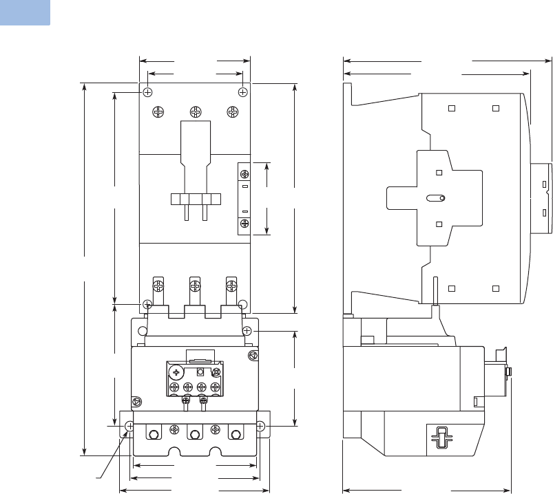
V5-T1-122 Volume 5—Motor Control and Protection CA08100006E—August 2012 www.eaton.com
1
1
1
1
1
1
1
1
1
1
1
1
1
1
1
1
1
1
1
1
1
1
1
1
1
1
1
1
1
1
1.1
IEC Contactors and Starters
XT
IEC Power Control
Approximate Dimensions in mm [in]
Frames F–G, XTAE080F–XTAE150G Starters with XTOB (80–150A)
91
[3.58]
90 [3.54]
150 [5.91]
57
[2.24]
170
[6.69]
156
[6.14]
160 [6.30]
277
[10.91]
70 [2.76]
7 [.276]
Dia.
100 [3.94]
134 [5.28]
74
[2.91]
118 [4.65]
95 [3.74]
Courtesy of CMA/Flodyne/Hydradyne ▪ Motion Control ▪ Hydraulic ▪ Pneumatic ▪ Electrical ▪ Mechanical ▪ (800) 426-5480 ▪ www.cmafh.com
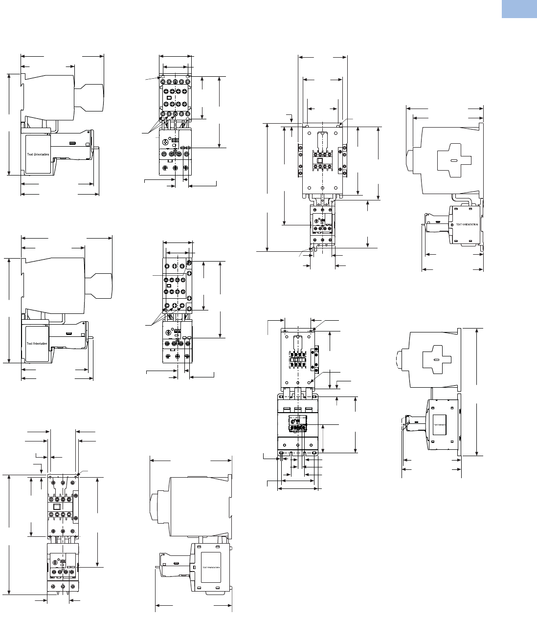
Volume 5—Motor Control and Protection CA08100006E—August 2012 www.eaton.com V5-T1-123
1
1
1
1
1
1
1
1
1
1
1
1
1
1
1
1
1
1
1
1
1
1
1
1
1
1
1
1
1
1
1.1
IEC Contactors and Starters
XT
IEC Power Control
Approximate Dimensions in mm [in]
XTAE Starters with C396 Overload Relay
Frame B, XTAE007B–XTAE012B Starters
with XTOE (0.35–20A)
Frame C, XTAE018C–XTAE032C Starters
with XTOE (0.35–45A)
Frame D, XTAE040D–XTAE065D Starters
with XTOE (20–100A)
Frames F–G, XTAE080F–XTAE115G Starters
with XTOE (20–100A)
Frame G, XTAE115G–XTAE150G Starters
with XTOE (100–175A)
117.0 [4.61]
75.8 [2.98]
110.4 [4.35]
102.7 [4.04]
143.2
[5.64] 1.2 Nm
[11 lb-in]
18.2 [0.71]
Trip/Test
10.6 [0.42]
Reset
35.0 [1.38]
Mounting
Holes for
M4 or #8
Screws
(4 places)
100.6
[3.96]
60.0
[2.36]
45.3 [1.78]
140.0 [5.50]
98.0 [3.80]
110.4 [4.35]
102.7 [4.04]
161.0
[6.30] 2.5–3.0 Nm
[22–26 lb-in]
18.2 [0.71]
Trip/Test
10.6 [0.42]
Reset
35.0 [1.38]
Mounting
Holes for
M4 or #8
Screws
(2 places)
117.3
[4.62]
75.0
[2.95]
45.0 [1.77]
55.0 [2.17]
136.2 [5.36]
To Reset
38.7 [1.52]
To Reset
146.1 [5.75]
159.7
[6.29]
To Reset
5.0 [0.20]
105.0
[4.13]
Mtg.
213.6
[8.41]
Mtg. Holes for
(4) #8 Screws or
M4 Screws
5.0 [0.20]
45.0 [1.77] Mtg.
132.4 [5.21]
To Reset
Mtg. Holes
for (2) M4
or #8 Screws 140.2 [5.52]
175.0 [6.89]
160.0 [6.30]
Mtg. Holes for
(4) M6 or #10
Screws
156.0
[6.14]
Mtg. 167.3
[6.59]
Mtg.
108.4
[4.27]
Mtg.
41.2 [1.62] Mtg.
56.0 [2.20]
222.3
[8.75]
To Reset
291.1
[11.46]
7.8
[0.31]
70.0
[2.76]
90.0
[3.54]
Mtg.
111.8
[4.40]
345.0
[13.6]
89.0
[3.50]
Terminal
Torque:
14 Nm
[124 lb-in]
77.0
[3.00]
152.0
[6.00]
161.0 [6.30]
157.0 [6.18]
156.0
[6.14]
M6 [#10] Screws
70.0
[2.76]
21.3 [0.84]
5.0
[0.20]
18.2 [0.71] Trip/Test
10.6 [0.42] Reset
36.0 [1.42]
110.0 [4.30]
Courtesy of CMA/Flodyne/Hydradyne ▪ Motion Control ▪ Hydraulic ▪ Pneumatic ▪ Electrical ▪ Mechanical ▪ (800) 426-5480 ▪ www.cmafh.com
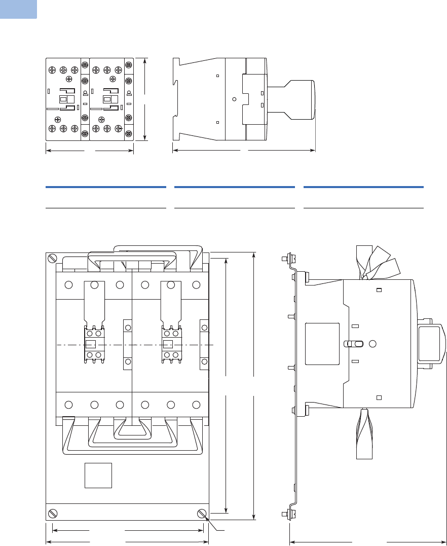
V5-T1-124 Volume 5—Motor Control and Protection CA08100006E—August 2012 www.eaton.com
1
1
1
1
1
1
1
1
1
1
1
1
1
1
1
1
1
1
1
1
1
1
1
1
1
1
1
1
1
1
1.1
IEC Contactors and Starters
XT
IEC Power Control
Approximate Dimensions in mm [in]
XTCR Reversing Combination
Frames B–D
Frames F–G
Frame B (7–15A) Frame C (18–32A) Frame D (40–65A)
WH D WH D WH D
90
[3.54]
68
[2.68]
117
[4.61]
90
[3.54]
85
[3.34]
138
[5.43]
110
[4.33]
115
[4.53]
146.8
[5.78]
H
D
W
314
[12.36]
299
[11.77]
M6
176 [6.93]
196 [7.72] 183 [7.20]
Courtesy of CMA/Flodyne/Hydradyne ▪ Motion Control ▪ Hydraulic ▪ Pneumatic ▪ Electrical ▪ Mechanical ▪ (800) 426-5480 ▪ www.cmafh.com

Volume 5—Motor Control and Protection CA08100006E—August 2012 www.eaton.com V5-T1-125
1
1
1
1
1
1
1
1
1
1
1
1
1
1
1
1
1
1
1
1
1
1
1
1
1
1
1
1
1
1
1.1
IEC Contactors and Starters
XT
IEC Power Control
Approximate Dimensions in mm [in]
Star-Delta Combination
Frames B–D
Frames F–G
Frame B Frame C Frame D
WH D WH D WH D
158
[6.22]
68
[2.68]
117
[4.61]
158
[6.22]
85
[3.34]
138
[5.43]
188
[7.40]
115
[4.53]
146.8
[5.78]
H
D
W
M6
314
[12.36]
299
[11.77]
144 [5.67] 144 [5.67]
308 [12.13] 183 [7.20]
Courtesy of CMA/Flodyne/Hydradyne ▪ Motion Control ▪ Hydraulic ▪ Pneumatic ▪ Electrical ▪ Mechanical ▪ (800) 426-5480 ▪ www.cmafh.com

V5-T1-126 Volume 5—Motor Control and Protection CA08100006E—August 2012 www.eaton.com
1
1
1
1
1
1
1
1
1
1
1
1
1
1
1
1
1
1
1
1
1
1
1
1
1
1
1
1
1
1
1.1
IEC Contactors and Starters
XT
IEC Power Control
Approximate Dimensions in mm [in]
Mechanical Interlock
Frames H–M—XTCEXMLM XTCEXMLN
Contactor with Terminal Shroud
Frames L–N Contactors, XTCE250L–XTCEC10N,
with Terminal Shroud XTLEXTS
15
[.59]
9 [.35]
515 [20.28]
430 [16.93]
270
[10.63]
300
[11.81]
20
[.79]
XTCE250L XTCE400M XTCE500M, XTCE570M
XTCE580N, XTCE650N,
XTCE750N, XTCE820N,
XTCEC10N
WH WH WH WH
150
[5.91]
384
[15.12]
150
[5.91]
404
[15.91]
174
[6.85]
426
[16.77]
236
[9.29]
506
[19.92]
W
H
Courtesy of CMA/Flodyne/Hydradyne ▪ Motion Control ▪ Hydraulic ▪ Pneumatic ▪ Electrical ▪ Mechanical ▪ (800) 426-5480 ▪ www.cmafh.com
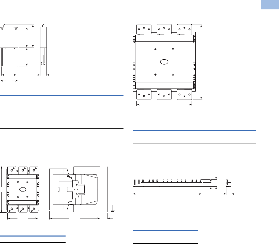
Volume 5—Motor Control and Protection CA08100006E—August 2012 www.eaton.com V5-T1-127
1
1
1
1
1
1
1
1
1
1
1
1
1
1
1
1
1
1
1
1
1
1
1
1
1
1
1
1
1
1
1.1
IEC Contactors and Starters
XT
IEC Power Control
Approximate Dimensions in mm [in]
Suppressor
XTCE_ Suppressor
Cable Terminal Block
XTCEXTLA
Flat Strip Conductor Terminals
XTCEXTFB
Three-Phase Commoning Link
Frame B
W1 W2 H1 H2 H3 D
XTCEXRSB_
XTCEXVSB_
XTCEXVSLB_
XTCEXDSB_
25
[.98]
9.2
[.36]
25.9
[1.02]
28
[1.10]
32
[1.26]
9
[.35]
XTCEXRSC_
XTCEXVSC_
XTCEXVSLC_
25
[.98]
9.2
[.36]
16
[.63]
28
[1.10]
32
[1.26]
9
[.35]
XTCEXRSF_
XTCEXVSF_
XTCEXVSLF_
25
[.98]
20
[.79]
18.5
[.73]
28
[1.10]
32
[1.26]
9
[.35]
H
XTCE250L 198 [7.80]
XTCE400M 218 [8.58]
W2 D
W1
H2
H3
H1
135
[5.31]
222
[8.74]
H
30
[1.18]
WH
XTCE500M–XTCE570M 171 [6.73] 232 [9.13]
XTCE750N–XTCE820N 231 [9.09] 310 [12.20]
W
XTCEXCLK3B 112 [4.41]
XTCEXCLK4B 157 [6.18]
XTCBXCLK5B 202 [7.95]
W
H
13.1
[.52]
W
18.1
[.71]
12.5
[.49]
Courtesy of CMA/Flodyne/Hydradyne ▪ Motion Control ▪ Hydraulic ▪ Pneumatic ▪ Electrical ▪ Mechanical ▪ (800) 426-5480 ▪ www.cmafh.com
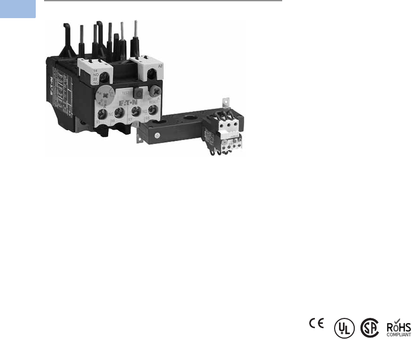
V5-T1-128 Volume 5—Motor Control and Protection CA08100006E—August 2012 www.eaton.com
1
1
1
1
1
1
1
1
1
1
1
1
1
1
1
1
1
1
1
1
1
1
1
1
1
1
1
1
1
1
1.1
IEC Contactors and Starters
XT
IEC Power Control
XTOB, XTOT Overload Relays
Contents
Description Page
Relays and Timers . . . . . . . . . . . . . . . . . . . . . . . . . V5-T1-3
Miniature Controls . . . . . . . . . . . . . . . . . . . . . . . . . V5-T1-18
Contactors and Starters . . . . . . . . . . . . . . . . . . . . V5-T1-35
Thermal Overload Relays
Catalog Number Selection . . . . . . . . . . . . . . . . V5-T1-129
Product Selection . . . . . . . . . . . . . . . . . . . . . . . V5-T1-130
Accessories . . . . . . . . . . . . . . . . . . . . . . . . . . . V5-T1-133
Technical Data and Specifications . . . . . . . . . . V5-T1-136
Dimensions . . . . . . . . . . . . . . . . . . . . . . . . . . . V5-T1-138
C440/XT Electronic Overload Relay . . . . . . . . . . . V5-T1-141
Manual Motor Protectors . . . . . . . . . . . . . . . . . . . . V5-T1-157
Combination Motor Controllers . . . . . . . . . . . . . . . V5-T1-193
XT Electronic Manual Motor Protector . . . . . . . . . V5-T1-216
Reference Data . . . . . . . . . . . . . . . . . . . . . . . . . . . V5-T1-229
Thermal Overload Relays
Product Description
The XT line of IEC motor
thermal overload relays
provides an efficient motor
protection solution, available
up to 630A. XTOB units can
be directly mounted to the
contactor or mounted
separately.
Features and Benefits
●Direct connect up to 250A
●Stand alone and CT type
up to 630A
●Large thermal overcurrent
range
●Test button
●Manual/automatic
selectable reset
●NO-NC auxiliary as
standard
●Class 10A (to 250A)
●Class 30 (CT type)
Standards and Certifications
●IEC EN 60947
●CE approved
●UL
●CSA
●ATEX
●RoHS
Notes
Short-circuit protection: Observe the maximum permissible fuse of the contactor with direct
device mounting. See MN03402001E for more information on overload relays for Frames B–G.
Trip Class: 10A
Suitable for protection of EEx e-motors. EC prototype test certificate available upon request.
See manuals MN03402001E and MN03407001E, Page V5-T1-133.
Instructional Leaflets
Pub51221 XTOB, D Frame overload relays
(inside of packaging)
Pub51222 XTOB, B–C Frame overload relays
(inside of packaging)
Courtesy of CMA/Flodyne/Hydradyne ▪ Motion Control ▪ Hydraulic ▪ Pneumatic ▪ Electrical ▪ Mechanical ▪ (800) 426-5480 ▪ www.cmafh.com
Volume 5—Motor Control and Protection CA08100006E—August 2012 www.eaton.com V5-T1-129
1
1
1
1
1
1
1
1
1
1
1
1
1
1
1
1
1
1
1
1
1
1
1
1
1
1
1
1
1
1
1.1
IEC Contactors and Starters
XT
IEC Power Control
Catalog Number Selection
XT IEC Overload Relays
XT OB P16 BC1 S
Type
OB = Bimetallic overload relay
OT = Current transformer overload relay
Device Type
XT = XT line of IEC control Trip Class
C1 = Class 10A (XTOB)
C3 = Class 30 (XTOT)
Mounting
Blank = Direct to contactor
S= Separate mount
Frame Size
Designation
B = 45 mm
C = 45 mm
D = 55 mm
G = 90 mm
L = 140 mm
Blank = XTOT only
Overload Release
Frame B
P16 = 0.1–0.16A
P24 = 0.16–0.24A
P40 = 0.24–0.4A
P60 = 0.4–0.6A
001 = 0.6–1A
1P6 = 1.0–1.6A
2P4 = 1.6–2.4A
004 = 2.4–4A
006 = 4–6A
010 = 6–10A
012 = 9–12A
016 = 12–16A
Frame C
P16 = 0.1–0.16A
P24 = 0.16–0.24A
P40 = 0.24–0.4A
P60 = 0.4–0.6A
001 = 0.6–1A
1P6 = 1.0–1.6A
2P4 = 1.6–2.4A
004 = 2.4–4A
006 = 4–6A
010 = 6–10A
016 = 12–16A
024 = 16–24A
032 = 24–32A
Frame D
010 = 6–10A
016 = 12–16A
024 = 16–24A
040 = 24–40A
057 = 40–57A
065 = 50–65A
075 = 65–75A
Frame F
035 = 25–35A
050 = 35–50A
070 = 50–70A
100 = 70–100A
Frame G
035 = 25–35A
050 = 35–50A
070 = 50–70A
100 = 70–100A
125 = 95–125A
150 = 120–150A
175 = 145–175A
Frame H
070 = 50–70A
100 = 70–100A
125 = 95–125A
160 = 120–160A
220 = 160–220A
250 = 200–250A
Frame L
070 = 50–70A
100 = 70–100A
125 = 95–125A
160 = 120–160A
220 = 160–220A
250 = 200–250A
300 = 200–300A
Frame M
063 = 42–63A
090 = 60–90A
125 = 85–125A
160 = 110–160A
240 = 160–240A
290 = 190–290A
400 = 170–400A
540 = 360–540A
Frame N
063 = 42–63A
090 = 60–90A
125 = 85–125A
160 = 110–160A
240 = 160–240A
290 = 190–290A
400 = 170–400A
540 = 360–540A
630 = 420–630A
Courtesy of CMA/Flodyne/Hydradyne ▪ Motion Control ▪ Hydraulic ▪ Pneumatic ▪ Electrical ▪ Mechanical ▪ (800) 426-5480 ▪ www.cmafh.com

V5-T1-130 Volume 5—Motor Control and Protection CA08100006E—August 2012 www.eaton.com
1
1
1
1
1
1
1
1
1
1
1
1
1
1
1
1
1
1
1
1
1
1
1
1
1
1
1
1
1
1
1.1
IEC Contactors and Starters
XT
IEC Power Control
Product Selection
Overload Relay, Direct Mount—Frame B
Overload Relay, Direct Mount—Frame C
Overload
Releases, Ir
Contact
Sequence
Contact
Configuration
For Use
with
Contactor
Amp Range
Short-Circuit Protection (A)
Catalog Number
Fuse
Maximum
Circuit
Breaker
CEC/NEC
Fuse
Type 1
Coordination,
gG/gL
Type 2
Coordination,
gG/gL
0.1–0.16 1NO-1NC 7–15A 25 0.5 25 3 XTOBP16BC1
0.16–0.24 1NO-1NC 7–15A 25 1 25 3 XTOBP24BC1
0.24–0.4 1NO-1NC 7–15A 25 2 25 3 XTOBP40BC1
0.4–0.6 1NO-1NC 7–15A 25 4 25 3 XTOBP60BC1
0.6–1 1NO-1NC 7–15A 25 4 25 3 XTOB001BC1
1–1.6 1NO-1NC 7–15A 25 6 25 6 XTOB1P6BC1
1.6–2.4 1NO-1NC 7–15A 25 10 25 6 XTOB2P4BC1
2.4–4 1NO-1NC 7–15A 25 16 25 15 XTOB004BC1
4–6 1NO-1NC 7–15A 25 20 25 20 XTOB006BC1
6–10 1NO-1NC 7–15A 50 25 25 35 XTOB010BC1
9–12 1NO-1NC 9–15A 50 25 25 45 XTOB012BC1
12–16 1NO-1NC 12–15A 50 25 30 45 XTOB016BC1
Overload
Releases, Ir
Contact
Sequence
Contact
Configuration
For Use
with
Contactor
Amp Range
Short-Circuit Protection (A)
Catalog Number
Fuse
Maximum
Circuit
Breaker
CEC/NEC
Fuse
Type 1
Coordination,
gG/gL
Type 2
Coordination,
gG/gL
0.1–0.16 1NO-1NC 18–32A 25 0.5 25 3 XTOBP16CC1
0.16–0.24 1NO-1NC 18–32A 25 1 25 3 XTOBP24CC1
0.24–0.4 1NO-1NC 18–32A 25 2 25 3 XTOBP40CC1
0.4–0.6 1NO-1NC 18–32A 25 4 25 3 XTOBP60CC1
0.6–1 1NO-1NC 18–32A 25 4 25 3 XTOB001CC1
1–1.6 1NO-1NC 18–32A 25 6 25 6 XTOB1P6CC1
1.6–2.4 1NO-1NC 18–32A 25 10 25 6 XTOB2P4CC1
2.4–4 1NO-1NC 18–32A 25 16 25 15 XTOB004CC1
4–6 1NO-1NC 18–32A 25 20 25 20 XTOB006CC1
6–10 1NO-1NC 18–32A 50 25 25 25 XTOB010CC1
10–16 1NO-1NC 18–32A 63 35 30 25 XTOB016CC1
16–24 1NO-1NC 18–32A 100 35 30 25 XTOB024CC1
24–32 1NO-1NC 25–32A 125 63 30 25 XTOB032CC1
Frame B
2 4 6 98 96A2 14/
22
97 95
Frame C
2 4 6 98 9614/
22
97 95
Courtesy of CMA/Flodyne/Hydradyne ▪ Motion Control ▪ Hydraulic ▪ Pneumatic ▪ Electrical ▪ Mechanical ▪ (800) 426-5480 ▪ www.cmafh.com
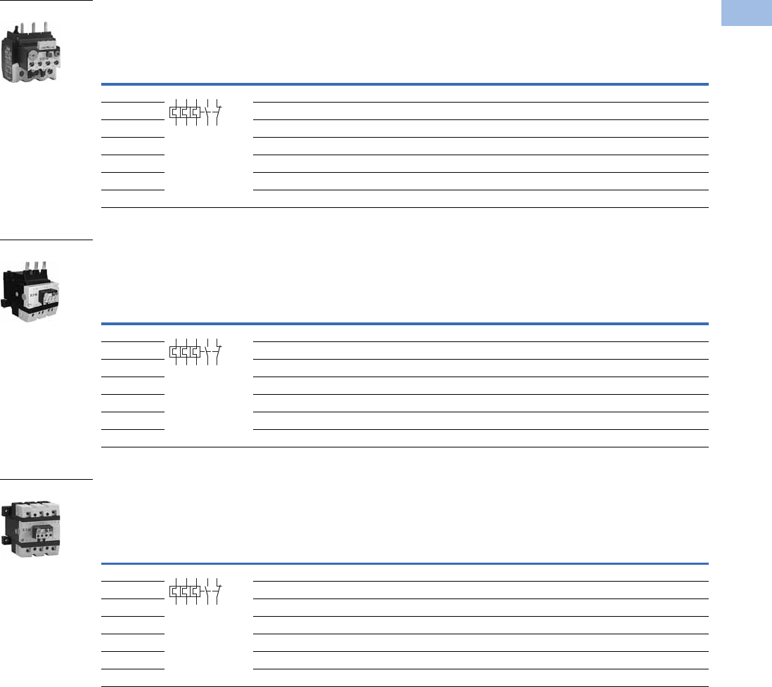
Volume 5—Motor Control and Protection CA08100006E—August 2012 www.eaton.com V5-T1-131
1
1
1
1
1
1
1
1
1
1
1
1
1
1
1
1
1
1
1
1
1
1
1
1
1
1
1
1
1
1
1.1
IEC Contactors and Starters
XT
IEC Power Control
Overload Relay, Direct Mount—Frame D
Overload Relay, Direct Mount—Frames F–G
Overload Relay, Separate Mount—Frames F–G
Overload
Releases, Ir
Contact
Sequence
Contact
Configuration
For Use
with
Contactor
Amp Range
Short-Circuit Protection (A)
Catalog Number
Fuse
Maximum
Circuit
Breaker
CEC/NEC
Fuse
Type 1
Coordination,
gG/gL
Type 2
Coordination,
gG/gL
6–10 1NO-1NC 40–72A 50 25 25 25 XTOB010DC1
10–16 1NO-1NC 40–72A 63 35 25 25 XTOB016DC1
16–24 1NO-1NC 40–72A 63 50 30 25 XTOB024DC1
24–40 1NO-1NC 40–72A 125 63 125 125 XTOB040DC1
40–57 1NO-1NC 50–72A 160 80 150 150 XTOB057DC1
50–65 1NO-1NC 65–72A 160 100 150 200 XTOB065DC1
65–75 1NO-1NC 72A 200 125 150 200 XTOB075DC1
Overload
Releases, Ir
Contact
Sequence
Contact
Configuration
For Use
with
Contactor
Amp Range
Short-Circuit Protection (A)
Catalog Number
Fuse
Maximum
Circuit
Breaker
CEC/NEC
Fuse
Type 1
Coordination,
gG/gL
Type 2
Coordination,
gG/gL
25–35 1NO-1NC 80–170A 125 100 125 125 XTOB035GC1
35–50 1NO-1NC 80–170A 160 125 150 200 XTOB050GC1
50–70 1NO-1NC 80–170A 250 160 150 200 XTOB070GC1
70–100 1NO-1NC 80–170A 315 200 400 400 XTOB100GC1
95–125 1NO-1NC 80–170A 315 200 500 400 XTOB125GC1
120–150 1NO-1NC 80–170A 315 200 600 600 XTOB150GC1
145–175 1NO-1NC 150–170A 315 200 600 600 XTOB175GC1
Overload
Releases, Ir
Contact
Sequence
Contact
Configuration
For Use
with
Contactor
Amp Range
Short-Circuit Protection (A)
Catalog Number
Fuse
Maximum
Circuit
Breaker
CEC/NEC
Fuse
Type 1
Coordination,
gG/gL
Type 2
Coordination,
gG/gL
25–35 1NO-1NC 80–170A 125 100 125 125 XTOB035GC1S
35–50 1NO-1NC 80–170A 160 125 150 200 XTOB050GC1S
50–70 1NO-1NC 80–170A 250 160 150 200 XTOB070GC1S
70–100 1NO-1NC 80–170A 315 200 400 400 XTOB100GC1S
95–125 1NO-1NC 80–170A 315 250 500 400 XTOB125GC1S
120–150 1NO-1NC 80–170A 315 250 600 600 XTOB150GC1S
145–175 1NO-1NC 150–170A 315 250 600 600 XTOB175GC1S
Frame D
2 4 6 98 96
97 95
Frames F–G
2 4 6 98 96
97 95
Frames F–G
2 4 6 98 96
97 95
Courtesy of CMA/Flodyne/Hydradyne ▪ Motion Control ▪ Hydraulic ▪ Pneumatic ▪ Electrical ▪ Mechanical ▪ (800) 426-5480 ▪ www.cmafh.com
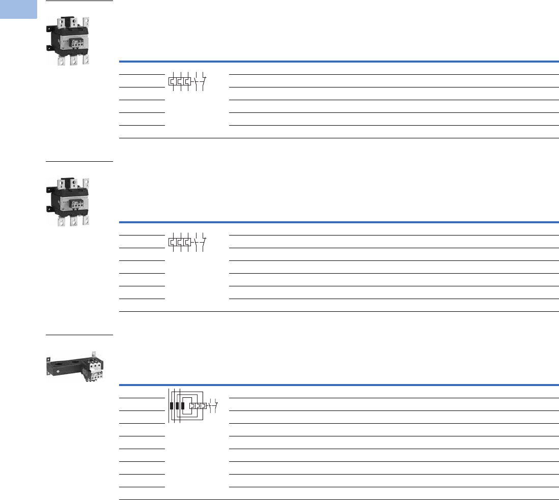
V5-T1-132 Volume 5—Motor Control and Protection CA08100006E—August 2012 www.eaton.com
1
1
1
1
1
1
1
1
1
1
1
1
1
1
1
1
1
1
1
1
1
1
1
1
1
1
1
1
1
1
1.1
IEC Contactors and Starters
XT
IEC Power Control
Overload Relay, Separate Mount—Frame H
Overload Relay, Separate Mount—Frame L
Current Transformer Operated Overload Relays, Separate Mount—Frames M–N 2
Notes
1 For separate mounting, short-circuit Type 1 rating is 500A and short-circuit Type 2 rating is 400A.
2 The main current parameters are defined by the main current wiring that is used.
Overload
Releases, Ir
Contact
Sequence
Contact
Configuration
For Use
with
Contactor
Amp Range
Short-Circuit Protection (A)
Catalog Number
Fuse
Maximum
Circuit
Breaker
CEC/NEC
Fuse
Type 1
Coordination,
gG/gL
Type 2
Coordination,
gG/gL
50–70 1NO-1NC 185–250A 250 160 150 200 XTOB070HC1
70–100 1NO-1NC 185–250A 315 200 400 400 XTOB100HC1
95–125 1NO-1NC 185–250A 315 250 500 400 XTOB125HC1
120–160 1NO-1NC 185–250A 400 250 600 600 XTOB160HC1
160–220 1NO-1NC 185–250A 400 1315 1600 800 XTOB220HC1
200–250 1NO-1NC 225–250A 400 1315 1600 700 XTOB250HC1
Overload
Releases, Ir
Contact
Sequence
Contact
Configuration
For Use
with
Contactor
Amp Range
Short-Circuit Protection (A)
Catalog Number
Fuse
Maximum
Circuit
Breaker
CEC/NEC
Fuse
Type 1
Coordination,
gG/gL
Type 2
Coordination,
gG/gL
50–70 1NO-1NC 185–250A 250 160 150 200 XTOB070LC1
70–100 1NO-1NC 185–250A 315 200 400 400 XTOB100LC1
95–125 1NO-1NC 185–250A 315 250 500 400 XTOB125LC1
120–160 1NO-1NC 185–250A 400 250 600 600 XTOB160LC1
160–220 1NO-1NC 185–250A 400 1315 1600 800 XTOB220LC1
200–250 1NO-1NC 225–250A 400 1315 1600 700 XTOB250LC1
200–300 1NO-1NC 225–300A 630 1630 1600 700 XTOB300LC1
Overload
Releases, Ir
Contact
Sequence
Contact
Configuration
For Use
with
Contactor
Amp Range
Short-Circuit Protection (A)
Catalog Number
Type 1
Coordination,
gG/gL
Type 2
Coordination,
gG/gL
Circuit
Breaker
CEC/NEC
Fuse
42–63 1NO-1NC 300–500A — — 150 200 XTOT063C3S
60–90 1NO-1NC 300–500A — — 250 250 XTOT090C3S
85–125 1NO-1NC 300–500A — — 500 400 XTOT125C3S
110–160 1NO-1NC 300–500A — — 600 600 XTOT160C3S
160–240 1NO-1NC 300–500A — — 600 700 XTOT240C3S
190–290 1NO-1NC 300–500A — — 600 700 XTOT290C3S
270–400 1NO-1NC 300–500A — — 1000 1000 XTOT400C3S
360–540 1NO-1NC 500A — — 600 1000 XTOT540C3S
420–630 1NO-1NC 630A — — 600 1000 XTOT630C3S
Frame H
1359795
2469896
Frame L
1359795
2469896
Frames M-N
9698
9597
Courtesy of CMA/Flodyne/Hydradyne ▪ Motion Control ▪ Hydraulic ▪ Pneumatic ▪ Electrical ▪ Mechanical ▪ (800) 426-5480 ▪ www.cmafh.com
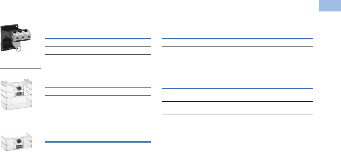
Volume 5—Motor Control and Protection CA08100006E—August 2012 www.eaton.com V5-T1-133
1
1
1
1
1
1
1
1
1
1
1
1
1
1
1
1
1
1
1
1
1
1
1
1
1
1
1
1
1
1
1.1
IEC Contactors and Starters
XT
IEC Power Control
Accessories
DIN Rail or Panel Mount Adapter,
Frames C–D 1
Te rm i n a l S h ro u d
Te rm i n a l S h ro u d
Terminal Lug Kit—Set of Three Lugs
Documentation—Manuals for Overload Monitoring
of EEX e-motors
Notes
1Can be snap fitted on a top hat rail (DIN rail) to IEC/EN 60715 or can be screw fitted.
2Orders must be placed in multiples of package quantity listed.
For Use
with…
Pkg.
Qty. 2Catalog Number
XTOB…CC1 5 XTOBXDINC
XTOB…DC1 2 XTOBXDIND
For Use
with… Catalog Number
XTOB…LC1 XTOBXTSL
For Direct
Mounting of … Catalog Number
XTOB…LC1 to XTCE250L
or XTCE300L
XTOBXTSCL
XTOBXDIN_
XTOBXTSL
XTOBXTSCL
Description
For Use
with…
Pkg.
Qty. 2Catalog Number
#6 AWG-350 kcmil XTOB…LC1 1 XTOBXTLL
Publication Number For Use with…
MN03402001E XTOB…BC1
XTOB…CC1
MN03407001E XTOB…DC1
XTOB…GC1
Courtesy of CMA/Flodyne/Hydradyne ▪ Motion Control ▪ Hydraulic ▪ Pneumatic ▪ Electrical ▪ Mechanical ▪ (800) 426-5480 ▪ www.cmafh.com
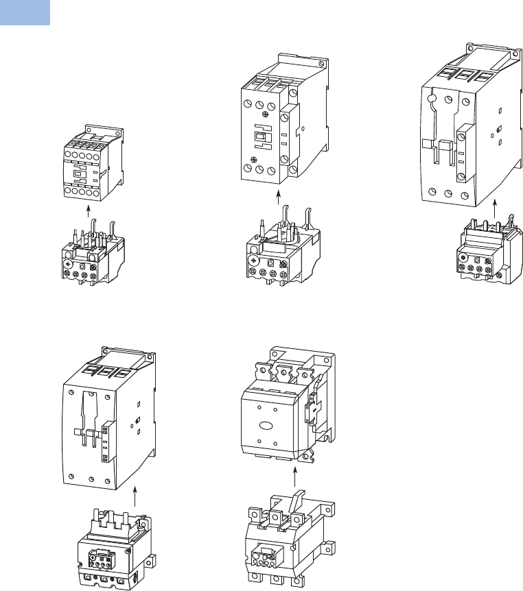
V5-T1-134 Volume 5—Motor Control and Protection CA08100006E—August 2012 www.eaton.com
1
1
1
1
1
1
1
1
1
1
1
1
1
1
1
1
1
1
1
1
1
1
1
1
1
1
1
1
1
1
1.1
IEC Contactors and Starters
XT
IEC Power Control
Overload Fitted Directly to the Contactor
Frame B (7–15A) Frame C (18–32A) Frame D (40–72A)
Frames F–G (80–170A) Frames H–L (185–250A)
Courtesy of CMA/Flodyne/Hydradyne ▪ Motion Control ▪ Hydraulic ▪ Pneumatic ▪ Electrical ▪ Mechanical ▪ (800) 426-5480 ▪ www.cmafh.com
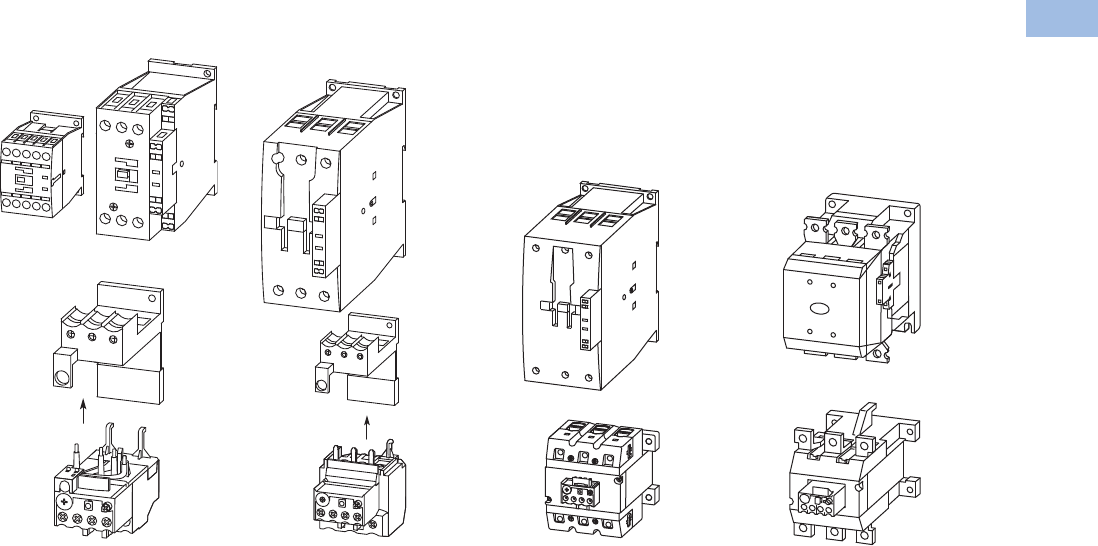
Volume 5—Motor Control and Protection CA08100006E—August 2012 www.eaton.com V5-T1-135
1
1
1
1
1
1
1
1
1
1
1
1
1
1
1
1
1
1
1
1
1
1
1
1
1
1
1
1
1
1
1.1
IEC Contactors and Starters
XT
IEC Power Control
Overload Mounted Separately from the Contactor
Frame C (18–32A) Frame D (40–72A) Frames F–G (80–170A) Frames H–L (185–250A)
Courtesy of CMA/Flodyne/Hydradyne ▪ Motion Control ▪ Hydraulic ▪ Pneumatic ▪ Electrical ▪ Mechanical ▪ (800) 426-5480 ▪ www.cmafh.com

V5-T1-136 Volume 5—Motor Control and Protection CA08100006E—August 2012 www.eaton.com
1
1
1
1
1
1
1
1
1
1
1
1
1
1
1
1
1
1
1
1
1
1
1
1
1
1
1
1
1
1
1.1
IEC Contactors and Starters
XT
IEC Power Control
Technical Data and Specifications
XTOB Overload Relay—General
Notes
1Damp heat, constant, to IEC 60068-2-78; damp heat, cyclic, to IEC 60068-2-30.
2Ambient temperature operating range to IEC/EN 60947, PTB: –5°C to 50°C.
36 mm2 flexible with ferrules to DIN 46228.
4Main contact terminal capacity, solid and stranded conductors with ferrules: When using two conductors use identical cross-section.
Description XTOB…BC1, XTOB…CC1 XTOB…DC1 XTOB…GC1, XTOB…GC1S XTOB…HC1, XTOB…LC1
Standards IEC/EN 60947, VDE 0660,
UL, CSA
IEC/EN 60947, VDE 0660,
UL, CSA
IEC/EN 60947, VDE 0660,
UL, CSA
IEC/EN 60947, VDE 0660,
UL, CSA
Climate proofing 111 1
Ambient temperature 2–25°C to 55°C
[–13°F to 131°F]
–25°C to 55°C
[–13°F to 131°F]
–25°C to 55°C
[–13°F to 131°F]
–25°C to 50°C
[–13°F to 122°F]
Temperature compensation Continuous Continuous Continuous Continuous
Mechanical shock resistance (IEC/EN 60068-2-27)
half-sinusoidal shock 10 ms
10g 10g 10g 10g
Degree of protection IP20 IP20 IP20 P00
Protection against direct contact when actuated
from front (IEC 536)
Finger and
back-of-hand proof
Finger and
back-of-hand proof
Finger and
back-of-hand proof
Finger and
back-of-hand proof
Insulation voltage (Ui) Vac 690 690 690 1000
Overvoltage category/pollution degree III/3 III/3 III/3 III/3
Impulse withstand voltage (Uimp) Vac 6000 6000 6000 8000
Operational voltage (Ue) Vac 690 690 690 1000
Safe isolation to VDE 0106 Part 101 and part 101/A1
between auxiliary contacts and main contacts (Vac) 440 440 440 500
between main contacts (Vac) 440 440 440 500
Overload release setting range 0.1–32A 6–75A 25–150A 50–300A
Short-circuit protection maximum fuse See overload relay tables starting on Page V5-T1-144.
Temperature compensation residual error >40°C <0.25 <0.25 <0.25 <0.25
Current heat loss (three conductors)
Lower value of setting range, W 2.5 3 16 16
Upper value of setting range 6 7.5 28 28
Terminal capacity
Solid, mm22 x (1–6) 2 x (1–16) 2 x (4–16) —
Flexible with ferrule, mm22 x (1–4)
2 x (1–6) 3
1 x 25
2 x (1–10) 4
1 x (4–70)
2 x (4–50)
—
—
Flexible with cable lug, mm2— — — 50–240
Stranded with cable lug, mm2— — — 50–240
Solid or stranded, AWG 14 - 8 14 - 2 2 / 0 250 kcmil
Flat conductor (number of segments x width x thickness, mm2) — — — 6 x 16 x 0.8
Busbar—width (mm) — — — 25
Terminal screw M4 M6 M10 M10 x 35
Tightening torque
Nm 1.8 3.5 10 18
Lb-in 16 31 88.5 159.31
Tools
Pozidriv screwdriver Size 2 Size 2 — —
Standard screwdriver 1 x 6 1 x 6 — —
Hexagon socket head spanner (SW) — — 5 mm 16 mm
Courtesy of CMA/Flodyne/Hydradyne ▪ Motion Control ▪ Hydraulic ▪ Pneumatic ▪ Electrical ▪ Mechanical ▪ (800) 426-5480 ▪ www.cmafh.com

Volume 5—Motor Control and Protection CA08100006E—August 2012 www.eaton.com V5-T1-137
1
1
1
1
1
1
1
1
1
1
1
1
1
1
1
1
1
1
1
1
1
1
1
1
1
1
1
1
1
1
1.1
IEC Contactors and Starters
XT
IEC Power Control
XTOB Overload Relay—Auxiliary and Control Circuit Connections
Note
1Rated operational current: Making and breaking conditions to DC-13, L/R constant as stated.
Description XTOB…BC1, XTOB…CC1 XTOB…DC1 XTOB…GC1, XTOB…GC1S XTOB…HC1, XTOB…LC1
Impulse withstand voltage (Uimp) Vac 6000 6000 6000 4000
Overvoltage category/pollution degree III/3 III/3 III/3 III/3
Terminal capacity
Solid, mm22 x (0.75–4) 2 x (0.75–4) 2 x (0.75–4) 2 x (0.75–4)
Flexible with ferrule, mm22 x (0.75–2.5) 2 x (0.75–2.5) 2 x (0.75–2.5) 2 x (0.75–2.5)
Solid or stranded (AWG) 2 x (18–12) 2 x (18–12) 2 x (18–12) 2 x (18–12)
Terminal screw M3.5 M3.5 M3.5 M3.5
Tightening torque
Nm 0.8–1.2 0.8–1.2 0.8–1.2 0.8–1.2
Lb-in 7–10.6 7–10.6 7–10.6 7–10.6
Tools
Pozidriv screwdriver Size 2 Size 2 Size 2 Size 2
Standard screwdriver 1 x 6 1 x 6 1 x 6 1 x 6
Rated insulated voltage (Ui) Vac 500 500 500 500
Rated operational voltage 500 500 500 500
Safe isolation to VDE 0106 Part 101 and part 101/A1
between auxiliary contacts
240 240 240 240
Conventional thermal current, Ith 666 6
Rated operational current—AC-15
Make contact
120V 1.5 1.5 1.5 1.5
240V 1.5 1.5 1.5 1.5
415V 0.5 0.5 0.5 0.5
500V 0.5 0.5 0.5 0.5
Break contact
120V 1.5 1.5 1.5 1.5
240V 1.5 1.5 1.5 1.5
415V 0.9 0.9 0.9 0.9
500V 0.8 0.8 0.8 0.8
Rated operational current—DC-13 L/R
<
15 ms 1
24V 0.9 0.9 0.9 0.9
60V 0.75 0.75 0.75 0.75
110V 0.4 0.4 0.4 0.4
220V 0.2 0.2 0.2 0.2
Short-circuit rating without welding maximum fuse, A gG/gl 6 6 6 6
Courtesy of CMA/Flodyne/Hydradyne ▪ Motion Control ▪ Hydraulic ▪ Pneumatic ▪ Electrical ▪ Mechanical ▪ (800) 426-5480 ▪ www.cmafh.com
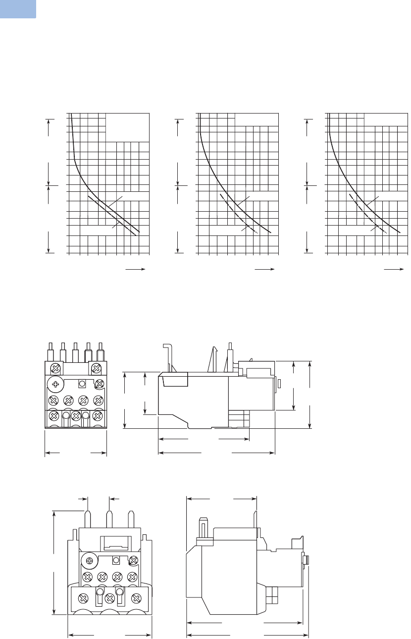
V5-T1-138 Volume 5—Motor Control and Protection CA08100006E—August 2012 www.eaton.com
1
1
1
1
1
1
1
1
1
1
1
1
1
1
1
1
1
1
1
1
1
1
1
1
1
1
1
1
1
1
1.1
IEC Contactors and Starters
XT
IEC Power Control
Tripping Characteristics
These tripping characteristics
are the mean values of the
spread at 20°C ambient
temperature in a cold state.
Tripping time depends on
response current. With
devices at operating
temperature, the tripping
time of the overload relay
reduces to approximately
25% of the read off value.
Specific characteristics for
each individual setting
range can be found in
MN03402001E.
XTOB...BC1, XTOB...CC1,
XTOB...DC1 XTOB...GC1 XTOB...HC1, XTOB...LC1
Dimensions
Approximate Dimensions in mm [in]
Frames B–C, XTOB…BC1 and XTOB…CC1 Overload Relays
Frame D, XTOB…DC1 Overload Relay
2h
100
60
40
20
10
6
4
2
1
40
20
10
6
4
2
1
0.6
XTOB...BC1,
XTOB...CC1,
XTOB...DC1
1 1.5 2 3 4 68 10 15 20
x Setting Current
2-Phase
Seconds Minutes
3-Phase
2h
100
60
40
20
10
6
4
2
1
40
20
10
6
4
2
1
0.6
XTOB...GC1
1 1.5 2 3 4 68 10 15 20
x Setting Current
2-Phase
Seconds Minutes
3-Phase
2h
100
60
40
20
10
6
4
2
1
40
20
10
6
4
2
1
0.6
XTOB...HC1,
XTOB...LC1
1 1.5 2 3 4 68 10 15 20
x Setting Current
2-Phase
Seconds Minutes
3-Phase
45 [1.77] 83 [3.27]
65 [2.56]
48
[1.89]
35.5
[1.40]
39.5
[1.56]
29.5
[1.16]
60 [2.36] 102 [4.02]
95.5 [3.76]
51.5
[2.03]
79.2
[3.12]
20.3
[.80]
Courtesy of CMA/Flodyne/Hydradyne ▪ Motion Control ▪ Hydraulic ▪ Pneumatic ▪ Electrical ▪ Mechanical ▪ (800) 426-5480 ▪ www.cmafh.com

Volume 5—Motor Control and Protection CA08100006E—August 2012 www.eaton.com V5-T1-139
1
1
1
1
1
1
1
1
1
1
1
1
1
1
1
1
1
1
1
1
1
1
1
1
1
1
1
1
1
1
1.1
IEC Contactors and Starters
XT
IEC Power Control
Approximate Dimensions in mm [in]
Frames B–C, XTOBXDINC DIN Rail or Panel Mount Adapter
and Frame D, XTOBXDIND DIN Rail or Panel Mount Adapter
Frames F–G, XTOB…GC1 Overload Relay Frames F–G, XTOB…G1CS Overload Relay
HWDD1D2
XTOB…CC1 85 [3.46] 45 [1.77] 90.5 [3.56] 58.3 [2.30] 3.8 [.15]
XTOB…DC1 86 [3.39] 60 [2.36] 112 [4.41] 80.5 [3.17] 4.7 [.19]
5 [.20]
H
16.5 [.65]
D2
42.5
[1.67]
W
D
D1
138
[5.43]
63 [2.48]
129 [5.08]
100 [3.94]
134 [5.28]
74
[2.91]
118 [4.65]
99 [3.90]
80 [3.15]
95 [3.74]
73 [2.87]
63 [2.48]
129 [5.08]
134 [5.28]
121
[4.76]
74
[2.91]
100 [3.94]
99 [3.90]
118 [4.65]
95 [3.74]
Courtesy of CMA/Flodyne/Hydradyne ▪ Motion Control ▪ Hydraulic ▪ Pneumatic ▪ Electrical ▪ Mechanical ▪ (800) 426-5480 ▪ www.cmafh.com
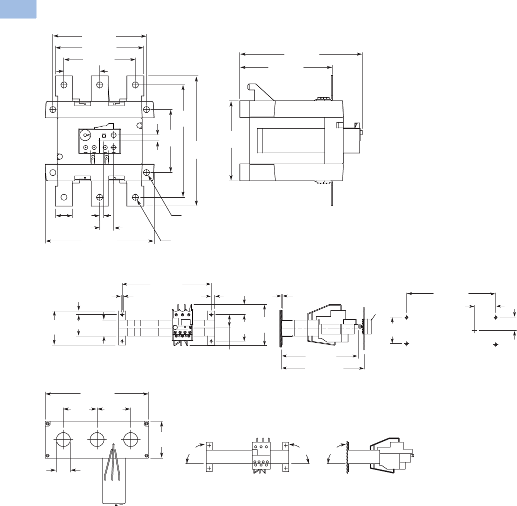
V5-T1-140 Volume 5—Motor Control and Protection CA08100006E—August 2012 www.eaton.com
1
1
1
1
1
1
1
1
1
1
1
1
1
1
1
1
1
1
1
1
1
1
1
1
1
1
1
1
1
1
1.1
IEC Contactors and Starters
XT
IEC Power Control
Approximate Dimensions in mm [in]
Frames L and H, XTOB…LC1, HC1 Overload Relay
XTOT…C3S Current Transformer Operated Overload Relay
121 [4.76]
110 [4.33]
96 [3.78]
128 [5.04]
74
[2.91]
144
[5.67]
169
[6.65]
48 [1.89]
25
[.98]
5
[.20] 16.5
[.65]
144 [5.67]
111 [4.37]
94
[3.70]
7 [.28]
7 [.28] Dia.
11 [.43] Dia.
*
**
*
** * = OFF
** = RESET/ON
7.5 [.30]
26
[1.02]
55
[2.17]
21 [.83]
85
[3.35]
185 [7.28]
71
[2.80] 44 [1.73] 33
[1.30]
8 [.31] 4.3 [.17] 185 [7.28]
M4
44
[1.73]
26 [1.02]
55
[2.17]
1.5 [.06]
159 [6.26]
172 – 250
[6.77 – 9.84]
*
*
* = RESET/ON
90° 90°
200 [7.87]
65
[2.56]
65
[2.56]
71
[2.80]
27
[1.06]
90°
Courtesy of CMA/Flodyne/Hydradyne ▪ Motion Control ▪ Hydraulic ▪ Pneumatic ▪ Electrical ▪ Mechanical ▪ (800) 426-5480 ▪ www.cmafh.com
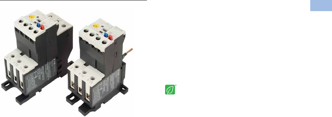
Volume 5—Motor Control and Protection CA08100006E—August 2012 www.eaton.com V5-T1-141
1
1
1
1
1
1
1
1
1
1
1
1
1
1
1
1
1
1
1
1
1
1
1
1
1
1
1
1
1
1
1.1
IEC Contactors and Starters
XT
IEC Power Control
C440/XT Electronic Overload Relay
Contents
Description Page
Relays and Timers . . . . . . . . . . . . . . . . . . . . . . . . . V5-T1-3
Miniature Controls . . . . . . . . . . . . . . . . . . . . . . . . . V5-T1-18
Contactors and Starters . . . . . . . . . . . . . . . . . . . . V5-T1-35
Thermal Overload Relays . . . . . . . . . . . . . . . . . . . . V5-T1-128
C440/XT Electronic Overload Relay
Standards and Certifications . . . . . . . . . . . . . . V5-T1-142
Catalog Number Selection . . . . . . . . . . . . . . . . V5-T1-143
Product Selection . . . . . . . . . . . . . . . . . . . . . . . V5-T1-144
Accessories . . . . . . . . . . . . . . . . . . . . . . . . . . . V5-T1-146
Technical Data and Specifications . . . . . . . . . . V5-T1-149
Dimensions . . . . . . . . . . . . . . . . . . . . . . . . . . . V5-T1-155
An Eaton
Green Solution
Manual Motor Protectors . . . . . . . . . . . . . . . . . . . V5-T1-157
Combination Motor Controllers . . . . . . . . . . . . . . . V5-T1-193
XT Electronic Manual Motor Protector . . . . . . . . . V5-T1-216
Reference Data . . . . . . . . . . . . . . . . . . . . . . . . . . . V5-T1-229
C440/XT Electronic Overload Relay
Product Description
Eaton’s new electronic
overload relay (EOL) is
the most compact, high-
featured, economical product
in its class. Designed on a
global platform, the new
EOL covers the entire power
control spectrum including
NEMA, IEC and
DP contactors. The NEMA
and DP versions are offered
with the C440 designation
while the IEC offering has the
XT designation. The
electronic design provides
reliable, accurate and value
driven protection and
communications capabilities
in a single compact device. It
is the flexible choice for any
application requiring easy-to-
use, reliable protection.
Eaton has a long history of
innovations and product
development in motor control
and protection, including both
traditional NEMA, as well as
IEC control. It was from this
experience that the C440 was
developed, delivering new
solutions to meet today’s
demands.
C440 is a self-powered
electronic overload relay
available up to 175A as a
self contained unit. With
external CTs, C440 can
protect motor up to
1500 FLA. Available add-on
accessories include remote
reset capability and
communication modules
with I/O for DeviceNet,
PROFIBUS, and Modbus.
Features and Benefits
Features
●Reliable, accurate, electronic motor protection
●Easy to select, install and maintain
●Compact size
●Flexible, intelligent design
●Global product offering—available with NEMA, IEC and DP
power control
Size/Range
●Broad FLA range
(0.33–1500A)
●Selectable trip class
(10A, 10, 20, 30)
●Direct mounting to NEMA,
IEC and DP contactors
●Most compact electronic
overload in its class
Motor Control
●Two B600 alarm (NO) and
fault (NC) contacts
●Test/Trip button
Motor Protection
●Thermal overload
●Phase loss
●Selectable (ON/OFF)
phase unbalance
●Selectable (ON/OFF)
ground fault
User Interface
●Large FLA selection dial
●Trip status indicator
●Operating mode LED
●DIP switch selectable trip
class, phase unbalance and
ground fault
●Selectable Auto/Manual
reset
Feature Options
●Remote reset
●120 Vac
●24 Vac
●24 Vdc
●Tamper-proof cover
●Communications modules
●Modbus RTU RS-485
●DeviceNet with I/O
●PROFIBUS with I/O
●Modbus RTU with I/O
●Ethernet IP with I/O
●Modbus TCP with I/O
Courtesy of CMA/Flodyne/Hydradyne ▪ Motion Control ▪ Hydraulic ▪ Pneumatic ▪ Electrical ▪ Mechanical ▪ (800) 426-5480 ▪ www.cmafh.com

V5-T1-142 Volume 5—Motor Control and Protection CA08100006E—August 2012 www.eaton.com
1
1
1
1
1
1
1
1
1
1
1
1
1
1
1
1
1
1
1
1
1
1
1
1
1
1
1
1
1
1
1.1
IEC Contactors and Starters
XT
IEC Power Control
Benefits
Reliability and Improved
Uptime
●C440 provides the users
with peace of mind
knowing that their
assets are protected
with the highest level
of motor protection and
communication capability
in its class
●Extends the life of plant
assets with selectable
motor protection features
such as trip class, phase
unbalance and ground fault
●Protects against
unnecessary downtime
by discovering changes
in your system (line/load)
with remote monitoring
capabilities
●Status LED provides
added assurance that
valuable assets are
protected by indicating the
overload operational status
Flexibility
●Available with NEMA,
IEC and DP contactors
●Improves return on
investment by reducing
inventory carrying costs
with wide FLA adjustment
(5:1) and selectable
trip class
●Design incorporates built-in
ground fault protection
thus eliminating the need
for separate CTs and
modules
●Flexible communication
with optional I/O enables
easy integration into plant
management systems for
remote monitoring and
control
●Available as an open
component and in
enclosed control and motor
control center assemblies
Monitoring Capabilities
●Individual phase
currents RMS
●Average three-phase
current RMS
●Thermal memory
●Fault indication (overload,
phase loss, phase
unbalance, ground fault)
Safety
●IP 20 rated terminal blocks
●Available in Eaton’s
industry leading FlashGard
MCCs
●Tested to the highest
industry standards such
as UL, CSA, CE and IEC
●RoHS compliant
Standards and Certifications
●UL
●CSA
●CE
●NEMA
●IEC/EN 60947 VDE 0660
●ISO 13849-1 (EN954-1)
●RoHS
●ATEX directive 94/9/EC
●Equipment Group 2,
Category 2
Electronic Overload Education
Description Definition Cause Effect if not Protected C440/XT Protection
Motor Protection
Thermal overload Overload is a condition in which
current draw exceeds 115% of
the full load amperage rating for
an inductive motor.
• An increase in the load or torque that is
being driven by the motor.
• A low voltage supply to the motor
causes the current to go high to
maintain the power needed.
• A poor power factor causing above
normal current draw.
• Increase in current draw leads to heat
and insulation breakdown, which can
cause system failure.
• Increase in current can increase
power consumption and waste
valuable energy.
• Thermal trip behavior is defined by
UL, CSA and IEC standards.
• Trip class is settable from 10A,
10, 20, 30
Ground fault A line to ground fault. A current leakage path to ground. An undetected ground fault can burn
through multiple insulation windings,
ultimately leading to motor failure, not to
mention risk to equipment or personnel
Fixed protective setting that takes the
starter offline if ground fault current
exceeds 50% of the FLA dial setting,
i.e., if the FLA dial is set to 12A, the
overload relay will trip if the ground
current exceeds 6A.
Unbalanced phases
(voltage and current)
Uneven voltage or current between
phases in a three-phase system.
When a three-phase load is powered with
a poor quality line, the voltage per phase
may be unbalanced.
Unbalanced voltage causes large
unbalanced currents and as a result this
can lead to motor stator windings being
overloaded, causing excessive heating,
reduced motor efficiency and reduced
insulation life.
Fixed protective setting that takes the
starter offline if a phase drops below
50% of the other two phases.
Phase loss—current
(single-phasing)
One of the three-phase voltages is
not present.
Multiple causes, loose wire, improper
wiring, grounded phase, open fuse, etc.
Single-phasing can lead to unwanted
motor vibrations in addition to the results
of unbalanced phases as listed above.
Fixed protective setting that takes the
starter offline if a phase is lost.
Courtesy of CMA/Flodyne/Hydradyne ▪ Motion Control ▪ Hydraulic ▪ Pneumatic ▪ Electrical ▪ Mechanical ▪ (800) 426-5480 ▪ www.cmafh.com
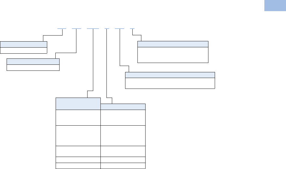
Volume 5—Motor Control and Protection CA08100006E—August 2012 www.eaton.com V5-T1-143
1
1
1
1
1
1
1
1
1
1
1
1
1
1
1
1
1
1
1
1
1
1
1
1
1
1
1
1
1
1
1.1
IEC Contactors and Starters
XT
IEC Power Control
Catalog Number Selection
XT Electronic Overload Relay—IEC 1
Note
1See Page V5-T1-144 for Product Selection.
Designation
XT = XT line of IEC control
Type
OE = Electronic overload relay
Mounting
Blank = Direct to contactor
P = Pass-through
S = Separate mount (Frames C and G only)
Trip Type
CS = Selectable Class 10A, 10, 20, 30
GS = Ground fault with selectable Class 10, 20
Overload Range
Contactor Frame
1P6 = 0.33–1.65A
005 = 1–5A
020 =4–20A
B = 45 mm
1P6 = 0.33–1.65A
005 = 1–5A
020 =4–20A
045 =9–45A
C = 45 mm
045 =9–45A
100 = 20–100A
D = 55 mm
100 = 20–100A F, G = 105 mm
175 = 35–175A G, H = 110 mm
XT OE 1P6 C CS S
Courtesy of CMA/Flodyne/Hydradyne ▪ Motion Control ▪ Hydraulic ▪ Pneumatic ▪ Electrical ▪ Mechanical ▪ (800) 426-5480 ▪ www.cmafh.com
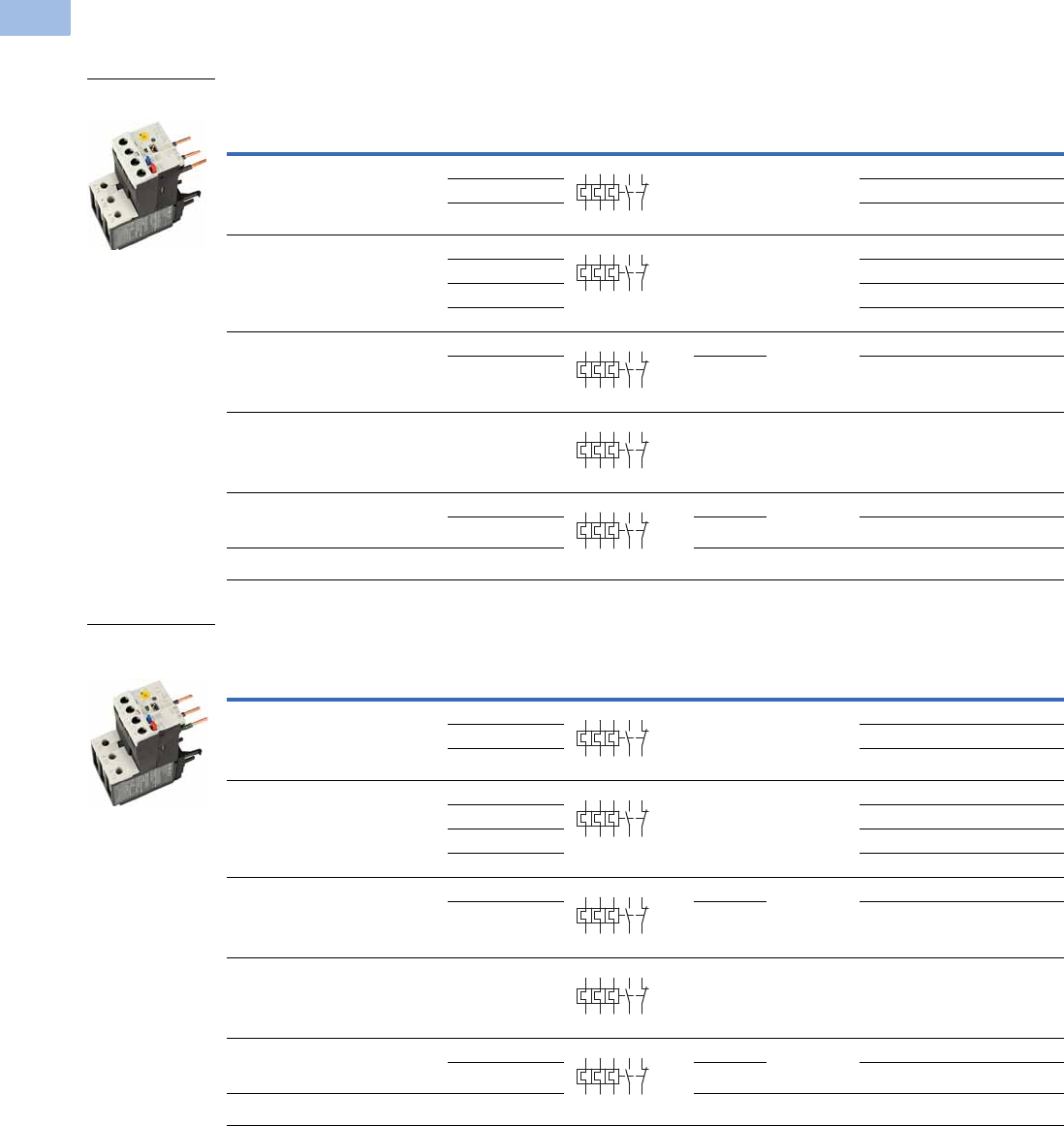
V5-T1-144 Volume 5—Motor Control and Protection CA08100006E—August 2012 www.eaton.com
1
1
1
1
1
1
1
1
1
1
1
1
1
1
1
1
1
1
1
1
1
1
1
1
1
1
1
1
1
1
1.1
IEC Contactors and Starters
XT
IEC Power Control
Product Selection
XT Electronic Overload Relays
XT Electronic Overload Relays for Direct Mount to XT Contactors
XT Electronic Overload Relays with Ground Fault for Direct Mount to XT Contactors
For Use with
XT Contactor
Frame
For Use with
Contactor
Overload
Range (Amps)
Contact
Sequence
Frame
Size
Auxiliary
Contact
Configuration Type Catalog Number
B XTCE007B…,
XTCE009B…,
XTCE012B…,
XTCE015B…
0.33–1.65 45 mm NO-NC ZEB12-1,65 XTOE1P6BCS
1–5 ZEB12-5 XTOE005BCS
4–20 ZEB12-20 XTOE020BCS
C XTCE018C…,
XTCE025C…,
XTCE032C
0.33–1.65 45 mm NO-NC ZEB32-1,65 XTOE1P6CCS
1–5 ZEB32-5 XTOE005CCS
4–20 ZEB32-20 XTOE020CCS
9–45 ZEB32-45 XTOE045CCS
D XTCE040D…,
XTCE050D…,
XTCE065D…,
XTCE072D…
9–45 45 mm NO-NC ZEB65-45 XTOE045DCS
20–100 55 mm ZEB65-100 XTOE100DCS
F XTCE080F…,
XTCE095F…
20–100 55 mm NO-NC ZEB150-100 XTOE100GCS
G XTCE115G…,
XTCE150G…,
XTCE170G…
20–100 55 mm NO-NC ZEB150-100 XTOE100GCS
35–175 110 mm ZEB150-175 XTOE175GCS
H XTCE185H… 35–175 110 mm NO-NC ZEB225-175 XTOE175HCS
For Use with
XT Contactor
Frame
For Use with
Contactor
Overload
Range (Amps)
Contact
Sequence
Frame
Size
Auxiliary
Contact
Configuration Type Catalog Number
B XTCE007B…,
XTCE009B…,
XTCE012B…,
XTCE015B…
0.33–1.65 45 mm NO-NC ZEB12-1,65-GF XTOE1P6BGS
1–5 ZEB12-5-GF XTOE005BGS
4–20 ZEB12-20-GF XTOE020BGS
C XTCE018C…,
XTCE025C…,
XTCE032C
0.33–1.65 45 mm NO-NC ZEB32-1,65-GF XTOE1P6CGS
1–5 ZEB32-5-GF XTOE005CGS
4–20 ZEB32-20-GF XTOE020CGS
9–45 ZEB32-45-GF XTOE045CGS
D XTCE040D…,
XTCE050D…,
XTCE065D…,
XTCE072D…
9–45 45 mm NO-NC ZEB65-45-GF XTOE045DGS
20–100 55 mm ZEB65-100-GF XTOE100DGS
F XTCE080F…,
XTCE095F…
20–100 55 mm NO-NC ZEB150-100-GF XTOE100GGS
GXTCE115G…,
XTCE150G…,
XTCE170G…
20–100 55 mm NO-NC ZEB150-100-GF XTOE100GGS
35–175 110 mm ZEB150-175-GF XTOE175GGS
H XTCE185H… 35–175 110 mm NO-NC ZEB225-175-GF XTOE175HGS
45 mm XT for
Direct Mount
2 4 6 98 96
97 95
2 4 6 98 96
97 95
2 4 6 98 96
97 95
2 4 6 98 96
97 95
2 4 6 98 96
97 95
45 mm XT for
Direct Mount
with Ground Fault
2 4 6 98 96
97 95
2 4 6 98 96
97 95
2 4 6 98 96
97 95
2 4 6 98 96
97 95
2 4 6 98 96
97 95
Courtesy of CMA/Flodyne/Hydradyne ▪ Motion Control ▪ Hydraulic ▪ Pneumatic ▪ Electrical ▪ Mechanical ▪ (800) 426-5480 ▪ www.cmafh.com
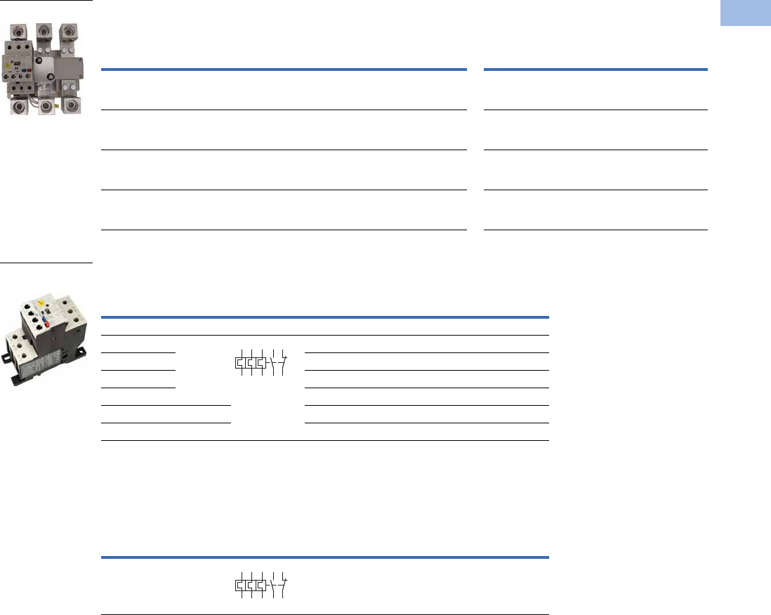
Volume 5—Motor Control and Protection CA08100006E—August 2012 www.eaton.com V5-T1-145
1
1
1
1
1
1
1
1
1
1
1
1
1
1
1
1
1
1
1
1
1
1
1
1
1
1
1
1
1
1
1.1
IEC Contactors and Starters
XT
IEC Power Control
XT Electronic Overload Relays for use with Large Frame XT Contactors (L–R)
Use CTs and 1-5A XT overload relay. CT kit does not include overload relay (order separately).
XT Electronic Overload Relays for Separate Mount
XT Electronic Overload Relay for Pass-Through Design
Pass-through design does not include any lugs to land wires.
Terminate motor leads directly on contactor.
XT
Contactor
Frame
For Use with IEC
Contactor Amp
Range (AC-3)
CT Range
(Amps) Description
CT Kit
Catalog Number
Terminal
Size
Overload Relay
Catalog Number
Overload Relay
with Ground Fault
Catalog Number
L, M 185–500A 60-300 300: 5 panel-mount CT kit
with integrated lugs
ZEB-XCT300 750 kcmil
(2) 250 kcmil
3/0 Cu/Al
XTOE005CCSS XTOE005CGSS
M, N 300–820A 120-600 600: 5 panel-mount CT kit
with integrated,
pass through holes
ZEB-XCT600 (2) 750 kcmil
3/0 Cu/Al
XTOE005CCSS XTOE005CGSS
N 580–1000A 200-1000 1000: 5 panel-mount CT kit
with integrated,
pass through holes
ZEB-XCT1000 (3) 750 kcmil
3/0 Cu/Al
XTOE005CCSS XTOE005CGSS
R 1600A 300-1500 1500: 5 panel-mount CT kit
with integrated,
pass through holes
ZEB-XCT1500 (4) 750 kcmil
1/0 Cu/Al
XTOE005CCSS XTOE005CGSS
Overload
Range (Amps)
Frame
Size
Contact
Sequence Type
Overload Relay
Catalog Number
Overload Relay
with Ground Fault
Catalog Number
Overload Relay
0.33–1.65 45 mm ZEB32-1,65/KK XTOE1P6CCSS XTOE1P6CGSS
1–5 ZEB32-5/KK XTOE005CCSS XTOE005CGSS
4–20 ZEB32-20/KK XTOE020CCSS XTOE020CGSS
9–45 ZEB32-45/KK XTOE045CCSS XTOE045CGSS
20–100 55 mm ZEB150-100/KK XTOE100GCSS XTOE100GGSS
35–175 110 mm ZEB150-175/KK XTOE175GCSS XTOE175GGSS
Overload
Range (Amps)
Frame
Size
Contact
Sequence Type
Overload Relay
Catalog Number
Overload Relay
with Ground Fault
Catalog Number
35–175 110 mm ZEB150-175/PT XTOE175GCSP XTOE175GGSP
1–5A OL with CTs
45 mm XT for
Separate Mount
1359795
2469896
1359795
2469896
Courtesy of CMA/Flodyne/Hydradyne ▪ Motion Control ▪ Hydraulic ▪ Pneumatic ▪ Electrical ▪ Mechanical ▪ (800) 426-5480 ▪ www.cmafh.com

V5-T1-146 Volume 5—Motor Control and Protection CA08100006E—August 2012 www.eaton.com
1
1
1
1
1
1
1
1
1
1
1
1
1
1
1
1
1
1
1
1
1
1
1
1
1
1
1
1
1
1
1.1
IEC Contactors and Starters
XT
IEC Power Control
Accessories
CT Kits
Accessories
Communication
The C440 is provided with two levels of communication capability.
Basic Communication via
Expansion Module—
Monitoring Only
Basic communication on
the C440 is accomplished
using an expansion module.
The expansion module plugs
into the expansion bay on
the C440 overload relay,
enabling communications
with the overload via their
Modbus RTU (RS-485)
network. No additional parts
are required. See
figure below.
Basic Communication—
Modbus
Advanced
Communication—
Monitoring and Control
C440 also has the ability to
communicate on industrial
protocols such as DeviceNet,
PROFIBUS, Modbus RTU and
Modbus TCP, and Ethernet
(planned) while providing
control capability using I/O.
An expansion module
(mentioned earlier) combined
with a communication
adapter and a communication
module allows easy
integration onto the
customer’s network. See
figure below.
Advanced Communication—
Communication Adapter with
Communication Module
Advanced
Communication—
Communication Module
The communication adapter
comes standard with four
inputs and two outputs
(24 Vdc or 120 Vac) while
providing the customer with
flexible mounting options
(DIN rail or panel). See
figure below,
Note
1Customer can wire remote mounted button to reset module (i.e., 22 mm pushbutton, catalog number M22-D-B-GB14-K10).
Description Catalog Number
Safety Cover
Clear Lexan cover that mounts on top of the FLA dial and DIP switches when closed. ZEB-XSC
Reset Bar
Assembles to the top of the overload to provide a larger target area for door
mounted reset operators.
ZEB-XRB
Remote Reset
Remote reset module (24 Vdc) 1C440-XCOM
Remote reset module (120 Vac) 1ZEB-XRR-120
Remote reset module (24 Vac) 1ZEB-XRR-24
Safety Cover
Reset Bar
Remote Reset
Courtesy of CMA/Flodyne/Hydradyne ▪ Motion Control ▪ Hydraulic ▪ Pneumatic ▪ Electrical ▪ Mechanical ▪ (800) 426-5480 ▪ www.cmafh.com
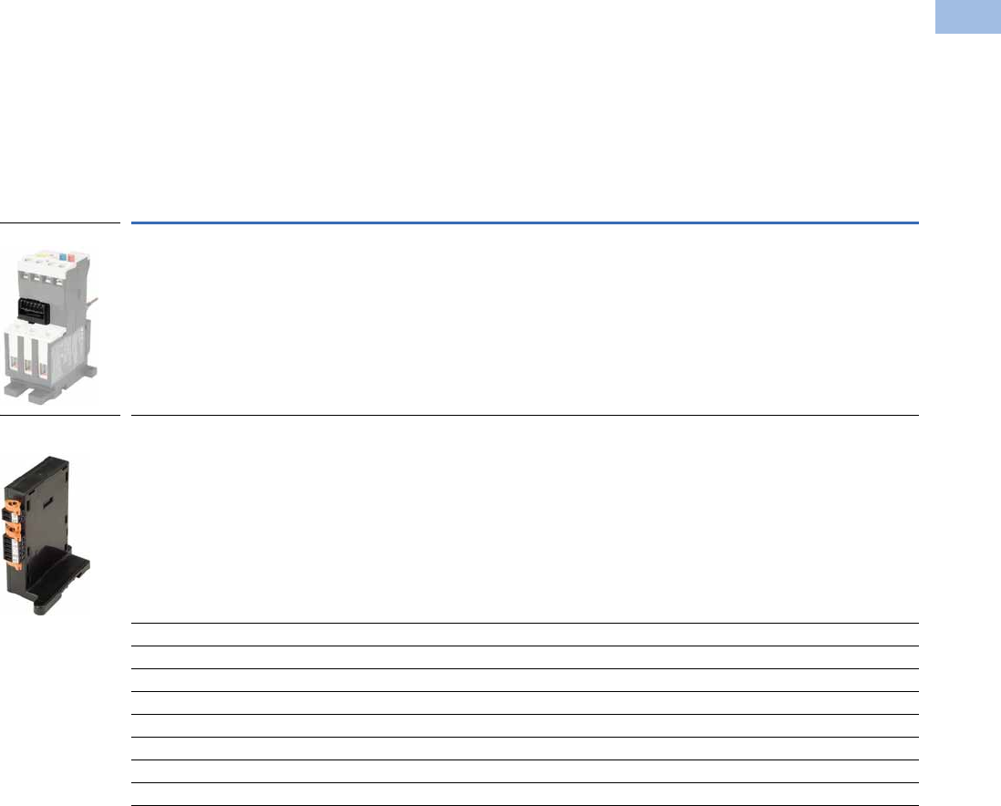
Volume 5—Motor Control and Protection CA08100006E—August 2012 www.eaton.com V5-T1-147
1
1
1
1
1
1
1
1
1
1
1
1
1
1
1
1
1
1
1
1
1
1
1
1
1
1
1
1
1
1
1.1
IEC Contactors and Starters
XT
IEC Power Control
The following information can be viewed using the communication option:
●Motor status—running,
stopped, tripped or
resetting
●Individual rms phase
currents (A, B, C)
●Average of three-phase
rms current
●Percent thermal capacity
●Fault codes (only available
prior to reset)
●Percent phase unbalance
●Ground fault current and
percent
●Overload relay settings—
trip class, DIP switch
selections, reset selections
●Modbus address (can be
set over the network)
Communication Accessories
Description Catalog Number
Expansion module (Remote Reset/Modbus RTU, RS-485 Communication) C440-XCOM
Communication adapter kit (DIN C Panel mounted adapter, required for advance communication option) C440-COM-ADP
DeviceNet communication module kit—120V I/O (consists of C440-XCOM + C441K + C440-COM-ADP) C440-DN-120
DeviceNet communication module kit—24 Vdc I/O (consists of C440-XCOM + C441L + C440-COM-ADP) C440-DN-24
PROFIBUS communication module kit—120V I/O (consists of C440-XCOM + C441S + C440-COM-ADP) C440-DP-120
PROFIBUS communication module kit—24V I/O (consists of C440-XCOM + C441Q + C440-COM-ADP) C440-DP-24
Modbus communication module kit—120V I/O (consists of C440-XCOM + C441N + C440-COM-ADP) C440-MOD-120
Modbus communication module kit—24 Vdc I/O (consists of C440-XCOM + C441P + C440-COM-ADP) C440-MOD-24
Modbus TCP/Ethernet IP communication module kit—120V I/O (consists of C440-XCOM + C441U) C440-ET-120
Modbus TCP/Ethernet IP communication module kit—24V I/O (consists of C440-XCOM + C441V) C440-ET-24
Expansion Module
Communication
Adapter
Courtesy of CMA/Flodyne/Hydradyne ▪ Motion Control ▪ Hydraulic ▪ Pneumatic ▪ Electrical ▪ Mechanical ▪ (800) 426-5480 ▪ www.cmafh.com
V5-T1-148 Volume 5—Motor Control and Protection CA08100006E—August 2012 www.eaton.com
1
1
1
1
1
1
1
1
1
1
1
1
1
1
1
1
1
1
1
1
1
1
1
1
1
1
1
1
1
1
1.1
IEC Contactors and Starters
XT
IEC Power Control
Modbus Communication Module
The Modbus module
combined with an expansion
module and a communication
adapter provide Modbus
communication capability to
the C440 electronic overload
relay.
Features and Benefits
●The Modbus
communication module is
capable of baud rates
up to 115K
●The Modbus address and
baud rate configuration can
be easily changed using
the HMi user interface
●Modbus address and baud
rate are set via convenient
DIP switches; LEDs are
provided to display
Modbus traffic
●Configuration with
common Modbus
configuration tools
●Terminals
●Unique locking
mechanism provides for
easy removal of the
terminal block with the
field wiring installed
●Each terminal is marked
for ease of wiring and
troubleshooting
●Selectable I/O assemblies
●4IN/2OUT
●Signal types include
24 Vdc I/O and
120 Vac I/O
●Each I/O module is
optically isolated
between the field I/O
and the network adapter
to protect the I/O and
communication circuits
from possible damage
due to transients and
ground loops
●Input Module features a
user-definable input
debounce, which limits
the effects of transients
and electrical noise
●Output Module supports
a user-definable safe
state for loss of
communication; hold
last state, ON or OFF
DeviceNet Communication Modules
The DeviceNet
Communication Module
provides monitoring and
control for the C440 overload
relay from a single DeviceNet
node. These modules also
offer convenient I/O in two
voltage options,
24 Vdc and 120 Vac.
Features and Benefits
●Communication to
DeviceNet uses only one
DeviceNet MAC ID
●Configuration
●DeviceNet MAC ID and
Baud rate are set via
convenient DIP switches
with an option to set
from the network
●Advanced configuration
available using common
DeviceNet tools
●Terminals
●Unique locking
mechanism provides for
easy removal of the
terminal block with the
field wiring installed
●Each terminal is marked
for ease of wiring and
troubleshooting
●Selectable I/O assemblies
●4IN/2OUT
●Signal types include
24 Vdc I/O and
120 Vac I/O
●Each I/O module is
optically isolated
between the field I/O
and the network adapter
to protect the I/O and
communication circuits
from possible damage
due to transients and
ground loops
●Input Module features a
user-definable input
debounce, which limits
the effects of transients
and electrical noise
●Output Module supports
a user-definable safe
state for loss of
communication; hold
last state, ON or OFF
●Combined status LED
PROFIBUS Communication Modules
The PROFIBUS module
combined with an expansion
module and a communication
adapter provide Modbus
communication capability to
the C440 electronic overload
relay.
Features and Benefits
●The PROFIBUS
communication module is
capable of baud rates
up to 12 Mb
●PROFIBUS address is
set via convenient DIP
switches; LEDs are
provided to display
PROFIBUS status
●Intuitive configuration
with common PROFIBUS
configuration tools
●Terminals
●Unique locking
mechanism provides for
easy removal of the
terminal block with the
field wiring installed
●Each terminal is marked
for ease of wiring and
troubleshooting
●Selectable I/O assemblies
●4IN/2OUT
●Signal types include
24 Vdc I/O and
120 Vac I/O
●Each I/O module is
optically isolated
between the field I/O
and the network adapter
to protect the I/O and
communication circuits
from possible damage
due to transients and
ground loops
●Input Module features a
user-definable input
debounce, which limits
the effects of transients
and electrical noise
●Output Module supports
a user-definable safe
state for loss of
communication; hold
last state, ON or OFF
Modbus
Communication Module
DeviceNet
Communication Module
PROFIBUS
Communication Module
Courtesy of CMA/Flodyne/Hydradyne ▪ Motion Control ▪ Hydraulic ▪ Pneumatic ▪ Electrical ▪ Mechanical ▪ (800) 426-5480 ▪ www.cmafh.com

Volume 5—Motor Control and Protection CA08100006E—August 2012 www.eaton.com V5-T1-149
1
1
1
1
1
1
1
1
1
1
1
1
1
1
1
1
1
1
1
1
1
1
1
1
1
1
1
1
1
1
1.1
IEC Contactors and Starters
XT
IEC Power Control
Technical Data and Specifications
Electronic Overload Relays up to 1500A
Specification
Description 45 mm 55 mm 110 mm
Electrical Ratings Range Range Range
Operating voltage (three-phase) and frequency 690 Vac (60/50 Hz) 690 Vac (60/50 Hz) 690 Vac (60/50 Hz)
FLA Range
0.33–1.65A
1–5A
4–20A
9–45A
20–100A 28–140A (NEMA)
35–175A (IEC)
Use with Contactors
XT IEC frames B, C, D F, G G, H
Freedom NEMA sizes 00, 0, 1, 2 3 4
Tri p C l a s s
10A, 10, 20, 30
Selectable
10A, 10, 20, 30
Selectable
10A, 10, 20, 30
Selectable
Motor Protection
Thermal overload setting 1.05 x FLA: does not trip
1.15 x FLA: overload trip
1.05 x FLA: does not trip
1.15 x FLA: overload trip
1.05 x FLA: does not trip
1.15 x FLA: overload trip
Feature Range Range Range
Phase loss Fixed threshold 50% Fixed threshold 50% Fixed threshold 50%
Phase unbalance (selectable: enable/disable) Fixed threshold 50% Fixed threshold 50% Fixed threshold 50%
Ground fault (selectable: enable/disable) 50% of FLA dial setting
>150% = 2 sec
>250% = 1 sec
50% of FLA dial setting
>150% = 2 sec
>250% = 1 sec
50% of FLA dial setting
>150% = 2 sec
>250% = 1 sec
Reset Manual/automatic Manual/automatic Manual/automatic
Indicators
Trip status Orange flag Orange flag Orange flag
Mode LED One flash: Overload operating properly
Two flashes: Current is above FLA dial
setting—pending trip
One flash: Overload operating properly
Two flashes: Current is above FLA dial
setting—pending trip
One flash: Overload operating properly
Two flashes: Current is above FLA dial
setting—pending trip
Options
Remote reset Yes Yes Yes
Reset bar Yes Yes Yes
Communication expansion module Yes Yes Yes
Communication adapter Yes Yes Yes
Capacity
Load terminals
Terminal capacity 12–10 AWG (4–6 mm2)
8–6 AWG (6–16 mm2)
6–1 AWG (16–50 mm2) 8–4/0 AWG (10–95 mm2)
Tightening torque 20–25 lb-in (2.3–2.8 Nm)
25–30 lb-in (2.8–3.4 Nm)
25–30 lb-in (2.8–3.4 Nm) 124 lb-in (14 Nm)
Input, auxiliary contact and remote reset terminals
Terminal capacity 2 x (18–12) AWG 2 x (18–12) AWG 2 x (18–12) AWG
Tightening torque 7–11 lb-in (0.8–1.2 Nm) 7–11 lb-in (0.8–1.2 Nm) 7–11 lb-in (0.8–1.2 Nm)
Voltages
Insulation voltage Ui (three-phase) 690 Vac 690 Vac 690 Vac
Insulation voltage Ui (control) 500 Vac 500 Vac 500 Vac
Rated impulse withstand voltage 6000 Vac 6000 Vac 6000 Vac
Overvoltage category/pollution degree III/3 III/3 III/3
Courtesy of CMA/Flodyne/Hydradyne ▪ Motion Control ▪ Hydraulic ▪ Pneumatic ▪ Electrical ▪ Mechanical ▪ (800) 426-5480 ▪ www.cmafh.com

V5-T1-150 Volume 5—Motor Control and Protection CA08100006E—August 2012 www.eaton.com
1
1
1
1
1
1
1
1
1
1
1
1
1
1
1
1
1
1
1
1
1
1
1
1
1
1
1
1
1
1
1.1
IEC Contactors and Starters
XT
IEC Power Control
Electronic Overload Relays up to 1500A, continued
Specification
Description 45 mm 55 mm 110 mm
Auxiliary and Control Circuit Ratings
Conventional thermal continuous current 5A 5A 5A
Rated operational current—IEC AC-15
Make contact (1800 VA)
120V 15A 15A 15A
240V 15A 15A 15A
415V 0.5A 0.5A 0.5A
500V 0.5A 0.5A 0.5A
Break contact (180 VA)
120V 1.5A 1.5A 1.5A
240V 1.5A1.5A1.5A
415V 0.9A 0.9A 0.9A
500V 0.8A 0.8A 0.8A
IEC DC-13 (L/R F 15 ms1)
0–250V 1.0A 1.0A 1.0A
Rated operational current—UL B600
Make contact (3600 VA)
120V 30A 30A 30A
240V 15A 15A 15A
480V 7.5A 7.5A 7.5A
600V 6A 6A 6A
Break contact (360 VA)
120V 3A 3A 3A
240V 1.5A1.5A1.5A
480V 0.75A 0.75A 0.75A
600V 0.6A 0.6A 0.6A
R300—Vdc ratings (28 VA)
0–120V 0.22A 0.22A 0.22A
250V 0.11A 0.11A 0.11A
Short-Circuit Rating without Welding
Maximum fuse 6A gG/gL 6A gG/gL 6A gG/gL
Environmental Ratings
Ambient temperature (operating) –13° to 149°F (–25° to 65°C) –13° to 149°F (–25° to 65°C) –13° to 149°F (–25° to 65°C)
Ambient temperature (storage) –40° to 185°F (–40° to 85°C) –40° to 185°F (–40° to 85°C) –40° to 185°F (–40° to 85°C)
Operating humidity UL 991 (H3) 5% to 95% non-condensing 5% to 95% non-condensing 5% to 95% non-condensing
Altitude (no derating) NEMA ICS1 2000m 2000m 2000m
Shock (IEC 600068-2-27) 15g any direction 15g any direction 15g any direction
Vibration (IEC 60068-2-6) 3g any direction 3g any direction 3g any direction
Pollution degree per IEC 60947-4-1 3 for product (2 for pcb) 3 for product (2 for pcb) 3 for product (2 for pcb)
Ingress protection IP20 IP20 IP20
Protection against direct contact when actuated from
front (IEC 536)
Finger- and back-of-hand proof Finger- and back-of-hand proof Finger- and back-of-hand proof
Mounting position Any Any Any
Climatic proofing Damp heat, constant to IEC 60068-2-30 Damp heat, constant to IEC 60068-2-30 Damp heat, constant to IEC 60068-2-30
Courtesy of CMA/Flodyne/Hydradyne ▪ Motion Control ▪ Hydraulic ▪ Pneumatic ▪ Electrical ▪ Mechanical ▪ (800) 426-5480 ▪ www.cmafh.com

Volume 5—Motor Control and Protection CA08100006E—August 2012 www.eaton.com V5-T1-151
1
1
1
1
1
1
1
1
1
1
1
1
1
1
1
1
1
1
1
1
1
1
1
1
1
1
1
1
1
1
1.1
IEC Contactors and Starters
XT
IEC Power Control
Electronic Overload Relays up to 1500A, continued
Specification
Description 45 mm 55 mm 110 mm
Electrical/EMC
Radiated emissions
IEC 60947-4-1-Table 15
EN 55011 (CISPIR 11) Group 1, Class A, ISM
30 mHz to 1000 mHz 30 mHz to 1000 mHz 30 mHz to 1000 mHz
Conducted emissions
IEC 60947-4-1-Table 14
EN 55011 (CISPIR 11) Group 1; Class ISM
0.15 mHz to 30 mHz 0.15 mHz to 30 mHz 0.15 mHz to 30 mHz
ESD immunity
IEC 60947-4-1 (Table 13)
±8 kV air, ±6 kV contact ±8 kV air, ±6 kV contact ±8 kV air, ±6 kV contact
Radiated immunity
IEC 60947-4-1
IEC 61000-4-3
10 V/m 80 mHz–1000 mHz
3 V/m from 1.4 to 2.7 gHz
80% amplitude modulated
1 kHz sine wave
10 V/m 80 mHz–1000 mHz
3 V/m from 1.4 to 2.7 gHz
80% amplitude modulated
1 kHz sine wave
10 V/m 80 mHz–1000 mHz
3 V/m from 1.4 to 2.7 gHz
80% amplitude modulated
1 kHz sine wave
Conducted immunity
IEC 60947-4-1, IEC 61000-4-6
140 dub (10V rms)
150 kHz–100 mHz
140 dub (10V rms)
150 kHz–100 mHz
140 dub (10V rms)
150 kHz–100 mHz
Fast transient immunity
IEC 60947-4-1 (Table 13)
IEC 61000-4-4
±4 kV using direct method
with accessory installed in expansion bay
±2 kV using direct method
±4 kV using direct method
with accessory installed in expansion bay
±2 kV using direct method
±4 kV using direct method
with accessory installed in expansion bay
±2 kV using direct method
Surge immunity
IEC 60947-4-1 (Table 13)
IEC 61000-4-5 a Class 4
Three-phase power inputs:
±4 kV line-to-line (DM)
±4 kV line-to-ground (CM)
Three-phase power inputs:
±4 kV line-to-line (DM)
±4 kV line-to-ground (CM)
Three-phase power inputs:
±4 kV line-to-line (DM)
±4 kV line-to-ground (CM)
With accessory installed in expansion bay:
±2 kV line-to-line (DM) –>1.2/50 us;
2 kV line-to-earth, 1 kV line-to-line
±4 kV line-to-ground (CM)
With accessory installed in expansion bay:
±2 kV line-to-line (DM) –>1.2/50 us;
2 kV line-to-earth, 1 kV line-to-line
±4 kV line-to-ground (CM)
With accessory installed in expansion bay:
±2 kV line-to-line (DM) –>1.2/50 us;
2 kV line-to-earth, 1 kV line-to-line
±4 kV line-to-ground (CM)
Power freq. magnetic field immunity
IEC 60947-4-1, IEC 61000-4-8
30 A/m, 50 Hz 30 A/m, 50 Hz 30 A/m, 50 Hz
Electromagnetic field
IEC 60947-4-1 Table 13, IEC 61000-4-3
10 V/m 10 V/m 10 V/m
Distortion IEEE 519 5% THD max., 5th harmonic 3% max. 5% THD max., 5th harmonic 3% max. 5% THD max., 5th harmonic 3% max.
Electrostatic discharge (ESD)
IEC 61000-4-2, EN 61131-2
4 kV contact
8 kV air discharge
4 kV contact
8 kV air discharge
4 kV contact
8 kV air discharge
Electrical fast transient (EFT)
IEC 61000-4-4, EN 61131-2
±2 kV using direct method ±2 kV using direct method ±2 kV using direct method
Surge immunity
IEC 61000-4-5, EN 61131-2
±2 kV line-to-ground (CM) ±2 kV line-to-ground (CM) ±2 kV line-to-ground (CM)
Courtesy of CMA/Flodyne/Hydradyne ▪ Motion Control ▪ Hydraulic ▪ Pneumatic ▪ Electrical ▪ Mechanical ▪ (800) 426-5480 ▪ www.cmafh.com

V5-T1-152 Volume 5—Motor Control and Protection CA08100006E—August 2012 www.eaton.com
1
1
1
1
1
1
1
1
1
1
1
1
1
1
1
1
1
1
1
1
1
1
1
1
1
1
1
1
1
1
1.1
IEC Contactors and Starters
XT
IEC Power Control
Communication Modules
Note
1Relates to C441M only.
Description Modbus DeviceNet PROFIBUS Ethernet
Electrical/EMC
Radiated emissions
IEC 60947-4-1—Table 15, EN 55011
(CISPIR 11) Group 1, Class A
30–1000 mHz 30–1000 mHz 30–1000 mHz 30–1000 mHz
Conducted emissions
IEC 60947-4-1—Table 14, EN 55011
(CISPIR 11) Group 1, Class A
0.15–30 mHz 0.15–30 mHz 0.15–30 mHz 0.15–30 mHz
ESD immunity
IEC 60947-4-1 (Table 13)
±8 kV air, ±4 kV contact ±8 kV air, ±4 kV contact ±8 kV air, ±4 kV contact ±8 kV air, ±4 kV contact
Radiated immunity
IEC 60947-4-1
10 V/m 80–1000 mHz
80% amplitude modulated
1 kHz sine wave
10 V/m 80–1000 mHz
80% amplitude modulated
1 kHz sine wave
10 V/m 80–1000 mHz
80% amplitude modulated
1 kHz sine wave
10 V/m 80–1000 mHz
80% amplitude modulated
1 kHz sine wave
Conducted immunity
IEC 60947-4-1
140 dBuV (10V rms)
150 kHz–80 mHz
140 dBuV (10V rms)
150 kHz–80 mHz
140 dBuV (10V rms)
150 kHz–80 mHz
140 dBuV (10V rms)
150 kHz–80 mHz
Fast transient immunity
IEC 60947-4-1 (Table 13) IEC 6100-4-4
±2 kV using direct method ±2 kV supply and control,
±1 kV communication
±2 kV supply and control,
±1 kV communication
±2 kV supply and control,
±1 kV communication
Surge immunity
IEC 60947-4-1 (Table 13)
IEC 61000-4-5 Class 3
User IO and communication lines 1:
±1 kV line-to-line (DM)
±2 kV line-to-ground (CM)
User IO and communication lines:
±0.5 kV line-to-line (DM)
±1 kV line-to-ground (CM)
User IO and communication lines:
±0.5 kV line-to-line (DM)
±1 kV line-to-ground (CM)
User IO and communication lines:
±0.5 kV line-to-line (DM)
±1 kV line-to-ground (CM)
Electromagnetic field 1
IEC 60947-4-1 (Table 13) IEC 61000-4-3
10 V/m 10 V/m 10 V/m 10 V/m
Environmental Ratings
Ambient temperature (operating) –4° to 122°F (–20° to 50°C) –13° to 122°F (–25° to 50°C) –13° to 122°F (–25° to 50°C) –13° to 122°F (–25° to 50°C)
Ambient temperature (storage) –40° to 185°F (–40° to 85°C) –40° to 185°F (–40° to 85°C) –40° to 185°F (–40° to 85°C) –40° to 185°F (–40° to 85°C)
Operating humidity 5–95% noncondensing 5–95% noncondensing 5–95% noncondensing 5–95% noncondensing
Altitude (no derating) 2000m 2000m 2000m 2000m
Shock (IEC 600068-2-27) 15G any direction 15G any direction 15G any direction 15G any direction
Vibration (IEC 60068-2-6) 3G any direction 3G any direction 3G any direction 3G any direction
Pollution degree per IEC 60947-1 3 3 3 3
Degree of protection IP20 IP20 IP20 IP20
Overvoltage category per UL 508 III III III III
DeviceNet
DeviceNet connections — Group 2, polling, bit strobe,
explicit, no UCMM
— Group 2, polling, bit strobe,
explicit, no UCMM
DeviceNet baud rate — 125K, 250K, 500K — 125K, 250K, 500K
Ethernet
Ethernet connections — — — Integrated two-port switch with dual
RJ45 Ethernet connections
Ethernet type — — — Ethernet 10/100 Mbs, AutoMDX,
Auto Negotiation
PROFIBUS
PROFIBUS connections — — Group 2, polling, bit strobe,
explicit, no UCMM
—
PROFIBUS baud rate — — 9.6K, 19.2K, 45.45K, 93.75K, 187.5K,
500K, 1.5M, 3M, 6M, 12M
—
Courtesy of CMA/Flodyne/Hydradyne ▪ Motion Control ▪ Hydraulic ▪ Pneumatic ▪ Electrical ▪ Mechanical ▪ (800) 426-5480 ▪ www.cmafh.com

Volume 5—Motor Control and Protection CA08100006E—August 2012 www.eaton.com V5-T1-153
1
1
1
1
1
1
1
1
1
1
1
1
1
1
1
1
1
1
1
1
1
1
1
1
1
1
1
1
1
1
1.1
IEC Contactors and Starters
XT
IEC Power Control
Communication Modules, continued
Note
1Relates to C441M only.
Description Modbus DeviceNet PROFIBUS Ethernet
C441_ 24 Vdc Input
Nominal input voltage 24 Vdc 24 Vdc 24 Vdc 24 Vdc
Operating voltage 18–30 Vdc 18–30 Vdc 18–30 Vdc 18–30 Vdc
Number of inputs 4 4 4 4
Signal delay 5 ms (programmable to 65 sec) 5 ms (programmable to 65 sec) 5 ms (programmable to 65 sec) 5 ms (programmable to 65 sec)
OFF-state voltage <6 Vdc <6 Vdc <6 Vdc <6 Vdc
ON-state voltage >18 Vdc >18 Vdc >10 Vdc >18 Vdc
Nominal input current 5 mA 5 mA 5 mA 5 mA
Isolation 1500V 1500V 1500V 1500V
Terminal screw torque 7–9 in-lb 7–9 in-lb 7–9 in-lb 7–9 in-lb
24V source current 50 mA 50 mA 50 mA 50 mA
Operating Voltage Range—DC Input Modules
OFF state 0–6 Vdc 0–6 Vdc 0–6 Vdc 0–6 Vdc
Transition region 6–18 Vdc 6–18 Vdc 6–18 Vdc 6–18 Vdc
ON state 18–30 Vdc 18–30 Vdc 18–30 Vdc 18–30 Vdc
C441_ 120 Vac Input
Nominal input voltage 120 Vac 120 Vac 120 Vac 120 Vac
Operating voltage 80–140 Vac 80–140 Vac 80–140 Vac 80–140 Vac
Number of inputs 4 4 4 4
OFF-state voltage <30 Vac <30 Vac <20 Vac <30 Vac
ON-state voltage >80 Vac >80 Vac >70 Vac >80 Vac
Nominal input current 15 mA 15 mA 15 mA 15 mA
Signal delay 1/2 cycle 1/2 cycle 1/2 cycle 1/2 cycle
Isolation 1500V 1500V 1500V 1500V
Terminal screw torque 7–9 in-lb 7–9 in-lb 7–9 in-lb 7–9 in-lb
Operating Voltage Range—AC Input Modules
OFF state 0–30 Vac 0–30 Vac 0–30 Vac 0–30 Vac
Transition region 30–80 Vac 30–80 Vac 30–80 Vac 30–80 Vac
ON state 80–140 Vac 80–140 Vac 80–140 Vac 80–140 Vac
Output Modules
Nominal voltage 120 Vac
24 Vdc
120 Vac
24 Vdc
120 Vac
24 Vdc
120 Vac
24 Vdc
Number of outputs (2) 1NO Form A
1NO/NC Form C
(2) 1NO Form A
1NO/NC Form C
(2) 1NO Form A
1NO/NC Form C
(2) 1NO Form A
1NO/NC Form C
Relay OFF time 3 ms 3 ms 3 ms 3 ms
Relay ON time 7 ms 7 ms 7 ms 7 ms
Max. current per point 15A (B300 rated) 5A (B300 rated) 5A (B300 rated) 5A (B300 rated)
Electrical life 100,000 cycles 100,000 cycles 100,000 cycles 100,000 cycles
Mechanical life 1,000,000 cycles 1,000,000 cycles 1,000,000 cycles 1,000,000 cycles
Courtesy of CMA/Flodyne/Hydradyne ▪ Motion Control ▪ Hydraulic ▪ Pneumatic ▪ Electrical ▪ Mechanical ▪ (800) 426-5480 ▪ www.cmafh.com

V5-T1-154 Volume 5—Motor Control and Protection CA08100006E—August 2012 www.eaton.com
1
1
1
1
1
1
1
1
1
1
1
1
1
1
1
1
1
1
1
1
1
1
1
1
1
1
1
1
1
1
1.1
IEC Contactors and Starters
XT
IEC Power Control
Short Circuit Ratings (North America CSA, cUL)
Changes to UL 508A and NEC in recent years have brought a focus to control panel safety with
regard to short-circuit current ratings (SCCR). Eaton’s C440 electronic overload relays combined
with XT series IEC and Freedom Series NEMA contactors provide a wide variety of SCCR
solutions needed for a variety of applications. The SCCR data in this document reflects the
latest information as of April 2010.
C440/XT Standalone Overload Relays (XT, C440)
IEC XT Starters with XT Electronic Overload Relays
Overload
FLA Range
Maximum
Operating
Voltage
Standard-Fault Short Circuit Data High-Fault Short Circuit Data
600V (kA)
Maximum
Fuse Size (A)
(RK5)
Maximum
Breaker
Size (A)
Fuses (RK5, J, CC) Thermal-Magnetic Circuit Breakers
480V (kA) 600V (kA)
Maximum
Fuse Size 480V (kA) 600V (kA)
Maximum
Breaker Size
0.33–1.65A600 Vac1 6 15 ——————
1–5A 600 Vac 5 20 20 100 100 30 100 35 20
4–20A 600 Vac 5 80 80 100 100 100 100 35 80
9–45A 600 Vac 5 175 175 100 100 100 100 35 100/175 (480/600)
20–100A 600 Vac 10 400 400 100 100 200 150 35 250/400 (480/600)
28–140A 600 Vac 10 450 500 100 100 400 100 65 400
35–175A 690 Vac 10 500 (gG) 350 (690 Vac)
320 (415 Vac)
100 100 500 (gG) 100 (415 Vac) — 350 (LGC3350)
320 (NZMH3)
Contactor
Frame Size
Maximum
Operating
Voltage
High-Fault Short Circuit Data Thermal-Magnetic Circuit Breakers
Fuses (RK5, J, CC)
480V 600V
Maximum
Fuse Size 480V 600V
Maximum
Breaker Size
B 1–5A 100 100 30 ———
4–20A 100 100 30 — — —
C 1–5A 100 100 60 — — —
4–20A 100 100 60 — — —
9–45A 100 100 60 — — —
D 9–45A 100 100 200 65 35 175
20–100A 100 100 200 65 35 175
F 20–100A 100 100 200 65 65 350
G 20–100A 100 100 200 65 65 350
35–175A 100 100 400 65 30 250 (480 Vac)
350 (600 Vac)
H 35–175A 100 100 400 65 30 400
Courtesy of CMA/Flodyne/Hydradyne ▪ Motion Control ▪ Hydraulic ▪ Pneumatic ▪ Electrical ▪ Mechanical ▪ (800) 426-5480 ▪ www.cmafh.com
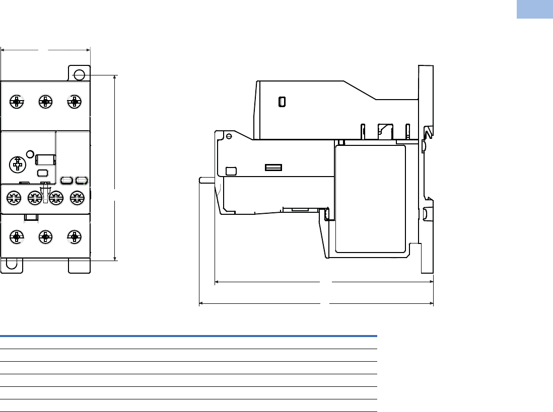
Volume 5—Motor Control and Protection CA08100006E—August 2012 www.eaton.com V5-T1-155
1
1
1
1
1
1
1
1
1
1
1
1
1
1
1
1
1
1
1
1
1
1
1
1
1
1
1
1
1
1
1.1
IEC Contactors and Starters
XT
IEC Power Control
Dimensions
Approximate Dimensions in Inches (mm)
45 mm C440/XT Electronic Overload Relays
Width
A
Depth
B1 B
Mounting Holes
(Height) C
NEMA Starter Size
00–2 1.80 (45.7) 4.32 (109.7) 4.63 (117.5) 3.68 (93.5)
XT IEC Frame Size
B, C, D 1.80 (45.7) 4.00 (101.6) 4.30 (109.2) 3.68 (93.5)
Standalone
0.35–45A 1.80 (45.7) 4.30 (109.2) 4.60 (116.8) 3.68 (93.5)
Text Orientation
B1
B
C
A
Courtesy of CMA/Flodyne/Hydradyne ▪ Motion Control ▪ Hydraulic ▪ Pneumatic ▪ Electrical ▪ Mechanical ▪ (800) 426-5480 ▪ www.cmafh.com
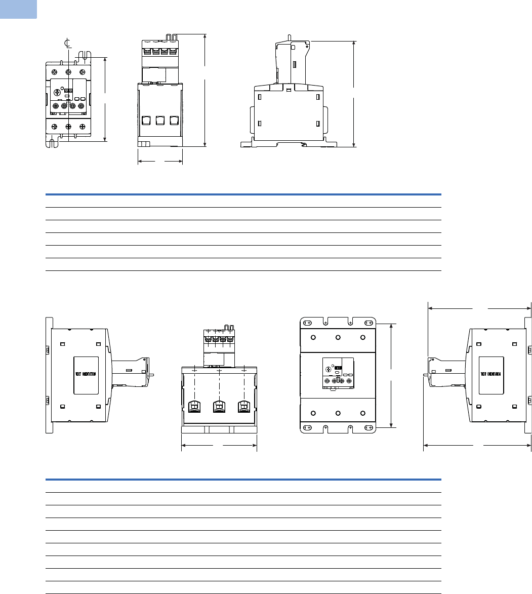
V5-T1-156 Volume 5—Motor Control and Protection CA08100006E—August 2012 www.eaton.com
1
1
1
1
1
1
1
1
1
1
1
1
1
1
1
1
1
1
1
1
1
1
1
1
1
1
1
1
1
1
1.1
IEC Contactors and Starters
XT
IEC Power Control
Approximate Dimensions in Inches (mm)
55 mm C440/XT Electronic Overload Relays
110 mm C440/XT Electronic Overload Relays
Width
A
Height To Reset
BB1
Mounting Depth
C
NEMA Starter Size
3 2.21 (56.0) 5.52 (140.2) 5.21 (132.4) 4.13 (104.8)
XT IEC Frame Size
D, F, G 2.21 (56.0) 5.52 (140.2) 5.21 (132.4) 4.13 (104.8)
Standalone
20–100A 2.21 (56.0) 5.52 (140.2) 5.21 (132.4) 4.13 (104.8)
Width
A
Height To Reset
BB1
Mounting Depth
C
NEMA Starter Size
4 4.33 (110.0) 6.20 (157.0) 5.90 (150.0) 6.00 (152.0)
XT IEC Frame Size
G 4.33 (110.0) 6.20 (157.0) 5.90 (150.0) 6.00 (152.0)
H 4.33 (110.0) 6.20 (157.0) 5.90 (150.0) 6.00 (152.0)
Standalone
4.33 (110.0) 6.20 (157.0) 5.90 (150.0) 6.00 (152.0)
Pass-Through
4.33 (110.0) 5.90 (149.0) 5.60 (142.0) 4.00 (102.0)
C
B
A
B1
C
B
B1
A
Courtesy of CMA/Flodyne/Hydradyne ▪ Motion Control ▪ Hydraulic ▪ Pneumatic ▪ Electrical ▪ Mechanical ▪ (800) 426-5480 ▪ www.cmafh.com
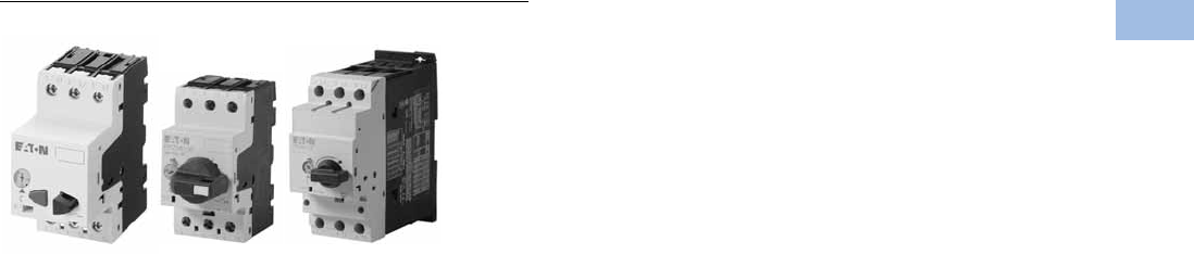
Volume 5—Motor Control and Protection CA08100006E—August 2012 www.eaton.com V5-T1-157
1
1
1
1
1
1
1
1
1
1
1
1
1
1
1
1
1
1
1
1
1
1
1
1
1
1
1
1
1
1
1.1
IEC Contactors and Starters
XT
IEC Power Control
Manual Motor Protectors
Contents
Description Page
Relays and Timers . . . . . . . . . . . . . . . . . . . . . . . . . V5-T1-3
Miniature Controls . . . . . . . . . . . . . . . . . . . . . . . . . V5-T1-18
Contactors and Starters . . . . . . . . . . . . . . . . . . . . V5-T1-35
Thermal Overload Relays . . . . . . . . . . . . . . . . . . . . V5-T1-128
C440/XT Electronic Overload Relay . . . . . . . . . . . V5-T1-141
Manual Motor Protectors
Features and Benefits . . . . . . . . . . . . . . . . . . . V5-T1-158
Standards and Certifications . . . . . . . . . . . . . . V5-T1-158
Product Identification . . . . . . . . . . . . . . . . . . . . V5-T1-159
Catalog Number Selection . . . . . . . . . . . . . . . . V5-T1-160
Product Selection . . . . . . . . . . . . . . . . . . . . . . . V5-T1-161
Accessories . . . . . . . . . . . . . . . . . . . . . . . . . . . V5-T1-164
Technical Data and Specifications . . . . . . . . . . V5-T1-176
Dimensions . . . . . . . . . . . . . . . . . . . . . . . . . . . V5-T1-185
Combination Motor Controllers . . . . . . . . . . . . . . . V5-T1-193
XT Electronic Manual Motor Protector . . . . . . . . . V5-T1-216
Reference Data . . . . . . . . . . . . . . . . . . . . . . . . . . . V5-T1-229
Manual Motor Protectors
Product Description
Eaton’s new XT family of
manual motor protectors
(MMPs) features a
pushbutton or rotary ON/OFF
manual disconnect, Class 10
adjustable bimetallic overload
relay and fixed magnetic
short-circuit trip capability
in one compact unit. Two
frame sizes are available:
Frame B (45 mm) for motors
with FLA ratings up to 32A
and Frame D (55 mm) covers
motor FLA ratings up to 65A.
Application Description
The XTPB and XTPR MMPs
can be used in the following
applications.
Motor Protective Circuit Breaker
In many countries outside
of the United States and
Canada, especially Europe,
the MMPs are tested and
classified as thermal-
magnetic circuit breakers
for use in motor branch
circuits. This can be an
important consideration for all
companies who export their
equipment and machines
internationally. Both the XTPB
and XTPR conform to IEC/EN
60947 and have the CE Mark.
Manual Motor Protectors
The XTPB and XTPR MMPs
are UL listed under UL 508 as
manual motor protectors. They
provide an economical solution
for applications requiring
simple manual starting and
stopping of motors. When
used as a manual starter, they
are typically installed in an
enclosure. Many enclosures
are offered as accessories for
the MMPs. Separate short-
circuit protective devices, such
as circuit breakers or fuses, are
wired ahead of the MMPs. The
short-circuit protective device
should be sized per the NEC
and should not exceed 400%
of the maximum FLA dial
setting of the MMP.
Group Motor Installations
A group motor installation
can be defined as more than
one motor circuit protected
by a single set of fuses or
circuit breaker on a motor
branch circuit. This eliminates
the need for individual fuses
or circuit breakers for each
motor circuit. Substantial
component cost savings,
panel space savings and
reduced wiring installation
time can be achieved in
group motor installations.
The MMPs are tested and
listed for group installation
.
If remote operation is required,
a magnetic contactor can be
wired in series with the MMP.
Article 430.53 of the NEC
contains the rules and
requirements for group motor
installations.
Refer to
application note AP03402001E
for NEC requirement for
group motor installation.
Individual Branch Motor
Applications
A UL 508 Type E self-
protected manual
combination starter/motor
controller consists of a single
device possessing four
essential elements:
disconnect, short circuit
protection, motor controller,
and motor overload
protection. Some MMPs
require use of a lineside
adapter for this type of
approval. When tested as an
official combination by UL,
this device takes the place of
a fuse-starter or breaker-
starter, XT Type E MMPs are
self-protected, meaning they
do not need additional short
circuit protection of a fuse or
breaker. Type E devices can
also be used with a contactor
or other types of UL approved
controllers. If tested with a
contactor, the combination
motor controller becomes a
Type F device. See Page
V5-T1-199 for XTFC Type F
devices.
Courtesy of CMA/Flodyne/Hydradyne ▪ Motion Control ▪ Hydraulic ▪ Pneumatic ▪ Electrical ▪ Mechanical ▪ (800) 426-5480 ▪ www.cmafh.com
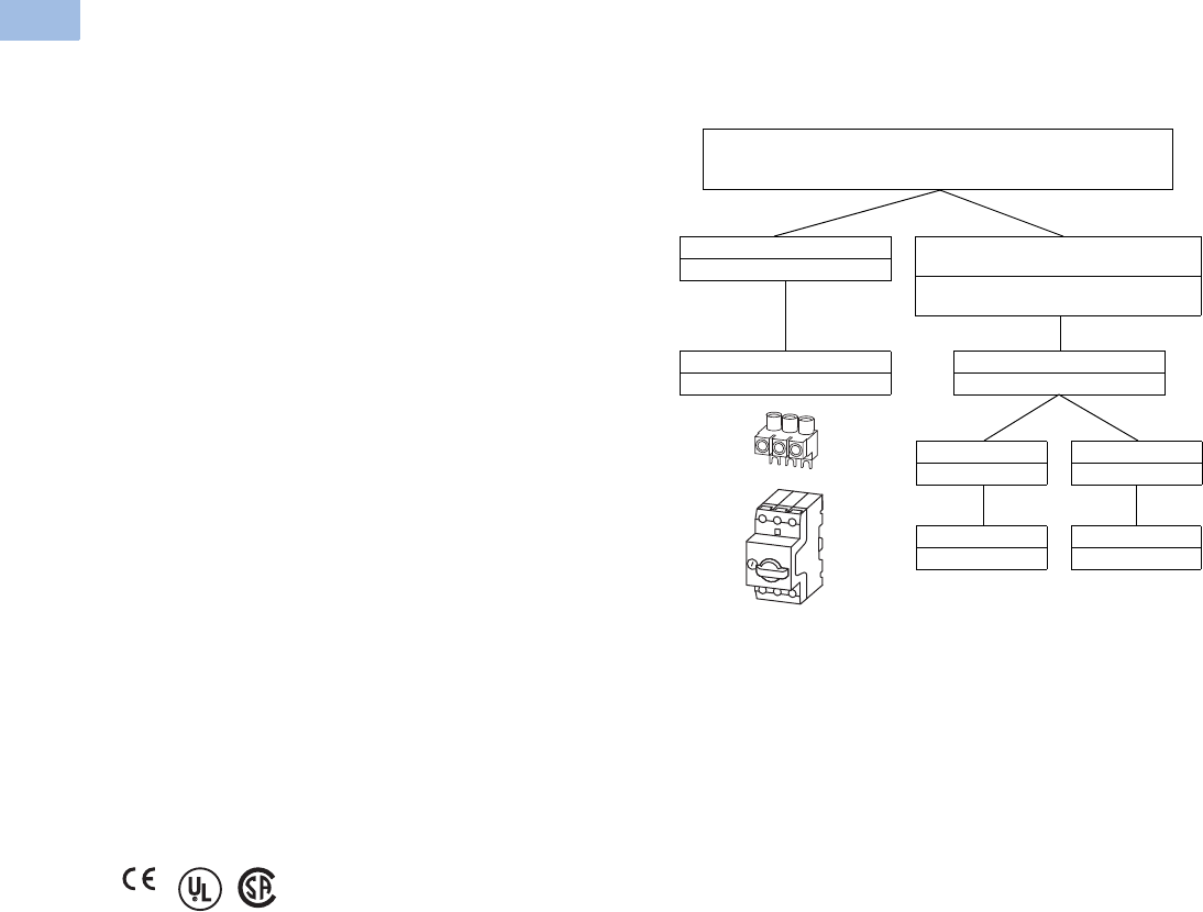
V5-T1-158 Volume 5—Motor Control and Protection CA08100006E—August 2012 www.eaton.com
1
1
1
1
1
1
1
1
1
1
1
1
1
1
1
1
1
1
1
1
1
1
1
1
1
1
1
1
1
1
1.1
IEC Contactors and Starters
XT
IEC Power Control
Features and Benefits
●ON/OFF rotary handle with
lockout provision
●Visible trip indication
●Class 10 overload
protection
●Phase loss sensitivity
●Ambient temperature
compensation to IEC/EN
60947, VDE 0660
●Fixed short-circuit trip—
14 times maximum setting
of overload FLA dial
●Type 2 coordination per IEC
947
●Identification markers
standard on starter
faceplate
●Motor applications from
0.1A to 65A
●Built-in heater and
magnetic trip elements
to protect the motor
●Adjustment dial for setting
motor FLA
●DIN rail mount
●Terminal types available:
●Screw terminals
●Screw (line) and spring
cage (load) terminals
●Spring cage terminals
●Accessories include:
●Front and side auxiliary
contacts
●Trip indicating contacts
●Tamperproof cover for
OLR dial
●Undervoltage release
●Shunt trip
●Through-the-door
operators
●Enclosures
●
Three-phase line side
connecting links
Standards and Certifications
●CE approved
●UL listed File No. E245398
●UL 508 group motor and
Type E compliant
●IEC/EN 60947
●CSA File 229767, Class
3211-05
●DIN VDE 0660 Part 100,
Part 101 and Part 102
Note: For Type 2 Coordination
of MMCs, see Page V5-T1-230.
Line Side Adapters—When to Use Them
Note: Line side adapters are not required for non-US applications.
Most countries outside of the US classify the MMP as a thermal
magnetic circuit breaker.
Line Side Adapter (LSA)
Required
Manual Motor Protector
and Line Side Adapter
Manual Motor Protectors
Self-Protected Manual Combination Starters
Line Side Adapter (LSA)
Not required
Group Installation
Upstream SCPD required.
UL 508 Type E Self-Protected Manual
Combination Starter
Self-protected. No additional SCPD needed in
branch circuit.
Line Side Adapter
XTPAXLSA
Line Side Adapter
XTPAXLSAD
MMP
XTPR…BC1
MMP
XTPR…DC1
Courtesy of CMA/Flodyne/Hydradyne ▪ Motion Control ▪ Hydraulic ▪ Pneumatic ▪ Electrical ▪ Mechanical ▪ (800) 426-5480 ▪ www.cmafh.com
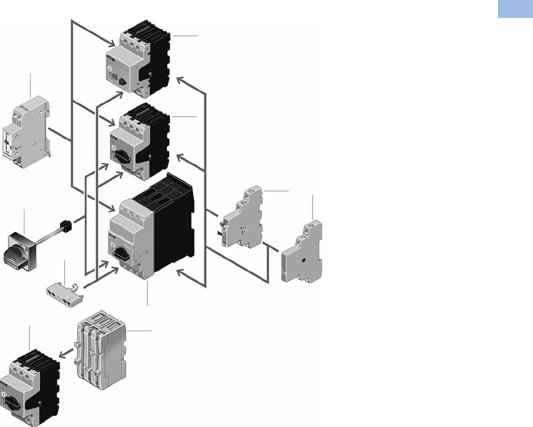
Volume 5—Motor Control and Protection CA08100006E—August 2012 www.eaton.com V5-T1-159
1
1
1
1
1
1
1
1
1
1
1
1
1
1
1
1
1
1
1
1
1
1
1
1
1
1
1
1
1
1
1.1
IEC Contactors and Starters
XT
IEC Power Control
Product Identification
Notes
Basic Units
1XTPB pushbutton manual motor
protectors (see Page V5-T1-161)
Rated operational current up to 25A
Switching capacity 50 kA/415V
Short-circuit release, adjustable
0.6–1 x lu
Single-phasing sensitive
2XTPR rotary manual motor protectors
(see Page V5-T1-162)
Rated operational current up to
32A, 65A
Switching capacity 150/50 kA/415V
Short-circuit release, fixed setting to
14 x lu
Overload release, adjustable 0.6–1 x lu
Single-phasing sensitive
With screws or spring-loaded
terminals
Mounting Accessories
3Rotary handle mechanism
(see Page V5-T1-167)
ON/OFF/tripped switch position indication
Lockable door/cover interlock
Extendable y plug fit extension shaft
Handle latched in switch positions
Optionally also without locking and
door interlock function
Insulated enclosures
(see Page V5-T1-171)
Surface mounting, enclosures, IP40,
IP55 and IP40 and IP55 front flush
mounting enclosure
Mounting/wiring (see Page V5-T1-167)
Component adapter for busbar mounting
Three-phase commoning link for
side-by-side-mounting
Mounting kits for rapid mounting of
direct-on-line, reversing and star-
delta starters
Add-On Functions
4Voltage releases (see Page V5-T1-166)
Undervoltage release
Shunt releases
With screws or spring-loaded terminals
5Standard auxiliary contacts
(see Page V5-T1-164)
ON/OFF indication
Differential fault indication overload/
short-circuit release
ON/OFF for (high capacity) contact
module
ON/OFF for starter combination
With early-make contacts
With screws or spring-loaded terminals
6Current limiter (see Page V5-T1-166)
Increases the switching capacity of the
10–25A manual motor protectors to
100 kA/440V
Can be used for individual group
protection
4
1
2
3
2
5
6
5
5
6
2
Courtesy of CMA/Flodyne/Hydradyne ▪ Motion Control ▪ Hydraulic ▪ Pneumatic ▪ Electrical ▪ Mechanical ▪ (800) 426-5480 ▪ www.cmafh.com
V5-T1-160 Volume 5—Motor Control and Protection CA08100006E—August 2012 www.eaton.com
1
1
1
1
1
1
1
1
1
1
1
1
1
1
1
1
1
1
1
1
1
1
1
1
1
1
1
1
1
1
1.1
IEC Contactors and Starters
XT
IEC Power Control
Catalog Number Selection
XT Manual Motor Protectors
XT PR 012 BC1
Type
PB = Manual motor protector—
pushbutton
PR = Manual motor protector—
rotary
PM = Manual motor protector—
magnetic only
PT = Manual transformer
protector (high mag.)
Designation
XT = XT IEC power control
Trip Class
C1 =Class 10
Blank = Magnetic only (no thermal trip)
Frame Size
B= 45 mm
D= 55 mm
Current Ratings
Frame B
P16 = 0.16A
P25 = 0.25A
P40 = 0.40A
P63 = 0.63A
001 = 1A
1P6 = 1.6A
2P5 = 2.5A
004 = 4A
6P3 = 6.3A
010 = 10A
012 = 12A
016 = 16A
020 = 20A
025 = 25A
032 = 32A
Frame D
016 = 16A
025 = 25A
032 = 32A
040 = 40A
050 = 50A
058 = 58A
063 = 63A
Courtesy of CMA/Flodyne/Hydradyne ▪ Motion Control ▪ Hydraulic ▪ Pneumatic ▪ Electrical ▪ Mechanical ▪ (800) 426-5480 ▪ www.cmafh.com
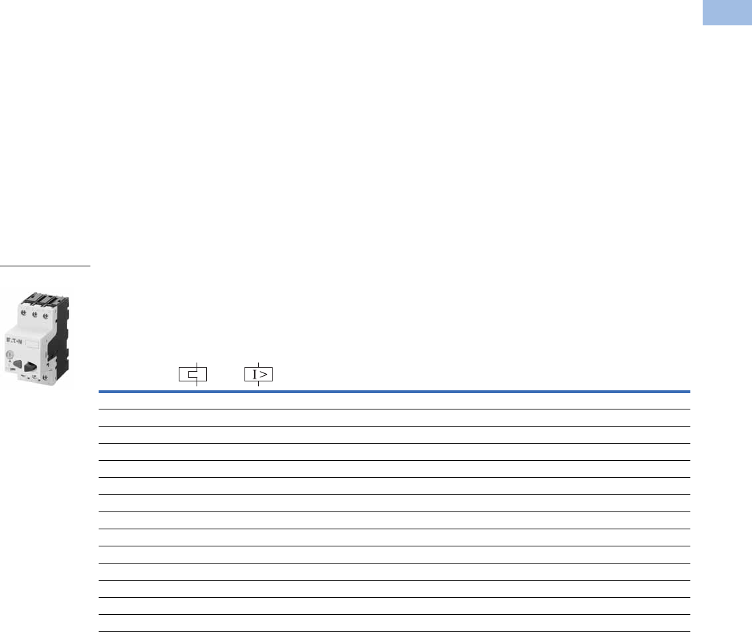
Volume 5—Motor Control and Protection CA08100006E—August 2012 www.eaton.com V5-T1-161
1
1
1
1
1
1
1
1
1
1
1
1
1
1
1
1
1
1
1
1
1
1
1
1
1
1
1
1
1
1
1.1
IEC Contactors and Starters
XT
IEC Power Control
Product Selection
Product Selection for Manual Motor Starter Applications
When ordering, specify catalog numbers according to the following stipulations:
XT manual motor protectors
are selected based on the
overload current range
required for a given motor.
This current range is
determined from the motor
full load ampere rating and
motor service factor usually
found on the motor
nameplate.
For motors with service
factors less than 1.15,
multiply the motor FLA by
0.90 to select appropriate
MMP.
Example: For motor having
FLA of 6.4A and service
factor of 1.0 (6.4A x 0.90 =
5.76A) select catalog number
XTPB6P3B01.
See Application Note—
AP03402001E.
For motor with service
factor of 1.15 or greater,
use motor nameplate full load
amperes to select the
appropriate MMP.
Example: For motor having
FLA of 11A and service factor
of 1.15, select catalog
number XTPR012BC1.
XTPB Pushbutton Manual Motor Protectors—Global and North American Ratings—Frame B
Type 1 and Type 2 Coordination Motor Protective Device with Thermal and Magnetic Trip
Notes
Single-phasing sensitivity to IEC/EN 60947-4-1, VDE 0660 Part 102.
Can be snap-fit to IEC/EN 60715 top-hat (DIN) with 7.5 or 15 mm height.
Service Factor (SF)—Setting Ir of current scale in dependence of load factor:
SF = 1.15 → Ir = 1 x In mot
SF = 1 → Ir = 0.9 x In mot
For manual motor protective circuit breaker switching capacity, see Page V5-T1-181.
1 Select manual motor protectors by full load amperes. Maximum motor ratings (kW, hp) are for reference only.
2 In this range, calculate motor rating according to rated current. Specified values to NEC 430.6(A)(1).
Rated
Uninterrupted
Current—
Iu = Ie (Amps)
FLA
Adjustment
Range/
Overload
Release—
Ir (Amps)
Short
Circuit
Release—
Irm (Amps)
Screw Terminal
Catalog Number
Maximum Motor Ratings 1
Maximum kW Rating
AC-3—P (kW)
Maximum hp Rating—P (hp)
UL 508/CSA C22.2 No. 14
Three-Phase Three-Phase
220–
240V
380–
415V 440V 500V
660–
690V 200V 240V 480V 600V
0.16 0.1–0.16 2.2 ————0.06
2222XTPBP16BC1
0.25 0.16–0.25 3.5 — 0.06 0.06 0.06 0.12 2222XTPBP25BC1
0.4 0.25–0.4 5.6 0.06 0.09 0.12 0.12 0.18 2222XTPBP40BC1
0.63 0.4–0.63 8.8 0.09 0.12 0.18 0.25 0.25 2222XTPBP63BC1
1 0.63–1 14 0.12 0.25 0.25 0.37 0.55 2221/2XTPB001BC1
1.6 1–1.6 22 0.25 0.55 0.55 0.75 1.1 223/4 3/4 XTPB1P6BC1
2.5 1.6–2.5 35 0.37 0.75 1.1 1.1 1.5 1/2 1/2 1 1-1/2 XTPB2P5BC1
4 2.5–4 56 0.75 1.5 1.5 2.2 3 3/4 3/4 2 3 XTPB004BC1
6.3 4–6.3 88 1.12.233411-1/235XTPB6P3BC1
10 6.3–10 140 2.24447.5337-1/210XTPB010BC1
12 8–12 168 3 5.5 5.5 5.5 11 3 3 7-1/2 10 XTPB012BC1
16 10–16 224 47.59912.5351010XTPB016BC1
20 16–20 280 5.5 9 11 12.5 15 5 — — 15 XTPB020BC1
25 20–25 350 5.5 12.5 12.5 15 22 — 7-1/2 15 20 XTPB025BC1
Frame B
Courtesy of CMA/Flodyne/Hydradyne ▪ Motion Control ▪ Hydraulic ▪ Pneumatic ▪ Electrical ▪ Mechanical ▪ (800) 426-5480 ▪ www.cmafh.com

V5-T1-162 Volume 5—Motor Control and Protection CA08100006E—August 2012 www.eaton.com
1
1
1
1
1
1
1
1
1
1
1
1
1
1
1
1
1
1
1
1
1
1
1
1
1
1
1
1
1
1
1.1
IEC Contactors and Starters
XT
IEC Power Control
XTPR Rotary Manual Motor Protectors with Screw Terminals—
Global Ratings and North American Ratings—Frame B
Type 1 and Type 2 Coordination Motor Protective Device with Thermal and Magnetic Trip
XTPR Rotary Manual Motor Protectors with Screw Terminals—
Global Ratings and North American Ratings—Frame D
Type 1 and Type 2 Coordination Motor Protective Device with Thermal and Magnetic Trip
Notes
Single-phasing sensitivity to IEC/EN 60947-4-1, VDE 0660 Part 102.
Can be snap-fit to IEC/EN 60715 top-hat (DIN) with 7.5 or 15 mm height.
Service Factor (SF)—Setting Ir of current scale in dependence of load factor:
SF = 1.15 → Ir = 1 x In mot
SF = 1 → Ir = 0.9 x In mot
For manual motor protective circuit breaker switching capacity, see Page V5-T1-181.
1 Select manual motor protectors by full load amperes. Maximum motor ratings (kW, hp) are for reference only.
2 In this range, calculate motor rating according to rated current. Specified values to NEC 430.6(A)(1).
Rated
Uninterrupted
Current—
Iu = Ie (Amps)
FLA
Adjustment
Range/
Overload
Release—
Ir (Amps)
Short
Circuit
Release—
Irm (Amps)
Screw Terminal
Catalog Number
Maximum Motor Ratings 1
Maximum kW Rating
AC-3—P (kW)
Maximum hp Rating—P (hp)
UL 508/CSA C22.2 No. 14
Three-Phase Three-Phase
220–
240V
380–
415V 440V 500V
660–
690V 200V 240V 480V 600V
0.16 0.1–0.16 2.2 ————0.06
2222XTPRP16BC1
0.25 0.16–0.25 3.5 — 0.06 0.06 0.06 0.12 2222XTPRP25BC1
0.4 0.25–0.4 5.6 0.06 0.09 0.12 0.12 0.18 2222XTPRP40BC1
0.63 0.4–0.63 8.8 0.09 0.12 0.18 0.25 0.25 2222XTPRP63BC1
1 0.63–1 14 0.12 0.25 0.25 0.37 0.55 2222XTPR001BC1
1.6 1–1.6 22 0.25 0.55 0.55 0.75 1.1 223/4 3/4 XTPR1P6BC1
2.5 1.6–2.5 35 0.37 0.75 1.1 1.1 1.5 1/2 1/2 1 1-1/2 XTPR2P5BC1
4 2.5–4 56 0.75 1.5 1.5 2.2 3 3/4 3/4 2 3 XTPR004BC1
6.3 4–6.3 88 1.12.233411-1/235XTPR6P3BC1
10 6.3–10 140 2.24447.5337-1/210XTPR010BC1
12 8–12 168 3 5.5 5.5 5.5 11 3 3 7-1/2 10 XTPR012BC1
16 10–16 224 47.59912.5351010XTPR016BC1
20 16–20 280 5.5 9 11 12.5 15 5 — — 15 XTPR020BC1
25 20–25 350 5.5 12.5 12.5 15 22 — 7-1/2 15 20 XTPR025BC1
32 25–32 448 7.5 15 15 22 30 7-1/2 10 20 25 XTPR032BC1
Rated
Uninterrupted
Current—
Iu = Ie (Amps)
FLA
Adjustment
Range/
Overload
Release—
Ir (Amps)
Short
Circuit
Release—
Irm (Amps)
Screw Terminal
Catalog Number
Maximum Motor Ratings 1
Maximum kW Rating
AC-3—P (kW)
Maximum hp Rating—P (hp)
UL 508/CSA C22.2 No. 14
Three-Phase Three-Phase
220–
240V
380–
415V 440V 500V
660–
690V 200V 240V 480V 600V
16 10–16 224 47.59912.5351015XTPR016DC1
25 16–25 350 5.5 12.5 12.5 15 22 7-1/2 7-1/2 20 25 XTPR025DC1
32 25–32 448 7.51517.5222210102530XTPR032DC1
40 32–40 560 11 20 22 24 30 10 15 30 30 XTPR040DC1
50 40–50 700 14 25 30 30 45 10 15 30 40 XTPR050DC1
58 50–58 812 17 30 37 37 55 15 15 40 50 XTPR058DC1
65 55–65 882 18.5 34 37 45 55 15 15 40 50 XTPR063DC1
Frame B
Frame D
Courtesy of CMA/Flodyne/Hydradyne ▪ Motion Control ▪ Hydraulic ▪ Pneumatic ▪ Electrical ▪ Mechanical ▪ (800) 426-5480 ▪ www.cmafh.com
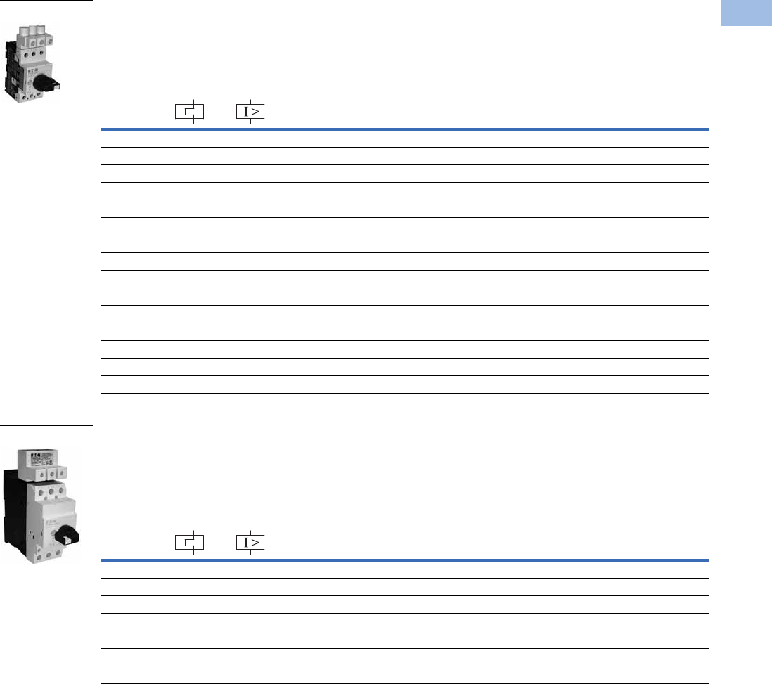
Volume 5—Motor Control and Protection CA08100006E—August 2012 www.eaton.com V5-T1-163
1
1
1
1
1
1
1
1
1
1
1
1
1
1
1
1
1
1
1
1
1
1
1
1
1
1
1
1
1
1
1.1
IEC Contactors and Starters
XT
IEC Power Control
XTPR Manual Self-Protected Motor Starters—North American Ratings, UL 508 Type E—Frame B 1
Motor Protective Device with Thermal and Magnetic Trip
XTPR Manual Self-Protected Motor Starters—North American Ratings, UL 508 Type E—Frame D 1
Motor Protective Device with Thermal and Magnetic Trip
Notes
A UL 508 Type E self-protected manual combination starter (XTPR) consists of a manual motor protector (XTPR) and a UL Listed line side adapter (e.g., XTPAXLSA).
The Type E self-protected manual combination starter alone is a legitimate short-circuit protective device and disconnect means for the downstream motor,
while the contactor has been added to provide remote operation of the motor circuit. Conductor size for XTPAXLSA is 14–6 AWG, XTPAXLSAD is 8 AWG–1/0.
1 UL 508 Type E starters are assembled from a standard XTPR and a special incoming terminal line side adapter (XTPAXLSA or XTPAXLSAD).
2 Select manual motor protectors by full load amperes. Maximum motor ratings (kW, hp) are for reference only.
3 In this range, calculate motor rating according to rated current. Specified values to NEC 430.6(A)(1).
Rated
Uninterrupted
Current—
Iu (Amps)
FLA
Adjustment
Range/
Overload
Release—
Ir (Amps)
Short
Circuit
Release—
Irm (Amps) Line Side
Adapter 1
Catalog Number
Manual Motor
Protector—
Screw Terminal
Catalog Number
Maximum Motor Ratings 2
Maximum hp Rating—P (hp)
Three-Phase
Rated Short-Circuit
Breaking Capacity (kA)
200V 240V
480V/
277V
600V/
247V 240V
480/
277V
600/
347V
0.16 0.1–0.16 2.2 331/2 1/2 65 65 50 XTPAXLSA XTPRP16BC1
0.25 0.16–0.25 3.4 331/2 1/2 65 65 50 XTPAXLSA XTPRP25BC1
0.4 0.25–0.4 5.6 331/2 1/2 65 65 50 XTPAXLSA XTPRP40BC1
0.63 0.4–0.63 8.8 331/2 1/2 65 65 50 XTPAXLSA XTPRP63BC1
1 0.63–1 14 331/2 1/2 65 65 50 XTPAXLSA XTPR001BC1
1.6 1–1.6 22 333/4 3/4 65 65 50 XTPAXLSA XTPR1P6BC1
2.5 1.6–2.5 35 1/2 1/2 1 1-1/2 65 65 50 XTPAXLSA XTPR2P5BC1
4 2.5–4 56 3/4123656550XTPAXLSA XTPR004BC1
6.3 4–6.3 88 11-1/235656550XTPAXLSA XTPR6P3BC1
10 6.3–11 140 3 3 7-1/2 10 65 65 50 XTPAXLSA XTPR010BC1
12 8–12 168 3 3 7-1/2 — 65 65 — XTPAXLSA XTPR012BC1
16 10–16 224 3 5 10 — 42 42 — XTPAXLSA XTPR016BC1
20 16–20 280 5 5 — — 18 18 — XTPAXLSA XTPR020BC1
25 20–25 350 5 7-1/2 15 — 18 18 — XTPAXLSA XTPR025BC1
32 25–32 448 7-1/2 10 25 — 18 18 — XTPAXLSA XTPR032BC1
Rated
Uninterrupted
Current—
Iu (Amps)
FLA
Adjustment
Range/
Overload
Release—
Ir (Amps)
Short
Circuit
Release—
Irm (Amps) Line Side
Adapter 1
Catalog Number
Manual Motor
Protector—
Screw Terminal
Catalog Number
Maximum Motor Ratings 2
Maximum hp Rating—P (hp)
Three-Phase
Rated Short-Circuit
Breaking Capacity (kA)
200V 240V
480V/
277V
600V/
247V
240V
480/
277V
600/
347V
16 10–16 224 3 5 1010656525XTPAXLSAD XTPR016DC1
25 16–25 350 7-1/2 7-1/2 20 25 65 65 25 XTPAXLSAD XTPR025DC1
32 25–32 448 10 10 25 30 65 65 25 XTPAXLSAD XTPR032DC1
40 32–40 560 10—3030656525XTPAXLSAD XTPR040DC1
50 40–50 700 — 15 30 — 65 65 — XTPAXLSAD XTPR050DC1
58 50–58 812 — — 40 — 65 65 — XTPAXLSAD XTPR058DC1
65 55–65 882 — — 40 — 65 65 — XTPAXLSAD XTPR063DC1
Frame B
Frame D
Courtesy of CMA/Flodyne/Hydradyne ▪ Motion Control ▪ Hydraulic ▪ Pneumatic ▪ Electrical ▪ Mechanical ▪ (800) 426-5480 ▪ www.cmafh.com

V5-T1-164 Volume 5—Motor Control and Protection CA08100006E—August 2012 www.eaton.com
1
1
1
1
1
1
1
1
1
1
1
1
1
1
1
1
1
1
1
1
1
1
1
1
1
1
1
1
1
1
1.1
IEC Contactors and Starters
XT
IEC Power Control
Accessories
Auxiliary Contacts
Side-Mount Auxiliary Contacts
Can be fitted on the right side of manual motor protectors (XTPB, XTPR, XTPM) and
manual transformer protectors (XTPT) and can be combined with XTPAXSATR_ and
XTPAXFA_ trip indicating auxiliary contact.
Front-Mount Auxiliary Contacts
Can be fitted to manual motor protectors (XTPB, XTPR, XTPM) and manual
transformer protectors (XTPT). 45 mm
(XTPR…B and XTPB) or 55 mm (XTPR…D)
widths of manual motor protectors remain unchanged.
Note
1
Orders must be placed in multiples of package quantity listed.
Contact
Configuration Contact Sequence
Pkg.
Qty. 1
Screw Terminal
Catalog Number
1NO-1NC 5 XTPAXSA11
1NO-2NC 5 XTPAXSA12
2NO-1NC 5 XTPAXSA21
Contact
Configuration Contact Sequence
Pkg.
Qty. 1
Screw Terminal
Catalog Number
1NO-1NC 5 XTPAXFA11
XTPAXSA_
L1 L2 L3
XTPAXSA11
1.14 1.22
1.13 1.21
1.14 1.22 1.32
1.13 1.21 1. 31
L1 L2 L3
XTPAXSA12
1.14 1.22 1.34
1.13 1. 21 1. 3 3
L1 L2 L3
XTPAXSA21
XTPAXFA11
1.5 4 1. 6 2
1.53 1.6 1
L1 L2 L3
XTPAXFA11
Courtesy of CMA/Flodyne/Hydradyne ▪ Motion Control ▪ Hydraulic ▪ Pneumatic ▪ Electrical ▪ Mechanical ▪ (800) 426-5480 ▪ www.cmafh.com
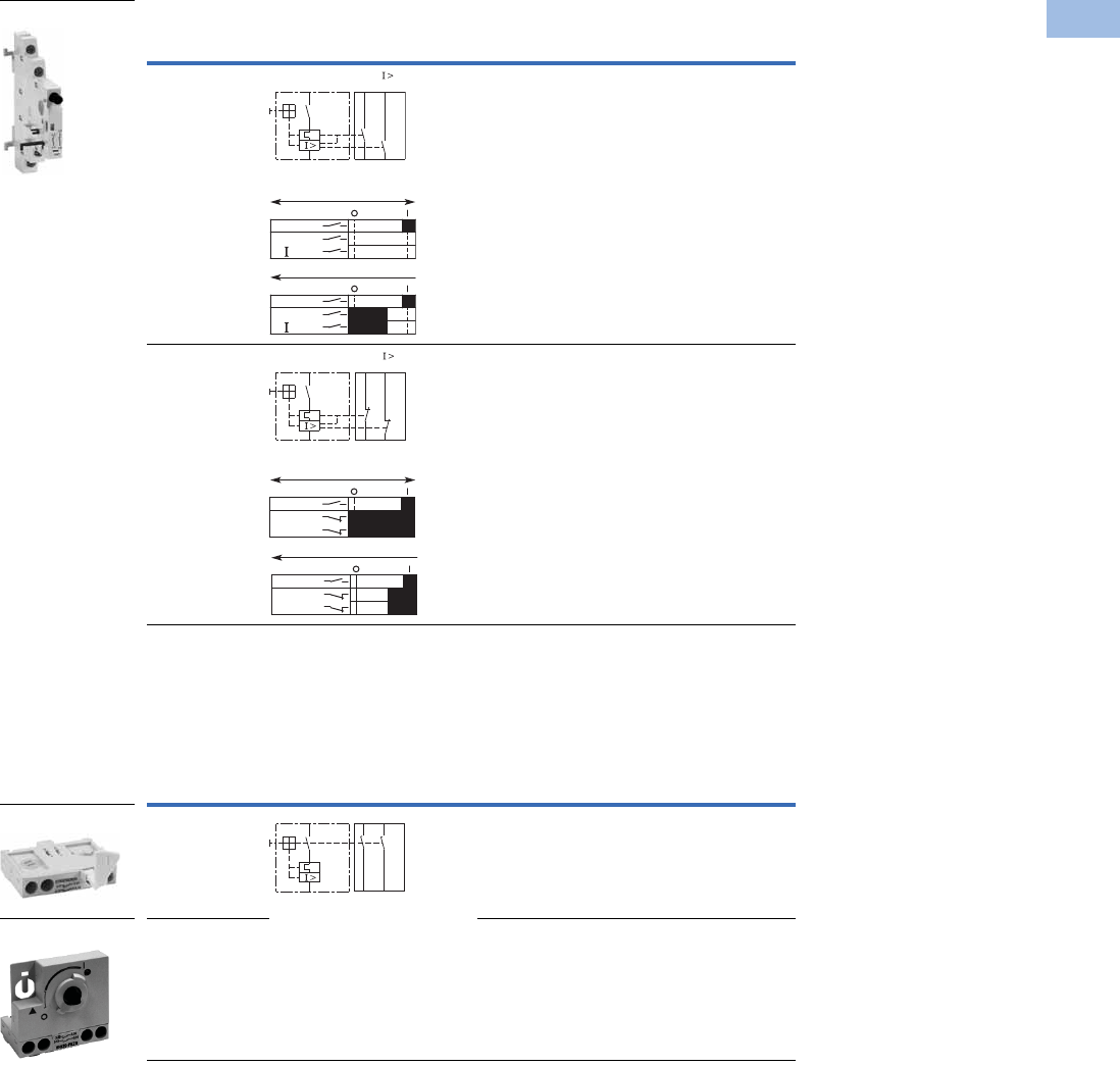
Volume 5—Motor Control and Protection CA08100006E—August 2012 www.eaton.com V5-T1-165
1
1
1
1
1
1
1
1
1
1
1
1
1
1
1
1
1
1
1
1
1
1
1
1
1
1
1
1
1
1
1.1
IEC Contactors and Starters
XT
IEC Power Control
Side-Mount Trip Indicating Auxiliary Contacts
Can be fitted on the right side of manual motor protectors. Can be combined with
standard auxiliary contacts. Trip indication: A. General trip indication (overload) B.
Short-circuit trip. Local short-circuit indication by red indicator, manually resettable.
Early-Make Front-Mount Auxiliary Contacts
For use with XTPB_, Frame B XTPR and XTPT. Can be fitted to the front of a manual
motor protector. 45 mm width of manual motor protector remains unchanged. For early
energization of undervoltage release, e.g., in emergency-stop circuits to EN 60204
.
Notes
1
Orders must be placed in multiples of package quantity listed.
2 Not for use with rotary handle mechanism.
Contact
Configuration Contact Sequence
Pkg.
Qty. 1
For Use
with… Catalog Number
2 x 1NO 2 XTPB, XTPR,
XTPM, XTPT
XTPAXSATR20
2 x 1NC 2 XTPB, XTPR,
XTPM, XTPT
XTPAXSATR02
Contact
Configuration Contact Sequence
Pkg.
Qty. 1
For Use
with… Catalog Number
2NO 5 XTPB XTPBXFAEM20
2NO 2 XTPR, XTPM,
XTPT
XTPAXFAEM20 2
XTPAXSATR_
4.44 4.14
“+”
4.43
“ ”
4.13
“+”
“ >”
On/Off
“+”
“ >”
Trip “+”
L1L2 L3
L1L2 L3
4.32 4.22
“+”
4.31
“ ”
4.21
On/Off
“+”
“ >”
Trip “+”
L1L2 L3
“+”
“ >”
L1L2 L3
XTPBXFAEM20
XTPAXFAEM20
3.14 3.24
3.13 3.23
Courtesy of CMA/Flodyne/Hydradyne ▪ Motion Control ▪ Hydraulic ▪ Pneumatic ▪ Electrical ▪ Mechanical ▪ (800) 426-5480 ▪ www.cmafh.com
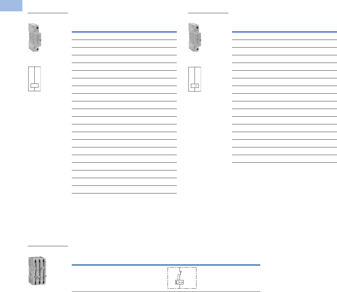
V5-T1-166 Volume 5—Motor Control and Protection CA08100006E—August 2012 www.eaton.com
1
1
1
1
1
1
1
1
1
1
1
1
1
1
1
1
1
1
1
1
1
1
1
1
1
1
1
1
1
1
1.1
IEC Contactors and Starters
XT
IEC Power Control
Additional Accessories
Shunt Release
Can be used to trip the manual motor
protector from a remote location. Can
be fitted on the left side of manual
motor protectors. Cannot be combined
with the XTPAXUVR. DC: Intermittent
operation 5 sec.
Undervoltage Release
Can be used to trip the manual motor
protector from a remote location. Can
be fitted on left side manual motor
protectors. Cannot be combined with
XTPAXSR. When combined with a circuit
breaker, it can be used as emergency-stop
device to IEC/EN 60204.
Current Limiter 2
The XTPAXCL enhances the switching capacity of the XT manual motor
protectors. It can be used with the XTPB, XTPR…BC1, XTPR…DC1 for
individual or group protections. The rated uninterrupted current is 63A for IEC
and 25A for UL/CSA. It can be mounted next to or behind the manual motor
protector. See Page V5-T1-181 for ratings when using the current limiter.
Notes
1 Orders must be placed in multiples of package quantity listed.
2 Max. rated operation voltage Ue = 690V, rated uninterrupted current Iu = 63A. Can be used for individual and
group protection. For group protection and in combination with the XTPR…D order additional XTPAXIT incoming
terminal if required. Mounting next to or behind the manual motor protector. 16–63A XTPR…D: 100 kA/400V, 10 kA/690V.
Pkg.
Qty. 1
Screw Terminal
Catalog Number
2XTPAXSR24V50H
2XTPAXSR48V50H
2XTPAXSR110V50H
2XTPAXSR120V60H
2XTPAXSR208V60H
2XTPAXSR220V50H
2XTPAXSR230V50H
2XTPAXSR240V50H
2XTPAXSR240V60H
2XTPAXSR380V50H
2XTPAXSR400V50H
2XTPAXSR415V50H
2XTPAXSR440V60H
2XTPAXSR480V60H
2XTPAXSR24VDC
2XTPAXSR48VDC
2XTPAXSR60VDC
2XTPAXSR110VDC
2XTPAXSR125VDC
2XTPAXSR220VDC
2XTPAXSR250VDC
XTPAXSR_
Contact Sequence
C1
C2
Pkg.
Qty. 1
Screw Terminal
Catalog Number
2XTPAXUVR24V50H
2XTPAXUVR24V60H
2XTPAXUVR48V50H
2XTPAXUVR60V50H
2XTPAXUVR110V50H
2XTPAXUVR120V60H
2XTPAXUVR208V60H
2XTPAXUVR220V50H
2XTPAXUVR230V50H
2XTPAXUVR240V50H
2XTPAXUVR240V60H
2XTPAXUVR380V50H
2XTPAXUVR400V50H
2XTPAXUVR415V50H
2XTPAXUVR440V60H
2XTPAXUVR480V60H
2XTPAXUVR600V60H
XTPAXUVR_
Contact Sequence
D1
D2
U
Description
Contact
Sequence
Pkg.
Qty. 1Catalog Number
To enhance the switching capacity of non-inherently
safe 10–25A manual motor protectors to 150 kA/440V
1XTPAXCL
XTPAXCL
L
T
Courtesy of CMA/Flodyne/Hydradyne ▪ Motion Control ▪ Hydraulic ▪ Pneumatic ▪ Electrical ▪ Mechanical ▪ (800) 426-5480 ▪ www.cmafh.com
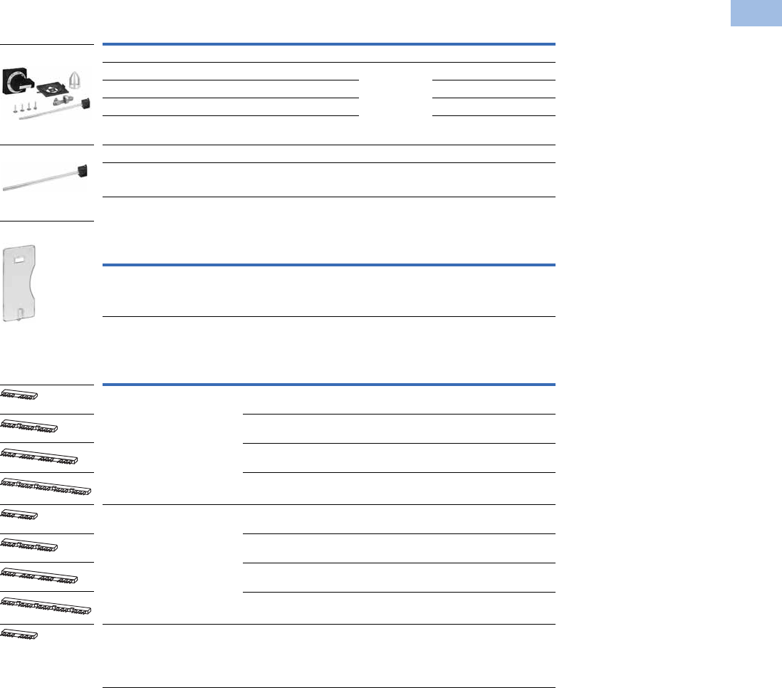
Volume 5—Motor Control and Protection CA08100006E—August 2012 www.eaton.com V5-T1-167
1
1
1
1
1
1
1
1
1
1
1
1
1
1
1
1
1
1
1
1
1
1
1
1
1
1
1
1
1
1
1.1
IEC Contactors and Starters
XT
IEC Power Control
IP65 Rotary Handle Mechanism 1234
Sealing Facility
Three-Phase Commoning Links 8
For parallel power feed to several manual motor protectors on terminals
1, 3 and 5.
Notes
1 Plug-in connection shafts, XTPAXRHMSFT_ can be cut to desired length for mounting depths of 100–240 mm. Carrier
with extension shaft included.
2 With ON/OFF switch position and “+” (tripped), lockable with 3 padlocks, 4–8 mm hasp. Can be locked in the
OFF position, if required.
3 Rotary handle mechanisms ship with door interlock disabled. See instruction publication with product for how to
enable door interlock.
4 Not for use with XTPAXFAEM20 early-make front-mount auxiliary contact.
5 Orders must be placed in multiples of package quantity listed.
6 For use on main switches to IEC/EN 60204.
7 For use on main switches with emergency-stop function to IEC/EN 60204.
8 Protected against accidental contact. Frame B short-circuit proof Ue = 690V, Iu = 63A.
Frame B links can be combined by
rotating mounting.
Description
Enclosure
Rating
Pkg.
Qty. 5Catalog Number
Complete Kits—Includes Handle, Shaft and Required Hardware
Rotary handle mechanism—black 6IP65
NEMA 12
UL/CSA 4X
1XTPAXRHMB
Rotary handle mechanism—red/yellow 71XTPAXRHMRY
Rotary handle mechanism—black—rotated 90° from vertical 61XTPAXRHM90B
Rotary handle mechanism—red/yellow—rotated 90° from
vertical 7
1XTPAXRHM90RY
Separate Parts
Shaft only—includes shaft to mount to XTPR, 175 mm length — 10 XTPAXRHMSFT
Description
Pkg.
Qty. 5Catalog Number
To prevent tampering with the overload release and the test function.
It can be sealed using industry standard sealing wire. For use with
XTPR manual motor protectors.
5XTPAXSW
For Use with…
Qty.
MMP
Length of
Link (mm)
Unit
Width (mm)
Pkg.
Qty. 5Catalog Number
MMP with no side-mounted
auxiliaries or voltage releases
290 45 10XTPAXCLKA2
3 135 45 10 XTPAXCLKA3
4 180 45 10 XTPAXCLKA4
5 225 45 10 XTPAXCLKA5
Each MMP with one auxiliary
contact or trip-indicating auxiliary
contact fitted on the right
299 45 + 9 10XTPAXCLKB2
3 153 45 + 9 10 XTPAXCLKB3
4 207 45 + 9 10 XTPAXCLKB4
5 261 45 + 9 10 XTPAXCLKB5
Each MMP with an auxiliary
contact and trip-indicating
auxiliary contact mounted on
the right or a voltage release
mounted on the left.
2 108 45 + 18 10 XTPAXCLKC2
XTPAXRHM_
XTPAXRHMSFT
XTPAXSW
Courtesy of CMA/Flodyne/Hydradyne ▪ Motion Control ▪ Hydraulic ▪ Pneumatic ▪ Electrical ▪ Mechanical ▪ (800) 426-5480 ▪ www.cmafh.com
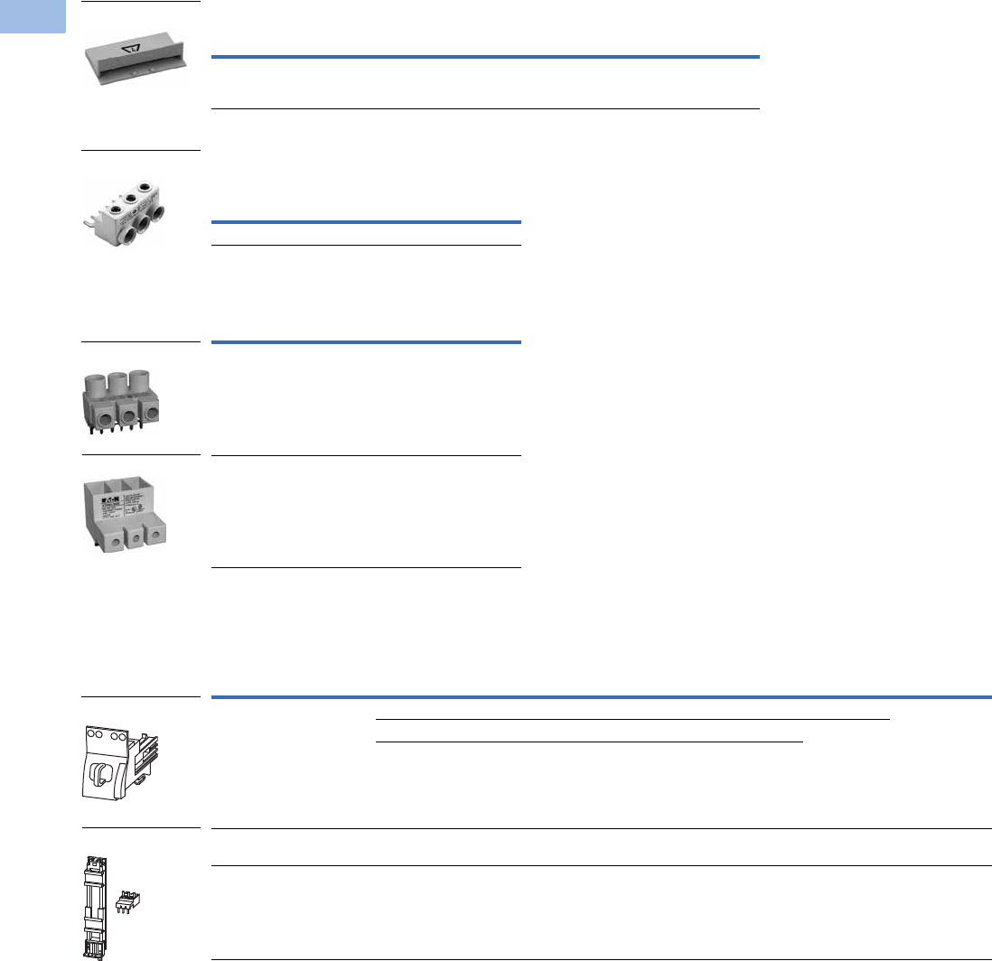
V5-T1-168 Volume 5—Motor Control and Protection CA08100006E—August 2012 www.eaton.com
1
1
1
1
1
1
1
1
1
1
1
1
1
1
1
1
1
1
1
1
1
1
1
1
1
1
1
1
1
1
1.1
IEC Contactors and Starters
XT
IEC Power Control
Shroud for Unused Terminals of Three-Phase Commoning Links
Incoming Terminals for Three-Phase
Commoning Link 2
Line-Side Adapter 3
Combination Connection Kits
Non-Reversing Starters
Notes
1 Orders must be placed in multiples of package quantity listed.
2 For three-phase commoning link, protected against accidental contact, Ue = 690V, Iu = 63A;
For conductor cross-sections: 2.5–25 mm2 stranded; 2.5–16 mm2 flexible with ferrules, AWG 14-6.
3 XTPAXLSA is for three-phase commoning link, finger and back-of-hand proof,
Ue = 690V, Iu = 60A for conductor cross sections: 2.5–25 mm2 stranded,
2.5–16 mm2 flexible with ferrule, AWG 14-6.
4 XTPAXLSAD cannot be combined with three-phase commoning links. Conductor size 8 AWG–1/0.
For Use with… Description
Pkg.
Qty. 1Catalog Number
Frame B
XTPR
To cover unused terminals on three-phase
commoning link. Protected against direct
contact.
20 XTPAXUTS
For Use with…
Pkg.
Qty. 1Catalog Number
Frame B XTPR, XTPB 5 XTPAXIT
For Use with…
Pkg.
Qty. 1Catalog Number
Frame B XTPR to create a
UL 508 Type E/F manual
combination starter
5XTPAXLSA
Frame D XTPR to create a
UL 508 Type E/F manual
combination starter
1XTPAXLSAD 4
For Use with… Description/Comprised of …
Std.
Pack 1Catalog Number
XTPR…B + XTCE…B Mechanical connection element for XTPR…B and contactor 1 XTPAXTPCB
Main current wiring between XTPR…B and contactor in toolless plug connection 1
Use contactor auxiliary switch XTCEXFAT_. Control cable guidance: max. six cables
up to 2.5 mm2 external diameter or four cables up to 3.5 mm2 external diameter.
XTPR…B + XTCE…C DIN rail adapter plate
Main current wiring between XTPR and contactor
1XTPAXTPCC
XTPR…D + XTCE…D DIN rail adapter plate
Main current wiring between XTPR and contactor
1XTPAXTPCD
XTPAXUTS
XTPAXIT
XTPAXLSA
XTPAXLSAD
XTPAXTPCB
XTPAXTPC_
Courtesy of CMA/Flodyne/Hydradyne ▪ Motion Control ▪ Hydraulic ▪ Pneumatic ▪ Electrical ▪ Mechanical ▪ (800) 426-5480 ▪ www.cmafh.com
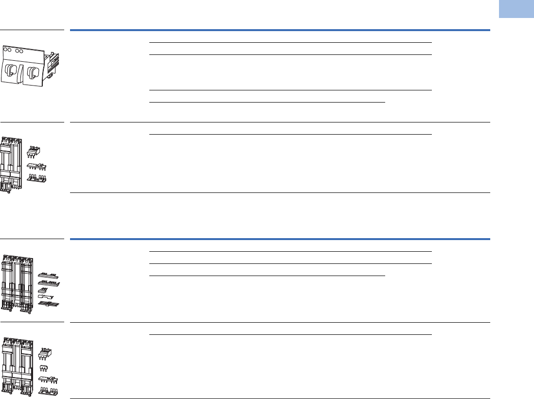
Volume 5—Motor Control and Protection CA08100006E—August 2012 www.eaton.com V5-T1-169
1
1
1
1
1
1
1
1
1
1
1
1
1
1
1
1
1
1
1
1
1
1
1
1
1
1
1
1
1
1
1.1
IEC Contactors and Starters
XT
IEC Power Control
Reversing Starters
Star-Delta Starter Sets
Note
1 Orders must be placed in multiples of package quantity listed.
For Use with… Description/Comprised of …
Std.
Pack 1Catalog Number
XTPR…B + XTCE…B01_ Mechanical connection element for XTPR…B and contactor 1 XTPAXTPCRB
Reversing starter main current wiring in toolless plug connection 1
Control cables for electrical interlocking in toolless plug connection:
– K1M: A1–K2M: 21
– K1M: 21–K2M: A1
– K1M: A2–K2M: A2
1
Cable guidance 1
Use contactor auxiliary switch XTCEXFAT_. Control cable guidance: max. six cables
up to 2.5 mm2 external diameter or four cables up to 3.5 mm2 external diameter.
XTPR…B + XTCE…C DIN rail adapter plate 1 XTPAXTPCRC
Reversing starter main current wiring 1
For Use with… Description/Comprised of …
Std.
Pack 1Catalog Number
XTPR…B + XTCE…B DIN rail adapter plate 1 XTPAXSDSB
Main current wiring between XTPR…B and contactor 1
Electrical interlock between delta and star contactor 1
Use as contactor auxiliary switch XTCEXFAT_
XTPR…B + XTCE…C DIN rail adapter plate 1 XTPAXSDSC
Main current wiring between XTPR…B and contactor 1
XTPAXTPCRB
XTPAXTPCRC
XTPAXSDSB
XTPAXSDSC
Courtesy of CMA/Flodyne/Hydradyne ▪ Motion Control ▪ Hydraulic ▪ Pneumatic ▪ Electrical ▪ Mechanical ▪ (800) 426-5480 ▪ www.cmafh.com
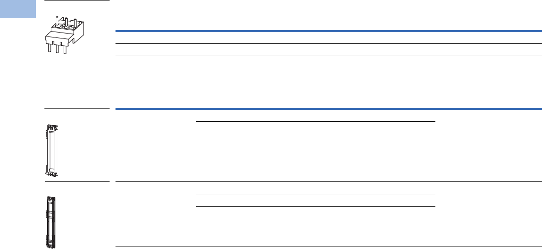
V5-T1-170 Volume 5—Motor Control and Protection CA08100006E—August 2012 www.eaton.com
1
1
1
1
1
1
1
1
1
1
1
1
1
1
1
1
1
1
1
1
1
1
1
1
1
1
1
1
1
1
1.1
IEC Contactors and Starters
XT
IEC Power Control
Electrical Connection Module
DIN Rail Adapter Plates
Note
1 Orders must be placed in multiples of package quantity listed.
For Use with… Description/Comprised of …
Std.
Pack 1Catalog Number
XTPR…B + XTCE…C Main current wiring between XTPR…B and contactor 5 XTPAXECMC
XTPR…D + XTCE…D Main current wiring between XTPR…D and contactor 5 XTPAXECMD
For Use with… Description/Comprised of …
Std.
Pack 1Catalog Number
XTPAXTPCB
XTPAXTPCRB
45 mm wide adapter plate with one DIN rail 4 XTPAXTPCPB
Connection element for side-by-side positioning of further plates
XTPAXECMD
XTPR…D + XTCE…C
XTPR…D + XTCE…D
55 mm wide adapter plate with two DIN rails 4 XTPAXTPCPD
Connection cams for further plates
For use with reversing and star-delta starters
XTPAXECM_
XTPAXTPCPB
XTPAXTPCPD
Courtesy of CMA/Flodyne/Hydradyne ▪ Motion Control ▪ Hydraulic ▪ Pneumatic ▪ Electrical ▪ Mechanical ▪ (800) 426-5480 ▪ www.cmafh.com

Volume 5—Motor Control and Protection CA08100006E—August 2012 www.eaton.com V5-T1-171
1
1
1
1
1
1
1
1
1
1
1
1
1
1
1
1
1
1
1
1
1
1
1
1
1
1
1
1
1
1
1.1
IEC Contactors and Starters
XT
IEC Power Control
Pushbutton MMP Enclosures
Insulated Enclosures for Surface Mounting of XTPB Pushbutton
Motor-Protective Circuit Breakers—Global Usage 1
Insulated Enclosures for Surface Mounting of XTPB Pushbutton
Manual Motor Protectors—North American Usage 23
Notes
1 Integrated terminal for PE(N) connection, two M25 cable entry knockouts at top and at bottom.
2 Built-in terminal for PE(N).
3 North American enclosures come with conduit adapters for use with 1/2 in NPT.
Degree of
Protection
For Use
with… Description Catalog Number
IP40
NEMA 1
XTPB MMP only or with:
XTPAXFA_, XTPBXFAEM20,
XTPAXSA_, XTPAXUVR_,
XTPAXSR_
—XTPBXENCS40
IP65
NEMA
3R, 4X, 12, 13
With actuation membrane. XTPBXENCS65
IP65
NEMA
3R, 4X, 12, 13
XTPB MMP only or with:
XTPAXFA_, XTPAXUVR_,
XTPAXSR_, XTPAXCL
Lockable in OFF position. XTPBXENCSLO65
IP65
NEMA
3R, 4X, 12, 13
XTPB MMP only or with:
XTPAXFA_, XTPBXFAEM20,
XTPAXUVR_, XTPAXSR_,
XTPAXCL
Lockable in OFF position in combination with XTPBXFAEM20
early-make front-mount auxiliary contact
XTPBXENCSLE65
IP65
NEMA
3R, 4X, 12, 13
With emergency-stop (e-stop) pushbutton actuator, red-yellow XTPBXENCSES65
IP65
NEMA
3R, 4X, 12, 13
With emergency-stop (e-stop) pushbutton actuator, red-yellow
key release
XTPBXENCSEK65
Degree of
Protection
For Use
with… Description Catalog Number
IP41
NEMA 1
XTPB MMP only or with:
XTPAXFA_, XTPBXFAEM20,
XTPAXSA_, XTPAXUVR_,
XTPAXSR_
—XTPBXENAS41
IP65
NEMA
3R, 4X, 12, 13
With actuating diaphragm XTPBXENAS65
IP65
NEMA
3R, 4X, 12, 13
XTPB MMP only or with:
XTPAXFA_, XTPAXUVR_,
XTPAXSR_, XTPAXCL
Lockable in OFF position XTPBXENASLO65
IP65
NEMA
3R, 4X, 12, 13
XTPB MMP only or with:
XTPAXFA_, XTPBXFAEM20,
XTPAXUVR_, XTPAXSR_,
XTPAXCL
Lockable in OFF position in combination with XTPBXFAEM20
early-make front-mount auxiliary contact
XTPBXENASLE65
IP65
NEMA
3R, 4X, 12, 13
With emergency-stop (e-stop) pushbutton actuator, red-yellow XTPBXENASES65
IP65
NEMA
3R, 4X, 12, 13
With emergency-stop (e-stop) pushbutton actuator, red-yellow
key release
XTPBXENASEK65
Courtesy of CMA/Flodyne/Hydradyne ▪ Motion Control ▪ Hydraulic ▪ Pneumatic ▪ Electrical ▪ Mechanical ▪ (800) 426-5480 ▪ www.cmafh.com

V5-T1-172 Volume 5—Motor Control and Protection CA08100006E—August 2012 www.eaton.com
1
1
1
1
1
1
1
1
1
1
1
1
1
1
1
1
1
1
1
1
1
1
1
1
1
1
1
1
1
1
1.1
IEC Contactors and Starters
XT
IEC Power Control
Insulated Enclosures for Surface Mounting of XTPB Pushbutton
Manual Motor Protectors—North American Usage 1
Note
1 Integrated terminal for PE(N) connection.
Degree of
Protection
For Use
with… Description Catalog Number
Front IP40
NEMA 1
XTPB MMP only or with:
XTPAXFA_, XTPBXFAEM20,
XTPAXSA_, XTPAXUVR_,
XTPAXSR_
—XTPBXENCF40
Front IP65
NEMA
3R, 4X, 12, 13
With actuating diaphragm XTPBXENCF55
Front IP65
NEMA
3R, 4X, 12, 13
XTPB MMP only or with:
XTPAXFA_, XTPAXUVR_,
XTPAXSR_, XTPAXCL
Lockable in OFF position XTPBXENCFLO55
Front IP65
NEMA
3R, 4X, 12, 13
XTPB MMP only or with:
XTPAXFA_, XTPBXFAEM20,
XTPAXUVR_, XTPAXSR_,
XTPAXCL
Lockable in OFF position in combination with XTPBXFAEM20
early-make front-mount auxiliary contact
XTPBXENCFLE55
Front IP65
NEMA
3R, 4X, 12, 13
With emergency-stop (e-stop) pushbutton actuator, red-yellow XTPBXENCFES55
Front IP65
NEMA
3R, 4X, 12, 13
With emergency-stop (e-stop) pushbutton actuator, red-yellow
key release
XTPBXENCFEK55
Courtesy of CMA/Flodyne/Hydradyne ▪ Motion Control ▪ Hydraulic ▪ Pneumatic ▪ Electrical ▪ Mechanical ▪ (800) 426-5480 ▪ www.cmafh.com

Volume 5—Motor Control and Protection CA08100006E—August 2012 www.eaton.com V5-T1-173
1
1
1
1
1
1
1
1
1
1
1
1
1
1
1
1
1
1
1
1
1
1
1
1
1
1
1
1
1
1
1.1
IEC Contactors and Starters
XT
IEC Power Control
Rotary MMP Enclosures
Insulated Enclosures for Surface Mounting of Frame B (0.1–32A)
XTPR Motor-Protective Circuit Breakers—Global Usage
Insulated Enclosures for Surface Mounting of Frame B (0.1–32A)
XTPR Rotary Manual Motor Protectors—North American Usage 3
Insulated Enclosures for Surface Mounting of Frame B XTPR (0.1–32A) Rotary Motor-Protective Circuit
Breakers with XTPAXFAEM20 Early-Make Front-Mount Auxiliary Contact—Global Usage
Notes
1 M25 metric cable entry knock-out, top and bottom. Cable push-through membrane, top and bottom, in the back plate and as a control line entry.
Includes N and PE terminals.
2 Integrated terminal for PE(N) connection, two M25 cable entry knockouts at the top and bottom.
3 Built-in N and PE terminal, lower part without knockouts.
Degree of
Protection
For Use
with… Description Catalog Number
IP41 with vertical
mounting
Frame B XTPR only or with:
XTPAXFA_, XTPAXSA_,
XTPAXSATR_, XTPAXUVR_,
XTPAXSR_, XTPAXCL
Cover with aperture dimensioned to accommodate front of
MMP. IP40, when mounted turned through 90° to left/right
XTPAXENCS41 1
IP65 With black/grey rotary handle XTPAXENCS65B 1
IP65 With red/yellow rotary handle for use as emergency-stop
switches to IEC/EN 60204
XTPAXENCS65RY 1
IP40 Frame B XTPR only or with:
XTPAXSA_, XTPAXUVR_,
XTPAXSR_, XTPAXCL
Cover with aperture dimensioned to accommodate front of MMP XTPAXENCS40 2
IP55 Frame B XTPR only or with:
XTPAXFA_, XTPAXSA_,
XTPAXUVR_, XTPAXSR_,
XTPAXCL
With black/gray rotary handle XTPAXENCS55B 2
IP55 With red/yellow rotary handle for use as emergency-stop
switches to IEC/EN 60204
XTPAXENCS55RY 2
Degree of
Protection
For Use
with… Description Catalog Number
IP55
NEMA 1, 12, 3R
Frame B XTPR only or with:
XTPAXSA_ and XTPAXFA_,
XTPAXUVR_ and XTPAXFA_,
XTPAXSR_ and XTPAXFA_,
XTPAXCL
With black/gray rotary handle XTPAXENAS55B
With red/yellow rotary handle for use as emergency-stop
switch to VDE 0113
XTPAXENAS55RY
Degree of
Protection
For Use
with… Description Catalog Number
IP65 Frame B XTPR and XTPAXFAEM20
only or with: XTPAXFA_,
XTPAXSA_, XTPAXSATR_,
XTPAXUVR_, XTPAXSR_,
XTPAXCL
With black/gray rotary handle XTPAXENCSEM65B
IP65 With red/yellow rotary handle for use as emergency-stop
switches to IEC/EN 60204
XTPAXENCSEM65RY
IP55 Frame B XTPR and XTPAXFAEM20
only or with: XTPAXFA_,
XTPAXUVR_, XTPAXSR_,
XTPAXCL
With black/gray rotary handle XTPAXENCSEM55B
IP55 With red/yellow rotary handle for use as emergency-stop
switches to IEC/EN 60204
XTPAXENCSEM55RY
Courtesy of CMA/Flodyne/Hydradyne ▪ Motion Control ▪ Hydraulic ▪ Pneumatic ▪ Electrical ▪ Mechanical ▪ (800) 426-5480 ▪ www.cmafh.com

V5-T1-174 Volume 5—Motor Control and Protection CA08100006E—August 2012 www.eaton.com
1
1
1
1
1
1
1
1
1
1
1
1
1
1
1
1
1
1
1
1
1
1
1
1
1
1
1
1
1
1
1.1
IEC Contactors and Starters
XT
IEC Power Control
Insulated Enclosures for Surface Mounting of Frame B XTPR (0.1–32A) Rotary Manual Motor Protectors
with XTPAXFAEM20 Early-Make Front-Mount Auxiliary Contact—North American Usage 1
Insulated Enclosures for Flush Mounting of Frame B (0.1–32A)
XTPR Rotary Manual Motor Protectors—Global Usage 2
Insulated Enclosures for Surface Mounting of Frame D (10–65A)
Rotary Motor-Protective Circuit Breakers
Notes
1 Built-in N and PE terminal, lower part without knockouts.
2 Integrated terminal for PE(N) connection.
Degree of
Protection
For Use
with… Description Catalog Number
IP55
NEMA 1, 12, 3R
Frame B XTPR only or with:
XTPAXSA_, XTPAXUVR_,
XTPAXCL
With black/grey rotary handle XTPAXENASEM55B
With red/yellow rotary handle for use as emergency-stop
switch to VDE 0113
XTPAXENASEM55RY
Degree of
Protection
For Use
with… Description Catalog Number
Front IP40 Frame B XTPR only or with:
XTPAXSA_, XTPAXUVR_,
XTPAXSR_, XTPAXCL
Cover with aperture dimensioned to accommodate front of MMP XTPAXENCF40
Front IP55 Frame B XTPR only or with:
XTPAXSA_, XTPAXUVR_,
XTPAXSR_, XTPAXFA_,
XTPAXCL
With black/gray rotary handle XTPAXENCF55B
With red/yellow rotary handle for use as emergency-stop
switches to IEC/EN 60204
XTPAXENCF55RY
Degree of
Protection
For Use
with… Description Catalog Number
IP65
NEMA 1, 12,
3R, 4X
Frame D XTPR only or with:
XTPAXFA_, XTPAXFAEM20,
XTPAXSA_, XTPAXSATR_,
XTPAXUVR_, XTPAXSR_,
XTPAXCL
With black/gray rotary handle XTPAXENCSD65B
IP65
NEMA 1, 12,
3R, 4X
With red/yellow rotary handle for use as emergency-stop
switches to IEC/EN 60204
XTPAXENCSD65RY
Courtesy of CMA/Flodyne/Hydradyne ▪ Motion Control ▪ Hydraulic ▪ Pneumatic ▪ Electrical ▪ Mechanical ▪ (800) 426-5480 ▪ www.cmafh.com
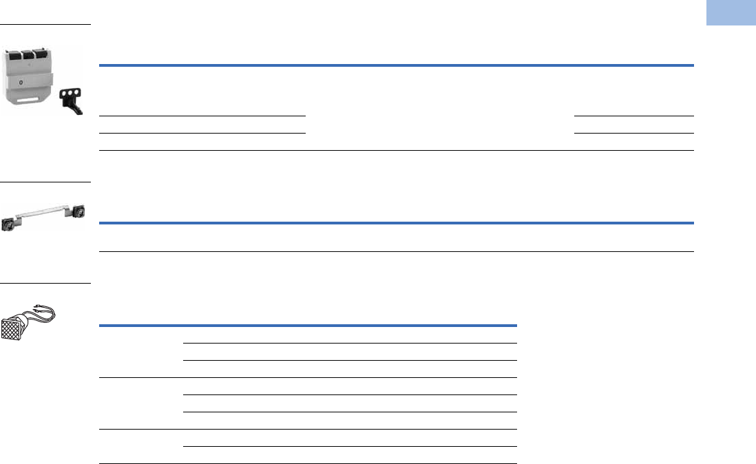
Volume 5—Motor Control and Protection CA08100006E—August 2012 www.eaton.com V5-T1-175
1
1
1
1
1
1
1
1
1
1
1
1
1
1
1
1
1
1
1
1
1
1
1
1
1
1
1
1
1
1
1.1
IEC Contactors and Starters
XT
IEC Power Control
MMP Enclosure Accessories
XTPR Manual Motor Protector Enclosure Padlock Attachment
Neutral Terminal for Use with XTPB and Frame B XTPR Flush-Mount Enclosures
Indicating Lights with Neon Bulb
For use with XTPR and XTPB enclosures.
Lights do not carry individual IP or NEMA rating. All enclosure ratings remain
valid when using indicating lights.
Notes
1 Orders must be placed in multiples of package quantity listed.
2 Lockable in the 0-position of the XTPR manual motor protector.
3 Lockable in the OFF position of the Frame B XTPR manual motor protector.
For Use
with… Description
Pkg.
Qty. 1Catalog Number
XTPAXENCS65B, XTPAXENCS65RY,
XTPAXENCSEM65B, XTPAXENCSEM65RY,
XTPAXENCS55B, XTPAXENCS55RY,
XTPAXENCSEM55B, XTPAXENCSEM55RY
Padlocking feature. Up to three padlocks with 3–6 mm hasp thickness.
For use as main switch to IEC/EN 60204
3XTPAXPL1 2
XTPAXENCSD65B, XTPAXENCSD65RY 1XTPAXPL2 2
XTPAXENCF55B, XTPAXENCF55RY 3XTPAXPL3 3
For Use
with… Description
Pkg.
Qty. 1Catalog Number
XTPBXENCF40, XTPBXENCF55, XTPAXENCF40,
XTPAXENCF55B, XTPAXENCF55RY
For connection of a fifth conductor 20 XTPAXNT
Color
Description—
Indicating Light
Pkg.
Qty. 1Catalog Number
White 110–230V 10 XTPAXILWB
230–400V 10 XTPAXILWN
415–500V 10 XTPAXILWC
Green 110–230V 10 XTPAXILGB
230–400V 10 XTPAXILGN
415–500V 10 XTPAXILGC
Red 110–230V 10 XTPAXILRB
230–400V 10 XTPAXILRN
XTPAXPL_
XTPAXNT
XTPAXIL_
Courtesy of CMA/Flodyne/Hydradyne ▪ Motion Control ▪ Hydraulic ▪ Pneumatic ▪ Electrical ▪ Mechanical ▪ (800) 426-5480 ▪ www.cmafh.com

V5-T1-176 Volume 5—Motor Control and Protection CA08100006E—August 2012 www.eaton.com
1
1
1
1
1
1
1
1
1
1
1
1
1
1
1
1
1
1
1
1
1
1
1
1
1
1
1
1
1
1
1.1
IEC Contactors and Starters
XT
IEC Power Control
Technical Data and Specifications
XT Manual Motor Protectors
Note
1Damp heat, constant, to IEC 60068-2-78; damp heat, cyclic, to IEC 60068-2-30.
Description
XTPBP16B–
XTPB025B
XTPRP16B–
XTPR032B
XTPR016D–
XTPR063D
General
Standards IEC/EN 60947,
VDE 0660, UL 508,
CSA C22.2 No. 14
IEC/EN 60947,
VDE 0660, UL 508,
CSA C22.2 No. 14
IEC/EN 60947,
VDE 0660, UL 508,
CSA C22.2 No. 14
Climatic proofing 111
Ambient temperature, °C
Storage –25/80 –25/80 –25/70
Open –25/55 –25/55 –25/55
Enclosed –25/40 –25/40 –25/40
Mounting position
Direction of incoming supply As required As required As required
Degree of protection
Device IP20 IP20 IP20
Terminals IP00 IP00 IP00
Protection against direct contact Finger and
back-of-hand proof
Finger and
back-of-hand proof
Finger and
back-of-hand proof
Shock resistance half-sinusoidal shock
10 ms to IEC 60068-2-27 (g)
25 25 15
Altitude (m), maximum 2000 2000 2000
Terminal capacity
Solid (mm2)1 x (1–6)
2 x (1–6)
1 x (1–6)
2 x (1–6)
1 x (1–50)
2 x (1–35)
Flexible with ferrule to DIN 46228, (mm2)1 x (1–6)
2 x (1–6)
1 x (1–6)
2 x (1–6)
1 x (1–35)
2 x (1–35)
Solid or stranded (AWG) 18–10 18–10 14–2
Terminal screw tightening torque
Main cable, Nm 1.7 1. 3
Main cable, lb-in 15.0 15.0 26.6
Control circuit cable, Nm 1 1 1
Control circuit cable, lb-in 8.9 8.9 8.9
Main Contacts
Rated impulse withstand voltage (Uimp), Vac 6000 6000 6000
Overvoltage category/pollution degree III/3 III/3 III/3
Rated operational voltage (Ue), Vac 690 690 690
Rated uninterrupted current = rated operational
current (Iu = Ie) in amperes
25 or current setting of
the overcurrent release
25 or current setting of
the overcurrent release
25 or current setting of
the overcurrent release
Rated frequency, Hz 40–60 40–60 40–60
Current heat loss (three-pole at operating temperature), W 6 6 22
Lifespan, mechanical (ops) 50,000 100,000 30,000
Lifespan, electrical (AC-3 at 400V) (ops) 50,000 100,000 30,000
Maximum operating frequency, operations/hr 25 40 40
Short-circuit rating
AC See Page V5-T1-181 See Page V5-T1-181 See Page V5-T1-181
DC (kA) 60 60 (up to XTPR016B)
40 (XTPR020B–XTPR032B)
60
Motor switching capacity
AC-3 (up to 690V) in amperes 25 32 65
DC-5 (up to 250V) in amperes 25 25 (3 contacts in series) 63 (3 contacts in series)
90 90
90
90 90
90
90 90
Courtesy of CMA/Flodyne/Hydradyne ▪ Motion Control ▪ Hydraulic ▪ Pneumatic ▪ Electrical ▪ Mechanical ▪ (800) 426-5480 ▪ www.cmafh.com

Volume 5—Motor Control and Protection CA08100006E—August 2012 www.eaton.com V5-T1-177
1
1
1
1
1
1
1
1
1
1
1
1
1
1
1
1
1
1
1
1
1
1
1
1
1
1
1
1
1
1
1.1
IEC Contactors and Starters
XT
IEC Power Control
XT Manual Motor Protectors, continued
Auxiliary Contacts
Description
XTPBP16B–
XTPB025B
XTPRP16B–
XTPR032B
XTPR016D–
XTPR063D
Releases
Overload release setting range (x Iu) 0.6–1.0 0.6–1.0 0.6–1.0
Fixed short-circuit release (x Iu)141414
Short-circuit release tolerance ± 20% ± 20% ± 20%
Phase-failure sensitivity IEC/EN 60947-1-1,
VDE 0660 Part 102
IEC/EN 60947-1-1,
VDE 0660 Part 102
IEC/EN 60947-1-1,
VDE 0660 Part 102
Temperature compensation
to IEC/EN 60947, VDE 0660, °C –5/40 –5/40 –5/40
operating range, °C –25/55 –25/55 –25/55
Temperature compensation residual error for T >20°C, %/K
<
0.25
<
0.25
<
0.25
Description XTPAXSA_ _ XTPAXFA_ _ XTPA(B)XFAEM_ _ XTPAXSATR_ _
Rated impulse withstand voltage, Uimp (Vac) 6000 4000 4000 6000
Overvoltage category/pollution degree III/3 III/3 III/3 III/3
Rated operational voltage
Ue (Vac) 500 440 440 500
Ue (Vdc) 250 250 250 250
Safe isolation to VDE 0106 Part 101 and
Part 101/A1 between auxiliary contacts
and main contacts (Vac)
690 690 690 690
Rated operational current
AC-15
220–240 V, Ie (A) 3.5 1 1 3.5
380–415 V, Ie (A) 2 — — 2
440–500 V, Ie (A) 1 — — 1
DC-13 L/R <100 ms
24 V, Ie (A) 2 2 2 2
60 V, Ie (A) 1.5 — — 1.5
110 V, Ie (A) 1 — — 1
220 V, Ie (A) 0.25 — — 0.25
Lifespan
Mechanical, operations (x 106) 0.1 0.1 0.1 0.01
Electrical, operations (x 106) 0.05 0.1 0.1 0.005
Contact reliability (at Ue = 24 Vdc, Umin–17V,
Imin = 5.4 mA, fault probability
<10–8 <1 fault
at 1 x 10⁸ operations
<10–8 <1 fault
at 1 x 10⁸ operations
<10–8 <1 fault
at 1 x 10⁸ operations
<10–8 <1 fault
at 1 x 10⁸ operations
Positively driven contacts to ZH 1/457 Yes — — —
Short-Circuit Rating without Welding
Fuseless FAZ-B4/1-HI — — FAZ-B4/1-HI
Fuse (A gG/gL) 10 10 10 10
Terminal Capacity
Solid or flexible conductor with ferrule (mm2) 0.75–2.5 0.75–1.5 0.75–1.5 0.75–2.5
Solid or stranded (AWG) 18–14 18–16 18–16 18–14
Courtesy of CMA/Flodyne/Hydradyne ▪ Motion Control ▪ Hydraulic ▪ Pneumatic ▪ Electrical ▪ Mechanical ▪ (800) 426-5480 ▪ www.cmafh.com
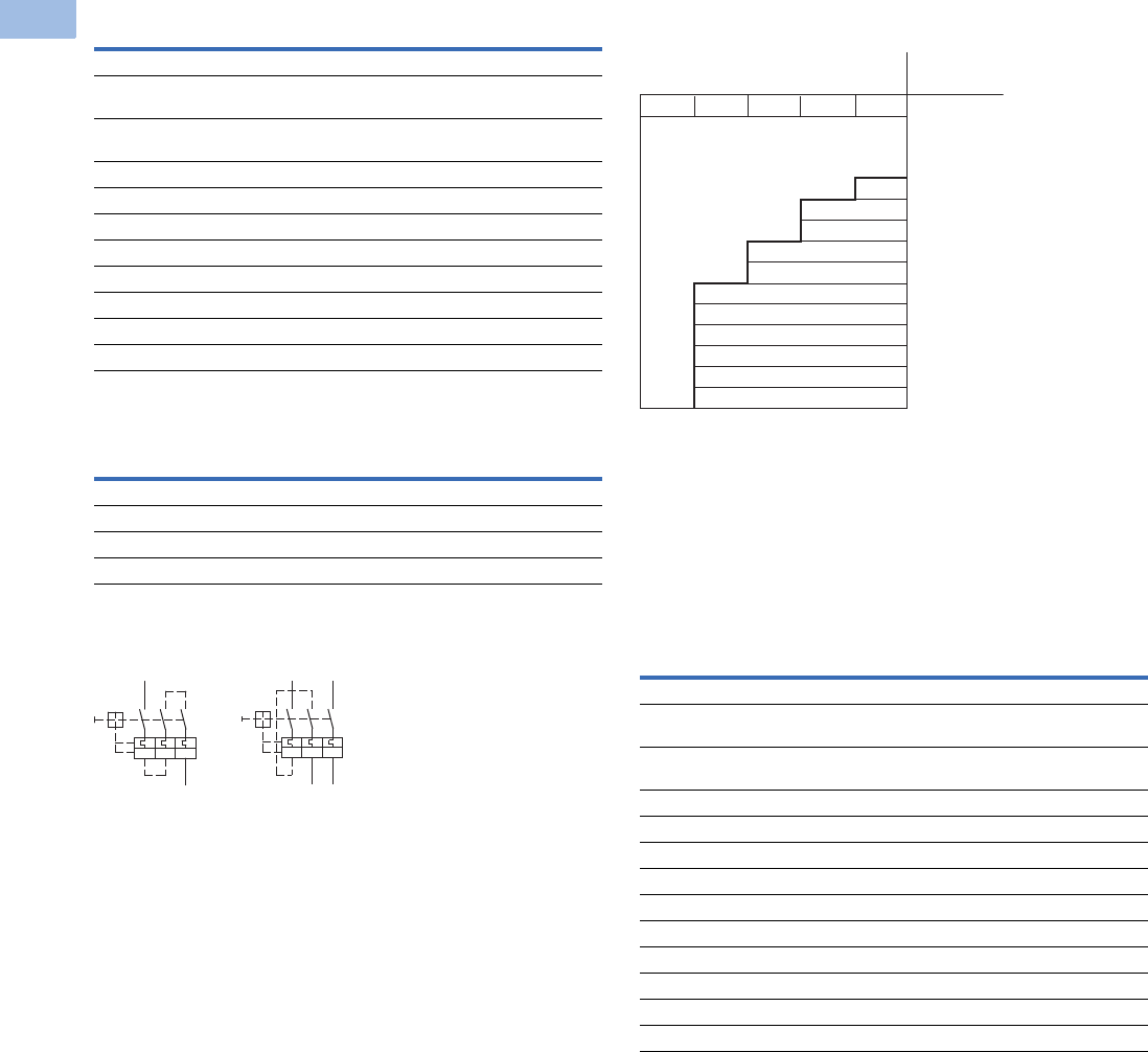
V5-T1-178 Volume 5—Motor Control and Protection CA08100006E—August 2012 www.eaton.com
1
1
1
1
1
1
1
1
1
1
1
1
1
1
1
1
1
1
1
1
1
1
1
1
1
1
1
1
1
1
1.1
IEC Contactors and Starters
XT
IEC Power Control
Undervoltage Release
Current Limiter
XTPB, XTPR Single- and Two-Pole Circuits with DC
and AC Current
Protection of PVC Insulated Cables Against Thermal
Overload at Short-Circuit
The chart above indicates which minimum cable cross-sections
are protected by XTPR motor protective circuit breakers up to
their rated conditional short-circuit current Iq.
Shunt Release
Description XTPAXUVR_
Cross-Section
Solid or flexible conductor with ferrule (mm2) 1 x (0.75–2.5)
2 x (0.75–2.5)
Solid or stranded (AWG) 1 x (18–14)
2 x (18–14)
Main Contact
Rated operational voltage, Ue (Vac) 42–480
Rated operational voltage, Ue (Vdc) 24–250
Pickup voltage, x Us0.85–1.1
Dropout voltage, x Us0.7–0.35
Power Consumption
Pickup AC (VA) 5
Sealing AC (VA) 3
Description XTPAXCL
Rated impulse withstand voltage (Uimp), Vac 6000
Overvoltage category/pollution degree III/3
Rated operational voltage, Ue (Vac) 690
Rated interrupted current = Rated operational current (lu = le) in amperes 63
135
246
I > I > I >
135
246
I > I > I >
Description XTPAXSR __
Cross-Section
Solid or flexible conductor with ferrule (mm2) 1 x (0.75–2.5)
2 x (0.75–2.5)
Solid or stranded (AWG) 1 x (18–14)
2 x (18–14)
Main Contact
Rated operational voltage, Ue (Vac) 42–480
Rated operational voltage, Ue (Vdc) 24–250
AC operating range, x Us0.7–1.1
DC operating range, x Us (intermittent operation 5s) 0.7–1.1
Power Consumption
Pickup AC (VA) 5
Sealing AC (VA) 3
Pickup DC (VA) 3
Sealing DC (VA) 3
Min. Cross-Section Protected
380-415V, 50 Hz, Cu mm2
Device
Type
4 2.5 1.5 1 0.75
XTPRP16BC1
...
XTPR6P3BC1
XTPR010BC1
XTPR016BC1
XTPR020BC1
XTPR025BC1
XTPR016DC1
XTPR025DC1
XTPR032DC1
XTPR040DC1
XTPR050DC1
XTPR058DC1
XTPR063DC1
Courtesy of CMA/Flodyne/Hydradyne ▪ Motion Control ▪ Hydraulic ▪ Pneumatic ▪ Electrical ▪ Mechanical ▪ (800) 426-5480 ▪ www.cmafh.com
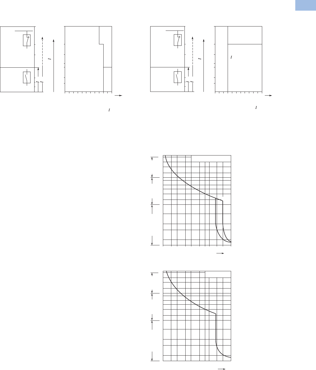
Volume 5—Motor Control and Protection CA08100006E—August 2012 www.eaton.com V5-T1-179
1
1
1
1
1
1
1
1
1
1
1
1
1
1
1
1
1
1
1
1
1
1
1
1
1
1
1
1
1
1
1.1
IEC Contactors and Starters
XT
IEC Power Control
Wiring Diagrams
Fuseless Installation with XTPR
Backup Protection Diagram—XTPR…B
Time/Current Curves
Characteristics
The time/current
characteristic, the current
limiting characteristics and
the I2t characteristics were
determined in accordance
with DIN VDE 0660 and IEC
60 947.
The tripping characteristic of
the inverse-time delayed
overload releases (thermal
overload releases or “a”
releases) for DC and AC with
a frequency of 0 to 400 Hz
also apply to the time/current
characteristic.
The characteristics apply to
the cold state. At operating
temperature, the tripping
times of the thermal releases
are reduced to approximately
25%.
Under normal operating
conditions, all three-poles of
the device must be loaded.
The three main conducting
paths must be connected in
series in order to protect
single-phase or DC loads.
With three-pole loading, the
maximum deviation in the
tripping time for 3 times the
setting current and upwards
is ±20% and thus in
accordance with DIN VDE
0165.
The tripping characteristics
for the instantaneous,
electromagnetic overcurrent
releases (short-circuit
releases or “n” releases) are
based on the rated current In,
which is also the maximum
value of the setting range for
circuit breakers with
adjustable overload releases.
If the current is set to a lower
value, the tripping current of
the “n” release is increased
by a corresponding factor.
The characteristics of the
electromagnetic overcurrent
releases apply to frequencies
of 50/60 Hz. Appropriate
correction factors must be
used for lower frequencies up
to 16-2/3 Hz, for higher
frequencies up to 400 Hz and
for DC.
Time/current characteristics,
current limiting characteristics
and I2t characteristics are
available on request.
XTPR…B
XTPR…B
415 Vac
Inherently short-circuit proof
Back-up
protection
range
with XTPAXCL
Rated
short-circuit
breaking
capacity
range
100
50
30
20
16
10
6
0.16... 101620 25
XTPR…B + XTPAXCL
XTPR…B
XTPR...B
Rated
Current
Inherently
short-circuit-proof
cn
cc
n [A]
cc rms [kA]
Backup Protection Diagram—XTPR…D
MMP Tripping Characteristics
XTPB, XTPR Frame B
XTPR Frame D
100
50
30
20
16
10
6
XTPR…D
XTPR…D
Back-up
protection
range
with XTPAXCL
Rated
short-circuit
breaking
capacity
range
16... 3225 40 50 63
XTPR...D + XTPAXCL
XTPR…D
Inherently
short-circuit-proof
415 Vac
Inherently short-circuit proof
cn
cc
cc rms [kA]
Rated
Current
n [A]
Rated
Current
n [A]
2
5
20
50
200
1
2
5
10
20
40
1
2
5
10
20
2h
1.5 2346810 15 20 30
XTPB, XTPR Frame B
XTPT
Seconds
Milli-seconds Minutes
x Rated Operational Current
XTPR Frame D
2
5
20
50
200
1
2
5
10
20
40
1
2
5
10
20
2h
1.5 2346810 15 20 30
Seconds
Milli-seconds Minutes
x Rated Operational Current
Courtesy of CMA/Flodyne/Hydradyne ▪ Motion Control ▪ Hydraulic ▪ Pneumatic ▪ Electrical ▪ Mechanical ▪ (800) 426-5480 ▪ www.cmafh.com
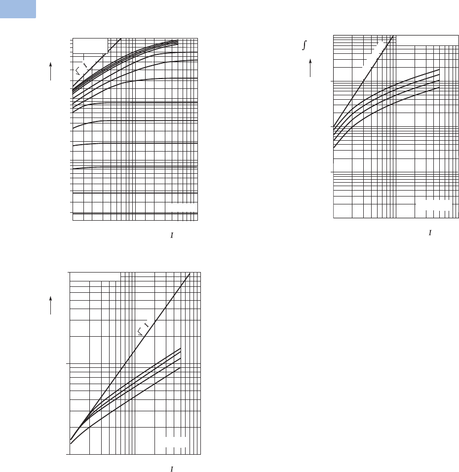
V5-T1-180 Volume 5—Motor Control and Protection CA08100006E—August 2012 www.eaton.com
1
1
1
1
1
1
1
1
1
1
1
1
1
1
1
1
1
1
1
1
1
1
1
1
1
1
1
1
1
1
1.1
IEC Contactors and Starters
XT
IEC Power Control
MMP Let-Through Tripping Characteristics
XTPB, XTPR Frame B XTPR Frame D
XTPR Frame D
1
2
3
6
4
8
10
4.0 A
6.3 A
2.5 A
1.6 A
0.25 A
10 A/12 A
0.1
0.2
0.3
0.4
0.6
0.8
0.01
0.02
0.015
0.03
0.04
0.06
0.08
12
1.5 3 4 6 8 10 2015 3040 60 80100
XTPB
XTPR Frame B
XTPM
16 A
20 A
25 A
32 A
1 A
0.4 A
0.63 A
Ue
= 400 V
2 • cc
cc rms [kA]
[kA]
I
D
^
63/58 A
50/40/32 A
25 A
16 A
XTPR Frame D
Ue
= 400 V
100101
cc rms[kA]
102
103
104
105
106
1st half-wave
i
2
dt
[A
2
s]
10
10 100
63/58 A
50/40/32 A
25 A
16 A
1
1
100
2 •
cc
XTPR Frame D
Ue
= 400 V
cc rms[kA]
[kA]
ID
^
Courtesy of CMA/Flodyne/Hydradyne ▪ Motion Control ▪ Hydraulic ▪ Pneumatic ▪ Electrical ▪ Mechanical ▪ (800) 426-5480 ▪ www.cmafh.com

Volume 5—Motor Control and Protection CA08100006E—August 2012 www.eaton.com V5-T1-181
1
1
1
1
1
1
1
1
1
1
1
1
1
1
1
1
1
1
1
1
1
1
1
1
1
1
1
1
1
1
1.1
IEC Contactors and Starters
XT
IEC Power Control
Manual Motor Protector Short-Circuit Ratings
Rated uninterrupted current Iu = Rated operational current Ie.
Rated conditional short-circuit current Iq—IEC/EN 60947-4-1.
Rated ultimate short-circuit breaking capacity Icu — IEC/EN 60947-2.
Rated operational short-circuit breaking capacity Ics — IEC/EN 60947-2.
Global Use, IEC/EN 60947—XTPB with Classification Type “1” and Type “2”
Global Use, IEC/EN 60947—XTPR…BC1 with Classification Type “1” and Type “2”
Notes
1N = Not required.
2XTPR…BC1, XTPT, XTPM—Required back-up fuse if the short-circuit current exceeds the rated conditional
short-circuit current (Icc > Iq); XTPB, XTPR…DC1—Fuse (A gG/gL) for enhancing the switching capacity of the
motor protective circuit breaker to 100 kA.
3No upstream protective device required, as it is the auto-protected range (100/150 kA—Frame B, 150 kA—Frame D).
Iu
230V 400V 440V 500V 690V
IqIcu Ics Fuse 12 IqIcu Ics Fuse 12 IqIcu Ics Fuse 12 IqIcu Ics Fuse 12 IqIcu Ics Fuse 12
A kA kA kA A kA kA kA A kA kA kA A kA kA kA A kA kA kA A
0.16–1 50505050 50505050 50505050 ———— ————
1.6 50505050 50505050 50505050 ———— ————
2.5 50505050 50505050 50505050 ———— ————
4 50505050 50505050 50505050 ———— ————
6.3 50505050 50505050 50505050 ———— ————
10 50 50 50 50 50 50 50 50 42 42 10 50 — — — — — — — —
12 50 50 10 50 50 50 10 50 15 15 10 50 — — — — — — — —
16 50 50 10 50 50 50 10 50 15 15 10 50 — — — — — — — —
20 50 50 10 50 50 50 10 50 10 10 10 50 — — — — — — — —
25 50 50 10 50 50 50 10 50 10 10 10 50 — — — — — — — —
Iu
230V 400V 440V 500V 690V
IqIcu Ics Fuse 12 IqIcu Ics Fuse 12 IqIcu Ics Fuse 12 IqIcu Ics Fuse 12 IqIcu Ics Fuse 12
A kA kA kA A kA kA kA A kA kA kA A kA kA kA A kA kA kA A
0.16–1 150 3150 3150 3N150
3150 3150 3N33 3N33 3N33 3N
1.6 150 3150 3150 3N150
3150 3150 3N33 3N33 3N33 3N
2.5 150 3150 3150 3N150
3150 3150 3N33 3N33 3N55550
4 150 3150 3150 3N150
3150 3150 3N33 3N33 3N33350
6.3 150 3150 3150 3N150
3150 3150 3N33 3N 4242650 33 250
10 150 3150 3150 3N150
3150 3150 3N 4242 1050 4242 6 50 3 3 2 50
12 50 50 10 50 50 50 10 50 15 15 10 50 15 15 6 50 3 3 2 50
16 50 50 10 50 50 50 10 50 15 15 10 50 15 15 6 50 3 3 2 50
20 50 50 10 50 50 50 10 50 15 15 10 50 6 6 6 50 3 3 2 50
25 50 50 10 50 50 50 10 50 10 10 10 50 6 6 6 50 3 3 2 50
32 50 50 10 50 50 50 10 50 10 10 10 50 6 6 6 50 3 3 2 50
Courtesy of CMA/Flodyne/Hydradyne ▪ Motion Control ▪ Hydraulic ▪ Pneumatic ▪ Electrical ▪ Mechanical ▪ (800) 426-5480 ▪ www.cmafh.com

V5-T1-182 Volume 5—Motor Control and Protection CA08100006E—August 2012 www.eaton.com
1
1
1
1
1
1
1
1
1
1
1
1
1
1
1
1
1
1
1
1
1
1
1
1
1
1
1
1
1
1
1.1
IEC Contactors and Starters
XT
IEC Power Control
Global Use, IEC/EN 60947—XTPR…DC1 with Classification Type “1” and Type “2”
Ratings for Group Motor Applications
UL 508/CSA C22.2 No. 14—XTPB—Frame B, Manual Motor Protector with Thermal and Magnetic Trip
Notes
1N = Not required.
2XTPR…BC1, XTPT, XTPM—Required back-up fuse if the short-circuit current exceeds the rated conditional short-circuit current (Icc > Iq); XTPB, XTPR…DC1—Fuse (A gG/gL) for enhancing the
switching capacity of the motor protective circuit breaker to 100 kA.
3No upstream protective device required, as it is the auto-protected range (100/150 kA—Frame B, 150 kA—Frame D).
4IEC/EN 60947-4-1.
522 kA 600 Vac.
Iu
230V 400V 440V 500V 690V
IqIcu Ics Fuse 12 IqIcu Ics Fuse 12 IqIcu Ics Fuse 12 IqIcu Ics Fuse 12 IqIcu Ics Fuse 12
A kA kA kA A kA kA kA A kA kA kA A kA kA kA A kA kA kA A
16 150 3150 325 N 150 3150 325 N 45 45 25 100 15 15 100 8 8 2.5 100
25 150 3150 325 N 150 3150 325 N 45 45 25 100 15 15 100 8 8 2.5 100
32 50 50 25 100 50 50 25 100 45 45 25 100 15 15 100 5 5 2.5 100
40 50 50 25 100 50 50 25 100 45 45 25 100 15 15 100 5 5 2.5 100
50 50 50 25 100 50 50 25 100 45 45 25 100 15 15 100 5 5 2.5 100
58 50 50 25 160 50 50 25 160 45 45 25 160 15 15 160 5 5 2.5 160
63 50 50 25 160 50 50 25 160 45 45 25 160 15 15 160 5 5 2.5 160
Catalog Number
Rated
Uninterrupted
Current—
Iu (Amps)
FLA
Adjustment
Range/Overload
Release—
Ir (Amps)
Short
Circuit
Release—
Irm (Amps) Maximum Protective Device for UL/CSA Group Protection
Maximum rms
Sym Current—
480V (kA)
w/Current
Limiter—
XTPAXCL
Maximum Fuse
Rating (A)
w/Current
Limiter—
XTPAXCL
Circuit Breaker
Maximum (A)
w/Current
Limiter—
XTPAXCL
XTPBP16BC1 0.16 0.1–0.16 2.2 50 — 600 — 600 —
XTPBP25BC1 0.25 0.16–0.25 3.5 50 — 600 — 600 —
XTPBP40BC1 0.4 0.25–0.4 5.6 50 — 600 — 600 —
XTPBP63BC1 0.63 0.4–0.63 8.8 50 — 600 — 600 —
XTPB001BC1 1 0.63–1 14 50 — 600 — 600 —
XTPB1P6BC1 1.6 1–1.6 22 50 — 600 — 600 —
XTPB2P5BC1 2.5 1.6–2.5 35 50 — 600 — 600 —
XTPB004BC1 4 2.5–4 56 50 — 600 — 600 —
XTPB6P3BC1 6.3 4–6.3 88 50 — 600 — 600 —
XTPB010BC1 10 6.3–10 140 30 50 600 600 600 600
XTPB012BC1 12 8–12 168 10 50 150 600 125 5600
XTPB016BC1 16 10–16 224 10 50 150 600 125 5600
XTPB020BC1 420 16–20 280 10 18 150 600 125 600
XTPB025BC1 425 20–25 350 10 18 150 600 125 600
Courtesy of CMA/Flodyne/Hydradyne ▪ Motion Control ▪ Hydraulic ▪ Pneumatic ▪ Electrical ▪ Mechanical ▪ (800) 426-5480 ▪ www.cmafh.com

Volume 5—Motor Control and Protection CA08100006E—August 2012 www.eaton.com V5-T1-183
1
1
1
1
1
1
1
1
1
1
1
1
1
1
1
1
1
1
1
1
1
1
1
1
1
1
1
1
1
1
1.1
IEC Contactors and Starters
XT
IEC Power Control
UL 508/CSA C22.2 No. 14—XTPR—Frame B (all Screw and Spring Cage Terminal Options),
Manual Motor Protector with Thermal and Magnetic Trip
UL 508/CSA C22.2 No. 14—XTPR—Frame D, Manual Motor Protector with Thermal and Magnetic Trip
Note
122 kA 600 Vac.
Catalog Number
Rated
Uninterrupted
Current—
Iu (Amps)
FLA
Adjustment
Range/Overload
Release—
Ir (Amps)
Short
Circuit
Release—
Irm (Amps) Maximum Protective Device for UL/CSA Group Protection
Maximum rms
Sym Current—
480V (kA)
w/Current
Limiter—
XTPAXCL
Maximum Fuse
Rating (A)
w/Current
Limiter—
XTPAXCL
Circuit Breaker
Maximum (A)
w/Current
Limiter—
XTPAXCL
XTPRP16BC1 0.16 0.1–0.16 2.2 50 — 600 — 600 —
XTPRP25BC1 0.25 0.16–0.25 3.5 50 — 600 — 600 —
XTPRP40BC1 0.4 0.25–0.4 5.6 50 — 600 — 600 —
XTPRP63BC1 0.63 0.4–0.63 8.8 50 — 600 — 600 —
XTPR001BC1 1 0.63–1 14 50 — 600 — 600 —
XTPR1P6BC1 1.6 1–1.6 22 50 — 600 — 600 —
XTPR2P5BC1 2.5 1.6–2.5 35 50 — 600 — 600 —
XTPR004BC1 4 2.5–4 56 50 — 600 — 600 —
XTPR6P3BC1 6.3 4–6.3 88 50 — 600 — 600 —
XTPR010BC1 10 6.3–10 140 30 50 600 600 600 600
XTPR012BC1 12 8–12 168 10 50 150 600 125 600
XTPR016BC1 16 10–16 224 10 50 150 600 125 1600
XTPR032BC1 32 25–32 448 10 18 150 600 125 600
XTPR025BC1 25 20–25 350 10 18 150 600 125 600
XTPR032BC1 32 25–32 448 10 18 150 600 125 600
Catalog Number
Rated
Uninterrupted
Current—
Iu (Amps)
FLA
Adjustment
Range/Overload
Release—
Ir (Amps)
Short
Circuit
Release—
Irm (Amps) Maximum Protective Device for UL/CSA Group Protection
Maximum rms
Sym Current—
480V (kA)
w/Current
Limiter—
XTPAXCL
Maximum Fuse
Rating (A)
w/Current
Limiter—
XTPAXCL
Circuit Breaker
Maximum (A)
w/Current
Limiter—
XTPAXCL
XTPR016DC1 16 10–16 224 65 — 600 — 600 —
XTPR025DC1 25 16–25 350 65 — 600 — 600 —
XTPR032DC1 32 25–32 448 65 — 600 — 600 —
XTPR040DC1 40 32–40 560 65 — 600 — 600 —
XTPR050DC1 50 40–50 700 65 — 600 — 600 —
XTPR058DC1 58 50–58 812 65 — 600 — 600 —
XTPR063DC1 65 55–63 882 65 — 600 — 600 —
Courtesy of CMA/Flodyne/Hydradyne ▪ Motion Control ▪ Hydraulic ▪ Pneumatic ▪ Electrical ▪ Mechanical ▪ (800) 426-5480 ▪ www.cmafh.com

V5-T1-184 Volume 5—Motor Control and Protection CA08100006E—August 2012 www.eaton.com
1
1
1
1
1
1
1
1
1
1
1
1
1
1
1
1
1
1
1
1
1
1
1
1
1
1
1
1
1
1
1.1
IEC Contactors and Starters
XT
IEC Power Control
UL 508 Type E Ratings—XTPR Frame B + XTPAXLSA
UL 508 Type E Ratings—XTPR Frame D + XTPAXLSAD
Note
1For UL 508 Type E applications, the manual motor protector assembly does not require a dedicated upstream protective
device in the panel, thus a maximum rating is not required.
Manual Motor
Protector—
Screw Terminal
Catalog Number
Line Side
Adapter
Catalog Number
FLA
Adjustment
Range/Overload
Release—
Ir (Amps)
Short
Circuit
Release—
Irm (Amps)
Maximum Upstream
Protective Device (A) 1
UL 508 Type E Application
Maximum rms Symmetrical Short-Circuit Ratings (kA) Maximum Fuse
600V
Maximum
Circuit Breaker
600V240V 480/277V 600/347V
XTPRP16BB1 XTPAXLSA 0.1–0.16 2.2 50 50 50 Not required Not required
XTPRP16BC1 XTPAXLSA 0.16–0.25 3.5 50 50 50 Not required Not required
XTPRP25BC1 XTPAXLSA 0.25–0.4 5.6 50 50 50 Not required Not required
XTPRP40BC1 XTPAXLSA 0.4–0.63 8.82 50 50 50 Not required Not required
XTPRP63BC1 XTPAXLSA 0.63–1 14 50 50 50 Not required Not required
XTPR001BC1 XTPAXLSA 1–1.6 22.4 50 50 50 Not required Not required
XTPR1P6BC1 XTPAXLSA 1.6–2.5 35 50 50 50 Not required Not required
XTPR2P5BC1 XTPAXLSA 2.5–4 56 50 50 50 Not required Not required
XTPR004BC1 XTPAXLSA 4–6.3 88.2 50 50 50 Not required Not required
XTPR6P3BC1 XTPAXLSA 6.3–10 140 50 50 50 Not required Not required
XTPR010BC1 XTPAXLSA 8–12 168 42 42 — Not required Not required
XTPR012BC1 XTPAXLSA 10–16 224 42 42 — Not required Not required
XTPR016BC1 XTPAXLSA 10–16 224 18 18 — Not required Not required
XTPR020BC1 XTPAXLSA 16–20 280 18 18 — Not required Not required
XTPR025BC1 XTPAXLSA 20–25 350 18 18 — Not required Not required
XTPR032BC1 XTPAXLSA 25–32 448 18 18 — Not required Not required
Manual Motor
Protector—
Screw Terminal
Catalog Number
Line Side
Adapter
Catalog Number
FLA
Adjustment
Range/Overload
Release—
Ir (Amps)
Short
Circuit
Release—
Irm (Amps)
Maximum Upstream
Protective Device (A) 1
UL 508 Type E Application
Maximum rms Symmetrical Short-Circuit Ratings (kA) Maximum Fuse
600V
Maximum
Circuit Breaker
600V240V 480/277V 600/347V
XTPR016DC1 XTPAXLSAD 10–16 224 65 65 25 Not required Not required
XTPR025DC1 XTPAXLSAD 16–25 350 65 65 25 Not required Not required
XTPR032DC1 XTPAXLSAD 25–32 448 65 65 25 Not required Not required
XTPR040DC1 XTPAXLSAD 32–40 560 65 65 25 Not required Not required
XTPR050DC1 XTPAXLSAD 40–50 700 65 65 — Not required Not required
XTPR058DC1 XTPAXLSAD 50–58 812 65 65 — Not required Not required
XTPR063DC1 XTPAXLSAD 55–65 882 65 65 — Not required Not required
Courtesy of CMA/Flodyne/Hydradyne ▪ Motion Control ▪ Hydraulic ▪ Pneumatic ▪ Electrical ▪ Mechanical ▪ (800) 426-5480 ▪ www.cmafh.com
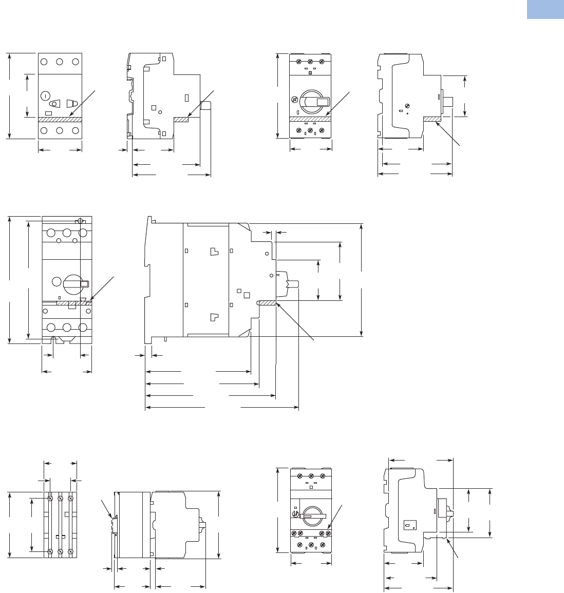
Volume 5—Motor Control and Protection CA08100006E—August 2012 www.eaton.com V5-T1-185
1
1
1
1
1
1
1
1
1
1
1
1
1
1
1
1
1
1
1
1
1
1
1
1
1
1
1
1
1
1
1.1
IEC Contactors and Starters
XT
IEC Power Control
Dimensions
Approximate Dimensions in mm [in]
Manual Motor Protectors—XTPB
Manual Motor Protectors, Manual Transformer
Protectors—XTPR…B
Manual Motor Protector—XTPR…DC1
Current Limiter—XTPAXCL
MMPs with Early-Make Auxiliary Contacts—
XTPR…BC1 + XTPAXFAEM20
5.5
[.22]
45
[1.77]
45
[1.77]
93
[3.66]
44
[1.73]
74 [2.91]
85 [3.35]
XTPAXFA _XTPAXFA _
45
[1.77]
93
[3.66] 45
[1.77]
50
[1.97]
88 [3.46]
94 [3.70]
XTPAXFA _
XTPAXFA _
30
[1.18] 7.5 [.30]
118 [4.65]
127 [5.00]
145 [5.71]
171 [6.73]
55 [2.17]
130
[5.12]
140
[5.57]
125
[4.92]
65
[2.56]
45
[1.77]
4 [.16]
XTPAXFA _
XTPAXFA _
*
93
[3.66]
28
[1.10]
45
[1.77]
* IEC/EN 60715 DIN Rail
90
[3.54]
73
[2.87]
7.5
[.30]
7.5
[.30]
44
[1.73]
70
[2.76]
49.5
[1.95]
XTPAXFAEM20
XTPAXFAEM20
45
[1.77]
45
[1.77] 55
[2.17]
93
[3.66]
50
[1.97]
68 [2.68]
86 [3.39]
80 [3.15]
Courtesy of CMA/Flodyne/Hydradyne ▪ Motion Control ▪ Hydraulic ▪ Pneumatic ▪ Electrical ▪ Mechanical ▪ (800) 426-5480 ▪ www.cmafh.com
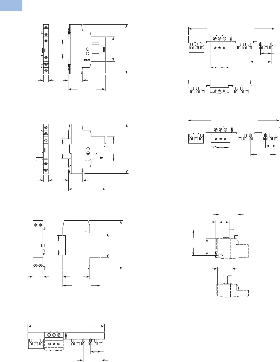
V5-T1-186 Volume 5—Motor Control and Protection CA08100006E—August 2012 www.eaton.com
1
1
1
1
1
1
1
1
1
1
1
1
1
1
1
1
1
1
1
1
1
1
1
1
1
1
1
1
1
1
1.1
IEC Contactors and Starters
XT
IEC Power Control
Approximate Dimensions in mm [in]
Standard Auxiliary Contact—XTPAXSA_
Trip Indicating Auxiliary Contact—XTPAXSATR_
Undervoltage/Shunt Release—XTPAXUVR_, XTPAXSR_
Three-Phase Commoning Link—XTPAXCLKA4, XTPAXCLKA2
Three-Phase Commoning Link—XTPAXCLKB5,
XTPAXCLKB4, XTPAXCLKB3 and XTPAXCLKB2
Three-Phase Commoning Link—XTPAXCLKC4, XTPAXCLKC2
Incoming Terminal, Line Side Adapter—XTPAXIT, XTPAXLSA
45
[1.77]
36
[1.42] 90
[3.54]
26
[1.02]
68 [2.68]
9
[.35]
36
[1.42]
45
[1.77] 90
[3.54]
26
[1.02]
68 [2.68]
9
[.35]
36
[1.42]
45
[1.77] 90
[3.54]
18
[.71]
49
[1.93]
68 [2.68]
180 [7.09] (90 [3.54])
27
[1.06]
45
[1.77]
Overlapping Mounting
to Extend the Three-Phase
Commoning Link
261 [10.28] (207 [8.15],
153 [6.02], 99 [3.90])
27
[1.06]
54
[2.13]
234 [9.21] (108 [4.25])
27
[1.06]
63
[2.48]
XTPAXLSA
73
[2.87] 48
[1.89]
XTPAXIT
31
[1.22]
7.5
[.30]
41
[1.61]
56
[2.20]
Courtesy of CMA/Flodyne/Hydradyne ▪ Motion Control ▪ Hydraulic ▪ Pneumatic ▪ Electrical ▪ Mechanical ▪ (800) 426-5480 ▪ www.cmafh.com
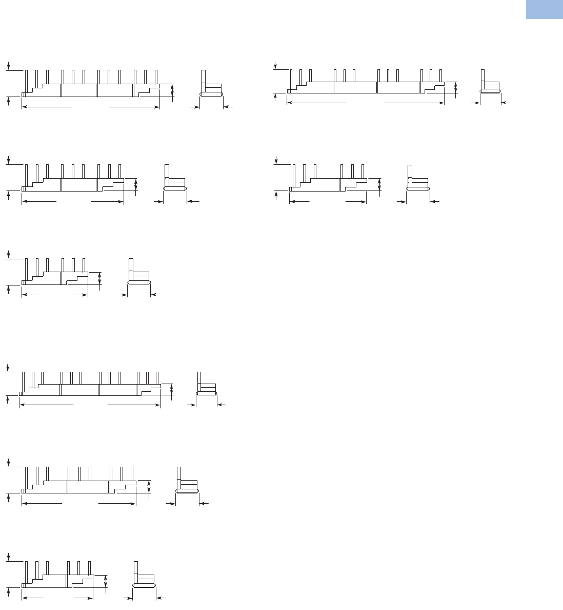
Volume 5—Motor Control and Protection CA08100006E—August 2012 www.eaton.com V5-T1-187
1
1
1
1
1
1
1
1
1
1
1
1
1
1
1
1
1
1
1
1
1
1
1
1
1
1
1
1
1
1
1.1
IEC Contactors and Starters
XT
IEC Power Control
Approximate Dimensions in mm [in]
Three-Phase Commoning Link
XTPAXCLKA4D, XTPAXCLKA3D and XTPAXCLKA2D
XTPAXCLKA4D
XTPAXCLKA3D
XTPAXCLKA2D
XTPAXCLKB4D, XTPAXCLKB3D and XTPAXCLKB2D
XTPAXCLKB4D
XTPAXCLKB3D
XTPAXCLKB2D
XTPAXCLKC4D and XTPAXCLKC2D
XTPAXCLKC4D
XTPAXCLKC2D
14
[.55]
205 [8.07] 33
[1.30]
36
[1.42]
151 [5.94] 14
[.55]
36
[1.42]
33
[1.30]
98 [3.86] 14
[.55]
36
[1.42]
33
[1.30]
232 [9.13] 14
[.55]
36
[1.42]
33
[1.30]
170 [6.69] 14
[.55]
36
[1.42]
33
[1.30]
117 [4.6] 14
[.55]
36
[1.42]
33
[1.30]
260 [10.24] 14
[.55]
36
[1.42]
33
[1.30]
115 [4.53] 14
[.55]
36
[1.42]
33
[1.30]
Courtesy of CMA/Flodyne/Hydradyne ▪ Motion Control ▪ Hydraulic ▪ Pneumatic ▪ Electrical ▪ Mechanical ▪ (800) 426-5480 ▪ www.cmafh.com

V5-T1-188 Volume 5—Motor Control and Protection CA08100006E—August 2012 www.eaton.com
1
1
1
1
1
1
1
1
1
1
1
1
1
1
1
1
1
1
1
1
1
1
1
1
1
1
1
1
1
1
1.1
IEC Contactors and Starters
XT
IEC Power Control
Approximate Dimensions in mm [in]
Insulated Enclosures for Surface Mounting of XTPB Manual Motor Protectors
Insulated Enclosures for Flush Mounting of XTPB Manual Motor Protectors
158
[6.22]
80 [3.15] 116.5 [4.59]
158
[6.22]
80 [3.15] 116.5 [4.59]
177.2 [6.98]
158
[6.22]
80 [3.15] 116.5 [4.59]
129.5 [5.10]
XTPBXENCS40, XTPBXENCS65, XTPBXENAS41, XTPBXENAS65 XTPBXENCSEK65, XTPBXENCSES65, XTPBXENASEK65, XTPBXENASES65
XTPBXENCSLE65, XTPBXENCSLO65, XTPBXENASLE65, XTPBXENASO065
129
[5.08]
90.2
[3.55]
69
[2.72]
93 [3.66]
115.2 [4.54]
129
[5.08]
90.2
[3.55]
69
[2.72]
93 [3.66]
115.2 [4.54]
175.9 [6.93]
129
[5.08]
90.2
[3.55]
69
[2.72]
93 [3.66]
115.2 [4.54]
XTPBXENCF40, XTPBXENCF55 XTPBXENCFEK55, XTPBXENCFES55
XTPBXENCFLE55, XTPBXENCFLO55
Courtesy of CMA/Flodyne/Hydradyne ▪ Motion Control ▪ Hydraulic ▪ Pneumatic ▪ Electrical ▪ Mechanical ▪ (800) 426-5480 ▪ www.cmafh.com
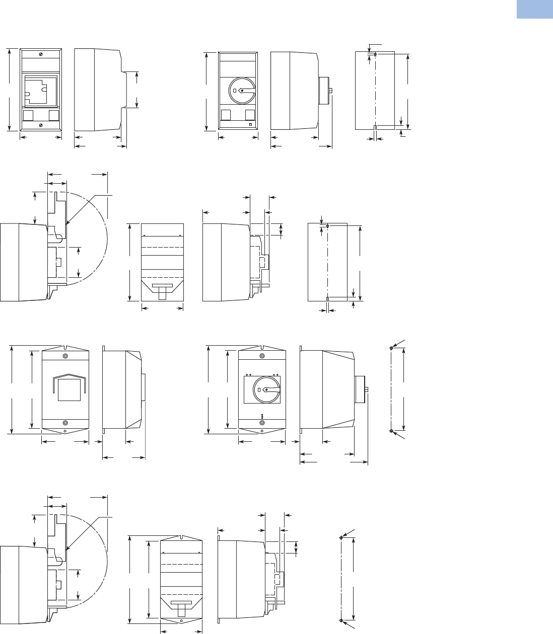
Volume 5—Motor Control and Protection CA08100006E—August 2012 www.eaton.com V5-T1-189
1
1
1
1
1
1
1
1
1
1
1
1
1
1
1
1
1
1
1
1
1
1
1
1
1
1
1
1
1
1
1.1
IEC Contactors and Starters
XT
IEC Power Control
Approximate Dimensions in mm [in]
Insulated Enclosures for Surface Mounting of XTPR…B Manual Motor Protectors
158
[6.22]
70
[2.76]
80 [3.15] 90 [3.54]
100 [3.94]
44
[1.73]
55
[2.17]
98 [3.86]
SVB-PKZ0-CI
30 [1.18]
33
[1.30]
80 [3.15]
158
[6.22]
97.5 [3.84] 28
[1.10]
30
[1.18] 4.5
[.18]
4.5
[.18] 8
[.31]
153
[6.02]
Drilling Dimensions
160
[6.30]
181
[7.13]
100
[3.94]
47.5
[1.87]
104
[4.09]
33
[1.30]
55
[2.17]
SVB-PKZ0-CI
97 [3.82]
160
[6.30]
181
[7.13]
44
[1.73]
98 [3.86]
30 [1.18]
114 [4.49] 28
[1.10]
30
[1.18]
M4
M4
171
[6.73]
Drilling Dimensions
XTPAXENCS40
158
[6.22]
80 [3.15] 97.5 [3.84]
125.5 [4.94]
4.5 [.18]
4.5
[.18]
8 [.31]
153
[6.02]
Drilling Dimensions
160
[6.30]
181
[7.13]
100
[3.94]
47.5
[1.87]
103 [4.06]
130 [5.12]
M4
M4
171
[6.73]
Drilling Dimensions
XTPAXENCS65B, XTPAXENCS65RY, XTPAXENCSEM65B, XTPAXENCSEM65RY,
XTPAXENAS55B, XTPAXENAS55RY, XTPAXENASEM55B, XTPAXENASEM55RY,
XTPAXENCSH65B, XTPAXENCSH65RY, XTPAXENCSEMH65B, XTPAXENCSEMH65RY
XTPAXENCS55B, XTPAXENCS55RY, XTPAXENCSEM55B, XTPAXENCSEM55RY
XTPAXENCS55_ + XTPAXPL1, XTPAXENCSEM55_ + XTPAXPL1
XTPAXENCSH41, XTPAXENCS41, XTPAXENAS41
XTPAXENCS65_ + XTPAXPL1, XTPAXENCSEM65_ + XTPAXPL1
Courtesy of CMA/Flodyne/Hydradyne ▪ Motion Control ▪ Hydraulic ▪ Pneumatic ▪ Electrical ▪ Mechanical ▪ (800) 426-5480 ▪ www.cmafh.com

V5-T1-190 Volume 5—Motor Control and Protection CA08100006E—August 2012 www.eaton.com
1
1
1
1
1
1
1
1
1
1
1
1
1
1
1
1
1
1
1
1
1
1
1
1
1
1
1
1
1
1
1.1
IEC Contactors and Starters
XT
IEC Power Control
Approximate Dimensions in mm [in]
Insulated Enclosures for Flush Mounting of XTPR…B Manual Motor Protectors
69
[2.72]
85 [3.35]
129
[5.08]
96 [3.78]
80 [3.15]
124 [4.88]
55
[2.17]
4 [.16]
R
70 – 72
[2.76 – 2.83]
116 – 118
[4.57 – 4.64]
98
[3.86]
30
[1.18]
58
[2.28]
55
[2.17]
96 [3.78]
80 [3.15]
124 [4.88]
XTPAXENCF40, XTPAXENCF55B, XTPAXENCF55RY Mounting Cutout XTPAXENCF_
XTPAXENCF55_ + XTPAXPL3
85
[3.35]
129
[5.08]
30
[1.18]
28 [1.10]
21
[.83]
Courtesy of CMA/Flodyne/Hydradyne ▪ Motion Control ▪ Hydraulic ▪ Pneumatic ▪ Electrical ▪ Mechanical ▪ (800) 426-5480 ▪ www.cmafh.com

Volume 5—Motor Control and Protection CA08100006E—August 2012 www.eaton.com V5-T1-191
1
1
1
1
1
1
1
1
1
1
1
1
1
1
1
1
1
1
1
1
1
1
1
1
1
1
1
1
1
1
1.1
IEC Contactors and Starters
XT
IEC Power Control
Approximate Dimensions in mm [in]
Insulated Enclosures for Surface Mounting of XTPR…D Manual Motor Protectors
Rotary Handle Mechanism—XTPAXRHM_
160 [6.30]
240
[9.45]
134 [5.28]
181 [7.13]
197 [7.76]
32 [1.26]
SVB-PKZ4-CI
98 [3.86]
72
[2.83]
3 [.12]
160 [6.30] 186 [7.32] 28 [1.10]
30
[1.18]
193
[7.60]
142 [5.60]
5.6 [.22]
Dia.
72
[2.83]
240
[9.45]
Drilling Dimensions
XTPAXENCSD65_ + XTPAXPL2XTPAXENCSD65B, XTPAXENCSD65RY
XTPAXENCSD65
48
[1.89]
At least 100 [3.94]
up to Cover Hinge
Mounting Depth:
100 – 240 [3.94 – 9.45]
from the top edge of
the mounting rail to the
front edge of the panel
door/cover
48
[1.89]
43 [1.69] Dia.
64
[2.52]
64
[2.52]
19.5
[.77]
62
[2.44]
Courtesy of CMA/Flodyne/Hydradyne ▪ Motion Control ▪ Hydraulic ▪ Pneumatic ▪ Electrical ▪ Mechanical ▪ (800) 426-5480 ▪ www.cmafh.com

V5-T1-192 Volume 5—Motor Control and Protection CA08100006E—August 2012 www.eaton.com
1
1
1
1
1
1
1
1
1
1
1
1
1
1
1
1
1
1
1
1
1
1
1
1
1
1
1
1
1
1
1.1
IEC Contactors and Starters
XT
IEC Power Control
Approximate Dimensions in mm [in]
Pushbutton MMP Enclosures
Insulated Enclosures for
Surface Mounting
XTPB Pushbutton Motor-
Protective Circuit Breakers
XTPB Pushbutton Manual
Motor Protectors
Frame B (0.1–32A) XTPR
Motor-Protective Circuit
Breakers
Frame B (0.1–32A) XTPR
Rotary Manual Motor
Protectors
Frame B XTPR (0.1–32A)
Rotary Motor-Protective
Circuit Breakers with
XTPAXFAEM20 Early-Make
Front-Mount Auxiliary Contact
Frame B XTPR (0.1–32A)
Rotary Manual Motor
Protectors with
XTPAXFAEM20 Early-Make
Front-Mount Auxiliary Contact
Frame D (10–65A) Rotary
Motor-Protective Circuit
Breakers
Insulated Enclosures for
Flush Mounting
XTPB Pushbutton Manual
Motor Protectors
Frame B (0.1–32A) XTPR
Rotary Manual Motor
Protectors
Catalog Number H x W x D
Global Usage
XTPBXENCS40 158 x 80 x 116.5
[6.22 x 3.15 x 4.59]
XTPBXENCS65 158 x 80 x 116.5
[6.22 x 3.15 x 4.59]
XTPBXENCSLO65 158 x 80 x 129.5
[6.22 x 3.15 x 5.10]
XTPBXENCSLE65 158 x 80 x 129.5
[6.22 x 3.15 x 5.10]
XTPBXENCSES65 158 x 80 x 177.2
[6.22 x 3.15 x 6.98]
XTPBXENCSEK65 158 x 80 x 177.2
[6.22 x 3.15 x 6.98]
Catalog Number H x W x D
North American Usage
XTPBXENAS41 158 x 80 x 116.5
[6.22 x 3.15 x 4.59]
XTPBXENAS65 158 x 80 x 116.5
[6.22 x 3.15 x 4.59]
XTPBXENASLO65 158 x 80 x 129.5
[6.22 x 3.15 x 5.10]
XTPBXENASLE65 158 x 80 x 129.5
[6.22 x 3.15 x 5.10]
XTPBXENASES65 158 x 80 x 177.2
[6.22 x 3.15 x 6.98]
XTPBXENASEK65 158 x 80 x 177.2
[6.22 x 3.15 x 6.98]
Catalog Number H x W x D
Global Usage
XTPAXENCS41 160 x 100 x 104
[6.30 x 3.94 x 4.09]
XTPAXENCS65B 160 x 100 x 130
[6.30 x 3.94 x 5.12]
XTPAXENCS65RY 160 x 100 x 130
[6.30 x 3.94 x 5.12]
XTPAXENCS40 158 x 80 x 100
[6.22 x 3.15 x 3.94]
XTPAXENCS55B 158 x 80 x 125.5
[6.22 x 3.15 x 4.94]
XTPAXENCS55RY 158 x 80 x 125.5
[6.22 x 3.15 x 4.94]
Catalog Number H x W x D
North American Usage
XTPAXENAS55B 160 x 100 x 130
[6.30 x 3.94 x 5.12]
XTPAXENAS55RY 160 x 100 x 130
[6.30 x 3.94 x 5.12]
Catalog Number H x W x D
Global Usage
XTPAXENCSEM65B
160 x 100 x 130
[6.30 x 3.94 x 5.12]
XTPAXENCSEM65RY
160 x 100 x 130
[6.30 x 3.94 x 5.12]
XTPAXENCSEM55B
158 x 80 x 100
[6.22 x 3.15 x 3.94]
XTPAXENCSEM55RY
158 x 80 x 100
[6.22 x 3.15 x 3.94]
Catalog Number H x W x D
North American Usage
XTPAXENCSEM55B
160 x 100 x 130
[6.30 x 3.94 x 5.12]
XTPAXENCSEM55RY
160 x 100 x 130
[6.30 x 3.94 x 5.12]
Catalog Number H x W x D
Global and
North American Usage
XTPAXENCSD65B 240 x 160 x 197
[9.45 x 6.30 x 7.76]
XTPAXENCSD65RY 240 x 160 x 197
[9.45 x 6.30 x 7.76]
Catalog Number H x W x D
Global and
North American Usage
XTPBXENCF40 129 x 90.2 x 115.2
[5.08 x 3.55 x 4.54]
XTPBXENCF55 129 x 90.2 x 115.2
[5.08 x 3.55 x 4.54]
XTPBXENCFLO55 129 x 90.2 x 115.2
[5.08 x 3.55 x 4.54]
XTPBXENCFLE55 129 x 90.2 x 115.2
[5.08 x 3.55 x 4.54]
XTPBXENCFES55 129 x 90.2 x 175.9
[5.08 x 3.55 x 6.93]
XTPBXENCFEK55 129 x 90.2 x 175.9
[5.08 x 3.55 x 6.93]
Catalog Number H x W x D
Global Usage
XTPAXENCF40 129 x 85 x 96
[5.08 x 3.35 x 3.78]
XTPAXENCF55B 129 x 85 x 124
[5.08 x 3.35 x 4.88]
XTPAXENCF55RY 129 x 85 x 124
[5.08 x 3.35 x 4.88]
Courtesy of CMA/Flodyne/Hydradyne ▪ Motion Control ▪ Hydraulic ▪ Pneumatic ▪ Electrical ▪ Mechanical ▪ (800) 426-5480 ▪ www.cmafh.com
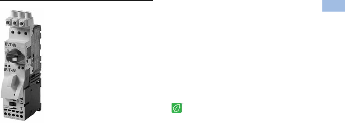
Volume 5—Motor Control and Protection CA08100006E—August 2012 www.eaton.com V5-T1-193
1
1
1
1
1
1
1
1
1
1
1
1
1
1
1
1
1
1
1
1
1
1
1
1
1
1
1
1
1
1
1.1
IEC Contactors and Starters
XT
IEC Power Control
Combination Motor Controllers
Contents
Description Page
Relays and Timers . . . . . . . . . . . . . . . . . . . . . . . . . V5-T1-3
Miniature Controls . . . . . . . . . . . . . . . . . . . . . . . . . V5-T1-18
Contactors and Starters . . . . . . . . . . . . . . . . . . . . V5-T1-35
Thermal Overload Relays . . . . . . . . . . . . . . . . . . . . V5-T1-128
C440/XT Electronic Overload Relay . . . . . . . . . . . V5-T1-141
Manual Motor Protectors . . . . . . . . . . . . . . . . . . . V5-T1-157
Combination Motor Controllers
Features . . . . . . . . . . . . . . . . . . . . . . . . . . . . . . V5-T1-194
Standards and Certifications . . . . . . . . . . . . . . V5-T1-194
Catalog Number Selection . . . . . . . . . . . . . . . . V5-T1-195
Product Selection . . . . . . . . . . . . . . . . . . . . . . . V5-T1-195
Accessories . . . . . . . . . . . . . . . . . . . . . . . . . . . V5-T1-203
Technical Data and Specifications . . . . . . . . . . V5-T1-205
Dimensions . . . . . . . . . . . . . . . . . . . . . . . . . . . V5-T1-211
An Eaton
Green Solution
XT Electronic Manual Motor Protector . . . . . . . . . V5-T1-216
Reference Data . . . . . . . . . . . . . . . . . . . . . . . . . . . V5-T1-229
Combination Motor Controllers
Product Description
Eaton’s XT IEC open non-
reversing and reversing
manual motor controllers
combine a manual motor
protector with an IEC
contactor(s) to provide a
complete motor protection
solution by combining motor
disconnect function, thermal
overload protection, magnetic
short-circuit protection and
remote control operation in
one compact, assembled
unit. these assembled
manual motor controllers
cover motors with FLA
ratings from 0.10A to 65A.
The UL 508 Type F labeled
combination motor controller
(CMC) includes a line side
adapter (LSA). These
assembled combination
motor controllers cover
motors with FLA ratings
from 0.10A to 65A.
Application Description
The XT IEC non-reversing and
reversing manual
and combination motor
controllers can be used in
the following applications:
Group Motor Control
Manual motor controllers
(MMCs) are ideal for group
motor applications where an
upstream breaker or fuse
provides protection for two or
more motors. XT manual
motor controllers (MMC)
combine a manual motor
protector, a wiring connector
link and IEC contactor.
Individual Branch Circuit for Motor Loads
Combination motor controller
(CMC), consisting of a line
side adapter, manual motor
protector, wiring connector
link and IEC contactor,
provide an efficient means to
build an entire branch circuit.
The XT CMC is UL 508 Type
F approved, meaning it is
“self-protected” and doesn’t
require the use of an
additional fuse or breaker for
short circuit protection. This
approval means CMC’s can
be used in place of a
traditional fuse-starter and
breaker-starter motor circuit.
Based around two key
functional components (MMP
and contactor), the CMC is a
very cost effective means to
build a branch circuit. Fuses
and breakers must be
oversized to prevent tripping
during motor start up, and
thus these oversized devices
can no longer protect the
motor. To compensate for
this, a motor overload relay is
necessary to protect the
motor.
The manual motor protector
was invented in Germany by
Moeller to correct this
inefficiency. The MMP
operates similarly to a circuit
breaker, except the inrush
(magnetic) protection is set to
14 times the running current,
thus accounting for motor
start-up current without the
necessity to oversize. A
overcurrent dial was added to
the face of the MMP to serve
as the motor overload
protection. This “motor
protective circuit breaker”, as
it is referred to in Europe,
now accomplishes all four
key functions of a motor
branch circuit: disconnect,
short circuit, motor controller
and motor overload
protection. With the addition
of a contactor, users have the
ability to remotely control the
starter device.
Whether a single motor
application or a multiple
motor application, CMC’s are
an ideal solution for
machinery OEMs and panel
builders.
Courtesy of CMA/Flodyne/Hydradyne ▪ Motion Control ▪ Hydraulic ▪ Pneumatic ▪ Electrical ▪ Mechanical ▪ (800) 426-5480 ▪ www.cmafh.com

V5-T1-194 Volume 5—Motor Control and Protection CA08100006E—August 2012 www.eaton.com
1
1
1
1
1
1
1
1
1
1
1
1
1
1
1
1
1
1
1
1
1
1
1
1
1
1
1
1
1
1
1.1
IEC Contactors and Starters
XT
IEC Power Control
Features
●ON/OFF rotary handle
with lockout provision
●Visible trip indication
●Test trip function
●Motor applications
from 0.10A to 65A
●Class 10 overload
protection
●Built-in heater and
magnetic trip elements
to protect the motor
●Phase loss sensitivity
●Type 2 coordination
●Ambient compensated
up to 55°C [140°F]
●Control inputs located at
front of starter for easy
access and wiring
●Wide range of coils
●DIN rail mount—
XTSC…BB_
●Mounting plates—
XTSC…BC_, XTSC…D
motor controllers
●Adjustment dial for setting
motor FLA
●Short-circuit trip at
14 times the maximum
setting of the FLA
adjustment dial
●UL 508 Type F CMC high
fault short-circuit ratings
●1NO-1NC auxiliary contact
as standard on manual
motor controller and
combination motor
controller
Standards and Certifications
UL 508 Type F combination
motor controller
●IEC Type 2 Approved per
IEC 60947-4-1
●UL Listed File No. E245398
●CE Mark
Note: For Type 2 Coordination of
MMCs, see Page V5-T1-230.
Protection in different controller
types
MMC and CMC Applications
Notes
Technical Paper AP03402001E.
Line side adapters are not required for non-U.S. applications.
Most countries outside of the U.S. classify the MMP as a
motor-protective circuit breaker.
1SCPD = Short-circuit protective device (circuit breaker, fuses).
2MMC = Manual motor controller
Combination Motor Controller
XTFC/XTFR
Line Side Adapter (LSA)
Not required Line Side Adapter (LSA)
Required—factory assembled
XTIEC Manual and Combination Motor Controllers
Manual Motor Controller
Use in group installation
applications. Upstream
SCPD 1 is required and must
be sized smaller than the
maximum upstream SCPD 1
rating on each MMC 2 used.
Tap rules should also be
observed.
UL 508 Type F Combination
Motor Controller
Use for single motor branch circuits or use
multiple CMC’s for a multiple motor panel
applications. No additional SCPD 1 is required
in the branch, as these devices are “self-
protected”.
Manual Motor Controller
XTSC/XTSR
Courtesy of CMA/Flodyne/Hydradyne ▪ Motion Control ▪ Hydraulic ▪ Pneumatic ▪ Electrical ▪ Mechanical ▪ (800) 426-5480 ▪ www.cmafh.com
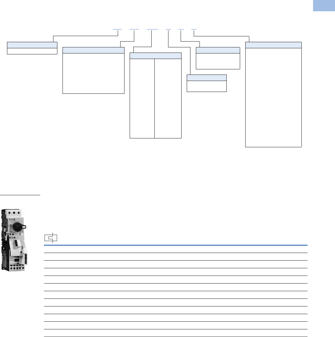
Volume 5—Motor Control and Protection CA08100006E—August 2012 www.eaton.com V5-T1-195
1
1
1
1
1
1
1
1
1
1
1
1
1
1
1
1
1
1
1
1
1
1
1
1
1
1
1
1
1
1
1.1
IEC Contactors and Starters
XT
IEC Power Control
Catalog Number Selection
Combination Motor Controllers
Product Selection
XTSC and XTSR Manual Motor Controllers (MMC)/Starter Combinations
Factory-Assembled Manual Motor Controller—Frame B MMP + Frame B Contactor—
Maximum UL Ratings 1
Notes
1 Select manual motor controllers by full load amperes. Maximum motor ratings (kW, hp) are for reference only.
2 Underscore (_) indicates magnetic coil suffix required. See Page V5-T1-198.
3 In this range, calculate motor rating according to rated current. Specified values to NEC 430.6(A)(1).
FLA Adjustment
Range/Overload
Release—Ir
(Amps) Short-Circuit
Release—
Irm (Amps)
Assembled Manual Motor Controller 2
Three-Phase
200V 240V 480V 600V
Non-Reversing
Catalog Number
Reversing
Catalog Number
0.1–0.16 3.2 33
1/2 1/2
XTSCP16BB_ XTSRP16BB_
0.16–0.25 3.5 33
1/2 1/2
XTSCP25BB_ XTSRP25BB_
0.25–0.4 5.6 33
1/2 1/2
XTSCP40BB_ XTSRP40BB_
0.4–0.63 8.82 33
1/2 1/2
XTSCP63BB_ XTSRP63BB_
0.63–1 14 331/2 1/2 XTSC001BB_ XTSR001BB_
1–1.6 22.4 333/4 1 XTSC1P6BB_ XTSR1P6BB_
1.6–2.5 35 1/2 1/2 1 1-1/2 XTSC2P5BB_ XTSR2P5BB_
2.5–4 56 1123XTSC004BB_ XTSR004BB_
4–6.3 88.2
1-1/2 1-1/2 3 5
XTSC6P3BB_ XTSR6P3BB_
6.3–10 140
337-1/23
XTSC010BB_ XTSR010BB_
8–12 168
337-1/23
XTSC012BB_ XTSR012BB_
10–16 224
33103
XTSC016BB_ —
XT SC 012 BBA
Type
SC = Manual motor controller—
FVNR
SR = Manual motor controller—
FVR
FC =
Combination motor controller,
UL 508 Type F—FVNR
FR =
Combination motor controller,
UL 508 Type F—FVR
Designation
XT = XT IEC power control
Coil Voltage
A= 110V 50 Hz, 120V 60 Hz
B= 220V 50 Hz, 240V 60 Hz
C= 415V 50 Hz, 480V 60 Hz
D= 550V 50 Hz, 600V 60 Hz
E= 208V 50 Hz
F= 230V 50 Hz
G= 190V 50 Hz, 220V 60 Hz
H= 240V 50 Hz, 277V 60 Hz
L= 380V 50 Hz, 440V 60 Hz
N= 400V 50 Hz
P= 380V 60 Hz
R= 12V 50/60 Hz
T= 24V 50/60 Hz
W= 42V 50 Hz, 48V 60 Hz
Y= 48V 50 Hz
AD = 120 Vdc
BD = 220 Vdc
RD =12 Vdc
TD =24 Vdc
WD =48 Vdc
Frame Size—Contactor
B = 45 mm, 7 to 15A
C = 45 mm, 18 to 32A
D = 55 mm, 40 to 65A
Rated Current of MMP
Frame B
P16 = 0.16A
P25 = 0.25A
P40 = 0.40A
P63 = 0.63A
001 = 1A
1P6 = 1.6A
2P5 = 2.5A
004 = 4A
6P3 = 6.3A
010 = 10A
012 = 12A
016 = 16A
020 = 20A
025 = 25A
032 = 32A
Frame D
016 = 16A
025 = 25A
032 = 32A
040 = 40A
050 = 50A
058 = 58A
063 = 63A
Frame Size—MMP
B = 45 mm, 0.1 to 32A
D = 55 mm, 16 to 63A
Frame B MMP +
Frame B Contactor
Courtesy of CMA/Flodyne/Hydradyne ▪ Motion Control ▪ Hydraulic ▪ Pneumatic ▪ Electrical ▪ Mechanical ▪ (800) 426-5480 ▪ www.cmafh.com
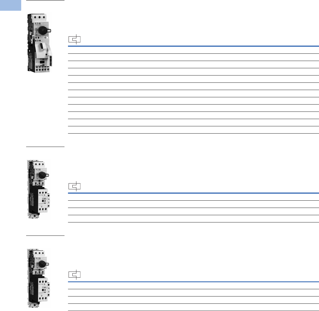
V5-T1-196 Volume 5—Motor Control and Protection CA08100006E—August 2012 www.eaton.com
1
1
1
1
1
1
1
1
1
1
1
1
1
1
1
1
1
1
1
1
1
1
1
1
1
1
1
1
1
1
1.1
IEC Contactors and Starters
XT
IEC Power Control
Factory-Assembled Motor Protective Device with Thermal and Magnetic Trip + Contactor—
Maximum IEC Ratings1
Factory-Assembled Manual Motor Controller—Frame B MMP + Frame C Contactor—
Maximum UL Ratings 1
Factory-Assembled Manual Motor Controller—Frame B MMP + Frame C Contactor—
Maximum IEC RatingS 1
Notes
1 Select manual motor controllers by full load amperes. Maximum motor ratings (kW, hp) are for reference only.
2 Underscore (_) indicates magnetic coil suffix required. See Page V5-T1-198.
FLA Adjustment
Range/Overload
Release—Ir
(Amps)
Short-Circuit
Release—
Irm (Amps)
Three-Phase Assembled Manual Motor Controller 2
220–
240V
380–
415V 500V
660–
690V
Non-Reversing
Catalog Number
Reversing
Catalog Number
0.1–0.16 3.2 ———0.06XTSCP16BB_ XTSRP16BB_
0.16–0.25 3.5 — 0.06 0.06 0.12 XTSCP25BB_ XTSRP25BB_
0.25–0.4 5.6 0.06 0.09 0.12 0.18 XTSCP40BB_ XTSRP40BB_
0.4–0.63 8.82 0.09 0.18 0.25 0.25 XTSCP63BB_ XTSRP63BB_
0.63–1 14 0.120.250.370.55XTSC001BB_ XTSR001BB_
1–1.6 22.4 0.250.550.751.1 XTSC1P6BB_ XTSR1P6BB_
1.6–2.5 35 0.37 0.75 1.1 1.5 XTSC2P5BB_ XTSR2P5BB_
2.5–4 56 0.75 1.5 2.2 3 XTSC004BB_ XTSR004BB_
4–6.3 88.2 1.1 2.2 3 4 XTSC6P3BB_ XTSR6P3BB_
6.3–10 140 2.2 4 4 7.5 XTSC010BB_ XTSR010BB_
8–12 168 3 5.5 5.5 11 XTSC012BB_ XTSR012BB_
10–16 224 47.5912.5XTSC016BB_ —
FLA Adjustment
Range/Overload
Release—Ir
(Amps)
Short-Circuit
Release—
Irm (Amps)
Assembled Manual Motor Controller 2
Three-Phase Non-Reversing
Catalog Number
Reversing
Catalog Number200V 240V 480V 600V
10–16 224 331010XTSC016BC_ XTSR016BC_
16–20 280 551015XTSC020BC_ XTSR020BC_
20–25 350 5 7-1/2 15 20 XTSC025BC_ XTSR025BC_
25–32 448 7-1/2 10 20 25 XTSC032BC_ XTSR032BC_
FLA Adjustment
Range/Overload
Release—Ir
(Amps)
Short-Circuit
Release—
Irm (Amps)
Three-Phase Assembled Manual Motor Controller 2
220–
240V
380–
415V 500V
660–
690V
Non-Reversing
Catalog Number
Reversing
Catalog Number
10–16 224 47.5912.5XTSC016BC_ XTSR016BC_
16–20 280 5.5 9 12.5 15 XTSC020BC_ XTSR020BC_
20–25 350 5.5 11 15 22 XTSC025BC_ XTSR025BC_
25–32 448 7.5 15 22 30 XTSC032BC_ XTSR032BC_
Frame B MMP +
Frame B Contactor
Frame B MMP +
Frame C Contactor
Frame B MMP +
Frame C Contactor
Courtesy of CMA/Flodyne/Hydradyne ▪ Motion Control ▪ Hydraulic ▪ Pneumatic ▪ Electrical ▪ Mechanical ▪ (800) 426-5480 ▪ www.cmafh.com

Volume 5—Motor Control and Protection CA08100006E—August 2012 www.eaton.com V5-T1-197
1
1
1
1
1
1
1
1
1
1
1
1
1
1
1
1
1
1
1
1
1
1
1
1
1
1
1
1
1
1
1.1
IEC Contactors and Starters
XT
IEC Power Control
Factory-Assembled Manual Motor Controller—Frame D MMP + Frame C Contactor—
Maximum UL Ratings 1
Factory-Assembled Manual Motor Controller—Frame D MMP + Frame C Contactor—
Maximum IEC Ratings 1
Factory-Assembled Manual Motor Controller—Frame D MMP + Frame D Contactor—
Maximum UL Ratings 1
Notes
1 Select manual motor controllers by full load amperes. Maximum motor ratings (kW, hp) are for reference only.
2 Underscore (_) indicates magnetic coil suffix required. See Page V5-T1-198.
FLA Adjustment
Range/Overload
Release—Ir
(Amps)
Short-Circuit
Release—
Irm (Amps)
Assembled Manual Motor Controller 2
Three-Phase Non-Reversing
Catalog Number
Reversing
Catalog Number200V 240V 480V 600V
10–16 224 351015XTSC016DC_ XTSR016DC_
16–25 350 5 7-1/2 15 20 XTSC025DC_ XTSR025DC_
25–32 448 7-1/2 10 25 30 XTSC032DC_ XTSR032DC_
FLA Adjustment
Range/Overload
Release—Ir
(Amps)
Short-Circuit
Release—
Irm (Amps)
Three-Phase Assembled Manual Motor Controller 2
220–
240V
380–
415V 500V
660–
690V
Non-Reversing
Catalog Number
Reversing
Catalog Number
10–16 224 47.5912.5XTSC016DC_ XTSR016DC_
16–25 350 5.5 12.5 12.5 22 XTSC025DC_ XTSR025DC_
25–32 448 7.5 15 17.5 22 XTSC032DC_ XTSR032DC_
FLA Adjustment
Range/Overload
Release—Ir
(Amps)
Short-Circuit
Release—
Irm (Amps)
Assembled Manual Motor Controller 2
Three-Phase Non-Reversing
Catalog Number
Reversing
Catalog Number200V 240V 480V 600V
32–40 560
10 15 30 30
XTSC040DD_ XTSR040DD_
40–50 700
15 15 30 —
XTSC050DD_ XTSR050DD_
50–58 812
15 15 40 —
XTSC058DD_ XTSR058DD_
55–65 882
15 15 40 —
XTSC063DD_ XTSR063DD_
Frame D MMP +
Frame C Contactor
Frame D MMP +
Frame C Contactor
Frame D MMP +
Frame D Contactor
Courtesy of CMA/Flodyne/Hydradyne ▪ Motion Control ▪ Hydraulic ▪ Pneumatic ▪ Electrical ▪ Mechanical ▪ (800) 426-5480 ▪ www.cmafh.com

V5-T1-198 Volume 5—Motor Control and Protection CA08100006E—August 2012 www.eaton.com
1
1
1
1
1
1
1
1
1
1
1
1
1
1
1
1
1
1
1
1
1
1
1
1
1
1
1
1
1
1
1.1
IEC Contactors and Starters
XT
IEC Power Control
Factory-Assembled Manual Motor Controller—Frame D MMP + Frame D Contactor—
Maximum IEC Ratings 1
AC and DC Coil Suffixes
Notes
The assembled manual motor controller (MMC) consists of an XTPR manual motor protector (MMP) and an XTCE contactor. For Frame B MMP +
Frame B contactor assemblies, the XTSC and XTSR can be mounted directly on DIN rail without an adapter. The contactors are supported
mechanically with a mechanical connection element (included in XTPAXTPCB, XTPAXRPCRB). For MMCs using a Frame C or Frame D contactor,
the assembly is mounted via a DIN rail adapter plate (XTPAXTPCPC, XTPAXTPCPD) and the electrical connection is made with electrical contact modules
(XTPAXECMC, XTPAXECMD), both included in XTPAXTPCC and XTPAXTPCD.
Service Factor (SF)—Setting Ir of current scale in dependence of load factor:
SF = 1.15 → Ir = 1 x In mot
SF = 1 → Ir = 0.9 x In mot
Single-phasing sensitivity to IEC/EN 60947-4-1, VDE 0660 Part 102.
1Select manual motor controllers by full load amperes. Maximum motor ratings (kW, hp) are for reference only.
2Underscore (_) indicates magnetic coil suffix required. See AC and DC coil suffixes above.
3With DC operation: Integrated diode-resistor combination, coil rating 2.6W.
Non-Reversing Manual
Motor Controller Power
Circuit
Reversing Manual
Motor Controller Power
Circuit
FLA Adjustment
Range/Overload
Release—Ir
(Amps)
Short-Circuit
Release—
Irm (Amps)
Three-Phase Assembled Manual Motor Controller 2
220–
240V
380–
415V 500V
660–
690V
Non-Reversing
Catalog Number
Reversing
Catalog Number
32–40 560 11 20 22 30 XTSC040DD_ XTSR040DD_
40–50 700 14 25 30 45 XTSC050DD_ XTSR050DD_
50–58 812 17 30 37 55 XTSC058DD_ XTSR058DD_
55–65 882 18.5 34 37 55 XTSC063DD_ XTSR063DD_
Frame D MMP +
Frame D Contactor
Coil Voltage Suffix Code
Frame B Contactors
110V 50 Hz, 120V 60 Hz A
220V 50 Hz, 240V 60 Hz B
230V 50 Hz F
24V 50/60 Hz T
24 Vdc TD 3
415V 50 Hz, 480V 60 Hz C
550V 50 Hz, 600V 60 Hz D
208V 60 Hz E
190V 50 Hz, 220V 60 Hz G
240V 50 Hz, 277V 60 Hz H
Coil Voltage Suffix Code
380V 50 Hz, 440V 60 Hz L
400V 50 Hz N
380V 60 Hz P
12V 50/60 Hz R
42V 50 Hz, 48V 60 Hz W
48V 50 Hz Y
120 Vdc AD 3
220 Vdc BD 3
12 Vdc RD 3
48 Vdc WD 3
Coil Voltage Suffix Code
Frame C and D Contactors
110V 50 Hz, 120V 60 Hz A
220V 50 Hz, 240V 60 Hz B
230V 50 Hz F
24V 50/60 Hz T
24–27 Vdc TD 3
415V 50 Hz, 480V 60 Hz C
550V 50 Hz, 600V 60 Hz D
208V 60 Hz E
190V 50 Hz, 220V 60 Hz G
240V 50 Hz, 277V 60 Hz H
Coil Voltage Suffix Code
380V 50 Hz, 440V 60 Hz L
400V 50 Hz N
380V 60 Hz P
12V 50/60 Hz R
42V 50 Hz, 48V 60 Hz W
48V 50 Hz Y
110–130 Vdc AD 3
200–240 Vdc BD 3
12–14 Vdc RD 3
48–60 Vdc WD 3
M
3 ~
M
3 ~
Courtesy of CMA/Flodyne/Hydradyne ▪ Motion Control ▪ Hydraulic ▪ Pneumatic ▪ Electrical ▪ Mechanical ▪ (800) 426-5480 ▪ www.cmafh.com
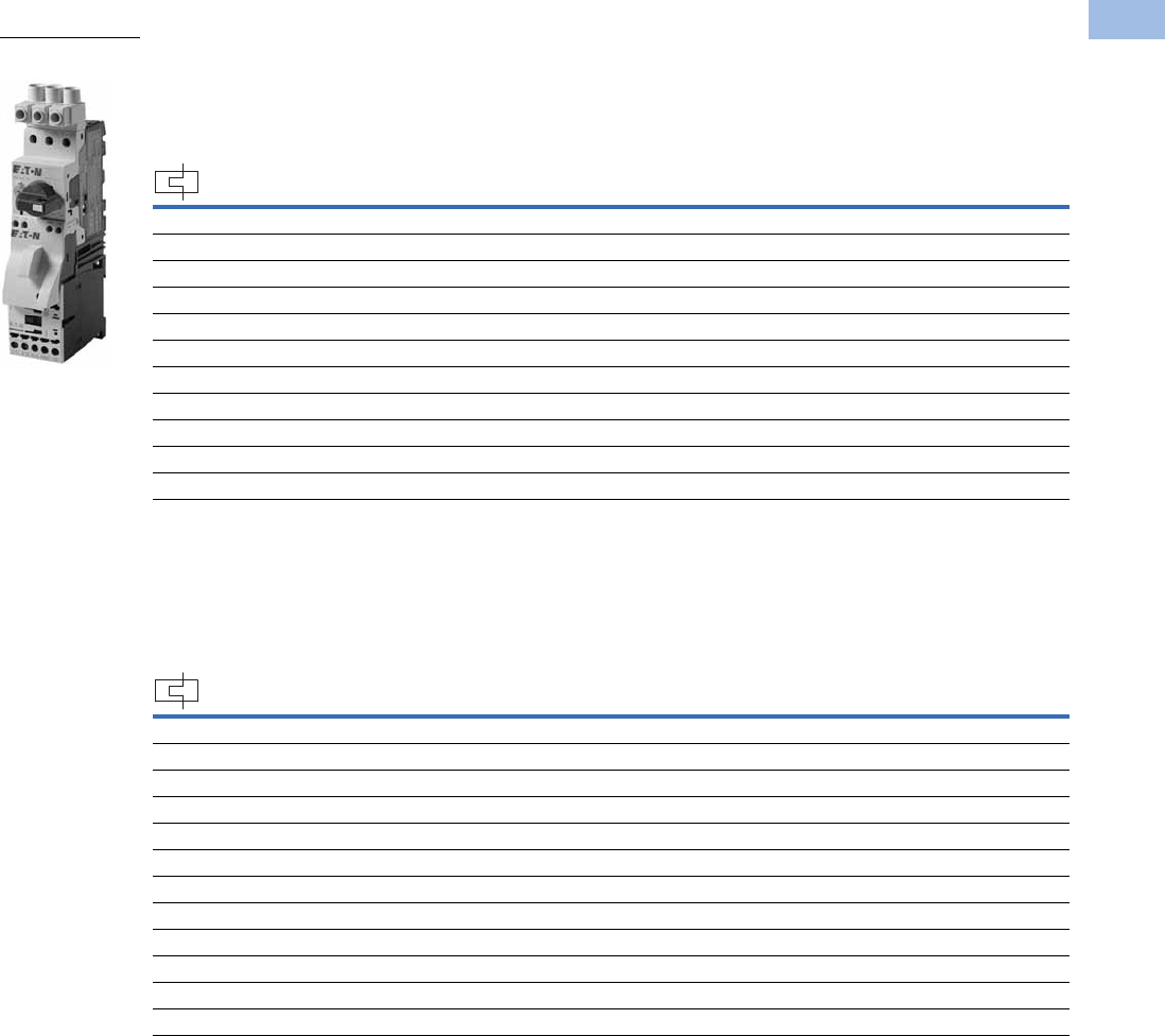
Volume 5—Motor Control and Protection CA08100006E—August 2012 www.eaton.com V5-T1-199
1
1
1
1
1
1
1
1
1
1
1
1
1
1
1
1
1
1
1
1
1
1
1
1
1
1
1
1
1
1
1.1
IEC Contactors and Starters
XT
IEC Power Control
XTFC and XTFR Combination Motor Controllers (CMC), UL 508 Type F
Factory-Assembled Type F Combination Motor Controller—Frame B MMP + Frame B Contactor—
Maximum UL Ratings 1
Factory-Assembled Type F Combination Motor Controller—Frame B MMP + Frame B Contactor—
Maximum IEC Ratings 1
Notes
1 Select combination motor controllers by full load amperes. Maximum motor ratings (kW, hp) are for reference only.
2 Underscore (_) indicates magnetic coil suffix required. See Page V5-T1-202.
3 In this range, calculate motor rating according to rated current. Specified values to NEC 430.6(A)(1).
FLA Adjustment
Range/Overload
Release—Ir
(Amps)
Short-Circuit
Release—
Irm (Amps)
Assembled Manual Motor Controller 2
Three-Phase Non-Reversing
Catalog Number
Reversing
Catalog Number200V 240V 480V 600V
0.16–0.25 3.5 33 1/2 1/2 XTFCP25BB_ XTFRP25BB_
0.25–0.4 5.6 33 1/2 1/2 XTFCP40BB_ XTFRP40BB_
0.4–0.63 8.82 33 1/2 1/2 XTFCP63BB_ XTFRP63BB_
0.63–1 14 33 1/2 1/2 XTFC001BB_ XTFR001BB_
1–1.6 22.4 33 3/4 1 XTFC1P6BB_ XTFR1P6BB_
1.6–2.5 35 1/2 1/2 1 1-1/2 XTFC2P5BB_ XTFR2P5BB_
2.5–4 56 1123XTFC004BB_ XTFR004BB_
4–6.3 88.2 1-1/2 1-1/2 3 5 XTFC6P3BB_ XTFR6P3BB_
6.3–10 140 3 3 7-1/2 10 XTFC010BB_ XTFR010BB_
8–12 168 3 3 7-1/2 — XTFC012BB_ XTFR012BB_
10–16 224 3510—XTFC016BB_ —
FLA Adjustment
Range/Overload
Release—Ir
(Amps)
Short-Circuit
Release—
Irm (Amps)
Three-Phase Assembled Manual Motor Controller 2
220–
240V
380–
415V 500V
660–
690V
Non-Reversing
Catalog Number
Reversing
Catalog Number
0.1–0.16 2.2 ———0.06XTFCP16BB_ XTFRP16BB_
0.16–0.25 3.5 — 0.06 0.06 0.12 XTFCP25BB_ XTFRP25BB_
0.25–0.4 5.6 0.06 0.09 0.12 0.18 XTFCP40BB_ XTFRP40BB_
0.4–0.63 8.82 0.09 0.18 0.25 0.25 XTFCP63BB_ XTFRP63BB_
0.63–1 14 0.12 0.25 0.37 0.55 XTFC001BB_ XTFR001BB_
1–1.6 22.4 0.25 0.55 0.75 1.1 XTFC1P6BB_ XTFR1P6BB_
1.6–2.5 35 0.37 0.75 1.1 1.5 XTFC2P5BB_ XTFR2P5BB_
2.5–4 56 0.75 1.5 2.2 3 XTFC004BB_ XTFR004BB_
4–6.3 88.2 1.1 2.2 3 4 XTFC6P3BB_ XTFR6P3BB_
6.3–10 140 2.2 4 4 7.5 XTFC010BB_ XTFR010BB_
8–12 168 3 5.5 5.5 11 XTFC012BB_ XTFR012BB_
10–16 224 47.5912.5XTFC016BB_ —
Frame B MMP + Two
Frame B Contactors
Courtesy of CMA/Flodyne/Hydradyne ▪ Motion Control ▪ Hydraulic ▪ Pneumatic ▪ Electrical ▪ Mechanical ▪ (800) 426-5480 ▪ www.cmafh.com

V5-T1-200 Volume 5—Motor Control and Protection CA08100006E—August 2012 www.eaton.com
1
1
1
1
1
1
1
1
1
1
1
1
1
1
1
1
1
1
1
1
1
1
1
1
1
1
1
1
1
1
1.1
IEC Contactors and Starters
XT
IEC Power Control
Factory-Assembled Type F Combination Motor Controller—Frame B MMP + Frame C Contactor—
Maximum UL Ratings 1
Factory-Assembled Type F Combination Motor Controller—Frame B MMP + Frame C Contactor—
Maximum IEC Ratings 1
Notes
1 Select combination motor controllers by full load amperes. Maximum motor ratings (kW, hp) are for reference only.
2 Underscore (_) indicates magnetic coil suffix required. See Page V5-T1-202.
FLA Adjustment
Range/Overload
Release—Ir
(Amps)
Short-Circuit
Release—
Irm (Amps)
Assembled Manual Motor Controller 2
Three-Phase Non-Reversing
Catalog Number
Reversing
Catalog Number200V 240V 480V 600V
10–16 224 3510—XTFC016BC_ XTFR016BC_
16–20 280 55——XTFC020BC_ XTFR020BC_
20–25 350 5 7-1/2 15 — XTFC025BC_ XTFR025BC_
25–32 448 7-1/2 10 20 — XTFC032BC_ XTFR032BC_
FLA Adjustment
Range/Overload
Release—Ir
(Amps)
Short-Circuit
Release—
Irm (Amps)
Three-Phase Assembled Manual Motor Controller 2
220–
240V
380–
415V 500V
660–
690V
Non-Reversing
Catalog Number
Reversing
Catalog Number
10–16 224 47.5912.5XTFC016BC_ XTFR016BC_
16–20 280 5.5 9 12.5 15 XTFC020BC_ XTFR020BC_
20–25 350 5.5 11 15 22 XTFC025BC_ XTFR025BC_
25–32 448 7.5 15 22 30 XTFC032BC_ XTFR032BC_
Courtesy of CMA/Flodyne/Hydradyne ▪ Motion Control ▪ Hydraulic ▪ Pneumatic ▪ Electrical ▪ Mechanical ▪ (800) 426-5480 ▪ www.cmafh.com

Volume 5—Motor Control and Protection CA08100006E—August 2012 www.eaton.com V5-T1-201
1
1
1
1
1
1
1
1
1
1
1
1
1
1
1
1
1
1
1
1
1
1
1
1
1
1
1
1
1
1
1.1
IEC Contactors and Starters
XT
IEC Power Control
Factory-Assembled Type F Combination Motor Controller—Frame D MMP + Frame C Contactor—
Maximum UL Ratings 1
Factory-Assembled Type F Combination Motor Controller—Frame D MMP + Frame C Contactor—
Maximum IEC Ratings 1
Factory-Assembled Type F Combination Motor Controller—Frame D MMP + Frame D Contactor—
Maximum UL Ratings 1
Notes
1 Select combination motor controllers by full load amperes. Maximum motor ratings (kW, hp) are for reference only.
2 Underscore (_) indicates magnetic coil suffix required. See Page V5-T1-202.
FLA Adjustment
Range/Overload
Release—Ir
(Amps)
Short-Circuit
Release—
Irm (Amps)
Assembled Manual Motor Controller 2
Three-Phase Non-Reversing
Catalog Number
Reversing
Catalog Number200V 240V 480V 600V
10–16 224 351010XTFC016DC_ XTFR016DC_
16–25 350 5 7-1/2 15 20 XTFC025DC_ XTFR025DC_
25–32 448 7-1/2 10 25 30 XTFC032DC_ XTFR032DC_
FLA Adjustment
Range/Overload
Release—Ir
(Amps)
Short-Circuit
Release—
Irm (Amps)
Three-Phase Assembled Manual Motor Controller 2
220–
240V
380–
415V 500V
660–
690V
Non-Reversing
Catalog Number
Reversing
Catalog Number
10–16 224 47.5912.5XTFC016DC_ XTFR016DC_
16–25 350 5.5 12.5 12.5 22 XTFC025DC_ XTFR025DC_
25–32 448 7.5 15 17.5 22 XTFC032DC_ XTFR032DC_
FLA Adjustment
Range/Overload
Release—Ir
(Amps)
Short-Circuit
Release—
Irm (Amps)
Assembled Manual Motor Controller 2
Three-Phase Non-Reversing
Catalog Number
Reversing
Catalog Number200V 240V 480V 600V
32–40 560 10 15 30 30 XTFC040DD_ XTFR040DD_
40–50 700 10 15 30 — XTFC050DD_ XTFR050DD_
50–58 812 15 15 40 — XTFC058DD_ XTFR058DD_
55–65 882 15 15 40 — XTFC063DD_ XTFR063DD_
Courtesy of CMA/Flodyne/Hydradyne ▪ Motion Control ▪ Hydraulic ▪ Pneumatic ▪ Electrical ▪ Mechanical ▪ (800) 426-5480 ▪ www.cmafh.com

V5-T1-202 Volume 5—Motor Control and Protection CA08100006E—August 2012 www.eaton.com
1
1
1
1
1
1
1
1
1
1
1
1
1
1
1
1
1
1
1
1
1
1
1
1
1
1
1
1
1
1
1.1
IEC Contactors and Starters
XT
IEC Power Control
Factory-Assembled Type F Combination Motor Controller—Frame D MMP + Frame D Contactor—
Maximum IEC Ratings 1
AC and DC Coil Suffixes
Notes
The assembled manual motor controller (MMC) consists of an XTPR manual motor protector (MMP) and an XTCE contactor. For Frame B MMP +
Frame B contactor assemblies, the XTSC and XTSR can be mounted directly on DIN rail without an adapter. The contactors are supported
mechanically with a mechanical connection element (included in XTPAXTPCB, XTPAXRPCRB). For 16A and above, the assembly is mounted via a
DIN rail adapter plate (XTPAXTPCPC, XTPAXTPCPD) and the electrical connection is made with electrical contact modules (XTPAXECMC,
XTPAXECMD), both included in XTPAXTPCC and XTPAXTPCD.
Service Factor (SF)—Setting Ir of current scale in dependence of load factor:
SF = 1.15 → Ir = 1 x In mot
SF = 1 → Ir = 0.9 x In mot
Single-phasing sensitivity to IEC/EN 60947-4-1, VDE 0660 Part 102.
1Select combination motor controllers by full load amperes. Maximum motor ratings (kW, hp) are for reference only.
2Underscore (_) indicates magnetic coil suffix required. See AC and DC coil suffixes above.
3With DC operation: Integrated diode-resistor combination, coil rating 2.6W.
XTFC Manual Motor
Controller
XTFR Manual Motor
Controller
FLA Adjustment
Range/Overload
Release—Ir
(Amps)
Short-Circuit
Release—
Irm (Amps)
Three-Phase Assembled Manual Motor Controller 2
220–
240V
380–
415V 500V
660–
690V
Non-Reversing
Catalog Number
Reversing
Catalog Number
32–40 560 11 20 22 30 XTFC040DD_ XTFR040DD_
40–50 700 14 25 30 45 XTFC050DD_ XTFR050DD_
50–58 812 17 30 37 55 XTFC058DD_ XTFR058DD_
55–65 882 18.5 34 37 55 XTFC063DD_ XTFR063DD_
Coil Voltage Suffix Code
Frame B Contactors
110V 50 Hz, 120V 60 Hz A
220V 50 Hz, 240V 60 Hz B
230V 50 Hz F
24V 50/60 Hz T
24 Vdc TD 3
415V 50 Hz, 480V 60 Hz C
550V 50 Hz, 600V 60 Hz D
208V 60 Hz E
190V 50 Hz, 220V 60 Hz G
240V 50 Hz, 277V 60 Hz H
Coil Voltage Suffix Code
380V 50 Hz, 440V 60 Hz L
400V 50 Hz N
380V 60 Hz P
12V 50/60 Hz R
42V 50 Hz, 48V 60 Hz W
48V 50 Hz Y
120 Vdc AD 3
220 Vdc BD 3
12 Vdc RD 3
48 Vdc WD 3
Coil Voltage Suffix Code
Frame C and D Contactors
110V 50 Hz, 120V 60 Hz A
220V 50 Hz, 240V 60 Hz B
230V 50 Hz F
24V 50/60 Hz T
24–27 Vdc TD 3
415V 50 Hz, 480V 60 Hz C
550V 50 Hz, 600V 60 Hz D
208V 60 Hz E
190V 50 Hz, 220V 60 Hz G
240V 50 Hz, 277V 60 Hz H
Coil Voltage Suffix Code
380V 50 Hz, 440V 60 Hz L
400V 50 Hz N
380V 60 Hz P
12V 50/60 Hz R
42V 50 Hz, 48V 60 Hz W
48V 50 Hz Y
110–130 Vdc AD 3
200–240 Vdc BD 3
12–14 Vdc RD 3
48–60 Vdc WD 3
M
3 ~
M
3 ~
Courtesy of CMA/Flodyne/Hydradyne ▪ Motion Control ▪ Hydraulic ▪ Pneumatic ▪ Electrical ▪ Mechanical ▪ (800) 426-5480 ▪ www.cmafh.com
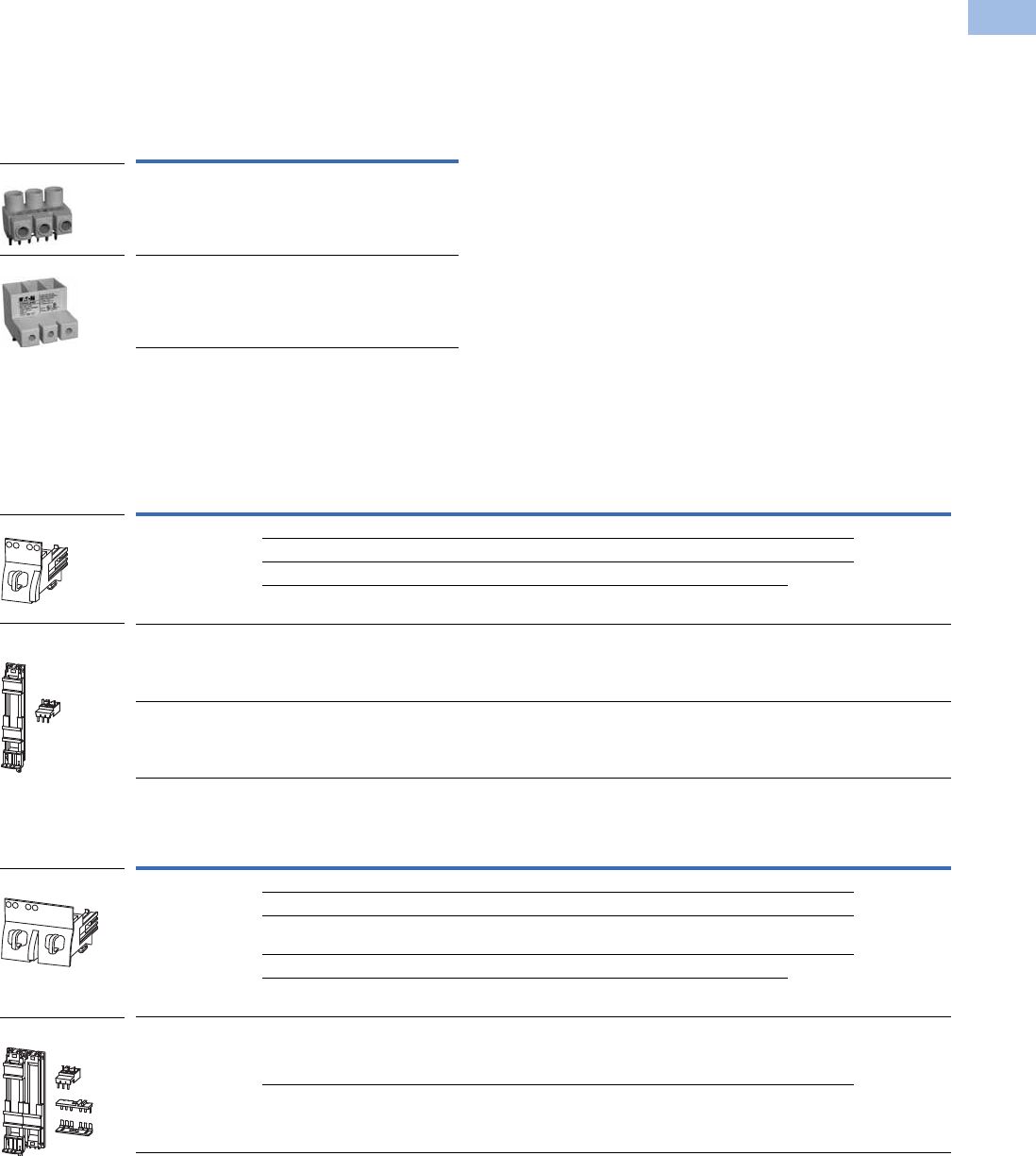
Volume 5—Motor Control and Protection CA08100006E—August 2012 www.eaton.com V5-T1-203
1
1
1
1
1
1
1
1
1
1
1
1
1
1
1
1
1
1
1
1
1
1
1
1
1
1
1
1
1
1
1.1
IEC Contactors and Starters
XT
IEC Power Control
Accessories
Line Side Adapters
Line side adapters are required for use with XTPR MMPs only when used as Type E
self-protected
manual combination starters or as part of XTFC or XTFR Type F combination motor controllers.
Not required for group installation.
Line Side Adapters
Combination Connection Kits
Combination connection kits include the necessary components to field assemble a manual motor
controller with an MMP (XTPR) and contactor (XTCE).
Non-Reversing Starters
Reversing Starters
Note
1 Orders must be placed in multiples of package quantity listed.
Description Catalog Number
For use with Frame B MMPs (up to 32A) XTPAXLSA
For use with Frame D MMPs (up to 40A) XTPAXLSAD
For Use with … Description/Composed of …
Std.
Pack 1Catalog Number
XTPR
…
B + XTCE
…
B Mechanical connection element for XTPR…B and contactor 1 XTPAXTPCB
Main current wiring between XTPR…B and contactor in toolless plug connection 1
Cable guidance 1
Use as contactor auxiliary switch XTCEXFAT_. Control cable guidance: max. six cables up to 2.5 mm2
external diameter or four cables up to 3.5 mm2 external diameter
XTPR
…
B + XTCE
…
C DIN rail adapter plate 1XTPAXTPCC
XTPR
…
D + XTCE
…
D Main current wiring between XTPR and contactor 1 XTPAXTPCD
For Use with … Description/Composed of …
Std.
Pack 1Catalog Number
XTPR
…
B + XTCE
…
B01_ Mechanical connection element for XTPR
…
B and contactor 1 XTPAXTPCRB
Reversing starter main current wiring in toolless plug connection 1
Control cables for electrical interlocking in toolless plug connection—
K1M: A1–K2M: 21, K1M: 21–K2M: A1, K1M: A2–K2M: A2
1
Cable guidance 1
Use as contactor auxiliary switch XTCEXFAT_. Control cable guidance: max. six cables up to 2.5 mm2
external diameter or four cables up to 3.5 mm2 external diameter.
XTPR
…
B + XTCE
…
C DIN rail adapter plate 1XTPAXTPCRB
Reversing starter main current wiring 1
XTPAXLSA
XTPAXLSA
XTPAXTPCB
XTPAXTPCC and
XTPAXTPCD
XTPAXTPCRB
XTPAXTPCRC
Courtesy of CMA/Flodyne/Hydradyne ▪ Motion Control ▪ Hydraulic ▪ Pneumatic ▪ Electrical ▪ Mechanical ▪ (800) 426-5480 ▪ www.cmafh.com

V5-T1-204 Volume 5—Motor Control and Protection CA08100006E—August 2012 www.eaton.com
1
1
1
1
1
1
1
1
1
1
1
1
1
1
1
1
1
1
1
1
1
1
1
1
1
1
1
1
1
1
1.1
IEC Contactors and Starters
XT
IEC Power Control
Electric Contact Module
DIN Rail Adapter Plates
Lateral Module
Connection Element
Note
1 Orders must be placed in multiples of package quantity listed.
For Use with … Description/Composed of …
Std.
Pack 1Catalog Number
XTPR
…
B + XTCE
…
C Main current wiring between XTPR
…
B and contactor 5 XTPAXECMC
Use only in combination with busbar adapter
XTPR
…
D + XTCE
…
D Main current wiring between XTPR
…
D and contactor 5 XTPAXECMD
Use only in combination with busbar adapter
For Use with … Description/Composed of …
Std.
Pack 1Catalog Number
XTPAXTPCB
XTPAXTPCRB
45 mm wide adapter plate with one DIN rail 4 XTPAXTPCPB
Connection element for side-by-side positioning of further plates
XTPR
…
B + XTCE
…
C
XTPAXECMC
45 mm wide adapter plate with one DIN rail 4 XTPAXTPCRPB
Connection element for side-by-side positioning of further plates
XTPAXECMD
XTPR
…
D + XTCE
…
C
XTPR
…
D + XTCE
…
D
55 mm wide adapter plate with two DIN rails 4 XTPAXTPCPD
Connection cams for further plates 4
For use with reversing and star-delta starters
For Use with … Description/Composed of …
Std.
Pack 1Catalog Number
— Can be grouped on the DIN rail adapter 10 XTPAXLM
Expansion of the mounting width by 9 mm
For Use with … Description/Composed of …
Std.
Pack 1Catalog Number
— For connection of several DIN rail adapters 50 XTPAXCNE
XTPAXEC_
XTPAXTPCPB
XTPAXTPCRPB
XTPAXTPCPD
Courtesy of CMA/Flodyne/Hydradyne ▪ Motion Control ▪ Hydraulic ▪ Pneumatic ▪ Electrical ▪ Mechanical ▪ (800) 426-5480 ▪ www.cmafh.com

Volume 5—Motor Control and Protection CA08100006E—August 2012 www.eaton.com V5-T1-205
1
1
1
1
1
1
1
1
1
1
1
1
1
1
1
1
1
1
1
1
1
1
1
1
1
1
1
1
1
1
1.1
IEC Contactors and Starters
XT
IEC Power Control
Technical Data and Specifications
XTSC Non-Reversing Manual Motor Controllers (MMC)—Component Bill of Material
Notes
1Underscore (_) indicates magnetic coil suffix required. See Page V5-T1-202.
2The connection between the XTPR…DC1 and the XTCE…C
_
contactor will be made with flexible wire and mounted to the DIN rail adapter plate (XTPAXTPCPD).
3The reversing connection between the XTPR…DC1 and the (2) XTCE…C_ contactors will be accomplished by using the non-reversing combination connection kit (XTPAXTPCD),
Frame D reversing link kit (XTCEXRLD), additional DIN rail adapter plate (XTPAXTPCPD) and DIN adapter connection element (XTPAXCNE).
Factory Assembled Manual Motor Protector + Contactor
Assembled Manual
Motor Controller 1
FLA Adjustment
Range/Overload
Release—Ir (Amps)
Component Catalog Numbers
Manual Motor
Protector
Combination
Connection Kit Contactor 1
Manual Motor Protector
Auxiliary Contact
XTSC Frame B MMP + Frame B Contactor
XTSCP16BB_ 0.1–0.16 XTPRP16BC1 XTPAXTPCB XTCE007B10_ XTPAXFA11
XTSCP25BB_ 0.16–0.25 XTPRP25BC1 XTPAXTPCB XTCE007B10_ XTPAXFA11
XTSCP40BB_ 0.25–0.4 XTPRP40BC1 XTPAXTPCB XTCE007B10_ XTPAXFA11
XTSCP63BB_ 0.4–0.63 XTPRP63BC1 XTPAXTPCB XTCE007B10_ XTPAXFA11
XTSC001BB_ 0.63–1 XTPR001BC1 XTPAXTPCB XTCE007B10_ XTPAXFA11
XTSC1P6BB_ 1–1.6 XTPR1P6BC1 XTPAXTPCB XTCE007B10_ XTPAXFA11
XTSC2P5BB_ 1.6–2.5 XTPR2P5BC1 XTPAXTPCB XTCE007B10_ XTPAXFA11
XTSC004BB_ 2.5–4 XTPR004BC1 XTPAXTPCB XTCE007B10_ XTPAXFA11
XTSC6P3BB_ 4–6.3 XTPR6P3BC1 XTPAXTPCB XTCE007B10_ XTPAXFA11
XTSC010BB_ 6.3–10 XTPR010BC1 XTPAXTPCB XTCE009B10_ XTPAXFA11
XTSC012BB_ 8–12 XTPR012BC1 XTPAXTPCB XTCE012B10_ XTPAXFA11
XTSC016BB_ 10–16 XTPR016BC1 XTPAXTPCB XTCE015B10_ XTPAXFA11
XTSC Frame B MMP + Frame C Contactor
XTSC016BC_ 10–16 XTPR016BC1 XTPAXTPCC XTCE018C10_ XTPAXFA1
XTSC020BC_ 16–20 XTPR020BC1 XTPAXTPCC XTCE025C10_ XTPAXFA11
XTSC025BC_ 20–25 XTPR025BC1 XTPAXTPCC XTCE025C10_ XTPAXFA11
XTSC032BC_ 25–32 XTPR032BC1 XTPAXTPCC XTCE032C10_ XTPAXFA11
XTSC Frame D MMP + Frame C Contactor
XTSC016DC_ 10–16 XTPR016DC1 2XTCE018C10_ XTPAXFA1
XTSC025DC_ 16–25 XTPR025DC1 2XTCE025C10_ XTPAXFA11
XTSC032DC_ 25–32 XTPR032DC1 2XTCE032C10_ XTPAXFA11
XTSC Frame D MMP + Frame D Contactor
XTSC040DD_ 32–40 XTPR040DC1 XTPAXTPCD 3XTCE040D00_ XTPAXFA11
XTSC050DD_ 40–50 XTPR050DC1 XTPAXTPCD 3XTCE050D00_ XTPAXFA11
XTSC058DD_ 50–58 XTPR058DC1 XTPAXTPCD 3XTCE065D00_ XTPAXFA11
XTSC063DD_ 55–65 XTPR063DC1 XTPAXTPCD 3XTCE065D00_ XTPAXFA11
Courtesy of CMA/Flodyne/Hydradyne ▪ Motion Control ▪ Hydraulic ▪ Pneumatic ▪ Electrical ▪ Mechanical ▪ (800) 426-5480 ▪ www.cmafh.com

V5-T1-206 Volume 5—Motor Control and Protection CA08100006E—August 2012 www.eaton.com
1
1
1
1
1
1
1
1
1
1
1
1
1
1
1
1
1
1
1
1
1
1
1
1
1
1
1
1
1
1
1.1
IEC Contactors and Starters
XT
IEC Power Control
XTSR Reversing Manual Motor Controllers (MMC)—Component Bill of Material
Notes
1Underscore (_) indicates magnetic coil suffix required. See Page V5-T1-202.
2The connection between the XTPR…DC1 and the XTCE…C
_
contactor will be made with flexible wire and mounted to the DIN rail adapter plate (XTPAXTPCPD).
3The reversing connection between the XTPR…DC1 and the (2) XTCE…C_ contactors will be accomplished by using the non-reversing combination connection kit (XTPAXTPCD),
Frame D reversing link kit (XTCEXRLD), additional DIN rail adapter plate (XTPAXTPCPD) and DIN adapter connection element (XTPAXCNE).
Factory Assembled Manual Motor Protector + Contactor
Assembled Manual
Motor Controller 1
FLA Adjustment
Range/Overload
Release—Ir (Amps)
Component Catalog Numbers
Manual Motor
Protector
Combination
Connection Kit Contactor 1
Manual Motor Protector
Auxiliary Contact
XTSR Frame B MMP + Frame B Contactor
XTSRP16BB_ 0.1–0.16 XTPBP16BC1 XTPAXTPCRB (2) XTCE007B01_ XTPAXFA11
XTSRP25BB_ 0.16–0.25 XTPRP25BC1 XTPAXTPCRB (2) XTCE007B01_ XTPAXFA11
XTSRP40BB_ 0.25–0.4 XTPRP40BC1 XTPAXTPCRB (2) XTCE007B01_ XTPAXFA11
XTSRP63BB_ 0.4–0.63 XTPRP63BC1 XTPAXTPCRB (2) XTCE007B01_ XTPAXFA11
XTSR001BB_ 0.63–1 XTPR001BC1 XTPAXTPCRB (2) XTCE007B01_ XTPAXFA11
XTSR1P6BB_ 1–1.6 XTPR1P6BC1 XTPAXTPCRB (2) XTCE007B01_ XTPAXFA11
XTSR2P5BB_ 1.6–2.5 XTPR2P5BC1 XTPAXTPCRB (2) XTCE007B01_ XTPAXFA11
XTSR004BB_ 2.5–4 XTPR004BC1 XTPAXTPCRB (2) XTCE007B01_ XTPAXFA11
XTSR6P3BB_ 4–6.3 XTPR6P3BC1 XTPAXTPCRB (2) XTCE007B01_ XTPAXFA11
XTSR010BB_ 6.3–10 XTPR010BC1 XTPAXTPCRB (2) XTCE009B01_ XTPAXFA11
XTSR012BB_ 8–12 XTPR012BC1 XTPAXTPCRB (2) XTCE012B01_ XTPAXFA11
XTSR Frame B MMP + Frame C Contactor
XTSR016BC_ 10–16 XTPR016BC1 XTPAXTPCR (2) XTCE018C01 XTPAXFA11
XTSR020BC_ 16–20 XTPR020BC1 XTPAXTPCRC (2) XTCE025C01_ XTPAXFA11
XTSR025BC_ 20–25 XTPR025BC1 XTPAXTPCRC (2) XTCE025C01_ XTPAXFA11
XTSR032BC_ 25–32 XTPR032BC1 XTPAXTPCRC (2) XTCE032C01_ XTPAXFA11
XTSR Frame D MMP + Frame C Contactor
XTSR016DC_ 10–16 XTPR016DC 2(2) XTCE018C01 XTPAXFA11
XTSR025DC_ 16–25 XTPR025DC1 2(2) XTCE025C01_ XTPAXFA11
XTSR032DC_ 25–32 XTPR032DC1 2(2) XTCE032C01_ XTPAXFA11
XTSR Frame D MMP + Frame D Contactor
XTSR040DD_ 32–40 XTPR040DC1 3(2) XTCE040D00_ XTPAXFA11
XTSR050DD_ 40–50 XTPR050DC1 3(2) XTCE050D00_ XTPAXFA11
XTSR058DD_ 50–58 XTPR058DC1 3(2) XTCE065D00_ XTPAXFA11
XTSR063DD_ 55–65 XTPR063DC1 3(2) XTCE065D00_ XTPAXFA11
Courtesy of CMA/Flodyne/Hydradyne ▪ Motion Control ▪ Hydraulic ▪ Pneumatic ▪ Electrical ▪ Mechanical ▪ (800) 426-5480 ▪ www.cmafh.com

Volume 5—Motor Control and Protection CA08100006E—August 2012 www.eaton.com V5-T1-207
1
1
1
1
1
1
1
1
1
1
1
1
1
1
1
1
1
1
1
1
1
1
1
1
1
1
1
1
1
1
1.1
IEC Contactors and Starters
XT
IEC Power Control
XTFC Non-Reversing Combination Motor Controllers—Component Bill of Material
Notes
1Underscore (_) indicates magnetic coil suffix required. See Page V5-T1-202.
2The connection between the XTPR…DC1 and the XTCE…C
_
contactor will be made with flexible wire and mounted to the DIN rail adapter plate (XTPAXTPCPD).
3The reversing connection between the XTPR…DC1 and the (2) XTCE…C
_
contactors will be accomplished by using the non-reversing combination connection kit (XTPAXTPCD),
Frame D reversing link kit (XTCEXRLD), additional DIN rail adapter plate (XTPAXTPCPD) and DIN adapter connection element (XTPAXCNE).
Factory Assembled Manual Motor Protector + Contactor + Line Side Adapter
Assembled
Combination
Motor Controller 1
FLA Adjustment Range/
Overload Release—Ir
(Amps)
Component Catalog Numbers
Line Side
Adapter
Manual Motor
Protector
Combination
Connection Kit Contactor 1
Manual Motor Protector
Auxiliary Contact
XTFC Frame B MMP + Frame B Contactor
XTFCP16BB_ 0.1–0.16 XTPAXLSA XTPRP16BC1 XTPAXTPCB XTCE007B10_ XTPAXFA11
XTFCP25BB_ 0.16–0.25 XTPAXLSA XTPRP25BC1 XTPAXTPCB XTCE007B10_ XTPAXFA11
XTFCP40BB_ 0.25–0.4 XTPAXLSA XTPRP40BC1 XTPAXTPCB XTCE007B10_ XTPAXFA11
XTFCP63BB_ 0.4–0.63 XTPAXLSA XTPRP63BC1 XTPAXTPCB XTCE007B10_ XTPAXFA11
XTFC001BB_ 0.63–1 XTPAXLS XTPR001BC1 XTPAXTPCB XTCE007B10_ XTPAXFA11
XTFC1P6BB_ 1–1.6 XTPAXLSA XTPR1P6BC1 XTPAXTPCB XTCE007B10_ XTPAXFA11
XTFC2P5BB_ 1.6–2.5 XTPAXLSA XTPR2P5BC1 XTPAXTPCB XTCE007B10_ XTPAXFA11
XTFC004BB_ 2.5–4 XTPAXLSA XTPR004BC1 XTPAXTPCB XTCE007B10_ XTPAXFA11
XTFC6P3BB_ 4–6.3 XTPAXLSA XTPR6P3BC1 XTPAXTPCB XTCE007B10_ XTPAXFA11
XTFC010BB_ 6.3–10 XTPAXLSA XTPR010BC1 XTPAXTPCB XTCE009B10_ XTPAXFA11
XTFC012BB_ 8–12 XTPAXLSA XTPR012BC1 XTPAXTPCB XTCE012B10_ XTPAXFA11
XTFC016BB_ 10–16 XTPAXLSA XTPR016BC1 XTPAXTPCB XTCE015B10_ XTPAXFA11
XTFC Frame B MMP + Frame C Contactor
XTFC016BC_ 10–16 XTPAXLSA XTPR016BC1 XTPAXTPCC XTCE018C10_ XTPAXFA11
XTFC020BC_ 16–20 XTPAXLSA XTPR020BC1 XTPAXTPCC XTCE025C10_ XTPAXFA11
XTFC025BC_ 20–25 XTPAXLSA XTPR025BC1 XTPAXTPCC XTCE025C10_ XTPAXFA11
XTFC032BC_ 25–32 XTPAXLSA XTPR032BC1 XTPAXTPCC XTCE032C10_ XTPAXFA11
XTFC Frame D MMP + Frame C Contactor
XTFC016DC_ 10–16 XTPAXLSAD XTPR016DC1 2XTCE018C10_ XTPAXFA11
XTFC025DC_ 16–25 XTPAXLSAD XTPR025DC1 2XTCE025C10_ XTPAXFA11
XTFC032DC_ 25–32 XTPAXLSAD XTPR032DC1 2XTCE032C10_ XTPAXFA11
XTFC Frame D MMP + Frame D Contactor
XTFC040DD_ 32–40 XTPAXLSAD XTPR040DC1 XTPAXTPCD 3XTCE040D00_ XTPAXFA11
XTFC050DD_ 40–50 XTPAXLSAD XTPR050DC1 XTPAXTPCD 3XTCE050D00_ XTPAXFA11
XTFC058DD_ 50–58 XTPAXLSAD XTPR058DC1 XTPAXTPCD 3XTCE065D00_ XTPAXFA11
XTFC063DD_ 55–65 XTPAXLSAD XTPR063DC1 XTPAXTPCD 3XTCE065D00_ XTPAXFA11
Courtesy of CMA/Flodyne/Hydradyne ▪ Motion Control ▪ Hydraulic ▪ Pneumatic ▪ Electrical ▪ Mechanical ▪ (800) 426-5480 ▪ www.cmafh.com

V5-T1-208 Volume 5—Motor Control and Protection CA08100006E—August 2012 www.eaton.com
1
1
1
1
1
1
1
1
1
1
1
1
1
1
1
1
1
1
1
1
1
1
1
1
1
1
1
1
1
1
1.1
IEC Contactors and Starters
XT
IEC Power Control
XTFR Reversing Combination Motor Controllers—Component Bill of Material
Notes
1Underscore (_) indicates magnetic coil suffix required. See Page V5-T1-202.
2The connection between the XTPR…DC1 and the XTCE…C
_
contactor will be made with flexible wire and mounted to the DIN rail adapter plate (XTPAXTPCPD).
3The reversing connection between the XTPR…DC1 and the (2) XTCE…C
_
contactors will be accomplished by using the non-reversing combination connection kit (XTPAXTPCD), Frame D reversing
link kit (XTCEXRLD), additional DIN rail adapter plate (XTPAXTPCPD) and DIN adapter connection element (XTPAXCNE).
Factory Assembled Manual Motor Protector + Contactor + Line Side Adapter
Assembled Combination
Motor Controller 1
FLA Adjustment Range/
Overload Release—Ir
(Amps)
Component Catalog Numbers
Line Side
Adapter
Manual Motor
Protector
Combination
Connection Kit Contactor 1
Manual Motor Protector
Auxiliary Contact
XTFR Frame B MMP + Frame B Contactor
XTFRP16BB_ 0.1–0.16 XTPAXLSA XTPRP16BC1 XTPAXTPCRB (2) XTCE007B01_ XTPAXFA11
XTFRP25BB_ 0.16–0.25 XTPAXLSA XTPRP25BC1 XTPAXTPCRB (2) XTCE007B01_ XTPAXFA11
XTFRP40BB_ 0.25–0.4 XTPAXLSA XTPRP40BC1 XTPAXTPCRB (2) XTCE007B01_ XTPAXFA11
XTFRP63BB_ 0.4–0.63 XTPAXLSA XTPRP63BC1 XTPAXTPCRB (2) XTCE007B01_ XTPAXFA11
XTFR001BB_ 0.63–1 XTPAXLSA XTPR001BC1 XTPAXTPCRB (2) XTCE007B01_ XTPAXFA11
XTFR1P6BB_ 1–1.6 XTPAXLSA XTPR1P6BC1 XTPAXTPCRB (2) XTCE007B01_ XTPAXFA11
XTFR2P5BB_ 1.6–2.5 XTPAXLSA XTPR2P5BC1 XTPAXTPCRB (2) XTCE007B01_ XTPAXFA11
XTFR004BB_ 2.5–4 XTPAXLSA XTPR004BC1 XTPAXTPCRB (2) XTCE007B01_ XTPAXFA11
XTFR6P3BB_ 4–6.3 XTPAXLSA XTPR6P3BC1 XTPAXTPCRB (2) XTCE007B01_ XTPAXFA11
XTFR010BB_ 6.3–10 XTPAXLSA XTPR010BC XTPAXTPCRB (2) XTCE009B01_ XTPAXFA11
XTFR012BB_ 8–12 XTPAXLSA XTPR012BC1 XTPAXTPCRB (2) XTCE012B01_ XTPAXFA11
XTFR Frame B MMP + Frame C Contactor
XTFR016BC_ 10–16 XTPAXLSA XTPR016BC1 XTPAXTPCRC (2) XTCE018C01_ XTPAXFA11
XTFR020BC_ 16–20 XTPAXLSA XTPR020BC1 XTPAXTPCRC (2) XTCE025C01_ XTPAXFA11
XTFR025BC_ 20–25 XTPAXLSA XTPR025BC1 XTPAXTPCRC (2) XTCE025C01_ XTPAXFA11
XTFR032BC_ 25–32 XTPAXLSA XTPR032BC1 XTPAXTPCRC (2) XTCE032C01_ XTPAXFA11
XTFR Frame D MMP + Frame C Contactor
XTFR016DC_ 10–16 XTPAXLSAD XTPR016DC1 2(2) XTCE018C01_ XTPAXFA11
XTFR025DC_ 16–25 XTPAXLSAD XTPR025DC1 2(2) XTCE025C01_ XTPAXFA11
XTFR032DC_ 25–32 XTPAXLSAD XTPR032DC1 2(2) XTCE032C01_ XTPAXFA11
XTFR Frame D MMP + Frame D Contactor
XTFR040DD_ 32–40 XTPAXLSAD XTPR040DC1 3(2) XTCE040D00_ XTPAXFA11
XTFR050DD_ 40–50 XTPAXLSAD XTPR050DC1 3(2) XTCE050D00_ XTPAXFA11
XTFR058DD_ 50–58 XTPAXLSAD XTPR058DC1 3(2) XTCE065D00_ XTPAXFA11
XTFR063DD_ 55–65 XTPAXLSAD XTPR063DC1 3(2) XTCE065D00_ XTPAXFA11
Courtesy of CMA/Flodyne/Hydradyne ▪ Motion Control ▪ Hydraulic ▪ Pneumatic ▪ Electrical ▪ Mechanical ▪ (800) 426-5480 ▪ www.cmafh.com

Volume 5—Motor Control and Protection CA08100006E—August 2012 www.eaton.com V5-T1-209
1
1
1
1
1
1
1
1
1
1
1
1
1
1
1
1
1
1
1
1
1
1
1
1
1
1
1
1
1
1
1.1
IEC Contactors and Starters
XT
IEC Power Control
Manual Motor Controllers Short-Circuit Ratings for UL/CSA Group Installations
Note
1Underscore (_) indicates magnetic coil suffix required. See Page V5-T1-202.
XTSC and XTSR Manual Motor Controllers (MMC)
FLA Adjustment
Range/Overload
Release—
Ir (Amps)
Short-Circuit
Release—
Irm (Amps)
Group Installation, UL/CSA
Assembled Controller 1
Max. rms Symmetrical Short-Circuit
Ratings (kA/kA with Current Limiter)
Maximum Upstream Protective Device
(A/A with Current Limiter)
Non-Reversing Reversing 240V 480V 600V
Maximum Fuse
600V
Maximum Circuit
Breaker 600V
XTSC and XTSR Frame B MMP + Frame B Contactor
XTSCP16BB_ XTSRP16BB_ 0.1–0.16 2.2 50 50 50 600 600
XTSCP25BB_ XTSRP25BB_ 0.16–0.25 3.5 50 50 50 600 600
XTSCP40BB_ XTSRP40BB_ 0.25–0.4 5.6 50 50 50 600 600
XTSCP63BB_ XTSRP63BB_ 0.4–0.63 8.82 50 50 50 600 600
XTSC001BB_ XTSR001BB_ 0.63–1 14 50 50 50 600 600
XTSC1P6BB_ XTSR1P6BB_ 1–1.6 22.4 50 50 50 600 600
XTSC2P5BB_ XTSR2P5BB_ 1.6–2.5 35 50 50 50 600 600
XTSC004BB_ XTSR004BB_ 2.5–4 56 505050600 600
XTSC6P3BB_ XTSR6P3BB_ 4–6.3 88.2 50 50 50 600 600
XTSC010BB_ XTSR010BB_ 6.3–10 140 22 22 22 150/600 125/600
XTSC012BB_ XTSR012BB_ 8–12 168 10/50 10/50 10/50 150/600 125/600
XTSC016BB_ — 10–16 224 10/50 10/50 10/50 150/600 125/600
XTSC and XTSR Frame B MMP + Frame C Contactor
XTSC016BC_ XTSR016BC_ 10–16 224 10/50 10/50 10/50 150/600 125/600
XTSC020BC_ XTSR020BC_ 16–20 280 10/18 10/18 10/18 150/600 125/600
XTSC025BC_ XTSR025BC_ 20–25 350 10/18 10/18 10/18 150/600 125/600
XTSC032BC_ XTSR032BC_ 25–32 448 5/18 5/18 5/18 150/600 125/600
XTSC and XTSR Frame D MMP + Frame C Contactor
XTSC016DC_ XTSR016DC_ 10–16 224 50 50 10 600 600
XTSC025DC_ XTSR025DC_ 16–25 350 50 50 10 600 600
XTSC032DC_ XTSR032DC_ 25–32 448 50 50 10 600 600
XTSC and XTSR Frame D MMP + Frame D Contactor
XTSC040DD_ XTSR040DD_ 32–40 560 50 50 10 600 600
XTSC050DD_ XTSR050DD_ 40–50 700 50 50 10 600 600
XTSC058DD XTSR058DD_ 50–58 812 50 50 — — —
XTSC063DD_ XTSR063DD_ 55–65 882 50 50 — — —
Courtesy of CMA/Flodyne/Hydradyne ▪ Motion Control ▪ Hydraulic ▪ Pneumatic ▪ Electrical ▪ Mechanical ▪ (800) 426-5480 ▪ www.cmafh.com

V5-T1-210 Volume 5—Motor Control and Protection CA08100006E—August 2012 www.eaton.com
1
1
1
1
1
1
1
1
1
1
1
1
1
1
1
1
1
1
1
1
1
1
1
1
1
1
1
1
1
1
1.1
IEC Contactors and Starters
XT
IEC Power Control
Combination Motor Controllers Short-Circuit Ratings for UL 508 Type F Application
Notes
1Underscore (_) indicates magnetic coil suffix required. See Page V5-T1-202.
2For UL 508 Type F applications, the combination motor controller assembly does not require a dedicated upstream protective device in the panel, thus a maximum rating is not required.
XTFC and XTFR Combination Motor Controllers (CMC), UL 508 Type F
FLA Adjustment
Range/Overload
Release—
Ir (Amps)
Short-Circuit
Release—
Irm (Amps)
UL 508 Type F Application
Assembled Controller 1
Max. rms Symmetrical Short-Circuit
Ratings (kA)
Maximum Upstream
Protective Device (A) 2
Non-Reversing Reversing 240V 480/277V 600/347V
Maximum Fuse
600V
Maximum Circuit
Breaker 600V
XTFC and XTFR Frame B MMP + Frame B Contactor
XTFCP16BB_ XTFRP16BB_ 0.1–0.16 2.2 65 65 — Not required Not required
XTFCP25BB_ XTFRP25BB_ 0.16–0.25 3.5 65 65 — Not required Not required
XTFCP40BB_ XTFRP40BB_ 0.25–0.4 5.6 65 65 — Not required Not required
XTFCP63BB_ XTFRP63BB_ 0.4–0.63 8.82 65 65 — Not required Not required
XTFC001BB_ XTFR001BB_ 0.63–1 14 65 65 — Not required Not required
XTFC1P6BB_ XTFR1P6BB_ 1–1.6 22.4 65 65 — Not required Not required
XTFC2P5BB_ XTFR2P5BB_ 1.6–2.5 35 65 65 — Not required Not required
XTFC004BB_ XTFR004BB_ 2.5–4 56 65 65 — Not required Not required
XTFC6P3BB_ XTFR6P3BB_ 4–6.3 88.2 65 65 — Not required Not required
XTFC010BB_ XTFR010BB_ 6.3–10 140 65 65 — Not required Not required
XTFC012BB_ XTFR012BB_ 8–12 168 50 50 — Not required Not required
XTFC016BB_ — 10–16 224 50 50 — Not required Not required
XTFC and XTFR Frame B MMP + Frame C Contactor
XTFC016BC_ XTFR016BC_ 10–16 224 18 18 — Not required Not required
XTFC020BC_ XTFR020BC_ 16–20 280 18 18 — Not required Not required
XTFC025BC_ XTFR025BC_ 20–25 350 18 18 — Not required Not required
XTFC032BC_ XTFR032BC_ 25–32 448 18 18 — Not required Not required
XTFC and XTFR Frame D MMP + Frame C Contactor
XTFC016DC_ XTFR016DC_ 10–16 224 65 65 50 Not required Not required
XTFC025DC_ XTFR025DC_ 16–25 350 65 65 50 Not required Not required
XTFC032DC_ XTFR032DC_ 25–32 448 65 65 50 Not required Not required
XTFC and XTFR Frame D MMP + Frame D Contactor
XTFC040DD_ XTFR040DD_ 32–40 560 65 65 50 Not required Not required
XTFC050DD_ XTFR050DD_ 40–50 700 65 65 — Not required Not required
XTFC058DD_ XTFR058DD_ 50–58 812 65 65 — Not required Not required
XTFC063DD_ XTFR063DD_ 55–65 882 65 65 — Not required Not required
Courtesy of CMA/Flodyne/Hydradyne ▪ Motion Control ▪ Hydraulic ▪ Pneumatic ▪ Electrical ▪ Mechanical ▪ (800) 426-5480 ▪ www.cmafh.com
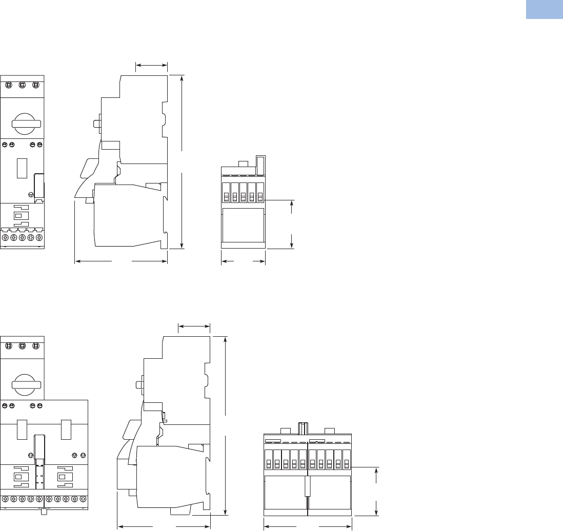
Volume 5—Motor Control and Protection CA08100006E—August 2012 www.eaton.com V5-T1-211
1
1
1
1
1
1
1
1
1
1
1
1
1
1
1
1
1
1
1
1
1
1
1
1
1
1
1
1
1
1
1.1
IEC Contactors and Starters
XT
IEC Power Control
Dimensions
Approximate Dimensions in mm [in]
XTSC…BB_
XTSR…BB_
49.7 [1.96]
To Terminals
45
[1.77]
95.7
[3.77]
178.5
[7.03]
32.5 [1.28]
To Terminals
49.7 [1.96]
To Terminals
90.3
[3.55]
32.5 [1.28]
To Terminals
95.3
[3.75]
183.4
[7.22]
Courtesy of CMA/Flodyne/Hydradyne ▪ Motion Control ▪ Hydraulic ▪ Pneumatic ▪ Electrical ▪ Mechanical ▪ (800) 426-5480 ▪ www.cmafh.com
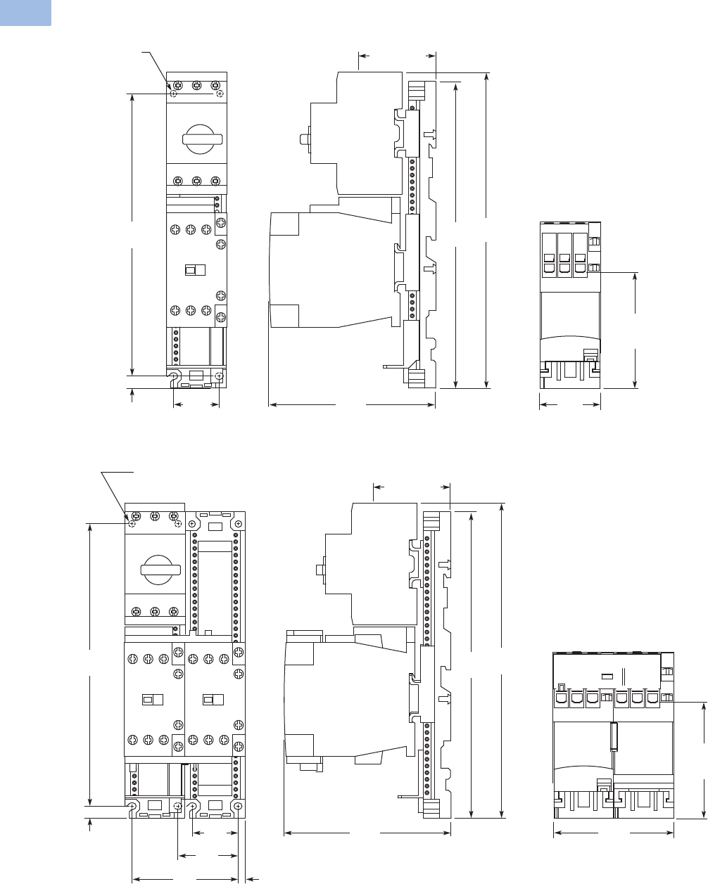
V5-T1-212 Volume 5—Motor Control and Protection CA08100006E—August 2012 www.eaton.com
1
1
1
1
1
1
1
1
1
1
1
1
1
1
1
1
1
1
1
1
1
1
1
1
1
1
1
1
1
1
1.1
IEC Contactors and Starters
XT
IEC Power Control
Approximate Dimensions in mm [in]
XTSC…BC_
XTSR…BC_
Mounting Holes
for M4 Screws
or #8 Screws
(4 Places)
34
[1.34]
210.8 [8.30]
Mounting
9 [.35]
86.8
[3.42]
To Terminals
45.2
[1.78]
57.5 [2.26]
To Terminals
124.3
[4.89]
228.8
[9.01]
235.7
[9.28]
86.8 [3.42]
To
Terminals
89.6
[3.53]
34
[1.34]
45
[1.77]
79
[3.11]
5.3
[.21]
210.8 [8.30]
Mounting
9 [.35]
124.3
[4.89]
228.8
[9.01]
235.4
[9.27]
Mounting Holes for
M4 Screws or #8 Screws
(4 Places)
57.5 [2.26]
To Terminals
Courtesy of CMA/Flodyne/Hydradyne ▪ Motion Control ▪ Hydraulic ▪ Pneumatic ▪ Electrical ▪ Mechanical ▪ (800) 426-5480 ▪ www.cmafh.com
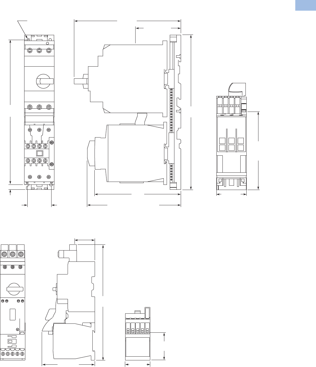
Volume 5—Motor Control and Protection CA08100006E—August 2012 www.eaton.com V5-T1-213
1
1
1
1
1
1
1
1
1
1
1
1
1
1
1
1
1
1
1
1
1
1
1
1
1
1
1
1
1
1
1.1
IEC Contactors and Starters
XT
IEC Power Control
Approximate Dimensions in mm [in]
XTSC…DD_
XTFC…BB_
142.8
[5.62]
To Coil
Terminals
83.4 [3.28]
To Terminals
196 [7.72]
158.5
[6.24]
172.1 [6.78]
To Optional Aux. Contacts
Mounting Holes for
M5 Screws or #10 Screws
(4 Places)
55 [2.17]
43.4 [1.71]
Mounting
266 [10.47]
Mounting
9 [.35]
284
[11.18]
49.7 [1.96]
To Terminals
45 [1.77]
36.3 [1.43]
To Terminals
95.7 [3.77]
209.2
[8.24]
Courtesy of CMA/Flodyne/Hydradyne ▪ Motion Control ▪ Hydraulic ▪ Pneumatic ▪ Electrical ▪ Mechanical ▪ (800) 426-5480 ▪ www.cmafh.com
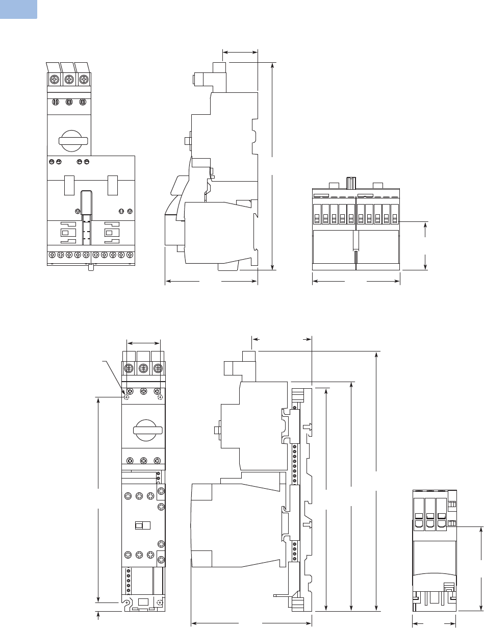
V5-T1-214 Volume 5—Motor Control and Protection CA08100006E—August 2012 www.eaton.com
1
1
1
1
1
1
1
1
1
1
1
1
1
1
1
1
1
1
1
1
1
1
1
1
1
1
1
1
1
1
1.1
IEC Contactors and Starters
XT
IEC Power Control
Approximate Dimensions in mm [in]
XTFR…BB_
XTFC…BC_
49.7 [1.96]
To Terminals
90.3
[3.55]
36.3 [1.43]
To Terminals
95.3
[3.75]
214.2
[8.43]
86.8 [3.42]
To Terminals
45.2
[1.78]
61.3 [2.41]
To Terminals
Mounting Holes
for M4 Screws
or #8 Screws
(4 Places)
124.3
[4.89]
34 [1.34]
Mounting
210.8 [8.30]
Mounting
9 [.35]
228.8
[9.01]
235.7
[9.28]
266.7
[10.50]
Courtesy of CMA/Flodyne/Hydradyne ▪ Motion Control ▪ Hydraulic ▪ Pneumatic ▪ Electrical ▪ Mechanical ▪ (800) 426-5480 ▪ www.cmafh.com
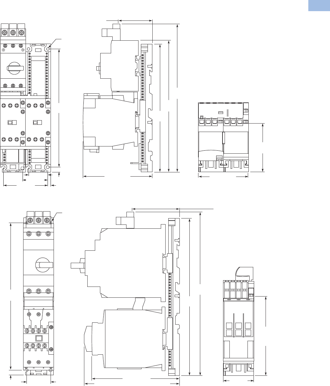
Volume 5—Motor Control and Protection CA08100006E—August 2012 www.eaton.com V5-T1-215
1
1
1
1
1
1
1
1
1
1
1
1
1
1
1
1
1
1
1
1
1
1
1
1
1
1
1
1
1
1
1.1
IEC Contactors and Starters
XT
IEC Power Control
Approximate Dimensions in mm [in]
XTFR…BC_
XTFC…DD_
86.8 [3.42]
To Terminals
89.6 [3.53]
61.3 [2.41]
To Terminals
124.3 [4.89]
228.8
[9.01]
235.4
[9.27]
266.4
[10.49]
Mounting Holes for
M4 Screws or #8 Screws
(8 Places)
45 [1.77]
79 [3.11] 5.3 [.21]
210.8
[8.30]
9 [.35]
34 [1.34]
142.8
[5.62]
To Coil
Terminals
55 [2.17]
158.5 [6.24]
172.1 [6.78] To Optional Aux. Contacts
86 [3.39]
To Line Side
Connector
Mounting Holes for
M5 Screws or #10 Screws
(4 Places)
284
[11.18]
266 [10.47]
Mounting
43.4 [1.71]
Mounting
9 [.35]
297
[11.69]
Courtesy of CMA/Flodyne/Hydradyne ▪ Motion Control ▪ Hydraulic ▪ Pneumatic ▪ Electrical ▪ Mechanical ▪ (800) 426-5480 ▪ www.cmafh.com
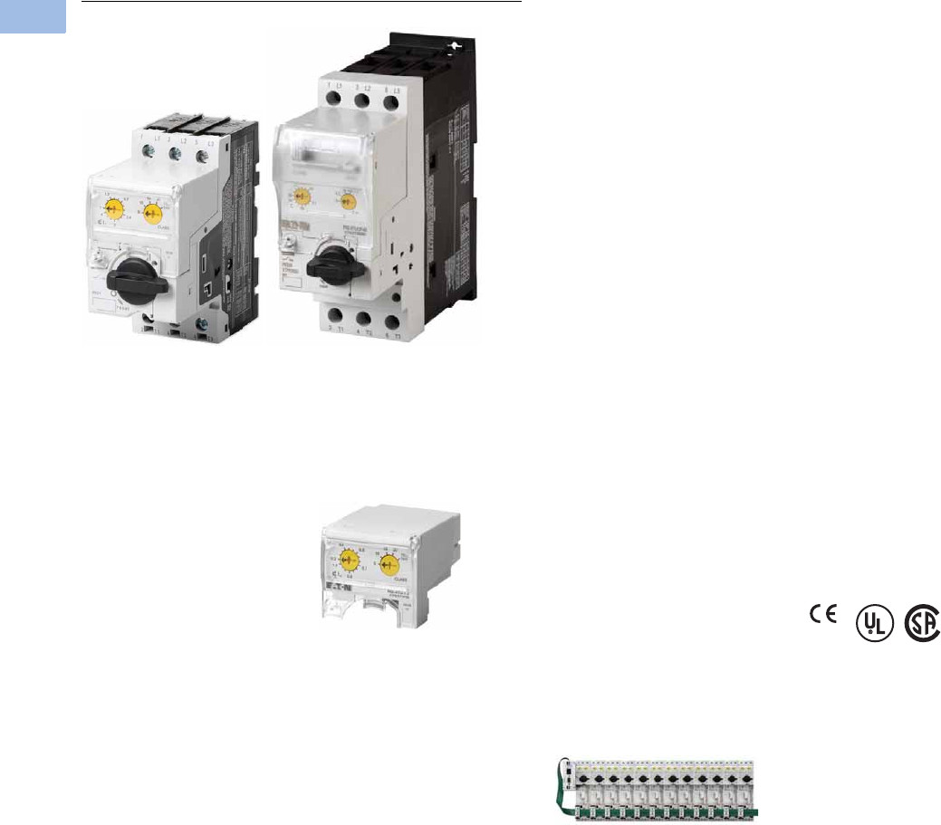
V5-T1-216 Volume 5—Motor Control and Protection CA08100006E—August 2012 www.eaton.com
1
1
1
1
1
1
1
1
1
1
1
1
1
1
1
1
1
1
1
1
1
1
1
1
1
1
1
1
1
1
1.1
IEC Contactors and Starters
XT
IEC Power Control
XT Electronic Manual Motor Protector
Contents
Description Page
Relays and Timers . . . . . . . . . . . . . . . . . . . . . . . . . V5-T1-3
Miniature Controls . . . . . . . . . . . . . . . . . . . . . . . . . V5-T1-18
Contactors and Starters . . . . . . . . . . . . . . . . . . . . V5-T1-35
Thermal Overload Relays . . . . . . . . . . . . . . . . . . . V5-T1-128
C440/XT Electronic Overload Relay . . . . . . . . . . . V5-T1-141
Manual Motor Protectors . . . . . . . . . . . . . . . . . . . V5-T1-157
Combination Motor Controllers . . . . . . . . . . . . . . . V5-T1-193
XT Electronic Manual Motor Protector
Catalog Number Selection . . . . . . . . . . . . . . . . V5-T1-217
Product Selection . . . . . . . . . . . . . . . . . . . . . . . V5-T1-218
Accessories . . . . . . . . . . . . . . . . . . . . . . . . . . . V5-T1-220
Technical Data and Specifications . . . . . . . . . . V5-T1-226
Dimensions . . . . . . . . . . . . . . . . . . . . . . . . . . . V5-T1-228
Reference Data . . . . . . . . . . . . . . . . . . . . . . . . . . . V5-T1-229
XT Electronic Manual Motor Protector
Product Description
The XT Electronic Manual
Motor Protector provides the
same functionality as the XT
thermal manual motor
protector, but with an added
level of flexibility and
selectability. The XTPE
incorporates electronic
control technology to enable
more options and larger dial
setting ranges. The trip units
are interchangeable, allowing
users to exchange as needed
using the same base. The
reduced number of part
numbers decreases bill of
material complexity while
reducing inventory demands.
The XTPE electronic manual
motor protector includes the
following features:
●4:1 max to min overcurrent
dial setting range
●Selectable trip class (5, 10,
15, 20)
●Interchangeable trip units
●Three base units (12, 32
and 65A)
●Common accessories with
the XTPR
Features and Benefits
Advanced Trip Unit
In addition to the selectability,
the XTPE is also available
with an advanced trip unit
that can communicate
system data and protector
data thru SmartWire-DT.
SmartWire-DT is an
innovative cost effective
connection technology that
enables quick installation of
control wiring to the starter
through a single green cable.
When on SmartWire-DT, the
XTPE can communicate the
following:
●Current Values
●Maximum phase current
●Overload warning
●Diagnostics Data
●Overload fault
●Cause of trip
(overcurrent or short
circuit)
●Phase loss
●Trip via TEST
●Status Messages
●Control unit type
●Overload setting
●Time-lag
●Switching status
XTPE Electronic MMP
The XTPE Electronic MMP
provides the selectability,
control, and insight options
that give panel builders and
OEMs the solutions
necessary to enhance motor
control designs while
reducing total costs.
Standards and Certifications
●CE approved
●UL Listed File No. E36332
●UL 508 group motor and
Type E
●IEC/EN 60947
●CSA File 012528,
Class 3211-05
Courtesy of CMA/Flodyne/Hydradyne ▪ Motion Control ▪ Hydraulic ▪ Pneumatic ▪ Electrical ▪ Mechanical ▪ (800) 426-5480 ▪ www.cmafh.com
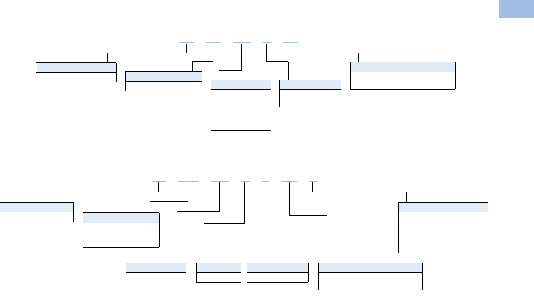
Volume 5—Motor Control and Protection CA08100006E—August 2012 www.eaton.com V5-T1-217
1
1
1
1
1
1
1
1
1
1
1
1
1
1
1
1
1
1
1
1
1
1
1
1
1
1
1
1
1
1
1.1
IEC Contactors and Starters
XT
IEC Power Control
Catalog Number Selection
XT—Manual Motor Protector
XT—Combinations
XT PE 004 BCS
Type
PE = Electronic MMP
Designation
XT = XT line of IEC control
Overload Release
1P2 = 0.3–1.2A
004 = 1–4A
012 = 3–12A
032 = 8–32A
065 = 16–65A
Trip Type
CS = Standard
CA = Advanced (SmartWire-DT)
MMP Frame
B = 45 mm
D = 55 mm
Type
FCE = Electronic
combination motor
controller
Designation
XT = XT line of IEC control
Contactor Frame
C = 45 mm
XT FCE 004 B C CS A
Overload Release
1P2 = 0.3–1.2A
004 = 1–4A
012 = 3–12A
032 = 8–32A
MMP Frame
B = 45 mm
Trip Type
CS = Selectable class 5, 10, 15, 20
CA = Selectable, advanced
Coil Voltage
A= 110V 50 Hz, 120V 60 Hz
B= 220V 50 Hz, 240V 60 Hz
F= 230V 50 Hz
T= 24V 50/60 Hz
TD = 24 Vdc
Courtesy of CMA/Flodyne/Hydradyne ▪ Motion Control ▪ Hydraulic ▪ Pneumatic ▪ Electrical ▪ Mechanical ▪ (800) 426-5480 ▪ www.cmafh.com

V5-T1-218 Volume 5—Motor Control and Protection CA08100006E—August 2012 www.eaton.com
1
1
1
1
1
1
1
1
1
1
1
1
1
1
1
1
1
1
1
1
1
1
1
1
1
1
1
1
1
1
1.1
IEC Contactors and Starters
XT
IEC Power Control
Product Selection
XT Electronic Manual Motor Protector
MMP Base
MMP Trip Units
MMP Advanced Trip Units Used with SmartWire-DT
MMP Complete Assembly
Note
1 In this range, calculate motor rating according to rated current. Specified values to NEC 430.6 (A) (1).
Maximum
Amperage
UL/CSA
IEC
Base Unit
Maximum Motor kW Ratings
220V
230V
240V
380V
400V
415V 440V 500V
600V
690V
Maximum Three-Phase hp Ratings
200V 240V 480V 600V Type Number Catalog Number
12 3 3 7.5 10 3 5.5 5.5 5.5 7.5 PKE12 XTPE012B
32 5 7.5 15 20 7.5 15 15 18.5 30 PKE32 XTPE032B
65 15 15 40 40 18.5 30 37 45 55 PKE65 XTPE065D
Overload
Release Setting
Amp Range
For Use with
Base Catalog
Number
UL/CSA
IEC
Trip Unit
Maximum Motor kW Ratings
Maximum Three-Phase hp Ratings 220V
230V
240V
380V
400V
415V 440V 500V
600V
690V200V 240V 480V 600V Type Number Catalog Number
0.3–1.2 XTPE012B 11
0.5 0.5 0.18 0.37 0.37 0.37 0.75 PKE-XTU-1,2 XTPEXT1P2B
1–4 XTPE012B 0.75 0.75 2 3 0.75 1.5 1.5 2.2 3 PKE-XTU-4 XTPEXT004B
3–12 XTPE012B 3 3 7.5 10 3 5.5 5.5 5.5 7.5 PKE-XTU-12 XTPEXT012B
XTPE032B
8–32 XTPE032B 5 7.5 15 20 7.5 15 15 18.5 30 PKE-XTU-32 XTPEXT032B
8–32 XTPE065D 7.5 7.5 20 25 7.5 15 15 18.5 30 PKE-XTUW-32 XTPEXT032D
16–65 XTPE065D 15 15 40 40 18.5 30 37 45 55 PKE-XTU-65 XTPEXT065D
Overload
Release Setting
Amp Range
For Use with
Base Catalog
Number
UL/CSA
IEC
Trip Unit
Maximum Motor kW Ratings
Maximum Three-Phase hp Ratings 220V
230V
240V
380V
400V
415V 440V 500V
600V
690V200V 240V 480V 600V Type Number Catalog Number
0.3–1.2 XTPE012B 11
0.5 0.5 0.18 0.37 0.37 0.37 0.75 PKE-XTUA-1,2 XTPEXTA1P2B
1–4 XTPE012B 0.75 0.75 2 3 0.75 1.5 1.5 2.2 3 PKE-XTUA-4 XTPEXTA004B
3–12 XTPE012B 3 3 7.5 10 3 5.5 5.5 5.5 7.5 PKE-XTUA-12 XTPEXTA012B
XTPE032B
8–32 XTPE032B 5 7.5 15 20 7.5 15 15 18.5 30 PKE-XTUA-32 XTPEXTA032B
8–32 XTPE065D 7.5 7.5 20 25 7.5 15 15 18.5 30 PKE-XTUWA-32 XTPEXTA032D
16–65 XTPE065D 15 15 40 40 18.5 30 37 45 55 PKE-XTUA-65 XTPEXTA065D
Overload
Release Setting
Amp Range
UL/CSA
IEC
Complete Manual Motor Protector
Maximum Motor kW Ratings
Maximum Three-Phase hp Ratings 220V
230V
240V
380V
400V
415V 440V 500V
600V
690V200V 240V 480V 600V Type Number Catalog Number
0.3–1.2 110.5 0.5 0.18 0.37 0.37 0.37 0.75 PKE12/XTU-1,2 XTPE1P2BCS
1–4 0.75 0.75 2 3 0.75 1.5 1.5 2.2 3 PKE12/XTU-4 XTPE004BCS
3–12 3 3 7.5 10 3 5.5 5.5 5.5 7.5 PKE12/XTU-12 XTPE012BCS
8–32 5 7.5 15 20 7.5 15 15 18.5 30 PKE32/XTU-32 XTPE032BCS
8–32 7.5 7.5 20 25 7.5 15 15 18.5 30 PKE65/XTUW-32 XTPE032DCS
16–65 1515404018.530 374555 PKE65/XTU-65XTPE065DCS
B Frame
B Frame
B Frame
D Frame
Courtesy of CMA/Flodyne/Hydradyne ▪ Motion Control ▪ Hydraulic ▪ Pneumatic ▪ Electrical ▪ Mechanical ▪ (800) 426-5480 ▪ www.cmafh.com
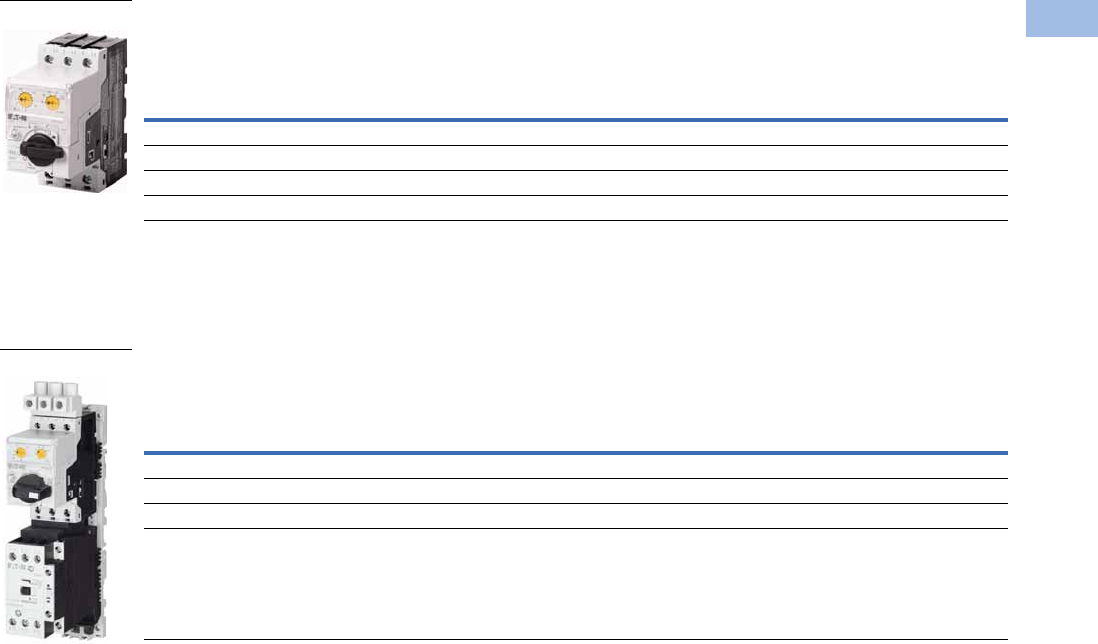
Volume 5—Motor Control and Protection CA08100006E—August 2012 www.eaton.com V5-T1-219
1
1
1
1
1
1
1
1
1
1
1
1
1
1
1
1
1
1
1
1
1
1
1
1
1
1
1
1
1
1
1.1
IEC Contactors and Starters
XT
IEC Power Control
MMP Used with SmartWire-DT—Complete Assembly
UL 508 Type E XT Electronic Combination Motor Controllers—Complete Assembly Including Trip Unit
B Frame Electronic MMP with C Frame Contactor
Notes
1 In this range, calculate motor rating according to rated current. Specified values to NEC 430.6 (A) (1).
2 Complete the catalog number by replacing the underscore (_) with the coil suffix from Page V5-T1-238.
3 SCCR: 14 kA, 600 Vac
4 SCCR: 18 kA, 480 Vac
Overload
Release Setting
Amp Range
UL/CSA
IEC
Complete Manual Motor Protector
Maximum Motor kW Ratings
Maximum Motor hp Ratings 220V
230V
240V
380V
400V
415V 440V 500V
600V
690V200V 230V 460V 575V Type Number Catalog Number
0.3–1.2 110.5 0.5 0.18 0.37 0.37 0.37 0.75 PKE12/XTUA-1,2 XTPE1P2BCA
1–4 0.75 0.75 2 3 0.75 1.5 1.5 2.2 3 PKE12/XTUA-4 XTPE004BCA
3–12 3 3 7.5 10 3 5.5 5.5 5.5 7.5 PKE12/XTUA-12 XTPE012BCA
8–32 5 7.5 15 20 7.5 15 15 18.5 30 PKE32/XTUA-32 XTPE032BCA
Overload
Release Setting
Amp Range
UL/CSA
Catalog Number
Standard
Catalog Number
With SmartWire-DT
Maximum Three-Phase hp Ratings Maximum Single-Phase hp Ratings
200V 240V
380Y/
415V
480Y/
277V
600Y/
347V 115V 200V 240V
0.3–1.2 11110.5 111XTFCE1P2BCCS_ 3XTFCE1P2BCCATD 3
1–4 0.75 0.75 1.5 2 — 0.125 0.25 0.33 XTFCE004BCCS_ 4XTFCE004BCCATD 4
3–12 3357.5—0.5 1 1.5 XTFCE012BCCS_ 4XTFCE012BCCATD 4
3–32 5 5 10 15 — 1.5 3 3 XTFCE032BCCS_ 4XTFCE032BCCATD 4
B Frame
B Frame
Courtesy of CMA/Flodyne/Hydradyne ▪ Motion Control ▪ Hydraulic ▪ Pneumatic ▪ Electrical ▪ Mechanical ▪ (800) 426-5480 ▪ www.cmafh.com
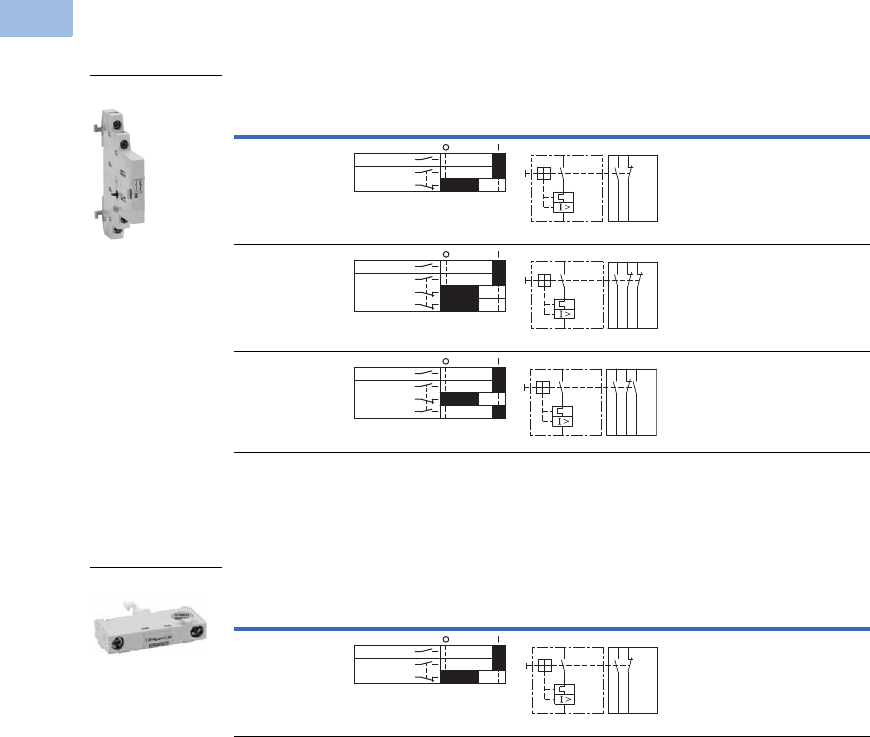
V5-T1-220 Volume 5—Motor Control and Protection CA08100006E—August 2012 www.eaton.com
1
1
1
1
1
1
1
1
1
1
1
1
1
1
1
1
1
1
1
1
1
1
1
1
1
1
1
1
1
1
1.1
IEC Contactors and Starters
XT
IEC Power Control
Accessories
Auxiliary Contacts
Side-Mount Auxiliary Contacts
Can be fitted on the right side of manual motor protectors (XTPB, XTPR, XTPM) and
manual transformer protectors (XTPT) and can be combined with XTPAXSATR_ and
XTPAXFA_ trip indicating auxiliary contact.
Front-Mount Auxiliary Contacts
Can be fitted to manual motor protectors (XTPB, XTPR, XTPM) and manual
transformer protectors (XTPT). 45 mm
(XTPR…B and XTPB) or 55 mm (XTPR…D)
widths of manual motor protectors remain unchanged.
Note
1
Orders must be placed in multiples of package quantity listed.
Contact
Configuration Contact Sequence
Pkg.
Qty. 1
Screw Terminal
Catalog Number
1NO-1NC 5 XTPAXSA11
1NO-2NC 5 XTPAXSA12
2NO-1NC 5 XTPAXSA21
Contact
Configuration Contact Sequence
Pkg.
Qty. 1
Screw Terminal
Catalog Number
1NO-1NC 5 XTPAXFA11
XTPAXSA_
L1 L2 L3
XTPAXSA11
1.14 1.22
1.13 1.21
1.14 1.22 1.32
1.13 1.21 1. 31
L1 L2 L3
XTPAXSA12
1.14 1.22 1.34
1.13 1. 21 1. 3 3
L1 L2 L3
XTPAXSA21
XTPAXFA11
1.5 4 1. 6 2
1.53 1.6 1
L1 L2 L3
XTPAXFA11
Courtesy of CMA/Flodyne/Hydradyne ▪ Motion Control ▪ Hydraulic ▪ Pneumatic ▪ Electrical ▪ Mechanical ▪ (800) 426-5480 ▪ www.cmafh.com
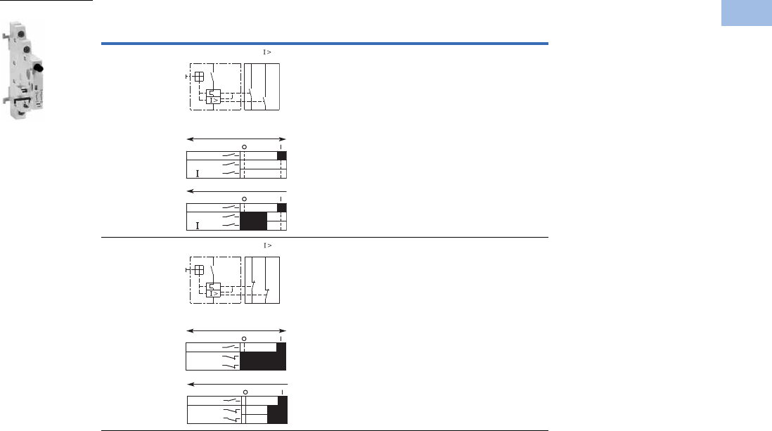
Volume 5—Motor Control and Protection CA08100006E—August 2012 www.eaton.com V5-T1-221
1
1
1
1
1
1
1
1
1
1
1
1
1
1
1
1
1
1
1
1
1
1
1
1
1
1
1
1
1
1
1.1
IEC Contactors and Starters
XT
IEC Power Control
Side-Mount Trip Indicating Auxiliary Contacts
Can be fitted on the right side of manual motor protectors. Can be combined with
standard auxiliary contacts. Trip indication: A. General trip indication (overload) B.
Short-circuit trip. Local short-circuit indication by red indicator, manually resettable.
Note
1
Orders must be placed in multiples of package quantity listed.
Contact
Configuration Contact Sequence
Pkg.
Qty. 1
For Use
with… Catalog Number
2 x 1NO 2 XTPE XTPAXSATR20
2 x 1NC 2 XTPE XTPAXSATR02
XTPAXSATR_
4.44 4.14
“+”
4.43
“ ”
4.13
“+”
“ >”
On/Off
“+”
“ >”
Trip “+”
L1L2 L3
L1L2 L3
4.32 4.22
“+”
4.31
“ ”
4.21
On/Off
“+”
“ >”
Trip “+”
L1L2 L3
“+”
“ >”
L1L2 L3
Courtesy of CMA/Flodyne/Hydradyne ▪ Motion Control ▪ Hydraulic ▪ Pneumatic ▪ Electrical ▪ Mechanical ▪ (800) 426-5480 ▪ www.cmafh.com
V5-T1-222 Volume 5—Motor Control and Protection CA08100006E—August 2012 www.eaton.com
1
1
1
1
1
1
1
1
1
1
1
1
1
1
1
1
1
1
1
1
1
1
1
1
1
1
1
1
1
1
1.1
IEC Contactors and Starters
XT
IEC Power Control
Additional Accessories
Shunt Release
Can be used to trip the manual motor protector from a remote
location. Can be fitted on the left side of manual motor
protectors. Cannot be combined with the XTPAXUVR. DC:
Intermittent operation 5 sec.
Undervoltage Release
Can be used to trip the manual motor protector from a remote
location. Can be fitted on left side manual motor protectors.
Cannot be combined with XTPAXSR. When combined with a
circuit breaker, it can be used as emergency-stop device to
IEC/EN 60204.
Note
1Orders must be placed in multiples of package quantity listed.
Pkg.
Qty. 1
Screw Terminal
Catalog Number
2XTPAXSR24V50H
2XTPAXSR48V50H
2XTPAXSR110V50H
2XTPAXSR120V60H
2XTPAXSR208V60H
2XTPAXSR220V50H
2XTPAXSR230V50H
2XTPAXSR240V50H
2XTPAXSR240V60H
2XTPAXSR380V50H
2XTPAXSR400V50H
2XTPAXSR415V50H
2XTPAXSR440V60H
2XTPAXSR480V60H
2XTPAXSR24VDC
2XTPAXSR48VDC
2XTPAXSR60VDC
2XTPAXSR110VDC
2XTPAXSR125VDC
2XTPAXSR220VDC
2XTPAXSR250VDC
XTPAXSR_
Contact Sequence
C1
C2
Pkg.
Qty. 1
Screw Terminal
Catalog Number
2XTPAXUVR24V50H
2XTPAXUVR24V60H
2XTPAXUVR48V50H
2XTPAXUVR60V50H
2XTPAXUVR110V50H
2XTPAXUVR120V60H
2XTPAXUVR208V60H
2XTPAXUVR220V50H
2XTPAXUVR230V50H
2XTPAXUVR240V50H
2XTPAXUVR240V60H
2XTPAXUVR380V50H
2XTPAXUVR400V50H
2XTPAXUVR415V50H
2XTPAXUVR440V60H
2XTPAXUVR480V60H
2XTPAXUVR600V60H
XTPAXUVR_
Contact Sequence
D1
D2
U
Courtesy of CMA/Flodyne/Hydradyne ▪ Motion Control ▪ Hydraulic ▪ Pneumatic ▪ Electrical ▪ Mechanical ▪ (800) 426-5480 ▪ www.cmafh.com
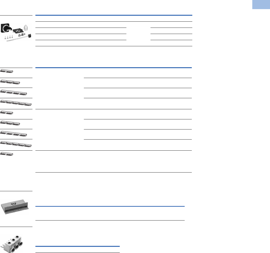
Volume 5—Motor Control and Protection CA08100006E—August 2012 www.eaton.com V5-T1-223
1
1
1
1
1
1
1
1
1
1
1
1
1
1
1
1
1
1
1
1
1
1
1
1
1
1
1
1
1
1
1.1
IEC Contactors and Starters
XT
IEC Power Control
IP65 Rotary Handle Mechanism 123
Three-Phase Commoning Links 7
For parallel power feed to several manual motor protectors on terminals
1, 3 and 5.
Shroud for Unused Terminals of Three-Phase Commoning Links
Incoming Terminals for Three-Phase
Commoning Link 8
Notes
1 Plug-in connection shafts, XTPAXRHMSFT_ can be cut to desired length for mounting depths of 100–240 mm. Carrier
with extension shaft included.
2 With ON/OFF switch position and “+” (tripped), lockable with 3 padlocks, 4–8 mm hasp. Can be locked in the
OFF position, if required.
3 Rotary handle mechanisms ship with door interlock disabled. See instruction publication with product for how to
enable door interlock.
4 Orders must be placed in multiples of package quantity listed.
5 For use on main switches to IEC/EN 60204.
6 For use on main switches with emergency-stop function to IEC/EN 60204.
7 Protected against accidental contact. Frame B short-circuit proof Ue = 690V, Iu = 63A.
Frame B links can be combined by
rotating mounting.
8 For three-phase commoning link, protected against accidental contact, Ue = 690V, Iu = 63A;
For conductor cross-sections: 2.5–25 mm2 stranded; 2.5–16 mm2 flexible with ferrules, AWG 14-6.
Description
Enclosure
Rating
Pkg.
Qty. 4Catalog Number
Complete Kits—Includes Handle, Shaft and Required Hardware
Rotary handle mechanism—black 5IP65
NEMA 12
UL/CSA 4X
1XTPEXRHMB
Rotary handle mechanism—red/yellow 61XTPEXRHMRY
Rotary handle mechanism—black—rotated 90° from vertical 51XTPEXRHM90B
Rotary handle mechanism—red/yellow—rotated 90° from vertical 61XTPEXRHM90RY
For Use with…
Qty.
MMP
Length of
Link (mm)
Unit
Width (mm)
Pkg.
Qty. 4Catalog Number
MMP with no side-mounted
auxiliaries or voltage releases
290 45 10XTPAXCLKA2
3 135 45 10 XTPAXCLKA3
4 180 45 10 XTPAXCLKA4
5 225 45 10 XTPAXCLKA5
Each MMP with one auxiliary
contact or trip-indicating auxiliary
contact fitted on the right
299 45 + 9 10XTPAXCLKB2
3 153 45 + 9 10 XTPAXCLKB3
4 207 45 + 9 10 XTPAXCLKB4
5 261 45 + 9 10 XTPAXCLKB5
Each MMP with an auxiliary
contact and trip-indicating
auxiliary contact mounted on
the right or a voltage release
mounted on the left.
2 108 45 + 18 10 XTPAXCLKC2
For Use with… Description
Pkg.
Qty. 4Catalog Number
Frame B
XTPE
To cover unused terminals on three-phase
commoning link. Protected against direct
contact.
20 XTPAXUTS
For Use with…
Pkg.
Qty. 4Catalog Number
Frame B XTPE 5 XTPAXIT
XTPAXRHM_
XTPAXUTS
XTPAXIT
Courtesy of CMA/Flodyne/Hydradyne ▪ Motion Control ▪ Hydraulic ▪ Pneumatic ▪ Electrical ▪ Mechanical ▪ (800) 426-5480 ▪ www.cmafh.com
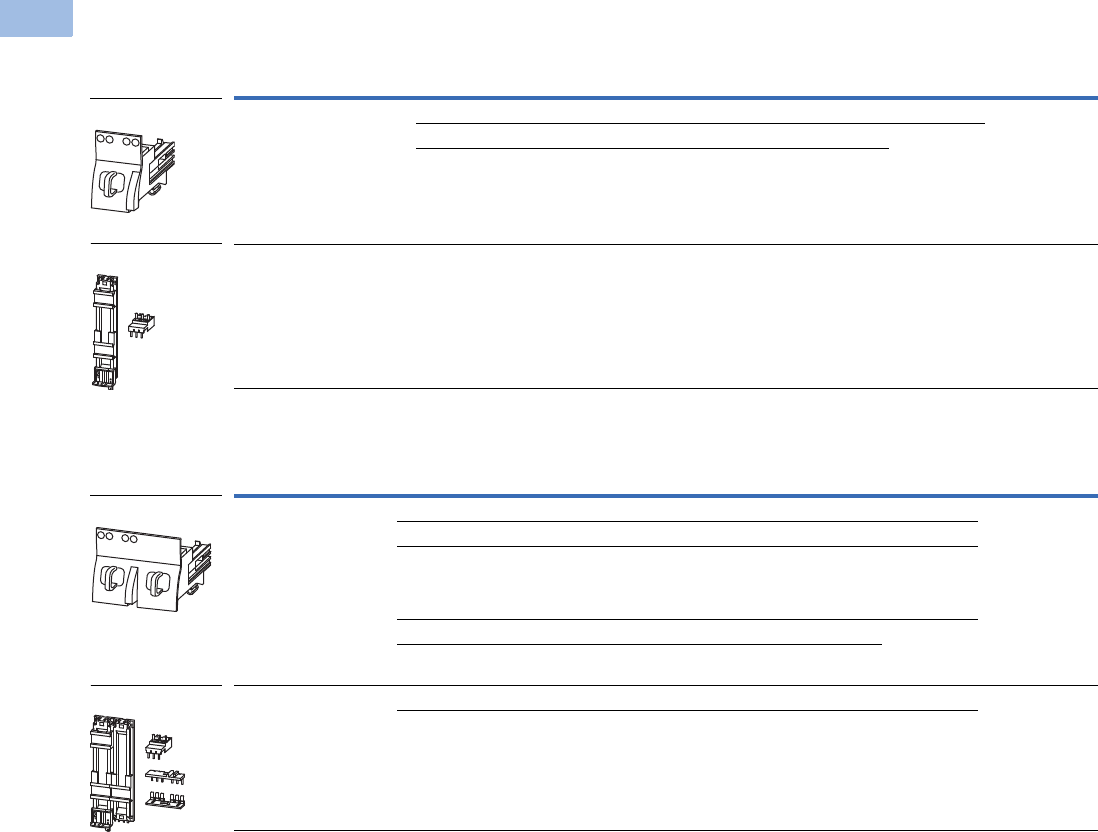
V5-T1-224 Volume 5—Motor Control and Protection CA08100006E—August 2012 www.eaton.com
1
1
1
1
1
1
1
1
1
1
1
1
1
1
1
1
1
1
1
1
1
1
1
1
1
1
1
1
1
1
1.1
IEC Contactors and Starters
XT
IEC Power Control
Combination Connection Kits
Non-Reversing Starters
Reversing Starters
Note
1 Orders must be placed in multiples of package quantity listed.
For Use with… Description/Comprised of …
Std.
Pack 1Catalog Number
XTPE…B + XTCE…B Mechanical connection element for XTPR…B and contactor 1 XTPAXTPCB
Main current wiring between XTPR…B and contactor in toolless plug connection 1
Use contactor auxiliary switch XTCEXFAT_. Control cable guidance: max. six cables
up to 2.5 mm2 external diameter or four cables up to 3.5 mm2 external diameter.
XTPR…B + XTCE…C DIN rail adapter plate
Main current wiring between XTPR and contactor
1XTPAXTPCC
For Use with… Description/Comprised of …
Std.
Pack 1Catalog Number
XTPE…B + XTCE…B01_ Mechanical connection element for XTPR…B and contactor 1 XTPAXTPCRB
Reversing starter main current wiring in toolless plug connection 1
Control cables for electrical interlocking in toolless plug connection:
– K1M: A1–K2M: 21
– K1M: 21–K2M: A1
– K1M: A2–K2M: A2
1
Cable guidance 1
Use contactor auxiliary switch XTCEXFAT_. Control cable guidance: max. six cables
up to 2.5 mm2 external diameter or four cables up to 3.5 mm2 external diameter.
XTPE…B + XTCE…C DIN rail adapter plate 1 XTPAXTPCRC
Reversing starter main current wiring 1
XTPAXTPCB
XTPAXTPC_
XTPAXTPCRB
XTPAXTPCRC
Courtesy of CMA/Flodyne/Hydradyne ▪ Motion Control ▪ Hydraulic ▪ Pneumatic ▪ Electrical ▪ Mechanical ▪ (800) 426-5480 ▪ www.cmafh.com
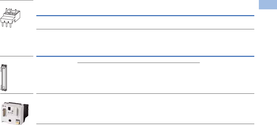
Volume 5—Motor Control and Protection CA08100006E—August 2012 www.eaton.com V5-T1-225
1
1
1
1
1
1
1
1
1
1
1
1
1
1
1
1
1
1
1
1
1
1
1
1
1
1
1
1
1
1
1.1
IEC Contactors and Starters
XT
IEC Power Control
Electrical Connection Module
DIN Rail Adapter Plates
Note
1 Orders must be placed in multiples of package quantity listed.
For Use with… Description/Comprised of …
Std.
Pack 1Catalog Number
XTPE…B + XTCE…C Main current wiring between XTPR…B and contactor 5 XTPAXECMC
For Use with… Description/Comprised of …
Std.
Pack 1Catalog Number
XTPAXTPCB
XTPAXTPCRB
45 mm wide adapter plate with one DIN rail 4 XTPAXTPCPB
Connection element for side-by-side positioning of further plates
XTPE…B +
XTCE…B or C
SmartWire-DT communication link 1 PKE-SWD-32
XTPAXECM_
XTPAXTPCPB
PKE-SWD-32
Courtesy of CMA/Flodyne/Hydradyne ▪ Motion Control ▪ Hydraulic ▪ Pneumatic ▪ Electrical ▪ Mechanical ▪ (800) 426-5480 ▪ www.cmafh.com

V5-T1-226 Volume 5—Motor Control and Protection CA08100006E—August 2012 www.eaton.com
1
1
1
1
1
1
1
1
1
1
1
1
1
1
1
1
1
1
1
1
1
1
1
1
1
1
1
1
1
1
1.1
IEC Contactors and Starters
XT
IEC Power Control
Technical Data and Specifications
XT Electronic Manual Motor Controllers
Description Specification XTPE012B XTPE032B XTPE065D
General
Standards and regulations IEC/EN 60947-4-1, VDE 0600, UL 508, CSA C 22.2 No. 14
Climatic proofing Damp heat, constant, to IEC 60068-2-78
Damp heat, cyclic, to IEC 60068-2-30
Ambient temperature
Storage –40° to 80°C –40° to 80°C –40° to 80°C
Open –25° to 55°C –25° to 55°C –25° to 55°C
Enclosed –25° to 40°C –25° to 40°C –25° to 40°C
Direction of incoming supply Any Any Any
Degree of protection Device IP20 IP20 IP20
Terminals IP00 IP00 IP00
Touch protection
Mechanical shock resistance half-sinusoidal shock,
10 ms to IEC 60068-2-27
25g 25g 25g
Altitude Max. 2000m Max. 2000m Max. 2000m
Conductor Cross-Sections
Screw terminals Solid 1 x (1–6) mm21 x (1–6) mm21 x (0.75–16) mm2
2 x (1–6) mm22 x (1–6) mm22 x (0.75–16) mm2
Stranded with ferrule
to DIN 46228
1 x (1–6) mm21 x (1–6) mm21 x (0.75–35) mm2
2 x (1–6) mm22 x (1–6) mm22 x (0.75–25) mm2
Solid or stranded 18–10 AWG 18–10 AWG 14–2 AWG
Screw Terminal Tightening Torque
Main conductor 1.7 Nm 1.7 Nm 3.3 Nm
Auxiliary conductor 1 Nm 1 Nm 1 Nm
Main Circuit
Rated impulse withstand voltage Ump 6,000 Vac 6,000 Vac 6,000 Vac
Overvoltage category/pollution degree III/3 III/3 III/3
Rated operational voltage Ue690V 690V 690V
Rated uninterrupted current = rated output current Iu = Ie12A 32A 65A
Rated frequency 40–60 Hz 40–60 Hz 40–60 Hz
Current heating losses (three-pole at operating
temperature)
6W 6W 6W
Lifespan, mechanical Operations 0.05 x 1060.05 x 1060.05 x 106
Lifespan, electrical (AC-3 at 400V) Operations 0.05 x 1060.05 x 1060.05 x 106
Maximum operating frequency Operations/h 60 60 60
Short-Circuit Rating
Motor switching capacity AC AC-3 up to 690V 12A 32A 65A
Trip Unit
Temperature compensation to IEC/EN 60947, VDE 0660 –5° to 40°C –5° to 40°C –5° to 40°C
Operating range –25° to 55°C –25° to 55°C –25° to 55°C
Temperature compensation residual error for T >40°C <0.1%/K <0.1%/K <0.1%/K
Overload release setting range 0.25–1 xlu0.25–1 xlu0.25–1 xlu
Fixed short-circuit trip setting 12 x lr (trip unit),14 x lu (base) 12 x lr (trip unit),14 x lu (base) 12 x lr (trip unit),14 x lu (base)
Short circuit release tolerance ±20% ±20% ±20%
Phase failure sensitivity Yes Yes Yes
Courtesy of CMA/Flodyne/Hydradyne ▪ Motion Control ▪ Hydraulic ▪ Pneumatic ▪ Electrical ▪ Mechanical ▪ (800) 426-5480 ▪ www.cmafh.com
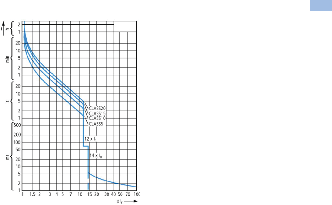
Volume 5—Motor Control and Protection CA08100006E—August 2012 www.eaton.com V5-T1-227
1
1
1
1
1
1
1
1
1
1
1
1
1
1
1
1
1
1
1
1
1
1
1
1
1
1
1
1
1
1
1.1
IEC Contactors and Starters
XT
IEC Power Control
Trip Characteristics
XT Electronic Manual Motor Controllers
XTPE …
Courtesy of CMA/Flodyne/Hydradyne ▪ Motion Control ▪ Hydraulic ▪ Pneumatic ▪ Electrical ▪ Mechanical ▪ (800) 426-5480 ▪ www.cmafh.com

V5-T1-228 Volume 5—Motor Control and Protection CA08100006E—August 2012 www.eaton.com
1
1
1
1
1
1
1
1
1
1
1
1
1
1
1
1
1
1
1
1
1
1
1
1
1
1
1
1
1
1
1.1
IEC Contactors and Starters
XT
IEC Power Control
Dimensions
Approximate Dimensions in Inches (mm)
XT Electronic MMP—B Frame
XT Electronic CMC With C Frame Contactor
XT Electronic MMP—D Frame
1.77
(45.0)
4.72 (120.0)
3.79 (96.2)
3.98
(101.0)
5.71 (145.0)
4.77 (121.2)
3.66 (92.9)
To Line
Side Adapter
10.63
(269.9)
To Line
Side
Adapter
9.46
(240.3)
9.01
(228.8)
Mounting
Rail
4.87 (123.8)
Line Side
Adapter
1.76
(44.6)
4.65 (118.0)
2.22
(56.5)
2.17
(55.0)
1.38
(35.0)
6.30
(160.0)
0.57
(14.5)
1.28
(32.5)
0.22 (5.5)
5.00 (127.0)
6.77 (172.0)
7.36 (187.0)
Courtesy of CMA/Flodyne/Hydradyne ▪ Motion Control ▪ Hydraulic ▪ Pneumatic ▪ Electrical ▪ Mechanical ▪ (800) 426-5480 ▪ www.cmafh.com

Volume 5—Motor Control and Protection CA08100006E—August 2012 www.eaton.com V5-T1-229
1
1
1
1
1
1
1
1
1
1
1
1
1
1
1
1
1
1
1
1
1
1
1
1
1
1
1
1
1
1
1.1
IEC Contactors and Starters
XT
IEC Power Control
Reference Data
Type 2 Coordination . . . . . . . . . . . . . . . . . . . . . . . V5-T1-230
Approvals for World Markets . . . . . . . . . . . . . . . . V5-T1-239
IEC Utilization Categories . . . . . . . . . . . . . . . . . . V5-T1-242
Motor Ratings Data . . . . . . . . . . . . . . . . . . . . . . . V5-T1-245
Ampacities of Insulated Conductors
(Based on 2005 NEC) . . . . . . . . . . . . . . . . . . . . V5-T1-249
Type 1 and Type 2 Coordination
What is it?
The International
Electrotechnical Commission
(IEC) developed short-circuit
performance criteria for
contactors and starters called
Type 1 coordination and Type
2 coordination. This defines
motor controller protection
levels following a short-circuit
fault. In order to achieve this
performance, the
combination of a motor
controller (contactor or
starter) and short-circuit
protective device (manual
motor protector, circuit
breaker or fuse) must meet
the following criteria as
specified by IEC 60947-4-1—
Low voltage switchgear and
controlgear—Part 4-1:
Contactors and motor-
starters—Electromechanical
contactors and motor-
starters:
Type 1 Coordination
Type 1 Coordination requires
that under short-circuit
conditions, the contactor or
starter shall cause no danger
to persons or installation and
may not be suitable for
further service without repair
and replacement of parts.
In this case, significant
damage is allowed to the
contactor/starter (e.g.,
contact welding, burning or
disintegration) and the
overload relay (e.g.,
component harm or heater
element burn-out).
Type 2 Coordination
Type 2 Coordination requires
that under short-circuit
conditions, the contactor or
starter shall cause no danger
to persons or installation and
shall be suitable for further
use. The risk of contact
welding is recognized, in
which case the manufacturer
shall indicate the measures to
be taken as regards to the
maintenance of the
equipment.
Courtesy of CMA/Flodyne/Hydradyne ▪ Motion Control ▪ Hydraulic ▪ Pneumatic ▪ Electrical ▪ Mechanical ▪ (800) 426-5480 ▪ www.cmafh.com

V5-T1-230 Volume 5—Motor Control and Protection CA08100006E—August 2012 www.eaton.com
1
1
1
1
1
1
1
1
1
1
1
1
1
1
1
1
1
1
1
1
1
1
1
1
1
1
1
1
1
1
1.1
IEC Contactors and Starters
XT
IEC Power Control
Type 2 Coordination
400, xx415V Type 2 Coordination—MMC
Notes
See Page V5-T1-238 for more information on wye-delta (star delta) applications.
1Values in parentheses ( ) are for Type 1 Coordination.
2Underscore (_) indicates magnet coil suffix required. See Page V5-T1-238.
P
(kW)
Ie
(A)
Iq
(kA)
MMP
Catalog Number
Contactor
Catalog Number 2
MMC
Catalog Number 2
0.06 0.21 50 (150) 1XTPRP25BC1 XTCE007B10_ XTSCP25BB_
0.09 0.31 50 (150) 1XTPRP40BC1 XTCE007B10_ XTSCP40BB_
0.12 0.41 50 (150) 1XTPRP63BC1 XTCE007B10_ XTSCP63BB_
0.18 0.60 50 (150) 1XTPRP63BC1 XTCE007B10_ XTSCP63BB_
0.25 0.80 50 (150) 1XTPR001BC1 XTCE007B10_ XTSC001BB_
0.37 1.10 50 (150) 1XTPR1P6BC1 XTCE007B10_ XTSC1P6BB_
0.55 1.50 50 (150) 1XTPR1P6BC1 XTCE007B10_ XTSC1P6BB_
0.75 1.90 50 (150) 1XTPR2P5BC1 XTCE007B10_ XTSC2P5BB_
1.10 2.60 50 (150) 1XTPR004BC1 XTCE007B10_ XTSC004BB_
1.50 3.60 50 (150) 1XTPR004BC1 XTCE007B10_ XTSC004BB_
2.20 5.00 50 (150) 1XTPR6P3BC1 XTCE007B10_ XTSC6P3BB_
3.00 6.60 50 (150) 1XTPR010BC1 XTCE018C10_ XTSC010BC_
4.00 8.50 50 (150) 1XTPR010BC1 XTCE018C10_ XTSC010BC_
5.50 11.3 50 XTPR012BC1 XTCE018C10_ XTSC012BC_
7.50 16.0 50 XTPR016BC1 XTCE018C10_ XTSC016BC_
11.0 21.7 50 XTPR025BC1 XTCE025C10_ XTSC025BC_
15.0 29.3 50 XTPR032BC1 XTCE032C10_ XTSC032BC_
5.50 11.3 50 XTPR016DC1 XTCE018C10_ XTSC016DC_
7.50 16.0 50 XTPR016DC1 XTCE018C10_ XTSC016DC_
11.0 21.7 50 XTPR025DC1 XTCE025C10_ XTSC025DC_
15.0 29.3 50 XTPR032DC1 XTCE032C10_ XTSC032DC_
18.5 36.0 50 XTPR040DC1 XTCE040D00_ XTSC040DD_
22.0 41.0 50 XTPR050DC1 XTCE050D00_ XTSC050DD_
30.0 55.0 50 XTPR058DC1 XTCE065D00_ XTSC058DD_
34.0 63.0 50 XTPR063DC1 XTCE065D00_ XTSC063DD_
Courtesy of CMA/Flodyne/Hydradyne ▪ Motion Control ▪ Hydraulic ▪ Pneumatic ▪ Electrical ▪ Mechanical ▪ (800) 426-5480 ▪ www.cmafh.com

Volume 5—Motor Control and Protection CA08100006E—August 2012 www.eaton.com V5-T1-231
1
1
1
1
1
1
1
1
1
1
1
1
1
1
1
1
1
1
1
1
1
1
1
1
1
1
1
1
1
1
1.1
IEC Contactors and Starters
XT
IEC Power Control
480V Type 2 Coordination—MMC
600V Type 2 Coordination—MMC
Notes
See Page V5-T1-238 for more information on wye-delta (star delta) applications.
1Values in parentheses ( ) are achieved without the current limiter.
2Underscore (_) indicates magnet coil suffix required. See Page V5-T1-238.
P
(hp)
Ie
(A)
Iq
(kA)
MMP
Catalog Number
Current Limiter
Catalog Number
Contactor
Catalog Number 2
MMC
Catalog Number 2
1/2 0.24 65 XTPRP25BC1 — XTCE007B10_ XTSCP25BB_
1/2 0.32 65 XTPRP40BC1 — XTCE007B10_ XTSCP40BB_
1/2 0.51 65 XTPRP63BC1 — XTCE007B10_ XTSCP63BB_
1/2 0.74 65 XTPR001BC1 — XTCE007B10_ XTSC001BB_
1/2 0.94 65 XTPR001BC1 — XTCE007B10_ XTSC001BB_
3/4 1.32 65 XTPR1P6BC1 — XTCE007B10_ XTSC1P6BB_
1 1.72 65 XTPR2P5BC1 — XTCE018C10_ XTSC2P5BC_
2 2.55 65 XTPR004BC1 — XTCE018C10_ XTSC004BC_
2 3.10 65 XTPR004BC1 — XTCE018C10_ XTSC004BC_
34.5565 (50) 1XTPR6P3BC1 XTPAXCL XTCE018C10_ XTSC6P3BC_
36.1565 (50) 1XTPR6P3BC1 XTPAXCL XTCE018C10_ XTSC6P3BC_
7-1/2 8.40 65 (50) 1XTPR010BC1 XTPAXCL XTCE018C10_ XTSC010BC_
7-1/2 11.0 65 (50) 1XTPR012BC1 XTPAXCL XTCE018C10_ XTSC012BC_
10 14.5 65 (50) 1XTPR016BC1 XTPAXCL XTCE018C10_ XTSC016BC_
10 20.0 65 (50) 1XTPR020BC1 XTPAXCL XTCE025C10_ XTSC020BC_
20 20.0 65 XTPR025DC1 — XTCE040D00_ XTSC025DD_
25 27.0 65 XTPR032DC1 — XTCE040D00_ XTSC032DD_
25 32.0 65 XTPR032DC1 — XTCE040D00_ XTSC032DD_
30 37.5 65 XTPR040DC1 — XTCE040D00_ XTSC040DD_
40 40.5 65 XTPR050DC1 — XTCE050D00_ XTSC050DD_
40 50.5 65 XTPR058DC1 — XTCE065D00_ XTSC058DD_
40 64.0 65 XTPR063DC1 — XTCE065D00_ XTSC063DD_
P
(hp)
Ie
(A)
Iq
(kA)
MMP
Catalog Number
Current Limiter
Catalog Number
Contactor
Catalog Number 2
MMC
Catalog Number 2
1/2 0.19 50 XTPRP25BC1 — XTCE007B10_ XTSCP25BB_
1/2 0.26 50 XTPRP40BC1 — XTCE007B10_ XTSCP40BB_
1/2 0.41 50 XTPRP63BC1 — XTCE007B10_ XTSCP63BB_
1/2 0.59 50 XTPRP63BC1 — XTCE007B10_ XTSCP63BB_
1/2 0.75 50 XTPR001BC1 — XTCE007B10_ XTSC001BB_
1 1.06 50 XTPR1P6BC1 — XTCE007B10_ XTSC1P6BB_
1 1.38 50 XTPR1P6BC1 — XTCE007B10_ XTSC1P6BB_
1-1/2 2.04 50 XTPR2P5BC1 — XTCE018C10_ XTSC2P5BC_
1-1/2 2.48 50 XTPR2P5BC1 — XTCE018C10_ XTSC2P5BC_
3 3.64 50 XTPR004BC1 — XTCE018C10_ XTSC004BC_
54.9250 (18) 1XTPR6P3BC1 XTPAXCL XTCE018C10_ XTSC6P3BC_
10 6.72 50 (18) 1XTPR010BC1 XTPAXCL XTCE018C10_ XTSC010BC_
10 8.60 50 (18) 1XTPR010BC1 XTPAXCL XTCE018C10_ XTSC010BC_
10 11.5 50 (18) 1XTPR012BC1 XTPAXCL XTCE018C10_ XTSC012BC_
10 16.0 50 (18) 1XTPR016BC1 XTPAXCL XTCE018C10_ XTSC016BC_
25 21.5 50 XTPR025DC1 — XTCE040D00_ XTSC025DD_
30 25.5 50 XTPR032DC1 — XTCE040D00_ XTSC032DD_
30 30.0 50 XTPR032DC1 — XTCE040D00_ XTSC032DD_
30 37.5 50 XTPR040DC1 — XTCE040D00_ XTSC050DD_
40 40.5 50 XTPR050DC1 — XTCE050D00_ XTSC050DD_
40 51.0 42 XTPR058DC1 — XTCE065D00_ XTSC058DD_
50 61.0 42 XTPR063DC1 — XTCE065D00_ XTSC063DD_
Courtesy of CMA/Flodyne/Hydradyne ▪ Motion Control ▪ Hydraulic ▪ Pneumatic ▪ Electrical ▪ Mechanical ▪ (800) 426-5480 ▪ www.cmafh.com

V5-T1-232 Volume 5—Motor Control and Protection CA08100006E—August 2012 www.eaton.com
1
1
1
1
1
1
1
1
1
1
1
1
1
1
1
1
1
1
1
1
1
1
1
1
1
1
1
1
1
1
1.1
IEC Contactors and Starters
XT
IEC Power Control
400, 415V Type 2 Coordination—Contactor and Overload Relay (Motor Starter) with Fused Disconnect
Notes
See Page V5-T1-238 for more information on wye-delta (star delta) applications.
1Underscore (_) indicates magnet coil code required. See Page V5-T1-238.
P
(kW)
Ie
(A)
Iq
(kA)
Fuses
Class gG/gL
Contactor
Catalog Number 1
Overload Relay
Catalog Number
Assembled Starter
Catalog Number 1
0.12 0.41 100 2 XTCE007B10_ XTOBP60BC1 XTAE007B10_P60
0.18 0.60 100 2 XTCE007B10_ XTOB001BC1 XTAE007B10_001
0.25 0.80 100 4 XTCE007B10_ XTOB001BC1 XTAE007B10_001
0.37 1.10 100 4 XTCE007B10_ XTOB1P6BC1 XTAE007B10_1P6
0.55 1.50 100 4 XTCE007B10_ XTOB1P6BC1 XTAE007B10_1P6
0.75 1.90 100 6 XTCE007B10_ XTOB2P4BC1 XTAE007B10_2P4
1.10 2.60 100 6 XTCE007B10_ XTOB004BC1 XTAE007B10_004
1.50 3.60 100 6 XTCE007B10_ XTOB004BC1 XTAE007B10_004
2.20 5.00 100 10 XTCE007B10_ XTOB006BC1 XTAE007B10_006
3.00 6.60 100 16 XTCE007B10_ XTOB010BC1 XTAE007B10_010
4.00 8.50 100 20 XTCE009B10_ XTOB010BC1 XTAE009B10_010
5.50 11.3 100 25 XTCE018C10_ XTOB016CC1 XTAE018C10_016
7.50 16.0 100 32 XTCE018C10_ XTOB016CC1 XTAE018C10_016
11.0 21.7 100 40 XTCE025C10_ XTOB024CC1 XTAE032C10_024
15.0 29.3 100 63 XTCE032C10_ XTOB032CC1 XTAE032C10_032
18.5 36.0 100 63 XTCE040D00_ XTOB040DC1 XTAE040D00_040
22.0 41.0 100 80 XTCE050D00_ XTOB057DC1 XTAE065D00_057
30.0 55.0 100 100 XTCE065D00_ XTOB057DC1 XTAE065D00_057
37.0 68.0 100 125 XTCE080F00_ XTOB070GC1 XTAE080F00_070
45.0 81.0 100 160 XTCE095F00_ XTOB100GC1 XTAE095F00_100
55.0 99.0 100 200 XTCE115G00_ XTOB100GC1 XTAE115G00_100
75.0 134.0 100 200 XTCE150G00_ XTOB150GC1 XTAE150G00_150
90.0 161.0 100 250 XTCE185L22_ XTOB220LC1 XTAE185L22_220
110.0 196.0 100 315 XTCE225L22_ XTOB220LC1 XTAE225L22_220
132.0 231.0 100 400 XTCE250L22_ XTOB250LC1 XTAE250L22_250
160.0 279.0 100 400 XTCE300M22_ XTOT290C35 XTAE300M22_290
200.0 349.0 100 500 XTCE400M22_ XTOT400C35 XTAE400M22_400
250.0 437.0 100 630 XTCE500M22_ XTOT540C35 XTAE500M22_540
Courtesy of CMA/Flodyne/Hydradyne ▪ Motion Control ▪ Hydraulic ▪ Pneumatic ▪ Electrical ▪ Mechanical ▪ (800) 426-5480 ▪ www.cmafh.com

Volume 5—Motor Control and Protection CA08100006E—August 2012 www.eaton.com V5-T1-233
1
1
1
1
1
1
1
1
1
1
1
1
1
1
1
1
1
1
1
1
1
1
1
1
1
1
1
1
1
1
1.1
IEC Contactors and Starters
XT
IEC Power Control
500V Type 2 Coordination—Contactor and Overload Relay (Motor Starter) with Fused Disconnect
Notes
See Page V5-T1-238 for more information on wye-delta (star delta) applications.
1Underscore (_) indicates magnet coil code required. See Page V5-T1-238.
P
(kW)
Ie
(A)
Iq
(kA)
Fuses
Class gG/gL
Contactor
Catalog Number 1
Overload Relay
Catalog Number
Assembled Starter
Catalog Number 1
0.12 0.33 100 2 XTCE007B10_ XTOBP40BC1 XTAE007B10_P40
0.18 0.48 100 2 XTCE007B10_ XTOBP60BC1 XTAE007B10_P60
0.25 0.70 100 2 XTCE007B10_ XTOB001BC1 XTAE007B10_001
0.37 0.90 100 2 XTCE007B10_ XTOB001BC1 XTAE007B10_001
0.55 1.20 100 4 XTCE007B10_ XTOB1P6BC1 XTAE007B10_1P6
0.75 1.50 100 4 XTCE007B10_ XTOB1P6BC1 XTAE007B10_1P6
1.10 2.10 100 6 XTCE007B10_ XTOB2P4BC1 XTAE007B10_2P4
1.50 2.90 100 6 XTCE007B10_ XTOB004BC1 XTAE007B10_004
2.20 4.00 100 10 XTCE007B10_ XTOB006BC1 XTAE007B10_006
3.00 5.30 100 16 XTCE009B10_ XTOB006BC1 XTAE009B10_006
4.00 6.80 100 16 XTCE009B10_ XTOB010BC1 XTAE009B10_010
5.50 9.00 100 20 XTCE012B10_ XTOB010BC1 XTAE012B10_010
7.50 12.1 100 25 XTCE018C10_ XTOB016CC1 XTAE018C10_016
11.0 17.4 100 32 XTCE025C10_ XTOB024CC1 XTAE025C10_024
15.0 23.4 100 50 XTCE040D00_ XTOB024DC1 XTAE040D00_024
18.5 28.9 100 50 XTCE040D00_ XTOB040DC1 XTAE040D00_040
22.0 33.0 100 63 XTCE050D00_ XTOB040DC1 XTAE050D00_040
30.0 44.0 100 80 XTCE065D00_ XTOB057DC1 XTAE065D00_057
37.0 54.0 100 100 XTCE080F00_ XTOB070GC1 XTAE080F00_070
45.0 65.0 100 125 XTCE095F00_ XTOB070GC1 XTAE095F00_070
55.0 79.0 100 160 XTCE115G00_ XTOB100GC1 XTAE115G00_100
75.0 107.0 100 200 XTCE185L22_ XTOB125LC1 XTAE185L22_125
90.0 129.0 100 200 XTCE185L22_ XTOB125LC1 XTAE185L22_125
110.0 157.0 100 250 XTCE185L22_ XTOB160LC1 XTAE185L22_160
132.0 184.0 100 250 XTCE185L22_ XTOB220LC1 XTAE185L22_220
160.0 224.0 100 315 XTCE225L22_ XTOB250LC1 XTAE225L22_250
Courtesy of CMA/Flodyne/Hydradyne ▪ Motion Control ▪ Hydraulic ▪ Pneumatic ▪ Electrical ▪ Mechanical ▪ (800) 426-5480 ▪ www.cmafh.com

V5-T1-234 Volume 5—Motor Control and Protection CA08100006E—August 2012 www.eaton.com
1
1
1
1
1
1
1
1
1
1
1
1
1
1
1
1
1
1
1
1
1
1
1
1
1
1
1
1
1
1
1.1
IEC Contactors and Starters
XT
IEC Power Control
690V Type 2 Coordination—Contactor and Overload Relay (Motor Starter) with Fused Disconnect
Notes
See Page V5-T1-238 for more information on wye-delta (star delta) applications.
1Underscore (_) indicates magnet coil code required. See Page V5-T1-238.
P
(kW)
Ie
(A)
Iq
(kA)
Fuses
Class gG/gL
Contactor
Catalog Number 1
Overload Relay
Catalog Number
Assembled Starter
Catalog Number 1
0.12 0.24 100 1 XTCE007B10_ XTOBP40BC1 XTAE007B10_P40
0.18 0.35 100 2 XTCE007B10_ XTOBP40BC1 XTAE007B10_P40
0.25 0.50 100 2 XTCE007B10_ XTOBP60BC1 XTAE007B10_P60
0.37 0.70 100 2 XTCE007B10_ XTOB001BC1 XTAE007B10_001
0.55 0.90 100 4 XTCE007B10_ XTOB001BC1 XTAE007B10_001
0.75 1.10 100 4 XTCE007B10_ XTOB1P6BC1 XTAE007B10_1P6
1.10 1.50 100 4 XTCE007B10_ XTOB1P6BC1 XTAE007B10_1P6
1.50 2.10 100 6 XTCE007B10_ XTOB2P4BC1 XTAE007B10_2P4
2.20 2.90 100 10 XTCE007B10_ XTOB004BC1 XTAE007B10_004
3.00 3.80 100 10 XTCE007B10_ XTOB004BC1 XTAE007B10_004
4.00 4.90 100 16 XTCE009B10_ XTOB006BC1 XTAE009B10_006
5.50 6.50 100 16 XTCE012B10_ XTOB010BC1 XTAE012B10_010
7.50 8.80 100 20 XTCE018C10_ XTOB010CC1 XTAE018C10_010
11.0 12.6 100 25 XTCE025C10_ XTOB016CC1 XTAE025C10_016
15.0 17.0 100 32 XTCE032C10_ XTOB024CC1 XTAE032C10_024
18.5 20.9 100 32 XTCE040D00_ XTOB024DC1 XTAE040D00_024
22.0 23.8 100 50 XTCE040D00_ XTOB040DC1 XTAE040D00_040
30.0 32.0 100 63 XTCE065D00_ XTOB040DC1 XTAE065D00_040
37.0 39.0 100 80 XTCE080F00_ XTOB050GC1 XTAE080F00_050
45.0 47.0 100 80 XTCE080F00_ XTOB050GC1 XTAE080F00_050
55.0 58.0 100 100 XTCE080F00_ XTOB070GC1 XTAE080F00_070
75.0 78.0 100 160 XTCE095F00_ XTOB100GC1 XTAE095F00_100
90.0 93.0 100 160 XTCE115G00_ XTOB100GC1 XTAE115G00_100
110.0 114.0 100 200 XTCE185L22_ XTOB125LC1 XTAE185L22_125
132.0 134.0 100 250 XTCE185L22_ XTOB160LC1 XTAE185L22_160
160.0 162.0 100 250 XTCE185L22_ XTOB220LC1 XTAE185L22_220
Courtesy of CMA/Flodyne/Hydradyne ▪ Motion Control ▪ Hydraulic ▪ Pneumatic ▪ Electrical ▪ Mechanical ▪ (800) 426-5480 ▪ www.cmafh.com

Volume 5—Motor Control and Protection CA08100006E—August 2012 www.eaton.com V5-T1-235
1
1
1
1
1
1
1
1
1
1
1
1
1
1
1
1
1
1
1
1
1
1
1
1
1
1
1
1
1
1
1.1
IEC Contactors and Starters
XT
IEC Power Control
400, 415V Type 2 Coordination—Contactor and Overload Relay (Motor Starter) with Fused Disconnect
Notes
See Page V5-T1-238 for more information on wye-delta (star delta) applications.
1GEC/Alstom “Red Spot.”
2Underscore (_) indicates magnet coil code required. See Page V5-T1-238.
P
(kW)
Ie
(A)
Iq
(kA)
Fuses 1
Class BS88
Contactor
Catalog Number 2
Overload Relay
Catalog Number
Assembled Starter
Catalog Number 2
0.12 0.41 80 4 XTCE007B10_ XTOBP60BC1 XTAE007B10_P60
0.18 0.60 80 4 XTCE007B10_ XTOBP60BC1 XTAE007B10_P60
0.25 0.80 80 4 XTCE007B10_ XTOB001BC1 XTAE007B10_001
0.37 1.10 80 6 XTCE007B10_ XTOB1P6BC1 XTAE007B10_1P6
0.55 1.50 80 10 XTCE007B10_ XTOB1P6BC1 XTAE007B10_1P6
0.75 1.90 80 16 XTCE007B10_ XTOB2P4BC1 XTAE007B10_2P4
1.10 2.60 80 16 XTCE007B10_ XTOB004BC1 XTAE007B10_004
1.50 3.60 80 20 XTCE007B10_ XTOB004BC1 XTAE007B10_004
2.20 5.00 80 20 XTCE007B10_ XTOB006BC1 XTAE007B10_006
3.00 6.60 80 20 XTCE007B10_ XTOB010BC1 XTAE007B10_010
4.00 8.50 80 25 XTCE009B10_ XTOB010BC1 XTAE009B10_010
5.50 11.3 80 25 XTCE018C10_ XTOB016CC1 XTAE018C10_016
7.50 16.0 80 25 XTCE018C10_ XTOB016CC1 XTAE018C10_016
11.0 21.7 80 35 and 32M35 XTCE025C10_ XTOB024CC1 XTAE032C10_024
15.0 29.3 80 50 XTCE032C10_ XTOB032CC1 XTAE032C10_032
18.5 36.0 80 63 XTCE040D00_ XTOB040DC1 XTAE040D00_040
22.0 41.0 80 80 XTCE050D00_ XTOB057DC1 XTAE065D00_057
30.0 55.0 80 100 XTCE065D00_ XTOB065DC1 XTAE065D00_065
Courtesy of CMA/Flodyne/Hydradyne ▪ Motion Control ▪ Hydraulic ▪ Pneumatic ▪ Electrical ▪ Mechanical ▪ (800) 426-5480 ▪ www.cmafh.com

V5-T1-236 Volume 5—Motor Control and Protection CA08100006E—August 2012 www.eaton.com
1
1
1
1
1
1
1
1
1
1
1
1
1
1
1
1
1
1
1
1
1
1
1
1
1
1
1
1
1
1
1.1
IEC Contactors and Starters
XT
IEC Power Control
400, 415V Type 2 Coordination—Contactor and Overload Relay (Motor Starter) with Circuit Breaker
Notes
See Page V5-T1-238 for more information on wye-delta (star delta) applications.
1Underscore (_) indicates magnet coil code required. See Page V5-T1-238.
2Use MMP contactor combination. See Page V5-T1-230.
P
(kW)
Ie
(A)
Iq
(kA)
Circuit
Breaker
Contactor
Catalog Number 1
Overload Relay
Catalog Number
Assembled Starter
Catalog Number 1
0.12 0.41 15 2222
0.18 0.60 15 2222
0.25 0.80 15 2222
0.37 1.10 15 2222
0.55 1.50 15 2222
0.75 1.90 15 2222
1.10 2.60 15 2222
1.50 3.60 15 2222
2.20 5.00 15 2222
3.00 6.60 15 2222
4.00 8.50 15 HMCPE015E0C XTCE018C10_ XTOB010CC1 XTAE018C10_010
5.50 11.3 15 HMCPE015E0C XTCE018C10_ XTOB016CC1 XTAE018C10_016
7.50 16.0 15 2222
11.0 21.7 15 2222
15.0 29.3 15 2222
18.5 36.0 50 2222
22.0 41.0 50 HMCPE100R3C XTCE050D00_ XTOB057DC1 XTAE050D00_057
30.0 55.0 50 HMCPE100R3C XTCE065D00_ XTOB065DC1 XTAE065D00_065
37.0 68.0 80 HMCPJ250D5L XTCE080F00_ XTOB070GC1 XTAE080F00_070
45.0 81.0 80 HMCPJ250F5L XTCE095F00_ XTOB100GC1 XTAE095F00_100
55.0 99.0 80 HMCPJ250G5L XTCE115G00_ XTOB125GC1 XTAE115G00_125
75.0 134.0 80 HMCPJ250J5L XTCE150G00_ XTOB150GC1 XTAE150G00_150
90.0 161.0 80 HMCPJ250W5L XTCE185L22_ XTOB220LC1 XTAE185L22_220
110.0 196.0 70 HMCPJ250W5L XTCE225L22_ XTOB220LC1 XTAE225L22_220
132.0 231.0 70 HMCPL600R6G XTCE300M22_ XTOT240C3S XTAE300M22_240
160.0 279.0 70 HMCPL600X6G XTCE300M22_ XTOT400C3S XTAE300M22_400
200.0 349.0 70 HMCPL600P6G XTCE400M22_ XTOT400C3S XTAE400M22_400
250.0 430.0 70 HMCPL600M XCE500M22_ XTOT540C3S XTAE500M22_540
Courtesy of CMA/Flodyne/Hydradyne ▪ Motion Control ▪ Hydraulic ▪ Pneumatic ▪ Electrical ▪ Mechanical ▪ (800) 426-5480 ▪ www.cmafh.com

Volume 5—Motor Control and Protection CA08100006E—August 2012 www.eaton.com V5-T1-237
1
1
1
1
1
1
1
1
1
1
1
1
1
1
1
1
1
1
1
1
1
1
1
1
1
1
1
1
1
1
1.1
IEC Contactors and Starters
XT
IEC Power Control
525V Type 2 Coordination—Contactor and Overload Relay (Motor Starter) with Circuit Breaker
480V Type 2 Coordination—Contactor and Overload Relay (Motor Starter) with Circuit Breaker
Notes
See Page V5-T1-238 for more information on wye-delta (star delta) applications.
1Underscore (_) indicates magnet coil code required. See Page V5-T1-238.
2Use MMP contactor combination.
P
(kW)
Ie
(A)
Iq
(kA)
Circuit
Breaker
Contactor
Catalog Number 1
Overload Relay
Catalog Number
Assembled Starter
Catalog Number 1
0.37 1.02 50 2222
0.55 1.22 50 2222
0.75 1.66 50 2222
1.10 2.22 50 2222
1.50 3.16 50 2222
2.20 4.25 50 2222
3.00 5.60 50 2222
4.00 7.50 50 2222
5.50 9.90 50 2222
7.50 14.1 50 2222
11.0 19.3 50 2222
15.0 23.5 50 2222
18.5 27.2 50 2222
22.0 37.0 50 2222
30.0 45.0 50 2222
37.0 54.0 50 HMCP100R3C XTCE080F00_ XTOB070GC1 XTAE080F00_070
45.0 66.0 50 HMCPJ250D5L XTCE080F00_ XTOB070GC1 XTAE080F00_070
55.0 79.0 50 HMCPJ250F5L XTCE115G00_ XTOB100GC1 XTAE115G00_100
75.0 111.0 50 HMCPJ250J5L XTCE115G00_ XTOB125GC1 XTAE115G00_125
90.0 130.0 50 HMCPJ250K5L XTCE185L00_ XTOB160LC1 XTAE185L00_160
110.0 159.0 50 HMCPJ250W5L XTCE185L00_ XTOB160LC1 XTAE185L00_160
132.0 185.0 50 HMCPL600N6G XTCE185L22_ XTOB220LC1 XTAE185L22_220
160.0 225.0 50 HMCPL600R6G XTCE225L22_ XTOB250LC1 XTAE225L22_250
200.0 270.0 50 HMCPL600X6G XTCE300M22_ XTOT290C3S XTAE300M22_290
P
(hp)
Ie
(A)
Iq
(kA)
Circuit
Breaker
Contactor
Catalog Number 1
Overload Relay
Catalog Number
Assembled Starter
Catalog Number 1
50.0 65.0 65 HMCPJ250D5L XTCE080F00_ XTOB070GC1 XTAE080F00_070
60.0 77.0 65 HMCPJ250G5L XTCE080F00_ XTOB100GC1 XTAE080F00_100
75.0 96.0 25 HMCPJ250J5L XTCE115G00_ XTOB125GC1 XTAE115G00_125
100.0 124.0 50 HMCPJ250K5L XTCE185L22_ XTOB160LC1 XTAE185L22_160
125.0 156.0 50 HMCPJ250W5L XTCE185L22_ XTOB160LC1 XTAE185L22_160
150.0 180.0 25 HMCPL600N6G XTCE225L22_ XTOB220LC1 XTAE225L22_220
200.0 240.0 50 HMCPL600N XTCE300M22_ XTOB240C3S XTAE300M22_240
250.0 290.0 50 HMCPL600R XTCE300M22_ XTOB290C3S XTAE300M22_290
300.0 361.0 50 HMCPL600Y XTCE400M22_ XTOB400C3S XTAE400M22_400
350.0 414.0 50 HMCPL600M XTCE500M22_ XTOB540C3S XTAE500M22_540
Courtesy of CMA/Flodyne/Hydradyne ▪ Motion Control ▪ Hydraulic ▪ Pneumatic ▪ Electrical ▪ Mechanical ▪ (800) 426-5480 ▪ www.cmafh.com

V5-T1-238 Volume 5—Motor Control and Protection CA08100006E—August 2012 www.eaton.com
1
1
1
1
1
1
1
1
1
1
1
1
1
1
1
1
1
1
1
1
1
1
1
1
1
1
1
1
1
1
1.1
IEC Contactors and Starters
XT
IEC Power Control
400, 415V Type 2 Coordination—Contactor with
Circuit Breaker 1
Magnet Coil Suffix
Frames A–B Frames C–F
P
(kW)
Ie
(A)
Iq
(kA)
Circuit
Breaker—MCP
Contactor
Catalog Number 2
1.50 3.60 50 HMCPE015E0C XTCE018C10_
2.20 5.00 50 HMCPE015E0C XTCE018C10_
3.00 6.60 50 HMCPE015E0C XTCE018C10_
4.00 8.50 50 HMCPE015E0C XTCE018C10_
5.50 11.3 50 HMCPE015E0C XTCE018C10_
7.50 16.0 50 HMCPE015E0C XTCE018C10_
11.0 21.7 50 HMCPE100R3C XTCE040D00_
15.0 29.3 50 HMCPE100R3C XTCE040D00_
18.5 36.0 50 HMCPE100R3C XTCE040D00_
22.0 41.0 50 HMCPE100R3C XTCE050D00_
30.0 55.0 50 HMCPE100R3C XTCE065D00_
37.0 68.0 80 HMCPJ250D5L XTCE080F00_
45.0 81.0 80 HMCPJ250F5L XTCE095F00_
55.0 99.0 80 HMCPJ250G5L XTCE115G00_
75.0 134.0 80 HMCPJ250J5L XTCE150G00_
90.0 161.0 80 HMCPJ250W5L XTCE185L22_
110.0 196.0 80 HMCPJ250W5L XTCE225L22_
132.0 231.0 70 HMCPL600R XTCE300M22_
160.0 279.0 70 HMCPL600X XTCE300M22_
200.0 350.0 70 HMCPL600P XTCE400M22_
250.0 430.0 70 HMCPL600M XTCE500M22_
Coil Voltage Suffix Code
110V 50 Hz, 120V 60 Hz A
220V 50 Hz, 240V 60 Hz B
230V 50 Hz F
24V 50/60 Hz T
24 Vdc TD 3
415V 50 Hz, 480V 60 Hz C
550V 50 Hz, 600V 60 Hz
D
208V 60 Hz
E
190V 50 Hz, 220V 60 Hz
G
240V 50 Hz, 277V 60 Hz
H
380V 50 Hz, 440V 60 Hz
L
400V 50 Hz
N
380V 60 Hz
P
12V 50/60 Hz
R
24V 50 Hz
U
42V 50 Hz, 48V 60 Hz
W
48V 50 Hz
Y
120 Vdc
AD
3
220 Vdc
BD
3
12 Vdc
RD
3
48 Vdc
WD
3
Coil Voltage Suffix Code
110V 50 Hz, 120V 60 Hz A
220V 50 Hz, 240V 60 Hz B
230V 50 Hz F
24V 50/60 Hz T
24–27 Vdc TD 3
415V 50 Hz, 480V 60 Hz C
550V 50 Hz, 600V 60 Hz D
208V 60 Hz E
190V 50 Hz, 220V 60 Hz G
240V 50 Hz, 277V 60 Hz H
380V 50 Hz, 440V 60 Hz L
400V 50 Hz N
380V 60 Hz P
12V 50/60 Hz R
24V 50 Hz U
42V 50 Hz, 48V 60 Hz W
48V 50 Hz Y
110–130 Vdc AD 3
200–240 Vdc BD 3
12–14 Vdc RD 3
48–60 Vdc WD 3
480V Type 2 Coordination—Contactor with
Circuit Breaker 1
Frame G Frames L–M
Wye-Delta (Star-Delta) Applications
If Type 2 Coordination is
required when using wye-
delta starters, the full voltage
(direct on-line) test data that
is included in this document
is valid. To ensure proper
protection, the K1M (main),
K3M (star) and K5M (delta)
contactors must all be the
same size (amperage). For
wye-delta starter kits, please
see Page V5-T1-55.
Notes
1For use with magnetic sensing means to monitor motor current.
2Underscore (_) indicates magnet coil code required. See magnet coil suffix tables on
this page.
3With DC operation: integrated diode-resistor combination, coil rating 2.6W.
P
(hp)
Ie
(A)
Iq
(kA)
Circuit
Breaker—MCP
Contactor
Catalog Number 2
50.0 65.0 65 HMCPJ250G5L XTCE080F00_
60.0 77.0 65 HMCPJ250G5L XTCE080F00_
150.0 180.0 50 HMCPL600N XTCE300M00_
200.0 240.0 50 HMCPL600N XTCE300M22__
250.0 300.0 50 HMCPL600R XTCE300M22_
300.0 361.0 50 HMCPL600Y XTCE400M00_
350.0 414.0 50 HMCPL600M XTCE500M00_
Coil Voltage Suffix Code
100–120V 50/60 Hz A
190–240V 50/60 Hz B
24V 50/60 Hz T
24–27 Vdc TD 3
480–500V 50/60 Hz C
380–440V 50/60 Hz L
42–48V 50/60 Hz W
110–130 Vdc AD 3
200–240 Vdc BD 3
48–60 Vdc WD 3
Coil Voltage Suffix Code
110–250V 40–60 Hz/DC A
250–500V 40–60 Hz/DC C
48–110V 40–60 Hz/DC Y 3
24–48 Vdc TD 3
Courtesy of CMA/Flodyne/Hydradyne ▪ Motion Control ▪ Hydraulic ▪ Pneumatic ▪ Electrical ▪ Mechanical ▪ (800) 426-5480 ▪ www.cmafh.com
Volume 5—Motor Control and Protection CA08100006E—August 2012 www.eaton.com V5-T1-239
1
1
1
1
1
1
1
1
1
1
1
1
1
1
1
1
1
1
1
1
1
1
1
1
1
1
1
1
1
1
1.1
IEC Contactors and Starters
XT
IEC Power Control
Approvals for World Markets
Overview
The XT line of products is
approved for use throughout
the world, including the USA
and Canada. As such, they
can be used without
restriction as devices for
world markets.
The majority of countries
permit the import of devices
on the manufacturer’s
undertaking that they have
been constructed in
accordance with the pertinent
specifications. In the USA and
Canada, however, there is a
legal obligation to obtain
official approval. In these
countries, devices and
enclosures—sometimes
even complete control
systems—are tested and
approved by independent
bodies.
In Europe, there also used to
be a legal obligation to obtain
official approval for low-
voltage switchgear and
controlgear. For industrial
control gear, this legal
obligation has now been
abolished, provided the
devices have been
manufactured and tested in
accordance with harmonized
European standards (such as
IEC/EN 60947). There is then
no longer a requirement for
them to carry their country’s
own approval mark.
Since January 1997, all
devices must conform to the
European Low-Voltage
Directive and, where
intended for sale within the
European Union, must carry
the CE mark.
This mark denotes that the
device carrying it conforms
to all relevant requirements
and specifications. The
mandatory application of this
mark therefore enables the
unrestricted use of marked
devices within the European
economic area.
Since January 1996, all
devices sold within the
European union must comply
with the Electromagnetic
Compatibility (EMC)
Directive. XT has passed the
required tests to these
Directives and the devices
carry the CE mark,
demonstrating compliance
with the EMC Directive.
Because devices bearing the
CE mark comply with the
harmonized standards,
approval and the associated
marking is no longer required
in the following countries:
Devices in the USA and
Canada have UL and CSA
approval.
Recently introduced is the
mandatory approval of
electrical products for:
●Slovakia
●Poland
●South Africa
●China
●Russia
●Turkey
●Argentina
Marking is partly mandatory
for these countries. The IEC
rating data is accepted as in
other European countries.
Approval is not mandatory
in the Czech Republic and
Hungary. The manufacturer’s
declaration of conformity is
sufficient here.
Romania requires that
components that are to be
used in public buildings must
be approved by the Romanian
test authority ICECON.
Selection of Devices
”Selection appropriate for
export” does not mean
merely meeting the requisite
approvals and conformity to
relevant specifications. The
meaning of the term goes a
great deal further by even
including that equipment
and installations must be
designed to a concept with
export in mind.
Europe
Conformité
Européen
(CE)
Belgium
Comité Electro-
technique Belge
Belgisch Elektro-
technisch Comité
(CEBEC)
Denmark
Danmarks
Elektriske
Materielkontrol
(DEMKO)
Finland
(FIMKO)
France
Union Technique
de l’Electricité
(UTE)
Netherlands
Naamloze
Vennootschap
tot Keuring van
Electrotechnische
Materialien
(KEMA)
Norway
Norges Elektriske
Materiellkontrol
(NEMKO)
Sweden
Svenska
Elektriska Materiel-
Kontrollanstalten
(SEMKO)
Switzerland
Schweizerischer
Elektrotechischer
Verein
(SEV)
Canada
Canadian
Standards
Association
(CSA)
USA
Underwriters
Laboratories
(UL)
Listing
Recognition
Russia
Devices for Russia
must bear the
appropriate
marking.
Russia
Goststandart
(GOST-R)
South Africa
ZA
SABS
Argentina
Courtesy of CMA/Flodyne/Hydradyne ▪ Motion Control ▪ Hydraulic ▪ Pneumatic ▪ Electrical ▪ Mechanical ▪ (800) 426-5480 ▪ www.cmafh.com

V5-T1-240 Volume 5—Motor Control and Protection CA08100006E—August 2012 www.eaton.com
1
1
1
1
1
1
1
1
1
1
1
1
1
1
1
1
1
1
1
1
1
1
1
1
1
1
1
1
1
1
1.1
IEC Contactors and Starters
XT
IEC Power Control
The following are important criteria for selecting switchgear suitable
for export:
For motor-protective circuit
breakers
Use inherently short-circuit
proof switches capable
of controlling the highest
prospective fault levels at
the point of installation
without the need for back-
up protection.
Advantage:
●No restrictions whatsoever
for installation
●Complete independence
from the on-site protective
system
●No problems getting
spare parts
For circuit breakers
Use types with visible
contacts, quick-make and
quick-break operation as
standard. Use current-limiting
circuit breakers for high short-
circuit levels. Selective
switches are recommended
for the selective graduation
of networks.
Advantage:
●Independence from local
accident prevention
regulations requiring visible
contacts and safety faults
caused by inexperienced
operating personnel.
●The effects of short-circuits
are kept to a minimum.
●Fuseless installations
offer greater safety and
reliability in plant operation.
In the event of a fault, only
the faulty section of the
system is isolated.
For contactors
Use contactors whose entire
range provides consistently
reliable operation in the event
of voltage drops (consistently
down to 80% Un should be
aimed for) and whose contact
system will not assume an
indeterminate position either
on closing or on opening in
such conditions.
Advantage:
●During electrification
work in areas such as
Africa and the Middle East,
an insufficient voltage
stability is—at least for a
certain time—likely in
many applications (for
example due to long spur
lines or small local
generators). The use of
devices that fulfill the
above requirements will
eliminate one of the main
failure causes related to
contactors.
For enclosures
Use insulated enclosures
with transparent covers
(i.e., “totally insulated”
enclosures).
Advantage:
●Total insulation is the best
possible protective
measure from the user’s
point of view, avoiding
reliance on the possibly
doubtful skills of unknown
installation personnel.
Furthermore, protective
measures based on
earthing are often
extremely difficult, if not
impossible (in the Middle
East, for example, due to
the dryness of the ground).
●Insulated enclosures
completely eliminate the
need for any additional
protection against
corrosion. The transparent
covers contribute
significantly to the correct
operation of a system,
because switchgear
operation can be
monitored even with the
doors or covers closed,
thus virtually eliminating
the possibility of these
being left open through
carelessness. The
transparent cover is an
important contribution to
safety, especially where
exports to areas of
uncertain skills are
concerned.
For overcurrent protective
devices
Always use circuit breakers
and motor-protective circuit
breakers. Avoid fuses as
much as possible.
Advantage:
●The operational reliability of
a system is especially
important for export
contracts. Circuit breakers
and motor-protective circuit
breakers provide this
reliability in full measure
since they can be
immediately reclosed once
a fault has been cleared,
they disconnect all poles,
they have ideal protection
through high tripping
accuracy and they can be
used for selective
operation. Because they
have no fuses or other
consumables, they also
greatly reduce the problem
of obtaining replacement
parts. The advantages of
fuseless design for export
are especially evident in
this case. No complicated
investigation is needed to
find out which fusing
system is used in the
respective location and
which specifications have
to be followed to select the
correct fuses. Often
several different fuse
systems with widely
varying characteristics are
used side-by-side in the
same country. For the
uninitiated, it may be
almost impossible to find
the right fuse in these
circumstances. These
problems do not arise
where a circuit breaker
is used.
Courtesy of CMA/Flodyne/Hydradyne ▪ Motion Control ▪ Hydraulic ▪ Pneumatic ▪ Electrical ▪ Mechanical ▪ (800) 426-5480 ▪ www.cmafh.com
Volume 5—Motor Control and Protection CA08100006E—August 2012 www.eaton.com V5-T1-241
1
1
1
1
1
1
1
1
1
1
1
1
1
1
1
1
1
1
1
1
1
1
1
1
1
1
1
1
1
1
1.1
IEC Contactors and Starters
XT
IEC Power Control
For main switches and
safety switches
Use devices with positive
contact separation and clear
switch position indication.
Advantage:
●The mechanical coupling
of the actuating element
with the contacts ensues
that the OFF position is
indicated only when all
main contacts are
separated by the
prescribed distance and
only in this position can the
switch be padlocked. This
ensures safety when
carrying out maintenance
and repair work on the
installation or machinery.
Test Authorities
Approvals for North America
In the U.S., the legally
established OSHA
(Occupational Safety and
Health Act) and the NEC
(National Electrical Code)
require the use of approved
devices and systems.
In Canada, all electrical
apparatus must comply with
the CEC (Canadian Electrical
Code), which requires that all
equipment and installations
have CSA approval.
In addition to the normal UL
and CSA approvals, the trade
regulations originating from
the NAFTA agreements allow
the application for a joint
UL and CSA approval. The
devices then carry a logo
that is recognized in both
countries.
Some local inspectors and
end users still refuse to
accept the joint listing.
USA
USA
UL
Canada
CDN
CSA
Romania
RO
ICECON
Russia
RUS
GOST-R
South Africa
ZA
SABS
Slovakia
SK
SKTC
Poland
PL
BBJ-SEP
Tu r k e y
TR
TSE
China
PRC
CCC
Ukraine
UA
Ukrain-GOST
Shipping Classifications
Approvals for North America
Germany
Germanischer Lloyd (GL)
Great Britain
Lloyd‘s Register of Shipping (LR)
France
Bureau Veritas (BV)
Russia
Russian Maritime Register of Shipping (RS)
Italy
Registro Italiano Navale (RINA)
Norway
Det Norske Veritas(DNV)
Poland
Polski Rejestr Statkow (PRS)
Type of Approval Approval Mark
The device is UL- and CSA-approved as discrete device.
The device is CSA-approved as discrete device.
The device is UL-approved as discrete device.
The device contains UL-approved components; its approval
conditions must be maintained in use (UL Recognized). The
device is CSA-approved as discrete device.
Courtesy of CMA/Flodyne/Hydradyne ▪ Motion Control ▪ Hydraulic ▪ Pneumatic ▪ Electrical ▪ Mechanical ▪ (800) 426-5480 ▪ www.cmafh.com

V5-T1-242 Volume 5—Motor Control and Protection CA08100006E—August 2012 www.eaton.com
1
1
1
1
1
1
1
1
1
1
1
1
1
1
1
1
1
1
1
1
1
1
1
1
1
1
1
1
1
1
1.1
IEC Contactors and Starters
XT
IEC Power Control
IEC Utilization Categories
(See also IEC/EN 60947-1; 2.1.18/IEV 441-17-19)
A combination of specified
requirements relating to the
condition in which the
switching device or fuse
fulfills its purpose and
selected to represent a
characteristic group of
real-life applications. The
specified requirements may,
for example, relate to the
values of making and
breaking capacity and other
characteristic values, data
concerning associated
circuits and the applicable
conditions of use and
operational behavior.
Used in Technical Data and Formula
Code Description
DF Duty factory
IDn Response value of earth-fault release
Icm Rated short-circuit making capacity
Icn Rated short-circuit breaking capacity
Ics Rated service short-circuit breaking capacity
Icu Rated ultimate short-circuit breaking capacity
Icw Rated short-time withstand current
IeRated operational current
IkTransformer initial short-circuit AC current
ILLoad monitoring response value
InRated current
INT Transformer rated current
IPK Rated peak withstand current
IqRated conditional short-circuit current
IrOvercurrent release set value
Irm Response value of non-delayed short-circuit release
IiResponse value of non-delayed short-circuit release
Irmf Response value of fixed, non-delayed short-circuit release
Code Description
Irmv Response value of short-time delayed short-circuit release
Isd Response value of short-time delayed short-circuit release
ITResponse value of earth-fault release
IgResponse value of earth-fault release
Ith Conventional free air thermal current
Ithe Conventional thermal current of enclosed devices
IuRated uninterrupted current
SNT Transformer rating
trTime delay of overload release response
tTTime delay of earth-fault release response
tgTime delay of earth-fault release response
tvTime delay of short-circuit release response
UcRated actuating voltage
UeRated operational voltage
UiRated insulation voltage
Uimp Rated impulse withstand voltage
UkTransformer short-circuit voltage
UsRated control voltage
Courtesy of CMA/Flodyne/Hydradyne ▪ Motion Control ▪ Hydraulic ▪ Pneumatic ▪ Electrical ▪ Mechanical ▪ (800) 426-5480 ▪ www.cmafh.com

Volume 5—Motor Control and Protection CA08100006E—August 2012 www.eaton.com V5-T1-243
1
1
1
1
1
1
1
1
1
1
1
1
1
1
1
1
1
1
1
1
1
1
1
1
1
1
1
1
1
1
1.1
IEC Contactors and Starters
XT
IEC Power Control
Annex A (informative)
Examples of Utilization Categories for Low Voltage Switchgear and Controlgear 1
Notes
160947-1 © IEC: 2004.
2Plugging is stopping or reversing the motor rapidly by reversing motor primary connections while the motor is running.
3Inching (jogging) is energizing a motor once or repeatedly for short periods to obtain small movements of the driven mechanism.
Category Typical Application Relevant IEC Product Standard
Nature of Current—AC
AC-1 Non-inductive or slightly inductive loads, resistance furnaces 60947-4-1
AC-2 Slip-ring motors: starting, switching off 60947-4-1
AC-3 Squirrel cage motors: starting, switching off motors during running 60947-4-1
AC-4 Squirrel cage motors: starting, plugging 2, inching 360947-4-1
AC-5a Switching of electric discharge lamp controls 60947-4-1
AC-5b Switching of incandescent lamps 60947-4-1
AC-6a Switching of transformers 60947-4-1
AC-6b Switching of capacitor banks 60947-4-1
AC-7a Slightly inductive loads for household appliances and similar applications 61095
AC-7b Motor-loads for household applications 61095
AC-8a Hermetic refrigerant compressor motor control with manual resetting of overload releases 60947-4-1
AC-8b Hermetic refrigerant compressor motor control with automatic resetting of overload releases 60947-4-1
AC-12 Control of resistive loads and solid-state loads with isolation by optocouplers 60947-5-1
AC-12 Control of resistive loads and solid-state loads with optical isolation 60947-5-2
AC-13 Control of solid-state loads with transformer isolation 60947-5-1
AC-14 Control of small electromagnetic loads 60947-5-1
AC-15 Control of AC electromagnetic loads 60947-5-1
AC-20 Connecting and disconnecting under no-load conditions 60947-3
AC-21 Switching of resistive loads, including moderate overloads 60947-3
AC-22 Switching of mixed resistive and inductive loads, including moderate overloads 60947-3
AC-23 Switching of motor loads or other highly inductive loads 60947-3
AC-31 Non-inductive or slightly inductive loads 60947-6-1
AC-33 Motor loads or mixed loads including motors, resistive loads and up to 30% incandescent lamp loads 60947-6-1
AC-35 Electric discharge lamp loads 60947-6-1
AC-36 Incandescent lamp loads 60947-6-1
AC-40 Distribution circuits comprising mixed resistive and reactive loads having a resultant inductive reactance 60947-6-2
AC-41 Non-inductive or slightly inductive loads, resistance furnaces 60947-6-2
AC-42 Slip-ring motors: starting, switching off 60947-6-2
AC-43 Squirrel cage motors: starting, switching off motors during running 60947-6-2
AC-44 Squirrel cage motors: starting, plugging 2, inching 360947-6-2
AC-45a Switching of electric discharge lamp controls 60947-6-2
AC-45b Switching of incandescent lamps 60947-6-2
AC-51 Non-inductive or slightly inductive loads, resistance furnaces 60947-4-3
AC-52a Control of slip ring motor stators: 8 h duty with on-load currents for start, acceleration, run 60947-4-2
AC-52b Control of slip ring motor stators: intermittent duty 60947-4-2
AC-53a Control of squirrel cage motors: 8 h duty with on-load currents for start, acceleration, run 60947-4-2
AC-53b Control of squirrel cage motors: intermittent duty 60947-4-2
AC-55a Switching of electric discharge lamp controls 60947-4-3
AC-55b Switching of incandescent lamps 60947-4-3
AC-56a Switching of transformers 60947-4-3
AC-56b Switching of capacitor banks 60947-4-3
Courtesy of CMA/Flodyne/Hydradyne ▪ Motion Control ▪ Hydraulic ▪ Pneumatic ▪ Electrical ▪ Mechanical ▪ (800) 426-5480 ▪ www.cmafh.com

V5-T1-244 Volume 5—Motor Control and Protection CA08100006E—August 2012 www.eaton.com
1
1
1
1
1
1
1
1
1
1
1
1
1
1
1
1
1
1
1
1
1
1
1
1
1
1
1
1
1
1
1.1
IEC Contactors and Starters
XT
IEC Power Control
Examples of Utilization Categories for Low-Voltage Switchgear and Controlgear, continued 1
Notes
160947-1 © IEC: 2004.
2Plugging is stopping or reversing the motor rapidly by reversing motor primary connections while the motor is running.
3Inching (jogging) is energizing a motor once or repeatedly for short periods to obtain small movements of the driven mechanism.
Category Typical Application Relevant IEC Product Standard
Nature of Current—AC, continued
AC-58a Control of hermetic refrigerant compressor motors with automatic resetting of overload releases:
h duty with on-load currents for start, acceleration, run
60947-4-2
AC-58b Control of hermetic refrigerant compressor motors with automatic resetting of overload releases: intermittent duty 60947-4-2
AC-140 Control of small electromagnetic loads with holding (closed) current
<
0,2 A, e.g., contactor relays 60947-5-2
Nature of Current—AC and DC
A Protection of circuits, with no rated short-time withstand current 60947-2
B Protection of circuits, with a rated short-time withstand current 60947-2
Nature of Current—DC
DC-1 Non-inductive or slightly inductive loads, resistance furnaces 60947-4-1
DC-3 Shunt-motors: starting, plugging 2, inching 3, dynamic breaking of motors 60947-4-1
DC-5 Series-motors: starting, plugging 2, inching 3, dynamic breaking of motors 60947-4-1
DC-6 Switching of incandescent lamps 60947-4-1
DC-12 Control of resistive loads and solid-state loads with isolation by optocouplers 60947-5-1
DC-12 Control of resistive loads and solid-state loads with optical isolation 60947-5-2
DC-13 Control of electromagnets 60947-5-1
DC-13 Control of electromagnets 60947-5-2
DC-14 Control of electromagnetic loads having economy resistors in circuit 60947-5-1
DC-20 Connecting and disconnecting under no-load conditions 60947-3
DC-21 Switching of resistive loads, including moderate overloads 60947-3
DC-22 Switching of mixed resistive and inductive loads, including moderate overloads (e.g., shunt motors) 60947-3
DC-23 Switching of motor loads or other highly inductive loads (e.g., series motors) 60947-3
DC-31 Resistive loads 60947-6-1
DC-33 Motor loads or mixed loads including motors 60947-6-1
DC-36 Incandescent lamp loads 60947-6-1
DC-40 Distribution circuits comprising mixed resistive and reactive loads having a resultant inductive reactance 60947-6-2
DC-41 Non-inductive or slightly inductive loads, resistance furnaces 60947-6-2
DC-43 Shunt-motors: starting, plugging 2, inching 3, dynamic breaking of DC 60947-6-2
DC-45 Series-motors: starting, plugging 2, inching 3, dynamic breaking of DC 60947-6-2
DC-46 Switching of incandescent lamps 60947-6-2
Courtesy of CMA/Flodyne/Hydradyne ▪ Motion Control ▪ Hydraulic ▪ Pneumatic ▪ Electrical ▪ Mechanical ▪ (800) 426-5480 ▪ www.cmafh.com

Volume 5—Motor Control and Protection CA08100006E—August 2012 www.eaton.com V5-T1-245
1
1
1
1
1
1
1
1
1
1
1
1
1
1
1
1
1
1
1
1
1
1
1
1
1
1
1
1
1
1
1.1
IEC Contactors and Starters
XT
IEC Power Control
Motor Ratings Data
Ampere Rating of AC and DC Motors
Ampere ratings of motors
vary somewhat, depending
upon the type of motor. The
values given below are for
drip-proof, Class B insulated
(T Frame) where available,
1.15 service factor, NEMA
Design B motors. These
values represent an average
full load motor current that
was calculated from the
motor performance data
published by several motor
manufacturers. In the case
of high torque squirrel cage
motors, the ampere ratings
will be at least 10% greater
than the values given below.
Caution—These average
ratings could be high or low
for a specific motor
and therefore heater coil
selection on this basis
always involves risk.
For fully reliable motor
protection, select heater
coils on the basis of full
load current rating as
shown on the motor
nameplate.
Ampere Ratings of Three-Phase, 60 Hz,
AC Induction Motor
Note
1380V 50 Hz.
hp
Syn.
Speed
RPM
Current in Amperes
200V 230V 380V 1460V 575V
1/4 1800 1.09 0.95 0.55 0.48 0.38
1200 1.61 1.40 0.81 0.70 0.56
900 1.84 1.60 0.93 0.80 0.64
1/3 1800 1.37 1.19 0.69 0.60 0.48
1200 1.83 1.59 0.92 0.80 0.64
900 2.07 1.80 1.04 0.90 0.72
1/2 1800 1.98 1.72 0.99 0.86 0.69
1200 2.47 2.15 1.24 1.08 0.86
900 2.74 2.38 1.38 1.19 0.95
3/4 1800 2.83 2.46 1.42 1.23 0.98
1200 3.36 2.92 1.69 1.46 1.17
900 3.75 3.26 1.88 1.63 1.30
1 3600 3.22 2.80 1.70 1.40 1.12
1800 4.09 3.56 2.06 1.78 1.42
1200 4.32 3.76 2.28 1.88 1.50
900 4.95 4.30 2.60 2.15 1.72
1-1/2 3600 5.01 4.36 2.64 2.18 1.74
1800 5.59 4.86 2.94 2.43 1.94
1200 6.07 5.28 3.20 2.64 2.11
900 6.44 5.60 3.39 2.80 2.24
2 3600 6.44 5.60 3.39 2.80 2.24
1800 7.36 6.40 3.87 3.20 2.56
1200 7.87 6.84 4.14 3.42 2.74
900 9.09 7.90 4.77 3.95 3.16
3 3600 9.59 8.34 5.02 4.17 3.34
1800 10.8 9.40 5.70 4.70 3.76
1200 11.7 10.2 6.20 5.12 4.10
900 13.1 11.4 6.90 5.70 4.55
5 3600 15.5 13.5 8.20 6.76 5.41
1800 16.6 14.4 8.74 7.21 5.78
1200 18.2 15.8 9.59 7.91 6.32
900 18.3 15.9 9.60 7.92 6.33
7-1/2 3600 22.4 19.5 11.8 9.79 7.81
1800 24.7 21.5 13.0 10.7 8.55
1200 25.1 21.8 13.2 10.9 8.70
900 26.5 23.0 13.9 11.5 9.19
10 3600 29.2 25.4 15.4 12.7 10.1
1800 30.8 26.8 16.3 13.4 10.7
1200 32.2 28.0 16.9 14.0 11.2
900 35.1 30.5 18.5 15.2 12.2
Courtesy of CMA/Flodyne/Hydradyne ▪ Motion Control ▪ Hydraulic ▪ Pneumatic ▪ Electrical ▪ Mechanical ▪ (800) 426-5480 ▪ www.cmafh.com

V5-T1-246 Volume 5—Motor Control and Protection CA08100006E—August 2012 www.eaton.com
1
1
1
1
1
1
1
1
1
1
1
1
1
1
1
1
1
1
1
1
1
1
1
1
1
1
1
1
1
1
1.1
IEC Contactors and Starters
XT
IEC Power Control
Ampere Ratings of Three-Phase, 60 Hz,
AC Induction Motor, continued
Single-Phase AC Motors
The following values of full-
load currents are for motors
running at usual speeds and
motors with normal torque
characteristics. Motors built
for especially low speeds or
high torques may have higher
full-load currents and
multispeed motors will have
full-load current varying with
speed, in which case the
nameplate current ratings
shall be used.
The voltages listed are rated
motor voltages. The currents
listed shall be permitted for
system voltage ranges of 110
to 120 and 220 to 240V.
hp
Syn.
Speed
RPM
Current in Amperes
200V 230V 380V 1460V 575V
15 3600 41.9 36.4 22.0 18.2 14.5
1800 45.1 39.2 23.7 19.6 15.7
1200 47.6 41.4 25.0 20.7 16.5
900 51.2 44.5 26.9 22.2 17.8
20 3600 58.0 50.4 30.5 25.2 20.1
1800 58.9 51.2 31.0 25.6 20.5
1200 60.7 52.8 31.9 26.4 21.1
900 63.1 54.9 33.2 27.4 21.9
25 3600 69.9 60.8 36.8 30.4 24.3
1800 74.5 64.8 39.2 32.4 25.9
1200 75.4 65.6 39.6 32.8 26.2
900 77.4 67.3 40.7 33.7 27.0
30 3600 84.8 73.7 44.4 36.8 29.4
1800 86.9 75.6 45.7 37.8 30.2
1200 90.6 78.8 47.6 39.4 31.5
900 94.1 81.8 49.5 40.9 32.7
40 3600 111 96.4 58.2 48.2 38.5
1800 116 101 61.0 50.4 40.3
1200 117 102 61.2 50.6 40.4
900 121 105 63.2 52.2 41.7
50 3600 138 120 72.9 60.1 48.2
1800 143 124 75.2 62.2 49.7
1200 145 126 76.2 63.0 50.4
900 150 130 78.5 65.0 52.0
60 3600 164 143 86.8 71.7 57.3
1800 171 140 90.0 74.5 59.4
1200 173 150 91.0 75.0 60.0
900 177 154 93.1 77.0 61.5
Full-Load Currents in Amperes, Single-Phase
Alternating-Current Motor
Note
1380V 50 Hz.
hp
Syn.
Speed
RPM
Current in Amperes
200V 230V 380V 1460V 575V
75 3600 206 179 108 89.6 71.7
1800 210 183 111 91.6 73.2
1200 212 184 112 92.0 73.5
900 222 193 117 96.5 77.5
100 3600 266 231 140 115 92.2
1800 271 236 144 118 94.8
1200 275 239 145 120 95.6
900 290 252 153 126 101
125 3600 — 292 176 146 116
1800 — 293 177 147 117
1200 — 298 180 149 119
900 — 305 186 153 122
150 3600 — 343 208 171 137
1800 — 348 210 174 139
1200 — 350 210 174 139
900 — 365 211 183 146
200 3600 — 452 257 226 181
1800 — 458 265 229 184
1200 — 460 266 230 184
900 — 482 279 241 193
250 3600 — 559 338 279 223
1800 — 568 343 284 227
1200 — 573 345 287 229
900 — 600 347 300 240
300 1800 — 678 392 339 271
1200 — 684 395 342 274
400 1800 — 896 518 448 358
500 1800 — 1110 642 555 444
hp 115V 200V 208V 230V
1/6 4.4 2.5 2.4 2.2
1/4 5.8 3.3 3.2 2.9
1/3 7.2 4.1 4.0 3.6
1/2 9.8 5.6 5.4 4.9
3/4 13.8 7.9 7.6 6.9
1169.28.88
1-1/2 20 11.5 11 10
2 24 13.8 13.2 12
3 34 19.6 18.7 17
5 56 32.2 30.8 28
7-1/280464440
10 100 57.5 55 50
Courtesy of CMA/Flodyne/Hydradyne ▪ Motion Control ▪ Hydraulic ▪ Pneumatic ▪ Electrical ▪ Mechanical ▪ (800) 426-5480 ▪ www.cmafh.com

Volume 5—Motor Control and Protection CA08100006E—August 2012 www.eaton.com V5-T1-247
1
1
1
1
1
1
1
1
1
1
1
1
1
1
1
1
1
1
1
1
1
1
1
1
1
1
1
1
1
1
1.1
IEC Contactors and Starters
XT
IEC Power Control
Three-Phase AC Motors
The following values of full-
load currents are typical for
motors running at speeds
usual for belted motors and
motors with normal torque
characteristics.
Motors built for low speeds
(1,200 RPM or less) or high
torques may require more
running current and multi-
speed motors will have full-
load current varying with
speed. In these cases the
nameplate current rating shall
be used.
The voltages listed are rated
motor voltages. The currents
listed shall be permitted for
system voltage ranges of 110
to 120, 220 to 240, 440 to
480 and 550 to 600V.
Full-Load Current Three-Phase Alternating-Current Motors
Note
1For 90 and 80 percent power factor, the above figures shall be multiplied by 1.1 and 1.25 respectively.
hp
Induction Type Squirrel Cage and Wound-Rotor Amperes Synchronous Type Unity Power Factor 1 Amperes
115V 200V 208V 230V 460V 575V 230V 460V 575V
1/2 4.4 2.5 2.4 2.2 1.1 .9 — — —
3/4 6.4 3.7 3.5 3.2 1.6 1.3 — — —
1 8.4 4.8 4.6 4.2 2.1 1.7 — — —
1-1/2 12.0 6.9 6.6 6.0 3.0 2.4 — — —
2 13.6 7.8 7.5 6.8 3.4 2.7 — — —
3 — 11.0 10.6 9.6 4.8 3.9 — — —
5 — 17.5 16.7 15.2 7.6 6.1 — — —
7-1/2 — 25.3 24.2 22 11 9 — — —
10 — 32.2 30.8 28 14 11 — — —
15 — 48.3 46.2 42 21 17 — — —
20 — 62.1 59.4 54 27 22 — —
25 — 78.2 74.8 68 34 27 53 26 21
30 —928880403263 32 26
40 — 120 114 104 52 41 83 41 33
50 — 150 143 130 65 52 104 52 42
60 — 177 169 154 77 62 123 61 49
75 — 221 211 192 96 77 155 78 62
100 — 285 273 248 124 99 202 101 81
125 — 359 343 312 156 125 253 126 101
150 — 414 396 360 180 144 302 151 121
200 — 552 528 480 240 192 400 201 161
250 ————302242— — —
300 ————361289— — —
350 ————414336— — —
400 ————477382— — —
450 ————515412— — —
500 ————590472— — —
Courtesy of CMA/Flodyne/Hydradyne ▪ Motion Control ▪ Hydraulic ▪ Pneumatic ▪ Electrical ▪ Mechanical ▪ (800) 426-5480 ▪ www.cmafh.com

V5-T1-248 Volume 5—Motor Control and Protection CA08100006E—August 2012 www.eaton.com
1
1
1
1
1
1
1
1
1
1
1
1
1
1
1
1
1
1
1
1
1
1
1
1
1
1
1
1
1
1
1.1
IEC Contactors and Starters
XT
IEC Power Control
DC Motors
The following values of full-
load currents are for motors
running at base speed.
Full-Load Current in Amperes, Direct-Current Motors
Note
1These are average direct-current quantities.
hp
Armature Voltage Rating 1
Ampere Capacity of Fuses for Motors
Recommended Values
120V 240V 120V 240V
1/4 3.1 1.6 5 3
1/3 4.1 2.0 5 3
1/2 5.4 2.7 7 3
3/4 7.6 3.8 10 5
19.5 4.7 15 7
1-1/2 13.2 6.6 20 10
2 17 8.5 25 12
325 12.2 30 15
5402050 25
7-1/2 58 29 80 40
10 76 38 100 50
15 — 55 — 75
20 — 72 — 100
25 — 89 — 125
30 — 106 — 150
40 — 140 — 200
50 — 173 — 250
60 — 206 — 275
75 — 255 — 350
100 — 341 — 500
125 — 425 — 600
150 — 506 — —
200 — 675 — —
Courtesy of CMA/Flodyne/Hydradyne ▪ Motion Control ▪ Hydraulic ▪ Pneumatic ▪ Electrical ▪ Mechanical ▪ (800) 426-5480 ▪ www.cmafh.com

Volume 5—Motor Control and Protection CA08100006E—August 2012 www.eaton.com V5-T1-249
1
1
1
1
1
1
1
1
1
1
1
1
1
1
1
1
1
1
1
1
1
1
1
1
1
1
1
1
1
1
1.1
IEC Contactors and Starters
XT
IEC Power Control
Ampacities of Insulated Conductors (Based on 2005 NEC)
Table 310.16. Allowable Ampacities of Insulated Conductors Rated 0–2000V, 60°–90°C [140°–194°F],
Not More Than Three Current-Carrying Conductors in Raceway or Cable or Earth (Directly Buried),
Based on Ambient Temperature of 30°C [86°F] 1
Notes
1Reprinted by permission from NFPA 70-2005. National Electrical Code®, Copyright© 2005. National Fire Protection Association, Batterymarch Park, Quincy, MA 02269.
2Unless otherwise specifically permitted elsewhere in this Code, the overcurrent protection for conductor types marked with an obelisk (†) shall not exceed 15A for No. 14, 20A for No. 12 and 30A
for No. 10 copper; or 15A for No. 12 and 25A for No. 10 aluminum and copper-clad aluminum after any correction factors for ambient temperature and number of conductors have been applied.
Size
AWG
kcmil
Temperature Rating of Conductor. See NEC Table 310-13.
Size
AWG
kcmil
Copper Aluminum or Copper-Clad Aluminum
60°C [140°F] 75°C [167°F] 90°C [194°F] 60°C [140°F] 75°C [167°F] 90°C [194°F]
Types
TW†, UF 2
Ty pe s
FEPW 2, RH 2, RHW 2,
THHW 2, THW 2,
THWN 2, XHHW 2,
USE 2, ZW 2
Types
TBS, SA, SIS, FEP 2, FEPB 2, MI,
RHH 2, RHW-2, THHN 2, THHW 2,
THW-2 2, THWN-2 2, USE-2,
XHH, XHHW 2, XHHW-2, ZW-2
Types
TW 2, UF 2
Types
RH 2, RHW 2,
THHW 2, THW 2,
THWN 2, XHHW 2,
USE 2
Types
TBS, SA, SIS, THHN 2,
THHW 2, THW-2, THWN-2,
RHH 2, RHW-2, USE-2, XHH,
XHHW, XHHW-2, ZW-2
18 — — 14 — — — —
16 — — 18 — — — —
14 20✝20✝25† — — — —
12 25✝25✝30† 20† 20† 25† 12
10 30 35✝40† 25 30† 35† 10
840 50 55 30 40 45 8
655 65 75 40 50 60 6
70 85 95 55 65 75 4 70
85 100 110 65 75 85 3 85
95 115 130 75 90 100 2 95
110 130 150 85 100 115 1 110
1/0 125 150 170 100 120 135 1/0
2/0 145 175 195 115 135 150 2/0
3/0 165 200 225 130 155 175 3/0
4/0 195 230 260 150 180 205 4/0
250 215 255 290 170 205 230 250
300 240 285 320 190 230 255 300
350 260 310 350 210 250 280 350
400 280 335 380 225 270 305 400
500 320 380 430 260 310 350 500
600 355 420 475 285 340 385 600
700 385 460 520 310 375 420 700
750 400 475 535 320 385 435 750
800 410 490 555 330 395 450 800
600 355 420 475 285 340 385 600
700 385 460 520 310 375 420 700
750 400 475 535 320 385 435 750
800 410 490 555 330 395 450 800
900 435 520 585 355 425 480 900
1000 455 545 615 375 445 500 1000
1250 495 590 665 405 485 545 1250
1500 520 625 705 435 520 585 1500
1750 545 650 735 455 545 615 1750
2000 560 665 750 470 560 630 2000
Courtesy of CMA/Flodyne/Hydradyne ▪ Motion Control ▪ Hydraulic ▪ Pneumatic ▪ Electrical ▪ Mechanical ▪ (800) 426-5480 ▪ www.cmafh.com

V5-T1-250 Volume 5—Motor Control and Protection CA08100006E—August 2012 www.eaton.com
1
1
1
1
1
1
1
1
1
1
1
1
1
1
1
1
1
1
1
1
1
1
1
1
1
1
1
1
1
1
1.1
IEC Contactors and Starters
XT
IEC Power Control
Table 310.16. Allowable Ampacities of Insulated Conductors Rated 0–2000V, 60°–90°C [140°–194°F],
Not More Than Three Current-Carrying Conductors in Raceway or Cable or Earth (Directly Buried),
Based on Ambient Temperature of 30°C [86°F]—Correction Factors 1
Where the number of current-carrying conductors in a raceway or
cable exceeds three, the allowable ampacities shall be reduced
as shown in the following table:
Table 310.15 (B)(2)(a). Adjustment Factor for More Than
Three Current-Carrying Conductors in Raceway or Cable
Where single conductors or multiconductor cables are stacked
or bundled longer than 24 in (610 mm) without maintaining
spacing and are not installed in raceways, the allowable
ampacity of each conductor shall be reduced as shown in
the above table.
Notes
1Reprinted by permission from NFPA 70-2005. National Electrical Code®, Copyright© 2005.
National Fire Protection Association, Batterymarch Park, Quincy, MA 02269.
2Unless otherwise specifically permitted elsewhere in this Code, the overcurrent protection
for conductor types marked with an obelisk (†) shall not exceed 15A for No. 14, 20A for No.
12 and 30A for No. 10 copper; or 15A for No. 12 and 25A for No. 10 aluminum and copper-
clad aluminum after any correction factors for ambient temperature and number of conductors
have been applied.
Temperature Rating of Conductor. See NEC Table 310-13.
Size
AWG
kcmil
Copper Aluminum or Copper-Clad Aluminum
Size
AWG
kcmil
60°C [140°F] 75°C [167°F] 90°C [194°F] 60°C [140°F] 75°C [167°F] 90°C [194°F]
Types
TW†, UF 2
Ty pe s
FEPW 2, RH 2, RHW 2,
THHW 2, THW 2,
THWN 2, XHHW 2,
USE 2, ZW 2
Types
TBS, SA, SIS, FEP 2, FEPB 2, MI,
RHH 2, RHW-2, THHN 2, THHW 2,
THW-2 2, THWN-2 2, USE-2,
XHH, XHHW 2, XHHW-2, ZW-2
Types
TW 2, UF 2
Types
RH 2, RHW 2,
THHW 2, THW 2,
THWN 2, XHHW 2,
USE 2
Types
TBS, SA, SIS, THHN 2,
THHW 2, THW-2, THWN-2,
RHH 2, RHW-2, USE-2, XHH,
XHHW, XHHW-2, ZW-2
Ambient
Temp. °C
For Ambient Temperatures Other Than 30°C [86°F], Multiply the
Allowable Ampacities Shown in the Table on Page V5-T1-249
by the Appropriate Factor Shown Below
For Ambient Temperatures Other Than 30°C [86°F], Multiply the
Allowable Ampacities Shown in the Table on Page V5-T1-249
by the Appropriate Factor Shown Below
Ambient
Temp. °F
21–25 1.08 1.05 1.04 1.08 1.05 1.04 70–77
26–30 1.00 1.00 1.00 1.00 1.00 1.00 78–86
31–35 0.91 0.94 0.96 0.91 0.94 0.96 87–95
36–40 0.82 0.88 0.91 0.82 0.88 0.91 96–104
41–45 0.71 0.82 0.87 0.71 0.82 0.87 105–113
46–50 0.58 0.75 0.82 0.58 0.75 0.82 114–122
51–55 0.41 0.67 0.76 0.41 0.67 0.76 123–131
56–60 — 0.58 0.71 — 0.58 0.71 132–140
61–70 — 0.33 0.58 — 0.33 0.58 141–158
71–80 — — 0.41 — — 0.41 159–176
Number of Current-Carrying
Conductors
Percent of Values in Tables as Adjusted
for Ambient Temperature if Necessary
4–6 80
7–9 70
10–20 50
21–30 45
31–40 40
41 and above 35
Courtesy of CMA/Flodyne/Hydradyne ▪ Motion Control ▪ Hydraulic ▪ Pneumatic ▪ Electrical ▪ Mechanical ▪ (800) 426-5480 ▪ www.cmafh.com

Volume 5—Motor Control and Protection CA08100006E—August 2012 www.eaton.com V5-T1-251
1
1
1
1
1
1
1
1
1
1
1
1
1
1
1
1
1
1
1
1
1
1
1
1
1
1
1
1
1
1
1.1
IEC Contactors and Starters
XT
IEC Power Control
Table 310.18. Allowable Ampacities of Three Single Insulated Conductors Rated 0–2000V,
150°–250°C [302°–482°F], in Raceway or Cable Based on Ambient Air Temperature of 40°C [104°F] 1
Note
1Reprinted by permission from NFPA 70-2005. National Electrical Code®, Copyright© 2005. National Fire Protection Association, Batterymarch Park, Quincy, MA 02269.
Size
AWG
kcmil
Temperature Rating of Conductor. See NEC Table 310-13.
Size
AWG
kcmil
150°C [302°F] 200°C [392°F] 250°C [482°F] 150°C [302°F]
Type Z Types FEP, FEPB, PFA Types PFAH, TFE Type Z
Copper Nickel or Nickel-Coated Copper Aluminum or Copper-Clad Aluminum
14 34 36 39 — 14
12 43 45 54 30 12
10 55 60 73 44 10
8768393 57 8
696 110 117 75 6
4 120 125 148 94 4
3 143 152 166 109 3
2 160 171 191 124 2
1 186 197 215 145 1
1/0 215 229 244 169 1/0
2/0 251 260 273 198 2/0
3/0 288 297 308 227 3/
4/0 332 346 361 260 4/0
250 — — — — 250
300 — — — — 300
350 — — — — 350
400 — — — — 400
500 — — — — 500
600 — — — — 600
700 — — — — 700
750 — — — — 750
800 — — — — 800
1000 — — — — 1000
1500 — — — — 1500
2000 — — — — 2000
Correction Factors
Ambient
Temp. °C For Ambient Temperatures Other Than 40°C [104°F], Multiply the Allowable Ampacities Shown Above By the Appropriate Factor Shown Below
Ambient
Temp. °F
41–50 0.95 0.97 0.98 0.95 105–122
51–60 0.90 0.94 0.95 0.90 123–140
61–70 0.85 0.90 0.93 0.85 141–158
71–80 0.80 0.87 0.90 0.80 159–176
81–90 0.74 0.83 0.87 0.74 177–194
91–100 0.67 0.79 0.85 0.67 195–212
101–120 0.52 0.71 0.79 0.52 213–248
121–140 0.30 0.61 0.72 0.30 249–284
141–160 — 0.50 0.65 — 285–320
161–180 — 0.35 0.58 — 321–356
181–200 — — 0.49 — 357–392
201–225 — — 0.35 — 393–437
Courtesy of CMA/Flodyne/Hydradyne ▪ Motion Control ▪ Hydraulic ▪ Pneumatic ▪ Electrical ▪ Mechanical ▪ (800) 426-5480 ▪ www.cmafh.com
