Schneider Electric DIGEST 175 NEMA Definite Purpose Type Contactors And Starters 111817 Catalog
119366-Catalog 119366-Catalog 119366-Catalog 785901 Batch10 unilog cesco-content
106294-Catalog 106294-Catalog 106294-Catalog 785901 Batch10 unilog cesco-content
121149-Catalog 121149-Catalog 121149-Catalog 785901 Batch10 unilog cesco-content
111910-Attachment 111910-Attachment 111910-Attachment 785901 Batch10 unilog cesco-content
97744-Catalog 97744-Catalog 97744-Catalog 785901 Batch10 unilog cesco-content
2014-10-17
: Pdf 111817-Catalog 111817-Catalog 785901 Batch10 unilog
Open the PDF directly: View PDF ![]() .
.
Page Count: 148 [warning: Documents this large are best viewed by clicking the View PDF Link!]
- NEMA-Definite_Purpose_Type_Contactors_and_Starters.pdf
- Table of Contents
- NEMA Contactors and Starters
- Manual Starters
- Manual Switches
- Manual Starters and Switches
- Manual Starters
- Manual Starters and Switches
- Reversing Drum Switches
- Motor Starters
- NEMA AC Magnetic Contactors and Starter
- Full Voltage Contactors- NEMA Rated
- Full Voltage Starters- NEMA Rated
- Full Voltage Starters
- Full Voltage Starters- NEMA Rated
- Full Voltage Contactors and Starters-NEMA Rated
- Full Voltage Vacuum Contactors
- Full Voltage Vacuum Starters-NEMA Rated
- Combination Starters- NEMA Rated
- Fusible Disconnect Switch Type
- General Information
- Non-Fusible Disconnect Switch Type
- 3-Pole Polyphase-600 Vac Maximum-50-60 Hz
- Fusible Disconnect Switch Type with Class R Fuse Clips
- 3-Pole Polyphase - 600 Vac Maximum - 50-60 Hz
- 3-Pole Polyphase-600 Vac Maximum-50-60 Hz
- Mag-Gard® Circuit Breaker
- 3-Pole Polyphase-600 Vac Maximum-50-60 Hz
- Mag-Gard® Circuit Breaker
- 3-Pole Polyphase-600 Vac Maximum-50-60 Hz
- Mag-Gard® Circuit Breakers in Oversized Enclosure, NEMA Size 0-2
- 3-Pole Polyphase-600 Vac Maximum-50-60 Hz
- Thermal Magnetic Circuit Breaker
- 3-Pole Polyphase-600 Vac Maximum-50-60 Hz
- 3-Pole Polyphase-600 Vac Maximum-50-60 Hz
- Application Data
- Accessories
- Interlocks and Control Transformers
- Approximate Dimensions
- Full Voltage Reversing Contactors-NEMA Rated
- Full Voltage Reversing Contactors-NEMA Rated
- Full Voltage Reversing Contactors-NEMA Rated
- Full Voltage Reversing Contactors-NEMA Rated
- Full Voltage Reversing Contactors and Starters-NEMA Rated
- Full Voltage Reversing Contactors and Starters-NEMA Rated
- Reversing Combination Starters-NEMA Rated
- Reversing Combination Starters-NEMA Rated
- Reversing Combination Starters-NEMA Rated
- Reversing Combination Starters-NEMA Rated
- Reversing Combination Starters-NEMA Rated
- Reversing Combination Starters-NEMA Rated
- Reversing Combination Starters
- Multispeed Magnetic Starters
- Multispeed Magnetic Starters
- Two Speed Combination Starters
- Reversing Two-Speed Magnetic Starters
- Two-Speed Magnetic Starters
- Two-Speed Combination Starters
- Lighting Contactors
- Lighting Contactors
- Lighting Contactors
- Lighting Contactors
- Lighting Contactors
- Lighting Contactors
- Lighting Contactors
- Lighting Contactors
- Lighting Contactors
- Lighting Contactors
- Definite Purpose Contactors
- Definite Purpose Contactors
- Definite Purpose Contactors
- Definite Purpose Starters
- WELL-GUARD Control™ Pump Panels
- WELL-GUARD Control™ Pump Panels
- WELL-GUARD Control™ Pump Panels
- WELL-GUARD Control™ Pump Panels
- AC Duplex Motor Controllers
- AC Duplex Motor Controllers
- AC Duplex Motor Controllers
- Definite Purpose Contactors
- Definite Purpose Contactors
- Thermal Overload Relays-NEMA Rated
- Protection components
- Protection components
- Protection Components
- Protection Components
- Protection Components
- Protection Components
- Thermal Overload Relays-NEMA Rated
- Thermal Overload Relays-NEMA Rated
- Thermal Overload Relays-NEMA Rated
- Thermal Overload Relays-NEMA Rated
- Separate Enclosures
- Separate Enclosures
- Separate Enclosures
- Separate Enclosures
- Separate Enclosures
- Separate Enclosures
- Separate Enclosures
- Factory Modifications (Forms)
- Factory Modifications (Forms)
- Factory Modifications (Forms)
- Factory Modifications (Forms)
- Factory Modifications (Forms)
- Magnetic Coils
- Magnetic Coils
- Replacement Parts Kits
- Replacement Parts Kits
- Accessories
- Accessories
- Accessories
- Accessories
- Accessories
- Accessories
- Thermal Unit Selection
- Thermal Unit Selection
- Thermal Unit Selection
- Thermal Unit Selection
- Thermal Unit Selection
- Thermal Unit Selection
- Thermal Unit Selection
- Thermal Unit Selection
- Thermal Unit Selection
- Thermal Unit Selection
- Thermal Unit Selection
- Thermal Unit Selection
- Thermal Unit Selection
- Thermal Unit Selection
- Thermal Unit Selection
- Thermal Unit Selection
- Thermal Unit Selection
- Thermal Unit Selection
- Thermal Unit Selection
- Thermal Unit Selection
- Thermal Unit Selection
- Thermal Unit Selection
- Thermal Unit Selection
- Thermal Unit Selection

16-1
© 2009 Schneider Electric
All Rights Reserved
16 NEMA/DEFINITE PURPOSE TYPE
CONTACTORS AND STARTERS
Table of Contents
Section 16
NEMA Contactors and Starters
Manual Starters and Switches (p. 16-2)
Definite Purpose Contactors and Starters (p. 16-76)
NEMA Rated Type S Contactors and Starters (p. 16-13)
Lighting Contactors (p. 16-64)
Pump Panel (p. 16-81) Combination Starters
(p. 16-30)
Electro-Mechanical Reduced Voltage Starter
(see Supplemental Digest)
NEMA AC Magnetic Contactors and Starter/Catalog
Numbering System 16-12
Combination Starters—NEMA Rated
Non-Reversing
Non-Fusible Disconnect Class 8538 16-31, 16-33
Fusible Disconnect Class 8538 16-30, 16-32, 16-33
Mag-Gard® Circuit Breaker Class 8539 16-34, 16-35, 16-36
Thermal Magnetic Circuit Breaker Class 8539 16-37, 16-38
Reversing
Non-Fusible Disconnect Class 8738 16-51
Fusible Disconnect Class 8738, 8739 16-50, 16-51
Mag-Gard Circuit Breaker Class 8739 16-52
Thermal Magnetic Circuit Breaker Class 8739 16-54
Contactors—NEMA Rated
Non-Reversing Class 8502 16-13
Reversing Class 8702 16-43
TeSys U Simple Motor Starter 16-11
Vacuum, Low Voltage, Non-Reversing Class 8502 16-27
Vacuum, Low Voltage, Reversing Class 8702 16-49
Definite Purpose Contactors and Starters
Class 8910, 8965
16-76, 16-88
Duplex Motor Starters Class 8941 16-85
Enclosures Class 9991 16-102
External Reset Mechanisms Class 9065 16-101
Factory Modifications (Forms) 16-109
Lighting Contactors Class 8903 16-64
Manual Starters and Switches Class 2510, 2511, 2512 16-2
Multispeed Starters Class 8810 16-58
Overload Relays
Bimetallic Class 9065 16-98
Melting Alloy Class 9065 16-90
Motor Logic/Motor Logic Plus Class 9065 16-91
TeSys T Motor Management System 16-92
Pump Panels
Full Voltage Class 8940 16-81
Reduced Voltage Starters
Electro-Mechanical Class 8600 See Supplemental Digest
Starters, Full Voltage—NEMA Rated
Non-Reversing Class 8536 16-17
Reversing Class 8736 16-45
Vacuum, Low Voltage, Non-Reversing Class 8536 16-29
Additional Products
Accessories Class 9998, 9999 16-117
Renewal Parts Class 9998 16-114
Thermal Units 16-125
Reversing Drum Switches Class 2601 16-10
Courtesy of Steven Engineering, Inc.-230 Ryan Way, South San Francisco, CA 94080-6370-Main Office: (650) 588-9200-Outside Local Area: (800) 258-9200-www.stevenengineering.com
www.schneider-electric.us
16 NEMA DEFINITE PURPOSE TYPE
CONTACTORS AND STARTERS
16-2 © 2009 Schneider Electric
All Rights Reserved
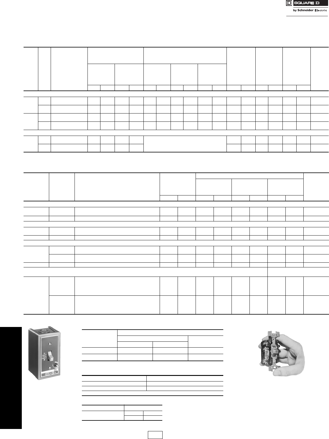
Manual Starters Type F—Fractional Horsepower
Class 2510, 2512 / Refer to Catalog 2510CT9701
Fractional Horsepower Manual Starters with Melting Alloy Type Thermal Overload Relay
Note: Continuous current rating—16 A.
Type FG2P
Table 16.1: Single-Unit Types—Class 2510—Rated 16 A — Thermal Units
Prices shown do not include thermal units. Standard trip thermal units are $21.50 each. See page 16-125 for selection
information.
Type of
Operator
No.
of
Poles Features
NEMA 1
General Purpose
Enclosure
Surface Mounting
General Purpose Flush Mounting
(Without Pull Box) NEMA
Type 4a
Watertight
and
Dusttight
Enclosure
NEMA
Types 3R, 7 & 9
Hazardous
Locations
Div. 1 & 2
Class I Groups
B, C, & D &
Class II Groups
E, F & G
Enclosure
Open
Type
Number
of
Thermal
Units
Required
Standard Oversized Gray
Flush
Plate
Standard
Stainless
Steel
Flush Plate
Jumbo
Stainless
Steel
Flush Plate
Type $ Price Type $ Price Type $ Price Type $ Price Type $ Price Type $ Price Type $ Price Type $ Price
Basic Starter—Class 2510
Togg le
1Standard
With Red Pilot Lightc
FG1
FG1P 86.00
129.00 FGJ1
FGJ1P 99.00
143.00 FF1
FF1P 78.00
122.00 FS1
FS1P 83.00
129.00 —
FSJ1P —
149.00 —
——
——
——
—FO1
FO1P 71.00
116.00 1
2Standard
With Red Pilot Lightc
FG2
FG2P 99.00
143.00 FGJ2
FGJ2P 116.00
158.00 FF2
FF2P 93.00
120.00 FS2
FS2P 99.00
143.00 —
FSJ2P —
165.00 —
——
——
——
—FO2
FO2P 86.00
129.00 1
Key
1Standard
With Red Pilot Lightc
FG3
FG3P 116.00
158.00 FGJ3
FGJ3P 129.00
171.00 FF3
FF3P 107.00
149.00 FS3
FS3P 114.00
158.00 —
FSJ3P —
179.00 —
——
——
——
—FO3
FO3P 99.00
143.00 1
2Standard
With Red Pilot Lightc
FG4
FG4P 129.00
171.00 FGJ4
FGJ4P 143.00
185.00 FF4
FF4P 122.00
165.00 FS4
FS4P 129.00
171.00 —
FSJ4P —
192.00 —
——
——
——
—FO4
FO4P 114.00
158.00 1
Starter with Handle Guard/Lock-Off—Class 2510
Togg le
1Standard
With Red Pilot Light c
FG5
FG5P 99.00
143.00 FGJ5
FGJ5P 114.00
158.00 Order basic starter plus
separate handle guard kit.
FW1
FW1P 320.00
435.00 FR1
— 350.00
—b—
—1
2Standard
With Red Pilot Lightc
FG6
FG6P 116.00
158.00 FGJ6
FGJ6P 129.00
171.00 FW2
FW2P 336.00
449.00 FR2
—363.00
—b—
—1
aFurnished with one 3/4" pipe tap in bottom (reversible for top feed). To obtain 3/4" pipe tap top and bottom, add suffix letter “H” to type number and add $19.10 to price.
bFor replacement starter, order open type above. For NEMA 4 with pilot light, retain pilot light mounting bracket from original device.
Type FO2
Table 16.2: Duplex Units—Class 2510
Type
of
Operator
No.
of
Poles Features
NEMA 1
General Purpose
Enclosure Surface
Mounting
General Purpose Flush Mounting (Without Pull Box) Number
of
Thermal
Units
Required
Gray Flush
Plate for Wall
or Cavity
Mounting
Stainless Steel
Flush Plate for
Wall or Cavity
Mounting
Replacement Starter
Class 2510
Type $ Price Type $ Price Type $ Price Type $ Price
One Starter in Duplex Enclosure—Class 2510
Togg le 2 Standard FG02 158.00 —————— 1
With Red Pilot Light cFG02P 201.00 ——————
Key 2 With Red Pilot Light cFG04P 201.00 —————— 1
Two Starters in One Enclosure—Class 2510
Togg le 2
Each Str. Standard FG22 243.00 FF22 228.00 ———— 2
With Red Pilot Light on Eachc FG22P 399.00 FF22P 386.00 FS22P 399.00 ——
Key 2 Ea. Str. With Red Pilot Light on EachcFG44P 458.00 FF44P 441.00 FS44P 458.00 —— 2
Starter and “AUTO-OFF-HAND” SPDT Selector Switch (AC Only)—Class 2510
Togg le
1Standard FG71 221.00 FF71 207.00 ———— 1
With Red Pilot Light cFG71P 264.00 FF71P 251.00 FS71P 264.00 ——
2Standard FG72 234.00 FF72 221.00 ———— 1
With Red Pilot LightcFG72P 278.00 FF72P 264.00 FS72P 278.00 ——
Key 2 With Red Pilot LightcFG74P 306.00 FF74P 293.00 FS74P 306.00 —— 1
Two Speed Starters (AC Only)—Class 2512 Replacement Starter
Class 2510
Togg le
1
With Mechanical Interlock:
2
Standard FG11 314.00 FF11 300.00 ——FO1T 86.00
With 2 Red Pilot LightscFG11P 471.00 FF11P 458.00 ——FO1PT 129.00
With HIGH-OFF-LOW Selector Switch:
With 2 Red Pilot Lightsc————FS101P 471.00 FO1PT 129.00
2
With Mechanical Interlock:
2
Standard FG22 342.00 FF22 329.00 ——FO2T 99.00
With 2 Red Pilot LightscFG22P 500.00 FF22P 485.00 ——FO2PT 143.00
With HIGH-OFF-LOW Selector Switch:
With 2 Red Pilot Lightsc————FS202P 500.00 FO2PT 143.00
cFor green pilot light, add the letter “G” to the catalog number (i.e. 2510FG2PG).
Table 16.3: Horsepower Ratings Type F
Volts
Maximum Horsepower
AC Single Phase DC
2-Pole Only
1-Pole 2-Pole
115–230 1 1 3/4
277 1 1 —
Table 16.4: Approvals—2510 Type F and K
Enclosed Open
(UL Listed) File E42243 (UL Component Recognized) File E42243
CCN NLRV CCN NLRV2
CSA Certified File LR25490 Class 3211-05
Table 16.5: How to Order
To Order Specify: Catalog Number
•Class Number
•Type Number
Class Type
2510 FG1
CP1 Discount
Schedule
Courtesy of Steven Engineering, Inc.-230 Ryan Way, South San Francisco, CA 94080-6370-Main Office: (650) 588-9200-Outside Local Area: (800) 258-9200-www.stevenengineering.com

www.schneider-electric.us
16 NEMA/DEFINITE PURPOSE TYPE
CONTACTORS AND STARTERS
© 2009 Schneider Electric
All Rights Reserved 16-3
Manual Switches 30 A, Reversing, Non-Reversing, Two Speed—Type K
Class 2510, 2511, 2512 / Refer to Catalog 2510CT9701
000
Note: Continuous current rating 30 A at 600 Vac maximum.
Table 16.6: Non-Reversing—Class 2510
Type
of
Operator
No.
of
Poles Features
NEMA 1
General Purpose
Enclosure Surface
Mounting
General Purpose Flush Mounting
(Without Pull Box) NEMA
Type 4 a
Watertight
and
Dusttight
Enclosure
NEMA
Types 3R, 7 & 9 a
Hazardous Locations
Div. 1 & 2
Class I Groups
B, C & D &
Class II Groups
E, F, and G
Enclosure
Open
Type
Standard Oversized Gray
Flush
Plate
Standard
Stainless
Steel
Flush Plate
Jumbo
Stainless
Steel
Flush Plate
Type $ Price Type $ Price Type $ Price Type $ Price Type $ Price Type $ Price Type $ Price Type $ Price
Toggle
2
Standard KG1 66.00 KGJ1 81.00 KF1 59.00 KS1 66.00 ——KW1 314.00 KR1 342.00 KO1 52.00
With Pilot Lightc
115 Vac KG1A 138.00 KGJ1A 153.00 KF1A 131.00 KS1A 138.00 KSJ1A 161.00 KW1A 428.00 ——KO1A b125.00
230 Vac KG1B 138.00 KGJ1B 153.00 KF1B 131.00 KS1B 138.00 KSJ1B 161.00 KW1B 428.00 ——KO1B b125.00
3
Standard KG2 149.00 KGJ2 165.00 KF2 143.00 KS2 149.00 ——KW2 386.00 KR2 442.00 KO2 120.00
With Pilot Lightc
208-277 Vac KG2B 221.00 KGJ2B 234.00 KF2B 215.00 KS2B 221.00 KSJ2B 243.00 KW2B 500.00 ——KO2B b207.00
440-600 Vac KG2C 221.00 KGJ2C 234.00 KF2C 215.00 KS2C 221.00 KSJ2C 243.00 KW2C 500.00 ——KO2C b207.00
2
Standard KG5 78.00 KGJ5 93.00 ——— ———KW5 327.00 ——KO5 64.00
With Pilot Lightc—
115 Vac KG5A 149.00 — ———— ———KW5A 440.00 ——KO5Ab120.00
230 Vac KG5B 149.00 — ———— ———KW5B 440.00 ——KO5Bb120.00
3
Standard KG6 162.00 KGJ6 176.00 ——— ———KW6 396.00 ——KO6 147.00
With Pilot Lightc
208-277 Vac KG6B 233.00 — ———— ———KW6B 512.00 ——KO6Bb219.00
440-600 Vac KG6C 233.00 — ———— ———KW6C 512.00 ——KO6Cb219.00
Key
2
Standard KG3 95.00 KGJ3 110.00 KF3 89.00 KS3 95.00 ———— — KO3 81.00
With Pilot Lightc
115 Vac KG3A 167.00 KGJ3A 179.00 KF3A 161.00 KS3A 167.00 KSJ3A 185.00 —— — KO3A 153.00
230 Vac KG3B 167.00 KGJ3B 179.00 KF3B 161.00 KS3B 167.00 KSJ3B 185.00 —— — — KO3B 153.00
3
Standard KG4 179.00 KGJ4 192.00 KF4 171.00 KS4 179.00 ———— — — KO4 165.00
With Pilot Lightc
208-277 Vac KG4B 251.00 KGJ4B 264.00 KF4B 243.00 KS4B 251.00 KSJ4B 270.00 —— — — KO4B 234.00
440-600 Vac KG4C 251.00 KGJ4C 264.00 KF4C 243.00 KS4C 251.00 KSJ4C 270.00 —— — — KO4C 234.00
aFurnished with one 3/4" pipe tap in bottom (reversible for top feed). To obtain 3/4" pipe tap top and bottom, add suffix letter “H” to type number and add $28.70 to price.
bWhen replacing starter with pilot light in NEMA 4 enclosure, retain pilot light mounting bracket from original device.
Table 16.7: Reversing—Class 2511
Type
of
Operator
No.
of
Poles
Motor Types
for Which Suitable
Features
(Including
Mechanical
Interlock)
NEMA 1
General Purpose
Enclosure
Surface Mounting
With Flush Plate for
Cavity Mounting
(Without
Pull Box)
Replacement
Switch
Class 2510
Type $ PriceType $ PriceType $ Price
Toggle
2Single Ø
3-Lead
Repulsion-Induction
Standard KG11 287.00 KF11 270.00 KO1T 66.50
With Pilot Light:c
115 Vac KG11A 399.00 KF11A 386.00 KO1AT 138.00
230 Vac KG11B 399.00 KF11B 386.00 KO1BT 138.00
3
Three Ø; Also
Single Ø Capacitor,
Split Ø, or 4-Lead
Repulsion-Induction
Standard KG22 441.00 KF22 428.00 KO2T 149.00
With Pilot Light:c
110–120 Vac KG22A 557.00 KF22A 543.00 KO2AT 221.00
208–220 Vac KG22B 557.00 KF22B 543.00 KO2BT 221.00
440–600 Vac KG22C 557.00 KF22C 543.00 KO2CT 221.00
Table 16.8: Two Speed—Class 2512
Type
of
Operator
No.
of
Poles
Motor Types
for Which Suitable
Features
(Including
Mechanical
Interlock)
NEMA 1
General Purpose
Enclosure
Surface Mounting
With Flush Plate for
Cavity Mounting
(Without
Pull Box)
Replacement
Switch
Class 2510
Type $ Price Type $ Price Type $ Price
Togg le
2Single Ø
Two Winding
(3-Lead)
Standard KG11 287.00 KF11 270.00 KO1T 66.50
With 2 Pilot Lights:c
115 Vac KG11A 513.00 KF11A 500.00 KO1AT 138.00
230 Vac KG11B 513.00 KF11B 500.00 KO1BT 138.00
3Three Ø
Separate Winding
(Wye-Connected)
Standard KG22 441.00 KF22 428.00 KO2T 152.00
With 2 Pilot Lightsc:
208–240 Vac KG22B 671.00 KF22B 656.00 KO2BT 221.00
440–600 Vac KG22C 671.00 KF22C 656.00 KO2CT 221.00
cFor green pilot light, add the letter “G” to the catalog number (i.e. 2510KW2CG).
Table 16.9: Class 2510 Horsepower Ratings
Class
2510 No. of
Poles Motor
Type AC
Maximum Hp DC Rating
115
Volts 230
Volts 460
Volts 575
Volts 90
Volts 115
Volts 230
Volts
KO1
KO3 2Single Ø2233121-1/2
KO2
KO4 3 Three Ø 2 7-1/2 10 10 1 2 1-1/2
KO5 2 Single Ø 2 3 7-1/2 10 1 2 1-1/2
KO6 3 Three Ø 2 7-1/2 15 20 1 2 1-1/2
Table 16.10: How to Order
To Order Specify: Catalog Number
•Class Number
•Type Number
Class Type
2510 KO2
Table 16.11: Class 2511 and 2512 Horsepower
Ratings Type K
Device No.
of
Poles
Motor Type
AC
Maximum Hp DC Ratings
115
Volts 230
Volts 460–575
Volts 90
Volts 115
Volts 230
Volts
Class
2511
2 Single Ø 2 2 3 1 2 1-1/2
3 Three Ø 2 7-1/2 10 1 2 1-1/2
Class
2512
2 Single Ø 2 2 3 1 2 1-1/2
33 Ø,
Constant or Variable
Torq ue 2 7-1/2 10 1 2 1-1/2
33 Ø,
Constant
Horsepower 2 7-1/2 10 1 2 1-1/2
CP1 Discount
Schedule
Courtesy of Steven Engineering, Inc.-230 Ryan Way, South San Francisco, CA 94080-6370-Main Office: (650) 588-9200-Outside Local Area: (800) 258-9200-www.stevenengineering.com
www.schneider-electric.us
16 NEMA/DEFINITE PURPOSE TYPE
CONTACTORS AND STARTERS
16-4 © 2009 Schneider Electric
All Rights Reserved
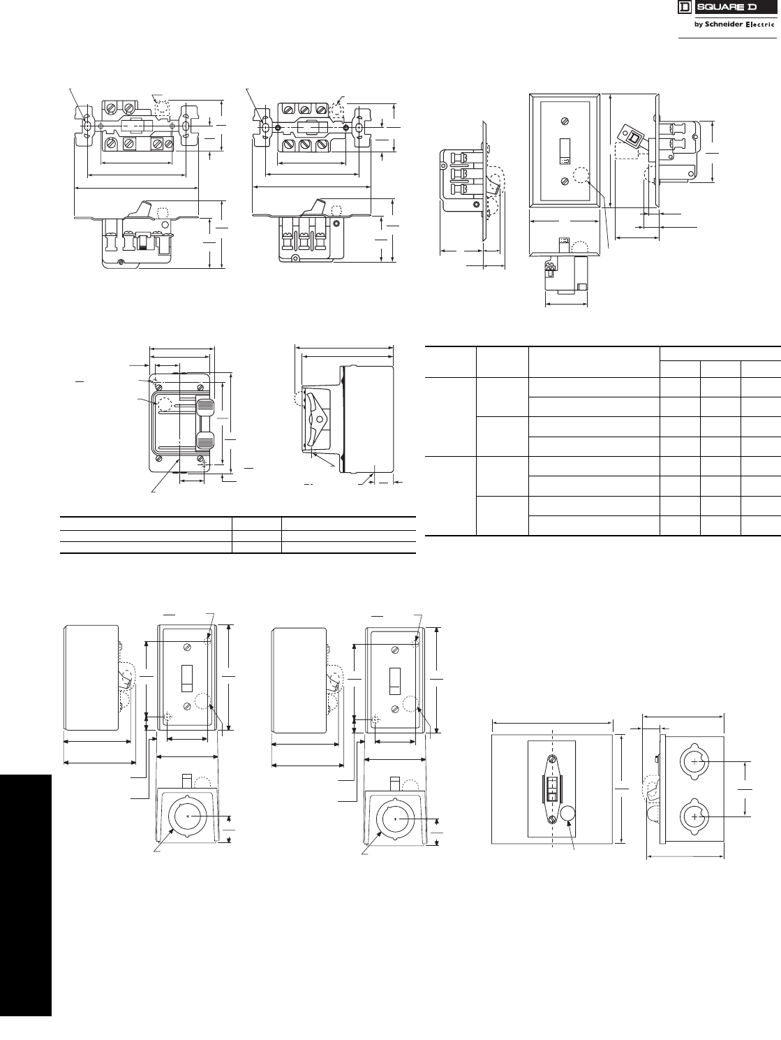
Manual Starters and
Switches
Type F and K—Approximate Dimensions
Class 2510, 2511, 2512 / Refer to Catalog 2510CT9701
Open Type
NEMA 4 Watertight Die Cast Zinc Enclosure
NEMA 1 General Purpose Enclosure (Surface Mount)
NEMA 1 General Purpose Enclosure (Flush Mount)
Table 16.12:
Device Class Type
Fractional Hp Starter 2510 FW1, 1P, 2, 2P
Motor Starting Switch 2510 KW1, 1A, 1B, 2, 2B, 2C
2.22
56
1.59
40
.84
21
1.69
43
4.13
105
3.28
83
2.38
60
MTG. HOLES FOR #6-32 SCREWS (2)
PILOT LIGHT
OFF
1.70
43
2.34
60
2.38
60
3.28
83 4.13
105
1.69
43
.84
21
OFF
MTG. HOLES FOR #6-32 SCREWS (2)
PILOT LIGHT
Types FO1, 1P, 2
Fractional Hp Starter
Types KO1, 1A, 1B, 2, 2B, 2C
Types KO5, 5A, 5B, 6, 6B, 6C
Motor Starting Switch
CONDUIT CENTER LINE
3
76
1.13
29
.25
6
2.75
70
(2) DIA. MTG. HOLE
.22
6
PILOT LIGHT
ON
OFF
.31
8
1.13
29
4.38
111
3.75
95
4.25
108
4.56
116
3"
414 PIPE TAP
.28
7.78
20
DIA. PADLOCK HOLE
2.75
70
2.88
73
4.25
108
1.63
41
0.56
14
0.69
17
1.06
27
3.00
76
OFF
2.88
73
1/2-3/4" Conduit
Knockout, Both Ends
Pilot
Light
Mtg. Holes dia. (2)
.25
6
Oversized
(Class 2510 Types FGJ & KGJ,
Single Unit)
2.75
70
2.88
73
4.25
108
1.63
41
0.56
14
0.41
10
1.06
27
3.00
76
OFF
2.44
62
1/2-3/4" Conduit
Knockout, Both Ends
Pilot
Light
Mtg. Holes dia. (2)
.25
6
Standard
(Class 2510 Types FG & KG, Single Unit)
OFF
Pilot Light
4.86
1230.71
18
3.28
83
3.09
78
2.20
56
4.35
110
Jumbo
(Class 9991 Type KE2; see page 16-9)
Table 16.13:
Device Type
of
Operator Class 2510 Type Dimensions
ABC
Fractional
Hp
Starter
Toggle
FF1, 1P, 2, 2P
FS1, 1P, 2, 2P 1-7/16 2-3/4 4-1/2
FSJ1P, 2P 1-7/16 3-1/2 5-1/4
Key
FF3, 3P, 4, 4P
FS3, 3P, 4, 4P 1-7/16 2-3/4 4-1/2
FSJ3P, 4P 1-7/16 3-1/2 5-1/4
Motor
Starting
Switch
Toggle
KF1, 1A, 1B, 2, 2B, 2C
KS1, 1A, 1B, 2, 2B, 2C 1-3/4 2-3/4 4-1/2
KSJ1A, 1B, 2B, 2C 1-3/4 3-1/2 5-1/4
Key
KF3, 3A, 3B, 4, 4B, 4C
KS3, 3A, 3B, 4, 4B, 4C 1-3/4 2-3/4 4-1/2
KSJ3A, 3B, 4B, 4C 1-3/4 3-1/2 5-1/4
.75
19
.91
23
A
OFF
PILOT
LIGHT
D
D
1.69
43
1.78
45
.66
17
.50
13
2.56
65
B
C
Courtesy of Steven Engineering, Inc.-230 Ryan Way, South San Francisco, CA 94080-6370-Main Office: (650) 588-9200-Outside Local Area: (800) 258-9200-www.stevenengineering.com

www.schneider-electric.us
16 NEMA/DEFINITE PURPOSE TYPE
CONTACTORS AND STARTERS
© 2009 Schneider Electric
All Rights Reserved 16-5
NEMA 3R, 7, and 9 Aluminum Enclosure for Hazardous
Locations
Dimensions for Duplex Devices
aSelector switch is on left, increases overall depth to 3-1/2".
bOnly one pilot light (located on right) is used on Class 2511 switches.
cDimensions include factory wired power connections.
dSelector Switch is on left, extends 1-5/8" from mounting surface.
Table 16.14: NEMA 3R, 7, and 9 Aluminum Enclosure for
Hazardous Locations
Device Class Type
Fractional Hp Starter 2510 FR1, 2
Motor Starting Switch 2510 KR1, 2
Table 16.15: NEMA 1 General Purpose Surface Mount Enclosure
for Duplex Devices
Device Type of
Operator Class Type
One Starter Toggle 2510 FGO2, 02P
Key 2510 FGO4P
Two S tar t ers Toggle 2510 FG22, 22P
Key 2510 FG44P
One Str. and
One Sel. Sw. a
Toggle 2510 FG71, 71P, 72, 72P
Key 2510 FG74P
Reversing Switchb Toggle 2511 KG11, 11A, 11B, 22, 22A, 22B, 22C
Two Speed Starter Toggle 2512 FG11, 11P, 22, 22P
Two Speed Switch Toggle 2512 KG11, 11A, 11B, 22, 22B, 22C
1.37
35
.70
18
5.75
146
.30
8
1.37
35
6.36
161
3.95
100
ON
OFF
CONDUIT CENTERLINE
2X .31
8MTG. HOLES
2X
4.35
110
1.19
30
3/4-14 PIPE TAP,
BOTTOM ONLY
.28
7PADLOCK HOLE
2.75
70 2.88
73
PILOT
LIGHT
OFF OFF
(4) .25
6
3.00
76 4.25
108
DIA. MTG. HOLES
.56
14
1.88
484.50
114
1.06
27
.38
10
1.88
48
1/2 - 3/4 CONDUIT KNOCKOUT, BOTH ENDS.
2.56
65 2.63
67
3.81
97
Table 16.16: General Purpose Flush Mounting Plate for
Duplex Devices
Device Type
of
Operator Class Type Dimensionsc
ABCD
Two
Starters
Toggle 2510 FF22, 22P 5-1/4 3-3/4 5-1/4 1-7/16
FS22P 4-9/16 3-1/2 4-1/2 1-7/16
Key 2510 FF44P 5-1/4 3-3/4 5-1/4 1-7/16
FS44P 4-9/16 3-1/2 4-1/2 1-7/16
One
Starter
and One
Selector
Switchd
Toggle 2510 FF71, 71P, 72, 72P 5-1/4 3/4 5-1/4 2
FS71P, 72P 4-9/16 3-1/2 4-1/2 2
Key 2510 FF74P 5-1/4 3-3/4 5-1/4 2
FS74P 4-9/16 3-1/2 4-1/2 2
Reversing
Switch Toggle 2511 KF11, 11A, 11B
KF22, 22A
KF22B, 22C 5-1/4 3-3/4 5-1/4 1-3/4
Two S pee d
Starter Toggle 2512 FF11, 11P, 22, 22P 5-1/4 3-3/4 5-1/4 1-7/16
Two S pee d
Switch Toggle 2512 KF11, 11A, 11B,
KF22, 22B, 22C 5-1/4 3-3/4 5-1/4 1-3/4
.75
19
2.56
65
.91
23
D
OFFOFF
PILOT
LIGHT
A
B
C
Manual Starters and
Switches
Approximate Dimensions—Type F and K
Class 2510, 2511, 2512 / Refer to Catalog 2510CT9701
Courtesy of Steven Engineering, Inc.-230 Ryan Way, South San Francisco, CA 94080-6370-Main Office: (650) 588-9200-Outside Local Area: (800) 258-9200-www.stevenengineering.com

www.schneider-electric.us
16 NEMA/DEFINITE PURPOSE TYPE
CONTACTORS AND STARTERS
16-6 © 2009 Schneider Electric
All Rights Reserved
Manual Starters Type M and T—Integral Horsepower
Class 2510, 2511, 2512 / Refer to Catalog 2510CT9701
All Except NEMA 7 & 9
NEMA 7 & 9 Only
Types M and T integral horsepower manual starters
provide convenient “On-Off” operation of small single
phase, polyphase or DC motors. Typical applications
include small machine tools, pumps, fans and
conveyors.
•Push button (M) or toggle (T) operators
•Reliable overload protection
•Pilot light and auxiliary contact available
Table 16.17: Integral Horsepower Manual Starters
Note that the prices shown do not include thermal units. Standard trip thermal units are $21.50 each; see page 16-125 for selection information.
Non-Reversing Class 2510 Max. Voltage: 600 Vac
No.
of
Poles
NEMA
Size
Ratings NEMA 1
Surface Mounting NEMA 4/4X
Watertight
and
Dusttight
Enclosure
Brushed
Stainless Steel
NEMA 4/4X
Watertight,
Dusttight and
Corrosion-Resistant
Glass-Polyester
Enclosure
a
NEMA 7 & 9
For Hazardous
Locations Class I
– Groups C, D
Class II –
Groups E, F & G
NEMA 12
Dusttight
and Driptight
Industrial
Use
Enclosure
Open Type
Motor
Voltage
Max. Hp Square
P.B .
Operator
Toggle
Operator $ Price
Square
P.B .
Operator
Toggle
Operator $ Price
Poly-
Phase Single
Phase Type Type $ Price Type $ Price Type $ Price Type $ Price Type
2-
Pole
M-0 115
230 —
—1
2MBG1 TBG1 264.00 MBW11b720.00 MBW1b720.00 MBR1b1004.00 MBA1b363.00 MBO1 TBO1 234.00
M-1 115
230 —
—2
3MCG1 TCG1 336.00 MCW11 891.00 MCW1 891.00 MCR1 1197.00 MCA1 435.00 MCO1 TCO1 306.00
M-1P 115
230 —
—3
5MCG2 TCG2 491.00 MCW12 1089.00 MCW2 1089.00 MCR2 1382.00 MCA2 593.00 MCO2 TCO2 309.00
3-
Pole
M-0 115
200-230
380-575
—
3
5
—
—
—MBG2 TBG2 314.00 MBW12b770.00 MBW2b770.00 MBR2b1062.00 MBA2b414.00 MBO2 TBO2 287.00
M-1 115
200-230
380-575
—
7-1/2
10
—
—
—MCG3 TCG3 386.00 MCW13 941.00 MCW3 941.00 MCR3 1254.00 MCA3 485.00 MCO3 TCO3 356.00
DC
2-
Pole
M-0 115
230 1 hp–D.C.
1-1/2 hp–D.C. MBG4 TBG4 264.00 MBW14 720.00 MBW4 720.00 ——MBA4 363.00 MBO4 TBO4 234.00
M-1 115
230 1-1/2 hp–D.C
2 hp–D.C. MCG5 TCG5 336.00 MCW15 891.00 MCW5 891.00 MCR5 1188.00 MCA5 435.00 MCO5 TCO5 306.00
aNEMA 7 & 9 enclosures are cast-iron. NEMA 7 & 9 enclosures (cast aluminum) are available for outdoor use; to order these type of enclosures, replace the “R” in the catalog number with a
“T”. For additional information, contact your local Square D Field Sales Office.
bApproved for group motor installations per NEC 430-53(c).
File E42243
CCN NLRV File LR60905
Class 3211-05
File E58760
CCN NPXZ File LR26817
Class 3218-04
Table 16.18: How to Order
To Order Specify: Catalog Number
•Class Number
•Type Number
Class Type
2510 MCA1
CP1 Discount
Schedule
Courtesy of Steven Engineering, Inc.-230 Ryan Way, South San Francisco, CA 94080-6370-Main Office: (650) 588-9200-Outside Local Area: (800) 258-9200-www.stevenengineering.com

www.schneider-electric.us
16 NEMA/DEFINITE PURPOSE TYPE
CONTACTORS AND STARTERS
© 2009 Schneider Electric
All Rights Reserved 16-7
Manual Starters Integral Horsepower—Type M and T
Class 2510, 2511, 2512 / Refer to Catalog 2510CT9701
Reversing and Two Speed
Class 2511 reversing and Class 2512 two-speed manual
starters consist of two mechanically interlocked Class 2510
Types M or T manual starters.
.
Thermal Units
Starters will not operate without properly installed thermal
units and device reset. Thermal unit must be installed so
that markings face the front of starter.
Application Data
Size–Available in NEMA Sizes M-0, M-1, and M-1P.
Poles–Two poles single phase; three poles polyphase;
2 poles DC.
Voltage–600 volts AC max.; 250 volts DC max.
Overload Relays–Melting alloy thermal overload relays
have provisions for one Type B thermal unit for single
phase starters and three Type B thermal units for three
phase starters. All thermal units must be installed and
the device reset before the starter contacts will
operate. After overload relays have tripped, allow one or
two minutes for the alloy to solidify before resetting.
Operator–Available with a push button or toggle operator
in open and NEMA 1 versions. NEMA 4/4X (stainless) &
12 versions utilize a direct acting push button only.
NEMA 4/4X (polyester) & 7/9 versions utilize an external
toggle to actuate a push button device inside.
Maintenance of Equipment
For proper performance, all equipment should be
periodically inspected and maintained. Replacement
contacts and interlocks are available in kit form to facilitate
servicing and stocking. In addition, the service bulletin
contains an exploded view of the device with components
clearly marked for easy identification by description and
part number.
Mechanism Lock Off–Both open devices and starters in
NEMA 1 surface and flush mounting, and NEMA 4, 4X, 7 &
9 and 12 enclosures can be locked in the OFF or STOP
position. The NEMA 1 surface mounting, 4, 4X, 7 & 9 and
12 enclosures can also be locked closed to prevent
unauthorized entry.
Accessories and Modification Kits
One auxiliary contact, either N.O. or N.C. can easily be
added internally to any open or enclosed Type M or T
manual starter. It occupies the space provided in either the
upper right hand or left hand corners of the device. These
contacts are for AC loads only. For electrical ratings refer
to page 16-119, Class 9999 Types SX11 or SX12.
A unique red pilot light assembly that clips into place is
available factory installed on NEMA 1, 4, 4X, 12 and flush
enclosures or as a field modification kit on the NEMA 1
surface or flush mounting enclosures. See page 16-9. The
color cap assembly snaps into a knockout in the enclosure
cover on the NEMA 1 enclosures. Pilot light kits are
available for use on Various voltages (110-600 volts). Pilot
light assemblies are not available for NEMA 7 & 9
enclosures.
Table 16.19: Reversing Class 2511
Class Description No.
of
Poles
NEMA
Size
Ratings NEMA 1
Surface Mounting Open Type
Motor
Voltage Maximum
Hp
Square
P.B.
Operator
Toggle
Operator $ Price Square
P.B.
Operator
Toggle
Operator $ Price
2511 Standard 3-Pole
M-0 200-230 3 MBG1 TBG1 984.00 MBO1 TBO1 899.00
380-575 5
M-1 200-230 7-1/2 MCG1 TCG1 1197.00 MCO1 TCO1 1112.00
380-575 10
Table 16.20: Two Speed (Wye-Connected Separate Winding Motors Only) Class 2512
Class Description No.
of
Poles
NEMA
Size
Ratings NEMA 1
Surface Mounting Open Type
Motor
Voltage Constant
Hp
Constant
Torque or
Variable
Torque
Square
P.B .
Operator
Toggle
Operator $ Price Square
P.B.
Operator
Toggle
Operator $ Price
2512 Standard 3-Pole
M-0 200-230 2 3 MBG1 TBG1 984.00 MBO1 TBO1 899.00
380-575 3 5
M-1 200-230 5 7-1/2 MCG1 TCG1 1197.00 MCO1 TCO1 1112.00
380-575 7-1/2 10
Table 16.21: Terminal information and Replacement Contact Kits
NEMA
Size
Power Terminals Auxiliary Interlock Terminals
No. of
Poles Service
Bulletin
Replacement Contact Kit
Type
of Lug
Wire Size
(Solid or Stranded
Copper Wire)
Min.-Max.
Type
of Lug
Wire Size
(Solid or Stranded
Copper Wire)
Min.-Max.
Class Type
M-0 Pressure
Wire #14–#8 Pressure
Wire #16–#12 2 or 3 312AS 9998 ML1
M-1 Pressure
Wire #14–#8 Pressure
Wire #16–#12 2 or 3 312AS 9998 ML2
M-1P Box
Lug #14–#6 Pressure
Wire #16–#12 2 312AS 9998 ML2
CP1 Discount
Schedule
Courtesy of Steven Engineering, Inc.-230 Ryan Way, South San Francisco, CA 94080-6370-Main Office: (650) 588-9200-Outside Local Area: (800) 258-9200-www.stevenengineering.com

www.schneider-electric.us
16 NEMA/DEFINITE PURPOSE TYPE
CONTACTORS AND STARTERS
16-8 © 2009 Schneider Electric
All Rights Reserved
Manual Starters Type M and T—Integral Horsepower—Approximate Dimensions
Class 2510, 2511, 2512 / Refer to Catalog 2510CT9701
NEMA 1
General Purpose Surface Mounting
NEMA 4/4X
Watertight and Dusttight
Stainless Steel
NEMA 12
Dusttight and Driptight
Industrial Use
NEMA 4/4X
Watertight, Dusttight and
Corrosion Resistant Glass
Polyester
NEMA 7 & 9
Hazardous Locations
Cast Iron
START
STOP
RESET
START
STOP
RESET
8.94
227
7.25
184
9.34
237
7.88
200
.84
21
.75
19
.28 Dia.
Mtg. Holes
3.38
86
1.69
43
4.25
108
1.28
33
.22
6
(3) .5 -.75 K.O.
Top and Bottom
Classes 2511, 2512, Types M & T
Sizes M-0 and M-1 NEMA 1
General Purpose Enclosure
Approximate Shipping Weight—9 lbs.
STAR T
STOP
RESET
6.00
152
4.13
105
3.38
86
.94
24
10.00
254
8.13
207
1.00
25
.88
22
.22
6
1.69
43
.94
24
5.00
127
1.06
27
1.00
25
1.00
25
1.06
27
.50 - .75 K.O.
(2) Top Back .50 - .75 K.O.
(2) Each Side
(1) .50 - .75 K.O.
(2) .75 - 1.00 K.O.
Top and Bottom
.22 Dia.
(3) Mounting
Holes
Class 2510 Type M & T Size M-1P
NEMA 1 General Purpose Enclosure
Approximate Shipping Weight—5 lbs.
STAR T
STOP
RESET
5.00
127
3.00
76
2.13
54
1.00
25
8.63
219
5.75
146
1.44
37
.22
6
1.06
27
3.91
99
1.02
26
1.14
29
1.02
26
(2) .50 - .75 K.O.
To p and Bottom
.22 Dia.
(4) Mounting
Holes
.50 - .75 K.O.
Each Side
Class 2510 Types M & T Sizes M-0 and M-1
NEMA 1 General Purpose Enclosure
Approximate Shipping Weight—5 lbs.
START
STOP
RESET
10.75
273
2.89
73
3.25
83
1.27
32
10.00
254
.38
10
10.92
277
(2) .31 Wide Slots
NEMA 4 Only
5.76
146
5.78
147 .75 Conduit Hub
Top and Bottom 1.31
33
.47
12
.31 Dia.
(2) Mounting
Holes
Class 2510 Type M Sizes M-0, M-1 and M-1P
NEMA 4/4X Watertight Stainless Steel Enclosure
NEMA 12 Dusttight Industrial Use Enclosure
Approximate Shipping Weight—9 lbs.
5.78
147
3.69
94
5.13
130
1.41
36
7.31
186
.72
18.81
21
8.75
222
10.34
263
(2) .31 Dia.
Mtg. Holes
ON
R
E
S
E
T
OFF
.75 Conduit Hub
To p and Bottom
.72
18
Class 2510 Type M Size M-0 (AC–DC)
and Size M-1 (DC) NEMA 4/4X
Watertight Corrosion-Resistant
Glass Polyester Enclosure
Approximate Shipping Weight—6 lbs.
8.75
222
.75
19
1.69
43
1.69
43
.75
19
12.13
308
(2) .31 Dia.
Mtg. Holes
.75 Conduit Hub
In Top and Bottom
5.00
127
2.19
56
6.50
165
6.41
163
1.28
33
ON
R
E
S
E
TOFF
Class 2510 Type M Sizes M-1 and M-1P (AC)
NEMA 4/4X Watertight Corrosion-Resistant
Glass Polyester Enclosure
Approximate Shipping Weight—6 lbs.
10.50
267
.34
9
9.94
252
(4) .13 Wide
Mtg. Slots
(1) .75 Conduit Top and Bottom (Std.)
(1) 1.50 Conduit Top and Bottom (Max.)
6.00
152
4.69
119
2.34
59
.66
17 6.13
156
ON
R
E
S
E
T
OFF
Class 2510 Type M Sizes M-0, M-1 and M-1P
NEMA 7 & 9 Hazardous Location
Cast Iron Enclosure
Approximate Shipping Weight—18 lbs.
START
STOP
RESET
3.50
89
5.72
145
5.13
130
1.25
32
.28
7
1.13
29
1.75
44
.69
18
.44 Travel to
11 Reset
1.13
29 3.97
101
4.03
102
Prov. for
(3) #10
Mounting
Screws
Class 2510 Type M Sizes M-0, M-1
and M-1P, Open Type
Approximate Shipping Weight—3 lbs.
Courtesy of Steven Engineering, Inc.-230 Ryan Way, South San Francisco, CA 94080-6370-Main Office: (650) 588-9200-Outside Local Area: (800) 258-9200-www.stevenengineering.com

www.schneider-electric.us
16 NEMA/DEFINITE PURPOSE TYPE
CONTACTORS AND STARTERS
© 2009 Schneider Electric
All Rights Reserved 16-9
Manual Starters and
Switches
Accessories and Modifications
Class 2510, 2511, 2512 / Refer to Catalog 2510CT9701
aStandard on Type K devices.
bLens cannot be replaced. Pilot light kits for NEMA 4 Enclosed Units are
for replacement purposes only.
cMay only be field-added to NEMA 1 enclosures. For green pilot light,
order 9999SPG1 additionally.
dFor proper operation, only one auxiliary contact kit per device may be
added.
eUsed to control a single phase motor utilizing a three phase starter.
fP11 Pilot Light Voltage Codes:
120 V—V02
200/208 V—V08
230 V—V03
460 V—V06
575 V—V07
The pilot light Form P11 requires a voltage code.
Catalog number example: 2510MBG1V02P11.
Contact Kits
See page 16-116 for Class 9998 Replacement Contact Kits.
Table 16.22: Accessories—Class 2510
Types F and K
Description Class & Type $ Price
Handle Guard Kit with Padlock Provisiona 2510FL1 14.30
Emergency Off Actuator 2510PB1 35.60
Additional Key for Key Operated Devices 2510FK1 4.80
Table 16.23: Pilot Light Kits—Class 2510
Types F and K
Application Voltage
Red
Pilot Light Green
Pilot Light $ Price
Class & Type Class & Type
Type KF, KG,
KWb
110–120 Vac 9999PL11 9999PL11G 71.00
208–277 Vac 9999PL12 9999PL12G 71.00
440–600 Vac 9999PL13 9999PL13G 71.00
Type FF or FG,
FWb115–240 Vac/dc 9999PL10 9999PL10G 42.80
Table 16.24: Replacement Nameplates—Class 2510 Types F and K
Description Application Nameplate
Marking
Nameplate Type Number—Class 2510
For Type K Switch For Type F Starter
(Includes “Reset” Indication)
$ Price
Without
Pilot
Light
With
Pilot
Light
Without
Pilot
Light
With
Pilot
Light
1-3/4" x 2-13/16" Nameplate
with Embossed Mounting
Holes for #6 Oval Head
Screws
Standard commercial switch
box cover or flush plate,
including Square D
stainless steel plates
(Blank)
(Special marking –
Specify marking desired.)
FN1
FN5
—
—
FN2
FN6
—
—
21.50
42.80
1-29/32" x 3-27/32"
Flat Nameplate
with Mounting
Holes for #6
Pan Head Screws
Square D NEMA 1
surface mounted
enclosure or
gray flush plate
(Blank)
High
Low
Forward
Reverse
(Special marking—
Specify marking desired.)
FN10
FN11
FN12
FN13
FN14
FN15
FN20
FN21
FN22
—
FN24
FN25
FN30
FN31
FN32
—
—
FN35
FN40
FN41
FN42
—
—
FN45
21.50
21.50
21.50
21.50
21.50
42.80
Table 16.25: Modifications (Types M & T only)
Description
Factory Modifications and
Forms Field Modifications
Form
Number Price
Addition Kit
Class & Type $ Price
Red
Pilot LightcP11f77.00 9999MP1 (110–120 V)
9999MP2 (208–240 V)
9999MP3 (440–600 V) 71.00
Auxiliary
Contactsd
X1 (1 N.O.)
X2 (1 N.C.) 105.00 9999SX11 (N.O.)
9999SX12 (N.C.) 99.00
Jumper
Straps eN/A — 9998SO31 14.30
Contactor
only Y76 No Charge N/A —
Table 16.26: How to Order
To Order Specify: Catalog Number
•Class Number
•Type Number
Class Type
9991 KE1
Table 16.27: Replacement Parts
Description Class and
Type $ Price
Replacement Toggle Kits:
Type FW and KW (NEMA 4)
Type FR and KR (NEMA 7 & 9) 9998HW1
9998HR2 29.30
30.90
Replacement Handle Kits:
NEMA 12 (Ser. B) Type MBA, MCA
NEMA 4/4X (Stainless) (Ser. B) Type MBW, MCW
NEMA 4/4X (Polyester) Type MBW, MCW
NEMA 7 and 9 Type MBR, MCR
9998HWA1
9998HWA1
9998HR3
9998HR3
57.00
57.00
57.00
57.00
Internal Lever 9998IL1 14.30
Table 16.28: Enclosures
For use with
Class 2510 Type Enclosure Catalog
Number $ Price
F and K
NEMA 1 Standard
9991EN1 29.30
M–Sizes M0 & M1 9991MG1 57.00
M–Size M1P 9991MG2 57.00
FO1, FO1P, FO2,
FO2P, FO3, FO3P,
FO4, FO4P NEMA 1 Oversized 9991FE1 42.80
KO1, KO1A, KO1B,
KO2, KO2B, KO2C,
KO3, KO3A, KO3B,
KO4, KO4B, KO4C,
KO5, KO5A, KO5B,
KO6, KO6B, KO6C
NEMA 1 Oversized 9991KE1 42.80
NEMA 1 Jumbo 9991KE2 86.00
NEMA 3R 9991KE3 215.00
CP1 Discount
Schedule
Courtesy of Steven Engineering, Inc.-230 Ryan Way, South San Francisco, CA 94080-6370-Main Office: (650) 588-9200-Outside Local Area: (800) 258-9200-www.stevenengineering.com
16-10 © 2009 Schneider Electric
All Rights Reserved
www.schneider-electric.us
16 NEMA/DEFINITE PURPOSE TYPE
CONTACTORS AND STARTERS
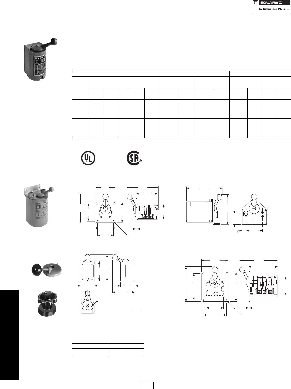
Reversing Drum Switches Type A and B
Class 2601 / Refer to Catalog 2510CT9701
NEMA 1, 3R, 4 & 13 Without Overload Protection
Class 2601 reversing drum switches may be used for across-the-line starting and reversing of AC polyphase, AC single
phase or DC motors, where overload protection is not required or is provided separately. They are compact and
inexpensive but ruggedly constructed. Drum switches are field convertible from maintained only to momentary only
operation. This conversion consists of removing the handle screw and handle, turning the shaft 180 degrees, then
replacing the handle and handle screw.
Optional handles – All devices offer as standard a one piece handle. An optional ball and shaft or fluted type handle
is available. Drum switches with optional handles are available on a factory Quick-Ship basis only. To order, add the
letter B or F to the type number, e.g., Class 2601 Type AW2B for a ball and shaft type, Class 2601 Type AW2F for a
fluted type. Add $19.10 to the price for a fluted type, no adder for a ball and shaft type. (See photos below.)
aMaintained – “Forward”; Momentary – “Reverse”; (Not field convertible)
Approximate Dimensions
Table 16.29:
600 Vac Maximum Class 2601 360 Vdc Maximum
Ratings NEMA 1
General Purpose
Enclosure
NEMA 4
Watertight and
Dusttight Enclosure
NEMA 3R
Rainproof
Outdoor Enclosure
NEMA 1
Maintained &
Momentarya
NEMA 13
Oiltight
Flush Mounting
Voltage
Maximum Horsepower
AC
Single
Phase
AC
Poly-
Phase DC Type $ Price Type $ Price Type $ Price Type $ Price Type $ Price
115-
200/230
230
460/575
1-1/2
—
2
—
—
2
—
2
1/4
—
1/4
—
AG2 158.00 AW2 428.00 AH2 207.00 AG2S2 158.00 AF2 131.00
115-
200/230
230
460/575
1-1/2
—
3
5
—
5
—
7-1/2
2
—
2
—
BG1 428.00 BW1 590.00 N/A — BG1S4 428.00 BF1 356.00
File
CCN E42243
NLRV File
Class LR25490
3211-05
Table 16.30: How to Order
To Order Specify: Catalog Number
•Class Number
•Type Number
Class Type
2601 AG2
Type AG2
Type AW2
3.38
86
5.20
132
3.19
81
3.70
94
.20
5
2.38
60
2.87
73
2.77
70
3.81
97
5.58
142
(4) .17 Mounting Holes
Class 2601 Type AF2 Class 2601 Types AW and BW
(2) 1/2" NPT
Pipe Thread
.60
15
1.82
46
5.50
140
6.89
175
3.20
81
Ball and Shaft Type
Optional Handles
Fluted Type
4.00
5.18
2.68
3.26
5.38
6.62
dimensions (inches) =
4.61
4.86
AG/AH
BG
(2) K.O. For 1/2" Conduits
2.91
3.53
Class 2601 Types AG, AH, BG
4.50
114
4.50
114
2.94
75
4.00
102 (4) .218 Mounting Holes
.20
5
5.12
130
3.25
83
6.54
166
4.82
122
5.95
151
Class 2601 Type BF1
CP1 Discount
Schedule
Courtesy of Steven Engineering, Inc.-230 Ryan Way, South San Francisco, CA 94080-6370-Main Office: (650) 588-9200-Outside Local Area: (800) 258-9200-www.stevenengineering.com

www.schneider-electric.us
16 NEMA DEFINITE PURPOSE TYPE
CONTACTORS AND STARTERS
© 2009 Schneider Electric
All Rights Reserved 16-11
Motor Starters NEMA Rated TeSys® U Simple Motor Starter
Refer to Catalog 8502CT0201
NEMA rated TeSys U motor starter is integrated, simple to choose and to install, consisting of a control unit snapped in
a powerbase. NEMA rated TeSys U can be configured to fit specific applications as well. The NEMA Rated TeSys U
uses the same optional accessories: reverser, current limiter, predictive maintenance options and communication
options as the IEC TeSys U.
Selecting a NEMA TeSys U Motor Starter in Three Steps
Accessories . . . . . . . . . . . . . . . . . . . . . . . . . . . . . . . . . . pages 18-29 to 18-31
Dimensions . . . . . . . . . . . . . . . . . . . . . . . . . . . . . . . . . . . . . . . . . . .page 18-50
Table 16.31: Step 1. Select Power Base (LUS32NR as a starter, LUB32NR as a self-protected starter)
Control
Connection NEMA Size
Three Phase (HP max.) Single Phase (HP max.) Power Bases
200/208 V 220/240 V 460 V 575/600 V 240 V Catalog
Number $ Price
With screw
terminations
17.57.51010 3 LUS32NR 348.00
17.57.51010 3 LUB32NR 488.00
Table 16.32: Step 2. Select Control Unit c
Setting Range
(Amps)
Standard
3-phase
Class 10 trip a$ Price Advanced
3-phase
Class 10 trip a$ Price Advanced
single-phase
Class 10 trip a$ Price Advanced
3-phase
Class 20 trip a$ Price
0.15–0.6 LUCAX6•• 120.00 LUCBX6•• 150.00 LUCCX6•• 150.00 LUCDX6•• 150.00
0.3–1.4 LUCA1X•• 120.00 LUCB1X•• 150.00 LUCC1X•• 150.00 LUCD1X•• 150.00
1.25–5.0 LUCA05•• 120.00 LUCB05•• 150.00 LUCC05•• 150.00 LUCD05•• 150.00
3–12 LUCA12•• 120.00 LUCB12•• 150.00 LUCC12•• 150.00 LUCD12•• 150.00
4.5–18 bLUCA18•• 120.00 LUCB18•• 150.00 LUCC18•• 150.00 LUCD18•• 150.00
8–32 bLUCA32•• 120.00 LUCB32•• 150.00 LUCC32•• 150.00 LUCD32•• 150.00
aComplete catalog number by adding appropriate code from voltage code table below. For example: LUCAX6FU.
bControl units for 4.5–18 and 8–32 can be used ONLY with 32 amp rated power bases (LUS32 / LUB32 / LU2B32 / LUS32NR / LUB32NR).
cThe control unit contains solid state overload relay and control power source for TeSys U. For more details on the different control units, their functions,
and placement on the power base see page 18-29.
Table 16.33: Voltage Codes
Volts 24 48–72 110–240
DC BLd——
AC B — —
DC or AC — ESeFU
dDC voltage with range of 0.90 to 1.10 of nominal.
e48–72 Vdc; 48 Vac
Table 16.34: Step 3. Select Auxiliary Contacts (optional)
Auxiliary Contact Blocks
Terminals Contact
Indicates
Contact
Normal
Status
Contact State for Each Modef
Catalog
Number $ Price
Off Ready Run Short
Circuit
Trip
Overload
Trip
(Manual
Reset)
Overload
Trip
(Remote/
Auto
Reset)g
Screw Ready condition N.O. O I I O O I LUA1C11
34.50
Fault condition N.C. I I I O O I
Screw Ready condition N.O. O I I O O I LUA1C20
Fault condition N.O. O O O I I O
Auxiliary Contact Function Modules
--2 N.O. --- - - -LUFN20
34.50--1 N.O. and 1 N.C. --- - - -LUFN11
--2 N.C. --- - - -LUFN02
fI–indicates closed contact; O–indicates open contact
gRequires multifunction or advanced control unit plus fault differentiation module LUFDDA10.
Accessories for both
LUS32/LUS32NR and LUB32/LUB32NR Quick Description For details & selection, see pages:
Current Limiter Increases the breaking capacity to 130kA @ 460 V 18-30
Reverser Stacked or side mounted 18-30
Line phase barrier Required for use as a self-protected combination starter (UL508E) 18-30
Multifunction Control Unit Has functions for monitoring and predictive maintenance 18-30
Function modules Fault differentiation, Thermal overload, Motor load indication 18-30
Communication modules Integrates into existing networks, major protocols available 18-31
TeSys U Starter Use TeSys U as a starter only 18-32
Soft Starter + TeSys U Use Altistart U01Soft Starter with TeSys U 18-32
Powerbus Use TeSys U with a prewired system 18-31
Configuration and connection accessories PowerSuite software, busbar, external handle 18-31
Control Unit
Function Modules
Auxiliary Contacts
Power Base
NEMA TeSys® U Motor Starter
=
Step 1
Step 2
Step 3
Power Base
Control Unit
Auxiliary Contact
E164862
CCN NLDX
LR43364
Class 3211 08
I11 Discount
Schedule
Courtesy of Steven Engineering, Inc.-230 Ryan Way, South San Francisco, CA 94080-6370-Main Office: (650) 588-9200-Outside Local Area: (800) 258-9200-www.stevenengineering.com

www.schneider-electric.us
16-12 © 2009 Schneider Electric
All Rights Reserved
16 NEMA/DEFINITE PURPOSE TYPE
CONTACTORS AND STARTERS
NEMA AC Magnetic
Contactors and Starter
Catalog Numbering System
Class 8502, 8536, 8538 / Refer to Catalog 8502CT9701
Devices are wired from factory according to customer
preference as follows:
•Common control
•Separate control (Form S)
•Control power transformer (CPT)
General Classification
8502 Contactor Page 16-13
8536 Starter Page 16-17
8538 Combination Starter with Disconnect Switch Page 16-30
8539 Combination Starter with Circuit Breaker Page 16-34
8702 Reversing Contactor Page 16-43
8736 Reversing Starter Page 16-45
8738 Reversing Combination Starter with Disconnect Switch Page 16-50
8739 Reversing Combination Starter with Circuit Breaker Page 16-52
8810 Two Speed Starter Page 16-58 a
8940 Pumping Plant Panel Page 16-81 a
8903 Type S Lighting Contactors Page 16-65 a
8941 Duplex Controller Page 16-85 a
Design
Type S NEMA Contactors and Starters
NEMA Size 8903 (only)
A Size 00
M30 Amperes
BSize 0
P60 Amperes
CSize 1
Q100 Amperes
DSize 2
V200 Amperes
ESize 3
X 300 Amperes
FSize 4
Y 400 Amperes
GSize 5
Z 600 Amperes
HSize 6
J800 Amperes
JSize 7
Enclosure
A NEMA 12 Industrial Use
F NEMA 1 Flush Mounting General Purpose
G NEMA 1 General Purpose Surface Mounting
H NEMA 3R Rainproof
O Open Style Device (no enclosure)
R NEMA 7 & 9 Hazardous Environments, Spin Top
T NEMA 7 & 9 Hazardous Environments, Bolted
W NEMA 4 Watertight, 4X Corrosion Resistant
Class 8536 Type S C G - 3 V02 Form S
Numerals
Used to designate specific, physical
arrangements, such as number of
poles, fuse clip size, etc.; but the
numbering varies with Class of
equipment. Consult Digest listings
for specific device numbers.
Voltage Code
AC operated devices without control transformer
Code Voltage/Frequency
V01 24/60
V02 120/60 or 110/50
V06 480/60 or 440/50
V07 600/60 or 550/50
V08 208/60
V81 - 480V Primary, 120V Secondary for units
using a fused transformer control circuit
Form (F4T).
This is only a partial listing consult Digest pages
16-13 and 16-110 for more information.
Common Forms (factory modifications) Page 16-109
A “Start-Stop” pushbuttons in the enclosure cover
BbBimetallic overload relays
C“Hand-Off-Auto” selector switch in the enclosure
cover
F4T Fused transformer control circuit (primary fuses only)
FF4T Fused transformer control circuit
(primary & secondary fuses)
H Solid state overload relay
P1 Red ON pilot light in the enclosure cover
S Separate control circuit
X01 One “normally closed” auxiliary contact N.C.
X10 One “normally open” auxiliary contact N.O.
Consult Digest pages
16-109 to 16-113 for additional form letters,
When more than one form is applied to a single device, arrange
Forms in alphabetical order.
P2 Green OFF pilot light in cover
aCombination two speed starters will replace the “S” with a “C”,
“U” or “D”. Pumping plant panels have Various leading
characters. Not all use Type S contactors. Duplex controllers
use “N”, “C”, “U”, and “D”.
bMay also designate Motor Logic Plus overload relay
Table 16.35: How to Order
To Order Specify: Catalog Number
•Class Number
•Type Number
•Voltage Code
•Form(s)
see pages
16-109–16-113
Class Type Voltage
Code Form(s)
8539 SCG44 V06 AH20P1X11
Note: Description: NEMA Size 1, (10 Hp) Mag-Gard Combo Starter in a
NEMA Type 1 enclosure with a 480V coil, start/stop pushbutton (A),
class 20 SSOLR (H20), red pilot light (P1), 1 N.O. and 1 N.C. auxiliary
contact (X11)
IMPORTANT - This information is intended for general interpretation of
catalog numbers. Do not use to create catalog numbers for this
product line.
Note: The terms Type and Form do not appear in the catalog number.
Courtesy of Steven Engineering, Inc.-230 Ryan Way, South San Francisco, CA 94080-6370-Main Office: (650) 588-9200-Outside Local Area: (800) 258-9200-www.stevenengineering.com
www.schneider-electric.us
16 NEMA/DEFINITE PURPOSE TYPE
CONTACTORS AND STARTERS
© 2009 Schneider Electric
All Rights Reserved 16-13
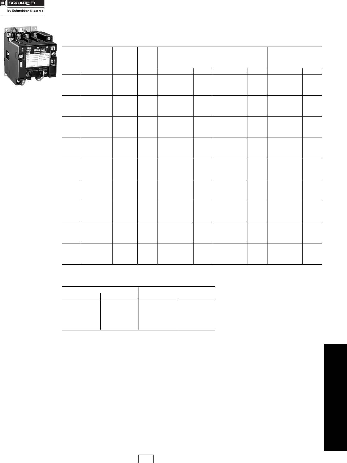
Full Voltage Contactors—
NEMA Rated
General Information
Class 8502 / Refer to Catalog 8502CT9701
Class 8502 Type S magnetic contactors are used to switch heating loads, capacitors, transformers, and electric motors
where overload protection is provided separately. Class 8502 contactors are available in NEMA sizes 00 through 7.
Type S contactors are designed for operation at 600 Vac, 50 to 60 Hz.
aSize 6 and 7 are rated NEMA 4 only, painted sheet steel.
bCoil voltage code must be specified to order this product.
Refer to standard voltage codes shown below.
c24 V coils are not available on Sizes 4–7. On Sizes 00–3, where 24 V coils are available,
Form S (separate control) must be specified (i.e., order as 8502SBO2V01S).
d120 Volt Polyphase contactors are wired for separate control Form S must be specified (i.e., order as 8502SCO2V02S).
Note: For voltage codes used with control transformers, see page 16-110.
Form S (separate control) is used when a separate source of power is available for the control (coil) voltage.
Form S is supplied at no charge.
Dimensions . . . . . . . . . . . . . . . . . . . . . . . . . . . . . . . . . . . . . . . . . . .page 16-23
Factory Modifications (Forms) . . . . . . . . . . . . . . . . . . . . . . . . . . .page 16-109
Separate Enclosures (Class 9991). . . . . . . . . . . . . . . . . . . . . . . .page 16-102
Replacement Parts (Class 9998) . . . . . . . . . . . . . . . . . . . . . . . . .page 16-114
Type S Accessories (Class 9999). . . . . . . . . . . . . . . . . . . . . . . . .page 16-117
For How to Order Information, see page 16-12.
Table 16.36: 3-Pole Polyphase—600 Vac Maximum—50–60 Hz
NEMA
Size
Continuous
Current
Ratings
Motor
Voltage Max.
Hp
Open Type NEMA 1
General Purpose
Enclosure
NEMA 4 & 4X
Watertight, Dusttight
Brushed Stainless
Steel Enclosure
(Size 0-5)a
Type $ Price Type $ Price Type $ Price
00 9
200
230
460
575
1-1/2
1-1/2
2
2
SAO12b329.00 SAG12b360.00 Use Size 0
018
200
230
460
575
3
3
5
5
SBO2b414.00 SBG2b446.00 SBW12b945.00
127
200
230
460
575
7-1/2
7-1/2
10
10
SCO2b485.00 SCG2b518.00 SCW12b1031.00
245
200
230
460
575
10
15
25
25
SDO2b882.00 SDG2b1031.00 SDW12b1391.00
390
200
230
460
575
25
30
50
50
SEO2b1425.00 SEG2b1715.00 SEW12b3167.00
4135
200
230
460
575
40
50
100
100
SFO2b3419.00 SFG2b4022.00 SFW12b6501.00
5270
200
230
460
575
75
100
200
200
SGO2b7451.00 SGG2b8550.00 SGW12b11685.00
6540
200
230
460
575
150
200
400
400
SHO2b20339.00 SHG2b25172.00 SHW2b32378.00
7810
200
230
460
575
—
300
600
600
SJO2b29028.00 SJG2b33875.00 SJW2b40995.00
Table 16.37: Coil Voltage Codes
Voltage Code $ Price Adder
60 Hz 50 Hz
24c
120d
208
240
277
480
600
Specify
—
110
—
220
—
440
550
Specify
V01
V02
V08
V03
V04
V06
V07
V99
No Charge
No Charge
No Charge
No Charge
No Charge
No Charge
No Charge
35.60
Type SCO2
Size 1, 3-Pole Contactor
CP1 Discount
Schedule
Courtesy of Steven Engineering, Inc.-230 Ryan Way, South San Francisco, CA 94080-6370-Main Office: (650) 588-9200-Outside Local Area: (800) 258-9200-www.stevenengineering.com

www.schneider-electric.us
16 NEMA/DEFINITE PURPOSE TYPE
CONTACTORS AND STARTERS
16-14 © 2009 Schneider Electric
All Rights Reserved
Full Voltage Contactors—
NEMA Rated Class 8502 / Refer to Catalog 8502CT9701
aNEMA 12 enclosures may be field modified for outdoor non-corrosive and non-service-entrance-rated applications; see page 16-104 for more
information.
bLimited to one Pilot Light and a Selector Switch or Start-Stop Push Button.
cCoil voltage code must be specified to order this product. Refer to voltage codes shown on page 16-13.
dNEMA 7 and 9 bolted cast aluminum are not UL listed.
Auxiliary Units
Auxiliary contacts and power poles can be added by the factory or in the field on all Type S starters and contactors. The
table below shows the maximum number of auxiliary units (in addition to the holding circuit contact) that can be
added to a given size starter or contactor. In addition, it is possible to add a second internal contact on NEMA Size 0, 1,
and 2 contactors and starters.
Dimensions. . . . . . . . . . . . . . . . . . . . . . . . . . . . . . . . . . . . . . . . . . . page 16-23
Factory Modifications (Forms) . . . . . . . . . . . . . . . . . . . . . . . . . . . page 16-109
Separate Enclosures (Class 9991) . . . . . . . . . . . . . . . . . . . . . . . page 16-102
Replacement Parts (Class 9998). . . . . . . . . . . . . . . . . . . . . . . . . page 16-114
Type S Accessories (Class 9999) . . . . . . . . . . . . . . . . . . . . . . . . page 16-117
For How to Order Information, see page 16-12.
Table 16.38: 3-Pole Polyphase—600 Vac Maximum—50–60 Hz
NEMA
Size
Continuous
Current
Ratings
Motor
Voltage Max.
Hp
NEMA 4X
Watertight, Dusttight,
Corrosion-Resistant
Glass-Polyester Enclosure
NEMA 7 & 9
Hazardous Locations Div. 1 & 2
Class I, Groups C & D
Class II, Groups E, F, & G
NEMA 12/3Ra
Dusttight & Driptight
Industrial Use
Enclosure
Type $ Price
Bolted Type
$ Price SPIN TOP®
Type $ Price Type $ Price
Cast IronbCast
Aluminumd
00 9
200
230
460
575
1-1/2
1-1/2
2
2
Use Size 0 Use Size 0 Use Size 0 Use Size 0
018
200
230
460
575
3
3
5
5
SBW22c945.00 SBT2cSBT42c2070.00 SBR2c2591.00 SBA2c617.00
127
200
230
460
575
7-1/2
7-1/2
10
10
SCW22c1031.00 SCT2cSCT42c2163.00 SCR2c2705.00 SCA2c689.00
245
200
230
460
575
10
15
25
25
SDW22c2057.00 SDT2cSDT42c3482.00 SDR2c4350.00 SDA2c1344.00
390
200
230
460
575
25
30
50
50
SEW22c3959.00 —SET42c5205.00 SER2c2007.00 SEA2c2084.00
4135
200
230
460
575
40
50
100
100
SFW22c8123.00 — SFT42c8415.00 SFR2c10524.00 SFA2c5247.00
5270
200
230
460
575
75
100
200
200
———SGT42c18542.00 SGR2c23178.00 SGA2c11685.00
6540
200
230
460
575
150
200
400
400
—————— —SHA2c29016.00
7810
200
230
460
575
–
300
600
600
—————— —SJA2c37719.00
Table 16.39:
NEMA Size Type No. of Poles of Basic Contactor Maximum Number of External Auxiliary Units
(In addition to holding circuit contact)
00 SA 2–3 4 single circuit auxiliary contacts (N.O. or N.C.) if second internal auxiliary contact is not used.
0, 1 and 2 SB
SC
SD
1, 2 or 3 4 single circuit auxiliary contacts (N.O. or N.C.)
2 single circuit auxiliary contacts (N.O. or N.C.) plus 1 power pole adder (1 or 2 poles, N.O. or N.C.).
4 or 5 2 single circuit auxiliary contacts (N.O. or N.C.)
3, 4 and 5 SE
SF
SG
2–5 (Size 3 and 4) 3 single circuit auxiliary contacts (N.O. or N.C.)
2–3 (Size 5) 2 single circuit auxiliary contacts (N.O. or N.C.) plus 1 NEMA Size 0-1 or Size 2 power pole adder (1 or 2 poles, N.O. or N.C.)
6 and 7 SH
SJ 2–3 3 single circuit auxiliary contacts (N.O. or N.C.)
2 single circuit auxiliary contacts (N.O. or N.C.) plus 1 NEMA Size 0–1 or Size 2 power pole adder (1 or 2 poles, N.O. or N.C.)
CP1 Discount
Schedule
Courtesy of Steven Engineering, Inc.-230 Ryan Way, South San Francisco, CA 94080-6370-Main Office: (650) 588-9200-Outside Local Area: (800) 258-9200-www.stevenengineering.com

www.schneider-electric.us
16 NEMA/DEFINITE PURPOSE TYPE
CONTACTORS AND STARTERS
© 2009 Schneider Electric
All Rights Reserved 16-15
Full Voltage Contactors—NEMA Rated
Class 8502 / Refer to Catalog 8502CT9701
aSize 6 and 7 are rated NEMA 4 only, painted sheet steel.
bCoil voltage code must be specified to order this product. Refer to standard coil voltage codes listed on page 16-13.
Dimensions . . . . . . . . . . . . . . . . . . . . . . . . . . . . . . . . . . . . . . . . . . .page 16-23
Factory Modifications (Forms). . . . . . . . . . . . . . . . . . . . . . . . . . . page 16-109
Separate Enclosures (Class 9991). . . . . . . . . . . . . . . . . . . . . . . page 16-102
Replacement Parts (Class 9998) . . . . . . . . . . . . . . . . . . . . . . . . page 16-114
Type S Accessories (Class 9999). . . . . . . . . . . . . . . . . . . . . . . . page 16-117
For How to Order Information, see page 16-12.
Table 16.40: 600 Vac Maximum—50–60 Hz
NEMA
Size
Continuous
Current
Ratings
Motor
Voltage Max.
Hp
Open Type NEMA 1
General Purpose Enclosure
NEMA 4 & 4X –Watertight,
Dusttight, Brushed Stainless Steel
Enclosure (Size 0-5)a
Type $ Price Type $ Price Type $ Price
1-Pole Single Phase
018
115
230 1
2SBO5b 329.00 SBG5b360.00 SBW15b860.00
127
115
230 2
3SCO5b399.00 SCG5b432.00 SCW15b945.00
2-Pole Single Phase
00 9 115
230 1/3
1SAO11b287.00 SAG11b318.00 Use Size 0
018
115
230 1
2SBO1b372.00 SBG1b404.00 SBW11b903.00
127
115
230 2
3SCO1b441.00 SCG1b476.00 SCW11b989.00
245
115
230 3
7-1/2 SDO1b827.00 SDG1b975.00 SDW11b1998.00
390 —
——
—SEO1b1310.00 SEG1b1601.00 SEW11b3054.00
4135 — — SFO1b3162.00 SFG1b3765.00 SFW11b6245.00
5270 — — SGO1b6852.00 SGG1b7952.00 SGW11b11087.00
6540 — — SHO1b17433.00 SHG1b22266.00 SHW1b29388.00
7810 — — SJO1b25452.00 SJG1b30285.00 SJW1b37407.00
4-Pole Polyphase
018
200
230
460
575
3
3
5
5
SBO3b527.00 SBG3b561.00 SBW13b1074.00
127
200
230
460
575
7-1/2
7-1/2
10
10
SCO3b599.00 SCG3b633.00 SCW13b1146.00
245
200
230
460
575
10
15
25
25
SDO3b1139.00 SDG3b1287.00 SDW13b2712.00
390
200
230
460
575
25
30
50
50
SEO3b1823.00 SEG3b2114.00 SEW13b3965.00
4135
200
230
460
575
40
50
100
100
SFO3b4757.00 SFG3b5360.00 SFW13b8864.00
5-Pole Polyphase
018
200
230
460
575
3
3
5
5
SBO4b684.00 SBG4b719.00 SBW14b1229.00
127
200
230
460
575
7-1/2
7-1/2
10
10
SCO4b755.00 SCG4b788.00 SCW14b1301.00
245
200
230
460
575
10
15
25
25
SDO4b1710.00 SDG4b1857.00 SDW14b3281.00
390
200
230
460
575
25
30
50
50
SEO4b2735.00 SEG4b3024.00 SEW14b4877.00
4135
200
230
460
575
40
50
100
100
SFO4b6579.00 SFG4b7182.00 SFW14b10688.00
CP1 Discount
Schedule
Courtesy of Steven Engineering, Inc.-230 Ryan Way, South San Francisco, CA 94080-6370-Main Office: (650) 588-9200-Outside Local Area: (800) 258-9200-www.stevenengineering.com

www.schneider-electric.us
16 NEMA/DEFINITE PURPOSE TYPE
CONTACTORS AND STARTERS
16-16 © 2009 Schneider Electric
All Rights Reserved
Full Voltage Contactors—
NEMA Rated
Class 8502 / Refer to Catalog 8502CT9701
\
aNEMA 12 enclosures may be field modified for outdoor non-corrosive and non-service-entrance-rated applications; see page 16-104 for more
information.
bLimited to 1 pilot light and a selector switch or Start-Stop push button.
cCoil voltage code must be specified to order this product. Refer to standard coil voltage codes shown on page 16-13.
dNEMA 7 and 9 bolted cast aluminum are not UL listed.
Coil Voltage Codes and page number reference for additional information are shown on page 16-13.
For How to Order Information, see page 16-12.
Table 16.41: 600 Vac Maximum—50–60 Hz
NEMA
Size
Continuous
Current
Ratings
Motor
Voltage Max.
Hp
NEMA 4X
Watertight, Dusttight
Corrosion-Resistant
Glass-Polyester Enclosure
NEMA 7 & 9, Div. 1 & 2
Hazardous Locations
Class I, Groups C & D
Class II, Groups E, F & G
NEMA 12/3Ra
Dusttight & Driptight
Industrial Use
Enclosure
Type $ Price Bolted Type SPIN TOP®
Type $ Price Type $ Price
Cast IronbCast Aluminumd$ Price
1-Pole Single Phase
018
115
230 1
2—
——SBT5cSBT45c1979.00 SBR5c2475.00 SBA5c531.00
127
115
230 2
3—
——SCT5cSCT45c2070.00 SCR5c2591.00 SCA5c603.00
2-Pole Single Phase
00 9 115
230 1/3
1Use Size 0 Use Size 0 Use Size 0 Use Size 0
018
115
230 1
2SBW21c903.00 SBT1cSBT41c2021.00 SBR1c2528.00 SBA1c575.00
127
115
230 2
3SCW21c989.00 SCT1cSCT41c2100.00 SCR1c2627.00 SCA1c647.00
245
115
230 3
7-1/2 SDW21c1998.00 SDT1cSDT41c3402.00 SDR1c4257.00 SDA1c1287.00
390
—
——
—Consult Square D/
Schneider Electric
CIC at
1-888-SquareD
(1-888-778-2733)
—
—SET41c5076.00 SER1c6344.00 SEA1c1971.00
4 135 — — —
—SFT41c8139.00 SFR1c10175.00 SFA1c4991.00
5 270 — — — — —
——
——SGR1c22350.00 SGA1c11087.00
6 540 — — — — —
——
—— — — SHA1c26112.00
7 810 — — — — — — — — — SJA1c34131.00
4-Pole Polyphase
018
200
230
460
575
3
3
5
5
SBW23c1074.00 SBT3c
Consult
Square D/
Schneider Electric
CIC at
1-888-SquareD
(1-888-778-2733)
2199.00 SBR3c2748.00 SBA3c732.00
127
200
230
460
575
7-1/2
7-1/2
10
19
SCW23c1146.00 SCT3c2291.00 SCR3c2867.00 SCA3c804.00
245
200
230
460
575
10
15
25
25
SDW23c2712.00 SDT3c4199.00 SDR3c5255.00 SDA3c1601.00
390
200
230
460
575
25
30
50
50 Consult Square D/Schneider Electric
CIC at 1-888-SquareD
(1-888-778-2733)
— SER3c7604.00 SEA3c2484.00
4 135
200
230
460
575
40
50
100
100
—SFR3c14283.00 SFA3c7011.00
5-Pole Polyphase
018
200
230
460
575
3
3
5
5
Consult Square D/
Schneider Electric
CIC at
1-888-SquareD
(1-888-778-2733)
— — ———SBA4c890.00
127
200
230
460
575
7-1/2
7-1/2
10
10
— — — — — SCA4c959.00
245
200
230
460
575
10
15
25
25
— — — — — SDA4c2169.00
390
200
230
460
575
25
30
50
50
— — ———SEA4c3396.00
4 135
200
230
460
575
40
50
100
100
— — — — — SFA4c8837.00
CP1 Discount
Schedule
Courtesy of Steven Engineering, Inc.-230 Ryan Way, South San Francisco, CA 94080-6370-Main Office: (650) 588-9200-Outside Local Area: (800) 258-9200-www.stevenengineering.com

www.schneider-electric.us
16 NEMA/DEFINITE PURPOSE TYPE
CONTACTORS AND STARTERS
© 2009 Schneider Electric
All Rights Reserved 16-17
Full Voltage Starters—
NEMA Rated Class 8536 / Refer to Catalog 8502CT9701
General Information
Type S magnetic starters are used for full-voltage starting and stopping of AC squirrel cage motors. Motor overload
protection is provided via melting alloy type thermal overload relays. Type S starters are available in NEMA Sizes 00
through 7, and are designed for operation at 600 Vac, 50 to 60 Hz.
Solid State Overload Relay Protection (MOTOR LOGIC®)
These ambient insensitive overload relays are available on Sizes 00 through 6 and standard on size 7. They provide
phase loss, phase unbalance protection. To order, add Form H10 (for Class 10), H20 (for Class 20), or H30 (for
selectable trip class protection). For more information about MOTOR LOGIC, see pages 16-91, 16-111 and 16-112.
3-Pole Polyphase—600 Vac Maximum—50–60 Hz
Note that prices shown do not include thermal units. Devices require 3 thermal units (Sizes 00–6). Standard trip thermal
units are $21.50 each. See page 16-125 for selection information.
aSize 6 and 7 are rated NEMA 4 only, painted sheet steel.
bCoil voltage code must be specified to order this product. Refer to standard coil voltage codes shown below.
c24 V coils are not available on Sizes 4–7. On Sizes 00-3, where 24 V coils are available, Form S (separate control) must be specified
(i.e., order as 8536SBO2V01S).
d120 Volt Polyphase contactors are wired for separate control. Form S (separate control) must be specified (i.e., order as 8536SCO2V02S).
Note: For voltage codes used with control transformers, see page 16-110.
Form S (separate control) is used when a separate source of power is available for the control (coil) voltage.
Form S is supplied at no charge.
Dimensions . . . . . . . . . . . . . . . . . . . . . . . . . . . . . . . . . . . . . . . . . . .page 16-23
Factory Modifications (Forms) . . . . . . . . . . . . . . . . . . . . . . . . . . .page 16-109
Separate Enclosures (Class 9991). . . . . . . . . . . . . . . . . . . . . . . .page 16-102
Replacement Parts (Class 9998) . . . . . . . . . . . . . . . . . . . . . . . . .page 16-114
Type S Accessories (Class 9999). . . . . . . . . . . . . . . . . . . . . . . . .page 16-117
For How to Order Information, see page 16-12.
Table 16.42:
NEMA
Size
Continuous
Current
Ratings
Motor
Voltage Max.
Hp
Open Type NEMA 1
General Purpose
Enclosure
NEMA 4 & 4X
Watertight, Dusttight
Brushed Stainless Steel
Enclosure (Size 0-5)a
NEMA 4X
Watertight, Dusttight,
Corrosion-Resistant
Glass-Polyester Enclosure
Type $ Price Type $ Price Type $ Price Type $ Price
00 9
200
230
460
575
1-1/2
1-1/2
2
2
SAO12b386.00 SAG12b419.00 Use Size 0 Use Size 0
018
200
230
460
575
3
3
5
5
SBO2b485.00 SBG2b518.00 SBW12b1017.00 SBW22b1017.00
127
200
230
460
575
7-1/2
7-1/2
10
10
SCO3b557.00 SCG3b590.00 SCW13b1103.00 SCW23b1103.00
245
200
230
460
575
10
15
25
25
SDO1b1013.00 SDG1b1160.00 SDW11b2186.00 SDW21b2186.00
390
200
230
460
575
25
30
50
50
SEO1b1638.00 SEG1b1929.00 SEW11b3380.00 SEW21b4226.00
4135
200
230
460
575
40
50
100
100
SFO1b3747.00 SFG1b4350.00 SFW11b6827.00 SFW21b8535.00
5270
200
230
460
575
75
100
200
200
SGO1b9152.00 SGG1b10254.00 SGW11b15795.00 ——
6540
200
230
460
575
150
200
400
400
SHO2b21756.00 SHG2b28881.00 SHW2b36003.00 ——
7810
200
230
460
575
—
300
600
600
SJO2b31256.00 SJG2b38381.00 SJW2b45503.00 ——
Table 16.43: Coil Voltage Codes
Voltage Code $ Price Adder
60 Hz 50 Hz
24c
120d
208
240
277
480
600
Specify
—
110
—
220
—
440
550
Specify
V01
V02
V08
V03
V04
V06
V07
V99
No Charge
No Charge
No Charge
No Charge
No Charge
No Charge
No Charge
35.60
Type SCO3
Size 1, 3-Pole Starter
Schneider Electric offers
express shipping for
factory modified NEMA
Type 1 and Type 12/3R
Enclosed Starters. When
you need them fast, our
Laser™ Delivery
program is the answer to
getting your product
when you need it most.
Ask for Laser™ Delivery,
then select the product
and the modifications
you need when you
place your order. It’s as
easy as that!
CP1 Discount
Schedule
Courtesy of Steven Engineering, Inc.-230 Ryan Way, South San Francisco, CA 94080-6370-Main Office: (650) 588-9200-Outside Local Area: (800) 258-9200-www.stevenengineering.com

www.schneider-electric.us
16 NEMA/DEFINITE PURPOSE TYPE
CONTACTORS AND STARTERS
16-18 © 2009 Schneider Electric
All Rights Reserved
Full Voltage Starters—
NEMA Rated Class 8536 / Refer to Catalog 8502CT9701
aNEMA 12 enclosures may be field modified for outdoor non-corrosive and non-service-entrance-rated applications; see page 16-104 for more
information.
bLimited to 1 Pilot Light and Selector Switch or Start-Stop Push-Button.
cCoil voltage code must be specified to order this product. Refer to standard coil voltage codes listed in selection Table 16.43 shown on page 16-17.
dNEMA 7 and 9 bolted cast aluminum are not UL listed.
Dimensions. . . . . . . . . . . . . . . . . . . . . . . . . . . . . . . . . . . . . . . . . . . page 16-23
Factory Modifications (Forms) . . . . . . . . . . . . . . . . . . . . . . . . . . . page 16-109
Separate Enclosures (Class 9991) . . . . . . . . . . . . . . . . . . . . . . . page 16-102
Replacement Parts (Class 9998). . . . . . . . . . . . . . . . . . . . . . . . . page 16-114
Type S Accessories (Class 9999) . . . . . . . . . . . . . . . . . . . . . . . . page 16-117
For How to Order Information, see page 16-12.
Table 16.44: 3-Pole Polyphase—600 Vac Maximum—50–60 Hz
Note that prices shown do not include thermal units. Devices require 3 thermal units (Sizes 00–6). Standard trip thermal units are $21.50 each. See
page 16-125 for selection information.
NEMA
Size
Continuous
Current
Ratings
Motor
Voltage Max.
Hp
NEMA 7 & 9
For Hazardous
Locations Div. 1 & 2
Class I–Groups C, D
Class II–Groups E, F, & G
NEMA 12/3Ra
Dusttight & Driptight
Industrial Use
Enclosure
Bolted Type SPIN TOP®
Type $ Price Type $ Price
Cast
IronbCast
Aluminumd$ Price
00 9
200
230
460
575
1-1/2
1-1/2
2
2
Use Size 0 Use Size 0 Use Size 0
018
200
230
460
575
3
3
5
5
SBT2cSBT42c2150.00 SBR2c2690.00 SBA2c689.00
127
200
230
460
575
7-1/2
7-1/2
10
10
SCT3cSCT43c2241.00 SCR3c2804.00 SCA3c761.00
245
200
230
460
575
10
15
25
25
SDT1cSDT41c3623.00 SDR1c4527.00 SDA1c1472.00
390
200
230
460
575
25
30
50
50
—SET43c5439.00 SER3c6800.00 SEA1c2298.00
4135
200
230
460
575
40
50
100
100
— SFT41c8778.00 SFR1c10971.00 SFA1c5574.00
5270
200
230
460
575
75
100
200
200
—SGT41c20970.00 SGR1c26211.00 SGA1c13386.00
6540
200
230
460
575
150
200
400
400
—————SHA2c32727.00
7810
200
230
460
575
–
300
600
600
—————SJA2c42227.00
Schneider Electric offers
express shipping for
factory modified NEMA
Type 1 and Type 12/3R
Enclosed Starters. When
you need them fast, our
Laser™ Delivery
program is the answer to
getting your product
when you need it most.
Ask for Laser™ Delivery,
then select the product
and the modifications
you need when you
place your order. It’s as
easy as that!
CP1 Discount
Schedule
Courtesy of Steven Engineering, Inc.-230 Ryan Way, South San Francisco, CA 94080-6370-Main Office: (650) 588-9200-Outside Local Area: (800) 258-9200-www.stevenengineering.com

www.schneider-electric.us
16 NEMA/DEFINITE PURPOSE TYPE
CONTACTORS AND STARTERS
© 2009 Schneider Electric
All Rights Reserved 16-19
Full Voltage Starters
Class 8536 / Refer to Catalog 8502CT9701
2-Pole Single Phase—600 Vac Maximum—50–60 Hz
4-Pole, 2-Phase—600 Vac Maximum—50–60 Hz
aCoil voltage code must be specified to order this product. Refer to standard coil voltage codes listed below.
b24 V coils are not available on Sizes 4–7. On sizes 00–3, where 24 V coils are available,
Form S (separate control) must be specified (i.e., order as 8536SBO2V01S).
c120 Volt Polyphase starters are wired for separate control. Form S (separate control)
must be specified (i.e., order as 8536SCO2V02S).
Note: For voltage codes used with control transformers, see 16-110.
Form S (separate control) is used when a separate source of power is available for the control (coil) voltage.
Form S is supplied at no charge.
Dimensions . . . . . . . . . . . . . . . . . . . . . . . . . . . . . . . . . . . . . . . . . . .page 16-23
Factory Modifications (Forms) . . . . . . . . . . . . . . . . . . . . . . . . . . .page 16-109
Separate Enclosures (Class 9991). . . . . . . . . . . . . . . . . . . . . . . .page 16-102
Replacement Parts (Class 9998) . . . . . . . . . . . . . . . . . . . . . . . . .page 16-114
Type S Accessories (Class 9999). . . . . . . . . . . . . . . . . . . . . . . . .page 16-117
For How to Order Information, see page 16-12.
Table 16.45:
Note that prices shown do not include thermal units. Devices require 1 thermal unit. Standard trip thermal units are $21.50 each. See page 16-125
for selection information.
NEMA
Size
Continuous
Current
Ratings
Motor
Voltage Max.
Hp
Open Type NEMA 1
General Purpose
Enclosure
NEMA 4 & 4X
Watertight, Dusttight
Brushed Stainless Steel
Enclosure
NEMA 4X
Watertight, Dusttight,
Corrosion-Resistant
Glass-Polyester Enclosure
Type $ Price Type $ Price Type $ Price Type $ Price
00 9 115
230 1/3
1 SAO11a386.00 SAG11a419.00 Use Size 0 Use Size 0
018 115
230 1
2SBO1a435.00 SBG1a468.00 SBW11a966.00 SBW21a966.00
127 115
230 2
3SCO1a507.00 SCG1a539.00 SCW11a1052.00 SCW21a1052.00
1P 36 115
230 3
5SCO2a662.00 SCG2a696.00 SCW12a1209.00 SCW22a1209.00
245 115
230 3
7-1/2 SDO6a918.00 SDG6a1067.00 SDW16a2091.00 SDW26a2091.00
Table 16.46:
Note that prices shown do not include thermal units. Devices require 2 thermal units. Standard trip thermal units are $21.50 each. See page 16-125
for selection information.
NEMA
Size
Continuous
Current
Ratings
Motor
Voltage Max.
Hp
Open Type NEMA 1
General Purpose
Enclosure
NEMA 4 & 4X
Watertight, Dusttight
Brushed Stainless Steel
Enclosure
NEMA 4X
Watertight, Dusttight,
Corrosion-Resistant
Glass-Polyester Enclosure
Type $ Price Type $ Price Type $ Price Type $ Price
018
200
230
460
575
3
3
5
5
SBO3a629.00 SBG3a675.00 SBW13a1229.00 SBW23a1229.00
127
200
230
460
575
7-1/2
7-1/2
10
10
SCO4a714.00 SCG4a761.00 SCW14a1301.00 SCW24a1301.00
245
200
230
460
575
10
15
25
25
SDO2a1283.00 SDG2a1430.00 SDW12a2910.00 SDW22a2910.00
390
200
230
460
575
25
30
50
50
SEO2a2096.00 SEG2a2357.00 SEW12a4206.00 Consult
Square D/
Schneider Electric
CIC at
1-888-SquareD
(1-888-778-2733)
4135
200
230
460
575
40
50
100
100
SFO2a5142.00 SFG2a5715.00 SFW12a9221.00
Table 16.47: Coil Voltage Codes
Voltage Code $ Price Adder
60 Hz 50 Hz
24b
120c
208
240
277
480
600
Specify
—
110
—
220
—
440
550
Specify
V01
V02
V08
V03
V04
V06
V07
V99
No Charge
No Charge
No Charge
No Charge
No Charge
No Charge
No Charge
35.60
CP1 Discount
Schedule
Courtesy of Steven Engineering, Inc.-230 Ryan Way, South San Francisco, CA 94080-6370-Main Office: (650) 588-9200-Outside Local Area: (800) 258-9200-www.stevenengineering.com

www.schneider-electric.us
16 NEMA/DEFINITE PURPOSE TYPE
CONTACTORS AND STARTERS
16-20 © 2009 Schneider Electric
All Rights Reserved
Full Voltage Starters
Class 8536 / Refer to Catalog 8502CT9701
2-Pole Single Phase—600 Vac Maximum—50–60 Hz
dNEMA 7 and 9 bolted cast aluminum are not UL listed.
4-Pole 2-Phase—600 Vac Maximum—50–60 Hz
aNEMA 12 enclosures may be field modified for outdoor non-corrosive and non-service-entrance-rated applications; see page 16-104 for more
information.
bLimited to 1 Pilot Light and Selector Switch or Start-Stop Push-Button.
cCoil voltage code must be specified to order this product. Refer to standard coil voltage codes listed on page 16-19.
Dimensions. . . . . . . . . . . . . . . . . . . . . . . . . . . . . . . . . . . . . . . . . . . page 16-23
Factory Modifications (Forms) . . . . . . . . . . . . . . . . . . . . . . . . . . . page 16-109
Separate Enclosures (Class 9991) . . . . . . . . . . . . . . . . . . . . . . . page 16-102
Replacement Parts (Class 9998). . . . . . . . . . . . . . . . . . . . . . . . . page 16-114
Type S Accessories (Class 9999) . . . . . . . . . . . . . . . . . . . . . . . . page 16-117
For How to Order Information, see page 16-12.
Table 16.48:
Note that prices shown do not include thermal units. Devices require 1 thermal unit. Standard trip thermal units are $21.50 each. See page 16-125
for selection information.
NEMA
Size
Continuous
Current
Ratings
Motor
Voltage Max.
Hp
NEMA 7 & 9
Hazardous Locations, Div. 1 & 2
Class I, Groups C & D
Class II, Groups E, F, & G
NEMA 12/3Ra
Dusttight & Driptight
Industrial Use Enclosure
Bolted Type SPIN TOP®
Type $ Price Type $ Price
Cast
IronbCast
Aluminumd$ Price
00 9 115
230 1/3
1 Use Size 0 Use Size 0 Use Size 0
018
115
230 1
2SBT1cSBT41 2091.00 SBR1c2619.00 SBA1c639.00
127
115
230 2
3SCT1cSCT41 2186.00 SCR1c2732.00 SCA1c710.00
1P 36 115
230 3
5SCT2cSCT42 2363.00 SCR2c2952.00 SCA2c867.00
245
115
230 3
7-1/2 SDT6cSDT46 3513.00 SDR6c4400.00 SDA6c1380.00
Table 16.49:
Note that prices shown do not include thermal units. Devices require 2 thermal units. Standard trip thermal units are $21.50 each. See page 16-125
for selection information.
NEMA
Size
Continuous
Current
Ratings
Motor
Voltage Max.
Hp Coil
Voltage
NEMA 7 & 9
Hazardous Locations
Class I, Groups C & D
Class II, Groups E, F, & G
NEMA 12/3R a
Dusttight & Driptight
Industrial Use Enclosure
Bolted
Type SPIN TOP®
Type $ Price Type $ Price
Cast
IronbCast
Aluminum $ Price
018
200
230
460
575
3
3
5
5
208
240
480
600
SBT3c
Consult
Square D/
Schneider
Electric
CIC at
1-888-SquareD
(1-888-778-2733)
2348.00 SBR3c2939.00 SBA3c846.00
127
200
230
460
575
7-1/2
7-1/2
10
10
208
240
480
600
SCT4c2433.00 SCR4c3047.00 SCA4c932.00
245
200
230
460
575
10
15
25
25
208
240
480
600
SDT2c4797.00 SDR2c6002.00 SDA2c1742.00
390
200
230
460
575
25
30
50
50
208
240
480
600
Consult
Square D/
Schneider Electric
CIC at
1-888-SquareD
(1-888-778-2733)
—SER2c8679.00 SEA2c2726.00
4135
200
230
460
575
40
50
100
100
208
240
480
600
———SFA2c7370.00
CP1 Discount
Schedule
Courtesy of Steven Engineering, Inc.-230 Ryan Way, South San Francisco, CA 94080-6370-Main Office: (650) 588-9200-Outside Local Area: (800) 258-9200-www.stevenengineering.com
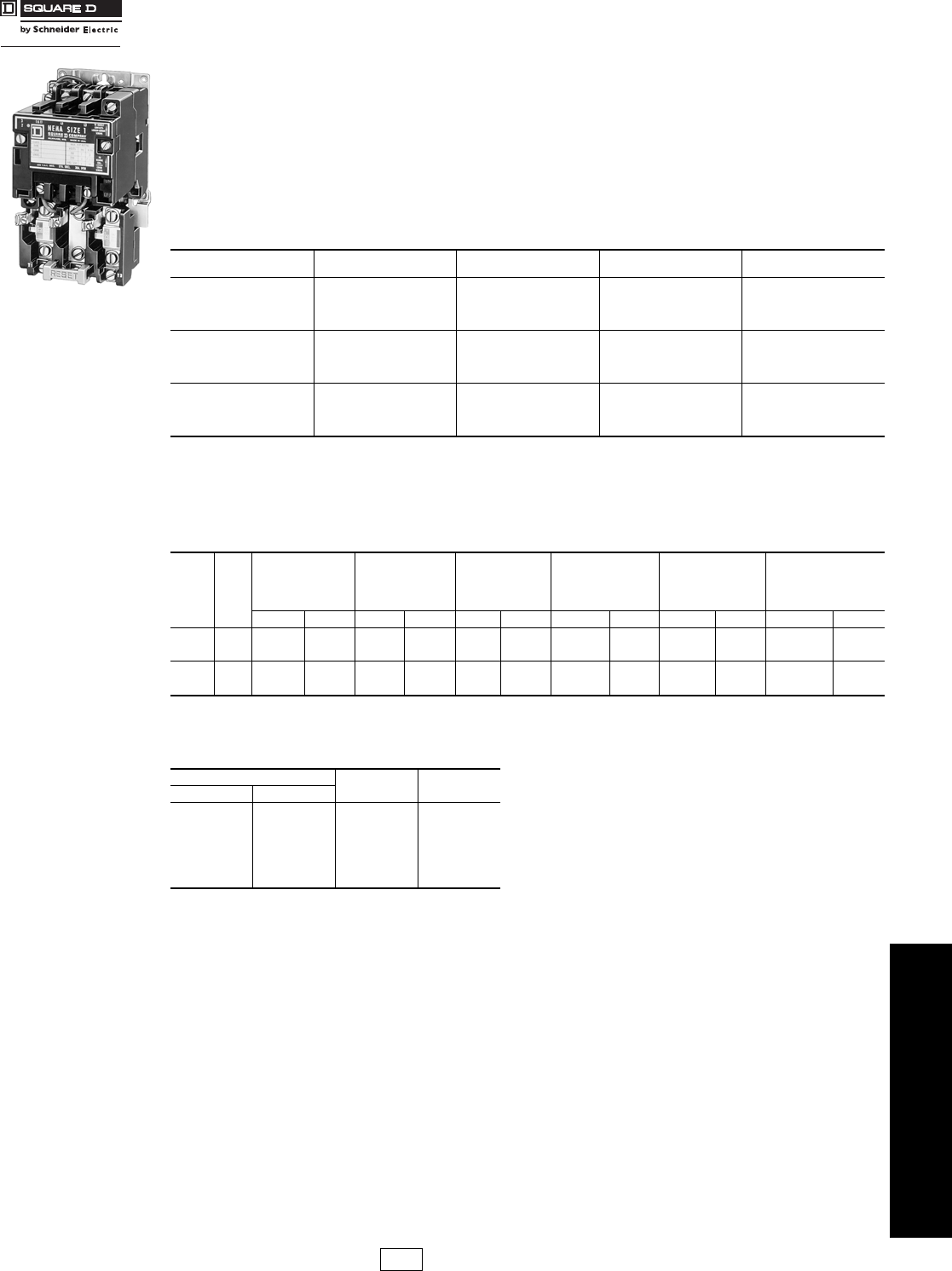
www.schneider-electric.us
16 NEMA/DEFINITE PURPOSE TYPE
CONTACTORS AND STARTERS
© 2009 Schneider Electric
All Rights Reserved 16-21
Full Voltage Starters—
NEMA Rated Class 8536 / Refer to Catalog 8502CT9701
Types SB–SD With Auxiliary Load Terminals
It is sometimes desirable to use capacitors in motor branch circuits to improve power factor. The Size 0–2 Type SB–SD
starters listed below include three auxiliary terminals to allow easy connection of power factor correction capacitors.
When capacitors are connected using these terminals, no adjustment to the selection of thermal units is necessary.
The auxiliary terminals accept #12–16 solid or stranded wire. NEMA Size 3 & 4 starters have provisions for auxiliary
connections. User must supply lugs as necessary.
The Type S starters with auxiliary load terminals may also be used to control two motors simultaneously from a single
starter. However, this application is tightly restricted by Section 430-53 of the National Electrical Code. Refer to the
NEC for restrictions regarding overload protection, size of controller and motor branch circuit protection.
Extra Capacity Single Phase Starters (Not NEMA Rated)
2-Pole Single Phase—250 Vac Maximum—50–60 Hz
aCoil voltage code must be specified to order this product. Refer to standard coil voltage codes shown below.
bUses a Size 3 overload relay.
cNEMA 12 enclosures may be field modified for outdoor non-corrosive and non-service-entrance-rated applications; see page 16-104 for more
information.
d24 V coils are not available on Sizes 4–7. On Sizes 00–3, where 24 V coils
are available, Form S (separate control) must be specified.
e120 Volt Polyphase starters are wired for separate control and must be
ordered with Form S (i.e., 8536SCO2V02S).
Note: For voltage codes used with control transformers, see page 16-110.
Form S (separate control) is used when a separate source of power is available for the control (coil) voltage.
Form S is supplied at no charge.
Dimensions . . . . . . . . . . . . . . . . . . . . . . . . . . . . . . . . . . . . . . . . . . .page 16-23
Factory Modifications (Forms) . . . . . . . . . . . . . . . . . . . . . . . . . . .page 16-109
Separate Enclosures (Class 9991). . . . . . . . . . . . . . . . . . . . . . . .page 16-102
Replacement Parts (Class 9998) . . . . . . . . . . . . . . . . . . . . . . . . .page 16-114
Type S Accessories (Class 9999). . . . . . . . . . . . . . . . . . . . . . . . .page 16-117
For How to Order Information, see page 16-12.
Table 16.50: 3-Pole Polyphase—600 Vac Maximum—50–60 Hz
Note that prices shown do not include thermal units. Devices require 3 thermal units. Standard trip thermal units are
$21.50 each. See page 16-125 for selection information.
NEMA
Size Motor
Voltage Max.
Hp Open
Type $ Price
0
200
230
460
575
3
3
5
5
SBTO2a485.00
1
200
230
460
575
7-1/2
7-1/2
10
10
SCTO3a557.00
2
200
230
460
575
10
15
25
25
SDTO1a1011.00
Table 16.51:
Note that prices shown do not include thermal unit. Devices require 1 thermal unit. Standard trip thermal unit is $21.50
each. See page 16-125 for selection information.
Motor
Voltage Max.
Hp
Open Type
NEMA 1
General
Purpose
Enclosure
NEMA 3R
Rainproof, Sleet
Resistant,
Outdoor Use
Enclosure
NEMA 4 & 4X
Watertight, Dusttight
Brushed Stainless
Steel Enclosure
NEMA 4X
Watertight
Corrosion Resistant
Glass-Polyester
Enclosure
NEMA 12/3R c
Dusttight & Driptight
Industrial Use
Enclosure
Type $ Price Type $ Price Type $ Price Type $ Price Type $ Price Type $ Price
115
230 5
10 SDO8ab 1304.00 — — SDH8ab 1787.00 ———— — —
115
230 7-1/2
15 SEO6a1431.00 SEG6a1722.00 SEH6a2091.00 SEW16a3176.00 SEW26a3969.00 SEA6a2091.00
Table 16.52: Coil Voltage Codes
Voltage Code $ Price Adder
60 Hz 50 Hz
24d
120e
208
240
277
480
600
Specify
—
110
—
220
—
440
550
Specify
V01
V02
V08
V03
V04
V06
V07
V99
No Charge
No Charge
No Charge
No Charge
No Charge
No Charge
No Charge
35.60
CP1 Discount
Schedule
Courtesy of Steven Engineering, Inc.-230 Ryan Way, South San Francisco, CA 94080-6370-Main Office: (650) 588-9200-Outside Local Area: (800) 258-9200-www.stevenengineering.com

www.schneider-electric.us
16 NEMA/DEFINITE PURPOSE TYPE
CONTACTORS AND STARTERS
16-22 © 2009 Schneider Electric
All Rights Reserved
Full Voltage Contactors and Starters—NEMA Rated
Class 8502, 8536 / Refer to Catalog 8502CT9701
Application Data for Selection
Tables and footnotes are taken from NEMA Standards.
aRatings shown are for applications requiring repeated interruptions of stalled motor
current or repeated closing of high transient currents encountered in rapid motor reversal,
involving more than five openings or closings per minute and more than ten in a ten-
minute period, such as plug-stop, plug-reverse or jogging duty. Ratings apply to single
speed and multi-speed controllers.
bPer NEMA Standards paragraph ICS 2-321.20, the service-limit current represents the
maximum rms current, in Amperes, which the controller may be expected to carry for
protracted periods in normal service. At service-limit current ratings, temperature rises
may exceed those obtained by testing the controller at its continuous current rating. The
ultimate trip current of over-current (overload) relays or other motor protective devices
shall not exceed the service-limit current ratings of the controller.
cFLUORESCENT LAMP LOADS—300 VOLTS AND LESS—The characteristics of
fluorescent lamps are such that it is not necessary to derate Class 8502 contactors below
their normal continuous current rating. Class 8903 contactors may also be used with
fluorescent lamp loads. For controlling tungsten and infrared lamp loads, and resistance
heating loads, Class 8903 AC lighting contactors are recommended. These contactors are
specifically designed for such loads and are applied at their full rating as listed in the Class
8903 Section.
dRatings apply to contactors which are employed to switch the load at the utilization voltage
of the heat producing element with a duty which requires continuous operation of not more
than five openings per minute. Class 8903 Types L and S lighting contactors are rated for
resistance heating loads.
eWhen discharged, a capacitor has essentially zero impedance. For repetitive switching by
a contactor, sufficient impedance should be connected in series to limit inrush current to
not more than 6 times the contactor rated continuous current. In many installations, the
impedance of connecting conductors may be sufficient for this purpose. When switching
to connect additional banks, the banks already on the line may be charged and can supply
additional available short-circuit current which should be considered when selecting the
impedance to limit the current.
The ratings for capacitor switching above assume the following maximum available fault
currents:
— NEMA Size 00–3: 5,000 A RMS Sym.
— NEMA Size 4–5: 10,000 A RMS Sym.
— NEMA Size 6: 18,000 A RMS Sym.
— NEMA Size 7: 30,000 A RMS Sym.
Note: If available fault current is greater than these values, connect sufficient impedance in
series as noted in the previous paragraph.
fFor NEMA Size 6 & 7, the operation rate is as follows: Continuous operation rate is 3
operations per minute maximum; Jogging or Plugging Duty operation rate is 15 operations
per minute for a maximum of three minutes.
The motor ratings in Table 16.53 are NEMA standard ratings and apply
only when the code letter of the motor is the same as or occurs earlier in
the alphabet than is shown in the Table 16.54. Motors having code
letters occurring later in the alphabet may require a larger controller.
Consult Square D/ Schneider Electric CIC at
1-888-SquareD (1-888-778-2733).
Table 16.53:
NEMA
Size Load
Voltage
Maximum
Hp
Rating—
Nonplugging
and
Nonjogging
Duty
Maximum
Hp
Rating—
Plugging
and
Jogging
Duty
a
Continuous
Current
Rating,
Amperes—
600 Volt
Max.
Service—
Limit
Current
Rating,
Amperes
b
Tungsten
and
Infrared
Lamp Load,
Amperes—
250 Volts
Max.
c
Resistance
Heating
Loads, KW—
other than
Infrared
Lamp Loads
d
KVA Rating for Switching
Transformer Primaries at
50 or 60 Cycles
3Ø
Rating for
Switching
Capacitors
e
Transformers
Having Inrush
Currents (Worst
Case Peak) of
Not More Than
20 Times Peak
of Continuous
Current Rating
Transformers
Having Inrush
Currents (Worst
Case Peak) of
Over 20 Through
40 Times Peak
of Continuous
Current Rating
Single
Phase Poly-
Phase Single
Phase Poly-
Phase Single
Phase Poly-
Phase Single
Phase Poly-
Phase Single
Phase Poly-
Phase KVAR
00
115
200
230
380
460
575
1/2
—
1
—
—
—
—
1-1/2
1-1/2
1-1/2
2
2
—
—
—
—
—
—
—
—
—
—
—
—
9
9
9
9
9
9
11
11
11
11
11
11
5
5
5
—
—
—
—
—
—
—
—
—
—
—
—
—
—
—
—
—
—
—
—
—
—
—
—
—
—
—
—
—
—
—
—
—
—
—
—
—
—
—
—
—
—
—
—
—
0
115
200
230
380
460
575
1
—
2
—
—
—
—
3
3
5
5
5
1/2
—
1
—
—
—
—
1-1/2
1-1/2
1-1/2
2
2
18
18
18
18
18
18
21
21
21
21
21
21
10
10
10
—
—
—
—
—
—
—
—
—
—
—
—
—
—
—
0.6
—
1.2
—
2.4
3.0
—
1.8
2.1
—
4.2
5.2
0.3
—
0.6
—
1.2
1.5
—
0.9
1.0
—
2.1
2.6
—
—
—
—
—
—
1
115
200
230
380
460
575
2
—
3
—
—
—
—
7-1/2
7-1/2
10
10
10
1
—
2
—
—
—
—
3
3
5
5
5
27
27
27
27
27
27
32
32
32
32
32
32
15
15
15
—
—
—
3
—
6
—
12
15
5
9.1
10
16.5
20
25
1.2
—
2.4
—
4.9
6.2
—
3.6
4.3
—
8.5
11.0
0.6
—
1.2
—
2.5
3.1
—
1.8
2.1
—
4.3
5.3
—
—
—
—
—
—
1P 115
230 3
5—
—1-1/2
3—
—36
36 42
42 24
24 —
——
——
——
——
——
——
—
2
115
200
230
380
460
575
3
—
7-1/2
—
—
—
—
10
15
25
25
25
2
—
5
—
—
—
—
7-1/2
10
15
15
15
45
45
45
45
45
45
52
52
52
52
52
52
30
30
30
—
—
—
5
—
10
—
20
25
8.5
15.4
17
28
34
43
2.1
—
4.1
—
8.3
10.0
—
6.3
7.2
—
14
18
1.0
—
2.1
—
4.2
5.2
—
3.1
3.6
—
7.2
8.9
—
—
8
—
16
20
3
115
200
230
380
460
575
—
—
—
—
—
—
—
25
30
50
50
50
—
—
—
—
—
—
—
15
20
30
30
30
90
90
90
90
90
90
104
104
104
104
104
104
60
60
60
—
—
—
10
—
20
—
40
50
17
31
34
56
68
86
4.1
—
8.1
—
16
20
—
12
14
—
28
35
2.0
—
4.1
—
8.1
10
—
6.1
7.0
—
14
18
—
—
27
—
53
67
4
200
230
380
460
575
—
—
—
—
—
40
50
75
100
100
—
—
—
—
—
25
30
50
60
60
135
135
135
135
135
156
156
156
156
156
120
120
—
—
—
—
30
—
60
75
45
52
86.7
105
130
—
14
—
27
34
20
23
—
47
59
—
6.8
—
14
17
10
12
—
23
29
—
40
—
80
100
5
200
230
380
460
575
—
—
—
—
—
75
100
150
200
200
—
—
—
—
—
60
75
125
150
150
270
270
270
270
270
311
311
311
311
311
240
240
—
—
—
—
60
—
120
150
91
105
173
210
260
—
27
—
54
68
41
47
—
94
117
—
14
—
27
34
20
24
—
47
59
—
80
—
160
200
6f
200
230
380
460
575
—
—
—
—
—
150
200
300
400
400
—
—
—
—
—
125
150
250
300
300
540
540
540
540
540
621
621
621
621
621
480
480
—
—
—
—
120
—
240
300
182
210
342
415
515
—
54
—
108
135
81
94
—
188
234
—
27
—
54
68
41
47
—
94
117
—
160
—
320
400
7f
230
460
575
—
—
—
300
600
600
—
—
—
—
—
—
810
810
810
932
932
932
—
—
—
180
360
450
315
625
775
—
—
—
—
—
—
—
—
—
—
—
—
240
480
600
Table 16.54:
Motor Hp Rating Maximum Allowable Motor Code Letter
1-1/2–2
3–5-
71/2 & above
L
K
H
Courtesy of Steven Engineering, Inc.-230 Ryan Way, South San Francisco, CA 94080-6370-Main Office: (650) 588-9200-Outside Local Area: (800) 258-9200-www.stevenengineering.com

www.schneider-electric.us
16 NEMA/DEFINITE PURPOSE TYPE
CONTACTORS AND STARTERS
© 2009 Schneider Electric
All Rights Reserved 16-23
Full Voltage Contactors and Starters—NEMA Rated
Class 8502, 8536 / Refer to Catalog 8502CT9701
Approximate Dimensions
Table 16.55: Dimensions for Class 8502 Open Type
NEMA
Size Type No.
of
Poles Fig. No.
Dimensions—Inches (Refer to Appropriate Figure) Wt
ABCDEFGHI
IN IN IN IN IN IN IN IN IN lbs.
00 SAO 2–3 1 3-7/32 4-11/32 4-7/32 1-5/8 1-5/8 7/32 3-15/16 — — 4
0 SBO 1–3 13-7/32 4-11/32 4-7/32 1-5/8 1-5/8 7/32 3-15/16 — — 4
1 SCO 4–5 4-1/4 4-11/32 4-7/32 1-5/8 2-5/8 7/32 3-15/16 — — 4-1/2
2SDO
2–3 14-5/16 5-1/8 4-15/16 2-5/32 2-5/32 7/32 4-19/32 17/32 1-1/16 6-3/4
4–5 5-5/8 5-1/8 4-15/16 2-5/32 3-15/32 7/32 4-19/32 17/32 1-1/16 8-1/4
3SEO
2–3 15-15/32 7-3/32 6-1/2 1-7/8 3-17/32 5/16 6-1/32 3-1/4 4-3/4 14
4–5 9-3/4 7-7/8 6-1/2 3-15/16 5-13/16 5/16 7 4-17/32 9-1/16 22
4SFO
2–3 16 8-3/16 6-1/2 2-1/16 3-15/16 5/16 7 3-19/32 5-5/16 18
4–5 9-3/4 8-3/16 6-1/2 3-15/16 5-13/16 5/16 7 4-17/32 9-1/16 22
5 SGO 2–3 1 8-2/3 12-5/16 8-3/4 3-1/4 5-13/16 5/8 11-1/8 4-3/4 7-1/4 45
6 SHO 2–3 1 10-35/64 28-1/16 9 3-17/32 7-1/32 5-1/16 18-9/16 4-3/4 7-1/4 80
7 SJO 2–3 1 10-35/64 37-1/4 10-7/8 3-17/32 7-1/32 7-7/32 22-3/8 4-3/4 7-1/4 135
Table 16.56: Dimensions for 8536 Open Type
00, 0, 1,
1P SAO–
SCO 2–3 2 3-1/2 6-49/64 4-7/32 1/2 1 1-39/64 13/64 6-1/4 3-31/32 5
0, 1 SBO–
SCO 4 2 4-17/32 6-49/64 4-7/32 1/2 1 2-2/3 13/64 6-1/4 3-31/32 5-1/2
2SDO
2–3 24-5/16 7-13/16 4-15/16 1/2 1 2-5/32 13/64 7-11/32 4-1/16 7-3/4
4 5-5/8 7-13/16 4-15/16 1/2 1 3-15/32 13/64 7-11/32 4-1/16 9-1/4
3SEO
2–3 25-15/32 11-3/32 6-1/2 7/8 1-3/4 3-19/32 5/16 10-3/16 5-3/4 17
4 9-3/4 12-1/8 6-1/2 1-13/16 1-3/4 5-13/16 5/16 11-3/16 5-3/4 25
4SFO
326 12-7/8 6-1/2 1-13/16 1-3/4 3-15/16 5/16 11-3/16 5-3/4 22
4 9-3/4 12-7/8 6-1/2 1-13/16 1-3/4 5-29/32 5/16 11-3/16 5-3/4 25
5 SGO 3 2 8-9/16 17-9/16 8-3/4 4-3/4 7-1/4 5-12/32 5/8 16-3/8 6 62
6 SHO 3 2 12-11/32 28-1/16 9 4-3/4 7-1/4 5-25/32 5-1/16 18-9/16 8-11/16 85
7 SJO 3 2 12-11/32 37-1/4 10-7/8 4-3/4 7-1/4 5-25/32 7-7/32 22-3/8 9 140
Table 16.57: Dimensions for NEMA 1 General Purpose Enclosure
NEMA
Size Type No.
of
Poles
Fig.
No.
Dimensions—Inches
AB CDEFGHIJKL
8502 8536
00
0
1
SAG
SBG
SCG
All
All
All
3
3
36 10 5-9/32 5-9/16 3 7/8 8-1/8 1 15/16 4-1/8 5 — —
2 SDG All 3 7-13/16 12-11/16 6-1/32 6-5/16 — 1-3/32 10-1/2 1-3/32 1-3/32 5-5/8 5-3/4 1-3/32 5-5/8
3 SEG All 3 11-7/16 21-13/16 8 8-3/8 — 1-17/32 18-3/4 1-17/32 1-17/32 8-3/8 7-3/4 1-17/32 8-3/8
4 SFG All 5 11-1/4 25-5/32 9 9 8-19/32 1-1/4 1-1/4 22-5/16 1-7/16 7/16 — — —
5 SGG All 5 17-7/32 44-7/32 12-13/16 12-15/16 13 2-1/8 2-1/8 40 2-1/8 9/16 — — —
6 SHG All 4 65-3/4 20-7/32 13-1/8 13-1/8 — 11 64-1/2 2-5/16 5-1/2 — — — —
7 SJG All 4 93 34-1/2 23-1/2 23-1/2 Floor Mounting
A
B
C
I
H
EF
G
D
Figure 1
Class 8502
A
B
C
E
D
FG
H
I
RESET
Figure 2
Class 8536
KK
DA
LE
FB
RESET
CJ
Pilot
Light
G
HH I
Figure 3
H
B
E(3) Closing Plates
G
A
F
C
Figure 4
RESET
A
(4) I Dia. Mtg. Holes
B
H
H
C
F
D
E
G
Figure 5
Courtesy of Steven Engineering, Inc.-230 Ryan Way, South San Francisco, CA 94080-6370-Main Office: (650) 588-9200-Outside Local Area: (800) 258-9200-www.stevenengineering.com

www.schneider-electric.us
16 NEMA/DEFINITE PURPOSE TYPE
CONTACTORS AND STARTERS
16-24 © 2009 Schneider Electric
All Rights Reserved
Full Voltage Contactors and Starters—NEMA Rated
Class 8502, 8536 / Refer to Catalog 8502CT9701
Approximate Dimensions
aSize 6 and 7 are sheet steel enclosures, and are rated NEMA 4 only.
bSize 6 and 7 are sheet steel enclosures, and are rated NEMA 4 only.
Table 16.58: NEMA 4 & 4X—Stainless Steel Watertight Enclosuresa
NEMA
Size Class Type No.
of
Poles
Dimensions—Inches Bot.
Hub
Only
Top &
Bot.
Hub
ABCDEFGH I JKLW X
0
and
1
8502 SBW All 6-3/8 7-1/8 13-3/16 1-9/16 3-1/4 12 19/32 1-3/16 11-25/32 1-5/8 2-5/16 5/16 3/4'' Dia.
Hub
1''
Dia.
Hub
SCW
8536 SBW All 6-3/8 7-13/16 13-3/16 1-9/16 3-1/4 12 19/32 1-7/8 11-25/32 1-5/8 2-5/16 5/16
SCW
2
8502 SDW All 8-1/8 7-7/8 16-3/16 1-9/16 5 15 1-3/32 1-15/16 14-3/4 2 2-5/8 5/16 3/4'' Dia.
Hub
1-1/2''
Dia.
Hub
8536 SDW All 8-1/8 8-9/16 16-3/16 1-9/16 5 15 1-3/32 2-7/8 14-3/4 2 2-5/8 5/16
3
and
4
8502 SEW All 18-5/32 8-3/4 32-7/32 3-5/64 12 30-1/2 7/8 3-11/16 26-23/32 2-9/16 3-3/16 7/16 3/4'' Dia.
Hub
2-1/2''
Dia.
Hub
SFW
8536 SEW All 18-5/32 9-9/16 32-7/32 3-5/64 12 30-1/2 7/8 4-1/2 26-23/32 2-9/16 3-3/16 7/16 3/4" Dia.
Hub
2-1/2"
Dia.
Hub
SFW
58502 &
8536 SGW All 17-7/32 12-5/8 47-7/32 4-1/8 9 46 5/8 4-19/32 28-5/16 3-1/8 5-3/4 9/16 3/4" Dia.
Hub
3-1/2"
Dia.
Hub
6a8502 &
8536 SHW All 20-7/32 12-1/8 65-7/32 4-1/8 12 64 5/8 4-19/32 30-13/16 2-11/16 4-1/2 9/16 3/4" Dia.
Hub
(2) 3"
Dia.
Hub
7a8502 &
8536 SJW All 34-1/2 23-1/2 101 Floor Mounting
Table 16.59: NEMA 4 & 4X—Stainless Steel Watertight Enclosures with Form F4Tb
NEMA
Size Class Type No.
of
Poles
Dimensions—Inches
AB C DEFGH I JKL
0
and
1
8502 SBW All 12-5/8 7-1/8 14-11/16 2-9/16 7-1/2 13-1/2 19/32 3-3/16 18-13/16 1-21/32 2-5/16 5/16
SCW
8536 SBW All 12-5/8 7-13/16 14-11/16 2-9/16 7-1/2 13-1/2 19/32 3-7/8 18-13/32 1-21/32 2-5/16 5/16
SCW
2
8502 SDW All 14-7/8 7-9/16 16-5/16 2-9/16 9-3/4 15 21/32 3-3/16 20-7/8 2 2-5/8 5/16
8536 SDW All 14-7/8 8-1/4 16-5/16 2-9/16 9-3/4 15 21/32 3-7/8 20-7/8 2 2-5/8 5/16
3
and
4
8502 SEW 2–3 Same as Standard NEMA 4 dimensions, see above.
SFW 2–3
8536 SEW 2–3 Same as Standard NEMA 4 dimensions, see above.
SFW 2–3
5 8502 & 8536 SGW All Same as Standard NEMA 4 dimensions, see above.
6b8502 & 8536 SHW All Form F4T is supplied as standard. Refer to page 16-110.
7b8502 & 8536 SJW All
Table 16.60: NEMA 4X—Watertight & Corrosion Resistant Glass Polyester Enclosures
Size Type No.
of
Poles
Dimensions—Inches (see the figure below) Bot.
Hub
Only
Top &
Bot.
Hub Weight
(lbs.)
AB CDEF G H I JKLW X
0, 1 SBW All 6-1/2 6-7/16 12-1/8 3/4 5 8-3/4 1-11/16 3-11/32 10-1/16 1-5/16 2-1/8 5/16 3/4 1 17
SCW
2 SDW All 8-1/2 7-1/16 13-7/8 3/4 7 10-1/2 1-11/16 3-29/32 11-15/16 1-5/8 2-3/8 5/16 3/4 1-1/2 22
B
C
E
A
(4) "L" DIA. MTG.HOLES
I
WX
H
D
D
K
J
F
G
G
NEMA 4 & 4X
Watertight Enclosure
RESET
A
DE D
G
F
C
SIZE 2
ONLY
(2) "L" DIA. MTG.
HOLES (SIZE 1)
(4) "L" DIA. MTG.
HOLES (SIZE 2) G
SIZE 2
ONLY
1" CONDUIT HUB TOP & BOTTOM - SIZE 1
1 1/2" CONDUIT HUB TOP & BOTTOM - SIZE 2
B
3/4" CONDUIT HUB IN SIZE 1 & SIZE 2
HK
J
I
Courtesy of Steven Engineering, Inc.-230 Ryan Way, South San Francisco, CA 94080-6370-Main Office: (650) 588-9200-Outside Local Area: (800) 258-9200-www.stevenengineering.com

www.schneider-electric.us
16 NEMA/DEFINITE PURPOSE TYPE
CONTACTORS AND STARTERS
© 2009 Schneider Electric
All Rights Reserved 16-25
Full Voltage Contactors and Starters—NEMA Rated
Class 8502, 8536 / Refer to Catalog 8502CT9701
Approximate Dimensions
aWith control power transformer (Form F4T)
bDimensions also for Form F4T.
Note: Devices with Form F4T may use larger enclosure. Consult Square D/Schneider Electric CIC at 1-888-SquareD
(1-888-778-2733) for dimensions.
NEMA 7 & 9—Bolted Cover, Cast Iron
See Figure 1 for dimensions for NEMA size 0 and 1 (weight is 59 pounds). See Figure 2 for NEMA size 2
(weight is 75 pounds).
Table 16.61: NEMA 4X—Watertight & Corrosion Resistant Glass Polyester Enclosures
NEMA
Size Type No.
of
Poles
Dimensions—Inches (see the figure to the left)
ABCEF
0-2a
SBW
All 16-7/8 9-25/32 22-3/4 10-1/8 21-1/2SCW
SDW
3-4bSEW All 25-13/16 11-15/16 33-1/2 18-1/2 32-1/4
SFW
Table 16.62: NEMA 7 & 9—SPIN TOP® Enclosure
Conduit Sizes
Loc. A, B, C & D Dimensions—Inches (See Figure 3) Wt.
(lbs.)
NEMA Size Std. Type E F G H J K L M N P Q R S T
0–1 1-1/4 SBR
SCR 10-5/8 26 15-1/4 8 4-3/4 5-3/8 3-3/4 1-1/16 7-1/2 11 7-5/16 2-1/16 — — 70
2 1-1/2 SDR 13-7/8 30-1/2 19-1/4 8 4-3/4 5-1/4 3-3/4 1-1/16 7 18 9-3/8 2-3/4 — — 100
3–4 2-1/2 SER
SFR 13-3/8 39-1/2 20-1/4 8 4-3/4 7-1/2 3-3/4 — 7-3/4 23 8-5/8 3 — — 165
195
5 4 SGR 19 53-1/2 27-3/4 — — 11-1/4 5-3/4 1/8 16 20-5/8 11-3/8 4-5/16 12 6-1/2 375
A
E
FC
B
Figure 1 (NEMA 4X)
(4) .42 Dia. Mtg. Holes
.63
16
11.00
279 9.75
248
9.25
235
2.40
61 4.90
125
.63
16
Optional
Mounting
(1) 1-11 1/2 Pipe Tap
at Top Standard
(1) 1-11 1/2 Pipe Tap
at Bottom Standard
(1) 3/4 - 14 Pipe Tap
at Bottom Standard
12.00
305
7.90
201
13.25
337
10
8.25
210
12.70
322
7.00 .25
6
179
Figure 1
Size 0 and 1
(4) .42 Dia. Mtg. Holes
.63
16
12.00
304 10.75
273
10.25
260
2.40
61 5.90
150
.63
16
Optional
Mounting
(1) 1 1/2 - 11 1/2 Pipe Tap
at Top Standard
(1) 1 1/2 - 11 1/2 Pipe Tap
at Bottom Standard
(1) 3/4 - 14 Pipe Tap
at Bottom Standard
13.75
349 15.00
381
10
9.25
235
14.44
367
9.63
245
7.50 .25
6
191
Figure 2
Size 2
N
A
BD
C
J
P
F
M
KH
Mtg. Holes
and/or Slots (3)
Rear View
Space Required to Remove
Bottom Cover
Space Required to
Remove Top Cover
Overload
Reset
Threaded
Cover
Enclosure
E
Q
R
G
Top View
T
L
Rear Seal
S
Circuit Breaker Operator
Handle - Combination
Form Only
(Add 1 IN to overall width)
Figure 3
NEMA 7 & 9
SPIN TOP Enclosure
Courtesy of Steven Engineering, Inc.-230 Ryan Way, South San Francisco, CA 94080-6370-Main Office: (650) 588-9200-Outside Local Area: (800) 258-9200-www.stevenengineering.com

www.schneider-electric.us
16 NEMA DEFINITE PURPOSE TYPE
CONTACTORS AND STARTERS
16-26 © 2009 Schneider Electric
All Rights Reserved
Full Voltage Contactors and Starters—NEMA Rated
Class 8502, 8536 / Refer to Catalog 8502CT9701
Approximate Dimensions
Table 16.63: NEMA 7 & 9—Bolted Cover, Cast Aluminum
NEMA
Size Type Dimensions—Inches Z
Dia. Wt.
(lbs.)
G H J K L N P Q, R S, T, U, V
0–1 SBT
SCT 14-1/4 17-1/4 9-1/2 12-1/4 8-7/8 4-1/2 11 2-3/8 3-1/8 1-1/2 75
2 SDT 13-5/8 27-5/8 9-1/2 12-1/4 19-1/4 9-5/8 11 2-3/8 3-1/8 1-1/2 115
3–4 SET
SFT 18-1/8 31-5/8 10 16-1/4 19-1/4 9-5/8 12-5/8 2-3/8 3-3/4 2-1/2 180
5 SGT 24-1/2 45-5/8 13-3/4 22-1/2 27-1/2 13-3/4 15-3/8 3-7/16 4 4 500
Table 16.64: NEMA 12/3R—Dusttight Enclosure
NEMA
Size Type No.
of
Poles
Dimensions—Inches Weight (lbs.)
ABCDEFGH IJ
Class
8502 Class
8536
0 SBA All 6-3/8 8-17/32 12-3/4 1-9/16 3-1/4 12 3/8 3-9/16 12-1/4 5/16 15 16
1SCAAll
2 SDA All 8-1/8 9-9/32 16 1-9/16 5 15 1/2 3-9/16 15-3/8 5/16 22 23
3 SEA All 18-5/32 9-9/16 31-1/2 3-5/64 12 30-1/2 1/2 4-1/2 26-23/32 7/16 65 68
4SFAAll 69 73
5 SGA All 17-7/32 13-7/16 47 4-1/8 9 46 1/2 5-13/32 28-5/16 9/16 160 177
6 SHA All 20-7/32 13 65 4-1/8 12 64 1/2 6-7/16 30-7/8 11/16 228 233
7 SJA All 34-1/2 23-1/2 93 Floor Mounting — —
Table 16.65: NEMA 12/3R—Dusttight Enclosure With Form F4T
NEMA
Size Type No.
of
Poles
Dimensions—Inches
ABC D E FGH I J
0SBAAll
11-7/8 8 13-1/2 2-13/16 6-3/4 12-3/4 3/8 3-29/32 18-3/8 5/16
1SCAAll
2 SDA All 14-7/8 8-1/8 16 2-9/16 9-3/4 15 3/8 3-21/32 21-1/2 5/16
3SEA2–3 Same as Standard NEMA 12 dimensions, see above.
4SFA2–3
5 SGA All Same as Standard NEMA 12 dimensions, see above.
6SHAAll Form F4T is supplied as standard. Refer to page 16-110.
7SJAAll
Table 16.66: NEMA 3R—Rainproof and Sleet Resistant Enclosures
Size Type No.
of
Poles
Dimensions—Inches
ABCD1D2EFG1G2H1H2JKLMNP
K.O.
XK.O.
Y
0, 1 SBH
SCH All 8-27/32 12-9/32 7-1/8 1-3/8 1-7/16 6 7-1/2 2-19/32 2-3/16 2-1/16 2-5/8 14-9/32 1-3/8 1-3/8 1-7/8 4-3/8 1-27/32 1/2
3/4
1
1/2
3/4
1
2 SDH All 9-27/32 16-9/32 8-5/8 1-3/8 1-7/16 7 11-1/2 2-19/32 2-3/16 2-1/16 2-5/8 16-25/32 1-5/16 1-3/4 2-1/8 4-7/8 1-27/32 1
1-1/4
1-1/2
1/2
3/4
3 SEH All 12-27/32 25-9/32 8-5/8 1-3/8 1-7/16 10 20-1/2 2-19/32 2-3/16 2-1/16 2-5/8 19-25/32 1-5/16 1-15/16 2-7/16 6-3/8 1-27/32
1
1-1/4
2
2-1/2
1/2
3/4
4 SFH All 12-27/32 40-9/32 9-1/8 1-3/8 1-7/16 10 35-1/2 2-19/32 2-3/16 2-1/16 2-5/8 20-9/32 1-5/16 2-5/16 2-11/16 6-3/8 1-27/32
1
1-1/4
2
2-1/2
1/2
3/4
ST
G
K
VU
H
Mtg. for 4 Bolts
J
Z
P
N
L
1/2" NPT for breather
and drain
R
Q
Circuit Breaker Handle
not supplied on
Class 8502 or 8536
NEMA 7 & 9
Bolted Cover, Cast Aluminum
DA
EG
F
B
G
D
(4) J Dia. Mtg. Holes
I
H
C
NEMA 12
A
D1 E D2
N
G1
FB
G2
(4) .36 Dia. Mtg. Holes
9
(3) Closing Plates
CP
J
XX
MM
YKL
H1
H2
NEMA 3R
Courtesy of Steven Engineering, Inc.-230 Ryan Way, South San Francisco, CA 94080-6370-Main Office: (650) 588-9200-Outside Local Area: (800) 258-9200-www.stevenengineering.com

www.schneider-electric.us
16 NEMA DEFINITE PURPOSE TYPE
CONTACTORS AND STARTERS
© 2009 Schneider Electric
All Rights Reserved 16-27
Full Voltage Vacuum
Contactors
600 Volt
Class 8502 / Refer to Catalog 8502CT9701
General Information
Class 8502 Type W non-reversing vacuum contactors used to switch capacitors, transformers and electric motors
where overload protection is separately provided. Type W vacuum contactors are designed for operation at 600 Volts,
50/60 Hz. (See page 16-49 for Class 8702 Reversing Vacuum Contactors.)
aCoil voltage code must be specified to order this product. Refer to standard coil voltage
codes listed in selection table below.
For How to Order Information, see page 16-12.
Table 16.67: Class 8502—Full Voltage 3 Pole Vacuum Contactors
NEMA
Size
Enclosed
Ampere
Rating
Locked
Rotor
Current
(A)
Motor
Voltage Max.
Hp
Open Type
Type $ Price
4 135 1080
200
230
460
575
40
50
100
100
WFO3a3965.00
5 270 2160
200
230
460
575
75
100
200
200
WGO3a8004.00
6 540 4320
200
230
460
575
150
200
400
400
WHO3a22383.00
Table 16.68: Class 9998—Replacement Coils for Class 8502
and 8702 Vacuum Contactors (Includes Rectifier)
Size Type Poles Class
&
Type
Suffix Number
(Complete Coil Number Consists of Class and Type
Followed by Suffix Number) $ Price
120 V
110 V 240 V
220 V 480 V
440 V 600 V
550 V
4
5
6
WF
WG
WH
3
3
3
9998WF
9998WG
9998WH
120
120
120
240
240
240
480
480
480
600
600
600
732.00
1724.00
1904.00
Table 16.69: Class 9999—Vacuum Contactor Kits
For Use With Kit Description Class 9999
Type $ Price
Type Size
WF–WG
WH 4–5
6Auxiliary Contacts, Non-Convertible
1-N.O. & 1-N.C. Isolated Contacts WX11 116.00
WF
WG–WH 4
5–6
Coil Circuit Auxiliary Contacts
1-N.O. & 1-N.C. Isolated Contacts, Delayed Break
1-N.C. Isolated Contact
WCX11
WLX01 153.00
476.00
WG 5 Lug Kits
(6) lugs included LUW5 261.00
WH 6 Lug Kits
(6) lugs included LUW6 270.00
Table 16.70: Coil Voltage Codes
Volts 110 120 220 240 440 480 550 600
50 Hz V02 V03 V06 V07
60 Hz V02 V03 V06 V07
Class 8502 Type WH
6.13
156
5.22
133
Line Term.
5.93
151
5.09
129
Load Term. 1.45
37
7.28
1858.94
227
7.90
201
2.50
64
2.50
64
12.50
318
Dimensions for Class 8502 Type WG Size 5
3.72
94
7.00
178
5.00
127
7.90
201
2.63
67
2.63
67
2.67
682.67
68
12.90
328
Te r m.
Holes
13.99
355
1.28
33
Coil
Interlock
Dimensions for Class 8502 Type WH Size 6
4.63
118
6.63
168
3.60
91
1.44
37
1.44
37
5.96
151
Front View
Shown Without
Cover Plate
and Overtravel
Gauge
Auxiliary
Interlock
Overtravel
Gauge
Dimensions for Class 8502 Type WF Size 4
CP1 Discount
Schedule
Courtesy of Steven Engineering, Inc.-230 Ryan Way, South San Francisco, CA 94080-6370-Main Office: (650) 588-9200-Outside Local Area: (800) 258-9200-www.stevenengineering.com

16-28 © 2009 Schneider Electric
All Rights Reserved
www.schneider-electric.us
16 NEMA DEFINITE PURPOSE TYPE
CONTACTORS AND STARTERS
Full Voltage Vacuum
Contactors
1500 Volt
Class 8502 / Refer to Catalog 8502CT9701
General Information
The Class 8502 Type V vacuum contactor is a three-pole, 1500 V rated device which meets UL508 (1.5 kV) and CSA.
Vacuum technology offers long life and low maintenance in a compact, lightweight design. The contactor is suitable
for contaminated atmospheres because the main contacts are sealed in vacuum bottles. Also, since gravity is not
used to assist contactor operation, the Class 8502 contactor may be mounted in any plane without special
modifications. Type V vacuum contactors are designed for the control of inductive or non-inductive loads at voltages
between 200 and 1500 Vac.
aCoil voltage code must be specified to order this product. Refer to standard coil voltage codes listed in selection table below.
For How to Order Information, see page 16-12.
Table 16.71: Class 8502—Full Voltage 3 Pole Vacuum Contactors
NEMA
Size
Enclosed
Ampere
Rating
Locked
Rotor
Current
(A)
Motor
Voltage Max.
Hp
Open Type
Type $ Price
4 160 1080
200 50
VFO3a3965.00
230 60
460 125
575 150
800 200
1000 250
1500 400
5 320 2160
200 100
VGO3a8004.00
230 125
460 250
575 300
800 400
1000 —
1500 800
6 540 4320
200 150
VHO3a22383.00
230 200
460 400
575 400
800 —
1000 —
1500 1300
Table 16.72: Class 9998—Replacement Coils for Class 8502 and 8702 (Contains Rectifier)
Size Type Poles Class
&
Type
Suffix Number
(Complete Coil Number Consists of Class and Type
Followed by Suffix Number) $ Price
120 Volts
110 Volts 240 Volts
220 Volts 480 Volts
440 Volts 600 Volts
550 Volts
4
5
6
VF
VG
VH
3
3
3
9998WF
9998WG
9998WH
120
120
120
240
240
240
480
480
480
600
600
600
732.00
1724.00
1904.00
Table 16.73: Class 9999—Vacuum Starter Kits
For Use With Kit Description Class 9999
Type $ Price
Type Size
VF–VG
VH 4–5
6Auxiliary Contacts, Non-Convertible
1 N.O. & 1 N.C. Isolated Contacts WX11 116.00
VF
VG–VH 4
5–6
Coil Circuit Auxiliary Contacts
1 N.O. & 1 N.C. Isolated Contacts, Delayed Break
1 N.C. Isolated Contact
WCX11
WLX01 153.00
476.00
VG 5 Lug Kits
(6) lugs included LUW5 261.00
VH 6 Lug Kits
(6) lugs included LUW6 1715.00
Table 16.74: Coil Voltage Codes
Volts 110 120 220 240 440 480 550 600
50 Hz V02 V03 V06 V07
60 Hz V02 V03 V06 V07
Class 8502 Type VH
3.60
91
5.87
149
Recess for
Auxiliary
Contact
Overtravel
Gauge
4.63
118
6.63
168
1.44
371.44
37
Front View
Shown Without
Overtravel
Gauge
Dimensions for Class 8502
Type VF Size 4
7.75
197
7.00
178
7.00
178
5.75
146
Std.
6.75
171
Mtg.
14.00
356
Line and
Load
Terminals:
One .50 - 13
Tapped
Hole
Per
Terminal
1
2
12
Coil
Terminal A
Coil
Terminal C
Two Dual Circuit Auxiliary
Contacts can be located
on both sides of contactor.
Coil Terminals B and D located
on opposite side of contactor.
Dimensions for Class 8502 Type VH Size 6
8.94
227
8.00
203
Mtg.
6.75 Mtg.
171
6.20
157
5.20 Line
132
5.05 Load
1287.90
201
Line Terminals:
Six 3/0 - 16
Tapped Holes
Load Terminals:
Six 3/0 - 16
Tappe d Holes
1
1
2
2
Coil
Terminal A
Coil
Terminal C
Two Dual Circuit Auxiliary
Contacts can be located
on both sides of contactor.
Coil Terminals B and D located
on opposite side of contactor.
Dimensions for Class 8502 Type VG Size 5
CP1 Discount
Schedule
Courtesy of Steven Engineering, Inc.-230 Ryan Way, South San Francisco, CA 94080-6370-Main Office: (650) 588-9200-Outside Local Area: (800) 258-9200-www.stevenengineering.com

www.schneider-electric.us
16 NEMA DEFINITE PURPOSE TYPE
CONTACTORS AND STARTERS
© 2009 Schneider Electric
All Rights Reserved 16-29
Full Voltage Vacuum
Starters—NEMA Rated
600 Volt
Class 8536 / Refer to Catalog 8538CT9701
General Information
Class 8536 Type W non-reversing vacuum starters are used to switch electric motors where overload protection is
not separately provided.
Type W vacuum starters are designed for operation at 600 Volts, 50/60 Hz. Starters are available exclusively with
Motor Logic® Feature Base Solid State Overload Relays.
aCoil voltage code must be specified to order this product. Refer to standard coil voltage codes listed in selection table at left.
For How to Order Information, see page 16-12.
Table 16.75: Class 8536—Full Voltage Vacuum Starters
NEMA
Size
Enclosed
Ampere
Rating
Locked Rotor
Current
(A)
Motor
Voltage Max.
Hp
Open Type
Type $ Price
4 135 1080
200
230
460
575
40
50
100
100
WFO3a4433.00
5 270 2160
200
230
460
575
75
100
200
200
WGO3a10125.00
6 540 4320
200
230
460
575
150
200
400
400
WHO3a24008.00
Table 16.76: Class 9998—Replacement Coils for Class 8536 Vacuum Starters
Size Type Poles Class
&
Type
Suffix Number
(Complete Coil Number Consists of Class and Type
Followed by Suffix Number) $ Price
120 Volts
110 Volts 240 Volts
220 Volts 480 Volts
440 Volts 600 Volts
550 Volts
4
5
6
WF
WG
WH
All
All
All
9998WF
9998WG
9998WH
120
120
120
240
240
240
480
480
480
600
600
600
732.00
1724.00
1904.00
Table 16.77: Class 9999—Vacuum Starter Kits
For Use With Kit Description Class 9999
Type $ Price
Type Size
WF–WG
WH 4–5
6Auxiliary Contacts, Non-Convertible
1 N.O. & 1 N.C. Isolated Contacts WX11 122.00
WF
WG–WH 4
5–6
Coil Circuit Auxiliary Contacts
1 N.O. & 1 N.C. Isolated Contacts, Delayed Break
1 N.C. Isolated Contact
WCX11
WLX01 114.00
503.00
WG 5 Lug Kits
(6) lugs included LUW5 275.00
Table 16.78: Coil Voltage Codes
Volts 110 120 220 240 440 480 550 600
50 Hz V02 V03 V06 V07
60 Hz V02 V03 V06 V07
11.20
284
12.21
310
.88
22
1.75
44
13.06
332
2.60
66
6.47
164
4.28
109
.24
6
(Reset
Travel)
.94
24
.42
11
5.21
132
Reset
Dimensions for Class 8536 Type WF Size 4
16.37
416
17.77
451
3.62
92
7.25
184
4.30
109 9.07
230
7.84
199
.24
6
(Reset
Travel)
1.13
29
8.59
218
Dimensions for Class 8536 Type WG Size 5
Reset
26.25
667
3.28
83
18.56
471
4.30
109
1.13
29
8.74
222
.24
6
(Reset
Travel)
8.59
218
Dimensions for Class 8536 Type WH Size 6
19.96
507
CP1 Discount
Schedule
Courtesy of Steven Engineering, Inc.-230 Ryan Way, South San Francisco, CA 94080-6370-Main Office: (650) 588-9200-Outside Local Area: (800) 258-9200-www.stevenengineering.com

16-30 © 2009 Schneider Electric
All Rights Reserved
www.schneider-electric.us
16 NEMA DEFINITE PURPOSE TYPE
CONTACTORS AND STARTERS
Combination Starters—
NEMA Rated
Fusible Disconnect Switch Type
Class 8538 / Refer to Catalog 8538CT9701
General Information
Class 8538 and 8539 Type S combination starters combine the requirements of motor overload and short circuit
protection into one package. These starters are manufactured in accordance with NEMA standards and are UL Listed
(although some Form numbers may not be listed—contact your local Square D representative for information). Class
8538 and 8539 combination starters are designed to operate at 600 Vac maximum, 50 to 60 Hz—and are supplied with
melting alloy overload relays as standard.
3-Pole Polyphase—600 Vac Maximum—50–60 Hz
Note that prices shown do not include thermal units. Devices require 3 thermal units. Standard trip thermal units are
$21.50 each. See page 16-125 for selection information. For class J fuse clip, use Form Y1072 (no charge).
aCoil voltage code must be specified to order this product. Refer to standard coil voltage codes shown on page 16-31.
bNEMA 12 enclosures may be field modified for outdoor non-corrosive and non-service-entrance-rated applications; see page 16-104 for more
information.
cNEMA Size 6 starters are NEMA 4 painted sheet steel enclosures.
Note: Some control transformers may require the use of oversized enclosures. Refer to control transformer selection table on page 16-40.
dNEMA 12 enclosures may be field modified for outdoor non-corrosive and non-service-entrance-rated applications; see page 16-104 for more
information.
eSingle phase units require one thermal unit and are not available with Form Hxx—Solid State Overload Relays.
fNot included in Laser™ Delivery program.
For How to Order Information, see page 16-12.
Table 16.79: Fusible Full Voltage Type (Class H Fuse Clips), with Melting Alloy Overload Relays
Ratings Fuse
Clip
Size
(A)
NEMA 1
General Purpose
Enclosure
NEMA 4 & 4X
Watertight
and Dusttight
Enclosure
Stainless Steel (304)
(Sizes 0-5)c
NEMA 4X
Watertight,
Dusttight and
Corrosion Resistant
Polyester Enclosure
NEMA 12/3Rb
Dusttight and Driptight
Industrial Use Enclosure
Motor
Voltage
(Starter
Voltage)
Max.
Hp
Poly-
phase
NEMA
Size
With
External
Reset
Without
External
Reset $ Price
Type $ Price Type $ Price Type $ Price Type Type
200
(208)
3 0 30 SBG12a1344.00 SBW12a2712.00 SBW22a3123.00 SBA22aSBA12a1686.00
5130 SCG12a1416.00 SCW12a2781.00 SCW22a3195.00 SCA22aSCA12a1758.00
7-1/2 60 SCG13a1443.00 SCW13a2811.00 SCW23a3239.00 SCA23aSCA13a1785.00
10 2 60 SDG12a2228.00 SDW12a4334.00 SDW22a4778.00 SDA22aSDA12a2712.00
20 3100 SEG15a3752.00 SEW15a7425.00 SEW25a8166.00 SEA25aSEA15a4377.00
25 200 SEG12a4064.00 SEW12a7739.00 — — SEA22aSEA12a4692.00
40 4 200 SFG15a7199.00 SFW15a11898.00 — — SFA25aSFA15a8936.00
75 5 400 SGG15a16122.00 SGW15a28112.00 — — SGA25aSGA15a20336.00
150 6 600 SHG13a42305.00 SHW13a54077.00 — — SHA23aSHA13a47219.00
230
(240)
3 0 30 SBG12a1344.00 SBW12a2712.00 SBW22a3123.00 SBA22aSBA12a1686.00
5130 SCG12a1416.00 SCW12a2781.00 SCW22a3195.00 SCA22aSCA12a1758.00
7-1/2 60 SCG13a1443.00 SCW13a2811.00 SCW23a3239.00 SCA23aSCA13a1785.00
15 2 60 SDG12a2228.00 SDW12a4334.00 SDW22a4778.00 SDA22aSDA12a2712.00
25 3100 SEG15a3752.00 SEW15a7425.00 SEW25a8166.00 SEA25aSEA15a4377.00
30 200 SEG12a4064.00 SEW12a7739.00 — — SEA22aSEA12a4692.00
50 4 200 SFG15a7199.00 SFW15a11898.00 — — SFA25aSFA15a8936.00
100 5 400 SGG15a16122.00 SGW15a28112.00 — — SGA25aSGA15a20336.00
200 6 600 SHG13a42305.00 SHW13a54077.00 — — SHA23aSHA13a47219.00
460
(480)
5 0 30 SBG13a1344.00 SBW13a2712.00 SBW23a3123.00 SBA23aSBA13a1686.00
10 1 30 SCG14a1443.00 SCW14a2811.00 SCW24a3239.00 SCA24aSCA14a1785.00
15 230 SDG16a2241.00 SDW16a4350.00 SDW26a4791.00 SDA26aSDA16a2712.00
25 60 SDG14a2271.00 SDW14a4377.00 SDW24a4820.00 SDA24aSDA14a2754.00
50 3 100 SEG13a3824.00 SEW13a7497.00 SEW23a8244.00 SEA23aSEA13a4449.00
100 4 200 SFG13a7254.00 SFW13a11955.00 — — SFA23aSFA13a8991.00
200 5 400 SGG13a16122.00 SGW13a28112.00 — — SGA23aSGA13a20336.00
400 6 600 SHG12a42305.00 SHW12a54077.00 — — SHA22aSHA12a47219.00
575
(600)
5 0 30 SBG13a1344.00 SBW13a2712.00 SBW23a3123.00 SBA23aSBA13a1686.00
10 1 30 SCG14a1443.00 SCW14a2811.00 SCW24a3239.00 SCA24aSCA14a1785.00
15 230 SDG16a2241.00 SDW16a4350.00 SDW26a4791.00 SDA26aSDA16a2712.00
25 60 SDG14a2271.00 SDW14a4377.00 SDW24a4820.00 SDA24aSDA14a2754.00
50 3 100 SEG13a3824.00 SEW13a7497.00 SEW23a8244.00 SEA23aSEA13a4449.00
100 4 200 SFG13a7254.00 SFW13a11955.00 — — SFA23aSFA13a8991.00
200 5 400 SGG13a16122.00 SGW13a28112.00 — — SGA23aSGA13a20336.00
400 6 600 SHG12a42305.00 SHW12a54077.00 — — SHA22aSHA12a47219.00
Table 16.80: Fusible Disconnect Switch Type (Class H Fuse Clips), Single Phaseef
Motor
Voltage Max.
Hp Coil
Voltage NEMA
Size Poles Fuse Clip
Size
(A)
NEMA 1
General Purpose
Enclosure
NEMA 4 & 4X
Watertight
and Dusttight
Enclosure
Stainless Steel (304)
NEMA 4X
Watertight,
Dusttight and
Corrosion Resistant
Polyester
Enclosure
NEMA 12/3Rd
Dusttight and Driptight
Industrial Use Enclosure
With
External
Reset
Without
External
Reset $ Price
Type $ Price Type $ Price Type $ Price Type Type
120 1
2
3120 0
1
2230
30
60
SBG62V02
SCG62V02
SDG62V02
1344.
1416.
2228.
SBW62V02
SCW62V02
SDW62V02
2712.
2781.
4334.
SBW65V02
SCW65V02
SDW65V02
3123.
3195.
4778.
SBA65V02
SCA65V02
SDA65V02
SBA62V02
SCA62V02
SDA62V02
1686.
1758.
2712.
240 2
3
7-1/2 240 0
1
2230
30
60
SBG62V03
SCG62V03
SDG62V03
1344.
1416.
2228.
SBW62V03
SCW62V03
SDW62V03
2712.
2781.
4334.
SBW65V03
SCW65V03
SDW65V03
3123.
3195.
4778.
SBA65V03
SCA65V03
SDA65V03
SBA62V03
SCA62V03
SDA62V03
1686.
1758.
2712.
Schneider Electric offers
express shipping for
factory modified NEMA
Combo Starters. When
you need them fast, our
Laser™ Delivery
program is the answer to
getting your product
when you need it most.
Ask for Laser™ Delivery,
then select the product
and the modifications
you need when you
place your order. It’s as
easy as that!
CP1 Discount
Schedule
Courtesy of Steven Engineering, Inc.-230 Ryan Way, South San Francisco, CA 94080-6370-Main Office: (650) 588-9200-Outside Local Area: (800) 258-9200-www.stevenengineering.com

www.schneider-electric.us
16 NEMA DEFINITE PURPOSE TYPE
CONTACTORS AND STARTERS
© 2009 Schneider Electric
All Rights Reserved 16-31
Combination Starters—
NEMA Rated
Non-Fusible Disconnect Switch Type
Class 8538 / Refer to Catalog 8538CT9701
3-Pole Polyphase—600 Vac Maximum—50-60 Hz
Note that prices shown do not include thermal units. Devices require 3 thermal units. Standard trip thermal units are
$21.50 each. See page 16-125 for selection information.
aNEMA 12 enclosures may be field modified for outdoor non-corrosive and non-service-entrance-rated applications; see page 16-104 for more
information.
bNEMA Size 6 starters are NEMA 4 painted sheet steel enclosure.
cCoil voltage code must be specified to order this product. Refer to standard coil voltage codes shown below.
dSingle phase units require one thermal unit and are not available with Form Hxx—Solid State Overload Relays.
eNot included in Laser™ Delivery program.
Note: Some control transformers may require the use of oversized enclosures. Refer to control transformer selection table on page 16-40.
f24 V coils are not available on Sizes 4–7. On Sizes 00–3, where 24 V coils are available,
Form S (separate control) must be specified(i.e., order as 8538SBG11V01S).
gThese voltage codes must include Form S (supplied at no charge).
When specifying Form S, please supply motor voltage when ordering
(i.e., order as 8538SCG11V02S).
Note: For voltage codes used with control transformers, see page 16-110.
Form S (separate control) is used when a separate source of power is available for the control (coil) voltage.
Form S is supplied at no charge.
For How to Order Information, see page 16-12.
Table 16.81: Non-Fusible Full Voltage Type, Non-Reversing, with Melting Alloy Overload Relays
Ratings NEMA 1
General Purpose
Enclosure
NEMA 4 & 4X
Watertight and
Dusttight Enclosure
Stainless Steel (304)
(Sizes 0–5)b
NEMA 4X
Watertight,
Dusttight and
Corrosion Resistant
Polyester Enclosure
NEMA 12/3Ra
Dusttight and Driptight Industrial
Enclosure
Motor
Voltage
(Starter
Voltage)
Max.
Hp
Poly-
phase
NEMA
Size
With
External
Reset
Without
External
Reset $ Price
Type $ Price Type $ Price Type $ Price Type Type
200
(208)
3
7-1/2
10
25
40
75
150
0
1
2
3
4
5
6
SBG11c
SCG11c
SDG11c
SEG11c
SFG11c
SGG11c
SHG11c
1301.00
1373.00
2169.00
3609.00
6956.00
15609.00
41174.00
SBW11c
SCW11c
SDW11c
SEW11c
SFW11c
SGW11c
SHW11c
2669.00
2739.00
4278.00
7284.00
11655.00
27599.00
52568.00
SBW21c
SCW21c
SDW21c
SEW21c
—
—
—
3068.00
3153.00
4706.00
8010.00
—
—
—
SBA21c
SCA21c
SDA21c
SEA21c
SFA21c
SGA21c
SHA21c
SBA11c
SCA11c
SDA11c
SEA11c
SFA11c
SGA11c
SHA11c
1643.00
1715.00
2654.00
4235.00
8693.00
19823.00
45710.00
230
(240)
3
7-1/2
15
30
50
100
200
0
1
2
3
4
5
6
SBG11c
SCG11c
SDG11c
SEG11c
SFG11c
SGG11c
SHG11c
1301.00
1373.00
2169.00
3609.00
6956.00
15609.00
41174.00
SBW11c
SCW11c
SDW11c
SEW11c
SFW11c
SGW11c
SHW11c
2669.00
2739.00
4278.00
7284.00
11655.00
27599.00
52568.00
SBW21c
SCW21c
SDW21c
SEW21c
—
—
—
3068.00
3153.00
4706.00
8010.00
—
—
—
SBA21c
SCA21c
SDA21c
SEA21c
SFA21c
SGA21c
SHA21c
SBA11c
SCA11c
SDA11c
SEA11c
SFA11c
SGA11c
SHA11c
1643.00
1715.00
2654.00
4235.00
8693.00
19823.00
45710.00
460
(480)
5
10
25
50
100
200
400
0
1
2
3
4
5
6
SBG11c
SCG11c
SDG11c
SEG11c
SFG11c
SGG11c
SHG11c
1301.00
1373.00
2169.00
3609.00
6956.00
15609.00
41174.00
SBW11c
SCW11c
SDW11c
SEW11c
SFW11c
SGW11c
SHW11c
2669.00
2739.00
4278.00
7284.00
11655.00
27599.00
52568.00
SBW21c
SCW21c
SDW21c
SEW21c
—
—
—
3068.00
3153.00
4706.00
8010.00
—
—
—
SBA21c
SCA21c
SDA21c
SEA21c
SFA21c
SGA21c
SHA21c
SBA11c
SCA11c
SDA11c
SEA11c
SFA11c
SGA11c
SHA11c
1643.00
1715.00
2654.00
4235.00
8693.00
19823.00
45710.00
575
(600)
5
10
25
50
100
200
400
0
1
2
3
4
5
6
SBG11c
SCG11c
SDG11c
SEG11c
SFG11c
SGG11c
SHG11c
1301.00
1373.00
2169.00
3609.00
6956.00
15609.00
41174.00
SBW11c
SCW11c
SDW11c
SEW11c
SFW11c
SGW11c
SHW11c
2669.00
2739.00
4278.00
7284.00
11655.00
27599.00
52568.00
SBW21c
SCW21c
SDW21c
SEW21c
—
—
—
3068.00
3153.00
4706.00
8010.00
—
—
—
SBA21c
SCA21c
SDA21c
SEA21c
SFA21c
SGA21c
SHA21c
SBA11c
SCA11c
SDA11c
SEA11c
SFA11c
SGA11c
SHA11c
1643.00
1715.00
2654.00
4235.00
8693.00
19823.00
45710.00
Table 16.82: Non-Fusible Disconnect Switch Type, Single Phasede
Motor
Voltage
Max.
Hp
Coil
Voltage
NEMA
Size
Poles
NEMA 1
General Purpose
Enclosures
NEMA 4 & 4X
Watertight and
Dusttight Enclosure
Stainless Steel (304)
NEMA 4X
Watertight, Dusttight
and Corrosion Resistant
Polyester Enclosure
NEMA 12/3Ra
Dusttight and Driptight
Industrial Enclosure
With
External Reset Without
External Reset $ Price
Type $ Price Type $ Price Type $ Price Type Type
120 1
2
3120 0
1
22SBG61V02
SCG61V02
SDG61V02
1301.00
1373.00
2169.00
SBW61V02
SCW61V02
SDW61V02
2669.00
2739.00
4278.00
SBW64V02
SCW64V02
SDW64V02
3068.00
3153.00
4706.00
SBA64V02
SCA64V02
SDA64V02
SBA61V02
SCA61V02
SDA61V02
1643.00
1715.00
2654.00
240 2
3
7-1/2 240 0
1
22SBG61V03
SCG61V03
SDG61V03
1301.00
1373.00
2169.00
SBW61V03
SCW61V03
SDW61V03
2669.00
2739.00
4278.00
SBW64V03
SCW64V03
SDW64V03
3068.00
3153.00
4706.00
SBA64V03
SCA64V03
SDA64V03
SBA61V03
SCA61V03
SDA61V03
1643.00
1715.00
2654.00
Table 16.83: Coil Voltage Codes
Voltage Code $ Price Adder
60 Hz 50 Hz
24gf
120g
208
240
277
480
600
Specify
—
110
—
220
—
440
550
Specify
V01
V02
V08
V03
V04
V06
V07
V99
No Charge
No Charge
No Charge
No Charge
No Charge
No Charge
No Charge
35.60
Refer to page 16-30 for details.
CP1 Discount
Schedule
Courtesy of Steven Engineering, Inc.-230 Ryan Way, South San Francisco, CA 94080-6370-Main Office: (650) 588-9200-Outside Local Area: (800) 258-9200-www.stevenengineering.com

16-32 © 2009 Schneider Electric
All Rights Reserved
www.schneider-electric.us
16 NEMA DEFINITE PURPOSE TYPE
CONTACTORS AND STARTERS
Combination Starters—
NEMA Rated
Fusible Disconnect Switch Type with Class R Fuse Clips
Class 8538 / Refer to Catalog 8538CT9701
3-Pole Polyphase – 600 Vac Maximum – 50-60 Hz
Note that prices shown do not include thermal units. Devices require 3 thermal units. Standard trip thermal units are
$21.50 each. See page 16-125 for selection information.
aNEMA 12 enclosures may be field modified for outdoor non-corrosive and non-service-entrance-rated applications; see page 16-104 for more
information.
bCoil voltage code must be specified to order this product. Refer to standard coil voltage codes shown below.
cNEMA Size 6 starters are NEMA 4 painted sheet steel enclosures.
Note: Some control transformers may require the use of oversized enclosures. Refer to the control transformer selection table on
page 16-40.
dSingle phase units require one thermal unit and are not available with Form Hxx—Solid State Overload Relays.
eNot included in Laser™ Delivery program.
f24 V coils are not available on Sizes 4–7. On Sizes 00-3, where 24 V coils are available,
Form S (separate control) must be specified (i.e., order as 8538SBG32V01S).
gThese voltage codes must include Form S (supplied at no charge).
When specifying Form S, please supply motor voltage when ordering
(i.e., order as 8538SCG32V02S).
Note: For voltage codes used with control transformers, see page 16-110.
Form S (separate control) is used when a separate source of power is available for the control (coil) voltage.
Form S is supplied at no charge.
For How to Order Information, see page 16-12.
Table 16.84: Fusible (with Class R Fuse Clips) Full Voltage Type, Non-Reversing,
with Melting Alloy Overload Relays—(100,000 AIC Rated)
Ratings NEMA 1
General Purpose
Enclosure
NEMA 4 & 4X
Watertight and
Dusttight Enclosure
Stainless Steel (304)
(Sizes 0–5)c
NEMA 4 & 4X
Watertight,
Dusttight and
Corrosion
Resistant
Polyester
Enclosure
NEMA 12/3Ra
Dusttight and
Driptight Industrial
Enclosure
Motor Voltage
(Starter Voltage)
Max.
Hp
Polyphase
NEMA Size
Fuse Clip
Size
(A)
With
External
Reset
Without
External
Reset $ Price
Type $ Price Type $ Price Type $ Price Type Type
200
(208)
3
5
7-1/2
10
20
25
40
75
150
0
1
1
2
3
3
4
5
6
30
30
60
60
100
200
200
400
600
SBG32b
SCG32b
SCG33b
SDG32b
SEG35b
SEG32b
SFG35b
SGG35b
SHG33b
1367.00
1436.00
1466.00
2249.00
3794.00
4108.00
7241.00
16221.00
42782.00
SBW32b
SCW32b
SCW33b
SDW32b
SEW35b
SEW32b
SFW35b
SGW35b
SHW33b
2732.00
2804.00
2834.00
4356.00
7469.00
7781.00
11942.00
28214.00
54176.00
SBW42b
SCW42b
SCW43b
SDW42b
SEW45b
—
—
—
—
3140.00
3225.00
3252.00
4791.00
8216.00
—
—
—
—
SBA42b
SCA42b
SCA43b
SDA42b
SEA45b
SEA42b
SFA45b
SGA45b
SHA43b
SBA32b
SCA32b
SCA33b
SDA32b
SEA35b
SEA32b
SFA35b
SGA35b
SHA33b
1709.00
1778.00
1808.00
2732.00
4419.00
4734.00
8978.00
20435.00
47696.00
230
(240)
3
5
7-1/2
15
25
30
50
100
200
0
1
1
2
3
3
4
5
6
30
30
60
60
100
200
200
400
600
SBG32b
SCG32b
SCG33b
SDG32b
SEG35b
SEG32b
SFG35b
SGG35b
SHG33b
1367.00
1436.00
1466.00
2249.00
3794.00
4108.00
7241.00
16221.00
42782.00
SBW32b
SCW32b
SCW33b
SDW32b
SEW35b
SEW32b
SFW35b
SGW35b
SHW33b
2732.00
2804.00
2834.00
4356.00
7469.00
7781.00
11942.00
28214.00
54176.00
SBW42b
SCW42b
SCW43b
SDW42b
SEW45b
—
—
—
—
3140.00
3225.00
3252.00
4791.00
8216.00
—
—
—
—
SBA42b
SCA42b
SCA43b
SDA42b
SEA45b
SEA42b
SFA45b
SGA45b
SHA43b
SBA32b
SCA32b
SCA33b
SDA32b
SEA35b
SEA32b
SFA35b
SGA35b
SHA33b
1709.00
1778.00
1808.00
2732.00
4419.00
4734.00
8978.00
20435.00
47696.00
460
(480)
5
10
15
25
50
100
200
400
0
1
2
2
3
4
5
6
30
30
30
60
100
200
400
600
SBG33b
SCG34b
SDG36b
SDG34b
SEG33b
SFG33b
SGG33b
SHG32b
11394.00
1466.00
2262.00
2291.00
3866.00
7298.00
16221.00
42782.00
SBW33b
SCW34b
SDW36b
SDW34b
SEW33b
SFW33b
SGW33b
SHW32b
2762.00
2834.00
4370.00
4400.00
7541.00
11997.00
28214.00
54176.00
SBW43b
SCW44b
SDW46b
SDW44b
SEW43b
—
—
—
3176.00
3252.00
4805.00
4841.00
8294.00
—
—
—
SBA43b
SCA44b
SDA46b
SDA44b
SEA43b
SFA43b
SGA43b
SHA42b
SBA33b
SCA34b
SDA36b
SDA34b
SEA33b
SFA33b
SGA33b
SHA32b
1736.00
1808.00
2748.00
2775.00
4491.00
9035.00
20435.00
47696.00
575
(600)
5
10
15
25
50
100
200
400
0
1
2
2
3
4
5
6
30
30
30
60
100
200
400
600
SBG33b
SCG34b
SDG36b
SDG34b
SEG33b
SFG33b
SGG33b
SHG32b
11394.00
1466.00
2262.00
2291.00
3866.00
7298.00
16221.00
42782.00
SBW33b
SCW34b
SDW36b
SDW34b
SEW33b
SFW33b
SGW33b
SHW32b
2762.00
2834.00
4370.00
4400.00
7541.00
11997.00
28214.00
54176.00
SBW43b
SCW44b
SDW46b
SDW44b
SEW43b
—
—
—
3176.00
3252.00
4805.00
4841.00
8294.00
—
—
—
SBA43b
SCA44b
SDA46b
SDA44b
SEA43b
SFA43b
SGA43b
SHA42b
SBA33b
SCA34b
SDA36b
SDA34b
SEA33b
SFA33b
SGA33b
SHA32b
1736.00
1808.00
2748.00
2775.00
4491.00
9035.00
20435.00
47696.00
Table 16.85: Fusible Disconnect Switch Type (Class R Fuses), Single Phasede
Motor
Voltage
Max.
Hp
Coil
Voltage
NEMA Size
Poles
Fuse Clip
Size
(A)
NEMA 1
General Purpose
Enclosure
NEMA 4 & 4X
Watertight
and Dusttight
Enclosure
Stainless Steel
NEMA 4X
Watertight, Dusttight
and Corrosion Resistant
Polyester Enclosure
NEMA 12/3R
Dusttight and Driptight
Industrial Use Enclosure
With
External Reset Without
External Reset $ Price
Type $ Price Type $ Price Type $ Price Type Type
120 1
2
3120 0
1
2230
30
60
SBG63V02
SCG63V02
SDG63V02
1367.00
1436.00
2249.00
SBW63V02
SCW63V02
SDW63V02
2732.00
2804.00
4356.00
SBW66V02
SCW66V02
SDW66V02
3140.00
3225.00
4791.00
SBA66V02
SCA66V02
SDA66V02
SBA63V02
SCA63V02
SDA63V02
1709.00
1178.00
2732.00
240 2
3
7-1/2 240 0
1
2230
30
60
SBG63V03
SCG63V03
SDG63V03
1367.00
1436.00
2249.00
SBW63V03
SCW63V03
SDW63V03
2732.00
2804.00
4356.00
SBW66V03
SCW66V03
SDW66V03
3140.00
3225.00
4791.00
SBA66V03
SCA66V03
SDA66V03
SBA63V03
SCA63V03
SDA63V03
1709.00
1178.00
2732.00
Table 16.86: Coil Voltage Codes
Voltage Code $ Price Adder
60 Hz 50 Hz
24gf
120g
208
240
277
480
600
Specify
—
110
—
220
—
440
550
Specify
V01
V02
V08
V03
V04
V06
V07
V99
No Charge
No Charge
No Charge
No Charge
No Charge
No Charge
No Charge
35.60
Refer to page 16-30 for details.
CP1 Discount
Schedule
Courtesy of Steven Engineering, Inc.-230 Ryan Way, South San Francisco, CA 94080-6370-Main Office: (650) 588-9200-Outside Local Area: (800) 258-9200-www.stevenengineering.com

www.schneider-electric.us
16 NEMA DEFINITE PURPOSE TYPE
CONTACTORS AND STARTERS
© 2009 Schneider Electric
All Rights Reserved 16-33
Combination Starters—NEMA Rated
Class 8538 / Refer to Catalog 8538CT9701
3-Pole Polyphase—600 Vac Maximum—50–60 Hz
Full Voltage Type With Melting Alloy Overload Relays
aNEMA 12 enclosures may be field modified for outdoor non-corrosive and non-service-
entrance-rated applications; see page 16-104 for more information.
bFor NEMA Size 3–5 starters in oversized NEMA 1, 4 or 12 enclosures, contact factory for
pricing and TAG number.
cCoil voltage code must be specified to order this product. Refer to standard coil voltage
codes shown to the right.
Note: Some control transformers may require the use of oversized enclosures. Refer to the
control transformer selection table on page 16-40.
dCoil voltage code must be specified to order this product. Refer to standard coil voltage
codes listed in selection Table 16.89.
.
e24 V coils are not available on Sizes 4–7. On Sizes 00–3, where 24 V coils are available,
Form S (separate control) must be specified (i.e., order as 8538SBG1158V01S).
fThese voltage codes must include Form S (supplied at no charge). When specifying
Form S,
supply motor voltage when ordering (i.e., order as 8538SCG1158V02S).
gNot included in Laser™ Delivery program.
Note: For voltage codes used with control transformers, see page 16-110.
For How to Order Information, see page 16-12.
Note that prices shown do not include thermal units. Devices require 3 thermal units, standard trip thermal units are $21.50 each. See page 16-125
for selection information.
Table 16.87:
Ratings NEMA 1
General Purpose
Enclosure
NEMA 4 & 4X
Watertight and
Dustight
Enclosure
Stainless Steel (304)
NEMA 12/3Ra
Dusttight and Driptight
Industrial Use Enclosure
Motor
Voltage
(Starter
Voltage)
Max.
Hp
Poly-
phase
NEMA
Size
Fuse
Clip
Size
(A)
With
External
Reset
Without
External
Reset $ Price
Type $ Price Type $ Price Type Type
Class 8538 Non-Fusible Disconnect Switch Type—NEMA Size 0–2bg
200
(208)
3
7-1/2
10
0
1
2
N/A
N/A
N/A
SBG11S8c
SCG11S8c
SDG11S8c
1656.00
1728.00
2528.00
SBW11S8c
SCW11S8c
SDW11S8c
3738.00
3807.00
3564.00
SBA21S8c
SCA21S8c
SDA21S8c
SBA11S8c
SCA11S8c
SDA11S8c
2285.00
2327.00
2178.00
230
(240)
3
7-1/2
15
0
1
2
N/A
N/A
N/A
SBG11S8c
SCG11S8c
SDG11S8c
1656.00
1728.00
2528.00
SBW11S8c
SCW11S8c
SDW11S8c
3738.00
3807.00
3564.00
SBA21S8c
SCA21S8c
SDA21S8c
SBA11S8c
SCA11S8c
SDA11S8c
2285.00
2327.00
2178.00
460
(480)
5
10
25
0
1
2
N/A
N/A
N/A
SBG11S8c
SCG11S8c
SDG11S8c
1656.00
1728.00
2528.00
SBW11S8c
SCW11S8c
SDW11S8c
3738.00
3807.00
3564.00
SBA21S8c
SCA21S8c
SDA21S8c
SBA11S8c
SCA11S8c
SDA11S8c
2285.00
2327.00
2178.00
575
(600)
5
10
25
0
1
2
N/A
N/A
N/A
SBG11S8c
SCG11S8c
SDG11S8c
1656.00
1728.00
2528.00
SBW11S8c
SCW11S8c
SDW11S8c
3738.00
3807.00
3564.00
SBA21S8c
SCA21S8c
SDA21S8c
SBA11S8c
SCA11S8c
SDA11S8c
2285.00
2327.00
2178.00
Class 8538 Fusible Disconnect Switch Type—NEMA Size 0–2bg
200
(208)
3 0 30 SBG12S8c1700.00 SBW12S8c3780.00 SBA22S8cSBA12S8c2327.00
5
7-1/2 1
130
60 SCG12S8c
SCG13S8c1772.00
1800.00 SCW12S8c
SCW13S8c3851.00
3879.00 SCA22S8c
SCA23S8c
SCA12S8c
SCA13S8c2370.00
2399.00
10 2 60 SDG12S8c2583.00 SDW12S8c5403.00 SDA22S8cSDA12S8c3324.00
230
(240)
3 0 30 SBG12S8c1700.00 SBW12S8c3780.00 SBA22S8cSBA12S8c2327.00
5
7-1/2 1
130
60 SCG12S8c
SCG13S8c1772.00
1800.00 SCW12S8c
SCW13S8c3851.00
3879.00 SCA22S8c
SCA23S8c
SCA12S8c
SCA13S8c2370.00
2399.00
15 2 60 SDG12S8c2583.00 SDW12S8c5403.00 SDA22S8cSDA12S8c3324.00
460
(480)
5 0 30 SBG13S8c1728.00 SBW13S8c3807.00 SBA23S8cSBA13S8c2357.00
10 1 30 SCG14S8c1800.00 SCW14S8c3879.00 SCA24S8cSCA14S8c2399.00
15
25 2
230
60 SDG16S8c
SDG14S8c2597.00
2627.00 SDW16S8c
SDW14S8c5418.00
5445.00 SDA26S8c
SDA24S8c
SDA16S8c
SDA14S8c3338.00
3366.00
575
(600)
5 0 30 SBG13S8c1728.00 SBW13S8c3807.00 SBA23S8cSBA13S8c2357.00
10 1 30 SCG14S8c1800.00 SCW14S8c3879.00 SCA24S8cSCA14S8c2399.00
15
25 2
230
60 SDG16S8c
SDG14S8c2597.00
2627.00 SDW16S8c
SDW14S8c5418.00
5445.00 SDA26S8c
SDA24S8c
SDA16S8c
SDA14S8c3338.00
3366.00
Class 8538 Fusible Disconnect Switch Type with Class R Fuse Clips—NEMA Size 0–2bg
200
(208)
3 0 30 SBG32S8c1722.00 SBW32S8c3753.00 SBA42S8cSBA32S8c2348.00
5
7-1/2 1
130
60 SCG32S8c
SCG33S8c1794.00
1821.00 SCW32S8c
SCW33S8c3873.00
3900.00 SCA42S8c
SCA43S8c
SCA32S8c
SCA33S8c2390.00
2420.00
10 2 60 SDG32S8c2604.00 SDW32S8c5426.00 SDA42S8cSDA32S8c3344.00
230
(240)
3 0 30 SBG32S8c1722.00 SBW32S8c3753.00 SBA42S8cSBA32S8c2348.00
5
7-1/2 1
130
60 SCG32S8c
SCG33S8c1794.00
1821.00 SCW32S8c
SCW33S8c3873.00
3900.00 SCA42S8c
SCA43S8c
SCA32S8c
SCA33S8c2390.00
2420.00
15 2 60 SDG32S8c2604.00 SDW32S8c5426.00 SDA42S8cSDA32S8c3344.00
460
(480)
5 0 30 SBG33S8c1751.00 SBW33S8c3830.00 SBA43S8cSBA33S8c2376.00
10 1 30 SCG34S8c1821.00 SCW34S8c3900.00 SCA44S8cSCA34S8c2420.00
15
25 2
230
60 SDG36S8c
SDG34S8c2619.00
2646.00 SDW36S8c
SDW34S8c5439.00
5468.00 SDA46S8c
SDA44S8c
SDA36S8c
SDA34S8c3360.00
3387.00
575
(600)
5 0 30 SBG33S8c1751.00 SBW33S8c3830.00 SBA43S8cSBA33S8c2376.00
10 1 30 SCG34S8c1821.00 SCW34S8c3900.00 SCA44S8cSCA34S8c2420.00
15
25 2
230
60 SDG36S8c
SDG34S8c2619.00
2646.00 SDW36S8c
SDW34S8c5439.00
5468.00 SDA46S8c
SDA44S8c
SDA36S8c
SDA34S8c3360.00
3387.00
Table 16.88: Class 8538 Fusible Disconnect Switch Type for
Horizontal Mountingg
Ratings NEMA 12/3Ra
Dusttight and Driptight
Industrial Use Enclosure
Motor
Voltage
(Starter
Voltage)
Max. Hp
Poly-
phase
NEMA
Size Fuse Clip
Size (A)
With
External
Reset
Without
External
Reset $ Price
Type Type
200
(208) 2
7-1/2 130
60 SCA22S1d
SCA23S1d
SCA12S1d
SCA13S1d1754.00
1781.00
230
(240) 2
7-1/2 130
60 SCA22S1d
SCA23S1d
SCA12S1d
SCA13S1d1754.00
1781.00
460
(480) 10 1 30 SCA24S1dSCA14S1d1781.00
575
(600) 10 1 30 SCA24S1dSCA14S1d1781.00
Table 16.89: Coil Voltage Codes
Voltage Code $ Price Adder
60 Hz 50 Hz
24fe
120f
208
240
277
480
600
Specify
—
110
—
220
—
440
550
Specify
V01
V02
V08
V03
V04
V06
V07
V99
No Charge
No Charge
No Charge
No Charge
No Charge
No Charge
No Charge
35.60
CP1 Discount
Schedule
Courtesy of Steven Engineering, Inc.-230 Ryan Way, South San Francisco, CA 94080-6370-Main Office: (650) 588-9200-Outside Local Area: (800) 258-9200-www.stevenengineering.com

www.schneider-electric.us
16 NEMA DEFINITE PURPOSE TYPE
CONTACTORS AND STARTERS
16-34 © 2009 Schneider Electric
All Rights Reserved
Combination Starters—NEMA Rated
Class 8539 / Refer to Catalog 8538CT9701
Mag-Gard® Circuit Breaker
3-Pole Polyphase—600 Vac Maximum—50–60 Hz
Note that prices shown do not include thermal units. Devices require 3 thermal units (Sizes 00–6). Standard trip thermal units are $21.50 each.
See page 16-125 for selection information.
aNEMA Size 6 and 7 starters are NEMA 4 painted sheet steel enclosures.
bNEMAs 7 and 9 bolted are not UL Listed.
cNEMA 12 enclosures may be field modified for outdoor non-corrosive and non-service-entrance-rated applications; see page 16-104 for more information.
dCoil voltage code must be specified to order this product. Refer to standard coil voltage codes shown below.
Note: Some control transformers may require the use of oversized enclosures. Refer to control transformer selection table on page 16-40.
e24 V coils are not available on Sizes 4–7. On Sizes 00–3, where 24 V coils are available, Form S
(separate control) must be specified (i.e., order as 8539SBG41V01S).
fThese voltage codes must include Form S (supplied at no charge). When specifying Form S, please
supply motor voltage when ordering (i.e., order as 8539SCG41V02S).
Note: For voltage codes used with control transformers, see page 16-110.
Form S (separate control) is used when a separate source of power is available for the
control (coil) voltage. Form S is supplied at no charge.
Dimensions. . . . . . . . . . . . . . . . . . . . . . . . . . . . . . . . . . . . . . . . . . . page 16-41
Factory Modifications (Forms) . . . . . . . . . . . . . . . . . . . . . . . . . . . page 16-109
Replacement Parts (Class 9998). . . . . . . . . . . . . . . . . . . . . . . . . page 16-114
Type S Accessories (Class 9999) . . . . . . . . . . . . . . . . . . . . . . . . page 16-117
For How to Order Information, see page 16-12.
Table 16.90: Full Voltage Type, Non-Reversing, with Melting Alloy Overload Relay
Ratings
NEMA 1
General
Purpose
Enclosure
NEMA
4 & 4X
Watertight
and Dusttight
Enclosure
Stainless Steel (304)
(Sizes 0–5)a
NEMA 4 & 4X
Watertight
Dusttight
and Corrosion
Resistant
Polyester
Enclosure
NEMAs 7 & 9
For Hazardous Locations
Class I, Groups C & D
Class II, Groups E, F & G
(Cast Aluminum)
Division 1 & 2
NEMA 12/3Rc
Dusttight and Driptight
Industrial Use
Enclosure
Motor Voltage
(Starter Voltage)
Hp
Range
Poly-
phase
NEMA
Size
Circuit
Breaker
(See
Page 7-32
for Breaker
Adjustment
Range)
Type $ Price Type $ Price Type $ Price SPIN TOP®
Type $ Price Bolted
Type b$ Price
With
External
Reset
Without
External
Reset $ Price
Type Type
200
(208)
1/4–1/3
1/2–1
1-1/2–3 0GJL36003M01
GJL36007M02
GJL36015M03
SBG41d
SBG42d
SBG43d1814.00 SBW41d
SBW42d
SBW43d3182.00 SBW51d
SBW52d
SBW53d3653.00 SBR41d
SBR42d
SBR43d3843.00 SBT41d
SBT42d
SBT43d3843.00 SBA51d
SBA52d
SBA53d
SBA41d
SBA42d
SBA43d2156.00
1/4–1/3
1/2–1
1-1/2–3
5
7-1/2
1
GJL36003M01
GJL36007M02
GJL36015M03
GJL36030M04
GJL36050M05
SCG41d
SCG42d
SCG43d
SCG44d
SCG45d
1886.00
SCW41d
SCW42d
SCW43d
SCW44d
SCW45d
3252.00
SCW51d
SCW52d
SCW53d
SCW54d
SCW55d
3738.00
SCR41d
SCR42d
SCR43d
SCR44d
SCR45d
3936.00
SCT41d
SCT42d
SCT43d
SCT44d
SCT45d
3936.00
SCA51d
SCA52d
SCA53d
SCA54d
SCA55d
SCA41d
SCA42d
SCA43d
SCA44d
SCA45d
2228.00
1-1/2–3
5
7-1/2–10 2GJL36015M03
GJL36030M04
GJL36050M05
SDG41d
SDG42d
SDG43d2669.00 SDW41d
SDW42d
SDW43d4778.00 SDW51d
SDW52d
SDW53d5255.00 SDR41d
SDR42d
SDR43d5255.00 SDT41d
SDT42d
SDT43d5255.00 SDA51d
SDA52d
SDA53d
SDA41d
SDA42d
SDA43d3153.00
15–25 3 FAL3610018M SEG42d3879.00 SEW42d7554.00 SEW52d8310.00 SER42d8679.00 SET42d8679.00 SEA52dSEA42d4505.00
30
40 4KAL3625025M
KAL3625026M SFG42d
SFG43d8508.00 SFW42d
SFW43d13208.00 SFW52d
SFW53d14534.00 SFR42d
SFR43d13521.00 SFT42d
SFT43d13521.00 SFA52d
SFA53d
SFA42d
SFA43d10245.00
50
60
75 5KAL3625030M
LAL3640032M
LAL3640033M
SGG42d
SGG44d
SGG45d19724.00 SGW42d
SGW44d
SGW45d31716.00 —
—
——SGR42d
SGR44d
SGR45d29381.00 SGT42d
SGT44d
SGT45d29381.00 SGA52d
SGA54d
SGA55d
SGA42d
SGA44d
SGA45d22859.00
100
125
150 6LAL3640036M
MAL3660040M
MAL3660042M
SHG43d
SHG44d
SHG45d42825.00 SHW43d
SHW44d
SHW45d49946.00 —
—
———
—
———
—
——SHA53d
SHA54d
SHA55d
SHA43d
SHA44d
SHA45d46670.00
230
(240)
1/4–1/3
1/2–1
1-1/2–3 0GJL36003M01
GJL36007M02
GJL36015M03
SBG41d
SBG42d
SBG43d 1814.00 SBW41d
SBW42d
SBW43d 3182.00 SBW51d
SBW52d
SBW53d3653.00 SBR41d
SBR42d
SBR43d3843.00 SBT41d
SBT42d
SBT43d3843.00 SBA51d
SBA52d
SBA53d
SBA41d
SBA42d
SBA43d2156.00
1/4–1/3
1/2–1
1-1/2–3
5–7-1/2
1
GJL36003M01
GJL36007M02
GJL36015M03
GJL36030M04
SCG41d
SCG42d
SCG43d
SCG44d
1886.00
SCW41d
SCW42d
SCW43d
SCW44d
3182.00
SCW51d
SCW52d
SCW53d
SCW54d
3738.00
SCR41d
SCR42d
SCR43d
SCR44d
3936.00
SCT41d
SCT42d
SCT43d
SCT44d
3936.00
SCA51d
SCA52d
SCA53d
SCA54d
SCA41d
SCA42d
SCA43d
SCA44d
2228.00
1-1/2–3
5–7-1/2
10
15
2
GJL36015M03
GJL36030M04
GJL36050M05
GJL36075M06
SDG41d
SDG42d
SDG43d
SDG44d
2669.00
SDW41d
SDW42d
SDW43d
SDW44d
4778.00
SDW51d
SDW52d
SDW53d
SDW54d
5255.00
SDR41d
SDR42d
SDR43d
SDR44d
5255.00
SDT41d
SDT42d
SDT43d
SDT44d
5255.00
SDA51d
SDA52d
SDA53d
SDA54d
SDA41d
SDA42d
SDA43d
SDA44d
3153.00
15–30 3 FAL3610018M SEG42d3879.00 SEW42d7554.00 SEW52d8310.00 SER42d8679.00 SET42d8679.00 SEA52dSEA42d4505.00
40
50 4KAL3625026M
KAL3625029M SFG43d
SFG44d8508.00 SFW43d
SFW44d13208.00 SFW53d
SFW54d14534.00 SFR43d
SFR44d13521.00 SFT43d
SFT44d13521.00 SFA53d
SFA54d
SFA43d
SFA44d10245.00
60
75
100 5KAL3625031M
LAL3640032M
LAL3640035M
SGG43d
SGG44d
SGG46d19724.00 SGW43d
SGW44d
SGW46d31716.00 —
—
——SGR43d
SGR44d
SGR46d29381.00 SGT43d
SGT44d
SGT46d29381.00 SGA53d
SGA54d
SGA56d
SGA43d
SGA44d
SGA46d22859.00
125–150
200 6MAL3660040M
MAL3660044M SHG44d
SHG46d42825.00 SHW44d
SHW46d49946.00 —
———
———
——SHA54d
SHA56d
SHA44d
SHA46d46670.00
250
300 7MAL3680045M
MAL36100047M SJG42d
SJG43d57837.00 SJW42d
SJW43d64958.00 —
———
———
——SJA52d
SJA53d
—
—61682.00
Table 16.91: Coil Voltage Codes
Voltage Code $ Price Adder
60 Hz 50 Hz
24fe
120f
208
240
277
480
600
Specify
—
110
—
220
—
440
550
Specify
V01
V02
V08
V03
V04
V06
V07
V99
No Charge
No Charge
No Charge
No Charge
No Charge
No Charge
No Charge
35.60 Refer to page 16-30 for details.
CP1 Discount
Schedule
Courtesy of Steven Engineering, Inc.-230 Ryan Way, South San Francisco, CA 94080-6370-Main Office: (650) 588-9200-Outside Local Area: (800) 258-9200-www.stevenengineering.com

www.schneider-electric.us
16 NEMA DEFINITE PURPOSE TYPE
CONTACTORS AND STARTERS
© 2009 Schneider Electric
All Rights Reserved 16-35
Combination Starters—NEMA Rated
Class 8539 / Refer to Catalog 8538CT9701
Mag-Gard® Circuit Breaker
3-Pole Polyphase—600 Vac Maximum—50–60 Hz
Note that prices shown do not include thermal units. Devices require 3 thermal units (Sizes 00–6). Standard trip thermal units are $21.50 each. See
page 16-125 for selection information.
aNEMA Size 6 and 7 starters are NEMA 4 painted sheet steel enclosures.
bNEMA 7 and 9 bolted are not UL Listed.
cNEMA 12 enclosures may be field modified for outdoor non-corrosive and non-service-entrance-rated applications; see page 16-104 for more information.
dCoil voltage code must be specified to order this product. Refer to standard coil voltage codes shown below.
Note: Some control transformers may require the use of oversized enclosures. Refer to control transformer selection table on page 16-40.
e24 V coils are not available on Sizes 4–7. On Sizes 00–3, where 24 V coils are available,
Form S (separate control) must be specified (i.e., order as 8539SBG41V01S).
fThese voltage codes must include Form S (supplied at no charge). When specifying Form S,
please supply motor voltage when ordering (i.e., order as 8539SCG41V02S).
Note: For voltage codes used with control transformers, see page 16-110.
Form S (separate control) is used when a separate source of power is available for the control (coil) voltage.
Form S is supplied at no charge.
Dimensions . . . . . . . . . . . . . . . . . . . . . . . . . . . . . . . . . . . . . . . . . . .page 16-41
Factory Modifications (Forms). . . . . . . . . . . . . . . . . . . . . . . . . . . page 16-109
Replacement Parts (Class 9998) . . . . . . . . . . . . . . . . . . . . . . . . page 16-114
Type S Accessories (Class 9999). . . . . . . . . . . . . . . . . . . . . . . . page 16-117
For How to Order Information, see page 16-12.
Table 16.92: Full Voltage Type, Non-Reversing, with Melting Alloy Overload Relays
Ratings
NEMA
Type 1
General
Purpose
Enclosure
NEMA
4 & 4X
Watertight
and Dusttight
Enclosure
Stainless Steel (304)
(Sizes 0–5)a
NEMA 4 & 4X
Watertight
Dusttight
and Corrosion
Resistant
Polyester
Enclosure
NEMAs 7 & 9
For Hazardous Locations
Class I, Groups C & D
Class II, Groups E, F & G
(Cast Aluminum)
Division 1 & 2
NEMA 12/3Rc
Dusttight and Driptight
Industrial Use
Enclosure
Motor
Voltage
(Starter
Voltage)
Hp
Range
Poly-
phase
NEMA
Size
Circuit Breaker
(See Page 7-32
for Breaker
Adjustment
Range)
Type $ Price Type $ Price Type $ Price SPIN TOP®
Type $ Price Bolted
Type b$ Price
With
External
Reset
Without
External
Reset $ Price
Type Type
460
(480)
1/4–1
1-1/2–3
50GJL36003M01
GJL36007M02
GJL36015M03
SBG41d
SBG42d
SBG43d1814. SBW41d
SBW42d
SBW43d3182. SBW51d
SBW52d
SBW53d3653. SBR41d
SBR42d
SBR43d3843. SBT41d
SBT42d
SBT43d3843. SBA51d
SBA52d
SBA53d
SBA41d
SBA42d
SBA43d2156.
1/4–1
1-1/2–3
5–7-1/2
10
1
GJL36003M01
GJL36007M02
GJL36015M03
GJL36030M04
SCG41d
SCG42d
SCG43d
SCG44d
1886.
SCW41d
SCW42d
SCW43d
SCW44d
3252.
SCW51d
SCW52d
SCW53d
SCW54d
3738.
SCR41d
SCR42d
SCR43d
SCR44d
3936.
SCT41d
SCT42d
SCT43d
SCT44d
3936.
SCA51d
SCA52d
SCA53d
SCA54d
SCA41d
SCA42d
SCA43d
SCA44d
2228.
5–7-1/2
10–15
20–25 2GJL36015M03
GJL36030M04
GJL36050M05
SDG41d
SDG42d
SDG43d2669. SDW41d
SDW42d
SDW43d4778. SDW51d
SDW52d
SDW53d5255. SDR41d
SDR42d
SDR43d5255. SDT41d
SDT42d
SDT43d5255. SDA51d
SDA52d
SDA53d
SDA41d
SDA42d
SDA43d3153.
20–25
30–50 3GJL36050M05
FAL3610018M SEG41d
SEG42d3879. SEW41d
SEW42d7554. SEW51d
SEW52d8310. SER41d
SER42d8679. SET41d
SET42d8679. SEA51d
SEA52d
SEA41d
SEA42d4505.
60–75
100 4KAL3625025M
KAL3625029M SFG42d
SFG44d8508. SFW42d
SFW44d13208. SFW52d
SFW54d14534. SFR42d
SFR44d13521. SFT42d
SFT44d13521. SFA52d
SFA54d
SFA42d
SFA44d10245.
125
150
200 5KAL3625031M
LAL3640032M
LAL3640033M
SGG43d
SGG44d
SGG46d19724. SGW43d
SGW44d
SGW46d31716. —
—
——SGR43d
SGR44d
SGR46d29381. SGT43d
SGT44d
SGT46d29381. SGA53d
SGA54d
SGA56d
SGA43d
SGA44d
SGA46d22859.
250
300
350
400
6
LAL3640036M
MAL3660040M
MAL3660042M
MAL3660044M
SHG43d
SHG44d
SHG45d
SHG46d
42825.
SHW43d
SHW44d
SHW45d
SHW46d
49946.
—
—
—
—
—
—
—
—
—
—
—
—
—
—
—
SHA53d
SHA54d
SHA55d
SHA56d
SHA43d
SHA44d
SHA45d
SHA46d
46670.
500
600 7MAL3690045M
MAL36100047M SJG42d
SJG43d57837. SJW42d
SJW43d64958. —
———
———
——SJA52d
SJA53d
—
—61682.
575
(600)
1/4–1
1-1/2–3
50GJL36003M01
GJL36007M02
GJL36015M03
SBG41d
SBG42d
SBG43d1814. SBW41d
SBW42d
SBW43d3182. SBW51d
SBW52d
SBW53d3653. SBR41d
SBR42d
SBR43d3843. SBT41d
SBT42d
SBT43d3843. SBA51d
SBA52d
SBA53d
SBA41d
SBA42d
SBA43d2156.
1/4–1
1-1/2–3
5–10 1GJL36003M01
GJL36007M02
GJL36015M03
SCG41d
SCG42d
SCG43d1886. SCW41d
SCW42d
SCW43d3252. SCW51d
SCW52d
SCW53d3738. SCR41d
SCR42d
SCR43d3936. SCT41d
SCT42d
SCT43d3936. SCA51d
SCA52d
SCA53d
SCA41d
SCA42d
SCA43d2228.
5–10
15–20
25 2GJL36015M03
GJL36030M04
GJL36050M05
SDG41d
SDG42d
SDG43d2669. SDW41d
SDW42d
SDW43d4778. SDW51d
SDW52d
SDW53d5255. SDR41d
SDR42d
SDR43d5255. SDT41d
SDT42d
SDT43d5255. SDA51d
SDA52d
SDA53d
SDA41d
SDA42d
SDA43d3153.
25–30
40–50 3GJL36050M05
FAL3610018M SEG41d
SEG42d3879. SEW41d
SEW42d7554. SEW51d
SEW52d8310. SER41d
SER42d8679. SET41d
SET42d8679. SEA51d
SEA52d
SEA41d
SEA42d4505.
60–100 4 KAL3625025M SFG42d8508. SFW42d13208. SFW52d14534. SFR42d13521. SFT42d13521. SFA52dSFA42d10245.
125
150
200 5KAL3625029M
KAL3625030M
LAL3640032M
SGG41d
SGG42d
SGG44d19724. SGW41d
SGW42d
SGW44d31716. —
—
——SGR41d
SGR42d
SGR44d29381. SGT41d
SGT42d
SGT44d29381. SGA51d
SGA52d
SGA54d
SGA41d
SGA42d
SGA44d22859.
250
300
350–400 6LAL3640035M
LAL3640036M
MAL3660040M
SHG42d
SHG43d
SHG44d42825. SHW42d
SHW43d
SHW44d49946. —
—
———
—
———
—
——SHA52d
SHA53d
SHA54d
SHA42d
SHA43d
SHA44d46670.
500
600 7MAL3680044M
MAL3680045M SJG41d
SJG42d57837. SJW41d
SJW42d64958. —
———
———
——SJA51d
SJA52d
—
—61682.
Table 16.93: Coil Voltage Codes
Voltage Code $ Price Adder
60 Hz 50 Hz
24fe
120f
208
240
277
480
600
Specify
—
110
—
220
—
440
550
Specify
V01
V02
V08
V03
V04
V06
V07
V99
No Charge
No Charge
No Charge
No Charge
No Charge
No Charge
No Charge
35.60 Refer to page 16-30 for details.
CP1 Discount
Schedule
Courtesy of Steven Engineering, Inc.-230 Ryan Way, South San Francisco, CA 94080-6370-Main Office: (650) 588-9200-Outside Local Area: (800) 258-9200-www.stevenengineering.com
16-36 © 2009 Schneider Electric
All Rights Reserved
www.schneider-electric.us
16 NEMA DEFINITE PURPOSE TYPE
CONTACTORS AND STARTERS
Combination Starters—
NEMA Rated
Mag-Gard® Circuit Breakers in Oversized Enclosure,
NEMA Size 0–2
Class 8539 / Refer to Catalog 8538CT9701
3-Pole Polyphase—600 Vac Maximum—50–60 Hz
Note that prices shown do not include thermal units. Devices require 3 thermal units. Standard trip thermal units are
$21.50 each. See page 16-125 for selection information.
aNEMA 12 enclosures may be field modified for outdoor non-corrosive and non-service-entrance-rated applications; see page 16-104 for more
information.
bFor NEMA Size 3–5 starters in oversized NEMA 1, 4 or 12 enclosures, contact factory for pricing and TAG number.
cCoil voltage code must be specified to order this product. Refer to standard coil voltage codes shown below.
Note: Some control transformers may require the use of oversized enclosures. Refer to control transformer selection table on page 16-40.
d24 V coils are not available on Sizes 4–7. On Sizes 00–3, where 24 V coils are available,
Form S (separate control) must be specified (i.e., order as 8539SBG41S8V01S).
eThese voltage codes must include Form S (supplied at no charge). When specifying
Form S, please supply motor voltage when ordering (i.e., order as 8539SCG41S8V02S).
fNot included in Laser™ Delivery program.
Note: For voltage codes used with control transformers, see page 16-110.
Form S (separate control) is used when a separate source of power is available for the control (coil) voltage.
Form S is supplied at no charge.
Dimensions. . . . . . . . . . . . . . . . . . . . . . . . . . . . . . . . . . . . . . . . . . . page 16-41
Factory Modifications (Forms) . . . . . . . . . . . . . . . . . . . . . . . . . . . page 16-109
Replacement Parts (Class 9998). . . . . . . . . . . . . . . . . . . . . . . . . page 16-114
Type S Accessories (Class 9999) . . . . . . . . . . . . . . . . . . . . . . . . page 16-117
For How to Order Information, see page 16-12.
Table 16.94: Mag-Gard® Circuit Breakers in Oversized Enclosure, NEMA Size 0–2bf
Full Voltage Type, Non-Reversing with Melting Alloy Overload Relays
Ratings NEMA 1
General Purpose
Enclosure
NEMA 4 & 4X
Watertight and
Dusttight
Enclosure
Stainless Steel (304)
NEMA 12/3Ra
Dusttight and Driptight
Industrial Use Enclosure
Motor
Voltage
(Starter
Voltage)
Hp
Range
Poly-
phase
NEMA
Size
Circuit Breaker
(See Page 7-32
for Breaker
Adjustment Range)
With
External
Reset
Without
External
Reset $ Price
Type $ Price Type $ Price Type Type
200
(208)
1/4–1/3
1/2–1
1-1/2–3 0GJL36003M01
GJL36007M02
GJL36015M03
SBG41S8c
SBG42S8c
SBG43S8c2169.00 SBW41S8c
SBW42S8c
SBW43S8c4248.00 SBA51S8c
SBA52S8c
SBA53S8c
SBA41S8c
SBA42S8c
SBA43S8c2798.00
1/4–1/3
1/2–1
1-1/2–3-
5
71/2
1
GJL36003M01
GJL36007M02
GJL36015M03
GJL36030M04
GJL36050M05
SCG41S8c
SCG42S8c
SCG43S8c
SCG44S8c
SCG45S8c
2241.00
SCW41S8c
SCW42S8c
SCW43S8c
SCW44S8c
SCW45S8c
4320.00
SCA51S8c
SCA52S8c
SCA53S8c
SCA54S8c
SCA55S8c
SCA41S8c
SCA42S8c
SCA43S8c
SCA44S8c
SCA45S8c
2867.00
1-1/2–3
5
71/2–10 2GJL36015M03
GJL36030M04
GJL36050M05
SDG41S8c
SDG42S8c
SDG43S8c3024.00 SDW41S8c
SDW42S8c
SDW43S8c5844.00 SDA51S8c
SDA52S8c
SDA53S8c
SDA41S8c
SDA42S8c
SDA43S8c3794.00
230
(240)
1/4–1/3
1/2–1
1-1/2–3 0GJL36003M01
GJL36007M02
GJL36015M03
SBG41S8c
SBG42S8c
SBG43S8c2169.00 SBW41S8c
SBW42S8c
SBW43S8c4248.00 SBA51S8c
SBA52S8c
SBA53S8c
SBA41S8c
SBA42S8c
SBA43S8c2798.00
1/4–1/3
1/2–1
1-1/2–3
5–7-1/2
1
GJL36003M01
GJL36007M02
GJL36015M03
GJL36030M04
SCG41S8c
SCG42S8c
SCG43S8c
SCG44S8c
2241.00
SCW41S8c
SCW42S8c
SCW43S8c
SCW44S8c
4320.00
SCA51S8c
SCA52S8c
SCA53S8c
SCA54S8c
SCA41S8c
SCA42S8c
SCA43S8c
SCA44S8c
3867.00
1-1/2–3
5–7-1/2
10
15
2
GJL36015M03
GJL36030M04
GJL36050M05
GJL36075M06
SDG41S8c
SDG42S8c
SDG43S8c
SDG44S8c
3024.00
SDW41S8c
SDW42S8c
SDW43S8c
SDW44S8c
5844.00
SDA51S8c
SDA52S8c
SDA53S8c
SDA54S8c
SDA41S8c
SDA42S8c
SDA43S8c
SDA44S8c
3794.00
460
(480)
1/4–1
1-1/2–3
50GJL36003M01
GJL36007M02
GJL36015M03
SBG41S8c
SBG42S8c
SBG43S8c2169.00 SBW41S8c
SBW42S8c
SBW43S8c4248.00 SBA51S8c
SBA52S8c
SBA53S8c
SBA41S8c
SBA42S8c
SBA43S8c2798.00
1/4–1
1-1/2–3
5–7-1/2
10
1
GJL36003M01
GJL36007M02
GJL36015M03
GJL36030M04
SCG41S8c
SCG42S8c
SCG43S8c
SCG44S8c
2241.00
SCW41S8c
SCW42S8c
SCW43S8c
SCW44S8c
4320.00
SCA51S8c
SCA52S8c
SCA53S8c
SCA54S8c
SCA41S8c
SCA42S8c
SCA43S8c
SCA44S8c
2867.00
5–7-1/2
10–15
20–25 2GJL36015M03
GJL36030M04
GJL36050M05
SDG41S8c
SDG42S8c
SDG43S8c3024.00 SDW41S8c
SDW42S8c
SDW43S8c5855.00 SDA51S8c
SDA52S8c
SDA53S8c
SDA41S8c
SDA42S8c
SDA43S8c3794.00
575
(600)
1/4–1
1-1/2–3
50GJL36003M01
GJL36007M02
GJL36015M03
SBG41S8c
SBG42S8c
SBG43S8c2169.00 SBW41S8c
SBW42S8c
SBW43S8c4248.00 SBA51S8c
SBA52S8c
SBA53S8c
SBA41S8c
SBA42S8c
SBA43S8c2798.00
1/4–1
1-1/2–3
5–10 1GJL36003M01
GJL36007M02
GJL36015M03
SCG41S8c
SCG42S8c
SCG43S8c2241.00 SCW41S8c
SCW42S8c
SCW43S8c4320.00 SCA51S8c
SCA52S8c
SCA53S8c
SCA41S8c
SCA42S8c
SCA43S8c3867.00
5–10
15–20
25 2GJL36015M03
GJL36030M04
GJL36050M05
SDG41S8c
SDG42S8c
SDG43S8c3024.00 SDW41S8c
SDW42S8c
SDW43S8c5844.00 SDA51S8c
SDA52S8c
SDA53S8c
SDA41S8c
SDA42S8c
SDA43S8c3794.00
Table 16.95: Coil Voltage Codes
Voltage Code $ Price Adder
60 Hz 50 Hz
24ed
120e
208
240
277
480
600
Specify
—
110
—
220
—
440
550
Specify
V01
V02
V08
V03
V04
V06
V07
V99
No Charge
No Charge
No Charge
No Charge
No Charge
No Charge
No Charge
35.60
CP1 Discount
Schedule
Courtesy of Steven Engineering, Inc.-230 Ryan Way, South San Francisco, CA 94080-6370-Main Office: (650) 588-9200-Outside Local Area: (800) 258-9200-www.stevenengineering.com

www.schneider-electric.us
16 NEMA DEFINITE PURPOSE TYPE
CONTACTORS AND STARTERS
© 2009 Schneider Electric
All Rights Reserved 16-37
Combination Starters—
NEMA Rated
Thermal Magnetic Circuit Breaker
Class 8539 / Refer to Catalog 8538CT9701
3-Pole Polyphase—600 Vac Maximum—50–60 Hz
Note that prices shown do not include thermal units. Devices require 3 thermal units (Sizes 0-6). Standard trip thermal
units are $21.50 each. See page 16-125 for selection information.
aNEMA Size 6 & 7 starters are NEMA 4 painted sheet steel enclosures.
bNEMA 7 & 9 bolted are not UL Listed.
cNEMA 12 enclosures may be field modified for outdoor non-corrosive and non-service-entrance-rated applications; see page 16-104 for more
information.
dCoil voltage code must be specified to order this product. Refer to standard coil voltage codes listed below.
eRated 250 Volts Max.
Note: Some control transformers may require the use of oversized enclosures. Refer to control transformer selection table on page 16-40.
f24 V coils are not available on Sizes 4–7. On Sizes 00–3, where 24 V coils are available, Form S
(separate control) must be specified (i.e., order as 8539SBG1V01S).
gThese voltage codes must include Form S (supplied at no charge). When specifying Form S,
please supply motor voltage when ordering (i.e., order as 8539SCG5V02S).
Note: For voltage codes used with control transformers, see page 16-110.
Form S (separate control) is used when a separate source of power is available for the control (coil) voltage.
Form S is supplied at no charge.
Dimensions . . . . . . . . . . . . . . . . . . . . . . . . . . . . . . . . . . . . . . . . . . .page 16-41
Factory Modifications (Forms) . . . . . . . . . . . . . . . . . . . . . . . . . . .page 16-109
Replacement Parts (Class 9998) . . . . . . . . . . . . . . . . . . . . . . . . .page 16-114
Type S Accessories (Class 9999). . . . . . . . . . . . . . . . . . . . . . . . .page 16-117
For How to Order Information, see page 16-12.
Table 16.96: Full Voltage Type, Non-Reversing, with Melting Alloy Overload Relays
Ratings
NEMA
Type 1
General
Purpose
NEMA
4 & 4X
Watertight
and Dusttight
Enclosure
Stainless Steel (304)
(Sizes 0–5)a
NEMA 4 & 4X
Watertight
Dusttight
and Corrosion
Resistant
Polyester Enclosure
NEMAs 7 & 9
For Hazardous Locations
Class I, Groups C & D
Class II, Groups E, F & G
(Cast Aluminum)
Division 1 & 2
NEMA 12/3Rc
Dusttight and Driptight
Industrial Use
Enclosure
Motor
Voltage
(Starter
Voltage)
Max.
Hp
Poly-
phase
NEMA
Size
Circuit Breaker
Type $ Price Type $ Price Type $ Price SPIN TOP®
Type $ Price Bolted
Type b$ Price
With
External
Reset
Without
External
Reset $ Price
Type Ampere
Rating Type Type
200
(208)
2
30FALe15
20 SBG1d
SBG3d1400. SBW1d
SBW3d2768. SBW11d
SBW13d3182. SBR1d
SBR3d3843. SBT1d
SBT3d3843. SBA11d
SBA13d
SBA1d
SBA3d1742.
5
7-1/2 1FALe35
50 SCG5d
SCG2d1472. SCW5d
SCW2d2840. SCW15d
SCW12d3267. SCR5d
SCR2d3936. SCT5d
SCT2d3936. SCA15d
SCA12d
SCA5d
SCA2d1814.
10 2 FALe60 SDG1d2255. SDW1d4364. SDW11d4805. SDR1d5255. SDT1d5255. SDA11dSDA1d2739.
15
20
25 3FAL
FAL
KAL
90
100
110
SEG3d
SEG1d
SEG5d3879. SEW3d
SEW1d
SEW5d7554. SEW13d
SEW11d
SEW15d8310. SER3d
SER1d
SER5d8679. SET3d
SET1d
SET5d8679. SEA13d
SEA11d
SEA15d
SEA3d
SEA1d
SEA5d4505.
30
40 4 KAL 125
200 SFG3d
SFG4d8508. SFW3d
SFW4d13208. SFW13d
SFW14d14534. SFR3d
SFR4d13521. SFT3d
SFT4d13521. SFA13d
SFA14d
SFA3d
SFA4d10245.
50
60
75 5LAL
200
250
300
SGG6d
SGG1d
SGG4d19724. SGW6d
SGW1d
SGW4d31716. —
—
——SGR6d
SGR1d
SGR4d29381. SGT6d
SGT1d
SGT4d29381. SGA16d
SGA11d
SGA14d
SGA6d
SGA1d
SGA4d22859.
100
125
150 6MAL
450
600
600
SHG4d
SHG3d
SHG5d42825. SHW4d
SHW3d
SHW5d49946. —
—
———
—
———
—
——SHA14d
SHA13d
SHA15d
SHA4d
SHA3d
SHA5d46670.
230
(240)
2
30FALe15
20 SBG1d
SBG3d1400. SBW1d
SBW3d2768. SBW11d
SBW13d3182. SBR1d
SBR3d3843. SBT1d
SBT3d3843. SBA11d
SBA13d
SBA1d
SBA3d1742.
5
7-1/2 1FALe30
45 SCG1d
SCG6d1472. SCW1d
SCW6d2840. SCW11d
SCW16d3267. SCR1d
SCR6d3936. SCT1d
SCT6d3936. SCA11d
SCA16d
SCA1d
SCA6d1814.
10
15 2FALe60
80 SDG1d
SDG7d2255. SDW1d
SDW7d4364. SDW11d
SDW17d4805. SDR1d
SDR7d5255. SDT1d
SDT7d5355. SDA11d
SDA17d
SDA1d
SDA7d2739.
20
25
30 3FAL
FAL
KAL
90
100
110
SEG3d
SEG1d
SEG5d3879. SEW3d
SEW1d
SEW5d7554. SEW13d
SEW11d
SEW15d8310. SER3d
SER1d
SER5d8679. SET3d
SET1d
SET5d8679. SEA13d
SEA11d
SEA15d
SEA3d
SEA1d
SEA5d4505.
40
50 4 KAL 150
200 SFG1d
SFG4d8508. SFW1d
SFW4d13208. SFW11d
SFW14d14534. SFR1d
SFR4d13521. SFT1d
SFT4d13521. SFA11d
SFA14d
SFA1d
SFA4d10245.
60
75
100 5LAL
225
250
350
SGG3d
SGG1d
SGG2d
19724. SGW3d
SGW1d
SGW2d
31716. —
—
——SGR3d
SGR1d
SGR2d
29381. SGT3d
SGT1d
SGT2d
29381. SGA13d
SGA11d
SGA12d
SGA3d
SGA1d
SGA2d
22859.
125
150
200 6MAL
450
600
800
SHG4d
SHG3d
SHG7d42825. SHW4d
SHW3d
SHW7d49946. —
—
———
—
———
—
——SHA14d
SHA13d
SHA17d
SHA4d
SHA3d
SHA7d46670.
250
300 7MAL
900
1000 SJG2d
SJG3d57837. SJW2d
SJW3d64958. —
———
———
——SJA12d
SJA13d
—
—61682.
Table 16.97: Coil Voltage Codes
Voltage Code $ Price Adder
60 Hz 50 Hz
24gf
120g
208
240
277
480
600
Specify
—
110
—
220
—
440
550
Specify
V01
V02
V08
V03
V04
V06
V07
V99
No Charge
No Charge
No Charge
No Charge
No Charge
No Charge
No Charge
35.60 Refer to page 16-30 for details.
CP1 Discount
Schedule
Courtesy of Steven Engineering, Inc.-230 Ryan Way, South San Francisco, CA 94080-6370-Main Office: (650) 588-9200-Outside Local Area: (800) 258-9200-www.stevenengineering.com

www.schneider-electric.us
16 NEMA DEFINITE PURPOSE TYPE
CONTACTORS AND STARTERS
16-38 © 2009 Schneider Electric
All Rights Reserved
Combination Starters—
NEMA Rated
Thermal Magnetic Circuit Breaker
Class 8539 / Refer to Catalog 8538CT9701
3-Pole Polyphase—600 Vac Maximum—50–60 Hz
Note that prices shown do not include thermal units. Devices require 3 thermal units (Sizes 00-6). Standard trip thermal
units are $21.50 each. See page 16-125 for selection information.
aNEMA Size 6 and 7 starters are NEMA 4 painted sheet steel enclosures.
bNEMA 7 and 9 bolted are not UL Listed.
cNEMA 12 enclosures may be field modified for outdoor non-corrosive and non-service-entrance-rated applications; see page 16-104 for more
information.
dCoil voltage code must be specified to order this product. Refer to standard coil voltage codes listed on page 16-37.
eSingle phase units require one thermal unit and are not available with Form Hxx—Solid State Overload Relays.
fNot included in Laser™ Delivery program.
Note: Some control transformers may require the use of oversized enclosures. Refer to control transformer selection table on page 16-40.
For How to Order Information, see page 16-12.
Table 16.98: Line Voltage Type, Non-Reversing, with Melting Alloy Overload Relays
Ratings
NEMA
Type 1
General
Purpose
Enclosure
NEMA
4 & 4X
Watertight
and Dusttight
Enclosure
Stainless Steel (304)
(Sizes 0–5)a
NEMA 4 & 4X
Watertight
Dusttight
and Corrosion
Resistant
Polyester Enclosure
NEMAs 7 & 9
For Hazardous Locations
Class I, Groups C & D
Class II, Groups E, F & G
(Cast Aluminum)
Division 1 & 2
NEMA 12/3Rc
Dusttight and Driptight
Industrial Use
Enclosure
Motor
Voltage
(Starter
Voltage)
Max.
Hp
Poly-
phase
NEMA
Size
Circuit Breaker
Type $ Price Type $ Price Type $ Price SPIN TOP®
Type $ Price Bolted
Type b$ Price
With
External
Reset
Without
External
Reset $ Price
Type Ampere
Rating Type Type
460
(480)
50FAL15SBG2d1814. SBW2d3182. SBW12d3653. SBR2d3843. SBT2d3843. SBA12dSBA2d2156.
7-1/2
10 1FAL20
25 SCG3d
SCG7d1886. SCW3d
SCW7d3252. SCW13d
SCW17d3738. SCR3d
SCR7d3936. SCT3d
SCT7d3936. SCA13d
SCA17d
SCA3d
SCA7d2228.
15
20
25 2FAL40
60
70
SDG3d
SDG4d
SDG5d2669. SDW3d
SDW4d
SDW5d4778. SDW13d
SDW14d
SDW15d5255. SDR3d
SDR4d
SDR5d5255. SDT3d
SDT4d
SDT5d5255. SDA13d
SDA14d
SDA15d
SDA3d
SDA4d
SDA5d3153.
30
40
50 3FAL80
90
100
SEG6d
SEG3d
SEG1d3879. SEW6d
SEW3d
SEW1d7554. SEW16d
SEW13d
SEW11d8310. SER6d
SER3d
SER1d8679. SET6d
SET3d
SET1d8679. SEA16d
SEA13d
SEA11d
SEA6d
SEA3d
SEA1d4505.
60
75
100 4KAL
110
125
200
SFG5d
SFG3d
SFG4d8508. SFW5d
SFW3d
SFW4d13208. SFW15d
SFW13d
SFW14d14534. SFR5d
SFR3d
SFR4d13521. SFT5d
SFT3d
SFT4d13521. SFA15d
SFA13d
SFA14d
SFA5d
SFA3d
SFA4d10245.
125
150
200 5LAL
225
250
350
SGG3d
SGG1d
SGG2d19724. SGW3d
SGW1d
SGW2d31716. —
—
——SGR3d
SGR1d
SGR2d29381. SGT3d
SGT1d
SGT2d29381. SGA13d
SGA11d
SGA12d
SGA3d
SGA1d
SGA2d22859.
250
300
350
400
6MAL
450
600
600
800
SHG4d
SHG3d
SHG5d
SHG7d
42825.
SHW4d
SHW3d
SHW5d
SHW7d
49946.
—
—
—
—
—
—
—
—
—
—
—
—
—
—
—
SHA14d
SHA13d
SHA15d
SHA17d
SHA4d
SHA3d
SHA5d
SHA7d
46670.
500
600 7MAL
900
1000 SJG2d
SJG3d57837. SJW2d
SJW3d64958. —
———
———
——SJA12d
SJA13d
—
—61682.
575
(600)
50FAL15SBG2d1814. SBW2d3182. SBW12d3653. SBR2d3843. SBT2d3843. SBA12dSBA2d2156.
7-1/2
10 1FAL15
20 SCG8d
SCG3d1886. SCW8d
SCW3d3252. SCW18d
SCW13d3738. SCR8d
SCR3d3936. SCT8d
SCT3d3936. SCA18d
SCA13d
SCA8d
SCA3d2228.
15
20
25 2FAL35
45
60
SDG8d
SDG9d
SDG4d2669. SDW8d
SDW9d
SDW4d4778. SDW18d
SDW19d
SDW14d5255. SDR8d
SDR9d
SDR4d5255. SDT8d
SDT9d
SDT4d5255. SDA18d
SDA19d
SDA14d
SDA8d
SDA9d
SDA4d3153.
30
40
50 3FAL60
80
90
SEG4d
SEG6d
SEG3d3879. SEW4d
SEW6d
SEW3d7554. SEW14d
SEW16d
SEW13d8310. SER4d
SER6d
SER3d8679. SET4d
SET6d
SET3d8679. SEA14d
SEA16d
SEA13d
SEA4d
SEA6d
SEA3d4505.
60
75
100 4FAL
KAL
KAL
100
110
150
SFG6d
SFG5d
SFG1d8508. SFW6d
SFW5d
SFW1d13208. SFW16d
SFW15d
SFW11d14534. SFR6d
SFR5d
SFR1d13521. SFT6d
SFT5d
SFT1d13521. SFA16d
SFA15d
SFA11d
SFA6d
SFA5d
SFA1d10245.
125
150
200 5KAL
LAL
LAL
200
200
250
SGG7d
SGG6d
SGG1d19724. SGW7d
SGW6d
SGW1d31716. —
—
——SGR7d
SGR6d
SGR1d29381. SGT7d
SGT6d
SGT1d29381. SGA17d
SGA16d
SGA11d
SGA7d
SGA6d
SGA1d22859.
250
300
350
400
6MAL
350
450
500
600
SHG6d
SHG4d
SHG2d
SHG3d
42825.
SHW6d
SHW4d
SHW2d
SHW3d
49946.
—
—
—
—
—
—
—
—
—
—
—
—
—
—
—
SHA16d
SHA14d
SHA12d
SHA13d
SHA6d
SHA4d
SHA2d
SHA3d
46670.
500
600 7MAL
800
900 SJG1d
SJG2d57837. SJW1d
SJW2d64958. —
———
———
——SJA11d
SJA12d
—
—61682.
Table 16.99: Thermal Magnetic Circuit Breaker Type, Single Phaseef
Motor
Voltage Max.
Hp Coil
Voltage NEMA
Size Poles Circuit
Breaker
(Type)
Ampere
Rating
NEMA 1
General Purpose
Enclosure
NEMA 4 & 4X
Watertight and Dusttight
Enclosure
Stainless Steel (304)
(Sizes 0–2)
NEMA 4 & 4X
Watertight, Dusttight and
Corrosion Resistant
Polyester Enclosure
NEMA 12/3Rc
Dusttight and Driptight Industrial Use
Enclosure
With
External Reset Without
External Reset $ Price
Type $ Price Type $ Price Type $ Price Type Type
120
1
2
3120
0
1
21FAL12030
FAL12050
FAL12070
30
50
70
SBG61V02
SCG61V02
SDG61V02
1400.00
1472.00
2255.00
SBW61V02
SCW61V02
SDW61V02
2768.00
2840.00
4364.00
SBW64V02
SCW64V02
SDW64V02
3182.00
3267.00
4805.00
SBA64V02
SCA64V02
SDA64V02
SBA61V02
SCA61V02
SDA61V02
1742.00
1814.00
2739.00
1
2
3
0
1
22FAL22025
FAL22035
FAL22080
25
35
80
SBG71V02
SCG71V02
SDG71V02
1400.00
1472.00
2255.00
SBW71V02
SCW71V02
SDW71V02
2768.00
2840.00
4364.00
SBW74V02
SCW74V02
SDW74V02
3182.00
3267.00
4805.00
SBA74V02
SCA74V02
SDA74V02
SBA71V02
SCA71V02
SDA71V02
1742.00
1814.00
2739.00
240 2
3
7.5 240 0
1
22FAL22025
FAL22035
FAL22080
25
35
80
SBG71V03
SCG71V03
SDG71V03
1400.00
1472.00
2255.00
SBW71V03
SCW71V03
SDW71V03
2768.00
2840.00
4364.00
SBW74V03
SCW74V03
SDW74V03
3182.00
3267.00
4805.00
SBA74V03
SCA74V03
SDA74V03
SBA71V03
SCA71V03
SDA71V03
1742.00
1814.00
2739.00
Refer to page 16-30 for details.
CP1 Discount
Schedule
Courtesy of Steven Engineering, Inc.-230 Ryan Way, South San Francisco, CA 94080-6370-Main Office: (650) 588-9200-Outside Local Area: (800) 258-9200-www.stevenengineering.com

www.schneider-electric.us
16 NEMA DEFINITE PURPOSE TYPE
CONTACTORS AND STARTERS
© 2009 Schneider Electric
All Rights Reserved 16-39
Combination Starters—NEMA Rated
Class 8538, 8539 / Refer to Catalog 8538CT9701
Application Data
aStandard enclosure includes non-oversize NEMAs 1, 4 & 4X Stainless, and 12.
Note: The Mag-Gard adjustable trip range is determined by the suffix of the circuit breaker
catalog number. Table 16.101 indicates the trip range which corresponds to a given suffix
number. The Mag-Gard Motor Circuit Protector should be adjusted to a level just above
Locked-Rotor Current of the motor. This setting will provide optimum overcurrent
protection for the motor. For more information on Mag-Gard instantaneous trip circuit
breakers, refer to the Mag-Gard circuit breaker section of this Catalog.
bStandard enclosure includes non-oversize NEMAs 1, 4 & 4X Stainless, and 12.
cStandard enclosure includes non-oversize NEMAs 1, 4 & 4X Stainless, and 12.
Note: The combination starter selection tables on pages 16-35–16-36 are suitable for motors
with Locked-Rotor Current letters per NEC Table 430-7(b) as listed in Table 16.104. For
other motors a special thermal magnetic circuit breaker with adjustable magnetic trip
settings for the specific motor is required. When ordering for these special applications,
specify the motor horsepower, voltage, frequency, full load current and code letter (or
locked rotor current) to assure proper protection.
dOrder Class 9999 Type SCU6 parts kit to convert power terminals to accept sizes 2/0–300
MCM wire. eTerminal block range limited to #16–#14.
fUse on FAL circuit breakers rated 25 A or less.
Table 16.100: Class 8539—UL Listed Short Circuit Ratings
Mag-Gard® Motor Circuit Protector Type
NEMA Size Voltage Enclosure Available Amperes
RMS Symmetrical
0 & 1, 2
Size 3 Type SE●41 &
SE●51 Only (GJL) 0–480 Standarda and
Oversize 100,000
0 & 1 (FAL) 0–480 Standarda and
Oversize 22,000
0 & 1 (FAL) 481–600 Standarda and
Oversize 10,000
3 (FAL) 0–480 Standarda and
Oversize 5,000
4 (KAL) 0–480 Standarda and
Oversize 10,000
0 & 1, 2
Size 3 Type SE●41 &
SE●51 Only (GJL) 481–600 Standarda and
Oversize 10,000
0–3 600 NEMA 7 & 9 5,000
2 600 Oversize 22,000
2–6 600 Standarda22,000
4 & 5 600 NEMA 7 & 9 10,000
7 0–480 Standarda30,000
7 481–600 Standarda22,000
Table 16.101: Table 1: Mag-Gard Trip Range
Suffix
Number Range
(A) Suffix
Number Range
(A) Suffix
Number Range
(A) Suffix
Number Range
(A)
M01 9–33 11M 8–28 25M 625–1250 33M 1500–3000
M02 21–77 12M 18–70 26M 750–1500 35M 1750–3500
M03 45–165 13M 50–180 29M 875–1750 36M 2000–4000
M04 90–330 15M 100–350 30M 1000–2000 40M 2500–5000
M05 150–550 16M 150–580 31M 1125–2250 42M 3000–6000
M06 225–825 18M 300–1100 32M 1250–2500 44M 3500–7000
Table 16.102: Class 8539—UL Listed Short Circuit Ratings
Thermal Magnetic Circuit Breaker Type
NEMA
Size Voltage Enclosure Available Amperes
RMS Symmetrical
0-3 600 Standardb5,000
4 & 5 600 Standardb10,000
6 600 Standardb18,000
7 0-480 Standardb30,000
7 481-600 Standardb22,000
Table 16.103: Class 8538—UL Listed Short Circuit Ratings
NEMA Size NEMA Fuse
Class Enclosure Available
Amperes RMS
Symmetrical
0–3 Class H or K Standardc5,000
0–3 Class R/J Standardc100,000
0–2 Class H or K Oversize 5,000
0–2 Class R/J Standard 100,000
4–5 Class H or K Standardc10,000
4–5 Class R/J Standardc100,000
6 Class H or K Standardc18,000
6 Class R/J Standardc100,000
Table 16.104: Table 2: Motor Code Letter Table
Horsepower Motor Code Letters
1/2 or less A-L
3/4–1-1/2 A-K
2–3 A-J
5–25 A-H
30–125 A-G
150 or more A-F
Table 16.105: Terminals
NEMA
Size Type
Line Terminals on Disconnect Power Terminals On Magnetic Starter Control Terminals On Magnetic Starter
Type of
Lug
Wire Range Type of
Lug Wire Range Wires Per
Terminal Type of
Lug Wire Range Wires Per
Terminal
Switch Circuit Breaker
0 & 1 SB &
SC Box
Lug #14–1/0 Cu/Al
#14–#4 Cuf
#12–#4 Al or #14–#1/0 Cu
#12–#1/0 Al
#14–#1 Cu/#8–#1/0 Al (GJL Breaker)
Pressure Wire #14–#8 Cu 1 or 2 Pressure Wire #16–#12 Cu 2
2SD
Box
Lug #14–1/0 Cu/Al #14–#1/0 Cu or #12–#1/0 Al
#14–#1 Cu/#8–#1/0 Al (GJL Breaker) Box Lug #14–#4 Cu 1 Pressure Wire #16–#12 Cu 2
3SE
Box
Lug #14–1/0 Cu/Al
#14–#2 Cu
#10–#2 Al (FA Breaker)
#4–300 MCM Cu/Al (KA Brkr)
#14–#1 Cu/#8–#1/0 Al (GJL Breaker)
Box Lug #14–#0 Cu 1 Pressure Wire #16–#12 Cu 2
4SF
Box
Lug #6–300 MCM Cu/Al #14–#1/0 Cu
#12–#1/0 Al (FA Breaker)
#4–300 MCM Cu/Al (KA Brkr) Box Lug #8–250 MCM Cu 1 Pressure Wire #16–#12 Cu 2
5SG
Box
Lug One #4–500 MCM Cu #4–300 MCM Cu/AL (KA Breaker)
(1)#1–600 MCM or
(2)#1–250 MCM Cu/Al (LA Brkr) Box Lug #4–500 MCM Cu 1 Pressure Wire #16–#12 Cu 2
6SH
Box
Lug —(1)#1–600 MCM or
(2)#1–250 MCM Cu/Al (LA Breaker)
(3)#3/0–500 MCM Cu/Al (MA Brkr) Parallel Groove 250–500 MCM Cud1 or 2 Pressure Wire #16–#12 Cue2
7 SJ Box Lug — (3)#3/0–500 MCM Cu/Al Parallel Groove 250–500 MCM Cu 1–4 Pressure Wire #16–#12 Cu 2
Courtesy of Steven Engineering, Inc.-230 Ryan Way, South San Francisco, CA 94080-6370-Main Office: (650) 588-9200-Outside Local Area: (800) 258-9200-www.stevenengineering.com

www.schneider-electric.us
16 NEMA DEFINITE PURPOSE TYPE
CONTACTORS AND STARTERS
16-40 © 2009 Schneider Electric
All Rights Reserved
Combination Starters—NEMA Rated
Class 8538, 8539 / Refer to Catalog 8538CT9701
Accessories
Interlocks and Control Transformers
A one or two pole electrical interlock can be
added to the disconnect switch or circuit
breaker. Thus, if a separate control circuit is
used, the magnetic starter can be
de-energized when the disconnect is
switched to the OFF position.
See Table 16.106 for proper interlock
selection. For electrical ratings of disconnect
and circuit breaker interlocks, see
Table 16.107 below.
An electrical interlock may also be factory
installed in either a disconnect switch or
circuit breaker combination starter. Specify
Form Y74 for single pole, or Form Y75 for
two pole interlocks. For pricing see factory
modifications (Forms).
aNo interlocks available for the GJL circuit breaker. The internally mounted auxiliary switch
(catalog number AAC) must be used.
bClass 8538 type numbers ending in suffix “S8”.
These 100 VA kits are designed specifically to allow for field modification
of NEMA Size 0, 1 and 2 combination starters that require a control
power transformer. The kit includes a 9070TF100 fused transformer on
a special mounting plate for ease of placement and installation on the
combo starter back pan. A wire harness (with wiring diagrams) is
included to complete the kit.
cRequires oversized enclosure. (Size 2 reversing enclosure.)
dAvailable in standard enclosure with Mag-Gard® circuit breaker and non-fusible
disconnect switch. Requires oversized enclosure with thermal-magnetic circuit breakers
and fusible disconnect switches. (Size 2 reversing enclosure.)
eComplete the contactor or starter Class and Type with Voltage Code, see page 16-110.
Internal Auxiliary Switch—Circuit breakers can be supplied with a
factory installed auxiliary switch for remote indication of an open and/or
tripped or a closed breaker. One (specify Form Y741) or two (specify
Form Y751) auxiliary switches can be supplied. The switches are
supplied with normally open and normally closed circuits with a common
connection. Contacts must be used on the same polarity and are rated
15 Amps at 240 Vac. The auxiliary switches are located internally and
are furnished with 19-20 inch long leads.
Alarm Switch—The alarm switch only operates when the breaker is
tripped. It is used to actuate bell alarms and warning lights. The alarm
switch is factory installed only (specify Form Y742) and consists of a
single pole single throw switch which is normally open except when the
breaker is tripped. The contacts are rated 4 Amps at 240 Vac. This
switch is located in the breaker and is supplied with 19-20 inch long
leads.
Transformer Selection—Space and drilling are provided in all
disconnect switch and circuit breaker combination starters in NEMA 1, 4
& 4X stainless and polyester, 12 and 7 & 9 bolted enclosures for the field
addition (or factory installation) of a Class 9070 control circuit
transformer and Class 9999 Type SFR4 fuse holder. This kit can be
either panel mounted or side mounted on the Type S starter. For
standard control transformer selection in combination starters, see
Table 16.109. Consult field office for transformer additions to NEMA 7 &
9 SPIN TOP® enclosures. For secondary fuse holder order 9080PF1.
Fuse Block Mounting Brackets—The standard capacity transformer,
Class 9070 Type T100, for the Size 0 and 1 starters mounts to the right
of the magnetic starter.
Standards—Most combination starters and forms are UL Listed in file
E152395, Category NKJH, and CSA File CR 584.
Table 16.106: Disconnect Switch and Breaker Interlocks
Class Type SPDT (Y74) DPDT (Y75)
Class 9999 Type $ Price Class 9999 Type $ Price
8538 SBb, SCb, SDb (Series B) R6 116.00 R7 221.00
8538
&
8738
SD (Series C) R43 116.00 R44 221.00
SB, SC (Series C) R45 107.00 R46 207.00
SE, SF (Series A) R8 131.00 R9 243.00
SE (Series B & C) R41 131.00 R42 243.00
SF (Series B & C) R39 135.00 R40 243.00
SG R35 435.00 R36 521.00
8539, 8739 SB, SC, SD, SE, SF, SGaR26 131.00 R27 243.00
8538 SBA, SCA, SBG, SCG (Series D) TC11 120.00 TC21 239.00
8538 SBAS8, SCAS8, SBGS8, SCGS8 (Series D) TC10 120.00 TC20 239.00
8738 SBAS8, SCAS8, SBGS8, SCGS8 (Series E) TC10 120.00 TC20 239.00
8738 SBA, SCA, SBG, SCG (Series E) TC11 120.00 TC21 239.00
8538 SDA, SDAb, SDG, SDGb (Series D) TC10 120.00 TC20 239.00
8738 SDA, SDG (Series E) TC10 120.00 TC20 239.00
8538, 8738 SEA, SEG (Series D) TC10 120.00 TC20 239.00
Table 16.107: Disconnect Switch and Breaker Interlock Electrical Ratings
Class 9999 Type R6, 8, 26, 35, 39, 41, 43, 45, TC10, & TC11 Class 9999 Type R7, 9, 27, 36, 40, 42, 44, 46 & TC 20, 21
AC—50 or 60 Hz AC—50 or 60 Hz
Volts
Maximum Current
Volts
Maximum Current
Make Break Continuous
Carrying
Current
Amps
Make Break Continuous
Carrying
Current
Amps
Amps Amps Amps VA Amps VA
120
240
480
600
40
20
10
8
15
10
8
6
15
15
15
15
120
240
480
600
30
15
7.5
6
3450
3450
3450
3450
3
1.5
.75
.6
345
345
345
345
10
10
10
10
Table 16.108: Control Transformer Field Modification Kits
Catalog Number Primary Voltage Secondary Voltage $ Price
9999CPT1D1 240 x 480 120 447.00
9999CPT1D3 208 120 447.00
Table 16.109: Control Transformer Selection
NEMA Size Starter Type
Standarde
Capacity
(Form F4T)
50 VAe
Additional
Capacity
(Form F4T10)
100 VAe
Additional
Capacity
(Form F4T11)
200 VAe
Additional
Capacity
(Form F4T12)
Class 9070
Type Class 9070
Type Class 9070
Type Class 9070
Type
0 & 1 SB & SC T100 T150 T200 T300c
2 SD T100 T150 T300dT300d
3 SE T150 T150 T300 T500
4 SF T300 T300 T500 T500
5SG
T50 and
8501XO20 T100 and
8501XO20 T150 and
8501XO20 T300 and
8501XO20
6SH
EO3S2 is
standard EO3S2 and
T50 EO3S2 and
T100 EO3S2 and
T200
7SJ
EO19S2 is
standard EO19S2 and
T50 EO19S2 and
T100 EO3S2 and
T200
CP1 Discount
Schedule
Courtesy of Steven Engineering, Inc.-230 Ryan Way, South San Francisco, CA 94080-6370-Main Office: (650) 588-9200-Outside Local Area: (800) 258-9200-www.stevenengineering.com

www.schneider-electric.us
16 NEMA DEFINITE PURPOSE TYPE
CONTACTORS AND STARTERS
© 2009 Schneider Electric
All Rights Reserved 16-41
Combination Starters—NEMA Rated
Class 8538, 8539 / Refer to Catalog 8538CT9701
Approximate Dimensions
aDimensions also for Form F4T (standard control transformer). Form F4T11 (100 VA extra capacity) and Form F4T12 (200 VA extra capacity) could require the use of an oversized enclosure.
Refer to control transformer selection table on page 16-40.
bClass 8538 Size 3 devices with 200 A fuse clips use dimensions for Class 8538 Size 4.
cLeft side only.
dDimensions include space for control circuit transformers.
eSize 6 enclosures are floor mounting.
Note: Illustrations may not represent the actual enclosure; they are intended for dimensional information only.
f(4) .31 in (8 mm) dia. mtg. holes for sizes 0, 1, and 2, (4) .44 in (11 mm) dia. mtg. holes for sizes 3 and 4, (4) .56 in (14 mm) dia. mtg. holes located on external flanges for size 5.
Table 16.110: NEMA 1 Enclosure—Figure 1
NEMA
Size Class Type Dimensions in InchesaTop & Bottom Sides Wt.
(lbs.)
ABCDE F G HIJKLMNOPW X Y
0–1 8538 & 8539 SBG
SCG 9-1/2 22-1/2 8-11/32 6-3/8 20-1/2 14-21/32 1-13/16 1-11/16 3 2-5/16 1-1/16 3-1/4 2-3/16 1-1/4 7/8 — 1/2–3/4 1/2–3/4 1/2 38
2 8538 & 8539 SDG 10-1/2 26 9-19/32 7-3/8 24 16-29/32 2-1/8 2 4 2-5/16 1-1/16 3-1/4 2-3/16 1-1/4 7/8 — 1–1-1/4 1/2–3/4 1/2 54
Table 16.111: NEMA 1 Enclosure—Figure 2
NEMA
Size Class Type Dimensions in InchesaTop & Bottom Sides Wt.
(lbs.)
AB C DE F GHI J K L M NOP W X Y
3b8538 & 8539 SEG 15-1/4 42 10-19/32 9-1/4 3 22-23/32 41 1/2 — 2-53/64 3-17/32 5 2-11/16 5-3/8 1-9/32 29/32 1–1-1/4
2–2-1/2 1/2–3/4 1/2 102
48538 SFG 16 52-1/2 10-17/32 10 3 23-21/32 51-1/2 1/2 — 2-53/64 3-17/32 5 2-11/16 5-3/8 1-9/32 29/32 2-1/2 1/2–3/4 1/2 163
8539 SFG 16 52-1/2 10-17/32 10 3 23-21/32 51-1/2 1/2 — 2-53/64 3-17/32 5 2-11/16 5-3/8 1-9/32 29/32 2-1/2 1/2–3/4 1/2 163
58538 SGG 20 78 15-1/2 12 4 29-13/32 77 1/2 — 3-33/64 4-39/64 9-1/4 3-3/16 — — — 1/2–3/4c3—450
8539 SGG 20 66 13-23⁄32 12 4 29-13/32 65 1/2 — 3-33/64 4-39/64 5 3-3/16 — — — 1/2–3/4 3 — 420
6e8538 & 8539 SHG 36 90 21-1/32 — — 41-3/8 — — — — — 5 — — — — — — — —
Table 16.112: NEMA 12/3R Enclosure—Figure 3
NEMA
Size Class Type Dimensions in InchesdWt.
(lbs.)
ABCD E FGH I J
0–1 8538 & 8539 SBA
SCA 9-1/2 8-11/32 24 3-1/4 2-1/2 4-1/2 23-1/2 19/32 4-7/16 14-5/16 40
2 8538 & 8539 SDA 10-1/2 9-19/32 27-3/4 3-1/4 2-1/2 5-1/2 27 3/8 4-1/8 16-9/16 55
3b8538 & 8539 SEA 15-1/4 10-19/32 42 5 3 9-1/4 41 1/2 5-1/16 22-5/16 111
48538 SFA 16 10-17/32 52-1/2 5 3 10 51-1/2 1/2 4-3/16 22-31/32 170
8539 SFA 16 10-17/32 52-1/2 5 3 10 51-1/2 1/2 5-3/16 22-31/32 170
58538 SGA 20 13-23/32 78 9-1/4 4 12 77 1/2 7-25/32 29-13/32 —
8539 SGA 20 13-23/32 66 5 4 12 65 1/2 7-25/32 27-13/32 440
6e8538 & 8539 SHA 36 17 90 5 — — — — — 47-3/8 —
Table 16.113: NEMA 4 and 4X Stainless Steel Enclosures—Figure 4
NEMA
Size Class Type Dimensions in InchesaBottom Top & Bot. Wt.
(lbs.)
ABCDEFGH I JKLW X
0–1 8538 & 8539 SBW
SCW 9-1/2 8-11/32 24-1/16 3-1/4 2-1/2 4-1/2 23-1/2 19/32 3-1/32 1-5/16 2-5/16 14-9/32 3/4 Hub 1 Hub 40
2 8538 & 8539 SDW 10-1/2 9-19/32 27-3/4 3-1/4 2-1/2 5-1/2 27 19/32 3 2 2-5/8 16-17/32 3/4 Hub 1-1/2 Hub 55
3b8538 & 8539 SEW 15-1/4 10-19/32 42 5 3-3/16 10-1/4 40-1/2 19/32 3 2-9/16 3-3/16 223/16 3/4 Hub 2-1/2 Hub 111
48538 SFW 16 10-17/32 52-1/2 5 3-9/16 11 51 19/32 3 2-9/16 3-3/16 22-15/32 3/4 Hub 2-1/2 Hub 158
8539 SFW 16 10-17/32 52-1/2 3-1/4 2-1/2 11 51 19/32 3 2-9/16 3-3/16 22-15/32 3/4 Hub 2-1/2 Hub 120
58538 SGW 20 13-23/32 78 9-1/4 4 12 77 9/16 4-1/2 3 3-1/2 29-13/32 3/4 Hub 3-1/2 Hub —
8539 SGW 20 13-23/32 66 5 4 12 65 9/16 4-1/2 3 3-1/2 29-13/32 3/4 Hub 3-1/2 Hub 440
6e8538 & 8539 SHW 36 17 90 — — — — — — — — 47-7/8 — — —
YO
N
C
Handle Swing
EB
K
M
D
A
Y
F
WXW
G
JHI
L
Cover Open 90°
f
Figure 1
NEMA 1 Enclosure
Handle Swing
D
AEH
LC
P
O
Y
B
G
Y
J
N
M
K
WXW
F
Cover Open 90°
Figure 2
NEMA 1 Enclosure
f
Handle Swing
Cover Open 90°
B
C
F
A
J
I
D
E
G
H
f
Figure 3
NEMA 12 Enclosure
Handle Swing
Cover Open 90°
B
C
F
A
L
WX
I
D
E
K
J
G
H
Figure 4
NEMAs 4 and 4X
Stainless Steel Enclosure
f
Courtesy of Steven Engineering, Inc.-230 Ryan Way, South San Francisco, CA 94080-6370-Main Office: (650) 588-9200-Outside Local Area: (800) 258-9200-www.stevenengineering.com

16-42 © 2009 Schneider Electric
All Rights Reserved
www.schneider-electric.us
16 NEMA DEFINITE PURPOSE TYPE
CONTACTORS AND STARTERS
Combination Starters—
NEMA Rated
Approximate Dimensions
Class 8538, 8539 / Refer to Catalog 8538CT9701
Note: Bolted enclosure comes equipped with 3 closing plates in the door.
Information on Hubs
Hubs are supplied with each NEMA
Type 4X combination starter as shown in the table below.
Note that hubs are only installed in stainless steel enclosures;
they are not installed in polyester enclosures.
Note: Illustrations may not represent the actual enclosure; they are intended for
dimensional information only.
Table 16.114: NEMA 4X Polyester Enclosure—Figure 1
NEMA
Size Class Dimensions in Inchesa
TypeABCEF
0, 1 8538 SBW
SCW
SDW 13.72 11.4 26.94 6.25 25.75
0, 1 8539
0, 1, & 2 8738, 8739 SBW
SCW
SDW 25.25 11.4 27.00 17.88 25.75
2 8538, 8539
3–4 8538, 8738
8539, 8739 SEW
SFWb26.31 11.4 33.50 18.50 32.25
aDimensions also for Form F4T (standard control transformer) and Form F4T10 (50 VA additional capacity).
Other control transformers may require the use of oversized enclosures. refer to the control transformer
selection table on page 16-40.
b8539 Size 4 only.
A
E
FC
B
Figure 1
NEMA 4X Polyester Enclosure
Table 16.115: NEMA 1, 4, 4X Stainless, 12/3R Oversize Enclosure—Figure 2
NEMA
Size
NEMA
Type
Encl.
Dimensions in Inches
Wide
AHigh
BDeep
CHandle
L
Mounting
DE
0–2
1 15 2-3/4 9-19/32 3-1/4 11-5/8 26-1/4
4 15 30-1/32 9-19/32 3-1/4 10 29-3/4
12 15 31 10-31/32 3-1/4 9 30-1/4
C
Handle Swing
EB
D
A
(4) .31 Dia. Mtg. Holes
8
L
Figure 2
Class 8538 and 8539
in Oversize Enclosures —
NEMA 1, 4 & 4X Stainless and 12
Table 16.116: Class 8539—NEMA 7 & 9 Bolted Enclosure—Figure 3
NEMA
Size Type Dimensions in Inches Wt.
(lbs.)
A B C D E F G H, J K, L, M, N P Z
0–2 SBT
SCT
SDT 14-1/4 27-5/8 9-1/2 1-1/4 19-1/4 9-5/8 11 2-3/8 3-1/8 1-1/2 1-1/2 115
3–4 SET
SFT 18-1/8 31-5/8 10 16-1/4 19-1/4 9-5/8 12-5/8 2-3/8 3-3/4 2-1/2 2-1/2 180
5 SGT 24-1/2 45-5/8 13-3/4 22-1/2 27-1/2 13-3/4 15-3/8 3-7/16 4 4 4 500
Table 16.117: Class 8539—NEMA 7 & 9 SPIN TOP® Enclosure—Figure 4
NEMA
Size Type
Conduit
Sizes
LOC. A, B,
C and D
Dimensions in Inches Wt.
(lbs.)
EFGHJKLMNPQRST
0–1 SBR
SCR 1-1/4 10-5/8 26 15-1/4 8 4-3/4 5-3/8 1-1/2 1-1/16 7-1/2 11 7-5/16 2-1/16 — — 70
2 SDR 1-1/2 13-7/8 30-1/2 19-1/4 8 4-3/4 5-1/4 1-1/2 1-1/16 7 18 9-3/8 2-3/4 — — 115
3–4 SER
SFR 2-1/2 13-3/8 39-1/2 20-1/4 8 4-3/4 7-1/2 2-1/2 — 10-1/2 23 8-5/8 3 — — 140
5 SGR 4 19 53-1/2 27-3/4 — — 11-1/4 4 1/8 16 20-5/8 11-3/8 4-5/16 12 6-1/2 290
K
H
L
A
NM
B
Mtg. for 4 Bolts
C
G
F
E
D
J
.19
5
(2) "Z" Pipe Tap Top and Bottom
1/2" NPT for Breather and Drain
Figure 3
Class 8539
NEMA 7 and 9 Bolted Enclosure
Table 16.118: Hub Sizes
NEMA Size Quantity Hub Size
0 & 1 1
20.75"
1.00"
21
20.75"
1.50"
3 & 4 1
20.75"
2.50"
Table 16.119: Conduit Sizes LOC A, B, C and D
NEMA Size Std.
0—1 1-1/4
21-1/2
3—4 2-1/2
54
N
A
BD
C
J
P
F
M
H
K
(3) Mtg. Holes
and/or Slots
Space Required To Remove
Top Cover
REAR VIEW
Space Required to Remove
Bottom Cover
Circuit Breaker
Operating Handle –
Combination Form Only
(Add 1.00 In. to Overall Width)
Overload
Reset
Threaded
Cover
Enclosure
E
Q
R
G
TOP VIEW
Figure 4
Class 8539
NEMA 7 and 9 SPIN TOP Enclosure
Courtesy of Steven Engineering, Inc.-230 Ryan Way, South San Francisco, CA 94080-6370-Main Office: (650) 588-9200-Outside Local Area: (800) 258-9200-www.stevenengineering.com

www.schneider-electric.us
16 NEMA DEFINITE PURPOSE TYPE
CONTACTORS AND STARTERS
© 2009 Schneider Electric
All Rights Reserved 16-43
Full Voltage Reversing
Contactors—NEMA Rated
3-Pole Polyphase—600 Vac Maximum—50–60 Hz
Class 8702 / Refer to Catalog 8502CT9701
Class 8702 Type S reversing magnetic contactors are used for starting, stopping, and reversing AC motors where
overload protection is separately provided. Class 8702 reversing contactors consist of two Class 8502 contactors
mechanically and electrically interlocked. Open type devices, Sizes 0–5, are available in either horizontal or vertical
arrangements. Sizes 00, 6, and 7 are available as horizontal only. Enclosed devices, Size 00–7, use horizontally
arranged components. Type S reversing contactors are designed for operation at 600 Vac, 50–60 Hz.
aNEMA 4 and 4X stainless steel enclosures (sizes 0–5) have a brushed finish. Sizes 6 and 7 are painted sheet steel and are rated NEMA 4 only.
bCoil voltage code must be specified to order this product. Refer to standard coil voltage codes listed in selection table below.
cNEMA 7 and 9 bolted are not UL listed.
dNEMA 12 enclosure may be field modified for outdoor non-corrosive and non-service-entrance-rated application; see page 16-104 for more information.
e24 V coils are not available on Sizes 4-7. On Sizes 00-3, where 24 V coils
are available, Form S (separate control) must be specified (i.e., order as 8702SAO4V01S).
fThese voltage codes must include Form S (supplied at no charge) (i.e., order as 8702SAO4V02S)
Note: For voltage codes used with control transformers, see page 16-110.
Form S (separate control) is used when a separate source of power is available for the control (coil) voltage.
Form S is supplied at no charge.
Dimensions . . . . . . . . . . . . . . . . . . . . . . . . . . . . . . . . . . . . . . . . . . .page 16-47
Factory Modifications (Forms) . . . . . . . . . . . . . . . . . . . . . . . . . . .page 16-109
Separate Enclosures (Class 9991). . . . . . . . . . . . . . . . . . . . . . . . page16-102
Replacement Parts (Class 9998) . . . . . . . . . . . . . . . . . . . . . . . . .page 16-114
Type S Accessories (Class 9999). . . . . . . . . . . . . . . . . . . . . . . . .page 16-117
For How to Order Information, see page 16-12.
Table 16.120:
NEMA Size
Continuous
Current Ratings
Motor
Voltage Max.
Hp
Open Type
NEMA
Type 1
General
Purpose
Enclosure
NEMA
Type 4 & 4X
Watertight,
Dusttight
Brushed
Stainless Steel
Enclosure
(Sizes 0–5)a
NEMA 7 & 9 c
Hazardous
Locations, Div. 1 & 2
Class I, Groups C & D
Class II, Groups E, F & G
NEMA 12/3Rd
Dusttight &
Driptight
Industrial Use
Enclosure
Vertical
Type Horizontal
Type $ Price Type $ Price Type $ Price Bolted
Type
Aluminum $ Price SPIN
TOP®
Type $ Price Type $ Price
00 9
200
230
460
575
1-1/2
1-1/2
2
2
—
—
—
—
SAO4b855.00 SAG4b917.00 Use Size 0 Use Size 0 Use Size 0 Use Size 0
018
200
230
460
575
3
3
5
5
SBO12bSBO4b1026.00 SBG4b1088.00 SBW14b1742.00 SBT49b3716.00 SBR9b4649.00 SBA4b1344.00
127
200
230
460
575
7-1/2
7-1/2
10
10
SCO7bSCO8b1169.00 SCG8b1259.00 SCW14b2241.00 SCT49b3900.00 SCR9b4877.00 SCA4b1515.00
245
200
230
460
575
10
15
25
25
SDO1bSDO2b2222.00 SDG2b2456.00 SDW11b3936.00 SDT43b6507.00 SDR3b8139.00 SDA1b2883.00
390
200
230
460
575
25
30
50
50
SEO1bSEO2b3689.00 SEG2b4094.00 SEW11b6287.00 SET43b10439.00 SER3b13050.00 SEA1b5034.00
4135
200
230
460
575
40
50
100
100
SFO1bSFO3b9201.00 SFG3b9945.00 SFW11b13820.00
—
—
—
—
—
—
—
—
—
—SFA1b11399.00
5270
200
230
460
575
75
100
200
200
SGO1bSGO3b16592.00 SGG3b20885.00 SGW11b24017.00
—
—
—
—
—
—
—
—
—
—SGA1b24017.00
6540
200
230
460
575
150
200
400
400
—
—
—
—
SHO1b41489.00 SHG1b48614.00 SHW1b55736.00
—
—
—
—
—
—
—
—
—
—SHA1b52461.00
7810
200
230
460
575
—
300
600
600
—
—
—
—
SJO1b59372.00 SJG1b66816.00 SJW1b73619.00
—
—
—
—
—
—
—
—
—
—SJA1b70343.00
Table 16.121: Coil Voltage Codes
Voltage Code $ Price Adder
60 Hz 50 Hz
24ef
120f
208
240
277
480
600
Specify
—
110
—
220
—
440
550
Specify
V01
V02
V08
V03
V04
V06
V07
V99
No Charge
No Charge
No Charge
No Charge
No Charge
No Charge
No Charge
35.60
NEMA 00, 0, 1
Reversing Contactor
CP1 Discount
Schedule
Courtesy of Steven Engineering, Inc.-230 Ryan Way, South San Francisco, CA 94080-6370-Main Office: (650) 588-9200-Outside Local Area: (800) 258-9200-www.stevenengineering.com

16-44 © 2009 Schneider Electric
All Rights Reserved
www.schneider-electric.us
16 NEMA DEFINITE PURPOSE TYPE
CONTACTORS AND STARTERS
Full Voltage Reversing
Contactors—NEMA Rated Class 8702 / Refer to Catalog 8502CT9701
aCoil voltage code must be specified to order this product. Refer to standard coil voltage codes listed in selection table on page 16-43.
bNEMA 7 and 9 bolted are not UL listed.
cNEMA 12 enclosure may be field modified for outdoor non-corrosive and non-service-entrance-rated application; see page 16-104 for more information.
dWhen adding 4 external auxiliary contacts to one Size 0 or 1 contactor, remove one of the return springs.
Dimensions. . . . . . . . . . . . . . . . . . . . . . . . . . . . . . . . . . . . . . . . . . . page 16-47
Factory Modifications (Forms) . . . . . . . . . . . . . . . . . . . . . . . . . . . page 16-109
Separate Enclosures (Class 9991) . . . . . . . . . . . . . . . . . . . . . . . page 16-102
Replacement Parts (Class 9998). . . . . . . . . . . . . . . . . . . . . . . . . page 16-114
Type S Accessories (Class 9999) . . . . . . . . . . . . . . . . . . . . . . . . page 16-117
For How to Order Information, see page 16-12.
Table 16.122: 600 Vac Maximum—50–60 Hz
NEMA
Size
Continuous
Current
Ratings
Motor
Voltage Max.
Hp Type of
Motor
Open Type
NEMA 1
General
Purpose
Enclosure
NEMA 4 & 4X
Watertight, Dusttight
Brushed Stainless
Steel Enclosure
NEMA 7 & 9 b
Hazardous Locations, Div. 1 & 2
Class I, Groups C & D
Class II, Groups E, F & G
NEMA 12/3Rc
Dusttight &
Driptight
Industrial Use
Enclosure
Vertical
Type Horizontal
Type $ Price Type $ Price Type $ Price Bolted
Type $ Price SPIN TOP®
Type $ Price Type $ Price
2-Pole Single Phase
00 9 115
230 1/3
1 Single
Phase
3-Wire
—
—SAO1a827. SAG1a887. Use Size 0 Use Size 0 Use Size 0 Use Size 0
018
115
230 1
2SBO9aSBO1a998. SBG1a1061. SBW11a1715. SBT46a3686. SBR6a4613. SBA1a1314.
127
115
230 2
3SCO1aSCO2a1139. SCG2a1229. SCW11a2142. SCT46a3873. SCR6a4841. SCA1a1485.
3-Pole Single Phase
00 9
115
230 1/3
1 4-Wire
Rep.-Ind. —
—SAO2a855. SAG2a917. Use Size 0 Use Size 0 Use Size 0 Use Size 0
115
230 1/3
1 4-Wire
Split Ph. —
—SAO3a855. SAG3a917. Use Size 0 Use Size 0 Use Size 0 Use Size 0
018
115
230 1
24-Wire
Rep.-Ind. SBO10aSBO2a1026. SBG2a1088. SBW12a1742. SBT47a3716. SBR7a4649. SBA2a1344.
115
230 1
24-Wire
Split Ph. SBO11aSBO3a1026. SBG3a1088. SBW13a1742. SBT48a3716. SBR8a4649. SBA3a1344.
127
115
230 2
34-Wire
Rep.Ind. SCO3aSCO4a1169. SCG4a1259. SCW12a2169. SCT47a3900. SCR7a3227. SCA2a1515.
115
230 2
34-Wire
Split Ph. SCO5aSCO6a1169. SCG6a1259. SCW13a2169. SCT48a3900. SCR8a3227. SCA3a1515.
4-Pole Polyphase
018
200
230
460
575
3
3
5
5
2 Phase
4-Wire
SBO13aSBO5a1310. SBG5a1368. SBW15a2028.
Consult
Square D/
Schneider Electric
CIC at
1-888-SquareD
(1-888-778-2733)
SBR10a5040. SBA5a1629.
127
200
230
460
575
7-1/2
7-1/2
10
10
SCO9aSCO10a1497. SCG10a1557. SCW15a2469. SCR10a5297. SCA5a1814.
245
200
230
460
575
10
15
25
25
—
—
—
—
SDO4a2820. SDG4a3054. SDW12a4620. SDR4a9071. SDA2a3528.
390
200
230
460
575
25
30
50
50
—
—
—
—
SEO4a4671. SEG4a5103. SEW12a7238.
—
—
—
—
—
—
—
—
—
— SEA2a6017.
4135
200
230
460
575
40
50
100
100
—
—
—
—
SFO4a11879. SFG4a12653. SFW12a16556.
—
—
—
—
—
—
—
—
—
—SFA2a14129.
Table 16.123: Auxiliary Units—Class 8702, 8736 and 8810
The table below shows the maximum number of auxiliary units (in addition to the holding circuit and interlocking
contacts) that can be added to either the forward or reverse contactor or starter.
NEMA Size (Type) No. of Poles of
Basic Contactor Maximum number of auxiliary units on each contactor, forward or reverse.
(In addition to internal holding circuit and interlocking contacts.)
00 (SA) 2 or 3 2 single circuit auxiliary contacts (N.O. or N.C.)
0, 1 and 2
(SB, SC and SD)
2 or 3 4 single circuit auxiliary contacts (N.O. or N.C.)d
4 2 single circuit auxiliary contacts (N.O. or N.C.)
3, 4, 5, 6, and 7 (SE, SF,
SG, SH, and SJ) Any 2 single circuit auxiliary contacts (N.O. or N.C.)
CP1 Discount
Schedule
Courtesy of Steven Engineering, Inc.-230 Ryan Way, South San Francisco, CA 94080-6370-Main Office: (650) 588-9200-Outside Local Area: (800) 258-9200-www.stevenengineering.com

www.schneider-electric.us
16 NEMA DEFINITE PURPOSE TYPE
CONTACTORS AND STARTERS
© 2009 Schneider Electric
All Rights Reserved 16-45
Full Voltage Reversing
Contactors—NEMA Rated
3-Pole Polyphase—600 Vac Maximum—50–60 Hz
Class 8736 / Refer to Catalog 8502CT9701
Class 8736 Type S reversing magnetic starters are used for full-voltage starting, stopping, and reversing AC squirrel
cage motors. Class 8736 starters consist of one Class 8502 contactor and one Class 8536 starter mechanically and
electrically interlocked. Open type devices, Sizes 0–5, are available in either horizontal or vertical arrangements. Sizes
00, 6, and 7 are available as horizontal only. Enclosed devices use horizontally arranged components. Type S starters
are designed for operation at 600 Vac, 50–60 Hz.
Overload Relays
Class 8736 Type S Size 00–6 reversing starters are provided with melting alloy thermal overload relay as standard.
Interchangeable thermal units are available in standard trip Sizes 00–6, as are bimetallic overload relays. Ambient
compensated and non-compensated versions are supplied with manual or automatic reset, trip current adjustment, and
an alarm contact on Sizes 0–2.
Quick trip is available on Sizes 00–4, and slow trip on Sizes 00–3.
Single phase starters use one thermal unit; three phase starters use three thermal units. See page 16-125 for selection
information.
Solid State Overload Relay Protection (MOTOR LOGIC®)
These ambient insensitive overload relays are available on three phase sizes 00 through 6 and standard on size 7.
They provide phase loss, phase unbalance protection. To order, add Form H10 (for Class 10), H20 (for Class 20), or
H30 (for selectable trip class protection). For more information about MOTOR LOGIC overload relays, see page 16-91.
aNEMA 4 and 4X stainless steel enclosures (sizes 0–5) have a brushed finish. Sizes 6 and 7 are painted sheet steel and are rated NEMA 4 only.
bCoil voltage code must be specified to order this product. Refer to standard coil voltage codes shown on page 16-46.
cNEMA 7 and 9 bolted are not UL listed.
dNEMA 12 enclosure may be field modified for outdoor non-corrosive and non-service-entrance-rated application; see page 16-104 for more information.
For How to Order Information, see page 16-12.
Table 16.124:
NEMA
Size
Continuous
Current Ratings
Motor
Voltage Max.
Hp
Open Type NEMA 1
General Purpose
Enclosure
NEMA
Type 4 & 4X
Watertight, Dusttight
Brushed
Stainless Steel
Enclosure
(Sizes 0–5)a
NEMA 7 & 9 c
Hazardous Locations
Class I, Groups C & D
Class II, Groups E, F & G
NEMA
Type 12/3Rd
Dusttight &
Driptight
Industrial Use
Enclosure
Vertical
Type Horizontal
Type $ Price Type $ Price Type $ Price Bolted
Type $ Price SPIN-
TOP®
Type $ Price Type $ Price
00 9
200
230
460
575
1-1/2
1-1/2
2
2
—
—
—
—
SAO16b926. SAG16b989. Use
Size 0 Use
Size 0 Use
Size 0 Use
Size 0
018
200
230
460
575
3
3
5
5
SBO10bSBO4b1097. SBG4b1160. SBW14b1814. SBT49b3794. SBR9b4742. SBA4b1416.
127
200
230
460
575
7-1/2
7-1/2
10
10
SCO7bSCO8b1241. SCG8b1331. SCW14b2241. SCT49b3978. SCR9b4976. SCA4b1587.
245
200
230
460
575
10
15
25
25
SDO1bSDO2b2349. SDG2b2583. SDW11b4064. SDT43b6642. SDR3b8064. SDA1b3011.
390
200
230
460
575
25
30
50
50
SEO1bSEO2b3902. SEG2b4307. SEW11b6501. SET43b10673. SER3b13343. SEA1b5247.
4135
200
230
460
575
40
50
100
100
SFO1bSFO3b9530. SFG3b10274. SFW11b14148.
—
—
—
—
—
—
—
—
—
—SFA1b11727.
5270
200
230
460
575
75
100
200
200
SGO1bSGO3b18309. SGG3b22602. SGW11b25734.
—
—
—
—
—
—
—
—
—
—SGA1b25734.
6540
200
230
460
575
150
200
400
400
—
—
—
—
SHO1b43205. SHG1b50331. SHW1b57452.
—
—
—
—
—
—
—
—
—
—SHA1b54176.
7810
200
230
460
575
–
300
600
600
—
—
—
—
SJO1b61250. SJG1b68736. SJW1b75497.
—
—
—
—
—
—
—
—
—
—SJA1b72221.
NEMA Sizes 00, 0, 1
Reversing Starter
(Horizontal Type)
NEMA Sizes 00, 0, 1
Reversing Starter
(Vertical Type)
CP1 Discount
Schedule
Courtesy of Steven Engineering, Inc.-230 Ryan Way, South San Francisco, CA 94080-6370-Main Office: (650) 588-9200-Outside Local Area: (800) 258-9200-www.stevenengineering.com

www.schneider-electric.us
16 NEMA DEFINITE PURPOSE TYPE
CONTACTORS AND STARTERS
16-46 © 2009 Schneider Electric
All Rights Reserved
Full Voltage Reversing
Contactors—NEMA Rated Class 8736 / Refer to Catalog 8502CT9701
aCoil voltage code must be specified to order this product. Refer to standard coil voltage codes shown below.
bNEMA 7 and 9 bolted are not UL listed.
cNEMA 12 enclosure may be field modified for outdoor non-corrosive and non-service-entrance-rated application; see page 16-104 for more information.
d24 V coils are not available on Sizes 4–7. On Sizes 00–3, where 24 V coils are available, Form S
(separate control) must be specified (i.e., order as 8736SCO1U01S).
eThese voltage codes must include Form S (supplied at no charge) (i.e., order as 8736SBO7V02S).
Note: For voltage codes used with control transformers, see page 16-110.
Form S (separate control) is used when a separate source of power is available for the control (coil) voltage.
Form S is supplied at no charge.
Dimensions. . . . . . . . . . . . . . . . . . . . . . . . . . . . . . . . . . . . . . . . . . . page 16-47
Factory Modifications (Forms) . . . . . . . . . . . . . . . . . . . . . . . . . . . page 16-109
Separate Enclosures (Class 9991) . . . . . . . . . . . . . . . . . . . . . . . page 16-102
Replacement Parts (Class 9998). . . . . . . . . . . . . . . . . . . . . . . . . .page16-114
Type S Accessories (Class 9999) . . . . . . . . . . . . . . . . . . . . . . . . page 16-117
For How to Order Information, see page 16-12.
Table 16.125: 600 Vac Maximum—50–60 Hz
Note that prices shown do not include thermal units. Standard trip thermal units are $21.50 each. See page 16-125 for selection information.
NEMA
Size
Continuous
Current
Ratings
Motor
Voltage Max.
Hp Type of
Motor
Open Type NEMA 1
General Purpose
Enclosure
NEMA 4 & 4X
Watertight,
Dusttight
Brushed Stainless
Steel Enclosure
NEMA 7 & 9 b
Hazardous Locations
Class I, Groups C & D
Class II, Groups E, F & G
NEMA 12/3Rc
Dusttight &
Driptight
Industrial Use
Enclosure
Vertical
Type Horizontal
Type $ Price Type $ Price Type $ Price Bolted
Type $ Price SPIN TOP®
Type $ Price Type $ Price
2-Pole Single Phase—1 Thermal Unit Required
00 9 115
230 1/3
1 Single
Phase
3-Wire
—
—SAO13a863. SAG13a923. Use Size 0 Use Size 0 Use Size 0 Use Size 0
018
115
230 1
2SBO7aSBO1a1034. SBG1a1094. SBW11a1751. SBT46a3722. SBR6a4656. SBA1a1350.
127
115
230 2
3SCO1aSCO2a1175. SCG2a1265. SCW11a2177. SCT46a3909. SCR6a4883. SCA1a1521.
3-Pole Single Phase—1 Thermal Unit Required
00 9
115
230 1/3
14-Wire
Rep.-Ind. —
—SAO14a891. SAG14a953. Use Size 0 Use Size 0 Use Size 0 Use Size 0
115
230 1/3
1 4-Wire
Split Ph. —
—SAO15a594. SAG15a635. Use Size 0 Use Size 0 Use Size 0 Use Size 0
018
115
230 1
24-Wire
Rep.-Ind. SBO8aSBO2a1062. SBG2a1124. SBW12a1778. SBT47a3752. SBR7a4692. SBA2a1380.
115
230 1
24-Wire
Split Ph. SBO9aSBO3a1062. SBG3a1124. SBW13a1778. SBT48a3752. SBR8a4692. SBA3a1380.
127
115
230 2
34-Wire
Rep.Ind. SCO3aSCO4a1205. SCG4a1295. SCW12a2205. SCT47a3942. SCR7a4932. SCA2a1551.
115
230 2
34-Wire
Split Ph. SCO5aSCO6a1205. SCG6a1295. SCW13a2205. SCT48a3942. SCR8a4932. SCA3a1551.
4-Pole Polyphase—2 Thermal Units Required
018
200
230
460
575
3
3
5
5
2 Phase
4-Wire
SBO11aSBO5a1382. SBG5a1443. SBW15a2100. Contact your nearest
Square D/Schneider
Electric sales office. SBR10a5133. SBA5a1670.
127
200
230
460
575
7-1/2
7-1/2
10
10
SCO9aSCO10a1566. SCG10a1629. SCW15a2541. Contact your nearest
Square D/Schneider
Electric sales office. SCR10a5396. SCA5a1886.
245
200
230
460
575
10
15
25
25
—SDO4a2948. SDG4a3182. SDW12a4748. Contact your nearest
Square D/Schneider
Electric sales office. SDR4a9248. SDA2a3609.
390
200
230
460
575
25
30
50
50
— SEO4a4886. SEG4a5318. SEW12a7482. ————SEA2a6228.
4135
200
230
460
575
40
50
100
100
—SFO4a12207. SFG4a12981. SFW12a16883. — — — — SFA2a14462.
Table 16.126: Coil Voltage Codes
Voltage Code $ Price Adder
60 Hz 50 Hz
24ed
120e
208
240
277
480
600
Specify
—
110
—
220
—
440
550
Specify
V01
V02
V08
V03
V04
V06
V07
V99
No Charge
No Charge
No Charge
No Charge
No Charge
No Charge
No Charge
35.60
CP1 Discount
Schedule
Courtesy of Steven Engineering, Inc.-230 Ryan Way, South San Francisco, CA 94080-6370-Main Office: (650) 588-9200-Outside Local Area: (800) 258-9200-www.stevenengineering.com
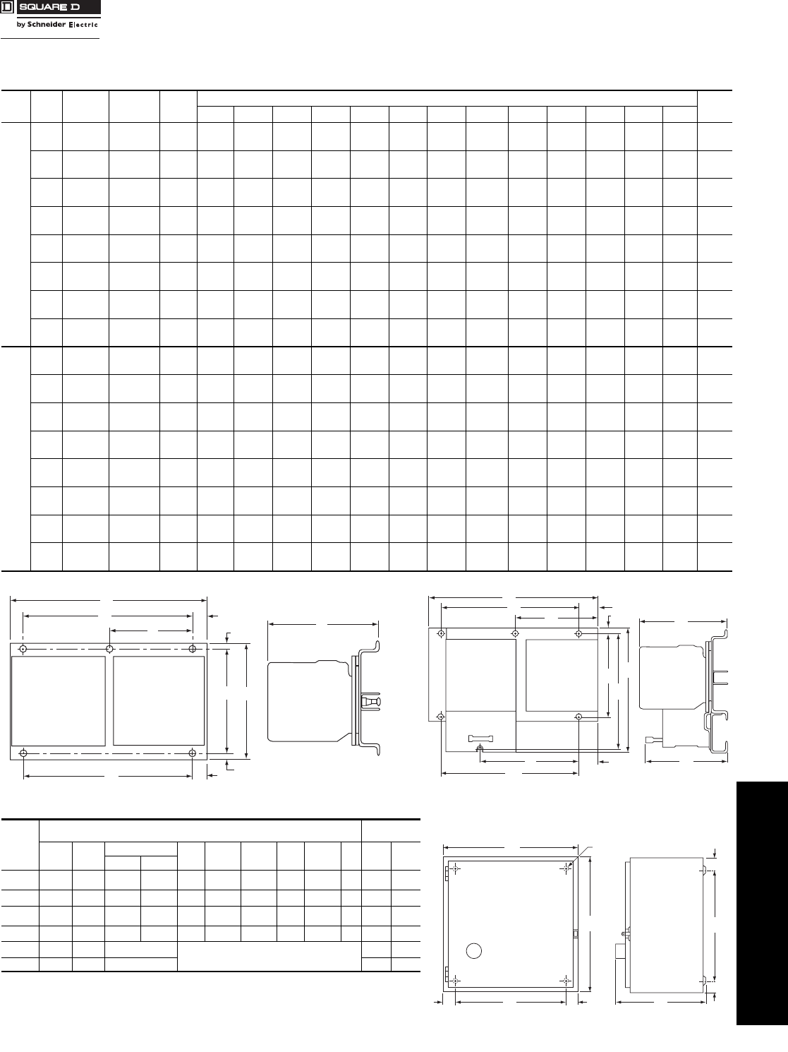
www.schneider-electric.us
16 NEMA/DEFINITE PURPOSE TYPE
CONTACTORS AND STARTERS
© 2009 Schneider Electric
All Rights Reserved 16-47
Full Voltage Reversing Contactors and Starters—NEMA Rated
Class 8702, 8736 / Refer to Catalog 8502CT9701
Approximate Dimensions
aVertical type design differs from that shown on the corresponding NEMA size horizontal type figure, but dimensions listed apply to that figure.
bStandard enclosure has space for a fused control transformer,
Form F4T, on Sizes 0-2, except for Size 0 & 1 4-Pole devices.
c3-Pole only.
Table 16.127: Open Type—2 or 3-Pole Only
Class NEMA
Size Type Mounting Figure
Number
Dimensions—Inches Weight
(lbs.)
AB CD E F G H I J K LM
8702
00 SAO Horizontal 1 7-1/8 5 5-5/16 — — 3-13/32 15/32 4-11/32 3/16 5-1/2 29/32 — — 12
0, 1 SBO, SCO Horizontal
Vertical 1
1a
7-1/8
5-15/32 5
9-7/32 5-5/16
5-5/16 —
5-1/2 —
7/32 3-13/32
—15/32
39/64 4-11/32
8 3/16
39/64 5-1/2
5-1/32 29/32
7/32 —
——
—12
12
2SDO
Horizontal
Vertical 1
1a
9
6-3/4 6-7/8
11-3/8 6-1/32
6-1/32 —
6-1/4 —
1/4 4-1/2
—3/8
1/2 5-5/8
10-3/8 1/4
1/2 6
1/4 1-1/2
1/4 —
——
—16
16
3 SEO Horizontal
Vertical 1
1a
12-23/32
7-13/64 7-31/32
19 7
711-3/4
6-1/4 31/64
31/64 —
—31/64
1-1/64 7
17 31/64
63/64 11-3/4
6-1/4 31/64
31/64 —
——
—35
35
4SFO
Horizontal
Vertical 1
1a
14-1/4
7-31/32 11-11/16
23-29/32 7
713-1/4
71/2
31/64 —
— 1/2
1-13/16 8
20-1/4 1-27/32
1-3/16 13-1/4
71/2
31/64 —
——
—45
45
5SGO
Horizontal
Vertical 1
1a
19-5/16
10-3/4 16-3/16
34-13/32 9-3/8
9-3/8 18
9-1/2 21/32
5/8 —
—1-1/32
1-1/4 14
32 1-5/32
1-5/32 18
9-1/2 21/32
5/8 —
——
—98
98
6 SHO Horizontal 1 22-3/8 28-3/64 9-33/64 18 40/64 — 3-53/64 21-3/16 3-1/32 18 49/64 — — 195
7 SJO Horizontal 1 24-1/4 37-1/4 13-13/16 19-3/4 1-33/64 — — 30 — — — — — 310
8736
00 SAO Horizontal 2 7-1/8 6-29/32 5-5/16 — — 3-13/32 15/32 4-11/32 6-7/32 4-17/32 5-1/16 21/32 — 13
0, 1 SBO, SCO Horizontal
Vertical 2
2a
7-1/8
5-15/32 6-29/32
11-33/64 5-5/16
5-5/16 —
5-1/32 —
7/32 3-13/32
—15/32
39/64 4-11/32
86-7/32
10-45/64 4-17/32
2-33/64 5-1/16
5-1/16 21/32
7/32 —
5-1/32 13
13
2SDO
Horizontal
Vertical 2
2a
9
6-3/4 8-1/2
13-31/64 6-1/32
6-1/32 —
6-1/4 —
1/4 4-1/2
— 3/8
25/32 5-5/8
10-3/8 7-1/2
12-31/32 5
3-1/8 5-5/32
5-5/32 1-1/2
1/4 —
618
18
3 SEO Horizontal
Vertical 2
2a
12-23/32
7-5/16 11-23/32
22-1/4 7
711-3/4
6-1/4 31/64
31/64 —
— 31/64
1-1/64 10-3/4
20-3/4 10-3/4
—11-3/4
6-1/4 6-1/4
6-1/4 31/64
31/64 11-3/4
6-1/4 38
38
4SFO
Horizontal
Vertical 2
2a
14-1/4
7-31/32 14-19/32
26-13/16 7
713-1/4
71/2
31/64 —
—1-27/32
1-27/32 12-1/4
24-1/2 12-1/4
—13-1/4
4-3/64 6-1/4
6-1/4 1/2
31/64 13-1/4
748
48
5SGO
Horizontal
Vertical 2
2a
19-5/16
10-3/4 20-29/32
39-5/32 9-3/8
9-3/8 18
9-1/2 21/32
21/32 —
—1-9/32
1-9/32 19
371/4 19
37-1/4 18
9-1/2 6-5/8
6-5/8 5/8
5/8 18
9-1/2 115
115
6 SHO Horizontal 2 22-3/8 28-3/64 9-33/64 18 44/64 — 3-53/64 21-3/16 3-1/32 18 49/64 — — 200
7 SJO Horizontal 1 24-1/4 37-1/4 13-13/16 19-3/4 1-33/64 — — 30 — — — — — 315
Table 16.128: NEMA 1 (Class 8702 and 8736)
NEMA
Size
Dimensions—Inches Weight
(lbs.)
AB CD E F G H I 8702 8736
8702 8736
00, 0c
1b11-7/8 11-7/8 7-13/32 7-17/32 9-3/4 1-1/16 1-1/16 9-3/4 1-1/16 5/16 16 17
2b14-7/8 14-1/8 7-9/16 7-21/32 12-3/4 1-1/16 1-1/16 12 1-1/16 5/16 24 25
3c
4c18-5/32 29-5/32 9-1/4 9-1/4 15-1/2 1-21/64 1-21/64 26-1/2 1-21/64 7/16 95 98
5 35-7/32 46-7/32 12-13/16 12-15/16 31 2-7/64 2-7/64 42 2-7/64 9/16 298 315
6 36-7/32 62-7/32 19-15/32 Floor Mounting. 400 405
7 34-1/2 93 23-1/2 — —
D
F
E
JK
G
HB
I
A
C
Figure 1 (Class 8702 Open Type)
C
RESET
M
JL
H
I
B
G
E
F
D
A
K
Figure 2 (Class 8736 Open Type)
RESET
A
B
H
H
C
F
D
E
G
(4) I Dia. Mtg. Holes
Figure 3—NEMA 1
Courtesy of Steven Engineering, Inc.-230 Ryan Way, South San Francisco, CA 94080-6370-Main Office: (650) 588-9200-Outside Local Area: (800) 258-9200-www.stevenengineering.com

www.schneider-electric.us
16 NEMA/DEFINITE PURPOSE TYPE
CONTACTORS AND STARTERS
16-48 © 2009 Schneider Electric
All Rights Reserved
Full Voltage Reversing Contactors and Starters—NEMA Rated
Class 8702, 8736 / Refer to Catalog 8502CT9701
Approximate Dimensions
aStandard enclosure has space for a fused control transformer, Form F4T, on Sizes 0-2, except for Size 0 & 1 4-Pole devices.
b3-Pole only.
cSize 6 & 7 are sheet steel enclosures and are rated NEMA 4 only.
dWith control power transformer (Form F4T).
eDimensions shown for 2 or 3-Pole devices only.
fWithout control transformer.
gWith control transformer (Form F4T).
hStandard enclosure has space for a fused control transformer, Form F4T, on Sizes 0-2, except for Size 0 & 1 4-Pole devices.
i3-Pole only.
Table 16.129: NEMA 4 & 4X—Stainless Steelc
NEMA
Size Class
Number
Dimensions—Inches Hub Dia. Weight
(lbs.)
W
Bot.
Only
X
Top
&
Bot.
A B C D E F G H I J K L 8702 8736
0a
1a8702 & 8736 12-5/8 7-13/16 14-11/16 2-9/16 7-1/2 13-1/2 19/32 3-7/8 18-13/32 1-21/32 2-5/16 5/16 3/4 1 25 26
2a8702 & 8736 14-7/8 8-1/4 15-3/4 2-9/16 9-3/4 15 3/8 3-7/8 20-7/8 1-23/32 2-5/8 5/16 3/4 1-1/2 33 35
3b
4b
8702 18-5/32 8-3/4 32-7/32 3-5/64 12 30-1/2 7/8 3-11/16 26-23/32 2-9/16 3-3/16 7/16 3/4 2-1/2 96 —
8736 18-5/32 9-9/16 32-7/32 3-5/64 12 30-1/2 7/8 4-1/2 26-23/32 2-9/16 3-3/16 7/16 3/4 2-1/2 — 99
58702 35-7/32 12-1/8 49-7/32 4-7/64 27 48 5/8 4-19/32 45-13/16 2-31/32 3-1/2 9/16 3/4 3-1/2 300 —
8736 35-7/32 12-15/16 49-7/32 4-7/64 27 48 5/8 5-13/32 45-13/16 2-31/32 3-1/2 9/16 3/4 3-1/2 — 317
6 8702 & 8736 36-7/32 19-15/32 70-1/8 Floor Mounting 500 505
7 8702 & 8736 34-1/2 23-1/2 101 ——
Table 16.130: NEMA 4X—Watertight and Corrosion Resistant
Glass Polyester Enclosure
See page 16-25 for drawing of enclosure.
NEMA Size Class Type No. of
Poles
Dimensions—Inches
ABCEF
0–2 8702/36 SBW
SCW
SDW All 16-7/8 9-25/32 22-3/4 10-1/8 21-1/2
0–2d8702/36 SBW
SCW
SDW All 24-5/8 11-15/16 27 17-7/8 25-3/4
3–4 8702/36 SEW
SFW 2,3 26-5/16 11-15/16 33-1/2 18-1/2 32-1/4
3–4d8702/36 SEW
SFW 4 32-1/2 12-1/8 39-5/16 23-7/8 38-1/8
Table 16.131: NEMA 7 and 9 Bolted Enclosure
See page 16-26 for drawing of enclosure.
NEMA
Size Type Dimensions—IncheseWt.
(lbs.)
G H J K L N P Q, R S, T, U, V
0–2 SBT
SCT
SDT 14-1/4 27-5/8 9-1/2 12-1/4 19-1/4 9-5/8 11-1/2 2-3/8 3-1/8 115
3–4 SET
SFT 24-1/2 45-5/8 13-3/4 22-1/2 27-1/2 13-3/4 15-3/8 3-7/16 4 180
Table 16.132: NEMA 7 & 9 SPIN TOP® Enclosure
See page 16-25 for drawing of enclosure.
NEMA
Size Type Dimensions—Inches Wt.
(lbs.)
ABfBgCfCgDEfEgFGfGgHfHgJfJgKLMNPR
0-1 SBR
SCR 12 41-1/16 46-1/8 68-1/16 79-1/8 16-3/4 7-1/4 12-1/4 7-11/16 26-1/8 26-1/8 3 9 24 24 8-1/2 2-1/16 9-3/8 5-1/4 1-1/2 3/8 70
2 SDR 16-1/8 48-1/2 50-1/2 81-1/2 85 20-1/4 12-1/8 9-1/8 8-5/8 27-3/4 32-3/4 8 4-1/2 25 30 12 2-5/8 11 5-1/2 2-1/2 3/8 100
3 SER Consult Square D/Schneider Electric CIC at 1-888-SquareD (1-888-778-2733)
Table 16.133: NEMA 12/3R
NEMA
Size Class
Number
Dimensions—Inches Weight
(lbs.)
A B C D E F G H I J 8702 8736
0h
1h8702 & 8736 11-7/8 7-3/4 13-3/4 2-9/16 6-3/4 12-3/4 1/2 3-21/32 18-1/8 5/16 23 24
2h8702 & 8736 14-7/8 7-7/8 16 2-9/16 9-3/4 15 1/2 3-21/32 21-1/4 5/16 31 32
3i
4i
8702 18-5/32 9-1/4 31-1/2 3-5/64 12 30-1/2 1/2 3-11/16 26-23/32 7/16 96 —
8736 18-5/32 9-9/16 31-1/2 3-5/64 12 30-1/2 1/2 4-1/2 26-23/32 7/16 — 99
58702 35-7/32 13-1/8 49 4-1/8 27 48 1/2 5-5/16 45-7/8 9/16 302 —
8736 35-7/32 13-15/16 49 4-1/8 27 48 1/2 6-1/8 45-7/8 9/16 — 319
6 8702 & 8736 36-7/32 19-15/32 62-7/32 Floor Mounting 490 495
7 8702 & 8736 34-1/2 23-1/2 93 — —
(4) L Dia. Mtg. Holes
G
DED A
C
F
B
J
HK
WX
I
G
NEMA 4 & 4X
Stainless Steel
A
DDG
FC
E
G
I
H
(4) J Dia. Mtg. Holes
B
NEMA 12
Courtesy of Steven Engineering, Inc.-230 Ryan Way, South San Francisco, CA 94080-6370-Main Office: (650) 588-9200-Outside Local Area: (800) 258-9200-www.stevenengineering.com

www.schneider-electric.us
16 NEMA DEFINITE PURPOSE TYPE
CONTACTORS AND STARTERS
© 2009 Schneider Electric
All Rights Reserved 16-49
Full Voltage Reversing Vacuum Contactors—NEMA Rated
Class 8702 / Refer to Catalog 8502CT9701
Class 8702 Type W Reversing Vacuum Contactors are used to switch capacitors, transformers and electric motors
where overload protection is separately provided. Type W reversing vacuum contactors are designed for operation at
600 Volts, 50/60 Hz.
Auxiliary Contacts—An auxiliary contact block, Class 9999 Type WX11, with one normally open contact and one
normally closed contact, is used with Size 4, 5 and 6 vacuum contactors. Additional auxiliary contact units may be
added to the Size 4 and 5 reversing contactors in the field. A maximum of 2 units may be added to the Size 4; a
maximum of 1 unit may be added to the Size 5.
Termination Means—The Size 4 reversing vacuum contactor is supplied with line and load side lugs. The Size
5 and 6 reversing vacuum contactors are supplied without line and load side lugs.
aCoil voltage code must be specified to order this product. Refer to standard coil voltage codes listed on page 16-50. Replacement coils are listed on page 16-27.
Approximate Dimensions
For How to Order Information, see page 16-12.
Table 16.134: Class 8702 Full Voltage Reversing Vacuum Contactors (Horizontal Only) 3-Pole Polyphase—600 Vac Maximum—50–60 Hz
NEMA
Size
Enclosed
Ampere
Rating
Motor
Voltage Maximum
Horsepower
Open Type
Type $ Price
4 135
200
230
380
460
575
40
50
75
100
100
WFO3a10659.00
5 270
200
230
380
460
575
75
100
150
200
200
WGO3a18678.00
6 540
200
230
380
460
575
150
200
300
400
400
WHO3Va45666.00
Table 16.135: Class 9998—Replacement Coils for Class 8702 Reversing Contactors
Size Type Poles Class
&
Type
Suffix Number
(Complete Coil Number Consists of Class and Type
Followed by Suffix Number) $ Price
120 Volts
110 Volts 240 Volts
220 Volts 480 Volts
440 Volts 600 Volts
550 Volts
4
5
6
WF
WG
WH
All
All
All
9998WF
9998WG
9998WH
120
120
120
240
240
240
480
480
480
600
600
600
732.00
1724.00
1904.00
Table 16.136: Class 9999—Vacuum Starter Kits
For Use With Kit Description Class 9999
Type $ Price
Type Size
WF–WG
WH 4–5
6Auxiliary Contacts, Non-Convertible
1 N.O. & 1 N.C. Isolated Contacts WX11 122.00
WF
WG–WH 4
5–6
Coil Circuit Auxiliary Contacts
1 N.O. & 1 N.C. Isolated Contacts, Delayed Break
1 N.C. Isolated Contact
WCX11
WLX01 114.00
503.00
WG 5 Lug Kits
(6) lugs included LUW5 275.00
Table 16.137: Coil Voltage Codes
Volts 110 120 220 240 440 480 550 600
50 Hz V02V03V06V07
60 Hz V02 V03 V06 V07
Plate
Name
1.5
1.76 0.38
2.75
.60
5.81
22.00
4.00 2.50 3.65
2.00
.86
6.90
14.00 18.00
9.56
4.26
2.48
2.50
1.89
1.40
24.00
3.98
3.75
1
2
3
4
5
6
0
1
2
7
8
9
Size 5 Reversing Contactor Outline without Lugs
Class 8702 WG
3.50
3 mtg. holes
.281 diaInterlock
Auxiliary Interlock
Gauge
Mechanical
Recess For
Over travel
.44
gauge
overtravel
4.20
6.88
4.88
6.54
9.75
1.13
1.44
1.44
Rear View
Front View
Side View
Drilling Plan
max
8.80
7.00
6.00
Size 4 Reversing Contactor Outline with Lugs
Class 8702 WF
2.70 2.70
4.40
3.40 3.90
6.50
16.40
14.00
18.00
7.75
1.40
4.40
2.00
2.70 2.70
22.00
24.00
Plate
Name
5.00
1.50
7.75
3.75
Size 6 Reversing Contactor Outline without Lugs
Class 8702 WH
CP1 Discount
Schedule
Courtesy of Steven Engineering, Inc.-230 Ryan Way, South San Francisco, CA 94080-6370-Main Office: (650) 588-9200-Outside Local Area: (800) 258-9200-www.stevenengineering.com

www.schneider-electric.us
16 NEMA/DEFINITE PURPOSE TYPE
CONTACTORS AND STARTERS
16-50 © 2009 Schneider Electric
All Rights Reserved
Reversing Combination Starters—NEMA Rated
Class 8738 / Refer to Catalog 8538CT9701
Class 8738 and 8739 Type S reversing combination starters combine the requirements of motor overload and short circuit protection into one
convenient package. Type S reversing combination starters are manufactured in accordance with NEMA standards, and are UL Listed (although
some Form numbers may not be listed—contact your nearest Square D/Schneider Electric sales office for further information). Class 8738 and
8739 reversing combination starters are designed to operate at 600 Vac, 50–60 Hz—and are supplied with melting alloy overload relays as
standard. For Class J fuses, use form Y1072 (No Charge).
Class 8738 Fusible Disconnect Switch Type
Note: that the prices shown do not include thermal units. Devices require 3 thermal units. Standard trip thermal units are $21.50 each.
See page 16-125 for selection information.
00
aNEMA 12 enclosures may be field modified for outdoor non-corrosive and non-service-entrance-rated applications; see page 16-104 for more information. For class J fuse clip, use
Form Y1072 (no charge).
bCoil voltage code must be specified to order this product. Refer to standard coil voltage codes shown below.
c24 V coils are not available on Sizes 4–7. On Sizes 00–3, where 24 V coils are available,
Form S (separate control) must be specified (i.e., order as 8738SBG12V01S).
dThese voltage codes must include Form S (supplied at no charge) (i.e., order as 8738SC13V02S).
Note: For voltage codes used with control transformers, see page 16-110.
Form S (separate control) is used when a separate source of power is available for the control (coil) voltage.
Form S is supplied at no charge.
Dimensions. . . . . . . . . . . . . . . . . . . . . . . . . . . . . . . . . . . . . . . . . . . page 16-56
Factory Modifications (Forms) . . . . . . . . . . . . . . . . . . . . . . . . . . . page 16-109
Replacement Parts (Class 9998). . . . . . . . . . . . . . . . . . . . . . . . . page 16-114
Type S Accessories (Class 9999) . . . . . . . . . . . . . . . . . . . . . . . . page 16-117
For How to Order Information, see page 16-12.
Table 16.138: Class 8738 Full-Voltage Type, Fusible (With Class H Fuse Clips) Reversing with
Melting Alloy Overload Relays—3-Pole Polyphase—600 Vac Maximum—50–60 Hz
Ratings NEMA 1
General Purpose
Enclosure
NEMA 4 & 4X
Watertight and Dusttight
Enclosure
Stainless Steel (304)
NEMA 4X
Watertight, Dusttight
and Corrosion Resistant
Polyester Enclosure
NEMA 12/3Ra
Dusttight and Driptight
Industrial Use Enclosure
Motor
Voltage
(Starter
Voltage)
Max.
Hp
Poly-
phase
NEMA
Size
Fuse
Clip
Size
Amps
With
External
Reset
Without
External
Reset $ Price
Type $ Price Type $ Price Type $ Price Type Type
200
(208)
30 30SBG12b2169.00 SBW12b3909.00 SBW22b4491.00 SBA22bSBA12b2654.00
5130 SCG12b2313.00 SCW12b4050.00 SCW22b4656.00 SCA22bSCA12b2798.00
7-1/2 60 SCG13b2340.00 SCW13b4077.00 SCW23b4692.00 SCA23bSCA13b2825.00
10 2 60 SDG12b3851.00 SDW12b6501.00 SDW22b7149.00 SDA22bSDA12b4478.00
20 3 100 SEG15b6357.00 SEW15b11001.00 — — SEA25bSEA15b7182.00
40 4 200 SFG15b13409.00 SFW15b19277.00 — — SFA25bSFA15b15672.00
75 5 400 SGG15b25605.00 SGW15b40589.00 — — SGA25bSGA15b30990.00
230
(240)
30 30SBG12b2169.00 SBW12b3909.00 SBW22b4491.00 SBA22bSBA12b2654.00
5130 SCG12b2313.00 SCW12b4050.00 SCW22b4656.00 SCA22bSCA12b2798.00
7-1/2 60 SCG13b2340.00 SCW13b4077.00 SCW23b4692.00 SCA23bSCA13b2825.00
15 2 60 SDG12b3851.00 SDW12b6501.00 SDW22b7149.00 SDA22bSDA12b4478.00
25 3 100 SEG15b6357.00 SEW15b11001.00 — — SEA25bSEA15b7182.00
50 4 200 SFG15b13409.00 SFW15b19277.00 — — SFA25bSFA15b15672.00
100 5 400 SGG15b25605.00 SGW15b40589.00 — — SGA25bSGA15b30990.00
460
(480)
50 30SBG13b2199.00 SBW13b3936.00 SBW23b4527.00 SBA23bSBA13b2682.00
10 1 30 SCG14b2340.00 SCW14b4077.00 SCW24b4692.00 SCA24bSCA14b2825.00
15 230 SDG16b3873.00 SDW16b6515.00 SDW26b7163.00 SDA26bSDA16b4491.00
25 60 SDG14b3893.00 SDW14b6543.00 SDW24b7199.00 SDA24bSDA14b4521.00
50 3 100 SEG13b6443.00 SEW13b11087.00 — — SEA23bSEA13b7268.00
100 4 200 SFG13b13464.00 SFW13b19332.00 — — SFA23bSFA13b15728.00
200 5 400 SGG13b26204.00 SGW13b41187.00 — — SGA23bSGA13b31589.00
575
(600)
50 30SBG13b2199.00 SBW13b3936.00 SBW23b4527.00 SBA23bSBA13b2682.00
10 1 30 SCG14b2340.00 SCW14b4077.00 SCW24b4692.00 SCA24bSCA14b2825.00
15 230 SDG16b3873.00 SDW16b6515.00 SDW26b7163.00 SDA26bSDA16b4491.00
25 60 SDG14b3893.00 SDW14b6543.00 SDW24b7199.00 SDA24bSDA14b4521.00
50 3 100 SEG13b6443.00 SEW13b11087.00 — — SEA23bSEA13b7268.00
100 4 200 SFG13b13464.00 SFW13b19332.00 — — SFA23bSFA13b15728.00
200 5 400 SGG13b26204.00 SGW13b41187.00 — — SGA23bSGA13b31589.00
Table 16.139: Coil Voltage Codes
Voltage Code $ Price Adder
60 Hz 50 Hz
24dc
120d
208
240
277
480
600
Specify
—
110
—
220
—
440
550
Specify
V01
V02
V08
V03
V04
V06
V07
V99
No Charge
No Charge
No Charge
No Charge
No Charge
No Charge
No Charge
35.60
CP1 Discount
Schedule
Courtesy of Steven Engineering, Inc.-230 Ryan Way, South San Francisco, CA 94080-6370-Main Office: (650) 588-9200-Outside Local Area: (800) 258-9200-www.stevenengineering.com

www.schneider-electric.us
16 NEMA DEFINITE PURPOSE TYPE
CONTACTORS AND STARTERS
© 2009 Schneider Electric
All Rights Reserved 16-51
Reversing Combination
Starters—NEMA Rated
Non-Fusible and Fusible Disconnect Switch Type
Class 8738 / Refer to Catalog 8538CT9701
3-Pole Polyphase—600 Vac Maximum—50–60 Hz
Note: that the prices shown do not include thermal units. Devices require 3 thermal units. Standard trip thermal units
are $21.50 each. See page 16-125 for selection information.
aNEMA 12 enclosures may be field modified for outdoor non-corrosive and non-service-entrance-rated applications; see page 16-104 for more
information.
bCoil voltage code must be specified to order this product. Refer to standard coil voltage codes shown on page 16-59.
cNEMA 12 enclosures may be field modified for outdoor non-corrosive and non-service-entrance-rated applications; see page 16-104 for more
information.
dCoil voltage code must be specified to order this product. Refer to standard coil voltage codes shown on page 16-52.
e5,000 AIC Rating
For How to Order Information, see page 16-12.
Table 16.140: Non-Fusible Disconnect Switch Type—Full-Voltage Type
Reversing with Melting Alloy Overload Relays
Ratings NEMA 1
General Purpose
Enclosure
NEMA 4 & 4X
Watertight and Dusttight
Enclosure
Stainless Steel (304)
NEMA 4X
Watertight, Dusttight
and Corrosion Resistant
Polyester
Enclosure
NEMA 12/3Ra
Dusttight and Driptight
Industrial Use Enclosure
Motor
Voltage
(Starter
Voltage)
Max.
Hp
Poly-
Phase
NEMA
Size
Fuse
Clip
Size
Amps
With
External
Reset
Without
External
Reset $ Price
Type $ Price Type $ Price Type $ Price Type Type
200
(208)
30NoneSBG11b2127.00 SBW11b3866.00 SBW21b4442.00 SBA21bSBA11b2613.00
7-1/2 1 None SCG11b2271.00 SCW11b4008.00 SCW21b4607.00 SCA21bSCA11b2754.00
10 2 None SDG11b3794.00 SDW11b6443.00 SDW21b7083.00 SDA21bSDA11b4419.00
25 3 None SEG11b6287.00 SEW11b10929.00 — — SEA21bSEA11b7113.00
40 4 None SFG11b13166.00 SFW11b19034.00 — — SFA21bSFA11b15431.00
75 5 None SGG11b25691.00 SGW11b40674.00 — — SGA21bSGA11b31076.00
230
(240)
30NoneSBG11b2127.00 SBW11b3866.00 SBW21b4442.00 SBA21bSBA11b2613.00
7-1/2 1 None SCG11b2271.00 SCW11b4008.00 SCW21b4607.00 SCA21bSCA11b2754.00
15 2 None SDG11b3794.00 SDW11b6443.00 SDW21b7083.00 SDA21bSDA11b4419.00
30 3 None SEG11b6287.00 SEW11b10929.00 — — SEA21bSEA11b7113.00
50 4 None SFG11b13166.00 SFW11b19034.00 — — SFA21bSFA11b15431.00
100 5 None SGG11b25691.00 SGW11b40674.00 — — SGA21bSGA11b31076.00
460
(480)
50NoneSBG11b2127.00 SBW11b3866.00 SBW21b4442.00 SBA21bSBA11b2613.00
10 1 None SCG11b2271.00 SCW11b4008.00 SCW21b4607.00 SCA21bSCA11b2754.00
25 2 None SDG11b3794.00 SDW11b6443.00 SDW21b7083.00 SDA21bSDA11b4419.00
50 3 None SEG11b6287.00 SEW11b10929.00 — — SEA21bSEA11b7113.00
100 4 None SFG11b13166.00 SFW11b19034.00 — — SFA21bSFA11b15431.00
200 5 None SGG11b25691.00 SGW11b40674.00 — — SGA21bSGA11b31076.00
575
(600)
50NoneSBG11b2127.00 SBW11b3866.00 SBW21b4442.00 SBA21bSBA11b2613.00
10 1 None SCG11b2271.00 SCW11b4008.00 SCW21b4607.00 SCA21bSCA11b2754.00
25 2 None SDG11b3794.00 SDW11b6443.00 SDW21b7083.00 SDA21bSDA11b4419.00
50 3 None SEG11b6287.00 SEW11b10929.00 — — SEA21bSEA11b7113.00
100 4 None SFG11b13166.00 SFW11b19034.00 — — SFA21bSFA11b15431.00
200 5 None SGG11b25691.00 SGW11b40674.00 — — SGA21bSGA11b31076.00
Table 16.141: Fusible Disconnect Switch Type With Class R Fuse Clips—100,000 AIC Rating
Ratings NEMA 1
General Purpose
Enclosure
NEMA 4 & 4X
Watertight and Dusttight
Enclosure
Stainless Steel (304)
NEMA 4X
Watertight, Dusttight
and Corrosion Resistant
Polyester
Enclosuree
NEMA 12/3Rc
Dusttight and Driptight
Industrial Use Enclosure
Motor
Voltage
(Starter
Voltage)
Max.
Hp
Poly-
Phase
NEMA
Size
Fuse
Clip
Size
Amps
With
External
Reset
Without
External
Reset $ Price
Type $ Price Type $ Price Type $ Price Type Type
200
(208)
30 30SBG32d2192.00 SBW32d3929.00 SBW42d4521.00 SBA42dSBA32d2676.00
5130 SCG32d2334.00 SCW32d4071.00 SCW42d4685.00 SCA42dSCA32d2817.00
7-1/2 60 SCG33d2363.00 SCW33d4100.00 SCW43d4706.00 SCA43dSCA33d2847.00
10 2 60 SDG32d3873.00 SDW32d6521.00 SDW42d7176.00 SDA42dSDA32d4499.00
20 3 100 SEG35d6399.00 SEW35d11043.00 — — SEA45dSEA35d7226.00
40 4 200 SFG35d13451.00 SFW35d19319.00 — — SFA45dSFA35d15714.00
75 5 400 SGG35d25707.00 SGW35d40689.00 — — SGA45dSGA35d31089.00
230
(240)
30 30SBG32d2192.00 SBW32d3929.00 SBW42d4521.00 SBA42dSBA32d2676.00
5130 SCG32d2334.00 SCW32d4071.00 SCW42d4685.00 SCA42dSCA32d2817.00
7-1/2 60 SCG33d2363.00 SCW33d4100.00 SCW43d4706.00 SCA43dSCA33d2847.00
15 2 60 SDG32d3873.00 SDW32d6521.00 SDW42d7176.00 SDA42dSDA32d4499.00
25 3 100 SEG35d6399.00 SEW35d11043.00 — — SEA45dSEA35d7226.00
50 4 200 SFG35d13451.00 SFW35d19319.00 — — SFA45dSFA35d15714.00
100 5 400 SGG35d25707.00 SGW35d40689.00 — — SGA45dSGA35d31089.00
460
(480)
50 30SBG33d2219.00 SBW33d3959.00 SBW43d4548.00 SBA43dSBA33d2705.00
10 1 30 SCG34d2363.00 SCW34d4100.00 SCW44d4712.00 SCA44dSCA34d2847.00
15 230 SDG36d3893.00 SDW36d6534.00 SDW46d7191.00 SDA46dSDA36d4514.00
25 60 SDG34d3915.00 SDW34d6564.00 SDW44d7433.00 SDA44dSDA34d4541.00
50 3 100 SEG33d6485.00 SEW33d11129.00 — — SEA43dSEA33d7311.00
100 4 200 SFG33d13508.00 SFW33d19376.00 — — SFA43dSFA33d15771.00
200 5 400 SGG33d26303.00 SGW33d41288.00 — — SGA43dSGA33d31688.00
575
(600)
50 30SBG33d2219.00 SBW33d3959.00 SBW43d4548.00 SBA43dSBA33d2705.00
10 1 30 SCG34d2363.00 SCW34d4100.00 SCW44d4712.00 SCA44dSCA34d2847.00
15 230 SDG36d3893.00 SDW36d6534.00 SDW46d7191.00 SDA46dSDA36d4514.00
25 60 SDG34d3915.00 SDW34d6564.00 SDW44d7433.00 SDA44dSDA34d4541.00
50 3 100 SEG33d6485.00 SEW33d11129.00 — — SEA43dSEA33d7311.00
100 4 200 SFG33d13508.00 SFW33d19376.00 — — SFA43dSFA33d15771.00
200 5 400 SGG33d26303.00 SGW33d41288.00 — — SGA43dSGA33d31688.00
CP1 Discount
Schedule
Courtesy of Steven Engineering, Inc.-230 Ryan Way, South San Francisco, CA 94080-6370-Main Office: (650) 588-9200-Outside Local Area: (800) 258-9200-www.stevenengineering.com

www.schneider-electric.us
16 NEMA DEFINITE PURPOSE TYPE
CONTACTORS AND STARTERS
16-52 © 2009 Schneider Electric
All Rights Reserved
Reversing Combination
Starters—NEMA Rated
Mag-Gard® Circuit Breaker
Class 8739 / Refer to Catalog 8538CT9701
3-Pole Polyphase—600 Vac Maximum—50–60 Hz
Note that the prices shown do not include thermal units. Devices require 3 thermal units. Standard trip thermal units are
$21.50 each. See page 16-125 for selection information.
aNEMA Size 6 starters are NEMA 4 painted sheet steel enclosures.
bNEMA 7 & 9 bolted are not UL Listed.
cNEMA 12 enclosures may be field modified for outdoor non-corrosive and non-service-entrance-rated applications; see page 16-104 for more
information.
dCoil voltage code must be specified to order this product. Refer to standard coil voltage codes listed below.
e24 V coils are not available on Sizes 4–7. On Sizes 00–3, where 24 V coils are available,
Form S (separate control) must be specified (i.e., order as 8739SBG41V01S).
fThese voltage codes must include Form S (supplied at no charge) (i.e., order as 8739SCG41V02S).
Note: For voltage codes used with control transformers, see page 16-110.
Form S (separate control) is used when a separate source of power is available for the control (coil) voltage.
Form S is supplied at no charge.
Dimensions. . . . . . . . . . . . . . . . . . . . . . . . . . . . . . . . . . . . . . . . . . . page 16-56
Factory Modifications (Forms) . . . . . . . . . . . . . . . . . . . . . . . . . . . page 16-109
Replacement Parts (Class 9998). . . . . . . . . . . . . . . . . . . . . . . . . page 16-114
Type S Accessories (Class 9999) . . . . . . . . . . . . . . . . . . . . . . . . page 16-117
For How to Order Information, see page 16-12.
Table 16.142: Full-Voltage Type, Reversing with Melting Alloy Overload Relays
Ratings
NEMA
Type 1
General
Purpose
Enclosure
NEMA
4 & 4X
Watertight
and Dusttight
Enclosure
Stainless Steel (304)
(Sizes 0-5)a
NEMA 4X
Watertight
Dusttight
and Corrosion
Resistant
Polyester Enclosure
NEMA 7 & 9b
For Hazardous Locations
Class I, Groups C & D
Class II, Groups E, F & G
NEMA 12/3Rc
Dusttight and Driptight
Industrial Use
Enclosure
Motor
Voltage
(Starter
Voltage)
Hp
Range
Poly-
phase
NEMA
Size
Circuit Breaker
(See Page 7-32
for Breaker
Adjustment
Range)
Type $ Price Type $ Price Type $ Price SPIN TOP®
Type $ Price Bolted
Type $ Price
With
External
Reset
Without
External
Reset $ Price
Type Type
200
(208)
1/4–1/3
1/2–1
11/2–3 0GJL36003M01
GJL36007M02
GJL36015M03
SBG41d
SBG42d
SBG43d2555. SBW41d
SBW42d
SBW43d4292. SBW51d
SBW52d
SBW53d4932. SBR41d
SBR42d
SBR43d5297. SBT41d
SBT42d
SBT43d5297. SBA51d
SBA52d
SBA53d
SBA41d
SBA42d
SBA43d3038.
1/4–1/3
1/2–1
11/2–3
5
7-1/2
1
GJL36003M01
GJL36007M02
GJL36015M03
GJL36030M04
GJL36050M05
SCG41d
SCG42d
SCG43d
SCG44d
SCG45d
2726.
SCW41d
SCW42d
SCW43d
SCW44d
SCW45d
4463.
SCW51d
SCW52d
SCW53d
SCW54d
SCW55d
5133.
SCR41d
SCR42d
SCR43d
SCR44d
SCR45d
5489.
SCT41d
SCT42d
SCT43d
SCT44d
SCT45d
5489.
SCA51d
SCA52d
SCA53d
SCA54d
SCA55d
SCA41d
SCA42d
SCA43d
SCA44d
SCA45d
3209.
1-1/2–3
5
71/2–10 2GJL36015M03
GJL36030M04
GJL36050M05
SDG41d
SDG42d
SDG43d4350. SDW41d
SDW42d
SDW43d6998. SDW51d
SDW52d
SDW53d7695. SDR41d
SDR42d
SDR43d8153. SDT41d
SDT42d
SDT43d8153. SDA51d
SDA52d
SDA53d
SDA41d
SDA42d
SDA43d4976.
15–25 3 FAL3610018M SEG42d6501. SEW42d11142. SEW52d12254. ——— — SEA52dSEA42d7326.
30
40 4KAL3625025M
KAL3625026M SFG42d
SFG43d14718. SFW42d
SFW43d20586. SFW52d
SFW53d22644. ————
SFA52d
SFA53d
SFA42d
SFA43d16982.
50
60
75 5KAL3625030M
LAL3640032M
LAL3640033M
SGG42d
SGG44d
SGG45d29808. SGW42d
SGW44d
SGW45d44792. —
—
———
—
———
—
——SGA52d
SGA54d
SGA55d
SGA42d
SGA44d
SGA45d35190.
100
125
150 6LAL3640036M
MAL3660040M
MAL3660042M
SHG43d
SHG44d
SHG45d64274. SHW43d
SHW44d
SHW45d71396. —
—
———
—
———
—
——SHA53d
SHA54d
SHA55d
SHA43d
SHA44d
SHA45d68120.
230
(240)
1/4–1/3
1/2–1
11/2–3 0GJL36003M01
GJL36007M02
GJL36015M03
SBG41d
SBG42d
SBG43d2555. SBW41d
SBW42d
SBW43d4292. SBW51d
SBW52d
SBW53d4932. SBR41d
SBR42d
SBR43d5297. SBT41d
SBT42d
SBT43d5297. SBA51d
SBA52d
SBA53d
SBA41d
SBA42d
SBA43d3038.
1/4–1/3
1/2–1
11/2–3
5–7-1/2
1
GJL36003M01
GJL36007M02
GJL36015M03
GJL36030M04
SCG41d
SCG42d
SCG43d
SCG44d
2726.
SCW41d
SCW42d
SCW43d
SCW44d
4463.
SCW51d
SCW52d
SCW53d
SCW54d
5133.
SCR41d
SCR42d
SCR43d
SCR44d
5489.
SCT41d
SCT42d
SCT43d
SCT44d
5489.
SCA51d
SCA52d
SCA53d
SCA54d
SCA41d
SCA42d
SCA43d
SCA44d
3209.
1-1/2–3
5–7-1/2
10
15
2
GJL36015M03
GJL36030M04
GJL36050M05
GJL36075M06
SDG41d
SDG42d
SDG43d
SDG44d
4350.
SDW41d
SDW42d
SDW43d
SDW44d
6998.
SDW51d
SDW52d
SDW53d
SDW54d
7695.
SDR41d
SDR42d
SDR43d
SDR44d
8153.
SDT41d
SDT42d
SDT43d
SDT44d
8153.
SDA51d
SDA52d
SDA53d
SDA54d
SDA41d
SDA42d
SDA43d
SDA44d
4976.
15–30 3 FAL3610018M SEG42d6501. SEW42d11142. SEW52d12254. — — — — SEA52dSEA42d7326.
40
50 4KAL3625026M
KAL3625029M SFG43d
SFG44d14718. SFW43d
SFW44d20586. SFW53d
SFW54d22644. —
————
SFA53d
SFA54d
SFA43d
SFA44d16982.
60
75
100 5KAL3625031M
LAL3640032M
LAL3640035M
SGG43d
SGG44d
SGG46d29808. SGW43d
SGW44d
SGW46d44792. —
—
———
—
———
—
——SGA53d
SGA54d
SGA56d
SGA43d
SGA44d
SGA46d35190.
125–150
200 6MAL3660040M
MAL3660044M SHG44d
SHG46d64274. SHW44d
SHW46d71396. —
———
———
——SHA54d
SHA56d
SHA44d
SHA46d68120.
Table 16.143: Coil Voltage Codes
Voltage Code $ Price Adder
60 Hz 50 Hz
24fe
120f
208
240
277
480
600
Specify
—
110
—
220
—
440
550
Specify
V01
V02
V08
V03
V04
V06
V07
V99
No Charge
No Charge
No Charge
No Charge
No Charge
No Charge
No Charge
35.60
CP1 Discount
Schedule
Courtesy of Steven Engineering, Inc.-230 Ryan Way, South San Francisco, CA 94080-6370-Main Office: (650) 588-9200-Outside Local Area: (800) 258-9200-www.stevenengineering.com

www.schneider-electric.us
16 NEMA DEFINITE PURPOSE TYPE
CONTACTORS AND STARTERS
© 2009 Schneider Electric
All Rights Reserved 16-53
Reversing Combination
Starters—NEMA Rated
Mag-Gard® Circuit Breaker
Class 8739 / Refer to Catalog 8538CT9701
3-Pole Polyphase—600 Vac Maximum—50–60 Hz
Note that the prices shown do not include thermal units. Devices require 3 thermal units. Standard trip thermal units are
$21.50 each. See page 16-125 for selection information.
aNEMA Size 6 starters are NEMA 4 painted sheet steel enclosures.
bNEMA 7 & 9 bolted are not UL Listed.
cNEMA 12 enclosures may be field modified for outdoor non-corrosive and non-service-entrance-rated applications; see page 16-104 for more
information.
dCoil voltage code must be specified to order this product. Refer to standard coil voltage codes listed below.
e24 V coils are not available on Sizes 4–7. On Sizes 00–3, where 24 V coils are available,
Form S (separate control) must be specified (i.e., order as 8739SBG41V01S).
fThese voltage codes must include Form S (supplied at no charge) (i.e., order as 8739SCG41V02S).
Note: For voltage codes used with control transformers, see page 16-110.
Form S (separate control) is used when a separate source of power is available for the control (coil) voltage.
Form S is supplied at no charge.
Dimensions . . . . . . . . . . . . . . . . . . . . . . . . . . . . . . . . . . . . . . . . . . .page 16-56
Factory Modifications (Forms) . . . . . . . . . . . . . . . . . . . . . . . . . . .page 16-109
Replacement Parts (Class 9998) . . . . . . . . . . . . . . . . . . . . . . . . .page 16-114
Type S Accessories (Class 9999). . . . . . . . . . . . . . . . . . . . . . . . .page 16-117
For How to Order Information, see page 16-12.
Table 16.144: Full-Voltage Type, Reversing with Melting Alloy Overload Relays
Ratings
NEMA
Type 1
General
Purpose
Enclosure
NEMA 4 & 4X
Watertight
and Dusttight
Enclosure
Stainless Steel (304)
(Sizes 0–5)a
NEMA 4X
Watertight
Dusttight
and Corrosion
Resistant
Polyester Enclosure
NEMA 7 & 9b
For Hazardous Locations
Class I, Groups C & D
Class II, Groups E, F & G
NEMA 12/3Rc
Dusttight and Driptight
Industrial Use
Enclosure
Motor
Voltage
(Starter
Voltage)
Hp
Range
Poly-
phase
NEMA
Size
Circuit Breaker
(See Page 7-32
for Breaker
Adjustment
Range)
Type $ Price Type $ Price Type $ Price SPIN TOP®
Type $ Price Bolted
Type $ Price
With
External
Reset
Without
External
Reset $ Price
Type Type
460
(480)
1/4–1
1-1/2–3
50GJL36003M01
GJL36007M02
GJL36015M03
SBG41d
SBG42d
SBG43d2555. SBW41d
SBW42d
SBW43d4292. SBW51d
SBW52d
SBW53d4932. SBR41d
SBR42d
SBR43d5297. SBT41d
SBT42v
SBT43d5297. SBA51d
SBA52d
SBA53d
SBA41d
SBA42d
SBA43d3038.
1/4–1
1-1/2–3
5–7-1/2
10
1
GJL36003M01
GJL36007M02
GJL36015M03
GJL36030M04
SCG41d
SCG42d
SCG43d
SCG44d
2726.
SCW41d
SCW42d
SCW43d
SCW44d
4463.
SCW51d
SCW52d
SCW53d
SCW54d
5133.
SCR41d
SCR42d
SCR43d
SCR44d
5489.
SCT41d
SCT42d
SCT43d
SCT44d
5489.
SCA51d
SCA52d
SCA53d
SCA54d
SCA41d
SCA42d
SCA43d
SCA44d
3209.
5–7-1/2
10–15
20–25 2GJL36015M03
GJL36030M04
GJL36050M05
SDG41d
SDG42d
SDG43d4350. SDW41d
SDW42d
SDW43d6998. SDW51d
SDW52d
SDW53d7695. SDR41d
SDR42d
SDR43d8153. SDT41d
SDT42d
SDT43d8153. SDA51d
SDA52d
SDA53d
SDA41d
SDA42d
SDA43d4976.
20–25
30–50 3GJL36050M05
FAL3610018M SEG41d
SEG42d6501. SEW41d
SEW42d11142. SEW51d
SEW52d12254. ————
SEA51d
SEA52d
SEA41d
SEA42d7326.
60–75
100 4KAL3625025M
KAL3625029M SFG42d
SFG44d14718. SFW42d
SFW44d20586. SFW52d
SFW54d22644. —
————
SFA52d
SFA54d
SFA42d
SFA44d16982.
125
150
200 5KAL3625031M
LAL3640032M
LAL3640035M
SGG43d
SGG44d
SGG46d29808. SGW43d
SGW44d
SGW46d44792. —
—
———
—
———
—
——SGA53d
SGA54d
SGA56d
SGA43d
SGA44d
SGA46d35190.
250
300
350
400
6
LAL3640036M
MAL3660040M
MAL3660042M
MAL3660044M
SHG43d
SHG44d
SHG45d
SHG46d
64274.
SHW43d
SHW44d
SHW45d
SHW46d
71396.
—
—
—
—
—
—
—
—
—
—
—
—
—
—
—
SHA53d
SHA54d
SHA55d
SHA56d
SHA43d
SHA44d
SHA45d
SHA46d
68120.
575
(600)
1/4–1
1-1/2–3
50GJL36003M01
GJL36007M02
GJL36015M03
SBG41d
SBG42d
SBG43d2555. SBW41d
SBW42d
SBW43d4292. SBW51d
SBW52d
SBW53d4932. SBR41d
SBR42d
SBR43d5297. SBT41d
SBT42d
SBT43d5297. SBA51d
SBA52d
SBA53d
SBA41d
SBA42d
SBA43d3038.
1/4–1
1-1/2–3
5–10 1GJL36003M01
GJL36007M02
GJL36015M03
SCG41d
SCG42d
SCG43d2726. SCW41d
SCW42d
SCW43d4463. SCW51d
SCW52d
SCW53d5133. SCR41d
SCR42d
SCR43d5489. SCT41d
SCT42d
SCT43d5489. SCA51d
SCA52d
SCA53d
SCA41d
SCA42d
SCA43d3209.
5–10
15–20
25 2GJL36015M03
GJL36030M04
GJL36050M05
SDG41d
SDG42d
SDG43d4350. SDW41d
SDW42d
SDW43d6998. SDW51d
SDW52d
SDW53d7695. SDR41d
SDR42d
SDR43d8153. SDT41d
SDT42d
SDT43d8153. SDA51d
SDA52d
SDA53d
SDA41d
SDA42d
SDA43d4976.
25–30
40–50 3GJL36050M05
FAL3610018M SEG41d
SEG42d6501. SEW41d
SEW42d11142. SEW51d
SEW52d12254. —
————
SEA51d
SEA52d
SEA41d
SEA42d7326.
60–100 4 KAL3625025M SFG42d14718. SFW42d20586. SFW52d22644. — — — — SFA52dSFA42d16982.
125
150
200 5KAL3625029M
KAL3625030M
LAL3640032M
SGG41d
SGG42d
SGG44d29808. SGW41d
SGW42d
SGW44d44792. —
—
———
—
———
—
——SGA51d
SGA52d
SGA54d
SGA41d
SGA42d
SGA44d35190.
250
300
350–400 6LAL3640035M
LAL3640036M
MAL3660040M
SHG42d
SHG43d
SHG44d64274. SHW42d
SHW43d
SHW44d71396. —
—
———
—
———
—
——SHA52d
SHA53d
SHA54d
SHA42d
SHA43d
SHA44d68120.
Table 16.145: Coil Voltage Codes
Voltage Code $ Price Adder
60 Hz 50 Hz
24fe
120f
208
240
277
480
600
Specify
—
110
—
220
—
440
550
Specify
V01
V02
V08
V03
V04
V06
V07
V99
No Charge
No Charge
No Charge
No Charge
No Charge
No Charge
No Charge
35.60
CP1 Discount
Schedule
Courtesy of Steven Engineering, Inc.-230 Ryan Way, South San Francisco, CA 94080-6370-Main Office: (650) 588-9200-Outside Local Area: (800) 258-9200-www.stevenengineering.com

www.schneider-electric.us
16 NEMA DEFINITE PURPOSE TYPE
CONTACTORS AND STARTERS
16-54 © 2009 Schneider Electric
All Rights Reserved
Reversing Combination
Starters—NEMA Rated
Thermal Magnetic Circuit Breaker
Class 8739 / Refer to Catalog 8538CT9701
3-Pole Polyphase—600 Vac Maximum—50–60 Hz
Note that the prices shown do not include thermal units. Devices require 3 thermal units. Standard trip thermal units are
$21.50 each. See page 16-125 for selection information.
aNEMA Size 6 starters are NEMA 4 painted sheet steel enclosures.
bNEMA 7 and 9 bolted are not UL Listed.
cNEMA 12 enclosures may be field modified for outdoor non-corrosive and non-service-entrance-rated applications; see page 16-104 for more
information.
dCoil voltage code must be specified to order this product. Refer to standard coil voltage codes shown below.
eRated 250 volts max.
f24 V coils are not available on Sizes 4–7. On Sizes 00–3, where 24 V coils are available,
Form S (separate control) must be specified (i.e., order as 8739SBG1V01S).
gThese voltage codes must include Form S (supplied at no charge) (i.e., order as 8739SCG5V02S).
Note: For voltage codes used with control transformers, see page 16-110.
Form S (separate control) is used when a separate source of power is available for the control (coil) voltage.
Form S is supplied at no charge.
Dimensions. . . . . . . . . . . . . . . . . . . . . . . . . . . . . . . . . . . . . . . . . . . page 16-56
Factory Modifications (Forms) . . . . . . . . . . . . . . . . . . . . . . . . . . . page 16-109
Replacement Parts (Class 9998). . . . . . . . . . . . . . . . . . . . . . . . . page 16-114
Type S Accessories (Class 9999) . . . . . . . . . . . . . . . . . . . . . . . . page 16-117
For How to Order Information, see page 16-12.
Table 16.146: Full-Voltage Type, Reversing with Melting Alloy Overload Relays
Ratings
NEMA
Type 1
General
Purpose
Enclosure
NEMA 4 & 4X
Watertight
and Dusttight
Enclosure
Stainless Steel (304)
(Sizes 0-5)a
NEMA 4X
Watertight
Dusttight
and Corrosion
Resistant
Polyester Enclosure
NEMA 7 & 9b
For Hazardous Locations
Class I, Groups C & D
Class II, Groups E, F & G
NEMA 12/3Rc
Dusttight and Driptight
Industrial Use
Enclosure
Motor
Voltage
(Starter
Voltage)
Max.
Hp
Poly-
phase
NEMA
Size
Circuit Breaker
Type $ Price Type $ Price Type $ Price SPIN TOP®
Type $ Price Bolted
Type $ Price
With
External
Reset
Without
External
Reset $ Price`
Type Ampere
Rating Type Type
200
(208)
2
30FALe15
20 SBG1d
SBG3d2228. SBW1d
SBW3d3965. SBW11d
SBW13d4563. SBR1d
SBR3d4940. SBT1d
SBT3d4940. SBA11d
SBA13d
SBA1d
SBA3d2712.
5
7-1/2 1FALe35
50 SCG5d
SCG2d2399. SCW5d
SCW2d4136. SCW15d
SCW12d4761. SCR5d
SCR2d5126. SCT5d
SCT2d5126. SCA15d
SCA12d
SCA5d
SCA2d2883.
10 2 FALe60 SDG1d4022. SDW1d6672. SDW11d7340. SDR1d7788. SDT1d7788. SDA11dSDA1d4649.
15
20
25 3FAL
FAL
KAL
90
100
110
SEG3d
SEG1d
SEG5d6501. SEW3d
SEW1d
SEW5d11142. SEW13d
SEW11d
SEW15d12254. —
—
————SEA13d
SEA12d
SEA15d
SEA3d
SEA1d
SEA5d7326.
30
40 4 KAL 125
200 SFG3d
SFG4d14718. SFW3d
SFW4d20586. SFW13d
SFW14d22644. —
————SFA13d
SFA14d
SFA3d
SFA4d16982.
50
60
75 5L
AL200
250
300
SGG6d
SGG1d
SGG4d29808. SGW6d
SGW1d
SGW4d44792. —
—
———
—
———
—
——SGA16d
SGA11d
SGA14d
SGA6d
SGA1d
SGA4d35190.
100
125
150 6MAL450
600
600
SHG4d
SHG3d
SHG5d64274. SHW4d
SHW3d
SHW5d71396. —
—
———
—
———
—
——SHA14d
SHA13d
SHA15d
SHA4d
SHA3d
SHA5d68120.
230
(240)
2
30FALe15
20 SBG1d
SBG3d2228. SBW1d
SBW3d3965. SBW11d
SBW13d4563. SBR1d
SBR3d4940. SBT1d
SBT3d4940. SBA11d
SBA13d
SBA1d
SBA3d2712.
5
7-1/2 1FALe30
45 SCG1d
SCG6d2399. SCW1d
SCW6d4136. SCW11d
SCW16d4761. SCR1d
SCR6d5126. SCT1d
SCT6d5126. SCA11d
SCA16d
SCA1d
SCA6d2883.
10
15 2FALe60
80 SDG1d
SDG7d4022. SDW1d
SDW7d6672. SDW11d
SDW17d7340. SDR1d
SDR7d7788. SDT1d
SDT7d7788. SDA11d
SDA17d
SDA1d
SDA7d4649.
20
25
30 3FAL
FAL
KAL
90
100
110
SEG3d
SEG1d
SEG5d6501. SEW3d
SEW1d
SEW5d11142. SEW13d
SEW11d
SEW15d12254. —
—
————
SEA13d
SEA11d
SEA15d
SEA3d
SEA1d
SEA5d7326.
40
50 4 KAL 150
200 SFG1d
SFG4d14718. SFW1d
SFW4d20586. SFW11d
SFW14d22644. —
————
SFA11d
SFA14d
SFA1d
SFA4d16982.
60
75
100 5LAL
LAL
LAL
225
250
350
SGG3d
SGG1d
SGG2d29808. SGW3d
SGW1d
SGW2d44792. —
—
———
—
———
—
——SGA13d
SGA11d
SGA12d
SGA3d
SGA1d
SGA2d35190.
125
150
200 6MAL450
600
800
SHG4d
SHG3d
SHG7d64274. SHW4d
SHW3d
SHW7d71396. —
—
———
—
———
—
——SHA14d
SHA13d
SHA17d
SHA4d
SHA3d
SHA7d68120.
Coil Voltage Codes
Voltage Code $ Price Adder
60 Hz 50 Hz
24gf
120g
208
240
277
480
600
Specify
—
110
—
220
—
440
550
Specify
V01
V02
V08
V03
V04
V06
V07
V99
No Charge
No Charge
No Charge
No Charge
No Charge
No Charge
No Charge
35.60
CP1 Discount
Schedule
Courtesy of Steven Engineering, Inc.-230 Ryan Way, South San Francisco, CA 94080-6370-Main Office: (650) 588-9200-Outside Local Area: (800) 258-9200-www.stevenengineering.com

www.schneider-electric.us
© 2009 Schneider Electric
All Rights Reserved 16-55
16 NEMA/DEFINITE PURPOSE TYPE
CONTACTORS AND STARTERS
3-Pole Polyphase—600 Vac Maximum—50–60 Hz
aNEMA Size 6 starters are NEMA 4 painted sheet steel enclosures.
bNEMA 7 and 9 bolted are not UL Listed.
cNEMA 12 enclosures may be field modified for outdoor non-corrosive and non-service-
entrance-rated applications; see page 16-104 for more information.
dCoil voltage code must be specified to order this product. Refer to standard coil voltage
codes shown below.
eStandard enclosure includes: NEMAs 1, 4 & 4X stainless, and 12/3R.
f24 V coils are not available on Sizes 4–7. On Sizes 00–3, where 24 V coils are available,
Form S (separate control) must be specified (i.e., order as 8739SBG2V01S).
gThese voltage codes must include Form S (supplied at no charge) (i.e., order as
8739SDG3V02S).
Note: For voltage codes used with control transformers, see page 16-110.
Form S (separate control) is used when a separate source of power is available for the
control (coil) voltage. Form S is supplied at no charge.
hStandard enclosure includes: NEMAs 1, 4 & 4X stainless, and 12.
For How to Order Information, see page 16-12.
Note that the prices shown do not include thermal units. Devices require 3 thermal units. Standard trip thermal units are $21.50 each. See
page 16-125 for selection information.
Table 16.147: Full-Voltage Type, Reversing with Melting Alloy Overload Relays
Ratings
NEMA
Type 1
General
Purpose
Enclosure
NEMA 4 & 4X
Watertight
and Dusttight
Enclosure
Stainless Steel (304)
(Sizes 0 - 5)a
NEMA 4X
Watertight
Dusttight
and Corrosion
Resistant
Polyester Enclosure
NEMA 7 & 9b
For Hazardous Locations
Class I, Groups C & D
Class II, Groups E, F & G
NEMA 12/3Rc
Dusttight and Driptight
Industrial Use
Enclosure
Motor
Voltage
(Starter
Voltage)
Max.
Hp
Poly-
phase
NEMA
Size
Circuit Breaker
Type $ Price Type $ Price Type $ Price SPIN TOP®
Type $ Price Bolted
Type $ Price
With
External
Reset
Without
External
Reset $ Price
Type Ampere
Rating Type Type
460
(480)
50FAL 15SBG2d2555. SBW2d4292. SBW12d4932. SBR2d5297. SBT2d5297. SBA12dSBA2d3038.
7-1/2
10 1FAL 20
25 SCG3d
SCG7d2726. SCW3d
SCW7d4463. SCW13d
SCW17d5133. SCR3d
SCR7d5489. SCT3d
SCT7d5489. SCA13d
SCA17d
SCA3d
SCA7d3209.
15
20
25 2FAL 40
60
70
SDG3d
SDG4d
SDG5d4350. SDW3d
SDW4d
SDW5d6998. SDW13d
SDW14d
SDW15d7695. SDR3d
SDR4d
SDR5d8153. SDT3d
SDT4d
SDT5d8153. SDA13d
SDA14d
SDA15d
SDA3d
SDA4d
SDA5d4976.
30
40
50 3FAL 80
90
100
SEG6d
SEG3d
SEG1d6501. SEW6d
SEW3d
SEW1d11142. SEW16d
SEW13d
SEW11d12254. —
—
——SET6d
SET3d
SET1d13599. SEA16d
SEA13d
SEA11d
SEA6d
SEA3d
SEA1d7326.
60
75
100 4KAL 110
125
200
SFG5d
SFG3d
SFG4d14718. SFW5d
SFW3d
SFW4d20586. SFW15d
SFW13d
SFW14d22644. —
—
——SFT5d
SFT3d
SFT4d26132. SFA15d
SFA13d
SFA14d
SFA5d
SFA3d
SFA4d16982.
125
150
200 5LAL 225
250
350
SGG3d
SGG1d
SGG2d29808. SGW3d
SGW1d
SGW2d44792. —
—
———
—
———
—
——SGA13d
SGA11d
SGA12d
SGA3d
SGA1d
SGA2d35190.
250
300
350
400
6MAL
450
600
600
800
SHG4d
SHG3d
SHG5d
SHG7d
64274.
SHW4d
SHW3d
SHW5d
SHW7d
71396.
—
—
—
—
—
—
—
—
—
—
—
—
—
—
—
SHA14d
SHA13d
SHA15d
SHA17d
SHA4d
SHA3d
SHA5d
SHA7d
68120.
575
(600)
50FAL15SBG2d2555. SBW2d4292. SBW12d4932. SBR2d5297. SBT2d5297. SBA12dSBA2d3038.
7-1/2
10 1FAL 15
20 SCG8d
SCG3d2726. SCW8d
SCW3d4463. SCW18d
SCW13d5133. SCR8d
SCR3d5489. SCT8d
SCT3d5489. SCA18d
SCA13d
SCA8d
SCA3d3209.
15
20
25 2FAL 35
45
60
SDG8d
SDG9d
SDG4d4350. SDW8d
SDW9d
SDW4d6998. SDW18d
SDW19d
SDW14d7695. SDR8d
SDR9d
SDR4d8153. SDT8d
SDT9d
SDT4d8153. SDA18d
SDA19d
SDA14d
SDA8t
SDA9d
SDA4d4976.
30
40
50 3FAL 60
80
90
SEG4d
SEG6d
SEG3d6501. SEW4d
SEW6d
SEW3d11142. SEW14d
SEW16d
SEW13d12254. —
—
——SET4d
SET6d
SET3d13599. SEA14d
SEA16d
SEA13d
SEA4d
SEA6d
SEA3d7326.
60
75
100 4FAL
KAL
KAL
100
110
150
SFG6d
SFG5d
SFG1d14718. SFW6d
SFW5d
SFW1d20586. SFW16d
SFW15d
SFW11d22644. —
—
——SFT6d
SFT5d
SFT1d26132. SFA16d
SFA15d
SFA11d
SFA6d
SFA5d
SFA1d16982.
125
150
200 5KAL
LAL
LAL
200
200
250
SGG7d
SGG6d
SGG1d29808. SGW7d
SGW6d
SGW1d44792. —
—
———
—
———
—
——SGA17d
SGA16d
SGA11d
SGA7d
SGA6d
SGA1d35190.
250
300
350
400
6MAL
350
400
500
600
SHG6d
SHG4d
SHG2d
SHG3d
64274.
SHW6d
SHW4d
SHW2d
SHW3d
71396.
—
—
—
—
—
—
—
—
—
—
—
—
—
—
—
SHA16d
SHA14d
SHA12d
SHA13d
SHA6d
SHA4d
SHA2d
SHA3d
68120.
Table 16.148: Class 8738 UL Listed Short Circuit Ratings
NEMA
Size Fuse Clip
Type Enclosure Amps Interrupting
Capability Rating (AIC)
0-3 Standard Standarde5,000
0-3 Class R Standarde100,000
4-5 Standard Standarde10,000
4-5 Class R Standarde100,000
Table 16.149: Coil Voltage Codes
Voltage Code $ Price Adder
60 Hz 50 Hz
24gf
120g
208
240
480
600
Specify
—
110
—
220
440
550
Specify
V01
V02
V08
V03
V06
V07
V99
No Charge
No Charge
No Charge
No Charge
No Charge
No Charge
35.60
Table 16.150: Class 8739 UL Listed Short Circuit Ratings
Mag-Gard® Motor Circuit Protector Type
NEMA
Size Voltage Enclosure Amps Interrupting
Capability Rating (AIC)
0 & 1, 2 (GJL) 0 – 480 Standardh100,000
0 & 1 (FAL) 0 – 480 Standardh22,000
0, 1, 2, & 3 (GJL) 481 – 600 Standardh10,000
0 & 1 481 – 600 Standardh10,000
2 – 6 600 Standardh22,000
Thermal Magnetic Circuit Breaker Type
0-3 600 Standardh5,000
4 & 5 600 Standardh10,000
6 600 Standardh18,000
CP1 Discount
Schedule
Reversing Combination
Starters—NEMA Rated
Thermal Magnetic Circuit Breaker
Class 8739 / Refer to Catalog 8538CT9701
Courtesy of Steven Engineering, Inc.-230 Ryan Way, South San Francisco, CA 94080-6370-Main Office: (650) 588-9200-Outside Local Area: (800) 258-9200-www.stevenengineering.com

www.schneider-electric.us
16 NEMA/DEFINITE PURPOSE TYPE
CONTACTORS AND STARTERS
16-56 © 2009 Schneider Electric
All Rights Reserved
Reversing Combination Starters—NEMA Rated
Class 8738, 8739 / Refer to Catalog 8538CT9701
Approximate Dimensions
aSize 6 enclosures are floor mounting.
bSee page 16-57 for important information on hubs for NEMA 4X enclosures.
cThe dimensions shown in all tables above are also for Form F4T (standard control transformer),
Form F4T11 (100 VA extra-capacity), and Form F4T12 (200 VA extra-capacity).
NOTE: Illustrations may not represent the actual enclosure;
they are intended for dimensional information only.
Table 16.151: NEMA 1 Enclosure (Size 0–2) Figure 1
NEMA
Size Class Type Dimensions (in inches)c—see Figure 1 Top & Bottom Sides Wt.
(lbs.)
AB C DE F GHIJKLMNOP W X Y
0–1 8738 & 8739 SBG
SCG 13-3/4 23 8-11/32 10-5/8 21 18-29/32 1-7/8 1-7/8 3-3/4 2-5/16 1-1/16 3-1/4 2-3/16 1-1/4 7/8 — 1/2–3/4–1 1/2–3/4–1 1/2 49
2 8738 & 8739 SDG 15 28-3/4 9-19/32 11-5/8 26-1/4 21-15/32 2-3/16 2 4 2-9/16 1-1/4 3-1/4 2-3/16 1-1/4 29/32 — 1–1-1/4 1–1-1/4 1/2 80
Table 16.152: NEMA 1 Enclosure (Size 3–6) Figure 2
NEMA
Size Class Type Dimensions (in inches)c—see Figure 2 Top & Bottom Sides Wt.
(lbs.)
AB C DE F GHI J KLMNOP W X Y
3 8738 & 8739 SEG 18-1/2 44 10-19/32 12-1/2 3 25-31/32 43-1/2 1/4 — 2-13/16 3-1/2 5 2-11/16 5-3/8 1-7/32 29/32 1–1-1/4
2–2-1/4 1/2–3/4 1/2 245
4
8738 SFG 21 51-1/2 10-17/32 15 3 30-23/32 51 1/4 — 2-13/16 3-1/2 5 2-11/16 5-3/8 1-7/32 29/32 2-1/2 1/2–3/4 1/2 —
8739 SFG 18-1/2 44 10-19/32 12-1/2 3 25-31/32 43-1/2 1/4 — 2-13/16 3-1/2 5 2-11/16 5-3/8 1-7/32 29/32 1–1-1/4
2–2-1/4 1/2–3/4 1/2 —
5
8738 SGG 30 77 15-1/2 22 4 39-13/32 76 1/2 — 3-1/2 6-9/32 9-1/4 3-3/16 — — — 1/2–3/4 3 — —
8739 SGG 30 65 13-23/32 22 4 39-13/32 64 1/2 — 3-1/2 6-9/32 5 3-3/16 — — — 1/2–3/4 3 — —
6 8738 & 8739 SHG 36 90 17-1/32 — — — — — — — — — — — — — — — — —
Table 16.153: NEMA 12/3R Enclosure Figure 3
NEMA
Size Class Type Dimensions (in inches)c—see Figure 3 Wt.
(lbs.)
ABCDEFGH I J
0–1 8738 & 8739 SBA
SCA 13-3/4 10-3/32 24-3/4 3-1/4 2-1/2 8-3/4 24 3/8 3-3/4 20-5/16 52
2 8738 & 8739 SDA 15 10-31/32 31 3-1/4 3 9 30-1/4 3/8 3-3/4 23-7/16 95
3 8738 & 8739 SEA 18-1/2 10-19/32 45 5 3 12-1/2 44 1/2 3-3/4 25-19/32 255
48738 SFA 21 10-19/32 52-1/2 5 3 15 51-1/2 1/2 3-3/4 30-11/32 —
8739 SFA 18-1/2 10-19/32 45 3-1/4 3 12-1/2 44 1/2 3-3/4 25-19/32 —
58738 SGA 30 15-1/2 78 9-1/4 4 22 77 1/2 7-1/2 39-13/32 —
8739 SGA 30 15-1/2 66 — 4 22 65 1/2 7-1/2 37-7/8 —
6a8739 SHA 36 17-1/32 90 — — — — — — — —
Table 16.154: NEMA 4X Polyester Enclosureb Figure 4
NEMA
Size Class Dimensions (in inches)c—see Figure 4
Type A B C E F
0-2 8738 &
8739
SBW
SCW
SDW 25.25 11.4 27.00 17.88 25.75
3-4 8739 SEW
SFW 26.31 11.4 33.50 18.50 32.25
YO
N
C
EB
K
M
D
A
Y
F
WXW
G
JHI
L
Handle
Swing
Cover
Open 90º
(4) .31 Dia. Mtg. Holes
8 (For Sizes 0, 1, and 2)
Figure 1:
NEMA 1 Enclosure (Sizes 0–2)
D
A
EHLC
P
O
Y
B
G
Y
J
N
M
K
WXW
F
Cover
Open 90º
Handle
Swing
(4) .44 Dia. Mtg. Holes
11 (For Sizes 3 and 4)
(4) .56 Dia. Mtg. Holes Located on
14 External Flanges (For Size 5)
Figure 2:
NEMA 1 Enclosure (Sizes 3–6)
B
Handle
Swing
C
F
A
J
I
D
E
G
H
(4) .31 Dia. Mtg. Holes
8 (For Sizes 0, 1, and 2)
(4) .44 Dia. Mtg. Holes
11 (For Sizes 3 and 4)
(4) .56 Dia. Mtg. Holes Located on
14 External Flanges (For Size 5)
Cover
Open 90º
Figure 3:
NEMA 12 Enclosure
A
E
FC
B
Figure 4: NEMA 4X Polyester Enclosure
Courtesy of Steven Engineering, Inc.-230 Ryan Way, South San Francisco, CA 94080-6370-Main Office: (650) 588-9200-Outside Local Area: (800) 258-9200-www.stevenengineering.com

www.schneider-electric.us
16 NEMA/DEFINITE PURPOSE TYPE
CONTACTORS AND STARTERS
© 2009 Schneider Electric
All Rights Reserved 16-57
Reversing Combination Starters
Class 8738, 8739 / Refer to Catalog 8538CT9701
Approximate Dimensions
aAbove dimensions also for Form F4T (standard control transformer), Form F4T11 (100 VA extra capacity) and Form F4T12 (200 VA extra capacity).
NOTE: Illustrations may not represent the actual enclosure; they are intended for dimensional information only.
Information on Hubs
Hubs are supplied with each NEMA 4X combination starter as shown in the table below.
Note that hubs are only installed in stainless steel enclosures; they are not installed in polyester enclosures.
Table 16.155: NEMA 4 & 4X Stainless Enclosure Figure 1
NEMA
Size Class Type Dimensions (in inches)a—see Figure 1 Bottom Top &
Bot. Wt.
(lbs.)
AB CDEFGHIJKLWX
0–1 8738 & 8739 SBW
SCW 13-3/4 8-11/32 25-3/16 3-1/4 2-1/2 8-3/4 24 19/32 3 1-5/8 2-5/16 18-17/32 3/4 Hub 1 Hub 52
2 8738 & 8739 SDW 15 9-19/32 30-1/32 3-1/4 2-1/2 10 29-3/4 5/8 3 2 2-5/8 21-1/32 3/4 Hub 1-1/2 Hub 95
3 8738 & 8739 SEW 18-1/2 10-9/16 45-3/16 5 3 12-1/2 44 19/32 3-1/2 2-5/8 3-3/16 25-1/2 3/4 Hub 2-1/2 Hub 255
48738 SFW 21 10-17/32 52-11/16 5 3 15 51-1/2 19/32 3-1/2 2-5/8 3-3/16 30-1/4 3/4 Hub 2-1/2 Hub —
8739 SFW 18-1/2 10-9/16 45-3/16 5 3 12-1/2 44 19/32 3-1/2 2-5/8 3-3/16 25-1/2 3/4 Hub 2-1/2 Hub —
58738 SGW 30 15-1/2 78-3/32 9-1/4 4 22 77 9/16 6-3/32 3 3-1/2 39-13/32 3/4 Hub 3-1/2 Hub —
8739 SGW 30 13-57/64 66-3/32 5 4 22 65 9/16 6-3/32 3 3-1/2 37-7/8 3/4 Hub 3-1/2 Hub —
6 8739 SHW 36 17-1/32 98 — — — — — — — — — — — —
Table 16.156: Class 8739—NEMA 7 & 9 Bolted Enclosure Figure 2
Note: Enclosure has 3 door mounted Closing Plates.
NEMA
Size Type Dimensions (in inches)—see Figure 2 Wt.
(lbs.)
G H J K L N P Q, R S, T, U, V Z
0–1 SBT
SCT 14-1/4 27-5/8 9-1/2 12-1/4 19-1/4 9-5/8 11 2-3/8 3-1/8 1-1/2 115
2 SDT 18-1/8 31-5/8 10 16-1/4 19-1/4 9-5/8 12-5/8 2-3/8 3-3/4 2-1/2 180
Table 16.157: Class 8739—NEMA 7 & 9 SPIN TOP® Enclosure Figure 3
NEMA
Size Type Conduit
Sizes Loc. A,
B, C and D
Dimensions (in inches)—see Figure 3 Wt.
(lbs.)
EFGHJKLMNPQR
0–1 SBR
SCR 1-1/2 13-7/8 45-1/4 19-1/4 8 4-3/4 5-1/4 1-1/2 1-1/16 7 18 9-3/8 2-3/4 120
2 SDR 2 13-3/8 52-1/2 20-1/4 8 4-3/4 7-1/2 2-1/2 — 7-3/4 23 8-5/8 3 130
Table 16.158:
NEMA Size Quantity Hub Size
0 & 1 1
20.75"
1.00"
21
20.75"
1.50"
3 & 4 1
20.75"
2.50"
B
C
F
A
(4) .31 Dia. Mtg. Holes (for Size 0, 1, & 2)
8
(4) .44 Dia. Mtg. Holes (for Size 3 & 4)
11
(4) .56 Dia. Mtg. Holes Located on
14 External Flanges (for Size 5)
L
WX
I
Cover Open 90º
D
E
K
J
G
H
Handle Swing
Figure 1:
NEMA 4 & 4X Stainless Enclosure
ST
G
VU
H
(4) Mtg. for Bolts
J
P
N
L
K
QR
.19
5(2) "Z" Pipe Tap Top and Bottom
1/2" NPT for Breather and Drain
Figure 2:
NEMA 7 & 9 Bolted Enclosure
N
A
BD
C
J
P
F
M
KH
Mtg. Holes
and/or Slots (3)
Rear View
Space Required to Remove
Bottom Cover
Space Required to
Remove Top Cover
Overload
Reset
Threaded
Cover
Enclosure
E
Q
R
G
Top View
T
L
Rear Seal
S
Circuit Breaker Operator
Handle - Combination
Form Only
(Add 1 IN to overall width)
Figure 3:
NEMA 7 & 9 SPIN TOP Enclosure
Courtesy of Steven Engineering, Inc.-230 Ryan Way, South San Francisco, CA 94080-6370-Main Office: (650) 588-9200-Outside Local Area: (800) 258-9200-www.stevenengineering.com

www.schneider-electric.us
16 NEMA/DEFINITE PURPOSE TYPE
CONTACTORS AND STARTERS
16-58 © 2009 Schneider Electric
All Rights Reserved
Multispeed Magnetic Starters
Class 8810 / Refer to Catalog 8502CT9701
Application Data
Multispeed motors are available in two basic versions: 1) Consequent
pole, and 2) separate winding. A separate winding motor has a winding
for each speed while a consequent pole motor has a winding for every
two speeds (three speed motors have two windings). The motor
connections (and thus the types of controllers) for two speed starters are
exemplified by the schematic diagrams shown below. Note that
consequent pole two speed controllers involve a 5-pole and a 3-pole
starter while separate winding controllers have two 3-pole starters. The
type of motor must be verified prior to ordering. Field modification of
starters to match the motor may not be possible.
Separate winding motors are usually chosen when flexibility is
important, since the speeds of a consequent pole motor are usually
limited to a 2/1 ratio; a broad range of speeds can be obtained on a
separate winding motor.
Both consequent pole and separate winding motors are available in
three types: 1) Constant horsepower, 2) Constant torque, and
3) Variable torque. Typical applications for these different types of
motors are shown below. Note: For detailed information involving the
technical aspects of flexibility of the starters used in the multispeed
controllers, see Classes 8702, 8736 and 8810 application data.
Additional Features—Special Relays for Non-Reversing and
Reversing Multispeed Starters
General. Some applications require special relays to control the speed
change and/or starting of the motor. The descriptions below cover the
four common relay schemes for these applications.
Form R1 Compelling Relay. This relay requires the motor to be started
at low speed before any higher speed can be selected. This
arrangement ensures that the motor will always start the load at low
speed. The stop button must be pressed before it is possible to change
from a higher to a lower speed. (Not available with Form R2.)
Form R2 Accelerating Relay/Timer. With Form R2 accelerating
relays, the ultimate speed is determined by the button which is pressed,
but the starter will start the motor at low speed and automatically
accelerate it through successive steps until the selected speed is
reached. Definite time intervals must elapse between each speed
change. Individual adjustable timing relays are provided for each
interval. The stop button must be pressed before it is possible to change
from a higher to a lower speed. (Not available with Form R1.)
Form R3 Decelerating Relay/Timer. This is similar in action to
Form R2 accelerating relays, except that they function to prevent
immediate transfer from a higher to a lower speed. A definite time
interval, preset on the timer, must elapse between each speed change.
Form R10 Antiplugging Relays/Timers. This form imposes a time
delay when transferring from the forward to the reverse direction or
reverse to forward, for reversing multispeed starters. This provides up
to a 60 second delay in the transfer of the direction of the motor, and can
help prevent damage which could result from plugging.
Overload Relay Modification. Form Y81 (Low Speed)—
For NEMA size 3 and 4, when the low speed full load current
does not appear on the appropriate thermal unit selection tables, include
Form Y81 (Low Speed) (No Charge for this form). This form modifies
the overload relay block to accept Type B thermal units. Consult your
nearest Square D/Schneider Electric sales office for assistance on
thermal unit selection.
Table 16.159: Typical Applications
Constant Hp Constant Torque Variable Torque
A. Spindles A. Conveyors A. Fans
B. Cutting Tools B. Mills B. Centrifugal Pumps
1. Lathes C. Dough Mixers
2. Saws D. Reciprocating Pumps
Table 16.160: Typical Schematic Diagrams
STOP HIGH4LOW 5H
HIGH
L
2
H
3L
LL
LLL
L1
L2
L3
LOL OL
H
H
H
H
OL OL OL OL OL OL
T1 T2 T3 T6 T4 T5
1
2-Speed
Consequent Pole
Constant Horsepower
NEMA Size 0-4
Sizes 5, 6 & 7 Use Special Circuitry
STOP HIGH 4LOW 5H
HIGH
L
2
H
3L
LLL
L1
L2
L3
LOL OL
H
H
H
H
HH
OL OL OL OL OL OL
T1 T2 T3 T6 T4 T5
1
2-Speed
Consequent Pole
Constant or Variable Torque
NEMA Size 0-4
Sizes 5, 6 & 7 Use Special Circuitry
STOP HIGH4LOW 5H
HIGH
L
2
H
3L
LLL
L1
L2
L3
LOLOL
H
H
H
H
OL OL OL OL OL OL
T1 T2 T3 T11 T12 T13
1
2-Speed
Separate Winding
Constant Hp, Constant Torque
and Variable Torque
NEMA Size 0-4
Sizes 5, 6 & 7 Use Special Circuitry
Table 16.161: Special Pilot Lighting
STOP HIGH 4LOW 5H
HIGH
L
2
H
L
H
3L
L OL OL
H
ON
To Power Circuit
1
One pilot light “ON”
STOP HIGH 4LOW 5H
HIGH
L
2
H
LH
3L
LOL OL
H
OFF
To Power Circuit
1
One pilot light “OFF”
STOP HIGH 4LOW 5H
HIGH
L
2
H
3L
L
L
OL OL
H
H
To Power Circuit
1
Two pilot lights
“L” and “H'”
STOP HIGH 4LOW 5H
HIGH
L
2
H
L
H
3L
LOL OL
H
ON
To Power Circuit
OFF
1
Two pilot lights
“ON” and “OFF”
STOP HIGH 4LOW 5H
HIGH
L
2
H
3L
L
L
OL OL
H
H
To Power Circuit
OFF
1
Three pilot lights
“L”, “H”, and “OFF”
Courtesy of Steven Engineering, Inc.-230 Ryan Way, South San Francisco, CA 94080-6370-Main Office: (650) 588-9200-Outside Local Area: (800) 258-9200-www.stevenengineering.com

www.schneider-electric.us
16 NEMA/DEFINITE PURPOSE TYPE
CONTACTORS AND STARTERS
© 2009 Schneider Electric
All Rights Reserved 16-59
Multispeed Magnetic Starters
Class 8810 / Refer to Catalog 8502CT9701
Multispeed motors are available in two basic versions: 1) Consequent pole, and 2) separate winding. A separate winding motor has a winding for
each speed while a consequent pole motor has a winding for every two speeds (three speed motors have two windings).
3-Pole Polyphase—600 Vac Maximum—50–60 Hz
Note that the prices shown do not include thermal units. Devices require 6 thermal units (Sizes 0–6). Standard trip thermal units are $21.50 each.
See page 16-125 for selection information.
aThe NEC 1300% maximum setting for instantaneous trip circuit breakers may be inadequate for multispeed motors.
bPrices and type numbers shown for three phase, separate-winding motor starters apply only when motor windings are Wye connected. When motor windings are connected open delta, use
the prices shown for three phase consequent pole motor starters.
cVoltage code must be specified to order this product. Refer to standard voltage codes shown on page 16-60.
dNEMA 4X hubs are included with each starter at no additional cost.
eNot available in Mag-Gard versions.
fNEMA 12 enclosures may be field modified for outdoor non-corrosive and non-service entrance rated applications. See page 16-104 for more information.
For How to Order Information, see page 16-12.
Table 16.162: Class 8810—Non-Combination Type
Type of
Motor NEMA
Size
Maximum Polyphase Horsepower Ratings
NEMA 1
General
Purpose
Enclosure
NEMA 4 & 4X
Watertight and
Dusttight
Enclosure
(Stainless Steel)
(304)
(Sizes 0—5)
Sheet Steel
(Size 6)
NEMA 4Xd
Watertight,
Dusttight
and Corrosion
Resistant
Enclosure
NEMA
7 and 9
For Hazardous
Locations
Class I
Groups C & D
Class II
Groups E, F & G
NEMA 12/3Rf
Dusttight and
Driptight
Industrial Use
Enclosure
Open Type
Constant
Horsepower
Motors
Constant Torque
or Variable
Torque Motors
200 V 230 V 460–
575 V 200 V 230 V 460–
575 V Type $ Price Type $ Price Type $ Price Type $ Price Type $ Price Type $ Price
Constant
Hp
0
1
2
3
4
5
6
2
5
7-1/2
20
30
60
100
2
5
10
25
40
75
150
3
7-1/2
20
40
75
150
300
—
—
—
—
—
—
—
—
—
—
—
—
—
—
—
—
—
—
—
—
—
Single Winding (Consequent Pole) 5-Pole–3-Pole
SBG1c
SCG1c
SDG1c
SEG1c
SFG1c
SGG1c
SHG1c
2199.
2370.
4307.
6501.
17352.
34286.
77286.
SBW1c
SCW1c
SDW1c
SEW1c
SFW1c
SGW1c
SHW1c
3567.
3708.
5958.
8837.
22365.
46008.
93308.
SBW51c
SCW51c
SDW51c
—
—
—
—
4100.
4278.
6557.
—
—
—
—
—
SCR1c
SDR1c
SER1c
—
—
—
—
5895.
10947.
17553.
—
—
—
SBA1c
SCA1c
SDA1c
SEA1c
SFA1c
SGA1c
SHA1c
2640.
2811.
4932.
7925.
20172.
46008.
83753.
SBO1c
SCO1c
SDO1c
SEO1c
SFO1c
SGO1c
SHO1c
2142.
2285.
4050.
6101.
15786.
31197.
70799.
Constant
Torq ue
or
Variable
Torq ue
0
1
2
3
4
5
6
—
—
—
—
—
—
—
—
—
—
—
—
—
—
—
—
—
—
—
—
—
3
7-1/2
10
25
40
75
150
3
7-1/2
15
30
50
100
200
5
10
25
50
100
200
400
SBG2c
SCG2c
SDG2c
SEG2c
SFG2c
SGG2c
SHG2c
2199.
2370.
4307.
6501.
17352.
34286.
77286.
SBW2c
SCW2c
SDW2c
SEW2c
SFW2c
SGW2c
SHW2c
3567.
3708.
5958.
8837.
22365.
46008.
93308.
SBW52c
SCW52c
SDW52c
—
—
—
—
4100.
4278.
6557.
—
—
—
—
—
SCR2c
SDR2c
SER2c
—
—
—
—
5895.
10947.
17553.
—
—
—
SBA2c
SCA2c
SDA2c
SEA2c
SFA2c
SGA2c
SHA2c
2640.
2811.
4932.
7925.
20172.
46008.
83753.
SBO2c
SCO2c
SDO2c
SEO2c
SFO2c
SGO2c
SHO2c
2142.
2285.
4050.
6101.
15786.
31197.
70799.
Constant
Hp
b
0
1
2
3
4
5
6
7
2
5
7-1/2
20
30
60
100
—
2
5
10
25
40
75
150
225
3
7-1/2
20
40
75
150
300
450
—
—
—
—
—
—
—
—
—
—
—
—
—
—
—
—
—
—
—
—
—
—
—
—
Two Winding (Separate Winding) 3-Pole–3-Poleb
SBG3c
SCG3c
SDG3c
SEG3c
SFG3c
SGG3c
SHG3c
SJG3c
1571.
1772.
3167.
4962.
12168.
28718.
58755.
76032.
SBW3c
SCW3c
SDW3c
SEW3c
SFW3c
SGW3c
SHW3c
—
2939.
3110.
3231.
7412.
17181.
40440.
66090.
—
SBW53c
SCW53c
SDW53c
—
—
—
—
—
3384.
3567.
3564.
—
—
—
—
—
—
SCR3c
SDR3c
SER3c
—
—
—
—
—
4968.
5264.
12018.
—
—
—
—
SBA3c
SCA3c
SDA3c
SEA3c
SFA3c
SGA3c
SHA3c
SJA3c
2015.
2213.
2529.
6386.
14988.
40440.
65195.
82826.
SBO3c
SCO3c
SDO3c
SEO3c
SFO3c
SGO3c
SHO3c
SJ03c
1515.
1686.
1956.
4590.
11429.
26994.
51848.
69195.
Constant
Torq ue
or
Variable
Torq ue
b
0
1
2
3
4
5
6
7
—
—
—
—
—
—
—
—
—
—
—
—
—
—
—
—
—
—
—
—
—
—
—
—
3
7-1/2
10
25
40
75
150
—
3
7-1/2
15
30
50
100
200
300
5
10
25
50
100
200
400
600
SBG4c
SCG4c
SDG4c
SEG4c
SFG4c
SGG4c
SHG4c
SJG4c
1571.
1772.
3167.
4962.
12168.
28718.
58755.
76032.
SBW4c
SCW4c
SDW4c
SEW4c
SFW4c
SGW4c
SHW4c
—
2939.
3110.
3231.
7412.
17181.
40440.
66090.
—
SBW54c
SCW54c
SDW54c
—
—
—
—
—
3384.
3567.
3564.
—
—
—
—
—
—
SCR4c
SDR4c
SER4c
—
—
—
—
—
4968.
5264.
12018.
—
—
—
—
SBA4c
SCA4c
SDA4c
SEA4c
SFA4c
SGA4c
SHA4c
SJA4c
2015.
2213.
2529.
6386.
14988.
40440.
65195.
82826.
SBO4c
SCO4c
SDO4c
SEO4c
SFO4c
SGO4c
SHO4c
SJO4c
1515.
1686.
1956.
4590.
11429.
26994.
51848.
69195.
Table 16.163: Class 8810—Combination Circuit Breaker Type (Thermal Magnetic Breakers)ae
Constant
Hp
0
1
2
3
4
5
6
2
5
7-1/2
20
30
60
100
2
5
10
25
40
75
150
3
7-1/2
20
40
75
150
300
—
—
—
—
—
—
—
—
—
—
—
—
—
—
—
—
—
—
—
—
—
Single Winding (Consequent Pole) 5-Pole–3-Pole
CBG1c
CCG1c
CDG1c
CEG1c
CFG1c
CGG1c
CHG1c
4206.
4377.
6758.
9162.
22224.
43758.
91229.
CBW1c
CCW1c
CDW1c
CEW1c
CFW1c
CGW1c
CHW1c
6429.
6566.
10089.
13836.
29460.
57816.
68843.
CBW51c
CCW51c
CDW51c
—
—
—
—
6962.
7140.
10089.
—
—
—
—
—
CCR1c
CDR1c
CER1c
—
—
—
—
8757.
14705.
22437.
—
—
—
CBA1c
CCA1c
CDA1c
CEA1c
CFA1c
CGA1c
CHA1c
4676.
4867.
7497.
10787.
26753.
56847.
65841.
—
—
—
—
—
—
—
—
—
—
—
—
—
—
Constant
Torq ue
or
Variable
Torq ue
0
1
2
3
4
5
6
—
—
—
—
—
—
—
—
—
—
—
—
—
—
—
—
—
—
—
—
—
3
7-1/2
10
25
40
75
150
3
7-1/2
15
30
50
100
200
5
10
25
50
100
200
400
CBG2c
CCG2c
CDG2c
CEG2c
CFG2c
CGG2c
CHG2c
4206.
4377.
6758.
9162.
22224.
43758.
91229.
CBW2c
CCW2c
CDW2c
CEW2c
CFW2c
CGW2c
CHW2c
6429.
6566.
10089.
13836.
29460.
57816.
68843.
CBW52c
CCW52c
CDW52c
—
—
—
—
6962.
7140.
10089.
—
—
—
—
—
CCR2c
CDR2c
CER2c
—
—
—
—
8757.
14705.
22437.
—
—
—
CBA2c
CCA2c
CDA2c
CEA2c
CFA2c
CGA2c
CHA2c
4676.
4867.
7497.
10787.
26753.
56847.
65841.
—
—
—
—
—
—
—
—
—
—
—
—
—
—
Constant
Hp
b
0
1
2
3
4
5
6
7
2
5
7-1/2
20
30
60
100
—
2
5
10
25
40
75
150
225
3
7-1/2
20
40
75
150
300
450
—
—
—
—
—
—
—
—
—
—
—
—
—
—
—
—
—
—
—
—
—
—
—
—
Two Winding (Separate Winding) 3-Pole–3-Poleb
CBG3c
CCG3c
CDG3c
CEG3c
CFG3c
CGG3c
CHG3c
CJG3c
3581.
3780.
5616.
7626.
17040.
38190.
72629.
95358.
CBW3c
CCW3c
CDW3c
CEW3c
CFW3c
CGW3c
CHW3c
—
5801.
5972.
8379.
12297.
16182.
52248.
84306.
—
CBW53c
CCW53c
CDW53c
—
—
—
—
—
6251.
6429.
8879.
—
—
—
—
—
—
CCR3c
CDR3c
CER3c
—
—
—
—
—
7830.
11429.
16905.
—
—
—
—
CBA3c
CCA3c
CDA3c
CEA3c
CFA3c
CGA3c
CHA3c
CJA3c
4050.
4248.
6357.
9248.
14379.
51278.
80199.
103217.
—
—
—
—
—
—
—
—
—
—
—
—
—
—
Constant
Torq ue
or
Variable
Torq ue
b
0
1
2
3
4
5
6
7
—
—
—
—
—
—
—
—
—
—
—
—
—
—
—
—
—
—
—
—
—
—
—
—
3
7-1/2
10
25
40
75
150
—
3
7-1/2
15
30
50
100
200
300
5
10
25
50
100
200
400
600
CBG4c
CCG4c
CDG4c
CEG4c
CFG4c
CGG4c
CHG4c
CJG4c
3581.
3780.
5616.
7626.
17040.
38190.
72629.
95358.
CBW4c
CCW4c
CDW4c
CEW4c
CFW4c
CGW4c
CHW4c
—
5801.
5972.
8379.
12297.
16182.
52248.
84306.
—
CBW54c
CCW54c
CDW54c
—
—
—
—
—
6251.
6429.
8879.
—
—
—
—
—
—
CCR4c
CDR4c
CER4c
—
—
—
—
—
7830.
11429.
16905.
—
—
—
—
CBA4c
CCA4c
CDA4c
CEA4c
CFA4c
CGA4c
CHA4c
CJA4c
4050.
4248.
6357.
9248.
14379.
51278.
80199.
103217.
—
—
—
—
—
—
—
—
—
—
—
—
—
—
CP1 Discount
Schedule
Courtesy of Steven Engineering, Inc.-230 Ryan Way, South San Francisco, CA 94080-6370-Main Office: (650) 588-9200-Outside Local Area: (800) 258-9200-www.stevenengineering.com

www.schneider-electric.us
16 NEMA/DEFINITE PURPOSE TYPE
CONTACTORS AND STARTERS
16-60 © 2009 Schneider Electric
All Rights Reserved
Two Speed Combination Starters
Class 8810 / Refer to Catalog 8502CT9701
3-Pole Polyphase—600 Vac Maximum—50–60 Hz
Note that the prices shown do not include thermal units.
aPrices and type numbers shown for three phase, separate-winding motor starters apply
only when motor windings are Wye connected. When motor windings are connected open
delta use the prices shown for three phase consequent pole motor starters.
bVoltage code must be specified to order this product. Refer to standard voltage codes
shown below.
cWhen separate control is specified, use V8x (see page 16-110) voltage codes to specify
motor and control voltages.
dNEMA 12 enclosures may be field modified for outdoor non-corrosive and non-service
entrance rated applications. See page 16-104 for more information.
Dimensions. . . . . . . . . . . . . . . . . . . . . . . . . . . . . . . . . . . . . . . . . . . page 16-62
Factory Modifications (Forms) . . . . . . . . . . . . . . . . . . . . . . . . . . . page 16-109
Replacement Parts (Class 9998). . . . . . . . . . . . . . . . . . . . . . . . . page 16-114
Type S Accessories (Class 9999) . . . . . . . . . . . . . . . . . . . . . . . . page 16-117
For How to Order Information, see page 16-12.
e24 V coils are not available on Sizes 4–7. On Sizes 00–3, where 24 V coils are available,
Form S (separate control) must be specified (i.e., order as 8810UBG1V01S).
fThese voltage codes must include Form S (supplied at no charge) (i.e., order as
8810UCG1V02S).
Note: For voltage codes used with control transformers, see page 16-110. Form S (separate
control) is used when a separate source of power is available for the control (coil) voltage.
Form S is supplied at no charge.
Devices require 6 thermal units (Sizes 0–6). Standard trip thermal units are $21.50 each. See page 16-125 for selection information.
Table 16.164: Class 8810—Combination Disconnect Switch Type (Class H Fuse Clips)
Type of
Motor NEMA
Size
Maximum Polyphase Horsepower Ratings
Fuse
Clip
Size
Amps
NEMA 1
General
Purpose
Enclosure
NEMA 4 & 4X
Watertight
and Dusttight Enclosure
Stainless Steel (304)
(Sizes 0—5)
Sheet Steel (Size 6 not 4X)
NEMA 12/3Rd
Dusttight and
Driptight
Industrial Use
Enclosure
Constant
Horsepower
Motors
Constant Torque
or Variable
Torque Motors
200 V 230 V 460—
575 V 200 V 230 V 460—
575 V Type $ Price Type $ Price Type $ Price
Constant
Horsepower
Single Winding (Consequent Pole) 5-Pole–3-Pole
0 223———
None
30c
UBG1b
DBG1b3537.00
3765.00 UBW1b
DBW1b5759.00
5988.00 UBA1b
DBA1b4008.00
4235.00
1 5 57-1/2———
None
30c
UCG1b
DCG1b3708.00
3936.00 UCW1b
DCW1b5903.00
6129.00 UCA1b
DCA1b4179.00
4406.00
2 7-1/2 10 20 — — — None
60 UDG1b
DDG1b6015.00
6129.00 UDW1b
DDW1b8751.00
8864.00 UDA1b
DDA1b6758.00
6870.00
3 202540———
None
100 UEG1b
DEG1b8666.00
8837.00 UEW1b
DEW1b13337.00
13508.00 UEA1b
DEA1b10287.00
10458.00
4 304075———
None
200 UFG1b
DFG1b19517.00
20970.00 UFW1b
DFW1b27693.00
25964.00 UFA1b
DFA1b24987.00
22500.00
5 6075150———
None
400 UGG1b
DGG1b39644.00
40154.00 UGW1b
DGW1b35799.00
54212.00 UGA1b
DGA1b34622.00
52446.00
6 100 150 300 — — — None
600 UHG1b
DHG1b87789.00
91085.00 UHW1b
DHW1b99824.00
103121.00 UHA1b
DHA1b95324.00
98621.00
Constant
Torq ue
or
Variable
Torq ue
0 ——— 3 3 5
None
30c
UBG2b
DBG2b3537.00
3765.00 UBW2b
DBW2b5759.00
5988.00 UBA2b
DBA2b4008.00
4235.00
1 — — — 7-1/2 7-1/2 10 None
30c
UCG2b
DCG2b3708.00
3936.00 UCW2b
DCW2b5903.00
6129.00 UCA2b
DCA2b4179.00
4406.00
2 — — — 10 15 25 None
60 UDG2b
DDG2b6015.00
6129.00 UDW2b
DDW2b8751.00
8864.00 UDA2b
DDA2b6758.00
6870.00
3 — — — 25 30 50 None
100 UEG2b
DEG2b8666.00
8837.00 UEW2b
DEW2b13337.00
13508.00 UEA2b
DEA2b10287.00
10458.00
4 — — — 40 50 100 None
200 UFG2b
DFG2b19517.00
20970.00 UFW2b
DFW2b27693.00
25964.00 UFA2b
DFA2b24987.00
22500.00
5 — — — 75 100 200 None
400 UGG2b
DGG2b39644.00
40154.00 UGW2b
DGW2b35799.00
54212.00 UGA2b
DGA2b34622.00
52446.00
6 — — — 150 200 400 None
600 UHG2b
DHG2b87789.00
91085.00 UHW2b
DHW2b99824.00
103121.00 UHA2b
DHA2b95324.00
98621.00
Constant
Horsepower
a
Two Winding (Separate Winding) 3-Pole–3-Pole
0 223———
None
30c
UBG3b
DBG3b2910.00
3140.00 UBW3b
DBW3b5133.00
5360.00 UBA3b
DBA3b3380.00
3609.00
1 5 57-1/2———
None
30c
UCG3b
DCG3b3110.00
3338.00 UCW3b
DCW3b5304.00
5531.00 UCA3b
DCA3b3581.00
3807.00
2 7-1/2 10 20 — — — None
60 UDG3b
DDG3b4877.00
4991.00 UDW3b
DDW3b7640.00
7754.00 UDA3b
DDA3b5616.00
5732.00
3 202540———
None
100 UEG3b
DEG3b7127.00
7866.00 UEW3b
DEW3b11798.00
11969.00 UEA3b
DEA3b8751.00
9491.00
4 304075———
None
200 UFG3b
DFG3b15159.00
17324.00 UFW3b
DFW3b22509.00
23021.00 UFA3b
DFA3b19803.00
21852.00
5 6075150———
None
400 UGG3b
DGG3b34073.00
34586.00 UGW3b
DGW3b48131.00
48644.00 UGA3b
DGA3b50439.00
50952.00
6 100 150 300 — — — None
600 UHG3b
DHG3b69188.00
72485.00 UHW3b
DHW3b80868.00
84164.00 UHA3b
DHA3b76766.00
80063.00
Constant
Torq ue
or
Variable
Torq ue
a
0 ——— 3 3 5
None
30c
UBG4b
DBG4b2910.00
3140.00 UBW4b
DBW4b5133.00
5360.00 UBA4b
DBA4b3380.00
3609.00
1 — — — 7-1/2 7-1/2 10 None
30c
UCG4b
DCG4b3110.00
3338.00 UCW4b
DCW4b5304.00
5531.00 UCA4b
DCA4b3581.00
3807.00
2 — — — 10 15 25 None
60 UDG4b
DDG4b4877.00
4991.00 UDW4b
DDW4b7640.00
7754.00 UDA4b
DDA4b5616.00
5732.00
3 — — — 25 30 50 None
100 UEG4b
DEG4b7127.00
7866.00 UEW4b
DEW4b11798.00
11969.00 UEA4b
DEA4b8751.00
9491.00
4 — — — 40 50 100 None
200 UFG4b
DFG4b15159.00
17324.00 UFW4b
DFW4b22509.00
23021.00 UFA4b
DFA4b19803.00
21852.00
5 — — — 75 100 200 None
400 UGG4b
DGG4b34073.00
34586.00 UGW4b
DGW4b48131.00
48644.00 UGA4b
DGA4b50439.00
50952.00
6 — — — 150 200 400 None
600 UHG4b
DHG4b69188.00
72485.00 UHW4b
DHW4b80868.00
84164.00 UHA4b
DHA4b76766.00
80063.00
Table 16.165: Coil Voltage Codes
Voltage Code $ Price Adder
60 Hz 50 Hz
24fe
120f
208
240
—
480
600
Specify
—
110
—
220
380
440
550
Specify
V01
V02
V08
V03
V05
V06
V07
V99
No Charge
No Charge
No Charge
No Charge
No Charge
No Charge
No Charge
35.60
CP1 Discount
Schedule
Courtesy of Steven Engineering, Inc.-230 Ryan Way, South San Francisco, CA 94080-6370-Main Office: (650) 588-9200-Outside Local Area: (800) 258-9200-www.stevenengineering.com

www.schneider-electric.us
© 2009 Schneider Electric
All Rights Reserved 16-61
16 NEMA/DEFINITE PURPOSE TYPE
CONTACTORS AND STARTERS
Reversing Two-Speed Magnetic Starters
Class 8810 / Refer to Catalog 8502CT9701
3-Pole Polyphase—600 Vac Maximum—50-60 Hz
Note that the prices shown do not include thermal units. Devices require 6 thermal units (Sizes 0–6). Standard trip thermal units are $21.50 each.
See page 16-125 for selection information.
3-Pole Polyphase—600 Vac Maximum—50–60 Hz
Note that the prices shown do not include thermal units. Devices require 6 thermal units (Sizes 0–6). Standard trip thermal units are $21.50 each.
See page 16-125 for selection information.
aPrices and type numbers shown for three phase, separate winding motor starters apply only when motor windings are Wye connected. When motor windings are connected open delta use
the prices shown for consequent pole motor starters.
bSpecify the speed which requires reversing by adding an L (low) or an H (high) after the type number, e.g., a Class 8810 Type SBG21 with reversing in low only would be ordered as a Class
8810 Type SBG21L.
cVoltage codes must be specified to order this product. Refer to standard voltage codes listed below.
d24 V coils are not available on Sizes 4–7. On Sizes 00–3, where 24 V coils are available,
Form S (separate control) must be specified (i.e., order as 8810SCG21V01S).
eThese voltage codes must include Form S (supplied at no charge) (i.e., order as 8810SDG21V02S).
fNEMA 12 enclosures may be field modified for outdoor non-corrosive and non-service entrance rated applications. See page 16-104 for more information.
Note: For voltage codes used with control transformers, see page 16-110.
Form S (separate control) is used when a separate source of power is available for the control (coil) voltage.
Form S is supplied at no charge.
Dimensions . . . . . . . . . . . . . . . . . . . . . . . . . . . . . . . . . . . . . . . . . . .page 16-62
Factory Modifications (Forms). . . . . . . . . . . . . . . . . . . . . . . . . . . page 16-109
Replacement Parts (Class 9998) . . . . . . . . . . . . . . . . . . . . . . . . page 16-114
Type S Accessories (Class 9999). . . . . . . . . . . . . . . . . . . . . . . . page 16-117
For How to Order Information, see page 16-12.
Table 16.166: Class 8810—Reversing
Type of
Motor NEMA
Size
Maximum Polyphase Ratings Reversing In One Speed Only (Specify High or Low)bReversing In Both Speeds
Constant
Horsepower
Motors
Constant Torque
or Variable
Torque Motors
NEMA
Type 1
General
Purpose
Enclosure
NEMA 12
Dusttight
and Driptight
Industrial Use
Enclosure
Open
Type
NEMA
Type 1
General
Purpose
Enclosure
NEMA 12/3Rf
Dusttight
and Driptight
Industrial Use
Enclosure
Open
Type
200 V 230 V 460–
575 V 200 V 230 V 460–
575 V Type $ Price Type $ Price Type $ Price Type $ Price Type $ Price Type $ Price
Single
Winding
Constant
Horsepower
0
1
2
3
4
5
2
5
7-1/2
20
30
60
2
5
10
25
40
75
3
7-1/2
20
40
75
150
—
—
—
—
—
—
—
—
—
—
—
—
—
—
—
—
—
—
SBG21c
SCG21c
SDG21c
SEG21c
SFG21c
SGG21c
3936.
4248.
6984.
10260.
20457.
46449.
SBA21c
SCA21c
SDA21c
SEA21c
SFA21c
SGA21c
5261.
5574.
8522.
13892.
28290.
58172.
SBO21c
SCO21c
SDO21c
SEO21c
SFO21c
SGO21c
3851.
4121.
6501.
9662.
19718.
42164.
SBG31c
SCG31c
SDG31c
SEG31c
SFG31c
SGG31c
4563.
4926.
8522.
13508.
26810.
56946.
SBA31c
SCA31c
SDA31c
SEA31c
SFA31c
SGA31c
6330.
6728.
10517.
17139.
33390.
68679.
SBO31c
SCO31c
SDO31c
SEO31c
SFO31c
SGO31c
4449.
4791.
8010.
11997.
24930.
52659.
Single
Winding
Constant
Torque or
Variable
Torq ue
0
1
2
3
4
5
—
—
—
—
—
—
—
—
—
—
—
—
—
—
—
—
—
—
3
7-1/2
10
25
40
75
3
7-1/2
15
30
50
100
5
10
25
50
100
200
SBG22c
SCG22c
SDG22c
SEG22c
SFG22c
SGG22c
3936.
4248.
6984.
10260.
20457.
46449.
SBA22c
SCA22c
SDA22c
SEA22c
SFA22c
SGA22c
5261.
5574.
8522.
13892.
28290.
58172.
SBO22c
SCO22c
SDO22c
SEO22c
SFO22c
SGO22c
3851.
4121.
6501.
9662.
19718.
42164.
SBG32c
SCG32c
SDG32c
SEG32c
SFG32c
SGG32c
4563.
4926.
8522.
13508.
26810.
56946.
SBA32c
SCA32c
SDA32c
SEA32c
SFA32c
SGA32c
6330.
6728.
10517.
17139.
33390.
68679.
SBO32c
SCO32c
SDO32c
SEO32c
SFO32c
SGO32c
4449.
4791.
8010.
11997.
24930.
52659.
Two Winding
Constanta
Horsepower
0
1
2
3
4
5
2
5
7-1/2
20
30
60
2
5
10
25
40
75
3
7-1/2
20
40
75
150
—
—
—
—
—
—
—
—
—
—
—
—
—
—
—
—
—
—
SBG23c
SCG23c
SDG23c
SEG23c
SFG23c
SGG23c
3252.
3452.
5817.
9005.
15929.
37335.
SBA23c
SCA23c
SDA23c
SEA23c
SFA23c
SGA23c
4577.
4778.
7353.
12639.
22338.
49058.
SBO23c
SCO23c
SDO23c
SEO23c
SFO23c
SGO23c
3167.
3324.
5432.
8267.
15188.
33048.
SBG33c
SCG33c
SDG33c
SEG33c
SFG33c
SGG33c
4193.
4620.
8067.
12027.
21284.
49455.
SBA33c
SCA33c
SDA33c
SEA33c
SFA33c
SGA33c
5958.
6386.
10061.
15885.
27693.
59396.
SBO33c
SCO33c
SDO33c
SEO33c
SFO33c
SGO33c
4077.
4449.
7554.
11228.
20487.
43388.
Two Winding
Constanta
Torq ue
or
Variable
Torq ue
0
1
2
3
4
5
—
—
—
—
—
—
—
—
—
—
—
—
—
—
—
—
—
—
3
7-1/2
10
25
40
75
3
7-1/2
15
30
50
100
5
10
25
50
100
200
SBG24c
SCG24c
SDG24c
SEG24c
SFG24c
SGG24c
3252.
3452.
5817.
9005.
15929.
37335.
SBA24c
SCA24c
SDA24c
SEA24c
SFA24c
SGA24c
4577.
4778.
7353.
12639.
22338.
49058.
SBO24c
SCO24c
SDO24c
SEO24c
SFO24c
SGO24c
3167.
3324.
5432.
8267.
15188.
33048.
SBG34c
SCG34c
SDG34c
SEG34c
SFG34c
SGG34c
4193.
4620.
8067.
12027.
21284.
49455.
SBA34c
SCA34c
SDA34c
SEA34c
SFA34c
SGA34c
5958.
6386.
10061.
15885.
27693.
59396.
SBO34c
SCO34c
SDO34c
SEO34c
SFO34c
SGO34c
4077.
4449.
7554.
11228.
20487.
43388.
Table 16.167: Class 8810—Non-Reversing, Vertically Arranged, Open Type, Two-Speed Starters
Type
of
Motor
NEMA
Size
Maximum Hp Ratings For Consequent Pole Motors For Separate Winding Motors
200 V 230 V 380 V 460-575 V Type $ Price Type $ Price
Constant
Horsepower
0
1
2
3
4
2
5
7-1/2
20
30
2
5
10
25
40
3
7-1/2
20
40
60
3
7-1/2
20
40
75
SBO11c
SCO11c
SDO11c
SEO11c
SFO11c
2142.00
2282.00
4050.00
6101.00
15786.00
SBO13c
SCO13c
SDO13c
SEO13c
SFO13c
1515.00
1686.00
2939.00
4563.00
11429.00
Constant
Torq ue
or
Variable
Torq ue
0
1
2
3
4
3
7-1/2
10
25
40
3
7-1/2
15
30
50
5
10
25
50
75
5
10
25
50
100
SBO12c
SCO12c
SDO12c
SEO12c
SFO12c
2142.00
2282.00
4050.00
6101.00
15786.00
SBO14c
SCO14c
SDO14c
SEO14c
SFO14c
1515.00
1686.00
2939.00
4563.00
11429.00
Table 16.168: Coil Voltage Codes
Voltage Code $ Price Adder
60 Hz 50 Hz
24ed
120e
208
240
—
480
600
Specify
—
110
—
220
380
440
550
Specify
V01
V02
V08
V03
V05
V06
V07
V99
No Charge
No Charge
No Charge
No Charge
No Charge
No Charge
No Charge
35.60
CP1 Discount
Schedule
Courtesy of Steven Engineering, Inc.-230 Ryan Way, South San Francisco, CA 94080-6370-Main Office: (650) 588-9200-Outside Local Area: (800) 258-9200-www.stevenengineering.com

www.schneider-electric.us
16 NEMA/DEFINITE PURPOSE TYPE
CONTACTORS AND STARTERS
16-62 © 2009 Schneider Electric
All Rights Reserved
Two-Speed Magnetic Starters
Class 8810 / Refer to Catalog 8502CT9701
aConsequent pole type starters consist of two 3-pole starters as pictured in Figure 4 and an additional 2-pole shorting contactor (not shown), all on a common base-plate, horizontally mounted.
bCurrent transformers used with Size 1 overload relay blocks.
cSolid state overloads and special current transformers.
NOTE: Illustrations may not represent the actual enclosure; they are intended for dimensional information only. Dimensions are shown in
inches.
Table 16.169: NEMA 1 Enclosure (see Figure 1)
Type ABCDEFGH
SBG and SCG 11-7/8 11-7/8 7-17/32 9-3/4 1-1/16 1-1/16 9-3/4 5/16
SDG 14-7/8 14-1/8 7-21/32 12-3/4 1-1/16 1-1/16 12 5/16
SEG3 & 4 and SFG3 & 4 18-5/32 29-5/32 9-15/64 15-1/2 1-11/32 1-11/32 26-1/2 7/16
SEG1 & 2 and SFG1 & 2 22-5/32 39-5/32 10-15/64 19-1/2 1-11/32 1-11/32 36-1/2 7/16
SGG1, 2, 3, 4 20-7/32 65-3/4 16-29/64 31 2-1/8 2-1/8 42 9/16
SHG1, 2, 3, 4 36-7/32 62-7/32 19-15/32 Floor Mount
SJG3 & 4 Consult Square D
Table 16.170: NEMA 4 Enclosure (see Figure 1)
Type A B C D E F G H I J
SBW and SCW 12-5/8 14-11/16 7-13/16 4-1/4 4-3/16 19/32 13-1/2 5/16 1-21/32 2-5/16
SDW 14-7/8 15-3/4 8-1/4 4-1/4 5-5/16 3/8 15 5/16 2-1/32 2-5/8
SEW3 & 4 and SFW3 & 4 18-5/32 32-7/32 8-19/64 12 3-5/64 55/64 30-1/2 7/16 2-37/64 3-3/16
SEW1 & 2 and SFW1 & 2 22-5/32 42-7/32 9-49/64 16 3-5/64 55/64 40-1/2 7/16 2-21/64 2-57/64
SGW1, 2, 3, 4 35-7/32 49-7/32 12-1/8 27 4-3/32 39/64 48 9/16 2-63/64 3-1/2
Table 16.171: NEMA 12/3R Enclosure (see Figure 1)
Type A B C D E F G H
SBA and SCA 11-7/8 13-1/2 7-3/4 4-1/4 3-13/16 3/8 12-3/4 5/16
SDA 14-7/8 15-3/4 7-7/8 4-1/4 5-5/16 3/8 15 5/16
SEA3 & 4 and SFA3 & 4 18-5/32 31-1/2 9-19/32 16 3-3/32 1/2 30-1/2 7/16
SEA1 & 2 and SFA1 & 2 22-5/3 41-1/2 10-19/32 16 3-3/32 1/2 40-1/2 7/16
SGA1, 2, 3, 4 35-7/32 49 13-7/64 27 4-7/64 1/2 48 9/16
SHA1, 2, 3, 4 36-7/32 62-7/32 19-15/32 Floor Mount
SJA3 & 4 Consult Square D
Table 16.172: Non-Reversing, Open Type
Fig.
No. NEMA
Size Type Mtg.
Holes ABCDEFGHIJKLMN
2
0 and 1
SBO1, 2
SCO1, 2 4 9-5/8 7-11/32 5-5/16 8 5/8 — 7/32 6-29/32 — 7/32 4-3/4 2-1/4 5-1/16 19/32
SBO3, 4
SCO3, 4 3 7-1/8 6-29/32 5-5/16 — — 3-13/32 15/32 6-7/32 — 7/32 3-9/16 1-5/8 5-1/16 19/32
2SDO1, 2 6 12-1/32 8-17/32 6-1/32 10-3/8 1/2 — 1/4 8-1/8 6-1/4 5/32 5-3/4 2-13/16 5-5/32 25/32
SDO3, 4 3 9 8-1/16 6-1/32 — — 4-1/2 3/8 7-1/2 — 3/16 4-11/32 2-5/32 5-5/32 25/32
3
3SEO1, 2 4 18 14-7/16 17 12-1/4 1-1/2 11/16 1/2 6-7/16 7-3/8 1-21/32 2-5/32 — — —
SEO3, 4 4 12-3/4 12-9/32 11-3/4 10-3/4 1-1/32 1/2 1/2 2-1/2 6-3/4 1-5/32 1-5/32 — — —
4SFO1, 2 4 18-5/8 15-19/32 17 12-1/4 1-27/32 1-1/2 1-1/8 6-7/16 7-21/32 1-21/32 1-21/32 — — —
SFO3, 4 4 14-1/4 14-19/32 13-1/4 12-1/4 1-27/32 1/2 1/2 2-15/16 7-3/8 1-21/32 1-21/32 — — —
45
SGO1, 2a4 29-9/32 20-9/32 9-3/8 5-13/32 1-9/32 28 5/8 12-9/16 19 5/8 22-17/32 1/2 2-13/32 6-5/8
SGO3, 4 4 19-9/32 20-9/32 9-3/8 5-13/32 1-9/32 18 5/8 2-5/8 19 5/8 12-17/32 1/2 2-13/32 6-5/8
46bSHO1, 2a4 29-17/32 22-7/16 9-17/32 6-31/32 3-13/16 28 3/4 11-5/8 21-3/16 5/8 9-7/8 9/16 3-1/32 9-5/16
SHO3, 4 4 19-17/32 22-7/16 9-17/32 6-31/32 3-13/16 18 3/4 21-3/16 1-11/16 5/8 9-7/8 9/16 3-1/32 9-5/16
—7cSJO3, 4 Consult Square D/Schneider Electric CIC at 1-888-SquareD (1-888-778-2733).
(4) H Dia. Mtg. Holes
G
DE
A
B
F
C
JI
RESET RESET
Figure 1:
NEMA 1, 4, and 12 Enclosures
RESET RESET
A
DFEG
IHB
N
J
L
K
C
PM
Travel
Figure 2:
Class 8810 NEMA Sizes 0, 1, and 2
RESET
RESET
J
GHI
DB
K
F
Prov. for (4) .31 Dia. Mtg. Screws
8
.50
13
.50
13
.50
13
C
A
E
.56
14 6.25
159
Reset
Travel
7.00
178
Figure 3:
Class 8810 NEMA Sizes 3 and 4
G
F
A
E
B
D
MM
M
H M
KJ
(4) L Dia. Mtg. Holes
C
I
N
Figure 4:
Class 8810 NEMA Size 5 and 6
Courtesy of Steven Engineering, Inc.-230 Ryan Way, South San Francisco, CA 94080-6370-Main Office: (650) 588-9200-Outside Local Area: (800) 258-9200-www.stevenengineering.com

www.schneider-electric.us
16 NEMA/DEFINITE PURPOSE TYPE
CONTACTORS AND STARTERS
© 2009 Schneider Electric
All Rights Reserved 16-63
Two-Speed Combination Starters
Class 8810 / Refer to Catalog 8502CT9701
Approximate Dimensions
Disconnect Switch or Circuit Breaker Type
aSize 3 (5-Pole–3-Pole) with FA, KA breaker or 100 A disconnect switch.
Size 4 (5-Pole–3-Pole) with KA breaker or 200 A disconnect switch. Size 3 & 4 (3-Pole–3-Pole) enclosures may be smaller.
Consult Square D/Schneider Electric CIC at 1-888-SquareD (1-888-778-2733) for additional dimensional information.
NOTE: Illustrations may not represent the actual enclosure; they are intended for dimensional information only.
Table 16.173: NEMA 1 Enclosure Figure 1
NEMA
Size Class Type Dimensions (in inches)—see Figure 1 Top & Bottom Sides
ABCDEF G HIJK LMNO W X Y
0–1 8810 CBG UBG DBG
CCG UCG DCG 13-7/8 23-1/8 8-1/4 10-5/8 21 19-9/32 1-7/8 1-7/8 3-3/4 2-5/16 1-1/16 3-19/64 2-3/16 1-1/4 7/8 1/2–3/4–1 1/2–3/4–1 1/2
2 8810 CDG UDG DDG 15-5/32 28-29/32 9-9/16 11-5/8 26-1/4 21-13/16 2-3/16 2 4 2-5/8 1-21/64 3-19/64 2-7/32 1-17/64 29/32 1–1-1/4 1/2–3/4 1/2
3a8810 CEG UEG DEG 22-1/8 42-5/8 10-1/8 18-5/8 40 29-1/8 2-11/32 2-1/8 4-1/4 2-5/8 1-1/4 3-19/64 2-1/4 7/8 3/4 1–1-1/4–1-1/2 1/2–3/4 1/2
4a8810 CFG UFG DFG 22-1/8 50-1/8 10-3/16 18-5/8 47-1/2 29-3/16 2-29/32 2-11/16 5-3/8 2-5/8 1-5/16 3-19/64 2-1/4 7/8 3/4 2-1/2 1/2–3/4 1/2
Table 16.174: NEMA 4 Enclosure Figure 2
NEMA
Size Class Type Dimensions (in inches)—see Figure 2 Bottom Top &
Bottom
ABCDEFGH I JKLWX
0–1 8810 CBW UBW DBW
CCW UCW DCW 13-7/8 8-21/64 25-3/16 3-19/64 2-9/16 8-3/4 24 19/32 3-61/64 1-5/8 2-5/16 18-17/32 3/4 Hub 1 Hub
2 8810 CDW UDW DDW 15-1/8 9-37/64 30-15/16 3-19/64 2-9/16 10 29-3/4 19/32 3-61/64 2 2-5/8 21-11/32 3/4 Hub 1-1/2 Hub
3a8810 CEW UEW DEW 22-1/8 10-1/8 46-1/4 3-19/64 3 16 44 5/8 3-15/16 1-3/4 2-5/8 29-1/8 3/4 Hub 2 Hub
4a8810 CFW UFW DFW 22-1/8 10-3/16 53-3/4 3-19/64 3 16 51-1/2 5/8 3-15/16 2-9/32 3-3/16 29-3/16 3/4 Hub 2-1/2 Hub
Table 16.175: NEMA 12 Enclosure Figure 3
NEMA
Size Class Type Dimensions (in inches)—see Figure 3
ABCDEFGH I J
0–1 8810 CBA UBA DBA
CCA UCA DCA 13-7/8 10-3/32 24-3/4 3-19/64 2-9/16 8-3/4 24 3/8 3-61/64 20-9/32
2 8810 CDA UDA DDA 15-5/32 10-31/32 31-1/4 3-19/64 3-5/64 9 30-1/4 1/2 4-53/64 23-7/16
3a8810 CEA UEA DEA 22-1/8 10-1/8 45 3-19/64 3 16 44 5/8 3-15/16 29-1/8
4a8810 CFA UFA DFA 22-1/8 10-3/16 52-1/2 3-19/64 3 16 51-1/2 5/8 3-15/16 29-3/16
O
N
C
HANDLE
SWING
EB
K
M
D
A
Y
(4) .31 DIA. MTG.HOLES
(for Size 0, 1, & 2)
8
F
WXW
G
J
HI
COVER OPEN 90°
L
Y
Figure 1:
NEMA 1 Enclosure
B
HANDLE
SWING
C
F
A
(4) .31 DIA. MTG.HOLES
(for Size 0, 1, & 2)
8
L
WX
I
COVER OPEN 90°
D
E
K
J
G
H
Figure 2:
NEMA 4 Enclosure
B
HANDLE
SWING
C
F
A
(4) .31 DIA. MTG.HOLES
(for Size 0, 1, & 2)
8
J
I
D
E
G
H
Figure 3:
NEMA 12 Enclosure
Courtesy of Steven Engineering, Inc.-230 Ryan Way, South San Francisco, CA 94080-6370-Main Office: (650) 588-9200-Outside Local Area: (800) 258-9200-www.stevenengineering.com

www.schneider-electric.us
16-64 © 2009 Schneider Electric
All Rights Reserved
16 NEMA/DEFINITE PURPOSE TYPE
CONTACTORS AND STARTERS
Lighting Contactors
Class 8903 / Refer to Catalog 8903CT9701R8/08
Multipole Lighting Contactors, Type L & LX
Features
•30 A fluorescent lighting rating, 20 A tungsten lighting rating
•Electrically and mechanically held
•2 through 12-pole versions
•Field-convertible contacts with N.O. and N.C. indicators
(8 N.C. contacts maximumd)
•Silver-Cadmium-Oxide double break contacts
aPrice does not include holding circuit contact.
bSeparate enclosures are available for these devices. It may be possible to improve delivery by ordering an open type contactor and separate Class 9991 enclosure.
cCoil voltage code must be specified to order this product. Refer to standard voltage codes listed below. All lighting contactors are provided with separate control as standard.
dFactory conversion of N.O. contacts to N.C., order by catalog number and add $42.80 to price (i.e. For 6 N.O. and 2 N.C. poles on an 8 pole contactor, order as 8903LG62V02). Versions are
available from the factory with up to 12 N.C. poles electrically held or 2, 4, 6 and 12 N.C. poles mechanically held. For field conversion, there is a maximum of eight N.C. poles for Type L and
a maximum of six N.C. poles for Type LX contactors.
eCannot support control transformer forms.
fNEMA 12 enclosures may be field modified for outdoor non-corrosive and non-service entrance rated applications. See page 16-104 for more information.
Factory Modifications (Forms) . . . . . . . . . . . . . . . . . . . . . . . . . . . . page 16-69
Replacement Coils. . . . . . . . . . . . . . . . . . . . . . . . . . . . pages 16-114, 16-115
Replacement Contacts. . . . . . . . . . . . . . . . . . . . . . . . . . . . . . . . . page 16-116
File
CCN E78427
NRNT File
Class LR60905
3211 07
Table 16.176: Multipole Lighting Contactors (50–60 Hz)
Contact
Ampere
Ratings
No.
of
Poles
NEMA 1
General Purpose
Enclosure
NEMA 1
Flush Mounting
General Purpose
Enclosure with
Plaster Adjustment
NEMA 3R
Rainproof
Enclosuree
NEMA 4 & 4X
Watertight, Dusttight
and Corrosion-
Resistant Glass-
Polyester Enclosure
NEMA 4 & 4X
Watertight, Dusttight
Brushed Stainless
Steel Enclosure
NEMA 12/3Rf
Dusttight and
Driptight Industrial
Use Enclosure
Open Typeb
Type $ PriceaType $ PriceaType $ PriceaType $ PriceaType $ PriceaType $ Price aType $ Pricea
Electrically Heldd
30c
2
3
4
LG20c
LG30c
LG40c
446.00
489.00
617.00
LF20c
LF30c
LF40c
689.00
732.00
860.00
LH20c
LH30c
LH40c
860.00
903.00
1031.00
LWW20c
LWW30c
LWW40c
1146.00
1197.00
1358.00
LW20c
LW30c
LW40c
917.00
959.00
1088.00
LA20c
LA30c
LA40c
860.00
903.00
1031.00
LO20c
LO30c
LO40c
404.00
446.00
575.00
6
8
10
LG60c
LG80c
LG1000c
890.00
1160.00
1331.00
LF60c
LF80c
LF1000c
1031.00
1301.00
1472.00
LH60c
LH80c
LH1000c
1202.00
1472.00
1643.00
LWW60c
LWW80c
LWW1000 c
1571.00
1908.00
2123.00
LW60c
LW80c
LW1000c
1259.00
1529.00
1700.00
LA60c
LA80c
LA1000c
1202.00
1472.00
1643.00
LO60c
LO80c
LO1000c
746.00
1017.00
1188.00
12 LG1200c1529.00 LF1200c1673.00 LH1200c1844.00 LWW1200 c2372.00 LW1200c1899.00 LA1200c1844.00 LO1200c1386.00
Mechanically Helde
30c
2
3
4
LXG20c
LXG30c
LXG40c
702.00
738.00
761.00
LXF20c
LXF30c
LXF40c
975.00
1008.00
1031.00
—
—
—
—
—
—
LXWW20c
LXWW30c
LXWW40c
1728.00
1764.00
1785.00
LXW20c
LXW30c
LXW40c
1728.00
1764.00
1785.00
LXA20c
LXA30c
LXA40c
1017.00
1052.00
1074.00
LXO20c
LXO30c
LXO40c
590.00
624.00
647.00
6
8
10
LXG60c
LXG80c
LXG1000c
1160.00
1287.00
1430.00
LXF60c
LXF80c
LXF1000c
1430.00
1557.00
1700.00
—
—
—
—
—
—
LXWW60c
LXWW80c
LXWW1000c
2186.00
2313.00
2456.00
LXW60c
LXW80c
LXW1000c
2186.00
2313.00
2456.00
LXA60c
LXA80c
LXA1000c
1472.00
1601.00
1742.00
LXO60c
LXO80c
LXO1000c
1044.00
1173.00
1314.00
12 LXG1200c1580.00 LXF1200c1850.00 ——LXWW1200c2604.00 LXW1200c2604.00 LXA1200c1893.00 LXO1200c1466.00
Table 16.177: Power Poles for Type L or LX -
The kits below are used to add 30 Ampere power poles to existing Type L contactors when additional circuits are required. Type L lighting
contactors are supplied with mounting brackets, so that adder poles may be mounted from the front by a single captive screw. Adder poles are
supplied standard with N.O. contacts which are convertible to N.C.
Power Pole Adder KitgCan Only Be Added to Contactor Typeh
Class 8903 Type $ Price
Single Pole LO60
LXO60
LO80
LXO80
LO1000
LXO1000
L1L 86.00
L1R 86.00
Double Pole
L3L 171.00
L3R 171.00
g8903LO (electrically held) devices can accommodate 10 or 12 N.C. contacts use only 120 V 60Hz coils.
hLO60 & LXO60—add 1-pole kits only, 1 on each side, for converting to 8-pole. To maintain proper operation, it cannot be
converted to greater than 8-pole contactor. LO80 & LXO80—use single-pole kits, 1 on each side, for converting to 10-pole
and use two-pole kits, 1 on each side, for converting to 12-pole. LO1000 & LXO1000—remove existing single pole kit and
install two-pole kits, 1 on each side, for converting to 12-pole.
Table 16.178: Coil Voltage Codes
Voltage Code $ Price
Adder
60 Hz 50 Hz
24
120
208
240
277
480
Specify
—
110
—
220
—
440
Specify
V01
V02
V08
V03
V04
V06
V99
No Charge
No Charge
No Charge
No Charge
No Charge
No Charge
35.60
Table 16.179: How to Order
To Order Specify: Catalog Number
•Class Number
•Type Number
•Voltage Code
•Form(s)
Class Type Voltage Code Form(s)
8903 LXG60 VO4 CF4R6
Type L
Type LX
Type L3L Type LO80 Type L3R
Type L1L Type LO60 Type L1R
CP1 Discount
Schedule
Courtesy of Steven Engineering, Inc.-230 Ryan Way, South San Francisco, CA 94080-6370-Main Office: (650) 588-9200-Outside Local Area: (800) 258-9200-www.stevenengineering.com

www.schneider-electric.us
16 NEMA/DEFINITE PURPOSE TYPE
CONTACTORS AND STARTERS
© 2009 Schneider Electric
All Rights Reserved 16-65
Lighting Contactors
Class 8903 / Refer to Catalog 8903CT9701R8/08
Features
•Electrically and mechanically held
•30–800 A lighting ratings
•2- through 5-pole versions (5-poles through 200 A)
•UL Listed short-circuit rating up to 100,000 Amperes
•Factory wired controls and clearly marked termination points
•Quick ship on most items in 5–7 days
Poles for Type S Only
A single-pole or double-pole kit can be added to any 2- or
3-pole 30 or 60 A Type S lighting contactor to make a 4- or
5-pole device. Factory assembled 4- and 5-pole contactors
utilize the basic 3-pole device with a single or double-pole
kit installed. Only one power pole can be added per
contactor. Sufficient room is provided in all enclosure
styles for the addition of a power pole kit.
For How to Order Information, see page 16-12.
jWhen power pole is added to 60 Ampere contactor, a 4-pole coil is also
required. Order from Coil Table page 16-115. 60 A power poles are
suitable for use with copper or aluminum wire.
Factory Modifications (Forms) . . . . . . . . . . . . . . . . . . . . . . . . . . . .page 16-69
Replacement Coils . . . . . . . . . . . . . . . . . . . . . . . . . . . . pages 16-114, 16-115
Replacement Contacts . . . . . . . . . . . . . . . . . . . . . . . . . . . . . . . . .page 16-116
Mechanically Held
Electrically Held
File LR60905
(Open Devices Only)
Class 3231 01
File E78427
CCN NRNT
Table 16.180: Multipole Lighting Contactors—Type S (50–60 Hz)
Contact
Ampere Ratings
No. of Poles
NEMA 1
General
Purpose
Enclosure
NEMA 1
Flush Mounting
General Purpose
Enclosure with
Plaster
Adjustment
NEMA
Type 3R
Rainproof
Enclosuref
NEMA 4 & 4X
Watertight,
Dusttight
and Corrosion-
Resistant Glass-
Polyester
Enclosure
NEMA
Type 4 & 4Xa
Watertight
and
Dusttight
Enclosure
NEMA
Type 12 / 3Rh
Dusttight and
Driptight
Industrial
Use Enclosure
Open Type
Type $ PricebType $ PricebType $ PricebType $ PricebType $ PricebType $ PricebType $ Priceb
Electrically Heldc
30
2
3
4
5
SMG1d
SMG2d
SMG3d
SMG4d
476.
518.
633.
831.
SMF1d
SMF2d
SMF3d
SMF4d
660.
689.
818.
1017.
SMH1d
SMH2d
SMH3d
SMH4d
647.
689.
804.
1002.
SMW21d
SMW22d
SMW23d
SMW24d
989.
1031.
1146.
1344.
SMW1d
SMW2d
SMW3d
SMW4d
989.
1031.
1146.
1344.
SMA1d
SMA2d
SMA3d
SMA4d
647.
810.
804.
1002.
SMO1de
SMO2de
SMO3de
SMO4de
446.
488.
603.
534.
60
2
3
4
5
SPG1d
SPG2d
SPG3d
SPG4d
975.
1031.
1287.
1857.
SPF1d
SPF2d
SPF3d
SPF4d
1215.
1272.
1529.
2100.
SPH1d
SPH2d
SPH3d
SPH4d
1287.
1344.
1601.
2142.
SPW21d
SPW22d
SPW23d
SPW24d
1998.
2057.
2712.
3281.
SPW1d
SPW2d
SPW3d
SPW4d
1998.
2057.
2712.
3281.
SPA1d
SPA2d
SPA3d
SPA4d
1287.
1344.
1601.
2142.
SPO1de
SPO2de
SPO3de
SPO4de
831.
890.
1146.
1715.
100
2
3
4
5
SQG1d
SQG2d
SQG3d
SQG4d
1601.
1715.
2114.
3024.
SQF1d
SQF2d
—
—
2015.
2127.
—
—
SQH1d
SQH2d
SQH3d
SQH4d
1971.
2084.
2484.
3396.
SQW21d
SQW22d
—
—
3815.
3959.
—
—
SQW1d
SQW2d
SQW3d
SQW4d
3054.
3167.
3965.
4877.
SQA1d
SQA2d
SQA3d
SQA4d
1971.
2084.
2484.
3396.
SQO1de
SQO2de
SQO3de
SQO4de
1314.
1430.
1827.
2739.
200
2
3
4
5
SVG1d
SVG2d
SVG3d
SVG4d
3765.
4022.
5285.
7127.
—
—
—
—
—
—
—
—
SVH1d
SVH2d
—
—
4991.
5247.
—
—
—
—
—
—
—
—
—
—
SVW1d
SVW2d
SVW3d
SVW4d
6245.
6501.
8864.
10646.
SVA1d
SVA2d
SVA3d
SVA4d
4991.
5247.
7011.
8793.
SVO1d
SVO2d
SVO3d
SVO4d
3167.
3423.
4761.
6543.
300 2
3SXG1d
SXG2d7952.
8550. —
——
——
——
——
——
—SXW1d
SXW2d11087.
11685. SXA1d
SXA2d11087.
11685. SXO1d
SXO2d6857.
7455.
400g2
3SYG1d
SYG2d20813.
23534. —
——
——
——
——
——
—SYW1d
SYW2d27935.
30654. SYA1d
SYA2d24659.
27378. SYO1d
SYO2d16299.
19020.
600g2
3SZG1d
SZG2d25550.
28704. —
——
——
——
——
——
—SZW1d
SZW2d32670.
35825. SZA1d
SZA2d29394.
32549. SZO1d
SZO2d20879.
24026.
800g2
3SJG1d
SJG2d30285.
33875. —
——
——
——
——
——
—SJW1d
SJW2d37535.
40995. SJA1d
SJA2d33845.
37719. SJO1d
SJO2d25457.
29033.
Mechanically Heldc
30
2
3
4
5
SMG10d
SMG11d
SMG12d
SMG13d
738.
782.
824.
1025.
SMF10d
SMF11d
SMF12d
SMF13d
923.
966.
1008.
1209.
—
—
—
—
—
—
—
—
SMW31d
SMW32d
SMW33d
SMW34d
1251.
1295.
1337.
1538.
SMW10d
SMW11d
SMW12d
SMW13d
1251.
1295.
1337.
1538.
SMA10d
SMA11d
SMA12d
SMA13d
912.
953.
995.
1196.
SMO10de
SMO11de
SMO12de
SMO13de
710.
752.
795.
995.
60
2
3
4
5
SPG10d
SPG11d
SPG12d
SPG13d
1485.
1544.
1827.
2399.
SPF10d
SPF11d
SPF12d
SPF13d
1758.
1814.
2100.
2669.
—
—
—
—
—
—
—
—
SPW31d
SPW32d
SPW33d
SPW34d
2511.
2570.
3252.
3824.
SPW10d
SPW11d
SPW12d
SPW13d
2511.
2570.
3252.
3824.
SPA10d
SPA11d
SPA12d
SPA13d
1800.
1857.
2142.
2712.
SPO10de
SPO11de
SPO12de
SPO13de
1373.
1430.
1715.
2285.
100
2
3
4
5
SQG10d
SQG11d
SQG12d
SQG13d
2084.
2199.
2627.
3537.
SQF10d
SQF11d
—
—
2241.
2357.
—
—
—
—
—
—
—
—
—
—
SQW31d
SQW32d
—
—
4419.
4563.
—
—
SQW10d
SQW11d
SQW12d
SQW13d
3537.
3653.
4478.
5390.
SQA10d
SQA11d
SQA12d
SQA13d
2456.
2570.
2996.
3909.
SQO10de
SQO11de
SQO12de
SQO13de
1827.
1943.
2370.
3281.
200 2
3
4
SVG10d
SVG11d
SVG12d
5333.
6015.
7353.
—
—
—
—
—
—
—
—
—
—
—
—
—
—
—
—
—
—
SVW10d
SVW11d
SVW12d
7811.
8495.
10859.
SVA10d
SVA11d
SVA12d
6557.
7241.
9008.
SVO10d
SVO11d
SVO12d
4505.
4877.
6215.
300 2
3SXG13d
SXG14d9320.
10232. —
——
——
——
——
——
—SXW13d
SXW14d12455.
13365. SXA13d
SXA14d12455.
13365. SXO13d
SXO14d7554.
7811.
400 2
3SYG16d
SYG17d22593.
25316. —
——
——
——
——
——
—SYW16d
SYW17d29714.
32436. SYA16d
SYA17d26441.
29160. SYO16d
SYO17d18080.
20799.
600 2
3SZG18d
SZG19d27329.
30483. —
——
——
——
——
——
—SZW18d
SZW19d34451.
37605. SZA18d
SZA19d31175.
34329. SZO18d
SZO19d22658.
25806.
aNEMA 4 & 4X enclosures are brush finished stainless steel for contactors sized 30 A through 300 A. Sizes 400–800 A are painted sheet steel.
bPrice does not include holding circuit contact.
cAll lighting contactors are provided with separate control as standard, except electrically held 400, 600 and 800 A devices. Electrically held 400, 600 and
800 A devices are provided with common control.
dVoltage code must be specified to order this product. Refer to standard voltage codes above left.
eSeparate enclosures are available for these devices. It may be possible to improve delivery by ordering an open type contactor and separate Class 9991
enclosure from pages 16-102 and 16-103.
fCannot support control transformer forms.
gForm F4T is provided as standard; include line voltage when ordering. Control voltage is 120–60.
For 400, 600 and 800 ampere devices—must specify line voltage, not coil voltage.
hNEMA 12 enclosures may be field modified for outdoor non-corrosive and non-service entrance rated applications. See page 16-104 for more
information.
Table 16.181:
Coil Voltage Codesc
Voltage Code Price
Adder
60 Hz 50 Hz
24i
120
208
240
277
480
Specify
—
110
—
220
—
440
Specify
V01
V02
V08
V03
V04
V06
V99
N/C
N/C
N/C
N/C
N/C
N/C
35.60
i24 volt coils are not
available for 200–800 A
devices.
Contact your nearest
Square D/Schneider
Electric sales office for
additional information.
Table 16.182:
Ampere
Rating Description Class 9999 Type $ Price
30
One N.O.
One N.C.
One N.O. and One N.C.
Two N . O.
Two N. C.
SB6
SB7
SB8
SB9
SB10
158.00
158.00
365.00
365.00
365.00
60
One N.O.
One N.C.
One N.O. and One N.C.
Two N . O.
Two N. C.
SB21j
SB22j
SB23j
SB24j
SB25j
306.00
306.00
656.00
656.00
656.00
CP1 Discount
Schedule
Courtesy of Steven Engineering, Inc.-230 Ryan Way, South San Francisco, CA 94080-6370-Main Office: (650) 588-9200-Outside Local Area: (800) 258-9200-www.stevenengineering.com

16-66 © 2009 Schneider Electric
All Rights Reserved
www.schneider-electric.us
16 NEMA DEFINITE PURPOSE TYPE
CONTACTORS AND STARTERS
Lighting Contactors Combination Lighting Contactors, Type S
Class 8903 / Refer to Catalog 8903CT9701R8/08
Features
The features include: disconnect switch and circuit breaker versions; rugged flange-mounted handle; easy installation;
occupation of less space; increased operator protection; room to spare for modifications; Class R fuse clips standard;
electrically and mechanically held; 30–600 Amperes.
It is desirable to install the branch-circuit protective device and lighting contactor, combining switching and over-current
protection, in one enclosure. Combination lighting contactors are well suited for industrial, highway and area lighting
applications, or where a lighting circuit may have to be disconnected for periodic maintenance. They may also be used
for resistance heating loads.
aPrice does not include holding circuit contact.
bFor NEMA 4 & 4X Watertight, Dusttight and Corrosion-Resistant Glass-Polyester enclosure pricing, multiply stainless steel enclosed price by 1.25 and
add Form G18 (limited to 100 A max.). 400 & 600 A enclosures are painted sheet steel (NEMA Type 4 & 4X).
cControl/coil voltage must be specified.
dCoil voltage codes must be specified to order this product. Refer to standard voltage codes shown on page 16-65.
eNEMA 12 enclosures may be field modified for outdoor non-corrosive and non-service entrance rated applications. See page 16-104 for more
information.
For How to Order Information, see page 16-12.
Table 16.183: Fusible or Non-Fusible Disconnect Switch (3-Pole, 50–60 Hz)
Contactor
Ampere
Rating
Fuse
Clip
Size
(A)
Fuse
Clip
Spacing
(V)
NEMA 1
General
Purpose
Enclosure
NEMA 4 & 4X b
Watertight and
Dusttight Enclosure
Stainless Steel
NEMA 12/3Re
Dusttight, Oiltight
Driptight, Industrial
Use Enclosure
Type $ Price aType $ PriceaType $ Price a
Electrically Heldc
30 None
30
30
—
600
250
SMG60d
SMG61d
SMG62d
1301.00
1373.00
1344.00
SMW60d
SMW61d
SMW62d
2669.00
2739.00
2712.00
SMA60d
SMA61d
SMA62d
1643.00
1715.00
1686.00
60 None
60
60
—
600
250
SPG60d
SPG61d
SPG62d
2042.00
2142.00
2100.00
SPW60d
SPW61d
SPW62d
4149.00
4248.00
4206.00
SPA60d
SPA61d
SPA62d
2528.00
2627.00
2583.00
100 None
100
100
—
600
250
SQG60d
SQG61d
SQG62d
3396.00
3609.00
3537.00
SQW60d
SQW61d
SQW62d
7070.00
7284.00
7212.00
SQA60d
SQA61d
SQA62d
4022.00
4235.00
4163.00
200 None
200
200
—
600
250
SVG60d
SVG61d
SVG62d
6629.00
6926.00
6870.00
SVW60d
SVW61d
SVW62d
11327.00
11627.00
11570.00
SVA60d
SVA61d
SVA62d
8366.00
8585.00
8607.00
300 None
400
400
—
600
250
SXG60d
SXG61d
SXG62d
13905.00
14418.00
14418.00
SXW60d
SXW61d
SXW62d
25898.00
26411.00
26411.00
SXA60d
SXA61d
SXA62d
18122.00
18635.00
18635.00
Mechanically Heldc
30 None
30
30
—
600
250
SMG70d
SMG71d
SMG72d
1458.00
1529.00
1502.00
SMW70d
SMW71d
SMW72d
2825.00
2897.00
2867.00
SMA70d
SMA71d
SMA72d
1800.00
1871.00
1844.00
60 None
60
60
—
600
250
SPG70d
SPG71d
SPG72d
2583.00
2682.00
2640.00
SPW70d
SPW71d
SPW72d
4692.00
4791.00
4748.00
SPA70d
SPA71d
SPA72d
3068.00
3167.00
3123.00
100 None
100
100
—
600
250
SQG70d
SQG71d
SQG72d
3909.00
4121.00
4050.00
SQW70d
SQW71d
SQW72d
7583.00
7797.00
7725.00
SQA70d
SQA71d
SQA72d
4535.00
4748.00
4676.00
200 None
200
200
—
600
250
SVG70d
SVG71d
SVG72d
8081.00
8379.00
8324.00
SVW70d
SVW71d
SVW72d
12780.00
13080.00
13023.00
SVA70d
SVA71d
SVA72d
9818.00
10116.00
10061.00
300 None
400
400
—
600
250
SXG70d
SXG71d
SXG72d
14261.00
14774.00
14774.00
SXW70d
SXW71d
SXW72d
26253.00
26766.00
26766.00
SXA70d
SXA71d
SXA72d
18477.00
18990.00
18990.00
File E16151
CCN NRNT
Table 16.184: Coil
Voltage
Codesc
Voltage Code $ Price
Adder
60 Hz 50 Hz
24k
120
208
240
277
480
Specify
—
110
—
220
—
440
Specify
V01
V02
V08
V03
V04
V06
V99
N/C
N/C
N/C
N/C
N/C
N/C
35.60
k24 volt coils are not
available for 200 A or
larger devices. Contact
local Square D Field Sales
Office for additional
information.
Table 16.185: Circuit Breaker (3-Pole, 50–60 Hz)
Contactor
Ampere
Rating
Circuit Breaker
NEMA 1
General
Purpose
Enclosure
NEMA 4 & 4Xb
Watertight and
Dusttight Enclosure
Stainless Steel
(30-300 A)
NEMA 12/3Re
Dusttight, Oiltight,
Driptight, Industrial
Use Enclosure
Ampere
Rating Maximum
Volts Type $ PriceaType $ PriceaType $ Price a
Electrically Heldc
30 30
30 600
240 SMG81d
SMG82d1814.00
1400.00 SMW81d
SMW82d3182.00
2768.00 SMA81d
SMA82d2156.00
1742.00
60 60
60 600
240 SPG81d
SPG82d2541.00
2127.00 SPW81d
SPW82d4649.00
4235.00 SPA81d
SPA82d3024.00
2613.00
100 100 600 SQG81d3666.00 SQW81d7340.00 SQA81d4292.00
200 200 600 SVG81d8181.00 SVW81d12879.00 SVA81d9918.00
300 300 600 SXG81d18023.00 SXW81d30014.00 SXA81d21155.00
400 400 600 SYG81d40085.00 SYW81d47205.00 SYA81d43929.00
600 600 600 SZG81d45090.00 SZW81d52212.00 SZA81d48936.00
Mechanically Heldc
30 30
30 600
240 SMG91d
SMG92d1971.00
1557.00 SMW91d
SMW92d3338.00
2925.00 SMA91d
SMA92d2313.00
1899.00
60 60
60 600
240 SPG91d
SPG92d3081.00
2669.00 SPW91d
SPW92d5189.00
4778.00 SPA91d
SPA92d3567.00
3153.00
100 100 600 SQG91d4179.00 SQW91d7853.00 SQA91d4805.00
200 200 600 SVG91d9633.00 SVW91d14333.00 SVA91d11970.00
300 300 600 SXG91d18378.00 SXW91d30371.00 SXA91d21510.00
400 400 600 SYG91d41864.00 SYW91d48986.00 SYA91d45710.00
600 600 600 SZG91d46728.00 SZW91d53991.00 SZA91d50715.00
CP1 Discount
Schedule
Courtesy of Steven Engineering, Inc.-230 Ryan Way, South San Francisco, CA 94080-6370-Main Office: (650) 588-9200-Outside Local Area: (800) 258-9200-www.stevenengineering.com

www.schneider-electric.us
16 NEMA DEFINITE PURPOSE TYPE
CONTACTORS AND STARTERS
© 2009 Schneider Electric
All Rights Reserved 16-67
Lighting Contactors NIGHT-MASTER® Combination Lighting Contactors
Class 8903 / Refer to Catalog 8903CT9701R8/08
NIGHT-MASTER Outdoor Combination Lighting Contactors offer disconnecting means, overcurrent protection and a
lighting contactor in one NEMA 3R Rainproof enclosure. These combination units satisfy requirements of the National
Electrical Code and UL 508 for service entrance equipment.
Features:
•Solid neutral standard
•Grounding lug standard
•Padlocking provisions
•Short and long versions available
•Electrically held Type S lighting contactor
•Eliminates the need for separate mounted safety switches
•Additional panel space eliminates the need for external mounting of time clocks
aPrice does not include holding circuit contact.
bAll lighting contactors are provided with separate control as standard.
cCoil voltage codes must be specified to order this product. Refer to standard voltage codes listed below.
NIGHT-MASTER Combination Lighting Contactors
The Class 8903 NIGHT-MASTER Outdoor Combination Lighting Contactor is the only product on the market that is
UL Listed for Service Entrance. This allows the contactor to be pole mounted when used to control lighting in remote
locations such as parks, monuments, group sports facilities, and streets and highways.
Factory modifications such as photocells, time switches, key operated selector switches, and the combination of
photocells and time switches (photocell on, time switch off) allow the NIGHT-MASTER to be located in applications
where manual operation of lights is not practical.
NIGHT-MASTER comes in long and short versions in sizes 30 through 200 Amperes. Most common modifications can
be provided from the factory, or added in the field to the pre-drilled and pre-tapped panels.
d24 volt coils are not available for 200 A devices. Contact your nearest
Square D/Schneider Electric sales office for additional information.
For How to Order Information, see page 16-12.
Table 16.186: Disconnect Switch Typeb (3-Pole)
Contactor
Ampere
Rating
Fuse Clip
Size
(A)
Fuse Clip
Spacing
(V)
Short Version Long Version
Class 8903
Type 3R $ Pricea
Class 8903
Type 3R
Stainless
Steel
$ PriceaClass 8903
Type 3R $ Pricea
Class 8903
Type 3R
Stainless
Steel
$ Price a
30 30
30 600
250 SMC61c
SMC62c2015.00
1956.00 SMH61c
SMH62c3263.00
3150.00 SMC63c
SMC64c2199.00
2177.00 SMH63c
SMH64c3600.00
3488.00
60 60
60 600
250 SPC61c
SPC62c2664.00
2505.00 SPH61c
SPH62c4275.00
4050.00 SPC63c
SPC64c2933.00
2825.00 SPH63c
SPH64c4725.00
4500.00
100 100
100 600
250 SQC61c
SQC62c4571.00
4454.00 SQH61c
SQH62c7425.00
7200.00 SQC63c
SQC64c4797.00
4626.00 SQH63c
SQH64c7875.00
7650.00
200 200
200 600
250 SVC61c
SVC62c
8171.00
7986.00 SVH61c
SVH62c
12525.00
12825.00 SVC63c
SVC64c
8949.00
8868.00 SVH63c
SVH64c
13725.00
13725.00
Table 16.187: Circuit Breaker Typeb (3-Pole)
Contactor
Ampere
Rating
Circuit Breaker Short Version Long Version
Ampere
Rating Maximum
Volts Class 8903
Type 3R $ Pricea
Class 8903
Type 3R
Stainless
Steel
$ PriceaClass 8903
Type 3R $ Pricea
Class 8903
Type 3R
Stainless
Steel
$ Price a
30 30 600 SMC81c2475.00 SMH81c4050.00 SMC83c2807.00 SMH83c4500.00
60 60 600 SPC81c3159.00 SPH81c5175.00 SPC83c3320.00 SPH83c5625.00
100 100 600 SQC81c4544.00 SQH81c7425.00 SQC83c4841.00 SQH83c7875.00
200 200 600 SVC81c8711.00 SVH81c14175.00 SVC83c9909.00 SVH83c14625.00
Table 16.188: Coil Voltage Codes
Voltage Code $ Price
Adder
60 Hz 50 Hz
24d
120
208
240
277
480
Specify
—
110
—
220
—
440
Specify
V01
V02
V08
V03
V04
V06
V99
No Charge
No Charge
No Charge
No Charge
No Charge
No Charge
35.60
UL Approved for
Service Entrance
File E16151
CCN NRNT
Long Version
Short Version
CP1 Discount
Schedule
Courtesy of Steven Engineering, Inc.-230 Ryan Way, South San Francisco, CA 94080-6370-Main Office: (650) 588-9200-Outside Local Area: (800) 258-9200-www.stevenengineering.com

www.schneider-electric.us
16 NEMA/DEFINITE PURPOSE TYPE
CONTACTORS AND STARTERS
16-68 © 2009 Schneider Electric
All Rights Reserved
Lighting Contactors Panelboard Lighting Contactors, Type PB
Class 8903 / Refer to Catalog 8903CT9701R8/08
General Information
Panelboard Lighting Contactors, sometimes called remote
control switches, are designed for use with lighting
panelboards and motor control centers where either panel
or bus mounting is desirable. Type PB lighting contactors
can be used in a retrofit or new project without increasing
the panelboard depth. They can be used to directly replace
many inoperative existing switches.
The features include: mechanically held; compatible with
Square D panelboards; short-circuit ratings to 100 kA;
compact arc suppression; bus or panel mounted; fits in
standard-depth lighting panelboards; easy manual
operation; standard coil clearing contacts; and operates in
any position.
aVoltage code must be specified to order this product. Refer to standard
voltage codes listed below.
Note: For Replacement coils, see page 16-115.
bSlotted mounting holes suitable for 2.88" to 3.19" mounting centers.
Panel Mount
Table 16.189: Class 8903 Type PB Lighting Contactors
Description Bus Mount Panel Mount (Includes Lugs)
Size (A) Poles Type $ Price Type $ Price
30 2
3PBM 10Ba
PBM 11Ba2129.00
2403.00 PBM 10a
PBM 11a2640.00
2973.00
60 2
3PBP 10Ba
PBP 11Ba2237.00
2573.00 PBP 10a
PBP 11a2762.00
3185.00
75 2
3PBN 10Ba
PBN 11Ba2237.00
2573.00 PBN 10a
PBN 11a2762.00
3185.00
100 2
3PBQ 10Ba
PBQ 11Ba2541.00
2978.00 PBQ 10a
PBQ 11a3119.00
3546.00
150 2
3PBR 10Ba
PBR 11Ba3162.00
4055.00 PBR 10a
PBR 11a3897.00
4787.00
200 2
3PBV 10Ba
PBV 11Ba3551.00
4496.00 PBV 10a
PBV 11a4409.00
5360.00
225 2
3PBW 10Ba
PBW 11Ba3909.00
4958.00 PBW 10a
PBW 11a4964.00
5990.00
Table 16.190: AC Coil Voltage Codes
60 Hz Voltage Code
120/ V02
208 V08
240/277 V39
480 V28
Table 16.191: Class 8903—Auxiliary Contacts
Type Description $ Price
PBX1
PBX2 (1) Auxiliary Contact SPDT
(2) Auxiliary Contacts SPDT 243.00
485.00
Table 16.192: Factory Modifications
Form Description $ Price
X11
X22 (1) Auxiliary Contact SPDT
(2) Auxiliary Contacts SPDT 158.00
314.00
Table 16.193: Dimensions (Panel Mount)
Amps
Dimensions
HWDABC E
IN mm IN mm IN mm IN mm IN mm IN mm IN mm
30–
100 11.75 298 7.50 191 3.88 98 2.25 57 7.38 187 2.25 57 9.25 235
150–
225 14.50 368 7.50 191 3.88 98 2.88 73 8.50 216 3.00 76 10.50 267
File E78427
CCN NRNT
B
C
A A
WD
E
H
Table 16.194: Control Distance
Wire Gauge
AWG
Maximum Distance (feet)
120 V 208 V 240 V 277 V 480 V
#14
#12
#10
550
900
1425
1650
2700
4275
2200
3600
5700
2925
4700
7550
8800
14400
22800
Table 16.195: Short-Circuit Ratings
RMS Sym.
Current (A) Max. Volts Short Circuit
Protection Device Recommended
100,000
22,000
65,000
600
600
240
Class J Fuses
Circuit Breaker—Square D—Type LHL
Circuit Breaker—Square D—Type LHL
Table 16.196: Maximum Wire Size (AWG)
Current Range Power Wire
(Cu/Al) Control Wire
(Cu Only)
30–100 A
150–225 A #1/0 Max.
350 MCM Max. #18–#10
#18–#10
Table 16.197: Dimensions (Bus Mount)
Amps
Dimensions
HWDAB
IN mm IN mm IN mm IN mm IN mm
30–
100 8.31 211 7.50 191 3.38 86 2.25 57 7.38 187
150–
225 9.50 241 7.50 191 3.38 86 2.88b73 8.50 216
B
A A
WD
H
CP1 Discount
Schedule
Courtesy of Steven Engineering, Inc.-230 Ryan Way, South San Francisco, CA 94080-6370-Main Office: (650) 588-9200-Outside Local Area: (800) 258-9200-www.stevenengineering.com

www.schneider-electric.us
16 NEMA/DEFINITE PURPOSE TYPE
CONTACTORS AND STARTERS
© 2009 Schneider Electric
All Rights Reserved 16-69
Lighting Contactors Modifications (Forms)
Class 8903 / Refer to Catalog 8903CT9701R8/08
Order Example
You have previously selected a Class 8903SMG2V02.
V02 means that you need a coil voltage of 120-60/110-50 wired for separate
control. You would like to add form FF4T with the transformer voltages being 480
volt primary, 120 volt secondary.
The new and complete Class, Type, Voltage Code and Form number:
kForm numbers should always be shown in alphabetical order.
Table 16.198:
Description Form
Letter
NEMA
Enclo-
sure
Type
Used On Type L
30
Amp
30
Amp 60
Amp 100
Amp 200
Amp 300
Amp
400
600
800
Amp
Std. Combo NIGHT-
MASTER
a
Elec.
Held Mech.
Held Elec.
Held Mech.
Held
“ON-OFF” (momentary contact) push button A3 1 Y Y 336. 336. 336. 336. 336. 336. 336.
A3 3R, 4, 12 Y Y 336. 336. 336. 336. 336. 336. 336.
“ON-OFF” push button (with holding circuit interlock) A12 Any Y Y Y 336. 336. 336. 336. 336. 336. 336.
“HAND–OFF–AUTO” selector switch. To substitute a
key operated selector switch, use Form C33 and
specify positions, legend marking, and key removal.
This form must be used with another selector switch
form (example: CC33). Add $266. (C33) + $224. (C) =
$490.
C1YYjYYj336. 336. 336. 336. 336. 336. 336.
C3R, 4, 12YYjYYjY336. 336. 336. 336. 336. 336. 336.
“ON-OFF” selector switch. To substitute a key operated
selector switch, use Form C33 and specify positions,
legend marking, and key removal. This form must be
used with another selector switch form (example:
C33C6). Add $266. (C33) + $224. (C6) = $490.
C6 1 YYYY 336. 336. 336. 336. 336. 336. 336.
C63R, 4, 12YYYY Y 336. 336. 336. 336. 336. 336. 336.
Control circuit fuse (1 fuse) F Any YYYY Y 314. 314. 314. 314. 314. 314. 314.
Control circuit fuses (2 fuses) F4 Any YYYY Y 314. 314. 314. 314. 314. 314. 314.
Control circuit transformer standard capacity 50/60 Hz
Fuses Tr a ns f or m e r
capacity
Primary Secondary
2 b0 Std. F4T1, 4, 12YYYY Y 386. 386. 543. 797. 968. 1097. i1097. c
2 1 Std. FF4T1, 4, 12YYYY Y 698. 698. 855. 1112. 1283. 1412. i1412. c
2 1 100 VA Add.FF4T111, 4, 12YYYY Y 975. 975. 1197. 1425. 1566. i1710. i1710. c
2 1 200 VA AddFF4T121, 4, 12YYYY Y 1241. 1241. 1467. 1695. i1839. i1839. i1839. c
2 1 300 VA AddFF4T131, 4, 12YYYY Y 1481. i1481. i1737. i1967. i2109. i2109. i2109. c
Noise reduced enclosure and shock mounted panel G4 Any Y 1389. 1389. 1596. 1674. 2307. 2921. 3924.
Addition of photoelectric receptacle G10 1d, 3R, 12 Y Y Y 185. 185. 185. 185. 185. 185. 185.
Addition of photoelectric receptacle with photo-cell G101 1d, 3R, 12 Y Y Y 399. 399. 399. 399. 399. 399. 399.
Addition of photoelectric receptacle and relay (R6)eG10R6 1d, 12 Y Y 549. 912. 912. 912. 1326. 1467. 1467.
With photo-cell installed eG101R6 1d, 12 Y Y 509. 750. 750. 750. 1026. 1121. 1121.
Addition of terminal blocks (other than standard).
“xx” Represents the number of terminals needed.
Available in multiples of 5 only.
(PER TERMINAL PRICE) WIRED G56xxAny YYYY Y 116. 116. 116. 116. 116. 116. 116.
(PER TERMINAL PRICE) UNWIREDG50xxAny YYYY Y 57. 57. 57. 57. 57. 57. 57.
Bracketing for internally mounted pilot device G53 Any YYYY Y 90. 90. 90. 90. 90. 90. 90.
Addition of 24 hour time clock (120-277 V only) K141, 4, 12YYYY 1197. 1197. 1197. 1197. 1197. 1197. 1197.
Addition of 24 hour time clock w/day omission (120-277 V)K1411, 4, 12YYYY 1197. 1197. 1197. 1197. 1197. 1197. 1197.
Addition of 7 day time clock (120-277 V) K1421, 4, 12YYYY 1368. 1368. 1368. 1368. 1368. 1368. 1368.
Addition of 24 hour time clock (120-277 V only) K14 3R Y N/A 783. 783. 783. 783. N/A N/A
Addition of 24 hr time clock w/skip day (120-277 V) K141 3R Y N/A 783. 783. 783. 783. N/A N/A
Addition of 7 day time clock (120-277 V) K142 3R Y N/A 954. 954. 954. 954. N/A N/A
Addition of solid neutral terminal block N 1, 4, 12YYYY Std. 116. 116. 116. 171. 342. 714. 855.
Red Pilot Light P1 Any YYYY Y 336. 336. 336. 336. 336. 336. 336.
Two or more lights f (each) P Any YYYY Y 336. 336. 336. 336. 336. 336. 336.
Red Push-To-Test Pilot Light P21 Any YYYY Y 435. 435. 435. 435. 435. 435. 435.
Interlock necessary for pilot light
one needed for each additional pilot light gAny YYYY Y h158. 158. 158. 158. 158. 158.
Two Wire Interface for Mechanically Held eR6 Any Y Y 363. 728. 728. 728. 1139. 1283. 1283.
Addition of under and overvoltage relay R46 Any YYYY Y 1463. 1463. 1463. 1463. 1463. 1463. 1463.
Three wire control for long distance applicationseR62 Any Y Y 728. 1454. 1454. 1454. 2280. 2564. 2564.
Auxiliary contacts (specify number of N.O. + N.C.) X Any YYYY Y h158. 158. 158. 158. 158. 158.
Addition of DC coil to Type L (7 poles max) Y48 Any Y 243. N/A N/A N/A N/A N/A N/A
Auxiliary electrical interlock installed on disconnect switch
or circuit breaker operating mechanism Y74 Any Y Y Y N/A 158. 158. 158. 158. 414. 414.
Coil Transient suppressor (120 Vac Only) Y145 Any Y Y Y 158. 158. 158. 158. 158. 158. N/A
Coil Transient suppressor (120 Vac Only) Y145 Any Y Y 314. 314. 314. 314. 314. 314. 314.
Addition of lightning arrestor Y1532Any YYYY Y 570. 570. 570. 570. 570. 570. 570.
Substitute copper only lugs for standard Y157 Any YYYY Y N/A N/A N/C N/C N/C N/C N/C
aNIGHT-MASTER maximum 200 A, minimum 30 A.
bTransformer Voltage Codes.
cMechanically held only. Electrically held device has a control circuit requiring a 120 V secondary, therefore, a transformer is supplied. The transformer comes wired to L1 and L2 unless Form
S is called for. It is supplied with two primary and one secondary fuse.
dPhotocell mounted on a NEMA 1 enclosure is designed for indoor areas which rely on natural light. Addition of the photocell does not make the enclosure suitable for outdoor (NEMA Type
3R) installations.
eAvailable for 24 V, 120 V, 240 V, 277 V and 480 V applications only.
fFor electrically held enclosed devices, the first pilot is wired in parallel with the coil. Operating interlocks are required for all additional pilot lights. Mechanically held devices require operating
interlocks for all pilot lights.
gDO NOT use Form X for any interlock which is wired in series with pilot light, but DO specify how pilot light and interlock are to be wired into the circuit.
hElectrically held 20 A multipole contactors cannot add interlocks. Additional poles can be used for the same function, however. Mechanically held (Type LX) provide one double throw auxiliary
(or status) contact as standard.
iSingle primary voltage must be specified using the codes shown below:
jForm R6 must be used with Form C on mechanically held devices.
Voltage 60 Hz Code
120–24
208–120
240–24
240–120
277–120
480–24
480–120
480–240
600–120
V89
V84
V82
V80
V85
V83
V81
V87
V86
Class Type Voltage Code Formk
8903 SMG2 V81 FF4T
CP1 Discount
Schedule
Courtesy of Steven Engineering, Inc.-230 Ryan Way, South San Francisco, CA 94080-6370-Main Office: (650) 588-9200-Outside Local Area: (800) 258-9200-www.stevenengineering.com

www.schneider-electric.us
16 NEMA DEFINITE PURPOSE TYPE
CONTACTORS AND STARTERS
16-70 © 2009 Schneider Electric
All Rights Reserved
Lighting Contactors Field Modifications
Class 8903 / Refer to Catalog 8903CT9701R8/08
aFor electrically held only.
bLimited to 400 and 600 A versions. 800 A is a factory modification only.
cVERSA CRIMP Lug prices subject to change. 9999AL hardware kit is also required. Two 1-pole kits required.
dOne or two lugs may be mounted on each terminal. Limited to 400 and 600 A versions. 800 A is factory modification only.
Table 16.199:
Description
Types L & LX Type S
30 Amp 30 Amp 60 Amp 100 Amp 200 Amp 300 Amp 400, 600,
800 Amp
Form
No.Kit $
Price Kit $
Price Kit $
Price Kit $
Price Kit $
Price Kit $
Price Kit $
Price
Auxiliary Contacts
1 N.O. LH or RH Mounting
1 N.C. LH or RH Mounting
1 N.C. & 1 N.O. Isolated LH or RH
1 N.O. Overlapping LH or RH
1 N.C. Overlapping LH or RH
—
—
—
—
—
—
—
—
—
—
9999SX6
9999SX7
9999SX8
9999SX9
9999SX10
86.00
86.00
116.00
116.00
116.00
9999SX6
9999SX7
9999SX8
9999SX9
9999SX10
86.00
86.00
116.00
116.00
116.00
9999SX6
9999SX7
9999SX8
9999SX9
9999SX10
86.00
86.00
116.00
116.00
116.00
9999SX6
9999SX7
9999SX8
9999SX9
9999SX10
86.00
86.00
116.00
116.00
116.00
9999SX6
9999SX7
9999SX8
9999SX9
9999SX10
86.00
86.00
116.00
116.00
116.00
9999SX6
9999SX7
9999SX8
9999SX9
9999SX10
86.00
86.00
116.00
116.00
116.00
X
Control Circuit Fuse Holder
Single Fuse Unit 9999LLX
and
9999SFR3
23.70
42.80 9999SFR3 64.00 9999SFR3 64.00 9999SFR3 64.00 9999SFR3 64.00 9999SFR3 64.00 9999SFR3 64.00 F
Two F use U nit 9999LLX
and
9999SFR4
23.70
57.00 9999SFR4 86.00 9999SFR4 86.00 9999SFR4 86.00 9999SFR4 86.00 9999SFR4 86.00 9999SFR4 86.00 F4
Transformers (For Prices
See Class 9070 Section) 9070T50 —9070T100 —9070T100 —9070T150 —9070T300 —9070T500 —9070T750 —T
Oversized Enclosures (Non-Combo)
NEMA 1
NEMA 4
NEMA 12
9991SDG3
9991SDW3
9991SDA3
266.00
779.00
456.00
9991SDG3
9991SDW3
9991SDA3
339.00
1169.00
684.00
9991SDG3
9991SDW3
9991SDA3
339.00
1169.00
684.00
—
—
—
—
—
—
—
—
—
—
—
—
—
—
—
—
—
—
—
—
—
—
—
—
—
—
—
Standard Enclosures
NEMA 1–Surface Mount
NEMA 3R
NEMA 4–Standard
NEMA 4–With 2 Cvr Mtd. Clsng
Plts
NEMA 4X–Glass Polyester
NEMA 12
NEMA 1–Flushmount–Complete
NEMA 1–Flush Mount Parts
FLUSH PARTS
Standard–Elec. held
Standard–Mech. held
Mounting Strap
Pull Box
9991LXG1
9991SDH1
9991SDW1
9991SDW11
9991SDW20
9991SDA11
—
—
—
9991SDF13
9991SDF13
9991SDF2
9991SDF1
95.00
323.00
779.00
798.00
779.00
323.00
—
—
—
114.00
114.00
66.00
77.00
9991SCG7a
9991SCH2
9991SCW1
9991SCW11
9991SCW20
9991SCA11
—
—
—
9991SCF11
9991SCF13
9991SCF2
9991SCF1
57.00
372.00
684.00
714.00
684.00
372.00
—
—
—
57.00
201.00
71.00
86.00
9991SDG7a
9991SDH1
9991SDW1
9991SDW11
9991SDW20
9991SDA11
—
—
—
9991SDF11
9991SDF13
9991SDF2
9991SDF1
143.00
485.00
1169.00
1197.00
1169.00
485.00
—
—
—
171.00
171.00
99.00
116.00
9991SFG8
9991SEH1
—
9991SEW11
—
9991SEA11
9991SEF11
—
—
—
—
—
—
599.00
684.00
—
1767.00
—
684.00
882.00
—
—
—
—
—
—
9991SFG4
9991SFH1
—
—
—
—
—
—
—
—
—
—
—
1259.00
1853.00
—
—
—
—
—
—
—
—
—
—
—
9991SGG8
—
—
—
—
—
—
—
—
—
—
—
—
1241.00
—
—
—
—
—
—
—
—
—
—
—
—
—
—
—
—
—
—
—
—
—
—
—
—
—
—
—
—
—
—
—
—
—
—
—
—
—
—
—
—
—
—
—
—
—
—
—
—
—
—
—
Internal Operator
Mounting Bracket 3010215901 26.10 3010215901 39.20 3010215901 39.20 3010215901 39.20 3010215901 39.20 3010215901 39.20 3010215901 39.20 G53
Solid Neutral 9999SN1 89.00 9999SN1 134.00 9999SN1 134.00 9999SN1 134.00 9999SN2 392.00 9999SN2 392.00 9999SN3b624.00 N
Combination Lighting Contactor Disconnect Interlock Kit
Breaker Type
1-Pole
2-Pole —
——
—9999R26
9999R27 131.00
243.00 9999R26
9999R27 131.00
243.00 9999R26
9999R27 131.00
243.00 9999R26
9999R27 131.00
243.00 9999R26
9999R27 131.00
243.00 9999R26
9999R27 131.00
243.00
Y74
Disconnect Type
1-Pole
2-Pole —
——
—9999TC11
9999TC21 120.00
239.00 9999TC10
9999TC20 116.00
221.00 9999TC10
9999TC20 120.00
239.00 9999R8
9999R9 131.00
243.00 9999R35
9999R36 435.00
521.00 9999R26
9999R27 131.00
243.00
Lightning Arrestor
175 Vac to Ground Max
2 or 3 wire Grounded SDSA1175 92.00 SDSA1175 92.00 SDSA1175 92.00 SDSA1175 92.00 SDSA1175 92.00 SDSA1175 92.00 SDSA1175 92.00
Y1532
650 Vac to Ground Max
3 or 4 wire Grounded SDSA3650 248.00 SDSA3650 248.00 SDSA3650 248.00 SDSA3650 248.00 SDSA3650 248.00 SDSA3650 248.00 SDSA3650 248.00
VERSA CRIMP® Lugs (Price Ea.) c
Range #8–1/0 Al/Cu
#1–2/0 Al/Cu
2/0–4/0 Al/Cu
4–300 kcmil Al/Cu
2/0–500 kcmil Al/Cu
400–600 kcmil Al
400–500 kcmil Cu
500–750 kcmil Al
500 kcmil Cu
400–600 kcmil Al
400–500 kcmil Cu
500–750 kcmil Al
500 kcmil Cu
—
—
—
—
—
—
—
—
—
—
—
—
—
—
—
—
—
—
—
—
—
—
—
—
—
—
—
—
—
—
—
—
—
—
—
—
—
—
—
—
—
—
—
—
—
—
—
—
—
—
—
—
—
—
—
—
—
—
—
—
—
—
—
—
—
—
—
—
—
—
—
—
—
—
—
—
—
—
VCEL02114S1
—
—
—
—
—
—
—
—
—
—
—
—
7.70
—
—
—
—
—
—
—
—
—
—
—
—
—
VCEL022516H1
VCEL024516H1
VCEL030516H1
—
—
—
—
—
—
—
—
—
—
12.20
16.10
49.10
—
—
—
—
—
—
—
—
—
—
—
—
—
VCEL05012H1
VCEL06012H1
VCEL06012H1
VCEL07512H1
VCEL07512H1
—
—
—
—
—
—
—
—
64.00
44.60
44.60
58.00
58.00
—
—
—
—
—
—
—
—
—
—
—
—
—
VCEL06012H2d
VCEL06012H2d
VCEL07512H2d
VCEL07512H2d
—
—
—
—
—
—
—
—
—
47.70
47.70
48.20
48.20
Hardware 2-Polec
Hardware 3-Pole
Hardware 4-Pole
—
—
—
—
—
—
—
—
—
—
—
—
—
—
—
—
—
—Not Needed —
—
—
9999AL13
9999AL14
9999AL15
143.00
179.00
215.00 9999AL11
9999AL11 53.40
53.40 9999AL12
9999AL12 116.00
116.00
CP1 Discount
Schedule
Courtesy of Steven Engineering, Inc.-230 Ryan Way, South San Francisco, CA 94080-6370-Main Office: (650) 588-9200-Outside Local Area: (800) 258-9200-www.stevenengineering.com

www.schneider-electric.us
16 NEMA DEFINITE PURPOSE TYPE
CONTACTORS AND STARTERS
© 2009 Schneider Electric
All Rights Reserved 16-71
Lighting Contactors Field Modifications
Class 8903 / Refer to Catalog 8903CT9701R8/08
Table 16.200: Mechanically Held
Description Form
No.
TYPE LX TYPE S
30 Amp 30 Amp 60 Amp 100 Amp 200 Amp 300 Amp 400, 600,
800 Amp
Kit $ Price Kit $ Price Kit $ Price Kit $ Price Kit $ Price Kit $ Price Kit $ Price
PUSH BUTTON
(ON-OFF)
NEMA 1 Enclosure A3
9999BLX
9999LXPB 35.60
116.00 a—9001KA2
9999SA3b21.50
215.00 9001KA2
9999SA3b21.50
215.00 9001KA2
9999SA3b21.50
215.00 9001KA2
9999SA3b21.50
215.00 9001KA2
9999SA3b21.50
215.00
NEMA 3R, 4 or 12
Enclosure 9001KA2
9999SA3b21.50
215.00 9001KA2
9999SA3b21.50
215.00 9001KA2
9999SA3b21.50
215.00 9001KA2
9999SA3b21.50
215.00 9001KA2
9999SA3b21.50
215.00 9001KA2
9999SA3b21.50
215.00 9001KA2
9999SA3b21.50
215.00
SELECTOR SWITCH
(2 POSITION)
NEMA 1 Enclosure C6
9999BLX
9999LXS 35.60
116.00 9001KN244
9001KS11BH1 4.40
96.00 9001KN244
9001KS11BH1 4.40
96.00 9001KN244
9001KS11BH1 4.40
96.00 9001KN244
9001KS11BH1 4.40
96.00 9001KN244
9001KS11BH1 4.40
96.00 9001KN244
9001KS11BH1 4.40
96.00
NEMA 3R, 4 or 12
Enclosure 9001KN244
9001KS11BH1 4.40
96.00 9001KN244
9001KS11BH1 4.40
96.00 9001KN244
9001KS11BH1 4.40
96.00 9001KN244
9001KS11BH1 4.40
96.00 9001KN244
9001KS11BH1 4.40
96.00 9001KN244
9001KS11BH1 4.40
96.00 9001KN244
9001KS11BH1 4.40
96.00
SELECTOR SWITCH
(3 POSITION)
NEMA 1 Enclosure
(MUST INCLUDE
TWO WIRE
CONTROL RELAY,
Form R6
C
9999BLX
9999SC2 35.60
116.00 9001KN260
9001KS46BH2 4.40
138.00 9001KN260
9001KS46BH2 4.40
138.00 9001KN260
9001KS46BH2 4.40
138.00 9001KN260
9001KS46BH2 4.40
138.00 9001KN260
9001KS46BH2 4.40
138.00 9001KN260
9001KS46BH2 4.40
138.00
NEMA 3R, 4 or 12
Enclosure 9001KN260
9001KS46BH2 4.40
138.00
TWO WIRE CONTROL
RELAY
(Form R6)f
R6 9999RLX
CA2SK11g35.60
95.00 8501X011 201.00 8501X011 201.00 8501X011 201.00 8501X011 201.00 8501X011 201.00 8501X011 201.00
Table 16.201: Electrically Held
Description Form
No.
TYPE L TYPE S
30 Amp 30 Amp 60 Amp 100 Amp 200 Amp 300 Amp 400, 600,
800 Amp
Kit $ Price Kit $ Price Kit $ Price Kit $ Price Kit $ Price Kit $ Price Kit $ Price
PILOT LIGHTS
(RED and GREEN)
NEMA 1 Enclosure
NEMA 3R, 4 or 12
Enclosure
P1 9999SP28R 215.00 9999SP2R
9999SP28R 215.00
215.00 9999SP3R
9999SP28R 215.00
215.00
c
9999SP14R
9999SP28R 215.00
215.00
d
9999SP28R
9999SP28R 215.00
215.00
d
9999SP28R
9999SP28R 215.00
215.00 9999SP28R
9999SP28R 215.00
215.00
PUSH BUTTONSe
NEMA 1 Enclosure A12
9999BLX
9999SA10 35.60
116.00 9999SA10 116.00 9999SA10 116.00 9999SA3 215.00 9999SA3 215.00 9999SA3 215.00 9999SA3 215.00
NEMA 3R, 4 or 12
Enclosure 9999SA3 215.00 9999SA3 215.00 9999SA3 215.00 9999SA3 215.00 9999SA3 215.00 9999SA3 215.00 9999SA3 215.00
SELECTOR SWITCH
(2 POSITION)
NEMA 1 Enclosure C6
9999BLX
9999SC22 35.60
116.00 9999SC22 116.00 9999SC22 116.00 9999SC22 116.00 9001KN244
9001KS11BH1 4.40
96.00 9001KN244
9001KS11BH1 4.40
96.00 9001KN244
9001KS11BH1 4.40
96.00
NEMA 3R, 4 or 12
Enclosure 9001KN244
9001KS11BH1 4.40
96.00 9001KN244
9001KS11BH1 4.40
96.00 9001KN244
9001KS11BM1 4.40
96.00 9001KN244
9001KS11BH1 4.40
96.00 9001KN244
9001KS11BH1 4.40
96.00 9001KN244
9001KS11BH1 4.40
96.00 9001KN244
9001KS11BH1 4.40
96.00
SELECTOR SWITCH
(3 POSITION)
NEMA 1 Enclosure C
9999BLX
9999SC2 35.60
116.00 9999SC2 116.00 9999SC2 116.00 9999SC2 116.00 9999SC8 215.00 9999SC8 215.00 9999SC8 215.00
NEMA 3R, 4 or 12
Enclosure 9999SC8 215.00 9999SC8 215.00 9999SC8 215.00 9999SC8 215.00 9999SC8 215.00 9999SC8 215.00 9999SC8 215.00
aNo field installed kit available.
bMechanically held contactors need two distinct signals to operate. An N.O. contact block must be added to the Class 9999 Type SA3 push button kit.
cSelection for 2- or 3-Pole only; for 4- or 5-Pole use Class 9999SP15R $215.
dThe coil voltage must be the same as the pilot light rating. Kit contains one (1) Class 9001, Type KP1R6 120 V/60 Hz red pilot light control unit. For other voltages, refer to the Class 9001,
Type KP Control Section.
eRequires holding circuit interlock for Type S or additional power pole on Type L devices.
fForm R6 available for 24 V, 120 V, 240 V and 277 V only.
gInsert CA2SK11( ) voltage code from page 23-20.
CP1 Discount
Schedule
Courtesy of Steven Engineering, Inc.-230 Ryan Way, South San Francisco, CA 94080-6370-Main Office: (650) 588-9200-Outside Local Area: (800) 258-9200-www.stevenengineering.com

www.schneider-electric.us
16 NEMA/DEFINITE PURPOSE TYPE
CONTACTORS AND STARTERS
16-72 © 2009 Schneider Electric
All Rights Reserved
Lighting Contactors
Class 8903 / Refer to Catalog 8903CT9701R8/08
Approximate Dimensions
a5-Pole, electrically held only.
bAll Type K Forms.
Table 16.202: Open Type
Electrically Held Mechanically Held
Ampere
Rating Type Number
of Poles
Dimensions Type Dimensions
ABC E A BCDEF
30 LO
2–4 2.88
73 5
127 4.62
117 3.12
79
LXO
2.88
73 ——
8.81
224 3.25
83 7.70
196
64.25
108 5
127 4.62
117 3.12
79 4.25
108 ——
8.81
224 3.25
83 7.70
196
8–12 5.63
143 5
127 4.62
117 3.12
79 5.63
143 ——
8.81
224 3.25
83 7.70
196
30 SMO
2–3 4.34
110 3.22
82 4.22
107 3.50
89 —7.15
182 3.79
96 4.68
119 —6.04
153 —
4–5 4.34
110 4.25
108 4.22
107 3.50
89 —7.15
182 4.54
115 4.68
119 —6.04
153 —
60 SPO
2–3 5.33
135 4.31
110 4.94
125 5.50
140 —8.25
210 4.61
117 5.23
133 —7.81
198 —
4–5 6.22
158 5.61
142 4.94
125 5.50
140 —8.70
221 5.90
150 5.23
133 —7.81
198 —
100 SQO
2–3 7.09
180 5.45
138 6.50
165 7.26
184 —10.13
257 5.94
151 6.72
171 —7.26
184 —
4–5 7.82
199 9.75
248 6.50
165 7.26
184 —10.56
268 9.75
248 6.72
171 —7.26
184 —
200 SVO
2–3 9.14
232 6.00
152 6.50
165 9.14
232 SVO
11.35
288 6.00
1526.72
171 —9.14
232 —
4 & 5a9.14
232 9.75
248 6.50
165 9.14
232 11.55
293 9.75
248 6.72
171 —9.14
232 —
300 SXO 2–3 12.31
313 8.66
220 8.74
222 12.25
311 SXO 12.31
313 8.66
220 10.50
267 —12.31
313 —
400 SYO 2–3 — 12.33
313 9.00
229 27.78
706
SYO —8.66
220 10.50
267 —21.00
533 —
600 SZO SZO
800 SJO 2–3 — 12.33
313 11.94
303 42.70
1085 — — —————
A
Mtg.
2.25
57
B
F
Mtg.
C
Mtg.
D
E
Open Type L & LX
Table 16.203: NEMA 1 Enclosure (Non-Combination)
Electrically and Mechanically Held
Ampere
Rating Type Number
of Poles Form(s) Dimensions
Width Height Depth
30 LG,
LXG Any
Standard, A3, A12, C, C6,
F, R6, Y48 7.81
198 12.69
322 6.03
153
P, T 11.88
302 11.88
302 7.44
189
30 K14, K141, K142 16.00
406 22.00
559 7.13
181
30 SMG 2–5
Electrically Held Std., A12, C, C6, P, X 6.00
152 10.00
254 5.28
134
Mechanically Held Std., X
Electrically Held T6.34
161 15.88
403 5.19
132
N14.88
378 14.12
359 7.56
192
Mechanically Held
T, N, R6
A3, C, C6, P 8.12
206 14.12
359 9.73
247
60 SPG
2–5 Electrically Held Std., A12, C, C6, P, X 7.81
198 12.69
322 6.03
153
2–5 Electrically Held &
Mechanically Held T, N, R6 14.88
378 14.12
359 7.56
192
2–5 Mechanically Held Std., A3, C, C6, P, X 8.12
206 14.12
359 9.73
247
100 SQG
2 & 3
Electrically Held Std., A12, C, C6, F,
P, X , T 11.25
286 25.15
639 8.99
228
Mechanically Held Std., F, X, T
Electrically Held N, R6, T, T10-T13,b18.15
461 29.15
740 9.24
235
Mechanically Held A3, C, C6, N, R6, T,
T10-T13,b
4 & 5
Electrically Held Std., A12, C, C6, F,
P, X 11.25
286 25.15
639 8.99
228
Mechanically Held Std., F, X
Electrically Held b18.15
461 29.15
740 9.24
235
Mechanically Held A3, C, C6, b
Electrically Held N, R6, T, T10-T13 22.15
563 39.15
994 10.24
260
Mechanically Held N, R6, T, T10-T13
200 SVG All Electrically and
Mechanically Held Standard and
All Forms 22.15
563 39.15
994 10.24
260
300 SXG All Electrically and
Mechanically Held Standard and
All Forms 17.21
437 44.21
1123 12.83
326
400
and
600
SYG
&
SZG All Electrically and
Mechanically Held Standard and
All Forms 20.21
513 65.75
1670 13.10
333
800 SJG 2–3 With or without any Forms 34.50
876 93.00
2362 23.50
597
B
AE
C
Open Type S
A
B
HE
D
HG
FC
Enclosure Saddle
NEMA 1 Flush Mounted
Table 16.204: NEMA 1 Flush Mounted
Ampere
Rating Type Form(s) Dimensions
ABCDEFG
30 LF
LXF
Standard, F, Y48, R6 15.19
386 8.94
227 7.63
194 12.88
327 5.44
138 10.94
278 5.13
130
A3, A12, C, C6,
T, P 24.00
610 17.50
445 15.00
381 19.25
489 7.12
181 ——
30 SMF
Electrically
Held Std., A12,
C, C6, P, X 13.44
341 7.19
183 5.88
149 11.13
283 4.75
121 9.19
233 4.50
114
Mechanically
Held Std., X
Electrically
Held T, N 24.00
610 17.50
445 15.00
381 19.25
489 5.75
146 ——
Mechanically
Held A3, C, C6,
T, N, P, R6
60 SPF
Electrically
Held Std., A12,
C, C6, P, X 15.19
386 8.94
227 7.63
194 12.88
327 5.44
138 10.94
278 5.13
130
Mechanically
Held Std., X
Electrically
Held T, N 24.00
61017.50
445 15.00
381 19.25
489 5.75
146 ——
Mechanically
Held A3, C, C6,
T, N, P, R6
100 SQF With or without any Forms 31.00
787 16.75
425 14.25
362 26.25
667 8.00
203 ——
Courtesy of Steven Engineering, Inc.-230 Ryan Way, South San Francisco, CA 94080-6370-Main Office: (650) 588-9200-Outside Local Area: (800) 258-9200-www.stevenengineering.com

www.schneider-electric.us
16 NEMA/DEFINITE PURPOSE TYPE
CONTACTORS AND STARTERS
© 2009 Schneider Electric
All Rights Reserved 16-73
Lighting Contactors
Class 8903 / Refer to Catalog 8903CT9701R8/08
Approximate Dimensions
aX hub is 1/4" left of center. W hub shown is another X hub. K dimension is distance between two X hubs. Actual W hub is located 3-3/16" to the right of X hub shown.
bAll “K” forms.
cFor glass polyester (through 100A), see Size 2 NEMA 4/4X dimensions on page 16-24.
Table 16.205: NEMA 3R
Ampere
Rating Type Number
of Poles ABCD1D2EFG1G2H1H2JKLMNP
K.O.
XK.O.
Y
30 SMH All 8.83
224 12.30
312 7.12
181 1.39
35 1.44
37 6.00
152 7.50
191 2.64
67 2.16
55 2.08
53 2.62
66 14.28
363 1.37
35 1.37
35 1.88
48 4.38
111 1.83
46
1/2
3/4
1
1/2
3/4
1
30
60 LH
SPH All 9.83
250 16.30
414 8.62
219 1.39
35 1.44
37 7.00
178 11.50
292 2.64
67 2.16
55 2.08
53 2.62
66 16.78
426 1.31
33 1.75
44 2.13
54 4.88
124 1.83
46
1
11/4
11/2
1/2
3/4
100 SQH All 12.83
326 25.30
643 8.62
219 1.39
35 1.44
37 10.00
254 20.50
521 2.64
67 2.16
55 2.08
53 2.62
66 19.78
502 1.31
33 1.94
49 2.44
62 6.38
162 1.83
46
1
11/4
2
21/2
1/2
3/4
200 SVH All 12.83
326 40.30
1024 9.12
232 1.39
35 1.44
37 10.00
254 35.50
902 2.64
67 2.16
55 2.08
53 2.62
66 20.28
515 1.31
33 2.31
59 2.69
68 6.38
162 1.83
46
1
11/4
2
21/2
1/2
3/4
Table 16.206: NEMA 4 and 4X Stainless Steel Onlyc
Ampere
Rating Type Number
of
Poles Form(s)
Dimensions for Stainless Steel Enclosures
For Glass Polyester (through 100 A), see Size 2 NEMA 4/4X dimensions on page 16-24.
Bottom
Hub
Only
Top &
Bottom
Hub
AB CDEFGHIJKLW X
30 LW
LXW Any
Standard, F, R6, Y48 8.13
206 7.88
200 16.19
411 1.56
40 5.00
127 15.00
381 .60
15 1.94
49 14.75
375 2.00
51 2.63
67 .31
83/4" 1 1/2"
A3, A12, C, C6, P, T 12.62
321 7.81
198 14.69
373 2.56
65 7.50
191 13.50
343 .63
16 3.38
86 18.44
468 1.69
43 2.31
59 .31
83/4" 1"
30 SMW 2–5
Electrically Held Std., A12, C, C6, P, X 6.38
162 7.13
181 13.19
335 1.56
40 3.25
83 12.00
305 .63
16 1.19
30 11.81
300 1.63
41 2.31
59 .31
83/4" 1"
Mechanically Held Std., F, X
Electrically Held T 12.63
321 7.11
181 14.69
373 2.56
65 7.50
191 13.50
343 .63
16 3.19
81 18.50
470 1.64
42 2.31
59 .31
83/4" 1"
Electrically Held N, R6 14.88
378 7.25
184 16.31
414 2.56
65 9.75
248 15.00
381 .63
16 3.19
81 20.88
530 2.06
52 2.63
67 .31
83/4" 1 1/2"
Mechanically Held A3, C, C6, T, N, P, R6
60 SPW 2–5
Electrically Held Std., A12, C, C6, P, X 8.13
206 7.88
200 16.19
411 1.56
40 5.00
127 15.00
381 .60
15 1.94
49 14.75
375 2.00
51 2.63
67 .31
83/4" 1 1/2"
Mechanically Held Std., A3, C, C6, P, X
Electrically Held T, N, R6 14.88
378 7.25
184 16.31
414 2.56
65 9.75
248 15.00
381 .63
16 3.88
98 20.88
530 2.06
52 2.63
67 .31
83/4" 1 1/2"
Mechanically Held A3, C, C6, T, N, P, R6
100 SQW
2 & 3
Electrically Held Std., A12, C, C6, F,
N, R6, P, T, T10-13, X 18.15
461 8.77
223 32.21
818 3.08
78 12.00
305 30.50
775 .61
15 3.67
93 26.71
678 2.58
66 3.19
81 .44
11 3/4" 2 1/2"
Mechanically Held Std., A3, C, C6, F, N,
P, R6, T, T10-13, X
4 & 5
Electrically Held Std., A12, C, C6, F, P, b18.15
461 8.77
223 32.21
818 3.08
78 12.00
305 30.50
775 .61
15 3.67
93 26.71
678 2.58
66 3.19
81 .44
11 3/4" 2 1/2"
Mechanically Held Std., A3, C, C6, P, b
Electrically Held N, R6, T, T10-13 22.15
563 9.77
248 42.21
1072 3.08
78 16.00
406 40.50
1029 .61
15 3.67
93 31.71
805 2.33
59 2.88
73 .44
11 3/4" 2 1/2"
Mechanically Held N, R6, T, T10-13
200 SVW All Electrically and
Mechanically Held Standard and
All Forms 22.15
563 9.77
248 42.21
1072 3.08
78 16.00
406 40.50
1029 .61
15 3.67
93 31.71
805 2.33
59 2.88
73 .44
11 3/4" 2 1/2"
300 SXW All Electrically and
Mechanically Held Standard and
All Forms 17.21
437 12.63
321 47.21
1199 4.11
104 9.00
229 46.00
1168 .61
15 4.59
117 28.32
719 3.11
79 5.75
146 .56
14 3/4" 3 1/2"
400 &
600
SYW
&
SZW All Electrically and
Mechanically Held Standard and
All Forms 20.21
513 12.13
308 65.21
1656 4.11
104 12.00
305 64.00
1626 .61
15 4.59
117 30.82
783 2.67
68 4.50
114 .56
14 3/4"
a
Two
3"a
800 SJW 2–3 With or without any Forms 34.50
876 23.50
597 101.00
2565 Floor Mounting
A
D2 C
P
G1
F
G2
B
E
N
D1
D30060-118-D
(3) Closing Plates
(4) .36 Dia. Mtg. Holes
K
MMXX
Y
J
H1
H2
L
NEMA 3R
(4) L. Dia. Mtg. Holes
G
DED A
C
F
B
C30054-260-A
J
HK
WX
I
G
NEMA 4 and 4X
Courtesy of Steven Engineering, Inc.-230 Ryan Way, South San Francisco, CA 94080-6370-Main Office: (650) 588-9200-Outside Local Area: (800) 258-9200-www.stevenengineering.com

www.schneider-electric.us
16 NEMA/DEFINITE PURPOSE TYPE
CONTACTORS AND STARTERS
16-74 © 2009 Schneider Electric
All Rights Reserved
Lighting Contactors
Class 8903 / Refer to Catalog 8903CT9701R8/08
Approximate Dimensions
aSee Figure 1 for all dimensions except 800 A; for 800 A dimensions, see Figure 2.
bAll Type “K” Forms using Class 9001 Type K Control Units.
cConduit size.
Table 16.207: NEMA 12/3R
Ampere
Rating Type Number
of Poles Form(s) Dimensionsa
ABCDEFGH IJ
30 LA
LXA Any
Standard, F, R6, Y48 8.13
206 8.50
216 15.75
400 1.56
40 5.00
127 15.00
381 .31
82.13
54 14.75
375 .31
8
A3, A12, C, C6, P, T 11.88
302 7.75
197 13.50
343 3.81
97 4.25
108 12.75
324 .38
10 4.94
125 18.12
460 .31
8
30 SMA 2-5
Electrically Held Std., A12, C, C6, P, X 6.38
162 8.53
217 12.75
324 1.56
40 3.25
83 12.00
305 .38
10 3.56
90 12.50
318 .31
8
Mechanically Held Std., F, P, X
Electrically Held T 11.88
302 7.75
197 13.50
343 2.56
65 6.75
171 12.75
324 .38
10 3.66
93 18.12
460 .31
8
Electrically Held N, R6 14.88
378 7.88
200 16.00
406 2.56
65 9.75
248 15.00
381 .50
13 3.66
93 21.25
540 .31
8
Mechanically Held A3, C, C6, T, N, P, R6
60 SPA 2-5
Electrically Held Std., A12, C, C6, P, X 8.13
206 9.28
236 16.00
406 1.56
40 5.00
127 15.00
381 .50
13 3.66
93 15.38
391 .31
8
Mechanically Held Std., A3, C, C6, P, X
Electrically Held T, N, R6 14.88
378 7.88
200 15.75
400 2.56
65 9.75
248 15.00
381 .38
10 3.66
93 21.25
540 .31
8
Mechanically Held A3, C, C6, T, N, P, R6
100 SQA
2 & 3
Electrically Held Std., A12, C, C6, F,
N, R6, P, T, T10-13, X
18.15
461 9.24
235 31.50
800 3.08
78 12.00
305 30.50
775 .50
13 3.67
93 26.71
678 .44
11
Mechanically Held Std., A3, C, C6, F, N,
P, R6, T, T10-13, X
4 & 5
Electrically Held Std., A12, C, C6, F, N, P, b
Mechanically Held Std., A3, C, C6, P, b
Electrically Held N, R6, T, T10-13, b22.15
563 10.24
260 41.50
1054 3.08
78 16.00
406 40.50
1029 .50
13 3.67
93 31.71
805 .44
11
Mechanically Held N, R6, T, T10-13, b
200 SVA All Electrically and
Mechanically Held Standard and
All Forms 22.15
563 10.24
260 41.50
1054 3.08
78 16.00
406 40.50
1029 .50
13 3.67
93 31.71
805 .44
11
300 SXA All Electrically and
Mechanically Held Standard and
All Forms 17.21
437 13.33
339 47.00
1194 4.11
104 9.00
229 46.00
1168 .50
13 4.59
117 28.32
719 .56
14
400 &
600
SYA
&
SZA All Electrically and
Mechanically Held Standard and
All Forms 20.21
513 13.00
330 65.00
1651 4.11
104 12.00
305 64.00
1626 .50
13 5.31
135 30.87
784 .69
18
800 SJA 2-3 With or without any Forms 93.00
2362 34.50
876 23.50
597 Floor Mounting
Table 16.208: NIGHT-MASTER® Outdoor Lighting Contactors (Short Version)—NEMA 3R
Ampere
Rating Description Type Number ABCDEFGHJcKLM Knockouts
NP Q
30 Disconnect Switch & Circuit
Breaker Types SMC61, 62 & 81 23.50
597 15.00
381 8.42
214 10.50
267 19.00
483 22.38
568 7.00
178 2.18
55 1.50
38 2.13
54 2.13
54 2.13
54 .50–
.75 1.–1.25
1.50 .50–
.75
60 Disconnect Switch & Circuit
Breaker Types SPC61, 62 & 81
100 Disconnect Switch & Circuit
Breaker Types SQC61, 62 & 81 34.53
877 20.00
508 8.42
214 10.50
267 30.04
763 33.41
849 7.00
178 2.18
55 2.0
51 2.68
68 2.68
68 3.44
87 .50–
.75 1.–1.25
2.-2.50 1.–1.25
1.5-2.0
200 Disconnect Switch Type
Circuit Breaker Type SVC61 & 62
SVC81 48.37
1229 19.00
483 9.12
232 10.53
267 44.00
1118 47.25
1200 7.00
178 2.18
55 2.50
64 2.68
68 2.68
68 3.44
87 .50–
.75 1.–1.25
2.–2.50 1.–1.25
1.5–2.0
Table 16.209: NIGHT-MASTER® Outdoor Lighting Contactors (Long Version)—NEMA 3R
Ampere
Rating Description Type Number ABCDEFGHJcKLM Knockouts
NP Q
30 Disconnect Switch & Circuit
Breaker Types SMC63, 64 & 83 38.88
987 15.00
381 8.42
214 10.42
265 34.38
873 37.76
959 7.00
178 2.18
55 1.50
38 2.13
54 2.13
54 2.13
54 .50–
.75 1.–1.25
1.50 .50–
.75
60 Disconnect Switch & Circuit
Breaker Types SPC63, 64 & 83
100 Disconnect Switch & Circuit
Breaker Types SQC63, 64 & 83 42.53
1080 20.00
508 8.42
214 10.42
265 38.04
966 41.41
1052 7.00
178 2.18
55 2.0
51 2.68
68 2.68
68 3.44
87 .50–
.75 1.–1.25
2.–2.50 1.–1.25
1.5–2.0
200 Disconnect Switch Type
Circuit Breaker Type SVC63 & 64
SVC83 56.37
1432 19.00
483 9.12
23210.53
267 52.00
1321 55.25
1403 7.00
178 2.18
55 2.50
64 2.68
68 2.69
68 3.44
87 .50–
.75 1.–1.25
2.–2.50 1.–1.25
1.5–2.0
A
DD
G
FC
E
G
I
H
(4) J Dia. Mtg. Holes
B
Figure 1: NEMA 12 (30–600 A)
B
A
C
Figure 2: NEMA 12 (800 A)
B
F
E
A
G
(4) .44 Dia. Mtg. Holes
11 D
J
H
LM K
NPQ
C
Figure 3: NIGHT-MASTER
Courtesy of Steven Engineering, Inc.-230 Ryan Way, South San Francisco, CA 94080-6370-Main Office: (650) 588-9200-Outside Local Area: (800) 258-9200-www.stevenengineering.com

www.schneider-electric.us
16 NEMA/DEFINITE PURPOSE TYPE
CONTACTORS AND STARTERS
© 2009 Schneider Electric
All Rights Reserved 16-75
Lighting Contactors
Class 8903 / Refer to Catalog 8903CT9701R8/08
Approximate Dimensions
aDimensions are the same for Form F4T (standard control transformer), Form F4T11 (100 VA extra capacity) and Form F4T12 (200 VA extra capacity).
Table 16.210: Combination Lighting Contactors—NEMA 1 Enclosure
Ampere
Rating Type Dimensionsa (see Figure 1) Top & Bot. Sides
ABCDEFGHIJKLMNOWXY
30
SMG6– & 8– 9.50
241 22.50
572 8.37
213 6.38
162 20.50
521 14.68
373 1.81
46 1.69
43 3.37
86 3.38
86 1.06
27 3.25
83 2.18
55 1.25
32 .87
22 .50-
.75 .50-
.75 .50
SMG7– & 9– 13.75
349 23.00
584 8.36
212 10.63
270 21.00
533 20.07
510 1.87
47 1.88
48 3.76
96 2.06
52 1.06
27 3.25
83 2.18
55 1.25
32 .87
22
.50-
.75-
1.0
.50-
.75-
1.0 .50
60
SPG6– & 8– 10.50
267 26.00
660 9.62
244 7.37
187 24.00
610 17.00
432 2.12
54 2.00
51 4.00
102 2.06
52 1.06
27 3.25
83 2.18
55 1.25
32 .87
22 1.0-
1.25 .50-
.75 .50
SPG7– & 9– 15.00
381 28.75
730 9.62
244 11.62
295 26.25
667 21.50
546 2.18
55 2.00
51 4.00
102 2.56
65 1.31
33 3.25
83 2.18
55 1.25
32 .87
22 1.0-
1.25 .50-
.75 .50
Table 16.211: NEMA 1 Enclosure
Ampere
Rating Type Dimensionsa (see Figure 2) Top & Bot. Sides
ABCDEFGHIJKLMNO W XY
100 SQG6– & 7–
SQG81 & 91 15.25
387 39.50
1003 10.60
269 9.25
235 3.00
76 22.68
576 41.00
1041 2.69
68 5.38
137 2.83
72 3.74
95 5.00
127 —1.21
31 .90
23 1.-1.25
2.-2.50 .50-
.75 .50
200 SVG6– & 7–
SVG81 & 91 16.00
406 50.00
1270 10.68
271 10.00
254 3.00
76 23.68
601 51.50
1308 2.69
68 5.38
137 2.83
72 3.74
95 5.00
127 —1.21
31 .90
23 2.50 .50-
.75 .50
200
SXG6– & 7– 20.00
508 75.00
1905 14.37
365 12.00
305 4.00
102 29.43
748 77.00
1956 3.19
81 —3.52
89 7.00
1789.25
235 —— — .50-
.75 3.00 —
SXG81 & 91 20.00
508 63.00
1600 14.37
365 12.00
305 4.00
102 27.43
697 65.00
1651 3.19
81 —3.52
89 7.00
178 5.00
127 —— — .50-
.75 3.00 —
400 SYG81 & 91 36.00
914 90.00
2286 17.00
432 Floor Mounting Enclosure — — —
600 SZG81 & 91
Table 16.212: NEMA 4 & 4X Enclosure
Ampere
Rating Type Dimensionsa (see Figure 3)
ABCDEFGHIJKL W X
30
SMW6–& 8– 9.50
241 8.36
212 24.76
629 3.25
83 2.50
64 4.50
114 23.50
597 .63
16 3.00
76 1.62
41 2.31
59 14.31
363 .75 Hub 1.0 Hub
SMW7– & 9– 13.75
349 8.36
212 25.26
642 3.25
83 4.75
121 4.25
108 24.00
610 .63
16 5.25
133 1.62
41 2.31
59 20.14
512 .75 Hub 1.0 Hub
60
SPW6– & 8– 10.50
267 9.61
244 28.26
718 3.25
83 2.50
64 5.50
140 27.00
686 .63
16 3.00
76 2.00
51 2.63
67 16.56
421 .75 Hub 1.50 Hub
SPW7– & 9– 15.00
381 9.61
244 31.01
788 3.25
83 5.38
137 4.25
108 29.75
756 .63
16 5.88
149 2.00
51 2.63
67 21.06
535 .75 Hub 1.50 Hub
100 SQW6– & 7–
SQW81 & 91 15.25
387 10.60
269 41.76
1061 5.00
127 2.50
64 10.25
260 40.50
1029 .63
16 3.24
82 2.61
66 3.19
81 22.18
563 .75 Hub 2.50 Hub
200 SVW6– & 7–
SVW81 & 91 16.00
406 10.56
268 52.26
1327 5.00
127 2.50
64 11.00
279 51.00
1295 .63
16 3.24
82 2.61
66 3.19
81 23.00
584 .75 Hub 2.50 Hub
300
SXW6– & 7– 20.00
508 14.21
361 78.12
1984 9.25
235 4.00
102 12.00
305 77.00
1956 .56
14 4.77
121 2.96
75 3.50
89 29.43
748 .75 Hub 3.50 Hub
SXW81 & 91 20.00
508 14.21
361 66.12
1679 5.00
127 4.00
102 12.00
305 65.00
1651 .56
14 4.77
121 2.96
75 3.50
89 27.43
697 .75 Hub 3.50 Hub
400 SYW81 & 91 36.00
914 17.71
450 98.00
2489 Floor Mounting Enclosure — —
600 SZW81 & 91
Table 16.213: NEMA 12/3R Enclosure
Ampere
Rating Type Dimensionsa (see Figure 4)
ABCDEFGH I J
30
SMA6– & 8– 9.50
241 8.36
212 24.26
616 3.25
83 2.50
64 4.50
114 23.50
597 .38
10 3.25
83 14.31
363
SMA7– & 9– 13.75
349 10.10
257 24.76
629 3.25
83 4.75
121 4.25
108 24.00
610 .38
10 5.50
140 22.00
559
60
SPA6– & 8– 10.50
267 9.61
244 27.76
705 3.25
83 2.50
64 5.50
140 27.00
686 .38
10 3.25
83 16.56
421
SPA7– & 9– 15.00
381 10.98
279 30.51
775 3.25
83 5.38
137 4.25
108 29.75
756 .38
10 6.13
156 23.43
595
100 SQA6– & 7–
SQA81 & 91 15.25
387 10.59
269 42.00
1067 5.00
127 3.00
76 9.25
235 41.00
1041 .50
13 3.75
95 22.31
567
200 SVA6– & 7–
SVA81 & 91 16.00
406 10.52
267 52.50
1334 5.00
127 3.00
76 10.00
254 51.50
1308 .50
13 3.75
95 23.00
584
300
SXA6– & 7– 20.00
508 14.21
361 78.00
1981 9.25
235 4.00
102 12.00
305 77.00
1956 .50
13 7.75
197 29.43
748
SXA81 & 91 20.00
508 14.21
361 66.00
1676 5.00
127 4.00
102 12.00
305 65.00
1651 .50
13 7.75
197 27.43
697
400 SYA81 & 91 36.00
914 17.71
450 90.00
2286 Floor Mounting Enclosure
600 SZA81 & 91
YO
N
C
EB
K
M
D
A
Y
F
WXW
G
JHI
Cover
Open 90
L
(4) .31 Dia. Mtg. Holes
8 (For Sizes 30 & 60 A)
Handle
Swing
Figure 1
NEMA 1 Enclosure
Combination Devices
YO
N
C
B
D
A
Y
F
WXW
HI
Cover
Open 90
L
E
K
J
G
(4) .44 Dia. Mtg. Holes
11 (For Sizes 100 & 200 A)
(4) .56 Dia. Mtg. Holes Located on
14 External Flanges (For Size 300 A)
Handle
Swing
Figure 2
NEMA 1 Enclosure
B
Handle
Swing
C
F
A
L
WX
Cover
Open 90º
D
E
K
I
J
G
H
(4) .31 Dia. Mtg. Holes
8 (For Sizes 30 & 60 A)
(4) .44 Dia. Mtg. Holes
11 (For Sizes 100 & 200 A)
(4) .56 Dia. Mtg. Holes Located on
14 External Flanges (For Size 300 A)
Figure 3
NEMA 4 & 4X Enclosure
B
Handle
Swing
C
F
A
(4) .31 Dia. Mtg. Holes
8 (For Sizes 30 & 60 A)
(4) .44 Dia. Mtg. Holes
11 (For Sizes 100 & 200 A)
(4) .56 Dia. Mtg. Holes Located on
14 External Flanges (For Size 300 A)
L
I
D
E
G
H
Cover
Open 90º
Figure 4
NEMA 12/3R Enclosure
Courtesy of Steven Engineering, Inc.-230 Ryan Way, South San Francisco, CA 94080-6370-Main Office: (650) 588-9200-Outside Local Area: (800) 258-9200-www.stevenengineering.com

www.schneider-electric.us
16 NEMA/DEFINITE PURPOSE TYPE
CONTACTORS AND STARTERS
16-76 © 2009 Schneider Electric
All Rights Reserved
Definite Purpose
Contactors
Types DP, DPA, and SYD
Class 8910 / Refer to Catalog 8910CT9301
•Compact Design
•Industry Standard Mounting
•Double Break Contacts
•Low Coil VA
•Straight-Through Wiring
•Low Cost
Definite purpose contactors are ideal for heating, air
conditioning, refrigeration, data processing, and food
service equipment. New compact 1 and 2-Pole contactors
are available along with standard size 2, 3, and 4-Pole
devices.
They feature quick connect terminals and binder head
screws for easy wiring. Box lugs are standard on 40
ampere contactors and larger. An exclusive DIN track
mounting option may reduce installation costs. Coils can
be changed on the Type DPA contactors quickly without a
tool. Auxiliary contact modules snap on either side of the
Type DPA contactors.
a50 A Resistive, maximum 277 V. All others rated 40 A Resistive
(above 277 V).
bAbove 240 V, all lines must be switched.
cSee page 16-116 for replacement contacts.
dVoltage code must be specified to order this product. Refer to standard
voltage codes listed below.
e24 V 50 Hz only.
fAvailable on Types DPA122, DPA123, and SYD138 only.
gNot available for Type DP11 through DP31 single-pole devices.
hNot available for Type DP one- and two-pole devices.
Table 16.214: Compact 1-Pole Contactors—600 Vac Maximum
Full
Load
Amperes
Locked Rotor
Amperes Resistive
Load
Amperes
Horsepower Ratings N.O.
Poles Type $ Price
277 V 460 V 575 V 115 V
1Ø 230 V
1Ø
20 100 100 80 25 1 2 1 DP11d32.80
25 125 125 100 30 2 3 1 DP21d38.20
30 150 150 120 40 2 3 1 DP31d45.90
40 240 200 160 50a251DP41d54.00
Type DP31V02
1-Pole
Table 16.215: Compact 2-Pole Contactors—600 Vac Maximumb
Full
Load
Amperes
Locked Rotor
Amperes Resistive
Load
Amperes
Horsepower Ratings N.O.
Poles Type $ Price
277 V 460 V 575 V 115 V
1Ø 230 V
1Ø
20 100 100 80 30 1 2 2 DP12d38.20
25 125 125 100 35 2 3 2 DP22d50.00
30 150 150 120 40 2 5 2 DP32d55.00
40 240 200 160 50 2 5 2 DP42d65.00
Type DP32V02
2-Pole
Table 16.216: 2, 3, and 4-Pole Contactors—600 Vac Maximumbc
Full
Load
Amperes
Locked Rotor
Amperes Resistive
Load
Amperes
Horsepower Ratings N.O.
Poles Type $ Price
230 V 460 V 575 V 115 V
1Ø 230 V
1Ø 230 V
3Ø 460/575 V
3Ø
20 120 100 80 25 1 2 5 7-1/2 2
3
4
DPA12d
DPA13d
DPA14d
53.00
61.00
76.00
25 150 125 100 35 2 3 7-1/2 10 2
3
4
DPA22d
DPA23d
DPA24d
58.00
67.00
86.00
30 180 150 120 40 2 5 10 15 2
3
4
DPA32d
DPA33d
DPA34d
71.00
75.00
99.00
40 240 200 160 50 3 7-1/2 10 20 2
3
4
DPA42d
DPA43d
DPA44d
79.00
88.00
114.00
50 300 250 200 65 3 10 15 30 2
3DPA52d
DPA53d164.00
174.00
60 360 300 240 75 5 10 25 30 2
3DPA62d
DPA63d185.00
193.00
75 450 375 300 94 5 15 25 40 2
3DPA72d
DPA73d221.00
247.00
90 540 450 360 120 7-1/2 20 30 50 2
3DPA92d
DPA93d286.00
311.00
120 720 600 480 120 10 25 40 75 2
3DPA122d
DPA123d352.00
382.00
132 800 800 520 132 — — — — 3 SYD138d703.00
220 1500 1500 1200 220 — — — — 3 SYD230d1327.00
352 2200 2200 1800 352 — — — — 3 SYD368d2744.00
Type DPA33V02
3-Pole
Table 16.217: Coil Voltage Codes
Voltage Code
Type DP, DPA Code
Type DPA122, DPA123, SYD
60 Hz 50 Hz
24
24
120
208
208-240
230-240
277
480
600
24
—
110
—
220
220
—
440
550
V14
—
V02
—
V09
—
V04
V06g
V07h
V12e
V01f
V02
V08
—
V03
V04
V06
V07
CP1B Discount
Schedule
Courtesy of Steven Engineering, Inc.-230 Ryan Way, South San Francisco, CA 94080-6370-Main Office: (650) 588-9200-Outside Local Area: (800) 258-9200-www.stevenengineering.com

www.schneider-electric.us
16 NEMA/DEFINITE PURPOSE TYPE
CONTACTORS AND STARTERS
© 2009 Schneider Electric
All Rights Reserved 16-77
Definite Purpose Contactors
Class 8910 / Refer to Catalog 8910CT9301
Types DP, DPA, and SYD Application Data
aVoltage code must be specified to order this product. Refer to standard voltage codes on
page 16-88.
bAbove 240 volts, all lines must be switched.
Note: N.C. poles on outside. N.C. poles open before N.O. poles close.
cCP1 discount schedule.
Note: See page 16-116 for replacement contacts.
Coil Replacement
dReplace diamond with suffix from DPA Coil Table 16.226. Example: Coil for Class 8910
DPA33V02 120 V 60 Hz would be a Class 9998 Type DA1V02.
eFor Types DP11 through DP32: Inrush 30 VA; Sealed 5 VA.
fCP10 Discount Schedule, not CP1.
Note: See page 16-133 for DPA12_ and SYD Replacement Coils.
gSolid or stranded copper wire only.
hContact your nearest Square D/Schneider Electric sales office.
iAvailable for 20 through 60 A only.
jAvailable for Type DPA contactors only.
Table 16.218: 2 Normally Open & 2 Normally Closed
4-Pole Contactors—600 Vac Maximum
Full
Load
Amperes
Resistive
Load
Amperes
N.O.
Poles N.C.
Polesb
Class 8910 $ Price
Type Form
20 25 2 2 DPA14aY392 148.00
25 35 2 2 DPA24aY392 159.00
30 40 2 2 DPA34aY392 171.00
40 50 2 2 DPA44aY392 186.00
Table 16.219: Auxiliary Contacts, 5 A, 600 Vac Rated
For Use With
Class 8910
Type
Contact
Arrangement Class 9999
Type $ Price
DPA
1 N.O.
1 N.C.
1 N.O. & 1 N.C.
2 N.O.
D10
D01
D11
D20
16.40
16.40
29.50
29.50
DPA122
DPA123
SYD
1 N.O.
1 N.C.
1 N.O. & 1 N.C.
SX6
SX7
SX8
57.00
57.00
77.00
Table 16.220: NEMA 1 General Purpose Enclosures
for Type DP, DPA and SYD Contactors
Class 8910
Type Full Load
Amperes Poles Class 9991
Type $ Price c
DP 20–40 1 & 2 DPG1 78.00
DPA 20–40 2 & 3 DPG1 78.00
DPA 50
20–40 2 & 3
4DPG2 99.00
DPA 60–75 2 & 3 DPG3 143.00
DPA 90–120 2 & 3 DPG4 287.00
SYD 132 2 & 3 DPG5 464.00
SYD 220 2 & 3 DPG6 464.00
Table 16.221: Application Data
Mechanical Life: 500,000 operations
Electrical Life:
Type DP
Type DPA, SYD 100,000 operations
200,000 operations
Duty Cycle: Continuous
Approvals:
UL Component Recognized
UL Listed (Form U1)
CSA Certified
DPA is CE marked
File E78351, CCN NLDX2
File E78351, CCN NLDX
File LR25490, Class 321104
Table 16.222: Class 8910 Type DPA Replacement Coils
Full Load
Amperes Poles Class 9998
Type
Volt-Amperese$ Pricef
Inrush Sealed
20–40 A 2 & 3 DA1d56 6 68.00
20–40 A 4 DA2d109 10 92.00
50–60 A 2 & 3 DA2d109 10 92.00
75–90 A 2 & 3 DA3d214 19 114.00
No tools required
Table 16.223: Terminals
Full Load
Amperes
Power Terminals
Type of Lug Wire Rangeg
20–30 A
40 A
50–60 A
75–90 A
120 A
132 A
220 A
352 A
Binder Head
Box Lug
Box Lug
Box Lug
Box Lug
Box Lug
Box Lug
Box Lug
#14–#8
#14–#6
#14–#2
#14–#I/O
#14–#I/O
#8–350 MCM
#8–350 MCM
#4–500 MCM
Table 16.224: Miscellaneous Parts
Description Class 9999
Type $ Price
DIN mounting bracket attachment (Type DPA, 20 A to 60 A only) DMB1 7.70
Type DP Series B Cover DPC1 2.10
Table 16.225: Factory Modifications
Auxiliary contacts can be factory installed along with a DIN mounting
bracket option. Special terminations are also available.
Modification Type Form $ Price
Factory installed auxiliary contacts — hh
Pressure wire connectors (20–30 A) DPA Y122 1.70 per pole
Box lugs (20–30 A) DP
DPA Y124 3.30 per pole
Cu/Al box lugs (20–40 A) DPA Y239 3.30 per pole
Cu/Al box lugs (20, 25 & 30 A) DP Y239 3.30 per pole
DIN mounting bracket attached (35 mm style)iDP
DPA Y135 3.30
8.70
Contact cover for Type DP Series B — Y248 2.10
UL Listed label on device DP U1 No Charge
Table 16.226: Type DPA Coil Voltage Codes
Voltage, 60 Hz Voltage, 50 Hz Voltage
Code
24
120
208–240
277
480
600
24
110
220
—
440
550
V14
V02
V09
V04
V06j
V07j
Bottom Tabs
Top Hooks
Operating Tab
Contactor
Auxiliary Contact Installation
CP1B CP1 CP10 Discount
Schedule
Courtesy of Steven Engineering, Inc.-230 Ryan Way, South San Francisco, CA 94080-6370-Main Office: (650) 588-9200-Outside Local Area: (800) 258-9200-www.stevenengineering.com

www.schneider-electric.us
16 NEMA DEFINITE PURPOSE TYPE
CONTACTORS AND STARTERS
16-78 © 2009 Schneider Electric
All Rights Reserved
Definite Purpose
Contactors
Types DP, DPA and SYD Approximate Dimensions
Class 8910 / Refer to Catalog 8910CT9301
2.87
73
3.29
84
1.63
42
2.31
59
.83
21
.27
7
2.16
55
1.63
42
2.22
57
Provisions for
(4) #10 or M5
Mounting Screws
Type DP—1-Pole
20 through 40 Full Load Amperes
2.50
64
2.00
51
1.50
38
.50
13
Provisions for
(4) #10 or M5
Mounting Screws
3.12
79
.25
6
.25
6
3.25
83
4.00
102
3.75
95
Type DPA—2 and 3-Pole
20 through 40 Full Load Amperes
3.17
81
2.25
57
.46
12
.81
21
3.25
83
.25
6
1.55
39
Provisions for
(4) #10 or M5
Mounting Screws
3.11
79
4.00
102
3.75
95
Type DPA—4-Pole
20 through 40 Full Load Amperes
.24
6
2.11
54
1.54
39
4.06
103
3.27
83
2.56
65
.23
6
.23
6
.51
13
Provisions for
(4) #10 or M5
Mounting Screws
.07
2
.09
2
3.72
94
3.67
93
Type DPA—2 and 3-Pole
50 and 60 Full Load Amperes
2.87
73
2.50
64
Provisions for
#10 or M5
Mounting Screws
3.39
86
4.44
113
4.37
111 .39
10
4.63
1185.20
132
.06
2
5.12
130
.44
11
.26
7.26
7
Type DPA—2 and 3-Pole
75 and 90 Full Load Amperes
2.87
73
3.29
84
1.63
42
2.31
59
.83
21
.27
7
2.16
55
1.63
42 2.22
57
Provisions for
(4) #10 or M5
Mounting Screws
Type DP—2-Pole
20 through 40 Full Load Amperes
Courtesy of Steven Engineering, Inc.-230 Ryan Way, South San Francisco, CA 94080-6370-Main Office: (650) 588-9200-Outside Local Area: (800) 258-9200-www.stevenengineering.com

www.schneider-electric.us
16 NEMA DEFINITE PURPOSE TYPE
CONTACTORS AND STARTERS
© 2009 Schneider Electric
All Rights Reserved 16-79
Definite Purpose
Contactors
Types DP, DPA and SYD Approximate Dimensions
Class 8910 / Refer to Catalog 8910CT9301
.31
8
.12
3
Provision for 1/4"
Mounting Screw
5.38
137
6.50
165
6.63
168
4.75
121
6.03
153
6.86
174
1.50
38
.31
8
Type DPA
120 Full Load Amperes
8.00
203
1.72
44
2.73
69
7.01
178
6.50
165
13.11
333
5.31
135
Provision for 5/16"
Mounting Screw
Type SYD230
220 Full Load Amperes
T1 T2 T3
5.45
138
1.86
47
.53
13
1.50
38
.53
13
2.69
68
6.03
153
6.50
165
12.00
305
4.75
121
Provision for 1/4"
Mounting Screw
Type SYD138
132 Full Load Amperes
8.74
222
19.33
491
11.12
282
1.12
28
2.50
64
9.50
241
7.25
184
4.10
104
.12
3
Provision for 1/2"
Mounting Screw
Type SYD368
352 Full Load Amperes
Courtesy of Steven Engineering, Inc.-230 Ryan Way, South San Francisco, CA 94080-6370-Main Office: (650) 588-9200-Outside Local Area: (800) 258-9200-www.stevenengineering.com

www.schneider-electric.us
16 NEMA/DEFINITE PURPOSE TYPE
CONTACTORS AND STARTERS
16-80 © 2009 Schneider Electric
All Rights Reserved
Definite Purpose Starters Types DPS and H through M
Class 8911 / Refer to Catalog 8910CT9301
Class 8911 definite purpose starters are inexpensive
starters for applications with relatively low duty cycles.
Typical applications include air compressors, agricultural
equipment, pumps, and HVAC equipment. Definite
purpose starters offer:
•Low cost
•Small size
•Melting alloy overload block
•Trip-free reset mechanism
•Open type or enclosed
•500,000 mechanical operations
aPrices do not include thermal units. Standard trip thermal units are
priced at $14.30 each. See page 16-125 for selection information.
bHolding circuit contacts are not provided as standard; refer to table
below for kit.
cVoltage code must be specified to order this product. Refer to standard
voltage codes listed below.
dType DPS 4-Pole starter not available. Suggest 3-Pole device with
auxiliary contact.
eUse for 20 to 40 A starters. For 50 A starters, use the 9999BLX bracket.
fDoes not include holding circuit interlock—order auxiliary contact.
gCP10 Discount Schedule, not CP1.
hReplace with Voltage Code from the Coil Table shown below.
iAuxiliary contacts are available factory installed. Consult Square
D/Schneider Electric CIC at 1-888-SquareD (1-888-778-2733).
jCP1B discount schedule.
Type DPSO23V02
Type DPSG23V02
Provisions for
(3) #10 or M5 Mounting Screws
Reset
3.50
89
1.60
41
6.20
157
7.00
178
0.5
13
1.50
38
4.00
102
Type DPSO—2 and 3-Pole
and
DSO 20–50 Full Load
Amperes
Approximate
Dimensions
Reset
6.00
152
10.00
254
1.00
25
4.13
105 .94
24
.94
24
8.13
207
3.00
76
.88
22
Type DPSG—2 and 3-Pole
20–40 Full Load Amperes
Table 16.227: 2- and 3-Pole Starters—600 Vac Maximum
No. of
Poles Full Load
Amperes
Horsepower Ratings Locked Rotor
Amperes Open Type NEMA 1
Enclosed No. of
Thermal
Unitsa
115 V
1Ø 230 V
1Ø 230 V
3Ø 460/575 V
3Ø 230 V 460 V 575 V Typeb$ PriceaTypeb$ Pricea
Compact
2-Pole
Single
Phase
20
25
30
1
2
2
2
3
5
—
—
—
—
—
—
120
150
180
100
125
150
80
100
120
DSO12c
DSO22c
DSO32c
260.00
284.00
320.00
DSG12c
DSG22c
DSG32c
318.00
342.00
381.00 1
2-Pole
Single
Phase
20
25
30
40
50
1
2
2
3
3
2
3
5
7 1/2
10
—
—
—
—
—
—
—
—
—
—
120
150
180
240
300
100
125
150
200
250
80
100
120
160
200
DPSO12c
DPSO22c
DPSO32c
DPSO42c
DPSO52c
270.00
296.00
333.00
365.00
482.00
DPSG12c
DPSG22c
DPSG32c
DPSG42c
DPSG52c
332.00
354.00
392.00
426.00
539.00
1
3-Pole
Poly-
Phase
20
25
30
40
50
60
75
90
1
2
2
3
3
5
5
7 1/2
2
3
5
7 1/2
10
10
15
20
3
7 1/2
10
10
15
25
25
30
5
10
15
20
30
30
40
50
120
150
180
240
300
360
450
540
100
125
150
200
250
300
375
450
80
100
120
160
200
240
300
360
DPSO13c
DPSO23c
DPSO33c
DPSO43c
DPSO53c
DPSO63c
DPSO73c
DPSO93c
297.00
320.00
363.00
399.00
638.00
680.00
809.00
1092.00
DPSG13c
DPSG23c
DPSG33c
DPSG43c
DPSG53c
DPSG63c
DPSG73c
DPSG93c
356.00
381.00
423.00
459.00
696.00
797.00
926.00
1211.00
3
Table 16.228: Cross Reference Existing/Replacement
Class 8911
Existing Device Replacement Device
HO33
HG33
JO33
JG33
KO33
KG33
KO43
KG43
LO33
LG33
MO33
MG33
MO43
MG43
DPSO13
DPSG13
DPSO23
DPSG23
DPSO33
DPSG33
d
d
DPSO43
DPSG43
DPSO53
DPSG53
d
d
Table 16.229: Miscellaneous Parts and Kits
Description Class & Type $ Price
Start-Stop push button kitef
Hand-Off-Auto selector switch kite
Standard N.C. overload relay contact
N.C. and N.O. isolated overload relay
alarm contacts
Overload relay jumper strap
8911DPB1
8911DSS1
9998SO1
9999SO4
9998SO31
134.00
134.00
42.80
116.00
14.30
Table 16.230: Class 8911 Type DPS
Replacement Parts
Full Load
Amperes Poles Class 9998
Type
Volt Amperes $ Priceg
Inrush Sealed
20–40 A 2 & 3 DA1h56 6 68.00
50 A 2 & 3 DA2h109 10 92.00
60–90 A 2 & 3 DA3h214 19 114.00
See page 16-116 for replacement contacts for DPS devices.
Table 16.231: Coil Voltage Codes
Voltage, 60 Hz Voltage, 50 Hz Voltage
Code
24
120
208–240
277
480
600
24
110
220
—
440
550
V14
V02
V09
V04
V06
V07
Table 16.232: Auxiliary Contacts For Type DPS
Startersi
Description Class 9999 Type $ Price j
1 N.O.
1 N.C.
1 N.O./1 N.C.
2 N.O.
D10
D01
D11
D20
16.40
16.40
29.50
29.50
Table 16.233: Ratings—Overload Contacts and Auxiliary Contacts
Device Volts
AC
Pilot Duty – AC Only
(35% Power Factor) Continuous
Current Rating
Make Carry & Break
9998 SO1
9999 SO4
9999 R20 & R21
9999 D10, D01,
D11 & D20
120 or Less 30 A 3 A 5 A
120–600 3600 VA 360 VA 5 A
Table 16.234: How to Order
To Order Specify: Catalog Number
•Class Number
•Type Number
•Voltage Code
•Form(s)
Class Type Coil Voltage
Code Form(s)
8911 DPSG33 V02
CP1 CP1B CP10 Discount
Schedule
Courtesy of Steven Engineering, Inc.-230 Ryan Way, South San Francisco, CA 94080-6370-Main Office: (650) 588-9200-Outside Local Area: (800) 258-9200-www.stevenengineering.com

www.schneider-electric.us
16 NEMA/DEFINITE PURPOSE TYPE
CONTACTORS AND STARTERS
© 2009 Schneider Electric
All Rights Reserved 16-81
WELL-GUARD Control™
Pump Panels
Full Voltage Type
Class 8940 / Refer to Catalog 8940CT9701R7/08
Class 8940 panels in NEMA 3R enclosures are specifically
designed for pumping applications. Featuring IEC Style
contactors and overload relays.
Extra space is provided for field installation of auxiliary
equipment.
aCircuit breaker disconnect supplied.
bFuse clips are sized for use with dual-element time-delay fuses.
cCoil voltage code must be specified to order this product. Refer to
standard voltage codes listed below.
d24 V coils are not available on Size 4 starters. On Size 1–3, 24 V coils
are available. Form S must be used.
eForm S required for separate control.
fNo Class Number required.
For How to Order Information, see page 16-12.
•Approved for submersible pump applications
•Class 10 overload relay through 100 hp—480 V,
50 hp—240 V
•Adjustable trip current
•All prices include a START push button and a HAND-
OFF-AUTO selector switch.
•Ambient temperature compensated overload
•Phase failure sensitive through 100 hp—480 V,
50 hp—240 V
•Sizes closely matched to common motor sizes
•All devices are UL Listed, and marked “SUITABLE
ONLY FOR USE AS SERVICE EQUIPMENT”
Type NPF4030
Type NPG4050
Table 16.235: 3-Pole Polyphase—480 Vac Maximum (50–60 Hz)
Volts Max. Hp
Polyphase Coil
Voltage Fuse Clip
AmperesbType $ Price
240
3
5
7-1/2
10
15
20
25
30
40
50
240–60
220–50
30
30
30
60
60
100
100
100
200
200
NPD2003c
NPE2005c
NPE2007c
NPF2010c
NPF2015c
NPG2020c
NPG2025c
NPJ2030c
NPJ2040c
NPJ2050c
1881.00
1881.00
1881.00
2208.00
2537.00
3618.00
4082.00
4082.00
6591.00
7520.00
480
3
5
7-1/2
10
15
20
25
30
40
50
60
75
100
480–60
440–50
30
30
30
30
30
60
60
60
100
100
100
200
200
NPD4003c
NPD4005c
NPD4007c
NPE4010c
NPE4015c
NPF4020c
NPF4025c
NPF4030c
NPG4040c
NPG4050c
NPJ4060c
NPJ4075c
NPJ4100c
1881.00
1881.00
1881.00
1881.00
2208.00
2537.00
2537.00
3681.00
4082.00
4082.00
6651.00
6651.00
7520.00
Table 16.236: Coil Voltage Codes
Voltage Code $ Price Adder
60 Hz 50 Hz
240
480 220
440 V03
V06 N/C
N/C
Table 16.237: AC Operated Devices with
Control Power Transformers
Voltage Code
60 Hz (Primary-Secondary)
240-120
480-120 V80
V81
Table 16.238: Class 8940 Electrical Interlock
Disconnect Switches
SPDT DPDT
30 A ElK1fElK2f
60 A ElK1fElK2f
100 A 9999TC10 9999TC20
200 A 9999R39 9999R40
400 A 9999R35 9999R36
Circuit Breakers
GJL N/A N/A
FAL 9999R26 9999R27
KAL 9999R26 9999R27
LAL 9999R26 9999R27
MAL 9999R26 9999R27
CP1 Discount
Schedule
Courtesy of Steven Engineering, Inc.-230 Ryan Way, South San Francisco, CA 94080-6370-Main Office: (650) 588-9200-Outside Local Area: (800) 258-9200-www.stevenengineering.com

16-82 © 2009 Schneider Electric
All Rights Reserved
www.schneider-electric.us
16 NEMA DEFINITE PURPOSE TYPE
CONTACTORS AND STARTERS
WELL-GUARD Control™
Pump Panels
Full Voltage Type, Type NS, SS, XS
Class 8940 / Refer to Catalog 8940CT9701R7/08
NOTE: Motor Logic™SSOLR are designed to protect 50/60 hertz three-phase AC motors from overload and phase
loss conditions. Open Delta systems or grounded B-phase systems are difficult to balance and could cause
the Motor Logic SSOLR to trip. For applications of this nature, it is recommended that bi-metallic overload
relays (Form B12) be used.
Class 8940 Type NS, SS, and XS panels in NEMA 3R enclosures are specifically designed for pumping applications.
Extra space is provided for field installation of auxiliary equipment.
•Type S Contactor provided as standard
•Approved for submersible pump applications
•Class 10 Motor Logic™ SSOLR through 200 hp–480 V, 100 hp–240 V, Type SS only (Includes rubber boot.)
•All prices include a START push button and a HAND-OFF-AUTO selector switch
•Adjustable trip current
•Phase failure sensitive through 200 hp–480 V, 100 hp–240 V, Type SS only
•Ambient temperature compensated overload
•All devices are UL Listed, and marked “SUITABLE ONLY FOR USE AS SERVICE EQUIPMENT”
NOTE: Class 10 Motor Logic SSOLR does not protect for phase imbalance.
aTo substitute an IEC ambient compensated bimetallic overload relay (up to size 5) for the Motor Logic SSOLR, request Form B12 and state motor hp
(no charge). This applies to the above (SSx) devices only.
bSee page 16-81 for coil voltage codes and pricing.
cFuse clips are sized for use with dual-element time-delay fuses.
dVoltage code not required for 240 V or 480 V common control with 8940SS controllers.
eCircuit breaker disconnect supplied. (See page 7-32 for circuit breaker adjustment range.)
fSee page 7-32 for circuit breaker adjustment range.
Table 16.239: 3-Pole Polyphase—480 Vac Maximum (50–60 Hz)—Fusible or Thermal Magnetic Breakera
Volts Maximum Hp
Polyphase Coil
Voltage Fuse Clip
AmperescType $ Price
240
3, 5, 7-1/2
10, 15
20, 25, 30
40, 50
75
100
100
200
250
300
240–60
220–50
30
60
100
200
LAL36250e
400
LAL36350e
MAL36700e
MAL36800e
MAL361000e
SSC2007d
SSD2015d
SSE2030d
SSF2050d
XSG2075b
SSG2100d
XSG2100b
XSH2200b
XSJ2250b
XSJ2300b
2003.00
2480.00
4194.00
7718.00
19890.00
16286.00
19890.00
43133.00
58145.00
58145.00
480
3, 5, 7-1/2, 10
15, 20, 25
30
40, 50
60, 75, 100
150
200
200
300
350
400
500
600
480–60
440–50
30
60
60
100
200
LAL36250e
400
LAL36350e
MAL36500e
MAL36600e
MAL36700e
MAL36800e
MAL361000e
SSC4010d
SSD4025d
SSD4030d
SSE4050d
SSF4100d
XSG4150b
SSG4200d
XSG4200b
XSH4300b
XSH4350b
XSH4400b
XSJ4500b
XSJ4600b
2003.00
2480.00
3338.00
4194.00
7718.00
19890.00
16286.00
19890.00
43133.00
43133.00
43133.00
58145.00
58145.00
Table 16.240: 3-Pole Polyphase—480 Vac Maximum (50–60 Hz)—Circuit Breaker (Mag-Gard®)
Volts Max. Hp
Polyphase Coil
VoltagebCircuit
BreakerfType $ Price
240
25
240–60
220–50
FAL3610018M XSE2025V03 4599.00
30 XSE2030V03 4599.00
40 KAL3625026M XSE2040V03 7650.00
50 KAL3625029M XSF2050V03 8258.00
480
40
480–60
440–50
FAL3610018M XSE4040V06 4599.00
50 XSE4050V06 4599.00
60 KAL3625025M XSE4060V06 7334.00
75 XSE4075V06 7650.00
100 KAL3625029M XSF4100V06 8258.00
Type SSD4030
Type SSE4050
CP1 Discount
Schedule
gStandard enclosure includes non-oversize NEMAs 1, 4 & 4X
Stainless, and 12.
For How to Order Information, see page 16-12.
Table 16.241: Class 8940—UL Listed
Short Circuit Ratings
Thermal Magnetic Circuit Breaker Type
NEMA
Size Voltage Enclosure Available Amperes
RMS Symmetrical
0-3 600 Standard 5,000
4 & 5 600 Standard 10,000
6 600 Standard 18,000
7 0-480 Standard 30,000
7 481-600 Standard 22,000
Table 16.242: Class 10 Pump Panel Replacement
Motor Logic SSOLR (with rubber boot)
Description Catalog Number $ Price
Pump Panel SSOLR 27A Special 3116154764 (Size 1) $192.00
Pump Panel SSOLR 45A Special 3116154883 (Size 2) 270.00
Pump Panel SSOLR 90A Special 3116155158 (Size 3) 329.00
Pump Panel SSOLR 135A Special 3116155368 (Size 4) 477.00
Pump Panel SSOLR 270A Special 3116118474 (Size 5) 221.00
Pump Panel SSOLR 540A Special 3116118476 (Size 6) 221.00
Pump Panel SSOLR 810A Special 3116118477 (Size 7) 221.00
Table 16.243: Class 8940—UL Listed
Short Circuit Ratings
NEMA Size NEMA Fuse
Class Enclosure Available
Amperes RMS
Symmetrical
0–3 Class H or K Standard 5,000
0–3 Class R Standard 100,000
0–2 Class H or K Standard 5,000
0–2 Class R Standard 100,000
4–5 Class H or K Standard 10,000
4–5 Class R Standard 100,000
6 Class H or K Standard 18,000
6 Class R Standard 100,000
Courtesy of Steven Engineering, Inc.-230 Ryan Way, South San Francisco, CA 94080-6370-Main Office: (650) 588-9200-Outside Local Area: (800) 258-9200-www.stevenengineering.com

www.schneider-electric.us
16 NEMA DEFINITE PURPOSE TYPE
CONTACTORS AND STARTERS
© 2009 Schneider Electric
All Rights Reserved 16-83
WELL-GUARD Control™
Pump Panels
Full Voltage Type, Type “S2”
Class 8940 / Refer to Catalog 8940CT9701R7/08
Class 8940 “S2” Pumping Plant Panels in NEMA 3R enclosures are specifically designed for oil field applications. All
panels are supplied with a Mag-Gard® circuit breaker or a visible blade, fused, disconnect switch. This line of pumping
plant panels features:
•Rugged spring latches for easy access without a tool
•Side mounted control units for convenient operation
•Door retainer available for windy areas
•Price includes Hand-Off-Auto selector switch
•UL Listed for use as service equipment for motors
•Extra panel space for additional electrical controls
•All devices are UL Listed, and marked “SUITABLE ONLY FOR USE AS SERVICE EQUIPMENT”
Thermal units must be ordered separately at $21.50 each. See page 16-125 for selection information.
NOTE: Overload relays are ambient temperature compensated.
aCoil voltage code must be supplied to order this product. See Coil Voltage Codes table to the left for codes.
bFuse clips are sized for use with dual-element time-delay fuses.
cIndicate pilot light color as Form P1 (red) or Form P2 (green). See page 16-109, footnote f for more selections.
dTo determine the maximum number of auxiliary contacts which can be added to each Type S device and for the appropriate “X Form,”
refer to tables in the Class 8536 section.
eMotor Logic SSOLR are designed to protect 50/60 hertz three-phase AC motors from overload, phase unbalance and phase loss conditions. Open Delta
systems or grounded B-phase systems are difficult to balance and could cause the Motor Logic SSOLR to trip. For applications of this nature, it is
recommended that bi-metallic overload relays (Form B12) be used.
f24 V coils are not available on Size 4 starters. On Size 1–3, 24 V coils are available. Form S must be used.
gForm S required for separate control.
For How to Order Information, see page 16-12.
Table 16.239: 3-Pole Polyphase—480 Vac Maximum (50–60 Hz)
Volts Max. Hp
Polyphase Coila
Voltage NEMA
Size
Fusible Disconnect Type Circuit Breaker Type
Fuse Clip
AmperesbType $ Price Frame Size Type $ Price
240
7-1/2
240–60
220–50
130WC1S2V03 2109.00 GJL36030M04 XC1S2V03 2228.00
10 260WD1S2V03 2880.00 GJL36050M05 XD1S2V03 2997.00
15 GJL36075M06 XD2S2V03 2997.00
30 3 100 WE1S2V03 4649.00 FAL3610018M XE1S2V03 4886.00
40 4200WF1S2V03 8724.00 KAL3625026M XF1S2V03 8963.00
50 KAL3625029M XF2S2V03 8963.00
480
7-1/2
480–60
440–50
130WC3S2V06 2109.00 GJL36015M03 XC3S2V06 2262.00
10 GJL36030M04 XC4S2V06 2262.00
15 2 60 WD3S2V06 2919.00 GJL36030M04 XD3S2V06 3036.00
25 2 GJL36050M05 XD4S2V06 3036.00
50 3 100 WE3S2V06 4748.00 FAL3610018M XE3S2V06 4986.00
75 4200WF3S2V06 8801.00 KAL3625025M XF3S2V06 9036.00
100 KAL3625029M XF4S2V06 9036.00
Table 16.240: Factory Modifications (Forms)
Description Form Letter $ Price
Substitute Class 10 IEC overload relay – state motor hp (NEMA Sizes 0–4 only) B12 No Charge
Control transformer with fused primary:
Ty p es :
NPD, NPE, NPF, SSC, WC, XC (50 VA)
NPG, SSD, XD, WD (100 VA)
NPJ, SSE, XE, WE (150 VA)
SSF, XF, WF (300 VA)
SSG, NSG, XSG (50 VA and an interposing control relay)
F4T 386.00
539.00
797.00
968.00
1097.00
Factory installed door wind latch assembly in a standard 8940NPD, NPE, NPF, NPG, NPJ, SSC, SSD, SSE and SSF G45 113.00
Elapsed time meter G97 827.00
Substitute Class 10 MOTOR LOGIC® SSOLRe H10 64.00
ON Delay Timer K25 1197.00
OFF Delay Timer K26 1197.00
Program timer with day omission feature K141 1197.00
Backspin timer (time delay upon energization) K15 1112.00
Start Pushbutton (S2 panels only) A28 No Charge
“Slim” panel (Types WC, WD, WE, XC, XD, XE only) L8 No Charge
“Short” panel (Types SSE, SSF, XE-S2 and XF-S2 only) L9 No Charge
Pilot light (specify lens color). Does not include auxiliary contact. Pc336.00
Separate control SNo Charge
Auxiliary contacts (specify N.O. or N.C.) Xd158.00
Special UL panel label for modified UL Listed devices on non-standard panels, requires approval
by manufacturing plant Y1 267.00
Lightning arrestor Y1532 570.00
Phase failure, phase reversal relay with time delay including under and over voltage protection R44 1463.00
Substitute standard trip melting alloy overload relays – Not available on IEC style contactors Y61 No Charge
Substitute quick-trip melting alloy overload relay (Sizes 1 and 2 only) – Not available on IEC style contactors Y611 No Charge
Table 16.241: Coil Voltage Codes
Voltage Code $ Price Adder
60 Hz 50 Hz
24fg
120g
208g
240
—
480
600g
Specify
—
110g
—
220
380
440
550g
Specify
V01
V02
V08
V03
V05
V06
V07
V99
N/C
N/C
N/C
N/C
N/C
N/C
N/C
35.60
Type WC3S2V06
Type XE3S2V02B12S
CP1 Discount
Schedule
Courtesy of Steven Engineering, Inc.-230 Ryan Way, South San Francisco, CA 94080-6370-Main Office: (650) 588-9200-Outside Local Area: (800) 258-9200-www.stevenengineering.com

www.schneider-electric.us
16 NEMA DEFINITE PURPOSE TYPE
CONTACTORS AND STARTERS
16-84 © 2009 Schneider Electric
All Rights Reserved
WELL-GUARD Control™ Pump Panels
Class 8940 / Refer to Catalog 8940CT9701R7/08
Approximate Dimensions
NOTE: Illustrations may not represent the actual enclosure; they are intended for
dimensional information only.
Table 16.242:
Type Fig. A B C D E F G H J K L M Knockouts V
IN mm IN mm IN mm IN mm IN mm IN mm IN mm IN mm IN mm IN mm Conduit IN mm R S T IN mm
NPD/E/F
SSC
SSD 1 39.05 992 13.73 349 6.67 169 9.70 246 33.05 839 37.93 963 7.00 178 2.41 61 3.00 76 3.00 76 2-1/2 2.41 61 1/2–3/4 1-1/4–
1-1/2 1/2–3/4 1.41 36
NPG/J
SSE/F
XSE/F 1 49.00 1245 19.15 486 8.81 224 10.37 263 44.07 1119 47.88 1216 7.00 178 2.17 55 2.69 68 3.44 87 2-1/2 2.57 65 1/2–3/4 1–1-1/4
1–2-1/2 1–1-1/4
1-1/2–2 1.41 36
WC—S2
WD—S2
XC—S2
XD—S2
1 38.50 978 19.00 483 7.29 185 9.39 239 34.00 864 37.38 949 7.00 178 2.18 55 2.13 54 2.13 54 1-1/2 2.12 54 1/2–3/4 1–1-1/4
1-1/2 1/2–3/4 — —
WE—S2
WF—S2
XE—S2
XF—S2
1 56.50 1435 23.00 584 8.23 209 10.33 262 52.00 1321 55.38 1407 7.00 178 2.18 55 2.69 68 3.44 87 2 2.68 68 1/2–3/4 1–1-1/4
2–2-1/2 1–1-1/4
1-1/2–2 1.50 38
SSG
XSG 1 74.50 1892 22.00 559 13.80 351 17.55 446 73.00 1854 .50 13 14.00 356 N/A N/A .56 14 N/A N/A N/A N/A N/A N/A N/A N/A 1.50 38
XSH 2 82.50 2096 36.00 914 20.00 508 23.25 591 80.00 2032 33.75 857 16.50 419 N/A N/A N/A N/A N/A N/A N/A N/A N/A N/A N/A N/A N/A N/A
XSJ 2 92.50 2350 34.00 864 20.00 508 23.25 591 90.00 2286 31.75 806 16.50 419 N/A N/A N/A N/A N/A N/A N/A N/A N/A N/A N/A N/A N/A N/A
Figure 2
Figure 1
Courtesy of Steven Engineering, Inc.-230 Ryan Way, South San Francisco, CA 94080-6370-Main Office: (650) 588-9200-Outside Local Area: (800) 258-9200-www.stevenengineering.com

www.schneider-electric.us
16 NEMA DEFINITE PURPOSE TYPE
CONTACTORS AND STARTERS
© 2009 Schneider Electric
All Rights Reserved 16-85
AC Duplex Motor
Controllers Class 8941
Duplex Motor Controllers are used to control two motors, and consist of two starters in a common enclosure. Two
separate disconnect switches or circuit breakers with operators are included with all combination devices. Unless
Form Y68 is specified, an alternation circuit (a Class 8501 Type XO40 relay) is included, which alternately operates
first one motor and then the other on each successive closing of a pilot device. Both motors will be energized should a
second pilot device close. All devices incorporate a terminal block to simplify wiring of pilot devices A and B. Typical
applications include pump motors where a second pump is required for peak demand periods yet alternation is
desirable to equalize pump wear.
aNEMA 12 enclosures may be field modified for outdoor applications. For details refer to Class 9991, page 16-104.
bCoil voltage code must be specified to order this product. Refer to standard voltage codes listed on page 16-87.
Note: For voltage codes used with control transformers, see page 16-110.
For How to Order Information, see page 16-12.
Table 16.243: 3-Pole Polyphase—600 Vac Maximum (50–60 Hz)
Non-Combination Type—Without Disconnect—With Electric Alternation
Note that the prices shown do not include thermal units. Devices require 6 thermal units. Standard trip thermal units are
$21.50 each. See page 16-125 for selection information.
NEMA
Size
Maximum
Rating
Each
Motor
NEMA 1
General
Purpose
Enclosure
NEMA 4/4X
Watertight
and Dusttight
Enclosure
Stainless Steel
NEMA 12
(NEMA 3 and 3R)a
Dusttight and
Driptight Industrial Use
Enclosure
Open
Type
Voltage Hp
Polyphase Type $ Price Type $ Price Type $ Price Type $ Price
0200–230
460–575 3
5NBG10b2322.00 NBW10b3105.00 NBA10b2564.00 NBO10b2138.00
1200–230
460–575 7-1/2
10 NCG20b2478.00 NCW20b3290.00 NCA20b2721.00 NCO20b2294.00
2200
230
460–575
10
15
25 NDG30b3731.00 NDW30b5427.00 NDA30b4359.00 NDO30b3290.00
3200
230
460–575
25
30
50 NEG40b5112.00 NEW40b8303.00 NEA40b5925.00 NEO40b4487.00
4 200
230
460–575
40
50
100 NFG50b10440.00 NFW50b15881.00 NFA50b13131.00 NFO50b9116.00
Table 16.244: 3-Pole Polyphase—600 Vac Maximum (50–60 Hz)
Combination Thermal Magnetic Circuit Breaker Type—With Electric Alternation
Note that the prices shown do not include thermal units. Devices require 6 thermal units. Standard trip thermal units are
$21.50 each. See page 16-125 for selection information.
Motor
Starter
Voltage
Max.
Hp
Poly-
phase
Coil
Voltage
b
NEMA
Size
Circuit
Breaker
NEMA 1
General Purpose
Enclosure
NEMA 4/4X
Watertight and Dusttight
Stainless Steel Enclosure
NEMA 12
(NEMA 3
and 3R)a
Dusttight and Driptight
Industrial Use Enclosure
Frame
Size Ampere
Rating Type $ Price Type $ Price Type $ Price
200
(208)
2
3
208–60
0FAL 15
20 CBG06b
CBG08b3945.00 CBW06b
CBW08b6951.00 CBA06b
CBA08b4701.00
5
7-1/2 1FAL 35
50 CCG12b
CCG15b4103.00 CCW12b
CCW15b7109.00 CCA12b
CCA15b4859.00
10 2 FAL 60 CDG22b5826.00 CDW22b10470.00 CDA22b6894.00
15
20
25 3FAL
FAL
KAL
90
100
110
CEG32b
CEG36b
CEG38b9401.00 CEW32b
CEW36b
CEW38b17490.00 CEA32b
CEA36b
CEA38b10782.00
30
40 4 KAL 125
200 CFG41b
CFG44b19584.00 CFW41b
CFW44b29924.00 CFA41b
CFA44 b23400.00
230
(240)
2
3
240–60
220–50
0FAL 15
20 CBG06b
CBG08b3945.00 CBW06b
CBW08b6951.00 CBA06b
CBA08b4701.00
5
7-1/2 1FAL 30
45 CCG14b
CCG16b4103.00 CCW14b
CCW16b7109.00 CCA14b
CCA16b4859.00
10
15 2FAL 60
80 CDG22b
CDG24b5826.00 CDW22b
CDW24b10470.00 CDA22b
CDA24b6894.00
25
30 3FAL
KAL 100
110 CEG36b
CEG38b9401.00 CEW36b
CEW38b17490.00 CEA36b
CEA38b10782.00
40
50 4 KAL 150
200 CFG43b
CFG44b19584.00 CFW43b
CFW44b29924.00 CFA43b
CFA44b23400.00
460
(480)
5
480–60
440–50
0FAL 15CBG10b4859.00 CBW10b7862.00 CBA10b5612.00
7-1/2
10 1FAL 20
25 CCG18b
CCG20b5013.00 CCW18b
CCW20b8019.00 CCA18b
CCA20b5769.00
15
20
25 2FAL 40
60
70
CDG26b
CDG28b
CDG30b6737.00 CDW26b
CDW28b
CDW30b12881.00 CDA26b
CDA28b
CDA30b7806.00
30
50 3FAL 80
100 CEG39b
CEG40b9401.00 CEW39b
CEW40b17490.00 CEA39b
CEA40b10782.00
75
100 4 KAL 125
200 CFG45b
CFG47b19584.00 CFW45b
CFW47b29924.00 CFA45b
CFA47b23400.00
CP1 Discount
Schedule
Courtesy of Steven Engineering, Inc.-230 Ryan Way, South San Francisco, CA 94080-6370-Main Office: (650) 588-9200-Outside Local Area: (800) 258-9200-www.stevenengineering.com

www.schneider-electric.us
16 NEMA/DEFINITE PURPOSE TYPE
CONTACTORS AND STARTERS
16-86 © 2009 Schneider Electric
All Rights Reserved
AC Duplex Motor
Controllers
Factory Modifications (Forms)
Class 8941
aNEMA 12 enclosures may be field modified for outdoor applications. For
details refer to Class 9991, page 16-104.
bHp rating applies only when dual element time delay fuses are used.
cCoil voltage code must be specified to order this product. Refer to
standard voltage codes listed on page 16-87.
Note: For voltage codes used with control transformers, see page 16-110.
dNot available on open style devices.
eAddition of terminal block 9080CA or 9080GR6 only. 5 point terminal
block is provided as standard for custom connection. A wiring diagram
must be supplied for factory wiring.
fNot available on this size. Use Form FF4T_ _.
gSingle primary voltage must be specified.
hThese Forms are most commonly used. Other Forms may be available.
Consult Square D/Schneider Electric CIC at 1-888-SquareD
(1-888-778-2733) for additional information.
For How to Order Information, see page 16-12.
Table 16.245: 3-Pole Polyphase—600 Vac Maximum (50–60 Hz) Combination Disconnect Switch Type—With
Electric Alternation
Note that the prices shown do not include thermal units. Devices require 6 thermal units. Standard trip thermal units are
$21.50 each. See page 16-125 for selection information.
Motor
Voltage
(Starter
Voltage)
Max.
Hp
Poly-
phase
Coil
Voltage
c
NEMA
Size
Fuse
Clip
Size
Ampsb
NEMA 1
General Purpose
Enclosure
NEMA 4/4X
Watertight and
Dusttight Enclosure
Stainless Steel
NEMA 12
(NEMA 3 and 3R)a
Dusttight and Driptight
Industrial Use Enclosure
Type $ Price Type $ Price Type $ Price
200
(208)
3
208-60
0None
30 UBG10c
DBG08c3731.00
3816.00 UBW10c
DBW08c6737.00
6822.00 UBA10c
DBA08c4487.00
4572.00
7-1/2 1 None
60 UCG20c
DCG18c3888.00
3974.00 UCW20c
DCW18c6894.00
6980.00 UCA20c
DCA18c4644.00
4730.00
10 2 None
60 UDG30c
DDG28c5642.00
5754.00 UDW30c
DDW28c10283.00
10398.00 UDA30c
DDA28c6708.00
6822.00
25 3 None
200 UEG40c
DEG38c8798.00
9072.00 UEW40c
DEW38c16892.00
17163.00 UEA40c
DEA38c10184.00
10454.00
230
(240)
3
240-60
220-50
0None
30 UBG10c
DBG08c3731.00
3816.00 UBW10c
DBW08c6737.00
6822.00 UBA10c
DBA08c4487.00
4572.00
7-1/2 1 None
60 UCG20c
DCG18c3888.00
3974.00 UCW20c
DCW18c6894.00
6980.00 UCA20c
DCA18c4644.00
4730.00
15 2 None
60 UDG30c
DDG28c5642.00
5754.00 UDW30c
DDW28c10283.00
10398.00 UDA30c
DDA28c6708.00
6822.00
30 3 None
200 UEG40c
DEG38c8802.00
9072.00 UEW40c
DEW38c16892.00
17163.00 UEA40c
DEA38c10184.00
10454.00
460
(480)
5
480-60
440-50
575
(600)
0None
30 UBG10c
DBG10c3731.00
3833.00 UBW10c
DBW10c6737.00
6836.00 UBA10c
DBA10c4487.00
4586.00
10 1 None
30 UCG20c
DCG20c3888.00
3987.00 UCW20c
DCW20c6894.00
6993.00 UCA20c
DCA20c4644.00
4743.00
25 2 None
60 UDG30c
DDG30c5642.00
5796.00 UDW30c
DDW30c10283.00
10440.00 UDA30c
DDA30c6708.00
6866.00
50 3 None
100 UEG40c
DEG40c8802.00
9230.00 UEW40c
DEW40c16892.00
17319.00 UEA40c
DEA40c10184.00
10611.00
Table 16.246: Factory Modifications (Forms)
DescriptionhEnclosure
Type Form Price/NEMA Size
0–1 2 3 4
PILOT DEVICES IN COVERd
“START-STOP” push buttons—one supplied for each motor.
(Form C or Form Y68 required.) 1, 4, 12 A 671.00 671.00 671.00 671.00
“HAND-OFF-AUTO” selector switch—one supplied for each motor. 1, 4,12 C 671.00 671.00 671.00 671.00
“NO. 1 LEAD—NO. 2 LEAD” selector switch for manual selection of lead pump.
(Form Y68 required.)
Red "ON" pilot light—one supplied for each motor.
Any
1, 4, 12
C13
P1 513.00
671.00 513.00
671.00 513.00
671.00 513.00
671.00
Push-to-test red “ON” pilot light—one supplied for each motor.
Non-standard markings for pilot devices.
“TEST” push button for each starter.
1, 4, 12
Any
Any
P21
G12
Y29
869.00
28.70
671.00
869.00
28.70
671.00
869.00
28.70
671.00
869.00
28.70
671.00
CONTROL CIRCUIT MODIFICATIONS
Fused control circuit without transformer
One fuse
Two fuses
Fused control circuit transformer, two fuses in primary, with 600, 480, 240 or 208 V primary
and 120 V secondary –one supplied for each starter.
Any
Any
Any
F
F4
F4T
627.00
627.00
770.00
627.00
627.00
1083.00
627.00
627.00
1596.00
627.00
627.00
1938.00
Fused control circuit transformer, two fuses in primary, one fuse in secondary—
one supplied for each starter.
100 VA additional capacity
200 VA additional capacity
Any
Any
Any
FF4T
FF4T11
FF4T12
1395.00
1994.00
2478.00
1710.00
2393.00
2934.00
2222.00
2849.00
3392.00 g
2564.00
3135.00
3675.00 g
g
Extra capacity control circuit transformer—two fuses in primary—one supplied for each
starter (See Table 16.247)
100 VA additional capacity
200 VA additional capacity
Elapsed time meter for each starter
Any
Any
Any
F4T11
F4T12
G97
1446.00
1853.00
1652.00
1767.00
2303.00
1652.00
2222.00
2763.00
1652.00
—
—
1652.00
f
f
Pressure switch for each starter (Square D pressure switch 9012GAW25)
Addition of 2 relays to modify controller for operation with single pole pilot devices.
Addition of 3 relays to modify controller for operation with single pole mercury float switches.
Any
Any
Any
D
R7
R8
755.00
1454.00
2178.00
755.00
1454.00
2178.00
755.00
1454.00
2178.00
755.00
1454.00
2178.00
Control circuit wired for separate 120 V source. Any S No
Charge No
Charge No
Charge No
Charge
Addition of 1 N.O. unwired interlock per starter for use by customer.
(1 N.O. unwired interlock per starter is supplied as standard.)
Addition of 1 N.C. unwired interlock per starter for customer use. Any
Any X10
X01 315.00
315.00 315.00
315.00 315.00
315.00 315.00
315.00
Modified wiring for use with double pole mercury float switches.
Deduct for omission of electrical alternating circuit.
Additional Control circuit terminals—per wired terminal.
(5 point terminal block is standard)
Unwired
Any
Any
Any
Any
Y24
Y68
G56e
G50e
314.00
869.00
116.00
57.00
314.00
869.00
116.00
57.00
314.00
869.00
116.00
57.00
314.00
869.00
116.00
57.00
Table 16.247:
NEMA
Size
Standard Capacity
(Form F4T) 100 VA Additional Capacity
(Form F4T11) 200 VA Additional Capacity
(Form F4T12)
Class 9070 Type Class 9070 Type Class 9070 Type
0 & 1 T100 T200 T300
2 T100 T200 T300
3 T150 T300 T500
4 T300 T500 T500
CP1 Discount
Schedule
Courtesy of Steven Engineering, Inc.-230 Ryan Way, South San Francisco, CA 94080-6370-Main Office: (650) 588-9200-Outside Local Area: (800) 258-9200-www.stevenengineering.com

www.schneider-electric.us
16 NEMA DEFINITE PURPOSE TYPE
CONTACTORS AND STARTERS
© 2009 Schneider Electric
All Rights Reserved 16-87
AC Duplex Motor Controllers
Class 8941
Approximate Dimensions
aFor FAL & KAL Ckt. Bkr. Dimension F=3-5/16. For 100 A Disc. Sw. Dimension F=4-7/8
bFor FA or KA Ckt. Bkr. K = 3-1/16. For 100 A Disc. Sw. K = 4-7/8
cFor FA or KA Ckt. Bkr. K = 3-5/16. For 100 A Disc. Sw. K = 4-7/8
d24 V coil is not available on Size 4. On Sizes 00–3, where 24 V
coils are available, Form S (separate control) must be specified.
eThese voltage codes must include Form S (No additional charge).
NOTE: Illustrations may not represent the actual enclosure; they are
intended for dimensional information only. Dimensions are in inches.
Table 16.248: NEMA 1 Enclosure—Non-Combination (Figure 1)
Starter Size A B C D E F G H
0, 1, or 2 20-1/2 24-1/8 8-11/16 17-7/8 21-1/2 1-5/16 1-5/16 5/16 Dia.
3 or 4 22-1/8 34 9-3/4 16 35-1/2 3-1/16 3/4 7/16 Dia.
Table 16.249: NEMA 1 Enclosure—Combination (Figure 2)
Starter Size ABCDEFGHJ K
0, 1, or 2
(For FAL Circuit Breaker and
30 A & 60 A Disconnect Switch) 20-3/8 35 9-5/8 17 32-1/2 3-5/16 1-1/4 1-1/4 1-1/4 7/16 Dia.
3 or 4
(For FAL & KAL Circuit Breaker
and 100 A Disconnect Switch) 32 44 10-3/4 24 46 a1 2-1/2 2-1/2 9/16 Dia.
Table 16.250: NEMA 4 Enclosure—Non-Combination (Figure 3)
Starter Size A B C D E F G H J
0, 1, or 2 20-1/2 24 8 25 15-3/8 26 2-9/16 1/2 5/16
3 or 4 22 34 9-1/8 35 17 36 2-1/2 1/2 9/16
Table 16.251: NEMA 4 Enclosure—Combination (Figure 4)
Starter Size A B C D E F G H J K
0, 1, or 2
(For FA Circuit Breaker and
30 A & 60 A Disconnect Switch) 20-1/2 35 9-9/16 36 15-3/8 37 2-9/16 1/2 5/16 3-5/16
3 or 4
(For FA and KA Circuit Breaker
and 100 A Disconnect Switch) 32 44 10-11/16 46 26 47 3 1/2 9/16 b
Table 16.252: NEMA 12/3R Enclosure—Non-Combination (Figure 3)
Starter Size A B C D E F G H J
0, 1, or 2 20-1/2 24-1/4 8 25-1/2 14-3/8 26-1/2 3-1/16 1/2 7/16
3 or 4 22 34 9-1/8 35-1/2 16 36-1/2 3 1/2 7/16
Table 16.253: NEMA 12/3R Enclosure—Combination (Figure 4)
Starter Size ABCDEFGHJK
0, 1, or 2
(For FA Circuit Breaker and
30 A & 60 A Disconnect Switch) 20-1/2 35 9-9/16 36-1/2 14-3/8 37-1/2 3 1/2 7/16 3-5/16
3 or 4
(For FA and KA Circuit Breaker
and 100 A Disconnect Switch) 32-1/4 44-1/4 10-11/16 46 24 47 4-1/8 1/2 9/16 c
Table 16.254: Coil Voltage Codes
Voltage Code $ Price Adder
60 Hz 50 Hz
24ed
120e
208
240
—
480
600
Specify
—
110
—
220
380
440
550
Specify
V01
V02
V08
V03
V05
V06
V07
V99
No Charge
No Charge
No Charge
No Charge
No Charge
No Charge
No Charge
35.60
AD
FF
E
B
G
H
C
Figure 1
AD
HJ
E
B
KG
F
C
Handle
Swing
Figure 2
E
G
H
H
F
D
G
B
AC
J Mtg. Holes
Figure 3
G
H
H
F
D
AK
C
B
GJ Mtg. Holes
Handle
Swing
E
Figure 4
Courtesy of Steven Engineering, Inc.-230 Ryan Way, South San Francisco, CA 94080-6370-Main Office: (650) 588-9200-Outside Local Area: (800) 258-9200-www.stevenengineering.com

www.schneider-electric.us
16 NEMA/DEFINITE PURPOSE TYPE
CONTACTORS AND STARTERS
16-88 © 2009 Schneider Electric
All Rights Reserved
Definite Purpose
Contactors
Reversing/Hoist, Type R
Class 8965 / Refer to Catalog 8910CT9301
Class 8965 Reversing Hoist Contactors meet the small
space requirements found in electrical hoists, light duty
cranes, door operators, and related products. They are
designed to perform in the short periods of jogging
experienced in hoist service. Note that these contactors
must be mounted upright on the vertical plane; the
contactors will not operate properly when mounted in any
other position.
aJumper straps connect the line side power terminals of the same phase
between the forward (up) and reverse (down) contactors in common; i.e.
L1 to L1, L2 to L2 and L3 to L3.
bCoils rated 120 Vac or less are supplied with quick connect terminals
only.
cVoltage code must be specified to order this product. Refer to standard
voltage codes shown in the coil table below.
dCP10 discount schedule.
eOne armature per kit.
Note: See page 16-116 for replacement contact kits.
fCP10 Discount Schedule.
gTape wound coils, 2 per package.
hMolded coil, 1 per package.
iSuitable for 440 V 50 Hz applications.
Application Data
Approvals
UL Component Recognized: File E78351, CCN NLDX2
CSA Certified: File LR60905, Class 3211 04
Type RO10V02
Table 16.255: AC Reversing/Hoist Contactors—600 Vac Maximum
No. of
Poles
Horsepower Ratings Power
Terminals
Witha
Jumper Straps Withouta
Jumper Straps $ Price
115 V
1Ø 230 V
1Ø 230 V
3Ø 460/575 V
3Ø Open Type Open Type
3-Pole
Polyphase 11-1/23 3
Quick Connect RO10cRO11c998.00
Pressure WirebRO12cRO13c
Table 16.256: Miscellaneous Hoist Contactor Kits For Use With Class 8965
Type Series Description Class Type Series Description Class Type $ Priced
RO10
RO11
RO12
RO13
A & B
Armature Kit 9998 RP1e
C
Armature Kit 9998 RP2e29.40
Contact
Carrier Order as Part Number
3100206050 Contact
Carrier Order as Part Number
3100208150 39.40
Table 16.257: Auxiliary Contacts Separate Module
Description Terminals Class 9999
Type $ Price
1 N.O.
Each Side
Quick Connect R10
50.00
Screw R12
1 N.C.
Each Side
Quick Connect R11
Screw R13
Table 16.258: Coil Table
Voltage
60 Hz Voltage
50 Hz Voltage
Code Replacement
Part Number $ Pricef
24-
120
208/220
240
480
600
—
110
—
220
440
550
V01
V02
V21
V03
V06
V07
3100240319g
3100240340g
3100240047h
3100240049h
3100240058hi
3100240060h
119.00
119.00
114.00
114.00
114.00
83.00
Table 16.259: Approximate Dimensions
(3 Poles per Contactor)
TypeABCDEFG
RO10, 11 3.31
84 3.31
84 3.03
77 2.69
68 1.34
34 1.56
40 2.66
68
RO12, 13 3.31
84 3.69
94 2.69
68 2.69
68 1.34
34 1.56
40 2.66
68
A
D
E
F
B
G
C
Provisions for
(3) #8 Mounting Screws
Table 16.260: Cross Reference—Obsolete Devices
Obsolete
Device Replacement
Device Auxiliary Contact
Required Obsolete
Device Replacement
Device Auxiliary Contact
Required
Class Type Class Type Class Type Class Type Class Type Class Type
8702
or
8965
HO3
HO4
HO5
HO6
HO7
HO8
8965
RO12
RO12
RO12
RO12
RO12
RO12
—
9999
9999
—
9999
9999
—
R12
R13
—
R12
R13
8965
RO2
RO2S1
RO2S2
RO3
RO3S1
RO3S2
RO3S3
RO4
RO4S1
RO5
RO5S1
RO5S2
RO6
RO6S1
RO6S2
8965
RO10
RO11
RO10
RO10
RO11
RO10
RO10
RO12
RO13
RO12
RO13
RO12
RO12
RO13
RO12
9999
9999
9999
9999
9999
9999
9999
—
—
9999
9999
9999
9999
9999
9999
R10
R10
R10
R11
R11
R11
R11
—
—
R12
R12
R12
R13
R13
R13
8965
RG2S1
RG5S1
RG5S2
RO1
RO1S1
RO1S2
RO1S3
RO1S4
RO1S5
RO1S6
8965
RO10
RO12
RO12
RO10
RO11
RO10
RO11
RO10
RO10
RO10
9999
9999
9999
—
—
—
—
—
—
—
R10
R12
R12
—
—
—
—
—
—
—
Coils Duty: Hoist Duty-H4 Intermittent
Voltage Range: AC coils only +10%,-15% of nominal
Burden Inrush 76 VA, Sealed 27 VA
Table 16.261: How to Order
To Order Specify: Catalog Number
•Class Number
•Type Number
•Voltage and Frequency
Class Type Voltage/Frequency
8695 RO10 V02
CP1 CP10 Discount
Schedule
Courtesy of Steven Engineering, Inc.-230 Ryan Way, South San Francisco, CA 94080-6370-Main Office: (650) 588-9200-Outside Local Area: (800) 258-9200-www.stevenengineering.com

www.schneider-electric.us
16 NEMA DEFINITE PURPOSE TYPE
CONTACTORS AND STARTERS
© 2009 Schneider Electric
All Rights Reserved 16-89
Definite Purpose
Contactors
Reversing Hoist, Type DPR
Class 8965 / Refer to Catalog 8910CT9301
Class 8965 Type DPR reversing/hoist contactors are designed for the control of motors in hoists, overhead doors,
small elevators, commercial laundry equipment, and other related products which use reversing motors. They are rated
to perform in the short periods of jogging experienced in hoist service.
The coils are designed to operate on line voltages of 85% to 110% of rated voltage, and are for applications at 50 or
60 Hz only. Coils are easily replaced with external base removed.
Auxiliary contacts may be easily field–added to any Class 8965 reversing contactor. Type DPR contactors accept one
auxiliary contact module with up to two isolated circuits per side (two modules per device). When auxiliary contacts are
ordered separately, two modules are normally used for each device; one for forward, one for reverse.
aFor rapid operation (jogging duty), use the next larger size contactor.
bOrder two replacement coils for reversing contactors.
cCP10 Discount Schedule, not CP1.
dSee page 16-116 for replacement contacts.
eVoltage code must be specified to order this product. Refer to standard voltage codes listed below.
fOrder two modules for Type DPR, one for each side.
Approvals
UL Component Recognized—File E42240, CCN NLDX
CSA Certified—File LR25490, Class 3211 04
Approximate Dimensions
Table 16.262: Reversing/Hoist Contactors—600 Vac Maximumd
No. of
Poles
Horsepower RatingsaOpen Type Replacement Coilb
115 V
1Ø 230 V
1Ø 230 V
3Ø 460/575 V
3Ø Type $ Price Class 9998
Type $ Pricec
3-
Pole
Poly-
Phase
1
2
2
3
3
5
2
3
5
7-1/2
10
10
5
7-1/2
10
15
15
25
7-1/2
10
15
20
30
30
DPR13e
DPR23e
DPR33e
DPR43e
DPR53e
DPR63e
998.00
1139.00
1283.00
1425.00
1614.00
1758.00
DA1e
DA1e
DA1e
DA1e
DA2e
DA2e
68.00
68.00
68.00
68.00
92.00
92.00
4-Pole
Poly-
Phase
1
2
2
3
2
3
5
7-1/2
5
7-1/2
10
10
7-1/2
10
15
20
DPR14e
DPR24e
DPR34e
DPR44e
1070.00
1211.00
1353.00
1497.00
DA2e
DA2e
DA2e
DA2e
92.00
92.00
92.00
92.00
Table 16.263: Auxiliary Contacts Separate Modulef
Description Class 9999 Type $ Price
1 N.O.
1 N.C.
1 N.O.–1 N.C.
2 N.O.
D10
D01
D11
D20
35.60
24.60
64.00
44.30
Table 16.264: Factory Installed
Description Form $ Price
1 N.O. Each Side X1010 95.00
1 N.C. Each Side X0101 95.00
1 N.O.–1 N.C. Each Side X1111 153.00
2 N.O. Each Side X2020 153.00
Table 16.265: Coil Voltage Codes
Volts ,
60 Hz Volts,
50 Hz Voltage
Code
24
120
208–240
277
480
600
24
110
220
—
440
550
V14
V02
V09
V04
V06
V07
Type DPR23V02
3.37
86
3.19
81
3.07
78
3.98
101
3.76 (Fastons)
96
3.86 (Box Lugs)
98
3.72
95
6.87
174
5.87
149
Type DPR13 through DPR43
CP1 CP10 Discount
Schedule
Courtesy of Steven Engineering, Inc.-230 Ryan Way, South San Francisco, CA 94080-6370-Main Office: (650) 588-9200-Outside Local Area: (800) 258-9200-www.stevenengineering.com

16-90 © 2009 Schneider Electric
All Rights Reserved
www.schneider-electric.us
16 NEMA DEFINITE PURPOSE TYPE
CONTACTORS AND STARTERS
Thermal Overload
Relays—NEMA Rated
Melting Alloy
Class 9065 / Refer to Catalog 9065CT9701
NEMA-rated Thermal Overload Relays feature:
•Exclusive One-Piece Thermal Unit
•Inverse Time Delay Trip
•Trip Free Reset Mechanism on Types G & S
•Replaceable Contact Units on Types G & S
Note that the prices shown on this page do not include thermal units. Standard trip thermal units are $21.50 each. Slow
trip (Class 30) and quick trip (Class 10) melting alloy thermal units are available for all Size 1, 2, 5 and 6, and some
Size 3 and 4 applications.
aMaximum power circuit rating for separate mounting overload relays, Types C, F, G, T and U, is 600 Vac or Vdc; Type S is 600 Vac only. Maximum
control circuit contact rating for Types C, F, G, T, U and SDO18 is 600 Vac and 250 Vdc; the remaining Type S versions are 600 Vac only
bNot UL listed.
cFor 4-pole starters used on two phase systems order two thermal units plus one Class 9998 Type SO31 jumper strap kit for every two starters. Each kit
includes two jumper straps.
dThis form cannot be field modified.
eField modification possible. Order 9999S04 (for Form Y342) or 9999S05 (for Form Y344).
Table 16.266: For Separate Mounting—Melting Alloy—600 Volts Maximum, AC or DCa
NEMA Size Maximum
Full Load
Current (A)
Open Type
for Separate Panel Mounting For Terminal Block Channel Mounting Order
Open Type Relay and Bracket Kit Below
Left Hand Type Right Hand Type $ Price Type $ Price
Single Pole Construction (One N.C. Contact)—1 Thermal Unit Required
1
2
3
4
5
25
45
86
133
266
CO1b
TO1b
UO1b
FO1Lb
GO11Lb
CO1Rb
TO1b
UO1b
FO1Rb
GO11Rb
64.00
72.00
122.00
192.00
777.00
—
—
—
—
—
—
—
—
—
—
Three Pole Construction (One Common N.C. Contact on Type S Only)—3 Thermal Units Required
1
2
3
4
25
45
86
133
SEO5
SEO8
SEO12
SEO15
129.00
185.00
243.00
386.00
SM2
SM2
—
—
35.60
35.60
—
—
5 266 Use 3 Type GO11R Relays Listed Above — —
Table 16.267: Replacement Melting Alloy Overload Relays for Square D Class 8536 Starters
Locate Class 8536 Starter in this Column Order Class 9065 Overload Relay from this Column
NEMA
Size Type Series Number
of
Poles Type $ Price Number of
Thermal
Units Required
00 SA A & B 2
3SDO4
SDO5 86.00
149.00 1
3
0SBA 2
3–5 SDO4
SDO5 86.00
149.00 1
3c
1SCA 2
3–5 SDO4
SDO5 86.00
149.00 1
3c
1P SC A 2 SDO10 116.00 1
2SDA 2
3–5 SDO7
SDO8 116.00
207.00 1
3c
3SEA
2
3
4
5
SDO11
SDO12
SDO13
SDO14
143.00
264.00
264.00
264.00
1
3
2
3
4SFA 3
4
5
SDO15
SDO16
SDO17
414.00
414.00
414.00
3
2
3
5SGA 3 SDO18 Series A 777.00 1
Form Y500 and Series B use SEO5 129.00 3
6SHA & B3 SEO5 129.00 3
Table 16.268: Special Features for Melting Alloy Types
Form $ Price
Substitute 1-N.O. isolated alarm contact and 1-N.C. contact per relay. (Type S starters only)e Y342e179.00
Substitute 2-N.C. contacts for standard N.C. contact per relay. (Type S starters only) Y344e179.00
Modify Type U relay to accept Type FB quick trip or SB slow trip thermal units. (Accepts Type C standard trip) Y21dNo Charge
Modify Type SDO12 relays to accept Type FB quick trip or SB slow trip thermal units, and Type F and Type SDO15 relays to accept
Type FB quick trip thermal units. (Rejects Type CC standard trip units) Y81dNo Charge
Type CO1R
Type SE05
CP1 Discount
Schedule
Courtesy of Steven Engineering, Inc.-230 Ryan Way, South San Francisco, CA 94080-6370-Main Office: (650) 588-9200-Outside Local Area: (800) 258-9200-www.stevenengineering.com

www.schneider-electric.us
16 NEMA/DEFINITE PURPOSE TYPE
CONTACTORS AND STARTERS
© 2009 Schneider Electric
All Rights Reserved 16-91
Thermal Overload
Relays—NEMA Rated
Solid State Overload Relay, Motor Logic® and Motor Logic Plus
Class 9065 / Refer to Catalog 9065CT9701
Motor Logic
Base Unit relays feature: 3 to 1 adjustment for trip current;
phase loss and unbalance protection; direct replacement
for Type S melting alloy. They are ambient insensitive and
self–powered. Electrical remote reset is also available.
NOTE: Motor Logic SSOLR are designed to protect
50/60 hertz three-phase AC motors from
overload, phase unbalance and phase loss
conditions. Open Delta systems or grounded
B-phase systems are difficult to balance and
could cause the Motor Logic SSOLR to trip.
For applications of this nature, it is
recommended that bi-metallic overload relays
(Form B12) be used.
aSize 00C, 0, and 1 are supplied without lugs. Lower amperage loads can
be protected by looping of power wires. Lugs are available, see page
16-120.
bLug - Bar Kits are available for Size 00C, 0 and 1. Lower amperage
loads can be protected by looping of power wires. See page 16-120.
cSize 5 Replacement Overload is only for existing NEMA S starters with
MOTOR LOGIC overload relay. External CTs and additional
components are not included.
dSize 5 is a complete drop-in replacement for Square D NEMA S melting
alloy, bimetallic, and Y500 overload relays only.
eNeed 9999ER4 for reset bar.
Feature Unit relays include all of the features found on the
Base Unit relays plus: switch selectable trip class; Class II
ground fault detection; and direct replacement for Type S
melting alloy. Electrical remote reset is also available.
fSize 00B, 00C, 0, and 1 are supplied without lugs. Lower amperage
loads can be protected by looping of power wires. Lugs are available.
See page 16-120.
gNEMA Size 00B and 00C are not actual NEMA sizes. These
designations are used to differentiate the lower FLA of these devices
from the NEMA Size 00 Motor Logic Solid State Overload Relay.
hSize 00B, 00C, 0, and 1 are supplied without lugs. Lower amperage
loads can be protected by looping of power wires.
iSize 5, 6 and 7 Replacement Overloads are only for existing NEMA S
starters with MOTOR LOGIC overload relay. External CTs and
additional components are not included.
jSize 5 is a complete drop-in replacement for Square D NEMA S melting
alloy, bimetallic, and Y500 overload relays only.
kNEMA Size 00B and 00C are not actual NEMA sizes. These
designations are used to differentiate the lower FLA of these devices
from the NEMA Size 00 Motor Logic Solid State Overload Relay.
Motor Logic Plus
(Plan Obsolescene Phase)
Motor Logic Plus solid state
overload relay is separately
powered and fully
programmable. It is designed
to protect 200–480 Vac or 600
Vac, 3-phase AC motor
applications. The SSOLR has
one Form C relay output rated
for 300 Vac maximum.
lWith 150:5 external current transformers.
mWith 300:5 external current transformers.
nWith 600:5 external current transformers
Example
Form B 4 2
Motor Logic Plus overload relay with a current range of
6–27 A and modifications to add communication module
for an open style starter package.
See pages 16-105–16-106 or dimensions.
Accessories located on page 16-120.
Table 16.269: Base Unit: For Separate Mounting
Solid State Overload Relay
600 Vac Maximum
NEMA Sizeg
(3-Pole)
Full Load
Current Range
(Amperes)
Open Type $ Price
Trip Class 10 Trip Class 20
00Ca
0a
1a
2
3
4
3–9
6–18
9–27
15–45
30–90
45–135
SSC10
SS010
SS110
SS210
SS310
SS410
SSC20
SS020
SS120
SS220
SS320
SS420
192.00
192.00
192.00
270.00
329.00
477.00
Table 16.270: Base Unit: Replacement SSOLR for
Retrofit of Square D Type S Starter
Solid State Overload Relay
600 Vac Maximum
Locate 8536 Starter in this
column Order Class 9065 Overload from this column
NEMA SizegFull Load
Current Range
(Amperes)
Open Type $ Price
Trip Class 10 Trip Class 20
00Cb
0b
1b
2
3e
4e
5c
5d
3-9
6-18
9-27
15-45
30-90
45-135
90-270
90-270
SSC10
SS010
SS110
SR210
SR310
SR410
SR510
SS510
SSC20
SS020
SS120
SR220
SR320
SR420
SR520
SS520
192.00
192.00
192.00
251.00
306.00
449.00
192.00
1044.00
Table 16.271: Feature Unit: For Separate Mounting
Solid State Overload Relay
600 Vac Maximum
NEMA Sizeg
(3-Pole)
Full Load
Current Range
(Amperes)
Open Type $ Price
Trip Class 10/20
00B
00C
0
1
2
3
4
1.5–4.5f
3–9f
6–18f
9–27f
15–45
30–90
45–135
SFB20
SFC20
SF020
SF120
SF220
SF320
SF420
221.00
221.00
221.00
221.00
309.00
378.00
545.00
Motor Logic
Table 16.272: Feature Unit: Replacement SSOLR for
Retrofit of Square D Type S Starter
Solid State Overload Relay
600 Vac Maximum
Locate 8536 Starter in this column Order Class 9065 Overload Relay from
this column
NEMA SizekFull Load Current
Range (Amperes)
Open Type $ Price
Trip Class 10/20
00Bh
00Ch
0h
1h
2
3
4
5i
5j
6i
7i
1.5–4.5
3–9
6–18
9–27
15–45
30–90
45–135
90–270
90–270
180–540
270–810
SFB20
SFC20
SF020
SF120
ST220
ST320
ST420
ST520
SF520
ST620
ST720
221.00
221.00
221.00
221.00
288.00
351.00
516.00
221.00
1074.00
221.00
221.00
Table 16.273:
Class 9065 SP Solid State
Overload Relay
$ Price
200 to 480 V 600 V Product
Description Current
Range
SPB4
SPC4
SP14
SP24
SP34
SP44l
SP54m
SP64n
SPB6
SPC6
SP16
SP26
SP36
SP46l
SP56m
SP66n
0.5–2.3 A
2.0–9.0 A
6.0–27.0 A
10.0–45.0 A
20.0–90.0 A
60.0–135.0 A
120.0–270.0 A
240.0–540.0 A
957.00
Table 16.274: Forms for factory addition to 8536 Open
Style only
Alpha Character
B MOTOR LOGIC Plus Overload Relay
First Digit Current Ranges
2
3
4
5
6
7
8
9
0.5–2.3 A
2.0–9.0 A
6.0–27.0 A
10.0–45.0 A
20.0–90.0 A
60.0–135.0 A
120.0–270.0 A
240.0–540.0 A
Second Digit Modifications
0
2
4
6
No Modification for 200–480 V
Add Communication Module for 200–480 V
No Modification for 600 V
Add Communication Module for 600 V
Motor Logic Plus
CP1 Discount
Schedule
Courtesy of Steven Engineering, Inc.-230 Ryan Way, South San Francisco, CA 94080-6370-Main Office: (650) 588-9200-Outside Local Area: (800) 258-9200-www.stevenengineering.com

16 NEMA DEFINITE PURPOSE TYPE
CONTACTORS AND STARTERS
16-92 © 2009 Schneider Electric
All Rights Reserved
www.schneider-electric.us
Protection components TeSys® T Motor Management System
TeSys T is a motor management system that provides full motor
monitoring, control, and protection when used with short circuit protection and a contactor.
TeSys T manages most critical processes while reducing downtime and increasing
productivity.
TeSys T is a flexible system that integrates seamlessly into your automation system
through five major communication protocols. TeSys T predicts what will happen in the
process, as it accurately monitors current, voltage, and power over a wide range.
TeSys T is a green motor management system with unique power monitoring capabilities
for better energy management.
TeSys T carries all appropriate and necessary third party certifications. See page 16-93.
Selection of TeSys T Products
LTMR Controller
The LTMR controller provides a wide range of current monitoring and five different
communication protocols.
For Pricing Information. . . . . . . . . . . . . . . . . . . . . . . . . . . . . . . . page 16-94
For Pricing Information. . . . . . . . . . . . . . . . . . . . . . . . . . . . . . . . page 16-94
Use the external current transformer for the 100 A to 1000 A range. See page 16-94 for
details. For more information about the LTMR controller, see page 16-94.
LTME Expansion Module
The LTME expansion module, when added to the LTMR controller, provides power
monitoring, energy management and voltage. The TeSys T expansion module makes the
most of your energy.
For Pricing Information. . . . . . . . . . . . . . . . . . . . . . . . . . . . . . . . page 16-94
The LTME expansion module and the LTMR controller are connected side-by-side or
remotely by cable. See page 16-94 for details. For more information about the LMTE
expansion module, see page 16-94.
LTMCU Compact Display
The LTMCU compact display is an easy and intuitive way to connect to the TeSys T
controller and allows full set-up through menus, full monitoring, full control and full
commissioning. The LTMCU display allows you to make minor changes “on the fly.”
For more flexibility, the LTMCU display is powered by the base unit and can be set up in
multiple languages.
For Pricing Information. . . . . . . . . . . . . . . . . . . . . . . . . . . . . . . . page 16-94
The LTMCU compact display connects to the LTMR controller or the LTME expansion
module with a cable, LU9R. See page 16-94 for details. For more information about LTMCU
compact display, see page 16-94.
For more information about TeSys T functionalities and communication capabilities, see
page 16-93.
Table 16.275:
Type of Fieldbus Modbus Profibus DP
Supply Voltage 24 Vdc 100–240 Vac 24 Vdc 100–240 Vac
Catalog
Number Current
Range
0.4–8 A LTMR08MBD LTMR08MFM LTMR08PBD LTMR08PFM
1.35–27 A LTMR27MBD LTMR27MFM LTMR27PBD LTMR27PFM
5–100 A LTMR100MBD LTMR100MFM LTMR100PBD LTMR100PFM
Table 16.276:
Type of Fieldbus Ethernet ModbusTCP CANopen DeviceNet
Supply Voltage 24 Vdc 100–240 Vac 24 Vdc 100–240 Vac 24 Vdc 100–240 Vac
Catalog
Number Current
Range
0.4–8 A LTMR08EBD LTMR08EFM LTMR08CBD LTMR08CFM LTMR08DBD LTMR08DFM
1.35–27 A LTMR27EBD LTMR27EFM LTMR27CBD LTMR27CFM LTMR27DBD LTMR27DFM
5–100 A LTMR100EBD LTMR100EFM LTMR100CBD LTMR100CFM LTMR100DBD LTMR100DFM
Table 16.277:
Input Voltage 24 Vdc 100–240 Vac
Catalog Number LTMEV40BD LTMEV40FM
Table 16.278:
Catalog Number LTMCU
Table 16.279: Configuration Tools and Accessories
Module Quick Description Find out more and Select it...
Current transformers Allows use of TeSys T up to 1000 A Page 16-95
Ground sensor Measures ground currents Page 16-95
Thermistor probe Measure temperatures of motor windings Page 16-95
Connecting cable Wire together the different modules Page 16-96
Magelis® compact display Use only one HMI for up to 8 TeSys T controllers Page 16-94
PowerSuite V2.5 or greater Configuration software for TeSys U and TeSys T Page 16-95
PowerLogic SMS 4.0 Use with TeSys T power/energy management features Page 16-96
LTMR08MBD
LTMEV40BD
LTMCU
New!
New!
New!
New!
I12 Discount
Schedule
Courtesy of Steven Engineering, Inc.-230 Ryan Way, South San Francisco, CA 94080-6370-Main Office: (650) 588-9200-Outside Local Area: (800) 258-9200-www.stevenengineering.com

16 NEMA/DEFINITE PURPOSE TYPE
CONTACTORS AND STARTERS
© 2009 Schneider Electric
All Rights Reserved 16-93
www.schneider-electric.us
Protection components TeSys® T Motor Management System
Protection functions:
•thermal overload
•phase imbalance and phase failure
•thermal motor protection via PTC probes
•phase reversal
•ground fault detection
•long starting times and motor stalling
•automatic load shedding and restarting
•load fluctuations (current, voltage, power)
•variations of Cos ϕ (power factor)
Metering functions:
•Measurements (rms values):
— current on the 3 phases
— voltage on the 3 phases (shedding)
— motor temperature
— ground fault sensing
•Values calculated:
— average current
— frequency
— Power factor, power, power consumption
Motor control functions:
A motor managed by a TeSys T controller can be
controlled:
•locally, using the logic inputs present on the product, or
via the human machine interface (HMI)
•remotely, via the network
Motor control modes:
10 predefined motor control modes are incorporated
in the controller:
•overload mode: monitoring of motors whose control is not
managed by the controller (2 or 3 wire)
•independent mode: starting of full voltage non-reversing
motors
•reverser mode: starting of full voltage reversing motors
•2-step mode: 2-step starting of motors (star-delta, by
autotransformer and by resistor) 2 or 3 wire
•2-speed mode: 2-speed starting of motors (Dahlander,
pole changer) 2 or 3 wire
A custom mode is available to allow the user to create
a specific motor control mode that is not predefined in
the controller.
Custom Logic has the basic functions of a small
programmable logic controller (PLC). Programming
can be done in Structured Text mode or in Block
Diagrams through PowerSuite V2.5 software. To
ensure consistency, the same software used to
commission the TeSys T controller is used for Custom
Logic programming.
Statistical and diagnostic functions:
•history of the last five detected faults
•motor statistics
•controller operations
•warning of pending faults
Standards and Certifications
Product Type LTMR Controllers LTMEV40 Expansion Modules
Conforming to standards IEC/EN 60947-4-1, UL 508, CSA 22-2 n°14, IACS E10
Product certifications UL, CSA, BV, LROS, DNV, GL, RINA, ABS, RMRos, NOM, CCC, C-TIC’K, ATEX, GOST, KERI
I12 Discount
Schedule
TeSys T detailed functionalities and possible configuration:
Communication:
TeSys T is a flexible motor management system that supports five major communication protocols: Modbus,
CANopen, DeviceNet, Profibus, and Ethernet Modbus TCP.
These communication protocols allow the TeSys T controller to integrate seamlessly into your automation
systems.
Ethernet Modbus TCP provides Faulty Device Replacement to reduce maintenance time to a minimum.
Possible Configurations:
TeSys T controller is a flexible motor management system using PowerSuite V2.5 commissioning tools.
PowerSuite is the configuration software for the TeSys T controllers. See page 16-95 for details.
LTM CU TeSys T
TeSys T
LTMR
PowerSuite
LTM CU
PowerSuite
PowerSuite
connector
PLC (automation platform)
Network or bus
Courtesy of Steven Engineering, Inc.-230 Ryan Way, South San Francisco, CA 94080-6370-Main Office: (650) 588-9200-Outside Local Area: (800) 258-9200-www.stevenengineering.com

16 NEMA/DEFINITE PURPOSE TYPE
CONTACTORS AND STARTERS
16-94 © 2009 Schneider Electric
All Rights Reserved
www.schneider-electric.us
LTMR Controller:
The controller is the central component in
the motor management system. It manages
the basic functions such as:
•measurement of 3-phase current via integral
current transformers from 0.4 to 100 A (up to
1000 A by external current transformers)
•measurement of ground current internally or
external ground sensors
•measurement of motor temperature
•inputs and outputs for the various motor control modes, detected fault
management, and other functions
Characteristics
As standard, the controller manages the following:
Control Modes
•overload mode
•independent mode
•reverser mode
•2-speed mode
•2-step mode
•Custom mode
Inputs/Outputs
•6 discrete logic inputs
•3 relay logic outputs (1 N.O.)
•1 relay output for detected fault signalling
(1 N.O. + 1 N.C.) overload relay
Measurements
•connection for a thermistor probe
•connections for a ground sensor
LTME Expansion Module:
The expansion module adds the following
functionalities to the TeSys T controller:
•voltage measurement between phases up to 690 V
nominal
•4 additional inputs
Inputs
•4 discrete logic inputs (isolated)
•2 types of power for the inputs: 24 Vdc and 100 to 240 Vac
— A 24 Vdc LTMR controller can be assembled with a 240 Vac expansion module
and vice versa
The LTMVE must be connected to the LTMR controller by a connecting
cable.
HMI — Human Machine Interface:
Depending on the application, two types of HMI can be used with the
motor management system.
•The LTMCU operator control unit:
— Control/monitoring of a 1 to 1 LTMR controller
•A Magelis XBTN410 terminal
— Control/monitoring of 1 to 8 LTMR controllers
LTMCU Compact Display:
•Configure the parameters
•Display information
•Monitor the alarms and detected faults
•Local control of the motor via the local control interface
(keys can be customized)
•Three different languages can be loaded into the
LTMCU controller at the same time: English, French,
Spanish are the defaults.
A language download utility (LangTool), together with all the other
languages, are available on the website www.schneider-electric.com.
This tool allows the languages present in the LTMCU control until to be
adapted.
The LTMCU HMI control unit has an additional front panel RJ45 port,
protected by a flexible cover.
Magelis Display:
Two applications have been predefined for the TeSys T controller.
Depending on the application loaded, the HMI terminal makes it
possible to:
•Configure and monitor a motor starter (LTM_1T1_V1.dop)
•Monitor and modify certain parameters up to 8 motor starters
(LTM_1T8_X_V1.dop)
XBTL1000 programming software is needed for loading applications into
the XBT HMI terminal.
Table 16.1: Controllers
Setting Range
(A) Control Voltage
(V) Current Range
(A) Catalog Number $ Price
For Modbus®
824 Vdc 0.4–8 LTMR08MBD 675.00
100–240 Vac 0.4–8 LTMR 08MFM 675.00
27 24 Vdc 1.35–27 LTMR27MBD 675.00
100–240 Vac 1.35–27 LT MR27 MFM 675.00
100 24 Vdc 5–100 LTMR100MBD 765.00
100–240 Vac 5–100 LTMR100MFM 765.00
For EtherNet Modbus TCP
824 Vdc 0.4–8 LTMR08 EBD 825.00
100–240 Vac 0.4–8 LTMR08EFM 825.00
27 24 Vdc 1.35–27 LTMR27 EBD 825.00
100–240 Vac 1.35–27 LTMR27EFM 825.00
100 24 Vdc 5–100 LTMR100EBD 935.00
100–240 Vac 5–100 LTMR100EFM 935.00
For CANopen
824 Vdc 0.4–8 LTMR08CBD 750.00
100–240 Vac 0.4–8 LTMR08CFM 750.00
27 24 Vdc 1.35–27 LTMR27CBD 750.00
100–240 Vac 1.35–27 LTMR27CFM 750.00
100 24 Vdc 5–100 LTMR100CBD 850.00
100–240 Vac 5–100 LTMR100CFM 850.00
For DeviceNet
824 Vdc 0.4–8 LTMR08DBD 750.00
100–240 Vac 0.4–8 LTMR08DFM 750.00
27 24 Vdc 1.35–27 LTMR27DBD 750.00
100–240 Vac 1.35–27 LTMR27DFM 750.00
100 24 Vdc 5–100 LTMR100DBD 850.00
100–240 Vac 5–100 LTMR100DFM 850.00
For Probibus DP
824 Vdc 0.4–8 LTMR08 PBD 750.00
100–240 Vac 0.4–8 LTMR08PFM 750.00
27 24 Vdc 1.35–27 LTMR27 PBD 750.00
100–240 Vac 1.35–27 LTMR27PFM 750.00
100 24 Vdc 5–100 LTMR100PBD 850.00
100–240 Vac 5–100 LTMR100PFM 850.00
LTMR08MBD
Table 16.2: Expansion Module
Input Control
Voltage Number of
Inputs Supply to the
Electronics Catalog Number $ Price
24 Vdc 4 via the LTMR
controller
LTMEV 40BD 300.00
100–240 Vac 4 LTMEV40FM 300.00
Table 16.3: HMI Modules and Software
Description Supply Voltage Catalog Number $ Price
Operator Control unit via the LTMR
controller LTMCU 265.00
Magelis compact display 24 Vdc XBTN410 300.00
Configuration software
Windows 99, 2000, XP VJD SND TMS V11M 161.00
LTMEV40BD
New!
LTMCU
New!
I12 Discount
Schedule
Protection Components TeSys® T Motor Management System
Courtesy of Steven Engineering, Inc.-230 Ryan Way, South San Francisco, CA 94080-6370-Main Office: (650) 588-9200-Outside Local Area: (800) 258-9200-www.stevenengineering.com

16 NEMA DEFINITE PURPOSE TYPE
CONTACTORS AND STARTERS
© 2009 Schneider Electric
All Rights Reserved 16-95
www.schneider-electric.us
Protection Components TeSys® T Motor Management System
aFor use with LTMR08●● controllers.
Note: Dimensional drawings are in catalog DIA1ED2061002EN-US.
bPTC: Positive Temperature Coefficient.
cSold in lots of 10.
Configuration with PowerSuite
The TeSys T configurator is incorporated in the PowerSuite software application,
versions 2.5 and higher.
PowerSuite software allows configuration, commissioning and maintenance of motor
starters protected by a TeSys T controller.
A library containing predefined motor control mode functions is available in order to:
•allow standardization
•avoid errors
•reduce motor starter setup times
By using logic functions, a custom mode makes it possible to:
•easily adapt these predefined motor control mode functions to the specific needs of your
applications
•create new functions
The functions thus defined can be saved and used to build your function library for future
applications.
To create special functions, a logic editor is incorporated in the configurator and allows a
choice of 2 programming languages:
•function block
•structured text
A
Table 16.1: Current Transformers
Current Transformer Ratio aCatalog Number $ Price
100:1 LT6CT1001 300.00
200:1 LT6CT2001 300.00
400:1 LT6CT4001 700.00
800:1 LT6CT8001 1000.00
Table 16.2: Ground Fault Sensors
Rated Operational Current le (A) Internal Toroid Ø (mm) Catalog Number $ Price
Closed Toroids, Type A
65 30 50437 250.00
85 50 50438 325.00
160 80 50439 410.00
250 120 50440 555.00
400 200 50441 835.00
630 300 50442 1530.00
Split Toroids, Type OA1530.00
85 46 50485 1145.00
250 110 50486 2010.00
Table 16.3: PTC Thermistor Probes b
Description Nominal Operating
Temperature
(NOT) °C Color Catalog Number c$ Price Each
Triple Probes 90 Green/green DA1TT090 3.30
110 Brown/brown DA1TT110 3.30
120 Grey/grey DA1TT120 3.30
130 Blue/blue DA1TT130 3.30
140 White/blue DA1TT140 3.30
150 Black/black DA1TT150 3.30
160 Blue/red DA1TT160 3.30
170 White/green DA1TT170 3.30
Table 16.4: Configuration Tools
Description Composition Catalog Number $ Price
Connection kit for PC serial port for
Modbus® PLC multidrop connection 1 x 3 m length cable
with two RJ45 connectors VW3A8106
75.00
1 RS232/RS485 converter with one
9-pin female SUB-D connector and
one RJ45 connector.
Interface for USB port (for use with
cable W3A8106) Length: 1.8 m
1 USB cable, SUB-D 9-pin SR2CBL06 156.00
Drivers supplied on CD-Rom
USB serial port cable for connecting a
TeSys T controller to your PC 1 USB/Serial Port Cable TXSCUSB485 250.00
LT6CT4001
DA1TT●●●
New!
New!
New!
New!
I12 Discount
Schedule
Courtesy of Steven Engineering, Inc.-230 Ryan Way, South San Francisco, CA 94080-6370-Main Office: (650) 588-9200-Outside Local Area: (800) 258-9200-www.stevenengineering.com

16 NEMA DEFINITE PURPOSE TYPE
CONTACTORS AND STARTERS
16-96 © 2009 Schneider Electric
All Rights Reserved
www.schneider-electric.us
Protection Components TeSys® T Motor Management System
TeSys T and SMS PowerLogic:
TeSys T is integrated in PowerLogic SMS Version 4.0. and will address energy
management needs by fully utilizing the TeSys T power/energy management features. For
more information on PowerLogic products, see Power Monitor Control Section 4.
aWhen ordering replace the ● in the catalog number with the number or letter required.
Table 16.1: Connecting Cables
Description Number and type of
connectors Length
m (ft) Catalog Number $ Price
LTMCU control unit 2 x RJ45 1 (3) VW3A1104R10 35.00
3 (10) VW3A1104R30 35.00
5 (16) VW3A1104R50 35.00
XBTN410 SUB-D 25-pin female
to RJ45 2.5 (8) XBTZ938 30.00
LTME expansion module
2 x RJ45 0.04 (0.13) LTMCC004 125.00
0.3 (1) LUR03 20.00
1 (3) LU3R10 25.00
180 degree Ethernet external
connector 1 x RJ45 –LTM9CE180T 20.00
Table 16.2: Connection Accessories
Description Length
m (ft) Catalog Number $ Price
For EtherNet (Modbus TCP) connection
Shielded twisted pair cables to standard EIA/TIA568
Cables fitted with 2 x RJ45
connectors for connection to
terminal equipment
Straight 2 (7) 490NTW00002 48.60
5 (16) 490NTW00005 58.00
12 (39) 490NTW00012 77.00
40 (131) 490NTW00040 150.00
80 (263) 490NTW00080 266.00
Shielded twisted pair cables, UL and CA 22.1 approved
Cables fitted with 2 x RJ45
connectors for connection to
terminal equipment
Straight 2 (7) 490NTW00002U 48.00
5 (16) 490NTW00005U 57.00
12 (39) 490NTW00012U 75.00
40 (131) 490NTW00040U 159.00
80 (263) 490NTW00080U 258.00
For Modbus® PLC connection
Cables fitted with 2 x RJ45 connectors 0.3 (1) VW3A8306R03 20.00
1 (3) VW3A8306R10 25.00
3 (10) VW3A8306R30 30.00
T-junctions 0.3 (1) VW3A8306TF03 75.00
1 (3) VW3A8306TF10 85.00
RS485 line terminator – VW3A8306R N/A
For CANopen connection
Cables 50 (164) TSXCANCA50 112.00
100 (328) TSXCANCA100 467.00
300 (984) TSXCANCA300 1323.00
IP20 connectors
SUB-D 9-pin female
Line end adapter switch
Elbowed (90°) – TSXCANKCDF90T 52.00
Straight – TSXCANKCDF180T 52.00
Elbowed (90°)
SUB-D 9-pin connector
for connection to PC or
diagnostic tool
–TSXCANKCDF90TP
78.00
For DeviceNet connection
Cables 50 (164) TSXCANCA50 112.00
100 (328) TSXCANCA100 467.00
300 (984) TSXCANCA300 1323.00
For Profibus DP connection
Cables 100 (328) TSXPBSCA100 826.00
400 (1313) TSXPBSCA400 2990.00
Connectors With line terminator – 490NAD01103 73.00
Without line terminator – 490NAD01104 62.00
With line terminator and
terminal port –490NAD01105 101.00
Table 16.3: Marking Accessories
Description Composition Sold in
lots of Catalog Number $ Price Each
Clip-in markers
(maximum of
5 per unit)
Strips of 10 identical
numbers (0 to 9) 25 AB1R● a0.52
Strips of 10 identical
capital letters (A to Z) 25 AB1G● a0.52
New!
New!
New!
I12 Discount
Schedule
Courtesy of Steven Engineering, Inc.-230 Ryan Way, South San Francisco, CA 94080-6370-Main Office: (650) 588-9200-Outside Local Area: (800) 258-9200-www.stevenengineering.com

16 NEMA DEFINITE PURPOSE TYPE
CONTACTORS AND STARTERS
© 2009 Schneider Electric
All Rights Reserved 16-97
www.schneider-electric.us
Protection Components TeSys® T Motor Management System
LTMR●● controllers
LTMEV40●● expansion modules
LTMCU operator control unit
a140 mm with RJ45 connector for connection to expansion module and to network, 166 mm with Profibus DP/CANopen connector.
bLeave a gap around the device of: 9 mm at 45 °C, 9 to 40 mm from 45 to 50 °C, 40 mm at 60 °C.
Current Transformers HMI Terminal
LT6CT XBTN410
c104 mm with mounting clips (supplied with the product).
d58 mm with SUB-D 25-pin elbowed cable XBTZ9680 for Twido®, TSX Micro™ and Premium™ PLCs
or XBTZ998 for Advantys™ STB distributed I/O system.
104 mm with SUB-D 25-pin cable XBTZ68/Z9681 for Twido®, TSX Micro™ and Premium™ PLCs
5.2 91
122.5 ▲
61
30.2
■
■
■■
5.5 45
120.7 ▲
61
30.2
▲
■
23
50
117
70
92
45
Panel mounting, cut-out
2,5
35255 5
25
95
35
107
30 42
1010
2,520
42,5 42,555
132
74
c
6
d
I12 Discount
Schedule
Courtesy of Steven Engineering, Inc.-230 Ryan Way, South San Francisco, CA 94080-6370-Main Office: (650) 588-9200-Outside Local Area: (800) 258-9200-www.stevenengineering.com

16-98 © 2009 Schneider Electric
All Rights Reserved
www.schneider-electric.us
16 NEMA DEFINITE PURPOSE TYPE
CONTACTORS AND STARTERS
Thermal Overload
Relays—NEMA Rated
Bimetallic
Class 9065 / Refer to Catalog 9065CT9701
Bimetallic thermal overload relays feature Class 20 protection with automatic reset or hand reset and a trip-free
mechanism. There are ambient temperature-compensated versions. Note that thermal units are not included in the
shown prices. Standard trip thermal units are $21.50 each.
aMaximum power contact rating for separate mounting overload relays. Maximum control circuit contact rating for Type S versions is 600 Vac only.
bB indicates ambient temperature-compensated bimetallic overload relay.
B1 indicates single phase non-ambient temperature compensated bimetallic overload relay.
B2 indicates polyphase non-ambient temperature compensated bimetallic overload relay.
cY59 indicates single phase ambient temperature compensated bimetallic overload relay.
dB2Y500 indicates bimetallic overload relay with current transformer sensing. BY500 indicates ambient temperature compensated bimetallic overload
relay with current transformer sensing. This part number does not include the current transformer assembly.
eNon-compensated Size 3 & 4 OLRs are no longer available. Select an ambient compensated OLR from appropriate table above.
fA retro-fit reset kit is required for pre-series B pump panels. See page 16-101 for selection.
Table 16.287: For Separate Mounting—Bimetallic—600 V Maximum AC or DCa
Description Size Maximum
Full Load
Current (Amperes) Open Type $ Price
Bracket Kit for Terminal Block
Channel Mounting Number of
Thermal Units
Required
Type Price
Single Pole Construction (One N.C. Contact)
Compensated
00, 0, 1 25 DA2 107.00 ——
1
260GA2 149.00 ——
3100 HA2 261.00 ——
4180 JA2 306.00 ——
Three Pole Construction (One Common SPDT Contact on Type S)
Non-
Compensated 1
226
45 SEO6B2
SEO9B2 392.00
441.00 SM2
SM2 35.60
35.60 3
Ambient
Temperature-
Compensated
1
226
45 SEO6B
SEO9B 441.00
441.00 SM2
SM2 35.60
35.60 3
For additional selections see International Control Products.
Table 16.288: Replacement Overload Relay for
Square D Class 8536 Bimetallic Overload Relay on an Existing Starter
Locate Class 8536 Starter in this Column Order Class 9065 Overload Relay
from this Column
NEMA
Size Type Series Number
of
Poles Form Type $ Price
Number of
Thermal
Units
Required
0SBA & BAny
Bb
B1b
B2b
SDO6B
SDO5B1
SDO6B2
441.00
392.00
392.00
3
2
3
1SCA & BAny
Bb
B1b
B2b
SDO6B
SDO5B1
SDO6B2
441.00
392.00
392.00
3
2
3
2SDAAny
Bb
B1b
B2b
SDO9B
SDO8B1
SDO9B2
512.00
464.00
464.00
3
2
3
3 eSE
A3Y59c26005-11000 243.00 1
A3SHA01Y59 1089.00 3
B
4 eSF
A3Y59c26005-11500 306.00 1
A3SJA01Y59 1431.00 3
B
5SGA & B3
B2dSEO6B2 392.00 3
BdSEO6B 441.00 3
6SHA & B3 B
B2 SEO6B
SEO6B2 441.00
392.00 3
3
Table 16.289: Replacement Overload Relay for
Square D Class 8940 Pump Panel with IEC Style
Bi-metallic Overload Relays Mounted on Current Transformers
AMP Range Number
of
Poles Form Series Typef$ Price
40A-63A 3 B12 B TJF40 428.00
63A-100A 3 B12 B TJF63 428.00
100A-160A 3 B12 B TJF100 468.00
160A-250A 3 B12 B TJF160 468.00
Class 9065
Type SEO6B2
Three Pole Construction
Non-Compensated
CP1 Discount
Schedule
Courtesy of Steven Engineering, Inc.-230 Ryan Way, South San Francisco, CA 94080-6370-Main Office: (650) 588-9200-Outside Local Area: (800) 258-9200-www.stevenengineering.com

www.schneider-electric.us
16 NEMA DEFINITE PURPOSE TYPE
CONTACTORS AND STARTERS
© 2009 Schneider Electric
All Rights Reserved 16-99
Thermal Overload Relays—NEMA Rated
Class 9065 / Refer to Catalog 9065CT9701
Approximate Dimensions
Table 16.290: Melting Alloy Type NEMA Style
Type Dimensions (IN) Shipping
Weight
(lbs.)ABCDEFGH IJKLMNOP
SEO5 3-
5/16 — 15/32 3-
31/32 3-
17/32 2-
13/16 7/32 11/16 2-
5/16 1/2 1/2 1/2 27/32 1 1-3/8 #10 1
SEO8 3-
5/16 — 15/32 3-
31/32 3-1/2 2-
13/16 3/16 11/16 2-
5/16 1/2 1/2 1/8 27/32 1 1-3/8 #10 1-1/4
SEO12 — 5-
19/32 9/16 5-3/4 5-
5/16 4-3/4 9/32 1-
7/16 3-
9/16 3/4 9/16 7/8 1-1/2 1-3/4 2 #1/4 3
SEO15 — 6-
31/32 9/16 5-3/4 5-
5/16 4-3/4 9/32 2-1/8 3-
9/16 3/4 9/16 7/8 1-1/2 1-3/4 2 #1/4 4
E
FG
K
H
I
J
M
L
N
O
C
D
A
B
Prov for (4) - p - Mtg Screws
Type SEO
.28
7.1
.69
17.5
1.34
34
.25
6.4
0.5
12.7
(2) 8-32 Mtg
Screws
.41
10.4
3.25
82.5
Reset
Travel
Tripped
2.75
69.82.93
74.4
Type CO1
Weight–1⁄2 Lb.
0.31
7.9
0.66
16.8
RESET
0.22
5.6 .44
11
1.38
35
Over Thermal
Unit
(2) 3/16 Dia
Mtg Holes
4.75
120.7
0.38
9.7
3.25
82.5
Tripped
Reset Travel
0.94
23.9
2.75
69.8
Type TO1a
Weight–1⁄2 Lb.
.27
6.86
.75
19
.77
19.6
RESET
.28
7
.6
15.2
6.19
157.23
0.22
5.59
2.0
50.8
Over Thermal
Unit
0.38
9.65
3.25
82.5
Reset Travel
Tripped
0.125
3.18
1.0 1.0
25.4 25.4
2.75
69.85
0.94
23.8
(2) 5
16Dia
Locating
Dowels
Type UO1a
Weight–11⁄2 Lb.
1.06
27 4.06
103
0.44
11
Reset
Travel
3.13
79
1.56
40
1.00
25
Right Hand
Prov for (3)
1/4 - 20
Mtg Screws 2.63
67
3.88
98
9.13
232
Alarm O.L. Com.
Terminal
Connections
1.00
25
2.13
54
1.06
27
Left Hand
Dual Dim In.
mm
Types GO11L and GO11R
Weight–5 lbs.
1.41
36 0.38
10
3.02
76
6.03
153
1.81
46
1.81
46
R
E
S
E
T
0.47
12
Prov for
(3)#10-24
Mtg Screws
Left
Hand Terminal
Connections
0.44
11
Reset
Travel
Dual Dim In
mm
Com O.L. Alarm
R
E
S
E
T
0.47
12
Right
Hand
1.41
36
4.94
125
Types FO1L and FO1R
Weight–2 lbs.
aDimensions shown for Types TO1 and UO1 do not apply when Form Y342 or Y34 is supplied.
Courtesy of Steven Engineering, Inc.-230 Ryan Way, South San Francisco, CA 94080-6370-Main Office: (650) 588-9200-Outside Local Area: (800) 258-9200-www.stevenengineering.com

www.schneider-electric.us
16 NEMA DEFINITE PURPOSE TYPE
CONTACTORS AND STARTERS
16-100 © 2009 Schneider Electric
All Rights Reserved
Thermal Overload Relays—NEMA Rated
Class 9065 / Refer to Catalog 9065CT9701
Approximate Dimensions
Bimetallic Overload Relays
Note: Dimensions shown in inches.
Motor Logic® Solid State Overload Relay
Table 16.291:
Class
9065 Ampere
Rating
Outline Dimensions Mtg.
Dimensions Reset
Dimensions Mtg.
Screw Max. Wire Size Approx.
Shipping
Weight (lbs)
ABCDEKLG
DA 25 3-1/2 7/8 3-3/16 3 1/2 3/8 1/8 10 8 2
GA 60 4-7/8 7/8 3-3/16 3 1/2 3/8 1/8 10 1 2
HA 100 4-7/8 1-1/4 3-3/16 3-1/2 1/16 1/2 1/8 10 00 3
JA 180 5-15/16 1-1/4 3-3/16 3-1/2 1/2 3/16 1/8 10 250 MCM 4
3.75
95 2.81
71
.50
13
3.59
91
2.30
58
.06
2
1.00
25
.89
23 3.94
100
Prov. for (4)
#10 Mtg. Screws
Reset
.31
8
Reset Travel
.31
8
.80
20
Types SEO6B and SEO6B2
Weight—1 Lb.
Reset
3.50
89 2.81
71
.50
13
.06
2
1.00
25
.89
23 Prov. for (4)
#10 Mtg. Screws
3.94
100
.31
8
Reset Travel
3.34
85
2.30
58
.31
8
.80
20
Types SEO9B and SEO9B2
Weight—11⁄4 Lb.
C
J
AD
L
Reset Travel
G
(2 Holes)
K
E
B
RESET
(2) Holes and (2) Slots
for 8-32 Mtg. Screws
.24
6
Reset Travel
3.90
99
2.69
68
2.23
57
1.00
25
3.26
83
1.59
40
.36
9
.89
23
.31
8
.27
7.28
7
2.81
71
NEMA Size 00B, 00C, 0, and 1 Devices
Note: NEMA Size 00B and 00C are not actual NEMA sizes. These
designations are used to differentiate the lower FLA of these devices from
the NEMA size 00 Motor Logic Solid State Overload Relay.
RESET
4.28
109
1.70
43 1.84
47 2.19
56
3.24
82
3.51
89
1.24
31
1.24
31
3.91
99
.24
6
Reset Travel
Size 2 Devices
RESET
3.56
90
2.26
57
1.08
27
.30
8
1.57
40
1.57
40 5.33
135
.38
10
2.96
75
1.50
38
.29
7
3.25
83
4.74
120
5.32
135
.32
8
3.80
97
4.16
106
5.02
128
4.45
113
.31
8
.24
6
Reset Travel
Size 3 Devices
RESET
.32
8
3.80
97
4.16
106
5.92
150
4.53
115
.31
8
3.56
90
2.26
57
1.08
27
.30
8
5.33
135
1.57
40
1.57
40
.38
10
2.96
75
1.50
38
.29
7
3.25
83
4.74
120
5.32
135
.24
6
Reset Travel
Size 4 Devices
Courtesy of Steven Engineering, Inc.-230 Ryan Way, South San Francisco, CA 94080-6370-Main Office: (650) 588-9200-Outside Local Area: (800) 258-9200-www.stevenengineering.com

www.schneider-electric.us
16 NEMA DEFINITE PURPOSE TYPE
CONTACTORS AND STARTERS
© 2009 Schneider Electric
All Rights Reserved 16-101
Thermal Overload
Relays—NEMA Rated
Approximate Dimensions
Class 9065 / Refer to Catalog 9065CT9701
Motor Logic® Plus—Solid State Overload Relay
External Reset Mechanisms
Class 9066
Type RA kits provide a convenient external means for resetting overload relays mounted in control enclosures of
almost any depth. Designed for use on NEMA 1, 4 or 12 enclosures, they can be used with any Square D open type
magnetic starter or Class 9065 overload relay. All kits are individually packaged for easy stocking and include complete
installation instructions.
Only a single mounting hole is required in the enclosure door. Each kit contains one or more threaded reset rods,
grooved at intervals of 3/4" so they can be cut to the approximate length required without thread damage. Final
adjustment is easily made after installation by rotating a plunger and tightening the lock nut. Mechanisms with more
than one reset rod include a steel cross bar with mounting holes located at 1/2" intervals, providing a choice of rod
locations to suit any application. All steel parts are electrically isolated from the enclosure and the operator.
Type RB kits make it possible to field install external reset mechanisms to Type S combination starters in NEMA 12
enclosures. They may also be used to replace external reset mechanisms on Type S combination starters in NEMA 1,
4 and 12 enclosures.
LISTEDIND.CONT.EQ.A159
TRIP=125%
CLASS10
FLA
31161-184-51
SERIES B
90
120
150
180
A600
P300
AC 3 Ph
50-60HZ
TRIP
PWR
210
270
MADE IN USA
SQUARE D COMPANY
8.25
210
5.88
149
7.38
187
2.25
57 1.18
30
7.75
197
NEMA Size 5 Type S Device
Note: The dimensions are for reference only.
1.20
30
2.20
56
2.14
54
3.10
79
2.03
52
2.28
58
2.65
67
3.05
77
.70
18
.25
6
3.60
91
3.85
98
4.37
111
4.70
119
5.05
128
.20
5
.34
9
MOTOR LOGIC Plus
Table 16.292:
Where Used Type of Enclosure Reset Mechanism Kit
Description Type $ Price
OEM Kit
for commercial enclosures NEMA
1, 12
With 1 Rod
With 2 Rods
With 3 Rods
RA1
RA2
RA3
57.00
71.00
86.00
Replacement on
8538, 8539 starters NEMA
1, 12 Size 0 and 1
Size 2 RB1
RB2 42.80
42.80
On commercial enclosures or
Type S combination starters NEMA
4W1 is a boot only and must be used
with RA or RB Kit listed above W1 28.70
Replacement on
Class 8536 Type S starters NEMA 1
with slip-on covers
Size 00, 0 and 1
Size 2
Size 3
SC1
SD1
SE1
7.20
12.00
14.30
Retro-fit kit Class 8940 Pump Panel NEMA 3R Reset for use with 9065TJF Series B OLR RTJF 42.80
Type RB1
Type W1
Type RA2 Series B
Type
SC1
CP1 Discount
Schedule
Courtesy of Steven Engineering, Inc.-230 Ryan Way, South San Francisco, CA 94080-6370-Main Office: (650) 588-9200-Outside Local Area: (800) 258-9200-www.stevenengineering.com

16-102 © 2009 Schneider Electric
All Rights Reserved
www.schneider-electric.us
16 NEMA DEFINITE PURPOSE TYPE
CONTACTORS AND STARTERS
Separate Enclosures NEMA Type 3R, 4, 4X, and 12
Class 9991
Separate enclosures can be used with open style devices for field assembly of enclosed controls. These enclosures,
plus the open style components, are equivalent to a factory-assembled device. Separate enclosures are to be used
only with the equipment listed below:
•NEMA 4 and 12 Class 9991 separate enclosures for Type S devices are supplied as standard with closing plates. See selection
chart below for specific number of closing plates on Various enclosures. For applications requiring enclosures without closing
plates, contact your nearest Square D/Schneider Electric sales office.
•NEMA 3R enclosures for field assembly of equipment for outdoor applications are provided with three closing plates, a reset
mechanism and predrilled panel as standard. For conduit connection to the top of these enclosures, select watertight hubs from
listing on Digest page 3-9 in accordance with applicable code requirements. Square D’s NEMA 12 enclosures can also be modified
for outdoor use. For details, refer to NEMA 12 enclosure modification information on page 16-104. NOTE: Not for use in high-
corrosive outdoor locations or sea coast environments.
•NEMA 4X enclosures for Type S devices, Sizes 0–2 and 30–60 Ampere, are provided as standard without closing plates. Cover
mounted control units for NEMA 4X separate enclosures are available as a factory modification only.
When closing plates are removed from NEMAs 4, 12 & 3R enclosure covers, the openings can be used for easy
installation of Class 9001 Type K or Type SK cover mounted control units. Convenient Class 9999 modification kits
containing Class 9001 Type K control kits can be found on page 16-118.
aFor contactors, replace reset assembly with proper closing plate; for NEMA 4 use Class 9001 Type K52, for NEMAs 3R and 12 use Class 9001
Type K51. Class 9991 Types SCW20 and SDW20 are designed for contactors only, reset closing plates not required.
bFor electrically held devices only.
cEnclosure suitable for starter with melting alloy and solid state overload relays only.
dThe standard cabinet has a brushed finish.
eType MBO, Size MO only.
fNEMA 12 enclosures may be field modified for outdoor non-corrosive and non-service-entrance-rated applications; see page 16-104 for more
information.
Table 16.293:
For Use With
Enclosure Classification
NEMA
Size
or
Ampere
Rating
NEMA 4X
Watertight, Dusttight
and
Corrosion-Resistant
Glass-Polyester
NEMA 4d
Watertight and Dusttight
Stainless Steel
NEMA 12/3R f
Dusttight and Driptight
NEMA 3R
Rainproof,
Sleet
Resistant,
Outdoor Use
Class Types (All Pole
Arrangements) Type $ Price Type $ Price Number of
Closing
Plates Type $ Price Number of
Closing
Plates Type $ Price
Manual Starters
2510 MBO, MCO MO
M1
M1P MW1e485.00 MW11 485.00 —MA1 129.00 ———
Magnetic Contactors
8502a
SAO, SBO, SCO 00, 0, 1 SCW20 684.00 SCW11 714.00 2SCA11 372.00 2SCH2 372.00
SDO 2 SDW20 1169.00 SDW11 1197.00 2SDA11 485.00 2SDH1 485.00
SEO 3 — — SEW11 1767.00 3SEA11 684.00 3SEH1 684.00
SFO 4 — — SFW11 3119.00 3SFA11 1853.00 3SFH1 1853.00
Magnetic Starters
8536
SAO, SBO, SCO 00, 0, 1 SCW21 684.00 SCW11 714.00 2SCA11 372.00 2SCH2 372.00
SDO 2 SDW21 1169.00 SDW11 1197.00 2SDA11 485.00 2SDH1 485.00
SEO 3 — — SEW11c1767.00 3SEA11c684.00 3SEH1 684.00
SFO 4 — — SFW11c3119.00 3SFA11c1853.00 3SFH1 1853.00
Lighting Contactors, Non-Combination, Electrically and Mechanically Held
8903a
LO, LXO 20 Amp SDW20 1107.00 SDW11 1197.00 2SDA11 485.00 2SDH1 485.00
SMO 30 Amp SCW20b684.00 SCW11 714.00 2SCA11 372.00 2SCH2 372.00
SPO 60 Amp SCW20b1169.00 SDW11 1197.00 2SDA11 485.00 2SDH1 485.00
SQO 100 Amp — — SEW11c1767.00 3SEA11c684.00 3SEH1 684.00
SVO 200 Amp — — — — — — — — SFH1 1853.00
Reversing and Two Speed Horizontally Arranged Contactors and Starters
8702a
8736 SBO, SCO
SDO 0, 1
2——
—SCW12
SDW12 1182.00
1754.00 3SCA12
SDA12 527.00
728.00 3—
——
—
8810 SBO & SCO 0, 1 — — SCW13 1610.00 3SCA13 714.00 3——
Table 16.294: How to Order
To Order Specify: Catalog Number
•Class Number
•Type Number
Class Type
9991 SCW11
Type SCW21
NEMA 4X
Enclosure
Type SCA11
NEMA 12
Enclosure
Type SCW11
NEMA 4
Enclosure
Type SCH2
NEMA 3R
Enclosure
CP1 Discount
Schedule
Courtesy of Steven Engineering, Inc.-230 Ryan Way, South San Francisco, CA 94080-6370-Main Office: (650) 588-9200-Outside Local Area: (800) 258-9200-www.stevenengineering.com

www.schneider-electric.us
16 NEMA DEFINITE PURPOSE TYPE
CONTACTORS AND STARTERS
© 2009 Schneider Electric
All Rights Reserved 16-103
Separate Enclosures
Class 9991
NEMA Type 1 and Flush Mounting
Flush Mounting Selection Table
Flush Mounting General Purpose separate enclosures for Type S
Sizes 0–2, 30–60 ampere are provided with knock-outs in the cover for
field assembly of one Class 9999 push button or selector switch kit and
one Class 9999 pilot light kit. (Refer to Class 9999 for selection.) For
Type S Size 3, 100 ampere, three closing plates are provided for
installation of Class 9001 Type K oiltight control units. For enclosure
dimensions, refer to page 16-105.
aFor contactors, replace reset assembly with proper closing plate. For Flush Mounting use
Class 9999 Type SG2 except for Class 9991 Type SDF11 which requires a Class 9001
Type K51 or K11 closing plate. Class 9991 Types SEF11 and LF1 are designed for
contactors only, reset closing plates not required.
bThe standard cabinet has a brushed finish.
NEMA 1 Selection Table
The NEMA 1 General Purpose separate enclosures listed below, when
used with open style components, are equivalent to a standard factory
assembled control device.
cCP2 Discount Schedule, not CP1.
dEnclosure suitable for starter with melting alloy or solid state overload relay only.
eFor horizontally arranged Class 8702 contactors replace reset assembly with a
Class 9001 Type K51 closing plate.
fFor electrically held contactors only. See page 16-104 for mechanically held contactors.
gSeries B starter enclosure.
hIf cover mounted control units are required, select oversized enclosure listed on
page 16-104.
Table 16.295:
For Use With NEMA
Size
or
Amp
Rating
Flush Mounting General Purpose (Components)
Flush Plates Mounting
Strap Pull Box
Class
Types
(All Pole
Arrange-
ments)
Standard Stainless
SteelbType $ Price Type $ Price
Type $ Price Type $ Price
2510 MBO &
MCO
MO
M1
M1P
MF1 215.00 (with pullbox and plaster adjustment)
MF2 129.00 (without pullbox but with mounting strap)
Magnetic Contactors
8502a
SBO &
SCO 0, 1 SCF11 57.00 SCF12 201.00 SCF2 71.00 SCF1 86.00
SDO 2 SDF11 171.00 SDF12 386.00 SDF2 99.00 SDF1 116.00
SEO 3 SEF11 882.00 (Enclosure Complete)
Magnetic Starters
8536
SBO &
SCO 0, 1 SCF11 57.00 SCF12 201.00 SCF2 71.00 SCF1 86.00
SDO 2 SDF11 171.00 SDF12 386.00 SDF2 99.00 SDF1 86.00
Lighting Contactors Non-Combination Electrically and Mechanically Held
8903a
LO, LXO 20 Amp SDF13 171.00 ——SDF2 99.00 SDF1 86.00
SMO 1–4 30 Amp SCF11 57.00 ——SCF2 71.00 SCF1 86.00
SMO 10–13 30 Amp SCF13 201.00 ——SCF2 71.00 SCF1 86.00
SPO 1–4 60 Amp SDF11 171.00 ——SDF2 99.00 SDF1 86.00
SPO 10–13 60 Amp SDF13 171.00 ——SDF2 99.00 SDF1 86.00
SQO 1–13 100 Amp SEF11 882.00 (Enclosure Complete)
Flush Mounting Starter With
Pull Box and Mounting Strap
Having Plaster Adjustment Feature
Table 16.296:
For Use With
General Purpose
NEMA 1
Enclosure
Class 9991
Class Type No. of
Poles Type $ Price
2510
F and K All EN1 29.30
M–Sizes M0 and M1 All MG1 57.00
M–Size M1P All MG2 57.00
8501
CO All UE1c39.40
XO 2–12, 2–4
w/Attachments UE7 99.00
XDO 2–8
w/o Attachments
8502
SAO, SBO,
SCO 2–4 SCG7 57.00
SDO 2–4 SDG7 143.00
SEO 2–4 SEG7 287.00
SFO 2–4 SFG8 599.00
8536
SAO, SBO,
SCO 2–4 SCG8 57.00
SDO 2–4 SDG8 143.00
SEO 2–4 SEG8d287.00
SFO 2–4 SFG8d599.00
SGO 3 SGG8dg 1241.00
8702,
8736
SAO, SBO, SCO All SCG9e171.00
SDO All SDG9e372.00
8903
LO, LXO All LXG1h143.00
SMO All SCG7f57.00
SPO All SDG7f143.00
SQO All SFG8 599.00
SVO All SFG4 1259.00
8910
DP 1–2 DPG1 78.00
DPA12, 13, 22, 23,
32, 33, 42, 43 2–3 DPG1 78.00
DPA14, 24, 34, 44,
52, 53 2–4 DPG2 99.00
DPA62, 63 2–3 DPG3 143.00
DPA72, 73, 92, 93,
122, 123 2–3 DPG4 287.00
H, J, K, L & M All UE6 99.00
8911
DPSO13, 23, 33, 43 3 DPSG1 59.00
DPSO53 3 DPSG2 102.00
DPSO63, 73, 93 3 SEG8 287.00
9050
AO
(Single Head) All UE6 99.00
HO All UE6 99.00
9070
EO51, EO61,
EO71, K750,
K1000 —SDG4 458.00
EO2, EO3, EO4,
EO15, EO16
EO18, EO19,
T75, T100, T150,
T200, T250, T300,
T350, T500
—LG1 143.00
EO1, EO17, T50 — UE7 99.00
Type SCG8
NEMA 1
Enclosure
CP1 CP2 Discount
Schedule
Courtesy of Steven Engineering, Inc.-230 Ryan Way, South San Francisco, CA 94080-6370-Main Office: (650) 588-9200-Outside Local Area: (800) 258-9200-www.stevenengineering.com

16-104 © 2009 Schneider Electric
All Rights Reserved
www.schneider-electric.us
16 NEMA DEFINITE PURPOSE TYPE
CONTACTORS AND STARTERS
Separate Enclosures NEMA Types 1, 4, and Oversize
Class 9991
NEMA 1, 4 and Oversized
For Addition of Control Circuit Transformer
The Class 9991 enclosures listed below accept an open type Class 8502 or 8536 Type S, NEMA Size 0, 1, 1P, or 2
contactor or starter along with a fused control circuit transformer (Form F4T) to allow field assembly of enclosed
controllers. In the cover of the Class 9991 Type SCG1 enclosure, knock-outs are provided for field addition of Class
9999 cover-mounted control units. All other Class 8502 & 8536 enclosures include a panel with space and drilling for
an open-type device and a fused control circuit transformer. In addition, three closing plates are included in each cover
for easy installation of Class 9001 Type K or SK control units.
Oversized enclosures for open type Class 8903 Type L & LX, 20 A and Type S, 30 and 60 A electrically and
mechanically held lighting contactors include a panel with space and drilling for an open- type contactor and fused
control circuit transformer (Form F4T) and/or an auxiliary relay for use with single pole pilot devices (Form R6). When
an auxiliary relay is required, use a Class 8501 Type XO11 relay. Three closing plates are provided as standard for
easy installation of Class 9001 Type K or SK control units. Note: A Class 9991 Type SCG1 NEMA 1 separate
enclosure can also be used for Class 8903 Type SMO, 30 A electrically held lighting contactor if Form F4T (control
transformer), with or without cover control units is required.
aFor mounting in SCG1 enclosure, a Class 9991 Type S1 adapter bracket is also required — $44.00
bNEMA 12 modified for outdoor use (see below).
cFor price list and complete description, see the Class 9070 section. Note: Class 9991 Type SCG1 enclosure is provided with a Class 9999 Type SF4
fuse block as standard.
dFor contactors (Class 8502), a separate closing plate is provided with each enclosure to replace the reset mechanism with the exception of
Class 9991 Type SCG1 which requires a separate reset closing plate
Class 9999 Type SG2 — $14.30
eThe standard cabinet has a brushed finish.
fMechanically held.
NEMA 12/3R Enclosures Modified for Outdoor Applications
(not to be used in salt air or corrosive environments)
Field Modifications for NEMA 3 dusttight, raintight and sleet resistant outdoor applications are as follows: Watertight
conduit hubs or equivalent provision for watertight connection at the conduit entrance shall be used.
Field Modifications for NEMA 3R rainproof and sleet resistant outdoor applications are as follows:
1. Watertight conduit hubs or equivalent provision for watertight connection at the conduit entrance, when the conduit enters at a level
higher than the lowest live part, shall be used.
2. Drain holes of 1/8 inch diameter shall be added to the bottom of the enclosure.
Class 9001 Type K oiltight/watertight control units can be easily installed in NEMAs 4, 12, and oversized NEMA 1
separate enclosures provided with closing plates. When installing control units simply remove the closing plates and
install the proper Class 9001 Type K components. Convenient control unit kits complete with assembled and pre-wired
operators for quick installation are available as Class 9999 user modification kits. See Table 16.298 for contents of
each control unit kit. Class 9001 Type SK NEMA 4X corrosion resistant control units may be used as an alternate.
Table 16.297:
For Use With Class 9991 Enclosure Recommended Class 9070c
Transformer Selection
Fuse
Block
Class Type
NEMA
Size or
Ampere
Rating
No.
of
Poles
General
Purpose
NEMA 1
Watertight and
Dusttight
Stainless Steel
NEMA 4e
Dusttight and
Driptight
Industrial Use
NEMA 12b
Standard Extra Capacity
Type $ Price Type $ Price Type $ Price Type VA 100 VA 150 VA 300 VA
Type Type Type
Magnetic Contactors and Starters
d
8502
&
8536
SAO,
SBO
&
SCO
00, 0 & 1
1–3
SCG1 270.00 SCW4 827.00 SCA4 485.00
T50 50 VA T100aT150a—
Class
9999
Type
SFR4
4–5 T100a100 VA — T150a—
SDO 2 2–5 SDG4 458.00 SDW4 1488.00 SDA4 705.00 T100 100 VA — T150 T300
Lighting Contactors, Non-Combination
8903
LO,
LXO 20 A All
SDG3 399.00 SDW3 1169.00 SDA3 684.00
T50 50 VA — — —
T50 50 VA T100aT150a—
SMOf30 A 1–3 T100a100 VA — T150a—
4–5 T100 100 VA — T150 T300
SPOf60 A 2–5
Table 16.298: Control Unit Selection Table
Class
9999
Type Control Function Kit Contents
Class & Type Description
SA3 Start-Stop
Pushbutton
1-9001 KR1B
1-9001 KR1R
1-9001 KN201
1-9001 KN202
2-9001 KA1
Start Operator
Stop Operator
Start Legend Plate
Stop Legend Plate
Contact Block
SC8 Hand-Off-Auto
Selector Switch
1-9001 KS43B
1-9001 KN260
1-9001 KA1
Selector Operator Switch
Hand-Off-Auto Legend Plate
Contact Block
SP28R Pilot Light
(120 V) 1-9001 KP1R31 Red Pilot Light
Type SCW4
NEMA 4 Enclosure
Type SCG1
With Starter, Transformer
and Fuse Block Installed
Type SCA4
NEMA 12 Enclosure
CP1 Discount
Schedule
Courtesy of Steven Engineering, Inc.-230 Ryan Way, South San Francisco, CA 94080-6370-Main Office: (650) 588-9200-Outside Local Area: (800) 258-9200-www.stevenengineering.com

www.schneider-electric.us
16 NEMA DEFINITE PURPOSE TYPE
CONTACTORS AND STARTERS
© 2009 Schneider Electric
All Rights Reserved 16-105
Separate Enclosures Approximate Dimensions
Class 9991
Table 16.299: NEMA 1—General Purpose Enclosures (Standard)
Class
9991
Type
For Use With Dimensions (inches/millimeters) Weight
(lbs.)
Class Type Size No. of
Poles Fig.
No. Mounting
Screws (in.) ABCDEFGH I JKL
LXG1 8903 LO, LXO 20 A 2–12 1 — 7.81
198 12.69
322 6.03
153 —1.09
28 10.50
267 1.09
28 1.09
28 5.63
143 5.75
146 1.09
28 5.63
143 8
DPG1 8910 DP 20–40 A 1–2 1 (4)#10 4.85
123 8.5
216 4.03
102 2.42
62 .109
35.75
146 .531
13 .92
23 3.00
76 3.75
95 —— 2
DPA 1–3
SCG7
8903 SMO (E.H.) 30 A All
1 (3)#10 6.00
152 10.00
254
5.28
134
3.00
76 .88
22 8.13
206 1.00
25 .94
24 4.13
105 5.00
127 —— 4
8502
SAO 00 2–3
SBO
SCO 0
1All
SCG8 8536
SAO 00 2–3
5.56
141
SBO
SCO 0
1All
DPG2 8910 DPA — —
DPSG1 8911 DPS — —
SDG7 8903 SPO (E.H.) 60 A 2–12
1(4)1/4
7.81
198 12.69
322
6.03
153
—1.09
28 10.50
267 1.09
28 1.09
28 5.63
143 5.75
146 1.09
28 5.63
143 8
8502 SDO 2 All
SDG8 8536 SDO 2 All 6.31
160
DPG3 8910 DPA — —
DPSG2 8911 DPS — —
SEG7 8502 SEO 3 All
1(4)3/8
11.44
291 21.81
554
8.00
203 —1.53
39 18.75
476 1.53
39 1.53
39 8.38
213 7.75
197 1.53
39 8.38
213 23
SEG8 8536 SEO 3 All
8911 DPSG63 to 93 — All
DPG4 8910 DPA — — 8.38
213
SFG8
8502 SFO 4 All
2 (4)7/16 11.25
286 25.15
639 8.99
228 8.60
218 1.25
32 1.25
32 22.31
567 1.42
36 .44
11 ——— 34
8536 SFO 4 All
8903 SQO
(E.H. & M.H.) 100 A All
SCG9
8702aSBO,
SCO 0 & 1
All 2 (4)5/16 11.88
302 11.88
302 7.41
188 9.75
248 1.06
27 1.06
27 9.75
248 1.06
27 .31
8——— 16
8922 ETBC20,
ETBC36 —
SDG9 8702aSCO 2 All 2 (4)5/16 14.88
378 14.13
359 7.56
192 12.75
324 1.06
27 1.06
27 12.00
305 1.06
27 .31
8——— 24
8922 ETBC60 —
aStandard enclosure has space for a fused control transformer, Form F4T, on Sizes 0–2.
Table 16.300: NEMA 1—General Purpose Enclosures (Oversize)
Class
9991
Type
For Use With
Class Type Size No. of
Poles Fig.
No. Mounting
Screws (in.) ABCDEFGH I
Weight
(lbs.)
SDG3 8903
LO, LXO
SMO (M.H.)
SPO
(Form F4T)
20 A
30 A
60 A All
2 (4)5/16 14.88
378 14.13
359
7.56
192
12.75
324 1.06
27 1.06
27 12.00
305 1.06
27 .31
8
15
SDG4
8502 SDO
(Form F4T) 2All
21
8536 SDO
(Form F4T) 2All 7.66
194
9070 EO51, EO61,
EO71, T750,
T1000 —— 7.56
192
SCG1
8502 SBO, SCO
(Form F4T) 0, 1 All
3 (4)9/32 6.34
161 15.88
403 5.19
132 4.66
118 .84
21 14.38
365 .75
19 .28
7.35
988536 SBO, SCO
(Form F4T) 0, 1 All
8903 SMO (E.H.)
(Form F4T) 30 A All
A
D
KL
K
E
B
F
HIH
G
RESET
CJ
Pilot
Light
A
B
EDF
RESET
C
H
G
H
(4) I Dia. Mtg. Holes
H
B
G
C
E
D
A
(4) I Dia. Mtg. Holes
Figure 1 Figure 2 Figure 3
Courtesy of Steven Engineering, Inc.-230 Ryan Way, South San Francisco, CA 94080-6370-Main Office: (650) 588-9200-Outside Local Area: (800) 258-9200-www.stevenengineering.com

www.schneider-electric.us
16 NEMA DEFINITE PURPOSE TYPE
CONTACTORS AND STARTERS
16-106 © 2009 Schneider Electric
All Rights Reserved
Separate Enclosures Approximate Dimensions
Class 9991
Table 16.301: NEMA 1—General Purpose Enclosures
Class
9991
Type
For Use With Dimensions (See Figure 4) Weight
(lbs.)
Class Type No. of
Poles ABCDEFGH J L
UE1 8501 CO All 3.63
92 5.28
134 3.31
84 1.88
48 3.63
92 1.06
27 1.50
38 1/4 in.a1/2–3/4 in. 2
UE6
8910 H, J, K
L & M All
4.91
125 5.75
146 5.53
140 3.50
89 4.38
111 1.56
40 2.00
51 9/32 in. 1/2–3/4 in.
1–1-1/4 in. 1/2–3/4 in. 2
9050
AO
(Single Head) All
HO All
UE7
8501 XO 2–12, 2–4
w/Attachments 4.87
124 7.79
198 7.53
191 3.50
89 6.38
162 1.31
33 1.88
48 #10 1/2–3/4 in. 4XDO 2–8
9070 EO1, EO17
T25, & T50 —
LG1 9070
EO2, EO3, EO4, EO15,
EO16, EO18, EO19
T75, T100, T150,
T200, T250, T300,
T350, & T500
—7.53
191 9.78
248 5.91
150 6.13
156 8.38
213 1.31
33 1.88
48 9/32 in. 1/2–3/4–1 in. b10
aClass 9991 UE1 has only (3) -H diameter mounting holes; 2 in the bottom as shown and 1 centered at the top.
bClass 9999 LG1 has three knockouts, top and bottom.
A
E
B
D
C
G
2
G
F
(4) H Dia. Mtg. Holes
"J" KO Top and Bottom
"L" KO Top and Bottom
Figure 4
Table 16.302: NEMA 3R—Rainproof & Sleet-Resistant Enclosures
Class
9991
Type
For Use With Dimensions (see Figure 5)
Class Type Size No. of
Poles ABCD1D2EFG1G2H1H2JKLMNP
K.O.
XK.O.
Y
SCH2
8502
8536 SBO,
SCO 0, 1
All 8.83
224 12.30
312 7.12
181 1.39
35 1.44
37 6.00
152 7.50
191 2.61
66 2.19
56 2.08
53 2.62
66 14.28
363 1.37
35 1.37
35 1.88
48 4.38
111 1.83
46
1/2
3/4
1
1/2
3/4
1
8903 SMO 30
Amp
SDH1
8502
8536 SDO 2
All 9.83
250 16.30
414 8.62
219 1.39
35 1.44
37 7.00
178 11.50
292 2.61
66 2.19
56 2.08
53 2.62
66 16.78
426 1.31
33 1.75
44 2.13
54 4.88
124 1.83
46
1
1-1/4
1-1/2
1/2
3/4
8903 LO
LXO 20
Amp
8903 SPO 60
Amp
SEH1
8502
8536 SEO 3
All 12.63
321 25.30
643 8.62
219 1.39
35 1.44
37 10.00
254 20.60
523 2.61
66 2.19
56 2.08
53 2.62
66 19.78
502 1.31
33 2.31
59 2.69
68 6.38
162 1.83
46
1
1-1/4
2
2-1/2
1/2
3/4
8903 SQO 100
Amp
SFH1
8502
8536 SFO 4 All 12.63
321 40.30
1024 9.12
232 1.39
35 1.44
37 10.00
254 35.50
902 2.61
66 2.19
56 2.08
53 2.62
66 20.28
515 1.31
33 2.31
59 2.69
68 6.38
162 1.83
46
1
1-1/4
2
2-1/2
1/2
3/4
8903 SVO 200
Amp 2-3
A
E
D1 D2
N
G1
G2
FB
C
P
J
L
K
H1
H2
MM
XX
Y
(4) .36 Dia. Mtg. Holes
9
(3) Closing Plates
Figure 5
Courtesy of Steven Engineering, Inc.-230 Ryan Way, South San Francisco, CA 94080-6370-Main Office: (650) 588-9200-Outside Local Area: (800) 258-9200-www.stevenengineering.com

www.schneider-electric.us
16 NEMA DEFINITE PURPOSE TYPE
CONTACTORS AND STARTERS
© 2009 Schneider Electric
All Rights Reserved 16-107
Separate Enclosures Approximate Dimensions
Class 9991
Table 16.303: NEMA 4X—Watertight and Corrosion Resistant Enclosures
Class
9991
Type
For Use With Dimensions (see Figure 6) Hub Dia.
Weight
(lbs.)
Class Type Size No. of
Poles ABCDEFGH I JKL
Bot.
Only
W
Top &
Bot.
X
SCW20
8903 SMO
(E.H.) 30
Amp All
6.50
165 6.44
164 12.13
308 .75
19 5.00
127 8.25
210 1.69
43 3.34
85 10.06
256 1.31
33 2.13
54 .31
83/4 in. 1 in. 78502 SBO,
SCO 0, 1 All
SCW21 8536 SBO,
SCO 0, 1 All
SDW20
8903 LO,
LXO 20
Amp All
8.50
216 7.06
179 13.88
352 .75
19 7.00
178 10.50
267 1.69
43 3.91
99 11.94
303 1.63
41 2.38
60 .31
83/4 in. 1-1/2
in. 13
8903 SPO
(E.H.) 60
Amp All
8502 SDO 2 All
SDW21 8536 SDO 2 All
A
DEDG
G
B
C
F
I
WX
J
HK
(4) L Dia. Mtg. Holes
Figure 6
Table 16.304: NEMA 4—Watertight Enclosures (Standard)
Class
9991
Type
For Use With Dimensions (see Figure 6) Hub Dia.
Weight
(lbs.)
Class Type Size No. of
Poles ABCDE FGH I JKL
Bot.
Only
W
Top &
Bot.
X
SCW11
8903 SMO 30 Amp All 6.38
162 7.13
181 13.19
335 1.56
40 3.25
83 12.00
305 .59
15 1.88
48 11.78
299 1.63
41 2.31
59 .31
83/4 in. 1 in. 12
8502 SBO, SCO 0, 1 All
8536 SBO, SCO 0, 1 All 6.38
162 7.81
198 13.19
335 1.56
40 3.25
83 12.00
305 .59
15 1.88
48 11.78
299 1.63
41 2.31
59 .31
8
SDW11
8903 LO, LXO 20 Amp All 8.13
206 7.88
200 16.19
411 1.56
40 5.00
127 15.00
381 1.09
28 1.94
49 14.75
375 2.00
51 2.63
67 .31
83/4 in. 1-1/2 in. 18
8903 SPO 60 Amp All
8502 SDO 2 All
8536 SDO 2 All 8.13
206 8.56
217 16.19
411 1.56
40 5.00
127 15.00
381 1.09
28 2.88
73 14.75
375 2.00
51 2.63
67 .31
8
SEW11
8903 SQO 100 Amp All 18.15
461 8.77
223 32.21
818 3.08
78 12.00
305 30.50
775 .86
22 3.67
93 26.71
678 2.58
66 3.19
81 .44
11
3/4 in. 2-1/2 in. 51
8502 SEO 3 All
8536 SEO 3 All 18.15
461 9.58
243 32.21
818 3.08
78 12.00
305 30.50
775 .86
22 4.48
114 26.71
678 2.58
66 3.19
81 .44
11
SFW11
8536 SFO 4 All
8502 SFO 4 All 18.15
461 8.77
223 32.21
818 3.08
78 12.00
305 30.50
775 .86
22 3.67
93 26.71
678 2.58
66 3.19
81 .44
11
Table 16.305: NEMA 4—Watertight Enclosures (Oversize)
Class
9991
Type
For Use With Dimensions (see Figure 7) Hub Dia.
Weight
(lbs.)
Class Type Size No. of
Poles ABCDE FGH I JKL
Bot.
Only
W
Top &
Bot.
X
SCW2 8702
8736 SCO 1 All
12.63
321 7.81
198 14.69
373 2.56
65 7.50
191 13.50
343 .59
15 3.88
98 18.41
468 1.66
42 2.31
59 .31
83/4 in. 1 in.
23
SCW3 8810 SBO
SCO 0
1All 19
SCW4 8502
8536 SBO, SCO
(Form F4T) 0, 1 All 24
SDW2 8702
8736 SDO 2 All
14.88
378 7.25
184 16.19
411 2.56
65 9.75
248 15.00
381 .38
10 3.88
98 20.88
530 1.72
44 2.63
67 .31
83/4 in. 1-1/2 in.
25
SDW3 8903 LO, LXO
SMO, SPO
(Form F4T)
20 Amp
30 Amp
60 Amp All 29
SDW4 8502
8536 SDO
(Form F4T) 2All 28
A
DD
EG
G
FC
J
K
H
I
WX
B
Figure 7
Courtesy of Steven Engineering, Inc.-230 Ryan Way, South San Francisco, CA 94080-6370-Main Office: (650) 588-9200-Outside Local Area: (800) 258-9200-www.stevenengineering.com

www.schneider-electric.us
16 NEMA DEFINITE PURPOSE TYPE
CONTACTORS AND STARTERS
16-108 © 2009 Schneider Electric
All Rights Reserved
Separate Enclosures
Class 9991
Approximate Dimensions
Table 16.306: NEMA 12/3R—Dusttight and Driptight Enclosures (Standard)
Class
9991
Type
For Use With Dimensions (see Figure 8) Weight
(lbs.)
Class Type Size No. of
Poles ABCDEFGHIJ
SCA11
8502 SBO, SCO 0, 1 All 6.38
162 8.53
217 12.75
324 1.56
40 3.25
83 12.00
305 .38
10 3.56
90 12.50
318 .31
8108536 SBO, SCO 0, 1 All
8903 SMO 30 Amp All
SDA11
8502 SDO 2 All
8.13
206 9.28
236 16.00
406 1.56
40 5.00
127 15.00
381 .50
13 3.56
90 15.38
391 .31
815
8536 SDO 2 All
8903 LO, LXO 20 Amp All
8903 SPO 60 Amp All
SEA11
8903 SQO 100 Amp All 18.15
461 9.24
235 31.50
800 3.08
78 12.0
305 30.50
775 .50
13 3.67
93 26.71
678 .44
11
51
8502 SEO 3 All
8536 SEO 3 All 18.15
461 9.58
243 31.50
800 3.08
78 12.0
305 30.50
775 .50
13 4.48
114 26.71
678 .44
11
SFA11
8536 SFO 4 All
8502 SFO 4 All 18.15
461 9.24
235 31.50
800 3.08
78 12.0
305 30.50
775 .50
13 3.67
93 26.71
678 .44
11
Table 16.307: NEMA 12/3R—Dusttight and Driptight Enclosures (Oversized)
Class
9991
Type
For Use With Dimensions (see Figure 9) Weight
(lbs.)
Class Type Size No. of
Poles ABCDEFGHIJ
SCA2 8702
8736 SCO 1 All
11.88
302 7.75
197 13.5
343 2.56
65 6.75
171 12.75
324 .38
10 3.66
93 18.13
460 .31
8
17
SCA3 8810 SBO
SCO 0
1All 18
SCA4 8502
8536
SBO, SCO
(Form
F4T) 0, 1 All 19
SDA2 8702
8736 SDO 2 All
14.88
378 7.88
200 16.00
406 2.56
65 9.75
248 15.00
381 .50
13 3.66
93 21.25
540 .31
8
24
SDA3 8903
LO, LXO
SMO, SPO
(Form
F4T)
20 Amp
30 Amp
60 Amp All 27
SDA4 8502
8536
SDO
(Form
F4T)2All 27
Table 16.308: Flush Mounting General Purpose Enclosures
Class
9991
Type
For Use With Dimensions (see Figure 10) Weight
(lbs.)
Class Type Size No. of
Poles ABCDEFGH
SDF13
(w/SDF1
& SDF2) 8903 LO, LXO 20 Amp All 15.19
386 8.94
227 7.63
194 12.88
327 5.44
138 10.94
278 5.13
130 .38
10 17
SCF11
(w/SDF1
& SDF2)
8502 SBO, SCO 0, 1 All
13.44
341 7.19
183 5.88
149 11.13
283 4.75
121 9.19
233 4.50
114 .38
10 10
8536 SBO, SCO 0, 1 All
8903 SMO
(E.H.) 30 Amp All
SDF11
(w/SDF1
& SDF2)
8502 SDO 2 All
15.19
386 8.94
227 7.63
194 12.88
327 5.44
138 10.94
278 5.13
130 .38
10 17
8536 SDO 2 All
8903 SPO
(E.H.) 60 Amp All
SEF11 8502 SEO 3 All 31.00
787 16.75
425 14.25
362 26.25
667 8.00
203 ——
.18
548
8903 SQO 100 Amp All
A
DEDG
F
C
GB
H
I
(4) J Dia. Mtg. Holes
Figure 8
A
EDD G
FC
GB
I
H
(4) J Dia. Mtg. Holes
Figure 9
C
A
B
HH
E G
DF
Figure 10
Courtesy of Steven Engineering, Inc.-230 Ryan Way, South San Francisco, CA 94080-6370-Main Office: (650) 588-9200-Outside Local Area: (800) 258-9200-www.stevenengineering.com

www.schneider-electric.us
16 NEMA DEFINITE PURPOSE TYPE
CONTACTORS AND STARTERS
© 2009 Schneider Electric
All Rights Reserved 16-109
Factory Modifications
(Forms)
For Full Voltage Contactors and Starters
Factory installed modifications are available for the classes of control equipment listed in the respective tables. Prices
shown are additions to standard equipment prices and are not to be used as separate selling prices. Kits are also
available for many field modifications and normal parts replacement on most control items. Refer to Classes 9998 and
9999 for complete listings.
Standard equipment dimensions and enclosure construction may not apply when certain special features are added.
Such cases should be referred to the factory with complete description when accurate dimensions are required.
NOTE: If UL label is required, consult Square D/Schneider Electric CIC at 1-888-SquareD (1-888-778-2733). Some
Forms are not UL Listed.
Table 16.309: Full Voltage Starters
Factory Modifications Enclosure Type Form NEMA Size
0001234567
PILOT
DEVICES
IN
COVER
Full
Voltage
Non-
Reversing
Controllers
Only
Classes
8502
8536
8538
8539
Push Buttons a
Start-Stop 1g, 3R, 4, 4X, 12
7 & 9 A
A—
—336.00
599.00 336.00
599.00 336.00
599.00 336.00
599.00 336.00
599.00 336.00
599.00 336.00
599.00 336.00
599.00
Start-Stop (maintained contact)e1g, 3R, 4, 4X, 12 A16 — 378.00 378.00 378.00 378.00 378.00 378.00 378.00 378.00
Start-Stop push button and Hand-Off-Auto selector switch 1g, 3R, 4, 4X, 12 AC — 671.00 671.00 671.00 671.00 671.00 671.00 671.00 671.00
On-Off 1g, 3R, 4, 4X, 12 A3 — 336.00 336.00 336.00 336.00 336.00 336.00 336.00 336.00
Single Oiltight Pushbutton (specify marking) 1, 3R, 4, 4X, 12 A11 — 336.00 336.00 336.00 336.00 336.00 336.00 336.00 336.00
Selector Switches
Hand-Off-Auto 1g, 3R, 4, 4X, 12
7 & 9 C
C—
—336.00
599.00 336.00
599.00 336.00
599.00 336.00
599.00 336.00
599.00 336.00
599.00 336.00
599.00 336.00
599.00
On-Off 1g, 3R, 4, 4X, 12
7 & 9 C6
C6 —
—336.00
599.00 336.00
599.00 336.00
599.00 336.00
599.00 336.00
599.00 336.00
599.00 336.00
599.00 336.00
599.00
NON-STANDARD markings for Pilot Devices 1, 3R, 4, 12 G12d— 30.00 30.00 30.00 30.00 30.00 30.00 30.00 30.00
Addition of padlock attachment to Class 9001 operators 1, 3R, 4, 12 G122 — 44.00 44.00 44.00 44.00 44.00 44.00 44.00 44.00
Pilot Lights (specify color/type) b See Table 16.310 below.
With Operating Interlock:
Add price of each interlock per light 1, 3R, 4, 4X, 12 Xf158.00 158.00 158.00 158.00 158.00 158.00 158.00 158.00 158.00
PILOT
DEVICES
IN
COVER
Full
Voltage
Reversing
and
Multi-Speed
Controllers
Only
Classes
8702
8736
8738
8739
8810
8811
8812
Push Buttons a
Forward-Reverse-Stop 1, 4, 4X, 12
7, 9 A1
A1 —
—570.00
1017.00 570.00
1017.00 570.00
1017.00 570.00
1017.00 570.00
1017.00 570.00
1017.00 570.00
1017.00 570.00
1017.00
High-Low-Stop 1, 4, 12 A2 — 570.00 570.00 570.00 570.00 570.00 570.00 570.00 570.00
Fast-Off-Slow 1, 4, 12 A9 — 570.00 570.00 570.00 570.00 570.00 570.00 570.00 570.00
High-Low push button and Hand-Off-Auto selector 1, 4, 12 A10C — 671.00 671.00 671.00 671.00 671.00 671.00 671.00 671.00
Single Oiltight Pushbutton (specify marking) 1, 4, 4X, 12 A11 — 336.00 336.00 336.00 336.00 336.00 336.00 336.00 336.00
Selector Switches
Hand-Off-Auto 1g, 4, 4X, 12
7 & 9 C
C—
—336.00
599.00 336.00
599.00 336.00
599.00 336.00
599.00 336.00
599.00 336.00
599.00 336.00
599.00 336.00
599.00
On-Off 1g, 4, 4X
7 & 9 C6
C6 —
—336.00
599.00 336.00
599.00 336.00
599.00 336.00
599.00 336.00
599.00 336.00
599.00 336.00
599.00 336.00
599.00
High-Off-Low 1, 4, 12 C7 224.00 336.00 336.00 336.00 336.00 336.00 336.00 336.00 336.00
Forward-Off-Reverse 1, 4, 4X, 12
7 & 9 C14 —336.00
599.00 336.00
599.00 336.00
599.00 336.00
599.00 336.00
599.00 336.00
599.00 336.00
599.00 336.00
599.00
High-Low and Hand-Off-Auto 1, 4, 12 CC17 — 671.00 671.00 671.00 671.00 671.00 671.00 671.00 671.00
Slow-Fast 1, 4, 4X, 12 C19 — 336.00 336.00 336.00 336.00 336.00 336.00 336.00 336.00
Forward-Reverse 1, 4, 4X, 12 C20 — 336.00 336.00 336.00 336.00 336.00 336.00 336.00 336.00
High-Low-Off-Auto 1, 4, 12 C25 — 671.00 671.00 671.00 671.00 671.00 671.00 671.00 671.00
NON-STANDARD markings for Pilot Devices Any G12d— 30.00 30.00 30.00 30.00 30.00 30.00 30.00 30.00
Pilot Lights b
With Operating Interlock:
Add price of each interlock per light 1, 4, 4X, 12 Xf158.00 158.00 158.00 158.00 158.00 158.00 158.00 158.00 158.00
aAll push buttons are momentary contact unless specified otherwise.
bIndicate pilot light color as Form P1 (red) or Form P2 (green), etc. as shown in the table below. Unless otherwise requested, standard practice is to wire red pilot light to indicate device is
energized. No additional auxiliary contact is required. Also, standard practice is to wire green pilot light to indicate device is de-energized. An additional normally closed auxiliary contact is
supplied. A wiring diagram must be supplied for other pilot light colors and/or arrangements.
cPilot lights available at 120 to 600 V only.
dSpecify marking and/or Class 9001 Type KN or Type SKN legend plate required.
eSpecify appropriate Class 9001 Type K or SK operator required.
fTo determine the maximum number of auxiliary contacts which can be added to each Type S device and for the appropriate “X Form”, refer to the tables in the Class 8536 section on
page 16-14 (for non-reversing single-speed devices) or the Class 8736 section on page 16-51 (for reversing or two-speed devices). For Class 8600 Reduced Voltage controllers, consult
Square D/Schneider Electric CIC at 1-888-SquareD (1-888-778-2733).
gVarious form combinations selected may force the use of a larger enclosure.
Table 16.310: Pilot Light Forms
Standard Push-to-Test LED LED-Push-to-Test
Form Ty 1/4/12 Ty 7/9 Form Ty 1/4/12 Ty 7/9 Form Ty 1/4/12 Ty 7/9 Form Ty 1/4/12 Ty 7/9
Red ON P1 336.00 599.00 P21 435.00 599.00 P51 383.00 599.00 P42 482.00 599.00
Red OFF P71 336.00 599.00 P81 435.00 599.00 P91 383.00 599.00 P43 482.00 599.00
Red Unwired P38 336.00 599.00 P28 435.00 599.00 P58 383.00 599.00 P44 482.00 599.00
Green ON P72 336.00 599.00 P82 435.00 599.00 P92 383.00 599.00 P45 482.00 599.00
Green OFF P2 336.00 599.00 P22 435.00 599.00 P52 383.00 599.00 P46 482.00 599.00
Green Unwired P39 336.00 599.00 P29 435.00 599.00 P59 383.00 599.00 P47 482.00 599.00
Amber P3 336.00 599.00 P23 435.00 599.00 P53 383.00 599.00 P63 482.00 599.00
Clear P4 336.00 599.00 P24 435.00 599.00 P54 383.00 599.00 P64 482.00 599.00
Yellow P35 336.00 599.00 P25 435.00 599.00 P55 383.00 599.00 P48 482.00 599.00
Blue P36 336.00 599.00 P26 435.00 599.00 P56 383.00 599.00 P66 482.00 599.00
White P37 336.00 599.00 P27 435.00 599.00 P57 383.00 599.00 P67 482.00 599.00
Red LOW - Green HI P73 672.00 1197.00 P83 870.00 1197.00 P93 765.00 1197.00 P77 963.00 1197.00
Green LOW - Red HI P74 672.00 1197.00 P84 870.00 1197.00 P94 765.00 1197.00 P78 963.00 1197.00
Red OFF - Green FWD/REV P75 1008.00 1796.00 P85 1305.00 1796.00 P95 1184.00 1796.00 P79 1445.00 1796.00
Green OFF - Red FWD/REV P76 1008.00 1796.00 P86 1305.00 1796.00 P96 1184.00 1796.00 P80 1445.00 1796.00
CP1 Discount
Schedule
Courtesy of Steven Engineering, Inc.-230 Ryan Way, South San Francisco, CA 94080-6370-Main Office: (650) 588-9200-Outside Local Area: (800) 258-9200-www.stevenengineering.com

www.schneider-electric.us
16 NEMA DEFINITE PURPOSE TYPE
CONTACTORS AND STARTERS
16-110 © 2009 Schneider Electric
All Rights Reserved
Factory Modifications (Forms)
Class 8536
For Full Voltage Contactors and Starters
aAll combination style devices such as 8538, 8539, 8738, 8739, that use Form S should
also use Form Y74 (auxiliary contact installed on disconnect switch) per
NEC Article 430-74.
bTable 16.314 at right.
cSingle primary voltage must be specified.
dNot available on Size 2 or Size 3 devices with 4- or 5-poles.
eNot available on this Size. Select appropriate transformer with secondary fuse protection.
fNot available with 24 V secondary on Size 3. Select appropriate transformer with
secondary fuse protection. See Table 16.314 for 24 V secondary restrictions.
gNot available with 24 V secondary. Select appropriate transformer with secondary fuse
protection. See Table 16.314 for 24 V secondary restrictions.
hSingle phase with one leg grounded or grounded B phase applications ONLY.
iNot available for NEMA Size 7.
jCannot be used with Marine controls.
bSelection of Control Circuit Transformers
The standard primary/secondary voltages for control circuit transformers
are indicated in the following table.
k12 V coils are not available on Sizes 3–7.
24 V coils are not available on Sizes 4–7.
To order, select the desired device with the appropriate transformer
Form designation. Then convert the previously selected voltage code
(V• •) to reflect the desired primary/secondary voltage for the
transformer. The secondary voltage should equal the previously
selected coil voltage of the device.
Example:
You have previously selected a Class 8536SDG1V02S. V02S means
that you need a coil voltage of 120-60/110-50 wired for separate control.
You would like to add Form FF4T with the transformer voltages being
480 volt primary, 120 volt secondary with Solid State Overload Relay
Protection Class 20 Trip Class (H20).
The new and complete class, type, voltage code and form number
will be:
lForm numbers should always be shown in alphabetical order. Each letter indicates the
beginning of a new form and may be followed by one or more numbers.
Table 16.311: Full Voltage Controllers Only
Classes 8502, 8536, 8538, 8539, 8702, 8736, 8738, 8739, 8810, 8811 and 8812
Factory Modifications Enclosure
Type Form NEMA SIZE
0001234567
CONTROL
CIRCUIT
Full Voltage
and
Multi-Speed
Controllers
Only
Classes
8502
8536
8538
8539
8702
8736
8738
8739
8810
8811
8812
Separate Control Circuit—
(specify
voltage and frequency) Any SaNo
Charge No
Charge No
Charge No
Charge No
Charge No
Charge No
Charge No
Charge
Fused Control Circuit (without control transformer)
One fuse 1, 3R, 4, 4X, 12 F 314.00 314.00 314.00 314.00 314.00 314.00 314.00 ——
Two fuses 1, 3R, 4, 4X, 7, 9, 12 F4 314.00 314.00 314.00 314.00 314.00 314.00 314.00 ——
Control Circuit Transformersb—Standard capacity (50 or 60 Hz) Note: All orders requesting Form FT will be supplied as Form F4T.
FUSES
Primary Secondary
2 0 1, 4, 4X, 12 F4Tf386.00 386.00 386.00 543.00 797.00 968.00 1097.00 c1097.00 1097.00
2 0 7 & 9 F4Tf441.00 441.00 441.00 741.00 1070.00 1326.00 1524.00 c1524.00 1524.00
11h 1, 4, 4X, 12 FF1T 698.00 698.00 698.00 855.00 1112.00 1283.00 1412.00 c1412.00 1412.00
2 1 1, 4, 4X, 12 FF4T 698.00 698.00 698.00 855.00 1112.00 1283.00 1412.00 c1412.00 1412.00
2 1 7 & 9 FF4T 755.00 755.00 755.00 1053.00 1353.00 1640.00 1839.00 c1839.00 1839.00
12h1, 4, 4X, 12 F1F10T 698.00 698.00 698.00 855.00 1112.00 1283.00 1412.00 c1412.00 1412.00
2 2 1, 4, 4X, 12 F4F10T 698.00 698.00 698.00 855.00 1112.00 1283.00 1412.00 c1412.00 1412.00
Additional Capacity (50 or 60 Hz)
Two fuses in primary
100 VA additional capacity 1, 4, 4X, 12 F4T11g684.00 684.00 684.00 882.00 1112.00 —e—e1395.00 1395.00
100 VA additional capacity 7 & 9 F4T11g741.00 741.00 741.00 1083.00 1353.00 —e—e——
200 VA additional capacity 1, 4, 4X, 12 F4T12g926.00 926.00 926.00 1155.00 —e—e—e1524.00 1524.00
Two fuses in primary and one fuse in secondary
100 VA additional capacity 1, 4, 4X, 12 FF4T11 998.00 998.00 998.00 1197.00 1425.00 1566.00 c1710.00 c1710.00 1710.00
100 VA additional capacity 7 & 9 FF4T11 1053.00 1053.00 1053.00 1395.00 1668.00 1925.00 c2138.00 c——
200 VA additional capacity 1, 4, 4X, 12 FF4T12 1241.00 1241.00 1241.00 1467.00 1695.00 c1839.00 c1839.00 c1839.00 1839.00
300 VA additional capacity 1, 4, 4X, 12 FF4T13 1481.00 1481.00 c1481.00 c1737.00 c1967.00 c2109.00 c2109.00 c2109.00 2109.00
400 VA additional capacity 1, 4, 4X, 12 FF4T14 1967.00 1967.00 c1967.00 c2280.00 c2507.00 c2793.00 c2793.00 c2793.00 c2793.00 c
500 VA additional capacity 1, 4, 4X, 12 FF4T15 2250.00 2250.00 c2250.00 c2564.00 c2793.00 c3077.00 c3077.00 c3077.00 c3077.00 c
Table 16.312: Marine Control
Class Factory
Modification Enclosure
Type Form $ Price
8502
8536
8538
8539
8702
8736
8738
8739
8810
8941
Modification of standard device for use
as marine control per UL508 12/3R
4/4X (S.S. only) M10 See Below
Table 16.313:
Form NEMA Sizei
00j0j123456
M10 — — 338.00 450.00 720.00 1260.00 3015.00 4725.00
Table 16.314:
AC-OPERATED DEVICES
With Control Transformers
Voltage Code
60 Hz (Primary–Secondary)
120–12k
120–24k
208–120
240–24k
240–120
277–120
480–24k
480–120
480–240
600–120
Specify
V88
V89
V84
V82
V80
V85
V83
V81
V87
V86
V99
Class Type Voltage Code Forml
8536 SDG1 V81 FF4H20T
CP1 Discount
Schedule
Courtesy of Steven Engineering, Inc.-230 Ryan Way, South San Francisco, CA 94080-6370-Main Office: (650) 588-9200-Outside Local Area: (800) 258-9200-www.stevenengineering.com

www.schneider-electric.us
16 NEMA DEFINITE PURPOSE TYPE
CONTACTORS AND STARTERS
© 2009 Schneider Electric
All Rights Reserved 16-111
Factory Modifications
(Forms)
For Full Voltage Contactors & Starters and Solid State Overload
Relays
Class 8502, 8536, 8538, 8539, 8702, 8736, 8738, 8739, 8810, 8811 and 8812
Solid State Overload Relay Factory Modifications (Forms)
The solid state overload relay is available on NEMA Size 00–7.
For Class 8536, 8538, 8539, 8736, 8738, 8739 and 8810 devices.
Table 16.315: Full Voltage Controllers Only
Classes 8502, 8536, 8538, 8539, 8702, 8736, 8738, 8739, 8810, 8811 and 8812
Factory Modifications Enclosure
Type Form NEMA Size
000123 4 5 67
Overload
Relays
Non-Compensated Bimetallic Overload Relays
Single Phase:
Types SB–SD (Sizes 0–2)bAny B1 — 35.60 35.60 35.60 ——— ——
Polyphase:
Two Element—For 2 Phase Only
Types SB–SD (Sizes 0–2) Any B1 — 35.60 35.60 35.60 ——— ——
Three Element
Types SB–SD (Sizes 0–2)
Type SG (Size 5)
Type SH (Size 6)
Any
Any
Any
B2
B2
B2
—
—
—
35.60
—
—
35.60
—
—
35.60
—
—
—
—
—
—
—
—
—
35.60
—
—
—
35.60
—
—
—a
Ambient Compensated Bimetallic Overload Relays
Three Element
Types SB–SD (Sizes 0–2)
Types SE–SF (Sizes 3 & 4)
Type SG (Size 5)
Type SH (Size 6)
1, 4, 7, 9, 12
Any
Any
Any
B
Y59
B
B
—
—
—
—
64.00
—
—
—
64.00
—
—
—
64.00
—
—
—
—
64.00
—
—
—
64.00
—
—
—
—
64.00
—
—
—
—
64.00
—
—
—
—a
Overload Relays—General
Modify Size 3 Type SE starters with melting alloy overload
relays to accept Type FB quick trip or SB slow trip thermal units Any Y81 ————N/C —— ——
Substitute 9999 SO4 isolated alarm contact (N.O.)
on melting alloy overload relay Any Y342 179.00 179.00 179.00 179.00 179.00 179.00
179.00
c179.00 —a
Substitute 9999 SO5 isolated alarm contact (N.C.)
on melting alloy overload relay Any Y344 179.00 179.00 179.00 179.00 179.00 179.00
179.00
c179.00 —a
aSize 7 uses a solid state overload relay as standard. See Class 8536 for complete details.
bSingle phase bimetallic overload relays for Type S Sizes 0–2 require two (2) thermal units per starter.
cFor Classes 8736, 8738 and 8739 Type SG, consult Square D/Schneider Electric CIC at 1-888-SquareD (1-888-778-2733).
Accessories available on page 16-120.
Form Description
Type S Starter with MOTOR LOGIC®
Solid State Overload Relay
1—MOTOR LOGIC, Base Unit, Trip Class 10
2—MOTOR LOGIC, Base Unit, Trip Class 20
3—MOTOR LOGIC, Feature Unit
0—No additional modifications
1—N.O. Auxiliary Contact (Field Convertible to N.C.)
Special Overload/Contactor Size Combinations (Base Unit & Feature Units):
(Must Be Specified On Size 00 Starter Orders)
Blank -Overload Matched to Starter Size (i.e., Size 1 contactor & 9-27 A overload)
0—A 6–18 A overload on a starter size as indicated by the Starter Catalog Number
1—A 9–27 A overload on a starter size as indicated by the Starter Catalog Number
2—A 15–45 A overload on a starter size as indicated by the Starter Catalog Number
3—A 30–90 A overload on a starter size as indicated by the Starter Catalog Number
4—A 45–135 A overload on a starter size as indicated by the Starter Catalog Number
8—A 1.5–4.5 A overload on a starter size as indicated by the Starter Catalog Number (only offered on Feature Units)
9—A 3–9 A overload on a starter size as indicated by the Starter Catalog Number
SPECIAL NOTE for Class 8810 devices:
You MUST SPECIFY TWO SEPARATE FORM NUMBERS TO GET MOTOR LOGIC OVERLOADS ON TWO SPEED STARTERS. The first form number is for the low speed winding and the
second is for the high speed winding.
EXAMPLE: Open Style, Size 4 Two Speed Starter with MOTOR LOGIC Overload Relays Required.
Single Winding, 460 V, Constant or Variable Torque
High Speed FLA = 96 A
Low Speed FLA = 27 A (use Size 2 Overload)
Catalog Number to Order: 8810 SF01V02 H202 H20S
Where: Form H20 is a Size 4 Contactor with a 45-135 A MOTOR LOGIC Overload Relay for the High Speed and form H202 is a 15–45 A MOTOR LOGIC Overload Relay on the low speed contactor.
H#
##
Table 16.316: Classes 8536, 8538, 8539, 8736, 8738, 8739 and 8810
Factory Modifications Form
NEMA Size (Overload Current Range)
000123456 7
3–9 A 6–18 A 9–27 A 15–45 A 30–90 A 45–135 A 90–270 A 180–540 A 270–810 A
MOTOR LOGIC Solid
State Overload Relay
Base Unit, Trip Class 10 H10 64.00 64.00 64.00 64.00 64.00 64.00 64.00 — —
Base Unit, Trip Class 20 H20 64.00 64.00 64.00 64.00 64.00 64.00 64.00 — —
Feature Unit H30 93.00 93.00 93.00 102.00 116.00 131.00 215.00 215.00 Std.
MOTOR LOGIC Solid
State Overload Relay
with Auxiliary Contact
Base Unit, Trip Class 10 H11 122.00 122.00 122.00 122.00 122.00 122.00 122.00 — —
Base Unit, Trip Class 20 H21 122.00 122.00 122.00 122.00 122.00 122.00 122.00 — —
Feature Unit H31 149.00 149.00 149.00 161.00 171.00 188.00 270.00 270.00 56.00
Table 16.317: Special Starter Combinations with MOTOR LOGIC Overload Relay Protection
NEMA
Contactor
Size
Solid State Overload Relay Size NEMA
Contactor
Size
Solid State Overload Relay Size
00B00C01234 00
B00C01234
00 dStd 2 ddddStd
0ddStd 3 n/a n/a n/a n/a n/a Std
1dddStd 4 n/a n/a n/a n/a n/a dStd
dPossible factory starter combinations available.
CP1 Discount
Schedule
Courtesy of Steven Engineering, Inc.-230 Ryan Way, South San Francisco, CA 94080-6370-Main Office: (650) 588-9200-Outside Local Area: (800) 258-9200-www.stevenengineering.com

www.schneider-electric.us
16 NEMA DEFINITE PURPOSE TYPE
CONTACTORS AND STARTERS
16-112 © 2009 Schneider Electric
All Rights Reserved
Factory Modifications
(Forms)
For Full Voltage Contactors & Starters
Refer to Catalog 8502CT9701
Table 16.318: MOTOR LOGIC® Plus Factory Modifications—Form B For use with Class 8536 (Open Starters)
Factory Modification
Form B
Second
Digit
Designator
First Digit Designator - Starter Packages with MOTOR LOGIC Plus Current Ranges
23456789
.5–2.3 A 2–9 A 6–27 A 10–45 A 20–90 A 60–135 A 120–270 A 240–540 A
No modification for 200–480 V 0 957.00 957.00 957.00 957.00 957.00 1070.00 1070.00 1070.00
Add communication module for 200–480 V 2171.00 171.00 171.00 171.00 171.00 171.00 171.00 171.00
No modification for 600 V 4 957.00 957.00 957.00 957.00 957.00 1070.00 1070.00 1070.00
Add communication module for 600 V 6171.00 171.00 171.00 171.00 171.00 171.00 171.00 171.00
Example: Form B 4 2 = MOTOR LOGIC Plus overload relay with a current range of 9–18 A and factory modifications to add A communication
module for 200–480 volt applications
Table 16.319: Full Voltage Controllers Only
Classes 8502, 8536, 8538, 8539, 8702, 8736, 8738, 8739, 8810, 8811 and 8812
Factory Modifications Enclosure
Type Form NEMA Size
00012 34567
Power
Poles
Addition of one NEMA Size 1,
30 A single pole N.O. unit
Any Y428 —287.00 287.00 287.00 b287.00 287.00 287.00 287.00 287.00
Addition of one NEMA Size 1,
30 A single pole N.C. unit
Any Y429 —287.00 287.00 287.00 b287.00 287.00 287.00 287.00 287.00
Addition of one NEMA Size 1,
30 A double pole N.O./N.O. unit
Any Y430 —441.00 441.00 441.00 b441.00 441.00 441.00 441.00 441.00
Addition of one NEMA Size 1,
30 A double pole N.C./N.C. unit
Any Y434 —441.00 441.00 441.00 b441.00 441.00 441.00 441.00 441.00
Addition of one NEMA Size 1,
30 A double pole N.O./N.C. unit
Any Y435 —441.00 441.00 441.00 b441.00 441.00 441.00 441.00 441.00
Addition of one NEMA Size 2
single pole N.O. unit
Any Y436 ———
414.00 b414.00 414.00 414.00 414.00 414.00
Addition of one NEMA Size 2
single pole N.C. unit
Any Y437 ———
414.00 b414.00 414.00 414.00 414.00 414.00
Addition of one NEMA Size 2
double pole N.O./N.O. unit
Any Y438 ———
698.00 b698.00 698.00 698.00 698.00 698.00
Addition of one NEMA Size 2
double pole N.C./N.C. unit
Any Y439 ———
698.00 b698.00 698.00 698.00 698.00 698.00
Addition of one NEMA Size 2
double pole N.O./N.C. unit
Any Y440 ———
698.00 b698.00 698.00 698.00 698.00 698.00
Miscellaneous
Coil transient suppressor (120 Volt only). Per Coil.
Addition of terminal blocks (specify wired or unwired).
Wired, per terminal. Each
Unwired, per terminal. Each
Any
1, 4, 12
1, 4, 12
Y145
G56a
G50a
158.00
—
—
158.00
116.00
57.00
158.00
116.00
57.00
158.00
116.00
57.00
158.00
116.00
57.00
158.00
116.00
57.00
158.00
116.00
57.00
158.00
116.00
57.00
158.00
116.00
57.00
aAddition of terminal block type 9080CA or 9080GR6 only. Number of circuits is same as ending of form number. (Ex.: G505 is 5 wire terminal block.) Available in groups of 5 only.
bWhen adding a power pole to a Size 2 device, also specify Form Y118 and add $140.00.
Table 16.320: Reversing Full Voltage Starters Onlyc
Class 8810
Factory Modifications Enclosure
Type Form NEMA Size
01234 5 6 7
Circuit Breaker
or
Disconnect Switch
Molded case circuit breaker 1
4, 7d, 9d
12
Y791
Y791
Y791
2010.00
2862.00
2037.00
2010.00
2862.00
2037.00
2451.00
3533.00
2564.00
2664.00
4886.00
2862.00
4872.00
7092.00
5079.00
9471.00
11808.00
10839.00
13944.00
18216.00
14990.00
19328.00
23601.00
20397.00
Non–fusible disconnect switch 1
4, 9d
12
Y792
Y792
Y792
1340.00
2172.00
1368.00
1340.00
2172.00
1368.00
1710.00
2646.00
1823.00
2165.00
4388.00
2366.00
2165.00
5327.00
4815.00
5355.00
7691.00
5925.00
—
—
—
—
—
—
Fusible switch with 30 A fuse clips 1
4
12
Y793
Y793
Y793
1566.00
2421.00
1596.00
1566.00
2421.00
1596.00
—
—
—
—
—
—
—
—
—
—
—
—
—
—
—
—
—
—
Fusible switch with 60 A fuse clips 1
4
12
Y794
Y794
Y794
—
—
—
1566.00
2421.00
1596.00
1823.00
2885.00
1938.00
—
—
—
—
—
—
—
—
—
—
—
—
—
—
—
Fusible switch with 100 A fuse clips 1
4
12
Y795
Y795
Y795
—
—
—
—
—
—
—
—
—
1336.00
4559.00
2537.00
—
—
—
—
—
—
—
—
—
—
—
—
Fusible switch with 200 A fuse clips 1
4
12
Y796
Y796
Y796
—
—
—
—
—
—
—
—
—
2885.00
5129.00
3105.00
3596.00
5840.00
5327.00
—
—
—
—
—
—
—
—
—
Fusible switch with 400 A fuse clips 1
4
12
Y797
Y797
Y797
—
—
—
—
—
—
—
—
—
—
—
—
—
—
—
5868.00
8204.00
6438.00
11039.00
15354.00
12861.00
—
—
—
Automatic molded case switch with 600 A fuse clips 1
4
12
Y798
Y798
Y798
—
—
—
—
—
—
—
—
—
—
—
—
—
—
—
—
—
—
13802.00
18075.00
14871.00
—
—
—
Automatic molded case switch with 1200 A or less fuse clips 1
4
12
Y799
Y799
Y799
—
—
—
—
—
—
—
—
—
—
—
—
—
—
—
—
—
—
15425.00
19697.00
17562.00
15425.00
19697.00
17562.00
Automatic molded case switch 1
4
12
Y7910
Y7910
Y7910
—
—
—
—
—
—
—
—
—
—
—
—
—
—
—
—
—
—
12293.00
16565.00
13361.00
13004.00
17276.00
14072.00
cFor non-reversing 2-speed starters with disconnect switch or circuit breaker, see pages 16-65–16-70.
dNEMA 7 & 9 adders apply to 8810 non-reversing devices Sizes 0, 1 and 2 only.
CP1 Discount
Schedule
Courtesy of Steven Engineering, Inc.-230 Ryan Way, South San Francisco, CA 94080-6370-Main Office: (650) 588-9200-Outside Local Area: (800) 258-9200-www.stevenengineering.com

www.schneider-electric.us
16 NEMA DEFINITE PURPOSE TYPE
CONTACTORS AND STARTERS
© 2009 Schneider Electric
All Rights Reserved 16-113
Factory Modifications (Forms)
Class 8502, 8536, 8538, 8539, 8702, 8736, 8738, 8739, and 8810
For Full Voltage Contactors & Starters
aIf controller has a control transformer, price that transformer with additional capacity for the relay provided.
bThis adder, used with a NEMA 4X enclosure, applies only to Classes 8538, 8539, 8738, 8739 and 8810 non-reversing.
cSpecify control and line voltage.
dMotor hp and voltage required when placing order. Meters will be panel mounted in NEMA 12 enclosures.
eTo determine the maximum number of auxiliary contacts which can be added to each Type S device and for the appropriate “X Form”, refer to the tables in the Class 8536 section on
page 16-14 (for non-reversing single-speed devices) or the Class 8736 section on page 16-44 (for reversing or two-speed devices). For Class 8600 Reduced Voltage controllers, consult
Square D/Schneider Electric CIC at 1-888-SquareD (1-888-778-2733).
fAddition of control relay 1–8 poles. Number of poles is same as ending of form number. (Ex: R174 = 4-Pole relay).
gNEMA 7 & 9 enclosures not available with Class 8600 devices.
hAvailable only on SPIN TOP and cast aluminum NEMA 7/9 enclosures.
Table 16.321: Full Voltage Controllersg
Classes 8502, 8536, 8538, 8539, 8702, 8736, 8738, 8739, and 8810
Factory Modifications Enclosure
Type Form
NEMA Size
01
1 PW
1 YD
2
2 PW
2 YD
3
3 PW
3 YD
4
4 PW
4 YD
5
5 PW
5 YD
6
6 PW
6 YD
7
7 PW
7 YD
Auxiliary
Relays
Control relay (4 & 8 poles)
1, 12 R174 $ 485.00 $ 485.00 $ 485.00 $ 485.00 $ 485.00 $ 485.00 $ 485.00 $ 485.00
4, 4X R174 741.00 741.00 741.00 741.00 741.00 741.00 741.00 741.00
7, 9 R174 741.00 741.00 741.00 741.00 741.00 741.00 ——
1, 12 R178 741.00 741.00 741.00 741.00 741.00 741.00 741.00 741.00
4, 4X R178 1112.00 1112.00 1112.00 1112.00 1112.00 1112.00 1112.00 1112.00
7, 9 R178 1112.00 1112.00 1112.00 1112.00 1112.00 1112.00 ——
Pneumatic Timing Relay – specify Class 9050 Type A or B
0.1 seconds to 1.0 minute—On delay 1K251197.00 1197.00 1197.00 1197.00 1197.00 1197.00 1197.00 1197.00
3R, 4, 4X, 12 K25 1566.00 1566.00 1566.00 1566.00 1566.00 1566.00 1566.00 1566.00
7, 9 K25 1566.00 1566.00 1566.00 1566.00 1566.00 1566.00 ——
0.1 seconds to 1.0 minute—Off delay 1K261197.00 1197.00 1197.00 1197.00 1197.00 1197.00 1197.00 1197.00
3R, 4, 4X, 12 K26 1566.00 1566.00 1566.00 1566.00 1566.00 1566.00 1566.00 1566.00
7, 9 K26 1566.00 1566.00 1566.00 1566.00 1566.00 1566.00 ——
1.0 to 3.0 minute—On delay 1, 3R, 4, 12 K37 1197.00 1197.00 1197.00 1197.00 1197.00 1197.00 1197.00 1197.00
4X, 7, 9 K37 1197.00 1197.00 1197.00 1197.00 1197.00 1197.00 ——
1.0 to 3.0 minute—Off delay 1, 3R, 4, 12 K38 1197.00 1197.00 1197.00 1197.00 1197.00 1197.00 1197.00 1197.00
4X, 7, 9 K38 1197.00 1197.00 1197.00 1197.00 1197.00 1197.00 ——
Solid State Timing Relay (specify timing range) and timer
(120 V control required) 1, 4, 4X, 7, 9, 12 K1070 449.00 449.00 449.00 449.00 449.00 449.00 449.00 449.00
Motor driven timing relayac 1, 4, 12 K5 2507.00 2507.00 2507.00 2507.00 2507.00 2507.00 2507.00 2507.00
Phase failure and phase reversal relay with time delay option including
under and over voltage protection. Addition of a protective relay with
options of Phase Failure with Time Delay, Phase Reversal and Under/
Over Voltage Protection. (RM3TR1). Both motor voltage and control
voltage (V8• voltage code) must be specified with device even if Form S
is specified. Form replaces Forms Y444, Y445, Y447, Y448 and Y449.
1, 3R, 4, 4X, 7/9, 12 R44 1463.00 1463.00 1463.00 1463.00 1463.00 1463.00 1463.00 1463.00
For multispeed controllers:
Compelling relay (requires motor to be started in low speed) 1, 4, 7, 9, 12 R1 941.00 941.00 941.00 941.00 941.00 941.00 941.00 941.00
Accelerating relay (provides timed acceleration to selected speed):
For Class 8810 1, 4, 7, 9, 12 R2 2195.00 2195.00 2195.00 2195.00 2195.00 2195.00 2195.00 2195.00
For Class 8811 1, 4, 7, 9, 12 R2 4388.00 4388.00 4388.00 4388.00 4388.00 4388.00 4388.00 4388.00
For Class 8812 1, 4, 7, 9, 12 R2 6579.00 6579.00 6579.00 6579.00 6579.00 6579.00 6579.00 6579.00
Decelerating relay (imposes a timing delay during transfer
from a higher to a lower speed):
For Class 8810 1, 4, 7, 9, 12 R3 2195.00 2195.00 2195.00 2195.00 2195.00 2195.00 2195.00 2195.00
For Class 8811 1, 4, 7, 9, 12 R3 4388.00 4388.00 4388.00 4388.00 4388.00 4388.00 4388.00 4388.00
For Class 8812 1, 4, 7, 9, 12 R3 6579.00 6579.00 6579.00 6579.00 6579.00 6579.00 6579.00 6579.00
Antiplugging timers and relays 1, 4, 7, 9, 12 R10 3846.00 3846.00 3846.00 3846.00 3846.00 3846.00 3846.00 3846.00
d
Meters
and
Metering
Ammeter in cover (includes current transformer if required)
Ammeter and switch with two current transformers
Ammeter and switch with three current transformers
Voltmeter mounted
Voltmeter and switch mounted
Elapsed time meter
Operation counter
1, 12
1, 12
1, 12
1, 12
1, 12
1, 12
1, 12
G91
G92
G93
G94
G95
G97
G99
1994.00
—
—
—
—
827.00
1425.00
1994.00
4274.00
5270.00
2820.00
4274.00
827.00
1425.00
1994.00
4274.00
5270.00
2820.00
4274.00
827.00
1425.00
1994.00
4274.00
5270.00
2820.00
4274.00
827.00
1425.00
2820.00
4274.00
5270.00
2820.00
4274.00
827.00
1425.00
2820.00
4274.00
5270.00
2820.00
4274.00
827.00
1425.00
2820.00
4274.00
5270.00
2820.00
4274.00
827.00
1425.00
2820.00
4274.00
5270.00
2820.00
4274.00
827.00
1425.00
Auxiliary
Contacts
Additional starter (contactor) auxiliary contacts
(Specify number of additional N.O. or N.C. contacts required
per contactor.) Each Any Xe158.00 158.00 158.00 158.00 158.00 158.00 158.00 158.00
Auxiliary contacts installed on disconnect switch or circuit
breaker operating mechanism.
SPDT 1, 4, 4X, 12 Y74 192.00 192.00 192.00 221.00 221.00 413.00 413.00 413.00
DPDT 1, 4, 4X, 12 Y75 386.00 386.00 386.00 441.00 441.00 570.00 570.00 570.00
(Note: Above contacts do not switch with automatic tripping of circuit
breaker. If such operation is required, consult your nearest Square D/
Schneider Electric Sales Office.)
Enclosures
Space heater with N.C. auxiliary contact 1, 4, 4X, 12 G51 386.00 386.00 684.00 1097.00 1767.00 2622.00 3987.00 3987.00
Function identification plate, with marking as specified Any G11 42.80 42.80 42.80 42.80 42.80 42.80 42.80 42.80
Drain and breather installed 7 & 9hY41 372.00 372.00 372.00 372.00 372.00 372.00 372.00 —
Cover gaskets added to NEMA 1 enclosures:
For Classes 8538 and 8539 1 Y47 143.00 143.00 Std. Std. Std. Std. ——
For Classes 8738 and 8739 1 Y47 Std. Std. Std. Std. Std. Std. ——
For other full voltage controllers 1 Y47 143.00 143.00 215.00 320.00 534.00 1070.00 1710.00 1710.00
For reduced voltage controllers 1 Y47 143.00 143.00 215.00 320.00 534.00 1070.00 1710.00 1710.00
Brushed stainless steel watertight device (add to catalog price of
sheet steel watertight device):
Class 8606 — Y56 — — 1710.00 2138.00 3419.00 4773.00 8546.00 8546.00
Classes 8630 and 8640 — Y56 — Std. Std. Std. Std. 4773.00 8546.00 8546.00
Non-standard size or location of conduit openings or hubs (Specify size
and location. Does not apply to SPIN TOP®starters. No deduction for
omission of standard conduit provision. Use of standard pipe plug by
user recommended instead.)
For 2-1/2 inch and smaller conduit. Each 4, 4X G7 86.00 86.00 86.00 99.00 99.00 99.00 ——
For 3 inch to 4 inch conduit. Each 4, 4X G7 215.00 215.00 215.00 215.00 215.00 215.00 ——
CP1 Discount
Schedule
Courtesy of Steven Engineering, Inc.-230 Ryan Way, South San Francisco, CA 94080-6370-Main Office: (650) 588-9200-Outside Local Area: (800) 258-9200-www.stevenengineering.com

www.schneider-electric.us
16 NEMA DEFINITE PURPOSE TYPE
CONTACTORS AND STARTERS
16-114 © 2009 Schneider Electric
All Rights Reserved
Magnetic Coils
Class 9998
NEMA S Size 5 E-Coil Modification Kit
Classes 8502, 8536, 8538, 8539, 8606, 8630, 8640, 8647, 8650, 8651,
8702, 8736, 8738, 8739, 8810, 8811, 8812, 8910 and 8903
Consisting of:
•E-Coil
•Armature
•15 A, 600 V Fuse and Holder (Class 9999SFR)
•Bottom Magnet
•Instruction Material
Table 16.322: Replacement AC Magnet Coils for Magnetic Contactors and Starters
(Refer to Table 16.324 on page 16-115 for listing of mechanically held unlatch coils.)
Equipment To Be Serviced Coil
Prefix
or Class
and Type
Hz
Suffix Number
(Complete Coil Number Consists of Prefix or Class
and Type Followed by Suffix Number.) Coil VA
$ Price
Device Size Type Poles 24
V110-115
V120
V208
V220
V240
V277
V380
V440
V480
V550
V600
VIn-
rush Sealed
Coils
for
Present
Design
Magnetic
Contactors
and
Starters
Classes
8502,
8536,
8538,
8539,
8606,
8630,
8640,
8647,
8650,
8651,
8702,
8736,
8738,
8739,
8810,
8811,
8812,
8903,
8910c
and
8940 (except NP)
8911d
8965e
30
Amp
L
2–6 9998L 60
50 23
24 —
44 44
45 50
52 a
53 53
54 55
——
60 —
62 62
63 —
65 65
66 150
140 30
30 85.00
8–12 9998LH 60
50 23
24 —
44 44
45 50
—a
53 53
54 55
——
60 —
62 62
——
65 65
—180
170 35
35 85.00
LX
(Latch)
2–4 9998L 60
50 23
24 —
44 44
45 50
52 —
53 53
54 55
——
60 —
62 62
63 —
65 65
66 150
140 —
—85.00
6–12 9998LH 60
50 23
24 —
44 44
45 50
——
53 53
54 55
——
60 —
62 62
——
65 65
—180
170 —
—85.00
00 SAb
(Series B) All 9998SAC 60
50 23
—a
45 45
—52
—a
54 54
—55
—59
—a
62 62
—a
65 65
—165
—33
—85.00
00
0, 1,
1–P & 30 Amp
SA (Series A)
SB, SC & SM All 31041-400 60
50
20
22
a
42 42
43 48
—a
51 51
53 52
—56
57 58
60 60
a
61
62 62
64
245
232
27
26
98.00
2 &
60 Amp SD & SP
2 & 3 31063-409 60
50 16
17 a
38 38
39 44
—a
47 47
48 49
—53
54 a
57 57
—a
60 60
61 311
296 37
36 128.00
4 & 5 31063-400 60
50 16
17 a
38 38
39
44
—a
47 47
48 49
—53
54 a
57 57
—a
60 60
61 438
429 38
37 128.00
3 &
100 Amp DPA12_,
SE, SQ & SYD138
2 & 3 31074-400 60
50 16
17 a
38 38
39 44
—a
47 47
48 49
—53
54 a
57 57
—a
60 60
61 700
678 46
47 254.00
4 & 5 31091-400 60
50 —
—a
38 38
39 44
—a
47 47
48 49
—53
54 a
57 57
58 a
60 60
61 1185
1260 85
89 254.00
4 & 200 Amp SF, SV &
SYD230 All 31091-400 60
50 —
—a
38 38
39 44
—a
47 47
48 49
—53
54 a
57 57
58 a
60 60
61 1185
1260 85
89 254.00
5 & 300 Amp
SG, SX &
SYD368 Series A All 31096-400 60
50 —
—a
09 09
10 15
—a
18 18
—19
—21
22 a
24 24
—a
29 29
30 2970
2970 212
250 354.00
SG, SX &
SYD368 Series B All 31096-320 60
50 —
—50
50 50
50 51
—52
52 52
52 53
—54
54 55
55 55
55 —
——
—1300
—14
—600.00
6 & 7 SH & SJ
2–3 Coil Part Number 3110440050 (All System Voltages)
1780 48 860.00
400, 600
& 800
Amp
SY, SZ, SJ
(Elect. Held) 1960 59
SY, SZ, SJ
(Mech. Held) 2–3 31104-418 60
50 —
—a
09 09
—15
—a
18 18
—19
——
—a
24 24
—a
29 29
—1530
1250 —
—860.00
aUse next higher voltage, 60 Hz coil.
bUse on Type S Series B devices only.
cFor 8910DPA1x to DPA9x, see page 16-77.
dFor 8911, see page 16-80
eFor 8965, see page 16-88 and 16-89.
Table 16.323:
Catalog Number Description $ Price
9998SG120 Coil Modification Kit 120 V 1506.00
9998SG480 Coil Modification Kit 480 V 1506.00
9998SG277 Coil Modification Kit 277 V 1506.00
9998SG208 Coil Modification Kit 208 V 1506.00
9998SG240 Coil Modification Kit 240 V 1506.00
9998SG380 Coil Modification Kit 380 V 1506.00
CP10 Discount
Schedule
Courtesy of Steven Engineering, Inc.-230 Ryan Way, South San Francisco, CA 94080-6370-Main Office: (650) 588-9200-Outside Local Area: (800) 258-9200-www.stevenengineering.com

www.schneider-electric.us
16 NEMA DEFINITE PURPOSE TYPE
CONTACTORS AND STARTERS
© 2009 Schneider Electric
All Rights Reserved 16-115
Magnetic Coils
Class 9998 / Refer to Catalog 9065CT9701
0
Table 16.324: Replacement AC Magnet Coils for Relays, Timers and Contactors
Equipment
To Be Serviced Coil
Prefix
or Class
and Type
Hz
Suffix Number
(Complete Coil Number Consists of Prefix or Class and Type Followed by Suffix Number) Coil VA
$ Price
Device Type Poles 24 V 110–115 V 120 V 208 V 220 V 240 V 277 V 380 V 440 V 480 V 550 V 600 V In-
rush Sealed
Classes 8501 and 9050
8501
(Relays) X All 9998-Xa60
50 23
24 —
44 44
—51
52 52
53 53
—55
——
——
62 62
——
65 65
—148
143 23
25 69.00
9050
(Timer)
A All 2959-S49- 60
50 W25A
W25B W31B
W32A W32A
W32B W34A
W34B W34B
W35A W35A
W35B W35B
W36A —
—W37B
W38A W38A
W38B W38B
W39A W39A
W39B 74
68 17
17 132.00
BbAll 31017-400- 60
50 33
34 —
—54
55 61
—61
63 63
64 65
——
—70
72 72
73 73
75 75
76 165
155 27
27 98.00
Mechanically Held Unlatch Coils—Classes 8508 and 8903
Note: A latch coil is also used with mechanically held devices. For selection of latch coils for mechanically held relays, refer to page 16-114.
8903
(Lighting
Contactors)
LX All 9998LX 60
50 23
——
44 44
—51
——
53 53
—55
——
——
62 62
——
65 65
—25
——
—118.00
SM, SP All 2959-S13 60
50 W23B
W24B c
W30B W30B
W31B W33A
—c
W33B W33B
W34B W34A
——
W36A c
W36B W36B
—c
W37B W37B
—80
——
—202.00
SQ, SV, SX,
SY, SZ All 31096-416 60
50 03
—c
09 09
—15
—c
18 18
—20
——
22 c
24 24
—c
28 28
—550
——
—202.00
SJ All 31123-403 60
50 03
—c
09 09
—15
—c
18 18
—20
——
22 c
24 24
—c
28 28
—2100
——
—202.00
Table 16.325: Replacement DC Magnet Coils for Magnetic Relays and Timers
Equipment To Be Serviced Coil
Prefix
or Class
and Type
Suffix Number
(Complete Coil Number Consists of Prefix or Class and Type Followed by Suffix Number.) Coil
Burden
Watts $ Price
Class Type Poles 6 V 12 V 18 V 24 V 32 V 48 V 64 V 72 V 90 V 110 V 115/
125 V 220 V 230/
250 V
8501
(Relays)
XD All 9998 XD 19 28 34 37 40 46 49 52 55 — 58 — 67 18 168.00
XDL — 9998 XDL 19 28 34B 37B 40B 46B 49B 52B 55B — 58B — 67B 50 216.00
XUD All 9998 XUD 19 28 — 37 — 46 — — — — 58d—67d16 168.00
9050
(Timers)
C 31018-400- 22 31 — 40 — 49 — — — — 61 — 70 14 312.00
H 4491S1 W21 W24 — W27 — W30 — — — — W34 — W37 14 210.00
Table 16.326: Replacement Coil for 8903 Panel Board Lighting Contactors
Class Type Replacement
Solenoid Catalog Number $ Price e
8903 PB
120 V 9998PBV02 428.00
208 V 9998PBV08 428.00
240/277 V 9998PBV39 428.00
480 V 9998PBV28 428.00
aTo order an unlatch coil add the letter “L” to the type number and the letter “B” to the suffix number.
Example: For a 120 V 60 Hz unlatch coil order a Class 9998 Type XL44B.
Price for the 9998 Type XL coil series is $114.00.
bSeries C (Double Pole) and Series E (Single Pole).
cUse next higher voltage, 60 Hz coil.
dNot dual rated. 125 Vdc or 250 Vdc only.
eCP1 discount schedule.
CP10 CP1 Discount
Schedule
Courtesy of Steven Engineering, Inc.-230 Ryan Way, South San Francisco, CA 94080-6370-Main Office: (650) 588-9200-Outside Local Area: (800) 258-9200-www.stevenengineering.com

www.schneider-electric.us
16 NEMA/DEFINITE PURPOSE TYPE
CONTACTORS AND STARTERS
16-116 © 2009 Schneider Electric
All Rights Reserved
Replacement Parts Kits
Class 9998
Class 9998 replacement parts kits are
available for servicing Square D relays,
contactors, and starters as well as
pressure, vacuum, and float switches.
Each kit contains the necessary movable
and stationary contacts, contact springs
(when required—NEMA Size 3 and above
do not include contact springs, and
springs are not available), and additional
hardware required to service the devices listed below. When servicing
devices having more poles than contained in the corresponding kit, it
may be necessary to order an additional kit.
aIncludes reversing, two speed and similar devices. Select coil based on NEMA size of
basic starter or contactor.
bSingle pole kits.
cFor class 8911, 60 A starter, use the 9998DRC7 contact kit.
Table 16.327: Magnetic Contactor and Starter Contact Kits
for Present Designs
Equipment To Be Serviced
No. of
Poles
in Kit
Class 9998
Parts Kit
Type No. $ Price
Class Type
NEMA
Size
or Amp
Rating
8502
8536
8538
8539
8547
8549
8606
8630
8640
8647
8702
8736
8738
8739
8810
8811
8812
8940
SA-, (Series B) 00 3 SJ1 90.00
SB- 0 3
4SL2
SL12 130.00
176.00
SB-, SC-(Power Pole Adder) 0 & 1 1 SL22 63.00
SC- 1 & 1P
13
4SL3
SL13 188.00
246.00
SD- 2 3
4SL4
SL14 370.00
494.00
SD-(Power Pole Adder) 2 1 SL24 124.00
SE- 3 2
3SL6
SL7 442.00
662.00
SF- 4 2
3SL8
SL9 848.00
1270.00
SG- 5 2
3SL10
SL11 2104.00
3120.00
SH- 6 2
3SL25
SL26 3762.00
5606.00
SJ- 7 2
3SL30
SL31 5454.00
8162.00
8903
L (Series C) &
LX (Series B) 30
Amp 4RA5B 174.00
SM- 30
Amp 3
4SL3
SL13 188.00
246.00
SP- 60
Amp 3
4SL4
SL14 370.00
494.00
SQ- 100
Amp 2
3SL6
SL7 442.00
662.00
SV- 200
Amp 2
3SL8
SL9 848.00
1270.00
SX- 300
Amp 2
3SL10
SL11 2104.00
3120.00
SY- 400
Amp 2
3SL25
SL26 3762.00
5606.00
SZ- 600
Amp 2
3SL32
SL33 3762.00
5606.00
SJ- 800
Amp 2
3SL30
SL31 5454.00
8162.00
PBM, PBP 30, 60 A 2PB2 520.00
PBN, PBQ 75, 100 A
PBM, PBP 30, 60 A 3PB3 780.00
PBN, PBQ 75, 100 A
PBR, PBV, PBW 150, 200,
225 A 2PB14 850.00
PBR, PBV, PBW 150, 200,
225 A 3PB15 1276.00
Table 16.328: Magnetic Contactor and Starter Contact Kits
for Obsolete Designs
Equipment To Be Serviced No. of
Poles
in Kit
Class 9998
Parts Kit
Type No. $ Price
Class Type NEMA
Size
8502 &
8536aSA-, (Series A) 00 3
4SL2
SL12 130.00
176.00
8903 LL, L (Series A, B) &
LX (Series A) 20
Amp 4RA5 174.00
Table 16.329: Class 8965 Replacement Contact Kits
Device
Type Device
Series Class 9998
Kit Type Device
Series Class 9998
Kit Type $ Price
DPR53
DPR63 A
ADRC5b
DRC6b—— 52.00
59.00
RO10 A & B RA10 CRA14 202.00
RO11 A & B RA11 CRA15 202.00
RO12 A & B RA12 CRA16 236.00
RO13 A & B RA13 CRA17 236.00
Table 16.330: Manual Starter Contact Kits
Equipment To Be Serviced No. of
Poles in
Kit
Class 9998
Parts Kit Type
No. $ Price
Class Type NEMA
Size
2510
Manual
Starters M-, T-
M-0 3 ML1 90.00
M-1 &
M-1P 3ML2 106.00
Table 16.331: Replacement Control Transformers (150 VA)
Class 8502, 8536 Type S Size 6
Voltage Part Number $ Price
60 Hz 50 Hz
240/480–120 220/440–110 3110451250
188.00
208–120 — 3110451252
277–120 — 3110451253
— 380–110 3110451254
600–120 550–110 3110451251
120–120 110–110 3110451255
240–120 220–110 3110451256
Table 16.332: Replacement Control Transformers (200 VA)
Class 8502, 8536 Type S Size 7
Voltage Part Number $ Price
60 Hz 50 Hz
240/480–120 220/440–110 3112350150
236.00
208–120 — 3112350152
277–120 — 3112350153
— 380–110 3112350154
600–120 550–110 3112350151
120–120 110–110 3112350155
240–120 220–110 3112350156
Table 16.333: Class 8910, 8911 & 8965 Replacement Contact Kits
Device To Be Serviced Class 9998
$ Price
1-Pole
Type 3-Pole
Type
Class 8910
Type Class 8911
Type Class 8965
Type Series
SYD138
SYD230
SYD368
—
—
—
—
—
—
—
—
—
—
—
—
SL27
SL28
SL29
662.00
1270.00
3120.00
DPA_20A
DPA_25A
DPA_30A
DPA_40A
DPSO1_
DPSO2_
DPSO3_
DPSO4_
DPR1_
DPR2_
DPR3_
DPR4_
B
B
B
B
DRC1
DRC2
DRC3
DRC4
—
—
—
—
24.80
22.80
24.80
29.00
DPA_50A
DPA_60Ac
DPA_75A
DPA_90A
DPA_120A
DPSO5_
DPSO6_
DPSO7_
DPSO9_
—
DPR5_
DPR6_
—
—
—
A, B
A, B
A
A
A
DRC5
DRC6
DRC7
DRC9
DRC12
—
—
—
—
—
52.00
59.00
100.00
132.00
222.00
Table 16.334: How to Order
To Order Specify: Catalog Number
•Class Number
•Type Number
Class Type
9998 SL6
CP10 Discount
Schedule
Courtesy of Steven Engineering, Inc.-230 Ryan Way, South San Francisco, CA 94080-6370-Main Office: (650) 588-9200-Outside Local Area: (800) 258-9200-www.stevenengineering.com

www.schneider-electric.us
16 NEMA DEFINITE PURPOSE TYPE
CONTACTORS AND STARTERS
© 2009 Schneider Electric
All Rights Reserved 16-117
Replacement Parts Kits Starter Accessories
Class 9998, 9999
Contact Units for Melting Alloy Type Overload Relays
One normally closed contact, Class 9998 Type SO1, is provided in each overload relay block on Type S starters
Sizes 00-4 and Size 6. On the Type S Size 5, a normally closed contact is provided with each of the three overload
relay blocks. The Class 9998 Type SO1 contact unit listed below is provided as standard in each Class 9065 melting
alloy overload relay. Contact modules can be easily replaced and are identified in the table below. Isolated overload
relay alarm circuit contacts are available as an optional feature. A pilot light or alarm bell can be wired in series with this
contact to indicate that the overload relay has tripped. For further information on isolated alarm contacts refer to
Class 9999 Types SO4 and SO5 (page 16-122).
aRefer to page 16-119 for contact ratings.
bThe Type SO1 is also the replacement contact unit for Class 9065 Type M melting alloy overload relays.
Class 9998 Type UB Universal Baseplate
A universal baseplate may be used to retrofit a Square D Type S NEMA starter into an application which is currently
using a competitive NEMA starter. The universal baseplate is a metal plate which attaches to the panel in the location
of the starter to be replaced. The Type S starter then mounts to the baseplate. It is available for NEMA Sizes 00
through 4, and mounting screws are provided with each plate.
The universal baseplate adapter allows the Type S starter to replace the following competitive starters:
Melting Alloy Overload Relay Jumper Strap Kits
Jumper strap kits are for use on three-phase manual or magnetic starters with melting alloy overload relays only,
where a three-phase starter is used to control a single-phase motor. These kits will include two jumper straps, a
wiring diagram showing how to wire a three-phase starter to control a single-phase motor, and single-phase (one
thermal unit) selection tables.
cCP1 discount schedule.
How to Order
Table 16.335:
Magnetic Starter
Description aParts Kit
Number $ Price
NEMA
Size Type Series
00–4
& 6 SA–SF
SH A & B Standard N.C. contact unit Class 9998 Type SO1b39.40
5SGA
Standard N.C. contact unit 3110251450 134.00
N.C. and N.O. alarm (three point) contact unit 3110251451 196.00
Table 16.336:
Competitor Starter NEMA Size Baseplate NEMA Size Baseplate NEMA Size Baseplate NEMA Size Baseplate $ Price
Allen Bradley 509 0, 1
UB01
2
UB02
3
UB03
4
UB04 No charge
Allen Bradley 709 1 2 3 4
Cutler Hammer Freedom Series 00, 0, 1 2 3 4
Furnas ESP100 0, 1 2 3 4
Furnas INNOVA 0, 1 2 3 4
General Electric CR306 00, 0, 1 2 3 4
Telemecanique “A” Line and Pre-type “S” 0, 1 UB11 2UB12 3UB13 4UB14
Table 16.337: Melting Alloy Overload Relay Jumper Strap Kits
Class For Starter Class 9998
Kit Type $ Price c
Size Type
ALL
00, 0, 1, 2
and M0 & M1 SA, SB, SC, SD and
M & T (Manual) SO31 14.30
3,4 SE, SF SO32 21.50
5 SG None Available
Table 16.338: How to Order
To Order Specify: Catalog Number
•Class Number
•Type Number
Class Type
9998 UB01
Class 9998 Type SO1
Overload Contact Unit
Part No. 31102-514-50.
Used on Size 5 Starter
(8536SGO) with Melting Alloy
Overload Relay.
L1 L2
1L1 L2 L3
T1
T1
T2
T2
T3
Motor Three Phase Starter
Wired to Control a
Single Phase Motor
Disconnecting Means, Provided
by User, or with Controller
Melting Alloy Overload Relay
Jumper Strap Kits
CP10 CP1 Discount
Schedule
Courtesy of Steven Engineering, Inc.-230 Ryan Way, South San Francisco, CA 94080-6370-Main Office: (650) 588-9200-Outside Local Area: (800) 258-9200-www.stevenengineering.com

www.schneider-electric.us
16 NEMA/DEFINITE PURPOSE TYPE
CONTACTORS AND STARTERS
16-118 © 2009 Schneider Electric
All Rights Reserved
Accessories
Class 9999
Cover-Mounted Control Units
Class 9999 push button, selector switch and pilot light cover-mounted control unit kits can be easily field installed in a NEMA 1, 3R, 4 or 12 Type S
contactor or starter enclosure cover. Knockouts or removable closing plates are furnished with many enclosure covers for convenient field
installation of control units. Kits are supplied with leads and clearly illustrated instructions. The Class 9999 cover mounted control unit kits are
identical to the units which are factory installed.
aAlso requires N.O. auxiliary contact for holding circuit contact when used on Class 8903 electrically held lighting contactors.
bEach pilot light kit contains 1 red and 1green lens cap.
cThe coil voltage must be the same as the pilot light rating. Kit contains one Class 9001 Type KP1R31120V, 60 Hz red pilot light control unit. For other voltages, refer to Class 9001 Type KP.
dUser made openings are required in order to field install these modification kits on standard 8502, 8536 Type S Sizes 0–2, and 8903 Sizes 30–60 A NEMAs 4 and 12 enclosures.
eTo mount control unit in a NEMA 1 enclosure, a Class 9999 Type BLX bracket is also required, $35.60.
fFor Class 8903 (mechanically held contactor) control unit kits, refer to the Class 8903 section, page 16-71.
Note: There are no field modification kits available for the polyester enclosures.
Table 16.339:
For Use With NEMA 1 Kit
Description NEMAs 3R & 12 Kit
Descriptiond
NEMA 4/4X Kit
(Stainless)
Descriptiond
Class Type
NEMA
Size
or Ampere
Rating
No.
of
Poles
Voltage
Red or Green Pilot LightbPush
Button Selector
Switch
$
Price
Red or
Green
Pilot
Lightb
Push
Button Selector
Switch
$
Price
Red or
Green
Pilot
Lightb
Push
Button Selector
Switch
$
PriceWith Control
Transformer
(Form F4T) Standard Start-
Stop On-
Off
Hand-
Off-
Auto
On-
Off 120 V
60 Hz
Start-Stop
or
On-Off
Hand-Off-
Auto 120 V 60 Hz
Start-
Stop
or
On-Off
Hand-
Off-
Auto
Type Price Type Price Type Type Type Type Type Type Type Type Type Type
8502
&
8536
SA, SB & SC 00, 0, 1 & 1P All
6–600
Volts
50–60
Hz
SP28Rc215. SP2R 215.
SA2 SA10 SC2 SC22 116.
SP28RcSA3aSC8 215. SP29R SA13 SC9 215.
SD 2 All SP28Rc215. SP3R 215.
SE 3 2–3 SP28Rc215. SP4R 215.
4–5 SP28Rc215. SP5R 215.
SF 4 All SP28Rc215. SP28Rc215. SA3 SA3 SC8 —215.
SG–SJ 5–7 All SP28Rc215. SP28Rc215.
8538
8539
8702
8736
SB & SC 0 & 1 All SP12R 215. SP12R 215.
SA2 SA10 SC2 SC22 116.
SD 2 All SP13R 215. SP13R 215.
SE 3 All SP14R 215. SP14R 215.
SF 4 All SP15R 215. SP15R 215.
SG–SJ 5–7 All SP28Rc215. SP28Rc215. SA3 SA3 SC8 —215.
f
8903
(Elec-
trically
Held)
L 20 Amp All SP28Rc215. ———SA10e—SC22
e116.
SM 30 Amp All SP28Rc215. SP2R 215. SA2aSA10aSC2 SC22 116.
SP 60 Amp All SP28Rc215. SP3R 215.
SQ 100 Amp All SP28Rc215. SP28Rc215. SA3aSA3aSC8 —215.
SJ, SV, SX
SY, SZ 200–800
Amp All SP28Rc215. SP28Rc215. SA3aSA3aSC8 —215.
Table 16.340: NEMA 1 Enclosure Closing Plates
For Use With
Description Type $ Price
Class Type NEMA Size
or
Ampere Rating
8502,
8536,
8903
SA–SE
or
SM–SP
00–3
or
30–60
Amp
For Pilot Light or Reset—
Slip-on Cover NEMA 1 Enclosure SG2 14.30
For Push Button or Selector Switch—
Slip-on Cover NEMA 1 Enclosure SG3 14.30
8538
&
8539
Pre-series “J”
SB–SF 0–4
For Push Button or Selector Switch—
Hinged Cover NEMA 1 Enclosure SG1 14.30
For Pilot Light—Hinged Cover
NEMA 1 Enclosure SG2 14.30
Table 16.341: How to Order
To Order Specify: Catalog Number
•Class Number
•Type Number
Class Type
9999 SP29R
Class 9999 Type SP2R
Pilot Light Kit
Class 9999 Type SA2
Push Button Kit Class 9999 Type SC2
Selector Switch Kit
Class 9999 Type SA3
Push Button Kit
CP1 Discount
Schedule
Courtesy of Steven Engineering, Inc.-230 Ryan Way, South San Francisco, CA 94080-6370-Main Office: (650) 588-9200-Outside Local Area: (800) 258-9200-www.stevenengineering.com

www.schneider-electric.us
16 NEMA/DEFINITE PURPOSE TYPE
CONTACTORS AND STARTERS
© 2009 Schneider Electric
All Rights Reserved 16-119
Accessories Auxiliary Contacts
Class 9999
Auxiliary Contacts for Manual and Magnetic
Contactors and Starters
Internal Contacts
Class 9999 Type SX11 internal contact
kit is a replacement unit for the N.O.
holding circuit contact supplied as
standard on Type S Sizes 00–2 three
phase starters and contactors. The
Class 9999 Type SX12 is a replacement
unit for the N.C. electrical contact which
is furnished as standard on Type S,
Sizes 00–2 mechanically interlocked
devices (e.g., Class 8736 reversing
starters). Internal contacts are also used on Class 2510
Types M & T manual starters. The internal contacts can be
used for other applications as long as the electrical rating is
not exceeded. See table below for electrical ratings.
External Contacts
Class 9999 Type SX6 external
auxiliary contact is supplied as
standard for the N.O. holding
circuit contact on Type S
Sizes 3–7 starters and
contactors. Additional auxiliary
contacts can be added to
Type S contactors, starters
and lighting contactors. These
contacts mount on either side
of the basic contactor and are
available with convertible or non-convertible contacts. The
contacts of the convertible version can be changed from
N.O. to N.C. or vice versa in the field. The non-convertible
version has fixed contacts, either N.O. or N.C.
To determine the number of auxiliary contacts which can
be added to each Type S contactor or starter, refer to the
Class 8536 or Class 8736 section.
See table below for electrical ratings.
aTypes SX9 and SX10 or Types SX16 and SX17 must be used together
and mounted on the same side of the contactor. They are suitable for
applications where it is necessary for a normally open contact to overlap
a normally closed contact.
bTypes SX11 and SX12 are not applicable for use on NEMA Sizes 3 or
larger. Internal contacts can also be used on Class 2510 Types M and
T manual starters.
cType DPA122 and DPA123 use same auxiliary contacts as Type SA-SJ
above. (Example: Class 9999 Type SX6).
Internal Auxiliary
Contact External Single Circuit
Auxiliary Contact
Table 16.342: Maximum Ratings for Type S Auxiliary Contacts and Timers
Class
9999
Type
Contact Ratings Class
9999
Type
Contact Ratings
Volts
AC
AC Only
(35% Power Factor) Continuous Volts
AC
AC Only
(35% Power Factor) Continuous
Make Break Make Break
SX11, SX12 120 or Less 30 A 3 A 3 A SX6-SX10
SX13-SX17
120 or Less 60 A 6 A 10 A
120-600 3600 VA 360 VA 3 A 120–600 7200 VA 720 VA 10 A
Table 16.343: Class 8502, 8536 and 8903 Type S
For Use With
Kit Description
Ordering Information
Type NEMA
Size
Class 9999
Type $ Price
External—Field Convertible
SA-SJ 00–7
1-N.O. Contact
1-N.C. Contact
1-N.O. and 1-N.C. Isolated Contacts
1-N.O. Overlapping Contact
1-N.C. Overlapping Contact
SX6
SX7
SX8
SX9a
SX10a
86.00
86.00
116.00
116.00
116.00
External—Non-Convertible
SA-SJ 00–7
1-N.O. Contact
1-N.C. Contact
1-N.O. & 1 N.C. Isolated Contacts
1-N.O. Overlapping Contact
1-N.C. Overlapping Contact
SX13
SX14
SX15
SX16a
SX17a
99.00
99.00
134.00
134.00
134.00
Internal—Non-Convertible
SA-SD 00–2 1-N.O. Contact
1-N.C. Contact SX11b
SX12b99.00
99.00
Table 16.344: Class 8910 and 8911 Definite Purpose
Contactors and Starters – Auxiliary
Contacts
Device To Be Serviced Auxiliary Contact Kit
Class 8910 or
8911 Type Contact
Arrangement Class 9999
Type $ Price
Each
DPAc
DPS
1 N.O. D10 24.60
1 N.C. D01
1 N.O./1 N.C. D11 44.30
2 N.O. D20
Table 16.345: Class 8965 Reversing/Hoist Contactors
–Auxiliary Contacts
Device To Be
Serviced Auxiliary Contact Kit
Class 8965 Type Contact
Arrangement Type of
Connector Class 9999
Type $ Price
Each
DPR
1 N.O.
Screw/
Quick-Connect
D10 35.60
1 N.C. D01
1 N.O./1 N.C. D11 64.00
2 N.O. D20
RO2 & RG2
RO10 Form X1
RO11 Form X1
1 N.O.
each side
Slip-on
R10
50.00
RO3 & RG3
RO10 Form X2
RO11 Form X2
1 N.C.
each side R11
RO5 & RG5
RO12 Form X1
RO13 Form X1
1 N.O.
each side
Screw
R12
RO6 & RG6
RO12 Form X2
RO13 Form X2
1 N.C.
each side R13
Table 16.346: How to Order
To Order Specify: Catalog Number
•Class Number
•Type Number
Class Type
9999 SX6
CP1 Discount
Schedule
Courtesy of Steven Engineering, Inc.-230 Ryan Way, South San Francisco, CA 94080-6370-Main Office: (650) 588-9200-Outside Local Area: (800) 258-9200-www.stevenengineering.com

www.schneider-electric.us
16 NEMA/DEFINITE PURPOSE TYPE
CONTACTORS AND STARTERS
16-120 © 2009 Schneider Electric
All Rights Reserved
Accessories Solid State Overload Relay, Motor Logic® and Motor Logic Plus
Class 9999, 9065 / Refer to Catalog 9065CT9701
Motor Logic—Class 9999
Isolated Auxiliary Contacts for Motor Logic
Overload Relays
Overload relay auxiliary contacts are available factory
installed or in kit form for field installation on MOTOR
LOGIC overload relays. These contacts may be used for
isolated alarm contact applications.
DIN Adapter
The DIN adapter provides a method to mount the MOTOR
LOGIC overload relay to a 35 mm DIN rail.
Lug-Lug and Lug-Extender Kits
A Class 9999 LL0 Lug-Lug Kit can be field installed on
separately mounted overload relays. The standard Size
00B, 00C, 0, and 1 Class 9065 Type SS and SF overload
relays are supplied without lugs. A Class 9999 LB0 Lug-
Extender Kit is designed for Size 00B, 00C, 0, and 1
Retrofit Starter Applications. This kit allows the lugs to be
in the same location as the Class 9065 melting alloy
overload relay, eliminating the need for additional wire
length.
Remote Reset Module
The Remote Reset Module can be easily field installed on
solid state overload relays. This module will allow the
overload relay to be reset from a remote location.
aTo be used to mount the remote reset module on the top of the
overload relay.
b120 Vac power required.
cNEMA Size 00B and 00C are not actual NEMA sizes. These
designations are used to differentiate the lower FLA of these devices
from the NEMA size 00 Motor Logic Solid State Overload Relay.
Motor Logic Plus—Class 9065
Lug-Lug Kit
This kit can be field installed on separately mounted
Motor Logic Plus overload relays.
Software Kit
Solutions software program allows an IBM PC compatible
computer (with Windows 95 or greater) to communicate
with a Motor Logic Plus overload relay connected to an
RS-485 network using Modbus protocol.
Communication Module
This module allows the Motor Logic Plus overload relay to
support RS-485 electrical communications standards. Up
to 99 Motor Logic Plus overload relays can be controlled
and monitored from one remote personal computer.
Table 16.347:
For Use With Parts Kit
Description Class 9999
Type $ Price
Class & Type NEMA Sizec
8536 SA-SJ 00B through 7 N.O. or N.C.
Auxiliary Contact
(Field
Convertible)
AC04 57.00
9065 SS, SR, SF, ST 00B through 7
Table 16.348:
For Use With Parts Kit
Description Class 9999
Type $ Price
Class & Type NEMA Sizec
9065 SS or SF 00B, 00C, 0, and 1 DIN Adapter DA01 23.90
Table 16.349:
For Use With Parts Kit
Description Class 9999
Type $ Price
Class & Type NEMA Sizec
9065 SS or SF 00B, 00C, 0, and 1 Lug-Lug Kit for
separate mounting LL0 42.80
9065 SS or SF 00B, 00C, 0, and 1 Lug-Extender Kit for
retrofitting existing
NEMA S starters LB0 35.60
Table 16.350:
For Use With Parts Kit
Description Class 9999
Type $ Price
Class and Type NEMA Sizec
536 SA-SJ 00B through 7 Remote Reset
Module RR04b162.00
9065 SS, SR, SF, ST 00B through 7
8536 SE-SF 3 and 4 Top Mounting
Bracket RB34ab 35.60
9065 SS, SR, SF, ST 3 and 4
Table 16.351:
For Use With Parts Kit
Description Class 9999
Type $ Price
Class & Type NEMA Size
8536 SA-SH 1–6 Lug-Lug Kit MLPL 80.00
9065 SP 1–6
Table 16.352:
For Use With Parts Kit
Description Class 9999
Type $ Price
Class & Type NEMA Size
8536 SA-SH 1–6 Software Kit MLPS 1295.00
9065 SP 1–6
Table 16.353:
For Use With Parts Kit
Description Class 9999
Type $ Price
Class & Type NEMA Size
8536 SA-SH 1–6 Modbus
Communication
Module MB22 171.00
9065 SP 1–6
Table 16.354: How to Order
To Order Specify: Catalog Number
•Class Number
•Type Number
Class Type
9999 AC04
CP1 Discount
Schedule
Courtesy of Steven Engineering, Inc.-230 Ryan Way, South San Francisco, CA 94080-6370-Main Office: (650) 588-9200-Outside Local Area: (800) 258-9200-www.stevenengineering.com

www.schneider-electric.us
16 NEMA/DEFINITE PURPOSE TYPE
CONTACTORS AND STARTERS
© 2009 Schneider Electric
All Rights Reserved 16-121
Accessories
Class 9999
Power Pole Adders
One single or double circuit power pole kit may be field
added to a basic 2 or 3-Pole Type S contactor or starter
Sizes 0, 1 and 2, or 30–60 A lighting contactors. See table
below for selection. The ratings for these power pole
adders correspond to the NEMA contact ratings found on
page 16-114. A two or three pole contactor or starter
accepts only one single or double circuit unit. A power pole
cannot be used on four or five pole devices or devices
which are mechanically interlocked.
To add a power pole to a Size 0 and 1 device, remove
return springs.
When adding a power pole to a Size 2 or 60 A device, a
coil change is required. Select a 4- and 5-Pole coil from the
coil selection table on page 16-114, or specify Form Y118
as noted in the footnote below.
When adding Sizes 0–2 power pole kits to a Size 3–7 or
100–800 A device, an adapter bracket (9999 SBT1) is
required. The Class 9999 Types SB6 through SB15 power
pole kits are suitable for copper wire only. Types SB21
through 25 are supplied with lugs suitable for copper and
aluminum wire.
aTo order a Size 2 or 60 A power pole kit complete with a new starter coil,
specify Form Y118, voltage and frequency and add $140.00 to the price
of the kit (e.g., Class 9999 Type SB11 Form Y118, 120 volts, 60 cycles.
Priced at $426.00).
Control Circuit Fuse Holder
The control circuit fuse holder is designed to be used on
Type S contactors and starters, Sizes 00–7, when either
one or two control circuit fuses, 600 V maximum, are
required. The Type SF3 and SF4 fuse holders will accept
standard 600 V Bussmann Type KTK or equivalent
fuses (13/32" x 1-1/2"); 6 Amperes maximum. The SFR3
and SFR4 will accept Class CC 600 V Bussmann Type
KTK-R or equivalent fuses only.
bFuses not included.
Transient Suppression Module
The transient suppression module is designed to be used
where the transient voltage, generated when opening the
coil circuit, interferes with the proper operation of nearby
integrated or solid state control circuits. The module
consists of an RC circuit and is designed to suppress the
coil voltage transients to approximately 200% of peak coil
supply voltage. The module is wired across the coil for
Type S, Sizes 00–5 and is designed for coil voltages of
120 volts only.
Table 16.355:
For Use With Power Pole Adder Kit
Type Size Description Class 9999
Type $ Price
SB, SC & SM 0, 1 & 30 A One N.O. power pole
adder
SB6 158.00
SD 2 SB11a287.00
SP 60 A SB21a
SB, SC & SM 0, 1 & 30 A One N.C. power pole
adder
SB7 158.00
SD 2 SB12a287.00
SP 60 A SB22a
SB, SC & SM 0, 1 & 30 A One N.O. and one N.C.
power pole adder
SB8 365.00
SD 2 SB13a656.00
SP 60 A SB23a
SB, SC & SM 0, 1 & 30 A Two N.O. power pole
adders
SB9 365.00
SD 2 SB14a656.00
SP 60 A SB24a
SB, SC & SM 0, 1 & 30 A Two N.C. power pole
adders
SB10 365.00
SD 2 SB15a656.00
SP 60 A SB25a
SE-SJ
&
SQ-SZ & SJ
3-7
&
100-800 A Adapter Bracket SBT1 26.10
Class 9999 Type
SB6 Single Power
Pole Adder
Class 9999 Type
SB9 Double
Power Pole Adder
Class 9999 Type
SB9 Double
Power Pole Adder
Table 16.356:
DescriptionbClass 9999
Type $ Price
Single Fuse Unit SF3 64.00
Single Fuse Unit for Class CC Fuse SFR3 64.00
Two Fuse Unit SF4 86.00
Two Fuse Unit for Class CC Fuses SFR4 86.00
Table 16.357:
Description Class 9999
Type $ Price
For Sizes 00-2 ST1 62.00
For Sizes 3-5 ST2 62.00
Table 16.358: How to Order
To Order Specify: Catalog Number
•Class Number
•Type Number
Class Type
9999 SM1
Class 9999 Type SF4
Fuse Kit
Class 9999 Type ST1
Transient Suppression Module
CP1 Discount
Schedule
Courtesy of Steven Engineering, Inc.-230 Ryan Way, South San Francisco, CA 94080-6370-Main Office: (650) 588-9200-Outside Local Area: (800) 258-9200-www.stevenengineering.com

16-122 © 2009 Schneider Electric
All Rights Reserved
www.schneider-electric.us
16 NEMA DEFINITE PURPOSE TYPE
CONTACTORS AND STARTERS
Accessories
Class 9999
Isolated Alarm Contacts For Melting Alloy Overload Relays
Isolated overload relay alarm contacts are available factory installed or in kit form for field installation in Type S,
NEMA Size 00–6a starters and Class 9065 Types M and S melting alloy overload relays. Type S, NEMA Size 7,
utilizes a solid state overload relay which has isolated alarm contacts as a standard feature. The alarm contacts
allow the starter to be used in applications which require isolated contacts, such as inputs to a computer.
Class 9999 Types SO4 and SO5 modules are interchangeable with the standard module (Class 9998 Type SO1)
and may be installed on starters already in service. The case is made of clear plastic (polycarbonate) to allow for
visual inspection of contacts.
aIsolated alarm contacts cannot be added in the field to the Type S Size 5 starter. Current transformers and a Size 1 overload block must be used. For
factory installation specify Form Y342.
Compression Lugs
A Class 9999 Type AL hardware kit is required to install Square D Versa-Crimp® compression lugs on Class 8903
Type S, 100–800 A lighting contactors. The lugs are suitable for both copper and aluminum wire.
One VCEL lug is required for each line or load terminal. Each Class 9999 Type AL hardware kit includes mounting
hardware for 3 terminals, line or load side.
EXAMPLE: To install compression lugs on a 300 A 3-Pole device, line and load sides, order six VCEL06012H1 lugs
and two Class 9999 Type AL11 hardware kits.
bOne or two lugs may be mounted on each terminal.
Solid Neutral
The Class 9999 Type SN kit can be used on Class 8903 Type S lighting contactors and other controllers where field
addition of a solid neutral is required. Each kit has lugs suitable for both copper and aluminum wire, and mounts with
two screws.
Tie Point Terminal Block
The tie point terminal block provides easy wiring of a Hand-Off-Auto selector switch or Start-Stop push buttons with
separate control. The T7 terminal block requires no panel space. It simply snaps on Type S Sizes 00–4 contactors and
starters by two tabs and is secured to the left hand coil terminal.
Table 16.359: Contact Unit For Melting Alloy Overload Relays
Magnetic Starter
Parts Kit Description Class 9999
Type $ Price
NEMA
Size Type
00-6aSA-SH
N.O. Isolated Alarm Contact Plus
Standard N.C. Overload Contact SO4 116.00
N.C. Isolated Alarm Contact Plus
Standard N.C. Overload Contact SO5
Table 16.360:
For Use With VERSA-CRIMP
Catalog Number Wire Range Hardware Kit
Class 9999
Type $ Price
Rating Class 8903
Type
100 Amp SQ VCEL02114S1 8–1/0 Al/Cu None Required —
200 Amp SV
VCEL022516H1 2-Pole 1–2/0 Al/Cu AL13—2-pole
AL14—3-pole
AL15—4-pole
143.00
179.00
215.00
VCEL024516H1 3-Pole 2/0–4/0 Al/Cu
VCEL030516H1 4-Pole 4–300 kcmil Al/Cu
300 Amp SX
VCEL05012H1 2/0–500 kcmil Al/Cu
AL11 55.00
VCEL06012H1 400–600 kcmil Al
400–500 kcmil Cu
VCEL07512H1 500–750 kcmil Al
500 kcmil Cu
400 Amp
or
600 Amp
SY
or
SZ
VCEL06012H2b400–600 kcmil Al
400–500 kcmil Cu AL12 107.00
VCEL07512H2b500–750 kcmil Al
500 kcmil Cu
Table 16.361:
No. of
Lugs Wire Capacity
Per Lug (Cu/Al)
Class 9999
Type $ Price
4 14–2/0 SN1 134.00
3 (1) 4–600 MCM or
(2) 1/0–250 MCM SN2 392.00
3 (Dual) (2) 2–600 MCM SN3 624.00
2 (Dual) (2) 6–350 MCM SN4 392.00
Table 16.362:
Magnetic
Contactor or Starter Class 9999
Type $ Price
NEMA Size Type
00–4 SA-SF T7 33.30
Table 16.363: How to Order
To Order Specify: Catalog Number
•Class Number
•Type Number
Class Type
9999 SO4
Type SO4
Class 8903
With Compression
Lugs Installed
Tie Point Terminal Block
CP1 Discount
Schedule
Courtesy of Steven Engineering, Inc.-230 Ryan Way, South San Francisco, CA 94080-6370-Main Office: (650) 588-9200-Outside Local Area: (800) 258-9200-www.stevenengineering.com

www.schneider-electric.us
16 NEMA DEFINITE PURPOSE TYPE
CONTACTORS AND STARTERS
© 2009 Schneider Electric
All Rights Reserved 16-123
Accessories Mechanical Interlocks
Class 9999
Mechanical Interlock
General: Type S contactors or starters can be mechanically interlocked so that only one device is energized at a time.
The mechanical interlock is an interference (non-jamming) type, locking at the beginning of the stroke of any starter or
contactor.
Type S Sizes 00, 0, 1 and 2—The mechanical interlock is mounted on the underside of the reversing baseplate. Two
pins extend from the mechanical interlock through openings in the baseplate and engage the contact carrier of each
contactor. Two styles of mechanical interlocks are used: one version for three pole contactors, a different version for
four or five pole contactors. When adding a power pole to the left-hand side of an existing Size 0, 1, or 2 three-
pole reversing contactor, a new mechanical interlock must also be installed. When added to the right-hand
side only, the power pole will not be mechanically interlocked with the left-hand contactor.
Type S Sizes 3 and 4—The mechanical interlock is separate from the mounting pan on Sizes 3 and 4. Cams on the
mechanical interlocks are operated by the contact carrier of each contactor. The mechanical interlock is attached to the
underside of the two contactor baseplates on Sizes 3 and 4.
aThe Type SM2 interlock is factory assembled for horizontal mounting, but can easily be converted to vertical mounting. Conversion instructions are
included.
Table 16.364: Mechanical Interlock for Two Contactors
The following mechanical interlock kits can be used to interlock 2–5 pole contactors. Mechanical interlocks for
horizontal and vertical arrangement are listed in Various pole arrangements.
Contactor
NEMA
Size
Class
9999
Type $ Price
Horizontal
Type SM1 for Size 00–1
Type SM6 for Size 2
Type SM12 for Sizes 3 & 4
Horizontal
Type SM2 for Size 0 or 1a
Type SM7 for Size 2
Type SM12 for Sizes 3 & 4
Ver tical
Type SM2 for Size 0 or 1a
Type SM10 for Size 2
Type SM11 for Size 3
Type SM13 for Size 4
00, 0, 1
0, 1
0, 1
0, 1
0, 1
SM1
SM2
SM3
SM4
SM5
116.00
116.00
116.00
116.00
116.00
Horizontal
Type SM3 for Size 0 or 1
Type SM8 for Size 2
Type SM12 for Sizes 3 & 4
Ver tical
Type SM4 for Size 0 or 1
Type SM9 for Size 2
Type SM11 for Size 3
Type SM13 for Size 4
Ver tical
Type SM5 for Size 0 or 1
Type SM11 for Size 3
Type SM13 for Size 4
2
2
2
2
2
3
3, 4
4
SM6
SM7
SM8
SM9
SM10
SM11
SM12
SM13
257.00
257.00
257.00
257.00
257.00
257.00
257.00
257.00
Table 16.365: Overload Relay Mounting Bracket
Mechanical interlock Types SM1 through SM10 for Sizes 00-2 devices use overload relay mounting brackets to support
the overload relay portion of the starter.
Kit Description Class
9999
Type $ Price
Bracket for one overload relay used with horizontal mechanical
interlocks, Types SM1 through SM10 SO11 14.30
Bracket for two overload relays used with vertical mechanical interlocks,
Types SM2, SM4, SM5, SM9 and SM10 SO12 42.80
Table 16.366: How to Order
To Order Specify: Catalog Number
•Class Number
•Type Number
Class Type
9999 SM1
Type SM1
Overload Relay
Mounting Bracket
Type SM12
CP1 Discount
Schedule
Courtesy of Steven Engineering, Inc.-230 Ryan Way, South San Francisco, CA 94080-6370-Main Office: (650) 588-9200-Outside Local Area: (800) 258-9200-www.stevenengineering.com

16-124 © 2009 Schneider Electric
All Rights Reserved
www.schneider-electric.us
16 NEMA DEFINITE PURPOSE TYPE
CONTACTORS AND STARTERS
Accessories Fuse Block Replacement Parts Kits
Class 9422, 9999 / Refer to Catalog 9420CT9701
Class 8538 (Series D and newer), Class 8738 (Series E and newer), and Class 8903 (Series C and newer) Type S
non-fusible combination starters and lighting contactors (sizes 0–2, 30 to 60 amps) can be converted to the fusible type
by installing a Class 9422 Fuse Clip Kit. Both fusible and non-fusible combination devices have the same size
enclosure in NEMAs 1, 4, and 12 construction, which permits this conversion. The 9422 Fuse Clip Kits contain line and
load fuse clips, load base, and fuse pullers.
aWhen using with a 9422FTCN or FTCF disconnect switch in 8538 or 8738 combination starters, remove and discard metal base plate.
bNo Class Number required Discount Schedule DE1.
cFuse clips are not provided in the Type SR4 and SR5 kits. On new installations Class 9999 Type S fuse clips must also be purchased. Three
non-removable pins are supplied and can be installed only in the latest production devices, which have a hole in the lower fuse clips.
dCannot be used in Series B or newer 8538 devices.
eClass 8538 type numbers ending in suffix “S8”.
NOTE: No external auxiliary contacts are available for the following circuit breakers: GJL circuit breaker must use
internal Catalog No. AAC. PowerPactTM D, H and J circuit breaker must use internal Catalog No. AAC.
Table 16.367: Class 9422 Replacement Fuse Clip Kits
Device
Used on Disconnect
Ampere
Rating
NEMA Class H, K, J, R Fuses
$ Price Class R
Fuse Clip Kits $ Price
Fuse Clip
Ratings—Amperes Class & Type
Size or
Ampere Rating 250 V
Max. 600 V
Max.
0, 1 & 30 A 30 0–30 — 9422TC30a42.80 RFK03b32.60
0, 1 & 30 A 30 31–60 0–30 9422TC33a71.00 RFK06b34.00
2 & 60 A 60 31–60 0–30 9422TC33 71.00 RFK06b36.50
2 & 60 A 60 — 31–60 9422TD63 99.00 RFK06Hb34.00
Table 16.368: Class 9999 Replacement Fuse Clip Kits (8538 Pre-Series D, 8738 Pre-Series E)
Device
Used on Disconnect
Ampere
Rating
NEMA Class H Fuses NEMA Class R Fuses NEMA Class J Fuses
Fuse Clip
Ratings—Amperes Type $ Price
Fuse Clip
Ratings—Amperes Type $ Price
Fuse Clip
Ratings—
Amperes
600 V
Max.
Type $ Price
Size or
Ampere Rating 250 V
Max. 600 V
Max. 250 V
Max. 600 V
Max.
0, 1 & 30 A 30 0–30
—
31–60
—
0–30
0–30
S1
S2
S2
21.50
35.60
35.60
0–30
—
31–60
—
0–30
0–30
SR1
SR2
SR2
35.60
47.60
47.60
—
0–30
0–30
—
SJ2
SJ2
—
105.00
105.00
2 & 60 A 60 31–60
—0–30
31–60 S2
S3 35.60
50.00 31–60
—0–30
31–60 SR2
SR3 47.60
64.00 0–30
31–60 SJ2
SJ3 105.00
125.00
3 & 100 A 100 61–100
101–200 61–100
—S4d
S5d144.00
270.00 61–100
101–200 61–100
—SR4c
SR4c47.60
47.60 61–100
—SJ4
—201.00
—
4 & 200 A 200 101–200 101–200 S5d270.00 101–200 101–200 SR4c47.60 ———
5 & 300 A 400 — — — —201–400 201–400 SR5c107.00 —— —
6 & 400, 600 A 600 — — — —401–600 401–600 SR5c107.00 —— —
Table 16.369: Class 9999 Auxiliary Contact Kits for Disconnect Switches and Circuit Breakers
Class Type SPDT DPDT Class Type SPDT DPDT
Type $ Price Type $ Price Type $ Price Type $ Price
8538, 8738 SB, SC (Series C) R45 71.00 R46 207.00 Disconnect Switches
8539, 8739 SB, SC, SD, SE, SF, SG R26 131.00 R27 243.00 9422 BTCF, BTCN, BTDF, BTEF,
BTEN TC11 120.00 TC21 239.00
8538 SBA, SCA, SBG, SCG (Series D) TC11 120.00 TC21 239.00 9422 TCF, TCN, TDF, TDN, TEF, TEN TC10 120.00 TC11 239.00
8738 SBA, SCA, SBG, SCG (Series E) TC10 120.00 TC20 239.00 9422 TF R8 87.00 R9 243.00
8538 SBe, SCe, SDe (Series B) R6 113.00 R7 221.00 Circuit Breaker Op. Mechs.
8538 SBAS8, SCAS8, SBGS8, SCGS8,
(Series D) TC10 120.00 TC20 239.00 9421 LF, LK, LL, LM, LN, LP, LR, LT,
LW R47 131.00 R48 221.00
8538, 8738 SD (Series C) R43 116.00 R44 221.00 9422 RM, RN, RP, RQ, RR, RT R26 131.00 R27 243.00
8538 SDA, SDAe, SDG, SDGe
(Series D) TC10 120.00 TC20 239.00 9422 CFA, CKA, CLA, CSF, CMP R26 131.00 R27 243.00
8738 SDA, SDG (Series E) TC10 120.00 TC20 239.00
8538, 8738 SE (Series B & C) R41 131.00 R42 243.00
8538, 8738 SE, SF (Series A) R8 131.00 R9 243.00
8538, 8738 SF (Series B & C) R39 135.00 R40 243.00
8538, 8738 SG R35 435.00 R36 521.00
Table 16.370: How to Order
To Order Specify: Catalog Number
•Class Number
•Type Number
Class Type
9999 R6
Class 9422 TC33
Fuse Block
Class 9999 Type S2
Interchangeable Fuse Clips
Class 9999 Type TC10
CP1 DE1 Discount
Schedule
Courtesy of Steven Engineering, Inc.-230 Ryan Way, South San Francisco, CA 94080-6370-Main Office: (650) 588-9200-Outside Local Area: (800) 258-9200-www.stevenengineering.com

www.schneider-electric.us
16 NEMA/DEFINITE PURPOSE TYPE
CONTACTORS AND STARTERS
© 2009 Schneider Electric
All Rights Reserved 16-125
Thermal Unit Selection
General
All tables are based on the operation of the motor and controller in the
same ambient temperature, 40oC (104oF) or less. Always be certain the
correct thermal units are installed in the starter before operating the
motor. Each thermal unit shall be installed such that its catalog number
is visible. See page 16-129, Figure 1 for complete thermal unit
installation instructions. On melting alloy thermal units the ratchet wheel
must engage the pawl assembly.
Selection Procedure
Slow Trip Thermal Unit Selection
To select Type SB slow trip thermal units, the selection table for a
standard Type B thermal unit may be used with the following
modifications: For continuous rated motors having service factors of
1.15 to 1.25, select thermal units from the standard Type B table using
93% (102% for Class 8198) of the full load current shown on the motor
nameplate and then substitute an SB for the B in the thermal unit type
number.
Example: A motor with a full load current of 12 amps controlled by an
8536SCG3 would require B22 thermal units for standard trip
applications and SB19.5 thermal units for slow trip applications. The SB
is selected by multiplying 12 amps times 93% for 11.16 amps and using
this value to select B19.5. Then add the S prefix to arrive at SB19.5.
For continuous rated motors having a service factor of 1.0, select
thermal units in the same manner using 84% (93% for Class 8198) of full
load current shown on the motor nameplate.
NOTE: SB thermal units are used on Size 0, 1, 2 and only some
Size 3 applications. Check thermal unit tables for current
ranges.
1. Determine motor data:
a. Full load current rating
b. Service factor
Note: If motor full load current (FLC) is not known, a tentative thermal unit selection could be made, based on horsepower and voltage.
Refer to page 16-129.
2. Motor and controller in same ambient temperature:
a. All starter classes, except Class 8198:
1. For 1.15 to 1.25 service factor motors use 100% of motor FLC for thermal unit selection.
2. For 1.0 service factor motors use 90% of motor FLC for thermal unit selection.
b. Class 8198 only:
1. For 1.0 service factor motors use 100% of motor FLC for thermal unit selection.
2. For 1.15 to 1.25 service factor motors use 110% of motor FLC for thermal unit selection.
3. Motor and controller in different ambient temperatures:
a. Multiply motor FLC by the multiplier in Table A. Use the resultant full load current for thermal unit selection.
4. Locate proper selection table from index, pages 16-126 and 16-127.
a. The proper thermal unit number will be found adjacent, to the right of the range of full load currents in which the motor FLC or resultant
full load current falls.
5. See page 16-128 for calculation of trip current rating.
Table A: Selection of Thermal Units for Special Applications
Class
of
Controller
Continuous
Duty
Motor
Service
Factor
Melting Alloy and
Non-Compensated
Bimetallic Relays
Ambient
Temp.-
Comp.
Relays
Ambient Temperature of Motor
Same as
Controller
Ambient
Constant
10oC
(18oF)
Higher
Than
Controller
Ambient
Constant
10o C
(18oF)
Lower
Than
Controller
Ambient
Constant
40oC
(104oF)
or less,
for Any
Controller
Ambient
Full Load Current Multiplier
All
Classes,
Except
8198
1.15 to
1.25 1.0 0.9 1.05 1.0
1.0 0.9 0.8 .95 0.9
Class
8198
1.15 to
1.25 1.1 1.0 1.15 1.1
1.0 1.0 0.9 1.05 1.0
Table 16.382: Thermal Unit Prices
Melting Alloy Bimetallic
Type of
Trip Thermal
Unit Type $ Price Type of
Trip Thermal
Unit Type $ Price
Standard
A21.50
Standard
AR 21.50
B21.50 AF 21.50
C21.50 AU 21.50
CC 21.50 E21.50
DD 21.50
Quick FB 35.60
Slow SB 57.00
CP1 Discount
Schedule
Courtesy of Steven Engineering, Inc.-230 Ryan Way, South San Francisco, CA 94080-6370-Main Office: (650) 588-9200-Outside Local Area: (800) 258-9200-www.stevenengineering.com

16-126 © 2009 Schneider Electric
All Rights Reserved
www.schneider-electric.us
16 NEMA DEFINITE PURPOSE TYPE
CONTACTORS AND STARTERS
Thermal Unit Selection
NOTE: For thermal unit selection tables for other devices including obsolete devices,
consult Square D/Schneider Electric CIC at 1-888-SquareD (1-888-778-2733).
Table continued on the next page; see page 16-127 for Footnotes.
NOTE: For thermal unit selection tables for other devices including obsolete devices,
consult Square D/Schneider Electric CIC at 1-888-SquareD (1-888-778-2733).
Thermal Unit Prices . . . . . . . . . . . . . . . . . page 16-125.
Table 16.383: Thermal Unit Selection
Controller Thermal Unit Selection Table Number
Hand Reset Melting Alloy Bimetallic
Starter Type Class Type SeriesaSize Standard
Trip (20) Quick Trip
(10) Slow Trip
(30) Non-
Compensated Compen-
sated
Manual
Starters
FHP
2510
2512
8908 FAFHP 43h————
Manual Starters
(Small
Enclosure) 2510 M, T A M–0
M–1
M–1P
1
1
1
72
72
72
j
j
j
—
—
—
—
—
—
Manual
Starters
(Large
Enclosure)
2510
2511
2512
8925
M, T A M–0
M–1
M–1P
2
2
2
73
73
73
j
j
j
—
—
—
—
—
—
DC
Magnetic
Starters
EC & M Crane
Control Product
7135
7136
7735
7736
C, D — 1, 2 65 — j——
E—3 9 — — — —
F—4 10 — — — —
G—5 12 — — — —
AC
Magnetic
Starters
(Small
Enclosure)
8536
8904b
(Starter
In Own
Enclosure)
8933
8998
8999
(Model 3
Control Center)
I-LINE®
and QMB
Motor
Starter
Centers
A
(8536
only) B, C 00 17h————
SA A, B 00 13 — j——
SB A 0 13 74 j833
SC A1 13 74 j833
A1P 41 — j——
SD A 2 56 75 j62 70
SE A3 18 76i134ij 63 37g
B3 — — — 142g—
SF A4 54 77i—1129g
B4 — — — 144g—
SG A 5 49 — — 38 46
Bl5 59 83 — 23 42
SH A, B 6 21 — — 39 47
8998
8999
(Model 4
Control Center)
SC A 1 Fusible 66 74 — 64 33
1 Circuit Breaker 15 74 —
SD A 2 Fusible 67 75 — 57 70
2 Circuit Breaker 58f75 —
SE A3 Small Enclosure 16 76i134ij 51 37g
3 Large Enclosure 68f76i133ij
B3 — — — 141g—
SF A4 61 77i—3529f
B4 — — — 143g—
SG A 5 24 — — 52 46
SH A 6 20 — — 48 47
8998
(Model 5 and
Model 6 MCCs)
SCkA1 109 — — — 97
1 COMPAC 6 104 — — — —
SDkA 2 110 — — — 98
SEkA 3 111 — — — 99g
SFkA 4 112 — — — 100g
SGkA 5 113 — — — 101
B5 CT 103 — — — —
SHkA 6 114 — — — 102
8911 DPSG A
20–30 A 135 — — — —
40 A 145 — — — —
50 A 146 — — — —
60–90 A 149 — — — —
Courtesy of Steven Engineering, Inc.-230 Ryan Way, South San Francisco, CA 94080-6370-Main Office: (650) 588-9200-Outside Local Area: (800) 258-9200-www.stevenengineering.com

www.schneider-electric.us
16 NEMA DEFINITE PURPOSE TYPE
CONTACTORS AND STARTERS
© 2009 Schneider Electric
All Rights Reserved 16-127
Thermal Unit Selection
Table 16.384: Thermal Unit Selection
Controller Thermal Unit Selection Table Number
Hand Reset Melting Alloy Bimetallic
Starter Type Class Type SeriesaSize Standard
Trip Quick Trip
(10) Slow Trip
(30) Non-
Compensated Compensated
AC
Magnetic
Starters
(Large
Enclosure)
8198 G, S — — 5 — j—6
8536
(Starter Used in
Multi-Motor Panel)
8538 8904e
8539 8906
8606 8907
8630c8920
8640d8922
9089 8924
8647 8925
8650 8930
8736 8941
8738
8739
A (8536 only) B, C 00 14h—— — —
SA A, B 00 53 — j55 25
SB, NB A 0 15 78 j64 33
SC, NC A 1 15 78 j64 33
SD, ND A 2 58 79 j57 70
SE, NE A3 1680i133ij 51 37g
B3 ———141g—
SF, NF A4 6181i—3529g
B4 ———143g—
SG A 5 24 — — 52 46
Bl5 59 83 — 23 42
SH A, B 6 20 — j48 47
8810
8811
8812
CB, DB, SB, UB A 0 15 78 j64 33
CC, DC, SC, UC A 1 15 78 j64 33
CD, DD, SD, UD A 2 58 79 j57 70
CE, DE, SE, UE A 3 16 80i133ij 51 37g
CF, DF, SF, UF A 4 61 81i—3529g
SE B 3 — — — 141g—
SF B 4 — — — 143g—
CG, DG, SG, UG A 5 24 — — 52 46
Bl5 59 83 — 23 42
CH, DH, SH, UH A 6 20 — j48 47
8940
WELL-GUARD®
Control
WC, XC A 1 13 78 — — 33
WD, XD, MD, RD, A 2 56 79 — — 70
WE, XE, ME, RE, A 3 18 80i——37g
PF, WF, XF, MF, RF, A 4 54 81i——29g
XSG, NSG,
MG,RG, VGh
A5 ——— — 46
Bl5————42
XSH, VH A 6 — — — — 47
8911 DPSO A
20–30 A 136 — — — —
40 A 147 — — — —
50 A 148 — — — —
60–90 A 150 — — — —
AC
Magnetic
Part-
Winding
8998
(Model 5 and
Model 6 MCCs)
SCkA 1 127 — — — 121
SDkA 2 128 — — — 122
SEkA 3 129 — — — 123g
SF A 4 105 — — — 117g
SG A 5 115 — — — 118
Bl5 CT 116 — — — —
Separately
Mounted
Overload
Relays
9065
AF B 4(133 A) — — — 30 —
AG A 5(266 A) — — — 36 —
AR A 1(25 A) — — — 32 —
AT A 2(45 A ) — — — 60 —
AU — 3(86 A) — — — 50 —
DA2 A 1(25 A) — — — — 140g
GA2 A 2(60 A) — — — — 139g
HA2 A 3(100 A) — — — — 138g
JA2 A 4(180 A) — — — — 137g
C A 1(25 A) 44 82 j——
F B 4(133 A) 19 85i———
G A 5(266 A) 22 — — — —
MEO A (32 A) 86 — — — —
SA
1(26 A) 59 83 j23 42
2(45 A) 69 84 j27 71
3(86 A) 34 — — — —
4(133 A) 28 — — — —
T A 2(45 A) 31 — j——
U — 3(86 A) 40 — — — —
aSeries letters listed refer to the marking on the nameplate of the basic open type starter. When the starter is supplied in a controller containing other devices, the controller may have a different
series letter marked on the enclosure nameplate.
bSmall enclosure tables apply for Class 8904 non-combination and non-reversing starters. For combination and reversing Class 8904 starters refer to the large enclosure selections, index
above.
cFor Class 8630 starters divide the delta connected motor full load current by 1.73, and use this quotient to select thermal units.
dFor Class 8640 and Class 8940 (MD, PD, ME, PE, MF, PF, MG and PG) starters use the full load current of each motor winding as a basis for thermal unit selection—normally one-half total
motor current.
eLarge enclosure tables apply for Class 8904 combination and reversing starters. For non-combination and non-reversing Class 8904 starters refer to small enclosure selections, page 16-126.
fUse for Autotransformer Starters (Fusible and Circuit Breaker).
gOrder Type E thermal units by number from Square D/Schneider Electric, Furnas Electric Company, Batavia, Illinois or a Furnas distributor at $13.50 each, subject to motor control discounts.
hType A thermal units for full load currents lower than those listed in this table are available. For complete information, consult Square D/Schneider Electric CIC at 1-888-SquareD
(1-888-778-2733).
iForm Y81 must be specified to use quick trip (Class 10) or slow trip (Class 30) thermal units on Size 3 starters and quick trip (Class 10) thermal units on Size 4 starters.
jThis device will accept Type SB slow trip (Class 30) thermal units. For selection, see page 16-125.
kRefers to type number of starter in MCC, not actual type number of MCC.
lDivide the motor FLC by 60 and use this quotient to select the appropriate thermal units.
Courtesy of Steven Engineering, Inc.-230 Ryan Way, South San Francisco, CA 94080-6370-Main Office: (650) 588-9200-Outside Local Area: (800) 258-9200-www.stevenengineering.com

16-128 © 2009 Schneider Electric
All Rights Reserved
www.schneider-electric.us
16 NEMA DEFINITE PURPOSE TYPE
CONTACTORS AND STARTERS
Thermal Unit Selection
Calculation of Trip Current Rating
Trip Current Rating—Trip current rating is a nominal value which approximates the minimum current to trip an overload relay in an ambient
temperature, outside of the enclosure, of 40oC (104oF). In all selection tables except
Class 8198, the trip current rating is 1.25 times the minimum full load current shown for the thermal unit selected. For Class 8198, the trip current
rating is 1.15 times the minimum full load current. This applies to bimetallic overload relays with the trip adjustment set at 100 percent.
Calculation Procedure
1. Use the selection table for the specific controller involved.
2. Find the minimum motor full load current listed for the thermal unit in question.
3. Multiply that current by 1.25 (1.15 for Class 8198). The result is the trip current rating.
Example 1: Determine the thermal unit selection and trip current rating for thermal units in a Class 8536 Type SCG3 Size 1 magnetic starter used
to control a three-phase, 1.15 service factor motor with a full load current of 17.0 Amperes, where the motor and controller are both located in a
40oC (104oF) ambient temperature.
1. From Table 13 the proper selection is B32.
2. The minimum motor full load current is 16. 0 Amperes.
3. Trip current rating is 16.0 x 1.25= 20.0 Amperes.
Protection Level is the relationship between trip current rating and full load current. Protection level, in percent, is the trip current rating divided by
the motor full load current times 100. In Example 1 the protection level for the B32 thermal unit is: 20.0/17.0 x 100=118%.
National Electrical Code, Section 430-32, allows a maximum protection level of 125% for the motor in the above example.
Minimum Trip Current (also called ultimate current) may vary from the trip current rating value, since ratings are established under standardized
test conditions. Factors which influence variations include: the number of thermal units installed, enclosure size, proximity to heat producing
devices, size of conductors installed, ambient (room) temperature, and others.
Except for ambient temperature-compensated overload relays, an ambient temperature higher than 40oC would lower the trip current, and a lower
temperature would increase it. This variation is not a factor in selecting thermal units for the average application, since most motor ratings are
based on an ambient temperature of 40oC, and motor capacity varies with temperature in about the same proportion as the change in trip current.
Temperature-compensated relays maintain a nearly constant trip current over a wide range of ambient temperature, and are intended for use where
the relay, because of its location, cannot sense changes in the motor ambient temperature.
Calculation of Trip Current For Ambient Temperatures Other Than 40oC
For a controller ambient temperature other than 40oC (104oF) trip current can be calculated by applying a correction factor from the curve in Figure
1. The approximate trip current for a particular ambient temperature is the product of (1) the multiplier M corresponding to the temperature and (2)
the 40oC trip current rating.
NOTE: Ambient temperature is the temperature surrounding the starter enclosure. Normal temperature rise inside the enclosure has been
taken into account in preparing the thermal unit selection tables.
Example 2: Determine the trip current for the motor and controller in Example 1, except the controller is in a 30oC (86oF) ambient temperature.
From the curve in Figure 1 the multiplier M is 1.1 at 30oC. Approximate Trip Current is 16.0 x 1.25 x 1.1=22 Amperes
.
100
80
60
40
20
0
-20
212
194
176
158
140
122
104
86
68
50
32
14
-4
002 04 06 0810 12 14
Ambient Temperature Correction
Curve for
Thermal Overload Relays
Ambient Temp - Equiv. Degrees Farenheit
Ambient Temp - Degrees Centigrade
Courtesy of Steven Engineering, Inc.-230 Ryan Way, South San Francisco, CA 94080-6370-Main Office: (650) 588-9200-Outside Local Area: (800) 258-9200-www.stevenengineering.com

www.schneider-electric.us
16 NEMA DEFINITE PURPOSE TYPE
CONTACTORS AND STARTERS
© 2009 Schneider Electric
All Rights Reserved 16-129
Thermal Unit Selection
Approximate Thermal Unit Selection Based On Horsepower and Voltage
General—Thermal units selected using approximate full load currents from the table below will provide a trip current between 101% and 125% of
full load current for many 4-pole, single speed, normal torque, 60 Hz motors. Since full load current rating of different makes and types of motors
vary so widely, these selections may not be suitable.
Thermal units should be selected on the basis of motor nameplate full load current and service factor. Thermal unit sizes originally selected on an
approximate basis should always be rechecked and corrected at the time of installation if required.
Instructions:
1. Locate motor horsepower and voltage.
2. Determine approximate full load current from the table below.
3. Use approximate full load current in place of actual nameplate full load current and follow instructions on page 16-125.
Only Use This Table When Motor Full Load Current Is Not Known
NOTE: These currents should not be used for selection of fuses, circuit breakers or wire sizes. See NEC tables 430-248 through 430-250. For
motors rated 208-220 volts, use 230 V column. For motors rated 440 to 550 volts, use 460 and 575 V columns, respectively.
Mounting Thermal Units
Always be certain the correct thermal units are installed in the starter before operating the motor. Thermal units should always be
mounted so that their type designation can be read from the front of the starter (see Figure 1). Melting alloy thermal units should
be mounted so that the tooth of the pawl assembly can engage the teeth of the ratchet wheel when the reset button is pushed.
Mounting surfaces of starter and thermal units should be clean and care should be taken to insure that thermal unit mounting
screws are fastened securely.
Table 16.385:
Motor
Horsepower
Motor Full Load Current
Three Ø Single Ø
200 V 230 V 460 V 575 V 115 V 230 V
1/20 0.39 0.34 0.17 0.14 1.30 0.65
1/12 0.55 0.48 0.24 0.19 1.90 0.95
1/80.740.640.320.262.601.30
1/60.900.780.390.313.241.62
1/41.221.060.530.424.402.20
1/31.521.320.660.535.472.74
1/22.071.800.900.727.453.73
3/42.882.501.251.0010.15.07
13.683.201.601.2812.66.31
1-1/25.184.502.251.8017.28.59
26.675.802.902.3221.410.7
39.668.404.203.3629.114.5
515.413.46.685.3542.921.4
7-1/2 22.6 19.6 9.82 7.86 58 29.2
10 29.7 25.8 12.9 10.3 — 36.3
15 43.6 38.0 19.0 15.2 — 49.9
20 57.4 49.9 24.9 20.0 — —
25 70.9 61.7 30.8 24.7 — —
30 84.3 73.3 36.7 29.3 — —
40 111. 96.4 48.2 38.5 — —
50 137. 119. 59.6 47.6 — —
60 163. 142. 70.8 56.6 — —
75 201. 175. 87.6 70.0 — —
100 265. 230. 115. 92.0 — —
125 327. 284. 142. 114. — —
150 389. 338. 169. 135. — —
200 511. 445. 222. 178. — —
Figure 1
Courtesy of Steven Engineering, Inc.-230 Ryan Way, South San Francisco, CA 94080-6370-Main Office: (650) 588-9200-Outside Local Area: (800) 258-9200-www.stevenengineering.com

www.schneider-electric.us
16 NEMA DEFINITE PURPOSE TYPE
CONTACTORS AND STARTERS
16-130 © 2009 Schneider Electric
All Rights Reserved
Thermal Unit Selection
Tables 1–6
Table 1
Motor FLC (A) Thermal
Unit
Number
1 T.U. 3 T.U.
0.33–0.36
0.37–0.40
0.41–0.45
0.46–0.52
0.53–0.59
0.29–0.32
0.33–0.36
0.37–0.39
0.40–0.47
0.48–0.56
B0.44
B0.51
B0.57
B0.63
B0.71
0.60–0.66
0.67–0.73
0.74–0.81
0.82–0.91
0.92–1.02
0.57–0.63
0.64–0.69
0.70–0.77
0.78–0.86
0.87–0.96
B0.81
B0.92
B1.03
B1.16
B1.30
1.03–1.14
1.15–1.29
1.20–1.42
1.43–1.64
1.65–1.80
0.97–1.11
1.12–1.23
1.24–1.37
1.38–1.55
1.56–1.75
B1.45
B1.67
B1.88
B2.10
B2.40
1.81–2.10
2.11–2.30
2.31–2.61
2.62–2.99
3.00–3.37
1.76–1.92
1.93–2.16
2.17–2.50
2.51–2.81
2.82–3.16
B2.65
B3.00
B3.30
B3.70
B4.15
3.38–3.94
3.95–4.24
4.25–4.54
4.55–5.29
5.30–5.73
3.17–3.40
3.41–3.76
3.77–4.00
4.01–4.68
4.69–5.18
B4.85
B5.50
B6.25
B6.90
B7.70
5.74–6.35
6.36–7.08
7.09–7.83
7.84–8.47
8.48–9.83
5.19–5.51
5.52–6.19
6.20–7.12
7.13–8.15
8.16–8.60
B8.20
B9.10
B10.2
B11.5
B12.8
9.84–10.5
10.6–11.4
11.5–12.8
12.9–13.9
14.0–16.1
16.2–18.0
8.61–9.21
9.22–10.1
10.2–11.2
11.3–12.0
—
—
B14.0
B15.5
B17.5
B19.5
B22.0
B25.0
Following Selections
for Size M-1 & M-1P Only.
—
—
16.2–17.6
17.7–20.6
20.7–23.1
23.2–26.0
—
—
11.3–12.1
12.2–13.6
13.7–15.3
15.4–17.3
17.4–19.1
19.2–21.7
21.8–24.2
24.3–26.0
B19.5
B22.0
B25.0
B28.0
B32.0
B36.0
B40.0
B45.0
Following Selections
for Size M-1P Only
23.2–27.1
27.2–29.2
29.3–33.0
33.1–36.0
—
—
—
—
B36.0
B40.0
B45.0
B50.0
Table 2
Motor FLC (A) Thermal
Unit
Number
1 T.U. 3 T.U.
0.35–0.38
0.39–0.43
0.44–0.48
0.49–0.56
0.57–0.63
0.30–0.32
0.33–0.37
0.38–0.39
0.40–0.48
0.49–0.57
B0.44
B0.51
B0.57
B0.63
B0.71
0.64–0.71
0.72–0.78
0.79–0.88
0.89–0.99
1.00–1.15
0.58–0.64
0.65–0.70
0.71–0.78
0.79–0.87
0.88–0.98
B0.81
B0.92
B1.03
B1.16
B1.30
1.16–1.23
1.24–1.43
1.44–1.51
1.52–1.75
1.76–1.93
0.99–1.13
1.14–1.25
1.26–1.40
1.41–1.58
1.59–1.79
B1.45
B1.67
B1.88
B2.10
B2.40
1.94–2.25
2.26–2.47
2.48–2.81
2.82–3.20
3.21–3.63
1.80–1.91
1.92–2.20
2.21–2.55
2.56–2.87
2.88–3.24
B2.65
B3.00
B3.30
B3.70
B4.15
3.64–4.19
4.20–4.53
4.54–4.89
4.90–5.68
5.69–6.27
3.25–3.48
3.49–3.85
3.86–4.10
4.11–4.79
4.80–5.31
B4.85
B5.50
B6.25
B6.90
B7.70
6.28–6.85
6.86–7.73
7.74–8.50
8.51–9.29
9.30–10.4
5.32–5.65
5.66–6.35
6.36–7.31
7.32–8.34
8.35–8.84
B8.20
B9.10
B10.2
B11.5
B12.8
10.5–11.3
11.4–12.3
12.4–13.9
14.0–15.0
15.1–18.0
8.85–9.47
9.48–10.4
10.5–11.5
11.6–12.0
—
B14.0
B15.5
B17.5
B19.5
B22.0
Following Selections
for Size M-1 & M-1P Only.
—
15.1–17.4
17.5–19.2
19.3–22.0
22.1–24.6
11.6–12.4
12.5–14.0
14.1–15.8
15.9–17.8
17.9–19.7
B19.5
B22.0
B25.0
B28.0
B32.0
24.7–26.0
—
—
19.8–22.4
22.5–25.1
25.1–26.0
B36.0
B40.0
B45.0
Following Selections
for Size M-1P Only.
24.7–29.1
29.2–31.7
31.8–36.0
—
—
—
B36.0
B40.0
B45.0
Table 3
Motor FLC (A) Thermal
Unit
Number
1 T.U. 3 T.U.
0.29–0.31
0.32–0.36
0.37–0.39
0.40–0.47
0.48–0.56
0.28–0.29
0.30–0.33
0.34–0.36
0.37–0.44
0.45–0.52
B0.44
B0.51
B0.57
B0.63
B0.71
0.57–0.63
0.64–0.69
0.70–0.77
0.78–0.86
0.87–0.97
0.53–0.59
0.60–0.64
0.65–0.71
0.72–0.80
0.81–0.90
B0.81
B0.92
B1.03
B1.16
B1.30
0.98–1.12
1.13–1.24
1.25–1.39
1.40–1.57
1.58–1.78
0.91–1.03
1.04–1.14
1.15–1.27
1.28–1.44
1.45–1.63
B1.45
B1.67
B1.88
B2.10
B2.40
1.79–1.96
1.97–2.20
2.21–2.41
2.42–2.75
2.76–3.25
1.64–1.79
1.80–2.01
2.02–2.19
2.20–2.52
2.53–2.95
B2.65
B3.00
B3.30
B3.70
B4.15
3.26–3.50
3.51–3.87
3.88–4.13
4.14–4.69
4.70–5.20
2.96–3.17
3.18–3.50
3.51–3.73
3.74–4.22
4.23–4.68
B4.85
B5.50
B6.25
B6.90
B7.70
5.21–5.53
5.54–6.23
6.24–7.18
7.19–8.20
8.21–8.98
4.69–4.98
4.99–5.59
5.60–6.43
6.44–7.41
7.42–8.02
B8.20
B9.10
B10.2
B11.5
B12.8
8.99–9.63
9.64–10.6
10.7–11.8
11.9–12.7
12.8–14.3
8.03–8.59
8.60–9.52
9.53–10.5
10.6–11.2
11.3–12.0
B14.0
B15.5
B17.5
B19.5
B22.0
14.4–16.1
16.2–18.0 —
—B25.0
B28.0
Following Selections
for Size M-1 & M-1P Only.
—
—
16.2–18.3
18.4–20.2
20.3–23.0
11.3–12.7
12.8–14.3
14.4–16.1
16.2–17.8
17.9–20.1
B22.0
B25.0
B28.0
B32.0
B36.0
23.1–26.0
—
—
20.2–22.6
22.7–25.5
25.6–26.0
B40.0
B45.0
B50.0
Following Selections
for Size M-1P Only
25.9–29.0
29.1–30.8
30.9–32.7
32.8–36.0
—
—
—
—
B45.0
B50.0
B56.0
B62.0
Table 4
Motor FLC (A) Thermal
Unit
Number
1 T.U. 3 T.U.
0.32–0.33
0.34–0.38
0.39–0.41
0.42–0.50
0.51–0.61
0.29–0.30
0.31–0.35
0.36–0.37
0.38–0.45
0.46–0.54
B0.44
B0.51
B0.57
B0.63
B0.71
0.62–0.68
0.69–0.74
0.75–0.83
0.84–0.93
0.94–1.05
0.55–0.61
0.62–0.66
0.67–0.74
0.75–0.83
0.84–0.93
B0.81
B0.92
B1.03
B1.16
B1.30
1.06–1.21
1.22–1.34
1.35–1.50
1.51–1.70
1.71–1.93
0.94–1.07
1.08–1.19
1.20–1.33
1.34–1.51
1.52–1.70
B1.45
B1.67
B1.88
B2.10
B2.40
1.94–2.12
2.13–2.38
2.39–2.61
2.62–2.99
3.00–3.53
1.71–1.87
1.88–2.10
2.11–2.29
2.30–2.63
2.64–3.09
B2.65
B3.00
B3.30
B3.70
B4.15
3.54–3.80
3.81–4.21
4.22–4.49
4.50–5.10
5.11–5.66
3.10–3.32
3.33–3.67
3.68–3.91
3.92–4.43
4.44–4.91
B4.85
B5.50
B6.25
B6.90
B7.70
5.67–6.03
6.04–6.79
6.80–7.84
7.85–8.96
8.97–9.82
4.92–5.23
5.24–5.88
5.89–6.77
6.78–7.90
7.91–8.44
B8.20
B9.10
B 10.2
B 11.5
B 12.8
9.83–10.4
10.5–11.6
11.7–12.9
13.0–13.9
14.0–15.7
15.8–18.0
8.45–9.05
9.06–9.99
10.0–11.0
11.1–11.9
12.0–12.0
—
B 14.0
B 15.5
B 17.5
B 19.5
B 22.0
B 25.0
Following Selections
for Size M-1 & M-1P Only.
—
—
17.8–20.1
20.2–22.2
22.3–25.3
25.4–26.0
—
12.0–13.4
13.5–15.1
15.2–17.0
17.1–18.9
19.0–21.4
21.5–24.0
24.1–26.0
B 22.0
B 25.0
B 28.0
B 32.0
B 36.0
B 40.0
B 45.0
Following Selections
for Size M-1P Only.
25.4–28.4
28.5–33.1
33.2–36.0
—
—
—
B 40.0
B 45.0
B 50.0
Table 5
Current Transformer Ratio Thermal
Unit
Number
25/5 50/5 75/5 100/5 150/5 200/5 250/5 300/5 400/5 500/5
Motor FLC
10.6–11.7
11.8–13.2
13.3–14.8
21.1–23.6
23.7–26.5
26.6–29.6
31.7–35.4
35.5–39.8
39.9–44.5
42.3–47.2
47.3–53.1
53.2–59.4
63.4–70.9
71.0–79.7
79.8–89.1
84.5–94.6
94.7–105.
106.–118.
106.–117.
118.–132.
133.–148.
127.–141.
142.–159.
160.–177.
169.–188.
189.–212.
213.–237.
211.–236.
237.–265.
266.–296.
B3.00
B3.30
B3.70
14.9–17.2
17.3–19.6
19.7–22.3
29.7–34.5
34.6–39.2
39.3–44.6
44.6–51.8
51.9–58.9
59.0–67.0
59.5–69.2
69.3–78.6
78.7–89.3
89.2–103.
104.–117.
118.–133.
119.–138.
139.–156.
157.–178.
149.–172.
173.–196.
197.–223.
178.–207.
208.–235.
236.–267.
238.–276.
277.–314.
315.–357.
297.–345.
346.–360.
—
B4.15
B4.85
B5.50
Table 6
Current Transformer Ratio Thermal
Unit
Number
25/5 50/5 75/5 100/5 150/5 200/5 250/5 300/5 400/5 500/5
Motor FLC
10.6–11.9
12.0–13.4
13.5–15.0
15.1–16.6
21.2–23.9
24.0–26.9
27.0–30.0
30.1–33.4
31.8–35.9
36.0–40.3
40.4–45.1
45.2–50.1
42.4–47.9
48.0–53.8
53.9–60.1
60.2–66.9
63.6–72.0
72.1–80.8
80.9–90.2
90.3–99.9
84.8–96.0
96.1–107.
108.–119.
120.–133.
106.–119.
120.–134.
135.–150.
151.–166.
127.–143.
144.–161.
162.–180.
181.–200.
170.–191.
192.–215.
216.–240.
241.–267.
212.–239.
240.–269.
270.–300.
301.–334.
AR 3.62
AR 3.98
AR 4.37
AR 4.80
16.7–18.7
18.8–20.7
20.8–22.8
33.5–37.5
37.6–41.4
41.5–45.7
50.2–56.3
56.4–62.2
62.3–68.5
67.0–75.1
75.2–82.9
83.0–91.4
100.–112.
113.–124.
125.–136.
134.–149.
150.–165.
166.–182.
167.–187.
188.–207.
208.–228.
201.–225.
226.–248.
249.–274.
268.–300.
301.–331.
332.–365.
335.–360.
—
—
AR 5.3
AR 5.8
AR 6.4
Index and Instructions: pages 16-125—16-129
Courtesy of Steven Engineering, Inc.-230 Ryan Way, South San Francisco, CA 94080-6370-Main Office: (650) 588-9200-Outside Local Area: (800) 258-9200-www.stevenengineering.com

www.schneider-electric.us
16 NEMA/DEFINITE PURPOSE TYPE
CONTACTORS AND STARTERS
© 2009 Schneider Electric
All Rights Reserved 16-131
Thermal Unit Selection
Tables 8–12
Table 8
Motor FLC (A) Thermal
Unit
Number
2.T.U.1Ø 2 T.U.2Ø 3 T.U.
0.37–0.39
0.40–0.42
0.43–0.46
0.47–0.50
0.51–0.54
0.37–0.39
0.40–0.42
0.43–0.46
0.47–0.50
0.51–0.54
0.30–0.31
0.32–0.34
0.35–0.37
0.38–0.41
0.42–0.45
AR .45
AR .49
AR .54
AR .59
AR .65
0.55–0.59
0.60–0.65
0.66–0.71
0.72–0.78
0.79–0.86
0.55–0.59
0.60–0.65
0.66–0.71
0.72–0.78
0.79–0.86
0.46–0.49
0.50–0.54
0.55–0.56
0.57–0.62
0.63–0.68
AR .71
AR .78
AR .86
AR .95
AR 1.05
0.87–0.94
0.95–1.04
1.05–1.14
1.15–1.25
1.26–1.42
0.87–0.94
0.95–1.04
1.05–1.14
1.15–1.25
1.26–1.42
0.69–0.75
0.76–0.82
0.83–0.91
0.92–1.00
1.01–1.18
AR 1.15
AR 1.26
AR 1.39
AR 1.53
AR 1.68
1.43–1.62
1.63–1.75
1.76–1.91
1.92–2.07
2.08–2.25
1.43–1.62
1.63–1.75
1.76–1.91
1.92–2.07
2.08–2.25
1.19–1.30
1.31–1.41
1.42–1.53
1.54–1.69
1.70–1.79
AR 1.85
AR 2.04
AR 2.24
AR 2.46
AR 2.71
2.26–2.47
2.48–2.73
2.74–2.99
3.00–3.31
3.32–3.71
2.26–2.47
2.48–2.73
2.74–2.99
3.00–3.31
3.32–3.71
1.80–2.02
2.03–2.19
2.20–2.43
2.44–2.81
2.82–3.12
AR 2.98
AR 3.28
AR 3.62
AR 3.98
AR 4.37
3.72–4.15
4.16–4.65
4.66–5.11
5.12–5.68
5.69–6.24
3.72–4.15
4.16–4.65
4.66–5.11
5.12–5.68
5.69–6.24
3.13–3.47
3.48–3.89
3.90–4.30
4.31–4.69
4.70–5.19
AR 4.80
AR 5.3
AR 5.8
AR 6.4
AR 7.0
6.25–7.15
7.16–7.84
7.85–8.56
8.57–9.40
9.41–10.2
6.25–7.15
7.16–7.84
7.85–8.56
8.57–9.40
9.41–10.2
5.20–5.93
5.94–6.45
6.46–7.08
7.09–7.71
7.72–8.39
AR 7.7
AR 8.5
AR 9.3
AR 10.2
AR 11.2
10.3–10.7
10.8–12.2
12.3–14.1
14.2–15.9
16.0–18.0
10.3–10.7
10.8–12.2
—
—
—
8.40–8.64
8.65–9.74
9.75–11.0
11.1–12.0
—
AR 12.4
AR 13.6
AR 15.4
AR 17.6
AR 20.5
Following Selections for Size 1 Only
—
—
—
16.0–18.1
18.2–20.8
10.8–12.2
12.3–14.1
14.2–15.9
16.0–18.1
18.2–20.8
—
—
11.1–12.4
12.5–13.9
14.0–15.9
AR 13.6
AR 15.4
AR 17.6
AR 20.5
AR 23.0
20.9–23.6
23.7–26.0
—
—
20.9–23.6
23.7–26.0
—
—
16.0–17.7
17.8–20.3
20.4–22.8
22.9–26.0
AR 27.0
AR 30.0
AR 35.0
AR 40.0
Table 9
Motor FLC (A) Thermal
Unit
Number
15.3–16.7
16.8–19.8
19.9–22.8
22.9–25.8
25.9–30.4
C 20.0
C 22.0
C 26.0
C 30.0
C 34.0
30.5–31.9
32.0–34.2
34.3–38.8
38.9–44.2
44.3–50.2
C 40.0
C 42.0
C 45.0
C 51.0
C 58.0
50.3–57.1
57.2–63.2
63.3–68.6
68.7–78.6
78.7–86.9
87.0–100.0
C 66.0
C 75.0
C 83.0
C 90.0
C103.0
C114.0
Table 10
Motor FLC (A) Thermal
Unit
Number
43.6–47.3
47.4–51.3
51.4–54.6
54.7–59.7
59.8–65.1
CC 54.5
CC 59.4
CC 64.3
CC 68.5
CC 74.6
65.2–70.1
70.2–75.1
75.2–82.2
82.3–89.2
89.3–96.5
CC 81.5
CC 87.7
CC 94.0
CC 103.0
CC 112.0
96.6–104.
105.–113.
114.–123.
124.–132.
133.–150.
CC 121.0
CC 132.0
CC 143.0
CC 156.0
CC 167.0
Table 11
Motor FLC (A) Thermal
Unit
Number
2 T.U. 3 T.U.
33.0–36.1
36.2–40.2
40.3–44.5
45.6–51.3
51.4–58.5
30.5–33.4
33.5–37.1
37.2–42.0
42.1–47.0
47.1–53.5
AU 44.0
AU 50.0
AU 56.0
AU 64.0
AU 72.0
58.6–62.6
62.7–71.3
71.4–77.1
77.2–86.9
87.0–93.3
53.6–57.5
57.6–64.4
64.5–69.4
69.5–77.4
77.5–83.6
AU 81.0
AU 88.0
AU 99.0
AU 110.0
AU 123.0
93.4–102.
103.–107.
108.–112.
113.–121.
122.–123.
83.7–92.9
93.0–100.
101.–104.
105.–115.
116.–119.
AU 135.0
AU 152.0
AU 169.0
AU 183.0
AU 198.0
124.–133.
——— 120.–123.
124.–133. AU 217.0
AU 235.0
Table 12
Motor FLC (A) Thermal
Unit
Number
92.–100.
101.–109.
110.–119.
120.–131.
132.–139.
DD 112.0
DD 121.0
DD 128.0
DD 140.0
DD 150.0
140.–156.
157.–166.
167.–180.
181.–189.
190.–209.
DD 160.0
DD 185.0
DD 213.0
DD 220.0
DD 230.0
210.–225.
226.–238.
239.–263.
264.–300.
DD 250.0
DD 265.0
DD 280.0
DD 300.0
Index and Instructions: pages 16-125—16-129
Courtesy of Steven Engineering, Inc.-230 Ryan Way, South San Francisco, CA 94080-6370-Main Office: (650) 588-9200-Outside Local Area: (800) 258-9200-www.stevenengineering.com

www.schneider-electric.us
16 NEMA DEFINITE PURPOSE TYPE
CONTACTORS AND STARTERS
16-132 © 2009 Schneider Electric
All Rights Reserved
Thermal Unit Selection
Tables 13–18
Table 13
Motor FLC (A) Thermal
Unit
Number
1.T.U. 2 T.U. 3 T.U.
0.29–0.31
0.32–0.34
0.35–0.38
0.39–0.45
0.46–0.54
0.29–0.31
0.32–0.34
0.35–0.38
0.39–0.45
0.46–0.54
0.28–0.30
0.31–0.34
0.35–0.37
0.38–0.44
0.45–0.53
B0.44
B0.51
B0.57
B0.63
B0.71
0.55–0.61
0.62–0.66
0.67–0.73
0.74–0.81
0.82–0.94
0.55–0.61
0.62–0.66
0.67–0.73
0.74–0.81
0.82–0.94
0.54–0.59
0.60–0.64
0.65–0.72
0.73–0.80
0.81–0.90
B0.81
B0.92
B1.03
B1.16
B1.30
0.95–1.05
1.06–1.22
1.23–1.34
1.35–1.51
1.52–1.71
0.95–1.05
1.06–1.22
1.23–1.34
1.35–1.51
1.52–1.71
0.91–1.03
1.04–1.14
1.15–1.27
1.28–1.43
1.44–1.62
B1.45
B1.67
B1.88
B2.10
B2.40
1.72–1.93
1.94–2.14
2.15–2.40
2.41–2.72
2.73–3.15
1.72–1.93
1.94–2.14
2.15–2.40
2.41–2.72
2.73–3.15
1.63–1.77
1.78–1.97
1.98–2.32
2.33–2.51
2.52–2.99
B2.65
B3.00
B3.30
B3.70
B4.15
3.16–3.55
3.56–4.00
4.01–4.40
4.41–4.88
4.89–5.19
3.16–3.55
3.56–4.00
4.01–4.40
4.41–4.88
4.89–5.19
3.00–3.42
3.43–3.75
3.76–3.98
3.99–4.48
4.49–4.93
B4.85
B5.50
B6.25
B6.90
B7.70
5.20–5.73
5.74–6.39
6.40–7.13
7.14–7.90
7.91–8.55
5.20–5.73
5.74–6.39
6.40–7.13
7.14–7.90
7.91–8.55
4.94–5.21
5.22–5.84
5.85–6.67
6.68–7.54
7.55–8.14
B8.20
B9.10
B 10.2
B 11.5
B 12.8
8.56–9.53
9.54–10.6
10.7–11.8
11.9–13.2
13.3–14.9
8.56–9.53
9.54–10.6
10.7–11.8
11.9–12.0
—
8.15–8.72
8.73–9.66
9.67–10.5
10.6–11.3
11.4–12.0
B 14.0
B 15.5
B 17.5
B 19.5
B 22.0
15.0–16.6
16.7–18.0 —
——
—B 25.0
B 28.0
Following Selections for Size 1 Only
—
—
—
16.7–18.9
19.0–21.2
11.9–13.2
13.3–14.9
15.0–16.6
16.7–18.9
19.0–21.2
—
11.4–12.7
12.8–14.1
14.2–15.9
16.0–17.5
B 19.5
B 22.0
B 25.0
B 28.0
B 32.0
21.3–23.0
23.1–25.5
25.6–26.0
—
21.3–23.0
23.1–25.5
25.6–26.0
—
17.6–19.7
19.8–21.9
22.0–24.4
24.5–26.0
B 36.0
B 40.0
B 45.0
B 50.0
Table 14
Motor FLC (A) Thermal
Unit
Number
1.T.U. 2 T.U. 3 T.U.
0.43–0.47
0.48–0.51
0.52–0.56
0.57–0.64
0.65–0.69
0.41–0.45
0.46–0.50
0.51–0.55
0.56–0.62
0.63–0.67
0.40–0.41
0.42–0.46
0.47–0.51
0.52–0.57
0.58–0.62
A.49
A.54
A.59
A.65
A.71
0.70–0.76
0.77–0.84
0.85–0.91
0.92–1.01
1.02–1.15
0.68–0.72
0.73–0.81
0.82–0.88
0.89–0.97
0.98–1.08
0.63–0.67
0.68–0.75
0.76–0.80
0.81–0.89
0.90–1.02
A.78
A.86
A.95
A1.02
A1.16
1.16–1.23
1.24–1.37
1.38–1.45
1.46–1.56
1.57–1.67
1.09–1.18
1.19–1.32
1.33–1.40
1.41–1.48
1.49–1.60
1.03–1.09
1.10–1.21
1.22–1.29
1.30–1.37
1.38–1.48
A1.25
A1.39
A1.54
A1.63
A1.75
1.68–1.77
1.78–1.92
1.93–2.09
2.10–2.31
2.32–2.56
1.61–1.72
1.73–1.84
1.85–2.00
2.01–2.22
2.23–2.45
1.49–1.58
1.59–1.72
1.73–1.85
1.86–2.05
2.06–2.29
A1.86
A1.99
A2.15
A2.31
A2.57
2.57–2.92
2.93–3.16
3.17–3.48
3.49–3.83
3.84–4.24
2.46–2.82
2.83–3.08
3.09–3.39
3.40–3.75
3.76–4.16
2.30–2.62
2.63–2.84
2.85–3.10
3.11–3.46
3.47–3.85
A2.81
A3.61
A3.95
A4.32
A4.79
4.25–4.62
4.63–4.92
4.93–5.61
5.62–5.85
5.86–6.36
4.17–4.51
4.52–4.83
4.84–5.49
5.50–5.67
5.68–6.16
3.86–4.16
4.17–4.46
4.47–5.08
5.09–5.35
5.36–5.82
A5.30
A5.78
A6.20
A6.99
A7.65
6.37–6.99
7.00–7.67
7.68–8.15
8.16–9.00
6.17–6.75
6.76–7.00
—
—
5.83–6.34
6.35–6.95
6.96–7.00
—
A8.38
A9.25
A9.85
A11.0
Table 15
Motor FLC (A) Thermal
Unit
Number
1.T.U. 2 T.U. 3 T.U.
0.31–0.33
0.34–0.36
0.37–0.40
0.41–0.48
0.49–0.57
0.31–0.33
0.34–0.36
0.37–0.40
0.41–0.48
0.49–0.57
0.29–0.31
0.32–0.36
0.37–0.38
0.39–0.46
0.47–0.55
B0.44
B0.51
B0.57
B0.63
B0.71
0.58–0.64
0.65–0.70
0.71–0.77
0.78–0.85
0.86–0.99
0.58–0.64
0.65–0.70
0.71–0.77
0.78–0.85
0.86–0.99
0.56–0.61
0.62–0.66
0.67–0.75
0.76–0.83
0.84–0.93
B0.81
B0.92
B1.03
B1.16
B1.30
1.00–1.10
1.11–1.28
1.29–1.41
1.42–1.58
1.59–1.80
1.00–1.10
1.11–1.28
1.29–1.41
1.42–1.58
1.59–1.80
0.94–1.06
1.07–1.18
1.19–1.31
1.32–1.47
1.48–1.67
B1.45
B1.67
B1.88
B2.10
B2.40
1.81–2.03
2.04–2.25
2.26–2.51
2.52–2.83
2.84–3.29
1.81–2.03
2.04–2.25
2.26–2.51
2.52–2.83
2.84–3.29
1.68–1.83
1.84–2.04
2.05–2.38
2.39–2.60
2.61–3.13
B2.65
B3.00
B3.30
B3.70
B4.15
3.30–3.75
3.76–4.22
4.23–4.65
4.66–5.16
5.17–5.53
3.30–3.75
3.76–4.22
4.23–4.65
4.66–5.16
5.17–5.53
3.14–3.59
3.60–3.94
3.95–4.19
4.20–4.72
4.73–5.21
B4.85
B5.50
B6.25
B6.90
B7.70
5.54–6.09
6.10–6.80
6.81–7.60
7.61–8.35
8.36–9.04
5.54–6.09
6.10–6.80
6.81–7.60
7.61–8.35
8.36–9.04
5.22–5.51
5.52–6.17
6.18–7.07
7.08–8.05
8.06–8.69
B8.20
B9.10
B10.2
B11.5
B12.8
9.05–9.99
10.0–11.1
11.2–12.3
12.4–13.7
13.8–15.4
9.05–9.99
10.0–11.1
11.2–12.0
—
—
8.70–9.32
9.33–10.2
10.3–11.3
11.4–12.0
—
B14.0
B15.5
B17.5
B19.5
B22.0
15.5–18.0 — — B 25.0
Following Selections for Size 1 Only
—
—
—
15.5–17.2
17.3–19.4
11.2–12.3
12.4–13.7
13.8–15.4
15.5–17.2
17.3–19.4
—
11.4–12.1
12.2–13.7
13.8–15.2
15.3–17.2
B17.5
B19.5
B22.0
B25.0
B28.0
19.5–21.7
21.8–23.9
24.0–26.0
—
19.5–21.7
21.8–23.9
24.0–26.0
—
17.3–18.9
19.0–21.4
21.5–23.7
23.8–26.0
B32.0
B36.0
B40.0
B45.0
Table 16
Motor FLC (A) Thermal
Unit
Number
1.T.U. 2 T.U. 3 T.U.
16.2–17.5
17.6–18.8
18.9–20.5
20.6–22.2
22.3–23.7
15.1–16.2
16.3–17.3
17.4–19.5
19.6–20.7
20.8–22.3
14.3–15.4
15.5–16.4
16.5–18.5
18.6–19.6
19.7–21.1
CC 20.9
CC 22.8
CC 24.6
CC 26.3
CC 28.8
23.8–25.4
25.5–27.3
27.4–29.3
29.4–31.5
31.6–33.9
22.4–24.0
24.1–25.7
25.8–27.5
27.6–29.6
29.7–31.7
21.2–22.7
22.8–24.4
24.5–26.1
26.2–28.1
28.2–30.0
CC 31.0
CC 33.3
CC 36.4
CC 39.6
CC 42.7
34.0–36.2
36.3–39.3
39.4–42.3
42.4–45.3
45.4–48.3
31.8–33.9
34.0–36.6
36.7–39.3
39.4–42.3
42.4–44.9
30.1–32.1
32.2–34.7
34.8–37.3
37.4–40.1
40.2–42.6
CC 46.6
CC 50.1
CC 54.5
CC 59.4
CC 64.3
48.4–52.0
52.1–54.9
55.0–59.7
59.8–65.4
65.5–69.6
45.0–48.3
48.4–50.9
51.0–55.5
55.6–59.9
60.0–64.2
42.7–45.8
45.9–48.3
48.4–52.6
52.7–56.8
56.9–60.9
CC 68.5
CC 74.6
CC 81.5
CC 87.7
CC 94.0
69.7–74.8
74.9–79.7
79.8–83.1
83.2–86.0
—
64.3–68.7
68.8–71.4
71.5–74.8
74.9–78.0
78.1–80.7
61.0–65.1
65.2–67.7
67.8–70.9
71.0–73.9
74.0–76.5
CC 103.0
CC 112.0
CC 121.0
CC 132.0
CC 143.0
—
—
—
80.8–86.0
—
—
76.6–80.2
80.3–83.1
83.2–86.0
CC 156.0
CC 167.0
CC 180.0
Table 17
Motor FLC (A) Thermal
Unit
Number
1.T.U. 2 T.U. 3 T.U.
0.42–0.46
0.47–0.50
0.51–0.55
0.56–0.62
0.63–0.67
0.39–0.43
0.44–0.47
0.48–0.52
0.53–0.58
0.59–0.64
0.38–0.40
0.41–0.44
0.45–0.49
0.50–0.55
0.56–0.60
A.49
A.54
A.59
A.65
A.71
0.68–0.73
0.74–0.81
0.82–0.89
0.90–0.98
0.99–1.12
0.65–0.68
0.69–0.77
0.78–0.84
0.85–0.93
0.94–1.05
0.61–0.65
0.66–0.72
0.73–0.79
0.80–0.88
0.89–0.98
A.78
A.86
A.95
A1.02
A1.16
1.13–1.20
1.21–1.34
1.35–1.41
1.42–1.51
1.52–1.62
1.06–1.13
1.14–1.25
1.26–1.33
1.34–1.42
1.43–1.52
0.99–1.07
1.08–1.17
1.18–1.25
1.26–1.33
1.34–1.44
A1.25
A1.39
A1.54
A1.63
A1.75
1.63–1.73
1.74–1.86
1.87–2.02
2.03–2.25
2.26–2.46
1.53–1.63
1.64–1.75
1.76–1.90
1.91–2.13
2.14–2.33
1.45–1.53
1.54–1.65
1.66–1.79
1.80–1.99
2.00–2.18
A1.86
A1.99
A2.15
A2.31
A2.57
2.47–2.77
2.78–2.99
3.00–3.26
3.27–3.59
3.60–3.99
2.34–2.73
2.74–2.86
2.87–3.14
3.15–3.47
3.48–3.83
2.19–2.45
2.46–2.65
2.66–2.90
2.91–3.19
3.20–3.56
A2.81
A3.61
A3.95
A4.32
A4.79
4.00–4.42
4.43–4.61
4.62–5.23
5.24–5.39
5.40–5.88
3.84–4.16
4.17–4.43
4.44–5.00
5.01–5.16
5.17–5.56
3.57–3.83
3.84–4.08
4.09–4.64
4.65–5.00
5.01–5.36
A5.30
A5.78
A6.20
A6.99
A7.65
5.89–6.56
6.57–7.18
7.19–7.80
7.81–9.00
5.57–6.22
6.23–6.89
6.90–7.00
—
5.37–5.87
5.88–6.43
6.44–6.79
6.80–7.00
A8.38
A9.25
A9.85
A11.0
Table 18
Motor FLC (A) Thermal
Unit
Number
1.T.U. 2 T.U. 3 T.U.
15.5–16.4
16.5–17.6
17.7–19.1
19.2–20.4
20.5–22.1
14.4–15.3
15.4–16.4
16.5–18.4
18.5–19.6
19.7–21.0
13.6–14.5
14.6–15.5
15.6–17.4
17.5–18.5
18.6–19.9
CC 20.9
CC 22.8
CC 24.6
CC 26.3
CC 28.8
22.2–23.4
23.5–25.6
25.7–27.3
27.4–29.4
29.5–31.5
21.1–22.7
22.8–24.2
24.3–25.9
26.0–27.8
27.9–29.8
20.0–21.5
21.6–22.9
23.0–24.5
24.6–26.3
26.4–28.2
CC 31.0
CC 33.3
CC 36.4
CC 39.6
CC 42.7
31.6–33.7
33.8–36.5
36.6–39.1
39.2–41.7
41.8–44.8
29.9–31.7
31.8–34.2
34.3–36.9
37.0–39.8
39.9–42.3
28.3–30.0
30.1–32.3
32.4–34.9
35.0–37.6
37.7–40.0
CC 46.6
CC 50.1
CC 54.5
CC 59.4
CC 64.3
44.9–48.0
48.1–50.7
50.8–54.9
55.0–59.9
60.0–63.3
42.4–45.3
45.4–47.9
48.0–51.9
52.0–56.5
56.6–60.7
40.1–42.8
42.9–45.3
45.4–49.1
49.2–53.4
53.5–57.4
CC 68.5
CC 74.6
CC 81.5
CC 87.7
CC 94.0
63.4–67.2
67.3–72.4
72.5–74.9
75.0–77.4
77.5–80.7
60.8–64.8
64.9–67.1
67.2–70.1
70.2–72.9
73.0–74.9
57.5–61.3
61.4–63.5
63.6–66.3
66.4–69.0
69.1–70.9
CC 103.0
CC 112.0
CC 121.0
CC 132.0
CC 143.0
80.8–83.1
83.2–86.0
—
—
75.0–77.9
78.0–80.9
81.0–82.9
83.0–86.0
71.0–73.7
73.8–76.5
76.6–78.4
78.5–86.0
CC 156.0
CC 167.0
CC 180.0
CC 196.0
Index and Instructions: pages 16-125—16-129
Courtesy of Steven Engineering, Inc.-230 Ryan Way, South San Francisco, CA 94080-6370-Main Office: (650) 588-9200-Outside Local Area: (800) 258-9200-www.stevenengineering.com

www.schneider-electric.us
16 NEMA DEFINITE PURPOSE TYPE
CONTACTORS AND STARTERS
© 2009 Schneider Electric
All Rights Reserved 16-133
Thermal Unit Selection
Tables 19–27
Table 19
Motor FLC (A) Thermal Unit Number
43.6–47.3
47.4–51.3
51.4–54.6
54.7–59.7
59.8–65.1
CC 54.5
CC 59.4
CC 64.3
CC 68.5
CC 74.6
65.2–70.1
70.2–75.1
75.2–82.2
82.3–89.2
89.3–96.5
CC 81.5
CC 87.7
CC 94.0
CC 103.0
CC 112.0
96.6–104.
105.–113.
114.–123.
124.–133.
CC 121.0
CC 132.0
CC 143.0
CC 156.0
Table 20
Motor FLC (A) Thermal Unit Number
133.–148.
149.–174.
175.–195.
196.–219.
220.–239.
B 1.30
B 1.45
B 1.67
B 1.88
B 2.10
240.–271.
272.–308.
309.–348.
349.–397.
398.–429.
B 2.40
B 2.65
B 3.00
B 3.30
B 3.70
430.–495.
496.–520. B 4.15
B 4.85
Table 21
Motor FLC (A) Thermal Unit Load
128.–140.
141.–163.
164.–179.
180.–201.
202.–227.
B 1.30
B 1.45
B 1.67
B 1.88
B 2.10
228.–251.
252.–278.
279.–308.
309.–346.
347.–380.
B 2.40
B 2.65
B 3.00
B 3.30
B 3.70
381.–426.
427.–454.
455.–489.
490.–520.
B 4.15
B 4.85
B 5.50
B 6.25
Table 22
Motor FLC (A) Thermal Unit Number
92.0–100.
101.–109.
110.–119.
120.–131.
132.–139.
DD 112.0
DD 121.0
DD 128.0
DD 140.0
DD 150.0
140.–156.
157.–166.
167.–180.
181.–189.
190.–209.
DD 160.0
DD 185.0
DD 213.0
DD 220.0
DD 230.0
210.–225.
226.–238.
239.–266.
DD 250.0
DD 265.0
DD 280.0
Table 23
Motor FLC (A) 2 or 3 T.U. Thermal Unit
Number
Large Enclosure Small Enclosure
0.31–0.32
0.33–0.36
0.37–0.39
0.40–0.43
0.44–0.47
0.29–0.30
0.31–0.33
0.34–0.37
0.38–0.41
0.42–0.45
AR .45
AR .49
AR .54
AR .59
AR .65
0.48–0.52
0.53–0.58
0.59–0.60
0.61–0.62
0.63–0.69
0.46–0.50
0.51–0.55
0.56–0.57
0.58–0.60
0.61–0.66
AR .71
AR .78
AR .86
AR .95
AR 1.05
0.70–0.76
0.77–0.84
0.85–0.93
0.94–1.03
1.04–1.23
0.67–0.73
0.74–0.81
0.82–0.90
0.91–0.99
1.00–1.18
AR 1.15
AR 1.26
AR 1.39
AR 1.53
AR 1.68
1.24–1.35
1.36–1.47
1.48–1.61
1.62–1.76
1.77–1.93
1.19–1.30
1.31–1.42
1.43–1.49
1.50–1.69
1.70–1.85
AR 1.85
AR 2.04
AR 2.24
AR 2.46
AR 2.71
1.94–2.12
2.13–2.35
2.36–2.61
2.62–2.79
2.80–3.14
1.86–2.03
2.04–2.25
2.26–2.50
2.51–2.68
2.69–3.01
AR 2.98
AR 3.28
AR 3.62
AR 3.98
AR 4.37
3.15–3.48
3.49–3.89
3.90–4.30
4.31–4.73
4.74–5.20
3.02–3.35
3.36–3.74
3.75–4.14
4.15–4.57
4.58–5.03
AR 4.80
AR 5.3
AR 5.8
AR 6.4
AR 7.0
5.21–5.95
5.96–6.49
6.50–7.08
7.09–7.77
7.78–8.48
5.04–5.76
5.77–6.29
6.30–6.87
6.88–7.54
7.55–8.25
AR 7.7
AR 8.5
AR 9.3
AR 10.2
AR 11.2
8.49–9.15
9.16–10.3
10.4–11.9
12.0–13.4
13.5–15.4
8.26–8.60
8.61–9.63
9.64–11.1
11.2–12.5
12.6–14.3
AR 12.4
AR 13.6
AR 15.4
AR 17.6
AR 20.5
15.5–17.5
17.6–19.8
19.9–22.5
22.6–26.0
—
14.4–16.1
16.2–18.2
18.3–20.6
20.7–23.4
23.5–26.0
AR 23.0
AR 27.0
AR 30.0
AR 35.0
AR 40.0
Table 24
Motor FLC (A) Thermal Unit Number
88.2–95.1
95.2–101.
102.–111.
112.–119.
120.–131.
DD 112.0
DD 121.0
DD 128.0
DD 140.0
DD 150.0
132.–149.
150.–170.
171.–180.
181.–197.
198.–204.
DD 160.0
DD 185.0
DD 220.0
DD 240.0
DD 250.0
205.–213.
214.–237.
238.–243.
244.–266.
DD 265.0
DD 280.0
DD 300.0
DD 320.0
Table 25
Motor FLC (A) Thermal Unit Number
0.28–0.30
0.31–0.33
0.34–0.36
0.37–0.39
0.40–0.42
AR .45
AR .49
AR .54
AR .59
AR .65
0.43–0.46
0.47–0.50
0.51–0.52
0.53–0.56
0.57–0.60
AR .71
AR .78
AR .86
AR .95
AR 1.05
0.61–0.66
0.67–0.73
0.74–0.81
0.82–0.90
0.91–1.05
AR 1.15
AR 1.26
AR 1.39
AR 1.53
AR 1.68
1.06–1.15
1.16–1.25
1.26–1.35
1.36–1.47
1.48–1.58
AR 1.85
AR 2.04
AR 2.24
AR 2.46
AR 2.71
1.59–1.74
1.75–1.94
1.95–2.20
2.21–2.47
2.48–2.76
AR 2.98
AR 3.28
AR 3.62
AR 3.98
AR 4.37
2.77–3.07
3.08–3.45
3.46–3.81
3.82–4.20
AR 4.80
AR 5.3
AR 5.8
AR 6.4
4.21–4.65
4.66–5.29
5.30–5.84
5.85–6.27
6.28–7.00
AR 7.0
AR 7.7
AR 8.5
AR 9.3
AR 10.2
Table 26
Size 7 Type J Size 8 Type K
Thermal
Unit
Number
Current Transformer Ratio
120/5 2000/5
Motor FLC
166.–187.
188.–211.
212.–232.
233.–267.
268.–301.
277.–312.
313.–352.
353.–388.
389.–445.
446.–503.
B 1.03
B 1.16
B 1.30
B 1.45
B 1.67
302.–336.
337.–383.
384.–425.
426.–466.
467.–522.
504.–561.
562.–640.
641.–708.
709.–777.
778.–870.
B 1.88
B 2.10
B 2.40
B 2.65
B 3.00
523.–587.
588.–656.
657.–764.
871.–978.
979.–1093.
1094.–1215.
B 3.30
B 3.70
B 4.15
Table 27
Motor FLC (A) Thermal
Unit
Number
2 or 3 T.U.
Large Enclosure Small Enclosure
4.32–4.93
4.94–5.40
5.41–5.95
5.96–6.13
6.14–6.81
4.14–4.71
4.72–5.18
5.19–5.74
5.75–5.98
5.99–6.47
AR 8.5
AR 9.3
AR 10.2
AR 11.2
AR 12.4
6.82–7.84
7.85–8.97
8.98–10.1
10.2–11.6
11.7–13.2
6.48–7.42
7.43–8.46
8.47–9.56
9.57–10.9
11.0–12.3
AR 13.6
AR 15.4
AR 17.6
AR 20.5
AR 23.0
13.3–15.0
15.1–17.1
17.2–19.6
19.7–21.9
22.0–23.8
12.4–14.0
14.1–15.9
16.0–18.1
18.2–20.3
20.4–22.0
AR 27.0
AR 30.0
AR 35.0
AR 40.0
AR 44.0
23.9–25.6
25.7–27.9
28.0–30.5
30.6–33.0
33.1–35.7
22.1–23.6
23.7–25.5
25.6–27.8
27.9–30.0
30.1–32.4
AR 47.0
AR 51.0
AR 55.0
AR 60.0
AR 66.0
35.8–39.5
39.6–41.5
41.6–45.0
—
32.5–35.7
35.8–38.3
38.4–40.9
41.0–45.0
AR 72.0
AR 79.0
AR 86.0
AR 94.0
Index and Instructions: pages 16-125—16-129
Courtesy of Steven Engineering, Inc.-230 Ryan Way, South San Francisco, CA 94080-6370-Main Office: (650) 588-9200-Outside Local Area: (800) 258-9200-www.stevenengineering.com

www.schneider-electric.us
16 NEMA DEFINITE PURPOSE TYPE
CONTACTORS AND STARTERS
16-134 © 2009 Schneider Electric
All Rights Reserved
Thermal Unit Selection
Tables 28–42
Table 28
Motor FLC (A) Thermal
Unit
Number
2 or 3 T.U.
Large
Enclosure Small
Enclosure
45.3–48.2
48.3–52.4
52.5–56.4
56.5–61.2
61.3–66.1
40.3–42.8
42.9–46.2
46.3–49.8
49.9–54.9
55.0–57.9
CC 64.3
CC 68.5
CC 74.6
CC 81.5
CC 87.7
66.2–71.4
71.5–77.0
77.1–80.7
80.8–87.7
87.8–94.9
58.0–62.5
62.6–67.3
67.4–73.4
73.5–78.9
79.0–84.9
CC 94.0
CC 103.0
CC 112.0
CC 121.0
CC 132.0
95.0–102.
103.–110.
111.–117.
118.–133.
—
85.0–91.0
91.1–97.2
97.3–104.
105.–121.
122.–133.
CC 143.0
CC 156.0
CC 167.0
CC 180.0
CC 196.0
Table 29
Motor FLC (A) Thermal
Unit
Number
50.0–55.9
56.0–60.9
61.0–65.9
66.0–69.9
70.0–75.9
E 88
E 89
E 91
E 92
E 93
76.0–81.9
82.0–86.9
87.0–92.9
93.0–97.9
98.0–107.9
E 94
E 96
E 97
E 98
E 99
108.0–113.9
114.0–125.9 E 101
E 102
Table 30
Motor FLC (A) Thermal
Unit
Number
Large
Enclosure Small
Enclosure
39.0–42.9
43.0–48.0
48.1–54.7
37.0–40.8
40.9–45.6
45.7–51.8
AU 44.0
AU 50.0
AU 56.0
54.8–62.2
62.3–71.3
71.4–76.0
51.9–58.8
58.9–67.4
67.5–70.4
AU 64.0
AU 72.0
AU 81.0
76.1–85.5
85.6–92.4
92.5–103.
70.5–79.4
79.5–86.3
86.4–96.7
AU 88.0
AU 99.0
AU 110.0
104.–111.
112.–123.
124.–133.
96.8–105.
106.–117.
118.–133.
AU 123.0
AU 135.0
AU 152.0
Table 31
Motor FLC (A) Thermal
Unit
Number
0.31–0.35
0.36–0.39
0.40–0.44
B 0.44
B 0.51
B 0.57
0.45–0.50
0.51–0.61
0.62–0.68
B 0.63
B 0.71
B 0.81
0.69–0.73
0.74–0.82
0.83–0.92
B 0.92
B 1.03
B 1.16
0.93–1.03
1.04–1.19
1.20–1.34
B 1.30
B 1.45
B 1.67
1.35–1.50
1.51–1.74
1.75–1.97
B 1.88
B 2.10
B 2.40
1.98–2.14
2.15–2.47
2.48–2.91
B 2.65
B 3.00
B 3.30
2.92–3.31
3.32–3.75
3.76–4.05
B 3.70
B 4.15
B 4.85
4.06–4.94
4.95–5.52
5.53–6.11
B 6.25
B 6.90
B 7.70
6.12–6.52
6.53–7.31
7.32–8.43
B 8.20
B 9.10
B 10.2
8.44–9.83
9.84–10.7
10.8–11.6
B 11.5
B 12.8
B 14.0
11.7–12.9
13.0–14.3
14.4–15.7
B 15.5
B 17.5
B 19.5
15.8–17.8
17.9–20.3
20.4–23.3
B 22.0
B 25.0
B 28.0
23.4–26.6
26.7–30.3
30.4–35.3
B 32.0
B 36.0
B 40.0
35.4–41.5
41.6–45 B 45.0
B 50.0
Table 32
Motor FLC (A) Thermal
Unit
Number
0.33–0.35
0.36–0.39
0.40–0.42
0.43–0.46
0.47–0.51
AR .45
AR .49
AR .54
AR .59
AR .65
0.52–0.56
0.57–0.62
0.63–0.68
0.69–0.75
0.76–0.83
AR .71
AR .78
AR .86
AR .95
AR 1.05
0.84–0.91
0.92–1.00
1.01–1.10
1.11–1.21
1.22–1.33
AR 1.15
AR 1.26
AR 1.39
AR 1.53
AR 1.68
1.34–1.47
1.48–1.62
1.63–1.77
1.78–1.96
1.97–2.16
AR 1.85
AR 2.04
AR 2.24
AR 2.46
AR 2.71
2.17–2.37
2.38–2.62
2.63–2.88
2.89–3.17
3.18–3.48
AR 2.98
AR 3.28
AR 3.62
AR 3.98
AR 4.37
3.49–3.83
3.84–4.20
4.21–4.62
4.63–5.08
5.09–5.57
AR 4.80
AR 5.3
AR 5.8
AR 6.4
AR 7.0
5.58–6.13
6.14–6.83
6.84–7.41
7.42–8.05
8.06–8.98
AR 7.7
AR 8.5
AR 9.3
AR 10.2
AR 11.2
8.99–9.93
9.94–10.9
11.0–12.4
12.5–14.3
14.4–15.8
AR 12.4
AR 13.6
AR 15.4
AR 17.6
AR 20.5
15.9–17.9
18.0–20.0
20.1–22.4
22.5–25.0
AR 23.0
AR 27.0
AR 30.0
AR 35.0
Table 33
Motor FLC (A) Thermal
Unit
Number
0.28–0.30
0.31–0.33
0.34–0.36
0.37–0.39
0.40–0.42
AR .45
AR .49
AR .54
AR .59
AR .65
0.43–0.46
0.47–0.50
0.51–0.52
0.53–0.56
0.57–0.60
AR .71
AR .78
AR .86
AR .95
AR 1.05
0.61–0.66
0.67–0.73
0.74–0.81
0.82–0.90
0.91–1.05
AR 1.15
AR 1.26
AR 1.39
AR 1.53
AR 1.68
1.06–1.15
1.16–1.25
1.26–1.35
1.36–1.47
1.48–1.58
AR 1.85
AR 2.04
AR 2.24
AR 2.46
AR 2.71
1.59–1.74
1.75–1.94
1.95–2.20
2.21–2.47
2.48–2.76
AR 2.98
AR 3.28
AR 3.62
AR 3.98
AR 4.37
2.77–3.07
3.08–3.45
3.46–3.81
3.82–4.20
4.21–4.65
AR 4.80
AR 5.3
AR 5.8
AR 6.4
AR 7.0
4.66–5.29
5.30–5.84
5.85–6.27
6.28–6.97
6.98–7.59
AR 7.7
AR 8.5
AR 9.3
AR 10.2
AR 11.2
7.60–7.89
7.90–8.95
8.96–10.3
10.4–11.7
11.8–12.0
AR 12.4
AR 13.6
AR 15.4
AR 17.6
AR 20.5
Following Selections
for Size 1 Only
11.8–13.3
13.4–15.2
15.3–17.2
AR 20.5
AR 23.0
AR 27.0
17.3–19.7
19.8–22.4
22.5–26.0
AR 30.0
AR 35.0
AR 40.0
Table 34
Motor FLC (A) Thermal
Unit
Number
15.1–16.2
16.3–17.5
17.6–19.1
19.2–20.7
20.8–22.2
CC 20.9
CC 22.8
CC 24.6
CC 26.3
CC 28.8
22.3–24.0
24.1–25.7
25.8–27.8
27.9–30.1
30.2–32.5
CC 31.0
CC 33.3
CC 36.4
CC 39.6
CC 42.7
32.6–35.1
35.2–38.0
38.1–41.1
41.2–44.0
44.1–47.2
CC 46.6
CC 50.1
CC 54.5
CC 59.4
CC 64.3
47.3–51.1
51.2–55.8
55.9–59.5
59.6–64.5
64.6–69.5
CC 68.5
CC 74.6
CC 81.5
CC 87.7
CC 94.0
69.6–75.0
75.1–78.1
78.2–82.3
82.4–86.0
CC 103.0
CC 112.0
CC 121.0
CC 132.0
Table 35
Motor FLC (A) Thermal
Unit
Number
2 T.U. 3 T.U.
36.3–39.9
40.0–44.1
44.2–50.0
50.1–56.4
56.5–64.4
34.7–37.1
37.2–41.5
41.6–47.1
47.2–53.4
53.5–60.7
AU 44.0
AU 50.0
AU 56.0
AU 64.0
AU 72.0
64.5–68.4
68.5–77.7
77.8–84.2
84.3–94.8
94.9–101.
60.8–64.9
65.0–73.4
73.5–79.5
79.6–89.0
89.1–96.9
AU 81.0
AU 88.0
AU 99.0
AU 110.0
AU 123.0
102.–115.
116.–122.
123.–133.
—
97.0–108.
109.–115.
116.–120.
121.–133.
AU 135.0
AU 152.0
AU 169.0
AU 183.0
Table 36
Motor FLC (A) Thermal
Unit
Number
90.6–97.4
97.5–111.
112.–129.
AF 110.0
AF 123.0
AF 135.0
130.–149.
150.–163.
164.–189.
AF 150.0
AF 159.0
AF 168.0
190.–213.
214.–240.
241.–266.
AF 188.0
AF 205.0
AF 220.0
Table 37
Motor FLC (A) Thermal
Unit
Number
27.1–30.0
30.1–33.2
33.3–35.7
35.8–39.4
39.5–43.4
E 67
E 69
E 70
E 71
E 72
43.5–46.9
47.0–51.5
51.6–57.0
57.1–62.8
62.9–69.1
E 73
E 74
E 76
E 77
E 78
69.2–75.0
75.1–83.3 E 79
E 80
Table 38
Motor FLC (A) Thermal
Unit
Number
85.0–95.9
96.0–108.
109.–127.
AF 123.0
AF 135.0
AF 150.0
128.–136.
137.–147.
148.–162.
AF 159.0
AF 168.0
AF 188.0
163.–185.
186.–202.
203.–219.
AF 205.0
AF 220.0
AF 240.0
220.–233.
234.–266. AF 260.0
AF 308.0
Table 39
Motor FLC (A) Thermal
Unit
Number
148.–173.
174.–189.
190.–205.
206.–222.
223.–243.
AR 1.68
AR 1.85
AR 2.04
AR 2.24
AR 2.46
244.–261.
262.–289.
290.–324.
325.–367.
368.–389.
AR 2.71
AR 2.98
AR 3.28
AR 3.62
AR 3.98
390.–404.
405.–451.
452.–495.
496.–520.
AR 4.37
AR 4.80
AR 5.3
AR 5.8
Table 40
Motor FLC (A) Thermal
Unit
Number
15.3–16.7
16.8–19.8
19.9–22.8
22.9–25.8
25.9–30.4
C 20.0
C 22.0
C 26.0
C 30.0
C 34.0
30.5–31.9
32.0–34.2
34.3–38.8
38.9–44.2
44.3–50.2
C 40.0
C 42.0
C 45.0
C 51.0
C 58.0
50.3–57.1
57.2–63.2
63.3–68.6
68.7–78.6
78.7–86.0
C 66.0
C 75.0
C 83.0
C 90.0
C 103.0
Table 41
Motor FLC (A) Thermal
Unit
Number
0.81–0.92
0.93–1.07
1.08–1.14
1.15–1.26
1.27–1.49
B 1.16
B 1.30
B 1.45
B 1.67
B 1.88
1.50–1.73
1.74–1.89
1.90–2.16
2.17–2.37
2.38–2.66
B 2.10
B 2.40
B 2.65
B 3.00
B 3.30
2.67–2.99
3.00–3.40
3.41–3.94
3.95–4.15
4.16–4.49
B 3.70
B 4.15
B 4.85
B 5.50
B 6.25
4.50–5.15
5.16–5.77
5.78–6.61
6.62–7.14
7.15–7.97
B 6.90
B 7.70
B 8.20
B 9.10
B 10.2
7.98–8.15
8.16–9.32
9.33–9.97
9.98–10.7
10.8–12.0
B 11.5
B 12.8
B 14.0
B 15.5
B 17.5
12.1–13.9
14.0–15.7
15.8–18.4
18.5–21.6
21.7–24.0
B 19.5
B 22.0
B 25.0
B 28.0
B 32.0
24.1–28.6
28.7–30.7
30.8–33.5
33.6–36.0
B 36.0
B 40.0
B 45.0
B 50.0
Table 42
Motor FLC (A) Thermal
Unit
Number
0.28–0.30
0.31–0.33
0.34–0.36
0.37–0.39
0.40–0.42
AR .45
AR .49
AR .54
AR .59
AR .65
0.43–0.46
0.47–0.50
0.51–0.52
0.53–0.56
0.57–0.60
AR .71
AR .78
AR .86
AR .95
AR 1.05
0.61–0.66
0.67–0.73
0.74–0.81
0.82–0.90
0.91–1.05
AR 1.15
AR 1.26
AR 1.39
AR 1.53
AR 1.68
1.06–1.15
1.16–1.25
1.26–1.35
1.36–1.47
1.48–1.58
AR 1.85
AR 2.04
AR 2.24
AR 2.46
AR 2.71
1.59–1.74
1.75–1.94
1.95–2.20
2.21–2.47
2.48–2.76
AR 2.98
AR 3.28
AR 3.62
AR 3.98
AR 4.37
2.77–3.07
3.08–3.45
3.46–3.81
3.82–4.20
4.21–4.65
AR 4.80
AR 5.3
AR 5.8
AR 6.4
AR 7.0
4.66–5.29
5.30–5.84
5.85–6.27
6.28–6.97
6.98–7.59
AR 7.7
AR 8.5
AR 9.3
AR 10.2
AR 11.2
7.60–7.89
7.90–8.95
8.96–10.3
10.4–11.7
11.8–13.3
AR 12.4
AR 13.6
AR 15.4
AR 17.6
AR 20.5
13.4–15.2
15.3–17.2
17.3–19.7
19.8–22.4
22.5–26.0
AR 23.0
AR 27.0
AR 30.0
AR 35.0
AR 40.0
Index and Instructions: pages 16-125—16-129
Courtesy of Steven Engineering, Inc.-230 Ryan Way, South San Francisco, CA 94080-6370-Main Office: (650) 588-9200-Outside Local Area: (800) 258-9200-www.stevenengineering.com

www.schneider-electric.us
16 NEMA DEFINITE PURPOSE TYPE
CONTACTORS AND STARTERS
© 2009 Schneider Electric
All Rights Reserved 16-135
Thermal Unit Selection
Tables 43–58
Table 43
Motor FLC (A) Thermal
Unit
Number
0.41–0.44
0.45–0.49
0.50–0.53
0.54–0.58
0.59–0.65
A.49
A.54
A.59
A.65
A.71
0.66–0.71
0.72–0.78
0.79–0.85
0.86–0.96
0.97–1.04
A.78
A.86
A.95
A1.02
A1.16
1.05–1.16
1.17–1.29
1.30–1.37
1.38–1.47
1.48–1.56
A1.25
A1.39
A1.54
A1.63
A1.75
1.57–1.65
1.66–1.79
1.80–1.95
1.96–2.15
2.16–2.38
A1.86
A1.99
A2.15
A2.31
A2.57
2.39–2.75
2.76–2.84
2.85–3.06
3.07–3.45
3.46–3.70
A2.81
A3.61
A3.95
A4.32
A4.79
3.71–4.07
4.08–4.32
4.33–4.90
4.91–5.35
5.36–5.85
A5.30
A5.78
A6.20
A6.99
A7.65
5.86–6.41
6.42–6.79
6.80–7.57
7.58–8.15
8.16–8.98
A8.38
A9.25
A9.85
A11.0
A11.9
8.99–9.67
9.68–9.95
9.96–10.8
10.9–12.1
12.2–13.1
A13.2
A14.1
A14.8
A16.2
A17.9
13.2–13.9
14.0–15.0
15.1–16.0
A19.8
A21.3
A25.2
Table 44
Motor FLC (A) Thermal
Unit
Number
0.34–0.38
0.39–0.43
0.44–0.48
0.49–0.53
0.54–0.62
B 0.44
B 0.51
B 0.57
B 0.65
B 0.71
0.63–0.69
0.70–0.78
0.79–0.88
0.89–0.99
1.00–1.10
B 0.81
B 0.92
B 1.03
B 1.16
B 1.30
1.11–1.26
1.27–1.43
1.44–1.59
1.60–1.81
1.82–2.00
B 1.45
B 1.67
B 1.88
B 2.10
B 2.40
2.01–2.28
2.29–2.52
2.53–2.87
2.88–3.28
3.29–3.75
B 2.65
B 3.00
B 3.30
B 3.70
B 4.15
3.76–4.27
4.28–4.77
4.78–5.27
5.28–5.91
5.92–6.25
B 4.85
B 5.50
B 6.25
B 6.90
B 7.70
6.26–6.83
6.84–7.65
7.66–8.55
8.56–9.56
9.57–10.3
B 8.20
B 9.10
B 10.2
B 11.5
B 12.8
10.4–11.3
11.4–12.4
12.5–14.1
14.2–15.7
15.8–17.9
B 14.0
B 15.5
B 17.5
B 19.5
B 22.0
18.0–20.1
20.2–22.5
22.6–25.0
B 25.0
B 28.0
B 32.0
Table 45
Size 7 Size 8
Thermal
Unit
Number
Type J Type K
Current Transformer
Ratio
1200/5 2000/5
Motor FLC (A)
Non-Compensated
136.–150.
151.–165.
166.–183.
184.–202.
203.–224.
227.–251.
252.–276.
277.–305.
306.–337.
338.–373.
AR 1.05
AR 1.15
AR 1.26
AR 1.39
AR 1.53
225.–267.
268.–293.
294.–319.
320.–349.
350.–381.
374.–445.
446.–489.
490.–532.
533.–582.
583.–636.
AR 1.68
AR 1.85
AR 2.04
AR 2.24
AR 2.46
382.–418.
419.–459.
460.–509.
510.–565.
566.–604.
637.–697.
698.–766.
767.–849.
850.–942.
943.–1007.
AR 2.71
AR 2.98
AR 3.28
AR 3.62
AR 3.98
605.–697.
698.–753. 1008.–1133.
—AR 4.37
AR 4.80
Compensated
161.–177.
178.–196.
197.–217.
218.–253.
254.–277.
268.–295.
296.–327.
328.–363.
364.–423.
424.–463.
AR 1.26
AR 1.39
AR 1.53
AR 1.68
AR 1.85
278.–301.
302.–325.
326.–354.
355.–381.
382.–419.
464.–503.
504.–543.
544.–592.
592.–635.
636.–699.
AR 2.04
AR 2.24
AR 2.46
AR 2.71
AR 2.98
420.–467.
468.–529.
530.–594.
595.–664.
665.–738.
700.–779.
780.–883.
884.–991.
992.–1107.
1108.–1231.
AR 3.28
AR 3.62
AR 3.98
AR 4.37
AR 4.80
739.–829. — AR 5.3
Table 46
Motor FLC (A) Thermal
Unit
Number
105.–116.
117.–132.
133.–148.
AR 3.28
AR 3.62
AR 3.98
149.–165.
166.–184.
185.–207.
AR 4.37
AR 4.80
AR 5.3
208.–229.
230.–266. AR 5.8
AR 6.4
Table 47
Motor FLC (A) Thermal
Unit
Number
146.–169.
170.–185.
186.–201.
202.–217.
218.–236.
AR 1.68
AR 1.85
AR 2.04
AR 2.24
AR 2.46
237.–253.
254.–279.
280.–311.
312.–353.
354.–396.
AR 2.71
AR 2.98
AR 3.28
AR 3.62
AR 3.98
397.–442.
443.–492.
493.–520.
AR 4.37
AR 4.80
AR 5.3
Table 48
Motor FLC (A) Thermal
Unit
Number
158.–187.
188.–206.
207.–224.
225.–244.
245.–267.
AR 1.68
AR 1.85
AR 2.04
AR 2.24
AR 2.46
268.–289.
290.–324.
325.–361.
362.–406.
407.–445.
AR 2.71
AR 2.98
AR 3.28
AR 3.62
AR 3.98
446.–463.
464.–520. AR 4.37
AR 4.80
Table 49
Motor FLC (A) Thermal
Unit
Number
82.5–88.2
88.3–95.9
96.0–102.
103.–109.
110.–121.
DD 112.0
DD 121.0
DD 128.0
DD 140.0
DD 150.0
122.–139.
140.–154.
155.–163.
164.–175.
176.–184.
DD 160.0
DD 185.0
DD 220.0
DD 240.0
DD 250.0
185.–195.
196.–215.
216.–224.
225.–243.
244.–266.
DD 265.0
DD 280.0
DD 300.0
DD 320.0
DD 340.0
Table 50
Motor FLC (A) Thermal
Unit
Number
14.4–16.1
16.2–18.6
18.7–20.5
20.6–23.4
23.5–26.9
AU 20.0
AU 23.0
AU 26.0
AU 29.0
AU 33.0
27.0–28.3
28.4–30.8
30.9–35.0
35.1–38.8
38.9–44.3
AU 38.0
AU 40.0
AU 44.0
AU 50.0
AU 56.0
44.4–49.3
49.4–55.5
55.6–61.0
61.1–68.6
AU 64.0
AU 72.0
AU 81.0
AU 88.0
68.7–76.3
76.4–86.0 AU 99.0
AU 110.0
Table 51
Motor FLC (A) Thermal
Unit
Number
15.7–17.7
17.8–19.9
20.0–22.7
22.8–25.7
25.8–29.1
AU 20.0
AU 23.0
AU 26.0
AU 29.0
AU 33.0
29.2–30.8
30.9–34.3
34.4–38.3
38.4–42.3
42.4–47.5
AU 38.0
AU 40.0
AU 44.0
AU 50.0
AU 56.0
47.6–53.0
53.1–60.5
60.6–64.9
65.0–71.5
71.6–77.3
AU 64.0
AU 72.0
AU 81.0
AU 88.0
AU 99.0
77.4–86.0 AU 110.0
Table 52
Motor FLC (A) Thermal
Unit
Number
92.0–103.
104.–116.
117.–139.
140.–150.
151.–167.
AF 123.0
AF 135.0
AF 150.0
AF 159.0
AF 168.0
168.–177.
178.–205.
206.–222.
223.–232.
233.–247.
AF 188.0
AF 205.0
AF 220.0
AF 240.0
AF 260.0
248.–266. AF 308.0
Table 53
Motor FLC (A) Thermal
Unit
Number
1 T. U. 3 T. U.
0.31–0.33
0.34–0.36
0.37–0.40
0.41–0.48
0.49–0.57
0.29–0.31
0.32–0.36
0.37–0.38
0.39–0.46
0.47–0.55
B 0.44
B 0.51
B 0.57
B 0.63
B 0.71
0.58–0.64
0.65–0.70
0.71–0.77
0.78–0.85
0.86–0.99
0.56–0.61
0.62–0.66
0.67–0.75
0.76–0.83
0.84–0.93
B 0.81
B 0.92
B 1.03
B 1.16
B 1.30
1.00–1.10
1.11–1.28
1.29–1.41
1.42–1.58
1.59–1.80
0.94–1.06
1.07–1.18
1.19–1.31
1.32–1.47
1.48–1.67
B 1.45
B 1.67
B 1.88
B 2.10
B 2.40
1.81–2.03
2.04–2.25
2.26–2.51
2.52–2.83
2.84–3.29
1.68–1.83
1.84–2.04
2.05–2.38
2.39–2.60
2.61–3.13
B 2.65
B 3.00
B 3.30
B 3.70
B 4.15
3.30–3.75
3.76–4.22
4.23–4.65
4.66–5.16
5.17–5.53
3.14–3.59
3.60–3.94
3.95–4.19
4.20–4.72
4.73–5.21
B 4.85
B 5.50
B 6.25
B 6.90
B 7.70
5.54–6.09
6.10–6.80
6.81–7.60
7.61–8.35
8.36–9.00
5.22–5.51
5.52–6.17
6.18–7.00
—
—
B 8.20
B 9.10
B 10.2
B 11.5
B 12.8
Table 54
Motor FLC (A) Thermal
Unit
Number
2 T. U. 3 T. U.
43.6–45.5
45.6–49.6
49.7–53.1
53.2–57.6
57.7–62.4
41.1–43.5
43.6–46.8
46.9–50.0
50.1–54.9
55.0–57.5
CC 64.3
CC 68.5
CC 74.6
CC 81.5
CC 87.7
62.5–67.5
67.6–71.1
71.2–75.9
76.0–81.9
82.0–84.6
57.6–61.8
61.9–66.2
66.3–72.4
72.5–78.1
78.2–80.7
CC 94.0
CC 103.0
CC 112.0
CC 121.0
CC 132.0
84.7–90.7
90.8–98.4
98.5–105.
106.–117.
118.–123.
80.8–86.5
86.6–93.9
94.0–100.
101.–112.
113.–117.
CC 143.0
CC 156.0
CC 167.0
CC 180.0
CC 196.0
124.–133.
—118.–123.
124.–133. CC 208.0
CC 219.0
Table 55
Motor FLC (A) Thermal
Unit
Number
2 T. U. 3 T. U.
0.38–0.40
0.41–0.43
0.44–0.48
0.49–0.52
0.53–0.56
0.31–0.33
0.34–0.36
0.37–0.39
0.40–0.43
0.44–0.47
AR .45
AR .49
AR .54
AR .59
AR .65
0.57–0.61
0.62–0.67
0.68–0.73
0.74–0.81
0.82–0.89
0.48–0.51
0.52–0.56
0.57–0.58
0.59–0.64
0.65–0.70
AR .71
AR .78
AR .86
AR .95
AR 1.05
0.90–0.97
0.98–1.07
1.08–1.17
1.18–1.31
1.32–1.49
0.71–0.77
0.78–0.85
0.86–0.94
0.95–1.03
1.04–1.22
AR 1.15
AR 1.26
AR 1.39
AR 1.53
AR 1.68
1.50–1.69
1.70–1.83
1.84–2.00
2.01–2.17
2.18–2.35
1.23–1.34
1.35–1.46
1.47–1.58
1.59–1.76
1.77–1.85
AR 1.85
AR 2.04
AR 2.24
AR 2.46
AR 2.71
2.36–2.60
2.61–2.87
2.88–3.14
3.15–3.47
3.48–3.90
1.86–2.08
2.09–2.27
2.28–2.51
2.52–2.90
2.91–3.23
AR 2.98
AR 3.28
AR 3.62
AR 3.98
AR 4.37
3.91–4.36
4.37–4.88
4.89–5.37
5.38–5.97
5.98–6.55
3.24–3.58
3.59–4.02
4.03–4.43
4.44–4.86
4.87–5.37
AR 4.80
AR 5.3
AR 5.8
AR 6.4
AR 7.0
6.56–7.50
7.51–8.23
8.24–9.00
5.38–6.12
6.13–6.65
6.66–7.00
AR 7.7
AR 8.5
AR 9.3
Table 56
Motor FLC (A) Thermal
Unit
Number
1 or 2 T. U. 3 T. U.
3.29–3.74
3.75–4.23
4.24–4.68
4.69–5.22
5.23–5.67
3.18–3.40
3.41–3.76
3.77–4.00
4.01–4.57
4.58–5.03
B 4.85
B 5.50
B 6.25
B 6.90
B 7.70
5.68–6.13
6.14–6.91
6.92–7.70
7.71–8.56
8.57–9.39
5.04–5.32
5.33–5.97
5.98–6.88
6.89–7.82
7.83–8.47
B 8.20
B 9.10
B 10.2
B 11.5
B 12.8
9.40–10.4
10.5–11.6
11.7–12.9
13.0–14.6
14.7–16.5
8.48–9.15
9.16–10.1
10.2–11.2
11.3–12.0
12.1–13.6
B 14.0
B 15.5
B 17.5
B 19.5
B 22.0
16.6–18.5
18.6–21.0
21.1–23.6
23.7–26.3
26.4–29.3
13.7–15.2
15.3–17.1
17.2–19.0
19.1–21.5
21.6–24.1
B 25.0
B 28.0
B 32.0
B 36.0
B 40.0
29.4–35.1
35.2–36.1
36.2–39.1
39.2–41.5
41.6–45.0
24.2–27.0
27.1–28.7
28.8–30.4
30.5–32.2
32.3–35.4
B 45.0
B 50.0
B 56.0
B 62.0
B 70.0
—
—35.5–38.2
38.3–45.0 B 79.0
B 88.0
Table 57
Motor FLC (A)) Thermal
Unit
Number
2 T. U. 3 T. U.
5.09–5.59
5.60–6.11
6.12–6.72
6.73–7.37
7.38–7.67
5.15–5.97
5.98–6.50
6.51–7.04
7.05–7.59
7.60–7.93
AR 8.5
AR 9.3
AR 10.2
AR 11.2
AR 12.4
7.68–8.68
8.69–9.94
9.95–11.1
11.2–12.9
13.0–14.7
7.94–9.04
9.05–10.2
10.3–11.5
11.6–13.2
13.3–14.9
AR 13.6
AR 15.4
AR 17.6
AR 20.5
AR 23.0
14.8–16.9
17.0–19.2
19.3–21.9
22.0–24.4
24.5–26.3
15.0–16.9
17.0–19.3
19.4–21.7
21.8–25.0
25.1–27.0
AR 27.0
AR 30.0
AR 35.0
AR 40.0
AR 44.0
26.4–28.0
28.1–30.3
30.4–32.2
32.3–34.4
34.5–36.6
27.1–29.1
29.2–30.8
30.9–32.9
33.0–35.0
35.1–37.1
AR 47.0
AR 51.0
AR 55.0
AR 60.0
AR 66.0
36.7–39.5
39.6–45.0
—
37.2–39.1
39.2–41.5
41.6–45.0
AR 72.0
AR 79.0
AR 86.0
Table 58
Motor FLC (A) Thermal
Unit
Number
1 or 2 T. U. 3 T. U.
3.37–3.82
3.83–4.33
4.34–4.79
4.80–5.33
5.34–5.79
3.28–3.51
3.52–3.89
3.90–4.14
4.15–4.73
4.74–5.22
B 4.85
B 5.50
B 6.25
B 6.90
B 7.70
5.80–6.27
6.28–7.03
7.04–7.88
7.89–8.73
8.74–9.55
5.23–5.53
5.54–6.21
6.22–7.17
7.18–8.19
8.20–8.90
B 8.20
B 9.10
B 10.2
B 11.5
B 12.8
9.56–10.6
10.7–11.8
11.9–13.1
13.2–14.9
15.0–16.9
8.91–9.57
9.58–10.6
10.7–11.8
11.9–12.7
12.8–14.4
B 14.0
B 15.5
B 17.5
B 19.5
B 22.0
17.0–18.8
18.9–21.5
21.6–24.1
24.2–26.8
26.9–29.9
14.5–16.1
16.2–18.2
18.3–20.2
20.3–22.8
22.9–25.6
B 25.0
B 28.0
B 32.0
B 36.0
B 40.0
30.0–35.5
35.6–36.5
36.6–39.6
39.7–41.5
41.6–45.0
25.7–28.8
28.9–30.6
30.7–32.4
32.5–34.6
34.7–38.6
B 45.0
B 50.0
B 56.0
B 62.0
B 70.0
— 38.7–45.0 B 79.0
Index and Instructions: pages 16-125—16-129
Courtesy of Steven Engineering, Inc.-230 Ryan Way, South San Francisco, CA 94080-6370-Main Office: (650) 588-9200-Outside Local Area: (800) 258-9200-www.stevenengineering.com

www.schneider-electric.us
16 NEMA DEFINITE PURPOSE TYPE
CONTACTORS AND STARTERS
16-136 © 2009 Schneider Electric
All Rights Reserved
Thermal Unit Selection
Tables 59–66
Table 59
Motor FLC (A) Thermal Unit
Number
1 or 2 T. U. 3 T. U.
0.34–0.38
0.39–0.43
0.44–0.47
0.48–0.53
0.54–0.60
0.29–0.31
0.32–0.35
0.36–0.38
0.39–0.46
0.47–0.55
B 0.44
B 0.51
B 0.57
B 0.63
B 0.71
0.61–0.68
0.69–0.76
0.77–0.86
0.87–0.97
0.98–1.07
0.56–0.62
0.63–0.67
0.68–0.75
0.76–0.84
0.85–0.95
B 0.81
B 0.92
B 1.03
B 1.16
B 1.30
1.08–1.23
1.24–1.39
1.40–1.55
1.56–1.77
1.78–1.96
0.96–1.09
1.10–1.21
1.22–1.35
1.36–1.53
1.54–1.73
B 1.45
B 1.67
B 1.88
B 2.10
B 2.40
1.97–2.15
2.16–2.41
2.42–2.71
2.72–3.03
3.04–3.53
1.74–1.90
1.91–2.14
2.15–2.34
2.35–2.67
2.68–3.22
B 2.65
B 3.00
B 3.30
B 3.70
B 4.15
3.54–4.01
4.02–4.56
4.57–5.03
5.04–5.59
5.60–5.95
3.23–3.48
3.49–3.87
3.88–4.14
4.15–4.73
4.74–5.28
B 4.85
B 5.50
B 6.25
B 6.90
B 7.70
5.96–6.58
6.59–7.31
7.32–8.15
8.16–9.13
9.14–9.91
5.29–5.64
5.65–6.39
6.40–7.43
7.44–8.55
8.56–9.40
B 8.20
B 9.10
B 10.2
B 11.5
B 12.8
9.92–10.7
10.8–12.1
12.2–13.5
13.6–15.1
15.2–17.0
9.41–10.0
10.1–11.2
11.3–12.5
12.6–13.5
13.6–15.4
B 14.0
B 15.5
B 17.5
B 19.5
B 22.0
17.1–18.9
19.0–21.5
21.6–24.0
24.1–26.0
—
15.5–17.5
17.6–19.9
20.0–22.2
22.3–25.5
25.6–26.0
B 25.0
B 28.0
B 32.0
B 36.0
B 40.0
Table 60
Motor FLC (A) Thermal Unit Number
6.84–7.49
7.50–8.05
8.06–9.10
9.11–9.99
10.0–11.1
AR 9.3
AR 10.2
AR 11.2
AR 12.4
AR 13.6
11.2–12.7
12.8–14.8
14.9–16.6
16.7–19.3
19.4–21.4
AR 15.4
AR 17.6
AR 20.5
AR 23.0
AR 27.0
21.5–25.1
25.2–28.3
28.4–31.2
31.3–33.3
33.4–35.7
AR 30.0
AR 35.0
AR 40.0
AR 44.0
AR 47.0
35.8–38.5
38.6–41.5
41.6–45.0
AR 51.0
AR 55.0
AR 60.0
Table 61
Motor FLC (A) Thermal Unit
Number
2 T. U. 3 T. U.
46.8–50.0
50.1–54.2
54.3–58.3
58.4–63.6
63.7–68.5
45.3–48.2
48.3–52.4
52.5–56.4
56.5–61.2
61.3–66.1
CC 64.3
CC 68.5
CC 74.6
CC 81.5
CC 87.7
68.6–74.0
74.1–79.8
79.9–83.0
83.1–88.9
89.0–95.6
66.2–71.4
71.5–77.0
77.1–79.0
79.1–84.7
84.8–91.1
CC 94.0
CC 103.0
CC 112.0
CC 121.0
CC 132.0
95.7–102.
103.–109.
110.–119.
120.–133.
—
91.2–98.1
98.2–104.
105.–113.
114.–123.
124.–133.
CC 143.0
CC 156.0
CC 167.0
CC 180.0
CC 196.0
Table 62
Motor FLC (A) Thermal Unit
Number
2 T. U. 3 T. U.
4.83–5.33
5.34–5.84
5.85–6.43
6.44–7.03
7.04–7.30
4.90–5.68
5.69–6.19
6.20–6.71
6.72–7.14
7.15–7.49
AR 8.5
AR 9.3
AR 10.2
AR 11.2
AR 12.4
7.31–8.29
8.30–9.49
9.50–10.7
10.8–12.3
12.4–14.0
7.50–8.48
8.49–9.66
9.67–10.8
10.9–12.4
12.5–13.9
AR 13.6
AR 15.4
AR 17.6
AR 20.5
AR 23.0
14.1–16.0
16.1–18.4
18.5–21.0
21.1–23.0
23.1–25.5
14.0–15.7
15.8–18.1
18.2–20.3
20.4–23.0
23.1–25.2
AR 27.0
AR 30.0
AR 35.0
AR 40.0
AR 44.0
25.6–26.7
26.8–28.3
28.4–30.3
30.4–32.5
32.6–34.5
25.3–26.6
26.7–28.2
28.3–30.2
30.3–32.3
32.4–34.3
AR 47.0
AR 51.0
AR 55.0
AR 60.0
AR 66.0
34.6–37.6
37.7–39.7
39.8–41.4
41.5–45.0
34.4–36.7
36.8–39.3
39.4–45.0
—
AR 72.0
AR 79.0
AR 86.0
AR 94.0
Table 63
Motor FLC (A) Thermal Unit Number
1 or 2 T. U. 3 T. U.
15.1–17.0
17.1–19.1
19.2–21.8
21.9–24.5
24.6–27.9
AU 20.0
AU 23.0
AU 26.0
AU 29.0
AU 33.0
28.0–29.5
29.6–32.9
33.0–36.6
36.7–40.3
40.4–45.1
AU 38.0
AU 40.0
AU 44.0
AU 50.0
AU 56.0
45.2–50.4
50.5–57.3
57.4–62.4
62.5–68.3
68.4–73.9
AU 64.0
AU 72.0
AU 81.0
AU 88.0
AU 99.0
74.0–80.6
80.7–86.0 AU 110.0
AU 123.0
Table 64
Motor FLC (A) Thermal
Unit
No.
2 T. U.
1Ø 2 T. U.
2Ø 3 T. U.
0.38–0.40
0.41–0.43
0.44–0.48
0.49–0.52
0.53–0.56
0.38–0.40
0.41–0.43
0.44–0.48
0.49–0.52
0.53–0.56
0.31–0.33
0.34–0.36
0.37–0.39
0.40–0.43
0.44–0.47
AR .45
AR .49
AR .54
AR .59
AR .65
0.57–0.61
0.62–0.67
0.68–0.73
0.74–0.81
0.82–0.89
0.57–0.61
0.62–0.67
0.68–0.73
0.74–0.81
0.82–0.89
0.48–0.51
0.52–0.56
0.57–0.58
0.59–0.64
0.65–0.70
AR .71
AR .78
AR .86
AR .95
AR 1.05
0.90–0.97
0.98–1.07
1.08–1.17
1.18–1.31
1.32–1.49
0.90–0.97
0.98–1.07
1.08–1.17
1.18–1.31
1.32–1.49
0.71–0.77
0.78–0.85
0.86–0.94
0.95–1.03
1.04–1.22
AR 1.15
AR 1.26
AR 1.39
AR 1.53
AR 1.68
1.50–1.69
1.70–1.83
1.84–2.00
2.01–2.17
2.18–2.35
1.50–1.69
1.70–1.83
1.84–2.00
2.01–2.17
2.18–2.35
1.23–1.34
1.35–1.46
1.47–1.58
1.59–1.76
1.77–1.85
AR 1.85
AR 2.04
AR 2.24
AR 2.46
AR 2.71
2.36–2.60
2.61–2.87
2.88–3.14
3.15–3.47
3.48–3.90
2.36–2.60
2.61–2.87
2.88–3.14
3.15–3.47
3.48–3.90
1.86–2.08
2.09–2.27
2.28–2.51
2.52–2.90
2.91–3.23
AR 2.98
AR 3.28
AR 3.62
AR 3.98
AR 4.37
3.91–4.36
4.37–4.88
4.89–5.37
5.38–5.97
5.98–6.55
3.91–4.36
4.37–4.88
4.89–5.37
5.38–5.97
5.98–6.55
3.24–3.58
3.59–4.02
4.03–4.43
4.44–4.86
4.87–5.37
AR 4.80
AR 5.3
AR 5.8
AR 6.4
AR 7.0
6.56–7.50
7.51–8.23
8.24–8.99
9.00–9.86
9.87–10.7
6.56–7.50
7.51–8.23
8.24–8.99
9.00–9.86
9.87–10.7
5.38–6.12
6.13–6.65
6.66–7.31
7.32–7.96
7.97–8.69
AR 7.7
AR 8.5
AR 9.3
AR 10.2
AR 11.2
10.8–11.2
11.3–12.8
12.9–14.8
14.9–16.7
16.8–18.0
10.8–11.2
11.3–12.0
—
—
—
8.70–8.99
9.00–10.1
10.2–11.5
11.6–12.0
—
AR 12.4
AR 13.6
AR 15.4
AR 17.6
AR 20.5
Following Selections for Size 1 Only.
—
—
—
16.8–19.0
19.1–22.0
11.3–12.8
12.9–14.8
14.9–16.7
16.8–19.0
19.1–22.0
—
—
11.6–13.0
13.1–14.6
14.7–16.5
AR 13.6
AR 15.4
AR 17.6
AR 20.5
AR 23.0
22.1–24.9
25.0–26.0
—
—
22.1–24.9
25.0–26.0
—
—
16.6–18.5
18.6–21.0
21.1–23.6
23.7–26.0
AR 27.0
AR 30.0
AR 35.0
AR 40.0
Table 65
Motor FLC (A) Thermal Unit Number
0.31–0.35
0.36–0.39
0.40–0.44
0.45–0.50
0.51–0.58
B 0.44
B 0.51
B 0.57
B 0.63
B 0.71
0.59–0.65
0.66–0.73
0.74–0.82
0.83–0.92
0.93–1.03
B 0.81
B 0.92
B 1.03
B 1.16
B 1.30
1.04–1.19
1.20–1.34
1.35–1.50
1.51–1.67
1.68–1.89
B 1.45
B 1.67
B 1.88
B 2.10
B 2.40
1.90–2.14
2.15–2.36
2.37–2.65
2.66–2.97
2.98–3.47
B 2.65
B 3.00
B 3.30
B 3.70
B 4.15
3.48–3.94
3.95–4.44
4.45–4.94
4.95–5.52
5.53–5.88
B 4.85
B 5.50
B 6.25
B 6.90
B 7.70
5.89–6.52
6.53–7.31
7.32–8.21
8.22–9.18
9.19–9.90
B 8.20
B 9.10
B 10.2
B 11.5
B 12.8
10.0–11.0
11.1–12.4
12.5–13.9
14.0–15.7
15.8–17.8
B 14.0
B 15.5
B 17.5
B 19.5
B 22.0
17.9–20.0
20.1–22.9
23.0–25.0
B 25.0
B 28.0
B 32.0
Following Selections
for Size 2 Only.
23.0–25.7
25.8–28.6
28.7–32.2
32.3–35.8
35.9–40.1
B 32.0
B 36.0
B 40.0
B 45.0
B 50.0
40.2–44.4
44.5–50.0 B 56.0
B 62.0
Table 66
Motor FLC (A) Thermal Unit Number
0.31–0.32
0.33–0.36
0.37–0.41
0.42–0.49
0.50–0.54
B 0.44
B 0.51
B 0.57
B 0.63
B 0.71
0.55–0.61
0.62–0.67
0.68–0.76
0.77–0.87
0.88–0.98
B 0.81
B 0.92
B 1.03
B 1.16
B 1.30
0.99–1.05
1.06–1.25
1.26–1.33
1.34–1.56
1.57–1.71
B 1.45
B 1.67
B 1.88
B 2.10
B 2.40
1.72–1.97
1.98–2.15
2.16–2.42
2.43–2.78
2.79–3.28
B 2.65
B 3.00
B 3.30
B 3.70
B 4.15
3.29–3.88
3.89–4.13
4.14–4.43
4.44–4.96
4.97–5.35
B 4.85
B 5.5
B 6.25
B 6.90
B 7.70
5.36–5.91
5.92–6.79
6.80–7.56
7.57–7.83
7.84–8.09
B 8.20
B 9.10
B 10.2
B 11.5
B 12.8
8.10–9.51
9.52–10.1
10.2–11.3
11.4–13.1
13.2–14.9
B 14.0
B 15.5
B 17.5
B 19.5
B 22.0
15.0–16.1
16.2–17.8
17.9–19.1
19.2–22.4
22.5–23.5
B 25.0
B 28.0
B 32.0
B 36.0
B 40.0
23.6–26.0 B 45.0
Index and Instructions: pages 16-125—16-129
Courtesy of Steven Engineering, Inc.-230 Ryan Way, South San Francisco, CA 94080-6370-Main Office: (650) 588-9200-Outside Local Area: (800) 258-9200-www.stevenengineering.com

www.schneider-electric.us
16 NEMA DEFINITE PURPOSE TYPE
CONTACTORS AND STARTERS
© 2009 Schneider Electric
All Rights Reserved 16-137
Thermal Unit Selection
Tables 67–73
Table 67
Motor FLC (A) Thermal Unit Number
3.79–4.14
4.15–4.44
4.45–5.22
5.23–5.29
5.30–5.99
B 5.50
B 6.25
B 6.90
B 7.70
B 8.20
6.00–6.82
6.83–7.68
7.69–7.92
7.93–8.47
8.48–9.99
B 9.10
B 10.2
B 11.5
B 12.8
B 14.0
10.0–10.8
10.9–12.3
12.4–12.9
13.0–15.1
15.2–16.7
B 15.5
B 17.5
B 19.5
B 22.0
B 25.0
16.8–17.9
18.0–20.1
20.2–23.8
23.9–25.8
25.9–28.3
B 28.0
B 32.0
B 36.0
B 40.0
B 45.0
28.4–29.6
29.7–32.1
32.2–34.4
34.5–38.3
38.4–39.9
B 50.0
B 56.0
B 62.0
B 70.0
B 79.0
40.0–45.0 B 88.0
Table 68
Motor FLC (A) Thermal Unit Number
14.9–16.1
16.2–17.3
17.4–19.5
19.6–20.7
20.8–22.4
CC 20.9
CC 22.8
CC 24.6
CC 26.3
CC 28.8
22.5–23.9
24.0–25.8
25.9–27.6
27.7–29.7
29.8–31.8
CC 31.0
CC 33.3
CC 36.4
CC 39.6
CC 42.7
31.9–34.2
34.3–37.0
37.1–39.6
39.7–42.5
42.6–45.0
CC 46.6
CC 50.1
CC 54.5
CC 59.4
CC 64.3
45.1–48.6
48.7–51.2
51.3–56.0
56.1–60.1
60.2–64.3
CC 68.5
CC 74.6
CC 81.5
CC 87.7
CC 94.0
64.4–68.9
69.0–71.9
72.0–75.4
75.5–78.9
79.0–82.1
CC 103.0
CC 112.0
CC 121.0
CC 132.0
CC 143.0
82.2–86.0 CC 156.0
Table 69
Motor FLC (A) Thermal
Unit
Number
1 or 2 T. U. 3 T. U.
3.46–3.90
3.91–4.44
4.45–4.91
4.92–5.51
5.52–5.84
3.38–3.65
3.66–4.07
4.08–4.36
4.37–5.19
5.20–5.59
B 4.85
B 5.50
B 6.25
B 6.90
B 7.70
5.85–6.54
6.55–7.33
7.34–8.31
8.32–9.22
9.23–10.0
5.60–5.98
5.99–6.78
6.79–7.91
7.92–9.12
9.13–10.0
B 8.20
B 9.10
B 10.2
B 11.5
B 12.8
10.1–11.2
11.3–12.5
12.6–14.2
14.3–16.1
16.2–18.4
10.1–10.7
10.8–12.0
12.1–13.5
13.6–14.6
14.7–16.7
B 14.0
B 15.5
B 17.5
B 19.5
B 22.0
18.5–20.5
20.6–23.2
23.3–26.6
26.7–29.6
29.7–33.5
16.8–18.9
19.0–21.6
21.7–24.1
24.2–27.6
27.7–31.2
B 25.0
B 28.0
B 32.0
B 36.0
B 40.0
33.6–37.2
37.3–41.5
41.6–45.0
—
31.3–35.5
35.6–37.8
37.9–41.5
41.6–45.0
B 45.0
B 50.0
B 56.0
B 62.0
Table 70
Motor FLC (A) Thermal Unit Number
4.24–4.62
4.63–5.05
5.06–5.54
5.55–6.13
6.14–6.44
AR 8.5
AR 9.3
AR 10.2
AR 11.2
AR 12.4
6.45–7.48
7.49–8.55
8.56–9.74
9.75–11.1
11.2–12.7
AR 13.6
AR 15.4
AR 17.6
AR 20.5
AR 23.0
12.8–14.4
14.5–16.4
16.5–18.9
19.0–21.6
21.7–23.3
AR 27.0
AR 30.0
AR 35.0
AR 40.0
AR 44.0
23.4–24.9
25.0–26.9
27.0–29.1
29.2–31.3
31.4–33.5
AR 47.0
AR 51.0
AR 55.0
AR 60.0
AR 66.0
33.6–36.9
37.0–39.1
39.2–40.9
41.0–45.0
AR 72.0
AR 79.0
AR 86.0
AR 94.0
Table 71
Motor FLC (A) Thermal Unit Number
3.98–4.53
4.54–5.03
5.04–5.46
5.47–6.01
6.02–6.31
AR 8.5
AR 9.3
AR 10.2
AR 11.2
AR 12.4
6.32–7.19
7.20–8.29
8.30–9.49
9.50–11.0
11.1–12.6
AR 13.6
AR 15.4
AR 17.6
AR 20.5
AR 23.0
12.7–14.3
14.4–16.5
16.6–19.2
19.3–21.9
22.0–23.8
AR 27.0
AR 30.0
AR 35.0
AR 40.0
AR 44.0
23.9–25.5
25.6–27.7
27.8–30.1
30.2–32.5
32.6–34.8
AR 47.0
AR 51.0
AR 55.0
AR 60.0
AR 66.0
34.9–38.5
38.6–41.5
41.6–45.0
AR 72.0
AR 79.0
AR 86.0
Table 72
Motor FLC (A) Thermal Unit
Number
1 T. U. 3 T. U.
2.38–2.62
2.63–2.94
2.95–3.31
2.38–2.62
2.63–2.94
2.95–3.31
FB 3.33
FB 3.71
FB 4.1
3.32–3.43
3.44–3.81
3.82–4.32
3.32–3.43
3.44–3.81
3.82–4.32
FB 4.5
FB 4.75
FB 5.3
4.33–4.75
4.76–5.38
5.39–5.75
4.33–4.75
4.76–5.38
5.39–5.75
FB 6.1
FB 6.75
FB 7.45
5.76–5.97
5.98–6.30
6.31–6.55
5.76–5.97
5.98–6.30
6.31–6.55
FB 7.8
FB 8.21
FB 8.6
6.56–6.89
6.90–7.14
7.15–7.36
6.56–6.89
6.90–7.14
7.15–7.36
FB 9.0
FB 9.5
FB 10.0
7.37–8.30
8.31–8.59
8.60–9.01
7.37–8.30
8.31–8.59
8.60–9.01
FB 10.6
FB 11.2
FB 12.1
9.02–9.68
9.69–9.99
10.0–10.9
9.02–9.68
9.69–9.99
10.0–10.9
FB 13.1
FB 13.9
FB 14.8
11.0–11.3
11.4–12.4
12.5–12.9
11.0–11.3
11.4–12.0
—
FB 15.6
FB 16.4
FB 17.6
13.0–14.0
14.1–14.5
14.6–15.7
—
—
—
FB 18.4
FB 19.4
FB 21.1
15.8–16.6
16.7–18.0 —
—FB 22.6
FB 23.6
Following Selections for Size M–1 & M–1P Only.
—
—11.4–12.4
12.5–12.9 FB 16.4
FB 17.6
—
—
—
13.0–14.0
14.1–14.5
14.6–15.7
FB 18.4
FB 19.4
FB 21.1
—
16.7–17.6
17.7–18.3
15.8–16.6
16.7–17.6
17.7–18.3
FB 22.6
FB 23.6
FB 24.8
18.4–19.4
19.5–20.5
20.6–21.7
18.4–19.4
19.5–20.5
20.6–21.7
FB 26.7
FB 28.3
FB 29.6
21.8–22.8
22.9–24.3
24.4–24.7
21.8–22.8
22.9–24.3
24.4–24.7
FB 30.5
FB 32.5
FB 34.1
24.8–25.4
25.5–26.0 24.8–25.4
25.5–26.0 FB 35.0
FB 36.6
Following Selections for Size M–1P Only.
26.1–27.7
27.8–28.9
29.0–30.6
—
—
—
FB 38.3
FB 40.2
FB 42.0
30.7–32.5
32.6–36.0 —
—FB 44.0
FB 46.0
Table 73
Motor FLC (A) Thermal Unit
Number
1 T. U. 3 T. U.
2.42–2.67
2.68–3.00
3.01–3.36
2.42–2.67
2.68–3.00
3.01–3.36
FB 3.33
FB 3.71
FB 4.1
3.37–3.53
3.54–3.91
3.92–4.41
3.37–3.53
3.54–3.91
3.92–4.41
FB 4.5
FB 4.75
FB 5.3
4.42–4.83
4.84–5.45
5.46–5.89
4.42–4.83
4.84–5.45
5.46–5.89
FB 6.1
FB 6.75
FB 7.45
5.90–6.04
6.05–6.55
6.56–6.72
5.90–6.04
6.05–6.55
6.56–6.72
FB 7.8
FB 8.21
FB 8.6
6.73–7.00
7.01–7.39
7.40–7.54
6.73–7.00
7.01–7.39
7.40–7.54
FB 9.0
FB 9.5
FB 10.0
7.55–8.41
8.42–8.91
8.92–9.16
7.55–8.41
8.42–8.91
8.92–9.16
FB 10.6
FB 11.2
FB 12.1
9.17–10.0
10.1–10.3
10.4–11.4
9.17–10.0
10.1–10.3
10.4–11.4
FB 13.1
FB 13.9
FB 14.8
11.5–11.8
11.9–12.9
13.0–13.4
11.5–11.8
11.9–12.9
—
FB 15.6
FB 16.4
FB 17.6
13.5–14.2
14.3–15.1
15.2–18.0
—
—
—
FB 18.4
FB 19.4
FB 21.1
Following Selections for Size M–1 & M–1P Only.
—
—
—
11.5–11.8
11.9–12.9
13.0–13.4
FB 15.6
FB 16.4
FB 17.6
—
—
15.2–17.1
13.5–14.2
14.3–15.1
15.2–17.1
FB 18.4
FB 19.4
FB 21.1
17.2–18.0
18.1–18.9
19.0–19.7
17.2–18.0
18.1–18.9
19.0–19.7
FB 22.6
FB 23.6
FB 24.8
19.8–20.9
21.0–21.9
22.0–23.1
19.8–20.9
21.0–21.9
22.0–23.1
FB 26.7
FB 28.3
FB 29.6
23.2–24.3
24.4–25.5
25.6–26.0
23.2–24.3
24.4–25.5
25.6–26.0
FB 30.5
FB 32.6
FB 34.1
Following Selections for Size M–1P Only.
26.1–26.8
26.9–27.3
27.4–28.7
—
—
—
FB 35.0
FB 36.6
FB 38.3
28.8–30.2
30.3–31.9
32.0–36.0
—
—
—
FB 40.2
FB 42.0
FB 44.0
Index and Instructions: pages 16-125—16-129
Courtesy of Steven Engineering, Inc.-230 Ryan Way, South San Francisco, CA 94080-6370-Main Office: (650) 588-9200-Outside Local Area: (800) 258-9200-www.stevenengineering.com

www.schneider-electric.us
16 NEMA DEFINITE PURPOSE TYPE
CONTACTORS AND STARTERS
16-138 © 2009 Schneider Electric
All Rights Reserved
Thermal Unit Selection
Tables 74–83
Table 74
Motor FLC (A) Thermal Unit
Number
1 T. U. 3 T. U.
2.23–2.47
2.48–2.76
2.77–3.04
2.23–2.47
2.48–2.76
2.77–3.04
FB 3.33
FB 3.71
FB 4.1
3.05–3.24
3.25–3.61
3.62–4.19
3.05–3.24
3.25–3.61
3.62–4.19
FB 4.5
FB 4.75
FB 5.3
4.20–4.62
4.63–5.14
5.15–5.39
4.20–4.62
4.63–5.14
5.15–5.39
FB 6.1
FB 6.75
FB 7.45
5.40–5.69
5.70–5.99
6.00–6.29
5.40–5.69
5.70–5.99
6.00–6.29
FB 7.8
FB 8.21
FB 8.6
6.30–6.64
6.65–6.99
7.00–7.39
6.30–6.64
6.65–6.99
7.00–7.39
FB 9.0
FB 9.5
FB 10.0
7.40–7.79
7.80–7.94
7.95–8.49
7.40–7.79
7.80–7.94
7.95–8.49
FB 10.6
FB 11.2
FB 12.1
8.50–8.99
9.00–9.59
9.60–10.1
8.50–8.99
9.00–9.59
9.60–10.1
FB 13.1
FB 13.9
FB 14.8
10.2–10.6
10.7–11.3
11.4–12.0
10.2–10.6
10.7–11.3
11.4–12.0
FB 15.6
FB 16.4
FB 17.6
12.0–12.6
12.7–13.8
13.9–14.7
—
—
—
FB 18.4
FB 19.4
FB 21.1
14.8–15.2
15.3–16.2
16.3–18.0
—
—
—
FB 22.6
FB 23.6
FB 24.8
Following Selections for Size 1 Only.
—
—
13.9–14.7
12.0–12.6
12.7–13.8
13.9–14.7
FB 18.4
FB 19.4
FB 21.1
14.8–15.2
15.3–16.2
16.3–17.4
14.8–15.2
15.3–16.2
16.3–17.4
FB 22.6
FB 23.6
FB 24.8
17.5–18.5
18.6–19.6
19.7–20.2
17.5–18.5
18.6–19.6
19.7–20.2
FB 26.7
FB 28.3
FB 29.6
20.3–21.5
21.6–22.4
22.5–23.2
20.3–21.5
21.6–22.4
22.5–23.2
FB 30.5
FB 32.6
FB 34.1
23.3–24.3
24.4–25.4
25.5–26.0
23.3–24.3
24.4–25.4
25.5–26.0
FB 35.0
FB 36.6
FB 38.3
Table 75
Motor FLC (A) Thermal Unit Number
3.22–3.57
3.58–4.14
4.15–4.56
FB 4.75
FB 5.3
FB 6.1
4.57–5.10
5.11–5.39
5.40–5.64
FB 6.75
FB 7.45
FB 7.8
5.65–5.96
5.97–6.25
6.26–6.58
FB 8.21
FB 8.6
FB 9.0
6.59–6.91
6.92–7.41
7.42–7.82
FB 9.5
FB 10.0
FB 10.6
7.83–8.32
8.33–8.89
8.90–9.47
FB 11.2
FB 12.1
FB 13.1
9.48–10.0
10.1–10.5
10.6–11.1
FB 13.9
FB 14.8
FB 15.6
11.2–12.0
12.1–12.7
12.8–13.5
FB 16.4
FB 17.6
FB 18.4
13.6–14.6
14.7–15.7
15.8–16.5
FB 19.4
FB 21.1
FB 22.6
16.6–17.4
17.5–18.8
18.9–20.1
FB 23.6
FB 24.8
FB 26.7
20.2–21.0
21.1–21.6
21.7–23.3
FB 28.3
FB 29.6
FB 30.5
23.4–24.3
24.4–25.0
25.1–26.3
FB 32.6
FB 34.1
FB 35.0
26.4–27.6
27.7–29.1
29.2–30.4
FB 36.6
FB 38.3
FB 40.2
30.5–32.0
32.1–33.3
33.4–35.2
FB 42.0
FB 44.0
FB 46.0
35.3–37.0
37.1–38.5
38.6–40.7
FB 48.0
FB 50.5
FB 52.5
40.8–45.0 FB 55.5
Table 76
Motor FLC (A) Thermal Unit Number
19.9–20.8
20.9–22.2
22.3–23.8
FB 26.7
FB 28.3
FB 29.6
23.9–25.4
25.5–27.2
27.3–29.2
FB 30.5
FB 32.6
FB 34.1
29.3–31.9
32.0–33.8
33.9–36.1
FB 38.3
FB 40.2
FB 42.0
36.2–38.5
38.6–41.4
41.5–43.6
FB 44.0
FB 46.0
FB 48.0
43.7–45.9
46.0–48.2
48.3–50.7
FB 50.5
FB 52.5
FB 55.5
50.8–53.9
54.0–56.7
56.8–60.8
FB 58.0
FB 60.0
FB 63.5
60.9–67.6
67.7–73.6
73.7–82.9
FB 69.0
FB 77.0
FB 84.0
83.0–86.0 FB 92.0
Table 77
Motor FLC (A) Thermal Unit Number
48.0–50.9
51.0–53.7
53.8–57.0
FB 50.5
FB 52.5
FB 55.5
57.1–60.4
60.5–64.0
64.1–71.9
FB 58.0
FB 60.0
FB 63.5
72.0–83.9
84.0–93.1
93.2–104
FB 69.0
FB 77.0
FB 84.0
105–109
110–123
124–133
FB 92.0
FB 105.0
FB 115.0
Table 78
Motor FLC (A) Thermal Unit
Number
1 T. U. 2 T. U. or
3 T. U.
2.26–2.51
2.52–2.82
2.83–3.09
2.26–2.51
2.52–2.82
2.83–3.09
FB 3.33
FB 3.71
FB 4.1
3.10–3.30
3.31–3.69
3.70–4.27
3.10–3.30
3.31–3.69
3.70–4.27
FB 4.5
FB 4.75
FB 5.3
4.28–4.72
4.73–5.25
5.26–5.53
4.28–4.72
4.73–5.25
5.26–5.53
FB 6.1
FB 6.75
FB 7.45
5.54–5.81
5.82–6.14
6.15–6.44
5.54–5.81
5.82–6.14
6.15–6.44
FB 7.8
FB 8.21
FB 8.6
6.45–6.81
6.82–7.19
7.20–7.59
6.45–6.81
6.82–7.19
7.20–7.59
FB 9.0
FB 9.5
FB 10.0
7.60–7.99
8.00–8.17
8.18–8.74
7.60–7.99
8.00–8.17
8.18–8.74
FB 10.6
FB 11.2
FB 12.1
8.75–9.31
9.32–9.94
9.95–10.5
8.75–9.31
9.32–9.94
9.95–10.5
FB 13.1
FB 13.9
FB 14.8
10.6–11.1
11.2–11.9
12.0–12.4
10.6–11.1
11.2–12.0
—
FB 15.6
FB 16.4
FB 17.6
12.5–13.1
13.2–14.3
14.4–15.3
—
—
—
FB 18.4
FB 19.4
FB 21.1
15.4–15.9
16.0–18.0 —
—FB 22.6
FB 23.6
Following Selections for Size 1 Only.
—
—
—
12.0–12.4
12.5–13.1
13.2–14.3
FB 17.6
FB 18.4
FB 19.4
14.4–15.3
15.4–15.9
16.0–16.9
14.4–15.3
15.4–15.9
16.0–16.9
FB 21.1
FB 22.6
FB 23.6
17.0–18.3
18.4–19.5
19.6–20.5
17.0–18.3
18.4–19.5
19.6–20.5
FB 24.8
FB 26.7
FB 28.3
20.6–21.1
21.2–22.6
22.7–23.7
20.6–21.1
21.2–22.6
22.7–23.7
FB 29.6
FB 30.5
FB 32.6
23.8–24.3
24.4–26.0 23.8–24.3
24.4–26.0 FB 35.0
Table 79
Motor FLC (A) Thermal Unit Number
3.31–3.67
3.68–4.23
4.24–4.69
FB 4.75
FB 5.3
FB 6.1
4.70–5.21
5.22–5.49
5.50–5.74
FB 6.75
FB 7.45
FB 7.8
5.75–6.07
6.08–6.35
6.36–6.71
FB 8.21
FB 8.6
FB 9.0
6.72–7.03
7.04–7.53
7.54–7.91
FB 9.5
FB 10.0
FB 10.6
7.92–8.53
8.54–9.14
9.15–9.71
FB 11.2
FB 12.1
FB 13.1
9.72–10.2
10.3–10.8
10.9–11.5
FB 13.9
FB 14.8
FB 15.6
11.6–12.3
12.4–13.0
13.1–13.9
FB 16.4
FB 17.6
FB 18.4
14.0–15.1
15.2–16.1
16.2–16.9
FB 19.4
FB 21.1
FB 22.6
17.0–17.9
18.0–19.4
19.5–20.7
FB 23.6
FB 24.8
FB 26.7
20.8–21.7
21.8–22.3
22.4–23.9
FB 28.3
FB 29.6
FB 30.5
24.0–25.1
25.2–25.9
26.0–27.1
FB 32.6
FB 34.1
FB 35.0
27.2–28.6
28.7–30.1
30.2–31.7
FB 36.6
FB 38.3
FB 40.2
31.8–33.3
33.4–34.5
34.6–36.5
FB 42.0
FB 44.0
FB 46.0
36.6–38.5
38.6–39.9
40.0–45.0
FB 48.0
FB 50.5
FB 52.5
Table 80
Motor FLC (A) Thermal Unit Number
20.5–21.7
21.8–23.1
23.2–24.8
FB 26.7
FB 28.3
FB 29.6
24.9–26.5
26.6–28.4
28.5–30.4
FB 30.5
FB 32.6
FB 34.1
30.5–32.8
32.9–34.9
35.0–37.3
FB 38.3
FB 40.2
FB 42.0
37.4–39.8
39.9–42.5
42.6–45.8
FB 44.0
FB 46.0
FB 48.0
45.9–48.2
48.3–50.6
50.7–53.1
FB 50.5
FB 52.5
FB 55.5
53.2–56.5
56.6–59.4
59.5–63.4
FB 58.0
FB 60.0
FB 63.5
63.5–71.0
71.1–78.8
78.9–86.0
FB 69.0
FB 77.0
FB 84.0
Table 81
Motor FLC (A) Thermal Unit Number
52.2–55.6
55.7–58.8
58.9–62.5
FB 50.5
FB 52.5
FB 55.5
62.6–66.0
66.1–70.1
70.2–78.6
FB 58.0
FB 60.0
FB 63.5
78.7–92.0
92.1–102
103–114
FB 69.0
FB 77.0
FB 84.0
115–123
124–133 FB 92.0
FB 105.0
Table 82
Motor FLC (A) Thermal Unit Number
2.36–2.63
2.64–2.96
2.97–3.23
FB 3.33
FB 3.71
FB 4.1
3.24–3.45
3.46–3.86
3.87–4.44
FB 4.5
FB 4.75
FB 5.3
4.45–4.95
4.96–5.47
5.48–5.75
FB 6.1
FB 6.75
FB 7.45
5.76–6.09
6.10–6.42
6.43–6.75
FB 7.8
FB 8.21
FB 8.6
6.76–7.16
7.17–7.43
7.44–7.99
FB 9.0
FB 9.5
FB 10.0
8.00–8.46
8.47–9.19
9.20–9.74
FB 10.6
FB 11.2
FB 12.1
9.75–10.3
10.4–10.8
10.9–11.6
FB 13.1
FB 13.9
FB 14.8
11.7–12.2
12.3–13.1
13.2–13.7
FB 15.6
FB 16.4
FB 17.6
13.8–14.3
14.4–15.5
15.6–16.7
FB 18.4
FB 19.4
FB 21.1
16.8–17.6
17.7–18.6
18.7–19.9
FB 22.6
FB 23.6
FB 24.8
20.0–21.1
21.2–25.0 FB 92.0
FB 105.0
Table 83
Motor FLC (A) Thermal Unit Number
2.30–2.60
2.61–2.87
2.88–3.17
FB 3.33
FB 3.71
FB 4.1
3.18–3.37
3.38–3.76
3.77–4.29
FB 4.5
FB 4.75
FB 5.3
4.30–4.75
4.76–5.26
5.27–5.51
FB 6.1
FB 6.75
FB 7.45
5.52–5.78
5.79–6.13
6.14–6.41
FB 7.8
FB 8.21
FB 8.6
6.42–6.75
6.76–7.09
7.10–7.57
FB 9.0
FB 9.5
FB 10.0
7.58–7.90
7.91–8.81
8.82–9.47
FB 10.6
FB 11.2
FB 12.1
9.48–10.0
10.1–10.7
10.8–11.4
FB 13.1
FB 13.9
FB 14.8
11.5–12.1
12.2–13.1
13.2–13.7
FB 15.6
FB 16.4
FB 17.6
13.8–14.7
14.8–16.0
16.1–17.3
FB 18.4
FB 19.4
FB 21.1
17.4–18.2
18.3–19.4
19.5–20.7
FB 22.6
FB 23.6
FB 24.8
20.8–22.3
22.4–23.5
23.6–24.2
FB 26.7
FB 28.3
FB 29.6
24.3–26.0 FB 30.5
Index and Instructions: pages 16-125—16-129
Courtesy of Steven Engineering, Inc.-230 Ryan Way, South San Francisco, CA 94080-6370-Main Office: (650) 588-9200-Outside Local Area: (800) 258-9200-www.stevenengineering.com

www.schneider-electric.us
16 NEMA DEFINITE PURPOSE TYPE
CONTACTORS AND STARTERS
© 2009 Schneider Electric
All Rights Reserved 16-139
Thermal Unit Selection
Tables 84–93
Table 84
Motor FLC (A) Thermal Unit Number
3.38–3.78
3.79–4.37
4.38–4.87
FB 4.75
FB 5.3
FB 6.1
4.88–5.51
5.52–5.73
5.74–6.09
FB 6.75
FB 7.45
FB 7.8
6.10–6.44
6.45–6.75
6.76–7.15
FB 8.21
FB 8.6
FB 9.0
7.16–7.57
7.58–8.07
8.08–8.47
FB 9.5
FB 10.0
FB 10.6
8.48–8.81
8.82–9.46
9.47–10.1
FB 11.2
FB 12.1
FB 13.1
10.2–10.8
10.9–11.4
11.5–12.1
FB 13.9
FB 14.8
FB 15.6
12.2–13.1
13.2–13.8
13.9–14.8
FB 16.4
FB 17.6
FB 18.4
14.9–16.1
16.2–17.4
17.5–18.3
FB 19.4
FB 21.1
FB 22.6
18.4–19.5
19.6–21.0
21.1–22.5
FB 23.6
FB 24.8
FB 26.7
22.6–23.7
23.8–24.5
24.6–26.4
FB 28.3
FB 29.6
FB 30.5
26.5–27.7
27.8–28.7
28.8–29.9
FB 32.6
FB 34.1
FB 35.0
30.0–31.8
31.9–33.5
33.6–35.1
FB 36.6
FB 38.3
FB 40.2
35.2–37.1
37.2–38.8
38.9–41.1
FB 42.0
FB 44.0
FB 46.0
41.2–45.0 FB 48.0
Table 85
Motor FLC (A) Thermal Unit Number
42.9–45.4
45.6–48.3
48.4–52.4
FB 44.0
FB 46.0
FB 48.0
52.5–55.9
56.0–59.8
59.9–63.8
FB 50.5
FB 52.5
FB 55.5
63.9–67.9
68.0–72.6
72.7–83.2
FB 58.0
FB 60.0
FB 63.5
83.3–94.7
94.8–105
106–116
FB 69.0
FB 77.0
FB 84.0
117–121
122–133 FB 92.0
FB 105.0
Table 86
Motor FLC (A) Thermal Unit Number
0.43–0.44
0.45–0.47
0.48–0.53
A .49
A .54
A .59
0.54–0.61
0.62–0.65
0.66–0.71
A .65
A .71
A .78
0.72–0.79
0.80–0.86
0.87–0.96
A .86
A .95
A 1.02
0.97–1.04
1.05–1.17
1.18–1.31
A 1.16
A 1.25
A 1.39
1.32–1.38
1.39–1.47
1.48–1.57
A 1.54
A 1.63
A 1.75
1.58–1.65
1.66–1.77
1.78–1.93
A 1.86
A 1.99
A 2.15
1.94–2.18
2.19–2.46
2.47–2.68
A 2.31
A 2.57
A 2.81
2.69–2.87
2.88–3.07
3.08–3.59
A 3.61
A 3.95
A 4.32
3.60–3.79
3.80–4.27
4.28–4.59
A 4.79
A 5.30
A 5.78
4.60–4.90
4.91–5.06
5.07–5.44
A 6.20
A 6.99
A 7.65
5.45–6.24
6.25–7.21
7.22–7.69
A 8.38
A 9.25
A 9.85
7.70–8.24
8.25–8.81
8.82–9.32
A 11.0
A 11.9
A 132
9.33–9.99
10.0–10.5
10.6–11.5
A 14.1
A 14.8
A 16.2
11.6–12.2
12.3–13.3
13.4–15.8
A 17.9
A 21.3
A 25.2
15.9–18.4
18.5–20.5
20.6–21.5
A 27.1
A 29.5
A 31.9
21.6–23.9
24.0–26.8
26.9–28.2
A 33.8
A 35.9
A 40.0
28.3–29.8
29.9–32.0 A 42.3
A 44.7
Table 87
Motor FLC (A) Thermal Unit Number
0.40–0.41
0.42–0.45
0.46–0.51
A .49
A .54
A .59
0.52–0.58
0.59–0.63
0.64–0.68
A .65
A .71
A .78
0.69–0.76
0.77–0.83
0.84–0.93
A .86
A .95
A 1.02
0.94–1.01
1.02–1.14
1.15–1.28
A 1.16
A 1.25
A 1.39
1.29–1.34
1.35–1.44
1.45–1.55
A 1.54
A 1.63
A 1.75
1.56–1.61
1.62–1.71
1.72–1.85
A 1.86
A 1.99
A 2.15
1.86–2.04
2.05–2.38
2.39–2.60
A 2.31
A 2.57
A 2.81
2.61–2.77
2.78–2.98
2.99–3.40
A 3.61
A 3.95
A 4.32
3.41–3.64
3.65–4.08
4.09–4.38
A 4.79
A 5.30
A 5.78
4.39–4.68
4.69–4.79
4.80–5.11
A 6.20
A 6.99
A 7.65
5.12–5.84
5.85–6.70
6.71–7.18
A 8.38
A 9.25
A 9.85
7.19–7.70
7.71–8.14
8.15–8.56
A 11.0
A 11.9
A 13.2
8.57–9.15
9.16–9.80
9.81–10.6
A 14.1
A 14.8
A 16.2
10.7–11.0 A 17.9
Table 88
Motor FLC (A) Thermal Unit Number
0.39–0.40
0.41–0.44
0.45–0.49
A .49
A .54
A .59
0.50–0.57
0.58–0.61
0.62–0.66
A .65
A .71
A .78
0.67–0.73
0.74–0.80
0.81–0.90
A .86
A .95
A 1.02
0.91–0.97
0.98–1.09
1.10–1.23
A 1.16
A 1.25
A 1.39
1.24–1.57
1.58–1.66
1.67–1.79
A 1.86
A 1.99
A 2.15
1.80–1.99
2.00–2.31
2.32–2.50
A 2.31
A 2.57
A 2.81
2.51–2.66
2.67–2.85
2.86–3.26
A 3.61
A 3.95
A 4.32
3.27–3.49
3.50–3.92
3.93–4.20
A 4.79
A 5.30
A 5.78
4.21–4.49
4.50–4.64
4.65–4.94
A 6.20
A 6.99
A 7.65
4.95–5.62
5.63–6.39
6.40–6.82
A 8.38
A 9.25
A 9.85
6.83–7.27
7.28–7.71
7.72–8.13
A 11.0
A 11.9
A 13.2
8.14–8.64
8.65–9.15
9.16–9.97
A 14.1
A 14.8
A 16.2
9.98–11.0 A 17.9
Table 89
Motor FLC (A) Thermal Unit Number
10.0–11.1
11.2–12.0
12.1–13.3
B 17.5
B 19.5
B 22.0
13.4–15.1
15.2–17.1
17.2–18.6
B 25.0
B 28.0
B 32.0
18.7–21.4
21.5–25.7
25.8–28.2
B 36.0
B 40.0
B 45.0
28.3–29.7
29.8–31.2
31.3–32.1
B 50.0
B 56.0
B 62.0
32.2–35.7
35.8–40.7
40.8–48.0
B 70.0
B 79.0
B 88.0
Table 90
Motor FLC (A) Thermal Unit Number
4.88–5.13
5.14–5.85
5.86–6.67
A 7.65
A 8.38
A 9.25
6.68–7.09
7.10–7.62
7.63–8.04
A 9.85
A 11.0
A 11.9
8.05–8.46
8.47–9.11
9.12–9.69
A 13.2
A 14.1
A 14.8
9.70–10.5
10.6–11.6
11.7–12.3
A 16.2
A 17.9
A 21.3
12.4–14.6
14.7–16.8
16.9–17.9
A 25.2
A 27.1
A 29.5
18.0–18.7
18.8–19.8
19.9–21.4
A 31.9
A 33.8
A 35.9
21.5–22.8
22.9–23.8
23.9–26.0
A 40.0
A 42.3
A 44.7
Table 91
Motor FLC (A) Thermal Unit Number
4.80–5.07
5.08–5.73
5.74–6.48
A 7.65
A 8.38
A 9.25
6.49–6.90
6.91–7.25
7.26–7.81
A 9.85
A 11.0
A 11.9
7.82–8.29
8.30–8.81
8.82–9.40
A 13.2
A 14.1
A 14.8
9.41–10.0
10.1–11.1
11.2–11.7
A 16.2
A 17.9
A 21.3
11.8–13.7
13.8–16.0
16.1–16.9
A 25.2
A 27.1
A 29.5
17.0–17.7
17.8–18.7
18.8–20.2
A 31.9
A 33.8
A 35.9
20.3–21.4
21.5–22.5
22.6–23.8
A 40.0
A 42.3
A 44.7
23.9–26.0 A 48.0
Table 92
Motor FLC (A) Thermal Unit Number
10.5–11.7
11.8–12.5
12.6–14.0
B 17.5
B 19.5
B 22.0
14.1–15.8
15.9–18.0
18.1–19.6
B 25.0
B 28.0
B 32.0
19.7–23.5
23.6–27.4
27.5–30.5
B 36.0
B 40.0
B 45.0
30.6–32.2
32.3–34.0
34.1–35.2
B 50.0
B 56.0
B 62.0
35.3–39.5
39.6–43.9
44.0–48.0
B 70.0
B 79.0
B 88.0
Table 93
Motor FLC (A) Thermal Unit Number
23.8–25.2
25.3–26.8
26.9–28.4
CC 36.4
CC 39.6
CC 42.7
28.5–30.3
30.4–32.1
32.2–34.2
CC 46.6
CC 50.1
CC 54.5
34.3–36.3
36.4–40.2
40.3–43.1
CC 59.4
CC 64.3
CC 68.5
43.2–45.9
46.0–49.2
49.3–51.6
CC 74.6
CC 81.5
CC 87.7
51.7–54.2
54.3–55.7
55.8–60.3
CC 94.0
CC 103.0
CC 112.0
60.4–63.5
63.6–67.1
67.2–70.3
CC 121.0
CC 132.0
CC 143.0
70.4–74.1
74.2–78.3
78.4–83.3
CC 156.0
CC 167.0
CC 180.0
83.4–86.0 CC 196.0
Index and Instructions: pages 16-125—16-129
Courtesy of Steven Engineering, Inc.-230 Ryan Way, South San Francisco, CA 94080-6370-Main Office: (650) 588-9200-Outside Local Area: (800) 258-9200-www.stevenengineering.com

www.schneider-electric.us
16 NEMA DEFINITE PURPOSE TYPE
CONTACTORS AND STARTERS
16-140 © 2009 Schneider Electric
All Rights Reserved
Thermal Unit Selection
Tables 94–102
Table 94
Motor FLC (A) Thermal Unit Number
25.8–27.5
27.6–29.4
29.5–31.4
CC 36.4
CC 39.6
CC 42.7
31.5–33.2
33.3–36.2
36.3–38.8
CC 46.6
CC 50.1
CC 54.5
38.9–41.6
41.7–44.7
44.8–47.9
CC 59.4
CC 64.3
CC 68.5
48.0–50.9
51.0–54.4
54.5–57.4
CC 74.6
CC 81.5
CC 87.7
57.5–60.6
60.7–63.9
64.0–68.4
CC 94.0
CC 103.0
CC 112.0
68.5–73.4
73.5–78.7
78.8–83.8
CC 121.0
CC 132.0
CC 143.0
83.9–86.0 CC 156.0
Table 95
Motor FLC (A) Thermal Unit Number
42.5–44.7
44.8–47.9
48.0–51.2
CC 64.3
CC 68.5
CC 74.6
51.3–55.2
55.3–59.4
59.5–63.8
CC 81.5
CC 87.7
CC 94.0
63.9–68.8
68.9–73.8
73.9–77.7
CC 103.0
CC 112.0
CC 121.0
77.8–82.5
82.6–86.6
86.7–91.9
CC 132.0
CC 143.0
CC 156.0
92.0–97.2
97.3–104
105–114
CC 167.0
CC 180.0
CC 196.0
115–123
124–150 CC 208.0
CC 219.0
Table 96
Motor FLC (A) Thermal Unit Number
49.5–52.0
52.1–54.8
54.9–58.7
CC 64.3
CC 68.5
CC 74.6
58.8–63.3
63.4–68.3
68.4–73.6
CC 81.5
CC 87.7
CC 94.0
73.7–79.4
79.5–85.5
85.6–89.7
CC 103.0
CC 112.0
CC 121.0
89.8–94.8
94.9–99.9
100–105
CC 132.0
CC 143.0
CC 156.0
106–111
112–126
127–131
CC 167.0
CC 180.0
CC 196.0
132–141
142–150 CC 208.0
CC 219.0
Table 97
Motor FLC (A) Thermal Unit Number
0.57–0.60
0.61–0.66
0.67–0.73
AR 1.05
AR 1.15
AR 1.26
0.74–0.81
0.82–0.90
0.91–1.05
AR 1.39
AR 1.53
AR 1.68
1.06–1.15
1.16–1.25
1.26–1.35
AR 1.85
AR 2.04
AR 2.24
1.36–1.47
1.48–1.58
1.59–1.74
AR 2.46
AR 2.71
AR 2.98
1.75–1.94
1.95–2.20
2.21–2.47
AR 3.28
AR 3.62
AR 3.98
2.48–2.76
2.77–3.07
3.08–3.45
AR 4.37
AR 4.80
AR 5.3
3.46–3.81
3.82–4.20
4.21–4.65
AR 5.8
AR 6.4
AR 7.0
4.66–5.29
5.30–5.84
5.85–6.27
AR 7.7
AR 8.5
AR 9.3
6.28–6.97
6.98–7.59
7.60–7.89
AR 10.2
AR 11.2
AR 12.4
7.90–8.95
8.96–10.3
10.4–11.7
AR 13.6
AR 15.4
AR 17.6
11.8–13.3
13.4–15.2
15.3–17.2
AR 20.5
AR 23.0
AR 27.0
17.3–19.7
19.8–22.4
22.5–26.0
AR 30.0
AR 35.0
AR 40.0
Table 98
Motor FLC (A) Thermal Unit Number
4.24–4.62
4.63–5.05
5.06–5.54
AR 8.5
AR 9.3
AR 10.2
5.55–6.13
6.14–6.44
6.45–7.48
AR 11.2
AR 12.4
AR 13.6
7.49–8.55
8.56–9.74
9.75–11.1
AR 15.4
AR 17.6
AR 20.5
11.2–12.7
12.8–14.4
14.5–16.4
AR 23.0
AR 27.0
AR 30.0
16.5–18.9
19.0–21.6
21.7–23.3
AR 35.0
AR 40.0
AR 44.0
23.4–24.9
25.0–26.9
27.0–29.1
AR 47.0
AR 51.0
AR 55.0
29.2–31.3
31.4–33.5
33.6–36.9
AR 60.0
AR 66.0
AR 72.0
37.0–39.1
39.2–40.9
41.0–45.0
AR 79.0
AR 86.0
AR 94.0
Table 99
Motor FLC (A) Thermal Unit Number
27.1–30.0
30.1–33.2
33.3–35.7
E 67
E 69
E 70
35.8–39.4
39.5–43.4
43.5–46.9
E 71
E 72
E 73
47.0–51.5
51.6–57.0
57.1–62.8
E 74
E 76
E 77
62.9–69.1
69.2–75.0
75.1–83.3
E 78
E 79
E 80
Table 100
Motor FLC (A) Thermal Unit Number
50–55.9
56–60.9
91–65.9
E 88
E 89
E 91
66–69.9
70–75.9
76–81.9
E 92
E 93
E 94
82–86.9
87–92.9
93–97.9
E 96
E 97
E 98
98–107.9
108–113.9
114–125.9
E 99
E 101
E 102
Table 101
Motor FLC (A) Thermal Unit Number
105–116
117–132
133–148
AR 3.28
AR 3.62
AR 3.98
149–165
166–184
185–207
AR 4.37
AR 4.80
AR 5.3
208–229
230–266 AR 5.8
AR 6.4
Table 102
Motor FLC (A) Thermal Unit Number
146–169
170–185
186–201
AR 1.68
AR 1.85
AR 2.04
202–217
218–236
237–253
AR 2.24
AR 2.46
AR 2.71
254–279
280–311
312–353
AR 2.98
AR 3.28
AR 3.62
354–396
397–442
443–492
AR 3.98
AR 4.37
AR 4.80
493–520 AR 5.3
Index and Instructions: pages 16-125—16-129
Courtesy of Steven Engineering, Inc.-230 Ryan Way, South San Francisco, CA 94080-6370-Main Office: (650) 588-9200-Outside Local Area: (800) 258-9200-www.stevenengineering.com

www.schneider-electric.us
16 NEMA/DEFINITE PURPOSE TYPE
CONTACTORS AND STARTERS
© 2009 Schneider Electric
All Rights Reserved 16-141
Thermal Unit Selection
Tables 103–110
Table 103
Motor FLC (A) Thermal Unit Number
40.8–45.5 B 1.03
45.6–49.9 B 1.16
51.0–57.5 B 1.30
57.6–65.9 B 1.45
66.0–73.1 B 1.67
73.2–81.5 B 1.88
81.6–92.3 B 2.10
92.4–104 B 2.40
105–114 B 2.65
115–128 B 3.00
129–140 B 3.30
141–160 B 3.70
161–193 B 4.15
194–209 B 4.85
210–232 B 5.50
233–248 B 6.25
249–266 B 6.90
Table 104
Motor FLC
(A) Thermal
Unit No. Max. Fuse
Rating (A)
0.65–0.73 B 1.03 1.50
0.74–0.82 B 1.16 1.50
0.93–0.91 B 1.30 1.60
0.92–1.04 B 1.45 2.00
1.05–1.16 B 1.67 2.00
1.17–1.26 B 1.88 2.25
1.27–1.47 B 2.10 2.60
1.48–1.65 B 2.40 3.00
1.66–1.89 B 2.65 3.50
1.90–2.17 B 3.00 4.00
2.18–2.49 B 3.30 4.50
2.50–2.79 B 3.70 5.00
2.80–3.13 B 4.15 5.60
3.14–3.36 B 4.85 6.00
3.37–3.69 B 5.50 7.00
3.70–3.92 B 6.25 7.00
3.93–4.42 B 6.90 8.00
4.43–4.99 B 7.70 9.00
5.00–5.27 B 8.20 10.0
5.28–5.84 B 9.10 12.0
5.85–6.61 B 10.2 12.0
6.62–7.42 B 11.5 15.0
7.43–8.02 B 12.8 15.0
8.03–8.53 B 14.0 15.0
8.54–9.34 B 15.5 17.5
9.35–10.1 B 17.5 17.5
10.2–10.8 B 19.5 20.0
10.9–12.0 B 22.0 25.0
12.1–13.0 B 25.0 25.0
13.1–15.5 B 28.0 30.0
600 V
Max. 250 V
Max.
15.6–17.9 B 32.0 30 30
18.0–21.4 B 36.0 30 40
21.5–25.1 B 40.0 30 40
25.2–27.0 B 45.0 30 40
Table 105
Motor FLC (A) Thermal Unit Number
105–112 CC 74.6
113–122 CC 81.5
123–131 CC 87.7
132–142 CC 94.0
143–153 CC 103.0
154–157 CC 112.0
158–169 CC 121.0
170–181 CC 132.0
182–195 CC 143.0
196–209 CC 156.0
210–227 CC 167.0
228–247 CC 180.0
248–266 CC 196.0
Table 109
Motor FLC (A) Thermal Unit Number
0.56–0.63
0.64–0.68
0.69–0.77
0.78–0.85
B 0.81
B 0.92
B 1.03
B 1.16
0.86–0.97
0.98–1.09
1.10–1.21
1.22–1.33
1.34–1.53
B 1.30
B 1.45
B 1.67
B 1.88
B 2.10
1.54–1.73
1.74–1.89
1.90–2.17
2.18–2.53
B 2.40
B 2.65
B 3.00
B 3.30
2.54–2.87
2.88–3.22
3.23–3.49
3.50–3.85
B 3.70
B 4.15
B 4.85
B 5.50
3.86–4.11
4.12–4.70
4.71–5.21
5.22–5.53
B 6.25
B 6.90
B 7.70
B 8.20
5.54–6.17
6.18–7.02
7.03–7.92
7.93–8.61
B 9.10
B 10.2
B 11.5
B 12.8
8.62–9.17
9.18–10.0
10.1–11.0
11.1–11.8
B 14.0
B 15.5
B 17.5
B 19.5
11.9–13.5
13.6–15.3
15.4–17.4
17.5–19.4
B 22.0
B 25.0
B 28.0
B 32.0
19.5–22.2
22.3–25.1
25.2–27.0
B 36.0
B 40.0
B 45.0
Table 110
Motor FLC (A) Thermal Unit Number
3.94–4.45
4.46–4.97
4.98–5.28
5.29–5.97
B 6.90
B 7.70
B 8.20
B 9.10
5.98–6.89
6.90–7.92
7.93–8.71
8.72–9.27
B 10.2
B 11.5
B 12.8
B 14.0
9.28–10.2
10.3–11.4
11.5–12.3
12.4–13.9
B 15.5
B 17.5
B 19.5
B 22.0
14.0–15.8
15.9–17.9
18.0–19.9
20.0–22.8
B 25.0
B 28.0
B 32.0
B 36.0
22.9–25.4
25.5–28.9
29.0–30.8
30.9–32.5
B 40.0
B 45.0
B 50.0
B 56.0
32.6–34.9
35.0–39.7
39.8–44.7
B 62.0
B 70.0
B 79.0
Index and Instructions: pages 16-125—16-129
Courtesy of Steven Engineering, Inc.-230 Ryan Way, South San Francisco, CA 94080-6370-Main Office: (650) 588-9200-Outside Local Area: (800) 258-9200-www.stevenengineering.com

www.schneider-electric.us
16 NEMA DEFINITE PURPOSE TYPE
CONTACTORS AND STARTERS
16-142 © 2009 Schneider Electric
All Rights Reserved
Thermal Unit Selection
Tables 111–116
Table 111
Motor FLC (A) Thermal Unit Number
14.0–14.9
15.0–16.2
16.3–17.2
17.3–18.7
18.8–20.2
CC 20.9
CC 22.8
CC 24.6
CC 26.3
CC 28.8
20.3–21.7
21.8–23.3
23.4–25.2
25.3–27.1
27.2–29.4
CC 31.0
CC 33.3
CC 36.4
CC 39.6
CC 42.7
29.5–31.6
31.7–34.0
34.1–36.8
36.9–39.8
39.9–42.3
CC 46.6
CC 50.1
CC 54.5
CC 59.4
CC 64.3
42.4–45.7
45.8–49.2
49.3–52.8
52.9–56.8
56.9–61.2
CC 68.5
CC 74.6
CC 81.5
CC 87.7
CC 94.0
61.3–66.1
66.2–71.2
71.3–76.7
76.8–82.9
83.0–90.0
CC 103.0
CC 112.0
CC 121.0
CC 132.0
CC 143.0
Table 112
Motor FLC (A) Thermal Unit Number
44.0–46.8
46.9–50.6
50.7–54.5
54.6–58.4
58.5–62.9
CC 64.3
CC 68.5
CC 74.6
CC 81.5
CC 87.7
63.0–67.7
67.8–72.9
73.0–78.1
78.2–83.9
84.0–91.1
CC 94.0
CC 103.0
CC 112.0
CC 121.0
CC 132.0
91.2–97.5
97.6–104
105–113
114–133
CC 143.0
CC 156.0
CC 167.0
CC 180.0
Table 113
Motor FLC (A) Thermal Unit Number
88.2–95.1
95.2–101
102–111
DD 112.0
DD 121.0
DD 128.0
112–119
120–131
132–149
DD 140.0
DD 150.0
DD 160.0
150–170
171–180
181–197
DD 185.0
DD 220.0
DD 240.0
198–204
205–213
214–237
DD 250.0
DD 265.0
DD 280.0
238–243
244–266 DD 300.0
DD 320.0
Table 114
Motor FLC (A) Thermal Unit Number
133–148
149–174
175–195
B 1.30
B 1.45
B 1.67
196–219
220–239
240–271
B 1.88
B 2.10
B 2.40
272–308
309–348
349–397
B 2.65
B 3.00
B 3.30
398–429
430–495
496–520
B 3.70
B 4.15
B 4.85
Table 115
Motor FLC (A) Thermal Unit Number
176–190 DD 112.0
191–203 DD 121.0
203–223 DD 128.0
224–239 DD 140.0
240–253 DD 150.0
254–299 DD 160.0
300–341 DD 185.0
342–361 DD 220.0
362–395 DD 240.0
396–409 DD 250.0
410–427 DD 265.0
428–475 DD 289.0
476–487 DD 300.0
488–532 DD 320.0
Table 116
Motor FLC (A)) Thermal Unit Number
81.6–91.1 B 1.03
91.2–101 B 1.16
102–115 B 1.30
116–131 B 1.45
132–146 B 1.67
147–163 B 1.88
164–184 B 2.10
185–209 B 2.40
210–229 B 2.65
230–257 B 3.00
258–281 B 3.30
282–321 B 3.70
322–387 B 4.15
388–419 B 4.35
420–465 B 5.60
466–497 B 6.25
496–532 B 6.90
Index and Instructions: pages 16-125—16-129
Courtesy of Steven Engineering, Inc.-230 Ryan Way, South San Francisco, CA 94080-6370-Main Office: (650) 588-9200-Outside Local Area: (800) 258-9200-www.stevenengineering.com

www.schneider-electric.us
16 NEMA/DEFINITE PURPOSE TYPE
CONTACTORS AND STARTERS
© 2009 Schneider Electric
All Rights Reserved 16-143
Thermal Unit Selection
Tables 117–127
Table 117
Motor FLC (A) Thermal Unit Number
100–111.9 E 88
112–121.9 E 89
122–131.9 E 91
132–139.9 E 92
140–151.9 E 93
152–163.9 E 94
164–173.9 E 96
174–185.9 E 97
186–195.9 E 98
196–215.9 E 99
216–227.9 E 101
228–251.9 E 102
Table 118
Motor FLC (A) Thermal Unit Number
210–233 AR 3.28
234–265 AR 3.62
266–297 AR 3.98
298–331 AR 4.37
332–369 AR 4.8
370–415 AR 5.3
416–459 AR 5.8
460–532 AR 6.4
Table 121
Motor FLC (A) Thermal Unit Number
1.14–1.21
1.22–1.33
1.34–1.47
AR 1.05
AR 1.15
AR 1.26
1.48–1.63
1.64–1.81
1.82–2.11
AR 1.39
AR 1.53
AR 1.68
2.12–2.31
2.32–2.51
2.52–2.71
AR 1.85
AR 2.04
AR 2.24
2.72–2.95
2.96–3.17
3.18–3.49
AR 2.46
AR 2.71
AR 2.98
3.50–3.89
3.90–4.41
4.42–4.95
AR 3.28
AR 3.62
AR 3.98
4.96–5.53
5.54–6.15
6.16–6.91
AR 4.37
AR 4.80
AR 5.3
6.92–7.63
7.64–8.41
8.42–9.31
AR 5.8
AR 6.4
AR 7.0
9.32–10.59
10.60–11.69
11.70–12.55
AR 7.7
AR 8.5
AR 9.3
12.56–13.95
13.96–15.19
15.20–15.79
AR 10.2
AR 11.2
AR 12.4
15.80–17.91
17.92–20.7
20.8–23.5
AR 13.6
AR 15.4
AR 17.6
23.6–26.7
26.8–30.5
30.6–34.5
AR 20.5
AR 23.0
AR 27.0
34.6–39.5
39.6–44.9
45.0–52.0
AR 30.0
AR 35.0
AR 40.0
Table 122
Motor FLC (A) Thermal Unit Number
8.48–9.25
9.26–10.11
10.12–11.09
AR 8.5
AR 9.3
AR 10.2
11.10–12.27
12.28–12.89
12.90–14.97
AR 11.2
AR 12.4
AR 13.6
14.98–17.11
17.12–19.49
19.50–22.3
AR 15.4
AR 17.6
AR 20.5
22.4–22.5
22.6–28.9
29.0–32.9
AR 23.0
AR 27.0
AR 30.0
33.0–37.9
38.0–43.3
43.4–46.7
AR 35.0
AR 40.0
AR 44.0
46.8–49.9
50.0–53.9
54.0–58.3
AR 47.0
AR 51.0
AR 55.0
58.4–62.7
62.8–67.1
67.2–73.8
AR 60.0
AR 66.0
AR 72.0
74.0–78.3
78.4–81.9
82.0–90.0
AR 79.0
AR 86.0
AR 94.0
Table 123
Motor FLC (A) Thermal Unit Number
54.2–60.1
60.2–66.5
66.6–71.5
E 67
E 69
E 70
71.6–78.9
79.0–86.9
87.0–93.9
E 71
E 72
E 73
94.0–103.1
103.2–114.1
114.2–125.7
E 74
E 76
E 77
125.8–138.3
138.4–150.1
150.2–166.6
E 78
E 79
E 80
Table 127
Motor FLC (A) Thermal Unit Number
1.12–1.27
1.28–1.37
1.38–1.55
1.56–1.71
B 0.81
B 0.92
B 1.03
B 1.16
1.72–1.95
1.96–2.19
2.20–2.43
2.44–2.67
B 1.30
B 1.45
B 1.67
B 1.88
2.68–3.07
3.08–3.47
3.48–3.79
3.80–4.35
B 2.10
B 2.40
B 2.65
B 3.00
4.36–5.07
5.08–5.75
5.76–6.45
6.46–6.99
B 3.30
B 3.70
B 4.15
B 4.85
7.00–7.71
7.72–8.23
8.24–9.41
9.42–10.43
B 5.50
B 6.25
B 6.90
B 7.70
10.44–11.07
11.08–12.35
12.36–14.05
14.06–15.85
B 8.20
B 9.10
B 10.2
B 11.5
15.86–17.23
17.24–18.35
18.36–20.1
20.2–22.1
B 12.8
B 14.0
B 15.5
B 17.5
22.2–23.7
23.8–27.1
27.2–30.7
30.8–34.9
B 19.5
B 22.0
B 25.0
B 28.0
35.0–38.9
39.0–44.5
44.6–50.3
50.4–54.0
B 32.0
B 36.0
B 40.0
B 45.0
Index and Instructions: pages 16-125—16-129
Courtesy of Steven Engineering, Inc.-230 Ryan Way, South San Francisco, CA 94080-6370-Main Office: (650) 588-9200-Outside Local Area: (800) 258-9200-www.stevenengineering.com

www.schneider-electric.us
16 NEMA DEFINITE PURPOSE TYPE
CONTACTORS AND STARTERS
16-144 © 2009 Schneider Electric
All Rights Reserved
Thermal Unit Selection
Tables 128–134
Table 128
Motor FLC (A) Thermal Unit Number
7.88–8.91
8.92–9.95 B 6.90
B 7.70
9.96–10.57
10.58–11.95
11.96–13.79
13.80–15.85
B 8.20
B 9.10
B 10.2
B 11.5
15.86–17.43
17.44–18.55
18.56–20.5
20.6–22.9
B 12.8
B 14.0
B 15.5
B 17.5
23.0–24.7
24.8–27.9
28.0–31.7
31.8–35.9
B 19.5
B 22.0
B 25.0
B 28.0
36.0–39.9
40.0–45.7
45.8–50.9
51.0–61.7
B 32.0
B 36.0
B 40.0
B 45.0
61.8–65.1
65.2–69.9
70.0–79.5
79.6–89.4
B 50.0
B 56.0
B 62.0
B 70.0
Table 129
Motor FLC (A) Thermal Unit Number
28.0–29.9
30.0–32.5
32.6–34.5
34.6–37.5
CC 20.9
CC 22.8
CC 24.6
CC 26.3
37.6–40.5
40.6–43.5
43.6–46.7
46.8–50.5
CC 28.8
CC 31.0
CC 33.3
CC 36.4
50.6–54.3
54.4–58.9
59.0–63.3
63.4–68.1
CC 39.6
CC 42.7
CC 46.6
CC 50.1
68.2–73.7
73.8–79.7
79.8–84.7
84.8–91.5
CC 54.5
CC 59.4
CC 64.5
CC 68.5
91.6–98.5
98.6–105.7
105.8–113.7
113.8–122.5
CC 74.6
CC 81.5
CC 87.7
CC 94.0
122.6–132.3
132.4–142.5
142.6–153.5
153.6–165.9
CC 103.0
CC 112.0
CC 121.0
CC 132.0
166.0–180.0 CC 143.0
Table 133
Motor FLC (A) Thermal Unit Number
4.60–5.23
5.24–5.86
5.87–6.25
B 6.90
B 7.70
B 8.20
6.26–7.09
7.10–8.25
8.26–9.49
B 9.10
B 10.2
B 11.5
9.50–10.3
10.4–11.2
11.3–12.5
B 12.8
B 14.0
B 15.5
12.6–13.8
13.9–15.0
15.1–16.9
B 17.5
B 19.5
B 22.0
17.0–19.1
19.2–22.0
22.1–24.4
B 25.0
B 28.0
B 32.0
24.5–28.0
28.1–31.8
31.9–36.0
B 36.0
B 40.0
B 45.0
36.1–38.5
38.6–41.2
41.3–44.4
B 50.0
B 56.0
B 62.0
44.5–50.3
50.4–56.9
57.0–59.0
B 70.0
B 79.0
B 88.0
Table 134
Motor FLC (A) Thermal Unit Number
4.30–4.98
4.99–5.57
5.58–5.94
B 6.90
B 7.70
B 8.20
5.95–6.71
6.72–7.79
7.80–8.93
B 9.10
B 10.2
B 11.5
8.94–9.77
9.78–10.5
10.6–11.7
B 12.8
B 14.0
B 15.5
11.8–13.0
13.1–14.0
14.1–15.0
B 17.5
B 19.5
B 22.0
15.1–17.2
17.3–19.9
20.0–22.3
B 25.0
B 28.0
B 32.0
22.4–26.0
26.1–29.8
29.9–34.0
B 36.0
B 40.0
B 45.0
34.1–36.7
36.8–39.5
39.6–42.1
B 50.0
B 56.0
B 62.0
42.2–46.6
46.7–51.5
51.6–54.0
B 70.0
B 79.0
B 88.0
Index and Instructions: pages 16-125—16-129
Courtesy of Steven Engineering, Inc.-230 Ryan Way, South San Francisco, CA 94080-6370-Main Office: (650) 588-9200-Outside Local Area: (800) 258-9200-www.stevenengineering.com

www.schneider-electric.us
16 NEMA/DEFINITE PURPOSE TYPE
CONTACTORS AND STARTERS
© 2009 Schneider Electric
All Rights Reserved 16-145
Thermal Unit Selection
Tables 135–139
Table 135
Motor FLC (A) Thermal Unit Number
1 T. U. 3 T. U.
0.77–0.88
0.89–1.02
1.03–1.19
1.20–1.37
1.38–1.62
0.85–0.95
0.96–1.09
1.10–1.21
1.22–1.35
1.36–1.56
B 1.30
B 1.45
B 1.67
B 1.88
B 2.10
1.63–1.90
1.91–2.12
2.13–2.46
2.47–2.83
2.84–3.19
1.57–1.76
1.77–1.94
1.95–2.22
2.23–2.57
2.58–2.87
B 2.40
B 2.65
B 3.00
B 3.30
B 3.70
3.20–3.61
3.62–3.89
3.90–4.32
4.33–4.57
4.58–5.19
2.88–3.21
3.22–3.50
3.51–3.79
3.80–4.04
4.05–4.53
B 4.15
B 4.85
B 5.50
B 6.25
B 6.90
5.20–5.79
5.80–6.16
6.17–6.94
6.95–7.99
7.80–8.99
4.54–5.03
5.04–5.36
5.37–5.97
5.98–6.89
6.90–7.79
B 7.70
B 8.20
B 9.10
B 10.2
B 11.5
9.00–9.98
9.99–10.6
10.7–11.6
11.7–13.1
13.2–14.2
7.80–8.53
8.54–9.09
9.10–9.99
10.0–10.9
11.0–11.7
B 12.8
B 14.0
B 15.5
B 17.5
B 19.5
14.3–15.4
15.5–17.6
17.7–20.0
–
11.8–13.4
13.5–15.4
15.5–17.9
18.0–20.0
B 22.0
B 25.0
B 28.0
B 32.0
For Type DPSG12 & DPSG13, 20 Ampere Starter.
Select Thermal Units from above.
20.1–22.7
22.8–25.0
–
18.0–20.2
20.3–23.2
23.3–25.0
B 32.0
B 36.0
B 40.0
For Type DPSG22 & DPSG23, 25 Ampere Starter.
Select any of the Thermal Units from above.
22.8–26.1
26.2–29.6
29.7–30.0
–
–
–
23.3–25.8
25.9–28.6
28.7–29.7
29.8–30.0
B 36.0
B 40.0
B 45.0
B 50.0
B 56.0
For Type DPSG32 & DPSG33, 30 Ampere Starter.
Select any of the Thermal Units from above.
Table 136
Motor FLC (A) Thermal Unit Number
1 T. U. 3 T. U.
0.98–1.09
1.10–1.24
1.25–1.41
1.42–1.59
1.60–1.81
0.88–0.98
0.99–1.13
1.14–1.26
1.27–1.38
1.39–1.62
B 1.30
B 1.45
B 1.67
B 1.88
B 2.10
1.82–2.04
2.05–2.19
2.20–2.52
2.53–2.90
2.91–3.29
1.63–1.82
1.83–2.04
2.05–2.36
2.37–2.72
2.73–3.07
B 2.40
B 2.65
B 3.00
B 3.30
B 3.70
3.30–3.69
3.70–3.99
4.00–4.42
4.43–4.69
4.70–5.37
3.08–3.44
3.45–3.69
3.70–4.11
4.12–4.34
4.35–4.89
B 4.15
B 4.85
B 5.50
B 6.25
B 6.90
5.38–5.94
5.95–6.34
6.35–7.05
7.06–8.14
8.15–9.39
4.90–5.44
5.45–5.80
5.81–6.47
6.48–7.45
7.46–8.49
B 7.70
B 8.20
B 9.10
B 10.2
B 11.5
9.40–10.3
10.4–11.1
11.2–12.2
12.3–13.5
13.6–14.7
8.50–9.29
9.30–9.99
10.0–10.8
10.9–12.1
12.2–13.1
B 12.8
B 14.0
B 15.5
B 17.5
B 19.5
14.8–16.1
16.2–18.3
18.4–20.0
–
13.2–14.6
14.7–16.4
16.5–18.9
19.0–20.0
B 22.0
B 25.0
B 28.0
B 32.0
For Type DPSO12 & DPSO13, 20 Ampere Starter.
Select Thermal Units from above.
18.4–20.9
21.0–23.6
23.7–25.0
–
–
19.0–20.9
21.0–24.1
24.2–25.0
B 28.0
B 32.0
B 36.0
B 40.0
For Type DPSO22 & DPSO23, 25 Ampere Starter.
Select any of the Thermal Units from above.
23.7–27.2
27.3–30.0
–
24.2–27.2
27.3–30.0
B 36.0
B 40.0
B 45.0
For Type DPSO32 & DPSO33, 30 Ampere Starter.
Select any of the Thermal Units from above.
Table 137
Motor FLC (A) Thermal Unit Number
50–55.9
56–60.9
61–65.9
66–69.9
E 88
E 89
E 91
E 92
70–75.9
76–81.9
82–86.9
87–92.9
E 93
E 94
E 96
E 97
93–97.9
98–107
108–113
114–125
E 98
E 99
E 101
E 102
126–138
139–153
154–163
164–180
E 103
E 104
E 106
E 107
Table 138
Motor FLC (A) Thermal Unit Number
22.6–25.5
25.6–26.4
26.5–28.9
29.0–31.9
E 62
E 65
E 66
E 67
32.0–34.5
34.6–36.9
37.0–40.6
40.7–44.0
E 69
E 70
E 71
E 72
44.1–47.4
47.5–53.1
53.2–58.3
58.4–63.5
E 73
E 74
E 76
E 77
63.6–69.9
70.0–77.1
77.2–83.3
83.4–86.9
E 78
E 79
E 80
E 96
87.0–92.9
93.0–100 E 97
E 98
Table 139
Motor FLC (A) Thermal Unit Number
13.7–15.2
15.3–16.8
16.9–18.7
18.8–20.0
E 57
E 59
E 60
E 61
20.1–22.5
22.6–23.3
23.4–25.5
25.6–27.9
E 62
E 65
E 66
E 67
28.0–30.8
30.9–33.2
33.3–36.6
36.7–38.9
E 69
E 70
E 71
E 72
39.0–43.1
43.2–47.4
47.5–50.0
50.1–55.2
E 73
E 74
E 76
E 77
55.3–60.0 E 78
Index and Instructions: pages 16-125—16-129
Courtesy of Steven Engineering, Inc.-230 Ryan Way, South San Francisco, CA 94080-6370-Main Office: (650) 588-9200-Outside Local Area: (800) 258-9200-www.stevenengineering.com

www.schneider-electric.us
16 NEMA DEFINITE PURPOSE TYPE
CONTACTORS AND STARTERS
16-146 © 2009 Schneider Electric
All Rights Reserved
Thermal Unit Selection
Tables 140–143
Table 140
Motor FLC (A) Thermal Unit Number
0.34–0.36
0.37–0.40
0.41–0.43
0.44–0.47
E 3
E 4
E 5
E 6
0.48–0.51
0.52–0.56
0.57–0.62
0.63–0.67
E 7
E 8
E 9
E 11
0.68–0.73
0.74–0.77
0.78–0.84
0.85–0.93
E 12
E 13
E 14
E 16
0.94–1.00
1.01–1.08
1.09–1.15
1.16–1.27
E 17
E 18
E 19
E 23
1.28–1.45
1.46–1.61
1.62–1.81
1.82–2.00
E 24
E 26
E 27
E 28
2.01–2.12
2.13–2.29
2.30–2.43
2.44–2.66
E 29
E 31
E 32
E 33
2.67–2.98
2.99–3.16
3.17–3.39
3.40–3.69
E 34
E 36
E 37
E 38
3.70–4.00
4.01–4.48
4.49–5.00
5.01–5.44
E 39
E 41
E 42
E 44
5.45–5.99
6.00–6.60
6.61–6.96
6.97–7.26
E 46
E 47
E 48
E 49
7.27–7.99
8.00–8.89
8.90–9.74
9.75–10.50
E 50
E 51
E 52
E 53
10.6–11.5
11.6–12.3
12.4–13.4
13.5–15.2
E 54
E 55
E 56
E 57
15.3–17.2
17.3–18.4
18.5–20.6
20.7–21.3
E 60
E 61
E 62
E 65
21.4–23.4
23.5–24.0 E 66
E 67
Table 141
Motor
FLC
(A)
Thermal
Unit No. Max. Fuse
Rating (A)
12.2–14.4 E56 25
14.5–17.8 E57 30
17.9–18.8 E60 40
18.9–21.4 E61 40
21.5–23.0 E62 45
23.1–25.7 E65 50
25.8–28.0 E66 50
28.1–31.0 E67 60
31.1–32.7 E69 60
32.8–35.5 E70 70
35.6–38.2 E71 80
38.3–43.3 E73 80
43.4–46.9 E73A 90
100
47.0–50.1 E74
600 V
Max. 250 V
Max.
50.2–54.0 E76 100 110
54.1–58.0 E77 100 110
58.1–60.0 E78 100 125
60.1–67.0 E79 100 125
67.1–70.5 E80 100 125
70.6–75.9 E94 100 125
76.0–82.0 E96 100 125
82.1–86.0 E97 100 125
Table 142
Motor FLC
(A) Thermal
Unit No. Max. Fuse
Rating (A)
11.7–13.5 E56 25
13.6–16.7 E57 30
16.8–18.1 E60 35
18.2–20.0 E61 40
20.1–21.9 E62 40
22.0–24.2 E65 45
24.3–26.2 E66 50
26.3–29.2 E67 50
29.3–32.0 E69 60
32.1–34.3 E70 70
34.4–36.2 E71 70
36.3–39.9 E73 80
40.0–43.8 E73A 90
90
100
43.9–46.2 E74
46.3–50.0 E76
600 V
Max. 250 V
Max.
50.1–53.9 E77 100 110
54.0–56.0 E78 100 110
56.1–61.0 E79 100 125
61.1–65.9 E80 100 125
66.0–72.0 E94 100 125
72.1–75.9 E96 100 125
76.0–79.9 E98 100 125
80.0–86.0 E101 100 125
Table 143
Motor FLC
(A) Thermal
Unit No. Max. Fuse
Rating (A)
18.9–20.0 E60 40
20.1–22.8 E61 45
22.9–24.7 E62 50
24.8–26.9 E65 50
27.0–29.2 E66 60
29.3–32.8 E67 60
32.9–34.9 E69 70
35.0–37.5 E70 70
37.6–39.6 E72 80
39.7–46.1 E73 80
46.2–49.9 E73A 100
50.0–56.3 E74 110
56.4–61.0 E76 125
61.1–64.0 E77 125
64.1–66.0 E78 125
66.1–72.4 E79 125
72.5–78.2 E80 150
78.3–83.9 E94 175
84.0–86.0 E96 175
86.1–92.8 E97 175
92.9–97.9 E98 200
98.0–105.0 E101 200
105.1–117.0 E102 200
117.1–133.0 E103 200
Index and Instructions: pages 16-125—16-129
Courtesy of Steven Engineering, Inc.-230 Ryan Way, South San Francisco, CA 94080-6370-Main Office: (650) 588-9200-Outside Local Area: (800) 258-9200-www.stevenengineering.com

www.schneider-electric.us
16 NEMA/DEFINITE PURPOSE TYPE
CONTACTORS AND STARTERS
© 2009 Schneider Electric
All Rights Reserved 16-147
Thermal Unit Selection
Tables 144–147
Table 144
Motor FLC
(A) Thermal
Unit No. Max. Fuse
Rating (A)
18.2–19.1 E60 40
19.2–22.1 E61 40
22.2–23.1 E62 45
23.2–25.7 E65 50
25.8–27.7 E66 50
27.8–31.3 E67 60
31.4–33.3 E69 70
33.4–35.9 E70 70
36.0–38.4 E71 80
38.5–44.2 E73 80
44.3–46.8 E73A 90
46.9–52.6 E74 100
52.7–56.0 E76 110
56.1–58.4 E77 125
58.5–61.9 E78 125
62.0–67.1 E79 125
67.2–72.3 E80 150
72.4–75.9 E94 150
76.0–85.6 E96 150
85.7–91.2 E98 175
91.3–100.0 E101 200
100.1–108.9 E102 200
109.0–119.9 E103 200
120.0–133.0 E104 200
Table 145
Motor FLC (A) Thermal Unit
Number
1 T.U. 3 T.U.
1.00–1.11
1.12–1.27
1.28–1.36
1.37–1.53
0.91–1.02
1.03–1.15
1.16–1.27
1.28–1.39
B1.30
B1.45
B1.67
B1.88
1.54–1.78
1.79–2.02
2.03–2.20
2.21–2.52
1.40–1.61
1.62–1.84
1.85–2.03
2.04–2.34
B2.10
B2.40
B2.65
B3.00
2.53–2.94
2.95–3.30
3.31–3.70
3.71–4.02
2.35–2.69
2.70–3.02
3.03–3.39
3.40–3.65
B3.30
B3.70
B4.15
B4.85
4.03–4.46
4.47–4.69
4.70–5.37
5.38–5.94
3.66–4.04
4.05–4.28
4.29–4.85
4.86–5.38
B5.50
B6.25
B6.90
B7.70
5.95–6.34
6.35–7.09
7.10–8.46
8.47–9.32
5.39–5.71
5.72–6.39
6.40–7.53
7.54–8.34
B8.20
B9.10
B10.2
B11.5
9.33–10.2
10.3–10.9
11.0–12.1
12.2–13.4
8.35–9.14
9.15–9.74
9.75–10.7
10.8–11.8
B12.8
B14.0
B15.5
B17.5
13.5–14.2
14.3–16.0
16.1–18.1
18.2–20.5
11.9–12.2
12.3–14.4
14.5–16.4
16.5–18.9
B19.5
B22.0
B25.0
B28.0
20.6–23.5
23.6–27.2
27.3–30.8
30.9–35.0
19.0–21.3
21.4–23.3
23.4–27.9
28.0–31.4
B32.0
B36.0
B40.0
B45.0
35.1–37.2
37.3–40.0
—
31.5–32.5
32.6–36.5
36.6–40.0
B50.0
B56.0
B62.0
For Type DPSG42 & DPSG43, 40 Ampere Starter.
Select any of the Thermal Units from above.
Table 146
Motor FLC (A) Thermal
Unit Number
1 T.U. 3 T.U.
3.90–4.22
4.23–4.49
4.50–5.14
5.15–5.78
3.60–3.89
3.90–4.15
4.16–4.76
4.77–5.30
B5.50
B6.25
B6.90
B7.70
5.79–6.23
6.24–7.03
7.04–8.23
8.24–9.31
5.31–5.70
5.71–6.46
6.47–7.65
7.66–8.55
B8.20
B9.10
B10.2
B11.5
9.32–10.1
10.2–10.7
10.8–11.9
12.0–13.1
8.56–9.36
9.37–9.9
10.0–10.9
11.0–12.0
B12.8
B14.0
B15.5
B17.5
13.2–13.9
14.0–15.9
16.0–18.0
18.1–20.8
12.1–12.8
12.9–14.2
14.3–16.0
16.1–18.5
B19.5
B22.0
B25.0
B28.0
20.9–23.1
23.2–26.9
27.0–31.4
31.5–36.0
18.6–21.2
21.3–24.9
25.0–28.0
28.1–31.7
B32.0
B36.0
B40.0
B45.0
36.1–38.8
38.9–41.7
41.8–46.3
46.4–50.0
31.8–34.6
34.7–37.4
37.5–40.0
40.1–46.4
B50.0
B56.0
B62.0
B70.0
— 46.5–50.0 B79.0
For Type DPSG52 & DPSG53, 50 Ampere Starter.
Select any of the Thermal Units from above.
Table 147
Motor FLC (A) Thermal
Unit Number
1 T.U. 3 T.U.
1.04–1.14
1.15–1.29
1.30–1.43
1.44–1.56
0.93–1.04
1.05–1.18
1.19–1.33
1.34–1.43
B1.30
B1.45
B1.67
B1.88
1.57–1.79
1.80–2.03
2.04–2.26
2.27–2.51
1.44–1.67
1.68–1.88
1.89–2.09
2.10–2.41
B2.10
B2.40
B2.65
B3.00
2.52–3.03
3.04–3.31
3.32–3.73
3.74–4.07
2.42–2.79
2.80–3.15
3.16–3.54
3.55–3.75
B3.30
B3.70
B4.15
B4.85
4.08–4.49
4.50–4.76
4.77–5.44
5.45–6.04
3.76–4.22
4.23–4.46
4.47–5.09
5.10–5.61
B5.50
B5.25
B6.90
B7.70
6.05–6.46
6.47–7.24
7.25–8.64
8.65–9.59
5.62–5.99
6.00–6.70
6.71–8.19
8.20–8.79
B8.20
B9.10
B10.20
B11.5
9.60–10.5
10.6–11.3
11.4–12.6
12.7–13.9
8.80–9.66
9.67–10.2
10.3–11.4
11.5–12.6
B12.8
B14.0
B15.5
B17.5
14.0–14.9
15.0–16.5
16.6–18.9
19.0–22.2
12.7–13.5
13.6–15.1
15.2–17.2
17.3–19.9
B19.5
B22.0
B25.0
B28.0
22.3–24.6
24.7–28.6
28.7–32.4
32.5–37.3
20.0–22.5
22.6–26.2
26.3–29.9
30.0–34.0
B32.0
B36.0
B40.0
B45.0
37.4–39.5
39.6–40.0
—
34.1–36.2
36.3–38.7
38.8–40.0
B50.0
B56.0
B62.0
For Type DPSO42 & DPSO43, 40 Ampere Starter.
Select any of the Thermal Units from above.
Index and Instructions: pages 16-125—16-129
Courtesy of Steven Engineering, Inc.-230 Ryan Way, South San Francisco, CA 94080-6370-Main Office: (650) 588-9200-Outside Local Area: (800) 258-9200-www.stevenengineering.com

www.schneider-electric.us
16 NEMA DEFINITE PURPOSE TYPE
CONTACTORS AND STARTERS
16-148 © 2009 Schneider Electric
All Rights Reserved
Thermal Unit Selection
Tables 148–150
Table 148
Motor FLC (A) Thermal
Unit Number
1 T.U. 3 T.U.
4.14–4.45
4.46–4.88
4.89–5.44
5.45–6.08
3.70–4.09
4.10–4.35
4.36–5.07
5.08–5.79
B5.50
B6.25
B6.90
B7.70
6.09–6.42
6.43–7.28
7.29–8.42
8.43–9.64
5.80–6.27
6.28–7.16
7.17–8.58
8.59–9.55
B8.20
B9.10
B10.2
B11.5
9.65–10.4
10.5–11.2
11.3–12.3
12.4–13.7
9.56–10.2
10.3–10.9
11.0–11.9
12.0–13.1
B12.8
B14.0
B15.5
B17.5
13.8–14.8
14.9–16.5
16.6–18.7
18.8–21.4
13.2–14.0
14.1–14.8
14.9–17.0
17.1–19.6
B19.5
B22.0
B25.0
B28.0
21.5–24.3
24.4–28.0
28.1–33.3
33.4–37.6
19.7–22.1
22.2–26.0
26.1–29.4
29.5–34.0
B32.0
B36.0
B40.0
B45.0
37.7–41.1
41.2–44.1
44.2–47.8
47.9–50.0
34.1–36.4
36.5–39.2
39.3–42.4
42.5–49.3
B50.0
B56.0
B62.0
B70.0
— 49.4–50.0 B79.0
For Type DPSO52 & DPSO53, 50 Ampere Starter.
Select any of the Thermal Units from above.
Table 149
Motor FLC (A) Thermal Unit Max. Fuse Rating
(Amp)
14.6–15.3
15.4–16.2
16.3–18.0
18.1–19.5
CC20.9
CC22.8
CC24.6
CC26.3
30
30
35
40
19.6–21.0
21.1–23.0
23.1–24.2
24.3–26.0
CC28.8
CC31.0
CC33.3
CC36.4
40
45
50
50
26.1–27.9
28.0–29.9
30.0–32.6
32.7–34.6
CC39.6
CC42.7
CC46.6
CC50.1
50
60
60
70
34.7–36.5
36.6–40.0
40.1–42.4
42.5–48.1
CC54.5
CC59.4
CC64.3
CC68.5
70
80
90
90
48.2–48.6
48.7–52.6
52.7–56.5
56.6–59.5
CC74.6
CC81.5
CC87.7
CC94.0
100
100
100
100
59.6–64.4
64.5–67.4
67.5–69.6
69.7–74.2
CC103.0
CC112.0
CC121.0
CC132.0
100
100
100
100
74.3–78.0
78.1–82.1
82.2–87.5
87.6–90.0
CC143.0
CC156.0
CC167.0
CC180.0
100
100
110
110
For Type DPSG60 to 90 Ampere Starter.
Select any of the Thermal Units from above.
Table 150
Motor FLC (A) Thermal Unit Max. Fuse Rating
(Amp)
14.6–15.5
15.6–16.6
16.7–18.5
18.6–20.1
CC20.9
CC22.8
CC24.6
CC26.3
30
35
35
40
20.2–21.8
21.9–23.6
23.7–25.1
25.2–27.2
CC28.8
CC31.0
CC33.3
CC36.4
45
45
50
50
27.3–29.2
29.3–31.4
31.5–33.8
33.9–36.5
CC39.6
CC42.7
CC46.6
CC50.1
60
60
70
70
36.6–39.1
39.2–42.3
42.4–44.9
45.0–50.6
CC54.5
CC59.4
CC64.3
CC68.5
80
80
90
100
50.7–51.9
52.0–56.1
56.2–60.7
60.8–64.1
CC74.6
CC81.5
CC87.7
CC94.0
100
100
100
100
64.2–69.5
69.6–73.6
73.7–76.7
76.8–81.6
CC103.0
CC112.0
CC121.0
CC132.0
100
100
100
100
81.7–84.6
84.7–88.0
88.1–90.0
CC143.0
CC156.0
CC167.0
100
110
110
For Type DPSO60 to 90 Ampere Starter.
Select any of the Thermal Units from above.
Index and Instructions: pages 16-125—16-129
Courtesy of Steven Engineering, Inc.-230 Ryan Way, South San Francisco, CA 94080-6370-Main Office: (650) 588-9200-Outside Local Area: (800) 258-9200-www.stevenengineering.com
