Mohawk Cat.Inside 2006 111845 Catalog
2014-11-11
: Pdf 111845-Catalog 111845-Catalog 001473 Batch12 unilog
Open the PDF directly: View PDF ![]() .
.
Page Count: 72

MOHAWK
THE COMPANY
From our main facility located in Leominster, MA, Mohawk
controls more than 385,000 square feet of manufacturing
space, employing the latest in manufacturing technology.
Led by the vast experience of our engineering, manufac-
turing, and quality staff, we are able to monitor each step of
the manufacturing process with real-time data acquisition.
We combine exceptional performance that goes beyond
standards compliance, enabling us to offer superior products
at competitive prices.
Included in this vast New England-based manufacturing
space is 50,000 square feet dedicated to advanced fiber
optic cable production. Our centralized control of all
operations enables us to meet your specifications and your
schedules, including copper and fiber composite cables.
We have a long, proud history and we will continue to live up
to your expectations of delivering quality products from our
ISO 9001 registered manufacturing facilities. Our products
make use of industry leading independent testing
laboratories such as Underwriters Laboratories and Intertek
ETL, assuring you both safety and performance compliance.
Mohawk engineers continue to lead the industry with
innovative, standards-leading products such as Augmented
Category 6 GigaLAN 10 UTP and Grade 6 fiber cables. By
tracking developments in the leading standards bodies which
create the active technology standards, we can anticipate
future cabling requirements. Customers can take advantage
of this insight by specifying products that will maximize their
investment in the cable plant.
Open Architecture: Guaranteed Cabling Excellence
Mohawk’s unique Open Architecture opens doors to a choice
of system components with end-to-end interoperability.
Combine Mohawk’s fiber optic cable and Category 5e, 6 or
enhanced Category 6 with any TIA/EIA-568-B compliant
connectivity hardware and your system will be guaranteed the
highest performance from backbone to outlet.
Mohawk lets you create your own unique networking solution
for flexibility and dependability. All Mohawk structured cabling
systems have been verified by an independent third-party
testing laboratory and are warranted from 15 years up to a
lifetime to meet or exceed the latest industry standards. Test
data provides additional guarantees that the cabling system
will support the latest applications.
Open Architecture also makes sense for installers. Through
Mohawk’s Accredited Contractors (MAC) program, contractors
can earn the SystemMATE accreditation. Becoming a
SystemMATE contractor allows them to offer Mohawk’s
ChannelMATE end-to-end warranteed system when installed
using any approved connectivity hardware, previously
defined by the industry standards.
Index
1-800-422-9961
www.mohawk-cable.com
■
UTP Cables
GigaLAN 10
™
Augmented Category 6. . . . . . . . . . . . . . . 4
GigaLAN®Category 6e+ . . . . . . . . . . . . . . . . . . . . . . . . . 6
AdvanceNet®Category 6e . . . . . . . . . . . . . . . . . . . . . . . . 8
6 LAN
™
Category 6. . . . . . . . . . . . . . . . . . . . . . . . . . . . . 10
MegaLAN®Category 5E+ . . . . . . . . . . . . . . . . . . . . . . . 12
5e LAN®Category 5e . . . . . . . . . . . . . . . . . . . . . . . . . . . 14
Category 5 . . . . . . . . . . . . . . . . . . . . . . . . . . . . . . . . . . . . 15
Category 3 . . . . . . . . . . . . . . . . . . . . . . . . . . . . . . . . . . . . 15
■
ScTP Cables
AdvanceNet®Category 6 . . . . . . . . . . . . . . . . . . . . . . . . 16
MegaLAN®Category 5E+ . . . . . . . . . . . . . . . . . . . . . . . 18
5e LAN®Category 5e . . . . . . . . . . . . . . . . . . . . . . . . . . . 20
Category 5. . . . . . . . . . . . . . . . . . . . . . . . . . . . . . . . . . . . 21
Category 3. . . . . . . . . . . . . . . . . . . . . . . . . . . . . . . . . . . . 21
■
UTP & ScTP Cables
High Pair Count . . . . . . . . . . . . . . . . . . . . . . . . . . . . . . . . 22
GigaLink
™
Category 6e+ Patch Cables . . . . . . . . . . . . 24
AdvanceLink®Category 6e Patch Cables . . . . . . . . . . . 24
MegaLink
™
Category 5e+ Patch Cables . . . . . . . . . . . 24
5e LAN®Category 5e Patch Cables . . . . . . . . . . . . . . . . 24
ARMM Cables . . . . . . . . . . . . . . . . . . . . . . . . . . . . . . . . . 25
ISO 9001:2000
CERTIFIED
■
Special Application Cables
Outside Plant Cables. . . . . . . . . . . . . . . . . . . . . . . . . . . . 26
VersaLANTM CM Indoor/Outdoor Cable . . . . . . . . . . . . . . 27
Cellular Tower Cables . . . . . . . . . . . . . . . . . . . . . . . . . . . 28
Industrial Ethernet Cables . . . . . . . . . . . . . . . . . . . . . . . . 29
Bundled Copper Cables . . . . . . . . . . . . . . . . . . . . . . . . . 30
Bundled Fiber & Copper Cables . . . . . . . . . . . . . . . . . . 31
■
Fiber Optic Cables
Distribution Cables . . . . . . . . . . . . . . . . . . . . . . . . . . . . . 34
Ribbon Cables. . . . . . . . . . . . . . . . . . . . . . . . . . . . . . . . . 37
Breakout Cables . . . . . . . . . . . . . . . . . . . . . . . . . . . . . . . 38
Outdoor Loose Tube Cables. . . . . . . . . . . . . . . . . . . . . . 42
Indoor/Outdoor Loose Tube Cables . . . . . . . . . . . . . . . .
44
Indoor/Outdoor Plenum Cables . . . . . . . . . . . . . . . . . . . 46
Central Tube Cables . . . . . . . . . . . . . . . . . . . . . . . . . . . . 47
Micro-Loose Tube®Cables . . . . . . . . . . . . . . . . . . . . . . . 48
ArmorLite
™
Cables . . . . . . . . . . . . . . . . . . . . . . . . . . . . . 49
Simplex & Duplex Cables . . . . . . . . . . . . . . . . . . . . . . . . 50
Tactical Cables. . . . . . . . . . . . . . . . . . . . . . . . . . . . . . . . . 51
Connectors . . . . . . . . . . . . . . . . . . . . . . . . . . . . . . . . . . . 52
Plug & Play Assemblies . . . . . . . . . . . . . . . . . . . . . . . . . 53
Field Breakout Kit . . . . . . . . . . . . . . . . . . . . . . . . . . . . . . 53
Part Number Cross Reference . . . . . . . . . . . . . . . . . . . . 54
Fiber Inventory . . . . . . . . . . . . . . . . . . . . . . . . . . . . . . . . . 58
■
Technical Section
Color Charts. . . . . . . . . . . . . . . . . . . . . . . . . . . . . . . . . . . 59
Insulations . . . . . . . . . . . . . . . . . . . . . . . . . . . . . . . . . . . . 60
Installation Guides . . . . . . . . . . . . . . . . . . . . . . . . . . . . . . 61
Slide Guides . . . . . . . . . . . . . . . . . . . . . . . . . . . . . . . . . . 65
Technical Advisory . . . . . . . . . . . . . . . . . . . . . . . . . . . . . . 66
MAC Certification. . . . . . . . . . . . . . . . . . . . . . . . . . . . . . . 67
Packaging . . . . . . . . . . . . . . . . . . . . . . . . . . . . . . . . . . . . 68
Shipping Guide . . . . . . . . . . . . . . . . . . . . . . . . . . . . . . . . 69
Locator. . . . . . . . . . . . . . . . . . . . . . . . . . . . . . . . . . . . . . . 70
NEW
Products with this logo comply with the EU-RoHS
directive 2002/95/EC (Restrictions on hazardous
substances) regulations.
Open Architecture
2 MOHAWK
Mohawk’s Open Architecture opens doors to allow a
completely flexible and warranted mix-and-match
network system, without the confines of competitive
dictated partnerships. Since the cable products and
installation practices are warranteed through Mohawk,
the channel performance is guaranteed for up to a
lifetime (see chart at right).
With the Open Architecture concept, designers and
end-users can create their customized network from
a variety of connectivity products which have been
third-party verified, through Mohawk’s ChannelMate®
program. Through our extensive Mohawk training,
contractors can earn the SystemMATE®accreditation.
Becoming a SystemMATE contractor allows them to
offer Mohawk’s ChannelMATE end-to-end system
warranty, installed using any approved connectivity
hardware, independently verified and defined by the
industry standards.
Mohawk provides the right combination of cable
products with many leading industry connectivity
products to deliver an infrastructure that affords
flexibility, expandability, and durability. With each
ChannelMATE warranteed system, the end-user is
provided with all test results, confirming that the
installed system meets or exceeds the latest TIA/EIA-
568-B standard, as well as ETL and UL specifications
to assure compliance for safety and performance.
Mohawk is an ISO 9001 compliant facility, adhering to
its quality standards.
ChannelMATE guarantees that the cable and
connectivity meet the specified backbone and
horizontal system specifications as defined in
TIA/EIA-568-B. All parts and labor are guaranteed
from 15 years up to the life of the system, depending
on the channel:
15-year Warranty 25-year Warranty
5e LAN Fiber Optic
Copper Backbone AdvanceNet
20-year Warranty Lifetime Warranty
MegaLAN GigaLAN
6 LAN GigaLAN 10
Open Architecture: Guaranteed Cabling Excellence
MOHAWK 3
Emerging applications such as converging
technologies (voice over IP, streaming video, etc.) and
large data storage enterprises will push bandwidth to
10 Gb/s. Network designers need to plan a cabling
infrastructure that will support multi-gigabit protocols
today and also be scalable for tomorrow’s
applications.
Mohawk’s GigaLAN 10
™
cabling solution delivers 10
GbE to the desktop needed in today’s bandwidth
intensive environments, found in both backbones and
enterprise data centers, SANs, and MANs. With
extended performance capabilities through the
unique engineering of GigaLAN 10 Augmented
Category 6 cable, it becomes today’s cost-effective
twisted-pair solution to fiber for migration to 10 Gb/s.
GigaLAN 10 meets the proposed Augmented
Category 6 standards, which will become TIA/EIA-
568-B.2-10, to support the operation of 10GBASE-T
over 100 meters. Transmission will employ full duplex
(transmitting and receiving simultaneously) over all
four-pairs for a data rate of 2.5 Gb/s per twisted pair
and extend the frequency characterization
requirements to 500 MHz.
From engineering design to quality assurance,
Mohawk products have exceeded all expectations for
over 50 years. With their proven track record,
combined with today’s ongoing development and
with the backing of Belden, Mohawk is poised to
significantly expand its cable product offerings and
market share to exceed goals for the next half century,
to become the leader in telecommunications.
Futureproof Tomorrow’s Network Today
STANDARDS:
EXCEEDS DRAFT TIA 568-B.2-10 CAT 6A, DRAFT ISO/IEC 11801 ED. 2.1 CAT
6A & DRAFT IEC 61156-5 CAT 6A HORIZONTAL CABLE
CONDUCTOR DCR:
6.6 V/100m (20.0 V/Mft) MAX
DCR UNBALANCE:
3% MAX
MUTUAL CAPACITANCE:
46 pF/m (14 pF/ft) NOM
CAPACITANCE UNBALANCE PAIR/GROUND:
33 pF/100m (100 pF/Mft) MAX
CHARACTERISTIC IMPEDANCE:
100 V67% (10-550 MHz)
INPUT IMPEDANCE:
100 V610% (1-100 MHz)
100 V615% (>100-350 MHz)
100 V622% (>350 MHz)
PROPAGATION DELAY SKEW:
25 ns/100m MAX
NOMINAL VELOCITY OF PROPAGATION (NVP):
PLENUM 72%
NON-PLENUM 68%
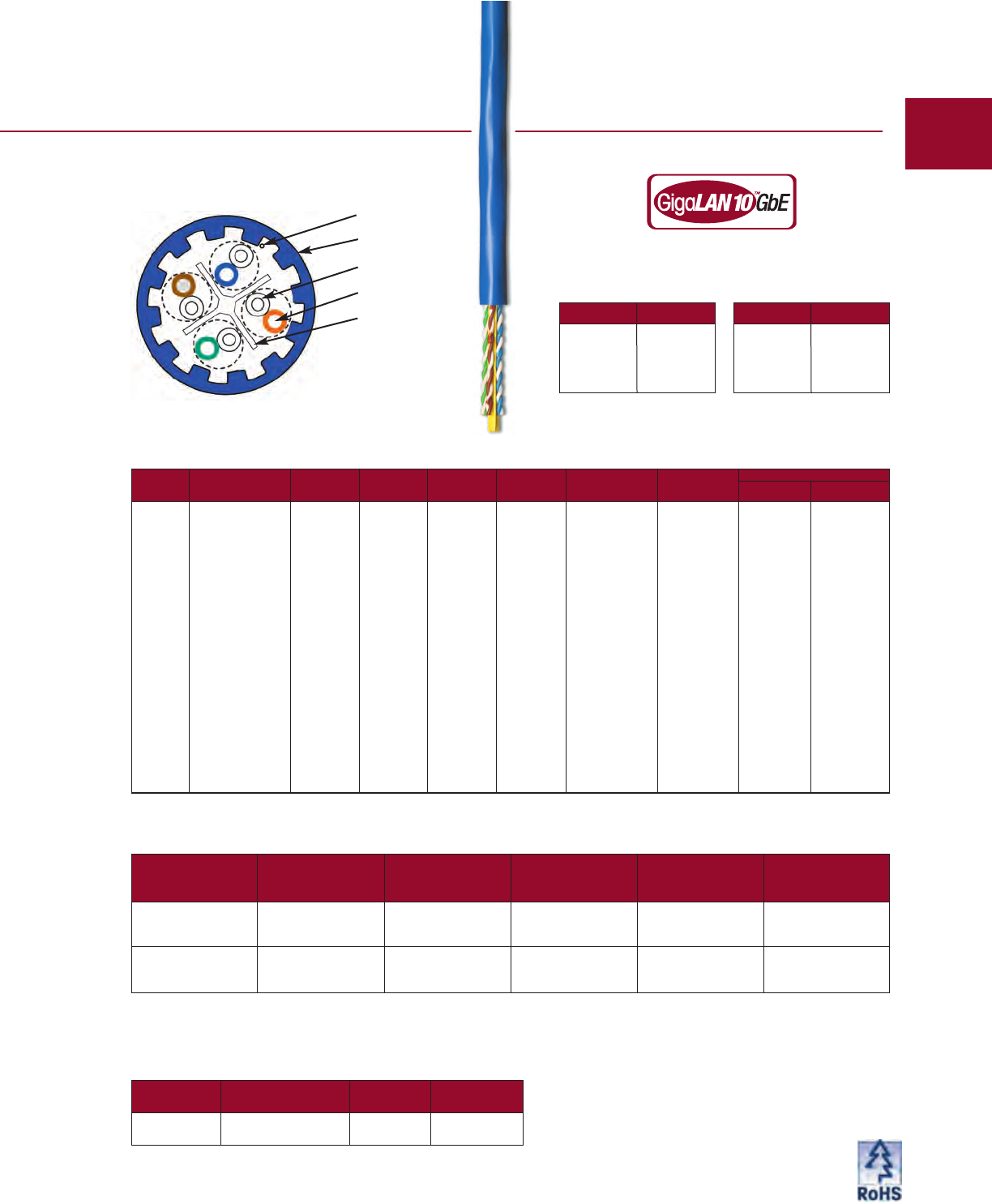
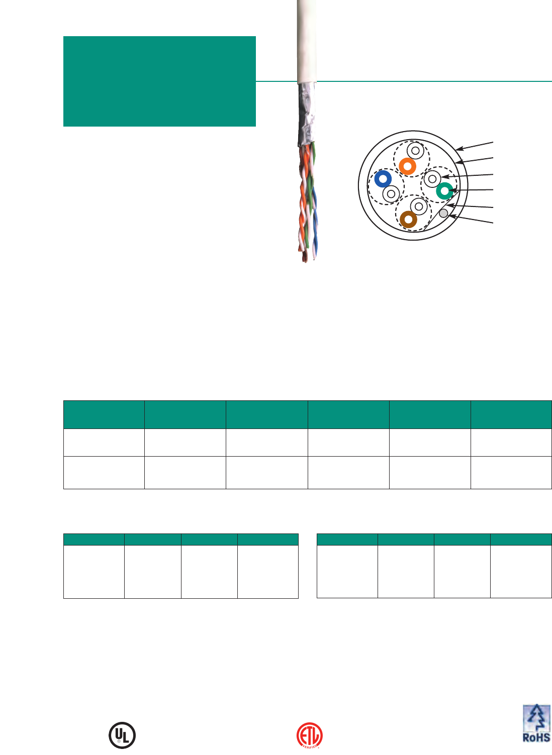
Augmented
Category 6 UTP
GigaLAN 10
™
Tested to 750 MHz
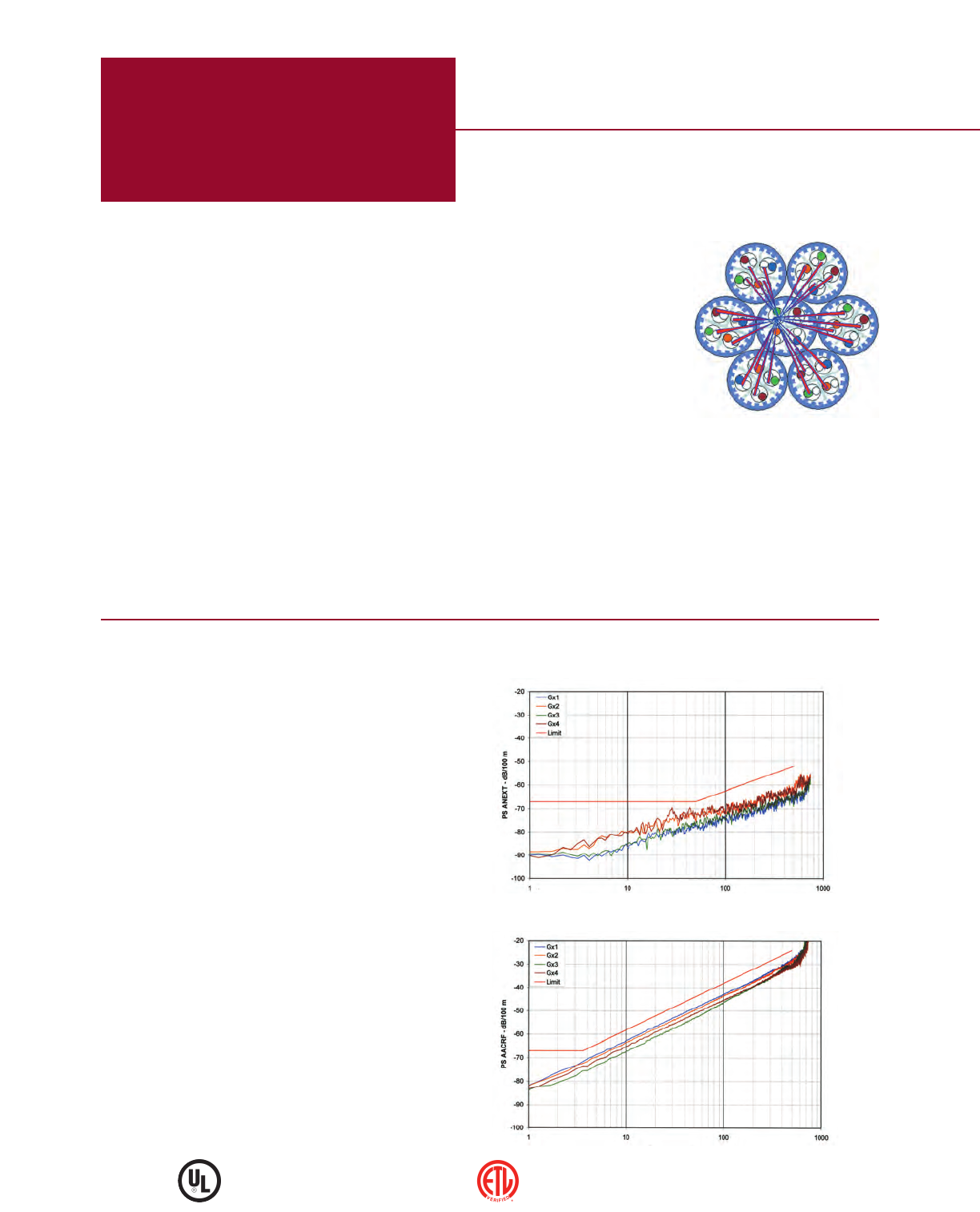
Power Sum Alien NEXT
Power Sum Alien ACRF
4 MOHAWK
Verified by ETL to TIA/EIA-568-B.2-10
Safety listed to NEC (NFPA 70)
GigaLAN 10, the highest performance Augmented Category 6
cable, supports 10GBASE-T applications over a full 100-meter
channel, exceeding the requirements of the current Draft of
ANSI/TIA/EIA-568-B.2-10. IEEE 802.3an is looking beyond the
present, specifying an operating range from 1-500 MHz.
GigaLAN 10’s unique FlexWeb®combined with patented fluted
jacket construction isolates the cable pairs and has outstanding
pair-to-pair balance for superior headroom and reduced crosstalk.
•Lifetime Warranty*
•Increase in power to 500 MHz due to lower insertion
loss characteristics than Category 6.
•Improvement in NEXT and ELFEXT vs. draft
Category 6A – 2 dB minimum for NEXT and 4 dB minimum
for ELFEXT.
•Application –Support for 10 Gigabit Ethernet / 10GBASE-T /
IEEE 802.3an; fully backwards compatible for 10BASE-T,
100BASE-T, and 1000BASE-T applications.
•Power Sum Alien Crosstalk –Power Sum Alien Crosstalk
measures the impact of many aggressors on one victim
pair. It is the sum of unwanted signal coupling of crosstalk
noise from the external
cabling pairs into a victim
pair of a cable. In the
illustration (see Figure 1), a
bundle of 7 cables with 6
cables around a center
cable is depicted. What is
being measured is the
noise coupling from the
pairs in the outer ring of
cables (aggressor pairs) to
the pairs in the center cable (victim pair). Each pair of the
aggressor cables contributes noise to each of the pairs in
the victim cable. The total impact on the victim is
determined using a power summation equation.
•This cable and/or its manufacture are covered by US
Patent Nos. 6,596,944, 6,074,503, 5,424,491, 7,135,641
and patent pending.
* Warranty available with MAC and SystemMATE®programs.
Figure 1
Electrical Characteristics
FPO
MOHAWK 5
Jacket Type
Mohawk Cable Dielectric Diameter Weight Listings
Part No. Type Type inch mm lbs/M' kg/km
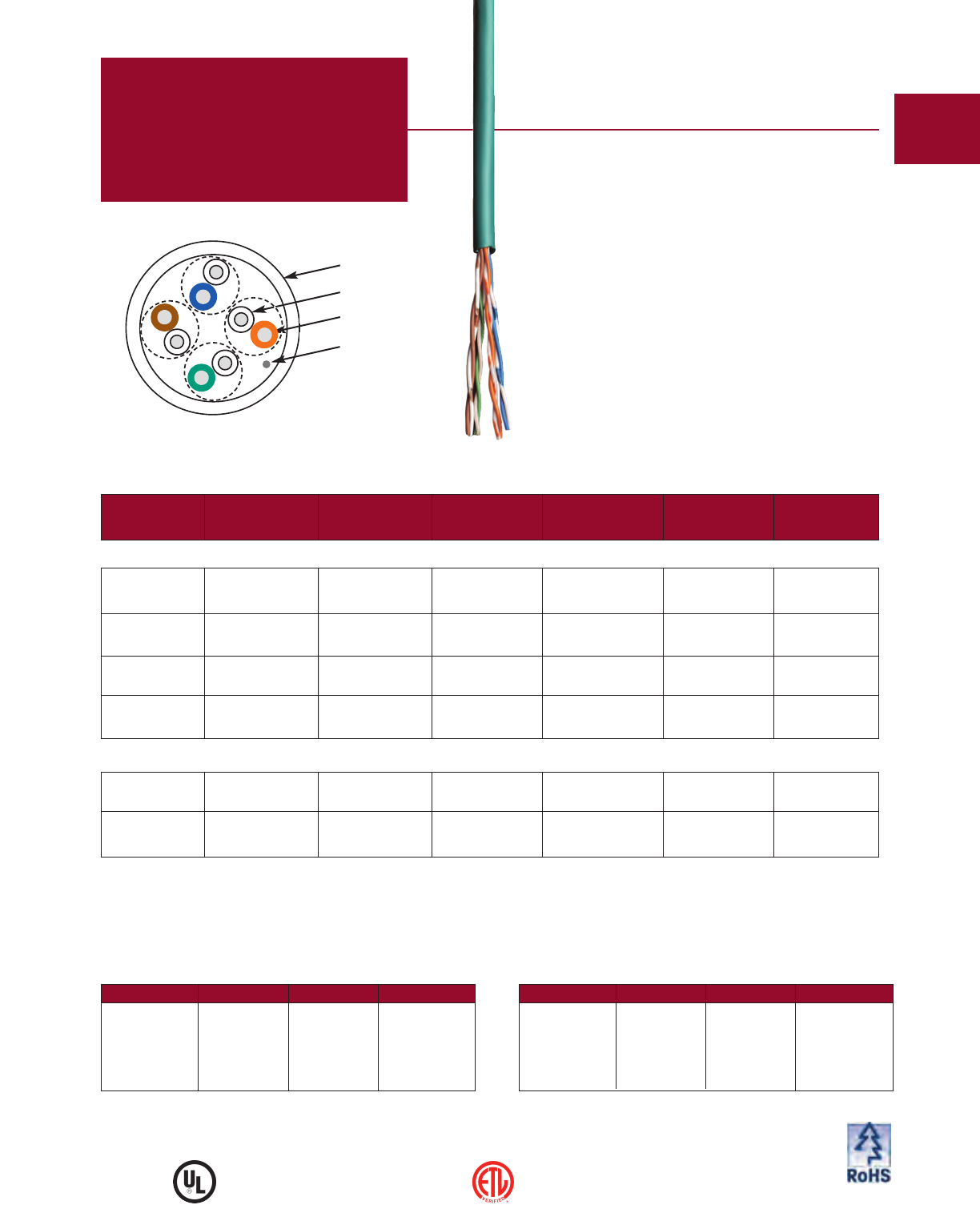
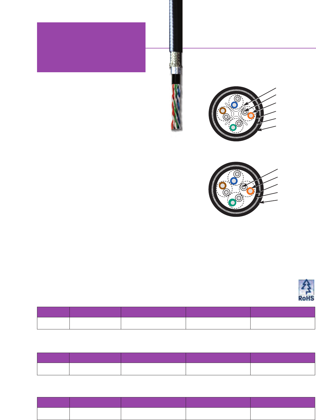
M58651 4 PAIR Thermoplastic White PVC 49 73 C(UL)US
Non-Plenum 23 AWG .320 8.13 CMR
UTP
M58647 4 PAIR FEP White ThermoPlen®* 50 74 C(UL)US
Plenum 23 AWG .320 8.13 CMP
UTP
*Plenum rated Thermoplastic. For pair colors see chart A on page 59.
Jacket Colors for
4-Pair Non-Plenum
Jacket Color Mohawk #
WHITE M58651
BLUE M58650
YELLOW M58652
GRAY M58653
FREQ INSERTION LOSS NEXT PS-NEXT ACRF
PS-ACRF
RETURN LOSS PROP DELAY PS-ANEXT PS-AACRF
(MHz) (dB/100m) (dB/100m) (dB/100m) (dB/100m) (dB/100m) (dB) (ns/100m) (dB/100m) (dB/100m)
max min min min min min max min min
.772 1.8 78.0 76.0 - - - - - -
1.0 2.0 76.3 74.3 71.8 69.8 20.0 570.0 67.0 67.0
4.0 3.7 67.3 65.3 59.8 57.8 24.2 552.0 67.0 66.2
8.0 5.2 62.8 60.8 53.7 51.7 26.3 546.7 67.0 60.1
10.0 5.9 61.3 59.3 51.8 49.8 27.0 545.4 67.0 58.2
16.0 7.4 58.2 56.2 47.7 45.7 27.0 543.0 67.0 54.1
20.0 8.3 56.8 54.8 45.8 43.8 27.0 542.0 67.0 52.2
25.0 9.3 55.3 53.3 43.8 41.8 26.5 541.2 67.0 50.2
31.25 10.4 53.9 51.9 41.9 39.9 25.9 540.4 67.0 48.3
62.5 14.9 49.4 47.4 35.9 33.9 24.2 538.6 65.6 42.3
100.0 19.0 46.3 44.3 31.8 29.8 23.1 537.6 62.5 38.2
155.0 24.0 43.4 41.4 28.0 26.0 22.0 536.9 59.6 34.4
200.0 27.5 41.8 39.8 25.8 23.8 21.4 536.5 58.0 32.2
250.0 31.0 40.3 38.3 23.8 21.8 20.9 536.3 56.5 30.2
300.0 34.2 39.1 37.1 22.3 20.3 20.4 536.1 55.3 28.7
350.0 37.2 38.1 36.1 20.9 18.9 20.1 535.9 54.3 27.3
400.0 40.0 37.3 35.3 19.8 17.8 19.7 535.8 53.5 26.2
500.0 45.3 35.8 33.8 17.8 15.8 19.2 535.6 52.0 24.2
550.0 47.7 35.2 33.2 - - 19.0 - - -
600.0 50.1 34.6 32.6 - - 18.8 - - -
650.0 52.4 34.1 32.1 - - 18.6 - - -
750.0 56.8 33.2 31.2 - - 18.2 - - -
Values above 500 MHz are for engineering information only.
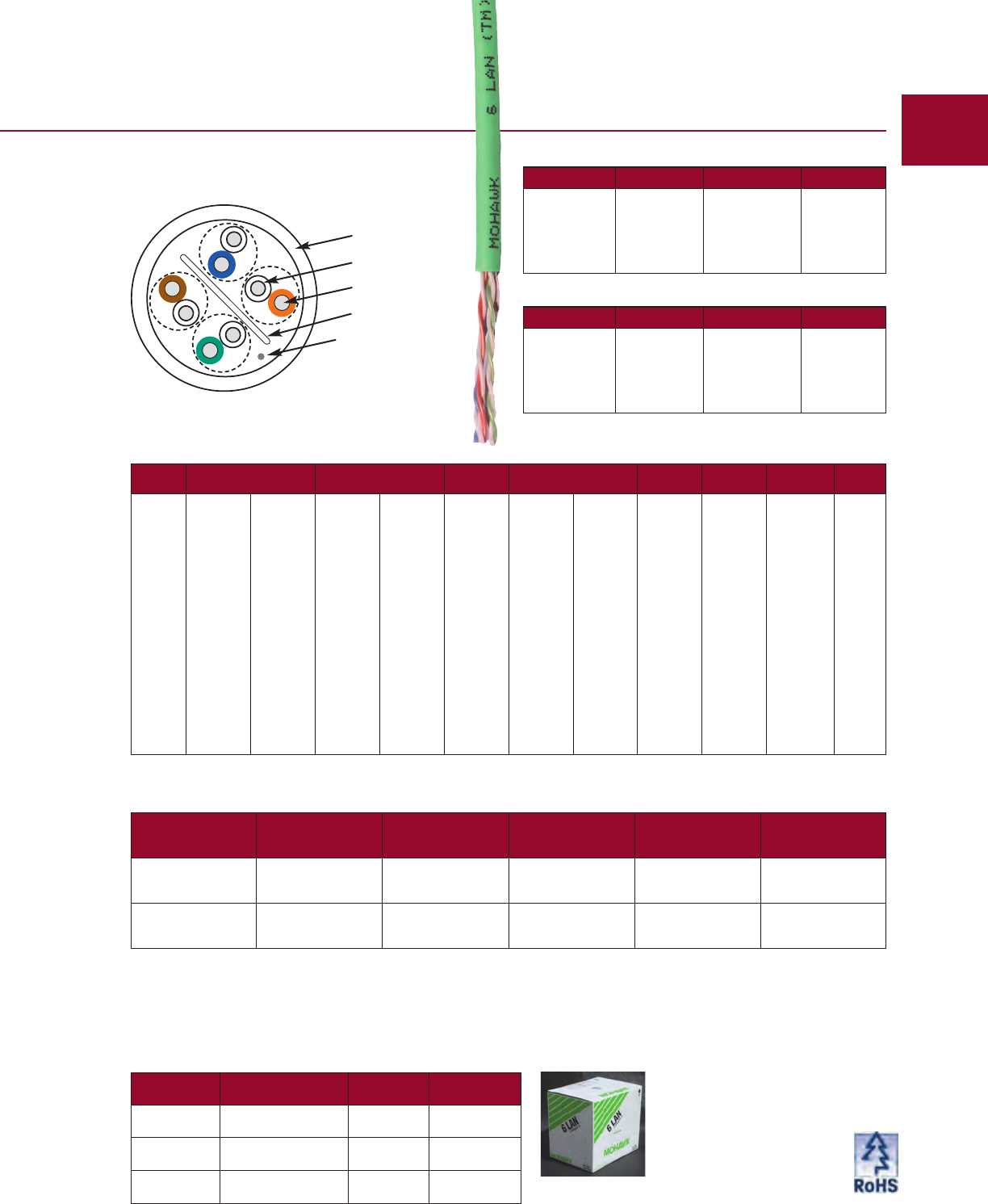
Ripcord
Jacket
Insulation
Conductor
FlexWeb
Custom colors available; please consult the factory.
Jacket Colors for
4-Pair Plenum
Jacket Color Mohawk #
WHITE M58647
BLUE M58646
YELLOW M58648
GRAY M58649
Packaging Options
Put-Up Package Number Per
Pallet Pallet Size
1000 Ft. 18” Reels 15
44
” x 44”
Cable DIagram
ALIEN CROSSTALK

STANDARDS:
EXCEEDS TIA/EIA 568-B.2-1 CAT 6 & ISO/IEC 11801:2002 CAT 6 HORIZONTAL CABLE
CONDUCTOR DCR:
6.71 V/100m (22.0 V/Mft) MAX
DCR UNBALANCE:
3% MAX
MUTUAL CAPACITANCE:
46 pF/m (14 pF/ft) NOM
CAPACITANCE UNBALANCE
PAIR/GROUND:
33 pF/100m (100 pF/Mft) MAX
CHARACTERISTIC IMPEDANCE:
100 V67% (10-550 MHz)
INPUT IMPEDANCE:
100 V612% (1-100 MHz)
100 V615% (>100-350 MHz)
100 V622% (>350 MHz)
PROPAGATION DELAY:
506 + 36/√ƒ ns/100m
MAX (1-500 MHz)
DELTA DELAY (SKEW):
30 ns/100m MAX (10-500 MHz)
NOMINAL VELOCITY OF
PROPAGATION (NVP):
PLENUM 72%
NON-PLENUM 68%
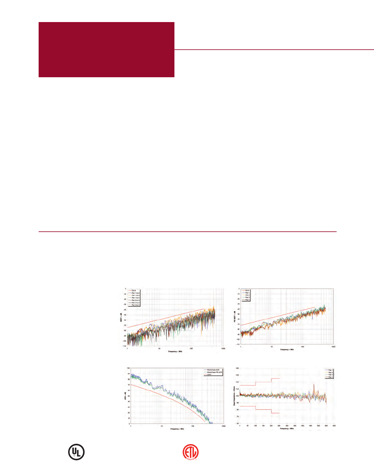
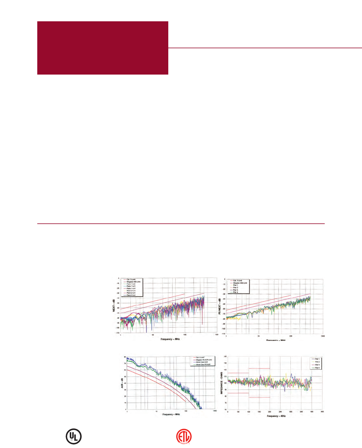
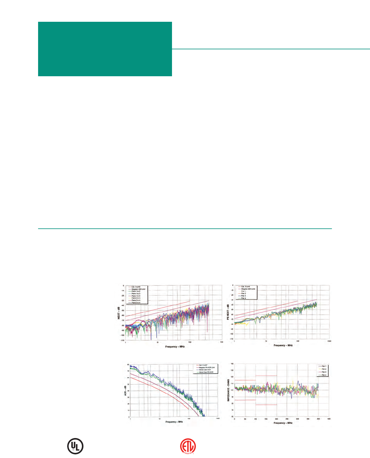
Near End Crosstalk (NEXT) Power Sum NEXT (PS NEXT)
Worst Case ACR and Power Sum ACR Input Impedance
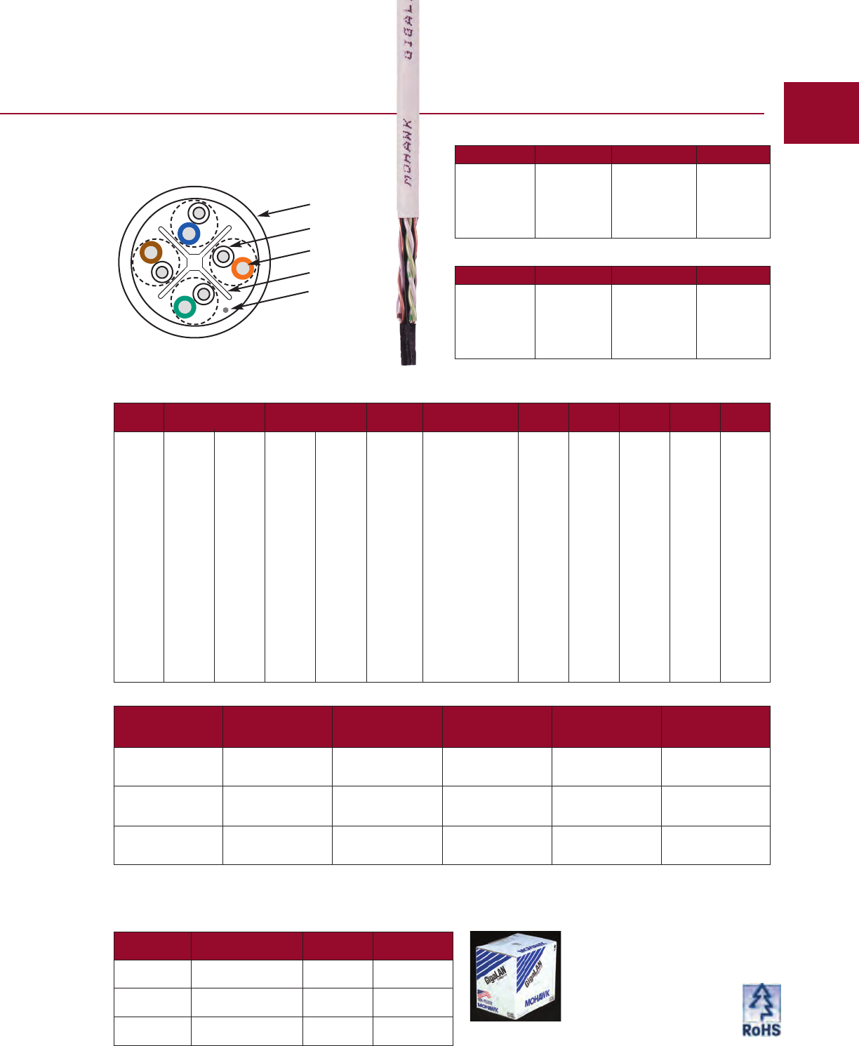
Category 6e+ UTP
GigaLAN®
6 MOHAWK
Verified by ETL to TIA/EIA-568-B.2-1
Safety listed to NEC (NFPA 70)
GigaLAN is the one of the highest performance unshielded
twisted pair (UTP) cable available today. The FlexWeb®
construction isolates the pairs throughout the length of the
cable, while providing an installer-friendly cable.
The unique GigaLAN FlexWeb construction isolates the
cable pairs and enhances the pair-to-pair balance for
superior crosstalk, LCL and LCTL performance. Compact
cable design meets the diameter requirements specified in
TIA/EIA-568-B, providing flexibility and ease of installation.
Electrical performance is ETL verified to TIA/EIA 568-B.2-1
Category 6.
•Tested to 750 MHz – with verified stability.
•Lifetime Warranty*
•34% increase in power due to lower insertion loss
characteristics at 100 MHz and greater than 50% at 250
MHz than Category 6.
•7 dB Minimum – Improvement in Near End Crosstalk
vs. Category 6 NEXT.
•33 dB Minimum ACR @ 100 MHz and positive ACR
to 460 MHz.
•Application – Proven support for Gigabit Ethernet /
1000BASE-T / IEEE 802.3ab, ATM up to 155 Mbps, IEEE
802.3af Power Over Ethernet for VoIP, 100 Mbps Fast
Ethernet / 100BASE-T / IEEE 802.3, ANSI.X3.263 FDDI TP-
PMD, Ethernet / 10BASE-T / IEEE 802.3, 4 & 16 Mbps Token
Ring / IEEE 802.5, T1/E1, xDSL, ISDN, 550 MHz Broadband
Video and standards under development such as ATM at
622 Mbps, 1.2, 2.4 and 4.8 Gbps.
•Enhanced Performance Parameters – All electrical
characteristics proven to exceed TIA/EIA 568-B.2-1 and
ISO/IEC 11801 Category 6 requirements: including NEXT
and ELFEXT (Pair-to-Pair and Power Sum), Insertion Loss,
Return Loss, and Delay Skew.
•This cable and/or its manufacture are covered by US
Patent Nos. 6,596,944, 6,074,503 and 5,424,491.
* Warranty available with MAC and SystemMATE® programs.
Tested to 750 MHz
Electrical Characteristics
Jacket Colors for 4-Pair Non-Plenum
Jacket Color Mohawk # Jacket Color Mohawk #
WHITE M57418 RED M57621
BLUE M57419 PINK M57867
YELLOW M57420 VIOLET M57870
GREEN M57421 ORANGE M57868
GRAY M57422 BLACK M57869
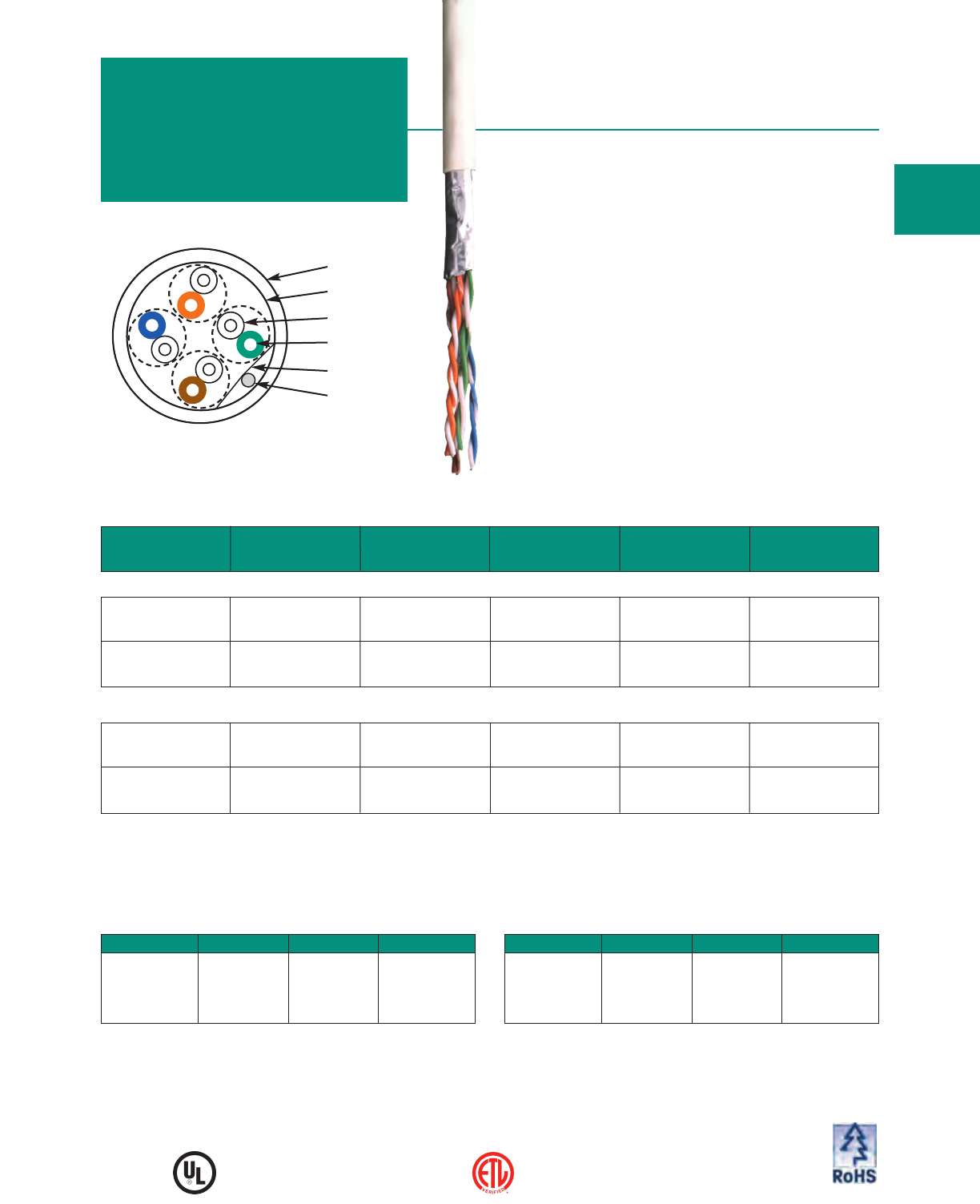
MOHAWK 7
Jacket
Insulation
Conductor
FlexWeb
Ripcord
Jacket Type
Mohawk Cable Dielectric Diameter Weight Listings
Part No. Type Type inch mm lbs/M' kg/km
M57418 4 PAIR Thermoplastic White PVC 34 51 C(UL)US
Non-Plenum 23 AWG .247 6.27 CMR
UTP
M57413 4 PAIR Dual Insulation** White ThermoPlen®* 37 55 C(UL)US
Plenum 23 AWG FEP on all 4 pairs .244 6.20 CMP
UTP .
M58405 4 Pair FEP White Smokeguard®† FP 36 54 UL CMP
PlenumPlus™ 23 AWG Rated for 125° C Limited Combustible
UTP .220 5.59 c(UL) CMP
*Plenum rated Thermoplastic. **US Patent No. 5,563,377. †Smokeguard is a registered trademark of AlphaGary. For pair colors see chart A on page 59.
FREQ INSERTION LOSS NEXT ACR PS-NEXT PS-ACR ELFEXT
PS-ELFEXT
RL DELAY
(MHz) (dB/100m) (dB/100m) (dB/100m) (dB/100m) (dB/100m) (dB/100m) (dB/100m) (dB) (ns/100m)
avg max avg min min avg min min min min min max
.772 1.6 1.7 93 83.0 81.3 86 81.0 79.3 - - - -
1.0 1.8 1.9 91 81.3 79.4 84 79.3 77.4 74.8 72.8 20.0 542.0
4.0 3.3 3.5 82 72.3 68.8 75 70.3 66.8 62.8 60.8 24.2 524.0
8.0 4.7 4.9 78 67.8 62.9 71 65.8 60.9 56.7 54.7 26.3 518.7
10.0 5.2 5.5 76 66.3 60.8 69 64.3 58.8 54.8 52.8 27.0 517.4
16.0 6.7 7.0 73 63.2 56.2 66 61.2 54.2 50.7 48.7 27.0 515.0
20.0 7.4 7.8 72 61.8 54.0 65 59.8 52.0 48.8 46.8 27.0 514.0
25.0 8.3 8.7 70 60.3 51.6 63 58.3 49.6 46.8 44.8 26.5 513.2
31.25 9.3 9.8 69 58.9 49.1 62 56.9 47.1 44.9 42.9 25.9 512.4
62.5 13.4 14.1 64 54.4 40.3 57 52.4 38.3 38.9 36.9 24.2 510.6
100.0 17.1 18.0 61 51.3 33.3 54 49.3 31.3 34.8 32.8 23.1 509.6
155.0 21.7 22.8 58 48.4 25.6 51 46.4 23.6 31.0 29.0 22.0 508.9
200.0 24.9 26.2 57 46.8 20.6 50 44.8 18.6 28.8 26.8 21.4 508.5
250.0 28.1 29.6 55 45.3 15.7 48 43.3 13.7 26.8 24.8 20.9 508.3
300.0 31.1 32.7 54 44.1 11.4 47 42.1 9.4 25.3 23.3 20.4 508.1
350.0 33.8 35.6 53 43.1 7.5 46 41.1 5.5 23.9 21.9 20.1 507.9
400.0 36.5 38.4 52 42.3 3.9 45 40.3 1.9 22.8 20.8 19.7 507.8
500.0 41.4 43.6 51 40.8 - 44 38.8 - 20.8 18.8 19.2 507.6
550.0 43.7 46.0 50 40.2 - 43 38.2 - - - 19.0 -
600.0 46.0 48.4 50 39.6 - 43 37.6 - - - 18.8 -
650.0 48.1 50.6 49 39.1 - 42 37.1 - - - 18.6 -
750.0 52.3 55.0 48 38.2 - 41 36.2 - - - 18.2 -
Values above 500 MHz are for engineering information only.
Jacket Colors for 4-Pair Plenum
Jacket Color Mohawk # Jacket Color Mohawk #
WHITE M57413 RED M57620
BLUE M57414 PINK M57750
YELLOW M57415 VIOLET M57860
GREEN M57416 ORANGE M57861
GRAY M57417 BLACK M57866
Custom colors available; please consult the factory.
Packaging Options
Put-Up Package Number Per
Pallet Pallet Size
1000 Ft. 14” Reels 36 42” x 42”
1000 Ft. Boxes
(15
!s
”W x 11
!f
”D x 14
!f
”H) 33 45” x 48”
1000 Ft. Reel in a Box
(12
#f
”W x 12
#f
”D x 12
&k
”H) 27 42” x 42”
Cable DIagram
Bulk put-ups available upon request; please consult the factory.
Above part numbers are for reels only. Add
“B” to end of Mohawk # for boxes, or “RB”
for Reel-in-a-box packaging.

STANDARDS:
EXCEEDS TIA/EIA 568-B.2-1 CAT 6, ISO/IEC 11801:2002 CAT 6, & IEC 61156-5 CAT 6 HORIZONTAL CABLE
CONDUCTOR DCR:
8.9 V/100m (27.1 V/Mft) MAX
DCR UNBALANCE:
3% MAX
MUTUAL CAPACITANCE:
46 pF/m (14 pF/ft) NOM
CAPACITANCE UNBALANCE
PAIR/GROUND:
66 pF/100m (200 pF/Mft) MAX
CHARACTERISTIC IMPEDANCE:
100 V615% (1-350 MHz)
INPUT IMPEDANCE:
100 V 6 15% (1-100 MHz)
100 V 618% (>100-200 MHz)
100 V 622% (>200-350 MHz)
PROPAGATION DELAY:
534 + 36/√ƒ ns/100m MAX
DELTA DELAY (SKEW):
25 ns/100m MAX
NOMINAL VELOCITY
OF PROPAGATION (NVP):
PLENUM 72%
NON-PLENUM 68%
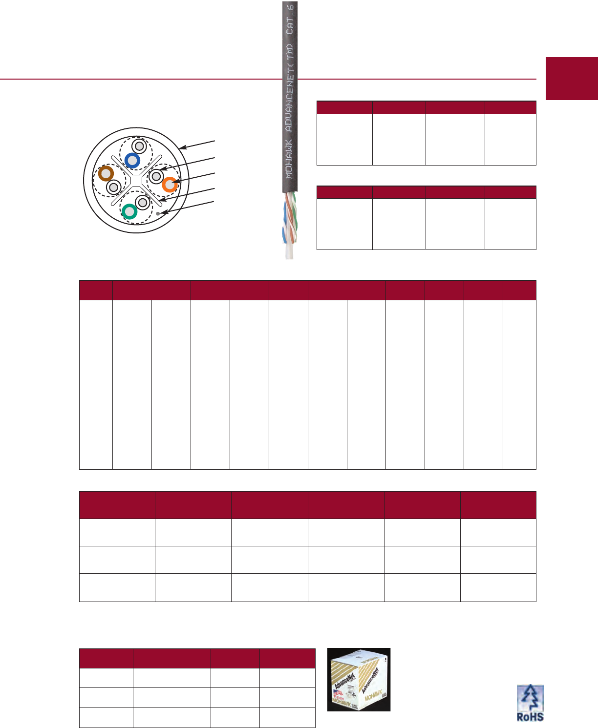
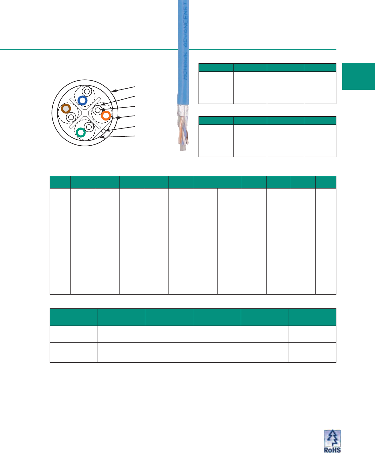
AdvanceNet is unshielded twisted pair cable tested to 650
MHz and ETL verified to TIA/EIA 568-B.2-1 Category 6.
With the new Mini FlexWeb®core separator, the AdvanceNet
cable isolates the pairs throughout the length of the cable,
while providing a smaller installer-friendly cable.
•25 Year Warranty*
•28 dB Minimum ACR @ 100 MHz – Proven support
for Gigabit Ethernet / 1000BASE-T / IEEE 802.3ab, ATM up
to 155 Mbps, IEEE 802.3af Power Over Ethernet for VoIP,
100 Mbps Fast Ethernet / 100BASE-T / IEEE 802.3,
ANSI.X3.263 FDDI TP-PMD, Ethernet / 10BASE-T / IEEE
802.3, 4 & 16 Mbps Token Ring / IEEE 802.5, T1/E1, xDSL,
ISDN, 550 MHz Broadband Video and standards under
development such as ATM at 622 Mbps, 1.2 and
2.4 Gbps.
•13 dB Minimum – Improvement in Near End Crosstalk
vs. Category 5e NEXT.
•.25 ns/meter Maximum Skew –Tightly controlled
propagation delay.
•Enhanced Performance Parameters – All electrical
characteristics proven to exceed TIA/EIA 568-B.2-1 and
ISO/IEC 11801 Category 6 requirements: NEXT and
ELFEXT (Pair-to-Pair and Power Sum), Insertion Loss,
Return Loss, and Delay Skew.
•This cable and/or its manufacture are covered by US
Patent Nos. 6,596,944, 6,074,503 and 5,424,491.
* Warranty available with MAC and SystemMATE®programs.
Category 6e UTP
AdvanceNet
®Tested to 650 MHz
Near End Crosstalk (NEXT) Power Sum NEXT (PS NEXT)
Worst Case ACR and Power Sum ACR Input Impedance
8 MOHAWK
Verified by ETL to TIA/EIA-568-B.2-1
Safety listed to NEC (NFPA 70)
Electrical Characteristics
Jacket Colors for 4-Pair Plenum
Jacket Color Mohawk # Jacket Color Mohawk #
WHITE M56905 GREEN M57197
BLUE M57193 RED M57198
PINK M57194 ORANGE M57199
YELLOW M57195 BLACK M57200
GRAY M57196 VIOLET M57201
Jacket Type
Mohawk Cable Dielectric Diameter Weight Listings
Part No. Type Type inch mm lbs/M' kg/km
M56889 4 PAIR Thermoplastic White PVC 30 45 C(UL)US
Non-Plenum 23 AWG .225 5.72 CMR
UTP
M56905 4 PAIR Dual Insulation** White ThermoPlen®* 33 49 C(UL)US
Plenum 23 AWG FEP on all 4 pairs .225 5.72 CMP
UTP
. M58414 4 PAIR FEP White Smokeguard®† FP 31 46 UL CMP
PlenumPlus™ 23 AWG Rated for 125° C Limited Combustible
UTP .200 5.08 c(UL) CMP
*Plenum rated Thermoplastic. **US Patent No. 5,563,377. †Smokeguard is a registered trademark of AlphaGary. For pair colors see chart A on page 59.
FREQ INSERTION LOSS NEXT ACR PS-NEXT PS-ACR ELFEXT PS-ELFEXT RL
(MHz) (dB/100m) (dB/100m) (dB/100m) (dB/100m) (dB/100m) (dB/100m) (dB/100m) (dB)
avg max avg min min avg min min min min min
.772 1.6 1.8 90 80.0 78.2 83 78.0 76.2 - - -
1.0 1.8 2.0 88 78.3 76.3 81 76.3 74.3 70.0 68.0 20.0
4.0 3.5 3.8 79 69.3 65.5 72 67.3 63.5 58.0 56.0 24.2
8.0 4.9 5.3 75 64.8 59.5 68 62.8 57.5 51.9 49.9 26.3
10.0 5.6 5.9 73 63.3 57.4 66 61.3 55.4 50.0 48.0 27.0
16.0 7.1 7.5 70 60.2 52.7 63 58.2 50.7 45.9 43.9 27.0
20.0 7.9 8.4 69 58.8 50.4 62 56.8 48.4 44.0 42.0 27.0
25.0 8.8 9.4 67 57.3 47.9 60 55.3 45.9 42.0 40.0 26.5
31.25 10.0 10.6 66 55.9 45.3 59 53.9 43.3 40.1 38.1 25.9
62.5 14.3 15.3 61 51.4 36.1 54 49.4 34.1 34.1 32.1 24.2
100.0 18.4 19.7 58 48.3 28.6 51 46.3 26.6 30.0 28.0 23.1
155.0 23.4 25.0 55 45.4 20.4 48 43.4 18.4 26.2 24.2 22.0
200.0 27.0 28.8 54 43.8 15.0 47 41.8 13.0 24.0 22.0 21.4
250.0 30.5 32.6 52 42.3 9.7 45 40.3 7.7 22.0 20.0 20.9
300.0 33.9 36.2 51 41.1 4.9 44 39.1 2.9 20.5 18.5 20.4
350.0 37.0 39.5 50 40.1 0.6 43 38.1 - 19.1 17.1 20.1
400.0 40.0 42.7 49 39.3 - 42 37.3 - 18.0 16.0 19.7
500.0 45.5 48.6 48 37.8 - 41 35.8 - 16.0 14.0 19.2
550.0 48.2 51.5 47 37.2 - 40 35.2 - - - 19.0
600.0 50.7 54.2 47 36.6 - 40 34.6 - - - 18.8
650.0 53.2 56.8 46 36.1 - 39 34.1 - - - 18.6
Values above 350 MHz are for engineering information only.
Jacket Colors for 4-Pair Non-Plenum
Jacket Color Mohawk # Jacket Color Mohawk #
WHITE M56889 GREEN M57206
BLUE M57202 RED M57207
PINK M57203 ORANGE M57208
YELLOW M57204 BLACK M57209
GRAY M57205 VIOLET M57210
MOHAWK 9
Jacket
Insulation
Conductor
FlexWeb
Ripcord
Custom colors available; please consult the factory.
Cable DIagram
Packaging Options
Put-Up Package Number Per
Pallet Pallet Size
1000 Ft. 14” Reels 36 42” x 42”
1000 Ft. Boxes
(15
!s
”W x 11
!f
”D x 14
!f
”H) 33 45” x 48”
1000 Ft. Reel in a Box
(12
#f
”W x 12
#f
”D x 12
&k
”H) 27 42” x 42”
Bulk put-ups available upon request; please consult the factory.
Above part numbers are for reels only. Add
“B” to end of Mohawk # for boxes, or “RB”
for Reel-in-a-box packaging.
STANDARDS:
MEETS
TIA/EIA 568-B.2-1 CAT 6 & ISO/IEC 11801:2002 CAT 6 HORIZONTAL CABLE
CONDUCTOR DCR:
8.9 V/100m (27.1 V/Mft) MAX
DCR UNBALANCE:
3% MAX
MUTUAL CAPACITANCE:
46 pF/m (14 pF/ft) NOM
CAPACITANCE UNBALANCE
PAIR/GROUND:
66 pF/100m (200 pF/Mft) MAX
CHARACTERISTIC IMPEDANCE:
100 V615% (1-250 MHz)
INPUT IMPEDANCE:
100 V 6 15% (1-100 MHz)
100 V 6 20% (>100-200 MHz)
100 V 6 25% (>200 MHz)
PROPAGATION DELAY:
534 + 36/√ƒns/100m MAX
DELTA DELAY (SKEW):
25 ns/100m MAX
NOMINAL VELOCITY
OF PROPAGATION (NVP):
PLENUM 72%
NON-PLENUM 68%
WHERE ƒ = FREQUENCY IN MHz
from .772 to 250 MHz.
Electrical Characteristics
Category 6 UTP
6 LAN
™
Tested to 550 MHz
Near End Crosstalk (NEXT) Power Sum NEXT (PS NEXT)
Worst Case ACR and Power Sum ACR Input Impedance
10 MOHAWK
Verified by ETL to TIA/EIA-568-B.2-1
Safety listed to NEC (NFPA 70)
ETL verified to TIA/EIA 568-B.2-1 Category 6.
•20 Year Warranty*
•24 dB Minimum ACR @ 100 MHz – Proven support
for Gigabit Ethernet / 1000BASE-T / IEEE 802.3ab, ATM up
to 155 Mbps, IEEE 802.3af Power Over Ethernet for VoIP,
100 Mbps Fast Ethernet / 100BASE-T / IEEE 802.3,
ANSI.X3.263 FDDI TP-PMD, Ethernet / 10BASE-T / IEEE
802.3, 4 & 16 Mbps Token Ring / IEEE 802.5, T1/E1, xDSL,
ISDN, 550 MHz Broadband Video and standards under
development such as ATM at 622 Mbps, 1.2 and 2.4 Gbps.
•With flat tape core separator throughout the length of the
cable.
•9 dB Minimum – Improvement in Near End Crosstalk
vs. Category 5e NEXT.
•Enhanced Performance Parameters –All electrical
characteristics proven to meet TIA/EIA 568-B.2-1 and
ISO/IEC 11801 Category 6 requirements: NEXT and
ELFEXT (Pair-to-Pair and Power Sum), Insertion Loss,
Return Loss, and Delay Skew.
•This cable and/or its manufacture is covered by US
Patent Nos. 6,998,537, 6,570,095 and 5,424,491.
* Warranty available with MAC and SystemMATE® programs.
Jacket
Insulation
Conductor
Core Separator
Ripcord
FREQ INSERTION LOSS NEXT ACR PS-NEXT PS-ACR ELFEXT PS-ELFEXT RL
(MHz) (dB/100m) (dB/100m) (dB/100m) (dB/100m) (dB/100m) (dB/100m) (dB/100m) (dB)
avg max avg min min avg min min min min min
.772 1.7 1.8 82 76.0 74.2 77 74.0 72.2 - - -
1.0 1.9 2.0 80 74.3 72.3 75 72.3 70.3 67.8 64.8 20.0
4.0 3.6 3.8 71 65.3 61.5 66 63.3 59.5 55.8 52.8 23.0
8.0 5.1 5.3 67 60.8 55.5 62 58.8 53.5 49.7 46.7 24.5
10.0 5.7 6.0 65 59.3 53.3 60 57.3 51.3 47.8 44.8 25.0
16.0 7.3 7.6 62 56.2 48.6 57 54.2 46.6 43.7 40.7 25.0
20.0 8.1 8.5 61 54.8 46.3 56 52.8 44.3 41.8 38.8 25.0
25.0 9.1 9.5 59 53.3 43.8 54 51.3 41.8 39.8 36.8 24.3
31.25 10.2 10.7 58 51.9 41.2 53 49.9 39.2 37.9 34.9 23.6
62.5 14.8 15.4 53 47.4 32.0 48 45.4 30.0 31.9 28.9 21.5
100.0 19.0 19.8 50 44.3 24.5 45 42.3 22.5 27.8 24.8 20.1
155.0 24.2 25.2 47 41.4 16.2 42 39.4 14.2 24.0 21.0 18.8
200.0 27.8 29.0 46 39.8 10.8 41 37.8 8.8 21.8 18.8 18.0
250.0 31.5 32.8 44 38.3 5.5 39 36.3 3.5 19.8 16.8 17.3
300.0 35.0 36.4 43 37.1 0.7 38 35.1 - 18.3 15.3 16.8
350.0 38.2 39.8 42 36.1 - 37 34.1 - 16.9 13.9 16.3
400.0 41.3 43.0 41 35.3 - 36 33.3 - - - 15.9
500.0 47.0 48.9 40 33.8 - 35 31.8 - - - 15.2
550.0 49.7 51.8 39 33.2 - 34 31.2 - - - 14.9
Values above 250 MHz are for engineering information only.
MOHAWK 11
Jacket Colors for 4-Pair Non-Plenum
Jacket Color Mohawk # Jacket Color Mohawk #
WHITE M58291 GREEN M58296
BLUE M58292 RED M58297
PINK M58293 ORANGE M58298
YELLOW M58294 BLACK M58299
GRAY M58295 VIOLET M58300
Jacket Colors for 4-Pair Plenum
Jacket Color Mohawk # Jacket Color Mohawk #
WHITE M58280 GREEN M58286
BLUE M58281 RED M58287
PINK M58282 ORANGE M58288
YELLOW M58283 BLACK M58289
GRAY M58285 VIOLET M58290
Jacket Type
Mohawk Cable Dielectric Diameter Weight Listings
Part No. Type Type inch mm lbs/M' kg/km
M58291 4 PAIR Thermoplastic White PVC 26 37 C(UL)US
Non-Plenum 24 AWG .216 5.49 CMR
UTP
M58280 4 PAIR Dual Insulation** White ThermoPlen®* 29 43 C(UL)US
Plenum 24 AWG FEP on all 4 pairs Rated for 125° C CMP
UTP .208 5.28
*Plenum rated Thermoplastic. ** US Patent No. 5,563,377. For pair colors see chart A on page 59.
Custom colors available; please consult the factory.
Packaging Options
Put-Up Package Number Per
Pallet Pallet Size
1000 Ft. 14” Reels 36 42” x 42”
1000 Ft. Boxes
(15
!s
”W x 11
!f
”D x 14
!f
”H) 33 45” x 48”
1000 Ft. Reel in a Box
(12
#f
”W x 12
#f
”D x 12
&k
”H) 27 42” x 42” Bulk put-ups available upon request; please consult the factory.
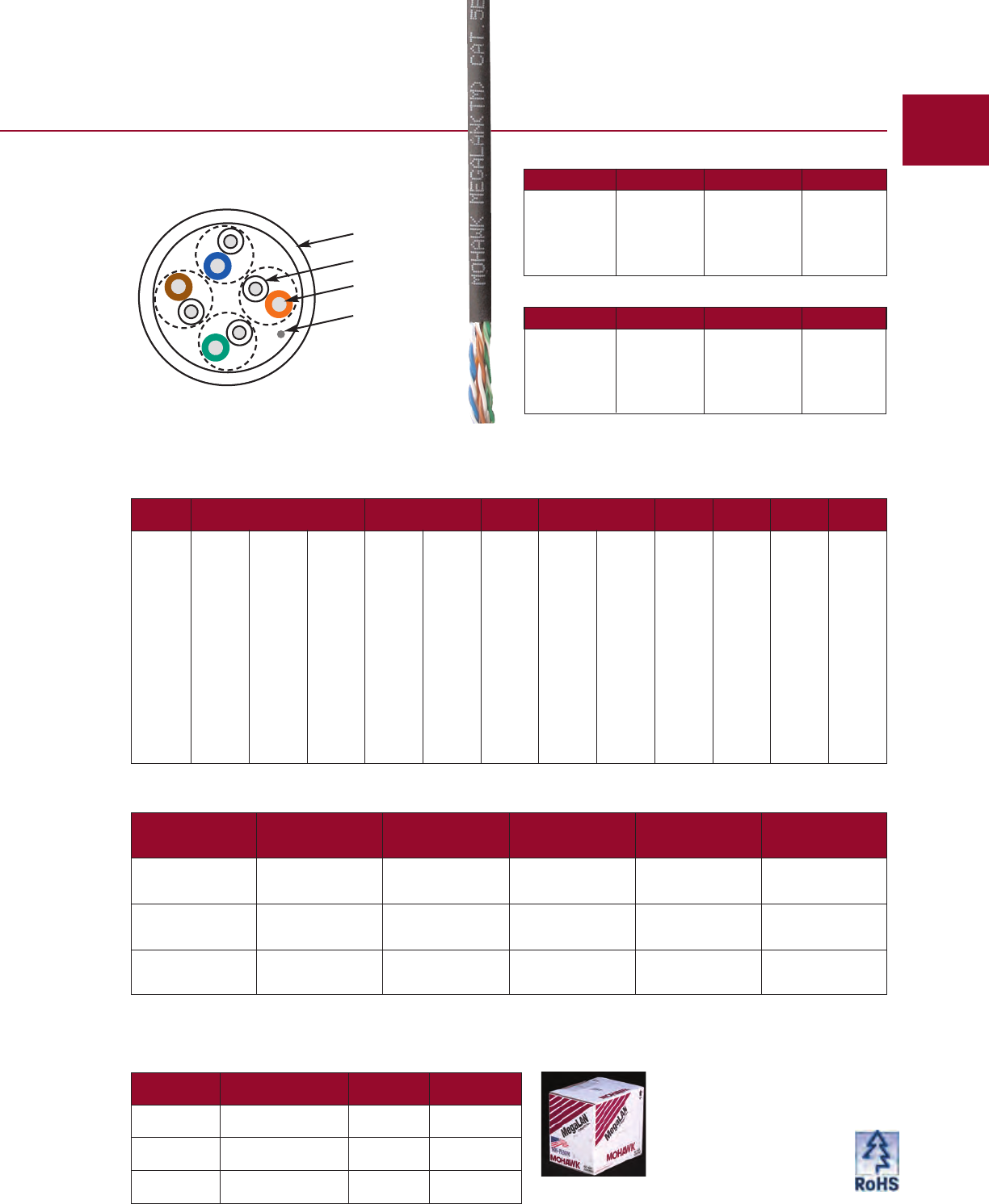
Cable DIagram
Above part numbers are for reels only. Add
“B” to end of Mohawk # for boxes, or “RB”
for Reel-in-a-box packaging.
Electrical Characteristics
STANDARDS:
EXCEEDS TIA/EIA 568-B.2 CAT 5e & ISO/IEC 11801:2002 CAT 5 HORIZONTAL CABLE
CONDUCTOR DCR:
8.9 V/100m (27.1 V/Mft) MAX
DCR UNBALANCE:
3% MAX
MUTUAL CAPACITANCE:
46 pF/m (14 pF/ft) NOM
CAPACITANCE UNBALANCE
PAIR/GROUND:
66 pF/100m (200 pF/Mft) MAX
CHARACTERISTIC IMPEDANCE:
100 V615% (1-400 MHz)
INPUT IMPEDANCE:
100 V615% (1-100 MHz)
100 V622% (>100-200 MHz)
PROPAGATION DELAY:
506 + 36/√ƒ ns/100m MAX
DELTA DELAY (SKEW):
25 ns/100m MAX
NOMINAL VELOCITY
OF PROPAGATION (NVP):
PLENUM 72%
NON-PLENUM 68%
Category 5E+ UTP
MegaLAN®Tested to 400 MHz
MegaLAN is ETL verified to Category 5e.
•20 Year Warranty*
•20 dB Minimum ACR @ 100 MHz – Proven support
for Gigabit Ethernet / 1000BASE-T / IEEE 802.3ab, ATM
up to 155 Mbps, 100 Mbps Fast Ethernet / 100BASE-T /
IEEE 802.3, ANSI.X3.263 FDDI TP-PMD, Ethernet /
10BASE-T / IEEE 802.3, 4 & 16 Mbps Token Ring / IEEE
802.5, T1/E1, xDSL, ISDN, 550 MHz Broadband Video
and standards under development such as ATM at 622
Mbps and 1.2 Gbps.
•5 dB Minimum – Improvement in Near End Crosstalk vs.
standard Category 5e NEXT.
•Meets Return Loss – Category 5e Standard.
•.25 ns/meter Maximum Skew – Tightly controlled
propagation delay.
•Enhanced Performance Parameters – All electrical
characteristics proven to exceed TIA/EIA 568-B Category 5e
requirements: Near End Crosstalk, Characteristic
Impedance, Insertion Loss, and Delay Skew. Also exceeds
TIA/EIA 568-B.2 Category 5e requirements: Power Sum
NEXT, and Far End Crosstalk – ELFEXT and PS-ELFEXT.
•Engineered for Future Applications – More than 10
years of service and still going strong, MegaLAN has a
proven track record of successful installations.
•User Friendly – No special stripping tools. No waiting
for deliveries. No compromises. Proven Performance all
the way.
•This cable and/or its manufacture are covered by US Patent
No. 5,424,491.
* Warranty available with MAC and SystemMATE®programs.
Near End Crosstalk (NEXT) Power Sum NEXT (PS NEXT)
Worst Case ACR and Power Sum ACR Input Impedance
12 MOHAWK
Verified by ETL to TIA/EIA-568-B.2
Safety listed to NEC (NFPA 70)
Jacket Colors for 4-Pair Non-Plenum
Jacket Color Mohawk # Jacket Color Mohawk #
WHITE M55989 VIOLET M57048
BLUE M56167 ORANGE M56954
PINK M56094 RED M56670
YELLOW M56095 BLACK M57129
GREEN M56165 GRAY M56746
Jacket
Insulation
Conductor
Ripcord
FREQ INSERTION LOSS NEXT ACR PS-NEXT PS-ACR ELFEXT
PS-ELFEXT
RL
(MHz) (dB/100m) (dB/mft) (dB/100m) (dB/100m) (dB/100m) (dB/100m) (dB/100m) (dB/100m) (dB)
avg max max avg min min avg min min min min min
.772 1.6 1.8 5.5 82 72.0 72.2 75 70.0 68.2 - - -
1.0 1.8 2.0 6.2 80 70.3 70.3 73 68.3 66.3 67.8 64.8 20.0
4.0 3.6 4.0 12.2 70 61.3 59.3 63 59.3 55.3 55.8 52.8 23.0
8.0 5.2 5.7 17.4 66 56.8 53.1 59 54.8 49.1 49.7 46.7 24.5
10.0 5.8 6.4 19.4 64 55.3 50.9 58 53.3 46.9 47.8 44.8 25.0
16.0 7.3 8.1 24.7 62 52.2 46.1 56 50.2 42.1 43.7 40.7 25.0
20.0 8.3 9.1 27.7 60 50.8 43.7 54 48.8 39.7 41.8 38.8 25.0
25.0 9.3 10.2 31.0 59 49.3 41.1 52 47.3 37.1 39.8 36.8 24.3
31.25 10.4 11.4 34.8 58 47.9 38.5 51 45.9 34.5 37.9 34.9 23.6
62.5 15.1 16.4 50 54 43.4 29.0 47 41.4 25.0 31.9 28.9 21.5
100.0 19.6 21.0 64 50 40.3 21.3 43 38.3 17.3 27.8 24.8 20.1
155.0 25.0 26.6 81 48 37.4 12.9 41 35.4 8.9 24.0 21.0 18.8
200.0 28.8 30.5 93 46 35.8 7.3 40 33.8 3.3 21.8 18.8 18.0
250.0 32.8 34.4 105 45 34.3 1.9 38 32.3 - 19.8 16.8 17.3
300.0 36.5 38.0 116 44 33.1 - 37 31.1 - - - 16.8
350.0 40.0 41.4 126 43 32.1 - 36 30.1 - - - 16.3
400.0 43.2 44.6 136 42 31.3 - 35 29.3 - - - 15.9
Values above 250 MHz are for engineering information only.
Jacket Type
Mohawk Cable Dielectric Diameter Weight Listings
Part No. Type Type inch mm lbs/M' kg/km
M55989 4 PAIR Thermoplastic White PVC 20 30 C(UL)US
Non-Plenum 24 AWG .190 4.83 CMR
UTP
M55988 4 PAIR Dual Insulation** White ThermoPlen®* 24 36 C(UL)US
Plenum 24 AWG FEP on all 4 pairs .190 4.83 CMP
UTP
M57113 4 PAIR FEP White Smokeguard®† FP 26 39 UL, CMP
PlenumPlus™ 24 AWG Rated for 125° C Limited Combustible
UTP .175 4.45 c(UL) CMP
*Plenum rated Thermoplastic. **US Patent No. 5,563,377. †Smokeguard is a registered trademark of AlphaGary. For pair colors see chart A on page 59.
MOHAWK 13
Jacket Colors for 4-Pair Plenum
Jacket Color Mohawk # Jacket Color Mohawk #
WHITE M55988 RED M56072
BLUE M56168 ORANGE M56876
PINK M56092 BLACK M56877
YELLOW M56093 VIOLET M56878
GRAY M56882 GREEN M56166
Custom colors available; please consult the factory.
Packaging Options
Put-Up Package Number Per
Pallet Pallet Size
1000 Ft. 12” Reels 60 38” x 48”
1000 Ft. Boxes
(13
&k
”W x 10
!f
”D x 12
!s
”H) 36 44” x 44”
1000 Ft. Reel in a Box
(11
&k
”W x 11
#k
”D x 11
&k
”H) 36 38” x 48” Bulk put-ups available upon request; please consult the factory.
Cable DIagram
Above part numbers are for reels only. Add
“B” to end of Mohawk # for boxes, or “RB”
for Reel-in-a-box packaging.
Jacket Colors for 4-Pair Plenum
Jacket Color Mohawk # Jacket Color Mohawk #
WHITE M57547 GREEN M57551
BLUE M57546 RED M57887
PINK M57548 ORANGE M57924
YELLOW M57550 BLACK M57936
GRAY M57545 VIOLET M57761
Jacket Colors for 4-Pair Non-Plenum
Jacket Color Mohawk # Jacket Color Mohawk #
WHITE M57554 GREEN M57557
BLUE M57553 RED M58008
PINK M57555 ORANGE M58009
YELLOW M57556 BLACK M58010
GRAY M57552 VIOLET M58007
FREQ INSERTION LOSS NEXT ACR PS-NEXT PS-ACR ELFEXT
PS-ELFEXT
RL
(MHz) (dB/100m) (dB/mft) (dB/100m) (dB/100m) (dB/100m) (dB/100m) (dB/100m) (dB/100m) (dB)
avg max max avg min min avg min min min min min
.772 1.6 1.8 5.5 79 68.0 66.2 70 64.0 62.2 - - -
1.0 1.8 2.0 6.3 77 66.3 64.3 68 62.3 60.3 63.8 60.8 20.0
4.0 3.8 4.1 13 68 57.3 53.2 57 53.3 49.2 51.8 48.8 23.0
8.0 5.4 5.8 18 64 52.8 47.0 54 48.8 43.0 45.7 42.7 24.5
10.0 6.0 6.5 20 62 51.3 44.8 52 47.3 40.8 43.8 40.8 25.0
16.0 7.6 8.2 25 60 48.2 40.0 50 44.2 36.0 39.7 36.7 25.0
20.0 8.6 9.3 28 58 46.8 37.5 48 42.8 33.5 37.8 34.8 25.5
25.0 9.7 10.4 32 57 45.3 34.9 47 41.3 30.9 35.8 32.8 24.3
31.25 10.9 11.7 36 56 43.9 32.2 46 39.9 28.2 33.9 30.9 23.6
62.5 15.8 17.0 52 52 39.4 22.4 42 35.4 18.4 27.9 24.9 21.5
100.0 20.5 22.0 67 48 36.3 14.3 38 32.3 10.3 23.8 20.8 20.1
155.0 26.2 28.1 86 45 33.4 5.3 35 29.4 1.3 20.0 17.0 18.8
200.0 30.2 32.4 99 43 31.8 - 33 27.8 - 17.8 14.8 18.0
Values above 100 MHz are for engineering information only.
Category 5e UTP
5e LAN®
14 MOHAWK
Verified by ETL to TIA/EIA-568-B.2
Safety listed to NEC (NFPA 70)
Jacket
Insulation
Conductor
Ripcord
•15 Year Warranty*
•14 dB Minimum ACR @ 100 MHz – Proven support
for Gigabit Ethernet / 1000BASE-T / IEEE 802.3ab, ATM up to
155 Mbps, 100 Mbps Fast Ethernet / 100BASE-T / IEEE
802.3, ANSI.X3.263 FDDI TP-PMD, Ethernet / 10BASE-T /
IEEE 802.3, 4 & 16 Mbps Token Ring / IEEE 802.5, T1/E1,
xDSL, ISDN, 550 MHz Broadband Video and standards
under development such as ATM at 622 Mbps.
•4 dB Minimum – Improvement in Near End Crosstalk vs.
TIA/EIA 568-B Category 5.
•ETL Verified to Category 5e.
•.45 ns/meter Maximum Skew – Tightly controlled
propagation delay.
•Engineered for Future Applications – Tested for all
parameters specified...for 4 pair UTP in TIA/EIA 568-B.2,
including PS-NEXT, Return Loss, ELFEXT and PS-ELFEXT.
•This cable and/or its manufacture are covered by US
Patent No. 5,424,491.
* Warranty available with MAC and SystemMATE®programs.
Jacket Type
Mohawk Cable Dielectric Diameter Weight Listings
Part No. Type Type inch mm lbs/M' kg/km
M57554 4 PAIR Thermoplastic White PVC 20 30 C(UL)US
Non-Plenum 24 AWG .190 4.83 CMR
UTP
M57547 4 PAIR Dual Insulation** White ThermoPlen®* 23 34 C(UL)US
Plenum 24 AWG FEP on all 4 pairs .180 4.57 CMP
UTP
M58104 4 PAIR FEP White Smokeguard®† FP 24 36 UL, CMP
PlenumPlus™ 24 AWG Rated for 125° C Limited Combustible
UTP .170 4.32 c(UL) CMP
*Plenum rated Thermoplastic. **US Patent No. 5,563,377. †Smokeguard is a registered trademark of AlphaGary. For pair colors see chart A on page 59.
Tested to 200 MHz
Custom colors available; please consult the factory.
Above part numbers are for reels only. Add “B” to end of
Mohawk # for boxes, or “RB” for Reel-in-a-box packaging.
Cable DIagram
M54998 4 PAIR Dual Insulation** None Gray ThermoPlen®* 23 34 C(UL)US
Plenum 24 AWG FEP on all 4 pairs .180 4.57 CMP
UTP
M55477 Dual 4 Pair Dual Insulation** None Gray ThermoPlen®* 45 67 C(UL)US
Plenum UTP/UTP FEP on all 4 pairs .180x.375 4.57x9.53 CMP
UTP
Category 5 & 3
Verified by ETL to TIA/EIA-568-B.2
Safety listed to NEC (NFPA 70)
*Plenum rated Thermoplastic. **US Patent No. 5,563,377. For pair colors see chart A on page 59.
Note: Also available in LSOH cable versions.
M54568 4 PAIR Thermoplastic None Lt. Gray PVC 20 30 C(UL)US
Non-Plenum 24 AWG .190 4.83 CMR
UTP
M54785 Dual 4 Pair Thermoplastic None Lt. Gray PVC 43 6
4
C(UL)US
Non-Plenum UTP/UTP .190x.395 4.83x10.03 CMR
Jacket Type
Mohawk Cable Dielectric Shield Type Diameter Weight Listings
Part No. Type Type inch mm lbs/M' kg/km
MOHAWK 15
Jacket
Insulation
Conductor
Ripcord
Jacket Colors for Category 5 4-Pair Non-Plenum
Jacket Color Mohawk # Jacket Color Mohawk #
WHITE M55995 RED M56009
BLUE M55436 ORANGE M55721
PINK M55959 BLACK M56230
YELLOW M55980 VIOLET M56210
GRAY M54568 GREEN M55994
Jacket Colors for Category 5 4-Pair Plenum
Jacket Color Mohawk # Jacket Color Mohawk #
WHITE M55530 RED M56256
BLUE M55586 ORANGE M55902
PINK M55837 BLACK M55901
YELLOW M55915 VIOLET M55900
GRAY M54998 GREEN M55916
Category 5
Custom colors available; please consult the factory.
Category 3
Category 5 UTP
•14 dB Minimum ACR @ 100 MHz – Proven support
for 155 Mbps ATM, 100 Mbps Fast Ethernet, 100 Mbps
TP-PMD, 100VG-AnyLAN, 550 MHz Broadband Video
and standards under development such as ATM at 622
Mbps.
•4 dB Minimum – Improvement in Near End Crosstalk
vs. TIA-EIA 568-B Category 5.
•.25 ns/meter Maximum Skew – Tightly controlled
propagation delay.
•Engineered for Future Applications – Tested for
parameters not specified for Category 5: 4 pair UTP in
TIA.EIA 568-B.2, such as PS-NEXT, ACR, RL, and
ELFEXT.
Cable DIagram
M52995 4 PAIR Thermoplastic None Lt. Gray PVC 21 31 C(UL)US
Non-Plenum 24 AWG .161 4.09 CMR
UTP
M55760 4 PAIR ThermoPlen®* None Gray ThermoPlen®* 21 31 C(UL)US
Plenum 24 AWG .161 4.09 CMP
UTP
Above part numbers are for reels only. Add “B” to end of
Mohawk # for boxes, or “RB” for Reel-in-a-box packaging.

Electrical Characteristics
STANDARDS:
EXCEEDS TIA/EIA 568-B.2-1 CAT 6 & ISO/IEC 11801:2002 CAT 6 HORIZONTAL CABLE
CONDUCTOR DCR:
8.9 V/100m (27.1 V/Mft) MAX
DCR UNBALANCE:
3% MAX
MUTUAL CAPACITANCE:
46 pF/m (14 pF/ft) NOM
CAPACITANCE UNBALANCE
PAIR/GROUND:
66 pF/100m (200 pF/Mft) MAX
CHARACTERISTIC IMPEDANCE:
100 V615% (1-300 MHz)
INPUT IMPEDANCE:
100 V 6 15% (1-100 MHz)
100 V 6 22% (>100-200 MHz)
100 V 6 32% (>200-350 MHz)
PROPAGATION DELAY:
534 + 36/√ƒ ns/100m MAX
DELTA DELAY (SKEW):
30 ns/100m MAX
NOMINAL VELOCITY
OF PROPAGATION (NVP):
PLENUM 72%
NON-PLENUM 68%
Category 6 ScTP
AdvanceNet
®Tested to 650 MHz
AdvanceNet is screened twisted pair (ScTP or FTP) cable
tested to 650 MHz that is third-party verified to Category 6.
Now with FlexWeb®construction, the AdvanceNet cable
isolates the pairs throughout the length of the cable, while
providing a round installer-friendly cable.
•25 Year Warranty*
•24 dB Minimum ACR @ 100 MHz – Proven support
for Gigabit Ethernet / 1000BASE-T / IEEE 802.3ab, ATM
up to 155 Mbps, 100 Mbps Fast Ethernet / 100BASE-T /
IEEE 802.3, ANSI.X3.263 FDDI TP-PMD, Ethernet /
10BASE-T / IEEE 802.3, 4 & 16 Mbps Token Ring / IEEE 802.5,
T1/E1, xDSL, ISDN, 550 MHz Broadband Video and
standards under development such as ATM at 622 Mbps,
1.2 and 2.4 Gbps.
•9 dB Minimum – Improvement in Near End Crosstalk
vs. standard Category 5e NEXT.
•.30 ns/meter Maximum Skew – Tightly controlled
propagation delay.
•100% insulation (plenum).
•Enhanced Performance Parameters – All electrical
characteristics proven to exceed TIA/EIA 568-B.2-1 and
ISO/IEC 11801 Category 6 requirements: NEXT and
ELFEXT (Pair-to-Pair and Power Sum), Insertion Loss,
Return Loss, and Delay Skew.
•Use All Shielded Components for a Shielded or Screened
System – Mohawk strongly recommends the use of shielded
or screened connecting hardware, and all shielded or screened
cords: patch, work area and equipment cords should be used
throughout the structured cabling system.
•This cable and/or its manufacture are covered by US
Patent Nos. 6,596,944, 6,074,503 and 5,424,491.
*Warranty available with MAC and SystemMATE®programs.
Near End Crosstalk (NEXT) Power Sum NEXT (PS NEXT)
Worst Case ACR and Power Sum ACR Input Impedance
16 MOHAWK
Verified by ETL to TIA/EIA-568-B.2-1
Safety listed to NEC (NFPA 70)
Jacket Colors for 4-Pair Non-Plenum
Jacket Color Mohawk # Jacket Color Mohawk #
WHITE M58155 GREEN M58160
BLUE M58156 RED M58161
PINK M58157 ORANGE M58162
YELLOW M58158 BLACK M58163
GRAY M58159 VIOLET M58164
Jacket Colors for 4-Pair Plenum
Jacket Color Mohawk # Jacket Color Mohawk #
WHITE M58175 GREEN M58180
BLUE M58176 RED M58181
PINK M58177 ORANGE M58182
YELLOW M58178 BLACK M58183
GRAY M58179 VIOLET M58184
FREQ INSERTION LOSS NEXT ACR PS-NEXT
PS-ACR ELFEXT PS-ELFEXT
RL
(MHz) (dB/100m) (dB/1000ft) (dB/100m) (dB/100m) (dB/100m)
(dB/100m) (dB/100m) (dB/100m)
avg max avg min min avg min min min min min
.772 1.7 1.8 86 76.0 74.2 80 74.0 72.2 – – –
1.0 1.9 2.0 82 74.3 72.3 75 72.3 70.3 70.0 68.0 20.0
4.0 3.6 3.8 73 65.3 61.5 65 63.3 59.5 58.0 56.0 23.0
8.0 5.0 5.3 69 60.8 55.5 61 58.8 53.5 51.9 49.9 24.5
10.0 5.6 6.0 67 59.3 53.3 60 57.3 51.3 50.0 48.0 25.0
16.0 7.1 7.6 66 56.2 48.6 58 54.2 46.6 45.9 43.9 25.0
20.0 7.9 8.5 64 54.8 46.3 56 52.8 44.3 44.0 42.0 25.0
25.0 8.9 9.5 63 53.3 43.8 54 51.3 41.8 42.0 40.0 24.3
31.25 10.0 10.7 62 51.9 41.2 53 49.9 39.2 40.1 38.1 23.6
62.5 14.4 15.4 58 47.4 32.0 49 45.4 30.0 34.1 32.1 21.5
100.0 18.5 19.8 54 44.3 24.5 45 42.3 22.5 30.0 28.0 20.1
155.0 23.6 25.2 52 41.4 16.2 43 39.4 14.2 26.2 24.2 18.8
200.0 27.1 29.0 50 39.8 10.8 42 37.8 8.8 24.0 22.0 18.0
250.0 30.7 32.8 49 38.3 5.5 40 36.3 3.5 22.0 20.0 17.3
300.0 34.0 36.4 48 37.1 0.7 39 35.1 – 20.5 18.5 16.8
350.0 37.2 39.8 47 36.1 – 38 34.1 – 19.1 17.1 16.3
400.0 40.2 43.0 46 35.3 – 37 33.3 – – – 15.9
500.0 45.7 48.9 45 33.8 – 36 31.8 – – – 15.2
550.0 48.4 51.8 44 33.2 – 35 31.2 – – – 14.9
600.0 51.0 54.5 43 32.6 – 35 30.6 – – – 14.7
650.0 53.5 57.2 42 32.1 – 35 30.1 – – – 14.4
Values above 350 MHz are for engineering information only.
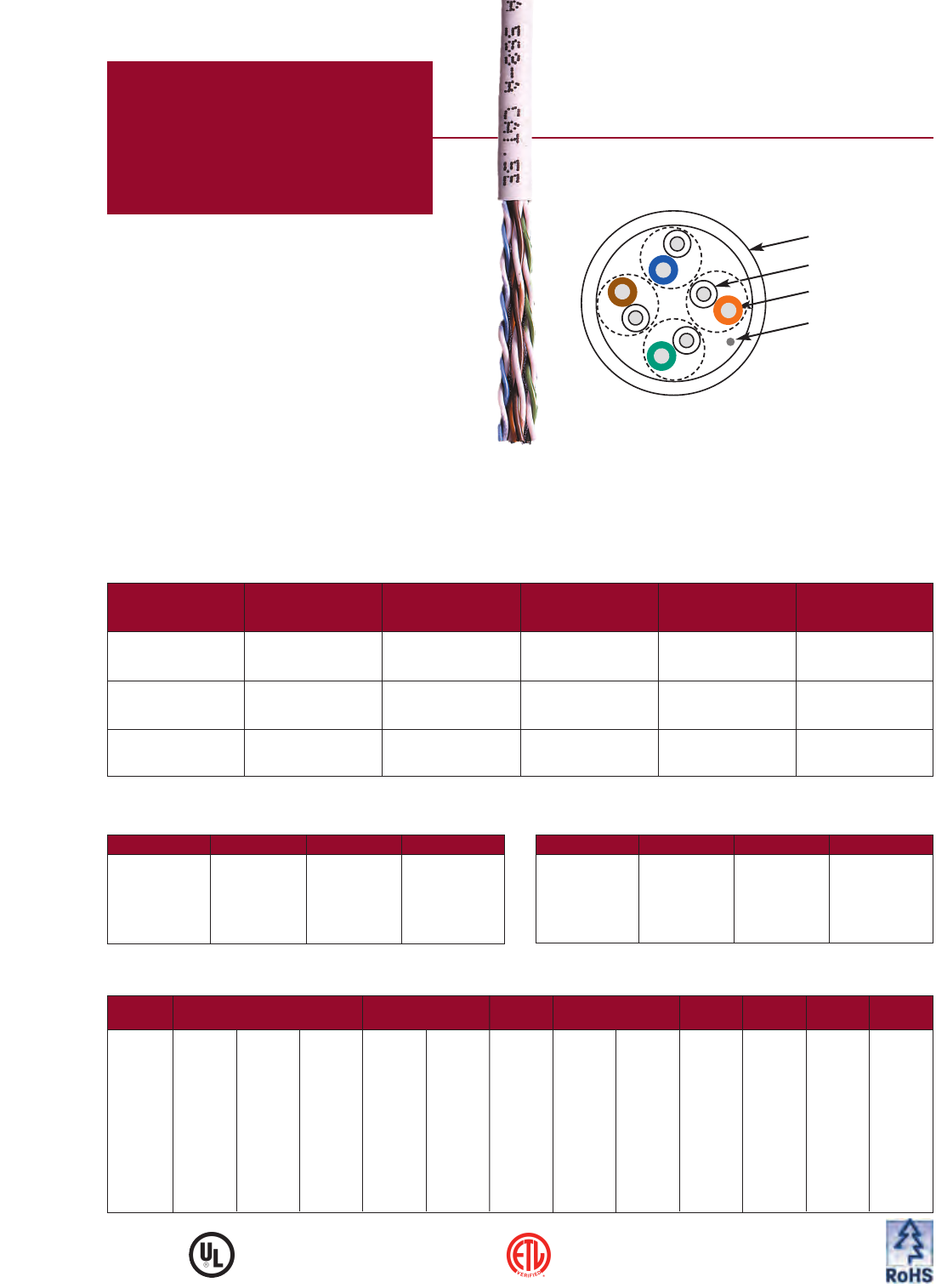
Jacket
Insulation
Conductor
Ripcord
Drain
Barrier/Shield
MOHAWK 17
Jacket Type
Mohawk Cable Dielectric Diameter Weight Listings
Part No. Type Type inch mm lbs/M' kg/km
M58155 4 PAIR Thermoplastic White PVC 44 65 C(UL)US
Non-Plenum 23 AWG .265 6.73 CMR
ScTP
M58175 4 PAIR FEP White ThermoPlen®* 49 73 C(UL)US
Plenum 23 AWG .255 6.48 CMP
ScTP
*Plenum rated Thermoplastic. For pair colors see chart A on page 59.
Custom colors available; please consult the factory.
Cable DIagram
STANDARDS:
EXCEEDS TIA/EIA 568-B.2 CAT 5e & ISO/IEC 11801:2002 CAT 5 HORIZONTAL CABLE
CONDUCTOR DCR:
8.9 V/100m (27.1 V/Mft) MAX
DCR UNBALANCE:
3% MAX
MUTUAL CAPACITANCE:
46 pF/m (14 pF/ft) NOM
CAPACITANCE UNBALANCE
PAIR/GROUND:
66 pF/100m (200 pF/Mft) MAX
CHARACTERISTIC IMPEDANCE:
100 V615% (1-400 MHz)
INPUT IMPEDANCE:
100 V 6 15% (1-100 MHz)
100 V 6 22% (>100-200 MHz)
PROPAGATION DELAY:
506 + 36/√ƒ ns/100m MAX
DELTA DELAY (SKEW):
30 ns/100m MAX
NOMINAL VELOCITY
OF PROPAGATION (NVP):
PLENUM 72%
NON-PLENUM 68%
Category 5E+ ScTP
MegaLAN®Tested to 400 MHz
Near End Crosstalk (NEXT) Power Sum NEXT (PS NEXT)
Worst Case ACR and Power Sum ACR Input Impedance
18 MOHAWK
Verified by ETL to TIA/EIA-568-B.2
Safety listed to NEC (NFPA 70)
Category 5E+ cable in a screened twisted pair (ScTP
or FTP) design, consisting of an overall tape/drain shield.
MegaLAN ScTP is ETL verified to Category 5e.
•20 Year Warranty*
•20 dB Minimum ACR @ 100 MHz – Proven support for Gigabit
Ethernet / 1000BASE-T / IEEE 802.3ab, ATM up to 155 Mbps,
100 Mbps Fast Ethernet / 100BASE-T / IEEE 802.3, ANSI.X3.263
FDDI TP-PMD, Ethernet / 10BASE-T / IEEE 802.3, 4 & 16 Mbps
Token Ring / IEEE 802.5, T1/E1, xDSL, ISDN, 550 MHz
Broadband Video and standards under development such as
ATM at 622 Mbps and 1.2 Gbps.
•5 dB Minimum – Improvement in Near End Crosstalk vs.
standard Category 5e NEXT.
•.30 ns/meter Maximum Skew – Tightly controlled
propagation delay.
•100% insulation (plenum).
•Enhanced Performance Parameters – All electrical characteristics
proven to exceed TIA/EIA 568-B Category 5e requirements: Near End
Crosstalk, Characteristic Impedance, Insertion loss and Delay Skew.
Also exceeds TIA/EIA 568-B.2 Category 5e requirements: Power Sum
NEXT, Return Loss, and Far End Crosstalk – ELFEXT and PS-ELFEXT.
•Engineered for Future Applications – Where cabling is to be
installed in a high external noise location. This could be in the path of
radar or next to a telecomm or a broadcast transmission point. Or is
security an issue? When quality cable is properly installed, grounded,
and tested, shielded cable provides measurably lower RF emissions.
•Use All Shielded Components for a Shielded or Screened
System – Mohawk strongly recommends the use of shielded or
screened connecting hardware, and all shielded or screened cords:
patch, work area and equipment cords should be used throughout the
structured cabling system.
•This cable and/or its manufacture are covered by US
Patent No. 5,424,491.
* Warranty available with MAC and SystemMATE®programs.
Electrical Characteristics
FREQ INSERTION LOSS NEXT ACR PS-NEXT PS-ACR ELFEXT
PS-ELFEXT
RL
(MHz) (dB/100m) (dB/1000ft) (dB/100m) (dB/100m) (dB/100m) (dB/100m) (dB/100m) (dB/100m) (dB)
avg max max avg min min avg min min min min min
.772 1.6 1.8 5.5 82 72.0 72.2 75 70.0 68.2 — — —
1.0 1.8 2.0 6.2 80 70.3 70.3 73 68.3 66.3 67.8 64.8 20.0
4.0 3.6 4.0 12.2 70 61.3 59.3 63 59.3 55.3 55.8 52.8 23.0
8.0 5.2 5.7 17.4 66 56.8 53.1 59 54.8 49.1 49.7 46.7 24.5
10.0 5.8 6.4 19.4 64 55.3 50.9 58 53.3 46.9 47.8 44.8 25.0
16.0 7.3 8.1 24.7 62 52.2 46.1 56 50.2 42.1 43.7 40.7 25.0
20.0 8.3 9.1 27.7 60 50.8 43.7 54 48.8 39.7 41.8 38.8 25.0
25.0 9.3 10.2 31.0 59 49.3 41.1 52 47.3 37.1 39.8 36.8 24.3
31.25 10.4 11.4 34.8 58 47.9 38.5 51 45.9 34.5 37.9 34.9 23.6
62.5 15.1 16.4 50 54 43.4 29.0 47 41.4 25.0 31.9 28.9 21.5
100.0 19.6 21.0 64 50 40.3 21.3 43 38.3 17.3 27.8 24.8 20.1
155.0 25.0 26.6 81 48 37.4 12.9 41 35.4 8.9 24.0 21.0 18.8
200.0 28.8 30.5 93 46 35.8 7.3 40 33.8 3.3 21.8 18.8 18.0
250.0 32.8 34.4 105 45 34.3 1.9 38 32.3 — 19.8 16.8 17.3
300.0 36.5 38.0 116 44 33.1 — 37 31.1 — — — 16.8
350.0 40.0 41.4 126 43 32.1 — 36 30.1 — — — 16.3
400.0 43.2 44.6 136 42 31.3 — 35 29.3 — — — 15.9
Values above 250 MHz are for engineering information only.
Jacket Type
Mohawk Cable Dielectric Diameter Weight Listings
Part No. Type Type inch mm lbs/M' kg/km
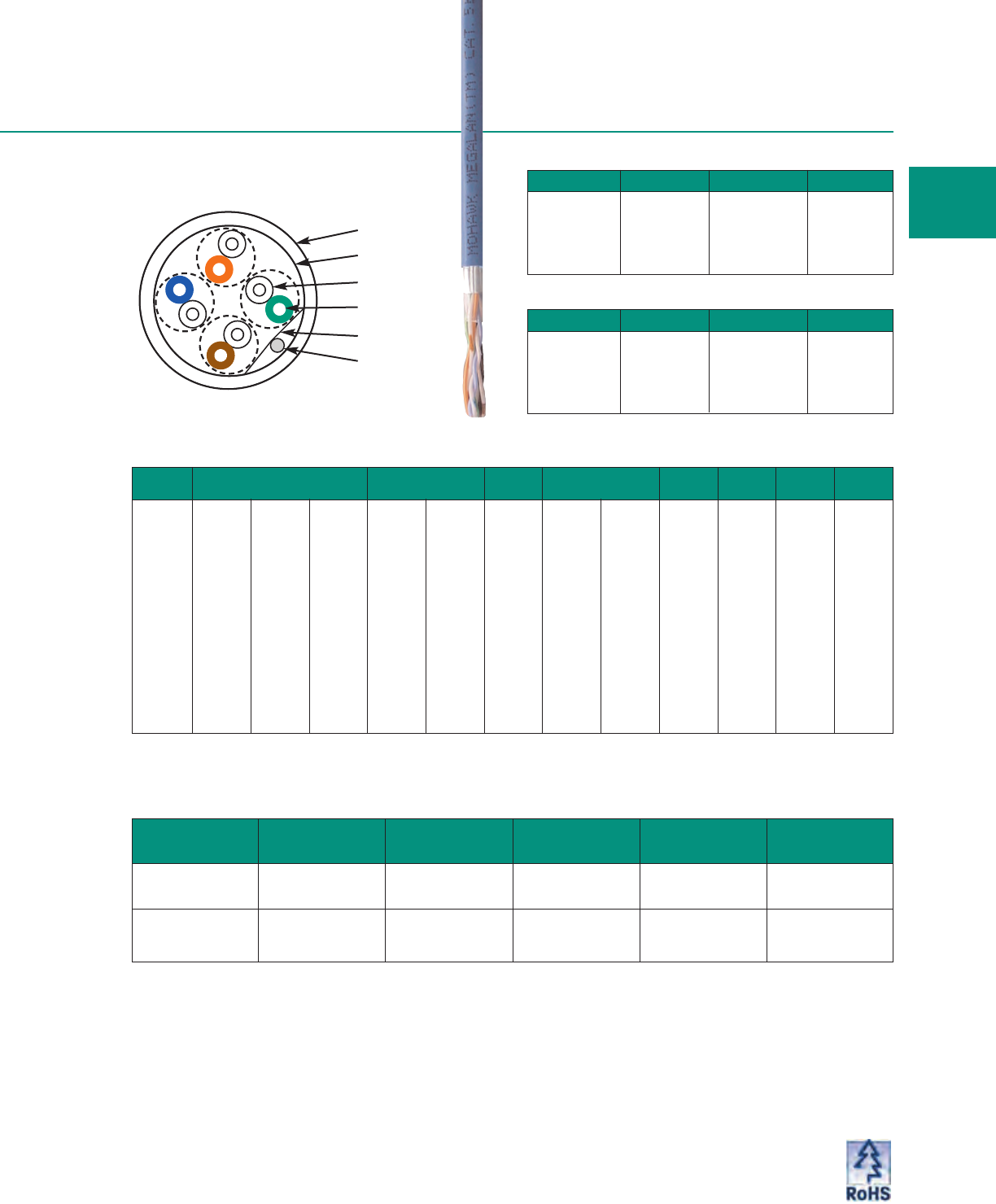
M55987 4 PAIR Thermoplastic White PVC 32 48 C(UL)US
Non-Plenum 24 AWG .245 6.22 CMR
ScTP
M55986 4 PAIR FEP White ThermoPlen®* 33 49 C(UL)US
Plenum 24 AWG .224 5.69 CMP
ScTP
*Plenum rated Thermoplastic. For pair colors see chart A on page 59.
Jacket Colors for 4-Pair Non-Plenum
Jacket Color Mohawk # Jacket Color Mohawk #
WHITE M55987 GREEN M57374
BLUE M57370 RED M57375
PINK M57371 ORANGE M57376
YELLOW M57372 BLACK M57377
GRAY M57373 VIOLET M57378
Jacket Colors for 4-Pair Plenum
Jacket Color Mohawk # Jacket Color Mohawk #
WHITE M55986 RED M57364
BLUE M57360 ORANGE M57365
PINK M57322 BLACK M57366
YELLOW M57361 VIOLET M57367
GRAY M57362 GREEN M57363
MOHAWK 19
Jacket
Shield
Insulation
Conductor
Barrier
Drain
Custom colors available; please consult the factory.
Cable DIagram
Category 5e ScTP
5e LAN®
•15 Year Warranty*
•14 dB Minimum ACR @ 100 MHz – Proven support
for Gigabit Ethernet / 1000BASE-T / IEEE 802.3ab, ATM up
to 155 Mbps, 100 Mbps Fast Ethernet / 100BASE-T / IEEE
802.3, ANSI.X3.263 FDDI TP-PMD, Ethernet / 10BASE-T /
IEEE 802.3, 4 & 16 Mbps Token Ring / IEEE 802.5, T1/E1,
xDSL, ISDN, 550 MHz Broadband Video and standards
under development such as ATM at 622 Mbps.
•4 dB Minimum – Improvement in Near End Crosstalk vs.
TIA/EIA 568-B Category 5.
•ETL verified to Category 5e.
•.30 ns/meter Maximum Skew – Tightly controlled
propagation delay.
•100% insulation (plenum).
•Engineered for Future Applications – Tested for all
parameters specified...for 4 pair ScTP in TIA/EIA 568-B.2,
including PS-NEXT, Return Loss, ELFEXT and PS-ELFEXT.
* Warranty available with MAC and SystemMATE®programs.
20 MOHAWK
Verified by ETL to TIA/EIA-568-B.2
Safety listed to NEC (NFPA 70)
Tested to 200 MHz
Jacket Type
Mohawk Cable Dielectric Diameter Weight Listings
Part No. Type Type inch mm lbs/M' kg/km
M58145 4 PAIR Thermoplastic Lt. Gray PVC 30 45 C(UL)US
Non-Plenum 24 AWG .232 5.89 CMR
ScTP
M58144 4 PAIR FEP Gray ThermoPlen®* 32 48 C(UL)US
Plenum 24 AWG .218 5.54 CMP
ScTP
*Plenum rated Thermoplastic.
Jacket Colors for 4-Pair Non-Plenum
Jacket Color Mohawk # Jacket Color Mohawk #
WHITE M58195 GREEN M58199
BLUE M58196 RED M58200
PINK M58197 ORANGE M58201
YELLOW M58198 BLACK M58202
GRAY M58145 VIOLET M58203
Jacket Colors for 4-Pair Plenum
Jacket Color Mohawk # Jacket Color Mohawk #
WHITE M58185 RED M58190
BLUE M58186 ORANGE M58191
PINK M58187 BLACK M58192
YELLOW M58188 VIOLET M58193
GRAY M58144 GREEN M58189
Jacket
Shield
Insulation
Conductor
Barrier
Drain
For pair colors see chart A on page 59.
Custom colors available; please consult the factory.
M54783 4 PAIR Thermoplastic Lt. Gray PVC 32 48 C(UL)US)
Non-Plenum 24 AWG .240 6.1 CMR
ScTP
M55082 4 PAIR FEP Gray ThermoPlen®* 34 51 C(UL)US
Plenum 24 AWG .230 5.84 CMP
ScTP
ScTP
Category 5 & 3
Verified by ETL to TIA/EIA-568-B.2
Safety listed to NEC (NFPA 70)
Category 5 ScTP
•Category 5 cable in a screened twisted pair (ScTP)
design, or overall shielded.
•10 dB Minimum ACR @ 100 MHz – Proven support
for 155 Mbps ATM, 100 Mbps Fast Ethernet, 100 Mbps
TP-PMD, 100VG-AnyLAN, 550 MHz Broadband Video
and standards under development such as ATM at
622 Mbps.
•.30 ns/meter Maximum Skew – Tightly controlled
propagation delay.
Jacket Colors for Category 5 4-Pair Non-Plenum
Jacket Color Mohawk # Jacket Color Mohawk #
GRAYM54783 BLACK M57277
BLUE M56912 ORANGE M57564
GREEN M57116 WHITE M57662
RED M56669 VIOLET M57850
Jacket Colors for Category 5 4-Pair Plenum
Jacket Color Mohawk # Jacket Color Mohawk #
GRAYM55082 GREEN M56823
WHITE M56760 RED M56809
BLUE M57009 BLACK M57269
PINK M58143
MOHAWK 21
Jacket
Shield
Insulation
Conductor
Barrier
Drain
Custom colors available; please consult the factory.
Category 5
Jacket Type
Mohawk Cable Dielectric Diameter Weight Listings
Part No. Type Type inch mm lbs/M' kg/km
Category 3
M53639 4 PAIR Thermoplastic Lt. Gray PVC 29 43 C(UL)US
Non-Plenum 24 AWG .210 5.33 CMR
ScTP
M54708 4 PAIR ThermoPlen®** Gray ThermoPlen®* 29 43 C(UL)US
Plenum 24 AWG .189 4.80 CMP
ScTP
*Plenum rated Thermoplastic. For pair colors see chart A on page 59.
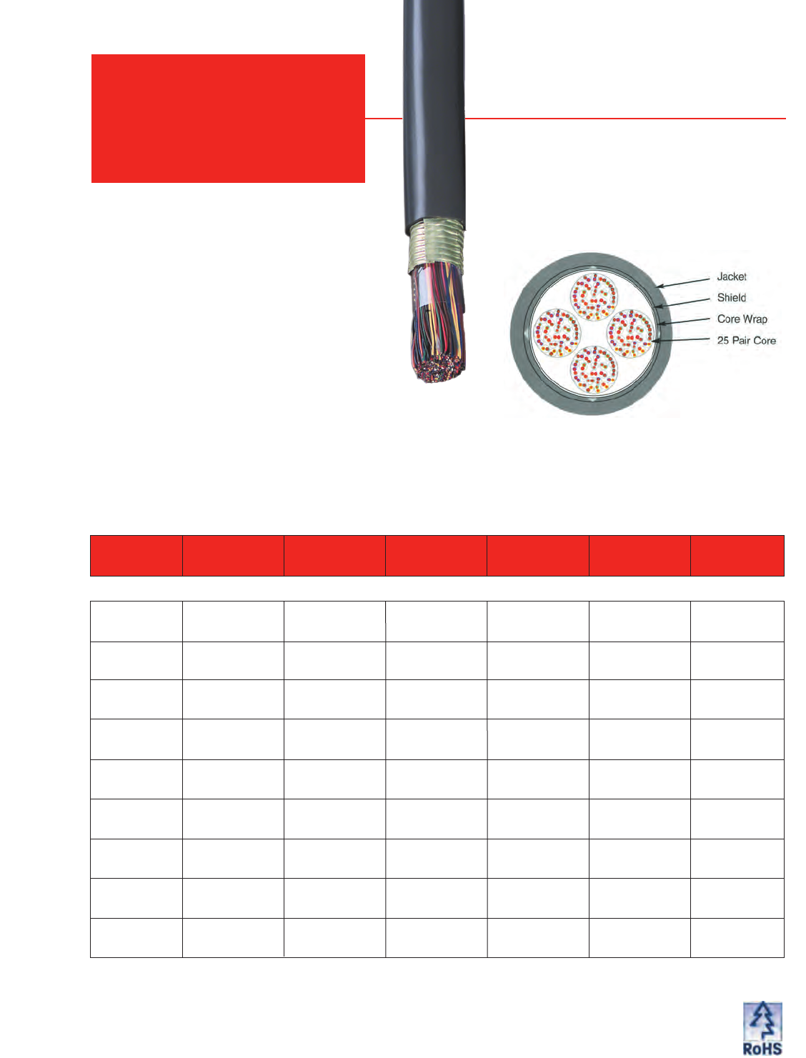
M56753† 25 PAIR None Lt. Gray PVC 119 177 4.7 119 C(UL)US
24 AWG UTP .470 11.94 CMR
M57040† 50 PAIR None Lt. Gray PVC 252 375 7.5 191 C(UL)US
24 AWG UTP .750 19.05 CMR
M56832† 25 PAIR O/A ALUM/PLYLt. Gray PVC 149 222 5.25 133 C(UL)US
24 AWG ScTP W/DW .522 13.26 CMR
M56773† 25 PAIR None Gray FEP 137 204 4.3 109 C(UL)US
24 AWG UTP .430 10.92 CMP
M56700 25 PAIR O/A ALUM/PLY Gray ThermoPlen®* 157 234 4.75 120 C(UL)US
24 AWG ScTP W/DW .472 11.99 CMP
Jacket Type Min Bend
Mohawk Cable Shield Type Diameter Weight Radius Listings
Part No. Type inch mm lbs/M' kg/km inch mm
Category 5: Plenum
Category 5: Non-Plenum
Category 5e: Non-Plenum
Category 5e: Plenum
M58142† 25 PAIR None Gray FEP 137 204 4.3 109 C(UL)US
24 AWG UTP .430 10.92 CMP
M58521 25 PAIR O/A ALUM/PLY Gray ThermoPlen®* 157 234 4.75 120 C(UL)US
24 AWG ScTP W/DW .472 11.99 CMP
Power Sum Backbone Cables**
OPERATING TEMP.: -20ºC to +60ºC (-4ºF to +140ºF)
STORAGE TEMP.: -20ºC to +75ºC (-4ºF to +167ºF)
INSTALLATION TEMP.:* 0ºC to +60ºC (+32ºF to +140ºF)
*THE INSTALLATION TEMPERATURE REFERS TO THE
TEMPERATURE OF THE
CABLE
WHILE BEING INSTALLED
OR PULLED. DO NOT INSTALL BELOW 0ºC (+32ºF).
25 and 50 pair Category 5 and 5e cables and/or
their manufacture are covered by US Patent
Nos. 5,821,466 and 5,424,491.
High Pair
Count Power Sum Backbone Cables**
22 MOHAWK
M58141† 25 PAIR None Lt. Gray PVC 119 177 4.7 119 C(UL)US
24 AWG UTP .470 11.94 CMR
M58522 50 PAIR None Lt. Gray PVC 252 375 7.5 191 C(UL)US
24 AWG UTP .750 19.05 CMR
M58520 25 PAIR O/A ALUM/PLY Lt. Gray PVC 149 222 5.25 133 C(UL)US
24 AWG ScTP W/DW .522 13.26 CMR
Type Reel/Put-up Gross Weight
(lbs.) Type Reel/Put-up Gross Weight
(lbs.) Type Reel/Put-up Gross Weight
(lbs.)
Plenum 22” Reel 1000 Ft. 131 Plenum 36” Reel 5000 Ft. 655 Non-Plenum 36” Reel 2000 Ft. 245
Plenum 30” Reel 2000 Ft. 262 Non-Plenum 24” Reel 1000 Ft. 119 Non-Plenum 48” Reel 5000 Ft. 640
Category 5/5e Power Sum 25 Pair Packaging Options
*Plenum rated Thermoplastic. †Verified by Independent Test Laboratories. For pair and binder colors see chart B on page 59.
M56801 25 PAIR None Gray ThermoPlen®* 123 183 3.9 99 C(UL)US
24 AWG UTP .389 9.88 CMP
M56126 50 PAIR None Gray ThermoPlen®* 224 333 5.5 140 C(UL)US
24 AWG UTP .550 13.97 CMP
M56128 100 PAIR None Gray ThermoPlen®* 467 695 7.9 201 C(UL)US
24 AWG UTP .786 19.96 CMP
M56129 200 PAIR None Gray ThermoPlen®* 942 1402 10.9 277 C(UL)US
24 AWG UTP 1.088 27.64 CMP
M57211 300 PAIR None Gray ThermoPlen®* 1397 2079 13.3 338 C(UL)US
24 AWG UTP 1.334 33.88 CMP
M58349 400 PAIR None Gray ThermoPlen®* 1760 2619 15.3 389 C(UL)US
24 AWG UTP 1.527 38.79 CMP
M55073 25 PAIR O/A ALUM/PLY Gray ThermoPlen®* 115 171 3.5 88 C(UL)US
24 AWG ScTP W/DW .346 8.79 CMP
Category 3: Plenum
M55700 25 PAIR None Lt. Gray PVC 100 149 3.6 91 C(UL)US
24 AWG UTP .364 9.25 CMR
M55216 50 PAIR None Lt. Gray PVC 197 293 5.9 150 C(UL)US
24 AWG UTP .591 15.01 CMR
M55211 100 PAIR None Lt. Gray PVC 381 567 7.1 180 C(UL)US
24 AWG UTP .707 17.96 CMR
M55212 200 PAIR None Lt. Gray PVC 814 1211 10.5 267 C(UL)US
24 AWG UTP 1.054 26.77 CMR
M57098 300 PAIR None Lt. Gray PVC 1186 1765 12.25 311 C(UL)US
24 AWG UTP 1.222 31.04 CMR
M57996 400 PAIR None Lt. Gray PVC 1750 2604 16.0 406 C(UL)US
24 AWG UTP 1.590 40.38 CMR
M55704 25 PAIR O/A ALUM/PLY Lt. Gray PVC 111 165 4.0 102 C(UL)US
24 AWG ScTP W/DW .394 10.01 CMR
Category 3: Non-Plenum
*Plenum rated Thermoplastic. For pair and binder colors see chart B on page 59.
MOHAWK 23
Pair Count Reel/Put-up Gross Weight
(lbs.) Pair Count Reel/Put-up Gross Weight
(lbs.) Pair Count Reel/Put-up Gross Weight
(lbs.)
25 20” Reel 1000 Ft. 123 100 30” Reel 1000 Ft. 467 200 72” Reel 5000 Ft. 4300
25 24” Reel 2000 Ft. 246 100 36” Reel 2000 Ft. 950 300 48” Reel 1000 Ft. 1897
25 36” Reel 5000 Ft. 620 100 42” Reel 2500 Ft. 1167 300 54” Reel 2000 Ft. 2800
25 36” Reel 6500 Ft. 805 100 48” Reel 4000 Ft. 1910 300 60” Reel 3000 Ft. 4200
50 22” Reel 1000 Ft. 224 100 54” Reel 5000 Ft. 2400 300 72” Reel 4000 Ft. 5600
50 30” Reel 2000 Ft. 455 200 42” Reel 1000 Ft. 814 400 54” Reel 1000 Ft. 1900
50 48” Reel 5000 Ft. 1160 200 54” Reel 2000 Ft. 1680 400 72” Reel 2000 Ft. 3900
Category 3 High Pair Count Packaging Options
Jacket Type Min Bend
Mohawk Cable Shield Type Diameter Weight Radius Listings
Part No. Type inch mm lbs/M' kg/km inch mm
UTP & ScTP
Patch Cables
GigaLink™Category 6e+ UTP Patch Cable — Tested to 750 MHz
Jacket Type
Mohawk Cable Dielectric Shield Type Diameter Weight Listings
Part No. Type Type inch mm lbs/M' kg/km
AdvanceLink®Category 6e UTP Patch Cable — Tested to 650 MHz
M57634 4 PAIR Thermoplastic None White PVC 29 43 C(UL)US
24 AWG (7/32) TC .226 5.7 CMG
UTP
For pair colors see chart A on page 59.
For pair colors see chart A on page 59.
M57507 4 PAIR Thermoplastic None White PVC 25 37 C(UL)US
24 AWG (7/32) TC .216 5.49 CMG
UTP
2
4
MOHAWK
Jacket Colors/Mohawk# BLUE -- M57635 RED -- M57641 GREEN -- M57638 YELLOW -- M57637
MegaLink™Category 5e+ UTP & ScTP Patch Cable
Jacket Type
Mohawk Cable Dielectric Shield Type Diameter Weight Listings
Part No. Type Type inch mm lbs/M' kg/km
M56726 4 PAIR Thermoplastic None White PVC 25 37 C(UL)US
24 AWG (7/32) TC .200 5.10 CMG
UTP
M57542 4 PAIR Thermoplastic O/A White PVC 23 34 C(UL)US
26 AWG (7/34) TC ALUM/PLY .203 5.16 CMG
ScTP W/DW
For pair colors see chart A on page 59.
Jacket Colors/Mohawk# for 4-Pair UTP BLUE -- M57076 RED -- M57073 GREEN -- M57075 YELLOW -- M56985
Jacket Colors/Mohawk# for 4-Pair ScTP BLUE -- M57544 RED -- M57770 GREEN -- M58219 YELLOW -- M58218
5e LAN®Category 5e UTP & ScTP Patch Cable
M58126 4 PAIR Thermoplastic None White PVC 25 37 C(UL)US
24 AWG (7/32) TC .200 5.10 CMG
UTP
M58208 4 PAIR Thermoplastic O/A White PVC 23 34 C(UL)US
26 AWG (7/34) TC ALUM/PLY .203 5.16 CMG
ScTP W/DW
For pair colors see chart A on page 59.
Jacket Colors/Mohawk# for 4-Pair UTP BLUE -- M58127 RED -- M58133 GREEN -- M58130 YELLOW -- M58129
Jacket Colors/Mohawk# for 4-Pair ScTP BLUE -- M58209 RED -- M58214 GREEN -- M58213 YELLOW -- M58211
Jacket Colors/Mohawk# BLUE -- M57508 RED -- M57519 GREEN -- M57512 YELLOW -- M57511
Additional colors & custom colors available - please consult the factory.
Additional colors & custom colors available - please consult the factory.
Additional colors & custom colors available - please consult the factory.
Additional colors & custom colors available - please consult the factory.
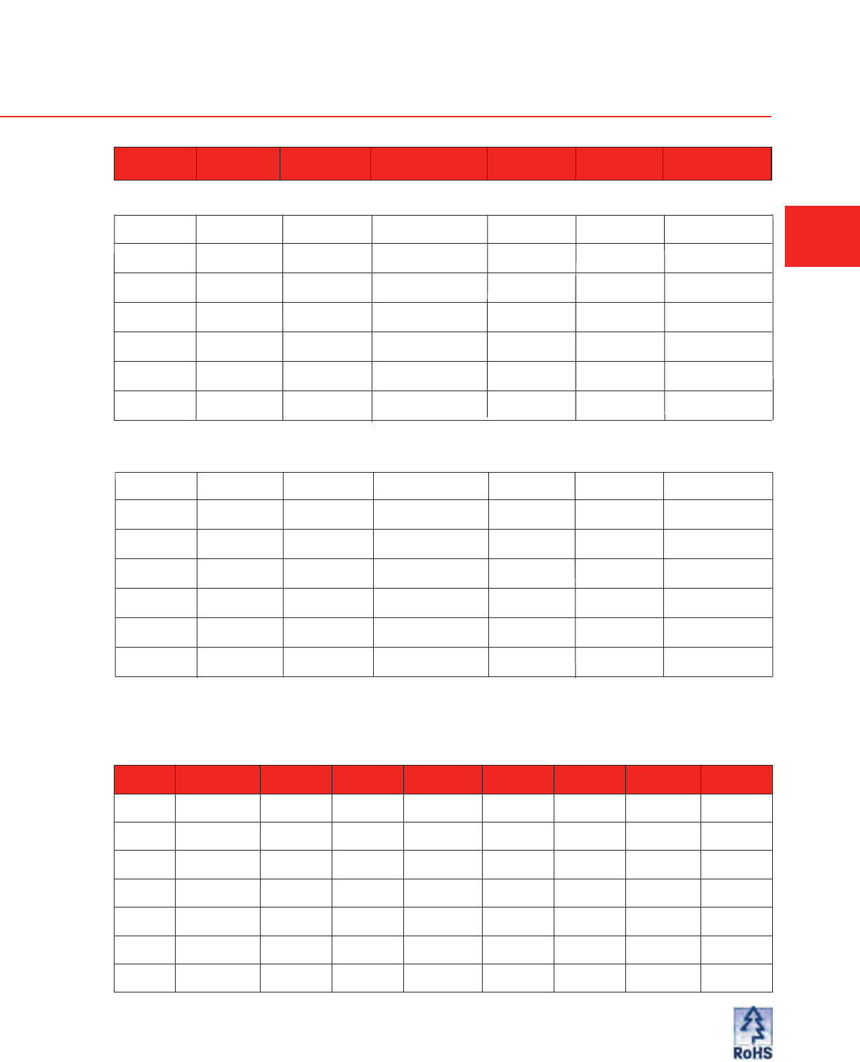
M58452 25 PAIR O/A .008 Gray PVC 115 171 4.7 119 UL, c(UL)
24 AWG CORRUGATED .470 11.9 CMR
ARMM ALUMINUM
M58460 50 PAIR O/A .008 Gray PVC 230 342 6.9 188 UL, c(UL)
24 AWG CORRUGATED .660 16.8 CMR
ARMM ALUMINUM
M58461 75 PAIR O/A .008 Gray PVC 345 519 7.8 190 UL, c(UL)
24 AWG CORRUGATED .760 19.3 CMR
ARMM ALUMINUM
M58453 100 PAIR O/A .008 Gray PVC 412 613 8.5 215 UL, c(UL)
24 AWG CORRUGATED .850 21.6 CMR
ARMM ALUMINUM
M58462 150 PAIR O/A .008 Gray PVC 616 918 9.9 261 UL, c(UL)
24 AWG CORRUGATED .990 25.1 CMR
ARMM ALUMINUM
M58454 200 PAIR O/A .008 Gray PVC 820 1222 11 280 UL, c(UL)
24 AWG CORRUGATED 1.10 27.9 CMR
ARMM ALUMINUM
M58455 250 PAIR O/A .008 Gray PVC 950 1415 12.2 310 UL, c(UL)
24 AWG CORRUGATED 1.22 30.9 CMR
ARMM ALUMINUM
M58456 300 PAIR O/A .008 Gray PVC 1100 1693 13.2 335 UL, c(UL)
24 AWG CORRUGATED 1.32 33.5 CMR
ARMM ALUMINUM
M58457 400 PAIR O/A .008 Gray PVC 1400 2086 15 380 UL, c(UL)
24 AWG CORRUGATED 1.50 38.1 CMR
ARMM ALUMINUM
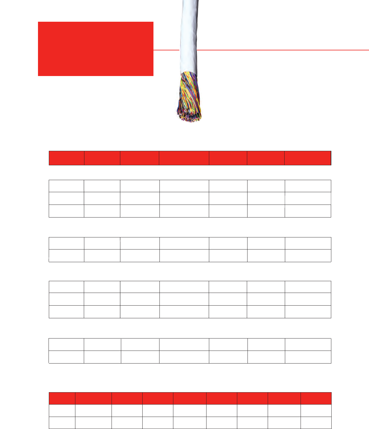
ARMM
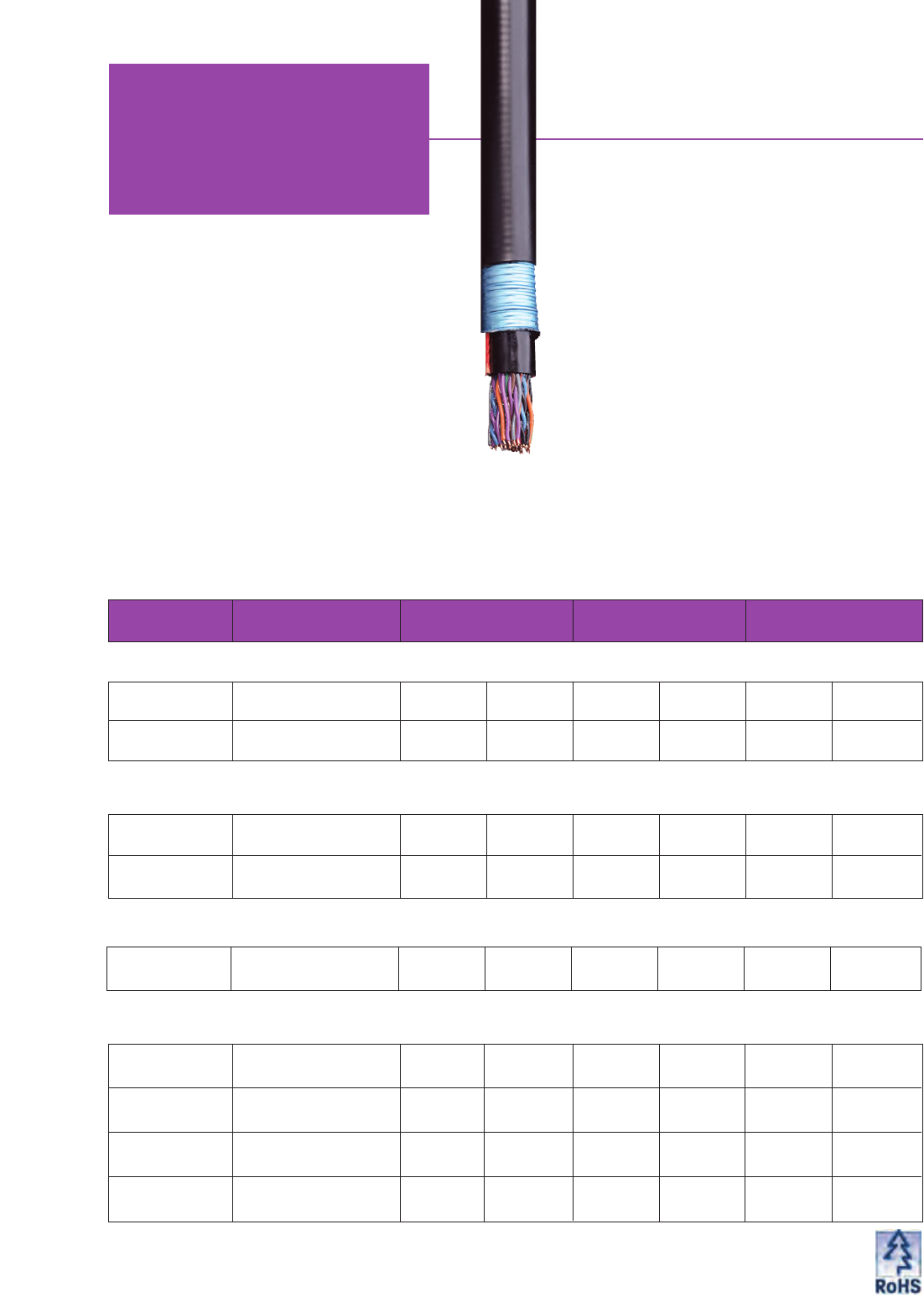
Riser Cable Multi-Pair
24 AWG Category 3
ARMM Riser Cable is a rugged multi-pair cable that
exceeds Category 3 Cable for use in backbone
cabling systems as described in TIA/EIA 568-B. The
cable consists of #24 AWG solid bare copper
insulated conductors, assembled into twisted pairs,
core wrap, corrugated aluminum shield bonded to an
overall PVC jacket.
The cable is riser (non-plenum) rated for use as a
vertical run in a shaft and for general purpose
communications use in accordance with Article 800 of
the National Electrical Code (NEC). The cable is UL
(USA) & c(UL) (CANADA) listed for this application by
passing UL 1666 Riser Cable Flammability test.
Jacket Min Bend
Mohawk Cable Shield Diameter Weight Radius Listings
Part No. Type Type inch mm lbs/M’ kg/km inch mm
Multi-Pair 24 AWG Category 3
For pair and binder colors see chart D on page 59.
MOHAWK 25
LAN-Trak OSP Category 5 Cable
M56871* 4 PAIR 24 AWG .196 4.98 22 33 2.00 51
Outdoor Duct/Aerial Lashed
M57041* 4 PAIR 24 AWG .246 6.25 30 45 2.50 61
Aerial Lashed
M57042* 4 PAIR 24 AWG .380 9.65 87 129 5.70 145
Direct Burial (Shielded)
M57656** 25 PAIR 24 AWG .730 18.54 300 446 11.00 280
Direct Burial
(Shielded)
*US Patent No. 5,424,491. **US Patent Nos. 5,424,491; 5,821,466. ***US Patent Nos. 5,424,491; 6,074,503; 6,496,944.
For 4 pair colors see chart A; for 25 pair colors see chart D on page 59.
26 MOHAWK
Special Applications
LAN-TrakTMOSP
LAN-Trak OSP delivers TIA/EIA 568-B Category 5, 5e+,
or 6 electrical performance in an outside plant cable,
because even small amounts of moisture or water in the
cable will degrade the electrical performance of a
Category cable. These cables are designed for
exposure to the elements. Jacketed with black UV
resistant polyethylene, they employ a craft-friendly semi-
dry flooding material that cleans easily from the cable
core.
Traditional petroleum based gels such as “icky-pick”
result in hard to clean and time consuming cable prep
time. This thixotropic gel has a dry, soft texture that is
dermally safe and cleans easily with citrus based
cleaners. The result is faster cable prep time, quicker
clean-ups and happier technicians.
These cables allow you to extend your current network
to outdoor satellite structures such as temporary
classrooms or trailers in a campus environment. They
are also well suited for runs under concrete slabs and in
other wet locations.
These cables are offered in both unshielded (UTP) and
the more robust shielded (ScTP) cables. Also, the NEC
may require a Category 5, 5e, or 6 rated protection
device.
As with all horizontal cables, run length is limited to 90
meters (295 feet) per TIA/EIA 568-B for Category 5, 5e,
or 6 operation.
Outside Plant Cable
AdvanceNet®LAN-Trak OSP Category 6 Cable
M57622*** 4 PAIR 24 AWG .271 6.88 36 54 2.75 70
Duct/Aerial Lashed
M57623*** 4 PAIR 24 AWG .460 11.68 99 147 6.90 175
Direct Burial (Shielded)
Mohawk Jacket Diameter Weight Min. Bend Radius
Part No. Cable Type Inch mm lbs/M’ kg/km Inch mm
MegaLAN®LAN-Trak OSP Category 5E+ Cable
M57561* 4 PAIR 24 AWG .251 6.38 31 46 2.50 61
Duct/Aerial Lashed
M57562* 4 PAIR 24 AWG .380 9.65 88 131 5.70 145
Direct Burial (Shielded)
LAN-Trak OSP Category 5e Cable
M58527** 25 PAIR 24 AWG .730 18.54 300 446 11.00 280
Direct Burial
(Shielded)
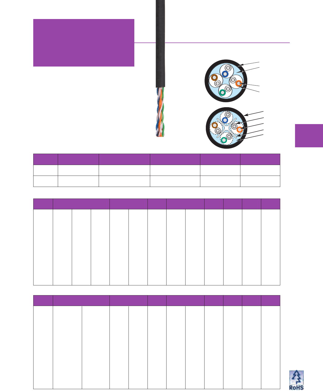
Special Applications
Versa
LAN
TM CM
The cable is suitable for use in buildings in wet loca-
tions and suitable for use outdoors in duct and for
aerial lashing. It is fully water blocked and has a
black sunlight resistant jacket. It is not suitable for
direct burial. This product and/or its manufacture is
covered by US patent No. 5,424,491.
The cable is NEC rated for general purpose
communications use in accordance with Article 800
of the National Electrical Code (NEC). The cable
is UL (USA) & c(UL) (CANADA) listed for this
application by passing UL 1581 vertical tray flame test.
Indoor/Outdoor Category 5e & 6 Cable
FREQ INSERTION LOSS NEXT ACR PS-NEXT PS-ACR ELFEXT
PS-ELFEXT
RL
(MHz) (dB/100m) (dB/mft) (dB/100m) (dB/100m) (dB/100m) (dB/100m) (dB/100m) (dB/100m) (dB)
avg max max avg min min avg min min min min min
.772 1.6 1.8 5.5 82 72.0 72.2 75 70.0 68.2 - - -
1.0 1.8 2.0 6.2 80 70.3 70.3 73 68.3 66.3 67.8 64.8 20.0
4.0 3.6 4.0 12.2 70 61.3 59.3 63 59.3 55.3 55.8 52.8 23.0
8.0 5.2 5.7 17.4 66 56.8 53.1 59 54.8 49.1 49.7 46.7 24.5
10.0 5.8 6.4 19.4 64 55.3 50.9 58 53.3 46.9 47.8 44.8 25.0
16.0 7.3 8.1 24.7 62 52.2 46.1 56 50.2 42.1 43.7 40.7 25.0
20.0 8.3 9.1 27.7 60 50.8 43.7 54 48.8 39.7 41.8 38.8 25.0
25.0 9.3 10.2 31.0 59 49.3 41.1 52 47.3 37.1 39.8 36.8 24.3
31.25 10.4 11.4 34.8 58 47.9 38.5 51 45.9 34.5 37.9 34.9 23.6
62.5 15.1 16.4 50 54 43.4 29.0 47 41.4 25.0 31.9 28.9 21.5
100.0 19.6 21.0 64 50 40.3 21.3 43 38.3 17.3 27.8 24.8 20.1
155.0 25.0 26.6 81 48 37.4 12.9 41 35.4 8.9 24.0 21.0 18.8
200.0 28.8 30.5 93 46 35.8 7.3 40 33.8 3.3 21.8 18.8 18.0
250.0 32.8 34.4 105 45 34.3 1.9 38 32.3 - 19.8 16.8 17.3
300.0 36.5 38.0 116 44 33.1 - 37 31.1 - - - 16.8
350.0 40.0 41.4 126 43 32.1 - 36 30.1 - - - 16.3
400.0 43.2 44.6 136 42 31.3 - 35 29.3 - - - 15.9
Electrical Characteristics - Category 5e
Jacket
Flooded Core
Conductor
Insulation
MOHAWK 27
Jacket
Insulation
Conductor
FlexWeb
Flooded
Core
FREQ INSERTION LOSS NEXT ACR PS-NEXT PS-ACR ELFEXT
PS-ELFEXT
RL
(MHz) (dB/100m) (dB/100m) (dB/100m) (dB/100m) (dB/100m) (dB/100m) (dB/100m) (dB)
avg max avg min min avg min min min min min
.772 1.6 1.8 86 77.0 75.2 80 75.0 73.2 - - -
1.0 1.8 2.0 82 75.3 73.3 75 73.3 71.3 70.0 68.0 20.0
4.0 3.5 3.8 73 66.3 62.5 65 64.3 60.5 58.0 56.0 23.0
8.0 5.0 5.3 69 61.8 56.5 61 59.8 54.5 51.9 49.9 24.5
10.0 5.6 5.9 67 60.3 54.4 60 58.3 52.4 50.0 48.0 25.0
16.0 7.1 7.5 66 57.2 49.7 58 55.2 47.7 45.9 43.9 25.0
20.0 7.9 8.4 64 55.8 47.4 56 53.8 45.4 44.0 42.0 25.0
25.0 8.9 9.4 63 54.3 44.9 54 52.3 42.9 42.0 40.0 24.3
31.25 10.0 10.6 62 52.9 42.3 53 50.9 40.3 40.1 38.1 23.6
62.5 14.4 15.3 58 48.4 33.1 49 46.4 31.1 34.1 32.1 21.5
100.0 18.5 19.7 54 45.3 25.6 45 43.3 23.6 30.0 28.0 20.1
155.0 23.5 25.0 52 42.4 17.4 43 40.4 15.4 26.2 24.2 18.8
200.0 27.2 28.8 50 40.8 12.0 42 38.8 10.0 24.0 22.0 18.0
250.0 30.7 32.6 49 39.3 6.7 40 37.3 4.7 22.0 20.0 17.3
300.0 34.0 36.2 48 38.1 2.0 39 36.1 0.0 20.5 18.5 16.8
350.0 37.2 39.5 47 37.1 - 38 35.1 - 19.1 17.1 16.3
400.0 40.2 42.7 46 36.3 - 37 34.3 - - - 15.9
500.0 45.8 48.6 45 34.8 - 36 32.8 - - - 15.2
550.0 48.4 51.5 44 34.2 - 35 32.2 - - - 14.9
Electrical Characteristics - Category 6
Category 5e
Cable Detail
Category 6
Cable Detail
Mohawk
Part No. Cable Type Jacket Diameter
inch mm
Weight
lbs/M’ kg/km
Min. Bend Radius
inch mm Listings
M58762 Cat 5e 4 PAIR 24 AWG
UTP
.251 6.38 38 57 2.50 61 C(UL)US
CM-LS
M58772 Cat 6 4 PAIR 24 AWG
UTP
.271 6.88
43
64 2.75 70 C(UL)US
CM-LS
28 MOHAWK
Special Applications
Cellular Tower
Cables
Mohawk’s Cellular Tower Cable is an overall foil/braid
shielded twisted pair cable intended for outdoor use. The
compact rugged design is more flexible versus traditional
armored cable typically used for this application. The
foil/braid shield is an excellent choice where interference
from external radio frequency or electromagnetic sources
is a concern.
These cables can be used not only to connect cellular
phone sites, but other services including pagers, mobile
radio, wireless data, personal communications service
(PCS), and even newer services such as high speed
broadband wireless internet access and weather
collection equipment.
•EMI & RFI Protection – 60% Coverage Braid and 100%
Coverage Metallic Foil Tape offer excellent EMI and RFI
immunity in a tower environment, where there may be
interference from other services located on the same
tower now or in the future.
•Easy Termination – Grounding is made simple because
the braid can be crimped to a ground wire or clamped to
the enclosure.
•Gel filled and fully water-blocked – Prevents migration
of water through the cable into sensitive electronics
enclosures. Gel filling prevents corrosion of the
conductors in the presence of water.
•UV stabilized polyethylene outer jacket.
•Meets applicable TIA/EIA Category grades.
•Category 5, 5e, and 6 conductors should be terminated
with 110 style Category rated jacks and the link
completed with a short Category rated patch cable.
•Standard RJ-45 plugs may not fit the Category 5e & 6
insulated conductors. Please consult the factory for the
proper plug to fit these cables.
Category 6 Cable
Mohawk
Part No. Cable Type Jacket Diameter
inch mm
Weight
lbs/M’ kg/km
Min. Bend Radius
inch mm
M58577 4 PAIR 24 AWG .305 7.75 49 73 3.0 76
Category 5E+ Cable
Mohawk
Part No. Cable Type Jacket Diameter
inch mm
Weight
lbs/M’ kg/km
Min. Bend Radius
inch mm
M58463 4 PAIR 24 AWG .276 7.01 43 64 2.8 71
Category 5 Cable
Mohawk
Part No. Cable Type Jacket Diameter
inch mm
Weight
lbs/M’ kg/km
Min. Bend Radius
inch mm
M58116 4 PAIR 24 AWG .250 6.35 38 57 2.5 64
Category 6
Cable Detail
Category 5E+/5
Cable Detail
FlexWeb
Conductor
Insulation
Inner Jacket
Braid Shield
Outer Jacket
Conductor
Insulation
Inner Jacket
Braid Shield
Outer Jacket
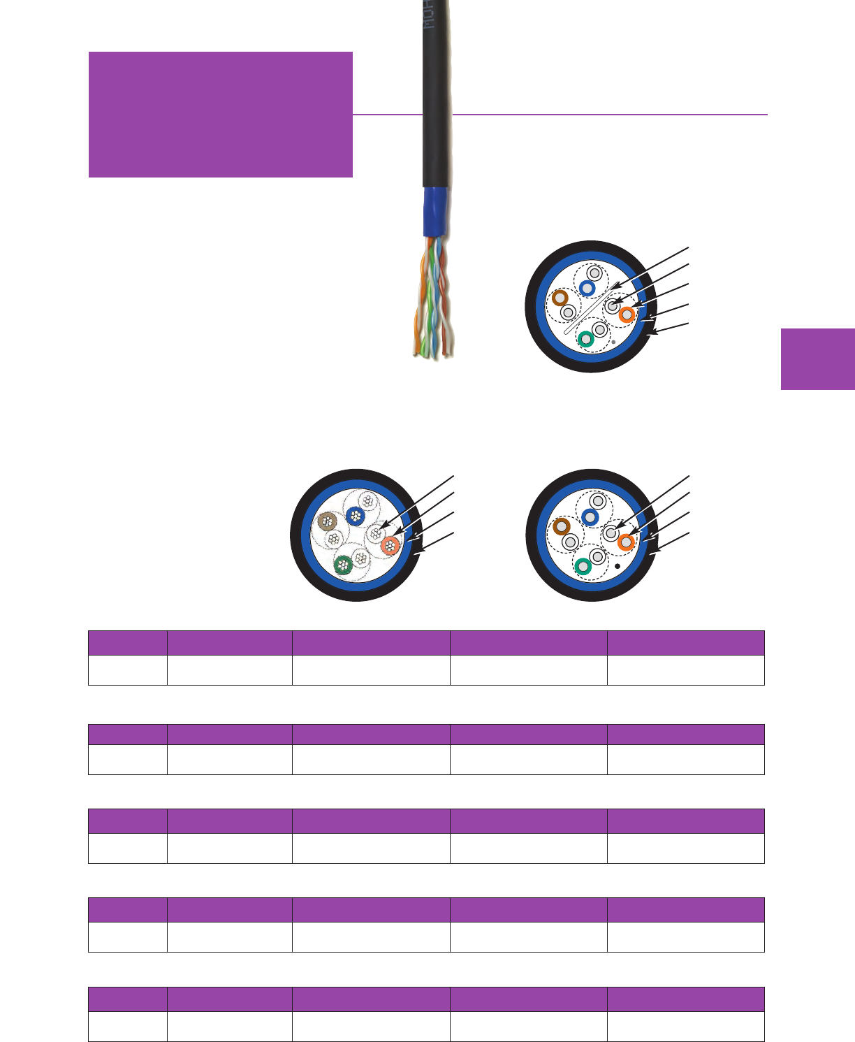
Industrial Grade Cables
Special Applications
OmniGUARD®
MOHAWK 29
AdvanceNet®Category 6e UTP Cable
Mohawk
Part No. Cable Type Dielectric Type Jacket Diameter
inch mm
Weight
lbs/M’ kg/km
M58622 4 PAIR 24 AWG UTP Polyolefin .266 6.76 39 58
Category 5e Stranded UTP Cable
Mohawk
Part No. Cable Type Dielectric Type Jacket Diameter
inch mm
Weight
lbs/M’ kg/km
M58509 4 PAIR 24 AWG UTP
STRANDED Polyolefin .260 6.60 37 55
MegaLAN®Category 5E+ UTP Cable
Mohawk
Part No. Cable Type Dielectric Type Jacket Diameter
inch mm
Weight
lbs/M’ kg/km
M58629 4 PAIR 24 AWG UTP Polyolefin .230 5.84 30 45
5e LAN®Category 5e UTP Cable
Mohawk
Part No. Cable Type Dielectric Type Jacket Diameter
inch mm
Weight
lbs/M’ kg/km
M58620 4 PAIR 24 AWG UTP Polyolefin .230 5.84 30 45
Category 5 UTP Cable
Mohawk
Part No. Cable Type Dielectric Type Jacket Diameter
inch mm
Weight
lbs/M’ kg/km
M58630 4 PAIR 24 AWG UTP Polyolefin .230 5.84 30 45
Category 6e
Cable Detail Tape
Separator
Conductor
Insulation
Inner Jacket
Outer Jacket
Category 5e Stranded
Cable Detail
Conductor
Insulation
Inner Jacket
Outer Jacket
Category 5E+/5e/5
Cable Detail
Conductor
Insulation
Inner Jacket
Outer Jacket
Rugged Cable Solutions for Extreme Environments
Today’s high-performance networking applications are
moving from clean office environments out to greasy
factory floors. Mohawk has responded with a line of
Industrial Ethernet cable solutions.
Mohawk’s OmniGUARD Industrial Grade AdvanceNet®
and LAN copper cable families include both unshielded
and shielded twisted pair constructions with Category 5,
Category 5e or Category 6. These cables are designed
to meet or exceed the performance standards of
TIA/EIA-568-B and ISO/IEC11801 requirements, while
providing added jacket compounds for durability.
•Riser – For use as vertical runs
in a shaft and for general-purpose
communications.
•Oil and UV-resistant – Black
TPE jacket for excellent abrasion/
cut-through resistance.
•-20°C to +60°C operating
temperature.
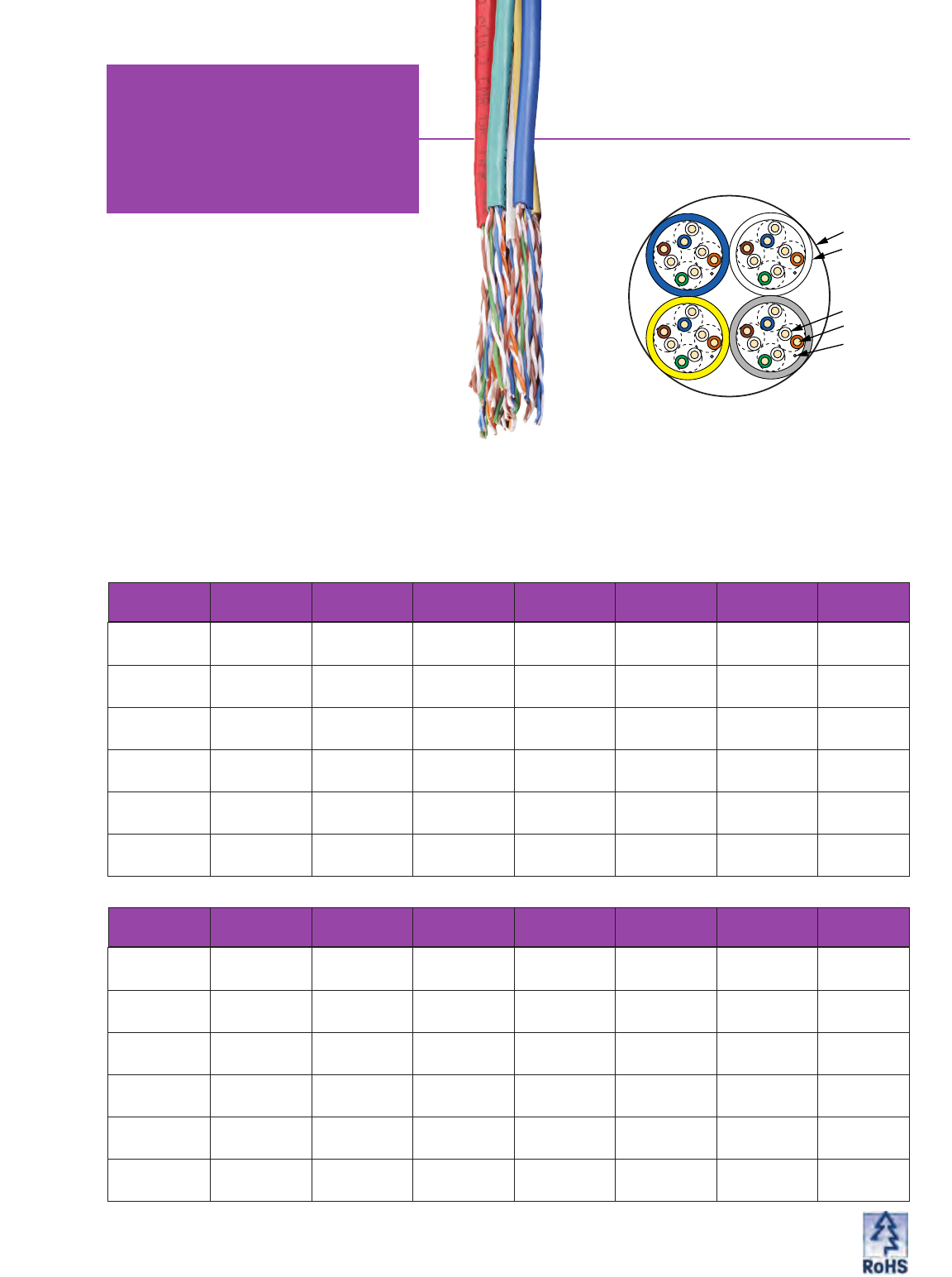
30 MOHAWK
Number Component Component Jacket Cable DiameterMohawk of Cable Dielectric Type Diameter Weight Listings
Part No. Components Type Type inch mm inch mm lbs/M' kg/km
M57404 3 4 PAIR Thermoplastic PVC .389 9.88 70 104 C(UL)US
Non-Plenum 24 AWG .201 5.11 CMR
UTP
M57407 4 4 PAIR Thermoplastic PVC .436 11.07 90 134 C(UL)US
Non-Plenum 24 AWG .201 5.11 CMR
UTP
M57408 64 PAIR Thermoplastic PVC .543 13.79 136 202 C(UL)US
Non-Plenum 24 AWG .201 5.11 CMR
UTP
M57409 3 4 PAIR Dual Insulation** ThermoPlen®*.360 9.14 74 110 C(UL)US
Plenum 24 AWG FEP on all .186 4.72 CMP
UTP 4 pairs
M57410 4 4 PAIR Dual Insulation** ThermoPlen®* .403 10.24 95 141 C(UL)US
Plenum 24 AWG FEP on all .186 4.72 CMP
UTP 4 pairs
M57411 6 4 PAIR Dual Insulation** ThermoPlen®* .502 12.75 140 208 C(UL)US
Plenum 24 AWG FEP on all .186 4.72 CMP
UTP 4 pairs
Bundled Cables
Special Applications
Media PullTM
Tired of setting up multiple cable reels
for a common cable pull?
Mohawk has the answer,
Media Pull Bundled Cables.
Ultimate Versatility
Media Pull Cables are multiples of individually jacketed
components, such as 4 pair copper cable elements.
The components are bundled together in a neat, clean
and easy to use package.
UL Approved
Mohawk’s line of Media Pull cables are fully approved
to UL safety requirements for CMR (Riser) or CMP (Plenum)
copper applications and for OFNR (Riser) or OFNP (Plenum)
fiber optic applications.
Guaranteed Performance
Individual cable elements are tested prior to cabling and tested
again once the cabling operation is complete. This additional testing
ensures that Media Pull constructions deliver the performance
you’ve come to expect from an industry leader like Mohawk.
Media Pull Category 6 Copper Components
Media Pull MegaLAN®Category 5E+ Copper Components
Number Component Component Jacket Cable DiameterMohawk of Cable Dielectric Type Diameter Weight Listings
Part No. Components Type Type inch mm inch mm lbs/M' kg/km
M57626 3 4 PAIR Thermoplastic PVC .478 12.14 104 155 C(UL)US
Non-Plenum 24 AWG .247 6.27 CMR
M57627 4 4 PAIR Thermoplastic PVC .536 13.61 132 196 C(UL)US
Non-Plenum 24 AWG .247 6.27 CMR
UTP
M57628 6 4 PAIR Thermoplastic PVC .670 17.02 229 341 C(UL)US
Non-Plenum 24 AWG .247 6.27 CMR
M57629 3 4 PAIR Dual Insulation** ThermoPlen®* .525 13.33 129 192 C(UL)US
Plenum 24 AWG FEP on all .244 6.20 CMP
UTP 4 pairs
M57630 4 4 PAIR Dual Insulation** ThermoPlen®* .586 14.88 162 241 C(UL)US
Plenum 24 AWG FEP on all .244 6.20 CMP
UTP 4 pairs
M57631 6 4 PAIR Dual Insulation** ThermoPlen®* .738 18.75 253 376 C(UL)US
Plenum 24 AWG FEP on all .244 6.20 CMP
UTP 4 pairs
*Plenum rated Thermoplastic. **U.S. Patent No. 5,563,377.
For pair colors see chart A on page 59. For component jacket colors see page 33.
BINDER
JACKET
INSULATION
CONDUCTOR
RIPCORD
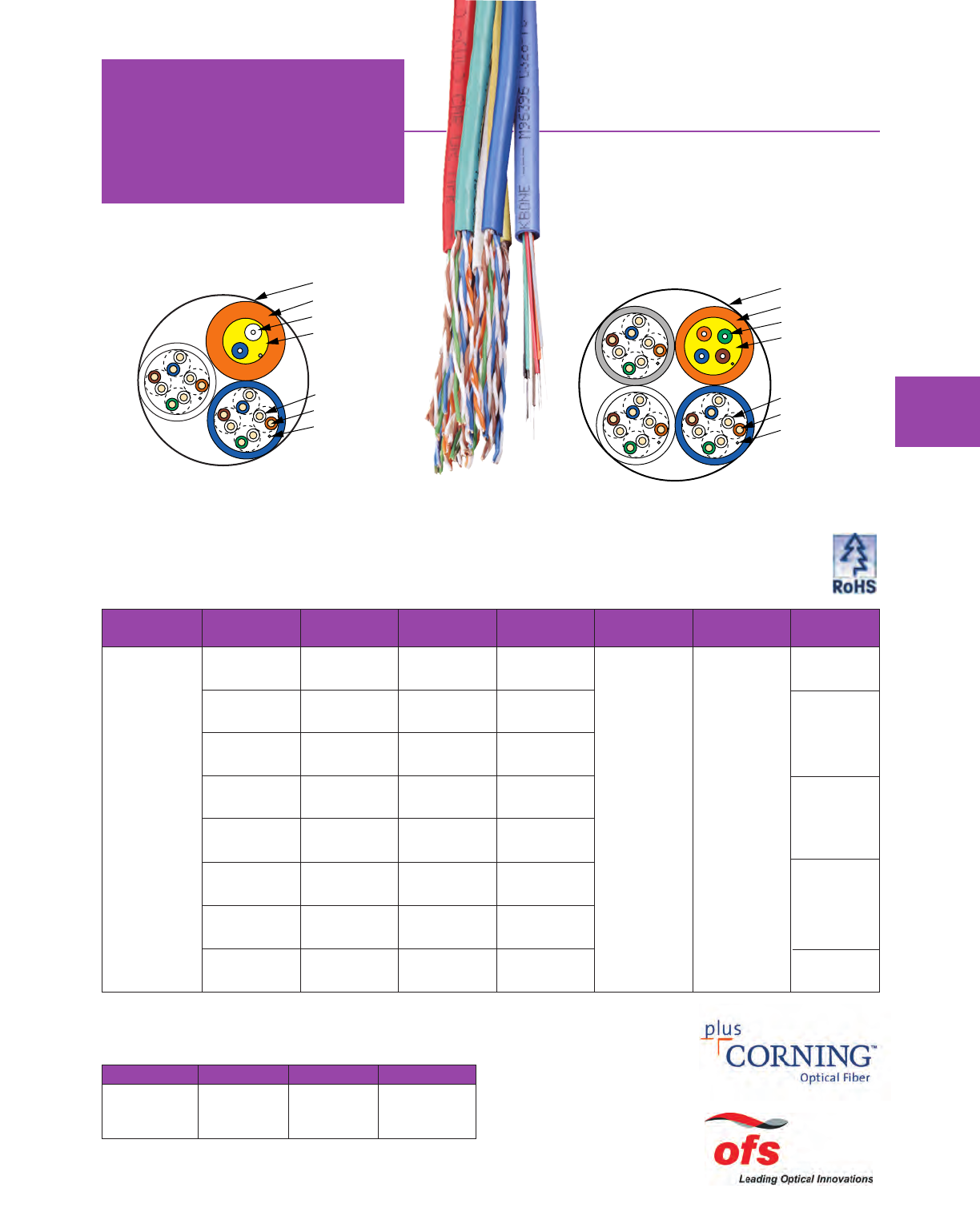
Number Component Component Jacket Cable Diameter Weight
Mohawk of Cable Dielectric Type Diameter lbs/ kg/ Listings
Part No. Components Type Type inch mm inch mm M' km
Both Fiber Optic & Copper Cables in
One Media Pull™Package
Special Applications
Bundled Cables
Number Component Component Jacket Cable DiameterMohawk of Cable Dielectric Type Diameter Weight Listings
Part No. Components Type Type inch mm inch mm lbs/M' kg/km
Media Pull Category 5 UTP Copper & AdvanceLite®Fiber Optic Components
*Plenum rated Thermoplastic.
Fiber Optic Component jacket colors: orange for multimode, yellow for single-mode.
M96632 2 4 PAIR FEP Thermoplen®* .351 8.92 60 89 C(UL)US
24 AWG .180 4.57 CMP
UTP
1 2 FIBER MM ThermoPlen®* Thermoplen®* UL, c(UL)
(62.5/125) .184 4.67 OFNP
DISTRIBUTION OFN FT6
M95830 3 4 PAIR FEP Thermoplen®* .387 9.83 83 124 C(UL)US
24 AWG .180 4.57 CMP
UTP
1 4 FIBER MM ThermoPlen®* Thermoplen®* UL, c(UL)
(62.5/125) .174 4.42 OFNP
DISTRIBUTION OFN FT6
Media Pull Bundled Cables are also available with Enhanced
Copper Cables, AdvanceLite Fiber Cables and Coaxial Cables.
M96512 2 4 PAIR Thermoplastic PVC .374 9.50 64 95 C(UL)US
24 AWG .198 5.03 CMR
UTP
1 2 FIBER MM PVC PVC UL, c(UL)
(62.5/125) .184 4.67 OFNR
DISTRIBUTION OFN FT4
M96633 3 4 PAIR Thermoplastic PVC .431 10.95 85 126 C(UL)US
24 AWG .198 5.03 CMR
UTP
1 4 FIBER MM PVC PVC UL, c(UL)
(62.5/125) .200 5.08 OFNR
DISTRIBUTION OFN FT4
Component Jacket Colors
Jacket Color Cable # Jacket Color Cable #
Blue 1 Yellow 4
White 2Green 5
Gray 3 Pink 6
BINDER
JACKET
BUFFERED FIBER
STRENGTH MEMBERS
INSULATION
CONDUCTOR
RIPCORD
BINDER
JACKET
BUFFERED FIBER
STRENGTH MEMBERS
INSULATION
CONDUCTOR
RIPCORD
For pair colors see chart A on page 59.
MOHAWK 31
AdvanceLite®
Fiber Optic Cables
32 MOHAWK
Mohawk has been manufacturing and testing fiber
optic cable in accordance with many industry
standards, including Telcordia, RUS and TIA/EIA,
since 1990. Cables are listed by Underwriters
Laboratories (UL) for compliance with the National
Electrical Code and Canadian Electrical Code.
Cables are available with fiber counts ranging from 1
to 216 in multimode, single-mode or hybrid versions.
They are compatible with all major manufacturers’
connectivity hardware, including LID fusion splicers.
Mohawk’s ISO 9001 registration assures our
customers of consistent quality. Also, by working
closely with customers, vendors, and industry
organizations, Mohawk can help determine the best
solution for a given application.
AdvanceLite features fiber optimized for laser-based
protocols, yet these cables are still compatible with
LED systems. They provide guaranteed link lengths
to handle multi-gigabit transmission while maintaining
full compatibility with existing installed FDDI-grade
cable.
Multimode —
Grade 6 is a 50/125 fiber that exceeds
TIA/EIA-568-B.3-1 (ISO 11801 OM3) for 500-meter
lengths at 10 Gigabit data rates.
Grade 5 is a 50/125 fiber that complies with
TIA/EIA-568-B.3-1 (ISO 11801 OM3) for 300-meter
lengths at 10 Gigabit data rates. (Formerly
AdvanceLite 2000)
Grade 4 is a 50/125 fiber that complies with
TIA/EIA-568-B.3 (ISO 11801 OM2) and provides
600-meter link lengths for Gigabit Ethernet. (Formerly
AdvanceLite 600)
Grade 3 is a 62.5/125 fiber that complies with
TIA/EIA-568-B.3 (ISO 11801 OM1) and provides up to
1000-meter link lengths for Gigabit Ethernet. (Formerly
AdvanceLite 1000)
Grade 2 is a 62.5/125 fiber that complies with
TIA/EIA-568-B.3 (ISO 11801 OM1) and provides up to
550-meter link lengths for Gigabit Ethernet. (Formerly
AdvanceLite 300)
Grade 1 is FDDI grade 62.5/125 fiber and is the
majority
of the currently installed base of cable. Not
recommended for future installations except as patch
cordage.
Single-Mode —
Grade SM2 is a single-mode fiber that complies with
ITU G.652.c/d. This is a low water peak fiber with
advantages for CWDM applications.
Grade SM1 is a single-mode fiber that complies with
ITU G.652.a/b.
Mohawk’s Range of Fiber Optic Cables for Gigabit Applications
Multimode Fiber Grade Selector
Short Wavelength or Long Wavelength, 50/125 micron
or 62.5/125 micron, we have a solution for you.
Mohawk has designed our Fiber Grade Selector to
help you determine which
multimode fiber type best
suits your application.
Legacy installations to
emerging networking
protocols are identified
and the guaranteed
performance of each fiber
is given along with the
appropriate optical
specifications.
Optical Fibers Supplied By:
Fiber Optic Inventory
When you need fiber optic cabling fast, Mohawk is
ready and waiting for you. We stock over 100 of our
most popular fiber optic cables, which can be
shipped from our warehouse with no minimum order
quantity necessary. Specific part numbers are listed
on page 58, where you may determine if the cable you
require is an inventory item.* *Mohawk reserves the right to modify managed inventory items at any time with or
without notice.
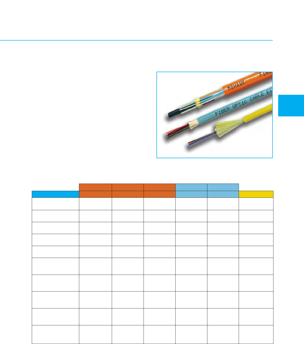
OM3 OM3
OM1 OM1 OM2
Grade 2 3 456SM2
Glass Type
62.5/125 MM 62.5/125 MM 50/125 MM 50/125 MM 50/125 MM Single-Mode
AdvanceLite AdvanceLite AdvanceLite AdvanceLite AdvanceLite Enhanced
6
Part Number Code BDACE W
(X)
Operating Wavelength 850/1300 850/1300 850/1300 850/1300 850/1300 1310/1550
(nm)
Min. OFL
1
Bandwidth 200/500 200/500 500/500 1500/500 3000/500 —
(MHz-km)
Min. Laser
2
Bandwidth 220/500 385/500 510/500 2000/500 4700/500 —
(MHz-km)
Max. Attenuation
Loose Tube 3.25/1.0 3.25/1.0 3.0/1.0 3.0/1.0 3.0/1.0 0.40/0.30
(dB/km)
Max. Attenuation
Tight Buffered
3
3.50/1.25 3.50/1.25 3.50/1.25 3.50/1.25 3.50/1.25 0.80/0.50
(dB/km)
100 Mbit Fast Ethernet
Min. Link Length 300/2000 300/2000 300/2000 300/2000 300/2000 5000/—
(meters S/L/E
4
)
1 Gigabit Ethernet
Min. Link Length 300/550 500/1000 600/600 1000
5
/600 1000
5
/600 5000/—
(meters S/L/E
4
)
10 Gigabit Ethernet
Min. Link Length 33/300 33/300 82/300 300/300 550/300 10,000/
(meters S/L/E
4
)40,000
1OFL – Overfilled Launch
2Effective Modal Bandwidth, determined by RML or
DMD performance specifications
3Max. Attenuation for Tight Buffered, Ribbon,
Micro-Loose Tube & VersaLite Cables
4S/L/E – Short wavelength (850 nm) / Long
wavelength (1310 nm) / Extra long wavelength
(1550 nm)
5>2000 meters for engineered links
6Low water peak Single-Mode suitable for
CWDM use complies with ITU G.652.c/d
Optical Characteristics
Meets or exceeds ISO/IEC 11801
MOHAWK 33
Jacket Colors
For outside plant cables, the standard jacket color
is black. This includes loose tube, RiserLite®and
VersaLite™ cables.
For tight buffered cables, excluding simplex and
duplex, the following is the standard jacket color
code:
Grades 2, 3, 4 — Orange
Grades 5, 6 — Aqua
Grades SM2 — Yellow
Non-standard jacket colors are available.
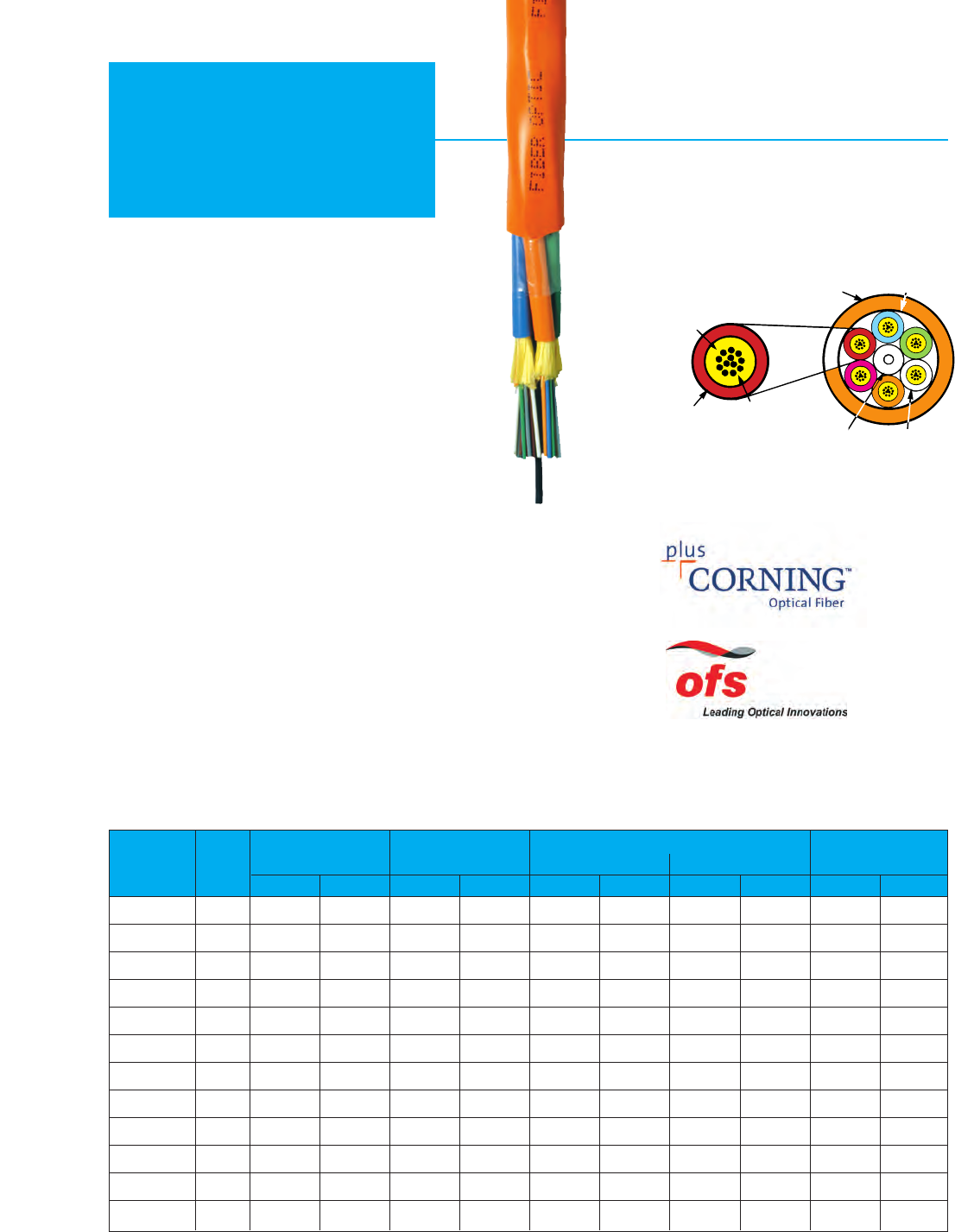
34 MOHAWK
Riser
Distribution
Weight
Outside
Diameter Short Term Long Term
Max. Load
(Installation)
Min. Bend Radius
2-12 Fibers
ARAMID STRENGTH
ELEMENTS
COLOR
CODED
JACKET
SPECIFIED FIBER
(COLOR CODED)
BUNDLES OF UP TO
12 FIBERS EACH
UPJACKETED
CENTRAL
STRENGTH
ELEMENT
FIBER BUNDLE DETAIL
OUTER JACKET
>12-144 Fibers
OVERALL POLYESTER
TAPE BARRIER
Recommended Applications
•Riser cabling
•Office cabling
•Computer room cabling
Product Features
•900 µm tight buffered fibers
•Color coded for easy termination
•Flame Retardant
•UL listed for code compliance
•MSHA approved cables are available
Mechanical, Environmental & Flame Characteristics
•Crush Resistance (EIA-455-41) 2000 N/cm
•Impact Resistance (EIA-455-25) 2000 Impacts
w/1.6 N-m
•Flexure (EIA-455-104) 2000 cycles min.
•Min. Bend Radius Long Term – No Load 10x Cable diameter
•Min. Bend Radius Short Term – Load 15x Cable diameter
•Operating Temp. – –20°C to +70°C
•Installation Temp. – –10°C to +60°C
•Storage Temp. – –40°C to +80°C
•UL/c(UL) Rated Type OFNR / OFN FT4
•Flame Resistance UL 1666 Passed
Riser UL/c(UL) Type OFNR / OFN FT4
AdvanceLite®
Part Fiber
Number Count mm in. kg/km lbs/M' cm in. cm in. Newtons lbs.
M9X037 24.67 .184 19 13 7.0 2.8 4.7 1.8 801 180
M9X038 4 5.08 .200 24 16 7.6 3.0 5.1 2.0 867 195
M9X039 6 5.59 .220 28 19 8.4 3.3 5.6 2.2 1201 270
M9X040 8 5.97 .235 33 22 8.9 3.5 6.1 2.4 1201 270
M9X042 12 6.48 .255 40 27 9.6 3.8 6.6 2.6 1334 300
M9X601* 24 8.26 .325 63 42 12.4 4.9 8.4 3.3 1735 390
M9X602 24 12.60 .496 124 83 18.8 7.4 12.7 5.0 4270 960
M9X604 36 16.36 .644 204 137 24.6 9.7 16.5 6.4 6405 1440
M9X606 48 15.93 .627 195 131 23.9 9.4 16.0 6.3 4203 945
M9X609 72 19.10 .750 290 195 28.6 11.3 19.1 7.5 6005 1350
M9X622 96 22.73 .895 432 290 34.0 13.4 22.9 9.0 8820 1983
M9X619 144 24.49 .964 467 314 36.8 14.5 24.4 9.6 12,210 2745
For “X” in part number see optical characteristics on page 33. *Single jacket version.
For Buffer and Inner Jacket colors see chart C on page 59.
Product Note: May be suitable for outdoor installations. Refer to Technical Advisory on page 66.
Stocked items available! See page 58 for specific part numbers in our inventory.
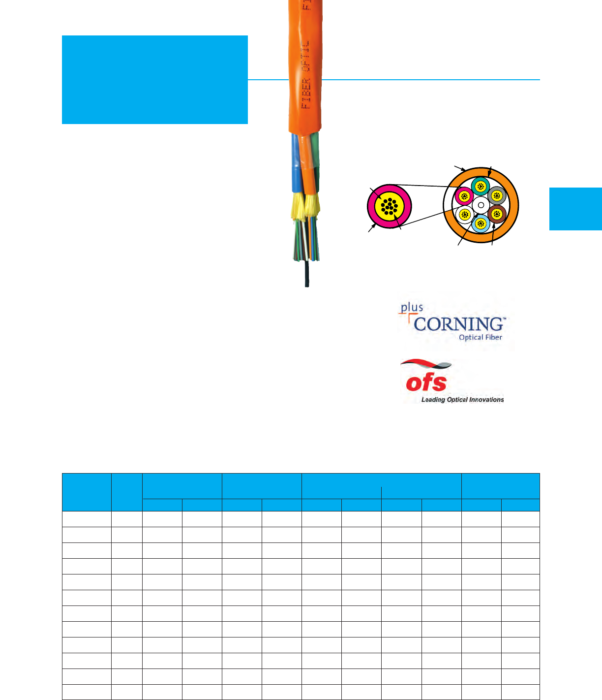
MOHAWK 35
Plenum
Distribution
For “X” in part number see optical characteristics on page 33. *Single jacket version.
For Buffer and Inner Jacket colors see chart C on page 59.
ARAMID STRENGTH
ELEMENTS
COLOR
CODED
JACKET
SPECIFIED FIBER
(COLOR CODED) BUNDLES OF UP TO
12 FIBERS EACH
UPJACKETED
CENTRAL
STRENGTH
ELEMENT
FIBER BUNDLE DETAIL
OUTER JACKET
OVERALL POLYESTER
TAPE BARRIER
2-12 Fibers
>12-144 Fibers
Recommended Applications
•Plenum or Riser cabling
•Office cabling
•Computer room cabling
Product Features
•900 µm tight buffered fibers
•Color coded for easy termination
•Flame Retardant
•UL listed for code compliance
Mechanical, Environmental & Flame Characteristics
•Crush Resistance (EIA-455-41) 2000 N/cm
•Impact Resistance (EIA-455-25) 2000 Impacts
w/1.6 N-m
•Flexure (EIA-455-104) 2000 cycles min.
•Min. Bend Radius Long Term – No Load 10x Cable diameter
•Min. Bend Radius Short Term – Load 15x Cable diameter
•Operating Temp. – –20°C to +70°C
•Installation Temp. – 0°C to +60°C
•Storage Temp. – –40°C to +80°C
•UL/c(UL) Rated Type OFNP / OFN FT6
•Flame Resistance UL 910 Passed
Plenum UL/c(UL) Type OFNP / OFN FT6
Weight
Outside
Diameter Short Term Long Term
Max. Load
(Installation)
Min. Bend Radius
Part Fiber
Number Count mm in. kg/km lbs/M' cm in. cm in. Newtons lbs.
M9X043 24.67 .184 21 14 7.0 2.8 4.7 1.8 801 180
M9X044 4 4.42 .174 19 13 7.0 2.8 4.7 1.8 867 195
M9X045 6 4.83 .190 24 16 7.6 3.0 5.1 2.0 1201 270
M9X046 8 5.64 .222 28 19 8.5 3.3 5.6 2.2 1201 270
M9X048 12 5.72 .225 33 22 8.6 3.4 5.8 2.3 1334 300
M9X611* 24 8.38 .330 60 40 12.4 4.9 8.4 3.3 1735 390
M9X612 24 12.52 .493 132 89 19.0 7.5 12.6 5.0 5618 1263
M9X614 36 15.09 .594 199 134 22.6 8.9 15.0 5.9 8509 1913
M9X616 48 15.21 .599 195 131 22.9 9.0 15.2 6.0 5538 1245
M9X620 72 19.15 .754 293 197 28.7 11.3 19.1 7.5 9310 2093
M9X623 96 22.96 .904 478 321 34.5 13.6 22.9 9.0 10,422 2343
M9X621 144 26.59 1.047 539 362 39.9 15.7 26.7 10.5 16,213 3645
Stocked items available! See page 58 for specific part numbers in our inventory.
AdvanceLite®
Product Note: May be suitable for outdoor installations. Refer to Technical Advisory on page 66.
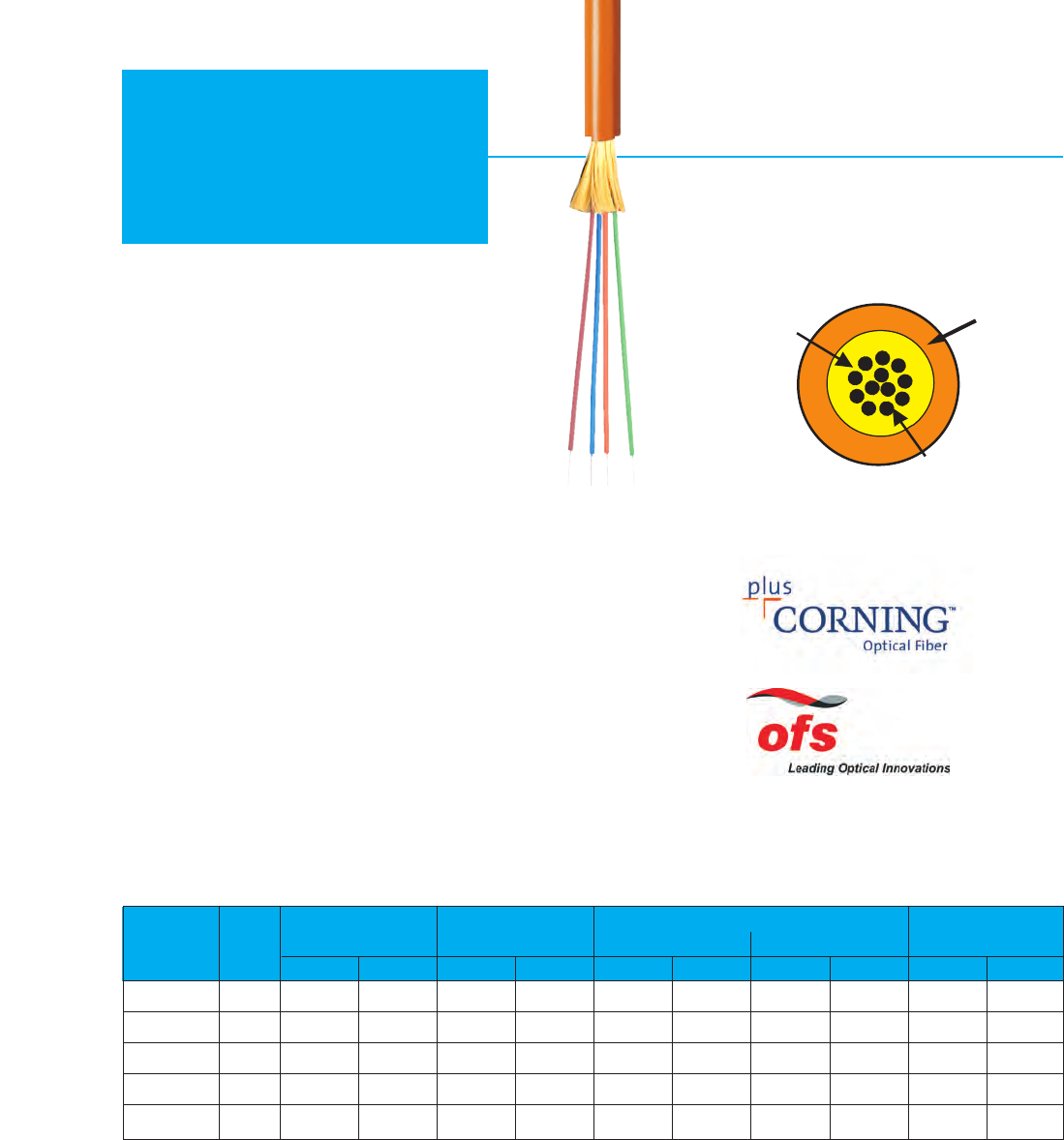
Light Duty – Low Smoke Zero Halogen
Riser UL/c(UL) Type OFNR / OFN FT4
36 MOHAWK
LSZH
Distribution
ARAMID STRENGTH
ELEMENTS
LSZH JACKET
SPECIFIED FIBER
(COLOR CODED)
Recommended Applications
•Riser cabling
•Office cabling
•Computer room cabling
Product Features
•900 µm tight buffered fibers
•Color coded for easy termination
•Flame Retardant
•UL listed for code compliance
Mechanical, Environmental & Flame Characteristics
•Crush Resistance (EIA-455-41) 2000 N/cm
•Impact Resistance (EIA-455-25) 2000 Impacts
w/1.6 N-m
•Flexure (EIA-455-104) 2000 cycles min.
•Min. Bend Radius Long Term – No Load 10x Cable diameter
•Min. Bend Radius Short Term – Load 15x Cable diameter
•Operating Temp. – –20°C to +70°C
•Installation Temp. – –10°C to +60°C
•Storage Temp. – –40°C to +80°C
•UL/c(UL) Rated Type OFNR / OFN FT4
•Flame Resistance UL 1666 Passed
For “X” in part number see optical characteristics on page 33.
For Buffer colors see chart C on page 59.
Weight
Outside
Diameter Short Term Long Term
Max. Load
(Installation)
Min. Bend Radius
Part Fiber
Number Count mm in. kg/km lbs/M' cm in. cm in. Newtons lbs.
M9X100 24.7 .184 22 15 7.1 2.8 4.6 1.8 801 180
M9X101 4 5.1 .200 25 17 7.6 3.0 5.1 2.0 867 195
M9X102 6 5.6 .220 31 21 8.4 3.3 5.6 2.2 1201 270
M9X103 86.0 .235 36 24 8.9 3.5 6.1 2.4 1201 270
M9X104 12 6.5 .255 43 29 9.7 3.8 6.6 2.6 1334 300
AdvanceLite®
Product Note: May be suitable for outdoor installations. Refer to Technical Advisory on page 66.
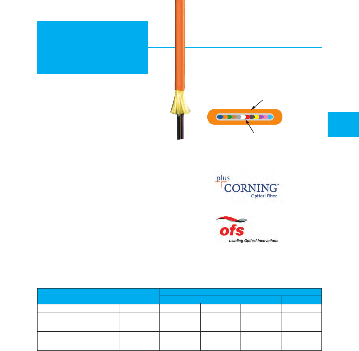
Riser Part Plenum Part Fiber Outside Diameter Weight
Number Number Count mm in. kg/km lbs/M’
M9X630 M9X640 2 2.9 .114 7 5
M9X631 M9X641 42.0 x 2.9 .078 x .115 6 4
M9X632 M9X642 6 2.0 x 3.5 .078 x .137 9 6
M9X633 M9X643 8 2.0 x 4.0 .078 x .158 9 6
M9X634 M9X644 12 2.0 x 4.6 .078 x .180 10 7
Riser UL/c(UL) Type OFNR / OFN FT4
Plenum UL/c(UL) Type OFNP / OFN FT6
MOHAWK 37
Riser & Plenum
Ribbon Cables
For “X” in part number see optical characteristics on page 33.
For Buffer colors see chart C on page 59.
Recommended Applications
•Inter-equipment connections
•NEBS applications
Product Features
•Color coded fibers
•Suitable for use with standard ribbon connectors
•Half-inch minimum bend radius
•Tight center-to-center tolerances
•Optional identification printing available
•OFNR or OFNP Rated
Mechanical, Environmental & Flame Characteristics
•Crush Resistance (EIA-455-41) 2000 N/cm
•Impact Resistance (EIA-455-25)
2000 Impacts w/1.6 N-m
•Flexure (EIA-455-104) 2000 cycles min.
•Min. Bend Radius
Long Term – No Load
10x Cable diameter
•Min. Bend Radius Short Term – Load 15x Cable diameter
•Short Term Load FOTP-33 100 lbs (444N)
•Operating Temp. – –20°C to +70°C
•Installation Temp. – 0°C to +60°C
•Storage Temp. – –40°C to +80°C
•UL/c(UL) Rated Type OFNR / OFN FT4
•Flame Resistance UL 1666 Passed
•UL/c(UL) Rated Type OFNP / OFN FT6
•Flame Resistance UL 910 Passed
OUTER JACKET
RIBBON FIBER
Stocked items available! See page 58 for specific part numbers in our inventory.
AdvanceLite®
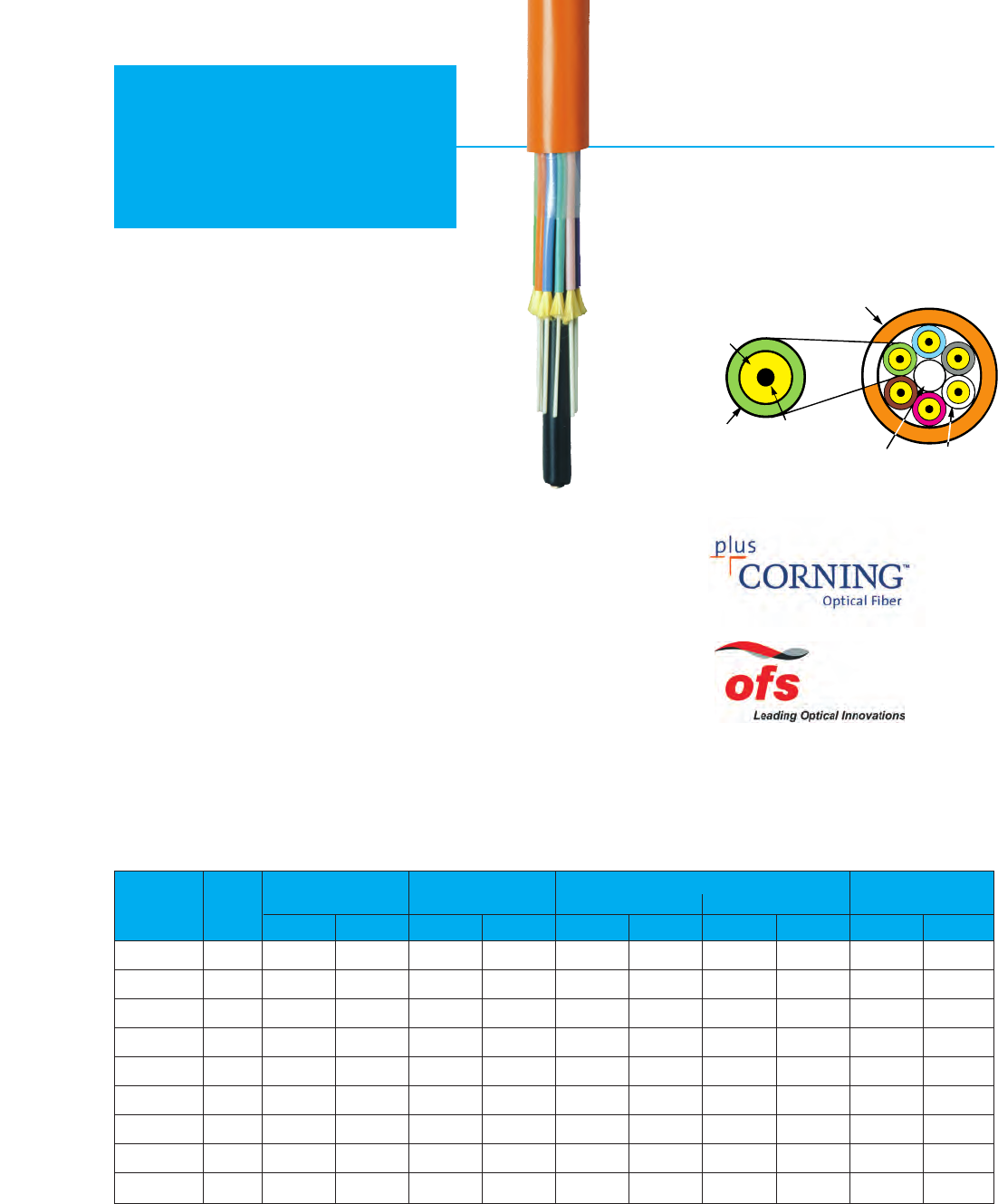
38 MOHAWK
Riser
Breakout 2.0 mm sub-unit –
Riser UL/c(UL) Type OFNR / OFN FT4
ARAMID STRENGTH
ELEMENTS
COLOR CODED
THERMOPLASTIC
JACKET
900 MICRON
TIGHT BUFFERED
FIBER 2.0 mm SUB-UNITS
CENTRAL MEMBER
SUB-UNIT DETAIL OUTER JACKET
Recommended Applications
•Riser cabling (typically under 300 meters)
•Office cabling
•Computer room cabling
Product Features
•900 µm tight buffered fibers
•Color coded for easy termination
•Flame Retardant
•UL listed for code compliance
•Direct connectorization
•MSHA approved cables are available
Mechanical, Environmental & Flame Characteristics
•Crush Resistance (EIA-455-41) 2000 N/cm
•Impact Resistance (EIA-455-25) 2000 Impacts
w/1.6 N-m
•Flexure (EIA-455-104) 2000 cycles min.
•Min. Bend Radius Long Term – No Load 10x Cable diameter
•Min. Bend Radius Short Term – Load 15x Cable diameter
•Operating Temp. – –20°C to +70°C
•Installation Temp. – –10°C to +60°C
•Storage Temp. – –40°C to +80°C
•UL/c(UL) Rated Type OFNR / OFN FT4
•Flame Resistance UL 1666 Passed
For “X” in part number see optical characteristics on page 33.
For fiber counts 2 – 12 see chart C on page 59. For greater than 12 fibers, jackets are orange or aqua (MM) or yellow (SM) and numbered.
Weight
Outside
Diameter Short Term Long Term
Max. Load
(Installation)
Min. Bend Radius
Part Fiber
Number Count mm in. kg/km lbs/M' cm in. cm in. Newtons lbs.
M9X005 26.60 .260 36 24 9.9 3.9 6.6 2.6 1068 240
M9X006 4 8.15 .321 52 35 12.2 4.8 8.1 3.2 1535 345
M9X007 6 9.09 .358 80 54 13.6 5.4 9.1 3.6 2415 543
M9X008 8 10.29 .405 103 69 15.4 6.1 10.3 4.1 2700 600
M9X009 10 11.56 .455 128 86 17.3 6.8 11.5 4.5 2700 600
M9X010 12 13.06 .514 164 110 19.6 7.7 13.1 5.1 2700 600
M9X011 18 13.21 .520 155 104 19.8 7.8 13.2 5.2 2700 600
M9X012 24 14.99 .590 201 135 22.6 8.9 15.0 5.9 2700 600
M9X083 36 17.27 .680 250 168 25.9 10.2 17.3 6.8 2700 600
AdvanceLite®
Product Note: May be suitable for outdoor installations. Refer to Technical Advisory on page 66.
Stocked items available! See page 58 for specific part numbers in our inventory.
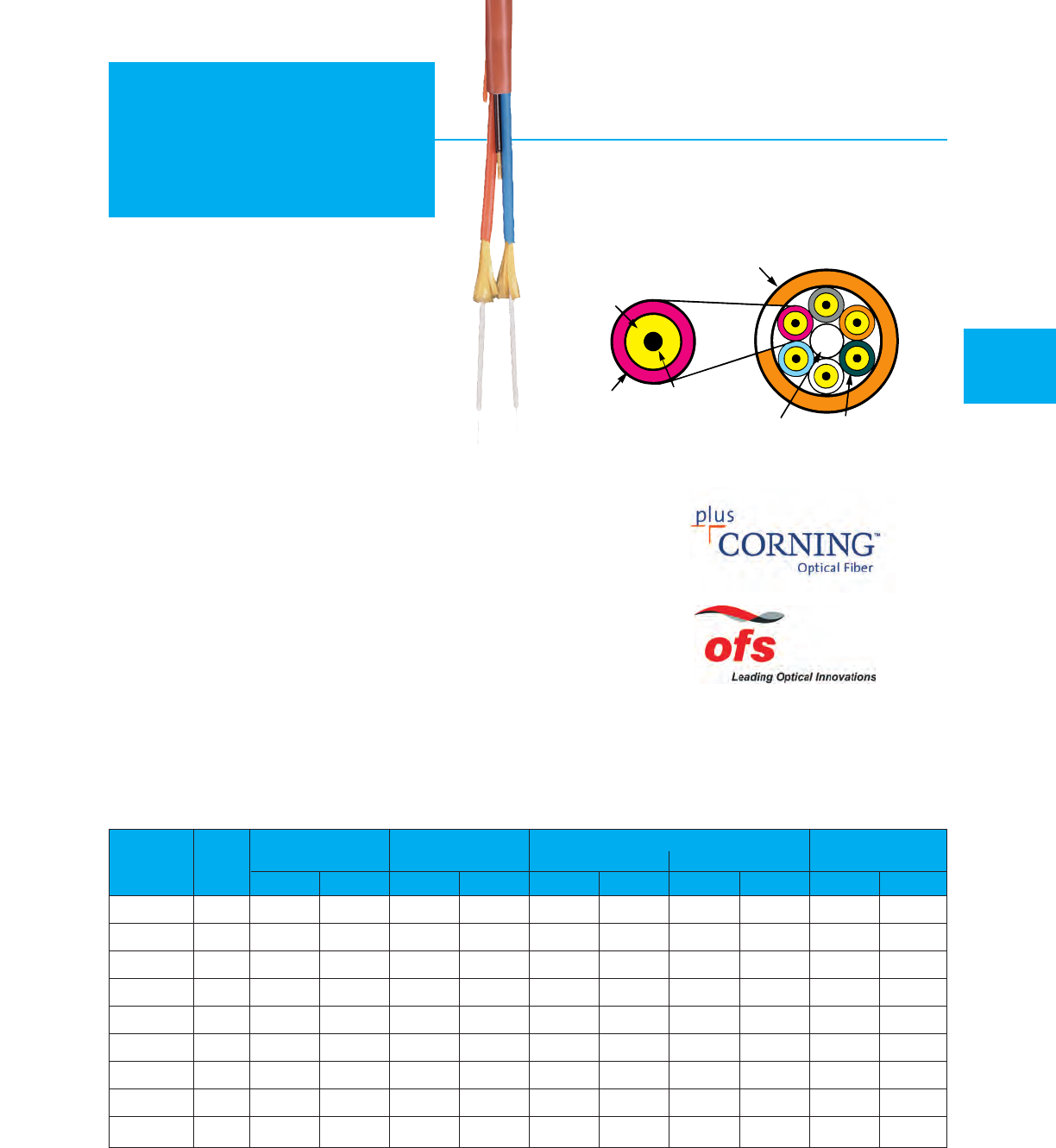
2.0 mm sub-unit –
Plenum UL/c(UL) Type OFNP / OFN FT6
MOHAWK 39
Plenum
Breakout
For “X” in part number see optical characteristics on page 33.
For fiber counts 2 – 12 see chart C on page 59. For greater than 12 fibers, jackets are orange or aqua (MM) or yellow (SM) and numbered.
900 MICRON
TIGHT BUFFERED
FIBER 2.0 mm SUB-UNITS
CENTRAL MEMBER
SUB-UNIT DETAIL OUTER JACKET
Recommended Applications
•Plenum and Riser cabling
•Office cabling
•Computer room cabling
Product Features
•900 µm tight buffered fibers
•Color coded for easy termination
•Flame Retardant
•UL listed for code compliance
•Direct connectorization
Mechanical, Environmental & Flame Characteristics
•Crush Resistance (EIA-455-41) 2000 N/cm
•Impact Resistance (EIA-455-25) 2000 Impacts
w/1.6 N-m
•Flexure (EIA-455-104) 2000 cycles min.
•Min. Bend Radius Long Term – No Load 10x Cable diameter
•Min. Bend Radius Short Term – Load 15x Cable diameter
•Operating Temp. – –20°C to +70°C
•Installation T
emp. – 0°C to +60°C
•Storage Temp. – –40°C to +80°C
•UL/c(UL) Rated Type OFNP / OFN FT6
•Flame Resistance UL 910 Passed
Weight
Outside
Diameter Short Term Long Term
Max. Load
(Installation)
Min. Bend Radius
ARAMID STRENGTH
ELEMENTS
COLOR CODED
THERMOPLASTIC
JACKET
Part Fiber
Number Count mm in. kg/km lbs/M' cm in. cm in. Newtons lbs.
M9X013 25.84 .230 30 20 8.9 3.5 5.8 2.3 801 180
M9X014 4 6.68 .263 45 30 9.9 3.9 6.6 2.6 1535 345
M9X015 6 7.85 .309 61 41 11.7 4.6 7.9 3.1 2068 465
M9X016 8 8.53 .336 82 55 13.0 5.1 8.7 3.4 2700 600
M9X017 10 9.78 .385 109 73 14.7 5.8 9.8 3.9 2700 600
M9X018 12 9.93 .391 89 60 15.0 5.9 9.9 3.9 2700 600
M9X019 18 11.58 .456 132 89 17.3 6.8 11.4 4.5 2700 600
M9X020 24 13.82 .544 174 117 20.6 8.1 13.7 5.4 2700 600
M9X082 36 15.54 .612 229 154 23.6 9.3 15.7 6.2 2700 600
Product Note: May be suitable for outdoor installations. Refer to Technical Advisory on page 66.
Stocked items available! See page 58 for specific part numbers in our inventory.
AdvanceLite®
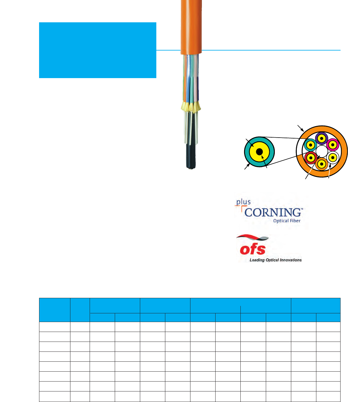
2.5 mm sub-unit –
Riser UL/c(UL) Type OFNR / OFN FT4
40 MOHAWK
Riser
Breakout
For “X” in part number see optical characteristics on page 33.
For fiber counts 2 – 12 see chart C on page 59. For greater than 12 fibers, jackets are orange or aqua (MM) or yellow (SM) and numbered.
ARAMID STRENGTH
ELEMENTS
COLOR CODED
THERMOPLASTIC
JACKET
900 MICRON
TIGHT BUFFERED
FIBER 2.5 mm SUB-UNITS
CENTRAL MEMBER
SUB-UNIT DETAIL OUTER JACKET
Recommended Applications
•Riser cabling
•Office cabling
•Computer room cabling
Product Features
•900 µm tight buffered fibers
•Color coded for easy termination
•Flame Retardant
•UL listed for code compliance
•Direct connectorization
•MSHA approved cables are available
Mechanical, Environmental & Flame Characteristics
•Crush Resistance (EIA-455-41) 2000 N/cm
•Impact Resistance (EIA-455-25) 2000 Impacts
w/1.6 N-m
•Flexure (EIA-455-104) 2000 cycles min.
•Min. Bend Radius Long Term – No Load 10x Cable diameter
•Min. Bend Radius Short Term – Load 15x Cable diameter
•Operating Temp. – –20°C to +70°C
•Installation Temp. – –10°C to +60°C
•Storage Temp. – –40°C to +80°C
•UL/c(UL) Rated Type OFNR / OFN FT4
•Flame Resistance UL 1666 Passed
Weight
Outside
Diameter Short Term Long Term
Max. Load
(Installation)
Min. Bend Radius
Part Fiber
Number Count mm in. kg/km lbs/M' cm in. cm in. Newtons lbs.
M9X021 27.62 .300 45 30 11.4 4.5 7.6 3.0 1068 240
M9X022 4 9.17 .361 64 43 13.7 5.4 9.1 3.6 1535 345
M9X023 6 10.67 .420 104 70 15.9 6.3 10.6 4.2 2700 600
M9X024 8 12.14 .478 135 91 18.2 7.2 12.1 4.8 2700 600
M9X025 10 13.72 .540 202 136 20.6 8.1 13.7 5.4 2700 600
M9X026 12 15.60 .614 220 148 23.4 9.2 15.6 6.1 2700 600
M9X027 18 15.75 .620 205 138 23.6 9.3 15.7 6.2 2700 600
M9X028 24 17.98 .708 271 182 26.9 10.6 18.0 7.1 2700 600
AdvanceLite®
Product Note: May be suitable for outdoor installations. Refer to Technical Advisory on page 66.
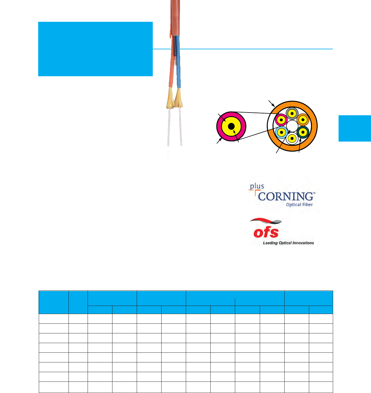
Weight
Part Fiber
Number Count mm in. kg/km lbs/M' cm in. cm in. Newtons lbs.
M9X029 2 6.88 .271 39 26 10.4 4.1 6.9 2.7 801 180
M9X030 4 7.72 .304 58 39 11.4 4.5 7.6 3.0 1535 345
M9X031 68.84 .348 82 55 13.2 5.2 8.9 3.5 2700 600
M9X032 8 10.36 .408 113 76 15.5 6.1 10.4 4.1 2700 600
M9X033 10 11.94 .470 149 100 17.9 7.1 11.9 4.7 2700 600
M9X034 12 11.96 .471 119 80 17.9 7.1 11.9 4.7 2700 600
M9X035 18 14.12 .556 179 120 21.1 8.3 14.2 5.6 2700 600
M9X036 24 16.94 .667 234 157 25.4 10.0 17.0 6.7 2700 600
Outside
Diameter Short Term Long Term
Max. Load
(Installation)
Min. Bend Radius
2.5 mm sub-units –
Plenum UL/c(UL) Type OFNP / OFN FT6
MOHAWK 41
Plenum
Breakout
For “X” in part number see optical characteristics on page 33.
For fiber counts 2 – 12 see chart C on page 59. For greater than 12 fibers, jackets are orange or aqua (MM) or yellow (SM) and numbered.
ARAMID STRENGTH
ELEMENTS
COLOR CODED
THERMOPLASTIC
JACKET
900 MICRON
TIGHT BUFFERED
FIBER 2.5 mm SUB-UNITS
CENTRAL MEMBER
SUB-UNIT DETAIL OUTER JACKET
Recommended Applications
•Plenum and Riser cabling
•Office cabling
•Computer room cabling
Product Features
•900 µm tight buffered fibers
•Color coded for easy termination
•Flame Retardant
•UL listed for code compliance
•Direct connectorization
Mechanical, Environmental & Flame Characteristics
•Crush Resistance (EIA-455-41) 2000 N/cm
•Impact Resistance (EIA-455-25) 2000 Impacts
w/1.6 N-m
•Flexure (EIA-455-104) 2000 cycles min.
•Min. Bend Radius Long Term – No Load 10x Cable diameter
•Min. Bend Radius Short Term – Load 15x Cable diameter
•Operating Temp. – –20°C to +70°C
•Installation Temp. – 0°C to +60°C
•Storage Temp. – –40°C to +80°C
•UL/c(UL) Rated Type OFNP / OFN FT6
•Flame Resistance UL 910 Passed
Product Note: May be suitable for outdoor installations. Refer to Technical Advisory on page 66.
AdvanceLite®
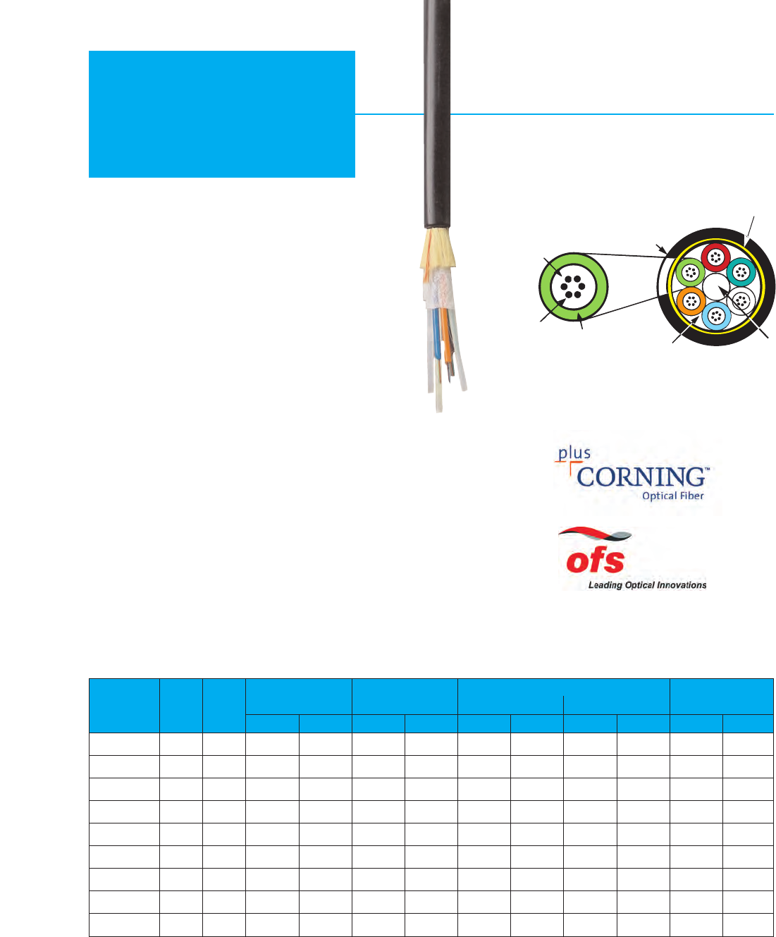
42 MOHAWK
Outdoor
Loose Tube Outdoor
Fibers
Part Fiber Per
Number Count Tube mm in. kg/km lbs/M' cm in. cm in. Newtons lbs.
M9X510T 6 6 9.65 .380 65 44 19.3 7.6 14.5 5.7 2700 600
M9X511T 12 69.65 .380 65 44 19.3 7.6 14.5 5.7 2700 600
M9X500T 24 6 9.65 .380 67 45 19.3 7.6 14.5 5.7 2700 600
M9X502T 36 6 9.65 .380 70 47 19.3 7.6 14.5 5.7 2700 600
M9X505T 48 12 12.19 .480 104 70 24.4 9.6 18.3 7.2 2700 600
M9X507T 72 12 12.19 .480 104 70 24.4 9.6 18.3 7.2 2700 600
M9X513T 96 12 13.89 .547 138 93 27.7 10.9 20.8 8.1 2700 600
M9X509T 144 12 17.78 .700 222 149 35.6 14.0 26.7 10.5 2700 600
M9X520T 216 12 18.16 .715 220 148 36.3 14.3 27.2 10.7 2700 600
Weight
Outside
Diameter Short Term Long Term
Max. Load
(Installation)
Min. Bend Radius
For “X” in part number see optical characteristics on page 33.
See color chart C on page 59.
THERMOPLASTIC
TUBE CENTRAL
E-GLASS
STRENGTH
MEMBER
WATER
BLOCKING
TAPE
OUTER JACKET
POLYETHYLENE
ARAMID STRENGTH
ELEMENTS
Recommended Applications
•Building interconnections and data trunk
•Long haul networking
•Ducts between buildings and aerial lashing
•Applications requiring good ozone,
moisture, weather resistance
Product Features
•All dielectric central strength member
•Excellent attenuation performance
•Dry water blocking for moisture protection
•Polyethylene jacket for weather and UV protection
•Breakout kits available (see page 53)
•Waterblock gel available
Mechanical & Environmental Characteristics
•Crush Resistance (EIA-455-41) 2000 N/cm
•Impact Resistance (EIA-455-25) 2000 Impacts
w/1.6 N-m
•Min. Bend Radius Long Term – No Load 15x Cable diameter
•Min. Bend Radius Short Term – Load 20x Cable diameter
•Operating Temp. – –40°C to +70°C
•Installation Temp. – –30°C to +60°C
•Storage Temp. – –50°C to +80°C
LOOSE TUBE DETAIL
MOISTURE
BLOCKING
GEL
MULTIPLE
250 MICRON
FIBERS
AdvanceLite®
Stocked items available! See page 58 for specific part numbers in our inventory.
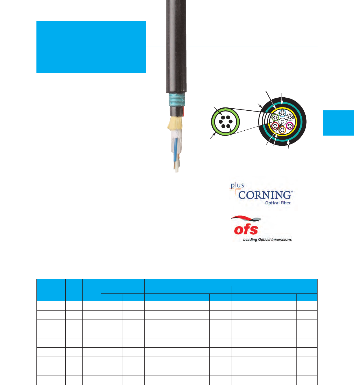
Outdoor Direct Burial – Armored
MOHAWK 43
Armored
Loose Tube
For “X” in part number see optical characteristics on page 33.
See color chart C on page 59.
Fibers
Part Fiber Per
Number Count Tube mm in. kg/km lbs/M' cm in. cm in. Newtons lbs.
M9X381T 6 6 13.46 .530 150 101 26.9 10.6 20.2 8.0 2700 600
M9X382T 12 613.46 .530 152 102 26.9 10.6 20.2 8.0 2700 600
M9X384T 24 6 13.46 .530 153 103 26.9 10.6 20.2 8.0 2700 600
M9X386T 36 6 13.46 .530 155 104 26.9 10.6 20.2 8.0 2700 600
M9X389T 48 12 16.51 .650 214 144 33.0 13.0 24.9 9.8 2700 600
M9X391T 72 12 16.51 .650 211 142 33.0 13.0 24.9 9.8 2700 600
M9X398T 96 12 17.53 .690 250 168 35.1 13.8 26.4 10.4 2700 600
M9X393T 144 12 22.10 .870 359 241 44.2 17.4 33.3 13.1 2700 600
M9X400T 216 12 22.10 .870 359 241 44.2 17.4 33.3 13.1 2700 600
Weight
Outside
Diameter Short Term Long Term
Max. Load
(Installation)
Min. Bend Radius
MOISTURE BLOCKING GEL
THERMO-
PLASTIC TUBE
MULTIPLE
250 MICRON
FIBERS CORRUGATED
STEEL ARMOR
CENTRAL
E-GLASS
STRENGTH
MEMBER
LOOSE TUBE DETAIL
OUTER JACKET
POLYETHYLENE
INNER JACKET
POLYETHYLENE
ARAMID
STRENGTH
ELEMENTS
Recommended Applications
•Building interconnections
•Telecommunications and data trunk
•Long haul networking
•Direct burial and aerial lashing
•Applications requiring good ozone,
moisture, weather resistance
Product Features
•Excellent attenuation performance
•Dry water blocking for moisture protection
•Polyethylene jacket for weather and UV protection
•Breakout kits available (see page 53)
•Corrugated Steel Tape
•Rodent Resistant
•Waterblock gel available
Mechanical & Environmental Characteristics
•Crush Resistance (EIA-455-41) 2000 N/cm
•Impact Resistance (EIA-455-25) 2000 Impacts
w/1.6 N-m
•Min. Bend Radius Long Term – No Load 15x Cable diameter
•Min. Bend Radius Short Term – Load 20x Cable diameter
•Operating Temp. – –40°C to +70°C
•Installation Temp. – –30°C to +60°C
•Storage Temp. – –50°C to +80°C
WATER
BLOCKING
TAPE
Stocked items available! See page 58 for specific part numbers in our inventory.
AdvanceLite®
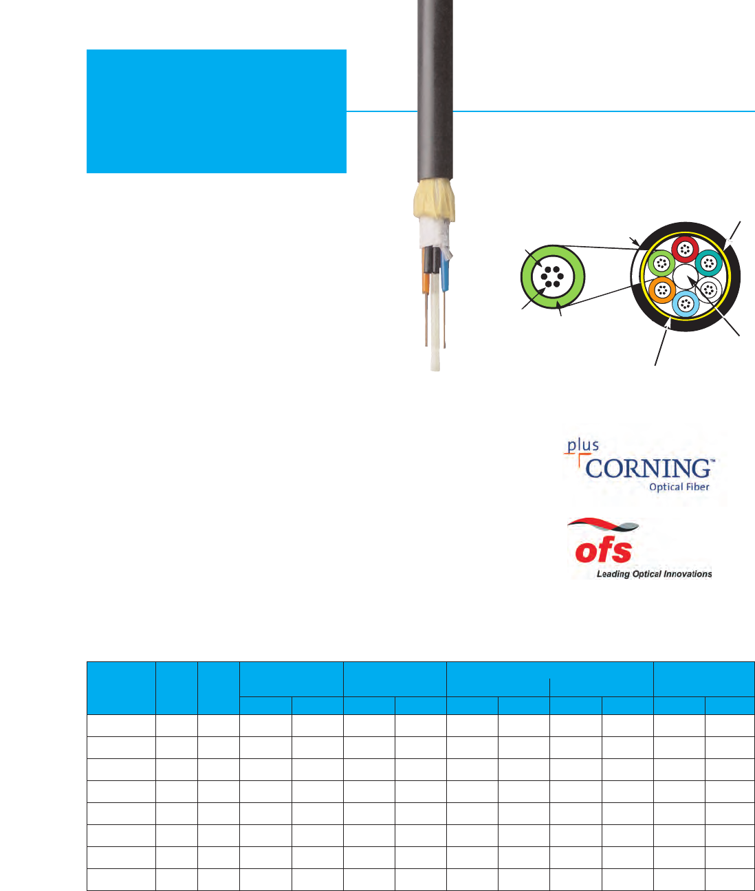
44 MOHAWK
Loose Tube
RiserLite®Indoor/Outdoor –
UL/c(UL) Type OFNR / OFN FT4
For “X” in part number see optical characteristics on page 33.
See color chart C on page 59.
CENTRAL
E-GLASS
STRENGTH
MEMBER
WATERBLOCKING
TAPE
LOOSE TUBE DETAIL
OUTER JACKET
PVC
ARAMID STRENGTH
ELEMENTS
Recommended Applications
•Indoor/outdoor installations
•Telecommunications and data trunk
•Building interconnections
Product Features
•No splicing required at building entrance
•Available with zero-halogen jacket
•Breakout kits available (see page 53)
•Fully waterblocked
Mechanical & Environmental Characteristics
•Crush Resistance (EIA-455-41) 2000 N/cm
•Impact Resistance (EIA-455-25) 2000 Impacts
w/1.6 N-m
•Min. Bend Radius Long Term – No Load 15x Cable diameter
•Min. Bend Radius Short Term – Load 20x Cable diameter
•Operating Temp. – –40°C to +70°C
•Installation Temp. – –20°C to +60°C
•Storage Temp. – –40°C to +80°C
•UL/c(UL) Rated Type OFNR / OFN FT4
•Flame Resistance UL 1666 Passed
Fibers
Part Fiber Per
Number Count Tube mm in. kg/km lbs/M' cm in. cm in. Newtons lbs.
M9X810 6 6 9.65 .380 94 63 19.3 7.6 14.5 5.7 2700 600
M9X811 12 69.65 .380 92 62 19.3 7.6 14.5 5.7 2700 600
M9X812 24 6 9.65 .380 91 61 19.3 7.6 14.5 5.7 2700 600
M9X813 36 6 9.65 .380 89 60 19.3 7.6 14.5 5.7 2700 600
M9X814 48 12 12.19 .480 132 89 24.4 9.6 18.3 7.2 2700 600
M9X815 72 12 12.19 .480 129 87 24.4 9.6 18.3 7.2 2700 600
M9X816 96 12 13.89 .547 170 114 27.7 10.9 20.8 8.2 2700 600
M9X817 144 12 17.78 .700 278 187 35.6 14.0 26.7 10.5 2700 600
Weight
Outside
Diameter Short Term Long Term
Max. Load
(Installation)
Min. Bend Radius
THERMOPLASTIC
TUBE
MULTIPLE
250 MICRON
FIBERS
MOISTURE
BLOCKING
GEL
AdvanceLite®
Stocked items available! See page 58 for specific part numbers in our inventory.
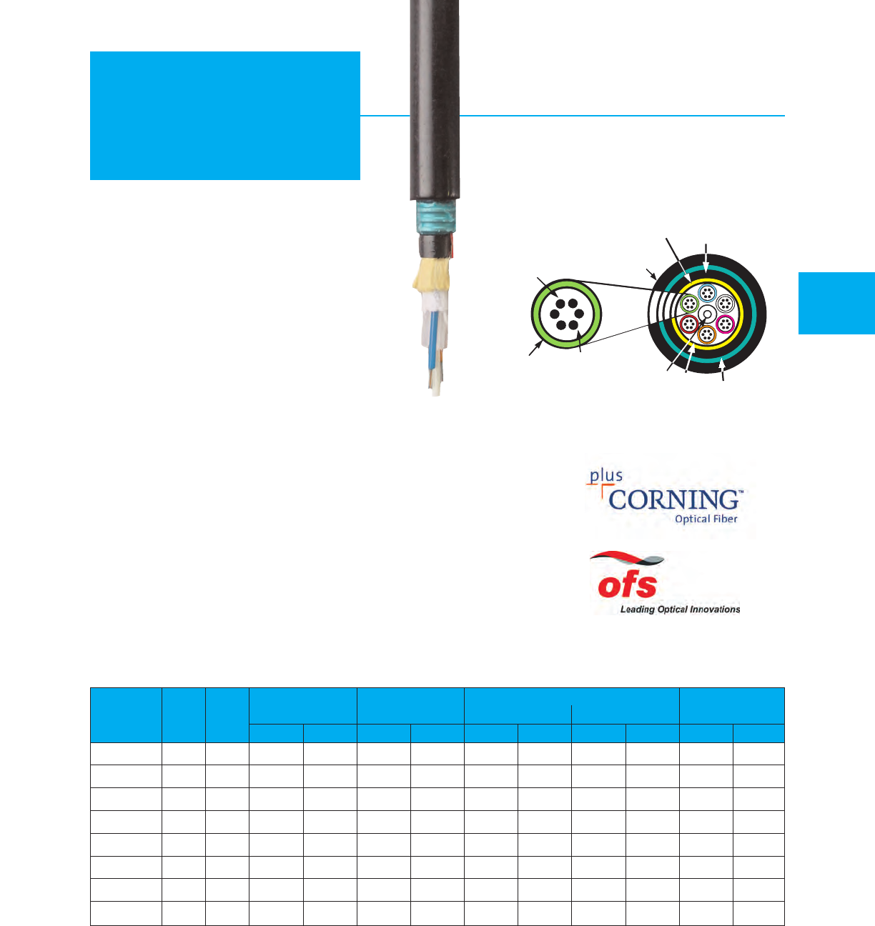
Indoor/Outdoor Direct Burial/
Armored UL/c(UL) Type OFCR/OFC FT4
MOHAWK 45
Loose Tube
RiserLite®
For “X” in part number see optical characteristics on page 33.
See color chart C on page 59.
MOISTURE BLOCKING GEL
THERMOPLASTIC
TUBE
MULTIPLE
250 MICRON
FIBERS
CORRUGATED
STEEL ARMOR
CENTRAL
E-GLASS
STRENGTH
MEMBER
LOOSE TUBE DETAIL
OUTER JACKET
PVC
WATER
BLOCKING
TAPE
ARAMID
STRENGTH
ELEMENTS
Recommended Applications
•Indoor/outdoor building interconnections
•Telecommunications and data trunk
•Long haul networking
•Direct burial and aerial lashing
Product Features
•No splicing required at building entrance
•Available with zero-halogen jacket
•Breakout kits available (see page 53)
•Fully waterblocked
Mechanical & Environmental Characteristics
•Crush Resistance (EIA-455-41) 2000 N-m
•Impact Resistance (EIA-455-25) 2000 Impacts
w/1.6 N-m
•Min. Bend Radius Long Term – No Load 15x Cable diameter
•Min. Bend Radius Short Term – Load 20x Cable diameter
•Operating Temp. – –40°C to +70°C
•Installation Temp. – –20°C to +60°C
•Storage Temp. – –40°C to +80°C
•UL/c(UL) Rated Type OFCR / OFC FT4
•Flame Resistance 1666 Passed
Fibers
Part Fiber Per
Number Count Tube mm in. kg/km lbs/M' cm in. cm in. Newtons lbs.
M9X890 6613.72 .540 205 138 27.4 10.8 20.6 8.1 2700 600
M9X891 12 6 13.72 .540 204 137 27.4 10.8 20.6 8.1 2700 600
M9X892 24 6 13.72 .540 202 136 27.4 10.8 20.6 8.1 2700 600
M9X893 36 6 13.72 .540 201 135 27.4 10.8 20.6 8.1 2700 600
M9X894 48 12 16.76 .660 262 176 33.5 13.2 25.1 9.9 2700 600
M9X895 72 12 16.76 .660 256 172 33.5 13.2 25.1 9.9 2700 600
M9X896 96 12 17.78 .700 307 206 35.6 14.0 26.7 10.5 2700 600
M9X897 144 12 22.35 .880 449 302 44.7 17.6 33.5 13.2 2700 600
Weight
Outside
Diameter Short Term Long Term
Max. Load
(Installation)
Min. Bend Radius
INNER JACKET
PVC
Stocked items available! See page 58 for specific part numbers in our inventory.
AdvanceLite®
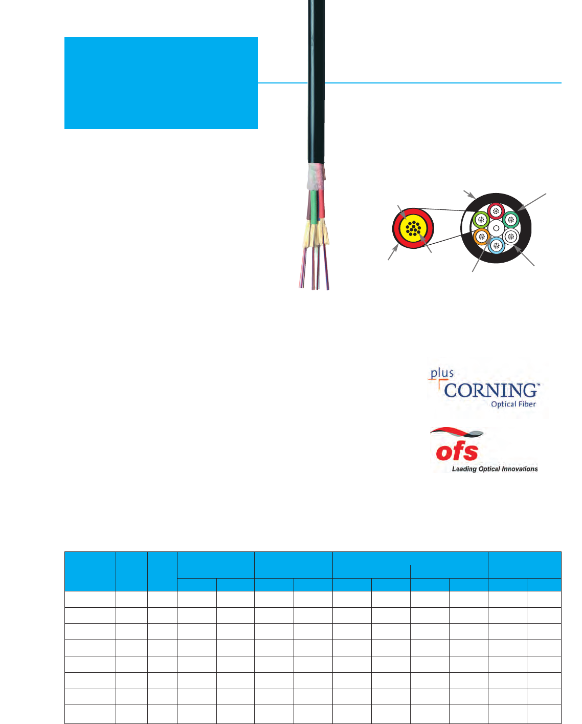
Indoor / Outdoor
UL/c(UL) Type OFNP / OFN FT6
46 MOHAWK
Plenum
VersaLite™
Recommended Applications
•Campus backbones
•Interbuilding installations
•Data centers
•High density cable trays
Product Features
•2 to 144 fiber
•Small diameter and bend radius facilitate installation in
tight spaces
•Fibers and subunits are color-coded for ease of
identification
•All-dielectric construction eliminates the need for
grounding
•Fibers grouped into sets of 12 for maximum density
Mechanical & Environmental Characteristics
•Crush Resistance (EIA-455-41) 250 N/cm
•Impact Resistance (EIA-455-25) 2000 Impacts w/1.6 N-m
•Flexure (EIA-455-104) 2000 Cycles min.
•Min. Bend Radius Long Term – No Load 15x Cable diameter
•Min. Bend Radius Short Term – Load 20x Cable diameter
•Operating Temp. – –40°C to +70°C
•Installation Temp. – 0°C to +60°C
•Storage Temp. – –40°C to +80°C
FIBER BUNDLE DETAIL
ARAMID STRENGTH
ELEMENTS
COLOR CODED
JACKET
OUTER JACKET OVERALL
TAPE BARRIER
BUNDLES OF UP TO
12 FIBERS EACH
UPJACKETED CENTRAL
STRENGTH ELEMENT
12 FIBERS
250 µm
>12-144 FIBERS
Short Term Long Term
Max. Load
(Installation)
Min. Bend Radius
Fibers
Part Fiber Per
Number Count Tube mm in. kg/km lbs/M' cm in. cm in. Newtons lbs.
M9X202 666.7 .265 49 33 13.5 5.3 10.2 4.0 1423 320
M9X204 12 12 6.7 .265 49 33 13.5 5.3 10.2 4.0 1423 320
M9X205 24 12 9.12 .359 70 47 18.3 7.2 13.7 5.4 1801 405
M9X206 36 12 9.12 .359 70 47 18.3 7.2 13.7 5.4 1801 405
M9X207 48 12 9.12 .359 71 48 18.3 7.2 13.7 5.4 1801 405
M9X209 72 12 10.9 .429 107 72 21.8 8.6 16.3 6.4 3216 723
M9X211 96 12 12.73 .501 152 102 25.4 10.0 19.1 7.5 4017 903
M9X215 144 12 16.89 .665 284 191 33.8 13.3 25.4 10.0 5618 1263
Options
•Available in 50 µm, 62.5 µm, single-mode,
and hybrid constructions
•Available in colored jackets for indoor only installations
•Available with Interlock Armor
Outside
Diameter Weight
For “X” in part number see optical characteristics on page 33.
See color chart C on page 59.
AdvanceLite®
Stocked items available! See page 58 for specific part numbers in our inventory.
SPECIFIED FIBER
(COLOR CODED)
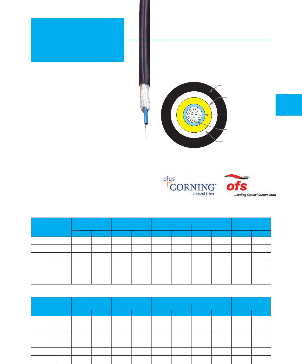
MOHAWK 47
Outside Plant
Central Tube Outside Plant
Recommended Applications
•Campus OSP backbones
•Drop cable
•Telecommunications and data trunk
Product Features
•Economical option for low fiber counts
•Quick and easy end preparation
•Fully waterblocked
•No rods – easy handling
Mechanical & Environmental Characteristics
•Crush Resistance (EIA-455-41) 250 N/cm
•Impact Resistance (EIA-455-25) 2000 Impacts
w/1.6 N-m
•Min. Bend Radius Long T
erm 15x Cable
•Min. Bend Radius Short Term 20x Cable
•Operating Temp. – –40°C to +70°C
•Installation Temp. – –30°C to +60°C
•Storage T
emp. – –40°C to +70°C
OUTER JACKET
STRENGTH MEMBER
BUFFER
FIBER
BARRIER
Weight
Outside
Diameter Short Term Long Term
Max. Load
(Installation)
Min. Bend Radius
Part Fiber
Number Count mm in. kg/km lbs/M' cm in. cm in. Newtons lbs.
M9X150 2 8.26 .325 52 35 16.5 6.5 12.45 4.9 2700 600
M9X151 4 8.26 .325 52 35 16.5 6.5 12.45 4.9 2700 600
M9X152 6 8.26 .325 52 35 16.5 6.5 12.45 4.9 2700 600
M9X153 8 8.26 .325 52 35 16.5 6.5 12.45 4.9 2700 600
M9X154 10 8.26 .325 52 35 16.5 6.5 12.45 4.9 2700 600
M9X155 12 8.26 .325 52 35 16.5 6.5 12.45 4.9 2700 600
Stocked items available! See page 58 for specific part numbers in our inventory.
AdvanceLite®
Weight
Outside
Diameter Short Term Long Term
Max. Load
(Installation)
Min. Bend Radius
Part Fiber
Number Count mm in. kg/km lbs/M' cm in. cm in. Newtons lbs.
M9X170 2 10.41 .410 101 68 20.8 8.2 15.6 6.15 2700 600
M9X171 4 10.41 .410 101 68 20.8 8.2 15.6 6.15 2700 600
M9X172 6 10.41 .410 101 68 20.8 8.2 15.6 6.15 2700 600
M9X173 8 10.41 .410 101 68 20.8 8.2 15.6 6.15 2700 600
M9X174 10 10.41 .410 101 68 20.8 8.2 15.6 6.15 2700 600
M9X175 12 10.41 .410 101 68 20.8 8.2 15.6 6.15 2700 600
Outdoor
Outdoor Armored
For “X” in part number see optical characteristics on page 33.
See color chart C on page 59.
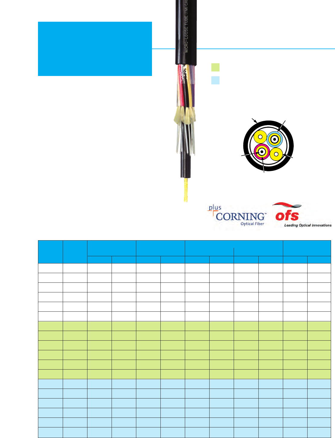
48 MOHAWK
Micro-Loose®
Tube Mini-tube – (900 µm)
UL/c(UL) Type OFN / OFN FT1
UL/c(UL) Type OFNR / OFN FT4
OUTER JACKET
POLYETHYLENE
SUB-UNIT JACKET
.098" (2.5 mm)
UPJACKETED ARAMID
STRENGTH ELEMENTS
ARAMID STRENGTH
ELEMENTS
MINI-TUBE 900
MICRON BUFFER
GEL-FILLED
For “X” in part number see optical characteristics on page 33.
See color chart C on page 59.
Recommended Applications
•Ducts between buildings
•T
elecommunications and data trunk
Product Features
•Loose buffer dimensions compatible
with standard connectors (900 µm)
•Waterblock gel for moisture protection
•Breakout kits not required for connectorization
Mechanical & Environmental Characteristics
•Crush Resistance (EIA-455-41) 600 N/cm
•Impact Resistance (EIA-455-25) 20 Impacts
w/1.0 N-m
•Min. Bend Radius Long Term – 15x Cable diameter
No Load
•Min. Bend Radius Short Term – 20x Cable diameter
Load
•Operating Temp. – –20°C to +70°C
•Installation Temp. – –20°C to +60°C
•Storage Temp. – –40°C to +70°C
AdvanceLite®
Weight
Outside
Diameter Short Term Long Term
Max. Load
(Installation)
Min. Bend Radius
Part Fiber
Number Count mm in. kg/km lbs/M' cm in. cm in. Newtons lbs.
M9X700 1 9.14 .360 64 43 18.3 7.2 13.7 5.4 1668 375
M9X701 2 9.14 .360 61 41 18.3 7.2 13.7 5.4 1535 345
M9X702 4 9.14 .360 58 39 18.3 7.2 13.7 5.4 1267 285
M9X703 610.62 .418 80 54 21.2 8.4 15.9 6.3 1801 405
M9X704 8 12.14 .478 113 76 24.3 9.6 18.2 7.2 2700 600
M9X705 12 15.60 .614 192 129 31.2 12.3 23.4 9.2 2700 600
M9X720 1 9.25 .364 79 53 18.5 7.3 14.0 5.5 1668 375
M9X721 2 9.25 .364 76 51 18.5 7.3 14.0 5.5 1535 345
M9X722 49.25 .364 73 49 18.5 7.3 14.0 5.5 1267 285
M9X723 6 10.72 .424 101 68 21.2 8.4 15.9 6.3 1801 405
M9X724 8 12.24 .482 115 77 24.3 9.6 18.2 7.2 2700 600
M9X725 12 15.70 .618 193 130 31.5 12.4 23.6 9.3 2700 600
M9X740 1 9.45 .372 85 57 18.8 7.4 14.2 5.6 1668 375
M9X741 29.45 .372 82 55 18.8 7.4 14.2 5.6 1535 345
M9X742 4 9.45 .372 76 51 18.8 7.4 14.2 5.6 1267 285
M9X743 6 10.97 .432 110 74 21.8 8.6 16.5 6.5 1801 405
M9X744 812.45 .490 140 94 24.9 9.8 18.8 7.4 2700 600
M9X745 12 15.90 .626 229 154 31.8 12.5 23.9 9.4 2700 600
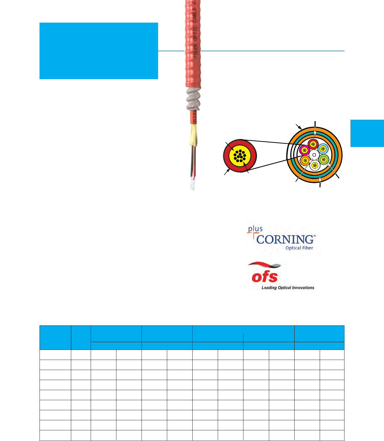
Heavy Duty Interlock Armored
Riser – UL/c(UL) Type OFCR / OFC FT4
Plenum – UL/c(UL) Type OFCP / OFC FT6
MOHAWK 49
BUNDLES
OF UP TO
12 FIBERS
EACH
INTERLOCK
ALUMINUM
ARMOR
CENTRAL
E-GLASS
STRENGTH
MEMBER
INNER JACKET
PVC
Recommended Applications
•Industrial environments
•Rugged installations
•Mining shafts
•T
elecommunications and data trunk
•Replacement for innerduct
Product Features
•Excellent mechanical protection
•Heavy duty construction
•Eliminates need for innerduct
•Versions available for outside plant
•Colored armor available
Mechanical & Environmental Characteristics
•Crush Resistance (EIA-455-41) 2000 N/cm
•Impact Resistance (EIA-455-25) 2000 Impacts
w/3 N-m
•Min. Bend Radius Long Term 15x Cable
•Min. Bend Radius Short Term 20x Cable
•Operating Temp. – –20°C to +70°C
•Installation Temp. – 0°C to +60°C
•Storage Temp. – –40°C to +70°C
•UL/c(UL) rated Type OFCR / OFC FT4
•Flame Resistance UL 1666 Passed
•UL/c(UL) Rated Type OFCP / OFC FT6
•Flame Resistance UL 910 Passed
COLOR
CODED
JACKET
SPECIFIED FIBER
(COLOR CODED)
FIBER BUNDLE DETAIL
Plenum
OUTER JACKET
PVC
For “X” in part number see optical characteristics on page 33.
For Buffer colors see chart C on page 59.
ARAMID STRENGTH
ELEMENTS
ArmorLite™
Stocked items available! See page 58 for specific part numbers in our inventory.
AdvanceLite®
Weight
Outside
Diameter Short Term Long Term
Max. Load
(Installation)
Min. Bend Radius
Part Fiber
Number Count mm in. kg/km lbs/M' cm in. cm in. Newtons lbs.
M9X240 6 12.2 .481 134 90 24.4 9.6 18.3 7.2 1201 270
M9X241 12 12.85 .506 153 103 25.7 10.1 19.3 7.6 1334 300
M9X242 24 16.03 .631 225 151 32.0 12.6 24.1 9.5 1735 390
M9X243 24 19.84
.781 201 135 39.6 15.6 29.7 11.7 5618
1263
M9X244 36 22.38 .881 460 309 44.7 17.6 33.5 13.2 8509 1913
M9X245 48 22.38 .881 4
39 295
44.7 17.6 33.5 13.2
55
38 1245
M9X246 72 26.19 1.031 644 433 52.3 20.6 39.4 15.5 9310 2093
M9X247 96 30.63 1.206 905 608 61.2 24.1 46.0 18.1 9608 2160
M9X248 144 33.81 1.331 1022 687 67.6 26.6 50.8 20.0 16213 3645
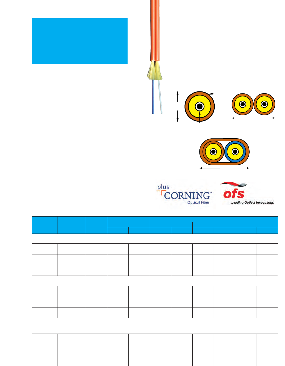
M9X001 Simplex 1 9 6 4.3 1.7 2.9 1.1 400 90
M9X002 Duplex 2 18 12 4.3 1.7 2.9 1.1 801 180
M9X080 2 31 21 6.3 2.5 4.2 1.7 801 180
2.9 mm diameter –
UL Type OFNR / c(UL) OFN FT4
UL Type OFNP / c(UL) OFN FT6
LSZH
50 MOHAWK
Simplex &
Duplex
Part Fiber
Number Type Count kg/km lbs/M' cm in. cm in. Newtons lbs.
Max. Load
(Installation)
Riser
.114"
(2.9 mm)
SIMPLEX
900 MICRON BUFFERED FIBER
.233" (5.9 mm)
JACKET DUPLEX
HEAVY DUTY DUPLEX
.284" (7.2 mm)
Weight Short Term Long Term
Min. Bend Radius
Plenum
For “X” in part number see optical characteristics on page 33.
Recommended Applications
•Patch cables
•Short run office cabling
•Computer room cabling
•Other sizes available
Mechanical, Environmental &
Flame Characteristics
•Crush Resistance (EIA-455-41) 200 N/cm
•Impact Resistance (EIA-455-25) 20 Impacts w/1.0 N-m
•Flexure (EIA-455-104) 100 cycles min.
•Min. Bend Radius Long Term – No Load 10x Cable diameter
•Min. Bend Radius Short Term – Load 15x Cable diameter
•Operating Temp. – –20°C to +70°C
•Installation Temp. – 0°C to +60°C
•Storage Temp. – –40°C to +70°C
•UL/c(UL) Rated Type OFNR / OFN FT4
•UL/c(UL) Rated Type OFNP / OFN FT6
•LSZH
Low Smoke Zero Halogen
LSZH Cables contain 62.5/125 grade 2 fiber.
Also available with other fiber types.
Heavy Duty
Duplex
M9X003 Simplex 1 9 6 4.3 1.7 2.9 1.1 400 90
M9X004 Duplex 2 19 13 4.3 1.7 2.9 1.1 801 180
M9X081 2 28 19 5.6 2.2 3.8 1.5 801 180
Heavy Duty
Duplex
M96436 Simplex 1 9 6 4.3 1.7 2.9 1.1 400 90
M98177 Duplex 2 19 13 4.3 1.7 2.9 1.1 801 180
M95890 234 23 6.3 2.5 4.2 1.7 801 180
Heavy Duty
Duplex
AdvanceLite®
Stocked items available! See page 58 for specific part numbers in our inventory.
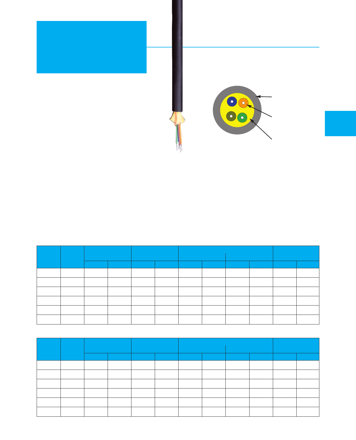
Fiber Optic Tactical Cables
MOHAWK 51
Tactical
Cables
Recommended Applications
•ENG vehicles
•Outdoor events
•Re-deployable communications
•Digital camera transmission
Product Features
•Rugged jacket
•Durable design for repeated handling
•Designed to military standards
•Superior level of crush resistance
Mechanical & Environmental Characteristics
•Crush Resistance (EIA-455-41) 440 N/cm
•Impact Resistance (EIA-455-25) 200 Impacts
w/2.2 N-m
•Flexure (EIA-455-104) 2000 Cycles min.
•Min. Bend Radius Long T
erm – 8x Cable diameter
No Load
•Min. Bend Radius Short Term – 15x Cable diameter
Load
•Operating Temp. (EIA-455-3) –55°C to +85°C
•Storage Temp. (EIA-455-3) –70°C to +85°C
Single-Mode
Multimode (62.5/125 Grade 2)
Additional optical fiber versions also available – contact factory.
See optical characteristics on page 33.
For buffer colors see chart C on page 59.
Weight
Nominal
OD Short Term Long Term
Max. Load
(Installation)
Min. Bend Radius
Part Fiber
Number Count mm in. kg/km lbs/M' cm in. cm in. Newtons lbs.
M96566 2 5.3 .210 28 19 8.3 3.2 4.3 1.7 1468 330
M96639 4 5.7 .225 28 19 8.6 3.4 4
.6
1.8 1468 330
M96567 6 6.1 .240 36 24 9.1 3.6 4.8 1.9 1468 330
M96568 8 6.
3 .250 39 26 9.7 3.8 6.4 2.5
1468 330
M96569 10 6.7 .265 42 28 10.2 4.0 6.9 2.7 1468 330
M96570 12 6.5 .255 36 24 9.7 3.8 5.1 2.0 1468 330
Weight
Nominal
OD Short Term Long Term
Max. Load
(Installation)
Min. Bend Radius
Part Fiber
Number Count mm in. kg/km lbs/M' cm in. cm in. Newtons lbs.
M96571 25.3 .210 28 19 8.3 3.2 4.3 1.7 1468 330
M96551 4 5.7 .225 28 19 8.6 3.4 4.6 1.8 1468 330
M96572 6 6.1 .240 36 24 9.1 3.6 4.8 1.9 1468 330
M96573 86.
3.250 39 26 9.7 3.8 6.4 2.5
1468 330
M96574 10 6.7 .265 42 28 10.2 4.0 6.9 2.7 1468 330
M96575 12 6.5 .255 36 24 9.7 3.8 5.1 2.0 1468 330
OUTER
JACKET
TIGHT
BUFFERED
FIBER
ARAMID
STRENGTH
MEMBER
Stocked items available! See page 58 for specific part numbers in our inventory.
AdvanceLite®
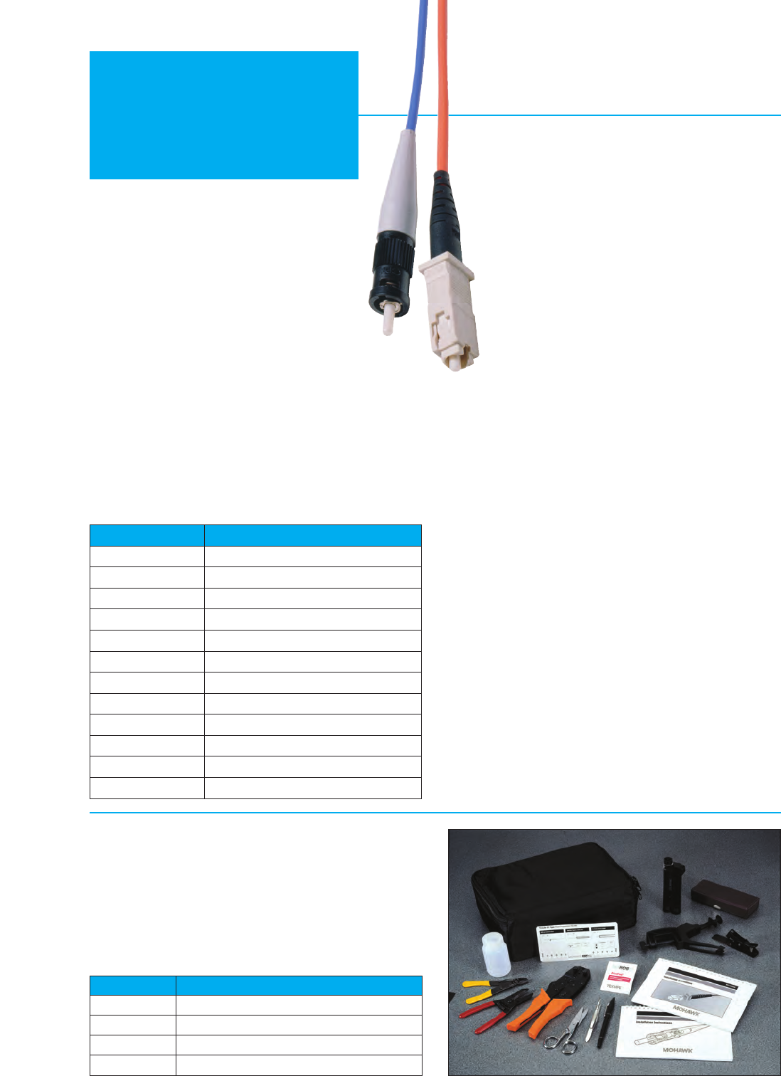
52 MOHAWK
Optimax®
System
Recommended Applications
•Field termination of cable
•Storage network connections
•Switch to fiber distribution
•Panel connections
Product Features
•Pre-Polished Fiber Stub
Does not require polishing paper; less craft-sensitive
•Safer, Simpler Installation
No epoxy, curing equipment or power needed
•Precision Fiber Contact
Pre-radiused PC ceramic ferrule assures durable contact and
optimum mechanical performance
•Dramatic Reductions in:
Installation Time; Cost of Equipment and Materials;
Expertise/Training Required
Options
•
Field-installable Multimode ST-Type, SC or LC Fiber Optic Connectors
The Optimax Connectors are reliable field installable
optical fiber connectors that are easy to install. They
do not require epoxy, curing or polishing. Their unique
design incorporates a factory polished fiber stub in a
splice mechanism which provides a fast, secure, and
reliable termination on optical fiber cables. All critical
steps are performed in the factory, ensuring a
superior-qualty connection every time. Only simple
tools are required for installation, making Optimax a
cost effective field termination.
Optimax Connectors are high-quality LC, SC and ST
Compatible connectors that use a ceramic ferrule with
a physical contact (PC) polish for Multimode and
super physical contact (SPC) polish for Single-mode
that ensures the best possible mating of optical fibers.
Connectors are available for 62.5 or 50/125 µm
Multimode fiber and Single-mode fiber installations.
Optimax®Tool Kit
Everything your field people need – and need to know – for
expert installations is packaged in a small convenient carrying
case: installation instructions and all the tools required to
terminate 900 µm buffered optical fiber and jacketed fiber.
Note: For installers already possessing basic fiber installation
tools, dedicated tools can be purchased separately.
Specifications
Interconnection Compatibility: All ST-type, SC and LC
connectors and compatibles
Field Assembly Time: 1 minute for 900 µm fiber; 3 minutes for
jacketed fiber
Insertion Loss (Attenuation): 0.3 dB (typical)
Durability: <0.2 dB change, 500 cycles multimode; <0.3 dB
change, 500 cycles single-mode
Nominal Fiber OD: 125 µm
Operating Temperature: 0°C to +60°C (+32°F to +140°F)
Storage Temperature: -40°C to +65°C (-40°F to +149°F)
Tensile Strength: 12 lbs (54 N)
Ferrule: Zirconia ceramic
Reflectance: -30 dB (typical) multimode; -40 dB (guaranteed)
single-mode
Part Number Description
A0408835 900µm 62.5/125 ST connector
AX101075 900µm 50/125 ST connector
AX101791 900µm Single-Mode ST connector
AX101793 Additional parts for jacketed ST
AX100029 900µm 62.5/125 SC connector
AX101077 900µm 50/125 SC connector
AX101792 900µm Single-Mode SC connector
AX101794 Additional parts for jacketed SC
AX101981 900µm 62.5/125 LC connector
AX101982 900µm 50/125 LC connector
AX101983 900µm Single-Mode LC connector
AX101984 Additional parts for jacketed LC
Part Number Description
AX100947 Complete Tool Kit
AX102062 Installation T
ool LC (does not include tool-clamp)
A0403634 Installation T
ools ST Compatible & SC (Includes tool-clamp)
A0408829 Cleaver
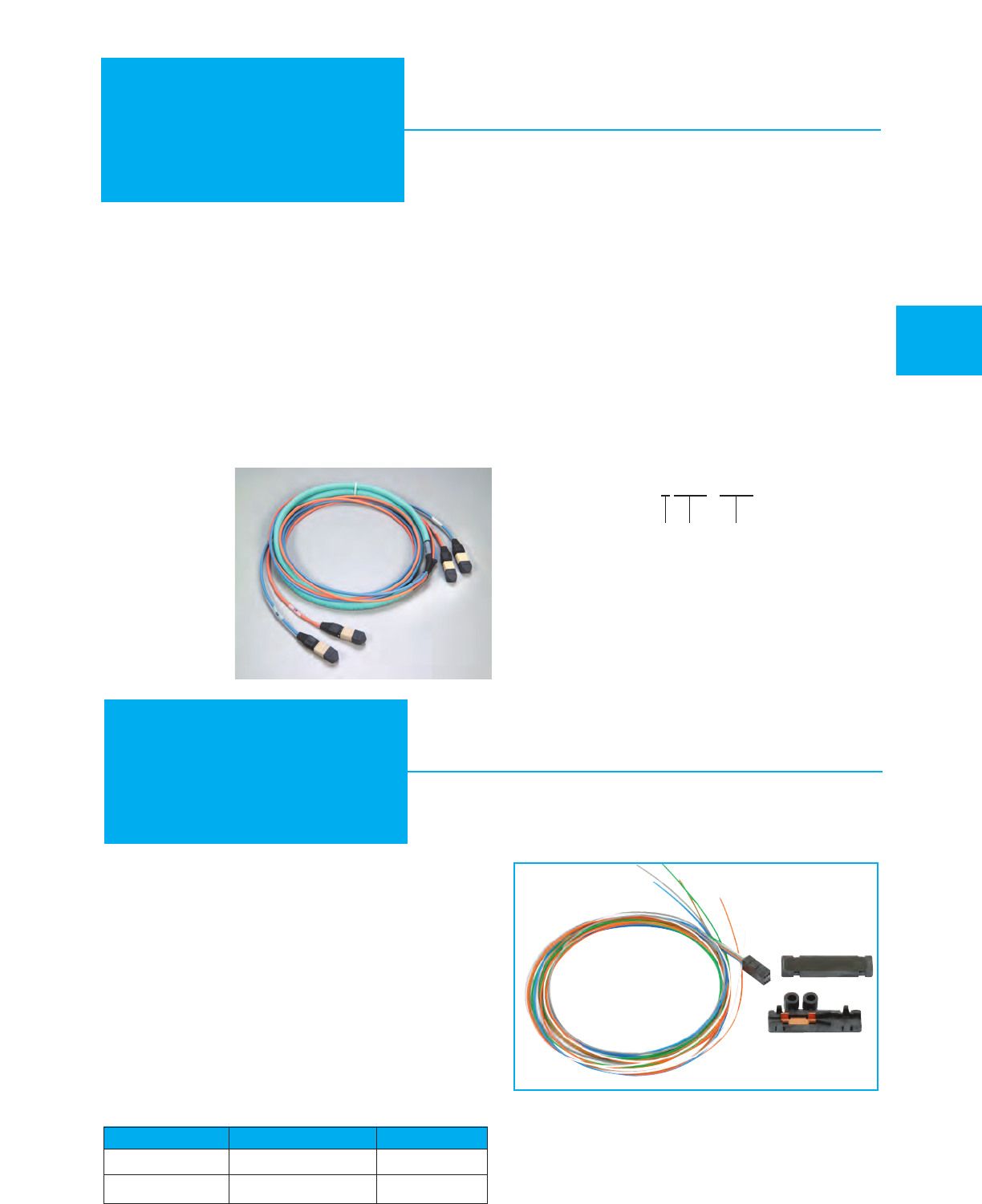
MOHAWK 53
Plug & Play
This Field Breakout Kit is designed to attach to one tube
of a loose tube cable and has either six or twelve 900 µm
tubes that hold each of the coated fibers. For each end of
the cable, one kit is needed for every tube. For example,
part number M9B511T has two tubes with six 62.5/125
fibers each. This cable requires four field breakout kits;
two for each end of the cable.
The kit is available in two sizes to accommodate the
two different tube sizes which are manufactured by
Mohawk. For tubes containing one to six fibers, the
diameter is 0.075" (1.9 mm) and for tubes containing
seven to twelve fibers, the diameter is 0.110" (2.8 mm).
Every kit is shipped with a complete set of instructions.
Part Number Tube Diameter Fibers/Tube
AX101100 0.075" (1.9 mm) ≤6
AX101101 0.110" (2.8 mm) 7-12
Breakout Kit
Pre-Terminated Cables for
Plug & Play Installations
Recommended Applications
•Intrabuilding installations
•Data centers
Product Features
•2 - 144 Fibers
•Maximum Density, Minimum Diameter
Fibers are grouped in sets of 12. Small diameter and bend
radius facilitate installation in tight spaces.
•Easy Identification and Installation
Subunits are color-coded for identification. All-dielectric
construction eliminates the need for grounding. Fibers
terminated in MPO connectors.
Options
•
Available in 50
µm,
62.5 µm, single-
mode, and hybrid
constructions.
•
Available in colored
jackets.
Mohawk’s unique data center assemblies combine compact
size with industry standard MPO terminations to facilitate quick
installations with maximum flexibility. Cable diameters are
reduced by as much as 35% to save space in cable
management pathways. The MPO terminations allow the
cables to plug into a variety of manufacturers’ fiber cassettes
which convert the MPO interface to an LC, SC, ST or other
connector style. Factory terminations provide a pre-qualified
high performance connection which removes the variability of
field polishing from the link. All cables are plenum (OFNP) rated
to allow them to be installed in any interior location. The fiber
performance can be specified using Mohawk’s grading system
to match the application. Hybrid cables, combining different
fiber types, can also be specified.
MD = Mini-Distribution Cable
MA = Mini-Distribution Interlock Armor Cable
X= Fiber Type
CCC = Fiber Count (12 - 144)
LLL = Length of Assembly (feet)
(For “X” in part number see optical characteristics on page 33.)
MD - X CCC - LLLF
MD - C 024 - 200F
Part No.
Example:
(Grade 5 24-fiber cable, 200 foot assembly)

Corning Cable Berk-Tek Mohawk Fiber Size
Fiber Optic Cable Part # Cross Reference
54 MOHAWK
Cross Reference
Corning Cable Berk-Tek Mohawk Fiber Size
Riser Rated Patch Cables (OFNR)
001K31-31141-24 ICR001CB3510/25 M92001 62.5/125
002K51-31141-24 ICR0X0CB3510/25 M95630 62.5/125
002K81-31130-24 ICR002CB3510/25 M9B037 62.5/125
001C31-31131-24 ICR001LB3520/55 M9A001 50/125
002C51-31131-24 ICR0X0LB3520/55 M9A002 50/125
002C81-31131-24 ICR002BB3520/55 M9A037 50/125
001E31-31131-24 ICR001AB0707 M9W001 Single-Mode
002E51-31131-24 ICR0X0AB0707 M9W002 Single-Mode
002E81-31131-24 ICR002AB0707 M9W037 Single-Mode
Plenum Rated Patch Cables (OFNP)
001K38-31141-29 ICP001CB3510/25 M92003 62.5/125
002K58-31141-29 ICP0X0CB3510/25 M96232 62.5/125
002K88-31130-29 ICP002CB3510/25 M9B043 62.5/125
001C38-31131-29 ICP001LB3520/55 M9A003 50/125
002C58-31131-29 ICP0X0LB3520/55 M9A004 50/125
002C88-31131-29 ICP002BB3520/55 M9A043 50/125
001E38-31131-29 ICP001AB0707 M93003 Single-Mode
002E58-31131-29 ICP0X0AB0707 M93004 Single-Mode
002E88-31131-29 ICP002AB0707 M93043 Single-Mode
Riser Rated Distribution Cables (OFNR)
004K81-31130-24 ICR004CB3510/25 M9B038 62.5/125
006K81-31130-24 PDR006CB3510/25 M9B039 62.5/125
008K81-31130-24 PDR008CB3510/25 M9B040 62.5/125
012K81-33130-24 PDR012CB3510/25 M9B042 62.5/125
024K81-33130-24 PDR024CB3510/25 M9B601 62.5/125
036K81-61130-24 PDR6B036CB3510/25 M9B604 62.5/125
048K81-T3130-24 PDR12B048CB3510/25 M9B606 62.5/125
072K81-T3130-24 PDR12B072CB3510/25 M9B609 62.5/125
096K81-T3130-24 PDR12B096CB3510/25 M9B622 62.5/125
144K81-T3130-24 PDR12B144CB3510/25 M9B619 62.5/125
004C81-31131-24 ICR004LB3520/55 M9A038 50/125
006C81-31131-24 PDR006LB3520/55 M9A039 50/125
008C81-31131-24 PDR008LB3520/55 M9A040 50/125
012C81-33131-24 PDR012LB3520/55 M9A042 50/125
024C81-33131-24 PDR024LB3520/55 M9A601 50/125
036C81-61131-24 PDR6B036LB3520/55 M9A604 50/125
048C81-T3131-24 PDR12B048LB3520/55 M9A606 50/125
072C81-T3131-24 PDR12B072LB3520/55 M9A609 50/125
096C81-T3131-24 PDR12B096LB3520/55 M9A622 50/125
144C81-T3131-24 PDR12B144LB3520/55 M9A619 50/125
Riser Rated Distribution Cables (OFNR) continued
004E81-31131-24 ICR004AB1010 M9W038 Single-Mode
006E81-31131-24 PDR006AB1010 M9W039 Single-Mode
008E81-31131-24 PDR008AB1010 M9W040 Single-Mode
012E81-33131-24 PDR012AB1010 M9W042 Single-Mode
024E81-33131-24 PDR024AB1010 M9W601 Single-Mode
036E81-61131-24 PDR6B036AB1010 M9W604 Single-Mode
048E81-T3131-24 PDR12B048AB1010 M9W606 Single-Mode
072E81-T3131-24 PDR12B072AB1010 M9W609 Single-Mode
096E81-T3131-24 PDR12B096AB1010 M9W622 Single-Mode
144E81-T3131-24 PDR12B144AB1010 M9W619 Single-Mode
Plenum Rated Distribution Cables (OFNP)
004K88-31130-29 ICP004CB3510/25 M9B044 62.5/125
006K88-31130-29 PDP006CB3510/25 M9B045 62.5/125
008K88-31130-29 PDP008CB3510/25 M9B046 62.5/125
012K88-33130-29 PDP012CB3510/25 M9B048 62.5/125
024K88-33130-29 PDP024CB3510/25 M9B611 62.5/125
036K88-61130-29 PDP6B036CB3510/25 M9B614 62.5/125
048K88-T3130-29 PDP12B048CB3510/25 M9B616 62.5/125
072K88-T3130-29 PDP12B072CB3510/25 M9B620 62.5/125
096K88-T3130-29 PDP12B096CB3510/25 M9B623 62.5/125
144K88-T3130-29 PDP12B144CB3510/25 M9B621 62.5/125
004C88-31131-29 ICP004LB3520/55 M9A044 50/125
006C88-31131-29 ICP006LB3520/55 M9A045 50/125
008C88-31131-29 ICP008LB3520/55 M9A046 50/125
012C88-33131-29 ICP012LB3520/55 M9A048 50/125
024C88-33131-29 ICP024LB3520/55 M9A611 50/125
036C88-61131-29 ICP6B036LB3520/55 M9A614 50/125
048C88-T3131-29 ICP12B048LB3520/55 M9A616 50/125
072C88-T3131-29 ICP12B072LB3520/55 M9A620 50/125
096C88-T3131-29 ICP12B096LB3520/55 M9A623 50/125
144C88-T3131-29 ICP12B144LB3520/55 M9A621 50/125
004E88-31131-29 ICP004AB1010 M9W044 Single-Mode
006E88-31131-29 PDP006AB1010 M9W045 Single-Mode
008E88-31131-29 PDP008AB1010 M9W046 Single-Mode
012E88-33131-29 PDP012AB1010 M9W048 Single-Mode
024E88-33131-29 PDP024AB1010 M9W611 Single-Mode
036E88-61131-29 PDP6B036AB1010 M9W614 Single-Mode
048E88-T3131-29 PDP12B048AB1010 M9W616 Single-Mode
072E88-T3131-29 PDP12B072AB1010 M9W620 Single-Mode
096E88-T3131-29 PDP12B096AB1010 M9W623 Single-Mode
144E88-T3131-29 PDP12B144AB1010 M9W621 Single-Mode

Fiber Optic Cable Part # Cross Reference
MOHAWK 55
Cross Reference
This cross reference should be used in conjunction with Mohawk’s Fiber Optic section. It
should be used for suggested alternative items which are functionally equal. Mohawk is
not responsible for variances due to competitors’ construction changes. Consult your
local Mohawk representative or the factory for items not listed or for special cable
constructions.
Corning Cable Berk-Tek Mohawk Fiber Size
ArmorLiteTM Plenum Rated Distribution Cables
006K88-31130-A3 PDPK006CB3510/25 M9B240 62.5/125
012K88-33130-A3 PDPK012CB3510/25 M9B241 62.5/125
024K88-33130-A3 PDPK024CB3510/25 M9B242 62.5/125
006C88-31131-A3 PDPK006BB3520/55 M9A240 50/125
012C88-33131-A3 PDPK012BB3520/55 M9A241 50/125
024C88-33131-A3 PDPK024BB3520/55 M9A242 50/125
006E88-31131-A3 PDPK006AB1010 M9W240 Single-Mode
012E88-33131-A3 PDPK012AB1010 M9W241 Single-Mode
024E88-33131-A3 PDPK024AB1010 M9W242 Single-Mode
Riser Rated Breakout Cables (OFNR)
002K61-31330-24 HDR002CB3510/25 M9B005 62.5/125
004K61-31330-24 HDR004CB3510/25 M9B006 62.5/125
006K61-31330-24 HDR006CB3510/25 M9B007 62.5/125
008K61-31330-24 HDR008CB3510/25 M9B008 62.5/125
012K61-31330-24 HDR012CB3510/25 M9B010 62.5/125
024K61-31330-24 HDR024CB3510/25 M9B012 62.5/125
036K61-31330-24 HDR036CB3510/25 M9B083 62.5/125
002C61-31331-24 HDR002BB3520/55 M9A005 50/125
004C61-31331-24 HDR004BB3520/55 M9A006 50/125
006C61-31331-24 HDR006BB3520/55 M9A007 50/125
008C61-31331-24 HDR008BB3520/55 M9A008 50/125
012C61-31331-24 HDR012BB3520/55 M9A010 50/125
024C61-31331-24 HDR024BB3520/55 M9A012 50/125
036C61-31331-24 HDR036BB3520/55 M9A083 50/125
002R61-31331-24 HDR002AB1010 M9W005 Single-Mode
004R61-31331-24 HDR004AB1010 M9W006 Single-Mode
006R61-31331-24 HDR006AB1010 M9W007 Single-Mode
008R61-31331-24 HDR008AB1010 M9W008 Single-Mode
012R61-31331-24 HDR012AB1010 M9W010 Single-Mode
024R61-31331-24 HDR024AB1010 M9W012 Single-Mode
036R61-31331-24 HDR036AB1010 M9W083 Single-Mode
Plenum Rated Breakout Cables (OFNP)
002K68-31330-29 HDP002CB3510/25 M9B013 62.5/125
004K68-31330-29 HDP004CB3510/25 M9B014 62.5/125
006K68-31330-29 HDP006CB3510/25 M9B015 62.5/125
008K68-31330-29 HDP008CB3510/25 M9B016 62.5/125
Plenum Rated Breakout Cables (OFNP) continued
012K68-31330-29 HDP012CB3510/25 M9B018 62.5/125
024K68-31330-29 HDP024CB3510/25 M9B020 62.5/125
036K68-31330-29 HDP036CB3510/25 M9B082 62.5/125
002C68-31331-29 HDP002BB3520/55 M9A013 50/125
004C68-31331-29 HDP004BB3520/55 M9A014 50/125
006C68-31331-29 HDP006BB3520/55 M9A015 50/125
008C68-31331-29 HDP008BB3520/55 M9A016 50/125
012C68-31331-29 HDP012BB3520/55 M9A018 50/125
024C68-31331-29 HDP024BB3520/55 M9A020 50/125
036C68-31331-29 HDP036BB3520/55 M9A082 50/125
002R68-31331-29 HDP002AB1010 M9W013 Single-Mode
004R68-31331-29 HDP004AB1010 M9W014 Single-Mode
006R68-31331-29 HDP006AB1010 M9W015 Single-Mode
008R68-31331-29 HDP008AB1010 M9W016 Single-Mode
012R68-31331-29 HDP012AB1010 M9W018 Single-Mode
024R68-31331-29 HDP024AB1010 M9W020 Single-Mode
036R68-31331-29 HDP036AB1010 M9W082 Single-Mode
Loose Tube Cables
002KW4-T3130A20 OPDD1B002CB3510/25 M9B058T 62.5/125
004KW4-T3130A20 OPDD2B004CB3510/25 M9B063T 62.5/125
006KW4-T3130A20 OPDD6B006CB3510/25 M9B510T 62.5/125
008KW4-T3130A20 OPDD2B008CB3510/25 M9B065T 62.5/125
012KW4-T3130A20 OPDD6B012CB3510/25 M9B511T 62.5/125
018KW4-T3130A20 OPDD6B018CB3510/25 M9B512T 62.5/125
024KW4-T3130A20 OPDD6B024CB3510/25 M9B500T 62.5/125
036KW4-T3130A20 OPDD6B036CB3510/25 M9B502T 62.5/125
048KW4-T3130A20 OPDD12B048CB3510/25 M9B505T 62.5/125
072KW4-T3130A20 OPDD12B072CB3510/25 M9B507T 62.5/125
096KW4-T3130A20 OPDD12B096CB3510/25 M9B513T 62.5/125
144KW4-T3130A20 OPDD12B144CB3510/25 M9B509T 62.5/125
216KW4-T3130A20 OPDD12B216CB3510/25 M9B520T 62.5/125
002CW4-T3131A20 OPDD1B002BB3520/55 M9A058T 50/125
004CW4-T3131A20 OPDD2B004BB3520/55 M9A063T 50/125
006CW4-T3131A20 OPDD6B006BB3520/55 M9A510T 50/125
008CW4-T3131A20 OPDD2B008BB3520/55 M9A065T 50/125
012CW4-T3131A20 OPDD6B012BB3520/55 M9A511T 50/125
018CW4-T3131A20 OPDD6B018BB3520/55 M9A512T 50/125
Corning Cable Berk-Tek Mohawk Fiber Size

56 MOHAWK
Cross Reference
Corning Cable Berk-Tek Mohawk Fiber Size
Fiber Optic Cable Part # Cross Reference
Loose Tube Cables continued
024CW4-T3131A20 OPDD6B024BB3520/55 M9A500T 50/125
036CW4-T3131A20 OPDD6B036BB3520/55 M9A502T 50/125
048CW4-T3131A20 OPDD12B048BB3520/55 M9A505T 50/125
072CW4-T3131A20 OPDD12B072BB3520/55 M9A507T 50/125
096CW4-T3131A20 OPDD12B096BB3520/55 M9A513T 50/125
144CW4-T3131A20 OPDD12B144BB3520/55 M9A509T 50/125
216CW4-T3131A20 OPDD12B216BB3520/55 M9A520T 50/125
002EW4-T3101A20 OPDD1B002AB0504 M9W058T Single-Mode
004EW4-T3101A20 OPDD2B004AB0504 M9W063T Single-Mode
006EW4-T3101A20 OPDD6B006AB0504 M9W510T Single-Mode
008EW4-T3101A20 OPDD2B008AB0504 M9W065T Single-Mode
012EW4-T3101A20 OPDD6B012AB0504 M9W511T Single-Mode
018EW4-T3101A20 OPDD6B018AB0504 M9W512T Single-Mode
024EW4-T3101A20 OPDD6B024AB0504 M9W500T Single-Mode
036EW4-T3101A20 OPDD6B036AB0504 M9W502T Single-Mode
048EW4-T3101A20 OPDD12B048AB0504 M9W505T Single-Mode
072EW4-T3101A20 OPDD12B072AB0504 M9W507T Single-Mode
096EW4-T3101A20 OPDD12B096AB0504 M9W513T Single-Mode
144EW4-T3101A20 OPDD12B144AB0504 M9W509T Single-Mode
216EW4-T3101A20 OPDD12B216AB0504 M9W520T Single-Mode
Armored Loose Tube Cables
002KW5-T3130A20 OPAD1B002CB3510/25 M9B358T 62.5/125
004KW5-T3130A20 OPAD2B004CB3510/25 M9B363T 62.5/125
006KW5-T3130A20 OPAD6B006CB3510/25 M9B381T 62.5/125
008KW5-T3130A20 OPAD2B008CB3510/25 M9B365T 62.5/125
012KW5-T3130A20 OPAD6B012CB3510/25 M9B382T 62.5/125
018KW5-T3130A20 OPAD6B018CB3510/25 M9B383T 62.5/125
024KW5-T3130A20 OPAD6B024CB3510/25 M9B384T 62.5/125
036KW5-T3130A20 OPAD6B036CB3510/25 M9B386T 62.5/125
048KW5-T3130A20 OPAD12B048CB3510/25 M9B389T 62.5/125
072KW5-T3130A20 OPAD12B072CB3510/25 M9B391T 62.5/125
096KW5-T3130A20 OPAD12B096CB3510/25 M9B398T 62.5/125
144KW5-T3130A20 OPAD12B144CB3510/25 M9B393T 62.5/125
216KW5-T3130A20 OPAD12B216CB3510/25 M9B400T 62.5/125
002CW5-T3131A20 OPAD1B002BB3520/55 M9A358T 50/125
004CW5-T3131A20 OPAD2B004BB3520/55 M9A363T 50/125
006CW5-T3131A20 OPAD6B006BB3520/55 M9A381T 50/125
008CW5-T3131A20 OPAD2B008BB3520/55 M9A365T 50/125
012CW5-T3131A20 OPAD6B012BB3520/55 M9A382T 50/125
018CW5-T3131A20 OPAD6B018BB3520/55 M9A383T 50/125
024CW5-T3131A20 OPAD6B024BB3520/55 M9A384T 50/125
036CW5-T3131A20 OPAD6B036BB3520/55 M9A386T 50/125
Armored Loose Tube Cables continued
048CW5-T3131A20 OPAD12B048BB3520/55 M9A389T 50/125
072CW5-T3131A20 OPAD12B072BB3520/55 M9A391T 50/125
096CW5-T3131A20 OPAD12B096BB3520/55 M9A398T 50/125
144CW5-T3131A20 OPAD12B144BB3520/55 M9A393T 50/125
216CW5-T3131A20 OPAD12B216BB3520/55 M9A400T 50/125
002EW5-T3101A20 OPAD1B002AB0504 M9W358T Single-Mode
004EW5-T3101A20 OPAD2B004AB0504 M9W363T Single-Mode
006EW5-T3101A20 OPAD6B006AB0504 M9W381T Single-Mode
008EW5-T3101A20 OPAD2B008AB0504 M9W365T Single-Mode
012EW5-T3101A20 OPAD6B012AB0504 M9W382T Single-Mode
018EW5-T3101A20 OPAD6B018AB0504 M9W383T Single-Mode
024EW5-T3101A20 OPAD6B024AB0504 M9W384T Single-Mode
036EW5-T3101A20 OPAD6B036AB0504 M9W386T Single-Mode
048EW5-T3101A20 OPAD12B048AB0504 M9W389T Single-Mode
072EW5-T3101A20 OPAD12B072AB0504 M9W391T Single-Mode
096EW5-T3101A20 OPAD12B096AB0504 M9W398T Single-Mode
144EW5-T3101A20 OPAD12B144AB0504 M9W393T Single-Mode
216EW5-T3101A20 OPAD12B216AB0504 M9W400T Single-Mode
RiserLite®Loose Tube Cables
006KWF-T4130A20 LTR6B006CB3510/25 M9B810 62.5/125
012KWF-T4130A20 LTR6B012CB3510/25 M9B811 62.5/125
024KWF-T4130A20 LTR6B024CB3510/25 M9B812 62.5/125
036KWF-T4130A20 LTR6B036CB3510/25 M9B813 62.5/125
048KWF-T4130A20 LTR12B048CB3510/25 M9B814 62.5/125
072KWF-T4130A20 LTR12B072CB3510/25 M9B815 62.5/125
096KWF-T4130A20 LTR12B096CB3510/25 M9B816 62.5/125
144KWF-T4130A20 LTR12B144CB3510/25 M9B817 62.5/125
006CWF-T4131A20 LTR6B006BB3520/55 M9A810 50/125
012CWF-T4131A20 LTR6B012BB3520/55 M9A811 50/125
024CWF-T4131A20 LTR6B024BB3520/55 M9A812 50/125
036CWF-T4131A20 LTR6B036BB3520/55 M9A813 50/125
048CWF-T4131A20 LTR12B048BB3520/55 M9A814 50/125
072CWF-T4131A20 LTR12B072BB3520/55 M9A815 50/125
096CWF-T4131A20 LTR12B096BB3520/55 M9A816 50/125
144CWF-T4131A20 LTR12B144BB3520/55 M9A817 50/125
006EWF-T4103A20 LTR6B006AB0504 M9W810 Single-Mode
012EWF-T4103A20 LTR6B012AB0504 M9W811 Single-Mode
024EWF-T4103A20 LTR6B024AB0504 M9W812 Single-Mode
036EWF-T4103A20 LTR6B036AB0504 M9W813 Single-Mode
048EWF-T4103A20 LTR12B048AB0504 M9W814 Single-Mode
072EWF-T4103A20 LTR12B072AB0504 M9W815 Single-Mode
096EWF-T4103A20 LTR12B096AB0504 M9W816 Single-Mode
144EWF-T4103A20 LTR12B144AB0504 M9W817 Single-Mode
Corning Cable Berk-Tek Mohawk Fiber Size

This cross reference should be used in conjunction with Mohawk’s Fiber Optic section. It
should be used for suggested alternative items which are functionally equal. Mohawk is
not responsible for variances due to competitors’ construction changes. Consult your
local Mohawk representative or the factory for items not listed or for special cable
constructions.
Corning Cable Berk-Tek Mohawk Fiber Size
RiserLite®Armored Loose Tube Cables
006KWG-T3130A20 LTRA6B006CB3510/25 M9B890 62.5/125
012KWG-T3130A20 LTRA6B012CB3510/25 M9B891 62.5/125
024KWG-T3130A20 LTRA6B024CB3510/25 M9B892 62.5/125
036KWG-T3130A20 LTRA6B036CB3510/25 M9B893 62.5/125
048KWG-T3130A20 LTRA12B048CB3510/25 M9B894 62.5/125
072KWG-T3130A20 LTRA12B072CB3510/25 M9B895 62.5/125
096KWG-T3130A20 LTRA12B096CB3510/25 M9B896 62.5/125
144KWG-T3130A20 LTRA12B144CB3510/25 M9B897 62.5/125
006CWG-T3131A20 LTRA6B006BB3520/55 M9A890 50/125
012CWG-T3131A20 LTRA6B012BB3520/55 M9A891 50/125
024CWG-T3131A20 LTRA6B024BB3520/55 M9A892 50/125
036CWG-T3131A20 LTRA6B036BB3520/55 M9A893 50/125
048CWG-T3131A20 LTRA12B048BB3520/55 M9A894 50/125
072CWG-T3131A20 LTRA12B072BB3520/55 M9A895 50/125
096CWG-T3131A20 LTRA12B096BB3520/55 M9A896 50/125
144CWG-T3131A20 LTRA12B144BB3520/55 M9A897 50/125
006RWG-T3101A20 LTRA6B006AB0504 M9W890 Single-Mode
012RWG-T3101A20 LTRA6B012AB0504 M9W891 Single-Mode
024RWG-T3101A20 LTRA6B024AB0504 M9W892 Single-Mode
036RWG-T3101A20 LTRA6B036AB0504 M9W893 Single-Mode
048RWG-T3101A20 LTRA12B048AB0504 M9W894 Single-Mode
072RWG-T3101A20 LTRA12B072AB0504 M9W895 Single-Mode
096RWG-T3101A20 LTRA12B096AB0504 M9W896 Single-Mode
144RWG-T3101A20 LTRA12B144AB0504 M9W897 Single-Mode
VersaLiteTM Loose Tube Cables
- LTP006CB3510/25 M9B202 62.5/125
- LTP012CB3510/25 M9B204 62.5/125
- LTP12B024CB3510/25 M9B205 62.5/125
- LTP12B036CB3510/25 M9B206 62.5/125
-LTP12B048CB3510/25 M9B207 62.5/125
-LTP12B072CB3510/25 M9B209 62.5/125
- LTP12B096CB3510/25 M9B211 62.5/125
-LTP12B144CB3510/25 M9B215 62.5/125
- LTP006BB3520/55 M9A202 50/125
- LTP012BB3520/55 M9A204 50/125
-LTP12B024BB3520/55 M9A205 50/125
- LTP12B036BB3520/55 M9A206 50/125
- LTP12B048BB3520/55 M9A207 50/125
VersaLiteTM Loose Tube Cables continued
- LTP12B072BB3520/55 M9A209 50/125
- LTP12B096BB3520/55 M9A211 50/125
- LTP12B144BB3520/55 M9A215 50/125
-LTP006AB0504 M9W202 Single-Mode
- LTP012AB0504 M9W204 Single-Mode
- LTP12B024AB0504 M9W205 Single-Mode
- LTP12B036AB0504 M9W206 Single-Mode
- LTP12B048AB0504 M9W207 Single-Mode
- LTP12B072AB0504 M9W209 Single-Mode
- LTP12B096AB0504 M9W211 Single-Mode
- LTP12B144AB0504 M9W215 Single-Mode
Riser Rated Ribbon Cables
002KJ1-21140-0F -M9B630 62.5/125
004KJ1-41140-0F - M9B631 62.5/125
008KJ1-81140-0F - M9B633 62.5/125
012KJ1-T3140-0F RDR012CB3510/25 M9B634 62.5/125
002CJ1-21111-0F -M9A630 50/125
004CJ1-41111-0F -M9A631 50/125
008CJ1-81111-0F -M9A633 50/125
012CJ1-T3111-0F RDR012BB3520/55 M9A634 50/125
002RJ1-21131-0F - M9W630 Single-Mode
004RJ1-41131-0F -M9W631 Single-Mode
008RJ1-81131-0F - M9W633 Single-Mode
012RJ1-T3131-0F RDR012AB0707 M9W634 Single-Mode
Plenum Rated Ribbon Cables
002KJ8-21140-0F - M9B640 62.5/125
004KJ8-41140-0F - M9B641 62.5/125
008KJ8-81140-0F -M9B643 62.5/125
012KJ8-T3140-0F RDP012CB3510/25 M9B644 62.5/125
002CJ8-21111-0F - M9A640 50/125
004CJ8-41111-0F -M9A641 50/125
008CJ8-81111-0F - M9A643 50/125
012CJ8-T3111-0F RDP012BB3520/55 M9A644 50/125
002RJ8-21131-0F -M9W640 Single-Mode
004RJ8-41131-0F - M9W641 Single-Mode
008RJ8-81131-0F - M9W643 Single-Mode
012RJ8-T3131-0F RDP012AB0707 M9W644 Single-Mode
Corning Cable Berk-Tek Mohawk Fiber Size
MOHAWK 57
Cross Reference Fiber Optic Cable Part # Cross Reference
58 MOHAWK
Fiber Optic
Inventory
Multimode Grade 2
62.5/125
Simplex/Duplex ..................p. 50
Riser Plenum
M9B002 M9B004
Distribution ...........................p. 34
Riser Plenum
M9B037 M9B043
M9B038 M9B044
M9B039 M9B045
M9B040 M9B046
M9B042 M9B048
M9B602 M9B611
M9B604 M9B612
M9B606 M9B616
M9B620
Ribbon..................................p. 37
Plenum
M9B644
ArmorLiteTM............................p. 49
Plenum
M9B240
M9B241
M9B242
Breakout ...............................p. 38
Riser Plenum
M9B005 M9B013
M9B006 M9B015
M9B007
M9B010
RiserLite®Indoor/Outdoor.........p. 44
Riser Riser Armored
M9B810 M9B890
M9B811 M9B891
M9B812
VersaLiteTMIndoor/Outdoor........p. 46
Plenum
M9B202
M9B204
M9B205
Loose Tube...........................p. 42
OSP OSP Armored
M9B058T M9B363T
M9B063T M9B381T
M9B510T M9B382T
M9B511T M9B384T
M9B500T
M9B502T
M9B505T
Central Loose Tube ..............p. 47
OSP
M9B150
M9B152
M9B155
Multimode Grade 4
50/125
Simplex/Duplex ..................p. 50
Riser Plenum
M9A002 M9A004
Distribution ...........................p. 34
Riser Plenum
M9A037 M9A043
M9A038 M9A044
M9A039 M9A045
M9A048
M9A611
M9A612
M9A616
ArmorLiteTM ............................p. 49
Plenum
M9A240
M9A241
M9A242
M9A243
Breakout ...............................p. 38
Riser
M9A007
M9A010
RiserLite®Indoor/Outdoor .......p. 44
Riser
M9A810
M9A811
M9A812
VersaLiteTM Indoor/Outdoor........p. 46
Plenum
M9A202
M9A204
M9A205
Loose Tube...........................p. 42
OSP OSP Armored
M9A510T M9A381T
M9A511T M9A382T
M9A500T M9A384T
Central Loose Tube ..............p. 47
OSP
M9A150
M9A152
M9A155
Multimode Grade 5
50/125
Simplex/Duplex ..................p. 50
Riser Plenum
M9C002 M9C004
Distribution ...........................p. 34
Riser Plenum
M9C037 M9C043
M9C038 M9C044
M9C039 M9C045
M9C042 M9C048
M9C602 M9C611
M9C604 M9C612
M9C616
ArmorLiteTM ............................p. 49
Plenum
M9C241
Breakout ...............................p. 38
Riser
M9C007
M9C010
RiserLite®Indoor/Outdoor .......p. 44
Riser
M9C810
M9C811
M9C812
VersaLiteTM Indoor/Outdoor........p. 46
Plenum
M9C202
M9C204
M9C205
Loose Tube...........................p. 42
OSP OSP Armored
M9C510T M9C381T
M9C511T M9C382T
M9C500T M9C384T
Central Loose Tube ..............p. 47
OSP
M9C150
M9C152
M9C155
Single-Mode
Simplex/Duplex ..................p. 50
Riser Plenum
M9W001 M9W004
M9W002
Distribution ...........................p. 34
Riser Plenum
M9W037 M9W043
M9W038 M9W045
M9W039 M9W048
M9W042 M9W612
M9W602 M9W616
M9W604
M9W606
ArmorLiteTM............................p. 49
Plenum
M9W240
M9W241
M9W242
RiserLite®Indoor/Outdoor .......p. 44
Riser
M9W810
M9W811
M9W812
VersaLiteTMIndoor/Outdoor........p. 46
Plenum
M9W204
M9W205
Loose Tube...........................p. 42
OSP OSP Armored
M9W510T M9W381T
M9W511T M9W382T
M9W500T M9W384T
M9W502T
M9W505T
Central Loose Tube ..............p. 47
OSP
M9W152
M9W155
Tactical Cable .......................p. 51
M96639
M96570
Mohawk’s inventoried fiber optic cables are listed here.
Look for the part number you require under the
appropriate grade of fiber to find if it is a stocked item.*
Please consult the factory for quantities available.
*Mohawk reserves the right to modify managed inventory items at any time with or
without notice.
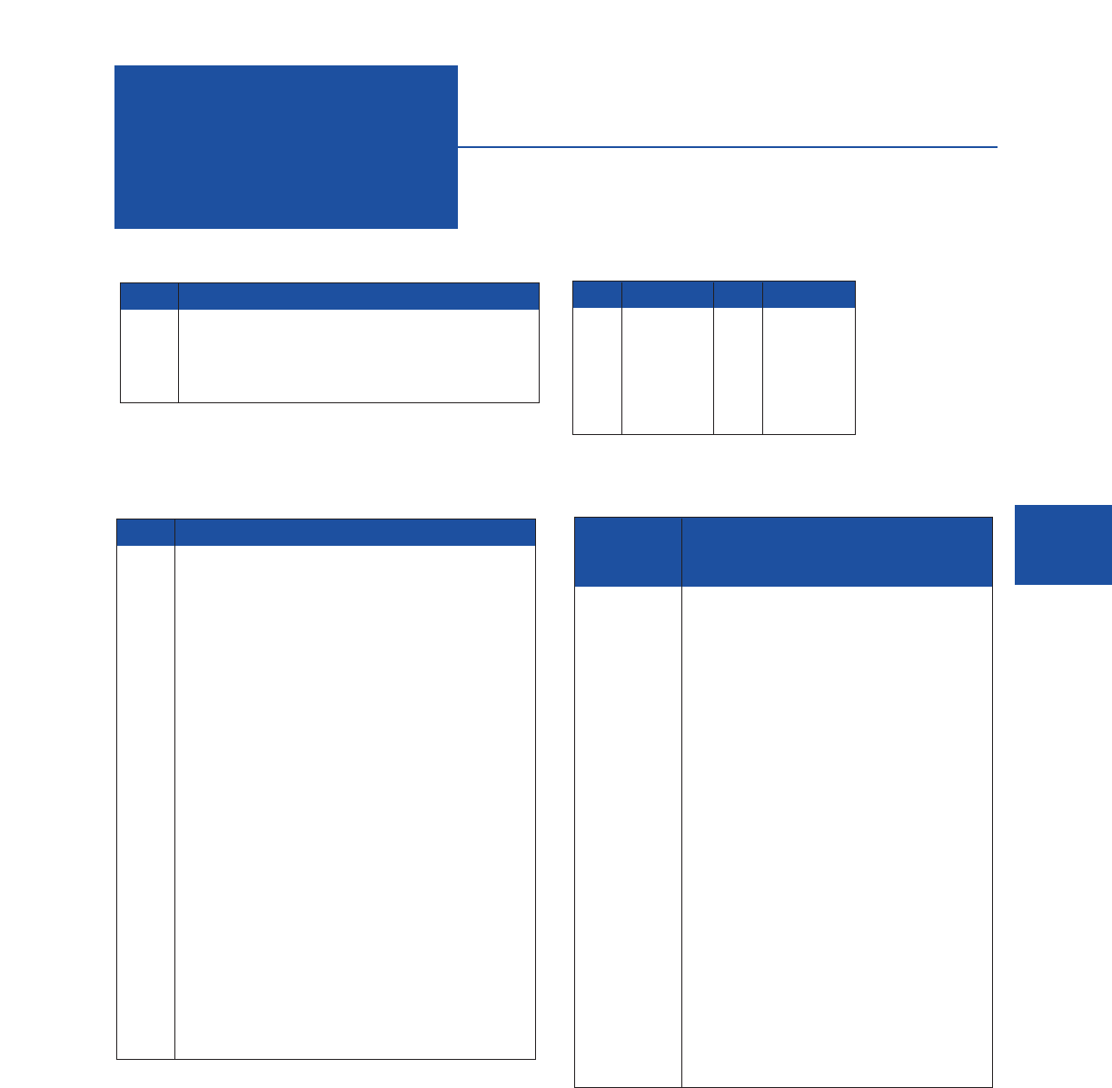
Color Code
Charts
Chart A
Pair No. Pair Color Code
1 White/Blue & Blue
2 White/Orange & Orange
3 White/Green & Green
4 White/Brown & Brown
Chart C
Fiber Color Fiber Color
1 Blue 7 Red
2 Orange 8 Black
3 Green 9 Yellow
4 Brown 10 Violet
5 Slate 11 Pink
6 White 12 Aqua
Chart B
Pair No. Pair Color Code
1 White/Blue & Blue/White
2 White/Orange & Orange/White
3 White/Green & Green/White
4 White/Brown & Brown/White
5 White/Slate & Slate/White
6 Red/Blue & Blue/Red
7 Red/Orange & Orange/Red
8 Red/Green & Green/Red
9 Red/Brown & Brown/Red
10 Red/Slate & Slate/Red
11 Black/Blue & Blue/Black
12 Black/Orange & Orange/Black
13 Black/Green & Green/Black
14 Black/Brown & Brown/Black
15 Black/Slate & Slate/Black
16 Yellow/Blue & Blue/Yellow
17 Yellow/Orange & Orange/Yellow
18 Yellow/Green & Green/Yellow
19 Yellow/Brown & Brown/Yellow
20 Yellow/Slate & Slate/Yellow
21 Violet/Blue & Blue/Violet
22 Violet/Orange & Orange/Violet
23 Violet/Green & Green/Violet
24 Violet/Brown & Brown/Violet
25 Violet/Slate & Slate/Violet
Chart D
Pair or Pair & Binder
Group Number Color Code
Tip Color Ring Color
1 White Blue
2 White Orange
3 White Green
4 White Brown
5 White Slate
6 Red Blue
7 Red Orange
8 Red Green
9 Red Brown
10 Red Slate
11 Black Blue
12 Black Orange
13 Black Green
14 Black Brown
15 Black Slate
16 Yellow Blue
17 Yellow Orange
18 Yellow Green
19 Yellow Brown
20 Yellow Slate
21 Violet Blue
22 Violet Orange
23 Violet Green
24 Violet Brown
25 Violet Slate
COLOR CODE REPEATS FOR EACH GROUP OF 25 PAIRS.
For cables containing multiple groups of 25 pairs, each group will be
identified by a color coded binder following the above color chart.
Example: 50 pair cable will have 2 groups of 25 pairs; first binder color is
white/blue, second binder is white/orange.
MOHAWK 59
60 MOHAWK
Insulations
Property Cellular
Considered Polyethylene Polyethylene Nylon Polypropylene Polyurethane PVC FEP
Acid Resistance G to E G to E P to F E F G to E E
Abrasion Resistance G F to G E F to G O F to G G to E
Alcohol Resistance E E P E P G E
Alkali Resistance G to E G to E E E F G E
Benzol (Aromatic Hydrocarbons) P P G P to F P P to F E
Resistance
Degreaser Solvents P P G P P P to F E
(Halogenated Hydrocarbons)
Electrical Properties E E F E P to F F to G E
Flame Resistance P P P P P E O
Gasoline, Kerosene P to F P to F G P to F F P E
(Aliphatic Hydrocarbons) Resistance
Heat Resistance G to E G E E G G to E O
Low Temperature Flexibility E G to E G P G P to G O
Nuclear Radiation Resistance G G P to F F G P to G O
Oil Resistance G to E G to E E E E P O
Oxidation Resistance E E E E E E O
Ozone Resistance E E E E E EE
Water Resistance E E P to F E P E E
Weather – Sun Resistance E E E E F to G G to E O
Comparative Properties of Insulations
PE, PVDF
Amps Polyurethane Polypropylene Nylon PE (X-linked) FEP
PVC PVC PVC Thermoplastic
(Semi-Rigid) Elastomers
Size
AWG 80°C90°C105°C 125°C 200°C
30 2 3 3 3 4
28 3 4 4 5 6
26 4 6 5 6 7
24 6 7 7 8 10
22 8910 11 13
20 10 12 13 14 17
18 15 17 18 20 24
16 19 22 24 26 32
14 27 30 33 40 45
12 36 40 45 50 55
10 47 55 58 70 75
8 65 70 75 90 100
6 95 100 105 125 135
4125 135 145 170 180
2 170 180 200 225 240
Current Carrying Capacity of Insulated Copper Conductors
P = Poor F = Fair G = Good E = Excellent O = Outstanding
Above ratings are based on average performance of compounds. Any specific property can often be improved by the use of selective compounding.
Single Conductor in Free Air 30°Ambient Temp.
Temperature Rating
Insulation Materials Nominal
PVDF 6.4
Nylon 4.0
Polyester 2.80
Polyethylene (Cellular) 1.50
Polyethylene (High Density) 2.34
Polyethylene (Low Density) 2.28
Polypropylene 2.24
Polyvinyl Chloride (Semi-Rigid) 4.3
Teflon FEP 2.15
Teflon TFE 2.15
Tefzel, Halar 2.6
FEP (Cellular) 1.5
Dielectric Constants of Insulations
UTP Installation
Guide
• Category 5e
• Category 6
UTP cables were developed and designed to be used
independent of the system application. Set transmission
performance criteria (Categories) have been established for the
various grades of UTP cables.
What are these Categories?
Categories are a method of classifying UTP cables and related
hardware within specific performance criteria.
Category 5e - Specifies cable and connecting hardware with
transmission characteristics up to 100 MHz. It differs from
Category 5 by having 3 dB tighter NEXT requirements and
additional requirements for PS NEXT, ELFEXT, PS ELFEXT,
and RL.
Category 6 - This document specifies cable and connecting
hardware with transmission characteristics up to 250 MHz. In
addition Category 6 has tighter insertion loss, NEXT, PS NEXT,
ELFEXT and PS ELFEXT over Category 5e.
Cable Handling
Length
The maximum horizontal cable length is 90 meters (295 feet).
Ten meters is allowed for cords in the work area, and for patch
cords or jumpers in the telecommunications closet.
The maximum backbone cable length is 90 meters (295 feet).
This 90 meter length assumes that 5 meters (16 feet) are
needed at each end for equipment cables connecting to the
backbone.
Pulling Tension
Maximum pulling tension for a 4 pair horizontal cable is 25 lbf.
Excessive pulling tensions may occur during installation. Once
the damage is done, reversing the effect may not be sufficient
enough to correct the problem and cable replacement is
recommended. Intermediate cable pulls within the overall cable
run may be necessary to avoid exceeding the maximum pulling
force.
Minimum Bend Radius
4 pair UTP cables have a 1” Min. Bend Radius.
CAUTION: Exceeding the minimum bend radius can distort the
cable geometry and result in degrading of transmission
performance.
Repositioning of the cable to the proper bend radii may not
correct the fault. Once the damage is done, the best option is
replacement of the damaged run.
There are two common places where exceeding the minimum
bend may occur:
• At the workstation wall outlet. After the cable is terminated,
too often the remaining cable is jammed into the wall outlet,
or worse, wrapped around itself and shoved into the outlet. A
better practice would be to gently work the excess cable
length back through the wall outlet into the wall.
• At the wiring closet, during routing of the cable to the terminal
block or patch panel. Prior cable placement practices may
have encouraged making the cable appear as formfitting or
tight against the routing structure (cable tray or rack) as
possible. A better practice would be to incorporate gently
sweeping curves along the cable path avoiding sharp bends
or changes in direction. Every effort should be made to
ensure the path the cable follows has smooth gradual
sweeps at any transition point.
Installation in Temperatures Below Freezing
The minimum installation temperature for plenum cables is
0° C (32° F). If the cable has to be installed when the temperature
is below 32° F the following precautions should be taken to
ensure that the jacket will not crack:
• Store the cable in a heated area whose temperature is above
50° F for 24 hours before installation.
• Transfer only enough cable to the job site for 4 hours work.
The cable will retain enough heat to prevent cracking. Cable
that has not been installed after 4 hours should be returned
to a heated area.
• Coil service loops in 10” to 12” loops. A tight coil could
cause the cable to crack.
• Normally the cables are terminated after the site is enclosed
and heated. Do not attempt to terminate the cables when the
temperature is below freezing.
Over Stressing
Eliminate cable stress caused by tension in suspended cable
runs and tightly cinched cable bundles
Excessive cable loading or stress can also occur if a cable is
incorrectly suspended in a cable run. A recommended cable
support spacing is 48" to 60" centers.
Avoid twisting of cable during installation. Excessive twisting
may result in distortion of cable geometry, and in severe cases
tears in the jacket.
In addition to the above guidelines extracted from TIA/EIA-568,
Mohawk strongly recommends the following supplementary
installation tips:
•Do not walk or step on high performance cable. Do not run
over high performance cable with hand trucks or forklifts.
This will exert excessive force on the cable, distorting the
geometry and/or crushing the pairs, resulting in electrical
shorts.
•Do not use staples, either from a staple gun or mounting in a
traditional manner with a hammer. Staples can exert
excessive force on the cable and distort the pair geometry.
•D-Rings, nail on clamps or Velcro straps offer acceptable
cable management techniques without compressing the
cable.
• Do not run cable near sources of heat, as this may
negatively impact cable attenuation.
•Maintain a 6" minimum spacing between cables and
sources of EMI, such as fluorescent lights or unshielded
power lines.
Termination
The installer must be acquainted with the Connector
Manufacturer’s installation instructions. The correct tools, wire
layout and untwist length are critical, especially in Category 6
installations. Modular jacks usually have the Pair color code
marked on the jack. The color code can be either T568A or
T568B wiring methods. Maintain the same pin to pair
combination throughout the installation. Changing pin pair
assignment can result in crossed pairs. Modular jacks and
cross-connect blocks employ IDC connectors to complete the
circuit between the cable and the hardware. The manufacturer
will recommend the tools needed to terminate the cable.
T
erminate with connecting hardware of the same category or
higher. Any link that has substituted a lower category
component is automatically classified to that lower category
.
The maximum allowable amount of untwisting during cable
termination to connecting hardware is 0.5" for Category 5e and
Category 6 cables. Exceeding the recommended length of
untwisting may cause performance problems. The same
techniques should be employed when terminating cross-
connect blocks. Maintaining jacket integrity to the point of
termination aids in maintaining cable geometry and NEXT
isolation from adjacent cable pairs.
Bridged taps and splices are not permitted as part of copper
horizontal cabling requirements.
T
esting
It is best to determine the lengths of several representative cable
runs and adjust the NVP to correspond to the known cable
lengths. If the readout for the cable length is longer than the
known length, the NVP should be decreased. Conversely, if the
readout for the cable length is shorter than the known length the
NVP should be increased.
The NVP values for Mohawk’s products are as follows:
Non-Plenum Plenum
Category 5e 68% 72%
Category 6 68% 72%
A Note of Caution:
Level II or Level III Testers will be required to accurately
measure Category 5e and 6 permanent links and channels.
Consult the manufacturer of your test set for clarification.
Category 5e and 6 - Permanent Link
Requirements at Specific Frequencies
Freq Insertion Loss NEXT
(MHz) 5e 6 5e 6
1.0 2.1 1.9 60.0 65.0
4.0 3.9 3.5 54.8 64.1
10.0 6.2 5.6 48.5 57.8
20.0 8.9 7.9 43.7 53.1
25.0 10.0 8.9 42.1 51.5
31.25 11.2 10.0 40.5 50.0
62.5 16.2 14.4 35.7 45.1
100.0 21.0 18.6 32.3 41.8
200.0 -- 27.4 -- 36.9
250.0 -- 31.1 -- 35.3
Freq ELFEXT RL
(MHz) 5e 65e 6
1.0 58.6 64.2 19.0 19.1
4.0 46.6 52.1 19.0 21.0
10.0 38.6 44.2 19.0 21.0
20.0 32.6 38.2 19.0 21.0
25.0 30.7 36.2 18.0 19.5
31.25 28.7 34.3 17.1 18.5
62.5 22.7 28.3 14.1 16.0
100.0 18.6 24.2 12.0 14.0
200.0 -- 18.2 -- 11.0
250.0 -- 16.2 -- 10.0
The Permanent Link requirements include 90 meters of
horizontal cable and the connectors at each end. The cables to
the test equipment are not part of the permanent link and are
subtracted out by the test equipment
Channel requirements include 90 meters of horizontal cable
and 10 meters of equipment cords, patch cords and jumpers.
The maximum length of cross-connect jumpers and patch
cords in the cross-connect facility should not exceed 5 meters.
For additional information and an ANSI referenced list, please
contact: GLOBAL ENGINEERING DOCUMENTS at 1-800-854-
7179.
For additional information on cable selection, please call 1-
800-422-9961 or email to techsupport@mohawk-cable.com.
These guides have been prepared by Mohawk as an aid for
installers of Mohawk Category and Fiber Optic Cables and are
not a warranty by Mohawk and should not be construed as
such.
Mohawk’s sole warranty with respect to its cables is set forth
in the document entitled “Mohawk Warranty,” which has been
or will be provided separately to installers of Mohawk Category
and Fiber Optic Cables.
MOHAWK 61
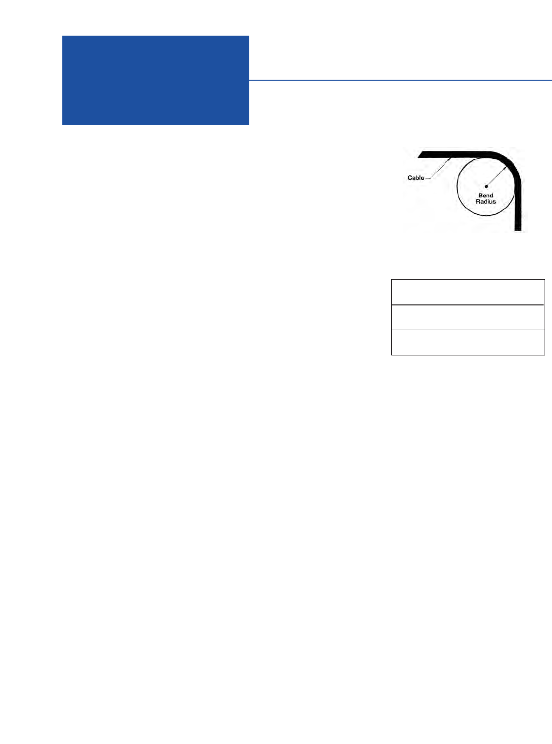
62 MOHAWK
Fiber Installation
Guide
FOREWORD
It is assumed that the reader has a general
understanding of fiber optic cable constructions
and terminology. BICSI (www.bicsi.org) is an
excellent resource for general information.
SAFETY PRECAUTIONS
• When installed on a live system, invisible laser
radiation may be present. Do not stare into
connector endface or view directly with optical
instruments.
• Wear safety glasses when working with optical
fiber.
• Dispose of all scrap fibers to avoid getting
fiber slivers.
Scope
The following guidelines are intended as a
general overview of important issues related to
the installation of fiber optic cable.
INSTALLATION SPECIFICATIONS
For a proper cable installation, it is important to
understand the cable specification. The two
most important specifications are the tensile
loading and bend radius specifications. It is very
important to adhere to these limits.
Tensile loading
Although there are two different types of tension
in fiber optic cables, the important tension for
the installation is the maximum load the cable
can be subjected to without causing permanent
damage. We call it the “maximum load
installation” and it is measured in Newton or
pounds. The “maximum load installation” can
also be known as “short term tension”,
“dynamic load”, “installation load” or
“installation tension”.
Whenever possible, the tension of the
installation should be monitored. The tension
can be measured with a dynamometer, or with
a pulling wheel. Breakaway pulling eyes are
available which separate if the tension
reaches a preset level. The use of a swivel is
recommended when pulling the cable in tray.
The swivel allows the cable and pulling rope to
twist independently.
If pulling a cable in an outside plant conduit,
the use of approved lubricants can help
minimize friction. The use of corrugated
innerducts can also help reduce the amount of
tension needed to pull the cable. When installing
loose-tube cables, the use of sealer is
recommended to prevent gel migration.
If a run is too long, or if several bends are in
the conduit, intermediate pull boxes should be
used to separate one pull into two or more
shorter pulls. A cable should not be pulled
through more than two 90°bends at one time. If
three or more 90°bends in a continuous run are
unavoidable, the cable should be installed from a
central point, unreeled into a figure-eight, and
then backfed to complete the installation. Sharp
bends may increase cable tension, so it is best
to install cable in sequences that minimize
stress and labor costs.
When running cable vertically, take note of
the cable weight. Install cables in a sequence
that applies the least amount of strain on the
cable. For example, most vertical chasers in
buildings tend to be congested at the lower
floors; instead, try to start your installation at
the top and work down the building, thereby
eliminating most of the cable installation by
the time you reach the lower floors. After
installation, the strength member of the cable
will need to support the hanging cable. If a long
vertical run is necessary, cable should be
secured at each floor and service loops should
be placed every three floors, at a minimum. This
procedure will help distribute the weight of the
cable vertically and will facilitate access to
moves, adds and changes (MACs), if needed at
a later date.
Bend radius
There are two types of bend radius:
•The short term minimum bend radius, or
dynamic bend radius, is the tightest
recommended bend while installing cable at
the maximum rated tension. It is the larger of
the two specified bend radii. Throughout the
pull, the minimum bend radius must be strictly
followed. If a location exists in the middle
of a run where a relatively tight bend is
unavoidable, the cable should be hand-fed
around the bend or a pulley can be used.
•The long term bend radius, or static bend
radius, is the tightest recommended bend
while the cable is under a minimum tension. It
is the smaller of the two specified bend radii.
After the pull is complete, the cable can be
bent more tightly to fit into existing space, but
not to exceed the long term minimum bend
radius.
Figure 1: Bend Radius
Table 1: Typical Bend Radius Specification
Short Term Long Term
(Installation) (Installed)
Outside Plant Cable 20x Cable 15x Cable
Diameter Diameter
Premise Cable 15x Cable 10x Cable
Diameter Diameter
Always follow the manufacturer’s guidelines
for minimum bend radius and tension. Failure
to do so may result in high attenuation
(macrobends) and possible damage to the cable
and fiber. Guidelines are normally supplied with
the cable manufacturer specification sheets. If
the bend radius specifications are unknown, the
industry de facto standard is to maintain a
minimum radius of 20X the diameter of the
cable.
The minimum bend radius must also be
adhered to when using service loops. Fiber optic
splice trays and patch panels are designed to
accommodate the bend radii of the individual
fibers, but outside of the hardware, extra care
must be taken.
INSTALLATION TOOLS
Gripping Techniques
General
To effectively utilize all of the available strength
in the cable, the strength member must be used.
The manufacturer’s specification will identify the
strength member(s) in the cable.
Cables with aramid yarn as the strength member
For cables using aramid yarn alone as the
strength member, the jacket can be removed
exposing the aramid. The aramid should be tied
in a knot with the pull rope, so that the jacket will
not be inadvertently used for strength.
Optionally, the jacket can be tied into a tight
knot before pulling. After pulling, the knot should
be cut off.
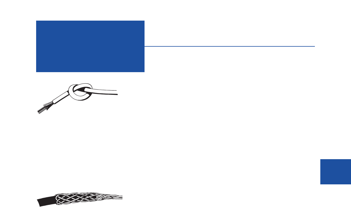
MOHAWK 63
Fiber Installation
Guide
Cables with aramid yarn and an e-glass central
member
For cables using aramid yarn and an e-glass
central member, a pulling grip should be used.
The strength member(s) should be attached
independently. This can be accomplished by
weaving the strength member into the fingers of
the grip, and then taping it together. All strength
members should be gripped equally to ensure a
proper distribution of tension.
Pre-terminated Fiber Optic Cable Assemblies
General
The factory pre-terminated fiber optic cable
assemblies may be specified in project
environments such as Data Centers. The
assemblies can be ordered in either indoor
(plenum) or outdoor versions, and different fiber
counts, and in multimode or single-mode. A
pulling eye can be factory installed on either end
or on both ends of the cable. The pulling eye
(and associated cable netting) will protect the
pre-terminated ends during the pull. This product
is a great time saver ensuring quality
connections every time.
Pulling eye
The pulling eyes (and associated cable
netting) are highly recommended. The pulling
eye will facilitate the installation as well as
protecting the pre-terminated ends during
the pull.
For both regular and pre-connectorized
cables, the maximum pull force is identified
with the “installation maximum load” cable
specification on our Datasheets.
In many cases, pulling is not done from point
to point, but rather from an intermediate point
pulling back in each direction to each
termination location. It is then important to make
sure that the cable is ordered with two pulling
eyes, one at each end.
The installation of a cable, which is pre-
connectorized on both ends, requires special
raceway considerations and pulling grips. A
typical fiber optic connector is 0.5 in. (1.25 cm)
in diameter, has a limited pull-off rating and must
be protected during cable placement. A pulling
grip for a pre-connectorized cable must
successfully isolate the connectors from any
tensile load by placing the load on the cable
itself. The pulling grip must also protect the
connectors from abrasion and damage. In
medium fiber counts (6 to 24 fibers) the
connectors must be staggered when installed to
reduce the diameter of the pulling grip. In high-
fiber counts (greater than 24 fibers), installation
of a connectorized cable may not be possible
due to the conduit size that would be required.
INSTALLATION GUIDELINES
Prior to installation
All optical fiber cables are tested before leaving
our manufacturing plant. Before installing the
cable, we recommend testing the cable on the
reel for continuity. This is to ensure that no
damage occurred during shipment. Since the
cost of installation is usually higher than the cost
of materials, testing the fibers before installation
can avoid unnecessary additional expenses
and help meeting important deadlines. At a
minimum, continuity testing can be done on the
reel with a visual fault locator or a simple fiber
tracer such as a flashlight, a modified flashlight
to properly hold the fibers, a microscope or a
bright red light (LED lookalike). With this simple
test, you should be able to identify broken fibers,
if any, within the optical fiber cable.
Also, it is recommended to double-check the
actual fiber count and the actual cable length, to
avoid any inconvenience.
It is preferable to use Velcro wraps instead of
tie-wraps. Remember not to distort the shape of
the cable, as this adds pressure onto the optical
fibers and may affect performance.
Fiber optic cables can be installed in
innerducts. The use of innerducts tends to
reduce the pulling tension required. Ensure that
the properly rated innerduct is being installed.
A 3 to 6 m (10 to 20 ft) of cable slack should
be stored in enclosure or on the wall to allow
repairs and/or relocation needs.
Installation in Temperatures Below Freezing
The minimum installation temperature for
plenum cables is 0° C (32° F). If the cable has to
be installed when the temperature is below 32°F
the following precautions should be taken to
ensure that the jacket will not crack:
• Store the cable in a heated area whose
temperature is above 50° F for 24 hours
before installation.
•Transfer only enough cable to the job site for 4
hours work. The cable will retain enough heat
to prevent cracking. Cable that has not been
installed after 4 hours should be returned to a
heated area.
• Coil service loops in 10” to 12” loops. A tight
coil could cause the cable to crack.
• Normally the cables are terminated after the
site is enclosed and heated. Do not attempt to
terminate the cables when the temperature is
below freezing.
OUTSIDE PLANT CABLE INSTALLATION
General
Protect exposed cables from vehicular and
public traffic.
Underground Installation
For underground installation, center pull long
cables. Store excess cable in vaults and manholes,
and identify optical cables with markers.
Aerial Installation
Use proper hardware matching cable, span and
tension requirements. Use correct cable jacket.
Buried Cable Installations
Identify cable locations with surface markers.
Anticipate obstructions.
Administration
A unique identifier shall be assigned to each
backbone cable and shall be marked on each
end. Reference should be made as per the
ANSI/TIA/EIA-606-A standard.
TERMINATION
General
Before termination, the cable should be properly
secured to provide a tension-free length of fiber.
When splicing fibers, mechanical or fusion, a
splice tray is needed to properly store the
completed splices. If connectors are to be used,
trays or shelves should be used to support the
fiber behind the connector. Proper strain relief
sleeves provided with the connectors should
always be used to prevent excessive bending of
fiber. No shelf is necessary if terminating a
breakout style cable with connectors.
Figure 2: Distribution Cable Tied in a Knot
Figure 3: Pulling Grip

64 MOHAWK
Fiber Installation
Guide
CABLE PREPARATION FOR THE
TERMINATION
General
It is acceptable to directly terminate the 900 µm
tight buffer from a distribution cable with a
connector, if the above precautions are taken. It
can be acceptable to directly terminate the 250
µm coated fiber from a loose buffer tube with a
connector in certain applications. However, it is
usually recommended to use a breakout kit
which converts a six or twelve fiber loose buffer
tube to a six or twelve fiber 900 µm distribution
style ready for termination.
If outside plant cables are used, the gel
flooding material needs to be cleaned with the
appropriate solvent (please consult the cable
manufacturer for recommendation on the choice
of solvent). The more thorough the cleaning, the
easier the termination procedure will be.
Cable preparation
To prepare the cable for termination, the outer
jacket must be properly stripped. Two ring cuts
should be made in the jacket; one about 2” from
the end and the second at the point where the
jacket is to be removed. Care must be taken not
to cut all the way through the jacket and into the
core. The 2” piece is removed from the end of
the cable exposing the core and the aramid
ripcord. Make a notch in the jacket alongside
the ripcord (do not cut the ripcord!). Pull the
ripcord with a needle-nose pliers, or similar,
until it reaches the second ring cut. Remove the
core from the sliced jacket and pull the jacket to
tear it at the ring cut.
Once the fiber optic cable is ready for
termination, follow the termination installation
instructions.
TESTING
General
Once the cable plant is installed and terminated,
it is recommended to test the fiber optic
segment. The testing should be done according
to TIA TSB-140. This document provides
guidelines for field-testing length, loss and
polarity of a completed fiber optic link.
It is necessary to perform an end-to-end
attenuation test to verify the quality of
installations and to ensure high quality system
performance. The best way to verify whether an
end-to-end link meets the link loss budget is to
divide the end-to-end link into segments at each
cross-connect and measure the attenuation of
each link segment. In order for the system to
operate properly, the sum of the attenuation for
the multiple link segments that form an end-to-
end link must be less than the link loss budget
calculated in the design phase.
Test equipment
Various types of testing equipment are available
on the market, such as Optical Loss Test Set
(OLTS), Visual Fault Locator (VFL) sets or the
Optical Time Domain Reflectometer. For
troubleshooting, the OTDR is recommended.
Optical Loss Test Set (OLTS)
The OLTS consists of a light source and an
optical power meter. The main function of this
equipment is to measure the optical power or
loss.
Visual Fault Locator (VFL) or tracer
The VFL is a red laser source; the tracer is an
LED source. Either instrument can be used to
trace fibers and troubleshoot faults on optical
fiber cables. The main function of this
equipment is to check continuity of the fiber,
as well as to identify fibers and connectors in
patch panels or outlets.
Optical Time Domain Reflectometer (OTDR)
The OTDR is a more sophisticated
measurement instrument. It uses a technology
that injects a series of optical pulses into the
fiber under test and analyzes the light scattering
and the light reflection. This allows the
instrument to measure the intensity of the return
pulse in functions of time and fiber length. The
OTDR is used to measure the optical power loss
and the fiber length, as well as to locate all
faults resulting from fiber breaks, splices or
connectors.
Fiber testing guidelines
The following testing guidelines promote
efficient and accurate testing:
• Clean all connections and adapters at the optical
test points prior to taking measurements, as per
ANSI/TIA/EIA-526-14A.
•The light source or OTDR (Optical Time Domain
Reflectometer) must operate within the range of
850 ± 30 nm, or 1300 ± 20 nm for multimode
testing.
• Test jumpers must be of the same fiber core size,
performance and connector type as the cable
system (e.g., 50/125 µm jumpers for a 50/125
µm optical fiber system) and shall be one to five
meters long.
ANSI/TIA/EIA-568-B.1 is the recommended test
method.
Every reel of fiber optic cable shipped from
Mohawk has a test report attached showing the
attenuation of all the fibers in the cable. Typical
values for a multimode cable are 2.7 dB/km
when measured at 850 nm and 0.7 dB/km
when measured at 1300 nm. Therefore, for a
run of 100 meters (328 feet), the typical cable
attenuation is only 0.27 dB at 850 nm and
0.07 dB at 1300 nm.
Most fiber optic connectors are specified
as having an insertion loss of less than 0.5 dB.
Since there are two connections for
each fiber, up to 1 dB of attenuation can be
expected to be added to the installed cable.
As the cable runs get shorter, the cable
attenuation becomes lower, but the connector
insertion loss remains the same. If the cable
is installed properly, most of the measured
attenuation will come from the connectors.
If several fibers off of the same cable show
high attenuation, or if a single fiber attenuation
remains high after retermination, an OTDR
should be used to isolate the problem. An OTDR
is an excellent tool for troubleshooting a failing
link by identifying the location of the faulty
component.
These guides have been prepared by
Mohawk as an aid for installers of Mohawk
Category and Fiber Optic Cables and are not
a warranty by Mohawk and should not be
construed as such. Mohawk’s sole warranty
with respect to its cables is set forth in the
document entitled “Mohawk Warranty,”
which has been or will be provided
separately to installers of Mohawk Category
and Fiber Optic Cables.

MOHAWK 65
Slide
Guides
LAN Cable Selector
Guide
Match your application to the
corresponding cable category.
Use the selector guide to
determine which copper
product best suits your needs.
From legacy 10BASE-T to
Gigabit Ethernet to emerging
networking protocols, the
applications are identified.
Worst-case performance is
stated at two frequencies for all
categories of performance,
from minimally compliant
Category 5e to our Category
6A GigaLAN 10.
Multimode Fiber Grade
Selector
Short Wavelength or Long
Wavelength, 50/125 micron or
62.5/125 micron, we have a
solution for you. Mohawk has
designed our Fiber Grade
Selector to help you determine
which multimode fiber type
best suits your application.
Legacy installations to
emerging networking protocols
are identified and the
guaranteed performance of
each fiber is given along with
the appropriate optical
specifications.
Plenum & Non-Plenum
Conduit Fill Guide
This rotary style guide lets you
determine the number of
cables, from Category 3 to
Augmented Category 6, that
will fill a trade size conduit.
Either plenum or non-plenum.

66 MOHAWK
Technical
Advisory Fiber Optic Cables
Tight Buffer for Outdoor Considerations
There are two standard types of fiber optic cables for
data/voice communications: tight buffered and loose
tube. As a rule, tight buffered cables are used indoors
(intrabuilding, premise) and loose tube cables are
used outdoors (interbuilding, outside plant).
Loose tube cables should be utilized in outside plant
installations whenever possible, due to their long history
with the various telephone companies, superior UV
resistance, and exceptional resistance to moisture.
Many studies have shown that the long term reliability
of optical fiber is highest when the fiber is contained
in a loose tube design. Loose tube cables may be
ordered in a “dry block” version for easier termina-
tion, thus avoiding the gel flooding which some con-
sider to be a problem.
Tight buffered cables utilize a 900 µm buffer over each
individual fiber to provide ease of handling and a
color code. These cables typically have a flame retar-
dant jacket, such as PVC, in order to meet the code
requirements necessary for installation in a building.
The combination of the tight buffers with the PVC
jacket results in a flexible design that is easy to work
with. When used in an outdoor environment, a tight
buffer cannot provide the same level of protection to
the optical fiber as a loose tube.
RiserLite®cables are designed to bridge the gap
between standard loose tube and tight buffered
cables. RiserLite cables are gel-filled, “dry blocked”
loose tube cables which allow them to be installed in
outdoor applications. They also have a UL OFNR and
c(UL) OFN FT4 rating, which allows them to be
installed in the building riser, as well.
Many installers prefer to use tight buffered cables in
the outside plant because of the relative ease of ter-
mination. If tight buffered cable is to be used in an
outside environment, then special care must be
taken. The cable must not be installed in aerial
lashed, self-support, or direct buried applications.
The cable must be installed below the frost line and in
a “dry” conduit. As an alternative, a product from
American Polywater (www.polywater.com) called
“IceFree” can help keep the conduit dry and prevent
water from freezing and damaging the fiber. Proper
pulling techniques must also be followed, as tight
buffered cables typically have lower pulling tensions
than loose tube cables.
If questions arise concerning a particular application,
call the Technical Support Group of Mohawk at
(800) 422-9961.
MAC
Certification MAC Warranty Program
MAC Warranty Program
Several years ago Mohawk developed a standards
based BiCSi accredited training program. This pro-
gram is geared primarily towards contractors, but is
also offered to consultants and end-users. After suc-
cessfully completing the training program the individ-
ual is eligible to receive 7 BiCSi credits.
There are two options available to become a Mohawk
Accredited Contractor (MAC). First, you may elect to
be trained by one of Mohawk’s on staff RCDD instruc-
tors. This would enable you to be eligible to receive
the 7 BiCSi credits. Second, you may choose to be
grandfathered into the MAC program by having suc-
cessfully completed an approved training program
offered by one of our connectivity partners.
The major benefit of being a MAC is to enable the
contractor to offer an extended warranty to the end-
user on Mohawk products.
The Mohawk ChannelMATE®Cabling System
Warranty period offered by a MAC is from 15 years to
lifetime. It encompasses Mohawk’s copper products
from Category 5e through Augmented Category 6,
including high pair count cables, copper backbone,
and all fiber optic cables.
Additional benefits of being a MAC contractor
include the backing of Mohawk’s comprehensive
technical support group for product information,
installation troubleshooting and industry updates on
the latest standards and applications guidelines.
MAC contractors may also be eligible for a product
rebate based on their qualified purchases. All backed
by the strength of Belden’s financial and managerial
resources.
MOHAWK 67
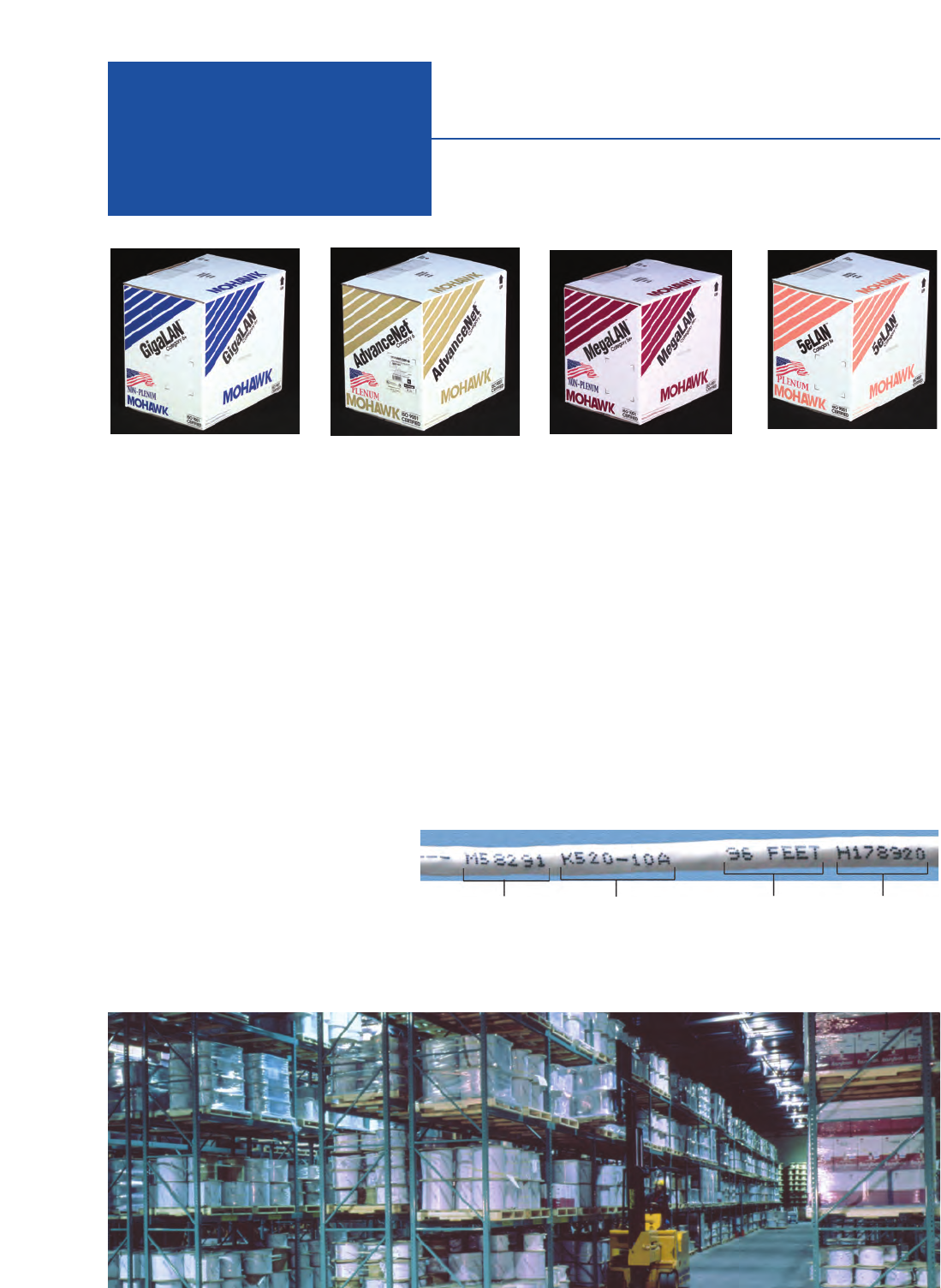
68 MOHAWK
Packaging Color Coded Cartons for
Ease of Category Identification
Reels
Mohawk’s standard UTP and ScTP copper cables are
available on 1000 ft. reels from inventory. Non-
standard cables are available in customer specified
lengths as well as 1000 ft. reels.
Fiber Optic Cables
Mohawk’s fiber optic cable is supplied on reels only
and is available in specified lengths with a –0+10%
tolerance on standard size reels. Non-standard put-
ups are available on request.
Easybox™
For Category 3–6e+ UTP Cables
The cable is packaged directly in the box and
dispenses in a tangle-free payout, as if on a reel,
in 1000 ft. lengths.
Cable Caddy™— Reel-in-a-box
For Category 3–6e+ UTP Cables
The 1000 ft. length of cable is placed on a plastic reel
and is dispensed from the front of the Cable Caddy.
Category 3–6e+ cables are also available on
standard 1000 ft. reels.
Smart Legend®
Mohawk’s Smart Legend designation
has been implemented to assist
installers with cable identification. A
serial number is printed every two feet
on all 4 pair cables (excluding OSP
cables) at final packaging. This allows
for easy identification of reels, saving installers the time of labeling each run. For multiple runs off the same
spool, only the addition of a single-character identifier is required, saving time wasted on a lengthy identification
scheme.
Part Number Lot Code Sequential Footage
Marker
Serial
Number
Shipping &
Packaging
Guide
Package Number Per
Pallet Size of Pallet
Cat 5e 5e LAN® • Cat 5E+ MegaLAN®Augmented Cat 6 • GigaLAN10TM
Package Number Per
Pallet Size of Pallet
Package Number Per
Pallet Size of Pallet
25 pair Gross 50 pair Gross 100 pair Gross
Weight Weight Weight
200 pair Gross 300 pair Gross 400 pair Gross
Weight Weight Weight
Cat 3 Non-Plenum
Cat 3 Plenum
25 pair Cat 5 & 5e Power Sum
High Pair Count Reel Put-ups
12” Reels 60 38” X 48”
Boxes 36 44” X 44”
Reel in a Box 36 38” X 48”
5e PVC Box 45 42” X 48”
18” Reels 15 44” X 44”
(13&k”W x 10!f”D x 12!s”H)
(11&k”W x 11#k”D x 11&k”H)
(14!f”W x 14!f”D x 7%k”H)
14” Reels 36 42” X 42”
Boxes 33 45” X 48”
Reel in a Box 27 42” X 42”
(15!s”W x 11!f”D x 14!f”H)
(12#f”W x 12#f”D x 12&k”H)
Cat 6 6 LANTM • Cat 6e AdvanceNet®
Cat 6e+ GigaLAN®
20” Reel 1000 ft 123 lbs 22” Reel 1000 ft 224 lbs 30” Reel 1000 ft 467lbs
24” Reel 2000 ft 246 lbs 30” Reel 2000 ft 455 lbs 36” Reel 2000 ft 950 lbs
36” Reel 5000 ft 620 lbs 48” Reel 5000 ft 1,160 lbs 42” Reel 2500 ft 1,167 lbs
36” Reel 6500 ft805 lbs 48” Reel
4
000 ft1,910 lbs
54” Reel 5000 ft 2,400 lbs
42” Reel 1000 ft814 lbs 48” Reel 1000 ft1,897 lbs 54” Reel 1000 ft 1,900 lbs
54” Reel 2000 ft 1,680 lbs 54” Reel 2000 ft 2,800 lbs 72” Reel 2000 ft 3,900 lbs
72” Reel 5000 ft 4,300 lbs 60” Reel 3000 ft 4,200 lbs
72” Reel 4000 ft 5,600 lbs
Plenum Gross Weight Riser Gross Weight
22” Reel 1000 ft 131 lbs 24” Reel 1000 ft 119 lbs
30” Reel 2000 ft 262 lbs 36” Reel 2000 ft 245 lbs
36” Reel 5000 ft 655 lbs 48” Reel 5000 ft 640 lbs
Package Number Per
Pallet Size of Pallet
Additional Reel Sizes
16” 27 48” X 48”
18” 15 44” X 44”
20” 8 42” X 42”
22” 8 42” X 42”
24” 8 48” X 48”
MOHAWK 69

70 MOHAWK
Locator
Mohawk P/N Page Mohawk P/N Page Mohawk P/N Page Mohawk P/N Page Mohawk P/N Page
M52995 .......................15
M53639 .......................21
M54568 .......................15
M54708 .......................21
M54783 .......................21
M54785 .......................15
M54998 .......................15
M55073 .......................23
M55082 .......................21
M55211 .......................23
M55212 .......................23
M55216 .......................23
M55436 .......................15
M55477 .......................15
M55530 .......................15
M55586 .......................15
M55700 .......................23
M55704 .......................23
M55721 .......................15
M55760 .......................15
M55837 .......................15
M55900 .......................15
M55901 .......................15
M55902 .......................15
M55915 .......................15
M55916 .......................15
M55959 .......................15
M55980 .......................15
M55986 .......................19
M55987 .......................19
M55988 .......................13
M55989 .......................13
M55994 .......................15
M55995 .......................15
M56009 .......................15
M56072 .......................13
M56092 .......................13
M56093 .......................13
M56094 .......................13
M56095 .......................13
M56126 .......................23
M56128 .......................23
M56129 .......................23
M56165 .......................13
M56166 .......................13
M56167 .......................13
M56168 .......................13
M56210 .......................15
M56230 .......................15
M56256 .......................15
M56669 .......................21
M56670 .......................13
M56700 .......................22
M56726 .......................24
M56746 .......................13
M56753 .......................22
M56760 .......................21
M56773 .......................22
M56801 .......................23
M56809 .......................21
M56823 .......................21
M56832 .......................22
M56871 .......................26
M56876 .......................13
M56877 .......................13
M56878 .......................13
M56882 .......................13
M56889 .........................9
M56905 .........................9
M56912 .......................21
M56954 .......................13
M56985 .......................24
M57009 .......................21
M57040 .......................22
M57041 .......................26
M57042 .......................26
M57048 .......................13
M57071 .......................24
M57073 .......................24
M57074 .......................24
M57075 .......................24
M57076 .......................24
M57077 .......................24
M57098 .......................23
M57113 .......................13
M57116 .......................21
M57129 .......................13
M57193 .........................9
M57194 .........................9
M57195 .........................9
M57196 .........................9
M57197 .........................9
M57198 .........................9
M57199 .........................9
M57200 .........................9
M57201 .........................9
M57202 .........................9
M57203 .........................9
M57204 .........................9
M57205 .........................9
M57206 .........................9
M57207 .........................9
M57208 .........................9
M57209 .........................9
M57210 .........................9
M57211 .......................23
M57216 .......................24
M57269 .......................21
M57277 .......................21
M57322 .......................19
M57360 .......................19
M57361 .......................19
M57362 .......................19
M57363 .......................19
M57364 .......................19
M57365 .......................19
M57366 .......................19
M57367 .......................19
M57370 .......................19
M57371 .......................19
M57372 .......................19
M57373 .......................19
M57374 .......................19
M57375 .......................19
M57376 .......................19
M57377 .......................19
M57378 .......................19
M57404 .......................30
M57407 .......................30
M57408 .......................30
M57409 .......................30
M57410 .......................30
M57411 .......................30
M57413 .........................7
M57414 .........................7
M57415 .........................7
M57416 .........................7
M57417 .........................7
M57418 .........................7
M57419 .........................7
M57420 .........................7
M57421 .........................7
M57422 .........................7
M57507 .......................24
M57508 .......................24
M57509 .......................24
M57511 .......................24
M57512 .......................24
M57517 .......................24
M57518 .......................24
M57519 .......................24
M57520 .......................24
M57542 .......................24
M57543 .......................24
M57544 .......................24
M57545 .......................14
M57546 .......................14
M57547 .......................14
M57548 .......................14
M57550 .......................14
M57551 .......................14
M57552 .......................14
M57553 .......................14
M57554 .......................14
M57555 .......................14
M57556 .......................14
M57557 .......................14
M57561 .......................26
M57562 .......................26
M57564 .......................21
M57570 .......................24
M57620 .........................7
M57621 .........................7
M57622 .......................26
M57623 .......................26
M57626 .......................30
M57627 .......................30
M57628 .......................30
M57629 .......................30
M57630 .......................30
M57631 .......................30
M57634 .......................24
M57635 .......................24
M57636 .......................24
M57637 .......................24
M57638 .......................24
M57639 .......................24
M57640 .......................24
M57641 .......................24
M57642 .......................24
M57656 .......................26
M57662 .......................21
M57750 .........................7
M57761 .......................14
M57770 .......................24
M57850 .......................21
M57860 .........................7
M57861 .........................7
M57866 .........................7
M57867 .........................7
M57868 .........................7
M57869 .........................7
M57870 .........................7
M57887 .......................14
M57924 .......................14
M57936 .......................14
M57996 .......................23
M58007 .......................14
M58008 .......................14
M58009 .......................14
M58010 .......................14
M58103 .......................13
M58104 .......................14
M58116 .......................28
M58126 .......................24
M58127 .......................24
M58128 .......................24
M58129 .......................24
M58130 .......................24
M58131 .......................24
M58132 .......................24
M58133 .......................24
M58134 .......................24
M58135 .......................24
M58141 .......................22
M58142 .......................22
M58143 .......................21
M58144 .......................20
M58145 .......................20
M58155 .......................17
M58156 .......................17
M58157 .......................17
M58158 .......................17
M58159 .......................17
M58160 .......................17
M58161 .......................17
M58162 .......................17
M58163 .......................17
M58164 .......................17
M58175 .......................17
M58176 .......................17
M58177 .......................17
M58178 .......................17
M58179 .......................17
M58180 .......................17
M58181 .......................17
M58182 .......................17
M58183 .......................17
M58184 .......................17
M58185 .......................20
M58186 .......................20
M58187 .......................20
M58188 .......................20
M58189 .......................20
M58190 .......................20
M58191 .......................20
M58192 .......................20
M58193 .......................20
M58195 .......................20
M58196 .......................20
M58197 .......................20
M58198 .......................20
M58199 .......................20
M58200 .......................20
M58201 .......................20
M58202 .......................20
M58203 .......................20
M58204 .......................24
M58205 .......................24
M58208 .......................24

Locator
Mohawk P/N Page Mohawk P/N Page Mohawk P/N Page Mohawk P/N Page Mohawk P/N Page
M58209 .......................24
M58210 .......................24
M58211 .......................24
M58212 .......................24
M58213 .......................24
M58214 .......................24
M58215 .......................24
M58216 .......................24
M58217 .......................24
M58218 .......................24
M58219 .......................24
M58220 .......................24
M58221 .......................24
M58222 .......................24
M58226 .......................24
M58280 .......................11
M58281 .......................11
M58282 .......................11
M58283 .......................11
M58285 .......................11
M58286 .......................11
M58287 .......................11
M58288 .......................11
M58289 .......................11
M58290 .......................11
M58291 .......................11
M58292 .......................11
M58293 .......................11
M58294 .......................11
M58295 .......................11
M58296 .......................11
M58297 .......................11
M58298 .......................11
M58299 .......................11
M58300 .......................11
M58349 .......................23
M58405 .........................7
M58414 .........................9
M58452 .......................25
M58453 .......................25
M58454 .......................25
M58455 .......................25
M58456 .......................25
M58457 .......................25
M58460 .......................25
M58461 .......................25
M58462 .......................25
M58463 .......................28
M58509 .......................29
M58520 .......................22
M58521 .......................22
M58522 .......................22
M58527 .......................26
M58577 .......................28
M58620 .......................29
M58622 .......................29
M58629 .......................29
M58630 .......................29
M58650 .........................5
M58651 .........................5
M58652 .........................5
M58653 .........................5
M58646 .........................5
M58647 .........................5
M58648 .........................5
M58649 .........................5
M58762 .......................27
M58772 .......................27
M92000s ............see M9X
M93000s ............see M9X
M95830 .......................31
M95890 .......................50
M96436 .......................50
M96512 .......................31
M96551 .......................51
M96566 .......................51
M96567 .......................51
M96568 .......................51
M96569 .......................51
M96570 .......................51
M96571 .......................51
M96572 .......................51
M96573 .......................51
M96574 .......................51
M96575 .......................51
M96632 .......................31
M96633 .......................31
M96639 .......................51
M98177 .......................50
M9A000’s...........see M9X
M9B000’s...........see M9X
M9C000’s...........see M9X
M9D000’s...........see M9X
M9E000’s ...........see M9X
M9W000’S..........see M9X
M9X001 .......................50
M9X002 .......................50
M9X003 .......................50
M9X004 .......................50
M9X005 .......................38
M9X006 .......................38
M9X007 .......................38
M9X008 .......................38
M9X009 .......................38
M9X010 .......................38
M9X011 .......................38
M9X012 .......................38
M9X013 .......................39
M9X014 .......................39
M9X015 .......................39
M9X016 .......................39
M9X017 .......................39
M9X018 .......................39
M9X019 .......................39
M9X020 .......................39
M9X021 .......................40
M9X022 .......................40
M9X023 .......................40
M9X024 .......................40
M9X025 .......................40
M9X026 .......................40
M9X027 .......................40
M9X028 .......................40
M9X029 .......................41
M9X030 .......................41
M9X031 .......................41
M9X032 .......................41
M9X033 .......................41
M9X034 .......................41
M9X035 .......................41
M9X036 .......................41
M9X037 .......................34
M9X038 .......................34
M9X039 .......................34
M9X040 .......................34
M9X042 .......................34
M9X043 .......................35
M9X044 .......................35
M9X045 .......................35
M9X046 .......................35
M9X048 .......................35
M9X080 .......................50
M9X081 .......................50
M9X082 .......................39
M9X083 .......................38
M9X100 .......................36
M9X101 .......................36
M9X102 .......................36
M9X103 .......................36
M9X104 .......................36
M9X150 .......................47
M9X151 .......................47
M9X152 .......................47
M9X153 .......................47
M9X154 .......................47
M9X155 .......................47
M9X170 .......................47
M9X171 .......................47
M9X172 .......................47
M9X173 .......................47
M9X174 .......................
47
M9X175 ...........................47
M9X202 .......................46
M9X204 .......................46
M9X205 .......................46
M9X206 .......................46
M9X207 .......................46
M9X209 .......................46
M9X211 .......................46
M9X215 .......................46
M9X240 .......................49
M9X241 .......................49
M9X242 .......................49
M9X243 .......................49
M9X244 .......................49
M9X245 .......................49
M9X246 .......................49
M9X247 .......................49
M9X248 .......................49
M9X381T .....................43
M9X382T .....................43
M9X384T .....................43
M9X386T .....................43
M9X389T .....................43
M9X391T .....................43
M9X393T .....................43
M9X398T .....................43
M9X400T .....................43
M9X500T .....................42
M9X502T .....................42
M9X505T .....................42
M9X507T .....................42
M9X509T .....................42
M9X510T .....................42
M9X511T .....................42
M9X513T .....................42
M9X520T .....................42
M9X601 .......................34
M9X602 .......................34
M9X604 .......................34
M9X606 .......................34
M9X609 .......................34
M9X611 .......................35
M9X612 .......................35
M9X614 .......................35
M9X616 .......................35
M9X619 .......................34
M9X620 .......................35
M9X621 .......................35
M9X622 .......................34
M9X623 .......................35
M9X630 .......................37
M9X631 .......................37
M9X632 .......................37
M9X633 .......................37
M9X634 .......................37
M9X640 .......................37
M9X641 .......................37
M9X642 .......................37
M9X643 .......................37
M9X644 .......................37
M9X700 .......................48
M9X701 .......................48
M9X702 .......................48
M9X703 .......................48
M9X704 .......................48
M9X705 .......................48
M9X720 .......................48
M9X721 .......................48
M9X722 .......................48
M9X723 .......................48
M9X724 .......................48
M9X725 .......................48
M9X740 .......................48
M9X741 .......................48
M9X742 .......................48
M9X743 .......................48
M9X744 .......................48
M9X745 .......................48
M9X810 .......................44
M9X811 .......................44
M9X812 .......................44
M9X813 .......................44
M9X814 .......................44
M9X815 .......................44
M9X816 .......................44
M9X817 .......................44
M9X890 .......................45
M9X891 .......................45
M9X892 .......................45
M9X893 .......................45
M9X894 .......................45
M9X895 .......................45
M9X896 .......................45
M9X897 .......................45
A0403634....................52
A0408829....................52
A0408835....................52
AX100029....................52
AX100947....................52
AX101075....................52
AX101077....................52
AX101100....................53
AX101101....................53
AX101791....................52
AX101792....................52
AX101793....................52
AX101794....................52
AX101981....................52
AX101982....................52
AX101983....................52
AX101984....................52
AX102062....................52
MOHAWK 71
