112170 Catalog
230819-Catalog 230819-Catalog 230819-Catalog 784572 Batch7 unilog cesco-content
2014-07-05
: Pdf 112170-Catalog 112170-Catalog 784572 Batch5 unilog
Open the PDF directly: View PDF ![]() .
.
Page Count: 48
Instrument Rated
Metering Equipment
Milbank Manufacturing | 4801 Deramus Ave., Kansas City, MO 64120 | 877.483.5314 | milbankworks.com

Milbank Manufacturing | 4801 Deramus Ave., Kansas City, MO 64120 | 877.483.5314 | milbankworks.com
Utility requirements for this equipment may vary. Always consult the serving
utility for their requirements before ordering or installing equipment.
2
MILBANK
OVERVIEW
Milbank Manufacturing | 4801 Deramus Ave., Kansas City, MO 64120 | 877.483.5314 | milbankworks.com
Milbank Overview
Energy At Work since 1927
Milbank builds solutions that move power for the residential, commercial, industrial, utility and transportation
sectors. Milbank combines more than 85 years of expertise in electrical engineering design and manufacturing
with a commitment to develop and globally implement sustainable, integrated power solutions. Milbank’s
portfolio includes electric metering systems, PowerGen™ wind and solar solutions, and portable power. A third-
generation, family-owned business, Milbank is headquartered in Kansas City, Mo. For more information, please
visit milbankworks.com.
Milbank meter sockets have set the standard for quality since
1927. With a 99.97% quality performance, thousands of
active products to meet your utility’s requirements and tens of
millions of sockets installed across the globe, our products help
keep energy at work. And with 22 stocking locations across the
U.S., and our OneSERT program to help during emergency
situations, our meter sockets are ready to go, wherever the job
may be.
Milbank’s standby and portable generators give you the peace
of mind of living life uninterrupted during increasingly frequent
power outages caused by severe weather, high demand and
other situations. Our electric vehicle supply equipment, wind
turbines and power management systems give you reliable and
sustainable ways to reduce both your energy costs and your
impact on the environment.
When it comes to commercial and industrial products, Milbank
has it covered! We offer a complete line of junction boxes,
telephone cabinet covers, transformer cabinets, wireways,
pushbutton enclosures, consoles and thermal management
products. We specialize in custom-built enclosures and are
more than happy to design a solution for your specific project.
Our commercial meter pedestals are easy to install, fast, safe
and secure, and completely customizable.
METERING
POWERGEN
COMMERCIAL & INDUSTRIAL

Milbank Manufacturing | 4801 Deramus Ave., Kansas City, MO 64120 | 877.483.5314 | milbankworks.com
Utility requirements for this equipment may vary. Always consult the serving
utility for their requirements before ordering or installing equipment.
3
TABLE OF
CONTENTS
Milbank Manufacturing | 4801 Deramus Ave., Kansas City, MO 64120 | 877.483.5314 | milbankworks.com
Table of Contents
CT Rated Sockets
Plunger bypass features & benefits .................................................................................................................................. 4
20 amp CT rated ........................................................................................................................................................... 5–8
Prewired CT rated............................................................................................................................................................. 9
Multi-position CT rated ................................................................................................................................................... 10
Lever bypass CT rated .............................................................................................................................................. 11–12
Demand side management ............................................................................................................................................. 13
Stainless steel CT rated .................................................................................................................................................. 14
CT Cabinets
CT cabinets feature & benefits ....................................................................................................................................... 16
Transformer cabinets ................................................................................................................................................ 18–20
Stud & lug type mounting racks ..................................................................................................................................... 21
Transformer cabinets with factory-installed CT racks ................................................................................................ 22–23
Metered transformer cabinet .......................................................................................................................................... 24
Transockets
Transockets features & benefits page ............................................................................................................................ 26
Transockets ............................................................................................................................................................... 27–30
Pedestals
Instrument Rated Pedestal .............................................................................................................................................. 31
Instrument Rated Commerical Pedestals ........................................................................................................................ 32
Test Switches
Test switches features & benefits ................................................................................................................................... 34
Test switches ............................................................................................................................................................ 35–36
Test switch worksheet .................................................................................................................................................... 37
Miscellaneous
Meter Forms ............................................................................................................................................................. 38–39
Accessories ............................................................................................................................................................... 40–41
Reference Information .............................................................................................................................................. 42–43
Index ......................................................................................................................................................................... 44–45
Milbank Manufacturing | 4801 Deramus Ave., Kansas City, MO 64120 | 877.483.5314 | milbankworks.com
Utility requirements for this equipment may vary. Always consult the serving
utility for their requirements before ordering or installing equipment.
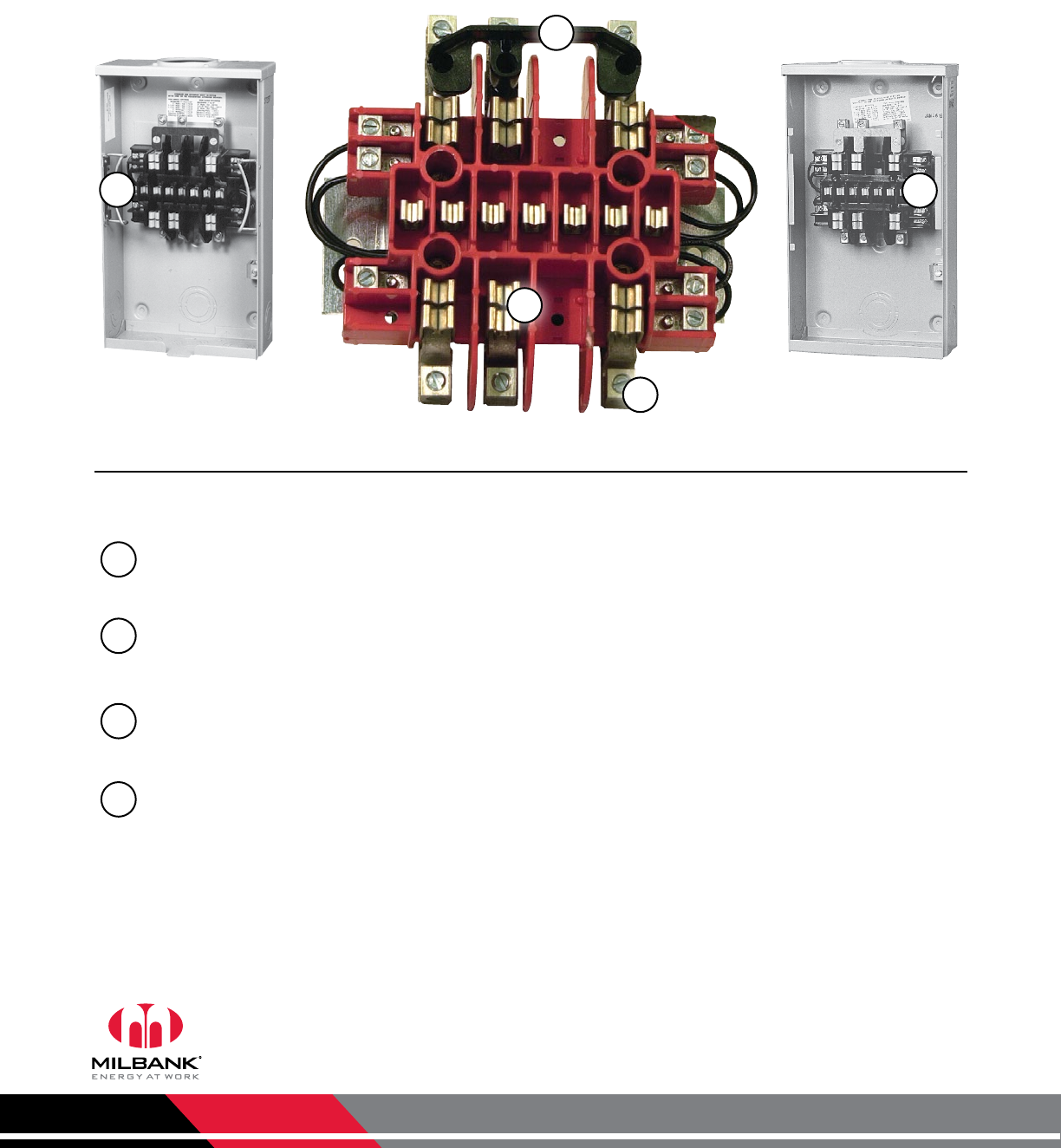
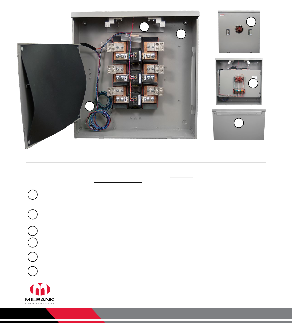
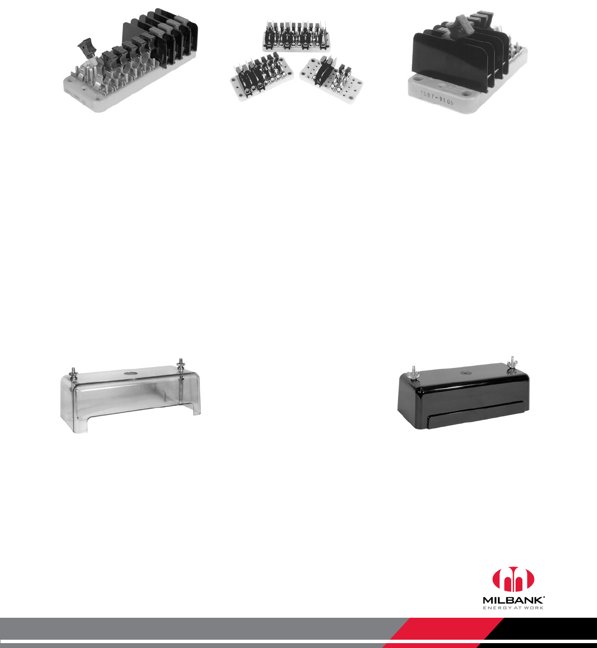
Highlights and Features
These units are available in a powder coated galvanized G90 steel or aluminum 3R shell.
Plunger Bypass: Once meter is removed from socket, plunger bypass disengages and CTs are shunted.
Connectors: #14 – 4 mechanical connectors provided for ease of connecting CT wires. If ring terminal is desired, use
U prefix rather than UC.
Terminals: Range of 5 to 13 terminal block assemblies available to meet most of your single and three phase
application needs.
Ringless/Ring Type: Units available in both ringless or ring type styles.
UC7545-RLUC7237-RL
1
2
3
1
2
3
4
44
CT Rated Sockets
Plunger Bypass Feature
Milbank Manufacturing | 4801 Deramus Ave., Kansas City, MO 64120 | 877.483.5314 | milbankworks.com
Utility requirements for this equipment may vary. Always consult the serving
utility for their requirements before ordering or installing equipment.
5
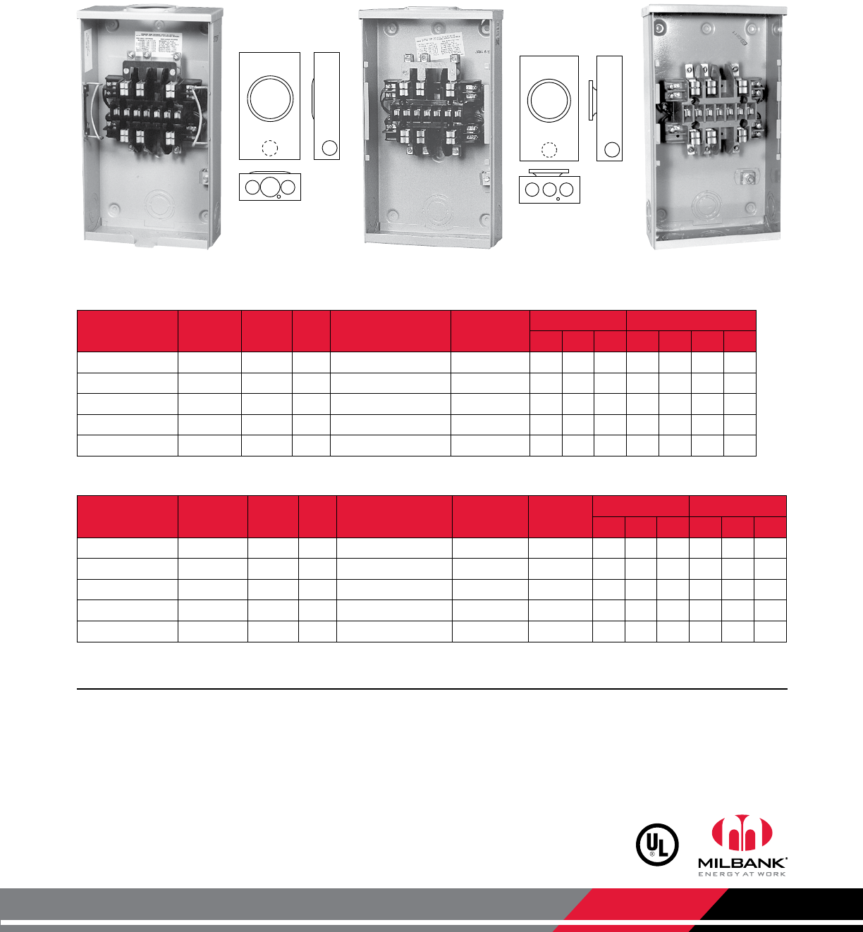
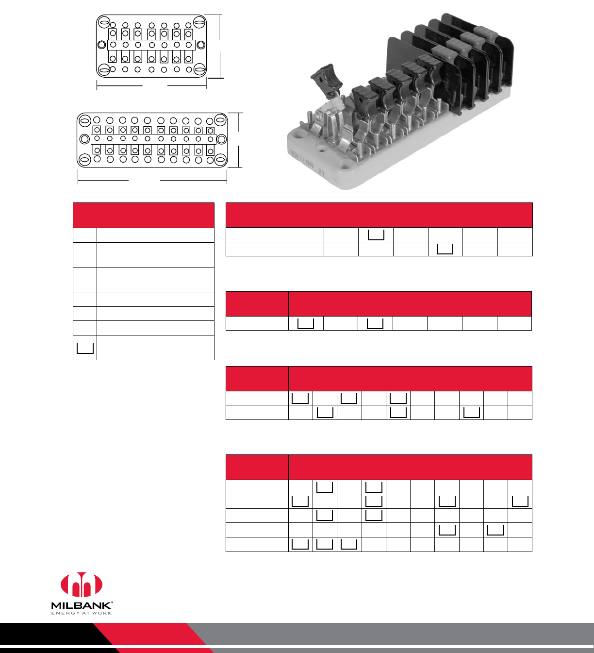
Notes
• Hubs: For proper hub selection, see the hub suffix chart on the accessories page.
• Bypass: Plunger type bypass automatically closes when meter is removed.
• Connectors: Units are supplied with mechanical type connectors (#4 max). If compression type connectors (#10) are
preferred, change catalog prefix to “U” (i.e. UC7544-RL becomes U7544-RL).
CT Rated Sockets
20 Amp | 5-13 Terminals
Catalog
Number Terminals Service Hub Meter Form Connectors
CU
Dimensions Knockouts
D" W" H" 1 2 3 4
UC1290-XL 5 OH/UG C.P. 3S #14 - 10 35⁄16 8 14 2 11⁄211⁄41⁄4
UC1299-XL 6 OH/UG C.P. 4S #14 - 10 35⁄16 8 14 2 11⁄211⁄41⁄4
UC7233-XL 7 OH/UG C.P. 7, 14, 15 & 24S #14 - 10 35⁄16 8 14 2 11⁄211⁄41⁄4
UC7235-XL 8 OH/UG C.P. 5S #14 - 10 35⁄16 8 14 2 11⁄211⁄41⁄4
UC7237-XL 13 OH/UG C.P. 6, 8, 9S & (ALT) 10S #14 - 10 35⁄16 8 14 2 11⁄211⁄41⁄4
Catalog
Number Terminals Service Hub Meter Form Connectors
CU Bypass Dimensions Knockouts
D" W" H" 1 2 3
UC1291-RL 5 OH/UG H.O. 3S #14 - 4 MAX Plunger 35⁄16 8 14 11⁄211⁄41⁄4
UC1300-RL 6 OH/UG H.O. 4S #14 - 4 MAX Plunger 35⁄16 8 14 11⁄211⁄41⁄4
UC7544-RL 8 OH/UG H.O. 5S #14 - 4 MAX Plunger 35⁄16 8 14 11⁄211⁄41⁄4
UC7545-RL 13 OH/UG H.O. 6, 8, 9S & (ALT) 10S #14 - 4 MAX Plunger 35⁄16 8 14 11⁄211⁄41⁄4
UC7582-XL 13 OH/UG C.P. 6, 8, 9S & (ALT) 10S #14 - 10 None 35⁄16 8 14 11⁄211⁄41⁄4
20 Amp | CT Rated Sockets | Ringless | Plunger Bypass
20 Amp | CT Rated Sockets | Ring Type
1290
1299
7233
7235
7237
1291
1300
7544
7545
7582
UC7545-RL UC7582-XLUC7237-RL
1
2 2 2
3
1
2
1
4
33
2
20 AMP
CT RATED
SOCKETS
Milbank Manufacturing | 4801 Deramus Ave., Kansas City, MO 64120 | 877.483.5314 | milbankworks.com
Utility requirements for this equipment may vary. Always consult the serving
utility for their requirements before ordering or installing equipment.
6
20 AMP
CT RATED
SOCKETS
CT Rated Sockets
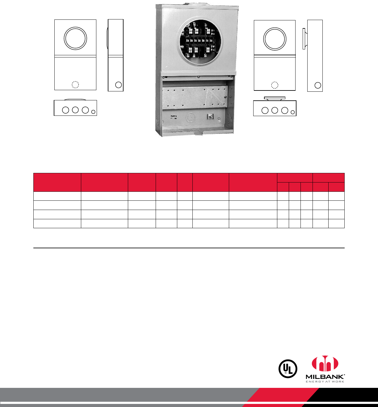
20 Amp | 1-Piece Cover | w/ Test Switch Provision
Notes
• Hubs: For proper hub selection, see the hub suffix chart on the accessory page.
• Pre-wiring: If standard factory pre-wiring is required, refer to wiring diagrams in the reference section of this catalog.
Determine appropriate diagram and send copy with order. If custom factory pre-wiring is required, consult factory for
details. Be sure to include meter socket catalog number, test switch model and number, and meter form number. Please be
sure to provide a copy of your wiring diagram.
• Connectors: Units are supplied with mechanical type connectors (#4 max). If compression type connectors (#10) are
preferred, change catalog prefix to “U” (i.e. UC7445-XL becomes U7445-XL).
• *Test Switch Cover: Units on this page are not designated for use with test switch covers without removing test switch
bridge prior to installing test switch.
• Test Switch Configurations: See page 34 for standard test switch configurations and page 35 for utility-specified test
switches.
7442
7444
7445
7478
Catalog
Number Terminals Service Hub Connectors
CU Meter Form Dimensions Knockouts
D" W" H" 1 2
UC7442-RL 5 OH/UG H.O. #14 - #4 Max 3S 41⁄812 20 11⁄41⁄4,1⁄2
UC7478-RL 6 OH/UG H.O. #14 - #4 Max 4S 41⁄812 20 11⁄41⁄4,1⁄2
UC7444-RL 8 OH/UG H.O. #14 - #4 Max 5S 41⁄812 20 11⁄41⁄4,1⁄2
UC7445-RL 13 OH/UG H.O. #14 - #4 Max 6, 8, 9 & (ALT) 10S 41⁄812 20 11⁄41⁄4,1⁄2
20 Amp | 1-Piece Cover | CT Rated Socket with Test Switch Provision* | Ringless
11
12
11
UC7478-YL
Milbank Manufacturing | 4801 Deramus Ave., Kansas City, MO 64120 | 877.483.5314 | milbankworks.com
Utility requirements for this equipment may vary. Always consult the serving
utility for their requirements before ordering or installing equipment.
7
11
12
11
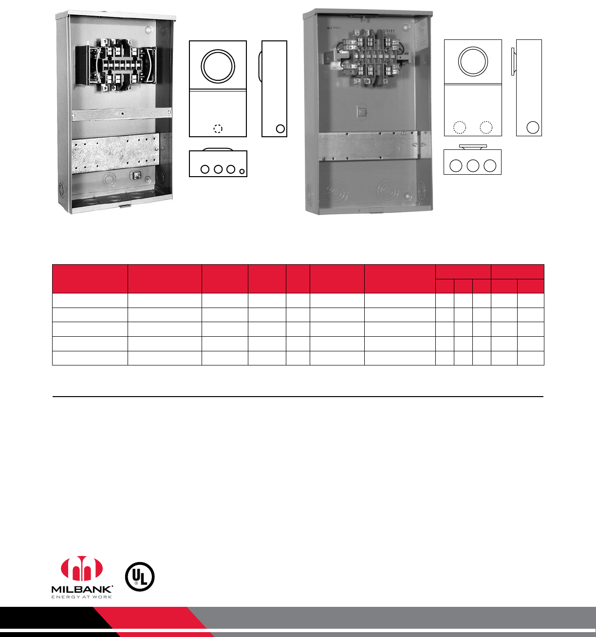
CT Rated Sockets
20 Amp | 2-Piece Cover | w/ Test Switch Provision
• Hubs: For proper hub selection, see the hub suffix chart on the accessory page.
• Sealing Rings: Ring type units are supplied with one MR-2 snap-type sealing ring.
• Pre-wiring: If standard factory pre-wiring is required, refer to wiring diagrams in the reference section of this catalog.
Determine appropriate diagram and send copy with order. If custom factory pre-wiring is required, consult factory for
details. Be sure to include meter socket catalog number, test switch model and number, and meter form number. Please be
sure to provide a copy of your wiring diagram.
• Connectors: Units are supplied with mechanical type connectors (#4 max). If compression type connectors (#10) are
preferred, change catalog prefix to “U” (i.e. UC7449-XL becomes U7449-XL).
• *Test Switch Cover: Units on this page are not designated for use with test switch covers.
• Test Switch Configurations: See page 34 for standard test switch configurations and page 35 for utility-specified test
switches.
Notes
7446
7448
7449
7532
7450
7460
7461
7636
Ringless
Catalog Number
Ring Type
Catalog Number Terminals Service Hub Connectors
CU Meter Form Dimensions Knockouts
D" W" H" 1 2
UC7446-RL UC7450-RL 5 OH/UG H.O. #14 - #4 Max 3S 41⁄812 20 11⁄41⁄4,1⁄2
UC7532-RL UC7636-RL 6 OH/UG H.O. #14 - #4 Max 4S 41⁄812 20 11⁄41⁄4,1⁄2
UC7448-RL UC7460-RL 8 OH/UG H.O. #14 - #4 Max 5S 41⁄812 20 11⁄41⁄4,1⁄2
UC7449-RL UC7461-RL 13 OH/UG H.O. #14 - #4 Max 6, 8, 9 & (ALT) 10S 41⁄812 20 11⁄41⁄4,1⁄2
20 Amp | 2-Piece Cover | CT Rated Socket with Test Switch Provision*
UC7449-RL
11
12
11
20 AMP
CT RATED
SOCKETS
Milbank Manufacturing | 4801 Deramus Ave., Kansas City, MO 64120 | 877.483.5314 | milbankworks.com
Utility requirements for this equipment may vary. Always consult the serving
utility for their requirements before ordering or installing equipment.
8
20 AMP
CT RATED
SOCKETS
CT Rated Sockets
20 Amp | Deeper 51⁄8" Shell | w/ Test Switch Provision
1 1
1 1 1 23423
3425
3426
3428
UC3423-XL UC3433-XL
• Hubs: For proper hub selection, see the hub suffix chart on the accessory page.
• Sealing Rings: Ring-type units are supplied with one MR-4 screw type sealing ring.
• Pre-wiring: If standard factory pre-wiring is required, refer to wiring diagrams in the reference section of this catalog.
Determine appropriate diagram and send copy with order. If custom factory pre-wiring is required, consult factory for
details. Be sure to include meter socket catalog number, test switch model and number, and meter form number. Please be
sure to provide a copy of your wiring diagram.
• Connectors: Units are supplied with mechanical type connectors (#4 max). If compression type connectors (#10) are
preferred, change catalog prefix to “U” (i.e. UC3423-XL becomes U3423-XL).
• Test Switch Cover: Units on this page can be used with clear lexan cover. See accessories page for ordering information.
• Test Switch Configurations: See page 34 for standard test switch configurations and page 35 for utility-specified test
switches.
• EUSERC Approval: All ring-type items on this page are EUSERC compliant.
Notes
Ringless
Catalog Number
Ring Type
Catalog Number Terminals Service Hub Connectors
CU Meter Form Dimensions Knockouts
D" W" H" 1 2
UC3425-XL UC3435-XL 5 OH/UG C.P. #14 - #2 Max 3S 51⁄812 20 11⁄41⁄4,1⁄2
UC3426-XL UC3436-XL 6 OH/UG C.P. #14 - #2 Max 4S 51⁄812 20 11⁄41⁄4,1⁄2
UC3428-XL UC3438-XL 8 OH/UG C.P. #14 - #2 Max 5S 51⁄812 20 11⁄41⁄4,1⁄2
UC3423-XL UC3433-XL 13 OH/UG C.P. #14 - #2 Max
6, 8, 9 & (ALT) 10S
51⁄812 20 11⁄41⁄4,1⁄2
— UC3434-XL 15 OH/UG C.P. #14 - #2 Max 39S or 76S 51⁄812 20 11⁄41⁄4,1⁄2
20 Amp | 2-Piece Cover | CT Rated Socket with Test Switch Provision
1 1 1
1 1 1
3433
3435
3436
3438
3434
Milbank Manufacturing | 4801 Deramus Ave., Kansas City, MO 64120 | 877.483.5314 | milbankworks.com
Utility requirements for this equipment may vary. Always consult the serving
utility for their requirements before ordering or installing equipment.
9
PREWIRED
CT RATED
SOCKETS
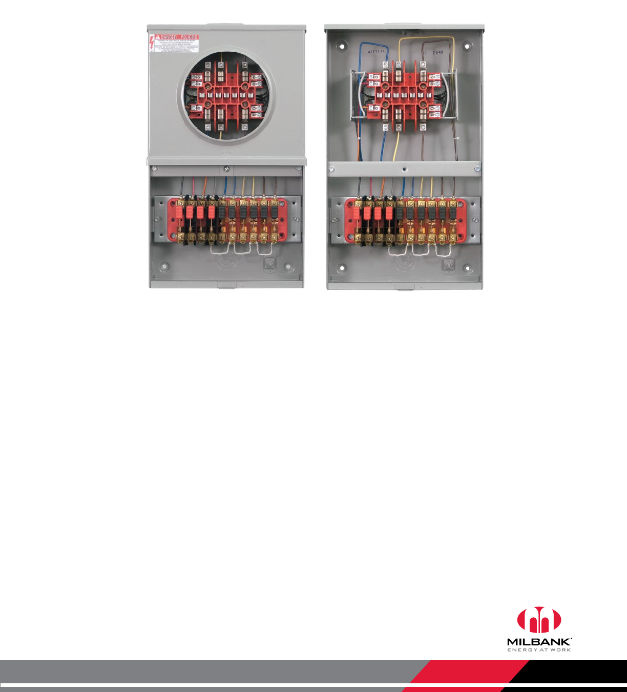
Prewired CT Rated Sockets
Factory wired to utility specification
UC7449-XL-871
For field-installable test switches, see page 34 for standard configurations. Test switches can
also be factory installed without prewiring. Consult factory for details.
Milbank’s CT Rated meter sockets are also available with factory prewiring and custom-
specified test switches. For factory prewiring and custom test switch configurations, see the
worksheet on page 35 and consult factory for details.
Available for both ring type and ringless applications.
Milbank Manufacturing | 4801 Deramus Ave., Kansas City, MO 64120 | 877.483.5314 | milbankworks.com
Utility requirements for this equipment may vary. Always consult the serving
utility for their requirements before ordering or installing equipment.
10
TWO
POSITION
CT RATED
SOCKETS
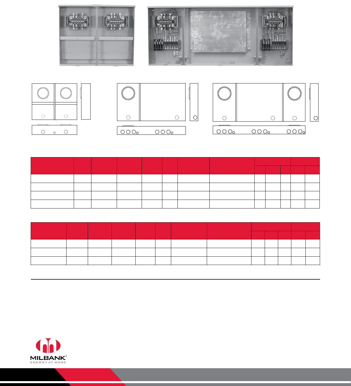
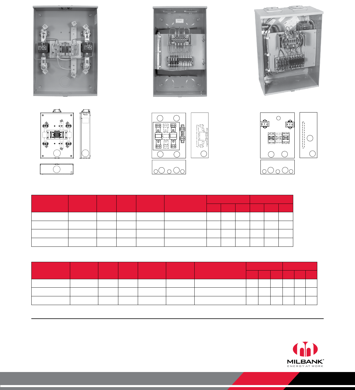
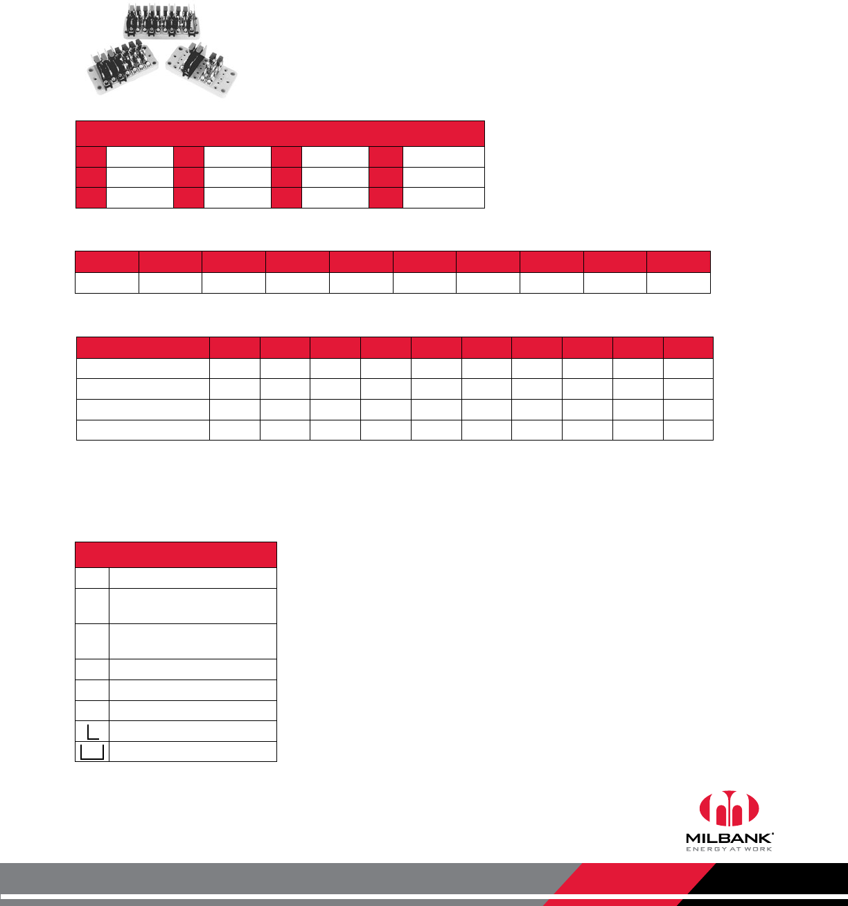
Multi-Position CT Rated Sockets
20 Amps | w/ Test Switch Provision
UC3453-XL SC6011-O-BL-21
Catalog
Number
UL
Listed Positions Terminals Service Hub Connectors
CU Meter Form Dimensions Knockouts
D" W" H" 1 2
UC3458-XL Yes 2 8 OH/UG C.P. #14 - #4 Max 5S 5 251⁄16 20 11⁄41⁄4,1⁄2
UC3453-XL Yes 2 13 OH/UG C.P. #14 - #4 Max 6, 8, 9 & (ALT) 10S 5 251⁄16 20 11⁄41⁄4,1⁄2
SC6010-O-BL-21 No 1 13 UG Blank #14 - #4 Max 6, 8, 9 & (ALT) 10S 41⁄8367⁄16 20 11⁄21⁄2,3⁄4
SC6011-O-BL-21 No 2 13 UG Blank #14 - #4 Max 6, 8, 9 & (ALT) 10S 41⁄84811⁄16 20 11⁄21⁄2,3⁄4
Catalog
Number
UL
Listed Positions Terminals Service Hub Connectors
CU Meter Form Dimensions Knockouts
D" W" H" 1 2
UC3448-XL Yes 2 8 OH/UG C.P. #14 - #4 Max 5S 51⁄8251⁄16 20 2 1⁄4,1⁄2
UC3443-XL Yes 2 13 OH/UG C.P. #14 - #4 Max 6, 8, 9 & (ALT) 10S 51⁄8251⁄16 20 2 1⁄4,1⁄2
UC3444-XL Yes 2 15 OH/UG C.P. #14 - #4 Max 39S or 76S 51⁄8251⁄16 20 2 1⁄4,1⁄2
20 Amps | Multi-Position CT Rated Sockets | Ringless
20 Amps | Multi-Position CT Rated Sockets | Ring Type
3443
3444
3448
3453
3458 6010 6011
• Hubs: For proper hub selection, see the hub suffix chart on the accessory page.
• Sealing Rings: Ring-type units are supplied with one MR-4 screw type sealing ring.
• Pre-wiring: If factory prewiring is required, specify on order. Be sure to include meter socket catalog number, test switch
model and number, and meter form number. Please be sure to provide a copy of your wiring diagram.
• Connectors: Units are supplied with mechanical type connectors (#4 max). If compression type connectors (#10) are
preferred, change catalog prefix to “U” (i.e. UC3453-XL becomes U3453-XL).
• The SC6010 and SC6011 include a section for additional electronic components. Remote CT cabinet required.
Notes
1
12
1
1
1
1 1 1 21 1 1 2
1 1 1
1 1 1 2 2 2
1 1 1 1 1 1
1 1 1
Milbank Manufacturing | 4801 Deramus Ave., Kansas City, MO 64120 | 877.483.5314 | milbankworks.com
Utility requirements for this equipment may vary. Always consult the serving
utility for their requirements before ordering or installing equipment.
11
80 AMP
LEVER BYPASS
CT RATED
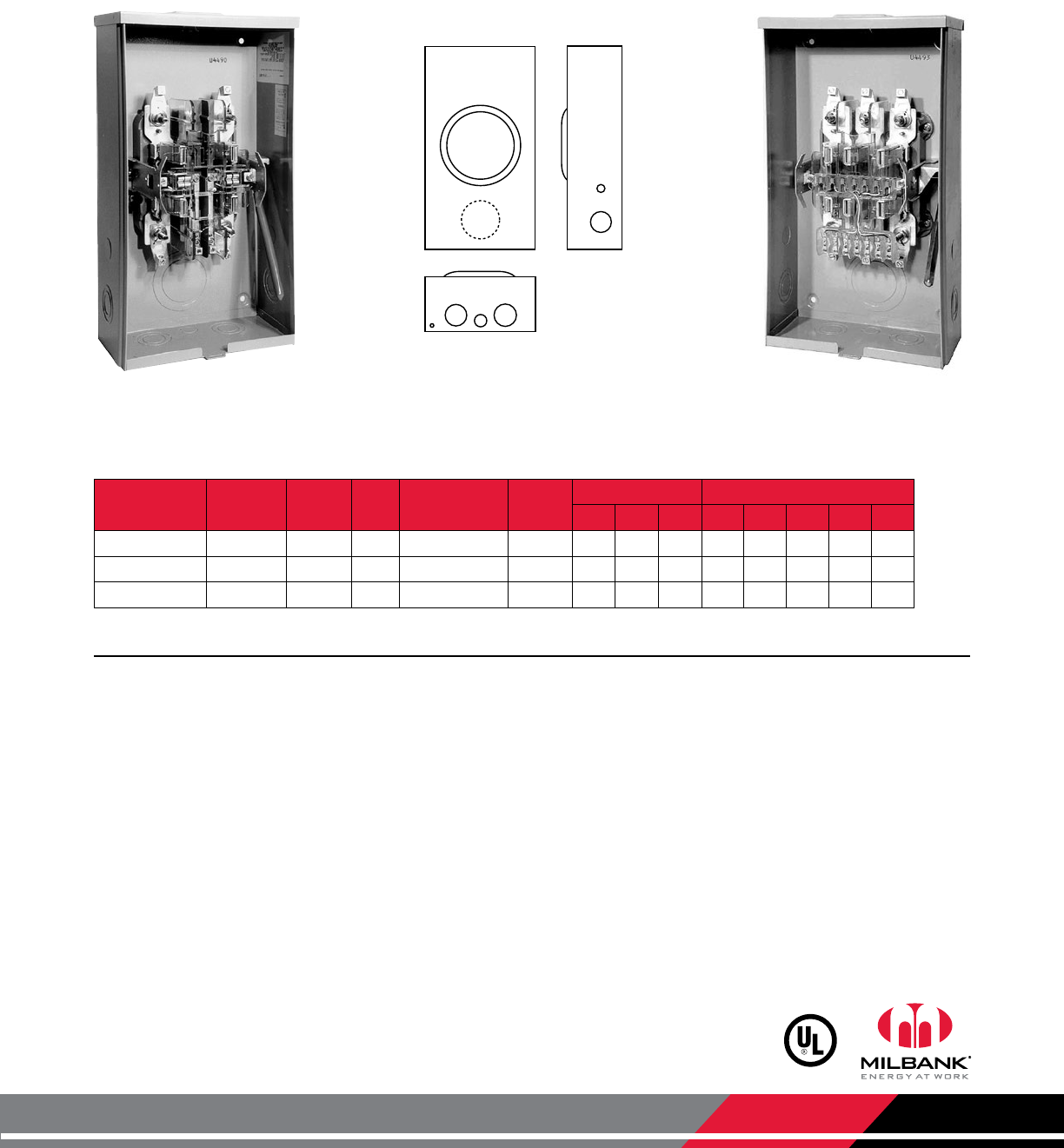
Lever Bypass CT Rated Sockets
80 Amps | Ringless | 600 VAC
U4490-XL U4493-XL
Catalog
Number Terminals Service Hub Connectors
CU Bypass Dimensions Knockouts
D" W" H" 1 2 3 4 5
U4490-XL 6 OH/UG C.P. #14 - #4 Max Lever 47⁄810 181⁄23 11⁄21⁄2,3⁄43⁄41⁄4
U4492-XL 8 OH/UG C.P. #14 - #4 Max Lever 47⁄810 181⁄23 11⁄21⁄2,3⁄43⁄41⁄4
U4493-XL 13 OH/UG C.P. #14 - #4 Max Lever 47⁄810 181⁄23 11⁄21⁄2,3⁄43⁄41⁄4
80 Amps | Transformer Rated Sockets | Lever Bypass | Ringless
12
2 2
3
4
5
4490
4492
4493
Notes
• Hubs: For proper hub selection, see the hub suffix chart on the accessories page.
• Bypass: Lever operates current bypass device and also supplies clamping action on current meter spades.
• Connectors: Units are supplied with mechanical type connectors (#4 max). If compression type connectors (#10) are
preferred, change catalog prefix to “U” (i.e. UC4490-XL becomes U4490-XL).
• Removable Handle: When removable handle is desired add suffix “-RH” to catalog number (i.e. U4493-XL becomes
U4493-XL-RH).
• Replacement Removable Handle: When a replacement removable handle (RH) is required order part #Z706850-SC.
Replacement handle will only work with factory ordered RH units.
Milbank Manufacturing | 4801 Deramus Ave., Kansas City, MO 64120 | 877.483.5314 | milbankworks.com
Utility requirements for this equipment may vary. Always consult the serving
utility for their requirements before ordering or installing equipment.
12
20 AMP
LEVER BYPASS
CT RATED
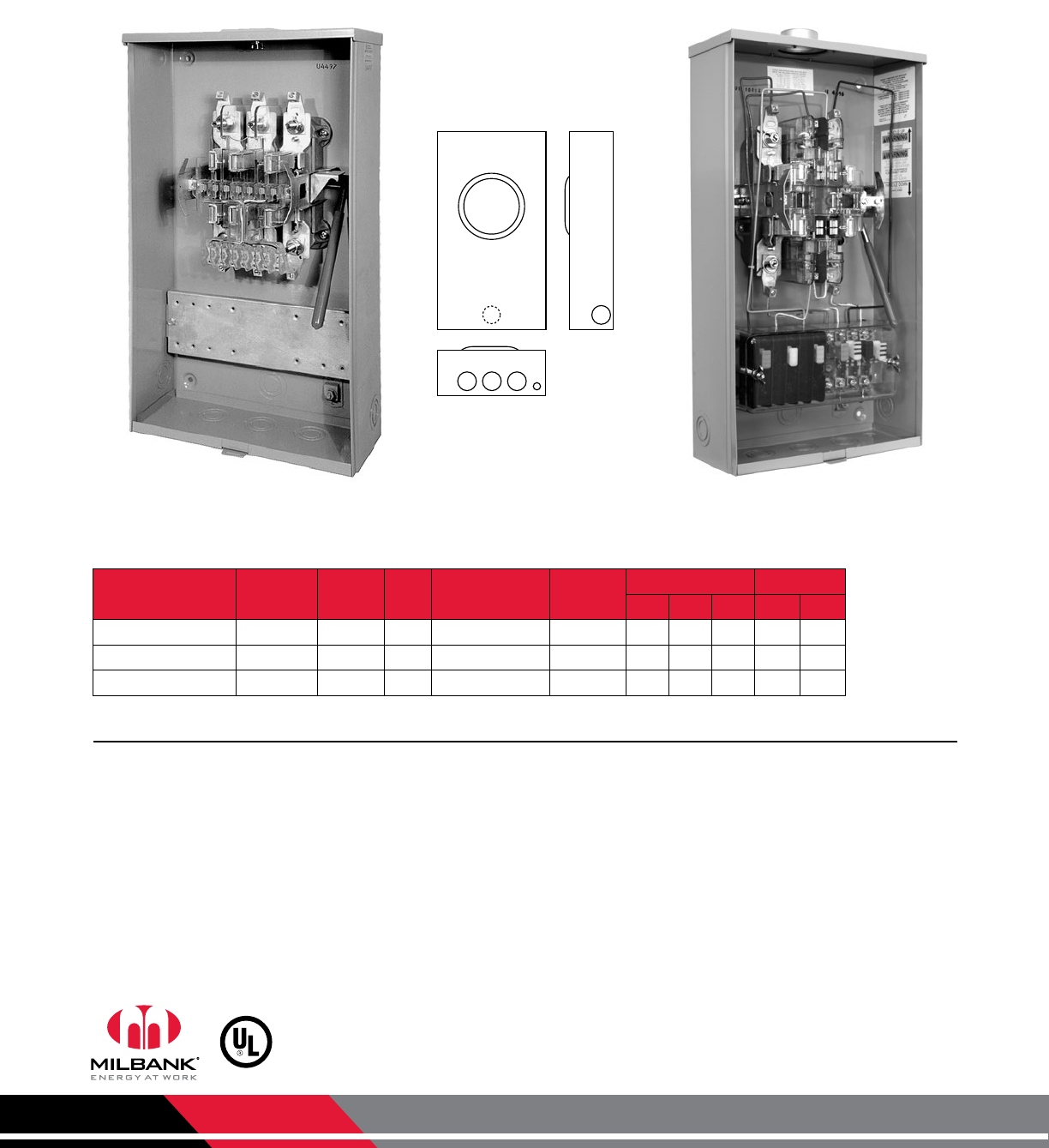
• Pre-wiring: If factory prewiring is required, specify on order. Be sure to include meter socket catalog number, test switch
model and number, and meter form number. Please be sure to provide a copy of your wiring diagram.
• Connectors: Units are supplied with mechanical type connectors (#4 max).
• Test Switch Cover: Units on this page can be used with clear lexan cover. See accessories page for ordering information.
Notes
Catalog Number Terminals Service Hub Connectors CU Bypass Dimensions Knockouts
D" W" H" 1 2
U4494-XL 6 OH/UG C.P. #14 - #4 Max Lever 47⁄812 22 11⁄21⁄4,1⁄2
U4496-XL 8 OH/UG C.P. #14 - #4 Max Lever 47⁄812 22 11⁄21⁄4,1⁄2
U4497-XL 13 OH/UG C.P. #14 - #4 Max Lever 47⁄812 22 11⁄21⁄4,1⁄2
20 Amp | Ringless | 1-Piece Cover | CT Rated Socket with Test Switch Provision
1 1
1 1 1 2
4494
4496
4497
U4497-XL U4496-ZL-WC-41
Lever Bypass CT Rated
20 Amp | Ringless | w/ Test Switch Provision
Milbank Manufacturing | 4801 Deramus Ave., Kansas City, MO 64120 | 877.483.5314 | milbankworks.com
Utility requirements for this equipment may vary. Always consult the serving
utility for their requirements before ordering or installing equipment.
13
DEMAND
SIDE
MANAGEMENT
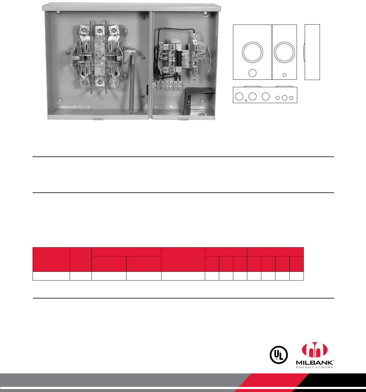
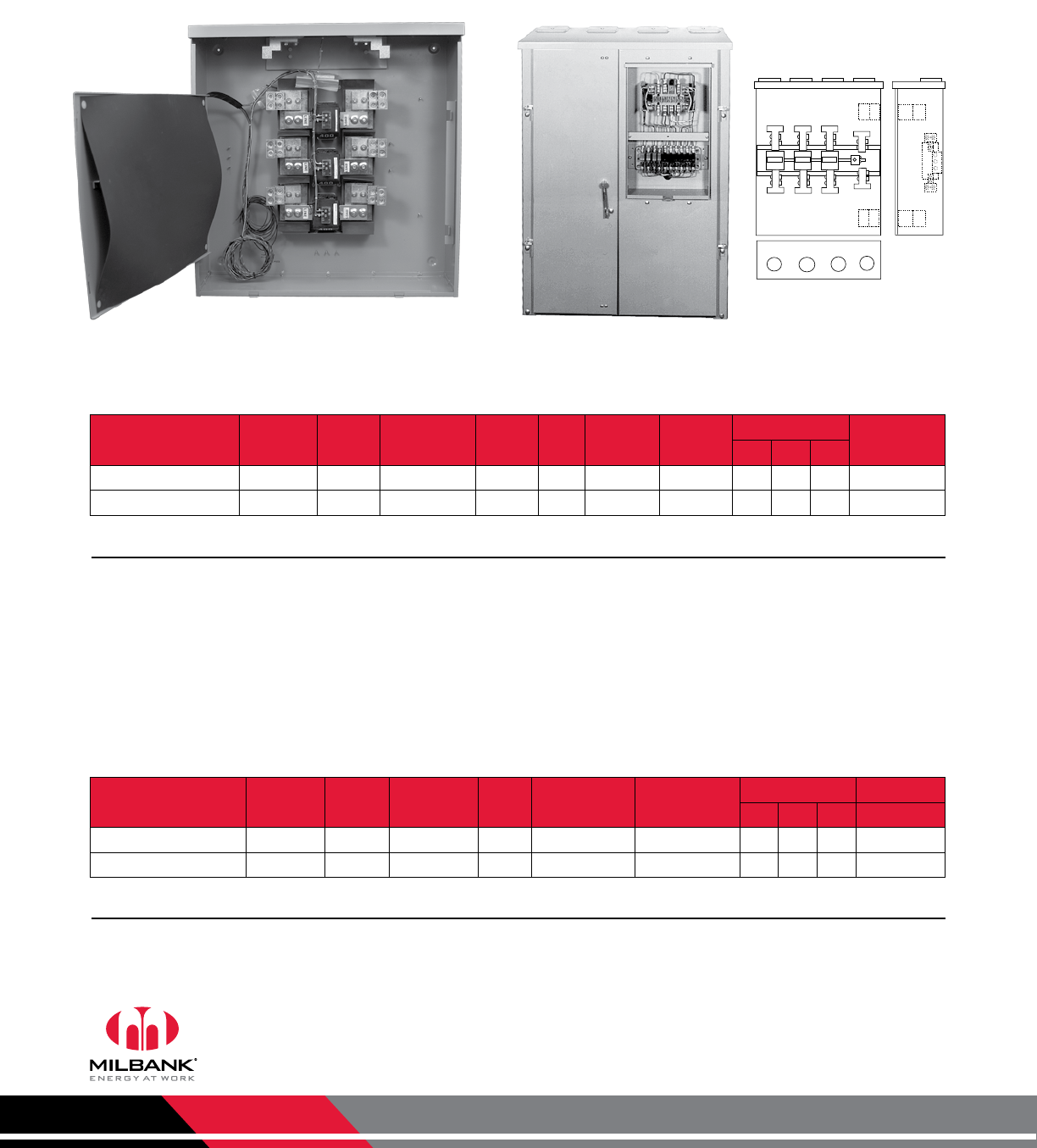
Demand Side Management
200/20 Amps | 4 Terminals | Ringless
1
11 1 2
3
433 4811
U4811-O-21
200/20 Amps | 4 Terminals | Two Positions | Off-Peak Metering
Catalog
Number Service
Connectors / CU
Bypass
Dimensions Knockouts
Left Side
(Line & Load) Right Side D" W" H" 1 2 3 4
U4811-O-21 UG #6-350 Terminal Strip Lever/Plunger 47⁄821 18 2 11⁄43⁄41⁄4,1⁄2
Notes
• Fifth Terminal: For field installed fifth terminal on left (200 amp) side, order catalog number K3866.
Application
The right position is used for sub-metering by the serving utility when a special electric rate is given to customers for devices
that can shed load during high energy demand. Contact your local utility for more information.
Features
• Low voltage compartment in lower right corner
• Left position is a 200 amp, 4 terminal heavy duty lever bypass interior
• Right position is 20 amp rated with a fifth terminal in the 9 o’clock position and a plunger bypass
• Right position is pre-wired to the terminal strip for easy installation
Milbank Manufacturing | 4801 Deramus Ave., Kansas City, MO 64120 | 877.483.5314 | milbankworks.com
Utility requirements for this equipment may vary. Always consult the serving
utility for their requirements before ordering or installing equipment.
14
STAINLESS
STEEL
CT RATED
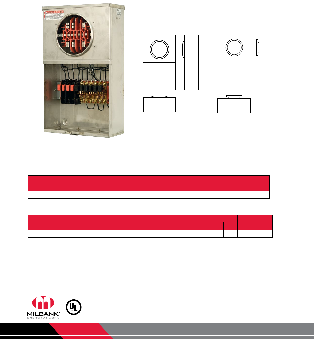
Stainless Steel CT Rated
20 Amps | with Test Switch Provision
3423 3433
UCSS3433-O
(shown as UCSS3433-O-141
pre-wired unit)
Catalog Number Terminals Service Hub Connectors CU Cover Dimensions Knockouts
D" W" H"
UCSS3423-O 13 OH/UG Blank #14 - #2 Max 2-Piece 51⁄812 20 None
Catalog Number Terminals Service Hub Connectors CU Cover Dimensions Knockouts
D" W" H"
UCSS3433-O 13 OH/UG Blank #14 - #2 Max 2-Piece 51⁄8 12 20 None
20 Amps | Ringless | CT Rated Socket with Test Switch Provision | Stainless Steel
20 Amps | Ring Type | CT Rated Socket with Test Switch Provision | Stainless Steel
• For Conduit Opening Applications: All conduit openings have dimples provided to center location. Top conduit opening
must have water-tight hub installed.
• Other Stainless Steel Products: Most units available in stainless steel—contact Milbank for details.
• EUSERC Approval: The UCSS3433-O is EUSERC compliant.
Notes

Milbank Manufacturing | 4801 Deramus Ave., Kansas City, MO 64120 | 877.483.5314 | milbankworks.com
Utility requirements for this equipment may vary. Always consult the serving
utility for their requirements before ordering or installing equipment.
15
NOTES
Notes
Milbank Manufacturing | 4801 Deramus Ave., Kansas City, MO 64120 | 877.483.5314 | milbankworks.com
Utility requirements for this equipment may vary. Always consult the serving
utility for their requirements before ordering or installing equipment.
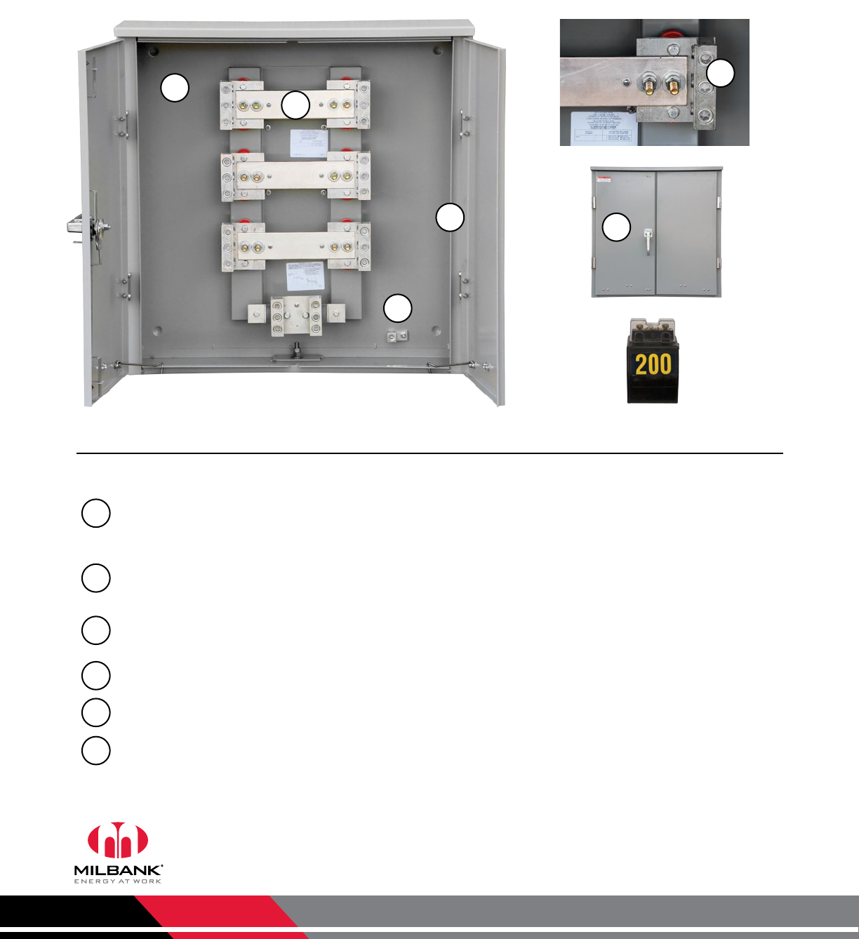
Highlights and Features
Powder Coat Painted NEMA 3R Shell: As with all Milbank products, our enclosures are constructed of G90U
galvenized steel and finished with attractive, light gray, baked powder coating. Our state-of-the-art finish combines
epoxy and polyester hybrid resins into a hybrid powder coating which is then electrostatically applied. This offers a
durable, non-fading finish.
Three-Point Latching Handle & Locking Mechanism: Padlocking handle with three-point latching system allows for
easy locking and securing of the unit.
Hinged Double Doors: Hinged overlapping double doors enhance ease-of-access and are secured with three-point
latching system.
Bar-Type CT Rack: Includes pre-placed studs to mount bar-type CTs. Withstand rating is 50K.
Lugs: Line, load and neutral rack lugs are single 600 kcmil or twin 250 kcmil.
Grounding Lug: Single position, 350 kcmil.
Some units available in stainless steel—contact Milbank for details.
1
2
3
4
5
6
U5990-O
(Window-style CT—
not included)
1
2
3
5
4
6
CT Cabinets
Features & Benefits

Milbank Manufacturing | 4801 Deramus Ave., Kansas City, MO 64120 | 877.483.5314 | milbankworks.com
Utility requirements for this equipment may vary. Always consult the serving
utility for their requirements before ordering or installing equipment.
17
NOTES
Notes
Milbank Manufacturing | 4801 Deramus Ave., Kansas City, MO 64120 | 877.483.5314 | milbankworks.com
Utility requirements for this equipment may vary. Always consult the serving
utility for their requirements before ordering or installing equipment.
18
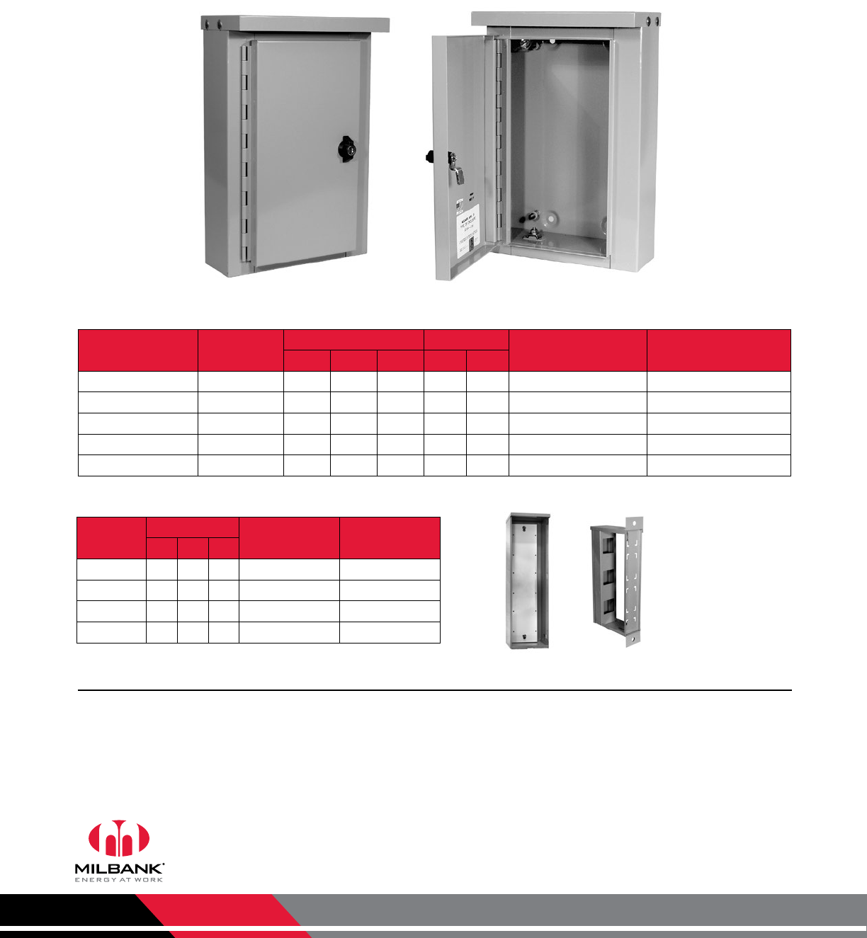
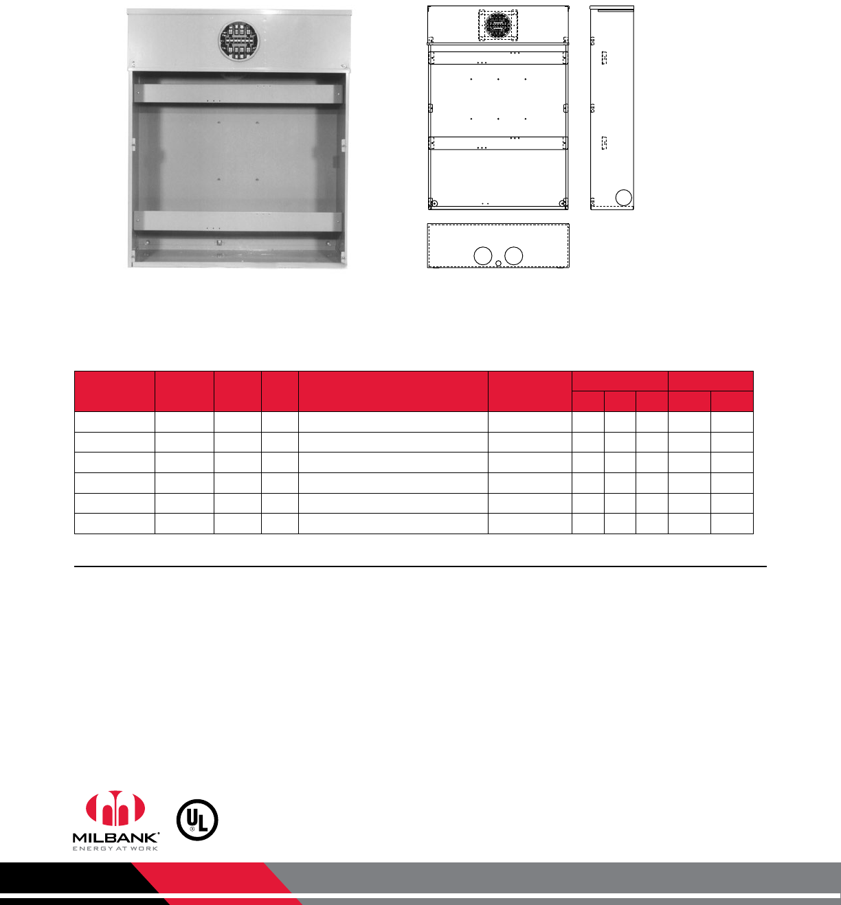
Current Transformer Cabinets | Type 3R
Catalog
Number
Gauge
Steel
Dimensions Panel Size Painted Steel Panel
Catalog Number
Wood Backboard
Catalog Number
W" H" D" W” H”
243210-LC3R-SP 14 24 32 10 21 29 A-24P32 A-24P32W
303610-LC3R-SP 14 30 36 10 27 33 A-36P30 A-36P30W
323610-LC3R-SP 14 32 36 10 29 33 A-32P36 A-32P36W
363612-LC3R-SP 14 36 36 12 33 33 A-36P36 A-36P36W
423616-CT3R 14 42 36 16 39 33 A-42P36 A-42P36W
Notes
• Features: Supplied with studs, continuous hinge and padlock provision. Steel panels and plywood backboard are optional.
• LC3R-SP: Indicates a single door with two padlockable wind handles.
• *PT48: PT48L and PT48AL has mounting emboss on the right side to be mounted on left side of CT cabinet. PT48R and
PT48AR have mounting emboss on left side to be mounted on right side of CT cabinet.
• Pole Mounting: For pole mounted CT rack applications, order catalog number S7860.
•
There are other sizes of outdoor transformer cabinets available, contact Milbank or refer to our enclosures catalog for details.
Current Transformer Cabinets
Continuous Hinge | Padlock Provision
TRANSFORMER
CABINETS
PT Cabinets
Catalog
Number
Dimensions Knockout Material
D" W" H"
PT48L 8 8 271⁄221⁄2" - right side Steel
PT48AL 8 12 36 21⁄2" - right side Aluminum
PT48R 8 8 271⁄221⁄2" - left side Steel
PT48AR 8 12 36 21⁄2" - left side Aluminum
PT48AR* S7860
Milbank Manufacturing | 4801 Deramus Ave., Kansas City, MO 64120 | 877.483.5314 | milbankworks.com
Utility requirements for this equipment may vary. Always consult the serving
utility for their requirements before ordering or installing equipment.
19
TRANSFORMER
CABINETS
Transformer Cabinets
CT and PT Cabinets
• For use as a current transformer cabinet or panel enclosure.
• For outdoor use to provide protection against rain, sleet
and snow, or indoor use to protect against dripping water.
Construction
• Enclosure and cover manufactured from 16 or 14 gauge
G90U galvanized steel.
• The doors are overlapping with no center post.
• Continuous door hinge with stainless steel hinge pins.
• Three point pad-lockable handle.
• Panel mounting studs provided for optional back panels.
• Drip shield top and seam-free sides, front and back.
Finish
• ANSI 61 gray polyester powder coating over phosphatized
G90U galvanized steel.
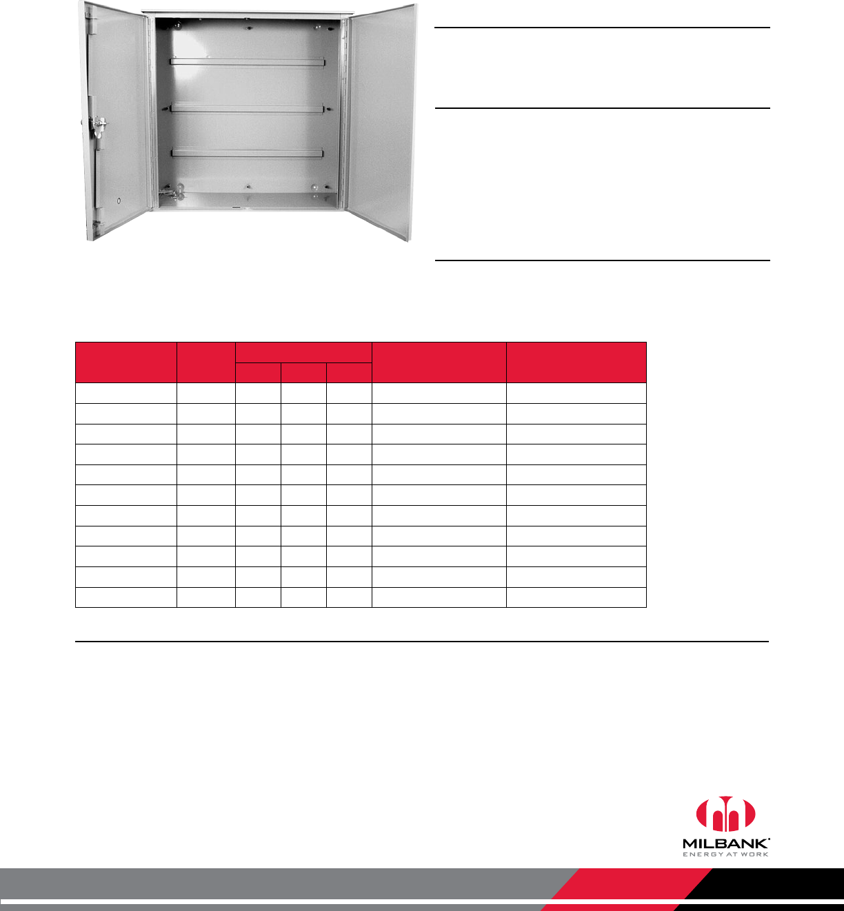
Application
Current Transformer Cabinets | Panel Enclosure
Catalog
Number Weight Dimensions Steel Panel Catalog # Wood Panel Catalog #
W" H" D"
303610-CT3R 99 30 36 10 A-36P30 A-36P30W
363010-CT3R 99 36 30 10 A-36P30 A-36P30W
363016-CT3R 121.5 36 30 16 A-36P30 A-36P30W
363610-CT3R 113 36 36 10 A-36P36 A-36P36W
363612-CT3R 118 36 36 12 A-36P36 A-36P36W
363616-CT3R 139 36 36 16 A-36P36 A-36P36W
443010-CT3R 116 44 30 10 A-30P44 A-30P44W
483612-CT3R 147 48 36 12 A-48P36 A-48P36W
483616-CT3R 163 48 36 16 A-48P36 A-48P36W
484812-CT3R 210 48 48 12 A-48P48 A-48P48W
606013-CT3R 274 60 60 13 A-60P60 A-60P60W
Notes
• Wall or Pole Mount: For wall or pole mount CT rack order S7860. This unit accomodates 3 donut style CTs. The
removable cover makes wiring much easier.
363612-CT3R
Milbank Manufacturing | 4801 Deramus Ave., Kansas City, MO 64120 | 877.483.5314 | milbankworks.com
Utility requirements for this equipment may vary. Always consult the serving
utility for their requirements before ordering or installing equipment.
20
TRANSFORMER
CABINETS
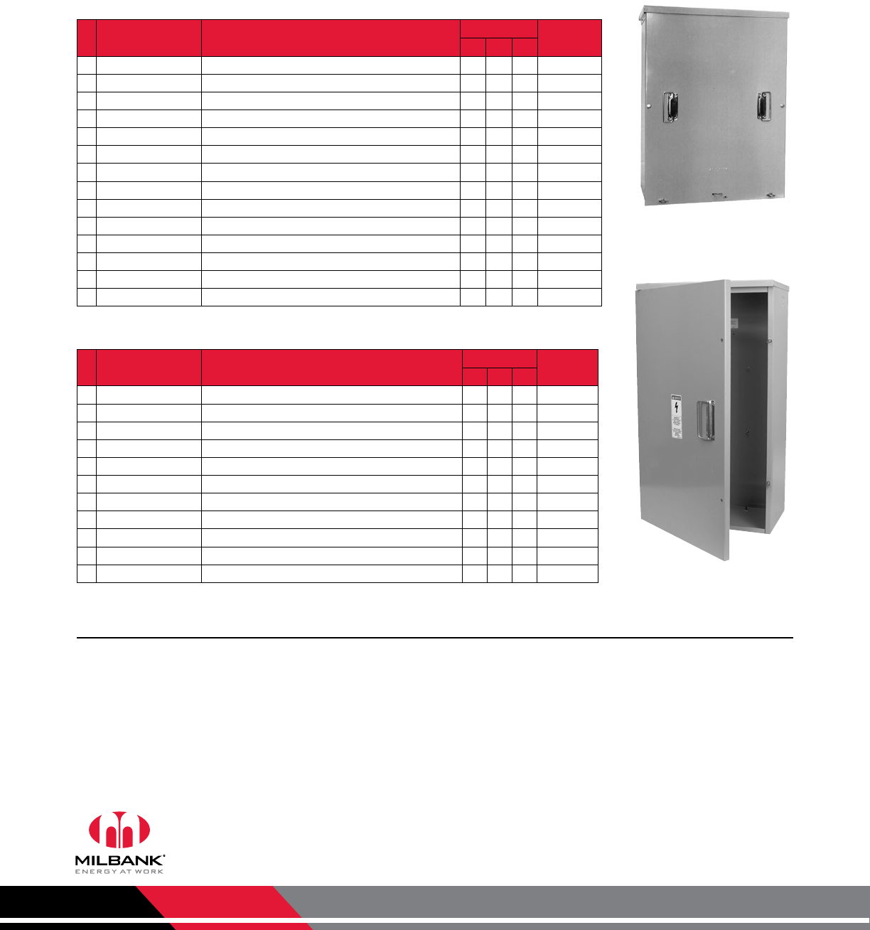
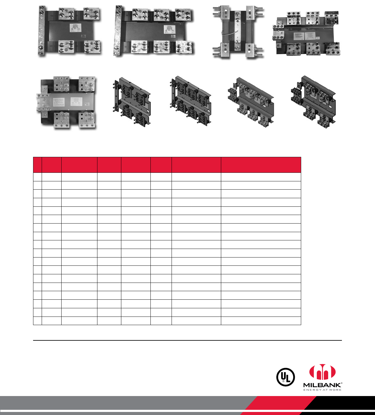
Current Transformer Cabinets
Compatible with Field Installable Racks
Screw Cover Current Transformer Cabinets
Hinge Cover Current Transformer Cabinets
* Catalog Number Compatible CT Racks
(see next page for matching code)
Dimensions Front
Cover
W" H" D"
CT24329-SC C, M 24 32 9 1 Piece
CT242411-SC A4, C, M, Q 24 24 11 1 Piece
CT243011-SC A4, C, M, Q 24 30 11 1 Piece
CT243611-SC A4, C, J, M, Q 24 36 11 1 Piece
* CT244811-SC A, C, D, J, M, Q 24 48 11 1 Piece
* CT303011-SC A4, B4, C, E, L, M, Q, R 30 30 11 1 Piece
* CT303611-SC A4, B4, C, E, J, K, L, M, Q, R 30 36 11 1 Piece
* CT303614-SC A4, B4, C, E, J, K, L, M, Q, R 30 36 14 1 Piece
* CT363611-SC A4, B4, C, E, J, K, L, M, Q, R 36 36 11 1 Piece
* CT364211-SC A4, B4, C, E, J, K, L, M, Q, R 36 42 11 2 Pieces
* CT364811-SC A, B, C, D, E, F, G, H, J, K, L, M, N, P, Q, R 36 48 11 2 Pieces
* CT364814-SC A, B, C, D, E, F, G, H, J, K, L, M, N, P, Q, R 36 48 14 2 Pieces
* CT424211-SC A4, B4, C, E, J, K, L, M, Q, R 42 42 11 2 Pieces
* CT484811-SC A, B, C, D, E, F, G, H, J, K, L, M, N, P, Q, R 48 48 11 2 Pieces
* Catalog Number Compatible CT Racks
(see next page for matching code)
Dimensions Front
Cover
W" H" D"
CT203611-HC C20 36 11 1 Piece
CT243011-HC A4, C, M, Q 24 30 11 1 Piece
CT243611-HC C, M 24 36 11 1 Piece
* CT244811-HC A, C, D, J, M, P, Q 24 48 11 1 Piece
* CT303611-HC A4, B4, C, E, J, K, L, M, Q, R 30 36 11 1 Piece
* CT304811-HC A, B, C, D, E, F, G, H, J, K, L, M, N, P, Q, R 30 48 11 1 Piece
* CT363611-HC A4, B4, C, E, J, K, L, M, Q, R 36 36 11 1 Piece
* CT364811-HC A, B, C, D, E, F, G, H, J, K, L, M, N, P, Q, R 36 48 11 1 Piece
* CT484811-HC A, B, C, D, E, F, G, H, J, K, L, M, N, P, Q, R 48 48 11 2 Pieces
* CT364814-HC A, B, C, D, E, F, G, H, J, K, L, M, N, P, Q, R 36 48 14 2 Pieces
* CT484814-HC A, B, C, D, E, F, G, H, J, K, L, M, N, P, Q, R 48 48 14 2 Pieces
CT24329-SC
CT203611-HC
Notes
• EUSERC Approval: Units denoted with an asterisk (*) are EUSERC compliant.
• Enclosure: These units are rated Type 3R, powder coat painted and constructed of galvanized steel.
• Mounting Rack: Select CT mounting rack from the next page.
• Mounting: 1⁄4-20 welded studs spaced to accept mounting racks.
Milbank Manufacturing | 4801 Deramus Ave., Kansas City, MO 64120 | 877.483.5314 | milbankworks.com
Utility requirements for this equipment may vary. Always consult the serving
utility for their requirements before ordering or installing equipment.
21
CT CABINET
MOUNTING
RACKS
CT Cabinet Mounting Racks
Stud & Lug Types
Screw Cover Current Transformer Cabinets
* Code Catalog
Number
SCCR
Rating Amps Volts Type of
Service Termination Type
*A4 K4797 50K 400 600 1Ø3W 1⁄2"-13 studs on 13⁄4" centers
*AK4797 50K 800 600 1Ø3W 1⁄2"-13 studs on 13⁄4" centers
*B4 K4798 50K 400 600 3Ø4W 1⁄2"-13 studs on 13⁄4" centers
*BK4798 50K 800 600 3Ø4W 1⁄2"-13 studs on 13⁄4" centers
*CK4793 10K 201–400 600 1Ø3W 1⁄2"-13 studs on 13⁄4" centers
*DK4795 10K 401–800 600 1Ø3W 1⁄2"-13 studs on 13⁄4" centers
*EK4794 10K 201–400 600 3Ø4W 1⁄2"-13 studs on 13⁄4" centers
*FK4796 10K 401–800 600 3Ø4W 1⁄2"-13 studs on 13⁄4" centers
*GK4729 50K 800 600 1Ø3W (3) #4-600 or (6) #1-250
*HK4722 50K 800 600 3Ø4W (3) #4-600 or (6) #1-250
*JK4903 50K 400 600 1Ø3W (1) #4-600 or (2) #1-250
*KK4904 50K 400 600 3Ø4W (1) #4-600 or (2) #1-250
LK5747 50K 800 600 3Ø4W Line: 1⁄2"-13 studs on 13⁄4" centers
Load: (3) #4-600 or (6) #1-250
MK5752 50K 800 600 1Ø3W Line: 1⁄2"-13 studs on 13⁄4" centers
Load: (3) #4-600 or (6) #1-250
NK5930 50K 800 600 3Ø4W (3) #4-600 or (6) #1-250
PK5931 50K 400 600 1Ø3W or 3Ø3W (1) #4-600 or (2) #1-250
QK5932 50K 400 600 1Ø3W or 3Ø3W 1⁄2"-13 studs on 13⁄4" centers
RK5933 50K 400 600 3Ø4W 1⁄2"-13 studs on 13⁄4" centers
K4797
K4729 K5932 K5933 K5930 K5931
K4798 K4793 K4722
Notes
• EUSERC Approval: Units marked with an asterisk are EUSERC compliant.
• CT racks on this page are for use with bar type CTs.
Milbank Manufacturing | 4801 Deramus Ave., Kansas City, MO 64120 | 877.483.5314 | milbankworks.com
Utility requirements for this equipment may vary. Always consult the serving
utility for their requirements before ordering or installing equipment.
22
TRANSFORMER
CABINETS
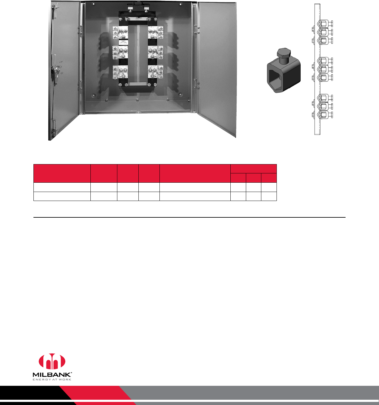
Current Transformer Cabinets
with Factory Installed CT Racks | 600 VAC
S1855-O
Catalog Number Amps Hub Gauge
Steel
Connectors
CU/AL
Dimensions
D" W" H"
S1855-O 400–800 Blank 12 (3) 3/0-750 kcmil per phase 12 36 36
S1856-O 800–1200 Blank 12 (5) 3/0-750 kcmil per phase 12 48 48
Current Transformer Cabinets | Non-UL Approved
Notes
• Features: These enclosures have three-point locking handles, liftoff hinges with stainless steel pins and two doors.
Connector
detail
Milbank Manufacturing | 4801 Deramus Ave., Kansas City, MO 64120 | 877.483.5314 | milbankworks.com
Utility requirements for this equipment may vary. Always consult the serving
utility for their requirements before ordering or installing equipment.
23
400 & 800 AMP
TRANSFORMER
CABINETS
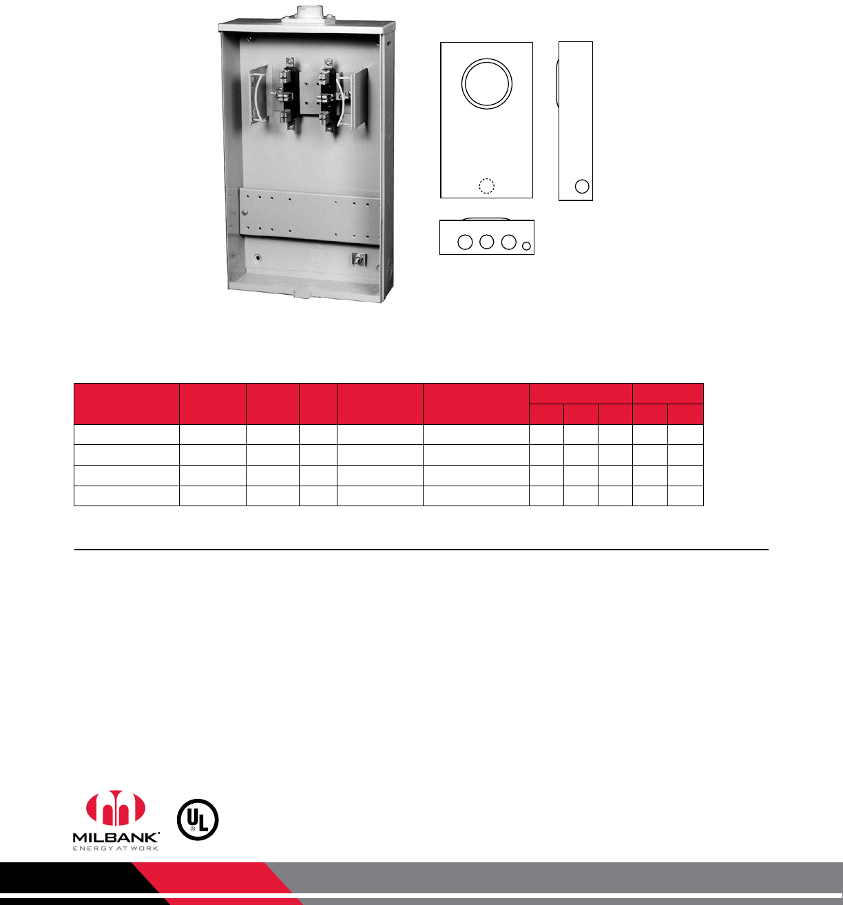
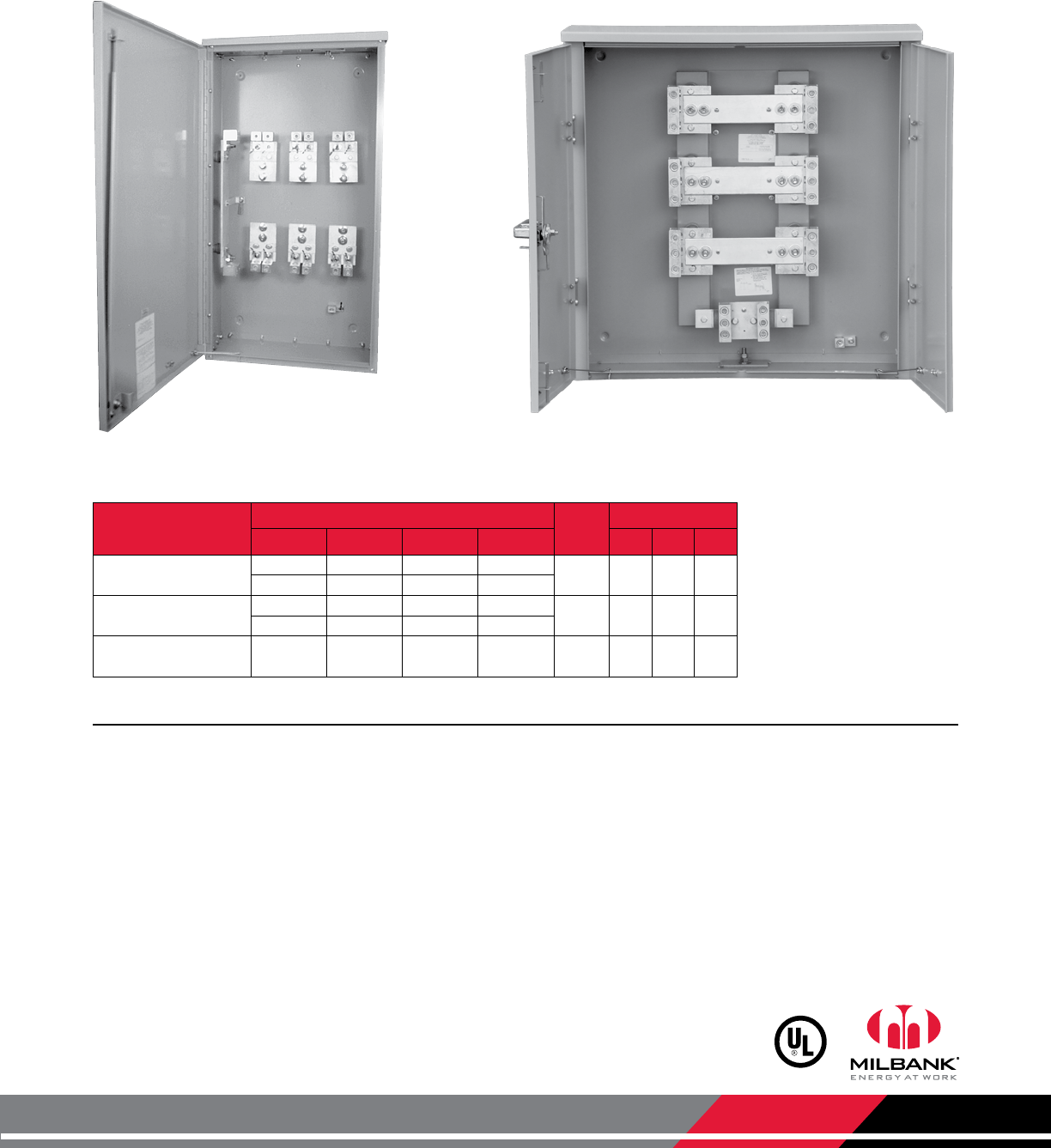
Current Transformer Cabinets
400 & 800 Amps
U4468-XT U5990-O
Catalog Number Ampacity Wiring Chart Hub Dimensions
Amps Wire Qty.
Per Phase Aluminum
Conductor Copper
Conductor D" W" H"
U4468-XT 400 1 — 600 kcmil (2) C.P. 10 24 45
400 2 250 kcmil 3/0
U4468-XT-K4469 800 2 — 600 kcmil (2) C.P. 10 24 45
800 4 250 kcmil 3/0
U5990-O 800 3 600 kcmil
or 2-250
600 kcmil
or 2-250 Blank 10 36 36
Current Transformer Cabinets | 3Ø
Notes
• Hubs: U4468 is supplied with two closing plates as standard. To order hubs, refer to the accessories section.
• Studs: The U4468 is supplied with 1⁄2"-13 twin studs with hex nuts with Belleville washers to mount bar-type transformers.
• 800 Amp Conversion Kit: To convert U4468 from 400 amps to 800 amps, order catalog number K4469.
• Padlock: The U4468 is provided with a padlockable 2-point latch. The U5990 is provided with a padlockable handle with
3-point latching mechanism.
• Withstand Rating: 50K SCCR available when conductors are lashed per instructions on label.
Milbank Manufacturing | 4801 Deramus Ave., Kansas City, MO 64120 | 877.483.5314 | milbankworks.com
Utility requirements for this equipment may vary. Always consult the serving
utility for their requirements before ordering or installing equipment.
24
METERED
TRANSFORMER
CABINETS
11
1
2
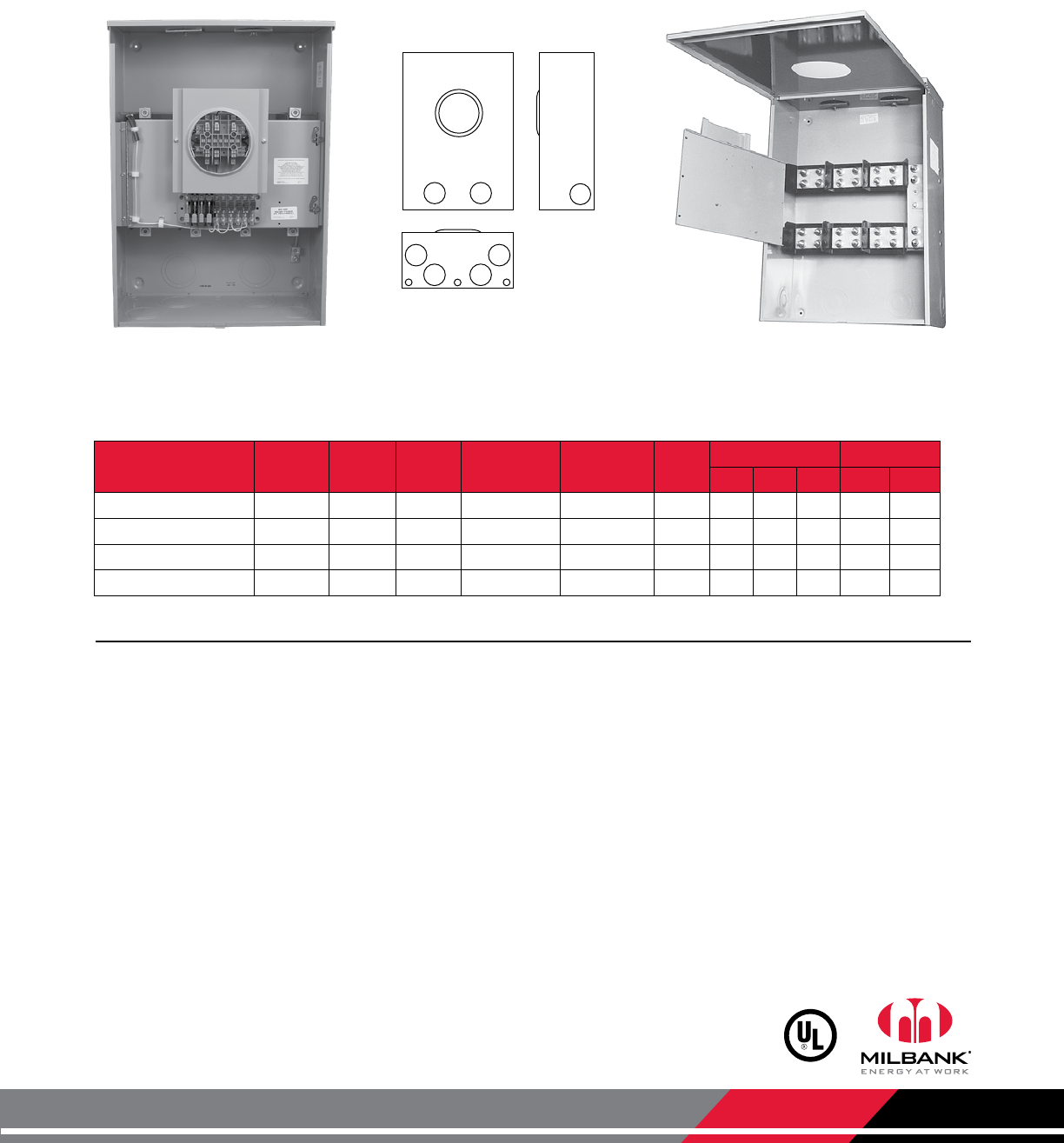
Metered Transformer Cabinets
Screw Cover | Ring Type
Catalog
Number Terminals Service Hub Compatible CT Racks
(see pg. 21 for matching code)
Type of
Service
Dimensions Knockouts
D" W" H" 1 2
U3320-R 6 OH H.O. A, C, D, J, L, M 1Ø3W 11 24 42 4 1
U3322-R 13 OH H.O. B, E, F, G, H, L, M 3Ø4W Y or Δ 11 36 42 4 1
U3555-R 15 OH H.O. B, E, F, G, H, L, M 3Ø4W Y or Δ 11 36 42 4 1
U3340-O 6 UG Blank A, C, D, J, L, M 1Ø3W 11 24 52 4 1
U3342-O 13 UG Blank B, E, F, G, H, L, M 3Ø4W Y or Δ 11 36 52 4 1
U3565-O 15 UG Blank B, E, F, G, H, L, M 3Ø4W Y or Δ 11 36 52 4 1
Metered Transformer Cabinets | Ring Type
S3565-O
3320
3322
3340
3342
3555
3565
Notes
• Meter Socket: 20 amp current transformer meter socket built in.
• Enclosure: NEMA Type 3R with screw cover.
• Current Transformer Mounting: 1⁄4–20 welded studs.
• Hubs: For proper hub selection, see hub suffix chart in the accessories section.
• Sealing Rings: Supplied with MR-4 screw type sealing ring.
• Lugs: For mounting rack information, refer to page 21.
• Test Switches: These units include test switch provision to mount above or below CT rack. Will accept 7 or 10 pole test
switches.
• EUSERC Approval: All units on this page are EUSERC compliant.

Milbank Manufacturing | 4801 Deramus Ave., Kansas City, MO 64120 | 877.483.5314 | milbankworks.com
Utility requirements for this equipment may vary. Always consult the serving
utility for their requirements before ordering or installing equipment.
25
NOTES
Notes
Milbank Manufacturing | 4801 Deramus Ave., Kansas City, MO 64120 | 877.483.5314 | milbankworks.com
Utility requirements for this equipment may vary. Always consult the serving
utility for their requirements before ordering or installing equipment.
Highlights and Features
Transocket Overhead/Underground Capabilities: From the factory, the rack is oriented for underground
applications but can be rotated 180° for overhead applications. The neutral lugs can be mounted on the side for
overhead applications. The VT pack mounting bridge moves from the top to the right side for overhead applications.
NEMA 3R Aluminum Shell: The alumnium shell reduces the overall weight of the unit compared to a steel shell.
Shell is powder coated.
Meter Socket & Test Switch on Swinging Door: Unit includes a 13-terminal CT-rated block. An 8-terminal block
option is also available. Includes a 10-pole test switch. A 7-pole test switch option is also available. Factory pre-wired
to conform to individual utility specifications.
Utility-Specific Wiring Harness: Wiring harness is color configured and wired per the utility specifications.
VT Pack Mounting Bridge: VT pack mounting bridge allows for installation of VT packs.
Wall Mount Bracket: Provides an easier means of installation for one installer, who can premount the bracket and
then hang the unit onto the wall bracket.
Stainless Steel Liftoff Handles: The durable, rust-resistant hinged handles lay flat against the front.
1
1
2
2
3
3
4
4
5
6
5
AP6014-O-400-NKO-21
6
Transockets
Features & Benefits
Milbank Manufacturing | 4801 Deramus Ave., Kansas City, MO 64120 | 877.483.5314 | milbankworks.com
Utility requirements for this equipment may vary. Always consult the serving
utility for their requirements before ordering or installing equipment.
27
400–600 AMP
TRANSOCKETS
Transockets
400–600 Amps | Ringless | 600 VAC
S9573-X S2674-XT S1890-XT
Catalog
Number Terminals Meter
Form Hub PTs Qty.
and Ratio
CTs Qty.
and Ratio
Termination
Type
Dimensions Knockouts
D" W" H" 1 2 3
S1891-XT 8 5S (2) C.P. (2) 4:1 (2) 200/5 Lugs mounted directly to
current transformer 91⁄218 24 21⁄2111⁄16
S3912-XT-21 13 8S (2) C.P. (2) 4:1 (2) 200/5 Lugs mounted directly to
current transformer 91⁄218 24 21⁄2111⁄16
S1890-XT 14 5S (2) C.P. (2) 4:1 (2) 200/5 Lugs mounted directly to
current transformer 91⁄218 24 21⁄2111⁄16
Catalog
Number Terminals Meter
Form Hub CTs Qty.
and Ratio
Termination
Type
Dimensions Knockouts
D" W" H" 1 2 3
S9573-X 6 4S C.P. (2) 200/5 Lay-in lugs 53⁄4191⁄227 31⁄21⁄4,1⁄2—
S3831-XT 6 4S (2) C.P. (2) 200/5 Mechanical lugs 111⁄418 30 4 31⁄21
S2690-XT 8 5S (2) C.P. (2) 200/5 Mechanical lugs 111⁄418 30 4 31⁄21
S2674-XT 13 8S (2) C.P. (3) 200/5 Mechanical lugs 111⁄418 30 4 31⁄21
600 Amps | Transockets | With PTs and Donut Type CTs | Ringless | 600 VAC
400 Amps | Transockets | Bar Type CTs Only | Ringless | 600 VAC
Notes
• Hubs: To order hubs as extra, refer to the hub suffix chart in the accessories section.
• Prewiring: Units supplied prewired with test switch and transformers in place. Contact factory if prewiring is desired.
11
3
11222
1
1
1890
1891
3912
2674
2690
3831
9573 11
22
333
2
22
1
12
1
Milbank Manufacturing | 4801 Deramus Ave., Kansas City, MO 64120 | 877.483.5314 | milbankworks.com
Utility requirements for this equipment may vary. Always consult the serving
utility for their requirements before ordering or installing equipment.
28
TRANSOCKETS Transockets
Compatible with CTs, PTs, or VT Packs
Catalog Number Terminals Service Test Switch Hub PTs Quantity
& Ratio
CTs Quantity
& Ratio
Dimensions Knockouts
D" W" H" 1
S2777-4X 14 OH/UG 10-pole (4) C.P. (2) 2.5:1 (3) 400/5 14 30 42 1⁄2
S2811-4X 14 OH/UG 10-pole (4) C.P. None (3) 400/5 14 30 42 1⁄2
Catalog Number Terminals Service Phase Test
Switch Hub VT Pack
Provision
CTs Qty.
& Ratio
Dimensions Knockouts
D" W" H"
A6015-O-400-NKO 8 OH/UG 1Ø or 3Ø3W 7-pole Blank Yes (2) 400/5 121⁄16 36 37 None
A6014-O-400-NKO 13 OH/UG 3Ø4W 10-pole Blank Yes (3) 400/5 121⁄16 36 37 None
1600 Amps | 14 Terminals | Ringless | 3Ø4W | Transocket
400–1000 Amps | 8 & 13 Terminals | Ringless | Transocket
S2777-4X
(shown factory prewired)
A6014-O-400-NKO
(shown factory prewired)
11
11
2777
2811
Notes
• Shell: Shell is unpainted aluminum and 3R rated.
• Prewiring: If custom factory prewiring is required, be sure to specify test switch requirements, meter form number and
provide a copy of your wiring diagram. If CTs are to be factory installed, specify CT ratio.
• VT Pack Provision: VT pack bridge included; VT pack not included.
• Removable/Rotatable CT Rack: These units include a CT rack which can be rotated 180 degrees for both overhead or
underground applications.
• Wall Mount Bracket: Bracket included for ease of hanging and installation.
• Lugs: Lugs are included with these units.
Notes
• Hubs: Units supplied with 4 closing plates as standard. To order hubs as extra, refer to the accessories page.
• Pre-wiring: If custom factory prewiring is required, be sure to specify test switch requirements, meter form number and
provide a copy of your wiring diagram. If CTs are to be factory installed, specify CT ratio, and PTs if applicable.
Milbank Manufacturing | 4801 Deramus Ave., Kansas City, MO 64120 | 877.483.5314 | milbankworks.com
Utility requirements for this equipment may vary. Always consult the serving
utility for their requirements before ordering or installing equipment.
29
400 AMP
TRANSOCKETS
Transockets
400 Amps | 600 VAC
U5944-XT
(shown factory prewired)
U2161-XT
Catalog Number Terminals Service Front
Cover Phase Test Switch Hub Dimensions Knockouts
D" W" H" 1 2
U2228-XT 6 OH/UG Hinged 1Ø Provision (2) C.P. 12 24 34 4 1
U2229-XT 8 OH/UG Hinged 1Ø or 3Ø3W Provision (2) C.P. 12 24 34 4 1
U2161-XT 13 OH/UG Hinged 3Ø4W Provision (2) C.P. 12 24 34 4 1
U5944-XT 13 OH/UG Lift-off 3Ø4W Provision (2) C.P. 12 24 34 4 1
400 Amps | 6–13 Terminals | Ringless | Transockets
Notes
• Hubs: Units are supplied with two closing plates as standard. To order hubs as extra, refer to the accessories page.
• Shell: Shell is powder-coat painted G90 galvanized steel and 3R rated.
• Pre-wiring: If custom factory prewiring is required, be sure to specify test switch requirements, meter form number and
provide a copy of your wiring diagram. If CTs are to be factory installed, specify CT ratio. There is no provision for PTs in
this unit.
• Studs: 1⁄2"-13 twin studs are supplied to mount bar type transformers. Hex nuts with Belleville washers are also supplied.
• Lugs: Lugs are included with these units.
1
1
222
1
11
11
2161
2228
2229
5944
Milbank Manufacturing | 4801 Deramus Ave., Kansas City, MO 64120 | 877.483.5314 | milbankworks.com
Utility requirements for this equipment may vary. Always consult the serving
utility for their requirements before ordering or installing equipment.
30
200/400/800 AMP
TRANSOCKETS
Transockets
200/400/800 Amps | 600 VAC
U4163-XT-11-LIU4163-XT-11-LI
1111
2
3
4163
4166
4554
4154
1111
2
3
Catalog Number Terminals Service Amps Hub Connectors Phase Dimensions Knockouts
Line Load D" W" H" 1 2 3*
U4554-X-Z21-LI 6 OH/UG 200/400 C.P. #4-600 #4-600 1Ø 10 21 41 4 11⁄43⁄8
U4166-XT-Z21-LI 6 OH/UG 400/800 C.P. #4-600 #4-600 1Ø 10 26 51 4 11⁄43⁄8
U4523-X-Z11-LI 13 OH/UG 200/400 C.P. #4-600 #4-600 3Ø 10 21 41 4 11⁄43⁄8
U4163-XT-11-LI 13 OH/UG 400/800 C.P. #4-600 #4-600 3Ø 10 26 51 4 11⁄43⁄8
200/400/800 Amps | 6 & 13 Terminals | Transockets | Ringless
Notes
• *Knockout #3: This is a 3⁄8" hole with plastic plug, not a concentric knockout.
• Lugs: Lugs are provided and are rated up to single 600 kcmil - #4 AWG.
• Short Circuit Current Withstand Rating: These units have a 50K short circuit current withstand rating.
• Units furnished with 1/2"-13 studs, washers and hex nuts and bolt with conical washer for CT mounting.
11
22
3
1
Milbank Manufacturing | 4801 Deramus Ave., Kansas City, MO 64120 | 877.483.5314 | milbankworks.com
Utility requirements for this equipment may vary. Always consult the serving
utility for their requirements before ordering or installing equipment.
31
INSTRUMENT
RATED
PEDESTAL
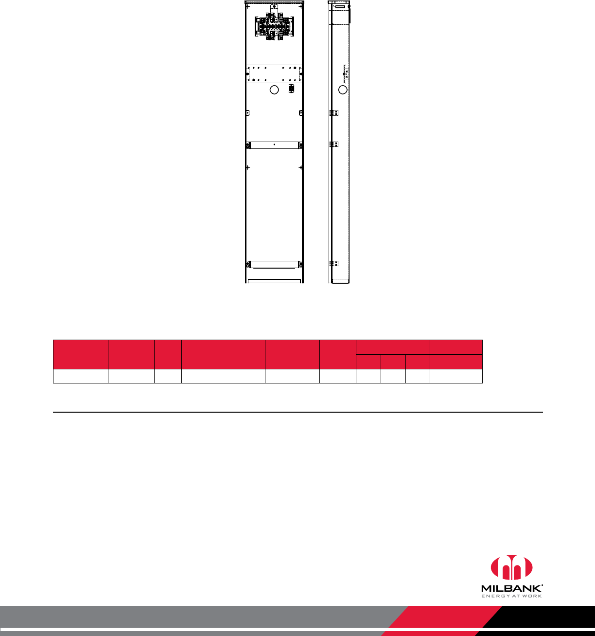
Instrument Rated Pedestal
20 Amps | 13 Terminals | With Test Switch Provision
Notes
• Contact factory for details.
• Also available in 6 & 8 terminals.
1 1
S4084-O
Ringless | Instrument Rated Pedestal | With Test Switch Provision
Catalog
Number Terminals Hub Meter Form Connectors
CU Bypass Dimensions Knockouts
D" W" H" 1
S4084-O 13 Blank
6, 8, 9 & (ALT) 10S
#14 - #4 Max None 41⁄812 58 11⁄4
Milbank Manufacturing | 4801 Deramus Ave., Kansas City, MO 64120 | 877.483.5314 | milbankworks.com
Utility requirements for this equipment may vary. Always consult the serving
utility for their requirements before ordering or installing equipment.
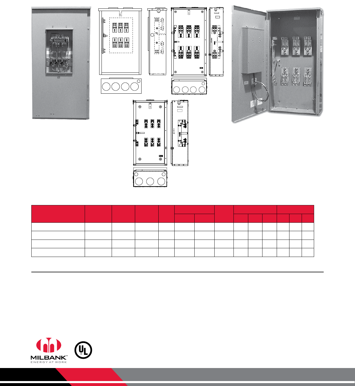
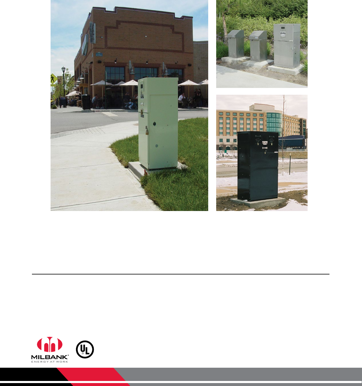
32 Instrument Rated Commercial Pedestals
Attractive | Easy to Install | Secure | Cost-effective
INSTRUMENT
RATED
PEDESTAL
Milbank Commercial Pedestals are pad-mounted, weatherproof electrical enclosures consisting of a utility
pull section with optional meter socket, and a customer section containing distribution and control equipment.
Milbank Commercial Pedestals are an attractive, secure, easy to install and cost-effective solution when
underground remote site power distribution and control equipment is required, replacing unsightly and
inefficient strut and backboard structures.
• Type 3R rainproof, vandal-resistant cabinet of powder-coated steel (aluminum or stainless steel also available)
• UL-listed as enclosed industrial control equipment (UL508)
• Isolated lockable & sealable utility metering and lug landing sections
• Lockable customer section for distribution and control equipment with internal deadfront
• Print pocket inside customer section door contains wiring schematics and installation instructions
• All stainless steel external hardware (screws, bolts, hinges, handles, hasps and sealing screws)
Standard Features

Milbank Manufacturing | 4801 Deramus Ave., Kansas City, MO 64120 | 877.483.5314 | milbankworks.com
Utility requirements for this equipment may vary. Always consult the serving
utility for their requirements before ordering or installing equipment.
33
NOTES
Notes
Milbank Manufacturing | 4801 Deramus Ave., Kansas City, MO 64120 | 877.483.5314 | milbankworks.com
Utility requirements for this equipment may vary. Always consult the serving
utility for their requirements before ordering or installing equipment.
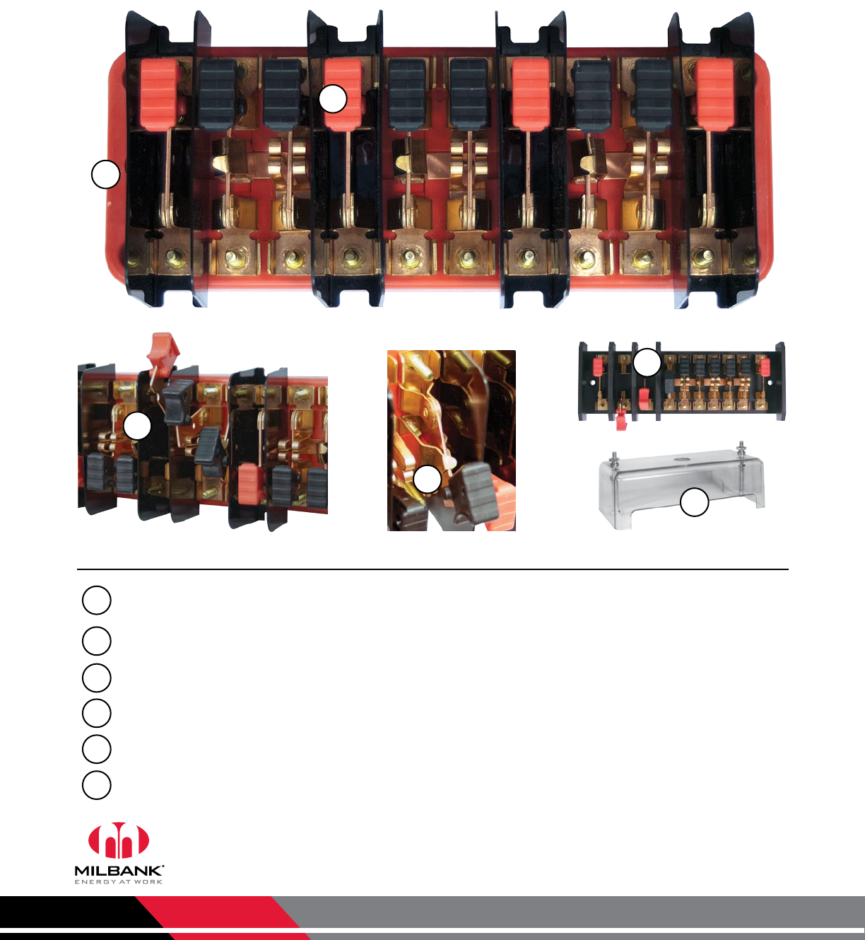
Highlights and Features
Handle Color Options: Standard colors are black for current and red for potential. Many non-standard colors are
available—contact Milbank for details. Handle material is polypropylene.
45 Degree Stops: 90 degree bends on 45 degree stops are standard. 180-degree bends are available where
additional strength is required.
Test Switch Barriers: Test switch barriers are made of polycarbonate as standard.
Test Switch Covers: Polycarbonate (clear or black). Test switch cover is clear when factory-installed unless otherwise
specified.
Test Switch Base: Test switch bases are red as standard and made of glass polyester.
Arboron Test Switch Base & Barriers Option: Base and barriers are available in Arboron, a thicker and more rigid
material that provides extra strength.
1
1
5
2
3
4
5
6
3
2
6
4
Test Switches
Features & Benefits
Milbank Manufacturing | 4801 Deramus Ave., Kansas City, MO 64120 | 877.483.5314 | milbankworks.com
Utility requirements for this equipment may vary. Always consult the serving
utility for their requirements before ordering or installing equipment.
35
TEST
SWITCHES
Test Switches
Details & Test Switch Covers
Factory Installed: For cover installed add the suffix -WC or -WCFL to the catalog number of desired test switch.
Field Installed: For field installed cover order kit number K3388 or K3388-BLK-FL.
The Milbank test switch is designed to meet the critical requirements of the electric utility industry. Not only do
they meet EEI, ANSI C12.9, and UL standards but they combine several special features giving the Milbank test
switch increased safety, durability and reliability. One such feature is our unique switch blade contact points
which cut through residue that builds up after years of service. Another distinction is our polarity barrier which is
designed to be flexible as well as offer exceptional insulating qualities. Our test switches are constructed from the
latest materials available using modern fabricating and assembly methods.
Switch Blades
Two dimples coined into one side of the
switch blade ensure positive contact in
corrosive, sooty environments—even
after years of inactivity.
Test Switch Covers
Standard test switch covers are made
from impact resistant clear thermal
plastic which has excellent tracking and
moisture resistant properties. If covers
are required, add suffix -WC (with cover)
to the catalog number or order separately
catalog number K3388. Black flush
mount covers are also available. Order
catalog number K3388-BLK-FL. 10 pole
base only.
Standard Cover
Test Switch Base
The base is molded from a high strength,
fiberglass reinforced, thermoset
polyester. This material is track resistant,
flame retardant and has low water
absorption qualities. Bases are available
in 7 pole and 10 pole sizes.
Switch Jaws
The switch blade jaw clips are constructed
from spring grade copper alloy. The
material and design ensure excellent
contact which prevents overheating.
Nickel Plating Option
Corrosion-resistant test switches with
nickel plating are available as an option.
Socket shells must be 51⁄8" deep
-OR-
must not have test switch bridge
mounted on back
in order to support a cover.
Polarity Barrier
For maximum protection potential
circuits are supplied with permanently
mounted barriers made from high tensile
strength polycarbonate.
Current Carrying Parts
Highly conductive copper and copper
alloy materials are used on all current
carrying parts. This ensures conductivity
and deters corrosion. Spring grades are
used where appropriate. Plating is
available if required. Contact general
offices to special order.
Flush Mount Cover (Black)
Milbank Manufacturing | 4801 Deramus Ave., Kansas City, MO 64120 | 877.483.5314 | milbankworks.com
Utility requirements for this equipment may vary. Always consult the serving
utility for their requirements before ordering or installing equipment.
36
TEST
SWITCHES
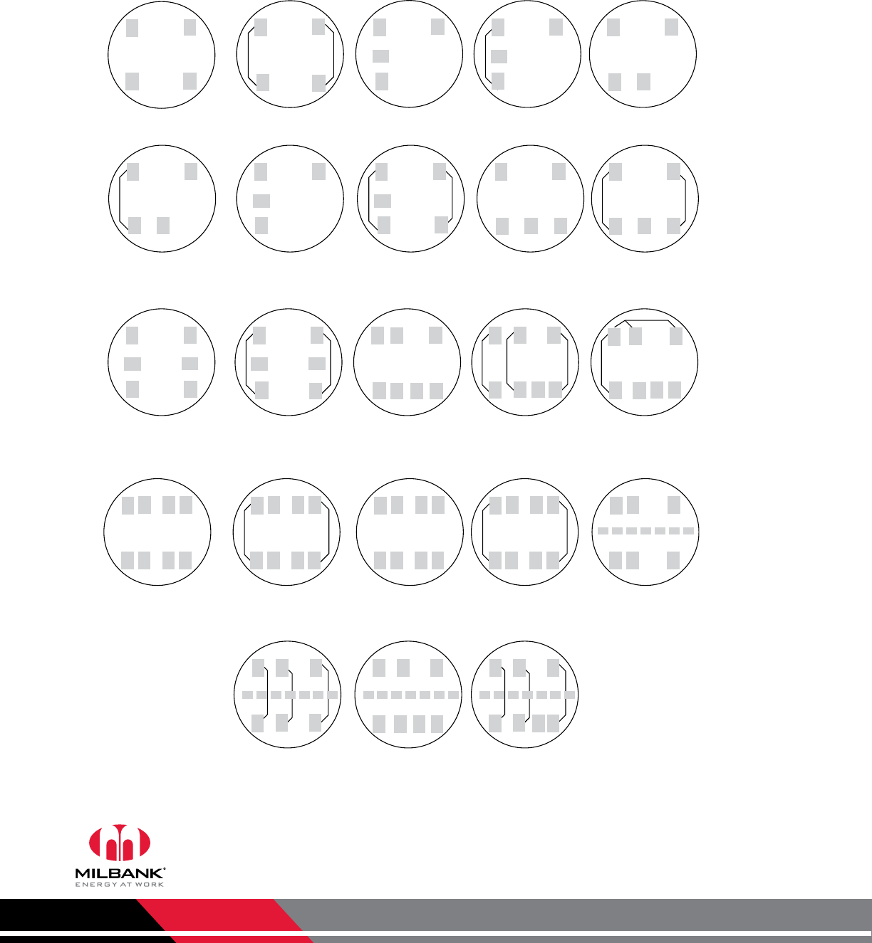
Test Switches
4, 7 & 10 Pole
7 1/2"
3 1/2"
3 1/2"
9 1/2"
Key
P Potential Switch
C+ Line side current switch with
short circuit assembly
CLoad side current switch
with test jack assembly
N Neutral bar (no switch)
Pn Neutral Potential Switch
X Unused Position on base
Insulating barrier, isolates
both sides of switch
Catalog
Number 7-Pole on a 10-Pole Base
TS07-0049 P X P X Pn X C+ C C C+
TS07-0106 X P C+ C P C+ C Pn X X
Catalog
Number 10-Pole
TS10-0109 P P P Pn C+ C C+ C C+ C
TS10-0110 P C+ C P C+ C P C+ C Pn
TS10-0111 P P P Pn C C+ C C+ C C+
TS10-0112 C+ C C+ C C+ C P P P Pn
TS10-0016 P P P Pn C C+ C C+ C C+
Catalog
Number 7-Pole
TS07-0105 P P Pn C+ C C+ C
Catalog
Number 4-Pole
TS04-0101 X P Pn X C+ C X
TS04-0104 X C+ C X P Pn X
Custom Pole Arrangements:
The key may be used to diagram
your own pole arrangement. Be
sure to specify base size and
whether all C+ line side, current
switch / shunt circuit assemblies
are to be bussed together. The
catalog numbers shown above
are connected in line-load pairs;
therefore, if bussing is required,
different catalog numbers will
apply.
Milbank Manufacturing | 4801 Deramus Ave., Kansas City, MO 64120 | 877.483.5314 | milbankworks.com
Utility requirements for this equipment may vary. Always consult the serving
utility for their requirements before ordering or installing equipment.
37
TEST SWITCH
WORKSHEET
Test Switch Worksheet
Electronic version available at milbankworks.com
Key
P Potential Switch
C+ Line side current switch with
short circuit assembly
CLoad side current switch
with test jack assembly
N Neutral bar (no switch)
Pn Neutral Potential Switch
X Unused Position on base
Insulating barrier (one side)
Insulating barrier (two sides)
4
7
10
Other ____
Yes | Clear ___ Black ___
No
7-Pole
10-Pole
Number of Poles Test Switch Cover (only available for 10-pole bases)
Base Size
q q
q q
q
q
q
q
Engineering Information: _________________________________________________________________________
_________________________________________________________________________________________________
_________________________________________________________________________________________________
Customer Name: ________________________________________________________________
Address: _______________________________________________________________________
________________________________________________________________________________
Phone / Fax #: _________________________________________________________________
Custom Pole Arrangements: The key may be used to diagram your own
pole arrangement. Be sure to specify base size and whether all C+ line side,
current switch / shunt circuit assemblies are to be bussed together. The
catalog numbers shown above are connected in line-load pairs; therefore, if
bussed is required, different catalog numbers will apply.
TEST SWITCH BASE
The base is molded from a high strength,
fiberglass reinforced, thermoset polyester.
This material is track-resistant, flame-retardant
and has low water absorption qualities. Bases
are available in two standard sizes following
NEMA mounting classifications.
Handle Color Key
BK Black PPurple YYellow GN Green
RRed BL Blue WWhite BKS Black Stripe
BR Brown GR Grey OOrange WS White Stripe
12345678910
Pole Position Chart
Feature 1 2 3 4 5 6 7 8 9 10
45° Angle Stops
Ganged Handles (C)
Bussing
Colored Handles
Special Features
Milbank Manufacturing | 4801 Deramus Ave., Kansas City, MO 64120 | 877.483.5314 | milbankworks.com
Utility requirements for this equipment may vary. Always consult the serving
utility for their requirements before ordering or installing equipment.
38
WATTHOUR
METER FORMS
Watthour Meter Forms
Standard Forms | Transformer Rated or Self-Contained
SC SC TR TR TR
TR SC SC SC SC
TR TR SC SC TR
TR TR SC SC TR
TR TR TR
2 and 3-WIRE FORMS
1S & 2S
2 and 3-WIRE FORMS
1S & 2S with BYPASS
2-WIRE FORM 3S
5th Term. 9 o'clock
2-WIRE FORM 3S
with BYPASS
2-WIRE FORM 3S
5th Te rm.6 o'clock
2-WIRE FORM 3S
with BYPASS
2 ELEMENT
3-WIRE NETWORK
FORM 12S 5th
TERM. 9 o'clock
2 ELEMENT 3-WIRE
NETWORK FORM 12S
with BYPASS
5th Term. 9 o'clock
2 ELEMENT 3-WIRE
NETWORK FORM 12S
with BYPASS
5th Te rm. 6 o'clock
2 ELEMENT
3-WIRE NETWORK
FORM 12S 5th
TERM. 6 o'clock
3-WIRE FORM 4S 3-WIRE FORM 4S
WITH BYPASS
2 or 3 ELEMENT
3∅4W Y or ∆
Y FORM 14S
∆ FORM 15S
2 or 3 ELEMENT
3∅4W Y or ∆
FORMS 14S & 15S
with BYPASS
2 ELEMENT
3∅4W Y or ∆
Y FORM 7S
∆ FORM 24S
with BYPASS
2 ELEMENT
2∅3W, 2∅4W, 3∅3W
FORM 5S
2 ELEMENT 2∅3W,
2∅4W, 3∅3W
FORM 5S with
BYPASS
2 ELEMENT
2∅3W, 2∅4W, 3∅3W
FORM 13S
2 or 3 ELEMENT
2∅3W, 2∅4W, 3∅3W
FORM 13S with
BYPASS
2 or 3 ELEMENT
3∅4W Y or ∆
Y FORM 9S
∆ FORM 8S
2 or 3 ELEMENT
3∅4W Y or ∆
FORMS 8S & 9S
with BYPASS
2 ELEMENT
3∅4W Y
FORM 6S
2 ELEMENT
3∅4W Y
FORM 6S
with BYPASS
TR = TRANSFORMER RATED
SC = SELF CONTAINED
Milbank Manufacturing | 4801 Deramus Ave., Kansas City, MO 64120 | 877.483.5314 | milbankworks.com
Utility requirements for this equipment may vary. Always consult the serving
utility for their requirements before ordering or installing equipment.
39
METER FORMS
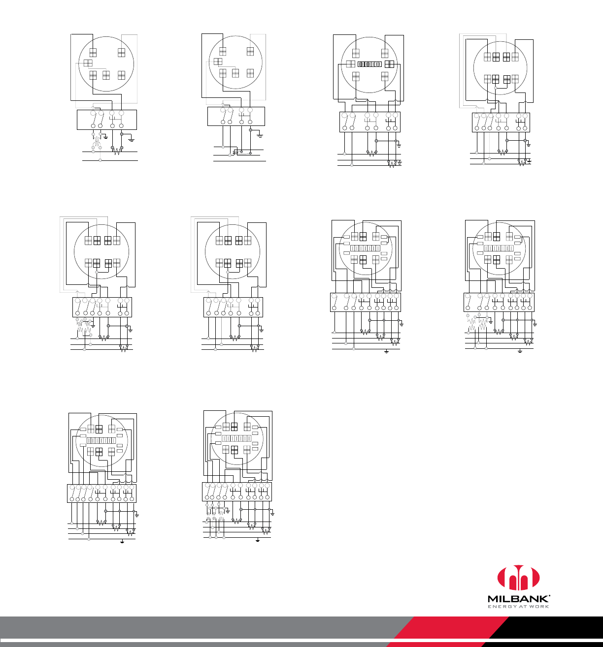
Meter Forms
Reference Information
+
+
I
LINE
(BONDED)
N
C.T.
LOAD
2++
DIAGRAM D
P
1
P
2
C+
1C
2
C+
2
PN
C
1
C.T.
DIAGRAM D
1∅3W or 3W Network with 2 C.T.’s
2 Stator Meter - Form 5S
8T Socket, Test Switch #TS07-0105
+
+
1
LINE
C.T.
LOAD
2
P
1
C+
1
++
3
+
+
PT PT
DIAGRAM E
P
3
P2
C
1
C+
3
C
3
C.T.
DIAGRAM E
3∅3W “∆” with 2 P.T.’s & 2 C.T.’s
2 Stator Meter - Form
5S
8T Socket, Test Switch #TS07-0105
+
+
1
LINE
C.T.
LOAD
2
P
1
C+
1
++
3
DIAGRAM F
P
3
P
2
C1
C+
3C
3
C.T.
DIAGRAM F
3∅3W “∆” with 2 C.T.’s
2 Stator Meter - Form 5S
8T Socket, Test Switch #TS07-
0105
+
+
C.T.
LOAD
P
1
+
+
P
3
PN
C+
C+
C.T.
C.T.
++
(BONDED)
DIAGRAM G
CC
C+
C
1
LINE
2
3
N
DIAGRAM G
3∅4W “Y” with 3 C.T.’s
2
1
⁄
2
Stator Meter - Form 6S
13T Socket, Test Switch #TS10-0109
+
+
1
LINE
C.T.
LOAD
2
P
1
+
+
3
P
3
PN
C+
N
C.T.
C.T.
++
(BONDED)
++
PT
PT
++
DIAGRAM H
C
C+
C+
C
C
DIAGRAM H
3∅4W “Y” with 2 P.T.’s & 3 C.T.’s
2
1
⁄
2
Stator Meter - Form 6S
13T Socket, Test Switch #TS10-0109
+
+
1
LINE
C.T.
LOAD
2
P
1
+
+
3
P
3
P
N
C+
N
C.T.
C.T.
++
(BONDED)
P
2
DIAGRAM I
C
C+
C
C+
C
DIAGRAM I
3∅4W “Y” or “∆” with 3 C.T.’s
“Y” 3 Stator Meter - Form 9S
“∆” 2 Stator Meter -
Form 8S
13T Socket, Test Switch #TS10-0109
+
+
1
LINE
C.T.
LOAD
2
P
1
+
+
3
PN
C+
N
C.T.
C.T.
+
+
(BONDED)
++
PT PT
+
+
P3
PT
++
DIAGRAM J
P
2
CC+CC+C
DIAGRAM J
3∅4W “Y” with 3 P.T.’s & 3 C.T.’s
3 Stator Meter - Form 9S
13T Socket, Test Switch #TS10-0109
DIAGRAM A
(ALT.LOC.)
+
+
+
+
I
LINE
(BONDED)
NC.T. LOAD
P
1
P
N
C+
1C1
P.T.
DIAGRAM A
1∅2W with 1 P.T. & 1 C.T.
Single Stator Meter(2W1∅) - Form 3S
5T Socket, Test Switch #TS04-0101
(ALT.LOC.)
+
+
I
LINE
(BONDED)
NC.T. LOAD
2
DIAGRAM B
P
1
P
N
C+
1
C
1
DIAGRAM B
1∅3W with 1 C.T.
Single Stator Meter (2W1∅) - Form 3S
5T Socket, Test Switch #TS04-0101
+
+
I
LINE
(BONDED)
NC.T.
LOAD
2
P
1
P2C+
1C+
2
C
2
C+
2
++
DIAGRAM C
C.T.
DIAGRAM C
1∅3W with 2 C.T.’s
Single Stator Meter (3W1∅) - Form 4S
6T Socket, Test Switch #TS07-0105
Prewiring: If standard factory prewiring is required,
refer to wiring diagrams on this page. Determine
appropriate diagram and send a copy with order.
If custom factory prewiring is required, specify on
order. Be sure to include meter socket catalog
number, test switch make and catalog number,
meter form number and provide a copy of your
wiring diagram.
Milbank Manufacturing | 4801 Deramus Ave., Kansas City, MO 64120 | 877.483.5314 | milbankworks.com
Utility requirements for this equipment may vary. Always consult the serving
utility for their requirements before ordering or installing equipment.
40
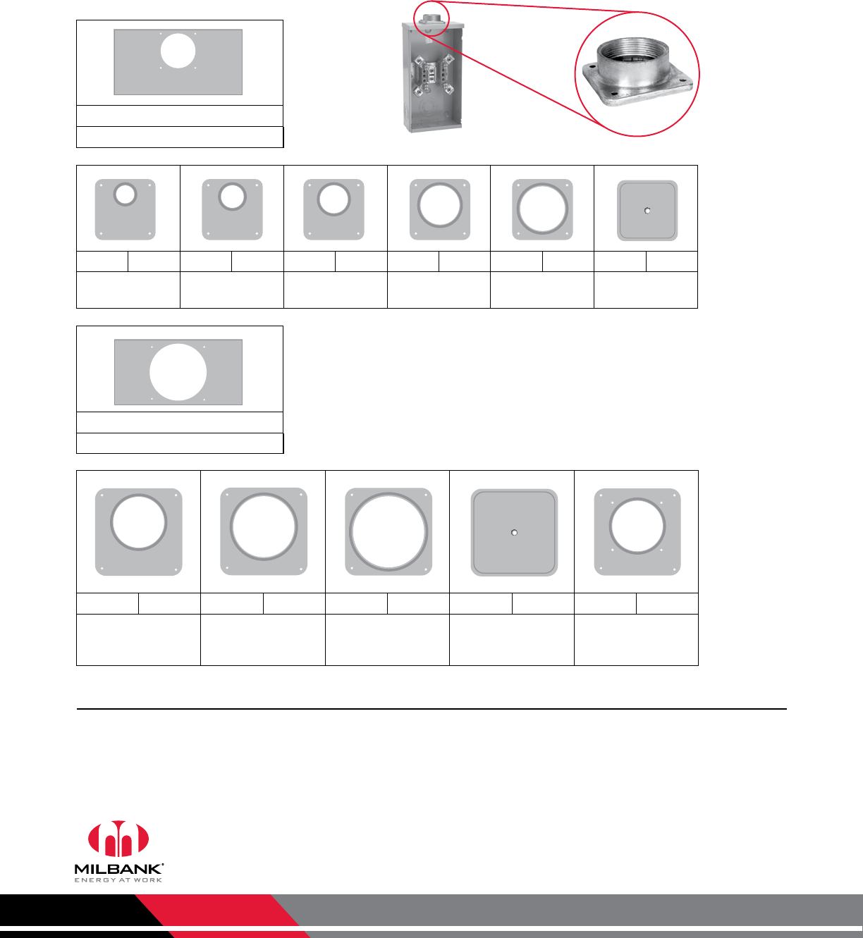
ACCESSORIES Accessories
Hubs and Closing Plates
-R
Large hub opening
-WL A7514 -YL A7515 -ZL A7516 -DL A7517 -EL A7518 -XL A7551
1" hub 11⁄4" hub 11⁄2" hub 2" hub 21⁄2" hub Small closing
plate
-F A8110 -G A8111 -H A8112 -X A9064 -RRL S8324
3" hub 31⁄2" hub 4" hub Large closing plate Large hub opening
adapted to small
hub oepning
-RL
Small hub opening
Notes
• Suffix: Add to catalog number for factory installation of hub.
• Packaging: Individually packed units for field installation.
• Abbreviations: H.O. (hub opening), C.P. (closing plate).
Milbank Manufacturing | 4801 Deramus Ave., Kansas City, MO 64120 | 877.483.5314 | milbankworks.com
Utility requirements for this equipment may vary. Always consult the serving
utility for their requirements before ordering or installing equipment.
41
ACCESORIES
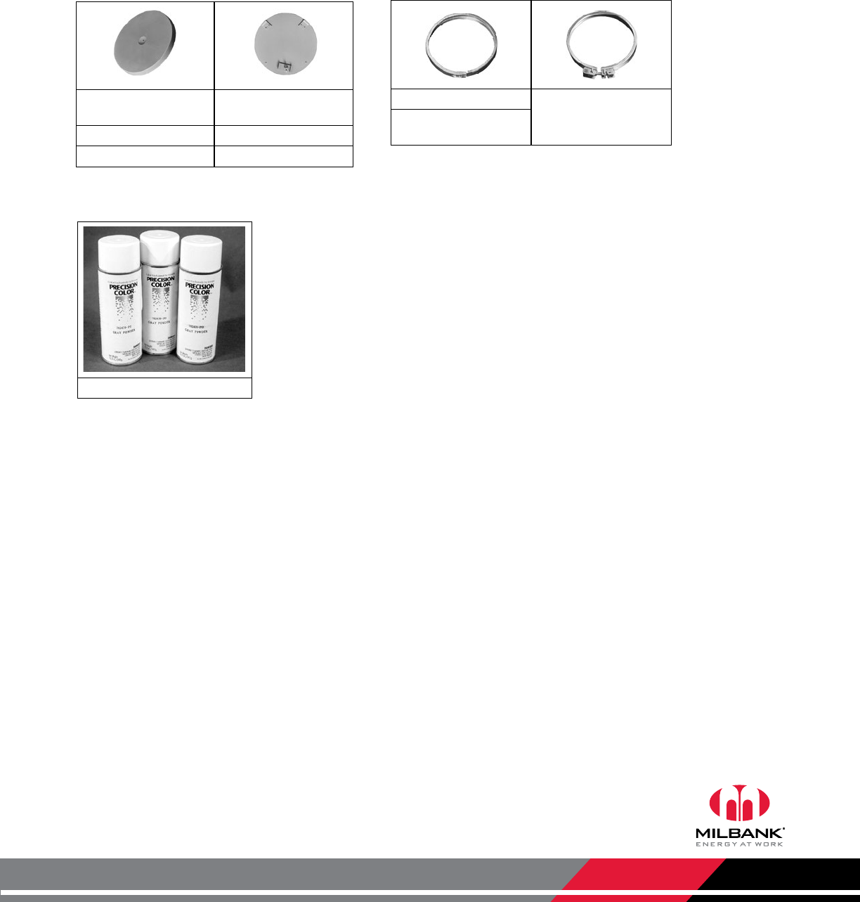
Accessories
Closing Covers, Sealing Rings and Touch-Up Paint
Closing Covers
Meter Closing Plate
(Ring Type / Ringless)
Metal Closing Plate
(For Ringless Sockets)
6003 - Grey Plastic CP-21
6116 - Clear Plastic
Sealing Rings
MR-2 - Snap Action MR-4 - Screw Type
(Stainless Steel)
MR2-SS - Stainless
Steel
Touch-Up Paint
A-GP - Light Grey
Milbank Manufacturing | 4801 Deramus Ave., Kansas City, MO 64120 | 877.483.5314 | milbankworks.com
Utility requirements for this equipment may vary. Always consult the serving
utility for their requirements before ordering or installing equipment.
42
ENERGIZATION
OF ELECTRICAL
EQUIPMENT
Energization of Electrical Equipment
Important Information for Installers
Before Energizing
A. Give equipment a thorough visual examination to determine that:
1) No shipping or installation damage exists.
2) Proper clearances have been maintained.
3) All connections have been made.
4) Equipment is clean and dry.
B. Make a thorough examination to:
1) Verify tightness of all bolted connections (see table below).
2) Manually operate all circuit breakers, switches, relays, etc.
3) Check rigidity of all mountings, bus bars and components.
4) Use test equipment to check continuity of circuitry and integrity of insulation.
C. All switches and circuit breakers should be in the “off” position.
D. Verify that manual meter bypass (if applicable) is in non-bypass position.
E. Install cover and/or close doors.
F. If installation is not being energized at this time, follow “after-energizing” steps listed below. These steps will secure the installation in
case of accidental energization.
When Energizing
A. Use caution and follow established safety procedures:
1) Wear safety apparel.
2) Use safety equipment.
3) Take action to prevent injury to yourself and others in the event of failure of the installation.
4) Take action to prevent/decrease damage to property in the event of failure of the installation.
5) If you are unsure how to safely energize the installation, get someone who is knowledgeable to do it.
After Energizing
A. Secure the installation:
1) To prevent accidental contact with energized parts, cover all openings with approved filler devices.
2) To prevent unauthorized access, secure all covers and/or doors with approved security devices.
3) Attach/post information to advise others of potential hazards associated with the installation.
Important Note
In addition to national and local electrical codes, many utilities have specific requirements for metering equipment. Always consult the serving
utility for their specifications and requirements prior to ordering or installing Milbank meter mounting equipment.
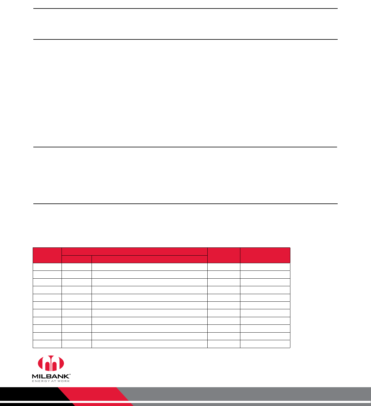
* Interior labels
typically indicate
the required
torque for wire
connectors and
studs, and should
be referenced first.
CU: Copper
AL: Aluminum
Nominal
Size
Joint Description Head Type Torque
(Inch Lbs.)
Screw Nut
10 Brass Brass Nut or Extruded Hole All 20-25 inch lbs.
10 Steel Copper or Aluminum Busbar ≤ 1/8" All 25-30 inch lbs.
10 Steel Steel Nut or Extruded Hole; CU or AL Busbar > 1/8" All 30-35 inch lbs.
12 Steel Aluminum Extruded Hole All 30-35 inch lbs.
12 Steel Steel Nut or Extruded Hole All 40-50 inch lbs.
1/4 Steel Aluminum Extruded Hole All 40-50 inch lbs.
1/4 Steel Steel Nut or Extruded Hole; CU or AL Busbar All 50-60 inch lbs.
5/16 Steel Aluminum Extruded Hole Hex 60-70 inch lbs.
5/16 Steel Steel Nut or Extruded Hole; CU or AL Busbar Hex 100-150 inch lbs.
3/8 Steel Steel Nut Hex 150-200 inch lbs.
1/2 Steel Steel Nut Hex 200-250 inch lbs.
Recommended Torque for General Applications*
Milbank Manufacturing | 4801 Deramus Ave., Kansas City, MO 64120 | 877.483.5314 | milbankworks.com
Utility requirements for this equipment may vary. Always consult the serving
utility for their requirements before ordering or installing equipment.
43
MATERIALS
& FINISHES
Materials & Finishes
Reference Information
Materials
Finish
Ratings & Compliance
The meter equipment listed in this catalog is made of galvanized steel (AISI* G90) to afford the best possible weather proofing.
*American Iron and Steel Institute.
Steel Quality
16 gauge, galvanized, sheet: 1 1/4 oz./ sq.ft. class zinc-coated. (AISI G90)
14 gauge, galvanized, sheet: 1 1/4 oz./ sq.ft. class zinc-coated.
Steel Sheet
Wire-Terminals: Alloy; 6061-T6, Tin-plated for CU/AL wire.
Bus Bar: Alloy; 6101-O & 6063-O
Aluminum Extrusion
3000 series aluminum sheet, H14, or 5052 series aluminum sheet, H32. Where applicable thicknesses range from .064–.125
Aluminum Sheet
Electrolytic copper with tin plating in most applications.
Copper Sheet & Bus
• In most units, support bases for current-carrying components are molded from fiberglass reinforced high-strength, track resistant,
thermoset polyester molding compounds.
• Clear or black safety shields and polarity barriers are molded from high-strength, track resistant, polycarbonate molding compounds.
• Various sheet insulating materials, as appropriate for the application are utilized in the fabrication of flat, formed and punched component
parts and barriers.
Insulating Materials
Light gray state-of-the-art electrostatically applied powder paint offers a durable, non-fading finish. For further information concerning the
chemical analysis of the weather resistant finish, please contact the factory.
Process
Zinc-coated with a chromate dip.
Metal Fastners
All Milbank electrical enclosures in this catalog are rated “Type 3R Enclosure” unless specified otherwise on the product’s page. All
enclosures with a UL designation are constructed per the appropriate UL Standard and may be installed per the National Electric Code.
UL procedure files associated with the UL Standards are listed as follows: Meter Sockets (UL 414, File E30202), Test Switches (UL 414, File
E62531), Power Outlets (UL 231, File E90945), Panelboards (UL 67, File E32628) and Pullout Switches (UL 1429, File E133062). Additional
standards are utilized as applicable: Meter Sockets (ANSI C12.7), Test Switches (ANSI C12.9) and Panelboards (NEMA PB-1).
Ratings & Compliance

Milbank Manufacturing | 4801 Deramus Ave., Kansas City, MO 64120 | 877.483.5314 | milbankworks.com
Utility requirements for this equipment may vary. Always consult the serving
utility for their requirements before ordering or installing equipment.
44
INDEX Index
6003....................................................41
6116....................................................41
243210-LC3R-SP .................................18
303610-CT3R ......................................19
303610-LC3R-SP .................................18
323610-LC3R-SP .................................18
363010-CT3R ......................................19
363016-CT3R ......................................19
363610-CT3R ......................................19
363612-CT3R ......................................19
363612-LC3R-SP .................................18
363616-CT3R ......................................19
423616-CT3R ......................................18
443010-CT3R ......................................19
483612-CT3R ......................................19
483616-CT3R ......................................19
484812-CT3R ......................................19
606013-CT3R ......................................19
A6014-O-400-NKO ............................28
A6015-O-400-NKO ............................28
A7514 .................................................40
A7515 .................................................40
A7516 .................................................40
A7517 .................................................40
A7518 .................................................40
A7551 .................................................40
A8110 .................................................40
A8111 .................................................40
A8112 .................................................40
A9064 .................................................40
CP-21 .................................................. 41
CT203611-HC .....................................20
CT242411-SC .....................................20
CT243011-HC .....................................20
CT243011-SC .....................................20
CT24329-SC .......................................20
CT243611-HC .....................................20
CT243611-SC .....................................20
CT244811-HC .....................................20
CT244811-SC .....................................20
CT303011-SC .....................................20
CT303611-HC .....................................20
CT303611-SC .....................................20
CT303614-SC .....................................20
CT304811-HC .....................................20
CT363611-HC .....................................20
CT363611-SC .....................................20
CT364211-SC .....................................20
CT364811-HC .....................................20
CT364811-SC .....................................20
CT364814-HC .....................................20
CT364814-SC .....................................20
CT424211-SC .....................................20
CT484811-HC .....................................20
CT484811-SC .....................................20
CT484814-HC .....................................20
K4722 .................................................21
K4729 .................................................21
K4793 .................................................21
K4794 .................................................21
K4795 .................................................21
K4796 .................................................21
K4797 .................................................21
K4797 .................................................21
K4798 .................................................21
K4798 .................................................21
K4903 .................................................21
K4904 .................................................21
K5747 .................................................21
K5752 .................................................21
K5930 .................................................21
K5931 .................................................21
K5932 .................................................21
K5933 .................................................21
MR-2 ...................................................41
MR2-SS ...............................................41
MR-4 ...................................................41
PT48AL ...............................................18
PT48AR ............................................... 18
PT48L ..................................................18
PT48R .................................................18
S1855-O .............................................22
S1856-O .............................................22
S1891-XT ............................................27
S1891-XT ............................................27
S1891-XT ............................................27
S2674-XT ............................................27
S2690-XT ............................................27
S2777-4X ............................................28
S2811-4X ............................................28
S3831-XT ............................................27
S4084-O .............................................31
S8324..................................................40
S9573-X ..............................................27
SC6010-O-BL-21 ................................10
SC6011-O-BL-21 ................................10
TS04-0101 ..........................................36
TS04-0104 ..........................................36
TS07-0049 ..........................................36
TS07-0105 ..........................................36
TS07-0106 ..........................................36
TS10-0016 ..........................................36
TS10-0109 ..........................................36
TS10-0110 ..........................................36
TS10-0111 ..........................................36
TS10-0112 ..........................................36
U2161-XT ............................................29
U2228-XT ............................................29
U2229-XT ............................................29
U3320-R .............................................. 24
U3322-R .............................................. 24
U3340-O ............................................. 24
U3342-O ............................................. 24
U3555-R .............................................. 24
U3565-O ............................................. 24
U4163-XT-11-LI ................................... 30
U4166-XT-Z21-LI ................................. 30
U4468-XT ............................................23
U4468-XT-K4469 .................................23
U4490-XL ............................................ 11
U4492-XL ............................................ 11
U4493-XL ............................................ 11
U4494-XL ............................................ 12
U4496-XL ............................................ 12
U4497-XL ............................................ 12
U4523-X-Z11-LI ..................................30
U4554-X-Z21-LI ..................................30
U4811-O-21 ........................................13
U5944-XT ............................................29
U5990-O ............................................. 23
UC1290-XL ...........................................5
UC1291-RL ...........................................5
UC1299-XL ...........................................5
UC1300-RL ...........................................5
UC3423-XL ...........................................8
UC3425-XL ...........................................8
UC3426-XL ...........................................8
UC3428-XL ...........................................8
UC3433-XL ...........................................8
UC3434-XL ...........................................8
UC3435-XL ...........................................8
UC3436-XL ...........................................8
UC3438-XL ...........................................8
UC3443-XL .........................................10

Milbank Manufacturing | 4801 Deramus Ave., Kansas City, MO 64120 | 877.483.5314 | milbankworks.com
Utility requirements for this equipment may vary. Always consult the serving
utility for their requirements before ordering or installing equipment.
45
INDEX
Index
UC3444-XL .........................................10
UC3448-XL .........................................10
UC3453-XL .........................................10
UC3458-XL .........................................10
UC7233-XL ...........................................5
UC7235-XL ...........................................5
UC7237-XL ...........................................5
UC7442-RL ...........................................6
UC7444-RL ...........................................6
UC7445-RL ...........................................6
UC7446-RL ...........................................7
UC7448-RL ...........................................7
UC7449-RL ...........................................7
UC7449-XL-871 ....................................9
UC7450-RL ...........................................7
UC7460-RL ...........................................7
UC7461-RL ...........................................7
UC7478-RL ...........................................6
UC7532-RL ...........................................7
UC7544-RL ...........................................5
UC7545-RL ...........................................5
UC7582-XL ...........................................5
UC7636-RL ...........................................7
UCSS3423-O ......................................14
UCSS3433-O ......................................14
Milbank Manufacturing | 4801 Deramus Ave., Kansas City, MO 64120 | 877.483.5314 | milbankworks.com
Utility requirements for this equipment may vary. Always consult the serving
utility for their requirements before ordering or installing equipment.
46
NOTES Notes
Milbank Manufacturing | 4801 Deramus Ave., Kansas City, MO 64120 | 877.483.5314 | milbankworks.com
Utility requirements for this equipment may vary. Always consult the serving
utility for their requirements before ordering or installing equipment.
47
NOTES
Notes
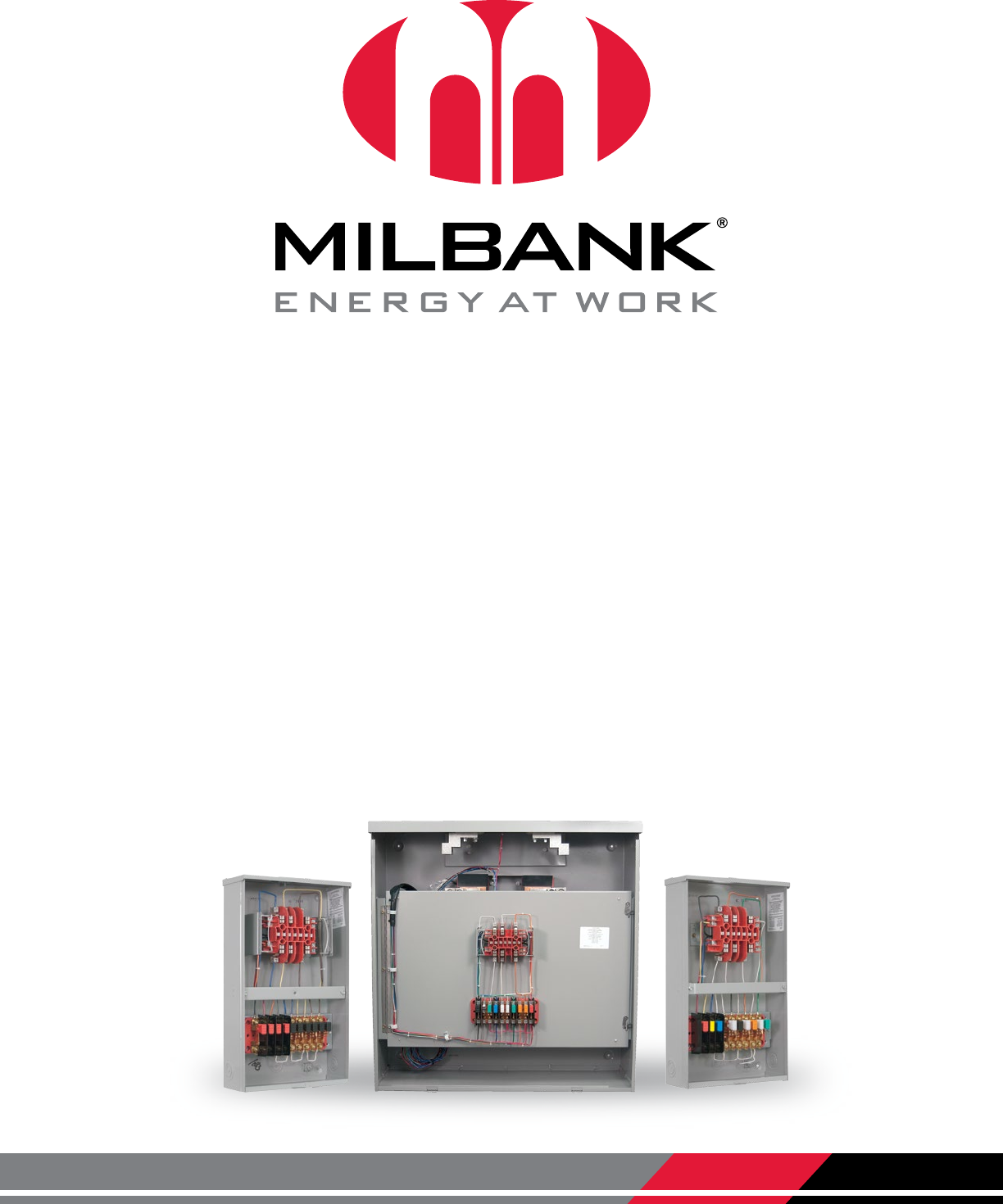
Milbank Manufacturing | 4801 Deramus Ave., Kansas City, MO 64120 | 877.483.5314 | milbankworks.com INSTRUMENT 4/13
