113659 Catalog
2014-07-05
: Pdf 113659-Catalog 113659-Catalog 662019 Batch5 unilog
Open the PDF directly: View PDF ![]() .
.
Page Count: 36
Low Voltage Products & Systems 4.A
ABB Inc. • 888-385-1221 • www.abb.us/lowvoltage 1SXU000023C0202 Rev. A
Manual motor
protectors
4
Revised March 2014 Revised March 2014
Manual motor protectors
Product index
Manual motor protectors ........................................... 4.1 – 4.34
Features and benefits .................................................................................................................4.1
General information
Suitable applications ......................................................................................................4.2 - 4.3
Motor ratings .........................................................................................................................4.4
Pilot duty ratings and overload trip classes ............................................................................4.5
Ordering details
Type MS116 ..........................................................................................................................4.6
Type MS132 ..........................................................................................................................4.7
Type MS450 /MS451 ............................................................................................................. 4.8
Type MS495 / MS496 ............................................................................................................ 4.9
Accessories ...........................................................................................................4.10, 4.12 - 4.16
Actuation tables ........................................................................................................................4.11
Connection diagrams ...............................................................................................................4.17
General accessory mounting layout ..........................................................................................4.18
Technical data ................................................................................................................4.19 - 4.31
Approximate dimensions ................................................................................................4.32 - 4.33
4 - Manual motor protectors

4.B Low Voltage Products & Systems
1SXU000023C0202 Rev. A ABB Inc. • 888-385-1221 • www.abb.us/lowvoltage
Manual motor
protectors
4
Revised March 2014 Revised March 2014
Notes
MS Series
Manual motor
protectors
Low Voltage Products & Systems 4.1
ABB Inc. • 888-385-1221 • www.abb.us/lowvoltage 1SXU000023C0202 Rev. A
4
Revised March 2014 Revised March 2014
Manual motor protectors
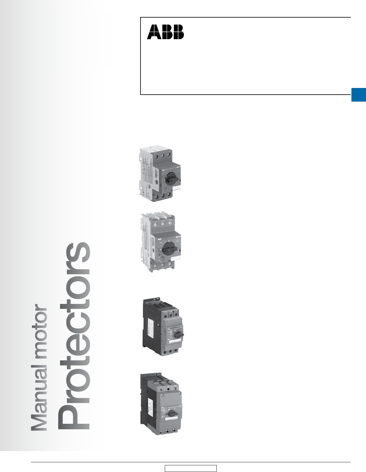
Types MS116, MS132, MS45x, MS49x
Manual motor
Protectors
Manual motor protectors are electromechanical devices for motor and circuit protection. These
devices offer local motor disconnect means, manual ON/OFF control, and protection against short
circuit, overload, and phase loss conditions. Manual motor protection saves cost, panel space, and
ensures quick and reliable short-circuit protection by reacting within milliseconds. Close coupling
adaptors are available for combination with ABB contactors in various applications.
Type MS116
•
Manual motor protectors suitable for use with single and three phase motors up to 25 hp
• Suitable as motor disconnect in single motor applications and group motor installa-
tions as outlined in NEC Article 430.53(C)
• 15 thermal setting ranges from 0.16 to 32 Amperes, overload Class 10A
• Phase loss sensitivity per IEC/EN 60947-4-1
• Short circuit current ratings up to 30 kA
• Motor controllers, manual (NLRV, NLRV7), UL file E137861
Type MS132
•
Manual motor protectors suitable for use with single and three phase motors up to 25 hp
• Suitable as motor disconnect in single motor applications and group motor installa-
tions as outlined in NEC Article 430.53(C)
• Suitable for Tap conductor protection as outlined in NEC Article 430.53(D)(3)
• Suitable as self-protected combination motor controllers Types E and F as outlined in
UL 508 and UL 60947-4-1A
• 15 thermal setting ranges from 0.16 to 32 Amperes, overload Class 10
• Phase loss sensitivity per IEC/EN 60947-4-1
• Short circuit current ratings up to 65 kA
• Motor controllers, manual (NLRV, NLRV7), UL file E137861
• Combination motor controllers (NKJH, NKJH7), UL file E345003
Type MS45x
•
Manual motor protectors suitable for use with single and three phase motors up to 50 hp
• Suitable as motor disconnect in single motor applications and group motor installa-
tions as outlined in NEC Article 430.53(C)
• Suitable as self-protected combination motor controller Type E as outlined in UL 508
and UL 60947-4-1A
• Phase loss sensitivity per IEC/EN 60947-4-1
• 3 thermal setting ranges from 28 to 50 Amperes, overload Classes 10 and 20
• Short circuit current ratings up to 65 kA
• Motor controllers, manual (NLRV), UL file E167205
• Combination motor controllers (NKJH, NKJH7), UL file E195536
Type MS49x
•
Manual motor protectors suitable for use with single and three phase motors up to 100 hp
• Suitable as motor disconnect in single motor applications and group motor installa-
tions as outlined in NEC Article 430.53(C)
• Suitable as self-protected combination motor controller Types E as outlined in UL 508
and UL 60947-4-1A
• Phase loss sensitivity per IEC/EN 60947-4-1
• 6 thermal setting ranges from 28 to 100 Amperes, overload Classes 10 and 20
• Short circuit current ratings up to 65 kA
• Motor controllers, manual (NLRV), UL file E167205
• Combination motor controllers (NKJH, NKJH7), UL file E195536
4
MS Series
Manual motor
protectors
4.2 Low Voltage Products & Systems
1SXU000023C0202 Rev. A ABB Inc. • 888-385-1221 • www.abb.us/lowvoltage
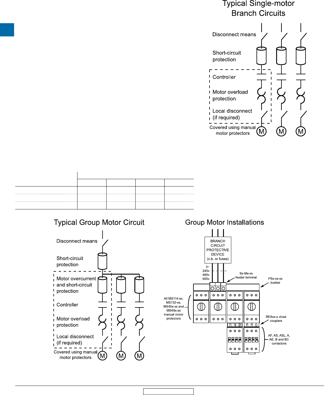
Single motor applications, suitable as motor disconnect
A manual motor protector is a simple, compact and economical alternative to conventional magnetic motor
controllers for local control of a single motor.
Upstream short-circuit and overcurrent protection in the form of either fuses or a circuit breaker is still required.
Manual motor protectors can replace the overload relay, contactor, and any wiring or components necessary for
controlling a contactor (i.e. pushbuttons) by utilizing the integral rotary handle for manual ON/OFF control.
Manual motor protectors also offer instantaneous (magnetic only) short-circuit trip functionality, allowing for
these devices to be utilized as UL 508/60947-4-1A circuit protectors.
MS Series Manual Motor Protectors are marked as “suitable as motor disconnect”, with the Types MS132 and
MS4xx not requiring additional accessories. This marking allows the devices to be utilized as local disconnects
within line-of-sight of the motor.
Group motor installation
Group motor installations utilize a single branch circuit protective device to protect multiple loads. Per NEC
Article 430.53(C), this branch circuit protection must be in the form of either fuses or an inverse-time (thermal
magnetic, MCCB) circuit breaker. Individual overload protection must be provided for each load. Devices
utilized in group motor installations must be marked as suitable in such applications.
Branch circuit protection for group motor installations is sized based on the sum of:
1. 250% (MCCB) or 175% (fuses) of the full-load current of the largest load in the group, plus
2. The sum of the full-load current of all additional loads
Conductors on the load side of the branch circuit protective device are sized in accordance with the full-load
current rating of said device.
In addition to meeting the requirements outlined above, Type MS132 devices are also suitable for tap conductor
protection in group installations as outlined in NEC Article 430.53(D), allowing the conductors on the load-side
of the branch circuit protective device to be sized no less than one-tenth (1/10) of the full-load current rating of
the protective device.
Devices suitable for these applications
Application
Manual motor protector type
MS116 MS132 MS45x MS49x
Motor disconnect • • • •
Group motor installation • • • •
Tap conductor protection •
Revised March 2014 Revised March 2014
General information
Suitable applications
MS Series
Manual motor
protectors
Low Voltage Products & Systems 4.3
ABB Inc. • 888-385-1221 • www.abb.us/lowvoltage 1SXU000023C0202 Rev. A
4
Revised March 2014 Revised March 2014
General information
Suitable applications
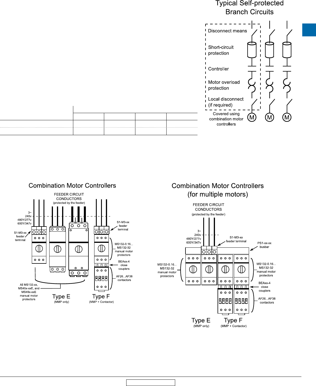
Combination motor controllers Types E & F
Combination motor controllers, as outlined in UL 508 Section 76, are a manufacturer’s tested combination of either individual
discrete components or a single controller. Fulfilling all the necessary components for a motor branch circuit, combination
motor controllers provide a disconnecting and load switching means, as well as overload and short-circuit protection. These
devices offer additional flexibility when selecting components for motor control and protection.
Combination motor controllers can also utilize busbar for self-protected, multiple motor installations. Busbar must be selected
and sized in accordance with the full-load current rating of the feeder circuit protective device.
Definitions
Type E Combination Motor Controllers are comprised of a UL 508 Disconnect, Branch Circuit Protector Device, Motor Controller
and Motor Overload typically included in a single Self-protected Control Device (manual motor protector). Following a short-
circuit fault, Type E Combination Motor Controllers are tested to operate for 6,000 electrical cycles, plus an additional 4,000
mechanical cycles, as outlined in UL 508 Table 83.1.
Type F Combination Motor Controllers are comprised of a UL 508 Disconnect, Branch Circuit Protector Device, and Motor
Overload typically included in a single Manual Self-protected Combination Controller with additional Magnetic or Solid State
Motor Controller utilized for remote operation (manual motor protector + contactor). The operational requirements following a
short-circuit fault differ for the manual motor protector and contactor.
Devices suitable for these applications
Combination motor
controller
Manual motor protector type
MS116
MS132 + S1-M3-xx
MS45x-xxE MS49x-xxE
Self-protected, Type E • • •
Self-protected,Type F •
4
MS Series
Manual motor
protectors
4.4 Low Voltage Products & Systems
1SXU000023C0202 Rev. A ABB Inc. • 888-385-1221 • www.abb.us/lowvoltage
Revised March 2014 Revised March 2014
General information
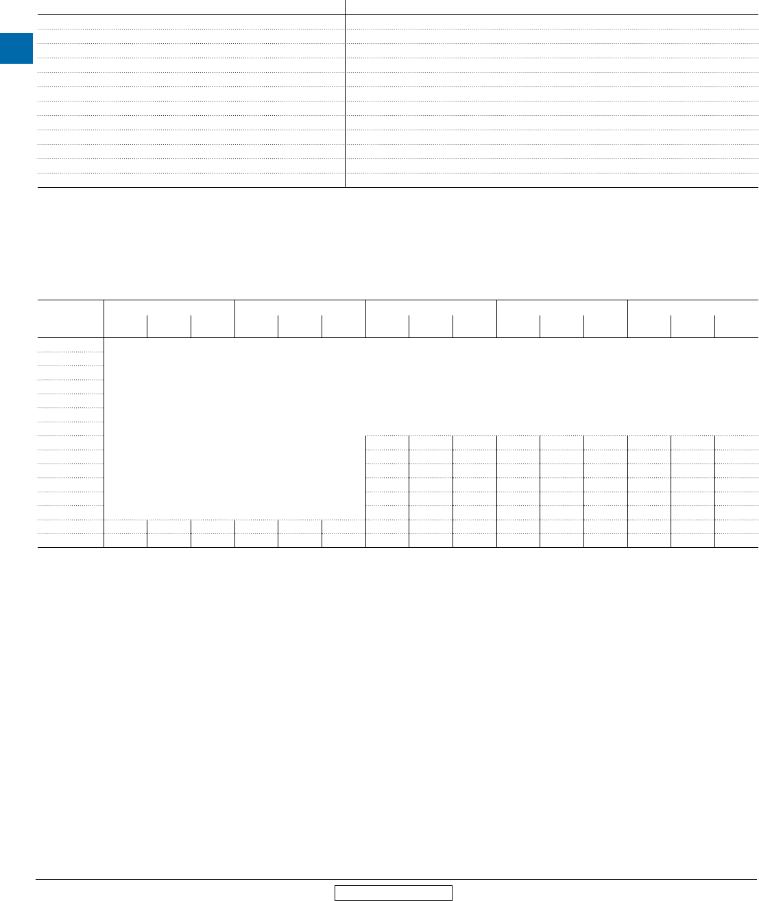
Motor ratings
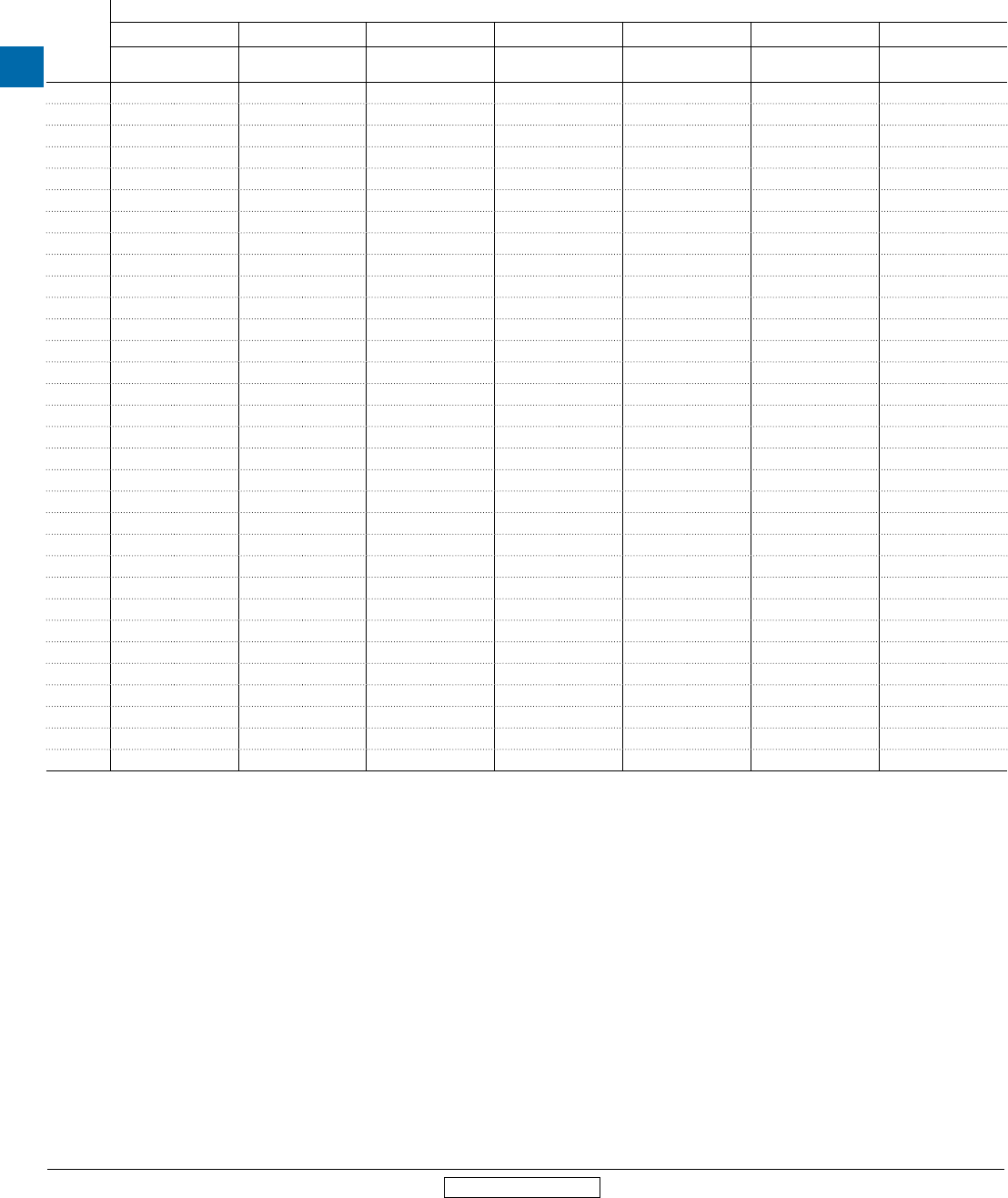
Horsepower to full-load Amperes for AC induction motors
Horse-
power (hp)
Full Load Amperes (FLA)
110…120 v ac 200 v ac 208 v ac 220…240 v ac 380…415 v ac 440…480 v ac 550…600 v ac
Single
phase
Three
phase
Single
phase
Three
phase
Single
phase
Three
phase
Single
phase
Three
phase
Single
phase
Three
phase
Single
phase
Three
phase
Single
phase
Three
phase
1/10 3.0 - - - - - 1.5 - 1.0 - - - - -
1/8 3.8 - - - - - 1.9 - 1.2 - - - - -
1/6 4.4 - 2.5 - 2.4 - 2.2 - 1.4 - - - - -
1/4 5.8 - 3.3 - 3.2 - 2.9 - 1.8 - - - - -
1/3 7.2 - 4.1 - 4.0 - 3.6 - 2.3 - - - - -
1/2 9.8 4.4 5.6 2.5 5.4 2.4 4.9 2.2 3.2 1.3 2.5 1.1 2.0 0.9
3/4 13.8 6.4 7.9 3.7 7.6 3.5 6.9 3.2 4.5 1.8 3.5 1.6 2.8 1.3
1 16.0 8.4 9.2 4.8 8.8 4.6 8.0 4.2 5.1 2.3 4.0 2.1 3.2 1.7
1-1/2 20.0 12.0 11.5 6.9 11.0 6.6 10.0 6.0 6.4 3.3 5.0 3.0 4.0 2.4
2 24.0 13.6 13.8 7.8 13.2 7.5 12.0 6.8 7.7 4.3 6.0 3.4 4.8 2.7
3 34.0 19.2 19.6 11.0 18.7 10.6 17.0 9.6 10.9 6.1 8.5 4.8 6.8 3.9
5 56.0 30.4 32.2 17.5 30.8 16.7 28.0 15.2 17.9 9.7 14.0 7.6 11.2 6.1
7-1/2 80.0 44.0 45.0 25.3 44.0 24.2 40.0 22.0 27.0 14.0 21.0 11.0 16.0 9.0
10 100.0 56.0 57.5 32.2 55.0 30.8 50.0 28.0 33.0 18.0 26.0 14.0. 20.0 11.0
15 135.0 84.0 - 48.3 - 46.2 68.0 42.0 44.0 27.0 34.0 21.0 27.0 17.0
20 - 108.0 - 62.1 - 59.4 88.0 54.0 56.0 34.0 44.0 27.0 35.0 22.0
25 - 136.0 - 78.2 - 74.8 110.0 68.0 70.0 44.0 55.0 34.0 44.0 27.0
30 - 160.0 - 92.0 - 88.0 136.0 80.0 87.0 51.0 68.0 40.0 54.0 32.0
40 - 208.0 - 120.0 - 114.0 176.0 104.0 112.0 66.0 88.0 52.0 70.0 41.0
50 - 260.0 - 150.0 - 143.0 216.0 130.0 139.0 83.0 108.0 65.0 86.0 52.0
60 - - - 177.0 - 169.0 - 154.0 - 103.0 - 77.0 - 62.0
75 - - - 221.0 - 211.0 - 192.0 - 128.0 - 96.0 - 77.0
100 - - - 285.0 - 273.0 - 248.0 - 165.0 - 124.0 - 99.0
125 - - - 359.0 - 343.0 - 312.0 - 208.0 - 156.0 - 125.0
150 - - - 414.0 - 396.0 - 360.0 - 240.0 - 180.0 - 144.0
200 - - - 552.0 - 528.0 - 480.0 - 320.0 - 240.0 - 192.0
250 - - - - - - - 604.0 - 403.0 - 302.0 - 242.0
300 - - - - - - - 722.0 - 482.0 - 361.0 - 289.0
350 - - - - - - - 828.0 - 560.0 - 414.0 - 336.0
400 - - - - - - - 954.0 - 636.0 - 477.0 - 382.0
450 - - - - - - - 1030.0 - - 515.0 - 412.0
500 - - - - - - - 1180.0 - 786.0 - 590.0 - 472.0
Full-load motor-running currents in Amperes corresponding to various AC horsepower ratings as published in Table 50.1 of UL 508.
MS Series
Manual motor
protectors
Low Voltage Products & Systems 4.5
ABB Inc. • 888-385-1221 • www.abb.us/lowvoltage 1SXU000023C0202 Rev. A
4
Revised March 2014 Revised March 2014
General information
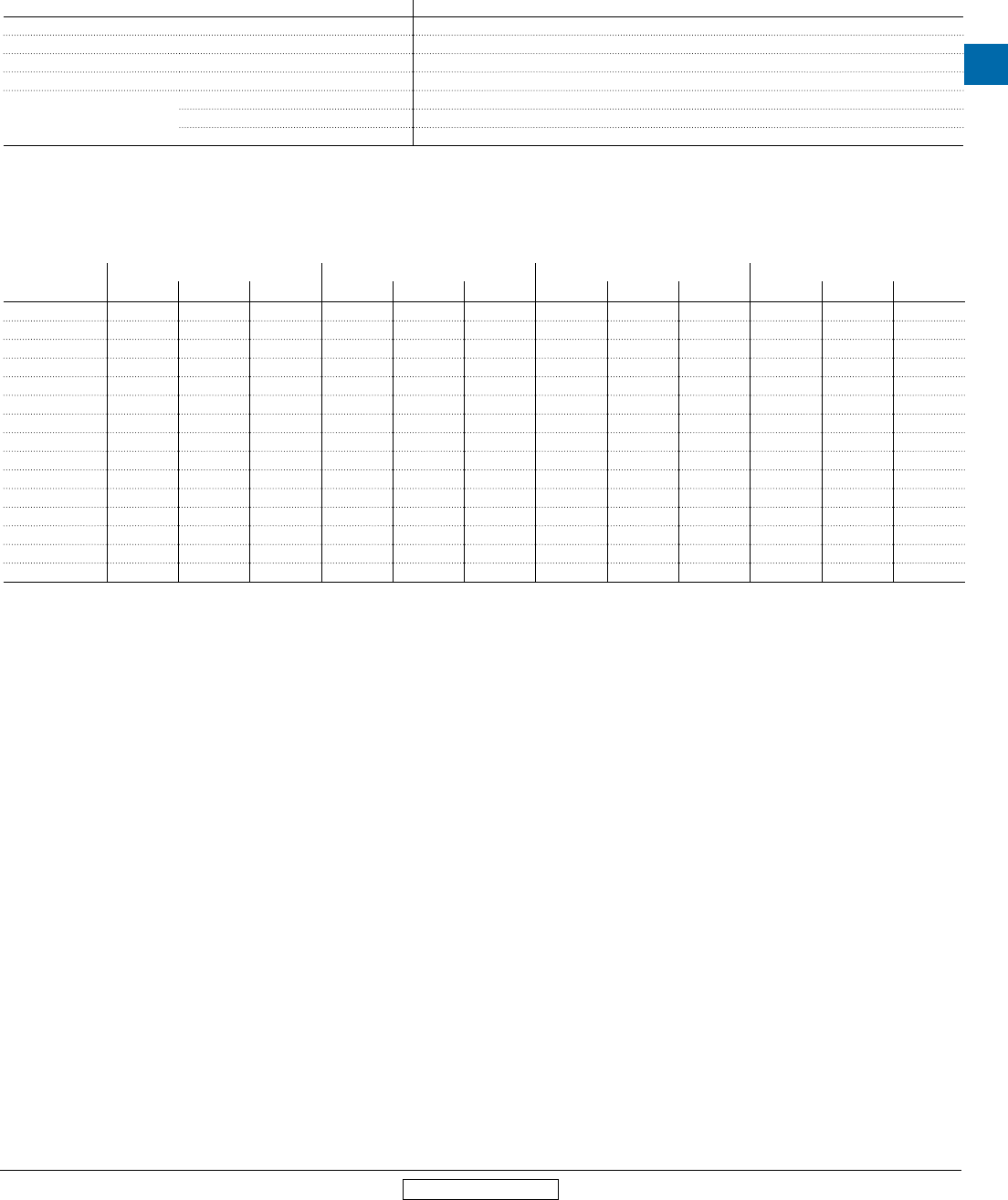
Pilot duty ratings and overload trip classes
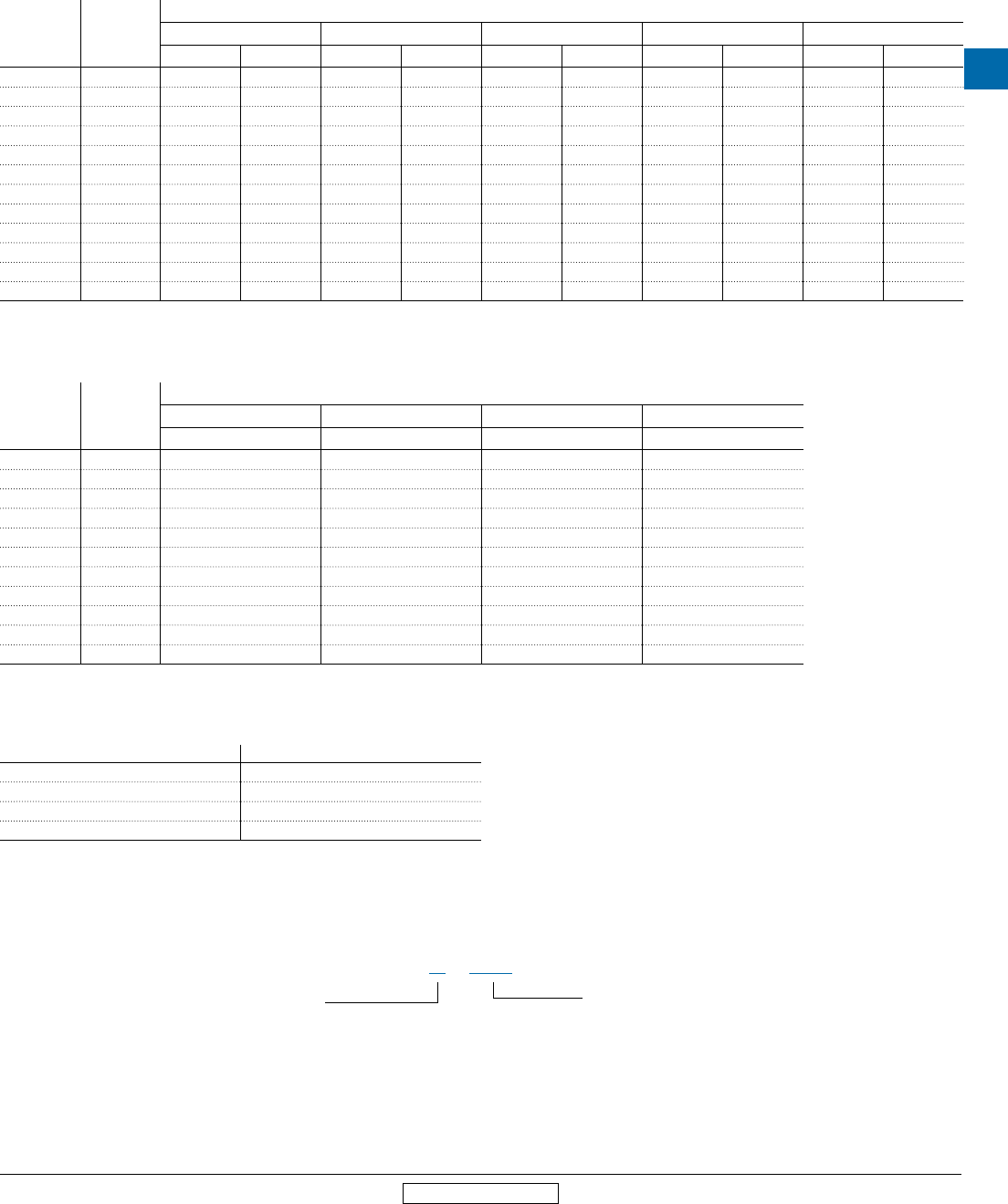
Pilot duty ratings for AC control circuit contacts
Contact rating
designation
Continuous
thermal, test
current (A)
Maximum current, 50/60 Hz (A)
120 v ac 240 v ac 480 v ac 600 v ac Volt-amperes
Make Break Make Break Make Break Make Break Make Break
A150 10 60 6.00 - - - - - - 7200 720
A300 10 60 6.00 30 3.00 - - - - 7200 720
A600 10 60 6.00 30 3.00 15 1.50 12 1.20 7200 720
B150 5 30 3.00 - - - - - - 3600 360
B300 5 30 3.00 15 1.50 - - - - 3600 360
B600 5 30 3.00 15 1.50 7.5 0.75 6 0.60 3600 360
C150 2.5 15 1.5 - - - - - - 1800 180
C300 2.5 15 1.5 7.5 0.75 - - - - 1800 180
C600 2.5 15 1.5 7.5 0.75 3.75 0.375 3.00 0.30 1800 180
D150 1.0 3.60 0.60 - - - - - - 432 72
D300 1.0 3.60 0.60 1.80 0.30 - - - - 432 72
E150 0.5 1.80 0.30 - - - - - - 216 36
Mechanical switching ratings and test values as published in Table 1-4-1 of NEMA ICS 5-2000 (R2005, R2010)
Pilot duty ratings for DC control circuit contacts
Contact rating
designation
Continuous
thermal, test
current (A)
Maximum current, 50/60 Hz (A)
120 v dc 250 v dc 301 to 600 v dc Volt-amperes
Make / Break Make / Break Make / Break Make / Break
N150 10 2.2 - - 275
N300 10 2.2 1.1 - 275
N600 10 2.2 1.1 0.40 275
P150 5.0 1.1 - - 138
P300 5.0 1.1 0.55 - 138
P600 5.0 1.1 0.55 0.20 138
Q150 2.5 0.55 - - 69
Q300 2.5 0.55 0.27 - 69
Q600 2.5 0.55 0.27 0.10 69
R150 1.0 0.22 - - 28
R300 1.0 0.22 0.11 - 28
Mechanical switching ratings and test values as published in Table 1-4-1 of NEMA ICS 5-2000 (R2005, R2010)
Overload trip classes
Trip class Tripping time Tp (seconds)
10A 2 < Tp ≤ 10
10 4 < Tp ≤ 10
20 6 < Tp ≤ 20
30 9 < Tp ≤ 30
Trip classes as published in Table 2 of UL 60947-4-1A.
Pilot duty rating explanation
A - 600
Max. thermal
current
Max. voltage
4
MS Series
Manual motor
protectors
4.6 Low Voltage Products & Systems
1SXU000023C0202 Rev. A ABB Inc. • 888-385-1221 • www.abb.us/lowvoltage
Revised March 2014 Revised March 2014
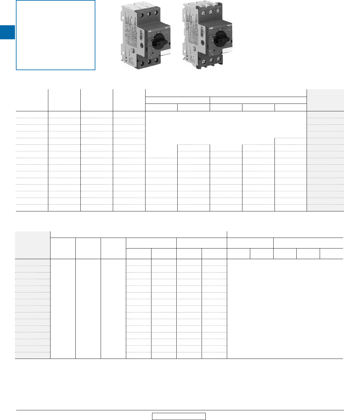
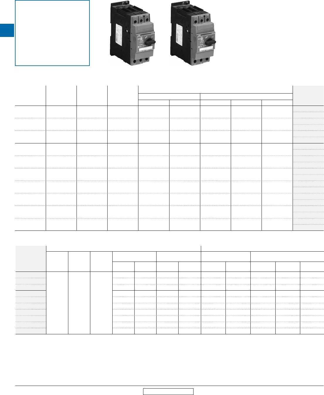
Type MS116
For applications up to 32A
MS116 Electrical ratings 1
Thermal setting
range (A)
Trip
class
Rated
operational current
Ie (A)
Rated instanta-
neous short-circuit
current setting
Ii (A)
AC Motor ratings, breaking all lines, 50/60 Hz (hp)
Catalog
number
Single phase 2Three phase
120V 240V 240V 480V 600V
0.10...0.16 10A 0.16 1.56
Horsepower not applicable; use upper limit of the device thermal setting range for rated
full-load
current in Amperes
MS116-0.16
0.16...0.25 10A 0.25 2.44 MS116-0.25
0.25...0.40 10A 0.40 3.90 MS116-0.4
0.40...0.63 10A 0.63 6.14 MS116-0.63
0.63...1.0 10A 1.00 11.5 1/2 MS116-1.0
1.0...1.6 10A 1.60 18.4 1/10 3/4 3/4 MS116-1.6
1.6...2.5 10A 2.50 28.8 1/6 1/2 1 1.5 MS116-2.5
2.5...4.0 10A 4.00 50.0 1/8 1/3 1 2 3 MS116-4.0
4.0...6.3 10A 6.30 78.8 1/4 1/2 1.5 3 5 MS116-6.3
6.3...10.0 10A 10.0 150 1/2 1.5 3 5 7.5 MS116-10
8.0...12.0 10A 12.0 180 1/2 2 3 7.5 10 MS116-12
10.0...16.0 10A 16.0 240 1 2 5 10 10 MS116-16
16.0...20.0 10A 20.0 300 1.5 3 5 10 15 MS116-20
20.0...25.0 10A 25.0 375 2 3 7.5 15 20 MS116-25
25.0...32.0 10A 32.0 480 2 5 10 20 25 MS116-32
MS116 Short circuit current ratings (kA)
Catalog
number
UL 508 - Motor controllers, manual (NLRV) UL 508 - Combination motor controllers (NKJH)
Max. fuse
size (A)
Fuse
class
Circuit
breaker
Motor disconnect 3Group motor installation Self-protected
Type E
Self-protected
Type F
240V
480V 600V 240V
480V 600V 480Y /
277V
600Y /
347V
480Y /
277V
600Y /
347V
Type F
contactors
MS116-0.16
200 J No rating
30 5 30 5
Use Type MS132
MS116-0.25 30 5 30 5
MS116-0.4 30 5 30 5
MS116-0.63 30 5 30 5
MS116-1.0 30 5 30 5
MS116-1.6 30 5 30 5
MS116-2.5 30 5 30 5
MS116-4.0 18 5 18 5
MS116-6.3 18 5 18 5
MS116-10 18 5 18 5
MS116-12 18 5 18 5
MS116-16 18 5 18 5
MS116-20 18 5 18 5
MS116-25 18 5 18 5
MS116-32 18 5 18 5
1 Always size manual motor protectors based on the full-load current of the motor.
2 For single phase connection diagram see page 4.17.
3 Suitable as motor disconnect only when provide with padlock adaptor SA1 or SA3; see accessories section.
Frame Sz. 1 Frame Sz. 2
MS116-0.16…MS116-16 MS116-20…MS116-32
Suitable applications:
• Single motor, suitable as motor
disconnect
• Group motor installation
MS Series
Manual motor
protectors
Low Voltage Products & Systems 4.7
ABB Inc. • 888-385-1221 • www.abb.us/lowvoltage 1SXU000023C0202 Rev. A
4
Revised March 2014 Revised March 2014
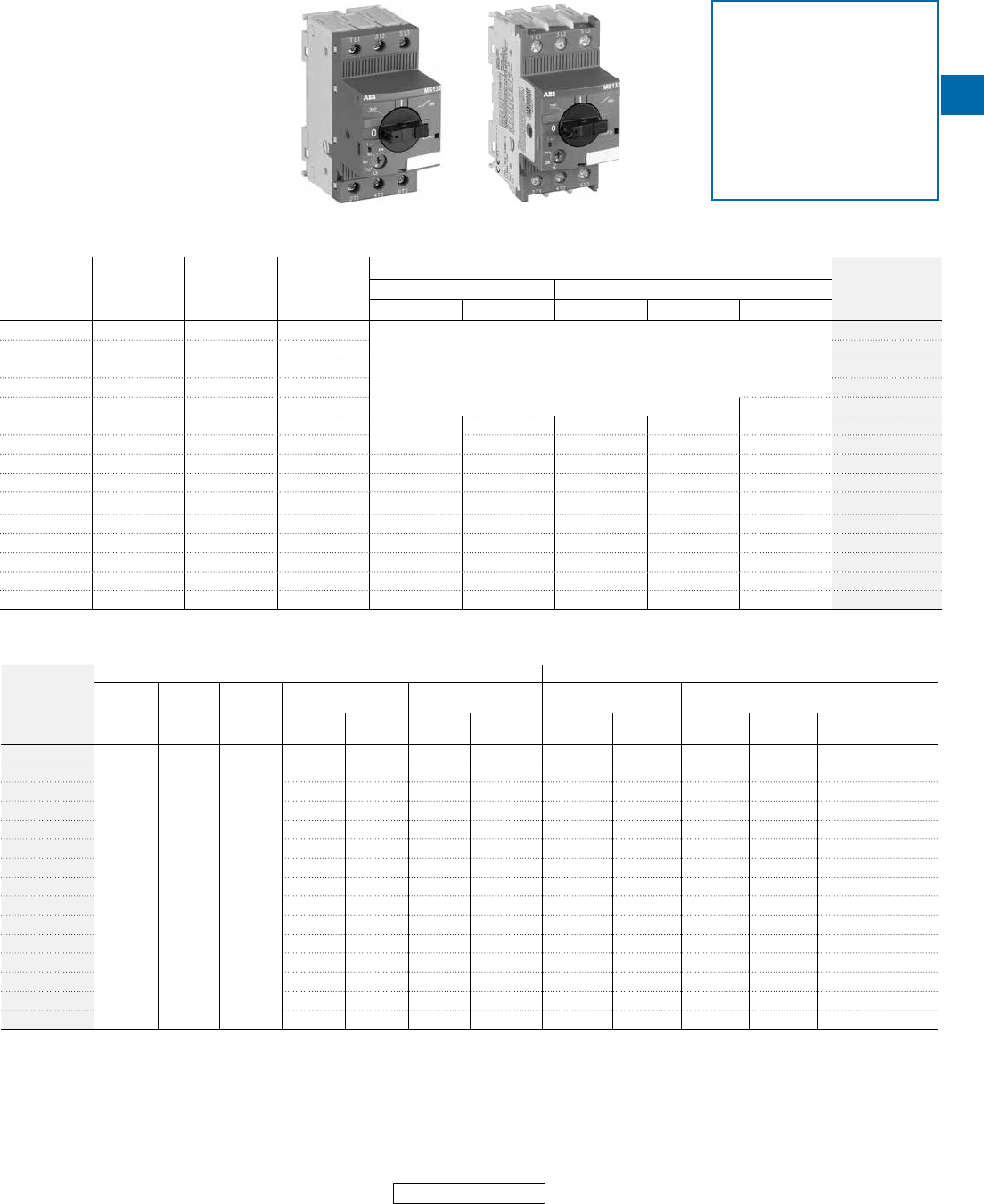
Type MS132
For applications up to 32A
MS132 Electrical ratings 1
Thermal setting
range (A)
Trip
class
Rated
operational current
Ie (A)
Rated instanta-
neous short-circuit
current
setting Ii (A)
AC Motor ratings, breaking all lines, 50/60 Hz (hp)
Catalog
number
Single phase 2Three phase
120V 240V 240V 480V 600V
0.10...0.16 10A 0.16 1.56
Horsepower not applicable; use upper limit of the device thermal setting range for rated
full-load current in Amperes
MS132-0.16
0.16...0.25 10 0.25 2.44 MS132-0.25
0.25...0.40 10 0.40 3.90 MS132-0.4
0.40...0.63 10 0.63 6.14 MS132-0.63
0.63...1.0 10 1.00 11.5 1/2 MS132-1.0
1.0...1.6 10 1.60 18.4 1/10 3/4 3/4 MS132-1.6
1.6...2.5 10 2.50 28.8 1/6 1/2 1 1.5 MS132-2.5
2.5...4.0 10 4.00 50.0 1/8 1/3 1 2 3 MS132-4.0
4.0...6.3 10 6.30 78.8 1/4 1/2 1.5 3 5 MS132-6.3
6.3...10.0 10 10.0 150 1/2 1.5 3 5 7.5 MS132-10
8.0...12.0 10 12.0 180 1/2 2 3 7.5 10 MS132-12
10.0...16.0 10 16.0 240 1 2 5 10 10 MS132-16
16.0...20.0 10 20.0 300 1.5 3 5 10 15 MS132-20
20.0...25.0 10 25.0 375 2 3 7.5 15 20 MS132-25
25.0...32.0 10 32.0 480 2 5 10 20 25 MS132-32
MS132 Short circuit current ratings (kA) 3
Catalog
number
UL 508 - Motor controllers, manual (NLRV) UL 508 - Combination motor controllers (NKJH)
Max. fuse
size (A)
Fuse
class
Circuit
breaker
Motor disconnect Group motor installation 4Self-protected
Type E 5
Self-protected
Type F 5
240V
480V 600V 240V
480V 600V 480Y / 277V 600Y / 347V 480Y / 277V 600Y / 347V Type F
contactors
MS132-0.16
Size per
NEC 6
Any fuse
class
MCCB,
size per
NEC
6 7
65 47 65 47 65 47 65 47 AF26…AF38
MS132-0.25 65 47 65 47 65 47 65 47 AF26…AF38
MS132-0.4 65 47 65 47 65 47 65 47 AF26…AF38
MS132-0.63 65 47 65 47 65 47 65 47 AF26…AF38
MS132-1.0 65 47 65 47 65 47 65 47 AF26…AF38
MS132-1.6 65 47 65 47 65 47 65 47 AF26…AF38
MS132-2.5 65 47 65 47 65 47 65 47 AF26…AF38
MS132-4.0 65 47 65 47 65 47 65 47 AF26…AF38
MS132-6.3 65 18 65 18 [35] 65 18 65 47 AF26…AF38
MS132-10 65 18 65 18 [35] 65 18 65 47 AF26…AF38
MS132-12 30 18 30 [35] 18 [35] 30 - 30 - AF26…AF38
MS132-16 30 18 30 [35] 18 [35] 30 - 30 - AF26…AF38
MS132-20 30 18 30 [35] 18 [35] 30 - 30 - AF26…AF38
MS132-25 30 18 30 [35] 18 [35] 30 - 30 - AF26…AF38
MS132-32 30 18 30 [35] 18 [35] 30 - 30 - AF26…AF38
1 Always size manual motor protectors based on the full-load current of the motor.
2 For single phase connection diagram see page 4.17.
3 For higher ratings using S803W current limiters see accessories section.
4 Also suitable for tap conductor protection. Group ratings increased to [x] kA using Class RK5 fuses.
5 Requires the use of line-side feeder terminal S1-M3-xx: see accessories section.
6 NEC refers to the National Electric Code.
7 MCCB interrupting rating must be equal to or greater than the rating of the device.
Frame Sz. 1 Frame Sz. 2
MS132-0.16…MS132-10 MS132-12…MS132-32
Suitable applications:
• Single motor, suitable as motor
disconnect
• Group motor installation
• Tap conductor protection
• Combination motor controllers
- Type E
- Type F
4
MS Series
Manual motor
protectors
4.8 Low Voltage Products & Systems
1SXU000023C0202 Rev. A ABB Inc. • 888-385-1221 • www.abb.us/lowvoltage
Revised March 2014 Revised March 2014
Type MS450 / MS451
For applications up to 50A
MS450 / MS451 Electrical ratings 1
Thermal setting
range (A)
Trip
class
Rated
operational
current Ie (A)
Rated instanta-
neous short-circuit
current
setting Ii (A)
AC Motor ratings, breaking all lines, 50/60 Hz (hp) Catalog
number
3
Single phase 2Three phase
120V 240V 240V 480V 600V
28.0…40.0 10 40.0 520 3 7.5 15 30 40 MS450-40
MS450-40E
36.0…45.0 10 45.0 585 5 7.5 15 30 40 MS450-45
MS450-45E
40.0…50.0 10 50.0 650 5 10 20 40 50 MS450-50
MS450-50E
11.0…16.0 20 16.0 208 1 3 5 10 15 MS451-16
MS451-16E
14.0…20.0 20 20.0 260 1.5 3 7.5 15 20 MS451-20
MS451-20E
18.0…25.0 20 25.0 325 2 5 10 20 25 MS451-25
MS451-25E
22.0…32.0 20 32.0 416 3 5 10 25 30 MS451-32
MS451-32E
28.0…40.0 20 40.0 520 3 7.5 15 30 40 MS451-40
MS451-40E
36.0…45.0 20 45.0 585 5 7.5 15 30 40 MS451-45
MS451-45E
40.0…50.0 20 50.0 650 5 10 20 40 50 MS451-50
MS451-50E
MS450 / MS451 Short circuit current ratings (kA)
Catalog number
4
UL 508 - Motor controllers, manual (NLRV) UL 508 - Combination motor controllers (NKJH)
Max. fuse
size (A) Fuse class Circuit
breaker
Motor disconnect Group motor installation Self-protected
Type E 3
Self-protected
Type F
240V
480V 600V 480Y/
277V
600Y/
347V 480Y / 277V 600Y / 347V 480Y / 277V 600Y / 347V Type F
contactors
MS450-40x
500
Any
fuse
class
MCCB,
500A
max.
5
65 25 65 25 65 25 - - -
MS450-45x 65 25 65 25 65 25 - - -
MS450-50x 65 25 65 25 65 25 - - -
MS451-16x 65 25 65 25 65 25 - - -
MS451-20x 65 25 65 25 65 25 - - -
MS451-25x 65 25 65 25 65 25 - - -
MS451-32x 65 25 65 25 65 25 - - -
MS451-40x 65 25 65 25 65 25 - - -
MS451-45x 65 25 65 25 65 25 - - -
MS451-50x 65 25 65 25 65 25 - - -
1 Always size manual motor protectors based on the full-load current of the motor.
2 For single phase connection diagram see page 4.17.
3 MS45x-xxE part numbers include the necessary components for Type E applications – Self-protected Type E ratings apply only to these devices.
4 Replace “x” in part number with “E” for self-protected Type E ratings. All other ratings leave blank.
5 MCCB interrupting rating must be equal to or greater than the rating of the device.
Frame Sz. 3 Frame Sz. 3
MS450-40…MS450-50 MS451-16…MS451-50
Suitable applications:
• Single motor, suitable as motor
disconnect
• Group motor installation
• Combination motor controller
- Type E
MS Series
Manual motor
protectors
Low Voltage Products & Systems 4.9
ABB Inc. • 888-385-1221 • www.abb.us/lowvoltage 1SXU000023C0202 Rev. A
4
Revised March 2014 Revised March 2014
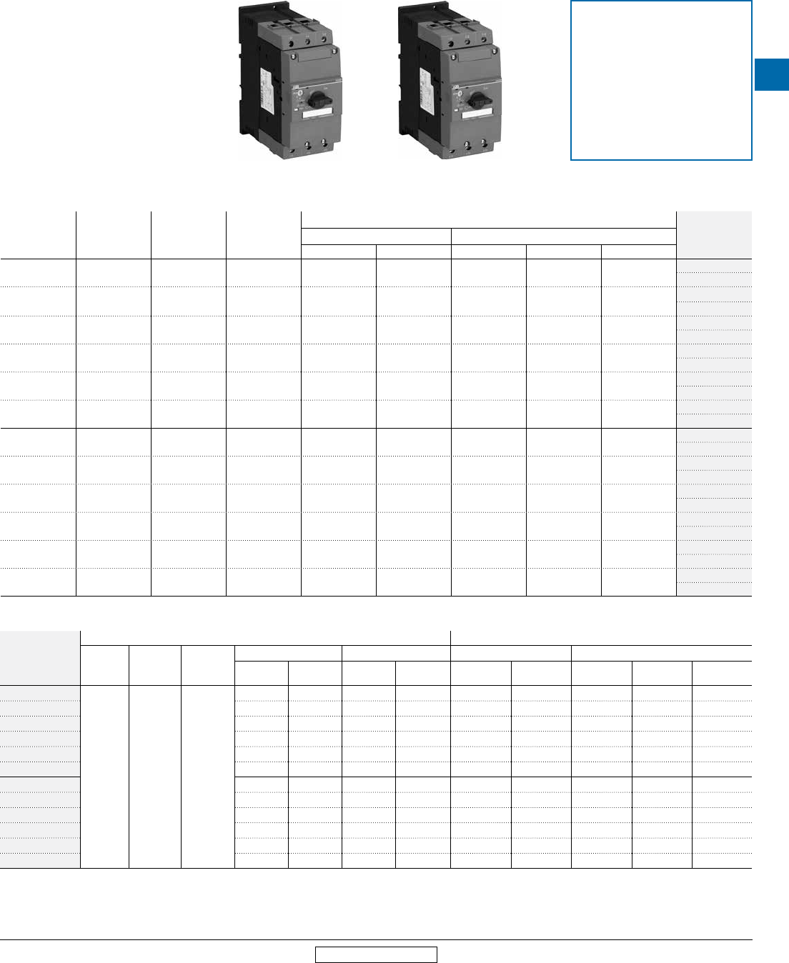
Type MS495 / MS496
For applications up to 100A
MS495 / MS496 Electrical ratings 1
Thermal
setting range (A)
Trip
class
Rated
operational
current Ie (A)
Rated instanta-
neous short-circuit
current
setting Ii (A)
AC Motor ratings, breaking all lines, 50/60 Hz (hp)
Catalog number
3
Single phase 2Three phase
120V 240V 240V 480V 600V
28.0…40.0 10 40.0 520 3 7.5 15 30 40 MS495-40
MS495-40E
36.0…50.0 10 50.0 650 5 10 20 40 50 MS495-50
MS495-50E
45.0…63.0 10 63.0 819 5 15 25 50 60 MS495-63
MS495-63E
57.0…75.0 10 75.0 975 7.5 15 25 60 75 MS495-75
MS495-75E
70.0…90.0 10 90.0 1170 10 20 30 75 100 MS495-90
MS495-90E
80.0…95.0 10 100.0 1235 10 20 40 75 100 MS495-100
MS495-100E
28.0…40.0 20 40.0 520 3 7.5 15 30 40 MS496-40
MS496-40E
36.0…50.0 20 50.0 650 5 10 20 40 50 MS496-50
MS496-50E
45.0…63.0 20 63.0 819 5 15 25 50 60 MS496-63
MS496-63E
57.0…75.0 20 75.0 975 7.5 15 25 60 75 MS496-75
MS496-75E
70.0…90.0 20 90.0 1170 10 20 30 75 100 MS496-90
MS496-90E
80.0…95.0 20 95.0 1235 10 20 40 75 100 MS496-100
MS496-100E
MS495 / MS496 Short circuit current ratings (kA)
Catalog number
4
UL 508 - Motor controllers, manual (NLRV) UL 508 - Combination motor controllers (NKJH)
Max. fuse
size (A)
Fuse
class
Circuit
breaker
Motor disconnect Group motor installation Self-protected Type E 3Self-protected Type F
240V
480V 600V 480Y/
277V
600Y/
347V 480Y / 277V 600Y / 347V 480Y / 277V 600Y / 347V Type F
contactors
MS495-40x
500
Any
fuse
class
MCCB,
500A
max.
5
65 30 65 30 65 30 - - -
MS495-50x 65 30 65 30 65 30 - - -
MS495-63x 65 30 65 30 65 30 - - -
MS495-75x 65 30 65 30 65 30 - - -
MS495-90x 65 30 65 30 65 - - - -
MS495-100x 65 30 65 30 65 - - - -
MS496-40x 65 30 65 30 65 30 - - -
MS496-50x 65 30 65 30 65 30 - - -
MS496-63x 65 30 65 30 65 30 - - -
MS496-75x 65 30 65 30 65 30 - - -
MS496-90x 65 30 65 30 65 - - - -
MS496-100x 65 30 65 30 65 - - - -
1 Always size manual motor protectors based on the full-load current of the motor.
2 For single phase connection diagram see page 4.17.
3 MS49x-xxE part numbers include the necessary components for Type E applications – Self-protected Type
E ratings apply only to these devices.
Frame Sz. 4 Frame Sz. 4
MS495-40…MS495-100 MS496-40…MS496-100
4 Replace “x” in part number with “E” for self-protected Type E ratings. All other ratings leave blank.
5 MCCB interrupting rating must be equal to or greater than the rating of the device.
Suitable applications:
• Single motor, suitable as motor
disconnect
• Group motor installation
• Combination motor controller
- Type E
4
MS Series
Manual motor
protectors
4.10 Low Voltage Products & Systems
1SXU000023C0202 Rev. A ABB Inc. • 888-385-1221 • www.abb.us/lowvoltage
Revised March 2014 Revised March 2014
Accessories
For Types MS116, MS132, MS45x, MS49x
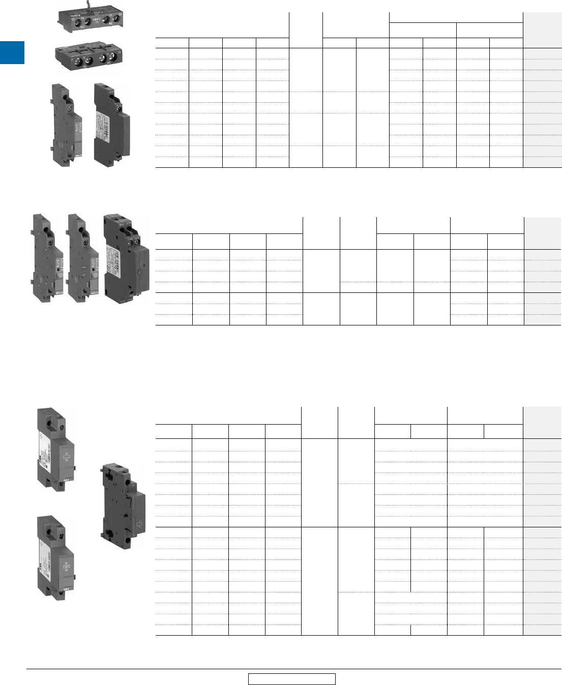
Auxiliary contacts
For use with MS…
Mounting
position
/ max.
quantity
Pilot duty rating
Auxiliary contacts
Catalog
number
Instantaneous Lagging / leading
116 132 45x 49x ac dc NO NC NO NC
• •
Right / 2 B600 Q600
1 1 - - HK1-11
• • 2 - - - HK1-20
• • - 2 - - HK1-02
• • - - 2 - HK1-20L
• • Front / 1 B300 Q300 1 1 - - HKF1-11
• • 2 - - - HKF1-20
• •
Left / 1 A600 Q300
1 1 - - HKS4-11
• • 2 - - - HKS4-20
• • - 2 - - HKS4-02
• • Front / 1 C300 R300 1 1 - - HK4-11
• • - 1 1 - HK4-W
Signalling contacts
For use with MS…
Description
Mounting
position
/ max.
quantity
Pilot duty rating Contacts Catalog
number
116 132 45x 49x ac dc NO NC
• •
Trip (bell)
alarm
Right / 1 B600 Q600
1 1 SK1-11
• • 2 - SK1-20
• • - 2 SK1-02
• • Left / 1 A600 Q300 2 2 SK4-11
•Short-
circuit
trip alarm
Right / 1 B600 Q600
1 1 CK1-11
• 2 - CK1-20
• - 2 CK1-02
Note(s):
CK1-xx contacts must mount flush on the right side of the MS132; these devices are supplementary and not required for use in UL 508 Type E &
F applications
SK4-11 contacts are required for UL 508 Type E applications using types MS4xx; included when purchasing types MS4xx-xxE
Trip units
For use with MS…
Description
Mounting
position /
max. quantity
Voltage rating; continuous Brief voltage rating;
5 seconds max. Catalog
number
116 132 45x 49x 50 Hz 60 Hz 50/60 dc
• •
Shunt
trip
Left / 1
24 v 20...70 v AA1-24
• • 110 v 70…190 v AA1-110
• • 200…240 v 190…330 v AA1-230
• • 350…415 v 330…500 v AA1-400
• •
Right / 1
20…24 v 20...70 v AA4-24
• • 30…110 v 70…190 v AA4-110
• • 210…240 v 190…330 v AA4-240
• • 350…415 v 330…500 v AA4-400
• •
Undervolt-
age
release
Left / 1
- 24 v - - UA1-24
• • 110 v 120 v - - UA1-120
• • - 208 v - - UA1-208
• • 230 v 240 v - - UA1-230
• • 415 v 480 v - - UA1-415
• • - 575 v - - UA1-575
• •
Right / 1
24 v - - UA4-24
• • 110…120 v - - UA4-120
• • 230…240 v - - UA4-240
• • 400 v - - - UA4-400
HKF1-11
HK4-11
HK1-11 HKS4-20
SK1-11 CK1-11 SK4-11
AA1-24
UA1-24
AA4-24
MS Series
Manual motor
protectors
Low Voltage Products & Systems 4.11
ABB Inc. • 888-385-1221 • www.abb.us/lowvoltage 1SXU000023C0202 Rev. A
4
Revised March 2014 Revised March 2014
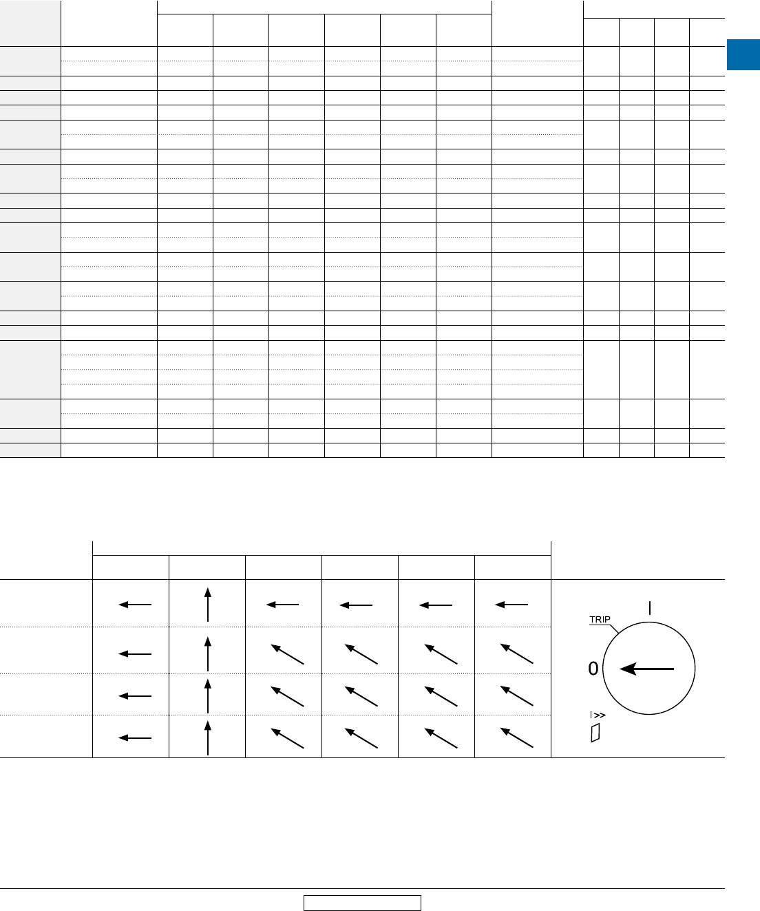
Actuation tables
For Types MS116, MS132, MS45x, MS49x
Operator positions
Type
Operator position
Key
Off On Thermal overload
trip
Short-circuit
trip
Undervoltage
trip
Shunt
trip
MS116-…
MS132-…
1
MS45x-…
MS49x-…
Auxiliary and signaling contact actuation tables
Catalog
number Description
Condition / state
Terminal numbers
For use with MS…
Off On Thermal
overload trip
Short-circuit
trip
Under-voltage
trip Shunt trip 116 132 45x 49x
HK1-11 1 NO O X O O O O 33…34 • •
1 NC X O X X X X 41…42
HK1-20 2 NO O X O O O O 33…34, 43…44 • •
HK1-02 2 NC X O X X X X 31…32, 41…42 • •
HK1-20L 2 NO leading contacts O X O O O O 33…34, 43…44 • •
HKF1-11 1 NO O X O O O O 13…14 • •
1 NC X O X X X X 21…22
HKF1-20 2 NO O X O O O O 13…14, 23…24 • •
HKS4-11 1 NO O X O O O O 33…34 • •
1 NC X O X X X X 41…42
HKS4-20 2 NO O X O O O O 33…34, 43…44 • •
HKS4-02 2 NC X O X X X X 31…32, 41…42 • •
HK4-11 1 NO O X O O O O 13…14 • •
1 NC X O X X X X 21…22
HK4-W 1 NO, leading (form C) O X O O O O 11…14 • •
1 NC (form C) X O X X X X 11…12
SK1-11 1 NO O O X X X X 57…58 • •
1 NC X X O O O O 65…66
SK1-20 2 NO O O X X X X 57…58, 67…68 • •
SK1-02 2 NC X X O O O O 55…56, 65…66 • •
SK4-11
1 NO O O X X X X 57…58
• •
1 NC X X O O O O 65…66
1 NO O O O X O O 77…78
1 NC X X X O X X 85…86
CK1-11 1 NO O O O X O O 77…78 •
1 NC X X X O X X 85…86
CK1-20 2 NO O O O X O O 77…78, 87…88 •
CK1-02 2 NC X X X O X X 75…76, 85…86 •
Note:
X = Indicates closed state
O = Indicates open state
For connection diagrams, see page 4.17.
1 + I>> indicator window = red.

4
MS Series
Manual motor
protectors
4.12 Low Voltage Products & Systems
1SXU000023C0202 Rev. A ABB Inc. • 888-385-1221 • www.abb.us/lowvoltage
Revised March 2014 Revised March 2014
Accessories
For Types MS116, MS132, MS45x, MS49x
Three phase busbar
For use with MS…
Description
Rated current (A)
Max. quantity of
MMP’s
Max. quantity of auxiliary and signaling
contacts per MMP
Max. quantity
of shunt trips or
U.V. releases per
MMP
Catalog
number
116 132 45x 49x 600 v ac
• •
2-position
busbar
65
2 - - PS1-2-0-65
• • 2 1 - PS1-2-1-65
• • 2 2 or 1 PS1-2-2-65
•108 2 - - PS4-2-0
• 2 1 or 1 PS4-2-2
• •
3-position
busbar
65
3 - - PS1-3-0-65
• • 3 1 - PS1-3-1-65
• • 3 2 or 1 PS1-3-2-65
• •
92
3 - - PS1-3-0-100
• • 3 1 - PS1-3-1-100
• • 3 2 or 1 PS1-3-2-100
•108 3 - - PS4-3-0
• 3 1 or 1 PS4-3-2
• •
4-position
busbar
65
4 - - PS1-4-0-65
• • 4 1 - PS1-4-1-65
• • 4 2 or 1 PS1-4-2-65
• • 92 4 - - PS1-4-0-100
• • 4 1 - PS1-4-1-100
•108 4 - - PS4-4-0
• 4 1 or 1 PS4-4-2
• •
5-position
busbar
65
5 - - PS1-5-0-65
• • 5 1 - PS1-5-1-65
• • 5 2 or 1 PS1-5-2-65
• • 92 5 - - PS1-5-0-100
• • 5 1 - PS1-5-1-100
• • Empty position busbar cover BS1-3
• Empty position busbar cover BS4-3
Note: Use of PS1 or PS4 busbar in group motor or self-protected Type E or F applications does not inhibit or alter the short-circuit current ratings for the devices utilized.
Three phase feeder terminals
For use with MS… Description
Rated current
(A) Connecting
capacity (AWG)
Required for UL 508 Types E or F
applications
Catalog
number
116 132 45x 49x 600 v ac
• •
Feeder terminal
65 10…4 S1-M1-25
• • 65 10…4 S1-M2-25
• • 65 10…4 • S1-M3-25
• • 92 8…2 • S1-M3-35
• 108 10…1/0 S4-M1
• Type E terminal ins. barrier 140 10…1/0 • DX495
Note(s): Only the S1-M3-xx terminals are acceptable for UL 508 Type E or F applications using type MS132.
The DX495 terminal is included when purchasing type MS49x-xxE devices.
Terminal shrouds
For use with MS… Description Catalog
number
116 132 45x 49x
•Terminal shroud, short KA450
• KA495
• Terminal shroud, long KA495C
PS1-2-0-65 PS1-3-1-100
S1-M3-25
KA450
DX495
MS Series
Manual motor
protectors
Low Voltage Products & Systems 4.13
ABB Inc. • 888-385-1221 • www.abb.us/lowvoltage 1SXU000023C0202 Rev. A
4
Revised March 2014 Revised March 2014
Accessories
For Types MS116, MS132, MS45x, MS49x
Accessories
For Types MS116, MS132
ABB Manual motor protectors can also be connected to the SMISSLINE power distribution bus system, which provides a versatile and flexible means of distributing power to a wide variety of
electrical devices. For complete system information, see Section 24.
SMISSLINE busbar adaptors for types MS116 / MS132
For use with MS… Description Catalog number
116 132 45x 49x
• • Adaptor, L1,L2,L3 bottom feed ZMS930
• • Adaptor, L1,L2,L3 top feed ZMS932
• • Adaptor, without feed wires ZMS139
9 mm wide additional housing ZMS935
Note(s):
The 9 mm wide additional housing is needed when an odd number of combi modules are
plugged on the socket; required to fill space into a full module (18 mm).
The 9 mm wide additional housing must also be used when a side-mount auxiliary contact is
used.
SMISSLINE busbar combi modules for types MS116 / MS132 +
AF Contactors
For use with MS… Description Catalog number
116 132 45x 49x
• • Combi module, L1,L2,L3 top feed ZMS930
• • Combi module, without feed wires ZMS137
Connection pin set for mounting two combi
modules side-by-side E210-SPV
4
MS Series
Manual motor
protectors
4.14 Low Voltage Products & Systems
1SXU000023C0202 Rev. A ABB Inc. • 888-385-1221 • www.abb.us/lowvoltage
Revised March 2014 Revised March 2014
Accessories
For Types MS116, MS132, MS45x, MS49x
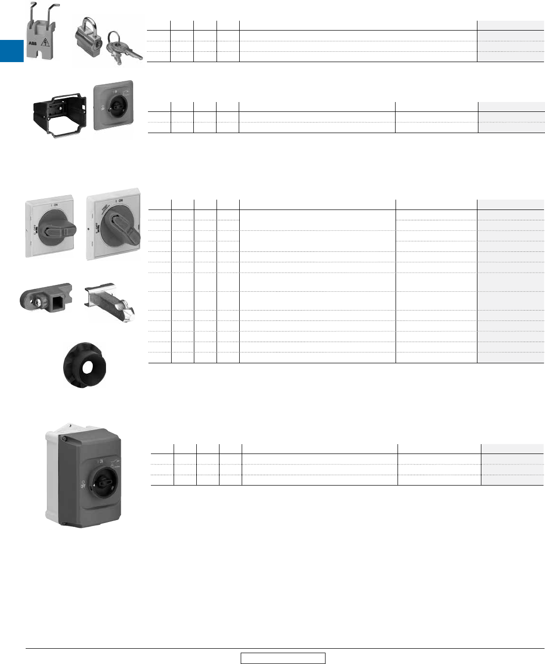
Locking accessories
For use with MS…
116 132 45x 49x Description Catalog number
• Lock adapter SA1
• • • • Padlock + 2 keys SA2
• Lock adapter + padlock + 2 keys SA3
Note: Types MS132 and MS4xx have integral locking mechanisms
Door mount kits - Type 12 & IP 65
For use with MS…
116 132 45x 49x Description Rotary positions Catalog number
• • Door mount w/ handle, black/gray On / Trip / Off DMS132-G
• • Door mount w/ handle, red/yellow On / Trip / Off DMS132-Y
Note(s): Type MS116 devices trip to the “Off” position
Max. 3 padlocks with bail diameter Ø 4…6.5 mm
Through-door hardware - Types 1, 3R, 12 and IP 64
For use with MS…
116 132 45x 49x Description Rotary positions Catalog number
••••Selector handle, black, defeatable, padlockable On / Off MSHD-LB
• • • On / Trip / Off MSHD-LTB
••••Selector handle, red/yellow, defeatable, padlockable On / Off MSHD-LY
• • • On / Trip / Off MSHD-LTY
• • • • Shaft coupler, coded, 6 mm, MSMN - 1SAM101923R0002
• • • • Shaft coupler, un-coded, 6 mm, MSMNO - 1SAM101923R0012
••••Drive spindle, 6 x 30 mm, for horizontal mounting,
MSOX-30 - 1SAM101924R0013
••••Drive spindle, 6 x 32 mm, for vertical (standard) mount-
ing, MSOX-32 - 1SAM101924R0003
• • • • Shaft, 6 x 85 mm - OXS6X85
• • • • Shaft, 6 x 105 mm - OXS6X105
• • • • Shaft, 6 x 130 mm - OXS6X130
• • • • Shaft, 6 x 180 mm - OXS6X180
• • • • Shaft alignment ring, MSH-AR - 1SAM201920R1000
Note(s): Through-door selector handles are rated Type 1, 3R and 12; IP 64 degree of protection
Max. 3 padlocks with bail diameter Ø 5…8 mm
For coded shaft couplers, the “On” position is dependent on the mounting orientation of the MMP
Must have handle, shaft coupler and shaft for through-door operation. Drive spindles can replace both shaft coupler and shaft.
Enclosures - Type 12 & IP 65
For use with MS…
116 132 45x 49x Description Rotary positions Catalog number
• • Molded plastic enclosure, black/gray On / Trip / Off IB132-G
• • Molded plastic enclosure, red/yellow On / Trip / Off IB132-Y
• • Adaptor, PG16 to 1/2 NPT - PG16-1/2NPT
Note(s): Type E rating for MS132 derated when using IB132 enclosures. Please contact technical support.
Type MS116 devices trip to the “Off” position
Max. 3 padlocks with bail diameter Ø 4…6.5 mm
For UL enclosure type ratings, contact technical support.
SA1 SA2
DMS132-G
MSHD-LY MSHD-LTY
1SAM101923R0002 1SAM101924R0013
1SAM201920R1000
IB132-G
MS Series
Manual motor
protectors
Low Voltage Products & Systems 4.15
ABB Inc. • 888-385-1221 • www.abb.us/lowvoltage 1SXU000023C0202 Rev. A
4
Revised March 2014 Revised March 2014
Accessories
For Types MS116, MS132, MS45x, MS49x
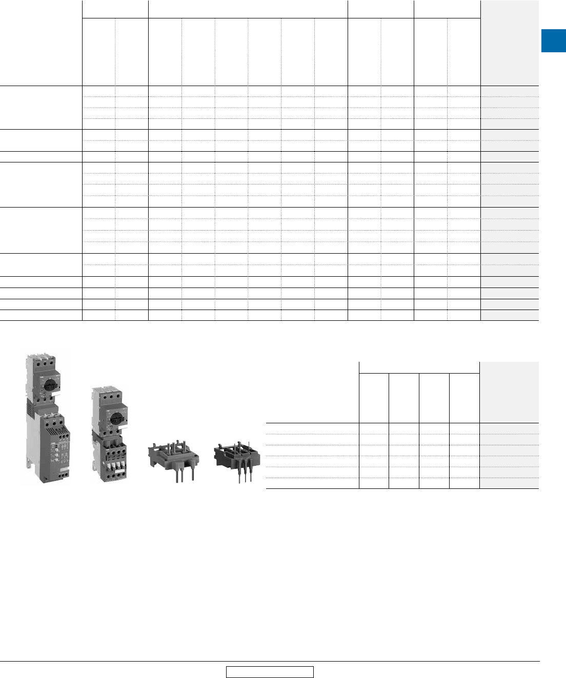
Close couplers for contactors
Manual motor protector
Miniature
contactors AF contactors AS contactors A / AE Contactors
Catalog
number
B6...B7
BC6...BC7
AF09...AF16
AF09Z...AF16Z
AF26...AF38
AF26Z...AF38Z
AF50...AF75
AF95...AF110
AS09...AS16
ASL09...ASL16
A50...A75, AE50...AE75
A95...A110
MS116-0.16…16
• • BEA7/132
• • BEA16-4
• • BEA26-4
• • BEA16-3
MS116-20…25 • • BEA16-4
• • BEA38-4
MS116-32 • • BEA38-4
MS132-0.16…10
• • BEA7/132
• • BEA16-4
• • BEA26-4
• • BEA16-3
MS132-12…16
• • BEA7/132
• • BEA16-4
• • BEA38-4
• • BEA16-3
MS132-20…25 • • BEA16-4
• • BEA38-4
MS132-32 • • BEA38-4
MS45x-40…50 • • BEA50/450
MS49x-40…100 • • BEA75/495
MS495-40…100 • • BEA110/495
Note: For spring terminated AS/ASL, use part number BEA16-3U with integral wire leads for spring terminals.
Close couplers for softstarters
Manual motor protector
PSR Softstarters
Catalog
number
PSR3…PSR16
PSR25…PSR30
PSR37…PSR45
PSR60…PSR105
MS116-0.16…16 • PSR16-MS116
MS116-20…32 • PSR30-MS132
MS132-0.16…10 • PSR16-MS116
MS132-12…32 • PSR30-MS132
MS45x-40…50 • PSR45-MS450
MS49x-40…100 • PSR105-MS495
MS132 + PSR Softstarter MS132 + AF Contactor BEA16-4 BEA16-3
4
MS Series
Manual motor
protectors
4.16 Low Voltage Products & Systems
1SXU000023C0202 Rev. A ABB Inc. • 888-385-1221 • www.abb.us/lowvoltage
Revised March 2014 Revised March 2014
Accessories
For Type MS132
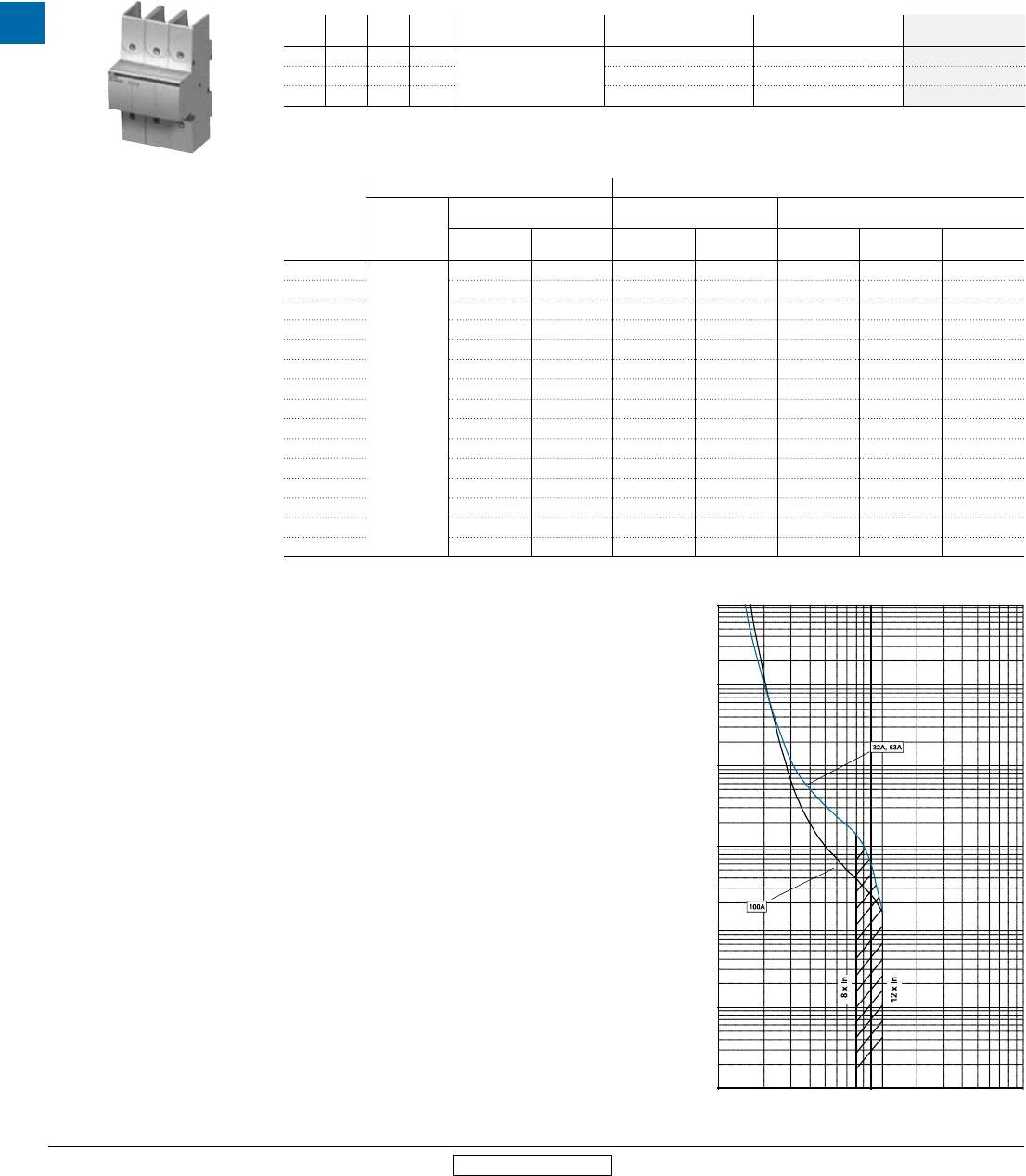
Rated for use with the type MS132, the S803W current limiters can provide selective coordination for individual downstream SCPDs, and can be utilized in combination for short-circuit protection
up to 65 kA at 600 v ac. For more information, see Section 17 - S800 Series.
Current limiters
For use with MS…
116 132 45x 49x Description Rated current (A)
600 v ac Connecting capacity (AWG) Catalog number
•
Current limiter, 3-pole
32 14…1 S803W-SCL32-SR
• 63 14…1 S803W-SCL63-SR
• 100 14…1 S803W-SCL100-SR
Note(s): The sum of the rated currents of all downstream motor protectors shall not exceed the rated current of the S803W.
The sum of all load currents including inrush currents shall not exceed the maximum permissible load of the S803W.
1 Also suitable for Tap Conductor protection.
2 Requires the use of a line-side feeder terminal S1-M3-xx; see accessories section.
3 MCCB interrupting rating must be equal to or greater than the rating of the device.
MS132 Short circuit current ratings using S803W current limiters (kA)
Catalog
number
UL 508 - Motor controllers, manual (NLRV) UL 508 - Combination motor controllers (NKJH)
Circuit breaker
Group motor installation 1Self-protected
Type E 2
Self-protected
Type F 2
240V
480V 600V 480Y/
277V
600Y/
347V
480Y/
277V
600Y/
347V
Type F
contactors
MS132-0.16
MCCB, 400A
max.
3
65 65 65 47 65 47 AF26…AF38
MS132-0.25 65 65 65 47 65 47 AF26…AF38
MS132-0.4 65 65 65 47 65 47 AF26…AF38
MS132-0.63 65 65 65 47 65 47 AF26…AF38
MS132-1.0 65 65 65 47 65 47 AF26…AF38
MS132-1.6 65 65 65 47 65 47 AF26…AF38
MS132-2.5 65 65 65 47 65 47 AF26…AF38
MS132-4.0 65 65 65 47 65 47 AF26…AF38
MS132-6.3 65 65 65 18 65 47 AF26…AF38
MS132-10 65 65 65 18 65 47 AF26…AF38
MS132-12 65 65 65 - 65 - AF26…AF38
MS132-16 65 65 65 - 65 - AF26…AF38
MS132-20 65 65 65 - 65 - AF26…AF38
MS132-25 65 65 65 - 65 - AF26…AF38
MS132-32 65 65 65 - 65 - AF26…AF38
S803W-SCL32-SR
10 000
1000
100
10
1
1 10 100
0.1
0.01
time [s]
n x Ie
Maximum load
MS Series
Manual motor
protectors
Low Voltage Products & Systems 4.17
ABB Inc. • 888-385-1221 • www.abb.us/lowvoltage 1SXU000023C0202 Rev. A
4
Revised March 2014 Revised March 2014
Connection diagrams
For Types MS116, MS132, MS45x, MS49x
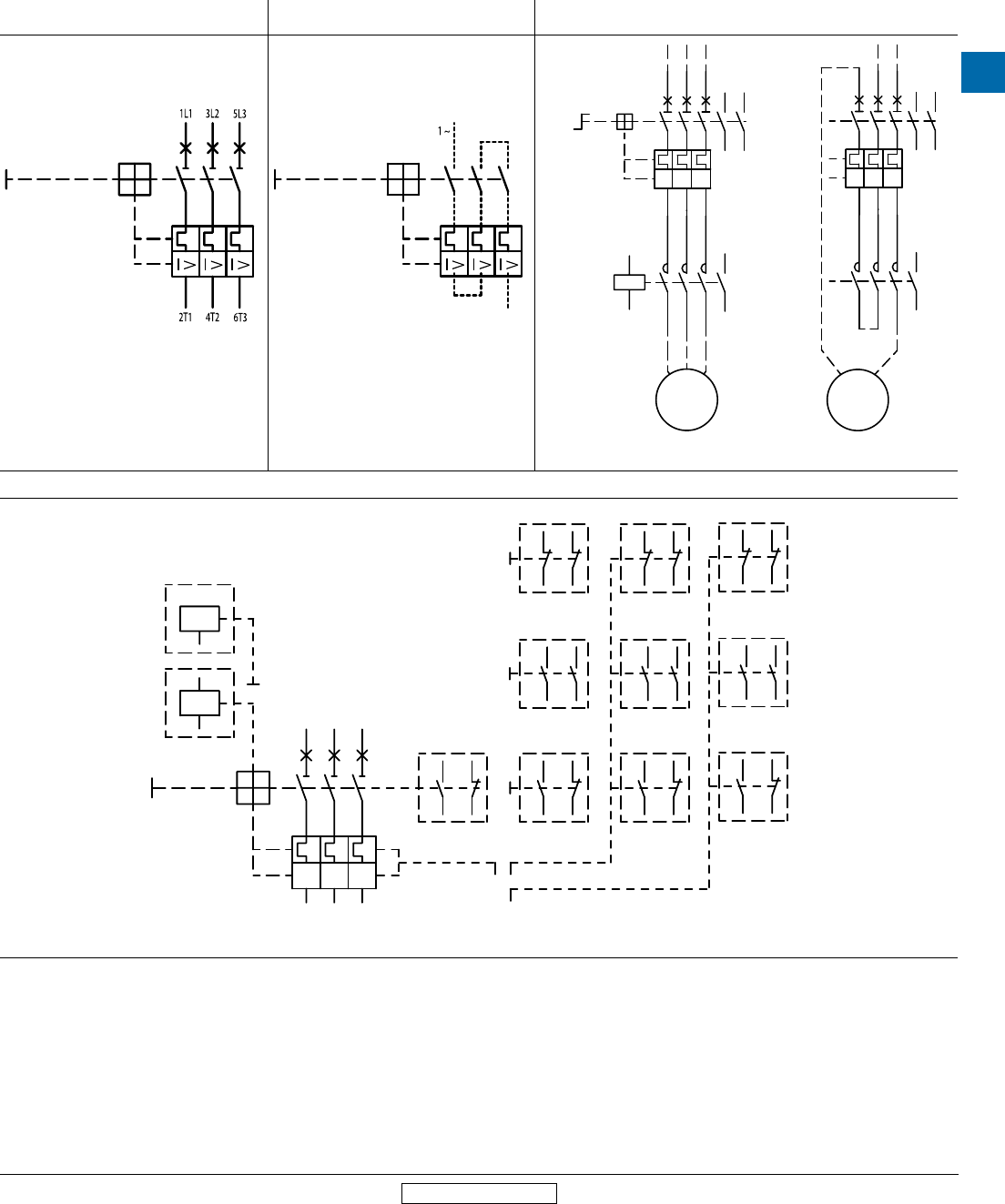
Connection diagrams
Three phase connection diagram for Types MS116, MS132,
and MS4xx
Single phase connection diagram for Types MS116,
MS132, and MS4xx Single and three phase connection diagram when using contactors
Accessories for use with Type MS116, MS132 & MS4xx
1314
KM1
A1A2
1/L1
3/L2
5/L3
2/T1
4/T2
6/T3
I> I> I>
5/L3
3/L2
1/L12/T1
4/T2
6/T3
Q1
3334
43
44
W
V
U
~
M
44
34 33
43
1314
1/L1
3/L2
5/L3
2/T1
4/T2
6/T3
I> I> I>
5/L3
3/L2
1/L12/T1
4/T2
6/T3
V
U
~
M
3 Phase Single Phase
6 T3
4 T22 T1
1 L1 5 L3
8676
I
> >
I
>
I
D1
D2
<
U
C1
C2
4232
88
4234
34 78
13 21
2214
6656
86
75 85
77 87
31 41
33 43
44
33 41 77
55 65
85
57 67
57 65
6658
58
78
3 L2
68
AA1...
AA4...
UA1...
UA4...
HKF1-11
HK4-11
HK1-11
HKS4-11
HKF1-20
HK4-20
HKF1-02
HK4-02
SK1-11
SK4-11
SK1-20
SK1-02
CK1-11
SK4-11
CK1-20
CK1-02
4
MS Series
Manual motor
protectors
4.18 Low Voltage Products & Systems
1SXU000023C0202 Rev. A ABB Inc. • 888-385-1221 • www.abb.us/lowvoltage
Revised March 2014 Revised March 2014
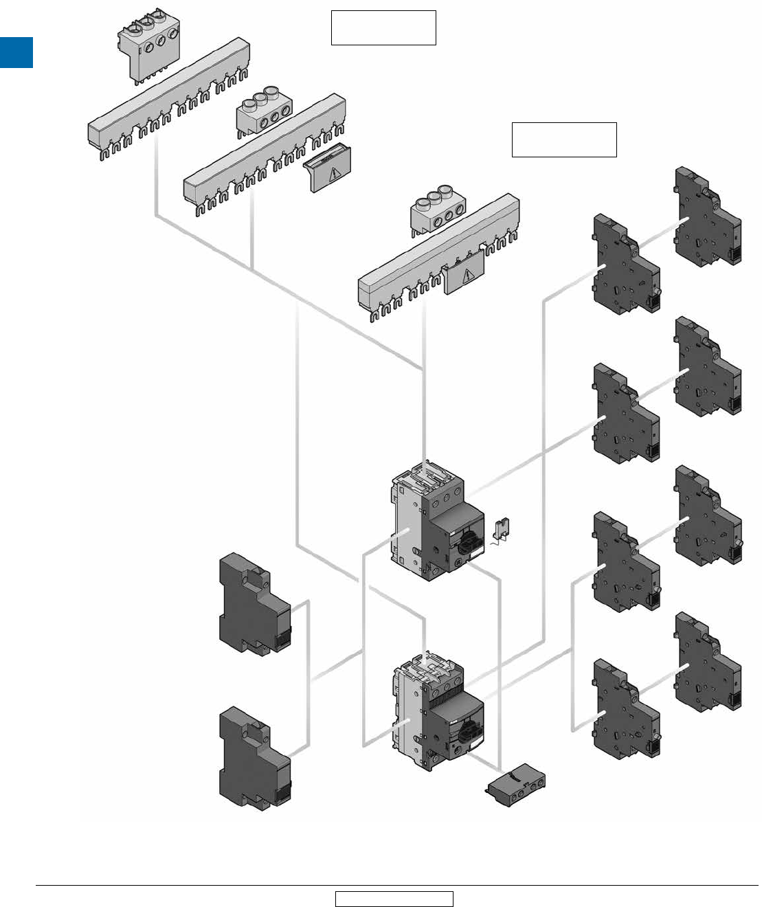
General accessory mounting layout
MS116 & MS132
MS116
UA1
AA1
SK1
HK1
CK1
CK1
HK1
HK1
SK1
HK1
S1-M1-25
PS1-..-65
BS1-3
PS1-..-65
S1-M2-25
MS132
S1-M1-25
PS1-..-100
BS1-3
SA1
3-phase busbar up
to 92 A
3-phase busbar up
to 65 A
HKF1
MS Series
Manual motor
protectors
Low Voltage Products & Systems 4.19
ABB Inc. • 888-385-1221 • www.abb.us/lowvoltage 1SXU000023C0202 Rev. A
4
Revised March 2014 Revised March 2014
Main circuit – Utilization characteristics according to IEC/EN
Type MS116
Standards IEC/EN 60947–2, IEC/EN 60947-4-1, IEC/EN 60947-1
Rated operational voltage Ue690 V AC
Rated frequency 50/60 Hz
Trip class 10A
Number of poles 3
Duty time 100 %
Rated impulse withstand voltage Uimp 6 kV
Rated insulation voltage Ui690 V AC
Rated operational current IeSee ordering details
Rated instantaneous short-circuit current setting IiSee ordering details
Rated service short-circuit breaking capacity Ics See table "Short-circuit breaking capacity and back-up fuses"
Rated ultimate short-circuit breaking capacity Icu See table "Short-circuit breaking capacity and back-up fuses"
Short-circuit breaking capacity and back-up fuses
lCS Rated service short-circuit breaking capacity
lCU Rated ultimate short-circuit breaking capacity
ICC Prospective short-circuit current at installation location
Note: Maximum rated current of the back-up fuses if ICC > ICS
Type 230 V AC 400 V AC 440 V AC 500 V AC 690 V AC
ICS
kA
ICU
kA
gG, aM
A
ICS
kA
ICU
kA
gG, aM
A
ICS
kA
ICU
kA
gG, aM
A
ICS
kA
ICU
kA
gG, aM
A
ICS
kA
ICU
kA
gG, aM
A
MS116-0.16
No back-up fuse required up to ICC = 50 kA
No back-up fuse required up to ICC = 30 kA
MS116-0.25
MS116-0.4
MS116-0.63
MS116-1.0
MS116-1.6
MS116-2.5 10 10 25 10 10 25 5 5 25
MS116-4.0 6 6 25 6 6 25 2 2 25
MS116-6.3 6 6 63 6 6 63 2 2 40
MS116-10 6 6 63 6 6 63 2 2 50
MS116-12 25 25 80 25 25 80 6 6 63 6 6 63 2 2 50
MS116-16 16 16 80 16 16 80 6 6 63 4 4 63 2 2 63
MS116-20 10 15 - 10 15 - 3 6 - 3 4 - 2 2 -
MS116-25 10 15 - 10 15 - 3 6 - 3 4 - 2 2 -
MS116-32 10 10 - 10 10 - 3 6 - 3 4 - 2 2 -
MS116-10: No need for back-up fuse in networks with a prospective current of up to 50 kA at 400 V.
MS116-16: No need for back-up fuse in networks with a prospective current of up to 16 kA at 400 V.
With an appropriate 80 A type gG fuse the device can be used in a network with a prospective current of up to 100 kA.
MS116-32: No need for back-up fuse in networks with a prospective current of up to 15 kA at 400 V.
Technical data - IEC/EN
MS116
4
MS Series
Manual motor
protectors
4.20 Low Voltage Products & Systems
1SXU000023C0202 Rev. A ABB Inc. • 888-385-1221 • www.abb.us/lowvoltage
Revised March 2014 Revised March 2014
Main circuit – Utilization characteristics according to UL/CSA
Type MS116
Standards UL 508, CSA 22.2 No. 14
Maximum operational voltage 600 V AC
Manual motor controller ratings See table "UL 508 – Manual motor controller"
Trip rating 125 % FLA
Motor ratings Horse power See table "Motor rating, three phase"
Full load amps (FLA) See table "Motor rating, three phase"
Locked rotor amps (LRA) See table "Motor rating, three phase"
Motor rating, three phase
hp Horse power
FLA Full load amps
LRA Locked rotor amps
Type 110-120 V AC 220-240 V AC 440-480 V AC 550-600 V AC
hp FLA LRA hp FLA LRA hp FLA LRA hp FLA LRA
MS116-0.16 - 0.16 0.96 - 0.16 0.96 - 0.16 0.96 - 0.16 0.96
MS116-0.25 - 0.25 1.5 - 0.25 1.5 - 0.25 1.5 - 0.25 1.5
MS116-0.4 - 0.4 2.4 - 0.4 2.4 - 0.4 2.4 - 0.4 2.4
MS116-0.63 - 0.63 3.78 - 0.63 3.78 - 0.63 3.78 - 0.63 3.78
MS116-1.0 - 1.0 6.0 - 1.0 6.0 1.0 6.0 1/2 0.9 8
MS116-1.6 - 1.6 9.6 - 1.6 9.6 3/4 1.6 12.5 3/4 1.3 10
MS116-2.5 - 2.5 15.0 1/2 2.2 20 1 2.1 15 1-1/2 2.4 16
MS116-4.0 - 4.0 16.0 1 4.2 30 2 3.4 25 3 3.9 25.6
MS116-6.3 1/2 4.4 40 1-1/2 6.4 40 3 4.8 32 5 6.1 36.8
MS116-10 1 8.4 60 3 9.6 64 5 7.6 46 7-1/2 9 50.8
MS116-12 1-1/2 12 80 3 9.6 64 7-1/2 11 63.5 10 11 64.8
MS116-16 2 13.6 100 5 15.2 92 10 14 81 10 11 64.8
MS116-20 3 19.2 128 5 15.2 92 10 14 81 15 17 93
MS116-25 3 19.2 128 7-1/2 22 127 15 21 116 20 22 116
MS116-32 5 30.4 184 10 28 162 20 27 145 25 27 146
Technical data - UL/CSA
MS116
1 Suitable as motor disconnect only when provided with padlock SA1 or SA3...
MS Series
Manual motor
protectors
Low Voltage Products & Systems 4.21
ABB Inc. • 888-385-1221 • www.abb.us/lowvoltage 1SXU000023C0202 Rev. A
4
Revised March 2014 Revised March 2014
General technical data
Type MS116
Pollution degree 3
Phase loss sensitive Yes
Ambient air temperature
Operation Open - compensated without derating -25 ... +55 °C
Open -25 ... +70 °C
Enclosed (IB132) 0 ... +40 °C
Storage -50 ... +80 °C
Ambient air temperature compensation Continuous
Maximum operating altitude permissible 2000 m
Resistance to shock acc. to IEC 60068-2-27 25 g / 11 ms
Resistance to vibrations acc. to IEC 60068-2-6 5 g / 3 ... 150 Hz
Mounting position Position 1-6 (optional for single mounting)
Mounting DIN-rail (EN 60715)
Group mounting On request
Minimum distance to other
units same type
Horizontal 0 mm
Vertical 150 mm
Minimum distance to
electrical conductive board
Horizontal, up to 400 V 0 mm
Horizontal, up to 690 V > 1.5 mm
Vertical 75 mm
Degree of protection Enclosure / terminals IP20
Main circuit – Connecting characteristics
Type MS116 ≤ 16 A MS116 ≥ 20 A
Connecting capacity
Solid 1 or 2 x 1 ... 4 mm² 2.5 ... 6 mm²
Flexible 1 or 2 x 0.75 ... 2.5 mm² 1 ... 6 mm²
Stranded acc. to UL/CSA 1 or 2 x AWG 16-12 AWG 12-8
Flexible acc. to UL/CSA 1 or 2 x AWG 16-12 AWG 12-8
Stripping length 9 mm 10 mm
Tightening torques 0.8 ... 1.2 Nm / 10 … 12 Ib.in 2.0 Nm / 18 Ib.in
Connection screw M3.5 (Pozidriv 2 / 5.5 mm) M4 (Pozidriv 2 / 6.5 mm)
Technical data
MS116
4
MS Series
Manual motor
protectors
4.22 Low Voltage Products & Systems
1SXU000023C0202 Rev. A ABB Inc. • 888-385-1221 • www.abb.us/lowvoltage
Revised March 2014 Revised March 2014
Main circuit – Utilization characteristics according to IEC/EN
Type MS132
Standards IEC/EN 60947–2, IEC/EN 60947-4-1, IEC/EN 60947-1
Rated operational voltage Ue690 V AC / 250 V DC
Rated frequency DC, 50/60 Hz
Trip class 10 (10A for MS132-0.16)
Number of poles 3
Duty time 100 %
Rated impulse withstand voltage Uimp 6 kV
Rated insulation voltage Ui690 V AC
Rated operational current IeSee ordering details
Rated instantaneous short-circuit current setting IiSee ordering details
Rated service short-circuit breaking capacity Ics See table "Short-circuit breaking capacity and back-up fuses"
Rated ultimate short-circuit breaking capacity Icu See table "Short-circuit breaking capacity and back-up fuses"
Short-circuit breaking capacity and back-up fuses
lCS Rated service short-circuit breaking capacity
lCU Rated ultimate short-circuit breaking capacity
ICC Prospective short-circuit current at installation location
Note: Maximum rated current of the back-up fuses if ICC > ICS
Type 230 V AC 400 V AC 440 V AC 500 V AC 690 V AC
ICS
kA
ICU
kA
gG, aM
A
ICS
kA
ICU
kA
gG, aM
A
ICS
kA
ICU
kA
gG, aM
A
ICS
kA
ICU
kA
gG, aM
A
ICS
kA
ICU
kA
gG, aM
A
MS132-0.16
No back-up fuse required up to
ICC = 100 kA
MS132-0.25
MS132-0.4
MS132-0.63
MS132-1.0
MS132-1.6
MS132-2.5
MS132-4.0 20 20 * 20 20 * 3 3 *
MS132-6.3 20 20 * 20 20 * 3 3 *
MS132-10 20 20 * 20 20 * 3 3 *
MS132-12 20 20 * 20 20 * 3 3 *
MS132-16 20 20 * 20 20 * 3 3 *
MS132-20 20 20 * 20 20 * 3 3 *
MS132-25 50 50 100 50 50 100 20 20 * 10 10 * 3 3 *
MS132-32 25 50 125 25 50 125 20 20 * 10 10 * 3 3 *
MS132-16: No need for back-up fuse in networks with a prospective current of up to 100 kA at 400 V.
MS132-32: No need for back-up fuse in networks with a prospective current of up to 50 kA at 400 V.
With an approbiate 125 A type gG fuse the device can be used in a network with a prospective current of up to 100 kA
* not available yet
Technical data - IEC/EN
MS132
MS Series
Manual motor
protectors
Low Voltage Products & Systems 4.23
ABB Inc. • 888-385-1221 • www.abb.us/lowvoltage 1SXU000023C0202 Rev. A
4
Revised March 2014 Revised March 2014
Main circuit – Utilization characteristics according to UL/CSA
Type MS132
Standards UL 508, CSA 22.2 No. 14
Maximum operational voltage 600 V AC
Manual motor controller ratings See table "UL 508 – Manual motor controller"
Trip rating 125 % FLA
Motor ratings Horse power See table "Motor rating, three phase"
Full load amps (FLA) See table "Motor rating, three phase"
Locked rotor amps (LRA) See table "Motor rating, three phase"
Motor rating, three phase
hp Horse power
FLA Full load amps
LRA Locked rotor amps
Type 110-120 V AC 220-240 V AC 440-480 V AC 550-600 V AC
hp FLA LRA hp FLA LRA hp FLA LRA hp FLA LRA
MS132-0.16 - 0.16 0.96 - 0.16 0.96 - 0.16 0.96 - 0.16 0.96
MS132-0.25 - 0.25 1.5 - 0.25 1.5 - 0.25 1.5 - 0.25 1.5
MS132-0.4 - 0.4 2.4 - 0.4 2.4 - 0.4 2.4 - 0.4 2.4
MS132-0.63 - 0.63 3.78 - 0.63 3.78 - 0.63 3.78 - 0.63 3.78
MS132-1.0 - 1.0 6.0 - 1.0 6.0 - 1.0 6.0 1/2 1.0 6.0
MS132-1.6 - 1.6 9.6 - 1.6 9.6 3/4 1.6 9.6 3/4 1.6 9.6
MS132-2.5 - 2.5 15.0 1/2 2.5 15.0 1 2.5 15.0 1-1/2 2.5 15.0
MS132-4.0 - 4.0 24.0 1 4.0 24.0 2 4.0 24.0 3 3.9 26.0
MS132-6.3 1/2 6.3 37.8 1-1/2 6.3 37.8 3 4.8 32.0 5 6.1 37.0
MS132-10 3/4 10.0 60.0 3 9.6 64.0 5 7.6 46.0 7-1/2 9.0 51.0
MS132-12 1-1/2 12.0 72.0 3 9.6 64.0 7-1/2 11.0 64.0 10 11.0 65.0
MS132-16 2 16.0 84.0 5 15.2 92.0 10 14.0 81.0 10 11.0 65.0
MS132-20 3 19.2 128.0 5 15.2 92.0 10 14.0 81.0 15 17.0 93.0
MS132-25 3 19.2 128.0 7-1/2 22.0 127.0 15 21.0 116.0 20 22.0 116.0
MS132-32 5 30.4 184.0 10 28.0 162.0 20 27.0 145.0 25 27.0 146.0
Technical data - UL/CSA
MS132
4
MS Series
Manual motor
protectors
4.24 Low Voltage Products & Systems
1SXU000023C0202 Rev. A ABB Inc. • 888-385-1221 • www.abb.us/lowvoltage
Revised March 2014 Revised March 2014
General technical data
Type MS132
Pollution degree 3
Phase loss sensitive Yes
Ambient air temperature
Operation Open - compensated without derating -25 ... +60 °C
Open -25 ... +70 °C
Enclosed (IB132) 0 ... +40 °C
Storage -50 ... +80 °C
Ambient air temperature compensation Continuous
Maximum operating altitude permissible 2000 m
Resistance to shock acc. to IEC 60068-2-27 25 g / 11 ms
Resistance to vibrations acc. to IEC 60068-2-6 5 g / 3 ... 150 Hz
Mounting position Position 1-6 (optional for single mounting)
Mounting DIN-rail (EN 60715)
Group mounting On request
Minimum distance to other
units same type
Horizontal 0 mm
Vertical 150 mm
Minimum distance to
electrical conductive board
Horizontal, up to 400 V 0 mm
Horizontal, up to 690 V > 1.5 mm
Vertical 75 mm
Degree of protection Enclosure / terminals IP20
Main circuit – Connecting characteristics
Type MS132-0.16 … MS132-10 MS132-12 … MS132-16 MS132-20 … MS132-32
Connecting capacity
Solid 1 or 2 x 1 ... 4 mm² 1 ... 4 mm² 2.5 ... 6 mm²
Flexible 1 or 2 x 0.75 ... 2.5 mm² 0.75 ... 2.5 mm² 1 ... 6 mm²
Stranded acc. to UL/CSA 1 or 2 x AWG 16-12 AWG 16-12 AWG 12-8
Flexible acc. to UL/CSA 1 or 2 x AWG 16-12 AWG 16-12 AWG 12-8
Stripping length 9 mm 10 mm 10 mm
Tightening torques 0.8 ... 1.2 Nm / 10 … 12 Ib.in 1.5 Nm / 14 Ib.in 2.0 Nm / 18 Ib.in
Connection screw M3.5 (Pozidriv 2) M4 (Pozidriv 2) M4 (Pozidriv 2)
Technical data
MS132
MS Series
Manual motor
protectors
Low Voltage Products & Systems 4.25
ABB Inc. • 888-385-1221 • www.abb.us/lowvoltage 1SXU000023C0202 Rev. A
4
Revised March 2014 Revised March 2014
Technical data
MS116 & MS132 Accessories
General technical data
Type PS1-x-x-65 PS1-x-x-100 S1-M1-25 S1-M2-25 S1-M3-25 S1-M3-35
Standards IEC/EN 60947-1, UL 508/60947-4-1A, CAN/CSA C22.2 No.14/60947-4-1-07
Rated operational voltage Ue690 V AC
Rated voltage UL/CSA 600 V AC
Rated operational current Ie65 A 100 A 65 A 100 A
Rated current UL/CSA 65 A 92 A 65 A 92 A
Rated frequency 50/60 Hz
Rated impulse withstand voltage Uimp 6 kV
Rated insulation voltage Ui690 V AC
Pollution degree 3
Cross-section 5 mm² 5 mm²
Ambient air temperature Operation -25...+70 °C
Storage -50...+80 °C
Connecting characteristics
Type S1-M1-25 S1-M2-25 S1-M3-25 S1-M3-35
Connecting capacity
Solid 1 x 6mm2…25 mm2 10...35 mm²
Flexible 1 x 6mm2…16mm2 10...35 mm²
Stranded acc. to UL/CSA 1 x AWG 10-4 AWG 8-2
Flexible acc. to UL/CSA 1 x AWG 10-4 AWG 8-2
Tightening torques 2.5 Nm / 22 lb.in 4.5 Nm / 40 lb.in
Connection screw Pozidriv 2 / M3.5 Hexgon SW4
General technical data
Type UA1 AA1
Standards IEC/EN 60947-1, UL 508/60947-4-1A, CAN/CSA C22.2 No.14/60947-4-1-07
Pick-up value % of Uc ≥ 85 ≥ 70
Drop-out value % of Uc 35…70 -
Power consumption Pick-up VA 9
Holding VA 3
Ambient air temperature Operation -20…+55 °C
Storage -50…+80 °C
Connecting characteristics
Type UA1 AA1
Connecting capacity
Solid 1 x 0.5...1.5 mm²
2 x 0.5...1.5 mm²
Flexible 1 x 0.5...1.5 mm²
2 x 0.5...1.5 mm²
Stranded acc. to UL/CSA 1 or 2 x AWG 18-14
Flexible acc. to UL/CSA 1 or 2 x AWG 18-14
Stripping length 8 mm
Tightening torques 0.8...1.2 Nm /
7...10.3 Ib.in
Connection screw Pozidriv 2 / M3
4
MS Series
Manual motor
protectors
4.26 Low Voltage Products & Systems
1SXU000023C0202 Rev. A ABB Inc. • 888-385-1221 • www.abb.us/lowvoltage
Revised March 2014 Revised March 2014
Technical data
MS116 & MS132 Accessories
Contact utilization characteristics per IEC
Type HKF1-xx HK1-xx HK1-20L SK1-xx CK1-xx
Standards IEC/EN 60947-5-1
Rated operational voltage Ue 250 V AC/ 690 V AC/
250 V DC 600 V DC
Conventional free-air thermal current Ith 5 A 6 A
Rated frequency 50/60 Hz
Rated impulse withstand voltage Uimp 6 kVA
Rated insulation voltage Ui 230 V 690 V
Pollution degree 3
Ambient air temperature Operation -20…+55 °C
Storage -50…+80 °C
Resistance to shock acc. to IEC 60068-2-27 25 g / 11 ms
Resistance to vibrations acc. to IEC 60068-2-6 2 g / 5…150 Hz
Number of poles 1 N.C. + 1 N.O. or 2 N.O. or 2 N.C. 2 leading N.O. 1 N.C. + 1 N.O. or 2 N.O. or 2 N.C.
Ie / Rated operational current AC-15 acc. to IEC/EN 60947-5-1 for utilization category
24 V, 50/60 Hz 3 6
120 V, 50/60 Hz 3 6
230 V, 50/60 Hz 1.5 4
400 V, 50/60 Hz - 3
690 V, 50/60 Hz - 1
Ie / Rated operational current DC-13 acc. to IEC/EN 60947-5-1 for utilization category
24 V 1.0 2
125 V 0.27 0.55
250 V 0.10 0.27
600 V - 0.15
Minimum switching capacity 17 V / 5 mA
Short-circuit protective device 10 A Type gG
Duty time 100 %
Mounting Front of MMS Right side of MMS
Mounting positions 1-6
Mechanical durability 100000 cycles
Electrical durability 100000 cycles
Contact utilization characteristics per UL/CSA
Type HKF1-xx HK1-xx HK1-20L SK1-xx CK1-xx
Standards UL 508/60947-4-1A, CAN/CSA C22.2 No.14/60947-4-1-07
Rated voltage UL/CSA 240 V AC/ 250 V DC 600 V AC/ 600 V DC
Pilot duty B300, Q300 B600, Q600
AC thermal rated current 5
AC maximum volt-ampere making 3600
AC maximum volt-ampere breaking 360
DC thermal rated current 2.5
DC maximum volt-ampere make/break 69
Connecting characteristics
Type HKF1-xx HK1-xx HK1-20L SK1-xx CK1-xx
Connecting capacity
Solid 1 or 2 x 1...1.5 mm²
Flexible 1 or 2 x 0.75...1.5 mm²
Flexible with non-insulated ferrule 1 or 2 x 0.75...1.5 mm²
Flexible with insulated ferrule 1 or 2 x 0.75...1.5 mm²
Stranded acc. to UL/CSA 1 or 2 x AWG 16-14
Flexible acc. to UL/CSA 1 or 2 x AWG 16-14
Stripping length 8 mm
Tightening torques 0.8...1.2 Nm / 7...10.3 Ib.in
Connection screw Pozidriv 2 / M3
MS Series
Manual motor
protectors
Low Voltage Products & Systems 4.27
ABB Inc. • 888-385-1221 • www.abb.us/lowvoltage 1SXU000023C0202 Rev. A
4
Revised March 2014 Revised March 2014
Main circuit – Utilization characteristics according to IEC/EN
Type MS45x, MS49x
Standards IEC/EN 60947–2, IEC/EN 60947-4-1, IEC/EN 60947-1
Rated operational voltage Ue690 V AC / 450 V DC
Rated frequency 50/60 Hz
Trip class 10, 20
Number of poles 3
Duty time 100 %
Rated impulse withstand voltage Uimp 6 kV
Rated insulation voltage Ui690 V AC
Rated operational current IeSee ordering details
Rated instantaneous short-circuit current setting IiSee ordering details
Rated service short-circuit breaking capacity Ics See table "Short-circuit breaking capacity and back-up fuses"
Rated ultimate short-circuit breaking capacity Icu See table "Short-circuit breaking capacity and back-up fuses"
Short-circuit breaking capacity and back-up fuses
lCS Rated service short-circuit breaking capacity
lCU Rated ultimate short-circuit breaking capacity
ICC Prospective short-circuit current at installation location
Note: Maximum rated current of the back-up fuses if ICC > ICS
Type 240 V AC 400 V AC 440 V AC 500 V AC 690 V AC
ICS
kA
ICU
kA
gG, aM
A
ICS
kA
ICU
kA
gG, aM
A
ICS
kA
ICU
kA
gG, aM
A
ICS
kA
ICU
kA
gG, aM
A
ICS
kA
ICU
kA
gG, aM
A
Short-circuit protection MS45x
MS45x-40 No back-up fuse required up to
ICC = 100 kA
25 50 160 15 50 125 5 10 100 2 4 63
MS45x-45 25 50 160 15 50 125 5 10 100 2 4 63
MS45x-50 25 50 160 15 50 125 5 10 100 2 4 80
MS45x: No need for back-up fuse in networks with a prospective current of up to 50 kA at 400 V.
With an appropriate 160 A type gG fuse the device can be used in a network with a prospective current of up to 100 kA.
Short-circuit protection MS49x
MS49x-40
No back-up fuse required up to
ICC = 100 kA
25 50 125 20 50 125 6 12 125 3 6 63
MS49x-50 25 50 125 20 50 125 6 12 125 3 6 80
MS49x-63 25 50 160 20 50 160 6 12 160 3 6 80
MS49x-75 25 50 160 20 50 160 6 8 160 3 5 100
MS49x-90 25 50 160 20 50 160 6 8 160 3 5 125
MS49x-100 25 50 160 20 50 160 6 8 160 3 5 125
MS49x-40: No need for back-up fuse in networks with a prospective current of up to 50 kA at 400 V.
With an appropriate 125 A type gG fuse the device can be used in a network with a prospective current of up to 100 kA.
MS49x-100: No need for back-up fuse in networks with a prospective current of up to 50 kA at 400 V.
With an appropriate 160 A type gG fuse the device can be used in a network with a prospective current of up to 100 kA.
Technical data - IEC/EN
MS45x & MS49x
4
MS Series
Manual motor
protectors
4.28 Low Voltage Products & Systems
1SXU000023C0202 Rev. A ABB Inc. • 888-385-1221 • www.abb.us/lowvoltage
Revised March 2014 Revised March 2014
Technical data - UL/CSA
MS45x & MS49x
Main circuit – Utilization characteristics according to UL/CSA
Type MS45x, MS49x
Standards UL 508, CSA 22.2 No. 14
Maximum operational voltage 600 V AC
Manual motor controller ratings See table “UL 508 – Manual motor controller”
Trip rating 125 % FLA
Motor ratings Horsepower See table “Motor rating, three phase”
Full load amps (FLA) See table “Motor rating, three phase”
Locked rotor amps (LRA) See table “Motor rating, three phase”
Motor rating, three phase
hp Horsepower
FLA Full load amps (FLA)
LRA Locked rotor amps (LRA)
Type 208 V AC 220-240 V AC 440-480 V AC 550-600 V AC
hp FLA LRA hp FLA LRA hp FLA LRA hp FLA LRA
Types MS450 / MS451
MS451-16 5 16.7 102.0 5 15.2 92.0 10 14.0 81.0 15 17.0 93.0
MS451-20 5 16.7 102.0 7.5 22.0 92.0 15 21.0 116.0 20 22.0 116.0
MS451-25 7.5 24.2 140.0 10 28.0 127.0 20 27.0 145.0 25 27.0 146.0
MS451-32 10 30.8 179.0 10 28.0 162.0 25 34.0 183.0 30 32.0 174.0
MS45x-40 15 46.2 257.0 15 42.0 232.0 30 40.0 218.0 40 41.0 232.0
MS45x-45 15 46.2 257.0 15 42.0 232.0 30 40.0 218.0 40 41.0 232.0
MS45x-50 15 46.2 257.0 20 54.0 232.0 40 52.0 290.0 50 52.0 290.0
Types MS495 / MS496
MS49x-40 15 46.2 257.0 15 42.0 232.0 30 40.0 218.0 40 41.0 232.0
MS49x-50 15 46.2 257.0 20 54.0 232.0 40 52.0 290.0 50 52.0 290.0
MS49x-63 20 59.4 321.0 25 68.0 290.0 50 65.0 363.0 60 62.0 348.0
MS49x-75 25 74.8 404.0 25 68.0 365.0 60 77.0 435.0 75 77.0 434.0
MS49x-90 30 88.0 481.0 30 80.0 435.0 75 96.0 543.0 100 99.0 580.0
MS49x-100 40 114.0 641.0 40 104.0 580.0 75 96.0 543.0 100 99.0 580.0
MS Series
Manual motor
protectors
Low Voltage Products & Systems 4.29
ABB Inc. • 888-385-1221 • www.abb.us/lowvoltage 1SXU000023C0202 Rev. A
4
Revised March 2014 Revised March 2014
Technical data
MS45x & MS49x
General technical data
Type MS45x MS49x
Pollution degree 3
Phase loss sensitive Yes
Ambient air temperature
Operation Open - compensated without derating -20 ... +60 °C
Open -20 ... +70 °C
Enclosed -20 ... +35 °C
Storage -50 ... +80 °C
Ambient air temperature compensation Continuous
Maximum operating altitude permissible 2000 m
Resistance to shock acc. to IEC 60068-2-27 25 g / 11 ms -
Resistance to vibrations acc. to IEC 60068-2-6 2 g / 5-150 Hz
Mounting position Position 1-6 (optional for single mounting)
Mounting DIN-rail 35 mm (EN 60715) DIN-rail 15 mm / 75 mm (EN 60715)
Minimum distance to other units
same type
Horizontal 0 mm 0 mm
Vertical - up to 240 V - 50 mm
Vertical - up to 440 V - 70 mm
Vertical - up to 500 V - 110 mm
Vertical - up to 690 V - 150 mm
Vertical 50 mm -
Minimum distance to
electrical conductive board
Horizontal 10 mm -
Horizontal - up to 500 V - 10 mm
Horizontal - up to 690 V - 30 mm
Vertical - up to 240 V - 50 mm
Vertical - up to 440 V - 70 mm
Vertical - up to 500 V - 110 mm
Vertical - up to 690 V - 150 mm
Vertical 50 mm -
Degree of protection Enclosure / terminals IP20
Main circuit – Connecting characteristics
Type MS45x MS49x
Connecting capacity
Solid 1 or 2 x 0.75 ... 16 mm² 2.5 ... 16 mm²
Flexible 1 x
2 x
0.75 ... 35 mm²
0.75 ... 25 mm²
10 ... 70 mm²
10 ... 50 mm²
Stranded acc. to UL/CSA 1 x
2 x
AWG 18-2
AWG 18-2
AWG 10-2/0
AWG 10-1/0
Flexible acc. to UL/CSA 1 x
2 x
AWG 18-2
AWG 18-2
AWG 10-2/0
AWG 10-1/0
Stripping length 13 mm 17 mm
Tightening torques 3 - 4.5 Nm / 27 … 40 Ib.in 4 - 6 Nm / 35 - 53 Ib.in
Connection screw Pozidriv 2 Hexagon 4
4
MS Series
Manual motor
protectors
4.30 Low Voltage Products & Systems
1SXU000023C0202 Rev. A ABB Inc. • 888-385-1221 • www.abb.us/lowvoltage
Revised March 2014 Revised March 2014
Technical data
MS45x & MS49x Accessories
General technical data
Type PS4-xxx S4-M1
Standards IEC/EN 60947-1
Rated operational voltage Ue690 V AC
Rated operational current Ie108 A
Rated frequency 50/60 Hz
Rated impulse withstand voltage Uimp 6 kV
Rated insulation voltage Ui690 V AC
Pollution degree 3
Cross-section 10 mm225 mm2
Ambient air temperature Operation -25... +70°C
Storage -50... +80°C
Main circuit – Connection characteristics
Type S4-M1
Connecting capacity
Solid 1x 2.5... 50 mm2
Flexible 1x 4... 16 mm2
Stranded acc. to UL/CSA 1x AWG 14-4
Flexible acc. to UL/CSA 1x AWG 14-4
Tightening torques 4 Nm
Connection screw Pozidriv 2
General technical data
Type UA4 AA4
Standards IEC/EN 60947-1, UL 508/60947-4-1A, CAN/CSA C22.2 No.14/60947-4-1-07
Pick-up value % of Uc≥ 85 ≥ 70
Drop-out value % of Uc35…70 -
Power Pick-up VA 20.2 Consult factory
consumption Holding VA 7.2 Consult factory
Connection characteristics
Type UA4 AA4
Connecting capacity
Solid 1 x 0.5... 2.5 mm²
2 x 0.5...1.5 mm² or 0.75...2.5 mm
Flexible 1 x 0.5...2.5 mm²
2 x 0.5...1.5 mm² or 0.75...2.5 mm
Stranded acc. to UL/CSA 1 or 2 x AWG 18-14
Flexible acc. to UL/CSA 1 or 2 x AWG 18-14
Stripping length 10 mm
Tightening torques 0.8...1.2 Nm / 7...10.3 Ib.in
Connection screw Pozidriv 2 / M3
MS Series
Manual motor
protectors
Low Voltage Products & Systems 4.31
ABB Inc. • 888-385-1221 • www.abb.us/lowvoltage 1SXU000023C0202 Rev. A
4
Revised March 2014 Revised March 2014
Technical data
MS45x & MS49x Accessories
General technical data
Type HK4-11 HK4-W HKS4 SK4
Standards IEC/EN 60947-1, IEC/EN 60947-5-1, UL 508, CSA22.2 No. 14
Rated operational voltage Ue230 V AC/220 V DC 690 V AC / 220 V DC 690 V AC 690 V AC
Conventional free-air thermal current Ith 2.5 A 5 A 10 A 10 A
Rated frequency DC, 50/60 Hz
Rated impulse withstand voltage Uimp 6 kV
Rated insulation voltage Ui300 V 300 V 690 V 690V
Pollution degree 3
Ambient air temperature Operation -20 ... +70°C
Storage -50 ... +80°C
Resistance to shock acc. to IEC 60068-2-27 25 g/11 ms
Resistance to vibrations acc. to IEC 60068-2-6 2 g / 5 ... 150 Hz
Number of poles 1 N.C. + 1 N.O. Changeover 1 N.C. + 1 N.O. /
2 N.O. / 2 N.C.
2 N.C. + 2 N.O.
Ie / Rated operational current AC-15
acc. to IEC/EN 60947-5-1 for utilization category
24 V , 50/60 Hz 2 A 4 A 6 A 6 A
230 V, 50/60 Hz 0.5 A 3 A 4 A 4 A
400 V, 50/60 Hz – 1.5 A 3 A 3 A
690 V, 50/60 Hz – 0.5 A 1 A 1 A
Ie / Rated operational current DC-13
acc. to IEC/EN 60947-5-1 for utilization category 24 V 1 A 1 A 2 A 2 A
48 V 0.3 A – – –
60 V 0.15 A – – –
110 V – 0.22 A 0.5 A 0.5 A
230 V – 0.1 A 0.25 A 0.25 A
Minimum switching capacity 17 V / 1 mA
Short-circuit protective device 10 A Type gG
Duty time 100%
Mounting Front of MMS Front of MMS Left side of MMS Left side of MMS
Mounting positions 1-6
Mechanical durability 100,000 cycles
Electrical durability 100,000 cycles
Main circuit – Connecting characteristics
Type HK4-11 HK4-W HKS4 SK4
Connecting capacity Solid 1x 0.5... 2.5 mm2
2x 0.5... 1.5 mm2 or 0.75... 2.5 mm
Flexible 1x 0.5... 2.5 mm2
2x 0.5... 1.5 mm2 or 0.75... 2.5 mm
Stranded acc. to UL/CSA 1 or 2x AWG 18-14
Flexible acc. to UL/CSA 1 or 2x AWG 18-14
Stripping length 10 mm
Tightening torques 0.8... 1.2 Nm / 7... 10.3 lb.in.
Connection screw Pozidriv 2
4
MS Series
Manual motor
protectors
4.32 Low Voltage Products & Systems
1SXU000023C0202 Rev. A ABB Inc. • 888-385-1221 • www.abb.us/lowvoltage
Revised March 2014 Revised March 2014
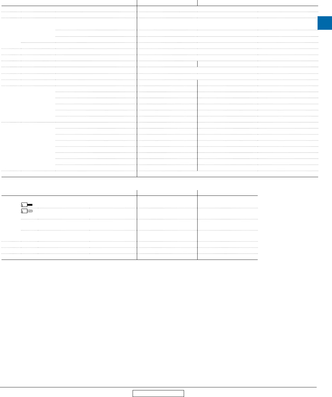
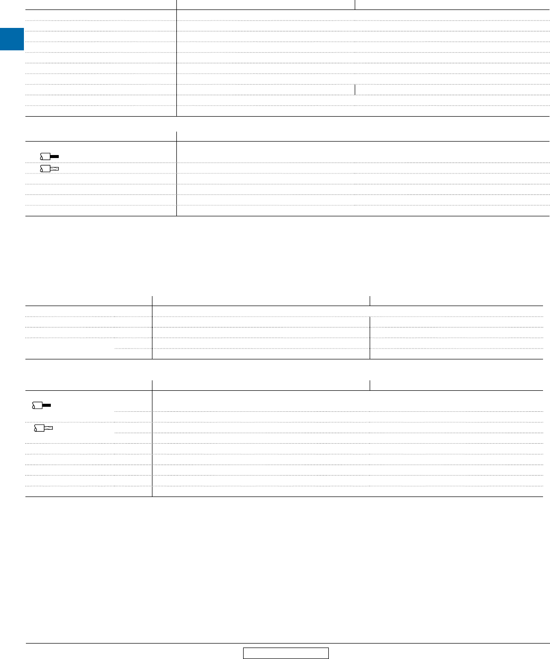
Approximate dimensions
1,5 / 0,06"
1,7 / 0,07"
14 / 0,55" 14 /
90 / 3,54"
45 / 1,77"
0,55"
35 / 1,38"
5,5 / 0,22"
45 / 1,77"
57,8 / 2,3"
70 / 2,76"
43,5 / 1,71"
80,1 / 3,15"
27,5 / 1,1"
75 / 2,95"
MS116-0.16... MS116-16, MS132-0.16…MS132-10
MS116-20... MS116-32, MS132-12... MS132-32
1,5 / 0,06"
1,7 / 0,07"
27,5 / 1,1"
45 / 1,77"
57,8 / 2,3"
35 / 1,38"
5,5 / 0,22"
69,8 / 2,75"
43,3 / 1,7"
79,9 / 3,15"
14 / 0,55" 14 /
75 / 2,95"
97,8 / 3,85"
45 / 1,77"
0,55"
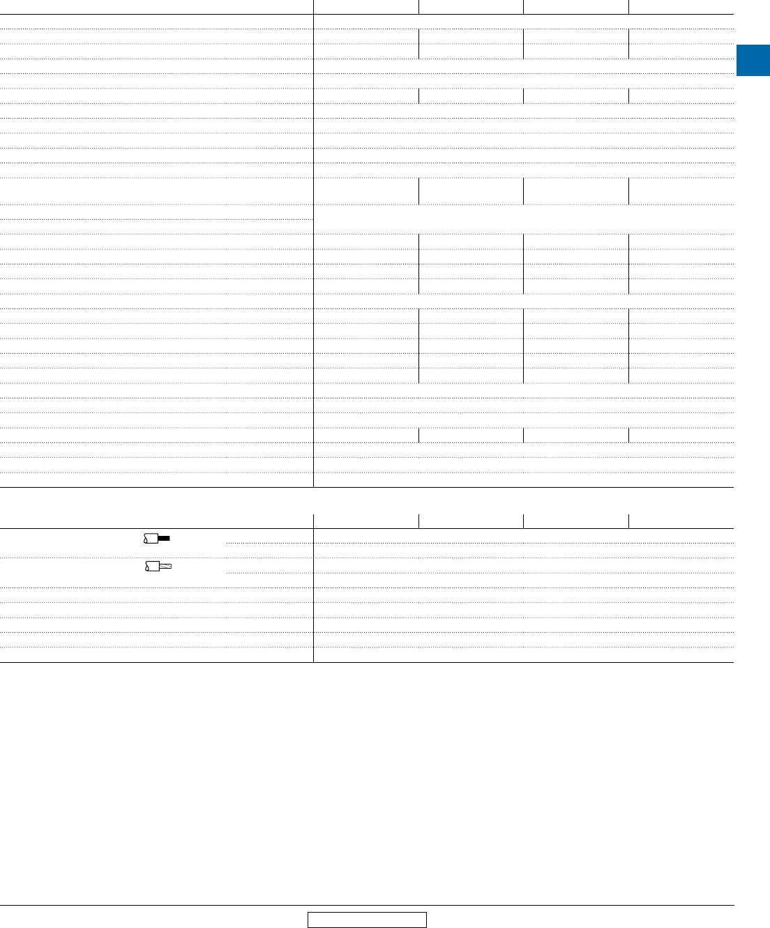
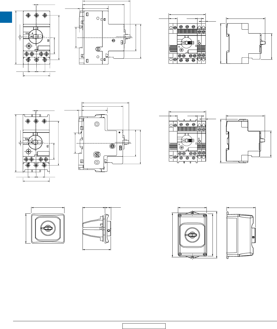
DMS132-x
81 3.19"
18 0.71" 9 0.35"
9 0.35"
86.5 3.41"
90 3.54"
57.8 2.28"
MS116-0.16…MS116-16 or MS132-0.16…MS132-10 + UA1, AA1,
SK1, HK1, CK1, HKF1-11
81 3.19"
18 0.71" 9 0.35"
9 0.35"
86.5 3.41"
97.8 3.85"
57.8 2.28"
MS116-20... MS116-32 or MS132-12... MS132-32 + UA1, AA1, SK1,
HK1, CK1, HKF1-11
IB132-x
121 4.76"
135.7 5.34" 92 3.62" 24 .94"
116.15 4.57"
I
ON
0
OFF
119 4.69"
I
ON
0
OFF
183 7.2"
174 6.85"
194 7.64"
118 4.65"
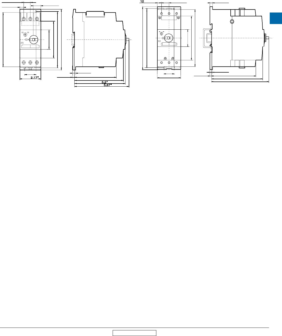
MS Series
Manual motor
protectors
Low Voltage Products & Systems 4.33
ABB Inc. • 888-385-1221 • www.abb.us/lowvoltage 1SXU000023C0202 Rev. A
4
Revised March 2014 Revised March 2014
Approximate dimensions
MS450-40…MS450-50, MS451-16…MS451-50 MS495-40…MS495-100, MS496-40…MS496-100
5.20
"
132
6.02
"
153
6.65
"
169
6.10
"
155
6.50
"
165
5.91
"
150
4.57
"
116
1.77
"
45
2.56
"
70
0.31
"
8
0.28
"
7
0.20
"
5
1.18
"
30
0.47
"
12 0.91
"
23
4.29
"
109
5.0
"
127
5.2
"
132
4.92
"
125
3.35
"
85
5.12
"
130
5.51
"
140
1.77
"
45
5.67
"
144
1.18
"
30
2.17
"
55
0.67
"
17
0.39
"
10 0.79
"
20
0.20
"
5
0.32
"
8

4
MS Series
Manual motor
protectors
4.34 Low Voltage Products & Systems
1SXU000023C0202 Rev. A ABB Inc. • 888-385-1221 • www.abb.us/lowvoltage
Revised March 2014 Revised March 2014
Notes
