SD17611 116611 Catalog
103008-Catalog 103008-Catalog 103008-Catalog 785901 Batch5 unilog cesco-content
2014-09-05
: Pdf 116611-Catalog 116611-Catalog 785901 Batch7 unilog
Open the PDF directly: View PDF ![]() .
.
Page Count: 30

11-1
© 2012 Schneider Electric
All Rights Reserved
11 OBSOLETE CIRCUIT BREAKERS
Table of Contents
Section 11
Obsolescent and Obsolete Circuit Breakers
Obsolescent and Obsolete Types
Circuit Breaker Availability 11-2
Pictorial and Dimensions 11-4—11-5
Obsolescent Circuit Breakers
F-Frame Thermal-Magnetic Circuit Breakers 11-6
K-Frame Thermal-Magnetic Circuit Breakers 11-7
Automatic Molded-Case Switches 11-8
Mag-Gard™ Motor Circuit Protector 11-9—11-10
UL Listed Marine Circuit Breakers 11-11
Circuit Breakers for NQO, NQOB and NQOD Panelboards, Branch
Circuit Breakers and Mounting Assemblies for ML Panelboards
11-12
Rating Plugs For Obsolete Electronic Trip Circuit Breakers 11-13
EH/EHB Circuit Breakers 11-14
FJA Thermal-Magnetic Circuit Breakers 11-15
QE Metering Circuit Breakers 11-16
KD/KG Thermal-Magnetic Circuit Breakers 11-17
NHL Thermal-Magnetic Molded Case Circuit Breaker 11-18
SE Circuit Breaker with Full-Function Trip Unit 11-19
SE Circuit Breaker Accessories 11-20
M-frame Thermal-Magnetic Circuit Breakers 11-21
Field-Installable Accessories 11-22
Mechanical Lug Information 11-23
Micrologic™ Series 2/3/A/B Trip Unit Test Sets 11-24
Micrologic™ Add-On Ground-Fault Module (GFM) 11-25
Masterpact™ M/MP/MC Circuit Breakers, UL 489/1066 Listed 11-26
Masterpact™ M/MP/MC Circuit Breaker Control Units 11-27
Masterpact™ M/MP/MC Circuit Breaker Accessories 11-28—11-29
Masterpact™ M/MP/MC Circuit Breaker Spare Parts 11-30

11-2 © 2012 Schneider Electric
All Rights Reserved
www.schneider-electric.us
11 OBSOLETE CIRCUIT BREAKERS
Obsolescent and
Obsolete Types
Circuit Breaker Availability
Class 600
Contact your local Sales Office for availability.
Table 11.1: Circuit Breaker Availability
Series of
Cat. No. Frame Size Vol ts Poles Amperes Availability
Obsolete No Longer Available Obsolescent
115A–130A MO-1 (Add-on) 120 Vac 1 15–30 X
215A–250A MO-2 (Add-on) 120/240 Vac 2 15–50 X
215B–250B MO-2B (Add-on) 120/240 Vac 2 S.P. 15–50 X
70000 Multi-Breaker 120 Vac 4 S.P. 15–50 X
111600 MO-2 120/240 Vac 2 15–30 X
131600 MO-2 120/240 Vac 2 15–30 X
151101 MO-1 120 Vac 1 15–30 X
151600 MO-2 120/240 Vac 2 15–30 X
161101 MO-1 120 Vac 1 With SN 15–30 X
161600 MO-2 120/240 Vac 2 With SN 15–30 X
161700 MO-2 120/240 Vac 2 S.P. 15–30 X
260000 MB (Left-hand) 120 Vac 4 S.P. 15–50 X
270000 MB (Right-hand) 120 Vac 4 S.P. 15–50 X
460000 MO-8 120/240 Vac 4 S.P. 15–50 X
470000 MO-4 120/240 Vac 4 S.P. 15–40 X
480000 MO-4 (Plug-in) 120/240 Vac 4 S.P. 15–50 X
940000 LM 600 Vac 2-3 125–800 X
950000 50 A Form W 250 Vac 1, 2, 3 15–50 X
951000 50 A Form W 250 Vac 2, 3 15–50 X
952000 50 A Form W 250 Vac 2, 3 15–50 X
953000 Flip-on Form W 230 Vac 1, 2, 3 15–50 X
954000 100 A Form W (Trip Unit) 250 Vac 2, 3 50–100 X
955000 100 A Form W 250 Vac 2, 3 50–100 X
956000 225 A Form W 250 Vac 2, 3 70–225 X
957000 400 A (KL) Form W 250 Vac 2, 3 125–400 X
958000 600 A (WL) Form W 250 Vac 2, 3 225–600 X
959000 KL Frame Only 600 Vac 2, 3 125–400 X
961000 50 A Form W 600 Vac 2, 3 15–50 X
962000 50 A Form W 600 Vac 2, 3 15–50 X
964000 100 A Form W 600 Vac 2, 3 50–100 X
965000 100 A Form W 600 Vac 2, 3 50–100 X
966000 225 A Form W 600 Vac 2, 3 70–225 X
967000 400 A (KL) Form W 600 Vac 2, 3 125–400 X
968000 600 A (WL) Form W 600 Vac 2, 3 225–600 X
970000 Type L Form W 240 Vac 1, 2, 3 10–50 X
971000 Type L Form W (Flip-on) 240 Vac 1, 2, 3 10–50 X
972000 M1 (Bolt-on) 240 Vac 2, 3 15–70 X
973000 M2 (Bolt-on) 240 Vac 2, 3 50–100 X
974000 MM (M) (Bolt-on) 120/240 Vac 2 S.P. 15–50 X
975000 100 A Trip Unit 250 Vac 2, 3 50–100 X
976000 225 A Trip Unit 250 Vac 2, 3 70–225 X
977000 KL Trip Unit 600 Vac 2, 3 125–400 X
978000 LM Trip Unit 600 Vac 2, 3 225–800 X
979000 WL Frame 600 Vac 2, 3 225–600 X
982000 50 A Form W (Flip-on) 125/250 Vac 1, 2, 3 15–50 X
984000 ML-2 250 Vac 2, 3 50–100 X
985000 100 A (G) Form W 600 Vac 2, 3 50–100 X
986000 100 A (F) Form W 600 Vac 2, 3 10–100 X
987000 ML-3 250 Vac 2, 3 125–225 X
988000 ML-1 250 Vac 2, 3 15–100 X
989000 ML-1 480 Vac 2, 3 15–100 X
991000 QB 120/240 Vac 1 15–50 X
992000 ML 120/240 Vac 1, 2, 3 10–50 X
992900 ML Form Y 277 Vac 1 10–20 X
994000 ML-2 600 Vac 2, 3 15–100 X
995000 100 A (G) Form W 600 Vac 2, 3 15–100 X
996000 100 A (F) Form W 600 Vac 2, 3 15–100 X
997000 ML-3 600 Vac 2, 3 50–225 X
998000 ML-1 600 Vac 2, 3 15–100 X
999000 ML-1 600 Vac 2, 3 15–100 X
A1B 100 A 120/240 Vac 1, 2, 3 15–100 X
EH, EHB 100 A 480Y/277 Vac 1, 2, 3 15–100 EH See page 11-14
FC 100 A 480 Vac 2, 3 15–100 FC See page 11-5
FD, FG, FJ 100 A 480Y/277 Vac 1, 2, 3 15–100 X
GJL / NENL 100 A 480 Vac 3 15–100 X
KA, KH, KC 250 A 480 Vac 2, 3 70–250 X See pgs. 11-6–11-8

www.schneider-electric.us
11 OBSOLETE CIRCUIT BREAKERS
© 2012 Schneider Electric
All Rights Reserved 11-3
Obsolescent and
Obsolete Types
Circuit Breaker Availability
Class 600
Contact your local Sales Office for availability.
Table 11.2: Circuit Breaker Availability. Continued
Series of
Cat. No. Frame Size Vol ts Poles Amperes Availability
Obsolete No Longer Available Obsolescent
FI, FIL 100 A 480 Vac 2, 3 20–100 X
KI, KIL 225 A 480 Vac 2, 3 110–225 X
LI, LIL 400 A 480 Vac 2, 3 300–400 X
KD, KG 250 A 240 Vac 2, 3 100–250 KG See page 11-17
LA(JKL) 0000 400 A 600 Vac 2, 3 125–400 X
MA-0000 1000 A 600 Vac 2, 3 125–1000 X
Masterpact M/MP/MC 6300 A 600 Vac 3, 4 800–6300 See pgs. 11-27–11-30
MEC 225 A 600 Vac 2, 3 100–225 X
MEC 400 A 600 Vac 2, 3 250–400 X
MEC 800 A 600 Vac 2, 3 400–800 X
MHAB, BC, CA MM (Plug-on) 120/240 Vac 2 S.P. 15–50 X
MHAB, BC, CA M1 (Plug-on) 120/240 Vac 2, 3 15–70 X
MHAB, BC, CA M2 (Plug-on) 120/240 Vac 2, 3 70–100 X
NHL 1200 A 480 Vac 2, 3 800–1200 See page 11-18
PEC 1200 A 600 Vac 2, 3 600–1200 X
PEC 1600 A 600 Vac 2, 3 1000–1600 X
PEC 2000 A 600 Vac 2, 3 1000–2000 X
QOT Series 1 120/240 Vac 1, 2 30 X
Q1, Q1B 150 A 120/240 Vac 1, 2 15–100 X
Q1, Q1B 150 A 240 Vac 3 15–100 X
Q1-H, Q1B-H 100 A 240 Vac 2 15–100 X
Q1-VH, Q1B-VH 125 A 120/240 Vac 2 15–30 X
Q1-VH, Q1B-VH 100 A 240 Vac 3 15–30 X
Q2, Q2-H, Q2H 225 A 240 Vac 2, 3 100–225 X
QE 200 A 120/240 Vac 2, 3 70–200 See page 11-16
SE 4000 A 600 Vac 3 200–4000 See pgs. 11-20
CK 1200 A 480 Vac 3 400–1200 X
CM 2000 A 480 Vac 3 1250–2000 X
XO 50 A 120/240 Vac 1, 2 15–50 X
Y1B 100 A 277 Vac 1 15–100 X
ME, MEL 250 A, 400 A, 800 A 600 Vac 3 100–800 X
MX, MXL 250 A, 400 A, 800 A 600 Vac 3 100–800 X
NA, NAL 1200 A 600 Vac 3 600–1200 X
NC, NCL 1200 A 600 Vac 3 600–1200 X
NX, NXL 1200 A 600 Vac 3 600–1200 X
NE, NEL 1200 A 600 Vac 3 600–1200 X
PAF 2000 A 600 Vac 3 600–2000 X
PHF 2000 A 600 Vac 2, 3 600–2000 X
PCF 2500 A 600 Vac 2, 3 1600–2500 X
PXF 2500 A 600 Vac 2, 3 600–2500 X
PEF 2500 A 600 Vac 3 600–2500 X
11-4 © 2012 Schneider Electric
All Rights Reserved
www.schneider-electric.us
11 OBSOLETE CIRCUIT BREAKERS
Obsolescent and
Obsolete Types
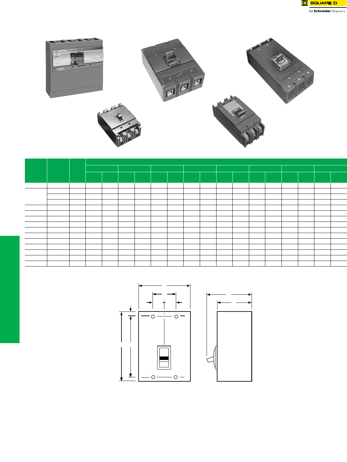
Pictorial and Dimensions
Class 600
Table 11.3: Circuit Breaker Dimensions
Circuit
Breaker
Type
Cat. No.
Prefix
Number
Poles
Dimensions
A B C D E F G H
in. mm in. mm in. mm in. mm in. mm in. m
min. mm in. mm
QB 991 13.75951.00252.50633.0678————————
ML
992 1 6.00 152 1.00 25 3.09 78 3.91 99 .88 22 4.25 108 — — .33 8
992 2 6.00 152 2.00 51 3.09 78 3.91 99 .88 22 4.25 108 — — .19 5
992 3 6.00 152 3.00 76 3.09 78 3.91 99 .88 22 4.25 108 — — 1.83 46
ML-1 999 2 & 3 6.50 165 4.47 113 3.06 78 3.94 100 .94 24 4.25 108 1.50 38 .75 19
ML-2 994 2 & 3 9.56 243 4.47 113 3.75 95 4.88 124 1.69 43 6.50 165 1.50 38 .75 19
ML-3 997 2 & 3 10.38 264 5.97 152 3.88 98 5.31 135 1.69 43 6.63 168 2.00 51 1.00 25
LA (W) LA 2 & 3 10.75 273 8.25 209 4.31 109 5.50 140 .63 16 9.50 241 2.75 70 1.38 35
MA (W) MA 2 & 3 16.00 406 8.25 209 4.06 103 6.06 154 .88 22 14.25 362 2.75 70 1.38 35
KL 967 2 & 3 22.00 559 8.25 209 5.50 140 7.00 178 .63 16 20.75 527 2.75 70 1.38 35
LM 940 2 & 3 22.00 559 8.25 209 5.50 140 7.00 178 .63 16 20.75 527 2.75 70 1.38 35
FIL (4) IFL 2 & 3 8.29 210 4.46 113 3.67 93 4.70 119 .44 11 7.41 188 1.50 38 .75 19
KIL (4) IKL 2 & 3 11.00 279 6.00 152 4.02 102 5.51 140 .88 22 9.25 235 2.00 51 1.00 25
LIL ILL 2 & 3 11.00 279 12.00 305 4.05 103 6.11 155 .88 22 9.25 235 4.00 102 2.00 51
NHL NHL 2 & 3 20.00 508 12.00 305 5.75 146 8.12 206 5.87 149 7.76 197 4.00 102 2.00 51
LIL
ML-1
LA (W) MA (W)
ML-2
G
AF
E
D
C
HH
B
www.schneider-electric.us
11 OBSOLETE CIRCUIT BREAKERS
© 2012 Schneider Electric
All Rights Reserved 11-5
Obsolescent and
Obsolete Types
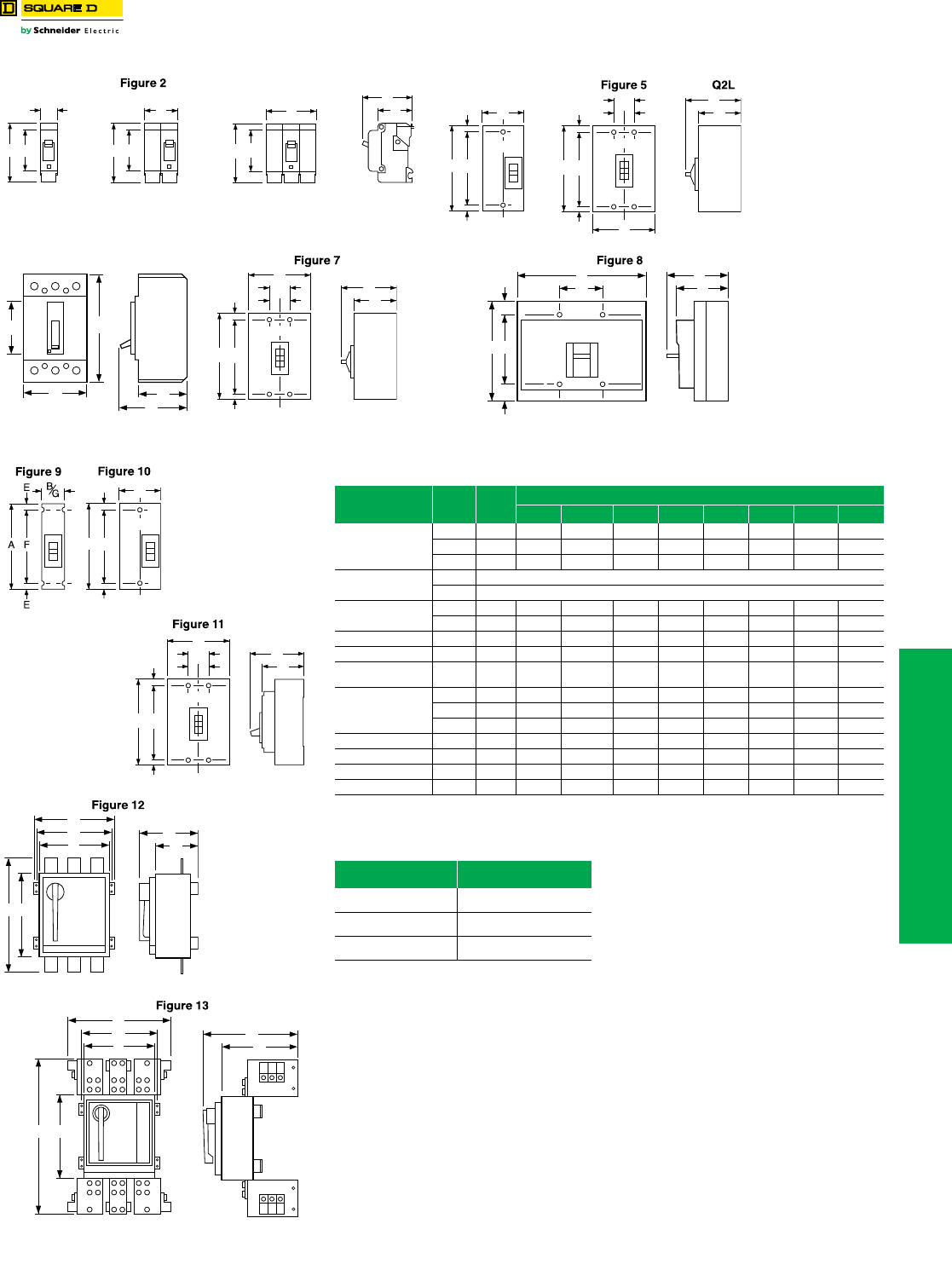
Pictorial and Dimensions
Class 600
a70–100 A is 4.00 in.
bDimensions E are 1.59 in at ON end and 0.63 in at OFF end.
cFCL 2-pole circuit breaker dimension B is 4.50 as in Fig. 23.
Figure 1
A
BE BE
A
Figure 3
BE
A
EH, EHB
D
C
C/L
Figure 4
B
E
E
FA
C/L
B
D
C
G
HH
E
E
FA
B
G
E
E
FA
D
C
Figure 6
A
D
C
EB
C/L
B
D
C
G
HH
E
E
FA
Table 11.4: Circuit Breaker Dimensions
Circuit Breaker
Cat. No. Prefix
No.
Poles
Fig.
No.
Dimensions—In.
A B C D E F G H
EH, EHB
1 1 1.00 3.50 2.00 2.97 2.44 — — —
2 2 2.00 3.50a2.00 2.97 2.44 — — —
3 3 3.00 3.50a2.00 2.97 2.44 — — —
FDA, FGA, FJA 1 Width 1.50
2, 3 Width 3.00
Q2L, Q2L-H 2 4 6.44 3.00 3.16 3.92 b4.25 — —
3 5 6.44 4.50 3.16 3.92 b4.25 1.50 0.75
KD, KG 2, 3 6 4.12 7.35 3.20 4.17 3.34 — — —
MXL, MEL 2 & 3 7 14.75 9.00 4.37 6.50 1.66 11.43 3.00 1.50
NAL, NCL,
NEL, NXL 2 & 3 8 12.12 14.98 6.40 8.07 1.69 8.75 5.00 —
FCL
1 9 6.00 1.50 3.16 4.13 0.44 5.13 1.50 —
2106.003.00c3.16 4.13 0.44 5.13 — —
3 11 6.00 4.50 3.16 4.13 0.44 5.13 1.50 0.75
MAL, MHL 2 & 3 8 14.00 9.00 4.53 6.50 1.66 10.69 3.00 1.50
NA, NC, NX, NE 2 & 3 8 12.12 14.98 6.40 8.07 1.69 8.75 5.0 —
PA, PH, PX, PE 2 & 3 12 20.06 13.70 7.25 10.47 14.00 12.00 12.75 —
PC, PX-25, PE-20-25 2 & 3 13 26.10 23.30 13.33 16.55 14.10 12.00 — —
Table 11.5:
Frame Size Approx. Shipping Weight
(Lbs.)
MAL
MHL 34
PA F
PHF 69
PXF
PEF 80
C/L
B
E
E
FA
C/L
B
D
C
G
HH
E
E
FA
B
G
AE
D
C
F
D
C
G
A
B
F
E
11-6 © 2012 Schneider Electric
All Rights Reserved
www.schneider-electric.us
11 OBSOLETE CIRCUIT BREAKERS
Obsolescent Circuit
Breakers
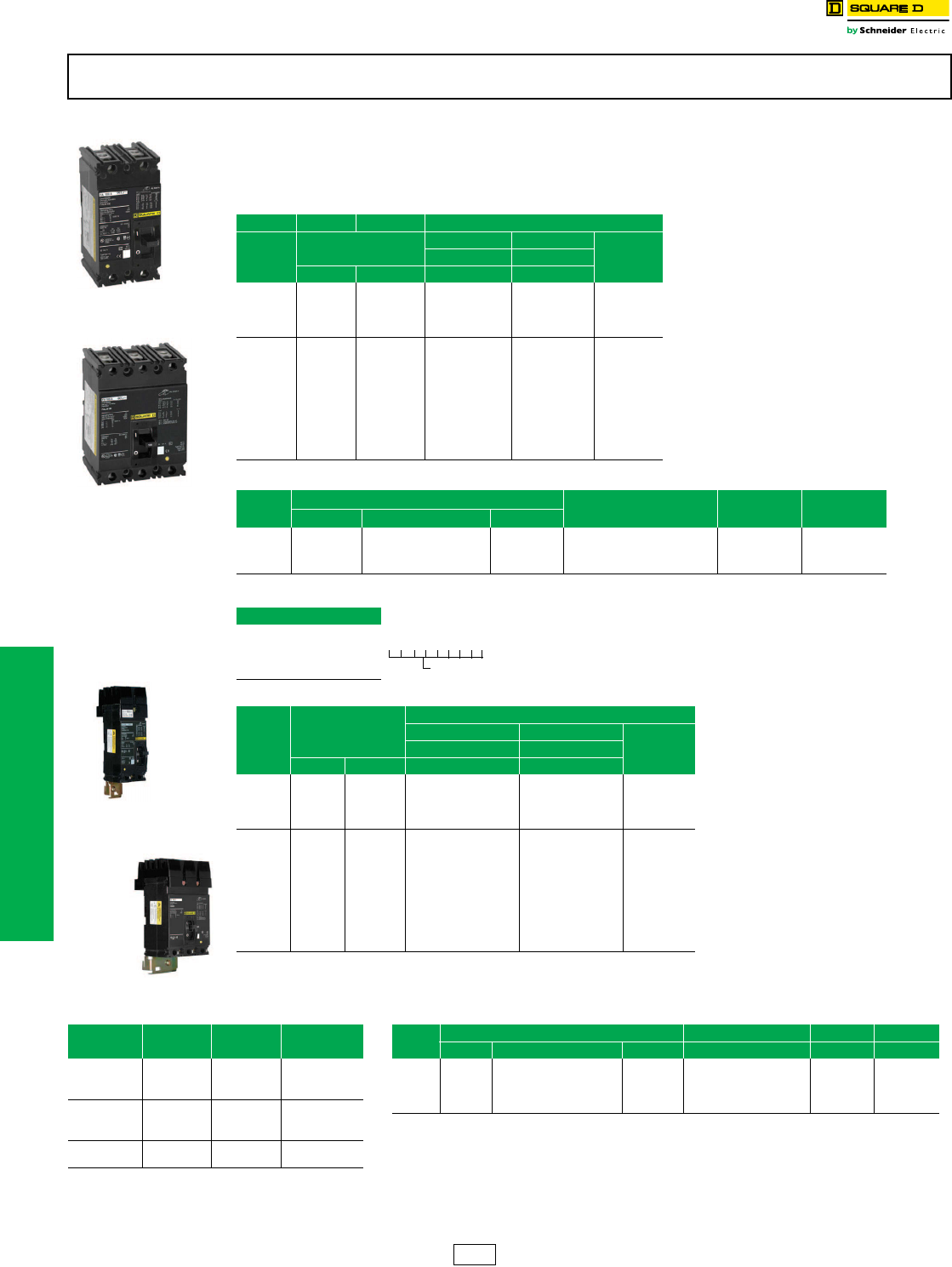
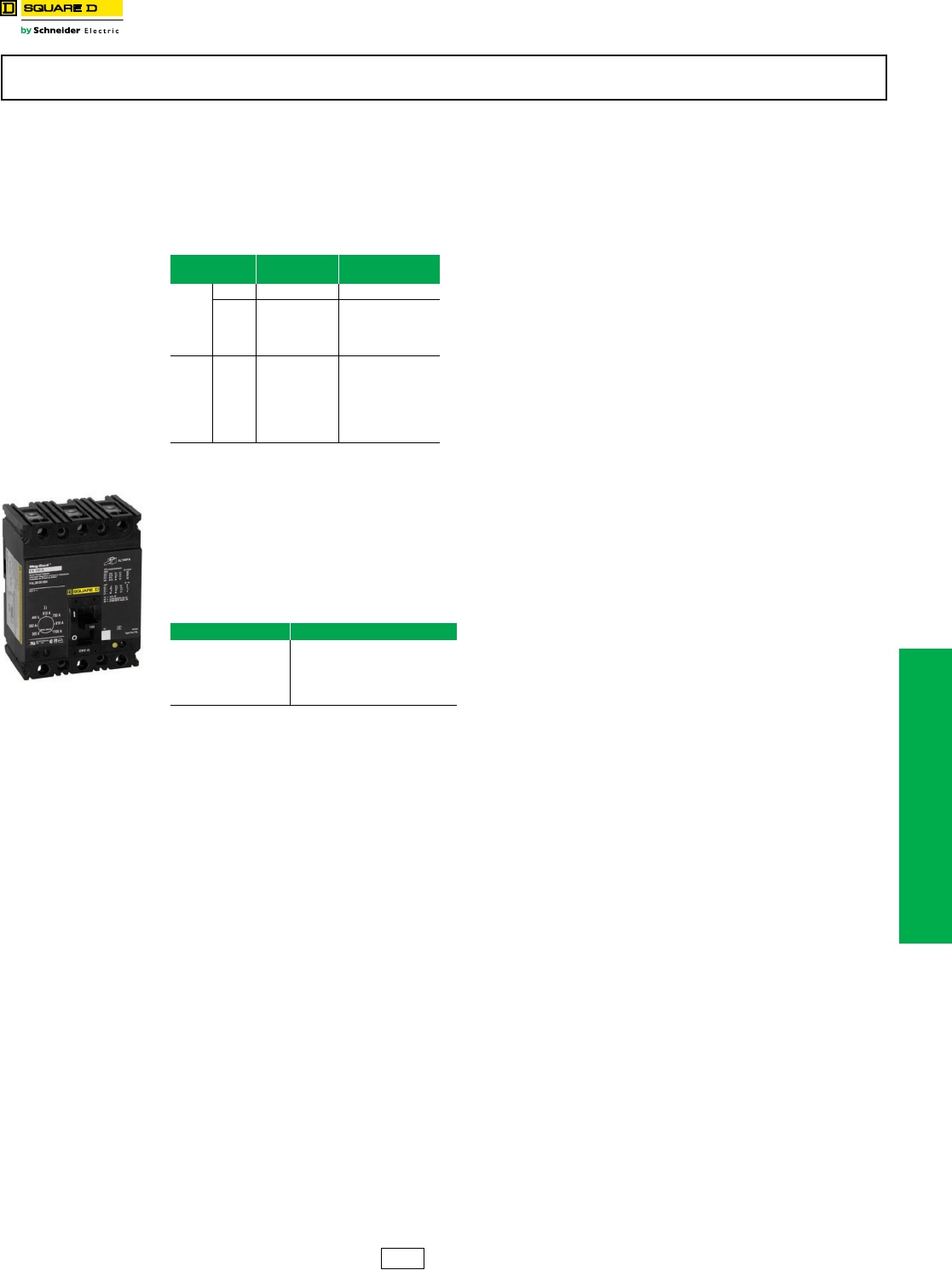
F-Frame Thermal-Magnetic Circuit Breakers
Class 650
Thermal-magnetic molded case circuit breakers shown on page 11-6 are permanent trip UL Listed, CSA® Certified, IEC
rated, and also meet the requirements of Federal Specification W–C–375B/GEN as indicated on Digest pages 7-4
through 7-7.
NOTE: Consider using PowerPact™ circuit breakers for situations requiring circuit breaker accessories. See Digest
Section 7 for more information.
a1P and 2P circuit breaker catalog numbers are completed by adding the required phase connection letters as a suffix. See Phase Option Table.
bFCL 2P circuit breakers are built using 3P module.
cFCL circuit breakers are not rated for 250 Vdc.
Accessories . . . . . . . . . . . . . . . . . . . . . . . . . . . . . . . . . . . . . . . . . Page 11-28
OptionalLugs . . . . . . . . . . . . . . . . . . . . . . . . . . . . . . . . . . . . . . . . . Page 11-23
Dimensions. . . . . . . . . . . . . . . . . . . . . . . . . . . . . . . . . . . . . . . . . . . . Page 11-5
Enclosures: see Digest Section 7
FC circuit breakers are obsolete. Please refer to Digest 176 for PowerPact™ molded case circuit breakers for new installations or
replacement.
Table 11.6: F-Frame—100 A, Thermal-Magnetic, Individually-Mounted, 480 Vac
Extra-High Interrupting
Ampere
Rating
Fixed AC Magnetic
Trip
2P 3P Terminal
Wire Range
(AWG)
480 Vac, 250 Vdc 480 Vac, 250 Vdc
Hold Trip Cat. No. Cat. No.
15 A 275 A 600 A — FCL34015
CU30FA4
(1) 14–10 Cu
20 A 275 A 600 A — FCL34020
25 A 275 A 600 A — FCL34025
30 A 275 A 600 A — FCL34030
35 A 400 A 850 A — FCL34035
AL100FA4
(1) 14–3 Cu
or (2) 12–1 Al
40 A 400 A 850 A — FCL34040
45 A 400 A 850 A — FCL34045
50 A 400 A 850 A FCL24050 FCL34050
60 A 800 A 1450 A FCL24060 FCL34060
70 A 800 A 1450 A FCL24070 FCL34070
80 A 800 A 1450 A FCL24080 FCL34080
90 A 900 A 1700 A FCL24090 FCL34090
100 A 900 A 1700 A FCL24100 FCL34100
Table 11.7: Interrupting Ratings
Volt ag e FAL FHL FCL FIL
240 Vac 480 Vac 600 Vac
240 Vac 10 kA 18 kA (1P), 25 kA (2P, 3P) 25 kA 25 kA (1P) 65 kA (2P, 3P) 100 kA 200 kA
480 Vac — 18 kA 18 kA 25 kA (2P, 3P) 65 kA 200 kA
600 Vac — — 14 kA 18 kA (2P, 3P) — 100 kA
Termination Option
Termination Letter
F = No Lugs
L = Lugs both ends
P with MT Suffix = Lugs ON end
P = Lugs OFF end
Table 11.8: F-Frame—100 A, Thermal-Magnetic, I-Line™ Construction, 480 Vac
Ampere
Rating
Fixed AC Magnetic
Trip
Extra-High Interruptingc
2Pa3P Terminal
Wire Range
(AWG)
480 Vac, 250 Vdcb480 Vac, 250 Vdcc
Hold Trip Cat. No. Cat. No.
15 A 275 A 600 A — FC34015
CU30FA4
(1) 14–10 Cu
20 A 275 A 600 A — FC34020
25 A 275 A 600 A — FC34025
30 A 275 A 600 A — FC34030
35 A 400 A 850 A — FC34035
AL100FA4
(1) 14–3 Cu
or (1) 12–1 Al
40 A 400 A 850 A — FC34040
45 A 400 A 850 A — FC34045
50 A 400 A 850 A FC24050( ) FC34050
60 A 800 A 1450 A FC24060( ) FC34060
70 A 800 A 1450 A FC24070( ) FC34070
80 A 800 A 1450 A FC24080( ) FC34080
90 A 900 A 1700 A FC24090( ) FC34090
100 A 900 A 1700 A FC24100( ) FC34100
FAL/FHL 2P
15–100 A
FAL/FHL 3P
15–100 A
FA 2P
3 in. (76 mm)
Mounting Height
FA 3P
4.5 in. (114 mm)
Mounting Height
F A L 3 6 1 0 0
For factory-installed termination, place
termination letter in the third block of the
circuit breaker catalog number.
Termination Letter
Table 11.9: Phase Options Table 11.10: Interrupting Ratings
Phase Option
Letter 1P 2P 3P Voltage FA FH FC FI
240 Vac 480 Vac 600 Vac
A
B
C
FA14035A
FA14035B
FA14035C
240 Vac 10 kA 18 kA (1P), 25 kA (2P, 3P) 25 kA 25 kA (1P) 65 kA (2P, 3P) 100 kA 200 kA
277 Vac — 18 kA — — 65 kA —
480 Vac — 18 kA 18 kA 25 kA (2P, 3P) 65 kA 200 kA
AB
AC
BC
FA24030AB
FA24030AC
FA24030BC
600 Vac — — 14 kA 18 kA (2P, 3P) — 100 kA
ABC
CBA
FA34030
FA34030CBA
DE2 Discount
Schedule
www.schneider-electric.us
11 OBSOLETE CIRCUIT BREAKERS
© 2012 Schneider Electric
All Rights Reserved 11-7
Obsolescent Circuit
Breakers
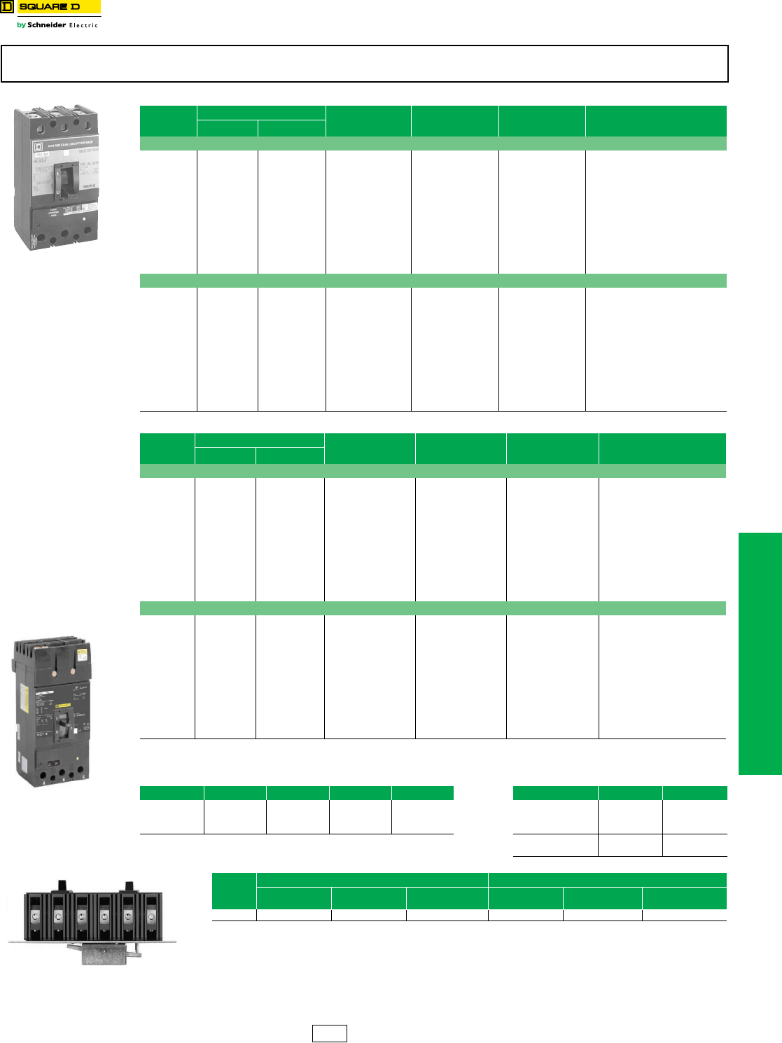
K-Frame Thermal-Magnetic Circuit Breakers
Class 655, 825, 660
aUL magnetic trip setting tolerances are ±25% for low and ±20% for high from nominal value shown.
bKC circuit breakers are 480 Vac
c2P and 3P circuit breaker catalog numbers are completed by adding the required phase connection letters as a suffix. See Phase Option Table.
Accessories . . . . . . . . . . . . . . . . . . . . . . . . . . . . . . . . . . . . . . . . . Page 11-28
OptionalLugs . . . . . . . . . . . . . . . . . . . . . . . . . . . . . . . . . . . . . . . . . Page 11-23
Dimensions . . . . . . . . . . . . . . . . . . . . . . . . . . . . . . . . . . . . . . . . . . . Page 11-5
Enclosures: see Digest Section 7
K-frame circuit breakers are obsolete. Please refer to Digest 176 for PowerPact™ molded case circuit breakers for new installations or
replacement.
Table 11.11: K-Frame—250 A, Thermal-Magnetic, Individually-Mounted, 600 Vac
Ampere
Rating
Adjustable AC Magnetic TripaStandard
Interrupting
Cat. No.
High
Interrupting
Cat. No.
Extra-High
Interruptingb
Cat. No.
Terminal
Wire Range
Low High
2P, 600 Vac, 250 Vdc
70 350 A 700 A KAL26070 KHL26070 —
AL250KA
(1) 4 AWG–350 kcmil Al
80 400 A 800 A KAL26080 KHL26080 —
90 450 A 900 A KAL26090 KHL26090 —
100 500 A 1000 A KAL26100 KHL26100 —
110 550 A 1100 A KAL26110 KHL26110 KCL24110
125 625 A 1250 A KAL26125 KHL26125 KCL24125
150 750 A 1500 A KAL26150 KHL26150 KCL24150
175 875 A 1750 A KAL26175 KHL26175 KCL24175
200 1000 A 2000 A KAL26200 KHL26200 KCL24200
225 1125 A 2250 A KAL26225 KHL26225 KCL24225
250 1250 A 2500 A KAL26250 KHL26250 KCL24250
3P, 600 Vac, 250 Vdc
70 350 A 700 A KAL36070 KHL36070 —
AL250KA
(1) 4 AWG–350 kcmil Al
80 400 A 800 A KAL36080 KHL36080 —
90 450 A 900 A KAL36090 KHL36090 —
100 500 A 1000 A KAL36100 KHL36100 —
110 550 A 1100 A KAL36110 KHL36110 KCL34110
125 625 A 1250 A KAL36125 KHL36125 KCL34125
150 750 A 1500 A KAL36150 KHL36150 KCL34150
175 875 A 1750 A KAL36175 KHL36175 KCL34175
200 1000 A 2000 A KAL36200 KHL36200 KCL34200
225 1125 A 2250 A KAL36225 KHL36225 KCL34225
250 1250 A 2500 A KAL36250 KHL36250 KCL34250
Table 11.12: K-Frame—250A, Thermal-Magnetic, I-Line™ Construction, 600 Vac
Ampere
Rating
Adjustable AC Magnetic TripaStandard
Interrupting
Cat. No.
High
Interrupting
Cat. No.
Extra-High
Interruptingb
Cat. No.
Terminal
Wire Range
Low High
2P, 600 Vac, 250 Vdcc
70 350 A 700 A KA26070( ) KH26070( ) —
AL250KA
(1) 4 AWG–350 kcmil Al
80 400 A 800 A KA26080( ) KH26080( ) —
90 450 A 900 A KA26090( ) KH26090( ) —
100 500 A 1000 A KA26100( ) KH26100( ) —
110 550 A 1100 A KA26110( ) KH26110( ) KC24110( )
125 625 A 1250 A KA26125( ) KH26125( ) KC24125( )
150 750 A 1500 A KA26150( ) KH26150( ) KC24150( )
175 875 A 1750 A KA26175( ) KH26175( ) KC24175( )
200 1000 A 2000 A KA26200( ) KH26200( ) KC24200( )
225 1125 A 2250 A KA26225( ) KH26225( ) KC24225( )
250 1250 A 2500 A KA26250( ) KH26250( ) KC24250( )
3P, 600 Vac, 250 Vdc
70 350 A 700 A KA36070 KH36070 —
AL250KA
(1) 4 AWG–350 kcmil Al
80 400 A 800 A KA36080 KH36080 —
90 450 A 900 A KA36090 KH36090 —
100 500 A 1000 A KA36100 KH36100 —
110 550 A 1100 A KA36110 KH36110 KC34110
125 625 A 1250 A KA36125 KH36125 KC34125
150 750 A 1500 A KA36150 KH36150 KH34150
175 875 A 1750 A KA36175 KH36175 KC34175
200 1000 A 2000 A KA36200 KH36200 KC34200
225 1125 A 2250 A KA36225 KH36225 KC34225
250 1250 A 2500 A KA36250 KH36250 KC34250
Table 11.13: Interrupting Ratings Table 11.14: Phase Options
Vol tage KA, KAL KH, KHL KC, KCL KI, KIL Phase Option Letter 2P 3P
240 Vac 42 kA 65 kA 100 kA 200 kA AB
AC
BC
KA26250AB
KA26250AC
KA26250BC
480 Vac 25 kA 35 kA 65 kA 200 kA
600 Vac 22 kA 25 kA — 100 kA
ABC
CBA
KA36250
KA36250CBA
KA/KH/KC 2P and 3P
4.5 in. (114 mm)
Mounting Height
Table 11.15: Walking Beam Mechanical Interlock Componentse
Circuit
Breaker
Prefix
Manually Operated Electrically Operated
Operator
Suffix
Walking Beam
Ass'y. Cat. No.
Mounting Pan Cat.
No.
Operator
Suffix
Walking Beam
Ass'y. Cat. No. Mounting Pan Cat. No.
KAL WB KA4WB KAWBP4 WBMO KA9WB KAWBP9
dWalking Beam Mechanical Interlock requires 2 circuit breakers with WB suffix, 1 walking beam assembly and 1 mounting pan.
eFully enclosed interlocked units are available in Type 1 and Type 3R enclosures, with two neutrals provided in each enclosure. The
completely enclosed assembly is not UL Listed. Consult your nearest Schneider Electric local sales office for more information.
DE2 Discount
Schedule
11-8 © 2012 Schneider Electric
All Rights Reserved
www.schneider-electric.us
11 OBSOLETE CIRCUIT BREAKERS
Obsolescent Circuit
Breakers
Automatic Molded-Case Switches
Class 680, 685
Automatic Molded Case Switches
Automatic molded case switches open instantaneously at a factory preset magnetic trip point, calibrated to protect only
the molded case switch itself, when it is subjected to high fault currents. The trip point is nonadjustable and provides no
overload or low level fault protection.
Molded case switches open when the handle is switched to the OFF position or in response to an auxiliary tripping
device such as a shunt trip.
Automatic switches will accept the same lugs and accessories as equivalent thermal-magnetic circuit breakers.
Automatic molded case switches are UL Listed per UL 489 and are CSA® Certified.
aUL magnetic trip tolerances are -20% / +30% from the nominal values shown.
bFHL and KHL automatic switches will not accept cylinder lock attachments.
cThe withstand rating is the fault current at rated voltage that the molded case switch will withstand without damage when protected by a circuit breaker
with an equal continuous current rating.
dThe short circuit current rating is the fault current, at rated voltage, that the molded case switch will withstand without damage when protected by a circuit
breaker with an equal continuous current rating.
Accessories . . . . . . . . . . . . . . . . . . . . . . . . . . . . . . . . . . . . . . . . . Page 11-28
OptionalLugs . . . . . . . . . . . . . . . . . . . . . . . . . . . . . . . . . . . . . . . . . Page 11-23
Dimensions. . . . . . . . . . . . . . . . . . . . . . . . . . . . . . . . . . . . . . . . . . . . Page 11-5
These automatic molded case switches are in obsolescence. Do not use on new applications. Limited service stock is available for
replacement or fill purposes. Contact your local Sales Office for product availability.
Table 11.16: Automatic Molded Case Switches, 600 Vac
Ampere
Rating
2P 3P Withstand Ratingdc Trip Point (A)aLug Kit
Installed
Cat. No. Availability Cat. No. Availability 240 Vac 480 Vac 600 Vac 250 Vdc AC DC
100 FHL26000MbFHL36000Mb65k 25k 18k 10k 1500 1725 AL100FA
150 — FHL3600015Mb65k 25k 18k — 2500 — AL150FA
400 LHL26000M LHL36000M 65k 35k 25k 10k 8000 9600 AL400LA
250 KHL26000MbNot Available KHL36000MbNot Available 65k 35k 25k 10k 4500 5175 AL250KA
600 MHL260006M Not Available MHL360006M 65k 65k 25k 10k 9000 9900 AL900MA
800 MHL260008M Not Available MHL360008M 65k 65k 25k 10k 9000 9900 AL900MA
DE2 Discount
Schedule
www.schneider-electric.us
11 OBSOLETE CIRCUIT BREAKERS
© 2012 Schneider Electric
All Rights Reserved 11-9
Obsolescent Circuit
Breakers
Mag-Gard™ Motor Circuit Protector
Class 680, 685
Mag-Gard™ Motor Circuit Protector
Instantaneous trip magnetic only circuit breakers have a single adjustment which simultaneously sets the magnetic trip
level of each individual pole. Mag-Gard circuit breakers comply with NEC® requirements for providing motor circuit
protection when installed as part of a UL Listed combination controller having motor overload protection. Interrupting
ratings are established for these UL Recognized Components only when they are used in combination with motor
starters with properly sized overload relays and contactors.
Mag-Gard circuit breakers will accept the same lugs and accessories as equivalent thermal-magnetic circuit breakers.
Mag-Gard circuit breakers are available with I-Line construction. H-construction Mag-Gard circuit breakers are also available.
aUL magnetic trip setting tolerances are -20%/+30% from the nominal values shown.
Adjustable instantaneous-trip circuit breakers are intended for use in combination with motor starters with overload
relays for the protection of motor circuits from short circuits. Other specific applications include rectifiers and resistance
welders. These circuit breakers contain a magnetic trip element in each pole with the trip point adjustable from the
front. Interrupting ratings are determined by testing the instantaneous-trip circuit breakers in combination with a
contactor and overload relay.
Select instantaneous-trip circuit breakers as follows:
1. Use selection table for motors, other than NEMA Design E, with locked-rotor indicating code letters per NEC® Table 430.7 (b) as
follows:
For other motors order a special thermal-magnetic circuit breaker with magnetic trip settings for the specific motor— specify motor
horsepower, voltage, frequency, full-load current and code letter or locked rotor current.
2. Determine motor hp rating from the motor nameplate.
3. Refer to the table at right and select an instantaneous-trip circuit breaker with an Ampere rating recommended for the hp and
voltage involved.
4. Select an adjustable trip setting of at least 800%, not to exceed 1300%, of the motor full-load Amperes. (FLA) for other than Design
E motors. For Design E motors, select an adjustable trip setting of at least 1100% not to exceed 1700% of FLA.
5. The NEC 1300% maximum setting may be inadequate for instantaneous-trip circuit breakers to withstand current surges typical of
the magnetization current of autotransformer type reduced voltage starters, or open transition wye-delta starters during transfer
from “start” to “run,” constant hp multi-speed motors, and motors labeled “high efficiency.” Select thermal-magnetic circuit breakers
from Digest page 7-32 for those applications.
6. Part-winding motors, per NEC® 430.3, should have two circuit breakers selected from the above at not more than one half the
allowable trip setting for the horsepower rating. The two circuit breakers should operate simultaneously as a disconnecting means
per NEC 430.103.
Accessories . . . . . . . . . . . . . . . . . . . . . . . . . . . . . . . . . . . . . . . . . Page 11-28
OptionalLugs . . . . . . . . . . . . . . . . . . . . . . . . . . . . . . . . . . . . . . . . . Page 11-23
Dimensions . . . . . . . . . . . . . . . . . . . . . . . . . . . . . . . . . . . . . . . . . . . Page 11-5
These Mag-Gard™ motor circuit protectors are obsolete. Please refer to Digest 176 for PowerPact™ molded case circuit breakers for
new installations or replacement.
Table 11.17: Magnetic Only 3–1200 A 600 Vac, 50/60 Hz
Ampere
Rating
Adjustablea
Trip Range
Cat. No.
3P only
KAL
150 A 750–1500 A KAL3615026M
250 A
400–800 A
750–1500 A
1000–2000 A
1125–2250 A
1250–2500 A
KAL3625021M
KAL3625026M
KAL3625030M
KAL3625031M
KAL3625032M
FAL
3 A
7 A
15 A
30 A
30 A
50 A
100 A
100 A
8–28 A
18–70 A
50–180 A
50–180 A
150–580 A
150–580 A
300–1100 A
FAL3600311M
FAL3600712M
FAL3601513M
FAL3603013M
FAL3603015M
FAL3605016M
FAL3610016M
FAL3610018M
Horsepower Motor Code Letters
1/2 or less A–L
3/4 to 1-1/2 A–K
2 to 3 A–J
5 to 25 A–H
30 to 125 A–G
150 or more A–F
DE2 Discount
Schedule
11-10 © 2012 Schneider Electric
All Rights Reserved
www.schneider-electric.us
11 OBSOLETE CIRCUIT BREAKERS
Obsolescent Circuit
Breakers
Mag-Gard™ Motor Circuit Protector
Class 680, 685
aMotor full-load currents are taken from NEC Table 430.150. Select wire and circuit breakers on basis of horsepower rather than nameplate full-load
current per NEC 430.6 (A) for general motor applications. Do not use these values to select overload relay thermal units. See Digest Section 15 for
selection of thermal units when actual full load current is not known. The voltages listed are rated motor voltages. Corresponding nominal system
voltages are 200 to 208, 220 to 240, 440 to 480 and 550 to 600 volts.
bOnly MIN and MAX settings are shown, intermediate settings are available on all circuit breakers.
Accessories . . . . . . . . . . . . . . . . . . . . . . . . . . . . . . . . . . . . . . . . . Page 11-28
OptionalLugs . . . . . . . . . . . . . . . . . . . . . . . . . . . . . . . . . . . . . . . . . Page 11-23
Dimensions. . . . . . . . . . . . . . . . . . . . . . . . . . . . . . . . . . . . . . . . . . . . Page 11-5
Table 11.18: Adjustable Instantaneous-Trip Circuit Breakers for Single Motor Circuit Protection
Hp Ratings of Induction Type
Squirrel-Cage and Wound Rotor Motors Full Load
Amperesa
Mag-Gard
Circuit Breaker
Cat. No.
Magnetic Trip
Settings b
3Ø 60 Hz ac
200 V 230 V 460 V 575 V MIN MAX
1/2 0.8 FAL3600311Ma1000% 3500%
1/2 1 FAL3600311Ma800% 2800%
3/4 1.1 FAL3600311M 700% 2500%
3/4 1 1.4 FAL3600311M 600% 2000%
1 1.8 FAL3600311M 400% 1600%
1/2 2 FAL3600311M 400% 1400%
1-1/2 2.1 FAL3600311M 400% 1300%
1/2 2.3 FAL3600311M 300% 1200%
1-1/2 2.6 FAL3600712M 700% 2700%
2 2.7 FAL3600712M 700% 2600%
3/4 2.8 FAL3600712M 600% 2500%
3/4 3.2 FAL3600712M 600% 2200%
2 3.4 FAL3600712M 500% 2100%
1 3.6 FAL3600712M 500% 1900%
3 3.9 FAL3600712M 500% 1800%
1 4.1 FAL3600712M 400% 1700%
3 4.8 FAL3600712M 400% 1500%
1-1/2 5.2 FAL3600712M 300% 1300%
1-1/2 6 FAL3600712M 300% 1200%
5 6.1 FAL3600712M 300% 1100%
2 6.8 FAL3601513M 700% 2600%
5 7.6 FAL3601513M 700% 2400%
2 7.8 FAL3601513M 600% 2300%
7-1/2 9 FAL3601513M 600% 2000%
3 9.6 FAL3601513M 500% 1900%
3 7-1/2 10 11 FAL3601513M 500% 1600%
10 14 FAL3603015M 700% 2500%
5 15.2 FAL3603015M 700% 2300%
15 17 FAL3603015M 600% 2100%
5 17.5 FAL3603015M 600% 2000%
15 21 FAL3603015M 500% 1700%
7-1/2 20 22 FAL3605016M 700% 2600%
7-1/2 25.3 FAL3605016M 600% 2300%
20 25 27 FAL3605016M 600% 2100%
10 28 FAL3605016M 500% 2100%
30 32 FAL3605016M 500% 1800%
10 32.2 FAL3605016M 500% 1800%
25 34 FAL3605016M 400% 1700%
30 40 FAL3605016M 400% 1500%
40 41 FAL3610018M 700% 2700%
15 42 FAL3610018M 700% 2600%
15 48.3 FAL3610018M 600% 2300%
40 50 52 FAL3610018M 600% 2100%
20 54 FAL3610018M 600% 2000%
20 60 62 FAL3610018M 500% 1800%
50 65 FAL3610018M 500% 1700%
25 68 FAL3610018M 400% 1600%
30 92 KAL3625025M 700% 1400%
40 104 KAL3625026M 700% 1400%
150 144 KAL3625030M 700% 1400%
50 150 KAL3625030M 700% 1300%
60 154 KAL3625031M 700% 1500%
125 156 KAL3625031M 700% 1400%
60 177.1 KAL3625032M 700% 1400%
150 180 KAL3625032M 700% 1400%
75 200 192 KAL3625032M 700% 1300%
DE2 Discount
Schedule
www.schneider-electric.us
11 OBSOLETE CIRCUIT BREAKERS
© 2012 Schneider Electric
All Rights Reserved 11-11
Obsolescent Circuit
Breakers
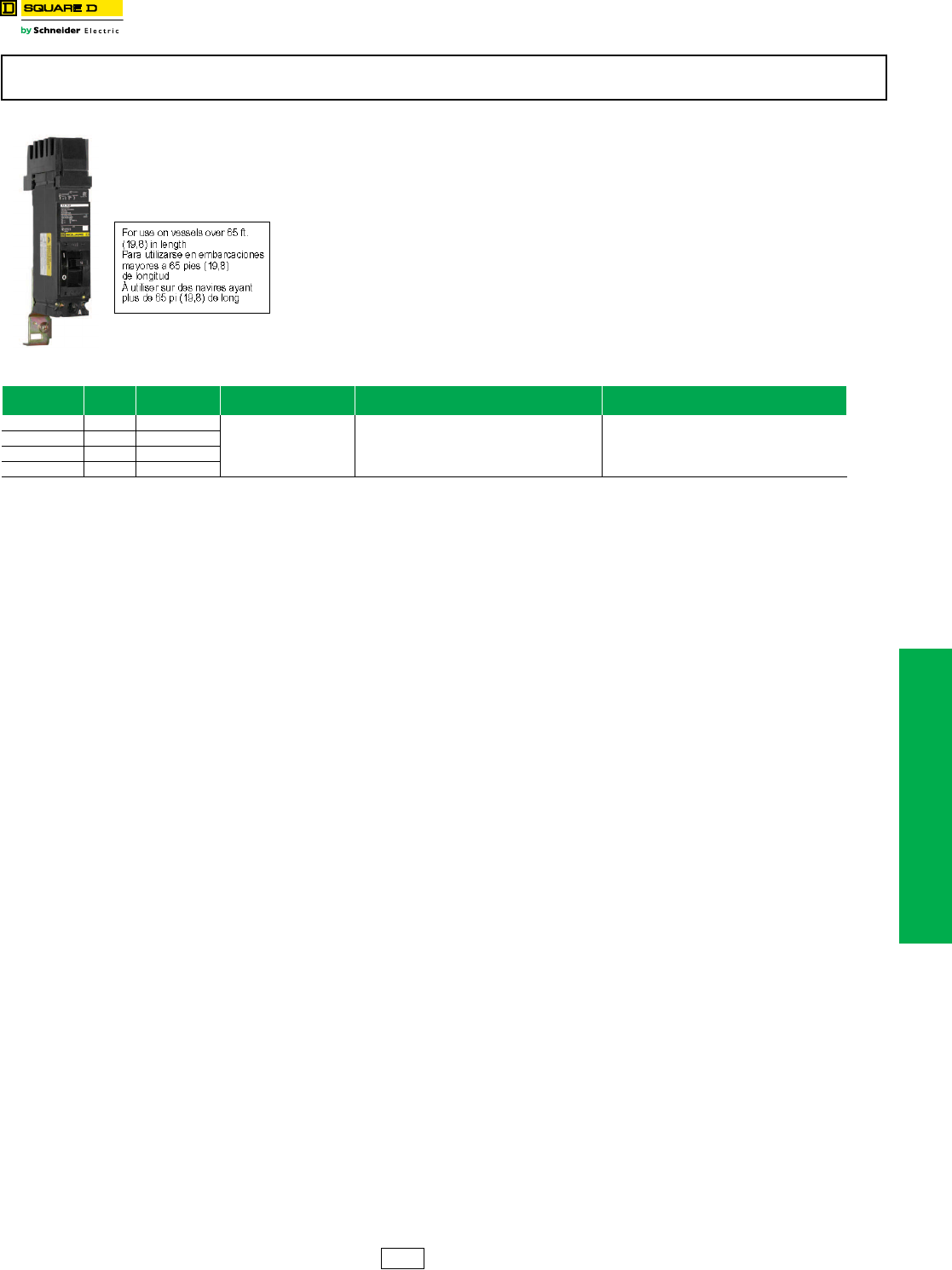
UL Listed Marine Circuit Breakers
Class 600
A standard for molded case circuit breakers which are intended to be installed and used
aboard a boat or vessel is included in Supplement SA to UL 489, “Standard for Molded
Case Circuit Breakers and Circuit Breaker Enclosures’’ (also referred to as UL product
category DKTY). This UL Standard was established in accordance with U.S. Coast Guard
regulations, applicable American Boat and Yacht Council Inc. publications, and NFPA® 302
“Standard for Motor Craft (Pleasure and Commercial)’’. In order to be UL Listed for marine
use, circuit breakers must not use aluminum or aluminum alloys for terminal connections
and must be calibrated at an ambient temperature of 40 oC. Standard circuit breakers
should not be specified or used in place of marine circuit breakers.
The following table lists those circuit breakers which are UL Marine Listed for use on
vessels over 65 ft. (19.8 m) in length. (PowerPact H and J-frame circuit breakers can also
be used in vessels under 65 ft. [19.8 m] in length.)
These marine circuit breakers are obsolete. Please refer to Digest 176 for PowerPact™ molded case circuit breakers for new
installations or replacement.
Table 11.19: CIrcuit Breakers for Marine Applications
Cat. No. Prefix Poles Ampere
Rating Application Cat. No. $ Price
FC, FCL 2, 3 15–100 A
For use only on vessels over
65 feet (19.8 m) in length.
Add the number “9’’ after the catalog number prefix
of the standard circuit breaker catalog number.
Example:
Standard FAL36100
Marine FAL936100
There is a 20% adder to the price of the equivalent
standard circuit breaker.
All marine circuit breakers are supplied
with copper lugs.
KA, KAL 2, 3 70–250 A
KH, KHL 2, 3 70–250 A
KC, KCL 2, 3 110–250 A
DE2 Discount
Schedule
11-12 © 2012 Schneider Electric
All Rights Reserved
www.schneider-electric.us
11 OBSOLETE CIRCUIT BREAKERS
Obsolescent Circuit
Breakers
Circuit Breakers for NQO, NQOB and NQOD Panelboards, Branch
Circuit Breakers and Mounting Assemblies for ML Panelboards
Replacing Obsolescent Q1 and Q1B Circuit Breakers In NQO, NQOB and NQOD Panelboards
Q1 and Q1B circuit breakers have been replaced by QO and QOB circuit breakers.
Table 1 below is used for replacing 1P, 2P or 3P Q1 and Q1B circuit breakers with QO and QOB branch circuit
breakers in NQO, NQOB and NQOD panelboards.
Table 2 below is used for replacing Q1 and Q1B main circuit breakers in NQO and NQOB panelboards.
aMounting assembly SK5669 is used to mount both Q1 and QO circuit breakers. Not required for replacement purposes.
b225 A maximum. For 400–600 ampere circuit breaker mounting assembly, see Class 1630 Service Bulletin.
cDiscount Schedule PE1A.
Branch Circuit Breakers and Mounting Assemblies for ML Panelboards
Replacement circuit breakers for ML panelboards are determined by the manufacture date of the panel and the panel
depth. (See chart below)
The tables below are used for replacing or adding circuit breakers to 10-5/8 inch deep ML panelboards manufactured
from 1962–1968 and for switchboards manufactured from 1962–1968.
dMounting assemblies for twin-mounted circuit breakers will only accept the same family and configuration of circuit breakers, i.e., FAL and FAL.
NQO, NQOB, and NQOD circuit breakers and panelboards are obsolete. Do not use on new applications. Limited service stock is
available for replacement or fill purposes. Contact your local Sales Office for product availability.
2P QO
2P QOB
2P Q1
Table 11.20: Replacing Q1 and Q1B Circuit Breakers with QO and QOB Branch Circuit Breakers
Panelboard
Type
Branch Circuit Breaker Mounting Assembly
Requiredc
Obsolete Available
NQOB Q1B QOB SK5668
NQOD QO SKNQOD225b
NQOD QOB SKNQOD225b
Table 11.21: Replacing Q1 and Q1B Main Circuit Breakers in NQO and NQOB Panelboards
Panelboard
Type
Main Circuit Breaker Mounting Assembly
Requiredc
Retaining Kit
Required
Obsolete Available
NQOB Q1B QOB SK5668 —
Table 11.22: Replacement Circuit Breakers in ML Panelboards
Manufacture Date Panel Depth Availability of Replacement Circuit Breakers
in. mm
1948–1956 8.63 219 No Replacements Available
1958–1961 10.00 254 No Replacements Available
1962–1968 10.63 270 Refer to Tables Below
Table 11.23: Replacement of Existing Circuit Breakers
Existing
Circuit
Breaker
Ampere
Rating
Mounting Height Cat. No.
Prefix
Replacement
Circuit
Breaker
Mounting
Assembly
Required
Poles
Required
Single or Twin
(Mounting
Assembly)
Availability
in. mm
ML-1 15–100 A 4.50 114 989 or 999 FAL SK4515d3P Twin
ML-3 100–225 A 6.00 152 997 KAL SK4516d3P Twin
LA (W) 225–400 8.25 210 LA LAL SK4517 3P Single
MA (W) 125–1000 A 8.25 210 MA MAL SK4578 3P Single
FAL 15–100 A 4.50 114 FAL FAL No
Mounting
Assembly
Required
3P Twin
Not Available
KAL 70–250 A 4.50 114 KAL KAL 3P Twin
LAL 125–400 A 6.00 152 LAL LAL 3P Single
MAL 300–1000 A 9.00 229 MAL MAL 3P Single
MAL 125–250 A 9.00 229 MAL LAL SK4517 3P Single
Table 11.24: Adding New Circuit Breakers
Cat. No.
Prefix Ampere Rating Mounting Assembly
Required
Mounting Height Poles
Required
Single or Twin
(Mounting Assembly)
in. mm
FAL 15–100 A SK4515 4.50 114 3P Twin
KAL 70–250 A SK4516 4.50 114 3P Twin
LAL 125–400 A SK4517 6.00 152 3P Single
MAL 300–1000 A SK4578 9.00 229 3P Single
DE5A PE1A Discount
Schedule
www.schneider-electric.us
11 OBSOLETE CIRCUIT BREAKERS
© 2012 Schneider Electric
All Rights Reserved 11-13
Obsolescent Circuit
Breakers
Rating Plugs For Obsolete Electronic Trip Circuit Breakers
Class 666, 671, 677
Replacement rating plugs for circuit breakers
manufactured before Micrologic™.
eContact your nearest local sales office for availability.
These rating plugs are for electronic circuit breakers which are obsolete. Please refer to Digest 176 for PowerPact™ circuit breakers
for new installations or replacement.
Table 11.25: Replacement Rating Plugs for Pre-
Micrologic Circuit Breakers
Circuit Breakers
Manufactured
Before Micrologic
Frame
Size
Ampere
Rating Cat. No.
ME
225 A
100 A ME2100
110 A ME2110
125 A ME2125
150 A ME2150
175 A ME2175
400 A 250 A ME4250
350 A ME4350
800 A
450 A ME8450
500 A ME8500
700 A ME8700
PE-G/PEC-G
Built before
June 1, 1982
and all PE/PEC
1200 A
600 A PE120600
700 A PE120700
800 A PE120800
900 A PE120900
1200 A PE121200
1600 A
1000 A PE161000
1200 A PE161200
1400 A PE161400
2000 A
1000 A PE161000
1200 A PE161200
1400 A PE161400
1800 A PE201800
2000 A PE202000
PE-G/PEC-G
Built after
June 1, 1982
1200 A
600 A PEG120600
700 A PEG120700
800 A PEG120800
1000 A PEG121000
1200 A PEG121200
1600 A
1000 A PEG161000
1200 A PEG161200
1400 A PEG161400
2000 A
1000 A PEG161000
1200 A PEG161200
1400 A PEG161400
1800 A PEG201800
2000 A PEG202000
Table 11.26: Interchangeable Rating Plug Kits for ME,
NE, PE and SE Circuit Breakers with
Full-Function Micrologic Trip System
Manufactured Between December 1989
and September 1992
Old Cat. No. New Cat. No. Multiplier Value
RP040 ARP040 0.400
RP050 ARP050 0.500
RP056 ARP056 0.563
RP058 ARP058 0.583
RP060 ARP060 0.600
RP063 ARP063 0.625
RP067 ARP067 0.667
RP070 ARP070 0.700
RP075 ARP075 0.750
RP080 ARP080 0.800
RP083 ARP083 0.833
RP088 ARP088 0.875
RP090 ARP090 0.900
RP100 ARP100 1.000
ME Micrologic
Circuit Breakers
ME Circuit Breakers
Manufactured
before Micrologic
PE Micrologic
Circuit Breakers
PE Circuit Breakers
Manufactured
before Micrologic
SE Micrologic
Circuit Breakers
Table 11.27: Replacement Rating Plugs for
Micrologic Circuit Breakers
Circuit Breaker Frame Size Ampere Rating Cat. No.e
Micrologic
ME Series 3
225 A
100 A ME2100RP
110 A ME2110RP
150 A ME2150RP
175 A ME2175RP
400 A 250 A ME4250RP
800 A
450 A ME8450RP
500 A ME8500RP
700 A ME8700RP
Micrologic
NE Series 1 1200 A
600 A NE120600RP
630 A NE120630RP
700 A NE120700RP
800 A NE120800RP
900 A NE120900RP
1000 A NE121000RP
Micrologic
PE Series 4
1200 A
600 A PE120600RP
700 A PE120700RP
1000 A PE121000RP
1200 A PE121200RP
1600 A 1000 A PE161000RP
1200 A PE161200RP
2000 A
1000 A PE201000RP
1200 A PE201200RP
1400 A PE201400RP
1600 A PE201600RP
1800 A PE201800RP
Micrologic
SE Series 2
200 A
100 A S9020100RP
125 A S9020125RP
150 A S9020150RP
175 A S9020175RP
200 A S9020200RP
400 A
200 A S9040200RP
250 A S9040250RP
300A S9040300RP
350 A S9040350RP
800 A
450 A S9080450RP
500 A S9080500RP
700 A S9080700RP
1200 A
800 A S9120800RP
1000 A S9121000RP
1200 A S9121200RP
1600 A 1600 A S9161600RP
2000 A 2000 A S9202000RP
DE5A DE2 Discount
Schedule
11-14 © 2012 Schneider Electric
All Rights Reserved
www.schneider-electric.us
11 OBSOLETE CIRCUIT BREAKERS
Obsolescent Circuit
Breakers
EH/EHB Circuit Breakers
Class 590, 652
aUL Listed as SWD (switching duty) rated.
bFor use only in Series 3 or Series E1 panelboards. Contact your nearest local sales office for use in earlier series panelboards
EH/EHB circuit breakers are obsolete. Do not use on new applications. Limited service stock is available for replacement or fill
purposes. Contact your local Sales Office for product availability.
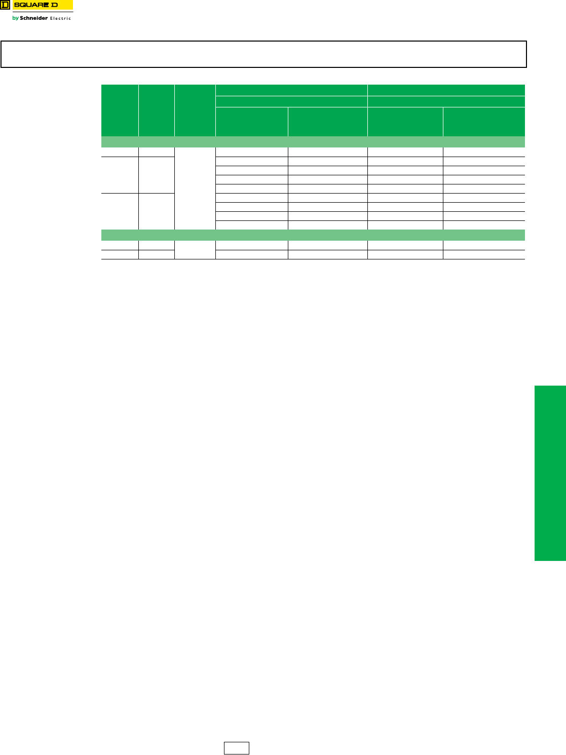
Table 11.28: E Frame—100 A, Thermal Magnetic (480Y/277 Vac)
Amp
Rating
1P
277 Vac—14 kA
120 Vac—65 kA
2P
480Y/277 Vac—14 kA
120/240 Vac—65 kA
3P
480Y/277 Vac—14 kA
240 Vac—65 kA
Wire Size
(AWG) Wire
Temp.
Plug-On Bolt-On Bolt-On Bolt-On
Cat. No. Availability Cat. No. Availability Cat. No. Availability Cat. No. Availability Al Cu
EH/EHB Circuit Breakers
15 A
Not Available Not Available EHB14015 aEHB24015 EHB34015 — (2) 14–10 60/75 oC
— — — — — — EHB340151042 — (2) 14–10 60/75 oC
— — EHB140151082 — — EHB340151082 — (2) 14–10 60/75 oC
20 A
Not Available Not Available EHB14020 aNot Available Not Available EHB34020 — (2) 14–10 60/75 oC
— — — — — — EHB340201042 — (2) 14–10 60/75 oC
— — Not Available Not Available Not Available Not Available EHB340201082 — (2) 14–10 60/75 oC
— — — — Not Available Not Available EHB340201212 — (2) 14–10 60/75 oC
25 A Not Available Not Available Not Available Not Available Not Available Not Available Not Available Not Available 12–8 14–8 60/75 oC
30 A
Not Available Not Available Not Available Not Available Not Available Not Available EHB34030 12–8 14–8 60/75 oC
— — EHB140301082 EHB240301042 EHB340301082 12–8 14–8 60/75 oC
— — — — EHB240301082 EHB340301212 12–8 14–8 60/75 oC
— — — — — — EHB3403035 12–8 14–8 60/75 oC
35 A Not Available Not Available Not Available Not Available Not Available Not Available EHB34035 12–2 14–2 75 oC
40 A
Not Available Not Available Not Available Not Available Not Available Not Available Not Available Not Available 12–2 14–2 75 oC
— — — — — — Not Available Not Available 12–2 14–2 75 oC
— — — — — — EHB340401212 12–2 14–2 75 oC
45 A Not Available Not Available Not Available Not Available Not Available Not Available Not Available Not Available 12–2 14–2 75 oC
50 A
Not Available Not Available Not Available Not Available EHB24050 Not Available Not Available 12–2 14–2 75 oC
— — — — — — EHB340501042 12–2 14–2 75 oC
— — — — — — EHB340501082 12–2 14–2 75 oC
— — — — — — Not Available Not Available 12–2 14–2 75 oC
60 A
Not Available Not Available Not Available Not Available EHB24060 Not Available Not Available 12–2 14–2 75 oC
— — — — — — Not Available Not Available 12–2 14–2 75 oC
— — — — — — Not Available Not Available 12–2 14–2 75 oC
70 A — — — — Not Available Not Available Not Available Not Available 4–2/0 4–2/0 75 oC
80 A — — — — Not Available Not Available Not Available Not Available 4–2/0 4–2/0 75 oC
90 A — — — — Not Available Not Available Not Available Not Available 4–2/0 4–2/0 75 oC
100 A — — — — EHB24100bNot Available Not Available 4–2/0 4–2/0 75 oC
100 A — — — — EHB241001082 Not Available Not Available 4–2/0 4–2/0 75 oC
EH/EHB HID Circuit Breakers — For Use on High Intensity Discharge Lighting Systems
15 A Not Available Not Available Not Available Not Available EHB24015HID Not Available Not Available — (2) 14–10 60/75 oC
20 A Not Available Not Available EHB14020HIDaNot Available Not Available EHB34020HID — (2) 14–10 60/75 oC
25 A Not Available Not Available Not Available Not Available Not Available Not Available Not Available Not Available 12–8 14–8 60/75 oC
30 A Not Available Not Available Not Available Not Available Not Available Not Available EHB34030HID 12–8 14–8 60/75 oC
Requires
1 Space
Requires
1 Space
Requires
2 Spaces
Requires
3 Spaces
DE5A Discount
Schedule

www.schneider-electric.us
11 OBSOLETE CIRCUIT BREAKERS
© 2012 Schneider Electric
All Rights Reserved 11-15
Obsolescent Circuit
Breakers
FJA Thermal-Magnetic Circuit Breakers
FJ 3-pole circuit breakers are obsolete. Please refer to Digest 176 for PowerPact™ molded case circuit breakers for new installations
or replacement.
Table 11.29: Mechanical Lug Kit Information
Circuit Breaker Application Number of Wires
Per Lug and
Wire Range
Kit
Cat. No.
Lugs
Per
Kit
Standard Ampere
Rating Optional Ampere
Rating
Al Lugs for Use with Al or Cu Wire
FJ 35–125 A FJ 15–30 A (1) 12–2/0 AWG Al or
(1) 14–2/0 AWG Cu AL100FD 3
Table 11.30: Handle Accessories
Circuit Breaker Type No. of Poles Cat. No.
Handle Padlock Attachment (locks ON or OFF)
FJ 1, 2 or 3 HPAFD
DE2 Discount
Schedule
www.schneider-electric.us
11 OBSOLETE CIRCUIT BREAKERS
11-16 © 2012 Schneider Electric
All Rights Reserved
Obsolescent Circuit
Breakers
QE Metering Circuit Breakers
QE circuit breakers are obsolete. Please refer to Digest 176 for PowerPact™ molded case circuit breakers for new installations or
replacement.
Table 11.31: Branch Circuit Breakers
Branch Device
System
Type
Branch Circuit Breaker
Ampere
Rating Cat. No. Availability
1Ø IN – 1Ø OUT
or
3Ø IN – 1Ø3W OUT
200 A Max.
70 A QE270VH
80 A QE280VH
90 A QE290VH
100 A QE2100VH
125 A QE2125VH Not Available
150 A QE2150VH
175 A QE2175VH Not Available
200 A QE2200VH Not Available
3Ø IN 3Ø OUT
200 A Max.
70 A QE370VH
80 A QE380VH Not Available
90 A QE390VH Not Available
100 A QE3100VH Not Available
125 A QE3125VH Not Available
150 A QE3150VH Not Available
175 A QE3175VH Not Available
200 A QE3200VH Not Available
Table 11.31: Branch Circuit Breakers
Branch Device
System
Type
Branch Circuit Breaker
Ampere
Rating Cat. No. Availability
DE5A Discount
Schedule
www.schneider-electric.us
11 OBSOLETE CIRCUIT BREAKERS
© 2012 Schneider Electric
All Rights Reserved 11-17
Obsolescent Circuit
Breakers
KD/KG Thermal-Magnetic Circuit Breakers
Class 540
KD and KG circuit breakers are obsolete. Please refer to Digest 176 for PowerPact™ molded case circuit breakers for new installations
or replacement.
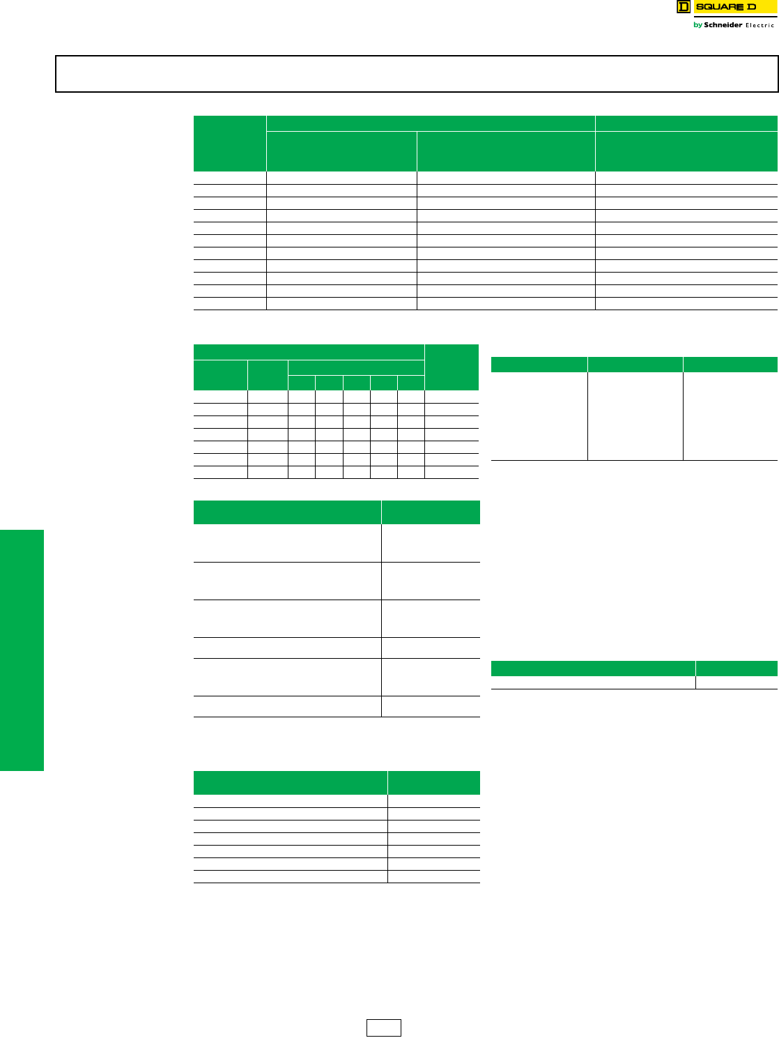
Table 11.32: PowerPact™ K Frame—250 A, Thermal-Magnetic (240 Vac)
Continuous
Current
Rating
@ 40o C
AC Magnetic
Trip Settings D Interrupting Level G Interrupting Level Terminal
Wire
Range
Hold Trip Cat. No. Availability Cat. No. Availability
2P, 240 Vac
100 A 1100 A 1700 A KDL22100 Not Available KGL22100 Not Available
AL250KD
6 AWG–350 kcmil
Al or Cu
110 A 1100 A 1700 A KDL22110 Not Available KGL22110 Not Available
125 A 1100 A 1700 A KDL22125 Not Available KGL22125 Not Available
150 A 1100 A 1700 A KDL22150 Not Available KGL22150 Not Available
175 A 1400 A 2400 A KDL22175 Not Available KGL22175 Not Available
200 A 1400 A 2400 A KDL22200 Not Available KGL22200 Not Available
225 A 1400 A 2400 A KDL22225 Not Available KGL22225 Not Available
250 A 1400 A 2400 A KDL22250 Not Available KGL22250 Not Available
3P, 240 Vac
100 A 1100 A 1700 A KDL32100 KGL32100 Not Available
AL250KD
6 AWG–350 kcmil
Al or Cu
110 A 1100 A 1700 A KDL32110 Not Available KGL32110 Not Available
125 A 1100 A 1700 A KDL32125 KGL32125 Not Available
150 A 1100 A 1700 A KDL32150 KGL32150 Not Available
175 A 1400 A 2400 A KDL32175 Not Available KGL32175 Not Available
200 A 1400 A 2400 A KDL32200 Not Available KGL32200 Not Available
225 A 1400 A 2400 A KDL32225 KGL32225 Not Available
250 A 1400 A 2400 A KDL32250 Not Available KGL32250 Not Available
Table 11.33: Mechanical Lug Kit Information
Kit Catalog
Number
Circuit Breaker Application Number of Wires Per Lug
and Wire Range Torque Lugs
Per Kit Availability
Standard Ampere
Rating Optional Ampere
Rating
Al Lugs for Use with Al or Cu Wire
AL250KD KDL, KGL 100–250 A — — (1) 6 AWG–350 kcmil 300 lb-in (34 N•m) 3 Not Available
Cu Lugs for Use with Cu Wire Only
CU250KD — — KDL, KGL 100–250 (1) 6 AWG–350 kcmil 300 lb-in (34 N•m) 3
Table 11.34: Handle Accessories
Circuit Breaker Type Cat. No. Availability
Handle Padlock Attachment (locks ON or OFF)
KDL, KGL HPAKD Not Available
Table 11.35: Interrupting Ratings (kA)
KDL
240 V 25
KDL and KGL
Circuit Breaker
3P
100–250 A
DE5A Discount
Schedule
11-18 © 2012 Schneider Electric
All Rights Reserved
www.schneider-electric.us
11 OBSOLETE CIRCUIT BREAKERS
Obsolescent Circuit
Breakers
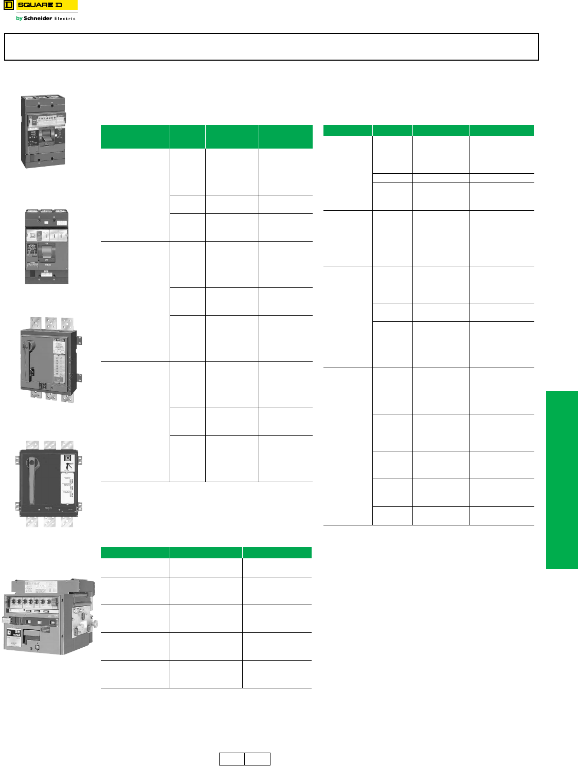
NHL Thermal-Magnetic Molded Case Circuit Breaker
Class 670
aUnless otherwise specified, wire sizes apply to both aluminum and copper conductors.
bUse with NAHEX handle extension.
NHL circuit breakers and related accessory products are obsolete. Please refer to Digest 176 for PowerPact™ molded case circuit
breakers for new installations or replacement.
NHL Circuit Breaker
800–1200 A
Table 11.36: NHL Circuit Breaker (1200 A, 480 Vac)
Ampere
Rating
AC Magnetic Trip
Settings
Amperes
2P 3P Standard Lug Kit Wire
Range
Low High Cat. No. Cat. No.
800 A 4000 A 8000 A — NHF368001021
AL1200NA
(4) 350–750-kcmil
1000 A 5000 A 10000 A — NHF3610001021
1200 A 5000 A 10000 A — NHF361200
1200 A 5000 A 10000 A — NHF3612001021
800 A 4000 A 8000 A — NHL36800
1000 A 5000 A 10000 A NHL261000 NHL361000
1000 A 5000 A 10000 A — NHL3610001021
1200 A 5000 A 10000 A NHL261200 NHL361200
1200 A 5000 A 10000 A — NHL3612001021
Table 11.37: Mechanical Lug Kit
Kit Cat. No. Circuit
Breaker
Ampere
Rating
Number of Wires Per
Lug and Wire Rangea
Lugs
Per Kit
AL1200NA NH 600–1200 (4) 350–750 kcmil 1
Table 11.38: Compression Lug Kit
Kit Cat. No. Circuit
Breaker
Number of Lugs
Per Terminal and Wire Rangea
Lugs
Per Kit
VC1200NA5 NH (1) 2/0 AWG–500 kcmil 1
VC1200NA7 NH (1) 500–750 kcmil Al or
500 kcmil Cu 1
Table 11.39: Mechanical Accessories
Cat. No. Circuit
Breaker Description No. of
Poles
HPANAbNH Handle Padlock Attachment 2, 3
NAHEX NH Handle Extension 2, 3
Table 11.40: Control Wire Terminations
Cat. No. Standard Package Quantity
AL1200NAT 1
DE5A Discount
Schedule
www.schneider-electric.us
11 OBSOLETE CIRCUIT BREAKERS
© 2012 Schneider Electric
All Rights Reserved 11-19
Obsolescent Circuit
Breakers
SE Circuit Breaker with Full-Function Trip Unit
Class 678
a“MR” (Motor Ready) indicates 120 Vac spring charging motor only already installed. Does not include shunt close or shunt trip option.
b“Z” indicates circuit breaker supplied without terminal connector kit.
cSubstitute (A) in place of (G) for ground-fault alarm (pick-up indication only).
SE circuit breakers and related accessories are obsolete. Please refer to Digest 176 for PowerPact™ molded case circuit breakers for
new installations or replacement.
Table 11.41: SE Circuit Breaker
Sensor Size Ampere
Rating
Rating
Plug
Installed
Fixed-Mounted Circuit Breaker Drawout Circuit Breaker
Cat. No.ab Cat. No.ab
Long-Time
Short-Time
Instantaneous
Long-Time
Short-Time
Instantaneous
w/Ground Faultc
Long-Time
Short-Time
Instantaneous
Long-Time
Short-Time
Instantaneous
w/Ground Faultc
Standard Interrupting Rating
1200 A 1200 A
ARP100
SEF361200LSMR — — —
3000 A 3000 A
SEF363000LS — SED363000LS —
— SEF363000LSG — SED363000LSG
SEF363000LSMR — SED363000LSMR —
— SEF363000LSGMR — SED363000LSGMR
4000 A 4000 A
SEF364000LSZ — — —
SEF364000LSMRZ —
— SEF364000LSGMRZ — SED364000LSGMR
— SEF364000LSAMRZ — —
High Interrupting Rating
1200 A 1200 A ARP100 — SEHF361200LSGMR — —
3000 A 3000 A SEHF363000LSMR — — —
DE5A Discount
Schedule
www.schneider-electric.us
11 OBSOLETE CIRCUIT BREAKERS
11-20 © 2012 Schneider Electric
All Rights Reserved
Obsolescent Circuit
Breakers
SE Circuit Breaker Accessories
Class 678
aUsed only with SE circuit breaker Series 3B.
bAlso field-installable on Series 3 and newer, and for Series 2 ground
fault circuit breakers.
cFixed-mounted circuit breakers only. Does not include key interlock.
Electric Joint Compound
SE drawout circuit breakers are supplied with factory-
applied joint compound on the plug-on connectors. The
compound should not be removed because it contributes
to the overall performance of the connection.
Whenever one of these units is removed and reinstalled,
the joint compound should be reapplied.
PJC 8311 is a two-ounce container of compound specially
formulated for the SE drawout connections. This
compound MUST BE USED ON SE DRAWOUT
CONNECTIONS. No other type of commercially available
joint compound should be used.
SE circuit breakers and related accessories are obsolete. Please refer to Digest 176 for PowerPact™ molded case circuit breakers for
new installations or replacement.
Table 11.42: Field-Replaceable Electronic Trip Unit Kits (Replaceable by Field Services Only)a
Ampere Rating
Trip Unit Function Cat. No.
Long-Time
Short-Time
Instantaneous
Long-Time
Short-Time
Instantaneous with
Ground Fault
Long-Time
Short-Time
Instantaneous with
Ground Fault Alarm
400 A — SETU400LSGB —
800 A SETU800LSB — —
800 A — SETU800LSGB —
1200 A SETU1200LSB — —
1200 A — SETU1200LSGB —
1600 A — SETU1600LSGB SETU1600LSAB
2500 A — SETU2500LSGB —
3000 A SETU3000LSB — —
3000 A — SETU3000LSGB SETU3000LSAB
4000 A SETU4000LSB — —
4000 A — SETU4000LSGB —
Table 11.43: SE Drawout Cell Keying Kit
Cell Key Positions Table
Availability
Cell Keying
Kit Cat. No.
Frame
Size
Drawout Carriage Cell Key Position
A B C D E
SECK0400 400 A X X Not Available
SECK0800 800 A X X Not Available
SECK1200 1200 A X X
SECK1600 1600 A X X
SECK2000 2000 A X X
SECK2500 2500 A X X
SECK3000 3000 A X X
Table 11.44: Field-Replaceable Accessory Kits
Description Kit
Cat. No.
Spring Charging Motor
Replacement Kit
120 Vac
24 Vdc
48 Vdc
125 Vdc
S3MOT120AC2
—
—
S3MOT125DC2
Shunt Close
Replacement Kit
120 Vac
24 Vdc
48 Vdc
125 Vdc
S3SC120AC2
S3SC024DC2
S3SC048DC2
S3SC125DC2
Shunt Tripb
Replacement Kit
120 Vac
24 Vdc
48 Vdc
125 Vdc
S3ST120AC2
S3ST024DC2
S3ST048DC2
S3ST125DC2
Undervoltage Tripb
Replacement Kit 120 Vac —
Auxiliary Switchb
Replacement Kit
4 ac/dc
4 ac/dc add on
4 ac only
8 ac only
S34DCB2
S34DCT2
S34AC2
S38AC2
Alarm Switchb
Replacement Kit 2 ac only S3AS2
Table 11.45: Field-Installable External Accessory
Kits
Description Kit
Cat. No.
Padlock Attachment SE2PA
Close Button Cover SE1CBC
Key Interlock Bracketc SE1KI
Series 1 Primary Injection Test Plug SEPITK1
Series 2 Primary Injection Test Plug SEPITK2
SE Drawout Crank SEDC
Fan Monitoring Switch Kit SE40FAN
Table 11.46: Neutral Current Transformers
Cat. No. Sensor Where Used
SE12NCT 800 SE, SEH
SE12NCT 1200 SE, SEH
SE30NCT 1600 SE, SEH
SE30NCT 2000 SE, SEH
SE30NCT 2500 SE, SEH
SE30NCT 3000 SE, SEH
SE40NCT 4000 SE, SEH
Table 11.47: Electric Joint Compound
Used With Cat. No.
SED Drawout Circuit Breakers PJC8311
DE5A Discount
Schedule
www.schneider-electric.us
11 OBSOLETE CIRCUIT BREAKERS
© 2012 Schneider Electric
All Rights Reserved 11-21
Molded Case Circuit
Breakers
M-Frame Thermal-Magnetic Circuit Breakers
.
Accessories . . . . . . . . . . . . . . . . . . . . . . . . . . . . . . . . . . . . . . . . . Page 11-28
OptionalLugs . . . . . . . . . . . . . . . . . . . . . . . . . . . . . . . . . . . . . . . . . Page 11-23
Dimensions . . . . . . . . . . . . . . . . . . . . . . . . . . . . . . . . . . . . . . . . . . . Page 11-5
Enclosures: see Digest Section 7
M-frame thermal-magnetic circuit breakers are obsolete. Please refer to Digest 176 for PowerPact™ molded case circuit breakers for
new installations or replacement.
Table 11.48: M-Frame—Thermal-Magnetic, Individually-Mounted Circuit Breakers, 600 Vac
Ampere
Rating
AC Magnetic
Trip SettingsaStandard Interrupting High Interrupting Terminal
Wire
Range
Low High Cat. No. Availability Cat. No. Availability
2P, 600 Vac, 250 Vdc
300 A
350 A
400 A
450 A
500 A
600 A
700 A
800 A
900 A
1000 A
1500 A
1750 A
2000 A
2250 A
2500 A
3000 A
3500 A
4000 A
4500 A
5000 A
3000 A
3500 A
4000 A
4500 A
5000 A
6000 A
7000 A
8000 A
9000 A
10000 A
MAL26300
MAL26350
MAL26400
MAL26450
MAL26500
MAL26600
MAL26700
MAL26800
MAL26900
MAL261000
Not Available
Not Available
Not Available
Not Available
Not Available
Not Available
Not Available
Not Available
Not Available
Not Available
MHL26300
MHL26350
MHL26400
MHL26450
MHL26500
MHL26600
MHL26700
MHL26800
MHL26900
MHL261000
Not Available
Not Available
Not Available
Not Available
Not Available
Not Available
Not Available
Not Available
AL900MA
(3) 3/0 AWG–500 kcmil
1200 A 5000 A 10000 A MAL261200 Not Available MHL261200 Not Available AL1000MAb
(4) 1/0 AWG–350 kcmil
3P, 600 Vac, 250 Vdc
300 A
350 A
400 A
450 A
500 A
600 A
700 A
800 A
900 A
1000 A
1500 A
1750 A
2000 A
2250 A
2500 A
3000 A
3500 A
4000 A
4500 A
5000 A
3000 A
3500 A
4000 A
4500 A
5000 A
6000 A
7000 A
8000 A
9000 A
10000 A
MAL36300
MAL36350
MAL36400
MAL36450
MAL36500
MAL36600
MAL36700
MAL36800
MAL36900
MAL361000
Not Available
Not Available
Not Available
Not Available
Not Available
Not Available
Not Available
Not Available
Not Available
Not Available
MHL36300
MHL36350
MHL36400
MHL36450
MHL36500
MHL36600
MHL36700
MHL36800
MHL36900
MHL361000
Not Available
Not Available
Not Available
Not Available
AL900MA
(3) 3/0 AWG–500 kcmil
1200 A 5000 A 10000 A MAL361200 Not Available MHL361200 AL1000MAb
(4) 1/0 AWG–350 kcmil
aUL magnetic trip setting tolerances are ±25% for low and ±20% for high from nominal values shown.
bThe AL100MA lug is the only lug available for the 1200 A MA and MH circuit breakers.
Table 11.49: M-Frame—Thermal-Magnetic, I-Line™ Construction Circuit Breakers, 600 Vac
Ampere
Rating
AC Magnetic
Trip SettingscStandard Interrupting High Interrupting Terminal
Wire
Range
Low High Cat. No. Availability Cat. No. Availability
2P, 600 Vac, 250 Vdcd
300 A
350 A
400 A
450 A
500 A
600 A
700 A
800 A
1500 A
1750 A
2000 A
2250 A
2500 A
3000 A
3500 A
4000 A
3000 A
3500 A
4000 A
4500 A
5000 A
6000 A
7000 A
8000 A
MA26300( )
MA26350( )
MA26400( )
MA26450( )
MA26500( )
MA26600( )
MA26700( )
MA26800( )
Not Available
Not Available
Not Available
Not Available
Not Available
Not Available
Not Available
Not Available
MH26300( )
MH26350( )
MH26400( )
MH26450( )
MH26500( )
MH26600( )
MH26700( )
MH26800( )
Not Available
Not Available
Not Available
Not Available
Not Available
Not Available
Not Available
Not Available
AL900MA
(3) 3/0 AWG–500 kcmil
3P, 600 Vac, 250 Vdc
300 A
350 A
400 A
450 A
500 A
600 A
700 A
800 A
1500 A
1750 A
2000 A
2250 A
2500 A
3000 A
3500 A
4000 A
3000 A
3500 A
4000 A
4500 A
5000 A
6000 A
7000 A
8000 A
MA36300
MA36350
MA36400
MA36450
MA36500
MA36600
MA36700
MA36800
Not Available
Not Available
Not Available
Not Available
Not Available
MH36300
MH36350
MH36400
MH36450
MH36500
MH36600
MH36700
MH36800
Not Available
Not Available
Not Available
Not Available
Not Available
AL900MA
(3) 3/0 AWG–500 kcmil
cUL magnetic trip setting tolerances are ±25% for low and ±20% for high from nominal values shown.
d2P circuit breaker catalog numbers are completed by adding required phase connection letters as suffix to catalog numbers. See Phase Options table.
Table 11.50: Interrupting Ratings
Voltag e MA/MAL MH/MHL
240 Vac 42 kA 65 kA
480 Vac 30 kA 65 kA
600 Vac 22 kA 25 kA
MAL/MHL 2P and 3p
300–1000 A
DE2 Discount
Schedule
11-22 © 2012 Schneider Electric
All Rights Reserved
www.schneider-electric.us
11 OBSOLETE CIRCUIT BREAKERS
Circuit Breaker
Accessories
Field-Installable Accessories
Field-Installable Electrical Accessories
Complete field-installable accessory catalog number by inserting suffix from Digest page 7-
36 between the parentheses in the catalog numbers shown in the table below. (Example:
LA11212) See Digest page 7-36 for accessory pricing; add 20% to factory-install field-
installable devices.
Table 11.51: Field-Installable Accessories for Thermal-Magnetic and Electronic Trip
Circuit Breakers
Circuit Breaker Shunt Trip Ground-Fault
Shunt TripaUndervoltage Trip Auxiliary Switches Alarm Switch
MA, MH
Series 2 MA1( ) MA1G MA1 ( ) MA1( ) Factory-Installed
Only Center Pole
ME, MX Factory-Installed
Only
Factory-Installed
Only
Factory-Installed
Only
Factory-Installed
Only
Factory-Installed
Only
NA, NC, NE, NX
Series 1, 2, 3 NA1( ) NA1( ) NA1( ) NA1( ) NA1( )
PA , PH, P C
Series 4 PA1( ) Factory-Installed
Only PA11121 PA1( ) Factory-Installed
Only
PE, PX
Series 4, 5, 6 PA1( ) Factory-Installed
Only
PA11121 PA1( ) Factory-Installed
Only
aUsed with obsolete GP Ground-Censor™ system or add-on ground-fault modules.
Table 11.52: Accessory Mounting Locations
MA, MH Series 2 circuit breakers or newer = Field-
installable accessories
ME/MX circuit breakers = Not field-installable accessories
NA, NC, NE, NX circuit breakers - FIeld-installable
accessories
“L” port and “R” port will accept shunt trips, alarm switches
and UVRs; “R2” port will accept auxiliary switches.
Maximum of one device per port.
PA, PH, PC, PE, PX Series 4 circuit breakers or newer = FIield-installable
accessories.
“L1” a
nd “L2” or “R1” and “R2” port combinations are required
to mount a single shunt trip. Both “L2” and “R2” ports will
accept a UVR. Both “L1” and R1” ports will accept
auxiliary switches. If alarm switch is factory installed in PA
or PC circuit breaker, it will be installed in “R2” port. For a
PE or PX circuit breaker, the alarm switch will be factory
installed in “L2” port.
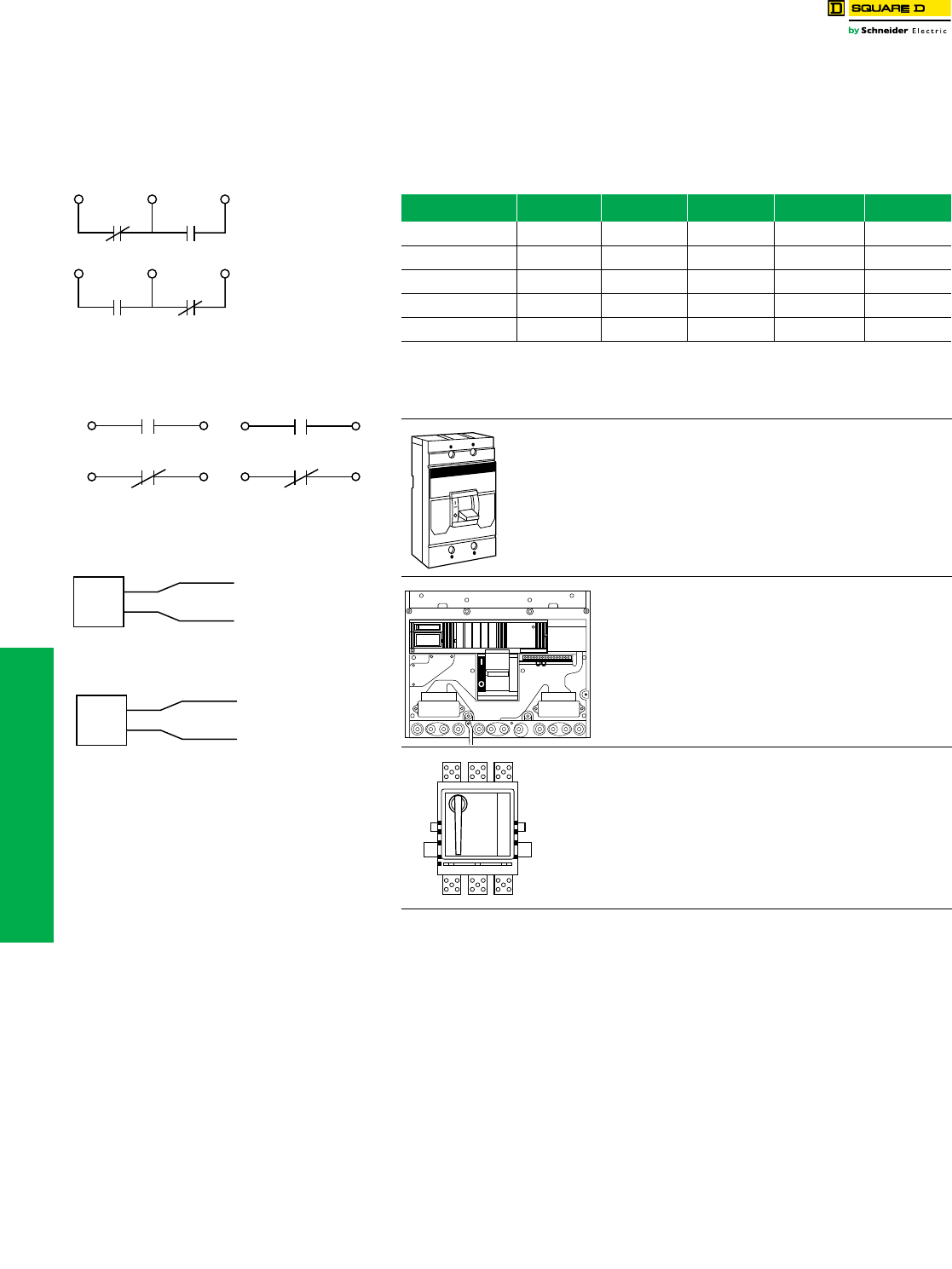
1A/1B
Circuit Breaker Closed
AB
Circuit Breaker Open or Tripped
AB
Auxiliary Switch
Contact Configuration
Color Code:
"A" Contact - Yellow Leads
"B" Contact - Blue Leads
Common-Striped Leads
Circuit Breaker Open or Closed
1A Alarm Switch
Configuration
Color Code: Red Leads
Circuit Breaker Tripped
Circuit Breaker Tripped
1B Alarm Switch
Configuration
Color Code: Red Leads
Circuit Breaker Open or Closed
Undervoltage Trip
Wiring Diagram
Brown
Brown
Brown Wires To Be
Connected To
Control Power
UVR
Shunt Trip
Wiring Diagram
Black
Black
Black Wires To Be
Connected To
Control Power
Shunt
Tr i p
L
R
LR1
R2
L1
L2
R1
R2
www.schneider-electric.us
11 OBSOLETE CIRCUIT BREAKERS
© 2012 Schneider Electric
All Rights Reserved 11-23
Circuit Breaker
Accessories
Mechanical Lug Information
aUnless otherwise specified, wire sizes apply to both aluminum and copper conductors.
bFor use in the OFF end only, when the OFF end is the load end.
cUse suffix 8002 for factory-installed Cu lugs. (20% adder.)
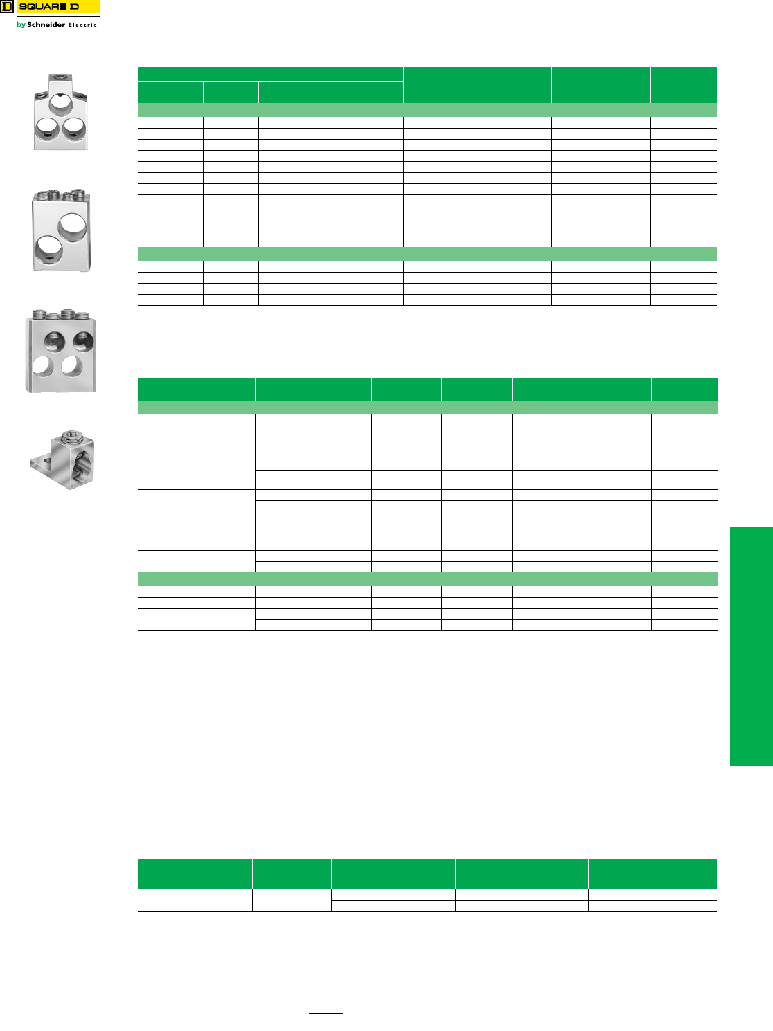
Compression Lug Kits
aSee instruction bulletins for recommended tools.
bUnless otherwise specified, wire sizes apply to both aluminum and copper conductors.
cAll P-frame circuit breakers require terminal pads for mounting lugs of any type.
Power Distribution Connectors (PDC) for Circuit Breakers—for Field Replacement of Mechanical
Lugs
Can be used for multiple load connections on one circuit breaker. Use in place of standard distribution blocks to save
space and time.
Field-installable kits, including tin-plated aluminum connectors and all necessary mounting hardware are available for
Square D FA, LA and Q4-frame molded case circuit breakers.
Connectors are UL Listed:
•For use on load end of circuit breaker only
•For use in UL508 Industrial Control applications only
•For use in UL 1995/CSA C22.2 No. 236 heating and cooling equipment
•For copper wire only
dNot for use with I-Line circuit breakers.
eWhen using fine stranded wire, increased cross sectional area may cause maximum wire size to be reduced.
fOFF end only when OFF end is the load end.
Table 11.53: Mechanical Lug Kit Information
Circuit Breaker Application (Number of Wires Per Lug )
Wire RangeaCat. No.
Lugs
Per
Kit
Availability
Per Kit
Standard Ampere
Rating Optional Ampere
Rating
Al Lugs for Use with Al or Cu Wire
— — LC, LI, LE, LX, LXI — (1) 500–750 kcmil AL600LI7 1
MA, MH 300–1000 A — — (3) 3/0 AWG–500 kcmil AL900MA 1
— — MA, MH 300–1000 A (2) 500–750 kcmil AL800MA7 1
— — MA, MH 300–1200 A (4) 1/0 AWG–350 kcmil AL1000MA 1
ME, MX 100–250 A — — (1) 6 AWG–350 kcmil AL250ME 3 Not Available
— — ME, MX 250–400 A (1) 350–750 kcmil AL400ME7 1 Not Available
— — ME, MX 100–800 A (2) 500–750 kcmil AL800MA7 1
ME, MX 300–800 A ME, MX 100–250 A (3) 3/0 AWG–500 kcmil AL900MA 1
— — ME, MX 300–1200 A (4) 1/0 AWG–350 kcmil AL1000MA 1
NA, NC, NE, NX 600–1200 A — — (4) 3/0 AWG–600 kcmil AL1200NE6 1 Not Available
——
PAF, PHF, PEF, PXF,
PCF 600–2500 A (1) 1/0 AWG–750 kcmil AL2500PA 2
Cu Lugs for Use with Cu Wire Only c
— — MA, MH 300–1000 A (3) 3/0 AWG–500 kcmil Cu CU1000MA 1
— — ME, MX 125–250 A (1) 4 AWG–250 kcmil Cu CU250ME 3 Not Available
— — ME, MX 100–800 A (3) 3/0 AWG–500 kcmil Cu CU1000MA 1
— — NA, NC, NE, NX 600–1200 A (4) 3/0 AWG–600 kcmil Cu CU1200NE6 1 Not Available
Table 11.54: Field-installable Compression Lug Kitsa
Circuit Breaker
Type Wire RangebDimension A
(In)
Max. Lugs
Per Terminal Cat. No. Lug Qty.
Per Kit Availability
Aluminum Compression Lug Kits
MA, MH 2/0 AWG–500 kcmil 1.9 2 VC600MA5 2 Not Available
500–750 kcmil 2.1 2 VC800MA7 2 Not Available
ME2, MX2 4 AWG–300 kcmil 1.5 1 VC250ME3 3 Not Available
250–350 kcmil 1.5 1 VC250ME35 3 Not Available
ME4, MX4
2/0 AWG–500 kcmil 2.2 1 VC400ME5 1 Not Available
500–750 kcmil Al
or 500 kcmil Cu 2.5 1 VC400ME7 1 Not Available
ME, MX, MA, MH
2/0 AWG–500 kcmil 1.9 2 VC600MA5 2 Not Available
500–750 kcmil Al
or 500 kcmil Cu 2.1 2 VC800MA7 2 Not Available
NA, NC, NE, NX
2/0 AWG–500 kcmil 3.3 4 VC1200NE5 4 Not Available
500–750 kcmil Al
or 500 kcmil Cu 3.6 4 VC1200NE7 4 Not Available
PA F, P H F, P C F, P E F 2/0 AWG–500 kcmil c6–8 VC2000PA5 4 Not Available
2/0 AWG–500 kcmil c6–8 VC2500PA7 4 Not Available
Copper Compression Lug KitsNot Available
ME4, MX4 250–500 kcmil Cu 2.6 1 CVC400ME5 1 Not Available
ME, MX 250–500 kcmil Cu 2.4 2 CVC600MA5 2 Not Available
NA, NC, NE, NX 250–500 kcmil Cu 3.3 4 CVC1200NE5 4 Not Available
500–750 kcmil Cu 3.6 4 CVC1200NE7 4 Not Available
Table 11.55: PDC Lugs
Use With Circuit BreakerdCicuit Breaker
Ampere Rating
Wires Per Terminal
& Wire Rangee
Cu
Cat. No. Lug Quantity
Per Kit
Dimension
A (i.) Availability
MAL, MHL, MEL, MXL 125–1000 A (6) 12–2/0 AWG Cu PDC6MA20 1 0.0 Not Available
(12) 14–4 AWG Cu PDC12MA4 1 0.0
AL900MA
AL1000MA
AL800MA7
AL2500PA
DE2 Discount
Schedule
11-24 © 2012 Schneider Electric
All Rights Reserved
www.schneider-electric.us
11 OBSOLETE CIRCUIT BREAKERS
Electronic Products Micrologic™ Series 2/3/A/B Trip Unit Test Sets
Class 690
NOTE: Listed below are the catalog numbers and the components required for testing
the entire family of Micrologic trip systems. The listing includes obsolete series
trip systems.
Micrologic Series B Trip Systems
Identified by label on front of trip unit
(LE/LX/LXI, ME/MX, NE/NX and PE/PX circuit breaker 9/92 to present)
(SE circuit breaker 10/92 to present)
This is the latest series of standard (LX/LXI, MX, NX and PX) and full-function (LE, ME, NE,
PE and SE) Micrologic trip systems.
Micrologic Series 3 and Series A Trip Systems
Identified by two rows of rotary switches
(ME/MX, NE/NX and PE/PX circuit breakers 11/89 to 9/92)
(SE circuit breakers 5/90 to 10/92)
For those customers who already own the Universal Test Set (CBTU1 or UTS3) and want
to test these earlier series Micrologic trip systems, see the following chart.
Micrologic Series 2 Trip Systems
Identified by only one row of rotary switches
Micrologic Series 2 Test Modules are obsolete and no longer available.
Note: For trip systems of this type that require testing, contact Technical Services toll free at 1-800-634-2003.
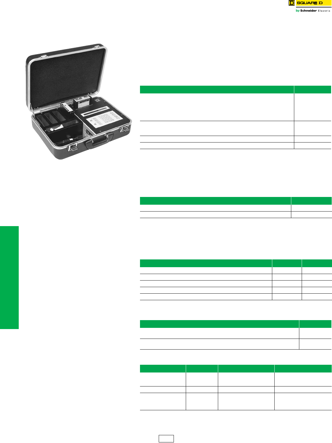
Table 11.56: Universal Test Set
Description Cat. No.
Universal Test Set includes the following:
1. Self-test module (CBTMT)
2. Standard and full-function Micrologic Series B module (CBTMB) includes rating plug adapter
3. Power cord
4. Ribbon cable for making the connection from the test set to the rating plug adapter
5. Instruction manual
UTS3
For those customers who already own the Universal Test Set and want to test the latest standard and
full-function (Series B) trip systems, all that is needed is Micrologic Series B module (CBTMB). Included
is the rating plug adapter and instruction manual.
CBTMB
Replacement ribbon cable and rating plug adapter for CBTMB CBTMBRK
Long-time and ground-fault memory reset module (Series B Electronics) MTMB
Table 11.57: Micrologic Series 3 and Series A Circuit Breaker Test Module
Circuit Breaker Test Module Cat. No.
Includes rating plug adapter and instruction manual CBTM4A
Replacement ribbon cable and rating plug adapter for CBTM4A CBTM4RK
Table 11.58: Micrologic Series 2 Circuit Breaker Test Module
Circuit Breaker Test Modules Cat. No. Availability
SE (5/85-5/90) includes rating plug adapter and instruction pages CBTM1 Not Available
Replacement ribbon cable and rating plug for CBTM1 CBTM1A Not Available
ME, PE (4/85-11/89) CBTM2 obsolete, no longer available CBTM2 Not Available
ME, NE, PE (10/86-11/89) includes rating plug adapter and instruction manual CBTM3 Not Available
Replacement ribbon cable and rating plug for CBTM3 CBTM3A Not Available
Table 11.59: Micrologic Series 1 Trip Systems for Circuit Breakers Manufactured
Before Micrologic
Trip System Test Set
ME/PE (8/78-4/85) Identified by slide type switches instead of rotary switches.
The very first series ME and PE electronic trip circuit breakers offered by Square D.
Test Set
Not Available
SE (7/83-5/85) The very first series of SE electronic trip circuit breakers had rotary switches and can be
identified by a three-digit serial number.
Test Set
Not Available
Table 11.60: Neutral Current Transformers
Cat. No. Availability Sensor Where Used
ME25CT2
ME4CT2
ME8CT2
Not Available
Not Available
Not Available
250 A
400 A
800 A
MXL,MEL
NE12CT2 1200 A NXL,NEL
PE12CT2
PE16CT2
PE20CT2
PE25CT2
Not Available
Not Available
Not Available
Not Available
1200 A
1600 A
2000 A
2500 A
PXF, PEF
DE2 Discount
Schedule
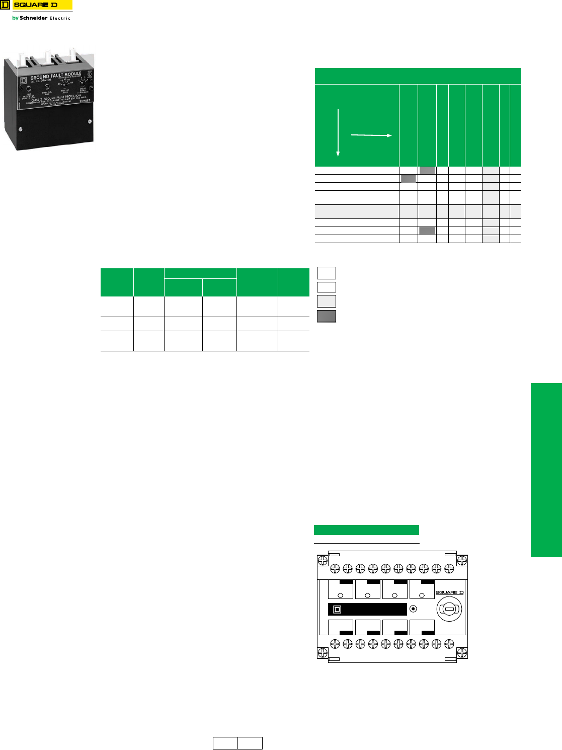
www.schneider-electric.us
11 OBSOLETE CIRCUIT BREAKERS
© 2012 Schneider Electric
All Rights Reserved 11-25
Ground-Fault Protection Micrologic™ Add-On Ground-Fault Module (GFM)
Class 931, 940, 960
The Micrologic ground-fault module (GFM) is a UL Listed
circuit breaker accessory for equipment protection. It is a
combination ground-fault relay and ground-fault sensing
device.
Micrologic Add-On Ground-Fault Module Features:
•Used in combination with the FA, KA, FC, KC, FI, and KI type
circuit breakers with a ground-fault shunt trip factory installed
(add the suffix “G” to the circuit breaker)
•Adjustable ground-fault pickup levels
•Adjustable ground-fault time delays
•Integral ground fault push-to-test feature and ground-fault
indicator
•All GFMs supplied for I-Line™ mounting, easily convertible to
unit mount by removing the
I-Line brackets
•Neutral current transformer is supplied for 3-phase 4-wire
applications. Refer to instructions for proper installation
•Zone-selective interlocking capability is standard with
upstream Micrologic trip system circuit breakers. The GFM
can also be zone interlocked with the GC ground-fault system
by using a restraint interface module.See Supplementary
Digest
•120 Vac control power is required for integral test feature.
Meets NEC 230-95(c)
NOTE: Ground-fault modules cannot be reverse fed.
aUse NEMA 1 or 3R enclosures only. See page 11-5 for dimensions.
RIM32 Restraint Interface Module
The RIM32 Restraint Interface Module is used to interface
the restraint signals between various Square D
Micrologic™ circuit breakers, Micrologic ground-fault
modules, and GC-100 ground-fault protection systems.
The restraint interface module operates on either 120 or
240 Vac, 50/60 Hz. The module is protected by a 1/4 A
fuse.
Allowable ZSI combinations are shown in Table 11.62.
(Series numbers for current design circuit breakers end in
B, for example NE Series 3B.) For double-ended or larger
systems, or systems which contain devices from different
columns in Table 11.62, contact your local Sales Office for
combination information.
If more inputs or outputs are needed, another restraint
interface module is necessary. Contact your local Sales
Office for information on multiple module installations.
NOTE: The maximum distance between
devices is 1000 ft. (305 m).
Table 11.61: Module/Enclosure Selection Chart
Companion
Circuit
Breaker
Prefix
Cat. No.
Enclosure Space Required Ground-Fault
Pickup
Adjustment
Range
Availability
I-Line
Switchboard
Individual
Enclosure a
FAL, FHL,
FCL, FA,
FH, FC
GFM100FA LA KA 20–100 A
FI GFM100FI LA — 20–100 A Not
Available
KAL, KHL,
KI, KA,
KH, KC
GFM250 LA LA 40–200 A
GFM250
Table 11.62: ZSI Combinations
Table 11.63: RIM32
Cat. No.
RIM32
aGFM is an output device only.
ZSI Combinations
(Where All Inputs Driven Are Same Column)
SE 2 (Ground Fault)
SE 2 (Short Time)
ME 3, NE1, PE 4
ME 4 & 5, NE 2 & 3
PE 5 & 6, SE 3
ME 5A, NE 3A,
PE 6A, SE 3A
LE 1B, ME 5B, NE 3B,
PE 6B, SE 3B
GC100
RIM 32
SE 2 (Ground Fault) 50 R R R RR50
SE 2 (Short Time) 1 R R R RR50
ME 3, NE1, PE 4 50 R 15 2 13 47 R 50
ME 4, 5 & 5A, NE 2, 3 & 3A, PE
5, 6 & 6A, SE 3, 3A 50 R R 1 1 7R14
LE 1B, ME 5B, NE 3B, PE 6B,
SE 3B 50 R10 1 R 26 R44
GC 100 R R R R R R750
GFMa50 2 1 1 5R10
RIM32 50 6 50 7 37 50 15 50
# Maximum inputs without RIM32. Self-restraint counts as one input.
R RIM32(s) required to restrain any devices.
Note:Note: Present design.
Invalid combination.
Inputs
Output
Circuit Breaker Series
GND
OUT
No. 4
Ground Fault
Restraint
GND
OUT
No. 5
Short Time
Restraint
GND
OUT
No. 6
Restraint
GND
OUT
GC-100
Ground Fault
Restraint
GND
IN
No. 1
Ground Fault
Restraint
GND
IN
No. 2
Short Time
Restraint
GND
IN
No. 3
Restraint
GND
IN
GC-100
Ground Fault
Restraint
PUSH
TO TEST
OUTPUTS
INPUTS
CAT. NO. RIM32
COM 240
Vac
COM
120
Vac
1/4 AMPERE
DE2 DE5A Discount
Schedule

11-26 © 2012 Schneider Electric
All Rights Reserved
www.schneider-electric.us
11 OBSOLETE CIRCUIT BREAKERS
Obsolescent Circuit
Breakers
Masterpact™ M/MP/MC Circuit Breakers, UL 489/1066 Listed
To order a complete circuit breaker, order:
1. Circuit breaker fixed or drawout frame..........................page 11-26
or cradle only................................................................page 11-32
or circuit breaker without cradle....................................page 11-26
2. Connections..................................................................page 11-23
3. Control unit....................................................................page 11-27
4. Rating plug....................................................................page 11-27
5. Accessories...................................................................page 11-28
Fixed and Drawout breakers listed below are complete with STR58U Trip unit which includes Long time, short time,
instantaneous and ground fault as well as options T (residual) and I (ammeter).
bNot UL Listed
Additional information: Catalog 0631CT9501, Data Sheet 0631HO9701
Masterpact™ M/MP/MC circuit breakers and related accessories are obsolete. Use Masterpact NT/NW for new applications. See DIgest
176. Limited service stock is available for replacement or fill purposes. Contact your local sales office for product availability.
Table 11.64: UL Listed Masterpact MP Circuit Breaker Frame
Rating AIR/
480 V
Fixed
3P
Drawout without Cradle
3P
Cradle Only
3P $ Price
MP16 to MP30—
UL 489/NEMA AB1
Standards
High Interrupting (H2)
Contact Schneider Electric Cedar Rapids
Plant Customer Service Group for current
pricing and availability.
MP16H2 1600 A 100 kA MP100135 MP100136 MP100141
MP20H2 2000 A 100 kA MP100137 MP100138 MP100133
MP30H2 3000 A 100 kA MP100139 MP100140 MP100132
DE2G Discount
Schedule
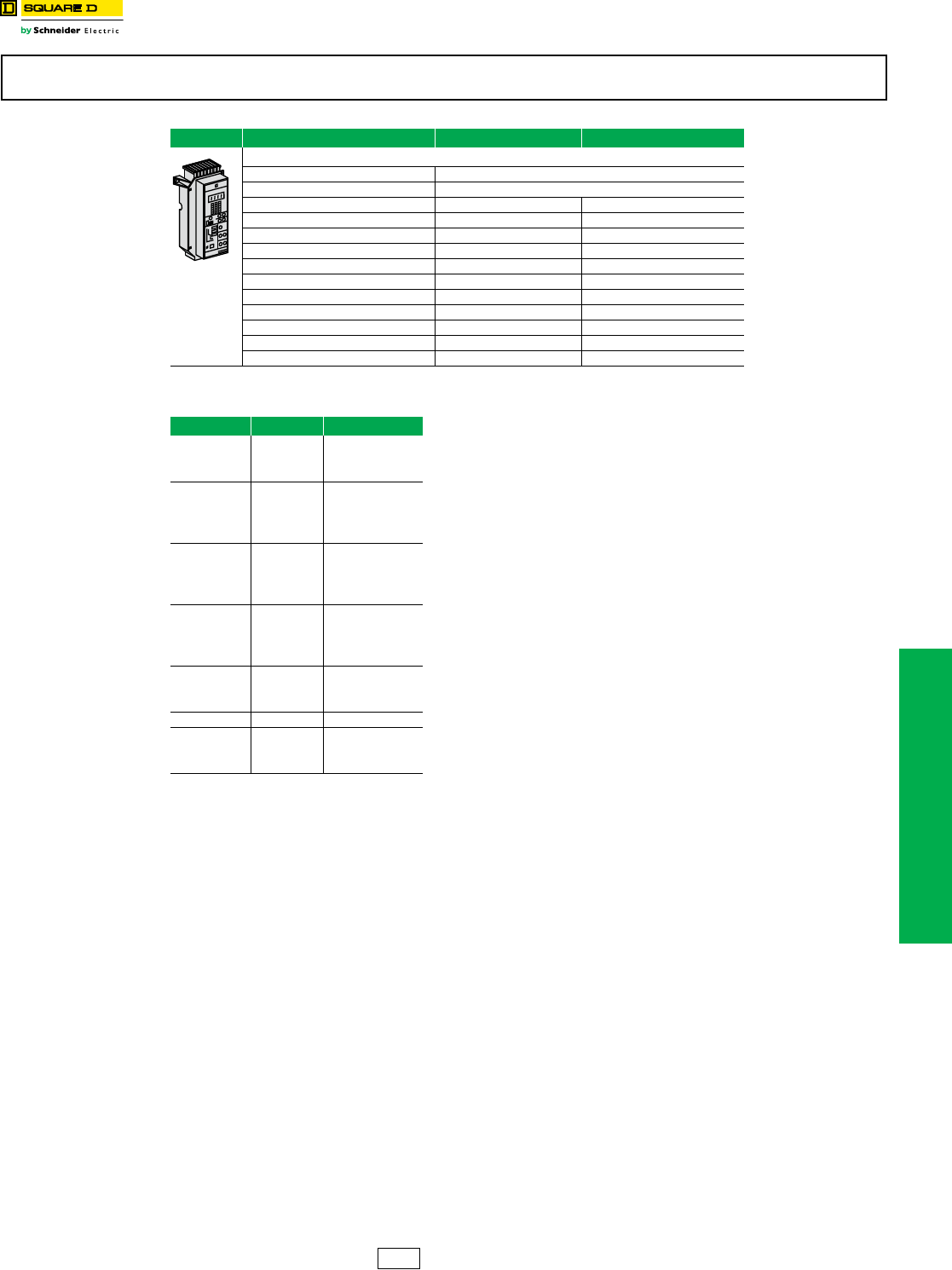
www.schneider-electric.us
11 OBSOLETE CIRCUIT BREAKERS
© 2012 Schneider Electric
All Rights Reserved 11-27
Obsolescent Circuit
Breakers
Masterpact™ M/MP/MC Circuit Breaker Control Units
aExternal neutral sensor not included.
bExternal AD module (see page 11-28) is required if load is below 20% or if setting is red zone.
NOTE: Mandatory for UL Listed Masterpact MP circuit breakers with STR 28D, STR 38S and STR 58U control
units. Not required on IEC Rated Masterpact circuit breakers.
Masterpact™ M/MP/MC circuit breakers and related accessories are obsolete. Use Masterpact NT/NW for new applications. See DIgest 176. Limited
service stock is available for replacement or fill purposes. Contact your local sales office for product availability.
Table 11.65: Control Units
Control Unit Ground-Fault ProtectionaWithout Ground-Fault Protectiona
STR 58U (long-time, short-time and instantaneous protection)
STR58U (long-time = 0.4x1 sensor rating) Includes Residual Type T — and Ammeter — I
External neutral sensor (TCE) b– see page 11-28
M1008H2 M1008H2NG
M10H2 M10H2NG
M1612H2 M1612H2NG
M16H2 M16H2NG
M20H2 M20H2NG
M25H2 M25H2NG
M3230H2 M3230H2NG
M32H2 M32H2NG
M6340H2 M6340H2NG
M6350H2 M6350H2NG
M63H2 M63H2NG
Table 11.66: Rating Plug (RL)
Sensor Rating Plug Rating Cat. No.
250 A
150 A 54732
200 A 54733
250 A 54734
400 A
200 A 54735
250 A 54736
300 A 54737
400 A 54738
600 A
300 A 54739
400 A 54740
500 A 54741
600 A 54742
800 A
400 A 54743
500 A 54744
600 A 54745
800 A 54746
1200 A
600 A 54747
800 A 54748
1200 A 54750
2500 A 1200 A 54759
5000 A
3000 A 54772
4000 A 54773
5000 A 54774
DE2G Discount
Schedule
For pricing contact your local
Schneider Electric distributor.
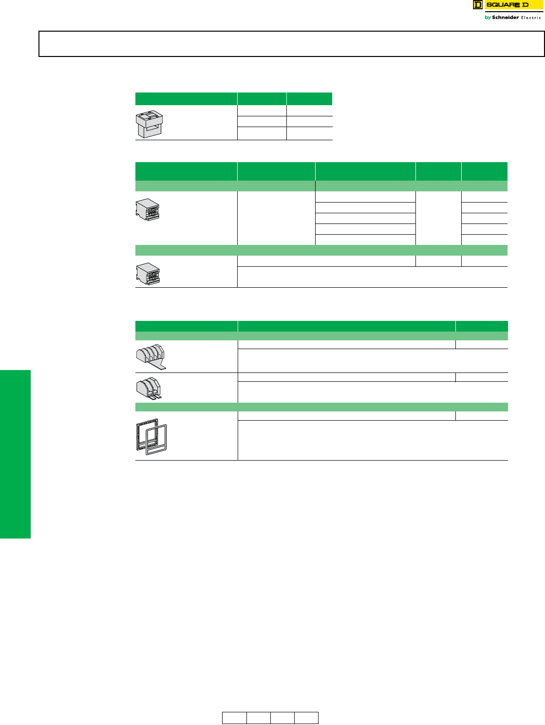
11-28 © 2012 Schneider Electric
All Rights Reserved
www.schneider-electric.us
11 OBSOLETE CIRCUIT BREAKERS
Obsolescent Circuit
Breakers
Masterpact™ M/MP/MC Circuit Breaker Accessories
aDiscount Schedule DE2G.
bDiscount Schedule DE2F
Masterpact™ M/MP/MC circuit breakers and related accessories are obsolete. Use Masterpact NT/NW for new applications. See DIgest
175. Limited service stock is available for replacement or fill purposes. Contact your local sales office for product availability.
Table 11.67: Neutral Sensor for 3ØH4W Systems (TCE)
NOTE: External neutral transformer (TCE) must have the same rating
as the circuit breaker current sensor.
Rating Cat. No.
800 A 54422
1250 A 54426
2000 A 54427
Table 11.68: Accessories (Must be ordered as separate items)
Accessory Description Discount
Schedule Cat. No.
Power Supply Module (AD) Input voltage
For STR 18M to STR 58U
control units
Output voltage: 24 Vdc
24/30 Vdc
DE2F
54440
48/60 Vdc 54441
10 Vac 50/60 Hz 54443
220 Vac 50/60 Hz 54444
380 Vac 50/60 Hz 54446
Battery Module (BAT)
Battery back-up power supply for AD module DE2F 54446
Table 11.69: Accessories for Cradle
Accessory Cat. No.
Position Switches
Four SPDT connected position switches (CE) 54590
Two SPDT disconnected position switches (CD) 54591
Door Escutcheon
Can be used with fixed or drawout circuit breakers 54594b
DE2F DE2G DE2 DE5A Discount
Schedule
For pricing contact your local
Schneider Electric distributor.
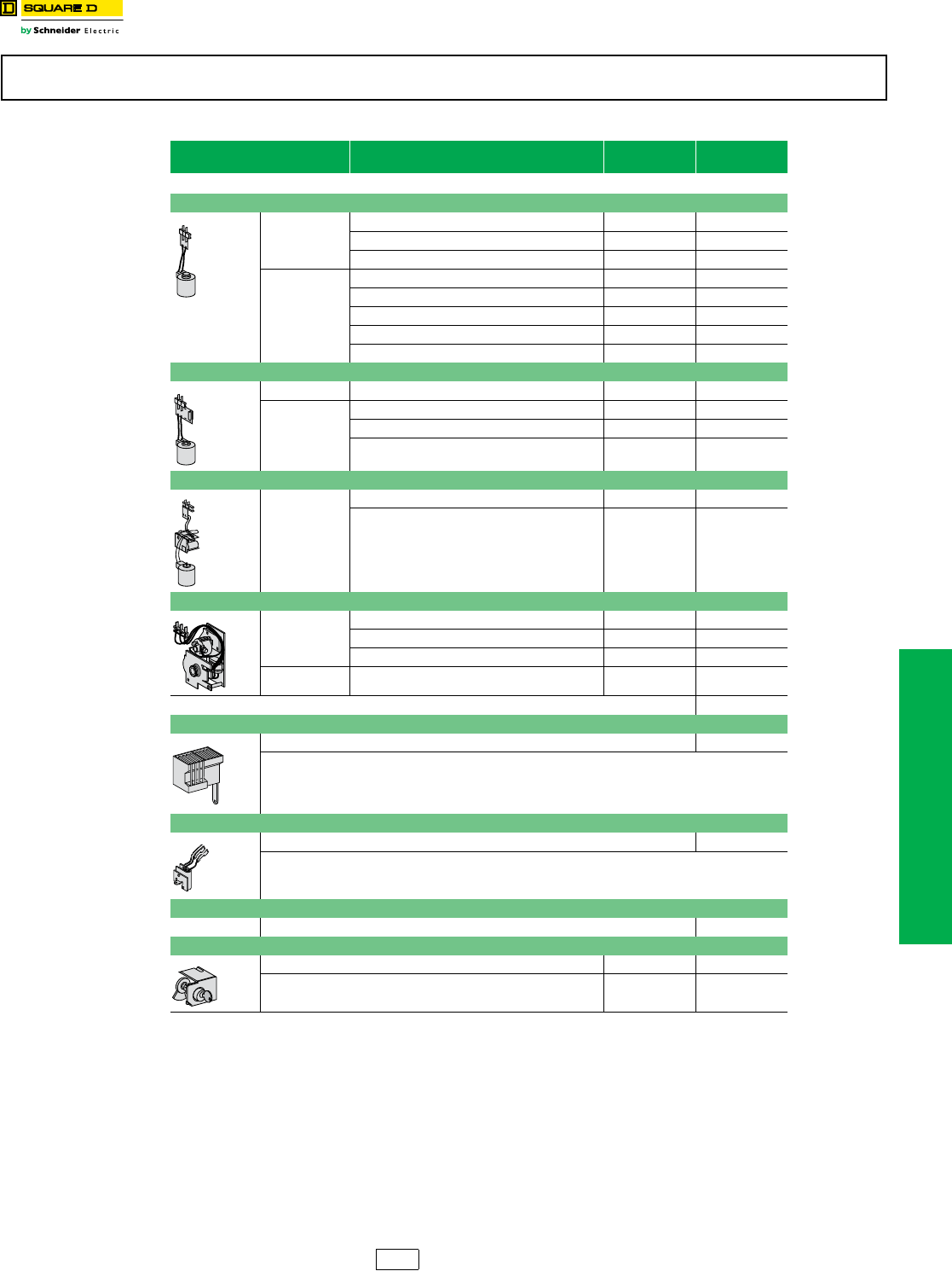
www.schneider-electric.us
11 OBSOLETE CIRCUIT BREAKERS
© 2012 Schneider Electric
All Rights Reserved 11-29
Obsolescent Circuit
Breakers
Masterpact™ M/MP/MC Circuit Breaker Accessories
aNot UL Listed.
Masterpact™ M/MP/MC circuit breakers and related accessories are obsolete. Use Masterpact NT/NW for new applications. See DIgest
175. Limited service stock is available for replacement or fill purposes. Contact your local sales office for product availability.
Table 11.70: Accessories for Circuit Breaker Frame
Volts ( V) Cat. No.
(XF)
Cat. No.
(MX)
•Maximum 2 shunt trips or 1 shunt trip + 1 undervoltage trip.
Closing Coil (XF)/Shunt Trip (MX)
AC 50/60 Hz
110/127 54449 54449
220/250 54503 54503
277 a54504 54504
DC
24 54495 54495
48 54497 54497
100/110 a54449 54449
200/220 a54503 54503
250 54504a54504
Undervoltage Trip (MN)
AC 50/60 Hz 440/480 54481
DC
24 54470
100/110 a54474
200/220a54478
Time Delayed Undervoltage Trip (MNR) – Not UL Listed
AC 50/60 Hz
110/127 54486
220/250 54488
Spring Charging Motor (MCH)—Includes Spring Charged Switch
AC 50/60 Hz
100/127 54512
200/240 54513
480a54518
DC 48/60 54511
Two Standard (2a+2b) Auxiliary Switches Standard
Four Auxiliary Switches (OF)
Four changeovers (SPDT) 54525
One Ready to Close Switch (PF)
One ready to close switch 54528
One Overcurrent Trip Switch (SDE)
Not available on switch version Standard
“OFF” Position Lock by Key Lock
Provision for KIRK key lock VKA 54536
Ronis (1 key lock) with provision VSRA1 54533
For pricing contact your local
Schneider Electric distributor.
DE2G Discount
Schedule
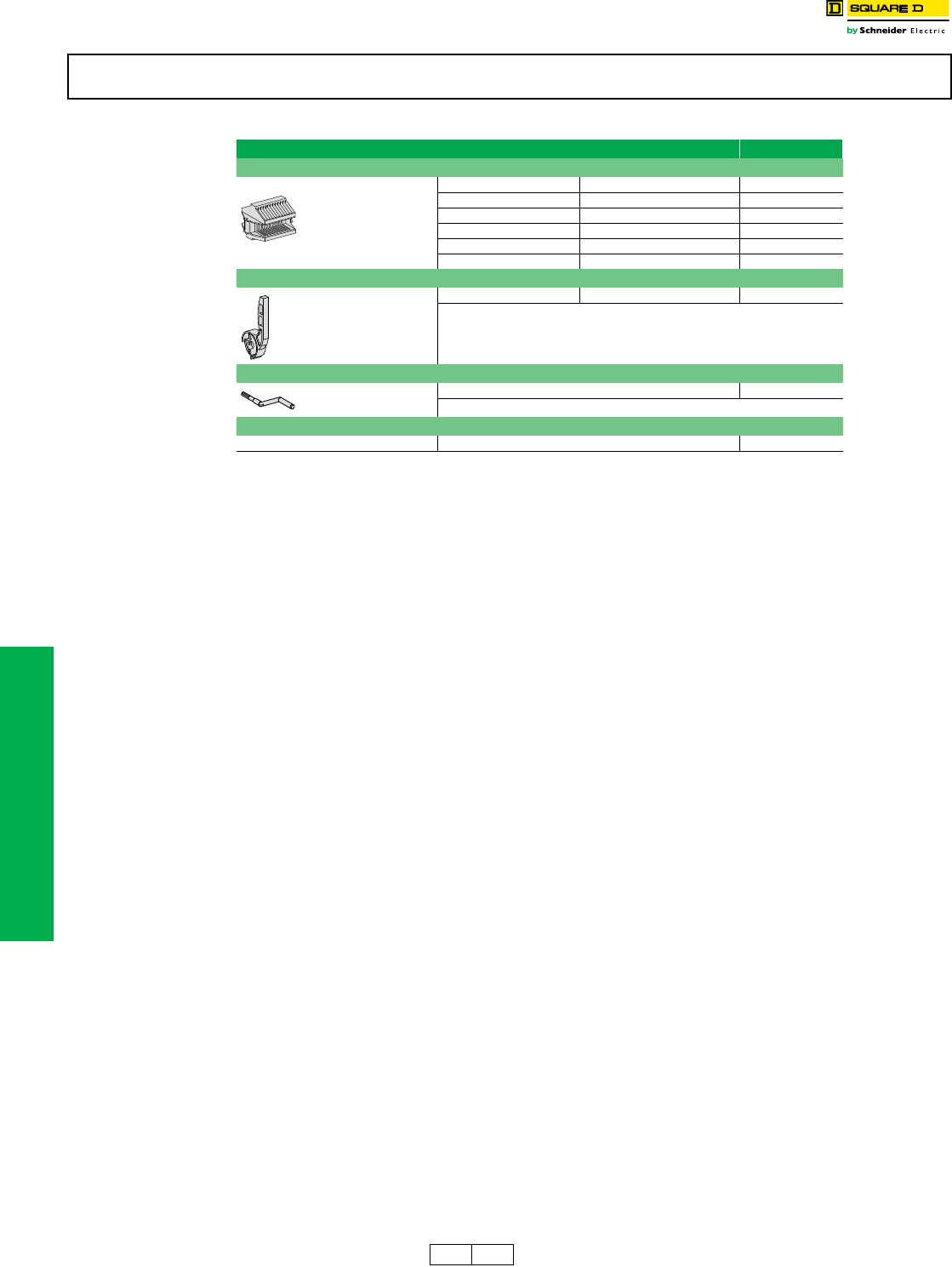
11-30 © 2012 Schneider Electric
All Rights Reserved
www.schneider-electric.us
11 OBSOLETE CIRCUIT BREAKERS
Obsolescent Circuit
Breakers
Masterpact™ M/MP/MC Circuit Breaker Spare Parts
Masterpact™ M/MP/MC circuit breakers and related accessories are obsolete. Use Masterpact NT/NW for new applications. See DIgest
175. Limited service stock is available for replacement or fill purposes. Contact your local sales office for product availability.
Table 11.71: Spare Parts
Spare Parts Cat. No.
Clusters for Cradle (Set of 2)
MP25–MP30 3P M20–M25L 3P 54063 (3)
MP25–MP30 4P M20–M25L 4P 54063 (4)
M32H 3P 54063 (3)
M32H 4P 54063 (4)
MP40–MP50 3P M50H 3P 54063 (6)
M50H 4P 54063 (7)
Charging Handle
One piece 685713
Racking Handle
One piece 685631
Vertical UL 489—UL 1066 Connectors
MP25–MP30 3P (set of three top or bottom connectors) 54107 (2)
For pricing contact your local
Schneider Electric distributor.
DE2F DE2 Discount
Schedule
