Product Detail Manual
2014-11-11
: Pdf 116620-Attachment 116620-Attachment 075352 Batch12 unilog
Open the PDF directly: View PDF ![]() .
.
Page Count: 14

PRODUCT SUBMITTAL / SUBSTITUTION REQUEST
TO:
PROJECT:
SPECIFIED ITEM:
Section Page Paragraph Description
PRODUCT SUBMITTAL / SUBSTITUTION REQUESTED:
The attached submittal package includes the product description, specifications, drawings, and performance data for use in the evaluation
of the request.
SUBMITTED BY:
Name: Signature:
Company:
Address:
Date: Telephone: Fax:
FOR USE BY THE ARCHITECT AND/OR ENGINEER
■■
Approved
■■
Approved as Noted
■■
Not Approved
(If not approved, please briefly explain why the product was not accepted.)
By: Date:
Remarks:
Gas Actuated Fastening Systems from Powers Fasteners, Inc.
PRODUCT INFORMATION
Trak-It®C3
www.powers.com Canada: (905) 673-7295 or (514) 631-4216 Powers USA: (800) 524-3244 or (914) 235-63001
c
SECTION CONTENTS Page No.
General Information...................... 1
Tool Specification .......................... 1
Performance Data.......................... 2
Pin Specifications .......................... 4
Ordering Information.................... 4
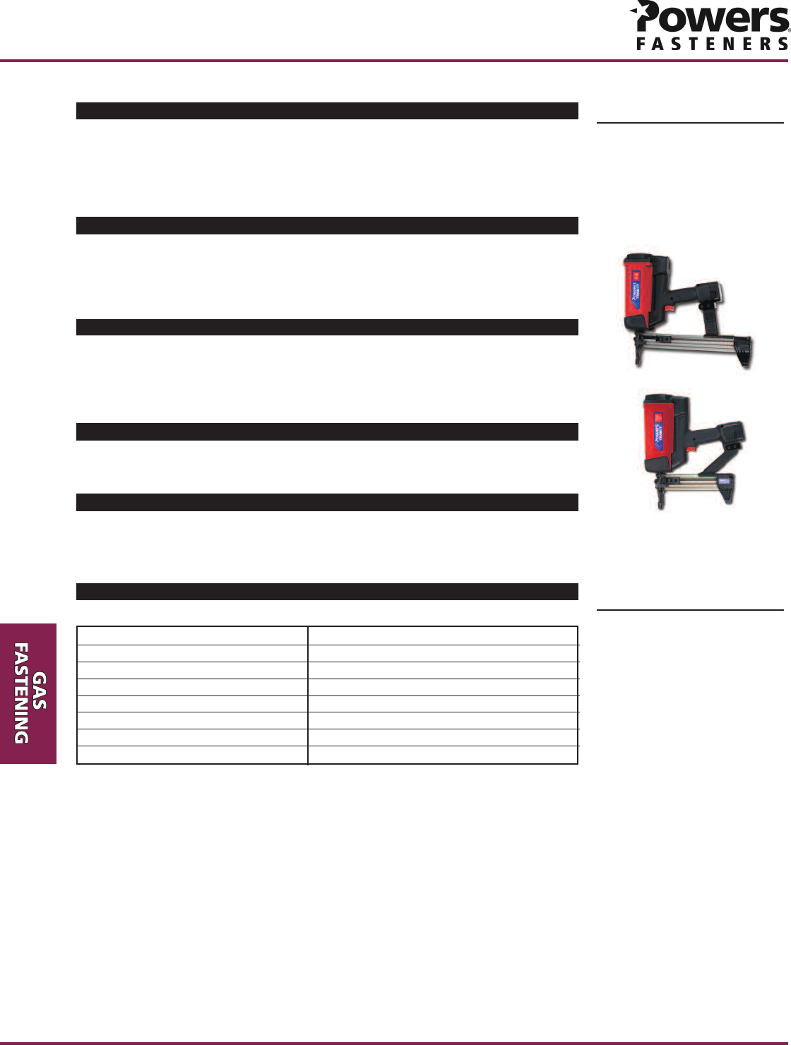
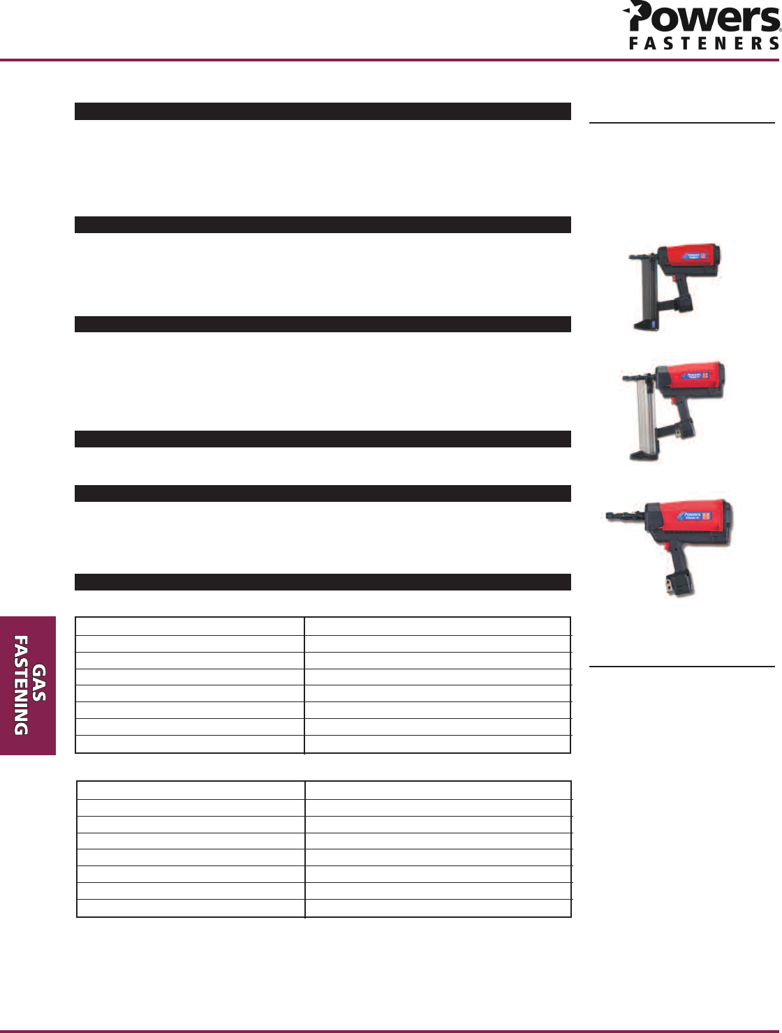
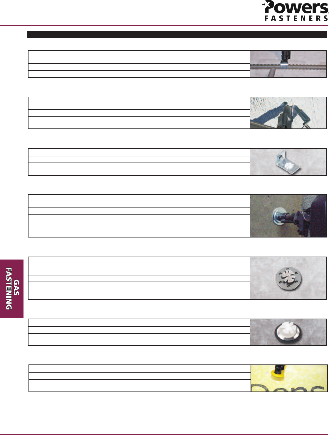
Trak-It C3 Tool
Trak-It C3-ST Tool
(Short Track)
SUITABLE BASE MATERIALS
Normal-Weight Concrete
Structural Lightweight Concrete
Concrete Masonry
Steel
TOOL SPECIFICATIONS
Tool Body Precision Moulded Aluminum and Plastic
Tool Length 17"
Tool Weight 8 lbs
Pin Length 1-1/2" total length
Pin Capacity 42 pins (22 pins - short track)
Power Capacity 90 Joules
Approximate Shots per Fuel Cell 1,000 pins
Approximate Shots per Battery Charge 5,500
Trak-It C3 Tool
Trak-It®C3 Gas Fastening System
PRODUCT DESCRIPTION
The Trak-It C3 gas fastening system was developed for use in light-duty static
applications, including attaching drywall track to concrete, block or steel, lath to concrete
or block, furring strips to concrete or block, and plywood to concrete or block base
materials. The system is designed for speed, efficiency and consistency. Operation of a
gas fastening system does not require licensing.
GENERAL APPLICATIONS AND USES
• Attaching steel track to concrete, block or steel
• Attaching plywood to concrete or block
• Attaching lath to concrete, block or steel
• Attaching furring strips to concrete or block
FEATURES AND BENEFITS
+ No licensing required
+ Each fuel cell contains enough gas to install up to 1,000 fasteners
+ Available for use with Stick-E™ accessories
+ Short or long track versions
APPROVALS AND LISTINGS
International Code Council, Evaluation Service (ICC-ES), ESR-2036 (Formerly ER-6157)
City of Los Angeles (COLA) Research Report LARR-25523
GUIDE SPECIFICATIONS
CSI Divisions: 03151–Concrete Anchoring, 04081-Masonry Anchorage, 05090-Metal
Fastenings, 06090-Wood and Plastic Fastenings, 09260-Finishes. Gas fastening systems
shall be Trak-It as supplied by Powers Fasteners, Inc.
Trak-It®C3
Powers USA: (800) 524-3244 or (914) 235-6300 Canada: (905) 673-7295 or (514) 631-4216 www.powers.com 2
PRODUCT INFORMATION
c
3/4 46100 120 110 190 110 255
(19.1) (101.6) (152.4) (0.44) (0.53) (0.49) (0.85) (0.49) (1.13)
0.102 7/8 46110 125 120 190 120 260
(2.59) (22.2) (101.6) (152.4) (0.49) (0.56) (0.53) (0.85) (0.53) (1.16)
146110 130 120 190 120 265
(25.4) (101.6) (152.4) (0.49) (0.58) (0.53) (0.85) (0.53) (1.18)
5/8 4370 80 75 90 80 100 85 110
(15.9) (101.6) (76.2) (0.31) (0.36) (0.33) (0.40) (0.36) (0.44) (0.38) (0.49)
0.102
3/4 4380 130 105 170 130 210 155 250
(2.59)
(19.1) (101.6) (76.2) (0.36) (0.58) (0.47) (0.76) (0.58) (0.93) (0.69) (1.11)
7/8 4380 160 105 190 130 220 155 250
(22.2) (101.6) (76.2) (0.36) (0.71) (0.47) (0.85) (0.58) (0.98) (0.69) (1.11)
14380 190 105 210 130 230 155 250
(25.4) (101.6) (76.2) (0.36) (0.85) (0.47) (0.93) (0.58) (1.02) (0.69) (1.11)
Minimum Concrete Compressive Strength (f´c)
Min.
Embed.
in.
(mm)
Min.
Spacing
in.
(mm)
Min.
Edge
Distance
in.
(mm)
Shank
Diameter
in.
(mm)
Min.
Embedment
in.
(mm)
Minimum
Spacing
in.
(mm)
Minimum
Edge
Distance
in.
(mm)
Shank
Diameter
in.
(mm)
Min.
Embedment
in.
(mm)
Minimum
Spacing
in.
(mm)
Minimum
Edge
Distance
in.
(mm)
Shank
Diameter
in.
(mm)
Tension Shear Tension Shear Tension Shear Tension Shear
lbs. lbs. lbs. lbs. lbs. lbs. lbs. lbs.
(kN) (kN) (kN) (kN) (kN) (kN) (kN) (kN)
2,000 psi (13.8 MPa) 3,000 psi (20.7 MPa) 4,000 psi (27.6 MPa) 5,000 psi (34.5 MPa)
PERFORMANCE DATA
Allowable Load Capacities for Trak-ItC3 Fasteners Installed in Normal-Weight Concrete1
Minimum Concrete Compressive Strength (f´c)
Tension Shear Tension Shear Tension Shear
lbs. lbs. lbs. lbs. lbs. lbs.
(kN) (kN) (kN) (kN) (kN) (kN)
3,000 psi (20.7 MPa) 4,000 psi (27.6 MPa) 5,000 psi (34.5 MPa)
Allowable Load Capacities for Trak-ItC3 Installed in Structural Lightweight Concrete1
1. Allowable load capacities listed are calculated using a safety factor of 5.0 or greater. Consideration of safety factors of 10 or higher may be necessary depending on the application, such
as life safety or overhead.
1. Allowable load capacities listed are calculated using a safety factor of 5.0 or greater. Consideration of safety factors of 10 or higher may be necessary depending on the application, such
as life safety or overhead.
0.102 3/4 4180 105 85 115
(2.59)
(19.1) (101.6) (25.4) (0.36) (0.47) (0.38) (0.51)
7/8 4185 120 90 130
(22.2) (101.6) (25.4) (0.38) (0.53) (0.40) (0.58)
Minimum Concrete Compressive Strength (f´c)
Tension Shear Tension Shear
lbs. lbs. lbs. lbs.
(kN) (kN) (kN) (kN)
3,000 psi (20.7 MPa) 4,000 psi (27.6 MPa)
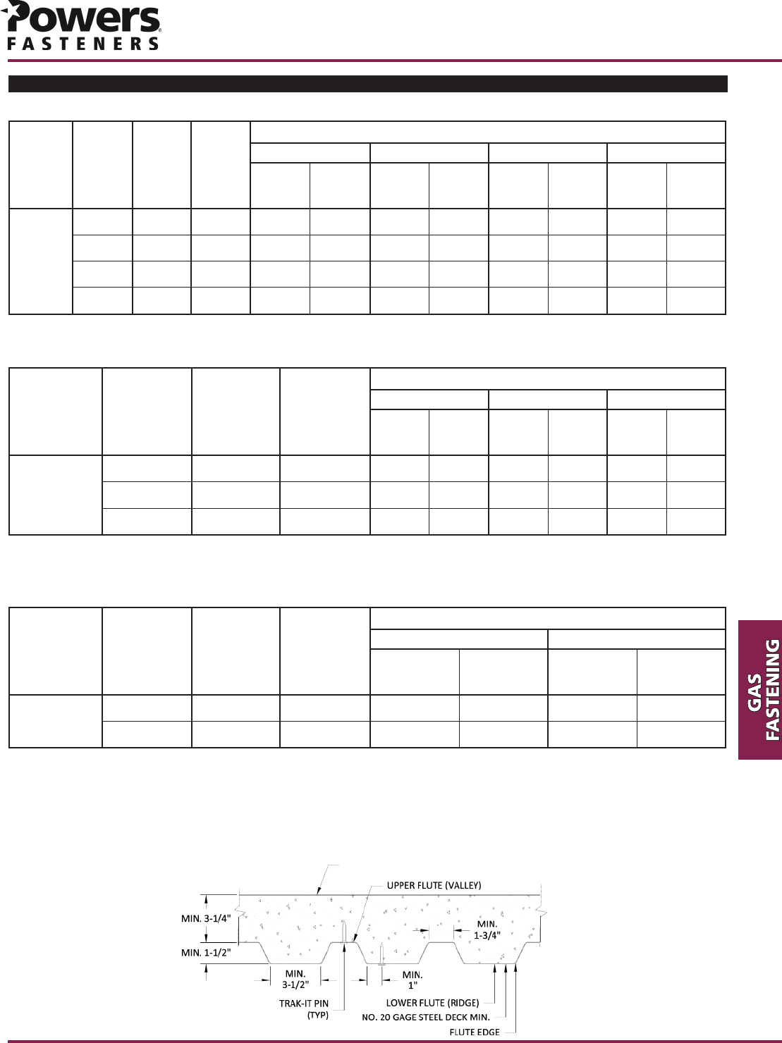
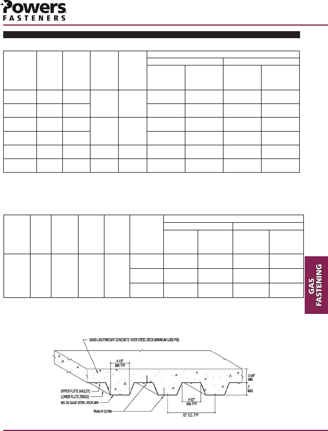
Allowable Load Capacities for Trak-It C3 Fasteners Installed Through Steel Deck into Structural
Lightweight Concrete1,2,3,4
1. Allowable load capacities listed are calculated using a safety factor of 5.0 or greater. Consideration of safety factors of 10 or higher may be necessary depending on the application, such
as life safety or overhead.
2. For fasteners installed through steel deck, the minimum edge distance is 1 inch from the edge of the deck rib and 6 inches from the end of the deck. Allowable shear loads may be applied in
any direction.
3. Fasteners are permitted to be installed in the lower or upper flute of the steel deck provided that proper installation procedures are maintained.
4. The allowable values are applicable to fasteners installed through the underside of a steel deck at the ribs and into minimum 3,000 psi structural lightweight concrete. The steel deck must have
a minimum base-metal thickness of 0.034 inch (20 gage) with a minimum yield point, Fy, of 33,000 psi and conform to the Steel Deck institute requirements for Standard Wide Rib Deck.
STRUCTUAL SAND-LIGHTWEIGHT CONCRETE
OVER STEEL DECK (MINIMUM 3,000 PSI)
PRODUCT INFORMATION
Trak-It®C3
www.powers.com Canada: (905) 673-7295 or (514) 631-4216 Powers USA: (800) 524-3244 or (914) 235-63003
c
0.102 7/8 4 3 3/4 65 80
(2.59)
(22.2) (101.6) (95.3) (0.29) (0.36)
143 3/4 65 120
(25.4) (101.6) (95.3) (0.29) (0.53)
Hollow or Grouted (Any Location)
Tension Shear
lbs. lbs.
(kN) (kN)
f´
m
≥
1,500 psi (10.4 MPa)
Allowable Load Capacities for Trak-It C3 Fasteners Installed in Concrete Masonry Units1,2
1. Allowable load capacities listed are calculated using a safety factor of 5.0 or greater. Consideration of safety factors of 10 or higher may be necessary depending on the application, such
as life safety or overhead.
2. Tabulated load values are for fasteners installed in minimum 6-inch wide, Minimum Grade N, Type II lightweight, medium and normal-weight concrete masonry units conforming to ASTM C 90.
The face shell thickness of the concrete masonry units shall be a minimum of 1-1/4 inch.
PERFORMANCE DATA
Fastener
Type
(Style)
Minimum
Spacing
in.
(mm)
Minimum
Edge
Distance
in.
(mm)
1/2 inch 1 1/2 115 260 165 260 175 255 175 205
Steel Pin (25.4) (12.7) (0.51) (1.16) (0.73) (1.16) (0.78) (1.13) (0.78) (0.91)
Tension Shear Tension Shear Tension Shear Tension Shear
lbs. lbs. lbs. lbs. lbs. lbs. lbs. lbs.
(kN) (kN) (kN) (kN) (kN) (kN) (kN) (kN)
3/16" 1/4" 3/8" 1/2"
1. Allowable load capacities listed are calculated using a safety factor of 5.0 or greater. Consideration of safety factors of 10 or higher may be necessary depending on the application, such
as life safety or overhead.
2. Steel members must have a minimum yield strength, fy, of 36,000 psi
3. Fasteners installed in 1/2-inch-thick steel must have a minimum embedment depth of 3/8-inch.
Allowable Load Capacities for Trak-It C3 Fasteners Installed in ASTM A 36 Steel1,2,3
Nominal Steel Thickness
Fastener
Type
(Style)
Minimum
Spacing
in.
(mm)
Minimum
Edge
Distance
in.
(mm)
1/2 inch 1 1/2 145 290 175 290 215 270 165 250
Steel Pin (25.4) (12.7) (0.64) (1.29) (0.78) (1.29) (0.96) (1.20) (0.73) (1.11)
Tension Shear Tension Shear Tension Shear Tension Shear
lbs. lbs. lbs. lbs. lbs. lbs. lbs. lbs.
(kN) (kN) (kN) (kN) (kN) (kN) (kN) (kN)
3/16" 1/4" 3/8" 1/2"
1. Allowable load capacities listed are calculated using a safety factor of 5.0 or greater. Consideration of safety factors of 10 or higher may be necessary depending on the application, such
as life safety or overhead.
2. Steel members must have a minimum yield strength, fy, of 50,000 psi
3. Fasteners installed in 1/2-inch-thick steel must have a minimum embedment depth of 3/8-inch.
Allowable Load Capacities for Trak-It C3 Fasteners Installed in ASTM A 572 Steel1,2,3
Nominal Steel Thickness
Allowable
Negative Pressure
(psf)
Minimum
Stud Spacing
(inches)
Minimum
Steel Stud
Thickness
(gage)
Fastener
Type
(style)
Plywood/Densglass®
0.102” Diameter
Sheathing
Densglass®Gold 16 24 50
Fastener Spacing
(inches)
6-1/2
1. Allowable load capacities are based on a minimum safety factor of 3.0.
Densglass®is a registered trademark of Georgia Pacific
Allowable Negative Transverse Loads Using Plywood/Densglass®Pin and Denz-TightTM Washer Fasteners1
18 Gage Steel Track
Tension
lbs.
(kN)
16 Gage Steel Track
Tension
lbs.
(kN)
Shank Diameter
in.
(mm)
Fastener
Type
(Style)
Plywood to Steel Pin 0.102
(2.59) 65
(0.29) 40
(0.18)
1. Allowable load capacities listed are calculated using a safety factor of 5.0 or greater. Consideration of safety factors of 10 or higher may be necessary depending on the application, such
as life safety or overhead.
Allowable Load Capacities for Trak-It C3 Plywood Pin Installed Through Plywood into Steel Track1
Min.
Embedment
in.
(mm)
Minimum
Spacing
in.
(mm)
Minimum
Edge
Distance
in.
(mm)
Shank
Diameter
in.
(mm)
Trak-It®C3
Powers USA: (800) 524-3244 or (914) 235-6300 Canada: (905) 673-7295 or (514) 631-4216 www.powers.com 4
PRODUCT INFORMATION
c
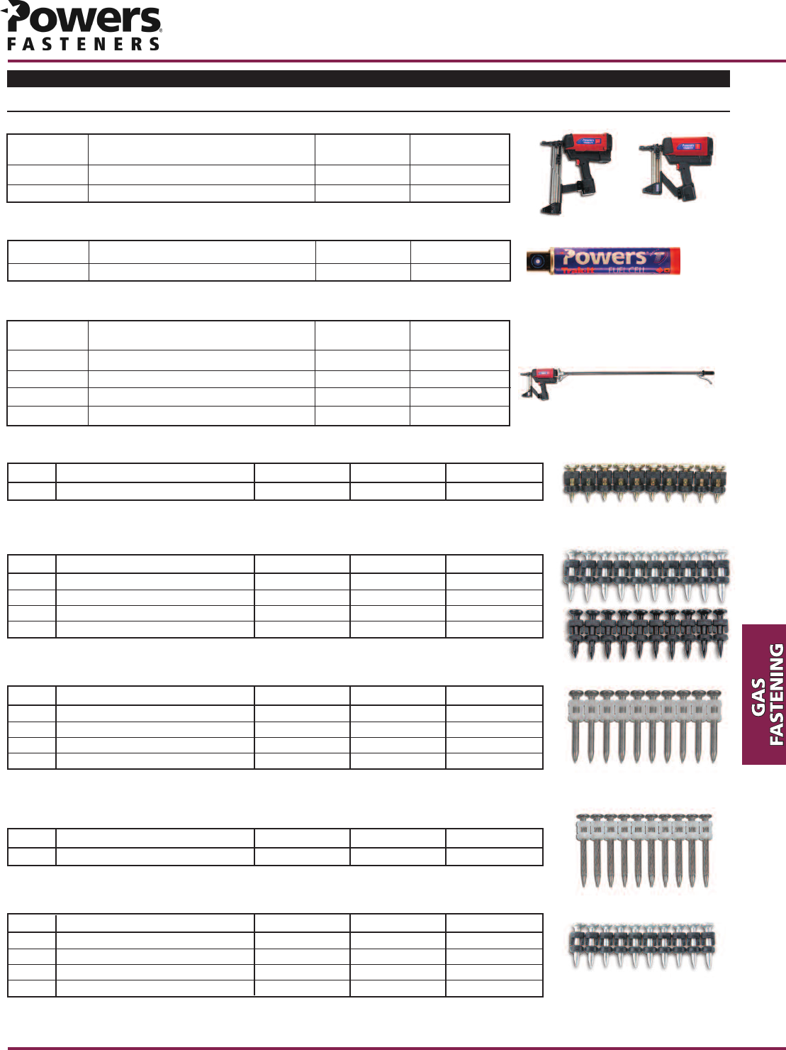
ORDERING INFORMATION
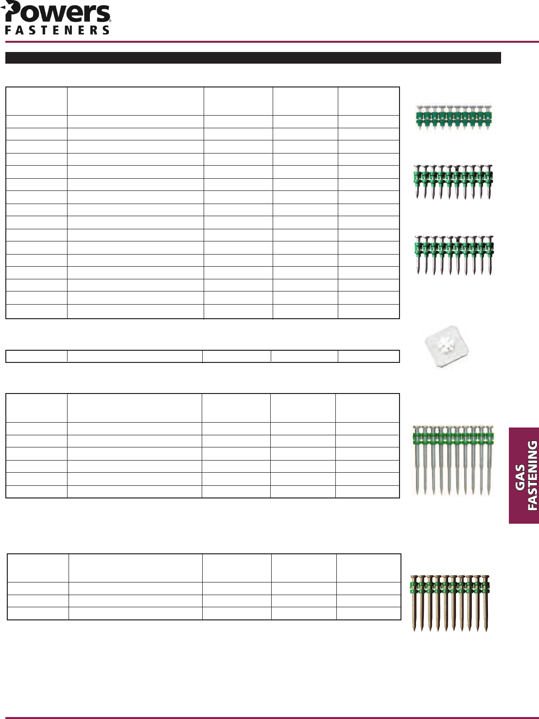
Cat. No. Description Shank Diameter Standard Box Standard Carton
55036 1 3/8" Zinc 0.102" 1,000 5,000
Plywood/Densglass®to Steel Pin (Spiral Knurl Shank with Rolled Point)
Cat. No. Description Shank Diameter Standard Box Standard Carton
55080 780 Step Shank Pin 0.120/0.102" 1,000 5,000
55081 1” Step Shank Pin 0.120/0.088" 1,000 5,000
55087 730 Step Shank Pin 0.120/0.102" 1,000 5,000
55085 680 Step Shank Pin 0.120/0.102" 1,000 5,000
Stick-E Pins (Step Shank)
Designed for use to attach plywood to light gage steel framing. All pins are zinc plated for a minimum level of corrosion resistance (mild service
condition). Each box of pins come packaged with one fuel cell.
Designed for use in hard aggregate and precast concrete. All pins are zinc plated for minimum level of corrosion resistance (mild service condition).
Each box of pins come packaged with one fuel cell.
©2011 Powers Fasteners, Inc. All Rights Reserved. Deszglass is a registered trademark of Georgia Pacific. Trak-It is a registered trademark and Stick-E is a trademark of Powers Fasteners, Inc.
For current information please visit www.powers.com
Cat. No. Description Shank Diameter Standard Box Standard Carton
55020 1/2" Steel Pin 0.120/0.102" 1,000 5,000
1/2" Steel Pin (Step Shank with Rolled Point)
Cat. No. Description Shank Diameter Standard Box Standard Carton
55022B 3/4" Black 0.102" 1,000 5,000
55024 1" Zinc 0.102" 1,000 5,000
55026 1 1/4" Zinc 0.102" 1,000 5,000
55028 1 1/2" Zinc 0.102" 1,000 5,000
Standard Pins (Smooth Shank with Rolled Point)
Designed for use in A36 and A572 steel beams, purlins, and bar joist.All pins are zinc plated for minimum level of corrosion resistance (mild service
condition).
Each box of pins come packaged with one fuel cell.
Designed for use in concrete and masonry. All pins are zinc plated or coated with black oxide for a minimum level of corrosion resistance (mild
service condition). Each box of pins come packaged with one fuel cell.
Cat. No. Description Shank Diameter Standard Box Standard Carton
55032 3/4" Black 0.102" 1,000 5,000
55033 1" Zinc 0.102" 1,000 5,000
55034 1 1/4" Zinc 0.102" 1,000 5,000
55035 1 1/2" Zinc 0.102" 1,000 5,000
Standard Pins with Break-free Collation (Smooth Shank with Rolled Point)
Designed for use in concrete and masonry. All pins are zinc plated or coated with black oxide for a minimum level of corrosion resistance (mild
service condition). Plastic collation breaks completely free of pin during installation.
Each box of pins come packaged with one fuel cell.
C3 Tools and Accessories
Trak-It C3 Tools
Cat No. STD Box STD Ctn.
Discription
1
1
1
1
C3 Trak-It
C3-ST Trak-It
55011
55002
Tool comes with case, charger and two batteries.
Trak-It Pole Tools
Cat No. STD Box STD Ctn.
Discription
1
1
1
1
1
1
1
1
55048
55051
55053
55055
6’ Pole Tool & One Trak-It C3-ST (Short Track) Tool
8’ Pole Tool & One Trak-It C3-ST (Short Track) Tool
6’ Pole Tool
8’ Pole Tool
Fuel cell works in temperatures down to 10°F.
Cat No. STD Box STD Ctn.
Discription
20 80
C3 Trak-It Fuel Cell
55010
Trak-It Fuel Cell
PRODUCT INFORMATION
Trak-It®C4
www.powers.com Canada: (905) 673-7295 or (514) 631-4216 Powers USA: (800) 524-3244 or (914) 235-63005
c
SECTION CONTENTS Page No.
General Information...................... 5
Tool Specification .......................... 5
Performance Data.......................... 6
Pin Specifications .......................... 8
Ordering Information.................... 9
Trak-It C4 Tool
Trak-It C4EX Tool
Trak-It C4CZ Tool
SUITABLE BASE MATERIALS
Normal-Weight Concrete
Structural Lightweight Concrete
Concrete Masonry
Steel
TOOL SPECIFICATIONS
Tool Body Precision Moulded Aluminum and Plastic
Tool Length 17-3/4"
Tool Weight 9.7 lbs
Pin Length 2-9/16" Total Length
Pin Capacity 42 pins
Power Capacity 120 Joules (C4) , 150 Joules (C4EX)
Approximate Shots per Fuel Cell 800 pins
Approximate Shots per Battery Charge 5,500
Trak-It C4 Tool/C4EX Tool
Tool Body Precision Moulded Aluminum and Plastic
Tool Length 17-3/4"
Tool Weight 9.7 lbs
Pin Length 3" Total Length
Pin Capacity Single Shot
Power Capacity 150 Joules
Approximate Shots per Fuel Cell 800 pins
Approximate Shots per Battery Charge 5,500
Trak-It C4CZ Single Shot Tool
Trak-It®C4 High Performance Gas Fastening System
PRODUCT DESCRIPTION
The Trak-It C4 and C4EX gas fastening systems were developed for use in high volume
production applications. Powerful rugged tools for fastening wood to concrete or steel.
The systems are designed for speed, increased power and durability.
The C4 CZ tool was designed for use with single shot powder pins together with gas
fastening technology. Operation of a gas fastening system does not require licensing.
GENERAL APPLICATIONS AND USES
• Attaching wood to concrete, block or steel
• Attaching Steel to concrete, block or steel
• Attaching Plywood to Steel
• Attaching Steel track to concrete
FEATURES AND BENEFITS
+ No licensing required
+ Increased power and durability
+ Handles up to 2-9/16” length fasteners
+ Each fuel cell contains enough gas to install up to 800 fasteners
+ Pin diameter range 0.102” to 0.145”
APPROVALS AND LISTINGS
International Code Council , Evaluation Service (ICC-ES), ESR-2249
GUIDE SPECIFICATIONS
CSI Divisions: 03151–Concrete Anchoring, 04081-Masonry Anchorage, 05090-Metal
Fastenings, 06090-Wood and Plastic Fastening. Gas fastening systems shall be Trak-It as
supplied by Powers Fasteners, Inc.
Allowable Load Capacities for Trak-It C4 Fasteners Installed in Normal Weight Concrete1,2,3
Allowable Load Capacities for Trak-It C4 Fasteners Installed in Lightweight Concrete
and Structural Sand-Lightweight Concrete over Steel Deck1,2,3,4
1. Allowable load capacities listed are calculated using a safety factor of 5.0 or greater. Consideration of safety factors of 10 or higher may be necessary depending on the application, such
as life safety or overhead.
2. The concrete thickness must be a minimum of 3 times the embedment depth of the fastener.
3. The tabulated allowable load values are for the fastener only. Wood or steel members connected to the steel substrate must be investigated in accordance with accepted design criteria.
1. Allowable load capacities listed are calculated using a safety factor of 5.0 or greater. Consideration of safety factors of 10 or higher may be necessary depending on the application, such
as life safety or overhead.
2. The steel deck must have a minimum base material thickness of No. 20 gage.
3. Concrete thickness must be a minimum of 3 times the embedment depth of the fastener. i.e, minimum yield strength, Fy, of 33 ksi, and conform to the Steel Deck Institute requirements for
Standard Wide Rib Deck, Type B.
4. The tabulated allowable load values are for the fastener only. Wood or steel members connected to the steel substrate must be investigated in accordance with accepted design criteria.
Shank
Type
Shank
Diameter
in.
(mm)
Minimum
Embedment
inches
(mm)
Minimum
Spacing
inches
(mm)
Minimum
Edge
Distance
inches
(mm)
Minimum Concrete Compressive Strength (f'c)
2,500 psi (17.2 mPa) 3,000 psi (20.7 mPa)
Tension
lbs.
(kN)
Shear
lbs.
(kN)
Tension
lbs.
(kN)
Shear
lbs.
(kN)
Straight 0.145
(3.68)
3/4
(19.1) 4
(101.6)
3
(76.2)
65
(0.29)
105
(0.47)
70
(0.31)
110
(0.49)
Straight 0.145
(3.68)
7/8
(22.2)
125
(0.56)
105
(0.47)
135
(0.60)
110
(0.49)
Step 0.145
(3.68)
3/4
(19.1) 4
(101.6)
3
(76.2)
80
(0.36)
220
(0.98)
90
(0.40)
235
(1.04)
Step 0.145
(3.68)
1
(25.4)
130
(0.58)
245
(1.09)
140
(0.62)
270
(1.20)
Taper 0.137
(3.48)
3/4
(19.1)
4
(101.6)
1-3/4
(44.5)
80
(0.36)
90
(0.40)
90
(0.40)
100
(0.44)
Taper 0.137
(3.48)
1
(25.4)
4
(101.6)
1-3/4
(44.5)
90
(0.40)
70
(0.31)
100
(0.44)
80
(0.36)
Shank
Type
Shank
Diameter
in.
(mm)
Minimum
Embedment
inches
(mm)
Minimum
Spacing
inches
(mm)
Minimum
Edge
Distance
inches
(mm)
Location
Minimum Concrete Compressive Strength (f'c)
2,500 psi (17.2 mPa) 3,000 psi (20.7 mPa)
Tension
lbs.
(kN)
Shear
lbs.
(kN)
Tension
lbs.
(kN)
Shear
lbs.
(kN)
Straight 0.145
(3.68)
3/4
(19.1)
4
(101.6)
1-1/8
(28.6)
Top 110
(0.49)
150
(0.67)
120
(0.53)
165
(0.73)
Lower Flute 70
(0.31)
180
(0.80)
80
(0.36)
200
(0.89)
Upper Flute 100
(0.44)
205
(0.91)
110
(0.49)
220
(0.98)
© 2011 Powers Fasteners, Inc. All Rights Reserved. Trak-It is a registered trademark of Powers Fasteners, Inc.
Trak-It®C4
Powers USA: (800) 524-3244 or (914) 235-6300 Canada: (905) 673-7295 or (514) 631-4216 www.powers.com 6
PRODUCT INFORMATION
c
PERFORMANCE DATA
PRODUCT INFORMATION
Trak-It®C4
www.powers.com Canada: (905) 673-7295 or (514) 631-4216 Powers USA: (800) 524-3244 or (914) 235-63007
c
Allowable Load Capacities for Trak-It C4 Fasteners Installed in ASTM A36 Steel (minimum f
ut
= 58 ksi)1
1. Allowable load capacities listed are calculated using a safety factor of 5.0 or greater. Consideration of safety factors of 10 or higher may be necessary depending on the application, such
as life safety or overhead.
Allowable Load Capacities for C4 Coated Step Shank ACQ Pin in Normal-Weight Concrete 1,2
1. Allowable load capacities listed are calculated using a safety factor of 5.0 or greater. Consideration of safety factors of 10 or higher may be necessary depending on the application, such
as life safety or overhead.
2. Tabulated values are listed for the fastener only. Wood or steel members connected to the concrete substrate must be investigated in accordance with accepted design criteria.
Fastener Type
(Style)
Shank
Diameter
inches
(mm)
Minimum
Spacing
inches
(mm)
Minimum
Edge
Distance
inches
(mm)
Minimum
Steel
Member
Thickness
inches
(mm)
Tension
lbs
(kN)
Shear
lbs
(kN)
1/2" Steel Pin 0.120
(3.05)
1
(25.4)
1/2
(12.7)
1/4
(6.4)
245
(1.09)
100
(0.44)
.680 Steel Pin 0.120
(3.05)
270
(1.20)
170
(0.75)
.730 Steel Pin 0.120
(3.05)
330
(1.46)
235
(1.04)
1" Steel Pin 0.145
(3.68)
360
(1.60)
360
(1.60)
1-1/4" Steel Pin 0.145
(3.68)
390
(1.73)
310
(1.38)
2" Steel Pin 0.145
(3.68)
240
(1.06)
280
(1.24)
2" Steel Pin (ACQ) 0.145
(3.68)
170
(0.75)
280
(1.24)
Fastener Type
(Style)
Minimum
Embedment
in.
(mm)
Minimum Concrete Compressive Strength
4,000 psi (27.6 mPa)
Tension
lbs.
(kN)
Shear
lbs.
(kN)
C4 Coated Step Shank ACQ Pin 3/4
(19.1)
200
(0.89)
280
(1.24)
PERFORMANCE DATA
Trak-It®C4
Powers USA: (800) 524-3244 or (914) 235-6300 Canada: (905) 673-7295 or (514) 631-4216 www.powers.com 8
PRODUCT INFORMATION
c
Cat No. Shank
Diameter STD Box STD Ctn.
Description
55111
55113
55130
55132
55124
55128
55145
55147
55161
55163
55165
55116
55118
55172
55173
55174
0.102
0.102
0.145
0.145
0.102
0.102
0.137
0.137
0.120
0.102
0.120
0.102
0.102
0.145
0.145
0.145
800
800
800
800
800
800
800
800
800
800
800
800
800
800
800
800
4000
4000
4000
4000
4000
4000
4000
4000
4000
4000
4000
4000
4000
4000
4000
4000
3/4” Pin
1” Pin
3/4" Straight Shank Pin
1” Straight Shank Pin
2-1/4” Pin
2-1/2” Pin
2-9/16” Taper Pin
2-9/16” Taper Pin w/ Washer
.500 Pin, (K)
.680 Pin, (K)
.730 Pin, (K)
1-1/4” Pin
1-1/2” Pin
1” Wood / Steel Pin, (K)
1-1/4” Wood / Steel Pin, (K)
2” Wood / Steel Pin, (K)
Cat No. Shank
Diameter STD Box STD Ctn.
Description
55134
55136
55141
55138
55140
55139
0.145/0.102
0.145/0.102
0.145/0.102
0.145/0.102
0.145/0.102
0.145/0.102
800
800
800
800
800
800
4000
4000
4000
4000
4000
4000
1-1/4” Step Shank Pin
1-1/2” Step Shank Pin
1-7/8” Step Shank Pin, (K)
2-3/8” Step Shank Pin
2-1/2” Step Shank Pin
2-1/4” Step Shank Pin
Cat No. Shank
Diameter STD Box STD Ctn.
Description
55167
55169
55171
0.145
0.145
0.145
800
800
800
4000
4000
4000
1” Step Shank Pin ACQ, (K)
1-1/4” Step Shank Pin ACQ, (K)
2” Step Shank Pin ACQ, (K)
(K) = knurled
Each box of pins come packaged with one fuel cell.
(K) = knurled
Each box of pins come packaged with one fuel cell.
(K) = knurled
Each box of pins come packaged with one fuel cell.
55149 -800 -
1” Square Washer (Stick E)
C4 Pins - Straight and Taper Pins
C4 Step Shank Pins
C4 Coated Step Shank Pins (ACQ)
ORDERING INFORMATION
ORDERING INFORMATION
Tools and Accessories
Fuel cell works in temperatures down to 10°F.
Tools comes with case, charger and two batteries.
PRODUCT INFORMATION
Trak-It®
www.powers.com Canada: (905) 673-7295 or (514) 631-4216 Powers USA: (800) 524-3244 or (914) 235-63009
c
Trak-It C4 Fuel Cell
Cat No. STD Box STD Ctn.
Description
12 72
C4 Trak-It Fuel Cell
55115
Cat No. STD Box STD Ctn.
Description
500 _
C4 Insulation Washer
55160
Cat No. STD Box STD Ctn.
Description
800
Shank
Diameter
0.131” 4,000
2-1/4” Duplex Kicker Pin
55180
Trak-It C4 Tools
Cat No. STD Box STD Ctn.
Description
1
1
1
1
1
1
C4 Trak-It
C4 EX Trak-It
C4 CZ Trak-It
55112
55127
55133
© 2011 Powers Fasteners, Inc. All Rights Reserved. Trak-It is a registered trademark of Powers Fasteners, Inc. For the most current information Visit www.powers.com
Trak-It®/ Stick-E
Powers USA: (800) 524-3244 or (914) 235-6300 Canada: (905) 673-7295 or (514) 631-4216 www.powers.com 10
PRODUCT INFORMATION
c
Stick-E Accessories for Trak-It C3
PRODUCT DESCRIPTION
The Stick-E fastening system uses Trak-It C3 gas technology with specially designed accessories for fastening typical applications
encountered by electricians and mechanical contractors. The Stick-E fastening system allows direct fastening through the fixture
with the magazine pin and accessory eliminating the need for drilling or anchoring.
Application For attaching small and large diameter cable ties to all types of walls and
ceilings including wood, steel beams, concrete and block. Ideal for strapping
wires and cable for hanging temporary lighting fixtures from all base materials.
(fits ties up to 1/4" wide.)
Contractor(s) Electricians
Suggested Pin Size(s) 780 Trak-It Step Shank Pins
Cable Tie Donut
Application For attaching conduit and light duty pipe to walls and ceilings of any base
material including wood, steel beams, concrete and steel purlins.
Contractor(s) Electricians
Suggested Pin Size(s) 780 Trak-It Step Shank Pins
Conduit Clip (One Hole Strap)
Application For suspending single or multiple wires and cable in runs from overhead ceilings
of all base materials including wood, steel beams, concrete and steel purlins.
Contractor(s) Electricians
Suggested Pin Size(s) 780 Trak-It Step Shank Pins
1" Trak-It Step Shank Pins
Bridal Ring
Application For attaching BX cable to walls and ceilings of any base material including
wood, steel beams, concrete and steel purlins.
Contractor(s) Cable Installers, Telecommunication Installers, Electricians
Suggested Pin Size(s) 780 Trak-It Step Shank Pins
BX Clip
Application For attaching duct straps to suspend HVAC ductwork onto ceiling of various
base materials.
Contractor(s) Sheet Metal Contractors
Suggested Pin Size(s) 780 Trak-It Step Shank Pins
Strap Washer
Mini Conduit Clip
APPLICATIONS GUIDE
Application For attaching conduit and piping to steel beams, wood and concrete ceilings.
Contractor(s) Electricians
Suggested Pin Size(s) 780 Trak-It Step Shank Pins
PRODUCT INFORMATION
Trak-It®/ Stick-E
www.powers.com Canada: (905) 673-7295 or (514) 631-4216 Powers USA: (800) 524-3244 or (914) 235-630011
c
Application For attaching rebar to existing concrete or wood forms prior to a pour.
Most popular in road and bridge construction and repair.
Contractor(s) Concrete Contractors
Suggested Pin Size(s) 780 Trak-It Step Shank Pins
Rebar Basket Clip
Application Attaching rod overhead to steel beams, wood or concrete ceilings for the
purpose of suspending utilities, cable trays, conduit and pipe.
Contractor(s) Electricians, Plumbers, Mechanical Contractors
Suggested Pin Size(s) 780 Trak-It Step Shank Pins
Break-Free Pins
Rod Hanger
APPLICATIONS GUIDE
Right Angle Clip
Application For suspending acoustical ceiling systems or light fixtures.
Contractor(s) Acoustical and Ceiling Contractors
Suggested Pin Size(s) 780 Trak-It Step Shank Pins
Break-Free Pins
Insulation Washer
Application For attaching exterior foam insulation to all base materials including wood,
steel and concrete.
Contractor(s) Insulation Contractors, Waterproofers
Suggested Pin Size(s) 780 Trak-It Step Shank Pins
Break-Free Pins
1 1/4" Break Free Rolled Point Trak-It Pins (most base materials)
1 1/2" Break Free Rolled Point Trak-It Pins (most base materials)
Stainless Steel Sealing Washer
Application For attaching waterproofing membrane to foundations and roofing applications.
Contractor(s) Insulation Contractors, Waterproofers, Roofers
Suggested Pin Size(s) 3/4" Perma-Seal Coated Rolled Point Trak-It Pins (most base materials)
1" Perma-Seal Coated Rolled Point Trak-It Pins (most base materials)
Lathing Washer
Application For attaching wire lathe to wood, steel, concrete or block for the purpose of
troweling stucco in exterior applications or plaster in interior applications. Can also
be used as a general purpose washer.
Contractor(s) Drywall, Plaster, Exterior Siding Contractors
Suggested Pin Size(s) 780 Trak-It Step Shank Pins
1" Break Free Rolled Point Trak-It Pins (most base materials)
1 1/4" Break Free Rolled Point Trak-It Pins (most base materials)
Application For attaching Densglass®exterior sheathing to steel studs.
Contractor(s) Drywall Contractors
Suggested Pin Size(s) 1-3/8” Plywood/Densglass®Pins
Denz-TightTM Washer
*Densglass®is a registered trademark of Georgia Pacific.
Trak-It®/ Stick-E
Powers USA: (800) 524-3244 or (914) 235-6300 Canada: (905) 673-7295 or (514) 631-4216 www.powers.com 12
PRODUCT INFORMATION
c
Conduit Clip 3/4 80 60
(19.1) (0.35) (0.27)
BX Clip 3/4 80 70
(19.1) (0.35) (0.31)
Bridal Ring 3/4 325 200
(19.1) (1.44) (0.89)
Cable Tie 3/4 50 60
(19.1) (0.22) (0.27)
Insulation Washer 3/4 300 400
(19.1) (1.33) (1.78)
Rebar Clip 3/4 275 275
(19.1) (1.22) (1.22)
Strap Washer 3/4 275 400
(19.1) (1.22) (1.78)
Rod Hanger 3/4 420 N/A
(19.1) (1.86)
Right Angle Clip 3/4 300 400
(19.1) (1.33) (1.78)
Ultimate Load
Minimum
Embed. Depth
hv
in.
(mm)
Stick-E Tension Shear
lbs. lbs.
(kN) (kN)
PERFORMANCE DATA
1.The values listed above are ultimate load capacities which should be reduced by a minimum safety factor of 5.0 or greater to determine the allowable working load. Consideration of safety factors of 10.0 or
higher may be necessary depending on the application, such as life safety or overhead.
2. Minimum 2,000 psi Concrete or Concrete Block at time of installation.
1.The values listed above are ultimate load capacities which should be reduced by a minimum safety factor of 5.0 or greater to determine the allowable working load. Consideration of safety factors of 10.0 or
higher may be necessary depending on the application, such as life safety or overhead.
Conduit BX Clip 3/4 80 70 80 70 80 70
(19.1) (0.35) (0.35) (0.35) (0.35) (0.35) (0.35)
Bridal Ring 3/4 325 200 325 200 325 200
(19.1) (1.44) (0.89) (1.44) (0.89) (1.44) (0.89)
Cable Tie 3/4 50 60 50 60 50 60
(19.1) (0.22) (0.27) (0.22) (0.27) (0.22) (0.27)
Strap Washer 3/4 275 400 275 400 275 400
(19.1) (1.22) (1.78) (1.22) (1.78) (1.22) (1.78)
Rod Hanger 3/4 420 N/A 420 N/A 420 N/A
(19.1) (1.86) (1.86) (1.86)
Ultimate Load
Minimum
Embedment
Depth
hv
in.
(mm)
Stick-E
Tension Shear Tension Shear Tension Shear
lbs. lbs. lbs. lbs. lbs. lbs.
(kN) (kN) (kN) (kN) (kN) (kN)
(3/16" Thick) (1/8" Thick) (12 Gage)
A36 Steel A572 Steel A572 Steel
Ultimate Load Capacities for Stick-E Accessories Installed with 780 Pin into A36 and A572 Steel1
Ultimate Load Capacities for Stick-E Accessories Installed with 780 Pin into Concrete, Concrete Block,
or Lightweight Concrete over Steel Deck1,2
Ultimate Load Capacites for Electrical Boxes Installed with 780 Trak-It Step Shank Pin into Concrete
or Concrete Block1,2,3
21Line 640 975 850
(25.5) (2.85) (4.34) (3.78)
780 5/8 32Triangle 720 1,115 1,055
(15.9) (50.9) (3.20) (4.96) (4.69)
42Square/Diamond 900 1,840 1,840
(50.9) (4.00) (8.18) (8.18)
Ultimate Load
Trak-It Pin
Shear
Horiz. Axis
lbs.
(kN)
Shear
Vert. Axis
lbs.
(kN)
Tension
lbs.
(kN)
Maximum
Spacing
in.
(mm)
Fastening
Pattern
Number
of Pins
(Per Box)
Minimum
Embed. Depth
hv
in.
(mm)
1. The values listed above are ultimate load capacities which should be reduced by a minimum safety factor of 5.0 or greater to determine the allowable working load. Consideration of safety factors of 10.0 or higher may be
necessary depending on the application, such as life safety or overhead.
1. Installations for Nominal 16 Gage Electrical Boxes, All Finishes.
2. Minimum 2,000 psi Concrete of Concrete Block at time of installation.
Cat. No. Description Standard Box Standard Carton
55157 Denz-TightTM Washer 100 1,000
Cat. No. Description Standard Box Standard Carton
55059 Conduit Clip 1/2" 100 1,000
55061 Conduit Clip 3/4" 100 1,000
55063 Conduit Clip 1" 100 1,000
PRODUCT INFORMATION
Trak-It®/ Stick-E
www.powers.com Canada: (905) 673-7295 or (514) 631-4216 Powers USA: (800) 524-3244 or (914) 235-630013
c
Cat. No. Description Standard Box Standard Carton
55092 Right Angle Clip (Wirehole 0.278") 100 1,000
Stick-E Right Angle Clip
Cat. No. Description Standard Box Standard Carton
55042 Insulation Washer 1 7/16" 100 1,000
Stick-E Insulation Washer
Cat. No. Description Standard Box Standard Carton
55040 Lathing Washer 1" with holes 100 1,000
Stick-E Lathing Washer
Cat. No. Description Standard Box Standard Carton
55043 SS Sealing Washer 3/4" 100 1,000
Stick-E Stainless Steel Sealing Washer
Stick-E Denz-TightTM Washer
ORDERING INFORMATION
Cat. No. Description Standard Box Standard Carton
55064 Mini Conduit Clip 1/2" 100 1,000
55066 Mini Conduit Clip 3/4" 100 1,000
55068 Mini Conduit Clip 1" 100 1,000
Stick-E Mini Conduit Clip
Cat. No. Description Standard Box Standard Carton
55076 Cable Tie Donut 100 1,000
Stick-E Cable Tie Donut
Stick-E Conduit Clip (One Hole Strap)
Cat. No. Description Standard Box Standard Carton
55054 Stick-E 3/8" BX Clips 100 1,000
Stick-E BX Clip
Cat. No. Description Standard Box Standard Carton
55094 Bridal Ring 1 1/4" 100 1,000
55095 Bridal Ring 1 1/2" 100 1,000
55096 Bridal Ring 2" 100 1,000
Stick-E Bridal Ring
Cat. No. Description Standard Box Standard Carton
55062 Strap Washer 1/2" Diameter 100 1,000
Stick-E Strap Washer
Cat. No. Description Standard Box Standard Carton
55050 Rod Hanger 1/4" 100 1,000
55052 Rod Hanger 3/8" 100 1,000
Stick-E Rod Hanger
Cat. No. Description Standard Box Standard Carton
55070 #3 and #4 Bar 100 1,000
Stick-E Rebar Basket Clip
© 2011 Powers Fasteners, Inc. All Rights Reserved. Stick-E is a registered trademark of Powers Fasteners, Inc. For the most current information Visit www.powers.com
