8_73850_Accessories 117248 Catalog
2014-09-04
: Pdf 117248-Catalog 117248-Catalog 662488 Batch7 unilog
Open the PDF directly: View PDF ![]() .
.
Page Count: 54
173More information online at bannerengineering.com
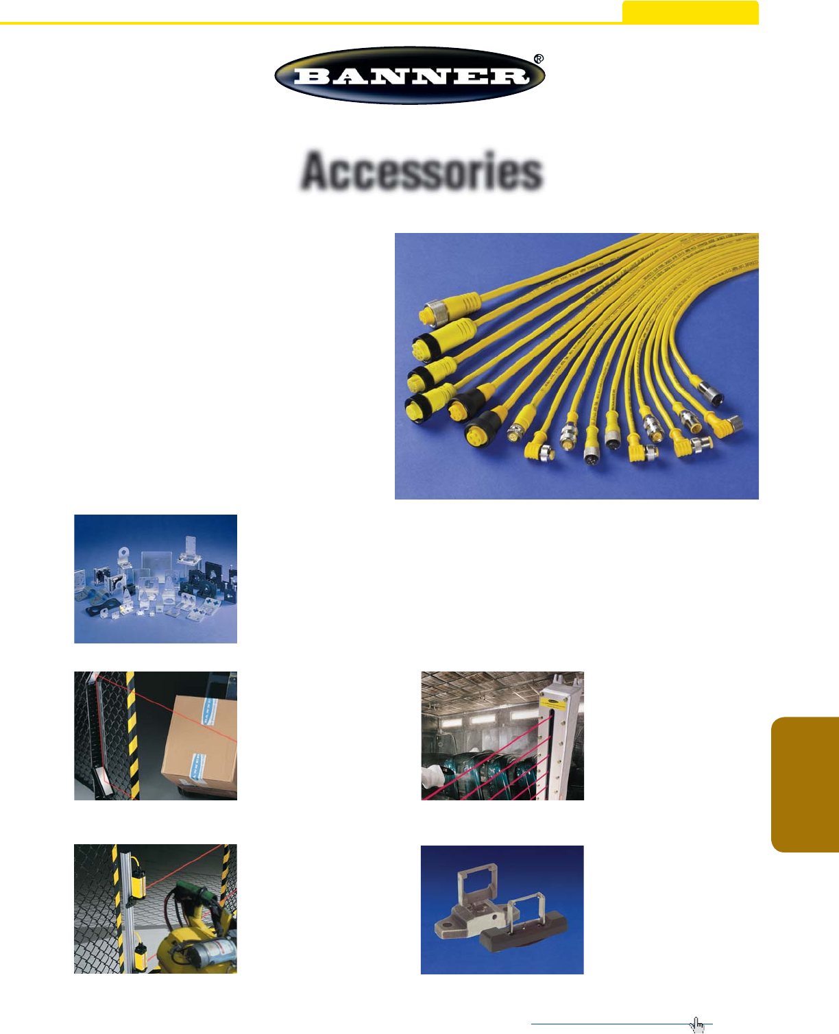
ACCESSORIES
ACCESSORIES
Corner Mirrors . . . . . page 204
• Mirrors expand guarding to multiple
sides of an area using one emitter/
receiver pair.
• Rotating end caps allow mirrors to rotate
to any angle.
• Glass and stainless steel models include
brackets for quick installation.
Accessories
Cables & Wiring Products . . . . . . . . . . page 174
• Choice of cable styles and lengths for each sensor or
module makes installation easier.
• PICO-GUARD plastic optical fibers are available in precut
lengths or in bulk.
• Cable glands and conduit adapters are available for use
with bulk cable.
• Interface boxes supply 24V dc power to emitters and
receivers.
• Indicator lights and lamps show remote indication of
device status.
• Contactor accessories enhance the use of high current
for a safety system.
Mounting Brackets. . . . . . . . . . . . . . . . . . . . . . . . . . . . . . . . . . . . . . . . . . . . . . . . . . . . . . page 190
• Broad offering of bracket styles makes it easy to install sensors vertically, horizontally, or diagonally.
• Swivel brackets offer greater range of motion.
• Adapter brackets provide mounting flexibility.
• Retrofit brackets enable you to install a different emitter/receiver using existing mounting holes.
• Replacement brackets are available for brackets included with emitters/receivers.
Stands. . . . . . . . . . . . page 209
• Stands reliably support Banner light
screens and corner mirrors.
• Standalone and mounting models have
dual channels to allow easy and accurate
height adjustment.
• Protective stands shield emitters/
receivers from impact and debris.
Explosive & Harsh Duty . page 212
• Lens shields protect emitter and receiver
lenses from impact and contamination.
• Tubular enclosures guard entire
EZ-SCREEN® or MINI-SCREEN® emitter/
receiver in a washdown environment.
• Protective enclosures provide rugged
protection for emitters/receivers and
mirrors.
• Explosion-proof enclosures protect
emitters/receivers in environments with
flammable gases, liquids or dust.
Replacement Parts. . . page 220
• Parts are available to replace lost
or damaged parts or to retrofit other
manufacturers’ parts.
• Replacement parts are designed to be
easy to swap in.
174 More information online at bannerengineering.com
ACCESSORIES
Cables & Wiring Products
CABLES &
WIRING
BRACKETS
CORNER
MIRRORS
STANDS
HARSH DUTY
SOLUTIONS
ACCESSORIES
REPLACEMENT
PARTS
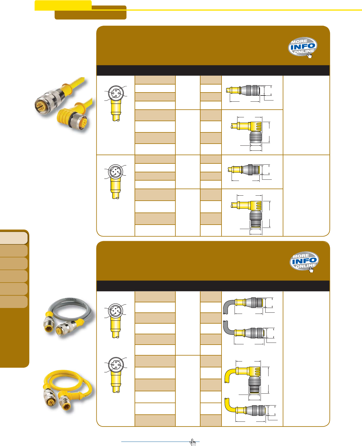
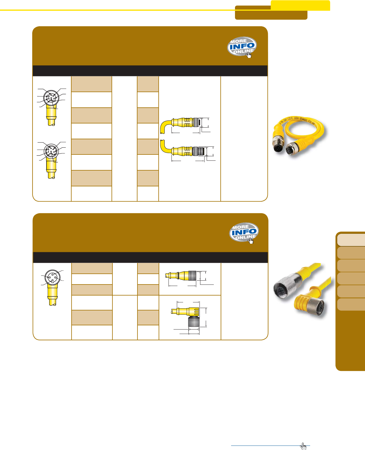
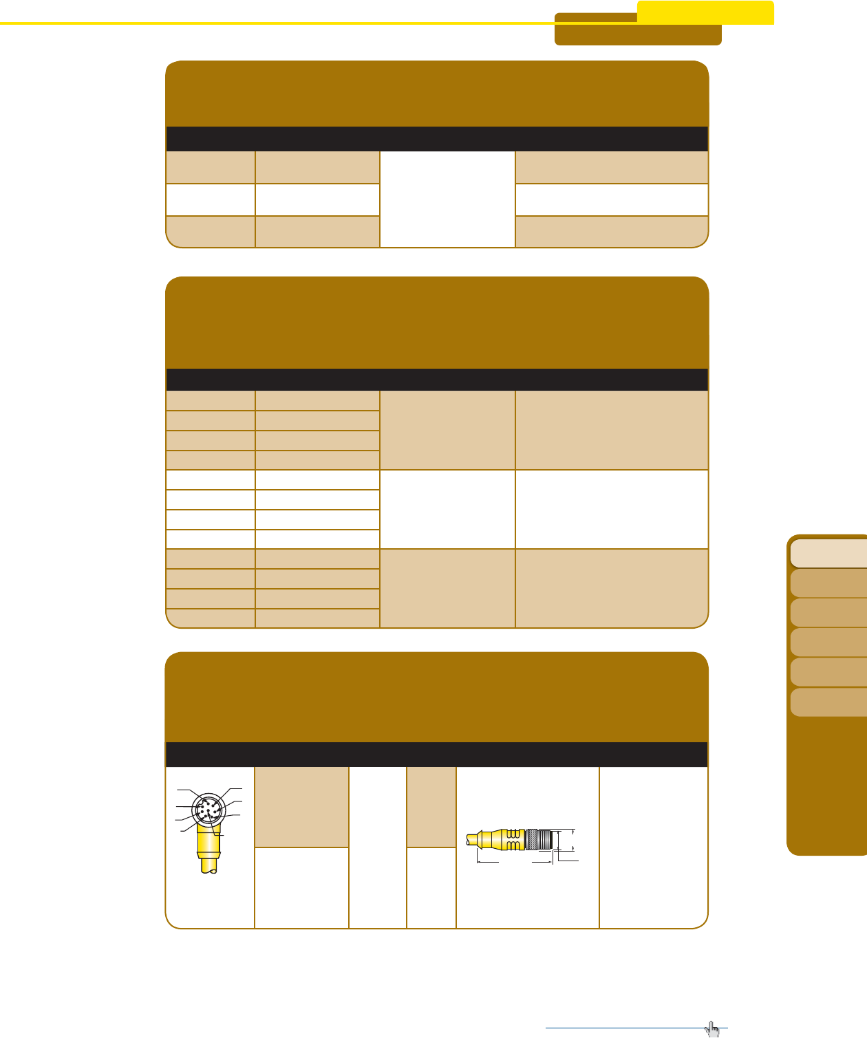
4-Pin Euro-Style Cables - Double Ended
Cable: PVC jacket, polyurethane connector body, chrome-plated brass coupling nut
Conductors: 22 or 20 AWG high-flex stranded, gold-plated contacts
Temperature: -40° to +90° C
Voltage Rating: 250V ac/300V dc
Pinout Model Style Length Dimensions Used With
2
3
4
1
MQDC-406
Female
Straight
2 m
M12 x 1
ø 15 mm
44 mm
max.
• STB w/solid-state
relay
• Muting Module
MQDC-415 5 m
MQDC-430 9 m
MQDC-450 15 m
MQDC-406RA
Female
Right Angle
2 m 38 mm
max.
M12 x 1
ø 15 mm
38 mm
max.
MQDC-415RA 5 m
MQDC-430RA 9 m
MQDC-450RA 15 m
2
34
1
MQDMC-406
Male
Straight
2 m
M12 x 1
ø 15 mm
44 mm
max.
• Muting Module
MQDMC-415 5 m
MQDMC-430 10 m
MQDMC-450 15 m
MQDMC-406RA
Male
Right Angle
2 m 38 mm
max.
M12 x 1
ø 15 mm
38 mm
max.
MQDMC-415RA 5 m
MQDMC-430RA 10 m
MQDMC-450RA 15 m
4-Pin Euro-Style Cables
Cable: PVC jacket, polyurethane connector body, chrome-plated brass coupling nut
Conductors: 20 or 22 AWG high-flex stranded, gold-plated contacts
Temperature: -40° to +90° C
Voltage Rating: 250V ac/300V dc
Pinout Model Style Length Dimensions Used With
Male
2
34
1
Female
2
3
4
1
MQDEC-403SS
Male
Straight/
Female
Straight
1 m
M12 x 1
ø 15 mm
44 mm
max.
M12 x 1
ø 15 mm
44 mm
max.
• Muting Module
MQDEC-406SS 2 m
MQDEC-412SS 4 m
MQDEC-420SS 7 m
MQDEC-430SS 10 m
MQDEC-450SS 15 m
MQDEC-403RS
Male Right
Angle/
Female
Straight
1 m
M12 x 1
ø 15 mm
44 mm
max.
38 mm
max.
M12 x 1
ø 15 mm
38 mm
max.
MQDEC-406RS 2 m
MQDEC-412RS 4 m
MQDEC-420RS 7 m
MQDEC-430RS 10 m
MQDEC-450RS 15 m
1 = Brown
2 = White
3 = Blue
4 = Black
1 = Brown
2 = White
3 = Blue
4 = Black
1 = Brown
2 = White
3 = Blue
4 = Black
175More information online at bannerengineering.com
Cables & Wiring Products
ACCESSORIES
CABLES &
WIRING
BRACKETS
CORNER
MIRRORS
STANDS
HARSH DUTY
SOLUTIONS
ACCESSORIES
REPLACEMENT
PARTS
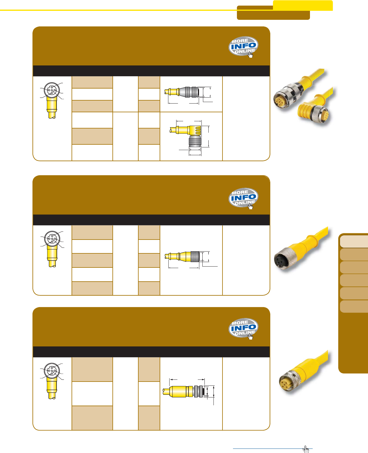
5-Pin Euro-Style Cables with Shield and "Twisted Pair"
Cable: PVC jacket, polyurethane connector body, chrome-plated brass coupling nut
Conductors: 20 AWG high-flex stranded, gold-plated contacts
Temperature: -40° to +90° C
Voltage Rating: 250V ac/300V dc
5-Pin Euro-Style Cables with Green/Yellow Grounding Wire
Cable: PVC jacket, polyurethane connector body, chrome-plated brass coupling nut
Conductors: 22 AWG high-flex stranded, gold-plated contacts
Temperature: -40° to +90° C
Voltage Rating: 250V ac/300V dc
5-Pin Euro-Style Cables
Cable: PVC jacket, polyurethane connector body, chrome-plated brass coupling nut
Conductors: 22 or 20 AWG high-flex stranded, gold-plated contacts
Temperature: -40° to +90° C
Voltage Rating: 250V ac/300V dc
Pinout Model Style length Dimensions Used With
2
3
5
4
1
MQDC1-506
Female
Straight
2 m
M12 x 1
ø 15 mm
44 mm
max.
• STB w/em relay
MQDC1-515 5 m
MQDC1-530 9 m
MQDC1-506RA
Female
Right
Angle
2 m 38 mm
max.
M12 x 1
ø 15 mm
38 mm
max.
MQDC1-515RA 5 m
MQDC1-530RA 9 m
1 = Brown
2 = White
3 = Blue
4 = Black
5 = Gray
Pinout Model Style Length Dimensions Used With
2
3
5
4
1QDE-515D
Female
Straight
5 m
ø M12 x 1
ø 15 mm
46 mm
max.
• EZ-SCREEN
Emitters w/5-pin
QD & Test (14 &
30 mm Resolution)
• AC Interface Boxes
QDE-525D 8 m
QDE-550D 15 m
QDE-575D 23 m
QDE-5100D 30 m
1 = Brown
2 = White
3 = Blue
4 = Black
5 = Green/Yellow
Pinout Model Style Length Dimensions Used With
2
3
5
4
1QDU-515C
Female
Straight
5 m
43 mm max.
14.2 mm
M12 x 1
• MICRO-SCREEN
QDU-525C 8 m
QDU-550C 15 m
1 = Brown
2 = White
3 = Blue
4 = Black
5 = Drain
176 More information online at bannerengineering.com
ACCESSORIES
Cables & Wiring Products
CABLES &
WIRING
BRACKETS
CORNER
MIRRORS
STANDS
HARSH DUTY
SOLUTIONS
ACCESSORIES
REPLACEMENT
PARTS
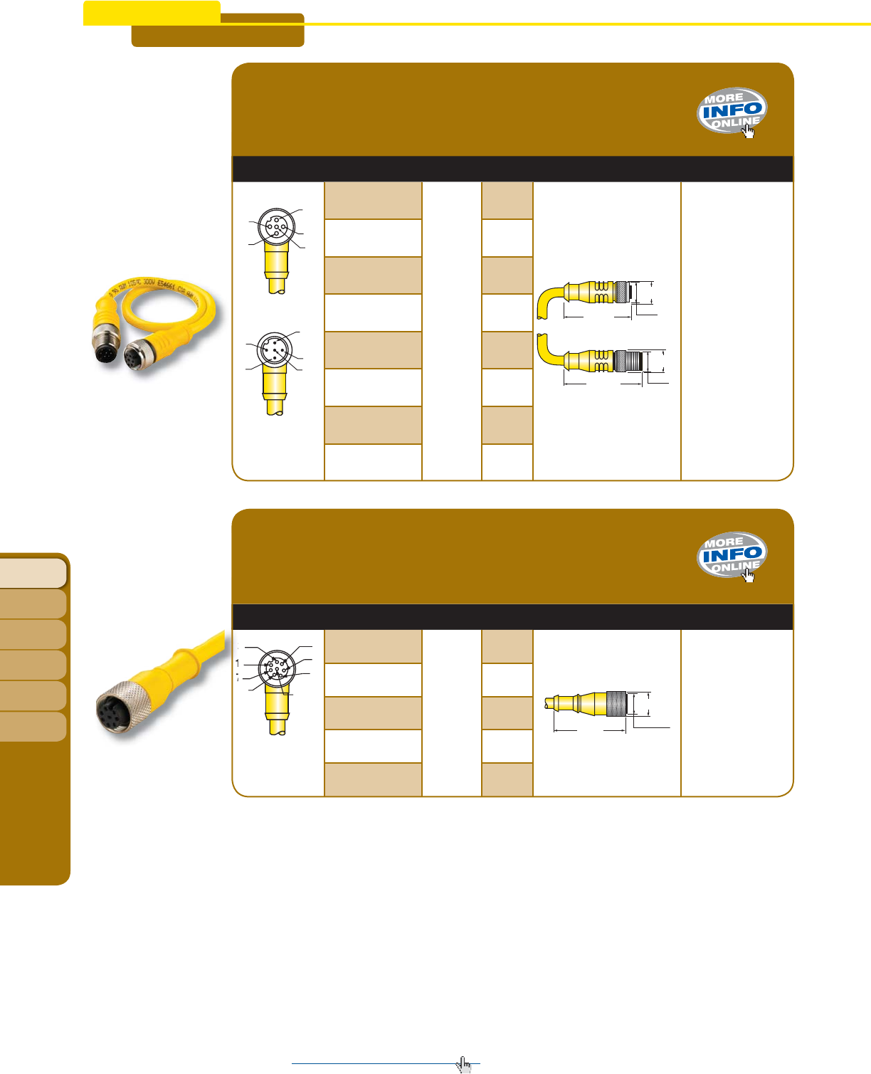
8-Pin Euro-Style Cables
Cable: PVC jacket, polyurethane connector body, chrome-plated brass coupling nut
Conductors: 22 AWG high-flex stranded, gold-plated contacts
Temperature: -40° to +90° C
Voltage Rating: 250V ac/300V dc
Pinout Model Style Length Dimensions Used With
5
4
3
2
8
1
7
6
QDE-815D
Female
Straight
5 m
ø M12 x 1
ø 15 mm
46 mm
max.
• EZ-SCREEN
Emitters &
Receivers w/8-pin
QD (14 & 30 mm
Resolution)
• EZ-SCREEN Emitters
& Receivers
w/8-pin QD
(Point & Grid)
• EZ-SCREEN Type 2
• AC Interface Boxes
QDE-825D 8 m
QDE-850D 15 m
QDE-875D 23 m
QDE-8100D 30 m
1 = Brown
2 = Or/Bk
3 = Orange
4 = White
5 = Black
6 = Blue
7 = Gn/Ye
8 = Violet
5-Pin Euro-Style Cables - Double Ended
Cable: PVC jacket, polyurethane connector body, chrome-plated brass coupling nut
Conductors: 22 AWG high-flex stranded, gold-plated contacts
Temperature: -40° to +90° C
Voltage Rating: 250V ac/300V dc
Pinout Model Style Length Dimensions Used With
Female
2
3
5
4
1
Male
1
4
5
3
2
DEE2R-51D
Female
Straight/
Male
Straight
0.3 m
42.0 mm
max.
M12 x 1
ø 15 mm
M12 x 1
ø 15 mm
48.5 mm
max.
• EZ-SCREEN
Emitters w/5-pin
QD & Test
(14 & 30 mm
Resolution)
• AC Interface Boxes
DEE2R-53D 1 m
DEE2R-58D 2.4 m
DEE2R-515D 4.5 m
DEE2R-525D 8 m
DEE2R-550D 15 m
DEE2R-575D 23 m
DEE2R-5100D 30 m
1 = Brown
2 = White
3 = Blue
4 = Black
5 = Gn/Ye
177More information online at bannerengineering.com
Cables & Wiring Products
ACCESSORIES
CABLES &
WIRING
BRACKETS
CORNER
MIRRORS
STANDS
HARSH DUTY
SOLUTIONS
ACCESSORIES
REPLACEMENT
PARTS
8-Pin Euro-Style Cables - Double Ended
Cable: PVC jacket, polyurethane connector body, chrome-plated brass coupling nut
Conductors: 22 AWG high-flex stranded, gold-plated contacts
Temperature: -40° to +90° C
Voltage Rating: 250V ac/300V dc
Pinout Model Style Length Dimensions Used With
Female
5
4
3
2
8
1
7
6
Male
5
4
3
2
8
17
6
DEE2R-81D
Female
Straight/
Male
Straight
0.3 m
42.0 mm
max.
M12 x 1
ø 15 mm
M12 x 1
ø 15 mm
48.5 mm
max.
• EZ-SCREEN
Emitters &
Receivers w/8-pin
QD (14 & 30 mm
Resolution)
• EZ-SCREEN Emitters
& Receivers
w/8-pin QD
(Point & Grid)
• EZ-SCREEN Type 2
• AC Interface Boxes
DEE2R-83D 1 m
DEE2R-88D 2.4 m
DEE2R-815D 4.5 m
DEE2R-825D 8 m
DEE2R-850D 15 m
DEE2R-875D 23 m
DEE2R-8100D 30 m
1 = Brown
2 = Or/Bk
3 = Orange
4 = White
5 = Black
6 = Blue
7 = Gn/Ye
8 = Violet
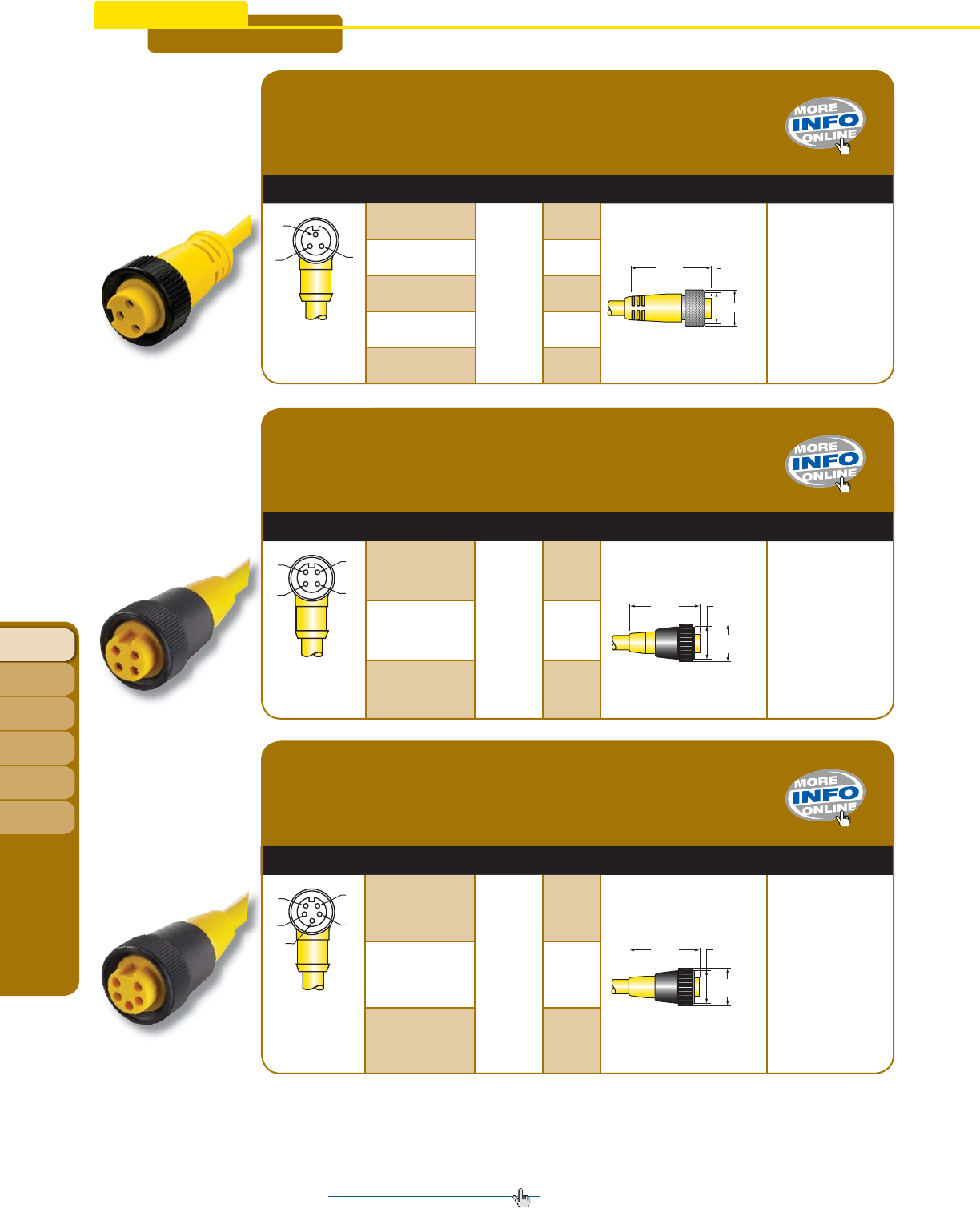
4-Pin Micro-Style Cables
Cable: PVC jacket, polyurethane connector body, chrome-plated brass coupling nut
Conductors: 22 or 20 AWG high-flex stranded, gold-plated contacts
Temperature: -40° to +80° C
Voltage Rating: 125V ac/150V dc
1 = Red/Black
2 = Red/White
3 = Red
4 = Green
Pinout Model Style Length Dimensions Used With
4
1
2
3
MQEAC-406
Female
Straight
2 m
M12 x 1
ø 15 mm
44 mm
max.
• SI-HG80 Hinge-
Style Switches
MQEAC-415 5 m
MQEAC-430 9 m
MQEAC-406RA
Female
Right
Angle
2 m 38 mm
max.
M12 x 1
ø 15 mm
38 mm
max.
MQEAC-415RA 5 m
MQEAC-430RA 9 m
178 More information online at bannerengineering.com
ACCESSORIES
Cables & Wiring Products
CABLES &
WIRING
BRACKETS
CORNER
MIRRORS
STANDS
HARSH DUTY
SOLUTIONS
ACCESSORIES
REPLACEMENT
PARTS
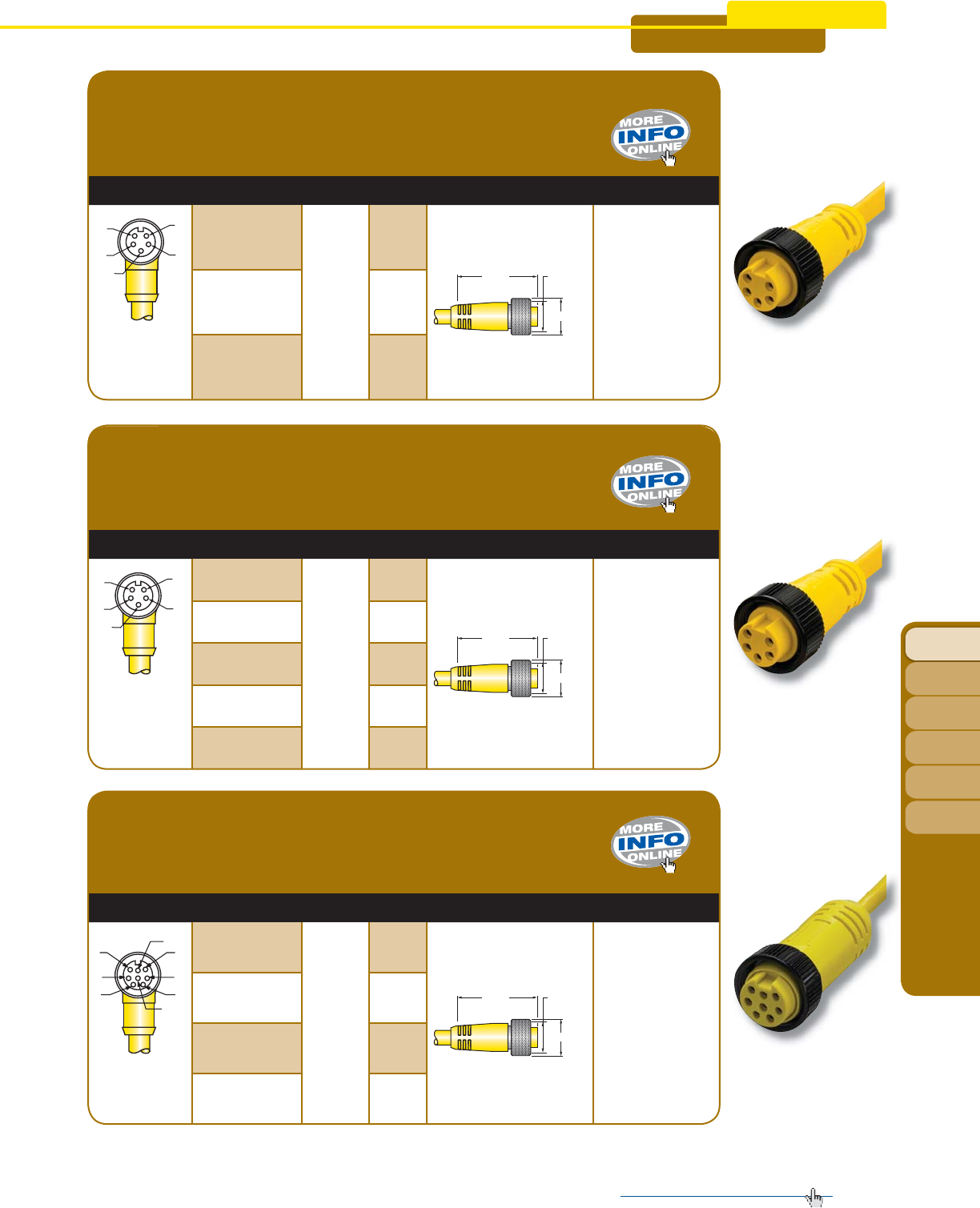
5-Pin Mini-Style Cables with Yellow Wire
Cable: PVC jacket, polyurethane connector body, nylon coupling nut
Conductors: 18 AWG high-flex stranded, PVC insulation, gold-plated contacts
Temperature: -40° to +80° C
Voltage Rating: 250V ac/300V dc
4-Pin Mini-Style Cables
Cable: PVC jacket, polyurethane connector body, nylon coupling nut
Conductors: 18 AWG high-flex stranded, PVC insulation, gold-plated contacts
Temperature: -40° to +80° C
Voltage Rating: 250V ac/300V dc
1 = Black
2 = Blue
3 = Yellow
4 = Brown
5 = White
1 = Green/Yellow
2 = Brown
3 = Blue
3-Pin Mini-Style Cable
Cable: PVC jacket, polyurethane connector body, nylon coupling nut
Conductors: 18 AWG high-flex stranded, PVC insulation, gold-plated contacts
Temperature: -40° to +80° C
Voltage Rating: 250V ac/300V dc
Pinout Model Style Length Dimensions Used With
1
2
4
3
5MBCC-506
Female
Straight
2 m
7/8-16UN-2B
ø 28 mm
max.
61 mm
max.
• STB w/em relay
• OTB w/em relay
MBCC-512 4 m
MBCC-530 9 m
Pinout Model Style Length Dimensions Used With
2
3
1QDS-315C
Female
Straight
5 m
58 mm
ø 26 mm
7/8-16UNF
• EZ-SCREEN
Emitters w/3-pin
QD (Point & Grid)
QDS-325C 8 m
QDS-350C 15 m
QDS-375C 23 m
QDS-3100C 30 m
1 = Brown
2 = White
3 = Blue
4 = Black
Pinout Model Style Length Dimensions Used With
4
3
1
2MBCC-406
Female
Straight
2 m
7/8-16UN-2B
ø 28 mm
max.
61 mm
max.
• STB w/solid-state
relay
• OTB w/solid-state
relay
MBCC-412 4 m
MBCC-430 9 m
179More information online at bannerengineering.com
Cables & Wiring Products
ACCESSORIES
CABLES &
WIRING
BRACKETS
CORNER
MIRRORS
STANDS
HARSH DUTY
SOLUTIONS
ACCESSORIES
REPLACEMENT
PARTS
8-Pin Mini-Style Cables
Cable: PVC jacket, polyurethane connector body, nylon coupling nut
Conductors: 18 AWG high-flex stranded, PVC insulation, gold-plated contacts
Temperature: -40° to +80° C
Voltage Rating: 250V ac/300V dc
5-Pin Mini-Style Cables with Shield and "Twisted Pair"
Cable: PVC jacket, polyurethane connector body, nylon coupling nut
Conductors: 18 AWG high-flex stranded, PVC insulation, gold-plated contacts
Temperature: -40° to +80° C
Voltage Rating: 250V ac/300V dc
5-Pin Mini-Style Cables with Green/Yellow Grounding Wire
Cable: PVC jacket, polyurethane connector body, nylon coupling nut
Conductors: 20 AWG high-flex stranded, PVC insulation, gold-plated contacts
Temperature: -40° to +80° C
Voltage Rating: 250V ac/300V dc
1 = Black
2 = Blue
3 = Green/Yellow
4 = Brown
5 = White
Pinout Model Style Length Dimensions Used With
1
2
4
3
5QDS-515C
Female
Straight
5 m
58 mm
ø 26 mm
7/8-16UNF
• EZ-SCREEN
Emitters w/5-pin
QD & TEST (Point
& Grid)
QDS-525C 8 m
QDS-550C 15 m
1 = Black
2 = Blue
3 = Drain
4 = Brown
5 = White
Pinout Model Style Length Dimensions Used With
1
2
4
3
5QDC-515C
Female
Straight
5 m
58 mm
ø 26 mm
7/8-16UNF
• MINI-SCREEN
QDC-525C 8 m
QDC-550C 15 m
QDC-5100 30 m
QDC-5150 45 m
Pinout Model Style Length Dimensions Used With
5
43
2
8
1
7
6QDS-815C
Female
Straight
5 m
58 mm
ø 26 mm
7/8-16UNF
• EZ-SCREEN
Receivers w/8-pin
QD (Point & Grid)
• Muting Module
QDS-825C 8 m
QDS-850C 15 m
QDS-875C 23 m
1 = Brown
2 = Or/Bk
3 = Orange
4 = White
5 = Black
6 = Blue
7 = Gn/Ye
8 = Violet
180 More information online at bannerengineering.com
ACCESSORIES
Cables & Wiring Products
CABLES &
WIRING
BRACKETS
CORNER
MIRRORS
STANDS
HARSH DUTY
SOLUTIONS
ACCESSORIES
REPLACEMENT
PARTS
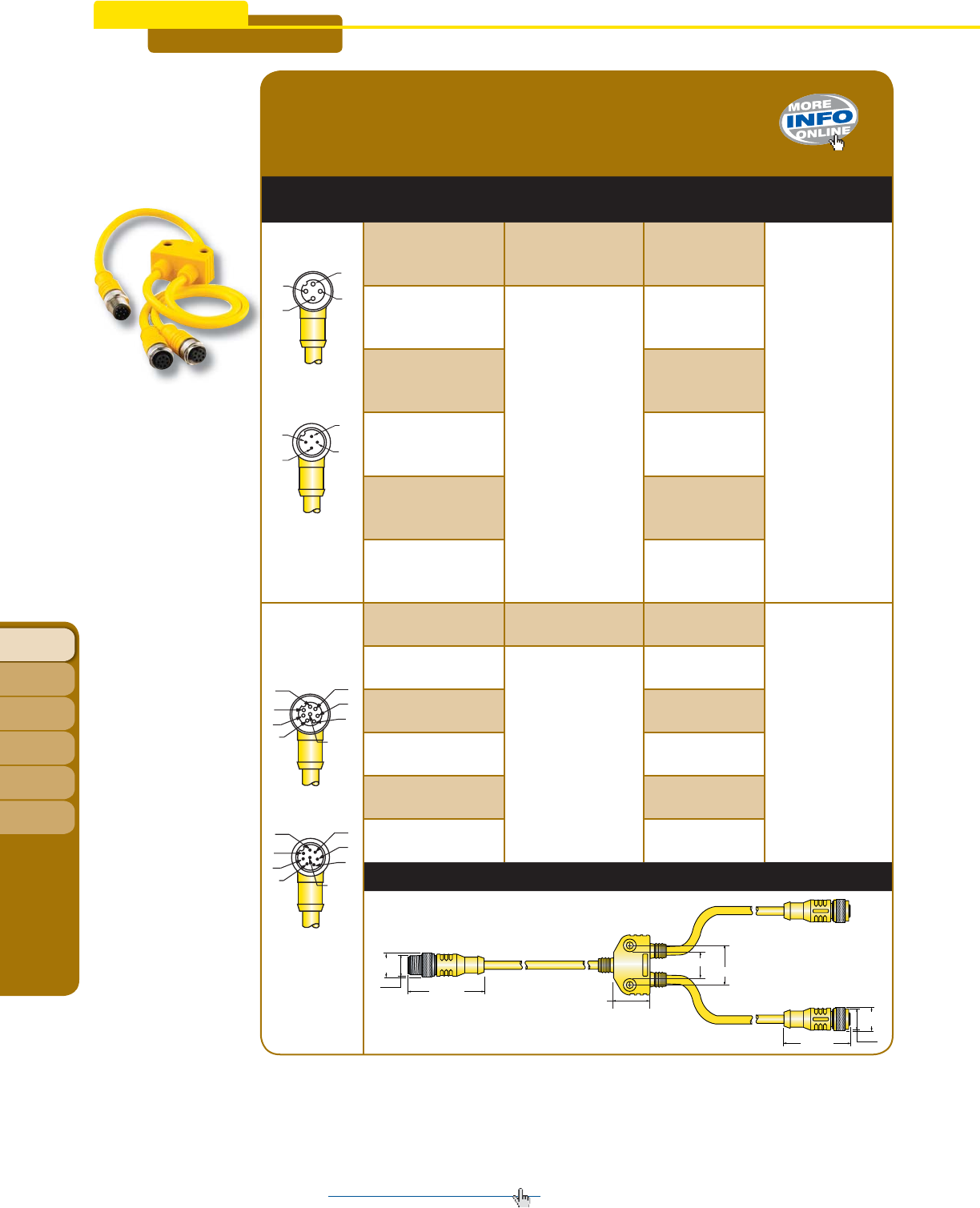
Splitters
Cable: PVC jacket, polyurethane connector body, chrome-plated brass coupling nut
Conductors: 22 AWG high-flex stranded, gold-plated contacts
Temperature: -40° to +90° C
Voltage Rating: 250V ac/300V dc
Pinout Model
Connections
Used WithBranches Trunk
1 = Brown
2 = White
3 = Blue
4 = Black
2
3
4
1
2
34
1
Male
Female CSB-M1240M1240 4-Pin Euro QD
No Branch
Female
No Trunk
Male
• Muting Module
CSB-M1241M1241
4-Pin
Euro QD
2 x 0.3 m
Female
0.3 m
Male
CSB-M1248M1241 2.5 m
Male
CSB-M12415M1241 5 m
Male
CSB-M12425M1241 8 m
Male
CSB-UNT425M1241 8 m
Unterminated
1 = Brown
2 = Or/Bk
3 = Orange
4 = White
5 = Black
6 = Blue
7 = Gn/Ye
8 = Violet
5
4
3
2
8
1
7
6
5
4
3
2
8
17
6
Male
Female
CSB-M1280M1280 8-Pin Euro QD
No Branch
Female
No Trunk
Male • EZ-SCREEN
Emitters &
Receivers w/8-pin
QD (14 & 30 mm
Resolution)
• EZ-SCREEN Emitters
& Receivers
w/8-pin QD
(Point & Grid)
• EZ-SCREEN Type 2
• AC Interface Boxes
• EZ-LIGHT Indicator
Light
• Muting Module
CSB-M1281M1281
8-Pin
Euro QD
2 x 0.3 m
Female
0.3 m
Male
CSB-M1288M1281 2.5 m
Male
CSB-M12815M1281 5 m
Male
CSB-M12825M1281 8 m
Male
CSB-UNT825M1281 8 m
Unterminated
Dimensions
48.5 mm
M12 x 1
ø 15 mm 18.0 mm
18.0 mm
(Trunk)
(Branches)
25.0 mm
42.0 mm M12 x 1
ø 15 mm
181More information online at bannerengineering.com
Cables & Wiring Products
ACCESSORIES
CABLES &
WIRING
BRACKETS
CORNER
MIRRORS
STANDS
HARSH DUTY
SOLUTIONS
ACCESSORIES
REPLACEMENT
PARTS
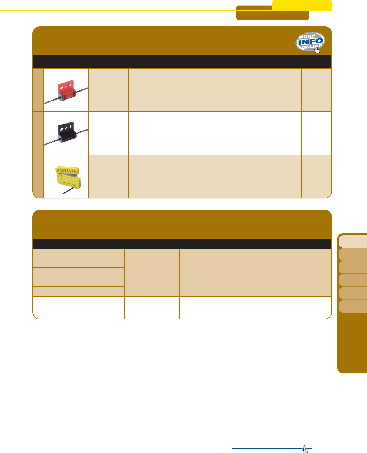
Model Style Description Used With
EZA-QDE-3 3-pin
Mini QD
Converts terminal chamber
end cap to QD model
• EZ-SCREEN Emitters w/Terminal
Chamber (Point & Grid)
EZA-QDE-5 5-pin
Mini QD
• EZ-SCREEN Emitters w/Terminal
Chamber & TEST (Point & Grid)
EZA-QDR-8 8-pin
Mini QD
• EZ-SCREEN Receivers w/Terminal
Chamber (Point & Grid)
Model Length Description Used With
UTB-325C 8 m
3-conductor
(Brown, Blue,
Green/Yellow)
• EZ-SCREEN Emitters w/Terminal
Chamber (Point & Grid)
• AC Interface Boxes
UTB-350C 15 m
UTB-3100C 30 m
UTB-3250C 75 m
UTB-525C 8 m
5-conductor
(Black, Blue, Brown,
White, Green/Yellow)
• EZ-SCREEN Emitters w/Terminal
Chamber & TEST (Point & Grid)
• AC Interface Boxes
UTB-550C 15 m
UTB-5100C 30 m
UTB-5250C 75 m
UTB-825C 8 m
8-conductor
(Brown, Orange/Black,
Orange, White, Black, Blue,
Violet, Green/Yellow)
• EZ-SCREEN Receivers w/Terminal
Chamber (Point & Grid)
• AC Interface Boxes
UTB-850C 15 m
UTB-8100C 30 m
UTB-8250C 75 m
QD End-Caps
Replace or convert EZ-SCREEN Grid and Point hard-wire terminal chamber end cap to QD model.
Unterminated Bulk Cable
Cable: PVC jacket
Conductors: 20 AWG high-flex strand, PVC insulation
Temperature: -40° to +80° C
Voltage Rating: 250V ac/300V dc
8-Pin Euro-Style Cables
Cable: PVC jacket, polyurethane connector body, chrome-plated brass coupling nut
Conductors: 22 AWG high-flex stranded, gold-plated contacts
Temperature: -40° to +90° C
Voltage Rating: 250V ac/300V dc
Pinout Model Style Length Dimensions Used With
5
4
3
2
8
17
6QDE2R4-815D
Male
Straight
5 m
M12 x 1
ø 15 mm
48.5 mm
max.
• EZ-SCREEN
Cascade Receivers
(CSSI to hard
contacts)
QDE2R4-825D 8 m
1 = Brown
2 = Black
3 = Blue
4 = n.c.
5 = n.c.
6 = n.c.
7 = n.c.
8 = White
182 More information online at bannerengineering.com
ACCESSORIES
Cables & Wiring Products
CABLES &
WIRING
BRACKETS
CORNER
MIRRORS
STANDS
HARSH DUTY
SOLUTIONS
ACCESSORIES
REPLACEMENT
PARTS
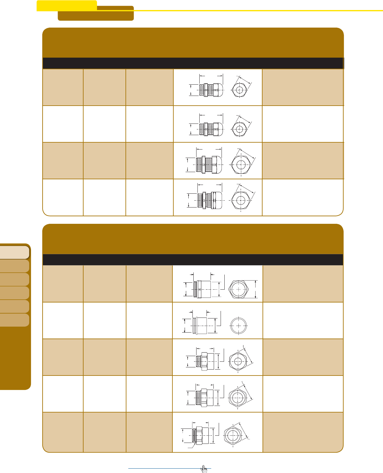
Cable Glands
• Secures the cable end in the housing and seals the point of connection.
• Available for EZ-SCREEN Point and Grid, rope pulls and safety interlock switches.
Model Size For Cable Diameter Dimensions Used With
SI-QS-CG13 PG13.5 3.0 to 8.0 mm PG 13.5
21.8 mm
34.2 mm
• EZ-SCREEN w/Terminal Chamber
(Point & Grid)
SI-QS-CGM16 M16 x 1.5 Plastic 3.0 to 8.0 mm
M16 x 1.5
19.0 mm
34.0 mm
• SI-QS75 Safety Interlock Switches
• SI-LS83 Safety Interlock Switches
SI-QS-CGM20 M20 x 1.5 Plastic 5.0 to 12.0 mm M20 x 1.5
25.0 mm
37.0 mm • SI-QS90 Safety Interlock Switches
• SI-LS100 Safety Interlock Switches
• SI-LS31 Safety Interlock Switches
• SI-LS42 Safety Interlock Switches
• RP-LS42 Rope Pull Switches
SI-QM-CGM20 M20 x 1.5 Metal 5.0 to 12.0 mm M20 x 1.5
24.0 mm
35.5 mm • SI-LM40 Safety Interlock Switches
• SI-QM100 Safety Interlock Switches
• SI-LM40 Safety Interlock Switches
• RP-LM40 Rope Pull Switches
• RP-QM72/QMT72 Rope Pull Switches
• RP-QM90 Rope Pull Switch
Conduit Adapters
• Connects conduit of different diameters.
• Available for EZ-SCREEN Point and Grid, rope pulls and safety interlock switches.
Model Size Thread Conversion Dimensions Used With
SI-QM-13 1/2" NPT to
PG13.5
PG 13.5 to
1/2" NPT
23.5 mm
24.0 mm
1/2" NPT
Internal Thread
PG13.5
• EZ-SCREEN w/Terminal Chamber
(Point & Grid)
SI-QM-13-M20 M20 to PG13.5 PG 13.5 to
M20
MM
0'
-
)NTERNAL4HREAD • EZ-SCREEN w/Terminal Chamber
(Point & Grid)
SI-QS-M16 1/2" – 14 NPT
Plastic
M16 x 1.5 to
1/2" – 14 NPT
24.0 mm
M16 x 1.5
1/2"-14 NPT
Internal Thread
25.0 mm • SI-QS75 Safety Interlock Switches
• SI-LS83 Safety Interlock Switches
SI-QS-M20 1/2" – 14 NPT
Plastic
M20 x 1.5 to
1/2" – 14 NPT
25.0 mm
M20 x 1.5
24.0 mm
1/2"-14 NPT
Internal Thread • SI-QS90 Safety Interlock Switches
• SI-LS100 Safety Interlock Switches
• SI-LS31 Safety Interlock Switches
• SI-LS42 Safety Interlock Switches
• RP-LS42 Rope Pull Switches
SI-QM-M20 1/2" – 14 NPT
Metal
M20 x 1.5 to
1/2" – 14 NPT
23.0 mm
M20 x 1.5
24.0 mm
1/2"-14 NPT
Internal Thread
O-ring
• SI-LM40 Safety Interlock Switches
• SI-QM100 Safety Interlock Switches
• SI-LM40 Safety Interlock Switches
• RP-LM40 Rope Pull Switches
• RP-QM72/QMT72 Rope Pull Switches
• RP-QM90 Rope Pull Switch
183More information online at bannerengineering.com
Cables & Wiring Products
ACCESSORIES
CABLES &
WIRING
BRACKETS
CORNER
MIRRORS
STANDS
HARSH DUTY
SOLUTIONS
ACCESSORIES
REPLACEMENT
PARTS
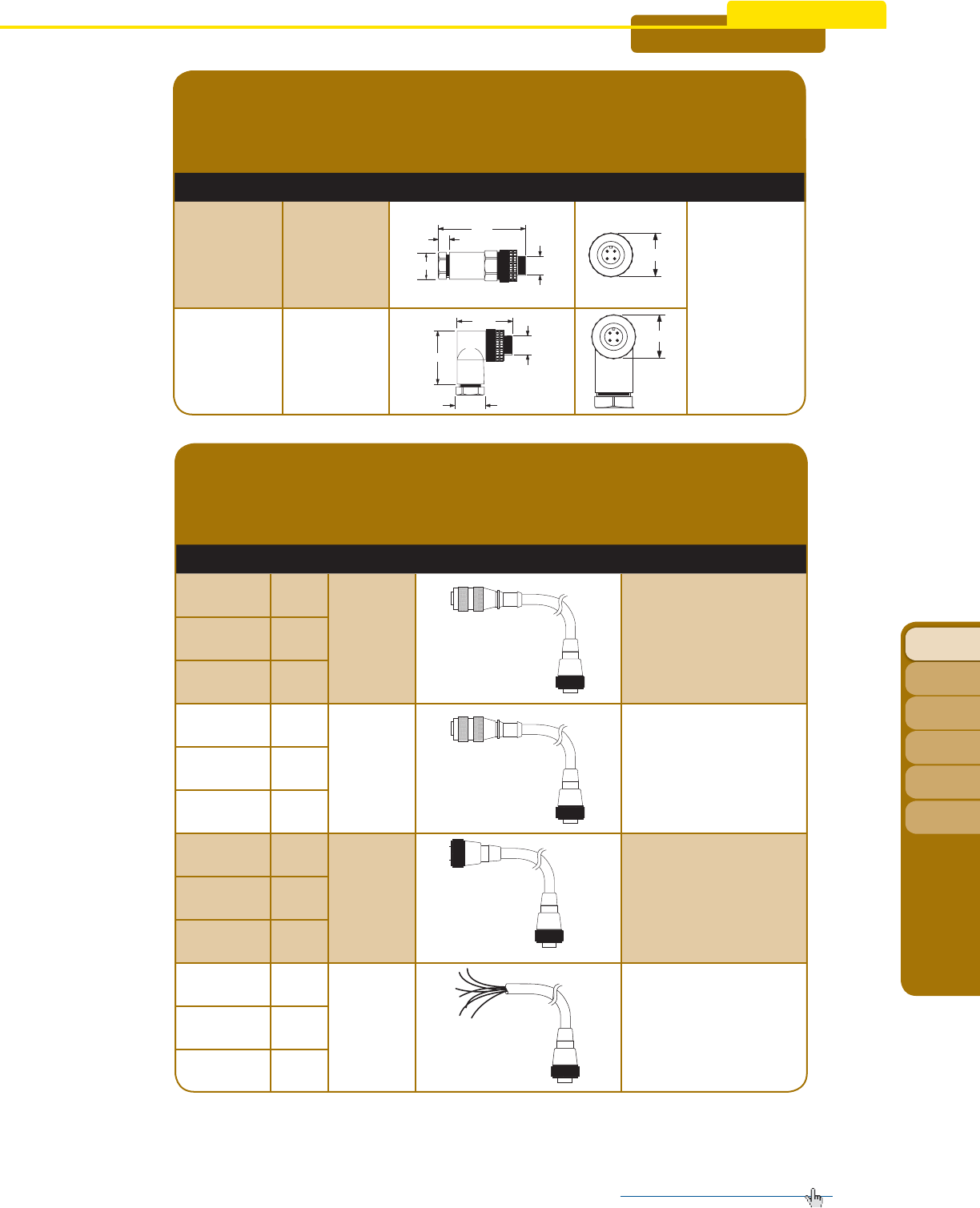
4-Pin Euro-Style Field-Wireable Connectors
Cable: Gold-plated, 4-pin models rated 250V ac/dc max., 4 A max.
Cable Diameter: 4.0 to 5.0 mm
Temperature: -25° to +90° C
Environmental Rating: NEMA 6P, IP67
Model Style Dimensions Pinout Used With
FIC-M12M4 Male
Straight M12 x 1
10 mm
60 mm
15.0 mm
20 mm
• Muting Module
FIC-M12M4A Male
Right Angle
41 mm
30.5 mm
15.0 mm
M12 x 1
20 mm
MSSI Cordsets for use with Muting Modules
Cable: PVC jacket, polyurethane connector body, chrome-plated brass coupling nut
Cable Diameter: 20 AWG high-flex stranded, PVC insulation, gold-plated contacts
Temperature: -40° to +80° C
Voltage Rating: 250V ac/300V dc
Model Length Description Used With
DESE4-508D 2.4 m 8-Pin
Female
Euro QD
to
7-Pin Male
Mini QD
• EZ-SCREEN Receivers
w/Euro QDs
(14 & 30 mm Resolution)
• Muting Modules
DESE4-515D 5 m
DESE4-525D 8 m
DESE5-508D 2.4 m 8-Pin
Female
Euro QD
to
7-Pin Male
Mini QD
• EZ-SCREEN Type 2
• Muting Modules
DESE5-515D 5 m
DESE5-525D 8 m
DES4-508C 2.4 m 8-Pin
Female
Mini QD
to
7-Pin Male
Mini QD
• EZ-SCREEN Receivers
w/Mini QDs (Grid & Point)
• Muting Modules
DES4-515C 5 m
DES4-525C 8 m
QDS-715C 5 m
Unterminated
end
to
7-Pin Male
Mini QD
• EZ-SCREEN Receivers
w/Terminal Chamber
(Grid & Point)
• Safeguarding w/Hard-Wired
Contacts
• Muting Modules
QDS-725C 8 m
QDS-750C 15 m
184 More information online at bannerengineering.com
ACCESSORIES
Cables & Wiring Products
CABLES &
WIRING
BRACKETS
CORNER
MIRRORS
STANDS
HARSH DUTY
SOLUTIONS
ACCESSORIES
REPLACEMENT
PARTS
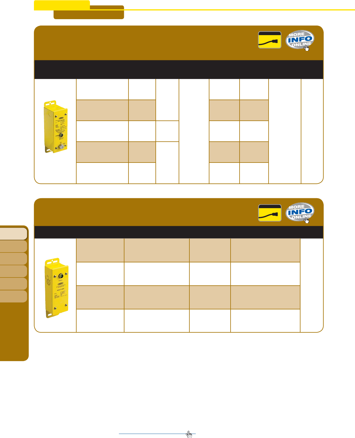
AC Emitter/Receiver Interface Boxes
• Provides AC power for up to three receivers or two cascaded emitter/receiver pairs, with external
device monitoring (EDM) available.
• Supplies +24V dc power at 0.7 amps (16.8 W max. power) and accepts input voltages from 100-250V ac (50-60 Hz).
Model
Emitter
Connection
AC Power
Connection Used with
Data
Sheet
EZAC-E-QE8 8-Pin Euro QD Hard-wired • EZ-SCREEN SLSE..-..Q8
(without Test input)
120321
EZAC-E-QE5 5-Pin Euro QD Hard-wired • EZ-SCREEN SLSE..-..Q5
(with Test input)
EZAC-E-QE8-QS3 8-Pin Euro QD 3-Pin
Mini QD
• EZ-SCREEN SLSE..-..Q8
(without Test input)
EZAC-E-QE5-QS5 5-Pin Euro QD 5-Pin
Mini QD
• EZ-SCREEN SLSE..-..Q5
(with Test input)
AC Emitter Interface Boxes
• Provides AC power for up to four emitters, with external device monitoring (EDM) available.
• Supplies +24V dc power at 0.7 amps (16.8 W max. power) and accepts input voltages from 100-250V ac (50-60 Hz).
Model
Safety
Outputs EDM
Emitter/
Receiver
Connection
AC Power
Connection
Output
and EDM
Connections Used with
Data
Sheet
EZAC-R9-QE8 3 NO Selectable
1- or 2-
Channel or
no EDM
8-Pin
Euro QD
Hard-wired Hard-wired
• EZ-SCREEN
120321
EZAC-R11-QE8
2 NO
&
1 NC
Hard-wired Hard-wired
EZAC-R15A-QE8-QS83
1 NO
&
1 SPDT
1-Channel 3-Pin
Mini QD
8-Pin
Mini QD
EZAC-R8N-QE8-QS53
1 NO
&
1 NC Power
Monitoring
3-Pin
Mini QD
5-Pin
Mini QD
EZAC-R10N-QE8-QS53 2 NO 3-Pin
Mini QD
5-Pin
Mini QD
NC = Normally Closed, NO = Normally Open
QD CABLES
PAGE 174
5- & 8-Pin Euro +
3- & 5-Pin Mini
QD CABLES
PAGE 176
8-Pin Euro +
3-, 5- & 8-Pin Mini
185More information online at bannerengineering.com
Cables & Wiring Products
ACCESSORIES
CABLES &
WIRING
BRACKETS
CORNER
MIRRORS
STANDS
HARSH DUTY
SOLUTIONS
ACCESSORIES
REPLACEMENT
PARTS
Input Voltage and Current 100-230V ac ±15%; 16.8W max., output 24V dc 0.7A
Input current: typ. 0.37A @ 100V ac in
typ. 0.23A @ 200V ac in
Inrush current: typ. 15A @ 100V ac in (5 milliseconds max.)
typ. 30A @ 200V ac in (5 milliseconds max.)
Output Voltage and Current 24V dc @ 0.7 A (16.8 W)
SELV; capable of buffering 20 milliseconds power interruptions
Supply Protection Circuitry Protected against transient voltages
Output Configuration Models EZAC-R.. only; see models listing on previous page.
Each normally open output channel is a series connection of contacts from two forced-guided (positive-guided)
relays, K1-K2. The normally closed contact is a parallel connection of contacts from K1-K2.
Contacts: AgNi, 5 µm gold-plated
Low Current Rating:
Caution: The 5 µm gold-plated contacts allow the switching of low current/low voltage.
To preserve the gold plating on the contacts, the following max. values should not be exceeded at any time:
Min. voltage: 1V ac/dc Max. voltage: 60V ac/dc
Min. current: 5 mA ac/dc Max. current: 300 mA
Min. power: 5 mW (5 mVA) Max. power: 7 W (7 VA)
High Current Rating:
If higher loads must be switched through one or more of the contacts, the minimum and maximum values of
the contact(s) changes to:
Min. voltage: 15V ac/dc Max. voltage: 250V ac/dc
Min. current: 30 mA ac/dc Max. current: 8 A
Min. power: 5 W (5 VA) Max. power: 200 W (2000 VA)
Mechanical life: 50,000,000 operations
Electrical life: 100,000 operations (typical @ 200 W [2000 VA] switched power, resistive load)
Feedback Contact Rating (Y1-Y2, Y3-Y4):
Min. voltage: 1V ac/dc Max. voltage: 60V ac/dc
Min. current: 5 mA ac/dc Max. current: 300 mA
Min. power: 5 mW (5 mVA) Max. power: 7 W (7 VA)
NOTE: Transient suppression is recommended when switching inductive loads. Install suppressors across
load. Never install suppressors across output contacts.
Output Response Time 10 milliseconds max.
Status Indicators Models EZAC-R.. : One bicolor (Red/Green) LED indicator on box cover indicates the power and output status of
internal relays K1 and K2.
Models EZAC-E.. : One Green LED indicator on box cover indicates the power status (ON when power is ON).
Construction Welded steel box with yellow polyester powder paint finish
Environmental Rating IEC IP65
Vibration Resistance 10 to 50 Hz @ 0.35 mm displacement per IEC 68-2-6
Mounting Box provides flanges for screw mounting; can be mounted directly to EZ-SCREEN receiver or emitter housing.
Operating Conditions Temperature: 0° to +55° C Relative humidity: 90% @ +55° C (non-condensing)
Application Notes The box offers a field-replaceable relay module; see Repairs section of data sheet for more information.
Certifications Approvals are in process.
Wiring Diagrams EZAC-R9QE8: WD009 (p. 250)
EZAC-R11-QE8: WD010 (p. 251)
EZAC-R15A-QE8-QS83: WD011 (p. 252)
EZAC-R8N-QE8-QS53: WD012 (p. 252)
EZAC-R10N-QE8-QS53: WD013 (p. 253)
EZAC-E-QE8/QE5: WD014 (p. 253)
AC Interface Box Specifications
186 More information online at bannerengineering.com
ACCESSORIES
Cables & Wiring Products
CABLES &
WIRING
BRACKETS
CORNER
MIRRORS
STANDS
HARSH DUTY
SOLUTIONS
ACCESSORIES
REPLACEMENT
PARTS
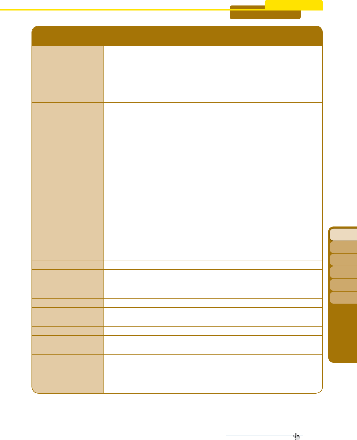
Mechanically Linked Contactors*
Provides an additional 10 or 16 amp carrying capability to any safety system.
Models
Coil
Voltage Contacts
Contact
Rating
Dimensions
(h x w x l) Used With
Data
Sheet
11-BG00-31-A12060 120V ac
3 NO
&
1 NC
10 amps 57 x 44 x 58 mm • EZ-SCREEN
• PICO-GUARD
• MICRO-SCREEN
• MINI-SCREEN 111881
11-BG00-31-D-024 24V dc 10 amps 57 x 44 x 58 mm
11-BF1601-12060 120V ac 16 amps** 80 x 44 x 80 mm
11-BF16C01-024 24V dc 16 amps** 80 x 44 x 80 mm
NC = Normally Closed, NO = Normally Open
* One Arc Suppressor is needed for each relay across the coil (see below).
** NC contact is rated at 10 amps
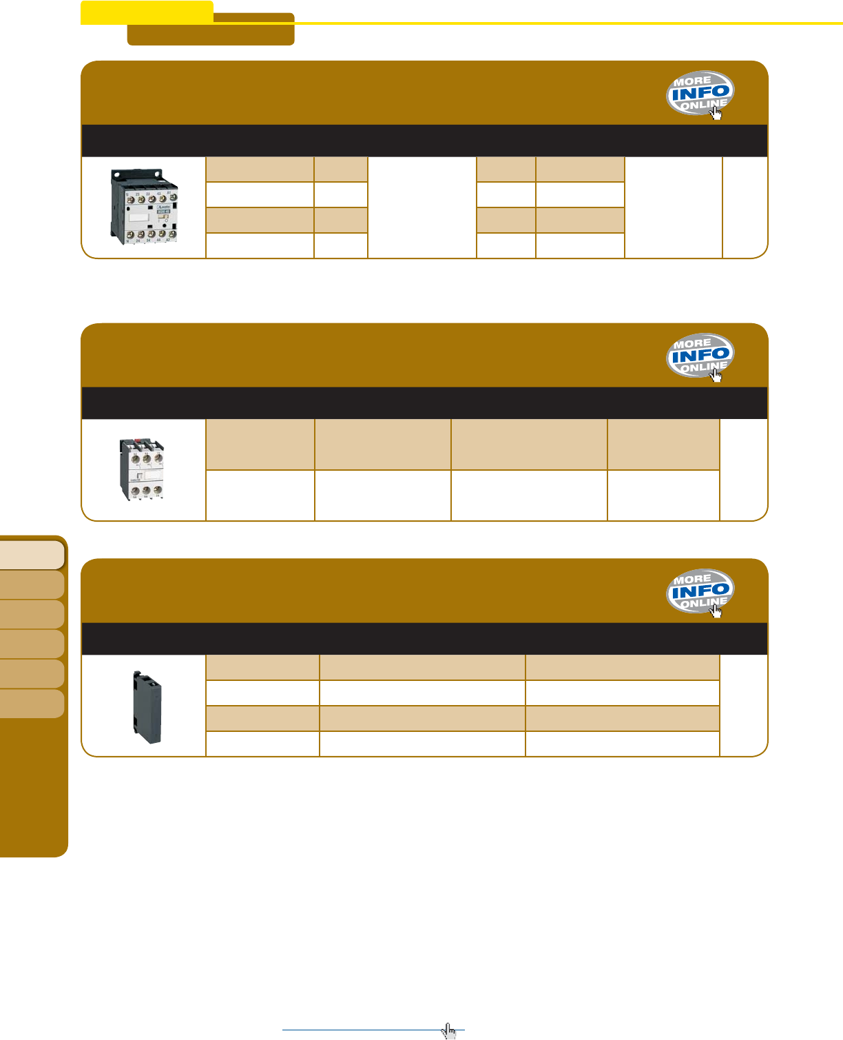
Auxiliary Contacts for Mechanically Linked Contactors
Adds contacts to mechanically linked contactors.
Models Contacts
Positively
Guided Used With
Data
Sheet
11-BGX10-40 4 NO No
(Aux. only)
• 11-BG Series
111881
11-G484-30 3 NO Yes
• 11-BF Series
Suppressors for Mechanically Linked Contactors
Extends the life of the actuating device—such as a light screen or control module—that uses a mechanically linked contactor.
Models Voltage Used With
Data
Sheet
11-BGX77-048 48V dc • 11-BG00-31-D024
111881
11-BGX77-240 125-240V ac • 11-BG00-31-A12060
11-G318-48 48V dc • 11-BF1C01-024
11-G477-240 125-240V ac • 11-BF1601-12060
NC = Normally Closed, NO = Normally Open
NC = Normally Closed, NO = Normally Open
187More information online at bannerengineering.com
Cables & Wiring Products
ACCESSORIES
CABLES &
WIRING
BRACKETS
CORNER
MIRRORS
STANDS
HARSH DUTY
SOLUTIONS
ACCESSORIES
REPLACEMENT
PARTS
Model Construction Connector* LED Function Inputs Used With Data Sheet
M18RGX8PQ8
18 mm
Threaded barrel
Nickel-plated brass
8-pin
Euro QD
Red/Green
indication follows
OSSD output of
the EZ-SCREEN
receiver
PNP
• EZ-SCREEN
121901
T18RGX8PQ8
18 mm
T-style
Right-angle
Thermoplastic
polyester
PNP
T30RGX8PQ8
30 mm
T-style
Right-angle
Thermoplastic
polyester
PNP
EZ-LIGHT
™
Smart Indicator Lights
• Indicates the status of a machine or process, using a solid or flashing color light in a sealed housing.
• Replaces panel indicators and post and stack lights with a single, compact unit.
* A mating cable is required (see page 180). Typically a CSB splitter and DEE2R-8..D cables are used.
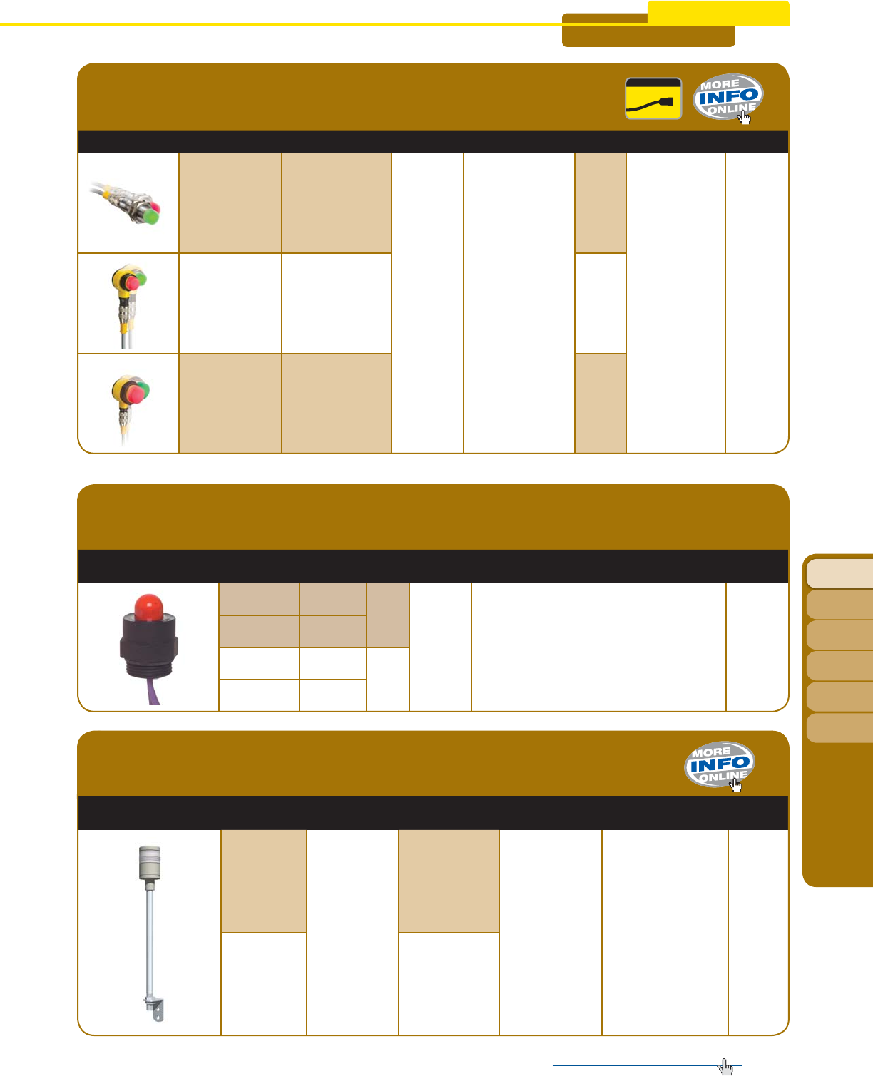
Indicator Lamps
• Indicates whether a switch is open or closed.
• Available in red or green, 120V ac or 24V ac/dc.
Model
Supply
Voltage
Lamp
Color Thread Used With
Data
Sheet
SI-PL3T-R 24V ac/dc
Red
M20 x 1.5
• SI-QS90 Safety Interlock Switches
• SI-LS42 Safety Interlock Switches
• SI-QM100 Safety Interlock Switches
• RP-LS42 Rope Pull Switches
• RP-QM72/QMT72 Rope Pull Switches
• RP-QM90 Rope Pull Switch
—
SI-PL3A-R 120V ac
SI-PL3T-G 24V ac/dc
Green
SI-PL3A-G 120V ac
Muting Lamps
• Indicates when muting is active for optical safety features with a muting module.
• Uses a solid-state LEDs light, eliminating the need to replace bulbs.
Model
Supply
Voltage
Lamp
Color
Overall
Height Used with
Data
Sheet
SSA-ML-A
24V ac/dc
Amber
383 mm
• PICO-GUARD
• MICRO-SCREEN
• MINI-SCREEN
• EZ-SCREEN
• Muting Modules
62097
SSA-ML-W White (clear)
QD CABLES
PAGE 176
8-Pin Euro
188 More information online at bannerengineering.com
ACCESSORIES
Cables & Wiring Products
CABLES &
WIRING
BRACKETS
CORNER
MIRRORS
STANDS
HARSH DUTY
SOLUTIONS
ACCESSORIES
REPLACEMENT
PARTS
Length
Standard
Polyethylene Jacket
PVC
Sheath
Fluoropolymer
Sheath
Dimensions
&IBER
MM
0OLYETHYLENE*ACKET
MM
&IBER
MM
06#3HEATH
MM
0OLYETHYLENE*ACKET
MM
&IBER
MM
0OLYETHYLENE*ACKET
MM
&LUOROPOLYMER3HEATH
MM
Bulk
9 m PIU430U PIU430UXP PIU430UXT
18 m PIU460U PIU460UXP PIU460UXT
30.5 m PIU4100U PIU4100UXP PIU4100UXT
61 m PIU4200U PIU4200UXP PIU4200UXT
100.5 m PIU4330U PIU4330UXP PIU4330UXT
152.5 m PIU4500U PIU4500UXP PIU4500UXT
488 m PIU41600U PIU41600UXP PIU41600UXT
Cut Lengths with Polished Ends
0.3 m PWS43P PWXP43P PWXT43P
0.5 m PWS45P PWXP45P PWXT45P
0.7 m PWS47P PWXP47P PWXT47P
1 m PWS410P PWXP410P PWXT410P
1.5 m PWS415P PWXP415P PWXT415P
2 m PWS420P PWXP420P PWXT420P
2.5 m PWS425P PWXP425P PWXT425P
3 m PWS430P PWXP430P PWXT430P
3.5 m PWS435P PWXP435P PWXT435P
4 m PWS440P PWXP440P PWXT440P
4.5 m PWS445P PWXP445P PWXT445P
5 m PWS450P PWXP450P PWXT450P
6 m PWS460P PWXP460P PWXT460P
7 m PWS470P PWXP470P PWXT470P
8 m PWS480P PWXP480P PWXT480P
9 m PWS490P PWXP490P PWXT490P
10 m PWS4100P PWXP4100P PWXT4100P
11 m PWS4110P PWXP4110P PWXT4110P
12 m PWS4120P PWXP4120P PWXT4120P
13 m PWS4130P PWXP4130P PWXT4130P
14 m PWS4140P PWXP4140P PWXT4140P
15 m PWS4150P PWXP4150P PWXT4150P
20 m PWS4200P PWXP4200P PWXT4200P
25 m PWS4250P PWXP4250P PWXT4250P
30 m PWS4300P PWXP4300P PWXT4300P
PICO-GUARD
™
Plastic Fiber Optics
Plastic optical fiber for use with Banner PICO-GUARD optical elements is available in bulk form (to be cut to length in the field)
or precut lengths with polished ends for maximum excess gain.
189More information online at bannerengineering.com
Cables & Wiring Products
ACCESSORIES
CABLES &
WIRING
BRACKETS
CORNER
MIRRORS
STANDS
HARSH DUTY
SOLUTIONS
ACCESSORIES
REPLACEMENT
PARTS
Model Description
Data
Sheet
Attenuator
SFA-FA
• Reduces excess gain in short-run applications
• Uses Banner 2.2 mm OD plastic fiber optic cable (1 mm core)
• Made of impact-resistant polycarbonate plastic
• Rated IEC IP67
109910
Splice
SFA-FS
• Provides easy connection of two fiber sections
• Simplifies connecting and disconnecting fibers
• Uses Banner 2.2 mm OD plastic fiber optic cable (1 mm core)
• Made of impact-resistant polycarbonate plastic
• Rated IEC IP67
109910
Fiber Cutter
PFC-2-25 • Uses Banner 2.2 mm OD diameter unterminated fiber optic cable (1 mm core)
• Contains 25 fiber cutters —
PICO-GUARD
™
Plastic Fiber Optic Accessories
Fiber optic devices used with PICO-GUARD optical elements improve performance and simplify installation.
7
Model Description
SFA-FCC-008 2.4 m
Conduit
• Made of flexible MEK-resistant polyamide
• Protects fiber
• Snaps into emitter/receiver
• Easily cuts to length
SFA-FCC-015 4.5 m
SFA-FCC-025 7.5 m
SFA-FCC-050 15 m
SFA-FCC-100 30 m
SFA-FCC-CGM20 M20
Threads
Cable
Gland
• Use with MEK-resistant conduit
• Made of MEK resistant polyamide
• Attaches conduit to emitter/receiver and PICO-GUARD controller
PICO-GUARD
™
Cable Glands and Conduits
Conduit and gland used with PICO-GUARD Grids provide MEK-resistant protection.
190 More information online at bannerengineering.com
Brackets
CABLES &
WIRING
BRACKETS
CORNER
MIRRORS
STANDS
HARSH DUTY
SOLUTIONS
ACCESSORIES
REPLACEMENT
PARTS
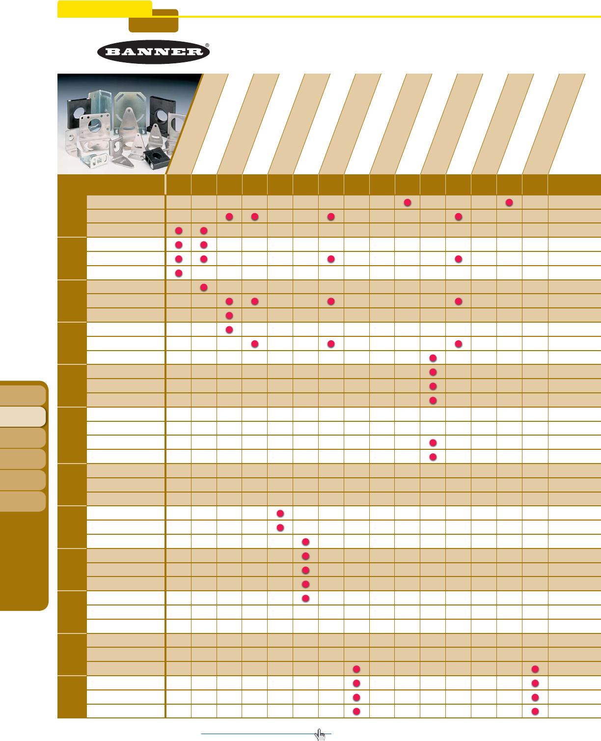
ACCESSORIES
EZ-SCREEN 14 & 30 mm
Resolution
EZ-SCREEN Cascade
EZ-SCREEN Point
EZ-SCREEN Grid
PICO-GUARD 12 mm
Point
PICO-GUARD 30 mm
Point
PICO-GUARD Grid
MICRO-SCREEN Emitter/
Receiver
MICRO-SCREEN Metal
Box
MICRO-SCREEN DIN Box
MINI-SCREEN Emitter/
Receiver
Heavy-Duty MINI-SCREEN
Emitter/Receiver
MINI-SCREEN Metal Box
MINI-SCREEN DIN Box
EZ-SCREEN Type 2
192
DIN-35-..
EZA-MBK-1
EZA-MBK-11
193
EZA-MBK-12
EZA-MBK-2
EZA-MBK-20
194
EZA-MBK-21
EZA-MBK-3
EZA-MBK-4
195
EZA-MBK-5
EZA-MBK-9
MSAMB
196
MSMB-1
MSMB-2
MSMB-3
197
MSMB-MSM-45
MSMMB
MSVM-1
MSMV10-8
198
SFA-IMB1
SFA-IMB2
SMA-MBK-1
199
SMB12MM
SMB1812SF
SMB30A
200
SMB30MM
SMB30SC
SMBAMS30P
201
SMBAMS30RA
SMBAMSBRA
SMBR55F01
202
SMBR55F02
SMBR55FRA
USCMB-..
203
USMB-1
USMB-6
USMB-8
Page References 21 25 28 28 38 38 37 42 45 46 58 63 64 65 78
Banner Bracket
191More information online at bannerengineering.com
Brackets
CABLES &
WIRING
BRACKETS
CORNER
MIRRORS
STANDS
HARSH DUTY
SOLUTIONS
ACCESSORIES
REPLACEMENT
PARTS
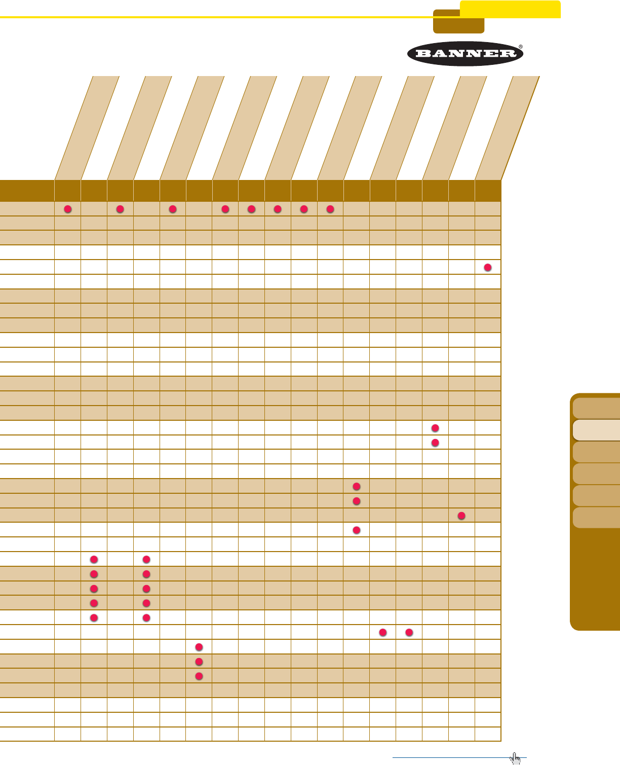
ACCESSORIES
DUO-TOUCH SG Modules
STB Buttons
DUO-TOUCH Modules
OTB Buttons
PICO-GUARD Controller
PICO-GUARD SFA-RD
Remote Display
E-Stop & Guard
Monitoring Modules
Safety Mat Monitoring
Modules
Muting Modules
Extension Modules
Interface Modules
PICO-GUARD Switches
SMBAMSBRA Bracket
SMBAMS30RA Bracket
MSM Mirrors
SSM Mirrors
MSA Stands
87 94 97 100 108 110 112 120 123 130 132 137 201 201 205 206 209
Selection Chart
192 More information online at bannerengineering.com
Brackets
CABLES &
WIRING
BRACKETS
CORNER
MIRRORS
STANDS
HARSH DUTY
SOLUTIONS
ACCESSORIES
REPLACEMENT
PARTS
NOTE: All dimensions in millimeters unless otherwise stated.
ACCESSORIES
Brackets
ACCESSORIES
Detailed
Dimensions
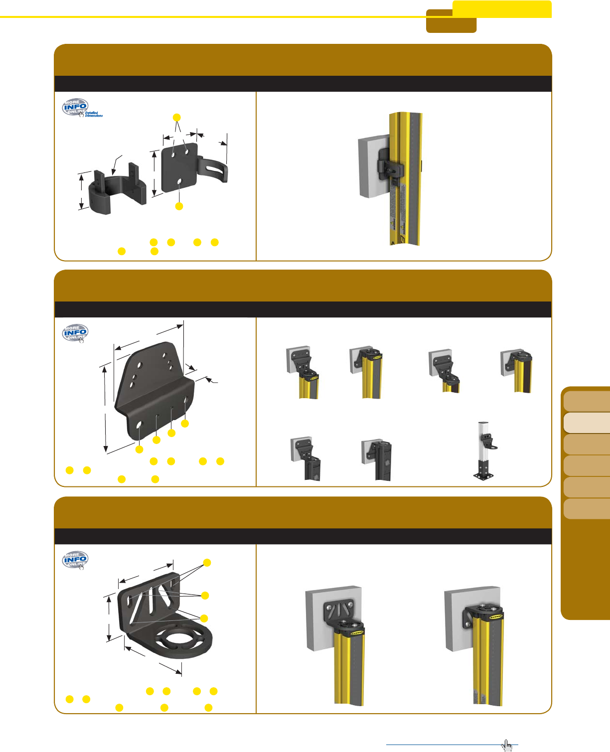
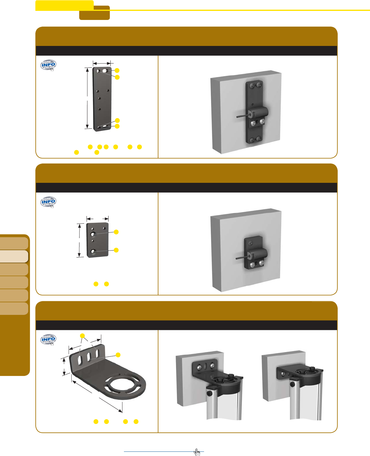
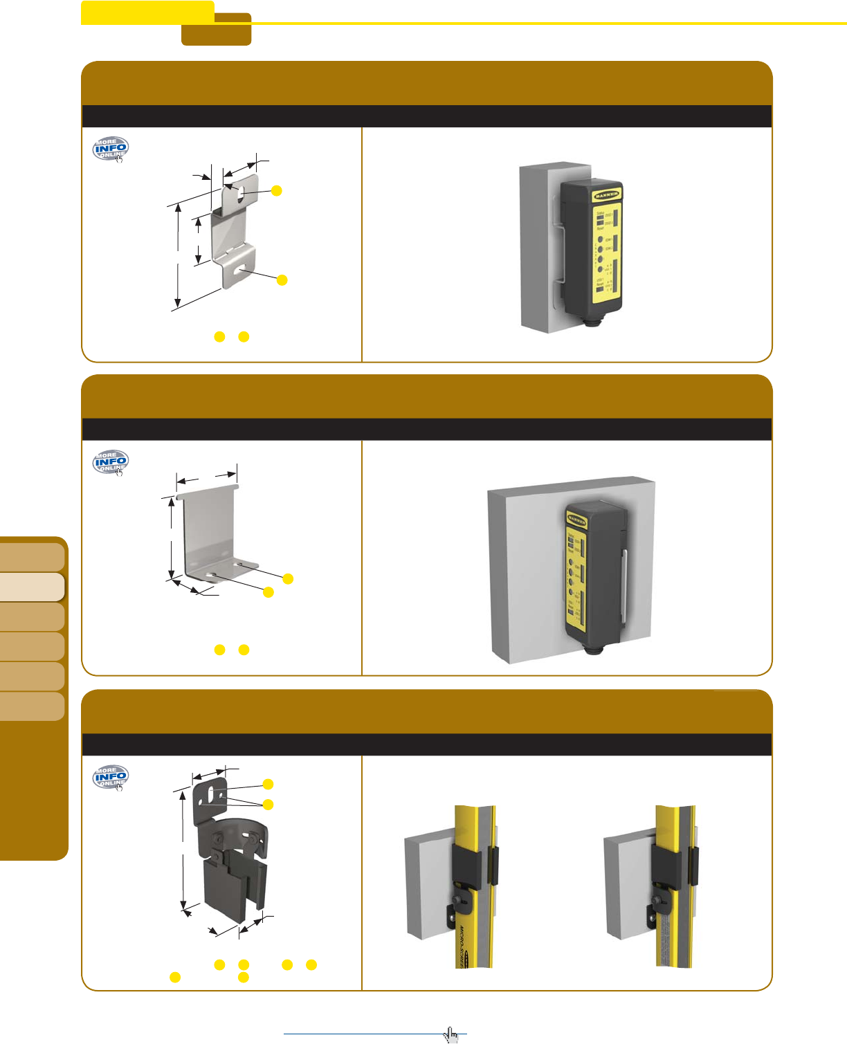
EZA-MBK-11
Kit contains two end-cap brackets to replace the brackets that come with the emitter/receiver and includes mounting hardware.
Brackets are made of cold-rolled steel with a black corrosion-resistant zinc chromate finish.
Dimensions Used With
50
63.2
25
A
BEZ-SCREEN 14 & 30 mm Resolution
Flanges Out Flanges In
Hole center spacing in mm: A to B = 20
Hole size in mm: 15.0 x 7.0
Detailed
Dimensions
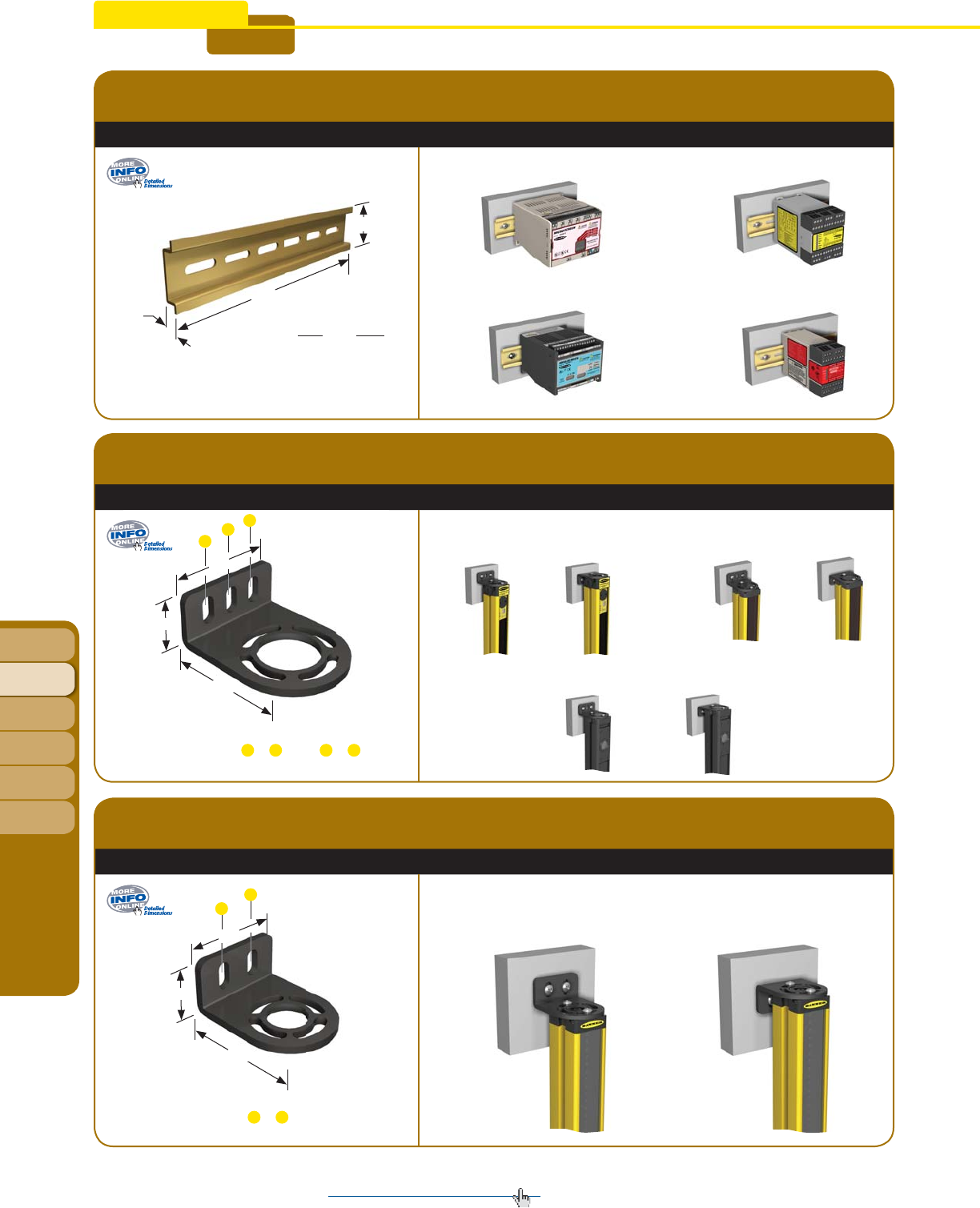
DIN-35-..
DIN rail is available in 70, 105 and 140 mm lengths, to hold one, two, or three modules.
Dimensions Used With
7.6
L
35
MICRO-SCREEN DIN Modules Two-Hand Control Modules
MINI-SCREEN DIN Modules Safety Modules
Hole center spacing in mm: 35.1
Hole size in mm: 25.4 x 5.3
Model Length
DIN-35-70 70 mm
DIN-35-105 105 mm
DIN-35-140 140 mm
Detailed
Dimensions
EZA-MBK-1
Two-bracket kit contains a replacement for the brackets that come with the emitter/receiver and includes mounting hardware.
Bracket is made of cold-rolled steel with a black corrosion-resistant zinc chromate finish.
Dimensions Used With
60
74.2
25
A
BCEZ-SCREEN Point & Grid Heavy-Duty MINI-SCREEN
PICO-GUARD Grid
Flanges Out Flanges In
Flanges Out Flanges Out
Flanges Out Flanges In
Hole center spacing in mm: A to B = 15.8, A to C = 31.5
Hole size in mm: 15.0 x 7.0
193More information online at bannerengineering.com
Brackets
CABLES &
WIRING
BRACKETS
CORNER
MIRRORS
STANDS
HARSH DUTY
SOLUTIONS
ACCESSORIES
REPLACEMENT
PARTS
NOTE: All dimensions in millimeters unless otherwise stated.
ACCESSORIES
Detailed
Dimensions
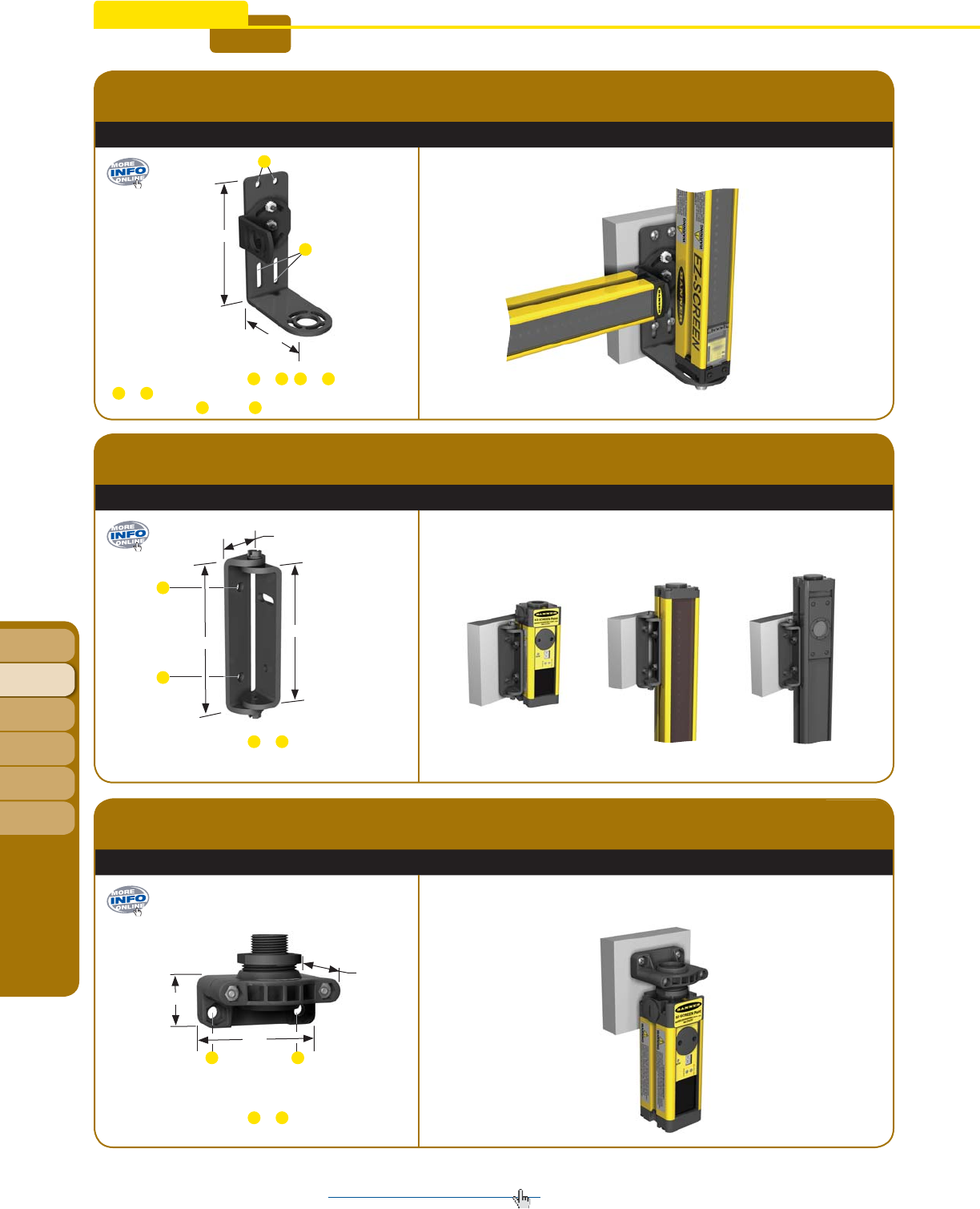
EZA-MBK-12
Kit contains two-piece center bracket to replace the support bracket that comes with the emitter/receiver and includes mounting
hardware. Bracket is made of cold-rolled steel with a black corrosion-resistant zinc chromate finish.
Dimensions Used With
55.6
55
A
B
50
40
ø 60
EZ-SCREEN 14 & 30 mm Resolution
Hole center spacing in mm: A to A = 20, A to B = 37.4
Hole size in mm: A = ø 7.0, B = ø 8.3
EZA-MBK-2
Kit contains two adapter brackets for attaching the standard EZA-MBK-1 bracket (included with the sensor) to any MSA series stand.
Dimensions Used With
88.9
12.7
73.6
A
B
B
A
MSA Stands
PICO-GUARD Grid
Flanges Out Flanges In
EZ-SCREEN 14 & 30 mm Resolution
Flanges Out Flanges In
Heavy-Duty MINI-SCREEN
Flanges Out Flanges In
Hole center spacing in mm: A to A = 63.9, B to B = 19.9,
A to B = 22
Hole size in mm: A = ø 8.3, B = ø 4.78
Detailed
Dimension
s
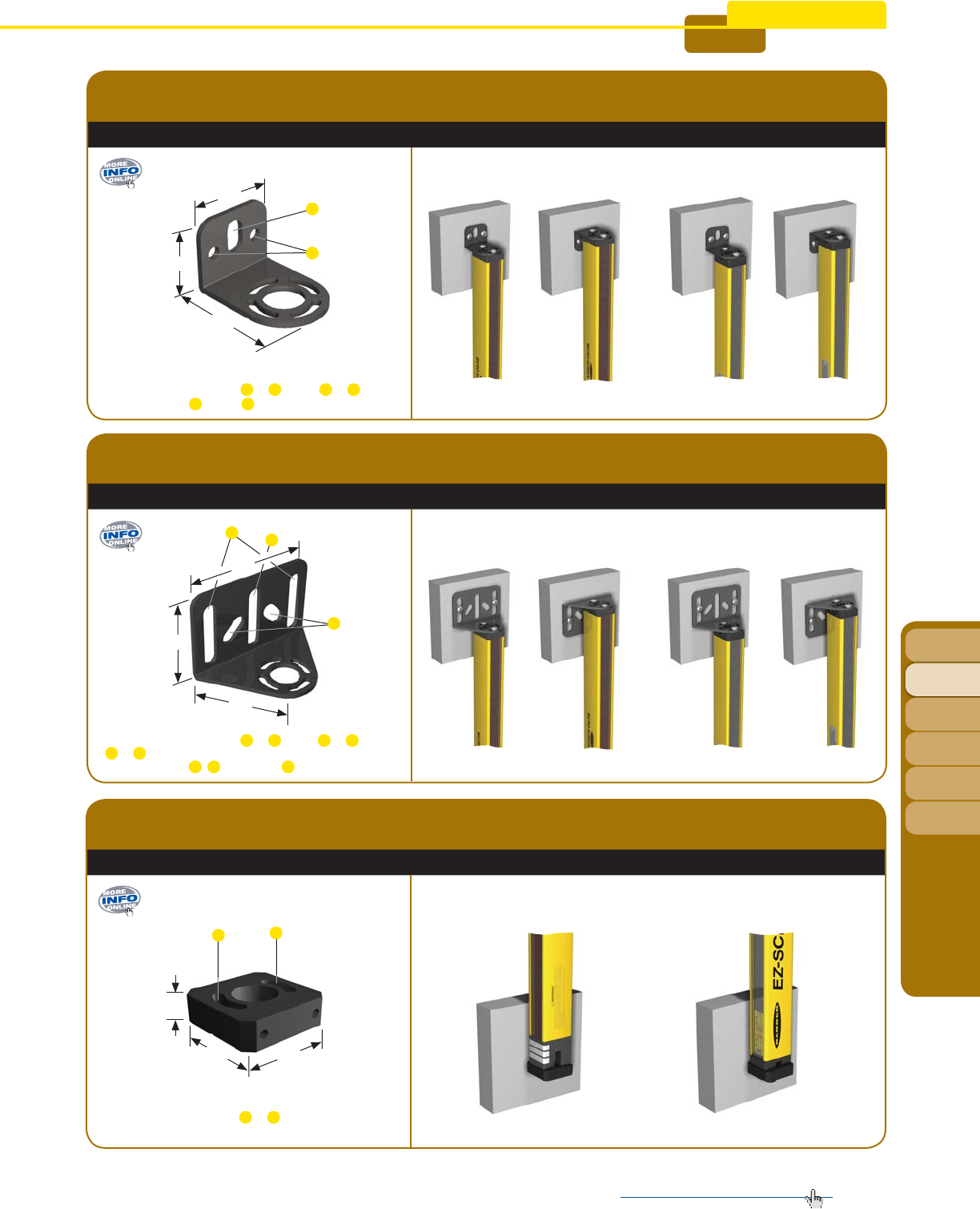
EZA-MBK-20
Universal adapter bracket attaches emitters and receivers to engineered/slotted aluminum framing such as 80/20™ and Unistrut™.
It retrofits the MINI-SCREEN, MICRO-SCREEN and MACHINE-GUARD.
Dimensions Used With
50.0
39.2
58.2
A
B
C
EZ-SCREEN 14 & 30 mm Resolution
Flanges Out Flanges In
Hole center spacing in mm: A to A = 44.4, B to B = 20.0,
C to C = 40.0
Hole size in mm: A = 10.2 x 5.4, B = 27.6 x 7.0, C = 25.0 x 7.0
Detailed
Dimension
s
194 More information online at bannerengineering.com
Brackets
CABLES &
WIRING
BRACKETS
CORNER
MIRRORS
STANDS
HARSH DUTY
SOLUTIONS
ACCESSORIES
REPLACEMENT
PARTS
NOTE: All dimensions in millimeters unless otherwise stated.
ACCESSORIES
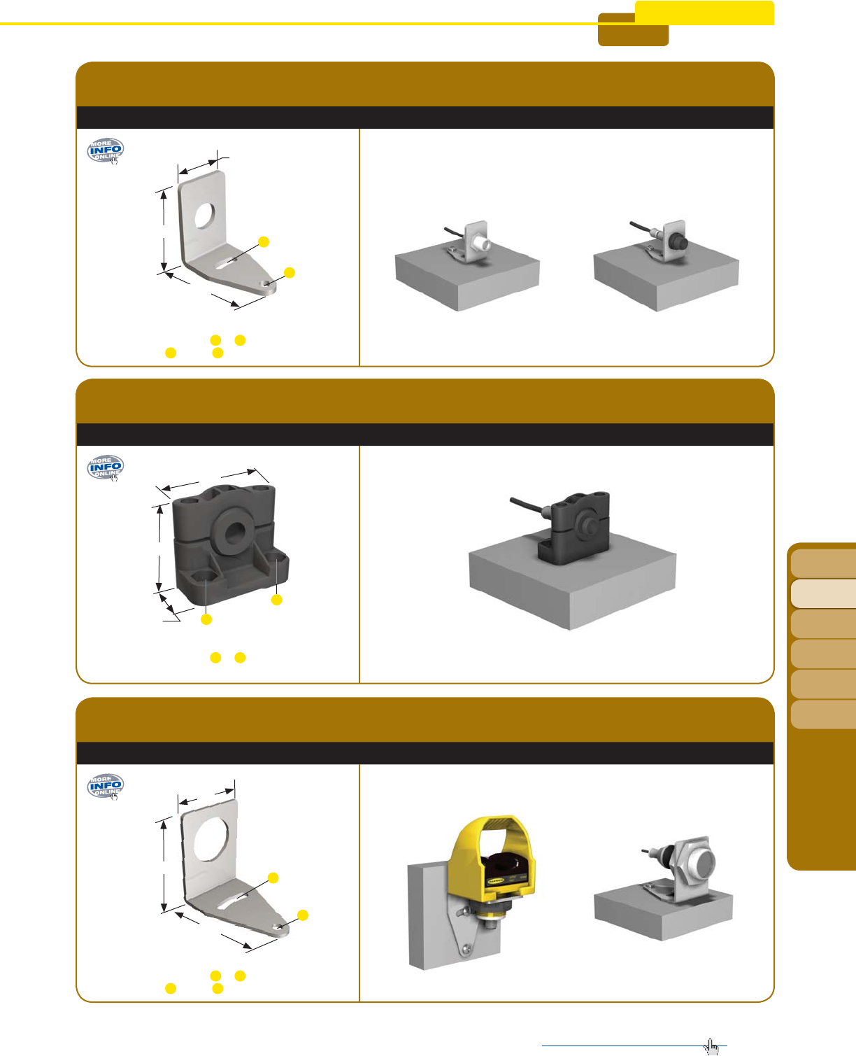
EZA-MBK-4
Top-mounting swivel bracket kit allows the sensor to tilt up to 45° in any direction and is made of black reinforced thermoplastic
polyester. Kit includes a model SMB30SC swivel bracket and a threaded adapter plate.
Dimensions Used With
66.5
29
58.7
A B
EZ-SCREEN Point
Hole center spacing in mm: A to B = 50.8
Hole size in mm: ø 7.0
Detailed
Dimension
s
EZA-MBK-3
Side-swivel bracket kit contains a two-part bracket and hardware. Bracket is made of cold-rolled steel with a black corrosion-
resistant zinc chromate finish. Use one kit for the EZ-SCREEN Point and two for the EZ-SCREEN and PICO-GUARD Grid or
MINI-SCREEN.
Dimensions Used With
100
25
109.4
100
A
B
Heavy-Duty MINI-SCREEN PICO-GUARD GridEZ-SCREEN Point & Grid
Hole center spacing in mm: A to B = 65
Hole size in mm: ø 7.0
Range of rotation: 180°
Detailed
Dimension
s
EZA-MBK-21
Kit contains four brackets for one side of an L-mounting, allowing four mounting variations. Inclined installations of 0° to 30° or
0° to 45° are possible. Use for mounting cascading light screens at right angles (L-configuration).
Dimensions Used With
133.9
98.2
A
B
EZ-SCREEN 14 & 30 mm Resolution
Hole center spacing in mm: A to A, B to B = 20;
A to B = 101.4
Hole size in mm: A = ø 7.3, B = 30.0 x 7.3
Detailed
Dimension
s
195More information online at bannerengineering.com
Brackets
CABLES &
WIRING
BRACKETS
CORNER
MIRRORS
STANDS
HARSH DUTY
SOLUTIONS
ACCESSORIES
REPLACEMENT
PARTS
NOTE: All dimensions in millimeters unless otherwise stated.
ACCESSORIES
Detailed
Dimensions
MSAMB
Kit contains two replacement brackets that come with MSA Series stands and includes mounting hardware. Brackets are made of
cold-rolled steel with a black corrosion-resistant zinc chromate finish.
Dimensions Used With
45.2
28.4
57.2
MINI-SCREEN
Hole center spacing in mm: to = 20, to = 44.3,
to = 28.5
Hole size in mm: = ø 5.3, = ø 3.9
EZA-MBK-5
Bottom-mounting swivel bracket kit allows the sensor to tilt up to 45° in any direction and is made of black reinforced thermoplastic
polyester. Kit includes a model SMB30SC swivel bracket and a threaded adapter.
Dimensions Used With
66.5
29
58.7
A B
EZ-SCREEN Point
Hole center spacing in mm: A to B = 50.8
Hole size in mm: ø 7.0
Detailed
Dimension
s
EZA-MBK-9
Slots in two-bracket kit provide 30 mm range for sensors. Brackets are made of cold-rolled steel with a black corrosion-resistant
zinc chromate finish.
Dimensions Used With
60
51.5
35.1
84
A
B
EZ-SCREEN Grid Heavy-Duty MINI-SCREEN
PICO-GUARD Grid
Flanges Out Flanges In
Flanges Out Flanges In
Flanges Out Flanges In
Hole center spacing in mm: A to B = 30.8
Hole size in mm: 21.0 x 7.0
Detailed
Dimension
s

196 More information online at bannerengineering.com
Brackets
CABLES &
WIRING
BRACKETS
CORNER
MIRRORS
STANDS
HARSH DUTY
SOLUTIONS
ACCESSORIES
REPLACEMENT
PARTS
NOTE: All dimensions in millimeters unless otherwise stated.
ACCESSORIES
MSMB-3
Two-bracket kit contains a replacement for the brackets that come with the emitter/receiver. Brackets are made of 11-gauge cold-
rolled steel with a black corrosion-resistant zinc chromate finish and four self-locking nuts.
Dimensions Used With
57.3
24.2
53.4
A
B
Top View
Flanges Out Flanges In
MINI-SCREEN
Bottom View
Flanges Out Flanges In
Hole center spacing in mm: A to A & B to B = 44.5
Hole size in mm: 10.2 x 4.8
Detailed
Dimension
s
MSMB-1
Two-bracket kit anchors top and bottom of sensor; bottom bracket allows connection of QD cable. Brackets are made of cold-rolled
steel with a black corrosion-resistant zinc chromate finish.
Dimensions Used With
38.1
20.8
53.9
B
A
Top View
Flanges Out Flanges In
MINI-SCREEN
Bottom View
Flanges Out Flanges In
Hole center spacing in mm: A to A, B to B = 25.4
Hole size in mm: A 5.1 x 4.8, B ø 6.8
Detailed
Dimension
s
MSMB-2
Low-profile two-bracket kit anchors top and bottom of sensor with vibration mounts (MSVM...); bottom bracket allows connection
of QD cable. Brackets are made of 11-gauge cold-rolled steel with a black corrosion-resistant zinc chromate finish.
Dimensions Used With
15.2
17.8
B
71.4
A
MINI-SCREEN
Top View Bottom View
Hole center spacing in mm: A to A & B to B = 60.9
Hole size in mm: 10.0 x 4.8
Detailed
Dimension
s
197More information online at bannerengineering.com
Brackets
CABLES &
WIRING
BRACKETS
CORNER
MIRRORS
STANDS
HARSH DUTY
SOLUTIONS
ACCESSORIES
REPLACEMENT
PARTS
NOTE: All dimensions in millimeters unless otherwise stated.
ACCESSORIES
MSMMB
Two-bracket kit contains a replacement for brackets that come with the MSM mirrors and includes mounting hardware. Brackets are
made of cold-rolled steel with a black corrosion-resistant zinc chromate finish.
Dimensions Used With
57.2
21.5
53.5
AB
MSM Mirrors
Flanges Out Flanges In
Hole center spacing in mm: A to B = 45.0
Hole size in mm: 10.0 x 4.7
Detailed
Dimension
s
MSVM-1 = for one emitter/receiver pair with 4 mm hardware (Qty 4).
MSVM10-8 = for two emitter/receiver pairs with 10-32" hardware (Qty 8).
MSMB-MSM-45
Bracket is a replacement for the bracket that comes with the mirror. Mounting hardware in included.
Dimensions Used With
136.5
76.3
192.8
A
BMSM4A Mirrors
Hole center spacing in mm: A to B = 50.8
Hole size in mm: A = ø 7.0, B = 87.7 x 7.0
Detailed
Dimension
s
MSVM..
Rubber spacer reduces vibration when installed between the mounting surface and a bracket. Packet contains two spacers.
Dimensions Used With
13.8
30.7
MINI-SCREEN
Detailed
Dimension
s
Note: For kit containing a bracket and MSM4A mirror, order model number MSA-MBM-K45.
198 More information online at bannerengineering.com
Brackets
CABLES &
WIRING
BRACKETS
CORNER
MIRRORS
STANDS
HARSH DUTY
SOLUTIONS
ACCESSORIES
REPLACEMENT
PARTS
NOTE: All dimensions in millimeters unless otherwise stated.
ACCESSORIES
SFA-IMB2
Optional retrofit bracket is designed to replace SI-MAG2.. Magnetic Interlock switches with PICO-GUARD switches. It is made of
black reinforced thermoplastic polyester.
Dimensions Used With
42.8
26.8
A
B
PICO-GUARD Switches
Hole center spacing in mm: A to B = 21.3
Hole size in mm: ø 4.3
Detailed
Dimension
s
SMA-MBK-1
Kit contains two replacement brackets for one SSM Series mirror and mounting hardware. Brackets are made of cold-rolled steel
with a black corrosion-resistant zinc chromate finish.
Dimensions Used With
60
60
101.2
A
B
SSM Mirrors
Flanges Out Flanges In
Hole center spacing in mm: A to A = 31.5, A to B = 15.7
Hole size in mm: 15.0 x 7.0
Detailed
Dimension
s
SFA-IMB1
Optional retrofit bracket is designed to replace SI-MAG1.. Magnetic Interlock switches with PICO-GUARD switches. It is made of
black reinforced thermoplastic polyester.
Dimensions Used With
24.9
88.9
B
A
A
B
PICO-GUARD Switches
Hole center spacing in mm: A to A, B to B = 78; A to B = 10.0
Hole size in mm: A = ø 4.3, B = 8.0 x 4.3
Detailed
Dimension
s
199More information online at bannerengineering.com
Brackets
CABLES &
WIRING
BRACKETS
CORNER
MIRRORS
STANDS
HARSH DUTY
SOLUTIONS
ACCESSORIES
REPLACEMENT
PARTS
NOTE: All dimensions in millimeters unless otherwise stated.
ACCESSORIES
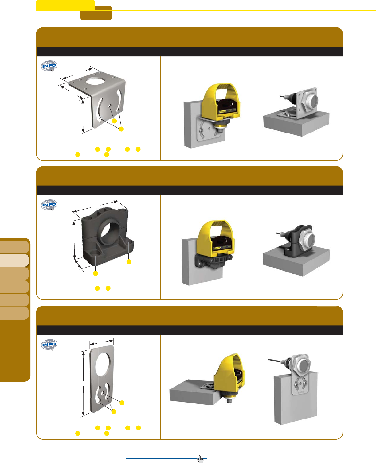
SMB1812SF
Swivel bracket of black reinforced thermoplastic polyester accommodates a 12 mm barrel-style sensor and allows the sensor to tilt
up to 45° in any direction. Stainless steel locking hardware is included.
Dimensions Used With
43.2
25.4
43.2
A
B
PICO-GUARD 12 mm Points
Hole center spacing in mm: A to B = 36.1
Hole size in mm: ø 5.0
Detailed
Dimension
s
SMB12MM
Twelve-gauge stainless-steel mounting bracket accommodates a 12 mm barrel-style sensor and allows ± 15° of lateral movement.
Dimensions Used With
38.1
42.9
25.4
A
B
PICO-GUARD 12 mm PointsPICO-GUARD 12 mm Switches
Hole center spacing in mm: A to B = 40
Hole size in mm: A = ø 6.3, B = 13.1 x 6.3
Detailed
Dimension
s
SMB30A
Twelve-gauge stainless-steel mounting bracket accommodates 30 mm barrel-style sensor and allows ± 15° of lateral movement.
Dimensions Used With
48
48
45
A
B
PICO-GUARD 30 mm PointsSTB/OTB
Hole center spacing in mm: A to B = 40
Hole size in mm: A = ø 6.3, B = 27.3 x 6.3
Detailed
Dimension
s
200 More information online at bannerengineering.com
Brackets
CABLES &
WIRING
BRACKETS
CORNER
MIRRORS
STANDS
HARSH DUTY
SOLUTIONS
ACCESSORIES
REPLACEMENT
PARTS
NOTE: All dimensions in millimeters unless otherwise stated.
ACCESSORIES
SMB30SC
Swivel bracket of black reinforced thermoplastic polyester accommodates a 30 mm barrel-style sensor and allows the sensor to tilt
up to 45° in any direction. Stainless steel locking hardware is included.
Dimensions Used With
58.7
29.2
66.5
A
B
PICO-GUARD 30 mm PointsSTB/OTB
Hole center spacing in mm: A to B = 50.8
Hole size in mm: ø 7.0
Detailed
Dimension
s
SMBAMS30P
Twelve-gauge stainless-steel mounting bracket allows more than 90° of rotation. Use for mounting a 30 mm sensor on the edge of a
surface.
Dimensions Used With
85
45
A
B
PICO-GUARD 30 mm PointsSTB/OTB
Hole center spacing in mm: A to A = 26.0, A to B = 13.0
Hole size in mm: A = 26.8 x 7.0, B = ø 6.3
Detailed
Dimension
s
SMB30MM
Twelve-gauge stainless-steel mounting bracket accommodates 30 mm barrel-style sensor and allows up to 90° of lateral movement,
depending on spacing of mounting screws.
Dimensions Used With
57.2
69.9
57.2
A
B
PICO-GUARD 30 mm PointsSTB/OTB
Hole center spacing in mm: A to A = 51.0, A to B = 25.4
Hole size in mm: A = 42.6 x 7.0, B = ø 6.3
Detailed
Dimension
s
201More information online at bannerengineering.com
Brackets
CABLES &
WIRING
BRACKETS
CORNER
MIRRORS
STANDS
HARSH DUTY
SOLUTIONS
ACCESSORIES
REPLACEMENT
PARTS
NOTE: All dimensions in millimeters unless otherwise stated.
ACCESSORIES
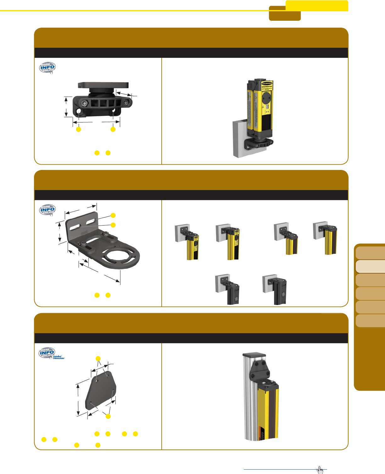
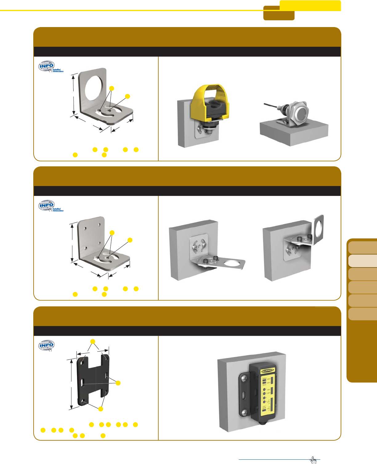
SMBR55F01
Flat-mounting bracket is a replacement for the bracket that comes with a remote display and is made of black reinforced
thermoplastic polyester.
Dimensions Used With
64
65
A
C
B
PICO-GUARD SFA-RD Remote Display
Hole center spacing in mm: A to A, B to B, C to C = 50.8;
A to B, B to C = 25.3
Hole size in mm: A, C = ø 5.6, B = 11.3 x 5.6
Detailed
Dimension
s
Detailed
Dimensions
SMBAMS30RA
Twelve-gauge stainless-steel right-angle mounting bracket accommodates a 30 mm sensor with QD and allows more than 90° of
rotation.
Dimensions Used With
48
45
48
A
B
PICO-GUARD 30 mm PointsSTB/OTB
Hole center spacing in mm: A to A = 25.3, A to B = 12.8
Hole size in mm: A = 26.8 x 7.0, B = ø 6.3
Detailed
Dimensions
SMBAMSBRA
The four holes in this twelve-gauge stainless-steel right-angle base bracket fit the slots in SMBAMS Series brackets. For additional
articulation, combine multiple SMBAMS.. brackets.
Dimensions Used With
48
45
48
A
B
SMBAMS30P Bracket SMBAMS30RA Bracket
Hole center spacing in mm: A to A = 25.3, A to B = 12.8
Hole size in mm: A = 26.8 x 7.0, B = ø 6.3
202 More information online at bannerengineering.com
Brackets
CABLES &
WIRING
BRACKETS
CORNER
MIRRORS
STANDS
HARSH DUTY
SOLUTIONS
ACCESSORIES
REPLACEMENT
PARTS
NOTE: All dimensions in millimeters unless otherwise stated.
ACCESSORIES
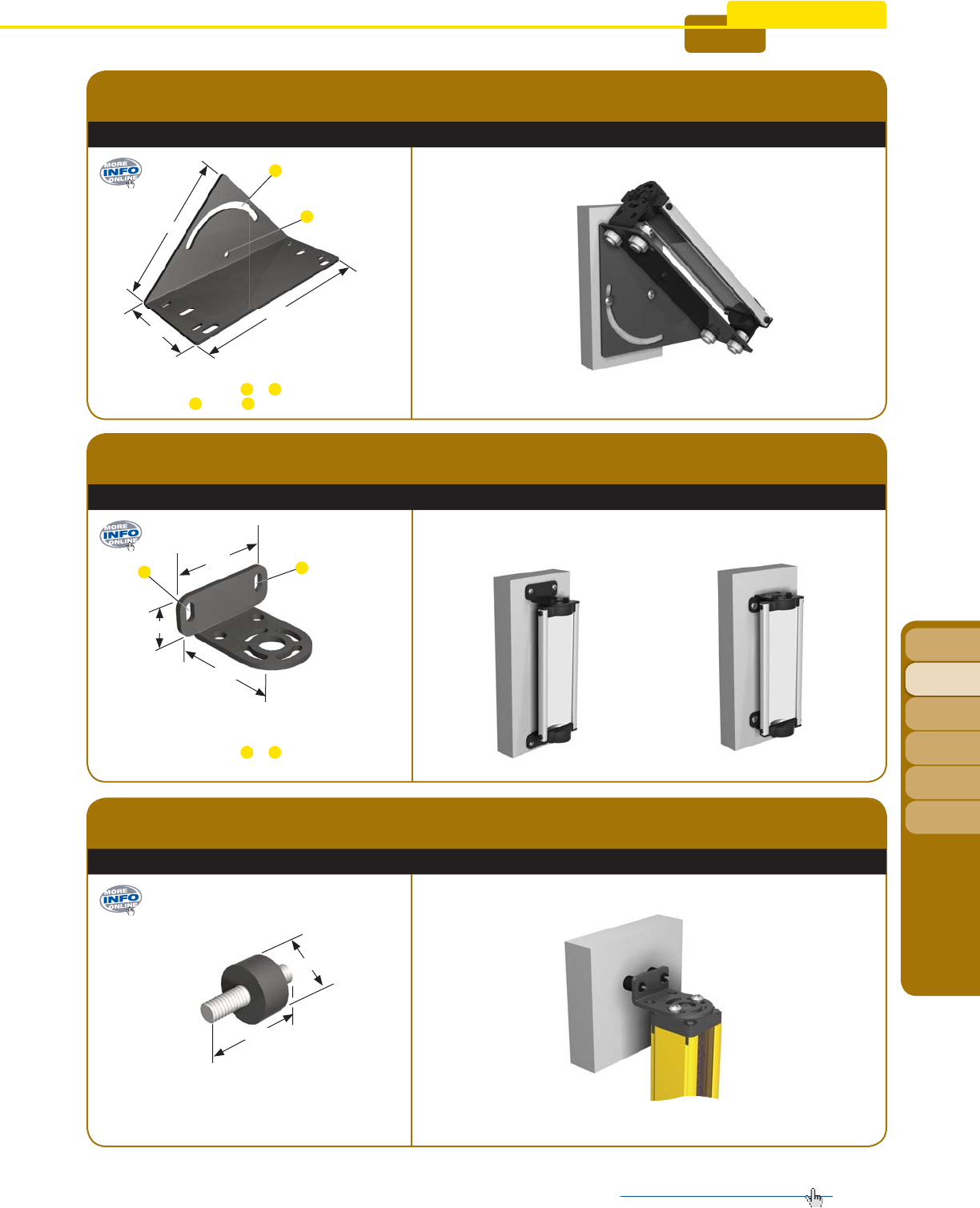
SMBR55FRA
Bracket attaches to the side of the sensor and is made from 19-gauge stainless steel.
Dimensions Used With
44
40
20 A
B
PICO-GUARD SFA-RD Remote Display
Hole center spacing in mm: A to B = 20
Hole size in mm: ø 5.4
Detailed
Dimension
s
USCMB-..
Bracket replaces center bracket and is made of cold-rolled steel with a black corrosion-resistant zinc chromate finish. Mounting
hardware is included. USCMB-1 fits emitters and receivers up to 900 mm long, and the two-bracket USCMB-2 fits emitters and
receivers more than 900 mm long.
Dimensions Used With
31.8
111.3
37.6 28.4
B
AEZ-SCREEN Type 2MICRO-SCREEN
Hole center spacing in mm: A to A = 19.9, A to B = 10.0
Hole size in mm: A = 12.2 x 7.11, B = ø 4.8
Detailed
Dimension
s
SMBR55F02
Bracket mounts to T-slotted or narrow flat surfaces and is made of 19-gauge stainless steel.
Dimensions Used With
30
34.8
72.9
10.7
A
B
PICO-GUARD SFA-RD Remote Display
Hole center spacing in mm: A to B = 50.3
Hole size in mm: 11.2 x 5.6
Detailed
Dimension
s
203More information online at bannerengineering.com
Brackets
CABLES &
WIRING
BRACKETS
CORNER
MIRRORS
STANDS
HARSH DUTY
SOLUTIONS
ACCESSORIES
REPLACEMENT
PARTS
NOTE: All dimensions in millimeters unless otherwise stated.
ACCESSORIES
USMB-8
Low-profile bracket is made of black anodized aluminum and allows ± 30° of movement. Use one per emitter or receiver. Bracket
does not include two 2 x M4 screws required for through-hole mounting.
Dimensions Used With
31.8
32.8
8.0
AB
EZ-SCREEN Type 2MICRO-SCREEN
Hole center spacing in mm: A to B = 22.7
Hole size in mm: 15.0 x 3.5
Detailed
Dimension
s
USMB-1
Two-bracket kit contains a replacement for the brackets that come with the emitter/receiver. Brackets are made of cold-rolled steel
with a black corrosion-resistant zinc chromate finish.
Dimensions Used With
31.7
26.9
41.5
A
B
Flanges Out Flanges In
EZ-SCREEN Type 2MICRO-SCREEN
Flanges Out Flanges In
Hole center spacing in mm: A to A = 20.0, A to B = 10.0
Hole size in mm: A = ø 4.7, B =12.7 x 7.0
Detailed
Dimension
s
USMB-6
Universal-mounting surface kit contains two brackets made of cold-rolled 13-gauge steel with a black corrosion-resistant zinc
chromate finish. Use one per emitter or receiver.
Dimensions Used With
69.0
41.9
40.3
AB
C
Flanges Out Flanges In
EZ-SCREEN Type 2MICRO-SCREEN
Flanges Out Flanges In
Hole center spacing in mm: A to A = 52.1, A to B = 26,
C to C = 30.6
Hole size in mm: A, B = 25.4 x 7.1, C = 15.5 x 7.0
Detailed
Dimension
s
204 More information online at bannerengineering.com
Corner Mirrors
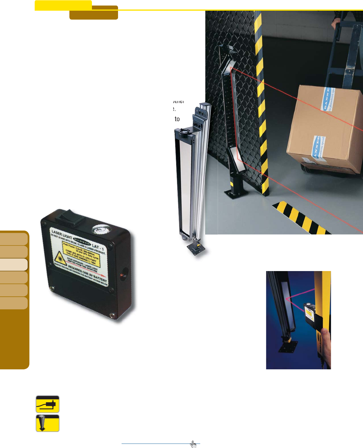
LAT-1 Laser Alignment Tool
• Totally self-contained visible-beam laser
tool simplifies the critical mechanical and
optical alignment of emitters, receivers and
mirrors.
• Use to align emitter/receiver pairs,
especially in applications that include long
distances or corner mirrors.
MSM Glass Models. . . . . . . . . . . . . . . . . . . . . . . . . . Page 205
SSM Stainless Steel Models . . . . . . . . . . . . . . . . . . . . . . . .206
Alignment Tools . . . . . . . . . . . . . . . . . . . . . . . . . . . . . . . . .208
Corner Mirrors
for Guarding Applications
• Mirrors expand guarding to mutiple sides of an area
using one emitter/receiver pair.
• Glass or stainless steel models are available.
• Mirrors mount easily to MSA Series stands or other
surfaces, using included brackets and hardware.
• Unique end-cap design allows mirrors to rotate to
± 45° after installation.
BRACKETS
PAGE 197
34!.$3
PAGE
209
ACCESSORIES
CABLES &
WIRING
BRACKETS
CORNER
MIRRORS
STANDS
HARSH DUTY
SOLUTIONS
ACCESSORIES
REPLACEMENT
PARTS
205More information online at bannerengineering.com
Corner Mirrors
ACCESSORIES
CABLES &
WIRING
BRACKETS
CORNER
MIRRORS
STANDS
HARSH DUTY
SOLUTIONS
ACCESSORIES
REPLACEMENT
PARTS
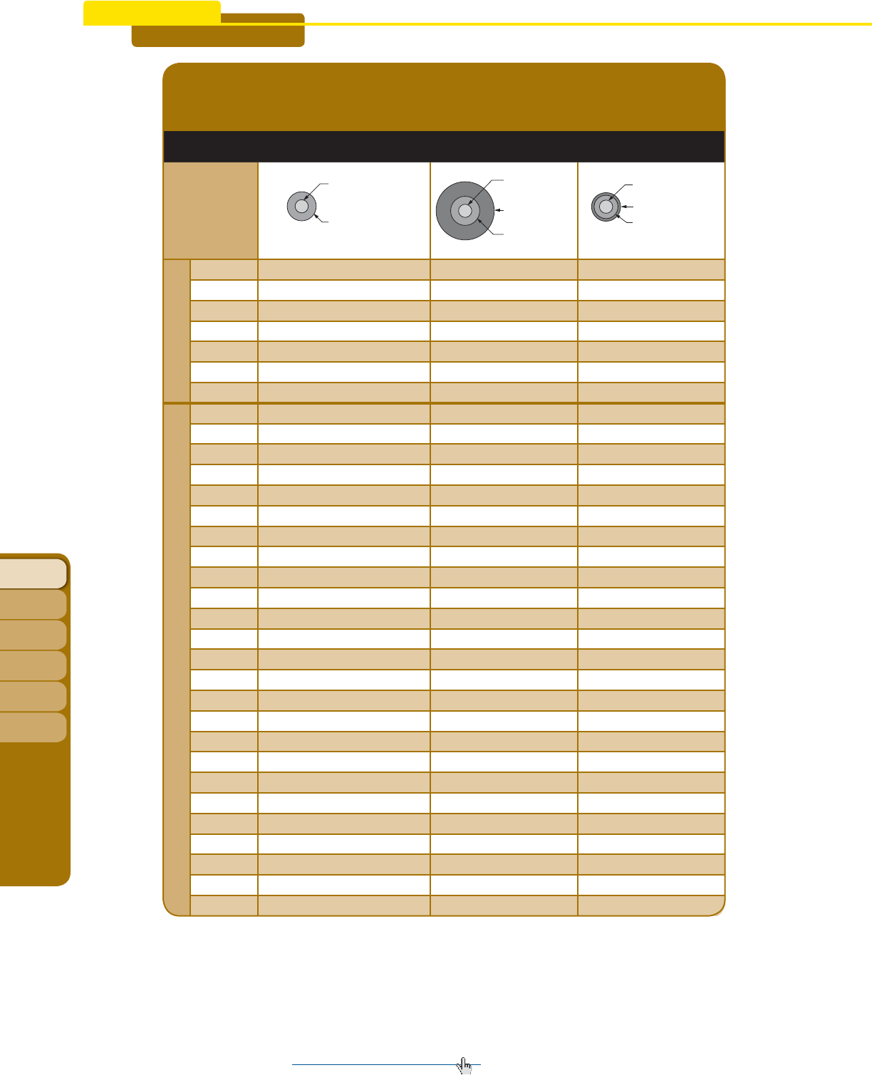
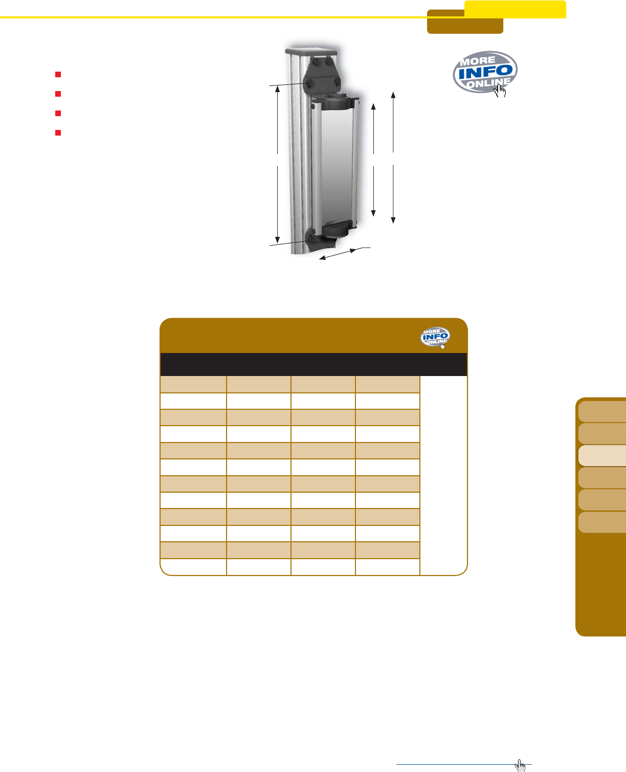
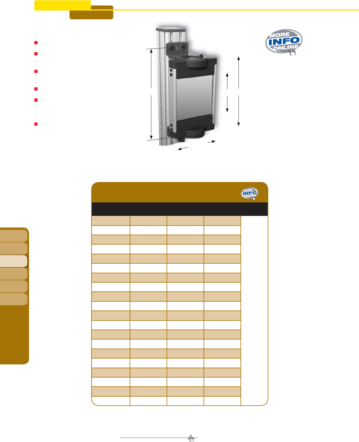
Mirror
Models
Reflective Area
(Y)
Mounting
Height (L1)
Mirror
Height (L2)*
Data
Sheet
MSM4A 165 mm 221 mm 191 mm
43685
MSM8A 267 mm 323 mm 292 mm
MSM12A 356 mm 411 mm 381 mm
MSM16A 457 mm 513 mm 483 mm
MSM20A 559 mm 615 mm 584 mm
MSM24A 660 mm 716 mm 686 mm
MSM28A 762 mm 818 mm 787 mm
MSM32A 864 mm 919 mm 889 mm
MSM36A 965 mm 1021 mm 991 mm
MSM40A 1067 mm 1123 mm 1092 mm
MSM44A 1168 mm 1224 mm 1194 mm
MSM48A 1270 mm 1326 mm 1295 mm
MSM Corner Mirrors
MSM Corner Mirrors
(shown with standard brackets and MSAMB** adapter
bracket mounted on MSA stand)
MSM Corner Mirrors
Compact for light-duty applications
Available in 12 lengths
Decreases range by 8%
Rated 85% efficiency
Detailed
Dimensions
Downloa
d
PDF
* The mounting brackets may be inverted from the positions shown (flanges pointing “inward”
instead of “outward,” as shown). When this is done, dimension L2 decreases by 66 mm.
** MSAMB adapter bracket kit included with each MSA stand.
72.9 mm
L1 L2
Y
206 More information online at bannerengineering.com
Corner Mirrors
ACCESSORIES
CABLES &
WIRING
BRACKETS
CORNER
MIRRORS
STANDS
HARSH DUTY
SOLUTIONS
ACCESSORIES
REPLACEMENT
PARTS
Mirror
Models
Reflective Area
(Y)
Mounting
Height (L1)
Mirror
Height (L2)*
Data
Sheet
SSM-100 100 mm 211 mm 178 mm
61934
SSM-150 150 mm 261 mm 228 mm
SSM-200 200 mm 311 mm 278 mm
SSM-250 250 mm 361 mm 328 mm
SSM-375 375 mm 486 mm 453 mm
SSM-475 475 mm 586 mm 553 mm
SSM-550 550 mm 661 mm 628 mm
SSM-675 675 mm 786 mm 753 mm
SSM-825 825 mm 936 mm 903 mm
SSM-875 875 mm 986 mm 953 mm
SSM-975 975 mm 1086 mm 1053 mm
SSM-1100 1100 mm 1211 mm 1178 mm
SSM-1175 1175 mm 1286 mm 1253 mm
SSM-1275 1275 mm 1386 mm 1353 mm
SSM-1400 1400 mm 1511 mm 1478 mm
SSM-1475 1475 mm 1586 mm 1553 mm
SSM-1550 1550 mm 1661 mm 1628 mm
SSM-1675 1675 mm 1786 mm 1753 mm
SSM-1750 1750 mm 1861 mm 1828 mm
SSM-1900 1900 mm 2011 mm 1978 mm
SSM Corner Mirrors
Robust for heavy-duty applications
Extra wide for use with long-range
optical safety systems
Available in stainless steel for
harsh applications
Available in 20 lengths
Rated 85% efficiency for SSM
models and 50% on SSM-S
models
Decreases range by 8% for SSM
models and 30% for SSM-S
models
Detailed
Dimensions
SSM Glass Corner Mirrors
Downloa
d
PDF
* The mounting brackets may be inverted from the positions shown (flanges pointing “inward”
instead of “outward,” as shown). When this is done, dimension L2 decreases by 66 mm.
** One EZA-MBK-2 adapter bracket kit required if used with a MSA stand.
NOTE: The total range decreases by approximately 8% per mirror.
SSM and SSM-S Corner Mirrors
(shown with standard brackets and EZA-MBK-2** adapter
bracket mounted on MSA stand)
115.0 mm
L1 L2
Y
207More information online at bannerengineering.com
Corner Mirrors
ACCESSORIES
CABLES &
WIRING
BRACKETS
CORNER
MIRRORS
STANDS
HARSH DUTY
SOLUTIONS
ACCESSORIES
REPLACEMENT
PARTS
* The mounting brackets may be inverted from the positions shown (flanges pointing “inward”
instead of “outward,” as shown). When this is done, dimension L2 decreases by 58 mm.
** One EZA-MBK-2 adapter bracket kit required if used with a MSA stand.
NOTE: The total range decreases by approximately 30% per mirror.
SSM-S Stainless Steel Corner Mirrors
Downloa
d
PDF
Mirror Model
Reflective Area
(Y)
Mounting
Height (L1)
Mirror
Height (L2)*
Data
Sheet
SSM-100-S 100 mm 211 mm 178 mm
67200
SSM-150-S 150 mm 261 mm 228 mm
SSM-200-S 200 mm 311 mm 278 mm
SSM-250-S 250 mm 361 mm 328 mm
SSM-375-S 375 mm 486 mm 453 mm
SSM-475-S 475 mm 586 mm 553 mm
SSM-550-S 550 mm 661 mm 628 mm
SSM-675-S 675 mm 786 mm 753 mm
SSM-825-S 825 mm 936 mm 903 mm
SSM-875-S 875 mm 986 mm 953 mm
SSM-975-S 975 mm 1086 mm 1053 mm
SSM-1100-S 1100 mm 1211 mm 1178 mm
SSM-1175-S 1175 mm 1286 mm 1253 mm
SSM-1275-S 1275 mm 1386 mm 1353 mm
SSM-1400-S 1400 mm 1511 mm 1478 mm
SSM-1475-S 1475 mm 1586 mm 1553 mm
SSM-1550-S 1550 mm 1661 mm 1628 mm
SSM-1675-S 1675 mm 1786 mm 1753 mm
SSM-1750-S 1750 mm 1861 mm 1828 mm
SSM-1900-S 1900 mm 2011 mm 1978 mm
208 More information online at bannerengineering.com
Corner Mirrors
ACCESSORIES
CABLES &
WIRING
BRACKETS
CORNER
MIRRORS
STANDS
HARSH DUTY
SOLUTIONS
ACCESSORIES
REPLACEMENT
PARTS
LAT-1 Laser Alignment Tools
Downloa
d
PDF
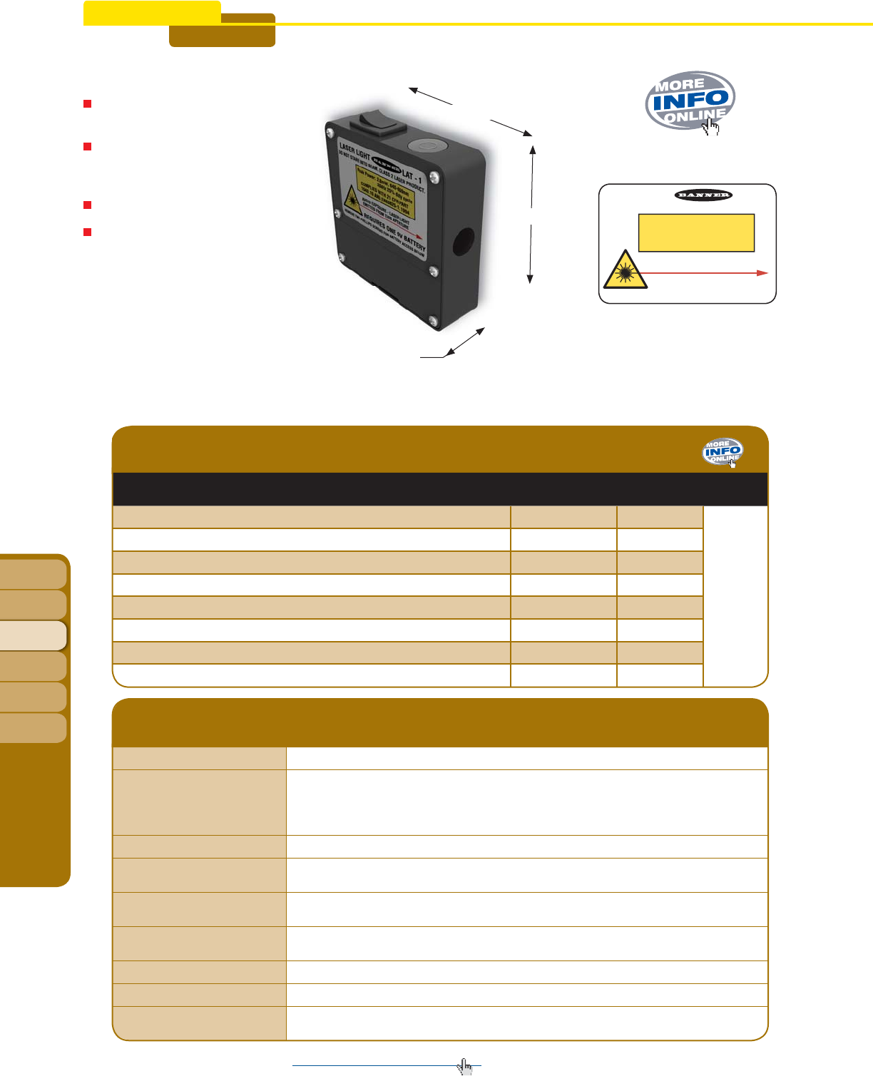
LAT-1 Laser Alignment Tool
(shown without clip)
Simplifies the alignment of any
emitter/receiver pair
Available for EZ-SCREEN,
PICO-GUARD, MICRO-SCREEN and
MINI-SCREEN
Includes a built-in bubble level
Uses one 9-volt battery, which is
included
Detailed
Dimensions
Laser Alignment Tools
75 mm
75 mm
21 mm
LASER LIGHT
REQUIRES ONE 9V BATTERY
DO NOT STARE INTO BEAM. CLASS 2 LASER PRODUCT.
REMOVE TWO PHILLIPS SCREWS FOR BATTERY ACCESS BELOW
Peak Power:
COMPLIES WITH 21 CFR PART
1040.10 AND EN60825-1; 1994
2.8mW, 640-660nm
33kHz 25% duty cycle
LAT - 1
AVOID EXPOSURE - LASER LIGHT
EMITTED FROM THIS APERTURE
Safety Light Screen Housing
LAT-1
with Clip Kit
Clip
w/Target
Data
Sheet
MINI-SCREEN®LAT-1-MS MSA-LAT-1
54599
MICRO-SCREEN®LAT-1-US USA-LAT-1
Heavy-Duty MINI-SCREEN®, EZ-SCREEN® Grid or Points, PICO-GUARD™ Grids LAT-1-HD EZA-LAT-1
EZ-SCREEN® 14 & 30 mm Resolution LAT-1-SS EZA-LAT-2
EZ-SCREEN® Type 2 LAT-1-LS LSA-LAT-1
All of the Above LAT-1 –
PICO-GUARD® SFP12 Safety Points LAT-1-SFP12 SFA-LAT-12
PICO-GUARD® SFP30 Safety Points LAT-1-SFP30 SFA-LAT-30
Supply Voltage and Current One standard 9V battery, included (replaceable); approximately 20 hours of continuous operation
Sensing Beam Class 2 laser, 640-660 nm visible red IEC
Pulse Width: 7 microseconds
Rep rate: 30 microseconds
Peak output power: 2.8 mW, 33kHz, 25% duty cycle
Beam Size at Aperture Approximately 2 mm diameter
Beam Divergence ± 1.0 milliradian within specified temperature range
± 0.5 milliradians at room temperature
Beam Placement Within ± 4 milliradians (approximately ±0.25 degrees) of parallel to front, back, top and bottom of
housing
Construction Aluminum housing; black anodized finish
Black polypropylene cover with flexible hinge for battery access
Environmental Rating NEMA 1; IEC IP50
Operating Conditions Temperature: 0° to +40° C Relative humidity: 90% @ +50° C (non-condensing)
Laser Classification U.S. Safety Standards 21 CFR 1040.10
European Standards EN 60825-1:1994
LAT-1 Laser Alignment Tool Specifications
209More information online at bannerengineering.com
Stands
For Optical Safety
System Sensors or
Corner Mirrors
• Free-standing supports for Banner optical safety
system emitters, receivers, and corner mirrors.
• Strong and lightweight, the stand’s square poles
have dual channels to make it easy to adjust height
accurately.
• The stand base is welded steel for maximum stability.
Stands
MSA Stands . . . . . . . . . . . . . . . . . . . . . . . Page 210
USA Protective Mounting Stands . . . . . . . . . . . . 211
MSA Protective Mounting Stands. . . . . . . . . . . . 211
BRACKETS
PAGE 193
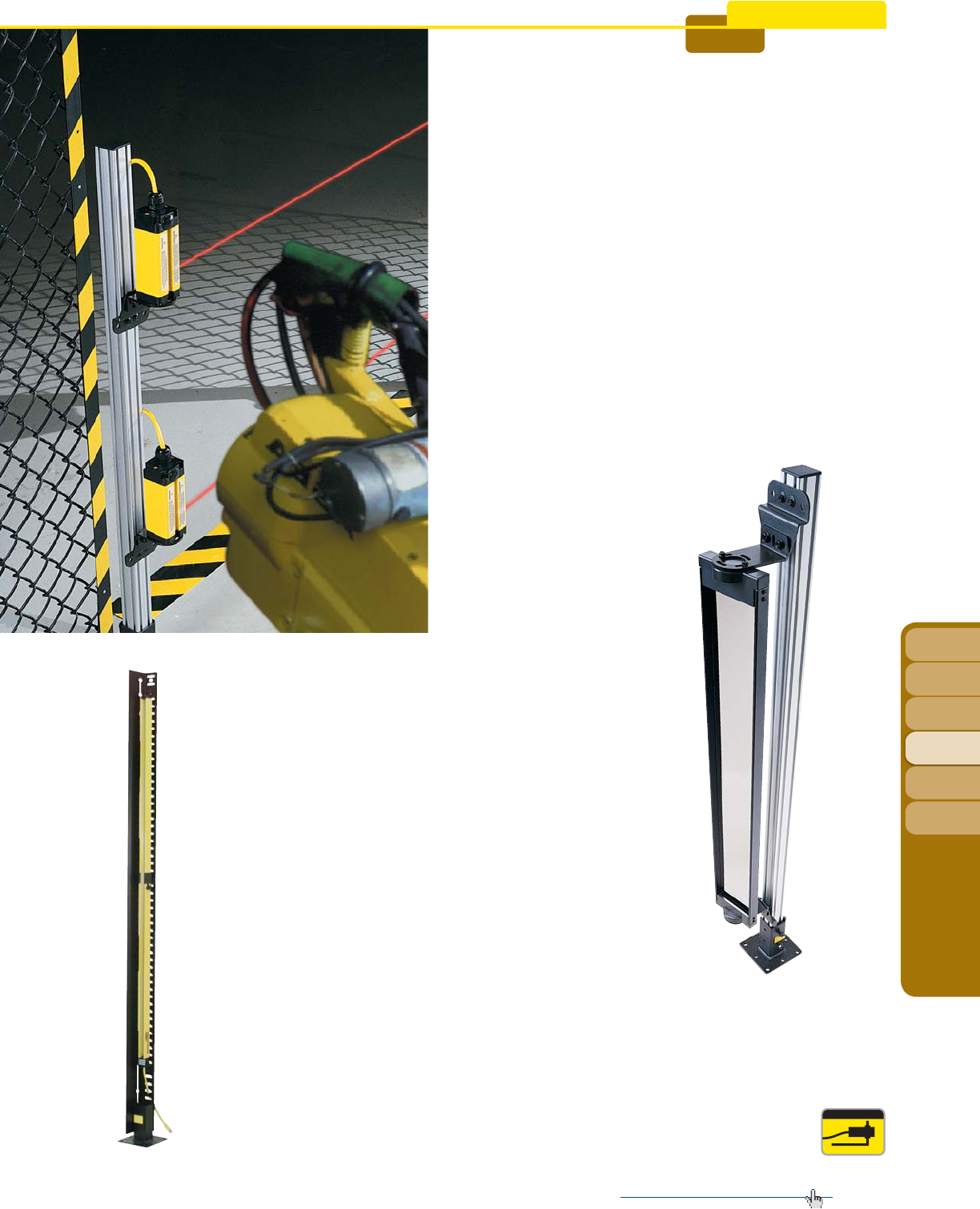
USA Protective Mounting Stands come with
mounting base
MSA Stand shown with MSM corner mirror
(sold on page 205).
Protective Mounting Stands
• Each stand shields two adjacent sides of an emitter or
receiver; combine two stands to surround the entire
sensor.
• Stand protects the sensor from impact and deflects
flying material such as weld splatter.
ACCESSORIES
CABLES &
WIRING
BRACKETS
CORNER
MIRRORS
STANDS
HARSH DUTY
SOLUTIONS
ACCESSORIES
REPLACEMENT
PARTS
210 More information online at bannerengineering.com
Stands
ACCESSORIES
CABLES &
WIRING
BRACKETS
CORNER
MIRRORS
STANDS
HARSH DUTY
SOLUTIONS
ACCESSORIES
REPLACEMENT
PARTS
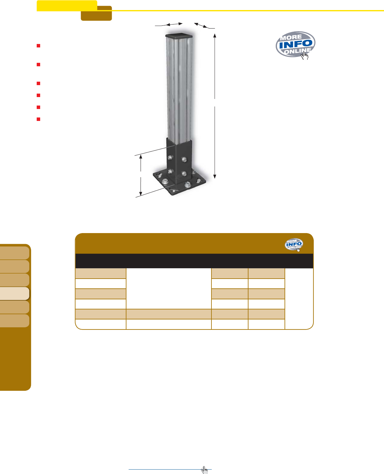
MSA Series Stands
Downloa
d
PDF
Model* Used With**
Stand
Height (L)
Useable Stand
Height
Data
Sheet
MSA-S24-1
EZ-SCREEN®, MICRO-SCREEN®,
MINI-SCREEN® and
Mirrors.
610 mm 483 mm
43687
MSA-S42-1 1067 mm 940 mm
MSA-S66-1 1676 mm 1549 mm
MSA-S84-1 2132 mm 2006 mm
SPKA-AG12-1 SFP12 Safety Points 1067 mm 940 mm
SPKA-AG30-1 SFP30 Safety Points 1067 mm 940 mm
MSA Stands
MSA Stand
Supports emitter, receiver or
corner mirror.
Available without stand base, for
attaching to a surface.
Available in four heights.
Assembles easily.
Includes mounting hardware.
Accepts attachment of USA Series
protective mounting stands.
Detailed
Dimensions
* Available without a base by adding suffix “NB” to model number (example, MSA-S24-1NB).
** Adapter brackets EZA-MBK-2 (2 each) are required for mounting EZ-SCREEN Grid and Point emitters/receivers, or SSM Series
mirrors.
40.0 mm
L
40.0 mm
127.0 mm
211More information online at bannerengineering.com
Stands
ACCESSORIES
CABLES &
WIRING
BRACKETS
CORNER
MIRRORS
STANDS
HARSH DUTY
SOLUTIONS
ACCESSORIES
REPLACEMENT
PARTS
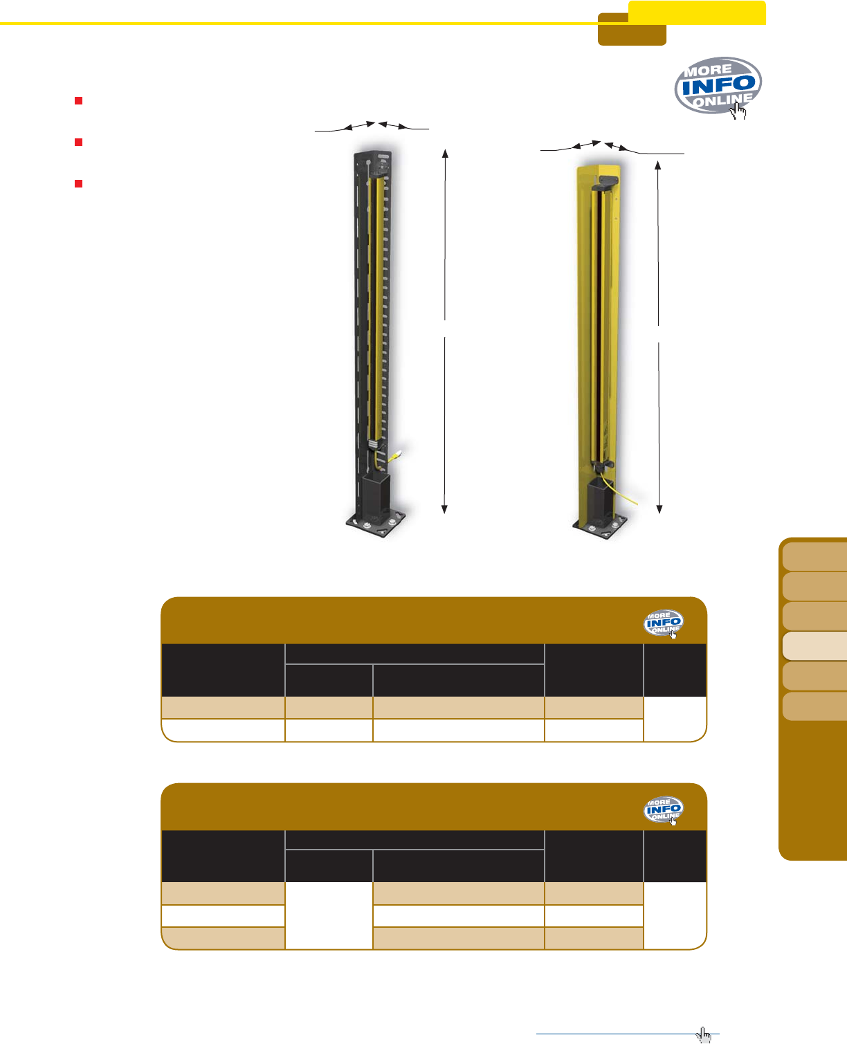
Used With
Model* Model Family Emitter/Receiver Defined Area
Mounting Stand
Height (L)
Data
Sheet
MSA-PMS-30
MINI-SCREEN®
305 to 610 mm 760 mm
64715
MSA-PMS-42 711 to 914 mm 1067 mm
MSA-PMS-54 1016 to 1219 mm 1372 mm
MSA Series Protective Mounting Stands
* Order base model MSA-SB-1 separately.
NOTE: Mounting hardware ordered separately.
Protective Mounting Stands
MSA Protective Mounting Stand
Mounts easily to wall, post, or
machine frame.
Available for MINI-SCREEN and
MICRO-SCREEN
Available in five heights
Detailed
Dimensions
USA Protective Mounting Stand
Downloa
d
PDF
Used With*
Model* Model Family Emitter/Receiver Defined Area
Mounting Stand
Height (L)
Data
Sheet
USA-PMS-40 MICRO-SCREEN®102 to 914 mm 1016 mm
57119
USA-PMS-62 MICRO-SCREEN®102 to 1422 mm 1651 mm
USA Series Protective Mounting Stands
Downloa
d
PDF
L
L
89.0 mm
51.0 mm
66.5 mm
104.6 mm
* USA Series stands are compatible with MINI-SCREEN emitters/receivers using special brackets (see data sheet).
212 More information online at bannerengineering.com
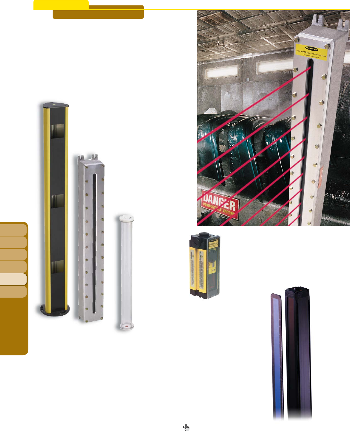
Explosive & Harsh Duty Solutions
Lens Shields and
Enclosures
• Replaceable lens shields protect sensor lenses from
damage.
• Tubular enclosures guard entire sensor in
washdown environments.
• Protective enclosures provide rugged
protection for sensors and mirrors.
• Explosion-proof enclosures protect sensors
in environments with flammable gases,
liquids or dust.
EZ-SCREEN Lens Shields . . . . . . . . . . . . . . . . . . . . . Page 213
MICRO-SCREEN Lens Shields . . . . . . . . . . . . . . . . . . . . . 214
MINI-SCREEN Lens Shields . . . . . . . . . . . . . . . . . . . . . . . 214
Heavy-Duty MINI-SCREEN Lens Shields . . . . . . . . . . . . . . 215
EZ-SCREEN Type 2 Lens Shields . . . . . . . . . . . . . . . . . . . . 215
EZA-TE Tubular Enclosures. . . . . . . . . . . . . . . . . . . . . . . . . 216
MSA-TE Tubular Enclosures . . . . . . . . . . . . . . . . . . . . . . . 217
MSHDA-TE Tubular Enclosures . . . . . . . . . . . . . . . . . . . . 217
EZA-S Protective Enclosures . . . . . . . . . . . . . . . . . . . . . . . 218
Explosion-Proof Enclosures . . . . . . . . . . . . . . . . . . . . . . . . 219
Harsh Duty
Lens Shields
• Covers the lens of an emitter or
receiver to prevent
damage.
• Available for
all sizes of EZ-SCREEN,
MICRO-SCREEN, MINI-
SCREEN emitters and
receivers.
ACCESSORIES
CABLES &
WIRING
BRACKETS
CORNER
MIRRORS
STANDS
HARSH DUTY
SOLUTIONS
ACCESSORIES
REPLACEMENT
PARTS
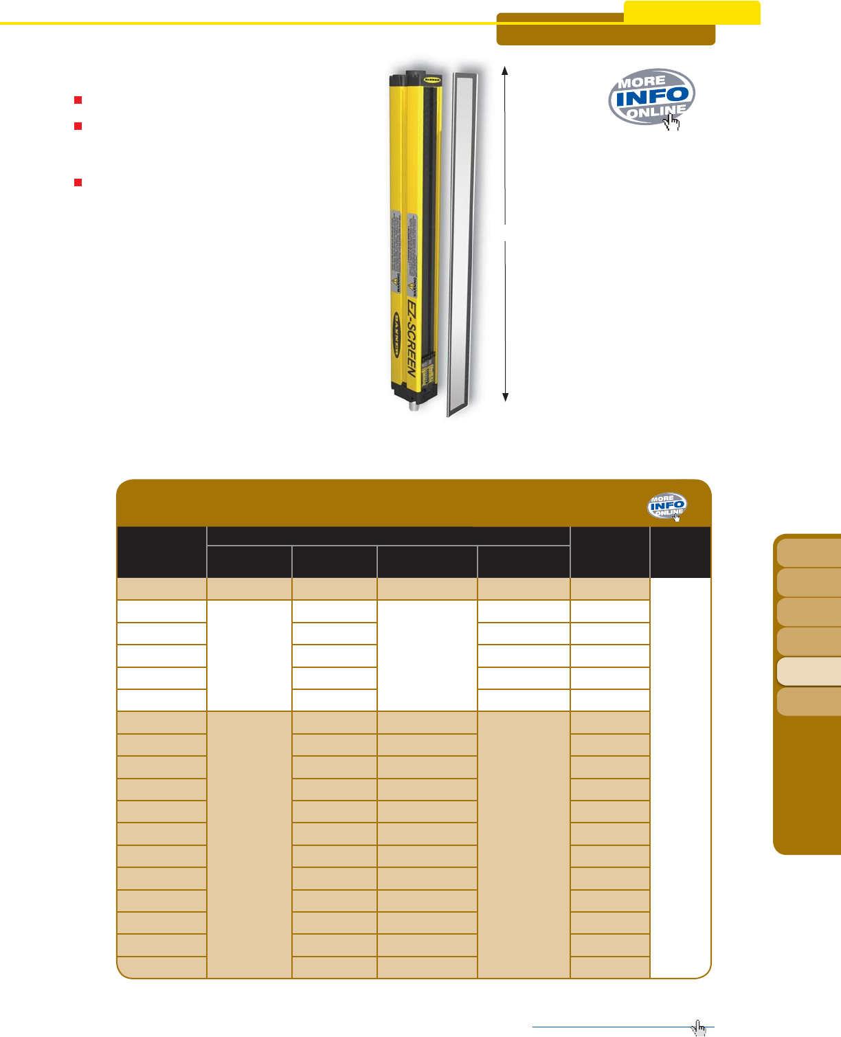
213More information online at bannerengineering.com
Explosive & Harsh Duty Solutions
ACCESSORIES
CABLES &
WIRING
BRACKETS
CORNER
MIRRORS
STANDS
HARSH DUTY
SOLUTIONS
ACCESSORIES
REPLACEMENT
PARTS
Used With
Model Model Family
Emitter/
Receiver Model
Emitter/Receiver
Defined Area
Emitter/Receiver
Protected Height
Lens Shield
Length (L)
Data
Sheet
EZS-149 EZ-SCREEN Point SP..1 — — 149 mm
61960
EZS-684
EZ-SCREEN Grid
SG..2-500
—
500 mm 684 mm
EZS-768 SG..2-584 584 mm 768 mm
EZS-984 SG..3-400 800 mm 984 mm
EZS-1251 SG..3-533 900 mm 1251 mm
EZS-1084 SG..4-300 1066 mm 1084 mm
EZS-150
EZ-SCREEN
14 & 30 mm
Resolution
SLS..150 150 mm 258 mm
EZS-300 SLS..300 300 mm 368 mm
EZS-450 SLS..450 450 mm 518 mm
EZS-600 SLS..600 600 mm 667 mm
EZS-750 SLS..750 750 mm 817 mm
EZS-900 SLS..900 900 mm 967 mm
EZS-1050 SLS..1050 1050 mm 1116 mm
EZS-1200 SLS..1200 1200 mm 1266 mm
EZS-1350 SLS..1350 1350 mm 1416 mm
EZS-1500 SLS..1500 1500 mm 1565 mm
EZS-1650 SLS..1650 1650 mm 1715 mm
EZS-1800 SLS..1800 1800 mm 1865 mm
Lens Shields
Lens Shield
Made of thin, strong polycarbonate
Attaches easily to sensor with an
adhesive-backed neoprene foam
gasket
Reduces range by approximately
10% per shield (20% per pair)
Detailed
Dimensions
NOTE: When shields are installed on both the emitter and receiver, maximum operating range is reduced by 20%.
EZ-SCREEN
®
Lens Shields
Downloa
d
PDF
L
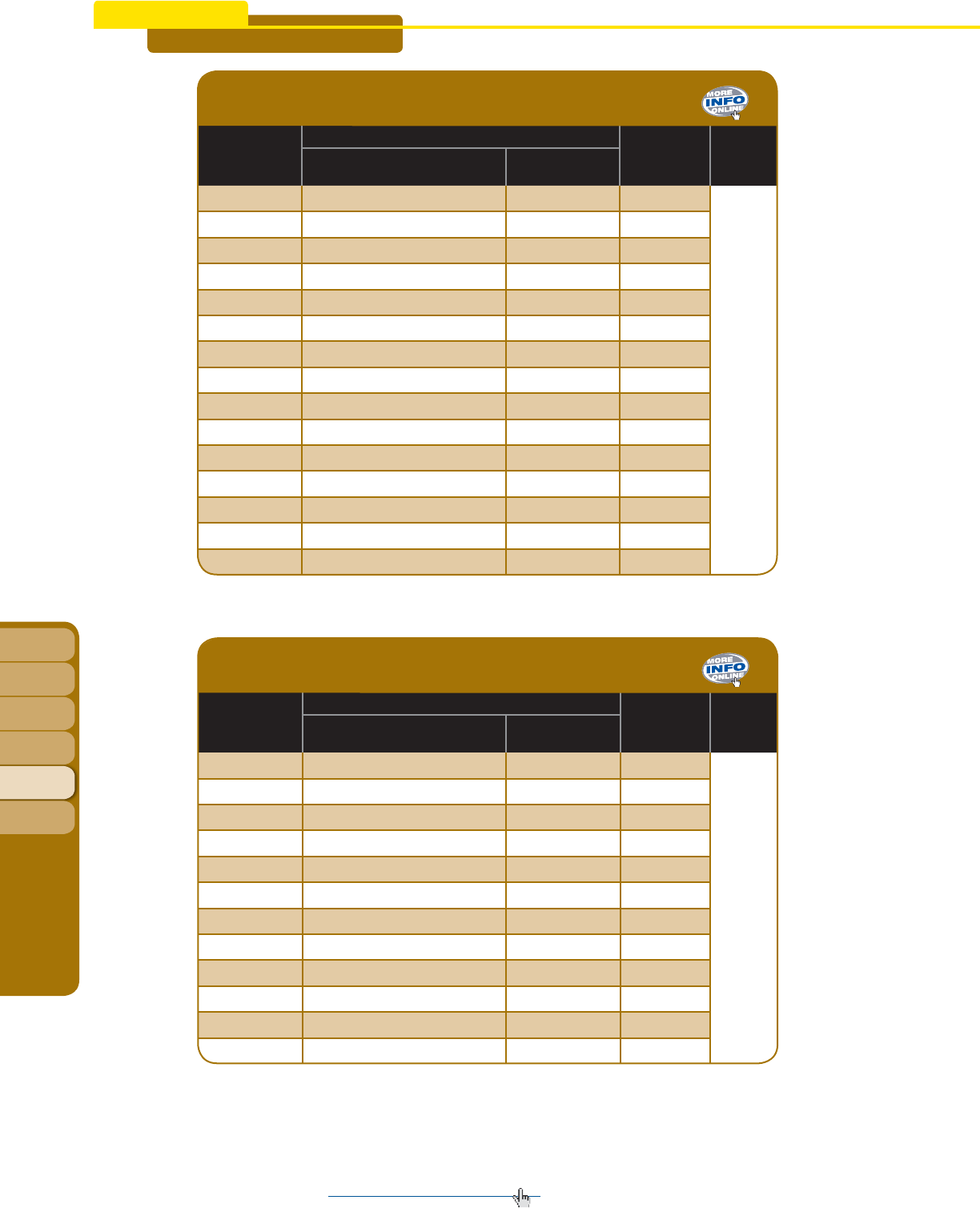
214 More information online at bannerengineering.com
Explosive & Harsh Duty Solutions
ACCESSORIES
CABLES &
WIRING
BRACKETS
CORNER
MIRRORS
STANDS
HARSH DUTY
SOLUTIONS
ACCESSORIES
REPLACEMENT
PARTS
Used With
Model
Emitter/Receiver
Model
Emitter/Receiver
Defined Area
Lens Shield
Length (L)
Data
Sheet
USS4 USE4../USR4.. 102 mm 112 mm
55131
USS8 USE8../USR8.. 203 mm 214 mm
USS12 USE12../USR12.. 305 mm 315 mm
USS16 USE16../USR16.. 406 mm 417 mm
USS20 USE20../USR20.. 508 mm 519 mm
USS24 USE24../USR24.. 610 mm 620 mm
USS28 USE28../USR28.. 711 mm 722 mm
USS32 USE32../USR32.. 813 mm 823 mm
USS36 USE36../USR36.. 914 mm 925 mm
USS40 USE40../USR40.. 1016 mm 1027 mm
USS44 USE44.. /USR44.. 1118 mm 1128 mm
USS48 USE48../USR48.. 1219 mm 1230 mm
USS56 US56../USR56.. 1422 mm 1433 mm
USS64 USE64../USR64.. 1626 mm 1636 mm
USS72 USE72../USR72.. 1829 mm 1829 mm
MICRO-SCREEN
®
Lens Shields
Downloa
d
PDF
NOTE: When shields are installed on both the emitter and receiver, maximum operating range is reduced by 20%.
Used With
Model
Emitter/Receiver
Model
Emitter/Receiver
Defined Area
Lens Shield
Length (L)
Data
Sheet
MSS4 MS(XL)E4../MS(XL)R4.. 114 mm 138 mm
44418
MSS8 MS(XL)E8../MS(XL)R8.. 215 mm 239 mm
MSS12 MS(XL)E12../MS(XL)R12.. 305 mm 341 mm
MSS16 MS(XL)E16../MS(XL)R16.. 406 mm 442 mm
MSS20 MS(XL)E20../MS(XL)R20.. 508 mm 544 mm
MSS24 MS(XL)E24../MS(XL)R24.. 610 mm 643 mm
MSS28 MS(XL)E28../MS(XL)R28.. 711 mm 745 mm
MSS32 MS(XL)E32../MS(XL)R32.. 813 mm 846 mm
MSS36 MS(XL)E36../MS(XL)R36.. 914 mm 948 mm
MSS40 MS(XL)E40../MS(XL)R40.. 1016 mm 1050 mm
MSS44 MS(XL)E44../ MS(XL)R44.. 1118 mm 1151mm
MSS48 MS(XL)E48../MS(XL)R48.. 1219 mm 1253 mm
MINI-SCREEN
®
Lens Shields
Downloa
d
PDF
NOTE: When shields are installed on both the emitter and receiver, maximum operating range is reduced by 20%.
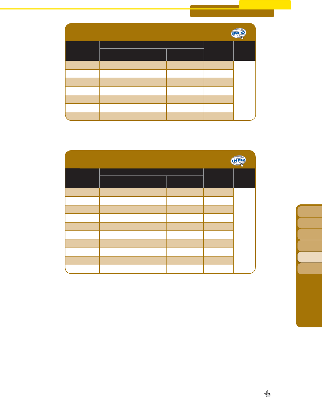
215More information online at bannerengineering.com
Explosive & Harsh Duty Solutions
ACCESSORIES
CABLES &
WIRING
BRACKETS
CORNER
MIRRORS
STANDS
HARSH DUTY
SOLUTIONS
ACCESSORIES
REPLACEMENT
PARTS
Used With
Model
Emitter/Receiver
Model
Emitter/Receiver
Defined Area
Lens Shield
Length (L)
Data
Sheet
MSHDS24 MSXLHDE24../MSXLHDR24.. 610 mm 661 mm
108622
MSHDS32 MSXLHDE32../MSXLHDR32.. 813 mm 864 mm
MSHDS40 MSXLHDE40../MSXLHDR40.. 1016 mm 1067 mm
MSHDS48 MSXLHDE48../MSXLHDR48.. 1219 mm 1270 mm
MSHDS56 MSXLHDE56../MSXLHDR56.. 1422 mm 1474 mm
MSHDS64 MSXLHDE64../MSXLHDR64.. 1626 mm 1677 mm
MSHDS72 MSXLHDE72../MSXLHDR72.. 1829 mm 1880 mm
Heavy-Duty MINI-SCREEN
®
Lens Shields
Downloa
d
PDF
NOTE: When shields are installed on both the emitter and receiver, maximum operating range is reduced by 20%.
Used With
Model
Emitter/Receiver
Model
Emitter/Receiver
Defined Area
Lens Shield
Length (L)
Data
Sheet
LSS-150 LS2..30-150 150 mm 210 mm
121366
LSS-300 LS2..30-300 300 mm 360 mm
LSS-450 LS2..30-450 450 mm 510 mm
LSS-600 LS2..30-600 600 mm 660 mm
LSS-750 LS2..30-750 750 mm 810 mm
LSS-900 LS2..30-900 900 mm 959 mm
LSS-1050 LS2..30-1050 1050 mm 1109 mm
LSS-1200 LS2..30-1200 1200 mm 1558 mm
LSS-1350 LS2..30-1350 1350 mm 1708 mm
LSS-1500 LS2..30-1500 1500 mm 1858 mm
EZ-SCREEN
®
Type 2 Lens S hields
Downloa
d
PDF
NOTE: When shields are installed on both the emitter and receiver, maximum operating range is reduced by 20%.
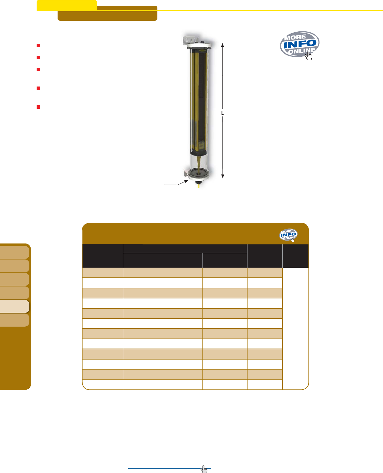
216 More information online at bannerengineering.com
Explosive & Harsh Duty Solutions
ACCESSORIES
CABLES &
WIRING
BRACKETS
CORNER
MIRRORS
STANDS
HARSH DUTY
SOLUTIONS
ACCESSORIES
REPLACEMENT
PARTS
Tubular Enclosures
Tubular Enclosure
(EZA-TE model shown)
Available for EZ-SCREEN or MINI-SCREEN
Ideal for high-power washdown environments
Made of clear FDA-grade polycarbonate
tubing, with acetal end caps
Includes stainless mounting brackets and
hardware
Rated NEMA 4X; IP67
Detailed
Dimensions
L
EZA-TE models: 86.4 mm
MSA-TE models: 86.4 mm
MSHDTA-TE models: 122.4 mm
Used With
Model
Emitter/Receiver
Model
Emitter/Receiver
Defined Area
Enclosure
Height (L)
Data
Sheet
EZA-TE-150 SLS..-150 150 mm 439 mm
117107
EZA-TE-300 SLS..-300 300 mm 541 mm
EZA-TE-450 SLS..-450 450 mm 744 mm
EZA-TE-600 SLS..-600 600 mm 846 mm
EZA-TE-750 SLS..-750 750 mm 1024 mm
EZA-TE-900 SLS..-900 900 mm 1151 mm
EZA-TE-1050 SLS..-1050 1050 mm 1354 mm
EZA-TE-1200 SLS..-1200 1200 mm 1455 mm
EZA-TE-1350 SLS..-1350 1350 mm 1608 mm
EZA-TE-1500 SLS..-1500 1500 mm 1760 mm
EZA-TE-1650 SLS..-1650 1650 mm 1913 mm
EZA-TE-1800 SLS..-1800 1800 mm 2065 mm
EZA-TE EZ-SCREEN
®
Series Tubular Enclosures
Downloa
d
PDF
NOTE: Use of the enclosure affects the sensing range of the emitter/receiver used: when used in pairs, range can be reduced
by 50%.
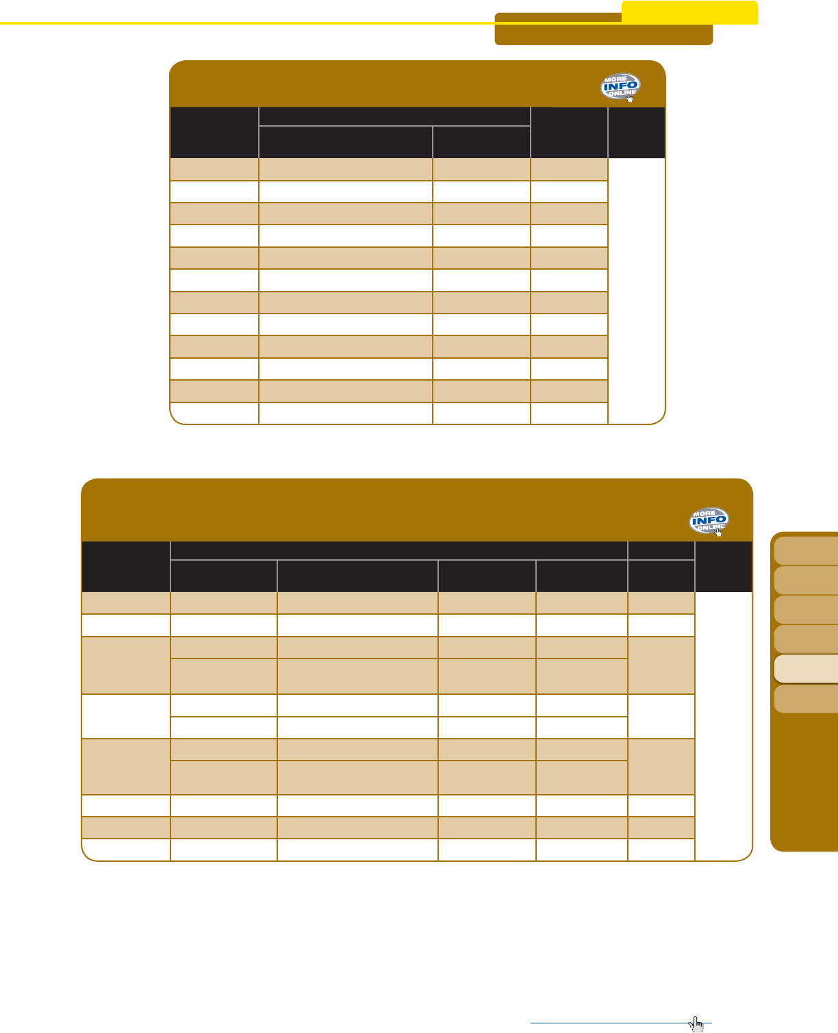
217More information online at bannerengineering.com
Explosive & Harsh Duty Solutions
ACCESSORIES
CABLES &
WIRING
BRACKETS
CORNER
MIRRORS
STANDS
HARSH DUTY
SOLUTIONS
ACCESSORIES
REPLACEMENT
PARTS
Used With
Model
Emitter/Receiver
Model
Emitter/Receiver
Defined Area
Enclosure
Height (L)
Data
Sheet
MSA-TE-4 MSXLE4../MSXLR4.. 114 mm 338 mm
109307
MSA-TE-8 MSXLE8../MSXLR8.. 215 mm 439 mm
MSA-TE-12 MSXLE12../MSXLR12.. 305 mm 541 mm
MSA-TE-16 MSXLE16../MSXLR16.. 406 mm 643 mm
MSA-TE-20 MSXLE20../MSXLR20.. 508 mm 744 mm
MSA-TE-24 MSXLE24../MSXLR24.. 610 mm 846 mm
MSA-TE-28 MSXLE28../MSXLR28.. 711 mm 947 mm
MSA-TE-32 MSXLE32../MSXLR32.. 813 mm 1049 mm
MSA-TE-36 MSXLE36../MSXLR36.. 914 mm 1151 mm
MSA-TE-40 MSXLE40../MSXLR40.. 1016 mm 1252 mm
MSA-TE-44 MSXLE44../MSXLR44.. 1118 mm 1354 mm
MSA-TE-48 MSXLE48../MSXLR48.. 1219 mm 1455 mm
MSA-TE MINI-SCREEN
®
Series Tubular Enclosures
Downloa
d
PDF
NOTE: Use of the enclosure affects the sensing range of the sensor used: when used in pairs, range can be reduced by 50%.
Used With
Model
Model
Family
Emitter/Receiver
Model
Emitter/Receiver
Defined Area
Emitter/Receiver
Protected Height
Enclosure
Height (L)
Data
Sheet
MSHDA-TE-6 EZ-SCREEN Point SP..1 — — 389 mm
117106
MSHDA-TE-24 MINI-SCREEN MSXLHDE24../MSXLHDR24.. 610 mm — 846 mm
MSHDA-TE-32
MINI-SCREEN MSXLHDE32../MSXLHDR32.. 813 mm —
1049 mm
EZ-SCREEN Grid SG..2-500
SG..2-584 —500 mm
584 mm
MSHDA-TE-40
MINI-SCREEN MSXLHDE40../MSXLHDR40.. 1016 mm —
1252 mm
EZ-SCREEN Grid SG..3-400 — 800 mm
MSHDA-TE-48
MINI-SCREEN MSXLHDE48../MSXLHDR48.. 1219 mm —
1455 mm
EZ-SCREEN Grid SG..3-533
SG..4-300 —1066 mm
900 mm
MSHDA-TE-56 MINI-SCREEN MSXLHDE56../MSXLHDR56.. 1422 mm — 1659 mm
MSHDA-TE-64 MINI-SCREEN MSXLHDE64../MSXLHDR64.. 1626 mm — 1862 mm
MSHDA-TE-72 MINI-SCREEN MSXLHDE72../MSXLHDR72.. 1829 mm — 2065 mm
MSHDA-TE Heavy-Duty MINI-SCREEN
®
& EZ-SCREEN
®
Point and Grid Series
Tubular Enclosures
Downloa
d
PDF
NOTE: Use of the enclosure affects the sensing range of the sensor used: when used in pairs, range can be reduced by 50%.
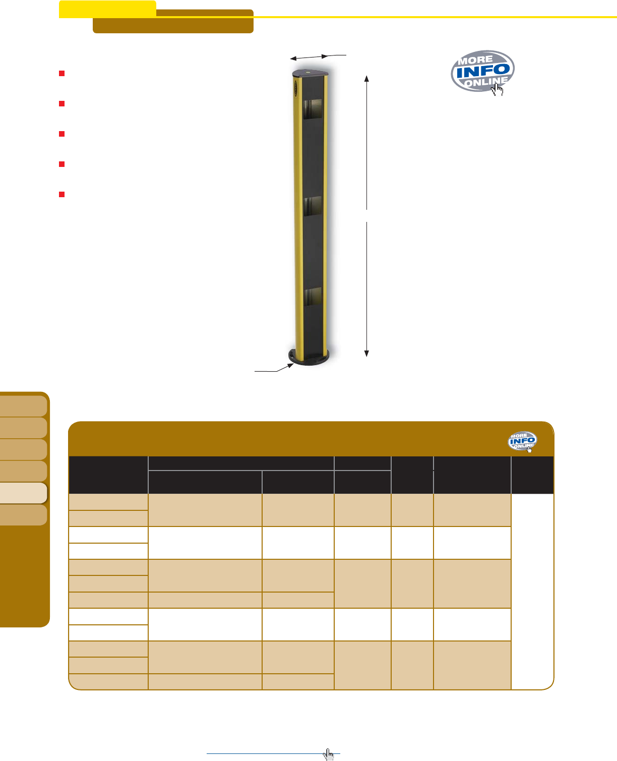
218 More information online at bannerengineering.com
Explosive & Harsh Duty Solutions
ACCESSORIES
CABLES &
WIRING
BRACKETS
CORNER
MIRRORS
STANDS
HARSH DUTY
SOLUTIONS
ACCESSORIES
REPLACEMENT
PARTS
EZA-S Protective Enclosures
EZA-S Protective Enclosure
Provide rugged protection for sensors and
mirrors in high-traffic areas
Available for mirrors and EZ-SCREEN Point
and Grid
Meets ANSI/RIA 15.06 and ISO 13855
standards for beam spacing
Includes independently adjustable mirrors
and bubble level to simplify alignment
Rotates up to 20°
Detailed
Dimensions
* Model numbers with suffix “M” include vertical mirrors for perimeter-guarding applications.
Model numbers with suffix “M45” include two 45°-mounted mirrors for access-guarding applications.
NOTE: The rear-surfaced glass mirrors are rated at 85% efficiency per mirror and reduce maximum range by 8% per mirror.
L
ø 177.8 mm
145.0 mm
Used With
Model*
Emitter/Receiver
Model
Emitter/Receiver
Protected Area
Enclosure
Height (L)
No. of
Openings
Application
Standard
Data
Sheet
EZA-S300
SG..4-300 900 mm 1543 mm 4 ANSI/RIA R15.06
ISO 13855
109308
EZA-S300-M
EZA-S400
SG..3-400 800 mm 1238 mm 3 ANSI/RIA R15.06
ISO 13855
EZA-S400-M
EZA-S500
SG..2-500 500 mm
1035 mm 2 ISO 13855EZA-S500-M
EZA-S500-M45 SP..1 —
EZA-S533
SG..3-533 1066 mm 1543 mm 3 ANSI/RIA R15.06
EZA-S533-M
EZA-S584
SG..2-584 584 mm
1238.2 mm 2ANSI/RIA R15.06EZA-S584-M
EZA-S584-M45 SP..1 —
EZA-S EZ-SCREEN
®
Protective Enclosures
Downloa
d
PDF
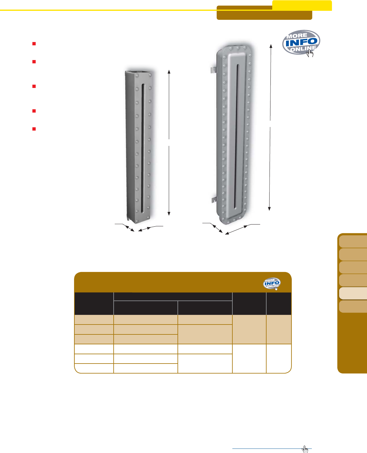
219More information online at bannerengineering.com
Explosive & Harsh Duty Solutions
ACCESSORIES
CABLES &
WIRING
BRACKETS
CORNER
MIRRORS
STANDS
HARSH DUTY
SOLUTIONS
ACCESSORIES
REPLACEMENT
PARTS
Explosion-Proof Enclosures
Model ..-XPE-32
Explosion-Proof Enclosure
Protects light screen in environments with
flammable gases, liquids or dust
Available for EZ-SCREEN Point and Grid,
MINI-SCREEN, and
MICRO-SCREEN
Complies with UL and CSA
for use in specific hazardous
atmospheres
Includes mounting brackets and
hardware
Reduces range by approximately
25% per emitter/receiver pair
Detailed
Dimensions
114 mm
117 mm
968 mm
Model ..-XPE-43
Explosion-Proof Enclosure
254 mm
197 mm
1321 mm
Used With
Model
Model
Family
Emitter/Receiver
Defined Area
Enclosure
Height
Data
Sheet
SS-XPE-32 EZ-SCREEN 450 to 600 mm
968 mm 63443
US-XPE-32 MICRO-SCREEN
508 to 711 mm
MS-XPE-32 MINI-SCREEN
SS-XPE-43 EZ-SCREEN 750 to 1050 mm
1321 mm 64216
US-XPE-43 MICRO-SCREEN
813 to 1016 mm
MS-XPE-43 MINI-SCREEN
Explosion-Proof Enclosures
Downloa
d
PDF
NOTE: Use of enclosure affects the sensing range of emitter/receiver used: when used in pairs, range can be reduced by 25%.
220 More information online at bannerengineering.com
ACCESSORIES
Replacement Parts
CABLES &
WIRING
BRACKETS
CORNER
MIRRORS
STANDS
HARSH DUTY
SOLUTIONS
ACCESSORIES
REPLACEMENT
PARTS
EZ-SCREEN
®
Replacement Parts
Model
Part
Number Description
EZA-LAT-1 66027 Replacement adapter hardware for Grid.
MGA-KS0-1 30140 SPST key reset switch, no wires (includes key)
SFA-CMH 69769 PICO-GUARD controller mounting hardware
SFA-CTB1 02638 PICO-GUARD controller 4-position terminal block
SFA-CTB2 02639 PICO-GUARD controller 9-position terminal block
SFA-CTB3 02640 PICO-GUARD controller 18-position terminal block
SFA-CTB4 75264 PICO-GUARD controller 5-position terminal block
SFA-IAG 02618 Interlock alignment guide
SFA-LAT-12 73000 Replacement adapter hardware for SPF12
SFA-LAT-30 73001 Replacement adapter hardware for SPF30
SFA-W-1 75158 Replacement window for Grid
STP-3 43958 Specified test piece, 45 mm dia. for Grid
PICO-GUARD
®
Replacement Parts
Model
Part
Number Description
EZA-ADE-1 71447 Copolyester access cover with label for 14 or 30 mm resolution emitters
EZA-ADE-2 72929 Copolyester access cover with inverted label for 14 or 30 mm resolution emitters
EZA-ADR-1 71448 Copolyester access cover with label for 14 or 30 mm resolution receiver
EZA-ADR-2 72930 Copolyester access cover with inverted label for 14 or 30 mm resolution receiver
EZA-AP-1 62859 Access port plug with o-ring for Grid and Point
EZA-CP-13 62860 Pg13.5 plug with o-ring for Grid and Point
EZA-ECE-1 62858 Emitter wiring chamber end cap (with gasket, captive screws, 3 plugs with o-rings, terminal block) for
Grid and Point
EZA-ECR-1 62857 Receiver wiring chamber end cap (with gasket, captive screws, 3 plugs with o-rings, terminal block) for
Grid and Point
EZA-SW-1 62863 Spanner wrench for Grid and Point
EZA-TBE-1 62861 Emitter terminal block for Grid and Point
EZA-TBR-1 62862 Receiver terminal block for Grid and Point
EZA-MBK-1 60630 Center bracket kit (includes 1 bracket and hardware to mount to MSA Series stands) for 14 or 30 mm
resolution EZ-SCREEN
EZA-MBK-11 71470 Standard bracket kit with hardware (includes 2 end brackets and hardware to mount to MSA Series stands)
for 14 or 30 mm resolution EZ-SCREEN
EZA-TP-1 71449 Access cover security plate (includes 2 screws, wrench) for 14 or 30 mm resolution EZ-SCREEN
MGA-K-1 28513 Replacement key for switch MGA-KS0-1
MGA-KS0-1 30140 Keyed reset switch (same as that included in kits)
SMA-MBK-1 61933 SSM Series Mirror Bracket Kit
STP-3 43958 Specified test piece, 45 mm dia.
STP-13 71929 14 mm test piece (for 14 mm resolution systems)
STP-14 71930 30 mm test piece (for 14 mm resolution systems with 2-beam Reduced Resolution and for 30 mm
resolution systems)
STP-15 71931 60 mm test piece (for 30 mm resolution systems with 2-beam Reduced Resolution)
221More information online at bannerengineering.com
Replacement Parts
ACCESSORIES
CABLES &
WIRING
BRACKETS
CORNER
MIRRORS
STANDS
HARSH DUTY
SOLUTIONS
ACCESSORIES
REPLACEMENT
PARTS
MICRO-SCREEN
®
Replacement Parts
Model
Part
Number Description
MGA-GS-1 27850 Ground strap for control box door
MGA-K-1 28513 Replacement key for MGA-KS-1 key switch
MGA-KS-1 28509 Key switch, pre-wired (includes key)
MGA-KSO-1 30140 SPST key reset switch, no wires (includes key)
MSA-MH-1 39024 Control box mounting hardware
MSA-PSD-1 61499 Power supply/relay board (115/230V ac) for models without fixed blanking
MSA-PSD-2 47377 Power supply/relay board (115/230V ac) for models with fixed blanking
MSA-PST-2 47376 Power supply/relay board (24V dc)
MSA-RM-1 39025 Relay module
MSA-RM-2 59689 Relay module with an additional complementary normally closed output and 6 amp FSDs
MSMA-PSC-2 62867 Power supply
MUSA-TA-1 43834 Transformer
STP-2 43957 Specified test piece, 19 mm dia.
STP-4 43836 Specified test piece, 32 mm dia.
STP-5 43837 Specified test piece, 58 mm dia.
STP-9 50694 Specified test piece, 83 mm dia.
USAB-1 51885 Controller board (light screen)
USAB-2 51886 Controller board (light screen)
USA-MH-2 60110 Control box mounting hardware
USA-PTB-1 55676 Terminal block, 20 position, emitter/receiver
USA-PTB-2 55677 Terminal block, 15 position, emitter/receiver
USA-PTB-3 55678 Terminal block, 5 position, DeviceNet
USA-PTB-4 55679 Terminal block, 20 position, output/E-stop/power hookup
USA-PTB-5 55680 Terminal block for 5 position, FSD
USCMB-1 51651 Mounting hardware kit for one emitter/receiver, 711 to 914 mm defined area
USCMB-2 54976 Mounting hardware kit for one emitter/receiver, 1016 to 1829 mm defined area
USDAB-1 50002 Controller board, no Fixed Blanking, Trip output
USDAB-1D 52245 Controller board for DeviceNet, no Fixed Blanking, Trip output
USDAB-1E 62092 Controller board for models with External Device Monitoring (EDM)
USDAB-2 50003 Controller board with Fixed Blanking, Trip output
USDAB-2D 52246 Controller board for DeviceNet with Fixed Blanking, Trip output
USDAL-1 55624 Controller board, no Fixed Blanking, Latch output
USDAL-1D 55625 Controller board for DeviceNet, no Fixed Blanking, Latch output
USDAL-2 55626 Controller board with Fixed Blanking, Latch output
USDAL-2D 55627 Controller board for DeviceNet with Fixed Blanking, Latch output
USDA-RM-1 50001 Power supply/relay board, 2 FSDs
USDA-RM-2 55707 Power supply/relay board, 4 FSDs
USMAB-1 64734 Controller board for Muting, Trip output
USMAL-1 60643 Controller board for Muting, Latch output
USMA-PSC-1 60642 Power supply
USMB-1 50000 Mounting hardware kit for one emitter/receiver, 102 to 610 mm defined area
222 More information online at bannerengineering.com
ACCESSORIES
Replacement Parts
CABLES &
WIRING
BRACKETS
CORNER
MIRRORS
STANDS
HARSH DUTY
SOLUTIONS
ACCESSORIES
REPLACEMENT
PARTS
MINI-SCREEN
®
Replacement Parts
Model
Part
Number Description
BA2MB 40091 Mounting hardware kit for one emitter/receiver
MDSA-PTB-1 61083 Terminal block, positions 1-26
MDSA-PTB-2 61084 Terminal block, positions 27-52
MDSDAL-1 65785 Controller board, Latch output
MDSDA-RM-1 48225 Power supply/relay board (24V dc)
MGA-GS-1 27850 Ground strap for control box door
MGA-GST-1 28511 Ground strap for transformer
MGA-K-1 28513 SPST key reset switch, no wires (includes key)
MGA-KS-1 28509 Key switch, pre-wired (includes key)
MGA-KSO-1 30140 SPST key reset switch, no wires (includes key)
MSAB-1 39029 Controller module, Trip output, without fixed blanking
MSAB-2 47381 Controller module (light screen), Trip output, with fixed blanking
MSAL-1 55695 Controller module, Latch output
MSA-MH-1 39024 Control box mounting hardware
MSA-PSD-2 47377 Power supply/relay board (115/230V ac) for metal boxes with fixed blanking
MSA-RM-1 39025 Relay module
MSA-RM-2 59689 Relay module with an additional complementary normally closed output and 6 amp FSDs
MSA-PSA-1 39027 Power supply board (115V ac) for metal boxes with Trip output
MSA-PSA-2 55694 Power supply board (115V ac) for metal boxes with Latch output
MSA-PSB-1 39028 Power supply board (230V ac) for metal boxes with Trip output
MSA-PSB-2 62006 Power supply board (230V ac) for metal boxes with Latch output
MSA-PST-1 43738 Power supply board (24V dc) for metal boxes without fixed blanking
MSA-PST-2 47376 Power supply board (24V dc) for metal boxes with fixed blanking
MSA-PTB-1 61077 Terminal block, positions 1-17
MSA-PTB-2 61078 Terminal block, positions 18-34
MSDAB-1 45281 Controller board, Trip output
MSDAL-1 48450 Controller board, Latch output
MSDA-RM-1 45280 Power supply/relay board (24V dc)
MSMA-PSC-2 62867 Power supply
MUSAB-1 43833 Controller module
MUSA-MH-1 43831 Control box mounting hardware
MUSA-PS-1 43832 Power supply board
MUSA-TA-1 43834 Transformer
STP-1 43835 Specified test piece, 38 mm dia.
STP-10 62026 Specified test piece, 89 mm dia.
STP-2 43957 Specified test piece, 19 mm dia.
STP-3 39911 Specified test piece, 45 mm dia.
STP-4 43836 Specified test piece, 32 mm dia.
STP-5 43837 Specified test piece, 58 mm dia.
STP-6 43838 Specified test piece, 76 mm dia.
STP-7 48981 Specified test piece, 26 mm dia.
223More information online at bannerengineering.com
Replacement Parts
ACCESSORIES
CABLES &
WIRING
BRACKETS
CORNER
MIRRORS
STANDS
HARSH DUTY
SOLUTIONS
ACCESSORIES
REPLACEMENT
PARTS
MINI-SCREEN
®
Replacement Parts (cont'd)
Model
Part
Number Description
STP-8 49126 Specified test piece, 51 mm dia.
USA-MH-2 60110 Control box mounting hardware
USMAB-1 64734 Muting system controller, Trip output
USMAL-1 60643 Muting system controller, Latch output
Safety Interlock Switches Replacement Parts
Model*
Part
Number Description Used In
SI-LM40KHD 49474
Individual Interlock
(without actuator)
SI-LM40MKH..D kits
SI-LM40KHE 49475 SI-LM40MKH..E kits
SI-LM40KHF 49476 SI-LM40MKH..F kits
SI-LM40KVD 49478 SI-LM40MKVD kit
SI-LM40KVE 49479 SI-LM40MKVE kit
SI-LS42DSG 47871 SI-LS42DMSG.. kits
SI-LS42USG 47872 SI-LS42UMSG.. kits
SI-LS42DSH 47875 SI-LS42DMSH.. kits
SI-LS42USH 47876 SI-LS42UMSH.. kits
SI-LS42DSI 47879 SI-LS42DMSI.. kits
SI-LS42USI 47880 SI-LS42UMSI.. kits
SI-LS42DSJ 47883 SI-LS42DMSJ.. kits
SI-LS42DMG 47873 SI-LS42DMMG.. kits
SI-LS42UMG 47874 SI-LS42UMMG.. kits
SI-LS42DMH 47877 SI-LS42DMMH.. kits
SI-LS42UMH 47878 SI-LS42UMMH.. kits
SI-LS42DMI 47881 SI-LS42DMMI.. kits
SI-LS42UMI 47882 SI-LS42UMMI.. kits
SI-LS42DMJ 47884 SI-LS42DMMJ.. kits
SI-LS100F 49480 SI-LS100.. kits
SI-LS83D 49481 SI-LS83.. kits
SI-LS83E 49482 SI-LS83..E kits
SI-QM100DSG 49460 SI-QM100DMSG kit
SI-QM100ASG 49461 SI-QM100AMSG kit
SI-QM100DMG 49463 SI-QM100DMMG kit
SI-QM100AMG 49464 SI-QM100AMMG kit
SI-QS75C 49472 SI-QS75..C kits
SI-QS75CHF 49473 SI-QS75MCHF kit
SI-QS90D 49466 SI-QS90..D kits
SI-QS90DHF 49467 SI-QS90MDHF kit
SI-QS90E 49468 SI-QS90..E kits
SI-QS90EHF 49469 SI-QS90MEHF kit
SI-QS90F 49470 SI-QS90..F kits
SI-QS90FHF 49471 SI-QS90MFHF kit
* Kits with one safety interlock switch and an actuator are available (see pages 148-160).
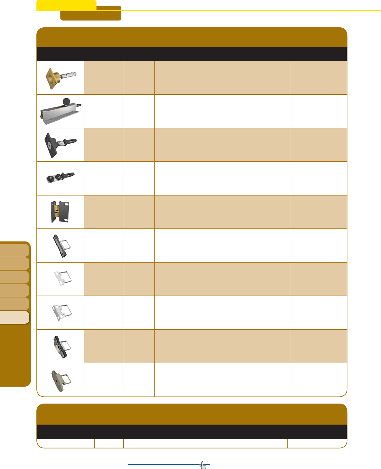
224 More information online at bannerengineering.com
ACCESSORIES
Replacement Parts
CABLES &
WIRING
BRACKETS
CORNER
MIRRORS
STANDS
HARSH DUTY
SOLUTIONS
ACCESSORIES
REPLACEMENT
PARTS
Replacement Actuators for Safety Interlock Switches
Model
Part
Number Description Used With
SI-QM-90A 48556
Flexible in-line, trumpet-style, metal actuator used for doors
or covers where alignment is difficult to maintain. Flexes
in all directions. Minimum engagement radius for hinged
closures is 150 mm.
• SI-LM40MKV models
SI-QM-SB 47895
Rigid in-line metal actuator used for doors or covers.
Slide-bolt design for use in heavy-duty applications where
alignment is difficult to maintain.
• SI-LM40MKH models
• SI-LS42 models
• SI-QM100 models
SI-QM-SMFA 48562
Flexible in-line metal actuator used for doors or covers
where alignment is difficult to maintain. Flexes in all
directions. Minimum engagement radius for hinged closures
is 150 mm.
• SI-LM40MKH models
• SI-LS42 models
• SI-QM100 models
SI-QM-SSA 48555
Rigid in-line metal actuator used for doors or covers
with accurate alignment, such as sliding doors. Minimum
engagement radius for hinged closures is 400 mm.
• SI-LM40MKH models
• SI-LS42 models
• SI-QM100 models
SI-QS-100 48561
High-extraction-force actuator for particularly heavy or large
doors. Adjustable from 50 to 100 Newtons (force). Used
only for switches with in-line actuator SI-QS-SSA.
• SI-QS75 models
• SI-QS90 models
SI-QS-SSA 48551 Rigid in-line metal (die-cast steel) actuator for doors or
covers with a radius of 150 mm or greater.
• SI-QS75 (high-force)
models
• SI-QS90 (high-force)
models
SI-QS-SSA-2 58855
Rigid in-line metal (stamped stainless steel) actuator used
for doors or covers with accurate alignment, such as sliding
doors. Minimum engagement radius for hinged closures is
150 mm.
• SI-LS83 models
• SI-LS100 models
SI-QS-SSA-3 58856
Rigid in-line metal (stamped stainless steel) actuator used
for doors or covers with accurate alignment, such as sliding
doors. Right-angle mounting flange. Minimum engagement
radius for hinged closures is 150 mm.
• SI-LS83 models
• SI-LS100 models
SI-QS-SSA-4 47896 Rigid in-line metal (stamped stainless steel) actuator for
doors or covers with a radius of 150 mm or greater.
• SI-QS75 models
• SI-QS90 models
SI-QS-SSU 46996
Flexible in-line metal (die-cast steel) actuator for hinged
doors with a radius of 50 mm or greater. Flexes in all
directions. Minimum engagement radius for hinged closures
is 150 mm.
• SI-LS83 models
• SI-LS100 models
• SI-QS75 models
• SI-QS90 models
Safety Interlock Switch Replacement Parts
Model
Part
Number Description
Used
With
SI-LS42-COVER 46995 Replacement terminal cover SI-LS42 models
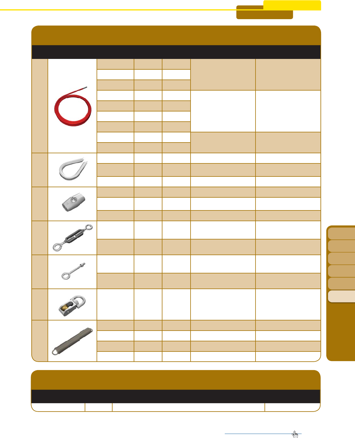
225More information online at bannerengineering.com
Replacement Parts
ACCESSORIES
CABLES &
WIRING
BRACKETS
CORNER
MIRRORS
STANDS
HARSH DUTY
SOLUTIONS
ACCESSORIES
REPLACEMENT
PARTS
Components for Wire Rope Assembly
Models
Part
Number
Package
Quantity Description
Used
With
Wire Ropes
RPA-C1-10 62074 10 m
2 mm steel wire rope with
0.5 mm red PVC jacket
(unterminated)
• RP-LM40 models
RPA-C1-20 62075 20 m
RPA-C1-100 69799 100 m
RPA-C2-10 62076 10 m
3 mm steel wire rope with
0.5 mm red PVC jacket
(unterminated)
• RP-LS42 models
• RP-QM72/QMT72 models
RPA-C2-20 62077 20 m
RPA-C2-50 46694 50 m
RPA-C2-80 46695 80 m
RPA-C3-20 62078 20 m 4 mm steel wire rope with
0.5 mm red PVC jacket
(unterminated)
• RP-QM90 models
RPA-C3-100 62079 100 m
Thimbles
RPA-T1-4 62065 4 pcs Thimble for 2 mm wire rope • RP-LM40 models
RPA-T2-4 62066 4 pcs Thimble for 3 mm wire rope • RP-LS42 models
• RP-QM72/QMT72 models
RPA-T3-4 62067 4 pcs Thimble for 4 mm wire rope • RP-QM90 models
Clamps
RPA-CC1-4 62068 4 pcs Clamp for 2 mm wire rope • RP-LM40 models
RPA-CC2-4 62069 4 pcs Clamp for 3 mm wire rope • RP-LS42 models
• RP-QM72/QMT72 models
RPA-CC3-4 62070 4 pcs Clamp for 4 mm wire rope • RP-QM90 models
Turnbuckles
RPA-TA1-1 62071 1 pc #4 Turnbuckle
• RP-LM40 models
• RP-LS42 models
• RP-QM72/QMT72 models
RPA-TA2-1 62072 1 pc #5 Turnbuckle • RP-QM90 models
Eye Bolts
RPA-EB1-1 62080 1 pc 1/4" - 20 Eye bolt
• RP-LM40 models
• RP-LS42 models
• RP-QM72/QMT72 models
RPA-EB2-1 65039 1 pc 5/16" - 20 Eye bolt • RP-QM90 models
Pulleys
RPA-P1-1 62081 1 pc Pulley
• RP-LM40 models
• RP-LS42 models
• RP-QM72/QMT72 models
Tensioning
Springs
RPA-S1-1 62073 1 pc Tensioning Spring #1 • RP-QM90 models
RPA-S2-1 62089 1 pc Tensioning Spring #2 • RP-QM90 models
RPA-S3-1 46693 1 pc Tensioning Spring #3 • RP-LS42 models
RPA-S4-1 46994 1 pc Tensioning Spring #4 • RP-LS42 models
Rope Pull Replacement Parts
Model
Part
Number Description
Used
With
SI-LS42-COVER 46995 Replacement terminal cover RP-LS42 models