Product Detail Manual
114279-Catalog 114279-Catalog 114279-Catalog 783936 Batch7 unilog cesco-content
2014-09-05
: Pdf 119547-Attachment 119547-Attachment 783936 Batch7 unilog
Open the PDF directly: View PDF ![]() .
.
Page Count: 59
CONTORLS INDEX
Section C
Ci
D2C Series
DuraTech Control Stations ...................2 - 5
D2C Series
Dimensional Data ................................6 - 7
XCS/XS/SWB Series
Control Stations
External Sealing Required................18 - 25
SWB Series
Device Boxes..........................................19
SWB Series
Conduit Opening Data ............................20
XCS Series
Cover Assemblies Control Stations ......21 - 25
XCS Series
Blank Covers...........................................26
FXCS/XCS Series
Accessories, Replacement Parts..........26 - 27
XS Series
Tumbler Switch........................................28
XAL/XAS Series
Fire Alarm Stations..................................29
CS Series
CONSPEC Control Stations...................8 - 10
CS Series
Dimensional Data
Catalog Logic .........................................11
FXCS Series
Seal-X Factory
Sealed Control Stations....................12 - 17
FXB Series
Seal-X Splice Boxes................................13
FXCS Series
Seal-X Factory Sealed
Cover Assemblies ............................14 - 17
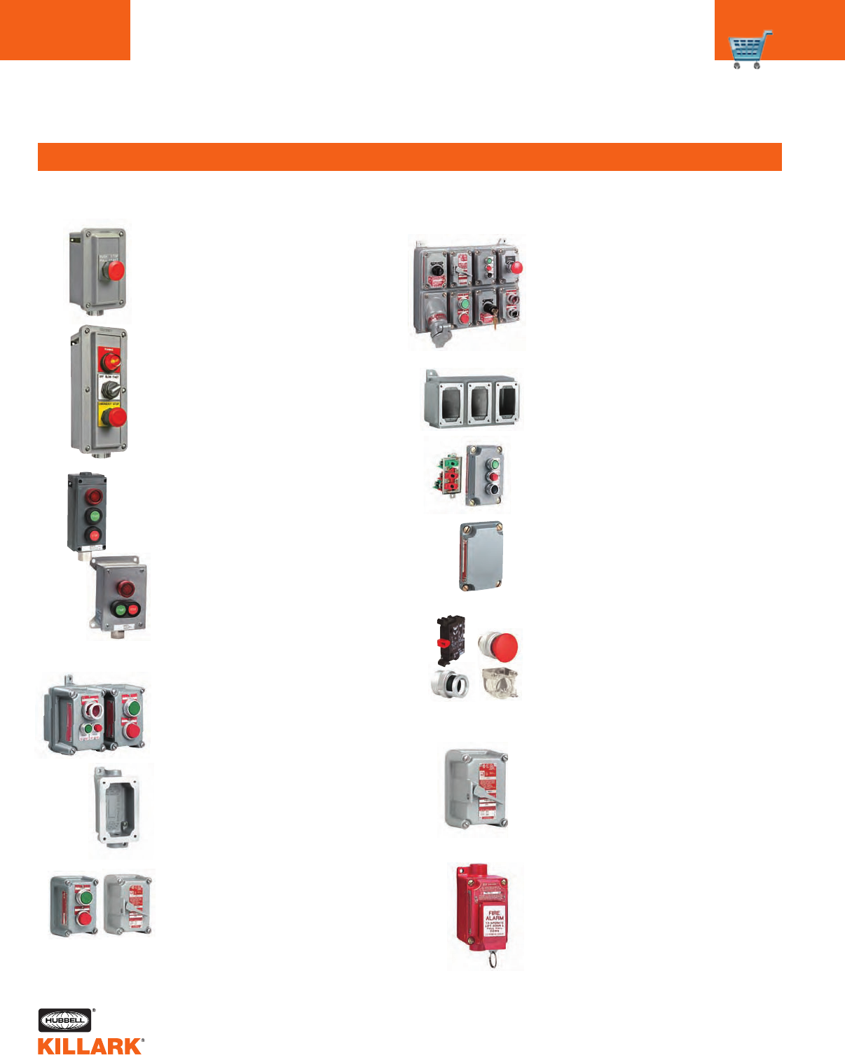
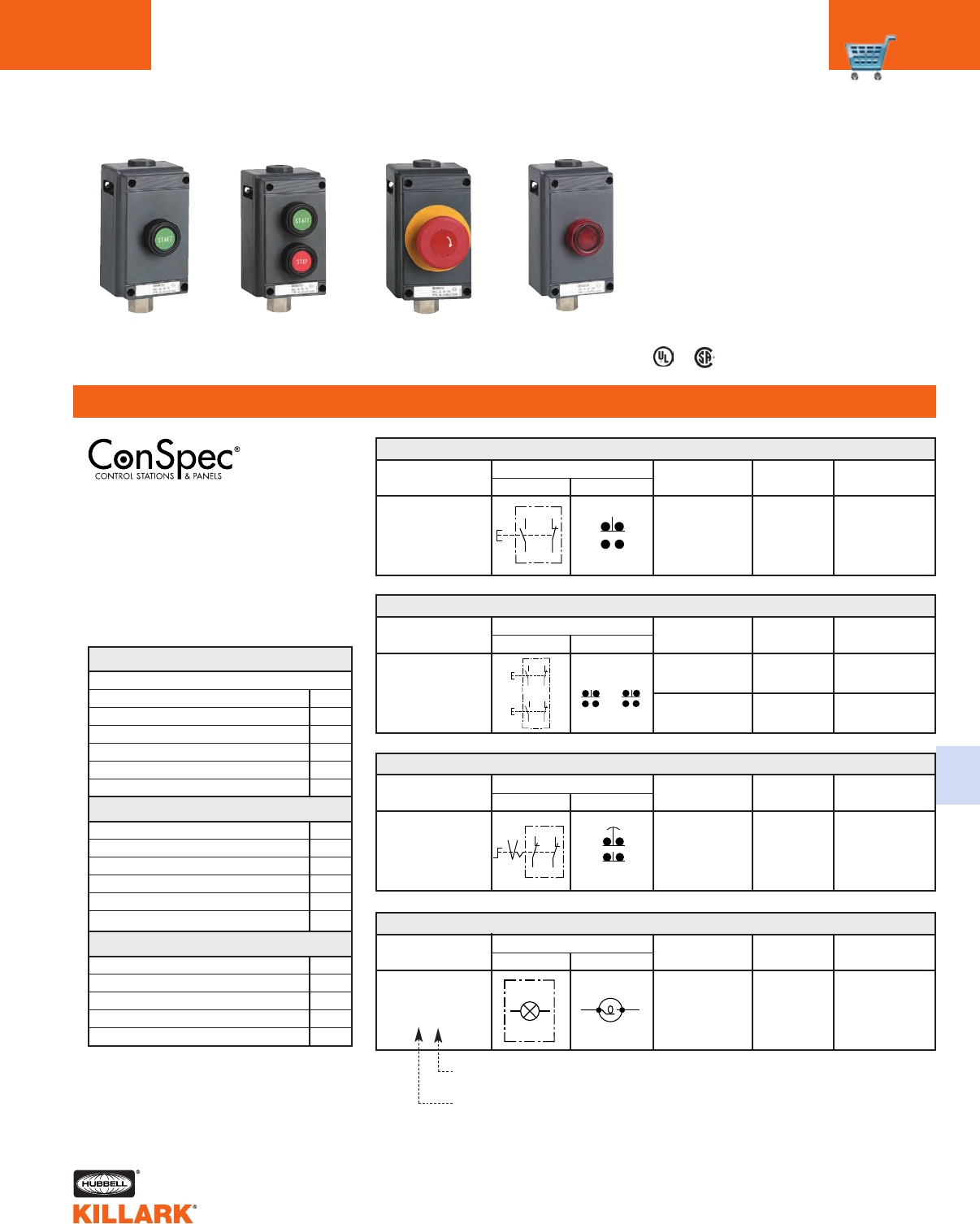
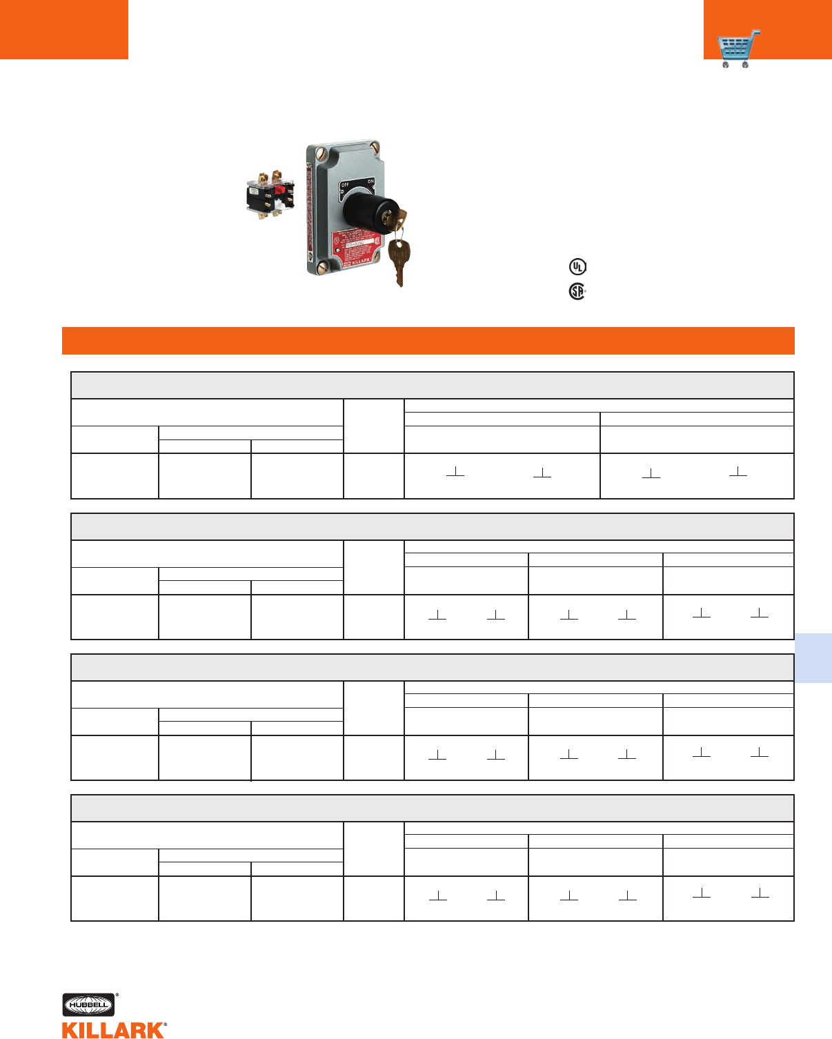
D2C SERIES •CONTROLS
CONTROL STATIONS - NON-METALLIC
C2
FEATURES-SPECIFICATIONS
Class I, Div. 2, Groups A,B,C,D
Class l, Zone 2, Groups IIC, llB, llA
NEMA 3, 4, 4X, 7 (Div.2)
Applications
Hazardous and corrosive environments
such as refineries, chemical plants, water
treatment and bio gas plants, and wher-
ever a combustible gas-air mixture may
occur.
Features
•Enclosures of rugged polyester resin
and gasketed for NEMA 4X hose down
protection
•Factory sealed contacts rated for heavy
duty NEMA A600/Q300 explo-
sion-protected operation
•No external seals required for most
applications
•Comprehensive selection of control
operators including:
–Push buttons (standard or mushroom
caps) with momentary & maintained
action for multiple functions or
emergency stop
–Rotary selector switches for maintained
or momentary operation
–Pilot lights (LED as standard) in multiple
voltages and colors
•Options for various enclosures entry
types and legend plates
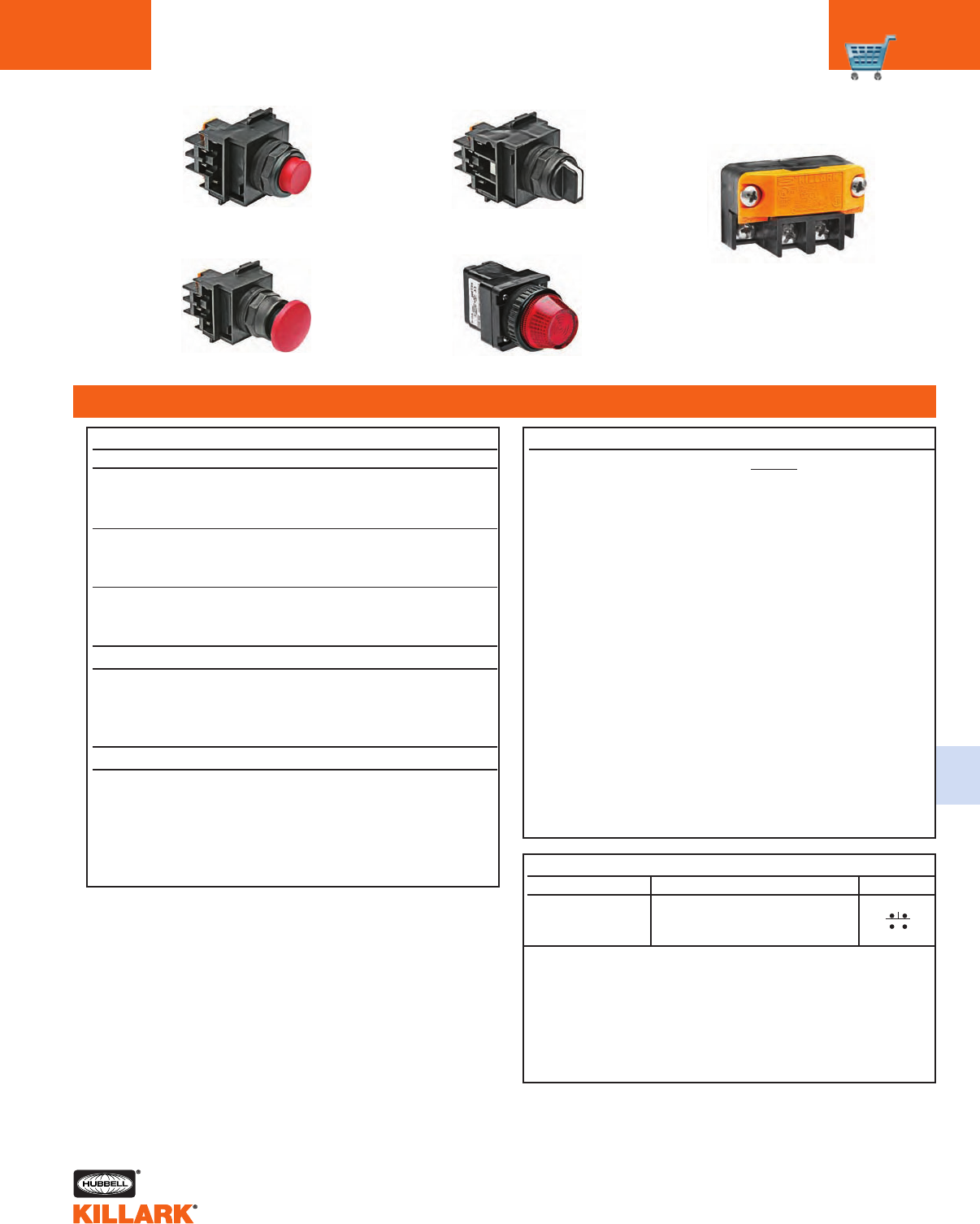
PRODUCT LINE OVERVIEW
ASSEMBLIES
CONTROL DEVICES
One device
ENCLOSURES
ENTRIES AND ACCESSORIES
Two devices Three devices
Push Button
Control Switch
Pilot Light
Size 1 Size 2
Hub with
Grounding locknut
Legend
Plates
Shrouded or mushroom style Maintained push-pull or twist-release button
Multiple position rotary maintained or momentary action
Full voltage, resistor or transformer and multi-voltage LED types
Hole Plug Lockouts
Factory Sealed
Contact Block
1N.O./1N.C.
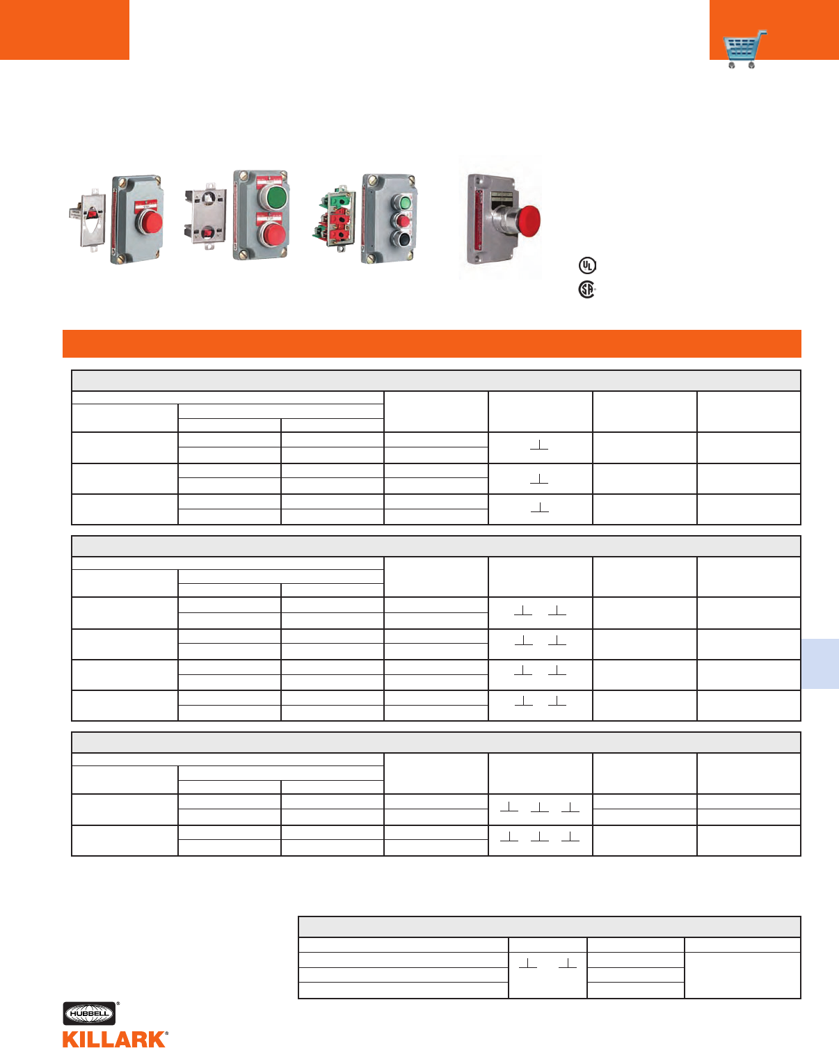
ONE DEVICE, DEAD END1
Single Push Button (Momentary Contact)
Complete Units (Box & Cover) NPT SIZE DIAGRAM COLOR LEGEND2
D2CG2B1 GREEN START
D2CG2B2 RED STOP
D2CG2B3 BLACK BLANK
Push-Pull Mushroom Button (Maintained Contact)
D2CG2MMR3 RED EMERGENCY STOP
Pilot Light (120V AC Light Emitting Diode Type)
D2CG2B24CL CLEAR BLANK
D2CG2B24GL GREEN BLANK
D2CG2B24RL RED BLANK
D2CG2B24BL BLUE BLANK
D2CG2B24AL AMBER BLANK
D2CG2B24WL WHITE BLANK
2 Position Rotary Selector Switch (Maintained Contact) LEGEND
D2CG2S2A3 3/4” OFF - ON
3 Position Rotary Selector Switch (Maintained Contact)
D2CG2S3C3 3/4” HAND-OFF-AUTO
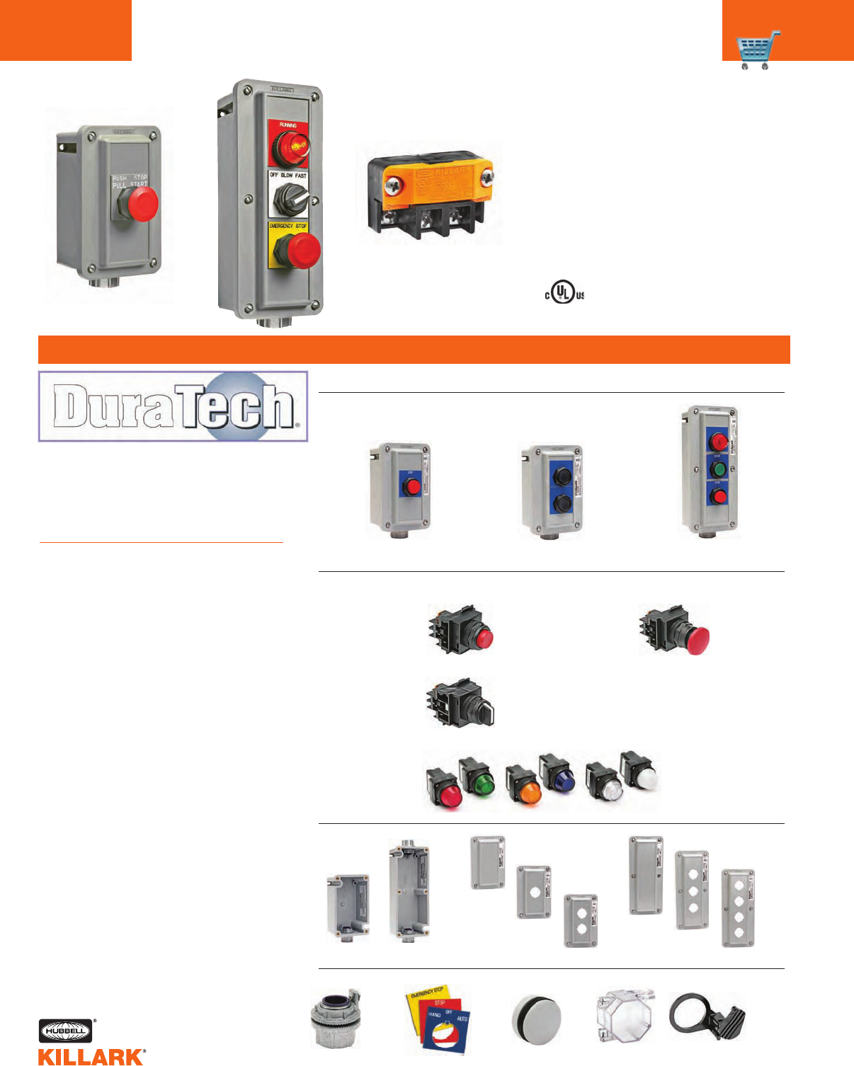
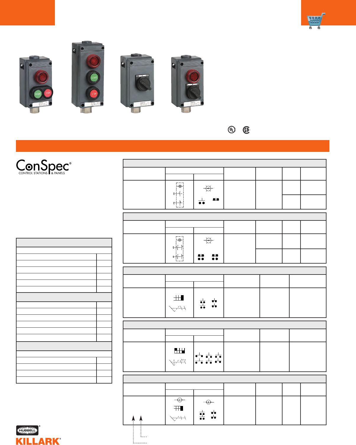
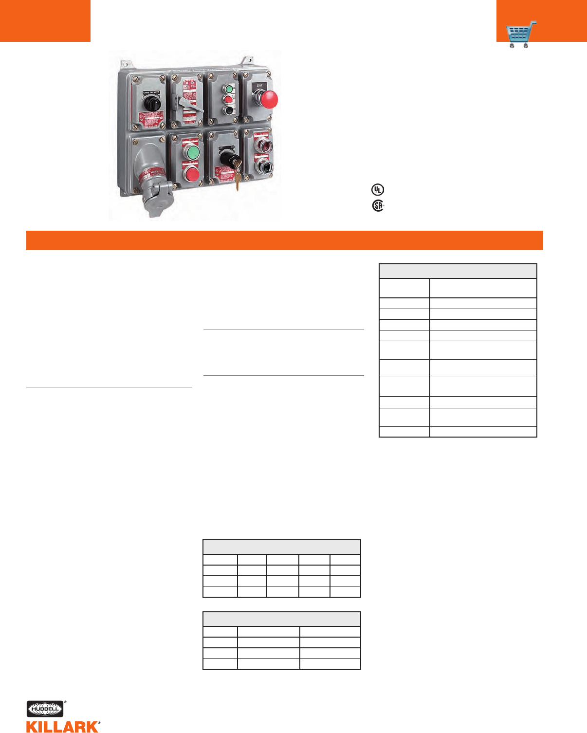
D2C SERIES •CONTROLS
ASSEMBLED CONTROL STATIONS C3
FEATURES-SPECIFICATIONS
C
D2CG2B2 D2CG2MMR3 D2CG2S3C3 D2CG2B7
D2CG8B15
The control stations on this page are the most commonly used configurations, including combinations of push buttons, pilot lights and
selector switches. See the following pages for components to configure custom stations.
3/4”
3/4”
3/4”
DIAGRAM
LEFT CENTER RIGHT
TWO DEVICES, DEAD END1
Two Push Buttons (Both Momentary Contact)
Complete Units (Box & Cover) NPT SIZE DIAGRAM COLOR LEGEND2
D2CG2B4 GREEN - RED START - STOP
D2CG2B7 BLACK - BLACK BLANK
Pilot Light (120V AC Light Emitting Diode Type) and Push Button (Momentary Contact)
D2CG2B13 RED LENS, BLACK BUTTON BLANK
3/4”
3/4”
THREE DEVICES, DEAD END1
Pilot Light (120V AC Light Emitting Diode Type) and two push buttons (Both Momentary Contact)
Complete Units (Box & Cover) NPT SIZE DIAGRAM COLOR LEGEND2
D2CG8B15 RED LENS, GREEN BLANK, START, STOP
& RED BUTTONS
Three Push Buttons (Each Momentary Contact)
D2CG8B9 GREEN, RED START, STOP, BLANK
& BLACK BUTTONS
3/4”
3/4”
1For 3/4” FEED-THRU, change G2 or G8 in catalog number to G5. Example D2CG2B1 becomes D2CG5B1. For other hub sizes, see page C4.
2Specify pilot light lens marking or blank button marking if required.
D2C SERIES •CONTROLS
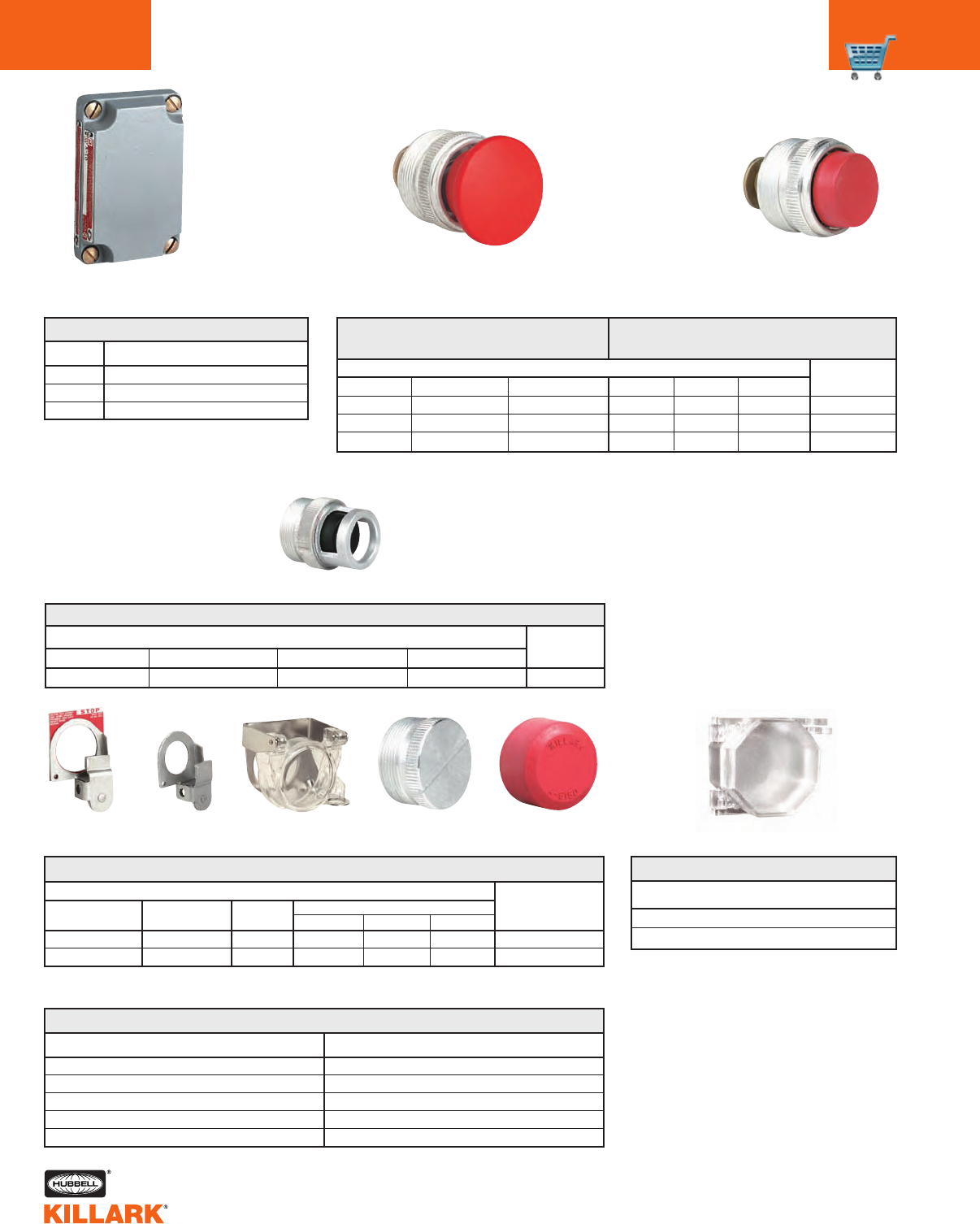
ENCLOSURES, ENTRY FITTINGS, ACCESSORIES, LEGENDS
C4
FEATURES-SPECIFICATIONS
PWBG
SIZE 1
PWCG10
D2CCG12
D2CCG11 PWBG
SIZE 2
PWCG20 D2CCG23 D2CCG24
SIZE 1 BOXES
Catalog Number Description
PWBG0 Blank - No Entries
PWBG1 w/1/2” NPT hub, dead end
PWBG2 w/3/4” NPT hub, dead end
PWBG3 w/1” NPT hub, dead end
PWBG4 w/1/2” NPT hubs, feed thru
PWBG5 w/3/4” NPT hubs, feed thru
PWBG6 w/1” NPT hubs, feed thru
PWBG25 w/clearance hole, 1/2” NPS
PWBG26 w/clearance hole, 3/4” NPS
PWBG27 w/clearance hole, 1” NPS
PWBG37 w/clearance hole, M2O
PWBG38 w/clearance hole, M25
PWBG39 w/clearance hole, M32
SIZE 1 COVERS
PWCG10 Blank-no device openings
D2CCG11 w/1 device opening 30mm
D2CCG12 w/2 device openings 30mm
SIZE 2 BOXES
Catalog Number Description
PWBG00 Blank - No Entries
PWBG7 w/1/2” NPT hub, dead end
PWBG8 w/3/4” NPT hub, dead end
PWBG9 w/1” NPT hub, dead end
PWBG10 w/1/2” NPT hubs, feed thru
PWBG11 w/3/4” NPT hubs, feed thru
PWBG12 w/1” NPT hubs, feed thru
PWBG31 w/clearance hole, 1/2” NPS
PWBG32 w/clearance hole, 3/4” NPS
PWBG33 w/clearance hole, 1” NPS
PWBG43 w/clearance hole, M20
PWBG44 w/clearance hole, M25
PWBG45 w/clearance hole, M32
SIZE 2 COVERS
PWCG20 Blank-no device openings
D2CG23 w/3 device openingS 30mm
D2CG24* w/4 device openings 30mm
ENTRY FITTINGS** & ACCESSORIES
Catalog Number Description
WH-1G Hub w/grounding locknut 1/2” NPT
WH-2G Hub w/grounding locknut 3/4” NPT
WH-3G Hub w/grounding locknut 1” NPT
YOCCHP Hole plug for 30mm operator
YOCCLOAX Lockout for half shroud momentary buttons
YOCCLOAM Lockout for momentary mushroom buttons
YOCCLOAP Lockout for maintained mushroom buttons
YOCCLOAFC Lockout cover (clear) for buttons or switches
** For other entry openings, contact factory.
* Space restrictions may apply for feed thru conduit entries.
LEGEND PLATES***
Blue plate with white lettering - add to end of base catalog
number YOCCLPBE. Example YOCCLPBE02.
Blank plates for engraving - add to end of base catalog
number YOCCLP. Example YOCCLPBE00.
*** contact factory for additional selections.
02 = CLOSE
03 = DOWN
04 = EMERGENCY STOP
07 = FORWARD
14 = OPEN
15 = POWER OFF
16 = POWER ON
17 = PUSH TO TEST
18 = RESET
BE00 = Blue Plate
GN00 =Green Plate
RD00 = Red Plate
19 = REVERSE
20 = RUN
22 = START
23 = STOP
24 = TEST
25 = UP
30 = PUSH TO RESET
56 = OFF - ON
83 = HAND - OFF - AUTO
WE00 = White Plate
YW00 = Yellow Plate
00 = Black Plate
D2C SERIES •CONTROLS
CONTROL OPERATORS, CONTACT BLOCKS C5
FEATURES-SPECIFICATIONS
C
* Operators supplied with one universal factory sealed 1 N.O. + 1 N.C. contact block. For
operator provided with two contact blocks, change last digit (3) of catalog number to 8.
For actuator only, change (3) to O.
Push Button - Momentary
Mushroom - Maintained
Rotary Switch
Pilot Light - LED
Factory Sealed
Contact Block
1 N.O./1 N.C.
Momentary Push Button Operators*
Catalog Number Description
D2CO1KX3 Black Push Button Full Shroud
D2CO1GX3 Green Push Button Full Shroud
D2CO1RX3 Red Push Button Full Shroud
D2CO1KH3 Black Push Button Half Shroud
D2CO1GH3 Green Push Button Half Shroud
D2CO1RH3 Red Push Button Half Shroud
D2CO1KM3 Black Push Button Mushroom
D2CO1GM3 Green Push Button Mushroom
D2CO1RM3 Red Push Button Mushroom
Maintained Mushroom Push Button Operators*
D2COM1K3 Black Push-Pull Mushroom
D2COM1G3 Green Push-Pull Mushroom
D2COM1R3 Red Push-Pull Mushroom
D2COT1R3 Red Twist to Release Mushroom
Rotary Selector Switch Operators*
D2CO52A3 Maintained 2-Position
D2CO53C3 Maintained 3-Position
D2CO63 Momentary Right, 2-Position
D2CO73 Maintained Center 3-Position
D2CO143 Maintained Left & Center 3-Position
D2CO153 Maintained Right & Center 3-Position
LED Pilot Light Devices
Add to end of base catalog number D2CO3. Example D2CO3A23.
A23 = Amber 120V AC/DC
A4 = Amber 24V AC/DC
AMV = Amber Multi-voltage 20V-254V AC/DC
B23 = Blue 120V AC/DC
B4 = Blue 24V AC/DC
BMV = Blue Multi-voltage 20V-254V AC/DC
C23 = Clear 120V AC/DC
C4 = Clear 24V AC/DC
CMV = Clear Multi-voltage 20V-254V AC/DC
G23 = Green 120V AC/DC
G4 = Green 24V AC/DC
GMV = Green Multi-voltage 20V-254V AC/DC
R23 = Red 120V AC/DC
R25R = Red 480VAC/DC resistor
R25T = Red 480VAC transformer
R4 = Red 24V AC/DC
RMV = Red multi-voltage 20V-254V AC/DC
W23 = White frosted 120V AC/DC
W4 = White frosted 24V AC/DC
WMV = White frosted Multi-voltage 20V-254V AC/DC
Factory Sealed Contact Block
Catalog Number Description Diagram
D2CU Factory Sealed Contact Block
(add suffix R for rotary 1 Normally Open and
selector switches) 1 Normally closed
Hazardous Rating:
Class I, Division 2, Groups A,B,C,D; Class I, Zone 2, Groups IIB+H2, IIA, T6
Terminal Capacity:
22 thru 12 AWG [0.5-2.5mm2] copper, solid or standed conductors.
Tightening torque 7 in-lbs. (tolerance +3.0/0.0) [~ 0.8Nm]
Contact Electrical Ratings:
NEMA A600- 7200 VA (Make), 720 VA (Break), 10 Amps Cont. @600V AC (Thermal)
NEMA Q300- 69 VA (Make & Break), 2.5 Amps Cont. @250V DC (Thermal)
Design your own DuraTech®configuration from components by completing the following:
Box Size Hub Size Dead End Feed Thru
Clearance Hole NPS Metric
Cover Size Number of Devices
Select Devices From Top (Position 1) to Bottom
Position 1__________________________________________________________________________________________________________________________________________________________________________________________________________
Position 2__________________________________________________________________________________________________________________________________________________________________________________________________________
Position 3__________________________________________________________________________________________________________________________________________________________________________________________________________
Position 4__________________________________________________________________________________________________________________________________________________________________________________________________________
D2C SERIES •CONTROLS
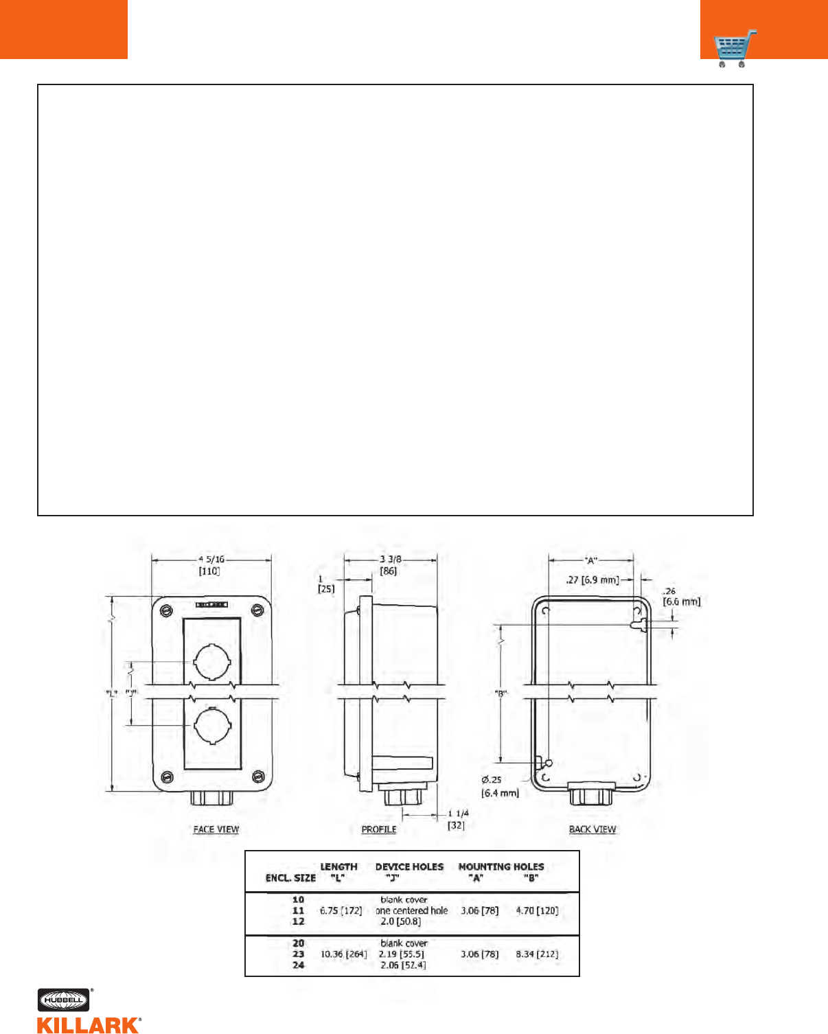
CUSTOM STATIONS ORDERING FORM, ENCLOSURE DIMENSIONS
C6
Device Nameplate Options
1 2
1 2 1 2 3 4
1/2 3/4 1
1/2 3/4 1 M20 M25 M32
D2C SERIES •CONTROLS
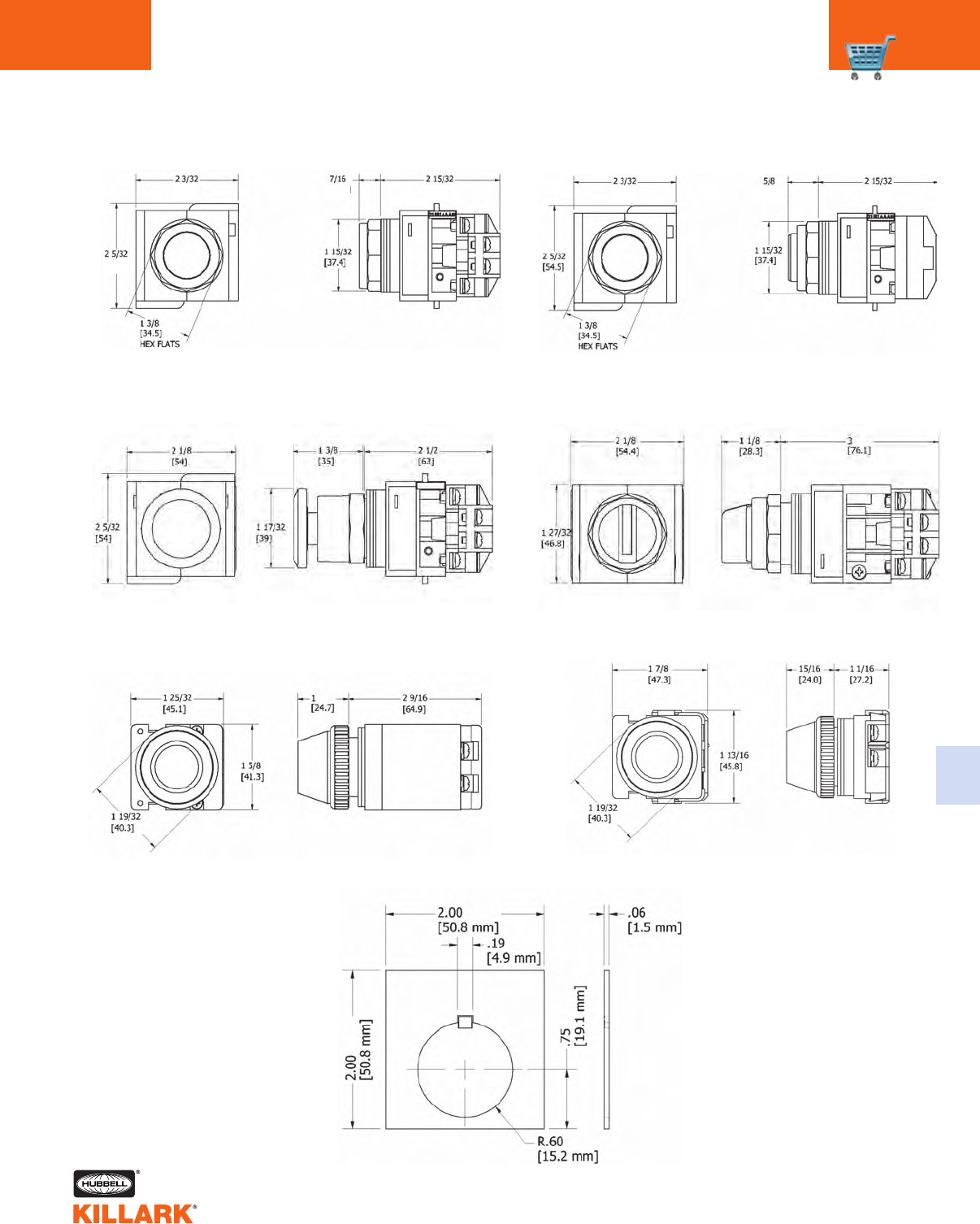
CONTROLS OPERATOR DIMENSIONS C7
C
Operators bought separately are provided with gaskets to accommodate panel thickness for D2C series enclosures.
Full-Shrouded Momentary Push Button Operator
(53) (63)
(11)
(21)
Half-Shrouded Button
Mushroom Push Button Selector Switch Device
Pilot Light Multi-Voltage 20V-240V AC/DC Pilot Light 120V AC (Full Voltage)
Legend Plate
(53) (53) (63)
CS SERIES •CONTROLS
CONTROL STATIONS
C8
FEATURES-SPECIFICATIONS
Stainless Steel Enclosure
FRP Enclosure
Class I, Div. 2, Groups A,B,C,D
Class l, Zones 1 & 2, Groups IIC, llB, llA
Class II, Div. 1 & 2, Groups E,F,G1
Class III
NEMA 3, 4, 4x
(A)Ex de IIC T6 IP66
Applications
Hazardous and corrosive environments
such as refineries, chemical plants,
water treatment and bio gas plants, and
wherever a combustible gas-air mixture
or combustible dust may occur.
Features
•Enclosures of Fiberglass Reinforced
Polyester or Stainless Steel.
•Durable EPDM gasket on enclosure
is concealed to protect it from
damage or premature aging by UV
light and chemical elements
•Snap-on mounting of individual explo-
sion-protected control components to
notched DIN-like rail
•Contact element utilizes a parallel
bridge contact with a four point
(H- contact) to ensure the utmost
reliability even with very low control
voltages and currents
•Fluorosilicate gasket in standard
pushbutton actuators is suitable for a
wide range of atmospheric conditions
(-50°C to 40°C)
•LED Pilot lights (incorporating
advanced voltage-sensing electronics)
operate on any voltage from 20V- 254V,
AC or DC
•Control switches in many configura-
tions
•Illuminated (Push-To-Test) push but-
tons, ammeters, potentiometers and
other control components available
•No external seals required for most
applications
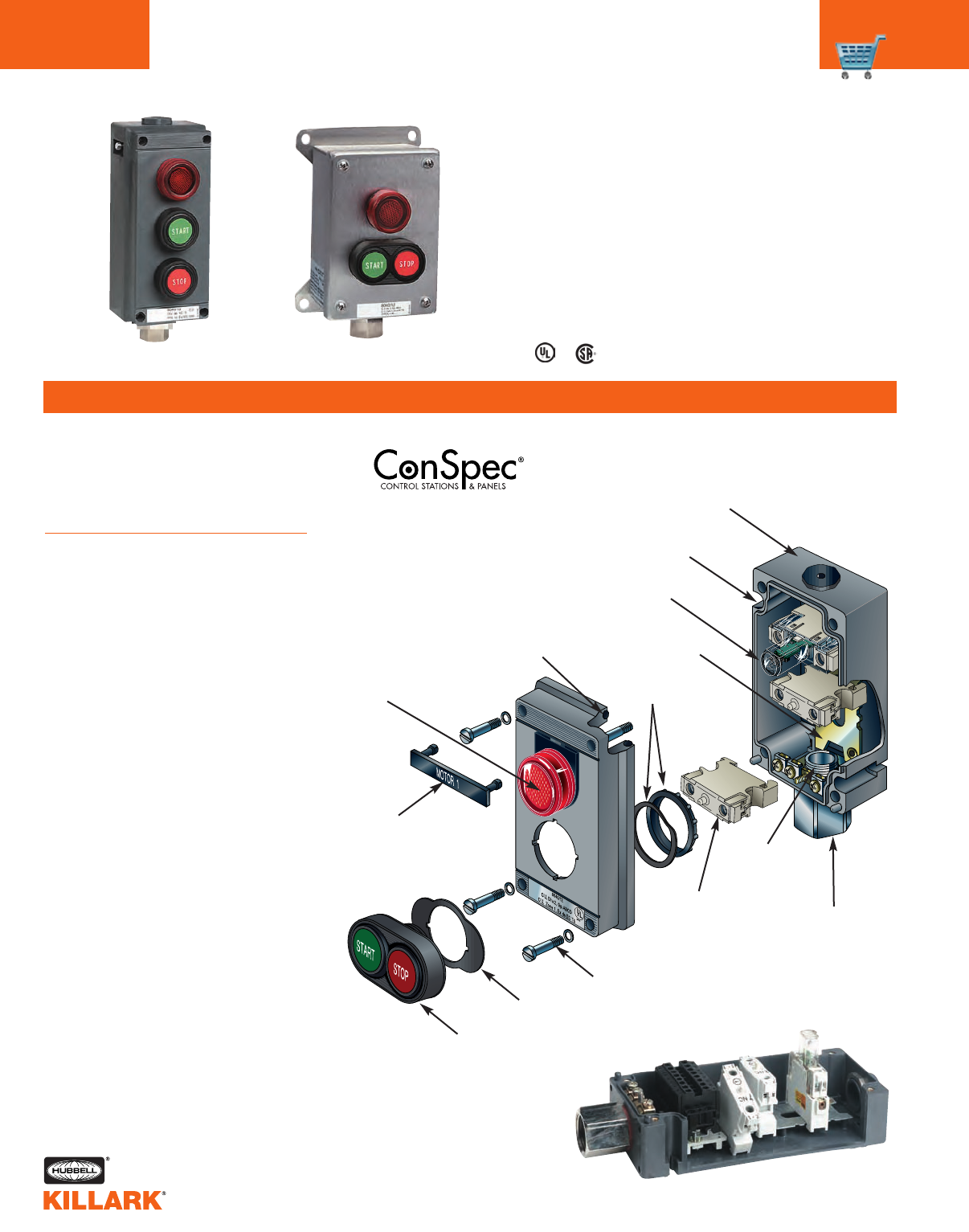
RUN
Two Types of Enclosure Materials
• Fiberglass Reinforced Polyester (FRP)
• 316L Stainless Steel
Pilot Light Bezel
Station I.D. Label
(optional)
Actuator Gasket
Conduit Hub
or Cable
Gland Entry
Ground Plate
With Terminals
Explosion
Protected
Contact Block
Spring Washer
& Retainer Nut
Recessed
EPDM
Gasketing
Integral
Mounting Slots (holes)
Component
Mounting Rail
Stainless Steel Cover Screws
Explosion Protected
LED Pilot Light
“THE” Standard in Hazardous
Location Control
1CSA Certified for Class II, Div. 1&2, EFG. UL LIsted for Class II, Div. 2, FG. Easy Change-out
Components Snap in Place
Dual Push-Button Actuator
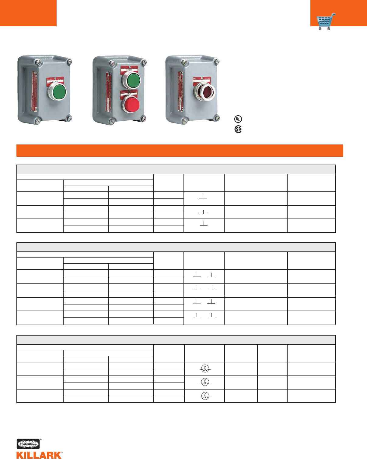
CS SERIES •CONTROLS
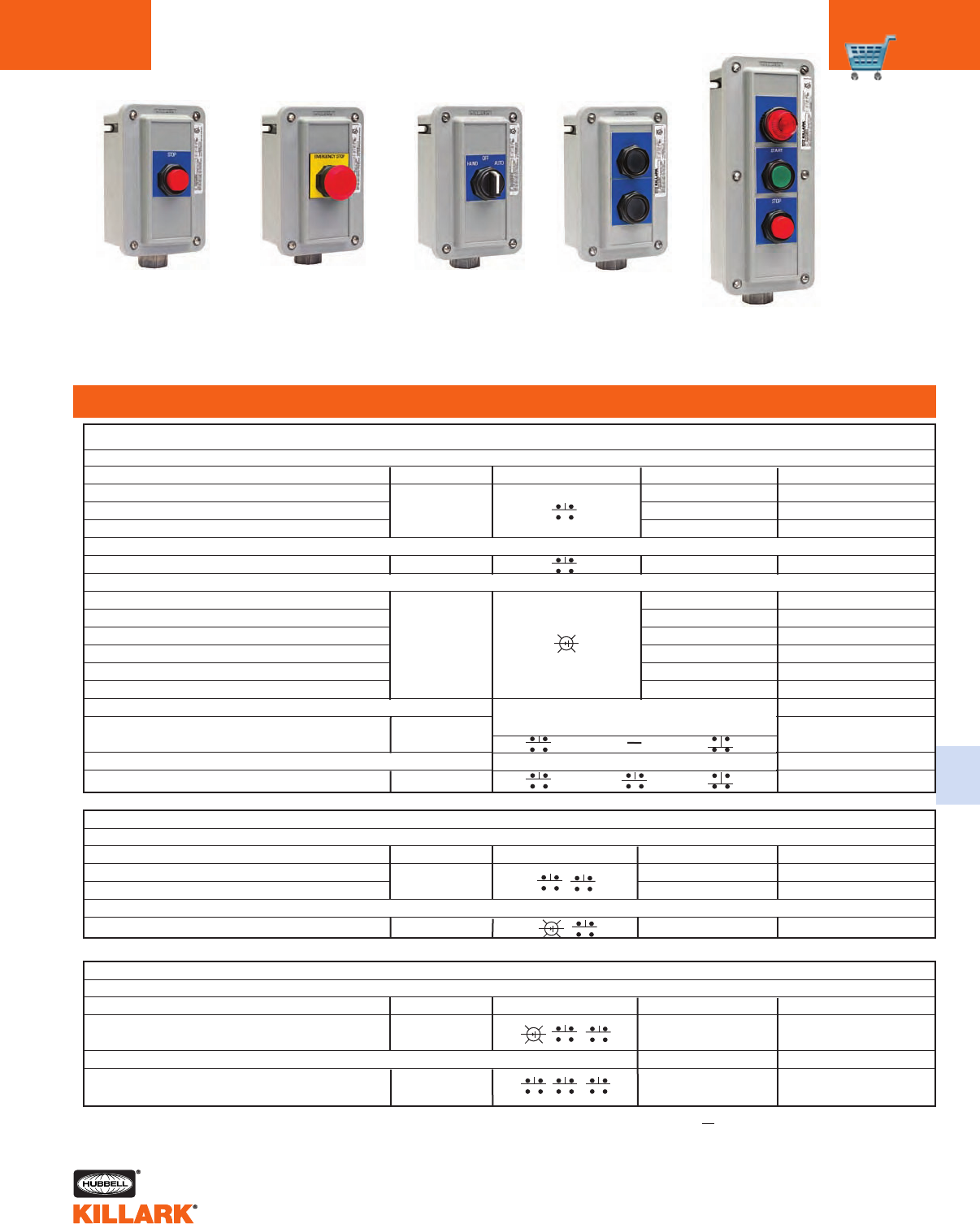
CONTROL STATIONS - STANDARD CONFIGURATIONS
FEATURES-SPECIFICATIONS
C
C9
Start
Push Button
Station
Start/Stop
Push Button
Station
E-Stop
Push Button
Station
Pilot Light
Station
Class I, Div. 2, Groups A,B,C,D
Class l, Zones 1 & 2, Groups IIC, llB, llA
Class II, Div. 1 & 2, Groups E,F,G1
Class III
NEMA 3, 4, 4X
(A)Ex de IICT6 IP66
CATALOG
NUMBER
CONTACT ARRANGEMENT
IEC NEMA
CONTACT
BLOCKS
BUTTON
COLOR
NAMEPLATE
MARKING
CS MOMENTARY SINGLE PUSH BUTTON
The control stations on this page are
the most commonly used configura-
tions, including combinations of pilot
lights and push buttons.
A
B
C
D
E
F
0
1
2
3
4
5
6
7
8
9
(Standard for IEC/CENELEC)
M25 Compression Gland Top Feed
M25 Compression Gland Bottom Feed
M25 Compression Gland Feed Through
Special
BOXES WITH CONDUIT HUB
BOXES WITH NON-METALLIC CABLE GLAND
BOXES WITH INTERNAL GROUND PLATE
(for MC/TC/TEC Cable Connectors)
1/2" NPT Top Feed
1/2" NPT Bottom Feed
1/2" NPT Feed Through
3/4" NPT Top Feed
3/4" NPT Bottom Feed
3/4" NPT Feed Through
1/2" NPT Top Feed
1/2" NPT Bottom Feed
1/2" NPT Feed Through
3/4" NPT Top Feed
3/4" NPT Bottom Feed
3/4" NPT Feed Through
Wiring Entry Logic
Insert one of the digits below to complete the
control station catalog number.
CSF124UO11
CSS124UO11
CATALOG
NUMBER
CONTACT ARRANGEMENT
IEC NEMA
CONTACT
BLOCKS
BUTTON
COLOR
NAMEPLATE
MARKING
CS MOMENTARY START-STOP PUSH BUTTONS
1 N.O. / 1 N.C.
1 N.O. / 1 N.C.
CATALOG
NUMBER
CONTACT ARRANGEMENT
IEC NEMA
CONTACT
BLOCKS
BUTTON
COLOR
NAMEPLATE
MARKING
CS MAINTAINED EMERGENCY STOP PUSH BUTTON
CATALOG
NUMBER
CONTACT ARRANGEMENT
IEC NEMA VOLT COLOR NAMEPLATE
MARKING
CS SINGLE PILOT LIGHT
Wiring entry: 4=3/4" NPT Bottom Feed. For other entries, see Wiring Entry Logic table at left.
Housing material: (F) FRP, (S) Stainless Steel.
1CSA Certified for Class II, Div. 1&2, EFG.
UL Listed for Class II, Div. 2, FG.
1 N.O. / 1 N.C. Green Start
23 11
24 12
Green
Red
Start
Stop
23 11
24 12
23 11
2412
START STOP
2 N.C. E-Stop
Red Large
I-0 12
11
22
21
CSF124C150
CSS124C150
CSF224UO11UO12
CSS224UO11UO12
20V-254V AC / DC Red LED —
CSF124PLRO
CSS124PLRO
X1 X2 •
•
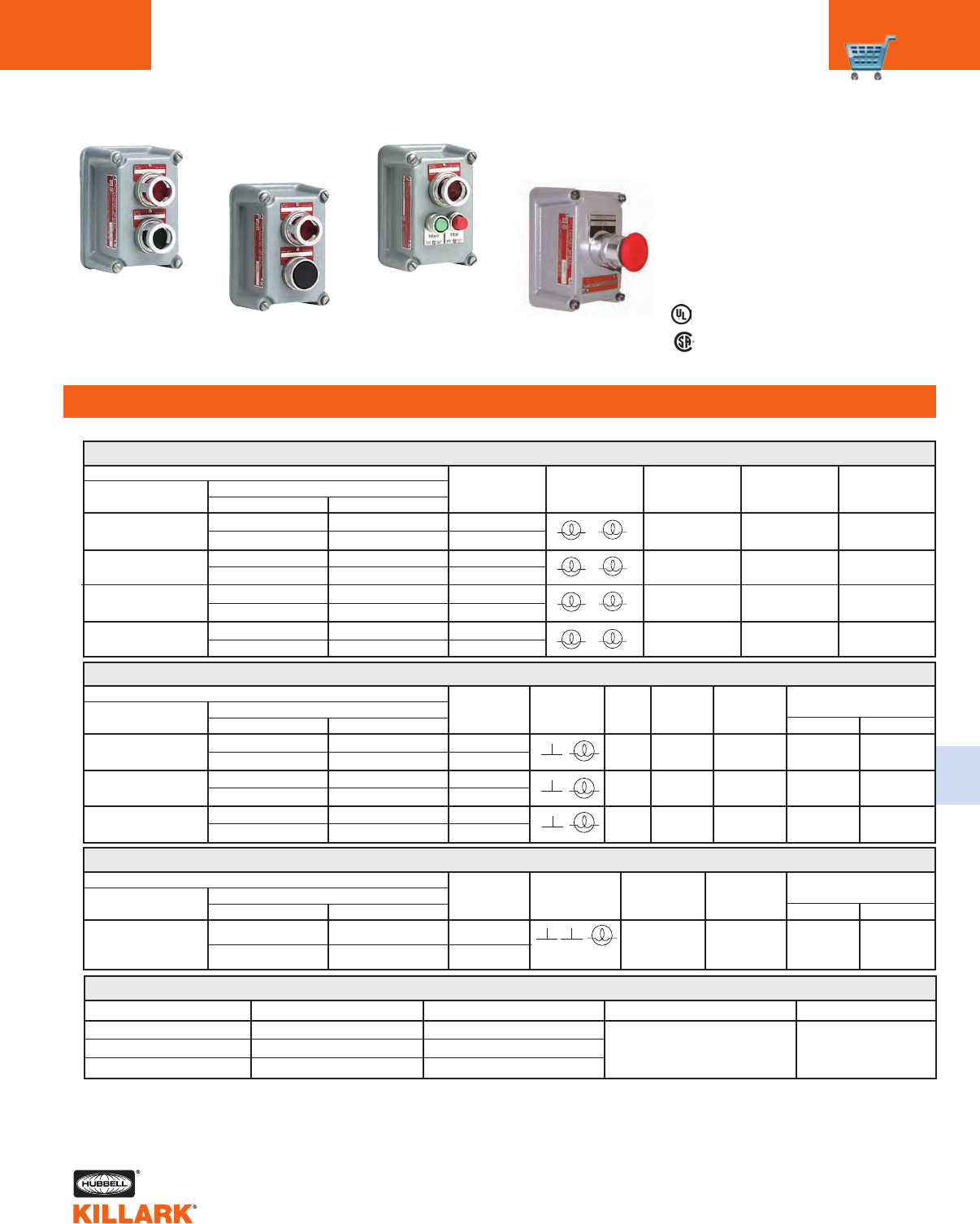
CS SERIES •CONTROLS
CONTROL STATIONS - STANDARD CONFIGURATIONS
C10
FEATURES-SPECIFICATIONS
Pilot Light and
Selector Switch
Station
Pilot Light &
Start/Stop Push
Button Station
Selector Switch
Station
Pilot Light &
2 Push Button
Station
Class I, Div. 2, Groups A,B,C,D
Class l, Zones 1 & 2, Groups IIC, llB, llA
Class II, Div. 1 & 2, Groups E,F,G1
Class III
NEMA 3, 4, 4X
(A)Ex de IICT6 IP66
The control stations on this page are
the most commonly used configura-
tions, including combinations of pilot
lights, push buttons and selector
switches.
A
B
C
D
E
F
0
1
2
3
4
5
6
7
8
9
(Standard for IEC/CENELEC)
M25 Compression Gland Top Feed
M25 Compression Gland Bottom Feed
M25 Compression Gland Feed Through
Special
BOXES WITH CONDUIT HUB
BOXES WITH NON-METALLIC CABLE GLAND
BOXES WITH INTERNAL GROUND PLATE
(for MC/TC/TEC Cable Connectors)
1/2" NPT Top Feed
1/2" NPT Bottom Feed
1/2" NPT Feed Through
3/4" NPT Top Feed
3/4" NPT Bottom Feed
3/4" NPT Feed Through
1/2" NPT Top Feed
1/2" NPT Bottom Feed
1/2" NPT Feed Through
3/4" NPT Top Feed
3/4" NPT Bottom Feed
3/4" NPT Feed Through
Wiring Entry Logic
Insert one of the digits below to complete the
control station catalog number.
CONTACT ARRANGEMENT
IEC NEMA
CS PILOT LIGHT (RED LED)/MOMENTARY DOUBLE PUSH BUTTONS
CSF334PLROU011U012
CSS334PLROU011U012
CSF224PLROU231
CSS224PLROU231
CONTACT ARRANGEMENT
IEC NEMA
CS PILOT LIGHT (RED LED)/MOMENTARY START-STOP PUSH BUTTONS
CONTACT ARRANGEMENT
IEC NEMA
CS MAINTAINED 2-POSITION SELECTOR SWITCH
2-Pos./2-Pole Off-On
—
CONTACT ARRANGEMENT
IEC NEMA
CS PILOT LIGHT/MAINTAINED 2-POSITION SELECTOR SWITCH
Off-On
Wiring entry: 4=3/4" NPT Bottom Feed. For other entries, see Wiring Entry Logic table at left.
Housing material: (F) FRP, (S) Stainless Steel.
CONTACT ARRANGEMENT
IEC NEMA
CS MAINTAINED 3-POSITION SELECTOR SWITCH
3-Pos./2-Pole
45°13 5 °
14
24
13
23
13 23
14 24
°°
°°
OFF ON
45°13 5 °
12
24
11
23
11 23
12 24
°°
°°
90°
OFF AUTO
4HAND
NAMEPLATE
MARKING
Start
Stop
BUTTON
COLOR
VOLT CONTACT
BLOCKS
20V-254V, AC/DC
NAMEPLATE
MARKING
Green
Red
Start
Stop
Green
Red
1 N.O./1 N.C.
BUTTON
COLOR
VOLT CONTACT
BLOCKS
20V-254V, AC/DC
1 N.O. / 1 N.C.
1 N.O. / 1 N.C.
NAMEPLATE
MARKING
COLOR
VOLT CONTACT
BLOCKS
20V-254V, AC/DC 2-Pos./2-Pole Red LED
CATALOG
NUMBER
CATALOG
NUMBER
CATALOG
NUMBER
CATALOG
NUMBER
CATALOG
NUMBER
CONTACT
BLOCKS
BUTTON
COLOR
NAMEPLATE
MARKING
CONTACT
BLOCKS
BUTTON
COLOR
NAMEPLATE
MARKING
X1 X2
23
24
11
12
1CSA Certified for Class II, Div. 1&2, EFG.
UL LIsted for Class II, Div. 2, FG.
START STOP
X1 X2
23 11
24 12
23 11
24 12
START STOP
CSF124NO21
CSS124NO21
H-O-A
—
CSF124N273
CSS124N273
CSF224PLRON021
CSS224PLRON021
45° 135°
14
24
13
23
13 23
14 24
°°
°°
•
OFF ON
•
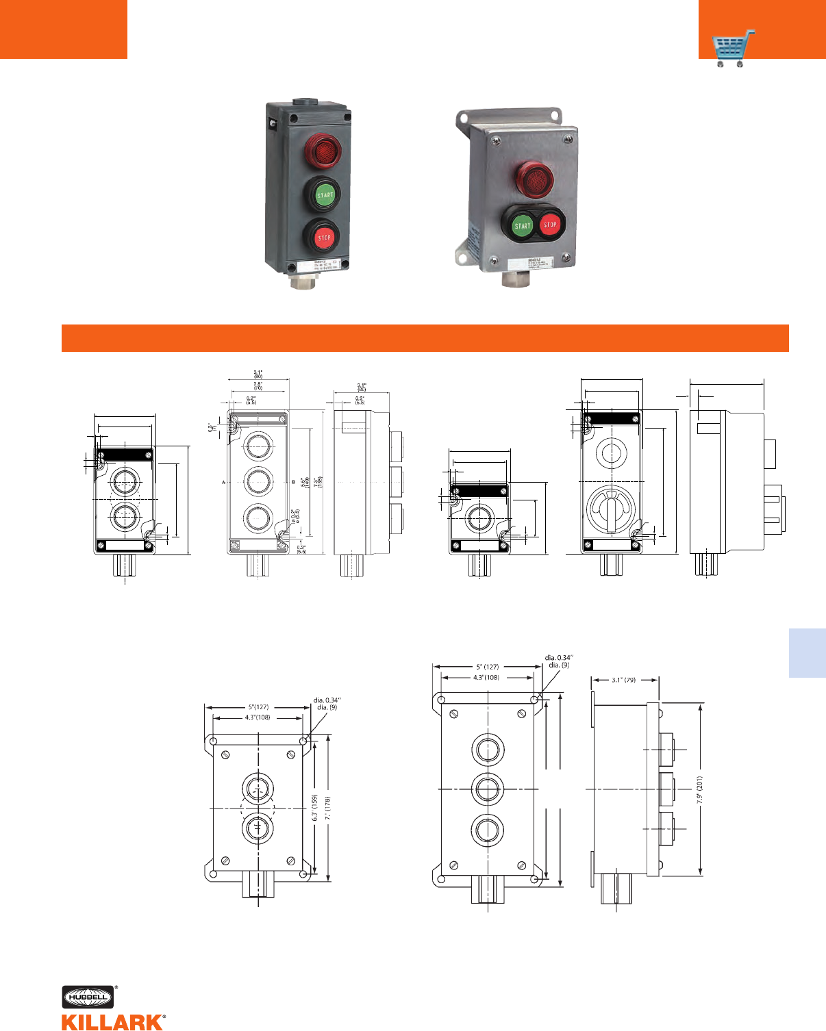
CS SERIES •CONTROLS
CONTROL STATIONS DIMENSIONAL DATA C11
FEATURES-SPECIFICATIONS
C
Stainless Steel Enclosure
FRP Enclosure
FRP Dimensions
Steel Dimensions
AB
0.2"
(5.5)
1.9"
(48)
3.7"
(93)
0.2"
(5.5)
0.3"
(7)
2.8"
(70)
3.1"
(80)
ø 0.2"
(ø 5.5)
AB
0.2"
(5.5)
0.2"
(5.5)
3.7"
(94)
5.5"
(139)
0.3"
(7)
2.8"
(70)
3.1"
(80)
ø 0.2"
ø (5.5)
7.3"
(185)
AB
0.2"
(5.5)
0.2"
(5.5)
5.5"
(140)
0.3"
(7)
2.8"
(70)
3.1"
(80)
ø 0.2"
ø (5.5)
3.78
(97)
.43"
(11)
CSF 11 Compact
CSS 12
CSS 22
CSS 33
CSF12/CSF 22 CSF 33 CSF Deep
for 4 Pole Switches
8.2” (207)
8.9” (226)
C12 FXCS SERIES •CONTROLS
FACTORY SEALED CONTROLS
FEATURES-SPECIFICATIONS
Applications
SEAL-X®Series Factory Sealed push
button stations, selector switches, pilot
lights and tumbler switches are used to
prevent the igniting of external haz-
ardous atmospheres by the enclosed
arcing devices in such areas as:
•Hazardous locations due to the pres-
ence of flammable gases or vapors,
combustible dusts or easily ignitable
fibers or flyings
•Installations at petroleum refineries,
chemical and petrochemical plants
and other processing or storage facil-
ities where similar hazards exist
•Use in conjunction with magnetic
starters or contactors for remote con-
trol of motors
Features
•Elimination of external sealing
requirements
•Lower installation cost
•NEMA 3 weatherproof
•Color coded wiring-more wiring
space-easier field installation
•Stainless steel captive screws for
cover assembly
•Ground boss for grounding in the
splice box
•Device bodies and covers are cast
copper-free aluminum alloy
Listed - File E53360
Certified - File LR11714
See files for details or call Killark.
Class I, Div. 1 & 2, Groups C,D
Class I, Zones 1 & 2, Groups llB, llA
Class II, Div. 1 & 2, Groups E,F,G
Class Ill
NEMA 3, 7(C,D) 9(E,F,G)
•Cast conduit hubs 1/2", 3/4" and 1"
either dead end or feed through
standard in both single and two
gang assemblies
•Push button, selector switches and
pilot light bodies are copper-free
aluminum
•Operating shaft in both push buttons
and selector switches are stainless
steel
•Miniature and standard size push
buttons. (Miniature 3/4" overall diam-
eter, standard 1 3/8" overall diameter)
Factory Sealed devices eliminate the
need for external sealing. The differ-
ence is the use of a sealing plate
between the arcing device and the
junction box. The sealing plate con-
fines ignited gases, vapors, flames,
or dust to the arcing device chamber,
preventing them from traveling through
the conduit system. Accurately ground
flanges on both sides of the sealing
plate provide flame-tight joints. Factory
poured seals around the wiring pigtails
insure safe sealing. (FXCS Series)
CURRENT 120 VAC 240 VAC 480 VAC 600 VAC
INRUSH 60 30 15 12
BREAKING 631.5 1.2
CARRYING 10 10 10 10
CONTACT BLOCK RATINGS
CURRENT 125 VDC 250 VDC
INRUSH .55 .275
BREAKING .55 .275
CARRYING 2.50 2.50
DC RATINGS (MAX. AMPS)
SUFFIX DESCRIPTION
NUMBER
MODIFICATIONS
AL Pilot light lens-amber
CL Pilot light lens-clear
GL Pilot light lens-green
RL Pilot light lens-red
MR Mushroom head-
Push button (red)
LO Push button LOCKOUT1
LOP Selector switch-padlock
LOCKOUT
1LOCKOUT must be installed at the factory.
LED lamps available. See page C39.
Electrical Rating
Push button stations, selector switches
600 VAC max. heavy duty.
SEAL-X®
C13
C
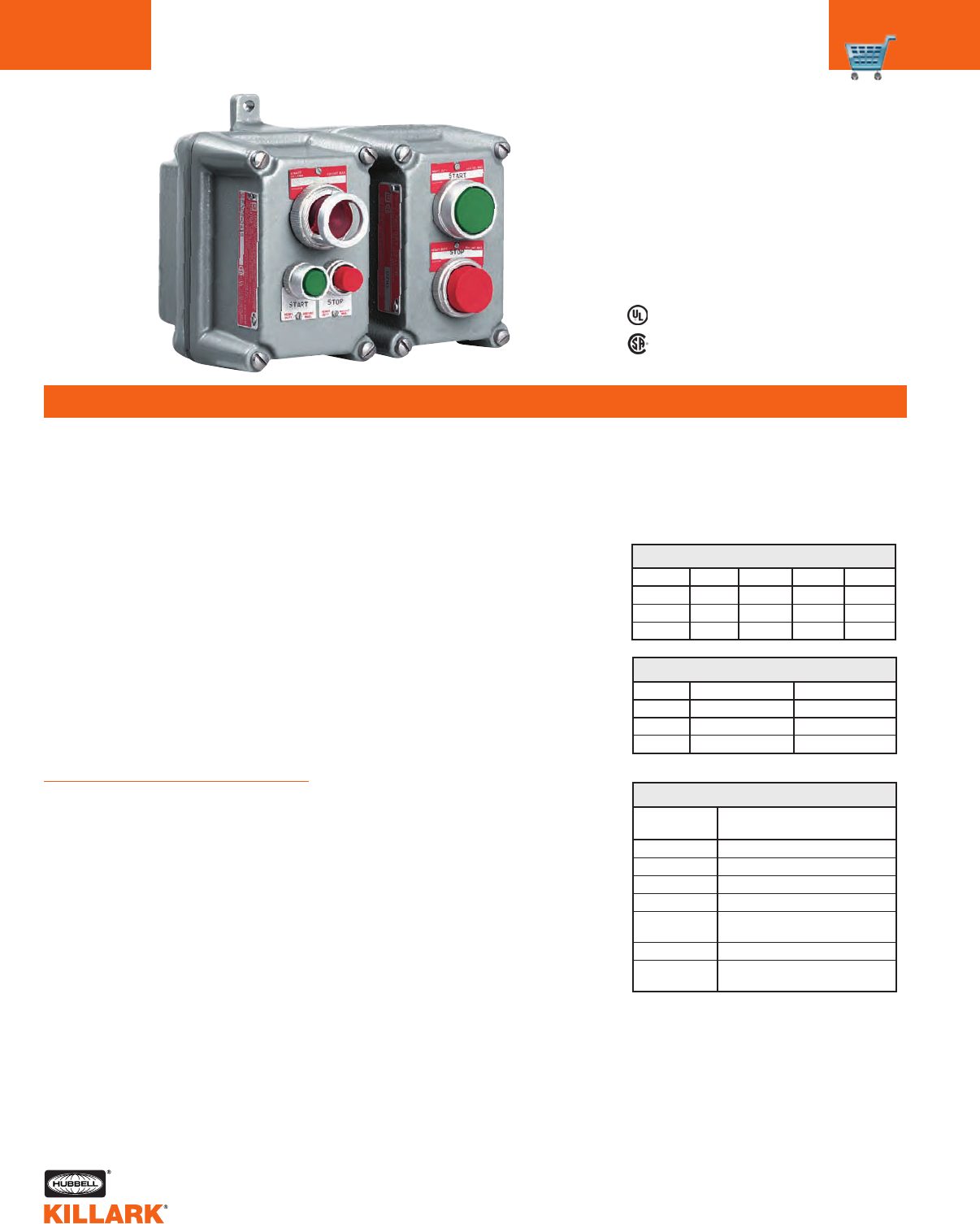
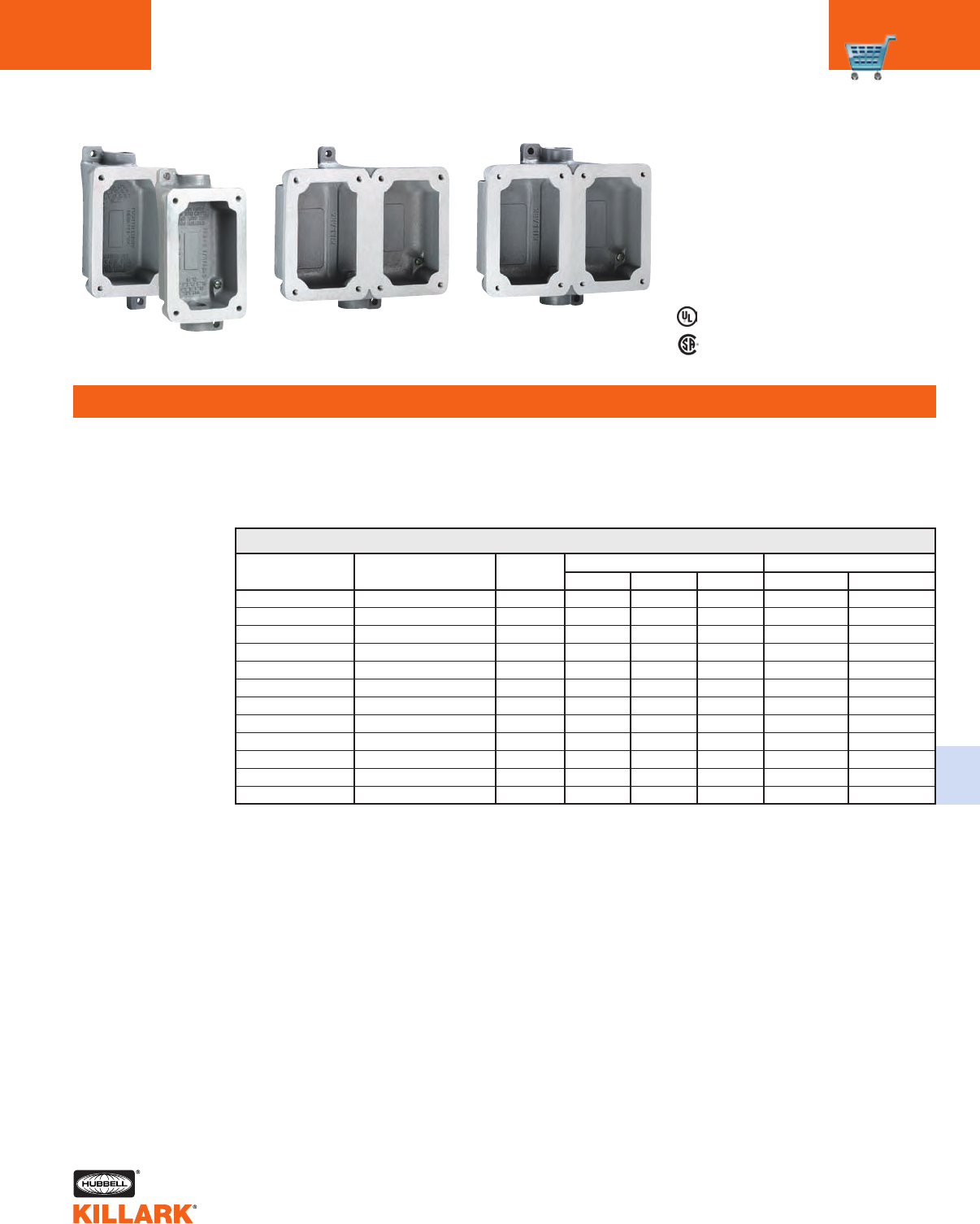
FXB SERIES •CONTROLS
FACTORY SEALED SPLICE BOXES/SEALING METHODS
FEATURES-SPECIFICATIONS
FXB-2
Dead End
FXB-8
Double Gang Dead End
FXB-11
Double Gang Feed Thru
Listed - File E53360
Certified- File LR11714
See files for details or call Killark.
Class I, Div. 1 & 2, Groups C,D
Class I, Zones 1 & 2, Groups llB, llA
Class II, Div. I & 2, Groups E,F,G
Class Ill
NEMA 3, 7(C,D) 9(E,F,G)
Splice Boxes
The FXB Series of splice boxes are
designed for use with the FXCS and
FXS Series of cover sub-assemblies.
FXB BACK BOX SELECTION AND DIMENSIONS
CATALOG NUMBER DESCRIPTION
FXB-1
FXB-2
FXB-3
FXB-4
FXB-5
FXB-6
FXB-7
FXB-8
FXB-9
FXB-10
FXB-11
FXB-12
Single gang/Dead-end
Single gang/Dead-end
Single gang/Dead-end
Single gang/Feed-thru
Single gang/Feed-thru
Single gang/Feed-thru
Double gang/Dead-end
Double gang/Dead-end
Double gang/Dead-end
Double gang/Feed-thru
Double gang/Feed-thru
Double gang/Feed-thru
MOUNTING
EXTERNAL
HUB
SIZE LENGTH WIDTH DEPTH HORIZONTALVERTICAL
1/2"
3/4"
1"
1/2"
3/4"
1"
1/2"
3/4"
1"
1/2"
3/4"
1"
6-13/16"
6-13/16"
6-13/16"
6-13/16"
6-13/16"
6-13/16"
6-13/16"
6-13/16"
7
6-13/16"
6-13/16"
7
3-11/16"
3-11/16"
3-11/16"
3-11/16"
3-11/16"
3-11/16"
7-17/32"
7-17/32"
7-17/32"
7-17/32"
7-17/32"
7-17/32"
1-3/4"
1-3/4"
1-3/4"
1-3/4"
1-3/4"
1-3/4"
2
2
2
2
2
2
6-3/16"
6-3/16"
6-3/16"
6-3/16"
6-3/16"
6-3/16"
6-3/16"
6-3/16"
6-3/16"
6-3/16"
6-3/16"
6-3/16"
2-1/4"
2-1/4"
2-1/4"
2-1/4"
2-1/4"
2-1/4"
2-1/4"
2-1/4"
2-1/4"
2-1/4"
2-1/4"
2-1/4"
FXB-5
Feed Thru
C14 FXCS SERIES •CONTROLS
FACTORY SEALED COVER ASSEMBLIES
FEATURES-SPECIFICATIONS
Class I, Div. 1 & 2, Groups C,D
Class I, Zones 1 & 2, Groups llB, llA
Class II, Div. I & 2, Groups E,F,G
Class Ill
NEMA 3, 7(C,D) 9(E,F,G)
Listed - File E53360 and/or E12379
Certified - File LR11714
See files for details or call Killark.
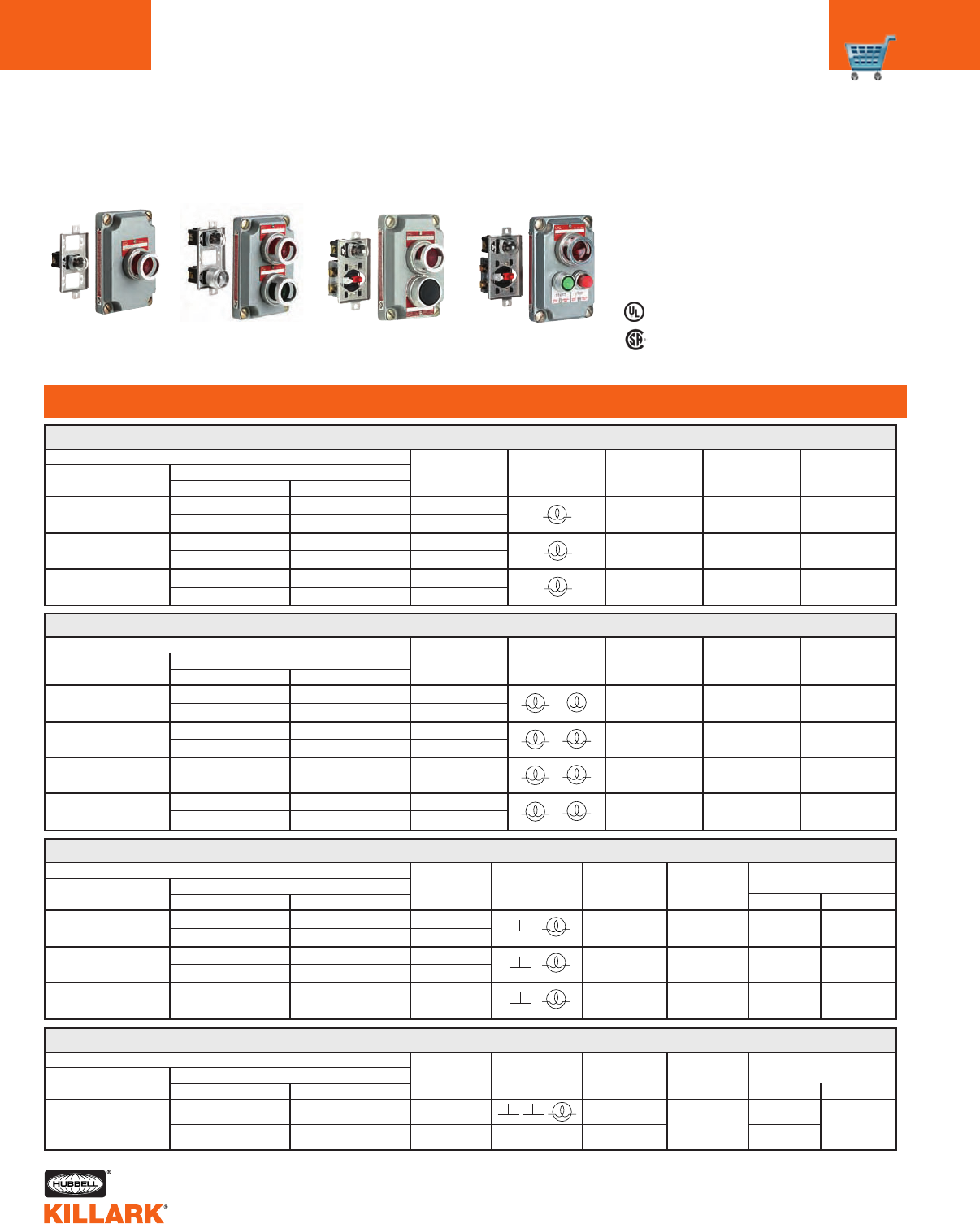
Single Push Button Double Push Button Pilot Light
CATALOG NUMBER
NAMEPLATE
COMPLETE UNITS (BOX & COVER) HUB DIAGRAM BUTTON
MARKING1
COVER WITH DEVICE DEAD-END FEED-THRU SIZE COLOR
FXCS-0B1 FXCS-1B1 FXCS-4B1 1/2" Green Start
FXCS-2B1 FXCS-5B1 3/4"
FXCS-0B2 FXCS-1B2 FXCS-4B2 1/2" Red Stop
FXCS-2B2 FXCS-5B2 3/4"
FXCS-0B3 FXCS-1B3 FXCS-4B3 1/2" Black Specify
FXCS-2B3 FXCS-5B3 3/4"
FXCS MOMENTARY CONTACT SINGLE PUSH BUTTON
CATALOG NUMBER
NAMEPLATE
COMPLETE UNITS (BOX & COVER) HUB DIAGRAM BUTTON
MARKING1
COVER WITH DEVICE DEAD-END FEED-THRU SIZE COLOR
FXCS-1B4 FXCS-4B4 1/2" Green/Red Start/Stop
FXCS-0B4 FXCS-2B4 FXCS-5B4 3/4"
FXCS-0B4-U FXCS-1B4U FXCS-4B4-U 1/2" Green/Red Start/Stop
FXCS-2B4U FXCS-5B4-U 3/4"
FXCS-0B5 FXCS-1B5 FXCS-4B5 1/2" Green/Green Start/Stop
FXCS-2B5 FXCS-5B5 3/4"
FXCS-0B7 FXCS-1B7 FXCS-4B7 1/2" Black/Black Specify
FXCS-2B7 FXCS-5B7 3/4"
FXCS MOMENTARY CONTACT DOUBLE PUSH BUTTON
CATALOG NUMBER
COMPLETE UNITS (BOX & COVER) HUB DIAGRAM VOLT LENS NAMEPLATE
COVER WITH DEVICE DEAD-END FEED-THRU SIZE COLOR2MARKING1
FXCS-0B24CL FXCS-1B24CL FXCS-4B24CL 1/2" 120V Clear Specify
FXCS-2B24CL FXCS-5B24CL 3/4"
FXCS-0B24GL FXCS-1B24GL FXCS-4B24GL 1/2" 120V Green Specify
FXCS-2B24GL FXCS-5B24GL 3/4"
FXCS-0B24RL FXCS-1B24RL FXCS-4B24RL 1/2" 120V Red Specify
FXCS-2B24RL FXCS-5B24RL 3/4"
FXCS PILOT LIGHT
1For other than standard marking, refer to the special feature section of price list.
2Lens colors other than listed may be specified by changing lens color suffix. See modifications page C12.
NOTE: Boxes and covers shipped separately.
*For control stations with 1" conduit openings or for double gang assemblies, order cover with device and box as separate components.
• •
• •
• •
• •
• •
• •
• •
• • • •
• •
• •
• • • •
• •
• •
• •
C15
C
FXCS SERIES •CONTROLS
FACTORY SEALED CONTROL STATION COVER ASSEMBLIES
FEATURES-SPECIFICATIONS
Class I, Div. 1 & 2, Groups C,D
Class l, Zones 1 & 2, Groups llB, IlA
Class II, Div. I & 2, Groups E,F,G Class Ill
NEMA 3, 7(C,D) 9(E,F,G)
Listed - File E53360 and /or E12379
Certified - File LR11714
See files for details or call Killark.
Double Pilot Lights
Pilot Light
Push Button
Pilot Light
Two Mini Push Buttons
Maintained
Push Button
1For other than standard marking, refer to the special feature section of price list.
2Lens colors other than listed may be specified by changing lens color suffix. See modifications page C12.
3Three nameplates supplied (Start/Stop, Blank, Emergency Stop) with FXCS maintained push button.
4Operation-when push button is depressed and contacts activated, operator will remain in depressed position until pulled out to
normal position.
NOTE: Boxes and covers shipped separately.
*For control stations with 1" conduit opening or for double gang assemblies, order cover with device and box as separate components.
CATALOG NUMBER
COMPLETE UNITS (BOX & COVER) HUB DIAGRAM LAMP LENS NAMEPLATE
COVER WITH DEVICE DEAD-END FEED-THRU SIZE VOLTS COLOR2MARKING1
FXCS-0B30CL FXCS-1B30CL FXCS-4B30CL 1/2" 120V Clear Specify
FXCS-2B30CL FXCS-5B30CL 3/4"
FXCS-0B30GL FXCS-1B30GL FXCS-4B30GL 1/2" 120V Green Specify
FXCS-2B30GL FXCS-5B30GL 3/4"
FXCS-0B30RL FXCS-1B30RL FXCS-4B30RL 1/2" 120V Red Specify
FXCS-2B30RL FXCS-5B30RL 3/4"
FXCS-0B30RL-GL FXCS-1B30RL-GL FXCS-4B30RL-GL 1/2"
FXCS-2B30RL-GL FXCS-5B30RL-GL 3/4" 120V Red/Green Specify
FXCS DOUBLE PILOT LIGHTS
CATALOG NUMBER NAMEPLATE
COMPLETE UNITS (BOX & COVER) HUB DIAGRAM BUTTON LENS MARKING1
COVER WITH DEVICE DEAD-END FEED-THRU SIZE COLOR COLOR2BUTTON LENS
FXCS-0B13-C FXCS-1B13-C FXCS-4B13-C 1/2" Red Clear Stop Specify
FXCS-2B13-C FXCS-5B13-C 3/4"
FXCS-0B13-O FXCS-1B13-O FXCS-4B13-O 1/2" Green Green Start Specify
FXCS-2B13-O FXCS-5B13-O 3/4"
FXCS-0B13-U FXCS-1B13-U FXCS-4B13-U 1/2" Black Red Specify Specify
FXCS-2B13-U FXCS-5B13-U 3/4"
FXCS MOMENTARY CONTACT PUSH BUTTON AND PILOT LIGHT
• •
LAMP
VOLTS
120V
120V
120V
CATALOG NUMBER NAMEPLATE
COMPLETE UNITS (BOX & COVER) HUB DIAGRAM BUTTON LENS MARKING1
COVER WITH DEVICE DEAD-END FEED-THRU SIZE COLOR COLOR2BUTTON LENS
FXCS-0A15 FXCS-1A15 FXCS-4A15 1/2"
Red/Green Red
FXCS-2A15 FXCS-5A15 3/4" 120 VAC
FXCS MOMENTARY CONTACT 2 MINI PUSH BUTTON AND 1 PILOT LIGHT
Stop
Start Specify
• •
• •
• • • •
• •
FXCS MAINTAINED CONTACT - PUSH/PULL MUSHROOM4
BUTTON COLOR
GREEN
RED
BLACK
CONTACT TYPE
1NO/1NC
1NO/1NC
1NO/1NC
COVER ASSEMBLY CAT. #
FXCS-OMMG3
FXCS-OMMR3
FXCS-OMMK3
CATALOG # WITH LOCKOUT #
FXCS-OMMR3-LOM
NAMEPLATE MARKING
3
C16 FXCS SERIES •CONTROLS
FACTORY SEALED COVER ASSEMBLIES
FEATURES-SPECIFICATIONS
Class I, Div. 1 & 2, Groups C,D
Class I, Zones 1 & 2, Groups llB, lIA
Class II, Div. 1 & 2, Groups E,F,G Class Ill
NEMA 3, 7(C,D) 9(E,F,G)
Listed - File E53360 and/or E12379
Certified - File LR11714
See files for details or call Killark.
Selector SwitchSelector Switch Key Selector Switch
1Nameplates are double sided.
For other than standard marking, refer to the special feature section of the price list.
STANDARD NAMEPLATE MARKINGS — 2 POSITION — Blank or Off-On — 3 POSITION — Blank or Hand-Off-Auto.
2Key operated selector switches are randomly keyed with keys removable in all positions.
For keyed alike or key removable in other than all positions contact factory.
For control stations with 1" conduit opening or for double gang assemblies, order cover with device and box as separate components.
FXCS TWO POSITION SELECTOR SWITCH – MAINTAINED CONTACT1
STANDARD STANDARD KEYED KEYED
COVER COMPLETE UNITS COVER COMPLETE UNITS2
WITH
HUB
(BOX & COVER) WITH (BOX & COVER)
DEVICE
SIZE
DEAD-END FEED-THRU DEVICE DEAD-END FEED-THRU
FXCS-0S2A1 1/2" FXCS-1S2A1 FXCS-4S2A1 FXCS-0K2A1 FXCS-1K2A1 FXCS-4K2A1
FXCS-0S2A1 3/4" FXCS-2S2A1 FXCS-5S2A1 FXCS-2K2A1 FXCS-5K2A1
FXCS-0S2A5 1/2" FXCS-1S2A5 FXCS-4S2A5 FXCS-0K2A5 FXCS-1K2A5 FXCS-4K2A5
FXCS-0S2A5 3/4" FXCS-2S2A5 FXCS-5S2A5 FXCS-2K2A5 FXCS-5K2A5
LEFT POSITION RIGHT POSITION
LEFT RIGHT LEFT RIGHT
CONTACT CONTACT CONTACT CONTACT
CATALOG NUMBER
FXCS TWO POSITION SELECTOR SWITCH – SPRING RETURNED1
LEFT POSITION RIGHT POSITION
LEFT RIGHT LEFT RIGHT
CONTACT CONTACT CONTACT CONTACT
CATALOG NUMBER
LEFT POSITION CENTER POSITION RIGHT POSITION
LEFT RIGHT LEFT RIGHT LEFT RIGHT
CONTACT CONTACT CONTACT CONTACT CONTACT CONTACT
• •
• • • •
CATALOG NUMBER
TYPE OPERATION — Spring return to left from right — Maintained in left — 1 N.O. Contact — 1 N.C. Contact
STANDARD
STANDARD KEYED
KEYED
• •
• •
• • • •
• •
• •
• • • •
• •
• • • •
• •
• • • • • •
• • • •
• •
• •
••
•• ••
•• ••
•• ••
••
••
••
••
••
FXCS THREE POSITION SELECTOR SWITCH – MAINTAINED CONTACT1
STANDARD KEYED
COVER COMPLETE UNITS COVER COMPLETE UNITS2
WITH
HUB
(BOX & COVER) WITH (BOX & COVER)
DEVICE
SIZE
DEAD-END FEED-THRU DEVICE DEAD-END FEED-THRU
FXCS-0S3C4 1/2" FXCS-1S3C4 FXCS-4S3C4 FXCS-0K3C4 FXCS-1K3C4 FXCS-4K3C4
FXCS-0S3C4 3/4" FXCS-2S3C4 FXCS-5S3C4 FXCS-2K3C4 FXCS-5K3C4
FXCS-0S3C5 1/2" FXCS-1S3C5 FXCS-4S3C5 FXCS-0K3C5 FXCS-1K3C5 FXCS-4K3C5
FXCS-0S3C5 3/4" FXCS-2S3C5 FXCS-5S3C5 FXCS-2K3C5 FXCS-5K3C5
STANDARD KEYED
COVER COMPLETE UNITS COVER COMPLETE UNITS2
WITH
HUB
(BOX & COVER) WITH (BOX & COVER)
DEVICE
SIZE
DEAD-END FEED-THRU DEVICE DEAD-END FEED-THRU
FXCS-0S2L3F 1/2" FXCS-1S2L3F FXCS-4S2L3F FXCS-OK2L3F22D FXCS-1K2L3F22D FXCS-4K2L3F22D
FXCS-0S2L3F 3/4" FXCS-2S2L3F FXCS-5S2L3F FXCS-2K2L3F22D FXCS-5K2L3F22D
FXCS THREE POSITION SELECTOR SWITCH – SPRING RETURNED1
LEFT POSITION CENTER POSITION RIGHT POSITION
LEFT RIGHT LEFT RIGHT LEFT RIGHT
CONTACT CONTACT CONTACT CONTACT CONTACT CONTACT
CATALOG NUMBER
TYPE OPERATION — Spring return to center from left or right — Maintained in center — 2 N.O. Contacts
TYPE OPERATION — Spring return to center from right — Maintained center and left 2 N.O. Contacts
TYPE OPERATION — Spring return to center from left — Maintained center and right 2 N.O. Contacts
STANDARD
COVER WITH
DEVICE
FXCS-0S3M6G
FXCS-0S3M6G
FXCS-0S3L6G
FXCS-0S3L6G
FXCS-0S3R6G
FXCS-0S3R6G
HUB
SIZE
1/2”
3/4”
1/2”
3/4”
1/2”
3/4”
• •
• •
• •
• •
• •
• •
• •
• •
• •
• •
• •
• •
• •
• •
• •
• •
• •
• •
STANDARD
COMPLETE UNITS
(BOX & COVER)
DEAD-END FEED-THRU
FXCS-1S3M6G FXCS-4S3M6G
FXCS-2S3M6G FXCS-5S3M6G
FXCS-1S3L6G FXCS-4S3L6G
FXCS -2S3L6G FXCS-5S3L6G
FXCS-1S3R6G FXCS-4S3R6G
FXCS-2S3R6G FXCS-5S3R6G
KEYED
COVER WITH
DEVICE
FXCS-0K3M6G32D
FXCS-0K3L6G32D
FXCS-0K3R6G32D
KEYED
COMPLETE UNITS 2
(BOX & COVER)
DEAD-END FEED-THRU
FXCS-1K3M6G32D FXCS-4K3M6G32D
FXCS-2K3M6G32D FXCS-5K3M6G32D
FXCS-1K3L6G32D FXCS-4K3L6G32D
FXCS-2K3L6G32D FXCS-5K3L6G32D
FXCS-1K3R6G32D FXCS-4K3R6G32D
FXCS-2K3R6G32D FXCS-5K3R6G32D
C17
C
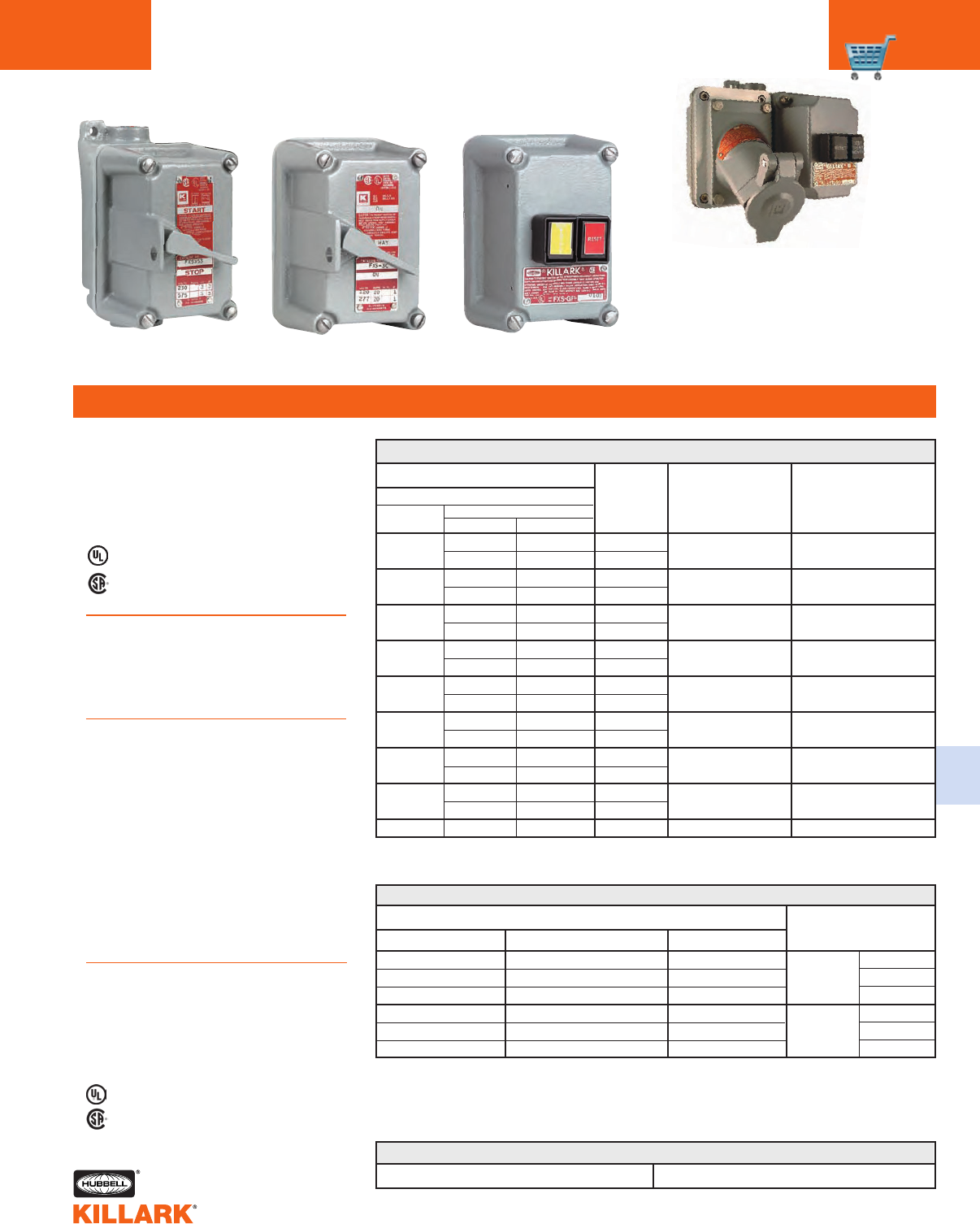
FXS SERIES •CONTROLS
FACTORY SEALED TUMBLER SWITCHES AND
GROUND FAULT INTERRUPTER
FEATURES-SPECIFICATIONS
Tumbler Switches Ground Fault Interrupter
Class I, Div. I & 2, Groups C,D
Class l, Zones 1 & 2, Groups llB,llA
Class II, Div. 1 & 2, Groups E,F,G
Class Ill
NEMA 3, 7(C,D) 9(E,F,G)
For control stations with 1" conduit opening or for double gang assemblies, order cover with device
and box as separate components.
*Boxes and covers shipped separately.
†See page DE25 for additional ground fault control stations.
FXS TUMBLER SWITCHES
1Rated 15 amperes, 240/480 VAC., 3Ø; 3HP-240 VAC., 5 HP-480 VAC.
2Horsepower rated 1 HP at 120 VAC, 2 HP at 240 VAC.
CATALOG NUMBER
FXS GROUND FAULT INTERRUPTER†
Applications
FXS Tumbler Switches are suitable for
applications where making, breaking or
changing connections in an electrical
circuit is required and where conditions
of load do not exceed the switch ratings.
Applications
FXS Ground Fault Interrupters are
designed to interrupt a circuit when a
ground fault is detected on equipment
which may be handled by personnel in
hazardous locations.
Features
•Test and Reset push buttons are
provided on cover assembly. Unit
should be tested monthly
•Includes new GFI to meet latest
UL943 GFCI standards revisions
•Exterior gasket provides NEMA 3
weatherproof protection
•Ground boss for grounding in the
splice box
•Color coded wiring
•Captive cover bolts are made from
stainless steel
COMPLETE UNIT
COVER (BOX, COVER AND SWITCH)
WITH SWITCH DEAD-END FEED-THRU
FXS-11C FXS-41C
FXS-21C FXS-51C
FXS-12C FXS-42C
FXS-22C FXS-52C
FXS-18C FXS-48C
FXS-28C FXS-58C
FXS-13C FXS-43C
FXS-23C FXS-53C
FXS-15C FXS-45C
FXS-25C FXS-55C
FXS-16C FXS-46C
FXS-26C FXS-56C
FXS-11D FXS-41D
FXS-21D FXS-51D
FXS-12D FXS-42D
FXS-22D FXS-52D
——
FXS-1C
FXS-2C
FXS-8C
FXS-3C
FXS-5C
FXS-6C
FXS-1D
FXS-2D
FXS-4C
SWITCH SWITCH RATING
STYLE 120/277 VAC, 1Ø
1-POLE 20 A2
2-POLE 20 A2
3-POLE 1
20 A2
SPDT (Center off) 20 A2
DPDT (No off) 20 A2
1-POLE 30 A2
2-POLE 30 A2
4-WAY 20 A2
3-WAY /
SPDT (No off)
HUB
SIZE
DEAD
END
FEED
THRU
1/2"
3/4"
1"
1/2"
3/4"
1"
CATALOG NUMBER
COMPLETE UNIT COVER ASSEMBLY BACK BOX*
FXS-GFI-1020 FXS-GFIO3 FXB-1
FXS-GFI-2020 FXS-GFIO3 FXB-2
FXS-GFI-3020 FXS-GFIO3 FXB-3
FXS-GFI-1120 FXS-GFIO3 FXB-4
FXS-GFI-2120 FXS-GFIO3 FXB-5
FXS-GFI-3120 FXS-GFIO3 FXB-6
Listed - File E80595
Certified - File LR61895
See files for details or call Killark.
HUB
SIZE
1/2"
3/4"
1/2"
3/4"
1/2"
3/4"
1/2"
3/4"
1/2"
3/4"
1/2"
3/4"
1/2"
3/4"
1/2"
3/4"
—
Listed - File E53360 and/or Ffile E10501
Certified - File LR11714
See files for details or call Killark.
Electrical Rating
GFI units are rated at 20A, 120 VAC,
60HZ. Class A.
4-6 miliamp trip setting
Trip Time-UL Curve
FXS GROUND FAULT INTERRUPTER WITH LED LAMP
CATALOG NUMBER FOR COVER ASSEMBLY FXS-GFIO3PL
* Order FXB back box as seperate item.
For GFI Protection with
receptacle, See page PR26
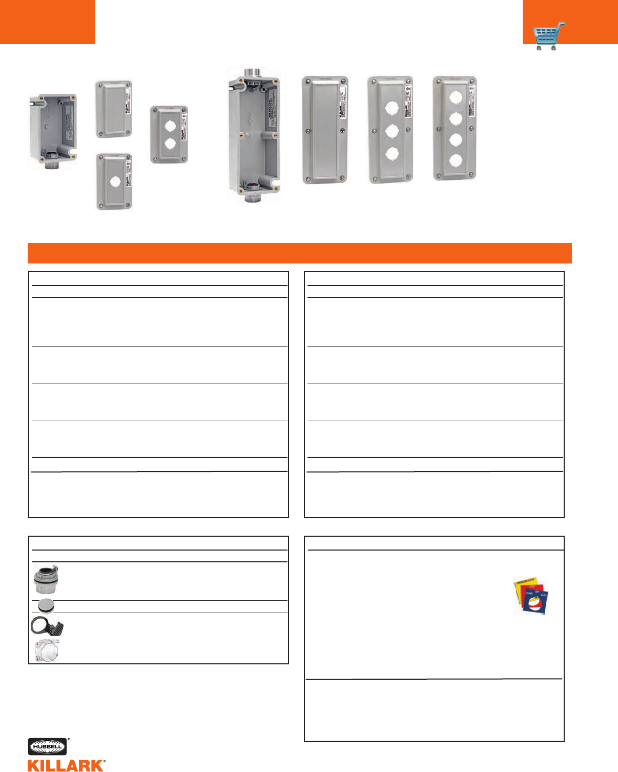
C18 XCS/XS/SWB SERIES •CONTROLS
CONTROL STATIONS EXTERNAL SEALING REQUIRED
FEATURES-SPECIFICATIONS
Applications
•Hazardous locations due to the pres-
ence of flammable gases or vapors,
combustible dusts or easily ignitable
fiber or flyings
•Installations at petroleum refineries,
chemical and petrochemical plants
and other processing or storage facili-
ties where similar hazards exist
•Use in conjunction with magnetic
starters or contactors for remote control
of motors
Features
•Device bodies and covers are cast cop-
perfree Aluminum alloy and provide a
wide assortment for custom assemblies
•Cast conduit hubs 1/2", 3/4" and 1"
either dead end or feed thru standard
in both single and two gang, SWB-1
thru SWB-12 device bodies
•SWB-13 thru SWB-38 are designed for
custom drilled and tapped conduit
openings on all four sides and the back
•Ground flange joint between bolted
cover and box provide required flame
path
•Push button, selector switches and pilot
light operator bodies are copper-free
aluminum
•Operating shaft in both push buttons
and selector switches are stainless
steel
•Open space between gangs for easy
wiring from one cover to another
Listed - File E53360
Certified - File LR11714, LR11712
See files for details or call Killark.
Class I, Div. 1 & 2, Groups C,D
Class l, Zones 1 & 2, Groups llB, IIA
Class II, Div. 1 & 2, Groups E,F,G
Class Ill
NEMA 7(C,D) 9(E,F,G)
•Miniature and standard size push but-
tons. (Miniature 3/4" overall diameter,
standard 1-3/8" overall diameter.)
•Contact blocks are rated heavy duty,
600 VAC max
•Internal ground screw
Electrical Rating
Push button stations, selector switches
heavy duty 600 VAC max.
Pilot lights 120 VAC.
XCS Special Assemblies
To order XCS cover assemblies for use
with multi-gang or 1" hub type SWB Series
splice boxes, simply order as follows:
Example: XCS-0B1 — Cover Assembly
SWB-6 —
Splice box with
1" feed thru hubs
Example: XCS-0B1 — Cover Assembly
XCS-0B24RL
— Cover Assembly
SWB-12 — Double gang
splice box
NOTE: Splice boxes and cover assemblies are
packaged in separate cartons.
CURRENT 125 VAC 250 VAC
INRUSH .55 .275
BREAKING .5 5 .275
CARRYING 2.50 2.5 0
DC RATINGS (MAX. AMPS)
CURRENT 120 VAC 240 VAC 480 VAC 600 VAC
INRUSH 60 30 15 12
BREAKING 631.5 1.2
CARRYING 10 10 10 10
CONTACT BLOCK RATINGS
CATALO G
SUFFIX DESCRIPTION
MODIFICATIONS
AL Pilot light lens-amber
CL Pilot light lens-clear
GL Pilot light lens-green
RL Pilot light lens-red
T2 1Pilot light transformer —
220/110VAC
T4 1Pilot light transformer —
440/110VAC
MR Mushroom head push button
(red)
LO Push button lockout2
LOP Selector switch
padlock-lockout
SU1 Stainless steel cover screws
1One transformer required for each pilot light.
Deep device bodies required for all
except single pilot light units when
transformers are used.
2Push button lockout must be factory installed.
LED lamps available. See page C39.
C19
C
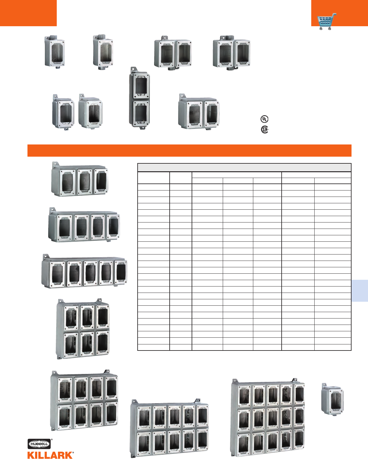
SWB SERIES •CONTROLS
DEVICE FODIES FOR USE WITH XCS/XS/XT COVER ASSEMBLIES
FEATURES-SPECIFICATIONS
2-3/8"(60)
2-3/8"(60)
2-3/8"(60)
2-3/8"(60)
2-3/8"(60)
2-3/8"(60)
2-1/2"(64)
2-1/2"(64)
2-1/2"(64)
2-1/2"(64)
2-1/2"(64)
2-1/2"(64)
2-3/8"(60)
2-3/8"(60)
2-1/8"(54)
5-3/4"(146)
9-3/16"(233)
12-11/16"(322)
16-3/16"(411)
9-3/16"(233)
12-3/4"(324)
16-1/4"(413)
16-1/4"(413)
2-3/8"(60)
2-3/8"(60)
2-3/8"(60)
5-3/8"(137)
5-3/8"(137)
5-3/8"(137)
5-3/8"(137)
5-3/8"(137)
5-3/8"(137)
5-3/8"(137)
5-3/8"(137)
5-3/8"(137)
5-3/8"(137)
5-3/8"(137)
5-3/8"(137)
6-1/8"(156)
6-1/8"(156)
11-3/8"(289)
6"(152)
6"(152)
6"(152)
6"(152)
11-1/8"(283)
11-3/16"(284)
11-5/16"(287)
11-5/16"(287)
6-1/8"(156)
6-1/8"(156)
6-1/8"(156)
2-1/4"(57)
2-1/4"(57)
2-1/4"(57)
2-1/4"(57)
2-1/4"(57)
2-1/4"(57)
2-1/4"(57)
2-1/4"(57)
2-1/4"(57)
2-1/4"(57)
2-1/4"(57)
2-1/4"(57)
2-1/2"(64)
3-5/16"(84)
2-1/2"(64)
3-5/16"(84)
3-5/16"(84)
3-5/16"(84)
3-5/16"(84)
3-5/16"(84)
3-5/16"(84)
3-5/16"(84)
3-5/16"(84)
3-5/16"(84)
3-5/16"(84)
3-5/16"(84)
3"(76)
3"(76)
3"(76)
3"(76)
3"(76)
3"(76)
6-1/2"(165)
6-1/2"(165)
6-1/2"(165)
6-1/2"(165)
6-1/2"(165)
6-1/2"(165)
3-5/8"(92)
3-5/8"(92)
3-5/8"(92)
7-1/8"(181)
10-5/8"(270)
14-1/8"(359)
17-5/8"(448)
10-5/8"(270)
14-1/8"(359)
17-3/4"(451)
17-3/4"(451)
3-5/8" (92)
3-5/8"(92)
3-5/8"(92)
5-7/8"(149)
5-7/8"(149)
5-7/8"(149)
5-7/8"(149)
5-7/8"(149)
5-7/8"(149)
5-7/8"(149)
5-7/8"(149)
5-7/8”(149)
5-7/8"(149)
5-7/8"(149)
5-7/8"(149)
5-1/4"(133)
5-1/4"(133)
10-3/8"(264)
5-1/4"(133)
5-1/4"(133)
5-1/4"(133)
5-1/4"(133)
12"(305)
10-3/8”(264)
12"(305)
17-1/8"(435)
5-1/4"(133)
5-1/4"(133)
5-1/4"(133)
Listed - File E53360
Certified - LR11712
See files for details or call Killark.
Class I, Div. 1 & 2, Groups C,D
Class l, Zones 1 & 2, Groups llB, IIA
Class II, Div. 1 & 2, Groups E,F,G
Class Ill
NEMA 7(C,D) 9(E,F,G)
CATALOG HUB EXTERNAL MOUNTING
NUMBER SIZE LENGTH WIDTH DEPTH VERTICAL HORIZONTAL
SWB-1 1/2"
SWB-2 3/4"
SWB-3 1"
SWB-4 1/2"
SWB-5 3/4"
SWB-6 1"
SWB-7 1/2"
SWB-8 3/4"
SWB-9 1"
SWB-10 1/2"
SWB-11 3/4"
SWB-12 1"
SWB-13 1
SWB-14 2
SWB-17 1
SWB-18 2
SWB-19 2
SWB-20 2
SWB-21 2
SWB-32 2
SWB-33 2
SWB-34 2
SWB-38 2
SWB-42 3/4"
SWB-45 3/4"
SWB-49 3/4"
1Maximum size drilled and tapped opening 1" — Shallow device bodies.
2Maximum size drilled and tapped opening 1-1/2" — Deep device bodies.
3SWB-1 thru SWB-12 Boxes have cast in conduit hubs. Additional conduit openings can not be included.
Use SWB-13-14 or 18 for custom conduit requirements. See following page for custom conduit information.
SWB-13 through SWB-38 boxes are blank
without conduit openings and can be
factory or field installed. See following
page for custom conduit information.
SWB DEVICE BODIES AND DIMENSIONS
SWB-13-14 SWB-18
SWB-19
SWB-20
SWB-17
SWB-33
SWB-34 SWB-38
Dead End
SWB-1-2-3 3
Feed Thru
SWB-4-5-6 3
Dead End
SWB-7-8-9 3
Feed Thru
SWB-10-11-12 3
SWB-32
SWB-42
(3/4" Dead End)
SWB-45
(3/4" Feed Thru)
SWB-48
(Two 1/2"on Bottom)
SWB-49
(Two 3/4"on Bottom)
SWB-21
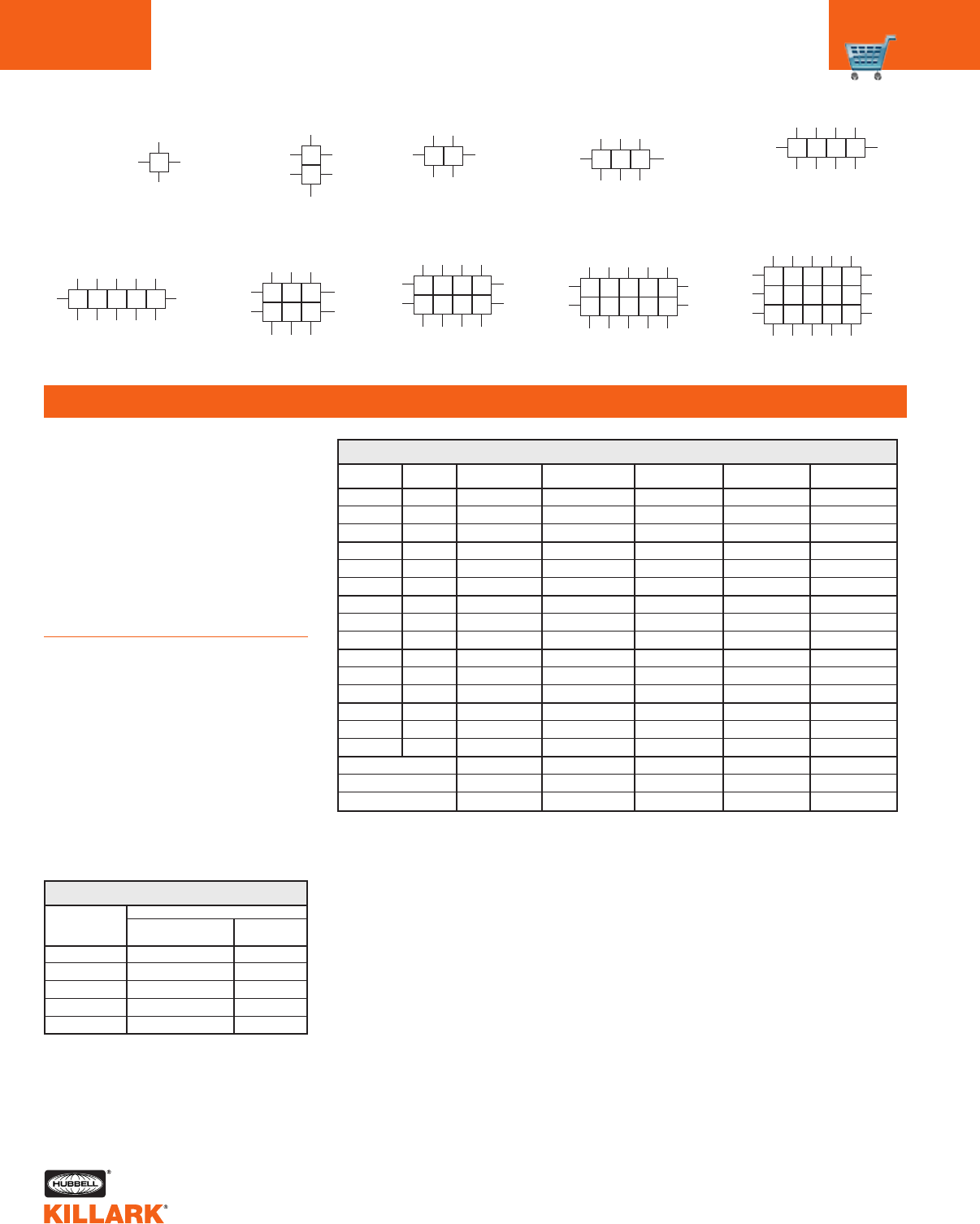
C20 SWB SERIES •CONTROLS
CONDUIT OPENING DATA
FEATURES-SPECIFICATIONS
To specify conduit openings select the
letter on these sketches which indicates
the position desired. All conduit open-
ings will be evenly spaced and located
in the area indicated on the location
chart. When they are to be more accu-
rately located, submit a sketch with
spacing dimensions. Specific conduit
openings must be located dimensional-
ly from box centerlines to conduit cen-
terlines and from outside back surface
of box to conduit centerline.
Ordering Instructions:
(1) Select the letter on location chart
which indicates conduit opening
position desired.
(2) Select symbol number from chart
which indicates conduit opening
type and size.
(3) Combine the conduit location letter,
size and type number, and add as a
suffix to SWB box catalog number.
Example: SWB-18-C1-J1-P1-V1
Conduit Opening Location Charts
11
2
1 2 1 2 3
1 2 3
4 5 6
1 2 3 4
1 2 3 4
5 6 7 8
12345 12345
6 7 8 9 10
12345
6 7 8 9 10
11 12 13 14 15
A BCD E
ABCDE
ABCDE
ABCDE
ABDE
ACE
RPN
ACE
ACE
RPN RPN
RQPON R Q P O N
R Q O N N O P Q R
R QPO N
J
JX
T
X
T
X
T
X
T
X
T
L
G
L
G
L
G
L
G
L
G
V
VJ
J
J
C
P
C
P
J
V
V
VV
SWB-13-14 SWB-17 SWB-18 SWB-19 SWB-20
SWB-21 SWB-32 SWB-33 SWB-34 SWB-38
SIZE FORM 1/2" 3/4" 1" 1-1/4" 1-1/2"
1MIN 1-3/16"(46) ————
2PRE 1-3/8"(35) ————
3GU 1-5/8"(41) ————
1MIN 1-3/8"(35) 1-1/2"(38) ———
2PRE 1-1/2"(38) 1-5/8"(41) ———
3GU 1-3/4"(44) 1-13/16"(46) ———
1MIN 1-1/2"(38) 1-3/4"(44) 1-13/16"(46) ——
2PRE 1-3/4"(44) 1-7/8"(48) 2"(51) ——
3GU 1-7/8"(48) 2"(51) 2-1/8"(54) ——
1MIN 1-11/16"(43) 1-15/16"(49) 2-1/16"(52) 2-5/16"(59) —
2PRE 1-15/16"(49) 2-1/16"(52) 2-1/4"(57) 2-1/2"(64) —
3GU 2-1/16"(52) 2-1/4"(57) 2-5/16"(59) 2-1/2"(64) —
1MIN 1-15/16"(49) 2-1/16"(52) 2-3/16"(56) 2-1/2"(64) 2-5/8"(67)
2PRE 2-1/8"(54) 2-1/4"(57) 2-3/8"(60) 2-5/8"(67) 2-3/4"(70)
3GU 2-3/16"(56) 2-9/32"(58) 7/16"(11) 2-5/8"(67) 2-3/4"(70)
1-1/8"(29) 1-3/8"(35) 1-11/16"(43) 2-3/16"(56) 2-7/16"(62)
1"(25) 1-1/4"(32) 1-1/2"(38) 1-7/8"(48) 2-1/8"(54)
7/8"(22) 1-1/16"(27) 1-3/8"(35) 1-11/16"(43) 1-15/16"(49)
1/2"
1/2"
1/2"
3/4"
3/4"
3/4"
1"
1"
1"
1-1/4"
1-1/4"
1-1/4"
1-1/2"
1-1/2"
1-1/2"
Locknut Bushing Conduit
Locknut Bushing Conduit
Locknut Bushing Conduit
1Minimum spacing required to provide clearance over locknuts and bushings.
2Preferred—more liberal spacings between centers of conduits to be used whenever possible.
3GU—spacing required for GU Series unions.
4Union hubs are supplied by using a drilled and tapped opening with GUM Series Union.
† Consult factory for special or additional conduit sizes, locations, and combinations
required but not illustrated.
MINIMUM HUB CENTERS FOR DRILLED AND TAPPED AND UNION HUBS
CONDUIT OPENINGS
CONDUIT DRILLED
SIZE AND TAPPED UNION4
1/2" 1 11
3/4" 2 12
1" 3 13
1-1/4" 4 14
1-1/2" 5 15
SYMBOL NUMBERS
C21
C
XCS SERIES •CONTROLS
COVER ASSEMBLIES •CONTROL STATIONS
FEATURES-SPECIFICATIONS
CATALOG NUMBER
COMPLETE UNITS (BOX & COVER) HUB DIAGRAM BUTTON NAMEPLATE
COVER WITH DEVICE DEAD-END FEED-THRU SIZE COLOR2MARKING1
XCS-0B1 XCS-1B1 XCS-4B1 1/2" Green Start
XCS-2B1 XCS-5B1 3/4"
XCS-0B2 XCS-1B2 XCS-4B2 1/2" Red Stop
XCS-2B2 XCS-5B2 3/4"
XCS-0B3 XCS-1B3 XCS-4B3 1/2" Black Specify
XCS-2B3 XCS-5B3 3/4"
XCS MOMENTARY CONTACT SINGLE PUSH BUTTON
CATALOG NUMBER
COMPLETE UNITS (BOX & COVER) HUB DIAGRAM BUTTON NAMEPLATE
COVER WITH DEVICE DEAD-END FEED-THRU SIZE COLOR2MARKING1
XCS-0B4 XCS-1B4 XCS-4B4 1/2" Green-Red Start/Stop
XCS-2B4 XCS-5B4 3/4"
XCS-0B4-U XCS-1B4-U XCS-4B4-U 1/2" Green-Red Start/Stop
XCS-2B4-U XCS-5B4-U 3/4"
XCS-0B5 XCS-1B5 XCS-4B5 1/2" Green-Green Start/Start
XCS-2B5 XCS-5B5 3/4"
XCS-0B7 XCS-1B7 XCS-4B7 1/2" Black-Black Specify
XCS-2B7 XCS-5B7 3/4"
XCS MOMENTARY CONTACT DOUBLE PUSH BUTTON
Listed - File E53360
Certified - File LR11714
See files for details or call Killark.
Class I, Div. 1 & 2, Groups C,D
Class I, Zones 1 & 2, Groups IIB, IIA
Class II, Div. 1 & 2, Groups E,F,G
Class Ill
NEMA 7(C,D) 9(E,F,G)
1For other than standard marking, refer to the special feature section of price list.
2Lens colors other than listed may be specified by changing lens color suffix. See modifications page C18.
For control stations with 1" conduit openings or for multi-gang assemblies, order cover with devices and box as separate components.
CATALOG NUMBER
COMPLETE UNITS (BOX & COVER) HUB DIAGRAM BUTTON NAMEPLATE
COVER WITH DEVICE DEAD-END FEED-THRU SIZE COLOR2MARKING1
XCS-0A8 XCS-1A8 XCS-4A8 1/2" Green-Red Start/Stop
XCS-2A8 XCS-5A8 3/4" Black Specify
XCS-0A9 XCS-1A9 XCS-4A9 1/2" Black Specify
XCS-2A9 XCS-5A9 3/4"
XCS MOMENTARY CONTACT THREE MINI PUSH BUTTONS
Single
Push Button
Double
Push Button
Three
Mini-Push Button
• •
• •
• •
• •
• • • •
• •
• • • •
• •
• • • •
• •
• • • •
• •
• •
• •
• •
• •
• •
• •
• •
• •
• • • •
CATALOG NUMBER (COVER WITH DEVICE) DIAGRAM BUTTON COLOR NAMEPLATE MARKING
XCS-OMMG3 GREEN
XCS-OMMR3 RED 3
XCS-OMMK3 BLACK
XCS MAINTAINED CONTACT PUSH PULL MUSHROOM PUSH BUTTON4
3Three nameplates supplied (Start/Stop, Blank, Emergency Stop) with XCS maintained push button.
4Operation - when push button is depressed and contact activated, operator will remain in depressed
position until pulled out in normal position.
Push-Pull
Mushroom Maintained
Push Button
• • • •
C22 XCS SERIES •CONTROLS
COVER ASSEMBLIES •CONTROL STATIONS
FEATURES-SPECIFICATIONS
Listed - File E53360
Certified - File LR11714
See files for details or call Killark.
Class I, Div. 1 & 2, Groups C,D
Class I, Zones 1 & 2, Groups IIB, IIA
Class II, Div. 1 & 2, Groups E,F,G
Class Ill
NEMA 7(C,D) 9(E,F,G)
CATALOG NUMBER NAMEPLATE
COMPLETE UNITS (BOX & COVER) HUB DIAGRAM BUTTON LENS MARKING1
COVER WITH DEVICE DEAD-END FEED-THRU SIZE COLOR COLOR BUTTON LENS
XCS-0A15
XCS-1A15 XCS-4A15 1/2" Red
Red
Stop
Specify
XCS-2A15 XCS-5A15 3/4" 120 VAC Green Start
XCS MOMENTARY CONTACT TWO MINI PUSH BUTTONS AND PILOT LIGHT4
CATALOG NUMBER
COMPLETE UNITS (BOX & COVER) HUB DIAGRAM LAMP LENS NAMEPLATE
COVER WITH DEVICE DEAD-END FEED-THRU SIZE VOLTS COLOR2MARKING1
XCS-0B30CL XCS-1B30CL XCS-4B30CL 1/2" 120V Clear Specify
XCS-2B30CL XCS-5B30CL 3/4"
XCS-0B30GL XCS-1B30GL XCS-4B30GL 1/2" 120V Green Specify
XCS-2B30GL XCS-5B30GL 3/4"
XCS-0B30RL XCS-1B30RL XCS-4B30RL 1/2" 120V Red Specify
XCS-2B30RL XCS-5B30RL 3/4"
XCS-0B30RL-GL XCS-1B30RL-GL XCS-4B30RL-GL 1/2" 120V Red/Green Specify
XCS-2B30RL-GL XCS-5B30RL-GL 3/4"
XCS DOUBLE PILOT LIGHT4
1For other than standard marking, refer to the special feature section of price list.
2Lens color suffix listed in modifications page C18. Unless different lens colors are specified by proper suffix catalog number, red lens will be provided.
3Pilot light transformers also listed in modifications. Add suffix to cover assembly catalog number.
4Pilot light transformers will not fit in these assemblies. When transformer is desired, use SWB-14, indicating conduit openings required from chart on
page C20 of this section. See page C18 for required transformer suffix. One transformer required for each lamp.
For control stations with 1" conduit openings or for multi-gang assemblies, order cover and box as separate components.
CATALOG NUMBER NAMEPLATE
COMPLETE UNITS (BOX & COVER) HUB DIAGRAM BUTTON LENS MARKING1
COVER WITH DEVICE DEAD-END FEED-THRU SIZE COLOR COLOR BUTTON LENS
XCS-0B13-C XCS-1B13-C XCS-4B13-C 1/2" Red Red Stop Specify
XCS-2B13-C XCS-5B13-C 3/4"
XCS-0B13-O XCS-1B13-O XCS-4B13-O 1/2" Green Red Start Specify
XCS-2B13-O XCS-5B13-O 3/4"
XCS-0B13-U XCS-1B13-U XCS-4B13-U 1/2" Black Red Specify Specify
XCS-2B13-U XCS-5B13-U 3/4"
XCS MOMENTARY CONTACT PUSH BUTTON AND PILOT LIGHT4
CATALOG NUMBER
COMPLETE UNITS (BOX & COVER) HUB DIAGRAM LAMP LENS NAMEPLATE
COVER WITH DEVICE DEAD-END FEED-THRU SIZE VOLTS COLOR2MARKING1
XCS-0B24CL XCS-1B24CL XCS-4B24CL 1/2" 120V Clear Specify
XCS-2B24CL XCS-5B24CL 3/4"
XCS-0B24GL XCS-1B24GL XCS-4B24GL 1/2" 120V Green Specify
XCS-2B24GL XCS-5B24GL 3/4"
XCS-0B24RL XCS-1B24RL XCS-4B24RL 1/2" 120V Red Specify
XCS-2B24RL XCS-5B24RL 3/4"
XCS PILOT LIGHT3
Pilot Light
Two Mini Push Buttons
Double
Pilot Light
Pilot Light
Pilot Light
Push Button
• •
• •
• •
• •
• • • •
2
2
C23
C
XCS SERIES •CONTROLS
COVER ASSEMBLIES •CONTROL STATIONS
FEATURES-SPECIFICATIONS
Listed - File E53360
Certified - File LR11714
See files for details or call Killark.
Class I, Div. 1 & 2, Groups C,D
Class I, Zones 1 & 2, Groups IIB, IIA
Class II, Div. 1 & 2, Groups E,F,G
Class Ill
NEMA 7 (C,D) 9(E,F,G)
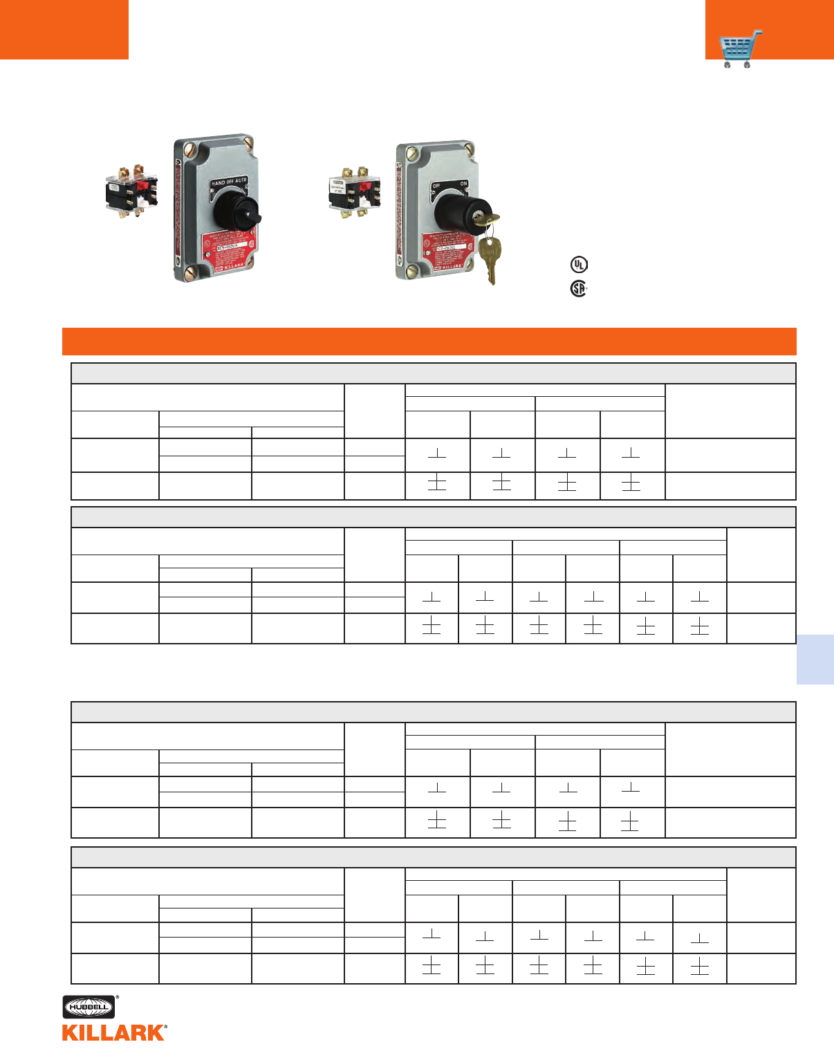
CATALOG NUMBER TWO POSITION DIAGRAM
LEFT POSITION RIGHT POSITION
COVER WITH COMPLETE UNITS (BOX & COVER)
HUB
LEFT RIGHT LEFT RIGHT
NAMEPLATE
DEVICE DEAD-END FEED-THRU
SIZE
BLOCKS BLOCKS BLOCKS BLOCKS
MARKING
XCS-0S2A1 XCS-1S2A1 XCS-4S2A1 1/2" OFF/ON
XCS-2S2A1 XCS-5S2A1 3/4"
XCS-0S2A52XCS-42S2A5 XCS-45S2A5 3/4" OFF/ON
XCS TWO POSITION SELECTOR SWITCH (MAINTAINED)*
CATALOG NUMBER THREE POSITION DIAGRAM
LEFT POSITION CENTER POSITION RIGHT POSITION
COVER WITH COMPLETE UNITS (BOX & COVER)
HUB
LEFT RIGHT LEFT RIGHT LEFT RIGHT
NAMEPLATE
DEVICE DEAD-END FEED-THRU
SIZE
BLOCKS BLOCKS BLOCKS BLOCKS BLOCKS BLOCKS
MARKING
XCS-0S3C4 XCS-1S3C4 XCS-4S3C4 1/2" HOA
XCS-2S3C4 XCS-5S3C4 3/4"
XCS-0S3C52XCS-42S3C5 XCS-45S3C5 3/4" HOA
XCS THREE POSITION SELECTOR SWITCH (MAINTAINED)*
• • • • • •
1For other than standard marking, refer to the special feature section of the price list.
2These sub-assemblies require deep style box SWB-14 or SWB-18 through SWB-49.
For control stations with 1" conduit openings or for multi-gang assemblies, order cover with devices and box as separate components.
• •
• •
• •
• •
• •
• •
• •
• •
• •
• •
• •
• •
CATALOG NUMBER TWO POSITION DIAGRAM
LEFT POSITION RIGHT POSITION
COVER WITH COMPLETE UNITS (BOX & COVER)
HUB
LEFT RIGHT LEFT RIGHT
NAMEPLATE
DEVICE DEAD-END FEED-THRU
SIZE
BLOCKS BLOCKS BLOCKS BLOCKS
MARKING
XCS-0K2A1D XCS-1K2A1D XCS-4K2A1D 1/2" OFF/ON
XCS-2K2A1D XCS-5K2A1D 3/4"
XCS-0K2A5D2XCS-42K2A5D XCS-45K2A5D 3/4" OFF/ON
XCS TWO POSITION KEY OPERATED SELECTOR SWITCH (MAINTAINED)*
• •
CATALOG NUMBER THREE POSITION DIAGRAM
LEFT POSITION CENTER POSITION RIGHT POSITION
COVER WITH COMPLETE UNITS (BOX & COVER)
HUB
LEFT RIGHT LEFT RIGHT LEFT RIGHT
NAMEPLATE
DEVICE DEAD-END FEED-THRU
SIZE
BLOCKS BLOCKS BLOCKS BLOCKS BLOCKS BLOCKS
MARKING
XCS-0K3C4D XCS-1K3C4D XCS-4K3C4D 1/2" HOA
XCS-2K3C4D XCS-5K3C4D 3/4"
XCS-0K3C5D2XCS-42K3C5D XCS-45K3C5D 3/4" HOA
XCS THREE POSITION KEY OPERATED SELECTOR SWITCH (MAINTAINED)*
1For other than standard marking, refer to the special feature section of the price list.
2These sub-assemblies require deep style box SWB-14 or SWB-18 through SWB-49.
For control stations with 1" conduit openings or for multi-gang assemblies, order cover with devices and box as separate components.
* Key removal in all positions for 2 & 3 position key operated selectors. Consult factory for variations.
• •
• •
• •
• •
• •
• •
• •
• •
• •
• •
• •
• •
• •
• •
• •
• •
• •
• •
• •
• •
• •
• •
• • • • • •
• •
• •
• •
• •
• •
• •
• •
• •
• •
• •
• •
Key Operated
Selector Switch
• •
• •
• •
• •
• •
• •
• • • •
1
1
C24 XCS SERIES •CONTROLS
COVER ASSEMBLIES •CONTROL STATIONS
FEATURES-SPECIFICATIONS
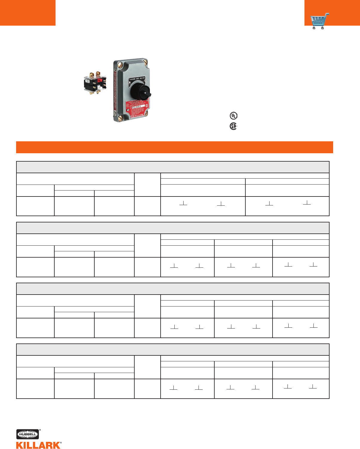
XCS SPRING RETURN SELECTOR SWITCH
Three Position Spring Return to Center From Left, Maintain in Right
CATALOG NUMBER THREE POSITION DIAGRAM
COMPLETE UNITS (BOX & COVER)
DEAD-END
XCS-0S3R6G XCS-42S3R6G XCS-45S3R6G 3/4"
LEFT POSITION CENTER POSITION RIGHT POSITION
FEED-THRU
COVER WITH
DEVICE1
HUB
SIZE
XCS SPRING RETURN SELECTOR SWITCH
Three Position Spring Return to Center From Right, Maintain in Left
CATALOG NUMBER THREE POSITION DIAGRAM
COMPLETE UNITS (BOX & COVER)
DEAD-END
XCS-0S3L6G XCS-42S3L6G XCS-45S3L6G 3/4"
LEFT POSITION CENTER POSITION RIGHT POSITION
FEED-THRU
COVER WITH
DEVICE1
HUB
SIZE
XCS SPRING RETURN SELECTOR SWITCH
Three Position Spring Return to Center From Right and Left
CATALOG NUMBER THREE POSITION DIAGRAM
COMPLETE UNITS (BOX & COVER)
DEAD-END
XCS-0S3M6G XCS-42S3M6G XCS-45S3M6G 3/4"
LEFT POSITION CENTER POSITION RIGHT POSITION
FEED-THRU
COVER WITH
DEVICE1
LEFT
BLOCK
RIGHT
BLOCK
LEFT
BLOCK
RIGHT
BLOCK
LEFT
BLOCK
RIGHT
BLOCK
HUB
SIZE
• • • •
XCS SPRING RETURN SELECTOR SWITCH
Two Position Spring Return to Left
CATALOG NUMBER TWO POSITION DIAGRAM
COMPLETE UNITS (BOX & COVER)
DEAD-END
XCS-0S2L3F XCS-42S2L3F XCS-45S2L3F 3/4"
LEFT POSITION RIGHT POSITION
FEED-THRU
COVER WITH
DEVICE1
LEFT
BLOCK
RIGHT
BLOCK
LEFT
BLOCK
RIGHT
BLOCK
HUB
SIZE
1All spring return assemblies must be installed on deep style box SWB-14 or SWB-18 through SWB-49.
For control stations with 1" conduit openings or for multi-gang assemblies, order cover with devices and box as separate components.
Selector Switch
• • • •
• • • • • • • • • • • •
LEFT
BLOCK
RIGHT
BLOCK
LEFT
BLOCK
RIGHT
BLOCK
LEFT
BLOCK
RIGHT
BLOCK
• • • • • • • • • • • •
LEFT
BLOCK
RIGHT
BLOCK
LEFT
BLOCK
RIGHT
BLOCK
LEFT
BLOCK
RIGHT
BLOCK
• • • • • • • • • • • •
Listed - File E53360
Certified - File LR11714
See files for details or call Killark.
Class I, Div. 1 & 2, Groups C,D
Class I, Zones 1 & 2, Groups IIB, IIA
Class II, Div. 1 & 2, Groups E,F,G
Class Ill
NEMA 7 (C,D) 9(E,F,G)
C25
C
XCS SERIES •CONTROLS
COVER ASSEMBLIES •CONTROL STATIONS
FEATURES-SPECIFICATIONS
XCS KEY OPERATED SPRING RETURN SELECTOR SWITCH1
Three Position Spring Return to Center From Left, Maintain in Right
CATALOG NUMBER THREE POSITION DIAGRAM
COMPLETE UNITS (BOX & COVER)
DEAD-END
XCS-0K3R6G32D XCS-42K3R6G32D XCS-45K3R6G32D 3/4"
LEFT POSITION CENTER POSITION RIGHT POSITION
FEED-THRU
COVER WITH
DEVICE2
HUB
SIZE
XCS KEY OPERATED SPRING RETURN SELECTOR SWITCH1
Three Position Spring Return to Center From Right, Maintain in Left
CATALOG NUMBER THREE POSITION DIAGRAM
COMPLETE UNITS (BOX & COVER)
DEAD-END
XCS-0K3L6G32D XCS-42K3L6G32D XCS-45K3L6G32D 3/4"
LEFT POSITION CENTER POSITION RIGHT POSITION
FEED-THRU
COVER WITH
DEVICE2
HUB
SIZE
XCS KEY OPERATED SPRING RETURN SELECTOR SWITCH1
Three Position Spring Return to Center From Right and Left
CATALOG NUMBER THREE POSITION DIAGRAM
COMPLETE UNITS (BOX & COVER)
DEAD-END
XCS-0K3M6G32D XCS-42K3M6G32D XCS-45K3M6G32D 3/4"
LEFT POSITION CENTER POSITION RIGHT POSITION
FEED-THRU
COVER WITH
DEVICE2
HUB
SIZE
XCS KEY OPERATED SPRING RETURN SELECTOR SWITCH1
Two Position Spring Return to Left
CATALOG NUMBER TWO POSITION DIAGRAM
COMPLETE UNITS (BOX & COVER)
DEAD-END
XCS-0K2L3F22D XCS-42K2L3F22D XCS-45K2L3F22D 3/4"
LEFT POSITION RIGHT POSITION
FEED-THRU
COVER WITH
DEVICE2
HUB
SIZE
1All key operators are furnished keyed different.
If keyed alike is required substitute letter “A” for “D” at end of catalog number.
Keys are removable in left position selectors and in center position for 3 position selectors.
For key removable in all positions change “22” in 2 position to “20” and “32” in 3 position to “30”.
2All spring return assemblies must be installed on deep style box SWB-14 or SWB-18 through SWB-49.
For control stations with 1" conduit openings or for multi-gang assemblies, order cover with devices and box
as separate components.
Key Operated
• • • •
LEFT
BLOCK
RIGHT
BLOCK
LEFT
BLOCK
RIGHT
BLOCK
• • • •
LEFT
BLOCK
RIGHT
BLOCK
LEFT
BLOCK
RIGHT
BLOCK
LEFT
BLOCK
RIGHT
BLOCK
• • • • • • • • • • • •
LEFT
BLOCK
RIGHT
BLOCK
LEFT
BLOCK
RIGHT
BLOCK
LEFT
BLOCK
RIGHT
BLOCK
• • • • • • • • • • • •
LEFT
BLOCK
RIGHT
BLOCK
LEFT
BLOCK
RIGHT
BLOCK
LEFT
BLOCK
RIGHT
BLOCK
• • • • • • • • • • • •
Listed - File E53360
Certified - File LR11714
See files for details or call Killark.
Class I, Div. 1 & 2, Groups C,D
Class I, Zones 1 & 2, Groups IIB, IIA
Class II, Div. 1 & 2, Groups E,F,G
Class Ill
NEMA 7 (C,D) 9(E,F,G)
C26 SEAL X/XCS SERIES •CONTROLS
BLANK ACCESSORIES/REPLACEMENT PARTS
Hole Plug Dust/Weather
Cap
Miniature
Push Button
CAT. NO. DESCRIPTION
X-10 Blank cover
X-60 Cover with (1) 3/4" NPSM Hole1
X-64 Cover with (2) 3/4" NPSM Holes1 2
X BLANK AND SPECIAL COVERS
1For “G” series short operators.
2When X-64 cover is used, one operator
must be a pilot light due to electrical clear-
ances. *1-1/2” diameter
STANDARD PUSH BUTTON ASSEMBLY MINIATURE PUSH BUTTON ASSEMBLY
(1-3/8” DIAMETER) (3/4” DIAMETER)
X-10
Blank Cover
LOCKOUT FOR MAINTAINED
PUSH BUTTON COVERS
XCS-OMMR3
FXCS-OMMR3
CATALOG NUMBER GOMLOCK
CATALOG NUMBER
PUSH BUTTON1SELECTOR HOLE DUST/WEATHER CAP
LOCKOUT LOCKOUT1PLUG1RED GREEN BLACK
DESCRIPTION
XLOB G0-567-LOK XOBP XDBR XDBG XDBB Standard operator
XLOA — XOAP ———Miniature operator
ACCESSORIES
CATALOG NUMBER DESCRIPTION
XCSNPPB XCS/FXCS full size (standard) push button
XCSNPPBM XCS/FXCS miniature push button
XCSNPPL XCS/FXCS pilot light
XCSNPSS2 XCS/FXCS 2 position selector switch
XCSNPSS3 XCS/FXCS 3 position selector switch
XCS REPLACEMENT BLANK NAMEPLATES
1Replacement only by qualified person. Operator is staked into position at factory.
Removal may damage operator or cover threads.
Miniature
Lockout
Selector
Lockout
Standard
Lockout GOM Lockout
Standard
Push Button
(Mushroom)
RED
XO1BR
XO3BR
XO5BR
GREEN
XO1BG
XO3BG
—
BLACK
XO1BK
XO3BK
—
CATALOG NUMBER
RED
XO1AR
XO3AR
—
GREEN
XO1AG
XO3AG
—
BLACK
XO1AK
XO3AK
—
SHROUD
Full
Half
Mushroom*
XCS PILOT LIGHT OPERATOR ASSEMBLY1
CATALOG NUMBER
RED GREEN CLEAR AMBER
XO21BR XO21BG XO21BC XO21BA Standard
Pilot Light
SHROUD
C27
C
SEAL X/XCS SERIES •CONTROLS
ACCESSORIES/REPLACEMENT PARTS
Contact Block
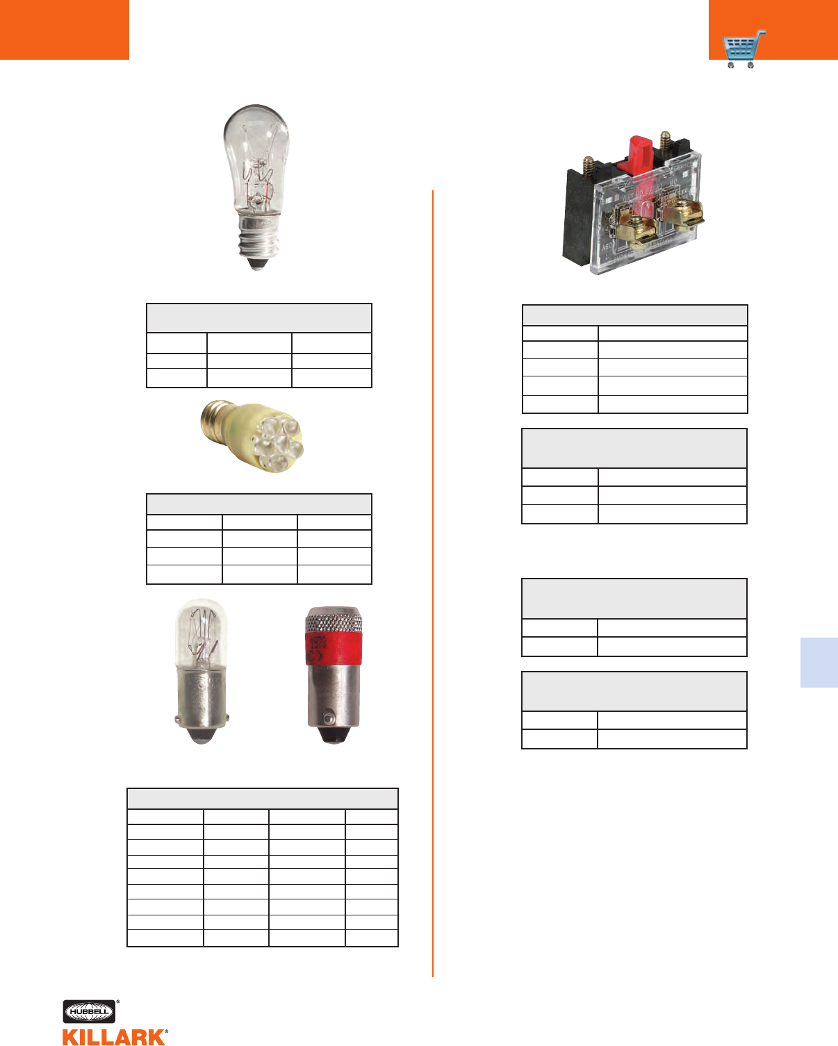
Incandescent
Filament Lamp
LED Lamp
Incandescent
Filament Lamp
LED Lamp
CAT. NO. VOLT COLOR
0460051B 120V AC/DC CLEAR
0460414B 24V AC/DC CLEAR
INCANDESCENT LAMP
CANDELABRA SCREW BASE
CAT. NO. VOLT COLOR
XCSLED-R110 120 VAC RED
XCSLED-G110 120 VAC GREEN
XCSLED-A110 120 VAC AMBER
XCS-FXCS LED LAMPS
CAT. NO. DESCRIPTION
GO-8672-BJK 1 N.O.
GO-8672-BJJ 1 N.O.
GO-8672-BJH 1 N.O. Early Make
GO-8672-BJE 1 N.C. Late Make
STANDARD CONTACT BLOCKS
CAT. NO. DESCRIPTION
YOWE-OT2B 1 N.O.
YOWE-OT2D 1 N.C.
CONTACT BLOCKS FOR XCS SERIES
CATALOG NUMBERS ENDING WITH
B4-U, B7, A8 OR A9
CAT. NO. DESCRIPTION
GO-8672-PTCH (1) N.O. (1) N.C.
CONTACT BLOCK FOR FXCS SERIES
CATALOG NUMBERS ENDING WITH
B-13U
CAT. NO. DESCRIPTION
GO-8672-PTCC (2) N.O. (2) N.C.
CONTACT BLOCK FOR FXCS SERIES
CATALOG NUMBERS ENDING WITH
B4-U, B7, A5, C5
CAT. NO. LAMP TYPE VOLTS AC/DC COLOR
YOSY24MB FILAMENT 24 CLEAR
YOSY120MB FILAMENT 120 CLEAR
GOLED-A110 LED 110 AMBER
GOLED-G110 LED 110 GREEN
GOLED-R110 LED 110 RED
GOLED-A24 LED 24 AMBER
GOLED-G24 LED 24 GREEN
GOLED-R24 LED 24 RED
XCS-FXCS LAMPS
C28
FEATURES-SPECIFICATIONS
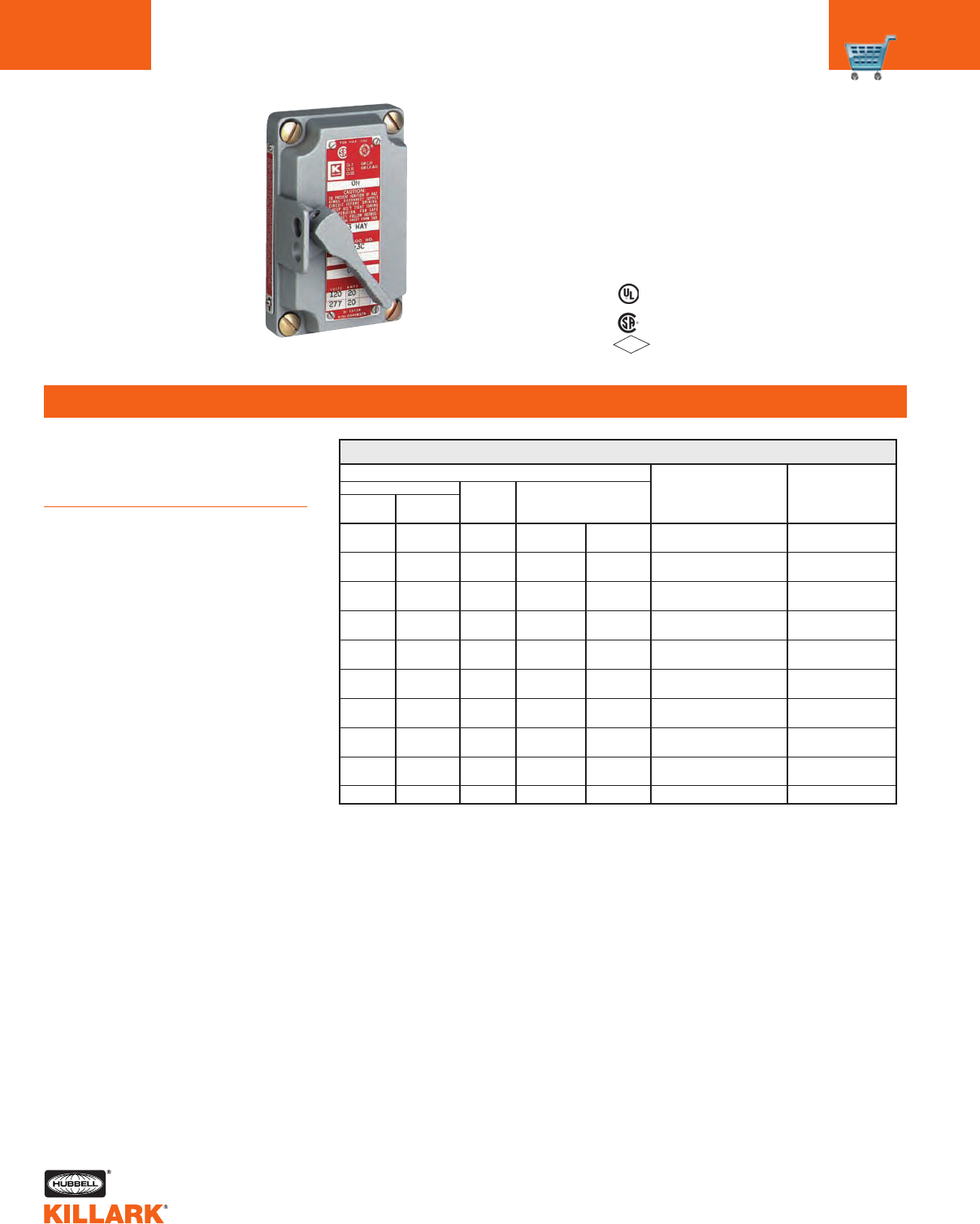
XS SERIES •CONTROLS
TUMBLER SWITCH
Class I, Div. 1 & 2, Groups C,D
Class l, Zones 1 & 2, Groups llB, llA
Class II, Div. 1 & 2, Groups E,F,G
Class Ill
NEMA 7(C,D) 9(E,F,G)
Applications
Used where making, breaking, or
changing connections in an electric cir-
cuit are required.
Features
XS Series are front lever rotary operat-
ed switch assemblies with standard
provisions for padlocking in either “ON”
or “OFF” position. The lever is connect-
ed to a threaded stainless steel shaft
which passes through the cover.
XS TUMBLER SWITCH
1Rated 15 amperes, 240/480 VAC., 3Ø: 3HP-240 VAC., 5 HP-480 VAC.
2Horsepower rated 1 HP at 120VAC, 2 HP at 240VAC.
SWITCH SWITCH RATING
STYLE 120/277 VAC, 1Ø
1-POLE 20A2
2-POLE 20A2
3-POLE 1
3-WAY / 20A2
SPDT No center off
SPDT 20A2
Center off
DPDT 20A2
No center off
DPDT 20A2
Center off
1-POLE 30A2
2-POLE 30A2
4-WAY 20A2
CATALOG NUMBER
COVER COMPLETE UNITS
WITH WITHOUT HUB (BOX, COVER AND SWITCH)
DEVICE DEVICE SIZE DEAD-END FEED-THRU
XS-1C XNS-1C 1/2" XS-11C XS-41C
3/4" XS-21C XS-51C
XS-2C XNS-2C 1/2" XS-12C XS-42C
3/4" XS-22C XS-52C
XS-8C XNS-8C 1/2" XS-18C XS-48C
3/4" XS-28C XS-58C
XS-3C XNS-3C 1/2" XS-13C XS-43C
3/4" XS-23C XS-53C
XS-5C XNS-5C 1/2" XS-15C XS-45C
3/4" XS-25C XS-55C
XS-6C XNS-6C 1/2" XS-16C XS-46C
3/4" XS-26C XS-56C
XS-7C XNS-7C 1/2" XS-17C XS-47C
3/4" XS-27C XS-57C
XS-1D XNS-1D 1/2" XS-11D XS-41D
3/4" XS-21D XS-51D
XS-2D XNS-2D 1/2" XS-12D XS-42D
3/4" XS-22D XS-52D
XS-4C — ———
XS-3C
Certified - File LR11712
See files for details or call Killark.
Listed - FILE E53360
File OP7A5.AE
FM
APPROVED
C29
FEATURES-SPECIFICATIONS
C
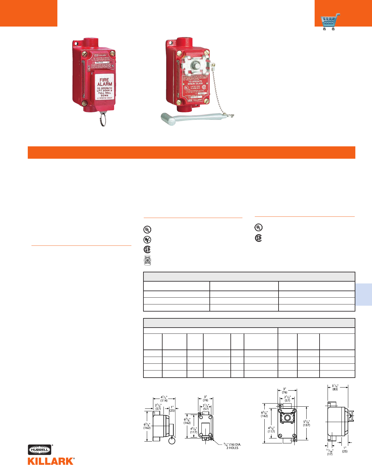
XAL/XAS SERIES •CONTROLS
FIRE ALARM STATIONS
Class I, Div. 1 & 2, Groups C,D
Class l, Zones 1 & 2, Groups llB, llA
Class II, Div. 1 & 2, Groups E,F,G
Class Ill
NEMA 7(C,D) 9(E,F,G)
XAS: Breaking glass with hammer pro-
vided activates alarm. Reset by replac-
ing glass.
Replacement glass catalog number
YOKK-15214.
Replacement hammer and chain
KIT-232.
XAS Series:
XAL-53
Dimensions
XAS-53
AC DC
CONTINUOUS CONTINUOUS
VOLTS MAKE VA BREAK VA CARRYING VOLTS MAKE CARRYING
AMPERES AMPERES AMPERES BREAK AMPERES
120 60 7200 6 720 10 125 1.1 2.5
240 30 7200 3 720 10 250 0.55 2.5
480 15 7200 1.5 720 10 600 0.2 2.5
600 12 7200 1.2 720 10 —— —
CONTACT BLOCK RATING
XAL FIRE ALARM STATION
Applications
•Hazardous areas due to the pres-
ence of flammable gases or vapors,
combustible dusts or easily ignitable
fibers or flyings
•Installation at petroleum refineries,
chemical and petrochemical plants,
storage areas, and other processing
facilities where hazardous sub-
stances are handled or stored
•Areas where emergency control of
fire alarm or signal circuits is required
Features
•Enclosure is made of copper free alu-
minum alloy
•Conduit openings are 3/4" NPT feed
through
•Red, textured powder epoxy paint
finish is standard on box and cover
and provides high visibility for alarm
station
•XAL-458 has (2) normally open and
(2) normally closed contacts.
•Bilingual nameplates included per
CSA requirement
•Internal ground screw is standard
Listed - File E50498
Certified - File LR31085
Listed - CE69
Listed - California State Fire Marshall
#7150-1439:100
Operation
XAL: The alarm station is activated by
lifting the front cover and pulling down
ring. This quick, easy to use two-step
process prevents unintentional opera-
tion. Operator is reset by depressing
shaft and returning plate to original
position.
XAL Series:
Listed - File E50498
Certified - File LR31085
See files for details or call Killark.
Note: On XAL-458 the overall depth is 5-9/16”
CATALOG NUMBER OPERATION TYPE CONTACT BLOCKS
XAL-53 Pull ring (1) NO/NC
XAL-458 Pull ring (2) NO/NC
XAS-53 Break glass (1) NO/NC
XAL
Pull Ring
XAS
Break Glass
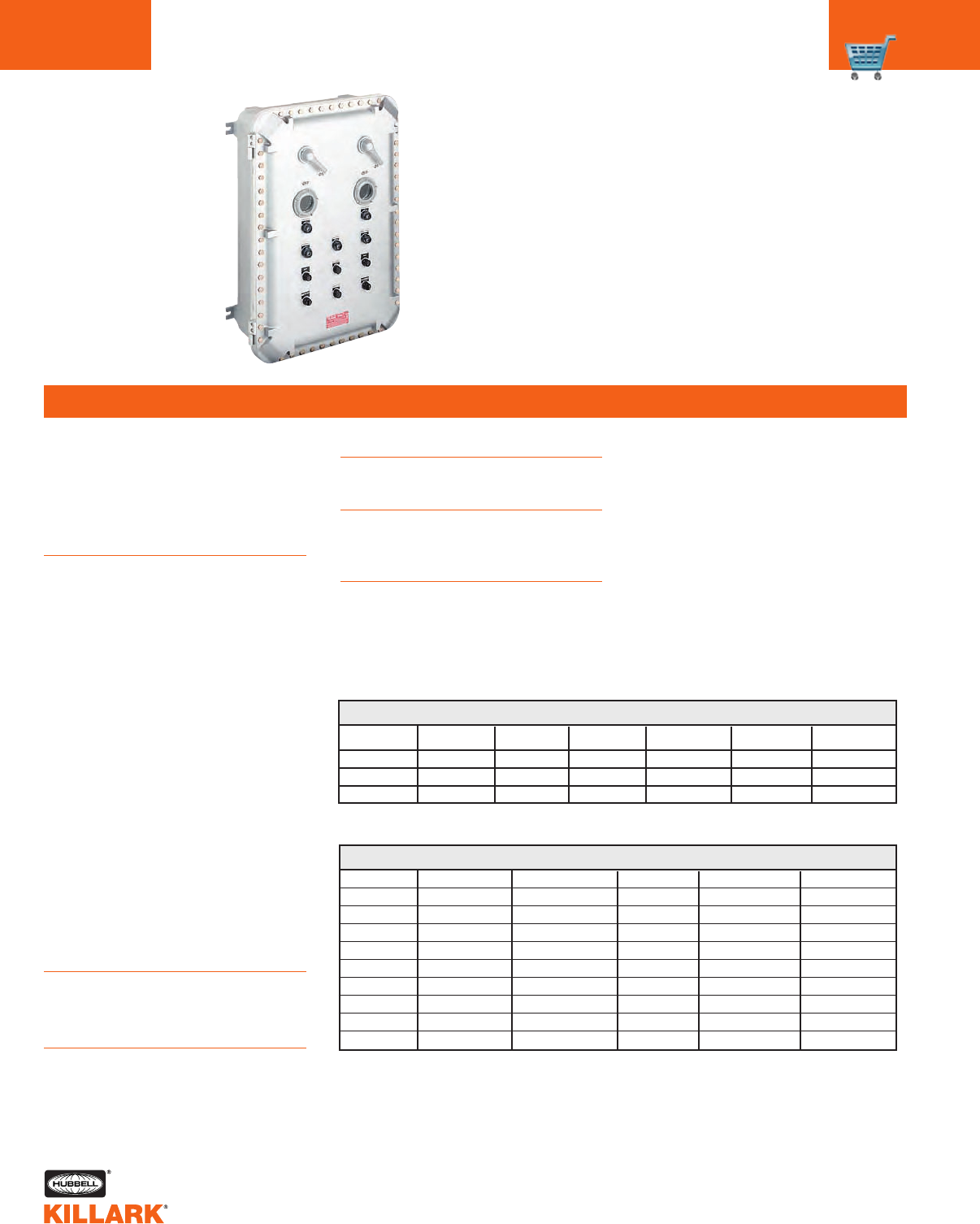
C30
Short Style
DB/SWB/GCS Enclosures. Assemblies
with wall thickness up to 1/2" thick.
Long Style
All B7E/XJB Enclosures. EXB (see page
E12) enclosures with cover thickness
up to 1-1/2” thick.
Extended Style
EXB larger size enclosures (see page
E12) with cover thickness up to 2-1/2”
thick.
Killark long and extended push but-
tons, selector switches, reset and
G SERIES •CONTROLS
CUSTOM CONTROL PANEL OPERATORS INTRODUCTION
FEATURES-SPECIFICATIONS
CURRENT 120 VAC 240 VAC 480 VAC 600 VAC 125 VDC 250 VDC
Inrush 60 30 15 12 .55 .275
Breaking 631.5 1.2 .55 .275
Carrying 10 10 10 10 2.50 2.50
CONTACT BLOCK RATINGS
Note: Contact blocks can be stacked four deep maximum.
AREA CLASSIFICATION CHART FOR OPERATORS
1Class II Div. 1 & 2 Group EFG NEMA 9EFG
2Class I Div. 1 & 2 Group CD, Class II Div. 1 & 2 Group EFG, Class III NEMA 7CD, 9EFG
3Class I Div. 1 & 2 Group BCD, Class II Div. 1 & 2 Group EFG, Class III NEMA 3, 4, 7BCD, 9EFG
4Class I Div. 1 & 2 Group BCD, Class II Div. 1 & 2 Group EFG, Class III NEMA 3, 4, 4X, 7BCD, 9EFG
5Class I Div. 1 & 2 Group CD, Class II Div. 1 & 2 Group EFG, Class III NEMA 3, 4, 7CD, 9EFG
Recommended Operator SelectionApplications
G Series custom control panel opera-
tors are designed for use in hazardous
locations when installed in suitable
enclosures such as B7E EXB, XJB, DB,
SWB and GCS Series boxes and B7,
Y7 Starter Enclosures.
Features
•Operators are all aluminum except
for certain movable parts which are
stainless steel, all other parts such as
screws are either stainless steel or
plated steel
•Threaded bodies are all 3/4"-14
NPSM thread
•Control stations can be grouped into
a single assembly thus reducing
installation time and cost
•Junction boxes may be used to
mount operators along with glass
lens for viewing internally mounted
meters. Additional relays, timers, ter-
minal blocks, or other equipment
may also be internally mounted to
provide a single centralized control
unit.
•Custom operators other than
standard assemblies listed may be
ordered by proper catalog number
from custom operator ordering
system pages C40 & C41
Electrical Rating
Push button stations, selector switches
Heavy duty 600 VAC max.
Pilot lights 120 VAC.
Dimensions
See Dimensional information for
G Series operators on page C42.
Class I, Div. 1 & 2, Groups B,C,D
Class I, Zones 1 & 2, Groups llB, llA
Class II, Div. 1 & 2, Groups E,F,G
Class Ill
NEMA 3, 4, 4X, 7(B,C,D) 9(E,F,G)
See Area Classification Chart below
potentiometer operators are CEN-
ELEC/ATEX EExd IIB+H2 when installed
in series EXB*CEN and GR*CEN enclo-
sures.
For pilot lights and illuminated push but-
tons in CENELEC/ATEX applications see
page C33.
GO14
GO24
GO54
GO64
GO74
GO83
GO104
GO144
GO154
GO162
GO172
GO182
GO192
GO212
GO222
GO232
GO252
GO262
GO272
GO282
GO302
GO342
GO352GO363
GO373
GO383
GO393
GO401
GO502
G0512
GO562
GO572
GO582
GO592
GO1133
GO1143
GO1332
GO1342
GOB34
GOB44
GOL14
GOL24
GOL34
GOL44
GOL54
GOL64
GOL74GOL83
GOL144
GOL154
GOL363
GOL374
GOL383
GOL393
GOL1133
GOL1143
GOLRST4
GOM15
GOR114
GORST4
GO113882
GO113722
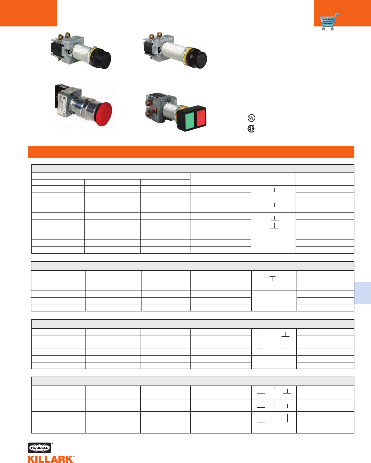
G SERIES •CONTROLS
PUSH BUTTONS C31
FEATURES-SPECIFICATIONS
C
G SINGLE PUSH BUTTON (MOMENTARY CONTACT)
CATALOG NUMBER1COLOR
Green
Black
Red
Black
Green
Red
Black
Green
Red
Black
CONTACT TYPE3
Start or Stop
Reset or Blank
Start or Stop
Reset or Blank
Reset or Blank
Reset or Blank
Reset or Blank
Reset or Blank
Reset or Blank
Reset or Blank
GO1-GX1B N34
GO1-KX1C N34
GO1-RX2B N34
GO1-KX2C N34
GO1-GX3C N34
GO1-RX3C N34
GO1-KX3C N34
GO1-GX0C N34
GO1-RX0C N34
GO1-KX0C N34
GOL1G1
GOL1K1
GOL1R2
GOL1K2
GOL1G3
GOL1R3
GOL1K3
GOL1G
GOL1R
GOL1K
None
GO21-GZ1B
GO21-KZ1C
GO21-RZ2B
GO21-KZ2C
GO21-GZ3C
GO21-RZ3C
GO21-KZ3C
GO21-GZ0C
GO21-RZ0C
GO21-KZ0C
SHORT4LONG EXTENDED NAMEPLATE MARKING2
G DOUBLE PUSH BUTTON (MOMENTARY CONTACT)
Start/Stop or Blank
Start/Stop or Blank
Start/Stop or Blank
Start/Stop or Blank
Start/Stop or Blank
Start/Stop or Blank
GO22-GR12D
GO22-KK12D
GO22-GR33D
GO22-KK33D
GO22-GR00D
GO22-KK00D
G02-GR12D N34
G02-KK12D N34
G02-GR33D N34
G02-KK33D N34
G02-GR00D N34
G02-KK00D N34
GOL2GR12
GOL2KK12
GOL2GR33
GOL2KK33
GOL2GR
GOL2KK
Listed - File E12379
Certified - File LR11714
See files for details or call Killark.
Class I, Div. 1 & 2, Groups B,C,D4
Class I, Zones 1 & 2, Groups llB, llA
Class II, Div. 1 & 2, Groups E,F,G
Class Ill
NEMA 3, 4, 4X, 7(B,C,D) 9(E,F,G)
See Area Classification Chart
page C40 for Details
G DOUBLE PUSH BUTTON (MAINTAINED CONTACT)5
Start/Stop or Blank
Start/Stop or Blank
Start/Stop or Blank
Start/Stop or Blank
—
—
—
—
—
—
—
—
GOR11-GR6D N34
GOR11-GR7D N34
GOR11-GR8D N34
GOR11-GR0D N34
1Refer to catalog page C30 to select proper operator for enclosure, pages C38 & C39 for accessories, page C30 for complete details on
Area Classification of operators, page C42 for Dimensional information.
2Nameplates are double sided.
3Contact Blocks are shown in their normal position.
4Short style operators are suitable for Class l Group C & D, Class ll Group E,F,G only.
5When pressed, the green button will remain in a depressed position. Pressing red button releases green from the depressed position.
• •
• •
• •
• •
Green/Red
Black/Black
Green/Red
Black/Black
Green/Red
Black/Black
• •
• • • •
• •
None
• • • •
None
Green/Red
Green/Red
Green/Red
Green/Red
• • • •
• • • •
• •
• •
• •
• •
Double Push Button
Single Push Button
Long
Single Push Button
Extended
“G” Series Operator
Maintained
G SINGLE PUSH BUTTON (MAINTAINED CONTACT) MUSHROOM HEAD PUSH - PULL OPERATION
Blank
Blank
Blank
Blank
Blank
Blank
GOM21-GM3C
GOM21-RM3C
GOM21-KM3C
GOM21-GM0C
GOM21-RM0C
GOM21-KM0C
GOM1-GM3C N34
GOM1-RM3C N34
GOM1-KM3C N34
GOM1-GM0C N34
GOM1-RM0C N34
GOM1-KM0C N34
GOML1G3
GOML1R3
GOML1K3
GOML1G
GOML1R
GOML1K
Green
Red
Black
Green
Red
Black
• •
• •
None
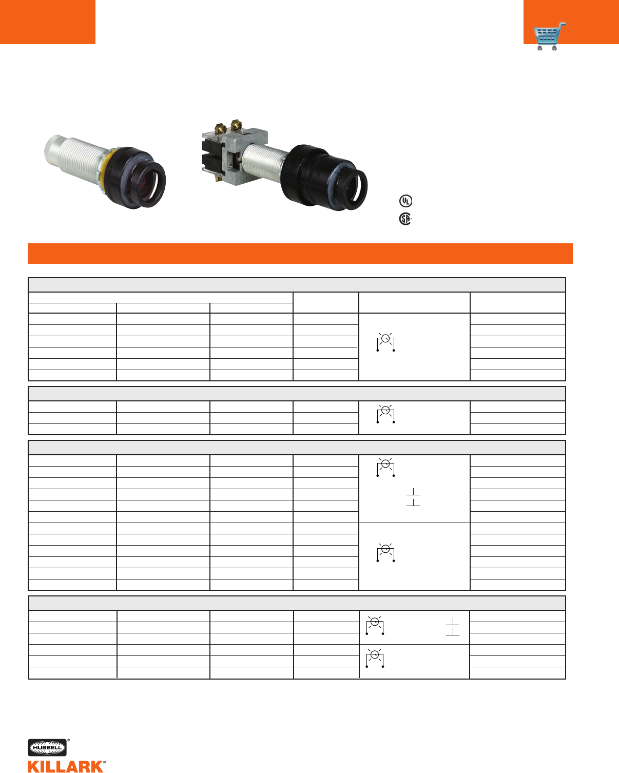
GS SERIES •CONTROLS
PILOT LIGHTS
C32
FEATURES-SPECIFICATIONS
GOL4A3
GOL4B3
GOL4C3
GOL4F3
GOL4G3
GOL4R3
GOL4A
GOL4B
GOL4C
GOL4F
GOL4G
GOL4R
G PILOT LIGHTS
CATALOG NUMBER1
COLOR
Amber
Blue
Clear
Frosted
Green
Red
CONTACT TYPE3
Blank
Blank
Blank
Blank
Blank
Blank
GOL3A
GOL3B
GOL3C
GOL3F
GOL3G
GOL3R
110-120 Volts
Full Volts
GOB3-A23C N34
GOB3-B23C N34
GOB3-C23C N34
GOB3-F23C N34
GOB3-G23C N34
GOB3-R23C N34
SHORT4LONG EXTENDED NAMEPLATE MARKING2
GO23-A23C
GO23-B23C
GO23-C23C
GO23-F23C
GO23-G23C
GO23-R23C
G ILLUMINATED BUTTON OR PUSH TO TEST PILOT LIGHT
Amber
Blue
Clear
Frosted
Green
Red
Amber
Blue
Clear
Frosted
Green
Red
Blank
Blank
Blank
Blank
Blank
Blank
Blank
Blank
Blank
Blank
Blank
Blank
110-120 Volts
No Contact
Blocks
GOB4-A233C N34
GOB4-B233C N34
GOB4-C233C N34
GOB4-F233C N34
GOB4-G233C N34
GOB4-R233C N34
GOB4-A230C N34
GOB4-B230C N34
GOB4-C230C N34
GOB4-F230C N34
GOB4-G230C N34
GOB4-R230C N34
—
—
—
—
—
—
—
—
—
—
—
—
1Refer to catalog page C30 to select proper operator for enclosure, pages C38 & C39 for accessories, page C30 for com
plete details on Area Classification of operators, page C42 for Dimensional information.
2Nameplates are double sided.
3Contact Blocks are shown in their normal position.
4Short style operators are suitable for Class l Group C & D, Class ll Group E,F,G only.
Listed - File E12379
Certified - File LR11714
See files for details or call Killark.
Class I, Div. 1 & 2, Groups B,C,D4
Class I, Zones 1 & 2, Groups llB, llA
Class II, Div. 1 & 2, Groups E,F,G
Class Ill
NEMA 3, 4, 4X, 7(B,C,D) 9(E,F,G)
See Area Classification Chart
page C40 for Details
G ILLUMINATED BUTTON OR PUSH TO TEST PILOT LIGHT WITH LED 110 VOLT LAMPS
Amber
Green
Red
Amber
Green
Red
Blank
Blank
Blank
Blank
Blank
Blank
110-120 Volts (LED)
No Contact Blocks
GOB4-A233C N34 LED
GOB4-G233C N34 LED
GOB4-R233C N34 LED
GOB4-A230C N34 LED
GOB4-G230C N34 LED
GOB4-R230C N34 LED
—
—
—
—
—
—
G PILOT LIGHTS WITH LED 110 VOLT LAMPS
Amber
Green
Red
Blank
Blank
Blank
GOB3-A23C N34 LED
GOB3-G23C N34 LED
GOB3-R23C N34 LED
—
—
—
GOL3A LED
GOL3G LED
GOL3R LED
GOL4A3 LED
GOL4G3 LED
GOL4R3 LED
GOL4A LED
GOL4G LED
GOL4R LED
110-120 Volts
Full Volts (LED)
110-120 Volts
Full Volts
• •
• •
110-120 Volts
Full Volts (LED) • •
• •
Pilot Light Illuminated Button

G SERIES •CONTROLS
PILOT LIGHTS FOR ATEX/CENELEC APPLICATIONS C33
FEATURES-SPECIFICATIONS
C
G PILOT LIGHTS
CATALOG NUMBER1COLOR
Amber
Blue
Clear
Frosted
Green
Red
CONTACT TYPE3
Blank
Blank
Blank
Blank
Blank
Blank
GOL3ACN
GOL3BCN
GOL3CCN
GOL3FCN
GOL3GCN
GOL3RCN
110-120 Volts
Full Volts
GOB3-A23C N34CN
GOB3-B23C N34CN
GOB3-C23C N34CN
GOB3-F23C N34CN
GOB3-G23C N34CN
GOB3-R23C N34CN
LONG EXTENDED NAME PLATE MARKING2
G ILLUMINATED PUSH BUTTON OR PUSH TO TEST PILOT LIGHT
Amber
Blue
Clear
Frosted
Green
Red
Amber
Blue
Clear
Frosted
Green
Red
Blank
Blank
Blank
Blank
Blank
Blank
Blank
Blank
Blank
Blank
Blank
Blank
110-120 Volts
No Contact
Blocks
GOB4-A233CN34CN
GOB4-B233CN34CN
GOB4-C233CN34CN
GOB4-F233CN34CN
GOB4-G233CN34CN
GOB4-R233CN34CN
GOB4-A230CN34CN
GOB4-B230CN34CN
GOB4-C230CN34CN
GOB4-F230CN34CN
GOB4-G230CN34CN
GOB4-R230CN34CN
1Refer to catalog page C30 to select proper operator for enclosure, pages C38 & C39 for accessories, page C30 for
complete details on Area Classification of operators, page C42 for Dimensional information.
2Nameplates are double sided.
3Contact Blocks are shown in their normal position.
NOTE: British standards BSEN50014 and EN50018 have special marking and relamping
demands that require modifications to the standard Killark Pilot Lights. Pilots lights
and illuminated push buttons on this page must be used for enclosures that are mod-
ified to meet ATEX/CENELEC.
Listed - File E12379
Certified - File LR11714
PTB No. 03ATEX 1203 U
Class I, Div. 1 & 2, Groups B,C,D
Class I, Zones 1 & 2, Groups llB+H2, llA
Class II, Div. 1 & 2, Groups E,F,G
Class Ill
NEMA 3, 4, 4X, 7(B,C,D) 9(E,F,G)
ATEX-EExd IIB + H2
G ILLUMINATED PUSH BUTTON OR PUSH TO TEST PILOT LIGHT WITH LED 110 VOLT LAMPS
Amber
Green
Red
Amber
Green
Red
Blank
Blank
Blank
Blank
Blank
Blank
110-120 Volts (LED)
No Contact Blocks
GOB4-A233CN34LEDCN
GOB4-G233CN34LEDCN
GOB4-R233CN34LEDCN
GOB4-A230CN34LEDCN
GOB4-G230CN34LEDCN
GOB4-R230CN34LEDCN
G PILOT LIGHTS WITH LED 110 VOLT LAMPS
Amber
Green
Red
Blank
Blank
Blank
GOB3-A23C N34LEDCN
GOB3-G23C N34LEDCN
GOB3-R23C N34LEDCN
GOL3ALEDCN
GOL3GLEDCN
GOL3RLEDCN
GOL4A3LEDCN
GOL4G3LEDCN
GOL4R3LEDCN
GOL4A0LEDCN
GOL4G0LEDCN
GOL4R0LEDCN
110-120 Volts
Full Volts (LED)
110-120 Volts
Full Volts
• •
• •
110-120 Volts
Full Volts (LED) • •
• •
Pilot Light ATEX Illuminated Push Button ATEX
GOL4A3CN
GOL4B3CN
GOL4C3CN
GOL4F3CN
GOL4G3CN
GOL4R3CN
GOL4A0CN
GOL4B0CN
GOL4C0CN
GOL4F0CN
GOL4G0CN
GOL4R0CN
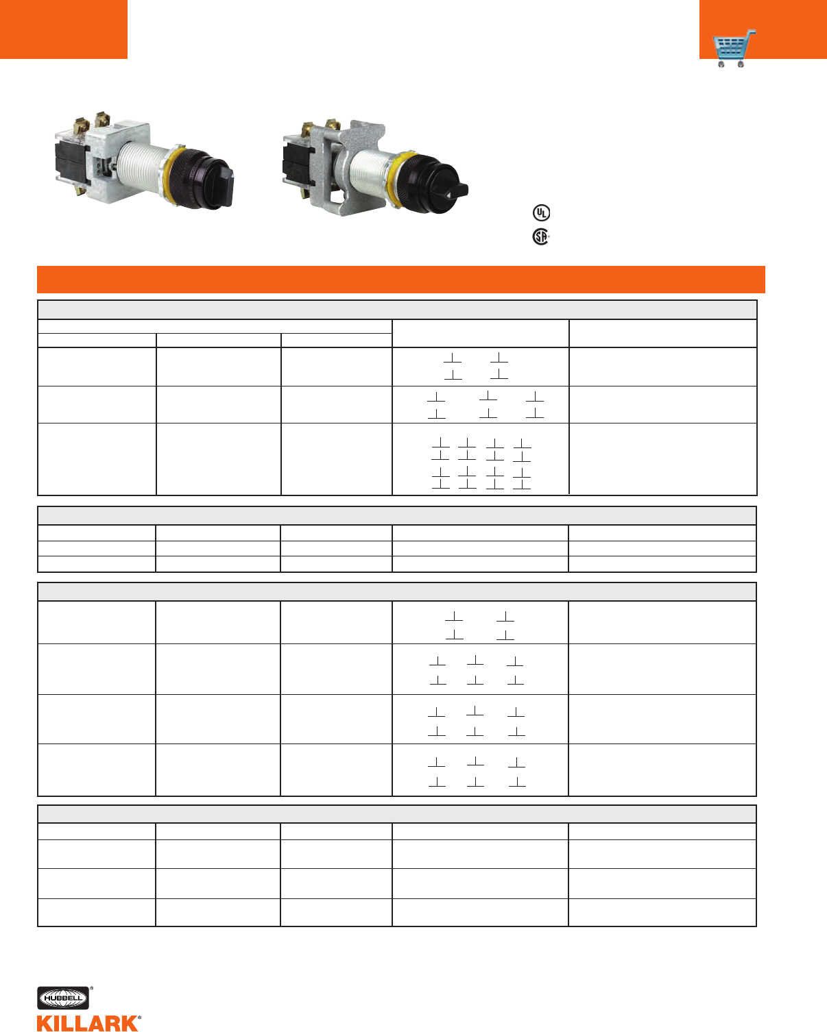
G SERIES •CONTROLS
SELECTOR SWITCHES
C34
G SELECTOR SWITCH MAINTAINED CONTACT WITHOUT CONTACTS
G025-2A0F
G025-3C0G
G025-4H0H
G0L52A
G0L53C
G0L54H
G05-2A0F N34
G05-3C0G N34
G05-4H0H N34
Two position
Three position
Four position
None
None
None
G SELECTOR SWITCH SPRING RETURN WITHOUT CONTACTS
G026-0F
G027-0G
G034-0G
G035-0G
G0L6
G0L7
G0L14
G0L15
G06-0F N34
G07-0G N34
G014-0G N34
G015-0G N34
Two position spring return to left
Three position spring return to
center from right or left
Three position spring return to
center from right, maintain in left
Three position spring return to
center from left, maintain in right
None
None
None
None
G SELECTOR SWITCH MAINTAINED CONTACT
CATALOG NUMBER1
CONTACT ARRANGEMENT3
SHORT4LONG EXTENDED TYPE OF OPERATION2
Listed - File E12379
Certified - File LR11714
See files for details or call Killark.
Class I, Div. 1 & 2, Groups B,C,D4
Class I, Zones 1 & 2, Groups llB, llA
Class II, Div. 1 & 2, Groups E,F,G
Class Ill
NEMA 3, 4, 4X, 7(B,C,D) 9(E,F,G)
See Area Classification Chart
page C40 for Details
Two position
Three position
Four position
Left Right
Left RightCenter
• •
G SELECTOR SWITCH SPRING RETURN
G026-3F
G027-6G
G034-6G
G035-6G
G0L63
G0L76
G0L146
G0L156
G06-3F N34
G07-6G N34
G014-6G N34
G015-6G N34
Two position spring return to left
Three position spring return to
center from right or left
Three position spring return to
center from right, maintain in left
Three position spring return to
center from left, maintain in right
• •
• •
1Refer to catalog page C30 to select proper operator for enclosure, C38 & C39 for Accessories, C30 for complete details on
Area Classification of operators, C42 for Dimensional Information, C40 for Special Contact Configurations.
2Nameplates are Double sided. 2 position marked ON-OFF and Blank on other side.
3 position marked HAND-OFF-AUTO and Blank on other side. 4 position is Blank.
3Contact Blocks are shown in their normal position.
4Short style operators are suitable for Class I Group C & D, Class II Group E,F,G only.
• •
• •
• •
• •
• •
• •
• •
• •
• •
Left Right
• •
• •
Selector Switch
Spring Return
Selector Switch
Maintained Contact
• • • •
• •
• •
• •
• • • •
• •
• •
• •
• • • •
• •
• •
• • • •
1 2 3 4
Left Right
Center
• •
• • • •
• •
• •
• •
Left Right
Center
• •
• •
• •
• •
• •
• •
Left
Right
Center
• •
• • • •
• •
• •
• •
G025-2A3F
G025-3C3G
G025-4H8H
G05-2A3F N34
G05-3C3G N34
G05-4H8H N34
G0L52A3
G0L53C3
G0L54H8
FEATURES-SPECIFICATIONS
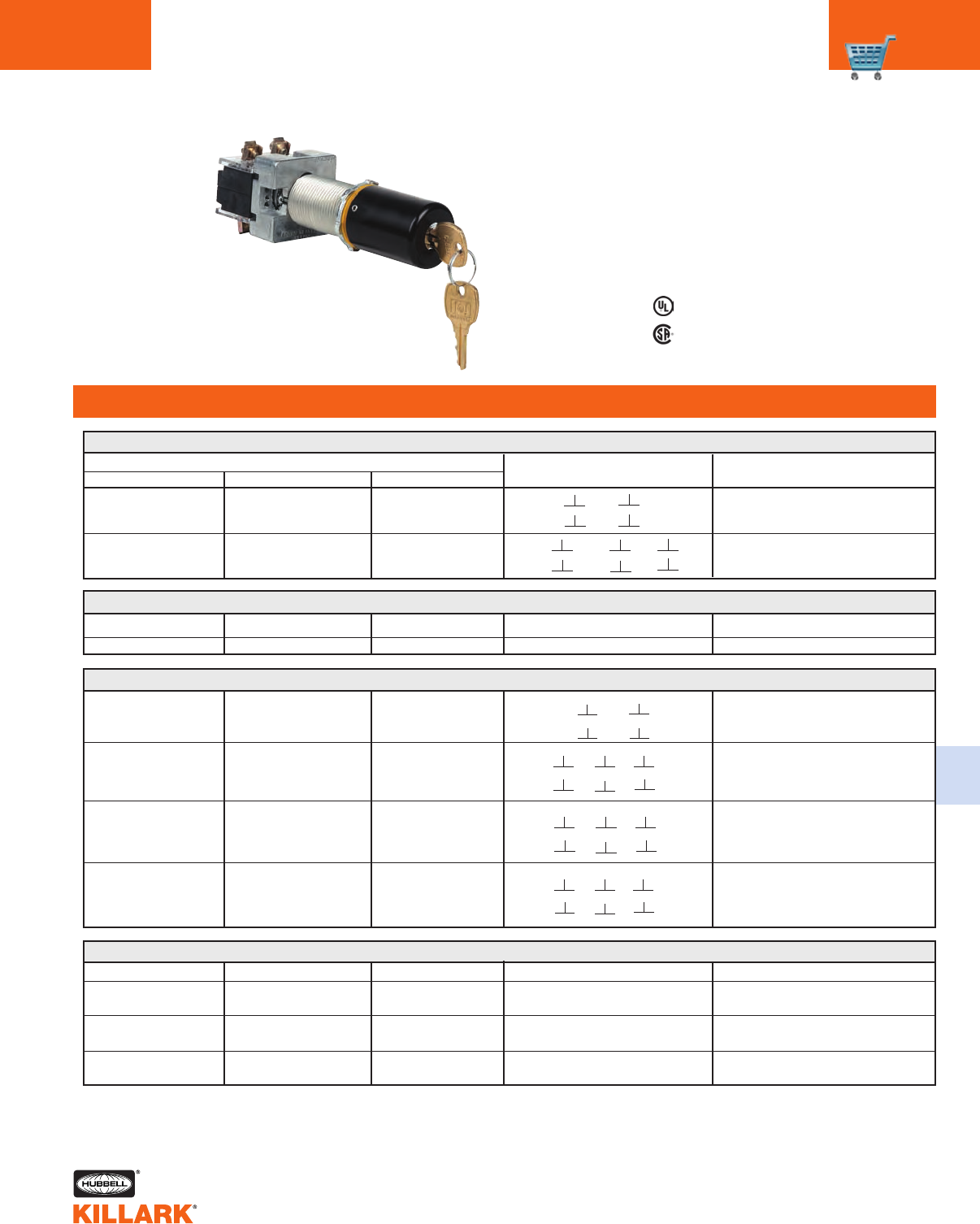
G SERIES •CONTROLS
KEYED SELECTOR SWITCHES C35
FEATURES-SPECIFICATIONS
C
G KEY SELECTOR SWITCH MAINTAINED CONTACT4
CATALOG NUMBER1
CONTACT ARRANGEMENT3
SHORT6LONG EXTENDED TYPE OF OPERATION25
G028-2A3F22D
G028-3C3G32D
G0L82A322D
G0L83C332D
G08-2A3F22D N34
G08-3C3G32D N34
Two position
Three position
Left Right
Left RightCenter
Listed - File E12379
Certified - File LR11714
See files for details or call Killark.
Class I, Div. 1 & 2, Groups B,C,D6
Class 1, Zones 1 & 2, Groups llB, llA
Class II, Div. 1 & 2, Groups E,F,G
Class Ill
NEMA 3, 4, 4X, 7(B,C,D) 9(E,F,G)
See Area Classification Chart
page C40 for Details
1Refer to catalog page C30 to select proper operator for enclosure, pages C38 & C39 for Accessories, page C30 for complete
details on Area Classification of operators, page C42 for Dimensional Information, page C40 for Special Contact Configurations.
2Nameplates are Double sided. 2 position marked ON-OFF and Blank on other side. 3 position marked HAND-OFF-AUTO
and Blank on other side. 4 position is Blank.
3Contact Blocks are shown in their normal position.
4All Key Operators are furnished Keyed Different If Keyed Alike is required substitute letter “A” for letter “D” in catalog number.
5Keys are removable in Left position on 2 position selectors and in Center position on 3 position selectors. For key removal
in ALL positions change “22” in 2 position to “20” and “32” in 3 position to “30”.
6Short style operators are suitable for Class I Group C & D, Class II Group E,F,G only.
G KEY SELECTOR SWITCH SPRING RETURN4
G056-2L3F22D
G057-3C6G32D
G058-3L6G32D
G059-3R6G32D
G036-2L3F22D N34
G037-3C6G32D N34
G038-3L6G32D N34
G039-3R6G32D N34
G KEY SELECTOR SWITCH MAINTAINED CONTACT WITHOUT CONTACTS4
G028-2A0F22D
G028-3C0G32D
G0L82A022D
G0L83C032D
G08-2A0F22D N34
G08-3C0G32D N34
Two position
Three position
None
None
• •
• •
• •
• •
• •
• •
• •
• •
• •
• •
G KEY SELECTOR SWITCH SPRING RETURN WITHOUT CONTACTS4
G056-2L0F22D
G057-3C0G32D
G058-3L0G32D
GO59-3R0G32D
G0L36L022D
G0L37C032D
G0L38L032D
G0L39R032D
G036-2L0F22D N34
G037-3C0G32D N34
G038-3LOG32D N34
G039-3R0G32D N34
Two position spring return to left
Three position spring return to
center from right or left
Three position spring return to
center from right, maintain in left
Three position spring return to
center from left, maintain in right
None
None
None
None
Key Operated
Selector Switch
• •
• •
• •
• •
Left Right
• •
• • • •
• •
• •
• •
Left Center Right
• •
• • • •
• •
• •
• •
Left Center Right
• •
• • • •
• •
• •
• •
Left Center Right
Two position spring return to left
Three position spring return to
center from right or left
Three position spring return to
center from right, maintain in left
Three position spring return to
center from left, maintain in right
G0L36L322D
G0L37C632D
G0L38L632D
G0L39R632D
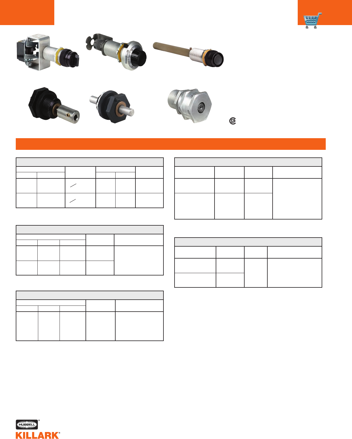
G SERIES •CONTROLS
SPECIALTY OPERATORS
C36
FEATURES-SPECIFICATIONS
TYPE
SWITCH
SPST
SPDT
(3-way)
Class I, Div. 1 & 2, Groups B,C,D4
Class I, Zones 1 & 2, Groups llB, llA
Class II, Div. 1 & 2, Groups E,F,G
Class Ill
NEMA 3, 4, 4X, 7(B,C,D) 9(E,F,G)
See Area Classification Chart
page C40 for Details
See file for details or call Killark.
Certified - File LR11714
RATINGS
125 VAC 250 VAC
10 Amp 5 Amp
10 Amp 10 Amp
NAMEPLATE
MARKING2
Off/On
or Blank
Off/On
or Blank
CATALOG NUMBER1
SHORT4
GO30-31F
GO30-33F
LONG
GO10-31F N34
GO10-33F N34
G SNAP SWITCH OPERATOR
(UL File E10501)
CATALOG NUMBER1
SHORT4
GO133
GO134
LONG
GO113 N34
GO114 N34
G POTENTIOMETERS AND RHEOSTATS OPERATOR
(UL File E150827)
TYPE
Single turn
Fifteen turn
EXTENDED
GOL113
GOL114
DESCRIPTION1
Control operator for use
with potentiometers or
rheostats having a 1/4"
diameter by 7/8" long
shaft.
CATA L O G
NUMBER1
GO-11388-0785
GO-11372-0935
G CAPILLARY SEALS
TYPE
Accepts
Capillary
With Max.
Bulb Dia.
of 9/16".
CAPILLARY
SIZE
0.078±
.002 Dia.
0.093±
.002 Dia.
DESCRIPTION1
Use where a mechanical
means for passing a thermo-
stat or similar capillary tube
through the wall of a haz-
ardous location enclosure.
CATA L O G
NUMBER1
GO-165
GO-185
GO-175
GO-195
GO-50
GO-51
SHAFT
DIAMETER
1/4”
3/8”
1/4”
3/8”
1/2”
1/2”
G ROTARY OR MOTOR SHAFT OPERATOR
GO50 requires 1-1/4" NPSM opening (UL File E150827)
TYPE
Male-Female
Male-Male
DESCRIPTION1
Rotary or motor shaft
operator used to
transfer rotary motion
through wall of explo-
sion proof enclosure.
CATALOG NUMBER1
SHORT3
GO40-KX2C
LONG
GO-RST
G RESET OPERATOR
(UL File E150827)
NAMEPLATE2
Reset
or
Blank
EXTENDED
GOLRST
TYPE OPERATION1
Black plunger type reset
operator, supplied with a
6” long fiber extension
which can be removed or
cut to desired length.
1Refer to catalog page C30 to select proper operator for enclosure, pages
C38 & C39 for Accessories, page C30 for complete details on Area
Classification of operators, page C42 for Dimensional Information.
2Nameplates are double sided.
3GO40 series reset button is suitable for Class II E, F, and G locations only.
4Short style operators are suitable for Class I Group C & D, Class II Group
E,F,G only.
5These devices are not UL or CSA approved.
• •
•
• •
Snap Switch Reset
Capillary Seal
Rotary or Motor Shaft
Potentiometer and Rheostat
(electrical device not included)
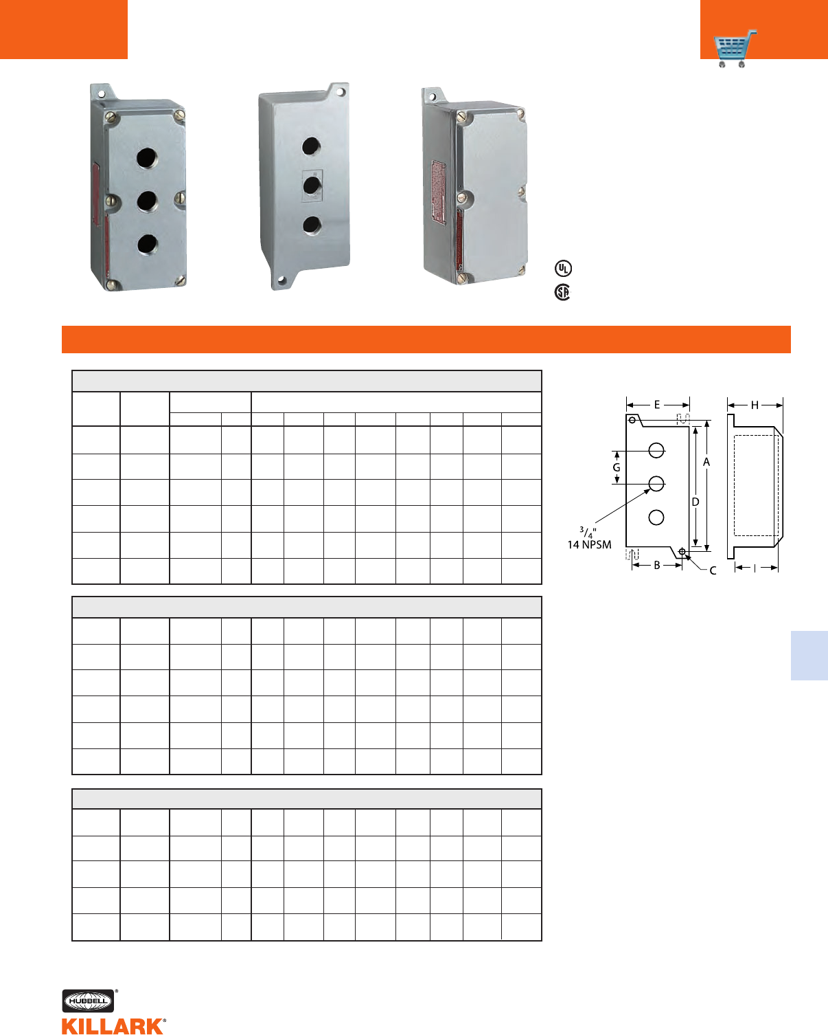
GCS/SWBC SERIES •CONTROLS
OPERATOR BODIES C37
FEATURES-SPECIFICATIONS
C
Class I, Div. 1 & 2, Groups C,D
Class I, Zones 1 & 2, Groups llB, llA
Class II, Div. 1 & 2, Groups E,F,G
Class Ill
NEMA 7(C,D) 9(E,F,G)
SWBC Series:
Listed - File E10514
Certified - File LR11716
See files for details or call Killark.
1All GCS and SWBC Series are cataloged without conduit openings.
Specify conduit size and location when ordering.
2GCS-83, GCS-834, and GCS-85, GCS-835 are provided with four
mounting lugs.
NO. OF
CATALOG OPERATOR CONSISTS OF DIMENSIONS
NUMBER HOLES BOX COVER AB CD EGH I
GCS-13 1 SWB-13 X-60 6-1/8" 2-3/8" 5/16" 5-3/16" 3-5/8" — 3-1/2" 2-9/16"
(156) (60) (8) (148) (92) (89) (65)
GCS-14 1 SWB-14 X-60 6-1/8" 2-3/8" 5/16" 5-1/4" 3-5/8" — 4-5/16" 3-3/8"
(156) (60) (8) (133) (92) (110) (86)
GCS-15 2 SWB-15 X-61 7-3/8" 3-1/8" 5/16" 6-1/2" 4" 1" 4-1/4" 3-1/4"
(187) (79) (8) (165) (102) (25) (108) (82)
GCS-16 3 SWB-16 X-62 9-3/8" 3-3/16" 5/16" 8-1/2" 4" 2" 4-1/4" 3-1/4"
(238) (81) (8) (216) (108) (51) (105) (82)
GCS-83 4 SWB-832X-84 13" 3-1/4" 3/8" 11-7/8" 4-3/8" 1-1/4" 4-3/16" 3-1/4"
(330) (82) (10) (302) (111) (32) (106) (82)
GCS-85 5 SWB-832X-85 13" 3-1/4" 3/8" 11-7/8" 4-3/8" 2" 4-3/16" 3-3/16"
(330) (82) (10) (302) (111) (51) (106) (81)
GCS STYLE 1 – WITH DRILLED AND TAPPED OPERATOR HOLES IN COVER1
Style 1 - GCS-16 Style 2 - GCS-163
Dimensions
Notes: Use short style operators for cover
devices and long style operators for
back of box mounted devices when
panel mounting.
Style 2 control stations with holes in
back of box are typically used for panel
mounting.
GCS-131 1 SWB-13 X-10 6-1/8" 2-3/8" 5/16" 5-3/16" 3-5/8" — 3-1/2" 2-9/16"
(156) (60) (8) (148) (92) (89) (65)
GCS-141 1 SWB-14 X-10 6-1/8" 2-3/8" 5/16" 5-1/4" 3-5/8" — 4-5/16" 3-3/8"
(156) (60) (8) (133) (92) (110) (86)
GCS-152 2 SWB-15 X-11 7-3/8" 3-1/8" 5/16" 6-1/2" 4" 1" 4-1/4" 3-1/4"
(187) (79) (8) (165) (102) (25) (108) (82)
GCS-163 3 SWB-16 X-12 9-3/8" 3-3/16" 5/16" 8-1/2" 4" 2" 4-1/4" 3-1/4"
(238) (81) (8) (216) (102) (51) (108) (82)
GCS-834 4 SWB-832X-83 13" 3-1/4" 3/8" 11-7/8" 4-3/8" 1-1/4" 4-3/16" 3-1/4"
(330) (82) (10) (302) (111) (32) (106) (82)
GCS-835 5 SWB-832X-83 13" 3-1/4" 3/8" 11-7/8" 4-3/8" 2" 4-3/16" 3-3/16"
(330) (82) (10) (302) (111) (51) (106) (81)
GCS STYLE 2 – WITH DRILLED AND TAPPED OPERATOR HOLES IN BACK OF BOX1
SWBC-13 None SWB-13 X-10 6-1/8" 2-3/8" 5/16" 5-3/16" 3-5/8" — 3-1/2" 2-9/16"
(156) (60) (8) (148) (92) (89) (65)
SWBC-14 None SWB-14 X-10 6-1/8" 2-3/8" 5/16" 5-1/4" 3-5/8" — 4-5/16" 3-3/8"
(156) (60) (8) (133) (92) (110) (86)
SWBC-15 None SWB-15 X-11 7-3/8" 3-1/8" 5/16" 6-1/2" 4" — 4-1/4" 3-1/4"
(187) (79) (8) (165) (102) (108) (82)
SWBC-16 None SWB-16 X-12 9-3/8" 3-3/16" 5/16" 8-1/2" 4" — 4-1/4" 3-1/4"
(238) (81) (8) (216) (111) (108) (82)
SWBC-83 None SWB-832X-83 13" 3-1/4" 3/8" 11-7/8" 4-3/8" — 4-3/16" 3-3/16"
(330) (82) (10) (302) (111) (106) (81)
SWB STYLE 3 – BLANK BOX AND COVER - NO OPERATOR HOLES1
Style 3 - SWBC-16
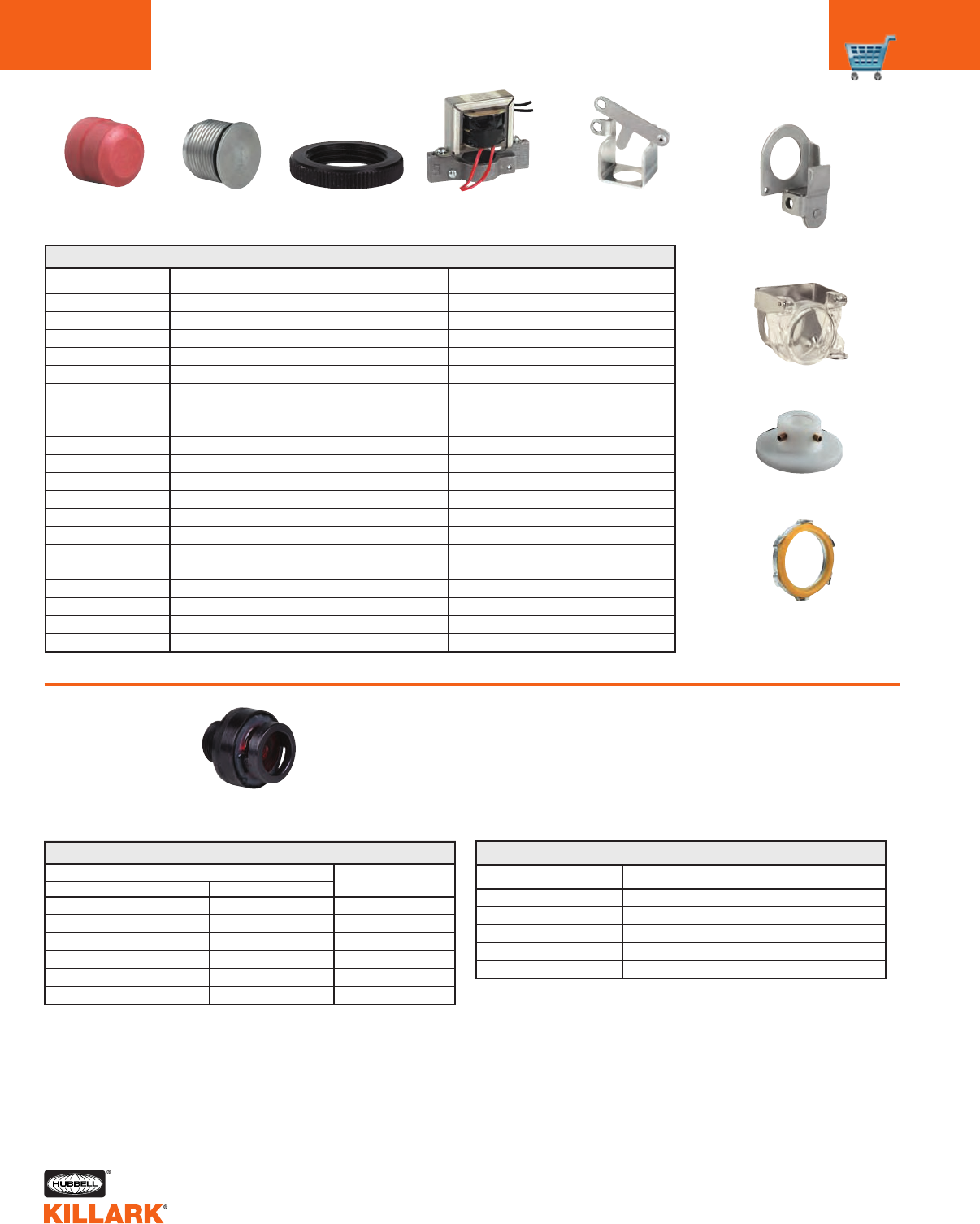
Rubber
Boot
Hole
Plug
Trim Locknut
Spacer
Selector Switch Lockout
CATALOG NUMBER USED ON OPERATOR TYPE DESCRIPTION
GO1, GO21, GOL1
GO1, GO21, GOL1
GO1, GO21, GOL1
3/4” NPSM
1/4” Thick, Used as external spacer.
GO23, GOB3, GOL3
GO23, GOB3, GOL3
GOB4, GOL4
GOB4, GOL4
GO2, GO22, GOL2, GOR11
GO1, GO21, GOL1
GO & GOL5-6-7-14-15-26-27-34-35
For use with GO’s
GO40, GO-RST, GOLRST
GO23, GOB3, GOL3, GOB4, GOL4
GO23, GOB3, GOL3, GOB4. GOL4
GO23, GOB3, GOL3, GOB4, GOL4
GOB3, GOL3, GOB4, GOL4
GOB3, GOL3, GOB4, GOL4
GOB3, GOL3, GOB4, GOL4
GO-8176-1
GO-8176-2
GO-8176-3
GO-8177
GO-8222
GO-8670-32
GO-8670-34
GO-8671-42
GO-8671-44
GO-8665
GO-10502
GO567-LOK
GO-RL
GO-9824
B7PLR220
B7PLR440
B7PLR550
GOLED-R110
GOLED-G110
GOLED-A110
Protective rubber boot (Black)
Protective rubber boot (Red)
Protective rubber boot (Green)
Hole plug
Trim locknut spacer
Transformer 220V-110V
Transformer 440V-110V
Transformer 220V-110V
Transformer 440V-110V
Push button lockout
Push button lockout
Selector switch lockout
Sealing lockout
Reset plate
Resistor kit 220V-110V
Resistor kit 440V-110V
Resistor kit 550V-110V
LED lamps 120V (Red)
LED lamps 120V (Green)
LED lamps 120V (Amber)
ACCESSORIES
REPLACEMENT LENS GUARD ASSEMBLIES
CATALOG NUMBER
GOL3/GOB3/GO23 SERIES GOL4/GOB4 SERIES LENS COLOR
GO15726-A KIT-354 Amber
GO15726-B KIT-355 Blue
GO15726-C KIT-356 Clear
GO15726-F KIT-357 Frosted
GO15726-G KIT-358 Green
GO15726-R KIT-359 Red
Lens Guard
Assembly
CATALOG NUMBER DESCRIPTION
YOKK-9484-2 Push button pilot lights
YOKK-10291 Double push button
YOKK-10286 2 Position selector switch
YOKK-10287 3 Position selector switch
YOKK-10285 4 Position selector switch
REPLACEMENT BLANK NAMEPLATES
Reset Plate
Push Button Lockout
GO-8665
Sealing Locknut
GO-RL
Transformer
GO-8670
Push Button Lockout
GO-10502
G SERIES •CONTROLS
ACCESSORIES/REPLACEMENT PARTS
C38
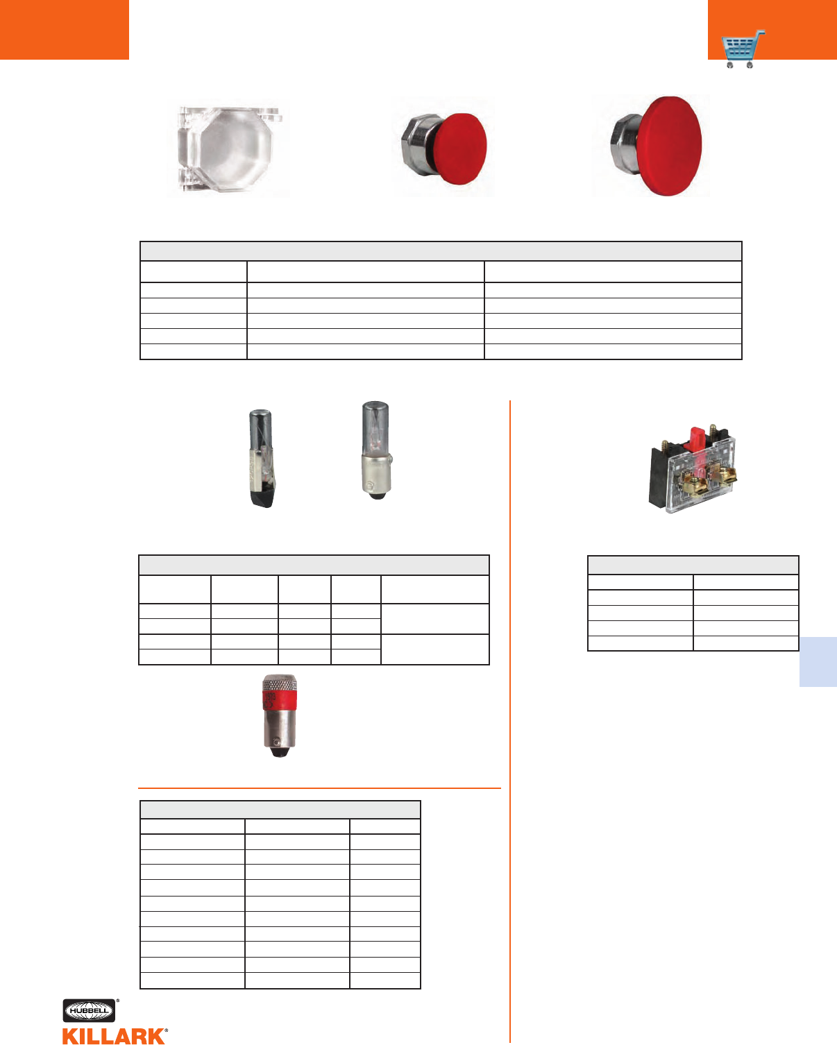
C49
Slide Base
GO23
CATALOG
NUMBER VOLTS WATTS AMPS STYLE
GO-8668-120 120 3 0.025 GO23
GO-8668-24 24 1.7 0.073
YOSY120MB 120 3 0.025 GOB3/GOL3
YOSY24MB 24 1.7 0.073 GOB4/GOL4
PILOT LIGHT LAMPS
Bayonet Base
GOL3/GOL4
GOB3/GOB4
Replacement
Parts
CATALOG NUMBER FOR USE ON OPERATOR TYPE DESCRIPTION
GOM1-GOM21-GOML-GO1-GO21-GOL1
GO1-GO21-GOL1
GO1-GO21-GOL1
GO1-GO21-GOL1
GO1-GO21-GOL1
GOMLOCK
GOMSTG
GOMSTR
GOMSTK
GOMJUR
Lock Out for Standard Size Momentary & Maintained Head
Standard Size Momentary Mushroom Head (Green)
Standard Size Momentary Mushroom Head (Red)
Standard Size Momentary Mushroom Head (Black)
Jumbo Size Momentary Mushroom Head (Red)
ACCESSORIES
Dimensions - Standard Mushroom - 1-1/2” Diameter
Jumbo Mushroom - 2-1/4” Diameter
GOMLOCK Jumbo Mushroom
Momentary
Standard Mushroom
Momentary
Contact Block
CATALOG NUMBER DESCRIPTION
GO-8672-BJK 1 N.O.
GO-8672-BJJ 1 N.C.
GO-8672-BJH 1 N.O. Early make
GO-8672-BJE 1 N.C. Late break
GO STANDARD CONTACT BLOCKS
CATALOG NUMBER VOLTS COLOR
GOLED-A110 110 VAC/DC Amber
GOLED-B110 110 VAC/DC Blue
GOLED-G110 110 VAC/DC Green
GOLED-R110 110 VAC/DC Red
GOLED-W110 110 VAC/DC White
GOLED-A24 24 VAC/DC Amber
GOLED-B24 24 VAC/DC Blue
GOLED-G24 24 VAC/DC Green
GOLED-R24 24 VAC/DC Red
GOLED-W24 24 VAC/DC White
PILOT LIGHT LED LAMPS
LED Lamp for G0B3/G0L3 - G0B4/G0L4
G SERIES •CONTROLS
ACCESSORIES/REPLACEMENT PARTS C39
C
G SERIES •CONTROLS
CUSTOM OPERATOR ORDERING SYSTEM
C40
FEATURES-SPECIFICATIONS
1. Select operator form and style
(short, long or extended).
2.Using the catalog numbering system
below, insert the proper letter or
number symbol as shown in appro-
priate charts on page C41, write the
complete catalog number.
GO1
FORM
SINGLE PUSH BUTTON
LONG STYLE
RX
COLOR
(RED)
2
CONTACTS
(1 N.C.)
B
NAMEPLATE
(STOP)
N34
CONSTANT
—
Example:
NOTE: For faster delivery on custom operators order push buttons and selector
switches without contact blocks and order contacts as a separate item.
GO1 & GO21
GOL1
GOM1
GO2 & GO22
GOL2
GOR11
GOB3 & GO23
GOL3
GOB4
GOL4
GO5 & GO25
GOL5
GO6 & GO26
GOL6
GO7 & GO27
GOL7
GO14 & GO34
GOL14
GO15 & GO35
GOL15
GO8 & GO28
GOL8
GO36 & GO56
GOL36
GO37 & GO57
GOL37
GO38 & GO58
GOL38
GO39 & GO59
GOL39
Chart 1
Chart 1
Chart 2
Chart 2
Chart 3
Chart 3
Chart 6
Chart 6
Chart 5
Chart 5
Chart 7
Chart 7
Chart 4
Chart 4
Chart 4
Chart 4
Chart 4
Chart 4
Chart 4
Chart 4
Chart 4
Chart 4
Chart 4
Chart 4
Chart 4
Chart 4
Chart 4
Chart 8
Chart 8
Chart 8
Chart 8
Chart 8
Chart 8
Chart 8
Chart 8
Chart 8
Chart 8
Chart 8
Chart 8
Chart 8
Chart 8
Chart 8
Chart 8
Chart 10
Chart 10
Chart 10
Chart 10
Chart 10
Single push button:
(Momentary contact)
Single push button:
(Maintained contact)
Double push button:
(Momentary contact)
Double push button:
(Maintained contact)
Pilot light
Illuminated push button
Selector switch
(Maintained contact)
Selector switch
(2 Position, spring return to left)
Selector switch
(3 Position, return to center from center)
Selector switch
(3 Position, return to center from right)
Selector switch
(3 Position, return to center from left)
Key selector switch
(Maintained contact)
Key selector switch
(2 Position, spring return to left)
Key selector switch
(3 Position, spring return to center)
Key selector switch
(3 Position, return to center from right)
Key selector switch
(3 Position, return to center from left)
Chart 9
Chart 9
Chart 9
Chart 9
Chart 9
DESCRIPTIONCATALOG SERIES COLOR VOLTAGE POSITION CAM CONTACTS NAMEPLATE KEY LOCK KEY TYPE
3.Spaces in catalog numbering sys-
tem which have symbol already
filled in cannot be changed.
4.Order accessories as separate
item from pages C38 & C39.
5.Add “N34” suffix to the end of all
long style operators with the follow-
ing prefix; G01, G02, G0B3, G0B4,
G05, G06, G07, G08, G010, G011,
G014, G015, G036, G037, G038,
G039.
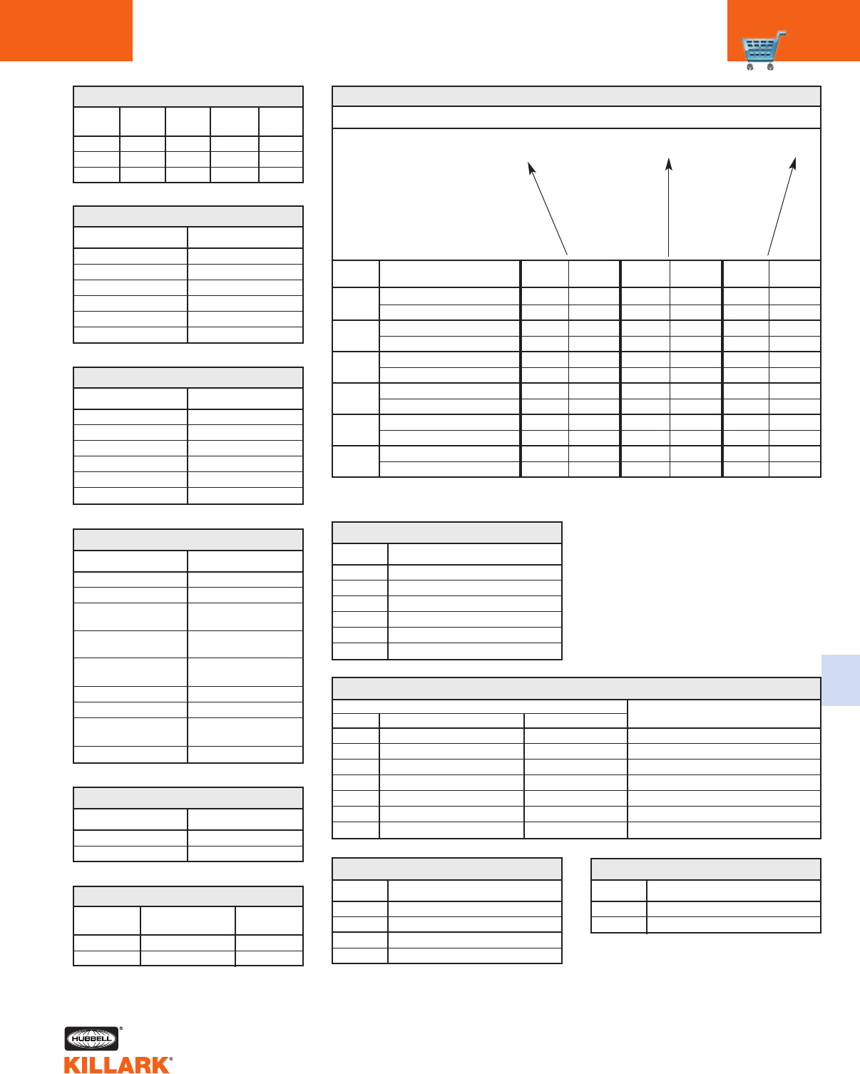
HAZARDOUS AND HOSTILE LOCATIONS
G SYMBOLS FOR ORDERING CUSTOM OPERATORS C41
C
A
B
C
D
E
G
NC
NO
NC
NO
NC
NO
NC
NO
NC
NO
NC
NO
SYMBOL ARRANGEMENT
1One N.O. block
2One N.C. block
One universal
3(One N.O. and one N.C.)
One delayed break
4N.C. block
One early make N.O.
5block
6Two N.O. blocks
7Two N.C. blocks
Two universal
8(Two N.O. and two N.C.)
0Omit contact block
CHART 4 – CONTACT BLOCKS
GO1 GO21
SYMBOL SYMBOL COLOR
KX K Z Black
RX R Z Red
GX G Z Green
SYMBOL COLOR
KK Black/Black
GG Green/Green
RR Red/Red
RG Red/Green
KR Black/Red
KG Black/Green
CHART 1 – SINGLE BUTTON
CHART 2 – DOUBLE BUTTON
GOL1 GOM1
SYMBOL SYMBOL
K KM
R RM
G GM
SYMBOL NO. OF POSITIONS
2Two
3Three
CHART 5 – SELECTOR SWITCHES
CHART 8 – NAMEPLATES1
NAMEPLATE MARKINGS G SERIES FORMS THAT
SYMBOL FRONT BACK NAMEPLATE CAN BE USED ON
A Omit nameplate Omit nameplate All
B Start Stop GO1, 21, 23, 20, 40, GOB3
C Blank Reset GO1, 21, 23, 20, 40, GOB3, GOB4
E Blank On GOR4
F Blank-Blank Off-On GO5, 25, 6, 26, 8, 28, 10, 30, 36, 56
G Blank-Blank-Blank Hand-Off-Auto GO5, 25, 7, 27, 8, 28, 10, 30, 14, 34
H Blank-Blank-Blank-Blank Start-Stop GO5, 25, 10, 30
SYMBOL TYPE
22 2 Position key remove left
20 2 Position key remove both
32 3 Position key remove center
30 3 Position key remove all
CHART 9 – KEY LOCK
1Symbol not required on extended length GOL
part number.
SYMBOL COLOR
AAmber
BBlue
CClear
FFrosted
GGreen
RRed
CHART 3 – PILOT LIGHT LENS
GO23 GOB3/GOB4
SYMBOL SYMBOL VOLTAGE
23 2 3 120
4424
CHART 6 – PILOT LIGHT LAMPS SYMBOL TYPE
DKeys different
AKeys alike
CHART 10 - KEY STYLE
CAM AND CONTACT SELECTION TABLE FOR 2 AND 3 POSITION SELECTOR OPERATOR
LEFT RIGHT LEFT RIGHT LEFT RIGHT
BLOCKS BLOCKS BLOCKS BLOCKS BLOCKS BLOCKS
XXOO
OO XX
XOXXOX
O X O OXO
X X OOO O
OOOOX X
OOXXO O
OOOOX X
OOXXO O
XXOOO O
X O OXO O
OOOOX X
CONTACTS BLOCKS
SYMBOL
CHART 7A – SELECTOR SWITCH CAMS
Note: Spring return operators are supplied with special fixed cam. Changes cannot be made for cam
substitution.
Left Center Right
position position position
CAM PART NUMBER
A0106775B
B11586ABAB
C11587ABAB
D11588ABAB
E11589ABAB
G11590ABAB
CHART 7B
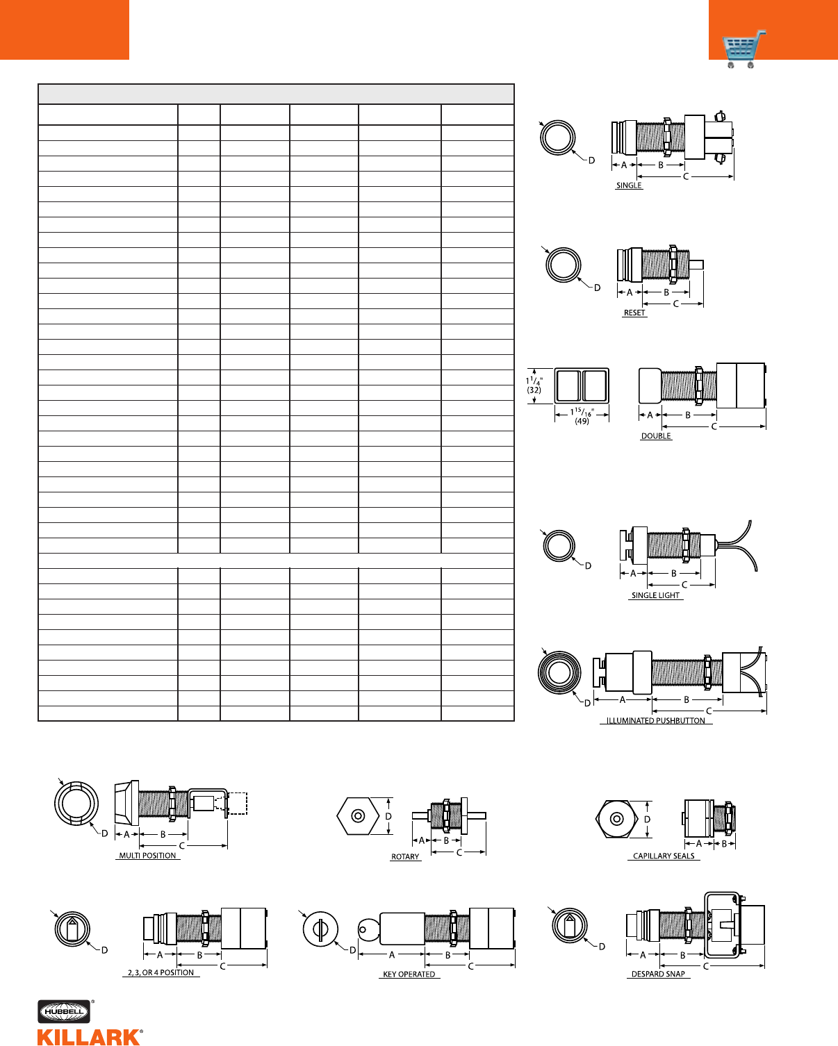
G SERIES •CONTROLS
DIMENSIONS
C42
GO1
GO2
GOB3
GOB4
GO5
GO6,GO7,GO14,GO15
GO8
GO10
GO16,GO18
GO17,GO19
GO21
GO22
GO23
GO25
GO26,GO27,GO34,GO35
GO30
GO36,GO37,GO38,GO39
GO40
GO50
GO51
GO56,GO57,GO58,GO59
GO113,GO114
GO133,GO134
GO-11388-078
GO-11372-093
GOR11
GO-RST
GOM1
EXTENDED LENGTH OPERATORS:
GOL1
GOL2
GOL3
GOL4
GOL5
GOL6,GOL7,GOL14,GOL15
GOL8
GOL36,GOL37,GOL38,GOL
GOL113,GOL114
GOLRST
SERIES FIGURE A
1
3
4
5
9
9
10
11
7
7
1
3
4
9
9
11
10
2
7
7
10
6
6
8
8
3
2
1
1
3
4
5
9
9
10
10
6
2
15/16"(24)
13/16"(21)
1-1/8"(29)
2-3/8"(60)
1-5/16"(33)
1-5/16"(33)
2-9/16"(65)
1-5/16"(33)
1-1/4"(32)
13/16"(21)
15/16"(24)
13/16"(21)
1-1/8"(29)
1-5/16"(33)
1-5/16"(33)
1-5/16"(33)
2-9/16"(65)
15/16"(24)
1-1/2"(38)
2-1/4"(57)
2-9/16"(65)
1"(25)
1"(25)
1-5/16"(33)
1-5/16"(33)
13/16"(21)
15/16"(24)
1-7/8"(48)
15/16"(24)
13/16"(210)
1-1/8"(29)
2-3/8"(60)
1-5/16"(33)
1-5/16"(33)
2-9/16"(65)
2-9/16"(65)
1"(25)
15/16"(24)
B
1-3/4"(44)
2"(51)
2"(51)
2-1/4"(57)
1-3/4"(44)
1-3/4"(44)
1-3/4"(44)
1-3/4"(44)
1"(25)
1"(25)
3/4"(19)
1"(25)
1"(25)
3/4"(19)
3/4"(19)
3/4"(19)
1-3/4"(00)
11/16"(17)
2"(51)
1-5/8"(41)
3/4"(19)
2"(51)
1"(25)
3/4"(19)
3/4"(19)
2"(51)
2-5/16"(59)
1-7/16"(37)
2-3/4"(70)
2-3/4"(70)
2-3/4"(70)
2-3/4"(70)
2-3/4"(70)
2-3/4"(70)
2-3/4"(70)
2-3/4"(70)
3"(76)
2-3/4"(70)
C
3-7/16"(87)
3-3/4"(95)
2-3/4"(70)
4"(101)
3-7/16"(87)
3-13/16"(97)
3-1/2"(89)
4"(101)
13/16"(21)
13/16"(21)
2-7/16"(62)
2-3/4"(70)
1-3/4"(44)
2-7/16"(62)
2-13/16"(71)
3"(76)
3-7/8"(98)
1"(25)
6-5/16"(160)
5-9/16"(141)
2-7/8"(73)
3-5/8"(67)
2-5/8"(67)
N/A
N/A
4-1/8"(105)
2-3/8"(+6")(60)
4"(101)
4-7/16"(113)
4-1/2"(114)
3-3/8"(86)
4-5/8"(117)
4-7/16"(113)
4-13/16"(122)
4-1/2"(114)
4-7/8"(124)
4-5/8"(117)
3"(+6")(76)
D
1-1/4"(32)
—
1-9/16"(40)
1-13/16"(46)
1-1/4"(32)
1-1/4"(32)
1-1/4"(32)
1-1/4"(32)
1-1/2"(38)
1-1/2"(38)
1-1/4"(32)
—
1-9/16"(40)
1-1/4"(32)
1-1/4"(32)
1-1/4"(32)
1-1/4"(32)
1-1/4"(32)
2-5/16"(59)
1"(25)
1-1/4"(32)
1-13/16"(46)
1-13/16"(46)
1-1/2"(38)
1-1/2"(38)
—
1-1/4"(32)
1-5/8"(41)
1-1/4"(32)
—
1-9/16"(40)
1-13/16"(46)
1-1/4"(32)
1-1/4"(32)
1-1/4"(32)
1-1/4"(32)
1-13/16"(46)
1-1/4"(32)
NOTE: All operators are for installation into a 3/4"-14 NPSM opening except GO50 which is for
1-1/4"-11-1/2 NPSM and GO-11388-078 + GO-11372-093 which are for use in a 3/4"-14 NPT opening.
Push Buttons
Pilot Lights
Special Operators
Selector Switches
FIGURE 1
FIGURE 2
FIGURE 3
FIGURE 4
FIGURE 5
FIGURE 6 FIGURE 7 FIGURE 8
FIGURE 9 FIGURE 10 FIGURE 11
G DIMENSIONS
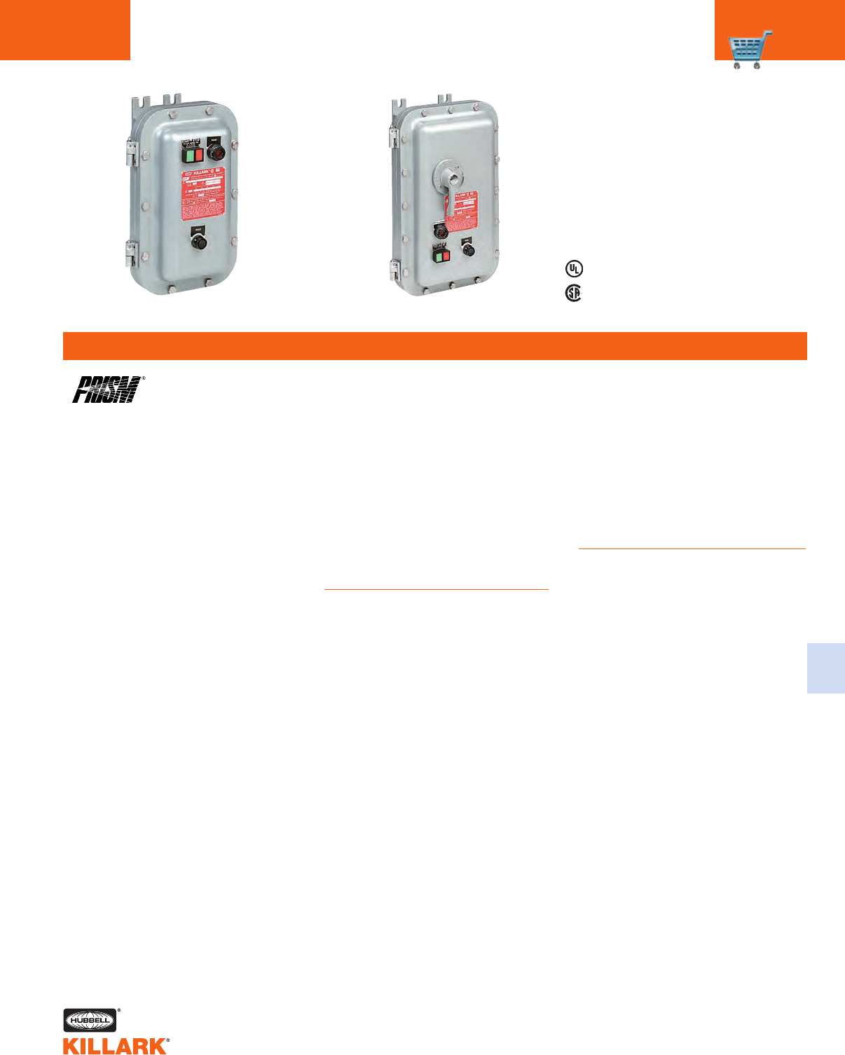
B7 SERIES •CONTROLS
MAGNETIC MOTOR STARTERS C43
FEATURES-SPECIFICATIONS
C
Applications
The PRISM® B7 Series of across-the-
line starter and combination motor con-
trol centers utilize SSNR single-speed,
non-reversing NEMA type starters.
Prism enclosures universal design
accommodates, as standard, the mag-
netic starters made by the following
manufacturers:
•Allen-Bradley — 509 Series
•Cutler-Hammer — A10 Series
•Cutler-Hammer — AN16 Series
•Furnas — Class 14 Series
•GE — CR306 Series
•Square D — 8536 Series
•Telemecanique — A20 Series
•Westinghouse — A200 Series
In addition, the SSNR combination
starters will house a motor circuit
protector or circuit breakers manufac-
tured by:
•Square D — FA, FH, FC Frames
•Cutler-Hammer –– HMC, EHD, FDB,
FD, HFD, FDC Frames
•General Electric –– TEB-TEC-TED-
THED-Frame
There is sufficient space in the combina-
tion starter enclosure for a control
transformer, if required.
Classified - File E83969
Certified - File LR11714
See files for details or call Killark.
Class I, Div. 1 & 2, Groups B,C,D
Class l, Zones 1 & 2, Groups llB, llA
Class II, Div. 1 & 2, Groups E,F,G
Class III, Div. 1 & 2
NEMA 3, 4, 4X, 7(B,C,D) 9(E,F,G)
Standard Materials
Enclosure – Copper-free aluminum
O-ring Gasket – BUNA-N nitrile
Cover Bolts – 316 grade stainless steel
CB/MCP Handle – Copper-free
aluminum
Reset Operator – Thermoplastic
polyester button molded onto stainless
steel shaft. Aluminum shroud.
Mounting Pan – Sheet aluminum
Hinge – Aluminum with stainless
steel pin
Reset Shroud – Black anodized
Features
•Nema 4, 4X rated – providing protec-
tion from hose directed water and
corrosion
•Universal mounting pan, pre-drilled
to facilitate easy field installation of
starters. Provision for grounding
supplied as standard.
•More wiring room – meets latest NEC
wire bend requirements
•Quick release, captivated cover bolts
of 316 grade stainless steel
•Flange sealing gasket located to the
inside of cover bolt – preventing
water seepage into enclosure through
bolt holes
•Hinged cover provided as standard
for an extra measure of safety and
convenience
•Breaker (MCP) handle can be pad-
locked in “ON” or “OFF” position
•Provisions provided for drain and
breather plus conduit openings for
power and control
•Reset button provided as standard
•Two control operator openings provid-
ed plugged as standard. Additional
openings can be factory or field
drilled.
•Copper-free (less than 4/10 of 1%
copper) enclosure
•Ductile mounting lugs
Catalog Logic
See page C48 for enclosures
with controls.
Line Starter Combination Starter
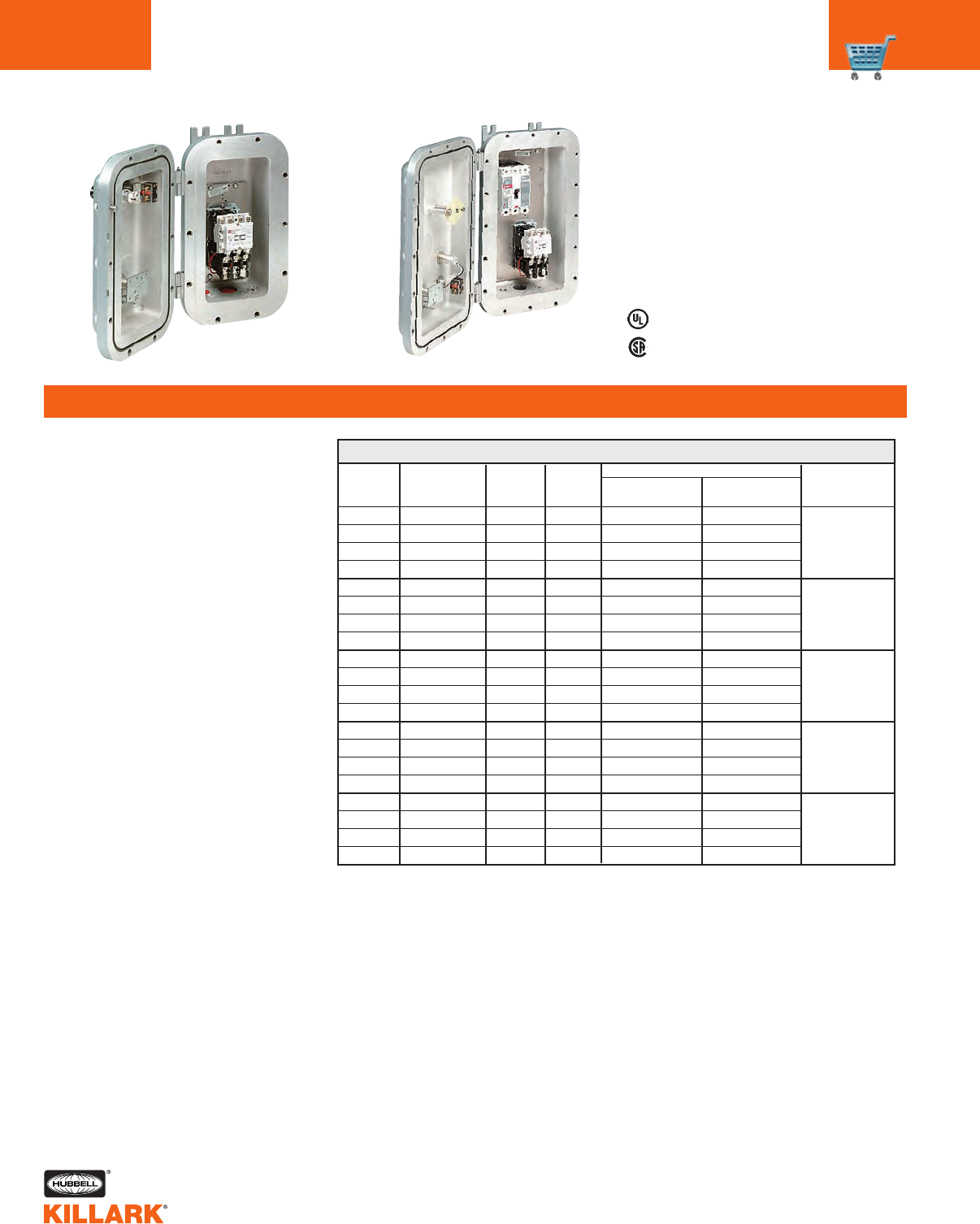
B7 SERIES •CONTROLS
MAGNETIC MOTOR STARTERS
C44
FEATURES-SPECIFICATIONS
B7 MAGNETIC LINE STARTERS
0
0
0
0
1
1
1
1
2
2
2
2
3
3
3
3
4
4
4
4
NEMA
STARTER
SIZE
MOTOR
VOLTS
COIL
VOLTS1MAX. HP
CATALOG NUMBER
CUTLER-HAMMER
SERIES AN16
SQUARE D
SERIES 8536
ENCLOSURE ONLY
NO INTERIORS
120
240
480
600
120
240
480
600
120
240
480
600
120
240
480
600
120
240
480
600
SEP. CONTROL
230
460
575
SEP. CONTROL
230
460
575
SEP. CONTROL
230
460
575
SEP. CONTROL
230
460
575
SEP. CONTROL
230
460
575
—
3
5
5
—
7-1/2
10
10
—
15
25
25
—
30
50
50
—
50
100
100
B7011
B7011
B7012
B7013
B7014
B7010HB
B7010HG
B7010HK
B7010HM
B7011HB
B7011HG
B7011HK
B7011HM
B7012HB
B7012HG
B7012HK
B7012HM
B7013HB
B7013HG
B7013HK
B7013HM
B7014HB
B7014HG
B7014HK
B7014HM
B7010SB
B7010SG
B7010SK
B7010SM
B7011SB
B7011SG
B7011SK
B7011SM
B7012SB
B7012SG
B7012SK
B7012SM
B7013SB
B7013SG
B7013SK
B7013SM
B7014SB
B7014SG
B7014SK
B7014SM
Classified - File E83969
Certified - File LR11714
See files for details or call Killark.
Class I, Div. 1 & 2, Groups B,C,D
Class l, Zones 1 & 2, Groups llB, llA
Class II, Div. 1 & 2, Groups E,F,G
Class III, Div. 1 & 2
NEMA 3, 4, 4X, 7(B,C,D) 9(E,F,G)
1See catalog logic page C48 for other standard coil voltages.
2Control transformers for use on Combination Starters Only. Will not fit into B701 Series of Non-
Combination Starters.
3See catalog page C48 for modifications and accessories to enclosure.
Magnetic Line Starters - 3 Pole,
3 Phase, Single Speed Non Revers-
ing 600 VAC Max, 60Hz
Square D or Cutler-Hammer motor
starters available as standard.
Heaters not included. See page
C49 to order.
Line Starter Combination Starter
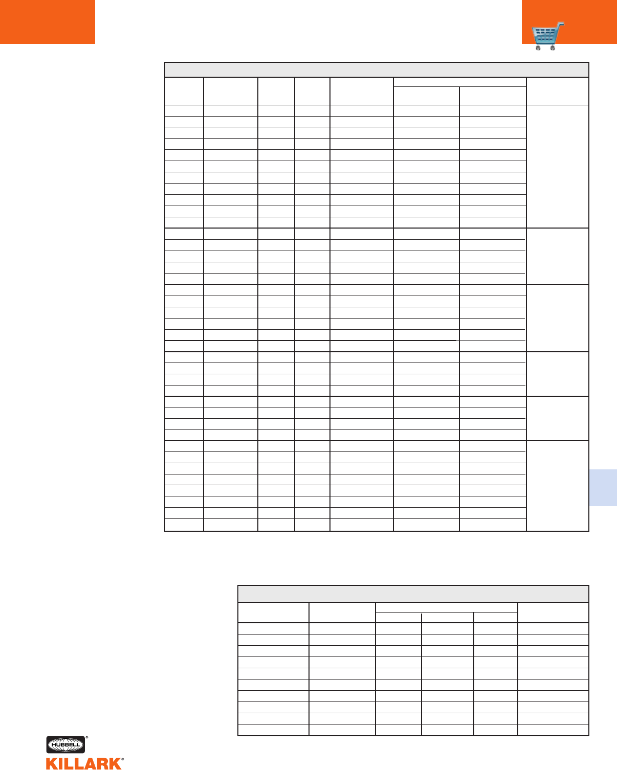
B7 SERIES •CONTROLS
MAGNETIC MOTOR STARTERS C45
C
ENCLOSURE
CAT. NUMBER
B7025A2
B7025A4
B7025C2
B7025C4
B7025G2
B7025G4
B7025S2
B7025S4
B7025W2
B7025W4
STARTER
MANUFACTURER
Allen Bradley
Allen Bradley
Cutler Hammer
Cutler Hammer
General Electric
General Electric
Square D
Square D
Westinghouse
Westinghouse
SIZE 5 COMBINATION MOTOR STARTER ENCLOSURE ONLY
STARTER
TYPE
Series 509
Series 509
Freedom-AN16
Freedom-AN16
Series 306
Series 306
Series 8536
Series 8536
Advantage
Advantage
C-H
J
K
J
K
J
K
J
K
J
K
GE
F-225
J-600
F-225
J-600
F-225
J-600
F-225
J-600
F-225
J-600
SQ-D
K
L
K
L
K
L
K
L
K
L
CIRCUIT BREAKER FRAME
B7 COMBINATION MAGNETIC LINE STARTERS
NEMA
STARTER
SIZE
MOTOR
VOLTS
COIL
VOLTS1MAX. HP ENCLOSURE ONLY
NO INTERIORS
120
120
120
240
240
480
480
480
600
600
600
120
120
240
480
600
120
120
240
240
480
600
120
240
480
600
120
240
480
600
120
120
240
240
480
480
600
600
SEP. CONTROL
SEP, CONTROL
SEP, CONTROL
230
230
460
460
460
575
575
575
SEP, CONTROL
SEP. CONTROL
230
460
575
SEP. CONTROL
SEP, CONTROL
230
230
460
575
SEP, CONTROL
230
460
575
SEP, CONTROL
230
460
575
SEP, CONTROL
SEP, CONTROL
230
230
460
460
575
575
—
—
—
1
3
1
2
5
1
2
5
—
—
7-1/2
10
10
—
—
15
15
25
25
—
30
50
50
—
50
100
100
—
—
75
100
150
200
150
200
CATALOG NUMBER
SQUARE D
SERIES 8536
DISCONNECT
TRIP
AMPS
CUTLER-HAMMER
SERIES AN16
0
0
0
0
0
0
0
0
0
0
0
1
1
1
1
1
2
2
2
2
2
2
3
3
3
3
4
4
4
4
5
5
5
5
5
5
5
5
3
7
15
7
15
3
7
15
3
7
15
15
30
30
30
30
50
70
50
70
50
50
100
100
100
100
150
150
150
150
250
400
250
400
250
400
250
400
B7020HBCA
B7020HBCB
B7020HBCC
B7020HGCB
B7020HGCC
B7020HKCA
B7020HKCB
B7020HKCC
B7020HMCA
B7020HMCB
B7020HMCC
B7021HBCC
B7021HBCF
B7021HGCF
B7021HKCF
B7021HMCF
B7022HBCK
B7022HBCM
B7022HGCK
B7022HGCM
B7022HKCK
B7022HMCK
B7023HBCQ
B7023HGCQ
B7023HKCQ
B7023HMCQ
B7024HBCT
B7024HGCT
B7024HKCT
B7024HMCT
B7025CBCMCPJ250
B7025CBCMCPK400
B7025CGCMCPJ250
B7025CGCMCPK400
B7025CKCMCPJ250
B7025CKCMCPK400
B7025CMCMCPJ250
B7025CMCMCPK400
B7020SBAA
B7020SBAB
B7020SBAC
B7020SGAB
B7020SGAC
B7020SKAA
B7020SKAB
B7020SKAC
B7020SMAA
B7020SMAB
B7020SMAC
B7021SBAC
B7021SBAF
B7021SGAF
B7021SKAF
B7021SMAF
B7022SBAK
B7022SBAM
B7022SGAK
B7022SGAM
B7022SKAK
B7022SMAK
B7023SBAQ
B7023SGAQ
B7023SKAQ
B7023SMAQ
B7024SBBT
B7024SGBT
B7024SKBT
B7024SMBT
B7025SBSMAGK250
B7025SBSMAGL400
B7025SGSMAGK250
B7025SGSMAGL400
B7025SKSMAGK250
B7025SKSMAGL400
B7025SMSMAGK250
B7025SMSMAGL400
B7021
B7021
B7022
B7023
B7024
See chart
below
Combination Starters
3-Pole, 3-Phase, Single
Speed Non Reversing
600VAC Max, 60Hz
Square D or Cutler-
Hammer motor
starters and motor cir-
cuit protector avail-
able. Heaters not
included. See page
C49 to order.
Enclosure sized to
accommodate control
circuit transformer.
1See catalog logic page C48 for other standard coil voltages.
2Combination Starter enclosures provide sufficient space for factory of field mounting a control transformer.
3See catalog page C48 for modifications and accessories to enclosure.
Supplied with Cutler-Hammer
Advantage Starters
Applications
The PRISM® B7 Series of Combination
Starters are used for Motor Control and
Circuit protection of motors in
Hazardous And Hostile locations.
These Hazardous locations are typically
due to the presence of flammable
gases or vapors, combustible dust, or
easily ignitable fibers and flyings, and
areas which are subject to corrosion,
weather and dampness.
Advantage Starter Features
•Solid-State Electronic Starter
•Brownout Protection
•Communications capabilities
•Overload Heaters not required
•Phase loss and phase unbalance
protection
•Selectable automatic/manual reset
•Class ll ground-fault protection
Enclosure Features
•Nema 4, 4X rated – providing protec-
tion from hose directed water and
corrosion
•Universal mounting pan, pre-drilled to
facilitate easy field installation of
starters. Provision for grounding sup-
plied as standard.
•More wiring room – meets latest NEC
wire bend requirements
•Quick release, captivated cover bolts
of 316 grade stainless steel
Classified - File E83969
Certified - File LR11714
See files for details or call Killark.
Class I, Div. 1 & 2, Groups B,C,D
Class l, Zones 1 & 2, Groups llB, llA
Class II, Div. 1 & 2, Groups E,F,G
Class III, Div. 1 & 2
NEMA 3, 4, 4X, 7(B,C,D) 9(E,F,G)
•Flange sealing gasket located to the
inside of cover bolt – preventing
water seepage into enclosure
through bolt holes
•Hinged cover provided as standard
for an extra measure of safety and
convenience
•Breaker (MCP) handle can be pad-
locked in “ON” or “OFF” position
•Provisions provided for drain and
breather plus conduit openings for
power and control
•Field replaceable reset button pro-
vided as standard with gold contact
blocks
•Two control operator openings
provided plugged as standard.
Additional openings can be factory
or field drilled
•Copper-free (less than 4/10 of 1%
copper) enclosure
•Ductile mounting lugs
Modifications & Accessories
•Select from B7 Modification Chart on
page C48
•Minimum Control Transformer
•Size 1-2 100VA
•Size 3-4 150VA
•Size 5 300VA
•Advantage Starters Auxiliary Contact
Modules
•2NO/2NC = B7ADAC
Standard Materials
Enclosure – Copper-free aluminum
O-ring Gasket – BUNA-N nitrile
Cover Bolts – 316 grade stainless steel
CB/MCP Handle – Copper-free
aluminum
Reset Operator – Thermoplastic poly-
ester button molded onto stainless steel
shaft. Aluminum shroud.
Mounting Pan – Sheet aluminum
Hinge – Aluminum with stainless steel
pin
Reset Shroud – Black anodized
NEMA STARTER
SIZE
MOTOR
VOLTS
MAXIMUM
HP
COIL
VOLTS
FULL LOAD
AMPERAGE RANGE(1)
DISCONNECT
AMP TRIP
B7AD COMBINATION STARTER
1L
1
2
3
4
5
120/60
120/60
120/60
120/60
120/60
120/60
.47-4.14
3.15-27
3.15-45
9.9-90
9.9-133
38.3-270
230
460
575
230
460
575
230
460
575
230
460
575
230
460
575
230
460
575
1
2
2
7-1/2
10
10
15
25
25
30
50
50
50
100
100
100
200
200
3
7
15
30
50
100
150
400
WITH MOTOR PROTECTOR AND STARTER ENCLOSURE ONLY
B7AD02LH6CA
B7AD02LH6CB
B7AD02LH6CC
B7AD021H6CF
B7AD022H6CK
B7AD023H6CQ
B7AD024H6CT
B7AD025H6K400
B7AD021
B7ADO21
B7AD022
B7AD023
B7AD024
B7AD025K
CATALOG NUMBER
Notes: (1) Heaters are not required with the Advantage Starter. The Overload Module has trip current settings via DIP Switch
between the amperage range shown.
(2) All Advantage Starters are wired for separate control and must be controlled at the coil voltage shown. For 50 HZ applica-
tions a 110V 50 Hz coil is available. To order with this 50 Hz coil replace the number “6” in catalog number with “5”.
(3) Enclosures provide sufficient space for factory or field mounting a control transformer.
B7 SERIES •CONTROLS
COMBINATION STARTERS
C46
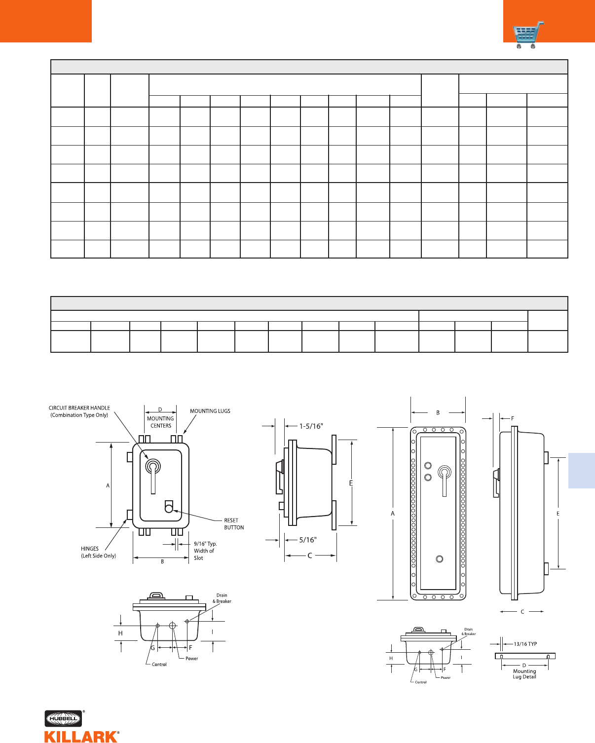
ABC D E FG H I J K L M
62-1/4" 20-1/4" 15" 18-1/2" 43-1/2" 2-5/8" 3-1/8" 5-3/8" 7-3/8" 3-1/2 4" 1/2" 1"
(1581) (514) (381) (470) (1105) (67) (79) (137) (187) (89) (102) (13) (25)
Starter Only
Starter Only
Starter Only
Starter Only
Combination
Starter
Combination
Starter
Combination
Starter
Combination
Starter
B7 DIMENSIONS
11/2" conduit openings may be used for drain and/or breather installation. Smaller conduit openings may be used by utilizing reducing bushings.
Custom conduit sizes and locations are available upon request.
(457) (280) (232) (92) (416) (54) (60) (68) (87)
(508) (317) (232) (127) (467) (63) (63) (68) (81)
(667) (317) (276) (127) (625) (63) (70) (103) (140)
(870) (419) (292) (229) (830) (95) (102) (113) (152)
(584) (368) (232) (178) (543) (54) (64) (68) (87)
(648) (368) (232) (178) (606) (54) (64) (68) (87)
(692) (454) (280) (263) (651) (89) (89) (106) (140)
(870) (546) (302) (356) (829) (121) (127) (116) (157)
DIMENSIONS FOR SIZE 5 COMBINATION STARTER
DIMENSIONS CONDUIT TOP & BTM. (NPT) ENCL. WT.
(LBS.)
540
ABCDEFGH I POWER CONTROL
B7011 0,1 18" 11" 9-1/8" 3-5/8" 16-3/8" 2-1/8" 2-3/8" 2-11/16" 3-7/16" 46 1-1/2" 3/4" 1/2"
B7012 2 20" 12-1/2" 9-1/8" 5" 18-3/8" 2-1/2" 2-1/2" 2-11/16" 3-3/16" 56 1-1/2" 3/4" 1/2"
B7013 3 26-1/4" 12-1/2" 10-3/4" 5" 24-5/8" 2-1/2" 2-3/4" 4-1/16" 5-1/2" 80 2" 1" 1/2"
B7014 4 34-1/4" 16-1/2" 11-1/2" 9" 32-5/8" 3-3/4" 4" 4-7/16" 6" 155 3" 1" 1/2"
B7021 0,1 23" 14-1/2" 9-1/8" 7" 21-3/8" 2-1/8" 2-1/2" 2-11/16" 3-7/16" 78 1-1/2" 3/4" 1/2"
B7022 2 25-1/2" 14-1/2" 9-1/8" 7" 23-7¼8" 2-1/8" 2-1/2" 2-11/16" 3-7/16" 88 1-1/2" 3/4" 1/2"
B7023 3 27-1/4" 17-7/8" 11" 10-3/8" 25-5/8" 3-1/2" 3-1/2" 4-3/16" 5-1/2" 143 2" 1" 1/2"
B7024 4 34-1/4" 21-1/2" 11-7/8" 14" 32-5/8" 4-3/4" 5" 4-9/16" 6-3/16" 235 3" 1" 1/2"
Dimensions B7 Size 0 Thru 4 Dimensions B7 Size 5
B7 SERIES •CONTROLS
MOTOR STARTERS DIMENSIONS C47
C
CATALOG
NUMBER
NEMA
SIZE TYPE
CATALOG
NUMBER
EST.
ENCLOLSRE
WEIGH
LBS.
DIMENSIONS CONDUIT OPENINGS
TOP/BOTTOM (IN.)1
TYPE
DRAIN
BREATHER
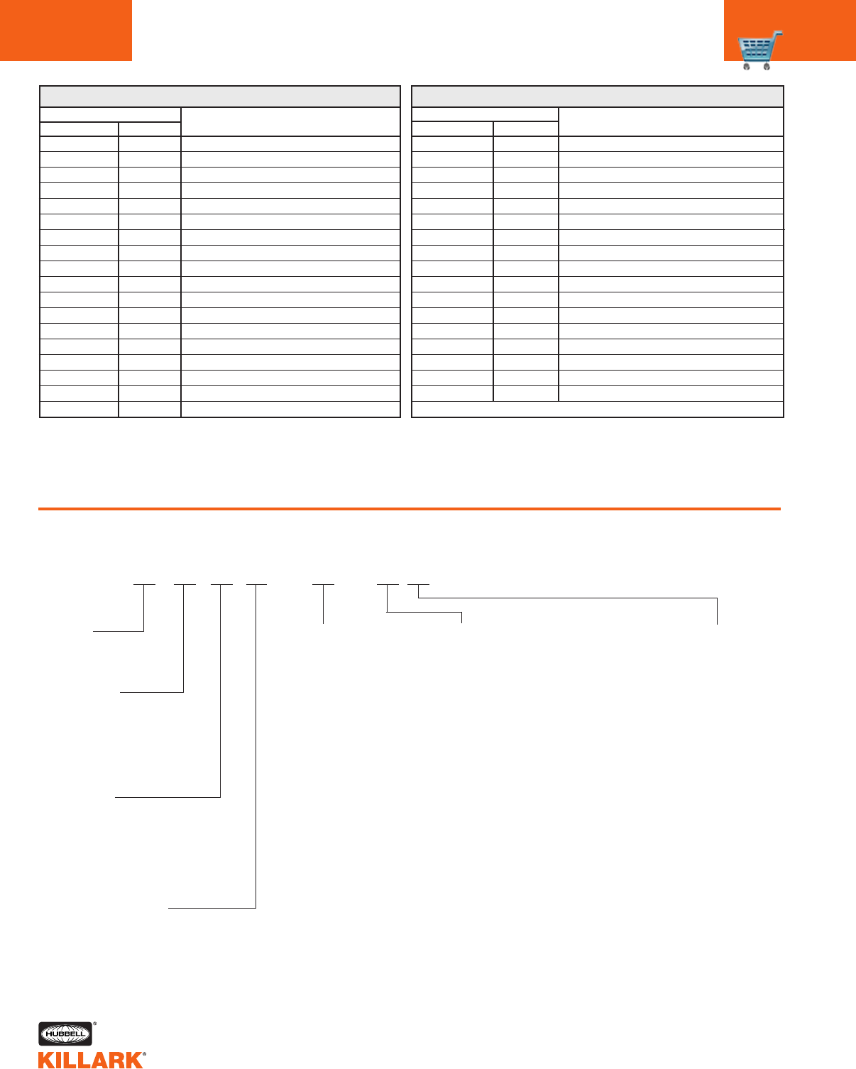
B7 SERIES •CONTROLS
MOTOR STARTERS ACCESSORIES/CATALOG LOGIC
C48
B7
Starter Manufacturer
S—Square D
H—Cutler-Hammer (Freedom)
Starter Size
0
1
2
3
4
Starter Type
01—Non-Combination
(SSNR)
02—Combination
(SSNR)
Series
Constant
Catalog Logic – B7 Enclosures with Controls
Starter Coil Voltage
A—110V-60HZ
B—120/110V-60/50HZ
C—120/240V=60/50HZ
D—208/220V-60HZ
E—208/220/480V-60HZ
F—220V-60HZ
G—240/220V-50/60HZ
H—240/480V-60HZ
J—440/380V-60/50HZ
K—480/440V-60/50HZ
L—550V-60HZ
M—600/550V-60/50HZ
N—600V-50HZ
V—Specify Voltage
Disconnect
Current Rating
A—3 AMP
B—7 AMP
C—15 AMP
D—20 AMP
E—25 AMP
F—30 AMP
G—35 AMP
H—40 AMP
J—45 AMP
K—50 AMP
L—60 AMP
M—70 AMP
N—80 AMP
P—90 AMP
Q—100 AMP
R—110 AMP
S—125 AMP
T—150 AMP
U—175 AMP
V—200 AMP
W—225 AMP
X—250 AMP
Disconnect Means
A—Sq. D. FAL Mag Guard
B—Sq. D. KAL Mag Guard
C—Cutler-Hammer HMCP Motor C.R. Protector
D—Sq. D. FAL Thermal Magnetic
E—Sq. D. FHL Thermal Magnetic
F—Sq. D. FCL Thermal Magnetic
G—Sq. D. KAL Thermal Magnetic
H—Sq. D KHL Thermal Magnetic
J—Sq. D. KCL Thermal Magnetic
K—Cutler-Hammer EHD Thermal Magnetic
L—Cutler-Hammer FDB Thermal Magnetic
M—Cutler-Hammer FD Thermal Magnetic
N—Cutler-Hammer HFD Thermal Magnetic
P—Cutler-Hammer FDC Thermal Magnetic
B7 MODIFICATIONS AND ACCESSORIES
CATALOG NUMBER DESCRIPTION
SIZE 0 THRU 4 SIZE 5
B7DBP B7EDBP Double pushbutton (Start/Stop)
B7RPL B7ERPL Red pilot light 120 Volt
B7GPL B7EGPL Green pilot light 120 Volt
B7APL B7EAPL Amber pilot light 120 Volt
B7LPBR B7ELPBR Illuminated red pushbutton 120 Volt
B7LPBG B7ELPBG Illuminated green pushbutton 120 Volt
B7LPBA B7ELPBA Illuminated amber pushbutton 120 Volt
B7PLR220 B7PLR220 Pilot light resistor 220 Volt to 110 Volt
B7PLR440 B7PLR440 Pilot light resistor 440 Volt to 110 Volt
B7PLR550 B7PLR550 Pilot light resistor 550 Volt to 110 Volt
B72SS B7ESS 2 position selector switch ( On-Off )
B7SSHOA B7ESSHOA 3 position selector switch ( Hand-Off-Auto )
B7HAC B75CAC Cutler Hammer auxiliary contact (1NO/1NC)
B7SAC B75SAC Square D auxiliary contact (1NO/1NC)
B7TB B7TB Terminal block ( 6 Terminals )
— B7IPR Interposing relay 120 Volt coil
B7CT50 — Control transformer 50VA (0,1,2)*
B7CT75 — Control transformer 75VA (0,1,2)*
* Control transformers are primary 240/480 - Secondary 120 Volt. Control
transformers for use on Combination Starters Only. Will not fit into
B701 Series of Non-Combination Starters.
* All control transformers include fused primary and secondary circuits.
** Installation of drains and breathers will void the NEMA4-4x ratings - voids Group B for CSA.
B7 MODIFICATIONS AND ACCESSORIES (CONTINUED)
CATALOG NUMBER DESCRIPTION
SIZE 0 THRU 4 SIZE 5
B7CT100 — Control transformer 100VA (0,1,2)*
B7CT150 — Control transformer 150VA (0,1,2)*
B7CT200 — Control transformer 200VA (3,4)*
B7CT250 — Control transformer 250VA (3,4)*
— B7CT300 Control transformer 300VA (5)*
— B7CT500 Control transformer 500VA (5)*
KB1B KB1B Breather** (not CSA)
KB1D KB1D Drain** (not CSA)
KIT-251 KIT-251 Grounding kit
B7SF B7SF Special finish - Baked epoxy outside
B7DLO B7DLO Delete lock “”ON”” feature for breaker handle
B7SH251 B7SH251 Space heater 25 Watt 120 Volt
B7SH252 B7SH252 Space heater 25 Watt 240 Volt
B7SH254 B7SH254 Space heater 25 Watt 480 Volt
B7SH501 B7SH501 Space heater 50 Watt 120 Volt
B7SH502 B7SH502 Space heater 50 Watt 240 Volt
B7SH504 B7SH504 Space heater 50 Watt 480 Volt
This Catalog Logic Chart is for reference only and is to be used for selection of special voltage and amperage requirements.
Consult Factory since not all assemblies are available with complete list of options displayed.
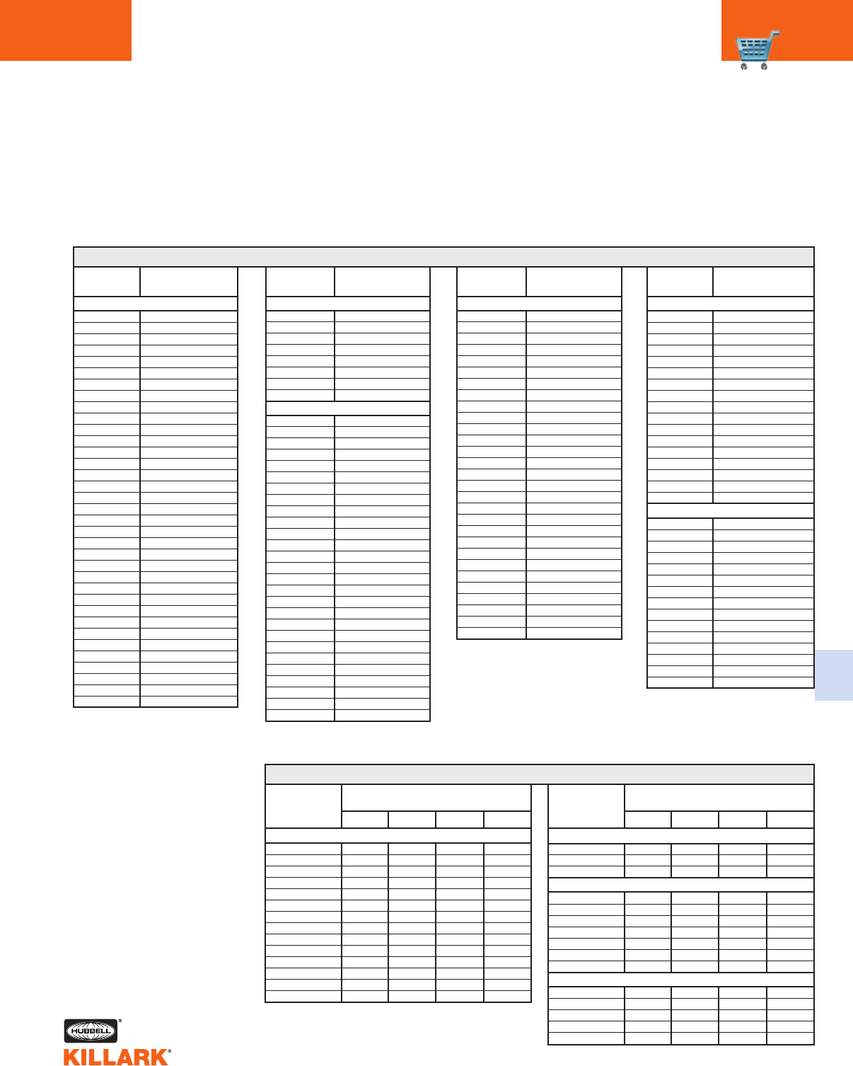
OVERLOAD HEATERS/NON-REVERSING •CONTROLS
3-POLE, 60HZ, 600VAC SINGLE-SPEED C49
C
FOR SIZE 0-1 FOR SIZE 1 FOR SIZE 3 FOR SIZE 4
CATALOG
NUMBER
FULL-LOAD
CURRENT (AMPS)
NOTE: Square D 8536 series starters SSNR ambient compensated 20ÞC to 60ÞC block type overload using 3 heaters.
Three required for each starter.
Overload heaters are not
supplied as part of the
starter assemblies and are
to be ordered as separate
items by catalog number
and priced accordingly.
Heaters should be selected
on the basis of the actual
full-load current and service
factor as shown on the
motor nameplate or in the
manufacturer’s published lit-
erature.
When motor and overload
relay are in the same ambi-
ent and the service factor of
the motor is 1.15 to 1.25,
select heaters from the
heater selection chart. If
the service factor of the
motor is 1.0, or there is no
service factor shown, or a
maximum of 115% protec-
tion is desired, select one
size smaller heater than
indicated.
When motor and overload
relay are in different ambi-
ents, select heaters from the
chart using adjusted motor
currents as follows:
decrease rated motor cur-
rent 1% for each ÞC motor
ambient exceeds controller
ambient; increase rated
motor current 1% for each
ÞC controller ambient
exceeds motor ambient.
CATALOG
NUMBER
FULL-LOAD
CURRENT (AMPS)
CATA L O G
NUMBER
FULL-LOAD
CURRENT (AMPS)
CATALOG
NUMBER
FULL-LOAD
CURRENT (AMPS)
CATAL O G
NUMBER
MOTOR FULL-LOAD AMPERE RATING
DIAL POSITION
KB044
KB051
KB057
KB063
KB071
KB081
KB092
KB103
KB116
KBI30
KBI45
KB167
KB188
KB210
KB240
KB265
KB330
KB300
KB370
KB415
KB485
KB550
KB625
KB690
KB770
KB820
KB910
KB102
KB115
KB128
KB014
KB155
KB175
KB195
KB022
KB022
KB025
KB280
KB032
KB036
KB040
KB045
KB050
0.28-0.30
0.31-0.34
0.35-0.37
0.38-0.44
0.45-0.53
0.54-0.59
0.60-0.64
0.65-0.72
0.73-0.80
0.81-0.90
0.91-1.03
1.04-1.14
1.15-1.27
1.28-1.43
1.44-1.62
1.63-1.77
1.78-1.97
1.98-2.32
2.33-2.51
2.52-2.99
3.00-3.42
3.43-3.75
3.76-3.98
3.99-4.48
4.49-4.93
4.94-5.21
5.22-5.84
5.85-6.67
6.68-7.54
7.55-8.14
8.15-8.72
8.73-9.66
9.67-10.5
10.6-11.3
11.4-12.0
KB485
KB550
KB625
KB690
KB770
KB820
KB910
KB102
KB115
KB128
KB014
KB155
KB175
KB195
KB022
KB025
KB280
KB032
KB036
KB040
KB045
KB050
KB056
KB062
KB070
KB079
KB088
3.18-3.40
3.41-3.76
3.77-4.00
4.01-4.57
4.58-5.03
5.04-5.32
5.33-5.97
5.98-6.88
6.89-7.82
7.83-8.47
8.48-9.15
9.16-10.1
10.2-11.2
11.3-12.0
12.1-13.6
13.7-15.2
15.3-17.1
17.2-19.0
19.1-21.5
21.6-24.1
24.2-27.0
27.1-28.7
28.8-30.4
30.5-32.2
32.3-35.4
35.5-38.2
38.3-45.0
13.6-14.5
14.6-15.5
15.6-17.4
17.5-18.5
18.6-19.9
20.0-21.5
21.6-22.9
23.0-24.5
24.6-26.3
26.4-28.2
28.3-30.0
30.1-32.3
32.4-34.9
35.0-37.6
37.7-40.0
40.1-42.8
42.9-45.3
45.4-49.1
49.2-53.4
53.5-57.4
57.5-61.3
61.4-63.5.
63.6-66.3
66.4-69.0
69.1-70.9
71.0-73.7
73.8-76.5
76.6-78.4
78.5-86.0
KCC209
KCC228
KCC246
KCC263
KCC288
KCC310
KCC333
KCC364
KCC396
KCC427
KCC466
KCC501
KCC545
KCC594
KCC643
KCC685
KCC749
KCC815
KCC877
KCC940
KCC103
KCC112
KCC121
KCC132
KCC143
KCC156
KCC167
KCC180
KCC196
11.4-12.7
12.8-14.1
14.2-15.9
16.0-17.5
17.6-1 9.7
19.8-21.9
22.0-24.4
24.5-26.0
KH2001B-3
KH2002B-3
KH2003B-3
KH2004B-3
KH2005B-3
KH2006B-3
KH2007B-3
KH2008B-3
KH2009B-3
KH2010B-3
KH2011B-3
KH2012B-3
KH2013B-3
KH2014B-3
.254
.375
.560
.814
1.20
1.79
2.15
3.23
4.55
6.75
9.14
14.0
18.7
23.5
.306
.452
.676
.983
1.45
2.16
2.60
3.90
5.50
8.17
10.8
16.9
22.7
28.5
.359
.530
.791
1.15
1.71
2.53
3.04
4.56
6.45
9.58
12.4
19.9
26.7
33.5
.411
.607
.907
1.32
1.96
2.90
3.49
5.23
7.40
11.0
14.0
22.8
30.7
38.5
ABCD
KCC643
KCC685
KCC746
KCC815
KCC877
KCC940
KCC103
KCC112
KCC121
KCC132
KCC143
KCC156
KCC167
KCC180
KCC196
KCC208
KCC219
41.1-43.5
43.6-46.8
46.9-50.0
50.1-54.9
55.0-57.5
57.6-61.8
61.9-66.2
66.3-72.4
72.5-78.1
78.2-80.7
80.8-86.5
86.6-93.9
94.0-100
101.-112.
113.-117.
118.-123.
124.-133.
KDD112
KDD121
KDD128
KDD140
KDD150
KDD160
KDD185
KDD220
KDD240
KDD250
KDD265
KDD280
KDD300
KDD320
KDD320
82.5-88.2
88.3-95.9
96.0-102.
103.-109.
110.-121.
122.-139.
140.-154.
155.-163.
164.-175.
176.-184.
185.-195.
196.-215.
216.-224.
225.-243.
244.-266.
FOR SIZES 0-1
CATAL O G
NUMBER
MOTOR FULL-LOAD AMPERE RATING
DIAL POSITION
KH2015B-3
KH2016B-3
KH2017B-3
29.0
39.6
53.9
34.0
45.5
60.9
39.1
51.5
67.9
44.1
57.4
74.9
KH2018-3
KH2019-3
KH2020-3
KH2021-3
KH2022-3
KH2023-3
KH2024-3
18.0
24.6
33.5
45.7
62.2
84.7
106.0
20.2
27.6
37.5
51.2
69.7
95.0
118.0
22.3
30.5
41.5
56.7
77.1
105.0
131.0
24.5
33.4
45.6
62.1
84.6
115.0
144.0
KH2004B-3
KH2005B-3
KH2006B-3
KH2007B-3
KH2008B-3
49
72
107
129
194
59
87
130
156
234
69
103
152
182
274
79
118
174
209
---
ABCD
FOR SIZE 2
FOR SIZES 3-4
FOR SIZE 5
FOR SIZE 2
FOR SIZE 5
SQUARE D 8536 SERIES STARTERS SSNR NEMA SIZES 0-1 THROUGH 5
CUTLER-HAMMER HEATER (EACH HEATER PACK CONSISTS OF 3 HEATERS)
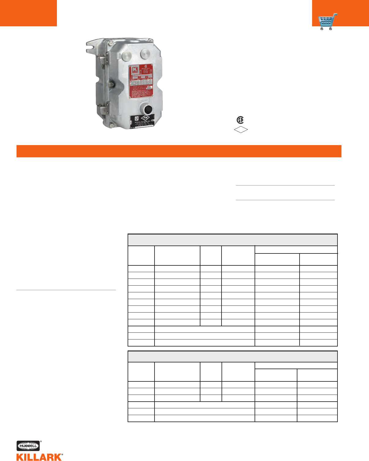
Y7 SERIES •CONTROLS
MOTOR STARTERS-MAGNETIC LINE STARTERS
C50
FEATURES-SPECIFICATIONS
Certified - File LR11714
Contact Killark for FM file numbers.
FM
APPROVED See files for details or call Killark.
Class I, Div. I & 2, Groups C,D
Class 1, Zones 1 & 2, Groups llB, llA
Class II, Div. 1 & 2, Groups E,F,G
Class Ill
NEMA 7(C,D) 9(E,F,G)
Y7011ZH
Applications
•Hazardous areas due to the pres-
ence of flammable gases or vapors,
combustible dusts or easily ignitable
fibers or flyings
•Installations at petroleum refineries,
chemical and petrochemical plants,
storage areas and other processing
facilities where hazardous sub-
stances are handled or stored
•Full-voltage, across-the-line starting
and stopping of polyphase AC squir-
rel cage induction motors or as the
primary starter for wound rotor
motors
•Provides running and undervoltage
protection of motor
•Remote starting and stopping of
motor
Features
•Rectangular bolted cover design pro-
vides for attractive, compact, uniform
installations
•Ground flange joint between box and
cover provides required flame path
•Two drilled and tapped power con-
duit openings, one top and one bot-
tom are standard on all assemblies.
•One 3/4"-14 NPT drilled, tapped and
plugged conduit opening is provided
in bottom for remote control
•Two 3/4"-14 NPSM drilled, tapped,
and plugged openings in cover are
provided for addition of local control
operator
•External reset button and stainless
steel cover bolts are standard
•Hinges are either stainless steel or
aluminum and are mounted on the
left side of all assemblies
•Enclosure is cast copper-free alu-
minum alloy
•Available for Cutler-Hammer AN16
Freedom or Square D 8536 starters
Overload Heaters
Heaters not included. See page C49
for heater selection
Dimensions
See page C52 for dimensional data
Modifications
See page C52
Y7 MAGNETIC LINE STARTER
(ENCLOSURES WITHOUT SPACE FOR CONTROL TRANSFORMER)
Y7 MAGNETIC LINE STARTER
(ENCLOSURES WITH SPACE FOR CONTROL TRANSFORMER)
NEMA
STARTER MOTOR COIL MAXIMUM
SIZE VOLTS VOLTS HP
0 Sep Control 120 —
0 230 240 3
0 440-460 480 5
1 Sep Control 120 —
1 230 240 7-1/2
1 440-460 480 10
2 Sep Control 120 —
2 230 240 15
2 440-460 480 25
0 Enclosure only No interior
1 Enclosure only No interior
2 Enclosure only No interior
CUTLER-HAMMER SQUARE D
SERIES AN16 SERIES 8536
Y7010BH Y7010BS
Y7010DH Y7010DS
Y7010KH Y7010KS
Y7011BH Y7011BS
Y7011DH Y7011DS
Y7011KH Y7011KS
Y7012BH Y7012BS
Y7012DH Y7012DS
Y7012KH Y7012KS
Y7010ZH Y7010ZS
Y7011ZH Y7011ZS
Y7012ZH Y7012ZS
CATALOG NUMBER
NEMA
STARTER MOTOR COIL MAXIMUM
SIZE VOLTS VOLTS HP
0 230//460 120 3//5
1 230//460 120 7 1/2//10
2 230//460 120 15//25
0 Enclosure only No interior
1 Enclosure only No interior
2 Enclosure only No interior
CUTLER-HAMMER SQUARE D
SERIES AN16 SERIES 8536
Y7000BH Y7000BS
Y7001BH Y7001BS
Y7002BH Y7002BS
Y7000ZH Y7000ZS
Y7001ZH Y7001ZS
Y7002ZH Y7002ZS
CATALOG NUMBER
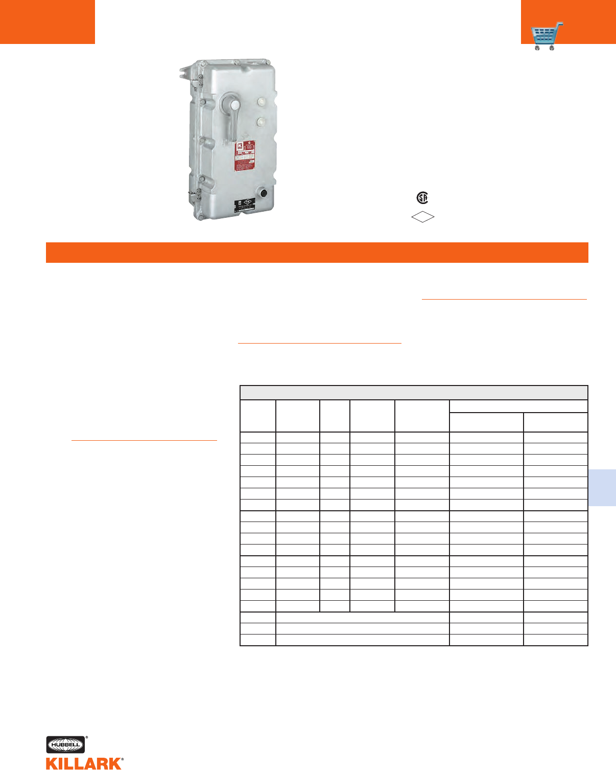
Y7 SERIES •CONTROLS
COMBINATION MOTOR STARTERS C51
FEATURES-SPECIFICATIONS
C
Certified - File LR11714
Contact Killark for FM file numbers.
FM
APPROVED
See files for details or call Killark.
Class I, Div. 1 & 2, Groups C,D
Class l, Zones 1 & 2, Groups llB, llA
Class II, Div. 1 & 2, Groups E,F,G
Class Ill
NEMA 7(C,D) 9(E,F,G)
Y7021ZHAZ
Applications
•Hazardous areas due to the
presence of flammable gases or
vapors, combustible dusts or
easily ignitable fibers or flyings
•Full-voltage, across-the-line
starting and stopping of
polyphase AC squirrel cage
induction motors or as the pri-
mary starter for wound rotor
motors
•Provides running and undervolt-
age protection of motor
•Motor branch circuit disconnect
and short circuit protection
Features
•Rectangular bolted cover design
provides for attractive, compact,
uniform installations
•Two 3/4"-14 NPSM drilled,
tapped, and plugged openings
are provided for addition of local
operators
•Two drilled, tapped and plugged
openings, one top and one bot-
tom are supplied for installation
of drain and breather
•Hinges are either stainless steel
or aluminum and are mounted
on the left side of all assemblies
•Circuit breaker handle mecha-
nism interlocks with circuit
breaker to prevent opening of
enclosure when circuit is in the
“ON” position
•External handle is vault type with
standard provisions for locking in the
“OFF” position with up to three pad-
locks
•Circuit breaker is trip free of handle
mechanism
Modifications
Modifications are available.
See page C52.
Dimensions
For dimensional data, see page C52.
Overload Heaters
Heaters are not included.
See page C49 for heater selection.
Y7 COMBINATION MAGNETIC LINE STARTER
NEMA DISCONNECT
STARTER MOTOR COIL MAXIMUM TRIP
SIZE VOLTS VOLTS HP AMPS
0 Sep Control 120 -3
0 Sep Control 120 -7
0 Sep Control 120 - 15
0 230 240 17
0 230 240 3 15
0 460 480 13
0 460 480 57
1 Sep Control 120 - 15
1 Sep Control 120 - 30
1 230 240 7-1/2 30
1 460 480 10 30
2 Sep Control 120 - 50
2 Sep Control 120 - 70
2 230 240 15 50
2 230 240 15 70
2 460 480 25 50
0 Enclosure only. No Interior
1 Enclosure only. No Interior
2 Enclosure only. No Interior
CUTLER-HAMMER SQUARE D
SERIES AN16 SERIES 8536
Y7020BHVV Y7020BSVV
Y7020BHVX Y7020BSVX
Y7020BHVA Y7020BSVA
Y7020DHVX Y7020DSVX
Y7020DHVA Y7020DSVA
Y7020KHVV Y7020KSVV
Y7020KHVX Y7020KSVX
Y7021BHVA Y7021BSVA
Y7021BHVC Y7021BSVC
Y7021DHVC Y7021DSVC
Y7021KHVC Y7021KSVC
Y7022BHVE Y7022BSVE
Y7022BHVG Y7022BSVG
Y7022DHVE Y7022DSVE
Y7022DHVG Y7022DSVG
Y7022KHVE Y7022KSVE
Y7020ZHVZ Y7020ZSVZ
Y7021ZHVZ Y7021ZSVZ
Y7022ZHVZ Y7022ZSVZ
CATALOG NUMBER
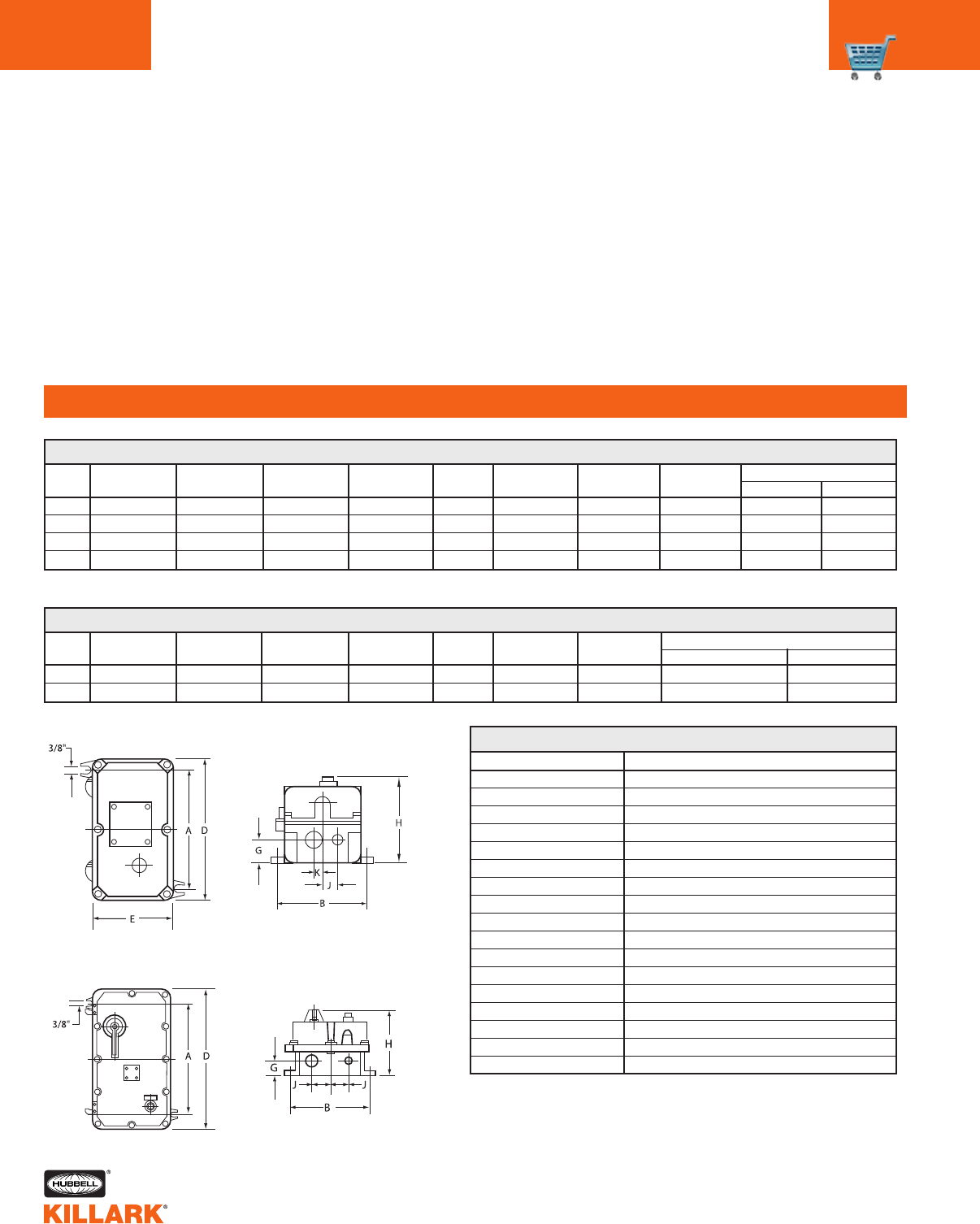
Y7 SERIES •CONTROLS
MOTOR STARTERS/MODIFICATIONS
C52
FEATURES-SPECIFICATIONS
Combination Starter Modifications
Modifications are available by ordering the
following by catalog number as separate
items and noting on the order that they are
to be assembled into the enclosure.
NEMA CONDUIT SIZE
SIZE AB DEGHJ K
POWER CONTROL
0-117-3/4"(197) 7-1/4"(184) 10"(254) 6"(152) 2"(51) 7-5/8"(194) 1-1/8"(28) 3/4"(19) 1-1/2" 3/4"
219"(228) 7-3/4"(197) 11-1/4"(286) 6-1/2"(165) 2"(51) 7-5/8"(194) 1-1/8"(28) 7/8"(22) 1-1/2" 3/4"
0-128-3/4"(222) 11-1/8"(282) 12-1/2"(317) 10-1/2"(267) 2"(51) 8-1/4"(209) 2-3/8"(60) 2-3/8"(60) 1-1/2" 3/4"
228-3/4"(222) 11-1/8"(282) 12-1/2"(317) 10-1/2"(267) 2"(51) 8-1/4"(209) 2-3/8"(60) 2-3/8"(60) 1-1/2" 3/4"
Y7 MAGNETIC LINE STARTERS DIMENSIONS
Dimensions
NEMA CONDUIT SIZE
SIZE AB DEGHJ POWER CONTROL
0-1 16-1/4"(413) 11-1/8"(282) 20"(508) 10-1/2"(267) 2"(51) 9"(228) 2-3/8"(60) 1-1/2" 3/4"
2 16-1/4"(413) 11-1/8"(282) 20"(508) 10-1/2"(267) 2"(51) 9"(228) 2-3/8"(60) 1-1/2" 3/4"
Y7 COMBINATION STARTERS DIMENSIONS
1Without space for control transformer. 2With space for control transformer.
Y7 MODIFICATIONS AND ACCESSORIES
* Control transformers are primary 240/480 - Secondary 120 Volt.
* All control transformers include fused primary and secondary circuits.
CATALOG NUMBER
GO22-GR12D
GOB3-R23C N34
GOB3-G23C N34
GOB3-A23C N34
B7PLR220
B7PLR440
B7PLR550
GO25-2A3F
GO25-3C3G
B7HAC
B7SAC
B7CT50
B7CT75
B7CT100
KDB-1
KDB-1
KIT-251
DESCRIPTION
Double pushbutton (Start/Stop)
Red pilot light 120 Volt
Green pilot light 120 Volt
Amber pilot light 120 Volt
Pilot light resistor 220 Volt to 120 Volt
Pilot light resistor 440 Volt to 120 Volt
Pilot light resistor 550 Volt to 120 Volt
2 position selector switch (On/Off)
3 position selector switch (Hand/Off/Auto)
Cutler-Hammer auxiliary contact (1NO/1NC)
Square D auxiliary contact (1NO/1NC)
Control transformer 50VA*
Control transformer 75VA*
Control transformer 100VA*
Breather
Drain
Grounding kit
Magnetic Line Starters
Sizes 0, 1, 2
Combination Starters
Sizes 0, 1, 2
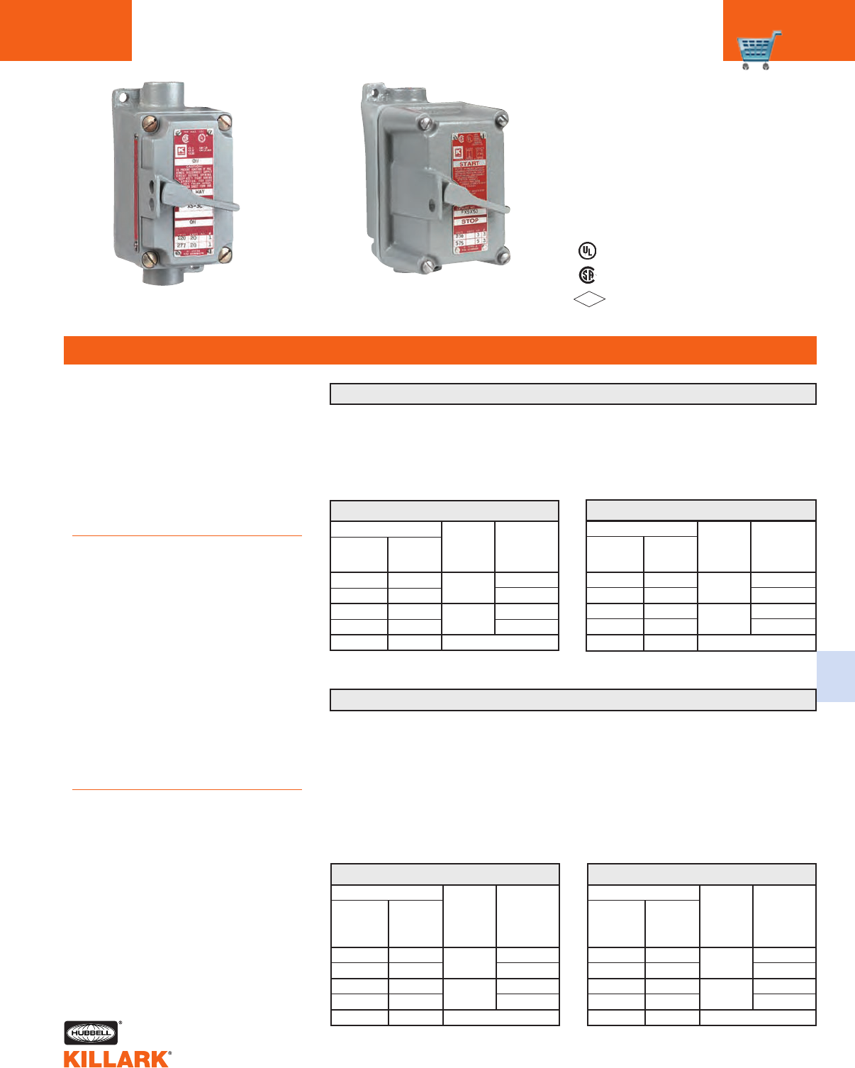
XSD/XSX/FXSD/FXSX SERIES •CONTROLS
MANUAL MOTOR STARTING SWITCHES C53
FEATURES-SPECIFICATIONS
C
Listed - File E53360 and/or E12379
Certified - File LR11714
FM – File 25219
See files for details or call Killark.
FM
APPROVED
XSD, XSX, Series
Non Factory Sealed
FXSD, FXSX Series
Factory Sealed
Class I, Div. 1 & 2, Groups C,D
Class 1, Zones 1 & 2, Groups llB, llA
Class II, Div. 1 & 2, Groups E,F,G
Class Ill
NEMA 7(C,D) 9(E,F,G)
NEMA 3 (Factory sealed type)
Applications
•Provides manual starting and stop-
ping of small AC or DC motors
•Motor running protection when over-
load heaters are used
•XSX/FXSX Series (without overload
protection) are ideally suited for
across-the-line applications where a
positive disconnect means is
required
Features
•FXSX-FXSD Series require no exter-
nal seals (factory sealed) and are
NEMA 3 (raintight) rated
•Enclosures are cast copper-free
aluminum alloy
•Operating shaft is stainless steel
•Multiple gang assemblies available in
combination with pilot lights, push-
buttons and switches on request
•Ground flange joint between bolted
cover and box provide required flame
path
•Provisions for padlocking switch in
either “ON” or ”OFF” position is stan-
dard
Dimensions
For dimensional data, see page C54.
CATALOG NUMBER
1-POLE 2-POLE HUB HUB
SINGLE SINGLE STYLE SIZE
PHASE PHASE
XSD-11 XSD-12 Dead 1/2"
XSD-21 XSD-22 end 3/4"
XSD-41 XSD-42 Feed 1/2"
XSD-51 XSD-52 thru 3/4"
XSD-01 XSD-02 Cover and Switch assembly
XSD SINGLE GANG2
Non-Factory Sealed:
Square D, Class 2510, Type F
1-Pole, 1HP, 115-230 VAC
2-Pole, 1HP, 115-230 VAC
3/4 HP, 115-230 VDC
Factory Sealed:
Square D, Class 2510, Type F
1-Pole, 1HP, 115-230 VAC
2-Pole, 1HP, 115-230 VAC
3/4 HP, 115-230 VDC
1Order heaters separately on page C54.
2FM and CSA only
1FM and CSA only
XSD/FXSD SERIES WITH OVERLOAD PROTECTION1
Non-Factory Sealed:
Square D, Class 2510, Type K
2-Pole, 2 HP, 115 VAC
2 HP, 200-230 VAC
3 HP, 460-575 VAC
3-Pole, 2 HP, 115 VAC
7-1/2 HP, 200-230 VAC
10 HP, 460-575 VAC
Factory Sealed:
Square D, Class 2510, Type K
2-Pole, 2 HP, 115 VAC
2 HP, 200-230 VAC
3 HP, 460-575 VAC
3-Pole, 2 HP, 115 VAC
3 HP, 200-230 VAC
5 HP, 460-575 VAC
XSX/FXSX SERIES WITHOUT OVERLOAD PROTECTION
CATALOG NUMBER
2-POLE 3-POLE HUB HUB
30A., 250V 30A., 250V STYLE SIZE
20A., 600V 20A., 600V
1-PHASE 3-PHASE
XSX-12 XSX-13 Dead 1/2"
XSX-22 XSX-23 end 3/4"
XSX-42 XSX-43 Feed 1/2"
XSX-52 XSX-53 thru 3/4"
XSX-2 XSX-3 Cover and Switch assembly
XSX SINGLE GANG1
CATALOG NUMBER
2-POLE 3-POLE HUB HUB
30A., 250V 30A., 250V STYLE SIZE
20A., 600V 20A., 600V
1-PHASE 3-PHASE
FXSX12 FXSX13 Dead 1/2"
FXSX22 FXSX23 end 3/4"
FXSX42 FXSX43 Feed 1/2"
FXSX52 FXSX53 thru 3/4"
FXSX02 FXSX03 Cover and Switch assembly
FXSX SINGLE GANG
CATALOG NUMBER
1-POLE 2-POLE HUB HUB
SINGLE SINGLE STYLE SIZE
PHASE PHASE
FXSD11 FXSD12 Dead 1/2"
FXSD21 FXSD22 end 3/4"
FXSD41 FXSD42 Feed 1/2"
FXSD51 FXSD52 thru 3/4"
FXSD01 FXSD02 Cover and Switch assembly
FXSD SINGLE GANG
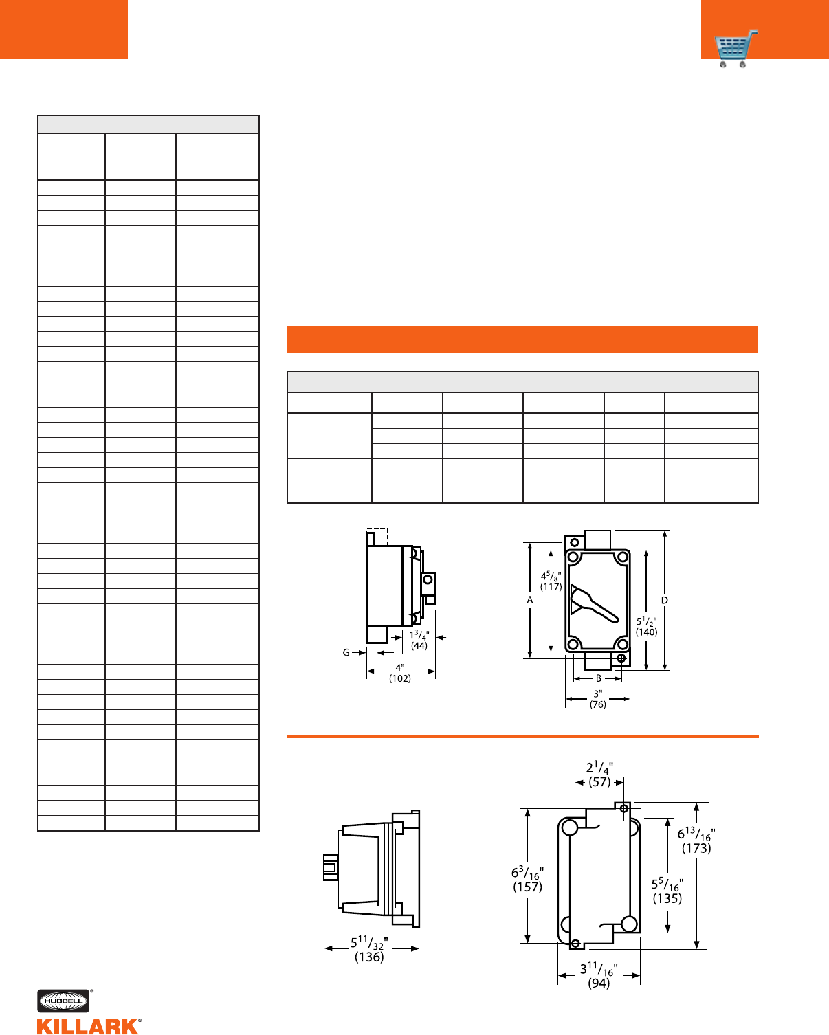
HEATER TABLE1
1Overload heaters are not supplied as part of the
starter assemblies and need to be ordered as
separate items by catalog number and priced
accordingly.
XSD/XSX NON-FACTORY SEALED DIMENSIONS
SQUARE D
FULL-LOAD HEATERCATALOG MOTOR CATALOGNUMBER CURRENT NUMBER
YOSD-A.49 0.41-0.44 A.49
YOSD-A.54 0.45-0.49 A.54
YOSD-A.59 0.50-0.53 A.59
YOSD-A.65 0.54-0.58 A.65
YOSD-A.71 0.59-0.65 A.71
YOSD-A.78 0.66-0.71 A.78
YOSD-A.86 0.72-0.78 A.86
YOSD-A.95 0.79-0.85 A.95
YOSD-A1.02 0.86-0.96 A1.02
YOSD-A1.16 0.97-1.04 A1.16
YOSD-A1.25 1.05-1.16 A1.25
YOSD-A1.39 1.17-1.29 A1.39
YOSD-A1.54 1.30-1.37 A1.54
YOSD-A1.63 1.38-1.47 A1.63
YOSD-A1.75 1.48-1.56 A1.75
YOSD-A1.86 1.57-1.65 A1.86
YOSD-A1.99 1.66-1.79 A1.99
YOSD-A2.15 1.80-1.95 A2.15
YOSD-A2.31 1.96-2.15 A2.31
YOSD-A2.57 2.16-2.38 A2.57
YOSD-A2.81 2.39-2.75 A2.81
YOSD-A3.61 2.76-2.84 A3.61
YOSD-A3.95 2.85-3.06 A3.95
YOSD-A4.32 3.07-3.45 A4.32
YOSD-A4.79 3.46-3.70 A4.79
YOSD-A5.30 3.71-4.07 A5.30
YOSD-A5.78 4.08-4.32 A5.78
YOSD-A6.20 4.33-4.90 A6.20
YOSD-A6.99 4.91-5.35 A6.99
YOSD-A7.65 5.36-5.85 A7.65
YOSD-A8.38 5.86-6.41 A8.38
YOSD-A9.25 6.42-6.79 A9.25
YOSD-A9.85 6.80-7.57 A9.85
YOSD-A11.0 7.58-8.15 A11.0
YOSD-A11.9 8.16-8.98 A11.9
YOSD-A13.2 8.99-9.67 A13.2
YOSD-A14.1 9.68-9.95 A14.1
YOSD-A14.8 9.96-10.8 A14.8
YOSD-A16.2 10.9-12.1 A16.2
YOSD-A17.9 12.2-13.1 A17.9
YOSD-A19.8 13.2-13.9 A19.8
YOSD-A21.3 14.0-15.0 A21.3
YOSD-A25.2 15.1-16.0 A25.2
BOX STYLE HUB SIZE ABDG
1/2" 5-1/4"(133) 2-1/4"(57) — 11/16"(17)
3/4" 5-1/4"(133) 2-1/4"(57) — 11/16"(17)
1" 5-3/8"(136) 2-3/8"(60) — 7/8"(22)
1/2" 5-1/4"(133) 2-1/4"(57) 6"(152) 11/16"(17)
3/4" 5-1/4"(133) 2-1/4"(57) 6"(152) 11/16"(17)
1" 5-3/8"(136) 2-3/8"(60) 6"(152) 7/8"(22)
FACTORY SEALED (FXSD/FXSX)
Single gang
dead-end
Single gang
feed-thru
XSD/XSX/FXSD/FXSX SERIES •CONTROLS
XSD/XSX/FXSD/FXSX HEATERS
C54
FEATURES-SPECIFICATIONS

FEATURES-SPECIFICATIONS
Class I, Div. 1 & 2, Groups B,C,D
Class l, Zones 1 & 2, Groups llB+H2, llA
Class II, Div. 1 & 2, Groups E,F,G
Class III, Div. 1 & 2
NEMA 3, 4, 4X, 7(B,C,D) 9(E,F,G)
CCertified - File LR11714
US
Constant for Series
Enclosure Size
1 = B7EP
2 = B7EQ
Operating Device
R = Rotary
P = Push Buttons
Starter Manufacturer
to be supplied
S = Square D
A = ABB
Blank = Enclosure only
Horsepower (FLA) of starter
Accessories
A = Aux. Contacts NO + NC
B7MS 1 R S 1 A
Applications
The PRISM®B7MS Series of non-revers-
ing, manual line voltage starters and
enclosures are suitable for use in applica-
tions requiring manual across-the-line
starting and stopping of small single and
polyphase AC motors, and where over-
load protection is needed. Manual starters
are generally used on small machine
tools, fans and blowers, pumps, compres-
sors, and conveyors as well as many
other types of electrical equipment.
PRISM®enclosures universal design
accommodates, as standard, IEC starter
manufacturers including Square D, Cutler-
Hammer, ABB, Siemens, Moeller,
Sprecher + Schuh, Allen-Bradley,
Advance Controls, and WEG.
Square D © Schneider Electric
Siemens © Siemens AG
Moeller © Moeller Electric Corp.
See catalog pg. DE8A for copyrights of other
brands referenced.
When ordered with starters, ABB or
Square D supplied.
Features
• Compact size enclosures provide
application flexibility with cost savings
over industry standard sizes
• NEMA 4, 4X rated - providing pro-
tection from hose directed water and
corrosion
• Pre-drilled to facilitate easy field
installation of starters
• 2 operating styles, rotary or push
button, including lock-out provision.
• Provisions for drain and breather
• Bi-directional ductile mounting lugs
• Two NPT conduit openings provided
as standard, with custom openings
on request
Electrical Rating
• Starters rated 600V, 3 phase up to 50HP
Standard Materials / Finish
• Enclosures: Copper-free aluminum
(less than 4/10 of 1% copper content)
• Cover Bolts: 316 Stainless Steel
• O-ring Gasket: Silicone
• Finish: Grey Powder Polyester painted
exterior, electrostatically applied
KIT-251 100 amp ground lug
AAuxiliary contacts 1 NO + 1 NC
SU-2 Hinge-9 Installed
SU3* Drain & Breather installed (NEMA 7CD)
SU3B* Drain & Breather installed (NEMA 7BCD)
B7SPNPT Change Std. conduit size and location
SU9 Special paint finish
SU14 Fungus proofing of enclosures
SUFFIX DESCRIPTION
NUMBER
*NOTE: The installation of a Drain & Breather will void the
NEMA 4-4X rating of enclosure.
MODIFICATIONS
Enclosure OUTSIDE BOX NOMINAL MOUNTING CONDUIT
DIMENSIONS INSIDE BOX DIMENSIONS SIZE
AB CDEFGHIJK -
B7MS1 5-3/4 8-1/16 6-5/16 3-5/8 5-13/16 5-1/16 3-1/8 8-1/8 --1-1/4 1
B7MS2 8-1/8 13-1/16 7-13/16 4-1/4 9-13/16 6-5/16 2-1/2 11-3/8 6-3/8 7-1/2 1-13/16 1-1/2
Catalog Logic
Fixed Lug Position For B7MS1
Optional Position For B7MS2
Standard Lug Position For B7MS2
DIMENSIONS
B7MS SERIES •CONTROLS
COMPACT MANUAL IEC STARTERS C55
C
B7MS1P
Push Button Style
B7MS2R
Rotary Style
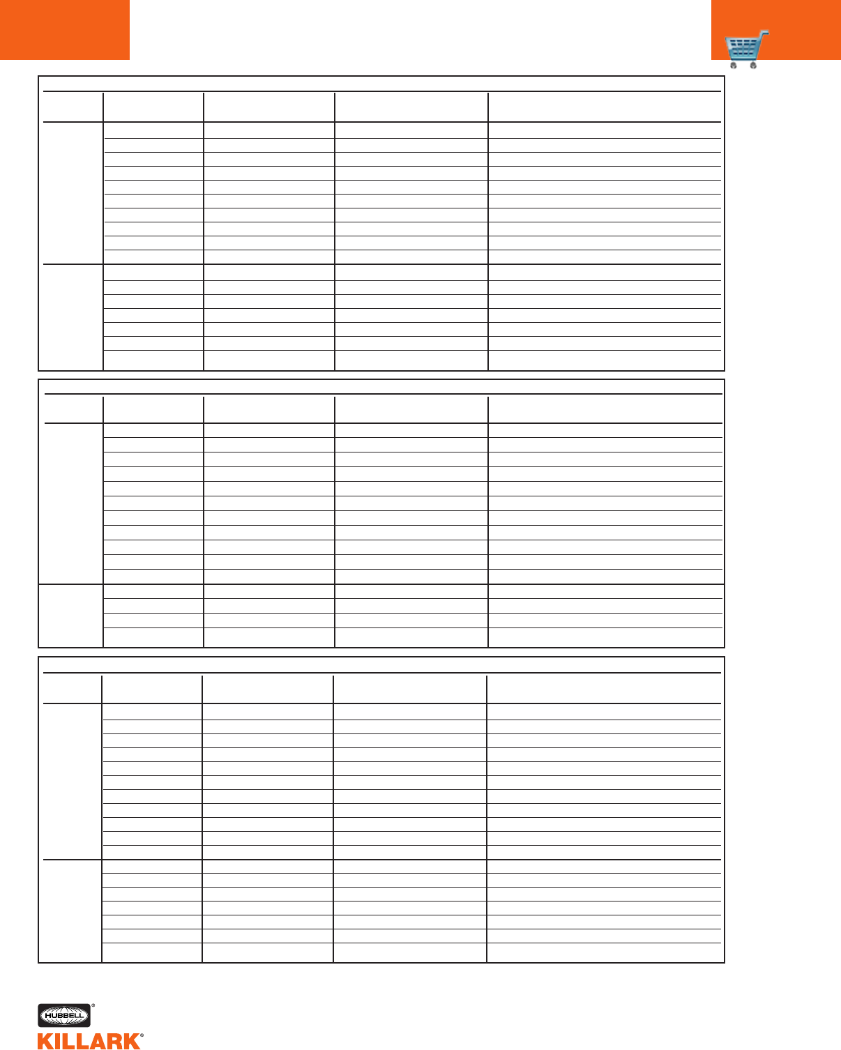
C56 B7MS SERIES • CONTROLS
COMPACT MANUAL IEC STARTERS
B7MS1R - For use with ABB
MS116, MS325, MS132
Automation Direct BM3
Cutler-Hammer XTPR
Moeller PKZMO
Seimens 3RV
Sprecher + Schuh KTA7
SQ D Telemecanique GV2P
WEG MPW25
B7MS2R - For use with
Automation Direct BM3
B7MS2RA - For use with ABB
MS450
B7MS1P - For use with
Cutler-Hammer XTPB
Moeller PKZMO1
SQ D Telemecanique GV2ME
WEG MPW25
B7MS2P - For use with
Advance Control MMS25
* B7MS1PRW - (enclosure
without starter) For use with
Allen-Bradley 140
Sorecher + Schuh KT4
B7MS - ROTARY STYLE WITH ABB MS132 & MS450 SERIES
CATALOG ADJUSTMENT SINGLE PHASE HP THREE PHASE HP
NUMBER RANGE FLA 120V 230V 200V-208V 230V 480V 600V
B7MS1RA-1 0.63 - 1.0 0.5 0.5
B7MS1RA-2 1.0 - 1.6 0.1 0.75 0.75
B7MS1RA-3 1.6 - 2.5 0.167 0.5 1 1.5
B7MS1RA-4 2.5 - 4.0 0.125 0.33 123
B7MS1RA-5 4.0 - 6.3 0.25 0.5 1.5 35
B7MS1R B7MS1RA-6 6.3 - 9.0 0.33 1 2.5 5 7.5
B7MS1RA-7 9.0 - 12.5 0.5 237.5 10
B7MS1RA-8 12.5 - 16.0 1 2.5 5 10 10
B7MS1RA-9 16.0 - 20.0 1.5 3510 15
B7MS1RA-10 20.0 - 25.0 23 7.5 15 20
B7MS2RA-12 11 - 16 135510 15
B7MS2RA-13 14 - 20 1.5 357.5 15 20
B7MS2RA-14 18 - 25 257.5 10 20 25
B7MS2RA-15 22 - 32 3510 10 25 30
B7MS2RA-16 28 - 40 3 7.5 15 15 30 40
B7MS2RA-17 36 - 45 5 7.5 15 15 30 40
B7MS2RA-18 40 - 50 5 10 15 20 40 50
B7MS - PUSH BUTTON STYLE SQUARE D GV2 SERIES
CATALOG ADJUSTMENT SINGLE PHASE HP THREE PHASE HP
NUMBER RANGE FLA 120V 230V 200V-208V 230V 480V 600V
B7MS1PS-1 0.63 - 1.0 0.5 0.5
B7MS1PS-2 1.0 - 1.6 0.1 0.75 1
B7MS1PS-3 1.6 - 2.5 0.167 0.5 0.5 1 1.5
B7MS1PS-4 2.5 - 4.0 0.125 0.33 0.75 123
B7MS1PS-5 4.0 - 6.3 0.25 0.5 1.5 1.5 35
B7MS1PS-6 6.0 - 10.0 0.5 1.5 23 57.5
B7MS1PS-7 9.0 - 14.0 0.75 23310 10
B7MS1PS-8 13.0 - 18.0 135510 15
B7MS1PS-9 17.0 - 23.0 1.5 357.5 15 20
B7MS1PS-10 20.0 - 25.0 2357.5 15 20
B7MS1PS-11 24.0 - 32.0 2510 10 20 30
B7MS2PS-12 10.0 - 16.0 123510 10
B7MS2PS-14 16.0 - 25.0 2357.5 15 20
B7MS2PS-16 25.0 - 40.0 3 7.5 10 10 25 30
B7MS2PS-18 40.0 - 63.0 5 10 20 20 40 50
ENCLOSURE
WITHOUT
STARTER
B7MS1R
ENCLOSURE
WITHOUT
STARTER
B7MS2RA
FOR USE
WITH ABB
ONLY
ENCLOSURE
WITHOUT
STARTER
B7MS1P*
ENCLOSURE
WITHOUT
STARTER
B7MS2P
B7MS - ROTARY STYLE WITH SQUARE D GV2 & GV3 SERIES
CATALOG ADJUSTMENT SINGLE PHASE HP THREE PHASE HP
NUMBER RANGE FLA 120V 230V 200V-208V 230V 480V 600V
B7MS1RS-1 0.63 - 1.0 0.5 0.5
B7MS1RS-2 1.0 - 1.6 0.1 0.75 1
B7MS1RS-3 1.6 - 2.5 0.167 0.5 0.5 1 1.5
B7MS1RS-4 2.5 - 4.0 0.125 0.33 0.75 123
B7MS1RS-5 4.0 - 6.3 0.25 0.5 1.5 1.5 35
B7MS1RS-6 6.0 - 10.0 0.5 1.5 23 57.5
B7MS1RS-7 9.0 - 14.0 0.75 23310 10
B7MS1RS-8 13.0 - 18.0 135510 15
B7MS1RS-9 17.0 - 23.0 1.5 357.5 15 20
B7MS1RS-10 20.0 - 25.0 2357.5 15 20
B7MS1RS-11 24.0 - 32.0 2510 10 20 30
ENCLOSURE
WITHOUT
STARTER
B7MS1R
ENCLOSURE
WITHOUT
STARTER
B7MS2R
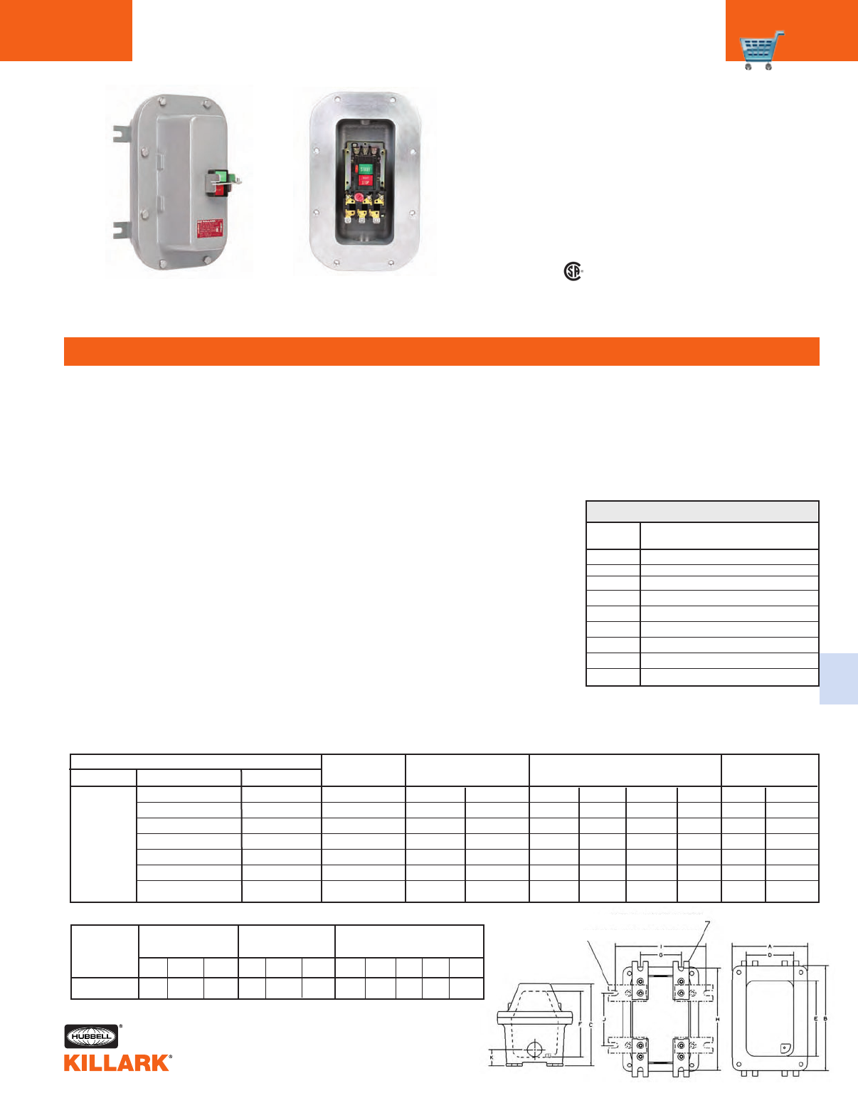
C57
C
B7MS SERIES • CONTROLS
COMPACT MANUAL NEMA STARTERS
FEATURES-SPECIFICATIONS
Class I, Div. 1 & 2, Groups B,C,D
Class l, Zones 1 & 2, Groups llB+H2, llA
Class II, Div. 1 & 2, Groups E,F,G
Class III, Div. 1 & 2
NEMA 3, 4, 4X, 7(B,C,D) 9(E,F,G)
B7MSN2P INTERNAL VIEW
CCertified - File LR11714
US
Applications
The PRISM®B7MSN Series of non-
reversing, manual line voltage starters
and enclosures are suitable for use in
applications requiring manual across-the-
line starting and stopping of small single
and polyphase AC motors, and where
overload protection is needed. Manual
starters are generally used on small
machine tools, fans and blowers, pumps,
compressors, and conveyors as well as
many other types of electrical equipment.
PRISM®enclosures universal design
accommodates, as standard, starter
manufacturers including
• Allen-Bradley 609 Series
• Cutler-Hammer B100M Series
• GE CR106 Series
• Square D 2510M Series
Allen Bradley © Rockwell Automation
Cutler-Hammer © Eaton Corporation
GE © General Electric Company
Square D © Schneider Electric
Features
• Compact size enclosures provide
application flexibility with cost savings
over industry standard sizes
• NEMA 4, 4X rated - providing pro-
tection from hose directed water and
corrosion
• Pre-drilled to facilitate easy field
installation of starters
• Large double green/red start-stop
push buttons
• Can be pad locked in “OFF” position
• Provisions for drain and breather
• Bi-directional ductile mounting lugs
• Two 1-1/2” NPT conduit openings pro-
vided as standard, with custom open
ings on request
Electrical Rating
NEMA starter sizes 0, 1, 1-1/2 FVNR;
2 pole single phase = 230 VAC
3 pole three phase = 600 VAC
2 pole VDC = 230 VDC
Overload Heaters
Heaters are not included, see next page.
Standard Materials /Finish
• Enclosures: Copper-free aluminum
(less than 4/10 of 1% copper content)
• Cover Bolts: 316 Stainless Steel
• O-ring Gasket: Silicone
• Finish: Grey Powder Polyester painted
exterior, electrostatically applied
** = INCLUDES 380VAC CH = CUTLER-HAMMER ONLY
KIT-251 100 amp ground lug
AO Aux. contact NO only
AC Aux. contact NC only
SU-2 Hinge-9 Installed
SU3* Drain & Breather installed (NEMA 7CD)
SU3B* Drain & Breather installed (NEMA 7BCD)
B7SPNPT Change Std. conduit size and location
SU9 Special paint finish
SU14 Fungus proofing of enclosures
SUFFIX DESCRIPTION
NUMBER
*NOTE: The installation of a Drain & Breather will void the
NEMA 4-4X rating of enclosure.
MODIFICATIONS
CATALOG NUMBER SIZE/PHASE SINGLE PHASE HP THREE PHASE DC HP
ENCLOSURE W/CUTLER-HAMMER W/SQUARE D 120VAC 230VAC 208VAC 230VAC 480VAC** 600VAC 115DC 230VDC
B7MSN2PC0B B7MSN2PS0B M-0 2P 12 1 CH 1.5 CH
B7MSN2PC1B B7MSN2PS1B M-1 2P 23 1.5 CH 2 CH
B7MSN2PSDB M-1P 2P 35
B7MSN2PC0C B7MSN2PS0C M-0 3P 33 5 5
B7MSN2PC1C B7MSN2PS1C M-1 3P 7.5 7.5 10 10
B7MSN2PS0V M-0 2P VDC 1 1.5
B7MSN2PS1V M-1 2P VDC 1.5 2
B7MSN2P
Optional Position
Standard Lug Position For B7MSN2P
Enclosure OUTSIDE BOX NOMINAL MOUNTING
DIMENSIONS INSIDE BOX DIMENSIONS
AB CDEFGHIJK
B7MSN2P 8-1/8 13-1/16 7-13/16 4-1/4 9-13/16 6-5/16 2-1/2 11-3/8 6-3/8 7-1/2 1-13/16
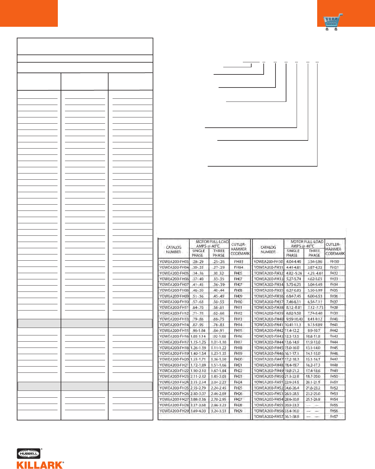
C58 B7MSN SERIES • CONTROLS
HEATERS, CATALOG LOGIC, DIMENSIONS
Catalog Logic
Constant for Series
Enclosure Size
2 = B7EQ
Operating Device
P = Push Buttons
Starter Manufacturer
C = Cutler-Hammer
S = Square D
Blank = Enclosure only
NEMA Size
O = Size Ø 1 = Size 1 D = Size 1-1/2
Number of Poles
B = 2 Pole 1 Ø (Cutler-Hammer, Sq.D only)
C = 3 Pole 3 Ø
V = 2 Pole DC
Accessories
AO = NO Aux. Contact AC = NC Aux. Contact
B7MSN 2 P C 1 B A
CATALOG
NUMBER
SINGLE
PHASE
THREE
PHASE
KB044
KB051
KB057
KB063
KB071
KB081
KB092
KB103
KB116
KB130
KB145
KB167
KB188
KB210
KB240
KB265
KB300
KB330
KB370
KB415
KB485
KB550
KB625
KB690
KB770
KB820
KB910
KB102
KB115
KB128
KB014
KB155
KB175
KB195
KB022
KB025
SIZE 1 & 1P
KB195
KB022
KB025
KB280
KB032
KB036
KB040
KB045
SIZE 1P
KB036
KB040
KB045
KB050
0.33 - 0.36
0.37 - 0.40
0.41 - 0.45
0.46 - 0.52
0.53 - 0.59
0.60 - 0.66
0.67 - 0.73
0.74 - 0.81
0.82 - 0.91
0.92 - 1.02
1.03 - 1.14
1.15 - 1.29
1.20 - 1.42
1.43 - 1.64
1.65 - 1.80
1.81 - 2.10
2.11 - 2.30
2.31 - 2.61
2.62 - 2.99
3.00 - 3.37
3.38 - 3.94
3.95 - 4.24
4.25 - 4.54
4.55 - 5.29
5.30 - 5.73
5.74 - 6.35
6.36 - 7.08
7.09 - 7.83
7.84 - 8.47
8.48 - 9.83
9.84 - 10.5
10.6 - 11.4
11.5 - 12.8
12.9 - 13.9
14.0 - 16.1
16.2 - 18.0
SIZE 1 & 1P
-----
-----
16.2 - 17.6
17.7 - 20.6
20.7 - 23.1
23.2 - 26.0
-----
-----
SIZE 1P
23.2 - 27.1
27.2 - 29.2
29.3 - 33.0
33.1 - 36.0
0.29 - 0.32
0.33 - 0.36
0.37 - 0.39
0.40 - 0.47
0.48 - 0.56
0.57 - 0.63
0.64 - 0.69
0.70 - 0.77
0.78 - 0.86
0.87 - 0.96
0.97 - 1.11
1.12 - 1.23
1.24 - 1.37
1.38 - 1.55
1.56 - 1.75
1.76 - 1.92
1.93 - 2.16
2.17 - 2.50
2.51 - 2.81
2.82 - 3.16
3.17 - 3.40
3.41 - 3.76
3.77 - 4.00
4.01 - 4.68
4.69 - 5.18
5.19 - 5.51
5.52 - 6.19
6.20 - 7.12
7.13 - 8.15
8.16 - 8.60
8.61 - 9.21
9.22 - 10.1
10.2 - 11.2
11.3 - 12.0
-----
-----
SIZE 1 & 1P
11.3 - 12.1
12.2 - 13.6
13.7 - 15.3
15.4 - 17.3
17.4 - 19.1
19.2 - 21.7
21.8 - 24.2
24.3 - 26.0
SIZE 1P
-----
-----
-----
-----
1Select heater element based on motor nameplate listed full load amps.
Trip rating of element is 125% of motor minimum F.L.A. listed for the element
B7MSN Heater Selection1
Square D 2510M Only
Motor Full Load AMPS @40oC
Size 0
B7MSN Heater Selections
CUTLER-HAMMER
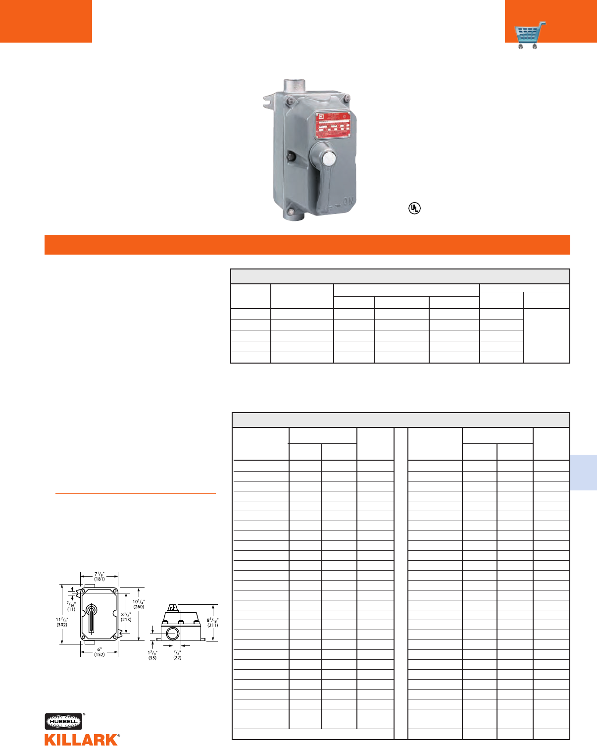
XMSW SERIES • CONTROLS
MANUAL LINE STARTERS C59
FEATURES-SPECIFICATIONS
C
HEATER TABLE FOR XMSW SERIES MANUAL LINE STARTERS1
MOTOR FULL-LOAD
AMPS @ 40OCCUTLER
CATALOG SINGLE THREE HAMMER
NUMBER PHASE PHASE
YOWEA200-FH03 .28-.29 .25-.26 FH03
YOWEA200-FH04 .30-.33 .27-.29 FH04
YOWEA200-FH05 .34-.36 .30 .32 FH05
YOWEA200-FH06 .37-.40 .33-.35 FH07
YOWEA200-FH07 .41-.45 .36-.39- FH07
YOWEA200-FH08 .46-.50 .40-.44 FH08
YOWEA200-FH09 .51-.56 .45-.49 FH09
YOWEA200-FH10 .57-.63 .50-.55 FH10
YOWEA200-FH11 .64-.70 .56-.61 FH11
YOWEA200-FH12 .71-.78 .62-.68 FH12
YOWEA200-FH13 .79-.86 .69-.75 FH13
YOWEA200-FH14 .87-.95 .76-.83 FH14
YOWEA200-FH15 .96-1.04 .84-.91 FH15
YOWEA200-FH16 1.05-1.14 .92-1.00 FH16
YOWEA200-FH17 1.15-1.25 1.01-1.10 FH17
YOWEA200-FH18 1.26-1.39 1.11-1.22 FH18
YOWEA200-FH19 1.40-1.54 1.23-1.35 FH19
YOWEA200-FH20 1.55-1.71 1.36-1.50 FH20
YOWEA200-FH21 1.72-1.89 1.51-1.66 FH21
YOWEA200-FH22 1.90-2.10 1.67-1.84 FH22
YOWEA200-FH23 2.11-2.32 1.85-2.03 FH23
YOWEA200-FH24 2.33-2.54 2.04-2.23 FH24
YOWEA200-FH25 2.55-2.79 2.24-2.45 FH25
YOWEA200-FH26 2.80-3.07 2.46-2.69 FH26
YOWEA200-FH27 3.08-3.36 2.70-2.95 FH27
YOWEA200-FH28 3.37-3.68 2.96-3.23 FH28
YOWEA200-FH29 3.69-4.03 3.24-3.53 FH29
MOTOR FULL-LOAD
AMPS @ 40OCCUTLER
CATALOG SINGLE THREE HAMMER
NUMBER PHASE PHASE
YOWEA200-FH30 4.04-4.40 3.54-3.86 FH30
YOWEA200-FH31 4.41-4.81 3.87-4.22 FH31
YOWEA200-FH32 4.82 -5.26 4.23 -4.61 FH32
YOWEA200-FH33 5.27-5.74 4.62-5.03 FH33
YOWEA200-FH34 5.75-6.25 5.04-5.49 FH34
YOWEA200-FH35 6.27-6.83 5.50-5.99 FH35
YOWEA200-FH36 6.84-7.45 6.00-6.53 FH36
YOWEA200-FH37 7.46-8.11 6.54-7.11 FH37
YOWEA200-FH38 8.12 -8.81 7.12 -7.73 FH38
YOWEA200-FH39 8.82-9.58 7.74-8.40 FH39
YOWEA200-FH40 9.59-10.40 8.41-9.12 FH40
YOWEA200-FH41 10.41-11.3 9.13-9.89 FH41
YOWEA200-FH42 11.4-12.2 9.9-10.7 FH42
YOWEA200-FH43 12.3-13.5 10.8-11.8 FH43
YOWEA200-FH44 13.6-14.9 11.9-13.0 FH44
YOWEA200-FH45 15.0-16.0 13.1-14.0 FH45
YOWEA200-FH46 16.1-17.1 14.1-15.0 FH46
YOWEA200-FH47 17.2-18.3 15.1-16.1 FH47
YOWEA200-FH48 18.4-19.7 16.2-17.3 FH48
YOWEA200-FH49 19.8-21.2 17.4-18.6 FH49
YOWEA200-FH50 21.3-22.8 18.7-20.0 FH50
YOWEA200-FH51 22.9-24.5 20.1-21.5 FH51
YOWEA200-FH52 24.6-26.4 21.6-23.2 FH52
YOWEA200-FH53 26.5-28.5 23.2-25.0 FH53
YOWEA200-FH54 28.6-30.8 25.1-26.8 FH54
YOWEA200-FH55 30.9-33.3 — — FH55
YOWEA200-FH56 33.4-36.0 — — FH56
YOWEA200-FH57 36.1-38.9 — — FH57
1Heaters not included. If heaters are required order as separate item by catalog number, three
phase starters require three heaters. Single phase starters require two heaters.
2Three pole starters may be used on two-phase four-wire circuits by running one wire direct to motor.
XMSW MANUAL LINE STARTERS1 2
CUTLER HAMMER/EATON
B100 STARTERS FULL
VOLTAGE, NON-REVERSING
SINGLE AND POLYPHASE
Listed - File E12379
See files for details or call Killark.
Applications
XMSW Series, non-reversing, manual
line voltage starters and enclosures are
suitable for use in applications requiring
manual across-the-line starting and
stopping of small single and polyphase
AC motors, and where overload protec-
tion is needed. Manual starters are
generally used on small machine tools,
fans and blowers, pumps, compressors,
and conveyors as well as many other
types of electrical machinery.
Features
•Rectangular bolted cover design
provides for attractive, compact,
uniform installations
•Enclosure and external handle are
diecast copper-free (less than 0.4%)
aluminum alloy
•Cast “ON,” “OFF,” “TRIPPED” markings
on cover align with external handle and
provide clear indication of enclosed
starter condition
•External handle is a vault type with
standard provisions for locking in the
”OFF” position with up to three
pad-locks. Provision for locking in
“ON” position is available as factory
modification (add suffix SU-40 to
catalog number).
•Two cast 1" NPT conduit hubs with
integral pipe stop, one top and
one bottom, are standard on all
assemblies
Electrical Rating
Starter sizes 0, 1, 11/2
Two pole, single phase; three pole,
polyphase
Maximum 10 HP, 600 Volts AC
Class I, Div. 1 & 2, Groups C,D
Class l, Zones 1 & 2, Groups llB,
llA
Class II, Div. 1 & 2, Groups E,F,G
Class Ill
NEMA 3R, 7(C,D) 9(E,F,G)
NEMA NUMBER OF MAXIMUM HORSEPOWER
SIZE POLE SIZE 120 VAC 208-240 VAC 480-600 VAC
0 2-PO LE; 1Ø, A C 1 2 —
0 3-PO LE; 3Ø, A C 2 3 5
1 2-PO LE; 1Ø, A C 2 3 —
1 3-POLE; 3Ø, A C 3 7-1/2 10
1-1/2 2-POLE; 1Ø, A C 3 5 —
CATALOG NUMBER
WITH ENCLOSURE
STARTER ONLY
XMSW-0BT
XMSW-0CT
XMSW-1BT XMSW-00T
XMSW-1CT
XMSW-DBT
1Select heater element based on motor
nameplate listed. Full-load amps.
Trip rating of element is125% of motor
minimum F.L.A. listed for the element.
Dimensions
