119893 Catalog
130227-Catalog 130227-Catalog 130227-Catalog Batch9 unilog cesco-content
114087-Catalog 114087-Catalog 114087-Catalog Batch9 unilog cesco-content
2014-10-23
: Pdf 119893-Catalog 119893-Catalog Batch9 unilog
Open the PDF directly: View PDF ![]() .
.
Page Count: 170 [warning: Documents this large are best viewed by clicking the View PDF Link!]

imagination at work
Motion
Solutions
Flexible Solutions for
Improved Machine Productivity
GE Intelligent Platforms Motion Solutions Product Catalog GFA-483T
GE
Intelligent Platforms
02.10 GFA-483T
©2010 GE Intelligent Platforms, Inc. All rights reserved.
*Trademark of GE Intelligent Platforms, Inc.
All other brands or names are property of their respective holders.
GE Intelligent Platforms Contact Information
Americas: 1 800 433 2682 or 1 434 978 5100
Global regional phone numbers are listed by location on our web site at www.ge-ip.com/contact
www.ge-ip.com

1
Motion Solutions
TABLE OF CONTENTS
Motion Controllers ...........................4
PACMotion ..................................5
DSM300 Series .............................17
S2K Series .................................20
Servo Amplifiers ........................... 49
VersaMotion Series .........................50
αi Series ...................................62
βi Series ...................................74
S2K Series .................................82
Servo Motors .............................. 91
αi Series ...................................95
βi Series ..................................106
VersaMotion Series ........................116
MTR Series ................................123
Stepping Amplifiers and Motors . . . . . . . . . . . . 137
Power Cube. . . . . . . . . . . . . . . . . . . . . . . . . . . . . . .138
MTR Series ................................141
Stepping Motor Cube ......................156
Motion Software .......................... 159
Motion Development Software . . . . . . . . . . . .160
Servo Sizing Software . . . . . . . . . . . . . . . . . . . . .162
Product Number Index ..................... 163
©2010 GE Intelligent Platforms, Inc. All Rights Reserved. *Trademark of GE Intelligent Platforms, Inc.
All other brands or names are property of their respective holders. 01.10 GFA-483T
www.ge-ip.com GE Intelligent Platforms
αHV
i
SERIES (con’t)
Brake Cables (Optional)
CB4N-0WPM-0070-AZ (7m)
CB4N-0WPM-0070-AZ (7m)
CB4N-0WPM-0070-AZ (7m)
CB4N-0WPM-0070-AZ (7m)
CB4N-0WPM-0140-AZ (14m)
CB4N-0WPM-0140-AZ (14m)
CB4N-0WPM-0140-AZ (14m)
CB4N-0WPM-0140-AZ (14m)
Encoder Battery (Optional)
Built-In (1-axis) Panel Mounted*
IC800BBK021 IC800ABK001
IC800BBK021 IC800ABK001
IC800BBK021 IC800ABK001
IC800ABK002 IC800ABK001
IC800ABK002 IC800ABK001
IC800ABK003 IC800ABK001
Power Supply Kits†
IC800PSHV011 (11kW)
IC800PSHV018 (18kW)
IC800PSHV030 (30kW)
IC800PSHV045 (45kW)
Motion Solutions
2
Proficy ME
Logic Developer-PLC
IC693ACC336
5V I/O Terminal Board
IC693DSM302
IC693DSM314
44A726268-001
24V I/O Terminal Board
A66L-6001-0023#Lxxxxx (unsheathed)
A66L-6001-0026#Lxxxxx (sheathed)
FSSB Servo Command Cable
Series 90-30RX3i
IC694DSM314 IC693DSM324
IC693CBL324 (1m)
IC693CBL325 (3m)
IC693CBL319 (1m)
IC693CBL311 (3m)
β
i
SERIES
Motors (cont-peak torque)
β0.4/5000is (0.4-1 Nm)
β0.5/6000is (0.65-2.5 Nm)
β1/6000is (1.2-5 Nm)
β2/4000is (2-7 Nm)
β4/4000is (3.5-10 Nm)
β8/3000is (7-15 Nm)
β12/3000is (11-27 Nm)
β22/2000is (20-45 Nm)
Amplifier Kits
IC800BIK020
IC800BIK020
IC800BIK020
IC800BIK040
IC800BIK040
Encoder Cables
(Straight x=0; Right Angle x=7)
CFDA-xWPB-0070-AZ (7m)
CFDA-xWPB-0070-AZ (7m)
CFDA-xWPB-0070-AZ (7m)
CFDA-xWPB-0070-AZ (7m)
CFDA-xWPB-0070-AZ (7m)
CFDA-xWPB-0140-AZ (14m)
CFDA-xWPB-0140-AZ (14m)
CFDA-xWPB-0140-AZ (14m)
CFDA-xWPB-0140-AZ (14m)
CFDA-xWPB-0140-AZ (14m)
Power Cables
(Standard x=P; Shielded x=E)
CP8B-1WxB-0070-AZ (7m)
CP3B-0WxB-0070-AZ (7m)
CP5B-0WxB-0070-AZ (7m)
CP6B-0WxB-0070-AZ (7m)
CP8B-1WxB-0140-AZ (14m)
CP3B-0WxB-0140-AZ (14m)
CP5B-0WxB-0140-AZ (14m)
CP6B-0WxB-0140-AZ (14m)
Power & Brake Cable
(Standard x=P; Shielded x=E)
CP9B-0WxB-0070-AZ (7m)
CP9B-0WxB-0140-AZ (14m)
Brake Cables (Optional)
CB6N-5WPM-0070-AZ (7m)
CB4N-0WPM-0070-AZ (7m)
CB4N-0WPM-0070-AZ (7m)
CB4N-0WPM-0070-AZ (7m)
CB6N-5WPM-0140-AZ (14m)
CB4N-0WPM-0140-AZ (14m)
CB4N-0WPM-0140-AZ (14m)
CB4N-0WPM-0140-AZ (14m)
Encoder Battery (Optional)
Built-In (1-axis) Panel Mounted*
IC800BBK021 IC800ABK001
IC800BBK021 IC800ABK001
IC800BBK021 IC800ABK001
IC800BBK021 IC800ABK001
IC800BBK021 IC800ABK001
Note:
Color coding indicates compatible product matches
and applies to products within a specific series.
*Each panel mounted battery pack can support up to 6 encoders
† One PSM power supply can support up to six αHVi amplifiers
depending on the motor ratings. The power supply must be
sized to match to system power requirements. See the section
“Selecting a Power Supply” on page 73.
βHV
i
SERIES
Motors (cont-peak torque)
β2/4000is (2-7 Nm)
β4/4000is (3.5-10 Nm)
β8/3000is (7-15 Nm)
β12/3000is (11-27 Nm)
β22/2000is (20-45 Nm)
Amplifier Kits
IC800BIHV010
IC800BIHV010
IC800BIHV020
IC800BIHV020
Encoder Cables
(Straight x=0; Right Angle x=7)
CFDA-xWPB-0070-AZ (7m)
CFDA-xWPB-0070-AZ (7m)
CFDA-xWPB-0070-AZ (7m)
CFDA-xWPB-0070-AZ (7m)
CFDA-xWPB-0140-AZ (14m)
CFDA-xWPB-0140-AZ (14m)
CFDA-xWPB-0140-AZ (14m)
CFDA-xWPB-0140-AZ (14m)
Power Cables
(Standard x=P; Shielded x=E)
CP3I-0WxB-0070-AZ (7m)
CP3I-0WxB-0070-AZ (7m)
CP4I-0WxB-0070-AZ (7m)
CP3I-0WxB-0140-AZ (14m)
CP3I-0WxB-0140-AZ (14m)
CP4I-0WxB-0140-AZ (14m)
Power & Brake Cable
(Standard x=P; Shielded x=E)
CP2I-0WxB-0070-AZ (7m)
CP2I-0WxB-0140-AZ (14m)
Brake Cables (Optional)
CB4N-0WPM-0070-AZ (7m)
CB4N-0WPM-0070-AZ (7m)
CB4N-0WPM-0070-AZ (7m)
CB4N-0WPM-0140-AZ (14m)
CB4N-0WPM-0140-AZ (14m)
CB4N-0WPM-0140-AZ (14m)
Encoder Battery (Optional)
IC800BBK021
IC800BBK021
IC800BBK021
IC800BBK021
αHV
i
SERIES
Motors (cont-peak torque)
α2/6000HVis (2-6 Nm)
α2/6000HVis (2-6 Nm)
α4/5000HVis (4-8.8 Nm)
α4/5000HVis (4-8.8 Nm)
α8/6000HVis (8-22 Nm)
α8/6000HVis (8-22 Nm)
α12/4000HVis (12-46 Nm)
α12/4000HVis (12-46 Nm)
α22/3000HVi (22-64 Nm)
α22/3000HVi (22-64 Nm)
α22/4000HVis (22-70 Nm)
α30/4000HVis (30-100 Nm)
α40/4000HVis (40-115 Nm)
α50/3000HVis (75-215 Nm)
Amplifier Kits
IC800BIHV010
IC800BIHV040
IC800AIHV010
IC800AIHV040
IC800AIHV080
IC800AIHV180
Dynamic Braking Module
ZA06B-6079-H401
Encoder Cables
(Straight x=0; Right Angle x=3)
CFDA-xWPB-0070-AZ (7m)
CFDA-xWPB-0070-AZ (7m)
CFDA-xWPB-0070-AZ (7m)
CFDA-xWPB-0070-AZ (7m)
CFDA-xWPB-0070-AZ (7m)
CFDA-xWPB-0070-AZ (7m)
CFDA-xWPB-0140-AZ (14m)
CFDA-xWPB-0140-AZ (14m)
CFDA-xWPB-0140-AZ (14m)
CFDA-xWPB-0140-AZ (14m)
CFDA-xWPB-0140-AZ (14m)
CFDA-xWPB-0140-AZ (14m)
Power Cables
(Standard x=P; Shielded x=E)
CP2I-0WxB-0070-AZ (7m)
CP2I-0WxB-0070-AZ (7m)
CP3I-0WxB-0070-AZ (7m)
CP3I-0WxB-0070-AZ (7m)
CP4I-0WxB-0070-AZ (7m)
CP4I-0WxB-0070-AZ (7m)
CP4I-0WxB-0070-AZ (7m)
CP9I-0MxB-0070-AZ (7m)
CP2I-0WxB-0140-AZ (14m)
CP2I-0WxB-0140-AZ (14m)
CP3I-0WxB-0140-AZ (14m)
CP3I-0WxB-0140-AZ (14m)
CP4I-0WxB-0140-AZ (14m)
CP4I-0WxB-0140-AZ (14m)
CP4I-0WxB-0140-AZ (14m)
CP9I-0MxB-0140-AZ (14m)
FANUC Digital Servos
IC695FTB001
Fiber Terminal I/O Block
IC695PMM335 IC694DSM324
www.ge-ip.com
GE Intelligent Platforms
3
Motion Solutions
Analog Servos and Steppers
Note:
Color coding indicates compatible product matches
and applies to products within a specific column.
†Use this cable in place of power cable for motors with optional brake
Proficy ME Logic Developer-PLC
IC693DSM314 IC693DSM302
IC693DSM314
IC693CBL324 (1m)
IC693CBL325 (3m)
Series 90-30RX3i
IC693DNM200
DeviceNet Master
(To DeviceNet S2K Models)
IC693ACC336
Terminal Board
IC800SKCFLY010 (1m)
IC800SKCFLY030 (3m)
S2K SERVO
AMPLIFIER
(RESOLVER)
115/230 VAC
Motors (cont-peak torque)
MTR-3T11-G (0.3-1.1 Nm)
MTR-3T12-G (0.6-2.4 Nm)
MTR-3T13-G (0.9-2.8 Nm)
MTR-3T21-G (0.6-2.2 Nm)
MTR-3T22-G (1.3-4 Nm)
MTR-3T23-G (2-6 Nm)
MTR-3T24-H (2.6-6.6 Nm)
MTR-3T43-H (5.6-11.3 Nm)
MTR-3T42-H (4.1-12 Nm)
MTR-3T43-J (6.1-12.1 Nm)
MTR-3T44-J (8.1-16.2 Nm)
MTR-3T45-H (10.2-20.5 Nm)
MTR-3T54-H (13.6-34.5 Nm)
MTR-3T55-H (17.1-43.4 Nm)
MTR-3T57-H (20.9-55.3 Nm)
MTR-3T66-H (35.9-87.3 Nm)
MTR-3T67-G (42-101.9 Nm)
MTR-3T69-G (53.9-131.6 Nm)
Amplifiers
IC800SSD104RS1
IC800SSD107RS1
IC800SSD216RS1
IC800SSD228RS1
Resolver Cables
CBL-3T-RD
CBL-3T-RD
CBL-3T-RD
CBL-3T-RD
Power Cables
CBL-T7-MP
CBL-T7-MP
CBL-3T-MP
CBL-3T-MP
Power and Brake Cables†
CBL-T7-MB
CBL-T7-MB
CBL-3T-MB
CBL-3T-MB
S2K SERVO
AMPLIFIER
(RESOLVER)
480 VAC
Motors (cont-peak torque)
MTR-3T42-H (4.1-12 Nm)
MTR-3T43-J (6.1-12.1 Nm)
MTR-3T44-J (8.1-16.2 Nm)
MTR-3T45-H (10.2-20.5 Nm)
MTR-3T54-H (13.4-38.3 Nm)
MTR-3T55-H (16.9-48.1 Nm)
MTR-3T66-H (34.7-52.2 Nm)
MTR-3T67-G (40.2-61 Nm)
MTR-3T69-G (52.3-79 Nm)
Amplifiers
IC800SSD407RS1
IC800SSD420RS1
Resolver Cables
CBL-3T-RD
CBL-3T-RD
Power Cables
CBL-T7-MP
CBL-3T-MP
Power and Brake Cables†
CBL-T7-MB
CBL-3T-MB
S2K SERVO
CONTROLLER
(RESOLVER)
115/230 VAC
Motors (cont-peak torque)
MTR-3T11-G (0.3-1.1 Nm)
MTR-3T12-G (0.6-2.6 Nm)
MTR-3T13-G (0.9-2.8 Nm)
MTR-3T21-G (0.6-2.2 Nm)
MTR-3T22-G (1.3-4.0 Nm)
MTR-3T23-G (2-6 Nm)
MTR-3T24-H (2.6-6.6 Nm)
MTR-3T43-H (5.6-11.3 Nm)
MTR-3T42-H (4.1-12 Nm)
MTR-3T43-J (6.1-12.1 Nm)
MTR-3T44-J (8.1-16.2 Nm)
MTR-3T45-H (10.2-20.5 Nm)
MTR-3T54-H (13.6-34.5 Nm)
MTR-3T55-H (17.1-43.4 Nm)
MTR-3T57-H (20.9-55.3 Nm)
MTR-3T66-H (36-87.3 Nm)
MTR-3T67-G (42-101.9 Nm)
MTR-3T69-G (53.9-131.6 Nm)
Controller
IC800SSI104RD2 DeviceNet
IC800SSI104RP2 PROFIBUS
IC800SSI104RS1 SERIAL
IC800SSI107RD2 DeviceNet
IC800SSI107RP2 PROFIBUS
IC800SSI107RS1 SERIAL
IC800SSI216RD2 DeviceNet
IC800SSI216RP2 PROFIBUS
IC800SSI228RD2 DeviceNet
IC800SSI228RP2 PROFIBUS
Resolver Cables
CBL-3T-RD
CBL-3T-RD
CBL-3T-RD
CBL-3T-RD
Power Cables
CBL-T7-MP
CBL-T7-MP
CBL-3T-MP
CBL-3T-MP
Power and Brake Cables†
CBL-T7-MB
CBL-T7-MB
CBL-3T-MB
CBL-3T-MB
S2K SERVO
CONTROLLER
(RESOLVER)
480 VAC
Motors (cont-peak torque)
MTR-3T42-H (4.1-12 Nm)
MTR-3T43-J (6.1-12.1 Nm)
MTR-3T44-J (8.1-16.2 Nm)
MTR-3T45-H (10.2-20.5 Nm)
MTR-3T54-H (13.4-38.3 Nm)
MTR-3T55-H (16.9-48.1 Nm)
MTR-3T66-H (34.7-52.2 Nm)
MTR-3T67-G (40.2-61 Nm)
MTR-3T69-G (52.3-79 Nm)
Controller
IC800SSI407RD2 DeviceNet
IC800SSI407RP2 PROFIBUS
IC800SSI407RS1 SERIAL
IC800SSI420RD2 DeviceNet
IC800SSI420RP2 PROFIBUS
Resolver Cables
CBL-3T-RD
CBL-3T-RD
Power Cables
CBL-T7-MP
CBL-3T-MP
Power and Brake Cables†
CBL-T7-MB
CBL-3T-MB
S2K STEPPER
CONTROLLER
115 VAC
Motors (holding torque)
MTR-1221-D (144 oz-in)
MTR-1231-D (238 oz-in)
MTR-1324-D (335 oz-in)
MTR-1337-D (675 oz-in)
MTR-1350-A (630 oz-in)
MTR-1350-D (995 oz-in)
MTR-1N31-I (650 oz-in)
MTR-1N32-I (1200 oz-in)
MTR-1N41-G (1905 oz-in)
Splash-proof Motors
(holding torque)
MTR-1324-D (335 oz-in)
MTR-1337-D (675 oz-in)
MTR-1350-A (630 oz-in)
MTR-1350-D (995 oz-in)
Controller
IC800STI105D2 DeviceNet
IC800STI105P2 PROFIBUS
IC800STI105S1 SERIAL
Encoder Cables
CBL-1C-ET
CBL-13-ET
CBL-14-ET
Power Cables
CBL-12-MPS
CBL-13-MP
CBL-14-MP
MOTOR CUBE
Stepping Motors
(holding torque)
IC800MCUB12160XN (50 oz-in)
IC800MCUB12210XN (100 oz-in)
IC800MCUB12310XN (175 oz-in)
Stepping Motor/Encoder
(holding torque)
IC800MCUB12160XE (50 oz-in)
IC800MCUB12210XE (100 oz-in)
IC800MCUB12310XE (175 oz-in)
Encoder Cable
CBL-12-ED-03M-RA (3m)
Power Cables
IC800MCC23P050 (5m)
IC800MCC23P100 (10m)
POWER CUBE
Stepping Amplifier
IC800PCUB00300
Stepping Motors
(holding torque)
MTR-1216 (61 oz-in)
MTR-1220 (116 oz-in)
MTR-1221 (124 oz-in)
MTR-1231 (236 oz-in)
MTR-1235 (185 oz-in)
MTR-1331-J (327 oz-in)
MTR-1N31-I (605 oz-in)
Splash-proof Motors
(holding torque)
MTR-1331-J (327 oz-in)
Encoder Cables
CBL-1C-ET
CBL-13-ET
CBL-14-ET
Power Cables
CBL-12-MP
CBL-13-MP
CBL-14-MP
I/O Cables
IC800PCUBC02S030 (200 S/R; 3m)
IC800PCUBC02S050 (200 S/R; 5m)
IC800PCUBC04S030 (400 S/R; 3m)
IC800PCUBC04S050 (400 S/R; 5m)
IC800PCUBC10S030 (1000 S/R; 3m)
IC800PCUBC10S050 (1000 S/R; 5m)
VersaMax Micro
HE693STP113
Horner Stepper Controller
www.ge-ip.com GE Intelligent Platforms
Motion Solutions
4
Motion Controllers
GE offers motion controllers for a broad range of applications
and system configurations providing the flexibility to choose
a system that optimizes performance and investment cost.
Regardless of your requirements, GE has a motion controller to
meet your requirements, from simple point-to-point indexing to
complex multi-axis machine control.
PACMotion Series
The PACMotion multi-axis motion controller, matched with world
class FANUC digital servos, is designed to deliver unsurpassed
machine productivity required for today’s high-speed machines
and lean manufacturing environments. Hosted by the powerful
PACSystems RX3i controller, PACMotion is part of a complete
automation control solution. Page 5
DSM300 Series
The DSM300 series are multi-axis servo motion controller modules
for the PACSystems* RX3i and Series 90*-30 PLCs. The DSM300
series can control FANUC digital servos or analog servos such
as the VersaMotion series. Page 17
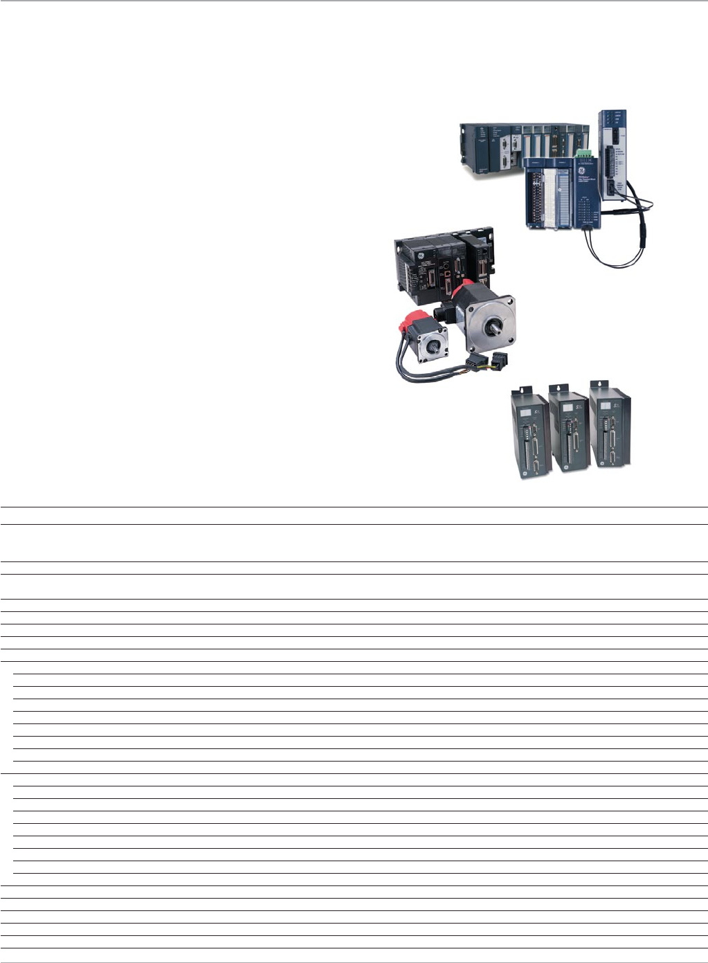
S2K Series
The S2K series are stand-alone motion controllers available for
brushless servo and stepping motor control and include an
integral AC power supply and servo amplifier. Page 20
Feature PACMotion DSM300 S2K
Architecture PAC-based PLC-based Stand-alone
Number of Axes Up to 4 FANUC Digital Servos DSM302: 2 Digital, 2 Analog 1
DSM314: 2 Digital, 4 Analog
DSM324: 4 Digital (Fiber Optic)
Dedicated Master Axis Virtual or Incremental Encoder No No
Servo Command Interface Fiberoptic Fiberoptic/GEF Digital/Analog n/a
Velocity/Analog Torque
Position Feedback Type Serial Encoder Serial Encoder/Quadrature Encoder Resolver
Motor Feedback Resolution (counts/rev) 64K, 128K, 1M 8K 4K
Motion Logic Program Interrupt Driven Task in PAC Separate Program in Module Separate Program in Module
PAC/PLC High Speed Interrupts 3 (time or event) No n/a
Motion Program Integrated Function Blocks or Structured Text Separate Text Program Separate Text Program
Motion Types
Incremental Moves Yes Yes Yes
Absolute Moves Yes Yes Yes
Synchronized Start Up to 8 axes 2 axes No
Delayed Start Up to 8 axes No No
Superimposed Motion Yes Yes Yes
Jogging Yes Yes Yes
Homing Yes Yes Yes
Acc/Dec Linear/ Programmable Jerk Linear/Fixed Jerk Linear/Fixed Jerk
Cam Function Advanced Basic Basic
Cam Queuing Yes No No
Cam Scaling Master and Slave No No
Cam Phase Correction Yes Yes No
Normalized Cam Profiles Yes No No
Dynamic Cam Profile Changes Yes No No
Cam Curve Fitting 1/2/3/5th order 1/2/3rd Order 1st Order
Ramping onto Cam Profile Yes No No
Number of Cam Profiles 2048 99 1
Electronic Gearing (Follower) Advanced Basic Basic
Digital Cam Switch 4 High Speed Outputs No No
Shortest Path Absolute Moves Yes No No
Move Queuing and Blending Advanced Basic Basic
Master/Slave Configuration Up to 40 Axes over PLC Backplane 4-axes on module Hardwired Encoder
www.ge-ip.com
GE Intelligent Platforms
5
Motion Solutions
PACMotion
The PACMotion controller is a versatile servo motion controller that
combines the benefits of a highly integrated motion and machine logic
solution with the performance, flexibility and scalability required for
advanced machine automation. PACMotion is designed to deliver
unsurpassed machine productivity required for today’s high-speed
machines and lean manufacturing environments. The 4-axis servo
motion controller is built on a high performance hardware platform,
with a new enhanced motion engine, operating system, and open
standard integrated programming paradigm. Add to that world class
reliability of FANUC servos and you have a motion system designed
to give you the best productivity and accuracy possible.
Performance to Improve Machine Productivity
• Real-timesynchronizationofupto40axes
• Threehighspeedtime-basedorevent-driveninterruptsenablefastdeterministiceventresponseandsynchronization
• Demand-drivendataexchangemodelbetweenthePACSystemsRX3iCPUandPACMotionmodulesmaysignificantly
reduce scan time impact
• Digitalcamswitch(PLS)functionwithmulti-trackhigh-speedoutputswithmicrosecondlevelresponse
• ReduceddowntimewithindustryleadingFANUCservosfeaturingMTBFratingsinexcessof400,000hours
• LowMTTRFANUCservosrequirenotuningorparametersetting;over5millionaxessold
Open and Integrated to Improve Engineering Productivity
• Singlesoftwaredevelopmentenvironmentwithsharedtagdatabaseforlogic,motion,I/Oandoperatorinterface
• Motionandmachinelogicinacommonprogramgreatlysimplifiesprogramming
• MotionfunctionblocksandstatemodeldesignedtocomplywiththePLCopenprogrammingstandardto
reduce learning curve and training costs
• Buffermodeallowsprogramlogictoqueuemotioncommandsequencesandspecifyorchangethevelocitytransition
between buffered moves on-the-fly
• AdvanceddiagnostictoolsincludedinProficysoftwarespeeddiagnosticsandmachinetimetomarket
Flexibility and Scalability
• Fourservoaxespermodule;Upto40axesinasinglePACSystemsRX3irack
• Built-infaceplateI/OandoptionalfiberI/OterminalblocksupportsextensiveuserconfigurabledigitalandanalogI/O
• AmplifiersandmotionI/Ocanbephysicallydistributedusingnoiseimmunefiberopticinterfaces
• Virtual(time-based)orreal(encoder)masteraxesoverthebackplanesupportadvancedcamandelectronic
gearing applications for flexible electronic line shaft applications
Motion Controllers
PACMotion
www.ge-ip.com GE Intelligent Platforms
Motion Solutions
6
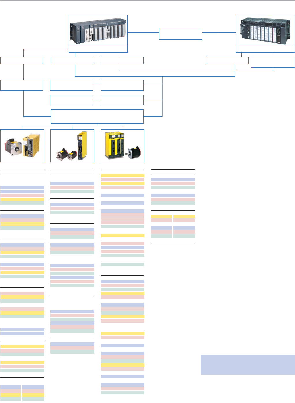
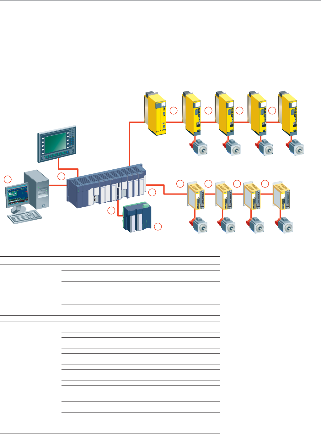
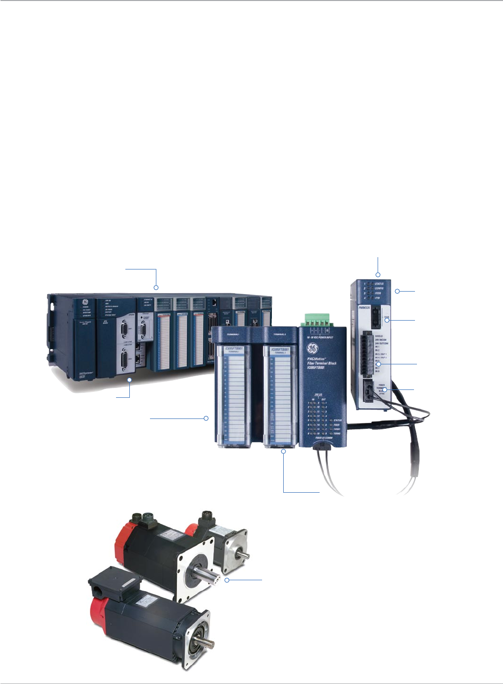
Each PACMotion module can control up to 4 axes of GE βi, βHVi or αHVi servos via a fiber optic command interface for
superior noise immunity, especially in distributed systems. By combining the versatility of the GE PACSystems RX3i and
QuickPanel operator interface products, GE provides customers with a complete integrated machine control solution.
This single-source system results in such benefits as ease of integration and programming, shorter development cycles,
and higher reliability.
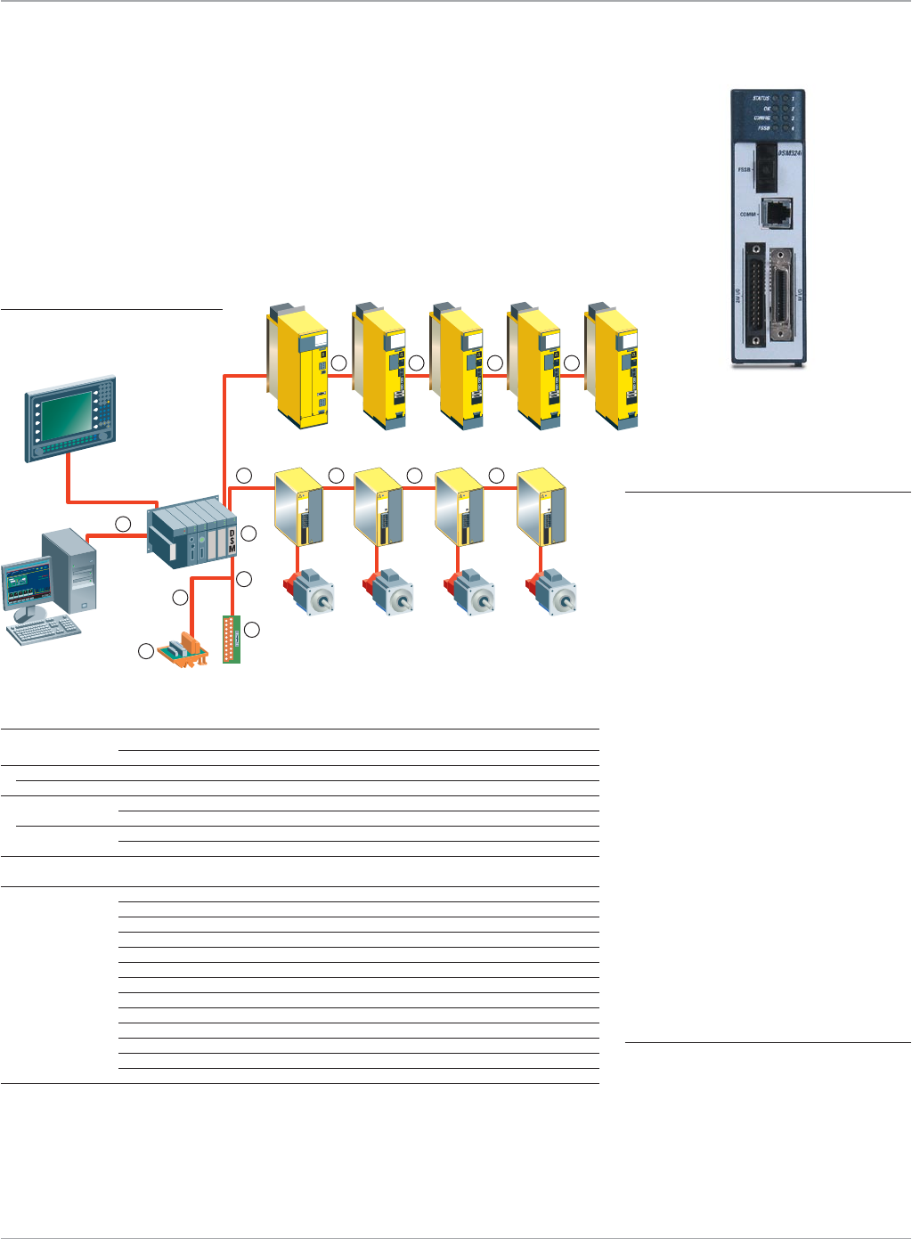
PACMotion System Configuration
APPLICATIONS
• High-speedprinting
• Packagingsystems
• High-speedassembly
• Woodworkingmachinery
• Automotiveassembly
• Materialhandling
• Webhandlingapplications
• Infeedconveyors
• Labeling
• Filling
Proficy Machine Edition
Logic Developer – PLC
Operator Interface
PACSystems
RX3i
Fiber Terminal Block
(FTB) βis/βHVis Series
Servo Motor βis/βHVis Series
Servo Motor βis/βHVis Series
Servo Motor βis/βHVis Series
Servo Motor
βi/βHVi Series
Amplifier βi/βHVi Series
Amplifier βi/βHVi Series
Amplifier βi/βHVi Series
Amplifier
PSM-HVi
Power SupplyαHVi Series
Amplifier αHVi Series
Amplifier αHVi Series
Amplifier αHVi Series
Amplifier
αHVi/αHVis Series
Servo Motor αHVi/αHVis Series
Servo Motor αHVi/αHVis Series
Servo Motor αHVi/αHVis Series
Servo Motor
C
D
E
A
D
D D D D
D D D
B
Part Number Description
A Motion Controller IC695PMM335 PACMotion Motion Controller for RX3i
B Motion I/O Expansion IC695FTB001 Optional Fiber Terminal Block (without terminal headers)
IC695FTB1B032 Optional Fiber I/O Terminal Block
(with screw terminal headers)
IC695FTB1S032 Optional Fiber I/O Terminal Block
(with spring clip terminal headers)
IC695FTB1B132 Optional Fiber I/O Terminal Block
(with extended shroud screw terminal headers)
IC695FTB1S132 Optional Fiber I/O Terminal Block
(with extended shroud spring clip terminal headers)
C Communication Cable IC693CBL316 Serial Cable for Programming - 3m (1 per system)
D Fiber Optic
Cables
ZA66L-6001-0023#L150R0 FSSB and FTB I/O Cable 0.15 Meter
ZA66L-6001-0023#L300R0 FSSB and FTB I/O Cable 0.3 Meter
ZA66L-6001-0023#L1R003 FSSB and FTB I/O Cable 1 Meter
ZA66L-6001-0023#L2R003 FSSB and FTB I/O Cable 2 Meter
ZA66L-6001-0023#L3R003 FSSB and FTB I/O Cable 3 Meter
ZA66L-6001-0026#L1R003 FSSB and FTB I/O Cable Sheathed, 1 Meter
ZA66L-6001-0026#L3R003 FSSB and FTB I/O Cable Sheathed, 3 Meter
ZA66L-6001-0026#L5R003 FSSB and FTB I/O Cable Sheathed, 5 Meter
ZA66L-6001-0026#L10R03 FSSB and FTB I/O Cable Sheathed, 10 Meter
ZA66L-6001-0026#L20R03 FSSB and FTB I/O Cable Sheathed, 20 Meter
ZA66L-6001-0026#L30R03 FSSB and FTB I/O Cable Sheathed, 30 Meter
ZA66L-6001-0026#L50R03 FSSB and FTB I/O Cable Sheathed, 50 Meter
ZA66L-6001-0026#L100R3 FSSB and FTB I/O Cable Sheathed, 100 Meter
E Proficy Programming Software IC646MPP001 Logic Developer PLC Professional without GlobalCare.
Complete with Software key
IC647MPP001 Logic Developer PLC Professional without GlobalCare.
Complete with USB Hardware key
IC646MBP001 Machine Edition Professional Development Suite without
GlobalCare. Complete with Software key
IC647MBP001 Machine Edition Professional Development Suite without
GlobalCare. Complete with USB Hardware key
Motion Controllers
PACMotion
www.ge-ip.com
GE Intelligent Platforms
7
Motion Solutions
PACMotion Controller Features
• Fastmotionpath(1ms)planningandpositionupdaterates(500µs)deliverimprovedaccuracyandfasterresponseto
changing control requirements
• UnlikemostPLC-basedmotion,PACMotiondeliversconsistentmotionupdaterateregardlessofthenumberofaxes
• HighreliabilityFANUCservosimprovemachineuptime
• Highspeedsynchronizationofupto40axisoverthePACSystemsRX3ibackplane
• Advancedcamandgearingfeaturesforelectroniclineshaftapplications
• Singlesoftwaredevelopmentenvironmentforcompleteautomationcontrolsolutionsimplifiesprogramming
• Distributedarchitectureforgreatermachineflexibility–upto100metersbetweenaxesusingnoiseimmunefibercables
• OptionalFiberTerminalBlockallowsdistributedmotioncentricI/Otoreducewiringcomplexityandcost
• Twohigh-speedpositioncaptureinputsperaxisforregistrationandsequencecontrol
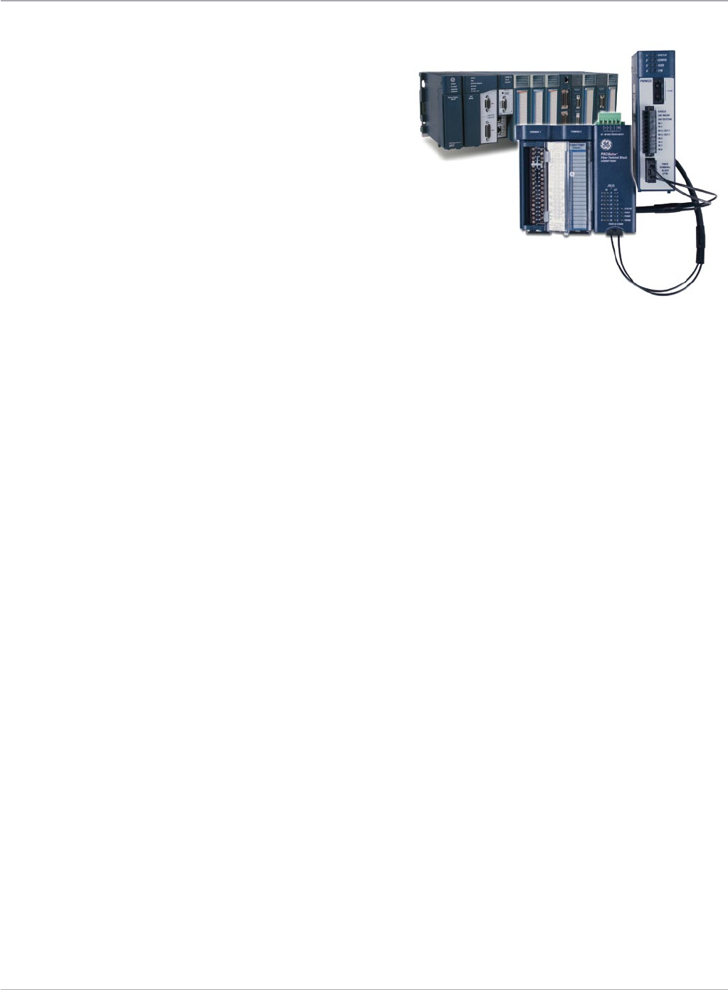
Optional Fiber Terminal Block I/O
• DINrailmounting
• Remotemountupto100meters
• 5V/24V/AnalogI/O
• UniqueIDpreventsconnection
to wrong PACMotion module
• ConfigurableI/Ofunctions
can be assigned to each point
• Connectionforupto5
incremental encoders
without marker or 4
encoders with marker
pulse
High density plug-on wir-
ing headers available with
spring clip or screw termi-
nals and extended shroud
(ordered separately)
Unlimited master/slave synchronization
of any axis to any other axis over the
PACSystems RX3i backplane
Axis and Status LEDs
Hot-swap module
in PACSystems RX3i rack
Fiber optic servo interface
(up to 4 axes)
8 on-board 24V I/O
Fiber optic I/O interface
Synchronized or delayed
start of up to any 8 axes
Motion Controllers
PACMotion
βi and βHVi Servos
• 0.4to22Nmcont.torquerange
• 230and460VACmodels
• Noiseimmunefiberopticinterface
• Absolutefeedbackwithoptionalbattery
• 64Kor128Kcount/revserialencoder
• Optionalholdingbrake
αHVi and αHVis Series Servos
• 2to75Nmcont.torquerange
• 460VAClineregenerativepowersupplies
• Noiseimmunefiberopticinterface
• Absolutefeedbackwithoptionalbattery
• 1Mcount/revserialencoder
• Optionalholdingbrake
www.ge-ip.com GE Intelligent Platforms
Packaging
Faster product turnover, greater variability and shorter production runs are at the heart of some key packaging machinery
automation trends in industries such as pharmaceutical, food and beverage and consumer packaged goods. Today’s automation
systems must provide the flexibility and scalability to keep pace with this explosion of new product introductions, while delivering
higher speed, accuracy and reliability to boost line productivity and asset utilization. End users and OEMs alike are now choosing
innovation over supplier standardization in order to optimize machine performance. Partnering with automation suppliers who offer
complete integrated control solutions can speed time to market and reduce development and deployment costs. Third generation
packaging machines demand the PACMotion advantage…high performance multi-axis motion control tightly integrated with a Process
Automation Controller (PAC), operator interface and extensive communications options all tied by one powerful software
environment…PACMotion delivers.
• Form,fillandseal
• Smartconveyors
• Cartoning
• Wrapping
• Fillingandcapping
• Highspeedlabeling
• Sorting/Diverting
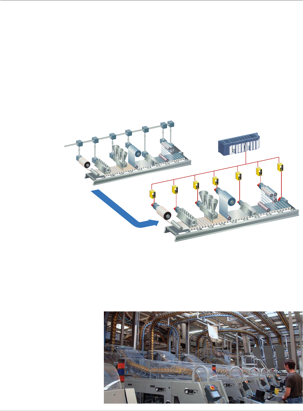
Printing
Many of the trends driving automation changes in the packaging industry are mirrored by the printing industry. Shorter print
runs with greater product variability require flexible, modular machine configurations, higher production speeds while maintaining
accurate registration and quick start-up and changeover.
Shaftless press designs offer mechanical simplicity, reduced noise levels, improved flexibility and high reliability to reduce total cost
of ownership. PACMotion is part of a complete automation system that tightly integrates line control, motion and operator interface
functions in a single software environment, reducing the design cycle for new press designs or line retrofits. PACMotion delivers the
performance and scalability required by today’s printing lines.
• Flexographic
• Gravure
• Offset
• Winders/Unwinders
• Laminators
• Registration
• Dryercontrol
• Infeedrollers
• Drawrollers
Motion Solutions
8
Motion Controllers
PACMotion
Traditional Mechanical Line Shaft Gearbox
Motor
Amplifier
Servo
Motor
Controller
Flexible Electronic Line Shaft
www.ge-ip.com
GE Intelligent Platforms
9
Motion Solutions
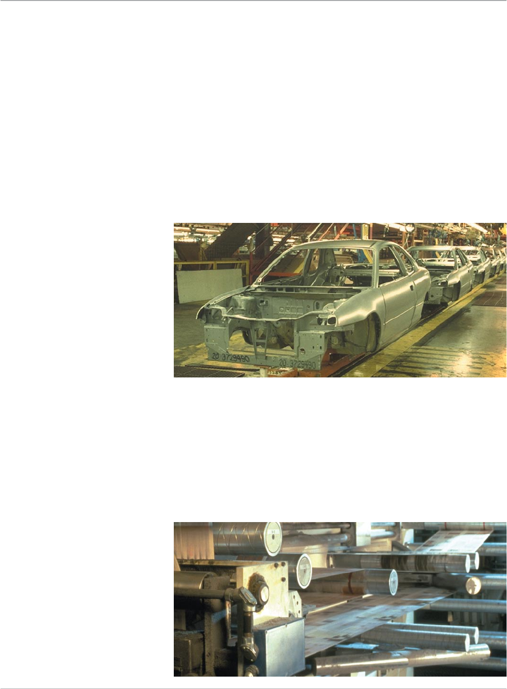
Material Handling and High-Speed Assembly
Price pressure, smaller products and shorter life cycles in automotive, medical and electronic products require lean manufacturing
lines with the flexibility to allow assemblers to reduce time to market for new products and build many product variations on the same
line.
Smaller products require automation and motion control systems that can meet the increased assembly precision at ever increasing
production speeds. System reliability is a crucial element to maintaining the high production rates necessary to reduce total cost
per assembly.
PACMotion is part of a complete automation system that tightly integrates material handling and assembly line control, motion
and operator interface functions in a single software environment, improving engineering productivity and delivering faster time
to market. PACMotion delivers the precision and flexibility to meet demanding assembly and handling challenges.
• Engine/TransmissionAssembly
• TransferLines
• TestStands
• RotaryDialTables
• ElectronicAssembly
• AdhesiveDispensing
• SmartConveyors
• BaggageHandlingSystems
Converting and Web Handling
Increasing line speed while reducing scrap is a critical factor in maintaining a competitive edge in the web handling and material
converting applications. Greater product variability requires flexible modular control systems that enable instant changeover from one
product run to the next. Adjusting for different web widths, repositioning edge guides and slitter position, changing cut length, and
rewind tension must be fast and accurate. Servo control technology replaces traditional mechanical adjustments, allowing for precise
and repeatable adjustments. Programmable jerk control reduces web breaks and film stretching while high servo response ensures
fast corrections to web disturbances. PACMotion is part of an integrated automation system for device and I/O control, motion and
operator interface to facilitate efficient programming and powerful diagnostics in a single software environment.
• Laminating
• CartonFolding
• RotaryDieCutting
• Folder/Gluers
• Unwinders/Rewinders
• SlitterPositioning
Motion Controllers
PACMotion
www.ge-ip.com GE Intelligent Platforms
Motion Solutions
10
Open and Integrated to Improve Engineering Productivity
Synchronization of separate motion and logic programs and the lack of open motion programming standards can present a challenge
even for simple motion applications. Proficy Machine Edition provides one tool for control, view, and motion and provides one universal
engineering development environment for all programming, configuration, and diagnostics, resulting in faster time to solution, reduced
training, and more compact, efficient design. The high level of PACMotion integration with the RX3i platform can significantly reduce
system engineering and commissioning costs:
• Motionandmachinelogicinacommonprogram
greatly simplifies programming
• Motionfunctionblocksandstatemodeldesignedtocomply
with the PLCopen programming standard, reduce learning curve
and training costs
•Buffermodeallowsprogramlogictoqueuemotioncommand
sequences and specify or change the velocity transition between
buffered moves on-the-fly
•AllProficyMachineEditioncomponents—view,logic,andmotion—
share a common database and common objects across applications,
including logic, scripts, and animation. Once a variable is created, it
can easily be used in all other domains of the application.
•ProficyMachineEditioncomponentssharecommondevelopment
tools such as a common user interface, drag-and-drop editing, and
takes full advantage of industry-standard technologies like MEL,
COM/DOM, OPC and ActiveX.
•ProficyMachineEditionsupportsIEClanguagessuchasRelay
Ladder, Instruction List, Structured Text, Function Block, and
SFC programming. In addition, C programming and Open Process
are available.
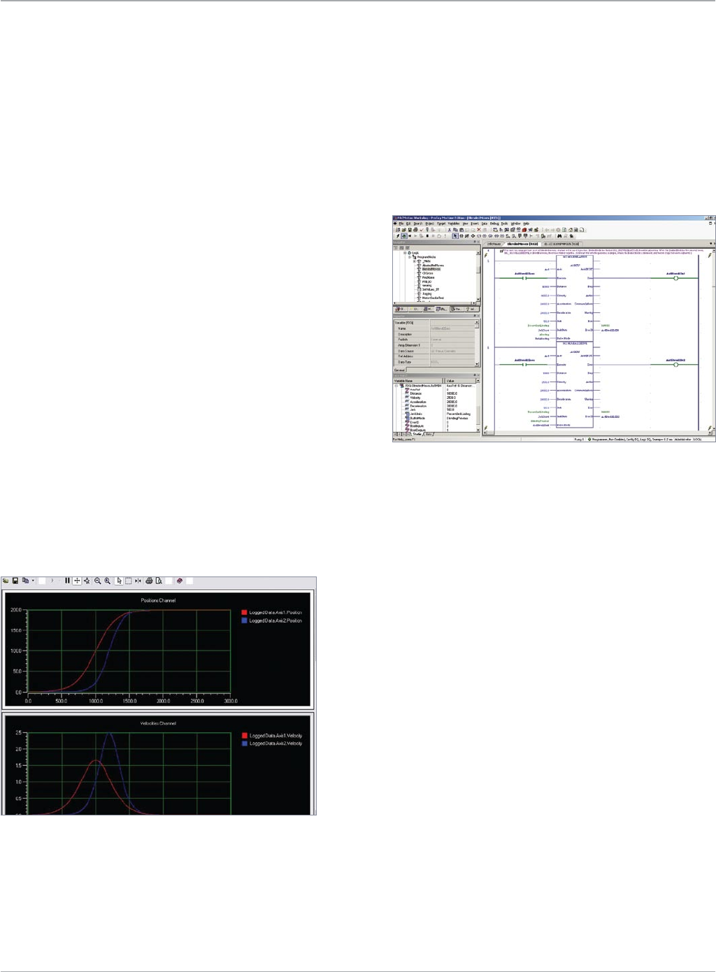
Powerful Diagnostic Tools
The Data Logger supports the high-speed capture of up to
48 parameters per PACMotion module.
• Loggingsessioncanbesingleshotorcontinuous
• Sampleratesasfastas500µs
• Datacollectioncanbesettostartbasedonatriggerevent
• CaptureddataisstoredasPLCfilesandcanbearchivedor
viewed using the Data Logger Window
The Diagnostic Logic Block is a separate program that runs
independently of the main application program.
• UsesthestandardLaddereditor
• CanbeexecutedwiththePLCintheRunorStopI/O
Enabled mode
• LibraryofDLBscanbereusedforfunctionssuchasmachine
troubleshooting, servo tuning, data logging, etc.
• DLBscanbesavedastoolchestobjects
• Programcodecanbecut/pastedbetweenaDLBandthemain
program providing a convenient way to test new code segments
Motion Controllers
PACMotion
www.ge-ip.com
GE Intelligent Platforms

11
Motion Solutions
PACMotion Module Specifications
Specification Details Comments
Motion Path Planning 1 ms Consistent update regardless of the number of axes in the system
PositionLoopUpdateRate 500µs AllaxesintheRX3irackareupdatedsimultaneously
VelocityLoopUpdateRate 125µs AllaxesintheRX3irackareupdatedsimultaneously
TorqueLoopUpdateRate 62.5µs AllaxesintheRX3irackareupdatedsimultaneously
Controlled Axes/Module 4 βi, βHVi or αHVi series servos are supported via a fiber optic interface
Master Axes/Module 1 Can be a virtual time-based or incremental encoder master
Servo Command Interface Fiber Optic 50 Mb/s FANUC Serial Servo Bus (FSSB)
FSSB Cable Length max. 100 meters between nodes 400 meters maximum for a 4 axis system
Maximum Axes per RX3i:
DC Power Supplies 40 + 10 master axes Requires 16 slot backplane, CPU and 4 DC power supplies
AC Power Supplies 32 + 8 master axes Requires 16 slot backplane, CPU and 3 AC power supplies
Position Resolution:
αHViSeries 1,048,576counts/rev —
βi and βHVi Series 65,536 or 131,072 counts/rev β2i and larger motors support the higher resolution
Feedback Type Incremental/Absolute Serial Encoder Optional battery backup required for absolute feedback mode
Faceplate I/O:
24VGeneralPurposeInputs 4opticallyisolated;source/sink —
24V High-Speed Inputs 2 optically isolated; source/sink Open circuit detection; can be used to connect a quadrature master encoder (500 kHz max)
24V General Purpose Inputs/Outputs 2 optically isolated; source/sink 125 mA maximum output current each
Connector Plug-onScrewTerminal —
Floating Point Support Yes Double precision IEEE 754
ModuleHotInsertion/Removal Yes —
Cam Profiles per Module 256 at one time Up to 2048 profiles can be stored in the RX3i file system for use by any module
Synch/Delayed Start Up to 8 axes Axes can be on any module and are synchronized over the backplane
HighSpeedPositionCapture 2Inputsperaxis ±1count=10µsjitter
Fiber Terminal Block Specifications
Specification Details Comments
Mounting 35 mm DIN Rail Must be mounted on a vertical surface for proper cooling
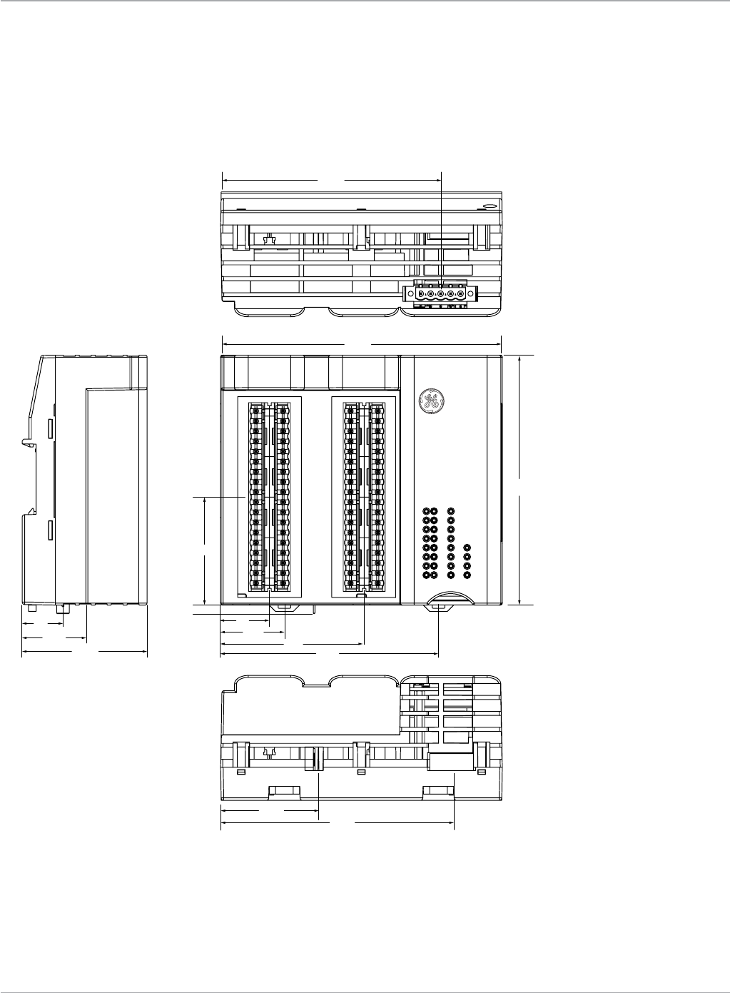
Dimensions:
inches 5.56Wx4.94Hx2.46D —
mm 141.2Wx125.5Hx62.5 —
Interface to PACMotion Module Fiber Optic Cable Maximum cable length is 100 meters; Interface uses a
unique ID for each PMM/FTB pair to prevent cross-connection
Terminal Header Options
IC694TBS032 High Density 36 point Spring Clip Terminals 2 required per FTB (ordered separately); 14-26 AWG
IC694TBB032 High Density 36 point Captive Screw Terminals 2 required per FTB (ordered separately); 14-26 AWG
IC694TBS132 High Density Spring Clip Terminals, Extended Shroud 2 required per FTB (ordered separately); 14-28 AWG
IC694TBB132 High Density Captive Screw Terminals, Extended Shroud 2 required per FTB (ordered separately); 14-28 AWG
PowerRequirements 19.2VDC—28.8VDC;0.45Amps@24V oneAWG#14(2.1mm2) or two AWG #16 (1.3mm2)
copper wires per terminal
24V Outputs (differential) 8 optically isolated; source; open load & short detection 2 groups of 4; 0.5 A max. per point; 4 A max. per group
24V General Purpose Inputs 16 optically isolated; source/sink 4 groups of 4
5V Outputs (differential) 4 RS422 Line Driver with short circuit protection; 48 mA max.
5V Inputs (differential/single-ended) 6 RS422 / RS485 Line Receiver with fault detection
5V Inputs (differential) 6 RS422 / RS485 Line Receiver with fault detection
Analog Inputs 2, ±10V differential 14 bit resolution
Analog Outputs 2, ±10V single-ended 12 bit resolution
24 V Power Output Reverse polarity protected by replaceable fuse
5 V Power Output 0.5 amp max. electronic overload protected
QuadEncoderOpenCircuitDetection Yes —
I/O Function Assignment Configurable I/O functions are assigned during
module hardware configuration
Motion Controllers
PACMotion
www.ge-ip.com GE Intelligent Platforms
Motion Solutions
12
PACMotion
Motion Controllers
.81
1.30
2.13
2.46
4.56
4.56
1.26
2.84 4.30
.97
.17
5.56
4.35
4.94
Fiber Terminal Block (FTB) Dimensions
www.ge-ip.com
GE Intelligent Platforms
13
Motion Solutions
PACMotion
Motion Controllers
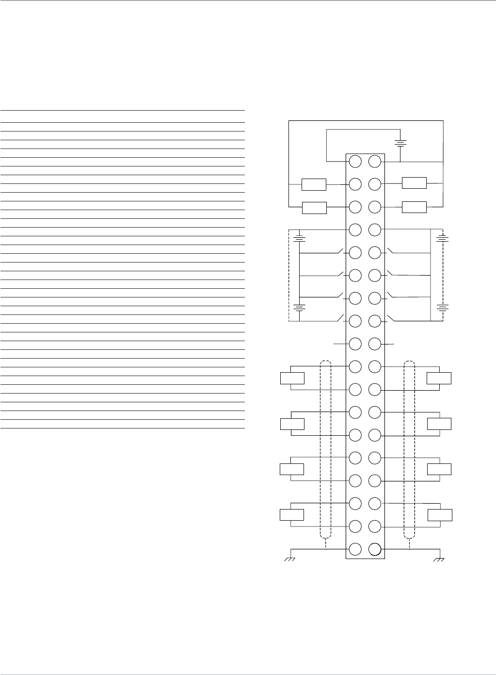
Fiber Terminal Block IC695FTB001 Wiring Diagram and Pin Assignments
FTB Terminal 1 Pin Assignments FTB Terminal 1 Wiring Diagram
Pin Circuit Identifier Circuit Type Default Circuit Function
1 24V+ 24VOutput Q1—Q4Power
2 Q1 24 VDC (ESCP) Output 24V Output
3 Q2 24 VDC (ESCP) Output 24V Output
4 24- 24V- I1—I4Common
5 I1 24 VDC Input Digital Input
6 I2 24 VDC Input Digital Input
7 I3 24 VDC Input Digital Input
8 I4 24 VDC Input Digital Input
9 +5V (OUT) +5V Output External Power
10 I17+ 5V Diff Input+ Fast Digital Input
11 I17- 5V Diff Input- Fast Digital Input
12 I18+ 5V Diff Input+ Fast Digital Input
13 I18- 5V Diff Input- Fast Digital Input
14 I19+ 5V Diff Input+ Fast Digital Input
15 I19- 5V Diff Input- Fast Digital Input
16 AI1+ ± 10V Analog Input Analog In 1 (+)
17 AI1- ±10VAnalogInput AnalogIn1(–)
18 Shield Shield Frame Ground
19 24V- 24V- Q1—Q4Common
20 Q3 24 VDC (ESCP) Output 24V Output
21 Q4 24 VDC (ESCP) Output 24V Output
22 24V- 24V- I5—I8Common
23 I5 24 VDC Input Digital Input
24 I6 24 VDC Input Digital Input
25 I7 24 VDC Input Digital Input
26 I8 24 VDC Input Digital Input
27 0V 0V External Power
28 I20+ 5V Diff Input+ Fast Digital Input
29 I20- 5V Diff Input- Fast Digital Input
30 I21+ 5V Diff Input+ Fast Digital Input
31 I21- 5V Diff Input- Fast Digital Input
32 I22+ 5V Diff Input+ Fast Digital Input
33 I22- 5V Diff Input- Fast Digital Input
34 AO1+ ±10V Analog Output Analog Out 1
35 COM ±10V Analog Output AO1 Common
36 Shield Shield Frame Ground
Field Wiring Terminals Field Wiring
1
3
5
7
9
11
13
15
17
19
2
4
6
8
10
12
14
16
18
27
–
+
Q2
Q1 Q3
Q4
20
21
22
23
24
25
26
28
29
30
31
32
33
34
35
36
24V
I2
I1
I4
I3
I5
I6
I7
I8
+5V
(OUT) 0V
I17
I18
I19
AI1
I20
I21
I22
AO1
–
+
–
+
–
+
–
+
24V 24V
24V 24V
24V 24V
SHIELD SHIELD
5V
5V
5V
±10V
5V
5V
5V
±10V
(–)
(+)
(–)
(+)
(–)
(+)
(–)
(+)
(–)
(+)
(–)
(+)
(–)
(+)
COM
(+)
www.ge-ip.com GE Intelligent Platforms
Motion Solutions
14
Pin Circuit Identifier Circuit Type Default Circuit Function
1 24V+ 24VOutput Q5—Q8Power
2 Q5 24 VDC (ESCP) Output 24V Output
3 Q6 24 VDC (ESCP) Output 24V Output
4 24V+ I9—I12Common
5 I9 24 VDC Input Digital Input
6 I10 24 VDC Input Digital Input
7 I11 24 VDC Input Digital Input
8 I12 24 VDC Input Digital Input
9 +5V (OUT) +5V OUT External Power
10 I23+ 5V Diff Input+ Fast Digital Input
11 I23- 5V Diff Input- Fast Digital Input
12 I24+/Q9+ 5V Diff Input+/5V Fast Digital Input
Diff Output+
13 I24-/Q9- 5V Diff Input-/5V Fast Digital Input
Diff Output-
14 I25+/Q10+ 5V Diff Input+/5V Fast Digital Input
Diff Output+
15 I25-/Q10- 5V Diff Input-/5V Fast Digital Input
Diff Output-
16 AI2+ ±10V Analog Input Analog In 2 (+)
17 AI2- ±10V Analog Input Analog In 2 (-)
18 SHIELD Frame Ground Shield
19 24V- 24V- Q5—Q8Common
20 Q7 24 VDC (ESCP) Output 24V Output
21 Q8 24 VDC (ESCP) Output 24V Output
22 24V+ 24V+ I13—I16Common
23 I13 24 VDC (ESCP) Input Digital Input
24 I14 24 VDC (ESCP) Input Digital Input
25 I15 24 VDC (ESCP) Input Digital Input
26 I16 24 VDC (ESCP) Input Digital Input
27 0V 0V External Power
28 I26+ 5V Diff Input Fast Digital Input
29 I26- 5V Diff Input Fast Digital Input
30 I27/Q11+ 5V Diff Input+/5V Fast Digital Input
Diff Output+
31 I27/Q11- 5V Diff Input-/5V Fast Digital Input
Diff Output-
32 I28/Q12+ 5V Diff Input+/5V Fast Digital Input
Diff Output+
33 I28/Q12- 5V Diff Input-/5V Fast Digital Input
Diff Output-
34 AO2+ ± 10V Analog Output Analog Output 2
35 COM ± 10V Analog Output AO2 Common
36 SHIELD Frame Ground Shield
PACMotion
Motion Controllers
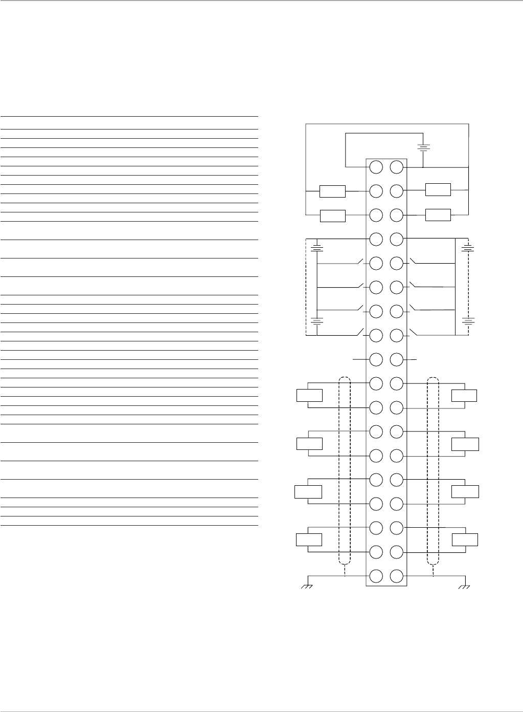
Fiber Terminal Block IC695FTB001 Wiring Diagram and Pin Assignments
FTB Terminal 2 Pin Assignments FTB Terminal 2 Wiring Diagram
Field Wiring Terminals Field Wiring
1
3
5
7
9
11
13
15
17
19
2
4
6
8
10
12
14
16
18
27
–
+
Q6
Q5 Q7
Q8
20
21
22
23
24
25
26
28
29
30
31
32
33
34
35
36
24V
I10
I9
I12
I11
I13
I14
I15
I16
+5V
(OUT) 0V
I23
I24/Q9
I25/Q10
AI2
I16
I27/Q11
I28/Q12
AO2
–
+
–
+
–
+
–
+
24V 24V
24V 24V
24V 24V
SHIELD SHIELD
5V
5V
5V
±10V
5V
5V
5V
±10V
(–)
(+)
(–)
(+)
(–)
(+)
(–)
(+)
(–)
(+)
(–)
(+)
(–)
(+)
COM
(+)
www.ge-ip.com
GE Intelligent Platforms

15
Motion Solutions
Motion Controllers
PACMotion
Motion Functions
Function Block Name Description
Single Axis Administrative Function Blocks
MC_Power Controls the Power Stage (MCON); causes all control loops to be closed and the control to be in the Standstill state
ready to perform motion commands
MC_ReadStatus Returns in detail the current axis status of the axis selected
MC_ReadAxisError Indicates general axis errors not relating to the execution of Functions or Function Blocks;
used to read a current error or warning on the axis
MC_ReadParameter Returns the value of a parameter; used to read an axis parameter
MC_ReadParameters Returns the values of parameters; used to read one or more axis parameters
MC_ReadBoolParameter Returns the value of a Boolean parameter; used to read an axis parameter
MC_ReadBoolParameters Returns the values of Boolean parameters; used to read one or more axis parameters
MC_ReadDwordParameters Returns the values of 32 bit word parameters; used to read one or more axis parameters
MC_WriteParameter Modifies the value of a parameter; used to write an axis parameter
MC_WriteParameters Modifies multiple parameter values; used to write multiple axis parameters
MC_WriteBoolParameter Modifies the value of a vendor specific parameter; used to write an axis parameter
MC_WriteBoolParameters Modifies multiple Boolean parameter values; used to write multiple axis parameters
MC_WriteDwordParameters Modifies multiple 32 bit word parameter values; used to write parameters that can not be expressed as real
including packed bits
MC_ReadActualPosition Used to read the actual axis position
MC_Reset Makes the transition from the state ErrorStop to StandStill by resetting all internal axis-related errors;
used to attempt to clear any errors on an axis and return it from the ErrorStop state to the Standstill state
MC_ModuleReset Makes the transition from the state ErrorStop to StandStill by resetting all internal errors;
used to attempt to clear any errors on a module and return any axes in the ErrorStop state to the Standstill state
MC_ReadDigitalInput Gives access to the value of the input, referenced by the datatype INPUT_REF;
provides the value of the referenced input (BOOL).
MC_ReadDigitalOutput Gives access to the value of an output, referenced by the datatype OUTPUT_REF;
provides the value of the referenced output (BOOL)
MC_WriteDigitalOutput Writes a value to a discrete output once (with Execute), referenced by the datatype OUTPUT_REF
MC_SetPosition Shifts the coordinate system of an axis by manipulating both the set-point position as well as the actual position of
an axis with the same value without any movement caused. (Re-calibration with same following error).
MC_SetOverride Sets the values of override for the whole axis, and all functions that are working on that axis
MC_ReadActualVelocity Returns the value of the actual velocity as long as Enable (EN) is set
MC_ReadTorqueCommand Returns the value of the torque command as long as Enable (EN) is set
MC_LibraryStatus Provides the user with visibility into their cam-profile memory usage; provides the number of selected cam-profiles,
the total number of bytes available, and the percentage of memory used
MC_ReadAnalogInput Gives access to the value of an analog input, referenced by the datatype INPUT_REF
MC_ReadAnalogOutput Gives access to the value of an analog output, referenced by the datatype OUTPUT_REF
MC_WriteAnalogOutput Writes a value to an analog output once (with Execute), referenced by the datatype OUTPUT_REF
MC_ReadEventQueue Returns the current PMM module event queue
MC_TouchProbe Used to record an axis position at a strobe trigger event
MC_AbortTrigger Used to abort MC_TouchProbe function blocks
MC_DigitalCamSwitch Commands a group of discrete output bits to switch in analogy to a set of mechanical cam controlled switches
connected to an axis
MC_DL_Configure Specifies the configuration parameters for data logged on the PMM
MC_DL_Activate Used to start data logging on the module in normal start mode
MC_DL_Get Writes the data logged into a file specified by the DATALOG_FILE_REF input
MC_DL_Delete Responsible for deleting data logger configuration from the PMM memory
Single Axis Motion Function Blocks
MC_MoveAbsolute Commands a controlled motion at a specified position
MC_MoveRelative Commands a controlled motion of a specified distance relative to the actual position at the time of the execution
MC_MoveAdditive Commands a controlled motion of a specified relative distance additional to the original commanded position
in the discrete motion state
MC_MoveSuperimposed Commands a controlled motion of a specified relative distance additional to an existing motion
MC_MoveVelocity Commands a never ending controlled motion at a specified velocity
MC_Home Commands the axis to perform the «search home» sequence
MC_Stop Commands a controlled motion stop and transfers the axis to the state “Stopping”
MC_JogAxis Jogs an axis forward or backward at the manual operation velocity and acceleration
MC_Halt Commands a controlled motion stop
www.ge-ip.com GE Intelligent Platforms

Motion Solutions
16
PACMotion
Motion Functions
Motion Controllers
Multiple Axis Administrative Function Blocks
MC_CamTableSelect Selects the cam-tables (cam-profiles) by setting the pointers to the relevant tables
MC_CamTableDeselect Deletes a cam-profile from the specified module to free memory
Multiple Axis Motion Function Blocks
MC_CamIn Engages a cam
MC_CamOut Disengages a slave axis from the master
MC_GearIn Commands the slave axis velocity at a ratio of the master axis velocity
MC_GearOut Used to disengage from a MC_GearIn function block
MC_Phasing Provides dynamic phase shifting capability for cam profiles
MC_GearInPos Commands a gear ratio between the position of the slave and master axes from the synchronization point onwards
MC_SyncStart Identifies which axes should be started at the same time and how much time can elapse
before the motion must start
MC_DelayedStart Identifies which axes should be started with a delay relative to each other and how much time can elapse
before the motion must start
PLC Support Function Blocks
MC_CamFileRead Copies the contents of a cam file from the PLC file system into reference memory
MC_CamFileWrite Copies cam data from reference memory to an existing cam file in the PLC file system,
overwriting the original data in the cam file
www.ge-ip.com
GE Intelligent Platforms
17
Motion Solutions
Part Number Description
A Motion Controller IC693DSM324 DSM324i Motion Controller for Series 90-30
IC694DSM324 DSM324i Motion Controller for PACSystems RX3i
B Terminal Boards IC693ACC336 DSM324i 5V High Speed & Analog I/O Terminal Board (1 per module)
C 44A726268-001 DSM324i 24V I/O Terminal Board (1 per module)
D I/O Interface Cables IC693CBL324 ACC336 Terminal Board Interface Cable - 1m (1 per module)
IC693CBL325 ACC336 Terminal Board Interface Cable - 3m (1 per module)
E IC693CBL311 DSM324i to 44A726268-001 Terminal Board Cable - 3m (1 per module)
IC693CBL319 DSM324i to 44A726268-001 Terminal Board Cable - 1m (1 per module)
F Communication IC693CBL316 Serial Cable for Programming - 3m (1 per system)
Cables
G Fiber Optic Cables ZA66L-6001-0023#L150R0 FSSB and FTB I/O Cable 0.15 Meter
ZA66L-6001-0023#L300R0 FSSB and FTB I/O Cable 0.3 Meter
ZA66L-6001-0023#L1R003 FSSB and FTB I/O Cable 1 Meter
ZA66L-6001-0023#L2R003 FSSB and FTB I/O Cable 2 Meter
ZA66L-6001-0023#L3R003 FSSB and FTB I/O Cable 3 Meter
ZA66L-6001-0026#L1R003 FSSB and FTB I/O Cable Sheathed, 1 Meter
ZA66L-6001-0026#L3R003 FSSB and FTB I/O Cable Sheathed, 3 Meter
ZA66L-6001-0026#L5R003 FSSB and FTB I/O Cable Sheathed, 5 Meter
ZA66L-6001-0026#L10R03 FSSB and FTB I/O Cable Sheathed, 10 Meter
ZA66L-6001-0026#L20R03 FSSB and FTB I/O Cable Sheathed, 20 Meter
ZA66L-6001-0026#L30R03 FSSB and FTB I/O Cable Sheathed, 30 Meter
ZA66L-6001-0026#L50R03 FSSB and FTB I/O Cable Sheathed, 50 Meter
ZA66L-6001-0026#L100R3 FSSB and FTB I/O Cable Sheathed, 100 Meter
Motion Controllers
APPLICATIONS
• Packagingmachines
• High-speedconveyorlines
• Assemblymachines
• Pickandplacegantries
• Textilemachines
• Coil/spoolwinding
• Adhesiveapplicators
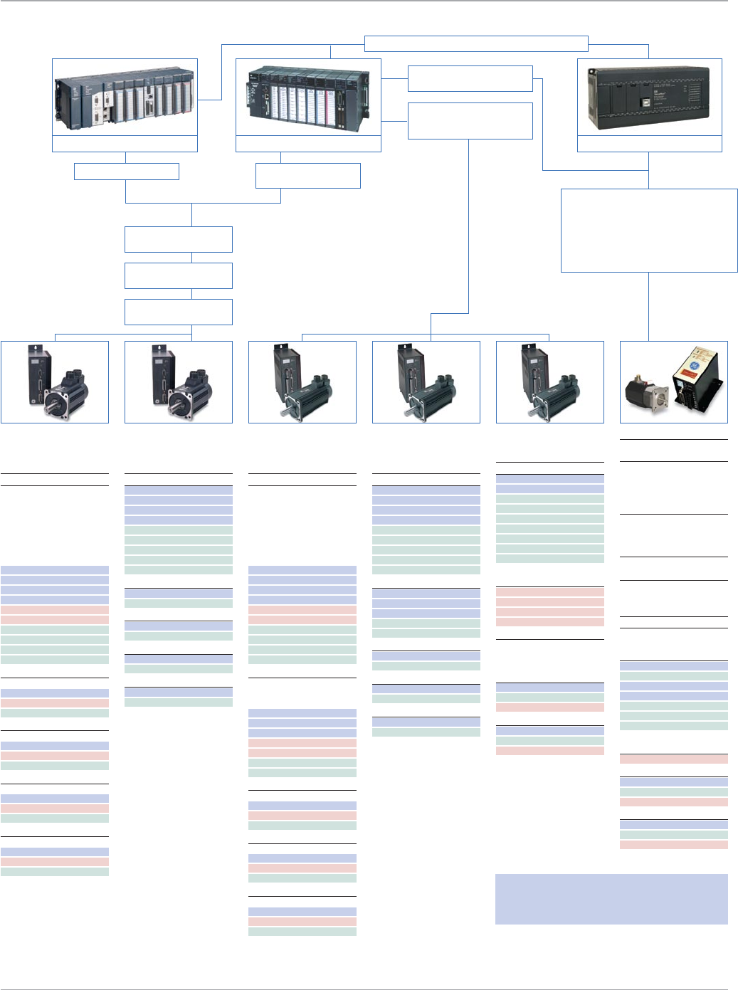
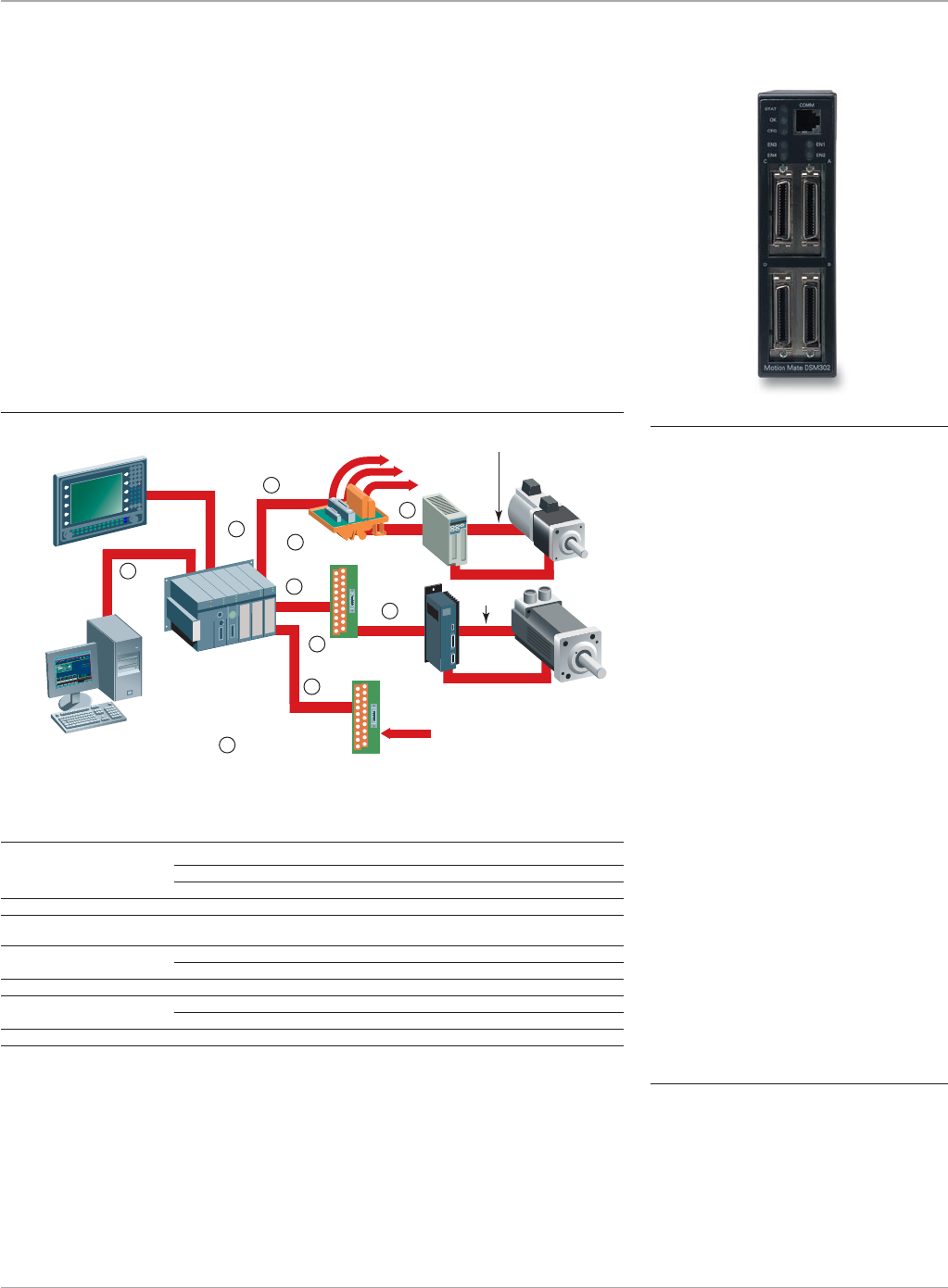
DSM324i Configuration
Features
• Distributedarchitectureforgreater
machineflexibility–upto100meters
between axes
• Improvedproductaccuracywith
velocity feed-forward control and
high-resolution feedback
• On-boardAnalogandDigitalI/O(trav-
el limits, home switch and high speed
position capture)
• Flashfirmwareavailablefromour
website makes upgrades a snap
• Easy-to-use;allpositioning,velocity
and torque loops are closed in the
controller. For properly sized drives, little
or no servo tuning is required once the
motor type code has been set
• DSM324iLocalLogicEnginehandles
high speed logic decisions synchronous
with motion update
• Cam&ElectronicGearingModesfor
your more complex applications
PLC Requirements
PLC Requirements: The RX3i or Series 90 -30 PLC with Machine Edition Logic Developer PLC will
support the DSM324i. Multiple DSM boards can be placed in PLC main, expansion, and remote racks.
The use of DSM modules is limited by the power supply capacity and the number of words of %AI data
supported by the selected CPU. Each axis of control requires a minimum of 40 words of %AI data and
a maximum of 84 words of %AI data depending on the mode selected. DSM324i requires a Series
90-30 CPU with Release 10 or higher Firmware or an RX3i CPU with Release 2.8 or higher Firmware.
DSM324i
The DSM324i can control up to 4 axes of βi, βHVi or αHVi Servos via a fiberoptic
command interface for superior noise immunity. By combining the versatility of the
GE PLCs and GE operator interface products with GE servos, DSM324i provides cus-
tomers with a complete solution. This single-source system results in such benefits as
ease of integration and programming, shorter development cycles, and higher reliability.
*See servo amplifier section for motor cable information.
Proficy Machine Edition
Logic Developer – PLC
Operator Interface
Terminal Boards
24 VDC I/O
5 V High
Speed I/O
Series 90-30 PLC
or
PACSystems
RX3i
βis/βHVis Series
Servo Motorβis/βHVis Series
Servo Motorβis/βHVis Series
Servo Motorβis/βHVis Series
Servo Motor
βi/βHVi Series
Amplifier βi/βHVi Series
Amplifier βi/βHVi Series
Amplifier βi/βHVi Series
Amplifier
PSM-HVi
Power Supply αHVi Series
Amplifier αHVi Series
Amplifier αHVi Series
Amplifier αHVi Series
Amplifier
C
G G G G
G G G G
D
B
E
FA
DSM300 for Series 90-30 and PACSystems RX3i
www.ge-ip.com GE Intelligent Platforms
Motion Solutions
18
Motion Controllers
APPLICATIONS
• High-speedconveyorlines
• Assemblymachines
• Pickandplacegantries
• Textilemachines
• Coil/spoolwinding
• Adhesiveapplicators
DSM302/314 Series Features
• Powerfulprocessorwithdigitalsignal
co-processor (DSP) provides a separate
control loop processor that operates
independently of PLC scan rates for fast
servo loop updates
• Enhancedtrackingaccuracywith
velocity feed-forward control and
high-resolution feedback
• On-boardI/Ofortravellimits,servo
enable, home switch and position
capture
• Flashfirmwareavailablefromour
website makes upgrades a snap
• Indigitalservomode,allpositioning,
velocity and torque loops are closed
in the controller. For properly sized
drives, little or no servo tuning is
required once the motor type code
has been set
• Alsoworksinanalogmodewithany
quadrature encoder-based servo to
provide a low-cost, high-performance
servo system
• DSM314LocalLogicEnginehandles
high speed logic decisions synchronous
with motion update
• Cam&ElectronicGearingModes
PLC and Motion
Programmer
Operator Interface
Products
From Master Encoder
(Follower Mode)
AUX Terminal Board
AUX
Terminal Board
Terminal Board
to I/O
VersaMotion
Series
Amplifier
S2K Amplifier
Servo
Motor
Servo
Motor
Encoder*
Power*
Power*
Resolver*
AUX I/O
DSM
Series 90-30 PLC
or
PACSystems RX3i
PLC Requirements
PLC Requirements: Machine Edition Logic Developer PLC will support the DSM. Multiple
DSM boards can be placed in PLC main, expansion, and remote racks. The use of DSM
modules is limited by the power supply capacity and the number of words of %AI data
supported by the selected CPU. Each axis of control requires a minimum of 40 words of
%AI data and a maximum of 64 words (84 for 4 axis DSM314) of %AI data depending on
the mode selected. DSM314 requires a CPU with Release 10 or higher Firmware.
F
B
C
G
D
A
D
D
C
DSM300 for Series 90-30 and PACSystems RX3i
DSM302/DSM314
The DSM300 Series is a family of motion controllers for GE Series 90-30 and PACSystems
RX3i PLC controllers. The DSM302 is a versatile two-axis motion controller that works
with any servo with an analog command interface. In addition, the DSM314 can control
up to 4 servos with an analog velocity or torque command interface. The DSM302 or
DSM314 is applicable in a broad range of single and multiaxis applications. By combin-
ing the versatility of the GE PLCs and GE operator interface products with GE servos,
DSM302/314 provides customers with a complete solution, from the motor to the
operator interface. This single-source system results in such benefits as ease of integration
and programming, shorter development cycles, and higher reliability.
Part Number Description
A Modules IC693DSM302 DSM302 Motion Controller (2 axis) for Series 90-30
IC693DSM314 DSM314 Motion Controller (4 analog/2 digital axes) for Series 90-30
IC694DSM314 DSM314 Motion Controller (4 analog/2 digital axes) for RX3i
B Terminal Boards IC693ACC335 Digital Servo Axis Terminal Board (one per axis)
C IC693ACC336 Analog Servo Axis Terminal Board (one per axis)
Auxiliary Terminal Board (for follower applications)
D Command Cables IC693CBL324 Terminal Board Connection Cable - 1m (one per axis)
IC693CBL325 Terminal Board Connection Cable - 3m (one per axis)
E Communication Cables IC693CBL316 Station Manager Serial Cable (one per motion system)
F Digital Servo Cables IC800CBL001 Servo Command Cable - 1m (one per axis)
IC800CBL002 Servo Command Cable - 3m (one per axis)
G Analog Servo Cables IC800SKCFLYxxx S2K interface cables xxx=010 (1m), xxx=030 (3m)
*See servo amplifier section for motor cable information.
E
www.ge-ip.com
GE Intelligent Platforms

19
Motion Solutions
DSM302 DSM314 DSM324i
General Standard Follower Standard Follower Standard Follower
Number of Digital Servo Axes 2 2 2 2 4 4
Number of Analog Servo Axes 2 2 4 4 n/a n/a
Analog Servo Command Types Velocity Velocity Torque/Velocity Torque/Velocity n/a n/a
Position Error Integrator Yes Yes Yes Yes Yes Yes
PositionCaptureInputs/Axis 2@5V 2@5V 2@5V 2@5V 2@5V 2@5V
PositionCaptureResponse 250µs 250µs +/-2count +/-2count +/-2count +/-2count
plus10µs plus10µs plus10µs plus10µs
Feedback
Position Feedback Options:
Digital Servo Axis GE GE GE GE GE GE
Serial Encoder Serial Encoder Serial Encoder Serial Encoder Serial Encoder Serial Encoder
Analog Servo Axis Quadrature Quadrature Quadrature Quadrature n/a n/a
Encoder Encoder Encoder Encoder
Position Resolution (counts/Rev):
Digital Servo Axis 8192 8192 8192 8192 8192 8192
Analog Servo Axis Based on encoder Based on encoder Based on encoder Based on encoder n/a n/a
Positioning Range (linear mode) ±8,388,607 ±8,388,607 ±536,870,911 ±536,870,911 ±536,870,911 ±536,870,911
Master Feedback n/a Quadrature Encoder n/a Quadrature Encoder n/a Quadrature Encoder
Master Feedback Max Frequency n/a 1MHz n/a 1MHz n/a 1MHz
Motion Features
Positioning Absolute Absolute Absolute Absolute Absolute Absolute
Incremental Incremental Incremental Incremental Incremental Incremental
Acceleration Types Linear Linear Linear Linear Linear Linear
Jerk Limited Jerk Limited Jerk Limited Jerk Limited Jerk Limited Jerk Limited
Motion Types Linear/Continuous Continuous Linear/Continuous Continuous Linear/Continuous Continuous
Follower Modes n/a Velocity/Position/Winder n/a Velocity/Position n/a Velocity/Position
Cam Support n/a n/a Yes Yes Yes Yes
Local Logic Program n/a n/a Yes Yes Yes Yes
PLC I/O References*
%I 64 64 32/48/64/80 32/48/64/80 32/48/64/80 32/48/64/80
%Q 64 64 32/48/64/80 32/48/64/80 32/48/64/80 32/48/64/80
%AI 40/50/64 50/64 24/44/64/84 24/44/64/84 24/44/64/84 24/44/64/84
%AQ 6/9/12 9/12 3/6/9/12 3/6/9/12 3/6/9/12 3/6/9/12
*DSM314 and DSM324i I/O References are based on the number of configured axes. Table data shown is for 1/2/3/4 axes.
I/O System DSM302/314 DSM324i Description
I/O Connectors 4 x 36 pin 1 x 36 pin; 1 x 24 pin
Analog Output 4 2 12 bit resolution plus sign; ±10 VDC; 5mA max.
Analog Inputs (Analog Axes only) 8 2 15 bit resolution plus sign; ±10 VDC
SNP Comm Port 1 RJ11 1 RJ11 RS232 - SNP Protocol
Servo Series Supported DSM302 DSM314 DSM324i
αHVi No No α22HVis
αHVis No No Yes
βis No No Yes
βHVis No No Yes
Hardware Features
Feature Comparison
Motion Controllers
www.ge-ip.com GE Intelligent Platforms

Motion Solutions
20
Motion Controllers
Features
• Resolverfeedback
• Twomoduletypesavailable:brushlessservoamplifierwithintegratedmotion
controller or stepping amplifier with integrated motion controller
• Widetorquerange:servosystemsfrom2.7-477lb-in(0.3-53.9Nm)continuous,step-
pers from 144-3074 oz-in (1-21.7 Nm). Standard features include all-digital,
self-tuning servo amplifier and 50,000 microstepping amplifier
• 14I/OpointswithDeviceNetorProfibusoptionsor21I/Opoints(4.3and7.2amp
models only) when no network option is specified
• Fullcomplementofdiagnosticinformationprovidedviaon-board,two-character
LED or over network or serial communication options
• Includespoint-to-pointmoves,joggingandadvancedfunctionssuchaselectronic
gearing/camming and pulse based motion. The command set includes full logic,
subroutines, variables and math functions in addition to I/O and network control.
• Amulti-taskingoperatingsystemsupportsabroadrangeofapplicationcomplexity...
from simple to advanced program requirements
• Small,self-containedpackageconservesvaluablepanelspace
• Allquick-disconnectterminationsforfastinstallationandchange-over
• UL,cUL,andCEcertifications
S2K Series
APPLICATIONS
• Packagingmachines
• Labelingmachines
• Bagmakingmachines
• Assembly
• Pickandplace
• Flyingcutoff
• Rotarytables
• Feed/cuttolength
• Electroniclineshafting
• Sortingconveyors
• andmanymore
Stand-Alone, Digital Amplifier and
Controller for Servo and Stepping
Motors
The GE S2K Series products offer amplifier
and motion control capability for brush-
less servo and stepping motor systems in
a stand-alone integrated package. The
S2K Series incorporate all-digital amplifi-
er technology and fast servo update rates
for enhanced performance. Advanced
features such as electronic gearing and
camming are supported. The DeviceNet
implementation includes the ODVA
defined position controller master/slave
protocol as well as peer-to-peer control
for multi-axis stand-alone systems.
Models are also available with a Profibus
DP-Slave implementation as well.
www.ge-ip.com
GE Intelligent Platforms
21
Motion Solutions
• Dynamictorquelimiting
• Complexmotionprofilesincludingjerk
limitedacceleration
• Electronicgearingandcamming
• Indexandphasesynchronization
• Highspeedregistration/positioncap-
tureforfeed/cuttomarkapplications
• Secondarypositionfeedbackfor
compensationofslipandlostmotion
• Userconfigurabledigitalandana-
logI/O
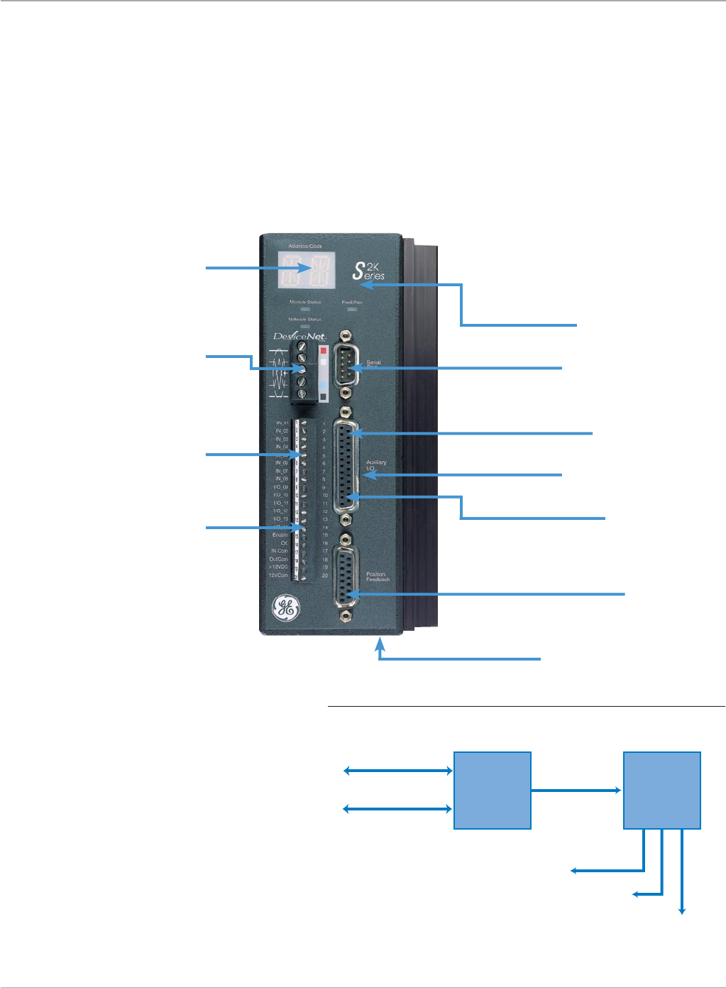
• Powerfulprogrammingenvironment
Nonvolatileprogram
storageinFlashEPROM
Serialcommunicationport
Differentialauxiliary
encoderinput
Quadratureencoderoutput
(motororauxiliaryencoderposition)
Highspeedposition
captureinput
Servoprimary
positionfeedback†
ACpowerinputandmotor
connectionsonbottomofunit
Two-characterLED
foreasy,real-time
diagnosticupdates
OptionalNetwork
communicationport*
•DeviceNet
•Profibus-DP(slave)
Rugged12-24VDCuser
I/Ocanbeconfigured
forsourceorsink
Quick-disconnect
terminalsforeasyfield
wiringandunitchangeovers
*Somecontrollermodelsareavailablewith
additionalI/Oinsteadofthenetworkcommu-
nicationport.
†Resolverfeedbackisstandardwithservo
motorcontrollers.Steppingmotorcontrollers
canprovideprimarypositionfeedbackviathe
differentialauxiliaryencoderinput.
SerialComm.
PositionCommand
488µSUpdate
ServoLoopUpdate
122 µS
Aux.Encoder
488µS
32 Bit µP25 MIPS
DSP
PositionCapture
(Strobe)
30 µS
0.5mSScan
3.84Char/µSMax.
I/O&ParameterUpdate
Single-Axis Controllers
Dual Processor Architecture
Powerfulmultiprocessordesign
providesthespeedandflexibility
tosolvemostofyourmotion
controlapplicationsfromsimple
single-axissolutionstoyourmost
demandingmulti-axissystems.
S2K Series
Single-Axis Controller Features
Motion Controllers
www.ge-ip.com GE Intelligent Platforms

Motion Solutions
22
Motion Controllers
S2K Series
Electrical Specifications
Power Specification
Specifications Units STI105 SSI104 SSI107 SSI216 SSI228 SSI407 SSI420
AC Input Voltage Range VAC 90-130, 1 phase 90-250, 1 or 3 phase 180-250, 3 phase 324-528, 3 phase
AC Input Frequency Range Hz 50-440
PWM Frequency to Motor kHz 16.4 8.2
Min. Motor Inductance mH n/a 1 (per phase)
Cont. Output Current Arms 5/phase 4.3 7.2 16 28 7.2 20
Peak Output Current Arms 5/phase 8.6 14.4 32 56 10.8 20
Max. Input Current 1-phase Arms 10 7 15 n/a n/a n/a n/a
3-phase Arms n/a 4 8 18 30 8 22
Max. Input Power KVA@RatedVAC 1.3 1.6 3.8 8.5 14.3 6.4 18
LogicInputPower VAC n/a n/a 90-250@0.5A +18-30VDC@1.5A
DCPowerOutputs VDC +5@0.25A;+12@0.5A
Digital Inputs and Outputs
Operating Range 12-24 VDC, 28.8 VDC maximum
Interface Format optically isolated, source/sink user-configurable
Inputs Number Available* 14 or 21 (max)
Maximum Off Voltage 4 VDC
Minimum On Voltage 10 VDC
Load 2 kΩ
Outputs Number Available* 6 or 10 (max)
Maximum On Resistance 35Ω
Maximum Load Current 100 mA
Maximum Off Leakage Current 200 nA
*Larger numbers available on models without a network port. Six of the I/O can be configured as either inputs or outputs.
Analog Inputs and Outputs
Operating Range ±10 VDC
Resolution 12 Bits (input)/8 Bits (output)
Input Impedance 50 kΩ
Output Current 5 mA
Number Available 2 Analog Inputs; 1 Analog Output
Auxiliary Encoder Input
Input Format single-ended or differential;
sine or square wave;
quadrature, pulse/direction or cw/ccw pulse
Input Voltage Range +5 to +15 VDC
Line Count Frequency 3 MHz maximum
Pulse Frequency 12 MHz maximum with 4X multiplier
Motor Resolver Feedback Input
Number Available 1
Resolution 4096 pulses per revolution
Maximum Speed 15,000 RPM
Type Control Transmitter
PhaseShift ±5.0degrees@5kHz
NullVoltage <20mV@5kHz
Transformation Ratio 0.5
Serial Communication
Available Ports 1
Functions Supported multi-purpose programming port
Format RS-232*
Maximum Addressable Units 1
Communication Rate 1200, 9600, 19200 or 38400 baud
Maximum Distance from Host to Unit 50 feet
Flow Control XON / XOFF
*Plug-on RS-422/485 serial converter available. See ordering information.
www.ge-ip.com
GE Intelligent Platforms

23
Motion Solutions
Environmental Specifications
Operating Temperature, Free Air Ambient*
SSI104, SSI105, SSI107 32 to 122°F (0 to 50°C)
SSI216, SSI228, SSI407, SSI420 32 to 104°F (0 to 40°C)
Storage and Shipping Temperature -40 to 176°F (-40 to 80°C)
Relative Humidity 5 to 95% noncondensing
Enclosure Type open
Altitude** 3300 feet (1000 m)
* Assumes heatsink in vertical orientation.
** Operation at higher altitudes requires controller derating. Please consult GE.
Communication Specifications DeviceNet Profibus® DP Slave
Number Available 1 port per unit 1 port per unit
Functions Supported I/O slave messaging, position controller profile, Profibus profile, multicast, broadcast
and explicit peer-to-peer messaging
Number of Nodes 64 maximum 100 maximum
InputPowerRequirements 11-25VDC@40mAmaximum none
Communication Rate 125, 250 or 500 KBaud 9.6, 19.2, 45.45, 93.75, 187.5, 500,
1500, 3000, 6000, 12000 Kbaud
Length of Drop Line 20 feet maximum
Length of Trunk Line thin cable 328 feet maximum
thickcable 328feetmaximum@500KBaud
820feetmaximum@250Kbaud
1,640feetmaximum@125Kbaud 3936feet@9.6Kbaud
S2K Series
Motion Controllers
www.ge-ip.com GE Intelligent Platforms

Motion Solutions
24
Operating System
PROGRAM 4 PROGRAM 2
PROGRAM 1
PROGRAM 3
Communications
&
OS Overhead
S2K Series Operating System
• Fouruserdefinedprogramsscheduled
sequentially (round robin)
• Program4executesonpower-upor
when a fault occurs
• Anyprogramcanstart/stopanyother
program
• Allprogramscanutilizecommon
motion blocks
Software Ca pa bil i ties
The S2K Series in te grat ed controller models allow up to 100 predefined motion blocks
and four user defined programs. Programs and motion blocks are defined using
Proficy*-Motion Developer Machine Edition, a powerful Microsoft Windows®-based
utility that pro vides the re sourc es to give users total ap pli ca tion pro gram man age ment.
The comprehensive programming language provides extensive math and logical
operators, program flow control, I/O manipulation, network control and system status
commands. Configuration and programming wizards simplify integration and reduce
engineering time.
Application Pro gram ming
Resources S2K Controller
Flow control
Labels per program 999
Nested GOSUBS per program 32
Variables
Boolean 256
Floating point *, † 2,048
Integer * 4,096
String 144
Programs
General purpose 3
Fault-handling 1
Countdown timers 8
Motion blocks 100
Concurrent task execution 6 maximum‡
Master axes per program 1
Flash EPROM Memory
User programs & Cam tables 60 Kbytes
Variable 42 Kbytes
*Integer and floating point variable memory space is shared;
numbers are maximum for each but not for both concurrently.
Floating point variables require twice the memory of integer
vari ables. Thus, for example, if 1,000 floating point variables
are used, 2,096 integer variables are possible.
† Floating point variables use a 32-bit mantissa and are precise
to 9 decimal digits.
‡ 4 programs, 1 motion block, 1 communication port.
RELATIONAL
> < = ≥ ≤ ≠
ARITHMETIC
+ - x ÷ √
SHIFT
Shift Left
Shift Right
LOGICAL
Not, And, Or, Xor
ROTATE
Left
Right
TRIG
Sin, Cos, Tan,
Arctan, Exp,
Nat. Log
EXTENSIVE
MATH & LOGICAL
OPERATORS
At the heart of the S2K Series controller is a powerful multi-tasking real-time operating
system and comprehensive programming language. Up to four programs, one motion
task and one communication task can be simultaneously executed. Time critical tasks
can be executed in a separate program, and Program 4 acts as a fault handler that
automatically executes on power-up or when a fault occurs. S2K controllers also support
immediate mode operation where an external host can load registers or issue commands
(over the serial or Network ports) that are executed in real time. This is a powerful feature
for applications where program variables are determined on-the-fly based on process
input and external events.
S2K Series
Motion Controllers
www.ge-ip.com
GE Intelligent Platforms

25
Motion Solutions
S2K Series
Programming Language
The Generation D programming language consists of registers, commands and variables. Users familiar with the product will find the mne-
monic form easy to use. Programs and motion blocks are developed using the registers and commands in the following list. A variety of
flow control commands, conditional operators and subroutines allow simple or complex application program development.
Reg/Cmd Class Description Reg/Cmd Class Description
Registers
! Program exits terminal window line editor
? Diagnostic reports value of register to the terminal window
p1, p2 Operand floating point operands
“p1”, $p2 Operand string operands
+ Operator concatenate strings p1 and p2
+, -, * , / , * * Operator arithmetic operators
>,>=, =, <>, <=, <
Operator relational operators
16#p3 Operand base 16 integer operand
2#p2 Operand base 2 integer operand
ABS Operator absolute value of any floating point
or integer operand
ADDN System address of network port
ADDR System RTU port address
AI Input/Output analog input
AIB Input/Output analog input deadband
AIN Input/Output network analog input
AIO Input/Output analog input offset
AND Operator logical AND of two operands of the same type
AO Input/Output analog output
AON Input/Output network analog output
AOP Input/Output power-up state of analog output
ASC Operator converts 1st character in string operand
to ASCII code
ATN Operator arctangent trigonometric function
AUTORET System enables auto retrieving of user memory
AUTOTUNE System automatically sets up control constants
BAUD System baud rate of serial port
BAUDN System data rate of network port
BIT System data bits of serial port
BS Input/Output backspaces cursor
CAE Motion cam enable
CAF Motion cam filter constant
CAI Motion cam position register increment
CAM Motion cam point
CAO Motion cam offset
CAP Motion cam shaft position
CAR Motion cam position register
CAS Motion cam scale factor
CAT Motion cam shaft position type
CAZ Motion zeros cam table
CCB Motion cam compile begin point
CCE Motion cam compile end point
CCM Motion compiles cam motion
CCP Motion cam compile start position
CE System conversion error
CHANGEPW System prompts for password change
CHR Operator converts ASCII character code to its associ-
ated character
CIE System computer interface format enable
CLL Input/Output clears line and positions cursor at beginning
of line
CLM System clears user memory; resets registers to defaults
CLS Input/Output clears display and positions cursor at home
CMD Axis position controller command output
CMO Axis commutation angle offset
CMR Axis motor poles to resolver poles commutation ratio
CNC System close network connection
COS Operator cosine trigonometric function of a floating point
operand
CR Input/Output positions cursor at beginning of next line down
CRH Input/Output positions cursor at home
CRM Input/Output remembers cursor position
CRP Input/Output positions cursor
CRR Input/Output positions cursor at remembered position
CURC Axis continuous current
CURCN Axis network continuous current
CURP Axis peak current
CURS Axis power save current
CURSN Axis network power save current
DEL Operator deletes characters from a string operand
DEL Program deletes current statement in the terminal window
line editor
DGC Diagnostic loads diagnostic condition for printing
DGE Diagnostic enables diagnostics
DGI Diagnostic load diagnostic item to print
DGL Diagnostic prints diagnostic line of items
DGO Diagnostic outputs diagnostic register value to serial port
DGP Diagnostic prints diagnostic message to serial port
DGS Diagnostic sets program to single step mode
DGT Diagnostic sets program to trace mode
DI Input/Output digital input
* Indicates registers that cannot be set in a program
Motion Controllers
www.ge-ip.com GE Intelligent Platforms

Motion Solutions
26
S2K Series
Reg/Cmd Class Description Reg/Cmd Class Description
DIN Input/Output network digital input
DINA Input/Output network digital input register assignment
DIR* Axis direction of motor for forward moves
DIRN* Axis network direction of motor for forward moves
DIRX Axis direction of auxiliary position
DIRXN Axis network direction of auxiliary position
DIT Input/Output digital input filter time
DO Input/Output digital output
DOE Input/Output fault on digital output fault enable
DON Input/Output network digital output
DONA Input/Output network digital output register assignment
DSE System display format enable
EG Input/Output positive-edge-sensitive digital input
EKB Input/Output empties key buffer
END Program ends program or motion block and exits editor
EOT Axis encoder output type
EXM Program executes motion block
EXP(p1) Operator takes exponential of a floating point operand
EXP Program executes program
EXVS Program executes command stored in string variable
FALSE Operand Boolean operator equivalent to OFF or a logical 0
FAULT Program enters editor at faulting statement
FC System fault code
FCN System network fault code
FCNN System network device fault code
FE Axis axis following error
FEB Axis following error bound
FI System fault input register
FIN Operator find string p1 in string operand p2
FIRMWARE System downloads firmware and saves in nonvolatile
memory
FR Axis axis feedback resolution
FRC Axis axis feedback resolution for commutation
FTI Operator converts floating point operand to an integer
by rounding
FTS Operator converts floating point operand to a string
FUNCTION Input/Output goes to label associated with key pressed
GET Input/Output gets one character from key buffer
GOSUB Program unconditionally branches to specified
subroutine label
GOTO Program unconditionally branches to specified label
GRB Motion gearing bound
GRD Motion gearing denominator
GRE Motion gearing enable
GRF Motion gearing filter constant
GRN Motion gearing numerator
HSE System enables XON, XOFF handshake protocol for
serial port
HT Motion halts motion
HTN Motion network halt
HWE Motion handwheel input enable
IF...GOSUB Program conditionally branches to specified subroutine
label
IF...GOTO Program conditionally branches to specified label
IF...THEN Program conditionally executes next command in program
IN Input/Output inputs register value from key buffer
INS Operator inserts characters into a string operand
IO Input/Output general I/O
IP System axis in position
IPB Axis in-position band
IPN System network in position
ITB Operator converts integer operand to a binary string
ITF Operator converts integer operand to a floating
point number
ITH Operator converts integer operand to a hexadecimal string
ITS Operator converts integer operand to a string
KA Axis acceleration feedforward
KD Axis derivative control gain
KEY System character in key buffer
KI Axis integral control gain
KL Axis motor inductance
KLALL Program kills all programs
KLP Program kills program
KM Axis motor number (stepper only)
KP Axis proportional control gain
KSN Axis network stall velocity threshold
KSSN Axis network stall sensitivity
KT Axis filter time constant
KVN Axis network bus voltage
KY Input/Output puts character into key buffer
KYA* Input/Output key assignment
L Program makes last statement the current statement
in line editor
LABEL Program makes statement at label the current statement in
line editor
LED Input/Output state of display LED
LEN Operator computes the length of a string operand
LFT Operator selects leftmost characters of a string
LGN Operator takes natural log of any floating point operand
LOCK Program locks interpreter to program
LWR Operator converts string operand to lower case
MAC Motion motion acceleration/deceleration
MACN Motion network motion acceleration/deceleration
MAP Motion motion acceleration/deceleration percentage
MB System motion block executing
MDC Motion motion deceleration
* Indicates registers that cannot be set in a program
Motion Controllers
www.ge-ip.com
GE Intelligent Platforms

27
Motion Solutions
S2K Series
Reg/Cmd Class Description Reg/Cmd Class Description
MDCN Motion network motion deceleration
MDP Motion motion deceleration percentage
MEMORY System reports memory remaining
MFA Motion motion feedrate acceleration/deceleration
MFD Motion motion feedrate deceleration
MFP Motion motion feedrate percentage
MID Operator selects middle characters of a string operand
MJK Motion motion jerk percentage
MOTION Program edits motion block
MOTORSET System automatically sets up motor constants
MPA Motion absolute move position
MPI Motion incremental move position
MPL Motion move pulses
MPN Motion network move position
MPO Motion offset move position
MPS Motion motion pulse start position
MT Motion motion type
MTM Motion move time
MVL Motion motion velocity
MVLN Motion network motion velocity
MVM Motion motion velocity for run to marker
MVP Motion motion velocity of pulse move
NCO System network connection open
NET System network connection available
NOT Operator logical NOT operation of any Boolean
or integer operand
OFA Axis axis position offset
OFF Operand Boolean operator equivalent to FALSE
or a logical 0
OFX Axis auxiliary position offset
ON Operand Boolean operator equivalent to TRUE
or a logical 1
OR Operator logical OR operation of two operand of the same
type
OTE Axis hardware overtravel enable
OTF Axis forward software overtravel
OTR Axis reverse software overtravel
OUSN Input/Output output command to network port with status
OUT Input/Output outputs string expression to serial port
OUTN Input/Output output command to network port
OUTS Input/Output outputs screen to display
PAR System parity of serial port
PASSWORD System prompts for password
PCA Axis axis position capture
PCX Axis auxiliary position capture
PFB Axis position feedback deadband
PFC Axis position feedback correction numerator
PFD Axis position feedback denominator
PFE* Axis position feedback enable
PFL Axis position feedback backlash
PFN Axis position feedback numerator
PFT Axis position feedback correction time
PHB Motion phase error bound
PHE Motion phase-locked loop enable
PHG Motion phase gain
PHL Motion phase length
PHM Motion phase multiplier
PHO Motion phase offset
PHP Motion phase position
PHR Motion phase error
PHT Motion phase lockout time
PHZ Motion phase zero
PIPN System network profile in progress
PLA* Axis axis position length
PLX* Axis auxiliary position length
POE Axis power output stage enable
POP Program pops “gosub” address from top of “gosub” stack
PROG System program executing
PROGRAM Program edits program
PSA Axis axis actual position
PSAN Axis network axis actual position
PSC Axis command position
PSCN Axis network command position
PSO Axis offset position
PSR Axis resolver position
PSX Axis auxiliary position
PUT Input/Output puts one character to serial port
PWE* Axis position register wrap enable
PZA Axis axis position synchronized
PZX Axis auxiliary position synchronized
Q Diagnostic reports value of register
QTX* Axis auxiliary quadrature type
RDN Motion network run direction flag
REM Program remark
REPEAT Program repeats motion from start of motion block
RETRIEVE System retrieves user memory
RETURN Program returns from subroutine
REVISION Diagnostic reports firmware revision
REVN Diagnostic network device revision
RGT Operator selects rightmost characters of a string operand
RHF Motion runs forward to home input
RHR Motion runs reverse to home input
RIN Motion network run incremental flag
RMF Motion runs forward to marker
RMN Motion network run mode
* Indicates registers that cannot be set in a program
Motion Controllers
www.ge-ip.com GE Intelligent Platforms

Motion Solutions
28
S2K Series
Reg/Cmd Class Description Reg/Cmd Class Description
RMR Motion runs reverse to marker
ROF Motion runs forward to overtravel input
ROL Operator rotates bits of an integer operand left by n
number of places
ROR Motion runs reverse to overtravel input
ROR Operator rotates bits of an integer operand right by n num-
ber of places (see ROL for operator description)
RPA Motion runs to absolute position
RPI Motion runs to incremental position
RPN Motion run profile of network device
RPO Motion runs to offset position
RSF System resets faults
RSFN System reset network faults
RSM Program resumes motion
RSTSTK Program resets “gosub” stack to empty
RTU System Remote terminal unit mode enable
RTUF System Remote terminal unit communication flag
RTV System retrieves variables from nonvolatile memory
to RAM
RVF Motion runs to velocity forward
RVR Motion runs to velocity reverse
SAVE System saves user memory
SCAN System maximum scan time
SCRD Input/Output screen data
SCRL Input/Output screen line
SCRP Input/Output screen position of data
SECURE System secures user memory
SHL Operator arithmetic shift of integer operand of n places
to the left
SHR Operator arithmetic shift of integer operand of n places
to the right
SIN Operator sine trigonometric function of a floating point
operand
SNI Input/Output scanned network input
SNIA Input/Output scanned network input address
SQR Operator takes square root of positive integer
or floating point operand
SRA System axis status
SRP System program status
SRS System system status
ST Motion stops motion
STEP Motion step input
STF(p1) Operator converts a string operand to a floating point num-
ber
STF System sets fault
STFN System network sets fault
STI Operator converts a string operand to an integer
STM System start time of timer
STN Motion network stop
STVB...GOTO Program set Boolean variable and if variable wasn’t set,
GOTO label
SUP Program suspends motion
SVL Input/Output saves screen lines
SVV System saves variables from RAM to nonvolatile memory
TAN Operator tangent trigonometric function of a floating
point operand
TL System axis at torque limit
TLC Axis torque limit current
TLE Axis torque limit enable
TM System timer timed out flag
TMR System timer
TRC Operator convert a floating point operand to an integer
by truncation
TRUE Operand Boolean operator equivalent to ON or a logical 1
UNLOCK Program unlocks interpreter from program
UPR Operator converts a string operand to upper case
UPS Input/Output update screen
URA* Axis axis unit ratio numerator
URB* Axis axis unit ratio denominator
URX* Axis auxiliary unit ratio
VB Variable Boolean variable
VBN Variable network Boolean variable
VF Variable floating point variable
VFA* System floating point variable allocation
VFN Variable network floating point variable
VI Variable integer variable
VIN Variable network integer variable
VLA Axis axis velocity
VLAN Axis network axis velocity
VLAT Axis axis velocity filter time constant
VLX Axis auxiliary velocity
VLXT Axis auxiliary velocity filter time constant
VS Variable string variable
VSN Variable network string variable
WAIT Program waits for expression to be true
WAIT...WHEN...GOTO
Program waits for expression to be true or when
expression becomes true goes to label
X Program steps through program/motion block
XOR Operator logical XOR function of two operands
of the same type
* Indicates registers that cannot be set in a program
Motion Controllers
www.ge-ip.com
GE Intelligent Platforms

29
Motion Solutions
S2K Series
Controller Diagnostics
Display Code Status Description
OK okay Drive enabled, CPUs and operating system functional
CC faulted Motor regeneration circuit over current
DT faulted Controller over temperature
EC faulted Motor regeneration circuit excessive duty cycle
EI faulted Excessive command increment
FE faulted Excess following error
FL faulted Feedback Lost (servo only)
LE faulted Lost enable
MT faulted Motor over temperature (servo only)
OC faulted Motor over current (servo only)
OV faulted Motor over voltage
PF faulted Power failure
PO faulted Position register overflow
SF faulted Software fault
UV faulted Motor under voltage
0-63 ok/faulted DeviceNet node address/fault code
• ok/faulted Flashingdecimalindicatesserialcommunicationtraffic
Multiple codes are alternately displayed in sequential order.
The S2K Series products include a 2-character LED on the front panel for real-time
diagnostic updates. The information is displayed in an easy-to-remember, mnemonic
format. Multiple faults are displayed on a round robin basis. The diagnostic information
is listed in the following table:
Hardware Ca pa bil i ties
The S2K Series servo and stepping controllers provide a
complete set of standard hardware resources.
Most on-board I/O can be configured by the user for application
specific usage. An auxiliary encoder input can be used as a mas-
ter input for electronic gearing/camming functions or for axis
position feedback from an encoder mounted at the load.
In addition to the standard RS-232 serial port, machine
designers may choose either the DeviceNet network option,
Profibus-DP Slave network option or additional digital I/O to
suit their application needs.
The S2K Series can control a wide torque range within a
single model. The reduced package size and the extensive
processing power provides motion control solutions for your
most demanding applications.
Hardware Resources S2K Controller
Master axes 1
Auxiliary encoder input 1
Digital inputs 8† or 11‡
Digital inputs/outputs 6† or 10‡
Analog inputs 2
Analog outputs 1
Serial ports 1
Network connection 1
Servo motor torque range 0.84 to 477 lb-in (0.09-53.9 Nm)
Stepping motor torque range 94-780 oz-in (0.67-5.51 Nm)
†14 total digital I/O lines are available on models with a network; 8 lines are inputs; 6 lines can be
configured as inputs or outputs
‡On units with additional I/O instead of network port, 21 total digital I/O lines are available; 11
lines are inputs; 10 lines can be configured as inputs or outputs
LED Status Display Codes
Motion Controllers
www.ge-ip.com GE Intelligent Platforms
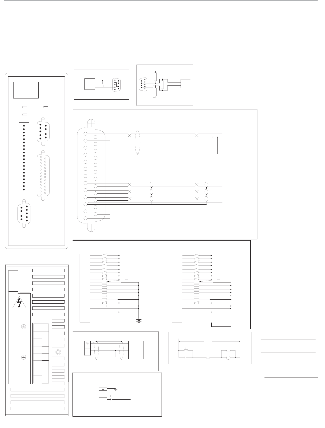
Motion Solutions
30
Serial
Port
MAIN VAC
M
Stop
Emergency
M(Aux)
Power On
RCAS
RECEIVE
Serial Port*
RS-232
Auxiliary I/O
FRONT VIEW
Emergency Stop Circuit
REMARKS:
IC800STI105P2
1
5
6
9
1 phase @ 10 Amps.
(1) Input power 90 to 130 VAC, 50-440 Hz
BOTTOM VIEW
1
1
SINKING CONNECTION
SOURCING CONNECTION
Discrete Inputs and Outputs
LOAD 100 MA MAX
Phase B-
Phase B+
Phase A-
Phase A+
Stepping Motor
MTR GND
M
VAC Input (1)
VAC
LOAD 100 MA MAX
6
9
1
5
Profibus
30 94 RLLL L
R
0-63 R X
address
64-99 L X
R
L
L
L
L
L
L
L
L
L
L
L
L
L
L
L
L
L
L
L
L
L
L
L
L
L
L
L
L
L
L
L
L
48 -LR
R
RR
62 -
63 -
61 -
57 -
Profibus
58 -
59 -
60 -
53 -
54 -
56 -
55 -
50 -
51 -
52 -
49 -
LL
R
RL
LR
LL
R
R
L
L
R
R
L
L
LL
L
LLL
L
L
L
L
R
R
L
L
L
L
L
L
RL
L
R
R
L
R
L
L
L
R
R
L
R
R
L
LR
L
R
L
RL
LR
L
L
L
R
L
R
R
R
R
R
R
L
L
L
L
39 -
44 -
45 -
47 -
46 -
40 -
41 -
43 -
42 -
35 99
36 -
38 -
37 -
31 95
32 96
33 97
34 98
RR
L
LL
RR
L
R
L
L
L
R
R
R
L
L
L
L
R
R
RL
L
L
L
LL
LL
R
R
R
R
R
L
L
R
R
L
L
R
R
R
R
LL
R
R
LR
L
R
L
L
R
R
R
L
L
R
RR
R
R
L
LR
LR
R
R
R
R
R
R
R
L
R
L
R
R
R
L
R
DIP Switch Positions (2)
R
R
R
R
R
R
R
R
R
R
R
R
R
R
R
R
R
R
R
R
R
R
R
R
R
R
R
R
1 2 4 8 16 32
R
R
12 76 LRRL
R
21 85
26 90
27 91
29 93
28 92
22 86
23 87
25 89
24 88
17 81
18 82
20 84
19 83
13 77
14 78
15 79
16 80
RLRL
L
LR
L
L
RR
R
L
R
R
L
L
R
R
L
L
LL
R
L
L
LL
RL
L
L
L
R
R
L
L
L
L
R
R
L
L
L
L
RL
R
L
R
L
R
L
L
R
L
R
R
L
R
L
LR
R
R
R
LR
RR
L
L
L
R
L
R
L
L
L
L
L
L
R
R
R
0 64
3 67
8 72
9 73
11 75
10 74
5 69
4 68
6 70
7 71
Address
Profibus
2 66
1 65
RRLR
L
RR
L
L
RL
L
R
L
R
L
RL
L
R
R
RL
R
RL
RL
RL
R
R
R
L
LR
R
L
L
R
R
R
R
R
R
R
R
LR
L
R
R
R
RR
RR
R
R
R
PROFIBUS
6
9
1
5
64 -
TRANSMIT
GROUND
HOST
12-24
-
+
L1
L2
12-24
-
+
COMPUTER
Auxiliary
I/O
Fwd/Rev
Address/Code
13
14
25
13 25
14
AI1+
AI1-
AI2+
AI2-
AO
Analog common
IN_A+
IN_A-
IN_B+
IN_B-
Tie
+5Vdc
+12Vdc
Common
Out_A+
Out_A-
Out_B+
Out_B-
Index+
Index-
common
IN_Index+
IN_Index-
A+
A-
B+
B-
Index+
Index-
common
+/-10V
Com
59
16
Module Status
Network Status
VDC
(2) Must turn off power before changing settings.
R= right (closed)
L= left (open)
10
11
14
15
12
13
16
17
18
19
20
I/O_11
OK
IN Com
OutCom
+12VDC
12VCom
I/O_14
Enable
I/O_12
I/O_13
IN_07
IN_08
I/O_09
I/O_10
IN_04
IN_02
IN_05
IN_06
IN_03
9
7
8
4
6
5
2
3
IN_01 1
20
19
18
17
16
13
12
15
14
11
10
8
9
6
7
5
4
3
2
1
20
15
19
18
17
16
13
14
12
11
2
8
7
9
10
4
3
6
5
1
VDC
Note: Termination resistors
390
220
390
Data line B
Data line A
only on end controllers.
Vp
Gnd
cable
Profibus
(NA)
L R
(0-99) 4
1
2
-
NA16
8
32
64
B+
L1
L2
NC
A+
A/B-
WARNING!
HAZARDOUS
VOLTAGES
A/B-
A+
B+
L1
NC
L2
S2K Series
User Control Connections
S2K Model: STI105 (Profibus Communication)
Motion Controllers
*Note:
The S2K serial port includes
12 V on pin 4. A jumper must
be placed from pin 4 to pin
7 to prev ent possible dam-
age to serial port on some
computers. Using a GE serial
communication cable
is recommended.
www.ge-ip.com
GE Intelligent Platforms
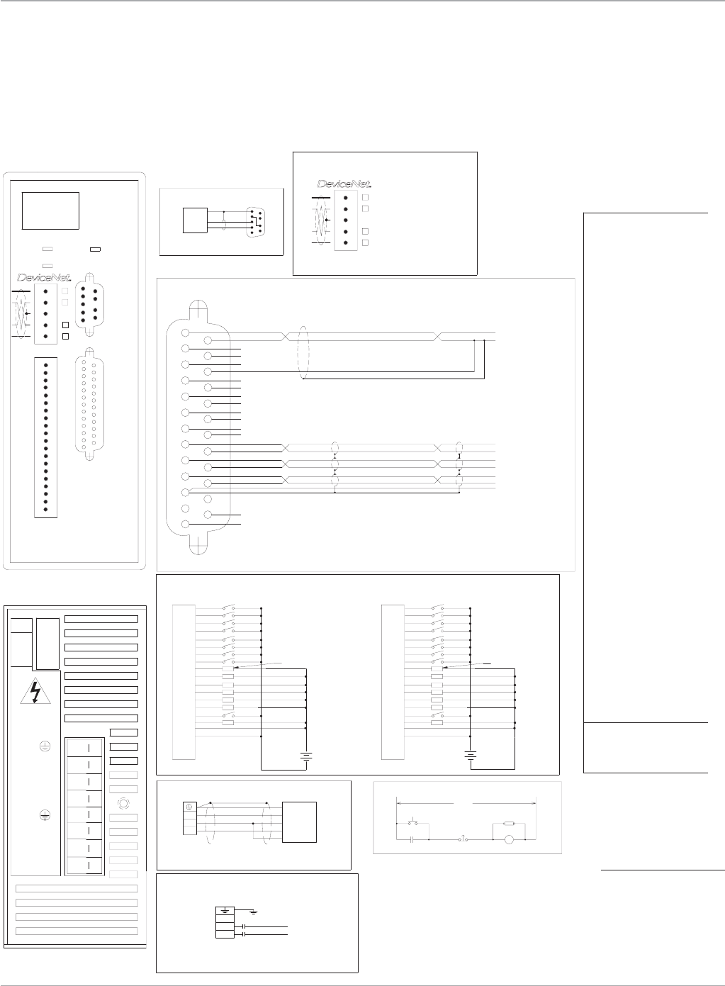
31
Motion Solutions
Motion Controllers
Serial
Port
MAIN VAC
M
Stop
Emergency
M(Aux)
Power On
RCAS
RECEIVE
Serial Port*
RS-232
Auxiliary I/O
FRONT VIEW
Emergency Stop Circuit
REMARKS:
IC800STI105D2
1
5
6
9
1 phase @ 10 Amps.
(1) Input power 90 to 130 VAC, 50-440 Hz
BOTTOM VIEW
1
1
DeviceNet
SINKING CONNECTION
SOURCING CONNECTION
Discrete Inputs and Outputs
LOAD 100 MA MAX
RR
R
L2R
Baud
Rate
Device Net
RL
L
R20 R
500K R L
N/A L L
250K L R
125K R R
L
L
R29 L
31
30
L
R
L
L
L
L
L
L
27
28
25
26
24
23
22
21
R
LL
RR
R
LR
L
L
R
LL
R
L
L
R
L
R
L
R
L
L
R
R
L
L
R
L
L
R
R
L
L
L
L
L
L
L
L
L
L
L
L
R
L11 L
16
18
19
17
14
15
13
12
R
R
RR
LR
LL
LR
R
R
RR
RR
R
L
L
L
L
R
R
R
L
L
L
L
L
L
L
L
7
9
10
8
5
6
3
4
R
L
LL
RL
RL
RR
L
R
RL
RL
L
R
R
L
R
LL
R
L
L
R
R
R
L
R
R
R
L
L
L
L
R
R
R
R
R
R
R
R
R
R
R
R
Address
Device Net 1 2 4 8 16 32
DIP Switch Positions (2)
0
1
RR
LR
R
R
RR
R
R
R
R
R
R
R
R
R
R
R
R
R
R
R
R
R
R
R
R
R
R
R
R
R
R
R
R
R
R
R
R
R
R
61
62
63
59
60
58
57
47
54
55
56
53
52
49
51
50
48
42
45
46
44
43
40
41
38
39
LRL
R
L
L
L
L
L
L
R
L
R
R
L
RL
L
R
R
R
LLL
L
L
L
LL
L
L
L
L
LL
L
L
L
L
L
L
L
LRL
L
LL
R
L
R
L
R
L
L
L
R
L
R
R
R
L
L
L
L
R
R
R
R
L
L
R
R
RR
L
L
L
L
L
R
R
L
R
R
L
L
L
L
L
L
L
L
L
R
R
R
R
L
L
L
L
R
LR
L
R
R
L
R
L
L
L
R
L
L
R
R
L
R
L
R
R
RR
L
L
L
L
LRL
R
R
R
R
L
L
L
L
L
L
L
L
R
R
R
R
L
L
R
R
L
L
L
L
33
35
36
37
34
32
R
RL
L
R
L
R
R
L
R
R
L
L
LR
RR R
LRR
R
R
R
R
R
R
R
R
L
L
L
L
RRL
Phase B-
Phase B+
Phase A-
Phase A+
Stepping Motor
MTR GND
M
VAC Input (1)
VAC
LOAD 100 MA MAX
1 2
TRANSMIT
GROUND
HOST
12-24
-
+
L1
L2
12-24
-
+
0006106_r01.eps
COMPUTER
Auxiliary
I/O
Fwd/Rev
Address/Code
13
14
25
13 25
14
AI1+
AI1-
AI2+
AI2-
AO
Analog common
IN_A+
IN_A-
IN_B+
IN_B-
Tie
+5Vdc
+12Vdc
Common
Out_A+
Out_A-
Out_B+
Out_B-
Index+
Index-
common
IN_Index+
IN_Index-
A+
A-
B+
B-
Index+
Index-
common
+/-10V
Com
59
16
Module Status
Network Status
V+ Red
CAN_H White
SHIELD Bare
CAN_L Blue
V- Black
5 Pin open style connector
(NA)
(DR)
VDC
(2) Must turn off power before changing settings.
R= right (closed)
L= left (open)
10
11
14
15
12
13
16
17
18
19
20
I/O_11
OK
IN Com
OutCom
+12VDC
12VCom
I/O_14
Enable
I/O_12
I/O_13
IN_07
IN_08
I/O_09
I/O_10
IN_04
IN_02
IN_05
IN_06
IN_03
9
7
8
4
6
5
2
3
IN_01 1
20
19
18
17
16
13
12
15
14
11
10
8
9
6
7
5
4
3
2
1
20
15
19
18
17
16
13
14
12
11
2
8
7
9
10
4
3
6
5
1
VDC
L R
(0-63) 4
1
2
DR 2
NA16
8
32
1
B+
L1
L2
NC
A+
A/B-
WARNING!
HAZARDOUS
VOLTAGES
A/B-
A+
B+
L1
NC
L2
S2K Series
User Control Connections
S2K Model: STI105 (DeviceNet Communication)
*Note:
The S2K serial port includes
12 V on pin 4. A jumper must
be placed from pin 4 to pin
7 to prev ent possible dam-
age to serial port on some
computers. Using a GE serial
communication cable
is recommended.
www.ge-ip.com GE Intelligent Platforms
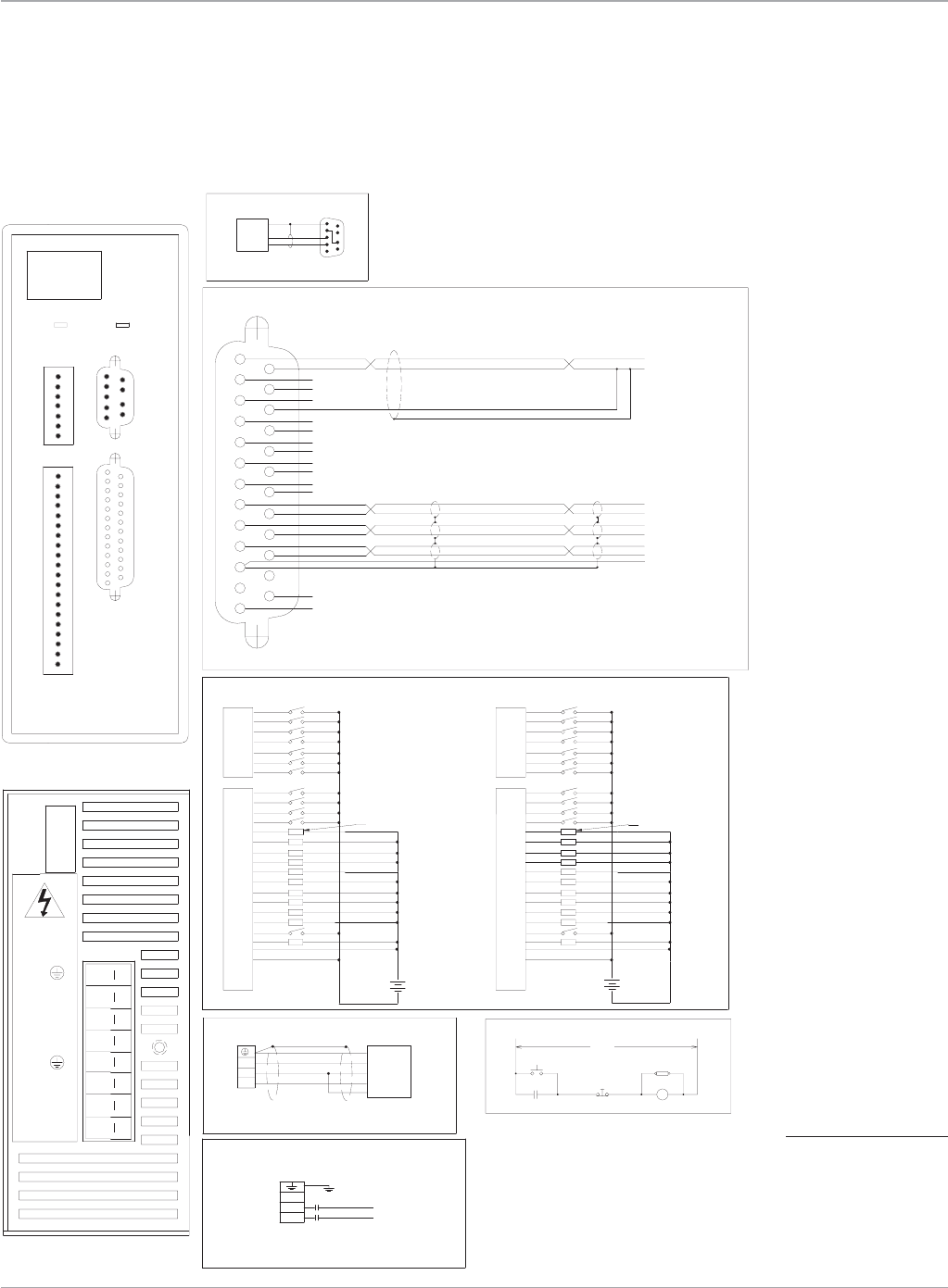
Motion Solutions
32
Serial
Port
MAIN VAC
M
Stop
Emergency
M(Aux)
Power On
RCAS
RECEIVE
Serial Port*
RS-232
Auxiliary I/O
FRONT VIEW
Emergency Stop Circuit
REMARKS:
IC800STI105S1
1
5
6
9
1 phase @ 10 Amps.
(1) Input power 90 to 130 VAC, 50-440 Hz
BOTTOM VIEW
1
1
SINKING CONNECTION
SOURCING CONNECTION
Discrete Inputs and Outputs
Phase B-
Phase B+
Phase A-
Phase A+
Stepping Motor
MTR GND
M
VAC Input (1)
VAC
LOAD 100 MA MAX LOAD 100 MA MAX
TRANSMIT
GROUND
HOST
12-24
-
+
L1
L2
12-24
-
+
COMPUTER
Auxiliary
I/O
Fwd/Rev
Address/Code
13
14
25
13 25
14
AI1+
AI1-
AI2+
AI2-
AO
Analog common
IN_A+
IN_A-
IN_B+
IN_B-
Tie
+5Vdc
+12Vdc
Common
Out_A+
Out_A-
Out_B+
Out_B-
Index+
Index-
common
IN_Index+
IN_Index-
A+
A-
B+
B-
Index+
Index-
common
+/-10V
Com
59
16
Module Status
VDC
10
11
14
15
12
13
16
17
18
19
20
I/O_18
OK
IN Com
OutCom
+12VDC
12VCom
I/O_21
Enable
I/O_19
I/O_20
I/O_16
I/O_17
IN_11
IN_09
IN_10
9
7
8
4
6
5
2
3
IN_08 1
20
19
18
17
16
13
12
15
14
11
10
8
9
6
7
5
4
3
2
1
20
15
19
18
17
16
13
14
12
11
2
8
7
9
10
4
3
6
5
1
VDC
2
7
4
5
6
3
1
2
7
3
4
5
6
1
IN_06
IN_05
IN_04
IN_07
IN_01
IN_03
IN_02
6
7
5
4
3
2
1
I/O_15
I/O_14
I/O_13
I/O_12
B+
L1
L2
NC
A+
A/B-
WARNING!
HAZARDOUS
VOLTAGES
A/B-
A+
B+
L1
NC
L2
S2K Series
User Control Connections
S2K Model: STI105 (Serial Communication)
*Note:
The S2K serial port includes
12 V on pin 4. A jumper must
be placed from pin 4 to pin
7 to prev ent possible dam-
age to serial port on some
computers. Using a GE serial
communication cable
is recommended.
Motion Controllers
www.ge-ip.com
GE Intelligent Platforms
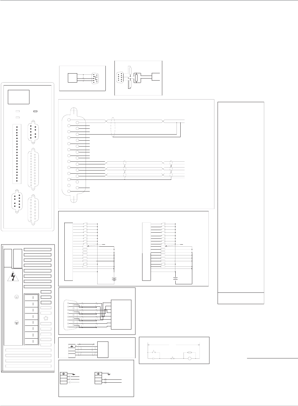
33
Motion Solutions
Position
Feedback
Serial
Port
MAIN VAC
M
Stop
Emergency
M(Aux)
Power On
RCAS
RECEIVE
Serial Port*
RS-232
Auxiliary I/O
FRONT VIEW
Brushless Servo Motor Emergency Stop Circuit
REMARKS:
1
5
6
9
B
C
D
A
1 phase @ 10 Amps, 3 phase @ 6 Amps
(1) Input power 90 to 250 VAC, 50-440 Hz
M
VAC
VAC Input (1)
VAC
M
Three Phase Single Phase
Note: Do not connect L3 for single phase
BOTTOM VIEW
1
8
9
15
1
1
PROFIBUS
6
9
1
5
IC800SSI104RP2
Position Feedback
Resolver
Motor
R
S
T
GND
TRANSMIT
GROUND
HOST
L1
L2
L1
L2
L3
COMPUTER
Auxiliary
I/O
Fwd/Rev
Address/Code
13
14
25
13 25
14
AI1+
AI1-
AI2+
AI2-
AO
Analog common
IN_A+
IN_A-
IN_B+
IN_B-
Tie
+5Vdc
+12Vdc
Common
Out_A+
Out_A-
Out_B+
Out_B-
Index+
Index-
common
IN_Index+
IN_Index-
A+
A-
B+
B-
Index+
Index-
common
+/-10V
Com
59
16
10
I/O_10
20
19
18
17
Enable
OK
I/O_14
I/O_13
I/O_12
I/O_11
15
16
14
12
13
11
I/O_09
IN_02
IN_01
9
2
1
12VCom
+12VDC
OutCom
IN Com
Module Status
Network Status
(2) Must turn off power before changing settings.
R= right (closed)
L= left (open)
IN_06
IN_05
6
5
8
7
IN_08
IN_07
4
3
IN_04
IN_03
LOAD 100 MA MAX
Discrete Inputs and Outputs
SINKING CONNECTION
20
15
18
19
16
17
13
14
11
12
2
10
9
7
8
4
5
6
3
1
-
+
SOURCING CONNECTION
12-24
VDC
20
15
19
18
17
16
13
14
12
11
2
8
7
9
10
4
3
6
5
1
12-24
VDC
-
+
LOAD 100 MA MAX
LL
L
LL31 95 R
64-99 L X
L
L
L
L
L
L
L
L
L
L
L
L
L
L
L
L
L
L
L
L
L
L
L
L
L
L
L
L
L
L
L
L
49 -LR
R
RL
50 -
51 -
52 -
53 -
54 -
55 -
56 -
57 -
58 -
59 -
60 -
61 -
62 -
63 -
Profibus
address
LL
R
LR
0-63 R X
RL
LL
RR
LR
LL
LLL
64 -
LLL
L
L
LL
RL
L
L
L
LR
R
L
R
R
R
L
L
L
LL
RR
RL
LRL
R
R
R
R
L
L
L
L
L
L
L
L
R
R
R
R
L
R
L
L
L
36 -
37 -
38 -
39 -
40 -
41 -
42 -
43 -
44 -
45 -
46 -
47 -
48 -
34 98
33 97
32 96
35 99
RL
R
RR
RR
L
R
L
R
L
R
R
L
LR
LL
LR
LLR
R
L
R
L
L
L
L
L
R
L
R
R
L
R
RL
RL
R
R
R
LL
R
L
L
L
L
RR
R
RL
RL
RR
RRR
R
R
R
R
L
L
L
L
R
R
R
R
R
R
R
R
R
R
R
R
R
R
R
1 2 4 8 16 32
R
R
R
R
R
R
R
R
R
R
R
R
R
R
R
R
R
R
R
R
R
R
R
R
R
R
R
R
DIP Switch Positions (2)
R
RL
L
RL13 77
16 80
15 79
14 78
19 83
20 84
18 82
17 81
24 88
25 89
23 87
22 86
28 92
29 93
27 91
26 90
21 85
30 94
LR
L
LR
RL
L
R
R
L
R
LL
R
RR
LR
LL
RLL
L
L
L
L
R
L
L
L
L
L
L
L
R
L
R
RL
L
L
L
L
LR
R
L
R
R
L
RL
L
LL
RR
RL
RRL
R
R
R
R
L
L
R
R
L
L
L
L
R
L
L
R
LL
R
L
R
1 65
2 66
7 71
6 70
4 68
5 69
10 74
11 75
9 73
8 72
3 67
0 64
12 76
(NA)
Profibus
Address
RR
L
RR
RR
L
R
L
R
R
LR
L
LR
LL
LR
RLR
R
L
L
L
R
R
L
L
R
R
R
R
R
R
R
L
L
L
R
R
R
R
L
L
L
L
RR
R
R
R
R
R
R
R
R
R
R
R
R
R
Note: Termination resistors
6
9
220
390
1
390
5
only on end controllers.
Profibus
Vp
Gnd
cable
Data line B
Profibus
Data line A
L R
S
T
R
L2
L1
L3
L1
L2
L3
T
L1
L2
L3
R
S
WARNING!
HAZARDOUS
VOLTAGES
(0-99)
1
2
4
NA
32
8
16
64
-
1
815
9
Therm
G
H
E
F
C
D
A
B
S1
Therm
R2
R1
S3
S2
S4
P2
S2K Series
User Control Connections
S2K Model: SSI104 (Profibus Communication)
Motion Controllers
*Note:
The S2K serial port includes
12 V on pin 4. A jumper must
be placed from pin 4 to pin
7 to prev ent possible dam-
age to serial port on some
computers. Using a GE serial
communication cable
is recommended.
www.ge-ip.com GE Intelligent Platforms
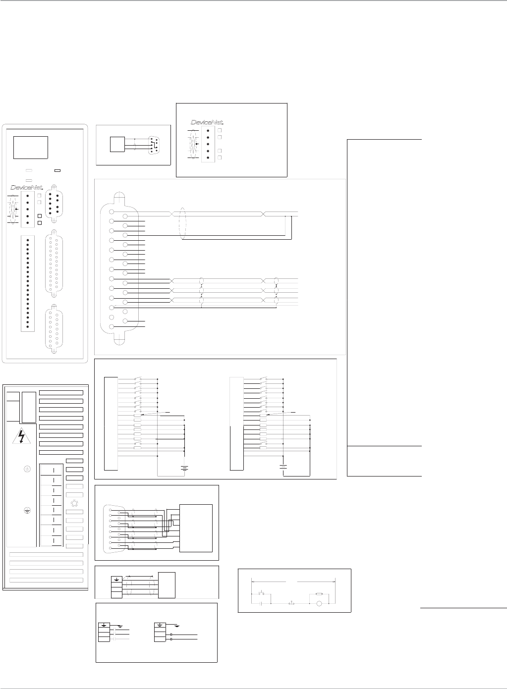
Motion Solutions
34
Position
Feedback
Serial
Port
MAIN VAC
M
Stop
Emergency
M(Aux)
Power On
RCAS
RECEIVE
Serial Port*
RS-232
Auxiliary I/O
FRONT VIEW
Brushless Servo Motor
Emergency Stop Circuit
REMARKS:
IC800SSI104RD2
1
5
6
9
B
C
D
A
1 phase @ 10 Amps, 3 phase @ 6 Amps
(1) Input power 90 to 250 VAC, 50-440 Hz
M
VAC
VAC Input (1)
VAC
M
Three Phase Single Phase
Note: Do not connect L3 for single phase
BOTTOM VIEW
1
8
9
15
1
1
DeviceNet
RR
R
L2R
Baud
Rate
Device Net
RL
L
R20 R
500K R L
N/A L L
250K L R
125K R R
L
L
R29 L
31
30
L
R
L
L
L
L
L
L
27
28
25
26
24
23
22
21
R
LL
RR
R
LR
L
L
R
LL
R
L
L
R
L
R
L
R
L
L
R
R
L
L
R
L
L
R
R
L
L
L
L
L
L
L
L
L
L
L
L
R
L11 L
16
18
19
17
14
15
13
12
R
R
RR
LR
LL
LR
R
R
RR
RR
R
L
L
L
L
R
R
R
L
L
L
L
L
L
L
L
7
9
10
8
5
6
3
4
R
L
LL
RL
RL
RR
L
R
RL
RL
L
R
R
L
R
LL
R
L
L
R
R
R
L
R
R
R
L
L
L
L
R
R
R
R
R
R
R
R
R
R
R
R
Address
Device Net 1 2 4 8 16 32
DIP Switch Positions (2)
0
1
RR
LR
R
R
RR
R
R
R
R
R
R
R
R
R
R
R
R
R
R
R
R
R
R
R
R
R
R
R
R
R
R
R
R
R
R
R
R
R
R
61
62
63
59
60
58
57
47
54
55
56
53
52
49
51
50
48
42
45
46
44
43
40
41
38
39
LR
L
R
L
L
L
L
L
L
R
L
R
R
L
RL
L
R
R
R
LLL
L
L
L
LL
L
L
L
L
LL
L
L
L
L
L
L
L
LRL
L
LL
R
L
R
L
R
L
L
L
R
L
R
R
R
L
L
L
L
R
R
R
R
L
L
R
R
RR
L
L
L
L
L
R
R
L
R
R
L
L
L
L
L
L
L
L
L
R
R
R
R
L
L
L
L
R
LR
L
R
R
L
R
L
L
L
R
L
L
R
R
L
R
L
R
R
RR
L
L
L
L
LRL
R
R
R
R
L
L
L
L
L
L
L
L
R
R
R
R
L
L
R
R
L
L
L
L
33
35
36
37
34
32
R
RL
L
R
L
R
R
L
R
R
L
L
LR
RRR
LRR
R
R
R
R
R
R
R
R
L
L
L
L
RRL
Position Feedback
Resolver
1 2
Motor
R
S
T
GND
TRANSMIT
GROUND
L1
L2
L1
L2
L3
COMPUTER
Auxiliary
I/O
Fwd/Rev
Address/Code
13
14
25
(0-63) 4
1
2
DR 2
NA16
8
32
1
T
L1
L2
L3
R
S
WARNING!
HAZARDOUS
VOLTAGES
13 25
14
AI1+
AI1-
AI2+
AI2-
AO
Analog common
IN_A+
IN_A-
IN_B+
IN_B-
Tie
+5Vdc
+12Vdc
Common
Out_A+
Out_A-
Out_B+
Out_B-
Index+
Index-
common
IN_Index+
IN_Index-
A+
A-
B+
B-
Index+
Index-
common
+/-10V
Com
59
16
10
I/O_10
20
19
18
17
Enable
OK
I/O_14
I/O_13
I/O_12
I/O_11
15
16
14
12
13
11
I/O_09
IN_02
IN_01
9
2
1
12VCom
+12VDC
OutCom
IN Com
Module Status
Network Status
V+ Red
CAN_H White
SHIELD Bare
CAN_L Blue
V- Black
5 Pin open style connector
(NA)
(DR)
(2) Must turn off power before changing settings.
R= right (closed)
L= left (open)
IN_06
IN_05
6
5
8
7
IN_08
IN_07
4
3
IN_04
IN_03
LOAD 100 MA MAX
Discrete Inputs and Outputs
SINKING CONNECTION
20
15
18
19
16
17
13
14
11
12
2
10
9
7
8
4
5
6
3
1
-
+
SOURCING CONNECTION
12-24
VDC
20
15
19
18
17
16
13
14
12
11
2
8
7
9
10
4
3
6
5
1
12-24
VDC
-
+
LOAD 100 MA MAX
L R
S
T
R
L2
L1
L3
L1
L2
L3
1
815
9
Therm
G
H
E
F
C
D
A
B
S1
Therm
R2
R1
S3
S2
S4
P2
S2K Series
User Control Connections
S2K Model: SSI104 (DeviceNet Communication)
Motion Controllers
*Note:
The S2K serial port includes
12 V on pin 4. A jumper must
be placed from pin 4 to pin
7 to prev ent possible dam-
age to serial port on some
computers. Using a GE serial
communication cable
is recommended.
www.ge-ip.com
GE Intelligent Platforms
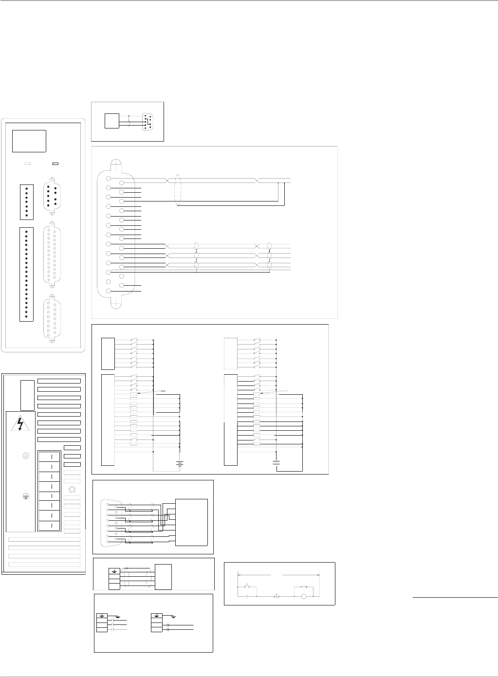
35
Motion Solutions
Position
Feedback
Serial
Port
MAIN VAC
M
Stop
Emergency
M(Aux)
Power On
RCAS
RECEIVE
Serial Port*
RS-232
Auxiliary I/O
FRONT VIEW
Brushless Servo Motor
Emergency Stop Circuit
REMARKS:
1
5
6
9
B
C
D
A
1 phase @ 10 Amps, 3 phase @ 6 Amps
(1) Input power 90 to 250 VAC, 50-440 Hz
M
VAC
VAC Input (1)
VAC
M
Three Phase Single Phase
Note: Do not connect L3 for single phase
BOTTOM VIEW
1
8
9
15
1
1
IC800SSI104RS1
Position Feedback
Resolver
Motor
R
S
T
GND
TRANSMIT
GROUND
L1
L2
L1
L2
L3
COMPUTER
Auxiliary
I/O
Fwd/Rev
Code
13
14
25
13 25
14
AI1+
AI1-
AI2+
AI2-
AO
Analog common
IN_A+
IN_A-
IN_B+
IN_B-
Tie
+5Vdc
+12Vdc
Common
Out_A+
Out_A-
Out_B+
Out_B-
Index+
Index-
common
IN_Index+
IN_Index-
A+
A-
B+
B-
Index+
Index-
common
+/-10V
Com
59
16
Module Status
LOAD 100 MA MAX
Discrete Inputs and Outputs
SINKING CONNECTION
20
15
18
19
16
17
13
14
11
12
2
10
9
7
8
4
5
6
3
1
6
7
5
4
3
2
-
+
1
SOURCING CONNECTION
VDC
12-24 20
15
18
19
16
17
13
14
11
12
2
7
9
8
10
3
4
5
6
6
7
1
5
4
3
2
VDC
12-24
-
+
LOAD 100 MA MAX
1
IN_05
IN_07
IN_06
IN_01
IN_04
IN_03
IN_02
5
7
6
3
4
1
2
20
19
18
17
16
13
12
15
14
11
10
I/O_13 6
Enable
12VCom
+12VDC
OutCom
IN Com
OK
I/O_20
I/O_19
I/O_21
I/O_18
I/O_14
I/O_15
I/O_17
I/O_16 9
8
7
I/O_12
IN_10
IN_09
IN_11
IN_08
4
5
3
2
1
S
T
R
L2
L1
L3
L1
L2
L3
T
L1
L2
L3
R
S
WARNING!
HAZARDOUS
VOLTAGES
1
815
9
Therm
G
H
E
F
C
D
A
B
S1
Therm
R2
R1
S3
S2
S4
P2
S2K Series
User Control Connections
S2K Model: SSI104 (Serial Communication)
Motion Controllers
*Note:
The S2K serial port includes
12 V on pin 4. A jumper must
be placed from pin 4 to pin
7 to prev ent possible dam-
age to serial port on some
computers. Using a GE serial
communication cable
is recommended.
www.ge-ip.com GE Intelligent Platforms
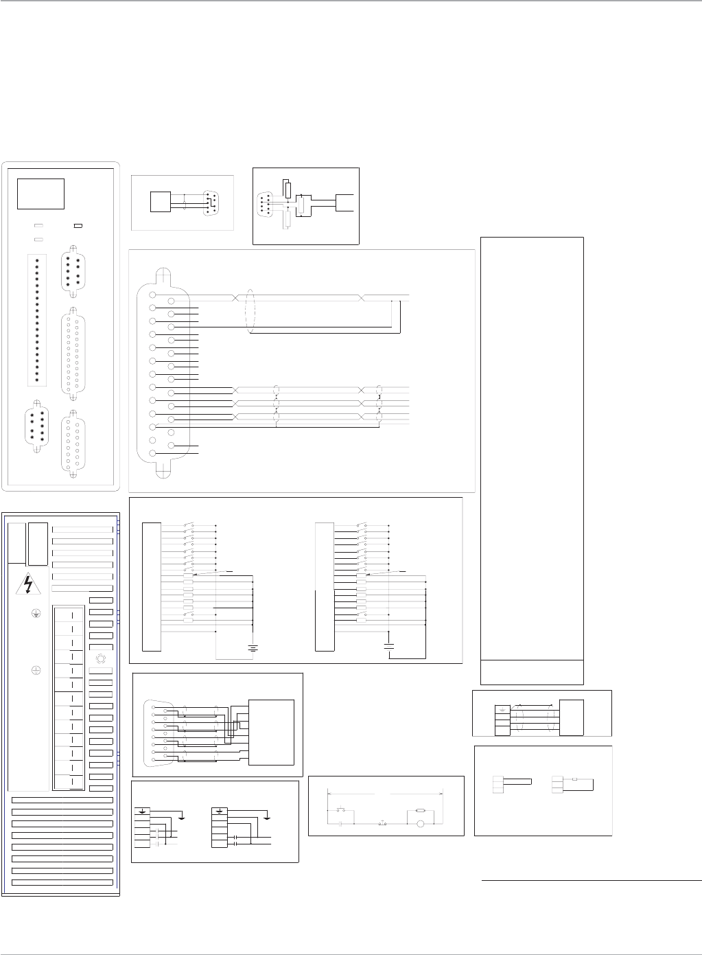
Motion Solutions
36
Position
Feedback
Serial
Port
MAIN VAC
M
Stop
Emergency
M(Aux)
Power On
RCAS
RECEIVE
Serial Port*
RS-232
Auxiliary I/O
FRONT VIEW
Brushless Servo Motor
Emergency Stop Circuit
REMARKS:
1
5
6
9
B
C
D
A
1 phase @ 15 Amps, 3 phase @ 8 Amps
(1) Input power 90 to 250 VAC, 50-440 Hz
1
815
9
Therm
G
H
E
F
C
D
A
B
S1
Therm
R2
R1
S3
S2
S4
P2
Position Feedback
Resolver
1
8
9
15
1
1
BOTTOM VIEW
VAC
Note: Do not connect L3 for single phase
VAC Input (1)
Three Phase
M
VAC
Single Phase
M
Clamp Connections
Internal
EXT
DC+
INT
External
DC+
INT
EXT
61
95
Profibus
PROFIBUS
6
9
1
5
IC800SSI107RP2
Motor
R
S
T
GND
Green
Black
White
Red
TRANSMIT
GROUND
HOST
L2
L1
L3
L1
L2
COMPUTER
Auxiliary
I/O
Fwd/Rev
Address/Code
13
14
25
13 25
14
AI1+
AI1-
AI2+
AI2-
AO
Analog common
IN_A+
IN_A-
IN_B+
IN_B-
Tie
+5Vdc
+12Vdc
Common
Out_A+
Out_A-
Out_B+
Out_B-
Index+
Index-
common
IN_Index+
IN_Index-
A+
A-
B+
B-
Index+
Index-
common
+/-10V
Com
59
16
10
I/O_10
20
19
18
17
Enable
OK
I/O_14
I/O_13
I/O_12
I/O_11
15
16
14
12
13
11
I/O_09
IN_02
IN_01
9
2
1
12VCom
+12VDC
OutCom
IN Com
Module Status
Network Status
(2) Must turn off power before changing settings.
R= right (closed)
L= left (open)
IN_06
IN_05
6
5
8
7
IN_08
IN_07
4
3
IN_04
IN_03
LOAD 100 MA MAX
Discrete Inputs and Outputs
SINKING CONNECTION
20
15
18
19
16
17
13
14
11
12
2
10
9
7
8
4
5
6
3
1
-
+
SOURCING CONNECTION
12-24
VDC
20
15
19
18
17
16
13
14
12
11
2
8
7
9
10
4
3
6
5
1
12-24
VDC
-
+
LOAD 100 MA MAX
E
S
O
G
A
L
T
S
V
U
O
A
D
R
Z
A
H
*Clamp resistor only required for extreme duty
cycle applications. Contact Whedco, Inc. for
recommended clamp resistor value and procedure
for connecting external clamp resistor.
Clamp
Resistor(*)
220
390 390
only on end controllers.
Note: Termination resistors
Vp
Gnd
Data line B
cable
Data line A Profibus
LL
L
LL31 95 R
64-99 L X
L
L
L
L
L
L
L
L
L
L
L
L
L
L
L
L
L
L
L
L
L
L
L
L
L
L
L
L
L
L
L
L
49 -LR
R
RL
50 -
51 -
52 -
53 -
54 -
55 -
56 -
57 -
58 -
59 -
60 -
61 -
62 -
63 -
Profibus
address
LL
R
LR
0-63 R X
RL
LL
RR
LR
LL
LLL
64 -
LLL
L
L
LL
RL
L
L
L
LR
R
L
R
R
R
L
L
L
LL
RR
RL
LRL
R
R
R
R
L
L
L
L
L
L
L
L
R
R
R
R
L
R
L
L
L
36 -
37 -
38 -
39 -
40 -
41 -
42 -
43 -
44 -
45 -
46 -
47 -
48 -
34 98
33 97
32 96
35 99
RL
R
RR
RR
L
R
L
R
L
R
R
L
LR
LL
LR
LLR
R
L
R
L
L
L
L
L
R
L
R
R
L
R
RL
RL
R
R
R
LL
R
L
L
L
L
RR
R
RL
RL
RR
RRR
R
R
R
R
L
L
L
L
R
R
R
R
R
R
R
R
R
R
R
R
R
R
R
1 2 4 8 16 32
R
R
R
R
R
R
R
R
R
R
R
R
R
R
R
R
R
R
R
R
R
R
R
R
R
R
R
R
DIP Switch Positions (2)
R
RL
L
RL13 77
16 80
15 79
14 78
19 83
20 84
18 82
17 81
24 88
25 89
23 87
22 86
28 92
29 93
27 91
26 90
21 85
30 94
LR
L
LR
RL
L
R
R
L
R
LL
R
RR
LR
LL
RLL
L
L
L
L
R
L
L
L
L
L
L
L
R
L
R
RL
L
L
L
L
LR
R
L
R
R
L
RL
L
LL
RR
RL
RRL
R
R
R
R
L
L
R
R
L
L
L
L
R
L
L
R
LL
R
L
R
1 65
2 66
7 71
6 70
4 68
5 69
10 74
11 75
9 73
8 72
3 67
0 64
12 76
(NA)
Profibus
Address
RR
L
RR
RR
L
R
L
R
R
LR
L
LR
LL
LR
RLR
R
L
L
L
R
R
L
L
R
R
R
R
R
R
R
L
L
L
R
R
R
R
L
L
L
L
RR
R
R
R
R
R
R
R
R
R
R
R
R
R
L R
S
T
R
WARNING!
2L2
2L1
1L3
1L2
EXT
1L1
INT
DC+
R
S
T
2L1
1L2
1L1
1L3
2L2
1L2
1L1
2L1
1L3
2L2
64
2
1
(0-99)
16
NA 8
4
-
32
S2K Series
User Control Connections
S2K Model: SSI107 (Profibus Communication)
Motion Controllers
*Note:
The S2K serial port includes 12 V on pin 4. A jumper
must be placed from pin 4 to pin 7 to prev ent possible
damage to serial port on some computers. Using a GE
serial communication cable is recommended.
www.ge-ip.com
GE Intelligent Platforms
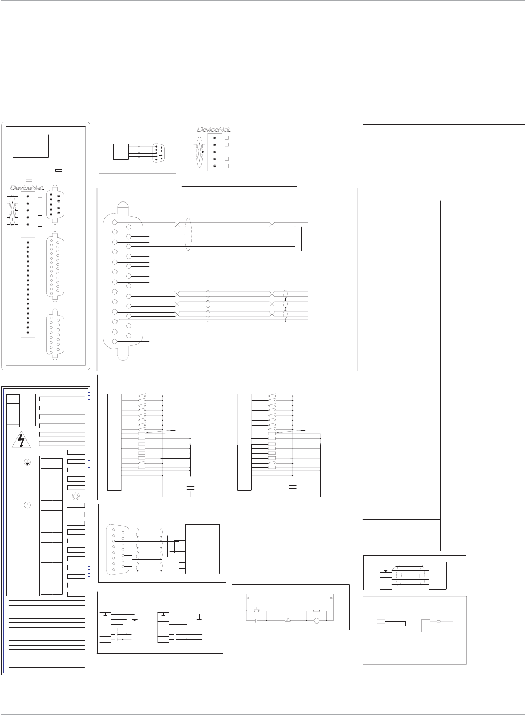
37
Motion Solutions
Position
Feedback
Serial
Port
MAIN VAC
M
Stop
Emergency
M(Aux)
Power On
RCAS
RECEIVE
Serial Port*
RS-232
Auxiliary I/O
FRONT VIEW
Brushless Servo Motor
Emergency Stop Circuit
REMARKS:
IC800SSI107RD2
1
5
6
9
B
C
D
A
1 phase @ 15 Amps, 3 phase @ 8 Amps
(1) Input power 90 to 250 VAC, 50-440 Hz
1
8
9
15
1
1
DeviceNet
RR
R
L2R
Baud
Rate
Device Net
RL
L
R20 R
500K R L
N/A L L
250K L R
125K R R
L
L
R29 L
31
30
L
R
L
L
L
L
L
L
27
28
25
26
24
23
22
21
R
LL
RR
R
LR
L
L
R
LL
R
L
L
R
L
R
L
R
L
L
R
R
L
L
R
L
L
R
R
L
L
L
L
L
L
L
L
L
L
L
L
R
L11 L
16
18
19
17
14
15
13
12
R
R
RR
LR
LL
LR
R
R
RR
RR
R
L
L
L
L
R
R
R
L
L
L
L
L
L
L
L
7
9
10
8
5
6
3
4
R
L
LL
RL
RL
RR
L
R
RL
RL
L
R
R
L
R
LL
R
L
L
R
R
R
L
R
R
R
L
L
L
L
R
R
R
R
R
R
R
R
R
R
R
R
Address
Device Net 1 2 4 8 16 32
DIP Switch Positions (2)
0
1
RR
LR
R
R
RR
R
R
R
R
R
R
R
R
R
R
R
R
R
R
R
R
R
R
R
R
R
R
R
R
R
R
R
R
R
R
R
R
R
R
61
62
63
59
60
58
57
47
54
55
56
53
52
49
51
50
48
42
45
46
44
43
40
41
38
39
LRL
R
L
L
L
L
L
L
R
L
R
R
L
RL
L
R
R
R
LLL
L
L
L
LL
L
L
L
L
LL
L
L
L
L
L
L
L
LRL
L
LL
R
L
R
L
R
L
L
L
R
L
R
R
R
L
L
L
L
R
R
R
R
L
L
R
R
RR
L
L
L
L
L
R
R
L
R
R
L
L
L
L
L
L
L
L
L
R
R
R
R
L
L
L
L
R
LR
L
R
R
L
R
L
L
L
R
L
L
R
R
L
R
L
R
R
RR
L
L
L
L
LRL
R
R
R
R
L
L
L
L
L
L
L
L
R
R
R
R
L
L
R
R
L
L
L
L
33
35
36
37
34
32
R
RL
L
R
L
R
R
L
R
R
L
L
LR
RRR
LRR
R
R
R
R
R
R
R
R
L
L
L
L
RRL
BOTTOM VIEW
VAC
Note: Do not connect L3 for single phase
VAC Input (1)
Three Phase
M
VAC
Single Phase
M
Clamp Connections
Internal
EXT
DC+
INT
External
DC+
INT
EXT
Position Feedback
Resolver 1 2
Motor
R
S
T
GND
TRANSMIT
GROUND
HOST
L2
L1
L3
L1
L2
COMPUTER
Auxiliary
I/O
Fwd/Rev
Address/Code
13
14
25
13 25
14
AI1+
AI1-
AI2+
AI2-
AO
Analog common
IN_A+
IN_A-
IN_B+
IN_B-
Tie
+5Vdc
+12Vdc
Common
Out_A+
Out_A-
Out_B+
Out_B-
Index+
Index-
common
IN_Index+
IN_Index-
A+
A-
B+
B-
Index+
Index-
common
+/-10V
Com
59
16
10
I/O_10
20
19
18
17
Enable
OK
I/O_14
I/O_13
I/O_12
I/O_11
15
16
14
12
13
11
I/O_09
IN_02
IN_01
9
2
1
12VCom
+12VDC
OutCom
IN Com
Module Status
Network Status
V+ Red
CAN_H White
SHIELD Bare
CAN_L Blue
V- Black
5 Pin open style connector
(NA)
(DR)
(2) Must turn off power before changing settings.
R= right (closed)
L= left (open)
IN_06
IN_05
6
5
8
7
IN_08
IN_07
4
3
IN_04
IN_03
LOAD 100 MA MAX
Discrete Inputs and Outputs
SINKING CONNECTION
20
15
18
19
16
17
13
14
11
12
2
10
9
7
8
4
5
6
3
1
-
+
SOURCING CONNECTION
12-24
VDC
20
15
19
18
17
16
13
14
12
11
2
8
7
9
10
4
3
6
5
1
12-24
VDC
-
+
LOAD 100 MA MAX
E
S
O
G
A
L
T
S
V
U
O
A
D
R
Z
A
H
*Clamp resistor only required for extreme duty
cycle applications. Contact Whedco, Inc. for
recommended clamp resistor value and procedure
for connecting external clamp resistor.
Clamp
Resistor(*)
L R
S
T
R
WARNING!
2L2
2L1
1L3
1L2
EXT
1L1
INT
DC+
R
S
T
DR
NA
(0-63)
2
1
8
16
4
1
2
32
2L1
1L2
1L1
1L3
2L2
1L2
1L1
2L1
1L3
2L2
1
815
9
Therm
G
H
E
F
C
D
A
B
S1
Therm
R2
R1
S3
S2
S4
P2
S2K Series
User Control Connections
S2K Model: SSI107 (DeviceNet Communication)
Motion Controllers
*Note:
The S2K serial port includes 12 V on pin 4. A jumper
must be placed from pin 4 to pin 7 to prev ent possi-
ble damage to serial port on some computers. Using
a GE serial communication cable is recommended.
www.ge-ip.com GE Intelligent Platforms
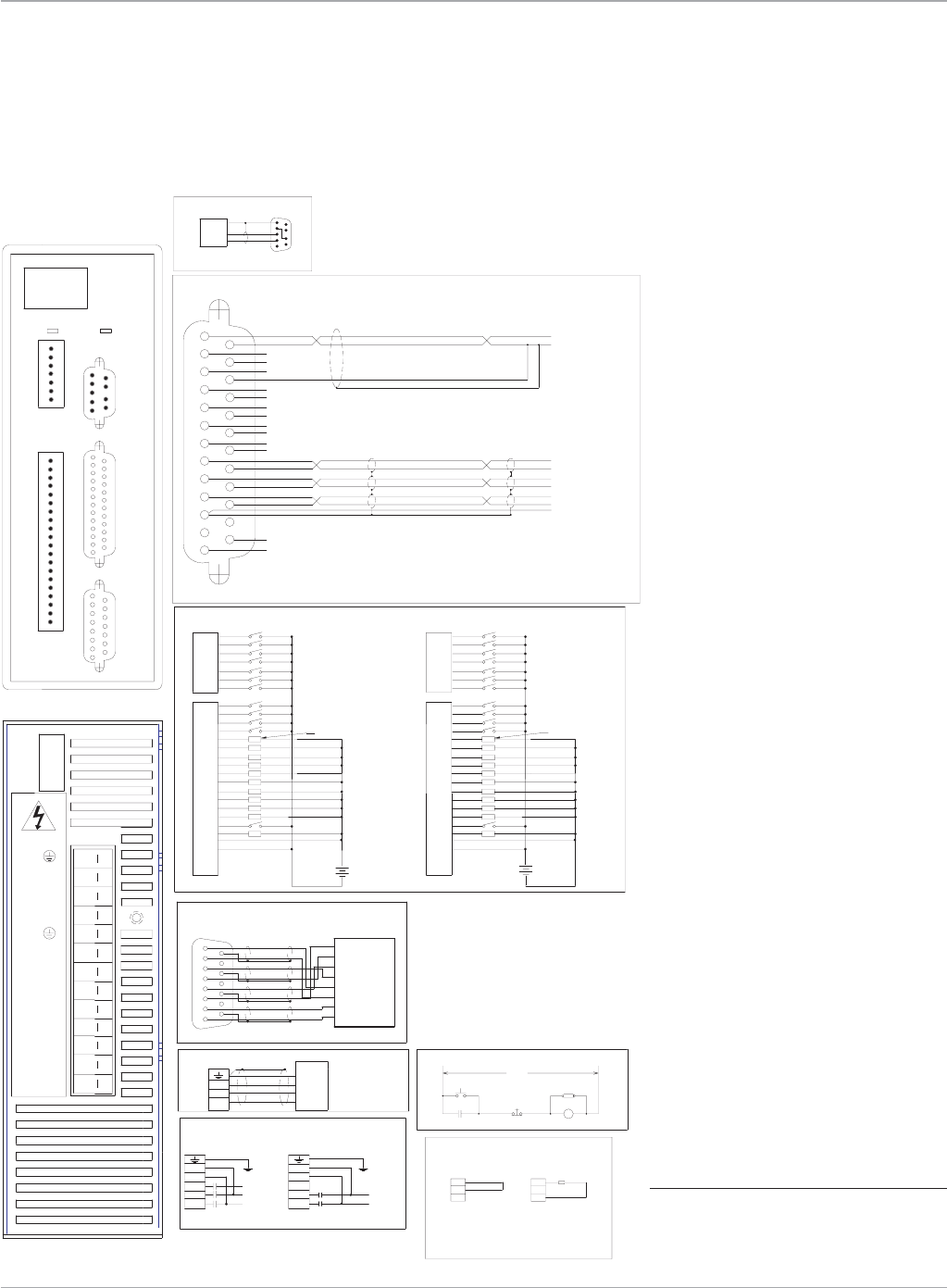
Motion Solutions
38
Position
Feedback
Serial
Port
MAIN VAC
M
Stop
Emergency
M(Aux)
Power On
RCAS
RECEIVE
Serial Port*
RS-232
Auxiliary I/O
FRONT VIEW
Brushless Servo Motor Emergency Stop Circuit
REMARKS:
IC800SSI107RS1
1
5
6
9
B
C
D
A
1 phase @ 15 Amps, 3 phase @ 8 Amps
(1) Input power 90 to 250 VAC, 50-440 Hz
1
8
9
15
1
1
BOTTOM VIEW
VAC
Note: Do not connect L3 for single phase
VAC Input (1)
Three Phase
M
VAC
Single Phase
M
Clamp Connections
Internal
EXT
DC+
INT
External
DC+
INT
EXT
Position Feedback
Resolver
Motor
R
S
T
GND
TRANSMIT
GROUND
HOST
L2
L1
L3
L1
L2
COMPUTER
Auxiliary
I/O
Fwd/Rev
Address/Code
13
14
25
13 25
14
AI1+
AI1-
AI2+
AI2-
AO
Analog common
IN_A+
IN_A-
IN_B+
IN_B-
Tie
+5Vdc
+12Vdc
Common
Out_A+
Out_A-
Out_B+
Out_B-
Index+
Index-
common
IN_Index+
IN_Index-
A+
A-
B+
B-
Index+
Index-
common
+/-10V
Com
59
16
Module Status
LOAD 100 MA MAX
Discrete Inputs and Outputs
SINKING CONNECTION
20
15
18
19
16
17
13
14
11
12
2
10
9
7
8
4
5
6
3
1
6
7
5
4
3
2
-
+
1
SOURCING CONNECTION
VDC
12-24 20
15
18
19
16
17
13
14
11
12
2
7
9
8
10
3
4
5
6
6
7
1
5
4
3
2
VDC
12-24
-
+
LOAD 100 MA MAX
1
IN_05
IN_07
IN_06
IN_01
IN_04
IN_03
IN_02
5
7
6
3
4
1
2
20
19
18
17
16
13
12
15
14
11
10
I/O_13 6
Enable
12VCom
+12VDC
OutCom
IN Com
OK
I/O_20
I/O_19
I/O_21
I/O_18
I/O_14
I/O_15
I/O_17
I/O_16 9
8
7
I/O_12
IN_10
IN_09
IN_11
IN_08
4
5
3
2
1
E
S
O
G
A
L
T
S
V
U
O
A
D
R
Z
A
H
*Clamp resistor only required for extreme duty
cycle applications. Contact Whedco, Inc. for
recommended clamp resistor value and procedure
for connecting external clamp resistor.
Clamp
Resistor(*)
S
T
R
WARNING!
2L2
2L1
1L3
1L2
EXT
1L1
INT
DC+
R
S
T
2L1
1L2
1L1
1L3
2L2
1L2
1L1
2L1
1L3
2L2
1
815
9
Therm
G
H
E
F
C
D
A
B
S1
Therm
R2
R1
S3
S2
S4
P2
S2K Series
User Control Connections
S2K Model: SSI107 (Serial Communication)
Motion Controllers
*Note:
The S2K serial port includes 12 V on pin 4. A jumper
must be placed from pin 4 to pin 7 to prev ent possible
damage to serial port on some computers. Using a
GE serial communication cable is recommended.
www.ge-ip.com
GE Intelligent Platforms
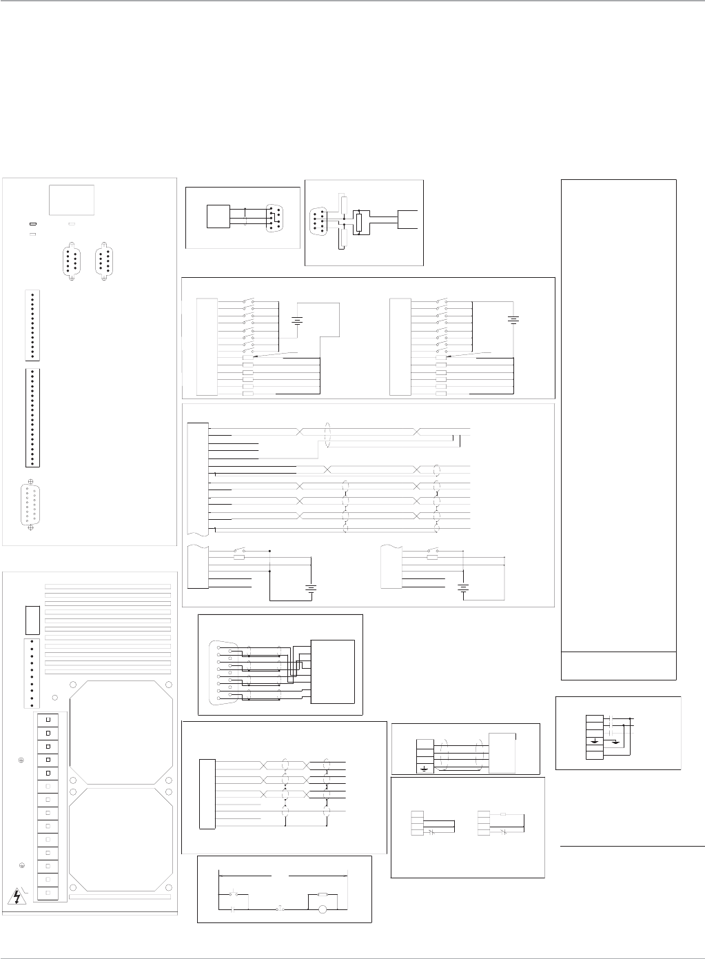
39
Motion Solutions
M(Aux)
Power On
Emergency
Stop
MAIN VAC
RCAS
M
M(Aux) M(Aux)
FRONT VIEW
16
59
Pulse Input
VAC Input (1)
Emergency Stop Circuit
RECEIVE
RS-232
Serial Port*
Clamp Connections
(1) Input power 180 to 250 VAC
Brushless Servo Motor
EXT
M
VAC
REMARKS:
DC-
Internal
DC+
INT
EXT
DC-
External
DC+
INT
A
B
D
C
Auxiliary I/O
IC800SSI228RP2
LOAD 100 MA MAX
Discrete Inputs and Outputs
SINKING CONNECTION
SOURCING CONNECTION
LOAD 100 MA MAX
Sinking Sourcing
1
6
5
9
3 phase 50-440 Hz @ 30 Amps for IC800SSI228RP2A
3 phase 50-440 Hz @ 18 Amps for IC800SSI216RP2A
BOTTOM VIEW
WARNING!
4 IN_B-
6 IN_I-
8 COM
10 SHD
9 TIE
5 IN_I+
7 +5V
3 IN_B+
2 IN_A-
1 IN_A+
IC800SSI216RP2
Resolver
Position Feedback
TRANSMIT
GROUND
L3
L1
L2
R
GND
T
S
Motor
HOST
-
+
12-24 12-24
-
+
12-24
-
+
-
12-24
+
Position
Feedback
Fwd/Rev
Address/Code
DB2
Module Status
Network Status
I/O_11
I/O_12
I/O_13
I/O_14
14
13
12
IN_03
IN_04
IN_07
IN_08
IN_05
IN_06
IN_01
IN_02
I/O_09
I/O_10
9
11
10
7
8
4
5
6
3
2
1
Serial
Port
Out Channel B-
Analog Common
Out Index-
Out Index+
Out Channel B+
Out Channel A+
Out Channel A-
Analog Input 2-
Analog Output
Analog Common
Analog Input 2+
Analog Input 1-
Analog Input 1+
Output Common
Input Common
15
16
14
19
18
17
20 Common
Common
+12VDC
Enable
OK
1
11
12
10
13
8
9
5
6
7
2
3
4
Analog common
Analog common
AI1+
AI2+
AI2-
Analog Output
AI1-
Out_A+
Out_B+
Out_A-
Index+
Index-
common
Out_B-
5
TIE
Shield
Common
+5VDC
IN_I-
IN_I+
IN_B-
IN_B+
IN_A-
IN_A+
Shield
Shield
COMPUTER
Common
Index-
Index+
B-
B+
A-
A+
Resistor(*)
Clamp
Shield
16
9
Common
+/-10V Output
+/-10V Command
Command Com
Index+
Index-
common
A+
A-
B-
B+
(2) Must turn off power before changing settings.
L= left (open)
R= right (closed)
20
15
18
19
16
17
13
14
11
12
2
10
9
7
8
4
5
6
3
1
VDC
20
15
19
18
17
16
13
14
12
11
2
8
7
9
10
4
3
6
5
1
VDC
9
14
11
13
12
10
8
7
6
5
3
4
1
2
VDC VDC
DB1
TB1
TB2
DB1
TB2
Enable
OK
Input common
Output common
+12VDC
Common Common
+12VDC
Output common
Input common
OK
Enable
TB4
3
8
10
9
7
6
5
4
2
1
DB3
DB3
PROFIBUS
O
1L2
1L3
DC-
1L1
EXT
2L1
INT
S
G
E
V
T
A
O
L
S
U
R
DC+
S
T
R
D
Z
A
A
H
TB4
L R
(Fan)
(Fan)
LL
L
LL31 95 R
64-99 L X
L
L
L
L
L
L
L
L
L
L
L
L
L
L
L
L
L
L
L
L
L
L
L
L
L
L
L
L
L
L
L
L
49 -LR
R
RL
50 -
51 -
52 -
53 -
54 -
55 -
56 -
57 -
58 -
59 -
60 -
61 -
62 -
63 -
Profibus
address
LL
R
LR
0-63 R X
RL
LL
RR
LR
LL
LLL
64 -
LLL
L
L
LL
RL
L
L
L
LR
R
L
R
R
R
L
L
L
LL
RR
RL
LRL
R
R
R
R
L
L
L
L
L
L
L
L
R
R
R
R
L
R
L
L
L
36 -
37 -
38 -
39 -
40 -
41 -
42 -
43 -
44 -
45 -
46 -
47 -
48 -
34 98
33 97
32 96
35 99
RL
R
RR
RR
L
R
L
R
L
R
R
L
LR
LL
LR
LLR
R
L
R
L
L
L
L
L
R
L
R
R
L
R
RL
RL
R
R
R
LL
R
L
L
L
L
RR
R
RL
RL
RR
RRR
R
R
R
R
L
L
L
L
R
R
R
R
R
R
R
R
R
R
R
R
R
R
R
1 2 4 8 16 32
R
R
R
R
R
R
R
R
R
R
R
R
R
R
R
R
R
R
R
R
R
R
R
R
R
R
R
R
DIP Switch Positions (2)
R
RL
L
RL13 77
16 80
15 79
14 78
19 83
20 84
18 82
17 81
24 88
25 89
23 87
22 86
28 92
29 93
27 91
26 90
21 85
30 94
LR
L
LR
RL
L
R
R
L
R
LL
R
RR
LR
LL
RLL
L
L
L
L
R
L
L
L
L
L
L
L
R
L
R
RL
L
L
L
L
LR
R
L
R
R
L
RL
L
LL
RR
RL
RRL
R
R
R
R
L
L
R
R
L
L
L
L
R
L
L
R
LL
R
L
R
1 65
2 66
7 71
6 70
4 68
5 69
10 74
11 75
9 73
8 72
3 67
0 64
12 76
(NA)
Profibus
Address
RR
L
RR
RR
L
R
L
R
R
LR
L
LR
LL
LR
RLR
R
L
L
L
R
R
L
L
R
R
R
R
R
R
R
L
L
L
R
R
R
R
L
L
L
L
RR
R
R
R
R
R
R
R
R
R
R
R
R
R
Note: Termination resistors
6
9
220
390
1
390
5
only on end controllers.
Profibus
Vp
Gnd
cable
Data line B
Profibus
Data line A
*Clamp resisitor only required for extreme duty cycle
applications. Contact GE Fanuc for recommended
clamp resistor value and procedure for connecting
external clamp resistor.
DB2
1
815
9
2L2
1L2
1L3
2L1
1L1
TB1
R
T
S
TB1
1
(0-99)
NA
32
16
4
2
8
64
-
Therm
Therm
S2
1
815
9
G
H
S1
R2
R1
F
D
E
S3
S4
C
B
A
S2K Series
User Control Connections
S2K Models: SSI216 and SSI228 (Profibus Communications)
Motion Controllers
*Note:
The S2K serial port includes
12 V on pin 4. A jumper must be
placed from pin 4 to pin 7 to prev-
ent possible damage to serial port
on some computers. Using a GE
serial communication cable
is recommended.
www.ge-ip.com GE Intelligent Platforms
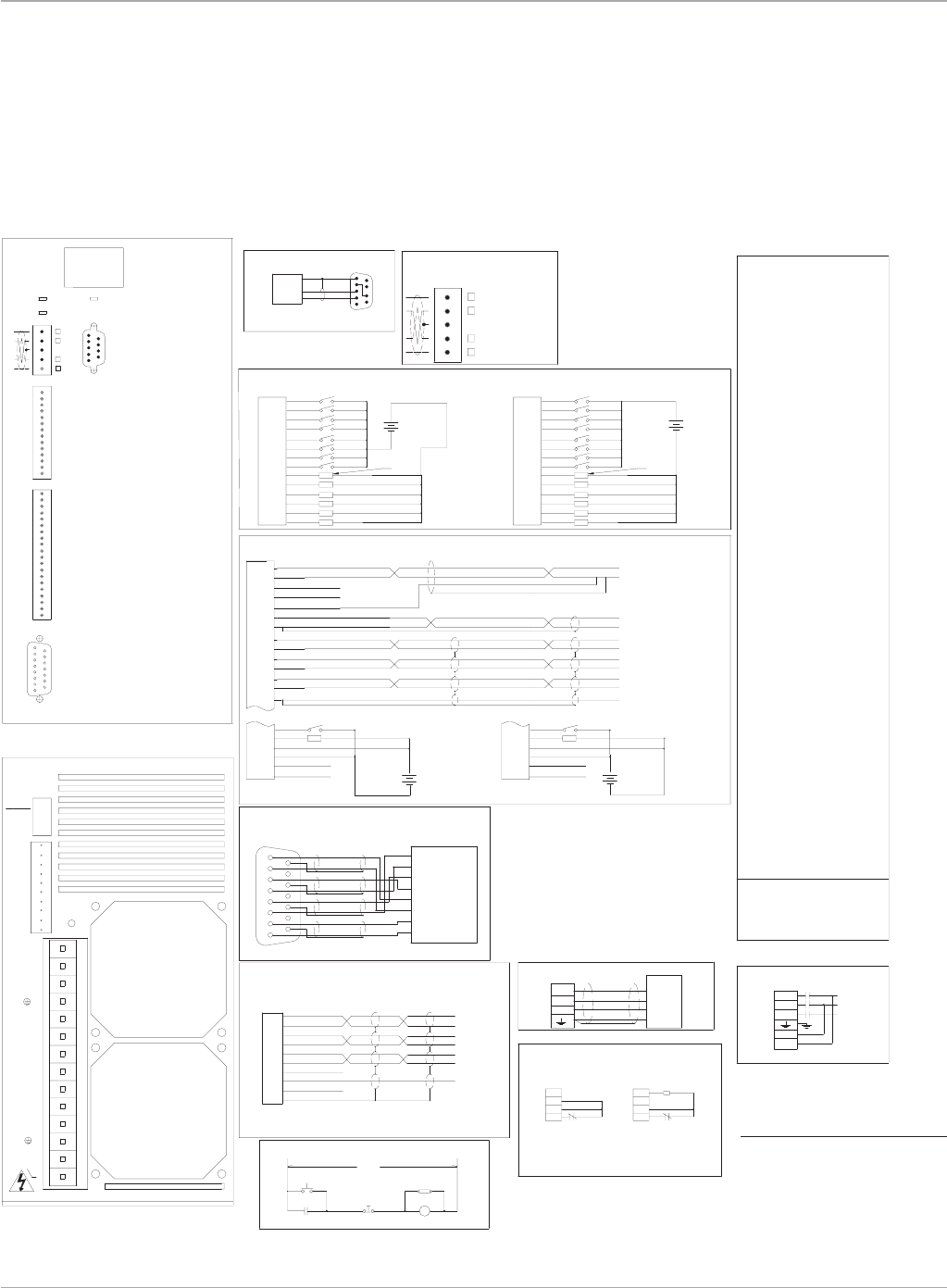
Motion Solutions
40
M(Aux)
Power On
Emergency
Stop
MAIN VAC
RCAS
M
M(Aux) M(Aux)
FRONT VIEW
BOTTOM VIEW
16
59
1 IN_A+
Pulse Input
Position Feedback
VAC Input (1)
Emergency Stop Circuit
RECEIVE
RS-232
Serial Port*
Clamp Connections
(1) Input power 180 to 250 VAC
Brushless Servo Motor
EXT
M
VAC
REMARKS:
DC-
Internal
DC+
INT
EXT
DC-
External
DC+
INT
A
B
D
C
Resolver
Auxiliary I/O
DeviceNet
R
R
R
R
R
R
R
R
R
R
R
R
L
L
L
L
L
L
L
L
L
R
L
L
L
L
L
L
L
RL L
R54
125K R R
250K L R
N/A L L
500K R L
Device Net
Rate
Baud
56
55
57
58
60
59
63
62
61
LL R
L
L
R
L
L
R
L
R
R
L
L
L
L
L
L
L
L
R
LR
L
R
L
R
L
R
R
L
L
R
L
L
R
L
L
RR44
46
45
48
50
51
49
52
53
47
RR R
L
R
L
R
R
R
L
L
L
L
L
R
R
R
R
R
R
R
L
R
L
R
L
L
R
L
RR
L
L
L
L
L
37
36
35
39
38
41
40
43
42
RLL
RL
LL
L
R
R
R
L
R
RL
R
R
L
L
RL
RL
R
L
R
L
R
L
L
LR
L
R
R
R
L
L
L
L
L
L
L
L
L
L
L
L
L
L
L
L
L
L
L
L
L
L
L
L
L
L
L
L
L
R
R
R
R
R
DIP Switch Positions (2)
1 2 4 8 16 32
R
R
R
R
R
R
R
R
R
R
R
R
L
L
L
L
R
L
L
L
L
L
L
L
L
L
L
L
L
R
L
L
LL15
32
34
33
26
25
28
27
30
31
29
RR
R
L
L
R
R
L
L
L
R
R
R
R
R
R
L
L
L
L
LL
R
L
R
R
L
RL
R
RL
L
L
L
L
R
R
L
L
17
19
18
16
21
22
23
24
20 L
LR
L
R
L
R
L
R
R
R
R
L
L
R
R
L
LR
R
RL
L
R
L
L
RR
R
R
R
R
R
R
RR
R
L
RL5
10
12
13
14
11
8
9
6
7
L
R
LR
L
R
R
L
R
L
R
L
L
L
L
L
L
R
L
L
R
L
R
R
R
L
L
L
R
R
L
L
L
L
R
R
0
4
3
1
2
Device Net
Address
RRRR
L
RR
L
L
R
R
L
L
R
R
R
R
R
R
R
R
L
L
L
R
R
R
R
R
R
R
R
R
R
R
R
R
R
R
R
R
R
R
R
R
R
R
R
R
R
R
R
R
R
R
3 phase 50-440 Hz @ 18 Amps for IC800SSI216RD2A
IC800SSI228RD2
LOAD 100 MA MAX
Discrete Inputs and Outputs
SINKING CONNECTION
SOURCING CONNECTION
LOAD 100 MA MAX
Sinking Sourcing
3 phase 50-440 Hz @ 30 Amps for IC800SSI228RD2A
IC800SSI216RD2
1 2
TRANSMIT
GROUND
L3
L1
L2
R
GND
T
S
Motor
HOST
-
+
12-24 12-24
-
+
12-24
-
+
-
12-24
+
1
815
9
1
815
9
Position
Feedback
Fwd/Rev
Address/Code
(Fan)
(Fan)
Module Status
Network Status
I/O_11
I/O_12
I/O_13
I/O_14
14
13
12
IN_03
IN_04
IN_07
IN_08
IN_05
IN_06
IN_01
IN_02
I/O_09
I/O_10
9
11
10
7
8
4
5
6
3
2
1
Serial
Port
Out Channel B-
Analog Common
Out Index-
Out Index+
Out Channel B+
Out Channel A+
Out Channel A-
Analog Input 2-
Analog Output
Analog Common
Analog Input 2+
Analog Input 1-
Analog Input 1+
Output Common
Input Common
15
16
14
19
18
17
20 Common
Common
+12VDC
Enable
OK
1
11
12
10
13
8
9
5
6
7
2
3
4
Analog common
Analog common
AI1+
AI2+
AI2-
Analog Output
AI1-
Out_A+
Out_B+
Out_A-
Index+
Index-
common
Out_B-
5
TIE
Shield
Common
+5VDC
IN_I-
IN_I+
IN_B-
IN_B+
IN_A-
IN_A+
Shield
Shield
COMPUTER
Common
Index-
Index+
B-
B+
A-
A+
Resistor(*)
Clamp
Shield
16
9
Common
+/-10V Output
+/-10V Command
Command Com
Index+
Index-
common
A+
A-
B-
B+
5 Pin open style connector
V- Black
CAN_L Blue
SHIELD Bare
CAN_H White
V+ Red
(DR)
(NA)
(2) Must turn off power before changing settings.
L= left (open)
R= right (closed)
20
15
18
19
16
17
13
14
11
12
2
10
9
7
8
4
5
6
3
1
VDC
20
15
19
18
17
16
13
14
12
11
2
8
7
9
10
4
3
6
5
1
VDC
9
14
11
13
12
10
8
7
6
5
3
4
1
2
VDC VDC
DB1
TB1
TB2
TB3
DB1
TB3
TB1
Enable
OK
Input common
Output common
+12VDC
Common Common
+12VDC
Output common
Input common
OK
Enable
TB4
TB4
8
10
9
7
5
6
4
3
2
1
U
E
S
G
A
T
L
V
O
S
O
D
R
A
H
A
Z
L R
INT
WARNING!
2L1
EXT
1L1
DC-
1L3
2L2
1L2
4 IN_B-
T
S
DC+
R
6 IN_I-
9 TIE
10 SHD
7 +5V
8 COM
5 IN_I+
2 IN_A-
3 IN_B+
DB2
DB2
*Clamp resisitor only required for extreme duty cycle
applications. Contact Whedco, Inc. for recommended
clamp resistor value and procedure for connecting
external clamp resistor.
4
(0-63)
2
1
32
16
NA
DR
8
1
2
2L2
1L2
1L3
2L1
1L1
TB2
S4
E
G
H
F
D
B
C
Therm
Therm
R1
R2
S2
S1
S3
R
T
S
A
TB2
S2K Series
User Control Connections
S2K Models: SSI216 and SSI228 (DeviceNet Communications)
Motion Controllers
*Note:
The S2K serial port includes 12 V on
pin 4. A jumper must be placed from
pin 4 to pin 7 to prev ent possible
damage to serial port on some com-
puters. Using a GE serial communi-
cation cable is recommended.
www.ge-ip.com
GE Intelligent Platforms
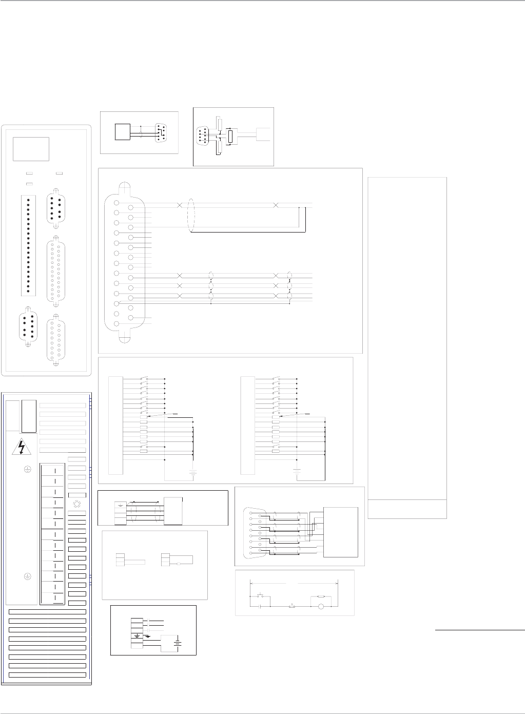
41
Motion Solutions
Position
Feedback
Serial
Port
MAIN VAC
M
Stop
Emergency
M(Aux)
Power On
RCAS
RECEIVE
Serial Port*
RS-232
Auxiliary I/O
FRONT VIEW
Brushless Servo Motor
Emergency Stop Circuit
REMARKS:
IC800SSI407RP2
1
5
6
9
B
C
D
A
1
8
9
15
1
1
BOTTOM VIEW
Clamp Connections
Internal External
Input power (1)
VAC
M
Input logic power 18 to 28.8 VDC @ 2 Amps
3 phase 50-440 Hz @ 8 Amps
(1) Input motor power 324 to 528 VAC
PROFIBUS
6
9
1
5
Position Feedback
Resolver
Motor
R
S
T
GND
TRANSMIT
GROUND
HOST
L1
+
L3
-
L2
24
COMPUTER
Auxiliary
I/O
Fwd/Rev
Address/Code
13
14
25
13 25
14
AI1+
AI1-
AI2+
AI2-
AO
Analog common
IN_A+
IN_A-
IN_B+
IN_B-
Tie
+5Vdc
+12Vdc
Common
Out_A+
Out_A-
Out_B+
Out_B-
Index+
Index-
common
IN_Index+
IN_Index-
A+
A-
B+
B-
Index+
Index-
common
+/-10V
Com
59
16
10
I/O_10
20
19
18
17
Enable
OK
I/O_14
I/O_13
I/O_12
I/O_11
15
16
14
12
13
11
I/O_09
IN_02
IN_01
9
2
1
12VCom
+12VDC
OutCom
IN Com
Module Status
Network Status
(2) Must turn off power before changing settings.
R= right (closed)
L= left (open)
IN_06
IN_05
6
5
8
7
IN_08
IN_07
4
3
IN_04
IN_03
LOAD 100 MA MAX
Discrete Inputs and Outputs
SINKING CONNECTION
20
15
18
19
16
17
13
14
11
12
2
10
9
7
8
4
5
6
3
1
-
+
SOURCING CONNECTION
12-24
VDC
20
15
19
18
17
16
13
14
12
11
2
8
7
9
10
4
3
6
5
1
12-24
VDC
-
+
LOAD 100 MA MAX
E
S
O
G
A
L
T
S
V
U
O
A
D
R
Z
A
H
*Clamp resistor only required for extreme duty
cycle applications. Contact Whedco, Inc. for
recommended clamp resistor value and procedure
for connecting external clamp resistor.
VDC
LL
L
LL31 95 R
64-99 L X
L
L
L
L
L
L
L
L
L
L
L
L
L
L
L
L
L
L
L
L
L
L
L
L
L
L
L
L
L
L
L
L
49 -LR
R
RL
50 -
51 -
52 -
53 -
54 -
55 -
56 -
57 -
58 -
59 -
60 -
61 -
62 -
63 -
Profibus
address
LL
R
LR
0-63 R X
RL
LL
RR
LR
LL
LLL
64 -
LLL
L
L
LL
RL
L
L
L
LR
R
L
R
R
R
L
L
L
LL
RR
RL
LRL
R
R
R
R
L
L
L
L
L
L
L
L
R
R
R
R
L
R
L
L
L
36 -
37 -
38 -
39 -
40 -
41 -
42 -
43 -
44 -
45 -
46 -
47 -
48 -
34 98
33 97
32 96
35 99
RL
R
RR
RR
L
R
L
R
L
R
R
L
LR
LL
LR
LLR
R
L
R
L
L
L
L
L
R
L
R
R
L
R
RL
RL
R
R
R
LL
R
L
L
L
L
RR
R
RL
RL
RR
RRR
R
R
R
R
L
L
L
L
R
R
R
R
R
R
R
R
R
R
R
R
R
R
R
1 2 4 8 16 32
R
R
R
R
R
R
R
R
R
R
R
R
R
R
R
R
R
R
R
R
R
R
R
R
R
R
R
R
DIP Switch Positions (2)
R
RL
L
RL13 77
16 80
15 79
14 78
19 83
20 84
18 82
17 81
24 88
25 89
23 87
22 86
28 92
29 93
27 91
26 90
21 85
30 94
LR
L
LR
RL
L
R
R
L
R
LL
R
RR
LR
LL
RLL
L
L
L
L
R
L
L
L
L
L
L
L
R
L
R
RL
L
L
L
L
LR
R
L
R
R
L
RL
L
LL
RR
RL
RRL
R
R
R
R
L
L
R
R
L
L
L
L
R
L
L
R
LL
R
L
R
1 65
2 66
7 71
6 70
4 68
5 69
10 74
11 75
9 73
8 72
3 67
0 64
12 76
(NA)
Profibus
Address
RR
L
RR
RR
L
R
L
R
R
LR
L
LR
LL
LR
RLR
R
L
L
L
R
R
L
L
R
R
R
R
R
R
R
L
L
L
R
R
R
R
L
L
L
L
RR
R
R
R
R
R
R
R
R
R
R
R
R
R
Note: Te rmination resistors
6
9
220
390
1
390
5
only on end controllers.
Profibus
Vp
Gnd
cable
Data line B
Profibus
Data line A
L R
EXT EXT
DC+
INT
DC+
INT Resistor(*)
Clamp
S
T
R
WARNING!
INT
EXT
1L1
1L2
1L3
COM
+24V
R
S
T
64
2
1
(0-99)
16
NA 8
4
-
32
1L1
COM
+24V
1L3
1L2
DC+
1
815
9
Therm
G
H
E
F
C
D
A
B
S1
Therm
R2
R1
S3
S2
S4
P2
S2K Series
User Control Connections
S2K Model: SSI407 (Profibus Communications)
Motion Controllers
*Note:
The S2K serial port includes
12 V on pin 4. A jumper must
be placed from pin 4 to pin 7
to prev ent possible damage
to serial port on some com-
puters. Using a GE serial
communication cable
is recommended.
www.ge-ip.com GE Intelligent Platforms
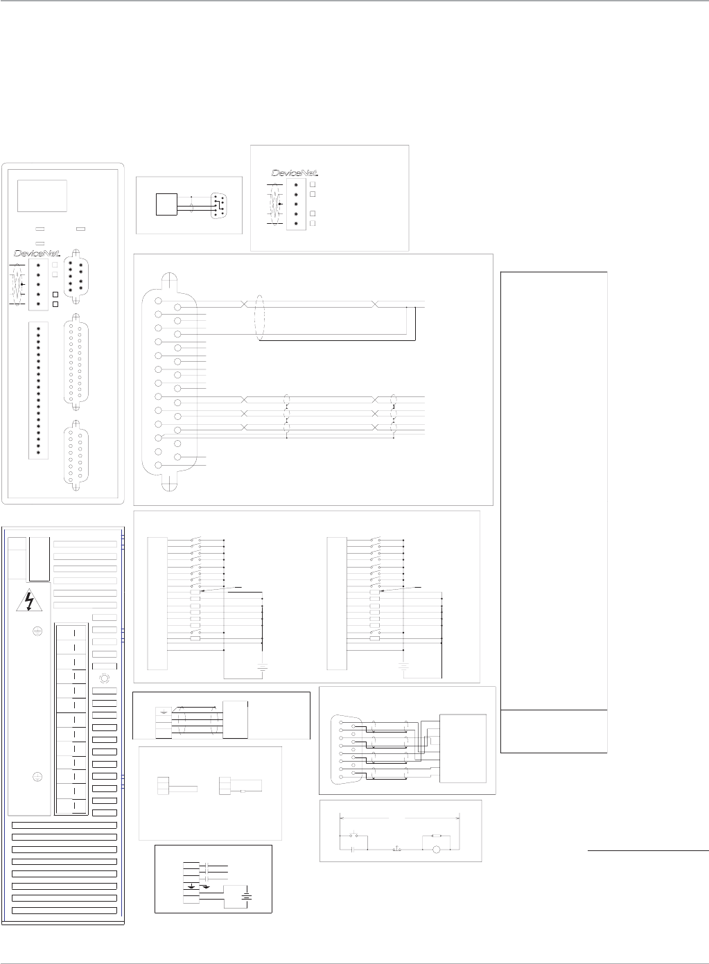
Motion Solutions
42
Position
Feedback
Serial
Port
MAIN VAC
M
Stop
Emergency
M(Aux)
Power On
RCAS
RECEIVE
Serial Port*
RS-232
Auxiliary I/O
FRONT VIEW
Brushless Servo Motor
Emergency Stop Circuit
REMARKS:
IC800SSI407RD2
1
5
6
9
B
C
D
A
1
8
9
15
1
1
DeviceNet
RR
R
L2R
Baud
Rate
Device Net
RL
L
R20 R
500K R L
N/A L L
250K L R
125K R R
L
L
R29 L
31
30
L
R
L
L
L
L
L
L
27
28
25
26
24
23
22
21
R
LL
RR
R
LR
L
L
R
LL
R
L
L
R
L
R
L
R
L
L
R
R
L
L
R
L
L
R
R
L
L
L
L
L
L
L
L
L
L
L
L
R
L11 L
16
18
19
17
14
15
13
12
R
R
RR
LR
LL
LR
R
R
RR
RR
R
L
L
L
L
R
R
R
L
L
L
L
L
L
L
L
7
9
10
8
5
6
3
4
R
L
LL
RL
RL
RR
L
R
RL
RL
L
R
R
L
R
LL
R
L
L
R
R
R
L
R
R
R
L
L
L
L
R
R
R
R
R
R
R
R
R
R
R
R
Address
Device Net 1 2 4 8 16 32
DIP Switch Positions (2)
0
1
RR
LR
R
R
RR
R
R
R
R
R
R
R
R
R
R
R
R
R
R
R
R
R
R
R
R
R
R
R
R
R
R
R
R
R
R
R
R
R
R
61
62
63
59
60
58
57
47
54
55
56
53
52
49
51
50
48
42
45
46
44
43
40
41
38
39
LR
L
R
L
L
L
L
L
L
R
L
R
R
L
RL
L
R
R
R
LLL
L
L
L
LL
L
L
L
L
LL
L
L
L
L
L
L
L
LRL
L
LL
R
L
R
L
R
L
L
L
R
L
R
R
R
L
L
L
L
R
R
R
R
L
L
R
R
RR
L
L
L
L
L
R
R
L
R
R
L
L
L
L
L
L
L
L
L
R
R
R
R
L
L
L
L
R
LR
L
R
R
L
R
L
L
L
R
L
L
R
R
L
R
L
R
R
RR
L
L
L
L
LRL
R
R
R
R
L
L
L
L
L
L
L
L
R
R
R
R
L
L
R
R
L
L
L
L
33
35
36
37
34
32
R
RL
L
R
L
R
R
L
R
R
L
L
LR
RRR
LRR
R
R
R
R
R
R
R
R
L
L
L
L
RRL
BOTTOM VIEW
Clamp Connections
Internal External
Input logic power 18 to 28.8 VDC @ 2 Amps
3 phase 50-440 Hz @ 8 Amps
(1) Input motor power 324 to 528 VAC
Input power (1)
M
VAC
Position Feedback
Resolver
1 2
Motor
R
S
T
GND
TRANSMIT
GROUND
HOST
+
-
L3
L2
L1
24
COMPUTER
Auxiliary
I/O
Fwd/Rev
Address/Code
13
14
25
13 25
14
AI1+
AI1-
AI2+
AI2-
AO
Analog common
IN_A+
IN_A-
IN_B+
IN_B-
Tie
+5Vdc
+12Vdc
Common
Out_A+
Out_A-
Out_B+
Out_B-
Index+
Index-
common
IN_Index+
IN_Index-
A+
A-
B+
B-
Index+
Index-
common
+/-10V
Com
59
16
10
I/O_10
20
19
18
17
Enable
OK
I/O_14
I/O_13
I/O_12
I/O_11
15
16
14
12
13
11
I/O_09
IN_02
IN_01
9
2
1
12VCom
+12VDC
OutCom
IN Com
Module Status
Network Status
V+ Red
CAN_H White
SHIELD Bare
CAN_L Blue
V- Black
5 Pin open style connector
(NA)
(DR)
(2) Must turn off power before changing settings.
R= right (closed)
L= left (open)
IN_06
IN_05
6
5
8
7
IN_08
IN_07
4
3
IN_04
IN_03
LOAD 100 MA MAX
Discrete Inputs and Outputs
SINKING CONNECTION
20
15
18
19
16
17
13
14
11
12
2
10
9
7
8
4
5
6
3
1
-
+
SOURCING CONNECTION
12-24
VDC
20
15
19
18
17
16
13
14
12
11
2
8
7
9
10
4
3
6
5
1
12-24
VDC
-
+
LOAD 10 0 MA MAX
E
S
O
G
A
L
T
S
V
U
O
A
D
R
Z
A
H
*Clamp resistor only required for extreme duty
cycle applications. Contact Whedco, Inc. for
recommended clamp resistor value and procedure
for connecting external clamp resistor.
VDC
L R
EXT EXT
DC+
INT
DC+
INT Resistor(*)
Clamp
S
T
R
WARNING!
DR
NA
(0-63)
2
1
8
16
4
1
2
32
1L1
1L2
COM
+24V
1L3
+24V
COM
S
1L3
1L2
1L1
DC+
EXT
INT
R
T
1
815
9
Therm
G
H
E
F
C
D
A
B
S1
Therm
R2
R1
S3
S2
S4
P2
S2K Series
User Control Connections
S2K Model: SSI407 (DeviceNet Communications)
Motion Controllers
*Note:
The S2K serial port includes
12 V on pin 4. A jumper must
be placed from pin 4 to pin 7
to prev ent possible damage
to serial port on some com-
puters. Using a GE serial
communication cable
is recommended.
www.ge-ip.com
GE Intelligent Platforms
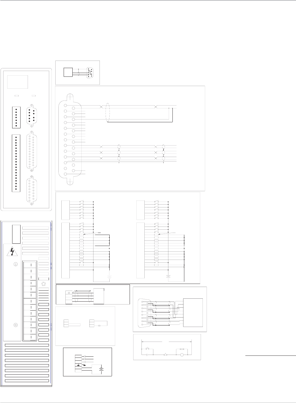
43
Motion Solutions
Position
Feedback
Serial
Port
MAIN VAC
M
Stop
Emergency
M(Aux)
Power On
RCAS
RECEIVE
Serial Port*
RS-232
Auxiliary I/O
FRONT VIEW
Brushless Servo Motor
Emergency Stop Circuit
REMARKS:
IC800SSI407RS1
1
5
6
9
B
C
D
A
1
8
9
15
1
1
BOTTOM VIEW
Clamp Connections
Internal External
Input logic power 18 to 28.8 VDC @ 2 Amps
3 phase 50-440 Hz @ 8 Amps
(1) Input motor power 324 to 528 VAC
Input power (1)
M
VAC
Position Feedback
Resolver
Motor
R
S
T
GND
TRANSMIT
GROUND
HOST
+
-
L3
L2
L1
24
COMPUTER
Auxiliary
I/O
Fwd/Rev
Address/Code
13
14
25
13 25
14
AI1+
AI1-
AI2+
AI2-
AO
Analog common
IN_A+
IN_A-
IN_B+
IN_B-
Tie
+5Vdc
+12Vdc
Common
Out_A+
Out_A-
Out_B+
Out_B-
Index+
Index-
common
IN_Index+
IN_Index-
A+
A-
B+
B-
Index+
Index-
common
+/-10V
Com
59
16
Module Status
LOAD 100 MA MAX
Discrete Inputs and Outputs
SINKING CONNECTION
20
15
18
19
16
17
13
14
11
12
2
10
9
7
8
4
5
6
3
1
6
7
5
4
3
2
-
+
1
SOURCING CONNECTION
VDC
12-24 20
15
18
19
16
17
13
14
11
12
2
7
9
8
10
3
4
5
6
6
7
1
5
4
3
2
VDC
12-24
-
+
LOAD 100 MA MAX
1
IN_05
IN_07
IN_06
IN_01
IN_04
IN_03
IN_02
5
7
6
3
4
1
2
20
19
18
17
16
13
12
15
14
11
10
I/O_13 6
Enable
12VCom
+12VDC
OutCom
IN Com
OK
I/O_20
I/O_19
I/O_21
I/O_18
I/O_14
I/O_15
I/O_17
I/O_16 9
8
7
I/O_12
IN_10
IN_09
IN_11
IN_08
4
5
3
2
1
E
S
O
G
A
L
T
S
V
U
O
A
D
R
Z
A
H
*Clamp resistor only required for extreme duty
cycle applications. Contact Whedco, Inc. for
recommended clamp resistor value and procedure
for connecting external clamp resistor.
VDC
EXT EXT
DC+
INT
DC+
INT Resistor(*)
Clamp
S
T
R
WARNING!
1L1
1L2
COM
+24V
1L3
+24V
COM
S
1L3
1L2
1L1
DC+
EXT
INT
R
T
1
815
9
Therm
G
H
E
F
C
D
A
B
S1
Therm
R2
R1
S3
S2
S4
P2
S2K Series
User Control Connections
S2K Model: SSI407 (Serial Communication)
Motion Controllers
*Note:
The S2K serial port includes
12 V on pin 4. A jumper must
be placed from pin 4 to pin 7
to prev ent possible damage
to serial port on some com-
puters. Using a GE serial
communication cable
is recommended.
www.ge-ip.com GE Intelligent Platforms
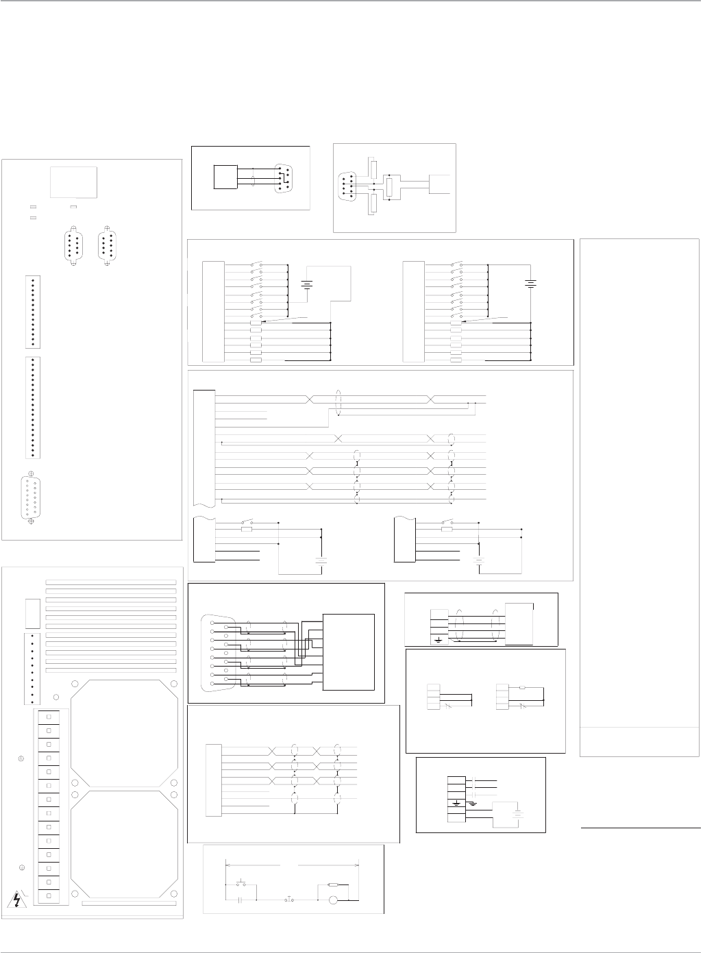
Motion Solutions
44
M(Aux)
Power On
Emergency
Stop
MAIN VAC
RCAS
M
M(Aux) M(Aux)
FRONT VIEW
BOTTOM VIEW
16
59
4 IN_B-
5 IN_I+
10 SHD
9 TIE
8 COM
7 +5V
6 IN_I-
3 IN_B+
2 IN_A-
1 IN_A+
Pulse Input
Position Feedback
Input power (1)
Emergency Stop Circuit
RECEIVE
RS-232
Serial Port*
Clamp Connections
(1) Input motor power 324 to 528 VAC
Input logic power 18 to 28.8 VDC @ 2 Amps
Brushless Servo Motor
EXT
M
VAC
REMARKS:
DC-
Internal
DC+
INT
EXT
DC-
External
DC+
INT
A
B
D
C
Resolver
Auxiliary I/O
3 phase 50-440 Hz @ 22 Amps
IC800SSI420RP2
LOAD 100 MA MAX
Discrete Inputs and Outputs
SINKING CONNECTION
SOURCING CONNECTION
LOAD 100 MA MAX
Sinking Sourcing
WARNING!
5
1
6
9
1
6
5
9
Profibus
TRANSMIT
GROUND
L3
L1
L2
R
GND
T
S
Motor
HOST
-
+
12-24 12-24
-
+
12-24
-
+
-
12-24
+
+
-
24
Position
Feedback
Fwd/Rev
Address/Code
(Fan)
(Fan)
DB2
Module Status
Network Status
I/O_11
I/O_12
I/O_13
I/O_14
14
13
12
IN_03
IN_04
IN_07
IN_08
IN_05
IN_06
IN_01
IN_02
I/O_09
I/O_10
9
11
10
7
8
4
5
6
3
2
1
Serial
Port
Out Channel B-
Analog Common
Out Index-
Out Index+
Out Channel B+
Out Channel A+
Out Channel A-
Analog Input 2-
Analog Output
Analog Common
Analog Input 2+
Analog Input 1-
Analog Input 1+
Output Common
Input Common
15
16
14
19
18
17
20 Common
Common
+12VDC
Enable
OK
1
11
12
10
13
8
9
5
6
7
2
3
4
Analog common
Analog common
AI1+
AI2+
AI2-
Analog Output
AI1-
Out_A+
Out_B+
Out_A-
Index+
Index-
common
Out_B-
5
TIE
Shield
Common
+5VDC
IN_I-
IN_I+
IN_B-
IN_B+
IN_A-
IN_A+
Shield
Shield
COMPUTER
*Clamp resisitor only required for extreme duty
cycle applications. Contact Whedco, Inc. for
recommended clamp resistor value and procedure
for connecting external clamp resistor.
Common
Index-
Index+
B-
B+
A-
A+
Resistor(*)
Clamp
Shield
16
9
Common
+/-10V Output
+/-10V Command
Command Com
Index+
Index-
common
A+
A-
B-
B+
(2) Must turn off power before changing settings.
L= left (open)
R= right (closed)
20
15
18
19
16
17
13
14
11
12
2
10
9
7
8
4
5
6
3
1
VDC
20
15
19
18
17
16
13
14
12
11
2
8
7
9
10
4
3
6
5
1
VDC
9
14
11
13
12
10
8
7
6
5
3
4
1
2
VDC VDC
DB1
TB2
TB3
DB2
DB1
TB3
Enable
OK
Input common
Output common
+12VDC
CommonCommon
+12VDC
Output common
Input common
OK
Enable
TB4
TB4
8
10
9
7
5
6
4
3
2
1
VDC
+24V
1L1
1L2
1L3
INT
EXT
DC-
S
DC+
T
R
S
G
S
E
T
A
L
V
O
A
O
U
D
A
R
Z
H
DB3
390
220
390
only on end controllers.
Note: Termination resistors
Vp
Gnd
Data line A
Data line B
Profibus
cable
LL
L
LL31 95 R
64-99 L X
L
L
L
L
L
L
L
L
L
L
L
L
L
L
L
L
L
L
L
L
L
L
L
L
L
L
L
L
L
L
L
L
LR
R
RL49 -
52 -
51 -
50 -
55 -
56 -
54 -
53 -
60 -
59 -
58 -
57 -
61 -
63 -
62 -
Profibus
address
LL
R
LR
0-63 R X
RL
LL
L
L
RR
R
L
LLL
64 -
LLL
L
L
LL
RL
L
L
L
LR
R
R
L
L
R
R
L
L
R
R
LL
R
L
LRL
R
R
L
L
L
L
R
R
L
L
L
L
R
R
LR
RR
L
L
L
34 98
33 97
32 96
37 -
38 -
36 -
35 99
42 -
43 -
41 -
40 -
46 -
47 -
45 -
44 -
39 -
48 -
RL
R
RR
RR
L
R
L
R
L
R
R
L
L
L
RL
L
R
LLR
L
R
L
R
L
L
L
L
R
L
R
R
L
R
RL
RL
R
R
R
LL
L
R
R
L
L
L
R
R
R
R
LR
L
R
RRR
L
L
R
R
L
L
R
R
R
R
R
R
R
R
RR
RR
R
R
R
R
R
1 2 4 8 16 32
R
R
R
R
R
R
R
R
R
R
R
R
R
R
R
R
R
R
R
R
R
R
R
R
R
R
R
R
DIP Switch Positions (2)
R
RL
L
RL13 77
16 80
15 79
14 78
19 83
20 84
18 82
17 81
24 88
25 89
23 87
22 86
28 92
29 93
27 91
26 90
21 85
30 94
LR
L
LR
RL
R
L
L
R
R
L
L
R
L
L
RR
R
L
RLL
L
L
L
L
R
L
L
L
L
L
L
L
L
R
RL
LR
L
L
L
LR
R
L
R
L
R
R
L
L
R
L
R
L
R
L
RRL
L
L
R
R
R
R
R
R
L
L
L
L
L
L
RR
LL
R
L
R
1 65
2 66
7 71
6 70
4 68
5 69
10 74
11 75
9 73
8 72
3 67
0 64
12 76
(NA)
Profibus
Address
RR
L
RR
RR
R
L
L
R
L
R
R
L
R
L
L
L
L
R
RLR
R
L
L
L
R
R
L
L
R
R
R
R
R
L
LR
LR
R
R
R
L
R
R
L
L
L
R
R
R
R
R
R
R
R
R
R
R
R
R
R
PROFIBUS
DB3
L R
1
815
9
COM
1L2
1L3
+24V
1
815
9
1L1
TB2
S4
E
G
H
F
D
B
C
Therm
Therm
R1
R2
S2
S1
S3
R
T
S
A
TB2
-
8
16
32
2
4
NA
(0-99)
1
64
S2K Series
User Control Connections
S2K Model: SSI420 (Profibus Communication)
Motion Controllers
*Note:
The S2K serial port includes
12 V on pin 4. A jumper must
be placed from pin 4 to pin
7 to prev ent possible dam-
age to serial port on some
computers. Using a GE serial
communication cable
is recommended.
www.ge-ip.com
GE Intelligent Platforms
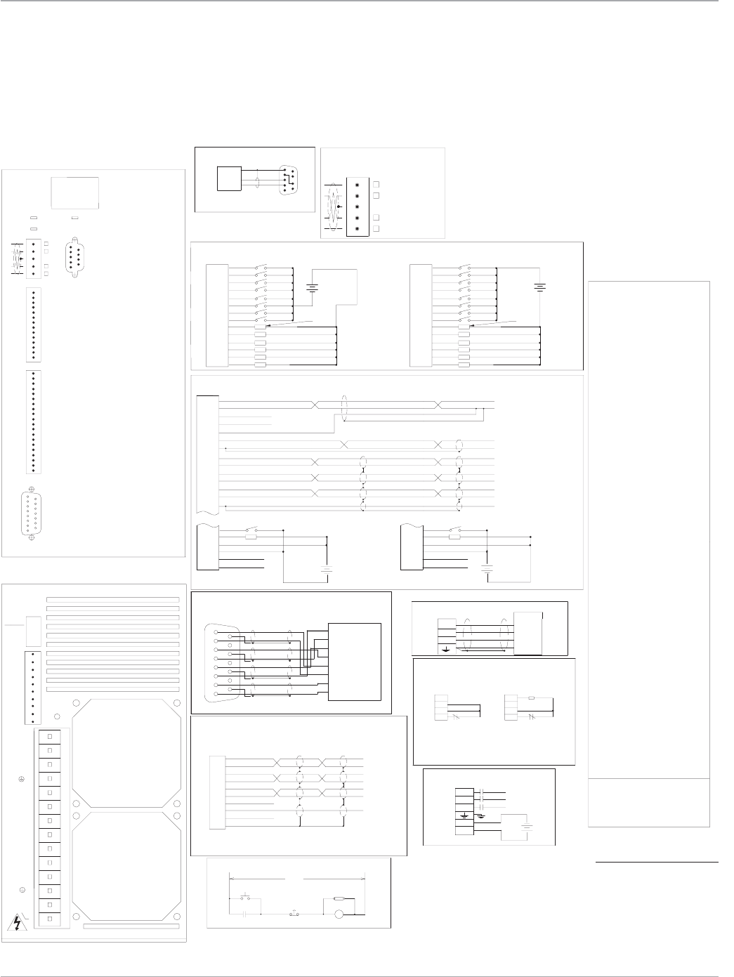
45
Motion Solutions
M(Aux)
Power On
Emergency
Stop
MAIN VAC
RCAS
M
M(Aux) M(Aux)
FRONT VIEW
BOTTOM VIEW
16
59
4 IN_B-
5 IN_I+
10 SHD
9 TIE
8 COM
7 +5V
6 IN_I-
3 IN_B+
2 IN_A-
1 IN_A+
Pulse Input
Position Feedback
Input power (1)
Emergency Stop Circuit
RECEIVE
RS-232
Serial Port*
Clamp Connections
(1) Input motor power 324 to 528 VAC
Input logic power 18 to 28.8 VDC @ 2 Amps
Brushless Servo Motor
EXT
M
VAC
REMARKS:
DC-
Internal
DC+
INT
EXT
DC-
External
DC+
INT
A
B
D
C
Resolver
Auxiliary I/O
DeviceNet
R
R
R
R
R
R
R
R
R
R
R
R
L
L
L
L
L
L
L
L
L
R
L
L
L
L
L
L
L
RL L
R54
125K R R
250K L R
N/A L L
500K R L
Device Net
Rate
Baud
56
55
57
58
60
59
63
62
61
LL R
L
L
R
L
L
R
L
R
R
L
L
L
L
L
L
L
L
R
LR
L
R
L
R
L
R
R
L
L
R
L
L
R
L
L
RR44
46
45
48
50
51
49
52
53
47
RR R
L
R
L
R
R
R
L
L
L
L
L
R
R
R
R
R
R
R
L
R
L
R
L
L
R
L
RR
L
L
L
L
L
37
36
35
39
38
41
40
43
42
RLL
RL
LL
L
R
R
R
L
R
RL
R
R
L
L
RL
RL
R
L
R
L
R
L
L
LR
L
R
R
R
L
L
L
L
L
L
L
L
L
L
L
L
L
L
L
L
L
L
L
L
L
L
L
L
L
L
L
L
L
R
R
R
R
R
DIP Switch Positions (2)
1 2 4 8 16 32
R
R
R
R
R
R
R
R
R
R
R
R
L
L
L
L
R
L
L
L
L
L
L
L
L
L
L
L
L
R
L
L
LL15
32
34
33
26
25
28
27
30
31
29
RR
R
L
L
R
R
L
L
L
R
R
R
R
R
R
L
L
L
L
LL
R
L
R
R
L
RL
R
RL
L
L
L
L
R
R
L
L
17
19
18
16
21
22
23
24
20 L
LR
L
R
L
R
L
R
R
R
R
L
L
R
R
L
LR
R
RL
L
R
L
L
RR
R
R
R
R
R
R
RR
R
L
RL5
10
12
13
14
11
8
9
6
7
L
R
LR
L
R
R
L
R
L
R
L
L
L
L
L
L
R
L
L
R
L
R
R
R
L
L
L
R
R
L
L
L
L
R
R
0
4
3
1
2
Device Net
Address
RRRR
L
RR
L
L
R
R
L
L
R
R
R
R
R
R
R
R
L
L
L
R
R
R
R
R
R
R
R
R
R
R
R
R
R
R
R
R
R
R
R
R
R
R
R
R
R
R
R
R
R
R
3 phase 50-440 Hz @ 22 Amps
IC800SSI420RD2
LOAD 100 MA MAX
Discrete Inputs and Outputs
SINKING CONNECTION
SOURCING CONNECTION
LOAD 100 MA MAX
Sinking Sourcing
WARNING!
1 2
TRANSMIT
GROUND
L3
L1
L2
R
GND
T
S
Motor
HOST
-
+
12-24 12-24
-
+
12-24
-
+
-
12-24
+
+
-
24
Position
Feedback
Fwd/Rev
Address/Code
(Fan)
(Fan)
DB2
Module Status
Network Status
I/O_11
I/O_12
I/O_13
I/O_14
14
13
12
IN_03
IN_04
IN_07
IN_08
IN_05
IN_06
IN_01
IN_02
I/O_09
I/O_10
9
11
10
7
8
4
5
6
3
2
1
Serial
Port
Out Channel B-
Analog Common
Out Index-
Out Index+
Out Channel B+
Out Channel A+
Out Channel A-
Analog Input 2-
Analog Output
Analog Common
Analog Input 2+
Analog Input 1-
Analog Input 1+
Output Common
Input Common
15
16
14
19
18
17
20 Common
Common
+12VDC
Enable
OK
1
11
12
10
13
8
9
5
6
7
2
3
4
Analog common
Analog common
AI1+
AI2+
AI2-
Analog Output
AI1-
Out_A+
Out_B+
Out_A-
Index+
Index-
common
Out_B-
5
TIE
Shield
Common
+5VDC
IN_I-
IN_I+
IN_B-
IN_B+
IN_A-
IN_A+
Shield
Shield
COMPUTER
*Clamp resisitor only required for extreme duty
cycle applications. Contact Whedco, Inc. for
recommended clamp resistor value and procedure
for connecting external clamp resistor.
Common
Index-
Index+
B-
B+
A-
A+
Resistor(*)
Clamp
Shield
16
9
Common
+/-10V Output
+/-10V Command
Command Com
Index+
Index-
common
A+
A-
B-
B+
5 Pin open style connector
V- Black
CAN_L Blue
SHIELD Bare
CAN_H White
V+ Red
(DR)
(NA)
(2) Must turn off power before changing settings.
L= left (open)
R= right (closed)
20
15
18
19
16
17
13
14
11
12
2
10
9
7
8
4
5
6
3
1
VDC
20
15
19
18
17
16
13
14
12
11
2
8
7
9
10
4
3
6
5
1
VDC
9
14
11
13
12
10
8
7
6
5
3
4
1
2
VDC VDC
DB1
TB1
TB2
TB3
DB2
DB1
TB3
TB1
Enable
OK
Input common
Output common
+12VDC
Common Common
+12VDC
Output common
Input common
OK
Enable
TB4
TB4
8
10
9
7
5
6
4
3
2
1
VDC
+24V
1L1
1L2
1L3
INT
EXT
DC-
S
DC+
T
R
S
G
S
E
T
A
L
V
O
A
O
U
D
A
R
Z
H
L R
1
815
9
4
(0-63)
2
1
32
16
NA
DR
8
1
2
COM
1L2
1L3
+24V
1
815
9
1L1
TB2
S4
E
G
H
F
D
B
C
Therm
Therm
R1
R2
S2
S1
S3
R
T
S
A
TB2
S2K Series
User Control Connections
S2K Model: SSI420 (DeviceNet Communication)
Motion Controllers
*Note:
The S2K serial port includes
12 V on pin 4. A jumper must
be placed from pin 4 to pin
7 to prev ent possible dam-
age to serial port on some
computers. Using a GE serial
communication cable
is recommended.
www.ge-ip.com GE Intelligent Platforms
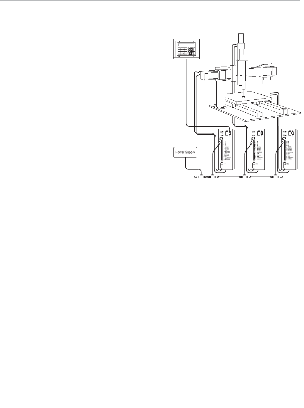
Motion Solutions
46
Motion Controllers
S2K Series is Ready to Net work
DeviceNet
A dedicated DeviceNet port is an optional feature of the S2K con-
trollers. The con trol ler includes full DeviceNet im ple men ta tion to facili-
tate the addition of motion control to in dus tri al systems designed
in a DeviceNet master/ slave or peer-to-peer con trol ar chi tec ture.
Peer-to-peer architecture offers users a quick, economic way to create
a multi-axis, stand-alone system. In a peer-to-peer or dis trib ut ed con-
trol system, S2K con trol lers com mu ni cate directly with each other over
the trunkline without hav ing to wait their turn in the scan list, resulting
in a rapid response time for inter-axis data exchange. Neither a
DeviceNet master controller nor knowledge of DeviceNet communica-
tion protocol is required to use peer-to-peer communications.
Peer-to-Peer Gantry Control System
The gantry drawing shown to the right illustrates a multi-axis pick-
and-place system designed with a single DeviceNet trunkline to con-
nect devices and coordinate motion control. Utilizing DeviceNet to
manage multiple axes of control in industrial automation equipment
keeps point-to-point wiring and system components to a minimum.
Users can mix and match any S2K Series servo and stepping con-
trollers from the product family on a single DeviceNet network.
Serial Communications
The S2K Motion Controller includes a multi-purpose RS232 serial port. The serial
port has configurable settings for baud rate, data bits and parity and supports
software flow control. A variety of commands associated with the serial port and
string manipulation are provided and the port supports ASCII serial or RTU Slave
protocol modes. Using the port in one mode prohibits usage in the other how-
ever, program control is provided to switch between serial port modes.
ASCII Protocol
Primarily the ASCII serial port is designed to be a programming and de-bugging
interface and can be used in terminal or data modes. ASCII is the default mode of
the serial port and may be used for many functions;
PROFIBUS-DP
PROFIBUS is an open, vendor-independent field-
bus standard for a wide range of applications in
industrial automation, including motion control.
The PROFIBUS specification defines the technical
characteristics of a serial field bus system that
links distributed digital controllers on the network,
from field level to cell level. It is a multi-master
system that allows the joint operation of several
automation, engineering or visualization systems
with their distributed peripherals on one bus. The
S2K is available as a Profibus DP slave device and
uses the Profibus profile’s Type 2 Octet-String 20
—the20-bytedatastring.
Slave devices do not have bus access rights and
can acknowledge receipt of messages or send
messages to the master upon request. A
PROFIBUS-DP network may have up to 127
stations with up to 32 stations per bus segment.
The S2K controllers accommodate station
addresses 0 - 99 and communicate via cyclic
data transfer, the process by which data and
parameters are transferred between master and
slave. The master can also initiate global com-
mands (multicast and broadcast) when event-
controlled synchronization of the slaves is
required. The S2K Motion Controller supports
global messages such as clear data, auto baud,
freeze/unfreeze and sync/unsync.
• Configurationandprogramming
• DownloadingnewS2Kfirmware
• Loadingandstoringprogramsand
motion blocks
• Read/Writesinglebits(Boolean)
VB1-VB256
• Read/Writesignedwords(Integer)
VI1-VI4096
• Read/Writesigneddoublewords
(DINT) VI1-VI4096
RTU Protocol
In RTU mode S2K motion controller can communicate to a Remote Terminal
Unit (RTU) master, such as an HMI. The S2K RTU Slave protocol allows the RTU
Master to:
• Monitoringvariableandregisterdata
via ASCII terminal or Motion Developer
• InterfacingtoserialdevicessuchasRF
tag readers, digital scales, bar code
readers or serial printers.
• Read/Writefloating-pointvariables
VF1-VF2047
• ReadText(Stringvariables128char-
acters each) VS1-VS144
www.ge-ip.com
GE Intelligent Platforms
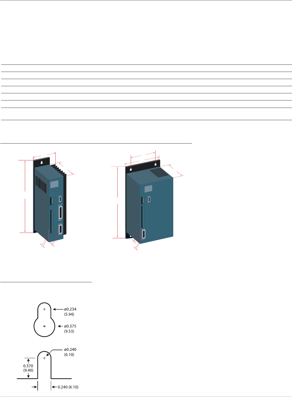
47
Motion Solutions
Motion Controllers
B
A
C
ED
STI105 SSI216
Dimension Feature SSI104 SSI107 SSI228 SSI407 SSI420
n/a Weight lb (kg) 4.0 (1.8) 7.0 (3.18) 13 (5.9) 6.0 (2.7) 14 (6.4)
A Depth in (mm) 6.05 (153.7) 8.15 (207.0) 10.15 (257.8) 8.15 (207) 10.15 (258)
B Width in (mm) 3.20 (81.3) 3.45 (87.6) 5.25 (133.4) 4.35 (110.5) 5.25 (133.4)
C Height in (mm) 8.50 (215.9) 8.50 (215.9) 12.20 (309.9) 8.50 (215.9) 12.20 (309.9)
D Position Feedback Connector Depth in (mm) 2.7 (68.6) 2.7 (68.6) 2.7 (68.6) 1.26 (32) 1.26 (32)
E User I/O Connector Depth in (mm) 0.75 (19.1) 0.75 (19.1) 0.75 (19.1) 0.75 (19.1) 0.75 (19.1)
F Center to center spacing between n/a n/a 3.66 (92.96) n/a 3.66 (92.96)
adjacent mounting holes
S2K Series Servo and Stepping Motor Controllers
STI105, SSI104, SSI107, SSI407 SSI216, SSI228, SSI420
S2K Series
Mechanical Dimensions
B
A
C
E
D
F
Mounting hole dimensions in (mm)
Top hole (all models)
Bottom hole (SSI216,
SSI228, SSI420)
Bottom hole (STI105, SSI104,
SSI107, SSI407)
www.ge-ip.com GE Intelligent Platforms

Motion Solutions
48
Motion Controllers
S2K Series
Ratings and Ordering Information
Stepper Models
IC800STI105D2 5 Amp, 115/230 VAC S2K Stepper Controller, Encoder Feedback, DeviceNet
IC800STI105P2 5 Amp, 115/230 VAC S2K Stepper Controller, Encoder Feedback, Profibus
IC800STI105S1 5 Amp, 115/230 VAC S2K Stepper Controller, Encoder Feedback, Extended I/O
Servo Models for MTR-Series Motors (Resolver Feedback)
IC800SSI104RD2 4.3 Amp, 115/230 VAC S2K Controller, Resolver Feedback, DeviceNet
IC800SSI104RP2 4.3 Amp, 115/230 VAC S2K Controller, Resolver Feedback, Profibus
IC800SSI104RS1 4.3 Amp, 115/230 VAC S2K Controller, Resolver Feedback, Extended I/O
IC800SSI107RD2 7.2 Amp 115/230 VAC S2K Controller, Resolver Feedback, DeviceNet
IC800SSI107RP2 7.2 Amp 115/230 VAC S2K Controller, Resolver Feedback, Profibus
IC800SSI107RS1 7.2 Amp 115/230 VAC S2K Controller, Resolver Feedback, Extended I/O
IC800SSI216RD2 16 Amp, 230 VAC S2K Controller, Resolver Feedback, DeviceNet
IC800SSI216RP2 16 Amp, 230 VAC S2K Controller, Resolver Feedback, Profibus
IC800SSI228RD2 28 Amp, 230 VAC S2K Controller, Resolver Feedback, DeviceNet
IC800SSI228RP2 28 Amp, 230 VAC S2K Controller, Resolver Feedback, Profibus
IC800SSI407RD2 7.2 Amp, 460 VAC S2K Controller, Resolver Feedback, DeviceNet
IC800SSI407RP2 7.2 Amp, 460 VAC S2K Controller, Resolver Feedback, Profibus
IC800SSI407RS1 7.2 Amp 460 VAC S2K Controller, Resolver Feedback, Extended I/O
IC800SSI420RD2 20 Amp, 460 VAC S2K Controller, Resolver Feedback, DeviceNet
IC800SSI420RP2 20 Amp, 460 VAC S2K Controller, Resolver Feedback, Profibus
Accessories
73006589 Hand Held I/O Simulator for 4.3 and 7.2A Models
IC800SLR001 50Ω, 100W External Regeneration Resistor Kit
IC800SLR002 100Ω, 225W External Regeneration Resistor Kit
IC800SLR003 20Ω, 300W External Regeneration Resistor Kit
IC800SLR004 15Ω, 1000W External Regeneration Resistor Kit
TRM-JAUX-03 S2K Auxiliary I/O Breakout Terminal Board, 3 ft cable*
TRM-JAUX-10 S2K Auxiliary I/O Breakout Terminal Board, 10 ft cable*
IC800MBUSADP RS232 to 422/485 Serial Converter for Modbus RTU Communications
*Required for Encoder feedback to S2K stepper controller when using CBL-13-ET or CBL-14-ET encoder cable.
Cables and Connectors
Cables in several lengths are available from GE for motor to amplifier connections and various other amplifier functions. It is strongly
recommended that you use the cables available from GE as shown below. GE does not ship mating power or feedback connectors for
the MTR-Series Motors with the motor. See appropriate motor section of this catalog for motor connector information.
www.ge-ip.com
GE Intelligent Platforms
S2K Series Cable/Connector GE Catalog Number Description
Aux. I/O Interface IC800SKCIxxx Interface Cable, S2K Auxiliary I/O to 44A726268-001 Terminal Board Assembly, 1 m or 3 m
IC800SKCFLYxxx Interface Cable, S2K Auxiliary I/O connector to Flying Leads, 1 m or 3 m
Serial IC800SKCS030 S2K Serial Communication Cable for PC (Motion Developer) Interface, 3 m
MTR-Series Motor Resolver* CBL-3T-RD-xx Resolver Cable, S2K to MTR-3T Series Servo Motor, xx=10, 20 or 30 feet
MTR-Series CBL-3T-MP-xx Power Cable, S2K to MTR-3T5x and 3T6x Servo Motors, xx=10, 20 or 30 feet
Motor Power* CBL-T7-MP-xx Power Cable, S2K to MTR-3T1x, 3T2x and 3T4x Servo Motors, xx=10, 20 or 30 feet
MTR-Series CBL-3T-MB-xx Power/Brake Cable, S2K to MTR-3T5x and 3T6x Servo Motors with Brake, xx=10, 20 or 30 feet
Motor Brake CBL-T7-MB-xx Power/Brake Cable, S2K to MTR-3T1x, 3T2x and 3T4x Servo Motors with Brake, xx=10, 20 or 30 feet
Commutating Encoder CBL-3C-L1D-FLY-XX Encoder cable, S2K to flying leads for connection of quadrature encoder with hall tracks, xx=10, 20 or 30 feet.
Connector TRM-21006664 Connector, 7 Point 4.3/5/7.2 Amp S2K Extended Digital I/O (S1 Modules)
Connector TRM-21006666 Connector, 14 Point Screw Terminal, S2K Digital I/O
Connector TRM-21006667 Connector, 20 Point Screw Terminal, S2K Digital I/O
Connector TRM-21006669 Connector, 4.3/5/7.2 Amp, 115/230V S2K Motor Power
Connector TRM-21006670 Connector, 4.3 Amp, 115/230V S2K AC Power
*For stepper motor cables, see Stepping Motor Cable and Amplifier Compatibility section of this catalog.
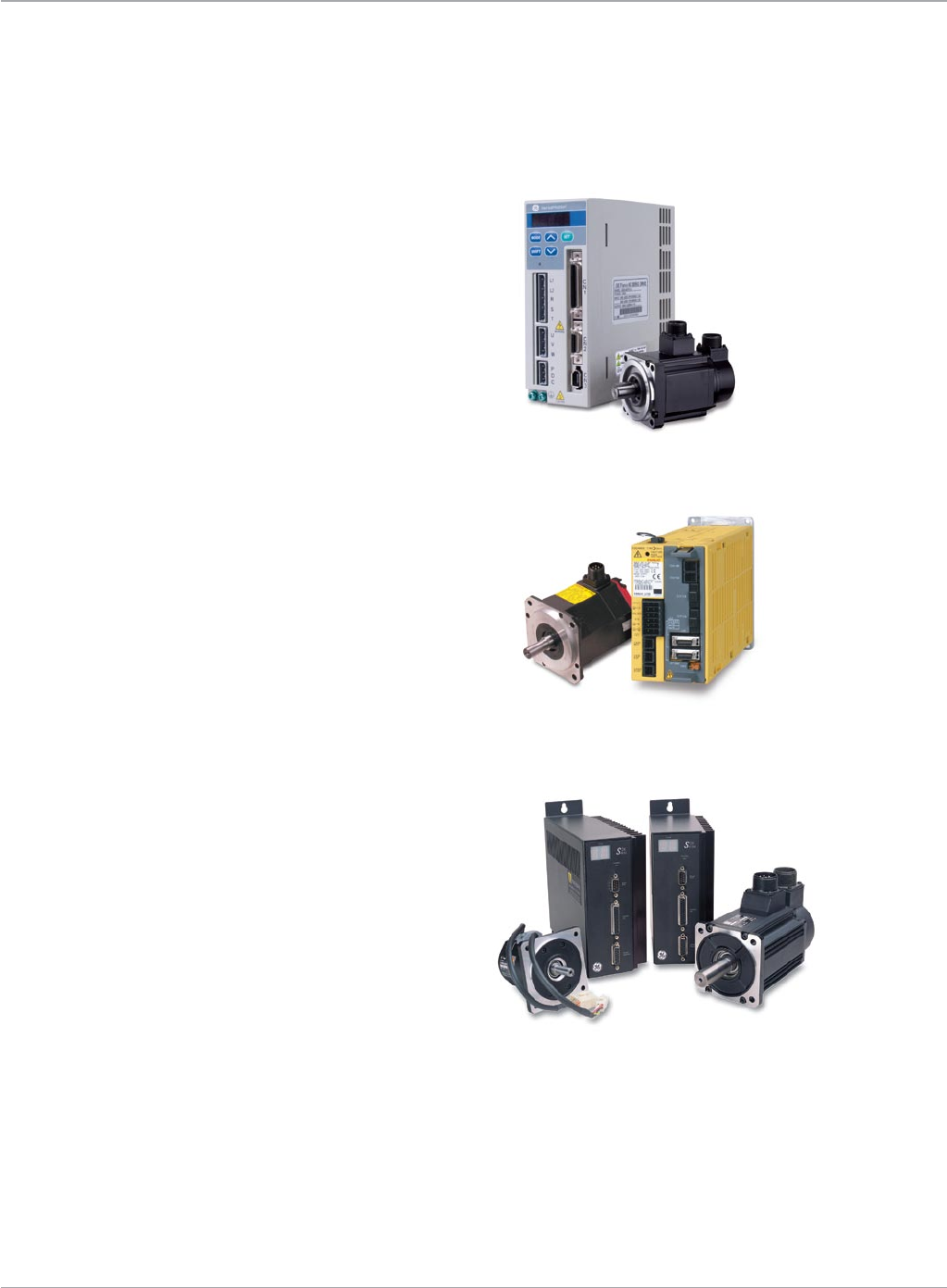
www.ge-ip.com GE Intelligent Platforms 49
Motion Solutions
www.ge-ip.com GE Intelligent Platforms
Servo Amplifiers
VersaMotion* Series
The VersaMotion family of servo amplifiers offers
a cost effective solution for a broad range of
motion applications. These versatile amplifiers
support stand-alone positioning capability using
up to 8 stored motion profiles, or can be con-
nected to any motion controller using an analog
or pulse command interface. The VersaMotion
Servo Amplifiers are matched for use with the
VersaMotion Servo Motors. Pages 116 and 117.
α and βi Series
The all digital α and βi Series Servo Amplifiers,
with over five million installed worldwide, offer
superior reliability and performance for unprece-
dented mean time between failure. They are
available in a wide range of ratings for use with
GE DSM300 Series motion controllers, and are
matched for use with the α and βi Series Servo
Motors. Pages 95, 96, 106 and 107.
S2K Series
For systems using a DSM300 or third-party
motion controller or where only speed or torque
control are required, GE offers the S2K Servo
Amplifiers. These brushless servos cover
a wide torque range (2.7-477 in-lb/0.3-53.9 Nm)
and offer high servo response to meet your most
demanding application requirements. The S2K
Series Amplifiers are matched for use with the
MTR Series motors. Pages 123 and 124.
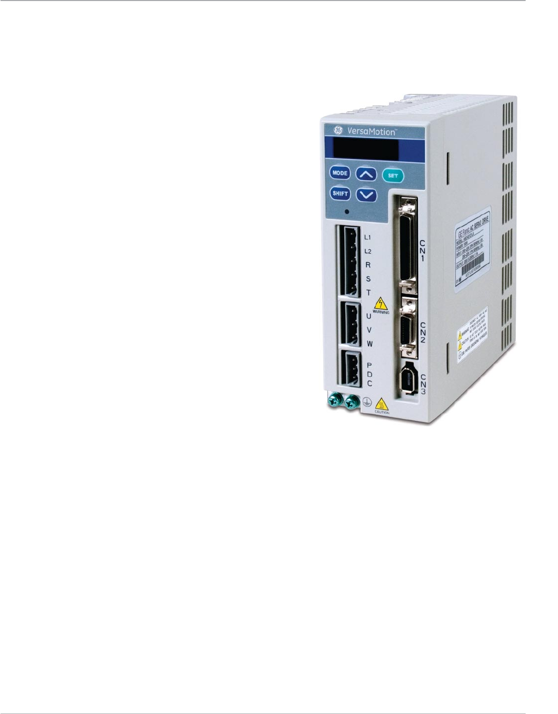
www.ge-ip.com
GE Intelligent Platforms
Motion Solutions
50
Servo Amplifiers
VersaMotion*
The VersaMotion family of servo amplifiers offers a cost effective solution for a broad
range of motion applications. These versatile amplifiers support simple stand-alone
positioning capability using up to 8 stored motion profiles or can be connected to
any motion controller using an analog or pulse command interface. A built-in
touchpad and display provides convenient access to configuration parameters
and system information. The serial interface supports multi-drop system
configurations and Modbus communication protocol.
Amplifier setup can be accomplished using the VersaMotion
software included with Proficy Machine Edition or using the
convenient front panel keypad.
Key Features:
• Versatileanalog(speedortorque)orpulsecommandinterface
• Position/Speed/Torquemodes
• Dualcontrolmodes
• Standalonesingle-axispositioncontrolmodeforsimplepoint-
to-point motion control
• Electronicgearingwithuser-definedratio
• ExternalJOGfunction
• Speed/Torquelimitoperation
• Built-inkeypad/displayforsetupanddiagnostics
• Motorsettlingtimebelow1msforfastresponse
• Lowspeedstabilityandperformance:lessthan0.5%error
at 1 RPM
• 10msecaccelerationtimefromrunningwithoutload
-/+ 3000 RPM
Built-in Functions:
• Simplestand-alonepoint-to-pointpositioningcontrolwith8
internal stored position settings (positions can be changed
overModbusforgreaterapplicationflexibility)
• MovetoHomefunction
• PositionTeachingcapability
• Incrementalencoderfeedback(2500ppr/10,000counts/rev)
• User-definableAcceleration/Decelerationwithjerklimiting
(s-curve)
• Feedstepcontrolfunction
• ModbusSlaveserialport(RS-485/RS-422)forreadingand
writing parameters from Machine Edition or updating stored
position set points from a host controller.
Machine Edition VersaMotion Set-up Features:
• ConfigurationParameterEditor(clear,read,writefunctions)
and initial configuration wizard
• Calculationtoolstodetermineproperconversionfromencoder
counts to desired user programming units
• Threechanneldigitaloscilloscopetodisplayandrecorddrive
status on-line
• Alarmhistoryandstatusmonitordiagnosticscreens
• DigitalI/Oset-up,monitoringandforcing.EachI/Opointcan
be individually set to one of the built-in functions (45 digital
input functions and 11 digital output functions)
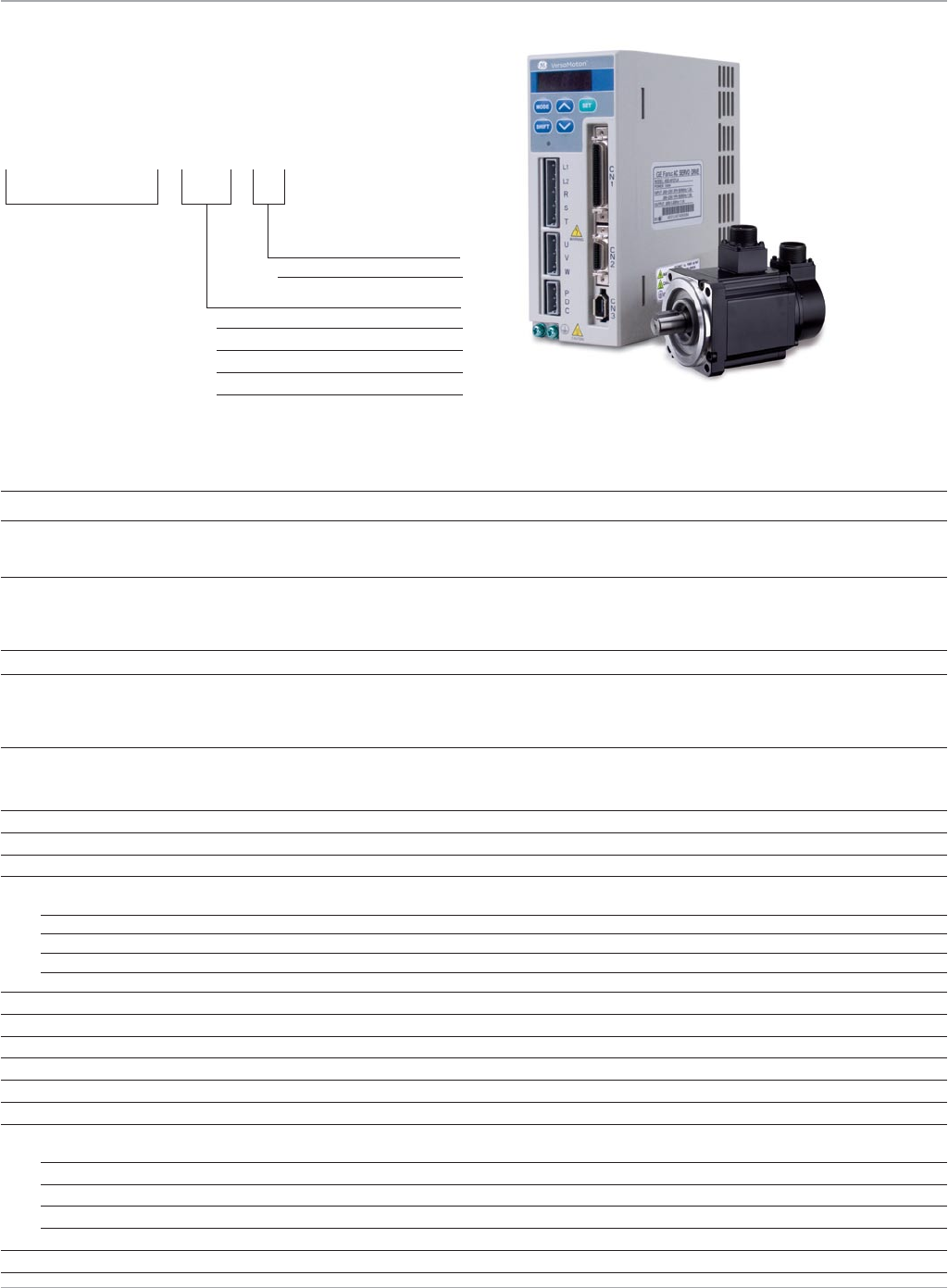
www.ge-ip.com GE Intelligent Platforms 51
Motion Solutions
Servo Amplifiers
VersaMotion*
Servo Amplifier Part Number Sequence
IC800VMA 04 2
Input Voltage
2–220VAC
Rated Power
01– 100 Watts 10– 1000 Watts
02– 200 Watts 20– 2000 Watts
04– 400 Watts 30– 3000 Watts
07– 750 Watts
Example:IC800VMA042isa400Watt220VACservoamplifier
Amplifier Specifications
Part Number IC800VMA012 IC800VMA022 IC800VMA042 IC800VMA072 IC800VMA102 IC800VMA202 IC800VMA302
RatedOutputPower 100W 200W 400W 750W 1000W 2000W 3000W
Voltage/ Frequency Three-phase or Three-phase or Three-phase or Three-phase or Three-phase or Three-phase Three-phase
Single-phase Single-phase Single-phase Single-phase Single-phase 220VAC;50/60Hz 220VAC;50/60Hz
220VAC;50/60Hz 220VAC;50/60Hz 220VAC;50/60Hz 220VAC;50/60Hz 220VAC;50/60Hz
PermissibleVoltage Three-phase: Three-phase: Three-phase: Three-phase: Three-phase: Three-phase: Three-phase:
Fluctuation 170~255VAC 170~255VAC 170~255VAC 170~255VAC 170~255VAC 170~255VAC 170~255VAC
Single-phase: Single-phase: Single-phase: Single-phase: Single-phase:
200~255VAC 200~255VAC 200~255VAC 200~255VAC 200~255VAC
CoolingSystem Convection Convection Convection FanCooling FanCooling FanCooling FanCooling
Electronic Gear Ratio Gear Ratio = N/M Gear Ratio = N/M Gear Ratio = N/M Gear Ratio = N/M Gear Ratio = N/M Gear Ratio = N/M Electronic gear N/M
whereN:1~32767, whereN:1~32767, whereN:1~32767, whereN:1~32767, whereN:1~32767, whereN:1~32767, multipleN:1~32767,
M:1:32767 M:1:32767 M:1:32767 M:1:32767 M:1:32767 M:1:32767 M:1:32767
(1/50<N/M<200) (1/50<N/M<200) (1/50<N/M<200) (1/50<N/M<200) (1/50<N/M<200) (1/50<N/M<200) (1/50<N/M<200)
Amplifier
PermissibleFrequencyFluctuation 50/60Hz+/-5%
Resolution/QuadratureFeedbackCounts 2500ppr/10000cpr
ControlModes Position/Velocity/Torque
DynamicBrake Built-in
PositionControlMode:
MaximumInputPulseFrequency 500KPPS(LineDriver)/Maximum200KPPS(OpenCollector)
PulseType Pulse/Direction;CW/CCW;A/BPhase
CommandSource Externalpulsetrain/Internalparameters
TorqueLimitOperation Yes
FeedForwardCompensation Yes
AnalogCommands:VoltageRange 0to+/-10VDC
TorqueandVelocityControlModeCommandSource Externalanalogsignal/Discretesetpointsstoredbyinternalparameters
SpeedControlRange 1:5000
SpeedControlFrequencyResponse Maximum450Hz
TorqueControlModePermissibleTimeforOverload 8secondsunder200%ratedoutput
CommunicationsInterface RS-232/RS-485/RS-422
Environmental
Altitude Altitude 1000 meters above sea level or lower
OperatingTemperature 0to55°C(Forcedcoolingforoperationabove55°C)
StorageTemperature -20°Cto65°C
Humidity 0to90%(Noncondensing)
Vibration <20Hz:9.8m/sec/sec(1G);20to50Hz:5.88m/sec/sec(0.6G)
Standards CE(IEC/EN61800-5-1),UL/cUL(508C),TUV,C-tick
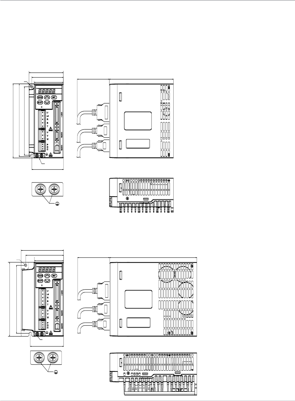
www.ge-ip.com
GE Intelligent Platforms
Motion Solutions
52
Servo Amplifiers
VersaMotion*
Dimensions
IC800VMA012, IC800VMA022, IC800VMA042
SCREW: M4x 0.7
MOUNTING SCREW TORQUE: 14(kgf-cm)
75
Ø6
69
64
69
PE
TERMINAL
162
159
150
70 140
LABEL
LABEL
SCREW: M4x 0.7
MOUNTING SCREW TORQUE: 14(kgf-cm)
93
Ø6
83
64
73
PE
TERMINAL
162
149
70 191
LABEL
LABEL
IC800VMA072, IC800VMA102
Dimensions shown in mm
Dimensions shown in mm
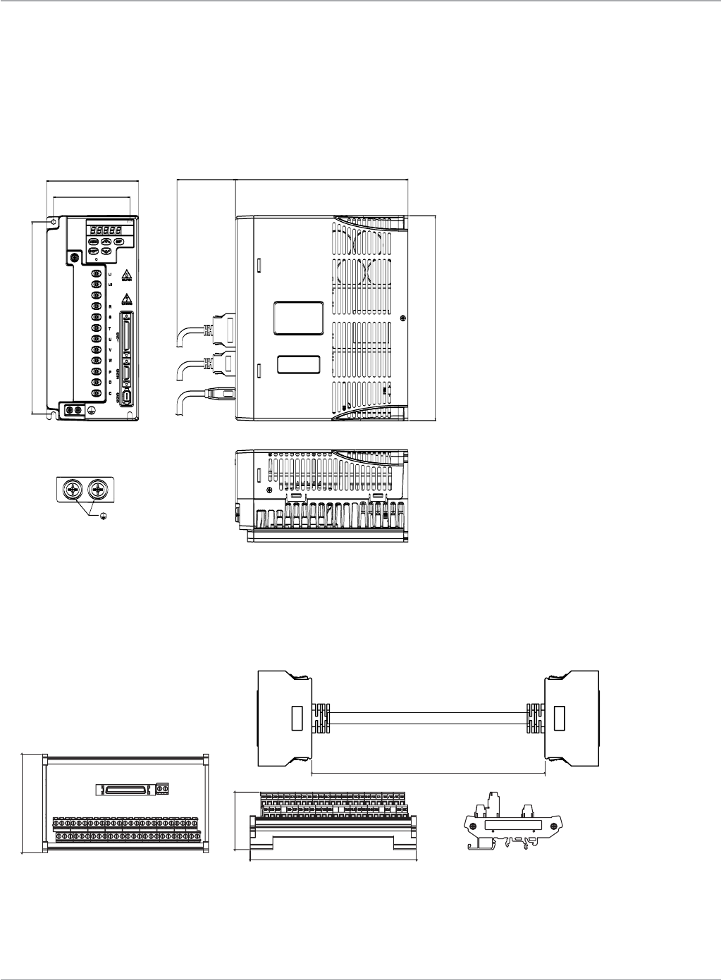
www.ge-ip.com GE Intelligent Platforms 53
Motion Solutions
Servo Amplifiers
VersaMotion*
Dimensions
IC800VMA202, IC800VMA302
SCREW: M4x 0.7
MOUNTING SCREW TORQUE: 14(kgf-cm)
110
91
229
245
70 206
LABEL
LABEL
Dimensions shown in mm
Dimensions shown in mm
Optional Cable and Terminal Block
146.4
50.7
86.8
500
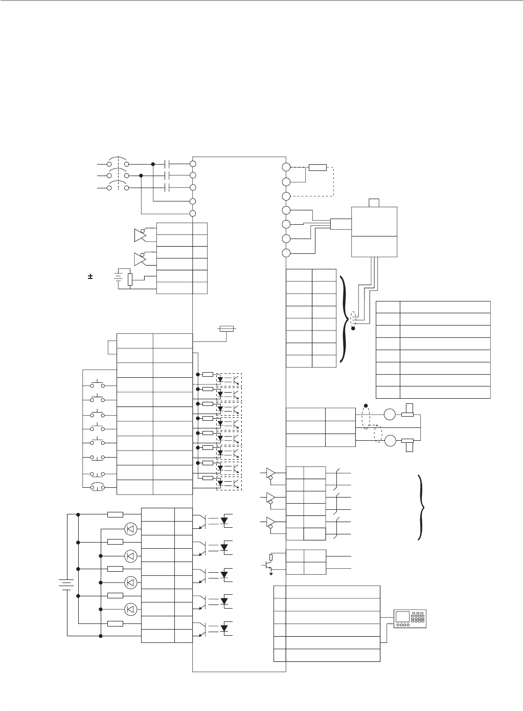
www.ge-ip.com
GE Intelligent Platforms
Motion Solutions
54
Servo Amplifiers
VersaMotion*
Connection Diagrams
Position Control Mode - Pulse Follower Mode
AC 220/230V
Single-phase
or Three-phase
50/60Hz
SIGN
/S IGN
PULSE
/P ULSE
T-REF
GND
37
36
41
43
18
13
R
S
T
L2
L1
5
4
7
9
10
2
14,16
13,15
P
D
C
U
V
W
FG
A
/A
B
/B
Z
/Z
+5V
GND
CN2
MCCB
CN1
SG
MC
Servo Drive
Pulse Input
(Line Driver)
Regenerative
Resistor
Servo
Motor
Encoder
Red
White
Black
Green
Twisted-pair or
twisted-shield
cable
VDD
COM+
COM-
DI1
DI2
DI3
DI4
DI5
DI6
DI7
DI8
17
11
45,47,49
9
10
34
8
33
32
31
30
DO1+
DO1-
DO2+
DO2-
DO3+
DO3-
DO4+
DO4-
DO5+
DO5-
7
6
5
4
3
2
1
26
28
27
24V
1.5K
1.5K
1.5K
1.5K
1.5K
SRDY
ZSPD
HOME
ALRM
DC24V
CN1
CN1
TPOS
SON
CCLR
ARST
CWL
CCWL
EMGS
TCM0
TCM1
6
5
4
3
2
1
RS422T-
RS422T +
RS422R - & RS232_RX
RS422R +
RS232_TX
RS232_GND
CN3
(Note 1)
10V
16
12,13,19
15
MON1
GND
MON2
10K
10K
SG
A
A
CN1
21
22
25
23
50
24
OA
/O A
OB
/O B
OZ
/O Z
CN1
A phase pulse
B phase pulse
Z phase pulse
PG Dividing
Ratio Output
Max. allowable
current 200mA
voltage 40V
48
13
OCZ
GNDZ phase open collector
A
/A
B
/B
Z
/Z
+5V
GND
Black
Black/Red
White
White/Red
Orange
Orange/R ed
Brown & Brown/White
Blue & Blue/W hite
Encoder Wiring
PT STANDARD CONNECTION
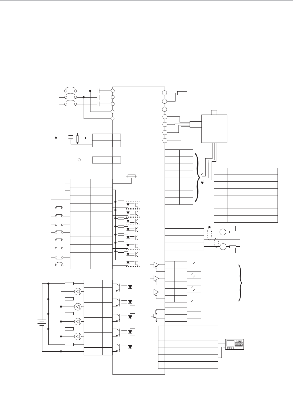
www.ge-ip.com GE Intelligent Platforms 55
Motion Solutions
VersaMotion*
Connection Diagrams
Position Control Mode - Stored Position Commands Mode
T-REF
GND
18
13
R
S
T
L2
L1
MCCB
CN1
MC
VDD
COM+
COM-
DI1
DI2
DI3
DI4
DI5
DI6
DI7
DI8
17
11
45,47,49
9
10
34
8
33
32
31
30
SON
CTRG
POS0
POS1
ARST
CWL
CCWL
EMGS
DO1+
DO1-
DO2+
DO2-
DO3+
DO3-
DO4+
DO4-
DO5+
DO5-
7
6
5
4
3
2
1
26
28
27
24V
1.5K
1.5K
1.5K
1.5K
1.5K
DC24V
CN1
CN1
AC 220/230V
Single-phase
or Three-phase
50/60Hz
Servo DriveRegenerative
Resistor
Servo
Motor
Encoder
Red
White
Black
Green
VCC20
5
4
7
9
10
2
14,16
13,15
A
/A
B
/B
Z
/Z
+5V
GND
CN2
SG
Twisted-pair or
twisted-shield
cable
6
5
4
3
2
1
RS422T-
RS422T+
RS422R - & RS232_RX
RS422R +
RS232_TX
RS232_GND
CN3
10V
P
D
C
U
V
W
FG
16
12,13,19
15
MON1
GND
MON2
10K
10K
SG
A
A
CN1
21
22
25
23
50
24
OA
/O A
OB
/O B
OZ
/O Z
CN1
A phase pulse
B phase pulse
Z phase pulse
PG Dividing
Ratio Output
48
13
OCZ
GNDZ phase open collector
Max. allowable
current 200mA
voltage 40V
A
/A
B
/B
Z
/Z
+5V
GND
Black
Black/Red
White
White/Red
Orange
Orange/R ed
Brown & Brown/White
Blue & Blue/W hite
Encoder Wiring
PR STANDARD CONNECTION
SRDY
ZSPD
HOME
ALRM
TPOS
Servo Amplifiers
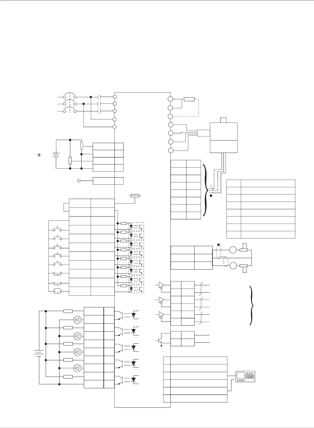
www.ge-ip.com
GE Intelligent Platforms
Motion Solutions
56
VersaMotion*
Connection Diagrams
Speed Control Mode
V-REF
GND
42
13
R
S
T
L2
L1
MCCB
CN1
MC
VDD
COM+
COM-
DI1
DI2
DI3
DI4
DI5
DI6
DI7
DI8
17
11
45,47,49
9
10
34
8
33
32
31
30
SON
TRQLM
SPD0
SPD1
ARST
CWL
CCWL
EMGS
DO1+
DO1-
DO2+
DO2-
DO3+
DO3-
DO4+
DO4-
DO5+
DO5-
7
6
5
4
3
2
1
26
28
27
24V
1.5K
1.5K
1.5K
1.5K
1.5K
SRDY
ZSPD
TSPD
ALRM
DC24V
CN1
CN1
BRKR
T-REF
GND
18
13
10K
10K
AC 220/230V
Single-phase
or Three-phase
50/60Hz
Servo Drive
VCC20
5
4
7
9
10
2
14,16
13,15
P
D
C
U
V
W
FG
A
/A
B
/B
Z
/Z
+5V
GND
CN2
SG
Regenerative
Resistor
Servo
Motor
Encoder
Red
White
Black
Green
Twisted-pair or
twisted-shield
cable
6
5
4
3
2
1
RS422T-
RS422T+
RS422R - & RS232_RX
RS422R +
RS232_TX
RS232_GND
CN3
10V
16
12,13,19
15
MON1
GND
MON2
10K
10K
SG
A
A
CN1
21
22
25
23
50
24
OA
/O A
OB
/O B
OZ
/O Z
CN1
A phase pulse
B phase pulse
Z phase pulse
PG Dividing
Ratio Output
48
13
OCZ
GNDZ phase open collector
Max. allowable
current 200mA
voltage 40V
A
/A
B
/B
Z
/Z
+5V
GND
Black
Black/Red
White
White/Red
Orange
Orange/R ed
Brown & Brown/White
Blue & Blue/W hite
Encoder Wiring
S STANDARD CONNECTION
Servo Amplifiers
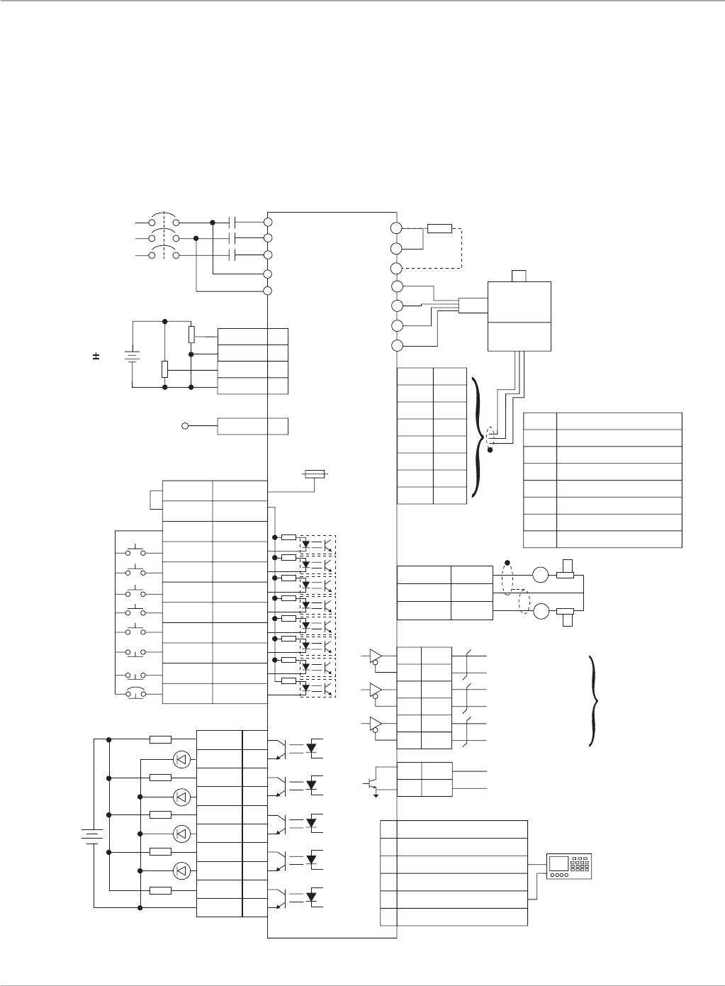
www.ge-ip.com GE Intelligent Platforms 57
Motion Solutions
Servo Amplifiers
VersaMotion*
Connection Diagrams
Torque Control Mode
V-REF
GND
42
13
R
S
T
L2
L1
MCCB
CN1
MC
VDD
COM+
COM-
DI1
DI2
DI3
DI4
DI5
DI6
DI7
DI8
17
11
45,47,49
9
10
34
8
33
32
31
30
SON
SPDLM
TCM0
TCM1
ARST
CWL
CCWL
EMGS
DO1+
DO1-
DO2+
DO2-
DO3+
DO3-
DO4+
DO4-
DO5+
DO5-
7
6
5
4
3
2
1
26
28
27
24V
1.5K
1.5K
1.5K
1.5K
1.5K
DC24V
CN1
CN1
T-REF
GND
18
13
10K
10K
AC 220/230V
Single-phase
or Three-phase
50/60Hz
Servo Drive
VCC20
5
4
7
9
10
2
14,16
13,15
P
D
C
U
V
W
FG
A
/A
B
/B
Z
/Z
+5V
GND
CN2
SG
Regenerative
Resistor
Servo
Motor
Encoder
Red
White
Black
Green
Twisted-pair or
twisted-shield
cable
6
5
4
3
2
1
RS422T-
RS422T+
RS422R - & RS232_RX
RS422R +
RS232_TX
RS232_GND
CN3
10V
16
12,13,19
15
MON1
GND
MON2
10K
10K
SG
A
A
CN1
21
22
25
23
50
24
OA
/O A
OB
/O B
OZ
/O Z
CN1
A phase pulse
B phase pulse
Z phase pulse
PG Dividing
Ratio Output
48
13
OCZ
GNDZ phase open collector
Max. allowable
current 200mA
voltage 40V
A
/A
B
/B
Z
/Z
+5V
GND
Black
Black/Red
White
White/Red
Orange
Orange/R ed
Brown & Brown/White
Blue & Blue/W hite
Encoder Wiring
T STANDARD CONNECTION
SRDY
ZSPD
TSPD
ALRM
BRKR

www.ge-ip.com
GE Intelligent Platforms
Motion Solutions
58
Servo Amplifiers
VersaMotion*
Ordering Information
VersaMotion VersaMotion VersaMotion VersaMotion
Model 100 Watt 200 Watt 400 Watt 750 Watt
MotorPartNumber IC800VMM01LNKSE25 IC800VMM02LNKSE25 IC800VMM04LNKSE25 IC800VMM07LNKSE25
Motor/BrakePartNumber N/A IC800VMM02LBKSE25 IC800VMM04LBKSE25 IC800VMM07LBKSE25
AmplifierPartNumber IC800VMA012 IC800VMA022 IC800VMA042 IC800VMA072
Cables
PowerCable 3m IC800VMCP030 IC800VMCP030 IC800VMCP030 IC800VMCP030
5m IC800VMCP050 IC800VMCP050 IC800VMCP050 IC800VMCP050
10m IC800VMCP100 IC800VMCP100 IC800VMCP100 IC800VMCP100
20m IC800VMCP200 IC800VMCP200 IC800VMCP200 IC800VMCP200
BrakeandPowerCable 3m N/A IC800VMCB030 IC800VMCB030 IC800VMCB030
5m N/A IC800VMCB050 IC800VMCB050 IC800VMCB050
10m N/A IC800VMCB100 IC800VMCB100 IC800VMCB100
20m N/A IC800VMCB200 IC800VMCB200 IC800VMCB200
EncoderCable 3m IC800VMCE030 IC800VMCE030 IC800VMCE030 IC800VMCE030
5m IC800VMCE050 IC800VMCE050 IC800VMCE050 IC800VMCE050
10m IC800VMCE100 IC800VMCE100 IC800VMCE100 IC800VMCE100
20m IC800VMCE200 IC800VMCE200 IC800VMCE200 IC800VMCE200
Communications & I/O Interface Cables
CommunicationsCable 3m IC800VMCS030 IC800VMCS030 IC800VMCS030 IC800VMCS030
FlyingleadI/OinterfaceCable 1m IC800VMCI010 IC800VMCI010 IC800VMCI010 IC800VMCI010
3m IC800VMCI030 IC800VMCI030 IC800VMCI030 IC800VMCI030
Amplifier Connectors
CN1I/OConnector(Note 1) IC800VMACONCN1 IC800VMACONCN1 IC800VMACONCN1 IC800VMACONCN1
CN2EncoderConnector(Note 2) IC800VMACONCN2 IC800VMACONCN2 IC800VMACONCN2 IC800VMACONCN2
CN3CommunicationConnector(Note 3) IC800VMACONCN3 IC800VMACONCN3 IC800VMACONCN3 IC800VMACONCN3
ACPowerConnector(Note 4) IC800VMACONACP IC800VMACONACP IC800VMACONACP IC800VMACONACP
MotorPowerConnector(Note 4) IC800VMACONMTRP IC800VMACONMTRP IC800VMACONMTRP IC800VMACONMTRP
ExternalBrakingResistorConnector(Note 4) IC800VMADBR001 IC800VMADBR001 IC800VMADBR001 IC800VMADBR001
Motor Connectors
PowerConnector(motoronly) IC800VMMCONP001 IC800VMMCONP001 IC800VMMCONP001 IC800VMMCONP001
PowerConnector(motor&brake) N/A IC800VMMCONP002 IC800VMMCONP002 IC800VMMCONP002
EncoderConnector IC800VMMCONE001 IC800VMMCONE001 IC800VMMCONE001 IC800VMMCONE001
Accessories
I/OTerminalBreakoutBoardandCable(Note 5) 0.5m IC800VMTBC005 IC800VMTBC005 IC800VMTBC005 IC800VMTBC005
ExternalBrakingResistor(Note 6) IC800VMBR040 IC800VMBR040 IC800VMBR040 IC800VMBR040
40Ω, 400 Watt
ExternalBrakingResistor(Note 6) IC800VMBR020 IC800VMBR020 IC800VMBR020 IC800VMBR020
20Ω, 1000 Watt
1)TheCN1connectorisonlyrequiredwhentheI/Obreakoutterminalboard(IC800VMTBC005)orflyingleadI/Ointerfacecable(IC800VMCI0xx)arenotusedforwiringaccesstotheamplifierI/Opoints.
2)TheCN2encoderconnectorispartoftheseparatelyorderedGEfeedbackcable.Thisconnectorisonlyrequiredwhenuserwillmanufacturetheirownmotorfeedbackcable.
3)TheCN3communicationconnectorispartoftheseparatelyorderedGEserialcommunicationcable(IC800VMCS030).Thisconnectorisonlyrequiredwhenuserwillmanufacturetheirown
communication cable.
4)TheseconnectorsareshippedwitheachVersaMotionamplifier(100Wto1kW)andareonlynecessarytoreplacelostordamagedconnectormates.Amplifiersrated2kWandlargerhavefixed
wiring terminals and do not use a plug-on connector mate.
5)TheoptionalbreakoutterminalboardprovidesscrewterminationsforwiringeachI/OpointontheamplifierCN1I/Oconnector.TheflyingleadI/Ointerfacecable(IC800VMCI0xx)orCN1connector
(IC800VMACONCN1)maybeused.
6)Theoptionalexternalbrakingresistorsareusedtodissipateexcessivereneneratedenergyduringfastdecelerationoflargeloadsfromhighspeeds.

www.ge-ip.com GE Intelligent Platforms 59
Motion Solutions
Servo Amplifiers
VersaMotion*
Ordering Information (continued)
VersaMotion VersaMotion VersaMotion
Model 1000 Watt 2000 Watt 3000 Watt
MotorPartNumber IC800VMM10LNKSE25 IC800VMM20LNKSE25 IC800VMM30MNKSE25
IC800VMM10MNKSE25 IC800VMM20MNKSE25
Motor/BrakePartNumber IC800VMM10LBKSE25 IC800VMM20LBKSE25 IC800VMM30MBKSE25
IC800VMM10MBKSE25 IC800VMM20MBKSE25
AmplifierPartNumber IC800VMA102 IC800VMA202 IC800VMA302
Cables
PowerCable 3m IC800VMCP1030 IC800VMCP2030 IC800VMCP3030
5m IC800VMCP1050 IC800VMCP2050 IC800VMCP3050
10m IC800VMCP1100 IC800VMCP2100 IC800VMCP3100
20m IC800VMCP1200 IC800VMCP2200 IC800VMCP3200
BrakeandPowerCable 3m IC800VMCB1030 IC800VMCB2030 IC800VMCB3030
5m IC800VMCB1050 IC800VMCB2050 IC800VMCB3050
10m IC800VMCB1100 IC800VMCB2100 IC800VMCB3100
20m IC800VMCB1200 IC800VMCB2200 IC800VMCB3200
EncoderCable 3m IC800VMCE1030 IC800VMCE1030 IC800VMCE1030
5m IC800VMCE1050 IC800VMCE1050 IC800VMCE1050
10m IC800VMCE1100 IC800VMCE1100 IC800VMCE1100
20m IC800VMCE1200 IC800VMCE1200 IC800VMCE1200
Communications & I/O Interface Cables
CommunicationsCable 3m IC800VMCS030 IC800VMCS030 IC800VMCS030
FlyingleadI/OinterfaceCable 1m IC800VMCI010 IC800VMCI010 IC800VMCI010
3m IC800VMCI030 IC800VMCI030 IC800VMCI030
Amplifier Connectors
CN1I/OConnector IC800VMACONCN1 IC800VMACONCN1 IC800VMACONCN1
CN2EncoderConnector IC800VMACONCN2 IC800VMACONCN2 IC800VMACONCN2
CN3CommunicationConnector IC800VMACONCN3 IC800VMACONCN3 IC800VMACONCN3
ACPowerConnector IC800VMACONACP N/A N/A
MotorPowerConnector IC800VMACONMTRP N/A N/A
ExternalBrakingResistorConnector IC800VMADBR001 N/A N/A
Motor Connectors
PowerConnector(motoronly) IC800VMMCONP003 IC800VMMCONP003 IC800VMMCONP004
PowerConnector(motor&brake) IC800VMMCONP003 IC800VMMCONP003 IC800VMMCONP004
EncoderConnector IC800VMMCONE002 IC800VMMCONE002 IC800VMMCONE002
Accessories
I/OTerminalBreakoutBoardandCable 0.5m IC800VMTBC005 IC800VMTBC005 IC800VMTBC005
ExternalBrakingResistor IC800VMBR040 IC800VMBR040 IC800VMBR040
40Ω, 400 Watt
ExternalBrakingResistor IC800VMBR020 IC800VMBR020 IC800VMBR020
20Ω, 1000 Watt
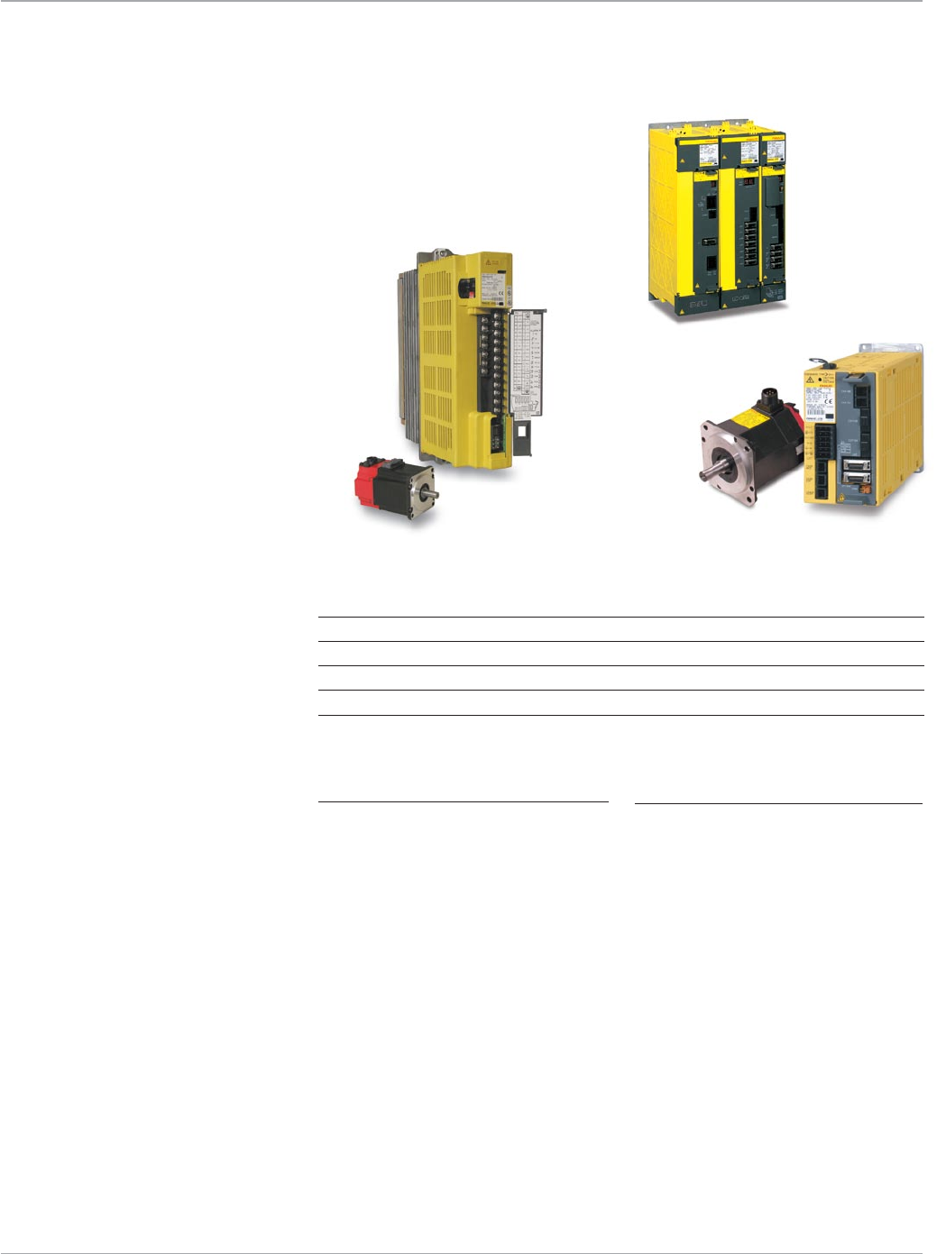
www.ge-ip.com
GE Intelligent Platforms
Motion Solutions
60
Servo Amplifiers
High-Performance Serial Encoders
Standard serial encoders built into the
motorsprovideexceptionalfeedback
resolution of 64K or 128K counts per
revolution. Serial encoders support higher
resolutions at high motor velocities than
standard quadrature encoders and are
more immune to noise. An optional battery
connection provides absolute position
feedback, eliminating the need to home
the system after a power shutdown.
Reduced Tuning and Setup
There is no need for potentiometer tuning
orpersonalitymodules;littletuningis
required for properly sized drives. All drive
parameters are stored in the controller in
astandardmotordatabase.Configuration
settings are not stored in the drive, making
it possible to replace drives with little set-
up time. Stored drive and machine param-
eters are quickly transferred to repeat pro-
duction machines.
All-Digital System
All control loops—current, velocity, and
position—are closed in the GE DSM Series
motioncontroller.High-speedmicropro-
cessors and/or digital signal processors
(DSPs) in the controller provide loop update
times of 250 µs. The high response servo
system can compensate for machine
design limitations, yielding faster accelera-
tion/deceleration rates and better respons-
es to load changes.
All-Digital Servo Command Signals
The DSM324i and βi or αi Series amplifiers
use a high speed fiber optic command
interface. The DSM302 and DSM314 use
a PWM command interface between the
controller and amplifier which improves
efficiency by varying the on-time of the
transistor switches that control motor
voltage and current. With its superior noise
immunity, both of these GE digital com-
mand interfaces allows for an increased
signal to noise ratio for improved accuracy
and performance.
INFO
For application, installation, and tuning
information, consult the Services website
at www.ge-ip.com.
Agency Approvals
UL,IECratingandCEmarkcompliant
α and βi Series Servo Amplifiers
All Digital Servo Systems Offer High Performance and Reliability.
GE α and βiSeriesServoDrives,basedonoverfivemillionaxesinstalledworldwide,
offer superior reliability and performance for unprecedented mean time between
failure. The α and βi Series Servos are available in a wide range of ratings for use
with GE DSM300 Series motion controllers.
Series Motor Series Controllers Command Continuous Power Supply
Interface Torque Range
In-lb Nm
αSVU α DSM302/314 PWM 53-495 6-56 Built-in
αHVi αHVi, αHVis PMM335/DSM324i FiberOptic 17.7-664 2-75 Separate PSM
βi βis PMM335/DSM324i FiberOptic 3.5-177 0.4-20 Built-in
βHVi βHVis PMM335/DSM324i FiberOptic 17.7-177 2-20 Built-in
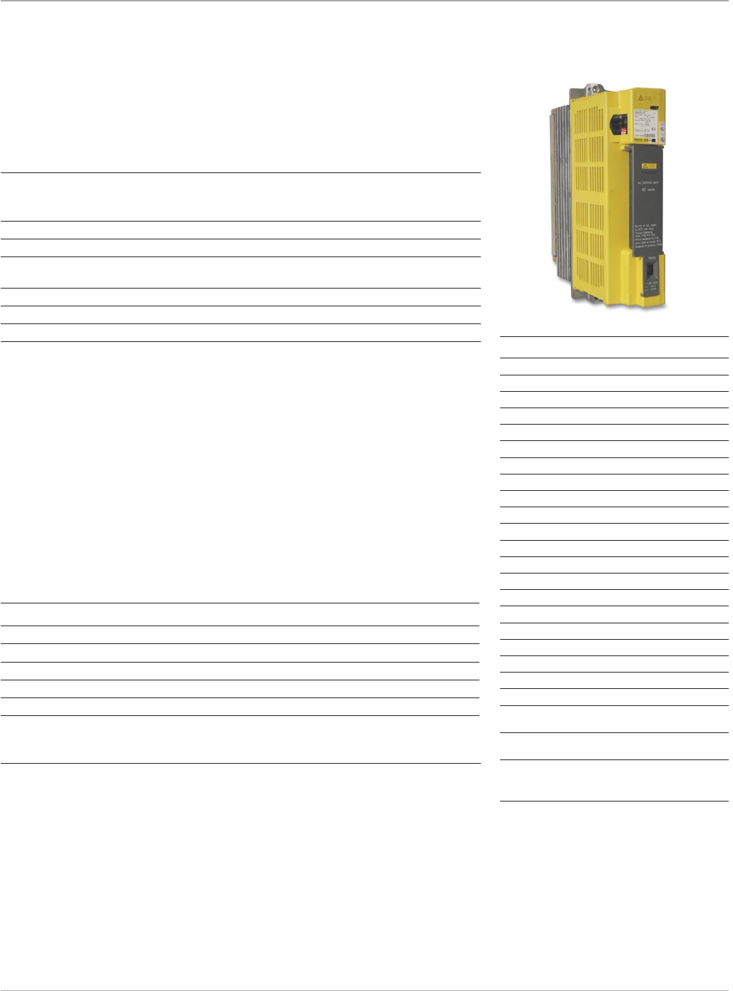
www.ge-ip.com GE Intelligent Platforms 61
Motion Solutions
Servo Amplifiers
Part Number Description Amplifier Series
ZA81L-0001-0083#3C 5.4kW,3-phaseAClinefilter βi
ZA81L-0001-0101#C 10.5kW,3-phaseAClinefilter βi
ZA81L-0001-0168 5.4kW,3-phaseAClinefilter βHVi
ZA81L-0001-0169 10.5kW,3-phaseAClinefilter βHVi
ZA81L-0001-0163 18kW,3-phaseAClinefilter PSM-11HVi,PSM-18HVi
ZA81L-0001-0164 45kW,3-phaseAClinefilter PSM-30HVi,PSM-45HVi
The βi Series Servo amplifiers can be
runonsinglephasepower;however,
the lifetime of the amplifier is reduced
because of higher input and ripple current.
AnAClinefilterisstronglyrecommended
to suppress the influences of high-
frequency input line noise on the drive
powersupply.Ifapowersourcewithinthe
specified voltage range is not available, a
transformer is required. The kVA rating
of the transformer should be equal to
or greater than the sum of all motor kW
ratings.Ifanisolation-typepower
transformerisused,anAClinefilter
is not required.
GEoffersthefollowinglinefilters;transformersmustbesuppliedbytheuserasrequired.
βi Series Servo
System Power Requirements
Amplifier Specification βi Series αHVi*/βHVi Series
Voltage(-15%,+10%):
3-phase 200-240VAC 400-480VAC
1-phase(seebelow) 220-240VAC n/a
Frequency 50/60Hz 50/60Hz
Allowablefrequencyfluctuation ±2Hz ±2Hz
Voltagefluctuationduring 7%orless 7%orless
acceleration/deceleration
AmbientTemperatureRange 0-55°C 0-55°C
Humidity(non-condensing) 90% 90%
Vibration Lessthan0.5G Lessthan0.5G
Motor Model Max. kW Rating
β0.4/5000
i
s 0.13
β0.5/6000
i
s 0.35
β1/6000
i
s 0.5
β2/4000
i
s 0.5
β4/4000
i
s 0.75
β8/3000
i
s 1.2
β12/3000
i
s 1.8
β22/2000
i
s 2.5
β2/4000HV
i
s 0.5
β4/4000HV
i
s 0.75
β8/3000HV
i
s 1.2
β12/3000HV
i
s 1.8
β22/2000HV
i
s 2.5
α2/6000HV
is
1.0
α4/5000HV
is
1.0
α8/6000HV
is
2.2
α12/4000
HVis
2.5
α22/3000HVi 4.0
α22/4000HVis 4.5
α30/4000HVis 5.5
α40/4000HVis 5.5
α50/3000HVis w/fan 14
IncomingDCPowerforβi Series
InputVoltage 24VDC(±10%)
CurrentRequirement(peramplifier):
β
i
Series 0.9 amps
βHV
i
Series 0.9 amps
Control Power Specification
The βiSeriesamplifiersrequirea24VDC
power supply for amplifier control power.
ThisDCpowersupplymustbesuppliedby
theuser.WerecommendtheGE24VDC
powersupply,partnumberIC690PWR024.
ThesameexternalDCpowersupplycanbe
used to provide power to multiple amplifi-
ers as long as the supply is rated for the
total current requirements of all of
the amplifiers.
The α series amplifiers and αHVi series
power supplies require a single phase
200-230VACcentralpowerinput.
*αHViseriesamplifiersuseaseparatelymountedsharedpowersupply.
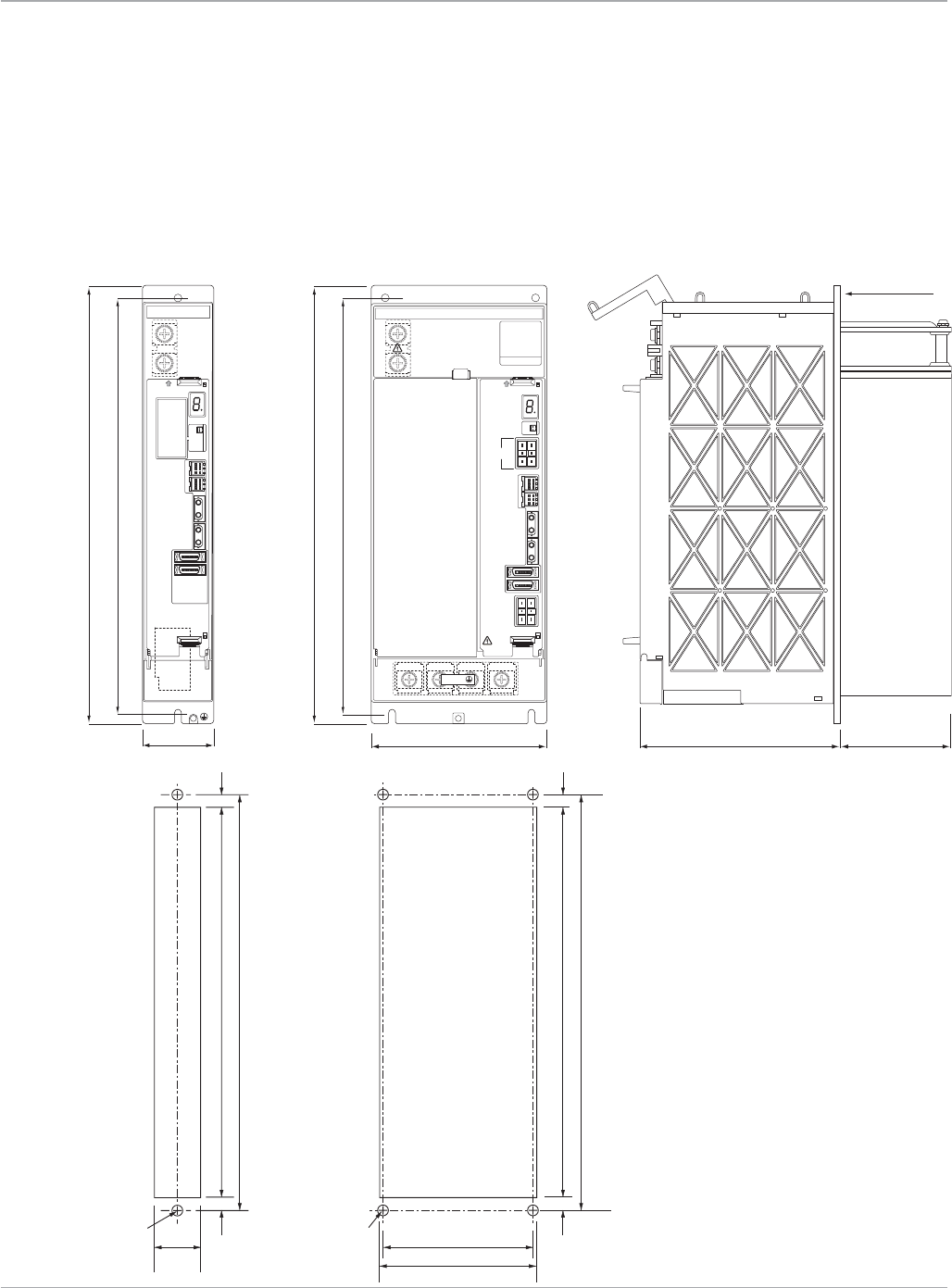
www.ge-ip.com
GE Intelligent Platforms
Motion Solutions
62
αHVi Series Servo Amplifiers and Power Supplies
Dimensions
αHVi Amplifier Dimension Drawings
Front view of
αSVM1-180HVi
Front view of
αSVM1-10HVi
αSVM1-40HVi
and αSVM1-80HVi
Panel cut-out for
αSVM1-10HVi
αSVM1-40HVi
and αSVM1-80HVi
The αHViSeriesamplifiersandPSM-HVipowersuppliesaredesignedwitharear-mountedheatsinkthatextendsthroughaholein
the mounting plate. This design eliminates most of the heat dissipation inside the control cabinet, reducing the temperature rise in
the cabinet and the load on cabinet cooling equipment.
Servo Amplifiers
FA NU C
ENCODER
BATTERY
CXA2B
CX5X
STATUS
BATTERY
CXA2A
COP10B
COP10A
JX5
ENC1
JF1
CAUTION
HIGHVO LT A GE
DISCHA RGE
TIME
>
2 min
380 (14.96)
360 (14.17)
172 (6.77)
60 (2.36) 1 0 0 (3.94) max.
mounting flange
F A NU C
CXA2B
AC
200-240 V
50/60 Hz
CX5X
CX1A CX1B
STATUS
CXA2A
COP10B
COP10A
JX5
ENC1
JF1
CX8
DBI CX9
DBC
CAUTION
When t he LE D is lit
don’ t to uch the t ermin als.
DISCHA RGE
TIME
380 (14.96)
360 (14.17)
172 (6.77)
150 (5.90) 1 0 0 (3.94) max.
mounting flange
>
2 Mins
U V W
F A N UC L T D
Y a men as hi 40 1-05 97 J A P A N
Side view
338 (13.31) 11
11
11
11
11
11
46 (1.81) 7 6 (2.99) 130 (5. 1 2)
136 (5.35)
360 (14.17) (0.43)
(0.43)
(0.43)
338 (13.31)
360 (14.17)
338 (13.31)
360 (14.17)
2-M5 2-M5 4-M5
(0.43)
(0.43)
(0.43)
338 (13.31) 11
11
11
11
11
11
46 (1.81) 7 6 (2.99) 130 (5. 1 2)
136 (5.35)
360 (14.17) (0.43)
(0.43)
(0.43)
338 (13.31)
360 (14.17)
338 (13.31)
360 (14.17)
2-M5 2-M5 4-M5
(0.43)
(0.43)
(0.43)
Panel cut-out for
αSVM1-180HVi
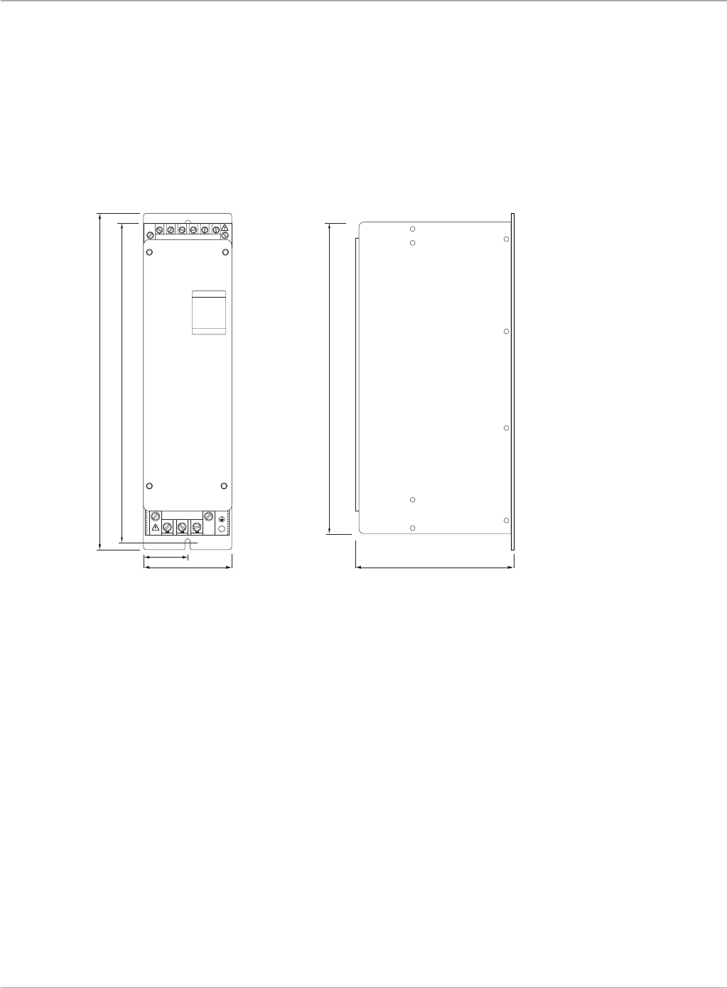
www.ge-ip.com GE Intelligent Platforms 63
Motion Solutions
Dynamic Brake Module Dimension Drawings
αHVi Series Servo Amplifiers and Power Supplies
Dimensions
Servo Amplifiers
Front view of
A06B-6079-H401
Side view
380 (14.96)
360 (14.17)
352 (13.86)
1 0 0 (3.93)
50 (1.97)
172 (6.77)
UV
T1
T2
W
F A NU C
Dynamic Brake Module (DBM)
F A N UC L T D
Y a men as hi 40 1-05 97 J A P A N
380 (14.96)
360 (14.17)
352 (13.86)
1 0 0 (3.93)
50 (1.97)
172 (6.77)
UV
T1
T2
W
F A NU C
Dynamic Brake Module (DBM)
F A N UC L T D
Y a men as hi 40 1-05 97 J A P A N
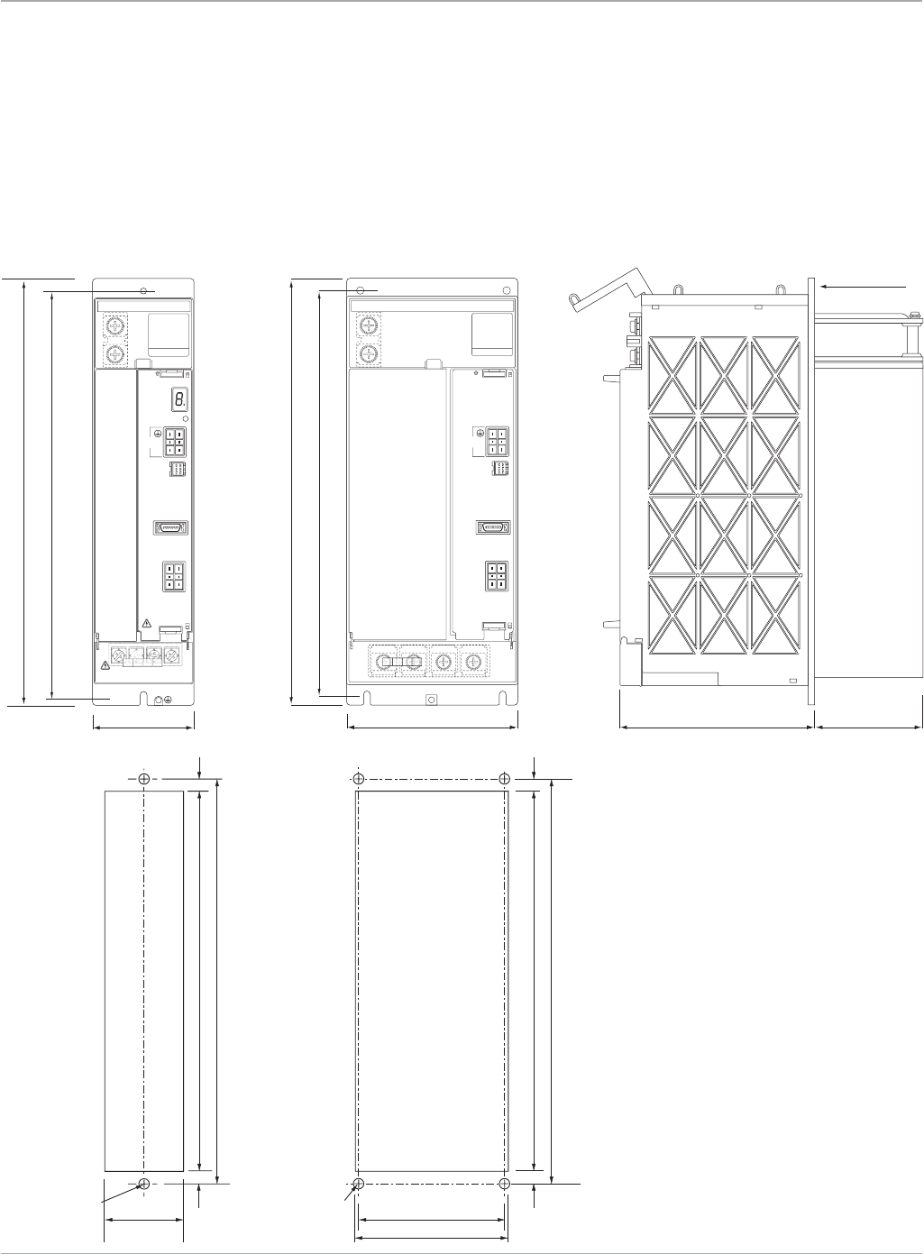
www.ge-ip.com
GE Intelligent Platforms
Motion Solutions
64
F A N UC L T D
Y a men as hi 40 1-05 97 J A P A N
FA NU C
CXA2A
AC
200-240 V
50/60 Hz
CX1A CX1B
STATUS
JX1B
CX3
MCCCX4
ESP
CAUTION
When t he LE D is lit
don’ t to uch the t ermin als.
DISCHA RGE
TIME
172 (6.77) 1 0 0 (3.94) max.
mounting flange
>
2 Mins
L1 L2 L3
3.5A
Input 1A
Output
380 (14.96)
360 (14.17)
90 (3.54)
Power Supply Dimension Drawings
αHVi Series Servo Amplifiers and Power Supplies
Dimensions
Servo Amplifiers
Front view of
PSM-11HVi and
PSM-18HVi
Front view of
PSM-30HVi and
PSM-45HVi
Side view
F A NU C
380 (14.96)
360 (14.17)
172 (6.77)
150 (5.90) 1 0 0 (3.94) max.
mounting flange
CXA2A
AC
200-240 V
50/60 Hz
CX1A CX1B
STATUS
JX1B
CX3
MCCCX4
ESP
CAUTION
When t he LE D is lit
don’t touch the termi nals.
DISCH ARGE
TIME
>
2 Min s
L1 L2 L3
3.5A
Input 1A
Output
F A N UC L T D
Y a men as hi 40 1-05 97 J A P A N
338 (13.31) 11
11
11
11
11
11
46 (1.81) 7 6 (2.99) 130 (5. 1 2)
136 (5.35)
360 (14.17) (0.43)
(0.43)
(0.43)
338 (13.31)
360 (14.17)
338 (13.31)
360 (14.17)
2-M5 2-M5 4-M5
(0.43)
(0.43)
(0.43)
338 (13.31) 11
11
11
11
11
11
46 (1.81) 7 6 (2.99) 130 (5. 1 2)
136 (5.35)
360 (14.17) (0.43)
(0.43)
(0.43)
338 (13.31)
360 (14.17)
338 (13.31)
360 (14.17)
2-M5 2-M5 4-M5
(0.43)
(0.43)
(0.43)
Panel cut-out for
PSM-11HVi and
PSM-18HVi
Panel cut-out for
PSM-30HVi and
PSM-45HVi
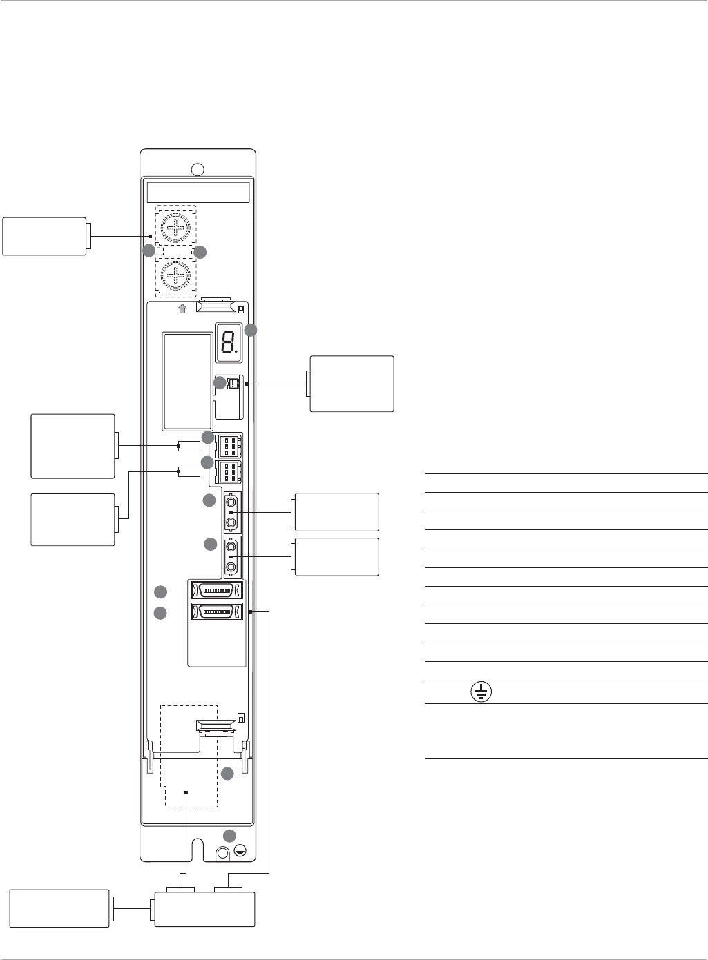
www.ge-ip.com GE Intelligent Platforms 65
Motion Solutions
αHVi Series Servo Amplifiers and Power Supplies
αSVM1-10HVi, αSVM1-40HVi, αSVM1-80HVi Connection Diagram
Servo Amplifiers
No. Name Remarks
1 DClinkterminalblock
2 DClinkchargeLED
3 STATUS StatusLED
4 CX5X Absoluteencoderbatteryinput
5 CXA2B InputconnectorforPSMinterface
6 CXA2A OutputconnectorforPSMinterface
7 COP10B Fiberopticservocommandinput
8 COP10A Fiberopticservocommandoutput
9 JX5 Noconnection
10 ENC1/JF1 Serialencoderfeedback
11 CZ2 Motorpowerconnector
12 Tapped hole for grounding the amplifier
FANUC
ENCODER
BATTERY
CXA2B
CX5X
STATUS
BATTERY
CXA2A
COP10B
COP10A
JX5
ENC1
JF1
CAUTION
HIGHVOLT A GE
DISCHARGE
TIME
>
2 min
1
3
4
5
6
7
8
9
10
11
12
2
DC Link connection
between amplifiers
and power supply
Fiber optic cable
to DSM324i
Motion Controller
Fiber optic
command to
next amplifier
Amplifier mounted
battery for Serial
Encoder Backup.
(See note 3)
IC800ABK002
E-stop, 24VDC and
serial encoder battery
input from previous
amplifier or
power supply
E-stop, 24VDC and
serial encoder
battery output to
next amplifier
Optional 24V power
for motor brake
(See note 2)
power encoder
αHVi or αHVis
series motor
Notes:
1. Always install the circuit breakers, magnetic con-
tactor,andAClinefilter.
2.Usearegulated24VDCpowersupplyforthe
amplifier.24VDCpowersupplyfortheamplifier
and power supply for the motor brake cannot
be shared.
3.TheIC800ABK001encoderbatterypackmounts
separately on the panel and can power up to 4
axes.Alternatively,theIC800ABK0021-axislithium
battery can be snapped onto each amplifier.
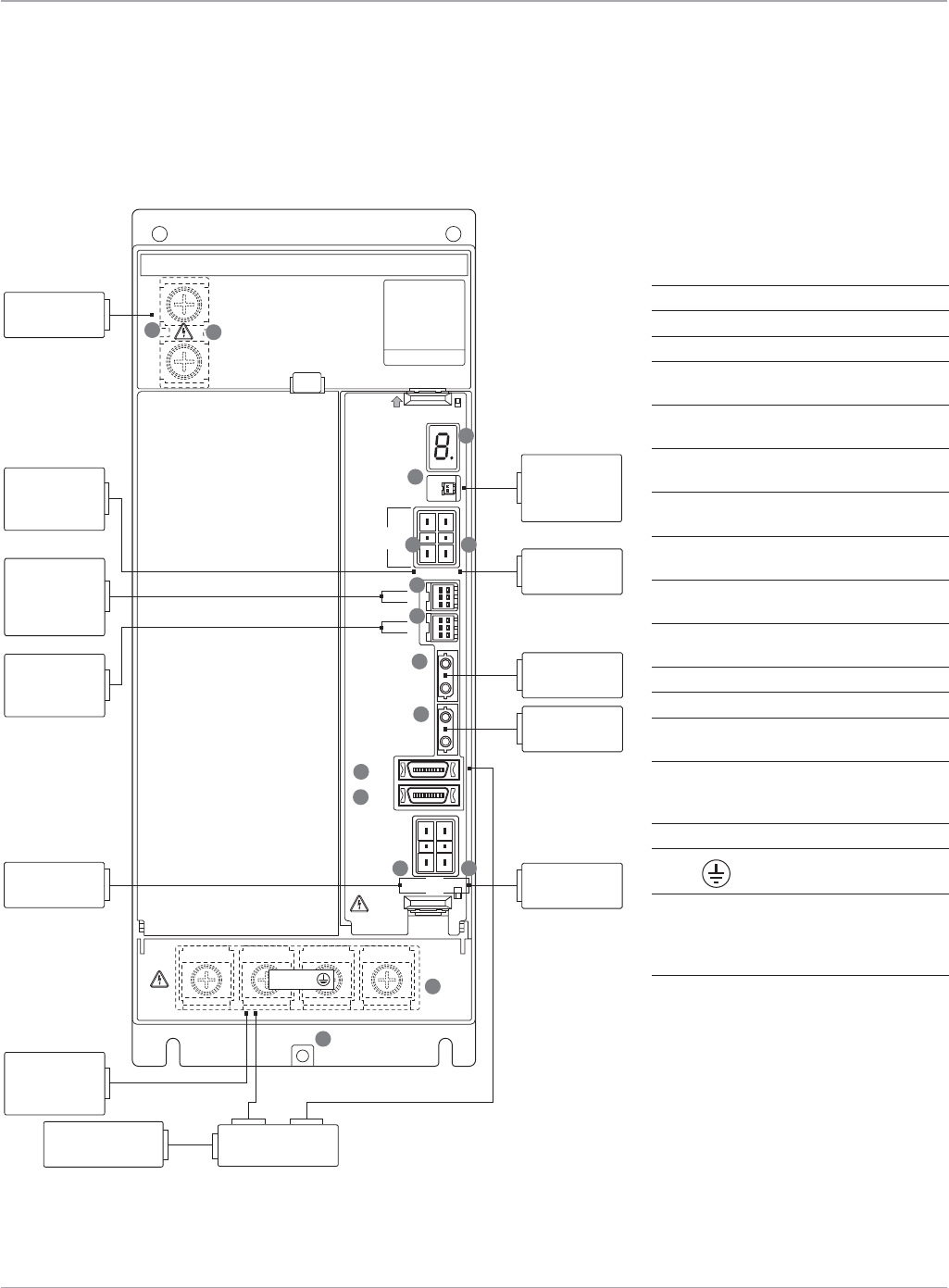
www.ge-ip.com
GE Intelligent Platforms
Motion Solutions
66
αHVi Series Servo Amplifiers and Power Supplies
αSVM1-180HVi, Connection Diagram
Servo Amplifiers
F A NUC
CXA2B
AC
200-240 V
50/60 Hz
CX5X
CX1A CX1B
STATUS
CXA2A
COP10B
COP10A
JX5
ENC1
JF1
CX8
DBI CX9
DBC
CAUTION
When the LED is lit
don’t touch t he terminals.
DISCHARG E
TIME >2 Mins
U V W
F A NUC L T D
Y a men ashi 401-059 7 JA P A N
4
5 6
7
8
9
10
11
12
15
1413
16
1
2
3
DC Link connection
between amplifiers
and power supply
Dynamic brake
module interface
(T2 on DBM)
Amplifier mounted
battery for serial
encoder backup.
(See note 3)
IC800ABK003
Fiber optic cable
to DSM324i
motion controller
200VAC input from
power supply
module CX1A
Dynamic brake
module MCC coil
control (T2 on DBM)
Fiber optic
command to
next amplifier
E-stop, 24VDC and
serial encoder battery
input from previous
amplifier or
power supply
E-stop, 24VDC and
serial encoder
battery output to
next amplifier
200VAC output to
dynamic brake
module (DBM)
terminal block T2
Optional 24V power
for motor brake
(See note 2)
power encoder
αHVi or αHVis
series motor
To motor power
terminal block T1
on Dynamic
brake module
Dynamic brake
module MCC coil
control (T2 on DBM)
No. Name Remarks
1 DClinkterminalblock
2 DClinkchargeLED
3 STATUS StatusLED
4 CX5X Absolute
encoder battery input
5 CX1A 200VACpowersupply
output connector
6 CX1B 200VACpowersupply
input connector
7 CXA2B Inputconnectorfor
PSM interface
8 CXA2A Outputconnectorfor
PSM interface
9 COP10B Fiberopticservo
command input
10 COP10A Fiberopticservo
command output
11 JX5 Noconnection
12 ENC1/JF1 Serialencoderfeedback
13 CX8 Dynamicbrakemodule
interface connector
14 CX9 Connectorforthemagnetic
contactor(MCC)drivecoil
of the dynamic brake module
15 TB2 Motorpowerconnector
16 Tapped hole for grounding
the amplifier
Notes:
1. Always install the circuit breakers, mag-
neticcontactor,andAClinefilter.
2.Usearegulated24VDCpowersupply
fortheamplifier.24VDCpowersupply
for the amplifier and power supply for
the motor brake cannot be shared.
3.TheIC800ABK001encoderbatterypack
mounts separately on the panel and
canpowerupto4axes.Alternatively,
theIC800ABK0031-axislithiumbattery
can be snapped onto each amplifier.
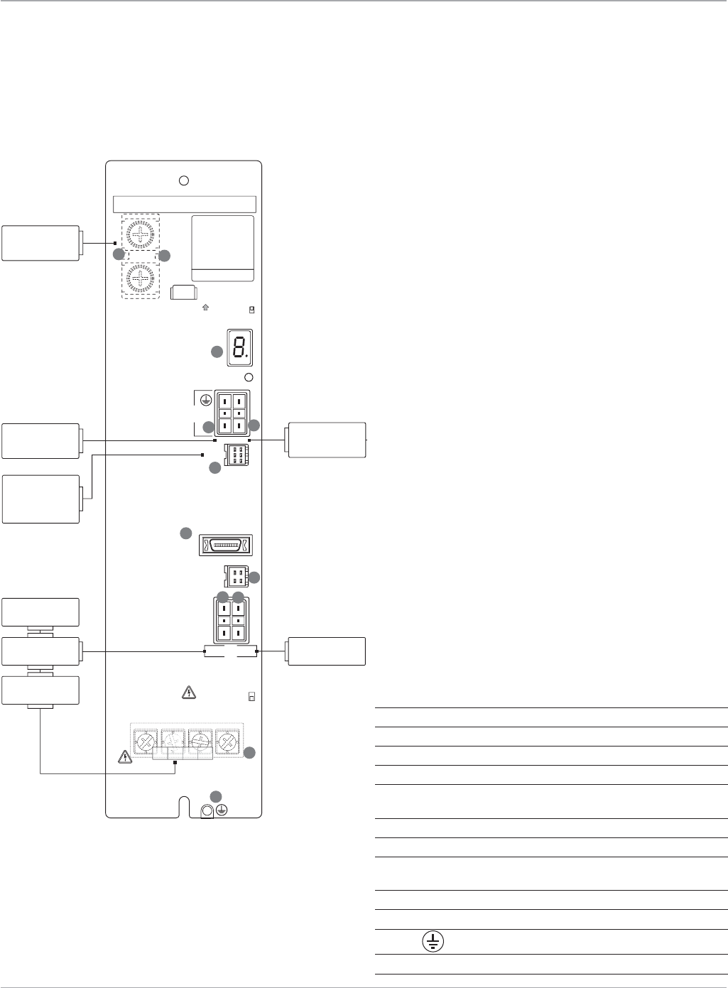
www.ge-ip.com GE Intelligent Platforms 67
Motion Solutions
αHVi Series Servo Amplifiers and Power Supplies
PSM-HVi Power Supply Connection Diagram
Servo Amplifiers
No. Name Remarks
1 DClinkterminalblock
2 DClinkchargeLED
3 STATUS StatusLED
4 CX1A 200VACpowersupplyinputconnector
5 CX1B 200VACpowersupplyoutputconnector
(used with αSVM1-180HVi only)
6 CXA2A OutputconnectorforPSMinterface
7 JX1B Notused
8 CX3 Connectorforthemainmagneticcontactor(MCC)
drive coil control signal
9 CX4 ConnectorforESPsignal
10 TB2 TerminalblockformainACpowerline
11 Tapped hole for grounding the power supply
12 CX37 Powerfailuredetectionoutput
FANUC L T D
Yame nashi 401-05 97 J A P A N
FANUC
CXA2A
AC
200-240 V
50/60 Hz
CX1A CX1B
STATUS
JX1B
CX37
CX3
MCCCX4
ESP
CAUTION
When the LED is lit
don’t touch t he terminals.
DISCHARG E
TIME >2 Mins
L1 L2 L3
45
6
7
11
10
9
12
8
1
2
3
3.5A
Input 1A
Output
DC Link connection
to amplifiers
Magnetic
Contactor
E-stop contact input
from machine
Circuit
Breaker
AC Line
Filter
200–240VAC 1φ
output to
αSVM1-180HVi only
E-stop, 24VDC and
serial encoder
battery output
to amplifiers
200–240VAC 1φ
Control Power
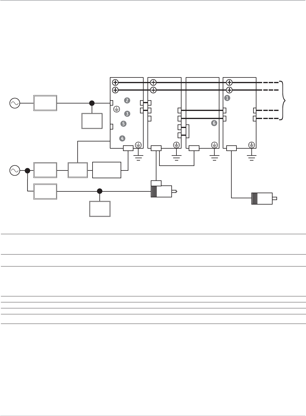
www.ge-ip.com
GE Intelligent Platforms
Motion Solutions
68
αHVi Series Servo Amplifiers and Power Supplies
αHVi System Connections
Notes:
1.PowersupplyandamplifierkitsincludeappropriatelengthDClinkbusbars.
2.ThepowersupplyconnectorkitincludedwithallpowersupplymodulekitsincludesconnectorsforCX1A,CX3andCX4.Each
αSVM1-180HViamplifierkitincludestwooftheCX1A/Bconnectorstojumperthe200VACsinglephasepowerfromthepower
supply module.
3.ThePSMinterfaceonconnectorsCXA2A/Bsupplies24VDCpowerfromthePSMpowersupplymoduletotheconnectedamplifiers.
Additionally, this interface allows shared signals such as system emergency stop and battery backup for the motor serial encod-
ers.Connectorsareincludedintheamplifierandpowersupplykits.Prefabricatedcablesarealsoavailable.Selectthecorrectcable
based on the battery type used to backup the motor serial encoder feedback for absolute positioning.
4. Position of dynamic brake module is for reference only. Normally this module is mounted above or below the amplifiers or at
theendofthemodulelineupsothatthestandardDClinkbusbarlengthisadequatetomakethelinkconnectionbetween
adjacentamplifiers.
No. Name Remarks Part Numbers
1 DCLinkBusBars 30,60or90mmlongbarkitsavailablebasedonwidthofmodule1 60mmkit:Z44A718031-G05
90mmkit:Z44A718031-G03
150mmkit:Z44A718031-G12
2 CX1A/CX1B 200VAC1phasecontrolpowerunit2 ZA06B-6071-K203(PSMconnectorkit)
ZA02B-0120-K321(2requiredforαSVM1-180HVi only)
3 CXA2A/CXA2B Output/inputconnectorsforPSMinterface3 ZA06B-6110-K210(connector:2required)
Z44C746453-001(200mmcableforshared
encoder battery)
Z44C746453-002(200mmcableforbuilt-in
encoder battery or no battery backup)
4 CX3 Connectorformainmagneticcontactor(MCC)controlsignal2 ZA06B-6071-K203(PSMconnectorkit)
5 CX4 E-Stopsignalconnector2 ZA06B-6071-K203(PSMconnectorkit)
6 COP10A/COP10B Fiberopticcommandcable Seepage17forcableoptions
PSM-HVi
Power Supply
Module
αSVM1-180HVi
Servo Amplifier
Module
Dynamic Brake
Module
αSVM1-80HVi
Servo Amplifier
Module
Circuit
Breaker 2
Circuit
Breaker 1
Main Power
400 to 480 VAC 3φ
Control Power
200 to 240 VAC 1φ
Magnetic
Contactor AC Reactor
Servo Motor
CX1A
CX4
TB2 TB2 T1 CZ2
CX3
MCC
CX1B CX1A
DC Link
Bus Bars
CXA2A CXA2B
COP10A
CXA2A CXA2B
To Additional
Amplifiers
CXA2A
Servo Motor
α50HVis
3φ Fan Motor
Circuit
Breaker 3
Lightning
Surge
Protector
Lightning
Surge
Protector
file name: aHViSystemconnection.epsfile name: aHViSystemconnection.eps
3φ
1φ
COP10B COP10B
CX8
T2
CX9
COP10A
Servo Amplifiers
(Note 4)

www.ge-ip.com GE Intelligent Platforms 69
Motion Solutions
Servo Amplifiers
The αHViseriesamplifiersandPSM-HVi power supply modules
can be ordered as individual components or as kits that include
connectors,sparefuses,andDClinkbusbars.Thekitsare
recommended for new installations while spare parts and
replacement units should use the part number for the amplifier
or power supply module. To place an order for a complete
system, select the servo motor(s) that meet your application
requirements, then select the amplifier kit(s), power supply kit,
cables, connectors and accessories.
αHVi Amplifier Kits
αHVi Series Servo Amplifiers and Power Supplies
Ordering Information
Part Number Kit Description Qty. Kit Contents
IC800AIHV010 10AmpαHVi Series Amplifier Package 1 αSVM1-10HViFSSBAmplifier(ZA06B-6127-H102)
1 SVMSpareControlPowerFuse(ZA06B-6073-K250)
2 CXA2A/BConnector(ZA06B-6110-K210)
1 CZ2MotorPowerOutputConnector(ZA06B-6110-K203#ZZM)
1 BusBarKitfor60mmModule(Z44A718031-G05)
IC800AIHV040 40AmpαHVi Series Amplifier Package 1 αSVM1-40HViFSSBAmplifier(ZA06B-6127-H104)
1 SVMSpareControlPowerFuse(ZA06B-6073-K250)
2 CXA2A/BConnector(ZA06B-6110-K210)
1 CZ2MotorPowerOutputConnector(ZA06B-6110-K203#ZZM)
1 BusBarKitfor60mmModule(Z44A718031-G05)
IC800AIHV080 80AmpαHVi Series Amplifier Package 1 αSVM1-80HViFSSBAmplifier(ZA06B-6127-H105)
1 SVMSpareControlPowerFuse(ZA06B-6073-K250)
2 CXA2A/BConnector(ZA06B-6110-K210)
1 CZ2MotorPowerOutputConnector(ZA06B-6110-K203#ZZM)
1 BusBarKitfor60mmModule(Z44A718031-G05)
IC800AIHV180 180AmpαHVi Series Amplifier Package 1 αSVM1-180HViFSSBAmplifier(ZA06B-6127-H106)
1 SVMSpareControlPowerFuse(ZA06B-6073-K250)
2 CXA2A/BConnector(ZA06B-6110-K210)
1 CX8/CX9DBModuleInterfaceConnectorKit(ZA06B-6073-K216)
1 BusBarKitfor150mmModule(Z44A718031-G12)
2 CX1A/BControlPowerConnectorKit(ZA02B-0120-K321)
PSM-HVi Power Supply Kits
Part Number Kit Description Qty. Kit Contents
IC800PSHV011 11kWPowerSupplyModulePackage 1 PSM-11HVi 11kWHVPowerSupplyModule(ZA06B-6150-H011)
1 SpareControlPowerFuse(ZA06B-6077-K250)
1 BusBarKitfor90mmModule(Z44A718031-G03)
1 PowerSupplyConnectorKit(ZA06B-6071-K203)
IC800PSHV018 18kWPowerSupplyModulePackage 1 PSM-18HVi18kWHVPowerSupplyModule(ZA06B-6150-H018)
1 SpareControlPowerFuse(ZA06B-6077-K250)
1 BusBarKitfor90mmModule(Z44A718031-G03)
1 PowerSupplyConnectorKit(ZA06B-6071-K203)
IC800PSHV030 30kWPowerSupplyModulePackage 1 PSM-30HVi30kWHVPowerSupplyModule(ZA06B-6150-H030)
1 SpareControlPowerFuse(ZA06B-6077-K250)
1 BusBarKitfor150mmModule(Z44A718031-G12)
1 PowerSupplyConnectorKit(ZA06B-6071-K203)
IC800PSHV045 45kWPowerSupplyModulePackage 1 PSM-45HVi45kWHVPowerSupplyModule(ZA06B-6150-H045)
1 SpareControlPowerFuse(ZA06B-6077-K250)
1 BusBarKitfor150mmModule(Z44A718031-G12)
1 PowerSupplyConnectorKit(ZA06B-6071-K203)
The αHViseriesamplifiersuseaseparatelymountedsharedpowersupplyforoneormoreaxes.Thesepowersuppliescan
regenerateenergybacktotheAClinesonoregenerativeresistorsormodulesarerequired.

www.ge-ip.com
GE Intelligent Platforms
Motion Solutions
70
Servo Amplifiers
αHVi Series Amplifier and Motor
Ordering Information
Motor Model α2/6000HVis α4/5000HVis α8/6000HVis
MotorPartNumber ZA06B-0219-B200 ZA06B-0216-B200 ZA06B-0233-B200
Motor/BrakePartNumber ZA06B-0219-B500 ZA06B-0216-B500 ZA06B-0233-B500
BetaAmplifierModel βSVM1-10HVi βSVM1-10HVi βSVM1-40HVi
BetaAmplifierPartNumber ZA06B-6131-H001 ZA06B-6131-H001 ZA06B-6131-H003
BetaAmplifierFanKit(Note1) n/a n/a ZA06B-6134-K002
BetaAmplifierKit IC800BIHV010 IC800BIHV010 IC800BIHV040
Alpha Amplifier Model αSVM1-10HVi αSVM1-10HVi αSVM1-40HVi
AlphaAmplifierPartNumber ZA06B-6127-H102 ZA06B-6127-H102 ZA06B-6127-H104
AlphaAmplifierKit IC800AIHV010 IC800AIHV010 IC800AIHV040
Cables α2/6000HVis α4/5000HVi α8/6000HVis
PowerCable 7M CP2I-0WPB-0070-AZ CP2I-0WPB-0070-AZ CP3I-0WPB-0070-AZ
14M CP2I-0WPB-0140-AZ CP2I-0WPB-0140-AZ CP3I-0WPB-0140-AZ
PowerCable 7M CP2I-0WEB-0070-AZ CP2I-0WEB-0070-AZ CP3I-0WEB-0070-AZ
(Shielded) 14M CP2I-0WEB-0140-AZ CP2I-0WEB-0140-AZ CP3I-0WEB-0140-AZ
FeedbackCable 7M CFDA-3WPB-0070-AZ CFDA-3WPB-0070-AZ CFDA-3WPB-0070-AZ
(RightAngle) 14M CFDA-3WPB-0140-AZ CFDA-3WPB-0140-AZ CFDA-3WPB-0140-AZ
FeedbackCable 7M CFDA-0WPB-0070-AZ CFDA-0WPB-0070-AZ CFDA-0WPB-0070-AZ
(Straight) 14M CFDA-0WPB-0140-AZ CFDA-0WPB-0140-AZ CFDA-0WPB-0140-AZ
BrakePowerCable 7M
Integratedwithpowercable Integratedwithpowercable
CB4N-0WPM-0070-AZ
14 M
Integratedwithpowercable Integratedwithpowercable
CB4N-0WPM-0140-AZ
PSMInterfaceCable(ExternalBattery) 200mm Z44C746453-001 Z44C746453-001 Z44C746453-001
PSMInterfaceCable(Built-inorNoBattery) 200mm Z44C746453-002 Z44C746453-002 Z44C746453-002
FiberOpticCommandCable 15CM ZA66L-6001-0023#L150R0
30CM ZA66L-6001-0023#L300R0
1M ZA66L-6001-0023#L1R003
2M ZA66L-6001-0023#L2R003
3M ZA66L-6001-0023#L3R003
FiberOpticCable(Sheathed) 1M ZA66L-6001-0026#L1R003
3M ZA66L-6001-0026#L3R003
5M ZA66L-6001-0026#L5R003
10M ZA66L-6001-0026#L10R03
20M ZA66L-6001-0026#L20R03
30M ZA66L-6001-0026#L30R03
50M ZA66L-6001-0026#L50R03
100M ZA66L-6001-0026#L100R3
Connector Kits α2/6000HVis α4/5000HVi α8/6000HVis
EncoderFeedbackConnector(JF1) ZA06B-6073-K214 ZA06B-6073-K214 ZA06B-6073-K214
CXA2A/BJumperConnector(2Req) ZA06B-6110-K210 ZA06B-6110-K210 ZA06B-6110-K210
CZ2MotorPowerOutputConnector ZA06B-6110-K203#ZZM ZA06B-6110-K203#ZZM ZA06B-6110-K203#ZZM
MotorHalfKeys Z44A730465-001 Z44A730465-016 Z44A730465-002
MotorFeedbackConnectorKit 90Deg ZA06B-6114-K204#E ZA06B-6114-K204#E ZA06B-6114-K204#E
Straight ZA06B-6114-K204#S ZA06B-6114-K204#S ZA06B-6114-K204#S
MotorPower/BrakeConnectorKit 90Deg ZA06B-6114-K220#E ZA06B-6114-K220#E n/a
Straight ZA06B-6114-K220#S ZA06B-6114-K220#S n/a
MotorPowerConnectorKit 90Deg n/a n/a Z44A730464-G18
Straight n/a n/a Z44A730464-G17
MotorBrakeConnectorKit 90Deg ZA06B-6114-K213#E ZA06B-6114-K213#E ZA06B-6114-K213#E
Straight ZA06B-6114-K213#S ZA06B-6114-K213#S ZA06B-6114-K213#S
Accessories α2/6000HVis α4/5000HVi α8/6000HVis
DCLinkBusBars Z44A718031-G05 Z44A718031-G05 Z44A718031-G05
SpareAmplifierControlPowerFuse ZA06B-6073-K250 ZA06B-6073-K250 ZA06B-6073-K250
EncoderBatteryBack-up(Multi-AxisPanelMountedKit)
(Note 2)
IC800ABK001 IC800ABK001 IC800ABK001
EncoderBatteryBack-up(Single-AxisBuilt-in)
(Note 2)
IC800ABK002 IC800ABK002 IC800ABK002
1) Separate user installed cooling fan is only required for the
β
SVM1-40HViamplifier.ThisfankitisincludedintheIC800BIHV040amplifierkitbutmustbeseparatelyorderedwhentheZA06B-6131-H003
amplifier is ordered.
2)Contentsofencoderbatterykitsisshownonpage78

www.ge-ip.com GE Intelligent Platforms 71
Motion Solutions
Servo Amplifiers
αHVi Series Amplifier and Motor
Ordering Information
Motor Model α12/4000HVis α22/3000HVi α22/4000HVis
MotorPartNumber ZA06B-0239-B200 ZA06B-0249-B200 ZA06B-0266-B200
Motor/BrakePartNumber ZA06B-0239-B500 ZA06B-0249-B500 ZA06B-0266-B500
BetaAmplifierModel βSVM1-40HVi βSVM1-40HVi n/a
BetaAmplifierPartNumber ZA06B-6131-H003 ZA06B-6131-H003 n/a
BetaAmplifierFanKit(Note1) ZA06B-6134-K002 ZA06B-6134-K002 n/a
BetaAmplifierKit IC800BIHV040 IC800BIHV040 n/a
Alpha Amplifier Model αSVM1-40HVi αSVM1-40HVi αSVM1-80HVi
AlphaAmplifierPartNumber ZA06B-6127-H104 ZA06B-6127-H104 ZA06B-6127-H105
AlphaAmplifierKit IC800AIHV040 IC800AIHV040 IC800AIHV080
Cables α12/4000HVis α22/3000HVi α22/4000HVis
PowerCable 7M CP3I-0WPB-0070-AZ CP4I-0WPB-0070-AZ CP4I-0WPB-0070-AZ
14M CP3I-0WPB-0140-AZ CP4I-0WPB-0140-AZ CP4I-0WPB-0140-AZ
PowerCable 7M CP3I-0WEB-0070-AZ CP4I-0WEB-0070-AZ CP4I-0WEB-0070-AZ
(Shielded) 14M CP3I-0WEB-0140-AZ CP4I-0WEB-0140-AZ CP4I-0WEB-0140-AZ
FeedbackCable 7M CFDA-3WPB-0070-AZ CFDA-3WPB-0070-AZ CFDA-3WPB-0070-AZ
(RightAngle) 14M CFDA-3WPB-0140-AZ CFDA-3WPB-0140-AZ CFDA-3WPB-0140-AZ
FeedbackCable 7M CFDA-0WPB-0070-AZ CFDA-0WPB-0070-AZ CFDA-0WPB-0070-AZ
(Straight) 14M CFDA-0WPB-0140-AZ CFDA-0WPB-0140-AZ CFDA-0WPB-0140-AZ
BrakePowerCable 7M CB4N-0WPM-0070-AZ CB4N-0WPM-0070-AZ CB4N-0WPM-0070-AZ
14M CB4N-0WPM-0140-AZ CB4N-0WPM-0140-AZ CB4N-0WPM-0140-AZ
PSMInterfaceCable(ExternalBattery) 200mm Z44C746453-001 Z44C746453-001 Z44C746453-001
PSMInterfaceCable(Built-inorNoBattery) 200mm Z44C746453-002 Z44C746453-002 Z44C746453-002
FiberOpticCommandCable 15CM ZA66L-6001-0023#L150R0
30CM ZA66L-6001-0023#L300R0
1M ZA66L-6001-0023#L1R003
2M ZA66L-6001-0023#L2R003
3M ZA66L-6001-0023#L3R003
FiberOpticCable(Sheathed) 1M ZA66L-6001-0026#L1R003
3M ZA66L-6001-0026#L3R003
5M ZA66L-6001-0026#L5R003
10M ZA66L-6001-0026#L10R03
20M ZA66L-6001-0026#L20R03
30M ZA66L-6001-0026#L30R03
50M ZA66L-6001-0026#L50R03
100M ZA66L-6001-0026#L100R3
Connector Kits α12/4000HVis α22/3000HVi α22/4000HVis
EncoderFeedbackConnector(JF1) ZA06B-6073-K214 ZA06B-6073-K214 ZA06B-6073-K214
CXA2A/BJumperConnector(2Req) ZA06B-6110-K210 ZA06B-6110-K210 ZA06B-6110-K210
CZ2MotorPowerOutputConnector ZA06B-6110-K203#ZZM ZA06B-6110-K203#ZZM ZA06B-6110-K203#ZZM
MotorHalfKeys Z44A730465-015 Z44A730465-003 Z44A730465-003
MotorFeedbackConnectorKit 90Deg ZA06B-6114-K204#E ZA06B-6114-K204#E ZA06B-6114-K204#E
Straight ZA06B-6114-K204#S ZA06B-6114-K204#S ZA06B-6114-K204#S
MotorPowerConnectorKit 90Deg Z44A730464-G18 Z44A730464-G20 Z44A730464-G20
Straight Z44A730464-G17 Z44A730464-G19 Z44A730464-G19
MotorBrakeConnectorKit 90Deg ZA06B-6114-K213#E ZA06B-6114-K213#E ZA06B-6114-K213#E
Straight ZA06B-6114-K213#S ZA06B-6114-K213#S ZA06B-6114-K213#S
Accessories α12/4000HVis α22/3000HVi α22/4000HVis
DCLinkBusBars Z44A718031-G05 Z44A718031-G05 Z44A718031-G05
SpareAmplifierControlPowerFuse ZA06B-6073-K250 ZA06B-6073-K250 ZA06B-6073-K250
EncoderBatteryBack-up(Multi-AxisPanelMountedKit)
(Note 2)
IC800ABK001 IC800ABK001 IC800ABK001
EncoderBatteryBack-up(Single-AxisBuilt-in)
(Note 2)
IC800ABK002 IC800ABK002 IC800ABK002
1) Separate user installed cooling fan is only required for the
β
SVM1-40HViamplifier.ThisfankitisincludedintheIC800BIHV040amplifierkitbutmustbeseparatelyorderedwhentheZA06B-6131-H003
amplifier is ordered.
2)Contentsofencoderbatterykitsisshownonpage78

www.ge-ip.com
GE Intelligent Platforms
Motion Solutions
72
αHVi Series Amplifier and Motor
Ordering Information (continued)
Motor Model α30/4000HVis α40/4000HVis α50/3000HVis w/ Fan
MotorPartNumber ZA06B-0269-B200 ZA06B-0273-B200 ZA06B-0276-B210
Motor/BrakePartNumber ZA06B-0269-B500 ZA06B-0273-B500 ZA06B-0276-B510
Alpha Amplifier Model αSVM1-80HVi αSVM1-80HVi αSVM1-180HVi
AlphaAmplifierPartNumber ZA06B-6127-H105 ZA06B-6127-H105 ZA06B-6127-H106
AlphaAmplifierKit IC800AIHV080 IC800AIHV080 IC800AIHV180
DynamicBrakingModule n/a n/a ZA06B-6079-H401
Cables α30/4000HVis α40/4000HVis α50/3000HVis w/ Fan
PowerCable 7M CP4I-0WPB-0070-AZ CP4I-0WPB-0070-AZ CP9I-0MPB-0070-AZ
14M CP4I-0WPB-0140-AZ CP4I-0WPB-0140-AZ CP9I-0MPB-0140-AZ
PowerCable 7M CP4I-0WEB-0070-AZ CP4I-0WEB-0070-AZ CP9I-0MEB-0070-AZ
(Shielded) 14M CP4I-0WEB-0140-AZ CP4I-0WEB-0140-AZ CP9I-0MEB-0140-AZ
FeedbackCable 7M CFDA-3WPB-0070-AZ CFDA-3WPB-0070-AZ CFDA-3WPB-0070-AZ
(RightAngle) 14M CFDA-3WPB-0140-AZ CFDA-3WPB-0140-AZ CFDA-3WPB-0140-AZ
FeedbackCable 7M CFDA-0WPB-0070-AZ CFDA-0WPB-0070-AZ CFDA-0WPB-0070-AZ
(Straight) 14M CFDA-0WPB-0140-AZ CFDA-0WPB-0140-AZ CFDA-0WPB-0140-AZ
BrakePowerCable 7M CB4N-0WPM-0070-AZ CB4N-0WPM-0070-AZ CB4N-0WPM-0070-AZ
14M CB4N-0WPM-0140-AZ CB4N-0WPM-0140-AZ CB4N-0WPM-0140-AZ
FanCable 7M n/a n/a CB5N-0WPM-0070-AZ
14M n/a n/a CB5N-0WPM-0140-AZ
PSMInterfaceCable(ExternalBattery) 200mm Z44C746453-001 Z44C746453-001 Z44C746453-001
PSMInterfaceCable(Built-inorNoBattery) 200mm Z44C746453-002 Z44C746453-002 Z44C746453-002
FiberOpticCommandCable 15CM ZA66L-6001-0023#L150R0
30CM ZA66L-6001-0023#L300R0
1M ZA66L-6001-0023#L1R003
2M ZA66L-6001-0023#L2R003
3M ZA66L-6001-0023#L3R003
FiberOpticCable(Sheathed) 1M ZA66L-6001-0026#L1R003
3M ZA66L-6001-0026#L3R003
5M ZA66L-6001-0026#L5R003
10M ZA66L-6001-0026#L10R03
20M ZA66L-6001-0026#L20R03
30M ZA66L-6001-0026#L30R03
50M ZA66L-6001-0026#L50R03
100M ZA66L-6001-0026#L100R3
Connector Kits α30/4000HVis α40/4000HVis α50/3000HVis w/ Fan
EncoderFeedbackConnector(JF1) ZA06B-6073-K214 ZA06B-6073-K214 ZA06B-6073-K214
CXA2A/BJumperConnector(2Req) ZA06B-6110-K210 ZA06B-6110-K210 ZA06B-6110-K210
CZ2MotorPowerOutputConnector ZA06B-6110-K203#ZZM ZA06B-6110-K203#ZZM ZA06B-6110-K203#ZZM
CX8/CX9DBModuleInterfaceConnectorKit n/a n/a ZA06B-6073-K216
CX1A/B180HViAmplifierControlPower n/a n/a ZA02B-0120-K321
MotorHalfKeys Z44A730465-003 Z44A730465-003 n/a
MotorFeedbackConnectorKit 90Deg ZA06B-6114-K204#E ZA06B-6114-K204#E ZA06B-6114-K204#E
Straight ZA06B-6114-K204#S ZA06B-6114-K204#S ZA06B-6114-K204#S
MotorPowerConnectorKit 90Deg Z44A730464-G20 Z44A730464-G20 Z44A730464-G20
Straight Z44A730464-G19 Z44A730464-G19 Z44A730464-G19
MotorBrakeConnectorKit 90Deg ZA06B-6114-K213#E ZA06B-6114-K213#E ZA06B-6114-K213#E
Straight ZA06B-6114-K213#S ZA06B-6114-K213#S ZA06B-6114-K213#S
MotorFanConnectorKit 90Deg n/a n/a ZA06B-6114-K214#E
Straight n/a n/a ZA06B-6114-K214#S
Accessories α30/4000HVis α40/4000HVis α50/3000HVis w/ Fan
DCLinkBusBars Z44A718031-G05 Z44A718031-G05 Z44A718031-G12
SpareAmplifierControlPowerFuse ZA06B-6073-K250 ZA06B-6073-K250 ZA06B-6073-K250
EncoderBatteryBack-up(PanelMountedKit)
(Note 1)
IC800ABK001 IC800ABK001 IC800ABK001
EncoderBatteryBack-up(Built-in)
(Note 1)
IC800ABK002 IC800ABK002 IC800ABK003
1)Contentsofencoderbatterykitsisshownonpage78
Servo Amplifiers

www.ge-ip.com GE Intelligent Platforms 73
Motion Solutions
Servo Amplifiers
PSM-HVi Power Supply
Ordering Information
The αHVi series amplifiers use a separately mounted shared
power supply. A power supply module (PSM) can service multiple
amplifiersinamulti-axissystem.Amaximumofsixamplifiers
maybeconnectedtoonepowersupplymodule;however,the
number of amplifier may be limited by the power supply ratings.
Model Number PSM-11HVi PSM-18HVi PSM-30HVi PSM-45HVi
PowerSupplyKit IC800PSHV011 IC800PSHV018 IC800PSHV030 IC800PSHV045
PowerSupplyOnly ZA06B-6150-H011 ZA06B-6150-H018 ZA06B-6150-H030 ZA06B-6150-H045
ContinuousOutputRating 11 18 30 45
PeakOutputRating* 34 58 87 124
DCLinkBusBars Z44A718031-G03 Z44A718031-G03 Z44A718031-G12 Z44A718031-G12
Connectors and Cables
ConnectorKit(IncludesCX4 ZA06B-6071-K203 ZA06B-6071-K203 ZA06B-6071-K203 ZA06B-6071-K203
Estop,CX3MCCandCX1A
ControlPowerConnectors)
MCCCoilControlOutput 25Ft Z44C742171-001 Z44C742171-001 Z44C742171-001 Z44C742171-001
FlyingLeadCable
200VControlPowerInput 25Ft Z44C742172-001 Z44C742172-001 Z44C742172-001 Z44C742172-001
FlyingLeadCable
EstopInputFlyingLeadCable 10Ft Z44C742176-001 Z44C742176-001 Z44C742176-001 Z44C742176-001
Accessories
SpareControlPowerFuse ZA06B-6077-K250 ZA06B-6077-K250 ZA06B-6077-K250 ZA06B-6077-K250
ACLineFilter ZA81L-0001-0163 ZA81L-0001-0163 ZA81L-0001-0164 ZA81L-0001-0164
NoiseFilterforPSM ZA06B-6077-K155 ZA06B-6077-K156 ZA06B-6077-K156 ZA06B-6077-K157
(requiredforCE)
*Peak rating is for 0.3 seconds
Selecting a Power Supply
Step 1 - Determine the total number and type of αHVi or αHVisseriesmotorsthatwillberequiredfromthelistbelow.Ifmorethan
sixaxesarerequireddividethemintogroupsofnomorethansixmotors.
Motor Model Continuous Output Acceleration Output
α22/3000HVi 4.0 kW 9.6 kW
α22/4000HVis 4.5 kW 20 kW
α30/4000HVis 5.5 kW 22 kW
α40/4000HVis 5.5 kW 24 kW
α50/3000HVis with fan 14 kW 39 kW
Step 2 - Total the continuous output for all motors in a group and multiply by 0.6.
Step 3 - Total the acceleration output for all motors in each group.
Step 4-Comparethecontinuousandaccelerationoutputtotalsforeachgrouptothecontinuousratingandpeakratingforthe
powersupplymodulesandselectaPSMmoduletomeetthefollowingconditions:
a)MotorContinuousOutputTotal*0.6mustbelessthanthePSMContinuousOutputRating
b)MotorAccelerationOutputTotalmustbelessthanthePSMPeakOutputRating
Example:
Anapplicationrequiresthefollowingmotors:
Qty 2 α22/4000HVis
Qty 2 α30/4000HVis
Qty 1 α50/3000HVis with fan
Sincethetotalnumberofmotorsislessthansix,assumethatonePSMwillbeused.Therefore,thetotalratingsforthesystemare:
Total the continuous output for all motors multiplied by 0.6 = 28 kW * 0.6 = 16.8 kW
Total the acceleration output for all motors = 123 kW
SelectthePSM-45HVi module with a continuous output rating of 45 kW and peak output rating of 124 kW.
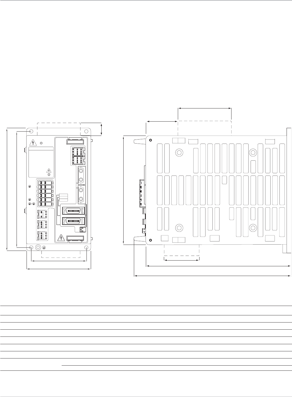
www.ge-ip.com
GE Intelligent Platforms
Motion Solutions
74
Servo Amplifiers
DISCHARGE TIME
CAUTION
HIGH
VOLTAGE
L2/L1
/L3
DCC/DCP
/W
V/U
CZ7
CX29
MCC
CX30
ESP
CXA20
DCOH
CXA19B
CXA19A
COP10B
COP10A
LED
POWER
LINK
ALM
JF1/ENC CX5X
JX5
2 min
FANUC
>
130 (5.12)
150 (5.91)
140 (5.51)
45 (1.77)
68.5 (2.70)
172 (6.77)
185 (7.31)
optional fan
optional encoder
battery case
optional encoder
battery case
56 (2.20)
62 (2.44)
75 (2.95)
17.5 (0.69)
†
βi Series Servo Amplifiers
Dimensions
The βi Series amplifiers are panel mounted devices with dimensions as shown. The βi Series amplifiers must be paired with the βis
Seriesmotors.Wheninstallingtheamplifiersmakesuretomaintainthespecifiedclearancesabove,belowandbetweenadjacent
amplifiers to allow for proper convection cooling.
Dimensions shown in mm (in).
βi Series Servo Amplifier Unit
βSVM1-20i
βi Series Servo Amplifiers Electrical Specifications
Model βSVM1-20
i
Rated output current (rms amps) 5.9
Currentlimit(Peakamps) 20
ACPower 200-240VAC(3-phase),220-240VAC(1-phase)50/60Hz±2Hz
DCControlPower 24VDC±10%@0.9Ampperamplifier
Max.Heatloss(watts) 66
Regenerativedischarge 16J
MaintenanceClearances: Aboveandbelowamplifier 40(1.57)
Besideandbetweenamplifiers 10(0.39)
*Thesevaluesarestandardvaluesat20°Cwithatoleranceof±10%.Thespeed-torquecharacteristicsvarydependingontheparametersettingandinputvoltageofthedigitalservoamplifiers.
(The above figures show average values.) These values may be changed without prior notice.
†Separately installed cooling fan required for β4ismotorwhenasinglephaseACpowersourceisusedandalwayswiththeβ8is motor.
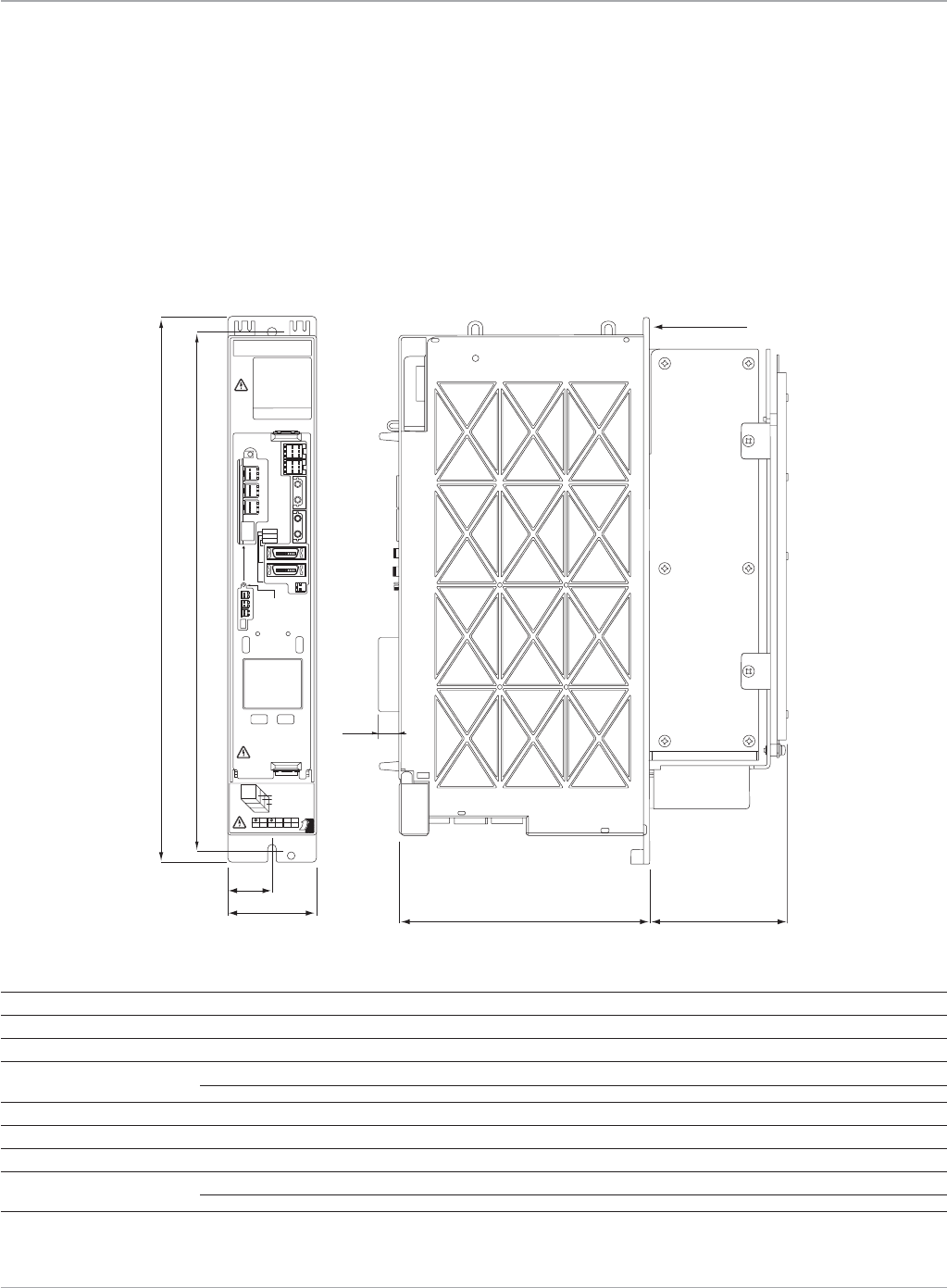
www.ge-ip.com GE Intelligent Platforms 75
Motion Solutions
Servo Amplifiers
Dimensions shown in mm (in).
CAUTION
CAUTION
HIGHVOLTAGE
DISCHAR GE
TIME
>
2 min
C24 (FRONT)
C25 (CENTER)
C26 (REAR)
FANUC
F A N UC L T D
Y a men ashi 4 01-0597 J A P A N
LED
POWER
LINK
ALM
C24 C25
CX5 X
SW
J
F1
/E
NC
C26 PULL
HERE
AL2VRI RC
L1 WU RCREL3
B
BATTERY
OPTIONAL
ENCODER
BATTERY
CASE
CX29
MCC
CX30
ESP
CXA20
DCOH
CXA19B
CXA19A
COP10B
COP10A
JX5
172 (6.77)
1 0 (0.39)
10 0 (3.94) max.
mounting flange
380 (14.96)
360 (14.17)
60 (2.36)
30 (1.18)
βi Series Servo Amplifiers
Dimensions
The βi Series amplifiers are panel mounted devices with dimensions as shown. The βi Series amplifiers must be paired with the βis
Seriesmotors.Wheninstallingtheamplifiersmakesuretomaintainthespecifiedclearancesabove,belowandbetweenadjacent
amplifiers to allow for proper convection cooling.
βi Series Servo Amplifier Unit
βSVM1-40i
βSVM1-10HVi
βSVM1-20HVi
βi Series Servo Amplifiers Electrical Specifications
Model βSVM1-40
i
βSVM1-10HV
i
βSVM1-20HV
i
Rated output current (rms amps) 12 3.1 5.6
Currentlimit(Peakamps) 40 10 20
ACPower 1-phase 220-240VAC,50/60Hz±2Hz n/a n/a
3-phase 200-240VAC,50/60Hz±2Hz 400-480VAC 400-480VAC
DCControlPower(peramplifier) 24VDC±10%@0.9Amp 24VDC±10%@0.9Amp 24VDC±10%@0.9Amp
Max.Heatloss(watts) 100 54 82
Regenerative discharge 50W 50W 50W
MaintenanceClearances: Aboveandbelowamplifier 50(1.97) 50(1.97) 50(1.97)
Besideandbetweenamplifiers n/a n/a n/a
*Thesevaluesarestandardvaluesat20°Cwithatoleranceof±10%.Thespeed-torquecharacteristicsvarydependingontheparametersettingandinputvoltageofthedigitalservoamplifiers.
(The above figures show average values.) These values may be changed without prior notice.
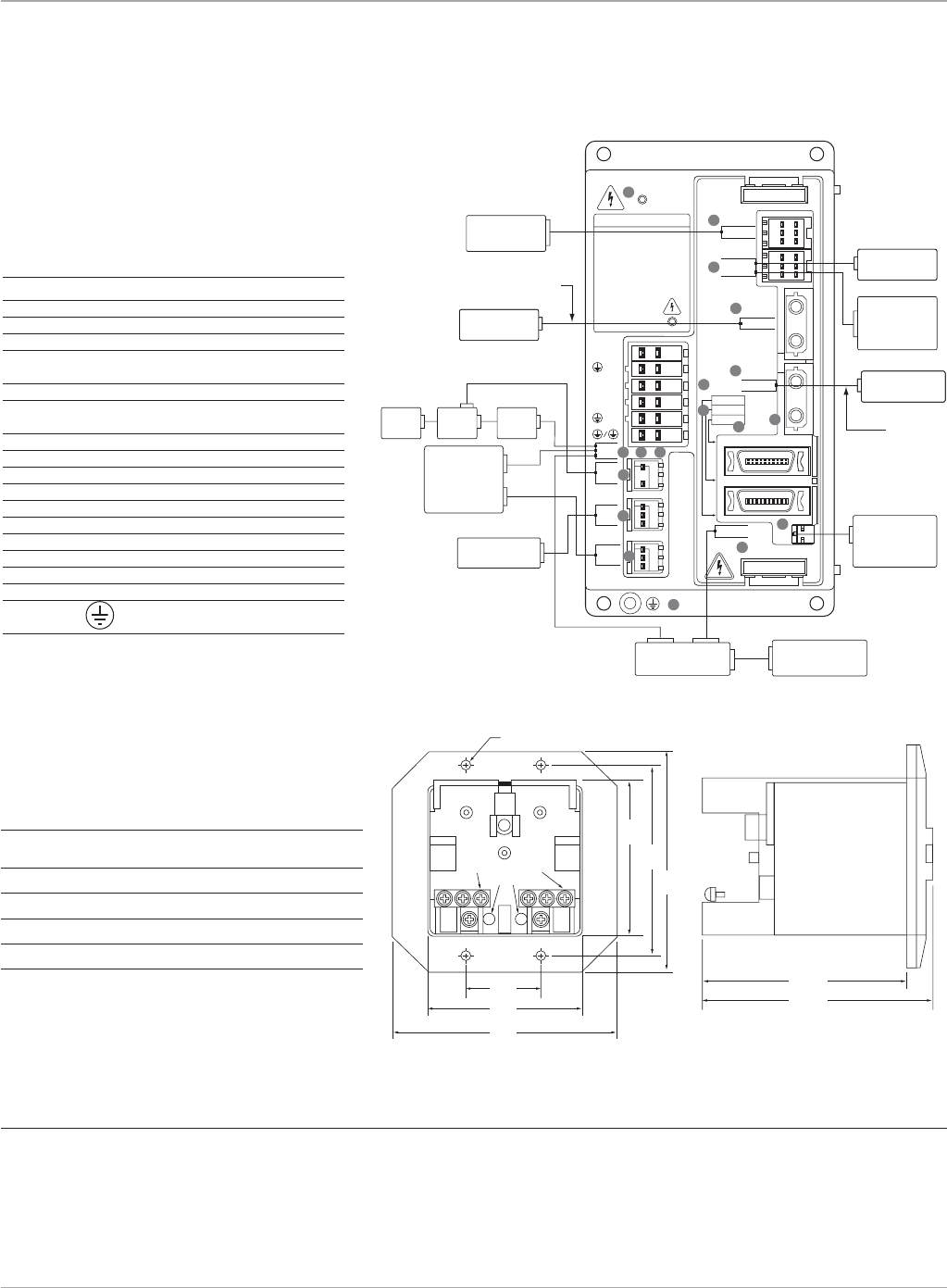
www.ge-ip.com
GE Intelligent Platforms
Motion Solutions
76
Servo Amplifiers
βi Series Servo Amplifiers
βSVM1-20i Connection Diagram
Notes:
1.Alwaysinstallthecircuitbreakers,magneticcontactor,andAClinefilter.
2.Usearegulated24VDCpowersupplyfortheamplifier.24VDCpowersupplyfortheamplifierandpowersupplyforthemotor
brake cannot be shared.
3.TheIC800ABK001encoderbatterypackmountsseparatelyonthepanelandcanpowerupto4axes.Alternatively,the
IC800BBK0211-axislithiumbatterycanbesnappedontoeachamplifier.
DISCHARGE TIME
CAUTION
HIGH
VOLTAGE
L2/L1
/L3
DCC/DCP
/W
V/U
CZ7
CX29
MCC
CX30
ESP
CXA20
DCOH
CXA19B
CXA19A
COP10B
COP10A
LED
POWER
LINK
ALM
JF1/ENC CX5X
JX5
2 min
FANUC
>
optical cable
optical fiber cable
βSVM1_20i
regulated power
supply 24 VDC
(See Note 2)
DSM324i
motion controller
AC line
filter
circuit
breaker
magnetic
contactor
discharge
resistor with
built-in thermostat
ZA06B-6130-H401
ZA06B-6130-H402
machine emergency
stop switch
E-Stop and 24 VDC
to next amplifier
fiber optic command
to next amplifier
panel mounted
battery case
(See Note 3)
IC800ABK001
1
8
9
10
11
12
15
16
18
13
14
2
5
6
7
34
power
βi Series
motor
optional 24 V power
supply for motor brake
(See Note 2)
encoder
amplifier mounted
battery case
IC800BBK021
(See Note 3)
17
Connector Location
No. Name Remarks
1 DClinkchargeLED
2 CZ7-1 Mainpowerinputconnector
3 CZ7-2 Dischargeresistorconnector
4 CZ7-3 Motorpowerconnector
5 CX29 Connectorformainpower
MCCcontrolsignal
6 CX30 E-Stopsignalconnector
7 CXA20 Regenerativeresistor
overtemperature switch connector
8 CXA19B 24VDCpowerinput
9 CXA19A 24VDCpowerinput
10 COP10B Fiberopticservocommandinput
11 COP10A Fiberopticservocommandoutput
12 ALM ServoalarmstatusLED
13 JX5 Reserved
14 LINK FiberopticlinkstatusLED
15 JF1 SerialEncoderFeedback
16 POWER ControlpowerstatusdisplayLED
17 CX5X Absoluteencoderbattery
18 Tapped hole for
grounding the amplifier
A
BC
D
+–
+
40
(1.57)
78
(3.07)
103
(4.06)
103
(4.06)
78
(3.07)
Ø4.3 (0.169) Mounting hole (x4)
93
(3.66)
92.2
(3.630)
106.3
(4.185)
DIM_aSeriesBatteryPk.eps
filename:DIM_aSeriesBatteryPk.eps
currentpageincatalog:45
source:GFH-001pg13
filename:DIM_aSeriesBatteryPk.eps
currentpageincatalog:45
source:GFH-001pg13
IC800ABK001 Absolute encoder battery pack
IC800ABK001 Encoder Battery Kit Dimensions
Key:
A 3-M3 negative terminals
B Negativeterminalindication
C Positiveterminalindication
D 3-M3 positive terminals
E 4-Ø4.3 (0.169) mounting holes
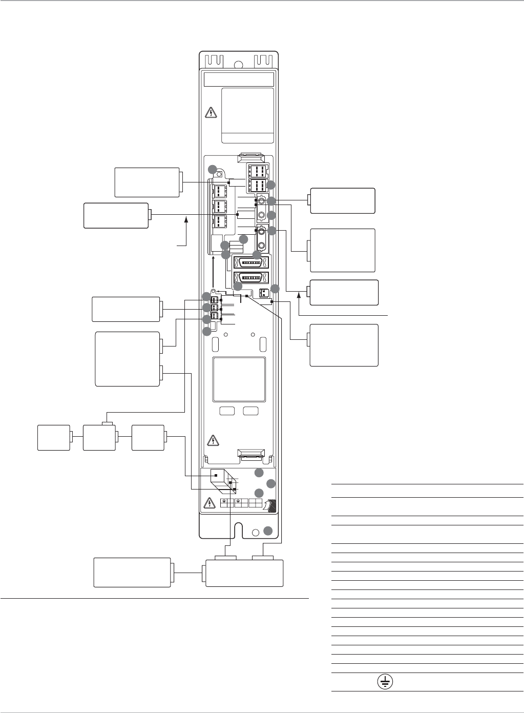
www.ge-ip.com GE Intelligent Platforms 77
Motion Solutions
Servo Amplifiers
βi Series Servo Amplifiers
βSVM1-40i Connection Diagram
βSVM1-10HVi
βSVM1-20HVi
power
optical fiber cable
regulated power
supply 24 VDC
(See Note 2)
discharge
resistor with
built-in thermostat
ZA06B-6089-H500
ZA06B-6089-H713
machine emergency
stop switch
βi Series
motor
optional 24 V power
supply for motor brake
(See Note 2)
E-Stop and 24 VDC
to next amplifier
fiber optic command
to next amplifier
panel mounted
battery case
(See Note 3)
optical cable
IC800ABK001
1
9
11
12
16 18
19
14
2
5
6
7
AC line
filter
circuit
breaker
magnetic
contactor
10
encoder
DSM324i
motion controller
amplifier mounted
battery case
IC800BBK021
(See Note 3)
3
4
CAUTION
CAUTION
HIGHVOLTAGE
DISCHARGE
TIME
>
2 min
CZ4 (FRONT)
CZ5 (CENTER)
CZ6 (REAR)
FANUC
F A NUC L T D
Y a menashi 401-0597 J APA N
LED
POWER
LINK
ALM
C24 C25
SW
JF1/ENC
C26 PULL
HERE
AL2VRI RC
L1 WU RCREL3
B
BATTERY
ENCODER
BATTERY
CX29
MCC
CX30
ESP
CXA20
DCOH
CXA19B
COP10B
COP10A
JX5
CXA19A
CX5X
13
15
17
8
Notes:
1.Alwaysinstallthecircuitbreakers,magneticcontactor,andAClinefilter.
2.Usearegulated24VDCpowersupplyfortheamplifier.24VDCpowersupply
for the amplifier and power supply for the motor brake cannot be shared.
3.TheIC800ABK001encoderbatterypackmountsseparatelyonthepaneland
canpowerupto4axes.Alternatively,theIC800BBK0211-axislithiumbat-
tery can be snapped onto each amplifier.
Connector Location
No. Name Remarks
1 DClinkchargeLED
2 CX29 Connectorformainpower
MCCcontrolsignal
3 CX30 E-Stopsignalconnector
4 CXA20 Regenerativeresistor
overtemperature switch connector
5 SW Settingswitch(DCalarmlevel)
6 CZ4 Mainpowerinputconnector
7 CZ5 Motorpowerconnector
8 CZ6 Dischargeresistorconnector
9 CXA19B 24VDCpowerinput
10 CXA19A 24VDCpowerinput
11 COP10B Fiberopticservocommandinput
12 COP10A Fiberopticservocommandoutput
13 ALM ServoalarmstatusLED
14 JX5 Reserved
15 LINK FiberopticlinkstatusLED
16 JF1 SerialEncoderFeedback
17 POWER ControlpowerstatusdisplayLED
18 CX5X Absoluteencoderbattery
19 Tapped hole for
grounding the amplifier

www.ge-ip.com
GE Intelligent Platforms
Motion Solutions
78
Servo Amplifiers
The βi series amplifiers can be ordered as individual compo-
nents or as kits that include connectors, regenerative discharge
resistor and spare fuses. The kit is recommended for new instal-
lation while spare parts, or replacement units, should use the
amplifier only model number.
To place an order for a complete servo system, select the Servo
Motor that meets your application requirements, then select the
amplifier kit, cables or connectors (customer built cables) and
accessories.
βi and βHVi Series Servo Amplifier Kits*
Part Number Qty. Kit Contents
IC800BIK020 1 βSVM1-20iAmplifier(ZA06B-6130-H002)
20 Amp βiSeriesAmplifierPackage 1 20WRegenerativeDischargeResistor(ZA06B-6130-H401)
1 Spare24VDCFuse(ZA06B-6073-K250)
1 CZ7PowerConnectorKit(ZA06B-6130-K200)
2 CXA1924VDCConnectorKit(ZA06B-6130-K201)
1 CXA20RegenerativeDischargeThermostatConnectorKit
(ZA06B-6130-K202)
1 CX29MCCConnectorKit(ZA06B-6130-K203)
1 CX30E-StopConnectorKit(ZA06B-6130-K204)
IC800BIK040 1 βSVM1-40iAmplifier(ZA06B-6130-H003)
40 Amp βiSeriesAmplifierPackage 1 Spare24VDCFuse(ZA06B-6073-K250)
1 CZ4PowerConnectorKit(ZA06B-6110-K200#XXS)
1 CZ5MotorPowerConnectorKit(ZA06B-6110-K202#YYS)
1 CZ6RegenerativeDischargeResistorConnectorKit
(ZA06B-6110-K201#XYM)
2 CXA1924VDCConnectorKit(ZA06B-6130-K201)
1 CXA20RegenerativeResistorThermostatConnectorKit(ZA06B-6130-K202)
1 CX29MCCConnectorKit(ZA06B-6130-K203)
1 CX30E-StopConnectorKit(ZA06B-6130-K204)
IC800BIHV010 1 βSVM1-10HViAmplifier(ZA06B-6131-H001)
10 Amp βHViSeriesAmplifierPackage 1 Spare24VDCFuse(ZA06B-6073-K250)
1 CZ4PowerConnectorKit(ZA06B-6110-K200#XXS)
1 CZ5MotorPowerConnectorKit(ZA06B-6110-K202#YYS)
1 CZ6RegenerativeDischargeResistorConnectorKit
(ZA06B-6110-K201#XYM)
2 CXA1924VDCConnectorKit(ZA06B-6130-K201)
1 CXA20RegenerativeResistorThermostatConnectorKit
(ZA06B-6130-K202)
1 CX29MCCConnectorKit(ZA06B-6130-K203)
1 CX30E-StopConnectorKit(ZA06B-6130-K204)
IC800BIHV020 1 βSVM1-20HViAmplifier(ZA06B-6131-H002)
20 Amp βHViSeriesAmplifierPackage 1 Spare24VDCFuse(ZA06B-6073-K250)
1 CZ4PowerConnectorKit(ZA06B-6110-K200#XXS)
1 CZ5MotorPowerConnectorKit(ZA06B-6110-K202#YYS)
1 CZ6RegenerativeDischargeResistorConnectorKit
(ZA06B-6110-K201#XYM)
2 CXA1924VDCConnectorKit(ZA06B-6130-K201)
1 CXA20RegenerativeResistorThermostatConnectorKit(ZA06B-6130-K202)
1 CX29MCCConnectorKit(ZA06B-6130-K203)
1 CX30E-StopConnectorKit(ZA06B-6130-K204)
IC800BIHV040 1 βSVM1-40HViAmplifier(ZA06B-6131-H003)
40 Amp βHViSeriesAmplifierPackage 1 Spare24VDCFuse(ZA06B-6073-K250)
1 CZ4PowerConnectorKit(ZA06B-6110-K200#XXS)
1 CZ5MotorPowerConnectorKit(ZA06B-6110-K202#YYS)
1 CZ6RegenerativeDischargeResistorConnectorKit(ZA06B-6110-K201#XYM)
2 24VDCConnectorKit(ZA06B-6130-K201CXA19)
1 CXA20RegenerativeResistorThermostatConnectorKit(ZA06B-6130-K202)
1 CX29MCCConnectorKit(ZA06B-6130-K203)
1 CX30EstopConnectorKit(ZA06B-6130-K204)
1 Amplifiercoolingfankit(ZA06B-6134-K002)
*Amplifierkitsprovidealloftherequiredamplifiercomponentsforcompleteinstallation;westronglyencouragekitsbeorderedfornew
systems. Separate amplifiers are available for spare or replacement units.
**See dimensions of battery pack on page 76
Holding Brake: For system designs which
includeaverticalaxisthatmustholdits
position when power is removed, a motor
holdingbrakeoptionisavailable.User
supplied24VDCpowerisrequired.To
connect to the power, a separate brake
cableisrequiredonallmotorsexcept
β2
i
s, β4
i
s, β2HV
i
s and β4HV
i
s models.
Encoder Battery Kit: All β
i
s Series Servo
motors feature a built-in serial encoder
that can be used in either incremental or
absolutemode.Inordertoutilizethe
absolute capability, an optional encoder
battery pack must be installed. This pack
allows the encoder’s position information
to be retained so that the machine does
not need to be referenced to a home
position every time power is restored to
the system.
The1-axisbatterypackincludesasmall
lithium battery and case which snaps on
theamplifierunit.The4-axisbatterypack
is panel mounted and uses standard
D-cell batteries.
βi Series Servo Amplifiers
Ordering Information
Battery Kits
Part Number Qty. Kit Contents
IC800BBK021 1 LithiumBattery(ZA06B-6093-K001)
1-Axisβi 1 BatteryHolder(ZA06B-6093-K002)
BatteryKit
IC800ABK001 4 D-CellAlkalineBattery
4-AxisD-Cell (ZA98L-0031-0005)
PanelMounted 1 PanelMountedBatteryPack
BatteryPack (ZA06B-6050-K060)**
IC800ABK002 1 LithiumBattery(ZA06B-6114-K504)
1-Axis
α
HVi 1 BatteryHolder(ZA06B-6114-K505)
BatteryKit
IC800ABK003 1 LithiumBattery(ZA06B-6114-K504)
1-Axis
α
HVi 1 BatteryHolder(ZA06B-6114-K506)
BatteryKitfor
α
SVM-180HVi
Amplifier

www.ge-ip.com GE Intelligent Platforms 79
Motion Solutions
Servo Amplifiers
βHVi Series Servo Amplifier and βHVis Series Servo Motor
Ordering Information
Model Number
β2/4000HVis β4/4000HVis β8/3000HVis β12/3000HVis β22/2000HVis
ServoMotor ZA06B-0062-B203 ZA06B-0064-B203 ZA06B-0076-B203 ZA06B-0079-B203 ZA06B-0086-B203
ServoMotorw/HoldingBrake ZA06B-0062-B503 ZA06B-0064-B503 ZA06B-0076-B503 ZA06B-0079-B503 ZA06B-0086-B503
AmplifierKit IC800BIHV010 IC800BIHV010 IC800BIHV010 IC800BIHV020 IC800BIHV020
AmplifierOnly ZA06B-6131-H001 ZA06B-6131-H001 ZA06B-6131-H001 ZA06B-6131-H002 ZA06B-6131-H002
Cables and Accessories Ordering Information
Model Number β2/4000HVis β4/4000HVis β8/3000HVis β12/3000HVis β22/2000HVis
PowerCable 7M CP2I-0WPB-0070-AZ CP2I-0WPB-0070-AZ CP3I-0WPB-0070-AZ CP3I-0WPB-0070-AZ CP4I-0WPB-0070-AZ
14M CP2I-0WPB-0140-AZ CP2I-0WPB-0140-AZ CP3I-0WPB-0140-AZ CP3I-0WPB-0140-AZ CP4I-0WPB-0140-AZ
PowerCable(Shielded) 7M CP2I-0WEB-0070-AZ CP2I-0WEB-0070-AZ CP3I-0WEB-0070-AZ CP3I-0WEB-0070-AZ CP4I-0WEB-0070-AZ
14M CP2I-0WEB-0140-AZ CP2I-0WEB-0140-AZ CP3I-0WEB-0140-AZ CP3I-0WEB-0140-AZ CP4I-0WEB-0140-AZ
FeedbackCable 7M CFDA-7WPB-0070-AZ CFDA-7WPB-0070-AZ CFDA-7WPB-0070-AZ CFDA-7WPB-0070-AZ CFDA-7WPB-0070-AZ
(RightAngleMotorConnector) 14M CFDA-7WPB-0140-AZ CFDA-7WPB-0140-AZ CFDA-7WPB-0140-AZ CFDA-7WPB-0140-AZ CFDA-7WPB-0140-AZ
FeedbackCable 7M CFDA-0WPB-0070-AZ CFDA-0WPB-0070-AZ CFDA-0WPB-0070-AZ CFDA-0WPB-0070-AZ CFDA-0WPB-0070-AZ
(StraightMotorConnector) 14M CFDA-0WPB-0140-AZ CFDA-0WPB-0140-AZ CFDA-0WPB-0140-AZ CFDA-0WPB-0140-AZ CFDA-0WPB-0140-AZ
HoldingBrakePowerCable 7M Integratedwith Integratedwith CB4N-0WPM-0070-AZ CB4N-0WPM-0070-AZ CB4N-0WPM-0070-AZ
14 M PowerCable PowerCable CB4N-0WPM-0140-AZ CB4N-0WPM-0140-AZ CB4N-0WPM-0140-AZ
ExternalRegenResistors ZA06B-6130-H403 ZA06B-6130-H403 ZA06B-6130-H403 ZA06B-6130-H403 ZA06B-6130-H403
CZ4PowerConnectorKit ZA06B-6110-K200#XXS ZA06B-6110-K200#XXS ZA06B-6110-K200#XXS ZA06B-6110-K200#XXS ZA06B-6110-K200#XXS
CZ5MotorPowerConnectorKit ZA06B-6110-K202#YYS ZA06B-6110-K202#YYS ZA06B-6110-K202#YYS ZA06B-6110-K202#YYS ZA06B-6110-K202#YYS
CZ6RegenResistorThermostat ZA06B-6110-K201#XYM ZA06B-6110-K201#XYM ZA06B-6110-K201#XYM ZA06B-6110-K201#XYM ZA06B-6110-K201#XYM
ConnectorKit
CXA19ConnectorKit ZA06B-6130-K201 ZA06B-6130-K201 ZA06B-6130-K201 ZA06B-6130-K201 ZA06B-6130-K201
CXA20RegenThermostat ZA06B-6130-K202 ZA06B-6130-K202 ZA06B-6130-K202 ZA06B-6130-K202 ZA06B-6130-K202
ConnectorKit
CX29MCCConnectorKit ZA06B-6130-K203 ZA06B-6130-K203 ZA06B-6130-K203 ZA06B-6130-K203 ZA06B-6130-K203
CX30EstopInputConnectorKit ZA06B-6130-K204 ZA06B-6130-K204 ZA06B-6130-K204 ZA06B-6130-K204 ZA06B-6130-K204
MotorFeedbackConnectorKit 90Deg ZA06B-6114-K204#E ZA06B-6114-K204#E ZA06B-6114-K204#E ZA06B-6114-K204#E ZA06B-6114-K204#E
Straight ZA06B-6114-K204#S ZA06B-6114-K204#S ZA06B-6114-K204#S ZA06B-6114-K204#S ZA06B-6114-K204#S
MotorHalfKey(Note 2) Z44A730465-001 Z44A730465-016 Z44A730465-002 Z44A730465-015 Z44A730465-003
MotorPower/Brake 90Deg ZA06B-6114-K220#E ZA06B-6114-K220#E N/A N/A N/A
ConnectorKit Straight ZA06B-6114-K220#S ZA06B-6114-K220#S N/A N/A N/A
MotorPowerConnectorKit 90Deg N/A N/A Z44A730464-G18 Z44A730464-G18 Z44A730464-G20
Straight N/A N/A Z44A730464-G17 Z44A730464-G17 Z44A730464-G19
MotorBrakeConnectorKit 90Deg N/A N/A ZA06B-6114-K213#E ZA06B-6114-K213#E ZA06B-6114-K213#E
Straight N/A N/A ZA06B-6114-K213#S ZA06B-6114-K213#S ZA06B-6114-K213#S
SpareControlPowerFuse ZA06B-6073-K250
EncoderBatteryKits 1axis IC800BBK021(Note 1)
4axis IC800ABK001(Note 1)
FiberopticCommandCable 15cm ZA66L-6001-0023#L150R0
1M ZA66L-6001-0023#L1R003
2M ZA66L-6001-0023#L2R003
3M ZA66L-6001-0023#L3R003
SheathedFiberopticCable 1M ZA66L-6001-0026#L1R003
5M ZA66L-6001-0026#L5R003
10M ZA66L-6001-0026#L10R03
20M ZA66L-6001-0026#L20R03
100 M
ZA66L-6001-0026#L100R3
FeedbackConnector(JF1) ZA06B-6073-K214
ACLineFilter 5.4kW ZA81L-0001-0168
10.5kW ZA81L-0001-0169
ReplacementEncoderBattery ZA06B-6093-K001(IC800BBK021kit);ZA98L-0031-0005(IC800ABK001kit)
1)TheIC800ABPK001panelmountedencoderbatterypackrequiresCXA19connectorkitforusersuppliedcable.Uses4D-cellbatteries.SeebreakdownofkitcontentsintheOrderingInformationsection.
2)HalfKeysareusedtofillthemotorshaftKeywaywhenacompressiontypecouplingisusedinordertopreservetherotationalbalanceofthemotor.

www.ge-ip.com
GE Intelligent Platforms
Motion Solutions
80
Servo Amplifiers
βi Series Servo Amplifier and βi Series Servo Motor
Ordering Information
Model Number
β0.4/5000is β0.5/6000is β1/6000is β2/4000is
ServoMotor ZA06B-0114-B203 ZA06B-0115-B203 ZA06B-0116-B203 ZA06B-0061-B203
ServoMotorw/HoldingBrake ZA06B-0114-B503 ZA06B-0115-B503 ZA06B-0116-B503 ZA06B-0061-B503
AmplifierKit IC800BIK020 IC800BIK020 IC800BIK020 IC800BIK020
AmplifierOnly ZA06B-6130-H002 ZA06B-6130-H002 ZA06B-6130-H002 ZA06B-6130-H002
Amplifier Fan Kit (Note 1) N/A N/A N/A N/A
Cables and Accessories Ordering Information
Model Number
β0.4/5000is β0.5/6000is β1/6000is β2/4000is
PowerCable 7M CP8B-1WPB-0070-AZ CP8B-1WPB-0070-AZ CP8B-1WPB-0070-AZ CP9B-0WPB-0070-AZ
14M CP8B-1WPB-0140-AZ CP8B-1WPB-0140-AZ CP8B-1WPB-0140-AZ CP9B-0WPB-0140-AZ
PowerCable(Shielded) 7M CP8B-1WEB-0070-AZ CP8B-1WEB-0070-AZ CP8B-1WEB-0070-AZ CP9B-0WEB-0070-AZ
14M CP8B-1WEB-0140-AZ CP8B-1WEB-0140-AZ CP8B-1WEB-0140-AZ CP9B-0WEB-0140-AZ
FeedbackCable(RightAnglemotorconnector)
7M CFDA-7WPB-0070-AZ CFDA-7WPB-0070-AZ CFDA-7WPB-0070-AZ CFDA-7WPB-0070-AZ
14M CFDA-7WPB-0140-AZ CFDA-7WPB-0140-AZ CFDA-7WPB-0140-AZ CFDA-7WPB-0140-AZ
FeedbackCable(Straightmotorconnector) 7M CFDA-0WPB-0070-AZ CFDA-0WPB-0070-AZ CFDA-0WPB-0070-AZ CFDA-0WPB-0070-AZ
14M CFDA-0WPB-0140-AZ CFDA-0WPB-0140-AZ CFDA-0WPB-0140-AZ CFDA-0WPB-0140-AZ
HoldingBrakePowerCable 7M CB6N-5WPM-0070-AZ CB6N-5WPM-0070-AZ CB6N-5WPM-0070-AZ IntegratedwithPowerCable
14M CB6N-5WPM-0140-AZ CB6N-5WPM-0140-AZ CB6N-5WPM-0140-AZ IntegratedwithPowerCable
ExternalRegenResistors 20W ZA06B-6130-H401 ZA06B-6130-H401 ZA06B-6130-H401 ZA06B-6130-H401
100W ZA06B-6130-H402 ZA06B-6130-H402 ZA06B-6130-H402 ZA06B-6130-H402
200 W N/A N/A N/A N/A
800 W N/A N/A N/A N/A
CZ7PowerConnectorKit ZA06B-6130-K200 ZA06B-6130-K200 ZA06B-6130-K200 ZA06B-6130-K200
CZ4PowerConnectorKit N/A N/A N/A N/A
CZ5MotorPowerConnectorKit N/A N/A N/A N/A
CZ6RegenResistorThermostatConnectorKit
N/A N/A N/A N/A
CXA1924VDCConnectorKit ZA06B-6130-K201 ZA06B-6130-K201 ZA06B-6130-K201 ZA06B-6130-K201
CXA20RegenThermostatConnectorKit ZA06B-6130-K202 ZA06B-6130-K202 ZA06B-6130-K202 ZA06B-6130-K202
CX29MCCConnectorKit ZA06B-6130-K203 ZA06B-6130-K203 ZA06B-6130-K203 ZA06B-6130-K203
CX30E-StopInputConnectorKit ZA06B-6130-K204 ZA06B-6130-K204 ZA06B-6130-K204 ZA06B-6130-K204
MotorFeedbackConnectorKit 90Deg ZA06B-6114-K204#E ZA06B-6114-K204#E ZA06B-6114-K204#E ZA06B-6114-K204#E
Straight ZA06B-6114-K204#S ZA06B-6114-K204#S ZA06B-6114-K204#S ZA06B-6114-K204#S
MotorHalfKey(Note 3) Z44A730465-013 Z44A730465-013 Z44A730465-011 Z44A730465-001
MotorPower/BrakeConnectorKit 90Deg N/A N/A N/A ZA06B-6114-K220#E
Straight N/A N/A N/A ZA06B-6114-K220#S
MotorPowerConnectorKit 90Deg ZA06B-6114-K230#E ZA06B-6114-K230#E ZA06B-6114-K230#E N/A
Straight ZA06B-6114-K230#S ZA06B-6114-K230#S ZA06B-6114-K230#S N/A
MotorBrakePowerConnectorKit 90Deg ZA06B-6114-K232#E ZA06B-6114-K232#E ZA06B-6114-K232#E N/A
Straight ZA06B-6114-K232#S ZA06B-6114-K232#S ZA06B-6114-K232#S N/A
SpareAmplifierControlPowerFuse ZA06B-6073-K250
EncoderBatteryKits 1axis IC800BBK021(Note 2)
4axis IC800ABK001(Note 2)
FiberopticCommandCable 15cm ZA66L-6001-0023#L150R0
1M ZA66L-6001-0023#L1R003
2M ZA66L-6001-0023#L2R003
3M ZA66L-6001-0023#L3R003
FiberopticCommandCable(sheathed) 1M ZA66L-6001-0026#L1R003
5M ZA66L-6001-0026#L5R003
10M ZA66L-6001-0026#L10R03
20M ZA66L-6001-0026#L20R03
100 M
ZA66L-6001-0026#L100R3
AmplifierFeedbackConnector(JF1) ZA06B-6073-K214
ACLineFilter 5.4kW ZA81L-0001-0083#3C
10.5kW ZA81L-0001-0101#C
ReplacementEncoderBattery ZA06B-6093-K001(IC800BBK021kit);ZA98L-0031-0005(IC800ABK001kit)
1) Separate user installed cooling fan is only required for the βSVM1-20i amplifier and β8/3000is motor or when single phase supply is used with the β4/4000is motor
2)TheIC800ABK001panelmountedencoderbatterypackrequiresCXA19connectorkitforusersuppliedcable.Uses4D-cellbatteries.
SeebreakdownofkitcontentsintheOrderingInformationsection.
3)HalfKeysareusedtofillthemotorshaftKeywaywhenacompressiontypecouplingisusedinordertopreservetherotationalbalanceofthemotor.

www.ge-ip.com GE Intelligent Platforms 81
Motion Solutions
Servo Amplifiers
βi Series Servo Amplifier and βi Series Servo Motor
Ordering Information
Model Number
β4/4000is β8/3000is β12/3000is β22/2000is
ServoMotor ZA06B-0063-B203 ZA06B-0075-B203 ZA06B-0078-B203 ZA06B-0085-B203
ServoMotorw/HoldingBrake ZA06B-0063-B503 ZA06B-0075-B503 ZA06B-0078-B503 ZA06B-0085-B503
AmplifierKit IC800BIK020 IC800BIK020 IC800BIK040 IC800BIK040
AmplifierOnly ZA06B-6130-H002 ZA06B-6130-H002 ZA06B-6130-H003 ZA06B-6130-H003
Amplifier Fan Kit (Note 1) ZA06B-6134-K003 ZA06B-6134-K003 N/A N/A
Cables and Accessories Ordering Information
Model Number
β4/4000is β8/3000is β12/3000is β22/2000is
PowerCable 7M CP9B-0WPB-0070-AZ CP3B-0WPB-0070-AZ CP5B-0WPB-0070-AZ CP6B-0WPB-0070-AZ
14M CP9B-0WPB-0140-AZ CP3B-0WPB-0140-AZ CP5B-0WPB-0140-AZ CP6B-0WPB-0140-AZ
PowerCable(Shielded) 7M CP9B-0WEB-0070-AZ CP3B-0WEB-0070-AZ CP5B-0WEB-0070-AZ CP6B-0WEB-0070-AZ
14M CP9B-0WEB-0140-AZ CP3B-0WEB-0140-AZ CP5B-0WEB-0140-AZ CP6B-0WEB-0140-AZ
FeedbackCable(RightAnglemotorconnector)
7M CFDA-7WPB-0070-AZ CFDA-7WPB-0070-AZ CFDA-7WPB-0070-AZ CFDA-7WPB-0070-AZ
14M CFDA-7WPB-0140-AZ CFDA-7WPB-0140-AZ CFDA-7WPB-0140-AZ CFDA-7WPB-0140-AZ
FeedbackCable(Straightmotorconnector) 7M CFDA-0WPB-0070-AZ CFDA-0WPB-0070-AZ CFDA-0WPB-0070-AZ CFDA-0WPB-0070-AZ
14M CFDA-0WPB-0140-AZ CFDA-0WPB-0140-AZ CFDA-0WPB-0140-AZ CFDA-0WPB-0140-AZ
HoldingBrakePowerCable 7M IntegratedwithPowerCable CB4N-0WPM-0070-AZ CB4N-0WPM-0070-AZ CB4N-0WPM-0070-AZ
14 M IntegratedwithPowerCable CB4N-0WPM-0140-AZ CB4N-0WPM-0140-AZ CB4N-0WPM-0140-AZ
ExternalRegenResistors 20W ZA06B-6130-H401 ZA06B-6130-H401 N/A N/A
100W ZA06B-6130-H402 ZA06B-6130-H402 N/A N/A
200W N/A N/A ZA06B-6089-H500 ZA06B-6089-H500
800W N/A N/A ZA06B-6089-H713 ZA06B-6089-H713
CZ7PowerConnectorKit ZA06B-6130-K200 ZA06B-6130-K200 N/A N/A
CZ4PowerConnectorKit N/A N/A ZA06B-6110-K200#XXS ZA06B-6110-K200#XXS
CZ5MotorPowerConnectorKit N/A N/A ZA06B-6110-K202#YYS ZA06B-6110-K202#YYS
CZ6RegenResistorThermostatConnectorKit
N/A N/A ZA06B-6110-K201#XYM ZA06B-6110-K201#XYM
CXA1924VDCConnectorKit ZA06B-6130-K201 ZA06B-6130-K201 ZA06B-6130-K201 ZA06B-6130-K201
CXA20RegenThermostatConnectorKit ZA06B-6130-K202 ZA06B-6130-K202 ZA06B-6130-K202 ZA06B-6130-K202
CX29MCCConnectorKit ZA06B-6130-K203 ZA06B-6130-K203 ZA06B-6130-K203 ZA06B-6130-K203
CX30E-StopInputConnectorKit ZA06B-6130-K204 ZA06B-6130-K204 ZA06B-6130-K204 ZA06B-6130-K204
MotorFeedbackConnectorKit 90Deg ZA06B-6114-K204#E ZA06B-6114-K204#E ZA06B-6114-K204#E ZA06B-6114-K204#E
Straight ZA06B-6114-K204#S ZA06B-6114-K204#S ZA06B-6114-K204#S ZA06B-6114-K204#S
MotorHalfKey(Note 3) Z44A730465-016 Z44A730465-002 Z44A730465-015 Z44A730465-003
MotorPower/BrakeConnectorKit 90Deg ZA06B-6114-K220#E N/A N/A N/A
Straight ZA06B-6114-K220#S N/A N/A N/A
MotorPowerConnectorKit 90Deg N/A Z44A730464-G18 Z44A730464-G18 Z44A730464-G20
Straight N/A Z44A730464-G17 Z44A730464-G17 Z44A730464-G19
MotorBrakePowerConnectorKit 90Deg N/A ZA06B-6114-K213#E ZA06B-6114-K213#E ZA06B-6114-K213#E
Straight N/A ZA06B-6114-K213#S ZA06B-6114-K213#S ZA06B-6114-K213#S
SpareAmplifierControlPowerFuse ZA06B-6073-K250
EncoderBatteryKits 1axis IC800BBK021(Note 2)
4axis IC800ABK001(Note 2)
FiberopticCommandCable 15cm ZA66L-6001-0023#L150R0
1M ZA66L-6001-0023#L1R003
2M ZA66L-6001-0023#L2R003
3M ZA66L-6001-0023#L3R003
FiberopticCommandCable(sheathed) 1M ZA66L-6001-0026#L1R003
5M ZA66L-6001-0026#L5R003
10M ZA66L-6001-0026#L10R03
20M ZA66L-6001-0026#L20R03
100 M
ZA66L-6001-0026#L100R3
AmplifierFeedbackConnector(JF1) ZA06B-6073-K214
ACLineFilter 5.4kW ZA81L-0001-0083#3C
10.5kW ZA81L-0001-0101#C
ReplacementEncoderBattery ZA06B-6093-K001(IC800BBK021kit);ZA98L-0031-0005(IC800ABK001kit)
1) Separate user installed cooling fan is only required for the βSVM1-20i amplifier and β8/3000is motor or when single phase supply is used with the β4/4000is motor
2)TheIC800ABK001panelmountedencoderbatterypackrequiresCXA19connectorkitforusersuppliedcable.Uses4D-cellbatteries.
SeebreakdownofkitcontentsintheOrderingInformationsection.
3)HalfKeysareusedtofillthemotorshaftKeywaywhenacompressiontypecouplingisusedinordertopreservetherotationalbalanceofthemotor.

www.ge-ip.com
GE Intelligent Platforms
Motion Solutions
82
Key Features:
• 2.7-477in-lb(0.3-53.9Nm)continuousstalltorquerange
• Autotuning
• ±10VDCanalogtorque/velocitycommand,pulse/direction
or cw/ccw pulse command input
• 122µsservoloopupdaterateforfastservoresponse
and improved accuracy
• UL,cUL(exceptIC800SSx407models)andCEregistration
• ResolverinterfacetoMTR-Seriesmotors
• Modelsavailablefor115,230and460VACsupply
• Electronicgearingmodewithuserdefinedratio
Applications
• Packagingmachines
• Labelingmachines
• Bagmakingmachines
• Assembly
• Pickandplace
• Flyingcutoff
• Rotarytables
• Feed/cuttolength
• Electroniclineshafting
• Randominfeed
• andmanymore
S2K Series Servos
For systems using a DSM300 or third-party motion controller
or where only speed or torque control are required, GE offers
the S2K Servo Amplifiers. These brushless servos cover a wide
torque range and offer high servo response to meet your most
demanding application requirements. All S2K Series Amplifiers
accept analog speed or torque commands in addition to pulse
command input for stepper replacement systems.
Servo Amplifiers
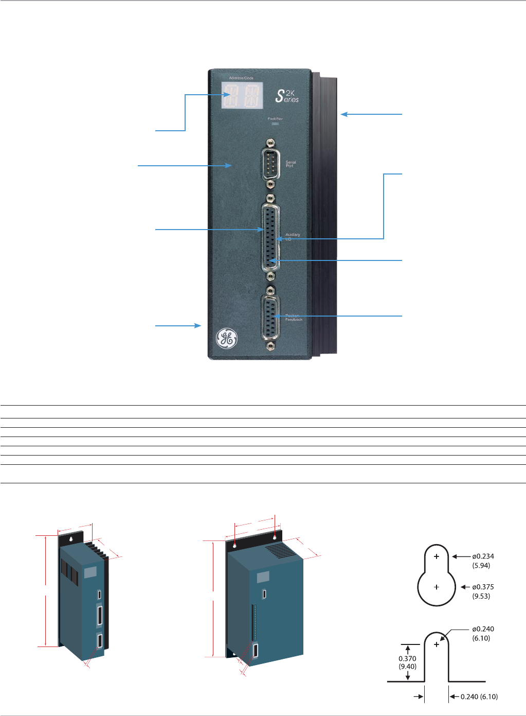
www.ge-ip.com GE Intelligent Platforms 83
Motion Solutions
Servo Amplifiers
B
A
C
D
B
A
C
E
D
F
Robust power blocks for
exceptionalreliability
Commandsignaland
torque limit analog inputs
Userconfigurablequadrature
encoder output
Resolver feedback from
MTR-Series servo motors
Two-characterdiagnosticLED
Sinusoidal commutation
for smooth velocity and
minimum torque ripple
Pulse/direction, quadrature
encoder or cw/ccw pulse
input format for position
control mode
ACpowerinputandmotor
connections on bottom of unit
to isolate electrical noise
Mechanical Dimensions
SSD216
Dimension Feature SSD104 SSD107 SSD228 SSD407 SSD420
n/a Weight lb (kg) 3.6 (1.64) 6.5 (2.95) 13 (5.9) 6.0 (2.7) 14 (6.4)
A Depth in (mm) 6.05 (153.7) 8.15 (207) 10.15 (258) 8.15 (207) 10.15 (258)
B Widthin(mm) 3.20(81.3) 3.45(87.6) 5.25(133.4) 4.35(110.5) 5.25(133.4)
C Heightin(mm) 8.50(215.9) 8.50(215.9) 12.20(309.9) 8.50(215.9) 12.20(309.9)
D PositionFeedbackConnectorDepthin(mm) 1.26(32) 1.26(32) 1.26(32) 1.26(32) 1.26(32)
E UserI/OConnectorDepthin(mm) n/a n/a 0.75(19) n/a 0.75(19)
F Centertocenterspacingbetween n/a n/a 3.66(92.96) n/a 3.66(92.96)
adjacentmountingholes
S2K Series Servo Amplifiers
The S2K amplifiers are designed with
features to satisfy the most demanding
industrial user.
Mounting hole dimensions in (mm)
Top hole (all models)
Bottomhole(SSD216,
SSD228, SSD420)
Bottomhole(SSD104,
SSD107, SSD407)
SSD104, SSD107, SSD407 SSD216, SSD228, SSD420

www.ge-ip.com
GE Intelligent Platforms
Power Specifications
Specifications Units SSD104 SSD107 SSD216 SSD228 SSD407 SSD420
ACInputVoltageRange VAC 90-250,1or3phase 180-250,3phase 324-528,3phase
ACInputFrequencyRange Hz 50-440
PWMFrequencytoMotor kHz 16.4 8.2
Min.MotorInductance mH 1(perphase)
Cont.OutputCurrent Arms 4.3 7.2 16 28 7.2 20
PeakOutputCurrent Arms 8.6 14.4 32 56 10.8 20
Max.InputCurrent1-phase Arms 7 15 n/a n/a n/a n/a
3-phase Arms 4 8 18 30 8 22
Max.InputPower KVA@RatedVAC 1.6 3.8 8.5 14.3 6.4 18
LogicInputPower VAC n/a n/a 90-250@0.5A +18-28.8VDC@1.5A
DCPowerOutputs VDC +5@0.25A;+12@0.5A
Motion Solutions
84
Servo Amplifiers
Analog Command Inputs
OperatingRange ±10VDC
Resolution 12Bits
InputImpedance 50kΩ
OutputCurrent 5mA
Pulse Command/Auxiliary Encoder Input
InputFormat single-endedordifferential;quadrature,pulse/direction
orcw/ccw;squareorsinewave
InputVoltageRange +5to+15VDC
LineCountFrequency 3MHzmaximum
PulseFrequency 12MHzmaximumwith4Xmultiplier
Differential Encoder Output*
OutputFormat differential;squarewave;quadrature,pulse/direction,
cw/ccw pulse
OutputVoltage +5VDC
LineCountFrequency 3MHzmaximum
PulseFrequency 12MHzmaximumwith4Xmultiplier
Motor Resolver Feedback Input
Number Available 1
Resolution 4096 pulses per revolution
MaximumSpeed 15,000RPM
Type ControlTransmitter
PhaseShift ±5.0degrees@5kHz
NullVoltage <20mV@5kHz
Transformation Ratio 0.5
Analog Output
OperatingRange ±10VDC
Resolution 8Bits
InputImpedance 50kΩ
OutputCurrent 5mA
RS-232 Serial Communication
Available 1
Functions Supported multipurpose programming port
MaximumAddressableUnits 1
CommunicationRate 9,600baud
MaximumDistanceofRS-232 50feet
FlowControl XON/XOFF
Environmental Specifications
OperatingTemperature,FreeAirAmbient**
SSD104,SSD105,SSD107 32to122°F(0to50°C)
SSD216,SSD228,SSD407,SSD420 32to104°F(0to40°C)
StorageandShippingTemperature -40to176°F(-40to80°C)
Enclosure Type open
*Encoderoutputprovidesa1:1bufferoftheauxiliaryencoder
input.Inservosystems,thisoutputcanbealternatelyconfig-
ured as the motor position output with selectable resolution.
**Assumes heatsink in vertical orientation.
S2K Series Servo Amplifiers
Electrical Specifications
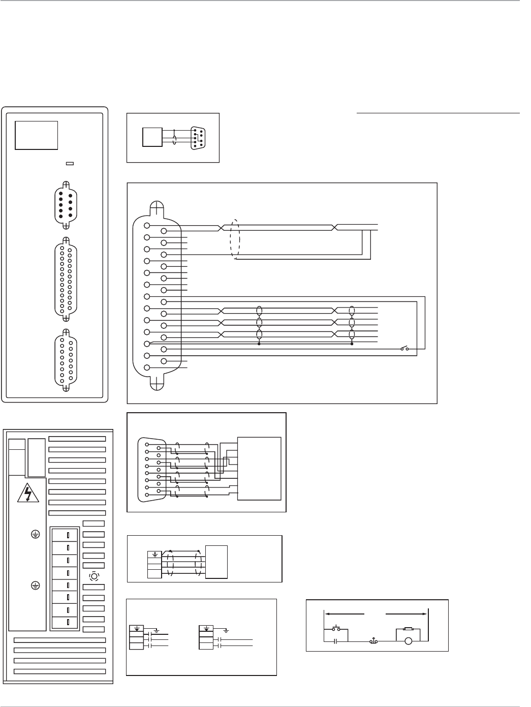
www.ge-ip.com GE Intelligent Platforms 85
Motion Solutions
Servo Amplifiers
5
Fwd/Rev
Code
9
9
5
6
1
16
13 25
114
114
AI1+ +/-10V Command
Command Com
Auxiliary I/O
AI1-
AI2+
AI2-
A0
Analog common
IN_A+
IN_A-
IN_B+
IN_B-
Tie
+5Vdc
+12Vdc
Common
common
Out_A+
Out_A-
Out_B+
Out_B-
Index+
Index-
common
A+
A-
B+
B-
Index+
Index-
SW1
SW1 must be closed to run
Enable-
Enable+
OK+
OK-
815
19
Position
Feedback
Serial
Port
Serial Port*
RS-232
COMPUTER
GROUND
TRANSMIT
RECEIVE
13
T
D
A
C
B
Motor
GND
S
R
T
S
R
25
Auxiliary
I/O
T
S
R
L3
L2
L1
WARNING!
HAZARDOUS
VOLTAGES
FRONT VIEW
BOTTOM VIEW
Brushless Servo Motor
REMARKS:
2
1
32
16
8
4
2
NA
DR
1
(D-63)
L3
L2
L1
L3
Three Phase
VAC
M
L2
L1
L3
L2
L1
Single Phase
VAC Input (1) Emergency Stop Circuit
VAC
M
L2
L1
Note: Do not connect L3 for single phase
Power On RCAS
M(Aux)
Emergency
Stop
M
(1) Input power 90 to 250 VAC, 50-440 Hz
1 phase @ 10 Amps, 3 phase @6 Amps
wire_S2K_SAmp104.eps
file name: wire_S2K_SAmp104.eps
current page in catalog: 27
source: "Figure 3-26" from source
sent by client
file name: wire_S2K_SAmp104.eps
current page in catalog: 27
source: "Figure 3-26" from source
sent by client
Main VAC
19
P2
Position Feedback
AS4
Resolver
S3
S2
S1
R1
R2
Therm
Therm
B
C
D
E
F
G
H
15
8
S2K Series Servo Amplifiers
Connection Diagrams
S2K Model: SSD104
*Note:
TheS2Kserialportincludes12Vonpin4.Ajumper
must be placed from pin 4 to pin 7 to prev ent possible
damagetoserialportonsomecomputers.UsingaGE
serial communication cable is recommended.
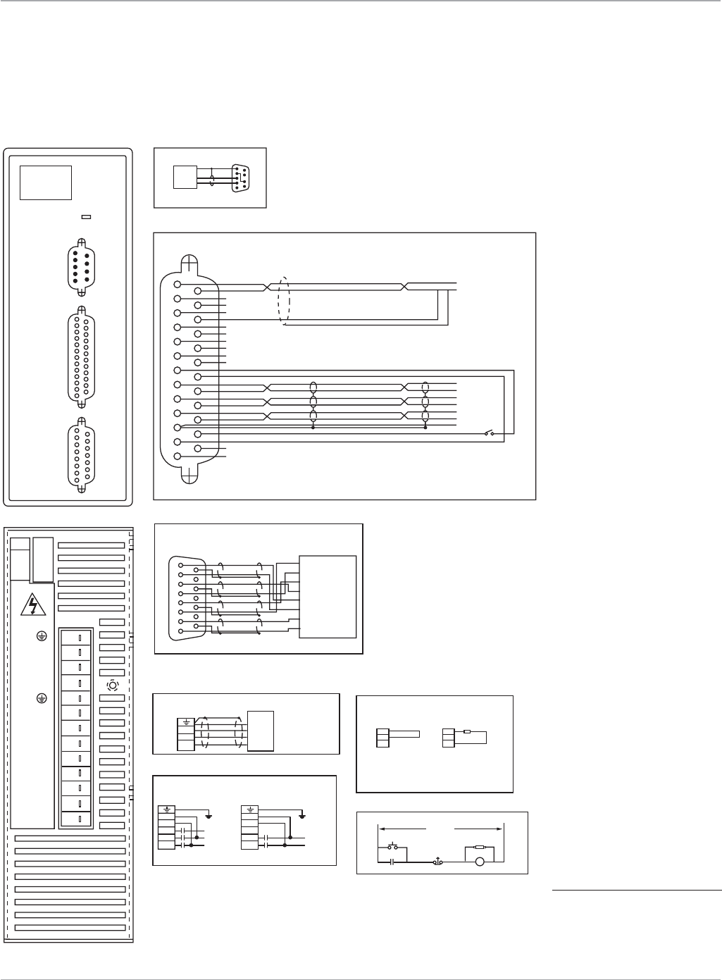
www.ge-ip.com
GE Intelligent Platforms
Motion Solutions
86
5
Fwd/Rev
Code
9
9
5
6
1
16
13 25
114
114
AI1+ +/-10V Command
Command Com
Auxiliary I/O
AI1-
AI2+
AI2-
A0
Analog common
IN_A+
IN_A-
IN_B+
IN_B-
Tie
+5Vdc
+12Vdc
Common
common
Out_A+
Out_A-
Out_B+
Out_B-
Index+
Index-
common
A+
A-
B+
B-
Index+
Index-
SW1
SW1 must be closed to run
Enable-
Enable+
OK+
OK-
815
19
Position
Feedback
Serial
Port
Serial Port*
RS-232
COMPUTER
GROUND
TRANSMIT
RECEIVE
13
T
D
A
C
B
Motor
GND
S
R
T
S
R
25
Auxiliary
I/O
T
S
R
2L2
2L1
1L3
1L2
1L1
EXT
INT
DC+
WARNING!
FRONT VIEW
BOTTOM VIEW
Brushless Servo Motor
REMARKS:
2
1
32
16
8
4
2
NA
DR
1
(D-63)
2L2
2L1
1L3
1L2
1L1
L3
Three Phase
VAC
M
L2
L1
Single Phase
Internal External
VAC Input (1)
Emergency Stop Circuit
Clamp Connections
Note: Do not connect L3 for single phase
Power On RCAS
M(Aux)
EXT
INTClamp
Resistor(*)
*Clamp resistor only required for extreme duty cycle
applications. Contact GE Fanuc for recommended
clamp resistor value and procedure for connecting
external clamp resistor.
DC+
EXT
INT
DC+
Emergency
Stop
M
(1) Input power 90 to 250 VAC, 50-440 Hz
1 phase @ 15 Amps, 3 phase @ 8 Amps
H
A
Z
A
R
D
O
U
S
V
O
L
T
A
G
E
S
2L2
2L1
1L3
1L2
1L1 VAC
M
L2
L1
wire_S2K_SAmp107.eps
filename:wire_S2K_SAmp107.eps
currentpageincatalog:29
source:"Figure3-28"from source
sent by client
filename:wire_S2K_SAmp107.eps
currentpageincatalog:29
source:"Figure3-28"from source
sent by client
Main VAC
19
P2
Position Feedback
AS4
Resolver
S3
S2
S1
R1
R2
Therm
Therm
B
C
D
E
F
G
H
15
8
S2K Series Servo Amplifiers
Connection Diagrams
S2K Model: SSD107
*Note:
The S2K serial port includes 12 V on pin
4.Ajumpermustbeplacedfrompin4
to pin 7 to prev ent possible damage to
serialportonsomecomputers.Usinga
GE serial communication cable is
recommended.
Servo Amplifiers
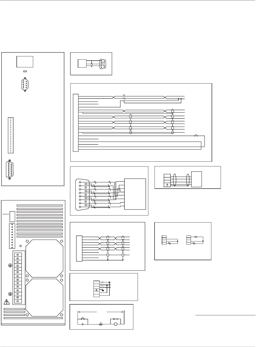
www.ge-ip.com GE Intelligent Platforms 87
Motion Solutions
5
Fwd/Rev
Code
9
9
5
6
1
16
AI1+ +/-10V Command
Command Com
+/-10V Output
Common
A+
A+
AI1-
AI2+
AI2-
Analog common
Analog common
Analog Output
A+
A-
B-
Index+
Index-
B+
IN_A+
IN_A-
IN_B+
IN_B-
IN_I+
IN_I-
TIE
Shield
+5VDC
Common
Common
common
Common
Out_A+Shield
Shield
Shield Enable
OK
Input Common
Output Common
+12VDC
Out_A-
Out_B+
Out_B-
Index+
Index-
common
B+
B-
Index+
Index-
Serial
Port
Serial Port*
RS-232
COMPUTER
HOST
GROUND
TRANSMIT
RECEIVE
1
2
3
4
5
6
7
8
9
10
1
2
3
4
5
6
7
8
9
10
1
2
3
4
5
6
7
8
9
10
IN_A+
IN_A-
IN_B+
IN_B-
IN_I+
IN_B-
+5V
COM
TIE
SHO
11
12
13
14
15
16
17
18
19
20
1
2
3
4
5
6
7
8
9
10
11
12
13
14
15
16
17
18
19
20
Analog Input 1+
Analog Input 1-
Analog Input 2+
Analog Input 2-
Analog Common
Analog Output
Analog Common
Out Channel A+
Out Channel A-
Out Channel B+
Out Channel B-
Out Index +
Out Index +
Common
Enable
OK
Input Common
Output Common
+12VDC
Common
FRONT VIEW
BOTTOM VIEW
REMARKS:
2L2
2L1
1L3
1L2
1L1
L3 VAC
M
L2
L1
Internal External
VAC Input (1)
Pulse Input
Emergency Stop Circuit
Clamp Connections
Power On RCAS
M(Aux)
M(Aux) M(Aux)
Clamp
Resistor(*)
*Clamp resistor only required for extreme duty cycle
applications. Contact GE Fanuc for recommended
clamp resistor value and procedure for connecting
external clamp resistor.
EXT
INT
DC+
DC-
Emergency
Stop
M
(1) Input power 180 to 250 VAC
3 phase 50-440 Hz @ 18 Amps for IC800SSD216RS1A
3 phase 50-440 Hz @ 30 Amps for IC800SSD228RS1A
EXT
INT
DC+
DC-
SW1 must be closed to run
Auxiliary I/O
SW1
WARNING!
H
A
Z
A
R
D
O
U
S
V
O
L
T
A
G
E
S
T
S
R
2L2
2L1
1L3
1L2
1L1
EXT
INT
DC+
DC-
2
1
32
16
8
4
2
NA
DR
(Empty)
(Fan)
(Fan)
1
(D-63)
815
19
Position
Feedback
TD
A
C
BMotor
GND
S
R
T
S
R
Brushless Servo Motor
wire_S2K_SAmp16&28.eps
filename:wire_S2K_SAmp16&28.eps
currentpageincatalog:31
source:"Figure3-30"from source
sent by client
filename:wire_S2K_SAmp16&28.eps
currentpageincatalog:31
source:"Figure3-30"from source
sent by client
Main VAC
19
P2
Position Feedback
AS4
Resolver
S3
S2
S1
R1
R2
Therm
Therm
B
C
D
E
F
G
H
15
8
S2K Series Servo Amplifiers
Connection Diagrams
S2K Model: SSD216 and SSD228
*Note:
The S2K serial port includes 12 V on pin
4.Ajumpermustbeplacedfrompin4
to pin 7 to prev ent possible damage to
serialportonsomecomputers.Usinga
GE serial communication cable is
recommended.
Servo Amplifiers
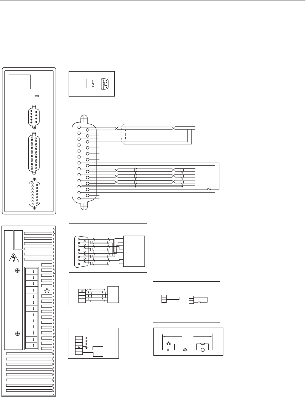
www.ge-ip.com
GE Intelligent Platforms
Motion Solutions
88
5
Fwd/Rev
Code
9
9
5
6
1
16
13 25
114
114
AI1+ +/-10V Command
Command Com
Auxiliary I/O
AI1-
AI2+
AI2-
A0
Analog common
IN_A+
IN_A-
IN_B+
IN_B-
Tie
+5Vdc
+12Vdc
Common
common
Out_A+
Out_A-
Out_B+
Out_B-
Index+
Index-
common
A+
A-
B+
B-
Index+
Index-
SW1
SW1 must be closed to run
Enable-
Enable+
OK+
OK-
815
19
Position
Feedback
Serial
Port
Serial Port*
RS-232
COMPUTER
HOST
GROUND
TRANSMIT
RECEIVE
13
T
D
A
C
B
Motor
GND
S
R
T
S
R
25
Auxiliary
I/O
T
S
R
COM
+24V
1L3
1L2
1L1
EXT
INT
DC+
WARNING!
FRONT VIEW
BOTTOM VIEW
Brushless Servo Motor
REMARKS:
Internal External
Input power (1) Emergency Stop Circuit
Clamp Connections
Power On
M(Aux)
RCAS
EXT
INTClamp
Resistor(*)
*Clamp resistor only required for extreme duty cycle
applications. Contact GE Fanuc for recommended
clamp resistor value and procedure for connecting
external clamp resistor.
DC+
EXT
INT
DC+
Emergency
Stop M
(1) Input motor power 324 to 528 VAC
3 phase 50-440 Hz @ 8 Amps
Input logic power 18 to 28.8 VDC @ 2 Amps
H
A
Z
A
R
D
O
U
S
V
O
L
T
A
G
E
S
19
P2
Position Feedback
AS4
Resolver
S3
S2
S1
R1
R2
Therm
Therm
B
C
D
E
F
G
H
15
8
COM
+24V
1L3
1L2
1L1
L3 VAC
M
L2
L1
24
VDC
+
-
wire_S2K_SAmp407R.eps
Main VAC
S2K Series Servo Amplifiers
Connection Diagrams
S2K Model: SSD407
*Note:
TheS2Kserialportincludes12Vonpin4.Ajumper
must be placed from pin 4 to pin 7 to prev ent possible
damagetoserialportonsomecomputers.UsingaGE
serial communication cable is recommended.
Servo Amplifiers
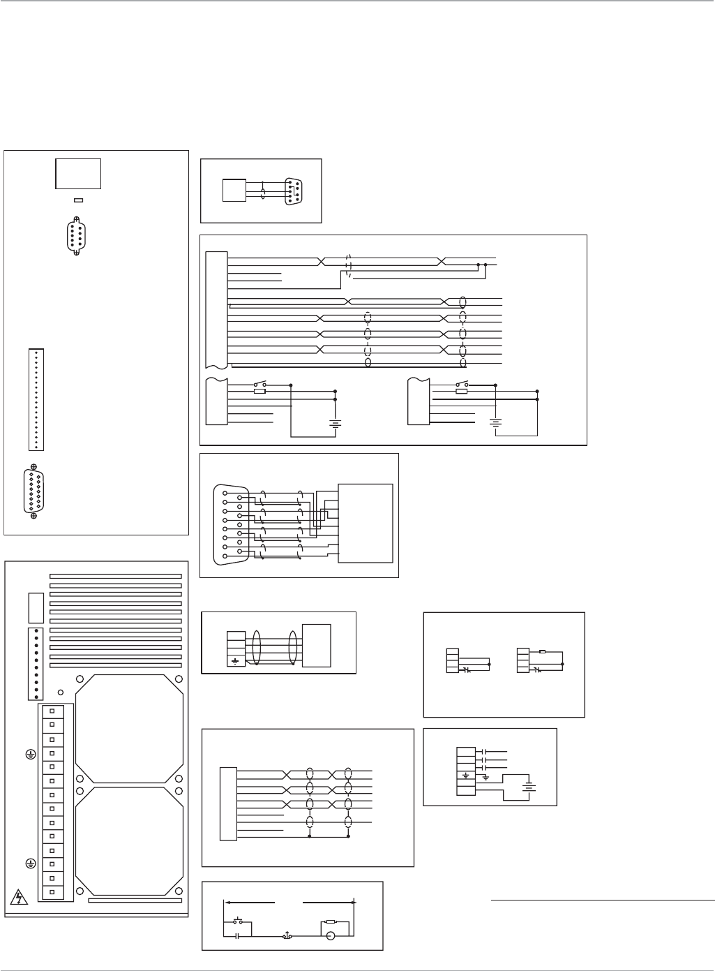
www.ge-ip.com GE Intelligent Platforms 89
Motion Solutions
5
Fwd/Rev
Code
9
9
5
6
1
16AI1+ +/-10V Command
Command Com
+/-10V Output
Common
A+
A+
AI1-
AI2+
AI2-
Analog common
Analog common
Analog Output
A+
A-
B-
Index+
Index-
B+
IN_A+
IN_A-
IN_B+
IN_B-
IN_I+
IN_I-
TIE
Shield
+5VDC
Common Common
common
Common
Sinking
12-24
VDC
Out_A+
Shield
Shield
Shield
OK
Enable
Input Common
Output Common
+12VDC
Out_A-
Out_B+
Out_B-
Index+
Index-
common
B+
B-
Index+
Index-
815
19
Position
Feedback
Serial
Port
Serial Port*
RS-232
COMPUTER
HOST
GROUND
TRANSMIT
RECEIVE
1
2
3
4
5
6
7
8
9
10
1
2
3
4
5
6
7
8
9
10
1
2
3
4
5
6
7
8
9
10
IN_A+
IN_A-
IN_B+
IN_B-
IN_I+
IN_B-
+5V
COM
TIE
SHO
11
12
13
14
15
16
17
18
19
20
1
2
3
4
5
6
7
8
9
10
11
12
13
14
15
16
17
18
19
20
Analog Input 1+
Analog Input 1-
Analog Input 2+
Analog Input 2-
Analog Common
Analog Output
Analog Common
Out Channel A+
Out Channel A-
Out Channel B+
Out Channel B-
Out Index +
Out Index +
Common
Enable
OK
Input Common
Output Common
+12VDC
Common
TD
A
C
BMotor
GND
S
R
T
S
R
FRONT VIEW
BOTTOM VIEW
Brushless Servo Motor
Internal External
Pulse Input
TB4
Emergency Stop Circuit
Clamp Connections
Power On
M(Aux)
M(Aux) M(Aux)
RCAS
Main VAC
Clamp
Resistor(*)
*Clamp resistor only required for extreme duty cycle
applications. Contact GE Fanuc for recommended
clamp resistor value and procedure for connecting
external clamp resistor.
EXT
INT
DC+
DC-
Emergency
Stop
M
EXT
INT
DC+
DC-
Auxiliary I/O
TB1
TB4
WARNING!
H
A
Z
A
R
D
O
U
S
V
O
L
T
A
G
E
S
T
S
R
COM
+24V
1L3
1L2
1L1
EXT
INT
DC+
DC-
(Fan)
(Fan)
+
-
Common
Sourcing
12-24
VDC
OK
Enable
Input Common
Output Common
+12VDC
15
16
17
18
19
20
+
-
DB1
DB2
TB1
DB1
REMARKS:
Input power (1)
(1) Input motor power 324 to 528 VAC
3 phase 50-440 Hz @ 8 Amps
Input logic power 18 to 28.8 VDC @ 2 Amps
COM
+24V
1L3
1L2
1L1
L3 VAC
M
L2
L1
24
VDC
+
-
wire_S2KAmp20a.eps
19
P2
Position Feedback
AS4
Resolver
S3
S2
S1
R1
R2
Therm
Therm
B
C
D
E
F
G
H
15
8
S2K Series Servo Amplifiers
Connection Diagrams
S2K Model: SSD420
*Note:
TheS2Kserialportincludes12Vonpin4.Ajumper
must be placed from pin 4 to pin 7 to prev ent possible
damagetoserialportonsomecomputers.UsingaGE
serial communication cable is recommended.
Servo Amplifiers

www.ge-ip.com
GE Intelligent Platforms
Motion Solutions
90
Servo Amplifiers
S2K Series Servo Amplifiers
Ratings and Ordering Information
Servo Models for MTR-Series Motors (Resolver Feedback)
IC800SSD104RS1 4.3Amp,115/230VACS2KAmplifier,ResolverFeedback
IC800SSD107RS1 7.2Amp,115/230VACS2KAmplifier,ResolverFeedback
IC800SSD216RS1 16Amp,230VACS2KAmplifier,ResolverFeedback
IC800SSD228RS1 28Amp,230VACS2KAmplifier,ResolverFeedback
IC800SSD407RS1 7.2Amp,460VACS2KAmplifier,ResolverFeedback
IC800SSD420RS1 20Amp,460VACS2KAmplifier,ResolverFeedback
Accessories
IC800SLR001 50Ω,100WExternalRegenerationResistorKit
IC800SLR002 100Ω,225WExternalRegenerationResistorKit
IC800SLR003 20Ω,300WExternalRegenerationResistorKit
IC800SLR004 15Ω,1000WExternalRegenerationResistorKit
TRM-JAUX-03 S2KAuxiliaryI/OBreakoutTerminalBoard,3ftcable
TRM-JAUX-10 S2KAuxiliaryI/OBreakoutTerminalBoard,10ftcable
S2K Series Cable GE Part Number Description
AuxiliaryI/OInterface IC800SKCIxxx InterfaceCable,S2KAuxiliaryI/Oto44A726268-001TerminalBoardAssembly,1mor3m
IC800SKCFLYxxx InterfaceCable,S2KAuxiliaryI/OconnectortoFlyingLeads,1mor3m
Serial IC800SKCS030 S2KSerialCommunicationCableforPC(MotionDeveloper)Interface,3m
MTR-SeriesMotorResolver CBL-3T-RD-xx ResolverCable,S2KtoMTR-3TSeriesServoMotor,xx=10,20or30feet
MTR-Series CBL-3T-MP-xx PowerCable,S2KtoMTR-3T5xand3T6xServoMotor,xx=10,20or30feet
MotorPower CBL-T7-MP-xx PowerCable,S2KtoMTR-3T1x,3T2xand3T4xServoMotor,xx=10,20or30feet
MTR-Series CBL-3T-MB-xx Power/BrakeCable,S2KtoMTR-3T5xand3T6xServoMotorwithBrake,xx=10,20or30feet
MotorBrake CBL-T7-MB-xx Power/BrakeCable,S2KtoMTR-3T1x,3T2xand3T4xServoMotorwithBrake,xx=10,20or30feet
Cables
CablesinseverallengthsareavailablefromGEformotortoamplifierconnectionsandvariousotheramplifierfunctions.Itisstrongly
recommended that you use the cables available from GE as shown below. GE does not ship mating power or feedback connectors for
the MTR-Series Motors with the motor. See appropriate motor section of this catalog for motor connector information.
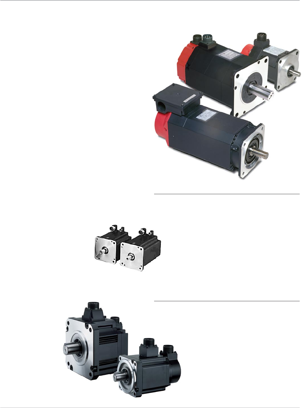
91
Motion Solutions
Servo Motors
Servo Motor Performance
for Demanding Applications
The GE Servo motors are a rugged family of
brushless servo motors covering a broad torque
and speed range. These motors utilize high ener-
gy rare earth magnets for superior cost/perfor-
mance ratio. Low inertia design provides high
acceleration rates for improved machine cycle
rates. MTR-Series motors use resolver feedback
and are matched for use withthe S2K family of
amplifiers and controllers.The βi Series motors
usehigh resolution serial encoder feedback
andare matched with βi Series amplifiers and
DSM300 Series Motion Controllers. The VersaMotion
Series motors use incremental encoder feedback
and are matched for use with the VersaMotion
Series amplifiers and DSM314 Series
Motion Controllers.
Servo Motor Features
• Modelsfrom0.84-644in-lb(0.095-75Nm)continuous
• RuggedresolverfeedbackonMTR-Series;highresolution
serial encoder feedback on βi Series.
• Absolutefeedbackavailableonβi Series with optional
battery backup
• Brushlessdesignminimizeselectromagnetic
interference, carbon dust and maintenance
• Metricservomountingconfigurations
• Optionalelectricallyreleasedholdingbrakes
• RuggedTENVhousingwithIP55toIP67protectionrating
• Somemodelsincludeintegralshaftoilseal
• Continuoustorquerangefrom0.32Nmto19.1
VersaMotion Servo Motor Features
• Highpeaktorqueof3xcontinuousforfastacceleration
• Incrementalencoderfeedback(2500ppr/10,000quadrature)
• Metricmountingconfiguration
• Optional24VDCholdingbrake(except100Watt)
• Lowinertiadesignforhighcyclerateand
improved response
• IP65protectionrating
• Powerandfeedbackcablesavailablein
standard lengths
www.ge-ip.com GE Intelligent Platforms

Motion Solutions
92
Servo Motors
Servo Motors
Feature Comparison
Feature αHVis Series βis Series βHVis Series VersaMotion Series MRT-3T Series
Cont.StallTorqueRange(In-lb(Nm)) 17.7-664(2-75) 3.5-177(0.4-20) 17.7-177(2-20) 2.83-126(0.32-14.3) 2.7-477(0.3-53.9)
Cont.SpeedRange(RPM) 2000-6000 2000-6000 2000-4000 1500–3000 950-9000
Max.SpeedRange(RPM) 3000-6000 2000-6000 2000-4000 3000–5000 1300-12900
CompatibleAmplifiers αHVi Series βi Series βHVi Series VersaMotion Series S2K Series
CompatibleControllers PMM335/DSM324i PMM335/DSM324i PMM335/DSM324i DSM314 DSM/S2K
Mounting Metric Metric Metric Metric Metric
ShaftConfiguration Straight/Keyway Straight/Keyway Straight/Keyway Straight/Keyway Straight/NoKeyway
BrushlessConstruction Yes Yes Yes Yes Yes
OptionalBrake 24VDC 24VDC 24VDC 24VDC 24VDC
FeedbackType SerialEncoder SerialEncoder SerialEncoder IncrementalEncoder Resolver
FeedbackResolution(Counts/rev) 1M 64K/128K 128K 10,000 4096
AbsoluteFeedback Yes* Yes* Yes* No No
AmplifierLineVoltage 400-480VAC3φ 220-240VAC1φ 400-480VAC3φ 200-255VAC1φ 115VAC1φ
200-240VAC3φ (100Wto1kW); 230VAC1or3φ
170-255VAC3φ 460VAC3φ
Shaft Seal Standard Standard Standard Standard MTR-3T10 Series
MTR-3T20 Series
ProtectionRating IP65Standard IP65Standard IP65Standard IP65 IP65
IP67Optional IP67Optional IP67Optional
Inertia Low Medium Medium Low/Medium Medium
*AbsolutefeedbackrequiresoptionalencoderbatterybackupforαHVi Series, βi Series, or βHVi Series amplifiers.
www.ge-ip.com
GE Intelligent Platforms
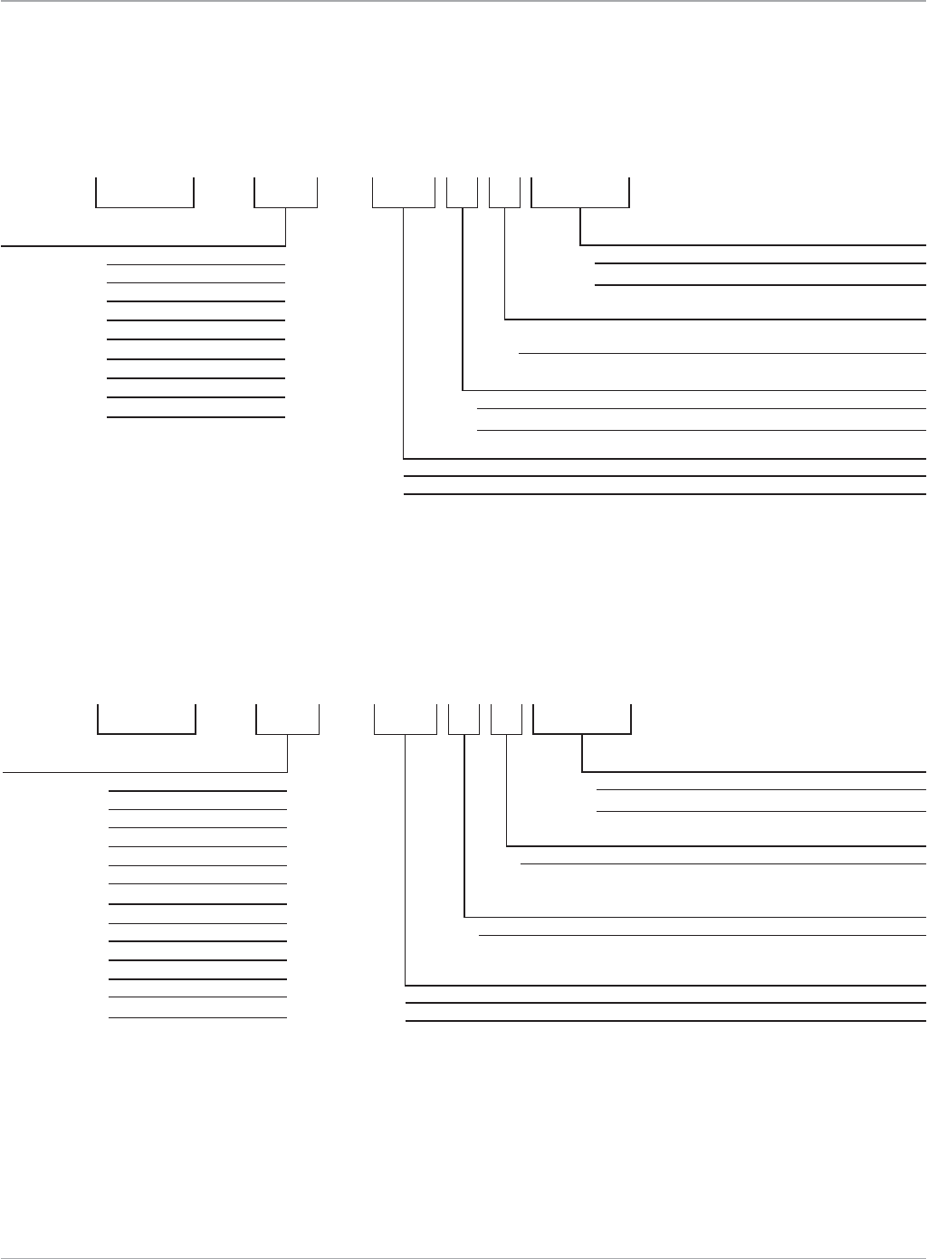
93
Motion Solutions
Servo Motors
αHVi and αHVis Series Servo Motors
Motor Part Numbers
i
Shaft
0- StraightShaftwithKeyway(Exceptα50/3000HVis which
Brake
2- NoBrake
5- 24VDCBrake
ZA06B 249-0 -B 200
Fan Cooling
0- NoFanCooling
1- FanCooling(α50/3000HVisonly)
#0100
Protection
Blank- IP65(standard)
#0100- IP67(optional)
Motor Model
αHVi Series 219- α2/6000HVis
216- α4/5000HVis
233- α8/6000HVis
239- α12/4000HVis
249- α22/3000HVi
266- α22/4000HVis
269- α30/4000HVis
273- α40/4000HVis
276- α50/3000HVis
doesnothaveaShaftKey)
βis and βHVis Series Servo Motors
Motor Part Numbers
i
Shaft
3- Straight Shaft with Keyway
Brake
2- NoBrake
5- 24VDCBrake
ZA06B 114-0 -B 203
Fan Cooling
0- NoFanCooling
Motor Model
βi Series 114- β0.4/5000is
115- β0.5/5000is
116- β1/5000is
061- β2/4000is
062- β2/4000HVis
063 - β4/4000is
064- β4/4000HVis
075- β8/3000is
076- β8/3000HVis
078- β12/3000is
079- β12/3000HVis
085- β22/2000is
086- β22/2000HVis
#0100
Protection
Blank- IP65(standard)
#0100- IP67(optional)
www.ge-ip.com GE Intelligent Platforms
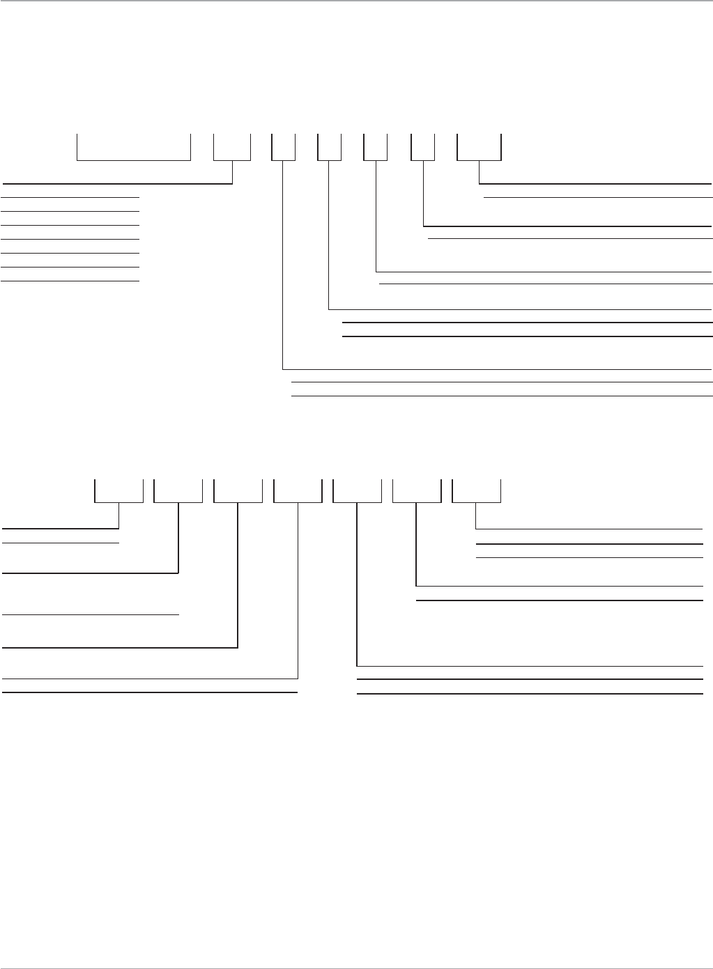
Motion Solutions
94
Servo Motors
MTR-Series Servo Motors
Motor Part Numbers
VersaMotion Series Servo Motors
Motor Part Numbers
Series
3T- Metric
Shaft Seal
0-Noseal(3T4x,3T5xand3T6xonly)
S-Shaftseal(3T1xand3T2x)
Winding
Frame/Stack
3T Series- 11, 12, 13, 21, 22, 23, 24,
42,43,44,45,54,55,57,
66,67,69
Brake
0- NoBrake
B- 24VDCBrake
Mounting Flange
M- Metric
Feedback
R- Resolver
MTR 3T 11 GR0MS
IC800VMM 30 L B K S E25
Feedback
E25–2500PPRIncrementalEncoder
Rated Power
01–100Watts
02–200Watts
04–400Watts
07–750Watts
10–1000Watts
20–2000Watts
30–3000Watts
Shaft Seal
S–ShaftOilSeal
Key
K–ShaftKey
Brake
N–Nobrake
B–24VDCBrake(except100WattMotor)
Inertia
L–LowInertia
M–MediumInertia
www.ge-ip.com
GE Intelligent Platforms

95
Motion Solutions
Servo Motors
αHVi and αHVis Series Servo Motors
Specifications
Motor Model Unit α2/6000HV
i
s α4/5000HV
i
s α8/6000HV
i
s α12/4000HV
i
s α22/3000HV
i
ContStallTorque* Nm 2 4 8 12 22
in-lb 17.7 35.4 70.8 106 195
PeakTorque* Nm 6 8.8 22 46 64
in-lb 53.1 77.9 194.7 407 566
RotorInertia kgm2x10-4 2.91 5.15 11.7 22.8 120
in-lb-s2x10-4 25.75 45.58 103.54 201.7 1062
RatedSpeed RPM 6000 4000 6000 3000 3000
NoLoadSpeed RPM 6000 5000 6000 4000 4000
Encoder Resolution Counts/Rev 1,000,000 1,000,000 1,000,000 1,000,000 1,000,000
FlangeSize mm 90 90 130 130 174
Mechanical Data
Weight kg 3 4.3 8 11.9 29
lb 6.6 9.46 17.6 26.2 63.8
AxialLoadRating kg 8 8 20 20 60
lb 17.6 17.6 44 44 132
RadialLoadRating kg 25 25 70 70 200
lb 55 55 154 154 440
MechanicalTimeConstant msec 5 3 2 2 4
ThermalTimeConstant min 15 20 20 25 60
StaticFriction Nm 0.1 0.2 0.3 0.3 1.2
Electrical Data
TorqueConstant* Nm/A 0.99 1.32 0.89 1.8 2.41
in-lb/A 8.76 11.68 7.87 15.9 21.33
Resistance* ohms 5.6 2.8 0.5 0.84 0.66
BackEMFConstant* V(rms)/krpm 35 46 31 63 84
RatedMotorPower kW 1 1 2.2 2.5 4
HP 1.3 1.3 3 3.4 5.4
Cont.StallCurrent A(rms) 2 3 9 6.7 9.1
MaxCurrent A(peak) 40 40 40 40 40
Insulation ClassF ClassF ClassF ClassF ClassF
Amplifier Model
αAmpModelNumber αSVM1-10HV
i
αSVM1-10HV
i
αSVM1-40HV
i
αSVM1-40HV
i
αSVM1-40HV
i
βAmpModelNumber βSVM1-10HV
i
βSVM1-10HV
i
βSVM1-40HV
i
βSVM1-40HV
i
βSVM1-40HV
i
Brake Data
HoldingTorque Nm 3 3 8 8 35
in-lb 26.6 26.6 71 71 310
InertiaAdder kgm2x10-4 0.2 0.2 0.7 0.7 6
in-lb-s2x10-4 1.77 1.77 6.18 6.18 53
WeightAdder kg 1 1 2.2 2.2 6
lb 2.2 2.2 4.9 4.9 13.2
Current A 0.9 0.9 1.1 1.1 1.2
Voltage VDC 24 24 24 24 24
Engage Time msec 20 20 30 30 30
ReleaseTime msec 60 60 160 160 160
Cooling Fan Data
ACInput60Hz VAC n/a n/a n/a n/a n/a
ACInput50Hz VAC n/a n/a n/a n/a n/a
RatedCurrent60Hz A(rms) n/a n/a n/a n/a n/a
RatedCurrent50Hz A(rms) n/a n/a n/a n/a n/a
Environmental Specifications
Humidity 80%non-condensing
AmbientTemperature 0to40ºC
Vibration lessthan5G(operating)
Altitude 3300feet(1000m)
*Datashownarenominalvaluesat20ºC
www.ge-ip.com GE Intelligent Platforms

Motion Solutions
96
Servo Motors
αHVi and αHVis Series Servo Motors
Specifications
Motor Model Unit α22/4000HV
i
sα30/4000HV
i
s α40/4000HV
i
s α50/3000HV
i
s with fan
ContStallTorque* Nm 22 30 40 75
in-lb 195 266 354 664
PeakTorque* Nm 70 100 115 215
in-lb 620 885 1018 1903
RotorInertia kgm2x10-4 52.7 75.9 99 145
in-lb-s2x10-4 466 672 876 1283
RatedSpeed RPM 3000 3000 3000 3000
NoLoadSpeed RPM 4000 4000 4000 3000
Encoder Resolution Counts/Rev 1,000,000 1,000,000 1,000,000 1,000,000
FlangeSize mm 174 174 174 174
Mechanical Data
Weight kg 17 23 28 42
lb 37.4 50.6 61.6 92.4
AxialLoadRating kg 60 60 60 60
lb 132 132 132 132
Radial Load Rating kg 200 200 200 200
lb 440 440 440 440
Mechanical Time Constant msec 2 2 1 1
ThermalTimeConstant min 30 35 40 30
StaticFriction Nm 0.8 0.8 1.2 1.8
Electrical Data
TorqueConstant* Nm/A 1.42 1.9 2.2 1.9
in-lb/A 12.57 16.82 19.47 16.82
Resistance* ohms 0.25 0.25 0.23 0.1
BackEMFConstant* V(rms)/krpm 50 66 77 66
RatedMotorPower kW 4.5 5.5 5.5 14
HP 6.0 7.4 7.4 18.8
Cont.StallCurrent A(rms) 15.5 15.9 18.1 39.6
MaxCurrent A(peak) 80 80 80 180
Insulation ClassF ClassF ClassF ClassF
Amplifier Model
αAmpModelNumber αSVM1-80HV
i
αSVM1-80HV
i
αSVM1-80HV
i
αSVM1-180HV
i
βAmpModelNumber n/a n/a n/a n/a
Brake Data
HoldingTorque Nm 35 35 35 35
in-lb 310 310 310 310
InertiaAdder kgm2x10-4 6 6 6 6
in-lb-s2x10-4 53 53 53 53
WeightAdder kg 6 6 6 6
lb 13.2 13.2 13.2 13.2
Current A 1.2 1.2 1.2 1.2
Voltage VDC 24 24 24 24
Engage Time msec 30 30 30 30
ReleaseTime msec 160 160 160 160
Cooling Fan Data
ACInput60Hz VAC n/a n/a n/a 170-2201-phase
ACInput50Hz VAC n/a n/a n/a 170-2421-phase
RatedCurrent60Hz A(rms) n/a n/a n/a 0.27
RatedCurrent50Hz A(rms) n/a n/a n/a 0.32
Environmental Specifications
Humidity 80%non-condensing
AmbientTemperature 0to40ºC
Vibration lessthan5G(operating)
Altitude 3300feet(1000m)
*Datashownarenominalvaluesat20ºC
www.ge-ip.com
GE Intelligent Platforms

97
Motion Solutions
Servo Motors
αHVi and αHVis Series Servo Motors
Speed Torque Curves
The curves illustrate the relationship
between motor speed and output torque.
The motor can operate continuously
at any combination of speed and
torque within the prescribed continuous
operating zone. The limit of the continu-
ous operating zone is determined with
the motor’s ambient temperature at 20°C
and its drive current as a pure sine wave.
Actualoperationislimitedbythecurrent
of the servo drive unit. The continuous
operating zone must be derated for
ambient temperature above 20°C.
1000
0
30
40
50
20
10
60
70
2000 3000
Torque (Nm)
α22/3000HVi
Speed (RPM)
Intermittent Operation
Continuous Operation
Torque (Nm)
α12/4000HVis
Speed (RPM)
0
10
20
40
50
30
300020001000 4000
Intermittent Operation
Continuous Operation
Torque (Nm)
α40/4000HVis
Speed (RPM)
0300020001000 4000
Intermittent Operation
80
100
140
120
20
40
60
Continuous Operation
1000
0
50
100
150
200
250
2000 3000
Torque (Nm)
α50/3000HVis w/Fan
Speed (RPM)
Intermittent Operation
Continuous Operation
Torque (Nm)
α22/4000HVis
Speed (RPM)
0
10
20
40
50
30
60
70
80
300020001000 4000
Intermittent Operation
Continuous Operation
α4/5000HVis
Torque (Nm)
Speed (RPM)
40002000 500030001000
Intermittent Operation
Continuous Operation
0
3
4
5
2
1
6
7
8
9
10
α2/6000HVis
0
3
4
5
2
1
6
7
Torque (Nm)
Speed (RPM)
600040002000 500030001000
Intermittent Operation
Continuous Operation
α8/6000HVis
0
15
20
25
10
5
Torque (Nm)
Speed (RPM)
600040002000 500030001000
Intermittent Operation
Continuous Operation
Torque (Nm)
α30/4000HVis
Speed (RPM)
0300020001000 4000
Intermittent Operation
80
100
120
20
40
60
Continuous Operation
www.ge-ip.com GE Intelligent Platforms

Motion Solutions
98
Servo Motors
αHVi Series Servo Motors
Dimensions
α2/6000HVis
B2/4_4/4iseries_SHAFT.eps
11.2
10
3
18
-0.025
+0
-0.009
+0
5
M5 Depth 12
16
11
-0.030
+0
14
23
128
+0.001
+0.012
ø
90
21.4 30.6
B2/4_iseries_MOTOR.eps
ø
120
4-ø6.6 ON ø10 0 D.B.C
7
3
10
32
12
D
C
B
A
4
22
40
8.7
ø 80
ø 43
-0.03
+0
-0.5
+0.5
66.2
56.7
75
Shaft detail
Motor
Dimensions shown mm
Dimension α2/6000HVis
A 130
Awithbrake 159
B 119
Bwithbrake 148
C 75
Cwithbrake 75
D 59
Dwithbrake 59
Notes
1. Shaftdiameterrunout=0.02mmmax
2. Flangesurfacerunout=0.06mmmax
3. Maximumradialloadforoutputshaftis25kgf(55lb)
1 2 3 4 5
U V WG
6
Power Connections
1 2 3 4 5
U V WGB B
6
Power/Brake Connections
www.ge-ip.com
GE Intelligent Platforms

99
Motion Solutions
Servo Motors
αHVi Series Servo Motors
Dimensions
α4/5000HVis
B2/4_4/4iseries_SHAFT.eps
11.2
10
3
18
-0.025
+0
-0.009
+0
5
M5 Depth 12
16
11
-0.030
+0
14
23
128
+0.001
+0.012
ø
90
21.4 30.6
B4/4_iseries_MOTOR.eps
ø
120
4-ø6.6 ON ø10 0 D.B.C
7
30
D
C
B
A
22
40
8.7
ø 80
ø 43
-0.03
+0
3
4
14
66.2
56.7
75
Shaft detail
Motor
Dimensions shown mm
Dimension α4/5000HVis
A 166
Awithbrake 195
B 155
Bwithbrake 184
C 111
C with brake 111
D 95
Dwithbrake 95
Notes
1. Shaftdiameterrunout=0.02mmmax
2. Flangesurfacerunout=0.06mmmax
3. Maximumradialloadforoutputshaftis25kgf(55lb)
1 2 3 4 5
U V WG
6
Power Connections
1 2 3 4 5
U V WGB B
6
Power/Brake Connections
www.ge-ip.com GE Intelligent Platforms
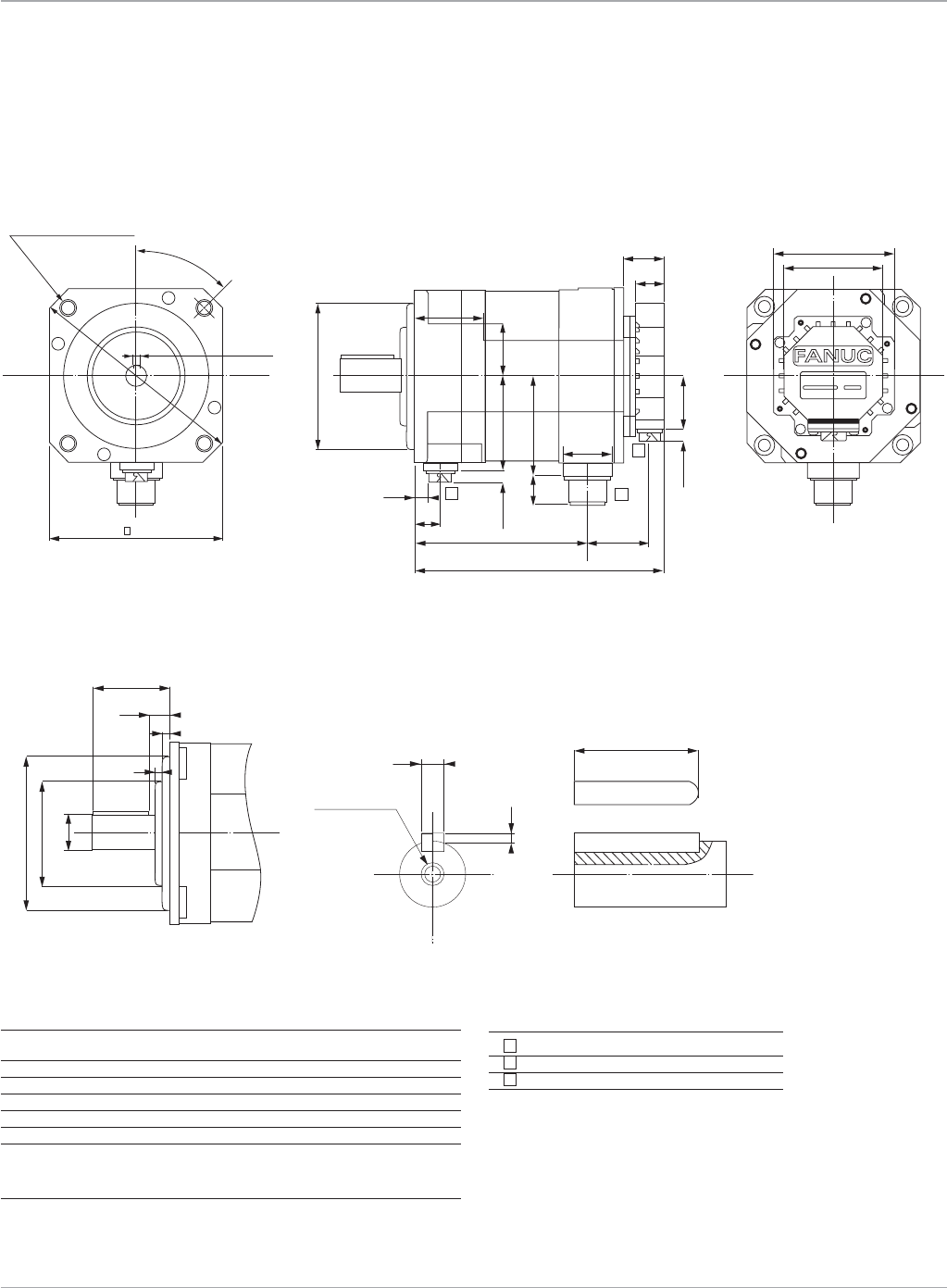
Motion Solutions
100
Servo Motors
Motor
αHVi Series Servo Motors
Dimensions
α8/6000HV
i
s and α12/4000HV
i
s
Dimension α8/6000HV
i
s α12/4000HV
i
s
A 166 222
Awithbrake 191 247
B 108 164
Bwithbrake 133 189
C 47 47
Cwithbrake 47 47
Notes
1. Shaftdiameterrunout=0.02mmmax
2. Flangesurfacerunout=0.05mmmax
3. Maximumradialloadforoutputshaftis70kgf(154lb)
45º
5-0.030
+0
Ø110 -0.035
+0
130
A
B
25 35
52
31
22
22 75
72 39.5
408.7
C
75
90
20
1 0
8.7
Ø165
4- Ø9 ON Ø145 D.B.C.
12
3
Ø110 -0.035
+0
8-0.036
+0
Ø24-0.021
+0
Ø74
55
45
6
4
M8
DEPTH 16
15 ± 0.5
3-0.29
+0
Shaft detail Dimensions shown mm
Connector Description
1 Brake(optional)
2 Power
3 Encoder
www.ge-ip.com
GE Intelligent Platforms
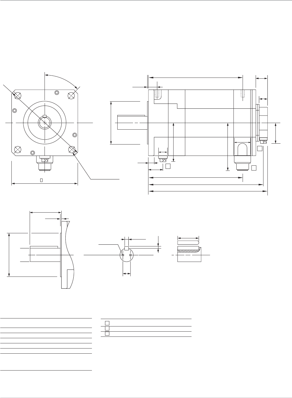
101
Motion Solutions
Servo Motors
αHVi Series Servo Motors
Dimensions
α22/3000HV
i
Connector Description
1 Brake(optional)
2 Power
3 Encoder
Dimension α22/3000HV
i
A 276
Awithbrake 317
B 265
Bwithbrake 306
C 215
Cwithbrake 256
Notes
1. Shaftdiameterrunout=0.03mmmax
2. Flangesurfacerunout=0.06mmmax
3. Maximumradialloadforoutputshaftis200kgf(440lb)
45º
ø 230
17 413.5 DIA HOLES
ON 200 D.B.C.
12
1 0
2-M6
DEPTH10
127
102.7
38
79
20
25
31
22
44
C
B
B
A
48.7
ø114.3 -0.025
+0
3-0.3
+0
-0.0 36
+0 70
ø114.3
ø35
-0.025
+0
-0
+0.01
3.2
203.2
12
3
Shaft detail
Motor
Dimensions shown mm
www.ge-ip.com GE Intelligent Platforms
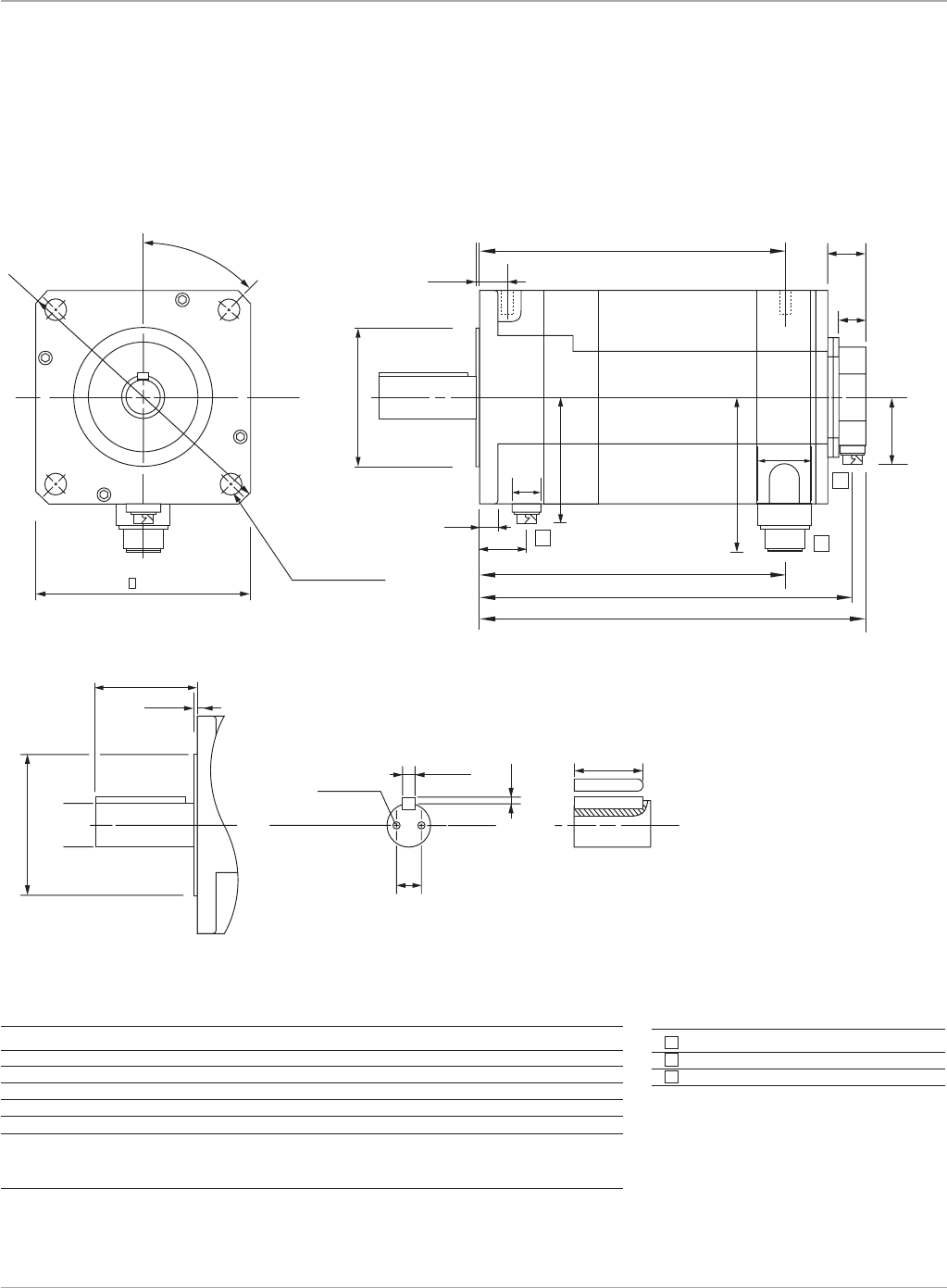
Motion Solutions
102
Servo Motors
www.ge-ip.com
GE Intelligent Platforms
αHVi Series Servo Motors
Dimensions
α22/4000HV
i
s, α30/4000HV
i
s, α40/4000HV
i
s
Connector Description
1 Brake(optional)
2 Power
3 Encoder
Dimension α22/4000HV
i
s α30/4000HV
i
s α40/4000HV
i
s
A 202 239 276
Awithbrake 243 280 317
B 191 228 265
Bwithbrake 232 269 306
C 141 178 215
Cwithbrake 182 219 256
Notes
1. Shaftdiameterrunout=0.03mmmax
2. Flangesurfacerunout=0.06mmmax
3. Maximumradialloadforoutputshaftis200kgf(440lb)
45º
ø 230
17 413.5 DIA HOLES
ON 200 D.B.C.
12
1 0
2-M6
DEPTH10
127
102.7
38
79
20
25
31
22
44
C
B
B
A
48.7
ø114.3 -0.025
+0
3-0.3
+0
-0.0 36
+0 70
ø114.3
ø35
-0.025
+0
-0
+0.01
3.2
203.2
12
3
Shaft detail
Motor
Dimensions shown mm
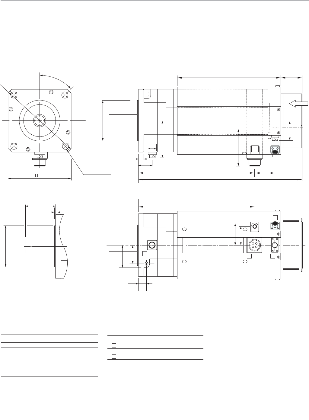
103
Motion Solutions
Servo Motors
www.ge-ip.com GE Intelligent Platforms
αHVi Series Servo Motors
Dimensions
α50/3000HV
i
s with Fan
Dimensions shown mm
Dimension α50/3000HV
i
s with Fan
A 416
Awithbrake 457
B 289
Bwithbrake 330
Notes
1. Shaftdiameterrunout=0.03mmmax
2. Flangesurfacerunout=0.06mmmax
3. Maximumradialloadforoutputshaftis200kgf(440lb)
Connector Description
1 Brake(optional)
2 Power
3 Encoder
4 Fan
45º
ø 230
17 413.5 DIA HOLES
ON 200 D.B.C.
12
20
127
102.7
38
79
25
B
288
330
60
50
AIR IN
A
48.7
ø114.3 -0.025
+0
ø114.3
ø35
-0.025
+0
-0
+0.01
3.2
62
62
52
52
123
4
Shaft detail
Motor
Dimensions shown mm
TAPSforeyebolts:m8depth15 +1
-0

Motion Solutions
104 www.ge-ip.com
Servo Motors
GE Intelligent Platforms
αHVi and αHVis Series Servo Motors
Connections
Description αHVi and αHVis Motors αHVi Series Amplifier
JF1 Connector
N/C 2 1
N/C 1 2
RD 6 5
RD 5 6
+5VDC 8,9 9,20
0VDC 7,10 12,14
+6VA(battery) 4 7
FrameGround 3 16
CableShield 3 16
GEMatingMotorConnector: AmplifierMatingConnector(JF1):
ZA06B-6114-K204#E(90degree) ZA06B-6073-K214
ZA06B-6114-K204#S(Straight)
Description α2HVis and α4HVis All other αSVM1-10HVi/ αSVM1-180HVi
Motor Connector αHVi and αHVis 40HVi/80HVi Amplifier
Motor Connector CZ2 Connector TB2 Connector
PhaseU 1 A B1 U
PhaseV 2 B A1 V
PhaseW 3 C B2 W
Earth(case) 4 D A2 PE
BrakeVDC 5 n/a n/a n/a
BrakeVDC 6 n/a n/a n/a
GEMatingMotorConnector: AmplifierMatingConnector(CZ2):
ZA06B-6114-K220#E(90degree)(α2HVis and α4HVis) ZA06B-6110-K203#ZZN
ZA06B-6114-K220#S(Straight)(α2HVis and α4HVis)
Z44A730464-G20(90degree)(αHVi and αHVis)
Z44A730464-G19(Straight)(αHVi and αHVis)
Z44A730464-G18(90degree)(α12/4000HVis)
Z44A730464-G17(Straight)(α12/4000HVis)
Description α8HVis, α12HVis, α22HVi, α22HVis, α30HVis, α40HVis, α50HVis Motor Brake Connector
BrakeVDC 1
BrakeVDC 2
Earth(case) 4
GEMatingMotorConnector:
ZA06B-6114-K213#E(90degree)
ZA06B-6114-K213#S(Straight)
24VDCBrakepowerconnectionsarenotpolarized.
Serial Encoder Connections
Power and Brake Connections
1
3
2
4
AllαHVi and αHVis Motors
AllotherαHVi and αHVis MotorPower
AllotherαHVi and αHVis Brake
αSVM1-10HVi, αSVM1-40HVi and αSVM1-80HVi
Amplifier(CZ2)
A
BC
D
1 2 3
8 9 10
4 5 6 7
αHViAmplifier(JF1)
3579
46810
14 16 18 20
1
2
12
2
B2
W
B1
U
B
A
A1
V
A2
G
1
654321
α2/6000HVis and α4/5000HVisMotorPower/Brake

105
Motion Solutions
www.ge-ip.com GE Intelligent Platforms
Servo Motors
αHVi and αHVis Series Servo Motor
Ordering Information
Motor Cables
See applicable amplifier section for information about the proper
cables to use with each motor.
Model Number Description
ZA06B-0216-B200 α4/5000HVis Servo Motor
ZA06B-0216-B500 α4/5000HVisServoMotorwithBrake
ZA06B-0219-B200 α2/6000HVis Servo Motor
ZA06B-0219-B500 α2/6000HVisServoMotorwithBrake
ZA06B-0233-B200 α8/6000HVis Servo Motor
ZA06B-0233-B500 α8/6000HVisServoMotorwithBrake
ZA06B-0239-B200 α12/4000HVis Servo Motor
ZA06B-0239-B200#0100 α12/4000HVisServoMotor,IP67Protection
ZA06B-0239-B500 α12/4000HVisServoMotorwithBrake
ZA06B-0239-B500#0100 α12/4000HVisServoMotorwithBrake,IP67Protection
ZA06B-0249-B200 α22/3000HVi Servo Motor
ZA06B-0249-B200#0100 α22/3000HViServoMotor,IP67Protection
ZA06B-0249-B500 α22/3000HViServoMotorwithBrake
ZA06B-0249-B500#0100 α22/3000HViServoMotorwithBrake,IP67Protection
ZA06B-0266-B200 α22/4000HVis Servo Motor
ZA06B-0266-B200#0100 α22/4000HVisServoMotor,IP67Protection
ZA06B-0266-B500 α22/4000HVisServoMotorwithBrake
ZA06B-0266-B500#0100 α22/4000HVisServoMotorwithBrake,IP67Protection
ZA06B-0269-B200 α30/4000HVis Servo Motor
ZA06B-0269-B200#0100 α30/4000HVisServoMotor,IP67Protection
ZA06B-0269-B500 α30/4000HVisServoMotorwithBrake
ZA06B-0269-B500#0100 α30/4000HVisServoMotorwithBrake,IP67Protection
ZA06B-0273-B200 α40/4000HVis Servo Motor
ZA06B-0273-B200#0100 α40/4000HVisServoMotor,IP67Protection
ZA06B-0273-B500 α40/4000HVisServoMotorwithBrake
ZA06B-0273-B500#0100 α40/4000HVisServoMotorwithBrake,IP67Protection
ZA06B-0276-B210 α50/3000HVis Servo Motor with Fan
ZA06B-0276-B210#0100 α50/3000HVisServoMotorwithFan,IP67Protection
ZA06B-0276-B510 α50/3000HVisServoMotorwithFanandBrake
ZA06B-0276-B510#0100 α50/3000HVisServoMotorwithFanandBrake,IP67Protection

Motion Solutions
106 www.ge-ip.com
Servo Motors
GE Intelligent Platforms
Motor Model Unit β0.4/5000is β0.5/6000is β1/6000is β2/4000is β4/4000is β8/3000is β12/3000is β22/2000is
ContStallTorque* in-lb(Nm) 3.5(0.4) 5.8(0.65) 10.6(1.2) 17.7(2) 31(3.5) 62(7) 97.4(11) 177(20)
PeakTorque* in-lb(Nm) 8.9(1) 22.1(2.5) 44.3(5) 62(7) 88.5(10) 132.8(15) 239(27) 398.3(45)
RotorInertia in-lb-s2x10-4 0.885 1.593 3.009 25.76 45.58 103.55 201.80 466.43
(kg-m2x10-4) (0.1) (0.18) (0.34) (2.91) (5.15) (11.7) (22.8) (52.7)
RatedSpeed RPM 4000 6000 6000 4000 3000 2000 2000 2000
NoLoadSpeed RPM 5000 6000 6000 4000 4000 3000 3000 2000
EncoderResolution Counts/Rev 65,536 65,536 65,536 131,072 131,072 131,072 131,072 131,072
FlangeSize mm 60 60 60 90 90 130 130 174
Mechanical Data
Weight lb(kg) 1.76(0.8) 2.2(1) 3.3(1.5) 6.16(2.8) 9.46(4.3) 16.28(7.4) 26.18(11.9) 37.4(17)
AxialLoadRating lb(kg) 11(5) 11(5) 11(5) 17.6(8) 17.6(8) 44(20) 44(20) 132(60)
RadialLoadRating lb(kg) 44(20) 44(20) 44(20) 55(25) 55(25) 154(70) 154(70) 440(200)
MechanicalTimeConstant msec 1 0.9 0.7 4 3 3 2 2
ThermalTimeConstant min 8 10 15 15 20 20 25 30
StaticFriction Nm 0.04 0.04 0.04 0.1 0.2 0.3 0.4 0.8
Electrical Data
TorqueConstant* in-lb/A(Nm/A) 0.99(0.11) 1.97(0.22) 3.98(0.45) 5.49(0.62) 6.64(0.75) 10.27(1.16) 9.56(1.08) 15.66(1.77)
Resistance* ohms 0.55 0.85 1.5 1.6 0.94 1 0.39 0.44
BackEMF* V(rms)/krpm 4 7.7 15.4 21 26 41 38 62
RatedMotorPower* HP(kW) 0.17(0.13) 0.47(0.35) 0.67(0.5) 0.67(0.5) 1(0.75) 1.6(1.2) 2.4(1.8) 3.4(2.5)
Cont.StallCurrent A(rms) 3.6 2.9 2.7 3.3 4.7 6 10.2 11.3
MaxCurrent A(peak) 20 20 20 20 20 20 40 40
Insulation ClassF ClassF ClassF ClassF ClassF ClassF ClassF ClassF
Amplifier Model
AmpModelNumber βSVM1-20
i
βSVM1-20
i
βSVM1-20
i
βSVM1-20
i
βSVM1-20
i
βSVM1-20
i
βSVM1-40
i
βSVM1-40
i
Brake Data
HoldingTorque in-lb(Nm) 5.8(0.65) 5.8(0.65) 10.6(1.2) 26.6(3) 26.6(3) 70.8(8) 70.8(8) 309.8(35)
InertiaAdder in-lb-s2x10-4
(kg-m2x10-4) 0.797(0.09) 0.797(0.09) 0.797(0.09) 1.770(0.2) 1.770(0.2) 6.195(0.7) 6.195(0.7) 53.100(6)
WeightAdder lb(kg) 0.88(0.4) 0.88(0.4) 0.88(0.4) 2.2(1) 2.2(1) 4.84(2.2) 4.84(2.2) 13.2(6)
Current A 0.5 0.5 0.5 0.9 0.9 1.1 1.1 1.2
Voltage VDC 24 24 24 24 24 24 24 24
Engage time msec 20 20 20 10 10 30 30 30
Releasetime msec 40 40 40 60 60 160 160 160
*Datashownarenominalvaluesat20°C
Environmental Specifications
Humidity 80%non-condensing
AmbientTemperature 0to40°C
Vibration lessthan5G(operating)
Altitude 3300feet(1000m)
βisSeries Servo Motors
Specifications

107
Motion Solutions
www.ge-ip.com
Servo Motors
GE Intelligent Platforms
Motor Model Unit
β
2/4000HV
is
β
4/4000HV
is
β
8/3000HV
is
β
12/3000HV
is
β
22/2000HV
is
ContStallTorque* Nm 2 3.5 7 11 20
in-lb 17.7 31 62 97.4 177
PeakTorque* Nm 7 10 15 27 45
in-lb 62 88.5 132.8 239 398.3
RotorInertia kgm2x10-4 2.91 5.15 11.7 22.8 52.7
in-lb-s2x10-4 25.76 45.58 103.55 201.80 466.43
RatedSpeed RPM 4000 3000 2000 2000 2000
NoLoadSpeed RPM 4000 4000 3000 3000 2000
EncoderResolution Counts/Rev 131,072 131,072 131,072 131,072 131,072
FlangeSize mm 90 90 130 130 174
Mechanical Data
Weight kg 2.8 4.3 7.4 11.9 17
lb 6.16 9.46 16.28 26.18 37.4
AxialLoadRating kg 8 8 20 20 60
lb 17.6 17.6 44 44 132
RadialLoadRating kg 25 25 70 70 200
lb 55 55 154 154 440
Mechanical Time Constant msec 4 3 3 2 2
ThermalTimeConstant min 15 20 20 25 30
StaticFriction Nm 0.1 0.2 0.3 0.4 0.8
Electrical Data
TorqueConstant* Nm/A 1.23 1.5 2.32 2.16 3.5
in-lb/A 10.89 13.28 20.53 19.12 30.98
Resistance* ohms 6.6 4 3.9 1.6 1.8
BackEMFConstant* V(rms)/krpm 43 53 81 76 120
RatedMotorPower* kW 0.5 0.75 1.2 1.8 2.5
HP 0.67 1 1.6 2.4 3.4
Cont.StallCurrent A(rms) 1.6 2.3 3 5.1 5.6
MaxCurrent A(peak) 10 10 10 20 20
Insulation ClassF ClassF ClassF ClassF ClassF ClassF
Amplifier Model
AmpModelNumber βSVM1-10HV
i
βSVM1-10HV
i
βSVM1-10HV
i
βSVM1-20HV
i
βSVM1-20HV
i
Brake Data
HoldingTorque in-lb 26.6 26.6 70.8 70.8 309.8
Nm 3 3 8 8 35
InertiaAdder kgm2x10-4 0.2 0.2 0.7 0.7 6
in-lb-s2x10-4 1.770 1.770 6.195 6.195 53.100
WeightAdder lb 2.2 2.2 4.84 4.84 13.2
kg 1 1 2.2 2.2 6
Current A 0.9 0.9 1.1 1.1 1.2
Voltage VDC 24 24 24 24 24
Engage time msec 10 10 30 30 30
Releasetime msec 60 60 160 160 160
*Datashownarenominalvaluesat20°C
Environmental Specifications
Humidity 80%non-condensing
AmbientTemperature 0to40°C
Vibration lessthan5G(operating)
Altitude 3300feet(1000m)
βHVisSeries Servo Motors
Specifications

Motion Solutions
108 www.ge-ip.com
Servo Motors
GE Intelligent Platforms
4000 600050001000
0
3
2.5
2
1.5
1
0.5
2000 3000
Torque (Nm)
β0.5/6000is
Speed (RPM)
Intermittent Operation
Continuous Operation
1000
0
15
20
25
10
5
30
2000 3000
Torque (Nm)
β12/3000is and β12/3000HVis
Speed (RPM)
Intermittent Operation
Continuous Operation
Torque (Nm)
β22/2000is and β22/2000HVis
Speed (RPM)
0
5
10
20
30
25
40
35
45
15
50
15001000500
Intermittent Operation
2000
Continuous Operation
1000
0
6
8
10
4
2
12
14
16
2000 3000
Torque (Nm)
β8/3000is and β8/3000HVis
Speed (RPM)
Intermittent Operation
Continuous Operation
4000 5000 60001000
0
6
5
4
3
2
1
2000 3000
Torque (Nm)
β1/6000is
Speed (RPM)
Intermittent Operation
Continuous Operation
Torque (Nm)
β2/4000is and β2/4000HVis
Speed (RPM)
0
1
2
4
6
5
7
3
8
300020001000
Intermittent Operation
Continuous Operation
4000
4000 50001000
0
1.2
1
0.8
0.6
0.4
0.2
2000 3000
Torque (Nm)
β0.4/5000is
Speed (RPM)
Intermittent Operation
Continuous Operation
Torque (Nm)
β4/4000is and β4/4000HVis
Speed (RPM)
0
2
4
8
10
6
12
300020001000
Intermittent Operation
Continuous Operation
4000
The curves illustrate the relationship
between motor speed and output
torque. The motor can operate continu-
ously at any combination of speed and
torque within the prescribed continuous
operating zone. The limit of the continu-
ous operating zone is determined with
the motor’s ambient temperature at 20°C
and its drive current as a pure sine wave.
Actualoperationislimitedbythecurrent
of the servo drive unit. The continuous
operating zone must be derated for
ambient temperature above 20°C.
βis and βHVis Series Servo Motors
Speed Torque Curves
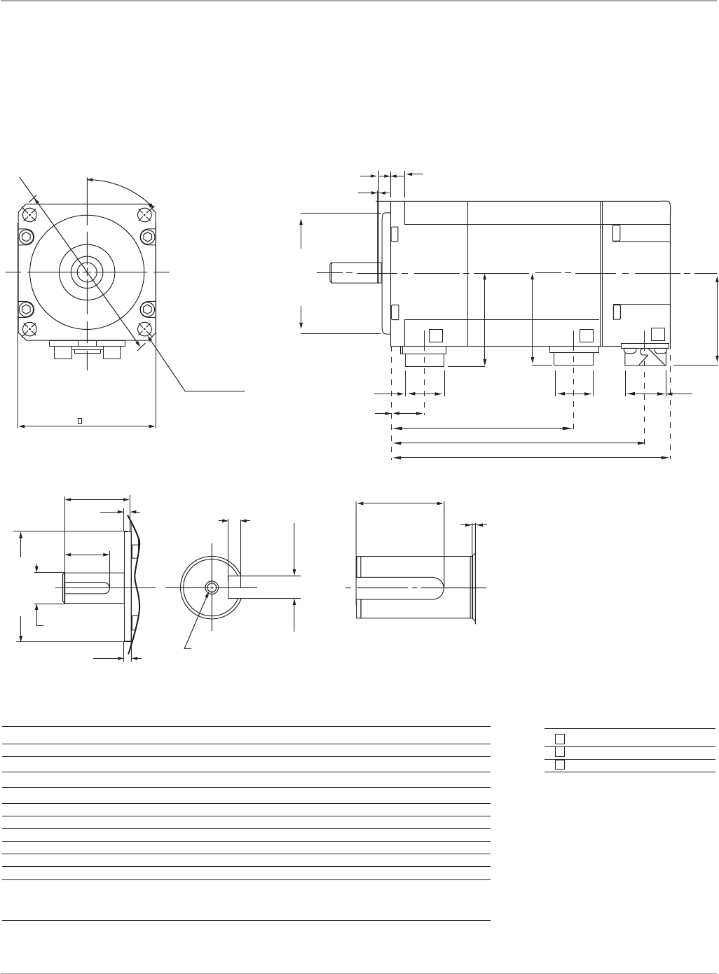
109
Motion Solutions
www.ge-ip.com GE Intelligent Platforms
Servo Motors
(3)
3.5
20
A4
A5
A2 A3
20
0.5
A1
ø 50 -0.025
+0
B04/4_05/5_1/5iseries_SHAFT.eps
βis Series Servo Motors
Dimensions
β0.4/5000is, β0.5/6000is, β1/6000is
16.8
6
3
0.5
38.2
37.6
37.7
15.8 15.8
14 C
B
A
ø 50-0.025
+0
ø
1 2 3
B04/5_05/5_1/5iseries_MOTOR.eps
45º
ø 80
60
4-ø5.5
ON ø70 D.B.C
Connector Description
1 Brake(optional)
2 Power
3 Encoder
Shaft detail
Motor
Dimensions shown mm
Dimension β0.4/5000is β0.5/6000is β1/6000is
A 75 89.5 118.5
Awithbrake 101.5 116 145
A1 ø9 0
-0.009 ø9 0
-0.009 ø14 0
-0.011
A2 1.20
-0.1 1.2 0
-0.1 2 0
-0.1
A3 30
-0.025 3 0
-0.025 50
-0.33
A4 M3Depth6 M3Depth6 M4Depth10
A5 25 25 30
B 65 79.5 108.5
Bwithbrake 91.5 106 135
C 34.5 49 78
Cwithbrake 61 75.5 104.5
Notes
1. Shaftdiameterrunout=0.02mmmax
2. Flangesurfacerunout=0.06mmmax
3. Maximumradialloadforoutputshaftis20kgf(44lb)
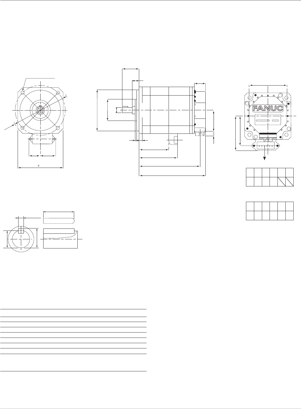
Motion Solutions
110 www.ge-ip.com
Servo Motors
GE Intelligent Platforms
βis Series Servo Motors
Dimensions
β2/4000is, β2/4000HVis
B2/4_4/4iseries_SHAFT.eps
11.2
10
3
18
-0.025
+0
-0.009
+0
5
M5 Depth 12
16
11
-0.030
+0
14
23
128
+0.001
+0.012
ø
90
21.4 30.6
B2/4_iseries_MOTOR.eps
ø
120
4-ø6.6 ON ø10 0 D.B.C
7
3
10
32
12
D
C
B
A
4
22
40
8.7
ø 80
ø 43
-0.03
+0
-0.5
+0.5
66.2
56.7
75
Shaft detail
Motor
Dimensions shown mm
β2/4000is
Dimension β2/4000HVis
A 130
Awithbrake 159
B 119
Bwithbrake 148
C 75
Cwithbrake 75
D 59
Dwithbrake 59
Notes
1. Shaftdiameterrunout=0.02mmmax
2. Flangesurfacerunout=0.06mmmax
3. Maximumradialloadforoutputshaftis25kgf(55lb)
1 2 3 4 5
U V WG
6
Power Connections
1 2 3 4 5
U V WGB B
6
Power/Brake Connections
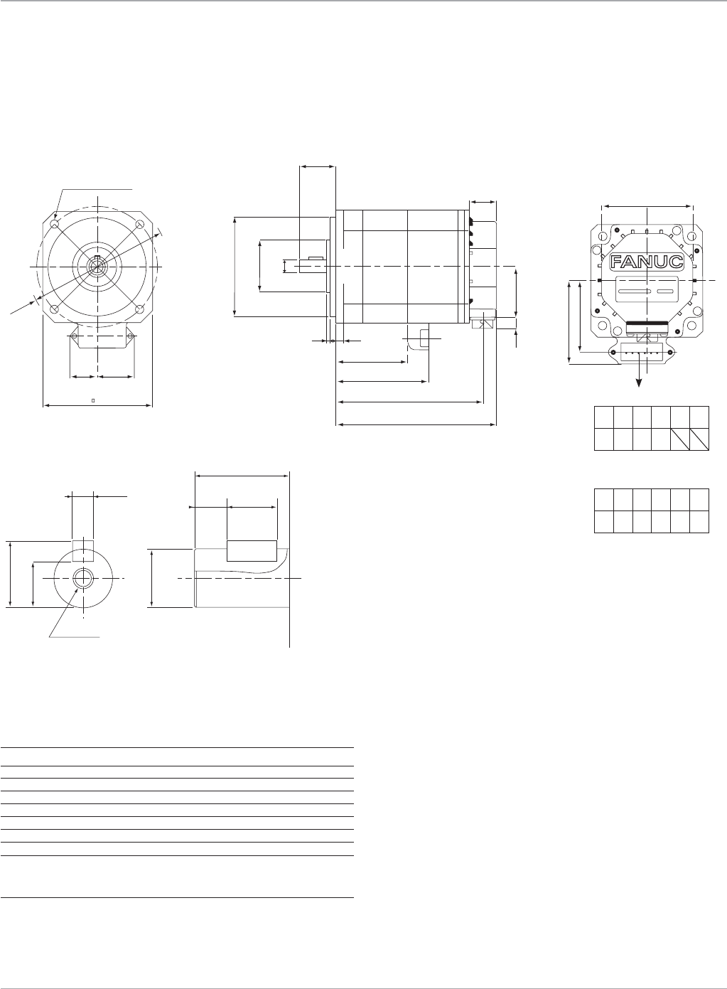
111
Motion Solutions
www.ge-ip.com
Servo Motors
GE Intelligent Platforms
βis Series Servo Motors
Dimensions
β4/4000is, β4/4000HVis
B2/4_4/4iseries_SHAFT.eps
11.2
10
3
18
-0.025
+0
-0.009
+0
5
M5 Depth 12
16
11
-0.030
+0
14
23
128
+0.001
+0.012
ø
90
21.4 30.6
B4/4_iseries_MOTOR.eps
ø
120
4-ø6.6 ON ø10 0 D.B.C
7
30
D
C
B
A
22
40
8.7
ø 80
ø 43
-0.03
+0
3
4
14
66.2
56.7
75
Shaft detail
Motor
Dimensions shown mm
β4/4000is
Dimension β4/4000HVis
A 166
Awithbrake 195
B 155
Bwithbrake 184
C 111
C with brake 111
D 95
Dwithbrake 95
Notes
1. Shaftdiameterrunout=0.02mmmax
2. Flangesurfacerunout=0.06mmmax
3. Maximumradialloadforoutputshaftis25kgf(55lb)
1 2 3 4 5
U V WG
6
Power Connections
1 2 3 4 5
U V WGB B
6
Power/Brake Connections
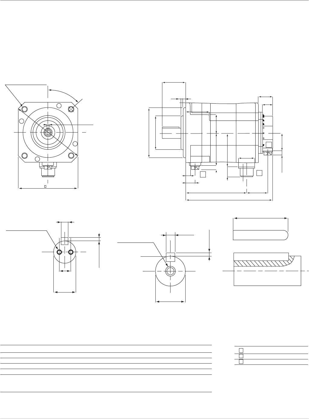
Motion Solutions
112 www.ge-ip.com
Servo Motors
GE Intelligent Platforms
B8/3_12/3iseries_SHAFT.eps
8
M8 DEPTH 16
24
A1
-0.036
+0
3-0.29
+0
-0.021
+0
ø
2.5
10
2 - M4 DEPTH 10
-0.13
+0
19 -0.013
+0
6-0.03
+0
ø
B8/3_12/3iseries_MOTOR.eps
1
B
20
10
A
2
47
3
31
52
6
55
4
40
35
25
75
(8.7)
(8.7)
22
39.5
72
74
110
22
ø
ø
-0.035
+0
45º
130
5
4-ø9 ON ø145 D.B.C.
ø165
-0.030
+0
Connector Description
1 Brake(optional)
2 Power
3 Encoder
Shaft detail
Motor
βis Series Servo Motors
Dimensions
β8/3000is, β8/3000HVis,
β12/3000is, β12/3000HVis
Dimensions shown mm
β8/3000is β12/3000is
Dimension β8/3000HVis β12/3000HVis
A 166 222
Awithbrake 191 247
A1 36 45
B 108 164
Bwithbrake 133 189
Notes
1. Shaftdiameterrunout=0.02mmmax
2. Flangesurfacerunout=0.05mmmax
3. Maximumradialloadforoutputshaftis70kgf(154lb)
β8/3000is
β8/3000HVis
β12/3000is
β12/3000HVis
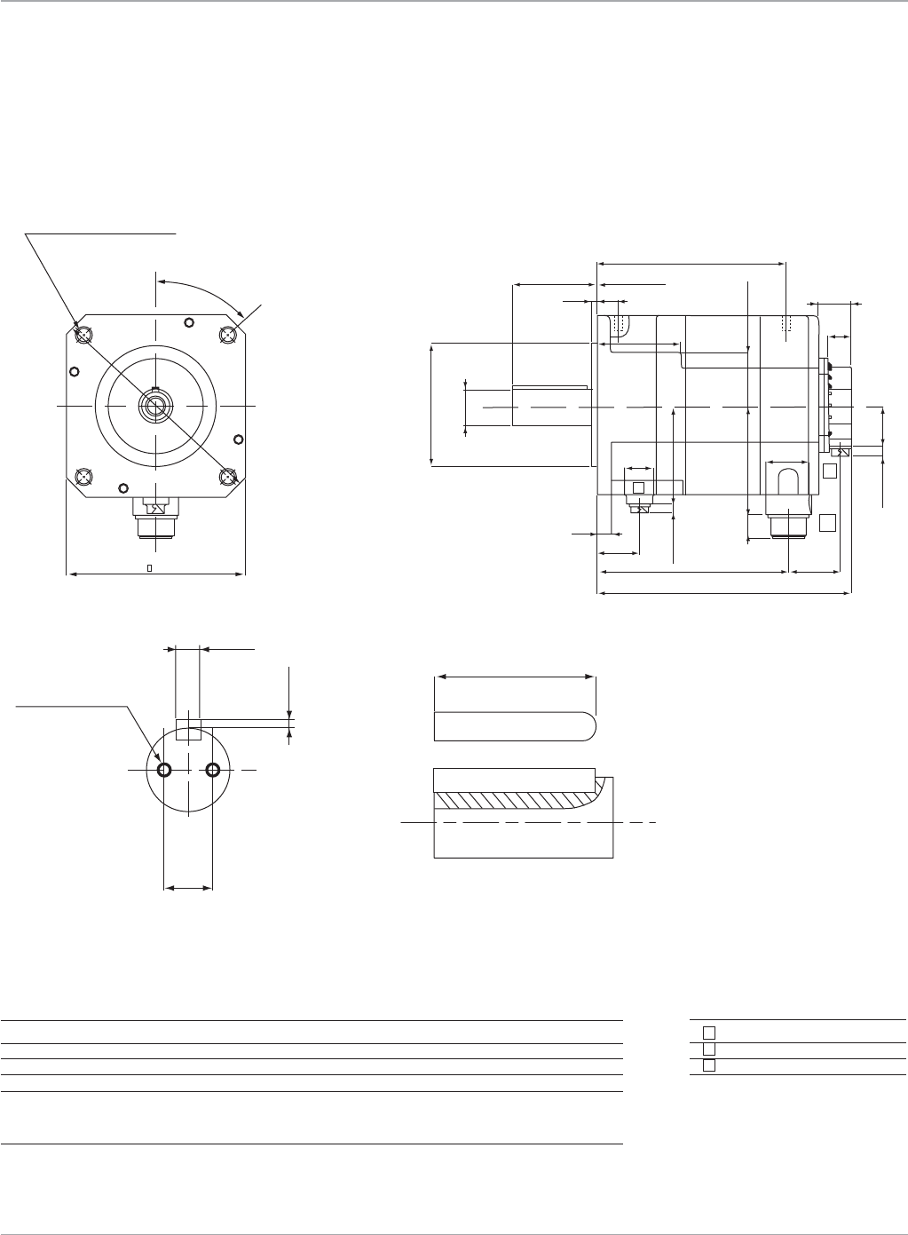
113
Motion Solutions
www.ge-ip.com
Servo Motors
GE Intelligent Platforms
B22/2iseries_SHAFT.eps
70
3
2 - M6 DEPTH 10
-0.30
+0
20
10 -0.038
+0
1
B
B
12
38
25
A
2
50
44
22
31
80
3.2
79
20
22 ± 0.5
40
(8.7)
(8.7)
(22) 105
94
51 (4 sides)
114.3
35
3
ø
ø
-0.025
+0
-0
+0.01
B22/2iseries_MOTOR.eps
45º
174
4-ø13.5 ON ø200 D.B.C.
ø
230
Connector Description
1 Brake(optional)
2 Power
3 Encoder
Shaft detail
Motor
βis Servo Series Motors
Dimensions
β22/2000is, β22/2000HVis
Dimensions shown mm
β22/2000is
Dimension β22/2000HVis
A 202
Awithbrake 243
B 141
Bwithbrake 182
Notes
1. Shaftdiameterrunout=0.03mmmax
2. Flangesurfacerunout=0.06mmmax
3. Maximumradialloadforoutputshaftis200kgf(440lb)
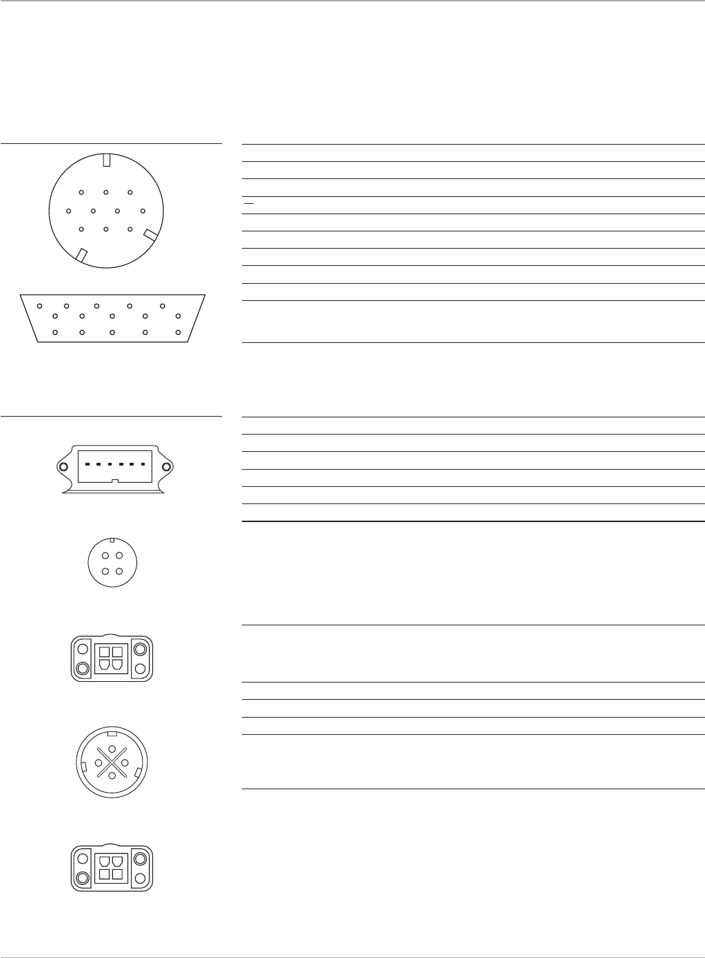
Motion Solutions
114 www.ge-ip.com
Servo Motors
GE Intelligent Platforms
βi Series Amplifier
Description βis and βHVis Motors JF1 Connector
N/C 2 1
N/C 1 2
RD 6 5
RD 5 6
+5VDC 8,9 9,20
0VDC 7,10 12,14
+6VA(battery) 4 7
FrameGround 3 16
CableShield 3 16
GEMatingMotorConnector:
ZA06B-6114-K204#E(90degree)
ZA06B-6114-K204#S(Straight)
β2
i
s & β4
i
s β8
i
s, β12
i
s, & β22
i
s β
i
-Series Amplifier
β0.4
i
s, β0.5
i
s & β1
i
s β2HV
i
s & β4HV
i
s β8HV
i
s, β12HV
i
s, & β22HV
i
s CZ7/CZ5 Connector
Description Motor Connector Motor Connector Motor Connector
PhaseU 1 1 A U
PhaseV 2 2 B V
PhaseW 3 3 C W
Earth(case) 4 4 D PE
BrakeVDC n/a 5 n/a n/a
BrakeVDC n/a 6 n/a n/a
GEMatingMotorConnector: AmplifierMatingConnector:
ZA06B-6114-K220#E(90degree)(β2is, β4is, β2HVis, β4HVis) ZA06B-6130-K200(β0.4 to β8is)
ZA06B-6114-K220#S(Straight)(β2is, β4is, β2HVis, β4HVis) ZA06B-6110-K202#YYS(β12is, β22is,
Z44A730464-G18(90degree)(β8is, β12is, β8HVis, β12HVis) AllβHVis)
Z44A730464-G17(Straight)(β2is, β4is, β2HVis, β4HVis)
ZA06B-6114-K230#E(β0.4is, β0.5is, β1is)
Z44A730464-G20(90degree)(β22is, β22HVis)
Z44A730464-G19(Straight)(β22is, β22HVis)
β
8
i
s,
β
12
i
s, &
β
22
i
s
β
0.4
i
s,
β
0.5
i
s &
β
1
i
s
β
8HV
i
s,
β
12HV
i
s, &
β
22HV
i
s
Description Motor Brake Connector Motor Brake Connector
BrakeVDC 1 1
BrakeVDC 2 2
Earth(case) 4 4
GEMatingMotorConnector:
ZA06B-6114-K213#E(90degree)(β8
i
s, β12
i
s, β22
i
s, β8HV
i
s, β12HV
i
s, β22HV
i
s)
ZA06B-6114-K213#S(Straight)(β8
i
s, β12
i
s, β22
i
s, β8HV
i
s, β12HV
i
s, β22HV
i
s)
ZA06B-6114-K232#E(β0.4
i
s, β0.5
i
s, β1
i
s)
24VDCBrakepowerconnectionsarenotpolarized.
Allβis and βHVis Motors
Connections
Serial Encoder Connections
1 2 3
8 9 10
4 5 6 7
1
3
2
4
2
3
1
4
β8is, β12is and β22is MotorPower
β8HVis, β12HVis and β22HVis MotorPower
β0.4is, β0.5is and β1is MotorPower
β8is, β12is and β22is Brake
β8HVis, β12HVis and β22HVis Brake
β0.4is, β0.5is and β1isBrake
Power and Brake Connections
A
BC
D
2
3
1
4
654321
β2is and β4isMotorPower/Brake
β2HVis and β4HVisMotorPower/Brake
βiand βHVisAmplifier(JF1)
3579
46810
14 16 18 20
1
2
12
βis and βHVis Series Servo Motors

115
Motion Solutions
www.ge-ip.com
Servo Motors
GE Intelligent Platforms
βis Series Servo Motors
Ordering Information
Model Number Description
ZA06B-0114-B203 β0.4/5000
i
s Servo Motor
ZA06B-0114-B203#0100 β0.4/5000
i
sServoMotor,IP67Protection
ZA06B-0114-B503 β0.4/5000
i
sServoMotorwithBrake
ZA06B-0114-B503#0100 β0.4/5000
i
sServoMotorwithBrake,IP67Protection
ZA06B-0115-B203 β0.5/6000
i
s Servo Motor
ZA06B-0115-B203#0100 β0.5/6000
i
sServoMotor,IP67Protection
ZA06B-0115-B503 β0.5/6000
i
sServoMotorwithBrake
ZA06B-0115-B503#0100 β0.5/6000
i
sServoMotorwithBrake,IP67Protection
ZA06B-0116-B203 β1/6000
i
s Servo Motor
ZA06B-0116-B203#0100 β1/6000
i
sServoMotor,IP67Protection
ZA06B-0116-B503 β1/6000
i
sServoMotorwithBrake
ZA06B-0116-B503#0100 β1/6000
i
sServoMotorwithBrake,IP67Protection
ZA06B-0061-B203 β2/4000
i
s Servo Motor
ZA06B-0061-B203#0100 β2/4000
i
sServoMotor,IP67Protection
ZA06B-0061-B503 β2/4000
i
sServoMotorwithBrake
ZA06B-0061-B503#0100 β2/4000
i
sServoMotorwithBrake,IP67Protection
ZA06B-0063-B203 β4/4000
i
s Servo Motor
ZA06B-0063-B203#0100 β4/4000
i
sServoMotor,IP67Protection
ZA06B-0063-B503 β4/4000
i
sServoMotorwithBrake
ZA06B-0063-B503#0100 β4/4000
i
sServoMotorwithBrake,IP67Protection
ZA06B-0075-B203 β8/3000
i
s Servo Motor
ZA06B-0075-B203#0100 β8/3000
i
sServoMotor,IP67Protection
ZA06B-0075-B503 β8/3000
i
sServoMotorwithBrake
ZA06B-0075-B503#0100 β8/3000
i
sServoMotorwithBrake,IP67Protection
ZA06B-0078-B203 β12/3000
i
s Servo Motor
ZA06B-0078-B203#0100 β12/3000
i
sServoMotor,IP67Protection
ZA06B-0078-B503 β12/3000
i
sServoMotorwithBrake
ZA06B-0078-B503#0100 β12/3000
i
sServoMotorwithBrake,IP67Protection
ZA06B-0085-B203 β22/2000
i
s Servo Motor
ZA06B-0085-B203#0100 β22/2000
i
sServoMotor,IP67Protection
ZA06B-0085-B503 β22/2000
i
sServoMotorwithBrake
ZA06B-0085-B503#0100 β22/2000
i
sServoMotorwithBrake,IP67Protection
βHVis Series Servo Motors
Ordering Information
Model Number Description
ZA06B-0062-B203
β
2/4000HVis Servo Motor
ZA06B-0062-B203#0100
β
2/4000HVisServoMotor,IP67Protection
ZA06B-0062-B503
β
2/4000HVisServoMotorwithBrake
ZA06B-0062-B503#0100
β
2/4000HVisServoMotorwithBrake,IP67Protection
ZA06B-0064-B203
β
4/4000HVis Servo Motor
ZA06B-0064-B203#0100
β
4/4000HVisServoMotor,IP67Protection
ZA06B-0064-B503
β
4/4000HVisServoMotorwithBrake
ZA06B-0064-B503#0100
β
4/4000HVisServoMotorwithBrake,IP67Protection
ZA06B-0076-B203
β
8/3000HVis Servo Motor
ZA06B-0076-B203#0100
β
8/3000HVisServoMotor,IP67Protection
ZA06B-0076-B503
β
8/3000HVisServoMotorwithBrake
ZA06B-0076-B503#0100
β
8/3000HVisServoMotorwithBrake,IP67Protection
ZA06B-0079-B203
β
12/3000HVis Servo Motor
ZA06B-0079-B203#0100
β
12/3000HVisServoMotor,IP67Protection
ZA06B-0079-B503
β
12/3000HVisServoMotorwithBrake
ZA06B-0079-B503#0100
β
12/3000HVisServoMotorwithBrake,IP67Protection
ZA06B-0086-B203
β
22/2000HVis Servo Motor
ZA06B-0086-B203#0100
β
22/2000HVisServoMotor,IP67Protection
ZA06B-0086-B503
β
22/2000HVisServoMotorwithBrake
ZA06B-0086-B503#0100
β
22/2000HVisServoMotorwithBrake,IP67Protection
Motor Cables
See applicable amplifier section for information about the proper
cables to use with each motor.

Motion Solutions
116 www.ge-ip.com
Servo Motors
GE Intelligent Platforms
VersaMotion Servo Motors
Specifications
Specifications IC800VMM01L IC800VMM02L IC800VMM04L IC800VMM07L
ProductName VersaMotion100Watt VersaMotion200Watt VersaMotion400Watt VersaMotion750Watt
RatedOutput(kW) 0.1 0.2 0.4 0.75
RatedTorque(Nm) 0.32 0.64 1.27 2.39
MaximumTorque(Nm) 0.96 1.92 3.82 7.16
RatedSpeed(RPM) 3000 3000 3000 3000
MaximumSpeed(RPM) 5000 5000 5000 5000
RatedCurrent(Amps) 0.9 1.55 2.6 5.1
MaximumCurrent(Amps) 2.7 4.65 7.8 15.3
RotorMomentofInertia(Kg.m2x10-4) 0.037 0.177 0.277 1.13
MechanicalTimeConstant(msec) 0.75 0.8 0.53 0.63
TorqueConstant-KT(Nm/A) 0.36 0.41 0.49 0.47
VoltageConstant-KE(mV/rpm) 13.6 16 17.4 17.2
ArmatureResistance(Ohm) 9.3 2.79 1.55 0.42
ArmatureInductance(mH) 24 10.84 6.84 3.53
ElectricalTimeConstant(msec) 2.58 3.89 4.43 8.37
MaximumRadialShaftLoad(Newton) 78.4 196 196 245
MaximumThrustShaftLoad(Newton) 39.2 68 68 98
AmplifierModel IC800VMA012 IC800VMA022 IC800VMA042 IC800VMA072
Motor Technical Data
InsulationClass ClassB
InsulationResistance >100Mohm,500VDC
InsulationStrength 1500VAC,50Hz,60seconds
VibrationGrade(um) 15
BrakePower(VDC) 24
Vibration 2.5G
IPRating IP65(exceptshaftandconnector)
Environmental Specifications
RelativeHumidity 20~90%RH(noncondensing)
OperatingTemperature 0to40°C
StorageTemperature -10to80°C

117
Motion Solutions
www.ge-ip.com
Servo Motors
GE Intelligent Platforms
VersaMotion Servo Motors
Specifications (continued)
Specifications IC800VMM10L IC800VMM10M IC800VMM20L IC800VMM20M IC800VMM30M
ProductName VersaMotion1000Watt VersaMotion1000Watt VersaMotion2000Watt VersaMotion2000Watt VersaMotion3000Watt
RatedOutput(kW) 1.0 1.0 2.0 2.0 3.0
RatedTorque(Nm) 3.18 4.77 6.37 9.55 14.32
MaximumTorque(Nm) 9.54 14.32 19.11 28.66 42.96
RatedSpeed(RPM) 3000 2000 3000 2000 2000
MaximumSpeed(RPM) 5000 3000 5000 3000 3000
RatedCurrent(Amps) 7.3 5.6 11.3 11.0 16.1
MaximumCurrent(Amps) 21.9 24.9 33.9 33.0 48.3
RotorMomentofInertia(Kg.m2x10-4) 2.65 9.14 4.45 15.88 55
MechanicalTimeConstant(msec) 0.74 1.64 0.66 1.05 1.06
TorqueConstant-KT(Nm/A) 0.44 0.85 0.53 0.87 0.89
VoltageConstant-KE(mV/rpm) 16.8 31.9 19.2 31.8 32
ArmatureResistance(Ohm) 0.20 0.465 0.14 0.174 0.052
ArmatureInductance(mH) 2.0 5.99 1.53 2.76 1.38
ElectricalTimeConstant(msec) 10.26 12.88 10.63 15.86 26.39
MaximumRadialShaftLoad(Newton) 490 490 490 490 1470
MaximumThrustShaftLoad(Newton) 98 98 98 98 490
AmplifierModel IC800VMA102 IC800VMA102 IC800VMA202 IC800VMA202 IC800VMA302
Motor Technical Data
InsulationClass ClassB
InsulationResistance >100Mohm,500VDC
InsulationStrength 1500VAC,50Hz,60seconds
VibrationGrade(um) 15
BrakePower(VDC) 24
Vibration 2.5G
IPRating IP65(exceptshaftandconnector)
Environmental Specifications
RelativeHumidity 20~90%RH(noncondensing)
OperatingTemperature 0to40°C
StorageTemperature -10to80°C
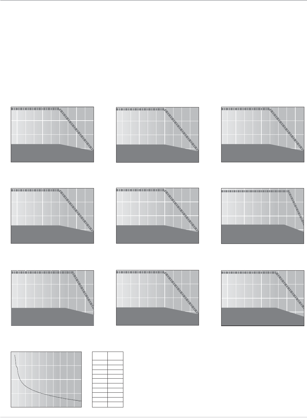
Motion Solutions
118 www.ge-ip.com
Servo Motors
GE Intelligent Platforms
VersaMotion Servo Motors
Speed Torque Curves
Torque (Nm)
IC800VMM02L (200 Watt)
Speed (RPM)
0
0.5
2
1
1.5
4500 5000
4000
3500
300025001500 20001000500
Continuous Operation
Intermittent Operation
Torque (Nm)
IC800VMM30M (3000 Watt)
Speed (RPM)
0
11
44
22
33
2700 3000
2400
2100
18001500900 1200600300
Continuous Operation
Intermittent Operation
Operating Time (seconds)
Load Torque vs. Operating Time
Load (% rated torque)
101
102
103
104
280 300
260
240
220200160 180140120
100
100
Operating
Load Time
120% 263.8 s
140% 35.2 s
160% 17.6 s
180% 11.2 s
200% 8 s
220% 6.1 s
240% 4.8 s
260% 3.9 s
280% 3.3 s
300% 2.8 s
Torque (Nm)
IC800VMM10M (1000 Watt)
Speed (RPM)
0
3.75
15
7.5
11.25
Continuous Operation
Intermittent Operation
2700 3000
2400
2100
18001500900 1200600300
Torque (Nm)
IC800VMM04L (400 Watt)
Speed (RPM)
0
1
4
2
3
4500 5000
4000
3500
300025001500 20001000500
Continuous Operation
Intermittent Operation
Torque (Nm)
IC800VMM07L (750 Watt)
Speed (RPM)
0
1.8
7.2
3.6
5.4
4500 5000
4000
3500
300025001500 20001000500
Continuous Operation
Intermittent Operation
Torque (Nm)
IC800VMM01L (100 Watt)
Speed (RPM)
0
0.25
1
0.5
0.75
4500 5000
4000
3500
300025001500 20001000500
Continuous Operation
Intermittent Operation
Torque (Nm)
IC800VMM10L (1000 Watt)
Speed (RPM)
0
2.5
10
5
7.5
4500 5000
4000
3500
300025001500 20001000500
Continuous Operation
Intermittent Operation
The curves illustrate the relationship
between motor speed and output
torque. The motor can operate continu-
ously at any combination of speed and
torque within the prescribed continuous
operating zone. The limit of the continu-
ous operating zone is determined with
the motor’s ambient temperature at 20°C
and its drive current as a pure sine wave.
Actualoperationislimitedbythecurrent
of the servo drive unit. The continuous
operating zone must be derated for
ambient temperature above 20°C.
Torque (Nm)
IC800VMM20M (2000 Watt)
Speed (RPM)
0
5
20
10
15
4500 5000
4000
3500
300025001500 20001000500
Continuous Operation
Intermittent Operation
Torque (Nm)
IC800VMM20L (2000 Watt)
Speed (RPM)
0
7.5
30
15
22.5
Continuous Operation
Intermittent Operation
2700 3000
2400
2100
18001500900 1200600300
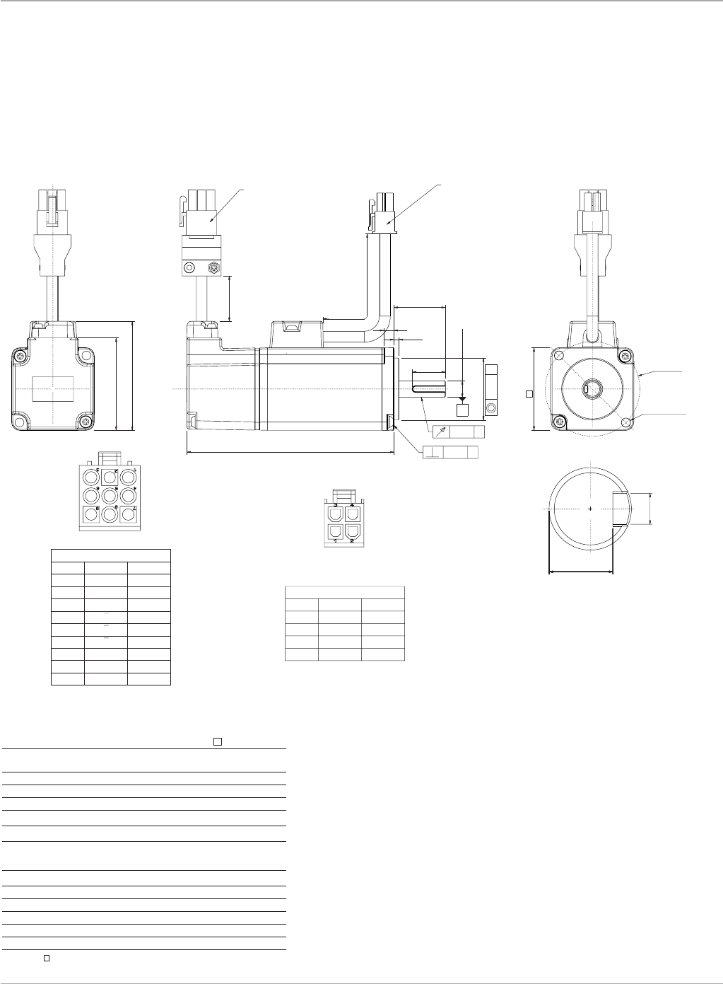
119
Motion Solutions
www.ge-ip.com
Servo Motors
GE Intelligent Platforms
VersaMotion Servo Motors
Dimensions
IC800VMM01L
0.04 M
Ø h7LB
LE
LR
300±50
LL
ØLA
2-Ø LZ
LC
( )44.95
( )52.95
LG
LW
RH
KW
M
Ø h6S
MOTOR CONNECTION
PIN No. FUNCTION COLOR
1URED
2VWHT
3WBLK
4C.G. GRN/YEL
ENCODER CONNECTION
PIN No. FUNCTION COLOR
1ABLK
2BWHT
3ZORG
4ABLK/RED
5BWHT/RED
6ZORG/RED
7 DC+5V BRN
8 GND BLU
9 SHIELD SHIELD
SHAFT END DETAILS
300±50
0.04 M
ENCODER CONNECTION
AMP 1-172169-9
MOTOR CONNECTION
C4202H00-2X2P
0.02 M
Dimension IC800VMM01L
LC 40
LZ 4.5
LA 46
S 8
LB 30
LL 100.6
LLwithbrake N/A(nobrakeavailableon
100Wattmodelatthistime)
LR 25
LE 2.5
LG 5
LW 16
RH 6.2
KW 3
Theboxes()attheendsofthemodelnamesareforshafttypeoroptions
(keyway,brakeandoilseal)
Dimensions shown mm
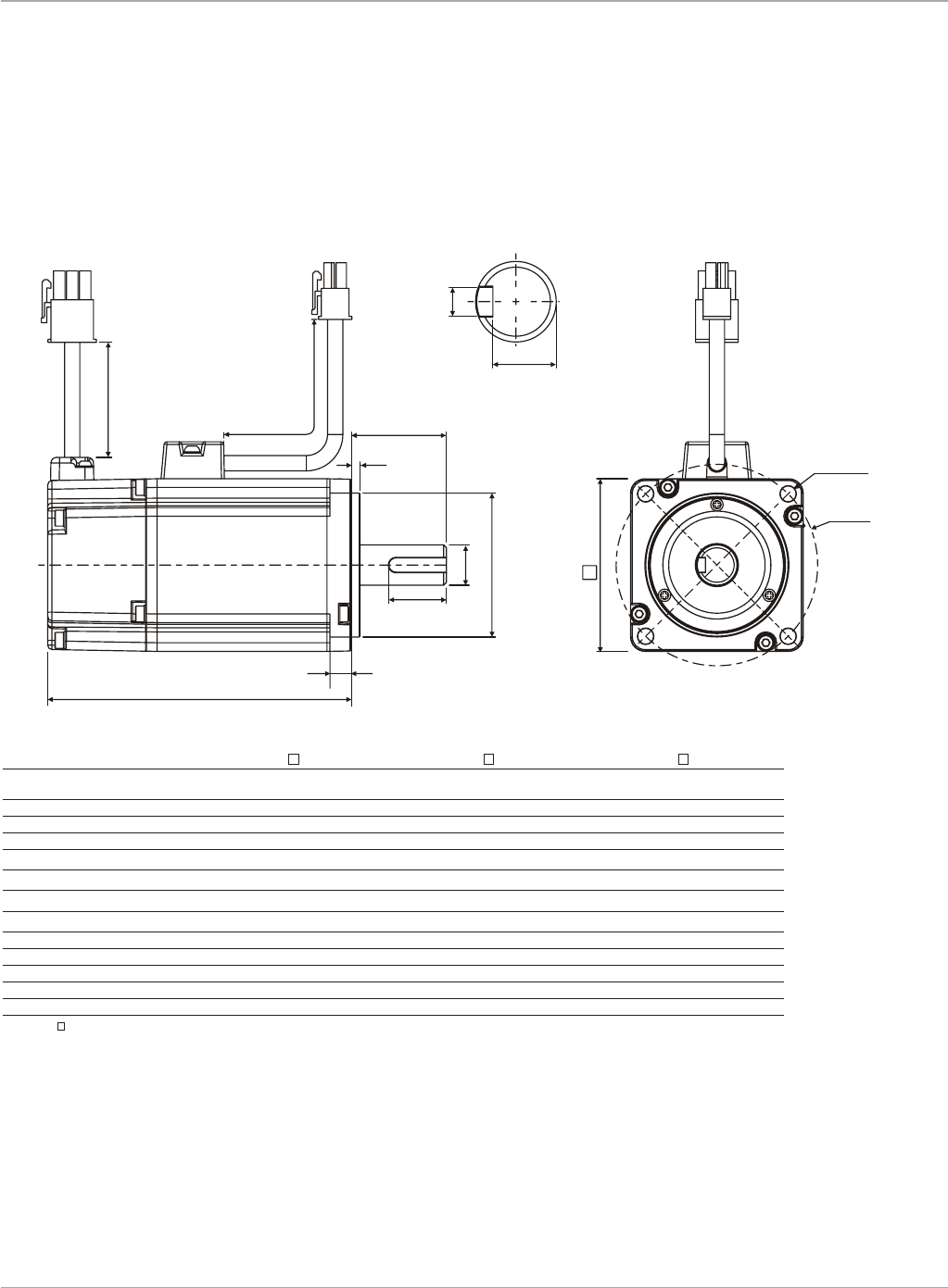
Motion Solutions
120 www.ge-ip.com
Servo Motors
GE Intelligent Platforms
VersaMotion Servo Motors
Dimensions
IC800VMM02L, IC800VMM04L, IC800VMM07L
300 ± 50 LR
RH
4-ØLZ
ØLA
LE
LW
LG
LL
ØSh6
ØLBh7
300 ± 50
LC
KW
Dimension IC800VMM02L IC800VMM04L IC800VMM07L
LC 60 60 80
LZ 5.5 5.5 6.6
LA 70 70 90
S 14 14 19
LB 50 50 70
LL 105.5 130.7 138.3
LLwithbrake 141.6 166.8 178
LR 30 30 35
LE 3 3 3
LG 7.5 7.5 8
LW 20 20 25
RH 11 11 15.5
KW 5 5 6
Theboxes()attheendsofthemodelnamesareforshafttypeoroptions(keyway,brakeandoilseal)
Dimensions shown mm
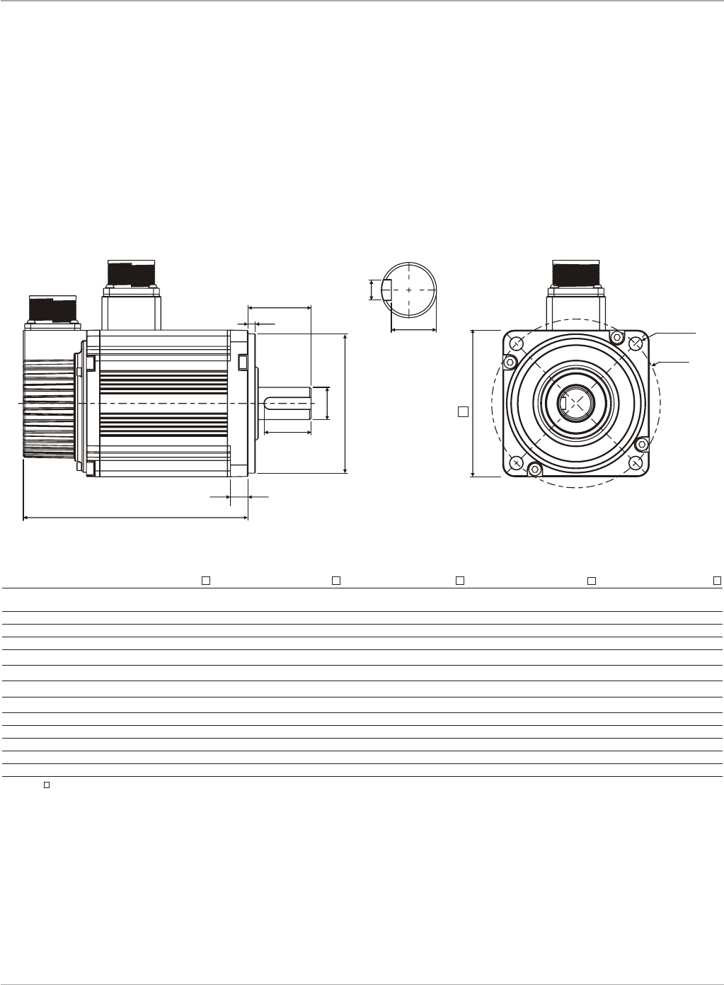
121
Motion Solutions
www.ge-ip.com
Servo Motors
GE Intelligent Platforms
VersaMotion Servo Motors
Dimensions
IC800VMM10L, IC800VMM10M, IC800VMM20L, IC800VMM20M, IC800VMM30M
LR
RH 4-ØLZ
ØLA
LE
LW
LG
LL
ØSh6
ØLBh7
LC
KW
Dimension IC800VMM10L IC800VMM10M IC800VMM20 L IC800VMM20 M IC800VMM30M
LC 100 130 100 130 180
LZ 9 4 9 4 13.5
LA 115 145 115 145 200
S 22 22 22 22 35
LB 95 110 95 110 114.3
LL 153.5 147.5 199 187.5 202.1
LLwithbrake 192.5 183.5 226 216 235
LR 45 55 45 55 79
LE 5 6 5 6 4
LG 12 11.5 12 11.5 20
LW 32 36 32 36 63
RH 18 18 18 18 30
KW 8 8 8 8 10
Theboxes()attheendsofthemodelnamesareforshafttypeoroptions(keyway,brakeandoilseal)
Dimensions shown mm

Motion Solutions
122 www.ge-ip.com
Servo Motors
GE Intelligent Platforms
VersaMotion Servo Motors
Ordering Information
Part Number
Motor Only Description Amplifier
IC800VMM01LNKSE25 100WattVersaMotionServoMotor IC800VMA012
IC800VMM02LNKSE25 200WattVersaMotionServoMotor IC800VMA022
IC800VMM02LBKSE25 200WattVersaMotionServoMotorwithBrake IC800VMA022
IC800VMM04LNKSE25 400WattVersaMotionServoMotor IC800VMA042
IC800VMM04LBKSE25 400WattVersaMotionServoMotorwithBrake IC800VMA042
IC800VMM07LNKSE25 750WattVersaMotionServoMotor IC800VMA072
IC800VMM07LBKSE25 750WattVersaMotionServoMotorwithBrake IC800VMA072
IC800VMM10LNKSE25 1000WattVersaMotionServoMotor IC800VMA102
IC800VMM10MNKSE25 1000WattVersaMotionServoMotor IC800VMA102
IC800VMM10LBKSE25 1000WattVersaMotionServoMotorwithBrake IC800VMA102
IC800VMM10MBKSE25 1000WattVersaMotionServoMotorwithBrake IC800VMA102
IC800VMM20LNKSE25 2000WattVersaMotionServoMotor IC800VMA202
IC800VMM20MNKSE25 2000WattVersaMotionServoMotor IC800VMA202
IC800VMM20LBKSE25 2000WattVersaMotionServoMotorwithBrake IC800VMA202
IC800VMM20MBKSE25 2000WattVersaMotionServoMotorwithBrake IC800VMA202
IC800VMM30MNKSE25 3000WattVersaMotionServoMotor IC800VMA302
IC800VMM30MBKSE25 3000WattVersaMotionServoMotorwithBrake IC800VMA302
Motor Cables
See applicable amplifier section for information about the proper
cables to use with each motor.

123
Motion Solutions
www.ge-ip.com
Servo Motors
GE Intelligent Platforms
Specifications Units 3T11-G 3T12-G 3T13-G 3T21-G 3T22-G 3T23-G 3T24-H 3T42-H 3T43-H 3T43-J 3T44-J
Continuous Stall Torque1 in-lb(Nm) 2.7(0.30) 5.3(0.6) 8(0.9) 5.3(0.60) 11.5(1.3) 17.7(2.0) 23.0(2.6) 36.3(4.1) 50.4(5.7) 54.0(6.1) 72(8.13)
PeakTorque3 in-lb(Nm) 9.3(1.05) 20.8(2.35) 24.6(2.78) 19.9(2.25) 35.5(4.01) 53.5(6.05) 58.2(6.58) 105.8(11.9) 100(11.3) 106.7(12.06) 143.6(16.23)
RatedSpeed:
@120VACinput RPM 3,500 4,250 4,500 3,025 2,325 1,800 1,500 1,475 925 1,500 1,050
@240VACinput 7,000 8,500 9,000 6,050 4,650 3,600 3,000 2,950 1,850 3,000 2,100
@480VACinput n/a n/a n/a n/a n/a n/a n/a 5,900 n/a 6,800 5,100
No-loadSpeed:
@120VACinput RPM 6,450 5,400 5,300 4,625 3,550 2,350 2,175 2,000 1,300 2,025 1,500
@240VACinput 12,900 10,800 10,600 9,250 7,100 4,700 4,350 4,000 2,600 4,050 3,000
@480VACinput n/a n/a n/a n/a n/a n/a n/a 7,900 n/a 8,100 6,000
Feedback 4096counts/revresolver(controltransmitter;0.5transformationratio)
Weight lb(kg) 2.6(1.2) 3.3(1.5) 4.2(1.9) 3.7(1.7) 5.0(2.3) 6.4(2.9) 7.7(3.5) 136(6.2) 16.7(7.6) 16.7(7.6) 20(9.0)
RotorInertia in-lb-s2x10-4
(kg-m2 x10-4) 1.02(0.12) 1.64(0.19) 2.26(0.26) 1.9(0.22) 3.4(0.38) 4.9(0.55) 6.4(0.72) 32(3.6) 46(5.2) 46(5.2) 60(6.8)
Shaft Thrust Load2 lb(kg) n/a n/a n/a 17(7.7) 17(7.7) 17(7.7) 17(7.7) 41.5(18.9) 41.5(18.9) 41.5(18.9) 41.5(18.9)
Shaft Radial Load2 lb(kg) n/a n/a n/a 62(28.1) 62(28.1) 62(28.1) 62(28.1) 157(71.5) 157(71.5) 157(71.5) 157(71.5)
TorqueConstant in-lb/A(rms)
(Nm/A (rms)) 2.4(0.27) 2.9(0.32) 2.9(0.32) 3.3(0.37) 4.3(0.49) 6.5(0.74) 7.0(0.79) 7.7(0.87) 11.9(1.34) 7.5(0.85) 10.2(1.15)
Resistance(phase) Ohms 16.3 6.8 3.9 8.8 4.81 6.1 4.6 3.2 3.9 1.54 1.8
Inductance(phase) mH 7.1 4.3 2.7 10.5 7.4 10.6 8.9 8.9 13.0 5.3 7.1
ElectricalTimeConstant ms 0.43 0.63 0.69 1.19 1.54 1.73 1.93 2.78 3.33 3.44 3.94
ContinuousCurrent A(rms) 0.96 1.88 2.73 1.72 2.65 2.7 3.3 4.7 4.6 7.2 7.2
1Torqueshownisavailableuptoanambienttemperatureof25°Cwithmotormountedtoa10’x10’x0.25’aluminumheatsink.ForhigherambienttemperaturethecontinuousTorquemustbederated
bymultiplyingbythefollowingfactor(155-t)/130wheret=ambientmotortemperatureindegreesC(40°Cmax.).
2Shaft loads are based on L10 bearing life at 3000 rpm and assume force is applied to center of shaft.
3PeaktorqueratingsarelimitedbythespecificamplifierorcontrollershownintheMTR-Seriesmotororderinginformationbasedontheamplifier’speakcurrentlimitations.
Optional Brake Data
InertiaAdder in-lb-s2x10-4
(kg-m2x10-4) 1.1(0.12) 1.1(0.12) 1.1(0.12) 1.1(0.12) 1.1(0.12) 1.1(0.12) 1.1(0.12) 9.7(1.1) 9.7(1.1) 9.7(1.1) 9.7(1.1)
WeightAdder lb(kg) 0.4(0.2) 0.4(0.2) 0.4(0.2) 0.4(0.2) 0.4(0.2) 0.4(0.2) 0.4(0.2) 1.3(0.6) 1.3(0.6) 1.3(0.6) 1.3(0.6)
Voltage VDC±10% 24 24 24 24 24 24 24 24 24 24 24
Current A 0.33 0.33 0.33 0.33 0.33 0.33 0.33 0.66 0.66 0.66 0.66
EngageTime ms 25 25 25 25 25 25 25 20 20 20 20
ReleaseTime ms 25 25 25 25 25 25 25 30 30 30 30
Torque in-lb(Nm) 10.6(1.2) 10.6(1.2) 10.6(1.2) 10.6(1.2) 10.6(1.2) 10.6(1.2) 10.6(1.2) 88.5(10) 88.5(10) 88.5(10) 88.5(10)
Environmental Specifications
RelativeHumidity 98%non-condensing
AmbientTemperature -20to40°Coperating
StorageTemperature -30to150°C
MTR-3T Series Servo Motors
Specifications

Servo Motors
Motion Solutions
124 www.ge-ip.com
GE Intelligent Platforms
Specifications Units 3T45-H 3T54-H 3T55-H 3T57-H 3T66-H 3T67-G 3T69-G
Continuous Stall Torque1 in-lb(Nm) 90.3(10.2) 120(13.5) 151(17) 195(22) 318(36) 372(42) 477(53.9)
ContinuousTorque in-lb(Nm) n/a 119.3(13.48) 150.3(16.98) n/a 307(34.69) 358.5(40.5) 463(52.3)
w/480V,20AS2K
PeakTorque3 in-lb(Nm) 181(20.45) 304.9(34.45) 383.9(43.38) 488.8(55.2) 772.5(87.3) 902(102) 1165(132)
PeakTorque in-lb(Nm) n/a 339(38.3) 426(48.1) n/a 462(52.2) 540(61) 699(78.9)
w/480V,20AS2K
RatedSpeed:
@120VACinput RPM 825 n/a n/a n/a n/a n/a n/a
@240VACinput 1,650 2,100 1,650 2,450 1,450 1,250 950
@480VACinput 4,000 4,300 3,400 n/a 3,150 2,700 2,100
No-loadSpeed:
@120VACinput RPM 1,175 n/a n/a n/a n/a n/a n/a
@240VACinput 2,350 2,700 2,150 3,050 2,000 1,700 1,300
@480VACinput 4,750 5,450 4,300 n/a 3,950 3,400 2,650
Feedback 4096counts/revresolver(controltransmitter;0.5transformationratio)
Weight lb(kg) 22.9(10.4) 28.6(13) 33(15) 41.9(19) 79.3(36) 92.5(42) 119(54)
RotorInertia in-lb-s2x10-4
(kg-m2 x10-4) 74(8.4) 220(24.9) 271(30.6) 373(42.1) 833(94) 965(109) 1230(139)
Shaft Thrust Load2 lb(kg) 41.5(18.9) 31.5(18.9) 31.5(18.9) 31.5(18.9) 48.3(21.9) 48.3(21.9) 48.3(21.9)
Shaft Radial Load2 lb(kg) 157(71.5) 115(52.3) 115(52.3) 115(52.3) 200(45) 200(45) 200(45)
TorqueConstant in-lb/A(rms)
(Nm/A(rms)) 12.9(1.46) 11.3(1.27) 14.2(1.6) 10(1.13) 15.4(1.74) 18(2.04) 23.3(2.63)
Resistance(phase) Ohms 2.1 0.8 0.9 0.3 0.32 0.35 0.41
Inductance(phase) mH 8.7 7.1 8.8 3.1 6.5 7.7 10
ElectricalTimeConstant ms 4.1 8.9 9.8 10.3 20.3 22 24.4
ContinuousCurrent A(rms) 7.1 10.6 10.6 19.5 20.7 20.7 20.6
1Torqueshownisavailableuptoanambienttemperatureof25°Cwithmotormountedtoa10’x10’x0.25’aluminumheatsink.ForhigherambienttemperaturethecontinuousTorquemustbederated
bymultiplyingbythefollowingfactor(155-t)/130wheret=ambientmotortemperatureindegreesC(40°Cmax.).
2Shaft loads are based on L10 bearing life at 3000 rpm and assume force is applied to center of shaft.
3PeaktorqueratingsarelimitedbythespecificamplifierorcontrollershownintheMTR-Seriesmotororderinginformationbasedontheamplifier’speakcurrentlimitations.
Optional Brake Data
InertiaAdder in-lb-s2x10-4
(kg-m2x10-4) 9.7(1.1) 31.9(3.6) 31.9(3.6) 31.9(3.6) 84.1(9.5) 84.1(9.5) 84.1(9.5)
WeightAdder lb(kg) 1.3(0.6) 3.3(1.5) 3.3(1.5) 3.3(1.5) 4.8(2.2) 4.8(2.2) 4.8(2.2)
Voltage VDC±10% 24 24 24 24 24 24 24
Current A 0.48 0.41 0.41 0.41 0.73 0.73 0.73
EngageTime ms 20 25 25 25 25 25 25
ReleaseTime ms 30 50 50 50 75 75 75
Torque in-lb(Nm) 88.5(10) 159(16) 159(16) 159(16) 354(40) 354(40) 354(40)
Environmental Specifications
Humidity 98%non-condensing
AmbientTemperature -20to40°Coperating
StorageTemperature -30to150°C
MTR-3T Series Servo Motors
Specifications (continued)
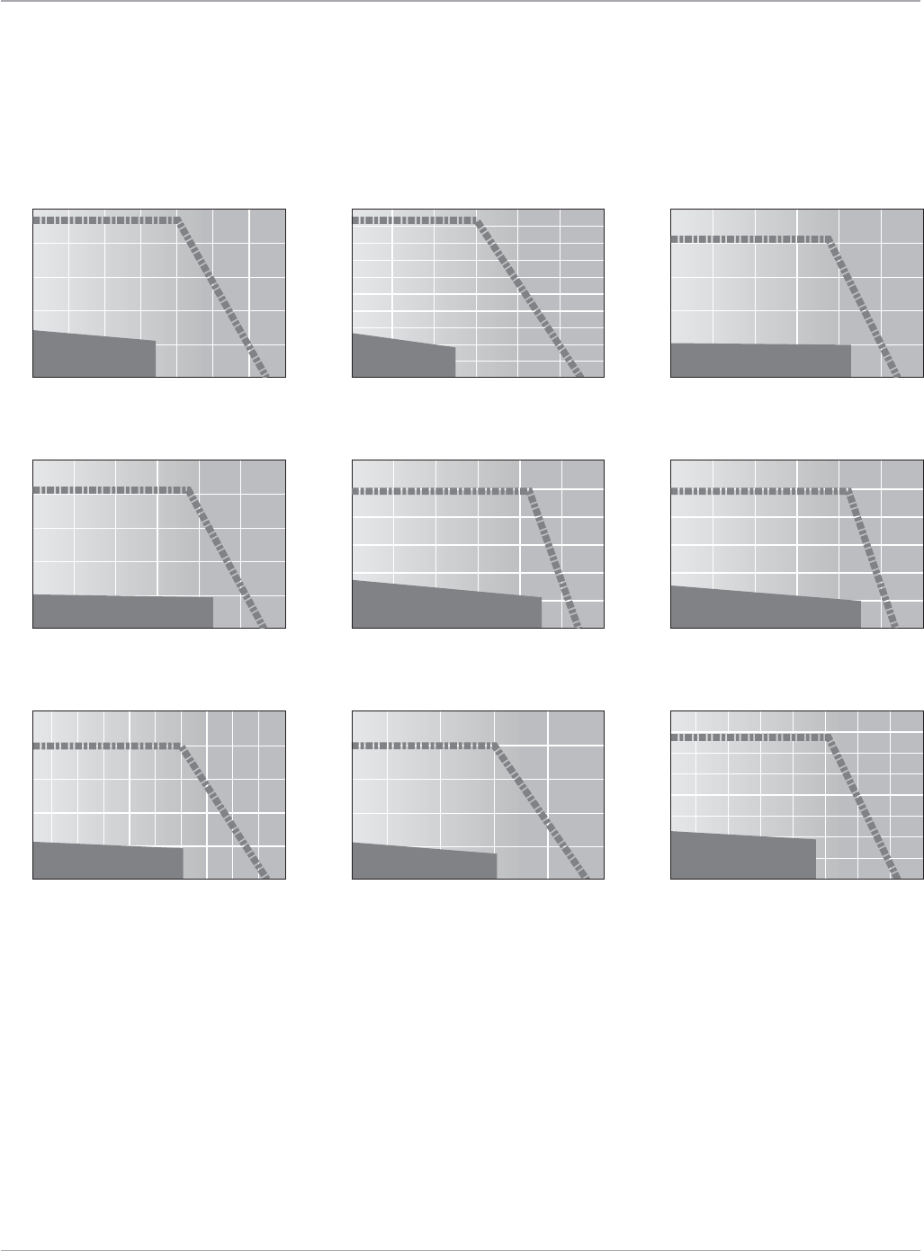
Servo Motors
125
Motion Solutions
www.ge-ip.com GE Intelligent Platforms
MTR-3T Series Servo Motors
Speed Torque Curves
Torque in-lb
MTR-3T11-G(115V)
Speed (RPM)
0
2
4
6
8
10
5000 7000
4000
3000
20001000
Intermittent Operation
Continuous Operation
6000
Torque in-lb
MTR-3T11-G(230V)
Speed (RPM)
0
2
1
3
5
7
9
4
6
8
10
10000 1400012000
8000
6000
4000
Intermittent Operation
Continuous Operation
Torque in-lb
MTR-3T12-G(115V)
Speed (RPM)
0
5
10
15
20
25
5000 6000
4000
3000
20001000
Intermittent Operation
Continuous Operation
Torque in-lb
MTR-3T12-G(230V)
Speed (RPM)
0
5
10
15
20
25
8000 10000 12000
6000
4000
2000
Intermittent Operation
Continuous Operation
Torque in-lb
MTR-3T13-G(115V)
Speed (RPM)
0
5
10
15
20
30
25
5000 6000
4000
3000
20001000
Intermittent Operation
Continuous Operation
Torque in-lb
MTR-3T13-G(230V)
Speed (RPM)
0
5
10
15
20
30
25
10000 12000
8000
6000
40002000
Intermittent Operation
Continuous Operation
Torque in-lb
MTR-3T21-G(115V)
Speed (RPM)
0
5
25
10
15
20
4500 5000
4000
3500
300025001500 20001000500
Continuous Operation
Intermittent Operation
Torque in-lb
MTR-3T21-G(230V)
Speed (RPM)
00
10
5
15
20
25
8000
600040002000
Intermittent Operation
Continuous Operation
10000
Torque in-lb
MTR-3T22-G(115V)
Speed (RPM)
0
5
10
15
25
20
35
30
40
4000
3000
2500
20001000500 1500
Intermittent Operation
Continuous Operation
3500
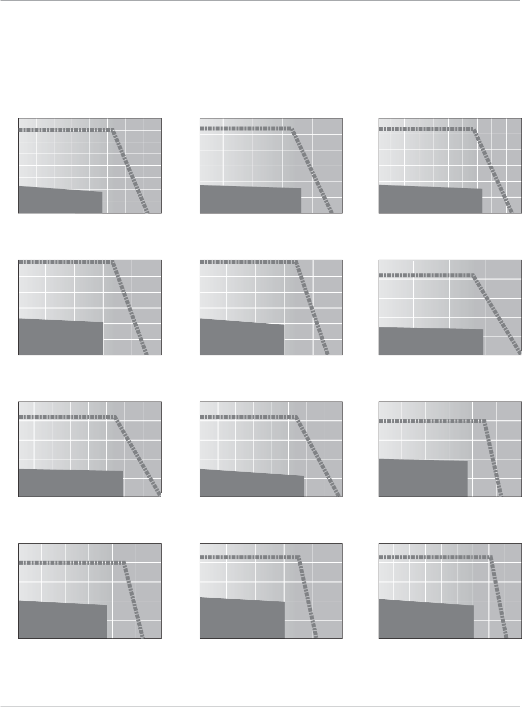
Motion Solutions
126 www.ge-ip.com
Servo Motors
GE Intelligent Platforms
MTR-3T Series Servo Motors
Speed Torque Curves (continued)
Torque in-lb
MTR-3T22-G(230V)
Speed (RPM)
8000
6000
4000 5000
3000
20001000
0
5
10
15
25
20
35
30
40
Continuous Operation
7000
Intermittent Operation
Torque in-lb
MTR-3T23-G(115V)
Speed (RPM)
0
20
10
30
40
50
60
2500
2000
1500
1000500
Intermittent Operation
Continuous Operation
Torque in-lb
MTR-3T23-G(230V)
Speed (RPM)
0
20
10
30
40
50
60
25002000 35003000 500045004000
1500
1000
500
Intermittent Operation
Continuous Operation
Torque in-lb
MTR-3T24-H(115V)
Speed (RPM)
0
20
10
30
40
50
60
2500
2000
1500
1000500
Intermittent Operation
Continuous Operation
Torque in-lb
MTR-3T24-H(230V)
Speed (RPM)
0
20
10
30
40
50
60
5000
4000
3000
20001000
Intermittent Operation
Continuous Operation
Torque in-lb
MTR-3T42-H(115V)
Speed (RPM)
0
25
50
75
100
125
1500
1000500
Intermittent Operation
Continuous Operation
2000
Torque in-lb
MTR-3T42-H(230V)
Speed (RPM)
0
25
50
75
100
125
2000
1500 3000
2500 3500
1000500
Intermittent Operation
Continuous Operation
4000
Torque in-lb
MTR-3T42-H(460V)
Speed (RPM)
0
25
50
75
100
125
4000
3000 7000
60005000
20001000
Continuous Operation
Intermittent Operation
8000
Torque in-lb
MTR-3T43-H(115V)
Speed (RPM)
0
25
50
75
100
125
15001000
750
500250
Continuous Operation
Intermittent Operation
1250
Torque in-lb
MTR-3T43-H(230V)
Speed (RPM)
0
25
50
75
100
125
30002000
1500 2500
1000500
Continuous Operation
Intermittent Operation
Torque in-lb
MTR-3T43-J(115V)
Speed (RPM)
0
25
50
75
100
125
2500
1500
1000500
Intermittent Operation
2000
Continuous Operation
Torque in-lb
MTR-3T43-J(230V)
Speed (RPM)
0
25
50
75
100
125
3500
2500
1500 3000
20001000500
Intermittent Operation
45004000
Continuous Operation
127
Motion Solutions
www.ge-ip.com GE Intelligent Platforms
Servo Motors
MTR-3T Series Servo Motors
Speed Torque Curves (continued)
Torque in-lb
MTR-3T43-J(460V)
Speed (RPM)
0
25
50
75
100
125
7000
5000
3000 6000
400020001000
Intermittent Operation
90008000
Continuous Operation
Torque in-lb
MTR-3T44-J(115V)
Speed (RPM)
0
25
50
75
100
150
125
1250
1000
750500250
Continuous Operation
Intermittent Operation
1500
Torque in-lb
MTR-3T44-J(230V)
Speed (RPM)
0
25
50
75
100
150
125
2500
2000
15001000500
Continuous Operation
Intermittent Operation
3000
Torque in-lb
MTR-3T44-J(460V)
Speed (RPM)
0
25
50
75
100
150
125
5000
4000
300020001000
Continuous Operation
Intermittent Operation
6000
Torque in-lb
MTR-3T45-H(115V)
Speed (RPM)
0
50
100
150
175
25
75
125
200
1250
1000
750500250
Intermittent Operation
Continuous Operation
Torque in-lb
MTR-3T45-H(230V)
Speed (RPM)
0
25
50
75
100
125
150
175
200
2500
2000
15001000500
Intermittent Operation
Continuous Operation
Torque in-lb
MTR-3T45-H(460V)
Speed (RPM)
0
50
100
150
200
175
125
75
25
4000
300020001000
Intermittent Operation
5000
Continuous Operation
Torque in-lb
MTR-3T54-H(230V)
Speed (RPM)
0
50
100
150
200
250
300
350
2500
200015001000500 3000
Continuous Operation
Intermittent Operation
Torque in-lb
MTR-3T54-H(460V)
Speed (RPM)
0
50
100
150
200
250
300
400
350
5000
4000300020001000 6000
Continuous Operation
Intermittent Operation
Torque in-lb
MTR-3T55-H(230V)
Speed (RPM)
0
50
100
200
300
350
150
250
400
1750
1250
750 1500
1000500250
Intermittent Operation
22502000
Continuous Operation
Torque in-lb
MTR-3T55-H(460V)
Speed (RPM)
0
50
100
200
300
400
350
450
150
250
500
3500
2500
1500 3000
20001000500
Intermittent Operation
Continuous Operation
45004000
Torque in-lb
MTR-3T57-H(230V)
Speed (RPM)
0
50
100
200
300
400
350
450
150
250
500
3500
2500
1500 20001000500
Intermittent Operation
Continuous Operation
3000
Servo Motors
Motion Solutions
128 www.ge-ip.com
GE Intelligent Platforms
MTR-3T Series Servo Motors
Speed Torque Curves (continued)
Torque in-lb
MTR-3T66-H(230V)
Speed (RPM)
0
100
200
400
600
500
700
300
800
15001000500
Intermittent Operation
Continuous Operation
2000
Torque in-lb
MTR-3T66-H(460V)
Speed (RPM)
0
100
200
400
500
300
600
300020001000
Intermittent Operation
Continuous Operation
4000
Torque in-lb
MTR-3T67-G(230V)
Speed (RPM)
0
100
200
400
500
600
700
800
900
300
1000
15001000500
Intermittent Operation
1250750250 1750
Continuous Operation
Torque in-lb
MTR-3T67-G(460V)
Speed (RPM)
0
100
200
400
500
600
300
700
300020001000
Intermittent Operation
25001500500 3500
Continuous Operation
Torque in-lb
MTR-3T69-G(230V)
Speed (RPM)
0
200
600
800
1000
400
1200
1000500
Intermittent Operation
750250 1500
Continuous Operation
1250
Radial Force (lbs.)
MTR-3T2xSeries
0
45
67.5
90
20 25
15
10
5
1500 RPM (Fa Max=22.5)
3000 RPM (Fa Max=17)
4500 RPM (Fa Max=14)
6000 RPM (Fa Max=12)
7500 RPM (Fa Max=11)
9000 RPM (Fa Max=10)
Distance from Flange along shaft extension
where radial force is applied (mm)
Radial Force (lbs.)
MTR-3T4xSeries
0
225
180
135
90
270
315
360
40
30
20
10
500 RPM (Fa Max=90)
2000 RPM (Fa Max=49)
1000 RPM (Fa Max=67)
3000 RPM (Fa Max=42)
4000 RPM (Fa Max=37)
5000 RPM (Fa Max=34)
6000 RPM (Fa Max=31)
7500 RPM (Fa Max=28)
Distance from Flange along shaft extension
where radial force is applied (mm)
Radial Force (lbs.)
MTR-3T5xSeries
0
90
135
180
225
40 50
30
20
10
1000 RPM (Fa Max=50)
2000 RPM (Fa Max=38)
3000 RPM (Fa Max=31)
4000 RPM (Fa Max=28)
5000 RPM (Fa Max=25)
6000 RPM (Fa Max=23)
Distance from Flange along shaft extension
where radial force is applied (mm)
Radial Force (lbs.)
Distance from Flange along shaft extension
where radial force is applied (mm)
135
225
180
270
315
360
40 50
30
20
10
MTR-3T6xSeries
1000 RPM (Fa Max=77)
2000 RPM (Fa Max=58)
3000 RPM (Fa Max=48)
4000 RPM (Fa Max=43)
5000 RPM (Fa Max=38)
6000 RPM (Fa Max=36)
Torque in-lb
MTR-3T69-G(460V)
Speed (RPM)
0
200
600
400
1000
800
20001000
Intermittent Operation
1500500 3000
Continuous Operation
2500
The L1020,000hourratingmeansthat10%
of the bearings will fail in 20,000 hours of
operation if within the parameters specified
on the curve. Median bearing life is between
4to5timestheL10 bearing fatigue life. The
bearing fatigue life is an industry standard
lifetime measurement and is a good indica-
torofmotorMTBF.
Bearing Fatigue Life (L10)
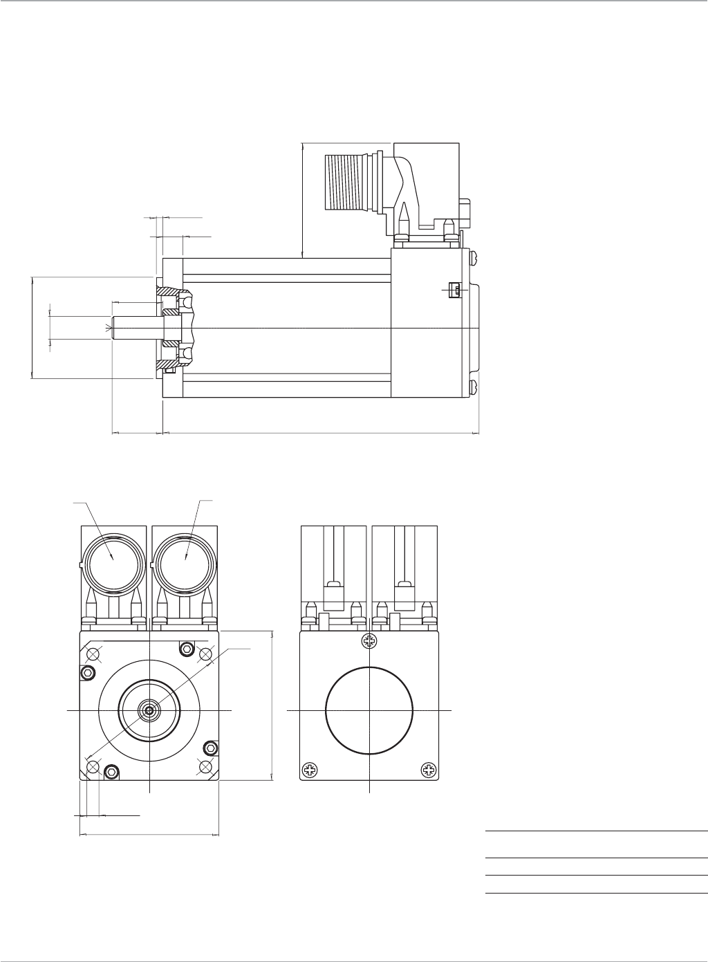
129
Motion Solutions
www.ge-ip.com GE Intelligent Platforms
Servo Motors
MTR-3T10 Series Servo Motor
Dimensions
Model L Max Weight
3T11 4.921(125) 2.6(1.2)
3T12 5.906(150) 3.3(1.5)
3T13 6.890(175) 4.2(1.9)
BrakeOption:Add1”(25mm)toL;Add0.4Ibs(0.2kg)
toWeight
Dimensionsareshownininches(mm),weightinpounds(kg)
0.26 Nm
0.60 Nm
0.90 Nm
1:1
SERVOMOTOR OUTLINE : 3T1 SERIES
STD. OPTION : 3T1XX + RES
Tolerances
Scale :
X.X = ± 0.3mm
X.XX = ± 0.1mm
Ang. Dim. = ± 1∞
CUSTOMER KEY OPTION (+WE1)
( in ) MoMODEL
6.890
5.906
3T13
3T12
3T11 4.921
CENTER HOLE
DR M3 DIN 332
BRAKE DATA :
1.2 Nm , 24V , 0.4A
BRAKE OPTION (+BR)
125
150
175
( mm)
SENSOR CONNECTOR
----------------
.19 (4.8) (x4)
2.323 (59)
SQ. 2.17 (SQ. 55)
ø 2.48 (63)
POWER CONNECTOR
---------------
( L ) MAX
1.79 (45.5)
.31 ± .04 (8 ± 1)
.10 ± .01 (2.5 ± 0.3)
ø 1.5746 (40) j6
ø .3544 (9) k6
.787 (20)
12.0
11.8 10.2
4
KEY A 3x3x12 DIN 6885
(20 ± 0.5)
.787 ± 0.02
Motor is available with
connectors rotated
180 degrees to face rear.
Dimensions in mm (in.)
Note: Brake option adds 25 mm (0.98")
to total length (LMax).
3T10.eps
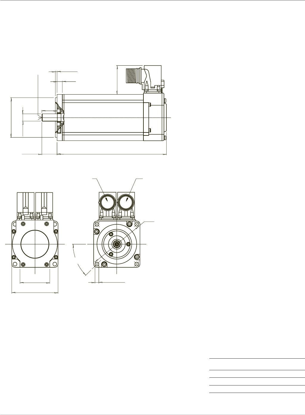
Motion Solutions
130 www.ge-ip.com
Servo Motors
GE Intelligent Platforms
MTR-3T20 Series Servo Motor
Dimensions
Model L Max Weight
3T21 5.63(143) 3.7(1.7)
3T22 6.61(168) 5.0(2.3)
3T23 7.59(193) 6.4(2.9)
3T24 8.58(218) 7.7(3.5)
BrakeOption:Add0.4Ibs(0.2kg)toWeight
Dimensionsareshownininches(mm),weightinpounds(kg)
( L ) MAX
6.3
SERVOMOTOR OUTLINE : 3T2 SERIES
STANDARD OPTION : + RES
1:2
X.X = ± 0.3mm
X.XX = ± 0.1mm
Ang. Dim. = ± 1∞
Weight :
Material :
SurfaceTolerances Scale :
BRAKE DATA :
1.2 Nm , 24V , 0.4A
BRAKE OPTION (+BR)
( L )MODEL
.906 (23)
ø .228 (5.8) (x4)
ø 3.35 (85)
12.5
CENTER HOLE
DR M4 DIN 13.07 (332)
3.5
16.0
15.8
45°
CUSTOMER KEY OPTION (+WE1)
193.00
168.00
3T24
3T23
3T22
.31 ± .04 (8 ± 1)
.10 ± .01 (2.5 ± 0.3)
ø .43 (11) k6
ø 2.36 (60) j6
(23 ± 0.5)
1.71 (43.5)
218.00
3T21 143.00
1.77 (45) (x4)
SQ. 2.76 (70)
.906 ± 0.02
POWER CONNECTOR
---------------
SENSOR CONNECTOR
----------------
KEY A 4x4x16 DIN 6885
3T20.eps
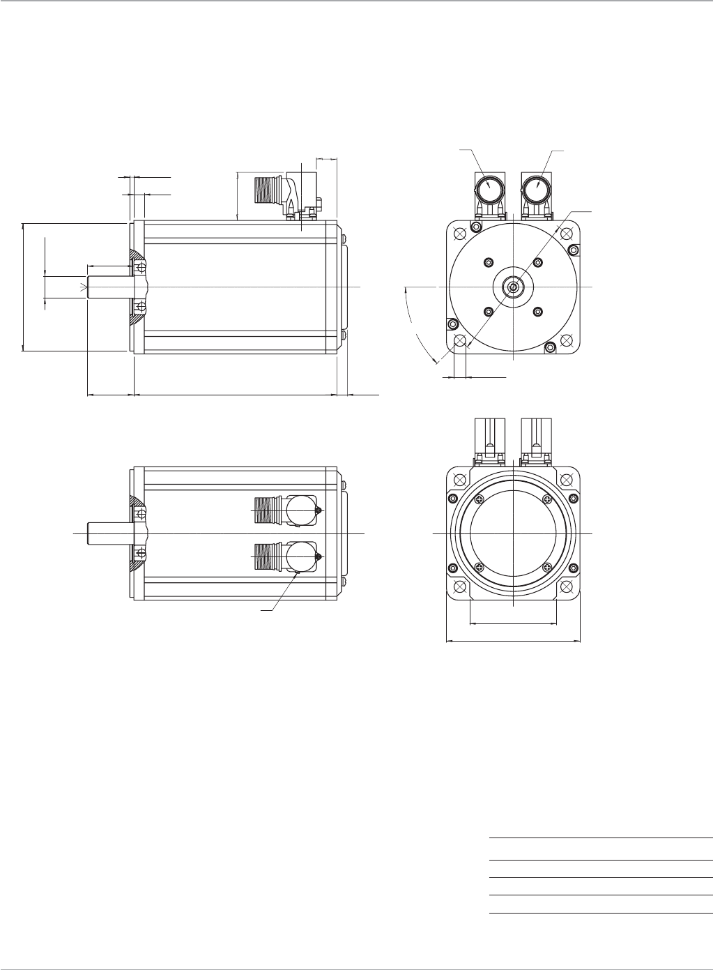
131
Motion Solutions
www.ge-ip.com GE Intelligent Platforms
Servo Motors
MTR-3T40 Series Servo Motor
Dimensions
Model L Max Weight
3T42 7.28(185) 13.6(6.2)
3T43 8.27(210) 16.7(7.6)
3T44 9.25(235) 20.0(9.0)
3T45 10.24(260) 22.9(10.4)
BrakeOption:Add1.3Ibs(0.6kg)toWeight
Dimensionsareshownininches(mm),weightinpounds(kg)
1.57 ± .02 (40 ± 0.5)
6.3
SERVOMOTOR OUTLINE : 3T4 SERIES
STANDARD OPTION : + RES + ENC1
1:2
X.X = ± 0.3mm
X.XX = ± 0.1mm
Ang. Dim. = ± 1∞
Weight :
Material :
SurfaceTolerances
Remove all burrs and sharp corners
Scale :
( L )
185
210
235
260
3T42
3T43
3T44
3T45
MODEL
1.57 (40)
45°
ø 5.12 (130)
.40 (10) MAX.
( L ) MAX.
CUSTOMER KEY OPTION (+WE1)
21.5
32.0
31.7
5
BRAKE DATA :
10 Nm , 24V , 0.7A
ø .354 (9) (x4)
.354 ± .04 (9 ± 1)
.138 ± .01 (3.5 ± 0.3)
CENTER HOLE
DR M6 DIN
13.07 (332)
ø .748 (19) k6
ø 4.33 (110) j6
2.95 (75) (x4)
SQ. 4.53 (115)
1.63 (41.5)
.709 (18)
BRAKE OPTION (+BR)
SENSOR CONNECTOR
----------------
KEY A 6x6x32 DIN 6885
POWER CONNECTOR
---------------
ROTATION STOP
3T40.eps
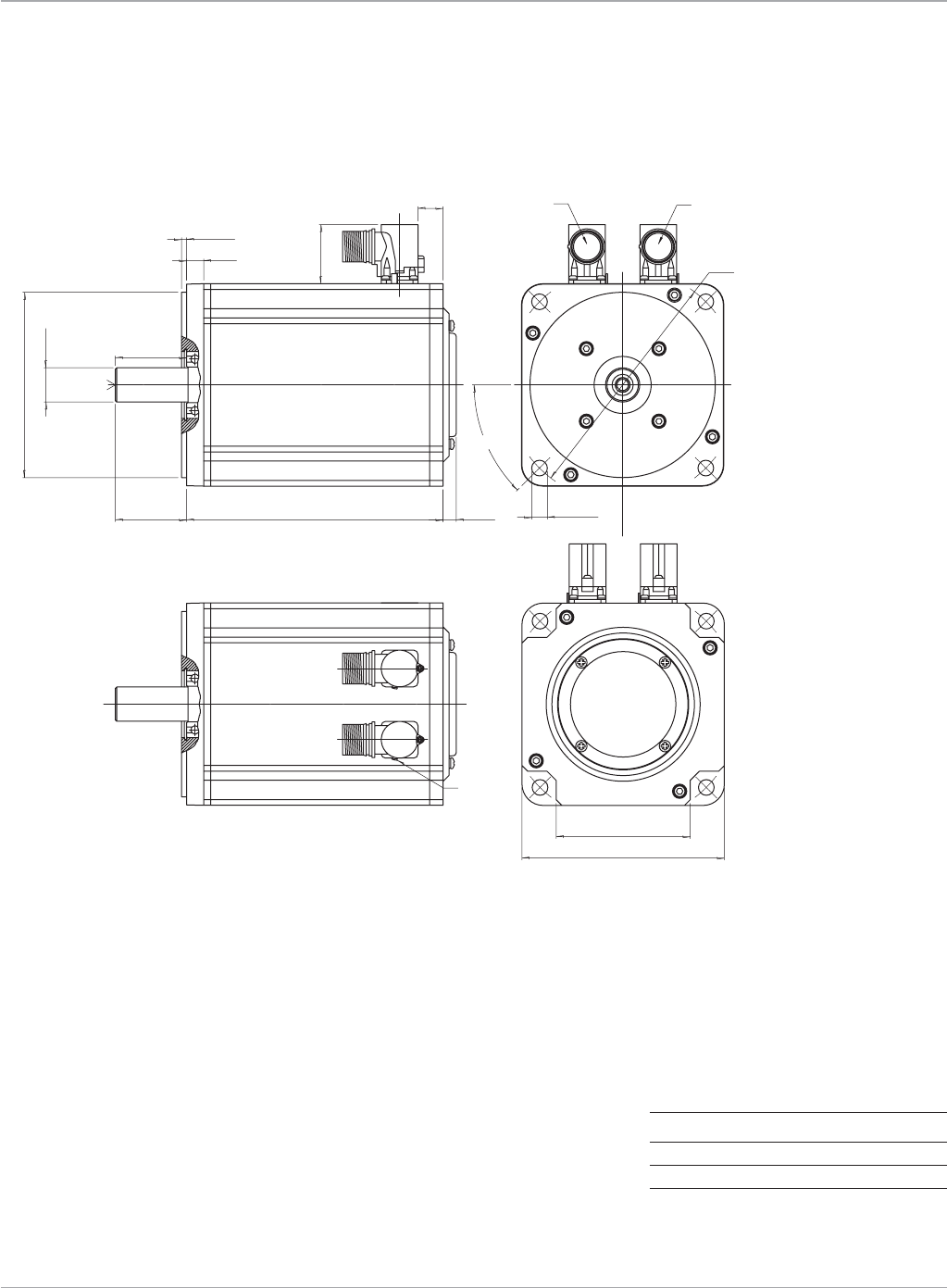
Motion Solutions
132 www.ge-ip.com
Servo Motors
GE Intelligent Platforms
MTR-3T50 Series Servo Motor
Dimensions
Model L Max Weight
3T54 9.06(230) 28.6(13.0)
3T55 10.04(255) 33.0(15.0)
3T57 12.01(305) 41.9(19.0)
BrakeOption:Add3.3Ibs(1.5kg)toWeight
Dimensionsareshownininches(mm),weightinpounds(kg)
CUSTOMER KEY OPTION (+WE1)
CENTER HOLE
DR M8 DIN
13.07(332)
BRAKE OPTION (+BR)
BRAKE DATA :
18 Nm , 24V , 0.6A
MODEL ( L )
3T53
3T54
3T55
205
230
255
3T57 305
Scale :
Remove all burrs and sharp corners
Tolerances Surface
Material :
Weight :
X.X = ± 0.3mm
X.XX = ± 0.1mm
Ang. Dim. = ± 1∞
1:2
SERVOMOTOR OUTLINE : 3T55 SERIES
STANDARD OPTION : + RES + ENC1
6.3
SQ. 5.59 (142)
( L ) MAX.
40.00
39.70
KEY A 8x7x40 DIN 6885
527
3.7 (94) x4
ø 5.12 (130) j6
ø .945 (24) k6
1.97 ± .02 (50 ± 0.5)
.138 ± .004 (3.5 ± 0.1)
.472 ± .04 (12 ± 1)
1.97 (50)
45°
ROTATION STOP
ø 6.5 (165)
ø .433 (11) (x4)
.40 (10) MAX.
1.63 (41.5)
.709 (18) SENSOR CONNECTOR
---------------- POWER CONNECTOR
---------------
3T50.eps
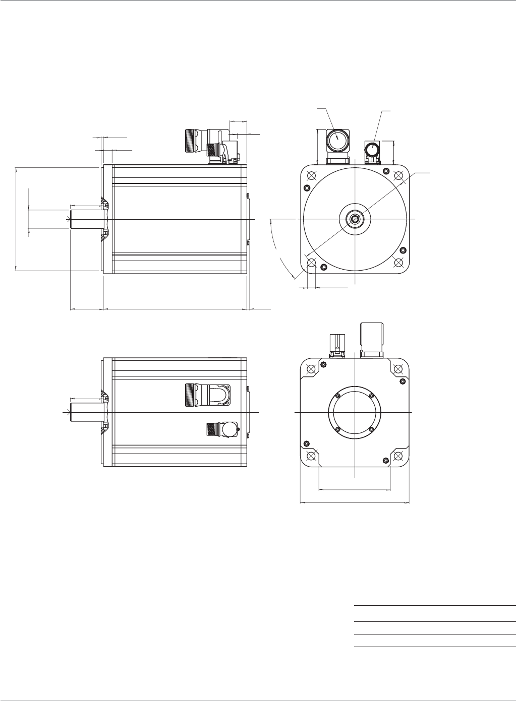
133
Motion Solutions
www.ge-ip.com GE Intelligent Platforms
Servo Motors
MTR-3T60 Series Servo Motor
Dimensions
Model L Max Weight
3T66 12.60(320) 79.3(36.0)
3T67 13.58(345) 92.5(42.0)
3T69 15.55(395) 119(54.0)
BrakeOption:Add4.8Ibs(2.2kg)toWeight
Dimensionsareshownininches(mm),weightinpounds(kg)
A
1.63 (41.5)
6.3
SERVOMOTOR OUTLINE : 3T6 SERIES
STANDARD OPTION : + RES + ENC1
1:3
X.X = ± 0.3mm
X.XX = ± 0.1mm
Ang. Dim. = ± 1∞
Weight :
SurfaceTolerances Scale :
395PMA69
( L )MODEL
BRAKE DATA :
40 Nm , 24V , 1.0A
BRAKE OPTION (+BR)
.157 ± .01 (4 ± 0.3)
.591 ± .04 (15 ± 1)
ø .551 (14) (x4)
ø 8.46 (215)
ø 7.09 (180) j6
ø 1.26 (32) k6
CENTER HOLE
DR M12
DIN 13.07 (332)
( L ) MAX.
SQ. 7.48 (190 )
4.92 (125) (x4)
2.28 ± .02 (58 ± 0.5)
.236 (6) MAX.
CUSTOMER KEY OPTION (+WE1)
4
50.00
49.70 35
45°
PMA64
PMA65
PMA66
270
295
320
PMA67 345
2.28 (58)
1.18 (30)
.67 (17)
2.28 (58)
SENSOR CONNECTOR
----------------
KEY A 10x8x50 DIN 6885
POWER CONNECTOR
---------------
(SEE NOTE BELOW)
3T60.eps

Motion Solutions
134 www.ge-ip.com
Servo Motors
GE Intelligent Platforms
15
42
E
11
3
45
6
9
10 27 12
8 1
PowerandBrake Resolver
Pin Function
1 PhaseT
2 PhaseS
Ground(Frame)
4 OptionalBrake-
5 PhaseR
E OptionalBrake+
Pin Function
1 S1(+sine)
2 S3(-sine)
3 S4(-cosine)
4 S2(+cosine)
5 R1(Excitation)
6 R2(ExcitationRTN)
7 Thermistor
8 Thermistor
MTR-3T Series
Servo Motor Connections

135
Motion Solutions
www.ge-ip.com GE Intelligent Platforms
Servo Motors
MTR-Series Servo Motors
Ordering Information
Amplifier/Controller
Part Number*
Motor Only Motor with Brake Description S2K Amplifier S2K Controller
MTR-3T11-G-R-0-M-S MTR-3T11-G-R-B-M-S 2.3in-lb,230V,IP65,Metric,Seal IC800SSD104RS1 IC800SSI104RS1
MTR-3T12-G-R-0-M-S MTR-3T12-G-R-B-M-S 5.3in-lb,230V,IP65,Metric,Seal IC800SSI104RD2
MTR-3T13-G-R-0-M-S MTR-3T13-G-R-B-M-S 8in-lb,230V,IP65,Metric,Seal IC800SSI104RP2
MTR-3T21-G-R-0-M-S MTR-3T21-G-R-B-M-S 5.6in-lb,230V,IP65,Metric,Seal
MTR-3T22-G-R-0-M-S MTR-3T22-G-R-B-M-S 11.5in-lb,230V,IP65,Metric,Seal
MTR-3T23-G-R-0-M-S MTR-3T23-G-R-B-M-S 17.7in-lb,230V,IP65,Metric,Seal
MTR-3T24-H-R-0-M-S MTR-3T24-H-R-B-M-S 23in-lb,230V,IP65,Metric,Seal
MTR-3T42-H-R-0-M-0 MTR-3T42-H-R-B-M-0 33in-lb,230V,IP65,Metric
MTR-3T43-H-R-0-M-0 MTR-3T43-H-R-B-M-0 54in-lb,230V,IP65,Metric
MTR-3T42-H-R-0-M-0 MTR-3T42-H-R-B-M-0 33in-lb,230V,IP65,Metric IC800SSD107RS1 IC800SSI107RS1
MTR-3T43-J-R-0-M-0 MTR-3T43-J-R-B-M-0 54in-lb,230V,IP65,Metric IC800SSI107RD2
MTR-3T44-J-R-0-M-0 MTR-3T44-J-R-B-M-0 72in-lb,230V,IP65,Metric IC800SSI107RP2
MTR-3T45-H-R-0-M-0 MTR-3T45-H-R-B-M-0 90in-lb,230V,IP65,Metric
MTR-3T54-H-R-0-M-0 MTR-3T54-H-R-B-M-0 120in-lb,230V,IP65,Metric IC800SSD216RS1 IC800SSI216RD2
MTR-3T55-H-R-0-M-0 MTR-3T55-H-R-B-M-0 151in-lb,230V,IP65,Metric IC800SSI216RP2
MTR-3T57-H-R-0-M-0 MTR-3T57-H-R-B-M-0 195in-lb,230V,IP65,Metric IC800SSD228RS1 IC800SSI228RP2
MTR-3T66-H-R-0-M-0 MTR-3T66-H-R-B-M-0 319in-lb,230V,IP65,Metric IC800SSI228RD2
MTR-3T67-G-R-0-M-0 MTR-3T67-G-R-B-M-0 372in-lb,230V,IP65,Metric
MTR-3T69-G-R-0-M-0 MTR-3T69-G-R-B-M-0 478in-lb,230V,IP65,Metric
MTR-3T42-H-R-0-M-0 MTR-3T42-H-R-B-M-0 33in-lb,460V,IP65,Metric IC800SSD407RS1 IC800SSI407RS1
MTR-3T43-J-R-0-M-0 MTR-3T43-J-R-B-M-0 54in-lb,460V,IP65,Metric IC800SSI407RD2
MTR-3T44-J-R-0-M-0 MTR-3T44-J-R-B-M-0 72in-lb,460V,IP65,Metric IC800SSI407RP2
MTR-3T45-H-R-0-M-0 MTR-3T45-H-R-B-M-0 90in-lb,460V,IP65,Metric
MTR-3T54-H-R-0-M-0 MTR-3T54-H-R-B-M-0 120in-lb,460V,IP65,Metric IC800SSD420RS1 IC800SSI420RD2
MTR-3T55-H-R-0-M-0 MTR-3T55-H-R-B-M-0 151in-lb,460V,IP65,Metric IC800SSI420RP2
MTR-3T66-H-R-0-M-0 MTR-3T66-H-R-B-M-0 318in-lb,460V,IP65,Metric
MTR-3T67-G-R-0-M-0 MTR-3T67-G-R-B-M-0 372in-lb,460V,IP65,Metric
MTR-3T69-G-R-0-M-0 MTR-3T69-G-R-B-M-0 478in-lb,460V,IP65,Metric
*Motorscanpossiblybeusedwithlargeramplifiers/controllersinordertoincreasethesystempeaktorquecapability.ContactGEforassistance.
Connector Mates
Motor Series Function Applicable Model Part Number Source
MTR-3TSeries MotorPower All 21000526 GE
Resolver All 21000525 GE
Motor Cables
See applicable amplifier section for information about the proper
cables to use with each motor.

Motion Solutions
136
Servo Motors
Notes:
www.ge-ip.com
GE Intelligent Platforms
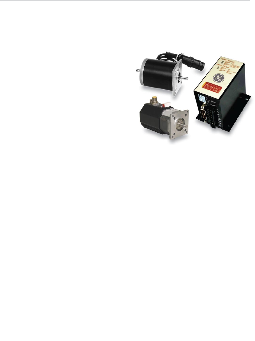
137
Motion Solutions
www.ge-ip.com GE Intelligent Platforms
Stepping Amplifiers and Motors
GE Intelligent Platforms MTR-Series Stepping
solutions provide an economical open loop
alternative when the performance of a servo
is not required. Stepping motors systems are
easy to set up, do not require the tuning that
is typical with servo motors and provide cost
effective solutions for a variety of
automation applications.
• NEMA23and34motormountingsmateeasilytoofftheshelf
gearheads
• PowerCuberequiresDCpoweronly-excellentforbatterybased
applications!
• 50,000MicrostepswhenusedwiththeS2KSeriesprovides
enhanced resolution and accuracy
• Steppingmotorholdingtorquerangefrom61–3074oz-in
(0.43-21.7Nm)
APPLICATIONS
• Packaging
• Testequipment
• Automaticfixturing
• Materialhandling
• Indextable
• Feed-to-length
• Lightassembly
• Semiconductor
• Electronicmanufacturing
• andmanymore
ThePowerCubeoffersfullorhalfstep
selectioninaverycompactpackagewhile
theS2KSteppingMotorControllerprovides
microstepping for applications requiring
improved smoothness and resolution.
When matched with the MTR-Series step-
ping motors these solutions provide
unparalleled performance in the field of
stepping motor technology and are ideal
for demanding automation applications.
TheuniqueSteppingMotorCubeprovides
the space-saving advantage of integrating
a stepping amplifier, control, motor and
communications in a single compact
package.TheSteppingMotorCubeis
availableinpulsecommandinputfor-
matsorwithanintegralDeviceNetcom-
munications interface. Providing multi-
axisnetworkedmotionsolutionshas
neverbeeneasier.Besidessavingvalu-
ablepanelspacetheSteppingMotor
Cubealsoreducessystemwiringand
integration costs.
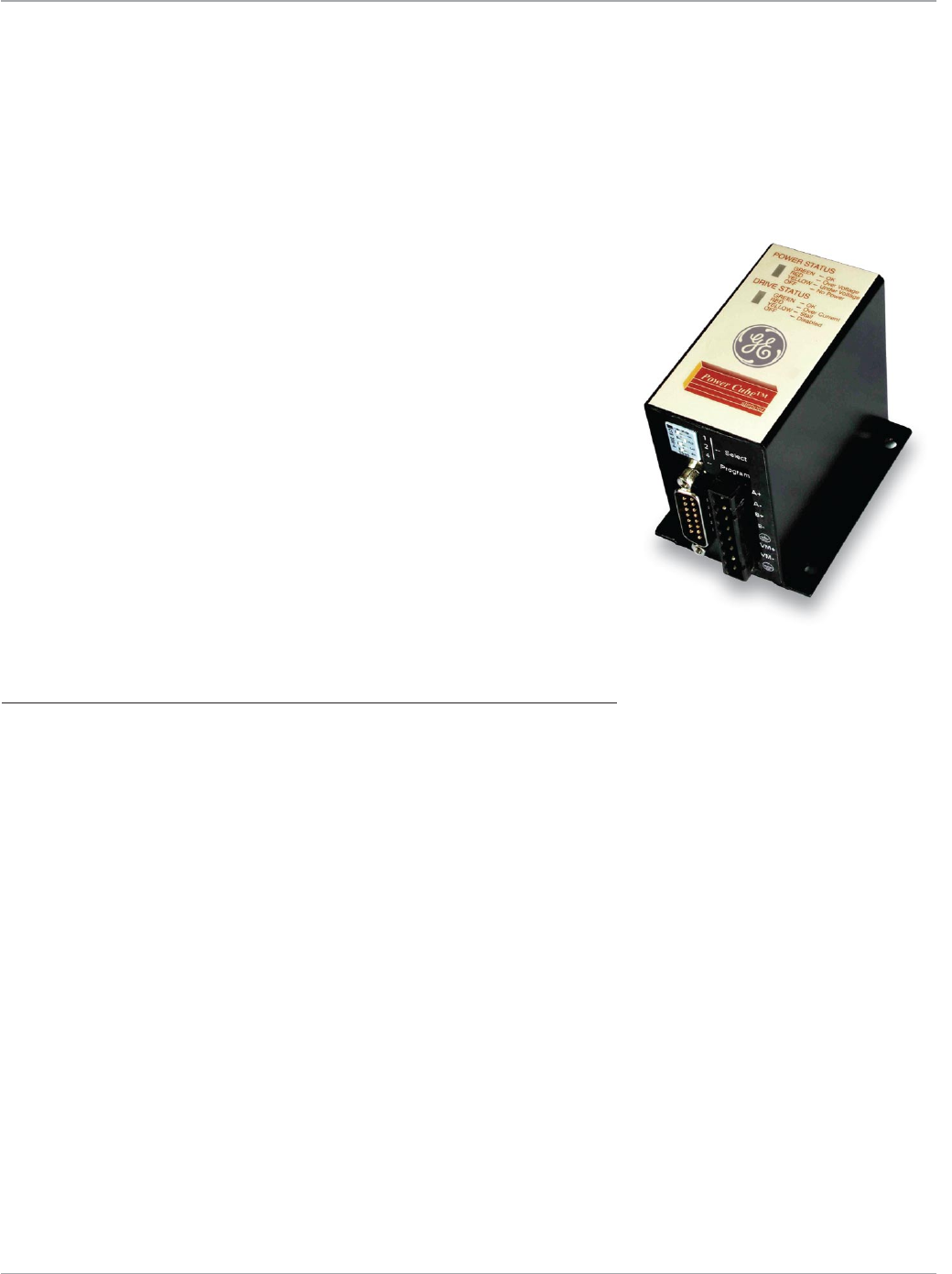
Motion Solutions
138 www.ge-ip.com
GE Intelligent Platforms
ThePowerCubeisidealforhighvolume
applicationssuchaspackaging,test
equipment,automaticfixturingand
materialhandling.ThePowerCubedrive
accepts pulse and direction inputs from
anexternalpulsesourcesuchasthe
GEOperatorControlStation(OCS)step-
pingcontrolmodule.Unlikemanylow-
cost stepping motor drives, the Power
Cubeisahighperformancebipolarchop-
per design. This drive design maintains
constant current in a wide range of
PowerCubeSteppingAmplifiers
Features
• LowcoststeppingdriveandmotorforOEMapplications
• Highperformancebipolarchoppertranslatorratedat4Ampscontinuous
• Acceptspowersupplyinputvoltagesfrom12-48VDC
• Ruggeddesignfordemandingapplications
• Fullandhalf-stepuserconfigurablemodes
• On-boardpotentiometerorremoteinputscanbeusedforcontrol
LikeallGEproducts,thePowerCubeincorporateskeydesignfeaturestoprovidethe
flexibility,performanceandserviceabilitydemandedbyindustrialusers.Thesefeatures
include:
• Completelypackageddriveunitwithheatsink
• Opticallyisolatedinputsfornoiseimmunity
• Overtemperature,overcurrentandovervoltageprotection
• Quickdisconnectterminalsforeaseofinstallationandreplacement
• OptionalMTR-Seriesmotorsandcablessimplifysystemintegration
Stepper Performance in a Space-Saving Package
ThePowerCubeSteppingMotor-DrivePackageprovidesacost-
effective solution for typical OEM stepping motor applications in
aruggedandeasytoinstallpackage.
operatingconditionsandprovidesbetter
high-speed performance than other simi-
lar drive designs.
Optional high performance MTR-Series
stepping motors are matched to the
drive characteristics to provide optimum
performance.LikeallotherGEmotor
products,thesemotorsprovidemaximum
powerinaminimumframesize.They
alsoincorporateexceptionalheat
dissipationcapability.

139
Motion Solutions
www.ge-ip.com
Stepping Amplifiers
GE Intelligent Platforms
Power Cube
Features
ORDERING INFORMATION
PowerCube IC800PCUB00300
DINRailMountingPlate IC800PCUBDINMTG
DB15toScrew
TerminalAdapter IC800CUBDB15ADP
Specifications
Pulse and Direction Inputs
InputFormat +4VDCpulse/direction;+24VDCpulse/direction
differential, optically isolated
InputVoltageRange 3.5-4.2VDCfor+4Vinput;
12-30VDCfor+24Vinput
MaximumInputPulseRate 50kHz
MinimumPulseWidth 5microseconds
Digital Inputs and Outputs
DedicatedInputs Enable,powersave
DedicatedOutputs OK,Stall
OperatingRange 4-24VDC,30VDCMaximum
InterfaceFormat opticallyisolated,source/sinkuserconfigurable
MaximumOffInputVoltage 1VDC
MinimumOnInputVoltage 4VDC
InputLoad 1kOhms
MaximumOnOutputResistance 35Ohms
MaximumLoadOutputCurrent 100mA
MaximumOffOutputLeakageCurrent 200nA
Step Size Selection
A B Step Size
open open FullStepping(200steps/rev)
open short HalfStepping(400steps/rev)
short open Microstepping(1,000steps/rev)
short=ConnecttoStepSizeCommon
DC Input Power Requirements
Drive 24VDC±20%@3.1Ampsmax.1
48VDC±10%@3.1Ampsmax.1
OvervoltageThreshold 54VDC±2VDC
UndervoltageThreshold 18VDC±2VDC
Output Power
Voltagerange 17to38Vrms2phase
Frequency 0-8kHzfundamental(16.4kHzPWM)
Current2 4Armsperphase
Environmental Specifications
OperatingTemperature,FreeAirAmbient 0to50°C@3Amps
1to45°C@4Amps
StorageandShippingTemperature -40to80°C
Enclosure Type Encapsulated
Motor Compatibility and Configuration
Stepping DIPSwitchLocation Connection AmpsRMSat AmpsRMSat StallVelocity
Motor 1 2 4 PRG 100%Current 60%current ThresholdRPS
MTR-1216 Off Off Off Off Parallel 2.5 1.5 9
MTR-1220 On Off Off Off Series 2.5 1.5 4
MTR-1221 Off On Off Off Parallel 3.5 2.1 4
MTR-1235 On On Off Off Series 3.0 1.8 3
MTR-1231 Off Off On Off Parallel 3.1 1.9 3
MTR-1331-J On Off On Off Series 4.0 2.4 4
MTR-1N31-I Off On On Off Series 4.0 2.4 4
Reserved On On On Off TBD TBD TBD TBD
1DCinputpowerhasundervoltageandovervoltagedetection.
2 The outputs are provided with internal overload protection.
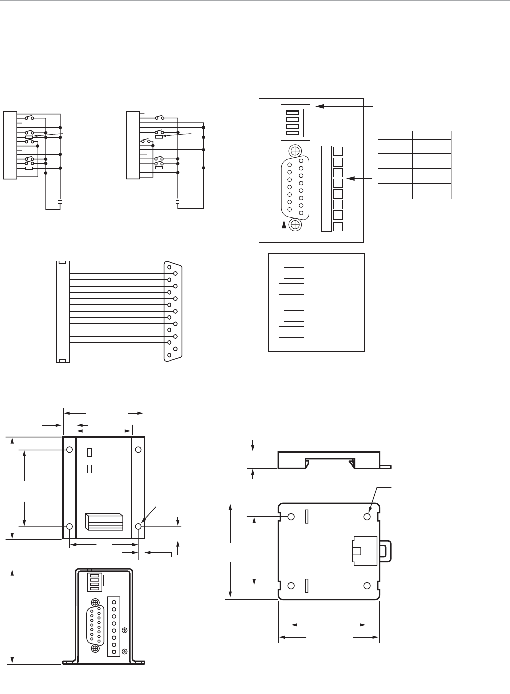
Motion Solutions
140 www.ge-ip.com
Stepping Amplifiers
GE Intelligent Platforms
Mechanical Specifications
Dimensionsininches(mm)
1
ON
-Select Motor
-Program
2
4
P
1
2
3
4
5
6
7
8
1
2
3
4
5
6
7
8
Phase A+
Phase A-
Phase B+
Phase B-
Earth_GND
VM+
VM-
Earth_GND
Position Function
9
10
11
12
13
14
15
1
2
3
4
5
6
7
8
Pulse + (24V)
Pulse + (4V)
Pulse -
Direction + (24V)
Direction + (4V)
Direction -
Input Common
Enable Input
Power Save
OK Output
Stall Output
Output Common
Step Size Select A
Step Size Select B
Step Size Common
DB15 PINOUT
Dip Switch
Motor Selection
1
2
3
4
5
6
7
8
9
10
11
12
13
14
15
Discrete Inputs and Outputs
x
x
1
2
3
4
5
6
7
8
9
10
11
12
13
14
15
x
x
LOAD 100 MA MAX LOAD 100 MA MAX
+
-
18-30
VDC
+
-
3.5-4.2
VDC
2.320 (58.9)
1.600 (40.6)
0.360 (9.1)
2.930
(74.4)
2.680
(68.1)
1
-Select Motor
-Program
91 A+
A-
B+
B-
VM+
VM-
2
3
4
2.210
(56.1)
1.969
(50.0)
0.180
(4.57)
0.360 (9.1)
0.492 (12.49)
0.180 (4.57) dia.
(4 places)
Weight = 12 oz. (0.34kg)
1.960
(49.8)
stepper
PowerCubeTM
POWER STATUS
DRIVE STATUS
GREEN - OK
RED - Over Voltage
YELLOW - Under Voltage
OFF - No Power
GREEN - OK
RED - Over Current
YELLOW - Stall
OFF - Disabled
15 8
2.756
(70.0)
2.933 (74.49)
2.205 (56.01)
Ø0.175 (4.445)
(4 PLACES)
USE 3MM
SCREW
0.5 (12.7) LONG
Power Cube
Connections
IC800CUBDB15ADP
Optional DB15 to Screw Terminal Adapter
IC800PCUBDINMTG
Optional DIN Rail Mount Plate
1
9
2
10
3
11
4
12
5
J2 J1
13
6
14
7
15
8
1
2
3
4
5
6
7
8
9
10
11
12
13
14
15
Pulse + (24V)
Pulse + (4V)
Pulse –
Direction + (24V)
Direction + (4V)
Direction –
Input Common
Enable
Power Save
OK
Stall
Output Common
Step Size Select A
Step Size Select B
Step Size Common
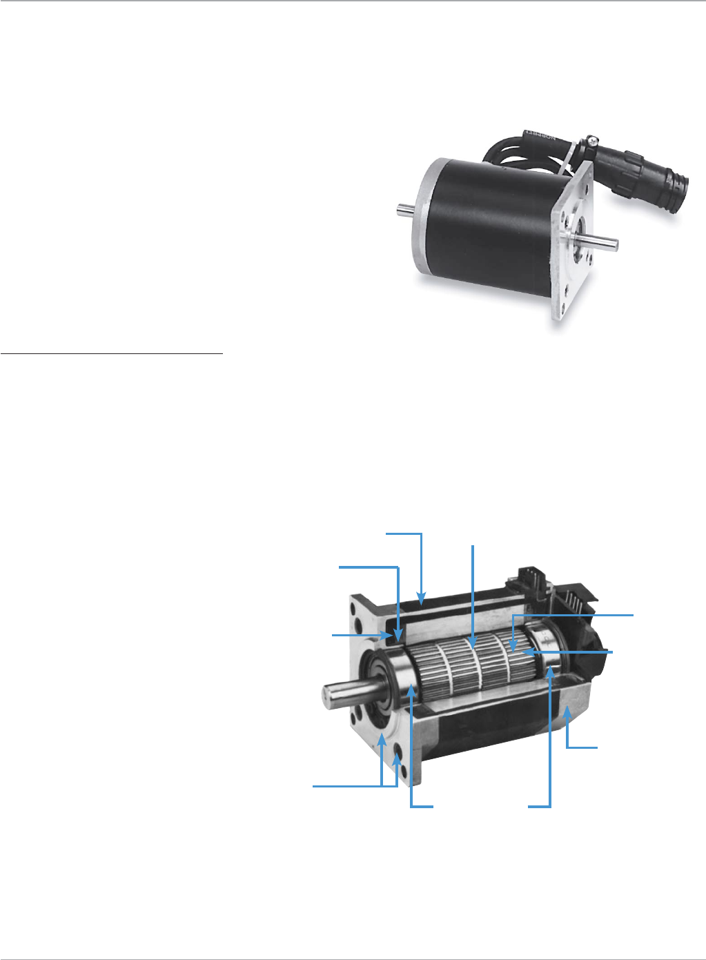
141
Motion Solutions
www.ge-ip.com GE Intelligent Platforms
Oversizedbearings
for longer life
Exposedlaminationsaid
thermal dissipation
Rare earth
rotor magnets
ClassHmagnetwire
Encapsulated stator
forexceptional
thermal dissipation
properties
NEMASize23
or34mounting
Laminatedrotor
Precision ground rotor
ODandhonedstator
IDforconcentricairgap
Unique octagonal end cap
simplifiesautomatedassembly
(1200Seriesonly)
High Performance at an Economical Price
The GE MTR-Series Stepping Motors provide
unparalleled performance in the field of stepping
motor technology and are ideal for the demanding
automation applications requiring precision
positioningand/orvelocitycontrol.Higherspeed
capabilityandcompactsizeprovideperformance
capabilitiesnotpreviouslyattainable.
Features
• Lowinertiadesignforimproved
machine cycle rates
• Fullyconnectorizedforeasyinstallation
• Longlifeoversizedbearingsandhigh
temperature insulation for superior
reliability
• Exposedlaminationsforimprovedheat
dissipation
• Economicaldesignwithoutsacrificing
performance
• Brushlessdesignminimizesmaintenance
• Optional500pprEncoder
Stepping motors provide a low cost
alternative for automation applications
requiring high torque without the high
speedprovidedbyservomotors.Inaddi-
tion, steppers can operate open loop,
which means they do not require the
costofthemotorpositionfeedback
device necessary with servo systems.
Stepping motors are easy to set up and
do not require the tuning that is typical
with servo motors and provide solutions
for a variety of automation applications
when used with GE motion control
products.ThePowerCubeisuser-config-
urableforhalf-steppingwhenapplica-
tions require improved smoothness and
resolution.Forfurtherperformance
enhancement,theS2KSteppingMotor
Controllerimplementsmicrostepping
technologyfor50,000stepsper
revolution.
MTR-Series Stepping Motors
MTR-Series high torque stepping motors
incorporate many design features to
enhancereliabilityandperformance.High
energy product rare earth magnets pro-
vide high torque-to-inertia ratios for
exceptionalmachinecyclerates.
Rare earth magnet inserts in the stator
increase torque production resulting
inmaximumpowerintheminimum
motorsize.

Motion Solutions
142 www.ge-ip.com
GE Intelligent Platforms
Stepping Motors
MTR-Series
Features
Specification Units MTR-1221-D MTR-1231-D MTR-1324-D MTR-1337-D MTR-1350-A MTR-1350-D MTR-1N31-I-D MTR-1N32-I-D MTR-1N41-G-A
HoldingTorque1 oz-in(Nm) 144(1.02) 238(1.68) 335(2.37) 675(4.77) 630(4.45) 995(7.02) 650(4.59) 1200(8.47) 1905(13.45)
Inertia oz-in-sec2 0.0017 0.0036 0.0083 0.0170 0.0250 0.0250 0.0202 0.038 0.0783
(kg-m2x10-3) (0.012) (0.025) (0.059) (0.12) (0.176) (0.176) (0.14) (0.27) (0.55)
RatedCurrent/Phase Amps 1.8 1.6 2.7 4.1 7.9 4.0 4.3 4.1 5.0
Phase Resistance2 Ohms 2.12 3.12 1.12 0.74 0.26 1.02 0.72 1.03 0.58
PhaseInductance mH 8.0 12.4 10.0 8.9 3.1 12.6 5.8 10.3 7.8
DetentTorque oz-in 9.4 17 22 42 64 64 18 36 65
(Nm) (0.066) (0.12) (0.16) (0.3) (0.45) (0.45) (0.13) (0.25) (0.46)
NumberofPhases n/a 2 2 2 2 2 2 2 2 2
NumberofPoles n/a 50 50 50 50 50 50 50 50 50
FullStepsperRevolution Steps 200 200 200 200 200 200 200 200 200
FullStepAngle Degrees 1.8 1.8 1.8 1.8 1.8 1.8 1.8 1.8 1.8
Weight Ib(kg) 1.5(0.68) 2.5(1.13) 3.2(1.45) 5.3(2.41) 7.6(3.45) 7.6(3.45) 5.0(2.27) 8.4(3.81) 11(4.98)
EncoderOption 500ppr,Incremental,DualChannelQuadraturewithIndex,+5V±10%,100KHZmaxfreq.,TTLCompatible
Allratingstypicalat25°Cunlessotherwisenoted.
1 Holdingtorquespecifiedformotorwindingtemperatureat130°Candmotorunmountedinstillairat40°C
2Phaseresistancewithwindingat130°Candmotorinstillairat40°C
Specification Units MTR-1216-D MTR-1220-D MTR-1221-D MTR-1231-D MTR-1235-D MTR-1331-J-D MTR-1N31-I-D
HoldingTorque1 oz-in(Nm) 61(0.43) 116(0.82) 124(0.87) 236(1.68) 185(1.31) 327(2.31) 605(4.27)
Inertia oz-in-sec2 0.0010 0.0015 0.0017 0.0036 0.0170 0.0202 0.0202
(kg-m2x10-3) (0.007) (0.011) (0.012) (0.025) (0.012) (0.014) (0.014)
Winding Parallel/Series Parallel Series Parallel Parallel Series Series Series
RatedCurrent/Phase Amps 2.5 2.7 1.8 1.6 3.4 4.2 4.3
Phase Resistance2 Ohms 0.84 0.76 2.12 3.12 0.68 0.52 0.72
PhaseInductance mH 2.3 2.5 8.0 12.4 2.4 4.4 5.8
DetentTorque oz-in 2.5 4.8 9.4 17 4.6 22 18
(Nm) (0.018) (0.034) (0.066) (0.12) (0.32) (0.16) (0.13)
NumberofPhases n/a 2 2 2 2 2 2 2
NumberofPoles n/a 50 50 50 50 50 50 50
FullStepsperRevolution Steps 200 200 200 200 200 200 200
FullStepAngle Degrees 1.8 1.8 1.8 1.8 1.8 1.8 1.8
Weight Ib(kg) 1.0(0.45) 1.2(0.55) 1.5(0.68) 2.5(1.13) 2.1(0.95) 3.2(1.45) 5.0(2.27)
EncoderOption 500ppr,Incremental,DualChannelQuadraturewithIndex,+5V±10%,100KHZmaxfreq.,TTLCompatible
Specifications for Stepping Motors used with S2K Series
Specifications for Stepping Motors used with Power Cube Amplifier
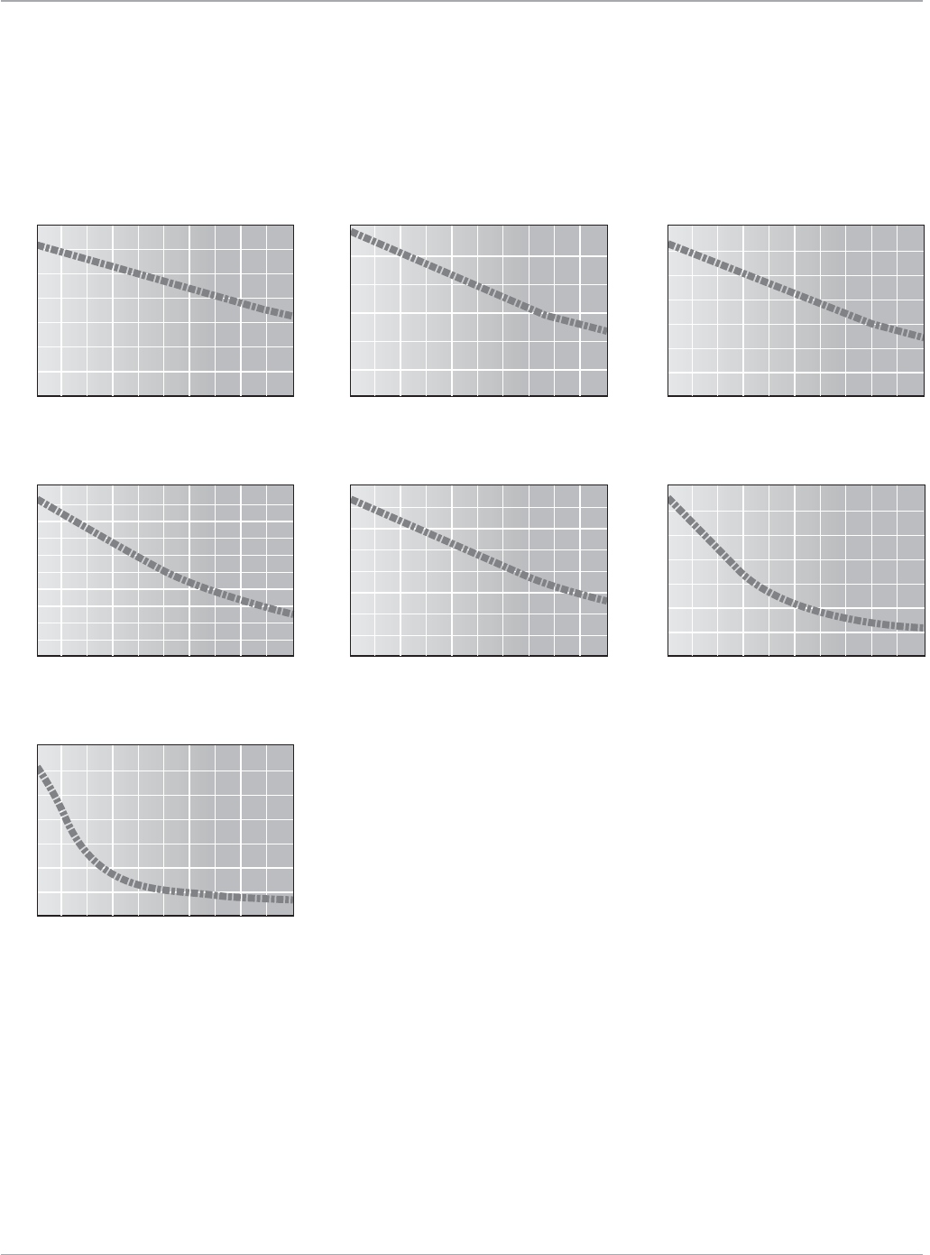
143
Motion Solutions
www.ge-ip.com GE Intelligent Platforms
Stepping Motors
MTR-Series
Speed Torque Curves for Power Cube Amplifier
300 600 900 1200 1500 1800 2100 2400 2700 3000
Torque (oz-in)
MTR-1216-*-D (48V Parallel Connection)
Speed (RPM)
0
10
20
30
40
50
60
70
300 600 900 1200 1500 1800 2100 2400 2700 3000
Torque (oz-in)
MTR-1231-*-D (48V Parallel Connection)
Speed (RPM)
0
50
25
75
100
125
150
250
175
200
225
300 600 900 1200 1500 1800 2100 2400 2700 3000
Torque (oz-in)
MTR-1220-*-D (48V Series Connection)
Speed (RPM)
0
20
40
60
80
100
120
300 600 900 1200 1500 1800 2100 2400 2700 3000
Torque (oz-in)
MTR-1235-*-D (48VDC Series Connection)
Speed (RPM)
0
50
25
75
100
125
150
200
175
300 600 900 1200 1500 1800 2100 2400 2700 3000
Torque (oz-in)
MTR-1221-*-D (48V Parallel Connection)
Speed (RPM)
0
20
40
60
80
100
140
120
300 600 900 1200 1500 1800 2100 2400 2700 3000
Torque (oz-in)
MTR-1331-J-*-D (48V Series Connection)
Speed (RPM)
0
50
100
150
200
250
350
300
300 600 900 1200 1500 1800 2100 2400 2700 3000
Torque (oz-in)
MTR-1N31-I-*-D (48V Series Connection)
Speed (RPM)
0
100
200
300
400
500
700
600
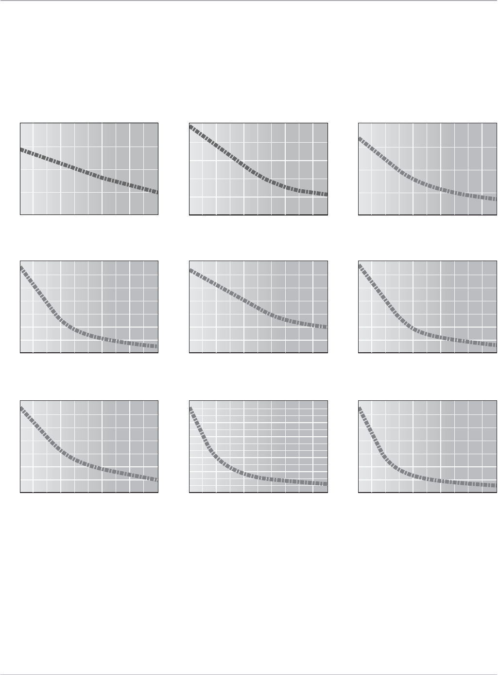
Motion Solutions
144 www.ge-ip.com
GE Intelligent Platforms
Stepping Motors
MTR-Series
Speed Torque Curves for S2K Amplifier/Controllers
300 600 900 1200 1500 1800 2100 2400 2700 3000
Torque (oz-in)
MTR-1337-*-D (85V Series Connection)
Speed (RPM)
0
100
200
300
400
500
700
600
300 600 900 1200 1500 1800 2100 2400 2700 3000
Torque (oz-in)
MTR-1350-*-A (85V Parallel Connection)
Speed (RPM)
0
100
200
300
400
500
700
600
300 600 900 1200 1500 1800 2100 2400 2700 3000
Torque (oz-in)
MTR-1324-*-D (85V Series Connection)
Speed (RPM)
0
100
200
400
300
300 600 900 1200 1500 1800 2100 2400 2700 3000
Torque (oz-in)
MTR-1350*-D (85V Series Connection)
Speed (RPM)
0
100
200
300
400
500
700
600
300 600 900 1200 1500 1800 2100 2400 2700 3000
Torque (oz-in)
MTR-1N31-I-*-D (85V Series Connection)
Speed (RPM)
0
100
200
300
400
500
700
600
300 600 900 1200 1500 1800 2100 2400 2700 3000
Torque (oz-in)
MTR-1N32-I-*-D (85V Series Connection)
Speed (RPM)
0
100
200
300
400
600
700
800
900
1000
1100
1200
1300
500
300 600 900 1200 1500 1800 2100 2400 2700 3000
Torque (oz-in)
MTR-1N41-G-A (85V Parallel Connection)
Speed (RPM)
0
300
600
900
1200
1500
2100
1800
200
150
100
50
0300 600 900 1200 1500 1800 2100 2400 2700 3000
Torque (oz-in)
MTR-1221-*-D (85V Series Connection)
Speed (RPM)
250
200
150
100
50
0300 600 900 1200 1500 1800 2100 2400 2700 3000
Torque (oz-in)
MTR-1231-*-D (85V Series Connection)
Speed (RPM)
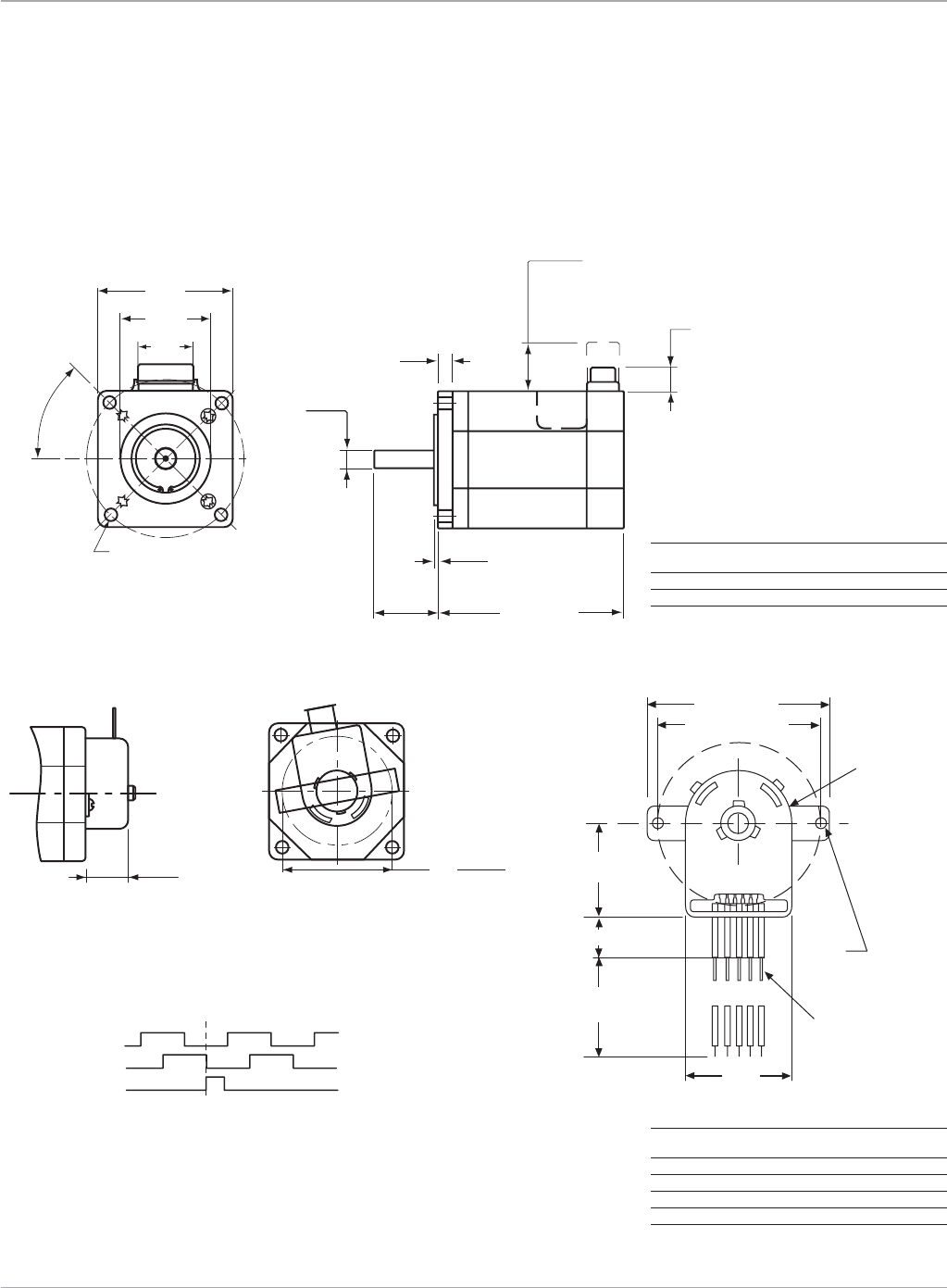
145
Motion Solutions
www.ge-ip.com GE Intelligent Platforms
(57. 1)
0.95
(38.1)
1.50 ± 0.002
(24)
2x45°
4x ø0.2 (5.08) thru
on a ø2.625 (66.67) B.C.
(20.6)
0.81
.72
18.29
(6.35)
0.25+0
-0.0005
(5.1)
0.2
2.25
(15.2)
(7.6)Max.
motor
only
Max. with optional
mating connector
plugged in
(1.4)
0.055
L. Max.
ø(1.812)
(46.02)
0.60
0.30
x
x
ENCODER OPTION
1200SeriesDim.eps
MTR-Series
MTR-1216, 1221 & 1231 Stepping Motor Dimensions
NEMA 23 Flange
Encoder Option
*Leadsareterminatedwith18inch(457mm)longAgilentTechnologiesHEDS-8903connector/cable.Encoderterminalsare0.025inchsquarepinson0.100inchcenters.
1.03 (26.16)
MAX.
2.05 (52.07)
Ø1.812 (46.02)
0.44 (11.18)
Ø.108
(2.74)
PIN
12345
ENCODER
5X
LEADS*
18.0 (457.2)
MIN.
1.18
(29.97)
Encoder Output
For CW direction of rotation when viewed from motor
drive shaft end. Minimum edge separation 45°.
Index gated to A and B.
Channel A
Channel B
Index (Z)
Pin Function
1 Ground
2 Z
3 A
4 +5V
5 B
Model LMax in (mm) Weight lb (kg)
MTR-1216 1.6(40.7) 1.0(0.45)
MTR-1221 2.06(52.3) 1.5(0.68)
MTR-1231 3.10(78.7) 2.5(1.14)
Stepping Motors
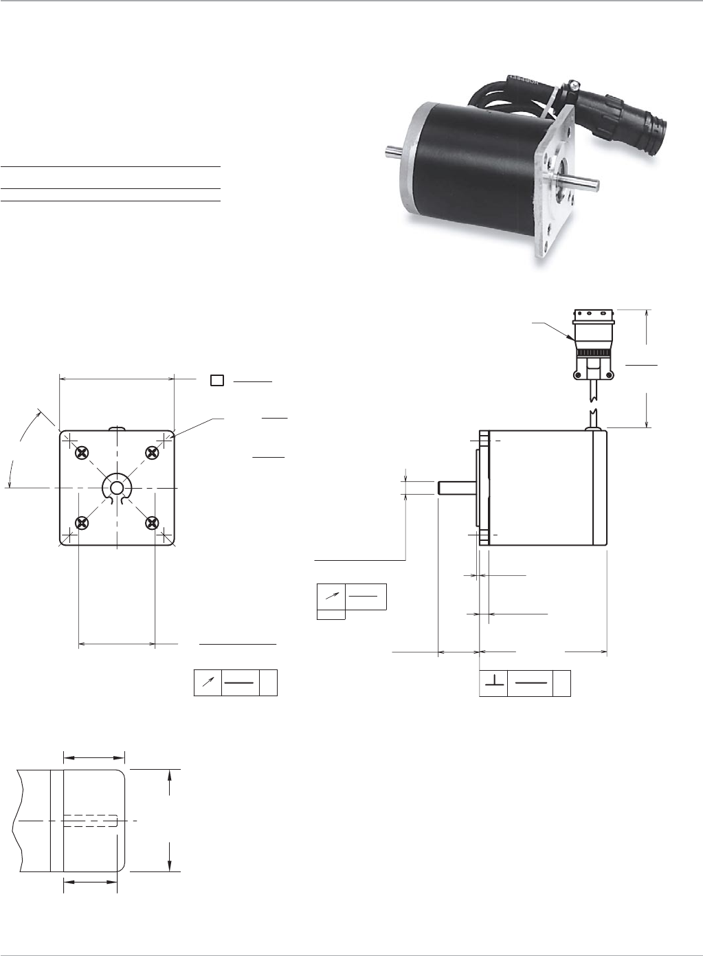
Motion Solutions
146 www.ge-ip.com
GE Intelligent Platforms
Stepping Motors
MTR-Series
MTR-1220 and 1235 Series Stepping Motor Dimensions
NEMA 23 Flange - Standard Construction
Model LMax in (mm) Weight lb (kg)
MTR-1220 2.06(52.3) 1.2(0.55)
MTR-1235 3.06(77.7) 2.1(0.95)
Metricdimensionsshownbeneath
0.80 -0.1
+0.1
2.17 -0.02
+0.02
55.118 -0.508
+0.508
1.00 (25.4) MAX.
)(
20.32 -2.54
+2.54)(
Encoder Option
.2500 +.0000
-.0005
4X ø THRU
EQUALLY SPACED ON
A ø B.C.
.002
.003
-A-
.003
.002
.2500 +.0000
-.0005
2.25
(57.15)
.75 ± .04
19.05 ± 1.02
6.35 -0.013
ø
12.0
(304.8)
MINIMUM
0,051
.06
(1.52)
.18
(4.57)
.81
(20.57)
1.500 ± .002
(38.1 ± 0.51)
.200
(5.08)
2.625
(66.68)
(6.35 -0.013)
ø
(0.051)
A
(0.077) A
(0.077)
L MAX.
(2X 45°)
ø
MOTOR POWER CONNECTOR
1200 Series
Encoder Option
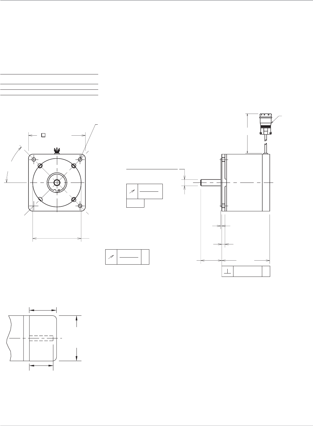
147
Motion Solutions
www.ge-ip.com GE Intelligent Platforms
MTR-Series
MTR-1300 Series Stepping Motor Dimensions
NEMA 34 flange - Standard Construction
Encoder Option
12.0 (304.8) MIN.
MOTOR
POWER
CONNECTOR
.06 (1.52)
.18 (4.57)
1.25 (31.75)
ø
3.38 (85.85)
4X ø .218 (5.46) THRU
EQUALLY SPACED ON
A ø 3.875 (98.43) B.C.
2.875 ± .002 (73.025 ± 0.51)
A
(0.077)
.003 (0.077)
.003
A
+.0000
-.0005
(9.53 - 0.013)
.002
-A-
(0.051)
.3750
L MAX.
ø
(2X 45°)
0.80 -0.1
+0.1
2.17 -0.02
+0.02
55.118 -0.508
+0.508
1.00 (25.4) MAX.
)(
20.32 -2.54
+2.54)(
Model LMax in (mm) Weight lb (kg)
MTR-1324 2.58(65.5) 3.2(1.45)
MTR-1337 3.76(95.5) 5.3(2.4)
MTR-1350 5.06(128.5) 7.6(3.45)
Stepping Motors
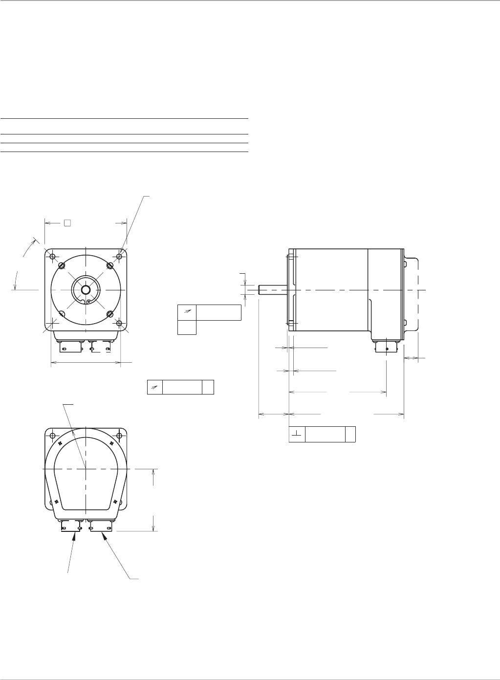
Motion Solutions
148 www.ge-ip.com
GE Intelligent Platforms
Stepping Motors
+.0000
-.0005
.3750
+.0000
-.0130
9.53
ø
1.25
(31.75)
.06
(1.52)
.18
(4.57)
.71 (18.04)
3.38 (85.85)
4X ø .218 (5.46) THRU
EQUALLY SPACED ON A
ø 3.875 (98.43) B.C.
.003 (.077) A
2.875 ± .002
(73.025 ± 0.051)
.002 (0.051)
-A-
.003 (.077) A
MAX-ENCODER
OPTION ONLY
ø
(2X 45°)
L2
L1 MAX.
()
2.62 (66.55) MAX.
R1.72 (43.69)
ENCODER
CONNECTOR
(ENCODER OPTION ONLY)
MOTOR
CONNECTOR
MTR-Series
MTR-1300 Series Stepping Motor Dimensions
NEMA 34 flange - Splashproof Construction
Model L1 Max. in (mm) L2 in (mm) Weight lb (kg)
MTR-1324 3.6(91.4) 2.87(72.9) 3.2(1.45)
MTR-1337 4.77(121.2) 4.02(102.1) 5.3(2.4)
MTR-1350 6.05(153.7) 5.30(134.6) 7.6(3.45)
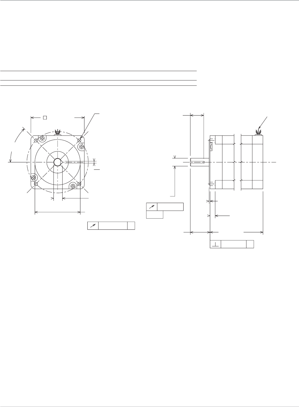
149
Motion Solutions
www.ge-ip.com GE Intelligent Platforms
4X ø .218 (5.54) THRU
EQUALLY SPACED ON
A ø 3.875 (98.43) B.C.
.003 A (.0762)
-A-
.003 A (.0762)
ø D +.0000
-.0005 (0.127)
+.000
-.017 (0.43)
K +.0000
-.0020 (.051)
.002 (.0508)
ÿ D
1N31
MOTOR
1N32
LINE
1
2
.5000 .1250
K
.555
T
4.65
3.13
L MAX.
.5000 .1250 .555
3.38 (85.85)
.06 (1.524)
L MAX.
ø 2.875 ± .002
(73.025 ± .051)
(2X 45°)
1.25 (31.75)
MOTOR
LEADS
.875 ± .010
(22.23 ± 0.254)
.33 (8.382)
T
12 inch min.
(304.8 mm min.)
MTR-Series
MTR-1N3x Series Stepping Motor Dimensions
Model D in (mm) K T L Max. Weight lb (Kg)
MTR-1N31 .5000(12.7) .1250(3.81) .555(14.097) 3.13(79.50) 5.0(2.27)
MTR-1N32 .5000(12.7) .1250(3.81) .555(14.097) 4.65(118.11) 8.4(3.81)
Stepping Motors
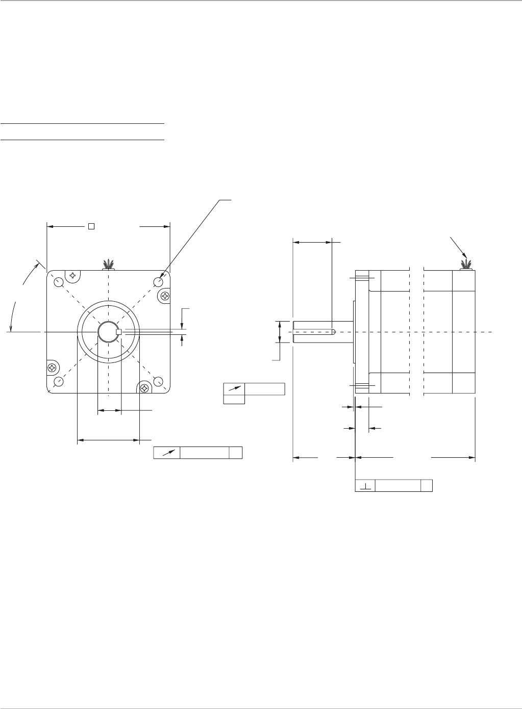
Motion Solutions
150 www.ge-ip.com
GE Intelligent Platforms
Stepping Motors
+.000
-.017
ø .7500 +.0000
-.0005
.1875 +.0000
-.0020
4.763 +.0000
-.0508
.003 A (.0762)
.002 (.0508)
-A-
.003 A (.0762)
MTR-1N41
MOTOR
MTR-1N42
LINE
1
25.91
3.89
L MAX.
.06 (1.524)
(2X 45°)
ø 2.186 ± .002 (55.524 ± .0508)
4X ø .328 (8.33) THRU
EQUALLY SPACED ON A
ø 4.950 (125.73) B.C.
2.19
(31.75)
1.375 ± .010
(34.925 ± .254)
.830
4.325 (109.86)
L MAX.
MOTOR
LEADS
.48 (12.192)
98.81
150.11
INCHES MM
()
19.05 +.0000
-.0127
()
21.082 +.0000
-.0432
()
MTR-Series
MTR-1N4x Series Stepping Motor Dimensions
Model LMax in (mm) Weight lb (kg)
MTR-1N41 3.89(98.81) 11(4.98)

151
Motion Solutions
www.ge-ip.com GE Intelligent Platforms
MTR Series
Connections
Motor Power
Standard Construction: MTR-1220, MTR-1235, MTR-1300 and MTR-1N Series
Splashproof Construction: MTR-1300
Encoder (500 line)
Standard Construction: MTR-1220, MTR-1235, MTR-1300 and MTR-1N Series
Splashproof Construction: MTR-1300
7
4
1
89
5
2
6
3
A
B
C
D
E
1
2
3
4
5
6
7
8
9
AB
C
D
E
F
G
H
J
K
Pin Function
1 A+
2 n/c
3 A-
4 n/c
5 Ground
6 n/c
7 B+
8 n/c
9 B-
Pin Function
A A+
B A-
C B+
D B-
E Ground
Pin Function
1 ChannelA+
2 ChannelA-
3 ChannelB+
4 ChannelB-
5 +5VDC
6 Ground
7 Index+
8 Index-
9 n/c
Pin Function
A ChannelA+
B ChannelA-
C ChannelB+
D ChannelB-
E Index+
F Index-
G +5VDC
H Ground
J n/c
K n/c
Stepping Motors

Motion Solutions
152 www.ge-ip.com
GE Intelligent Platforms
Stepping Motors
MTR Series
Connections
Motor Power
MTR-1216, MTR-1221 and MTR-1231
Encoder (500 line)
MTR-1216, MTR-1221 and MTR-1231
Parallel Connection Series Connection
Pin For PowerCube Amplifier For S2K Controller
1 A- A-
2 A- Jumpertopin5
3 B- B-
4 B- Jumpertopin7
5 A+ Jumpertopin2
6 A+ A+
7 B+ Jumpertopin4
8 B+ B+
Pin Function
1 Ground
2 Z
3 A
4 +5V
5 B
12345678
12345
12345678
12345
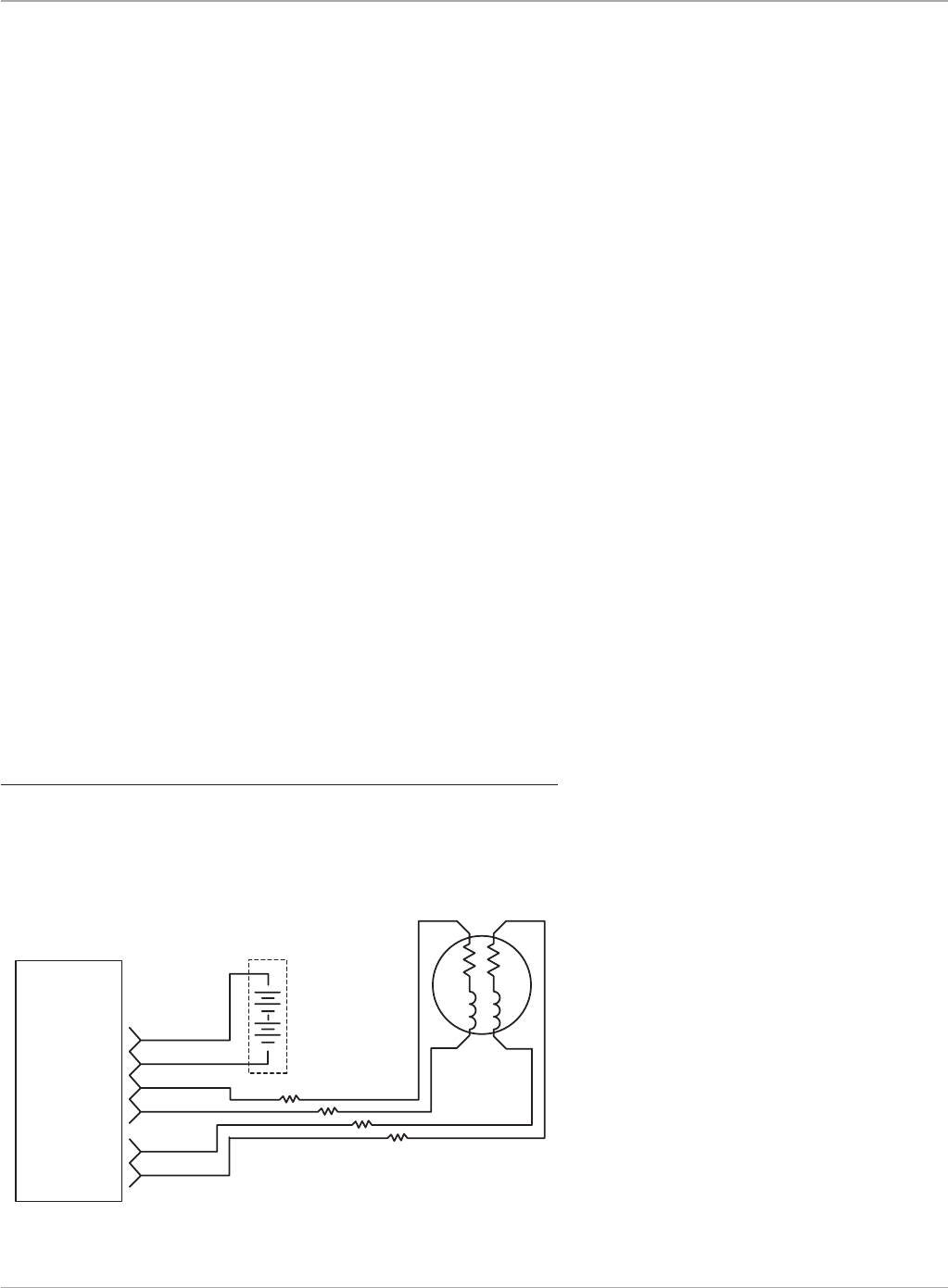
153
Motion Solutions
www.ge-ip.com GE Intelligent Platforms
Stepping Motors
Stepping Motor Systems
Cable Resistance and the Performance
STEPPING
MOTOR
CONTROLLER
POWER
POWER COM
MOTOR A+
MOTOR A-
MOTOR B+
MOTOR B-
24 VDC
POWER
SUPPLY
RC
RA RB
AB
LA LB
A+ B+
A- B-
RC
RC
RC
STEPPING MOTOR
wire_stepmotorsystem.eps
file name: wire_stepmotorsystem.eps
current page in catalog: 118
source: from Whedco catalog pg M-4
file name: wire_stepmotorsystem.eps
current page in catalog: 118
source: from Whedco catalog pg M-4
An Example Case
Supposewehaveasteppingmotorwiredasshowninthefigurebelow.
Thecableusedtoconnectastepping
motor driver to the motor itself is a criti-
calsystemcomponent.Apoorcable
choicecanrobanotherwisewell-
designed system of torque and power
andseriouslydegradesystemreliability.
Amongthemanycableissuesthatmust
beconsidered,suchasflexibilityand
environmental factors, the system
designermustchooseacablewiththe
proper electrical resistance for the
application. This is especially important
insteppingmotorsystems.Let’sreview
theeffectsofcableresistanceinstep-
ping motor systems and learn how
to select the proper resistance for your
application.
Cable Resistance Limits the Voltage Available to the Motor
Everycableexhibitselectricalcapaci-
tance, inductance, and resistance, all of
which can degrade the performance of
a stepping motor system. In most cases,
the effect of the capacitance and
inductance are small compared to the
inductance and capacitance of the
motor, and thus have a relatively small
effect on the system performance. It is
thecableresistancethathasthemost
effect on motor performance.
Unlikeservomotorsystemsthatprovide
motorcurrentonademandbasis,
stepping motor systems are designed to
supply a constant current to the motor.
Thiscurrentmultipliedbythecableresis-
tanceresultsinavoltagedropthatsub-
tractsdirectlyfromthevoltageavailable
to run the motor. The effect is to lower
themaximumspeedatwhichthemotor
canrunandthemaximumtorquethe
motor can produce.
Thecontrollerisconnectedtoamotorthrough100
ftofacablewithfour#20AWGconductors.The
motorisdesignedtooperateat5ampsperphase.
Number20AWGcopperwirehasaresistanceof
about10ohmsper1000ft.Thereis200ftofthis
wireinserieswitheachmotorphase(100ftin
serieswitheachofthetwophaseleads)foratotal
resistanceof2ohmsperphase.UsingOhm’slaw,
wecancalculatethevoltagedropduetothecable
resistance:
Icable = Imotor=5amps
Rcable= (10/1000ohmsperfoot)*200ft=2ohms
Vcable = Icable * Rcable=(5amps*2ohms)=10volts
Thisvoltagedropreducesthevoltageavailableat
themotorfromtheoriginal24tojust14voltsand
will cause the motor torque to drop at lower
speeds.Themostnoticeablelossoftorque
occurswhenthemotorisnearthemaximum
power point.
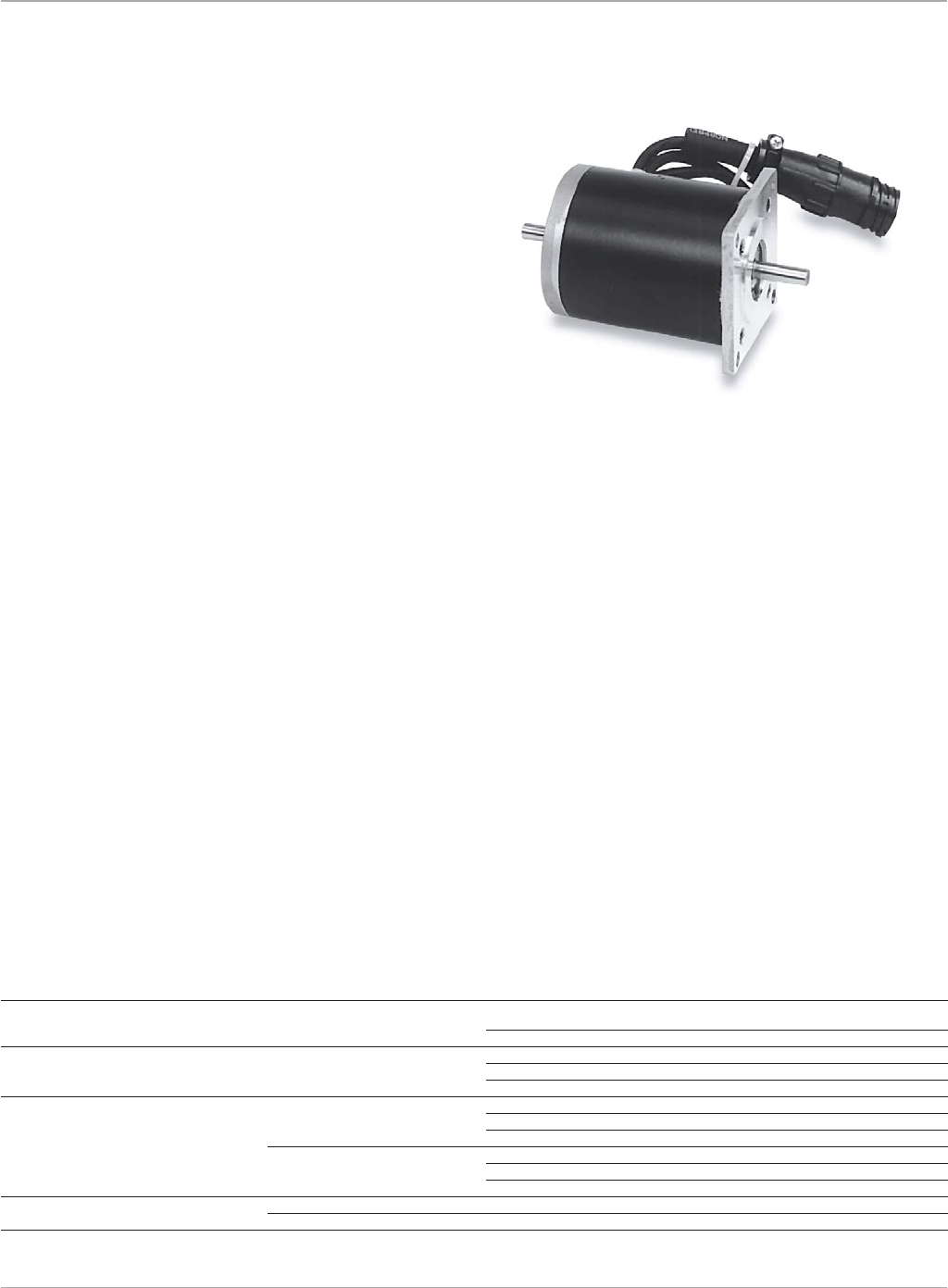
Motion Solutions
154 www.ge-ip.com
GE Intelligent Platforms
Stepping Motors
Stepping Motor Systems
Cable Resistance Consumes Power
For the Best System Performance, Choose a Low Resistance Cable
Asecondeffectofcableresistanceistoconsumepowerfrom
thedriveanditspowersupply.Continuingwiththeexample
case,thetotalpowerlossinthecableis:
Ifthepeakmotorrequirementisalso100watts,thepowersup-
plycapacitymustbenearlydoubledtoallowforthecableloss.
This not only increases the cost of the system components, it will
shortenthemeantimebetweenfailuresduetoincreasedoper-
ating temperatures.
Alowresistancecableenhancesthe
performanceandreliabilityofmost
steppingmotorsystems.Aruleofthumb
that serves well in many applications is
tokeepthecableresistancelessthanor
equal to the motor phase resistance. This
ensures that the voltage drop across the
cableandthecablepowerdissipationare
similar to the voltage drop and the
dissipation in the motor while it is at rest.
Since the stepping motor drive selected
will usually have output voltage and
power ratings several times greater than
themotorstaticlosses,suchacable
willprovidethebestperformancein
most systems.
Pcable = Icable
2XRcable
Pcable =5amps2X2ohms
Pcable =50wattsperphase
=100wattstotalcableloss
Stepping Motor Connector Mates
Motor Series Function Part Number Source
MTR-1216,1221,1231Series MotorPower 640620-8housing AMP
643075-8cover AMP
MTR-1220,1235 MotorPower 206708-1receptacle AMP
66101-4contact(Qty9) AMP
206966-1clamp AMP
MTR-1300&MTR-1NSeries MotorPower 206708-1receptacle AMP
66101-4contact(Qty9) AMP
206966-1clamp AMP
Encoder 206705-2receptacle AMP
66099-4contact(Qty9) AMP
206966-1clamp AMP
MTR-1300Series(SplashproofMotors) MotorPower 21000399 GE
Encoder MS3116F12-10S Bendix

155
Motion Solutions
www.ge-ip.com GE Intelligent Platforms
Stepping Motors
MTR-Series Stepping Motors
Cable and Amplifier Compatibility
Ordering Information
PowerCube Amplifier S2K Stepping Controller
Part Number Description I/O Cable Power Cable Encoder Cable Power Cable Encoder Cable
MTR-1216-E-D-E-0 61oz-in,NEMA23,Encoder* IC800PCUBCxxS CBL-12-MP CBL-1C-ET n/a CBL-1C-ET
MTR-1216-N-D-E-0 61oz-in,NEMA23* IC800PCUBCxxS CBL-12-MP n/a n/a n/a
MTR-1220-E-D-E-0 116oz-in,NEMA23,Encoder IC800PCUBCxxS CBL-13-MP CBL-1C-ET n/a n/a
MTR-1220-N-D-E-0 116oz-in,NEMA23 IC800PCUBCxxS CBL-13-MP n/a n/a n/a
MTR-1221-E-D-E-0 144oz-in,NEMA23,Encoder(124oz-inwithPowerCube)* IC800PCUBCxxS CBL-12-MP CBL-1C-ET CBL-12-MPS CBL-1C-ET
MTR-1221-N-D-E-0 144oz-in,NEMA23(124oz-inwithPowerCube)* IC800PCUBCxxS CBL-12-MP n/a CBL-12-MPS n/a
MTR-1231-E-D-E-0 230oz-in,NEMA23,Encoder* IC800PCUBCxxS CBL-12-MP CBL-1C-ET CBL-12-MPS CBL-1C-ET
MTR-1231-N-D-E-0 230oz-in,NEMA23* IC800PCUBCxxS CBL-12-MP n/a CBL-12-MPS n/a
MTR-1235-E-D-E-0 185oz-in,NEMA23,Encoder IC800PCUBCxxS CBL-13-MP CBL-13-ET n/a n/a
MTR-1235-N-D-E-0 185oz-in,NEMA23 IC800PCUBCxxS CBL-13-MP n/a n/a n/a
MTR-1324-E-D-E-0 335oz-in,NEMA34,Encoder n/a n/a n/a CBL-13-MP CBL-13-ET
MTR-1324-E-D-E-S 335oz-in,NEMA34,Encoder,Splashproof n/a n/a n/a CBL-14-MP CBL-14-ET
MTR-1324-N-D-E-0 335oz-in,NEMA34 n/a n/a n/a CBL-13-MP n/a
MTR-1324-N-D-E-S 335oz-in,NEMA34,Splashproof n/a n/a n/a CBL-14-MP n/a
MTR-1331-J-E-D-E-0 327oz-in,NEMA34,Encoder IC800PCUBCxxS CBL-13-MP CBL-13-ET n/a n/a
MTR-1331-J-E-D-E-S 327oz-in,NEMA34,Encoder,Splashproof IC800PCUBCxxS CBL-14-MP CBL-14-ET n/a n/a
MTR-1331-J-N-D-E-0 327oz-in,NEMA34 IC800PCUBCxxS CBL-13-MP CBL-13-ET n/a n/a
MTR-1331-J-N-D-E-S 327oz-in,NEMA34,Splashproof IC800PCUBCxxS CBL-14-MP CBL-14-ET n/a n/a
MTR-1337-E-D-E-0 675oz-in,NEMA34,Encoder n/a n/a n/a CBL-13-MP CBL-13-ET
MTR-1337-E-D-E-S 675oz-in,NEMA34Encoder,Splashproof n/a n/a n/a CBL-14-MP CBL-14-ET
MTR-1337-N-D-E-0 675oz-in,NEMA34 n/a n/a n/a CBL-13-MP n/a
MTR-1337-N-D-E-S 675oz-in,NEMA34,Splashproof n/a n/a n/a CBL-14-MP n/a
MTR-1350-E-A-E-0 630oz-in,NEMA34,Encoder n/a n/a n/a CBL-13-MP CBL-13-ET
MTR-1350-E-A-E-S 630oz-in,NEMA34,Encoder,Splashproof n/a n/a n/a CBL-14-MP CBL-14-ET
MTR-1350-E-D-E-0 995oz-in,NEMA34,Encoder n/a n/a n/a CBL-13-MP CBL-13-ET
MTR-1350-E-D-E-S 995oz-in,NEMA34,Encoder,Splashproof n/a n/a n/a CBL-14-MP CBL-14-ET
MTR-1350-N-A-E-0 630oz-in,NEMA34 n/a n/a n/a CBL-13-MP n/a
MTR-1350-N-A-E-S 630oz-in,NEMA34,Splashproof n/a n/a n/a CBL-14-MP n/a
MTR-1350-N-D-E-0 995oz-in,NEMA34 n/a n/a n/a CBL-13-MP n/a
MTR-1350-N-D-E-S 995oz-in,NEMA34,Splashproof n/a n/a n/a CBL-14-MP n/a
MTR-1N31-I-N-D-S-0 650oz-in,NEMA34,(605oz-inwithPowerCube) IC800PCUBCxxS CBL-13-MP n/a CBL-13-MP n/a
MTR-1N32-I-N-D-S-0 1200oz-in,NEMA34 n/a n/a n/a CBL-13-MP n/a
MTR-1N41-G-N-A-E-0 1905oz-in,NEMA42 n/a n/a n/a CBL-13-MP n/a
Cable Ordering Information
Part Number Description
SteppingMotorPowerCables CBL-12-MP-xx* PowerCable,MTR-1216,1221&1231SteppingMotortoPowerCube,xx=10,20or30feet
CBL-12-MPS-xx* PowerCable,MTR-1216,1221&1231SteppingMotortoS2K,xx=10,20or30feet
CBL-13-MP-xx PowerCable,MTR-1235,1300&1NSeriesSteppingMotors,xx=10,20or30feet
CBL-14-MP-xx PowerCable,MTR-1235,1300&1NSeriesSplashproofSteppingMotors,xx=10,20or30feet
EncoderCables CBL-1C-ET-xx EncoderCable,MTR-1216,1221&1231SteppingMotors,xx=10,20or30feet
CBL-13-ET-xx** EncoderCable,FlyingLeadtoMTR-1235,1300&1NSeriesSteppingMotors,xx=10,20or30feet
CBL-14-ET-xx** EncoderCable,FlyingLeadtoMTR-1235,1300&1NSeriesSplashproofSteppingMotors,xx=10,20or30feet
PowerCubeI/OCables IC800PCUBC02S0x0 InterfaceCable,PowerCubeAmplifierDB-15I/OConnectortoFlyingLeads,200Steps/Rev,x=3or5m
IC800PCUBC04S0x0 InterfaceCable,PowerCubeAmplifierDB-15I/OConnectortoFlyingLeads,400Steps/Rev,x=3or5m
IC800PCUBC10S0x0 InterfaceCable,PowerCubeAmplifierDB-15I/OConnectortoFlyingLeads,1000Steps/Rev,x=3or5m
*MTR1216,1221an1231motorwindingconnectiontype(seriesorparallel)isdeterminedbythemotorpowercablenotbythewindingdesignation(AorD)inthemotorpartnumber.
**RequiresTRM-JAUX-xxbreakoutboardforencoderfeedbacktoS2Ksteppingmotorcontroller.
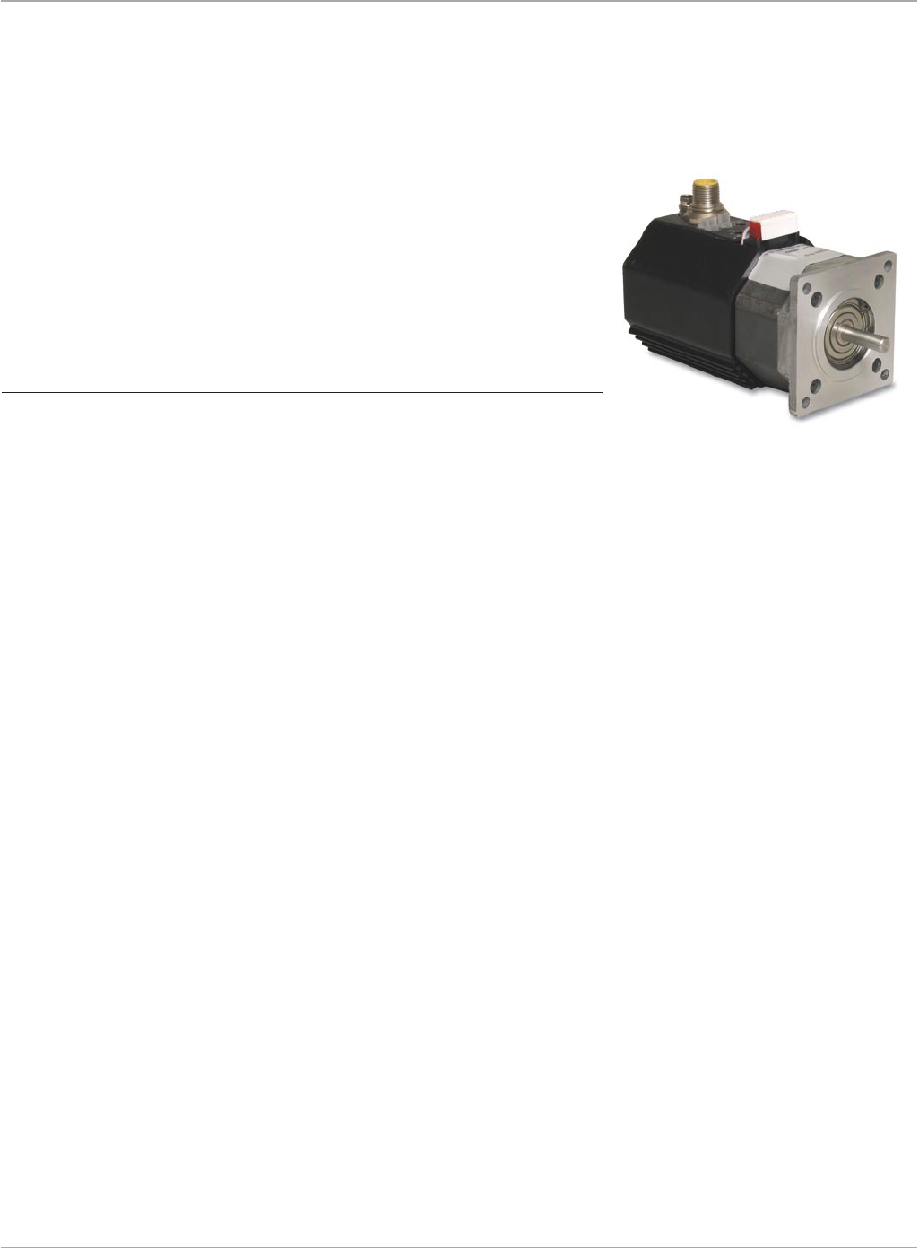
Motion Solutions
156 www.ge-ip.com
GE Intelligent Platforms
Stepping Motor Cube: Complete, Integrated Stepping
Motor and Drive
Designersofindustrialsteppingmotorapplicationscontinually
demand more features, fewer system components and less
wiring.GEraisesthebarwithitshigh-performanceStepping
MotorCube,integratingmotor,driveandcontrolcommunications
inasinglepackage.
Features
• Integraldrivewith3-Amp,24-48VDC
power input
• NEMA23steppingmotor
• Threemodelsavailablewithtorque
ratingsfrom50to175oz-in
• Optional500pprEncoderonpulse
command models
ThelatestadditiontoGE’soffering
of leading-edge, integrated motion con-
trolproducts,theSteppingMotorCubefits
easily into systems where panel space is
limited.
Specifications
Designedtoperforminindustrialenvironments,theSteppingMotorCubefeatures:
• Fullorhalf-stepmodes
• 50kHzmaxpulsefrequency
• 2µsminimumpulsewidth
SteppingMotorCube
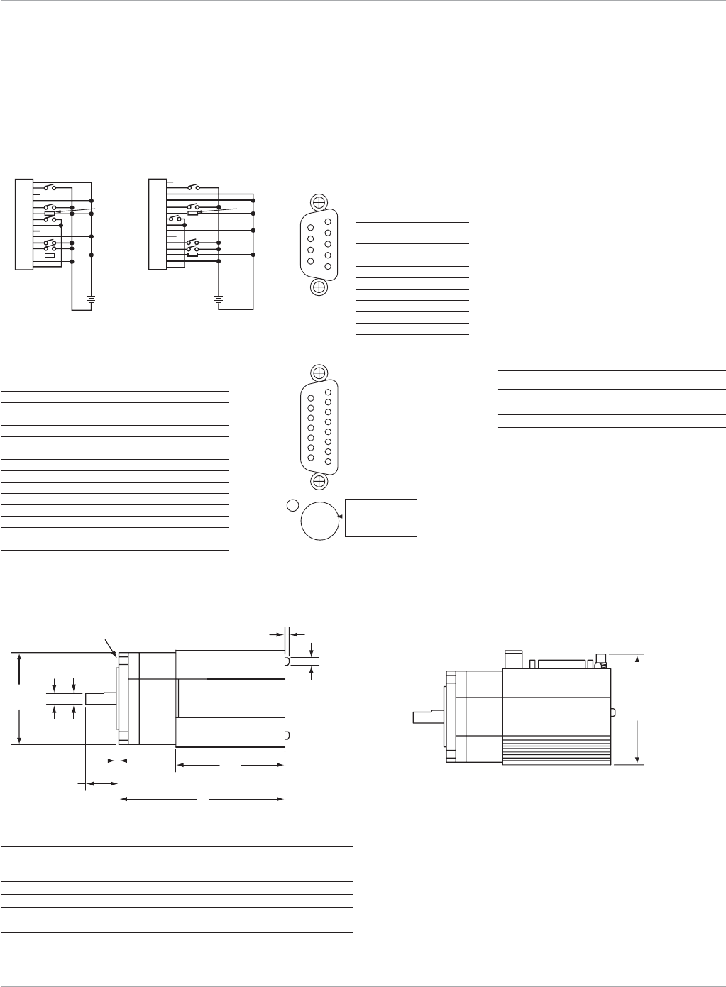
157
Motion Solutions
www.ge-ip.com GE Intelligent Platforms
Stepping Motors
2.770
(70.4)
SideView–PulseCommandConfiguration
Stepping Motor Cube
Connection Information
DB-15 Connector*
Pin Function
1 Pulse+(24V)
2 Pulse-
3 Direction+(4V)
4 InputCommon
5 PowerSave
6 StallOutput
7 StepSizeSelectA
8 StepSizeCommon
9 Pulse+(4V)
10 Direction+(24V)
11 Direction-
12 EnableInput
13 OKOutput
14 OutputCommon
15 StepSizeSelectB
*OptionalDB-15toscrewterminaladaptor
(IC800CUBDB15ADP)isavailable
DB9 Pinout
Pin Function
1 ChannelA+
2 ChannelB+
3 Index+
4 +5V
5 Gnd
6 ChannelA-
7 ChannelB-
8 Index-
9 Gnd
Model LMax in (mm) L1 in (mm) Weight lb (kg)
IC800MCUB12160XN 3.7(93.9) 2.7(68.6) 1.6(0.73)
IC800MCUB12210XN 4.2(106.7) 2.7(68.6) 2.1(0.95)
IC800MCUB12310XN 5.2(132.1) 2.7(68.6) 3.1(1.41)
IC800MCUB12160XE 4.5(114.3) 3.5(88.9) 1.8(0.82)
IC800MCUB12210XE 5.0(127.0) 3.5(88.9) 2.3(1.1)
IC800MCUB12310XE 6.0(152.4) 3.5(88.9) 3.3(1.5)
(1.4)
0.055
2.250
(57.2)
0.250
(6.35)
0.217
(5.51)
(20.57)
0.810
L
+0.07
-0.04 (1.02)
L1
0.184
(4.67)
(2.85)
0.112
4X ø 0.20 (5.08) THRU
ON A ø 2.625 (66.68) B.C.
(1.78)
TopView
1
2
3
4
5
6
7
8
9
61
95
Channel A+
Channel B+
Index +
+ 5V
Gdn
Channel A-
Channel B-
Index -
Gnd
DB9 PINOUT
1
2
3
4
5
6
7
8
9
10
11
12
13
14
15
Discrete Inputs and Outputs
x
x
1
2
3
4
5
6
7
8
9
10
11
12
13
14
15
x
x
LOAD 100 MA MAX LOAD 100 MA MAX
+
-
18-30
VDC
+
-
3.5-4.2
VDC
Encoder Output OptionDiscrete Inputs and Outputs
91
15 8
02
0301
Power
DC Power
Pin 1 = Vmotor +
Pin 2 = Frame
Pin 3 = Vmotor Com
Mechanical Dimensions in (mm)
Step Size Selection
A B Step Size
open open FullStepping(200steps/rev)
open short HalfStepping(400steps/rev)
short open Microstepping(1,000steps/rev)
short=ConnecttoStepSizeCommon
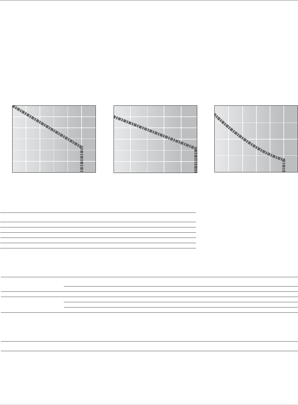
Motion Solutions
158 www.ge-ip.com
GE Intelligent Platforms
Stepping Motors
Cable Ordering Information
Part Number Description
SteppingMotorCubePowerCables IC800MCC23P050 PowerCable,MotorCubeSteppingMotortoFlyingLead,5m
IC800MCC23P100 PowerCable,MotorCubeSteppingMotortoFlyingLead,10m
EncoderCables CBL-12-ED-03M-RA EncoderCable,SteppingMotorCubeDB-9RightAngleConnectortoFlyingLead,3m
SteppingMotorCubeI/OCables IC800PCUBC02S0x0 InterfaceCable,MotorCubeDB-15I/OConnectortoFlyingLeads,200Steps/Rev,x=3or5m
IC800PCUBC04S0x0 InterfaceCable,MotorCubeDB-15I/OConnectortoFlyingLeads,400Steps/Rev,x=3or5m
IC800PCUBC10S0x0 InterfaceCable,MotorCubeDB-15I/OConnectortoFlyingLeads,1000Steps/Rev,x=3or5m
Accessory Ordering Information
Part Number Description
ScrewTerminalAdapter IC800CUBDB15ADP PlugonAdapterConvertsDB15ConnectionstoScrewTerminals
Stepping Motor Cube
Performance Curves
Theperformancecurvesshowratedtorqueavailablefor48VDC
andfullsteppingmode.Torquemustbereducedby30%forhalf-
steppingmode.Lowerbusvoltageswillalsodecreasetheavail-
ablespeedandtorque.
Consultthefactoryforanapplication-
specificSteppingMotorCubesizingor
for more information on how GE can
improve the performance of your
stepping motor control systems.
50
40
30
20
10
0
600 1200 1800 2400 30603000
Torque (oz-in)
MCUB1216
Current 2.5 Amps peak Bus Voltage 48 VDC
Speed (RPM)
600
0
50
100
150
200
1200 1800 2400 30603000
Torque (oz-in)
MCUB1231
Current 3.0 Amps peak Bus Voltage 48 VDC
Speed (RPM)
600 1200 1800 2400 3000
Torque (oz-in)
MCUB1221
Current 3.0 Amps peak Bus Voltage 48 VDC
Speed (RPM)
120
100
80
60
40
20
0
MotorCube Ordering Information
Part Number Description
IC800MCUB12160XE 50oz-inSteppingMotorCube,Pulse/DirectionInterfacewith500lineEncoder
IC800MCUB12160XN 50oz-inSteppingMotorCube,Pulse/DirectionInterface
IC800MCUB12210XE 100oz-inSteppingMotorCube,Pulse/DirectionInterfacewith500lineEncoder
IC800MCUB12210XN 100oz-inSteppingMotorCube,Pulse/DirectionInterface
IC800MCUB12310XE 175oz-inSteppingMotorCube,Pulse/DirectionInterfacewith500lineEncoder
IC800MCUB12310XN 175oz-inSteppingMotorCube,Pulse/DirectionInterface
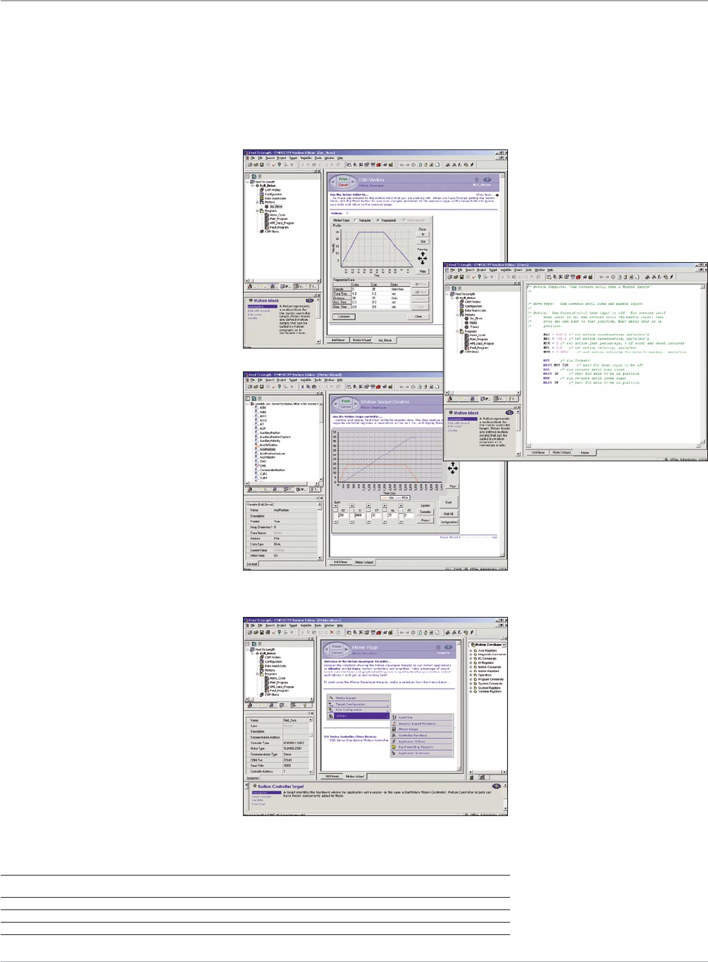
159
Motion Solutions
www.ge-ip.com GE Intelligent Platforms
Development Software
Motion Developer
S2K Series controllers are
configured using the Motion
Developer software. This easy-
to-use interface provides the
user with a range of program-
ming methods appropriate for
both the beginner and the
more advanced programmer.
Motion Developer is also a
member of the GE Intelligent
Platforms Proficy Machine
Edition environment which can
include factory automation
software applications like View
and Control. Thus, a complete
machine control solution is
further simplified with one
programming environment.
Ordering Information
Motion Developer with 15 months GlobalCare Complete BC646MODEV
5-pack Motion Developer with 15 months GlobalCare Complete BC646MODEV05PK
10-pack Motion Developer with 15 months GlobalCare Complete BC646MODEV10PK
1 year GlobalCare Complete Renewal SA648MODEV
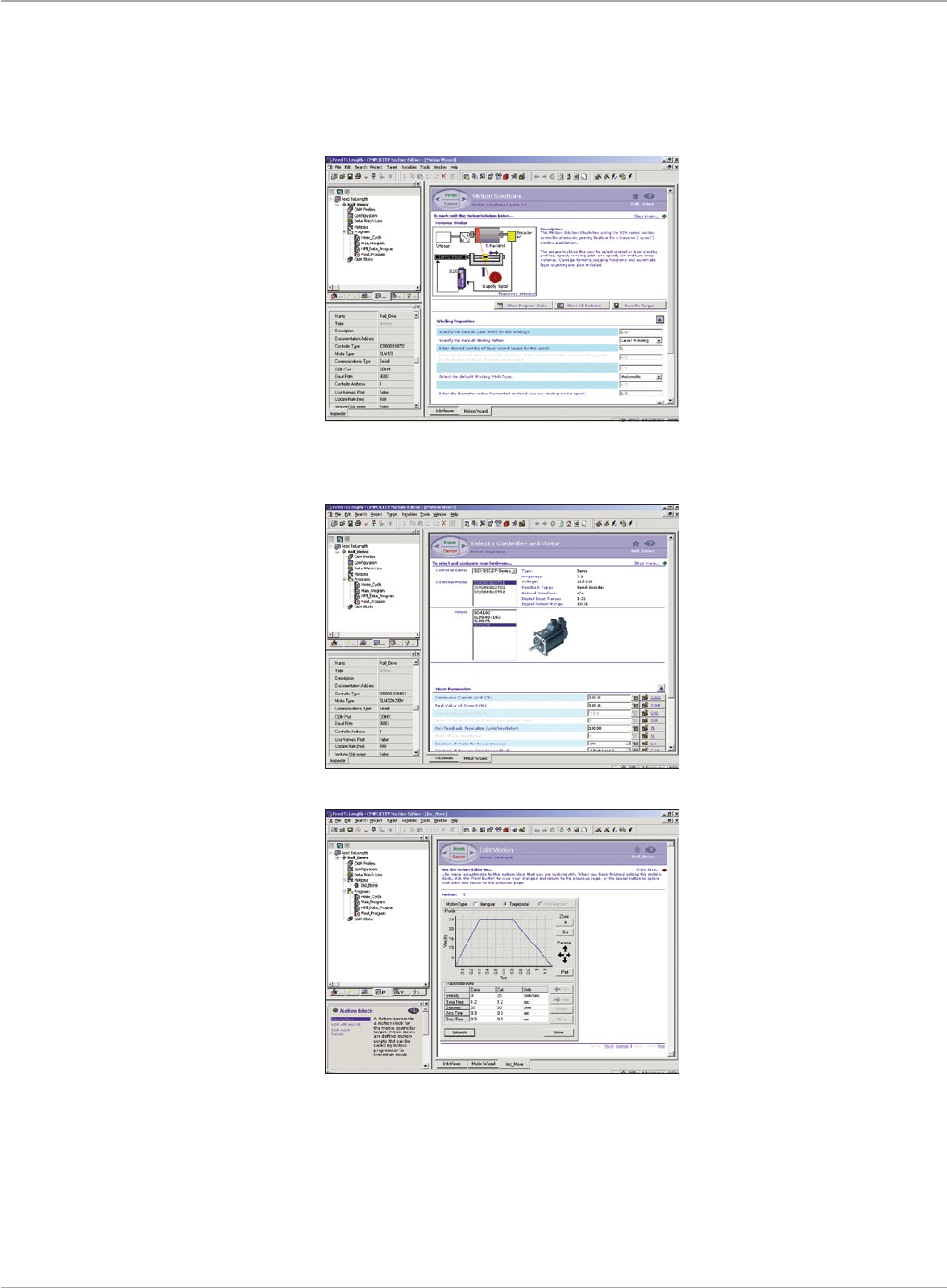
Motion Solutions
160 www.ge-ip.com
GE Intelligent Platforms
Motion Software
Development Software
New Application Wizard
Application Wizards provide step-by-step
instructions to guide the first-time user
through controller configuration and
simple motion programming.
The Motion Solutions templates aid the
user in rapid development of common
applications such as flying cutoff, rotary
knife and traverse (spool) winder.
Each Motion Developer “project” stores all
of the configuration, motion and program
information for a complete multi-axis
system. Projects can be reused or modi-
fied at any time.
Configuration Wizard
Setting up your system is simplified with
drop-down motor/drive lists complete
with pictures. Complete controller config-
urations, including communication
parameters, user unit scaling, master
encoder configuration, position rollover,
I/O configuration and electronic gearing
are configured using a simple question
and answer format. The S2K “autotune”
function provides a novice user with a
way to get optimum performance without
having in-depth knowledge of tuning
parameters.
Motion Wizard
Adding new motion blocks is as easy as
selecting the move type from the avail-
able list and filling in the blanks.
Incremental moves can be created using
the Motion Calculator. Advanced users
can customize motion blocks using the
text editor. Up to 100 motion blocks can
be created and called by any of the four
programs. Once created, these motion
blocks can be saved in the Toolchest
library (drawer) under a user-specified
name for re-use in future projects.
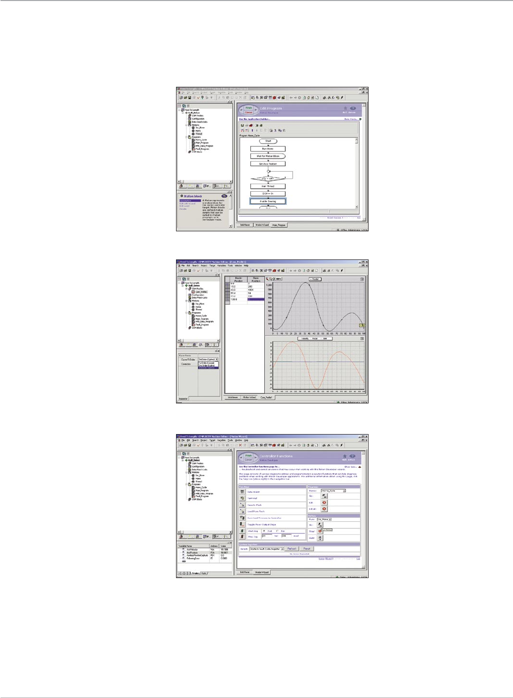
161
Motion Solutions
www.ge-ip.com GE Intelligent Platforms
Motion Software
Development Software
Graphical Motion Editor
The graphical motion Program Editor
allows programs to be developed using a
flow chart format. New commands can
be inserted from the menus or drag-and-
dropped from the Toolchest. Double click-
ing a program block allows block param-
eters to be changed. Program flow control
is easy to create by making or breaking
connections. Selecting a decision block
highlights the conditional program path
for easy visualization.
CAM Editor
Motion Developer provides a graphical
CAM Profile Editor for developing electron-
ic CAM Profiles. Data points can be import-
ed/exported in CSV file format, manually
entered into the data table or by inserting
and dragging points on the graph. CAM
Profiles can be subdivided into sectors
with each sector supporting individual
first, second or third order curve fitting.
Multiple profiles can be stored in a project.
On-line Menu
Motion Developer also includes tools to
aid in quick start-up and debugging. The
Controller Functions screen provides the
user with a convenient way to start/stop
motion blocks or programs, jog the axis
motor, view or reset system status and
faults and open the Data Watch window
or the terminal window for immediate
mode communications with the selected
controller.
The Data Watch and Motion Scope func-
tions allow the user to view an “o’scope-
style” trend chart for selected variables.
The Data Watch window allows you to
monitor and change both system and
user variables in real time.
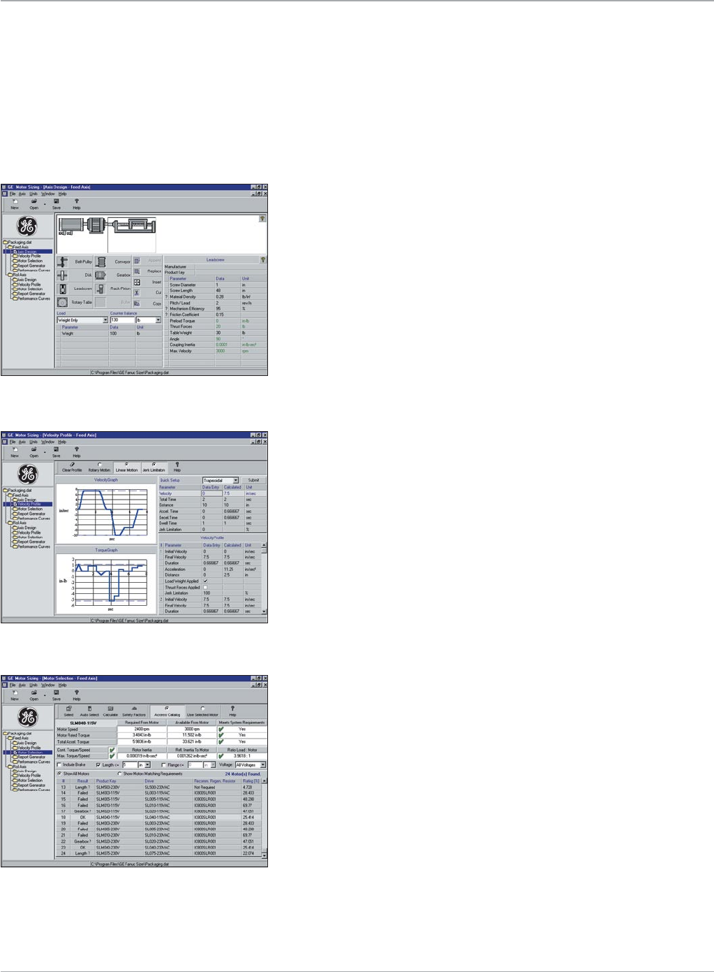
Motion Solutions
162 www.ge-ip.com
GE Intelligent Platforms
Motion Software
The GE Sizer is a powerful motor selection program to assist in the selection of GE servo solutions for a broad range of user defined
applications. GE Sizer is one of the most advanced motor selection programs available, providing users the flexibility to quickly define
and analyze many possible system configurations in order to determine the optimum solution. Advanced features include:
Servo Motor Sizing Software
• Graphicaldesignofsystemmechanicsandmotionprofiles
• Multipleaxescanbeanalyzedandsavedinonefilewithuser
defined axes names
• Flexibleuserdefinedunitsofmeasure
• Inclinedloadsinincrementsof1degreewithuserdefined
counterbalancing
• Graphicaldisplayofselectedmotortorque/speedcurvewith
superimposed loading
• Comprehensiveon-lineandprintedreportcanbeexportedto
an MS-Word template that can be customized by the user
The Axis Design screen (above) is first used to define the system mechanics
using graphical icons with fill-in-the-blank data tables.
The Velocity Profile screen (below) is then used to define the motion profile
for each axis and supports the following features:
• QuickSet-upforsimpletriangularortrapezoidalvelocityprofilesora
free form tool to define complex, multi-speed profiles
• Jerklimitedorlinearaccelerationmaybedefinedforeachaccel/decel
segment
• Thrustloadandapplicationloadmaybedefinedforeachmotionseg-
ment allowing complex machine cycles to be quickly analyzed
• Enterorviewprofiledataineitherlinearorrotaryunits
• Togglejerklimitingon/offwithconvenienttoolbarbuttontoquickly
assess impact on required peak motor torque
The Motor Selection screen (right) is used to search the database of GE
motors for the optimum solution. The selection screen includes:
• AutomaticselectionandrankingofviableGEservomotorsolutions
• Userdefinedsafetyfactorsfortorquemargin,load/motorinertiaratio,etc.
• RegenerationresistorcalculationsautomaticallyrecommendGEresistor
kit part number
• Userdefinedmotorselectioncriteriaincludesvoltage,motorlengthand
diameter, brake, inertia ratio and torque safety margin
The GE Sizer software can make short work of choosing and documenting
the best GE motor solution for your motion applications. The intuitive graphi-
cal interface makes it easy to use for a novice without sacrificing the flexibili-
ty or features demanded by more experienced users.

163
Motion Solutions
www.ge-ip.com GE Intelligent Platforms
Index
Product Number Product Name Page Number Product Number Product Name Page Number
21000525 MTR-3T Series Resolver Connector Mate . . . . . . . . . . . . . . . . . . . . . . . . 135
21000526 MTR-3T Series Motor Power Connector Mate ....................135
73006589 Hand Held I/O Simulator for 4.3 and 7.2A Models .................48
206705-2 Stepping Motor Connector Mate - receptacle . . . . . . . . . . . . . . . . . . . 154
206708-1 Stepping Motor Connector Mate - receptacle . . . . . . . . . . . . . . . . . . . 154
206966-1 Stepping Motor Connector Mate - clamp ........................154
21000399 Stepping Motor Connector Mate ................................154
44A726268-001 DSM324i 24V I/O Terminal Board (1 per module). . . . . . . . . . . . . . . . . . 17
640620-8 Stepping Motor Connector Mate - housing ......................154
643075-8 Stepping Motor Connector Mate - cover . . . . . . . . . . . . . . . . . . . . . . . . 154
66099-4 Stepping Motor Connector Mate - contact (Qty 9) ................154
66101-4 Stepping Motor Connector Mate - contact (Qty 9) ................154
BC646MODEV Motion Developer with 15 months GlobalCare Complete .........159
BC646MODEV05PK 5-pack Motion Developer with 15 months . . . . . . . . . . . . . . . . . . . . . . 159
GlobalCare Complete
BC646MODEV10PK 10-pack Motion Developer with 15 months . . . . . . . . . . . . . . . . . . . . . 159
GlobalCare Complete
CB4N-0WPM-0070-AZ Holding Brake Power Cable, 7 M ...................70, 71, 72, 79, 81
CB4N-0WPM-0140-AZ Holding Brake Power Cable, 14 M ..................70, 71, 72, 79, 81
CB5N-0WPM-0070-AZ Fan Cable, 7 M ..................................................72
CB5N-0WPM-0140-AZ Fan Cable, 14 M .................................................72
CB6N-5WPM-0070-AZ Holding Brake Power Cable, 7 M .................................80
CB6N-5WPM-0140-AZ Holding Brake Power Cable, 14 M ................................80
CBL-12-ED-03M-RA Encoder Cable, Stepping MotorCube DB-9 Right Angle ...........158
Connector to Flying Lead, 3 m
CBL-12-MPS-xx Power Cable, MTR-1216, 1221 & 1231 Stepping Motor ...........155
to S2K, xx = 10, 20 or 30 feet
CBL-12-MP-xx Power Cable, MTR-1216, 1221 & 1231 Stepping Motor ...........155
to PowerCube, xx = 10, 20 or 30 feet
CBL-13-ET-xx Encoder Cable, Flying Lead to MTR-1235, 1300 & 1N Series ......155
Stepping Motors, xx = 10, 20 or 30 feet
CBL-13-MP-xx Power Cable, MTR-1235, 1300 & 1N Series Stepping Motors, . . . . 155
xx = 10, 20 or 30 feet
CBL-14-ET-xx Encoder Cable, Flying Lead to MTR-1235, 1300 & 1N Series ......155
Splashproof Stepping Motors, xx = 10, 20 or 30 feet
CBL-14-MP-xx Power Cable, MTR-1235, 1300 & 1N Series Splashproof ..........155
Stepping Motors, xx = 10, 20 or 30 feet
CBL-1C-ET-xx Encoder Cable, MTR-1216, 1221 & 1231 Stepping Motors, .......155
xx = 10, 20 or 30 feet
CBL-3C-L1D-FLY-XX Encoder cable, S2K to flying leads for connection of . .............48
quadrature encoder with hall tracks, xx =1 0, 20 or 30 feet
CBL-3T-MB-xx Power/Brake Cable, S2K to MTR-3T5x and 3T6x . . . . . . . . . . . . . . .48, 90
Servo Motors with Brake, xx = 10, 20 or 30 feet
CBL-3T-MP-xx Power Cable, S2K to MTR-3T5x and 3T6x Servo Motors, . . . . . . .48, 90
xx = 10, 20 or 30 feet
CBL-3T-RD-xx Resolver Cable, S2K to MTR-3T Series Servo Motor, . . . . . . . . . . . .48, 90
xx = 10, 20 or 30 feet
CBL-T7-MB-xx Power/Brake Cable, S2K to MTR-3T1x, 3T2x and 3T4x . . . . . . . . .48, 90
Servo Motors with Brake, xx = 10, 20 or 30 feet
CBL-T7-MP-xx Power Cable, S2K to MTR-3T1x, 3T2x and 3T4x ................48, 90
Servo Motors, xx = 10, 20 or 30 feet
CFDA-0WPB-0070-AZ Feedback Cable (Straight motor connector), 7 M . .70, 71, 72, 79, 80, 81
CFDA-0WPB-0140-AZ Feedback Cable (Straight motor connector), 14 M . .70, 71, 72, 79, 80, 81
CFDA-3WPB-0070-AZ Feedback Cable (Right Angle), 7 M . . . . . . . . . . . . . . . . . . . . . . . . 70, 71, 72
CFDA-3WPB-0140-AZ Feedback Cable (Right Angle), 14 M .......................70, 71, 72
CFDA-7WPB-0070-AZ Feedback Cable (Right Angle motor connector), 7 M . . . . . . . 79, 80, 81
CFDA-7WPB-0140-AZ Feedback Cable (Right Angle motor connector), 14 M ......79, 80, 81
CP2I-0WEB-0070-AZ Power Cable (Shielded), 7 M . . . . . . . . . . . . . . . . . . . . . . . . . . . . . . . . . . . . . 79
CP2I-0WEB-0140-AZ Power Cable (Shielded), 14 M . . . . . . . . . . . . . . . . . . . . . . . . . . . . . . . . . . . . 79
CP2I-0WPB-0070-AZ Power Cable, 7 M ...............................................79
CP2I-0WPB-0140-AZ Power Cable, 14 M ..............................................79
CP3B-0WEB-0070-AZ Power Cable (Shielded), 7 M . . . . . . . . . . . . . . . . . . . . . . . . . . . . . . . . . . . . . 81
CP3B-0WEB-0140-AZ Power Cable (Shielded), 14 M . . . . . . . . . . . . . . . . . . . . . . . . . . . . . . . . . . . . 81
CP3B-0WPB-0070-AZ Power Cable, 7 M ...............................................81
CP3B-0WPB-0140-AZ Power Cable, 14 M ..............................................81
CP2I-0WEB-0070-AZ Power Cable (Shielded), 7 M . . . . . . . . . . . . . . . . . . . . . . . . . . . . . . . . . . . . . 70
CP2I-0WEB-0140-AZ Power Cable (Shielded), 14 M . . . . . . . . . . . . . . . . . . . . . . . . . . . . . . . . . . . . 70
CP2I-0WPB-0070-AZ Power Cable, 7 M ...............................................70
CP2I-0WPB-0140-AZ Power Cable, 14 M ..............................................70
CP3I-0WEB-0070-AZ Power Cable (Shielded), 7 M . . . . . . . . . . . . . . . . . . . . . . . . . . . . . . 70, 71, 79
CP3I-0WEB-0140-AZ Power Cable (Shielded), 14 M . . . . . . . . . . . . . . . . . . . . . . . . . . . . . 70, 71, 79
CP3I-0WPB-0070-AZ Power Cable, 7 M . . . . . . . . . . . . . . . . . . . . . . . . . . . . . . . . . . . . . . . . 70, 71, 79
CP3I-0WPB-0140-AZ Power Cable, 14 M . . . . . . . . . . . . . . . . . . . . . . . . . . . . . . . . . . . . . . . 70, 71, 79
CP4I-0WEB-0070-AZ Power Cable (Shielded), 7 M . . . . . . . . . . . . . . . . . . . . . . . . . . . . . . 71, 72, 79
CP4I-0WEB-0140-AZ Power Cable (Shielded), 14 M . . . . . . . . . . . . . . . . . . . . . . . . . . . . . 71, 72, 79
CP4I-0WPB-0070-AZ Power Cable, 7 M . . . . . . . . . . . . . . . . . . . . . . . . . . . . . . . . . . . . . . . . 71, 72, 79
CP4I-0WPB-0140-AZ Power Cable, 14 M . . . . . . . . . . . . . . . . . . . . . . . . . . . . . . . . . . . . . . . 71, 72, 79
CP5B-0WEB-0070-AZ Power Cable (Shielded), 7 M . . . . . . . . . . . . . . . . . . . . . . . . . . . . . . . . . . . . . 81
CP5B-0WEB-0140-AZ Power Cable (Shielded), 14 M . . . . . . . . . . . . . . . . . . . . . . . . . . . . . . . . . . . . 81
CP5B-0WPB-0070-AZ Power Cable, 7 M ...............................................81
CP5B-0WPB-0140-AZ Power Cable, 14 M ..............................................81
CP6B-0WEB-0070-AZ Power Cable (Shielded), 7 M . . . . . . . . . . . . . . . . . . . . . . . . . . . . . . . . . . . . . 81
CP6B-0WEB-0140-AZ Power Cable (Shielded), 14 M . . . . . . . . . . . . . . . . . . . . . . . . . . . . . . . . . . . . 81
CP6B-0WPB-0070-AZ Power Cable, 7 M ...............................................81
CP6B-0WPB-0140-AZ Power Cable, 14 M ..............................................81
CP8B-1WEB-0070-AZ Power Cable (Shielded), 7 M . . . . . . . . . . . . . . . . . . . . . . . . . . . . . . . . . . . . . 80
CP8B-1WEB-0140-AZ Power Cable (Shielded), 14 M . . . . . . . . . . . . . . . . . . . . . . . . . . . . . . . . . . . . 80
CP8B-1WPB-0070-AZ Power Cable, 7 M ...............................................80
CP8B-1WPB-0140-AZ Power Cable, 14 M ..............................................80
CP9B-0WEB-0070-AZ Power Cable (Shielded), 7 M . . . . . . . . . . . . . . . . . . . . . . . . . . . . . . . . . .80, 81
CP9B-0WEB-0140-AZ Power Cable (Shielded), 14 M . . . . . . . . . . . . . . . . . . . . . . . . . . . . . . . . .80, 81
CP9B-0WPB-0070-AZ Power Cable, 7 M ............................................80, 81
CP9B-0WPB-0140-AZ Power Cable, 14 M . . . . . . . . . . . . . . . . . . . . . . . . . . . . . . . . . . . . . . . . . . .80, 81
CP9I-0MEB-0070-AZ Power Cable (Shielded), 7 M . . . . . . . . . . . . . . . . . . . . . . . . . . . . . . . . . . . . . 72
CP9I-0MEB-0140-AZ Power Cable (Shielded), 14 M . . . . . . . . . . . . . . . . . . . . . . . . . . . . . . . . . . . . 72
CP9I-0MPB-0070-AZ Power Cable, 7 M ...............................................72
CP9I-0MPB-0140-AZ Power Cable, 14 M ..............................................72
IC646MBP001 Machine Edition Professional Development Suite . . . . . . . . . . . . . . . . . 6
without GlobalCare. Complete with Software key
IC646MPP001 Logic Developer PLC Professional without GlobalCare. . . . . . . . . . . . . 6
Complete with Software key
IC647MBP001 Machine Edition Professional Development Suite . . . . . . . . . . . . . . . . . 6
without GlobalCare. Complete with USB Hardware key
IC647MPP001 Logic Developer PLC Professional without GlobalCare. . . . . . . . . . . . . 6
Complete with USB Hardware key
IC693ACC335 Digital Servo Axis Terminal Board (one per axis) . . . . . . . . . . . . . . . . . . 18
IC693ACC336 DSM324i 5V High Speed & Analog I/O Terminal Board . . . . . . . . .17, 18
(1 per module)

Motion Solutions
164 www.ge-ip.com
GE Intelligent Platforms
Index
Product Number Product Name Page Number Product Number Product Name Page Number
IC693CBL311 DSM324i to 44A726268-001 Terminal Board Cable - 3m ..........17
(1 per module)
IC693CBL316 Serial Cable for Programming (1 per system) . . . . . . . . . . . . . . . 6, 17, 18
IC693CBL319 DSM324i to 44A726268-001 Terminal Board Cable - 1m ..........17
(1 per module)
IC693CBL324 ACC336 Terminal Board Interface Cable - 1m (1 per module) ...17, 18
IC693CBL325 ACC336 Terminal Board Interface Cable - 3m (1 per module) ...17, 18
IC693DSM302 DSM302 Motion Controller (2 axis) for Series 90-30 . . . . . . . . . . . . . . . 18
IC693DSM314 DSM314 Motion Controller (4 analog/2 digital axes) ..............18
for Series 90-30
IC693DSM324 DSM324i Motion Controller for Series 90-30 ......................17
IC694DSM314 DSM314 Motion Controller (4 analog/2 digital axes) for RX3i . . . . . . 18
IC694DSM324 DSM324i Motion Controller for PACSystems RX3i . . . . . . . . . . . . . . . . . 17
IC694TBB032 High Density 36 point Captive Screw Terminals . . . . . . . . . . . . . . . . . . 11
IC694TBB132 High Density Captive Screw Terminals, Extended Shroud . . . . . . . . . 11
IC694TBS032 High Density 36 point Spring Clip Terminals ......................11
IC694TBS132 High Density Spring Clip Terminals, Extended Shroud .............11
IC695FTB001 Optional Fiber Terminal Block (without terminal headers) . . . . . . . . . . 6
IC695FTB1B032 Optional Fiber I/O Terminal Block (with screw terminal headers) . . . 6
IC695FTB1S032 Optional Fiber I/O Terminal Block . . . . . . . . . . . . . . . . . . . . . . . . . . . . . . . . 6
(with spring clip terminal headers)
IC695FTB1B132 Optional Fiber I/O Terminal Block . . . . . . . . . . . . . . . . . . . . . . . . . . . . . . . . 6
(with extended shroud screw terminal headers)
IC695FTB1S132 Optional Fiber I/O Terminal Block . . . . . . . . . . . . . . . . . . . . . . . . . . . . . . . . 6
(with extended shroud spring clip terminal headers)
IC695PMM335 PACMotion Motion Controller for RX3i ............................. 6
IC800ABK001 Encoder Battery Backup Kits, . . . . . . . . . . . . . . . . . .70, 71, 72, 79, 80, 81
Panel Mounted, 4 axis
IC800ABK002 Encoder Battery Backup Kits, Built-in . . . . . . . . . . . . . . . . . . . . . 70, 71, 72
IC800ABK003 Encoder Battery Backup Kits, Built-in . . . . . . . . . . . . . . . . . . . . . . . . . . . . 72
IC800AIHV010 10 Amp αHVi Series Amplifier Package . . . . . . . . . . . . . . . . . . . . . . .69, 70
IC800AIHV040 40 Amp αHVi Series Amplifier Package . . . . . . . . . . . . . . . . . . . 69, 70, 71
IC800AIHV080 80 Amp αHVi Series Amplifier Package . . . . . . . . . . . . . . . . . . . 69, 71, 72
IC800AIHV180 180 Amp αHVi Series Amplifier Package . . . . . . . . . . . . . . . . . . . . . .69, 72
IC800BBK021 Encoder Battery Kits, 1 axis ...............................79, 80, 81
IC800BIHV010 10 Amp βHVi Series Amplifier Package ....................70, 78, 79
IC800BIHV020 20 Amp βHVi Series Amplifier Package ........................78, 79
IC800BIHV040 40 Amp βHVi Series Amplifier Package ....................70, 71, 78
IC800BIK020 20 Amp βi series Amplifier Package .......................78, 80, 81
IC800BIK040 40 Amp βi series Amplifier Package ...........................78, 81
IC800CBL001 Servo Command Cable - 1m (one per axis) .......................18
IC800CBL002 Servo Command Cable - 3m (one per axis) .......................18
IC800CUBDB15ADP Plug on Adapter Converts DB15 Connections to ............139, 158
Screw Terminals (Pulse/ Direction models only)
IC800MBUSADP RS232 to 422/480 Serial Converter for Modbus ...................48
RTU Communications
IC800MCC23P050 Power Cable, MotorCube Stepping Motor to Flying Lead, 5 m . . . . 158
IC800MCC23P100 Power Cable, MotorCube Stepping Motor to Flying Lead, 10 m ...158
IC800MCUB12160XE 50 oz-in Stepping Motor Cube, Pulse/Direction Interface .........158
with 500 line Encoder
IC800MCUB12160XN 50 oz-in Stepping Motor Cube, Pulse/Direction Interface .........158
IC800MCUB12210XE 100 oz-in Stepping Motor Cube, Pulse/Direction Interface ........158
with 500 line Encoder
IC800MCUB12210XN 100 oz-in Stepping Motor Cube, Pulse/Direction Interface ........158
IC800MCUB12310XE 175 oz-in Stepping Motor Cube, Pulse/Direction Interface ........158
with 500 line Encoder
IC800MCUB12310XN 175 oz-in Stepping Motor Cube, Pulse/Direction Interface ........158
IC800PCUB00300 Power Cube ...................................................139
IC800PCUBC02S0x0 Interface Cable, PowerCube Amplifier/MotorCube . . . . . . . . . . 155, 158
DB-15 I/O Connector to Flying Leads, 200 Steps/Rev,
x = 3 or 5 m
IC800PCUBC04S0x0 Interface Cable, PowerCube Amplifier/MotorCube . . . . . . . . . . 155, 158
DB-15 I/O Connector to Flying Leads, 400 Steps/Rev,
x = 3 or 5 m
IC800PCUBC10S0x0 Interface Cable, PowerCube Amplifier/ MotorCube . . . . . . . . . 155, 158
DB-15 I/O Connector to Flying Leads, 1000 Steps/Rev,
x = 3 or 5 m
IC800PCUBDINMTG DIN Rail Mounting Plate . . . . . . . . . . . . . . . . . . . . . . . . . . . . . . . . . . . . . . . . 139
IC800PSHV011 11 kW Power Supply Module Package . . . . . . . . . . . . . . . . . . . . . . . .69, 73
IC800PSHV018 18 kW Power Supply Module Package . . . . . . . . . . . . . . . . . . . . . . . .69, 73
IC800PSHV030 30 kW Power Supply Module Package . . . . . . . . . . . . . . . . . . . . . . . .69, 73
IC800PSHV045 45 kW Power Supply Module Package . . . . . . . . . . . . . . . . . . . . . . . .69, 73
IC800SKCFLYxxx Interface Cable, S2K Auxiliary I/O connector. . . . . . . . . . . . . . . 18, 48, 90
to Flying Leads, 1 m or 3 m
IC800SKCIxxx Interface Cable, S2K Auxiliary I/O to 44A726268-001 . . . . . . . . . .48, 90
Terminal Board Assembly, 1 m or 3 m
IC800SKCS030 S2K Serial Communication Cable for PC (Motion Developer) . . .48, 90
Interface, 3 m
IC800SLR001 50Ω, 100W External Regeneration Resistor Kit . . . . . . . . . . . . . . . .48, 90
IC800SLR002 100Ω, 225W External Regeneration Resistor Kit . . . . . . . . . . . . . . .48, 90
IC800SLR003 20Ω, 300W External Regeneration Resistor Kit . . . . . . . . . . . . . . . .48, 90
IC800SLR004 15Ω, 1000W External Regeneration Resistor Kit . . . . . . . . . . . . . . .48, 90
IC800SSD104RS1 4.3 Amp, 115/230 VAC S2K Amplifier, Resolver Feedback . . . . 90, 135
IC800SSD107RS1 7.2 Amp, 115/230 VAC S2K Amplifier, Resolver Feedback . . . . 90, 135
IC800SSD216RS1 16 Amp, 230 VAC S2K Amplifier, Resolver Feedback . . . . . . . . . 90, 135
IC800SSD228RS1 28 Amp, 230 VAC S2K Amplifier, Resolver Feedback . . . . . . . . . 90, 135
IC800SSD407RS1 7.2 Amp, 460 VAC S2K Amplifier, Resolver Feedback ......... 90, 135
IC800SSD420RS1 20 Amp, 460 VAC S2K Amplifier, Resolver Feedback . . . . . . . . . 90, 135
IC800SSI104RD2 4.3 Amp, 115/230 VAC S2K Controller, Resolver Feedback, . . 48, 135
DeviceNet
IC800SSI104RP2 4.3 Amp, 115/230 VAC S2K Controller, Resolver Feedback, . . 48, 135
Profibus
IC800SSI104RS1 4.3 Amp, 115/230 VAC S2K Controller, Resolver Feedback, . . 48, 135
Extended I/O
IC800SSI107RD2 7.2 Amp 115/230 VAC S2K Controller, Resolver Feedback, ... 48, 135
DeviceNet
IC800SSI107RP2 7.2 Amp 115/230 VAC S2K Controller, Resolver Feedback, ... 48, 135
Profibus
IC800SSI107RS1 7.2 Amp 115/230 VAC S2K Controller, Resolver Feedback, ... 48, 135
Extended I/O
IC800SSI216RD2 16 Amp, 230 VAC S2K Controller, Resolver Feedback, . . . . . . . 48, 135
DeviceNet
IC800SSI216RP2 16 Amp, 230 VAC S2K Controller, Resolver Feedback, . . . . . . . 48, 135
Profibus
IC800SSI228RD2 28 Amp, 230 VAC S2K Controller, Resolver Feedback, . . . . . . . 48, 135
DeviceNet
IC800SSI228RP2 28 Amp, 230 VAC S2K Controller, Resolver Feedback, . . . . . . . 48, 135
Profibus
IC800SSI407RD2 7.2 Amp, 460 VAC S2K Controller, Resolver Feedback, ....... 48, 135
DeviceNet
IC800SSI407RP2 7.2 Amp, 460 VAC S2K Controller, Resolver Feedback, ....... 48, 135
Profibus

165
Motion Solutions
www.ge-ip.com GE Intelligent Platforms
Index
Product Number Product Name Page Number Product Number Product Name Page Number
IC800SSI407RS1 7.2 Amp 460 VAC S2K Controller, Resolver Feedback, . . . . . . . 48, 135
Extended I/O
IC800SSI420RD2 20 Amp, 460 VAC S2K Controller, Resolver Feedback, . . . . . . . 48, 135
DeviceNet
IC800SSI420RP2 20 Amp, 460 VAC S2K Controller, Resolver Feedback, . . . . . . . 48, 135
Profibus
IC800STI105D2 5 Amp, 115/230 VAC S2K Stepper Controller, . . . . . . . . . . . . . . . . . . . . 48
Encoder Feedback, DeviceNet
IC800STI105P2 5 Amp, 115/230 VAC S2K Stepper Controller, . . . . . . . . . . . . . . . . . . . . 48
Encoder Feedback, Profibus
IC800STI105S1 5 Amp, 115/230 VAC S2K Stepper Controller, . . . . . . . . . . . . . . . . . . . . 48
Encoder Feedback, Extended I/O
IC800VMA012 100W, 220VAC; 50/60 Hz VersaMotion Servo Amplifier .........51, 58
IC800VMA022 200W, 220VAC; 50/60 Hz VersaMotion Servo Amplifier .........51, 58
IC800VMA042 400W, 220VAC; 50/60 Hz VersaMotion Servo Amplifier .........51, 58
IC800VMA072 750W, 220VAC; 50/60 Hz VersaMotion Servo Amplifier .........51, 58
IC800VMA102 1000W, 220VAC; 50/60 Hz VersaMotion Servo Amplifier . . . . . . .51, 59
IC800VMA202 2000W, 220VAC; 50/60 Hz VersaMotion Servo Amplifier . . . . . . .51, 59
IC800VMA302 3000W, 220VAC; 50/60 Hz VersaMotion Servo Amplifier . . . . . . .51, 59
IC800VMACONACP AC Power Connector .........................................58, 59
IC800VMACONCN1 CN1 I/O Connector ...........................................58, 59
IC800VMACONCN2 CN2 Encoder Connector ......................................58, 59
IC800VMACONCN3 CN3 Communication Connector . . . . . . . . . . . . . . . . . . . . . . . . . . . . . .58, 59
IC800VMACONMTRP Motor Power Connector ......................................58, 59
IC800VMADBR001 External Braking Resistor Connector ..........................58, 59
IC800VMBR020 External Braking Resistor, 20Ω, 1000 Watt . . . . . . . . . . . . . . . . . . . .58, 59
IC800VMBR040 External Braking Resistor, 40Ω, 400 Watt .....................58, 59
IC800VMCB030 Brake and Power Cable, 3 m. . . . . . . . . . . . . . . . . . . . . . . . . . . . . . . . . . . . . 58
IC800VMCB050 Brake and Power Cable, 5 m. . . . . . . . . . . . . . . . . . . . . . . . . . . . . . . . . . . . . 58
IC800VMCB100 Brake and Power Cable, 10 m . . . . . . . . . . . . . . . . . . . . . . . . . . . . . . . . . . . 58
IC800VMCB1030 Brake and Power Cable, 3 m. . . . . . . . . . . . . . . . . . . . . . . . . . . . . . . . . . . . . 59
IC800VMCB1050 Brake and Power Cable, 5 m. . . . . . . . . . . . . . . . . . . . . . . . . . . . . . . . . . . . . 59
IC800VMCB1100 Brake and Power Cable, 10 m . . . . . . . . . . . . . . . . . . . . . . . . . . . . . . . . . . . 59
IC800VMCB1200 Brake and Power Cable, 20 m . . . . . . . . . . . . . . . . . . . . . . . . . . . . . . . . . . . 59
IC800VMCB200 Brake and Power Cable, 20 m . . . . . . . . . . . . . . . . . . . . . . . . . . . . . . . . . . . 58
IC800VMCB2030 Brake and Power Cable, 3 m. . . . . . . . . . . . . . . . . . . . . . . . . . . . . . . . . . . . . 59
IC800VMCB2050 Brake and Power Cable, 5 m. . . . . . . . . . . . . . . . . . . . . . . . . . . . . . . . . . . . . 59
IC800VMCB2100 Brake and Power Cable, 10 m . . . . . . . . . . . . . . . . . . . . . . . . . . . . . . . . . . . 59
IC800VMCB2200 Brake and Power Cable, 20 m . . . . . . . . . . . . . . . . . . . . . . . . . . . . . . . . . . . 59
IC800VMCB3030 Brake and Power Cable, 3 m. . . . . . . . . . . . . . . . . . . . . . . . . . . . . . . . . . . . . 59
IC800VMCB3050 Brake and Power Cable, 5 m. . . . . . . . . . . . . . . . . . . . . . . . . . . . . . . . . . . . . 59
IC800VMCB3100 Brake and Power Cable, 10 m . . . . . . . . . . . . . . . . . . . . . . . . . . . . . . . . . . . 59
IC800VMCB3200 Brake and Power Cable, 20 m . . . . . . . . . . . . . . . . . . . . . . . . . . . . . . . . . . . 59
IC800VMCE030 Encoder Cable, 3 m .............................................58
IC800VMCE050 Encoder Cable, 5 m .............................................58
IC800VMCE100 Encoder Cable, 10 m ............................................58
IC800VMCE1030 Encoder Cable, 3 m .............................................59
IC800VMCE1050 Encoder Cable, 5 m .............................................59
IC800VMCE1100 Encoder Cable, 10 m ............................................59
IC800VMCE1200 Encoder Cable, 20 m ............................................59
IC800VMCE200 Encoder Cable, 20 m ............................................58
IC800VMCI010 Flying lead I/O interface Cable, 1 m ...........................58, 59
IC800VMCI030 Flying lead I/O interface Cable, 3 m ...........................58, 59
IC800VMCP030 Power Cable, 3 m ...............................................58
IC800VMCP050 Power Cable, 5 m ...............................................58
IC800VMCP100 Power Cable, 10 m ..............................................58
IC800VMCP1030 Power Cable, 3 m ...............................................59
IC800VMCP1050 Power Cable, 5 m ...............................................59
IC800VMCP1100 Power Cable, 10 m ..............................................59
IC800VMCP1200 Power Cable, 20 m ..............................................59
IC800VMCP200 Power Cable, 20 m ..............................................58
IC800VMCP2030 Power Cable, 3 m ...............................................59
IC800VMCP2050 Power Cable, 5 m ...............................................59
IC800VMCP2100 Power Cable, 10 m ..............................................59
IC800VMCP2200 Power Cable, 20 m ..............................................59
IC800VMCP3030 Power Cable, 3 m ...............................................59
IC800VMCP3050 Power Cable, 5 m ...............................................59
IC800VMCP3100 Power Cable, 10 m ..............................................59
IC800VMCP3200 Power Cable, 20 m ..............................................59
IC800VMCS030 Communications Cable, 3 m ..................................58, 59
IC800VMM01LNKSE25 100 Watt VersaMotion Servo Motor ......................... 58, 122
IC800VMM02LBKSE25 200 Watt VersaMotion Servo Motor with Brake .............. 58, 122
IC800VMM02LNKSE25 200 Watt VersaMotion Servo Motor ......................... 58, 122
IC800VMM04LBKSE25 400 Watt VersaMotion Servo Motor with Brake .............. 58, 122
IC800VMM04LNKSE25 400 Watt VersaMotion Servo Motor ......................... 58, 122
IC800VMM07LBKSE25 750 Watt VersaMotion Servo Motor with Brake .............. 58, 122
IC800VMM07LNKSE25 750 Watt VersaMotion Servo Motor ......................... 58, 122
IC800VMM10LBKSE25 1000 Watt VersaMotion Servo Motor with Brake. . . . . . . . . . . . . 59, 122
IC800VMM10LNKSE25 1000 Watt VersaMotion Servo Motor ........................ 59, 122
IC800VMM10MBKSE25 1000 Watt VersaMotion Servo Motor with Brake. . . . . . . . . . . . . 59, 122
IC800VMM10MNKSE25 1000 Watt VersaMotion Servo Motor ........................ 59, 122
IC800VMM20LBKSE25 2000 Watt VersaMotion Servo Motor with Brake. . . . . . . . . . . . . 59, 122
IC800VMM20LNKSE25 2000 Watt VersaMotion Servo Motor ........................ 59, 122
IC800VMM20MBKSE25 2000 Watt VersaMotion Servo Motor with Brake. . . . . . . . . . . . . 59, 122
IC800VMM20M NKSE25 2000 Watt VersaMotion Servo Motor ........................ 59, 122
IC800VMM30MBKSE25 3000 Watt VersaMotion Servo Motor with Brake. . . . . . . . . . . . . 59, 122
IC800VMM30MNKSE25 3000 Watt VersaMotion Servo Motor ........................ 59, 122
IC800VMMCONE001 Encoder Connector .............................................58
IC800VMMCONE002 Encoder Connector .............................................59
IC800VMMCONP001 Power Connector (motor only) . . . . . . . . . . . . . . . . . . . . . . . . . . . . . . . . . . . 58
IC800VMMCONP002 Power Connector (motor & brake). . . . . . . . . . . . . . . . . . . . . . . . . . . . . . . . 58
IC800VMMCONP003 Power Connector (motor only) and (motor & brake) ...............59
IC800VMMCONP004 Power Connector (motor only) and (motor & brake) ...............59
IC800VMTBC005 I/O Terminal Breakout Board and Cable .......................58, 59
MS3116F12-10S Stepping Motor Connector Mate ................................154
MTR-1216-E-D-E-0 Stepping Motor, 61 oz-in, NEMA 23, Encoder . . . . . . . . . . . . . . . . . . . . 155
MTR-1216-N-D-E-0 Stepping Motor, 61 oz-in, NEMA 23 . . . . . . . . . . . . . . . . . . . . . . . . . . . . . 155
MTR-1220-E-D-E-0 Stepping Motor, 116 oz-in, NEMA 23, Encoder ...................155
MTR-1220-N-D-E-0 Stepping Motor, 116 oz-in, NEMA 23 . . . . . . . . . . . . . . . . . . . . . . . . . . . . 155
MTR-1221-E-D-E-0 Stepping Motor, 144 oz-in, NEMA 23, Encoder ...................155
(124 oz-in with PowerCube)
MTR-1221-N-D-E-0 Stepping Motor, 144 oz-in, NEMA 23 . . . . . . . . . . . . . . . . . . . . . . . . . . . . 155
(124 oz-in with PowerCube)
MTR-1231-E-D-E-0 Stepping Motor, 230 oz-in, NEMA 23, Encoder ...................155
MTR-1231-N-D-E-0 Stepping Motor, 230 oz-in, NEMA 23 . . . . . . . . . . . . . . . . . . . . . . . . . . . . 155

Motion Solutions
166 www.ge-ip.com
GE Intelligent Platforms
Index
Product Number Product Name Page Number Product Number Product Name Page Number
MTR-1235-E-D-E-0 Stepping Motor, 180 oz-in, NEMA 23, Encoder ...................155
MTR-1235-N-D-E-0 Stepping Motor, 180 oz-in, NEMA 23 . . . . . . . . . . . . . . . . . . . . . . . . . . . . 155
MTR-1324-E-D-E-0 Stepping Motor, 335 oz-in, NEMA 34, Encoder ...................155
MTR-1324-E-D-E-S Stepping Motor, 335 oz-in, NEMA 34, Encoder, Splashproof . . . . . . 155
MTR-1164-N-D-E-0 Stepping Motor, 335 oz-in, NEMA 34 . . . . . . . . . . . . . . . . . . . . . . . . . . . . 155
MTR-1164-N-D-E-S Stepping Motor, 335 oz-in, NEMA 34, Splashproof . . . . . . . . . . . . . . . 155
MTR-1331-J-E-D-E-0 Stepping Motor, 327 oz-in, NEMA 34, Encoder ...................155
MTR-1331-J-E-D-E-S Stepping Motor, 327 oz-in, NEMA 34, Encoder, Splashproof . . . . . . 155
MTR-1331-J-N-D-E-0 Stepping Motor, 327 oz-in, NEMA 34 . . . . . . . . . . . . . . . . . . . . . . . . . . . . 155
MTR-1331-J-N-D-E-S Stepping Motor, 327 oz-in, NEMA 34, Splashproof . . . . . . . . . . . . . . . 155
MTR-1337-E-D-E-0 Stepping Motor, 675 oz-in, NEMA 34, Encoder ...................155
MTR-1337-E-D-E-S Stepping Motor, 675 oz-in, NEMA 34 Encoder, Splashproof .......155
MTR-1337-N-D-E-0 Stepping Motor, 675 oz-in, NEMA 34 . . . . . . . . . . . . . . . . . . . . . . . . . . . . 155
MTR-1337-N-D-E-S Stepping Motor, 675 oz-in, NEMA 34, Splashproof . . . . . . . . . . . . . . . 155
MTR-1350-E-A-E-0 Stepping Motor, 630 oz-in, NEMA 34, Encoder ...................155
MTR-1350-E-A-E-S Stepping Motor, 630 oz-in, NEMA 34, Encoder, Splashproof . . . . . . 155
MTR-1350-E-D-E-0 Stepping Motor, 995 oz-in, NEMA 34, Encoder ...................155
MTR-1350-E-D-E-S Stepping Motor, 995 oz-in, NEMA 34, Encoder, Splashproof . . . . . . 155
MTR-1350-N-A-E-0 Stepping Motor, 630 oz-in, NEMA 34 . . . . . . . . . . . . . . . . . . . . . . . . . . . . 155
MTR-1350-N-A-E-S Stepping Motor, 630 oz-in, NEMA 34, Splashproof . . . . . . . . . . . . . . . 155
MTR-1350-N-D-E-0 Stepping Motor, 995 oz-in, NEMA 34 . . . . . . . . . . . . . . . . . . . . . . . . . . . . 155
MTR-1350-N-D-E-S Stepping Motor, 995 oz-in, NEMA 34, Splashproof . . . . . . . . . . . . . . . 155
MTR-1N31-I-N-D-S-0 Stepping Motor, 650 oz-in, NEMA 34, . . . . . . . . . . . . . . . . . . . . . . . . . . . 155
(605 oz-in with PowerCube)
MTR-1N32-I-N-D-S-0 Stepping Motor, 1200 oz-in, NEMA 34 ...........................155
MTR-1N41-G-N-A-E-0 Stepping Motor, 1905 oz-in, NEMA 42 ...........................155
MTR-3T11-G-R-0-M-S 2.3 in-lb, 230V, IP65, Metric, Seal, Motor only . . . . . . . . . . . . . . . . . . . . 135
MTR-3T11-G-R-B-M-S 2.3 in-lb, 230V, IP65, Metric, Seal, Motor with Brake ..............135
MTR-3T12-G-R-0-M-S 5.3 in-lb, 230V, IP65, Metric, Seal, Motor only . . . . . . . . . . . . . . . . . . . . 135
MTR-3T12-G-R-B-M-S 5.3 in-lb, 230V, IP65, Metric, Seal, Motor with Brake ..............135
MTR-3T13-G-R-0-M-S 8 in-lb, 230V, IP65, Metric, Seal, Motor only ......................135
MTR-3T13-G-R-B-M-S 8 in-lb, 230V, IP65, Metric, Seal, Motor with Brake. . . . . . . . . . . . . . . . 135
MTR-3T21-G-R-0-M-S 5.6 in-lb, 230V, IP65, Metric, Seal, Motor only . . . . . . . . . . . . . . . . . . . . 135
MTR-3T21-G-R-B-M-S 5.6 in-lb, 230V, IP65, Metric, Seal, Motor with Brake ..............135
MTR-3T22-G-R-0-M-S 11.5 in-lb, 230V, IP65, Metric, Seal, Motor only ...................135
MTR-3T22-G-R-B-M-S 11.5 in-lb, 230V, IP65, Metric, Seal, Motor with Brake .............135
MTR-3T23-G-R-0-M-S 17.7 in-lb, 230V, IP65, Metric, Seal, Motor only ...................135
MTR-3T23-G-R-B-M-S 17.7 in-lb, 230V, IP65, Metric, Seal, Motor with Brake .............135
MTR-3T24-H-R-0-M-S 23 in-lb, 230V, IP65, Metric, Seal, Motor only .....................135
MTR-3T24-H-R-B-M-S 23 in-lb, 230V, IP65, Metric, Seal, Motor with Brake . . . . . . . . . . . . . . 135
MTR-3T42-H-R-0-M-0 33 in-lb, 230V, IP65, Metric, Motor only ..........................135
MTR-3T42-H-R-B-M-0 33 in-lb, 460V, IP65, Metric, Motor with Brake . . . . . . . . . . . . . . . . . . . 135
MTR-3T43-H-R-0-M-0 54 in-lb, 230V, IP65, Metric, Motor only ..........................135
MTR-3T43-H-R-B-M-0 54 in-lb, 230V, IP65, Metric, Motor with Brake . . . . . . . . . . . . . . . . . . . 135
MTR-3T43-J-R-0-M-0 54 in-lb, 460V, IP65, Metric, Motor only ..........................135
MTR-3T43-J-R-B-M-0 54 in-lb, 230V, IP65, Metric, Motor with Brake . . . . . . . . . . . . . . . . . . . 135
MTR-3T44-J-R-0-M-0 72 in-lb, 230V, IP65, Metric, Motor only ..........................135
MTR-3T44-J-R-B-M-0 72 in-lb, 230V, IP65, Metric, Motor with Brake . . . . . . . . . . . . . . . . . . . 135
MTR-3T45-H-R-0-M-0 90 in-lb, 230V, IP65, Metric, Motor only ..........................135
MTR-3T45-H-R-B-M-0 90 in-lb, 460V, IP65, Metric, Motor with Brake . . . . . . . . . . . . . . . . . . . 135
MTR-3T54-H-R-0-M-0 120 in-lb, 230V, IP65, Metric, Motor only .........................135
MTR-3T54-H-R-B-M-0 120 in-lb, 460V, IP65, Metric, Motor with Brake . . . . . . . . . . . . . . . . . . 135
MTR-3T55-H-R-0-M-0 151 in-lb, 230V, IP65, Metric, Motor only .........................135
MTR-3T55-H-R-B-M-0 151 in-lb, 460V, IP65, Metric, Motor with Brake . . . . . . . . . . . . . . . . . . 135
MTR-3T57-H-R-0-M-0 195 in-lb, 230V, IP65, Metric, Motor only .........................135
MTR-3T57-H-R-B-M-0 195 in-lb, 230V, IP65, Metric, Motor with Brake . . . . . . . . . . . . . . . . . . 135
MTR-3T66-H-R-0-M-0 319 in-lb, 230V, IP65, Metric, Motor only .........................135
MTR-3T66-H-R-B-M-0 318 in-lb, 460V, IP65, Metric, Motor with Brake . . . . . . . . . . . . . . . . . . 135
MTR-3T67-G-R-0-M-0 372 in-lb, 230V, IP65, Metric, Motor only .........................135
MTR-3T67-G-R-B-M-0 372 in-lb, 460V, IP65, Metric, Motor with Brake . . . . . . . . . . . . . . . . . . 135
MTR-3T69-G-R-0-M-0 478 in-lb, 230V, IP65, Metric, Motor only .........................135
MTR-3T69-G-R-B-M-0 478 in-lb, 460V, IP65, Metric, Motor with Brake . . . . . . . . . . . . . . . . . . 135
SA648MODEV 1 year GlobalCare Complete Renewal ...........................159
TRM-21006664 Connector, 7 Point 4.3/5/7.2 Amp S2K Extended Digital I/O . . . . . . . 48
(S1 Modules)
TRM-21006666 Connector, 14 Point Screw Terminal, S2K Digital I/O . . . . . . . . . . . . . . 48
TRM-21006667 Connector, 20 Point Screw Terminal, S2K Digital I/O . . . . . . . . . . . . . . 48
TRM-21006669 Connector, 4.3/5/7.2 Amp, 115/230V S2K Motor Power . . . . . . . . . . . 48
TRM-21006670 Connector, 4.3 Amp, 115/230V S2K AC Power ....................48
TRM-JAUX-03 S2K Auxiliary I/O Breakout Terminal Board, 3 ft cable ..........48, 90
TRM-JAUX-10 S2K Auxiliary I/O Breakout Terminal Board, 10 ft cable .........48, 90
Z44A718031-G03 DC Link Bus Bars, 90mm Kit . . . . . . . . . . . . . . . . . . . . . . . . . . . . . . 68, 69, 73
Z44A718031-G05 DC Link Bus Bars, 60mm Kit . . . . . . . . . . . . . . . . . . . . . . . 68, 69, 70, 71, 72
Z44A718031-G12 DC Link Bus Bars, 150mm Kit ..........................68, 69, 72, 73
Z44A730464-G17 Motor Power Connector ...............................70, 71, 79, 81
Z44A730464-G18 Motor Power Connector ...............................70, 71, 79, 81
Z44A730464-G19 Motor Power Connector Kit, Straight ...................71, 72, 79, 81
Z44A730464-G20 Motor Power Connector ...............................71, 72, 79, 81
Z44A730465-001 Motor Half Key ...........................................70, 79, 80
Z44A730465-002 Motor Half Key ...........................................70, 79, 81
Z44A730465-003 Motor Half Key ........................................71, 72, 79, 81
Z44A730465-011 Motor Half Key ..................................................80
Z44A730465-013 Motor Half Key ..................................................80
Z44A730465-015 Motor Half Key ...........................................71, 79, 81
Z44A730465-016 Motor Half Key ...........................................70, 79, 81
Z44C742171-001 MCC Coil Control Output Flying Lead Cable, 25 Ft. . . . . . . . . . . . . . . . . 73
Z44C742172-001 200V Control Power Input Flying Lead Cable, 25 Ft. ...............73
Z44C742176-001 Estop Input Flying Lead Cable 10 Ft. . . . . . . . . . . . . . . . . . . . . . . . . . . . . . 73
Z44C746453-001 200 mm PSM Interface Cable (External Battery) . . . . . . . .68, 70, 71, 72
Z44C746453-002 200 mm PSM Interface Cable (Built-in or No Battery). . . .68, 70, 71, 72
ZA02B-0120-K321 E-Stop Connector (one per amplifier; included in . . . . . . . . . . 68, 69, 72
amplifier Kit)
ZA06B-0061-B203 β2/4000is Servo Motor ..................................... 80, 115
ZA06B-0061-B203#0100 β2/4000is Servo Motor, IP67 Protection .........................115
ZA06B-0061-B503 β2/4000is Servo Motor with Brake .......................... 80, 115
ZA06B-0061-B503#0100 β2/4000is Servo Motor with Brake, IP67 Protection ..............115
ZA06B-0062-B203 β2/4000HVis Servo Motor .................................. 79, 115
ZA06B-0062-B203#0100 β2/4000HVis Servo Motor, IP67 Protection . . . . . . . . . . . . . . . . . . . . . . 115
ZA06B-0062-B503 β2/4000HVis Servo Motor with Brake ....................... 79, 115
ZA06B-0062-B503#0100 β2/4000HVis Servo Motor with Brake, IP67 Protection ...........115
ZA06B-0063-B203 β4/4000is Servo Motor ..................................... 81, 115
ZA06B-0063-B203#0100 β4/4000is Servo Motor, IP67 Protection .........................115
ZA06B-0063-B503 β4/4000is Servo Motor with Brake .......................... 81, 115
ZA06B-0063-B503#0100 β4/4000is Servo Motor with Brake, IP67 Protection ..............115

167
Motion Solutions
www.ge-ip.com
Index
GE Intelligent Platforms
ZA06B-0064-B203 β4/4000HVis Servo Motor .................................. 79, 115
ZA06B-0064-B203#0100 β4/4000HVis Servo Motor, IP67 Protection . . . . . . . . . . . . . . . . . . . . . . 115
ZA06B-0064-B503 β4/4000HVis Servo Motor with Brake ....................... 79, 115
ZA06B-0064-B503#0100 β4/4000HVis Servo Motor with Brake, IP67 Protection ...........115
ZA06B-0075-B203 β8/3000is Servo Motor ..................................... 81, 115
ZA06B-0075-B203#0100 β8/3000is Servo Motor, IP67 Protection .........................115
ZA06B-0075-B503 β8/3000is Servo Motor with Brake .......................... 81, 115
ZA06B-0075-B503#0100 β8/3000is Servo Motor with Brake, IP67 Protection ..............115
ZA06B-0076-B203 β8/3000HVis Servo Motor .................................. 79, 115
ZA06B-0076-B203#0100 β8/3000HVis Servo Motor, IP67 Protection . . . . . . . . . . . . . . . . . . . . . . 115
ZA06B-0076-B503 β8/3000HVis Servo Motor with Brake ....................... 79, 115
ZA06B-0076-B503#0100 β8/3000HVis Servo Motor with Brake, IP67 Protection ...........115
ZA06B-0078-B203 β12/3000is Servo Motor .................................... 81, 115
ZA06B-0078-B203#0100 β12/3000is Servo Motor, IP67 Protection ........................115
ZA06B-0078-B503 β12/3000is Servo Motor with Brake ......................... 81, 115
ZA06B-0078-B503#0100 β12/3000is Servo Motor with Brake, IP67 Protection .............115
ZA06B-0079-B203 β12/3000HVis Servo Motor ................................. 79, 115
ZA06B-0079-B203#0100 β12/3000HVis Servo Motor, IP67 Protection .....................115
ZA06B-0079-B503 β12/3000HVis Servo Motor with Brake ...................... 79, 115
ZA06B-0079-B503#0100 β12/3000HVis Servo Motor with Brake, IP67 Protection ..........115
ZA06B-0080-B203 β22/2000is Servo Motor .................................... 81, 115
ZA06B-0080-B203#0100 β22/2000is Servo Motor, IP67 Protection ........................115
ZA06B-0080-B503 β22/2000is Servo Motor with Brake ......................... 81, 115
ZA06B-0080-B503#0100 β22/2000is Servo Motor with Brake, IP67 Protection .............115
ZA06B-0086-B203 β22/2000HVis Servo Motor ................................. 79, 115
ZA06B-0086-B203#0100 β22/2000HVis Servo Motor, IP67 Protection .....................115
ZA06B-0086-B503 β22/2000HVis Servo Motor with Brake ...................... 79, 115
ZA06B-0086-B503#0100 β22/2000HVis Servo Motor with Brake, IP67 Protection ..........115
ZA06B-0114-B203 β0.4/5000is Servo Motor ................................... 80, 115
ZA06B-0114-B203#0100 β0.4/5000is Servo Motor, IP67 Protection . . . . . . . . . . . . . . . . . . . . . . . 115
ZA06B-0114-B503 β0.4/5000is Servo Motor with Brake . . . . . . . . . . . . . . . . . . . . . . . . 80, 115
ZA06B-0114-B503#0100 β0.4/5000is Servo Motor with Brake, IP67 Protection . . . . . . . . . . . . 115
ZA06B-0115-B203 β0.5/6000is Servo Motor ................................... 80, 115
ZA06B-0115-B203#0100 β0.5/6000is Servo Motor, IP67 Protection . . . . . . . . . . . . . . . . . . . . . . . 115
ZA06B-0115-B503 β0.5/6000is Servo Motor with Brake . . . . . . . . . . . . . . . . . . . . . . . . 80, 115
ZA06B-0115-B503#0100 β0.5/6000is Servo Motor with Brake, IP67 Protection . . . . . . . . . . . . 115
ZA06B-0116-B203 β1/6000is Servo Motor ..................................... 80, 115
ZA06B-0116-B203#0100 β1/6000is Servo Motor, IP67 Protection .........................115
ZA06B-0116-B503 β1/6000is Servo Motor with Brake .......................... 80, 115
ZA06B-0116-B503#0100 β1/6000is Servo Motor with Brake, IP67 Protection ..............115
ZA06B-0216-B200 α4/5000HVis Servo Motor .................................. 70, 105
ZA06B-0216-B500 α4/5000HVis Servo Motor with Brake ....................... 70, 105
ZA06B-0219-B200 α2/6000HVis Servo Motor .................................. 70, 105
ZA06B-0219-B500 α2/6000HVis Servo Motor with Brake ....................... 70, 105
ZA06B-0233-B200 α8/6000HVis Servo Motor .................................. 70, 105
ZA06B-0233-B500 α8/6000HVis Servo Motor with Brake ....................... 70, 105
ZA06B-0239-B200 α12/4000HVis Servo Motor ................................. 71, 105
ZA06B-0239-B200#0100 α12/4000HVis Servo Motor, IP67 Protection .....................105
ZA06B-0239-B500 α12/4000HVis Servo Motor with Brake ...................... 71, 105
ZA06B-0239-B500#0100 α12/4000HVis Servo Motor with Brake, IP67 Protection ..........105
ZA06B-0249-B200 α22/3000HVi Servo Motor .................................. 71, 105
ZA06B-0249-B200#0100 α22/3000HVi Servo Motor, IP67 Protection ......................105
ZA06B-0249-B500 α22/3000HVi Servo Motor with Brake ....................... 71, 105
ZA06B-0249-B500#0100 α22/3000HVi Servo Motor with Brake, IP67 Protection ...........105
ZA06B-0266-B200 α22/4000HVis Servo Motor ................................. 71, 105
ZA06B-0266-B200#0100 α22/4000HVis Servo Motor, IP67 Protection .....................105
ZA06B-0266-B500 α22/4000HVis Servo Motor with Brake ...................... 71, 105
ZA06B-0266-B500#0100 α22/4000HVis Servo Motor with Brake, IP67 Protection ..........105
ZA06B-0269-B200 α30/4000HVis Servo Motor ................................. 72, 105
ZA06B-0269-B200#0100 α30/4000HVis Servo Motor, IP67 Protection .....................105
ZA06B-0269-B500 α30/4000HVis Servo Motor with Brake ...................... 72, 105
ZA06B-0269-B500#0100 α30/4000HVis Servo Motor with Brake, IP67 Protection ..........105
ZA06B-0273-B200 α40/4000HVis Servo Motor ................................. 72, 105
ZA06B-0273-B200#0100 α40/4000HVis Servo Motor, IP67 Protection .....................105
ZA06B-0273-B500 α40/4000HVis Servo Motor with Brake ...................... 72, 105
ZA06B-0273-B500#0100 α40/4000HVis Servo Motor with Brake, IP67 Protection ..........105
ZA06B-0276-B210 α50/3000HVis Servo Motor with Fan ........................ 72, 105
ZA06B-0276-B210#0100 α50/3000HVis Servo Motor with Fan, IP67 Protection ............105
ZA06B-0276-B510 α50/3000HVis Servo Motor with Fan and Brake ............. 72, 105
ZA06B-0276-B510#0100 α50/3000HVis Servo Motor with Fan and Brake, ................105
IP67 Protection
ZA068-6050-K060 Panel Mount Battery Pack .......................................78
ZA06B-6071-K203 PSM Connector Kit . . . . . . . . . . . . . . . . . . . . . . . . . . . . . . . . . . . . . . . 68, 69, 73
ZA06B-6073-K214 Amplifier Feedback Connector (JF1) .............70, 71, 72, 79, 80, 81
ZA06B-6073-K216 CX8/CX9 DB Module Interface Connector Kit . . . . . . . . . . . . . . . . . .69, 72
ZA06B-6073-K250 Spare Amplifier Control Power Fuse ......69, 70, 71, 72, 78, 79, 80, 81
ZA06B-6077-K155 Noise Filter for PSM .............................................73
ZA06B-6077-K156 Noise Filter for PSM .............................................73
ZA06B-6077-K157 Noise Filter for PSM .............................................73
ZA06B-6077-K250 Spare Control Power Fuse ....................................69, 73
ZA06B-6079-H401 Dynamic Braking Module ........................................72
ZA06B-6089-H500 External Regen Resistors, 200 W .................................81
ZA06B-6089-H713 External Regen Resistors, 800 W .................................81
ZA06B-6093-K001 Lithium Encoder Battery ..................................79, 80, 81
(replacement battery for IC800BBK021 Kit)
ZA06B-6093-K002 Battery Holder (for IC800BBK021 Kit) .............................78
ZA06B-6110-K200#XXS CZ4 Power Connector Kit .................................78, 79, 81
ZA06B-6110-K201#XYM CZ6 Regen Resistor Thermostat Connector Kit. . . . . . . . . . . . . 78, 79, 81
ZA06B-6110-K202#YYS CZ5 Motor Power Connector Kit . . . . . . . . . . . . . . . . . . . . . . . . . . 78, 79, 81
ZA06B-6110-K203#ZZM CZ2 Motor Power Output Connector . . . . . . . . . . . . . . . . . . .69, 70, 71, 72
ZA06B-6110-K210 Connector for PSM Interface .......................68, 69, 70, 71, 72
ZA06B-6114-K204#E Motor Feedback Connector Kit, 90 Deg . . . . . . . . .70, 71, 72, 79, 80, 81
ZA06B-6114-K204#S Motor Feedback Connector Kit, Straight .........70, 71, 72, 79, 80, 81
ZA06B-6114-K213#E Motor Brake Connector Kit, 90 Deg . . . . . . . . . . . . . . . . 70, 71, 72, 79, 81
ZA06B-6114-K213#S Motor Brake Connector Kit, Straight . . . . . . . . . . . . . . . 70, 71, 72, 79, 81
ZA06B-6114-K214#E Motor Fan Connector Kit, 90 Deg . . . . . . . . . . . . . . . . . . . . . . . . . . . . . . . . 72
ZA06B-6114-K214#S Motor Fan Connector Kit, Straight . . . . . . . . . . . . . . . . . . . . . . . . . . . . . . . 72
ZA06B-6114-K220#E Motor Power/Brake Connector Kit, 90 Deg . . . . . . . . . . . . .70, 79, 80, 81
ZA06B-6114-K220#S Motor Power/Brake Connector Kit, Straight. . . . . . . . . . . . .70, 79, 80, 81
ZA06B-6114-K230#E Motor Power Connector Kit, 90 Deg ..............................80
ZA06B-6114-K230#S Motor Power Connector Kit, Straight .............................80
ZA06B-6114-K232#E Motor Brake Connector Kit, 90 Deg . . . . . . . . . . . . . . . . . . . . . . . . . . . . . . 80
ZA06B-6114-K232#S Motor Brake Connector Kit, Straight . . . . . . . . . . . . . . . . . . . . . . . . . . . . . 80
ZA06B-6114-K504 Lithium Battery (for IC800ABK002 Kit) ............................78
Product Number Product Name Page Number Product Number Product Name Page Number

Motion Solutions
168 www.ge-ip.com
GE Intelligent Platforms
ZA06B-6114-K505 Battery Holder (for IC800ABK002 Kit) .............................78
ZA06B-6114-K506 Battery Holder (for IC800ABK003 Kit) .............................78
ZA06B-6127-H102 αSVM1-10HVi FSSB Amplifier .................................69, 70
ZA06B-6127-H104 αSVM1-40HVi FSSB Amplifier .............................69, 70, 71
ZA06B-6127-H105 αSVM1-80HVi FSSB Amplifier .............................69, 71, 72
ZA06B-6127-H106 αSVM1-180HVi FSSB Amplifier ................................69, 72
ZA06B-6130-H002 βi series Amplifier only . . . . . . . . . . . . . . . . . . . . . . . . . . . . . . . . . . . 78, 80, 81
ZA06B-6130-H003 βi series Amplifier only .......................................78, 81
ZA06B-6130-H401 External Regen Resistors, 20 W ...........................78, 80, 81
ZA06B-6130-H402 External Regen Resistors, 100 W ..............................80, 81
ZA06B-6130-H403 External Regen Resistors . . . . . . . . . . . . . . . . . . . . . . . . . . . . . . . . . . . . . . . . 79
ZA06B-6130-K200 CZ7 Power Connector Kit .................................78, 80, 81
ZA06B-6130-K201 CXA19 24 VDC Connector Kit . . . . . . . . . . . . . . . . . . . . . . . . . .78, 79, 80, 81
ZA06B-6130-K202 CXA20 Regen Thermostat Connector Kit . . . . . . . . . . . . . . .78, 79, 80, 81
ZA06B-6130-K203 CX29 MCC Connector Kit . . . . . . . . . . . . . . . . . . . . . . . . . . . . . .78, 79, 80, 81
ZA06B-6130-K204 CX30 E-Stop Input Connector Kit. . . . . . . . . . . . . . . . . . . . . . .78, 79, 80, 81
ZA06B-6131-H001 βHVi Series Amplifier only . . . . . . . . . . . . . . . . . . . . . . . . . . . . . . . . 70, 78, 79
ZA06B-6131-H002 βHVi Series Amplifier only ....................................78, 79
ZA06B-6131-H003 βHVi Series Amplifier only .......................................70
ZA06B-6134-K002 βBeta Amplifier Fan Kit .......................................70, 71
ZA06B-6134-K003 βi series Amplifier Fan Kit .......................................81
ZA06B-6150-H011 PSM-11HVi 11kW Power Supply Module . . . . . . . . . . . . . . . . . . . . . .69, 73
ZA06B-6150-H018 PSM-18HVi 18 kW HV Power Supply Module . . . . . . . . . . . . . . . . . .69, 73
ZA06B-6150-H030 PSM-30HVi 30 kW HV Power Supply Module . . . . . . . . . . . . . . . . . .69, 73
ZA06B-6150-H045 PSM-45HVi 45 kW HV Power Supply Module . . . . . . . . . . . . . . . . . .69, 73
ZA66L-6001-0023#L150R0 Fiberoptic Command Cable, 15 cm . . . . . . .6, 17, 70, 71, 72, 79, 80, 81
ZA66L-6001-0023#L1R003 Fiberoptic Command Cable, 1 M ..........6, 17, 70, 71, 72, 79, 80, 81
ZA66L-6001-0023#L2R003 Fiberoptic Command Cable, 2 M ..........6, 17, 70, 71, 72, 79, 80, 81
ZA66L-6001-0023#L300R0 Fiberoptic Command Cable, 3 M ..........6, 17, 70, 71, 72, 79, 80, 81
ZA66L-6001-0023#L3R003 Fiberoptic Command Cable, 3 M ..........6, 17, 70, 71, 72, 79, 80, 81
ZA66L-6001-0026#L10R03 Fiberoptic Command Cable ..............6, 17, 70, 71, 72, 79, 80, 81
(sheathed), 10 M
ZA66L-6001-0026#L100R3 Fiberoptic Command Cable ..............6, 17, 70, 71, 72, 79, 80, 81
(sheathed), 100 M
ZA66L-6001-0026#L1R003 Fiberoptic Command Cable ..............6, 17, 70, 71, 72, 79, 80, 81
(sheathed), 1 M
ZA66L-6001-0026#L20R03 Fiberoptic Command Cable ..............6, 17, 70, 71, 72, 79, 80, 81
(sheathed), 20 M
ZA66L-6001-0026#L30R03 Fiberoptic Command Cable (sheathed), 30 M ........ 6, 17, 70, 71, 72
ZA66L-6001-0026#L3R003 Fiberoptic Command Cable (sheathed), 3 M . . . . . . . . . 6, 17, 70, 71, 72
ZA66L-6001-0026#L50R03 Fiberoptic Command Cable (sheathed), 50 M ........ 6, 17, 70, 71, 72
ZA66L-6001-0026#L5R003 Fiberoptic Command Cable ..............6, 17, 70, 71, 72, 79, 80, 81
(sheathed), 5 M
ZA81L-0001-0083#3C 5.4 kW, 3-phase AC line filter . . . . . . . . . . . . . . . . . . . . . . . . . . . . . 61, 80, 81
ZA81L-0001-0101#C 10.5 kW, 3-phase AC line filter ............................61, 80, 81
ZA81L-0001-0163 18 kW, 3-phase AC line filter ..................................61, 73
ZA81L-0001-0164 45 kW, 3-phase AC line filter ..................................61, 73
ZA81L-0001-0168 5.4 kW, 3-phase AC line filter . . . . . . . . . . . . . . . . . . . . . . . . . . . . . . . . .61, 79
ZA81L-0001-0169 10.5 kW, 3-phase AC line filter ................................61, 79
ZA98L-0031-0005 D-Cell Alkaline Battery. . . . . . . . . . . . . . . . . . . . . . . . . . . . . . . . . . . . 79, 80, 81
(replacement battery for IC800ABK001 Kit)
Index
Product Number Product Name Page Number Product Number Product Name Page Number

imagination at work
Motion
Solutions
Flexible Solutions for
Improved Machine Productivity
GE Intelligent Platforms Motion Solutions Product Catalog GFA-483T
GE
Intelligent Platforms
02.10 GFA-483T
©2010 GE Intelligent Platforms, Inc. All rights reserved.
*Trademark of GE Intelligent Platforms, Inc.
All other brands or names are property of their respective holders.
GE Intelligent Platforms Contact Information
Americas: 1 800 433 2682 or 1 434 978 5100
Global regional phone numbers are listed by location on our web site at www.ge-ip.com/contact
www.ge-ip.com
