8998CT9701
2014-09-27
: Pdf 120048-Attachment 120048-Attachment 785901 Batch8 unilog
Open the PDF directly: View PDF ![]() .
.
Page Count: 132 [warning: Documents this large are best viewed by clicking the View PDF Link!]
- Product Description
- Application and General Information
- Structures and Bussing
- Incoming Devices
- Main Lug Compartments
- Main Circuit Breakers
- Optional Masterpact Power Circuit Breaker Main Units—Stored Energy/Drawout Style/Insulated Case
- MCC Masterpact Main Accessory Groups
- Tie Breakers
- Main Fusible Switches
- Standard Wire Lug Ranges (Mechanical)
- 3-Phase, 4-Wire Systems
- PowerLogic® Circuit Monitor
- PowerLogic Power Meter
- Transient Voltage Surge Suppressor (TVSS) Units for MCC Incoming Mains
- Model IMA TVSS (120 kA Surge Rating)
- Model IMA TVSS (160kA Surge Rating)
- Model IMA TVSS (240 kA Surge Rating)
- Additional Options
- Branch Feeder Units
- Combination Starter Units
- Full Voltage Non-Reversing (FVNR) Starters with Circuit Breakers
- Full Voltage Non-Reversing Vacuum Starters with Circuit Breakers
- Application-Rated Compac 6 Starters—Full Voltage Non-Reversing with Circuit Breakers
- Full Voltage Reversing (FVR) Starters with Circuit Breakers
- Full Voltage Reversing Vacuum Starters with Circuit Breakers
- Application-Rated Compac 6 Starters—Full Voltage Reversing with Circuit Breakers
- Reduced Voltage Autotransformer (RVAT) Starters with Circuit Breakers
- Reduced Voltage Autotransformer (RVAT) Vacuum Starters with Circuit Breakers
- Full Voltage 2-Step Part-Winding (FVPW) Starters with Circuit Breakers
- Full Voltage 2-Speed 1-Winding Starters (Consequent Pole) with Circuit Breakers
- Full Voltage 2-Speed 2-Winding Starters (Separate Winding) with Circuit Breakers
- Full Voltage 2-Speed Reversing Starters with Circuit Breakers
- Wye-Delta Closed Transition Starters with Circuit Breakers (Non-UL Listed)
- Wye-Delta Open Transition Starters with Circuit Breakers (Non-UL Listed)
- Full Voltage Non-Reversing (FVNR) Starters with Fusible Switch Disconnects
- Full Voltage Non-Reversing Vacuum Starters with Fusible Switch Disconnects
- Application-Rated Compac 6 Starters—Full Voltage Non-Reversing with Fusible Disconnects
- Full Voltage Reversing (FVR) Starters with Fusible Switch Disconnects
- Full Voltage Reversing Vacuum Starters with Fusible Switch Disconnects
- Application-Rated Compac 6 Starters—Full Voltage Reversing with Fusible Disconnects
- Reduced Voltage Autotransformer (RVAT) Starters with Fusible Switch Disconnects
- Reduced Voltage Autotransformer Vacuum Starters with Fusible Switch Disconnects
- Full Voltage 2-Step Part-Winding (FVPW) Starters with Fusible Switch Disconnects
- Full Voltage 2-Speed, 1-Winding Starters (Consequent Pole) with Fusible Switch Disconnects
- Full Voltage 2-Speed, 2-Winding Starters (Separate Winding) with Fusible Switch Disconnects
- Full Voltage 2-Speed Reversing Starters with Fusible Switch Disconnects
- Wye-Delta Closed Transition Starters with Fusible Switch Disconnects (Non-UL Listed)
- Wye-Delta Open Transition Starters with Fusible Switch Disconnects (Non-UL Listed)
- Altivar® 61 and 71 AC Drives
- Altivar AC Drive Features
- Combination Altistart® 48 Soft Start Units
- Selection
- Features
- Unit Options
- AccuSine® Power Correction System
- General Information
- Accusine PCS Sizing
- Single-Phase Distribution Transformers 120/240V Secondary
- Three-Phase Distribution Transformers 208Y/120 V Secondary
- Distribution Panelboards
- Factory Installed Panelboard Branch Circuit Breakers
- Empty Mounting Units
- Full Section Empty Mounting Units (Relay Section)
- Unwired Master Terminal Compartment
- Blank Doors
- Power Factor Correction Capacitors
- Selection
- Capacitor Sizing Table—480 V
- PowerLogic® Ethernet Gateways
- Transparent Ready® Equipment Configurations
- Gateway Ethernet Switches
- High Resistance Ground Unit
- ASCO 7000 Series Automatic Transfer Switches With Microprocessor Control Panel (Non-UL Listed)
- Model 6 iMCCs
- Repeaters/Bridges/Gateways
- Technical Overview
- Selection Guide
- Dimensions
- Typical Specifications
- Part 1 General
- Part 2 Product
- 2.01 Manufacturers
- 2.02 Materials
- 2.03 MCC Finish
- 2.04 Structures
- 2.05 Wireways
- 2.06 Barriers
- 2.07 Bussing
- 2.08 Typical Unit Construction
- 2.09 Components for Typical Units
- 2.10 Six-Inch Unit Construction
- 2.11 Components for Six-Inch Units
- 2.12 Adjustable Frequency AC Drive Unit Construction
- 2.13 Solid-State Reduced-Voltage Starter Unit Construction
- 2.14 General Communication Cabling
- 2.15 Modbus® Communication Cabling
- 2.16 Ethernet (Modbus TCP) Communication Cabling
- 2.17 DeviceNet™ Communication Cabling
- 2.18 CANopen Communication Cabling
- 2.19 PROFIBUS DP Communication Cabling
- 2.20 Quality Control
- Part 3 Execution
Model 6 Motor Control Centers
Catalog
8998CT9701R07/09
2009
Class 8998
CONTENTS
Description . . . . . . . . . . . . . . . . . . . . . . . . . . . . . . . . . . . . . . . . . . . . . Page
Product Description . . . . . . . . . . . . . . . . . . . . . . . . . . . . . . . . . . . . . . . . . . 7
Application and General Information . . . . . . . . . . . . . . . . . . . . . . . . . . . . 14
Technical Overview . . . . . . . . . . . . . . . . . . . . . . . . . . . . . . . . . . . . . . . . 102
Selection Guide . . . . . . . . . . . . . . . . . . . . . . . . . . . . . . . . . . . . . . . . . . . 105
Dimensions . . . . . . . . . . . . . . . . . . . . . . . . . . . . . . . . . . . . . . . . . . . . . . 107
Typical Specifications . . . . . . . . . . . . . . . . . . . . . . . . . . . . . . . . . . . . . . . 112
Index . . . . . . . . . . . . . . . . . . . . . . . . . . . . . . . . . . . . . . . . . . . . . . . . . . . 130

Model 6 Motor Control Centers
Table of Contents
3
07/2009
© 1997–2009 Schneider Electric
All Rights Reserved
Product Description............................................................................................................................... 7
Introduction .................................................................................................................................... 7
Features ................................................................................................................................... 8
Codes and Standards ..................................................................................................................... 9
Certification .................................................................................................................................... 9
NEMA/EEMAC Wiring Classes and Enclosure Types ................................................................... 9
Wiring Classes .......................................................................................................................... 9
Class 1—Independent Units ............................................................................................... 9
Class 2—Interconnected Units ........................................................................................... 9
Type A................................................................................................................................. 9
Type B................................................................................................................................. 9
Type B-D............................................................................................................................. 9
Type B-T ............................................................................................................................. 9
Type C .............................................................................................................................. 10
Enclosure Types ..................................................................................................................... 10
Type 1............................................................................................................................... 10
Type 1A (Gasketed).......................................................................................................... 10
Type 3R ............................................................................................................................ 10
Type 12............................................................................................................................. 10
Shipping Weights ......................................................................................................................... 10
Altitude Ratings ............................................................................................................................ 11
Motor Control Center Heat Dissipation ......................................................................................... 11
Structure Steel Gauge Information ............................................................................................... 13
Application and General Information................................................................................................... 14
Structures and Bussing ................................................................................................................ 14
Structure ................................................................................................................................. 14
Bussing Options and Modifications ........................................................................................ 14
Structure Options and Modifications ....................................................................................... 15
Special Structures .................................................................................................................. 15
Model 6 to Model 5 Transition Section ................................................................................... 16
Switchboard to Model 6 Transition Section ............................................................................ 16
Bus Duct Connection .............................................................................................................. 16
Model 4 to Model 6 Transition Section ................................................................................... 17
Incoming Devices ......................................................................................................................... 18
Main Lug Compartments ........................................................................................................ 18
Main Circuit Breakers ............................................................................................................. 19
Optional Masterpact® Power Circuit Breaker Main Units—Stored Energy/Drawout Style/
Insulated Case ........................................................................................................................ 20
MCC Masterpact Main Accessory Groups ............................................................................. 22
Tie Breakers ........................................................................................................................... 23
Main Fusible Switches ............................................................................................................ 24
Standard Wire Lug Ranges (Mechanical) ............................................................................... 24
3-Phase, 4-Wire Systems ....................................................................................................... 26
PowerLogic® Circuit Monitor ................................................................................................... 28
PowerLogic Power Meter ....................................................................................................... 29
Transient Voltage Surge Suppressor (TVSS) Units for MCC Incoming Mains ....................... 32
Model IMA TVSS (120 kA Surge Rating) ............................................................................... 33
Model IMA TVSS (160kA Surge Rating) ................................................................................ 33
Model IMA TVSS (240 kA Surge Rating) ............................................................................... 33
Additional Options .................................................................................................................. 33
Branch Feeder Units .................................................................................................................... 34
Circuit Breaker Branch Feeder Units ......................................................................................34
Fusible Switch Branch Feeder Units ...................................................................................... 35
Combination Starter Units ............................................................................................................ 36
Full Voltage Non-Reversing (FVNR) Starters with Circuit Breakers ....................................... 36
Full Voltage Non-Reversing Vacuum Starters with Circuit Breakers ......................................37
Application-Rated Compac™ 6 Starters—Full Voltage Non-Reversing with Circuit Breakers ...... 38

© 1997–2009 Schneider Electric
All Rights Reserved
Model 6 Motor Control Centers
Table of Contents
407/2009
Full Voltage Reversing (FVR) Starters with Circuit Breakers ..................................................39
Full Voltage Reversing Vacuum Starters with Circuit Breakers ..............................................39
Application-Rated Compac 6 Starters—Full Voltage Reversing with Circuit Breakers ...........40
Reduced Voltage Autotransformer (RVAT) Starters with Circuit Breakers .............................41
Reduced Voltage Autotransformer (RVAT) Vacuum Starters with Circuit Breakers ...............41
Full Voltage 2-Step Part-Winding (FVPW) Starters with Circuit Breakers ..............................42
Full Voltage 2-Speed 1-Winding Starters (Consequent Pole) with Circuit Breakers ...............42
Full Voltage 2-Speed 2-Winding Starters (Separate Winding) with Circuit Breakers ..............43
Full Voltage 2-Speed Reversing Starters with Circuit Breakers ..............................................43
Wye-Delta Closed Transition Starters with Circuit Breakers (Non-UL Listed) ........................44
Wye-Delta Open Transition Starters with Circuit Breakers (Non-UL Listed) ...........................45
Full Voltage Non-Reversing (FVNR) Starters with Fusible Switch Disconnects .....................46
Full Voltage Non-Reversing Vacuum Starters with Fusible Switch Disconnects ....................46
Application-Rated Compac 6 Starters—Full Voltage Non-Reversing with Fusible Disconnects ...47
Full Voltage Reversing (FVR) Starters with Fusible Switch Disconnects ...............................48
Full Voltage Reversing Vacuum Starters with Fusible Switch Disconnects ............................48
Application-Rated Compac 6 Starters—Full Voltage Reversing with Fusible Disconnects ...........49
Reduced Voltage Autotransformer (RVAT) Starters with Fusible Switch Disconnects ...........50
Reduced Voltage Autotransformer Vacuum Starters with Fusible Switch Disconnects ..........50
Full Voltage 2-Step Part-Winding (FVPW) Starters with Fusible Switch Disconnects ............50
Full Voltage 2-Speed, 1-Winding Starters (Consequent Pole) with Fusible Switch Disconnects ..51
Full Voltage 2-Speed, 2-Winding Starters (Separate Winding) with Fusible Switch Disconnects .51
Full Voltage 2-Speed Reversing Starters with Fusible Switch Disconnects ...........................51
Wye-Delta Closed Transition Starters with Fusible Switch Disconnects (Non-UL Listed) ......... 52
Wye-Delta Open Transition Starters with Fusible Switch Disconnects (Non-UL Listed) ........52
Altivar® 61 and 71 AC Drives .......................................................................................................53
MCC Package Features ..........................................................................................................53
Factory Options: ......................................................................................................................53
Altivar AC Drive Features .............................................................................................................54
Options ...................................................................................................................................55
Combination Altistart® 48 Soft Start Units ....................................................................................60
Selection .......................................................................................................................................60
Standard Duty Applications .....................................................................................................60
Severe Duty Applications ........................................................................................................60
Features .......................................................................................................................................62
Shorting Contactor ..................................................................................................................62
Torque Control System (TCS) ................................................................................................62
Starting and Stopping .............................................................................................................62
Protective Features .................................................................................................................62
Monitoring and Indication ........................................................................................................63
NEMA/EEMAC Type 3R Enclosure Applications for AC Drives and Soft Starts .....................66
Environmental Control ............................................................................................................66
Ratings ....................................................................................................................................67
Unit Options ..................................................................................................................................68
Options And Modifications ......................................................................................................68
Pilot Devices ...........................................................................................................................71
Pilot Lights ..............................................................................................................................72
Overload Relays .....................................................................................................................73
TeSys® T Motor Management Controller ................................................................................74
Motor Logic® Solid-State Overload Relays .............................................................................75
Motor Logic Plus Solid State Overload Relays .......................................................................76
AccuSine® Power Correction System .................................................................................86
General Information ................................................................................................................86
Accusine PCS Sizing ..............................................................................................................87
Single-Phase Distribution Transformers 120/240V Secondary .................................................. 88
Three-Phase Distribution Transformers 208Y/120 V Secondary ............................................89

Model 6 Motor Control Centers
Table of Contents
5
07/2009
© 1997–2009 Schneider Electric
All Rights Reserved
Distribution Panelboards ........................................................................................................ 90
Factory Installed Panelboard Branch Circuit Breakers ........................................................... 90
Empty Mounting Units ............................................................................................................ 91
Full Section Empty Mounting Units (Relay Section) ............................................................... 91
Unwired Master Terminal Compartment ................................................................................. 91
Blank Doors ............................................................................................................................ 91
Power Factor Correction Capacitors ......................................................................................92
Selection ................................................................................................................................. 92
Capacitor Sizing Table—480 V .............................................................................................. 93
PowerLogic® Ethernet Gateways ........................................................................................... 94
Transparent Ready® Equipment Configurations .................................................................... 94
Gateway Ethernet Switches ................................................................................................... 94
High Resistance Ground Unit ................................................................................................. 95
ASCO 7000 Series Automatic Transfer Switches With Microprocessor Control Panel
(Non-UL Listed) ............................................................................................................................ 96
Model 6 iMCCs ............................................................................................................................. 98
Common Mounting Configurations for Automation Components ........................................... 99
iMCC-Network Cabling ......................................................................................................... 100
Ethernet Switches ................................................................................................................. 100
Repeaters/Bridges/Gateways ..................................................................................................... 101
Technical Overview........................................................................................................................... 102
Short Circuit Current Ratings ..................................................................................................... 102
Bus Bracing or Withstand Rating .......................................................................................... 102
Integrated Equipment Rating ................................................................................................ 102
Interrupt Rating ..................................................................................................................... 102
Series Connected Short Circuit Current Ratings .................................................................. 102
Short Circuit Current Rating ................................................................................................. 102
UL Listed Short Circuit Current Ratings ............................................................................... 103
“Self-Certified” Short Circuit Current Ratings ....................................................................... 103
Selection Guide................................................................................................................................. 105
Layout Instructions ............................................................................................................... 105
Unit Designation Chart for Planning ...........................................................................................106
Dimensions ....................................................................................................................................... 107
General ...................................................................................................................................... 107
NEMA/EEMAC Type 1, Type 1A (Gasketed), or Type 12 Enclosures ................................. 107
NEMA/EEMAC Type 3R Non-Walk-In Basic Enclosures ..................................................... 108
Bottom Conduit Entry ........................................................................................................... 109
Top Conduit Entry ................................................................................................................. 111
Typical Specifications ....................................................................................................................... 112
Part 1 General ............................................................................................................................ 112
1.01 Description .................................................................................................................... 112
1.02 Submittals ..................................................................................................................... 112
1.03 Regulatory Requirements ............................................................................................. 112
1.04 Packing/Shipping .......................................................................................................... 112
1.05 Storage ......................................................................................................................... 112
1.06 Warranty .................................................................................................................................. 112
Part 2 Product ....................................................................................................................................... 112
2.01 Manufacturers ......................................................................................................................... 112
2.02 Materials .................................................................................................................................. 113
2.03 MCC Finish ............................................................................................................................. 113
2.04 Structures ................................................................................................................................ 113
2.05 Wireways ................................................................................................................................ 114
2.06 Barriers ......................................................................................................................... 114
2.07 Bussing ......................................................................................................................... 114

© 1997–2009 Schneider Electric
All Rights Reserved
Model 6 Motor Control Centers
Table of Contents
607/2009
2.08 Typical Unit Construction ..............................................................................................115
2.09 Components for Typical Units .......................................................................................116
2.10 Six-Inch Unit Construction ............................................................................................116
2.11 Components for Six-Inch Units .....................................................................................117
2.12 Adjustable Frequency AC Drive Unit Construction .......................................................118
2.13 Solid-State Reduced-Voltage Starter Unit Construction ...............................................123
2.14 General Communication Cabling ..................................................................................127
2.15 Modbus® Communication Cabling ...............................................................................127
2.16 Ethernet (Modbus TCP) Communication Cabling .........................................................127
2.17 DeviceNet™ Communication Cabling ...........................................................................127
2.18 CANopen Communication Cabling ...............................................................................128
2.19 PROFIBUS DP Communication Cabling ......................................................................128
2.20 Quality Control ..............................................................................................................128
Part 3 Execution .........................................................................................................................129
3.01 Location ........................................................................................................................129
Model 6 Motor Control Centers
Introduction Product Description
7
07/2009
© 1997–2009 Schneider Electric
All Rights Reserved
Product Description
Introduction
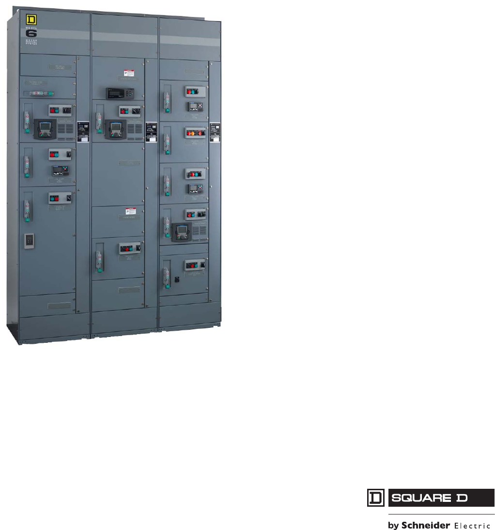
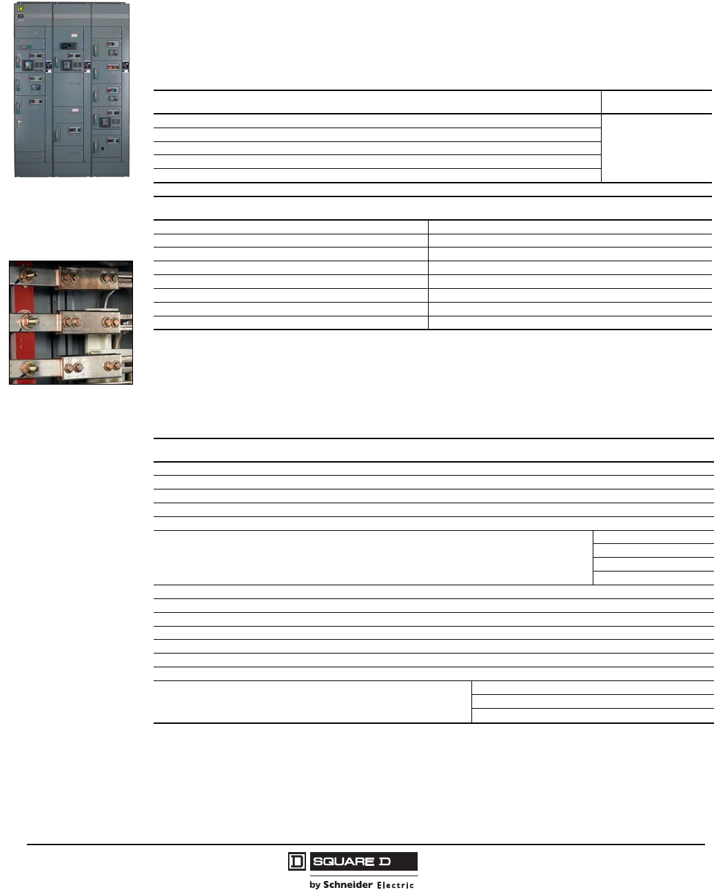
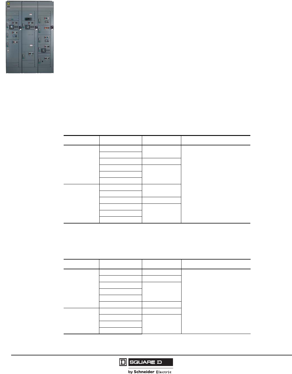
Motor control centers (MCCs) provide the most suitable method for grouping electrical motor control,
automation, and power distribution in a compact and economical package. Motor control centers consist
of totally enclosed, dead front, free-standing structures bolted together. These sections support and
house control units, a common bus bar for distributing power to the control units, and a network of wire
trough and conductor entrance areas for accommodating incoming and outgoing load and control wires.
The control units consist of components such as combination motor starters, branch feeder devices,
AC drives, soft starts, or lighting panelboards. Each unit is mounted in an individual, isolated
compartment having its own door. Standard MCC dimensions are 20 in. wide (including a 4 in. vertical
wireway trough) by 90 in. high (add 1.5 in. base channel and a 3 in. removable top lifting channel) by
15 or 20 in. deep. Larger sections are often required for mounting larger equipment or for providing
space for customer-mounted devices.
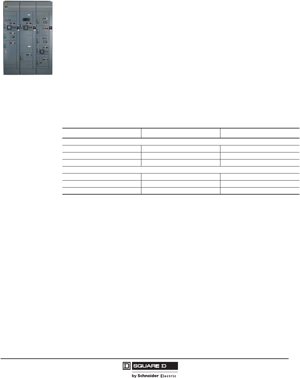
Two package styles are available: standard and industrial. These Model 6 feature packages allow you
to custom design the MCC to fit your specific requirements. The standard package lets you tailor the
MCC by selecting only those options that you need for an individual project, guaranteeing the optimal
cost/value balance. The industrial package includes options most often requested and specified by
industrial customers. Offering the options as part of a package reduces the possibility of leaving out
common industrial features. See the following table for a comparison of the two packages.
All features of the industrial package can be added individually to the standard version.
Option Standard Package Industrial Package
Structure Features
Vertical ground bus material Steel Copper
Horizontal bus material Tin-plated aluminum1
1Exceptions: 1600–2500 A are tin plated copper.
Tin-plated copper
Fishtape barriers Optional Included
Unit Features
Interior color Gray White
Nameplates Optional Included
X1 and X2 wired to terminal blocks Optional Included
© 1997–2009 Schneider Electric
All Rights Reserved
Model 6 Motor Control Centers
Product Description Features
807/2009
Features
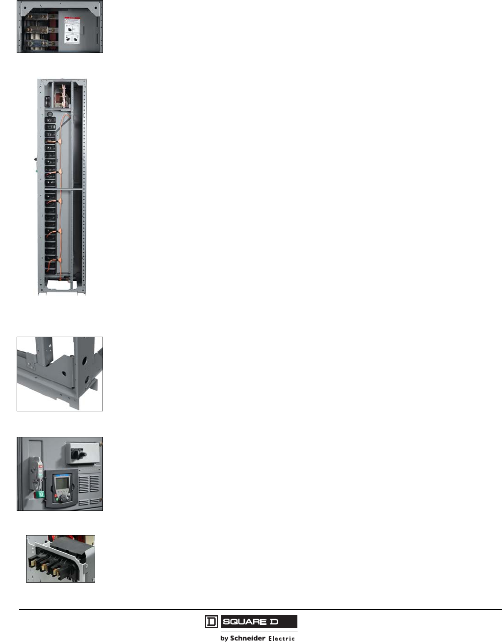
•Horizontal power bus is located at the top of the structure for easy installation, inspection, and
maintenance without the need to remove units.
•Non-conductive, two-piece, sliding, horizontal bus barrier provides convenient access for splicing
and maintenance without the need to remove the panels.
•Captive, four-bolt, horizontal splice bars with self-contained nuts and hardware make installation
easy and reduce the possibility of splice bar loss.
•A full-depth vertical wireway maximizes the wire pulling area. The Model 6 MCC has the largest
vertical wireway in the industry.
•Vertical bus barriers and wireway openings, when supplied, are built in 3 in. increments. This
feature allows more mounting flexibility for the units and reduces wasted space in the enclosure.
•Vertical ground bus is located in each section. This bus mates with ground stabs on the rear of
each plug-on unit to create a positive ground connection, with first make/last break operation.
•Frame is constructed with 12-gauge steel, and features welded corner channels for exceptional
structural rigidity.
•Leveling notches in the base channel provide a means of aligning the section during installation.
•Cast metal handle, an industry-exclusive feature, is more rugged than composites, and clearly
indicates disconnect status, including a ‘tripped’ circuit breaker, for added safety.
•Quarter-turn fasteners on unit and wireway doors expedite closing and opening.
•L-shaped unit door hinge pins are easily removed with a screwdriver for general maintenance.
•Each unit is fully compartmentalized, with solid side, back, and bottom plates. This feature allows
more mounting space for components and confines any potential faults within the individual unit.
•A hinged, or fold-down, unit bottom plate allows additional space for wiring and maintenance.
•Shrouded power stabs protect stabs against damage during unit maintenance, and provide a
self-aligning system for installation of units and connection to the vertical bus.
Sliding Bus Barriers
Full Depth
Vertical Wireway
(Right-Side View)
Structural Integrity
Innovative
Shrouded Power Stabs
Model 6 Motor Control Centers
Codes and Standards / NEMA/EEMAC Wiring Classes, Enclosure Types Product Description
9
07/2009
© 1997–2009 Schneider Electric
All Rights Reserved
Codes and Standards
Model 6 Motor Control Centers are manufactured to National Electrical Manufacturers Association
(NEMA) Standard ICS 18-2001 and Electrical Equipment Manufacturers Association of Canada
(EEMAC) standards. Model 6 MCCs are also manufactured to Underwriters Laboratories (UL)
Standard 845 and bear the “UL Listed” label, where applicable. The “UL Listed” mark is applied to
vertical sections and units that are installed within those sections. It should be noted that sections and
installed units are independently listed devices. Thus, it is possible to have non-UL Listed units
installed in UL Listed vertical sections.
All sections and units listed in this catalog are UL Listed, unless otherwise noted. The Model 6 MCC
meets Canadian Standards Association (CSA) specification standards and can carry the CSA label.
Certification
Model 6 Motor Control Centers are certified by the American Bureau of Shipping (ABS) for use in
power distribution, control, and protection of motor and non-motor loads for multiple applications on
board ABS Classed Vessels, Offshore Rigs and Platforms, and Marine applications. ABS develops
and verifies conformance with standards for design, construction, and operational maintenance of
marine-related facilities. Many customers require ABS certification for products used by and for marine
facilities. The certification granted by ABS includes classification of use of the motor control center for
both Essential and/or Non-Essential Services.
NEMA/EEMAC Wiring Classes and Enclosure Types
Wiring Classes
Class 1—Independent Units
Class 1 motor control centers consist of mechanical groupings of combination motor control units,
branch feeders, other units, and electrical devices arranged in a convenient assembly. The
manufacturer completes wiring between components within each unit. Wiring between units is not
required.
Class 2—Interconnected Units
Class 2 MCCs are the same as Class 1 MCCs with the addition of manufacturer-furnished electrical
interlocking and wiring between units as specifically described in the overall control system diagrams
supplied by the purchaser.
Type A
User (field) wiring connects directly to device terminals internal to the unit. Type A wiring is provided
only on Class 1 MCCs.
Type B
User (field) control wiring connects to unit terminal block(s) in or adjacent to each motor control unit.
User load (power) wiring for Size 3 or smaller combination motor control units connects as follows:
Type B-D
User load (power) wiring connects directly to the device terminals, which are located immediately
adjacent to, and are readily accessible from, the vertical wireway.
Type B-T
User load (power) wiring connects to factory-wired power terminal blocks located in or adjacent to
each unit.
User load (power) wiring for Size 4 or larger combination motor control units and branch feeder
units connects directly to the unit device terminals.
®
®
Control Terminal Block

© 1997–2009 Schneider Electric
All Rights Reserved
Model 6 Motor Control Centers
Product Description Enclosure Types / Shipping Weights
10 07/2009
Type C
User (field) control wiring and load wiring on Size 3 or smaller motor control units connects to master
terminal blocks mounted at the top or bottom of those vertical sections containing control units. Unit
control wiring and load wiring on Size 3 or smaller units are factory-wired from unit-located terminal
blocks to the master terminal blocks.
User load (power) wiring for Size 4 or larger units connects directly to the device terminals. As an option,
user load (power) wiring for all sizes of motor control units may connect directly to the device terminals
within the MCC units. See page 85 for load wiring options.
Enclosure Types
Type 1
Intended for indoor use only. Type 1 enclosures are designed primarily to provide protection against
contact with energized equipment inside. They are to be used in locations where normal service
conditions exist.
Type 1A (Gasketed)
Intended to restrict the entrance of dust and falling dirt into Type 1 enclosures. Type 1A enclosures are
not dust-tight. Neoprene gasketing is the standard material used.
Type 3R
Intended for outdoor use only. Type 3R enclosures are designed primarily to provide protection against
falling rain and sleet and remain undamaged by the formation of ice on the enclosure. They are not
intended to provide protection against conditions such as dust, internal condensation, internal icing, or
extreme heat or cold. The Model 6 Type 3R enclosure is built with galvannealed steel, which provides
a high level of resistance to corrosion when compared to standard hot or cold rolled steel with the
same paint finish.
Type 12
Intended for indoor use only. Type 12 enclosures are designed primarily to protect against dust, falling
dirt, light splashing, and dripping of non-corrosive liquid. They are not intended to provide protection
against conditions such as internal condensation.
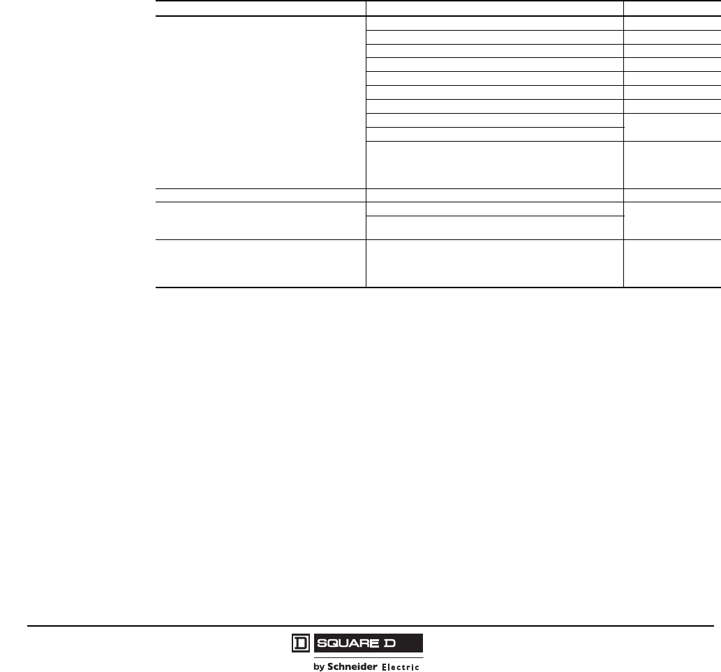
Shipping Weights
One, two, or three vertical sections can be shipped together on a pallet. Larger MCCs are split into
shipping blocks of three sections maximum. The following table lists typical approximate shipping
weights for a normal mix of MCC equipment. Some sections, based on installed devices and width of
the section, may vary from values shown in the table.
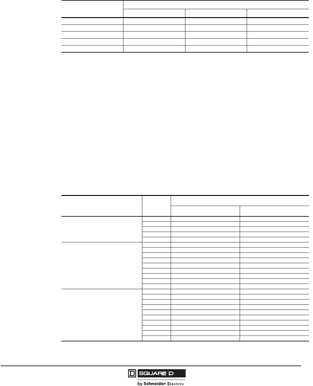
Approximate MCC Shipping Weights
NEMA/EEMAC Enclosure Type Depth (inches) 1 Section (lbs) 2 Sections (lbs) 3 Sections (lbs)
1, 1A, 12 15 600 1200 1800
3R Non-Walk-In 151
(27.2 in. overall)
1See the NEMA/EEMAC 3R dimensions drawing on page 108.
900 1800 2700
1, 1A, 12 20 750 1500 2250
3R Non-Walk-In 201
(32.2 in. overall) 1050 2100 3150
Model 6 Motor Control Centers
Altitude Ratings / Heat Dissipation Product Description
11
07/2009
© 1997–2009 Schneider Electric
All Rights Reserved
Altitude Ratings
The following table lists the MCC derating factors necessary at altitudes of 6,600 ft (2,000 m)
and higher.
Motor Control Center Heat Dissipation
The following table lists the approximate heat dissipation of various MCC units. This information is
often requested by engineers who are sizing HVAC equipment to cool and ventilate equipment rooms.
Values include an estimate of heat dissipated by the MCC Power Bus. To use, add the values for each
of the units in the MCC. Values are given in BTUs per hour and watts.
The values given are for “typical” applications, and include an adjustment for power bus contribution.
Make the following adjustments for special situations:
•Add 10–20 percent to the total heat dissipation for MCCs that make extensive use of relays, timers,
and other control devices.
•Add 10 percent to the total heat dissipation for MCCs with 1200–1600 A main bus.
•Add 20 percent to the total heat dissipation for MCCs with 2000–2500 A main bus.
Altitude Altitude Rating Correction Factors1
1For variable frequency drives above 3,300 ft (1,000 m), derate the output current rating by 1% for each additional 330 ft (100 m)
up to a maximum of 9,900 ft (3000 m).
For solid state reduced voltage starters above 3,300 ft (1,000 m), derate the nominal output current by 2.2% for each additional
330 ft (100 m) up to a maximum of 6,600 ft (2,000 m).
Full Load Current System Voltage Ambient Temperature
6,600 ft (2,000 m) 1.0 1.0 1.0
8,500 ft (2,600 m) 0.99 0.95 1.0
13,000 ft (3,900 m) 0.96 0.80 0.95
14,000 ft (4,300 m) 0.95 0.80 0.90
15,000 ft (4,600 m) 0.93 0.80 0.85
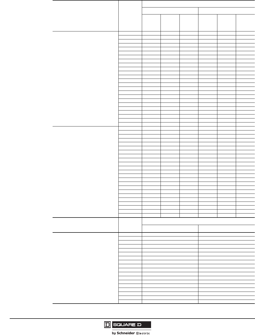
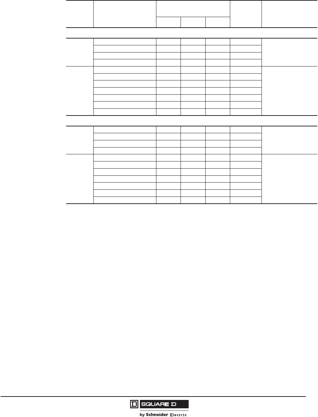
Typical Heat Dissipation Values1
1For programmable logic controllers, unit heat dissipation can be significant. Contact the MCC Technical Assistance Group (TAG)
for the heat dissipation of these devices.
Description Size/Rating Heat Dissipation
BTUs/hr Watts
Combination Starters (Circuit Breaker or
Fusible Disconnect)
1 270 79
2 360 106
3 720 210
4 1440 420
5 2400 700
Main and Branch Feeder Breakers
15–150 A 270 79
175–250 A 720 210
300–400 A 780 230
500–600 A 1320 390
700–800 A 2220 650
900–1200 5802 1700
1600 A 8020 2350
2000 A 12,628 3700
2500 A 27,815 8150
Main and Branch Feeder Switches
30 A 126 37
60 A 156 46
100 A 282 85
200 A 780 230
400 A 1020 300
600 A 2047 600
800 A 3242 950
1200 A 8874 2600
1600 A 15,529 4550
2000 A 24,232 7100
© 1997–2009 Schneider Electric
All Rights Reserved
Model 6 Motor Control Centers
Product Description Heat Dissipation
12 07/2009
Typical Heat Dissipation Values (Continued)
Description Motor
Rated HP
@ 480V
Heat Dissipation
BTUs/hr Watts
Drive Line
Reactor
3% / 5%
Load
Reactor
or Filter
Drive Line
Reactor
3% / 5%
Load
Reactor
or Filter
Combination Altivar 61 AC drives
(variable torque rated)
1 150 27 / 41 255 44 8 / 12 75
2 150 48 / 48 255 45 14 / 14 75
3 218 68 / 68 273 64 20 / 20 80
5 389 99 / 89 307 119 29 / 26 90
7.5 491 106 / 140 324 144 31 / 41 95
10 608 147 / 147 324 178 43 / 43 95
15 741 177 / 208 375 217 52 / 61 110
20 1092 180 / 180 444 320 53 / 53 130
25 1338 184 / 184 444 392 54 / 54 130
30 1662 212 / 222 461 487 62 / 65 135
40 2447 229 / 242 495 717 67 / 71 145
50 3331 246 / 276 870 976 72 / 81 255
60 4301 1
1A 3% line reactor is standard in these drive sizes.
— / 328 870 1260 1— / 96 255
75 4928 1— / 369 836 1444 1— / 108 245
100 5690 1— / 614 921 1667 1— / 180 270
125 8447 1— / 470 887 2475 1— / 138 260
150 11002 1— / 498 904 3224 1— / 146 265
200 13016 1— / 747 990 3814 1— / 219 290
250 14676 1— / 1197 1109 4300 1— / 351 325
300 17450 1— / 2682 1024 5113 1— / 786 300
350 19717 1— / 2560 1535 5777 1— / 750 450
400 22931 1— / 2491 1621 6719 1— / 730 475
450 24665 1— / 2642 — 7227 1— / 774 —
500 52927 1— / 2379 — 8281 1— / 697 —
Combination Altivar 71 AC drives
(constant torque rated)
1 150 27 / 41 255 44 8 / 12 75
2 218 48 / 48 255 64 14 / 14 75
3 297 68 / 68 273 87 20 / 20 80
5 492 99 / 89 307 144 29 / 26 90
7.5 608 106 / 140 324 178 31 / 41 95
10 741 147 / 147 324 217 43 / 43 95
15 1092 177 / 208 375 320 52 / 61 110
20 1338 180 / 180 444 392 53 / 53 130
25 1659 184 / 184 444 486 54 / 54 130
30 2447 212 / 222 461 717 62 / 65 135
40 3331 229 / 242 495 976 67 / 71 145
50 4253 1— / 276 870 1246 1— / 81 255
60 4936 1— / 328 870 1446 1— / 96 255
75 5607 1— / 369 836 1643 1— / 108 245
100 5446 1— / 470 921 2475 1— / 138 270
125 8774 1— / 498 887 2571 1— / 146 260
150 9638 1— / 747 904 2824 1— / 219 265
200 10205 1— / 1197 990 2990 1— / 351 290
250 14146 1— / 2242 1109 4145 1— / 657 325
300 17877 1— / 2229 1024 5238 1— / 653 300
350 18556 1— / 2160 1535 5437 1— / 633 450
400 21279 1— / 2449 1621 6235 1— / 716 475
450 24719 1— / 2058 — 7243 1— / 603 —
Description Soft Start
Frame
Heat Dissipation
BTUs/hr Watts
Combination Altistart 48 Soft Start
(includes shorting contactor as standard)
10 51 15
15 51 15
20 85 25
25 85 25
30 85 25
40 85 25
50 85 25
60 85 25
75 85 25
100 85 25
125 85 25
150 171 50
200 171 50
250 171 50
300 273 80
350 273 80
400 273 80
500 273 80

Model 6 Motor Control Centers
Structure Steel Gauge Information Product Description
13
07/2009
© 1997–2009 Schneider Electric
All Rights Reserved
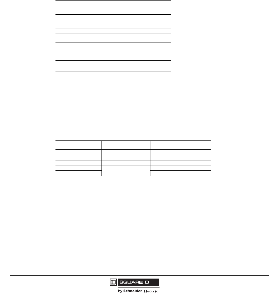
Structure Steel Gauge Information
Model 6 MCCs are totally enclosed, dead front, free standing assemblies. All steel is in compliance
with UL 845/CSA requirements:
Part Description Thickness (Gauge)
Corner Channels 12
Back Plates: 20–30 in. wide 16
35 in. wide 14
End Closing Plates 16 (NEMA/EEMAC Type 3R: 12 gauge)
Unit Doors 14 and 16 (NEMA/EEMAC Type 3R: 12 gauge on outer door)
Side Channels 11
Top and Bottom Frame 12
Top and Bottom Plates 14
Base Channels 10
Lifting Angle 7
© 1997–2009 Schneider Electric
All Rights Reserved
Model 6 Motor Control Centers
Application and General Information Structures and Bussing
14 07/2009
Application and General Information
Structures and Bussing
Structure
Each section provides 72 in. of vertical mounting space for MCC units. Special sections are required
for selected units such as autotransformer starters and some main breakers, drives, and soft starters.
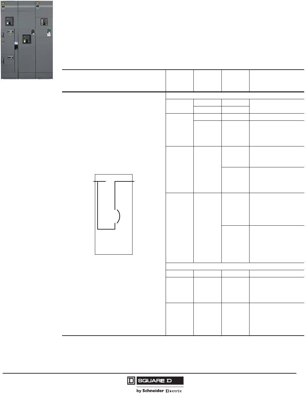
Bussing Options and Modifications
Horizontal Bus Splice
NEMA/EEMAC Enclosure Type Depth
General Purpose Type 1
15 in. - Standard
20 in. - Optional
General Purpose Type 1 Gasketed (often referred to as Type 1A)
Industrial Duty Type 12
Outdoor Duty Type 3R Non-Walk-In
Outdoor Duty Type 3R Walk-In (Contact the Project Support and Engineering Center in Nashville.)
Main Bus Amps and Material 1
600 A tin-plated aluminum 1200 A silver-plated copper
600 A tin-plated copper 1600 A tin-plated copper (20 in. deep only)
600 A silver-plated copper 1600 A silver-plated copper (20 in. deep only)
800 A tin-plated aluminum 2000 A tin-plated copper (20 in. deep only)
800 A tin-plated copper 2000 A silver-plated copper (20 in. deep only)
800 A silver-plated copper 2500 A tin-plated copper 2
1200 A tin-plated aluminum 2500 A silver-plated copper 2
1200 A tin-plated copper
NOTE: For 3-phase, 4-wire systems, see page 26.
1Ratings shown based on 149 ° F (65 °C) max. temperature rise per UL 845. Consult the MCC Technical Assistance Group (TAG)
for current density ratings.
2Not available in NEMA/EEMAC Type 12 or 3R enclosures.
Description
Bus bar surge protection. Requires 6 in. mounting space near the incoming feeder. Not UL Listed. Not for use on ungrounded systems.
300 A vertical bus – tin-plated copper (Standard)
Substitute 600 A vertical bus – tin-plated copper
Substitute 600 A vertical bus – silver-plated copper
4 bolt splice (captive) on main/horizontal bus (Standard)
Bus Withstand Rating
Modifications to increase the bus system withstand rating to meet available fault current requirements.
Does not increase individual unit ratings.
42,000 A rms (Standard)
65,000 A rms
85,000 A rms
100,000 A rms 1
1480 V maximum
Tin-plated copper vertical ground bus
Tin-plated copper horizontal ground bus - 1/4 in. x 1 in., rated 300 A (Standard)
Tin-plated copper horizontal ground bus - 1/4 in. x 2 in., rated 600 A 2
2Standard on 2500 A horizontal bus
Silver-plated copper horizontal ground—1/4 in. x 1 in. (rated 300 A)
Silver-plated copper horizontal ground—1/4 in. x 2 in. (rated 600 A)
Optional 2 in. main/horizontal bus – tin-plated copper 2
Optional 2 in. main/horizontal bus – silver-plated copper
Insulated horizontal bus (Non-UL Listed)
Standard section (600–1600 A)
Main lug section (600–1600 A)
Main circuit breaker/fusible switch section (600–1600 A)

Model 6 Motor Control Centers
Structures and Bussing Application and General Information
15
07/2009
© 1997–2009 Schneider Electric
All Rights Reserved
Structure Options and Modifications
Special Structures
Not available in NEMA/EEMAC Type 3R construction or reduced height sections.
Automatic Vertical
Bus Shutter
Description
12 in. high pull box
18 in. high pull box
Two-piece top plate
Bottom plate for NEMA/EEMAC Type 1 Gasketed
Drip hood (Not available with 2500A horizontal bus)
Strip heater (200 Watts at 120 V) (Not available in sections with Size 6 RVAT, bottom feed main lugs, bottom feed mains and
branches over 600 A, or distribution transformers)
Thermostat for control of strip heater (6 heaters maximum)
Seismic certification
Reduced height construction:
Structure height including base channels (without lifting
angles): 79.5 in. 73.5 in. 67.5 in.
Available unit mounting space: 60 in. 54 in. 48 in.
Amount section shortened: 12 in. 18 in. 24 in.
Application: Not available on back-to-back, corner, NEMA/EEMAC Type 3R, or sections with neutral bussing. Reduced height
construction reduces the section’s unit mounting space and does not reduce either the top or bottom horizontal wireway.
Wire tie retainers in vertical wireway
Manual vertical bus barrier closing shutters (Standard)
Automatic vertical bus shutters
Non-standard exterior color (includes one coat of Schneider Electric selected paint.) Consult factory for specifications detailing
primers, paint, thickness, and application process.
Fishtape barrier (Prevents rising of bottom-entering fishtapes into wireway. Standard on Industrial.)
Rodent barriers (Standard)
GFI receptacle (NEMA/EEMAC Type 3R Non-Walk-In)
Fluorescent light (NEMA/EEMAC Type 3R Non-Walk-In)
Description Application
Back-to-back splice transition section 2500 A Max.
Through-the-back splice 1
1Tin plated copper splice standard. Not available with neutral bus or relay sections.
1200 A Max.
Corner Sections 2500 A Max.
31.00
787
or
41.00
1041
12.00
305
Back-To-Back Transition Section
Top View
1.00
25
Between
Sections
20.00
508
or
25.00
635
20.00
508
or
25.00
635
15.00
381
or
20.00
508
Corner Section
Top View
Front
15.00
381
or
20.00
508
20.00
508
Through-the-Back Splice
Top View
1.00
25
Between
Sections
Dual Dimensions = INCHES
millimeters
© 1997–2009 Schneider Electric
All Rights Reserved
Model 6 Motor Control Centers
Application and General Information Structures and Bussing
16 07/2009
Model 6 to Model 5 Transition Section
Model 6 MCCs will splice directly to a Model 5 MCC, provided the Model 5 structure was built after
May 1992.
If the Model 5 MCC was built prior to May of 1992, contact the MCC Technical Assistance Group
(TAG). Custom splice plates will be required and supplied with the first section in the Model 6 line-up
depending on which side of the existing Model 5 line-up the Model 6 is installed.
Switchboard to Model 6 Transition Section
Square D® brand Switchboards can be provided with bussed transitions to Model 6 Motor Control
Center line-ups. Contact the MCC TAG for details.
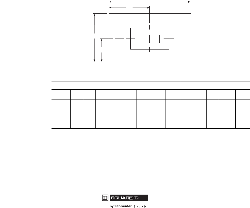
Bus Duct Connection
I-Line® II feeder busway compartments must always be located at the top of the section. A 12 in. high
pull box is required. I-Line II Busway should be positioned edgewise A, B, C, left-to-right as shown in
the figure below. To facilitate installation, both front and side accessibility is recommended. No
additional mounting space is required.
NOTE: Must be “I-Line II Feeder End” Style; Qwik Flange is not available. NEMA/EEMAC Type 3R is
not available. Bus duct connections are not UL Listed in MCCs.
No Main Disconnect 1
1With no main disconnect, the connection from busway to horizontal bus is made with main bus. A main lug compartment is not
required.
C/B Disconnect 2
2With a main disconnect, the connection from busway to disconnect is made with either cable or bus, depending on ampacity.
Fusible Main Disconnect 2
MCC Bus
Ampacity Width
(In.) Depth
(In.) Conn MCC Mains
Ampacity Width
(In.) Depth
(In.) Conn MCC Mains
Ampacity Width
(In.) Depth
(In.) Conn
600 A
800 A
1200 A 20 15
or
20 Bus 110–600 A 20 15 or 20 Cable 200–600 A 20 15 or 20 Cable
1600 A
2000 A 25 3
3A 25 in. wide section is a standard section with a 9 in. wireway and will accept plug-on units. A 72 in. unit mounting space is
available. For 3P4W (left to right orientation), a 30 in. wide section is required. For 3P4W (front to rear orientation), a 25 in. wide section
is required.
20 Bus 800–1200 A 20 20 Bus 800–1200 A 20 20 Bus
— — — — 1600–2500 A 25 20 Bus 1600–2000 A 30 20 Bus
W/2
W
Top View
Front
Typical
MCC
Section
D/2
D
ABC
C
L
C
L
Model 6 Motor Control Centers
Structures and Bussing Application and General Information
17
07/2009
© 1997–2009 Schneider Electric
All Rights Reserved
Model 4 to Model 6 Transition Section
NOTE: Not Available In NEMA/EEMAC Type 3R Construction
Provides transition from existing Model 4 to a new Model 6 MCC. The transition requires a 12 in.
extension on the first section of the Model 6 lineup. A transition section does not affect the space
calculation when estimating the number of sections. The transition section must be ordered with at
least one Model 6 section and cannot ship separately. The Model 6 ampacity must be equal to
or less than the ampacity of the Model 4 bus. Neutral bus is not supported.
NOTE: Splice bars are included with the transition section.
The transition section will match the depth of the Model 6 MCC, and can be used to splice a
front-of-board Model 6 to an existing back-to-back Model 4 MCC (20 in. deep). The transition section
will be rear aligned with both the Model 4 and the Model 6 sections. On 3-phase, 4-wire systems, the
3-phase bus bars will splice together, but the Model 4 neutral bus bar will not be carried through in the
Model 6.
NOTE: When ordering a Model 4 to Model 6 transition section, you must provide the original Model 4
factory order number.
Basic Transition 1
1Includes 12 in. wide structure with 800 A bus as standard.
Model 4 on left and Model 6 on right
Model 6 on left and Model 4 on right
Transition Bussing Modifications
Model 4 Bus Model 6 Bus
600 A Aluminum or Copper 600 A Copper
800 A Aluminum 800 A Copper
1000 A Aluminum (2) 2 in. 1200 A Copper
1200 A Aluminum (2) 3 in. 1200 A Copper
1000 A Aluminum (1) 4 in. 1200 A Copper
1200 A Copper (2) 2 in. 1200 A Copper
1000 A Copper (1) 3 in. 1200 A Copper
1200 A Copper (1) 4 in. 1200 A Copper
1400 A Aluminum (2) 4 in. 1600 A Copper
1600 A Copper (2) 3 in. 1600 A Copper
1800 A Copper (2) 4 in. 2000 A Copper
2000 A Copper (2) 4 in. 2000 A Copper
© 1997–2009 Schneider Electric
All Rights Reserved
Model 6 Motor Control Centers
Application and General Information Incoming Devices
18 07/2009
Incoming Devices
Incoming or main devices are used to connect power to the motor control center. In the majority of MCC
applications, the system is rated as 480 V, 3-phase, 3-wire. If a neutral wire connection is required, a
neutral kit can be supplied (see “3-Phase, 4-Wire Systems” on page 26).
Typically, one of three devices is used to connect power to the MCC: main lugs, main circuit breaker, or main
fusible switch. One of these devices is connected to the horizontal main bus with cable or hard bus. Cabled
or bussed branch devices or cabled starter units (those with an L, M, or P frame circuit breaker disconnect, or
600 A or larger fusible switch disconnect) cannot be installed in the same section as a main device.
As with all electrical equipment rated 600 V or less, incoming cables must be rated using the 75 °C
temperature ratings tables in the National Electrical Code® (NEC®). The incoming lugs are 194° F (90 °C)
lugs, and 194 °F (90 °C) cable can be used. However, the cable must be applied to the 75 °C ratings.
All main devices must be top- or bottom-located.
Main Lug Compartments
Main lug compartments must be specified in the absence of other incoming line provisions.
3-phase, 3-wire main lugs include neutral assembly for cable connection to other units with
solid neutrals.
Main lug units short circuit current ratings to 100,000 A are available.
Top Located Main Lug Compartments
System Amps Space (Inches) Horizontal Bus Connection
3-phase, 3-wire
600 1
1Not available @ 100,000 A.
6
Bussed
800
1200 12
1600 2
230 in. wide by 20 in. deep section
72
2000 2
2500 2
3-phase, 4-wire
600 19
800
1200 3
325 in. wide section with 9 in. wireway
12
1600 2
72
2000 2
2500 2
Bottom Located Main Lug Compartments
System Amps Space (Inches) Horizontal Bus Connection
3-phase, 3-wire
600 18
Bussed
1200 1
125 in. wide section with 9 in. wireway
36
1600 2
230 in. wide by 20 in. deep section
72
2000 2
2500 2
600 18
3-phase, 4-wire
1200 136
1600 2
72
2000 2
2500 2
Model 6 Motor Control Centers
Incoming Devices Application and General Information
19
07/2009
© 1997–2009 Schneider Electric
All Rights Reserved
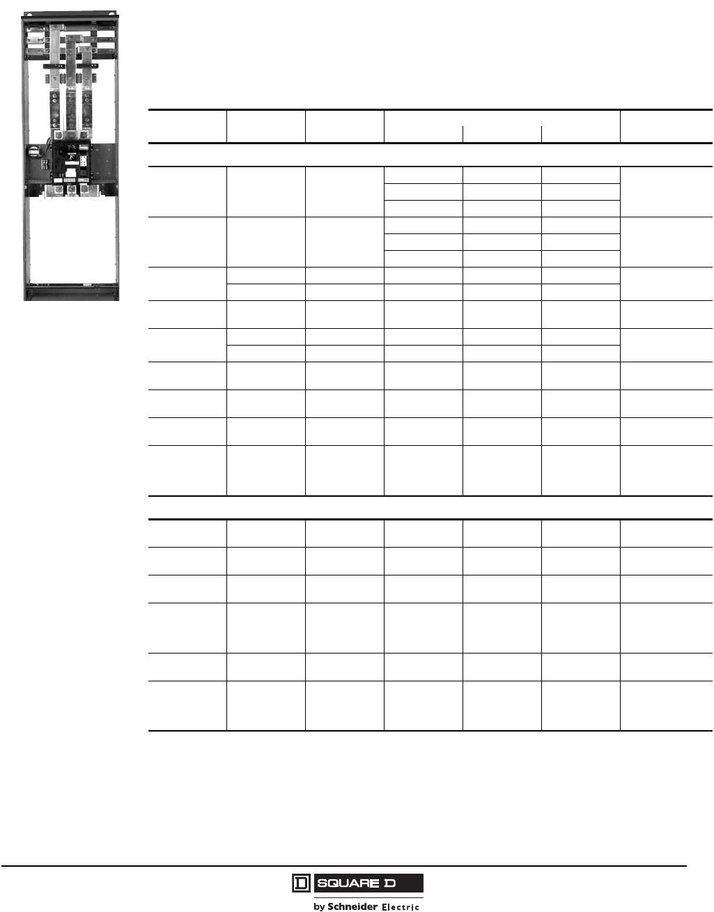
Main Circuit Breakers
•Main circuit breaker units are located in 20 in. wide by 15 in. or 20 in. deep sections, except where
noted. Mains must be mounted at the top or bottom of the MCC section.
•Thermal-magnetic, molded case circuit breakers are standard. Optional electronic trip circuit
breakers are available as shown in the tables below.
•All units are for 3-phase, 3-wire systems. 3-phase, 4-wire applications may require additional space
(see “3-Phase, 4-Wire Systems” on page 26).
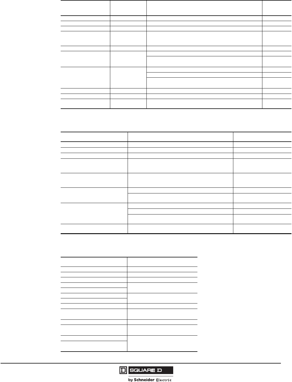
Main Circuit Breaker
Thermal-Magnetic, Molded Case Circuit Breakers
Breaker Trip
Ratings (Amps)
Breaker Frame
(Amps) Breaker Type Unit Interrupting Rating (kA) Space (Inches)
208/240 V 480 V 600 V
Standard (80%) Rated
15-150 150 HG/HJ/HL
65 35 18
12 (Plug On)100 65 25
100 100 50
175-250 250 JG/JJ/JL
65 35 18
18 (Plug On)100 65 25
100 100 50
300-400 400LH653525
21 (Top Entry)
27 (Bottom Entry)
600 LI 100 100 100
450-600 600 LI 100 100 100 24 (Top Entry)
36 1 (Bottom Entry)
1Requires single shippling split.
800 800MJ656525
18 (Top Entry)
36 1 (Bottom Entry)
1200 PL/PK 100 100 50
1200 1200 PL/PK 100 100 50 21 (Top Entry)
36 1 (Bottom Entry)
1600 2
2Specify top or bottom entry.
3000 RL/RK 100 100 65 72 1
(20 W X 20 D)
2000 23000 RL/RK 100 100 65 72 1
(20 W x 20 D)
2500 23000 RL/RK 100 100 65
72 1
(25 W x 20 D)
NEMA/EEMAC
Type 1/1A only
Optional 100% Rated 3
3All 100% rated circuit breakers are molded case with Micrologic electronic trip. LE electronic trip circuit breakers include Full
Function Trip Unit with LSI tripping functions. P- and R-frame electronic trip circuit breakers include Basic 3.0 Trip Unit with LI
tripping functions.
300-400 400 LE 100 65 35 24 (Top Entry)
36 (Bottom Entry)
600 1200 PL/PK 100 100 50 18 (Top Entry)
36 1 (Bottom Entry)
800 1200 PL/PK 100 100 50 21 (Top Entry)
36 1 (Bottom Entry)
1200 21200 PL/PK 100 100 50
72 1
(20 W x 20 D)
NEMA/EEMAC
Type 1/1A only
1600 23000 RL/RK 100 100 65 72 1
(20 W x 20 D)
2000 23000 RL/RK 100 100 65
72 1
(25 W x 20 D)
NEMA/EEMAC
Type 1/1A only
© 1997–2009 Schneider Electric
All Rights Reserved
Model 6 Motor Control Centers
Application and General Information Incoming Devices
20 07/2009
Optional Masterpact Power Circuit Breaker Main Units—Stored Energy/Drawout
Style/Insulated Case
Masterpact NT and NW power circuit breakers are available in Model 6 Motor Control Centers as an
incoming main device. The Masterpact NT/NW circuit breaker offered in the Model 6 MCC is a
UL489 Listed insulated case circuit breaker with drawout style mounting. These circuit breakers
contain a two-step stored energy mechanism which provides 5-cycle maximum closing in both
manually and electrically operated types.
NOTE: Masterpact circuit breakers are rated at 80% of their capacity in MCC construction.
MCC drawout main circuit breaker include the following features:
UL 845/CSA listed with UL 489 version
Stored energy breaker mechanism
Internal barriers for separating line, load, and control areas
Micrologic trip units (Standard 5.0 included, 6.0P with Ground Fault optional).
Modbus communications for Web-enabled power and control compatability is optional
Fully bussed power circuit
Control compartment including trip unit power supply and additional panel space
Optional Arc Flash version tested to show the arc flash hazard risk category referenced by NFPA 70E
All offered Masterpact circuit breakers are equipped with the Micrologic Electronic Trip System. In
Model 6, two trip unit models are available: 5.0 Basic and 6.0 Power. The MCC Masterpact NT/NW
main circuit breaker comes with Basic 5.0 trip units as standard, with LSI tripping functions: long-time
trip, long-time trip delay adjustments, short-time trip, short-time trip delay adjustment, and
instantaneous trip. The optional 6.0P Micrologic trip unit offers LSIG tripping functions: long-time trip,
long-time trip delay adjustments, short-time trip, short-time trip delay adjustments, instantaneous trip,
ground fault trip, and ground fault trip delay adjustment.
Main Circuit Breaker Unit Interrupting Ratings per UL 845/CSA
Circuit Breaker Type
(Interrupting Rating Code) 240 V
Delta 480 V
Delta or Wye 600 V
Delta or Wye
800-1200 A NT (H) 65 50 50
800-1200 A NT (L1) 100 65 1
1100 kA interrupting rating is available by ordering optional Arc Flash (LF) version.
—
800-2500 A NW (N) 65 65 50
800-2500 A NW (H) 100 100 65
800-2500 A NW (L) 100 100 65
Model 6 Motor Control Centers
Incoming Devices Application and General Information
21
07/2009
© 1997–2009 Schneider Electric
All Rights Reserved
Masterpact Main Circuit Breakers
Breaker
Frame Unit Type and Amps
MCC Unit Short Circuit Rating
(kA) Circuit
Breaker
Model No. Space (Inches)
240 V 480 V 600 V
Top Entry
NT
M6MDT800H 65 50 50 NT08H
72
(25 W x 20 D)
M6MDT800L1 100 65 — NT08L1
M6MDT1200H 65 50 50 NT12H
M6MDT1200L1 100 65 — NT12L1
NW
M6MDT1200NWN 1
1Top entry mains must be at the end of the MCC lineup. Top entry mains ship as two shipping splits: one 30 in. wide section for the
breaker and one 20 in. wide section (25 in. wide for 4W) as an incoming cable section. No through bus is included in the incoming
cable section. NOTE: Bottom entry can be at the end or middle of the MCC lineup.
65 65 50 NW12N 3W
Two full sections required
1 @ (30 W x 20 D)
1 @ (20 W x 20 D)
4W
Two full sections required
1 @ (30 W x 20 D)
1 @ (25 W x 20 D)
M6MDT1200NWL 1100 100 65 NW12L
M6MDT1600N 165 65 50 NW16N
M6MDT1600L 1100 100 65 NW16L
M6MDT2000N 165 65 50 NW20N
M6MDT2000L 1100 100 65 NW20L
M6MDT2500H 1,2
2Available as NEMA/EEMAC Type 1/1A only.
100 100 65 NW25H
Bottom Entry
NT
M6MDB800H 65 50 50 NT08H
72
(25 W x 20 D)
M6MDB800L1 100 65 — NT08L1
M6MDB1200H 65 50 50 NT12H
M6MDB1200L1 100 65 — NT12L1
NW
M6MDB1200NWN 65 65 50 NW12N
3W or 4 W
72 H x 30 W
(20 D)
M6MDB1200NWL 100 100 65 NW12L
M6MDB1600N 65 65 50 NW16N
M6MDB1600L 100 100 65 NW16L
M6MDB2000N 65 65 50 NW20N
M6MDB2000L 100 100 65 NW20L
M6MDB2500H 2100 100 65 NW25H

© 1997–2009 Schneider Electric
All Rights Reserved
Model 6 Motor Control Centers
Application and General Information Incoming Devices
22 07/2009
MCC Masterpact Main Accessory Groups
The MCC Masterpact drawout breaker package is offered in two accessory groups—Limited and
Enhanced—to help in selecting and pricing the most popular options. See the Accessory Group
descriptions below for the Masterpact options included in each accessory group. Refer to the
Masterpact NT/NW Universal Power Circuit Breaker catalog #0613CT0001 for a full description of the
trip units and the accessories.
Limited Accessory Group includes:
5.0 trip unit (LSI)
Sensor Plug = Unit Amp Rating
Rating plug “A”
No communications
4 Form C auxiliary switches
1 Form C overcurrent trip switch
Padlockable push button cover
Transparent cover over front of circuit breaker (NEMA/EEMAC Type 12) only)
Automatic cradle shutters with padlocking provisions
Enhanced Accessory Group includes:
6.0 P trip unit (LSIG)
Sensor Plug = Unit Amp Rating
Rating plug “A”
Modbus breaker communications module and 24 Vdc communications power supply,
unwired to MCC network
4 Form C auxiliary switches
1 Form C overcurrent trip switch
Padlockable push button cover
Transparent cover over front of circuit breaker (NEMA/EEMAC Type 12 only)
Schneider key interlock for circuit breaker
Spring charging motor (120 Vac)
Shunt trip without communications (120 Vac)
Shunt close without communications (120 Vac)
Electric reset (120 Vac)
Ground fault
Neutral CT (4-wire model only)
Automatic cradle shutters with padlocking provisions
Model 6 Motor Control Centers
Incoming Devices Application and General Information
23
07/2009
© 1997–2009 Schneider Electric
All Rights Reserved
Tie Breakers
Tie Breakers are used to connect two MCCs together to allow either MCC Main to feed both MCCs as
required. The tie breaker consists of a PowerPact® or Masterpact circuit breaker and hard bus
transition network to complete the connection between the power buses from each MCC. The mains of
the two MCCs may be on the outside ends or in the middle of the lineup with a tie breaker. The
Trip Rating, Frame (Amps), and Breaker Frame of the tie breaker should match those of the main.
Neutral bus is not available in the tie breaker, therefore the neutral is not continuous nor switched
through the tie. Contact factory for applications requiring continuous or switched neutral.
The standard configuration includes a manual throwover of the tie breaker. Automatic throwover
systems controlled by a programmable logic controller can be provided for PowerPact P-frame or
Masterpact NW circuit breakers in the MCC.
Description Trip
Rating
(Amps)
Frame
(Amps) Breaker
Frame Tie Breaker Total
Space (Inches)1
1Tie breaker total space will be as shown, and includes a bus transition between two MCCs and the tie breaker. Each MCC Main
must also include the key interlock option.
Tie Breaker Arrangement
Standard 80% Rated
800 800 MJ 72 (20 W x 20 D)
1200 PL/PK
1200
1200 PL/PK 72 (20 W x 20 D)
3000 Masterpact
Drawout NW
72
Two full sections required
1 @ (30 W x 20 D)
1 @ (20 W x 20 D)
1600–2000 3000
RL/RK
72
Two full sections required
2 @ (20 W x 20 D)
Masterpact
Drawout NW
72
Two full sections required
1 @ (30 W x 20 D)
1 @ (20 W x 20 D)
2500 3000
RL/RK
72
Two full sections required
2 @ (20 W x 20 D)
NEMA/EEMAC
Type 1/1A only
Masterpact
Drawout NW
72
Two full sections required
1 @ (30 W x 20 D)
1 @ (20 W x 20 D)
NEMA/EEMAC
Type 1/1A only
Optional 100% Rated
800 1200 PL/PK 72 (20 W x 20 D)
1200 1200 PL/PK
72
(20 W x 20 D)
NEMA/EEMAC
Type 1/1A only
1600–2000 3000 RL/RK
72
Two full sections required
2 @ (20 W x 20 D)
NEMA/EEMAC
Type 1/1A only
Tie
MCC 2MCC 1
© 1997–2009 Schneider Electric
All Rights Reserved
Model 6 Motor Control Centers
Application and General Information Incoming Devices
24 07/2009
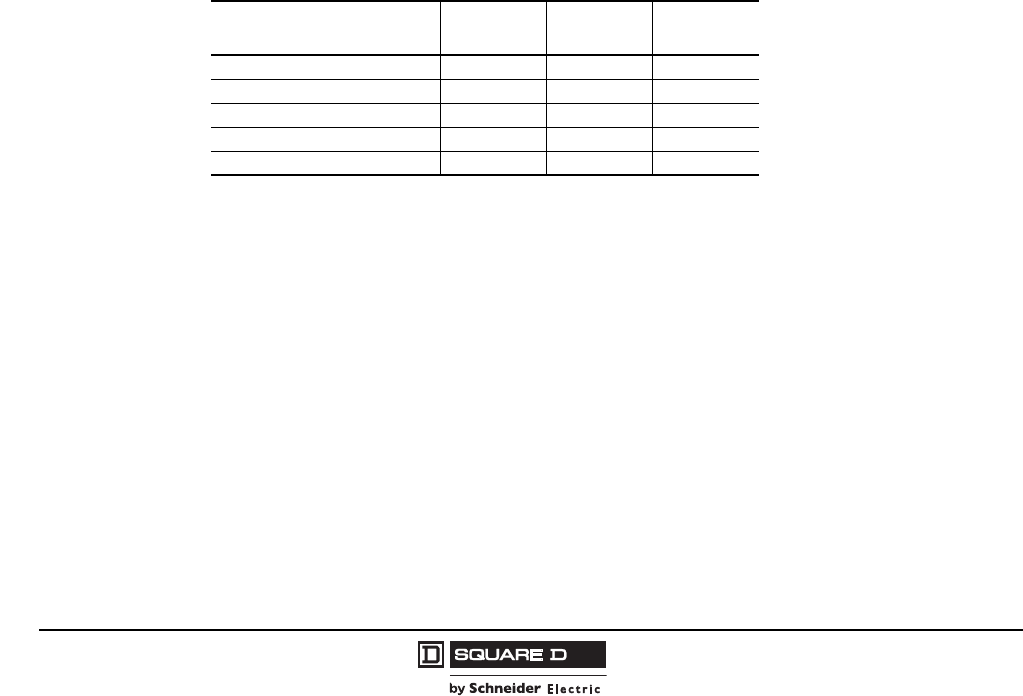
Main Fusible Switches
Main fusible switch units are located in 20 in. wide by 15 in. or 20 in. deep sections, except where
noted. Mains must be mounted at the top or the bottom of the MCC section.
All main switches use automatic molded case switches in series with Class R fuse clips (up to
600 A) or L fuse clips (above 600 A).
All fusible units have a short circuit rating of 100,000 A.
All main switches listed are for 3-phase, 3-wire systems. 3-phase, 4-wire applications may require
additional space (see “3-Phase, 4-Wire Systems” on page 26).
Special Note for All Main Devices
Branches 450 A or larger cannot be installed in the same vertical section as the main device.
Standard Wire Lug Ranges (Mechanical)
Mechanical set-screw type lugs are supplied as standard for Model 6 MCC main, branch, and neutral line
and/or load connection. Compression crimp type lugs are available (see “Wiring Options” on page 85).
Main Fusible Switches
Maximum Fuse Size (Amps)
600 V Max. Space (Inches)
200 24 (plug-on)
400 45 (Top Entry)
54 (Bottom Entry)
600 60
800 60 (Top Entry)
601 (Bottom Entry)
1Requires a single shipping split.
1000 2
2Specify top or bottom entry.
721 (20 W X 20 D, Top Entry)
601 (Bottom Entry)
1200 721 (20 W X 20 D, Top Entry)
601 (Bottom Entry)
1600 721 (30 W X 20 D)
2000 72 1 (30 W X 20 D)
Main Lugs
Main Lug Amps Lug Wire Range Lugs Per Phase/Neutral
600 3/0–500 kcmil 2
800 3
1200 3/0–600 kcmil 41
1Up to 750 kcmil wire size can be used if a 12 in. high pull box is ordered.
1600 3/0–750 kcmil 6
2000, 2500 6
Model 6 Motor Control Centers
Incoming Devices Application and General Information
25
07/2009
© 1997–2009 Schneider Electric
All Rights Reserved
Main and Branch Circuit Breaker Lug Ranges
Circuit Breaker
Frame Amps Standard Lug Wire Range Lugs Per
Phase
H 150 14–3/0 1
J 175 4–4/0 1
J 250 3/0–350 kcmil1
1Wire size is limited to 250 kcmil on Compac™ 6 units.
1
LA/LH 125–400 (2) 1–250 kcmil
or
(1) 1–600 kcmil
1
LI/LX/LE/LXI 300–600 (2) 4/0–500 kcmil 1
M/P 700–800 3/0–500 kcmil (standard) 3
3/0–600 kcmil Cu or Al; 750 kcmil compacted aluminum only
(optional) 2
P 1000–1200
3/0–500 kcmil (standard) 4
350–600 kcmil Cu or Al (optional) 3
3/0–600 kcmil Cu or Al; 750 kcmil compacted aluminum only
(optional) 3
R 1600–2500 1/0–750 kcmil 6
NT Drawout 800–1200 3/0–500 kcmil 4
NW Drawout 800–2500 3/0-750 kcmil (top entry)
3/0-500 kcmil (bottom entry) 8
Main and Branch Fusible Switch Lug Ranges
Main Switch Amps Standard Lug Wire Range Lugs Per Phase
30 #12–4 1
60 #8–1 1
100 #14–2 1
200 #1–300 kcmil (branches)
or
#4–4/0 1 (mains)
1Lugs for up to 250 kcmil wire are available. Contact factory for AL250JD lug kit if larger lugs are needed.
1
400 (2) #1–250 kcmil
or
(1) #1–600 kcmil
1
600
800
3/0–500 kcmil 3
3/0–600 kcmil Cu or Al;
750 kcmil compacted aluminum only (optional) 2
1000
1200
3/0–500 kcmil (standard) 4
350–600 kcmil (standard) 3
3/0–600 kcmil Cu or Al;
750 kcmil compacted aluminum only (optional) 3
1600
2000 1/0–750 kcmil 6
Neutral Lug Ranges
Application Lug Wire Range
100 A Main or Branch (2) #14–1/0
200–250 A Main or Branch (2) #4–300 kcmil
400–600 A Main or Branch (2) 3/0–500 kcmil
800 A Main or Branch (3) 3/0–500 kcmil
1000 A Main or Branch
1200 A Main or Branch (4) 3/0–750 kcmil
1600–2500 A Main or Branch
800–1200 A NT Drawout (4) 3/0–500 kcmil
1200–2500 A NW Drawout (8) 3/0–750 kcmil (Top Entry)
(8) 3/0–500 kcmil (Bottom Entry)
600–2500 A Main Lugs See Main Lugs Table on page 24
Neutral Rating 1250 A Max. (4) 3/0–750 kcmil
(14) #6–300 kcmil
600–800 A (1) 1.5 in. x 1/4 in. Cu
Holes drilled for customer variations
1200–2000 A (2) 1.5 in. x 1/4 in. Cu
Max. 100% Rating is 1250 A
© 1997–2009 Schneider Electric
All Rights Reserved
Model 6 Motor Control Centers
Application and General Information Incoming Devices
26 07/2009
3-Phase, 4-Wire Systems
If the motor control center contains only motor loads, and no future 4-wire loads are anticipated, it is
not necessary to bring the neutral conductor into the MCC. As an option, a neutral lug assembly
(Figure 1 in “4-Wire Examples” on page 27) can be provided in the incoming main section to terminate
a neutral conductor. Additional lugs can be added for connections to the neutral.
When 4-wire loads are present in the MCC, solid neutral bussing (Figure 2 in “4-Wire Examples” on
page 27) can be provided in individual sections and connected to provide a continuous neutral bar. A
neutral lug termination option must be selected for the incoming main section when selecting solid
neutral bus in the MCC. Lugs are not provided when selecting solid neutral bus, but holes are
pre-drilled to accommodate user-mounted lugs. As an option, neutral conductors for loads can be
connected to the MCC neutral bus via a neutral bus drop located in each vertical wireway for easy
access (Figure 2 in “4-Wire Examples” on page 27).
A special 12 in. neutral distribution unit (Figure 3 in “4-Wire Examples” on page 27) can be provided to
terminate branch device neutral connections in 15 in. deep sections. Such branches should be located
close to the main for easier interconnections. A neutral lug termination option must be selected when
selecting a neutral distribution unit.
Description Application Space (Inches)
Neutral lug termination 1
(Provides termination for fourth wire on
3-phase, 4-wire systems)
1Neutrals in units are factory-connected when the neutral distribution option or neutral bus drop option are chosen.
110–150 A main or branch 2
2Except for Compac 6 units.
0
175–250 A main or branch 0
300–400 A main or branch 3
3When >35 kA SCCR or electronic trip, an additional 6 in. of space is required on top located mains and an additional 3 in. for
bottom located mains and branches.
0
450–600 A top located main breaker 18
450–600 A 6
600–800 A main switch or top located branch switch 5 in. added to width
600–800 A bottom located branch switch 0
1000–2000 A main or branch switch 5 in. added to width
800–2500 A main or branch breaker
600–2500 A main lugs
See Main Lug
Compartments,
3-phase, 4-wire
system, page 18
Neutral distribution unit , 4
4Neutral distribution units must go in the next adjacent section on bottom feed full section mains. 12 in. of additional space is not
required on top-feed, full section (72 in.) mains.
Neutral rating 1250 A max. 12
Solid neutral bus 5
(20 in. deep sections required)
5Not available with through-the-back splice.
600–800 A (1)1.5 in. x 0.25 in. cu 0
1200–2500 A (2) 1.5 in. x 0.25 in. cu
max. 100% rating is 1200 A
Neutral bus drop , 6, 7
(Provides vertical extension of solid neutral bus
into vertical wireway to facilitate neutral
connections from units)
625 in. wide section required when used with a cabled main or branch breaker devices (450–600 A branches and 400–600 A
mains). Neutral bus drop is not available in sections with 800 A or larger top main or any branch breakers , or 600 A or larger top
main or any branch switches. However, the 4-wire Neutral Lug Termination will be factory-connected to the MCC neutral and
additional holes are drilled for unit load neutrals on the main/branch neutral termination.
7600–1200 A bottom entry, fusible switch main will add 12 in. to unit height.
Provides vertical extension of solid neutral bus into vertical
wireway to facilitate neutral connections from units. 0
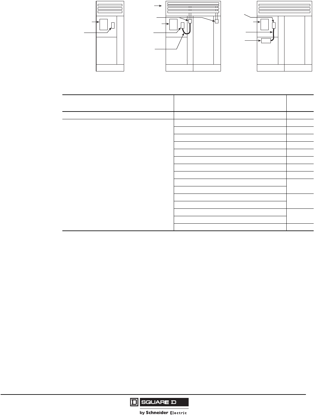
Model 6 Motor Control Centers
Incoming Devices Application and General Information
27
07/2009
© 1997–2009 Schneider Electric
All Rights Reserved
4-Wire Examples
Service Entrance Label (not available on Main Lug Systems)
Description Application Space
(Inches)
3-phase, 3-wire system with a main breaker/switch 15–2500 A1
1Ground fault protection is added to all 1000 A and larger mains when a service entrance is specified and the system voltage is 480 V.
0
3-phase, 4-wire system with a main breaker/switch
NOTE: A neutral lug termination option and/or
solid neutral bus option is required on 4-wire systems.
110–150 A without GFI 3
110–150 A with GFI 3
175–250 A without GFI 0
175–250 A with GFI 0
300–400 A without GFI 2
2When SCCR is >35 kA on 300–400 A applications, an additional 15 in. of space is required for top feed installations and an
additional 9 in. for bottom feed.
0
300–400 A with GFI 3
3Requires an additional 15 in. of space for top feed applications.
12
450–600 A without GFI 6
450–600 A with GFI 12 4
4Requires an additional 6 in. of space when the metering option is selected.
800–2500 A circuit breaker with GFI 0
600–2000 A switch with GFI
800 A circuit breaker without GFI 15
1200 A circuit breaker (80% rated) without GFI
600–800 A switch without GFI 12
1000–1200 A bottom incoming switch without GFI
Any other main without GFI (except as shown above) 0
Disconnect
Cable
A
B
C
Cable
Disconnect
Neutral Lug
Termination
Assembly
A
N
B
C
Figure 3
Disconnect
A
B
C
Figure 1 Figure 2
Neutral Lug
Termination
Assembly
Solid
Neutral
Bus
Neutral Lug
Termination
Assembly
Neutral
Distribution
Unit
Neutral Drops
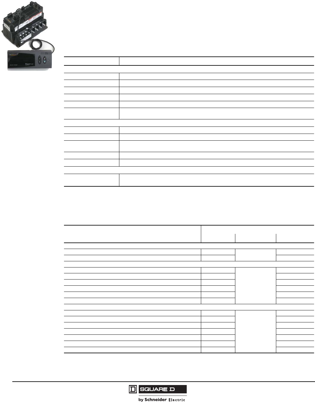
© 1997–2009 Schneider Electric
All Rights Reserved
Model 6 Motor Control Centers
Application and General Information Incoming Devices
28 07/2009
PowerLogic® Circuit Monitor
PowerLogic series 3000 and 4000 circuit monitors are multifunction digital metering and monitoring
devices capable of replacing a variety of meters, relays, transducers, and other components. Data
available for local viewing includes metered values plus extensive min/max, alarm, and analog/digital
input data. Circuit monitor data is available for viewing and recording via standard RS-485, RS-232
(series 4000 only) or optional Ethernet communications. A 4-line x 20-character LCD type display with
customizable displays is provided as standard. An optional vacuum fluorescent display with
backlighting is also available. The circuit monitors offer waveform capture, event/alarm logging and
custom alarms. Included with the circuit monitor are a current transformer, current transformer shorting
terminal block, current/voltage module, voltage connections, and power supply.
PowerLogic CM4000
Description Application
Monitors
CM3250 with LCD Display Circuit Monitor, data logging, waveform capture, 8MB memory, LCD Display
CM3350 with LCD Display Circuit Monitor, same features as CM3250 with Disturbance Monitoring
CM4250 with LCD Display Instrumentation, data logging, waveform and disturbance capture, programmable logic, 2 option card slots
CM4000T with LCD Display CM4000 features plus high-speed voltage transient detection and capture.
CMDLC 4-line x 20 character Liquid Crystal Display with backlighting
CMDVF 4-line x 20 character Vacuum Fluorescent Display with I/R port and proximity sensor substituted for
standard LCD display
I/O Modules
IOC 44 1, 2
1Only one slot is available for I/O Modules or the Ethernet ECC21 card on CM3000.
2Two slots are available for two IOC44 I/O Modules or one IOC44 I/O Module and one Ethernet ECC21 card on CM4250/4000T.
Field Installable I/O card with 4 status inputs, 3 relay (10 A) outputs, and 1 pulse output (KYZ)
IOX0404 3
3Available on CM4250/4000T only. Choose only one module per circuit monitor.
I/O Extender module with 4 status inputs and 4 analog inputs (4 to 20 mA)
IOX2411 3I/O Extender module with 4 inputs (32 Vdc), 2 outputs (60 Vdc), 1 analog input (0-5 Vdc),
1 analog output (4-20 mA)
IOXO8 3I/O Extender module with 8 status inputs (120 Vac)
IOX 3I/O Extender module only, no installed I/O, accepts up to 8 I/O modules with maximum of 4 analog I/O
Accessories
ECC21 1, 2 Ethernet communications card, 100 Mbps fiber and 10/100 Mbps UTP Ethernet port and 1 RS-485
master port
Circuit Monitor Space Requirements
Device Type Additional Space Requirements (Inches)
Main Unit Monitor Unit 1
1The circuit monitor unit must be placed adjacent to (below, above, or next to) the main unit.
Total
Main Lugs
600–1200 A 0 12 12
1600–2500 A 0 12 2
2If space is not available for the circuit monitor, an option is available to integrate the metering equipment on the door of
main. This option requires no additional space for the circuit monitor module. On bottom located mains, this option protrudes 6.2 in.
out from the door and reduces customer aisleway by the same dimension.
Main Circuit Breaker
110–250 A 6
12
18
300–400 A 9 21
450–600 A 6 18
800 A 15 27
1200 A 80% rated 15 27
1200 A 100% rated; 1600–2500 A 0 12
Main Fusible Switch
200 A 6
12
18
Top Located, 400 A 3 15
Bottom Located, 400 A 618
600–800 A 12 24
Top Located, 1000–2000 A 012
Bottom Located, 1000–2000 A 12 24
1600–2000 A 012
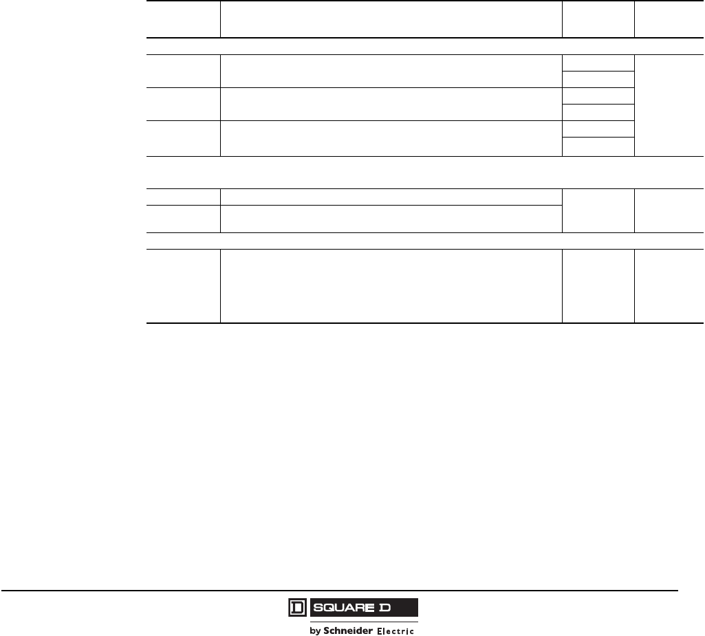
Model 6 Motor Control Centers
Incoming Devices Application and General Information
29
07/2009
© 1997–2009 Schneider Electric
All Rights Reserved
PowerLogic Power Meter
The PowerLogic Series 800 Power Meter is a high-performance power monitoring component able to
provide advanced power measurement capabilities in a compact MCC plug-in unit. It is designed for
use in basic power metering applications and can replace conventional metering devices such as
ammeters, voltmeters, and watt-hour meters while providing powerful capabilities not offered by
analog metering. This option can offer an economical advantage in MCCs requiring multiple analog
meters for voltage, current, and watt-hours. With its easy to use intuitive interface and self guiding
menus, the large antiglare and back lit display makes this meter the easiest to navigate and use.
•Monitor current, voltage, power, and energy simultaneously
•Individual harmonic measurements on current and voltage
•THD measurement
•Modbus® RS-485 Communications and compatible with Transparent Ready® Equipment
The Power Meter offering below is for MCC incoming main devices only. The MCC power meter option
includes the power meter module, front mounted display for easy viewing, main and control voltage
fusing, and necessary current transformers with shorting terminal blocks in the main device. Optional
modules can be added to the power meter to increase type and number of inputs and outputs. For
other power meter applications, contact the MCC Technical Assistance Group (TAG).
Description Application System Space
(Inches)
Meters
PM820 Power Meter door mounted display + module with instrumentation functions,
THD measurement, alarming, and 80 kb logging.
3-phase, 3-wire
See “Power
Meter Space
Requirements”
on page 30
3-phase, 4-wire
PM850 Power Meter door mounted display + module with instrumentation functions,
THD measurement, alarming, 800 kb logging, and waveform capture.
3-phase, 3-wire
3-phase, 4-wire
PM870
Power Meter door mounted display + module with instrumentation functions,
THD measurement, alarming, 800 kb logging, configurable waveform capture,
and sag/swell detection.
3-phase, 3-wire
3-phase, 4-wire
I/O Modules
Up to 2 modules of the same or different types can be mounted on the meter to expand the I/O.
PM8M26 I/O module with 2 digital outputs (relays), 6 digital inputs
—0
PM8M2222 I/O module with 2 digital outputs, 2 digital inputs, 2 analog outputs and 2 analog
inputs
Accessories
PM8ECC
Ethernet Communications Card includes: instantaneous readings, advance
security, TRE Level 1, Web browser based Diagnostics and Register Reader,
10/100BaseTx Ethernet, RS-485, and support for 2-wire and 4-wire
daisy-chains. Supported protocols: ModbusTCP/IP, FTP, SNMP MIB2, ARP,
UDP, and HTTP.
Available on all Power Meter 800 Series meters.
—0
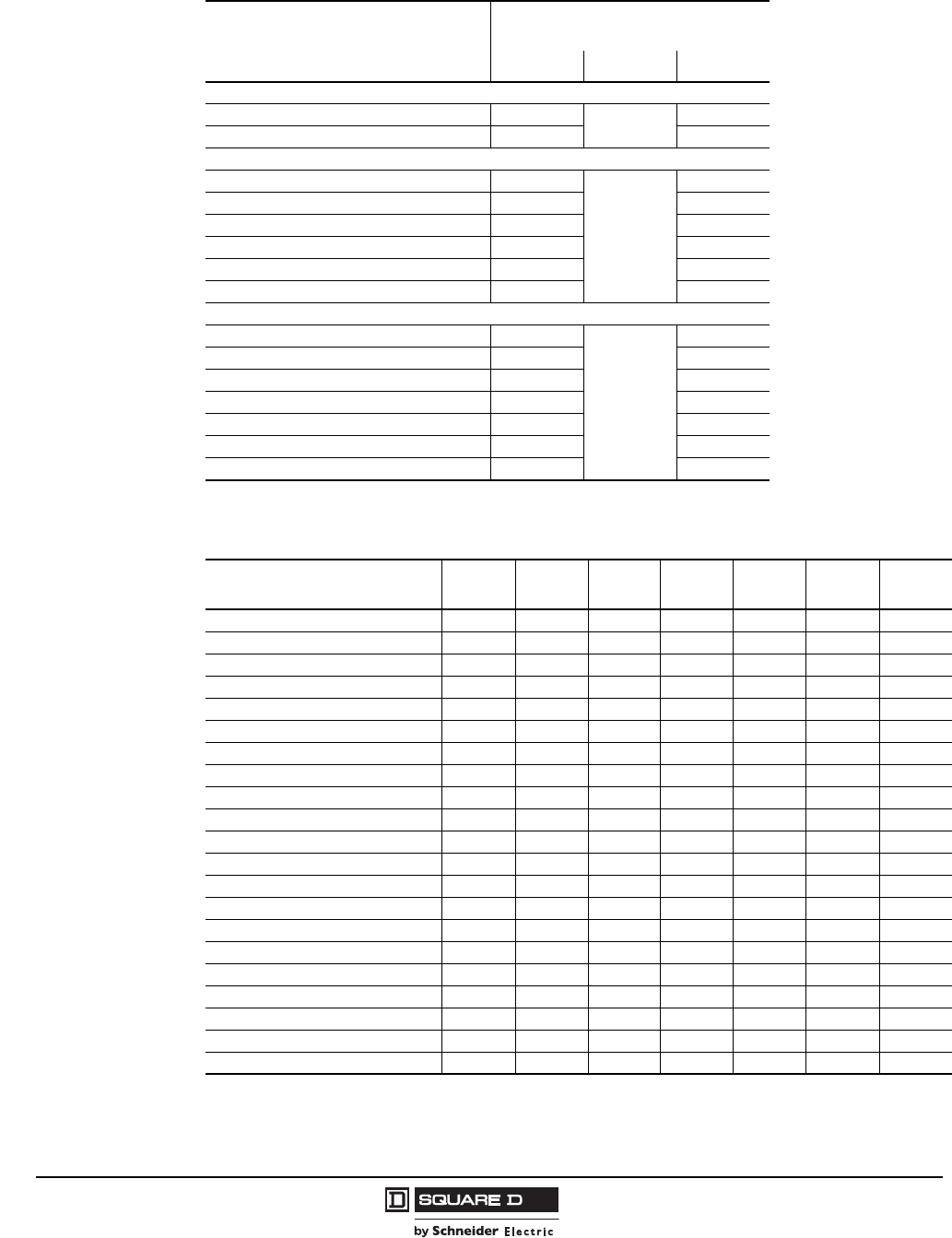
© 1997–2009 Schneider Electric
All Rights Reserved
Model 6 Motor Control Centers
Application and General Information Incoming Devices
30 07/2009
Power Meter Space Requirements
Device Type
Additional Space
Requirements (Inches)
Main Unit Meter Unit 1
1The power meter unit must be placed adjacent to (below, above, or next to) the main unit.
Total
Main Lugs
600–1200 A 066
1600–2500 A 06
Main Circuit Breaker
110–250 A 6
6
12
300–400 A 915
450–600 A 612
800 A 15 21
1200 A 80% rated 15 21
1200 A 100% rated; 1600–2500 A 0 6
Main Fusible Switch
200 A 6
6
12
Top-located, 400 A 39
Bottom-located, 400 A 612
600–800 A 12 18
Top-located, 1000–1200 A 0 6
Bottom-located, 1000–1200 A 12 18
1600–2000 A 0 6
PowerLogic Power Meter and Circuit Monitor Comparison
Feature Model
PM820 Model
PM850 Model
PM870 Model
CM3250 Model
CM3350 Model
CM4250 Model
CM4000T
Amps, volts, power, energy, PF X X XXXXX
Communications: RS485 Modbus X X XXXXX
Communications: optional Ethernet X X XXXXX
Demand readings, THD X X XXXXX
Trending and forecasting XXXX
ITIC/SEMI F47/NEMA MG-1-1998 Optional Optional Optional Optional
Extended memory XX
Alarm event log X X XXXXX
High speed (100ms) alarms X XXXXX
Disturbance (10ms) alarms X X X
Transient (1 microsec) alarms X
Interval min./max./avg. log XXXX
Billing log X X X
Waveform capture X XXXXX
Disturbance waveform capture XXXX
100ms event recordings XXX
Infrared port Optional Optional Optional Optional
Analog inputs/outputs (maximum) (4) (4) (4) (0) (0) (4) (4)
Digital inputs/outputs (maximum) (17) (17) (17) (8) (8) (24) (24)
Programmable math and LOGIC functions X X
Downloadable firmware X X XXXXX
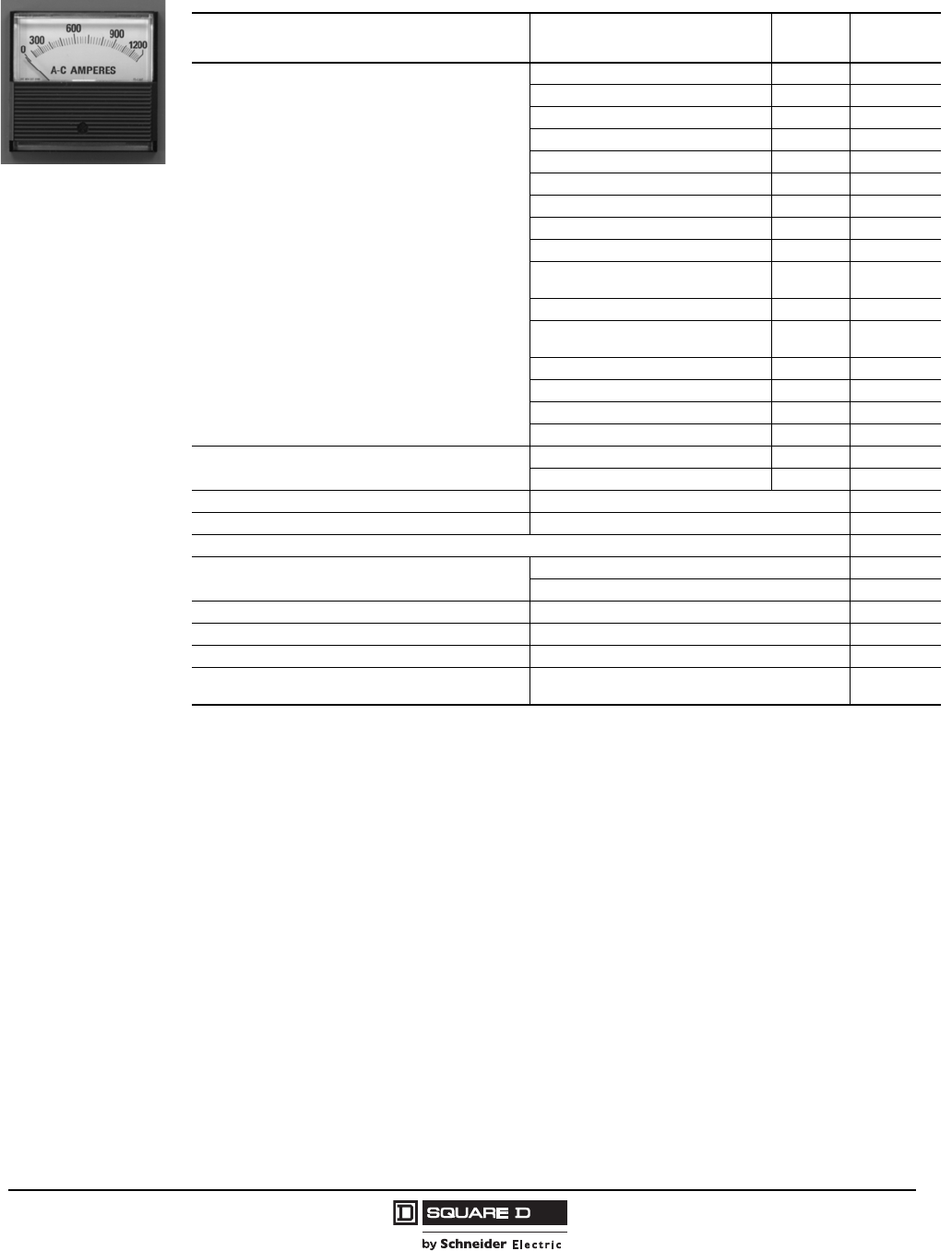
Model 6 Motor Control Centers
Incoming Devices Application and General Information
31
07/2009
© 1997–2009 Schneider Electric
All Rights Reserved
Analog Meter
Metering Options1
1Total space of unit and meter options shall not exceed 72 in.
Description Application Metering
Sequence Space
(Inches)
AC ammeter with transfer switch and two current
transformers and shorting terminal blocks
(Three CTs provided on 4-wire systems)
110–250 A main circuit breakers Hot 15
When used with voltmeter 0
15–250 A branch circuit breaker Cold 15
When used with voltmeter 0
300–600 A main/branch circuit breakers Cold 9
When used with voltmeter 0
800–2500 A main/branch circuit breakers Not available 2
2Analog metering is not available on PowerPact M-, P-, and R-frame units. Use an optional Micrologic ammeter, power, or harmonic
trip unit on the circuit breaker, or a PowerLogic circuit monitor/power meter for switch applications.
30–200 A main/branch fusible switches Cold 15
When used with voltmeter 0
400 A and above main/branch fusible
switches Cold 9
When used with voltmeter 0
600–2000 A main/branch fusible
switches Not available 2
600–1200 A top located main lugs Hot 9
When used with voltmeter 0
600–1200 A bottom main lugs Hot 0
1600–2500 A main lugs Hot 0
AC voltmeter with VM transfer switch and two potential
transformers (Three PTs provided on 4-wire systems)
Main and branch feeders2Cold 9
Main lugs Hot 0
Elapsed time meter 3
3Not available on Compac 6 starters.
Starter unit 0
AC ammeter with current transformer Starter unit 3
1% meters (switchboard type) 6
Ground detection lights Main breaker/switch only 12
Main lugs 12
Fuse for metering circuit For special applications only 0
Current transformer (CT) For special applications only 3
Potential transformer (PT) For special applications only 6
Shorting terminal blocks for metering CTs Option for starters, branch feeders
(standard on PowerLogic devices) 0
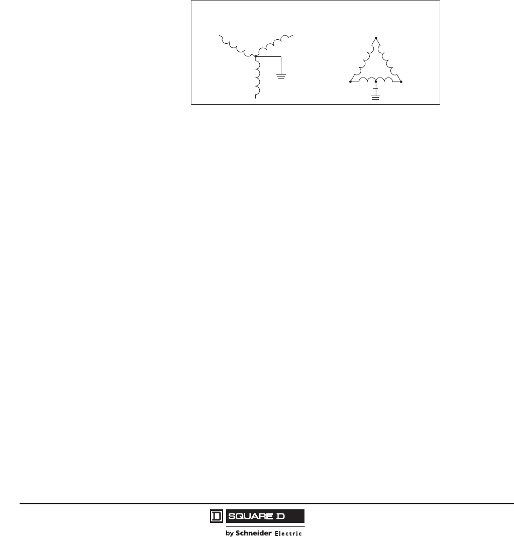
© 1997–2009 Schneider Electric
All Rights Reserved
Model 6 Motor Control Centers
Application and General Information Incoming Devices
32 07/2009
Transient Voltage Surge Suppressor (TVSS) Units for MCC Incoming Mains
General Information
NOTE: TVSS units must be installed on grounded power distribution systems. Installation on an
ungrounded power distribution system is not recommended. See the figure below for proper
transformer feed to the MCC where TVSS units can be applied.
•Must be located as close as possible to the incoming main provision.
•TVSS units for 4-wire systems must include a solid neutral bus and/or neutral lug termination
assembly in the MCC.
•TVSS components for installation in MCC-mounted panelboards or on distribution transformer
secondaries should use a panel-mounted TVSS component.
All MCC TVSS units for MCC incoming mains include as standard:
•Flange-mounted disconnect
•Door-mounted diagnostic lights for each phase
•Audible alarm with Test/Disable/Enable switch
•TVSS with EMI/RFI filter
•UL 1449 Standard, Second Edition, Tested and Recognized Component
•UL 1283 Recognized Component
•cUL Certified Component
•Motor Control Center certifications per UL 845, CSA (Canada) and NOM (Mexico)
•Individually fused suppression modules utilizing surge-rated fuses
•Each suppression MOV is thermally protected for low current faults
•High energy parallel MOV design for Category A, B, C3 exposure levels per IEEE C62.41 criteria
•Can be applied to MCCs with 100 kAIC short circuit withstand rating
•Designed as standard MCC unit construction to enable new or retrofit applications
•One Form C alarm contact
Selection
1. Select the TVSS Model based on:
a. System voltage (480 Vac, 240 Vac, 208 Vac, or 600 Vac).
b. Desired surge current capacity (120 kA, 160 kA, or 240 kA). If a surge current capacity higher than
240 kA is required, more than one TVSS unit can be added to the MCC to bring it to the desired
surge current capacity. When adding more than one TVSS unit to an MCC, all units should be
mounted in the same section, if possible, and as close as possible to the MCC incoming main unit.
c. Type of loads to be protected (branch loads, service entrance applications, or large individual
loads).
d. If backup redundancy is a requirement, two TVSS units should be added in the same MCC
section and in adjacent mounting spaces.
2. Select the TVSS model based on the main power transformer connection (see figure above),
desired surge current capacity, and type of loads to be protected.
Transformer Secondary
or
Grounded Wye
CA
B
High Leg Delta
N
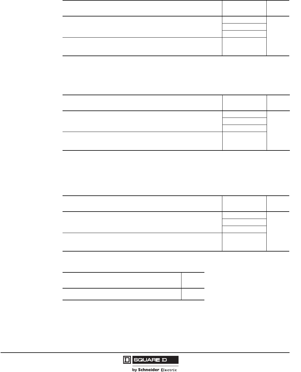
Model 6 Motor Control Centers
Incoming Devices Application and General Information
33
07/2009
© 1997–2009 Schneider Electric
All Rights Reserved
Model IMA TVSS (120 kA Surge Rating)
•For protection of small MCC lineups and non-critical loads
•120,000 A per phase surge current capacity
Model IMA TVSS (160kA Surge Rating)
•For protection of branch loads/electronics, large individual loads, and drives/soft starts
•160,000 A per phase surge current capacity
Model IMA TVSS (240 kA Surge Rating)
•For application on high exposure systems for service entrance protection with large power
electronic loads (drives/soft starts)
•240,000 A per phase surge current capacity
Additional Options
Customer Incoming Power Connection to MCC System Voltage Space
(Inches)
Three phases with or without neutral connected to MCC (3- or 4-wire MCC). Wye
secondary transformer with grounded neutral.
208 Vac
6
480 Vac
600 Vac
Transformer with high-leg delta secondary. Three phases with or without neutral
connected to MCC (3- or 4-wire MCC).
NOTE: B-phase is configured as the high leg.
240 Vac
Description Space
(Inches)
Surge Counter—Door mounted display that counts the number
of transients entering the facility through the suppressor. 0
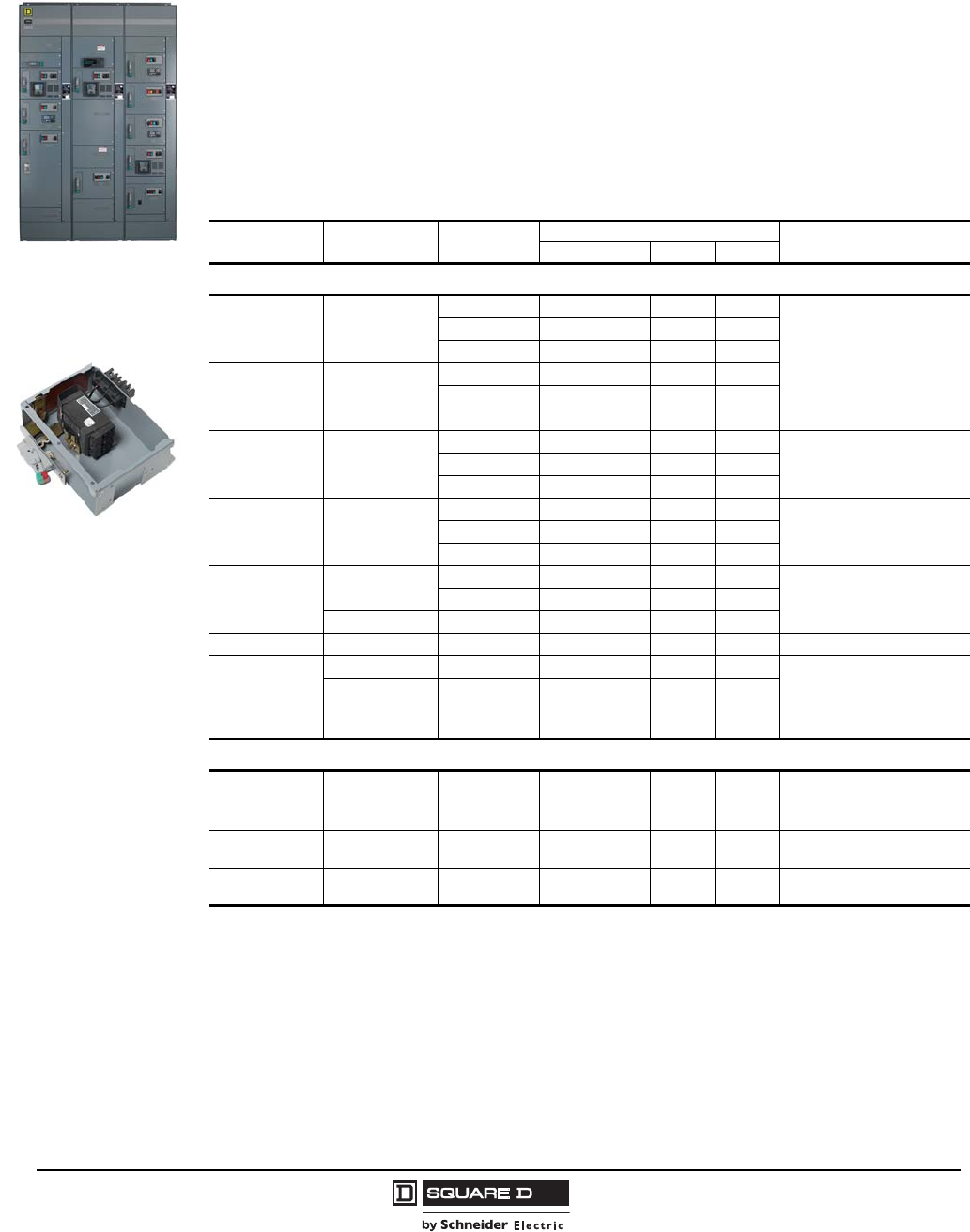
© 1997–2009 Schneider Electric
All Rights Reserved
Model 6 Motor Control Centers
Application and General Information Branch Feeder Units
34 07/2009
Branch Feeder Units
Circuit Breaker Branch Feeder Units
•Branch feeder units may be located in 20 in. wide by 15 in. or 20 in. deep sections, except where
noted.
•Select trip rating and desired unit interrupting rating. (The unit interrupting rating is equal to the
breaker rating.)
•Units listed are for 3-phase, 3-wire systems. 3-phase, 4-wire applications may require additional
space (see “3-Phase, 4-Wire Systems” on page 26). Four-wire applications are not available on
Compac™ 6 units.
Compac 6, H-frame,
150A, Circuit Breaker
Branch Feeder Unit
Thermal-Magnetic Molded Case Circuit Breakers
Breaker Trip
Rating (Amps) Breaker Frame
(Amps) Breaker
Type Unit Interrupting Rating (kA) Space (Inches)
208/240 V 480 V 600 V
Standard (80%) Rated
15–150 150
HG 65 35 18
6
(Compac 6, Plug-on)
HJ 100 65 25
HL 100 100 50
175–250 250
JG 65 35 18
JJ 100 65 25
JL 100 100 50
15–150 150
HG 65 35 18 12
(Plug On)
HJ 100 65 25
HL 100 100 50
175–250 250
JG 65 35 18 18
(Plug On)
JJ 100 65 25
JL 100 100 50
300–400 400 LA 42 30 22 27
(Plug On)
LH 65 35 25
600 LI 100 100 100
450–600 600 LI 100 100 100 36 1
1Specify top or bottom entry.
800 800 MJ 65 65 25 18 (Top Entry)
18 2 (25 W, Bottom Entry)
2Top located in section with 9 in. vertical wireway for bottom cable entry.
1200 PL/PK 100 100 50
1200 1200 PL/PK 100 100 50 21 (Top Entry)
21 2 (25 W, Bottom Entry)
Optional 100% Rated 3
3All 100% rated circuit breakers are molded case with Micrologic electronic trip. LE electronic trip circuit breakers include Full
Function Trip Unit with LSIG tripping functions. P and R-frame electronic trip circuit breakers include Basic 3.0 Trip Unit with LI
tripping functions.
300–400 400 LE 100 65 35 36 1
600 1200 PL/PK 100 100 50 18 (Top Entry)
18 2 (25 W, Bottom Entry)
800 1200 PL/PK 100 100 50 21 (Top Entry)
21 2 (25 W, Bottom Entry)
1200 1200 PL/PK 100 100 50 72 4 (20 W x 20 D)
NEMA/EEMAC Type 1/1A only
4Requires single shipping split.
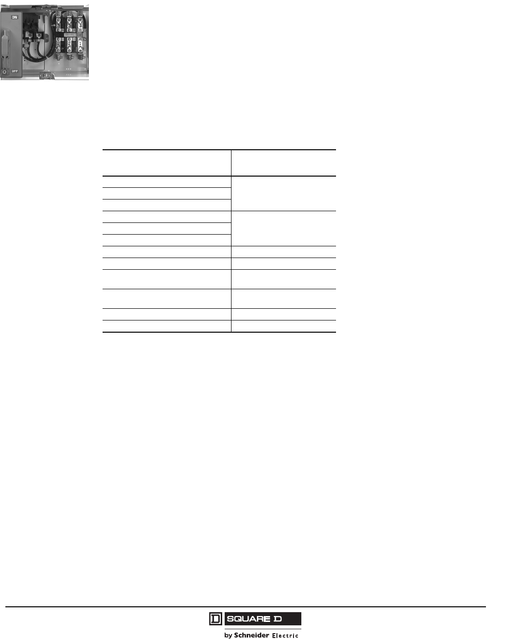
Model 6 Motor Control Centers
Branch Feeder Units Application and General Information
35
07/2009
© 1997–2009 Schneider Electric
All Rights Reserved
Fusible Switch Branch Feeder Units
Branch feeder units may be located in 20 in. wide by 15 in. or 20 in. deep sections, except where
noted.
Branch feeder units up to 100 A use a bladed switch disconnect. Above 100 A, the disconnect is an
automatic molded case switch.
Class H (0–600 A) and Class L (800–1200 A) fuse clips are provided as standard, except
Compac 6, six inch units, which use Class J fuse clips. Class R fuse clips can be provided for
30–600 A switches.
All fusible switch units have a short circuit rating of 100,000 A.
Fuses are not included as standard.
Units listed are for 3-phase, 3-wire systems. 3-phase, 4-wire applications may require additional
space (see “3-Phase, 4-Wire Systems” on page 26). Four-wire applications are not available on
Compac 6 units.
NOTE: Only one 400 A or larger main disconnect, top located main lug, or starter unit can be installed
per section. Only one 450 A or larger cabled/bussed branch can be installed per section.
Fusible Switch Branch
Feeder Unit
Main Fusible Switches—600 V Max.
Maximum Fuse Size
(Amps) Space (Inches)
30
6 1 (Plug-on)
1Compac 6 units.
60
100
30
12 (Plug On)60
100
200 24 (Plug On)
400 51
6002
2Specify top or bottom exit.
60 (top exit)
60 3 (25 W, bottom exit)
3Top located in section with 9 in. vertical wireway for bottom cable entry.
800260 (top exit)
60 2 (25 W, bottom exit)
1000272 4 (25 W x 20 D)
4Requires single shipping split.
1200272 4 (30 W x 20 D)
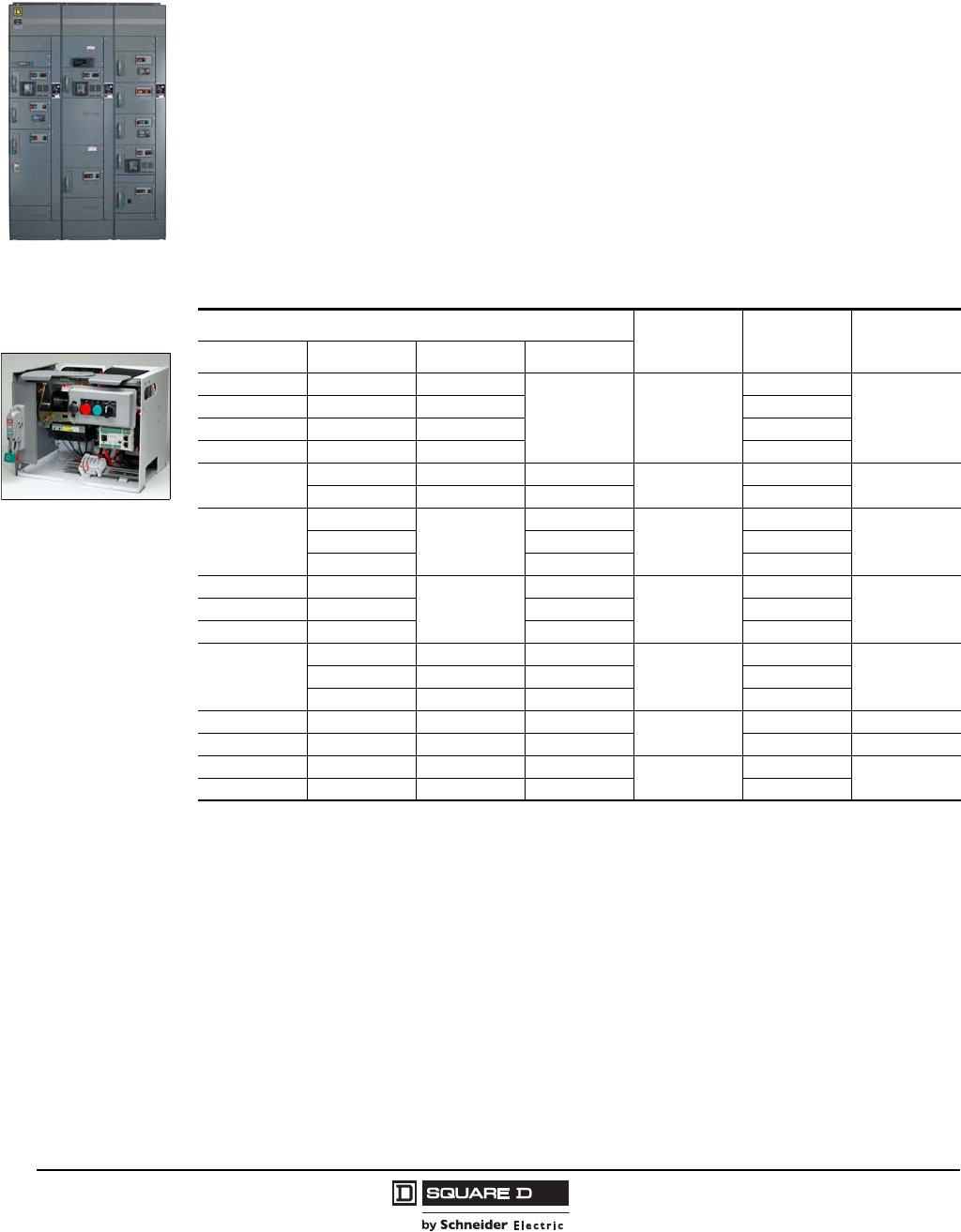
© 1997–2009 Schneider Electric
All Rights Reserved
Model 6 Motor Control Centers
Application and General Information Combination Starter Units
36 07/2009
Combination Starter Units
Combination starter units combine the requirements of motor overload and short circuit protection into
one convenient package. Starter units are provided with Schneider Electric Type S or TeSys® D-Line
contactors, thermal or solid-state overloads, and fusible switch or circuit breaker disconnects.
Full Voltage Non-Reversing (FVNR) Starters with Circuit Breakers
FVNR combination starters will mount in standard 20 in. wide by 15 in. or 20 in. deep sections, except
where noted.
All Compac™ 6, NEMA-rated, six-inch starters use GJL frame Mag-Gard® motor circuit protectors
(MCPs). All standard height starters with MCP frames through 250 A use PowerPact® electronic motor
circuit protectors. All starters with MCP frames above 250A use L- and P-frame Mag-Gard motor circuit
protectors. Thermal-magnetic circuit breakers may be substituted for motor circuit protectors on starter
units. All units are UL Listed.
Motor Control Center units are available with short circuit ratings up to 100,000 A.
Combination Starter Unit
with Circuit Breaker
Disconnect
Starter Horsepower NEMA Size MCP Frame
(Amps) Space
(Inches)
208 V 240 V 480 V 600 V
0.33 0.5 1
—1
3
61
1Compac 6 units.
113 7
357.5 15
57.510 30
551010130 12
7.5 — — 50
10
—
25
15
2
30
1210 25 50
15 — 100
——
50
30
3
50
1820 25 50 100
25 30 — 150
40
—— 60
4
100
2140 75 100 150
50 100 — 250
50 60 125 150 5250 42 2
2When the thermal-magnetic circuit breaker option is chosen, the space requirement is 48 in.
75 100 200 200 400 48
100 — 250 300 6400 72 (20 W x 20 D)
150 200 400 400 600
Model 6 Motor Control Centers
Combination Starter Units Application and General Information
37
07/2009
© 1997–2009 Schneider Electric
All Rights Reserved
Full Voltage Non-Reversing Vacuum Starters with Circuit Breakers
Vacuum contactor combination starters will mount in standard 20 in. wide by 15 in. or 20 in. deep
sections, except where noted.
All vacuum starter units with circuit breaker disconnects use PowerPact electronic motor circuit
protectors (MCPs) or L-frame or PowerPact M- or P-frame thermal magnetic (TM) circuit breakers. All
units are UL Listed.
Motor Control Center units are available with short circuit ratings up to 100,000 A.
Starter Horsepower NEMA Size MCP Frame or
TM Trip/Frame
(Amps)
Space
(Inches)
208 V 240 V 480 V 600 V
——— 60
4
100 MCP
2140 40 75 100 150 MCP
— 50 100 — 250A MCP
50 — — 150
5
200/400 TM
48
— 60 125 — 225/400 TM
60 75 150 200 250/400 TM
75 — — — 300/400 TM
— 100 200 350/400 TM
———250
6 600/800 TM 72 (20 W x 20 D)
100 125 250 300
125 150 300 400
150 — 350 —
— 200 400 —
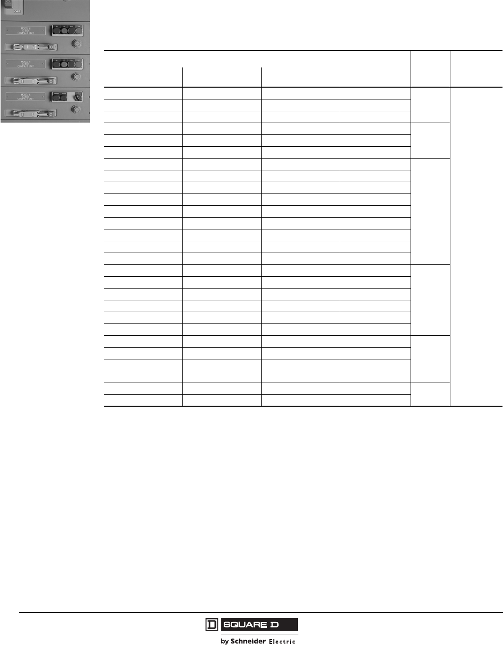
© 1997–2009 Schneider Electric
All Rights Reserved
Model 6 Motor Control Centers
Application and General Information Combination Starter Units
38 07/2009
Application-Rated Compac 6 Starters—Full Voltage Non-Reversing with Circuit Breakers
All Compac 6 application-rated, six-inch starters use TeSys® D-Line contactors and GJ frame
Mag-Gard adjustable instantaneous trip breakers (UL Listed for 100,000 A at 480 V short circuit
rating). Compac 6 application-rated six-inch starters will mount in 20 in. wide by 15 in. or 20 in. deep
sections. Select application rated units based on system voltage and motor full load amps.
Compac 6 Units
Application-Rated FVNR Combination Starters—With Mag-Gard Circuit Breaker (480 V Max.)
Starter Ampacity Overload Relay
Ampacity Range 1
1Maximum overload relay ampacity when used on Compac 6 units.
Circuit
Breaker
(Amps)
Space
(Inches)
208 V 240 V 480 V
1 1 1 0.63 to 1.0
3
6
1.6 1.6 1.6 1.0 to 1.6
2.1 2.1 2.1 1.6 to 2.1
2.5 2.5 2.5 2.1 to 2.5
74 4 4 2.5 to 4.0
4.8 4.8 4.8 4.0 to 4.8
5.5 5.5 5.5 4.8 to 5.5
15
7 7 7 5.5 to 7.0
9 9 — 7.0 to 9.0
— — 7.6 7.0 to 7.6
— 9.6 — 9.0 to 9.6
11 — 9.0 to 11
— — 9 7.6 to 9.0
— — 11 9.0 to 11.0
— 11 — 9.6 to 11.0
12 12 12 11 to 12.0
30
— — 14 12.0 to 14.0
17 17 — 12.0 to 17.5
22 22 — 17.5 to 22.0
— — 17 14 to 17
— — 21 17 to 21
23 23 — 22 to 23
50
— — 23 21 to 23
30 30 30 23 to 30
34 34 34 30 to 34
37 37 — 34 to 37 75
42 42 — 37 to 42
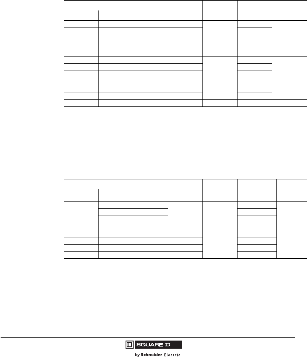
Model 6 Motor Control Centers
Combination Starter Units Application and General Information
39
07/2009
© 1997–2009 Schneider Electric
All Rights Reserved
Full Voltage Reversing (FVR) Starters with Circuit Breakers
FVR combination starters will mount in standard 20 in. wide by 15 in. or 20 in. deep sections, except
where noted. All starters with motor circuit protector (MCP) frames through 250 A use PowerPact
electronic motor circuit protectors. All starters with MCP frames above 250 A use L-frame Mag-Gard
motor circuit protectors. All units are UL Listed.
Motor Control Center units are available with short circuit ratings up to 100,000 A.
Full Voltage Reversing Vacuum Starters with Circuit Breakers
Vacuum contactor combination starters will mount in standard 20 in. wide by 15 in. or 20 in. deep
sections, except where noted. All vacuum starter units with circuit breaker disconnects use PowerPact
electronic motor circuit protectors (MCP) or L-frame thermal magnetic (TM) circuit breakers as
indicated. All units are UL Listed.
Motor Control Center units are available with short circuit ratings up to 100,000 A.
Starter Horsepower NEMA Size MCP Frame
(Amps) Space
(Inches)
208 V 240 V 480 V 600 V
5 5 10 10 130 18
—7.5—— 50
——— 15
2
30
1810 10 25 25 50
—15—— 100
——— 30
3
50
2720 25 50 50 100
25 30 — — 150
——— 60
4
100
3340 40 75 100 150
— 50 100 — 250
75 100 200 200 5 400 72 (25 W)
Starter Horsepower NEMA Size MCP Frame or
TM Trip/Frame
(Amps)
Space
(Inches)
208 V 240 V 480 V 600 V
40
——
100 4
100 MCP
2140 75 150 MCP
50 100 250 MCP
50 — — 150
5
200/400 TM
48
— 60 125 — 225/400 TM
60 75 150 200 250/400 TM
75 — — — 300/400 TM
— 100 200 — 350/400 TM
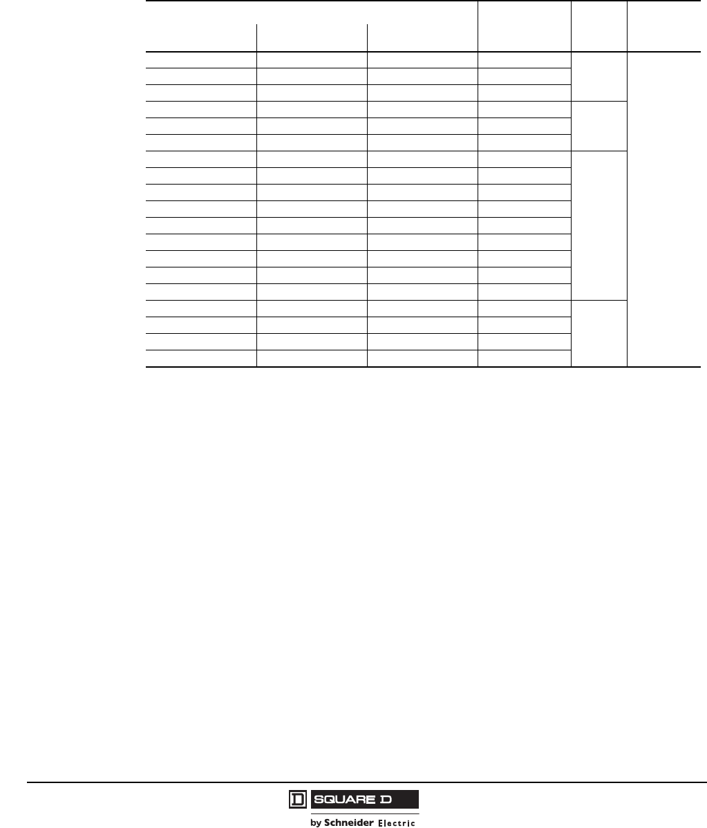
© 1997–2009 Schneider Electric
All Rights Reserved
Model 6 Motor Control Centers
Application and General Information Combination Starter Units
40 07/2009
Application-Rated Compac 6 Starters—Full Voltage Reversing with Circuit Breakers
All Compac 6 application-rated, six-inch starters use TeSys D-Line contactors and GJ frame Mag-Gard
adjustable instantaneous trip breakers (UL Listed for 100,000 A at 480 V short circuit rating).
Compac 6 application-rated six-inch starters will mount in 20 in. wide by 15 in. or 20 in. deep sections.
Select application rated units based on system voltage and motor full load amps.
Application-Rated FVR Combination Starters – With Mag-Gard® Circuit Breaker (480 V Max.)
Starter Ampacity Overload Relay
Ampacity
Range1
1Maximum overload relay ampacity when used on Compac 6 units.
Circuit
Breaker
(Amps)
Space
(Inches)
208 V 240 V 480 V
1 1 1 0.63 to 1.0
3
6
1.6 1.6 1.6 1.0 to 1.6
2.1 2.1 2.1 1.6 to 2.1
2.5 2.5 2.5 2.5 to 4.0
74 4 4 2.5 to 4.0
4.8 4.8 4.8 4.0 to 4.8
5.5 5.5 5.5 4.8 to 5.5
15
7 7 7 5.5 to 7.0
— — 7.6 7.0 to 7.6
9 9 — 7.0 to 9.0
— 9.6 — 9.0 to 9.6
11 — — 9.0 to 11
— — 9 7.6 to 9.0
— — 11 9.0 to 11.0
— 11 — 9.6 to 11
12 12 12 11.0 to 12.0
30
— — 14 12.0 to 14.0
17 17 — 12.0 to 17.5
22 22 — 17.5 to 22.0
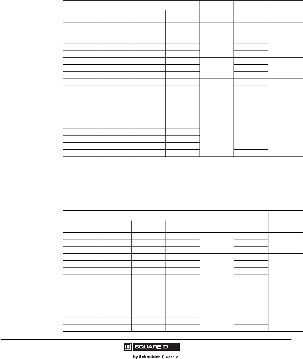
Model 6 Motor Control Centers
Combination Starter Units Application and General Information
41
07/2009
© 1997–2009 Schneider Electric
All Rights Reserved
Reduced Voltage Autotransformer (RVAT) Starters with Circuit Breakers
RVAT combination starters mount in standard 20 in. wide by 20 in. deep sections. Sections with RVAT
starters require single shipping splits. All RVAT starter units with circuit breaker disconnects use
thermal-magnetic (TM) circuit breakers. All units are UL Listed.
Motor Control Center units are available with short circuit ratings up to 100,000 A.
Reduced Voltage Autotransformer (RVAT) Vacuum Starters with Circuit Breakers
RVAT vacuum contactor combination starters mount in standard 20 in. wide by 20 in. deep sections.
Sections with RVAT starters require single shipping splits. All RVAT starter units with circuit breaker
disconnects use thermal magnetic (TM) circuit breakers. All units are UL Listed.
Motor Control Center units are available with short circuit ratings up to 100,000 A.
Starter Horsepower NEMA Size TM
Trip/Frame
(Amps)
Space
(Inches)
208 V 240 V 480 V 600 V
——— 30
3
80/150
48 (20 D)
— — 30 — 100/150
— — — 40 110/150
15 — — — 125/150
20 25 50 50 150/150
——— 60
4
175/250
60 (20 D)25 30 60 75 200/250
40 50 100 100 250/250
50 — — 150
5
200/400
72 (25 W X 20 D)
60 125 — 225/400
60 75 150 200 250/400
75 — — — 300/400
— 100 200 — 350/400
———250
6600/800 72 (30 W x 20 D)
100 125 250 300
———350
125 150 300 400
150 — 350 —
— 200 400 — 800/800
Starter Horsepower NEMA Size TM
Trip/Frame
(Amps)
Space
(Inches)
208 V 240 V 480 V 600 V
——— 60
4
175/250
60 (20 D)25 30 60 75 200/250
40 50 100 100 250/250
50 — — 150
5
200/400
72 (25 W x 20 D)
— 60 125 — 225/400
60 75 150 200 250/400
75 — — — 300/400
— 100 200 — 350/400
———250
6600/800 72 (30 W x 20 D)
100 125 250 300
———350
125 150 300 400
150 — 350 —
— 200 400 — 800/800
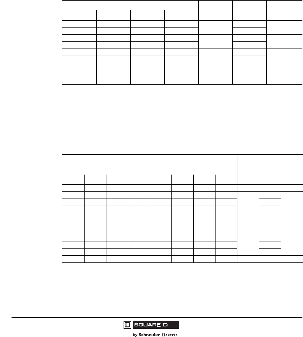
© 1997–2009 Schneider Electric
All Rights Reserved
Model 6 Motor Control Centers
Application and General Information Combination Starter Units
42 07/2009
Full Voltage 2-Step Part-Winding (FVPW) Starters with Circuit Breakers
Part-winding combination starters will mount in standard 20 in. wide by 15 in. or 20 in. deep sections,
except where noted. Part-winding starters use a separate motor circuit protector (MCP) for each of the
two motor windings. All starters with MCP frames through 250 A use PowerPact electronic motor
circuit protectors. All starters with MCP frames above 250 A use L-frame Mag-Gard motor circuit
protectors. All units are UL Listed.
Each MCP has an external operating mechanism. Part-winding starters require six thermal units.
Motor Control Center units are available with short circuit ratings up to 100,000 A.
Full Voltage 2-Speed 1-Winding Starters (Consequent Pole) with Circuit Breakers
Two-speed combination starters will mount in standard 20 in. wide by 15 in. or 20 in. deep sections,
except where noted. All starters with motor circuit protector (MCP) frames through 250 A use
PowerPact electronic motor circuit protectors. All starters with MCP frames above 250 A use L-frame
Mag-Gard motor circuit protectors. All units are UL Listed.
Motor windings are Wye connected as standard. Open Delta connection is available.
Motor Control Center units are available with short circuit ratings up to 100,000 A.
Starter Horsepower NEMA Size MCP Frame
(Amps) Space
(Inches)
208 V 240 V 480 V 600 V
5 51015
130 30
10 10 15 — 50
— — 25 25 250 30
20 25 40 40 100
— — 50 60 3100 36
40 50 75 75 150
———1004150 54
75 75 150 150 250
150 150 350 350 5 400 72 (25 W x 20 D)
Starter Horsepower
NEMA
Size
MCP
Frame
(Amps)
Space
(Inches)
Constant Horsepower Constant Or Variable Torque
208 V 240 V 480 V 600 V 208 V 240 V 480 V 600 V
5 5 7.5 7.5 5 7.5 10 10 1 30 21
—— 1015——— 15
2
30
247.510202010102525 50
————— 15—— 100
10— 2530——— 30
3
50
51 1
1When using an ambient compensated, bimetal overload, 60 in. of mounting space is required.
20 25 40 40 20 25 50 50 100
————25 30—— 150
—— 5060——— 60
4
100
6030 40 75 75 40 40 75 100 150
— — — — — 50 100 — 250
60 75 150 150 75 100 200 200 5 400 72 (25 W)
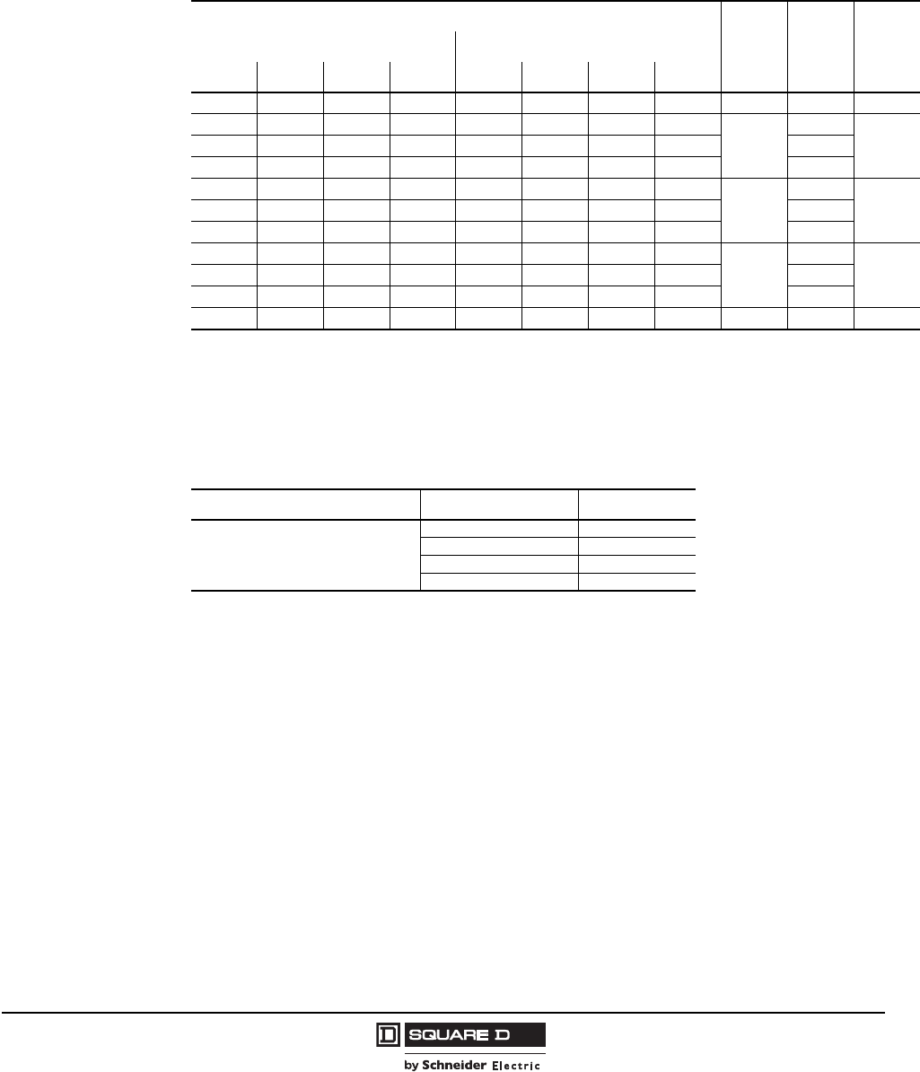
Model 6 Motor Control Centers
Combination Starter Units Application and General Information
43
07/2009
© 1997–2009 Schneider Electric
All Rights Reserved
Full Voltage 2-Speed 2-Winding Starters (Separate Winding) with Circuit Breakers
Two-speed combination starters will mount in standard 20 in. wide by 15 in. or 20 in. deep sections,
except where noted. All starters with MCP frames through 250 A use PowerPact electronic motor
circuit protectors. All starters with MCP frames above 250 A use L-frame Mag-Gard motor circuit
protectors. All units are UL Listed.
Motor Control Center units are available with short circuit ratings up to 100,000 A.
Full Voltage 2-Speed Reversing Starters with Circuit Breakers
This table lists the option to provide reversing contactors and control to a standard 2-speed starter.
The reversing contactors will be the same NEMA size as the 2-speed starter contactor. The control
circuit/control circuit transformer should be sized for the additional contactor load.
Starter Horsepower
NEMA
Size
MCP
Frame
(Amps)
Space
(Inches)
Constant Horsepower Constant Or Variable Torque
208 V 240 V 480 V 600 V 208 V 240 V 480 V 600 V
5 5 7.5 7.5 5 7.5 10 10 1 30 21
—— 10 5——— 15
2
30
247.510202010102525 50
————— 15—— 100
10 — 25 30 — — — 30
3
50
3020 25 40 40 20 25 50 50 100
— — — — 25 30 — — 150
— — 50 60 — — — 60
4
100
3330 40 75 75 40 40 75 100 150
— — — — — 50 100 — 250
60 75 150 150 75 100 200 200 5 400 72 (25 W)
Add Reversing to 2-Speed Starter
Application 2-Speed Starter Size Space (Inches)
Reversing in both speeds
Reversing in low seed only
Reversing in high speed only
112
212
318
4 1
125 in. wide section required when a circuit breaker disconnect is used.
24
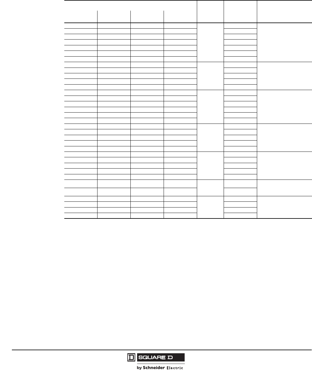
© 1997–2009 Schneider Electric
All Rights Reserved
Model 6 Motor Control Centers
Application and General Information Combination Starter Units
44 07/2009
Wye-Delta Closed Transition Starters with Circuit Breakers (Non-UL Listed)
Wye-Delta Closed Transition combination starters will mount in standard 20 in. wide by 15 in. or 20 in.
deep sections, except where noted. All Wye-Delta starter units with circuit breaker disconnects use
thermal magnetic (TM) circuit breakers.
Motor Control Center units are available with short circuit ratings up to 100,000 A.
Starter Horsepower1
1Wye-Delta starter motor information sheet is required with each Wye-Delta starter.
NEMA
Size
TM
Trip/Frame
(Amps) Space (Inches)2
2Space requirements listed are for resistor banks that meet standard Wye-Delta starting characteristics. Additional space may be
required for other Wye-Delta applications. Contact the MCC TAG for layout information.
208 V 240 V 480 V 600 V
1.5255
1
15/150
60
2 3 7.5 7.5 20/150
3 5 10 10 30/150
5 — 15 15 40/150
— 7.5 — — 50/150
7.5 10 — — 60/150
10 — — — 70/150
——— 20
2
40/150
66
— — 20 30 60/150
— — 25 — 70/150
15 15 30 40 90/150
20 25 40 — 100/150
— — 50 50
3
100/150
72 (30 W)
25 — — — 110/150
30 75 75 125/150
30 40 — — 150/150
40 — — — 175/250
— 50 — — 200/250
— — — 100
4
150/150
Two full sections required
2 @ (20 W x 20D)
— — 100 — 175/250
50 — — 150 225/250
— 75 150 — 250/250
60 — — — 300/400
— — — 250
5
300/400
Two full sections required
1 @ (20 W x 20 D)
1 @ (30 W x 20 D)
75 100 250 300 350/400
— 125 — — 400/400
125 150 300 —
150 — — —
— — — 350 6Three full sections required
2 @ (20 W x 20 D)
1 @ (30 W x 20 D)
— — 350 400
— 200 400 500
6
Three full sections required
1 @ (20 W x 20 D)
1 @ (25 W x 20 D)
1 @ (30 W x 20 D)
200 250 500 600
250 300 — 700
300 350 600 —
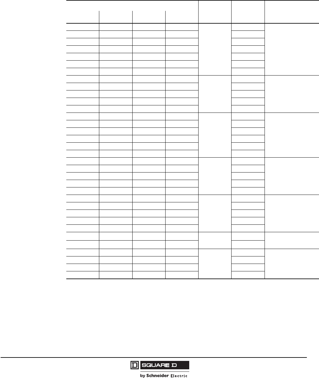
Model 6 Motor Control Centers
Combination Starter Units Application and General Information
45
07/2009
© 1997–2009 Schneider Electric
All Rights Reserved
Wye-Delta Open Transition Starters with Circuit Breakers (Non-UL Listed)
Wye-Delta Open Transition combination starters will mount in standard 20 in. wide by 15 in. or 20 in.
deep sections, except where noted. All Wye-Delta starter units with circuit breaker disconnects use
PowerPact thermal magnetic (TM) circuit breakers.
Motor Control Center units are available with short circuit ratings up to 100,000 A.
Starter Horsepower1
1Wye-Delta starter motor information sheet is required with each Wye-Delta starter.
NEMA Size TM
Trip/Frame
(Amps) Space (Inches)2
2Space requirements listed are for resistor banks that meet standard Wye-Delta starting characteristics. Additional space may be
required for other Wye-Delta applications. Contact the MCC TAG for layout information.
208 V 240 V 480 V 600 V
1.5 2 5 5
1
15/150
24
2 3 7.5 7.5 20/150
3 5 10 10 30/150
5 — 15 15 40/150
—7.5—— 50/150
7.5 10 — — 60/150
10 — — — 70/150
——— 20
2
40/150
30
— — 20 30 60/150
— — 25 — 70/150
15 15 30 40 90/150
20 25 40 — 100/150
— — 50 50
3
100/150
42
25 — — — 110/150
— 30 75 75 125/150
30 40 — — 150/150
40 — — — 175/250
— 50 — — 200/250
———100
4
150/150
72 (20 W)
— — 100 — 175/250
50 — — 150 225/250
— 75 150 — 250/250
60 — — — 300/400
———250
5
300/400
72 (30 W)
75 100 250 300 350/400
— 125 — — 400/400
125 150 300 —
150 — — —
———3506Two full sections required
1 @ (20 W x 20 D)
1 @ (30 W x 20 D)
— — 350 400
200 400 500
6Two full sections required
1 @ (25 W x 20 D)
1 @ (30 W x 20 D)
200 250 500 600
250 300 — 700
300 350 600 —
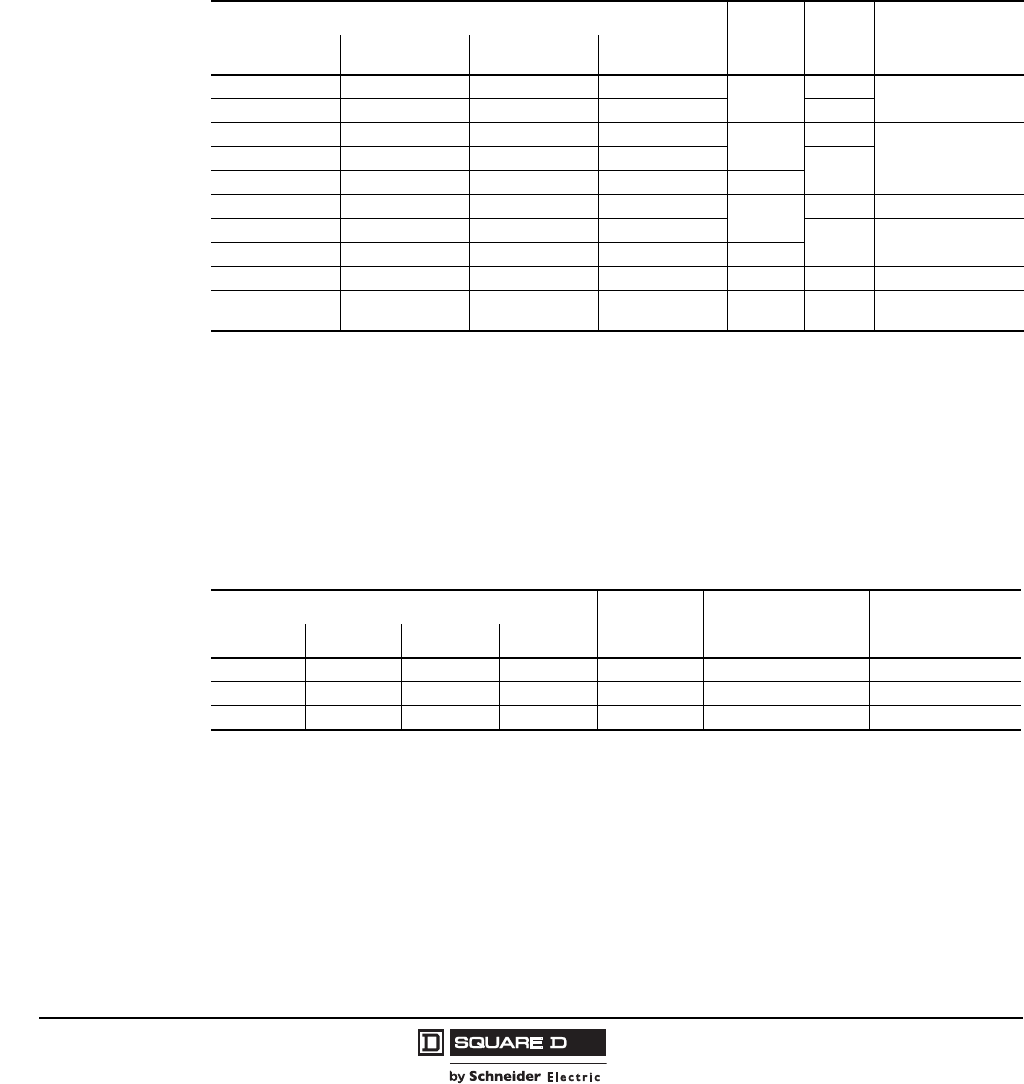
© 1997–2009 Schneider Electric
All Rights Reserved
Model 6 Motor Control Centers
Application and General Information Combination Starter Units
46 07/2009
Full Voltage Non-Reversing (FVNR) Starters with Fusible Switch Disconnects
FVNR combination starters will mount in 20 in. wide by 15 in. or 20 in. deep sections, except where
noted. All FVNR starter units with fusible switch disconnects are provided with Class H fuse clips.
Class R fuse clips can be provided at no additional charge. Fusible disconnect combination starters
Sizes 5 and 6 use molded case automatic circuit interrupters in series with fuse clips.
NOTE: Do not use renewable link fuses in fused switches.
All Compac 6, NEMA-rated, six-inch units use Class J fuses (rated for 100,000 AIR at 600 V).
Compac 6 units mount in 20 in. wide by 15 in. or 20 in. deep sections. Up to twelve Compac 6 units
can be installed in a Model 6 vertical section.
Motor Control Center unit short circuit current ratings to 100,000 A are available.
Full Voltage Non-Reversing Vacuum Starters with Fusible Switch Disconnects
FVNR vacuum combination starters will mount in 20 in. wide by 15 in. or 20 in. deep sections, except
where noted. All FVNR vacuum starters with fusible disconnects are provided with Class J fuse clips.
Fusible disconnect combination starters Sizes 5 and 6 use molded case automatic circuit interrupters
in series with fuse clips.
Motor Control Center unit short circuit current ratings to 100,000 A are available.
Starter Type and Horsepower NEMA
Size
Fusible
Switch
(Amps) Space (Inches)
208 V 240 V 480 V 600 V
551010
130 61
1Compac 6 starters.
7.52
25 hp maximum with solid state overload relays.
7.5 — — 60
551010
130
127.527.5 — — 60
10 15 25 25 2
20 25 50 50 3100 18
25 30 — — 200 30
40 50 100 100 4
75 100 200 200 5 400 72
150 200 400 400 6 600 72
(30 W x 20 D)
Starter Horsepower NEMA Size Fusible Switch
(Amps) Space (Inches)
208 V 240 V 480 V 600 V
40 50 100 100 4 200 30
75 100 200 200 5 400 72
150 200 400 400 6 600 72 (30 W x 20 D)
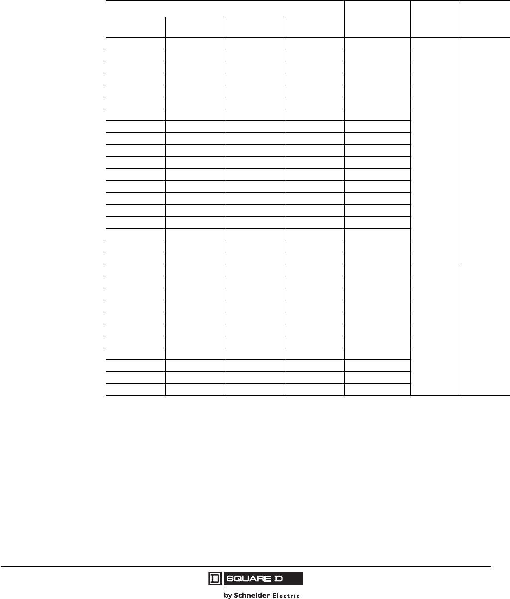
Model 6 Motor Control Centers
Combination Starter Units Application and General Information
47
07/2009
© 1997–2009 Schneider Electric
All Rights Reserved
Application-Rated Compac 6 Starters—Full Voltage Non-Reversing with
Fusible Disconnects
All Compac 6 application-rated, six-inch starters use TeSys D-Line contactors and Class J fuses (rated
for 100,000 AIR at 600 V). Compac 6 application-rated six-inch starters will mount in 20 in. wide by 15 in.
or 20 in. deep sections. Select application rated starters based on system voltage and motor full load
amps.
Starter Ampacity Overload Relay
Ampacity
Range 1
1Maximum overload relay ampacity range when used in Compac 6 starters.
Fusible
Switch
(Amps)
Space
(Inches)
208 V 240 V 480 V 600 V
11110.63 to 1.0
30
6
1.6 1.6 1.6 1.6 1.0 to 1.6
2.5 2.5 2.5 2.5 1.6 to 2.5
44442.5 to 4.0
5.5 5.5 5.5 5.5 4.0 to 5.5
7776.15.5 to 7.0
— — 7.6 — 7.0 to 7.6
9 9 — — 7.0 to 9.0
— 9.6 — — 9.0 to 9.6
11 — — — 9.0 to 11
— — — 7 6.1 to 7.0
— — — 9 7.0 to 9.0
— — 9 — 7.6 to 9.0
— — — 11 9.0 to 11
— — 12 — 9.0 to 12
— 12 — — 9.6 to 12
12 — — — 11 to 12
— — 14 — 12 to 14
17 17 — — 12 to 17.5
22 22 — — 17.5 to 22
60
— — — 12 11 to 12
— — — 17 12 to 17
— — 17 — 14 to 17
— — 23 23 17 to 23
23 23 — — 22 to 23
— — — 27 23 to 27
30 30 30 23 to 30
— — 34 — 30 to 34
37 37 — — 30 to 37
42 42 — — 37 to 42
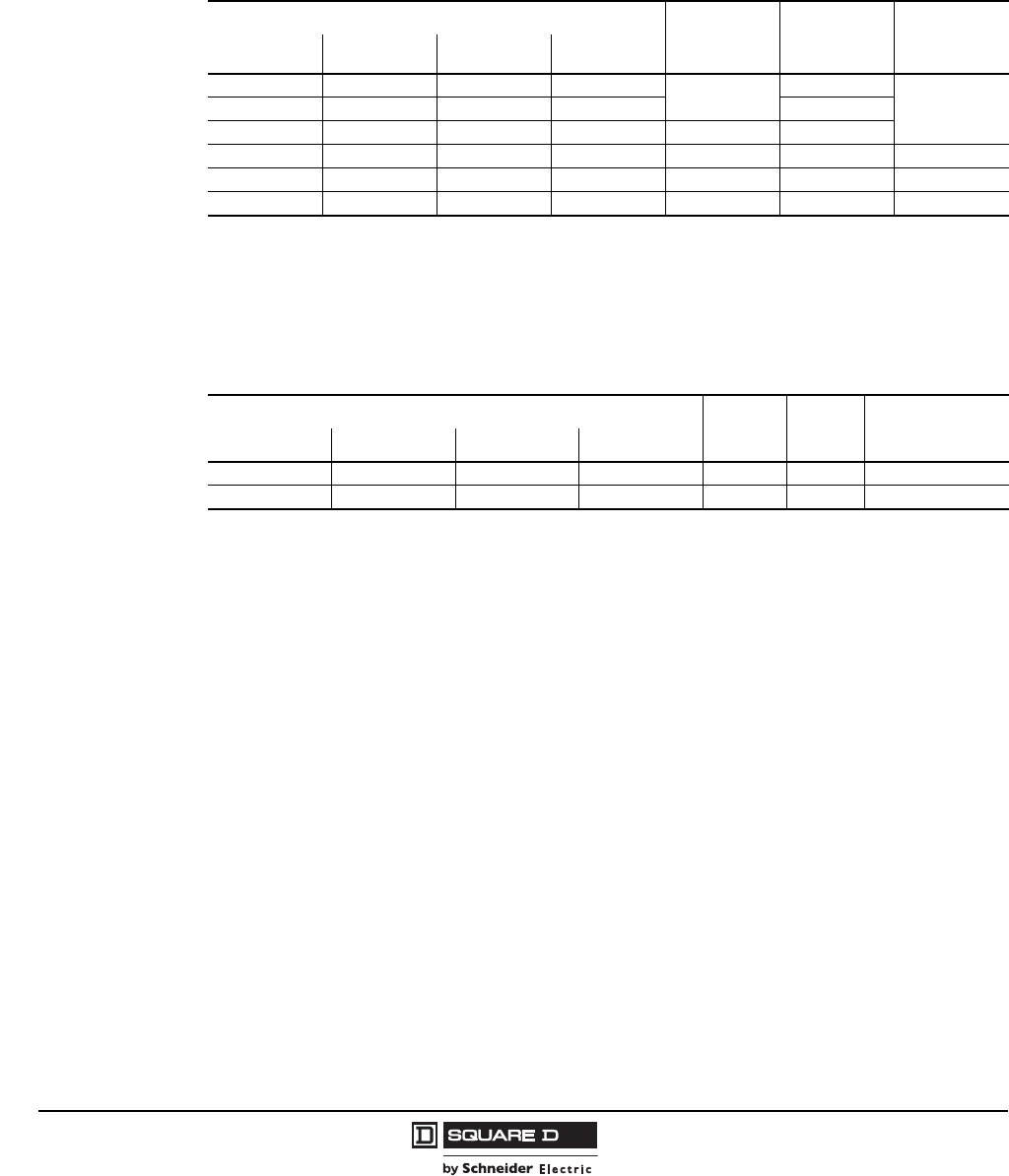
© 1997–2009 Schneider Electric
All Rights Reserved
Model 6 Motor Control Centers
Application and General Information Combination Starter Units
48 07/2009
Full Voltage Reversing (FVR) Starters with Fusible Switch Disconnects
FVR combination starters will mount in 20 in. wide by 15 in. or 20 in. deep sections, except where
noted. All FVR starter units with fusible switch disconnects are provided with Class H fuse clips as
standard. Class R fuse clips are available. Size 5 fusible disconnect combination starters use a molded
case automatic circuit interrupter in series with fuse clips. All units are UL Listed.
Motor Control Center units are available with short circuit ratings up to 100,000 A.
Full Voltage Reversing Vacuum Starters with Fusible Switch Disconnects
Vacuum combination starters will mount in 20 in. wide by 15 in. or 20 in. deep sections, except where
noted. All vacuum starter units with fusible disconnects are provided with Class J fuse clips. These
starters use molded case automatic circuit interrupters in series with fuse clips.
Motor Control Center units are available with short circuit ratings up to 100,000 A.
Starter Horsepower NEMA Size Fusible
Switch
(Amps)
Space
(Inches)
208 V 240 V 480 V 600 V
551010
130
187.5 7.5 — — 60
10 15 25 25 2 60
20 25 50 50 3 100 27
40 50 100 100 4 200 39
75 100 200 200 5 400 72 (25 W)
Starter Type and Horsepower NEMA
Size F/S
Amps Space (Inches)
208 V 240 V 480 V 600 V
40 50 100 100 4 200 39
75 100 200 200 5 400 72 (25 W)
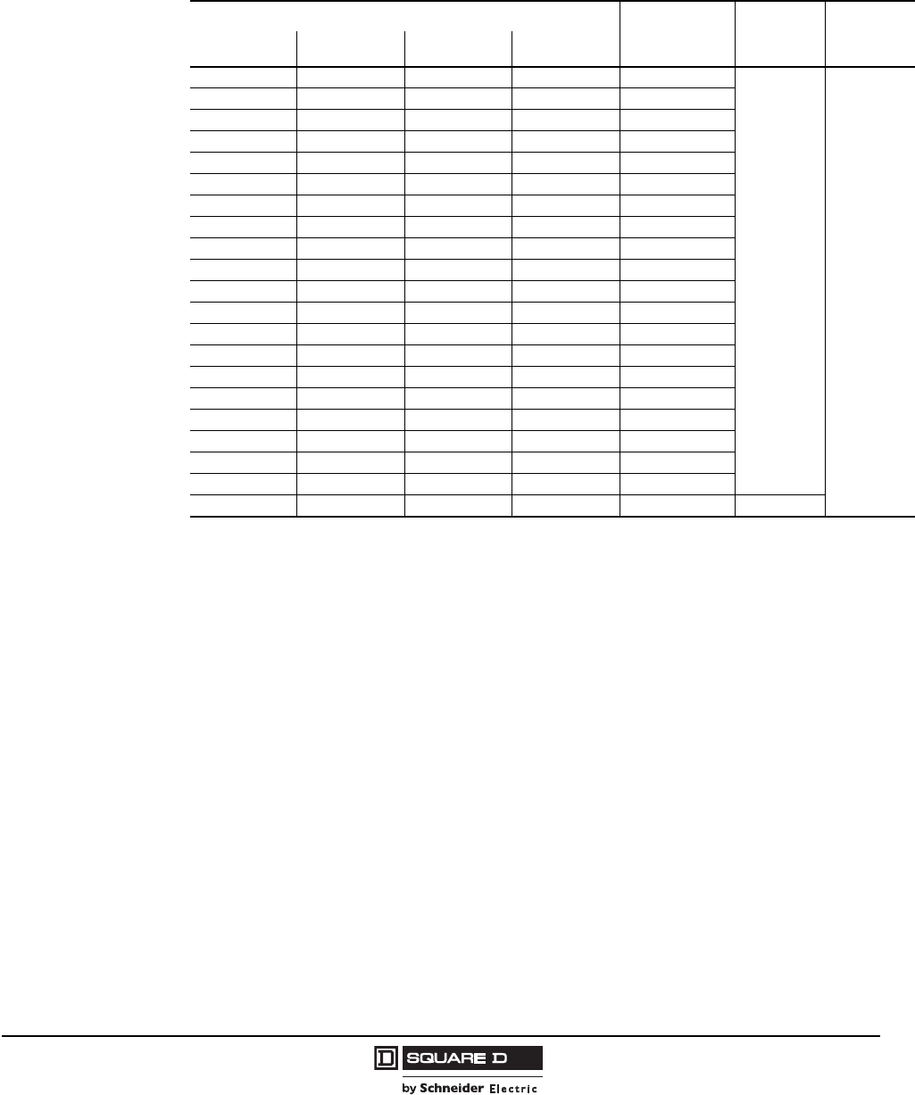
Model 6 Motor Control Centers
Combination Starter Units Application and General Information
49
07/2009
© 1997–2009 Schneider Electric
All Rights Reserved
Application-Rated Compac 6 Starters—Full Voltage Reversing with Fusible Disconnects
All Compac 6 application-rated, six-inch starters with fusible switch disconnects use TeSys D-Line
contactors and Class J fuses (rated for 100,000 AIR at 600 V). Compac 6 application-rated, six-inch
starters will mount in 20 in. wide by 15 in. or 20 in. deep sections. Select application rated units based
on system voltage and motor full load amps.
Starter Ampacity Overload Relay
Ampacity
Range 1
1Maximum overload relay ampacity range when used in Compac 6 starters.
Fusible
Switch
(Amps)
Space
(Inches)
208 V 240 V 480 V 600 V
1 1 1 1 0.63 to 1.0
30 6
1.6 1.6 1.6 1.6 1.0 to 1.6
2.5 2.5 2.5 2.5 1.6 to 2.5
44442.5 to 4.0
5.5 5.5 5.5 5.5 4.0 to 5.5
— — — 6.1 5.5 to 6.1
7 7 7 — 5.5 to 7.0
— — 7.6 — 7.0 to 7.6
9 9 — — 7.0 to 9.0
— 9.6 — — 9.0 to 9.6
11 — — — 9.0 to 11
— — — 7 6.1 to 7.0
— — — 9 7.0 to 9.0
— — 9 — 7.6 to 9.0
— — — 11 9.0 to 11
— — 12 — 9.0 to 12
— 12 — — 9.6 to 12
12 — — — 11 to 12
— — 14 — 12 to 14
17 17 — — 12 to 17.5
22 22 — — 17.5 to 22 60
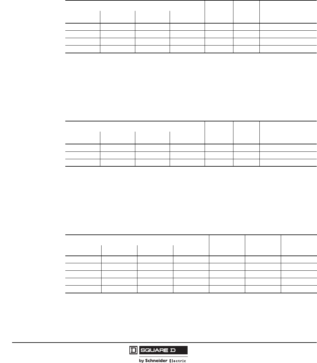
© 1997–2009 Schneider Electric
All Rights Reserved
Model 6 Motor Control Centers
Application and General Information Combination Starter Units
50 07/2009
Reduced Voltage Autotransformer (RVAT) Starters with Fusible Switch Disconnects
RVAT combination starters will mount in 20 in. wide by 15 in. or 20 in. deep sections, except where
noted. Sections with RVAT starters require single shipping splits. All RVAT starter units with fusible
disconnects are provided with Class H fuse clips as standard. Class R fuse clips are available. Fusible
disconnect combination starters Sizes 5 and 6 use molded case automatic circuit interrupters in series
with fuse clips.
Motor Control Center units are available with short circuit ratings up to 100,000 A.
Reduced Voltage Autotransformer Vacuum Starters with Fusible Switch Disconnects
Sections with RVAT starters require single shipping splits. Provided with Class J fuse clips. Fusible
disconnect combination starters Sizes 5 and 6 use molded case automatic circuit interrupters in series
with fuse clips. All units are UL Listed.
Motor Control Center units are available with short circuit ratings up to 100,000 A.
Full Voltage 2-Step Part-Winding (FVPW) Starters with Fusible Switch Disconnects
Part-winding starters use a fusible disconnect with separate fuse clips for each of the two motor
windings. Each switch has an external operating mechanism. Part-winding starters require six thermal
units. All units are UL Listed.
Motor Control Center units are available with short circuit ratings up to 100,000 A.
Starter Type and Horsepower NEMA Size Fusible
Switch
(Amps) Space (Inches)
208 V 240 V 480 V 600 V
20 25 50 50 3 100 54 (20 D)
40 50 100 100 4 200 72 (20 D)
75 100 200 200 5 400 72 (25 W x 20 D)
150 200 400 400 6 600 72 (50 W x 20 D)
Starter Type and Horsepower NEMA Size Fusible
Switch
(Amps) Space (Inches)
208 V 240 V 480 V 600 V
40 50 100 100 4 200 72 (20 D)
75 100 200 200 5 400 72 (25 W x 20 D)
150 200 400 400 6 600 72 (50 W x 20 D)
Starter Horsepower NEMA Size MCP Frame
(Amps) Space
(Inches)
208 V 240 V 480 V 600 V
55101513030
—— 25252 6030
— — 50 60 3 100 42
— — — 100 4 200 66
150 150 350 350 5 400 72 (25 W)
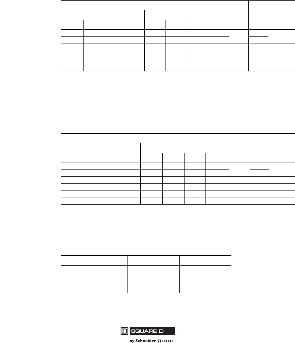
Model 6 Motor Control Centers
Combination Starter Units Application and General Information
51
07/2009
© 1997–2009 Schneider Electric
All Rights Reserved
Full Voltage 2-Speed, 1-Winding Starters (Consequent Pole) with Fusible Switch
Disconnects
Two-speed combination starters will mount in standard 20 in. wide by 15 in. or 20 in. deep sections,
except where noted. Motor windings are Wye connected as standard. Available as Open Delta
connected. All units are UL Listed.
Motor Control Center units are available with short circuit ratings up to 100,000 A.
Full Voltage 2-Speed, 2-Winding Starters (Separate Winding) with Fusible Switch
Disconnects
Two-speed combination starters will mount in standard 20 in. wide by 15 in. or 20 in. deep sections,
except where noted. All units are UL Listed.
Motor Control Center units are available with short circuit ratings up to 100,000 A.
Full Voltage 2-Speed Reversing Starters with Fusible Switch Disconnects
The table below lists the option to provide reversing contactors and control to a standard 2-speed
starter. The reversing contactors will be the same NEMA size as the 2-speed starter contactor. The
control circuit/control circuit transformer should be sized for the additional contactor load.
Starter Type and Horsepower
NEMA
Size
Fusible
Switch
(Amps)
Space
(Inches)
Constant Horsepower Constant or Variable Torque
208 V 240 V 480 V 600 V 208 V 240 V 480 V 600 V
5 5 7.5 7.5 5 5 10 10 130 21
————7.57.5—— 60
7.510202010 152525 2 60 24
20 25 40 40 25 30 50 50 3 100 51 1
1When using an ambient compensated, bimetallic overload relay, 60 in. of mounting space is required.
30 40 75 75 40 50 100 100 4 200 66
60 75 150 150 75 100 200 200 5 400 72 (25 W)
Starter Type and Horsepower
NEMA
Size
Fusible
Switch
(Amps)
Space
(Inches)
Constant Horsepower Constant or Variable Torque
208 V 240 V 480 V 600 V 208 V 240 V 480 V 600 V
5 5 7.5 7.5 5 5 10 10 130 21
— — — — 7.5 7.5 — — 60
7.5102020 10 15 25 25 2 60 24
20 25 40 40 25 30 50 50 3 100 30
30 40 75 75 40 50 100 100 4 200 39
60 75 150 150 75 100 200 200 5 400 72 (25 W)
Add Reversing to 2-Speed Starter
Application 2-Speed Starter Size Space (Inches)
Reversing in both speeds
Reversing in low speed only
Reversing in high speed only
112
212
318
424
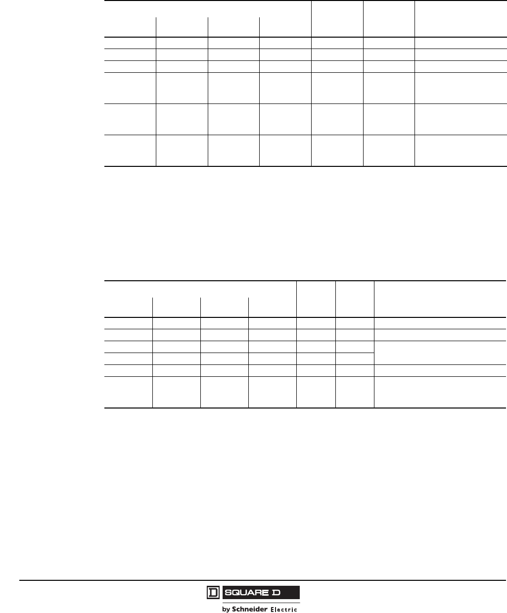
© 1997–2009 Schneider Electric
All Rights Reserved
Model 6 Motor Control Centers
Application and General Information Combination Starter Units
52 07/2009
Wye-Delta Closed Transition Starters with Fusible Switch Disconnects (Non-UL Listed)
Wye-Delta Closed Transition combination starters will mount in standard 20 in. wide by 15 in. or 20 in.
deep sections, except where noted.
Motor Control Center units are available with short circuit ratings up to 100,000 A.
Wye-Delta Open Transition Starters with Fusible Switch Disconnects (Non-UL Listed)
Wye-Delta Open Transition combination starters will mount in standard 20 in. wide by 15 in. or 20 in.
deep sections, except where noted.
Motor Control Center units are available with short circuit ratings up to 100,000 A.
Starter Horsepower1
1Wye-Delta starter motor information sheet is required with each Wye-Delta starter.
NEMA
Size
Fusible
Switch
(Amps) Space (Inches)2
2Space requirements listed are for resistor banks that meet standard Wye-Delta starting characteristics. Additional space may be
required for other Wye-Delta applications. Contact the MCC TAG for layout information.
208 V 240 V 480 V 600 V
10 10 15 15 1 60 60
20 25 40 40 2 100 66
40 50 75 75 3 200 72 (30 W)
60 75 150 150 4 400
Two full sections required
1 @ (25 W x 20 D)
1 @ (30 W x 20 D)
150 150 300 300 5 600
Three full sections required
2 @ (25 W x 20 D)
1 @ (30 W x 20 D)
300 350 600 700 6 800
Three full sections required
2 @ (25 W x 20 D)
1 @ (35 W x 20 D)
Starter Horsepower1
1Wye-Delta starter motor information sheet is required with each Wye-Delta starter.
NEMA
Size
Fusible
Switch
(Amps) Space (Inches)2
2Space requirements listed are for resistor banks that meet standard Wye-Delta starting characteristics. Additional space may be
required for other Wye-Delta applications. Contact the MCC TAG for layout information.
208 V 240 V 480 V 600 V
10 10 15 15 1 60 30
20 25 40 40 2 100 42
40 50 75 75 3 200 72 (20 W)
60 75 150 150 4 400
150 150 300 300 5 600 72 (30 W)
300 350 600 700 6 800
Two full sections required:
1 @ (25 W x 20 D)
1 @ (30 W x 20 D)
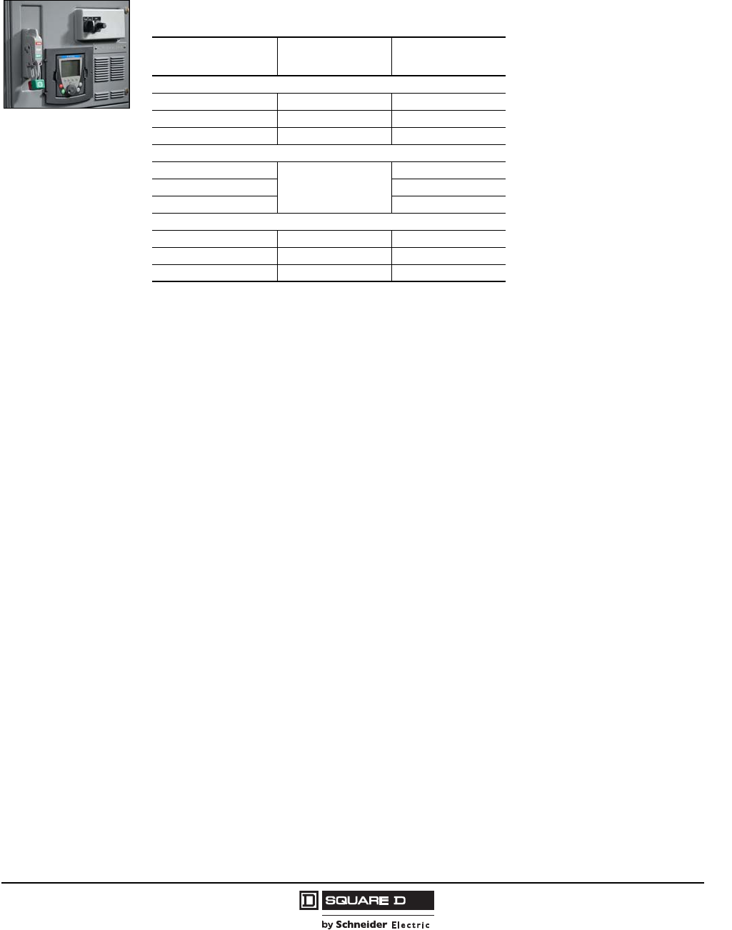
Model 6 Motor Control Centers
AC Drive Units Application and General Information
53
07/2009
© 1997–2009 Schneider Electric
All Rights Reserved
Altivar® 61 and 71 AC Drives
Altivar 61 and 71 AC drives in MCCs offer economical, general purpose drives in a high density,
space-saving package. Units are available in NEMA/EEMAC Type 1, Type 1 Gasketed (Type 1A),
Type 3R Outdoor-Rated, and Type 12 MCC enclosures in the following ranges.
MCC Package Features
As standard, basic MCC Altivar 61 and 71 AC drive units include:
Altivar 61 or 71 AC Drive
Operator keypad display mounted on the front of the unit
Disconnect circuit breaker or fusible switch
3% line reactors above 50 hp Variable Torque (VT) or 40 hp Constant Torque (CT) @ 480 V,
above 25 hp VT or 20 hp CT @ 240 V, and above 20 hp VT/CT @ 208 V
Cooling fans
UL 845 listed for 100,000 AIC short circuit withstand at 480 V
Control station plate with space for five 22 mm operators or three 30 mm (9001 Type K) operators
MCC Altivar AC Drive units are plug-on style saddles (up to 50 hp VT) or full sections which can be
factory/field-installed in Model 6 MCCs or field-installed in Model 5 MCCs. There are no preferred or
restricted locations for mounting any Altivar AC Drive in Square D® brand MCC sections.
Circuit breakers used on the MCC Altivar AC Drive basic units are thermal-magnetic type. As an option,
PowerPact electronic motor circuit protectors can be substituted for the thermal-magnetic circuit breakers
up to 250 A. Fusible switches used on the MCC Altivar AC Drive units are bladed switches (molded case
switches above 100 A) with Class J fuse clips installed between the drive and the switch.
NOTE: Fusible disconnect drives do not include the power fuses installed at the factory.
Factory Options:
Bypass contactors available as either integrated in the drive or barriered from the drive unit (<250 hp)
Line or load contactor: <125 hp Variable Torque (VT) or 100 hp Constant Torque (CT)
Line reactors (3 or 5%)
NOTE: 3% line reactors are standard above 50 hp VT or 40 hp CT @ 480V, above 25 hp VT or
20 hp CT @ 240V, and above 20 hp CT/VT @ 208V
Motor protecting filters or output reactors
Pilot devices 22 mm or 30 mm
Unit extensions to provide additional panel space
Wired and unwired control relays
Motor Ratings Altivar 61 Variable
Torque Rated Altivar 71 Constant
Torque Rated
NEMA/EEMAC Type 1 and Type 1A (Gasketed) Enclosures
NOTE: Determine the type of application the
drive will be applied to: variable torque or
constant torque. Variable torque ratings are to
be used on centrifugal pumps and fan loads
which are considered light duty with maximum
110% current overload. The Altivar 61 AC
Drive is used for variable torque applications
and has many specific features dedicated for
pump and fan applications. Constant torque
ratings are to be used on all other types of
loads to provide normal duty and maximum
overload capacity of 170%. The Altivar 71 AC
Drive is used for constant torque application
and has increased rating and performance for
demanding loads.
460 Vac, 3-phase, 60 Hz 1–500 hp 1–450 hp
230 Vac, 3-phase, 60 Hz 1–50 hp 1–40 hp
200 Vac, 3-phase, 60 Hz 1–40 hp 1–40 hp
NEMA/EEMAC Type 3R Enclosures
460 Vac, 3-phase, 60 Hz
Use constant torque
1–40 hp
230 Vac, 3-phase, 60 Hz 1–20 hp
200 Vac, 3-phase, 60 Hz 1–20 hp
NEMA/EEMAC Type 12 Enclosures
460 Vac, 3-phase, 60 Hz 1–100 hp 1–75 hp
230 Vac, 3-phase, 60 Hz 1–50 hp 1–40 hp
200 Vac, 3-phase, 60 Hz 1–40 hp 1–40 hp

© 1997–2009 Schneider Electric
All Rights Reserved
Model 6 Motor Control Centers
Application and General Information AC Drive Units
54 07/2009
Altivar AC Drive Features
Performance
Torque: sensorless flux vector control (ATV71 can include sensor for tighter control)
Frequency range: 0.1 to 500Hz
Speed range: 1 to 100 open loop
Overtorque = 170% of nominal torque for 60 seconds (220% for 2 seconds) for ATV71 Constant
Torque rated drives and 110% of nominal torque for 60 seconds for ATV61 Variable Torque rated
drives
Auto-tuning
Dynamic speed regulation
Protective Features
Motor and inverter thermal protection
Short-circuit between phases and between phase and ground
Main supply and motor phase loss
Mains undervoltage and overvoltage
Degraded operation on voltage dip
Auto restart
Catch on the fly with speed search
Monitoring and Indication
Door-mounted, LCD type operator keypad displays setup parameters and the last fault occurrence
with plain text display. Factory preset for the most common adjustments and the control schemes
ordered with the unit. Security to prevent accidental adjustments is provided by a password. Programs
are saved in the keypad, allowing storage and retrieval of four different programs between multiple
drive units.
Other features include:
Real time display of:
— Drive state (running, ready, accelerating, decelerating, etc.)
— Reference frequency (in Hz)
— Output frequency (in Hz)
— Motor speed (in RPM)
— Motor current (in amps)
— Mains voltage (in volts)
— Motor voltage (in volts)
— Output power (in watts)
— Motor thermal state (in %)
— Drive thermal state (in %)
— Energy consumed (Wh)
— Last fault
— Run time (hrs)
One normally open contact indication of drive running (closes on run)
One normally closed contact indication of drive fault (opens on fault)
Standard Analog output for motor current, motor frequency, ramp output, motor power and motor
torque.
Standard Modbus or CANopen serial communication port
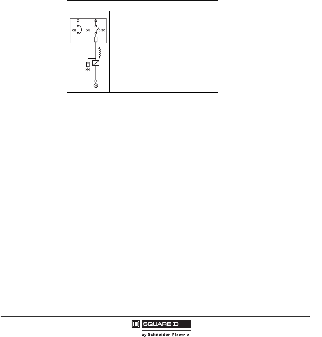
Model 6 Motor Control Centers
AC Drive Units Application and General Information
55
07/2009
© 1997–2009 Schneider Electric
All Rights Reserved
Options
Commissioning software for personal computers
I/O extension cards
120 Vac interface card
Controller Inside option card
Modbus® plus communication card
Uni-Telway/Modbus communication card
Ethernet communication card
DeviceNet™ communication card
PROFIBUS communication card
“Basic” Drive Power Circuit
• Consist of disconnect switch and drive
pre-programmed for selected options if applicable.
• Unit is UL 845 Listed for 100,000 A short circuit
current.
• Includes operator LCD keypad/display mounted on
front of the unit.
• Pilot Devices are optional and are available as
22 mm XB4 or XB5 type pilot devices, or 30 mm
9001 Type K pilot devices.
• Control power transformer (480 V/120 V), if
necessary, for enclosure ventilation fans is
included.
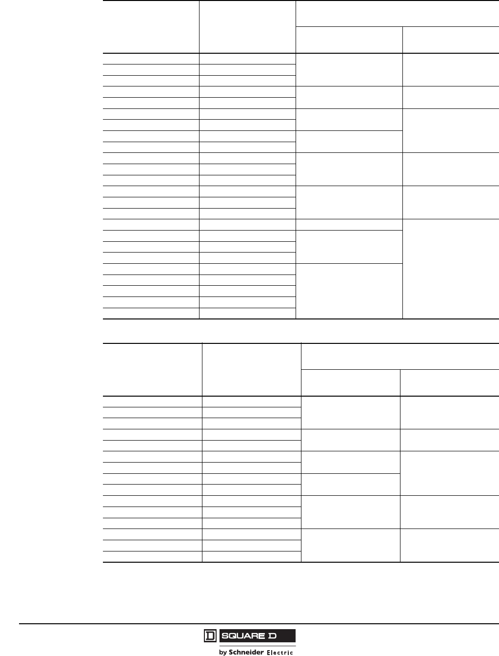
© 1997–2009 Schneider Electric
All Rights Reserved
Model 6 Motor Control Centers
Application and General Information AC Drive Units
56 07/2009
Variable Torque Rated 480 V Drives with Circuit Breaker Disconnects
Motor Rated Horsepower
@ 460 V Maximum Continuous
Output Amps
Space
(Inches)
NEMA/EEMAC Type 1 and
1A (Gasketed) NEMA/EEMAC Type 12
12.1
12 24
23.4
34.8
57.6 15 30
7.5 11
10 14 24
36
15 21
20 27 27
25 34
30 40
45 45
40 52
50 65
60 77
72 (20 W) 72 (20 W)
75 96
100 124
125 156 72 (25 W x 20 D)
Not available in
NEMA/EEMAC Type 12
150 180
72 (30 W x 20 D)
200 240
250 302
300 361
72 (35 W x 20 D)
350 414
400 477
450 515
500 590
Variable Torque Rated 480 V Drives with Fusible Switch Disconnects
Motor Rated Horsepower
@ 460 V Maximum Continuous
Output Amps
Space
(Inches)
NEMA/EEMAC Type 1
and 1A (Gasketed) NEMA/EEMAC Type 12
12.1
12 24
23.4
34.8
57.6
15 30
7.5 11
10 14 24
36
15 21
20 27 27
25 34
30 40
45 48
40 52
50 65
60 77
72 (20 W) 72 (20 W)
75 96
100 124
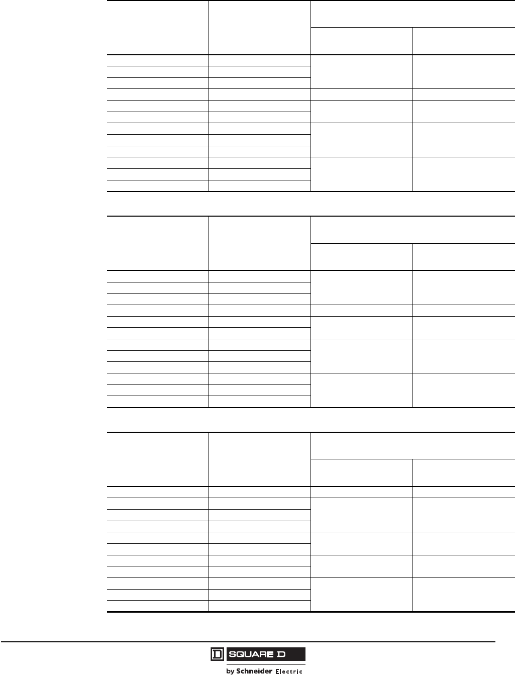
Model 6 Motor Control Centers
AC Drive Units Application and General Information
57
07/2009
© 1997–2009 Schneider Electric
All Rights Reserved
Variable Torque Rated 240 V Drives with Circuit Breaker Disconnects
Motor Rated Horsepower
@ 230 V Maximum Continuous
Output Amps
Space
(Inches)
NEMA/EEMAC Type 1
and 1A (Gasketed) NEMA/EEMAC Type 12
14.2
12 24
26.8
311
5 15.2 15 30
7.5 22 24 36
10 28
15 42
45 45
20 54
25 68
30 80
72 (20 W) 72 (20 W)
40 104
50 130
Variable Torque Rated 240 V Drives with Fusible Switch Disconnects
Motor Rated Horsepower
@ 230 V Maximum Continuous
Output Amps
Space
(Inches)
NEMA/EEMAC Type 1
and 1A (Gasketed) NEMA/EEMAC Type 12
14.2
12 24
26.8
311
5 15.2 15 30
7.5 22 24 36
10 28
15 42
45 48
20 54
25 68
30 80
72 (20 W) 72 (20 W)
40 104
50 130
Variable Torque Rated 208 V Drives with Circuit Breaker Disconnects
Motor Rated Horsepower
@ 200 V Maximum Continuous
Output Amps
Space
(Inches)
NEMA/EEMAC Type 1
and 1A (Gasketed) NEMA/EEMAC Type 12
1 4.6 12 24
27.5
15 30
311
5 16.7
7.5 24 24 36
10 31
15 46 45 45
20 59
25 75
72 (20 W) 72 (20 W)
30 88
40 114
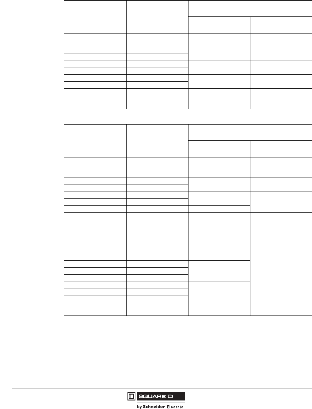
© 1997–2009 Schneider Electric
All Rights Reserved
Model 6 Motor Control Centers
Application and General Information AC Drive Units
58 07/2009
Variable Torque Rated 208 V Drives with Fusible Switch Disconnects
Motor Rated Horsepower
@ 200 V Maximum Continuous
Output Amps
Space
(Inches)
NEMA/EEMAC Type 1
and 1A (Gasketed) NEMA/EEMAC Type 12
1 4.6 12 24
27.5
15 30
311
516.7
7.5 24 24 36
10 31
15 46 45 48
20 59
25 75
72 (20 W) 72 (20 W)
30 88
40 114
Constant Torque Rated 480 V Drives with Circuit Breaker Disconnects
Motor Rated Horsepower
@ 460 V Maximum Continuous
Output Amps
Space
(Inches)
NEMA/EEMAC Type 1
and 1A (Gasketed) NEMA/EEMAC Type 12
12.1
12 24
23.4
34.8
57.6
15 30
7.5 11
10 14 24 36
15 21
20 27 27
25 34
45 45
30 40
40 52
50 65
72 (20 W) 72 (20 W)
60 77
75 96
100 124 72 (25 W x 20 D)
Not available in NEMA/EEMAC
Type 1
125 156
72 (30 W x 20 D)
150 180
200 240
250 302
72 (35 W x 20 D)
300 361
350 414
400 477
450 515
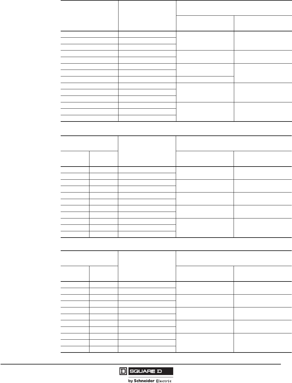
Model 6 Motor Control Centers
AC Drive Units Application and General Information
59
07/2009
© 1997–2009 Schneider Electric
All Rights Reserved
Constant Torque Rated 480 V Drives with Fusible Switch Disconnects
Motor Rated Horsepower
@ 460 V Maximum Continuous
Output Amps
Space
(Inches)
NEMA/EEMAC Type 1
and 1A (Gasketed) NEMA/EEMAC Type 12
12.1
12 24
23.4
34.8
57.6
15 30
7.5 11
10 14 24 36
15 21
20 27 27
25 34
45 48
30 40
40 52
50 65
72 (20 W) 72 (20 W)
60 77
75 96
Constant Torque Rated 208/240 V Drives with Circuit Breaker Disconnects
Motor Rated Horsepower Maximum Continuous
Output Amps
Space
(Inches)
@ 200 V @230 V NEMA/EEMAC Type 1
and 1A (Gasketed) NEMA/EEMAC Type 12
— 1 4.6/4.2 12 24
— 2 7.5/6.8
3 3 11/9.6 15 30
5 5 16.7/15.2
7.5 7.5 24/22 24 36
10 10 31/28
15 15 46/42 45 45
20 20 59/54
25 25 75/68
72 (20 W) 72 (20 W)
30 30 88/80
40 40 114/104
Constant Torque Rated 208/240 V Drives with Fusible Switch Disconnects
Motor Rated Horsepower Maximum Continuous
Output Amps
Space
(Inches)
@ 200 V @230 V NEMA/EEMAC Type 1
and 1A (Gasketed) NEMA/EEMAC Type 12
— 1 4.6/4.2 12 24
— 2 7.5/6.8
3 3 11/9.6 15 30
5 5 16.7/15.2
7.5 7.5 24/22 24 36
10 10 31/28
15 15 46/42 45 48
20 20 59/54
25 25 75/68
72 (20 W) 72 (20 W)
30 30 88/80
40 40 114/104
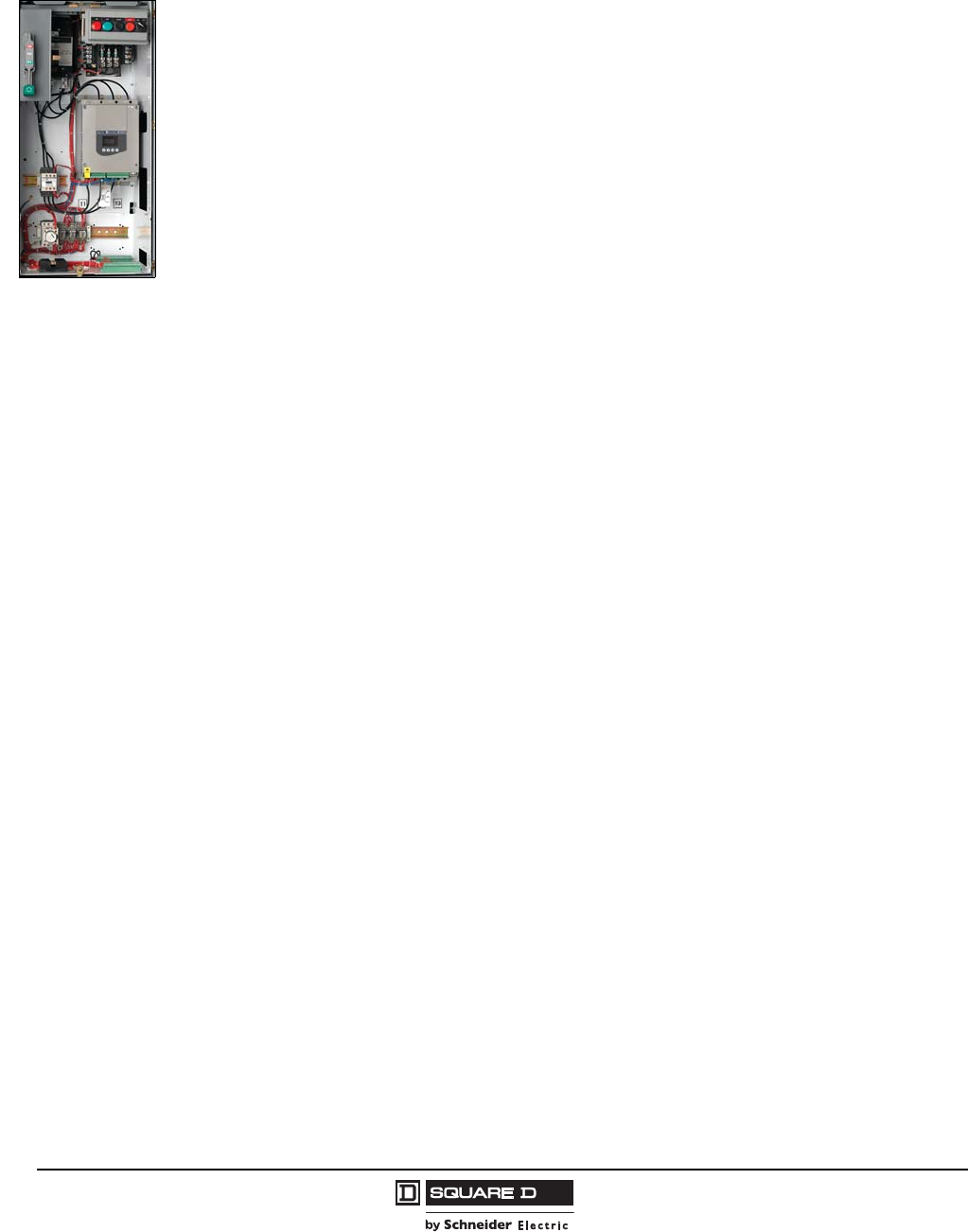
© 1997–2009 Schneider Electric
All Rights Reserved
Model 6 Motor Control Centers
Application and General Information Soft Start Units
60 07/2009
Combination Altistart® 48 Soft Start Units
Altistart 48 (ATS48) MCC soft start units are available from 11–604 A in NEMA/EEMAC Type 1, Type 1A
(Gasketed), Type 12, and Type 3R MCC enclosures. Units are available for three phase, 60 Hz, 208 V,
240 V, 480 V, or 600 V, 3- or 4-wire power systems. The Altistart 48 soft start in MCCs can provide soft
starting (reduced voltage) and deceleration along with machine and motor protection of standard NEMA
B-Design three-phase squirrel cage asynchronous motors in the following power ranges:
3–200 hp @ 208 V
5–250 hp @ 230 V
10–500 hp @ 460 V
15–600 hp @ 575 V
The MCC soft start units integrate the latest technology Altistart 48 soft start from Schneider Electric
into a combination starter package for MCCs. MCC soft start units include a shorting contactor, shunt
trip input power disconnect, door-mounted keypad, and 120 Vac control circuitry. TeSys® D- and
F-Line contactors are standard (NEMA-type contactors are optional). All packages and options are
UL 845 Listed for a minimum 65,000 Amp short circuit rating up to 600V (ratings of 100,000 A @ 600 V
are available with fuses).
All soft starter units with circuit breaker disconnects through 250 A and 800–1200 A frames use
PowerPact® thermal magnetic (TM) circuit breakers. All soft starter units with 400–600 A frame
disconnects use L-frame thermal-magnetic (TM) circuit breakers. The fusible switch disconnects used
on MCC soft start units are automatic molded case switches. Provisions for Class J or L fuses are
provided. Fuses are not installed at the factory. All units are UL Listed.
Selection
The ATS48 controller must be selected on the basis of 3 main criteria:
Main voltage supply: Three-phase AC voltage: 208, 240, 480, or 600 V
The power and the nominal current (motor FLA) indicated on the motor nameplate
The type of application and the operating cycle. The application types are:
— Standard duty
— Severe duty
NOTE: Standard or severe duty applications define the limiting values of the current and the duty
cycle ratings.
Standard Duty Applications
In standard duty applications, the ATS48 controller is designed to provide:
Starting at 400% nominal motor current (In) for 23 seconds or at 300% nominal motor current (In)
for 46 seconds from a cold state
Starting at 300% nominal motor current (In) for 23 seconds or at 400% nominal motor current (In)
for 12 seconds with a load factor of 50% and 10 starts per hour or an equivalent thermal cycling
The motor thermal protection conforms to Class 10 overload protection.
Severe Duty Applications
In severe duty applications, the ATS48 controller is designed to provide:
Starting at 400% nominal motor current (In) for 48 seconds or at 300% nominal motor current (In)
for 90 seconds from a cold state
Starting at 400% nominal motor current (In) for 25 seconds with a load factor of 50% and 5 starts
per hour or an equivalent thermal cycling
The motor thermal protection conforms to Class 20 overload protection.

Model 6 Motor Control Centers
Soft Start Units Application and General Information
61
07/2009
© 1997–2009 Schneider Electric
All Rights Reserved
Contact the MCC TAG for additional application information for those applications requiring:
2-speed or delta-wye motors
The ATS48 can operate with a 2-speed motor. A motor demagnetizing period must elapse before
changing from low speed to high speed in order to avoid antiphase between the line supply and the
motor, which would generate very high currents.
Motors other than NEMA Design B
High efficiency motors
Low slip motors
Power factor correction capacitors
Do not connect power factor correction capacitors to the terminals of a motor controlled by an
ATS48 soft start. The power factor capacitors must be controlled and connected to a line side
contactor sequenced by the ATS48 at end of starting.
Controller oversizing of more than 50%
Multi-motor applications
Motors may be connected in parallel provided that the power limit of the starter is not exceeded
(the sum of the motor currents must not exceed the nominal current of the starter selected,
depending on the type of application). Individual thermal protection and local disconnect is required
for each motor.
Non-standard trip characteristics
Modifications not listed in this catalog
Horsepower greater than those listed in this catalog
Long motor cable lengths
Very long motor cables cause voltage drops due to the resistance of the cable. If the voltage drop is
significant, it could affect the current consumption and the torque available. This criteria must be
taken into account when selecting the motor and the starter.
NOTE: Do not use the ATS48 controller upstream of loads other than motors (for example
transformers and resistance type loads).
See the Altistart 48 catalog #8636CT0201 and data bulletin #8600PD9201 for additional information.

© 1997–2009 Schneider Electric
All Rights Reserved
Model 6 Motor Control Centers
Application and General Information Soft Start Units
62 07/2009
Features
Shorting Contactor
A shorting contactor is supplied on all units. This allows the motor current to bypass the soft start's
thyristors once the soft start has ramped up to full voltage/full speed. The use of a shorting contactor
reduces temperature rise within the enclosure during steady state operation and requires less current
carrying duty on the thyristors.
Torque Control System (TCS)
The Altistart 48 uses TCS ramping to accelerate the motor to full voltage. Basing the acceleration ramp
on the motor torque rather than current or voltage, as used in traditional soft starts, provides a linear
speed ramp independent of the motor loading without tachometer feedback. The TCS ramp is also
used for improved control of deceleration and eliminates the need for a special controller to handle
water hammer problems.
Starting and Stopping
Four types of starting are available:
TCS soft start—adjustable from 1 to 60 seconds
TCS with “boost”—adjustable from 50 to 100% of mains voltage
Current limit—adjustable from 150 to 500% of controller rating
Voltage ramping
Three types of stopping are available:
Freewheel or coast to stop
TCS soft stop—adjustable from 1 to 60 seconds
InTele braking—adjustable from 50 to 100%
Protective Features
Solid state motor thermal overload protection—programmable from Class 10 through 30
Soft start thermal protection
Motor phase loss protection
Line supply failure
Overcurrent fault
Locked rotor fault
Line frequency outside limits +/-5% or +/-20%
Selectable protection, including:
— Phase reversal
— Stall and jam
— Thermal overload pre-alarm
— Current threshold alarm
— Underload fault
Transient suppression modules on all contactors

Model 6 Motor Control Centers
Soft Start Units Application and General Information
63
07/2009
© 1997–2009 Schneider Electric
All Rights Reserved
Monitoring and Indication
Door mounted keypad:
Displays setup parameters and fault codes.
Factory preset for most common adjustments.
Security to avoid accidental controller modifications is provided by dip switches on the back of the
keypad, which must be adjusted to provide access to 3 programming levels.
Real time indication via the digital keypad of:
Motor current
Load torque
Motor thermal state
Power factor
Fault status
Two logic outputs:
Motor thermal overload or indication of motor current present
Current threshold alarm
Motor underload alarm
One analog output for 4 to 20 or 0 to 20 mA indication of motor current, torque, thermal state, active
power, or power factor.
Two logic inputs, which are configurable for force to freewheel, thermal overload reset, or indication of
external fault.
Options:
Input isolation contactor
Full voltage bypass
NEMA hp-rated contactors substituted for Telemecanique D or F line contactors
Reversing
120 Vac control power transformer
120 Vac customer VA capacity added to control power transformer
Push-To-Test pilot lights
LED pilot lights
Auxiliary interlocks
Network Communications: Modbus®, DeviceNet™, PROFIBUS, and Ethernet
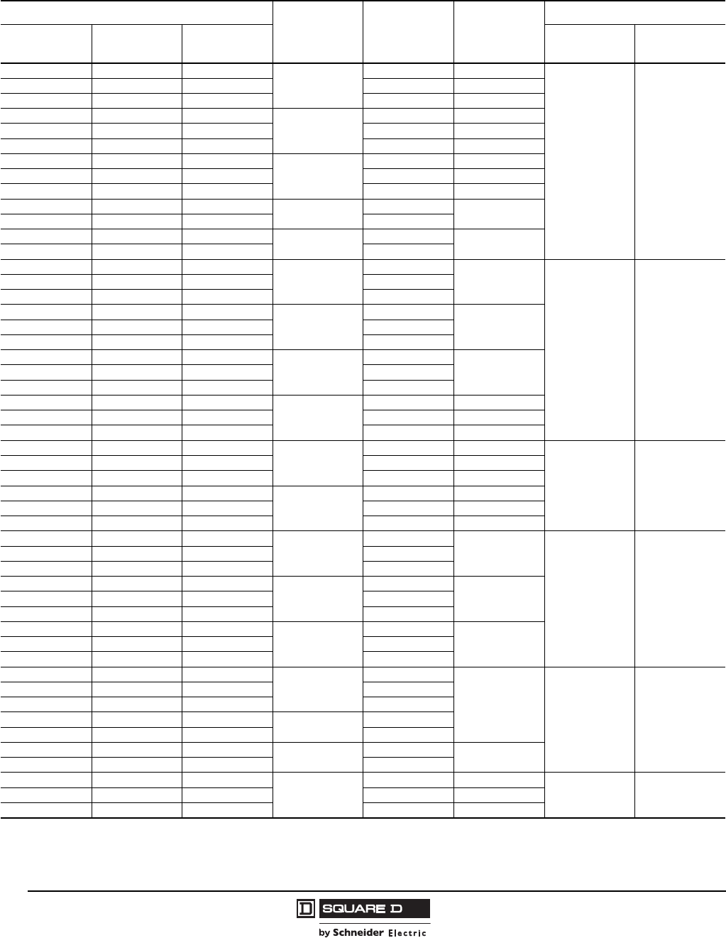
© 1997–2009 Schneider Electric
All Rights Reserved
Model 6 Motor Control Centers
Application and General Information Soft Start Units
64 07/2009
Standard Duty Altistart 48 Soft Starts with Circuit Breaker Disconnects 1
(Pumps, Fans, Lightly Loaded, or Unloaded Starting Applications)
1Motor rated horsepower shown for convenience only. Size per actual motor full load amps. For severe duty applications, choose the next larger horsepower size.
Starter Type and Horsepower Soft Start
Frame Max. Unit Amps TM Trip/Frame
(Amps)
Space (Inches) 2
2Space shown is applicable to NEMA/EEMAC Type 1, 1A, 12, and 3R enclosures. Options may require additional space.
200 V 230 V 460 V IEC Contactors NEMA
Contactors
3——
D17
10 20/150
30 42
— — 10 14 25/150
— 5 — 15 30/150
5——
D22
16 30/150
— — 15 21 40/150
— 7.5 — 24 45/150
7.5 — —
D32
24 45/150
— — 20 27 50/150
— 10 — 28 50/150
10 — — D38 30 60/150
——25 34
——30
D47 40 80/150
—15— 42
15 — —
D62
46
110/150
30 42
——40 52
—20— 54
20 — —
D75
59
110/150
——50 65
—25— 68
25 — —
D88
74
110/150
——60 77
—30— 80
30 — —
C11
88 125/150
— — 75 96 125/150
— 40 — 104 150/150
40 — —
C14
114 175/250
42 60
— — 100 124 200/250
— 50 — 130 200/250
50 — —
C17
143 200/250
— 60 — 154 225/250
— — 125 156 225/250
60 — —
C21
169
250/600
72
(20 W x 20 D) 72
(20 W x 20 D)
— — 150 180
— 75 — 192
75 — —
C25
211
450/600
— — 200 240
— 100 — 248
100 — —
C32
273
450/600
— — 250 302
— 125 — 312
125 — —
C41
343
600/800 72
(35 W x 20 D) 72
(35 W x 20 D)
— 150 — 360
— — 300 361
150 — — C48 396
— — 350 414
— — 400 C59 477 800/800
— 200 — 480
200 — —
C66
528 800/800 72
(35 W x 20 D) Not Available
— — 500 590 1000/1200
— 250 — 604 1000/1200
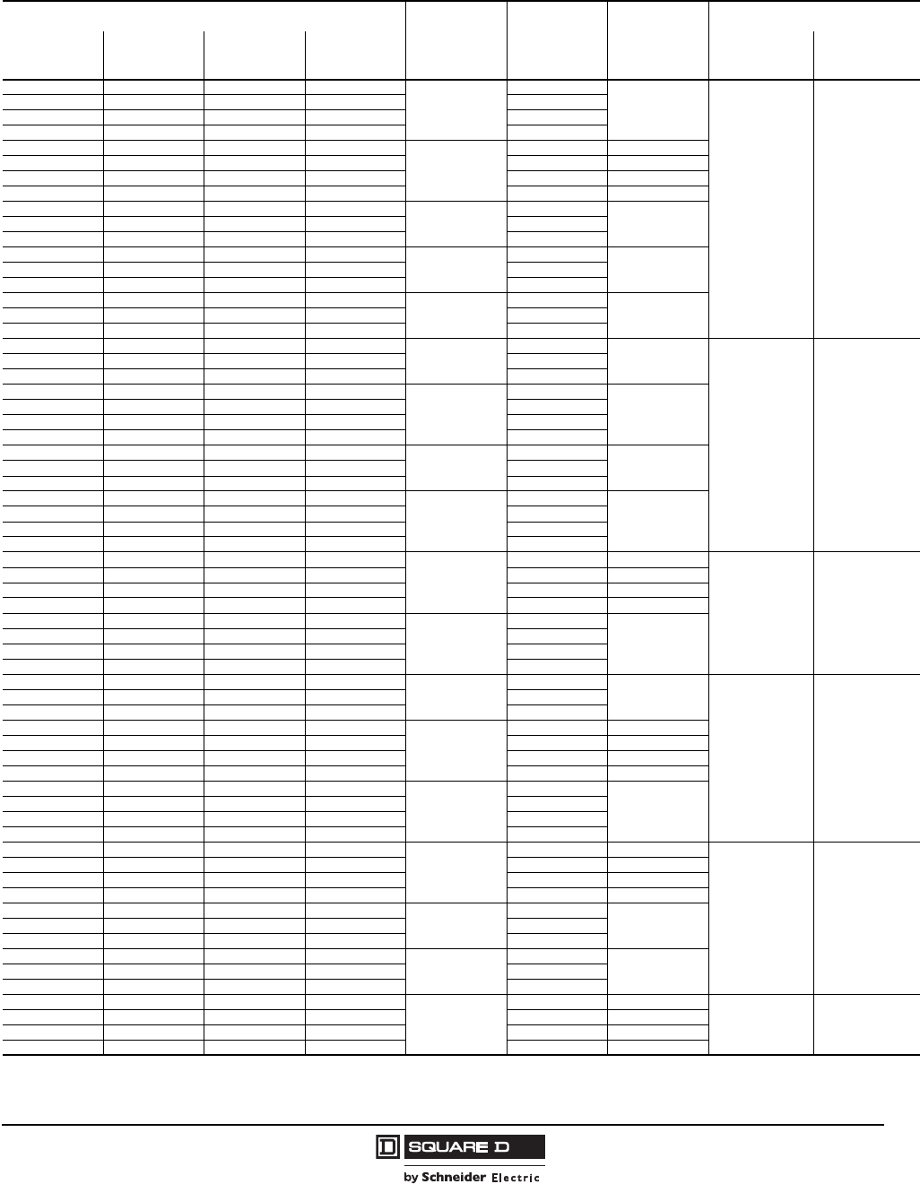
Model 6 Motor Control Centers
Soft Start Units Application and General Information
65
07/2009
© 1997–2009 Schneider Electric
All Rights Reserved
Standard Duty Altistart 48 Soft Starts With Fusible Switch Disconnects 1
(Pumps, Fans, Lightly Loaded or Unloaded Starting Applications)
1Motor rated horsepower shown for convenience only. Size per actual motor full load amps. For severe duty applications, choose the next larger horsepower size.
Power fuses are not included.
Starter Type and Horsepower Soft Start
Frame Max. Unit
Amps F/S Amps
(Fuse Class)
Space (Inches) 2
2Space shown is applicable to NEMA/EEMAC Type 1, 1A, 12, and 3R enclosures. Options may require additional space.
200 V 230 V 460 V 575 V IEC
Contactors NEMA
Contactors
3———
D17
10
30 (J)
30 42
——10— 14
—5—— 15
———15 17
5———
D22
16 30 (J)
— — 15 — 21 30 (J)
— — — 20 22 60 (J)
— 7.5 — — 24 60 (J)
7.5 — — — D32 24 60 (J)
— — 20 25 27
—10—— 28
10 — — — D38 30 60 (J)
———30 32
——25— 34
——30—
D47 40 100 (J)
———40 41
—15—— 42
15 — — — D62 46 100 (J)
30 42
— — 40 50 52
—20—— 54
20 — — —
D75
59
200 (J)
———60 62
——50— 65
—25—— 68
25 — — — D88 74 200 (J)
— — 60 75 77
—30—— 80
30 — — —
C11
88
200 (J)
——75— 96
— — — 100 99
—40—— 104
40 — — —
C14
114 200 (J)
42 60
— — 100 — 124 400 (J)
— — — 125 125 400 (J)
— 50 — — 130 400 (J)
50 — — —
C17
143
400 (J)
———150 144
—60—— 154
— — 125 — 156
60 — — — C21 169 400 (J)
72
(30 W x 20 D) 72
(30 W x 20 D)
— — 150 — 180
—75—200 192
75 — — —
C25
211 400 (J)
— — 200 — 240 600 (J)
— — — 250 242 600 (J)
— 100 — — 248 600 (J)
100 — — —
C32
273
600 (J)
———300 289
— — 250 — 302
—125— — 312
———350
C41
343 600 (J)
72
(30 W x 20 D) 72
(30 W x 20 D)
125 — — — 343 600 (J)
— 150 — — 360 800 (L)
— — 300 — 361 800 (L)
———400
C48 382 800 (L)
150 — — — 396
— — 350 — 414
———500
C59 472 1000 (L)
— — 400 — 477
—200— — 480
200 — — —
C66
528 1000 (L) 72
(35 W x 20 D) Not Available
— — — 600 580 1000 (L)
— — 500 — 590 1200 (L)
— 250 — — 604 1200 (L)
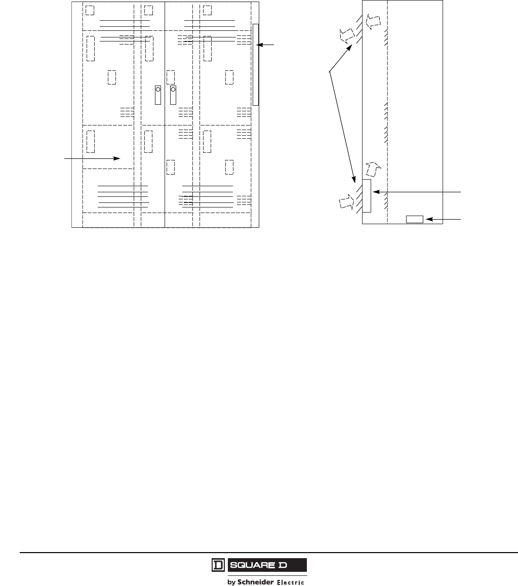
Model 6 Motor Control Centers
Application and General Information NEMA Type 3R Enclosures for AC Drives and Soft Starts
© 1997–2009 Schneider Electric
All Rights Reserved
66 07/2009
NEMA/EEMAC Type 3R Enclosure Applications for AC Drives and Soft Starts
NEMA/EEMAC Type 3R MCCs manufactured by Schneider Electric are non-walk-in enclosures with a design based on the
standard Type 1 MCC. Additional housing and gasketing provide protection from rain, sleet, and ice. The Type 3R MCC for
AC drives and soft starts features louvered and filtered openings on the front doors, along with humidity controls inside the
enclosure (see Figure 1). The MCC enclosure is further modified to include fan-forced ventilation while continuing to meet
NEMA/EEMAC Type 3R enclosure requirements and the UL 845 MCC standard.
Environmental Control
The ventilated NEMA/EEMAC Type 3R MCC manages the internal MCC environment to maintain the required temperature and
humidity levels for the drive and soft start controls in outside environments from
14 to 104 °F (-10 to 40 °C). The following features are included:
Dual Door Fans—Dual door fans force fresh air into the enclosure and move air out of the enclosure. The centrifugal impeller
fans use highly reliable ball bearing rotors. A factory-preset thermostat controls the fans, based on the MCCs internal
temperature. Door interlock switches turn the fans off when the outer NEMA/EEMAC Type 3R door is opened.
Positive Pressure Ventilation—The intake fans, mounted at the lower vents, blow air into the cabinet. This air increases the
cabinet's internal air pressure relative to the air pressure outside the cabinet. The “positive” air pressure created inside the
cabinet helps force out dirt and contaminants. This positive pressure ventilation method is common practice for industrial
atmospheres: it provides a cleaner environment for drive and soft start electronics than one that would be created by exhaust
fans mounted at the upper vents.
Space Heaters—Space heaters add heat to prevent condensation during cooler periods, overnight, and in winter weather.
NOTE: Space heaters do not permit use of the MCC in temperatures below 14 °F (-10 °C).
Center Ventilated NEMA/EEMAC Type 3R Enclosure
DDD
Front View of
NEMA/EEMAC Type 3R MCC
(dashed lines represent units)
Side View of
NEMA/EEMAC
Type 3R MCC
Environmental
Controls
Filtered
Ventilation
Space Heaters
Fans
Transformer
Power Supply for
Environmental
Controls

Model 6 Motor Control Centers
NEMA Type 3R Enclosures for AC Drives and Soft Starts Application and General Information
67
07/2009
© 1997–2009 Schneider Electric
All Rights Reserved
Humidity Controls —It is crucial to maintain a level of dryness in or around the electronic controls for drives and soft starts.
Condensation must be avoided. The space heaters will supply the MCC with heat when necessary to reduce condensate
formation. A factory-preset thermostat and humidistat monitor humidity levels and turn on the space heaters to dry the internal
MCC ambient air.
Self-Contained Power Supply—The fused control transformer(s) supplied in each MCC line-up provide power for space
heaters and fans. There is no need for external power once the main 3-phase power is connected. The power supply is pre-
wired at the factory to fans, space heaters, and environmental controls through protected wiring provisions. Each transformer
is able to supply power to three sections and should be mounted at the bottom of the MCC section.
Filtered Louvers—Each NEMA/EEMAC Type 3R MCC door contains top and bottom louvers for ventilation. Behind each
louver is a coarse rubber filter that helps keep debris from entering the MCC.
NOTE: All drives and soft starts include internal thermal protection switches to shut down the drive or soft start unit before
damage occurs.
Ratings
Altivar 71: 1–40 hp, 480 V, or 1–15 hp, 208/230 V
NOTE: A maximum of four ATV71 drives are allowed in a single section. Mount drive units starting at the top of the section.
Altistart 48 Soft Start: 10–500 hp, 480 V
15–600 hp, 600 V
5–250 hp, 240 V
3–200 hp, 208 V
NOTE: In hotter climates, Schneider Electric suggests installing a shed for shading the MCC as a best practice, since high
temperatures are not always consistent.
Altivar 71—Use constant torque ratings for variable torque applications
14 to 104 °F (-10 to 40 °C)
Up to 2000 A horizontal bus
Outdoor, Rainproof, Sleet Resistant Enclosure (NEMA/EEMAC Type 3R)
UL 845 Listed
0–480 Vac, 3Ph, 3W or 4W
Non-walk-in
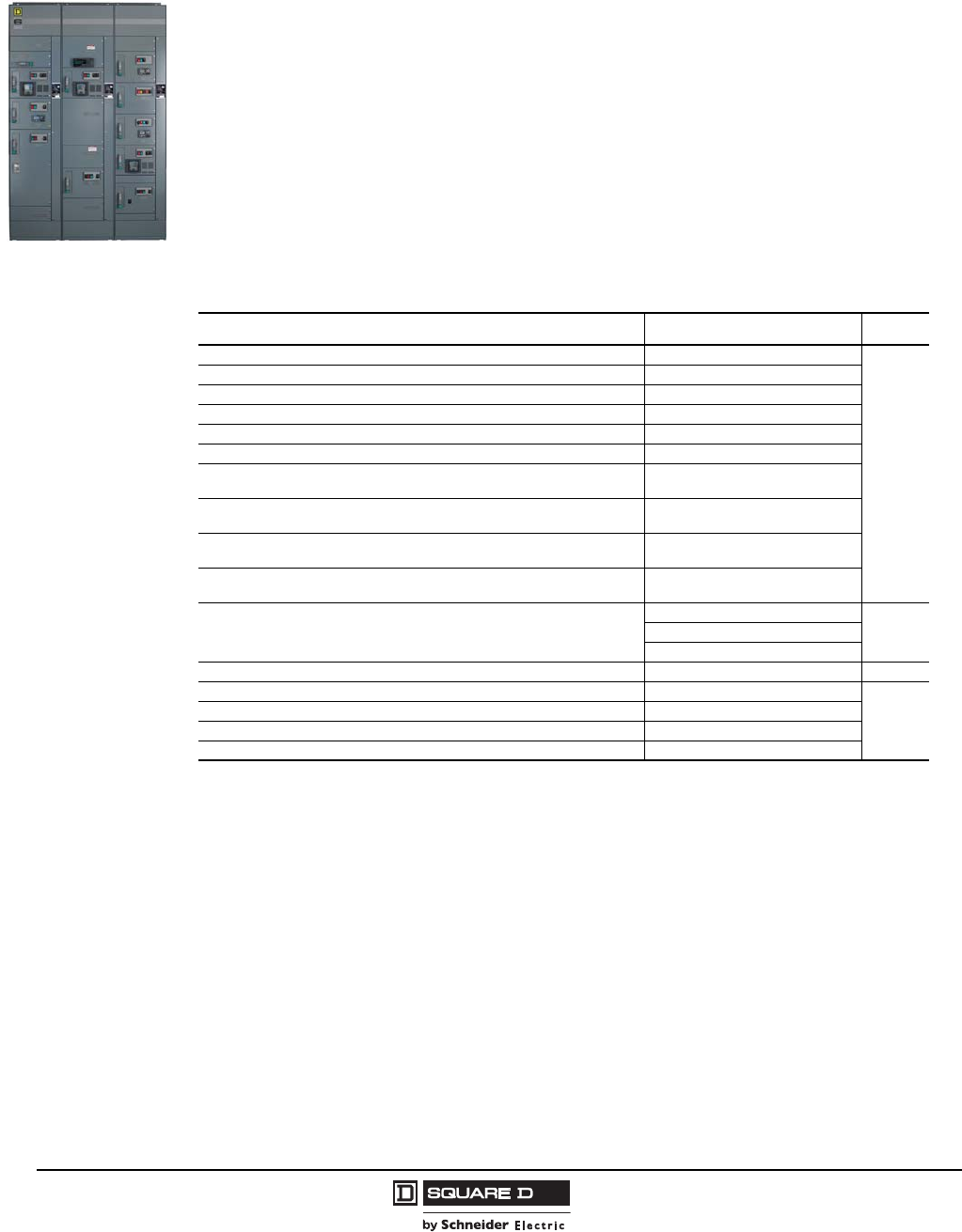
© 1997–2009 Schneider Electric
All Rights Reserved
Model 6 Motor Control Centers
Application and General Information Unit Options
68 07/2009
Unit Options
Options And Modifications
Various options can be provided on Model 6 units to meet specific customer requirements. Many
options require additional mounting space as indicated in the following tables. It is not necessary to
add a unit extender modification to accommodate the additional space listed below. The space
requirements listed are for typical unit arrangements. Unusual combinations or variations may require
additional space.
The total space added to any one unit should total 3, 6, 9, 12, or 24 in. to avoid multiple unit extenders.
Unit extenders may be specified to allow additional unit space for customer requirements (see
page 81). Some units (primarily full section 72 in. units) contain room for limited options without the
need for the additional space listed. Contact MCC TAG for additional information or layout assistance.
NOTE: Unit options listed are based on factory-selected components. Other devices are available.
Contact MCC TAG for further information.
Control And Timing Relays
Description Application Space
5-pole Control Relay D-Line (wired or unwired), (3 NO + 2 NC) Starter or MT unit
3
4-pole Control Relay Type X (wired or unwired), (2 NO + 2 NC) Starter or MT unit
9-pole Control Relay D-Line (wired or unwired), (5 NO + 4 NC) Starter or MT unit
8-pole Control Relay Type X (wired or unwired), (4 NO + 4 NC) Starter or MT unit
5-pole Latching Relay D-Line (wired or unwired), (3 NO + 2 NC) 4-pole relay with mechanical latch
4-pole Latching Relay Type X (wired or unwired), (2 NO + 2 NC) 4-pole relay with mechanical latch
Pneumatic Timer D-Line (wired or unwired), (3 NO + 2 NC) Instantaneous
and (1 NO + 1 NC) Timed Contacts On Delay
Pneumatic Timer D-Line (wired or unwired), (3 NO + 2 NC) Instantaneous
and (1 NO + 1 NC) Timed Contacts Off Delay
Pneumatic Timer Type X (wired or unwired), (2 NO + 2 NC) Instantaneous
and (1 NO + 1 NC) Timed Contacts On Delay
Pneumatic Timer Type X wired or (unwired), (2 NO + 2 NC) Instantaneous
and (1 NO + 1 NC) Timed Contacts Off Delay
Motor Operated Timing Relay, (Single Timing Step)
(1) Timed Circuit
6(2) Timed Circuit
Each Instantaneous Contact
Multifunction Timing Relay Type RE7 (wired or unwired) 1, 2 2PDT (form C)
1Fusible FVNR units Size 1 and 2 require 3 in. of space, max. (1). Not available in Compac starters with CPT.
2Instantaneous contacts not available.
Multifunction 3
2-pole Control Relay SK-Line (wired or unwired), (1 NO + 1 NC) Starter or MT unit
0
3-pole Control Relay Type K (wired or unwired) , 3PDT (form C) General Purpose
4-pole Control Relay Type R (wired or unwired) 4PDT (form C) General Purpose
Phase Failure Relay Type MP (wired or unwired) , SPDT (form C) Phase Failure
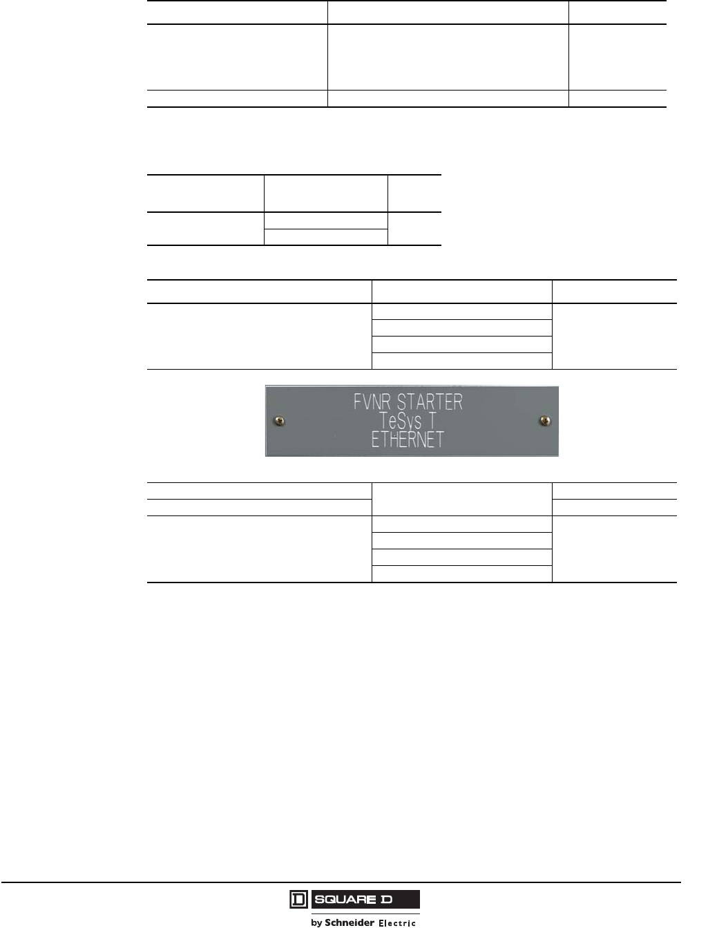
Model 6 Motor Control Centers
Unit Options Application and General Information
69
07/2009
© 1997–2009 Schneider Electric
All Rights Reserved
Special Function Relays
Description Application Space (Inches)
Duplex Alternator Used with (2) Combination Starters
0 1
1Compelling, accelerating, and decelerating relays used with Size 3 and 4, 2-speed 2-winding starters require 6 in. of
mounting space.
Compelling Relay 2-Speed Starters
Accelerating Relay 2-Speed Starters
Decelerating Relay 2-Speed Starters
Over/Undervoltage Relay Starter Units (Single Phase – 120 V) 3
Motor Winding Heaters
Description Application Space
(Inches)
Motor Winding Heater 3–100 hp @ 480 V 0
101–300 hp @ 480 V
Unit Nameplates
Description Application Space (Inches)
Unit nameplate engraved
(1.5 in. x 6.5 in.)
White letters on gray (standard)
0
Black letters on white
White letters on black
White letters on red
Unit nameplate other than standard size All 0
Stainless steel mounting hardware —
Master nameplate engraved
(8 in. x 10 in.)
White letters on gray
0
Black letters on white
White letters on black
White letters on red
Standard Unit Nameplate
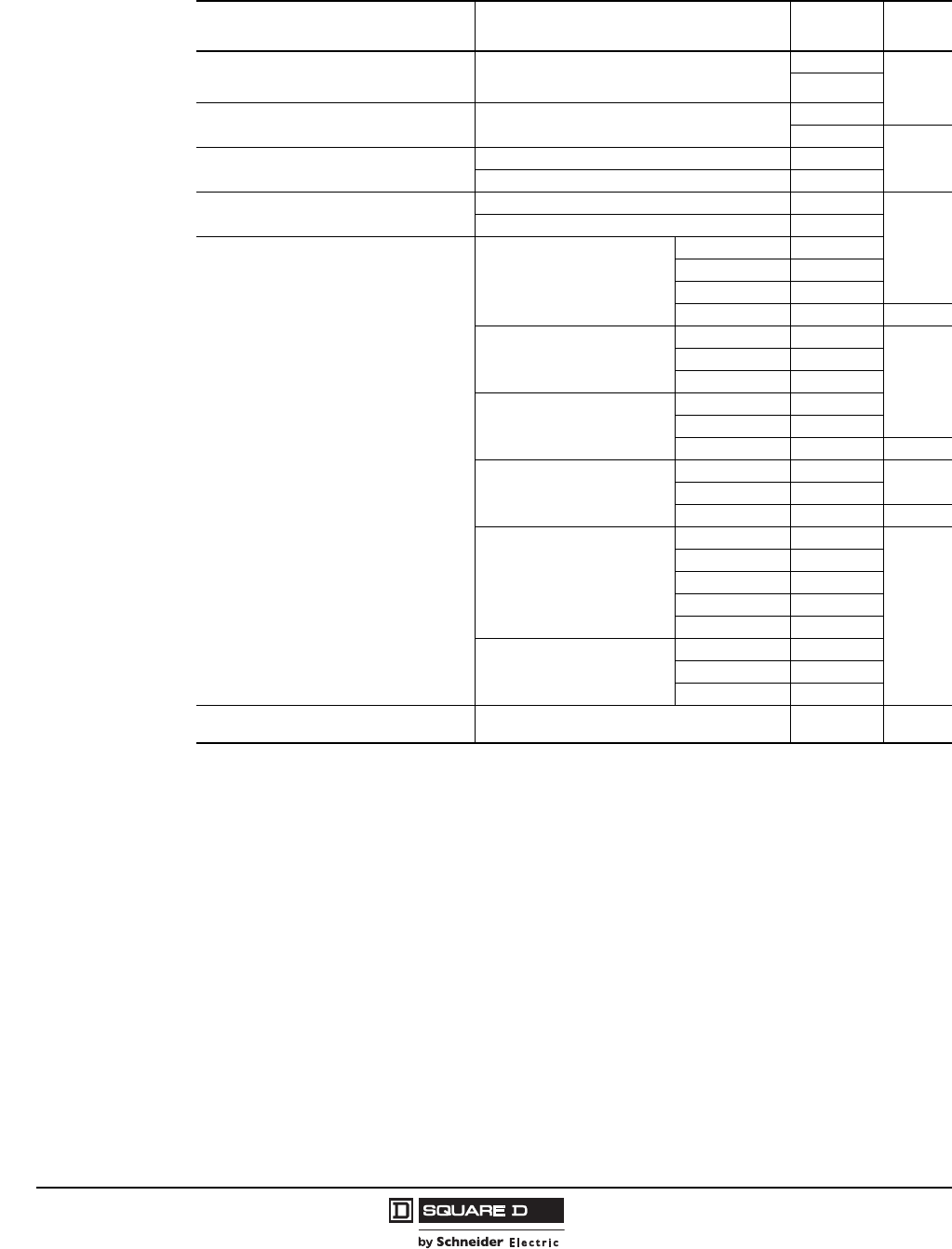
© 1997–2009 Schneider Electric
All Rights Reserved
Model 6 Motor Control Centers
Application and General Information Unit Options
70 07/2009
Control Circuit Variations
Description Application Description Space
(Inches)
Unfused Separate 120V Control Circuit with
Control Power Disconnect
Standard on all starters unless control power
transformer is chosen. (All Size 6 starters have
control power transformer as standard)
SPDT
0DPDT
Fused Separate 120V Control Circuit with
Control Power Disconnect Includes one fuse and control circuit interlock. SPDT
DPDT
0
Fused Line Voltage Control Circuit
(two primary fuses)
Control power taken between phases
Control power taken from phase and neutral
Operating Mechanism Interlock 1
(Not suitable for use as loss source indiation)
1Not suitable for use as loss source indication.
SPDT
0
DPDT
Fused Control Power Transformer
(two primary fuses and one secondary fuse as
standard)
VA rating shown in parentheses ( ) is the
excess capacity for other control devices after
subtracting the contactor requirements.
Size 1 FVNR
50VA (23)
100VA (73)
150VA (123)
300VA (273) 6
Size 1 FVR and 2-Speed;
All Size 2
100VA (62)
0
150VA (112)
300VA (262)2
26 in. required on Size 1 2-Speed and all Size 2 starters.
All Size 3, except
2-Speed 1-Winding
150VA (104)
300VA (253)
500VA (453) 9
All Size 4 and Size 3
2-Speed 1-Winding
300VA (211) 0
500VA (411)
750VA (661) 9
All Size 5 and All RVAT
(Use Line Voltage Coil
with Interposing Relay)
50VA (25)
0
100VA (75)
150VA (125)
300VA (275)3
36 in. required on Size 1-3 RVAT and RVPW.
500VA (475)4
49 in. required on Size 1-3 RVAT and RVPW.
All Size 6
150VA (15) STD
300VA (165)
450VA (315)
Transient Suppression Module Size 1-5 Starters
(Maximum coil voltage = 120 V) 0
Model 6 Motor Control Centers
Unit Options Application and General Information
71
07/2009
© 1997–2009 Schneider Electric
All Rights Reserved
Pilot Devices
Model 6 Motor Control Centers use Class 9001 Type XB5 22 mm pilot devices as standard. Starters
are provided with a removable hinged station plate that has five knockouts for XB5 (maximum of three
Type K 30 mm devices). Compac 6 starters are provided with a control station plate that has knockouts
for four Class 9001 Type XB5 22 mm pilot devices. Type K devices cannot be substituted on
Compac 6 starters.
NOTE: When more pilot devices are specified than will fit in the station plate, the additional devices will
be mounted directly in the unit door. Not applicable to Compac 6.
Control Station
Plate
Description Application Space
(Inches)
Start-Stop push button Any starter
0
Forward-Reverse-Stop push button FVR
High-Low-Stop push button 2-speed
Fast-Off-Slow push button 2-speed
High-Low push button 2-speed
Fast-Slow push button 2-speed
On-Off push button Any starter
Single Function push button Any starter
Illuminated push button Any starter
Maintain Contact push button Any starter
Hand-Off-Auto selector switch Any starter
Hand-Off-Auto selector switch with manual speed potentiometer AC Drives
Start-Stop selector switch Any starter
On-Auto selector switch Any starter
On-Off selector switch Any starter
High-Off-Low selector switch 2-speed
Hand-Auto selector switch Any starter
Test-Auto selector switch Any starter
Forward-Off-Reverse selector switch FVR
Forward-Off-Reverse selector switch with manual speed potentiometer AC Drives
High-Low selector switch 2-speed
Slow-Off-Fast selector switch 2-speed
Slow-Fast selector switch 2-speed
Forward-Reverse selector switch FVR
High-Low-Off selector switch 2-Speed
4-position selector switch Any starter—Type K operators
Switchboard type rotary cam selector switch Any circuit
Substitute Type K pilot devices (XB5 STD.) (N/A on Compac 6) Any starter (max. 3 Type K devices)
Substitute Type XB4 pilot devices (XB5 STD.) Any starter
Addition of dust boots to above pilot devices Any pilot device
Omit control station plate (solid steel unit door) Units without pilot devices
Units with pilot devices (door mounted)
© 1997–2009 Schneider Electric
All Rights Reserved
Model 6 Motor Control Centers
Application and General Information Unit Options
72 07/2009
Pilot Lights
Model 6 Motor Control Centers use Class 9001 Type XB5 22 mm pilot devices as standard. Starters
are provided with a removable hinged station plate that has five knockouts for XB5 (maximum of three
Type K 30 mm devices). Compac 6 starters are provided with a control station plate that has knockouts
for four class 9001 Type XB5 22 mm pilot devices. Type K and push-to-test devices cannot be
substituted on Compac 6 starters.
NOTE: When more pilot devices are specified than will fit in the station plate, the additional devices will
be mounted directly in the unit door. Not applicable to Compac 6.
Description Application Space
(Inches)
Pilot lights
“On” (Red, Green) Any starter, AC Drive 1
1LED-type direct supply.
0
“Off” (Red, Green) Any starter
Special configuration2
2Any starter application requires a diagram with order entry.
Red
Any starter
Green
Yellow
Blue
White
Push-To-Test pilot lights
(not available on Compac 6)
“On” (Red, Green) Any starter
“Off” (Red, Green) Any starter
Special configuration 2
Red
Any starter
Green
Yellow
Blue
White
“RUN” Red
AC Drives
Green
“STOPPED” Red
Green
“FAULT” Yellow
“HAND” and “AUTO”
Substitute Type K pilot light (not available on Compac 6) Any starter
Substitute Type XB4 pilot light
Model 6 Motor Control Centers
Unit Options Application and General Information
73
07/2009
© 1997–2009 Schneider Electric
All Rights Reserved
Overload Relays
Model 6 motor control center units with Type S starters are available in NEMA/EEMAC Sizes 1
through 6. Type S starters are provided with melting alloy overload relay blocks as standard. Their
trip-free construction allows the overload relay to trip even if the reset lever is blocked or held in the
reset position. Features such as the trip-to-test and the visible trip indicator minimizes troubleshooting
time. With these features and state-of-the-art design, the Model 6 starter unit has earned a solid
reputation that no other NEMA/EEMAC starter can equal.
Schneider Electric has added the solid state motor overload protection to its existing family of overload
relay protection equipment, including melting alloy and bi-metallic devices. Technological migration
allows Schneider Electric customers the ability to make the same space “smarter,” while preserving
backward compatibility.
Auxiliary Electrical
Interlocks
Auxiliary Electrical Interlocks 1
1Elapsed time meters, transient suppression module, and Off pilot light use one auxiliary interlock each. Size 1 starters with three
auxiliary interlocks require a minimum 100 VA control power transformer.
Max. Aux. Interlocks Per Contactor Description
Type Size Qty.
FVNR 1-2 4
When the starter has more than one contactor (FVR, RVAT,
2-speed), indicate which contactor receives the interlock.
3-6 4
FVR 2
2Maximum of 2 interlocks per contactor for Compac 6 starters.
1-2 4
3-5 2
2-speed
1-winding
CHP: Low 1-4 2
CHP: High 1-2 4
3-4 2
CVT: Low 1-2 4
3-4 2
CVT: High 1-4 2
2-speed
2-winding
1-2 4
33
42
RVAT 3-6 5
Description Application Space
(Inches)
Melting alloy overload relay Any starter 0 1
1Size 3 2-speed 1-winding requires 9 in. space adder.
Ambient compensated bi-metallic overload relay Any starter
TeSys® T Motor Managment Controller Any starter See
following
tables.
Motor Logic Solid State Overload Relay (SSOLR) Any starter
Motor Logic Plus/Motor Logic Plus II SSOLR Any starter
Isolated alarm contact – N.O. Melting alloy only 0
Overload alarm light (Amber) 2
2Not available on Size 3 and 4 starters with bimetal overload.
Melting alloy, bimetal 0
Overload alarm light – LED (Amber) Melting alloy, bimetal
Omit overload relay Converts combination starter to combination contactor 0
Omit external overload reset button — 0
Additional overload relay (See NEC 430-53 for proper application)
Size 1 starters 6
Size 2 starters 6
Size 3 starters 9
Size 4 starters 12
Factory-installed thermal units 3
(Will be sized per NEC 430-150, unless full load current provided
with order)
3Order must include thermal unit selection or motor full load current ratings. 2-speed and part-winding starters require six thermal
units.
All standard melting alloy and bimetal thermal units
(set of 3) 0
Type FB Quick Trip (set of 3)
Type SB Slow Trip (set of 3)
© 1997–2009 Schneider Electric
All Rights Reserved
Model 6 Motor Control Centers
Application and General Information Unit Options
74 07/2009
TeSys® T Motor Management Controller
The TeSys T Motor Managment controller connects directly to the communication network offering data
monitoring and control. Communication users gain access to motor data variables and system process
control through “onboard” I/O. The TeSys T controller includes thermal overload, over/under current, long
start/jam, ground fault, and phase failure/unbalance protection. In addition, when combined with a PLC,
the Tesys T controller provides an independent data monitoring and control system.
The TeSys T controller is available in five different native, open communication protocols: CANopen,
DeviceNet™, Ethernet TCP/IP, Modbus®, and PROFIBUS.
Voltage and load monitoring is available by selecting the optional Expansion Module. The additional
motor monitoring includes over/under voltage, phase reversal, over/under power factor, and load
shedding. In addition, the optional HMI may be supplied on each unit to provide local monitoring,
configuration, and control functions.
The Tesys T Motor Management Controller includes:
•Native open communication protocol
•Six discrete inputs and three relay outputs
•RJ-45 port for connection to expansion module, HMI display, or PC
•24 Vdc or 120 Vac, 50/60 Hz control power
•Status indicating LEDs
— HMI communication—Communication between controller and HMI device
— Power—Controller state
— Alarm—Warning or fault condition
— Fallback—Communication loss on active control source
— PLC communication—Network status
•Fault relay—1 N.O. and 1 N.C.
•Ground Fault CT input
•Thermistor/PTC input
NOTE: The TeSys T Motor Management Controller is not available with vacuum starters, Altivar®
drives, or Compac 6 starters.
TeSys T and Motor Logic Plus™ Family Solid-State Overload Relay (SSOLR) Space Addition
Requirements–Circuit Breaker Type Disconnects
Size FVNR FVR 2S2W 2S1W RVAT PW
1 0 in. 3 in. 3 in. 3 in. — 0 in.
2 0 in. 3 in. 3 in. 3 in. — 0 in.
3 0 in. 0 in. 0 in. 0 in. 3 in. 0 in.
4 3 in. 15 in. 27 in. 27 in. 6 in. —
5 0 in. 25 in. 0 in. 0 in. 0 in. —
6 0 in. — — — 0 in. —
TeSys T and Motor Logic Plus Family SSOLR Space Addition Requirements–Fusible Switch
Type Disconnects
Size FVNR FVR 2S2W 2S1W RVAT PW
1 0 in. 3 in. 3 in. 3 in. — 0 in.
2 0 in. 3 in. 3 in. 3 in. — 0 in.
3 (100 A) 3 in. 0 in. 0 in. 0 in. 3 in. 0 in.
3 (200 A)0 in.—————
4 9 in. 15 in. 27 in. 0 in. 0 in. —
5 0 in. 25 in. 0 in. 0 in. 0 in. —
60 in.—————
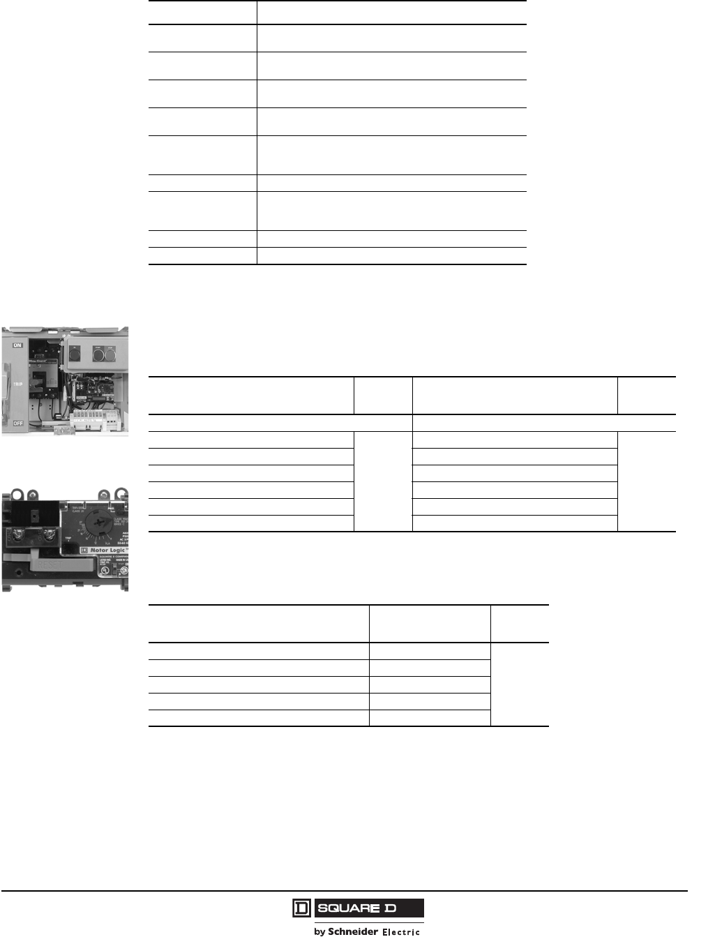
Model 6 Motor Control Centers
Unit Options Application and General Information
75
07/2009
© 1997–2009 Schneider Electric
All Rights Reserved
Motor Logic® Solid-State Overload Relays
The Motor Logic SSOLR family of products offers a degree of flexibility for selecting the amount of motor
protection or control you require. Coupled with the Square D® brand Type S contactor, the Motor Logic
SSOLRs form the benchmark for NEMA/EEMAC-style motor starters. They are available fully integrated
in the Model 6 MCC, forming a complete power and control system.
TeSys T Options
Option Description
Expansion Module Voltage and Load monitoring. Four additional logic inputs.
Powered through the controller. RJ-45 port.
RJ-45 Port Programming port. Mounted in 22mm control station plate.
Door mounted if more than five 22mm pilot devices.
HMI Door mounted operator interface. LCD display—4 lines, 20
characters. RJ-45 port.
Programmer Hand held HMI. Enables configuring and commissioning of
the controller.
Ground Fault CT Measures ground faults at levels significantly lower than the
ground fault detection based on the internal summation of the
3-phase currents.
Reset Push Button Mounted in 22 mm control station plate. Local Operator reset.
PowerSuite™ Software Enables configuring and commissioning of the controller.
Default logic can be modified or new logic can be created
with this software.
Warning Pilot Light CSP-mounted; provides visibility of TeSys T Warning.
Fault Pilot Light CSP-mounted; provides visibility of TeSys T Fault.
Motor Logic Solid State
Overload Relay “Base Unit”
Unit with Motor Logic Solid
State Overload Relay
Application Space
(Inches) Application Space
(Inches)
Motor Logic Base Unit Motor Logic Feature Base Unit
Size 1–2 FVNR and FVR
0
Size 1–2 FVNR and FVR
0
Size 1–2 2SPD 1,2
1Specify Full Load Current for both speeds.
2Not all configurations are available.
Size 1–2 2SPD ,
Size 3–4 FVNR, FVR and RVAT Size 3–4 FVNR, FVR and RVAT
Size 3–4 2SPD and PW ,Size 3–4 2SPD and PW ,
Size 5 2SPD and PW ,Size 5 2SPD and PW ,
Size 5–6 FVNR, FVR and RVAT Size 5–6 FVNR, FVR and RVAT
Motor Logic Options
Description Application Space
(Inches)
Isolated Auxiliary Contact (required for fault pilot light) All Starters with Motor Logic
0
Auto Reset and Isolated Auxiliary contact All Starters with Motor Logic
Remote Reset and Isolated Auxiliary Contact All Starters with Motor Logic
Overload Light Requires Isolated Contact
MCC Looping Terminal Kit Size 1 Starters
© 1997–2009 Schneider Electric
All Rights Reserved
Model 6 Motor Control Centers
Application and General Information Unit Options
76 07/2009
Motor Logic Plus Solid State Overload Relays
The Motor Logic Plus family of solid state overload relays are programmable electronic overloads with
motor protective features and communications capabilities.
The Motor Logic Plus provides voltage and current monitoring with an integral LED display. The
communication port allows for connectivity to an upstream network.
The Motor Logic Plus II provides protective and control functions. The Motor Logic Plus II integrates
I/O with four digital inputs and two relay outputs for network control functions.
Motor Logic Plus Family SSOLR Application Notes:
•Not available with vacuum starters, Altivar drives, or with Compac 6 starters.
•120 Vac control power available with individual control power transformers or separate source.
•The Motor Logic Plus SSOLR is provided with a communications module as standard.
Part #9999MB22.
Motor Logic Plus Family SSOLR Communications Adaptors
Overload Relay Type Description Space (Inches)
Motor Logic Plus
Modbus® 2-wire communications adapter, part #9999MB22
0
Modbus 4-wire communications adapter, part #9999MB11
DeviceNet™ communications adapter, part #9999DN
PROFIBUS communications adapter, part #CIO-MLP-PR-IO
Motor Logic Plus II DeviceNet communications adapter, part #9999DN2
PROFIBUS communications adapter, part #CIO-MLPII-PR
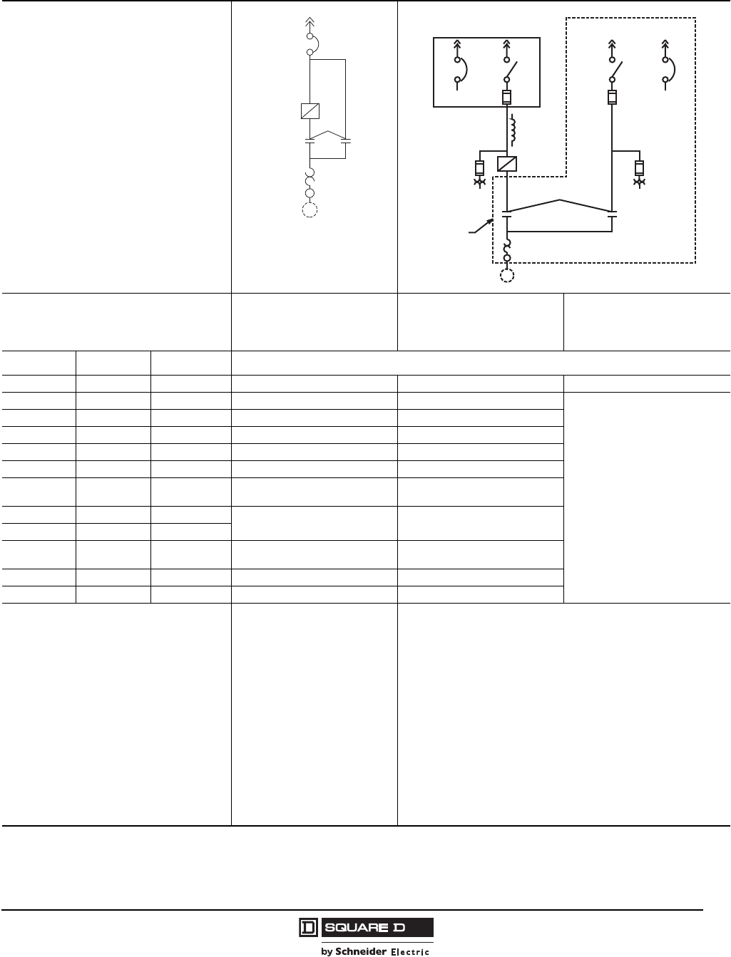
Model 6 Motor Control Centers
Unit Options: AC Drives Application and General Information
77
07/2009
© 1997–2009 Schneider Electric
All Rights Reserved
AC Drive Power Contactor Options 1
1Only one allowed.
Power Circuit Diagram
Description
Integrated Bypass 2
Available with circuit
breaker disconnect only.
Uses TeSys contactors.
2Bypass is not isolated from the drive compartment. Both drive and bypass must be removed at the same time.
Barriered Bypass
(Uses NEMA contactors)
Barriered Application Rated
Compac 6 Bypass
(14 A maximum)
208 V 240 V 480 V Space (Inches)
1–5 hp 1–5 hp 1–10 hp 12 18 6
7.5–10 hp 7.5–10 hp 15–20 hp 12 18
N/A
— — 25 hp VT 12 18
15 hp 25 hp CT 9 18
15–20 hp 20 hp 30–40 hp 9 27
25 hp VT 50 hp VT 9 27
25 hp 25 hp CT
30 hp All 50 hp CT 5 added to width 27 in adjacent section
30–40 hp VT 40–50 hp VT 60–100 hp VT 5 added to width 33 in adjacent section for CB
39 in adjacent section for FS
30–40 hp CT 40 hp CT 60–75 hp CT
— — 100 hp CT 20 added to width 33 in adjacent section for CB
39 in adjacent section for FS
— — 125–150 hp All 20 added to width 25 added to width
— — 200 hp All 20 added to width 25 added to width
• Basic Drive features with
isolation and bypass contactors
for emergency full speed
operation in same compartment.
• TeSys D- or F-Line contactors
are used.
• Only available as circuit breaker
disconnect common to drive and
bypass.
• Drive and bypass are UL 845
Listed for 100,000 A SCCR and
coordinated for Type 1
protection.
• Includes AFC-Off-Bypass
selector switch, Red Push-To-
Test “AFC” Pilot Light and
Yellow Push-To-Test “Bypass”
Pilot Light on bypass control
island.
• Basic drive features with isolation and bypass contactors for
emergency full speed operation.
• Barriered application-rated Compac 6 bypass uses TeSys contactors.
NEMA contactors are used on barriered NEMA bypass.
• Separate disconnect for drive and bypass can be operated
independently.
• Drive and bypass starter are enclosed in separate barriered
compartments.
• Drive and bypass are UL 845 Listed for 100,000 A SCCR and
coordinated for Type 1 protection.
• Includes AFC-Off-Bypass selector switch, Red Push-To-Test “AFC” Pilot
Light and Yellow Push-To-Test “Bypas” Pilot Light on bypass control
island. (Non-Push-To-Test used on Compac 6)
M
CB
Drive
CB CBor orDISCDISC
Separate
Unit
M

© 1997–2009 Schneider Electric
All Rights Reserved
Model 6 Motor Control Centers
Application and General Information Unit Options: AC Drives
78 07/2009
AC Drive Power Contactor Options (Continued)
Power Circuit Diagram
Description Load Contactor Line Contactor
208 V 240 V 480 V Space (Inches)
1–3 hp All 1–3 hp All 1–10 hp All 12 12
5 hp All 5 hp All 15 hp All 12 12
7.5–10 hp All 7.5–10 hp All 20 hp All 12 12
— — 25 hp VT
15–20 hp VT 15–25 hp VT 30–50 hp VT 99
15–20 hp CT 15–20 hp CT 25–40 hp CT
25–50 hp VT 30–50 hp VT 60–100 hp VT 5 added to width 5 added to width
25–40 hp CT 25–40 hp CT 50–75 hp CT
• Basic Drive features with load
contactor for motor isolation.
Contactor is open when drive is
not running.
• TeSys D- or F-Line contactors are
used.
• Drive and load are UL 845 Listed
for 100,000 A SCCR.
• Basic Drive features with line
contactor for isolating drive from
input line.
• TeSys D- or F-Line contactors are
used.
• Drive and line contactor are UL
845 Listed for 100,000 A SCCR.
AC Drive Miscellaneous Options
Option Space (Inches)
Line Reactors (3% or 5%)
Each line reactor is mounted in the MCC cabinet as a separate unit above the
drive unit and is factory wired to the line side of the drive
1–5 hp, 208/240 V or 1–10 hp, 480 V (3 or 5% Impedance) 1
1Space is applicable to NEMA/EEMAC Type 1, 1A, or 3R. Contact MCC TAG for line reactors in NEMA/EEMAC Type 12 MCCs for
these sizes.
6
7.5–20 hp, 208/240 V or 15–40 hp, 480 V (3 or 5% Impedance) 9
25 hp VT, 240 V or 50 hp VT, 480 V (3 or 5% Impedance) 12
25–40 hp CT, 208/240 V or 25–40 hp VT, 208 V or 30–50 hp VT, 240 V or
50–100 hp CT, 480 V or 60–125 hp VT, 480 V 0
125–200 hp CT or 150–250 hp VT, 480 V
250–450 hp CT or 300–500 hp VT, 480 V
Motor Protecting Filters or 5% Output Reactors
Each load filter/reactor is mounted in the MCC cabinet as a separate unit adjacent
to the drive unit and is factory wired to the load side of the drive. Not available on
NEMA/EEMAC Type 12 MCCs.
1–10 hp, 480 V 6
15–40 hp, 480 V 9
50–75 hp, 480 V 12
100–125 hp, 480 V 21 (bottom mounted only in adjacent section)
150–200 hp, 480 V
250–300 hp, 480 V 24 (bottom mounted only in adjacent section)
350–400 hp, 480 V
M
CB or Disc
Power
Fuse
Drive
M
CB or Disc
Power
Fuse
Drive
Model 6 Motor Control Centers
Unit Options: AC Drives Application and General Information
79
07/2009
© 1997–2009 Schneider Electric
All Rights Reserved
AC Drive Miscellaneous Options (continued)
Option Space (Inches)
100 VA customer capacity on drive's 120 V control transformer
1–3 hp, 208/240 V or 1–3 hp, 480 V with basic power option 3
5–100 hp, 480 V or 5–50 hp, 208/240 V 0
300 VA customer capacity on drive's 120 V control transformer
125-500 hp VT or 100-450 hp CT, 480 V with basic power option 0
Extended I/O Cards 1
Each option board is pre-installed onto drive inside unit with all customer
terminations left unwired (Type 1A wiring).
1A maximum of two extended I/O cards can be installed. If a comm. card is present, only one extended I/O card can be installed.
Basic I/O card (VW3A3201)
0
Extended I/O card (VW3A3202)
Controller inside card (VW3A3501)—mounting only, no programming. Contact
MCC TAG for applications requiring programming.
115 Vac Logic Input adapter (VW3A3101). Adapts seven logic inputs for use with
user supplied 115 Vac signals
3 on Basic Power Option for 1–15 hp 480 V
or 1–10 hp, 208/240 V
0 for all others
Communications Cards (choose only one)
Each option board is pre-installed and does not include network wiring. Network
interwiring within the MCC must be purchased separately.
Modbus®/Uni-Telway (VW3A3303)
0
Modbus Plus (VW3A3302)
PROFIBUS DP (VW3A3307)
DeviceNet™ (VW3A3309)
Ethernet TCP/IP (VW3A3310D)
Ethernet IP (VW3A3316)
FIPIO® (VW3A3311)
INTERBUS® (VW3A3304)
LonWorks® (VW3A3312)
Metasys N2 (VW3A3313)
BACnet® (VW3A3315)
Apogee® FLNPI (VW3A3314)
Dynamic Braking Resistors
The use of braking resistors dissipates excess energy generated by the motor
whenever the motor functions in the generator mode as on high inertia loads or
machines with a driving load. Resistors are mounted in the MCC cabinet as a
separate unit above the drive unit and is factory wired to the DC bus of the drive.
Not available in NEMA/EEMAC Type 12 MCCs.
1–2 hp, 208/240 V or 1–10 hp, 480 V 6
3–10 hp, 208/240 V or 15–20 hp, 480 V 9
15–20 hp, 208/240 V or 25–40 hp, 480 V 9
Drive Unit Extenders
1–25 hp VT or 1–20 hp CT, 480 V or 1–10 hp, 208/240 V
Provides space added below drive unit for added devices with single door to cover
the drive and added space. Available for Basic and Barriered Bypass Power
Options only.
3, 6, or 12
30–50 hp VT or 25–40 hp CT, 480 V or 15–25 hp VT or 15–20 hp CT, 208/240 V
Provides space added below drive unit for added devices with single door to cover
the drive and added space. Available for Basic and Barriered Bypass Power
Options only.
3, 6, or 9
Control and Timing Relays:
Auto Start Relay without Delay
Provides interposing relay for starting drive in auto mode via customer supplied
120 Vac. Requires Hand-Off-Auto Selector Switch For Basic and Barriered Bypass units,
add 3 for 1–25 hp VT @ 480 V,
or 1–20 hp CT @ 480 V,
or 1–10 hp @ 208/240 V.
Add 0 for all others.
Auto Start Relay with Delay
Provides interposing relay for starting drive in auto mode via customer supplied
120 Vac or dry contact. Adjustable time delay for delaying drive start from 1.5-30
seconds is included. Requires Hand-Off-Auto Selector Switch
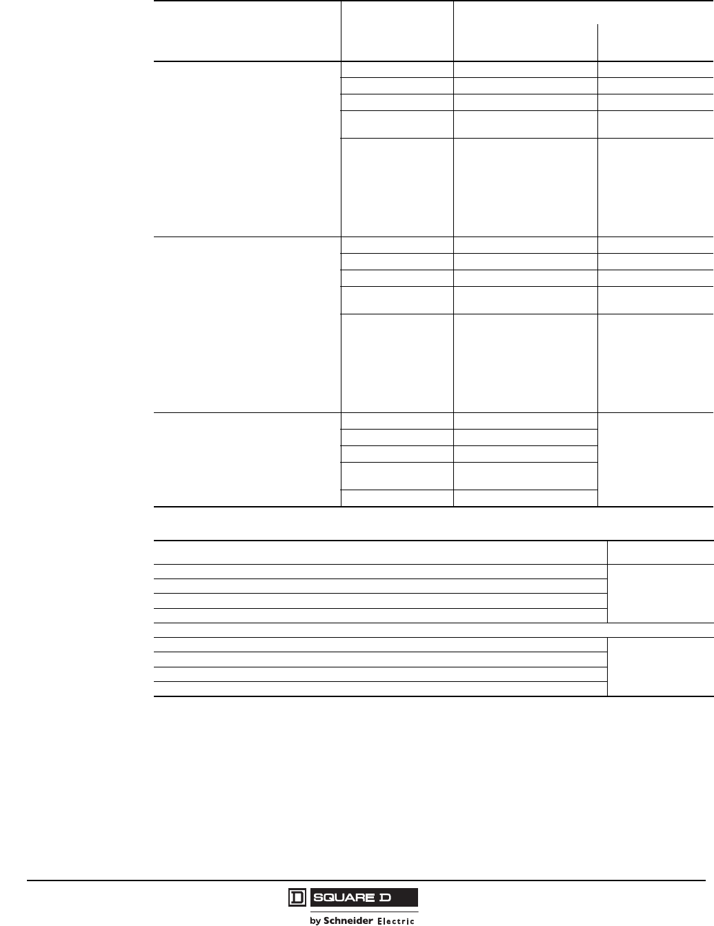
© 1997–2009 Schneider Electric
All Rights Reserved
Model 6 Motor Control Centers
Application and General Information Unit Options: Altistart Solid-State Starters
80 07/2009
Soft Start Unit Power Options
Description Soft Start Frame
Space (Inches)
IEC
Contactors NEMA
Contactors
Input Isolation Contactor
(Replaces the standard shunt trip
disconnect. Standard feature if reversing
or full voltage bypass is chosen.)
As an option, MCC soft start units can
include an input contactor instead of a
shunt trip disconnect to isolate the soft
start in case of a fault condition. The input
contactor also opens when the motor is
not in use. This provides protection from
voltage transients when the electronics are
most susceptible to damage. Control
power is maintained after the input
contactor is opened so fault diagnostics
are available.
D17 – D47 15 15
D62-C11 18 15
C14-C17 18 12 (5 added to width)
C21-C32 10 added to width for
CB version only 20 added to width
C41-C66 (IEC)
or
C41-C59 (NEMA) 0 20 added to width
Integrated Full Voltage Bypass Starter
(requires input isolation contactor)
As an option, MCC soft start units can
include a full voltage bypass to allow
emergency full voltage starting of the
motor in case the soft start is unable to be
used. This feature includes necessary
control and power circuitry to start the
motor with full voltage using a bypass
enable/disable selector switch. A Class 20
overload relay is provided to protect the
motor in the bypass mode. The bypass
contactor also acts as a shorting contactor
in the soft start mode. Not available with
Reversing Capability.
D17 - D47 15 27
D62-C11 18 27
C14-C17 18 12 (5 added to width)
C21-C32 10 added to width for
CB version only 20 added to width
C41-C66 (IEC)
or
C41-C59 (NEMA) 0 20 added to width
Reversing Capability
(includes input isolation contactor)
Not available with NEMA contactors or full
voltage bypass.
D17 - D47 15
Consult Factory
D62-C11 18
C14-C17 18
C21-C32 10 added to width for
CB version only
C41-C66 20 added to width
Soft Start Unit Control Options
Description Space (Inches)
1.5-30 sec. start delay
0
Emergency Off push button, maintained contact. Requires Shunt Trip option on disconnect.
Current meter–analog, 2.5 in. panel type, 0-200% of nominal motor current
Elapsed time meter
Auxiliary Electrical Interlocks
Run contacts, 1 NO, 5A @ 120 Vac (8501 Type R relay)
0
Bypass run contacts, 1 NO, 5A @ 120 Vac (8501 Type R relay). Requires integrated full voltage bypass.
Auto mode contacts, 1 NO, 5A @ 120 Vac (8501 Type R relay). Requires Hand-Off-Auto switch.
Fault contacts, 1 NO, 5A @ 120 Vac (8501 Type R relay)
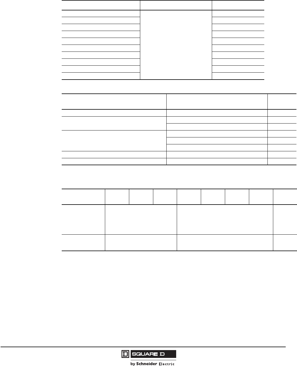
Model 6 Motor Control Centers
Unit Options Application and General Information
81
07/2009
© 1997–2009 Schneider Electric
All Rights Reserved
Unit Extenders
Unit extenders are used to provide additional component mounting space within a unit. Only one unit
extension is recommended per unit. Total unit size cannot be increased beyond 72 in. Space
requirements shown for the modifications in this catalog already include the unit extension.
Description Application Space (Inches)
3 in. unit extender
All plug-in units
3
6 in. unit extender 6
9 in. unit extender 9
12 in. unit extender 12
15 in. unit extender 15
18 in. unit extender 18
21 in. unit extender 21
24 in. unit extender 24
30 in. unit extender 30
36 in. unit extender 36
Fusible Switch Options
Description Application Space
(Inches)
Class R fuse clips 1
1Not available on Compac 6 starters.
30–600 A fusible switches; Size 1-6 fusible starters
Class J fuse spacing
(standard with Compac™ 6 fusible starters and branches)
30–400 A fusible switches
600 A fusible switches
Next larger size Class J fuse clips
Size 1, 5, 6 fusible starters
Size 2, 3 fusible starters
Size 4 starters
Next smaller size fuse clips Size 1–6 fusible starters
Key interlock (single cylinder) Per lock/ per switch
Factory Installed Fuses
Type Class
Max. Fuse Size FRN/RK5 KTN/RK1 LPN/RK5 FRS/RK5 KTS/RK1 LPJ/J LPS/RK5 KRP/L
30
60
100
200
400
600
250 V 600 V —
1200
1600
2000 — — 600 V
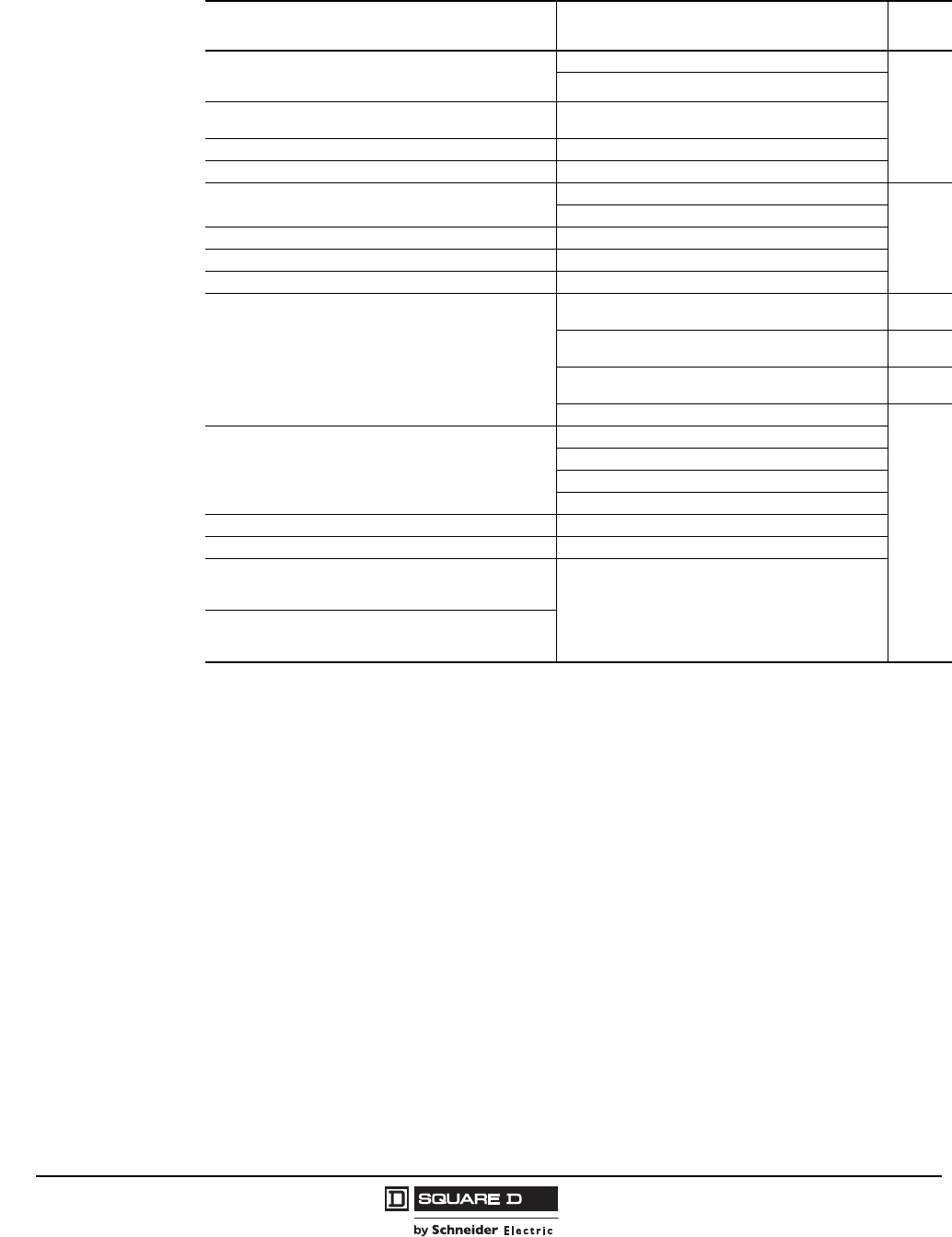
© 1997–2009 Schneider Electric
All Rights Reserved
Model 6 Motor Control Centers
Application and General Information Unit Options
82 07/2009
Circuit Breaker Options
Description Application Space
(Inches)
Substitute L-interrupting circuit breaker for J-interrupting
circuit breaker. (Part-winding starters require two circuit
breakers.)
H-frame units
0
J-frame units
Substitute thermal-magnetic circuit breaker for motor circuit
protector. All starters (Include actual hp information)
122 °F (50 °C) rise breaker All (non-UL)
Key interlock (Schneider Electric brand) 1
1Not available on Compac 6.
Per lock on any device
Operating mechanism interlock 2
2Not available in 600–2500 A mains/branches that do not have handle operators.
SPDT
0
DPDT1
Shunt trip (120 Vac) Any unit with a circuit breaker
Shunt trip (24 Vdc) Any unit with a circuit breaker
Undervoltage trip Any unit with a circuit breaker
Phase failure relay, Type MP SPDT (Form C) for
main circuit breaker or switch
15–600 A main circuit breaker
200–400 A main switch 9
800 A main circuit breaker
1200 A (80%) main circuit breaker 15
600–800 A main switch
1000–1200 A bottom incoming main switch 12
All other mains
0
Auxiliary switch 3
3Low level switches for switching very low loads are available on PowerPact H/J/M/P or R-frame breakers.
Any unit with a circuit breaker
1 Form C contact
2 Form C contacts (PowerPact only)
3 Form C contacts (PowerPact M-, P-, and R-frame only)
Alarm switch 3Any unit with a circuit breaker (1A or 1B switch)
Overcurrent trip switch (SDE) 3PowerPact circuit breaker (1 Form C contact)
Electrical operator (two-step, stored energy). Includes
spring-charging motor and terminals for remote contact
control of open/close operation Mains/branches with PowerPact P-frame circuit breaker
Electrical operator with Modbus communications (two-step,
stored energy). Includes spring-charging motor and actuators
for serial communication control of open/close operation
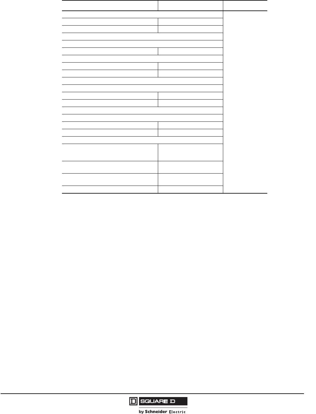
Model 6 Motor Control Centers
Unit Options Application and General Information
83
07/2009
© 1997–2009 Schneider Electric
All Rights Reserved
Circuit Breaker Micrologic® Electronic Trip Unit Options
Description Application Space (Inches)
350–600A Breakers (L-frame)
0
Standard function LX substituted for LA/LH/LI LSI1
1Ground fault tripping functions can be added to these trip units. See the Ground Fault Options table on
page 84.
Full function LE substituted for LA/LH LSI
700–2500A Circuit Breakers (PowerPact M-, P-, and R-frame)
Standard
5.0 LSI
Ammeter
5.0A LSI
6.0A LSIG
Trip unit power supply (recommended for ammeter trip unit)
Power
5.0P LSI
6.0P LSIG
Trip unit power supply (provided standard for power trip unit)
Harmonic
5.0H LSI
6.0H LSIG
Trip unit power supply (provided standard for harmonic trip unit)
Modbus Breaker Communications Module (BCM)
installed and unwired (Includes 24 Vdc
communications power supply) A trip unit only
Modbus BCM unwired (Includes 24 Vdc
communications power supply) P or H trip unit
Wiring to MCC Modbus network (adds network
cable to main/branch unit) Intelligent MCC or Transparent
Ready MCC
Communications for shunt trip A, P, or H trip unit
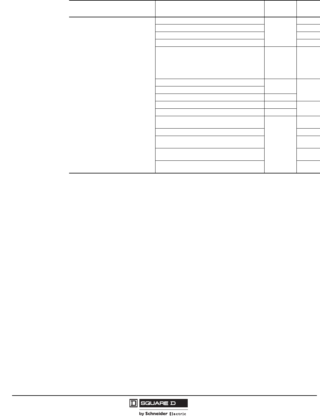
© 1997–2009 Schneider Electric
All Rights Reserved
Model 6 Motor Control Centers
Application and General Information Unit Options
84 07/2009
Ground Fault Options
Description Application Ground
Fault Type Space
(Inches)
Ground fault protection (zero sequence)
Size 1–2 starter
GA
6
Size 3 starter 9
Size 4–5 starter 12
Size 6 starter 0
Size 6 autotransformer
Order
appropriate
Micrologic
electronic trip
unit option
(6.0A, P or H)
0
15–250 A branch circuit breaker 1
1Not available on Compac 6.
GFM 6110–250 A main circuit breaker
200 A main/branch fusible switch GA
300–600 A main or branch circuit breakers LX MX C/B 2
212 in. of additional space required for 3-phase, 4-wire systems with neutral lug option.
0
300–600 A main or branch circuit breakers LE ME C/B
600–800 A main or branch switch
Order
appropriate
Micrologic
electronic trip
unit option
(6.0A, P or H)
0 (3 W)
12 (4 W)
1000-1200 A branch switch or top incoming main switch 0
1000-1200 A bottom incoming main switch 0 (3 W)
12 (4 W)
800-1200 A main or branch circuit breaker (80%)
800 A main or branch circuit breaker (100%) 0 (3 W)
15 (4 W)
1200 A main or branch circuit breaker (100%)
1600-2500 A main circuit breaker or switch 0
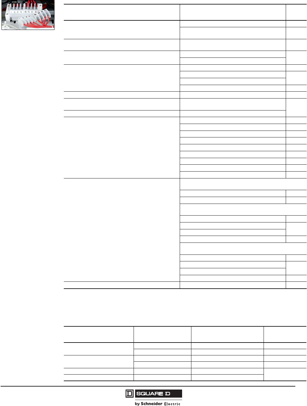
Model 6 Motor Control Centers
Unit Options Application and General Information
85
07/2009
© 1997–2009 Schneider Electric
All Rights Reserved
Control Terminal Block
Wiring Options
Description Application Space
(Inches)
Additional terminal blocks
NOTE: Max. 20 control terminals per unit; 12 max. with power
terminals
All starters—unwired (per terminal point) 0
All starters—wired (per terminal point) 0
Control power transformer leads X1 and X2 wired to the
control terminal block (standard on industrial package) All starters 0
Power terminal blocks (will reduce max. control from 20 to 12) Size 1–2 starters 0
Size 3 starters
Starter control wiring; size, and type
#16 AWG Type MTW (standard) 0
#14 AWG Type MTW 1
1Not applicable to Compac 6, Altivar®, or Altistart® units.
0
#16 AWG Type SIS
#14 AWG Type SIS 0
Standard wire labels—plastic sleeve All starter control wiring—Schneider Electric numbering 0
Custom wire labels—plastic sleeve All starter control wiring—User-defined (13 characters
max.) 0
Ring tongue terminals 2
2Provided where possible and allowed by UL procedure.
All starter control wiring
Copper crimp lugs
(For customer connections only; cable sizes must be
provided)
Main lug compartments 0
Size 1-4 starters , 3
3Not UL Listed.
0
15–150 A main/branch circuit breaker 3
175–250 A main/branch circuit breaker 0
15–100 branch fusible switch 3
110–225 A main/branch fusible switch 6
600-800 A Main Switch 12
800 A Main or Branch Circuit Breaker 15
All other units 6
Main/branch mechanical lug alternatives
Aluminum Lug for 600 kcmil Cu or Al cable or 750 kcmil
compacted Al cable (2/phase, AL800P7K kit)
700–800 A Circuit Breaker 15
600–800 A Main Switch 12
Aluminum Lug for 600 kcmil Cu or Al cable
(3/phase, AL1200P6KU kit)
1000–1200 A Circuit Breaker (80% rated) 15
1000–1200 A Circuit Breaker (100% rated) 0
1000–1200 A Top Incoming Main Switch
1000–1200 A Bottom Incoming Main Switch 12
Aluminum Lug for 750 kcmil compacted AL cable
(3/phase, AL1200P7KU kit)
1000–1200 A Circuit Breaker (80% rated) 15
1000–1200 A Circuit Breaker (100% rated) 0
1000–1200 A Top Incoming Main Switch
1000–1200 A Bottom Incoming Main Switch 12
Special wire colors—3 max. All starter control wiring 0
Optional Burndy Type Copper Crimp Lugs
Circuit Breaker Frame Maximum Amps Burndy Crimp Lug
Lug Wire Range Lugs Per Phase
H60 #6–1/0 Cu 1
150 #4–2/0 Cu 1
J150 #4–2/0 Cu 1
250 2/0–300kcmil Cu 1
P (molded case switch) 600 4/0–500 kcmil Cu 2
M and P (circuit breakers/switches) 800 500–750 kcmil Cu
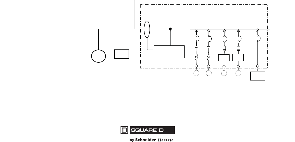
© 1997–2009 Schneider Electric
All Rights Reserved
Model 6 Motor Control Centers
Application and General Information Miscellaneous Units
86 07/2009
AccuSine® Power Correction System
General Information
The AccuSine Power Correction System (PCS) is an active harmonic filter (AHF) which actively injects
opposite harmonics current on the source side of the load and it:
When installed in the MCC, the AccuSine PCS will compensate for harmonic loads within and fed by the
MCC. This is an essential function as MCCs continually incorporate more and more solid state components
such as AC drives, soft starts, and PLCs, which increase the potential for power quality issues.
The Model 6 MCC AccuSine package includes:
Decreases harmonic related
overheating of cables, switchgear,
and transformers.
Reduces downtime caused by
nuisance thermal tripping of
protective devices.
Increases electrical network
reliability and reduces operating
costs.
Corrects to the 50th harmonic;
reduces harmonics level to meet
IEEE 519 at the MCC main
incoming power connection.
Cost effective approach to groups of
harmonic loads and as an
alternative to multi-pulse drives.
50 A or 100 A rated model Accusine
PCS for 208–480 V
Door-interlocked disconnect and
fusing
Door-mounted display (HMI) for
programming and monitoring
Suitable for use in 100 kAIC rated
MCCs
UL/cUL Listed
Rated for NEMA/EEMAC Type 1 or
Type 1A (Gasketed) enclosures.
Not available for Type 12 or Type 3R
enclosures.
Two current transformers for
installation by contractor at the MCC
main incoming cables. Three CTs
are supplied when single-phase
loads are present.
Up to five multiple units can be
connected in parallel to increase
compensation up to 500 A of
harmonic current compensation.
Standard MCC bus and enclosure
depth allow the active filtering to be
retrofitted onto the MCC for future
expansion of harmonic compensation.
Typical MCC AccuSine Installation
Upstream
Electrical
Network
Corrected Loads
MCC Enclosure
Uncorrected Loads
Active
Filter VFD VFD
MMMM
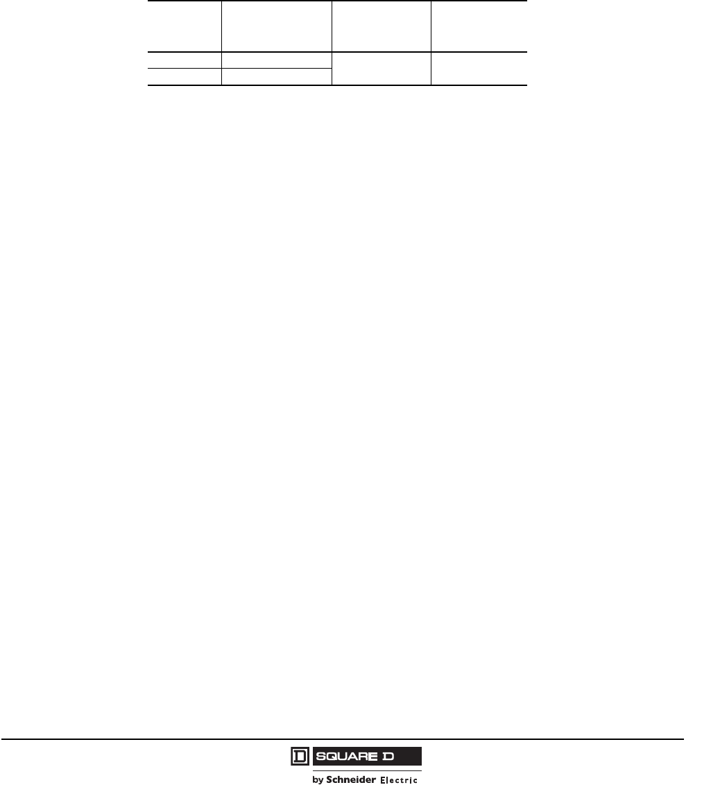
Model 6 Motor Control Centers
Miscellaneous Units Application and General Information
87
07/2009
© 1997–2009 Schneider Electric
All Rights Reserved
Accusine PCS Sizing
A harmonic study is not required to select the size of the AccuSine PCS installation, because when
AccuSine PCS is installed it becomes a lower impedance for harmonics than the existing power
supply. Unlike passive devices, AccuSine PCS is easy to apply and cannot be overloaded. For proper
sizing, contact your local Schneider Electric representative, or visit the Schneider Electric website
(www.schneider-electric.us) for downloadable sizing software. To expedite the product selection
process, have a single line diagram and/or details of the application including sizes of transformers,
non-linear and linear loads, and any existing filters and capacitors.
AccuSine Power Correction System for Model 6 MCC
Total
Current
(RMS Amps)
Disconnect Switch
(Amps) Voltage Rating
(Volts) Space (Inches)
50 100 208/240/480 72
(20 W x 20 D)
100 150
© 1997–2009 Schneider Electric
All Rights Reserved
Model 6 Motor Control Centers
Application and General Information Miscellaneous Units
88 07/2009
Single-Phase Distribution Transformers 120/240V Secondary
Distribution transformers are provided with a primary circuit breaker or fusible switch.
5 kVA and 10 kVA transformers may be mounted in a standard 20 in. W x 15 or 20 in. D section. 15 kVA
and 25 kVA transformers must be mounted in a 20 in. W x 20 in. D section.
302 °F (150 °C) temperature rise transformers are supplied as standard.
NOTE: 5 kVA and 10 kVA transformers are available in multiple section shipping splits. All other
transformers listed are bottom mounted in a single shipping split. Shielded isolation transformers are
available, and other primary voltages can be supplied.
Distribution Transformer
Disconnect kVA Rating Disconnect Amps Space (Inches)
480 V
Primary
Circuit Breaker
0.5 kVA 15 6
1 kVA 15 12
1.5 kVA 15 15
5 kVA 15 21 1
1Unit mounted transformers are available in 5 kVA and 10 kVA ratings. Requires a 30 in. space.
10 kVA 30 21 1
15 kVA 40 36
25 kVA 60 36
240 V
Primary
Circuit Breaker
0.5 kVA 15 6
1 kVA 15 12
1.5 kVA 15 15
5 kVA 30 21 1
10 kVA 50 21 1
15 kVA 70 36
25 kVA 125 36
600 V
Primary
Circuit Breaker
0.5 kVA 15 6
1 kVA 15 12
1.5 kVA 15 15
5 kVA 15 21 1
10 kVA 20 21 1
15 kVA 30 36
25 kVA 50 36
480 V
Primary
Fusible Switch
0.5 kVA 15 6
1 kVA 15 12
1.5 kVA 15 15
5 kVA 15 21 1
10 kVA 25 21 1
15 kVA 35 36
25 kVA 60 36
240 V
Primary
Fusible Switch
0.5 kVA 15 6
1 kVA 15 12
1.5 kVA 15 15
5 kVA 25 21 1
10 kVA 45 21 1
15 kVA 70 36
25 kVA 125 48
600 V
Primary
Fusible Switch
0.5 kVA 15 6
1 kVA 15 12
1.5 kVA 15 15
5 kVA 10 21 1
10 kVA 20 21 1
15 kVA 30 36
25 kVA 50 36
Model 6 Motor Control Centers
Miscellaneous Units Application and General Information
89
07/2009
© 1997–2009 Schneider Electric
All Rights Reserved
Three-Phase Distribution Transformers 208Y/120 V Secondary
Distribution transformers are provided with primary circuit breaker or fusible switch. 302 °F (150 °C)
temperature rise transformers are supplied as standard. Three-phase distribution transformers must
be located in 20 in. deep sections.
NOTE: All transformers listed must be bottom mounted in a single shipping split. Shielded isolation
transformers are available and other primary voltages can be supplied.
.
Disconnect kVA Rating Disconnect Amps Space (Inches)
480 V
Primary
Circuit Breaker
9 kVA 15 30
15 kVA 20 30
30 kVA 40 36
45 kVA 60 36 1
1Requires a 25 in. wide structure.
240 V
Primary
Circuit Breaker
9 kVA 30 30
15 kVA 40 30
30 kVA 90 36
45 kVA 125 36
600 V
Primary
Circuit Breaker
9 kVA 15 30
15 kVA 20 30
30 kVA 40 36
45 kVA 50 36
480 V
Primary
Fusible Switch
9 kVA 15 30
15 kVA 20 30
30 kVA 40 36
45 kVA 60 36
240 V
Primary
Fusible Switch
9 kVA 25 30
15 kVA 40 30
30 kVA 80 36
45 kVA 125 48
600 V
Primary
Fusible Switch
9 kVA 10 30
15 kVA 20 30
30 kVA 35 36
45 kVA 50 36
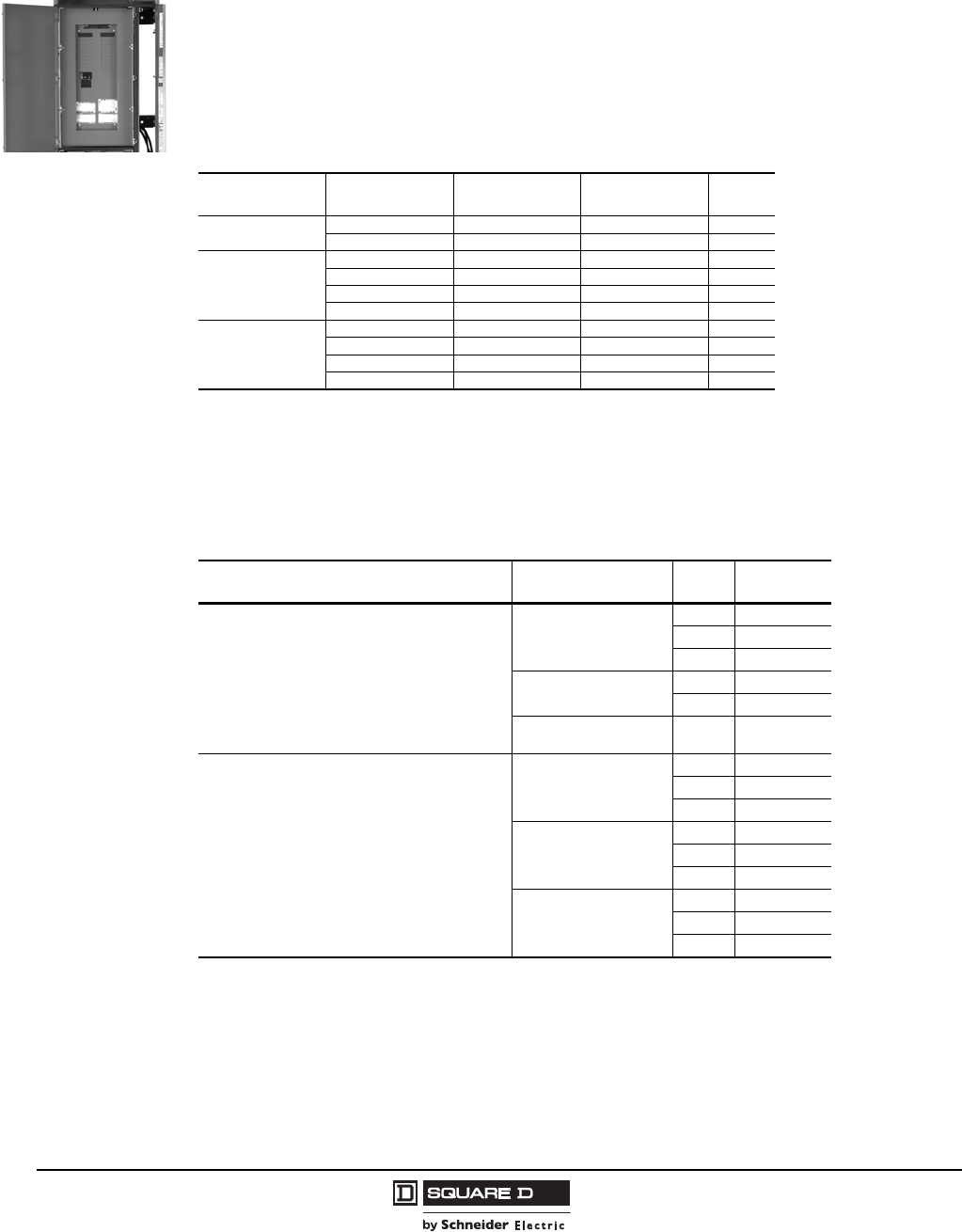
© 1997–2009 Schneider Electric
All Rights Reserved
Model 6 Motor Control Centers
Application and General Information Miscellaneous Units
90 07/2009
Distribution Panelboards
Panelboards are provided with space for branch circuit breakers. All panelboards are provided with a
main circuit breaker. Copper bus is standard. The 3-phase Type NQ 30 circuit is also available with a
main lug.
NOTE: NQ 18- and 30-circuit panelboards utilize back-fed main units, thus reducing the available pole
spaces for circuit feeds. NF panelboards must be located in the top of the section.
Ratings:1-Phase NQ = 120/240 V
3-Phase NQ = 240 V
3-Phase NF = 277/480 V
Factory Installed Panelboard Branch Circuit Breakers
The branch circuit breakers below are rated for 10,000 AIR at the voltage listed. Higher interrupt
ratings are available.
Distribution Panelboard
in an MCC
Unit Type 1-Pole Spaces Main Amperes Interrupting
Rating Space
(Inches)
1-Phase
Type NQ 18 100 — 27
42 225 — 51
3-Phase
Type NQ
18 100 — 27
30 100 — 33
42 225 — 51
Main Lug 30 100 — 33 1
1Main Lug.
3-Phase
Type NF
30 — 65 kAIC 45 2
225 in. wide structure.
30 — 100 kAIC 45
42 — 65 kAIC 57
42 — 100 kAIC 57
Panelboard Type Branch Circuit
Breaker Type Poles Amps
NQ
QOB branch circuit breakers are standard,
unless otherwise noted.
QO/QOB
120/240V
1 10–70
2 10–125
3 10–100
QO/QOB – GFI
120/240V
1 15–30
2 15–60
QO/QOB
240V 2 15–100
NF
EDB branch circuit breakers are standard,
unless otherwise noted.
EDB
(bolt-on only)
1 15–70
2 15–125
3 15–125
EGB
(bolt-on only)
1 15–70
2 15–125
3 15–125
EJB
(bolt-on only)
1 15–70
2 15–100
3 15–100
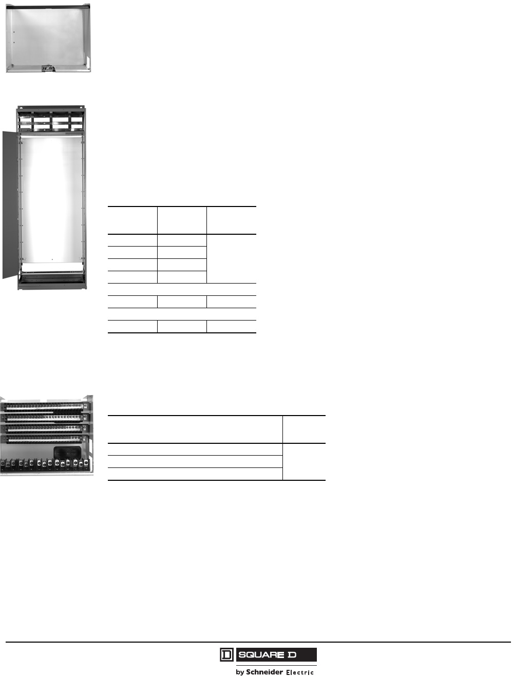
Model 6 Motor Control Centers
Miscellaneous Units Application and General Information
91
07/2009
© 1997–2009 Schneider Electric
All Rights Reserved
Empty Mounting Units
Empty mounting units are available in 3-inch increments from 6 in. through 48 in. high.
Includes a removable undrilled unit and a hinged door to provide space for customer mounted devices.
Unit dimensions are 13.85 in. wide by 9.5 in. deep. Height is dependent on unit selected.
Empty mounting units may be used in 20 in. wide by 15 in. or 20 in. deep sections.
Full Section Empty Mounting Units (Relay Section)
Consists of a removable undrilled mounting pan and a full height door on structure for customer mounted
devices. The section does not contain vertical bus or a vertical wireway. The section cannot be modified
to accept plug-on units. Horizontal bus is supplied to allow feed through to additional MCC sections.
Panel height: 68 in.
Panel depth (clearance from panel to door):
11.7 in. (15 in. deep section)
16.7 in. (20 in. deep section)
Unwired Master Terminal Compartment
Includes a removable 12 in. unit, hinged door, unwired control and power terminal blocks, and mounting
provisions. Compartment may be located anywhere in a 20 in. wide by 15 in. or 20 in. deep section.
Blank Doors
Blank covers are available in 3-inch increments from 3 in. through 36 in. high. Factory-assembled MCC
orders are automatically provided with the proper number of blank covers to fill any unused space in
each section.
Future prepared space may be provided if desired; to provide future prepared space, add the desired
number and size required.
Blank doors are required to fill prepared space when rearranging plug-in units in an existing motor
control center.
Empty Mounting Unit
Relay Section
Section
Width Panel
Width Space
(Inches)
20 in. 18.13 in.
72
25 in. 23.13 in.
30 in. 28.13 in.
35 in. 33.13 in.
Omit horizontal bus for listed sections
—— 0
3-point door latch
—— 0
Master Terminal
Compartment
(Unit Shown Unwired)
Terminal Provisions Space
(Inches)
100 control points
12100 control points and 15 power points
70 control points and 30 power points
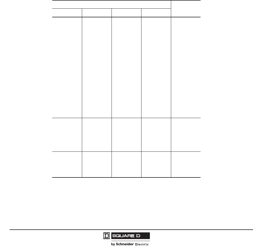
© 1997–2009 Schneider Electric
All Rights Reserved
Model 6 Motor Control Centers
Application and General Information Miscellaneous Units
92 07/2009
Power Factor Correction Capacitors
Power Factor Correction Capacitors listed are environmentally safe and include fuses for protection of
the capacitor. These capacitors include discharge resistors as required by the NEC. Capacitors are
mounted directly below the corresponding starter and are connected between the starter
contactor and overload relay. Installation of capacitors does not affect normal selection of overload
thermal units, starters, or disconnects.
Do not use capacitors on controllers subject to plugging or jogging. It is recommended that only Full
Voltage Non-Reversing (FVNR) starters be provided with power factor correction capacitors.
Capacitors can be applied to other types of starters, but auxiliary contactors are often required. Some
types of starters are not compatible with individual motor correction. Contact the MCC TAG for details
or application assistance.
Selection
To select unit type, determine kvar rating from table below. Match kvar rating to last digits listed on unit type.
kvar Rating Space
(inches)
208 V 240 V 480 V 600 V
1
1.5
2
2.5
3
4
5
6
7
7.5
9
10
1
1.5
2
2.5
3
4
5
6
7
7.5
8
9
10
11
12
12.5
15
17.5
1
1.5
2
2.5
3
4
5
6
7
7.5
8
9
10
11
12
12.5
13.5
15
16
17.5
18
22.5
25
27.5
30
1
1.5
2
2.5
3
4
5
6
7.5
10
11
12
12.5
15
16
17.5
18
20
22.5
25
27.5
30
6
11
12.5
15
17.5
20
20
22.5
25
27.5
30
32.5
35
37.5
40
42.5
45
50
60
32.5
35
37.5
40
45
50
60
12
22.5
25
27.5
32.5
35
37.5
40
42.5
45
70
80
—18
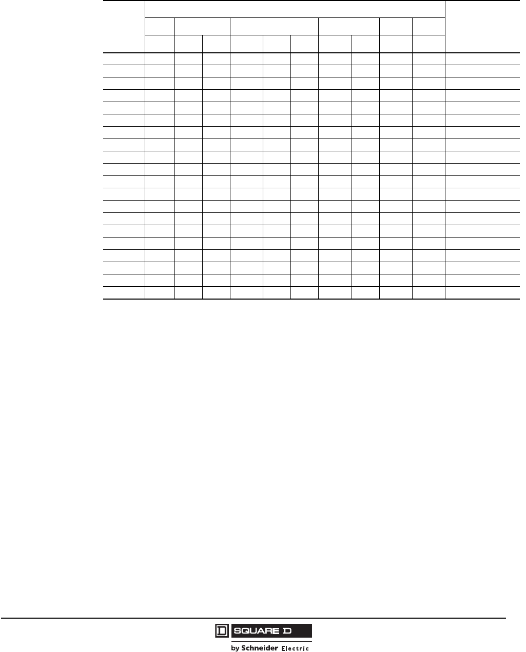
Model 6 Motor Control Centers
Miscellaneous Units Application and General Information
93
07/2009
© 1997–2009 Schneider Electric
All Rights Reserved
Capacitor Sizing Table—480 V
Size capacitors (in kvar) to the particular motor loads to be corrected. If motor characteristics are not
available, the values in the last column provide approximate sizing.
hp
RPM – NEMA/EEMAC Design Approx.
Value When
Motor Data Is Not
Available
3600 1800 1200 900 720 600
BBCBCDBCB B
3 1.5 1.5 1 2 1 1 3 2 3 4 1.5
5 22.523224245 2
7.52.5334325456 2.5
10 4 4 4 5 4 3 6 4 7.5 8 3
15 5 5 5 6 5 5 7.5 5 8 10 4
20 6 6 5 7.5 5 6 9 6 10 12.5 5
25 7.5 7.5 6 8 6 6 10 6 12.5 17.5 7
30 8 8 7.5 10 7.5 10 15 9 15 20 9
40 12.5 15 10 15 10 12 17.5 12 20 25 10
50 15 17.5 12 20 12 15 22.5 15 22.5 30 12
60 17.5 20 17.5 22.5 17.5 18 25 18 30 35 15
75 20 25 20 25 20 22.5 30 22.5 35 40 18
100 22.5 30 27.5 30 27.5 30 35 27.5 40 45 22.5
125 25 35 35 35 35 37.5 40 37.5 45 50 27.5
150 30 40 37.5 40 37.5 45 50 45 50 60 32.5
200 35 50 45 50 45 60 70 60 70 90 40
250 40 60 55 60 55 70 80 70 90 100 50
300 45 70 65 75 65 75 100 90 100 120 55
350 50 75 — 90 — — 120 — 120 135 65
400 75 80 — 100 — — 130 — 140 150 70

© 1997–2009 Schneider Electric
All Rights Reserved
Model 6 Motor Control Centers
Application and General Information Miscellaneous Units
94 07/2009
PowerLogic® Ethernet Gateways
The PowerLogic devices listed below provide an interface between Ethernet and Modbus® devices. In
addition to the high-speed communications, the Ethernet connectivity opens up information access via
standard web browsers. The gateway can connect with up to 64 Modbus or PowerLogic devices. Each
unit includes the gateway, control power disconnect, fused control power transformer, and DC power
supply. Connection cables to the Modbus or Ethernet network are not included.
Transparent Ready® Equipment Configurations
MCC Transparent Ready options provide the ability to access pre-programmed/pre-linked web pages in
the MCC equipment. This allows the customer to quickly commission and view a wide range of process
data using web browser software. The MCC can be pre-tested and pre-wired at the factory with the
Ethernet connection ready for the customer’s network.
The Transparent Ready levels below offer web page choices for real time data, enhanced graphics,
and reporting capability.
Gateway Ethernet Switches
A gateway Ethernet switch serves as a hardware interface between an EGX Ethernet gateway and
other Ethernet connections such as the customer's Ethernet network outside the MCC, and the
programming port on the outside of the MCC door. A choice of switch types is available, depending on
the hardware (copper wire or fiber optic) the customer would prefer. For Transparent Ready MCCs, the
default selection is 10/100 Mbps if no other choice is made.
NOTE: The Ethernet switches and bulkhead port connector are not provided unless a Transparent
Ready level is requested. For customers requesting network provisions only, the gateway is provided
with no switches.
Description Application Space
(Inches)
EGX100 PowerLogic Ethernet Gateway with one UTP Ethernet Port (10/100 Mbps), one RS-485 serial
port, and one RS-232 serial port.
9
EGX300
PowerLogic integrated gateway-server provides serial support for Modbus RTU, Modbus ASCII,
JBus and PowerLogic protocols to support a wide range of devices. Includes one 10/100BaseTx
Ethernet port and one serial port configurable for RS485 (2/4-wire) or RS232 (RJ45). Connects
up to 64 network devices. Includes 512MB webserver memory.
Description Application
TR1—Essential
Web enabled and factory configured for Ethernet Mains monitoring only 1
1Requires one of the following: PowerLogic power meter with an ECC card, PowerLogic circuit monitor with an ECC card, or an
EGX gateway with Ethernet switches.
Five web pages of real time data using Web-Generator 1 (WG-1) 2
2Web-Generator (WG-1) software provides basic informational pages for use with the PowerLogic ECC or EGX Ethernet Gateway.
Main + downstream devices monitoring 3
3Requires at least one Modbus compatible device (TeSys T Motor Management Controller, PowerLogic Meter, Altivar 61/71 AC drive,
or Altistart Soft Start). Requires one of the following: PowerLogic power meter with an ECC card, PowerLogic circuit monitor with an
ECC card, or an EGX gateway with Ethernet switches.
TR2—Deluxe
Features of TR1 Plus graphical pages for use on EGX system supported software:
Web-Generator 2 (WG2) 4
4Web-Generator (WG-2) software provides advanced informational pages for use with the PowerLogic EGX Ethernet Gateway.
Main + downstream devices 5
5Requires at least one Modbus compatible device (TeSys T Motor Management Controller, PowerLogic Meter, Altivar 61/71 AC
drive, or Altistart Soft Start). Requires an EGX300 gateway with Ethernet switches.
Description Space Adder
10/100 Mbps Ethernet RS485 Switches (Available with EGX Gateways only)
Provides five 10/100 Mbps twisted pair (RJ-45 connectors)ports for connecting an Ethernet factory network and
mounted programming port to the EGX Gateway(s)
Fiber Optic Interface Switches (Available with EGX Gateways only)
Provides four 10/100Mbps twisted pair (RJ-45 connectors) ports and one 100Mbps fiber optic port
(100 Base=hFX, Duplex SC connector) for connecting an Ethernet factory network and mounted programming
port to the EGX Gateway(s).
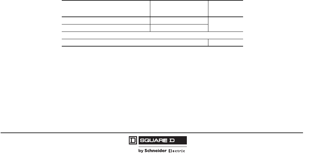
Model 6 Motor Control Centers
Miscellaneous Units Application and General Information
95
07/2009
© 1997–2009 Schneider Electric
All Rights Reserved
High Resistance Ground Unit
The High Resistance Ground Unit offers ground fault control and monitoring for power systems using
ungrounded delta or wye transformer secondaries. The Model 6 Motor Control Center high resistance
ground unit can be applied to 480 V and 600 V ungrounded delta and wye, 50/60Hz systems. The high
resistance ground unit is available for both 3-phase, 3-wire wye and delta power systems. The Model 6
high resistance ground unit facilitates a controlled, sequential process shutdown, thereby reducing the
adverse affects resulting from an uncontrolled shutdown.
Standard Package Features:
Resistor bank limits overvoltages by grounding the system neutral through impedance
High resistance ground indication/control panel
The high resistance neutral grounding equipment will contain the following equipment on an operator's
panel on the front of the unit as standard:
Line Disconnect
Test Push-button
A digital display unit containing the following functions:
— Green Light to Indicate “Normal” Operating Status
— Flashing red Light to Indicate “Fault” Status
— Red Light to Indicate “Harmonic” Status
— Fault reset
— Alarm silence
— Pulse on/off
— Amber light to indicate “pulse” status
— Indication of Under-Voltage condition
— Indication of Under-Current condition
— Ethernet/Modbus port for Communications
— Single setpoint Meter Relay
The relay to monitor fundamental voltage and current will incorporate an adjustable time delay function
to avoid spurious alarms.
The relay to monitor harmonic voltage and current will incorporate an adjustable time delay function to
avoid spurious alarms.
High Resistance Ground Unit for Model 6 MCC
System Voltage Configuration Current Range
(Ground Current Amps) Space
(Inches)
480 V, 3-phase, Wye or Delta 1–10 72
(20 W X 20 D)
600 V, 3-phase, Wye or Delta 2–7
Additional Options
Portable hook-on ammeter with carrying case 0
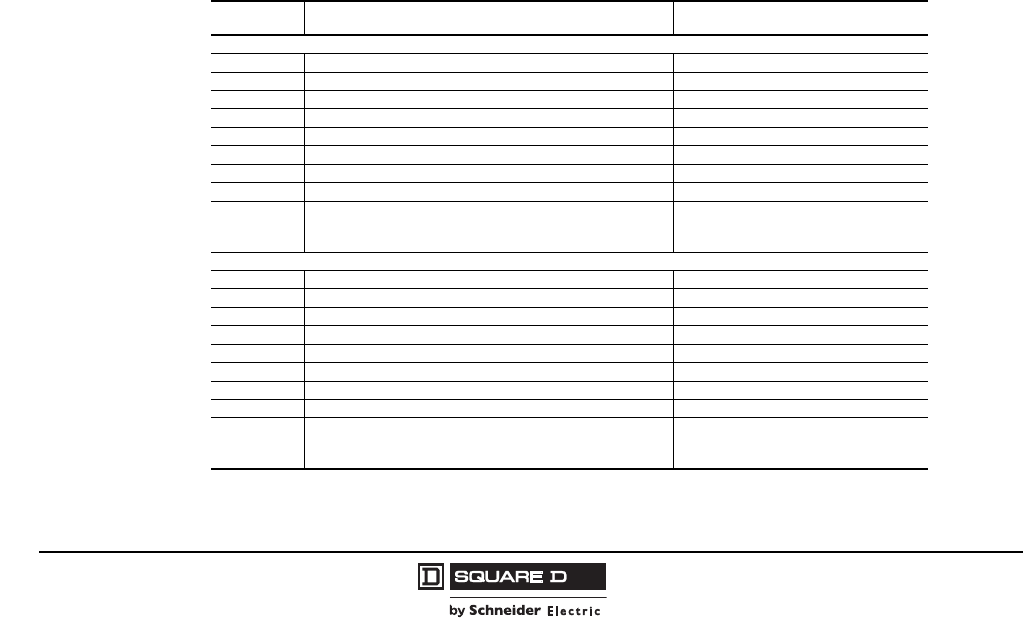
© 1997–2009 Schneider Electric
All Rights Reserved
Model 6 Motor Control Centers
Application and General Information Miscellaneous Units
96 07/2009
ASCO 7000 Series Automatic Transfer Switches With
Microprocessor Control Panel (Non-UL Listed)
The standard automatic transfer switch is the ASCO 7000 Series switch. High speed transfer of loads
between alternate sources of power, regardless of ampacity size, is achieved by a reliable, field proven
solenoid operating mechanism. When combined with a programmable microprocessor controller with
keypad and LCD display, the automatic transfer switch offers the most advanced method of
transferring all types of loads, such as, motors, electronic drives, UPS’s, and microprocessor-based
systems. 7000 Series automatic transfer switches are open transfer in ampacity sizes from 30 through
1200 A. If you have any questions, contact MCC TAG.
•Conventional two-position transfer configuration with automatic control
•UL Listed to 1008 Transfer Switch Equipment and CSA certified to CSA 22.2 No. 178-1978
Automatic Transfer Switches
•Independently qualified and certified listed to IEC 60947-6-1, CE marked (optional; limited to
certain accessories)
•Rated up to 600 Vac, 30–1200 A
•Reliable and field proven solenoid operating mechanism
•High withstand and close-on ratings including 30 cycle withstand current rating for optimum
flexibility in circuit breaker coordination (600–1200 A)
•Solid, switched, or overlapping neutral conductor options
•Front replaceable main and arcing contacts (800–1200 A)
•Programmable microprocessor controller with keypad and LCD display
•Centrally located terminal block for customer control connections (260–1200 A)
•16 mm, industrial grade control switches and indicating lights
•Switch position indicators and true source acceptability lights
•Standard ground conductor connections
•Four auxiliary contacts—two contacts closed when switch is in normal position and two contacts
closed when switch is in emergency position
ASCO 7000 Series Automatic Transfer Switches With Microprocessor Control Panel
Rating Lug Range Space (Inches)
3Ø3W (can be used with solid neutral through 800 A; ASCO accessory 22)
30 A (1) #14–#4/0 361
1Must be top or bottom located.
70 A (1) #14–4/0 36
100 A (1) #14–4/0 36
150 A (2) 1/0–250 kmcil or (1) #4–600 kcmil 72 (25 W) 2
2No vertical bus or vertical wireway.
260 A (2) #1/0–250 kcmil or (1) #4–600 kcmil 72 (25 W)
400 A (1) #4–600 kcmil or (1) #4–600 kcmil 72 (25 W)
600 A (3) #2–600 kcmil 72 (25 W x 20 D)
800 A (4) 1/0–750 kcmil 72 (30 W x 20 D)
1200 A (4) 1/0–750 kcmil Two full sections required:
1 @ (30 W x 20 D)
1 @ (20 W x 20 D)
3Ø4W with switched neutral (ASCO accessory 28)
30 A (1) #14–4/0 36
70 A (1) #14–4/0 36
100 A (1) #14–4/0 36
150 A (2) 1/0–250 kcmil or (1) #4–600 kcmil 72 (25 W)
260 A (2) 1/0–250 kcmil or (1) #4–600 kcmil 72 (25 W)
400 A (2) 1/0–250 kcmil or (2) 1/0–250 kcmil 72 (25 W)
600 A (2) #2–600 kcmil 72 (25 W x 20 D)
800 A (4) 1/0–750 kcmil 72 (30 W x 20 D)
1200 A (4) 1/0–750 kcmil Two full sections required:
1 @ (30 W x 20 D)
1 @ (20 W x 20 D)
Model 6 Motor Control Centers
Miscellaneous Units Application and General Information
97
07/2009
© 1997–2009 Schneider Electric
All Rights Reserved
Standard Features and Optional Accessories
Description ASCO
Accessory
Code
Accessory panel required for some ASCO accessories.1
118 in. additional space required for 30–100 A switches; no additional space required on larger switches.
AP
Extended time delay on engine start.2
2Requires accessory panel option AP.
2C
3-phase differential voltage sensing of alternate source.24E
3-phase overvoltage sensing of normal source.24H
Reset switch to manually bypass time delay on retransfer to normal. 6B
Reset switch to manually retransfer to normal source after time delay. 6C
Toggle and selector switches to permit manual or automatic reset to normal. 6D
Normal/alternate source available pilot lights. 9C/9D
Push-to-test pilot lights for connected-to-normal and connected-to-emergency source. 9E/9F
Engine generator exercise timer with switch to select with load or without load. 11C
Three position engine control switch: Stop/Auto/Engine Test. 12
(2) auxiliary contacts that close when switch is connected to normal source 14A
(2) auxiliary contacts that close when switch is connected to emergency source 14B
Two-pole, double throw contacts operate when emergency source voltage is present at transfer switch terminals. 18B
Two-pole, double throw contacts operate when normal source voltage is present at transfer switch terminals. 18G
Solid neutral for 3-wire switch. (Cannot be used if either source has ground fault protection.)
30–150 A switch
22
260 A switch
400 A switch
600 A switch
800 A switch
1200 A switch
In-phase monitor for motor loads; monitors sources and retransfers to normal when both sources are phase;
prevents excess transients on transfer. 27
Equipment ground lug 33
Selective load disconnect control contacts that operate with time delay prior to and/or after load transfer and retransfer. 31Z
Serial communication module for remote communication 72A
Connectivity module for remote communications using Ethernet TCP/IP networks. 72E

© 1997–2009 Schneider Electric
All Rights Reserved
Model 6 Motor Control Centers Intelligent Motor Control Centers
98 07/2009
Model 6 iMCCs
Model 6 iMCCs feature the same overall structure and unit features as Model 6 motor control centers
with additional “intelligent” capabilities. Schneider Electric supports two popular methods for
configuring Model 6 iMCCs to customize your application:
•iMCC-Hardwired I/O: PLC Interwiring
•iMCC-Network: Network Cabling
iMCC- Hardwired I/O: PLC Interwiring offers a hardwired I/O system in the Model 6 MCC that
provides basic information and control capabilities. With the I/O mounted in the MCC, the starters are
wired to the I/O at the Schneider Electric manufacturing plant and the system is tested prior to
shipment. This pre-wired MCC is more cost effective than separately mounting and wiring the
automation hardware outside of the MCC. This option can also include an independent network.
iMCC Network: A key feature of our iMCC-Network solution is the integration of intelligent devices and
device level networks for control and automation that delivers improved performance. Popular network
protocols such as CANopen, DeviceNet™, Ethernet, Modbus®, and PROFIBUS communicate directly
to every unit of the iMCC for an effective method of connecting centralized control to widely distributed
I/O. The network of your choice creates a common thread for a variety of motor control equipment that
not only improves control, but also allows for simple and easy installation and operation.
Networking allows for easy monitoring of critical data of each motor or load connected to the iMCC,
enabling precise process control at all times. With this information, your staff can respond to potential
problems proactively. Real-time access to information and records of last faults allows for simplified
diagnostics and reduced downtime.
Using network control to consolidate all I/O communications significantly reduces the amount of
tedious wiring that would normally be required for a hardwired I/O MCC with similar functionality. We
design a network cabling solution that is appropriate for your selected communication network. Our
industry-leading full-depth wireway effectively separates network cabling from high voltage cabling.
Additionally, our standard wireway barrier isolates the communication cabling from the load cabling
routed in the vertical wireway.
Experience the benefits of an iMCC network:
•Remote monitoring capability
•Reduced downtime and system interwiring
•Control to every bucket
•Lower commissioning costs
•Flexible configuration
•Cabling system compliant to applicable standards.
•DeviceNet solution is Open DeviceNet Vendor Association (ODVA) certified.
Model 6 Motor Control Centers
Intelligent Motor Control Centers
99
07/2009
© 1997–2009 Schneider Electric
All Rights Reserved
Common Mounting Configurations for Automation Components
PLC components are packaged in Schneider Electric MCCs in two distinct configurations: a unit-mount
configuration and a full-section configuration. The unit-mount configuration supports plug-on
installation and location flexibility in the MCC. The full-section configuration provides increased space
for mounting PLCs and associated equipment. Two full sections can be joined to provide maximum
mounting space. For additional automation component mounting information, consult the Model 6
MCC catalog.
NOTE: The configurations shown below represent the maximum PLC component densities available.
Power distribution, power supplies, component selection, communication protocol, fusing, interposing
relays, and CableFast modules affect the actual component densities. The configurations shown are
standard configurations. Schneider Electric can also provide custom configurations to meet your
specific requirements.
PLC Type
Unit Mounts Special Units (no wireway) 1
1Special units include 18, 24, 30, and 36 in. high configurations. These units are not plug-in and take up the vertical wireway. They must be mounted at the bottom
of a 20 in. wide section.
Full Sections
12 in.
(13.5 x 11 in.) 18 in.
(13.5 x 17 in.) 18 in. Height 24 in. Height 20 in. wide
(16.4 x 63.4 in.) 25 in. wide
(21.4 x 63.4 in.) 30 in. wide
(26.4 x 63.4 in.) 35 in. wide
(31.4 x 63.4 in.)
Momentum™ 2 modules 4 modules 6 modules 8 modules 12 modules 18 modules 24 modules 30 modules
Micro™ 1 PLC (fixed I/O)
and power supply 2 PLC
(fixed I/O) 1 PLC and
1 Expansion 1 PLC and
2 Expansion
up to 5
interconnected
PLCs
up to 5
interconnected
PLCs
up to 5
interconnected
PLCs
up to 5
interconnected
PLCs
Compact™ up to one 5-slot rack
plus one 2-slot rack up to two
5-slot racks up to two
5-slot racks up to three
5-slot racks up to two
5-slot racks up to four
5-slot racks up to four
5-slot racks up to four
5-slot racks
Quantum™ N/A up to one
6-slot
backplane
up to one
10-slot
backplane
up to one
10-slot
backplane
up to four
6-slot
backplanes
up to four
10-slot
backplanes
up to four
10-slot
backplanes
up to four
16-slot
backplanes
Premium™ N/A up to one
8-slot
backplane
up to one
8-slot
backplane
up to two
6-slot
backplanes
up to four
8-slot
backplanes
up to four
12-slot
backplanes
up to four
12-slot
backplanes
up to four
12-slot
backplanes
PLC Foldout Rack
Description Application
6 in. foldout rack 12 in. unit or larger
12 in. foldout rack 18 in. unit or larger
18 in. foldout rack 24 in. unit or larger
Options for Automation Components in MCCs
Description of Charge Application Space (inches)
24 Vdc Control power supply rated 8 A — 6
Power supply unit 500 VA/115 Vac —
120 Vac starter interposing relay Size 3–5 starters
0
24 Vdc starter interposing relay —
Telemecanique relay module Size 3–5 starters
Surge suppressor All starters
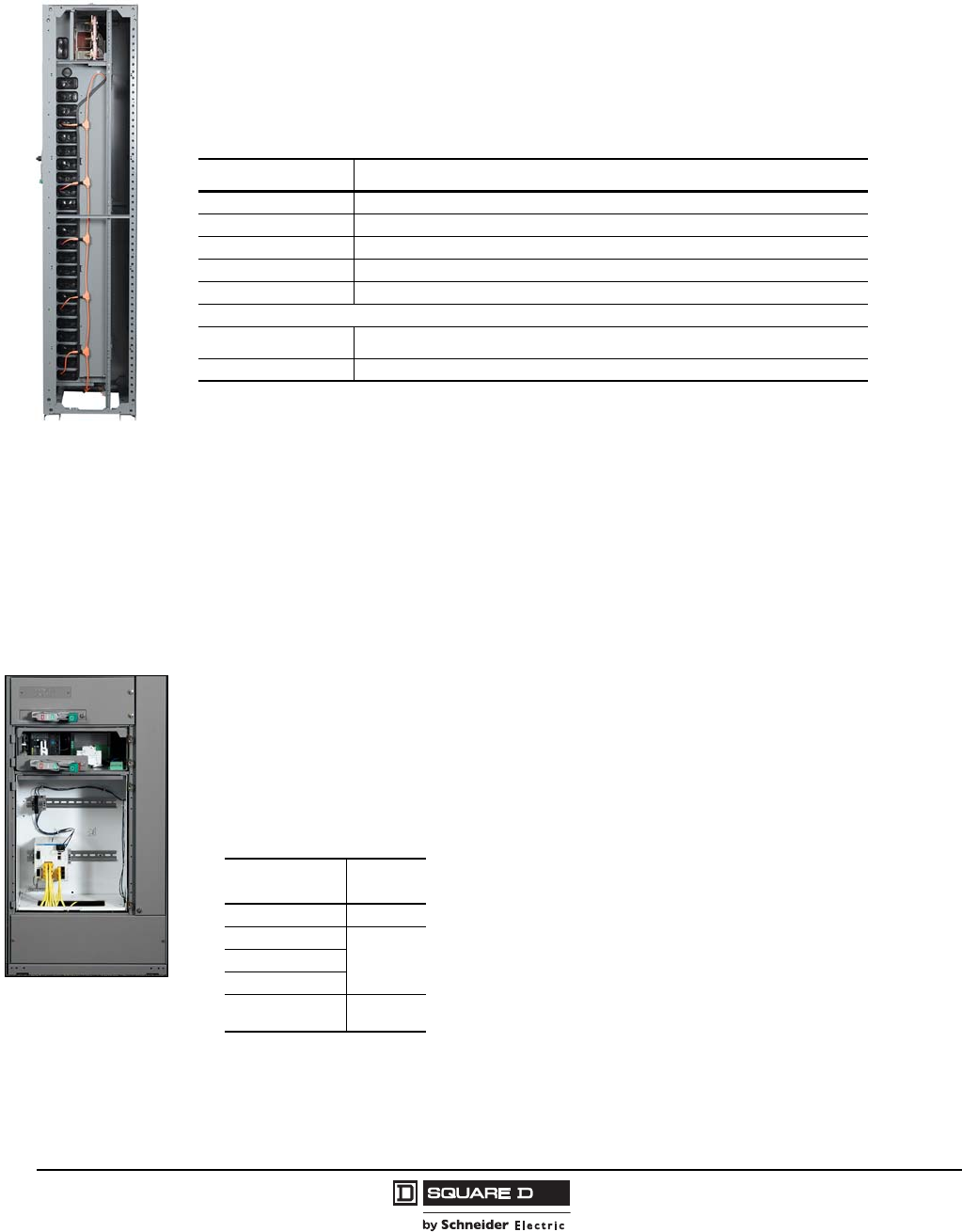
© 1997–2009 Schneider Electric
All Rights Reserved
Model 6 Motor Control Centers Intelligent Motor Control Centers
100 07/2009
iMCC-Network Cabling
Class 1 cabling is 600 V, 8 A rated, 15 AWG power pair, 18 AWG data pair with a braided shield and
drain. This cable solution provides current protection, eliminating the need for a vertical wireway
communication barrier. (The communication barrier option is still available.)
Class 2/CM cabling is 600 V, 22 AWG, 4-conductor with a foil shield and drain.
Class 2/CM and CAT5E rated cable solutions require a mechanical communication barrier for standard
sections.
Ethernet Switches
There are two primary ways to configure your Ethernet communications network:
Distributed switch(es) per shipping split
Centralized switch(es) per MCC
Application Notes:
48 ports maximum per unit
Recommend using only 80% of ports for I/O, interconnectivity expansion, etc.
8 port switch unit can be mounted anywhere
Switch units with more than 8 ports must be bottom located
Switch units require a separate 6 in. unit, 8 A power supply; see the table below.
Network Cabling
iMCC Network Cabling
Network Class/Rating
CANopen 1
1Optional Class 2/CM cabling available for DeviceNet and CANopen applications. Consult the MCC TAG for pricing
and Quote-To-Cash selector assistance.
Class 1
DeviceNet 1Class 1 2
2Open DeviceNet Vendor Association (ODVA) approved.
Ethernet TCP/IP CAT5E 3
3CAT5E cables connect devices to centralized switch. See the “Ethernet Switch Options” table below.
Modbus Class 2/CM
PROFIBUS Class 2/CM
Option Description
Communication barrier 4
4Optional for Class 1 cabling only. Communication barrier mounted in vertical wireway of Standard Section
supplied as standard with Ethernet, Modbus, and PROFIBUS Class 2/CM applications.
Mounted in vertical wireway. Adds additional mechanical protection for network cable.
Ethernet Switch Options
Switch Ports Space
812
16
1824
48
24 Vdc power
supply, rated 8 A 6
Model 6 Motor Control Centers
Intelligent Motor Control Centers
101
07/2009
© 1997–2009 Schneider Electric
All Rights Reserved
Repeaters/Bridges/Gateways
Repeaters, bridges, and gateways are recommended for the following applications/reasons:
Provide a convenient termination point for network cabling.
Allow the iMCC to be isolated and tested as a subsystem for ease of troubleshooting.
iMCC is located in the middle of a network. (Two repeaters are used in this configuration.)
Ground levels can vary from enclosure to enclosure, thus the possibility exists of introducing noise into a system if a repeater
is not implemented.
NOTE: Repeaters are typically not required for short cable runs routed in the same area.
Model 6 iMCC Bridges/Repeaters
Network Description Space
(Inches) Notes
Modbus®RS-485 repeater 9Manufactured by B&B Electronics
PowerLogic® RS-232/RS-485 converter, with 120 Vac Power Supply
PROFIBUS
24 Vdc/8 A Power Supply 6 Default with iMCC-Network with PROFIBUS
PROFIBUS Cable Terminations
9
Default with iMCC-Network with PROFIBUS.
Required with MLPII starters.
PROFIBUS Cable Terminations with RS-485 Repeater
Manufactured by Siemens
PROFIBUS Cable Terminations with PROFIBUS Active Terminations
PROFIBUS Cable Terminations with RS-485 Repeater and PROFIBUS Active
Terminator
DeviceNet™ 24 Vdc/10 A Power Supply 6
Repeater 9
© 1997–2009 Schneider Electric
All Rights Reserved
Model 6 Motor Control Centers
Technical Overview Short Circuit Current Ratings
102 07/2009
Technical Overview
Short Circuit Current Ratings
Motor control centers are being applied to electrical systems with increasingly high available fault
currents. Because of ever increasing short circuit requirements, Schneider Electric continually pursues
higher ratings through new design and testing.
Many “buzz” words and terms are used to describe short circuit ratings and how they relate to motor
control centers. Here are a few with a description of what they actually mean:
Bus Bracing or Withstand Rating
This term describes the capacity of the bus network to withstand the mechanical forces generated
during a short circuit (fault).
Integrated Equipment Rating
This term is not clearly defined, especially when applied to motor control centers. While it is often assumed
that this term means series connected short circuit ratings or short circuit current ratings, this term can also
have other interpretations. Integrated equipment ratings are generally not provided for MCCs.
Interrupt Rating
This term describes the maximum fault current level that a particular device can interrupt. This type of
rating applies only to devices that operate to interrupt a short circuit when it occurs. This term does not
apply to power bus or components of the electrical system that do not interrupt current. Different units
within the same motor control center may have different interrupt ratings. Further, the interrupt rating
does not take into consideration the effect of a main device or the bus withstand rating.
Series Connected Short Circuit Current Ratings
This term describes short circuit ratings that take into consideration the effect of a main overcurrent
protective device located in the motor control center or in upstream equipment. It does not necessarily
mean that the main has to open whenever a fault occurs. Many engineers feel that series connected short
circuit ratings mean that a system cannot be “coordinated” (coordination refers to a system’s capability of
interrupting a fault at the lowest level thereby limiting the amount of equipment shut down as a result of that
fault). System coordination should be considered when designing any electrical distribution system and the
level of coordination will often dictate the type of equipment used. It is possible to maintain acceptable levels
of system coordination while utilizing series short circuit ratings and alternately, avoidance of series
connected short circuit ratings will not automatically mean that the system will be fully coordinated. Fault
coordination should not be confused with series connected short circuit current ratings.
Short Circuit Current Rating
This term is Schneider Electric’s “bottom line” in describing the overall short circuit rating of a motor
control center. It means that the motor control center will withstand and/or interrupt a fault on an
electrical system capable of supplying the specified fault current.
To be properly applied, a motor control center must have a short circuit current rating equal to or greater
than the specified available fault current. In order to obtain this rating, a motor control center must contain:
1. A main device capable of interrupting the specified fault current, located in the motor control center
or in upstream equipment. A short circuit current rating of a motor control center cannot be greater
than the interrupt rating of the main device feeding it.
or:
2. A bus bracing or withstand rating equal to or greater than the specified fault current.
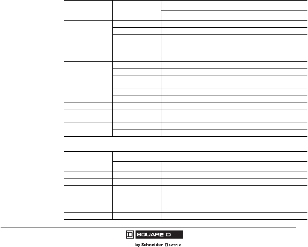
Model 6 Motor Control Centers
Short Circuit Current Ratings Technical Overview
103
07/2009
© 1997–2009 Schneider Electric
All Rights Reserved
and:
3. Units with short circuit current ratings equal to or greater than the specified fault current. All units
must either have an interrupt rating greater than or equal to the specified fault current or carry a
series connected short circuit rating greater than or equal to this level.
UL Listed Short Circuit Current Ratings
Underwriters’ Laboratories (UL) has defined test criteria for motor control center short circuit ratings. In
general, UL witnesses the testing of “worst case” configurations of motor control center units,
structures, and bussing at the short circuit current levels for which the equipment is being rated. In
many cases, such as units with circuit breaker disconnects, the same unit must be subjected to those
fault levels more than once. To pass, equipment must withstand and/or interrupt the fault in
accordance with UL criteria. UL Listed short circuit ratings ensure that different manufacturers are
“comparing apples to apples” when describing short circuit current ratings.
“Self-Certified” Short Circuit Current Ratings
Short circuit current ratings that are obtained through first-party testing and/or engineering evaluation,
are certified by the manufacturer, and are not UL Listed are known as “self-certified” ratings.
Self-certified short circuit ratings should not necessarily be considered unacceptable. However,
caution should be used because the basis for the short circuit ratings may differ from one manufacturer
to another.
Main and Branch Feeder Circuit Breakers—Short Circuit Ratings
Breaker Trip
Rating (Amps) Breaker Frame Unit Interrupting Rating (kA)
208/240V 480V 600V
150
HG 65 35 18
HJ 100 65 25
HL 100 100 50
250
JG 65 35 18
JJ 100 65 25
JL 100 100 50
400
LA 42 30 22
LH 65 35 25
LE 100 65 35
600
LI 100 100 100
LX 100 65 35
LXI 100 100 100
800 MJ 65 65 25
1200 PK 65 50 50
PL 100 100 —
3000 RK 65 65 65
RL 100 100 50
Main and Branch Feeder Fusible Switch—Short Circuit Ratings
Maximum Fuse Size
(Amps)
Short Circuit Rating
Class H Class J Class R Class L
30 5 kA 100 kA 100 kA —
60 5 kA 100 kA 100 kA —
100 10 kA 100 kA 100 kA —
200 10 kA 100 kA 100 kA —
400 10 kA 100 kA 100 kA —
600 10 kA 100 kA 100 kA —
2000 — — — 100 kA
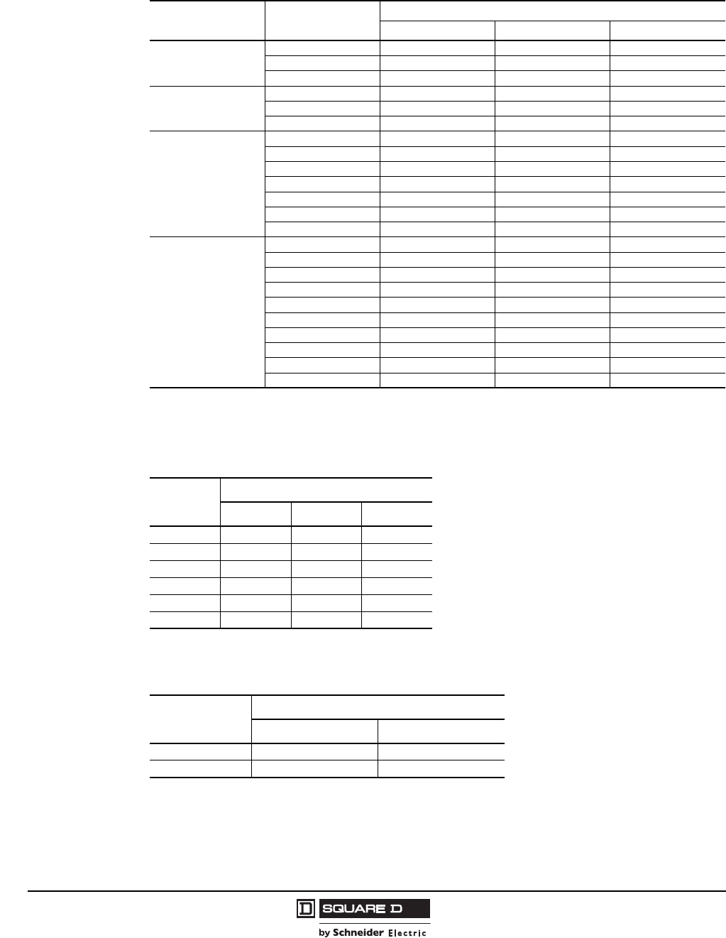
© 1997–2009 Schneider Electric
All Rights Reserved
Model 6 Motor Control Centers
Technical Overview Short Circuit Current Ratings
104 07/2009
Circuit Breaker Combination Starter with Melting Alloy, Bimetallic, or Solid State Overloads—
Short Circuit Ratings
NEMA Size Breaker Frame Unit Interrupting Rating (kA)
208/240 V 480 V 600 V
1, 2, 3, and 4
HG 65 35 18
HJ 100 65 25
HL 100 100 50
4 and 5
JG 65 35 18
JJ 100 65 25
JL 100 100 50
5
LA 100 100 50
LH 100 100 50
LC 65 65 50
LE 100 100 50
LI 100 100 100
LX 100 100 50
LXI 100 100 100
6
LA 100 100 50 1
1Denotes Thermal-Magnetic rating; Magnetic-only is 22 kA.
LH 100 100 50 1
LC 65 65 35
LE 100 100 50
LI 100 100 100
LX 100 100 50
LXI 100 100 100
MJ 65 65 25
PK — — 50
PL 100 100 —
Fusible Switch Combination Starter Units (NEMA/EEMAC) with Melting Alloy, Bimetallic
Thermal, or Solid State Overloads—Short Circuit Ratings
Ratings for all voltages through 600 V.
NEMA Size Short Circuit Rating
Class H Class J Class R
1 10 kA 100 kA 100 kA
2 10 kA 100 kA 100 kA
3 10 kA 100 kA 100 kA
4 10 kA 100 kA 100 kA
5 10 kA 100 kA 100 kA
6 10 kA 100 kA 100 kA
Circuit Breaker or Fusible Switch Compac 6 Application Rated Combination Starter Units and
Bimetallic Thermal Overloads—Short Circuit Ratings
Only use GJL Magnetic Only or Thermal-Mag breakers and Class J fuses
Disconnect Short Circuit Rating
480 V Maximum 600 V Maximum
Circuit breaker 100 kA NA
Fusible switch 100 kA 100 kA
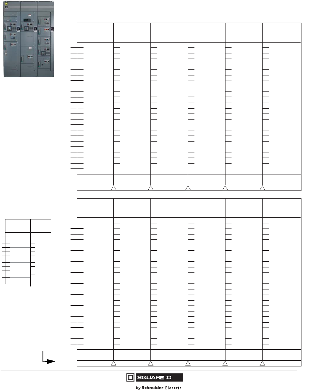
Model 6 Motor Control Centers
Layout Instructions Selection Guide
105
07/2009
© 1997–2009 Schneider Electric
All Rights Reserved
Selection Guide
Layout Instructions
The lines between letters represent 3 in. increments.
When planning your
MCC line-up, use this
form. Start at the top
of the leftmost
column, drawing a line
across the column at
the increment mark
where the unit stops,
e.g., a Compac 6,
6 in. unit would take
up spaces A and B.
A line would be drawn
across the column
from B and that unit
designation would be
“A.” The next unit
designation would be
“C,” and so on.)
Example:
Use page 106 to detail
which components
you’ll need to build
your MCC.
Indicate shipping splits
here by filling in the
appropriate triangle(s).
(Maximum of
three sections.)
MCC
Section ____
MCC
Section ____
A
B
C
D
E
F
G
H
I
J
K
L
M
A 6 in.
(COMPAC 6)
E 12 in.
(Standard Unit)
I 12 in.
(Standard Unit)
C 6 in.
(COMPAC 6)
1
MCC
Section ____
MCC
Section ____
MCC
Section ____
MCC
Section ____
MCC
Section ____
MCC
Section ____
A
B
C
D
E
F
G
H
I
J
K
L
M
N
O
P
Q
R
S
T
U
V
W
X
MCC
Section ____
MCC
Section ____
MCC
Section ____
MCC
Section ____
MCC
Section ____
MCC
Section ____
A
B
C
D
E
F
G
H
I
J
K
L
M
N
O
P
Q
R
S
T
U
V
W
X
Model 6 Motor Control Centers
Selection Guide Unit Designation Chart for Planning
© 1997–2009 Schneider Electric
All Rights Reserved
106 07/2009
Unit Designation Chart for Planning
Section/
Unit
Location
Starter
Class or
Description Size
CB
Trip/
Fuse
Clips
(A)
hp
Rating
Aux.
Intlks.
Control Devices
Other
Nameplate
Identifications
Push
Button Selector
Switches Indicating
Lights
NO
NC
Start-Stop
Fwd-Rev-Stop
Fast-Slow-Stop
Hand-Off-Auto
On-Off
Fwd-Off-Rev
Fast-Off-Slow
Green (Stopped)
Red (Run, Fwd, Fast)
Amber (Rev, Slow)
Push-to-Test
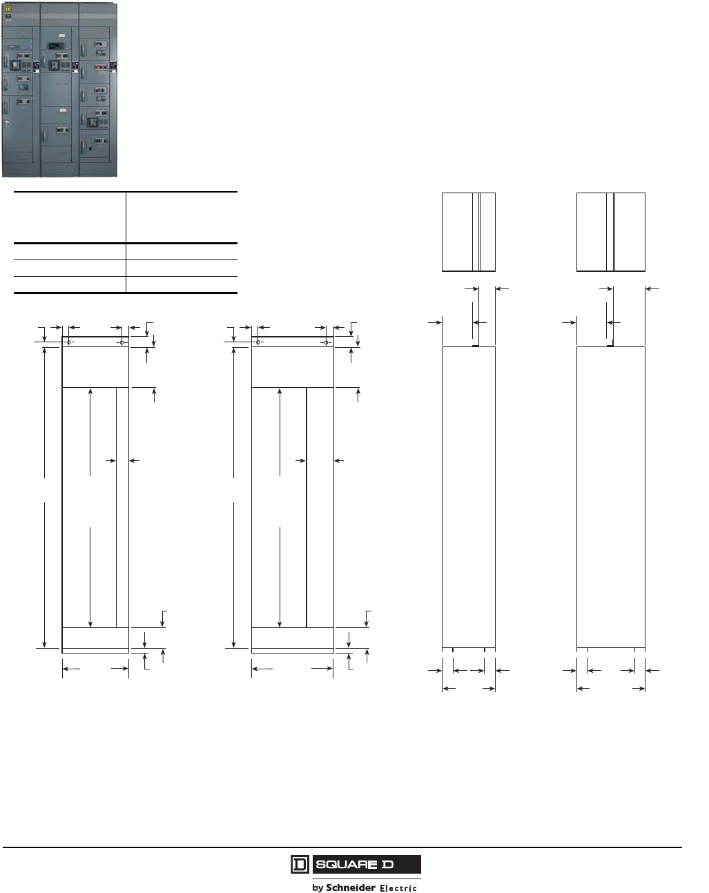
Model 6 Motor Control Centers
General Dimensions
107
07/2009
© 1997–2009 Schneider Electric
All Rights Reserved
Dimensions
General
Standard sections contain both a vertical bus system and a vertical wireway. A relay section contains
neither, but does have horizontal power and ground bus for splicing to other sections. A relay section
can be equipped with a relay pan for customer-mounted equipment and devices. Starter units and
main or branch devices that require 72 inches of space are mounted in a relay section.
A transition section is used to splice two different models of Square D® brand MCCs together (see
page 16), turn a corner, or create a back-to-back arrangement (see page 15). Conduit entry is not
recommended in transition sections.
NEMA/EEMAC Type 1, Type 1A (Gasketed), or Type 12 Enclosures
Notes:
All dimensions are shown in inches.
Depths shown indicate actual depth of the structure. Doors and cover plates extend forward 0.06 inches.
Handles and door mounted devices extend forward 2.45 inches or less.
Standard door swing extends forward 15.38 inches for unit doors. On full-section units, 20, 25, or 30 inches is
required for doors.
72" Unit
Mounting
Space
90.00
4.00
12.00
6.00
20.00 1.50
1.56
XX
20-in-wide Section with
Standard Vertical Wireway
72" Unit
Mounting
Space
90.00
9.00
12.00
6.00
25.00 1.50
1.56
XX
25-in-wide Section with
Optional Vertical Wireway
3.00
3.00
15" D
Right Side
View
9.10
3.90
3.383.38
15.00
20" D
Right Side
View
9.10
8.90
3.383.38
20.00
Number of Sections
Per Shipping
Assembly Dimension “X”
11.90
25.00
3 10.00
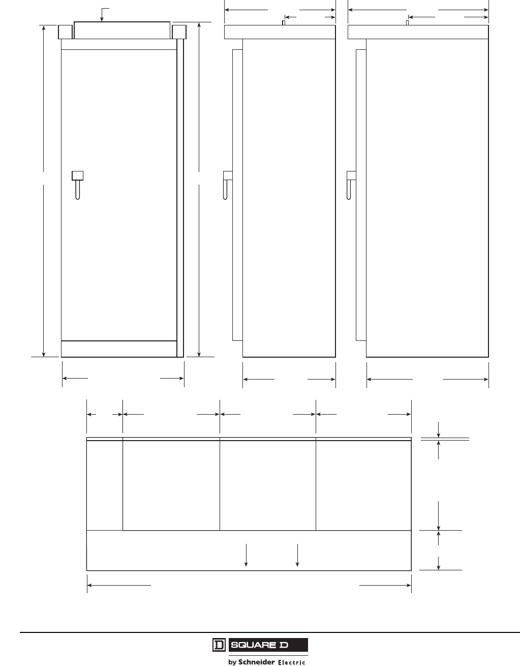
Model 6 Motor Control Centers
Dimensions NEMA/EEMAC Enclosures
© 1997–2009 Schneider Electric
All Rights Reserved
108 07/2009
NEMA/EEMAC Type 3R Non-Walk-In Basic Enclosures
31.6 in.
16.5 in.
32.2 in.
Removable lifting angle
Front View
92.9 in. 94.7 in.
26.6 in.
Side View
15 in. Deep Section
27.2 in.
11.5 in.
Side View
20 in. Deep Section
11.3 in.
0.3 in.
Standard Section
Width
20, 25, or 30 in.
Floor Plan
6 in.
Front
26, 31, 36, or 41 in.
Standard Section
Width
20, 25, or 30 in.
Standard Section
Width
20, 25, or 30 in.
Standard
Section
Depth
15 or 20 in.
Individual exterior door
provided over each
vertical section
(single sections).
Combined width of sections, plus 6 in. per shipping split
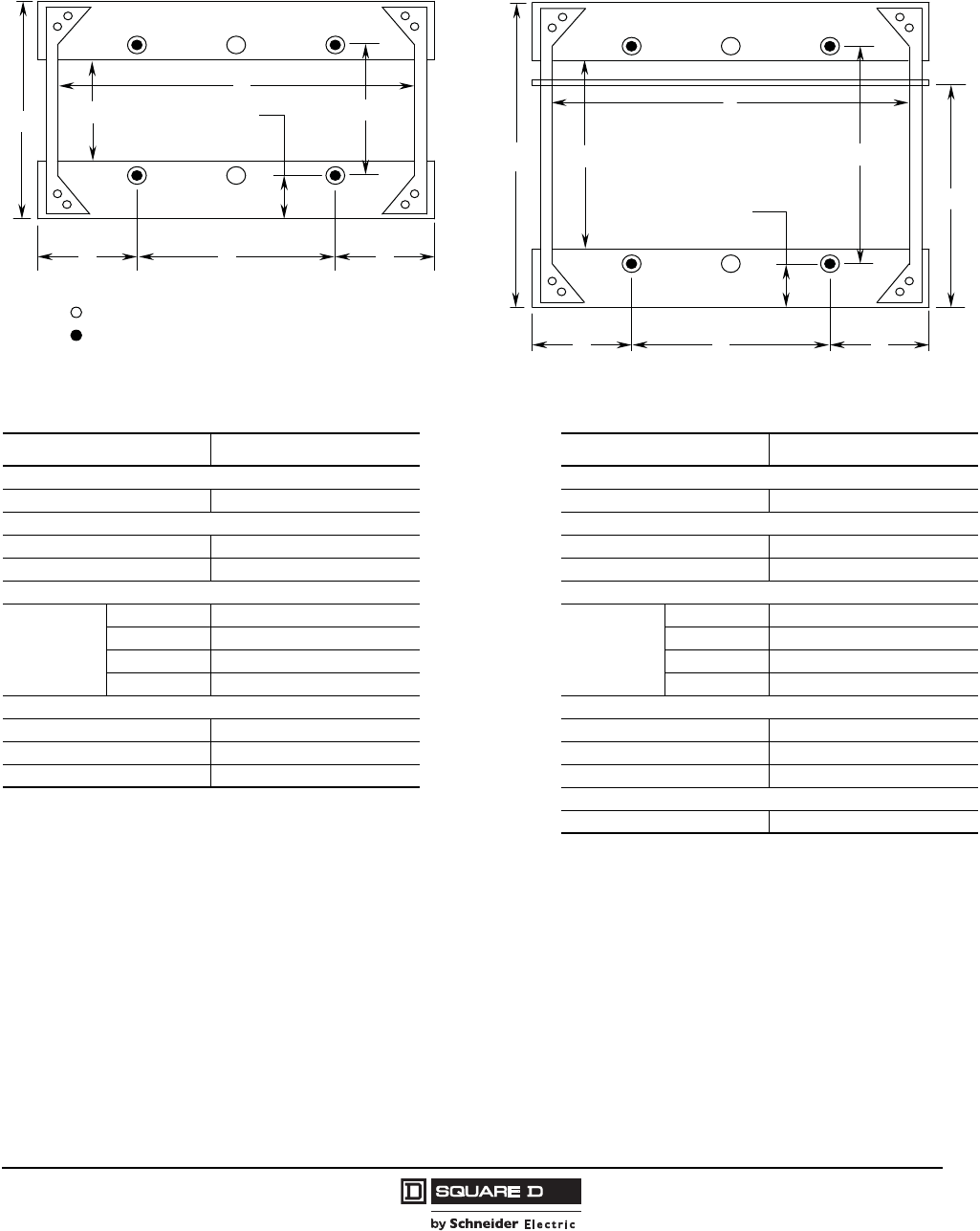
Model 6 Motor Control Centers
NEMA/EEMAC Enclosures Dimensions
109
07/2009
© 1997–2009 Schneider Electric
All Rights Reserved
Bottom Conduit Entry
NOTES:
The dimensions shown are tie-down locations within individual MCC sections. Refer to factory supplied drawings to determine
appropriate anchor locations for the equipment pad.
Depths shown indicate actual depth of the structure. Doors and cover plates extend forward 0.06 in.
Handles and door mounted devices extend forward 2.45 in. or less.
Standard door swing extends forward 15.38 in. for unit doors. On full-section units, 20, 25, or 30 in. is required for doors.
NEMA/EEMAC Type 12 section width is extended to account for gasketing between sections.
Vertical clearance for conduit entry to nearest obstruction is 7 in. minimum, except 20 in. deep sections where ground bus
obstruction is 5 in.
NEMA/EEMAC Type 1, Type 1A (Gasketed), and Type 12 Enclosures—Anchor Locations
NEMA/EEMAC Type 1, Type 1A (Gasketed), and Type 12 Enclosures—Bottom Conduit Entry and Structure Anchoring
Information for Standard and Seismic Installation
Dimension Size (In.) Dimension Size (In.)
Section Depth Section Depth
A15 H20
Available Conduit Entry Available Conduit Entry
B8.24 I13.24
C 17.22 J 17.22
Section Width Anchor Section Width Anchor
D
20 10
K
20 10
25 15 25 15
30 20 30 20
35 25 35 25
Anchors Anchors
E 5.00 L 5.00
F9.98 M14.98
G 2.50 N 2.50
Ground Bus
O12.85
Seismic Anchor Locations
A
D
E
H
M
K
L
E
F
L
G
N
B
C
I
J
O
Standard Anchor Locations
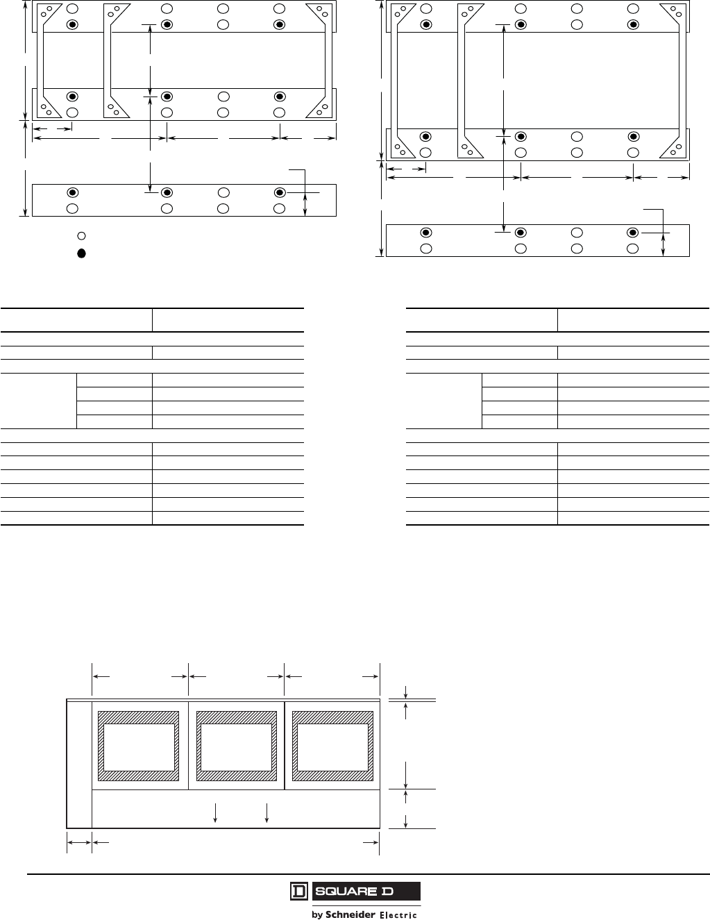
Model 6 Motor Control Centers
Dimensions NEMA/EEMAC Enclosures
© 1997–2009 Schneider Electric
All Rights Reserved
110 07/2009
NOTES:
•The dimensions shown are tie-down locations within individual MCC sections. Refer to factory supplied drawings to determine
appropriate anchor locations for the equipment pad.
NEMA/EEMAC Type 3R (Non Walk-in) Enclosure—Anchor Locations
NEMA/EEMAC Type 3R (Non Walk-in) Enclosure—Structure Anchoring Information for Standard and Seismic Installation
Dimension Size (In.) Dimension Size (In.)
Section Depth Section Depth
A15 A20
Section Width Anchor Section Width Anchor
B
20 10
B
20 10
25 15 25 15
30 20 30 20
35 25 35 25
Anchors Anchors
C 5.00 C 5.00
D 9.98 D 14.98
E 11.60 E 11.60
F 12.50 F 12.50
G 5.00 G 5.00
H 3.60 H 3.60
Enclosure depth is dimension A (15 in.) + E (11.6 in.) = 26.6 in. Enclosure depth is dimension A (20 in.) + E (11.6 in.) = 31.6 in.
B G
F
E
C
E
A D
A
D
E
F
C
E
H
G
HB
Seismic Anchor Locations
Standard Anchor Locations
Additional Conduit Entry Information for NEMA/EEMAC Type 3R Enclosures
Conduit entry
area is the same
as NEMA 1
enclosure.
Standard
section width
20, 25, or 30 in.
Standard
section width
20, 25, or 30 in.
Standard
section width
20, 25, or 30 in.
Floor plan
conduit entry
6 in.
Front 11.3 in.
0.3 in.
Standard
section depth
15 or 20 in.
Combined width of sections plus 6.0 in. per shipping split
Conduit entry
area is the same
as NEMA 1
enclosure.
Conduit entry
area is the same
as NEMA 1
enclosure.
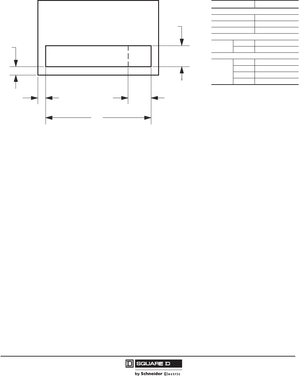
Model 6 Motor Control Centers
NEMA/EEMAC Enclosures Dimensions
111
07/2009
© 1997–2009 Schneider Electric
All Rights Reserved
Top Conduit Entry
NOTES:
NEMA/EEMAC Type 12 section width is extended to account for gasketing between sections.
Vertical clearance for conduit entry to nearest obstruction is 12 in. minimum.
Control is limited to area within C x D for all top-located mains in standard structure.
NEMA/EEMAC Type 1, Type 1A (Gasketed), and Type 12 Enclosures—Top Conduit Entry Information for Standard and
Seismic Installation
A
B
E
D
C
Dimension Size (In.)
Available Conduit Entry
A1.62
B1.39
C4.14
Control Only Width
D20 3.26
25 8.26
Section Width
E
20 17.22
25 22.22
30 27.22
35 32.22
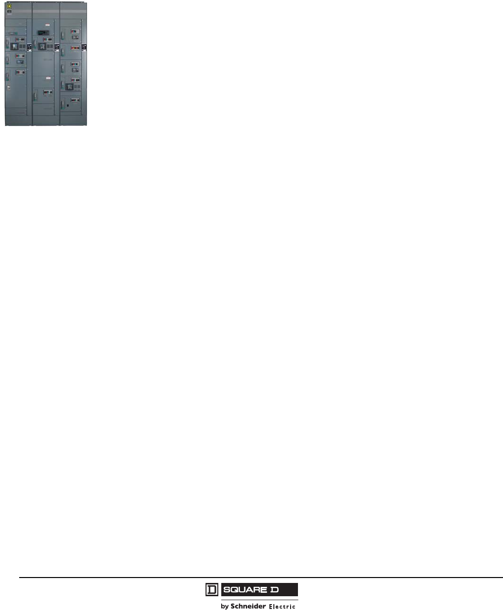
© 1997–2009 Schneider Electric
All Rights Reserved
Model 6 Motor Control Centers
Typical Specifications
112 07/2009
Typical Specifications
NOTE: Optional items are shown in bold text enclosed in square brackets. For example, [600 A]
[800 A] [1200 A].
Part 1 General
1.01 Description
This section includes requirements for a motor control center (MCC) and all required control
devices as shown on the drawing and specified to be part of the MCC equipment. The MCC shall
be 480 V, 3-Phase, 3-Wire, 60 Hz unless otherwise indicated (600 V in Canada).
1.02 Submittals
Submit with the delivery of the MCC an Installation and Maintenance Manual and one (1) copy of
the manufacturer's drawings per shipping block.
1.03 Regulatory Requirements
The MCC must conform to Underwriters Laboratories (UL) 845, current revision, CSA, EEMAC,
NEMA ICS-18, the latest version of the National Electrical Code, and the Canadian Electrical Code.
The MCC must be manufactured in an ISO 9001 certified facility.
1.04 Packing/Shipping
The MCC shall be separated into shipping blocks no more than three vertical sections each.
Shipping blocks shall be shipped on their sides to permit easier handling at the job site. Each
shipping block shall include a removable lifting angle, which will allow an easy means of attaching
an overhead crane or other suitable lifting equipment.
1.05 Storage
If the MCC cannot be placed into service reasonably soon after its receipt, store it in a clean, dry,
and ventilated building free from temperature extremes. Acceptable storage temperatures are from
32 °F (0 °C) to 104 °F (40 °C).
1.06 Warranty
The MCC shall be warranted to be free from defects in materials and workmanship for a period of
eighteen (18) months from date of invoice from manufacturer or authorized sales channel.
Part 2 Product
2.01 Manufacturers
A. Shall be Square D® brand or equal.
B. Additions to existing MCCs shall be the same as the original manufacturer.

Model 6 Motor Control Centers
Typical Specifications
113
07/2009
© 1997–2009 Schneider Electric
All Rights Reserved
2.02 Materials
A. Steel material shall comply with UL 845 and CSA requirements.
B. Each MCC shall consist of one or more vertical sections of heavy gauge steel bolted together to
form a rigid, free-standing assembly. A removable 7 gauge structural steel lifting angle shall be
mounted full width of the MCC shipping block at the top. Removable 7 gauge bottom channel sills
shall be mounted underneath front and rear of the vertical sections and shall extend the full width
of the shipping block. Vertical sections shall be made of welded side-frame assembly formed from
a minimum of 12 gauge steel. Internal reinforcement structural parts shall be of 12 and 14 gauge
steel to provide a strong, rigid assembly. The entire assembly shall be constructed and packaged
to withstand normal stresses in transit and during installation.
2.03 MCC Finish
A. All steel parts shall be provided with UL and CSA listed acrylic/alkyd baked enamel paint finish
or TGIC Powder Coat, except plated parts used for ground connections. All painted parts shall
undergo a multi-stage treatment process, followed by the finishing paint coat.
B. Pre-treatment shall include:
1. Hot alkaline cleaner to remove grease, oil, and other contaminants.
2. Iron phosphate or other approved pretreatment technology to improve adhesion and
corrosion resistance.
C. The paint shall be applied using an electro-deposition process to ensure a uniform paint coat
with high adhesion.
D. The standard paint finish shall be tested to UL 50 per ASTM B117 (5% ASTM salt spray) with no
greater than 0.125 in. (3 mm) loss of paint from a scribed line along with minimal field blisters.
E. Paint color shall be #49 medium light gray per ANSI standard Z55.1-967 (55-65 gloss) on all
surfaces unless specified otherwise. Control station plates and escutcheon plates shall be a
contrasting gray. Unit interior saddles may be painted white for better visibility inside the unit.
2.04 Structures
A. Structures shall be totally enclosed, dead-front, free-standing assemblies. Structures shall be
capable of being bolted together to form a single assembly.
B. The overall height of the MCC shall not exceed 90 in. (2286 mm) (not including base channel or
lifting angle). Base channels of 1.5 in. (38 mm) in height and lifting angles of 3 in. (76 mm) in
height shall be removable. The total width of one section shall be 20 in. (508 mm). (Widths of 25
in. (630 mm), 30 in. (760 mm), and 35 in. (890 mm) can be used for larger devices.)
C. Structures shall be NEMA/EEMAC Type [1 (general purpose)] [1A (gasketed general
purpose)] [12 (industrial duty)] [3R non-walk-in (rainproof)].
D. Each 20 in. (508 mm) wide standard section shall have all the necessary hardware and bussing
for modular plug-on units to be added and moved around. All unused space shall be covered by
hinged blank doors or appropriate cover plate and equipped to accept future units. Vertical bus
openings shall be covered by manual bus shutters.
E. Each section shall include a top plate (single piece or two-piece). NEMA/EEMAC Type 12
enclosures shall also include a bottom plate. Top and bottom plates shall be removable for
ease in cutting conduit entry openings.

© 1997–2009 Schneider Electric
All Rights Reserved
Model 6 Motor Control Centers
Typical Specifications
114 07/2009
2.05 Wireways
A. Structures shall contain a minimum 12 in. (305 mm) high horizontal wireway at the top of each
section and a minimum 6 in. (152 mm) high horizontal wireway at the bottom of each section.
These wireways shall run the full length of the MCC to allow room for power and control cable
to connect between units in different sections.
B. A full-depth vertical wireway shall be provided in each MCC section that accepts modular
plug-on units. The vertical wireway shall connect with both the top and bottom horizontal
wireway. The vertical wireway shall be 4 in. (102 mm) wide minimum with a separate hinged
door. There should be a minimum of 60 in.2 (387 cm2) of cabling space available for
15-inch-deep sections and 80 in.2 (516 cm2) of cabling space available for 20-inch-deep
sections. Access to the wireways shall not require opening control unit doors. Structures that
house a single, full section control unit are not required to have vertical wireways. Those control
units must open directly into the MCC horizontal wireways.
2.06 Barriers
A. All power bussing and splice connections shall be isolated from the unit compartments and the
wireways. The horizontal bus shall be mounted onto a glass-filled polyester support assembly
that braces the bus against the forces generated during a short circuit. The horizontal bus shall
be isolated from the top horizontal wireway by a two-piece, rigid, non-conductive barrier. The
barrier design shall allow qualified personnel to slide the barriers both left and right, to allow
access to the bus and connections for maintenance without having to remove the barrier.
Barrier sliding shall occur via an upper and lower track system.
B. The vertical bus shall be housed in a molded glass-filled polyester support that provides bus
insulation and braces the bus against the forces generated during a short circuit. These
supports shall have openings every 3 in. (75 mm) for unit stab-on connections. Each opening
shall be provided with a manual shutter to close off the stab opening. These shutters shall be
attached to the structure so that when they are removed (to allow a stab connection), they are
retained in the structure and are readily accessible for use should a plug-on unit be removed
from the MCC.
C. [Barriers shall be provided in the vertical structure and unit designs to prevent the
contact of any energized bus or terminal by a fishtape inserted through the conduit or
wireway areas.]
2.07 Bussing
A. All bussing and connectors shall be [tin-plated aluminum] [tin-plated copper]
[silver-plated copper].
B. The main horizontal bus shall be rated at [600 A] [800 A] [1200 A] [1600 A] [2000 A]
[2500 A (NEMA/EEMAC Type 1 enclosure only)] continuous, and shall extend the full length
of the MCC. Bus ratings shall be based on 149 °F (65 °C) maximum temperature rise in a
104 °F (40 °C) ambient. Provisions shall be provided for splicing additional sections onto either
end of the MCC.
C. The horizontal bus splice bars shall be pre-assembled into a captive bus stack. This bus stack
is installed into the end of the MCC power bus to allow the installation of additional sections.
The main bus splice shall use four bolts, two on each side of the bus split, for each phase.
Additional bolts must not be required when splicing higher amperage bus. The splice bolts shall
secure to self-clenching nuts installed in the bus assembly. It shall be possible to maintain any
bus connection with a single tool.
D. Each section that accepts plug-on units shall be provided with a vertical bus for distributing power
from the main bus to the individual plug-on starter units. This bus shall be copper and plated the
same as the main bus, and shall be rated at [300 A] [600 A] continuous. The vertical bus shall be
connected directly to the horizontal bus stack without the use of risers or other intervening
connectors. It shall be possible to maintain the vertical to horizontal bus connection with a single
tool. “Nut and bolt” bus connections to the power bus shall not be permitted. When a back-to-back
unit arrangement is used, separate vertical bus shall be provided for both the front and rear units.

Model 6 Motor Control Centers
Typical Specifications
115
07/2009
© 1997–2009 Schneider Electric
All Rights Reserved
E. A [tin-plated copper] [silver-plated copper] ground bus shall be provided that runs the entire
length of the MCC. The ground bus shall be rated for [300 A] [600 A]. A compression lug shall
be provided in the MCC for a 4/0-250 kcmil ground cable. The ground bus shall be provided
with (6) 0.38 in. (10 mm) holes for each vertical section to accept customer-supplied ground
lugs for any loads requiring a ground conductor.
F. Each vertical section shall have a [steel] [copper] vertical ground bus that is connected to the
horizontal ground bus. This vertical ground bus shall be installed so that the plug-on units
engage the ground bus prior to engagement of the power stabs and shall disengage only after
the power stabs are disconnected upon removal of the plug-on unit.
G. The system shall be rated for an available short circuit capacity of [42,000] [65,000] [85,000]
[100,000] rms amperes.
2.08 Typical Unit Construction
A. Units with circuit breaker disconnects through the 400 A frame size, and fusible switch
disconnects through 400 A, shall connect to the vertical bus through a spring-reinforced,
stab-on connector. Units with larger disconnects shall be connected directly to the main
horizontal bus with appropriately sized cable or riser bus.
B. All conducting parts on the line side of the unit disconnect shall be shrouded by a suitable
insulating material to prevent accidental contact with those parts.
C. Unit mounting shelves shall include hanger brackets to support the unit weight during
installation and removal. All plug-on units shall use a twin-handle camming lever located at the
top of the bucket to rack in and rack out the plug-on unit. The cam lever shall work in
conjunction with the hanger brackets to ensure positive stab alignment.
D. A lever handle operating mechanism must be provided on each disconnect. With the unit stabs
engaged onto the vertical phase bus and the unit door closed, the handle mechanism shall
allow complete ON/OFF control of the unit. All circuit breaker operators shall include a separate
TRIPPED position to clearly indicate a circuit breaker trip condition. It shall be possible to reset
a tripped circuit breaker without opening the control unit door. Clear indication of disconnect
status shall be provided by adhering to the following operator handle positions:
1. Handle “ON” position must be up and within 45 degrees of being parallel to the face of the
equipment.
2. Handle “OFF” position must be down and within 45 degrees of being parallel to the face of
the equipment.
3. The minimum separation between the “ON” and “OFF” positions shall be 90 degrees.
4. On circuit breaker disconnects, the “TRIPPED” position of the handle must be perpendicular
to the face of the equipment +/- 30 degrees. Minimum separation between “ON” and
“TRIPPED” shall be 30 degrees. Minimum separation between “TRIPPED” and “OFF” shall
be 45 degrees.
E. A mechanical interlock shall prevent the operator from opening the unit door when the
disconnect is in the ON position. Another mechanical interlock shall prevent the operator from
placing the disconnect in the ON position while the unit door is open. It shall be possible for
authorized personnel to defeat these interlocks.
F. A non-defeatable interlock shall be provided to prevent installing or removing a plug-on unit
unless the disconnect is in the OFF position.
G. The plug-on unit shall have a grounded, stab-on connector that engages the vertical ground
bus prior to, and releases after, the power bus stab-on connectors engage/release.
H. Provisions shall be provided for locking all disconnects in the OFF position with up to three
padlocks.
I. Handle mechanisms shall be located on the left side to encourage operators to stand to the left
of the unit being switched.
J. Unit construction shall combine with the vertical wireway isolation barrier to provide a fully
compartmentalized design.
K. [Surfaces (back, side, and bottom plates) of the unit shall be painted white.]

© 1997–2009 Schneider Electric
All Rights Reserved
Model 6 Motor Control Centers
Typical Specifications
116 07/2009
2.09 Components for Typical Units
A. Combination Starters
1. All combination starters shall use a unit disconnect as described in specification 2.08.
Magnetic starters shall be furnished in all combination starter units. All starters shall use
NEMA/EEMAC rated contactors. Starters shall be provided with a three-pole, external
manual reset, overload relay for [eutectic melting alloy] [ambient compensated
bimetallic] [solid state] thermal overload units.
2. When provided, control circuit transformers shall include two primary protection fuses and
one secondary fuse (in the non-ground secondary conductor). The transformer shall be
sized to accommodate the contactor(s) and all connected control circuit loads. The
transformer rating shall be fully visible from the front when the unit door is opened.
3. When a unit control circuit transformer is not provided, the disconnect shall include an
electrical interlock for disconnection of externally powered control circuits.
4. Auxiliary control circuit interlocks shall be provided where indicated. Auxiliary interlocks
shall be field convertible to normally open or normally closed operation.
5. NEMA/EEMAC Size 1–4 starters shall be mounted directly adjacent to the vertical wireway
so that power wiring (motor leads) shall connect directly to the starter terminals without the
use of interposing terminals. Larger starters shall be arranged so that power wiring may exit
through the bottom of the starter cubicle without entering the vertical wireway.
B. Terminal Blocks
1. When Type B wiring is specified, all starter units shall be provided with unit control terminal
blocks.
2. Terminal blocks shall be pull-apart type, 250 V, and rated for 10 A. All current carrying parts
shall be tin-plated. Terminals shall be accessible from inside the unit when the unit door is
opened. Terminal blocks shall be DIN rail-mounted with the stationary portion of the block
secured to the unit bottom plate. The stationary portion shall be used for factory connections
and shall remain attached to the unit when removed. The terminals used for field
connections shall face forward so they can be wired without removing the unit or any of its
components.
3. When Type C wiring is specified, all starter units shall be provided with unit control terminal
blocks as described for Type B wiring, along with power terminal blocks for NEMA/EEMAC
Size 1–3 units. An additional set of terminal blocks shall be provided in a terminal
compartment located in each section. These terminal blocks shall be pre-wired to the unit
terminals so that all field control connections can be made at the terminal compartments.
C. Nameplates
When provided, nameplates shall be engraved phenolic with a gray background and white letters.
Total outside dimensions shall be a minimum of 1.5 in. (38 mm) H x 6.25 in. (159 mm) W.
D. Pilot Device Panel
Each combination starter unit shall be provided with a hinged/removable control station plate
that can accommodate up to five 22 mm pilot devices or three 30 mm pilot devices. [The
control station plate can be deleted if no local unit pilot devices are required.]
2.10 Six-Inch Unit Construction
A. Units with circuit breaker disconnects through 250 A frame and fusible switch disconnects
through 100 A shall connect to the vertical bus through a spring-reinforced, stab-on connector.
Stabs on all plug-on units shall be cable connected to the unit disconnect. Six-inch fusible units
shall accept Class J fuses only.
B. All conducting parts on the line side of the unit disconnect shall be shrouded by a suitable
insulating material.

Model 6 Motor Control Centers
Typical Specifications
117
07/2009
© 1997–2009 Schneider Electric
All Rights Reserved
C. Unit mounting shelves shall include hanger brackets to support the unit weight during
installation and removal. All six-inch plug-on units shall be installable without the assistance of
a camming device so as to allow maximum accessibility with the unit installed.
D. A lever handle operating mechanism must be provided on each disconnect. With the unit stabs
engaged into the vertical phase bus and the unit door closed, the handle mechanism shall allow
complete ON/OFF control of the unit disconnect with clear indication of the disconnects status.
All circuit breaker operators shall include a separate TRIPPED position to clearly indicate a
circuit breaker trip condition. It shall be possible to reset a tripped circuit breaker without
opening the control unit door.
1. A mechanical interlock shall prevent an operator from opening the unit door when the
disconnect is in the ON position. Another mechanical interlock shall prevent an operator
from placing the disconnect in the ON position while the door is open. It shall be possible for
authorized personnel to defeat these interlocks.
2. A non-defeatable interlock shall be provided between the lever handle and the structure to
prevent installing or removing a plug-on unit unless the disconnect is in the OFF position.
The plug-on unit shall have a grounded stab-on connector which engages the vertical
ground bus prior to, and releases after, the power bus stab-on connectors engage/release.
E. Provisions shall be made for locking all disconnects in the OFF position with up to three
padlocks.
F. Handle mechanisms shall be located on the bottom left side of the unit and operate horizontally
to encourage operators to stand to the left of the unit being switched.
G. Unit construction shall combine with the vertical wireway isolation barrier to provide a fully
compartmentalized design.
H. A maximum of twelve six-inch units can be installed per vertical section without placement
restrictions in new or existing applications.
2.11 Components for Six-Inch Units
A. Six-Inch Combination Starters
1. All six-inch combination starters shall use a unit disconnect as described in specification
2.10. All starters shall use [NEMA/EEMAC] [IEC]-rated contactors. Starter units shall be
provided with a 3-pole, external manual reset, overload relay for [eutectic melting alloy
(NEMA rated units only)] [solid state (NEMA rated units only)] [ambient compensated
bi-metallic (application-rated units)] motor overload protection.
2. When provided, control circuit transformers shall include two primary protection fuses and
one secondary fuse (in the non-ground secondary conductor). The transformer shall be
sized to accommodate the contactor(s) and all connected control circuit loads.
3. When a unit control circuit transformer is not provided, the disconnect shall include an
electrical interlock for disconnection of externally powered control circuits.
4. Auxiliary control circuit interlocks shall be provided where indicated. For NEMA rated starters,
auxiliary interlocks shall be field convertible to normally open or normally closed operation.
5. NEMA/EEMAC Size 1 starters shall be mounted directly adjacent to the vertical wireway so
that power wiring (motor leads) will connect directly to the starter terminals.
B. Terminal Blocks for Six-Inch Units
1. All starter units shall be provided with unit control terminal blocks.
2. Terminal blocks shall be pull-apart type, 250 V, and rated for 10 A. All current-carrying parts
shall be tin-plated. Terminals shall be accessible from inside the unit when the unit door is
opened. The stationary portion of the terminal block shall be used for factory connections
and will remain attached to the unit when the portion used for field connections is removed.
The terminals used for field connections shall be accessible so they can be wired without
removing the unit or any of its components.

© 1997–2009 Schneider Electric
All Rights Reserved
Model 6 Motor Control Centers
Typical Specifications
118 07/2009
C. Nameplates
Nameplates shall be provided for each MCC and unit compartment. They shall be engraved
phenolic with a gray background and white letters. Total outside dimensions shall be a minimum
of 1.5 in. (38 mm) H x 6.25 in. (159 mm) W.
D. Pilot Device Control Panel
Each unit to be provided with a control panel for a maximum of four pilot devices. [Pilot device
control panel can be deleted if no local unit pilot devices are required.] Control panel to be
removable by loosening two semi-captive fasteners for customer access.
2.12 Adjustable Frequency AC Drive Unit Construction
A. The AC drive controller unit shall be a combination disconnect-drive MCC style unit. The input
[circuit breaker] [fusible switch] shall provide NEC required branch circuit protection. The
branch circuit protection shall have an external operator. The adjustable frequency drives shall
be [variable torque] [constant torque] AC drives. Wiring between the AC drive and the
disconnect shall not be disturbed when removing or installing the AC drive controller unit from
the MCC.
B. Units should be of modular construction so that it is possible to readily interchange units of the
same size without modifications to the MCC structure.
C. All conducting parts on the line side of the unit disconnect shall be isolated to prevent
accidental contact with those parts.
D. AC drive controller units up to 50 hp variable torque shall be plug-on units which connect to the
vertical bus through a spring-reinforced, stab-on connector. Units larger than 50 hp variable
torque shall be connected directly to the main horizontal bus with appropriately sized cable or
riser bus.
E. All AC drive controller unit interior mounting panels shall be white for better visibility.
F. A disconnect operator shall be provided per specification 2.08 D.
G. All plug-on AC drive controller units shall have a grounded stab-on connector which engages
the vertical ground bus prior to, and releases after, the power bus stab-on connectors
engage/release.
H. All AC drive controller units shall be provided with unit control terminal blocks for use in
terminating field wiring. Terminal blocks shall be pull-apart type, 250 V, and rated for 10 A. All
current-carrying parts shall be tin-plated. Terminals shall be accessible from inside the unit
when the unit door is opened. The stationary portion of the terminal block shall be used for
factory connections and will remain attached to the unit when the portion used for field
connections is removed. The terminals used for field connections shall be accessible so they
can be wired without removing the unit or any of its components.
I. The AC drive controller unit shall incorporate a self-contained, air-based cooling system. Any air
exhaust vents shall be louvered to help direct air flow away from personnel operating the AC drive
controller unit. Any fans, ductwork, or filters shall be easily accessible for maintenance.
J. The AC drive controller unit cooling system shall be sized to cool the drive regardless of
mounting location within the MCC. The AC drive controller unit shall not be restricted to a
specific location in the MCC.
K. An internal overtemperature trip shall be provided to detect cooling system failure or blockage.
Upon occurrence of an overtemperature trip, the cooling system fans shall continue running to
provide a rapid cool down.
L. Power for the cooling system shall be provided internal to the AC drive controller unit by use of
a control power transformer that includes two primary fuses and one secondary fuse (in the
non-ground secondary conductor).
M. Electrical Ratings
1. The AC drive controller unit shall be designed to operate from an input voltage of [208]
[240] [480] [600] Vac, + or -10%.
2. The AC drive controller unit shall operate from an input voltage frequency range of 57–63 Hz.

Model 6 Motor Control Centers
Typical Specifications
119
07/2009
© 1997–2009 Schneider Electric
All Rights Reserved
3. The displacement power factor shall not be less than 0.95 lagging under any speed or load
condition.
4. The efficiency of the AC drive at 100% speed and load shall not be less than 96%.
5. The variable torque overtorque capacity shall be 130% for 1 minute. [The constant torque
overtorque capacity shall be 170% for 1 minute.]
6. The output carrier frequency of the AC drive shall be selectable between 1 kHz and 16 kHz,
depending on inverter rating for low noise operation. The output carrier frequency of the AC
drive shall be randomly modulated to avoid resonance.
7. All AC drive controller unit feeder equipment, including conductors, lugs, disconnects,
contactors, etc., shall be sized per NEC Article 430 for the AC drive input current rating. An
impedance range corresponding to a 22,000 to 100,000 A fault availability level shall be
assumed for the input current rating.
N. Protection
1. The AC drive controller unit shall be protected against fault currents up to and including
100,000 A rms symmetrical at 480 Vac and shall be UL 845 listed as verification.
2. Upon power-up, the AC drive shall automatically test for valid operation of memory, option
module, loss of analog reference input, loss of communication, dynamic brake failure, DC to
DC power supply, control power, and the pre-charge circuit.
3. The AC drive controller unit shall be protected against short circuits between output phases,
between output phases and ground, on the internal power supplies, and on the logic and
analog outputs.
4. The AC drive controller unit shall have a minimum AC undervoltage power loss ride-through
of 200 milliseconds (12 cycles). The AC drive shall have the user-defined option of
frequency fold-back to increase the duration of the power-loss ride-through.
5. The AC drive will have a selectable ride-through function which will allow the logic to
maintain control for a minimum of one second (60 cycles) without faulting.
6. For a fault condition other than a ground fault, short circuit, or internal fault, an auto restart
function shall provide restart attempts for a period of 5 minutes and up to an unlimited
amount time depending on setting. The restart attempts shall be separated by increasingly
longer waiting periods to allow the condition to be cleared.
7. The deceleration mode of the AC drive shall be programmable. The stop modes shall
include free-wheel stop, ramp stop, fast stop, and DC injection braking.
8. Upon loss of the analog process follower reference signal, the AC drive shall be
programmable to fault and freewheel stop, ramp stop, fast stop, stop without trip,
automatically restart, run at last speed, or maintain a user-defined low speed setting.
9. The AC drive shall have solid-state I²t protection that is UL Listed, meets UL 508C as a
Class 10 overload protection, and meets IEC 60947. The minimum adjustment range shall
be from 25 to 150% of the nominal current rating of the AC drive controller unit.
10. The AC drive shall have three skip frequency ranges with hysteresis adjustment that can
each be programmed independently, back-to-back, or overlapping.
11. The AC drive shall be include an adjustable thermal alarm which can be assigned to a relay
or logic output to indicate the drive temperature has reached the thermal alarm setting.
O. Adjustment and Configuration
1. The AC drive shall have a user selectable Auto Tune feature. The Auto Tune will
automatically send motor-rated current to the connected motor and store the resulting
resistance data into memory. The AC drive will automatically optimize the operating
characteristics according to the stored data.
2. The AC drive motor and control parameters will be factory preset to operate most common
applications. Necessary adjustments for factory supplied unit operator controls and
sequencing shall be pre-programmed and tested by the manufacturer.
3. A choice of three types of acceleration and deceleration ramps will be available in the AC
drive software—linear, S curve, and U curve—as well as custom.

© 1997–2009 Schneider Electric
All Rights Reserved
Model 6 Motor Control Centers
Typical Specifications
120 07/2009
4. The acceleration and deceleration ramp times shall be adjustable from 0.01 to 6000
seconds.
5. The volts per frequency ratios shall be user selectable to meet variable torque loads,
normal, and high torque machine applications.
6. The memory shall retain and record run status and fault type of the past eight faults for
operator review.
7. The software shall have an energy saving function that will optimize the energy consumed.
A constant volts/Hz ratio will be maintained during acceleration. The output voltage will then
automatically adjust to meet the torque requirement of the load.
8. Slip compensations shall be a software-enabled function.
9. The AC drive shall offer programmable DC injection braking that will brake the AC motor by
injecting DC current and creating a stationary magnetic pole in the stator. The level of
current will be adjustable between 10–110% of rated current and available from 0.1–30
seconds continuously. For continuous operation after 30 seconds, the current shall be
automatically reduced to 50% of the nameplate current of the motor.
10. Sequencing logic will coordinate the engage and release thresholds and time delays for the
sequencing of the AC drive output, mechanical actuation, and DC injection braking in order
to accomplish smooth starting and stopping of a mechanical process.
P. Graphic Display Terminal Interface
1. The graphic display terminal shall provide 8 lines of 240 by 160 pixels in plain English to
control, adjust, and configure the AC drive including all electrical values, bar charts,
configuration parameters, I/O assignment, application and activity function access, faults,
local control, adjustment storage, self-test, and diagnostics. There will be a standard
selection of six additional languages built in to the operating software as standard.
2. The AC drive model number, torque type, software revision number, horsepower, output
current, motor frequency, and motor voltage shall all be listed on the drive identification
display as viewed on the graphic display terminal.
3. The graphic display shall be able to indicate one, two, or five digital values, or up to two
values by bar graph. As a minimum, the selectable display values shall consist of speed
reference, output frequency, output current, motor torque, output power, output voltage, line
voltage, DC voltage, motor thermal state, drive thermal state, elapsed time, motor speed,
machine speed reference, and machine speed.
4. The graphic display terminal will consist of programmable function keys. The functions will
allow both operating commands and programming options to be preset by the operator.
5. The graphic display terminal shall offer levels of settings from simple start-up to advanced user
menus consisting of parameter setting, I/O map, fault history, and drive configuration. Password
protection shall be available to limit unauthorized access to various levels of the menus.
6. The navigation wheel shall provide the ability to scroll through menus and screens, select or
activate functions, or increase the value of a selected parameter.
7. An escape key shall allow a parameter to return the existing value if adjustment is not required
and the value is displayed. The escape function will also return to a previous menu display.
8. A RUN key and a STOP key shall command normal starting and stopping as programmed
when the AC drive is in keypad control mode. The STOP key shall be active in all control
modes.
9. A [Windows® based personal computer] [serial communication link] [detachable
graphic terminal display] user interface shall be available.
10. The keypad shall store up to four user configuration programs in nonvolatile memory. An
operator shall have the ability to download a stored configuration to multiple AC drives.
11. The operator interface shall be MCC door-mounted on the AC drive controller unit for ease
of access and increased visibility.
12. All door-mounted controls shall be NEMA/EEMAC Type 12 rated.

Model 6 Motor Control Centers
Typical Specifications
121
07/2009
© 1997–2009 Schneider Electric
All Rights Reserved
Q. Control
1. Pilot devices shall be industrial rated [22mm] [30mm] type control operators and used
independently of the keypad display. Software assignments for control inputs and outputs to
operate factory-supplied controls shall be pre-configured from the factory. The following
basic controls shall be provided:
[HAND-OFF-AUTO selector switch - The HAND mode shall allow manual operation
of start, stop, and speed control. The AC drive shall start when the control
operation is in the HAND mode. A door-mounted, manual-speed potentiometer
shall be used to control speed in the HAND mode. The AC drive shall run at the
low speed setting or higher as required by the position of the manual-speed
potentiometer. This mode shall function as 2-wire control and automatically
restart after a power outage or auto restart after a fault. The OFF position of the
control operation shall stop the AC drive and prevent it from restarting. The AUTO
(automatic) mode shall receive an [auto start contact] [serial link command] to
control starting and stopping of the AC drive. This contact shall also start and
stop bypass (if used) when both the automatic and bypass modes of operation
are selected. Speed control shall be from a customer supplied [4–20 mAdc] [serial
link communication] signal.]
[START-STOP pushbuttons—START/STOP pushbuttons shall provide 3-wire
start/stop control.]
[POWER On pilot light, red]
[FAULT pilot light, yellow, push-to-test]
[RUN pilot light, green, push-to-test]
[STOPPED pilot light, red, push-to-test]
[HAND/AUTO pilot lights, yellow, push-to-test]
NOTE: Additional controls can be found on the equipment electrical diagrams.
2. 2-wire or 3-wire control strategy shall be defined within the software.
3. The control power for the digital inputs and outputs shall be 24 Vdc.
4. The internal power supply incorporates an automatic current fold-back that protects the
internal power supply if incorrectly connected or shorted. The transistor logic outputs shall
be current limited and not be damaged if shorted or if excess current is pulled.
5. All logic connections shall be furnished on pull-apart terminal strips.
6. There will be (2) two software assignable analog inputs with interference filtering. The
analog inputs will be software selectable and consisting of user defined configurations:
x-y mA or x-y V.
7. There will be five software assignable logic inputs that will be selected and assigned in the
software. The selection of assignments shall consist of forward, reverse, jog, plus/minus
speed (2 inputs required), setpoint memory, preset speeds (up to 8 inputs), auto/manual
control, controlled stop, terminal or keypad control, output contactor (2 inputs required),
motor switching, and fault reset.
8. There will be two software assignable analog outputs with interference filtering. The analog
outputs can be selected and assigned in the software. The analog output assignments shall
be proportional to the following motor characteristics: frequency, current, power, torque,
voltage, and thermal state. The output signal will be user-defined configurations:
x-y mA or x-y V.
9. Two voltage-free Form C relay output contacts shall be provided. One of the contacts will
indicate AC drive fault status. The other contact will be user assignable.

© 1997–2009 Schneider Electric
All Rights Reserved
Model 6 Motor Control Centers
Typical Specifications
122 07/2009
Note to Specification Writer: Items 10 and 11 are optional network communications specifications.
10. [Drives shall include network communication interface for data acquisition only over
[Modbus] [Modbus Plus] [Ethernet (Modbus TCP)] [DeviceNet] [PROFIBUS DP]. Drive
control and speed control via PLC hardwired I/O shall include:]
[PLC Analog output (4–20 mA) speed reference signal]
[PLC Analog input (4–20 mA) speed feedback signal]
[PLC digital output drive start control] [PLC digital outputs for drive preset speed
control]
[PLC digital input drive run (Run =1)]
[PLC digital input drive fault (Fault = 1)]
11. [Drives shall include network communication interface for control and data
acquisition over [Modbus] [Modbus Plus] [Ethernet (Modbus TCP)] [DeviceNet]
[PROFIBUS DP] [Ethernet IP].
[At a minimum, drive units shall allow configuration of these parameters:]
— [Motor Frequency]
— [Motor Voltage]
— [Ramp Profiles]
— [I/O Assignments]
— [Current Limitation]]
[Drive units shall be capable of making these adjustments:]
— [Speed Range]
— [Ramp Time]
— [Thermal Protection]
[Drive units shall allow control of these parameters:]
— [Start/Stop]
—[Braking]
— [Frequency Reference]
— [Fault Resets]
R. Optional Isolation/Bypass Contactors
1. As a UL Listed option, the AC drive controller unit shall include [NEMA rated isolation and
bypass contactors packaged as a separate MCC unit with steel barriers segregating
the AC drive from the bypass starter][IEC rated isolation and bypass contactors
integrated with the AC drive as one MCC unit to reduce space].
2. The isolation and bypass contactors shall be mechanically and electrically interlocked
complete with a Class 10 thermal overload relay, disconnect interlocked with the door, control
circuit transformer, AFC/OFF/BYPASS switch, and BYPASS RUN and AFC RUN lights.
3. The operator shall have full control of the bypass starter by operation of the door-mounted
selector switch.
4. When the drive is supplied with a HAND-OFF-AUTO selector switch, the AUTO mode shall
also control the run/stop of the bypass operation.
S. Optional Harmonic Provisions
1. A harmonic distortion analysis shall be performed and priced as a separate line item by the
AC drive manufacturer based upon system documentation supplied by the contractor. The
documentation shall consist of one-line diagrams, distribution transformer information (kVA,
%Z, and X/R ratio), and emergency standby generator performance specifications. The
harmonic distortion analysis report shall be part of the approval drawing process, submitted
to the engineer for approval. If the calculations determine that harmonic distortion values
are higher than the voltage and current values specified in IEEE 519-1992, the drive

Model 6 Motor Control Centers
Typical Specifications
123
07/2009
© 1997–2009 Schneider Electric
All Rights Reserved
manufacturer shall provide line reactors of sufficient percent impedance to meet the IEEE
specified values. The line reactor shall be ventilated in the MCC and shall be completely
factory wired and tested with the AC drive controller unit.
2. A [3% impedance] [5% impedance] line reactor shall be provided that is completely
factory wired and tested with the AC drive controller unit.
3. An active harmonic filter shall be provided to perform electronic cancellation of load
produced harmonic currents such that the upstream power harmonic current and voltage
are reduced below the IEEE 519-1992 guidelines for load demand and voltage distortion
limits. Filter shall be Square D® brand Accusine or equivalent. Performance of the filter shall
be independent of the impedance of the power source: AC lines or back-up generator. All
necessary current transducers, reactors, and operator interfaces shall be supplied with the
MCC. A factory certified start-up technician shall be used to start up each harmonic filter to
achieve optimum system performance.
T. Optional Load Filters
As a UL Listed option, the AC drive controller unit shall include a motor protection filter unit
designed to limit peak voltages and reduce electrical stress on the motor insulation. This option
shall be required for motor lead lengths above 150 ft. (50 m). The filter unit shall be ventilated to
limit heat build up within the MCC.
2.13 Solid-State Reduced-Voltage Starter Unit Construction
A. The soft start controller unit shall be a combination disconnect/soft starter, MCC-style unit. The
input [circuit breaker][fusible switch] shall provide NEC required branch circuit protection.
The branch circuit protection shall have an external operator. Wiring between the soft starter
and the disconnect shall not be disturbed when removing or installing the soft start controller
unit from the MCC. Units shall be of modular construction so that units of the same size can be
interchanged without modifications to the MCC structure.
B. All conducting parts on the line side of the unit disconnect shall be isolated to prevent
accidental contact with those parts.
C. Soft start controller units rated for standard duty (up to 156 A) shall be plug-on units which
connect to the vertical bus through a spring-reinforced stab-on connector. Units rated higher
than 156 A shall be connected directly to the main horizontal bus with appropriately sized cable
or riser bus.
D. All soft start controller unit interior mounting panels shall be white for better interior visibility.
E. A disconnect operator shall be provided per specification 2.08 D.
F. All plug-on soft start controller units shall have a grounded stab-on connector which engages
the vertical ground bus prior to, and releases after, the power bus stab-on connectors
engage/release.
G. Handle mechanisms shall be located on the left side to encourage operators to stand to the left
of the unit being switched.
H. All soft start controller units shall be provided with unit control terminal blocks for use in
terminating field wiring. Terminal blocks shall be pull-apart type, 250 V, and rated for 10 A. All
current-carrying parts shall be tin-plated. Terminals shall be accessible from inside the unit
when the unit door is opened. The stationary portion of the terminal block shall be used for
factory connections and will remain attached to the unit when the portion used for field
connections is removed. The terminals used for field connections shall be accessible so they
can be wired without removing the unit or any of its components.
I. The enclosure shall include a door-mounted digital keypad for adjusting the soft start parameters
and viewing the motor, soft start, and fault status without opening the enclosure door.
J. A shorting contactor shall be supplied in each soft start controller unit to reduce temperature rise
within the unit and MCC enclosure. The shorting contactor shall be rated to carry the motor full
load current during steady state after full voltage has been applied to the motor by the soft starter.

© 1997–2009 Schneider Electric
All Rights Reserved
Model 6 Motor Control Centers
Typical Specifications
124 07/2009
K. Electrical Ratings
1. The soft start controller unit shall be designed to operate from an input voltage between
-10% and +10% of nominal voltage rating.
2. The soft start controller unit shall operate from an input voltage frequency range of +/-5%.
By configuration, it shall be capable of operation at a supply line frequency that can vary by
+/- 20% during steady state operation.
3. The soft starter shall be capable of supplying 400% of rated full load current for 23 seconds
at the maximum ambient temperature.
4. All soft start controller unit power and control devices shall be rated for:
[Standard Duty capable of 10 evenly spaced starts per hour at 400% of full rated
current for 12 seconds per start without tripping.]
[Severe Duty capable of 5 evenly spaced starts per hour at 400% of full rated
current for 25 seconds per start without tripping.]
5. The silicon-controlled rectifiers (SCRs) shall have a minimum peak inverse voltage (PIV)
rating of 1800 Vac. Lower rated SCRs with protection by metal oxide varistors (MOVs) are
not acceptable.
L. Protection
1. A microprocessor-based thermal protection system shall be included that continuously
calculates the temperature rise of the motor and soft starter and provides:
A motor overload pre-alarm that indicates by relay contact or logic output that the motor
windings have exceeded 130% of their rated temperature rise. This function shall be for
alarm only.
A motor overload fault will stop the motor if the windings have exceeded 140% of their
rated temperature rise.
An electronic circuit with a time-constant adjustable to the motor's thermal cooling
time-constant that ensures memorization of the thermal state even if power is removed
from the soft starter.
2. The soft starter shall provide line and motor phase loss, phase reversal, underload, stall,
and jam protection.
3. The soft start controller unit shall include a shorting contactor which closes after full voltage
has been applied to the motor by the soft starter to reduce the current carrying duty on the
SCRs. The integral protective features shall be active even when the shorting contactor is
used to bypass the SCRs during steady state operation.
4. All units and options shall be constructed with protection provisions to pass UL 845 short
circuit testing criteria at a minimum of 65,000 A short circuit current.
5. Diagnostic faults and soft start status shall be displayed on the door-mounted keypad after a
fault condition.
6. The motor must be automatically protected from solid state component failure by one of the
following means:
[Shunt trip coil to trip disconnect in the event of a soft start fault condition,
including a shorted SCR.]
[Isolation contactor that opens when the motor is stopped or when the controller
detects a fault condition including a shorted SCR.]
M. Adjustments and Configurations
1. All programming/configuration devices, display units, and field control wiring terminals shall
be accessible on the front of the control module. Exposure to control circuit boards or
electrical power devices during routine adjustments is prohibited.
2. Digital indication shall provide, as a minimum, the following conditions:

Model 6 Motor Control Centers
Typical Specifications
125
07/2009
© 1997–2009 Schneider Electric
All Rights Reserved
Soft starter status—ready, starting/stopping, run
Motor status—current, torque, thermal state, power factor, operating time, power in kW
Fault status—motor thermal overload, soft starter thermal fault, loss of line or motor
phase, line frequency fault, low line voltage fault, locked rotor fault, motor underload,
maximum start time exceeded, external fault, serial communication fault, line phase
reversal fault, motor overcurrent fault
3. The starter shall be preset to the following for operation without adjustment in most
applications:
Linear (torque-controlled) acceleration ramp of 15 seconds
Current limitation to 400% of the motor full load current rating
Class 10 overload protection
Motor current preset per NEC / NFPA 70 table 430.150 for standard hp motors
4. A digital keypad shall be used to configure the following operating parameters as required:
Motor full load amps adjustable from 40 to 130% of the controller's rating
Current limitation on starting adjustable from 150 to 700% of the motor current rating,
not to exceed 500% of the soft start rating
Torque ramp adjustable from 1 to 60 seconds
Initial torque adjustable from 10 to 100% of nominal motor torque
Torque limit adjustable from 10 to 200% of nominal motor torque
Maximum start time adjustable from 10 to 999 seconds
Voltage boost adjustable from 50 to 100% of the nominal supply voltage
Selection of freewheel, soft stop, or braking
Linear (torque-controlled) deceleration ramp time adjustable from 1 to 60 seconds
Threshold to change to freewheel following a soft stop from 0 to 100% of the nominal
motor torque
Braking torque level adjustable from 0 to 100% effectiveness
Selection of Class 2, 10, 10A, 15, 20, 25, or 30 motor thermal overload protection
5. A digital keypad shall be used configure the following controller parameters as required:
Selectable automatic reset operation
Cancellation of the torque control loop for multi motor installations
Adjustment of the stator loss estimation for specialty motors
Assignment of soft start inputs and outputs
Activation of phase reversal protection
Reset of motor thermal state
Return to factory parameter settings
Activation of test mode for use with low power motors
Indication of elapsed time in hours of starting, running and stopping
6. Output relays shall provide the following status indications:
One Form A (N.O.) minimum for indication of fault
One Form A (N.O.) for indication that acceleration ramp is complete and current is below
130% motor FLA (end of start)
One Form A (N.O.) assignable to one of the following functions: motor thermal alarm,
motor current level alarm, and motor underload alarm

© 1997–2009 Schneider Electric
All Rights Reserved
Model 6 Motor Control Centers
Typical Specifications
126 07/2009
7. Additional inputs and outputs shall be available to provide the following status indications:
Two assignable control inputs for the following functions: force to freewheel stop,
external fault input, disable serial link control, external motor overload reset, or general
fault reset
Two assignable logic-level signal outputs for the following functions: motor thermal
overload alarm, “motor powered” signal, motor overcurrent alarm, or motor underload
alarm
One analog output shall be available for 4 to 20 mA indication of motor current, motor
torque, motor power, motor thermal state, or power factor
8. Relay and I/O functions listed above must be isolated with respect to common.
N. Control Options
1. The soft starter's control circuit shall be fed from the line supply and be completely
independent of the power circuit and separate from relay control logic.
2. The peripheral soft starter control circuitry shall be operated from a control power
transformer included within the enclosure.
3. Operator devices shall be door-mounted and shall be (choose all that apply):
Black START and red STOP push buttons
Three position H-O-A switch which provides for manual (HAND) start or remote signal
(AUTO) start from user-supplied relay contacts
Three position FORWARD/OFF/REVERSE selector switch mounted on the door control
island (available with reversing starter only)
Red RUN pilot light illuminated whenever the soft starter is provided a run command and
no fault condition is present
Green OFF pilot light illuminated whenever the soft starter is supplied with control power
and no run command is present
O. Shorting Contactor (Standard On All Units)
1. A microprocessor shall control the operation of the shorting contactor via an output relay.
2. The shorting contactor shall close, shorting the SCRs after the acceleration ramp is
compete and motor current is below 130% of motor FLA, and open on a stop command to
allow a deceleration ramp.
3. Overload protection integral to the soft starter shall continue to protect the motor when
shorting is engaged.
Note to Specification Writer: Item P is optional; delete if not needed.
P. [Full Voltage Emergency Starter]
1. [The soft start controller unit shall include full voltage starting capability to start and
control the motor instead of the reduced voltage soft start method of starting the
motor.]
2. [The full voltage emergency starter shall be UL Listed and shall include [an IEC rated]
[a NEMA Rated] contactor capable of carrying the motor inrush and motor full load
current.]
3. [A door-mounted BYPASS/NORMAL selector switch shall be provided to enable the
user to manually select the motor starting method. NORMAL mode provides a
reduced voltage start using the soft starter. In BYPASS mode, the soft starter will be
left inactive and the motor will be started using an across-the-line full voltage starting
method.]
4. [An overload provision independent of the soft starter shall be provided to protect
the motor in the BYPASS mode.]
5. [The full voltage emergency starter components shall be integrated inside the soft
start controller unit and shall be fully tested by the MCC manufacturer.]

Model 6 Motor Control Centers
Typical Specifications
127
07/2009
© 1997–2009 Schneider Electric
All Rights Reserved
2.14 General Communication Cabling
A. The MCC shall employ a pre-engineered communication cabling system to interconnect units
within the MCC.
B. Network cabling shall be routed through the lower horizontal wireway to isolate the network
from the horizontal bussing routed through the top.
C. The full-depth vertical wireway serves to separate communications from power cabling to
prevent noise interference on the network cable.
D. The communication cabling installation shall meet Class 2 wiring practices under the provisions
of NEC articles 725 and 800.
E. Provisions for appropriate terminators and grounding shall be provided.
F. Addition, removal, or rearrangement of units shall not interrupt the trunk line and shall not affect
the cabling of other units attached to the trunk line.
G. Cable assemblies will use 5-pole Micro-style connectors with a single keyway and will comply
with SAE-H1738-2 specifications.
H. Connectors are to be epoxy-coated for a 500-hour salt-spray test per Mil-Std 202F.
I. Cable coupler design shall include a vibration-resistant ratchet to prevent loosening.
J. The system will be constructed of molded PVC material.
2.15 Modbus® Communication Cabling
A. The Modbus cabling system will be UL 498 Listed.
B. An extended ground pin shall ensure first make/last break ground connections.
C. The cabling system shall consist of individual trunk line segments in each MCC section. A
trunk/drop topology will be used. Trunk line segments will be routed from the lower wireway into
each vertical section. The trunkline for sections containing plug-on vertical bus shall have six
taps spaced 12 in. apart. Unused tee connectors will be capped at the factory.
D. A 36-in. (915 mm) “pigtail” cable shall connect the communication device in each MCC unit to
the trunk cable via a pre-engineered tap. One end of the pigtail cable will terminate in a
Micro-style connector and will be attached to the trunk. The other end will terminate at the
communication device in the MCC unit.
2.16 Ethernet (Modbus TCP) Communication Cabling
A. The Modbus TCP/IP (Ethernet) communications network shall be configured in a star topology.
B. The cabling system shall consist of multiple, custom-length Ethernet patch cables that each
connect a single network device to a central Ethernet switch unit located in the MCC.
C. Ethernet switches located in the MCC shall be Connexium, Hirschmann, or approved equal.
2.17 DeviceNet™ Communication Cabling
A. The DeviceNet cabling system will be ODVA rated with a trunkline-dropline topology.
B. Control power shall be provided through individual unit transformers that are separate from the
network to reduce network power demand. This will allow devices to operate independently of
the network power supply.
C. Sectioned cabinets shall have six pre-molded trunklines with tees. Full length cabinets shall
have one trunkline with a tee. A tee at the bottom of each section shall provide the means of
connection to the next section with a pre-molded section of cable.
D. A 36-in. (915 mm) “pigtail” cable shall connect the tee in the dropline to the DeviceNet device
located in the MCC unit.

© 1997–2009 Schneider Electric
All Rights Reserved
Model 6 Motor Control Centers
Typical Specifications
128 07/2009
2.18 CANopen Communication Cabling
A. The CANopen cabling system will be configured in a trunkline-dropline topology.
B. Control power shall be provided through individual unit transformers that are separate from the
network to reduce network power demand. This will allow devices to operate independently of
the network power supply.
C. Sectioned cabinets shall have six pre-molded trunklines with tees. Full length cabinets shall
have one trunkline with a tee. A tee at the bottom of each section shall provide the means of
connection to the next section with a pre-molded section of cable.
D. A 36-in. (915 mm) “pigtail” cable shall connect the tee in the dropline to the CANopen device
located in the MCC unit.
2.19 PROFIBUS DP Communication Cabling
A. The PROFIBUS DP cabling system shall consist of individual trunk line segments in each MCC
section. A trunkline-dropline topology will be used. Trunk line segments will be routed from the
lower wireway into each vertical section. The trunkline for sections containing plug-on vertical bus
shall have six taps spaced 12 in. apart. Unused tee connectors will be capped at the factory.
B. Sectioned cabinets shall have six pre-molded trunklines with tees. Full length cabinets shall
have one trunkline with a tee. A tee at the bottom of each section shall provide the means of
connection to the next section with a pre-molded section of cable.
C. A 36-in. (915 mm) “pigtail” cable shall connect the tee in the dropline to the PROFIBUS DP
device located in the MCC unit.
2.20 Quality Control
A. The entire MCC shall go through a quality inspection before shipment. This inspection will
include:
1. Physical Inspection of:
Structure
Electrical conductors, including:
— Bussing
— General Wiring
—Units
2. Electrical Tests
General electrical tests include:
— Power Circuit Phasing
— Control Circuit Wiring
— Instrument Transformers
— Meters
— Ground Fault System
— Device Electrical Operation
AC dielectric tests shall be performed on the power circuit.
3. Each device shall be configured and addressed to correspond with software settings.
4. A Read/Write test shall be performed prior to shipment on all network devices including, but
not limited to, Overloads, Drives, and Soft Starters.

Model 6 Motor Control Centers
Typical Specifications
129
07/2009
© 1997–2009 Schneider Electric
All Rights Reserved
5. Testing shall be designed to verify system operation and shall include these verifications as
a minimum:
Drawings and Bill of Materials
I/O addressing
Correct device operation by I/O address
Host Communications
Control Network Interface
6. Markings/Labels include:
Instructional type
Underwriters Laboratory (UL)/Canadian Standards Association (CSA)
Inspector's stamps
7. The manufacturer shall use integral quality control checks throughout the manufacturing
process to ensure that the MCC meets operating specifications.
Part 3 Execution
3.01 Location
A. Motor control centers are not to be placed in hazardous locations. The area chosen shall be
well ventilated and totally free from humidity, dust, and dirt. The temperature of the area shall
be no less than 32 °F (0 °C) and no greater than 104 °F (40 °C). For indoor locations, protection
must be provided to prevent moisture entering the enclosure.
B. Motor control centers shall be located in an area with a minimum of 3 ft. (915 mm) of free space
in front for front-of-board construction. An additional 3 ft. (915 mm) should be allowed in the
rear for back-to-back construction. This free space will give adequate room to remove and
install units. A minimum of 0.5 in. (13 mm) space should be provided between the back of
front-of-board MCCs and a wall. 6 in. (152 mm) is required for damp locations.
C. The MCCs shall be assembled in the factory on a smooth level surface so that all sections are
properly aligned. A similar smooth and level surface shall be provided for installation. An
uneven foundation will cause misalignment of shipping blocks, units, and doors. The surface
under a MCC shall be of a non-combustible material unless bottom plates are installed in each
vertical section.

Model 6 Motor Control Centers
Index
© 1997–2009 Schneider Electric
All Rights Reserved
130 07/2009
A
ABS (American Bureau of Shipping) 9
AC ammeter with current transformer 31
AccuSine® Power Correction System 86
altitude ratings 11
ammeter 31
application-rated Compac™ 6 units
full voltage non-reversing starters 38
full voltage reversing starters 40, 49
non-reversing starters 47
auxiliary electrical interlocks 73
B
back-to-back section 15
bottom plate 15
branch feeder units 34
circuit breaker 34
fusible switch 35
bus bracing rating 102
bus duct connection 16
bus shutters 15
bussing 14
C
circuit breaker
branch feeder units 34
main 19
combination starter units 36
full voltage non-reversing starters 36
full voltage reversing starters 39
full voltage reversing vacuum starters 37,
46
Compac 6 starters 38, 40, 47, 49
control circuit variations 70
corner sections 15
CSA (Canadian Standards Association) 9
current transformer 31
D
dimensions 107
NEMA/EEMAC Type 1 107
NEMA/EEMAC Type 1 gasketed 107
NEMA/EEMAC Type 12 107
NEMA/EEMAC Type 3R 108
distribution panelboards 90
distribution transformers 88
drip hood 15
E
EEMAC (Electrical Equipment Manufacturers
Association of Canada) 9
elapsed time meter 31
enclosure types 10
NEMA 1 10
NEMA 1 Gasketed (NEMA 1A) 10
NEMA 12 10
NEMA 3R 10
exterior color 15
F
fluorescent light 15
full voltage 2-speed 1-winding starters
(consequent pole) 42, 51
full voltage 2-speed 2-winding starters
(separate winding) 43, 51
full voltage 2-speed reversing starters 43, 51
full voltage non-reversing starters 36
full voltage reversing starters 39, 48
full voltage reversing vacuum starters 37, 39,
46, 48
fuse
metering circuit 31
fusible switch
branch feeder units 35
main 24
FVNR starters 36, 46
FVPW starters 42, 50
FVR starters 48
G
GFI receptacle 15
ground detection lights 31
H
heat dissipation 11
I
I-Line® busway 16
IMA TVSS 33
incoming devices 18
four-wire examples 27
IMA TVSS 33
lug ranges 24
main circuit breakers 19
main fusible switches 24
main lug compartments 18
PowerLogic® power meter 29
PowerLogic circuit monitor 28
surge counter 33
integrated equipment rating 102
interrupt rating 102
L
layout instructions 105
M
main bus 14
main lug compartments 18
miscellaneous units 86
AccuSine® Power Correction System 86
distribution panelboards 90
distribution transformers 88
PowerLogic Ethernet gateways 94
Model 4 transition section 17
Motor Logic® Plus solid state overload relay
76
Motor Logic solid state overload relay 75
N
NEMA (National Electrical Manufacturers
Association) 9
NEMA/EEMAC enclosures 10, 14
NEMA/EEMAC Type 1 enclosure
dimensions 107
NEMA/EEMAC Type 1 gasketed enclosure
dimensions 107
NEMA/EEMAC Type 12 enclosure
dimensions 107
NEMA/EEMAC Type 3R enclosure
dimensions 108
NEMA/EEMAC Wiring Classes 9
Class 1 9
Class 2 9
Type A 9
Type B 9
Type B-D 9
Type B-T 9
Type C 10
O
overload relays 73
P
pilot devices 71
pilot lights 72
potential transformer 31
PowerLogic® Ethernet gateways 94
PowerLogic power meter 29
PowerLogic circuit monitor 28
product description 7
pull box 15
R
rating
bus bracing 102
integrated equipment 102
interrupt 102
self-certified short circuit current 103
series 102
short circuit current 102
UL Listed short circuit current 103
withstand 102
reduced voltage autotransformer starters 41,
50
rodent barriers 15
RVAT starters 41, 50
S
selection guide 105
self-certified short circuit current rating 103
series rating 102
shipping weights 10
short circuit current rating 102
self-certified 103
UL Listed 103
short circuit current ratings 102
specifications 112
splice bar 14

Model 6 Motor Control Centers
Index
131
07/2009
© 1997–2009 Schneider Electric
All Rights Reserved
starter
2-speed 2-winding 43
combination 36
Compac 6 38, 40, 47, 49
full voltage 2-speed 1-winding 42, 51
full voltage 2-speed 2-winding 51
full voltage 2-speed reversing 43, 51
full voltage 2-step part-winding 42, 50
FVNR 36, 46
FVNR vacuum 37, 46
FVR 48
FVR starters 39
FVR vacuum 39, 48
RVAT 41, 50
wye-delta closed transition 44, 52
wye-delta open transition 45, 52
steel gauge information 13
strip heater 15
structure 14
structure options 15
surge counter 33
switchboard transition 16
T
technical overview 102
bus bracing rating 102
integrated equipment rating 102
interrupt rating 102
self-certified short circuit current rating
103
series rating 102
short circuit current rating 102
short circuit current ratings 102
UL Listed short circuit current rating 103
withstand rating 102
TeSys® T 74
U
UL Listed 9
UL Listed short circuit current rating 103
unit options 68
auxiliary electrical interlocks 73
control circuit variations 70
Motor Logic Plus SSOLR 76
Motor Logic SSOLR 75
overload relays 73
pilot devices 71
pilot lights 72
TeSys T 74
V
vertical bus 14
W
withstand rating 102
wye-delta closed transition starters 44, 52
wye-delta open transition starters 45, 52

8998CT9701R07/09 © 1997–2009 Schneider Electric All Rights Reserved
Replaces 8998CT9701R7/02, 11/2003
Schneider Electric
1990 Sandifer Blvd.
Seneca, SC 29678
1-888-SquareD
(1-888-778-2733)
www.schneider-electric.us
19 Waterman Avenue
Toronto, Ontario M4B 1Y2
1-800-565-6699
www.schneider-electric.ca
07/2009
